Embed Size (px)
Citation preview
BUREAU OF DESIGN AND ENVIRONMENT MANUAL
Chapter Fifty-two
PAVEMENT PRESERVATION


Illinois PAVEMENT PRESERVATION September 2010
52-i HARD COPIES UNCONTROLLED
Chapter Fifty-two PAVEMENT PRESERVATION
Table of Contents
Section Page 52-1 PAVEMENT PRESERVATION DEFINITIONS ....................................................... 52-1.1
52-1.01 Pavement Preservation ........................................................................ 52-1.1 52-1.01(a) Preventive Maintenance ................................................ 52-1.2 52-1.01(b) Minor Rehabilitation ...................................................... 52-1.2 52-1.01(c) Routine Maintenance .................................................... 52-1.2
52-2 INTRODUCTION TO PAVEMENT PRESERVATION ............................................ 52-2.1 52-3 PAVEMENT PERFORMANCE .............................................................................. 52-3.1
52-3.01 Causes of Pavement Deterioration ....................................................... 52-3.2
52-3.01(a) Flexible Pavement Deterioration ................................... 52-3.2 52-3.01(b) Rigid Pavement Deterioration ....................................... 52-3.3
52-3.02 Use of Pavement Preservation to Maintain Pavement Performance..... 52-3.4
52-4 TREATMENT SELECTION GUIDELINES ............................................................. 52-4.1
52-4.01 Gather Pavement Information .............................................................. 52-4.1 52-4.02 Assessing IRIS CRS and Distress Data ............................................... 52-4.2 52-4.03 Evaluate Pavement Data ...................................................................... 52-4.2 52-4.04 Identify Feasible Preservation Treatments ........................................... 52-4.3 52-4.05 Select Most Appropriate Preservation Treatment ................................. 52-4.3
52-5 TREATMENTS ...................................................................................................... 52-5.1
52-5.01 Special Considerations......................................................................... 52-5.1
52-5.01(a) Raised Pavement Markers ............................................ 52-5.2 52-5.01(b) Pavement Preparation .................................................. 52-5.2 52-5.01(c) Pavement Markings ...................................................... 52-5.2 52-5.01(d) Traffic Control ............................................................... 52-5.2 52-5.01(e) Project Letting ............................................................... 52-5.2
52-5.02 Flexible Pavement Treatment Summaries ............................................ 52-5.3
52-5.02(a) Crack Filling .................................................................. 52-5.3 52-5.02(b) Crack Sealing ................................................................ 52-5.4 52-5.02(c) Fog Seal ....................................................................... 52-5.5 52-5.02(d) Sand Seal ..................................................................... 52-5.5

Illinois PAVEMENT PRESERVATION September 2010
52-ii HARD COPIES UNCONTROLLED
Table of Contents (Continued)
Section Page
52-5.02(e) Slurry Seal .................................................................... 52-5.6 52-5.02(f) Micro-Surfacing ............................................................. 52-5.7 52-5.02(g) Bituminous Surface Treatment (BST) ............................ 52-5.8 52-5.02(h) Cape Seal ..................................................................... 52-5.9 52-5.02(i) Cold In-Place Recycling (CIR) ....................................... 52-5.10 52-5.02(j) Hot In-Place Recycling (HIR) ........................................ 52-5.11 52-5.02(k) Surface Maintenance at the Right Time (SMART)
Overlay ......................................................................... 52-5.12 52-5.02(l) Half-SMART Overlay ..................................................... 52-5.15 52-5.02(m) Ultra-Thin Bonded Wearing Course .............................. 52-5.16 52-5.02(n) Cold Milling ................................................................... 52-5.16
52-5.03 Rigid Pavement Treatment Summaries ................................................ 52-5.18
52-5.03(a) Crack Sealing ................................................................ 52-5.18 52-5.03(b) Joint Resealing ............................................................. 52-5.19 52-5.03(c) Longitudinal Crack Repair ............................................. 52-5.19 52-5.03(d) Diamond Grinding ......................................................... 52-5.20 52-5.03(e) Diamond Grooving ........................................................ 52-5.21 52-5.03(f) Ultra-Thin Bonded Wearing Course .............................. 52-5.22 52-5.03(g) Full-Depth Repairs ........................................................ 52-5.22 52-5.03(h) Partial-Depth Repairs .................................................... 52-5.23
52-6 REFERENCES ...................................................................................................... 52-6.1

Illinois PAVEMENT PRESERVATION September 2010
52-1.1 HARD COPIES UNCONTROLLED
Chapter Fifty-two PAVEMENT PRESERVATION
This chapter provides information regarding the use of pavement preservation strategies for maintaining pavement condition. The Department’s policies and procedures regarding the use of pavement preservation techniques are also presented.
52-1 PAVEMENT PRESERVATION DEFINITIONS
Many transportation agencies are using pavement preservation programs to manage their pavement assets more cost-effectively. Pavement preservation procedures have been in use for many years, but often agencies use the same pavement preservation terminology in different manners. Therefore, the Federal Highway Administration (FHWA) Office of Asset Management provided the following guidance regarding pavement preservation definitions in a memorandum dated September 12, 2005:
Pavement preservation represents a proactive approach in maintaining our existing highways. It enables State transportation agencies (STAs) to reduce costly, time-consuming rehabilitation and reconstruction projects and the associated traffic disruptions. With timely preservation, we can provide the traveling public with improved safety and mobility, reduced congestion, and smoother, longer lasting pavements. This is the true goal of pavement preservation, a goal in which the FHWA, through its partnership with the States, local agencies, industry organizations, and other interested stakeholders, is committed to achieve.
The memorandum also defined several pavement preservation related terms including:
• pavement preservation, • preventive maintenance, • minor rehabilitation (non-structural), and • routine maintenance.
These terms are described in more detail in the following sections.
52-1.01 Pavement Preservation
Pavement preservation is a program employing a network level, long-term strategy that enhances pavement performance by using an integrated, cost-effective set of practices that extend pavement service life, improve safety, and meet motorist expectations. Pavement preservation includes work conducted on a pavement prior to major rehabilitation, restoration, or reconstruction. Pavements with significant structural deterioration are not candidates for pavement preservation treatments.
Illinois PAVEMENT PRESERVATION September 2010
52-1.2 HARD COPIES UNCONTROLLED
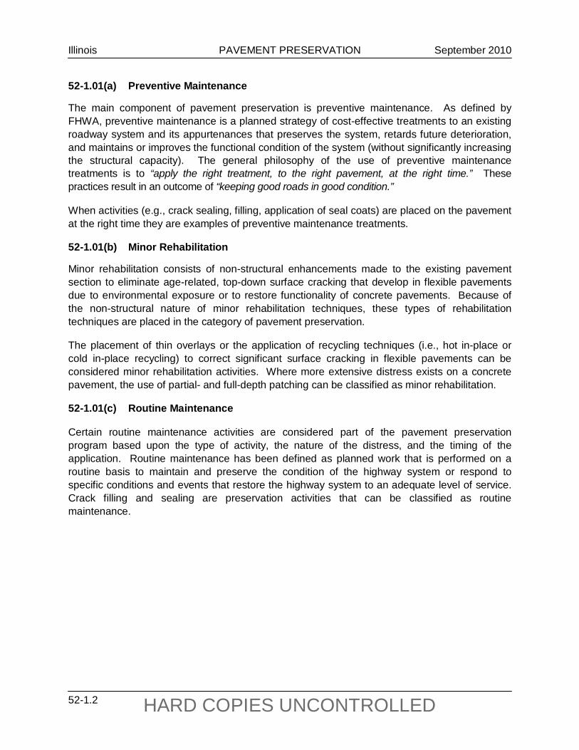
52-1.01(a) Preventive Maintenance
The main component of pavement preservation is preventive maintenance. As defined by FHWA, preventive maintenance is a planned strategy of cost-effective treatments to an existing roadway system and its appurtenances that preserves the system, retards future deterioration, and maintains or improves the functional condition of the system (without significantly increasing the structural capacity). The general philosophy of the use of preventive maintenance treatments is to “apply the right treatment, to the right pavement, at the right time.” These practices result in an outcome of “keeping good roads in good condition.”
When activities (e.g., crack sealing, filling, application of seal coats) are placed on the pavement at the right time they are examples of preventive maintenance treatments.
52-1.01(b) Minor Rehabilitation
Minor rehabilitation consists of non-structural enhancements made to the existing pavement section to eliminate age-related, top-down surface cracking that develop in flexible pavements due to environmental exposure or to restore functionality of concrete pavements. Because of the non-structural nature of minor rehabilitation techniques, these types of rehabilitation techniques are placed in the category of pavement preservation.
The placement of thin overlays or the application of recycling techniques (i.e., hot in-place or cold in-place recycling) to correct significant surface cracking in flexible pavements can be considered minor rehabilitation activities. Where more extensive distress exists on a concrete pavement, the use of partial- and full-depth patching can be classified as minor rehabilitation.
52-1.01(c) Routine Maintenance
Certain routine maintenance activities are considered part of the pavement preservation program based upon the type of activity, the nature of the distress, and the timing of the application. Routine maintenance has been defined as planned work that is performed on a routine basis to maintain and preserve the condition of the highway system or respond to specific conditions and events that restore the highway system to an adequate level of service. Crack filling and sealing are preservation activities that can be classified as routine maintenance.

Illinois PAVEMENT PRESERVATION September 2010
52-2.1 HARD COPIES UNCONTROLLED
52-2 INTRODUCTION TO PAVEMENT PRESERVATION
The intended purpose of a pavement preservation program is to maintain or restore the surface characteristics of a pavement and to extend service life of the pavement assets being managed. However, the improvements are such that there is no increase in capacity or strength but they can have a positive impact on the structural capacity by slowing deterioration. As a means of improving the functional condition of the network and reducing the overall rate of deterioration of the pavement asset, preventive maintenance treatments are used in the pavement preservation program. Because they are relatively inexpensive in comparison to resurfacing or reconstruction projects, the preventive maintenance treatments are an effective means to preserve the investment in the pavement asset.
An effective pavement preservation program has two main objectives:
1. Preserve the Pavement Investment. This objective involves minimizing the structural failures and extending the structural life of the pavement to preserve the investment the Department has made in the pavement asset.
2. Maintain High Level of Service (LOS). This objective involves maintaining acceptable smoothness and surface friction in order to provide a high LOS for the roadway customers.
The implementation of a pavement preservation program is good practice, as it focuses on maximizing the condition and life of a network of pavements while minimizing the network’s life-cycle cost. The noted benefits of the use of a pavement preservation program vary from district to district, but have been documented as including the following benefits:
1. Improved Pavement Performance. Preservation activities extend the performance of the pavement and help to improve the overall condition of the network.
2. Higher Customer Satisfaction. Use of preservation activities can lead to smoother roads and fewer construction delays.
3. Cost Savings. Less expensive treatments and the extension of service lives of pavements help to lower or stabilize operating costs.
4. Increased Safety. Preventive maintenance treatments are designed to provide safer surfaces in terms of improved pavement texture and correction of safety related defects (e.g., ruts, improving surface drainage).
A successful pavement preservation program relies on proper treatment selection and timing of the treatment to be successful. In order to select the right treatment for the right pavement at the right time, gather the following information:
• structure and condition of the existing pavement, • expected performance of the pavement, • how different treatments affect their performance, and • other factors that may affect the treatment performance.
Illinois PAVEMENT PRESERVATION September 2010
52-2.2 HARD COPIES UNCONTROLLED
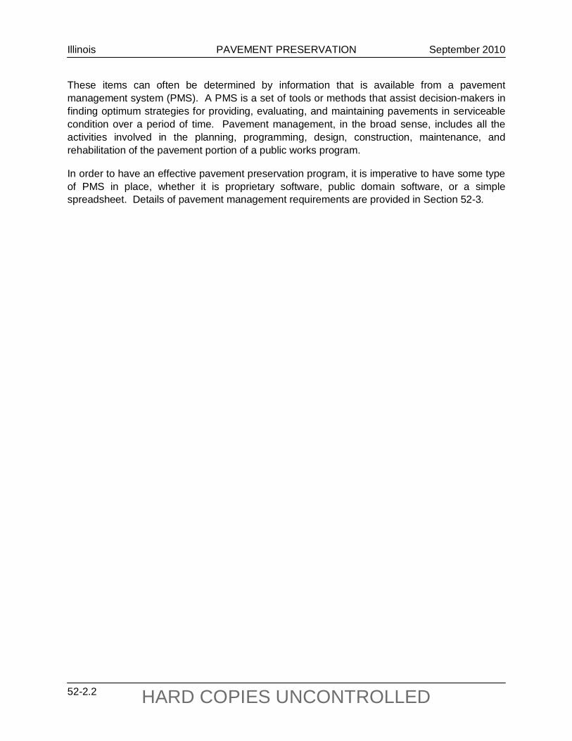
These items can often be determined by information that is available from a pavement management system (PMS). A PMS is a set of tools or methods that assist decision-makers in finding optimum strategies for providing, evaluating, and maintaining pavements in serviceable condition over a period of time. Pavement management, in the broad sense, includes all the activities involved in the planning, programming, design, construction, maintenance, and rehabilitation of the pavement portion of a public works program.
In order to have an effective pavement preservation program, it is imperative to have some type of PMS in place, whether it is proprietary software, public domain software, or a simple spreadsheet. Details of pavement management requirements are provided in Section 52-3.

Illinois PAVEMENT PRESERVATION September 2010
52-3.1 HARD COPIES UNCONTROLLED
52-3 PAVEMENT PERFORMANCE
One of the keys to an effective pavement preservation program is understanding how pavements perform. Figure 52-3.A illustrates the typical life cycle of a pavement and the categories of treatments that are appropriate at different times of the life of the pavement. The application of these treatments is also based upon the condition of the pavement, as preventive maintenance treatments are used early on in the life of a pavement while a pavement is still in relatively good condition. There is also a time when preventive maintenance is no longer appropriate (i.e., the pavement has deteriorated to a point that more extensive cracking and other distresses are present), but it is too soon to trigger the pavement for major rehabilitation. Pavements at this condition level would receive minor rehabilitation treatments (e.g., thin overlays, in-place recycling). Together, the use of preventive maintenance treatments and minor rehabilitation techniques along with routine maintenance provide pavement preservation options for a pavement that is still in relatively good condition.
If preventive maintenance or minor rehabilitation is not used during the life of the pavement, the pavement will deteriorate to the point that major rehabilitation (e.g., structural restoration, full-depth repairs, thick overlays, reconstruction) is necessary. Where a pavement develops significant levels of distress, pavement preservation activities are no longer viable treatment options. If preventive maintenance or minor rehabilitation is used on a pavement that is highly deteriorated, the life of the chosen treatment can be greatly reduced.
Figure 52-3.A depicts a generic pavement performance curve. There can be significant differences in the shape of the performance curve for different pavements due to various issues (e.g., environment, design, construction).
RELATIONSHIP BETWEEN PAVEMENT CONDITION AND TYPICAL TYPES OF TREATMENT
Figure 52-3.A
Pavement Condition
Preventive Maintenance
Reconstruction
Good
Poor
Rehabilitation
Time (years)
Routine/Corrective Maintenance

Illinois PAVEMENT PRESERVATION September 2010
52-3.2 HARD COPIES UNCONTROLLED
The philosophy of pavement preservation is to address pavements while they are still in good condition and without any serious structural damage. A preventive maintenance treatment applied at the right time can restore the pavement almost to its original condition. Systematic, successive preservation treatments applied correctly help prolong the service life of the asset and delay the more expensive major rehabilitation treatments and reconstruction. Figure 52-3.B depicts how the application of successive preventive maintenance treatments (shown as the solid line) can help maintain the pavement in good condition for a longer period of time as compared to a pavement without treatments (depicted by the dashed line performance curve). Additionally, performing a series of successive pavement preservation treatments during the life of a pavement is less disruptive to traffic than the long closures normally associated with reconstruction projects.
To apply pavement preservation techniques at the optimal time, it is imperative to understand the causes of pavement deterioration for the various types of pavements.
PAVEMENT PERFORMANCE EXTENDED BY PREVENTIVE MAINTENANCE
Figure 52-3.B
52-3.01 Causes of Pavement Deterioration
The first step in understanding pavement deterioration is to understand the general causes of deterioration.
52-3.01(a) Flexible Pavement Deterioration
For flexible pavements, which are HMA or other bituminous surfaces, the general causes of primary deterioration include traffic, environment/aging, and material problems. A secondary
Pavement Condition
Time (Years)
Good
Poor

Illinois PAVEMENT PRESERVATION September 2010
52-3.3 HARD COPIES UNCONTROLLED
cause of deterioration is due to moisture infiltration. These causes of deterioration influence the performance of the pavement in various ways:
1. Traffic. Traffic can lead to load-related distress (e.g., plastic deformation that manifests as rutting) or structural fatigue cracking that occurs in the wheelpaths of the pavement. Fatigue cracking can lead to the occurrence of potholes. Additional traffic-related distress includes polishing of the pavement surface due to surface wear, which leads to friction loss.
2. Environment and Aging. Environment and aging can cause oxidation of the HMA and lead to block cracking and weathering/raveling. Environmental forces can also cause thermal cracking, which typically is seen as regularly spaced transverse cracks.
3. Materials. Material problems include bleeding (contributing to loss of friction), shoving and surface deformation, and stripping.
4. Moisture. Moisture infiltration, while a secondary cause of deterioration, can lead to further breakdown of existing cracks and cause increased roughness. The infiltration of moisture will also soften the subgrade and can lead to the occurrence of longitudinal cracking at the edge of the pavement or potholes.
52-3.01(b) Rigid Pavement Deterioration
For rigid pavements, which are portland cement concrete (PCC) surfaced, the general causes of primary deterioration include traffic loadings, environment and material problems, and poor construction quality. Secondary causes of deterioration are due to incompressibles in joints and moisture infiltration. These causes of deterioration influence the performance of the pavement in various ways:
1. Traffic. Traffic can lead to load-related distress in the slab (e.g., mid-slab cracking for jointed pavements, punchouts on CRCP). Pumping, faulting, and corner breaks are also load-related distresses. Traffic-related distress includes polishing of the pavement surface due to surface wear, which leads to friction loss.
2. Environment and Materials. Environment and material problems include D-cracking (durability cracking) and alkali-silica reactivity (ASR). The environment can also cause oxidation of the longitudinal joint seal, which will allow moisture infiltration into the pavement structure.
3. Construction. Poor construction quality can cause problems (e.g., longitudinal cracking, surface distress in the form of map cracking, scaling).
4. Incompressible Materials. Large incompressible materials lodged in a joint can be the cause of joint spalls. The current standard for jointed PCC pavements does not use sealant on transverse joints because it has been found that a narrow joint minimizes the sizes of incompressibles being trapped, which reduces the risk of joint spalling.

Illinois PAVEMENT PRESERVATION September 2010
52-3.4 HARD COPIES UNCONTROLLED
5. Moisture. Moisture infiltration to sub-surface layers, while a secondary cause of deterioration, can lead to further breakdown of existing cracks and spalls and cause increased roughness. The infiltration of moisture will also soften the subgrade and can lead to the occurrence of pumping, transverse joint faulting, and corner breaks.
Understanding the distress mechanisms that cause pavement deterioration is essential in properly identifying preservation strategies and treatments for pavements. The causes of deterioration can lead to a variety of distresses.
52-3.02 Use of Pavement Preservation to Maintain Pavement Performance
Pavement preservation can address many of the various distress types discussed in Section 52-3.01. Specifically, pavement preservation techniques have two main uses:
• prevent or slow many distresses from occurring, or • correct some minor surface distress when applied.
Some of the pavement problems that are prevented or slowed with the use of pavement preservation for flexible and rigid pavements are identified in Figure 52-3.C. The distresses that are corrected with the use of pavement preservation are listed in Figure 52-3.D.
HMA or Other Bituminous Surface Problems PCC Problems
Loss of Fines (pumping) Crack Deterioration Block Cracking Edge Cracking Patch Deterioration Weathering/Raveling
Loss of Fines (pumping) Crack Deterioration Corner Breaks Patch Deterioration Joint Faulting
PAVEMENT PROBLEMS PREVENTED OR SLOWED WITH PAVEMENT PRESERVATION
Figure 52-3.C
HMA or Other Bituminous Surface Problems PCC Problems
Stable HMA Rutting Raveling Bleeding/Flushing Surface Friction Loss Roughness
Joint Seal Damage Map Cracking And Scaling Surface Friction Loss Roughness
PAVEMENT PROBLEMS CORRECTED WITH PAVEMENT PRESERVATION
Figure 52-3.D

Illinois PAVEMENT PRESERVATION September 2010
52-3.5 HARD COPIES UNCONTROLLED
The benefits realized by the application of pavement preservation are accomplished because these techniques achieve the following:
• reduce water infiltration, • maintain drainage, • reduce water infiltration into cracks and joints, • slow aging effects of the pavement, and • minimize dynamic loads.
The reduction in water infiltration and the proper maintenance of drainage help protect the underlying layers of the pavement from being softened or washed away. It also helps to reduce the effects of freeze/thaw-induced distress. The use of global preventive maintenance surface treatments can help to slow HMA aging/hardening. The pavement preservation techniques also help preserve the pavement by reducing and/or correcting pavement roughness, which helps minimize dynamic loadings and, in turn, extends the life of the pavement.
There is a point in the life of the pavement when pavement preservation techniques will no longer provide an adequate treatment to the pavement. In these cases, the pavement has deteriorated to the point that preservation techniques, if used, will have shortened lives. Some indicators that the pavement section is not a viable candidate for preservation treatments are shown in Figure 52-3.E.
HMA or Other Bituminous Surface Problems PCC Problems
Severely Deteriorated (reflective, longitudinal, and transverse) Cracks
Delaminations
Unstable rutting
Punchouts
Corner Breaks
Severely Deteriorated Cracks
INDICATIONS THAT IT IS TOO LATE FOR PAVEMENT PRESERVATION
Figure 52-3.E

Illinois PAVEMENT PRESERVATION September 2010
52-3.6 HARD COPIES UNCONTROLLED

Illinois PAVEMENT PRESERVATION September 2010
52-4.1 HARD COPIES UNCONTROLLED
52-4 TREATMENT SELECTION GUIDELINES
The use of pavement preservation strategies to maintain the condition of the pavement network requires that a district address the following two questions:
• Is the pavement a good candidate for pavement preservation? • If so, what treatment(s) can be applied?
Appropriate maintenance strategies are determined based on a combination of the current condition of the pavement and the types of distresses present. In some cases, combinations of preservation strategies are needed to correct the combination of distress that is present on the pavement. The process of selecting the most appropriate combination of pavements and treatments for preservation activities includes the following general steps:
• gather pavement information, • assess pavement condition, • evaluate pavement data, • identify feasible preservation treatments, and • select the most appropriate preservation treatment.
52-4.01 Gather Pavement Information
Selecting appropriate preservation techniques includes the collection of historical pavement information. The type of information needed to select the right projects and treatments include:
• pavement type, • pavement age and design life, • traffic, and • pavement cross section and materials.
This information can be stored in a pavement management system (PMS) and be accessed to make informed selection of the “right treatment at the right time on the right road.”
When determining the type of treatment, gather the following minimum information from the PMS and use this information in the decision process:
• route ID, • location designations (beginning/ending locations), • surface type, • pavement surface age, • condition rating, • condition survey date, • prominent distress type, and • average daily traffic (ADT).

Illinois PAVEMENT PRESERVATION September 2010
52-4.2 HARD COPIES UNCONTROLLED
Use this information to track the performance of the pavement sections over time and to support pavement preservation treatment selection. The pavement type dictates the choice of treatment, as different techniques are appropriate for various surface types.
In addition to pavement type, the age and design life of the pavement can provide insight into how the pavement has performed over time and how it can be expected to perform in the future. If the pavement is near the end of its design life, it may be an indication that preservation is not appropriate. The traffic level information, specifically the number of heavy trucks, is a critical detail for determining treatments that cannot provide appropriate performance for the expected traffic level. Knowing the existing pavement structure and materials properties can be very useful to determine which treatments will work best with the current structure and how the pavement section might perform in the future.
52-4.02 Assessing IRIS CRS and Distress Data
In addition to gathering historical pavement information, assess the current condition of the pavement in order to determine feasible preservation treatments. Ideally, the condition would be determined in the form of a standard condition rating procedure to include details of the types, severities, and the amounts of all distresses present on the pavement.
Condition Rating Surveys are typically conducted every two years on Interstates (during even numbered years) and other marked routes (Even Numbered Years — Districts 1 (Cook County), 4, 5, 8, and 9; Odd Numbered Years — Districts 1 (Collar Counties), 2, 3, 6, and 7). Pavement conditions can be tracked over time and used in making treatment selections if data is maintained in a PMS.
52-4.03 Evaluate Pavement Data
In order to determine whether a pavement section is a good candidate for pavement preservation treatments, the district should consider the following questions:
• Is there excessive distress (large quantities and/or severe levels of distress) on the pavement section or are the occurring distresses a warning sign of an underlying structural problem?
• Is there evidence of structural problems or severe deterioration (e.g., any of the distresses listed in Figure 52-3.E)?
• Has the time for applying a pavement preservation treatment to the pavement while in “good” condition passed?
• Are there other known pavement problems (e.g., material problems, signs of construction problems) on the pavement section?
• Is there a history of pavement problems in this location?
Illinois PAVEMENT PRESERVATION September 2010
52-4.3 HARD COPIES UNCONTROLLED
If the answer to the majority of these questions is “no,” then the pavement section is likely a good candidate for pavement preservation techniques. For pavement sections where the answer to most of these questions is “yes,” the district should not consider preservation techniques and instead plan major rehabilitation or future reconstruction for the roadway; see Chapter 53.
52-4.04 Identify Feasible Preservation Treatments
The appropriate treatment strategy for those pavement sections identified as candidates for pavement preservation can be determined by looking at the type and severity of pavement distresses present on the pavement. Guidelines for determining recommended and feasible treatments are provided in Figures 52-4.A and 52-4.B for flexible and rigid pavements, respectively. These figures provide guidance for treatment selection based upon attributes (e.g., distress levels, ride, friction, traffic levels, relative cost). These characteristics are primarily based on a relationship between a single treatment and a single distress. Where multiple distresses exist, examine the appropriate treatment(s) to address each distress type. Use the recommended treatments in combination with engineering judgment to make final treatment decisions.
52-4.05 Select Most Appropriate Preservation Treatment
Of the feasible preservation treatments, the most appropriate treatment is one that can provide the best cost/benefit while meeting the constraints of the project. There are several methods to identify the treatment with the most benefit for the associated cost. This analysis is done internally within many PMS. Ideally, the selection of the right treatment at the right time is governed by optimization (i.e., maximizing benefits for given constraints). However, treatment selection can be accomplished through a manual assessment of the benefits versus the projected project cost.
In addition to the benefits and costs of the feasible treatments, the selection of the most appropriate preservation treatment also includes considering the variety of project constraints that affect treatment selection. The types of project constraints that should be considered when selecting the most appropriate preservation treatment include:
• availability of qualified contractors, • availability of quality materials, • Department practice or district preference, • time (of year) of construction, • initial costs, • user preferences, • pavement noise, • facility downtime, and • surface friction.
The effect of these constraints will vary from project to project and should be reviewed for each project when finalizing treatment selection.

Illinois PAVEMENT PRESERVATION September 2010
52-4.4 HARD COPIES UNCONTROLLED
L1F
FN
RN
RF
FF
FF
FF
FN
RL2
, L3,
L4
NR
NR
NR
NR
NR
NR
NR
NR
NR
NR
NR
NR
NR
M1
RR
FR
RR
RR
RR
FF
FM
2R
RN
RN
RF
NR
FF
FF
NR
NR
NR
M3,
M4
FF
NR
NR
NR
NR
NR
NR
FF
NR
NR
NR
N1,
N2
NR
NR
NR
NR
FR
FF
RR
R*
FF
N3
NR
NR
NR
NR
NR
FN
RN
RR
RR
*N
RF
O1
NR
NR
FR
FR
RR
FF
R**
FF
O2,
O3
RR
NR
NR
NR
FF
FF
FF
NR
NR
O4,
O5
FF
NR
NR
NR
NR
NR
NR
NR
NR
NR
NR
NR
Ove
rlaye
d Pa
tch
Ref
lect
ive
Cra
ckin
gP
1, P
2, P
3, P
4, P
5F*
F*F*
F*F*
F*F*
F*F*
F*F*
F*F*
Q1
RR
FF
FF
FF
FF
FF
FQ
2, Q
3R
FN
RN
RN
RF
FF
FF
FF
FQ
4, Q
5N
RN
RN
RN
RN
RN
RN
RN
RF
FN
RN
RN
RR
1R
RF
FF
FF
FF
FF
FF
R2,
R3
FF
NR
NR
FF
FF
FF
FN
RN
RR
4, R
5N
RN
RN
RN
RN
RN
RN
RN
RN
RN
RN
RN
RN
RC
ente
rline
Det
erio
ratio
nS
1, S
2, S
3, S
4F*
F*F*
F*F*
F*F*
F*F*
F*F*
F*F*
T1F
FF
RF
FR
FR
RR
**F
FT2
FF
NR
NR
NR
FF
FF
FF
NR
NR
T3, T
4N
RN
RN
RN
RN
RN
RN
RN
RN
RN
RN
RN
RN
RPe
rman
ent P
atch
Det
erio
ratio
nU
1, U
2, U
3, U
4F*
F*F*
F*F*
F*F*
F*F*
F*F*
F*F*
V1
NR
NR
NR
NR
NR
FF
FR
RR
FR
V2,
V3
NR
NR
NR
NR
NR
NR
NR
NR
RR
RN
RR
W1,
W2
NR
NR
FF
RR
RR
FF
FF
FW
3, W
4N
RN
RN
RN
RF
FF
FR
RR
*N
RN
RR
efle
ctiv
e D
-Cra
ckin
gX1
, X2,
X3
NR
NR
NR
NR
NR
NR
NR
NR
FF
NR
FF
Fric
tion
Poo
rN
RN
RN
RR
RR
RR
FF
RR
F<
5,00
0R
RR
RR
RR
RR
RR
RR
5,00
0 –
10,0
00R
RF
FF
RR
RF
RR
RR
> 10
,000
RR
NR
NR
NR
FF
FN
RR
RR
RR
elat
ive
Cos
t($
to $
$$$)
$$
$$$
$$$$
$$$$
$$$
$$$
$$$
$$$
$
Not
e 1.
Inf
orm
atio
n ab
out p
avem
ent d
istre
ss c
odes
is lo
cate
d in
App
endi
x C
of t
he Il
linoi
s H
ighw
ay In
form
atio
n S
yste
m R
oadw
ay In
form
atio
n &
Pro
cedu
re M
anua
l.N
ote
2. T
his
treat
men
t may
onl
y be
use
d w
ith a
ppro
val f
rom
BD
E a
nd w
ill re
quire
an
Exp
erim
enta
l Fea
ture
acc
ordi
ng to
Con
stru
ctio
n M
emor
andu
m 0
2-2.
Not
e 3.
Pre
serv
atio
n tre
atm
ents
do
not c
orre
ct a
lliga
tor c
rack
ing.
Of t
he tr
eatm
ents
, chi
p se
als
are
mos
t app
ropr
iate
at a
ddre
ssin
g th
e al
ligat
or c
rack
ing.
Not
e 4.
If s
tabl
e ru
tting
is p
rese
nt w
ithou
t oth
er d
istre
sses
, mic
rosu
rfaci
ng o
r mill
and
ove
rlay
are
the
reco
mm
ende
d tre
atm
ents
.N
ote
5. I
f cra
ckin
g is
join
t ref
lect
ion
rela
ted,
the
pres
erva
tion
treat
men
ts w
ill n
ot c
orre
ct th
e di
stre
ss.
R -
Rec
omm
ende
d tre
atm
ent f
or th
e sp
ecifi
ed p
avem
ent c
ondi
tion.
Car
e m
ust b
e ex
amin
ed in
mak
ing
sure
that
all
criti
cal d
istre
ss ty
pes
are
addr
esse
d by
the
sele
cted
trea
tmen
t.R
* - R
ecom
men
ded
treat
men
t whe
n us
ed w
ith m
illin
g pr
ior t
o tre
atm
ent.
R**
- U
sed
in c
ombi
natio
n w
ith c
rack
sea
ling.
F - F
easi
ble
treat
men
t but
dep
ends
upo
n ot
her p
roje
ct c
onst
rain
ts in
clud
ing
othe
r exi
stin
g di
stre
sses
. F*
- Th
is is
a lo
caliz
ed d
istre
ss a
nd s
houl
d be
trea
ted
loca
lly w
hile
oth
er d
istre
ss ty
pes
pres
ent s
houl
d di
ctat
e ch
oice
of g
loba
l tre
atm
ent.
NR
- Tr
eatm
ent i
s no
t rec
omm
ende
d to
cor
rect
the
spec
ified
pav
emen
t con
ditio
n.
"Sta
ble"
Rut
ting
4
Wea
ther
ing/
Rav
elin
g
Edge
Cra
ckin
g
Shov
ing,
Bum
ps, S
ags,
and
Cor
ruga
tion
HIR
2M
icro
- su
rfac
ing
Chi
p Se
alPa
vem
ent C
ondi
tions
ADT
Sand
Se
al 2
Dis
tres
s Le
vels
1C
rack
Fi
lling
Fog
Seal
2
Ref
lect
ive
Wid
enin
g C
rack
Blo
ck C
rack
ing
Long
itudi
nal /
Cen
ter o
f Lan
e C
rack
ing
Join
t Ref
lect
ion
and
Tran
sver
se C
rack
ing
5
Allig
ator
/ Fat
igue
Cra
ckin
g 3
Col
d M
illSl
urry
Se
alC
rack
Se
alin
gSM
ART
Ultr
a- T
hin
Bon
ded
Wea
ring
Cou
rse
Cap
e Se
alC
IR 2
TREATMENT SELECTION GUIDELINES FOR FLEXIBLE PAVEMENTS
Figure 52-4.A

Illinois PAVEMENT PRESERVATION September 2010
52-4.5 HARD COPIES UNCONTROLLED
A1,
A2
NR
FN
RN
RF
NR
NR
NR
A3
NR
NR
NR
NR
NR
FR
NR
A4,
A5
NR
NR
NR
NR
NR
RN
RN
RB
1N
RN
RN
RN
RR
NR
NR
NR
B2,
B3
RN
RN
RN
RF
FN
RF
B4,
B5
FN
RN
RN
RN
RF
NR
FC
1, C
2N
RR
RN
RF
NR
FF
C3,
C4
NR
FR
*N
RF
FR
FD
1N
RR
NR
NR
RN
RN
RN
RD
2N
RF
NR
NR
FN
RR
NR
D3
NR
NR
NR
NR
NR
FR
NR
E1,
E2
RN
RN
RN
RF
FN
RN
RE
3, E
4F
NR
NR
NR
FR
NR
NR
Edge
Pun
chou
ts (C
RC
P)F1
, F2,
F3
NR
NR
NR
NR
FR
NR
NR
G1,
G4
NR
RF
NR
FN
RN
RN
RG
2, G
5N
RF
RN
RF
NR
NR
RG
3, G
6N
RN
RR
*N
RN
RN
RN
RR
H1,
H2
RN
RN
RN
RF
FN
RN
R
H3
NR
NR
NR
NR
NR
RN
RN
R
I1N
RN
RF
NR
RN
RN
RN
RI2
NR
NR
FN
RR
NR
FN
RI3
NR
NR
FN
RF
NR
FN
R
Rid
eIR
I > 1
40 in
/mi
NR
NR
RN
RF
NR
NR
F*Sk
idP
oor
NR
NR
RR
RN
RN
RN
R
Rel
ativ
e C
ost
($ to
$$$
$)$
$$$
$$$$
$$$
$$$$
$$$
$
Not
e 1.
Inf
orm
atio
n ab
out p
avem
ent d
istre
ss c
odes
is lo
cate
d in
App
endi
x C
of t
he Il
linoi
s H
ighw
ay In
form
atio
n S
yste
m R
oadw
ay In
form
atio
n &
Pro
cedu
re M
anua
l.N
ote
2. T
his
treat
men
t may
onl
y be
use
d w
ith a
ppro
val f
rom
BD
E a
nd w
ill re
quire
an
Exp
erim
enta
l Fea
ture
acc
ordi
ng to
Con
stru
ctio
n M
emor
andu
m 0
2-2.
Not
e 3.
LTR
(Loa
d Tr
ansf
er R
esto
ratio
n) is
nor
mal
ly u
sed
in c
ombi
natio
n w
ith d
iam
ond
grin
ding
R -
Rec
omm
ende
d tre
atm
ent f
or th
e sp
ecifi
ed p
avem
ent c
ondi
tion.
Car
e m
ust b
e ex
amin
ed in
mak
ing
sure
that
all
criti
cal d
istre
ss ty
pes
are
addr
esse
d by
the
sele
cted
trea
tmen
t.R
* - R
ecom
men
ded
whe
n us
ed in
con
junc
tion
with
LTR
and
/or S
ubse
alin
g/U
nder
seal
ing.
F - F
easi
ble
treat
men
t but
dep
ends
upo
n ot
her p
roje
ct c
onst
rain
ts in
clud
ing
othe
r exi
stin
g di
stre
sses
. F*
- Fe
asib
le tr
eatm
ent i
f poo
r rid
e is
a re
sult
of u
ndow
eled
join
ts o
r fau
lted
trans
vers
e (m
id-s
lab)
cra
ckin
g.F*
* - O
ther
dis
tress
type
s sh
ould
dic
tate
cho
ice
of tr
eatm
ent.
NR
- Tr
eatm
ent i
s no
t rec
omm
ende
d to
cor
rect
the
spec
ified
pav
emen
t con
ditio
n.
F**
Popo
uts/
Hig
h St
eel
Perm
anen
t Pat
ch D
eter
iora
tion
F**
F**
F**
F**
F**
F**
J1, J
2, J
3
Map
Cra
ckin
g an
d Sc
alin
g
Cor
ner B
reak
s (J
PCP)
NR
NR
NR
K1,
K2,
K3
Faul
ting
Join
t Det
erio
ratio
n
NR
F**
NR
NR
LTR
2, 3
Cen
terli
ne D
eter
iora
tion
Long
itudi
nal C
rack
ing
Dis
tres
s Le
vels
1C
rack
Se
alin
gJo
int
Res
ealin
gD
iam
ond
Grin
ding
Tran
sver
se C
rack
ing
Pave
men
t Con
ditio
ns
D-c
rack
ing
Dia
mon
d G
roov
ing
Full-
Dep
th
Rep
airs
Part
ial-D
epth
R
epai
rsU
ltra-
Thi
n B
onde
d W
earin
g C
ours
e
F**
F**
TREATMENT SELECTION GUIDELINES FOR RIGID PAVEMENTS
Figure 52-4.B

Illinois PAVEMENT PRESERVATION September 2010
52-4.6 HARD COPIES UNCONTROLLED

Illinois PAVEMENT PRESERVATION March 2017
52-5.1 HARD COPIES UNCONTROLLED
52-5 TREATMENTS
Many different pavement preservation techniques and treatments are available. These range from localized applications to treatments that are applied to the entire pavement surface. For all preservation treatments, the purpose is to minimize the effects of pavement distress or prevent them from occurring.
Commonly used preventive maintenance treatments and minor rehabilitation techniques are summarized in this section. Further details regarding the treatments are available in the IDOT Standard Specifications, supplemental specifications, and special provisions. Figure 52-5.A presents the common flexible and rigid pavement treatments. Section 52-5.01 provides details that are applicable to a variety of treatments.
52-5.01 Special Considerations
There are several special considerations that must be addressed prior to the construction of various pavement preservation techniques.
Treatments for Flexible Pavements Treatments for Rigid Pavements
Crack Filling Crack Sealing Fog Seals (1), (2) Sand Seals (1), (2) Slurry Seals Micro-surfacing Bituminous Surface Treatments (Chip Seals) Cape Seals Cold In-place Recycling (CIR) (1), (2) Hot In-place Recycling (HIR) (1), (2) Surface Maintenance at the Right Time (SMART) Overlay Half-SMART Overlay Ultra-Thin Bonded Wearing Course Cold Milling
Crack Sealing Joint Resealing Longitudinal Crack Repair Diamond Grinding Diamond Grooving Ultra-Thin Bonded Wearing Course (1) Full-Depth Repairs Partial-Depth Repairs
1. This treatment will only be allowed with approval from BDE. 2. Requires an experimental feature according to Construction Memorandum 02-2.
PAVEMENT PRESERVATION TREATMENTS FOR FLEXIBLE AND RIGID PAVEMENTS
Figure 52-5.A

Illinois PAVEMENT PRESERVATION March 2017
52-5.2 HARD COPIES UNCONTROLLED
52-5.01(a) Raised Pavement Markers
Review all pavement sections for the presence of raised pavement markers (RPMs) prior to treatment placement for global treatments. Evaluate the thickness of the treatment to determine if the RPMs can remain in place. For thin treatments (e.g., fog seals, sand seals), the lens of the marker can be removed and tape placed over the marker during treatment placement. Following treatment placement, the tape can be removed and a new lens installed.
If the thickness of the treatment is more than 0.25 in. (6 mm), remove the markers and repair the hole from the removal of the markers prior to the new treatment. After treatment, reposition the new marker in the new surface.
52-5.01(b) Pavement Preparation
Some pavement preservation treatments require complete removal of all pavement markings (e.g., thermoplastic, paint). When designing a project, review construction requirements of the selected treatment to determine if this work is required.
Evaluate all flexible pavement sections for the presence of bumps greater than 0.5 in. (12.5 mm), using a 16 ft (4.9 m) straightedge. For flexible treatments that do not include milling or recycling of the pavement surface, grind the bumps prior to treatment placement. Give special attention to properly cleaning all milled materials off the pavement surface prior to treatment placement. Cleaned surfaces are imperative prior to global flexible surface treatments in order to obtain proper bonding to the underlying pavement. Crack sealing, when needed prior to preventive maintenance treatment, should optimally be placed at least three months prior to the placement of the treatment to minimize difficulties in constructing the treatment.
52-5.01(c) Pavement Markings
A period of several days of good drying weather is necessary prior to the placement of permanent markings on various flexible pavement treatments. Review each treatment specification to determine what length of time is necessary for a project. Temporary markings of water-based paint or foil-backed tape will be necessary until permanent markings can be applied.
52-5.01(d) Traffic Control
Proper traffic control is required to ensure acceptable cure times for the majority of treatments. Without proper traffic control after placement, premature failure of the preservation treatment may occur. For rigid pavements, the use of conventional patch materials is usually best for the long-term performance of the pavement but requires adequate curing that may not be available in high-traffic volume areas or at certain times of the year.
52-5.01(e) Project Letting
The designer should review the weather limitations for the selected treatment when determining the letting date. Some treatments have small ranges of dates and/or temperatures in which

Illinois PAVEMENT PRESERVATION March 2017
52-5.3 HARD COPIES UNCONTROLLED
they can be constructed. Schedule the letting at a time to avoid late season paving to promote proper cure of the treatment prior to the onset of winter.
52-5.02 Flexible Pavement Treatment Summaries
52-5.02(a) Crack Filling
Crack filling is effective at reducing or delaying moisture damage, further crack deterioration, roughness, and rutting. However, crack filling can also have a negative impact on roughness and friction. The following provides additional information and considerations for use of this treatment:
1. Treatment Description. Crack filling is the process of placing material into non-working cracks to substantially reduce the infiltration of water and to reinforce the adjacent pavement. Crack filling is characterized by minimal crack preparation and the use of lower quality bituminous filler materials.
2. Pavement Conditions Addressed. Adds no structural benefit, but does reduce moisture infiltration through cracks. Only practical if extent of cracking is minimal and if there is little to no structural cracking.
3. Application Limitations. These treatments are not recommended when structural failures exist (e.g., extensive fatigue cracking, high-severity rutting) or if there is extensive pavement deterioration or little remaining life. Crack filling is appropriate for non-working (e.g., longitudinal, block) cracks 0.25 in. (6 mm) to 1.0 in. (25 mm) wide.
Non-working cracks narrower than 0.25 in. (6 mm) that do not exhibit spalling should not be filled. These cracks generally do not penetrate through the surface course nor do they pose a source of pavement deterioration. The practice of filling this type of crack by the method of pouring filler on the pavement surface is seldom of value. Perform a crack analysis to determine whether crack filling would be effective.
4. Construction Considerations. Placement should occur during cool, dry weather conditions. Application during cool weather will allow for expanded crack widths. Proper crack cleaning and a dry crack are essential to achieving good bond and maximum performance.
5. Traffic Considerations. Performance is not significantly affected by varying ADT or truck levels. However, improper installation can permit the filler to fail.
6. Special Considerations. Crack filling may have negative effects. Undesirable visual impacts may occur, which include tracking of filling material by tire action, obscuring lane markings, and adversely affecting friction/skid resistance. Crack filling may result in a rougher pavement surface when the filler material is forced out of the cracks during warm months.
7. Performance Period. 2 to 4 years.
8. Relative Cost ($ to $$$$). $

Illinois PAVEMENT PRESERVATION March 2017
52-5.4 HARD COPIES UNCONTROLLED
52-5.02(b) Crack Sealing
Crack sealing is effective at reducing or delaying moisture damage, further crack deterioration, roughness, and rutting. However, crack sealing can also have a negative impact on roughness and friction. The following provides additional information and considerations for use of this treatment:
1. Treatment Description. Crack sealing is the process of placing higher-quality material into “working” cracks (i.e., those that open and close with changes in temperature) in order to reduce water infiltration into a pavement. In contrast to crack “filling,” crack sealing requires crack routing and uses higher quality sealant materials. Thermosetting and thermoplastic materials are both used for crack sealing.
2. Pavement Conditions Addressed. Adds no structural benefit, but does reduce future intrusion of incompressible materials, water, and soluble chemicals (e.g., salts, brines) into the cracks. It is only practical if extent of cracking is minimal and if there is little to no structural cracking.
3. Application Limitations. These treatments are not recommended where structural failures exist (e.g., extensive fatigue cracking, high-severity rutting) or if there is extensive pavement deterioration or little remaining life. Crack sealing is appropriate for cracks 0.25 in. to 0.75 in. (6 mm to 19 mm) wide.
Non-working cracks narrower than 0.25 in. (6 mm) that do not exhibit spalling should not be routed and sealed. These cracks generally do not penetrate through the surface course nor do they pose a source of pavement deterioration. The practice of routing and sealing this type of crack can increase pavement roughness without gaining any benefit.
4. Construction Considerations. Placement should occur during cool, dry weather conditions with moderate yearly temperatures. Proper crack preparation and cleaning is essential to good bond and maximum performance. Some agencies also use a hot compressed air lance prior to sealing.
5. Traffic Considerations. Performance is not significantly affected by varying ADT or truck levels. However, improper installation can permit the sealant to fail.
6. Special Considerations. Crack sealing may have negative effects. Undesirable visual impacts may occur, which include tracking of sealing material by tire action, obscuring lane markings, and adversely affecting skid resistance. Crack sealing may result in a rougher pavement surface where the sealant material is forced out of the cracks during warm months. Sealing is best accomplished several months in advance of any other preventive maintenance surface applications.
7. Performance Period. 2 to 8 years.
8. Relative Cost ($ to $$$$). $

Illinois PAVEMENT PRESERVATION March 2017
52-5.5 HARD COPIES UNCONTROLLED
52-5.02(c) Fog Seal
Fog seals are effective at sealing the pavement, inhibiting raveling, enriching the hardened/ oxidized HMA, and providing some pavement edge-shoulder delineation. The following provides additional information and considerations for use of this treatment:
1. Treatment Description. Fog seals are very light applications of a diluted asphalt emulsion placed directly on the pavement surface with no aggregate. Typical application rates range from 0.05 to 0.10 gal/yd2 (0.23 to 0.45 L/m2).
2. Pavement Conditions Addressed. Fog seals are placed primarily to seal the pavement, inhibit raveling, slightly enrich a hardened/oxidized HMA, and provide some pavement edge-shoulder delineation. No structural benefit is added by this treatment.
3. Application Limitations. This treatment must be approved by BDE and will require an experimental feature study according to Construction Memorandum 02-2. This treatment is not recommended where structural failures exist (e.g., significant fatigue cracking) or if there is already flushing/bleeding, friction loss, or thermal cracking. Fog seals can have a negative impact on friction and stripping in susceptible HMA pavements.
4. Construction Considerations. Typically, a slow-setting emulsion (e.g., CSS-1H, SS-1H) is used that requires time to “break.” Because of this, the pavement is sometimes closed for two hours for curing before being re-opened to traffic.
5. Traffic Considerations. Increased ADT or truck levels can increase surface wear.
6. Special Considerations. Give special consideration to the raised pavement markers and bump grinding prior to treatment placement.
7. Performance Period. 1 to 3 years.
8. Relative Cost ($ to $$$$). $
52-5.02(d) Sand Seal
Sand seals are effective at improving poor friction and reducing or preventing moisture damage, cracking, raveling, roughness, and rutting. The following provides additional information and considerations for use of this treatment:
1. Treatment Description. A sand seal is a thin asphalt surface treatment constructed by spraying a non-diluted emulsion, spreading a thin layer of fine aggregate (i.e., sand), and rolling. Sand seals are typically 0.1 in. to 0.2 in. (2.5 mm to 5 mm) thick. The primary purpose is to increase surface friction; however, in some cases, sand seals are used to “lock” the aggregates in a chip seal.
2. Pavement Conditions Addressed. Sand seals are primarily placed to improve poor friction; however, they are effective at slowing or preventing other distresses (e.g.,

Illinois PAVEMENT PRESERVATION March 2017
52-5.6 HARD COPIES UNCONTROLLED
moisture damage, cracking, raveling, roughness, rutting). No structural benefit is added by this treatment.
3. Application Limitations. This treatment must be approved by BDE and will require an experimental feature study according to Construction Memorandum 02-2. This treatment is not recommended where structural failures exist (e.g., fatigue cracking, high-severity rutting), if there is extensive pavement deterioration, or little remaining life. Sand seals can also have a negative impact on stripping in susceptible HMA pavements.
4. Construction Considerations. Sand seals should be constructed when conditions are dry (i.e., the risk of rain is not likely, which would hinder the proper construction of the sand seal) and when the minimum air temperature is moderate (i.e., normally 50°F (10°C) or above). To ensure good bond to the existing pavement, the surface should be clean and dry prior to emulsion placement.
5. Traffic Considerations. Sand seals should generally be limited to lower volume traffic conditions with a low percentage of trucks.
6. Special Considerations. Give special consideration to the raised pavement markers and bump grinding prior to treatment placement.
7. Performance Period. 3 to 4 years.
8. Relative Cost ($ to $$$$). $$
52-5.02(e) Slurry Seal
Slurry seals are effective at sealing low-severity cracks, waterproofing the surface, and restoring friction. The following provides additional information and considerations for use of this treatment:
1. Treatment Description. Slurry seals are a mixture of crushed well-graded aggregate (e.g., fine sand, mineral filler) and asphalt emulsion that is spread over the entire pavement surface with either a squeegee or spreader box attached to the back of a truck. They are effective in sealing low-severity surface cracks, waterproofing the pavement surface, and improving skid resistance at speeds below 30 mph (50 km/h). Thickness is generally less than 0.5 in. (12.5 mm).
2. Pavement Conditions Addressed. Slurry seals can be used to address low-severity cracking, raveling/weathering (remove loose material), HMA oxidation and hardening, friction loss, and moisture infiltration. While slurry seals add no structural capacity, they can temporarily seal cracks, if severity is low, or fill very minor rutting, if the ruts are not severe and are stable. It is strongly recommended to complete needed patching and crack sealing before slurry seal placement.
3. Application Limitations. Slurry seals are not recommended where structural failures exist (e.g., significant fatigue cracking and deep rutting) or if there is high-severity

Illinois PAVEMENT PRESERVATION March 2017
52-5.7 HARD COPIES UNCONTROLLED
thermal cracking. Analyze existing materials as slurry seals can accelerate the development of stripping in susceptible HMA pavements.
4. Construction Considerations. Ensure the pavement surface is clean and remove pavement markings prior to placement as required in the Specifications. Aggregates must be clean, angular, durable, well-graded, and uniform. Avoid placement in hot weather (potential flushing problems) or when freezing temperatures are expected. Slurry seals should be placed between May 1 and October 15 and when the temperature is at least 50°F (10°C) and rising and the forecast for the next 24 hours is above 40°F (4.4°C). Avoid premature opening to traffic and premature placement of raised reflective pavement markers and permanent pavement markings. Quick setting emulsions may cure in as little as 1 hour, but others may require from 2 to 4 hours depending upon the environmental conditions. Use temporary pavement markings until permanent markings are applied a minimum of 7 days following slurry seal placement.
5. Traffic Considerations. Performance in terms of surface wear is affected by increasing ADT and truck traffic levels. Slurry mix properties (e.g., aggregate quality, gradation, modifiers, emulsion content) can be modified to accommodate higher traffic volumes. Avoid areas with heavy truck turning or downgrade locations as there is a high potential for early damage.
6. Special Considerations. Give special consideration to raised reflective pavement markers and bump grinding prior to treatment placement.
7. Performance Period. 3 to 6 years.
8. Relative Cost ($ to $$$$). $$
52-5.02(f) Micro-Surfacing
Micro-surfacing is effective at correcting or inhibiting raveling and oxidation of the pavement surface, improving surface friction, sealing the pavement surface, and filling minor surface irregularities and wheel ruts up to 1.25 in. (30 mm) deep. The following provides additional information and considerations for use of this treatment:
1. Treatment Description. Applied in a process similar to slurry seals, micro-surfacing consists of a mixture of latex-modified emulsified asphalt, mineral aggregate, mineral filler, water, and additives. Micro-surfacing material is mixed in specialized, compartmented, self-powered trucks and placed on the pavement using an augured screed box.
2. Pavement Conditions Addressed. Micro-surfacing may be used to address low-severity cracking, raveling/weathering (remove loose material), low- to medium-severity bleeding, minor roughness, friction loss, and moisture infiltration. Adds limited structural capacity. Temporarily seals fatigue cracks (if severity is low) and can serve as a rut-filler (if the existing ruts are stable).

Illinois PAVEMENT PRESERVATION March 2017
52-5.8 HARD COPIES UNCONTROLLED
3. Application Limitations. Micro-surfacing is not recommended when the pavement contains structural failures (e.g., significant fatigue cracking), high-severity thermal cracking, or extensive pavement deterioration. Analyze existing materials as micro-surfacing can also accelerate this distress. An example of this analysis is provided in Section 53-3.08.
4. Construction Considerations. Ensure the pavement surface is clean and remove pavement markings prior to placement as required in the Specifications. Avoid placement in hot weather if there is potential for flushing problems. Placement in cool weather can lead to early raveling. Do not place when freezing temperatures are expected. Only use micro-surfacing between May 1 and October 15 and when the temperature is at least 50°F (10°C) and rising and the forecast for the next 24 hours is above 40°F (4.4°C). Avoid premature placement of raised reflective pavement markers and permanent pavement markings. Use temporary pavement markings until permanent markings are applied a minimum of 7 days following micro-surfacing placement. Micro-surfacing typically breaks within a few minutes of placement and can carry traffic after approximately one hour.
5. Traffic Considerations. Micro-surfacing is very successful on both low-and high-volume roadways. However, avoid areas of heavy truck turning or downgrade locations as there is a high potential for early damage. The dusting of a blotter material can be used to allow for earlier opening of intersections and turning lanes.
6. Special Considerations. If micro-surfacing is being used to fill ruts, specify this on the plans along with appropriate gradation and application rate. Give special consideration to raised reflective pavement markers and bump grinding prior to treatment placement.
7. Performance Period. 4 to 7 years.
8. Relative Cost ($ to $$$$). $$
52-5.02(g) Bituminous Surface Treatment
Bituminous Surface Treatments (BST)s, also known as chip seals, are effective at improving poor friction, inhibiting raveling, correcting minor roughness and bleeding, and sealing the pavement surface. The following provides additional information and considerations for use of this treatment:
1. Treatment Description. Asphalt emulsion is applied directly to the pavement surface (0.26 to 0.46 gal/yd2 (1.2 to 2.2 L/m2)) followed by the application of aggregate chips (16 to 30 lb/yd2 (9 to 16 kg/m2)), which are then immediately rolled to imbed chips (50% to 70%). Application rates depend upon aggregate gradation and maximum size. This treatment can be applied in multiple layers (e.g., double chip seals) and in combination with other surface treatments.
2. Pavement Conditions Addressed. BSTs can be used to address longitudinal, transverse, and block cracking; raveling/weathering (remove loose material); friction

Illinois PAVEMENT PRESERVATION March 2017
52-5.9 HARD COPIES UNCONTROLLED
loss; minor roughness; low-severity bleeding; and moisture infiltration. Adds almost no structural capacity. The flexible impermeable HMA surface helps reduce cracking and is somewhat effective at sealing medium-severity fatigue cracks in comparison with other treatments.
3. Application Limitations. BSTs are not recommended for pavements with the following conditions:
• structural deficiency, • cracks greater than 0.25 in. (6 mm) wide, • medium- to high-severity alligator cracking, • many potholes, • rutting greater than 1 in. (25 mm) deep, and • very rough surface.
BSTs can also accelerate the development of stripping in susceptible HMA pavements.
4. Construction Considerations. Surface must be clean. Place treatment during warm weather with chip spreader immediately behind asphalt distributor and rollers close behind the spreader. BSTs are placed from May 1 to August 31 and when the temperature in the shade is above 55°F (13°C). Approximately two hours of cure time are required before roadway may be re-opened to normal speed traffic. Brooming is usually required to remove loose chips. Use lightweight aggregate to help minimize claims. Flaggers may be needed at crossing intersections to control traffic. Avoid premature placement of pavement markers and striping.
5. Traffic Considerations. With special design and proper placement, BSTs can perform well on high-volume roads. However, its use is sometimes limited to lower-speed, lower-volume roads because of the propensity for loose chips to crack windshields.
6. Special Considerations. Give special consideration to raised reflective pavement markers and bump grinding prior to treatment placement. Additional information is available from the BLRS Report, Seal Coats (Oil & Chipping).
7. Performance Period. Single seals (A-1): 4 to 6 years; double seals (A-2): 5 to 7 years; triple seals (A-3): 6 to 8 years.
8. Relative Cost ($ to $$$$). $$
52-5.02(h) Cape Seal
A cape seal combines a BST with micro-surfacing to provide a smooth wearing quiet surface at a lower cost than an HMA overlay. The following provides additional information and considerations for use of this treatment:
Treatment Description. The treatment consists of a BST, followed within a few days by a micro-surfacing treatment to cover the chips and seal them in.

Illinois PAVEMENT PRESERVATION March 2017
52-5.10 HARD COPIES UNCONTROLLED
Pavement Conditions Addressed. Cape seal can be used to address longitudinal, transverse, and block cracking; friction loss; raveling/weathering (remove loose material); minor roughness; low- to medium-severity bleeding; and moisture infiltration. Adds limited structural capacity. It is somewhat effective at sealing medium-severity fatigue cracks in comparison with other treatments.
Application Limitations. Not recommended for pavements with the following conditions:
• structural deficiency, • cracks > 0.25 in. (6 mm) wide, • medium- to high-severity alligator cracking, • many potholes, • rutting > 1 in. (25 mm) deep, and • very rough surface.
Cape seals can accelerate the development of stripping in susceptible HMA pavements.
9. Construction Considerations. Construction should be done in summer months, and micro-surfacing should follow the BST by no more than 12 days. Temperature and placement time of year details for chip seals and micro-surfacing apply to the use of this treatment. Clean the existing surface and correct any areas requiring pavement repairs using partial depth repairs prior to application of the BST. Avoid premature placement of raised reflective pavement markers and permanent pavement markings after the micro-surfacing layer has been placed. Use temporary pavement markings until permanent markings are applied a minimum of seven days following micro-surfacing placement.
10. Traffic Considerations. Because the application of the micro-surfacing removes the hazard of loose chips, the final surface of the cape seal leaves no concerns. However, keep traffic to slower speeds on high-volume or high-speed roadways until the BST portion has cured properly and/or it is covered by the micro-surfacing.
11. Special Considerations. Give special consideration to raised reflective pavement markers and bump grinding prior to treatment placement.
12. Performance Period. 4 to 7 years.
13. Relative Cost ($ to $$$$). $$
52-5.02(i) Cold In-Place Recycling
Cold In-Place Recycling (CIR) is very effective at correcting distresses contained in the top 2 in to 4 in. (50 mm to 100 mm) of the pavement surface. Examples include poor friction and roughness, bleeding, raveling, rutting, and poor cross slope. The following provides additional information and considerations for use of this treatment:
1. Treatment Description. Cold in-place recycling (CIR) is an in-situ process used to recycle the top 2 in to 4 in. (50 mm to 100 mm) of an existing HMA pavement to construct a new HMA layer. As the name suggests, the recycling process is conducted
Illinois PAVEMENT PRESERVATION March 2017
52-5.11 HARD COPIES UNCONTROLLED
without the addition of heat. During the CIR process, the reclaimed asphalt pavement (RAP) is sized, mixed with additives (e.g., asphalt binder, emulsion, rejuvenator, virgin aggregate), and re-laid. The recycled pavement is then typically resurfaced with a surface treatment or HMA overlay.
2. Pavement Conditions Addressed. CIR is effective where cracking is limited to the surface layers; profile, crown, and cross slope problems; poor ride quality and surface friction; rutting, corrugations, and bumps; raveling; and flushing/bleeding.
3. Application Limitations. This treatment must be approved by BDE and will require an experimental feature study according to Construction Memorandum 02-2. CIR is not an appropriate treatment for pavements with major or extensive structural deficiencies (e.g., severe alligator cracking, severe structural rutting) or distresses deeper than the CIR depth. CIR may also be difficult to conduct on steep grades, tightly curved roads, or on roads with many utility appurtenances.
4. Construction Considerations. The CIR process uses a number of pieces of equipment including tanker trucks, milling machines, crushing and screening units, mixers, pavers, and rollers. Do not perform CIR at temperatures below 50°F (10°C) or when it is raining. It takes one to two weeks of good weather for the CIR material to cure.
CIR pavement can remain tender for a number of days. Do not allow this treatment to remain exposed over the winter season without a BST or HMA overlay as the final surface.
5. Traffic Considerations. CIR is most often used on secondary and low volume roads.
6. Special Considerations. Remove and replace areas of weak material with suitable patching material prior to recycling to reduce the risk of the cold planing machine or other CIR equipment breaking through the pavement.
7. Performance Period. 5 to 13 years.
8. Relative Cost ($ to $$$$). $$$
52-5.02(j) Hot In-Place Recycling
Hot In-Place Recycling (HIR) is effective at correcting surface distresses that are limited to the top 1 in. to 2 in. (25 mm to 50 mm). Examples include rutting, corrugations, raveling, flushing/bleeding, loss of surface friction, minor thermal cracking, and minor load-associated cracking. The following provides additional information and considerations for use of this treatment:
1. Treatment Description. Hot in-place recycling (HIR) is a process of correcting HMA pavement surface distress by softening the existing surface with heat, mechanically loosening the pavement surface, mixing the loosened surface material with recycling agent, aggregate, rejuvenators, or HMA, and relaying the recycled material without

Illinois PAVEMENT PRESERVATION March 2017
52-5.12 HARD COPIES UNCONTROLLED
removing it from the site. Different HIR processes include surface recycling (e.g., heater scarification), repaving, and remixing.
2. Pavement Conditions Addressed. HIR is effective at correcting surface distresses that are limited to the top 1 in. to 2 in. (25 mm to 50 mm). Examples include rutting, corrugations, raveling, flushing, loss of surface friction, minor thermal cracking, and minor load-associated cracking.
3. Application Limitations. This treatment must be approved by BDE and will require an experimental feature study according to Construction Memorandum 02-2. Good HIR candidates have no structural failures, limited variation in the existing HMA mix, no paving fabrics or interlayers in the anticipated treatment depth plus 25%, no deep ruts greater than one-half of the anticipated HIR treatment depth, and no large stone mixes. The presence of rubber in the surface lift, rubberized seal coats, and some crack fillers require special attention in the mix design process.
4. Construction Considerations. As the HIR equipment is relatively wide and long, short road sections, particularly in urban settings, are not suitable for HIR treatment. Do not perform HIR at temperatures below 50°F (10°C) or when it is raining.
HIR pavement can remain tender for a number of days. Do not allow the treatment to remain exposed over the winter season without a bituminous surface treatment or HMA overlay as the final surface.
5. Traffic Considerations. HIR is appropriate for very low to high traffic conditions. Only use the heater-scarification process for low volume traffic. The remixing and repaving processes can be used on high traffic volume roads.
6. Special Considerations. Remove crack sealant prior to the HIR operation to reduce flash fires or excessive blue smoke from the treatment placement.
7. Performance Period. 6 to 15 years, depending on method of HIR.
8. Relative Cost ($ to $$$$). $$$
52-5.02(k) Surface Maintenance at the Right Time Overlay
The combination of cold milling and the application of a Surface Maintenance at the Right Time (SMART) overlay is a viable option for improving rideability, surface friction, profile, crown, and cross slope. The following provides additional information and considerations for use of this treatment:
1. Treatment Description. SMART overlays may be continuous or intermittent and consist of placing a 1.50 in. (38 mm) (1.75 in. (44 mm) for F-mix) single-pass overlay on a previously resurfaced pavement that is not in need of significant repair and is in good condition. If the SMART overlay is applied at the correct time, it can delay serious distresses, extend the life of the pavement, and decrease the overall cost.

Illinois PAVEMENT PRESERVATION March 2017
52-5.13 HARD COPIES UNCONTROLLED
2. Pavement Conditions Addressed. SMART Overlay can be used to address low-severity cracking, raveling/weathering, friction loss, roughness, low-severity flushing/bleeding, and low-severity block cracking. Thin overlays may also be used to correct rutting (requires use of separate rut-fill application).
3. Application Limitations. The selection criteria for SMART projects are presented in Figure 52-5.B. SMART overlays are not allowed on Interstate highways or bare PCC pavements. Four-lane routes, with the exception of Interstates, may be considered if the two-lane truck and patching directional criteria presented in Figure 52-5.B are met. Also, consider ramps and unmarked narrow pavements that do not have excessive rutting or shoving for SMART projects. Consider local SMART project participation on a case-by-case basis. For rural facilities, ensure that the section is at least 1.0 mile (1.6 km) in length. If deviations from these criteria are necessary, contact BDE for approval.
4. Pavement Distress. SMART overlays are also not recommended where there are structural failures (e.g., fatigue cracking), excessive rutting, extensive pavement deterioration, or if there is high-severity thermal cracking. Pavements with these significant distresses (e.g., CRS distress levels L3, L4, O4, T2, T3, T4) are not eligible. The surface should be uniform to ensure uniform compaction.
5. Construction Considerations. Surface must be clean. A tack coat prior to overlay placement will help improve the bond to the existing surface. SMART overlays dissipate heat rapidly and, therefore, depend upon minimum specified mix placement temperatures and timely compaction.
6. Traffic Considerations. Performance is not affected by different ADT or percent trucks.
7. Special Considerations. Repair localized distressed areas prior to the placement of the overlay. If milling is not used in conjunction with the SMART overlay, give special consideration to bump grinding prior to treatment placement.
8. Curb Ramps. Refer to Section 58-1.09(a) regarding curb ramps.
9. Existing Public Educational Facility Entrances. If surface deficiencies in such entrances exist, repairs/resurfacing should be extended to the right-of-way limits and be consistent with other SMART criteria.
10. Performance Period. 7 to 10 years.
11. Relative Cost ($ to $$$$). $$$

Illinois PAVEMENT PRESERVATION March 2017
52-5.14 HARD COPIES UNCONTROLLED
Criteria Selection Guidelines
Minimum CRS limitations 5.5 minimum (marked routes) 4.5 minimum (unmarked routes)
Maximum CRS limitations 6.5 maximum (marked routes) 6.0 maximum (unmarked routes)
Limits on multiple units/day < 500/day
Milling Recommended (see Note 1)
Longitudinal crack control Recommended (see Note 2)
Bare concrete pavement resurfacing Not allowed
Resurfacing thickness 1.50 in. (38 mm) (1.75 in. (44 mm) for F mixture) (see Note 3)
Patching limitations 6% maximum (see Note 4)
3R spot improvements No (see Note 6)
Safety shoulder additions No (see Note 5)
Narrow pavement resurfacing No (except on unmarked routes)
Raised pavement markers Replace existing
Geometric improvements Not allowed except to address Five Percent Locations
Right-of-way Not allowed except to address Five Percent Locations or ADA elements altered by the project
M-2.12 (M-5.30) medians Allowed (if average project cost is under $400,000/mile ($250,000/km))
Five Percent Locations See Section 12-3.08(b)
Notes:
1. Use cold milling where necessary to reduce pavement irregularities and to produce a uniform surface or to correct cross slope. Milling is required where rutting is continuous and exceeds 0.25 in (6 mm) or where the CRS block cracking distress level is M3 or M4. Also, include milling where CRS distress levels V2, V3, W3, or W4 are present. Milling need not be continuous throughout the section.
2. Strip reflective crack control is required where distress levels R4, R5, or S4 are present.
3. Exceptions are allowed for limited areas of extensive pavement distress but require approval from BDE. Consider other resurfacing programs if exception is necessary for the majority of the project.
4. Limit patching to no more than 6% if less than 250 MUs/day or no more than 5% if 250 to 500 MUs/day. Limit alligator or edge cracking that requires patching to no more than 4% at all traffic levels.
5. Include only minimal shoulder work. In urban areas, minimal curb repair may be included.
6. Exceptions are allowed for spot safety improvements. The following items, up to a total of 15% of the contract cost, may be included but require approval from BDE:
• spot guardrail updates, • minor spot drainage improvements, including culvert extensions/repairs • manhole or inlet adjustments off of the pavement, • isolated ditch cleaning, and • isolated entrance culvert replacement.
SELECTION CRITERIA FOR SMART PROJECTS
Figure 52-5.B

Illinois PAVEMENT PRESERVATION March 2017
52-5.15 HARD COPIES UNCONTROLLED
52-5.02(l) Half-SMART Overlay
Placing a combination of HMA level binder and a bituminous surface treatment (BST) is a viable option for improving surface friction, profile, crown, and cross slope. The following provides additional information and considerations for use of this treatment:
1. Treatment Description. Half-SMART overlays consist of placing a nominal 0.75 in. (19 mm) layer of HMA level binder followed by a BST. Only place this treatment on a previously resurfaced pavement that is not in need of significant repair and is in good condition.
2. Pavement Conditions Addressed. Half-SMART overlays are applicable for low-severity cracking; raveling/weathering (remove loose material), friction loss, low-severity flushing/bleeding, and low-severity block cracking (may perform better with additional milling). Half-SMART overlays may also be used to correct minor rutting (depths less than 0.25 in. (6 mm)).
3. Application Limitations. Half-SMART overlays are not recommended where there are structural failures (e.g., fatigue cracking), extensive pavement deterioration, or if there is high-severity thermal cracking. If this treatment is being placed to correct rutting, evaluate the pavement to determine if the rutting is stable. Do not use half-SMART overlays on pavements that have unstable rutting due to stripping in the existing asphalt layers.
4. Construction Considerations. Surface must be clean. A tack coat prior to overlay placement will help improve the bond to the existing surface. The level binder layer of a Half-SMART overlay dissipates heat rapidly and, therefore, depends upon minimum specified mix placement temperatures and timely compaction. Place the BST portion during warm weather with the chip spreader immediately behind the asphalt distributor and rollers close behind the spreader. Place BSTs from May 1 to August 31 and when the temperature in the shade is above 55°F (13°C). Approximately 2 hours of cure time are required before roadway may be re-opened to normal speed traffic. Brooming is usually required to remove loose chips. Lightweight aggregate can be used to help minimize claims. Flaggers may be needed at crossing intersections to control traffic. Avoid premature placement of pavement markers and striping.
5. Traffic Considerations. Use of the Half-SMART overlay is sometimes limited to lower-speed, lower-volume roads because of the BST layer, which has the propensity for loose chips to crack windshields.
6. Special Considerations. Repair localized distressed areas prior to the placement of the overlay. If milling is not used in conjunction with the Half-SMART overlay, give special consideration to bump grinding prior to treatment placement.
7. Performance Period. 5 to 7 years.
8. Relative Cost ($ to $$$$). $$

Illinois PAVEMENT PRESERVATION March 2017
52-5.16 HARD COPIES UNCONTROLLED
52-5.02(m) Ultra-Thin Bonded Wearing Course
An ultra-thin bonded wearing course (UTBWC) is an alternative to bituminous surface treatments, micro-surfacing, or thin HMA overlays as it effectively addresses minor surface distresses and increases surface friction. The following provides additional information and considerations for use of this treatment:
1. Treatment Description. A UTBWC is formed in one pass with the application of a heavy, polymer-modified asphalt emulsion tack coat and a gap-graded, polymer-modified 0.4 in. to 0.8 in. (10 mm to 20 mm) HMA layer.
2. Pavement Conditions Addressed. This treatment is applicable for low-severity cracking (high severity can be addressed with cold milling), raveling/weathering (remove loose material), high-severity friction loss, low-severity roughness, and low-severity flushing/bleeding. Provides some increased capacity and retards fatigue cracking, but is not suited for rutted pavements.
3. Application Limitations. Ultra-thin bonded wearing courses are not recommended where structural failures exist (e.g., significant fatigue cracking, deep rutting) or if there is high-severity thermal cracking. They also are not appropriate where there is extensive pavement deterioration or little remaining life.
4. Construction Considerations. This treatment requires special paving equipment to place the mix. Repair localized structural problems prior to overlay application.
5. Traffic Considerations. It is capable of withstanding high ADT volumes and truck traffic better than other thin treatments.
6. Special Considerations. Give special consideration to bump grinding prior to treatment placement.
7. Performance Period. 7 to 12 years.
8. Relative Cost ($ to $$$$). $$$
52-5.02(n) Cold Milling
Cold milling is effective at removing distresses in the top of the pavement, providing a smoother surface by removing vertical deformations, and improving surface friction. See Section 53-4 for a list of potential applications. The following provides additional information and considerations for use of this treatment:
1. Treatment Description. Cold milling involves the removal of part or all of an existing HMA surface. This treatment is typically used to prepare an HMA surface for an HMA overlay. It is not generally suggested as a stand-alone treatment, but may be allowed in some rare cases.

Illinois PAVEMENT PRESERVATION March 2017
52-5.17 HARD COPIES UNCONTROLLED
2. Pavement Conditions Addressed. Cold milling adds no structural benefit, but removes surface cracking and roughness, and restores friction. It can also be used to restore proper grades and cross-slopes on existing pavement.
3. Application Limitations. Do not consider cold milling a stand-alone treatment unless all of the following conditions are met:
• pavement is structurally sound;
• at least 3 in. (75 mm) of the existing overlay remains in place;
• removed material is equal to existing lift or at least 1 in. (25 mm) of surface or 1.5 in. (37 mm) of binder course remains);
• the existing mixture contains a high content of fines with low air voids (i.e., to prevent raveling);
• the pavement is cross sectioned (1000-ft (300-m) intervals) to determine milling scheme and plan details; and
• the district reviews and agrees upon implementation.
4. Construction Considerations. The following are keys to obtaining a quality-milled surface:
• Use a good working milling machine with a 12 ft (3.6 m) recommended width.
• Control milling speed to achieve a smooth uniform surface (30 ft/min (9 m/min) or slower for deep cuts).
• Use a 30 ft (9 m) ski to control grade and a stringline for longitudinal guidance.
• Perform pavement patching prior to milling.
• Remove pavement castings and cover holes prior to milling.
• Adjust casting after milling to meet final surface elevation.
• If this treatment is used as a stand-alone treatment, a fine-toothed milling drum is needed to improve the smoothness and safety of the milled surface.
5. Traffic Considerations. Cold milling can be used at all traffic levels.
6. Special Considerations. If milling without placing an overlay, the designer should include Check Sheet #13 “Recurring Special Provision for Hot-Mix Asphalt Surface Correction” to ensure proper milling equipment is used.
7. Performance Period. Remaining life of the pavement (does not extend life).

Illinois PAVEMENT PRESERVATION March 2017
52-5.18 HARD COPIES UNCONTROLLED
8. Relative Cost ($ to $$$$). $
52-5.03 Rigid Pavement Treatment Summaries
52-5.03(a) Crack Sealing
Crack sealing is effective at reducing or delaying moisture damage, as well as crack deterioration and associated roughness. However, roughness can also be increased because of the sealing process itself, particularly if placed in an overband configuration. The following provides additional information and considerations for use of this treatment:
1. Treatment Description. Crack sealing is an operation involving thorough crack preparation and placement of high-quality materials into or over candidate cracks to significantly reduce moisture infiltration and to retard the rate of crack deterioration. Sealed cracks in PCC pavements deteriorate less and contribute less to the overall deterioration of the pavement. PCC cracks are typically sealed with thermosetting bituminous materials.
2. Pavement Conditions Addressed. Crack sealing is effective at sealing low- or medium-severity transverse or longitudinal cracks where the crack width is ≤ 0.5 in. (13 mm). Full-depth working transverse cracks typically experience the same range of movement as transverse joints; therefore, it is recommended that these cracks be sealed to reduce water and incompressibles.
Pavements that have experienced blowups can be treated to slow the development of further blowups. This is accomplished by providing an adequate program of crack routing and sealing to keep additional incompressibles and water from infiltrating the pavement in conjunction with re-establishing pavement expansion.
3. Application Limitations. Crack sealing is most effective when performed on PCC pavements that exhibit minimal structural deterioration and in which the cracks are not showing other significant distress (e.g., faulting, spalling).
Do not use crack sealing where there are unpatched pavement blowups, rocking slabs, pumping of water or fines through the crack, or full-depth punchouts. In these instances, use full-depth patching.
4. Construction Considerations. Sealant performance is dependent on many construction factors, including material type and placement geometry, and application in a clean and dry substrate.
5. Traffic Considerations. Performance is not significantly affected by varying ADT or truck levels, but should be allowed to cure before opening to traffic. Improper installation can permit the sealant to fail.
6. Special Considerations. Crack sealing may have negative effects. Undesirable visual impacts may occur, which include tracking of sealing material by tire action, obscuring lane markings, and adversely affecting skid resistance. Crack sealing may result in a

Illinois PAVEMENT PRESERVATION March 2017
52-5.19 HARD COPIES UNCONTROLLED
rougher pavement surface when the sealant material is forced out of the cracks during warm months.
7. Performance Period. 4 to 8 years.
8. Relative Cost ($ to $$$$). $
52-5.03(b) Joint Resealing
Joint resealing helps keep moisture out of the pavement layers and incompressibles out of joints, which reduces faulting, pumping, and spalling. The following provides additional information and considerations for use of this treatment:
1. Treatment Description. Resealing transverse joints in PCC pavements is intended to minimize the infiltration of surface water into the underlying pavement structure and to prevent the intrusion of incompressibles into the joint. A range of materials from bituminous to silicone are used in various configurations.
2. Pavement Conditions Addressed. Joint resealing is effective at keeping moisture out of the pavement layers and incompressibles out of joints, which can result in less faulting, pumping, and spalling.
3. Application Limitations. For jointed plain concrete pavements with narrow, no-seal transverse joints, this treatment is limited to centerline and edge joints. Joint resealing is most effective when performed on PCC pavements that exhibit minimal structural deterioration. Base material selection on the expected time until next treatment.
4. Construction Considerations. Sealant performance is dependent on many construction factors, including material type and placement geometry, and application in a clean and dry substrate.
5. Traffic Considerations. Performance is not affected by different ADT or percent trucks. Silicone sealants that are not properly recessed are more likely to fail in the wheelpath.
6. Special Considerations. Joint resealing is necessary when the existing sealant has deteriorated to the point that it readily allows water and incompressibles to enter the joint. The primary cause of sealant failure is improper installation (e.g., not preparing joint sidewalls, getting bonding).
7. Performance Period. 4 to 8 years for hot-poured asphalt sealant; approximately 8 years for silicone sealant.
8. Relative Cost ($ to $$$$). $
52-5.03(c) Longitudinal Crack Repair
Many CRC pavements exhibit longitudinal cracking with severe spalling and “D” cracking adjacent to the cracks. The cost of placing a full-depth patch at these locations would be prohibitive. Longitudinal crack repair is a cost-effective method of prolonging the service life of

Illinois PAVEMENT PRESERVATION March 2017
52-5.20 HARD COPIES UNCONTROLLED
a pavement that has distress along a longitudinal crack while the rest of the pavement is sound. The following provides additional information and considerations for use of this treatment:
1. Treatment Description. The longitudinal crack is milled to a depth of 2 in. to 3 in. (50 mm to 75 mm), with a width of 12 in. to 24 in. (300 mm to 600 mm). The milled area is then filled with an HMA mixture without a need to overlay the pavement.
2. Pavement Conditions Addressed. This treatment can be used to address low-to medium-severity longitudinal cracking.
3. Application Limitations. This treatment is not recommended for pavements with longitudinal cracking that has excessive faulting or high-severity structural deterioration (e.g., D-cracking, Alkali-Silica Reaction (ASR)) along the crack.
4. Construction Considerations. Milled area must be coated with an asphalt prime coat prior to placing the HMA material to ensure proper bonding.
5. Traffic Considerations. Performance is not affected by different ADT or percent trucks.
6. Special Considerations. Depending on location of the distress, traffic control can be an issue.
7. Performance Period. 5 to 8 years.
8. Relative Cost ($ to $$$$). $$
52-5.03(d) Diamond Grinding
Diamond grinding is effective at removing joint faulting and other surface irregularities to restore a smooth-riding surface and increase pavement surface friction. The following provides additional information and considerations for use of this treatment:
1. Treatment Description. Diamond grinding is the removal of a thin layer of concrete (generally up to about 0.25 in. (6 mm)) from the surface of the pavement, using special equipment outfitted with a series of closely spaced, diamond saw blades.
2. Pavement Conditions Addressed. Diamond grinding is used to remove joint faulting and other surface irregularities to restore a smooth-riding surface and increase pavement surface friction.
3. Application Limitations. If significant faulting is present or other signs of structural failure (e.g., mid-panel cracks, corner breaks), diamond grinding is not appropriate. The presence of materials-related distresses (e.g., D-cracking, ASR) may also preclude the use of diamond grinding. Soft aggregate will wear much quicker and require more frequent grinding.
4. Construction Considerations. Typically constructed with a moving lane closure with traffic operating in the adjacent lanes. Diamond grinding should be used in conjunction

Illinois PAVEMENT PRESERVATION March 2017
52-5.21 HARD COPIES UNCONTROLLED
with all restoration techniques including load-transfer restoration, full- and partial depth repair.
5. Traffic Considerations. Grinding may be used to remove faulting, which, if the mechanism is not addressed, can reoccur due to the continued application of truck traffic. If used to restore friction to a polished pavement (due to vehicle traffic), heavy volumes of traffic may cause the problem to recur.
6. Special Considerations. Note that diamond grinding is a surface repair method because it corrects the existing faulting and wear of PCC pavements. It does nothing to correct pavement distress mechanisms. Therefore, grinding usually is performed in combination with other rehabilitation methods to both repair certain pavement distresses and prevent their recurrence.
7. Performance Period. 8 to 15 years.
8. Relative Cost ($ to $$$$). $$
52-5.03(e) Diamond Grooving
Diamond grooving is effective at increasing wet-pavement friction and reducing splash and spray in identified problem areas. The following provides additional information and considerations for use of this treatment:
1. Treatment Description. Diamond grooving is the process of cutting narrow, discrete grooves in the PCC surface to reduce hydroplaning and wet-pavement crashes in localized areas. Grooving can be performed in both the longitudinal and transverse directions, but is more commonly performed longitudinally.
2. Pavement Conditions Addressed. Grooving is conducted to increase wet-pavement friction and reduce splash and spray. Diamond grooving is conducted in localized areas of a project where wet-pavement crashes have historically been a problem (e.g., curves, intersections).
3. Application Limitations. In general, candidate pavements for grooving should be structurally and functionally sound.
4. Construction Considerations. Clearly indicate the areas to be grooved on the project plans. The grooves should be cut in accordance with recommendations of the International Grinding and Grooving Association (IGGA), which specify 0.75 in. (19 mm) spacing with 0.125 in. (3 mm) depth and width. The entire lane area should be grooved; however, allowance should be made for small areas that were not grooved because of pavement surface irregularities. Grooving is most commonly performed longitudinally due to ease of construction; however, if the district would like to place the grooving transversely, the Central Bureau of Materials (CBM) should be contacted for assistance. This treatment can be used in conjunction with diamond grinding.
5. Traffic Considerations. Performance is not affected by varying ADT or truck levels.

Illinois PAVEMENT PRESERVATION March 2017
52-5.22 HARD COPIES UNCONTROLLED
6. Special Considerations. None.
7. Performance Period. Remaining service life of the pavement structure.
8. Relative Cost ($ to $$$$). $$
52-5.03(f) Ultra-Thin Bonded Wearing Course
In addition to using on HMA pavements, ultra-thin bonded wearing courses (UTBWC) have had limited use by the Department on PCC pavements. The early performance data is promising for use in limiting moisture infiltration and slowing the deterioration of rigid pavements. The following provides additional information and considerations for use of this treatment:
1. Treatment Description. A UTBWC is formed in one pass with the application of a heavy, polymer-modified asphalt emulsion tack coat and a gap-graded, polymer-modified 0.4 in. to 0.8 in. (10 mm to 20 mm) HMA layer.
2. Pavement Conditions Addressed. UTBWC can be used to address low-severity cracking (patching can be used to remove medium- and high-severity cracks prior to treatment), minor joint spalling (remove loose material), high-severity friction loss, and low-severity roughness.
3. Application Limitations. This treatment must be approved by BDE for use on rigid pavements. Ultra-thin bonded wearing courses are not recommended where structural distresses exist (e.g., extensive D-cracking, ASR). They also are not appropriate where there is extensive pavement deterioration or little remaining life.
4. Construction Considerations. UTBWC requires special paving equipment to place the mix. Repair localized structural problems prior to overlay application.
5. Traffic Considerations. It is capable of withstanding high ADT volumes and truck traffic better than other thin treatments.
6. Special Considerations. Give special consideration to bump grinding prior to treatment placement. This treatment should not be used directly upon PCC pavement prone to blowups. UTBWCs are not thick enough to insulate the PCC, but instead will increase the heat in the PCC causing additional blowups.
7. Performance Period. Estimated at 7 to 12 years.
8. Relative Cost ($ to $$$$). $$$
52-5.03(g) Full-Depth Repairs
Full-depth repairs are effective at correcting slab distress that extend beyond one-third the pavement depth (e.g., longitudinal and transverse cracking, corner breaks, joint spalling). The following provides additional information and considerations for use of this treatment:

Illinois PAVEMENT PRESERVATION March 2017
52-5.23 HARD COPIES UNCONTROLLED
1. Treatment Description. Full-depth repairs are cast-in-place concrete repairs that extend through the full thickness of the existing PCC slab. The technique involves the full-depth removal and replacement of full or half-lane width areas of an existing deteriorated PCC pavement. See Section 53-4 for the requirements of full-depth patching for continuously reinforced and jointed plain concrete pavements.
2. Pavement Conditions Addressed. Full-depth repairs are used to repair localized distresses and to prepare distressed PCC pavements for a structural overlay to avoid premature failure of the overlay.
3. Application Limitations. Full-depth repairs are not cost effective if deterioration is widespread within a project. If the existing pavement is structurally deficient, or is nearing the end of its fatigue life, a structural enhancement (e.g., an overlay) is needed to prevent continued cracking of the original pavement.
4. Construction Considerations. During construction, it is very important to properly prepare the base; restore joint load transfer; and finish, texture, and cure the new material per governing specifications.
5. Traffic Considerations. Because full-depth repairs have typically been completed using conventional PCC materials, curing time may be an issue in urban areas. Use high early strength concretes in cases where it is not desirable to close a lane overnight.
6. Special Considerations. It is not desirable to create the large number of closely spaced joints in a pavement that would result from placing a large number of closely spaced patches.
7. Performance Period. 10 years to 15 years.
8. Relative Cost ($ to $$$$). $$$$
52-5.03(h) Partial-Depth Repairs
Partial-depth repairs are primarily used to correct joint spalling. They can also be used to correct localized areas of distress that are limited to the upper third of the slab thickness. The following provides additional information and considerations for use of this treatment:
1. Treatment Description. Partial-depth repairs are defined as the removal of small, shallow areas of deteriorated PCC that are then replaced with a suitable repair material. These repairs restore structural integrity and improve ride quality, thereby extending the service life of pavements that have spalled or distressed joints.
2. Pavement Conditions Addressed. Partial-depth repairs are primarily used to correct joint spalling caused by:
• the intrusion of incompressible materials into the joints; • areas of scaling, weak concrete, clay balls, or high steel; and • the use of joint inserts.

Illinois PAVEMENT PRESERVATION March 2017
52-5.24 HARD COPIES UNCONTROLLED
3. Application Limitations. This treatment is not applicable for pavements with:
• cracking and joint spalling caused by compressive stress buildup in long-jointed pavements;
• spalling caused by dowel bar misalignment or lockup; • cracking caused by improper joint construction techniques (e.g., late sawing,
inadequate saw cut depth, inadequate insert placement depth); • working cracks caused by shrinkage, fatigue, or foundation movement; and • spalls caused by D-cracking or reactive aggregate.
4. Construction Considerations. During construction, it is very important to properly determine repair boundaries; prepare the patch area; and finish, texture, and cure the new material per governing specifications. If distress is found to extend below the upper third of the slab, or if steel is exposed, a full-depth repair is required.
5. Traffic Considerations. Partial-depth repairs perform under all traffic conditions. Use high early strength concretes in cases that early opening to traffic is required or when it is not desirable to close a lane overnight. However, it should be recognized that very high early strength materials may compromise the durability of the patch.
6. Special Considerations. Partial-depth patches should be a minimum of 1 ft by 1 ft (300 mm by 300 mm) in area.
7. Performance Period. 5 to 15 years.
8. Relative Cost ($ to $$$$). $ to $$ (depends upon percent of pavement needing repair)

Illinois PAVEMENT PRESERVATION September 2010
52-6.1 HARD COPIES UNCONTROLLED
52-6 REFERENCES
1. Guide for the Design of Pavement Structures, American Association of State Highway and Transportation Officials, Washington, DC., 1993.
2. Modern Pavement Management, Haas, R., W. R. Hudson, and J. Zaniewski, Krieger Publishing Company, Malabar, FL., 1994.
3. FHWA-RD-03-031 Distress Identification Manual for the Long-Term Pavement Performance Program, Miller, J. S. and W. Y. Bellinger, Federal Highway Administration, Washington, DC., 2003.
4. FHWA-NHI-04-171 Pavement Preservation: Design and Construction of Quality Preventive Maintenance Treatments, Peshkin, D. G., T. E. Hoerner, K. D. Smith, J. E. Bruinsma, and S. B. Seeds, NHI Course 131103, Reference Manual, National Highway Institute, Federal Highway Administration, Washington, DC., 2004.
5. Seal Coats (Oil & Chipping), BLRS Technology Transfer Center (T2), IDOT, 2006.

Illinois PAVEMENT PRESERVATION September 2010
52-6.2 HARD COPIES UNCONTROLLED