Embed Size (px)
Citation preview

KINGS COLLEGE OF ENGINEERING
DEPARTMENT OF CIVIL ENGINEERING
Question Bank Sub. Code/Name: CE1303 Structural Analysis-I
Year: III Sem:V
UNIT-I
DEFLECTION OF DETERMINATE STRUCTURES
1.Why is it necessary to compute deflections in structures?
Computation of deflection of structures is necessary for the following reasons: a. If the deflection of a structure is more than the permissible, the structure will not look
aesthetic and will cause psychological upsetting of the occupants. b. Exessive deflection may cause cracking in the materials attached to the structure. For
example, if the deflection of a floor beam is excessive, the floor finishes and partition walls supported on the beam may get cracked and unserviceable.
2.What is meant by cambering technique in structures?
Cambering is a technique applied on site, in which a slight upward curve is made in the structure/ beam during construction, so that it will straighten out and attain the straight shape during loading. This will considerably reduce the downward deflection that may occur at later stages.
3.Name any four methods used for computation of deflections in structures.
1. Double integration method 2.Macaulay’s method
3. Conjugate beam method 4.Moment area method
5. Method of elastic weights 6.Virtual work method- Dummy unit load method
7. Strain energy method 8.Williot Mohr diagram method
4. State the difference between strain energy method and unit load method in the determination of
deflection of structures. In strain energy method, an imaginary load P is applied at the point where the deflection is
desired to be determined. P is equated to zero in the final step and the deflection is obtained. In unit load method, an unit load (instead of P) is applied at the point where the deflection is
desired.
5. What are the assumptions made in the unit load method?
` 1. The external & internal forces are in equilibrium.
2. Supports are rigid and no movement is possible.
3. The materials is strained well with in the elastic limit.
6. Give the equation that is used for the determination of deflection at a given point in beams
and frames. Deflection at a point is given by,
δI = l

0 Where Mx = moment at a section X due to the applied loads
mx = moment at a section X due to a unit load applied at that point I and in the direction of thedesired displacement EI = flexural rigidity
7.Write down the equations for moments due to the external load for beam shown in Fig.
X2 X3
X1 50KN
A
B
R X1 RB
x X2
x X3
10m
Portion Mx Limits
AC RAx 0 to 4
CD RAx - 50(x-4) 4 to 5
DB RAx - 50(x-4) 5 to 10
8.Distinguish between pin jointed and rigidly jointed structure.
Sl.no Pin jointed structure Rigidly jointed structure
1. The joints permit change of angle The members connected at a rigid joint will between connected member. maintain the angle between them even
under deformation due to loads.
2. The joints are incapable of transferring Members can transmit both forces and any moment to the connected members moments between themselves through the
and vice-versa. joint.
3. The pins transmit forces between Provision of rigid joints normally increases connected member by developing shear. the redundancy of the structures.
9.What is meant by thermal stresses?
Thermal stresses are stresses developed in a structure/member due to change in
temperature. Normally, determine structures do not develop thermal stresses. They can absorb changes in lengths and consequent displacements without developing stresses.
10. What is meant by lack of fit in a truss?
One or more members in a pin jointed statically indeterminate frame may be a little
shorter or longer than what is required. Such members will have to be forced in place during the assembling. These are called members having Lack of fit. Internal forces can develop in a redundant frame (without external loads) due to lack of fit.

11. Write down the two methods of determining displacements in pin jointed plane frames by
the unit load concept.
The methods of using unit loads to compute displacements are,
i) Dummy unit load method.
ii) Using the principle of virtual work.
iii)
12. What is the effect of temperature on the members of a statically determinate plane truss.
In determinate structures temperature changes do not create any internal stresses. The changes in lengths of members may result in displacement of joints. But these would not result in internal stresses or changes in external reactions.
13. Distinguish between ‘deck type’ and ‘through type’ trusses.
A deck type is truss is one in which the road is at the top chord level of the
trusses. We would not see the trusses when we ride on the road way. A through type truss is one in which the road is at the bottom chord level of the
trusses. When we travel on the road way, we would see the web members of the trusses on our left and right. That gives us the impression that we are going` through’ the bridge.
14. Define static indeterminacy of a structure.
If the conditions of statics i.e., ΣH=0, ΣV=0 and ΣM=0 alone are not sufficient to
find either external reactions or internal forces in a structure, the structure is called a statically indeterminate structure.
15. Briefly outline the steps for determining the rotation at the free end of the cantilever
loaded as shown in Fig. W
B
A l
X
Ans: W
B
A l x
B 1
A
l
X
a. Mx = -Wx
b. mx = -1

c.
l l
d. θB = Mx mx dx = -Wx) (-1) dx
0 EI 0
EI
16. The horizontal displacement of the end D of the portal frame is required.
Determine the relevant equations due to the unit load at appropriate point.
30 KN B 3m 3m C
E
4m
A
D

X
Ans: X
B C
E
4m X X
X X X
A x x 1
D
Apply unit force in the horizontal direction at D. mx values are tabulated as below:
Portion mx Limits
DC 1x 0 to 4m
CE 14 0 to 3m
EB 14 3 to 6m
BA 1x 0 to 4m
17. Differentiate the statically determinate structures and statically indeterminate structures?
Sl.No statically determinate structures statically indeterminate structures
1. Conditions of equilibrium are sufficient Conditions of equilibrium are insufficient to to analyze the structure analyze the structure
2. Bending moment and shear force is Bending moment and shear force is dependent independent of material and cross of material and independent of cross sectional sectional area. area.
3. No stresses are caused due to Stresses are caused due to temperature change temperature change and lack of fit. and lack of fit.
18. Define : Trussed Beam.
A beam strengthened by providing ties and struts is known as Trussed Beams.
19. Define: Unit load method. The external load is removed and the unit load is applied at the point, where the
deflection or rotation is to found.

20. Give the procedure for unit load method.
1. Find the forces P1, P2, ……. in all the members due to external loads. 2. Remove the external loads and apply the unit vertical point load at the
joint if the vertical deflection is required and find the stress.
3. Apply the equation for vertical and horizontal deflection.

UNIT-II
INFLUENCE LINES
1. Where do you get rolling loads in practice?
Shifting of load positions is common enough in buildings. But they are more pronounced in bridges and in gantry girders over which vehicles keep rolling.
2. Name the type of rolling loads for which the absolute maximum bending moment occurs at the
midspan of a beam.
(i) Single concentrated load (ii) udl longer than the span (iii) udl shorter than the span (iv) Also when the resultant of several concentrated loads crossing a span, coincides with a concentrated load then also the maximum bending moment occurs at the centre of the span.
3. What is meant by absolute maximum bending moment in a beam?
When a given load system moves from one end to the other end of a girder, depending upon the position of the load, there will be a maximum bending moment for every section. The maximum of these bending moments will usually occur near or at the midspan. The maximum of maximum bending moments is called the absolute maximum bending moment.
4. Where do you have the absolute maximum bending moment in a simply supported beam when a
series of wheel loads cross it?
When a series of wheel loads crosses a simply supported beam, the absolute maximum bending moment will occur near midspan under the load Wcr , nearest to midspan (or the heaviest load). If Wcr is placed to one side of midspan C, the resultant of the load system R shall be on the other side of C; and Wcr and R shall be equidistant from C. Now the absolute maximum bending moment will occur under Wcr . If Wcr and R coincide, the absolute maximum bending moment will occur at midspan.
5. What is the absolute maximum bending moment due to a moving udl longer than the span of a
simply supported beam?
When a simply supported beam is subjected to a moving udl longer than the span, the absolute maximum bending moment occurs when the whole span is loaded.
Mmax max = wl
2
8
6. State the location of maximum shear force in a simple beam with any kind of loading. In a simple beam with any kind of load, the maximum positive shear force occurs at the
left hand support and maximum negative shear force occurs at right hand support.
7.What is meant by maximum shear force diagram? Due to a given system of rolling loads the maximum shear force for every section of the girder
can be worked out by placing the loads in appropriate positions. When these are plotted for all the sections of the girder, the diagram that we obtain is the maximum shear force diagram. This diagram

yields the ‘design shear’ for each cross section.
8. What is meant by influence lines?
An influence line is a graph showing, for any given frame or truss, the variation of any force or displacement quantity (such as shear force, bending moment, tension, deflection) for all positions of a moving unit load as it crosses the structure from one end to the other.
9. What are the uses of influence line diagrams? (i) Influence lines are very useful in the quick determination of reactions, shear force,
bending moment or similar functions at a given section under any given system of moving loads and
(ii) Influence lines are useful in determining the load position to cause maximum value of a given function in a structure on which load positions can vary.
10. Draw the influence line diagram for shear force at a point X in a simply supported beam AB of span ‘l’ m.
1
A X
B
x (l-x)
(l-x)
l +
x/l
11. Draw the ILD for bending moment at any section X of a simply supported beam and mark the
ordinates.
1
A X
B
x (l-x)
(l-x) l
12. What do you understand by the term reversal of stresses?
In certain long trusses the web members can develop either tension or compression depending upon the position of live loads. This tendancy to change the nature of stresses is called reversal of stresses.

13. State Muller-Breslau principle.
Muller-Breslau principle states that, if we want to sketch the influence line for any force quantity (like thrust, shear, reaction, support moment or bending moment) in a structure,
(i) We remove from the structure the resistant to that force quantity and (ii) We apply on the remaining structure a unit displacement corresponding to that force quantity. The resulting displacements in the structure are the influence line ordinates sought.
14. State Maxwell-Betti’s theorem.
A B C l l
RA RB RC
1
In a linearly elastic structure in static equilibrium acted upon by either of two systems of
external forces, the virtual work done by the first system of forces in undergoing the displacements caused by the second system of forces is equal to the virtual work done by the second system of forces in undergoing the displacements caused by the first system of forces.
15. What is the necessity of model analysis?
(i) When the mathematical analysis of problem is virtually impossible. (ii) Mathematical analysis though possible is so complicatedand time consuming that the
model analysis offers a short cut. (iii) The importance of the problem is such that verification of mathematical analysis by an
actual test is essential.
16. Define similitude.
Similitude means similarity between two objects namely the model and the prototype with
regard to their physical characteristics: • Geometric similitude is similarity of form
• Kinematic similitude is similarity of motion • Dynamic and/or mechanical similitude is similarity of masses and/or forces.
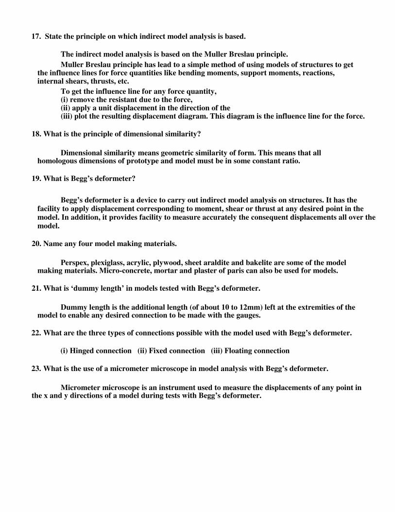
17. State the principle on which indirect model analysis is based.
The indirect model analysis is based on the Muller Breslau principle. Muller Breslau principle has lead to a simple method of using models of structures to get
the influence lines for force quantities like bending moments, support moments, reactions, internal shears, thrusts, etc.
To get the influence line for any force quantity, (i) remove the resistant due to the force, (ii) apply a unit displacement in the direction of the (iii) plot the resulting displacement diagram. This diagram is the influence line for the force.
18. What is the principle of dimensional similarity?
Dimensional similarity means geometric similarity of form. This means that all homologous dimensions of prototype and model must be in some constant ratio.
19. What is Begg’s deformeter?
Begg’s deformeter is a device to carry out indirect model analysis on structures. It has the facility to apply displacement corresponding to moment, shear or thrust at any desired point in the model. In addition, it provides facility to measure accurately the consequent displacements all over the model.
20. Name any four model making materials.
Perspex, plexiglass, acrylic, plywood, sheet araldite and bakelite are some of the model making materials. Micro-concrete, mortar and plaster of paris can also be used for models.
21. What is ‘dummy length’ in models tested with Begg’s deformeter.
Dummy length is the additional length (of about 10 to 12mm) left at the extremities of the model to enable any desired connection to be made with the gauges.
22. What are the three types of connections possible with the model used with Begg’s deformeter.
(i) Hinged connection (ii) Fixed connection (iii) Floating connection
23. What is the use of a micrometer microscope in model analysis with Begg’s deformeter.
Micrometer microscope is an instrument used to measure the displacements of any point in
the x and y directions of a model during tests with Begg’s deformeter.

PART –B
1. A beam ABC is supported at A, B and C as shown in Fig. 7. It has the hinge at D. Draw the influence lines
for
(1) reactions at A, B and C
(2) shear to the right of B
(3) bending moment at E
2. Determine the influence line ordinates at any section X on BC of the continuous
beam ABC shown in Fig. 8, for reaction at A.
3. In Fig. 1, D is the mid point of AB. If a point load W travels from A to C along the span where and
what will be the maximum negative bending moment in AC.
Fig. 1 .
4. Sketch qualitatively the influence line for shear at D for the beam in Fig. 2. (Your sketch shall clearly
distinguish between straight lines and curved lines)
5. A single rolling load of 100 kN moves on a girder of span 20m. (a) Construct the influence lines for (i)
Shear force and (ii) Bending moment for a section 5m from the left support. (b) Construct the influence
lines for points at which the maximum shears and maximum bending moment develop. Determine
these maximum values.
B A
2m
8m 3m 4m
C E D
5m 5m
x X
C B A
ÄBF
B A C
D
Ä
CAK Ä
DAI Ä
C D B
Ä
A
6. Derive the influence diagram for reactions and bending moment at any section of a simply supported
beam. Using the ILD, determine the support reactions and find bending moment at 2m, 4m and 6m for
a simply supported beam of span 8m subjected to three point loads of 10kN, 15kN and 5kN placed at
1m, 4.5m and 6.5m respectively.
7. Two concentrated rolling loads of 12 kN and 6 kN placed 4.5 m apart, travel along a freely supported
girder of 16m span. Draw the diagrams for maximum positive shear force, maximum negative shear
force and maximum bending moment.
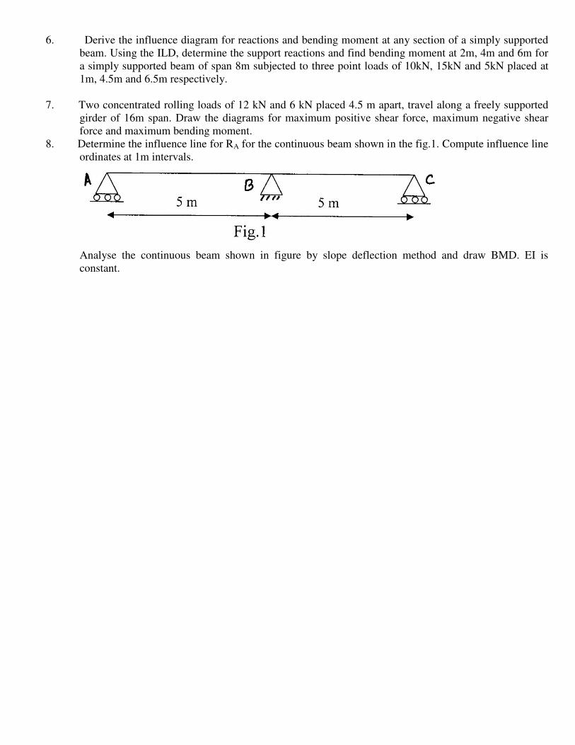
8. Determine the influence line for RA for the continuous beam shown in the fig.1. Compute influence line
ordinates at 1m intervals.
Analyse the continuous beam shown in figure by slope deflection method and draw BMD. EI is
constant.

UNIT-III
ARCHES
1.What is an arch? Explain.
An arch is defined as a curved girder, having convexity upwards and supported at its ends. The supports must effectively arrest displacements in the vertical and horizontal directions. Only then there will be arch action.
2.What is a linear arch? If an arch is to take loads, say W1, W2, and W3 (fig) and a Vector diagram and funicular
polygon are plotted as shown, the funicular polygon is known as the linear arch or theoretical arch.
p
W2
q Q R
W1 D
W
3
W1 W2 W3 PQ R S O t P C O E S
A T B r
Space Diagram
s
H
Vector Diagram
The polar distance ‘ot’ represents the horizontal thrust. The links AC, CD, DE, and EB will be under compression and there will be no bending moment. If an arch of this shape ACDEB is provided, there will be no bending moment.
For a given set of vertical loads W1, W2…..etc., we can have any number of linear arches depending on where we choose ‘O’ or how much horizontal thrust (ot) we choose to introduce.
3.State Eddy’s theorem.
Eddy’s theorem states that “ The bending moment at any section of an arch is proportional to the vertical intercept between the linear arch (or theoretical arch) and the centre line of the actual arch.”
BMx = Ordinate O2O3 x scale factor
X W2
W1 W3
o2 Actual arch
o3 Theoretical arch
x o1

X
4.Explain with the aid of a sketch, the normal thrust and radial shear in an arch rib.
H A B H
R
N
Let us take a section X of an arch. (fig (a) ). Let θ be the inclination of the tangent at X. If H is the horizontal thrust and V the vertical shear at X, from the free body of the RHS of the arch, it is clear that V and H will have normal and radial components given by,
N= H cosθ + Vsinθ R= V cosθ -Hsinθ
5. Which of the two arches, viz. circular and parabolic is preferable to carry a uniformly distribute
load? Why?
Parabolic arches are preferably to carry distributed loads. Because, both, the shape of the
arch and the shape of the bending moment diagram are parabolic. Hence the intercept
between the theoretical arch andactual arch is zero everywhere. Hence, the bending moment
at every section of the arch will be zero. The arch will be under pure compression which will
be economical.
6.What is the difference between the basic action of an arch and a suspension cable?
An arch is essentially a compression member which can also take bending moments and shears. Bending moments and shears will be absent if the arch is parabolic and the loading uniformly distributed.
A cable can take only tension. A suspension bridge will therefore have a cable and a stiffening girder. The girder will take the bending moment and shears in the bridge and the cable, only tension.Because of the thrusts in the cables and arches, the bending moments are considerably reduced.
If the load on the girder is uniform, the bridge will have only cable tension and no bending moment on the girder.
8.Under what conditions will bending moment in an archbezerothroughout.
The bending moment in an arch throughout the span will be zero, if (i) the arch is parabolic and (ii) the arch carries uniformly distributed load throughout the span.
9.Draw the ILD for bending moment at a section X at a distance x from the left end of a three hinged
parabolic arch of span ’l’ and rise ‘h’.
Mx = x – Hy
x Hy

(+) (-)
x(l-x)/ l
x(l-x)/ l
10. Indicate the positions of a moving point load for maximum negative and positive bending
moments in a three hinged arch.

Considering a three hinged parabolic arch of span ‘l’ and subjected to a moving point load W, the position of the point load for
a. Maximum negative bending moment is 0.25l from end supports.
b. Maximum positive bending moment is 0.211l from end supports.
11. Draw the influence line for radial shear at a section of a three hinged arch.
Radial shear is given by Fx = H sinθ - V cosθ,
where θ is the inclination of tangent at X.
l sinθ
l – x cosθ
4r
l
x
cosθ
l
12. Sketch the ILD for the normal thrust at a section X of a symmetric three hinged
parabolic arch. Normal thrust at X is given by P = H cosθ + V sinθ,
where θ is the inclination of tangent at X.
l cosθ
4yc
x sinθ
l
(l-x)sinθ
l 13. Distinguish between two hinged and three hinged arches.
Sl.No. Two hinged arches Three hinged arches
1. Statically indeterminate to first degree Statically determinate
2. Might develop temperature stresses Increase in temperature causes increase in central rise. No stresses.
3. Structurally more efficient Easy to analyse. But in costruction, the central hinge may involve additional expenditure.
4. Will develop stresses due to sinking of Since this is determinate, no stresses due to supports support sinking.

14. Explain rib-shortening in the case of arches. In a two hinged arch, the normal thrust which is a compressive force along the axis of the
arch will shorten the rib of the arch. This in turn will release part of the horizontal thrust. Normally, this effect is not considered in the analysis (in the case of two hinged arches).
Depending upon the importance of the work we can either take into account or omit the effect of rib shortening. This will be done by considering (or omitting) strain energy due to axial compression along with the strain energy due to bending in evaluating H.

15. Explain the effect of yielding of support in the case of an arch. Yielding of supports has no effect in the case of a 3 hinged arch which is determinate.
These displacements must be taken into account when we analyse 2 hinged or fixed arches under ∂U
= H instead of zero
∂H
∂U = VA instead of zero
∂VA Here U is the strain energy of the arch and ∂H and VA are the displacements due to yielding of supports. 16. Write the formula to calculate the change in rise in three hinged arch if there is a rise in
temperature.
Change in rise = l2 + 4r
2 α T
4r
where l = span length of the arch
r = central rise of the arch
α = coefficient of thermal expansion
T = change in temperature
17. In a parabolic arch with two hinges how will you calculate the slope of the arch at any point. Slope of parabolic arch = θ = tan
-1 4r (l – 2x)
l2 where θ = Slope at any point x (or) inclination of tangent
at x. l = span length of the arch r = central rise of the arch
19. How will you calculate the horizontal thrust in a two hinged parabolic arch if there is a rise in temperature.
Horizontal thrust =
l α TEI
y2dx
0
where l = span length of the arch
y = rise of the arch at any point x
α = coefficient of thermal expansion
T = change in temperature
E = Young’s Modulus of the material of the arch
I = Moment of inertia
19. What are the types of arches according to the support conditions.
i. Three hinged arch
ii. Two hinged arch

iii. Single hinged arch
iv. Fixed arch (or) hingeless arch
20. What are the types of arches according to their shapes. i. Curved arch
ii. Parabolic arch
iii. Elliptical arch
iv. Polygonal arch

UNIT-1V
SLOPE-DEFLECTION METHOD
1.What are the assumptions made in slope-deflection method?
(i) Between each pair of the supports the beam section is constant. (ii) The joint in structure may rotate or deflect as a whole, but the angles
between the members meeting at that joint remain the same.
2. How many slope deflection equations are available for a two span continuous beam? There will be 4 nos. of slope-deflection equations, two for each span.
3. What is the moment at a hinged end of a simple beam?
Moment at the hinged ends of a simple beam is zero.
4. What are the quantities in terms of which the unknown moments are expressed in slope-deflection method?
In slope-deflection method, unknown moments are expressed in terms of
(i) slopes (θ) and (ii) deflections ( )
5. The beam shown in Fig. is to be analysed by slope-deflection method. What are the unknowns and, to determine them, what are the conditions used?
A B C
Unknowns: θA, θB, θC
Equilibrium equations used: (i) MAB = 0 (ii) MBA + MBC = 0 (iii) MCB = 0 6. How do you account for sway in slope deflection method for portal frames?
Because of sway, there will br rotations in the vertical members of a frame. This causes moments in the vertical members. To account for this, besides the equilibrium, one more equation namely shear equation connecting the joint-moments is used.
7. Write down the equation for sway correction for the portal frame shown in Fig.
The shear equation (sway correction) is
MAB +
MBA +
MCD +
MDC = 0
D l l
A
8. Write down the slope deflection equation for a fixed end support.
A
B C D
θA + θB + 3
The slope deflection equation for end A is MAB
= M’AB + 2EI

l l
Here θA= 0. Since there is no support settlement,
= 0.
MAB = M’AB + 2EI B + 3

l l
9. Write down the equilibrium equations for the frame shown in Fig.
C Unknowns : θB , θC
B
Equilibrium equations : At B, MBA + MBC = 0
h l At C, MCB + MCD = 0
P Shear equation : MAB + MBA – Ph + MCD + MDC + P = 0
l l
A
D
10. Who introduced slope-deflection method of analysis?
Slope-deflection method was introduced by Prof. George A.Maney in 1915.
11. Write down the general slope-deflection equations and state what each term represents?
A B
General slope-deflection equations:
MA
B = M’AB + 2EI θA + θB + 3
l
l
MB
A = M’BA + 2EI θB + θA + 3
l l
where, M’AB , M’BA = Fixed end moment at A and B respectively due to the given loading.
θA , θB = Slopes at A and B respectively = Sinking of support A with respect to B
13. Mention any three reasons due to which sway may occur in portal frames. Sway in portal frames may occur due to (i) unsymmetry in geometry of the frame (ii)
unsymmetry in loading or (iii) Settlement of one end of a frame.
13. How many slope-deflection equations are available for each span? Two numbers of slope-deflection equations are available for each span, describing the
moment at each end of the span.
14. Write the fixed end moments for a beam carrying a central clockwise moment.
A
B
l/2 l/2
Fixed end moments : M’AB = M’BA = M
4

15. State the limitations of slope deflection method. (i) It is not easy to account for varying member sections
(ii) It becomes very cumbersome when the unknown displacements are large in number.
16. Why is slope-deflection method called a ‘displacement method’?