Embed Size (px)
Citation preview

1
Branch Feeder Monitor
BFM II
MODBUS Communications
Protocol
Reference Guide
BG0589 Rev. A6

2
Every effort has been made to ensure that the material herein is complete and accurate.
However, the manufacturer is not responsible for any mistakes in printing or faulty instructions contained in this book. Notification of any errors or misprints will be received with appreciation.
For further information regarding a particular installation, operation or maintenance of equipment, contact the manufacturer or your local representative or distributor.
REVISION HISTORY
A1 Nov 2015 Initial MODBUS guide
A2 ---- Updated MODBUS guide
A3 Jan 2016 Add Min/Max log registers (V, I, P, PF)
A4 Mar 2016 Add DI/AI/RO and GPRS
A5 Mar-2016 DI and Counter MODBUS address assignment
A6 Aug-2016 New module support – 9RO, up to 2 modules per system, 18 relay outputs Submeter & Virtual meter ID name setup
Modbus is a trademark of Schneider Electric.

3
Table of Contents
1. GENERAL...................................................................................................... 8
2. MODBUS PROTOCOL IMPLEMENTATION ................................................. 9
2.1 Transmission Modes ..................................................................................... 9 2.2 Address Field ............................................................................................... 9 2.3 Function Field............................................................................................... 9
Table 2-1 Modbus Function Codes ........................................................................ 9 2.4 Exception Responses .................................................................................... 9 2.5 Modbus Register Addresses ......................................................................... 9 2.6 Submeter Addressing ................................................................................. 10 2.7 Data Formats ............................................................................................. 10 2.7.1 16-BIT SCALED INTEGER FORMAT ......................................................................... 10 2.7.2 32-BIT LONG INTEGER FORMAT ............................................................................ 11 2.8 User Assignable Registers .......................................................................... 12 2.9 Password Protection .................................................................................. 12 2.10 Data Recording and File Transfer ............................................................... 12 2.10.1 LOG FILE ORGANIZATION ................................................................................... 12
Data Log File ................................................................................................... 13 Billing/TOU Profile Log File................................................................................. 13
2.10.2 FILE TRANSFERS ............................................................................................. 13 Common File Transfer ....................................................................................... 13 Reading Multi-section Profile Files ....................................................................... 14
2.11 TCP Notification Client ............................................................................... 15
3. MODBUS REGISTER MAP ......................................................................... 16
3.1 Modbus Setup Registers ............................................................................. 16 Modbus Assignable Registers ............................................................................. 16 Assignable Registers Map .................................................................................. 16 Modbus Conversion Scales ................................................................................ 16
3.2 16-bit Scaled Analog Values - Basic Register Set ....................................... 16 3.3 16-bit Scaled Analog Registers, Binary Registers and Counters ................. 18
None .............................................................................................................. 18 Setpoint Status ................................................................................................ 18 Special Inputs .................................................................................................. 18 1-Cycle Phase Values ........................................................................................ 18 1-Cycle Low Phase Values ................................................................................. 19 1-Cycle High Phase Values ................................................................................ 19 1-Cycle Total Values ......................................................................................... 19 1-Cycle Auxiliary Values .................................................................................... 20 1-Cycle Analog Inputs ....................................................................................... 20 Raw Analog Inputs ........................................................................................... 20 1-Second Analog Inputs .................................................................................... 20 Phasor ............................................................................................................ 20 1-Second Phase Values ..................................................................................... 21 1-Second Low Phase Values .............................................................................. 21 1-Second High Phase Values .............................................................................. 22 1-Second Total Values ...................................................................................... 22 1-Second Auxiliary Values ................................................................................. 22 Present Demands ............................................................................................. 22

4
Total Energies .................................................................................................. 23 Billing Summary Registers ................................................................................. 23 Maximum Demands .......................................................................................... 24 TOU Parameters ............................................................................................... 24 Billing TOU Register #1 ..................................................................................... 24 Billing TOU Register #2 ..................................................................................... 24 Billing TOU Register #3 ..................................................................................... 24 Billing TOU Register #4 ..................................................................................... 25 Billing TOU Register #5 ..................................................................................... 25 Billing TOU Register #6 ..................................................................................... 25 Billing TOU Register #7 ..................................................................................... 25 Billing TOU Register #8 ..................................................................................... 26 Billing Summary Accumulated Demands .............................................................. 26 Billing Summary Block Demands ........................................................................ 26 Billing Summary Sliding Window Demands .......................................................... 26 Billing Summary Maximum Demands .................................................................. 27 Billing TOU Maximum Demand Register #1.......................................................... 27 Billing TOU Maximum Demand Register #2.......................................................... 27 Billing TOU Maximum Demand Register #3.......................................................... 27 Billing TOU Maximum Demand Register #4.......................................................... 27
3.4 32-bit Binary and Analog Values ................................................................ 28 Setpoint Status SP1-SP16 ................................................................................. 28 Pulse Inputs .................................................................................................... 29 Relay Outputs .................................................................................................. 29 1-Cycle Phase Values ........................................................................................ 29 1-Cycle Low Phase Values ................................................................................. 30 1-Cycle High Phase Values ................................................................................ 30 1-Second Analog Inputs .................................................................................... 30 1-Cycle Total Values ......................................................................................... 31 1-Cycle Auxiliary Values .................................................................................... 31 Phasor ............................................................................................................ 31 1-Second Phase Values ..................................................................................... 31 1-Second Low Phase Values .............................................................................. 32 1-Second High Phase Values .............................................................................. 32 1-Second Total Values ...................................................................................... 33 1-Second Auxiliary Values ................................................................................. 33 Present Demands ............................................................................................. 33 Total Energies .................................................................................................. 34 Billing Summary Registers ................................................................................. 34 Maximum Demands .......................................................................................... 34 1-Cycle Analog Inputs ....................................................................................... 35 Raw Analog Inputs ........................................................................................... 35 Energy/TOU Parameters .................................................................................... 35 Billing TOU Energy Register #1 .......................................................................... 35 Billing TOU Energy Register #2 .......................................................................... 35 Billing TOU Energy Register #3 .......................................................................... 35 Billing TOU Energy Register #4 .......................................................................... 35 Billing TOU Energy Register #5 .......................................................................... 35 Billing TOU Energy Register #6 .......................................................................... 36 Billing TOU Energy Register #7 .......................................................................... 36 Billing TOU Energy Register #8 .......................................................................... 36 Billing Summary Accumulated Demands .............................................................. 36 Billing Summary Sliding Window Demands .......................................................... 36 Billing Summary (Total) Maximum Demands ....................................................... 36 Billing TOU Maximum Demand Register #1.......................................................... 36 Billing TOU Maximum Demand Register #2.......................................................... 36 Billing TOU Maximum Demand Register #3.......................................................... 37 Billing TOU Maximum Demand Register #4.......................................................... 37 Billing TOU Maximum Demand Register #5.......................................................... 37 Billing TOU Maximum Demand Register #6.......................................................... 37
5
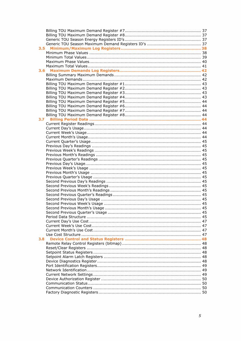
Billing TOU Maximum Demand Register #7.......................................................... 37 Billing TOU Maximum Demand Register #8.......................................................... 37 Generic TOU Season Energy Registers ID’s .......................................................... 37 Generic TOU Season Maximum Demand Registers ID’s ......................................... 37
3.5 Minimum/Maximum Log Registers ............................................................. 38 Minimum Phase Values ..................................................................................... 38 Minimum Total Values ....................................................................................... 39 Maximum Phase Values ..................................................................................... 40 Maximum Total Values ...................................................................................... 41
3.6 Maximum Demands Log Registers .............................................................. 42 Billing Summary Maximum Demands .................................................................. 42 Maximum Demands .......................................................................................... 42 Billing TOU Maximum Demand Register #1.......................................................... 43 Billing TOU Maximum Demand Register #2.......................................................... 43 Billing TOU Maximum Demand Register #3.......................................................... 43 Billing TOU Maximum Demand Register #4.......................................................... 43 Billing TOU Maximum Demand Register #5.......................................................... 44 Billing TOU Maximum Demand Register #6.......................................................... 44 Billing TOU Maximum Demand Register #7.......................................................... 44 Billing TOU Maximum Demand Register #8.......................................................... 44
3.7 Billing Period Data ..................................................................................... 44 Current Register Readings ................................................................................. 44 Current Day’s Usage ......................................................................................... 44 Current Week’s Usage ....................................................................................... 44 Current Month’s Usage ...................................................................................... 44 Current Quarter’s Usage.................................................................................... 45 Previous Day’s Readings ................................................................................... 45 Previous Week’s Readings ................................................................................. 45 Previous Month’s Readings ................................................................................ 45 Previous Quarter’s Readings .............................................................................. 45 Previous Day’s Usage ........................................................................................ 45 Previous Week’s Usage ..................................................................................... 45 Previous Month’s Usage .................................................................................... 45 Previous Quarter’s Usage .................................................................................. 45 Second Previous Day’s Readings ........................................................................ 45 Second Previous Week’s Readings ...................................................................... 45 Second Previous Month’s Readings ..................................................................... 45 Second Previous Quarter’s Readings ................................................................... 45 Second Previous Day’s Usage ............................................................................ 45 Second Previous Week’s Usage .......................................................................... 45 Second Previous Month’s Usage ......................................................................... 45 Second Previous Quarter’s Usage ....................................................................... 45 Period Data Structure ....................................................................................... 45 Current Day’s Use Cost ..................................................................................... 47 Current Week’s Use Cost ................................................................................... 47 Current Month’s Use Cost .................................................................................. 47 Use Cost Structure ........................................................................................... 47
3.8 Device Control and Status Registers .......................................................... 48 Remote Relay Control Registers (bitmap) ............................................................ 48 Reset/Clear Registers ....................................................................................... 48 Setpoint Status Registers .................................................................................. 48 Setpoint Alarm Latch Registers .......................................................................... 48 Device Diagnostics Register ............................................................................... 48 Port Identification Registers ............................................................................... 49 Network Identification ....................................................................................... 49 Current Network Settings .................................................................................. 49 Device Authorization Register ............................................................................ 50 Communication Status ...................................................................................... 50 Communication Counters .................................................................................. 50 Factory Diagnostic Registers .............................................................................. 50

6
3.9 Device Setup Registers .............................................................................. 50 Control/Alarm Setpoints Setup ........................................................................... 50 Factory Device Settings and Identification ........................................................... 51 Basic Setup ..................................................................................................... 51 Demands Setup ............................................................................................... 51 Device Options Setup ....................................................................................... 52 Local Settings .................................................................................................. 52 Clock Setup and Status ..................................................................................... 53 Communication Ports Setup ............................................................................... 53 Network Setup ................................................................................................. 54 Dial-up/GPRS Modem Setup .............................................................................. 54 Security/Password Setup ................................................................................... 54 Expert Power Service Setup ............................................................................... 55 Internet Service Provider (ISP) accounts ............................................................. 55 TCP Notification Client Setup ............................................................................. 55 Channel Assignments ........................................................................................ 55 Transformer Correction Setup ............................................................................ 55 Submeter ID name Setup .................................................................................. 56 Data Log #1 Setup ........................................................................................... 56 Data Log #16 (Profile Data Log) Setup ............................................................... 56 TOU Daily Profile Setup ..................................................................................... 56 TOU Calendar Setup ......................................................................................... 57 Billing Rates Setup ........................................................................................... 58 Billing/TOU Registers Setup ............................................................................... 58 Billing/TOU Registers Source Setup .................................................................... 58 Counter Source Setup 1-64 ............................................................................... 59 Digital Inputs Setup DI1-DI64 ........................................................................... 59 Digital Inputs Setup DI65-DI72 .......................................................................... 59 Relay Outputs Setup ......................................................................................... 59 Counter Source Setup 65-72 ............................................................................. 60 Analog Inputs Setup ......................................................................................... 60
3.10 Expansion I/O Slots Configuration ............................................................. 61 Expansion I/O Slots Configuration Info................................................................ 61 Expansion I/O Modules Type Info ....................................................................... 61
3.11 File Transfer Blocks .................................................................................... 64 File Transfer Control Blocks ............................................................................... 64 File Info Response Block (Variation 0 – File info) .................................................. 65 File Info Response Block (Variation 1 – Current record info) .................................. 66 File Info Response Block (Variation 2 – Data log record structure) .......................... 66 File Info Response Block (Variation 2 – Profile data log record structure) ................. 66 Event Log Response Block ................................................................................. 67 Data Log Response Block .................................................................................. 67 Profile Data Log Response Block ......................................................................... 68
3.12 Billing/TOU Daily Profile Data Log ............................................................. 70
4. DATA SCALES AND UNITS ....................................................................... 72
Data Scales ..................................................................................................... 72 Data Units ....................................................................................................... 72
5. DATA FORMATS ........................................................................................ 73
Timestamp ...................................................................................................... 73 File ID ............................................................................................................ 73 File Attributes .................................................................................................. 73 File Status Word .............................................................................................. 73 File Record Status Word .................................................................................... 73 Billing/TOU Profile Log Channel ID ...................................................................... 73 Waveform Log Channel ID ................................................................................. 73 Billing/TOU Profile Log Channel Mask .................................................................. 73 Waveform Channel Mask ................................................................................... 73

7
TOU Tariff Change Time .................................................................................... 73 Billing Register Source ID .................................................................................. 73 Setpoint Trigger Parameters ID .......................................................................... 74 Relays ............................................................................................................ 74 Setpoint Action ID ............................................................................................ 74 Billing/TOU Register Units (as EM133-R) ............................................................. 74 Counter Source ID ............................................................................................ 75 Relay Output Pulse Source ID ............................................................................ 75 Event Source/Point ID ...................................................................................... 75 Event Effect ID ................................................................................................ 75 Data/Function Point ID ...................................................................................... 76 Event Type ID .................................................................................................. 76 Device Diagnostics ........................................................................................... 76
6. BFM II PARAMETERS FOR DATA MONITORING AND LOGGING .......... 78
7. SETPOINTS TRIGGERS AND ACTIONS ................................................... 85
8. DISPLAY VIEWS ......................................................................................... 87

8
1. General
This document specifies a subset of the Modbus serial communications protocol used to transfer data between a master computer station and the BFM II. The document provides the complete information necessary to develop third-party communications software capable of communication with the Series BFM II instruments.
For additional information concerning communications operation, configuring the communications parameters, and communications connections see the BFM II Installation and Operation Manual.

9
2. Modbus Protocol Implementation
For detailed information about Modbus protocol, Modbus message framing and error checking, refer to the Modbus Protocol Reference Guide. It can be downloaded from the www.modbus.org Website. The following paragraphs outline some issues concerning the implementation of the Modbus protocol in the BFM II.
2.1 Transmission Modes
The BFM II can be set up to communicate on a serial Modbus network using either RTU, or ASCII serial transmission mode, and via the Internet using Modbus/TCP mode. Refer to the BFM II Installation and Operation Manual for information on selecting the transmission mode in your meter.
2.2 Address Field
The address field contains a device submeter address (1-247) on a Modbus network. The user assigned device address (see Communication Ports Setup in Section 3.7) is used as a
reference address of the first device submeter. See Submeter Addressing in Section 2.6 for more information on device addressing.
Broadcast mode using address 0 is not supported.
2.3 Function Field
The Modbus functions implemented in the BFM II are shown in Table 2-1. Function 04 can be used in the same context as function 03.
Table 2-1 Modbus Function Codes
Code (decimal)
Meaning in Modbus Action
03 Read holding registers Read multiple registers 04 Read input registers Read multiple registers 06 Preset single register Write single register 16 Preset multiple registers Write multiple registers
081 Loop-back test Communications test
1 The BFM II supports only diagnostic code 0 - return query data.
2.4 Exception Responses
The instrument sends an exception response when an error is detected in the received message. To indicate that the response is notification of an error, the high order bit of the function code is set to 1.
Implemented exception response codes:
01 - Illegal function
02 - Illegal data address
03 - Illegal data value
04 - Device failure
When the character framing, parity, or redundancy check detects a communication error, processing of the master's request stops. The instrument will not act on or respond to the
message.
2.5 Modbus Register Addresses
The BFM II Modbus registers are numbered in the range of 0 to 65535. From Modbus applications, the BFM II Modbus registers can be accessed by simulating holding registers of the Modicon 584, 884 or 984 Programmable Controller, using a 5-digit “4XXXX” or 6-digit “4XXXXX” addressing scheme.

10
To map the BFM II register address to the range of the Modbus holding registers, add a value
of 40001 to the device register address. When a register address exceeds 9999, use a 6-digit
addressing scheme by adding 400001 to the BFM II register address.
2.6 Submeter Addressing
Each active submeter in the BFM II is assigned a unique communication address that allows accessing its private registers and setups. A separate Modbus address is engaged for each submeter for which at least one current input is allocated in the Channel Assignments Setup (see Section 3.7), and for each additional submeter, which is allocated as a target in the Billing/TOU Registers Source Setup (see Section 3.7).
The BFM II can occupy up to 40 contiguous addresses starting with the device reference address. All submeter addresses are assigned automatically in a sequential order starting from the device base address that is programmed through the device Communication Setup. The following table illustrates submeter addressing in the device with the base address N.
Device Base Address
Submeter Number Submeter Address
N SM 1 N SM 2 N+1 …
SM 54 N+53 SM 55 N+54 …
SM 60 N+59
Your device is factory preset to address 1 and occupies the range of addresses 1 through 18, configured for 18 three-phase submeters.
NOTE
Device setup settings, excluding the alarm setpoints and data log setup, are shared across all submeters. Though you can read/write them using any submeter address, your changes affect all submeters in the device. Note that the
communication port setup may only be changed via the device base address.
Select your submeters (both metering and Totalization) in a sequence without gaps so that your device would not occupy unnecessary network addresses.
If you connect a number of devices to a serial network, allocate a range of addresses for each device so that they do not overlap. For example, if you use three devices with 18 submeters in each one, assign the base address 1 to the first device, the address 19 to the second, and the address 37 to the third device so that they will occupy three non-overlapped address ranges 1 through 18, 19 through 36, and 37 through 54.
2.7 Data Formats
The BFM II uses two data formats to pass data between a master application and the instrument: 16-bit short integer and 32-bit long integer formats. Binary values and counters are always transmitted in 32-bit registers, while analog values can be read both in 32-bit and in 16-bit scaled registers.
2.7.1 16-bit Scaled Integer Format
16-bit scaled analog data is transmitted in a single 16-bit Modbus register being scaled to the range of 0 to 9999. To get a true reading, a reverse conversion should be done using the following formula:
LO9999
)LOHI(XY
where:
Y - True reading in engineering units
X - Raw input data in the range of 0 to 9999
LO and HI - Data low and high scales in engineering units

11
The engineering scales are indicated for every scaled 16-bit register. Refer to Section 4
“Data Scales and Units” for applicable data scales and measurement units.
CONVERSION EXAMPLES
1. Voltage readings
Voltage engineering scales (see Section 4):
HI = Vmax = 600.0V LO = 0V
If the raw data reading is 1449 then the voltage reading in engineering units will be as follows:
Volts reading = 1449 (600.0 - 0)/(9999 - 0) + 0 = 86.9V
2. Current readings
Assume device settings: CT primary current = 50A. Current engineering scales (see Section 4):
HI = Imax = CT primary current 2 = 50.00 2 = 100.00A
LO = 0A
If the raw data reading is 250 then the current reading in engineering units will be as follows:
Amps reading = 250 (100.00 - 0)/(9999 - 0) + 0 = 2.50A
3. Power readings
a) Assume device settings: CT primary current = 50A. Active Power engineering scales (rounded to whole kW, see Section 4):
HI = Pmax = Vmax Imax 2 = (600.0 1) (50.00 2) 2 = 120,000W = 120 kW
LO = -Pmax = -120 kW
If the raw data reading is 5500 then the power reading in engineering units will be as follows:
Watts reading = 5500 (120 - (-120))/(9999 - 0) + (-120) = 12.013kW
If the raw data reading is 4000 then the power reading in engineering units will be as follows:
Watts reading = 4000 (120 - (-120))/(9999 - 0) + (-120) = -23.99kW
4. Power Factor readings
Power factor engineering scales:
HI = 1.000. LO = -1.000.
If the raw data reading is 8900 then the power factor in engineering units will be as follows:
Power factor reading = 8900 (1.000 - (-1.000))/(9999 - 0) + (-1.000) = 0.78
2.7.2 32-bit Long Integer Format
32-bit long integer data is transmitted in two adjacent 16-bit Modbus registers as unsigned (UINT32) or signed (INT32) whole numbers. The first register contains the low-order word (lower 16 bits) and the second register contains the high order word (higher 16 bits). The
low-order word always starts at an even Modbus address.
The value range for unsigned data is 0 to 4,294,967,295; for signed data the range is -2,147,483,648 to 2,147,483,647.
If your Modbus driver does not support a 32-bit long integer format, you can read the two 16-bit registers separately, and then convert them into a 32-bit value as follows (using C notation):
32-bit value = (signed short) high order register 65536L + (unsigned short) low order register
12
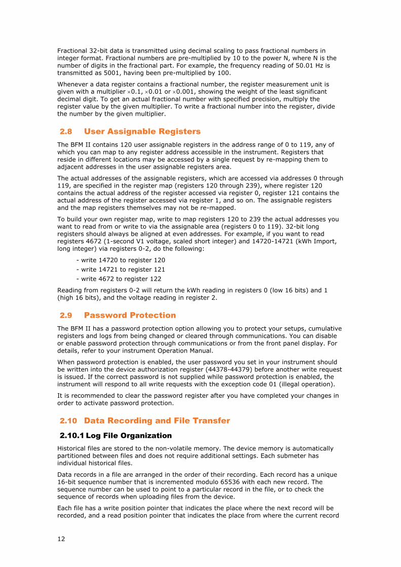
Fractional 32-bit data is transmitted using decimal scaling to pass fractional numbers in
integer format. Fractional numbers are pre-multiplied by 10 to the power N, where N is the
number of digits in the fractional part. For example, the frequency reading of 50.01 Hz is transmitted as 5001, having been pre-multiplied by 100.
Whenever a data register contains a fractional number, the register measurement unit is given with a multiplier 0.1, 0.01 or 0.001, showing the weight of the least significant
decimal digit. To get an actual fractional number with specified precision, multiply the register value by the given multiplier. To write a fractional number into the register, divide the number by the given multiplier.
2.8 User Assignable Registers
The BFM II contains 120 user assignable registers in the address range of 0 to 119, any of
which you can map to any register address accessible in the instrument. Registers that reside in different locations may be accessed by a single request by re-mapping them to adjacent addresses in the user assignable registers area.
The actual addresses of the assignable registers, which are accessed via addresses 0 through 119, are specified in the register map (registers 120 through 239), where register 120 contains the actual address of the register accessed via register 0, register 121 contains the actual address of the register accessed via register 1, and so on. The assignable registers
and the map registers themselves may not be re-mapped.
To build your own register map, write to map registers 120 to 239 the actual addresses you want to read from or write to via the assignable area (registers 0 to 119). 32-bit long registers should always be aligned at even addresses. For example, if you want to read registers 4672 (1-second V1 voltage, scaled short integer) and 14720-14721 (kWh Import, long integer) via registers 0-2, do the following:
- write 14720 to register 120
- write 14721 to register 121
- write 4672 to register 122
Reading from registers 0-2 will return the kWh reading in registers 0 (low 16 bits) and 1
(high 16 bits), and the voltage reading in register 2.
2.9 Password Protection
The BFM II has a password protection option allowing you to protect your setups, cumulative registers and logs from being changed or cleared through communications. You can disable
or enable password protection through communications or from the front panel display. For details, refer to your instrument Operation Manual.
When password protection is enabled, the user password you set in your instrument should be written into the device authorization register (44378-44379) before another write request is issued. If the correct password is not supplied while password protection is enabled, the instrument will respond to all write requests with the exception code 01 (illegal operation).
It is recommended to clear the password register after you have completed your changes in
order to activate password protection.
2.10 Data Recording and File Transfer
2.10.1 Log File Organization
Historical files are stored to the non-volatile memory. The device memory is automatically partitioned between files and does not require additional settings. Each submeter has individual historical files.
Data records in a file are arranged in the order of their recording. Each record has a unique 16-bit sequence number that is incremented modulo 65536 with each new record. The sequence number can be used to point to a particular record in the file, or to check the sequence of records when uploading files from the device.
Each file has a write position pointer that indicates the place where the next record will be recorded, and a read position pointer that indicates the place from where the current record

13
will be read. Both pointers show sequence numbers of the records they point to rather than
record offsets in the file.
After acknowledging a record you have read, the read pointer automatically advances to the next record in the file. When the read pointer gets to the record to which the file write pointer points, the end-of-file (EOF) flag is set. It is automatically cleared when a new record is added to the file, or when you explicitly move the read pointer to any record within a file.
Each file has a wrap-around attribute (circular file), the most recent records overwrites the oldest records. When this happens at the current read position, the read pointer
automatically advances forward in order to point to the oldest record in the file.
The BFM II keeps a separate read pointer for each communication port so that access to the same file through a different port will not affect current active sessions for other ports.
Data Log File
Data log file of each submeter can store up to 16 measured parameters per a record. The number of parameters that each record will hold and the list of parameters you want to be recorded in the file can be selected through the Data log setup registers for a particular file.
Recording data to the data log file can be triggered through the setpoints on a time basis using the meter clock.
Billing/TOU Profile Log File
Data log file #16 is automatically configured for a daily profile log of the energy usage and maximum demand registers. A profile log file is organized as a multi-section file that has a separate section for each energy and maximum demand register. A file record stores the summary data (total of all tariffs) and all tariff data for each configured Billing/TOU register. See Section 3.9 for information on the file record structure.
The number of sections is taken automatically from the Billing/TOU Registers setup. Since each Billing/TOU energy register has a shadow maximum demand register, the number of sections in the file can be twice the number of the allocated Billing/TOU registers.
Sections within a file can be addressed by a section number, or by a section channel ID.
A multi-section file has a single write position pointer for all sections and stores data in all
sections simultaneously. This means that records with the same sequence number in all sections are associated with the same event. A multi-section file has also a single read
position pointer for all sections.
You can review the list of parameters recorded to the file through the file info request/response blocks using info requests with variation 2 (see Section 3.8), or through the Data log #16 setup - it shows the list of parameters for the first file section, which represents the first configured energy usage register.
2.10.2 File Transfers
File transfer protocol provides both data transfer and information services. File transfer is performed through two blocks of registers: a 32-word master request block and a 648-word read-only file response block. After a master application has written the request into the file request block, the requested data is available for a read through the file response block registers. File transfer functions allow changing the file or section position in order to point to the desired record.
The information service uses separate 8-word file info request and 200-word file info
response blocks. The extended file information is available including current file pointers’ positions, file contents, the number of records in the file, allocated file size, time of the last file update, and more.
See Section 3.8 for information on register locations.
Common File Transfer
Log files can be read either in a sequence record-by-record, or in a random order. Each Read-File request fills the file response block with the data of the record pointed to by the file (or section) read pointer. If you want to begin reading a file from a particular record, which sequence number is known, you can change the pointer position by issuing the Set-File-Position request with the desired sequence number. If you want to read a file from the

14
beginning, send the Reset-File-Position request that moves the pointer to the oldest file
record. If you do not change the file position, then you will continue reading the file from the
record following the one you have read the last time you accessed the file.
You need not explicitly move the file position to the following record if you want to continue reading a file in sequence after you have uploaded the current record. Instead, issue an acknowledgment request that automatically advances the file pointer to the next record, and then read the record data through the file response block.
The file response block can contain more than one record. The number of records available in
the block and the file record size in words are always reported in the block heading. There are no special rules on how to read records from the file transfer block. You can read a single record or all records together, or begin reading from the last record and end with the first record. However, you should remember: 1) after an acknowledgment, the file position moves to the record following the last one you have accessed in the file transfer block; and 2) data in the file transfer block does not change until you either issue an acknowledgment, or explicitly change the file position by the Set-File-Position or Reset-File-Position requests.
The file transfer is completed after you have read the last record of the file. Before storing a
file record to your database, always check bit 9 in the record status word, which contains the end-of-file (EOF) flag. This bit set to 1 indicates that the file read pointer does not point to any record within the file, and you should not store any record that has this bit set. The EOF flag is set only after you have acknowledged the last record of the file, so that testing for end-of-file requires one extra read. If you wish to stop the transfer just after storing the last file record, acknowledge the record and check bit 0 in the record status word. Bit 0 is set to
1 only once when you read the last record of the file.
The following gives a summary of steps you should do to read an ordinal log file:
1. If you wish to begin reading a file from a particular record or from the first record, use either the Set-File-Position request with the desired record sequence number, or the Reset-File-Position request. Preset a section number and channel ID to zero.
2. Write the Read-File request with a section number and channel ID set to zero.
3. Read the record data from the file response block.
4. Write an acknowledgment for the file. You need not fill all the request fields: only the file
function is required. The file pointer will be moved to the next file record.
5. Repeat steps 3-4 until all the file records are read.
Reading Multi-section Profile Files
In a multi-section data profile file, all user requests including an acknowledgment; the Read-File, Set-File-Position and Reset-File-Position requests, relate to a particular file section rather than to the file itself.
A file section can be requested either by a section number, or by a section channel ID. If you use a channel ID, preset the section number field to 0xFFFF. If a section number is specified, the channel ID field will not be checked. The BFM II returns both fields in the response block
heading, so you can always identify what channel data is being read from the present file section. If you want to know which channels are recorded to the file sections, check the file channel mask in the file info block. This is a bitmap that contains one in a bit position if a channel with an ID equal to the bit number is recorded to the file, and contains zero if it is not.
The following gives a summary of steps for reading a multi-section data log file:
1. If you wish to begin reading a file section from a particular record or from the first
record, use either the Set-File-Position request with the desired record sequence number, or the Reset-File-Position request. Specify either a section number, or the channel ID for the section from where you want to read data. If you use a channel ID, preset the section number field to 0xFFFF.
2. Write the Read-File request with the section number and channel ID as shown in the previous step.
3. Read the record data from the file response block.

15
4. Write an acknowledgment for the file. The file section pointer will be moved to the next
record.
5. Repeat steps 3-4 until all the section records are read.
2.11 TCP Notification Client
The TCP notification client can establish connections with a remote Modbus/TCP server and send notification messages either on events, or periodically on a time basis.
Notification messages are sent via a block of 16 Modbus registers using write function 16. The following table shows the message exchange structure.
Modbus Register
Description Type Comment
+0-1 Device serial number UINT32
+2-4 Device MAC address CHAR6
+5 Device address UINT16 Submeter address
+6-7 Device IP address UINT32 Network byte order
+8 Event type UINT16 See F22 in Section 5
+9 Event sequence number UINT16
+10-11 Event timestamp, seconds UINT32 Local time since Jan 1, 1970
+12-13 Event timestamp, seconds fraction, in microseconds UINT32
+14-15 Reserved UINT32 Written as 0
After receiving a write acknowledgement from a server, a TCP connection is still open for 10 seconds (20 seconds via GPRS) to give the server an opportunity to access meter registers through an open socket. It may help you access the meter from outside your local network when the server is located on another network, or when using wireless GPRS communications. The notification client will respond to all server requests as if it were a regular incoming connection.
If the server does not close a connection, it will be closed in 20 seconds if there is no activity
on the socket. In the event a connection attempt was unsuccessful, the notification client retries two more times before announcing a connection failure.
The server’s IP address, port number and starting Modbus register address are programmable in the meter. See “TCP Notification Client Setup” for more information on the client setup. To configure and enable the notification client in your meter via PAS, select
Communication Setup in the Meter Setup menu, and click on the TCP Notification Client Setup tab.
Client connections are triggered via programmable setpoints. To send event notifications to a server, configure a setpoint to respond to desired triggers or to periodic time events and add the "Send notification" action to the end of the setpoint actions list.

16
3. Modbus Register Map
3.1 Modbus Setup Registers
Address Point ID
Description Options/Range Units Type R/W
Notes
Modbus Assignable Registers
0-119 Shared across all submeters +0 Register 0 contents 0-65535 UINT16 R/W
+1 Register 1 contents 0-65535 UINT16 R/W
...
+119 Register 119 contents 0-65535 UINT16 R/W
Assignable Registers Map
120-239 Shared across all submeters +0 Register 0 address 0-65535 UINT16 R/W
+1 Register 1 address 0-65535 UINT16 R/W
+119 Register 119 address 0-65535 UINT16 R/W
Modbus Conversion Scales
240 Low raw scale 0 UINT16 R/W Shared across all submeters
241 High raw scale 9999 UINT16 R/W
242 Voltage scale, in secondary volts 60-600 (default 600V) 1V UINT16 R/W
243 Current scale, in secondary amps = CT secondary current (1A, 5A, 50A) Current overload
20, 100, 1000 (2.0A, 10.0A, 100.0A)
0.1A UINT16 R
3.2 16-bit Scaled Analog Values - Basic Register Set
Address Point ID Description Low and High Scales1 Units1 Type R/W
Notes
256-308 1-Second Values
+0 0x1100 V1 Voltage 0-Vmax U1 UINT16 R
+1 0x1101 V2 Voltage 0-Vmax U1 UINT16 R
+2 0x1102 V3 Voltage 0-Vmax U1 UINT16 R
+3 0x1103 I1 Current 0-Imax U2 UINT16 R
+4 0x1104 I2 Current 0-Imax U2 UINT16 R
+5 0x1105 I3 Current 0-Imax U2 UINT16 R
+6 0x1106 kW L1 -Pmax-Pmax U3 INT16 R
+7 0x1107 kW L2 -Pmax-Pmax U3 INT16 R
+8 0x1108 kW L3 -Pmax-Pmax U3 INT16 R
+9 0x1109 kvar L1 -Pmax-Pmax U3 INT16 R
+10 0x110A kvar L2 -Pmax-Pmax U3 INT16 R

17
Address Point ID Description Low and High Scales1 Units1 Type R/W
Notes
+12 0x110C kVA L1 -Pmax-Pmax U3 UINT16 R
+13 0x110D kVA L2 -Pmax-Pmax U3 UINT16 R
+14 0x110E kVA L3 -Pmax-Pmax U3 UINT16 R
+15 0x110F Power factor L1 -1.000-1.000 0.001 INT16 R
+16 0x1110 Power factor L2 -1.000-1.000 0.001 INT16 R
+17 0x1111 Power factor L3 -1.000-1.000 0.001 INT16 R
+18 0x1403 Total PF -1.000-1.000 0.001 INT16 R
+19 0x1400 Total kW -Pmax-Pmax U3 INT16 R
+20 0x1401 Total kvar -Pmax-Pmax U3 INT16 R
+21 0x1402 Total kVA -Pmax-Pmax U3 UINT16 R
+22 0x1501 In Current 0-Imax U2 UINT16 R
+23 0x1502 Frequency 4500-6500 0.01Hz UINT16 R
+24 0x3709 Maximum kW import sliding window demand -Pmax-Pmax U3 UINT16 R
+25 0x160F kW import accumulated demand -Pmax-Pmax U3 UINT16 R
+26 0x370B Maximum kVA sliding window demand -Pmax-Pmax U3 UINT16 R
+27 0x1611 kVA accumulated demand -Pmax-Pmax U3 UINT16 R
+28 0x3703 I1 Maximum ampere demand 0-Imax U2 UINT16 R
+29 0x3704 I2 Maximum ampere demand 0-Imax U2 UINT16 R
+30 0x3705 I3 Maximum ampere demand 0-Imax U2 UINT16 R
+31 0x1700 kWh import (low) 0-9999 0.1kWh UINT16 R 2 +32 0x1701 kWh import (high) 0-9999 1MWh UINT16 R 2 +33 0x1702 kWh export (low) 0-9999 0.1kWh UINT16 R 2 +34 0x1703 kWh export (high) 0-9999 1MWh UINT16 R 2 +35 0x1704 kvarh import (low) 0-9999 0.1kvarh UINT16 R 2 +36 0x1705 kvarh import (high) 0-9999 1Mvarh UINT16 R 2 +37 0x1706 kvarh export (low) 0-9999 0.1kvarh UINT16 R 2 +38 0x1707 kvarh export (high) 0-9999 1Mvarh UINT16 R 2 +39 0x1112 Reserved 0 UINT16 R
+40 0x1113 Reserved 0 UINT16 R
+41 0x1114 Reserved 0 UINT16 R
+42 0x1115 Reserved 0 UINT16 R
+43 0x1116 Reserved 0 UINT16 R
+44 0x1117 Reserved 0 UINT16 R
+45 0x1708 kVAh (low) 0-9999 0.1kVAh UINT16 R 2 +46 0x1708 kVAh (high) 0-9999 1MVAh UINT16 R 2 +47 0x1609 Present kW import sliding window demand -Pmax-Pmax U3 UINT16 R
+48 0x160B Present kVA sliding window demand -Pmax-Pmax U3 UINT16 R
+49 Reserved 0 UINT16 R
+50 0x111B Reserved 0 UINT16 R
+51 0x111C Reserved 0 UINT16 R
+52 0x111D Reserved 0 UINT16 R

18
1 For volts, amps and power scales refer to Chapter 4 ”Data Scales and Units”.
2 If you use these energy registers instead of 32-bit registers, limit the energy roll value to 8 digits (see Device Options Setup) to avoid overflow.
3.3 16-bit Scaled Analog Registers, Binary Registers and Counters
Address Point ID Description Low and High Scales1 Units1 Type R/W Notes
3584 0x0000 None 0 UINT16 R
3616 0x0080 Setpoint Status 0x0000-0xFFFF UINT16 R Bitmap: 0=released,
1=operated
3648-3649 Special Inputs
+0 0x0100 Not used 0 UINT16 R
+1 0x0101 Phase rotation order 0=error, 1=positive (ABC),
2=negative (CBA)
UINT16 R
3776 0x0300 Event Flags 0x0000-0x00FF UINT16 R Bitmap: 0=OFF, 1=ON
3968 0x0600 Digital Inputs 0x0000-0xFFFF UINT16 R Bitmap: 0=open, 1=closed
4096 0x0800 Relay Outputs 0x0000-0x0FFF UINT16 R Bitmap: 0=open, 1=closed
4224-4295 Counters
+0,1 0x0A00 Counter #1 0-999,999,999 UINT32 R/W
+2,3 0x0A01 Counter #2 0-999,999,999 UINT32 R/W
…
+70,71 0x0A47 Counter #72 0-999,999,999 UINT32 R/W
4352-4384 1-Cycle Phase Values
+0 V1 Voltage 0-Vmax U1 UINT16 R
+1 0x0C01 V2 Voltage 0-Vmax U1 UINT16 R
+2 0x0C02 V3 Voltage 0-Vmax U1 UINT16 R
+3 0x0C03 I1 Current 0-Imax U2 UINT16 R
+4 0x0C04 I2 Current 0-Imax U2 UINT16 R
+5 0x0C05 I3 Current 0-Imax U2 UINT16 R
+6 0x0C06 kW L1 -Pmax-Pmax U3 INT16 R
+7 0x0C07 kW L2 -Pmax-Pmax U3 INT16 R
+8 0x0C08 kW L3 -Pmax-Pmax U3 INT16 R
+9 0x0C09 kvar L1 -Pmax-Pmax U3 INT16 R
+10 0x0C0A kvar L2 -Pmax-Pmax U3 INT16 R
+11 0x0C0B kvar L3 -Pmax-Pmax U3 INT16 R
+12 0x0C0C kVA L1 0-Pmax U3 UINT16 R
+13 0x0C0D kVA L2 0-Pmax U3 UINT16 R
+14 0x0C0E kVA L3 0-Pmax U3 UINT16 R
+15 0x0C0F Power factor L1 -1.000-1.000 0.001 INT16 R
+16 0x0C10 Power factor L2 -1.000-1.000 0.001 INT16 R
+17 0x0C11 Power factor L3 -1.000-1.000 0.001 INT16 R
+18 0x0C12 Reserved 0 UINT16 R

19
Address Point ID Description Low and High Scales1 Units1 Type R/W Notes
+19 0x0C13 Reserved 0 UINT16 R
+20 0x0C14 Reserved 0 UINT16 R
+21 0x0C15 Reserved 0 UINT16 R
+22 0x0C16 Reserved 0 UINT16 R
+23 0x0C17 Reserved 0 UINT16 R
+24-26 Reserved 0 UINT16 R
+27 0x0C1B Reserved 0 UINT16 R
+28 0x0C1C Reserved 0 UINT16 R
+29 0x0C1D Reserved 0 UINT16 R
+30 0x0C1E V12 Voltage 0-Vmax U1 UINT16 R
+31 0x0C1F V23 Voltage 0-Vmax U1 UINT16 R
+32 0x0C20 V31 Voltage 0-Vmax U1 UINT16 R
4416-4427 1-Cycle Low Phase Values
+0 0x0D00 Low L-N voltage 0-Vmax U1 UINT16 R
+1 0x0D01 Low current 0-Imax U2 UINT16 R
+2 0x0D02 Low kW -Pmax-Pmax U3 INT16 R
+3 0x0D03 Low kvar -Pmax-Pmax U3 INT16 R
+4 0x0D04 Low kVA 0-Pmax U3 UINT16 R
+5 0x0D05 Low PF Lag 0-100.0 0.001 UINT16 R
+5 0x0D06 Low PF Lead 0-100.0 0.001 UINT16 R
+7 0x0D07 Reserved 0 UINT16 R
+8 0x0D08 Reserved 0 UINT16 R
+9 0x0D09 Reserved 0 UINT16 R
+10 0x0D0A Reserved 0 UINT16 R
+11 0x0D0B Low L-L voltage 0-Vmax U1 UINT16 R
4480-4491 1-Cycle High Phase Values
+0 0x0E00 High L-N voltage 0-Vmax U1 UINT16 R
+1 0x0E01 High current 0-Imax U2 UINT16 R
+2 0x0E02 High kW -Pmax-Pmax U3 INT16 R
+3 0x0E03 High kvar -Pmax-Pmax U3 INT16 R
+4 0x0E04 High kVA 0-Pmax U3 UINT16 R
+5 0x0E05 High PF Lag 0-1.000 0.001 UINT16 R
+5 0x0E06 High PF Lead 0-1.000 0.001 UINT16 R
+7 0x0E07 Reserved 0 UINT16 R
+8 0x0E08 Reserved 0 UINT16 R
+9 0x0E09 Reserved 0 UINT16 R
+10 0x0E0A Reserved 0 UINT16 R
+11 0x0E0B High L-L voltage 0-Vmax U1 UINT16 R
4544-4553 1-Cycle Total Values
+0 0x0F00 Total kW -Pmax-Pmax U3 INT16 R
+1 0x0F01 Total kvar -Pmax-Pmax U3 INT16 R
+2 0x0F02 Total kVA 0-Pmax U3 UINT16 R
+3 0x0F03 Total PF -1.000-1.000 0.001 INT16 R

20
Address Point ID Description Low and High Scales1 Units1 Type R/W Notes
+4 0x0F04 Total PF lag 0-1.000 0.001 UINT16 R
+5 0x0F05 Total PF lead 0-1.000 0.001 UINT16
+5 0x0F06 Total kW import 0-Pmax U3 UINT16
+7 0x0F07 Total kW export 0-Pmax U3 UINT16 R
+8 0x0F08 Total kvar import 0-Pmax U3 UINT16 R
+9 0x0F09 Total kvar export 0-Pmax U3 UINT16 R
+10 0x0F0A 3-phase average L-N/L-L voltage 0-Vmax U1 UINT16 R 1
+11 0x0F0B 3-phase average L-L voltage 0-Vmax U1 UINT16 R
+12 0x0F0C 3-phase average current 0-Imax U2 UINT16 R
4608-4612 1-Cycle Auxiliary Values
+0 0x1000 Not used UINT16 R
+1 0x1001 In (neutral) Current 0-Imax U2 UINT16 R
+2 0x1002 Frequency 4500-6500 0.01Hz UINT16 R +3 0x1003 Voltage unbalance 0-3000 0.1% UINT16 R
+4 0x1004 Current unbalance 0-3000 0.1% UINT16 R
7360-7375 1-Cycle Analog Inputs
+0 0x3B00 Analog input AI1 AI1min-AI1max UINT16 R
+1 0x3B01 Analog input AI2 AI2min-AI2max UINT16 R
…
+15 0x3B0F Analog input AI16 AI16min-AI16max UINT16 R
7392-7407 Raw Analog Inputs
+0 0x3B80 Analog input AI1 0-4095 UINT16 R
+1 0x3B81 Analog input AI2 0-4095 UINT16 R
…
4512-4527 1-Second Analog Inputs
+0 0x0E80 Analog input AI1 AI1min-AI1max UINT16 R
+1 0x0E81 Analog input AI2 AI2min-AI2max UINT16 R
…
+15 0x0E8F Analog input AI16 AI16min-AI16max UINT16 R
4640-4655 Phasor
+0 0x1080 V1 Voltage magnitude 0-Vmax U1 UINT16 R
+1 0x1081 V2 Voltage magnitude 0-Vmax U1 UINT16 R
+2 0x1082 V3 Voltage magnitude 0-Vmax U1 UINT16 R
+3 0x1083 Not used UINT16 R
+4 0x1084 I1 Current magnitude 0-Imax U2 UINT16 R
+5 0x1085 I2 Current magnitude 0-Imax U2 UINT16 R
+5 0x1086 I3 Current magnitude 0-Imax U2 UINT16 R
+7 0x1087 Not used UINT16 R
+8 0x1088 V1 Voltage angle -180.0-180.0 0.1º INT16 R
+9 0x1089 V2 Voltage angle -180.0-180.0 0.1º INT16 R
+10 0x108A V3 Voltage angle -180.0-180.0 0.1º INT16 R

21
Address Point ID Description Low and High Scales1 Units1 Type R/W Notes
+11 0x108B Not used INT16 R
+12 0x108C I1 Current angle -180.0-180.0 0.1º INT16 R
+13 0x108D I2 Current angle -180.0-180.0 0.1º INT16 R
+14 0x108E I3 Current angle -180.0-180.0 0.1º INT16 R
+15 0x108F Not used INT16 R
4672-4704 1-Second Phase Values
+0 0x1100 V1 Voltage 0-Vmax U1 UINT16 R
+1 0x1101 V2 Voltage 0-Vmax U1 UINT16 R
+2 0x1102 V3 Voltage 0-Vmax U1 UINT16 R
+3 0x1103 I1 Current 0-Imax U2 UINT16 R
+4 0x1104 I2 Current 0-Imax U2 UINT16 R
+5 0x1105 I3 Current 0-Imax U2 UINT16 R
+6 0x1106 kW L1 -Pmax-Pmax U3 INT16 R
+7 0x1107 kW L2 -Pmax-Pmax U3 INT16 R
+8 0x1108 kW L3 -Pmax-Pmax U3 INT16 R
+9 0x1109 kvar L1 -Pmax-Pmax U3 INT16 R
+10 0x110A kvar L2 -Pmax-Pmax U3 INT16 R
+11 0x110B kvar L3 -Pmax-Pmax U3 INT16 R
+12 0x110C kVA L1 0-Pmax U3 UINT16 R
+13 0x110D kVA L2 0-Pmax U3 UINT16 R
+14 0x110E kVA L3 0-Pmax U3 UINT16 R
+15 0x110F Power factor L1 -1.000-1.000 0.001 INT16 R
+16 0x1110 Power factor L2 -1.000-1.000 0.001 INT16 R
+17 0x1111 Power factor L3 -1.000-1.000 0.001 INT16 R
+18 0x1112 Reserved 0 UINT16 R
+19 0x1113 Reserved 0 UINT16 R
+20 0x1114 Reserved 0 UINT16 R
+21 0x1115 Reserved 0 UINT16 R
+22 0x1116 Reserved 0 UINT16 R
+23 0x1117 Reserved 0 UINT16 R
+24-26 Reserved 0 UINT16 R
+27 0x111B Reserved 0 UINT16 R
+28 0x111C Reserved 0 UINT16 R
+29 0x111D Reserved 0 UINT16 R
+30 0x111E V12 Voltage 0-Vmax U1 UINT16 R
+31 0x111F V23 Voltage 0-Vmax U1 UINT16 R
+32 0x1120 V31 Voltage 0-Vmax U1 UINT16 R
4736-4747 1-Second Low Phase Values
+0 0x1200 Low L-N voltage 0-Vmax U1 UINT16 R
+1 0x1201 Low current 0-Imax U2 UINT16 R
+2 0x1202 Low kW -Pmax-Pmax U3 INT16 R
+3 0x1203 Low kvar -Pmax-Pmax U3 INT16 R
+4 0x1204 Low kVA 0-Pmax U3 UINT16 R

22
Address Point ID Description Low and High Scales1 Units1 Type R/W Notes
+5 0x1205 Low PF Lag 0-1.000 0.001 UINT16 R
+6 0x1206 Low PF Lead 0-1.000 0.001 UINT16 R
+7 0x1207 Reserved 0 UINT16 R
+8 0x1208 Reserved 0 UINT16 R
+9 0x1209 Reserved 0 UINT16 R
+10 0x120A Reserved 0 UINT16 R
+11 0x120B Low L-L voltage 0-Vmax U1 UINT16 R
4800-4811 1-Second High Phase Values
+0 0x1300 High L-N voltage 0-Vmax U1 UINT16 R
+1 0x1301 High current 0-Imax U2 UINT16 R
+2 0x1302 High kW -Pmax-Pmax U3 INT16 R
+3 0x1303 High kvar -Pmax-Pmax U3 INT16 R
+4 0x1304 High kVA 0-Pmax U3 UINT16 R
+5 0x1305 High PF Lag 0-1.000 0.001 UINT16 R
+6 0x1306 High PF Lead 0-1.000 0.001 UINT16 R
+7 0x1307 Reserved 0 UINT16 R
+8 0x1308 Reserved 0 UINT16 R
+9 0x1309 Reserved 0 UINT16 R
+10 0x130A Reserved 0 UINT16 R
+11 0x130B High L-L voltage 0-Vmax U1 UINT16 R
4864-4873 1-Second Total Values
+0 0x1400 Total kW -Pmax-Pmax U3 INT16 R
+1 0x1401 Total kvar -Pmax-Pmax U3 INT16 R
+2 0x1402 Total kVA 0-Pmax U3 UINT16 R
+3 0x1403 Total PF -1.000-1.000 0.001 INT16 R
+4 0x1404 Total PF lag 0-1.000 0.001 UINT16 R
+5 0x1405 Total PF lead 0-1.000 0.001 UINT16
+6 0x1406 Total kW import 0-Pmax U3 UINT16
+7 0x1407 Total kW export 0-Pmax U3 UINT16 R
+8 0x1408 Total kvar import 0-Pmax U3 UINT16 R
+9 0x1409 Total kvar export 0-Pmax U3 UINT16 R
+10 0x140A 3-phase average L-N/L-L voltage 0-Vmax U1 UINT16 R 1
+11 0x140B 3-phase average L-L voltage 0-Vmax U1 UINT16 R
+12 0x140C 3-phase average current 0-Imax U2 UINT16 R
4928-4932 1-Second Auxiliary Values
+0 0x1000 Not used UINT16 R
+1 0x1001 In (neutral) Current 0-Imax U2 UINT16 R
+2 0x1002 Frequency 4500-6500 0.01Hz UINT16 R +3 0x1003 Voltage unbalance 0-3000 0.1% UINT16 R
+4 0x1004 Current unbalance 0-3000 0.1% UINT16 R
4992-5021 Present Demands
+0 0x1600 V1 Volt demand 0-Vmax U1 UINT16 R
+1 0x1601 V2 Volt demand 0-Vmax U1 UINT16 R

23
Address Point ID Description Low and High Scales1 Units1 Type R/W Notes
+2 0x1602 V3 Volt demand 0-Vmax U1 UINT16 R
+3 0x1603 I1 Ampere demand 0-Imax U2 UINT16 R
+4 0x1604 I2 Ampere demand 0-Imax U2 UINT16 R
+5 0x1605 I3 Ampere demand 0-Imax U2 UINT16 R
+6 0x1606 Not used UINT16 R
+7 0x1607 Not used UINT16 R
+8 0x1608 Not used UINT16 R
+9 0x1609 kW import sliding window demand 0-Pmax U3 UINT16 R
+10 0x160A kvar import sliding window demand 0-Pmax U3 UINT16 R
+11 0x160B kVA sliding window demand 0-Pmax U3 UINT16 R
+12 0x160C Not used UINT16 R
+13 0x160D Not used UINT16 R
+14 0x160E Not used UINT16 R
+15 0x160F kW import accumulated demand 0-Pmax U3 UINT16 R
+16 0x1610 kvar import accumulated demand 0-Pmax U3 UINT16 R
+17 0x1611 kVA accumulated demand 0-Pmax U3 UINT16 R
+18 0x1612 kW import predicted sliding window demand 0-Pmax U3 UINT16 R
+19 0x1613 kvar import predicted sliding window demand 0-Pmax U3 UINT16 R
+20 0x1614 kVA predicted sliding window demand 0-Pmax U3 UINT16 R
+21 0x1615 Not used UINT16 R
+22 0x1616 Not used UINT16 R
+23 0x1617 Not used UINT16 R
+24 0x1618 kW export sliding window demand 0-Pmax U3 UINT16 R
+25 0x1619 kvar export sliding window demand 0-Pmax U3 UINT16 R
+26 0x161A kW export accumulated demand 0-Pmax U3 UINT16 R
+27 0x161B kvar export accumulated demand 0-Pmax U3 UINT16 R
+28 0x161C kW export predicted sliding window demand 0-Pmax U3 UINT16 R
+29 0x161D kvar export predicted sliding window demand 0-Pmax U3 UINT16 R
5056-5073 Total Energies
+0,1 0x1700 kWh import 0-999,999,999 0.1 kWh UINT32 R
+2,3 0x1701 kWh export 0-999,999,999 0.1 kWh UINT32 R
+4,5 0x1702 Not used INT32 R
+6,7 0x1703 Not used UINT32 R
+8,9 0x1704 kvarh import 0-999,999,999 0.1 kvarh UINT32 R
+10,11 0x1705 kvarh export 0-999,999,999 0.1 kvarh UINT32 R
+12,13 0x1706 Not used INT32 R
+14,15 0x1707 Not used UINT32 R
+16,17 0x1708 kVAh total 0-999,999,999 0.1 kVAh UINT32 R
5088-5095 Billing Summary Registers
+0,1 0x1780 Summary energy register #1 0-999,999,999 0.1 kWh UINT32 R
+2,3 0x1781 Summary energy register #2 0-999,999,999 0.1 kWh UINT32 R
+4,5 0x1782 Summary energy register #3 0-999,999,999 0.1 kWh UINT32 R
+6,7 0x1783 Summary energy register #4 0-999,999,999 0.1 kWh UINT32 R

24
Address Point ID Description Low and High Scales1 Units1 Type R/W Notes
7104-7120 Maximum Demands
+0 0x3700 V1 Maximum volt demand 0-Vmax U1 UINT16 R
+1 0x3701 V2 Maximum volt demand 0-Vmax U1 UINT16 R
+2 0x3702 V3 Maximum volt demand 0-Vmax U1 UINT16 R
+3 0x3703 I1 Maximum ampere demand 0-Imax U2 UINT16 R
+4 0x3704 I2 Maximum ampere demand 0-Imax U2 UINT16 R
+5 0x3705 I3 Maximum ampere demand 0-Imax U2 UINT16 R
+6-8 Not used 0 UINT16 R
+9 0x3709 Maximum kW import sliding window demand 0-Pmax U3 UINT16 R
+10 0x370A Maximum kvar import sliding window demand 0-Pmax U3 UINT16 R
+11 0x370B Maximum kVA sliding window demand 0-Pmax U3 UINT16 R
+12-14 Not used UINT16 R
+15 0x370F Maximum kW export sliding window demand 0-Pmax U3 UINT16 R
+16 0x3710 Maximum kvar export sliding window demand 0-Pmax U3 UINT16 R
7424-7425 TOU Parameters
+0 0x3C00 Active tariff 0-7 UINT16
+1 0x3C01 Active profile 0-15: 0-3 = Season 1 Profile #1-4, 4-7 = Season 2 Profile #1-4, 8-11 = Season 3 Profile #1-4, 12-15 = Season 4 Profile #1-4
UINT16
7488-7499 Billing TOU Register #1
+0,1 0x3D00 Tariff #1 register 0-999,999,999 0.1 kWh UINT32 R
+2,3 0x3D01 Tariff #2 register 0-999,999,999 0.1 kWh UINT32 R
+4,5 0x3D02 Tariff #3 register 0-999,999,999 0.1 kWh UINT32 R
+6,7 0x3D03 Tariff #4 register 0-999,999,999 0.1 kWh UINT32 R
+8,9 0x3D04 Tariff #5 register 0-999,999,999 0.1 kWh UINT32 R
+10,11 0x3D05 Tariff #6 register 0-999,999,999 0.1 kWh UINT32 R
+12,13 0x3D06 Tariff #7 register 0-999,999,999 0.1 kWh UINT32 R
+14,15 0x3D07 Tariff #8 register 0-999,999,999 0.1 kWh UINT32 R
7552-7563 Billing TOU Register #2
+0,1 0x3E00 Tariff #1 register 0-999,999,999 0.1 kWh UINT32 R
+2,3 0x3E01 Tariff #2 register 0-999,999,999 0.1 kWh UINT32 R
+4,5 0x3E02 Tariff #3 register 0-999,999,999 0.1 kWh UINT32 R
+6,7 0x3E03 Tariff #4 register 0-999,999,999 0.1 kWh UINT32 R
+8,9 0x3E04 Tariff #5 register 0-999,999,999 0.1 kWh UINT32 R
+10,11 0x3E05 Tariff #6 register 0-999,999,999 0.1 kWh UINT32 R
+12,13 0x3E06 Tariff #7 register 0-999,999,999 0.1 kWh UINT32 R
+14,15 0x3E07 Tariff #8 register 0-999,999,999 0.1 kWh UINT32 R
7616-7627 Billing TOU Register #3
+0,1 0x3F00 Tariff #1 register 0-999,999,999 0.1 kWh UINT32 R

25
Address Point ID Description Low and High Scales1 Units1 Type R/W Notes
+2,3 0x3F01 Tariff #2 register 0-999,999,999 0.1 kWh UINT32 R
+4,5 0x3F02 Tariff #3 register 0-999,999,999 0.1 kWh UINT32 R
+6,7 0x3F03 Tariff #4 register 0-999,999,999 0.1 kWh UINT32 R
+8,9 0x3F04 Tariff #5 register 0-999,999,999 0.1 kWh UINT32 R
+10,11 0x3F05 Tariff #6 register 0-999,999,999 0.1 kWh UINT32 R
+12,13 0x3F06 Tariff #7 register 0-999,999,999 0.1 kWh UINT32 R
+14,15 0x3F07 Tariff #8 register 0-999,999,999 0.1 kWh UINT32 R
7680-7691 Billing TOU Register #4
+0,1 0x4000 Tariff #1 register 0-999,999,999 0.1 kWh UINT32 R
+2,3 0x4001 Tariff #2 register 0-999,999,999 0.1 kWh UINT32 R
+4,5 0x4002 Tariff #2 register 0-999,999,999 0.1 kWh UINT32 R
+6,7 0x4003 Tariff #4 register 0-999,999,999 0.1 kWh UINT32 R
+8,9 0x4004 Tariff #5 register 0-999,999,999 0.1 kWh UINT32 R
+10,11 0x4005 Tariff #6 register 0-999,999,999 0.1 kWh UINT32 R
+12,13 0x4006 Tariff #7 register 0-999,999,999 0.1 kWh UINT32 R
+14,15 0x4007 Tariff #8 register 0-999,999,999 0.1 kWh UINT32 R
7744-7759 Billing TOU Register #5
+0,1 0x4100 Tariff #1 register 0-999,999,999 0.1 kWh UINT32 R
+2,3 0x4101 Tariff #2 register 0-999,999,999 0.1 kWh UINT32 R
+4,5 0x4102 Tariff #2 register 0-999,999,999 0.1 kWh UINT32 R
+6,7 0x4103 Tariff #4 register 0-999,999,999 0.1 kWh UINT32 R
+8,9 0x4104 Tariff #5 register 0-999,999,999 0.1 kWh UINT32 R
+10,11 0x4105 Tariff #6 register 0-999,999,999 0.1 kWh UINT32 R
+12,13 0x4106 Tariff #7 register 0-999,999,999 0.1 kWh UINT32 R
+14,15 0x4107 Tariff #8 register 0-999,999,999 0.1 kWh UINT32 R
7808-7823 Billing TOU Register #6
+0,1 0x4200 Tariff #1 register 0-999,999,999 0.1 kWh UINT32 R
+2,3 0x4201 Tariff #2 register 0-999,999,999 0.1 kWh UINT32 R
+4,5 0x4202 Tariff #2 register 0-999,999,999 0.1 kWh UINT32 R
+6,7 0x4203 Tariff #4 register 0-999,999,999 0.1 kWh UINT32 R
+8,9 0x4204 Tariff #5 register 0-999,999,999 0.1 kWh UINT32 R
+10,11 0x4205 Tariff #6 register 0-999,999,999 0.1 kWh UINT32 R
+12,13 0x4206 Tariff #7 register 0-999,999,999 0.1 kWh UINT32 R
+14,15 0x4207 Tariff #8 register 0-999,999,999 0.1 kWh UINT32 R
7872-7887 Billing TOU Register #7
+0,1 0x4300 Tariff #1 register 0-999,999,999 0.1 kWh UINT32 R
+2,3 0x4301 Tariff #2 register 0-999,999,999 0.1 kWh UINT32 R
+4,5 0x4302 Tariff #2 register 0-999,999,999 0.1 kWh UINT32 R
+6,7 0x4303 Tariff #4 register 0-999,999,999 0.1 kWh UINT32 R

26
Address Point ID Description Low and High Scales1 Units1 Type R/W Notes
+8,9 0x4304 Tariff #5 register 0-999,999,999 0.1 kWh UINT32 R
+10,11 0x4305 Tariff #6 register 0-999,999,999 0.1 kWh UINT32 R
+12,13 0x4306 Tariff #7 register 0-999,999,999 0.1 kWh UINT32 R
+14,15 0x4307 Tariff #8 register 0-999,999,999 0.1 kWh UINT32 R
7936-7951 Billing TOU Register #8
+0,1 0x4400 Tariff #1 register 0-999,999,999 0.1 kWh UINT32 R
+2,3 0x4401 Tariff #2 register 0-999,999,999 0.1 kWh UINT32 R
+4,5 0x4402 Tariff #2 register 0-999,999,999 0.1 kWh UINT32 R
+6,7 0x4403 Tariff #4 register 0-999,999,999 0.1 kWh UINT32 R
+8,9 0x4404 Tariff #5 register 0-999,999,999 0.1 kWh UINT32 R
+10,11 0x4405 Tariff #6 register 0-999,999,999 0.1 kWh UINT32 R
+12,13 0x4406 Tariff #7 register 0-999,999,999 0.1 kWh UINT32 R
+14,15 0x4407 Tariff #8 register 0-999,999,999 0.1 kWh UINT32 R
8000-8007 Billing Summary Accumulated Demands
+0 0x4500 Summary register #1 0-Pmax U3 UINT16 R
+1 0x4501 Summary register #2 0-Pmax U3 UINT16 R
+2 0x4502 Summary register #3 0-Pmax U3 UINT16 R
+3 0x4503 Summary register #4 0-Pmax U3 UINT16 R
+5 0x4504 Summary register #5 0-Pmax U3 UINT16 R
+6 0x4505 Summary register #6 0-Pmax U3 UINT16 R
+7 0x4506 Summary register #7 0-Pmax U3 UINT16 R
+8 0x4507 Summary register #8 0-Pmax U3 UINT16 R
8032-8039 Billing Summary Block Demands
+0 0x4580 Summary register #1 0-Pmax U3 UINT16 R
+1 0x4581 Summary register #2 0-Pmax U3 UINT16 R
+2 0x4582 Summary register #3 0-Pmax U3 UINT16 R
+3 0x4583 Summary register #4 0-Pmax U3 UINT16 R
+4 0x4584 Summary register #5 0-Pmax U3 UINT16 R
+5 0x4585 Summary register #6 0-Pmax U3 UINT16 R
+6 0x4586 Summary register #7 0-Pmax U3 UINT16 R
+7 0x4587 Summary register #8 0-Pmax U3 UINT16 R
8064-8071 Billing Summary Sliding Window Demands
+0 0x4600 Summary register #1 0-Pmax U3 UINT16 R
+1 0x4601 Summary register #2 0-Pmax U3 UINT16 R
+2 0x4602 Summary register #3 0-Pmax U3 UINT16 R
+3 0x4603 Summary register #4 0-Pmax U3 UINT16 R
+4 0x4604 Summary register #5 0-Pmax U3 UINT16 R
+5 0x4605 Summary register #6 0-Pmax U3 UINT16 R
+6 0x4606 Summary register #7 0-Pmax U3 UINT16 R
+7 0x4607 Summary register #8 0-Pmax U3 UINT16 R

27
Address Point ID Description Low and High Scales1 Units1 Type R/W Notes
8160-8167 Billing Summary Maximum Demands
+0 0x4780 Summary register #1 0-Pmax U3 UINT16 R
+1 0x4781 Summary register #2 0-Pmax U3 UINT16 R
+2 0x4782 Summary register #3 0-Pmax U3 UINT16 R
+3 0x4783 Summary register #4 0-Pmax U3 UINT16 R
+4 0x4784 Summary register #5 0-Pmax U3 UINT16 R
+5 0x4785 Summary register #6 0-Pmax U3 UINT16 R
+6 0x4786 Summary register #7 0-Pmax U3 UINT16 R
+7 0x4787 Summary register #8 0-Pmax U3 UINT16 R
8192-8199 Billing TOU Maximum Demand Register #1 +0 0x4800 Tariff #1 register 0-Pmax U3 UINT16 R +1 0x4801 Tariff #2 register 0-Pmax U3 UINT16 R +2 0x4802 Tariff #3 register 0-Pmax U3 UINT16 R +3 0x4803 Tariff #4 register 0-Pmax U3 UINT16 R +4 0x4804 Tariff #5 register 0-Pmax U3 UINT16 R +5 0x4805 Tariff #6 register 0-Pmax U3 UINT16 R +6 0x4804 Tariff #7 register 0-Pmax U3 UINT16 R +7 0x4805 Tariff #8 register 0-Pmax U3 UINT16 R
8224-8231 Billing TOU Maximum Demand Register #2 +0 0x4880 Tariff #1 register 0-Pmax U3 UINT16 R +1 0x4881 Tariff #2 register 0-Pmax U3 UINT16 R +2 0x4882 Tariff #3 register 0-Pmax U3 UINT16 R +3 0x4883 Tariff #4register 0-Pmax U3 UINT16 R +4 0x4884 Tariff #5 register 0-Pmax U3 UINT16 R +5 0x4885 Tariff #6 register 0-Pmax U3 UINT16 R +6 0x4884 Tariff #7 register 0-Pmax U3 UINT16 R +7 0x4885 Tariff #8 register 0-Pmax U3 UINT16 R
8256-8261 Billing TOU Maximum Demand Register #3 +0 0x4900 Tariff #1 register 0-Pmax U3 UINT16 R +1 0x4901 Tariff #2 register 0-Pmax U3 UINT16 R +2 0x4902 Tariff #3 register 0-Pmax U3 UINT16 R +3 0x4903 Tariff #4 register 0-Pmax U3 UINT16 R +4 0x4904 Tariff #5 register 0-Pmax U3 UINT16 R +5 0x4905 Tariff #6 register 0-Pmax U3 UINT16 R +6 0x4904 Tariff #7 register 0-Pmax U3 UINT16 R +7 0x4905 Tariff #8 register 0-Pmax U3 UINT16 R
8320-8327 Billing TOU Maximum Demand Register #4 +0 0x4A00 Tariff #1 register 0-Pmax U3 UINT16 R +1 0x4A01 Tariff #2 register 0-Pmax U3 UINT16 R

28
Address Point ID Description Low and High Scales1 Units1 Type R/W Notes
+2 0x4A02 Tariff #3 register 0-Pmax U3 UINT16 R +3 0x4A03 Tariff #4 register 0-Pmax U3 UINT16 R +4 0x4A04 Tariff #5 register 0-Pmax U3 UINT16 R +5 0x4A05 Tariff #6 register 0-Pmax U3 UINT16 R +6 0x4A04 Tariff #7 register 0-Pmax U3 UINT16 R +7 0x4A05 Tariff #8 register 0-Pmax U3 UINT16 R
8288-8295 Billing TOU Maximum Demand Register #5
+0 0x4980 Tariff #1 maximum demand 0-Pmax U3 UINT16 R
+1 0x4981 Tariff #2 maximum demand 0-Pmax U3 UINT16 R
… R
+7 0x4987 Tariff #8 maximum demand 0-Pmax U3 UINT16 R
8352-8359 Billing TOU Maximum Demand Register #6
+0 0x4A80 Tariff #1 maximum demand 0-Pmax U3 UINT16 R
+1 0x4A81 Tariff #2 maximum demand 0-Pmax U3 UINT16 R
… R
+7 0x4A87 Tariff #8 maximum demand 0-Pmax U3 UINT16 R
8896-8903 Billing TOU Maximum Demand Register #7
+0 0x5300 Tariff #1 maximum demand 0-Pmax U3 UINT16 R
+1 0x5301 Tariff #2 maximum demand 0-Pmax U3 UINT16 R
… R
+7 0x5307 Tariff #8 maximum demand 0-Pmax U3 UINT16 R
8928-8935 Billing TOU Maximum Demand Register #8
+0 0x5380 Tariff #1 maximum demand 0-Pmax U3 UINT16 R
+1 0x5381 Tariff #2 maximum demand 0-Pmax U3 UINT16 R
… R
+7 0x5387 Tariff #8 maximum demand 0-Pmax U3 UINT16 R
1 For volts, amps and power scales refer to Chapter 4 ”Data Scales and Units”.
3.4 32-bit Binary and Analog Values
Address Point ID Description Options/Range1 Units1 Type R/W Notes
11776-11777 0x0000 None 0 UINT32 R
11840-11841 0x0080 Setpoint Status SP1-SP16 0x00000000 - 0x0000FFFF UINT32 R Bitmap: 0=released, 1=operated 11904-11907 Special Inputs

29
Address Point ID Description Options/Range1 Units1 Type R/W Notes
+0,1 0x0100 Not used 0 UINT32 R
+2,3 0x0101 Phase rotation order 0=error, 1=positive (ABC), 2=negative (CBA)
UINT32 R
12544-12615 0x0600 Digital Inputs UINT32 R Bitmap: 0=open, 1=closed
12544-12561 Digital inputs DI1–DI18 0x00000000 - 0xFFFFFFFF UINT32 R
12562-12579 Digital inputs DI19–DI36 0x00000000 - 0xFFFFFFFF UINT32 R
12580-12597 Digital inputs DI37–DI54 0x00000000 - 0xFFFFFFFF UINT32 R
12598-12615 Digital inputs DI55–DI72 0x00000000 - 0xFFFFFFFF UINT32 R
0x0600 Digital input DI1 0/1 TRG 0x0600
0x0601 Digital input DI2 0/1 TRG 0x0601
...
0x0647 Digital input DI172 0/1 TRG 0x0647
Pulse Inputs 9
0x0700 Digital input DI1 0/1 TRG
0x0701 Digital input DI2 0/1 TRG
...
0x0747 Digital input DI72 0/1 TRG
Relay Outputs
12800-12801 Relay outputs RO1–RO18 0x00000000 - 0x00000FFF UINT32 R Bitmap: 0=open, 1=closed
12864-12865 Not used
0x0800 Relay output RO1 0/1 TRG
0x0801 Relay output RO2 0/1 TRG
...
0x0811 Relay output RO18 0/1 TRG
13056-13119 Counters
+0,1 0x0A00 Counter #1 0-999,999,999 UINT32 R/W
+2,3 0x0A01 Counter #2 0-999,999,999 UINT32 R/W
…
+62,63 0x0A1F Counter #32 0-999,999,999 UINT32 R/W
13312-13377 1-Cycle Phase Values
+0,1 0x0C00 V1 Voltage 0-Vmax U1 UINT32 R
+2,3 0x0C01 V2 Voltage 0-Vmax U1 UINT32 R
+4,5 0x0C02 V3 Voltage 0-Vmax U1 UINT32 R
+6,7 0x0C03 I1 Current 0-Imax U2 UINT32 R
+8,9 0x0C04 I2 Current 0-Imax U2 UINT32 R
+10,11 0x0C05 I3 Current 0-Imax U2 UINT32 R
+12,13 0x0C06 kW L1 -Pmax-Pmax U3 INT32 R
+14,15 0x0C07 kW L2 -Pmax-Pmax U3 INT32 R
+16,17 0x0C08 kW L3 -Pmax-Pmax U3 INT32 R
+18,19 0x0C09 kvar L1 -Pmax-Pmax U3 INT32 R
+20,21 0x0C0A kvar L2 -Pmax-Pmax U3 INT32 R
+22,23 0x0C0B kvar L3 -Pmax-Pmax U3 INT32 R

30
Address Point ID Description Options/Range1 Units1 Type R/W Notes
+24,25 0x0C0C kVA L1 0-Pmax U3 UINT32 R
+26,27 0x0C0D kVA L2 0-Pmax U3 UINT32 R
+28,29 0x0C0E kVA L3 0-Pmax U3 UINT32 R
+30,31 0x0C0F Power factor L1 -1000-1000 0.001 INT32 R
+32,33 0x0C10 Power factor L2 -1000-1000 0.001 INT32 R
+34,35 0x0C11 Power factor L3 -1000-1000 0.001 INT32 R
+36,37 0x0C12 Reserved 0 UINT32 R
+38,39 0x0C13 Reserved 0 UINT32 R
+40,41 0x0C14 Reserved 0 UINT32 R
+42,43 0x0C15 Reserved 0 UINT32 R
+44,45 0x0C16 Reserved 0 UINT32 R
+46,47 0x0C17 Reserved 0 UINT32 R
+48,49 0x0C18 Not used 0 UINT32 R
+50,51 0x0C19 Not used 0 UINT32 R
+52,53 0x0C1A Not used 0 UINT32 R
+54,55 0x0C1B Reserved 0 UINT32 R
+56,57 0x0C1C Reserved 0 UINT32 R
+58,59 0x0C1D Reserved 0 UINT32 R
+60,61 0x0C1E V12 Voltage 0-Vmax U1 UINT32 R
+62,63 0x0C1F V23 Voltage 0-Vmax U1 UINT32 R
+64,65 0x0C20 V31 Voltage 0-Vmax U1 UINT32 R
13440-13453 1-Cycle Low Phase Values
+0,1 0x0D00 Low L-N voltage 0-Vmax U1 UINT32 R
+2,3 0x0D01 Low current 0-Imax U2 UINT32 R
+4,5 0x0D02 Low kW -Pmax-Pmax U3 INT32 R
+6,7 0x0D03 Low kvar -Pmax-Pmax U3 INT32 R
+8,9 0x0D04 Low kVA 0-Pmax U3 UINT32 R
+10,11 0x0D05 Low PF Lag 0-1000 0.001 UINT32 R
+12,13 0x0D06 Low PF Lead 0-1000 0.001 UINT32 R
13568-13581 1-Cycle High Phase Values
+0,1 0x0E00 High L-N voltage 0-Vmax U1 UINT32 R
+2,3 0x0E01 High current 0-Imax U2 UINT32 R
+4,5 0x0E02 High kW -Pmax-Pmax U3 INT32 R
+6,7 0x0E03 High kvar -Pmax-Pmax U3 INT32 R
+8,9 0x0E04 High kVA 0-Pmax U3 UINT32 R
+10,11 0x0E05 High PF Lag 0-1000 0.001 UINT32 R
+12,13 0x0E06 High PF Lead 0-1000 0.001 UINT32 R
13632-13663 1-Second Analog Inputs
+0,1 0x0E80 Analog input AI1 AI1min-AI1max INT32 R
+2,3 0x0E81 Analog input AI2 AI2min-AI2max INT32 R
…
+30,31 0x0E8F Analog input AI16 AI16min-AI16max INT32 R
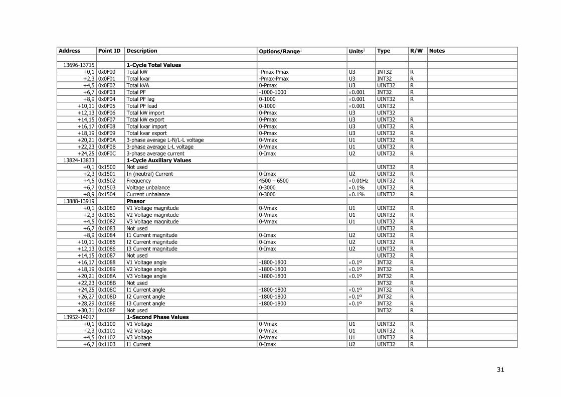
31
Address Point ID Description Options/Range1 Units1 Type R/W Notes
13696-13715 1-Cycle Total Values
+0,1 0x0F00 Total kW -Pmax-Pmax U3 INT32 R
+2,3 0x0F01 Total kvar -Pmax-Pmax U3 INT32 R
+4,5 0x0F02 Total kVA 0-Pmax U3 UINT32 R
+6,7 0x0F03 Total PF -1000-1000 0.001 INT32 R
+8,9 0x0F04 Total PF lag 0-1000 0.001 UINT32 R
+10,11 0x0F05 Total PF lead 0-1000 0.001 UINT32
+12,13 0x0F06 Total kW import 0-Pmax U3 UINT32
+14,15 0x0F07 Total kW export 0-Pmax U3 UINT32 R
+16,17 0x0F08 Total kvar import 0-Pmax U3 UINT32 R
+18,19 0x0F09 Total kvar export 0-Pmax U3 UINT32 R
+20,21 0x0F0A 3-phase average L-N/L-L voltage 0-Vmax U1 UINT32 R
+22,23 0x0F0B 3-phase average L-L voltage 0-Vmax U1 UINT32 R
+24,25 0x0F0C 3-phase average current 0-Imax U2 UINT32 R
13824-13833 1-Cycle Auxiliary Values
+0,1 0x1500 Not used UINT32 R
+2,3 0x1501 In (neutral) Current 0-Imax U2 UINT32 R
+4,5 0x1502 Frequency 4500 – 6500 0.01Hz UINT32 R
+6,7 0x1503 Voltage unbalance 0-3000 0.1% UINT32 R
+8,9 0x1504 Current unbalance 0-3000 0.1% UINT32 R
13888-13919 Phasor
+0,1 0x1080 V1 Voltage magnitude 0-Vmax U1 UINT32 R
+2,3 0x1081 V2 Voltage magnitude 0-Vmax U1 UINT32 R
+4,5 0x1082 V3 Voltage magnitude 0-Vmax U1 UINT32 R
+6,7 0x1083 Not used UINT32 R
+8,9 0x1084 I1 Current magnitude 0-Imax U2 UINT32 R
+10,11 0x1085 I2 Current magnitude 0-Imax U2 UINT32 R
+12,13 0x1086 I3 Current magnitude 0-Imax U2 UINT32 R
+14,15 0x1087 Not used UINT32 R
+16,17 0x1088 V1 Voltage angle -1800-1800 0.1º INT32 R
+18,19 0x1089 V2 Voltage angle -1800-1800 0.1º INT32 R
+20,21 0x108A V3 Voltage angle -1800-1800 0.1º INT32 R
+22,23 0x108B Not used INT32 R
+24,25 0x108C I1 Current angle -1800-1800 0.1º INT32 R
+26,27 0x108D I2 Current angle -1800-1800 0.1º INT32 R
+28,29 0x108E I3 Current angle -1800-1800 0.1º INT32 R
+30,31 0x108F Not used INT32 R
13952-14017 1-Second Phase Values
+0,1 0x1100 V1 Voltage 0-Vmax U1 UINT32 R
+2,3 0x1101 V2 Voltage 0-Vmax U1 UINT32 R
+4,5 0x1102 V3 Voltage 0-Vmax U1 UINT32 R
+6,7 0x1103 I1 Current 0-Imax U2 UINT32 R

32
Address Point ID Description Options/Range1 Units1 Type R/W Notes
+8,9 0x1104 I2 Current 0-Imax U2 UINT32 R
+10,11 0x1105 I3 Current 0-Imax U2 UINT32 R
+12,13 0x1106 kW L1 -Pmax-Pmax U3 INT32 R
+14,15 0x1107 kW L2 -Pmax-Pmax U3 INT32 R
+16,17 0x1108 kW L3 -Pmax-Pmax U3 INT32 R
+18,19 0x1109 kvar L1 -Pmax-Pmax U3 INT32 R
+20,21 0x110A kvar L2 -Pmax-Pmax U3 INT32 R
+22,23 0x110B kvar L3 -Pmax-Pmax U3 INT32 R
+24,25 0x110C kVA L1 0-Pmax U3 UINT32 R
+26,27 0x110D kVA L2 0-Pmax U3 UINT32 R
+28,29 0x110E kVA L3 0-Pmax U3 UINT32 R
+30,31 0x110F Power factor L1 -1000-1000 0.001 INT32 R
+32,33 0x1110 Power factor L2 -1000-1000 0.001 INT32 R
+34,35 0x1111 Power factor L3 -1000-1000 0.001 INT32 R
+36,37 0x1112 Reserved 0 UINT32 R
+38,39 0x1113 Reserved 0 UINT32 R
+40,41 0x1114 Reserved 0 UINT32 R
+42,43 0x1115 Reserved 0 UINT32 R
+44,45 0x1116 Reserved 0 UINT32 R
+46,47 0x1117 Reserved 0 UINT32 R
+48,49 0x1118 Not used 0 UINT32 R
+50,51 0x1119 Not used 0 UINT32 R
+52,53 0x111A Not used 0 UINT32 R
+54,55 0x111B Reserved 0 UINT32 R
+56,57 0x111C Reserved 0 UINT32 R
+58,59 0x111D Reserved 0 UINT32 R
+60,61 0x111E V12 Voltage 0-Vmax U1 UINT32 R
+62,63 0x111F V23 Voltage 0-Vmax U1 UINT32 R
+64,65 0x1120 V31 Voltage 0-Vmax U1 UINT32 R
14080-14093 1-Second Low Phase Values
+0,1 0x1200 Low L-N voltage 0-Vmax U1 UINT32 R
+2,3 0x1201 Low current 0-Imax U2 UINT32 R
+4,5 0x1202 Low kW -Pmax-Pmax U3 INT32 R
+6,7 0x1203 Low kvar -Pmax-Pmax U3 INT32 R
+8,9 0x1204 Low kVA 0-Pmax U3 UINT32 R
+10,11 0x1205 Low PF Lag 0-1000 0.001 UINT32 R
+12,13 0x1206 Low PF Lead 0-1000 0.001 UINT32 R
14208-14221 1-Second High Phase Values
+0,1 0x1300 High L-N voltage 0-Vmax U1 UINT32 R
+2,3 0x1301 High current 0-Imax U2 UINT32 R
+4,5 0x1302 High kW -Pmax-Pmax U3 INT32 R
+6,7 0x1303 High kvar -Pmax-Pmax U3 INT32 R
+8,9 0x1304 High kVA 0-Pmax U3 UINT32 R

33
Address Point ID Description Options/Range1 Units1 Type R/W Notes
+10,11 0x1305 High PF Lag 0-1000 0.001 UINT32 R
+12,13 0x1306 High PF Lead 0-1000 0.001 UINT32 R
14336-14355 1-Second Total Values
+0,1 0x1400 Total kW -Pmax-Pmax U3 INT32 R
+2,3 0x1401 Total kvar -Pmax-Pmax U3 INT32 R
+4,5 0x1402 Total kVA 0-Pmax U3 UINT32 R
+6,7 0x1403 Total PF -1000-1000 0.001 INT32 R
+8,9 0x1404 Total PF lag 0-1000 0.001 UINT32 R
+10,11 0x1405 Total PF lead 0-1000 0.001 UINT32
+12,13 0x1406 Total kW import 0-Pmax U3 UINT32
+14,15 0x1407 Total kW export 0-Pmax U3 UINT32 R
+16,17 0x1408 Total kvar import 0-Pmax U3 UINT32 R
+18,19 0x1409 Total kvar export 0-Pmax U3 UINT32 R
+20,21 0x140A 3-phase average L-N/L-L voltage 0-Vmax U1 UINT32 R 1
+22,23 0x140B 3-phase average L-L voltage 0-Vmax U1 UINT32 R
+24,25 0x140C 3-phase average current 0-Imax U2 UINT32 R
14464-14473 1-Second Auxiliary Values
+0,1 0x1500 Not used UINT32 R
+2,3 0x1501 In (neutral) Current 0-Imax U2 UINT32 R
+4,5 0x1502 Frequency 4500 – 6500 0.01Hz UINT32 R
+6,7 0x1503 Voltage unbalance 0-3000 0.1% UINT32 R
+8,9 0x1504 Current unbalance 0-3000 0.1% UINT32 R
14592-14651 Present Demands
+0,1 0x1600 V1 Volt demand 0-Vmax U1 UINT32 R
+2,3 0x1601 V2 Volt demand 0-Vmax U1 UINT32 R
+4,5 0x1602 V3 Volt demand 0-Vmax U1 UINT32 R
+6,7 0x1603 I1 Ampere demand 0-Imax U2 UINT32 R
+8,9 0x1604 I2 Ampere demand 0-Imax U2 UINT32 R
+10,11 0x1605 I3 Ampere demand 0-Imax U2 UINT32 R
+12,13 0x1606 Not used UINT32 R
+14,15 0x1607 Not used UINT32 R
+16,17 0x1608 Not used UINT32 R
+18,19 0x1609 kW import sliding window demand 0-Pmax U3 UINT32 R
+20,21 0x160A kvar import sliding window demand 0-Pmax U3 UINT32 R
+22,23 0x160B kVA sliding window demand 0-Pmax U3 UINT32 R
+24,25 0x160C Not used 0 UINT32 R
+26,27 0x160D Not used 0 UINT32 R
+28,29 0x160E Not used 0 UINT32 R
+30,31 0x160F kW import accumulated demand 0-Pmax U3 UINT32 R
+32,33 0x1610 kvar import accumulated demand 0-Pmax U3 UINT32 R
+34,35 0x1611 kVA accumulated demand 0-Pmax U3 UINT32 R
+36,37 0x1612 kW import predicted sliding window demand 0-Pmax U3 UINT32 R
+38,39 0x1613 kvar import predicted sliding window demand 0-Pmax U3 UINT32 R

34
Address Point ID Description Options/Range1 Units1 Type R/W Notes
+40,41 0x1614 kVA predicted sliding window demand 0-Pmax U3 UINT32 R
+42,43 0x1615 Not used UINT32 R
+44,45 0x1616 Not used UINT32 R
+46,47 0x1617 Not used UINT32 R
+48,49 0x1618 kW export sliding window demand 0-Pmax U3 UINT32 R
+50,51 0x1619 kvar export sliding window demand 0-Pmax U3 UINT32 R
+52,53 0x161A kW export accumulated demand 0-Pmax U3 UINT32 R
+54,55 0x161B kvar export accumulated demand 0-Pmax U3 UINT32 R
+56,57 0x161C kW export predicted sliding window demand 0-Pmax U3 UINT32 R
+58,59 0x161D kvar export predicted sliding window demand 0-Pmax U3 UINT32 R
14720-14737 Total Energies
+0,1 0x1700 kWh import 0-999,999,999 0.1 kWh UINT32 R
+2,3 0x1701 kWh export 0-999,999,999 0.1 kWh UINT32 R
+4,5 0x1702 Not used INT32 R
+6,7 0x1703 Not used UINT32 R
+8,9 0x1704 kvarh import 0-999,999,999 0.1 kvarh UINT32 R
+10,11 0x1705 kvarh export 0-999,999,999 0.1 kvarh UINT32 R
+12,13 0x1706 Not used INT32 R
+14,15 0x1707 Not used UINT32 R
+16,17 0x1708 kVAh total 0-999,999,999 0.1 kVAh UINT32 R
14784-14791 Billing Summary Registers
+0,1 0x1780 Summary energy register #1 0-999,999,999 0.1 kWh UINT32 R
+2,3 0x1781 Summary energy register #2 0-999,999,999 0.1 kWh UINT32 R
+4,5 0x1782 Summary energy register #3 0-999,999,999 0.1 kWh UINT32 R
+6,7 0x1783 Summary energy register #4 0-999,999,999 0.1 kWh UINT32 R
+8,9 0x1784 Summary energy register #5 0-999,999,999 0.1 kWh UINT32 R
+10,11 0x1785 Summary energy register #6 0-999,999,999 0.1 kWh UINT32 R
+12,13 0x1786 Summary energy register #7 0-999,999,999 0.1 kWh UINT32 R
+14,15 0x1787 Summary energy register #8 0-999,999,999 0.1 kWh UINT32 R
18816-18839 Maximum Demands
+0,1 0x3700 V1 Maximum volt demand 0-Vmax U1 UINT32 R
+2,3 0x3701 V2 Maximum volt demand 0-Vmax U1 UINT32 R
+4,5 0x3702 V2 Maximum volt demand 0-Vmax U1 UINT32 R
+6,7 0x3703 I1 Maximum ampere demand 0-Imax U2 UINT32 R
+8,9 0x3704 I2 Maximum ampere demand 0-Imax U2 UINT32 R
+10,11 0x3705 Not used 0 U2 UINT32 R
+12,13 0x3706 Not used 0 UINT32 R
+14,15 0x3707 Not used 0 UINT32 R
+16,17 0x3708 Not used 0 UINT32 R
+18,19 0x3709 Maximum kW import sliding window demand 0-Pmax U3 UINT32 R
+20,21 0x370A Maximum kvar import sliding window demand 0-Pmax U3 UINT32 R
+22,23 0x370B Maximum kVA sliding window demand 0-Pmax U3 UINT32 R
+24,25 0x3737 Not used UINT32 R

35
Address Point ID Description Options/Range1 Units1 Type R/W Notes
+26,27 0x370D Not used UINT32 R
+28,29 0x370E Not used UINT32 R
+30,31 0x370F Maximum kW export sliding window demand 0-Pmax U3 UINT32 R
+32,33 0x3710 Maximum kvar export sliding window demand 0-Pmax U3 UINT32 R
19328-19359 1-Cycle Analog Inputs
+0,1 0x3B00 Analog input AI1 AI1min-AI1max INT32 R
+2,3 0x3B01 Analog input AI2 AI2min-AI2max INT32 R
…
+30,31 0x3B0F Analog input AI16 AI16min-AI16max INT32 R
19392-19423 Raw Analog Inputs
+0, 1 0x3B80 Analog input AI1 0-4095 UINT32 R
+2, 3 0x3B81 Analog input AI2 0-4095 UINT32 R
…
+30, 31 0x3B8F Analog input AI16 0-4095 UINT32 R
19456-19459 Energy/TOU Parameters
+0,1 0x3C00 Active tariff 0-15 UINT32 R
+2,3 0x3C01 Active profile 0-15 1-3 = Season 1 Profile #1-4, 4-7 = Season 2 Profile #1-4, 8-11 = Season 3 Profile #1-4, 12-15 = Season 4 Profile #1-4
UINT32 R
19584-19599 Billing TOU Energy Register #1
+0,1 0x3D00 Tariff #1 register 0-999,999,999 0.1 kWh UINT32 R
+2,3 0x3D01 Tariff #2 register 0-999,999,999 0.1 kWh UINT32 R
… R
+14,15 0x3D07 Tariff #8 register 0-999,999,999 0.1 kWh UINT32 R
19712-19727 Billing TOU Energy Register #2
+0,1 0x3E00 Tariff #1 register 0-999,999,999 0.1 kWh UINT32 R
+2,3 0x3E01 Tariff #2 register 0-999,999,999 0.1 kWh UINT32 R
… R
+14,15 0x3E07 Tariff #8 register 0-999,999,999 0.1 kWh UINT32 R
19840-19855 Billing TOU Energy Register #3
+0,1 0x3F00 Tariff #1 register 0-999,999,999 0.1 kWh UINT32 R
+2,3 0x3F01 Tariff #2 register 0-999,999,999 0.1 kWh UINT32 R
… R
+14,15 0x3F07 Tariff #8 register 0-999,999,999 0.1 kWh UINT32 R
19968-19983 Billing TOU Energy Register #4
+0,1 0x4000 Tariff #1 register 0-999,999,999 0.1 kWh UINT32 R
+2,3 0x4001 Tariff #2 register 0-999,999,999 0.1 kWh UINT32 R
… R
+14,15 0x4007 Tariff #8 register 0-999,999,999 0.1 kWh UINT32 R
20096-20111 Billing TOU Energy Register #5
+0,1 0x4100 Tariff #1 register 0-999,999,999 0.1 kWh UINT32 R

36
Address Point ID Description Options/Range1 Units1 Type R/W Notes
+2,3 0x4101 Tariff #2 register 0-999,999,999 0.1 kWh UINT32 R
… R
+14,15 0x4107 Tariff #8 register 0-999,999,999 0.1 kWh UINT32 R
20224-20239 Billing TOU Energy Register #6
+0,1 0x4200 Tariff #1 register 0-999,999,999 0.1 kWh UINT32 R
+2,3 0x4201 Tariff #2 register 0-999,999,999 0.1 kWh UINT32 R
… R
+14,15 0x4207 Tariff #8 register 0-999,999,999 0.1 kWh UINT32 R
20352-20367 Billing TOU Energy Register #7
+0,1 0x4300 Tariff #1 register 0-999,999,999 0.1 kWh UINT32 R
+2,3 0x4301 Tariff #2 register 0-999,999,999 0.1 kWh UINT32 R
… R
+14,15 0x4307 Tariff #8 register 0-999,999,999 0.1 kWh UINT32 R
20480-20495 Billing TOU Energy Register #8
+0,1 0x4400 Tariff #1 register 0-999,999,999 0.1 kWh UINT32 R
+2,3 0x4401 Tariff #2 register 0-999,999,999 0.1 kWh UINT32 R
… R
+14,15 0x4407 Tariff #8 register 0-999,999,999 0.1 kWh UINT32 R
20608-20627 Billing Summary Accumulated Demands
+0,1 0x4500 Summary register #1 demand 0-Pmax U3 UINT32 R
+2,3 0x4501 Summary register #2 demand 0-Pmax U3 UINT32 R
… 0-Pmax U3 UINT32 R
+14,15 0x4507 Summary register #8 demand 0-Pmax U3 UINT32 R
20736-20755 Billing Summary Sliding Window Demands
+0,1 0x4600 Summary register #1 demand 0-Pmax U3 UINT32 R
+2,3 0x4601 Summary register #2 demand 0-Pmax U3 UINT32 R
… 0-Pmax U3 UINT32 R
+14,15 0x4607 Summary register #8 demand 0-Pmax U3 UINT32 R
20928-20979 Billing Summary (Total) Maximum Demands
+0,1 0x4780 Summary register #1 maximum demand 0-Pmax U3 UINT32 R
+2,3 0x4781 Summary register #2 maximum demand 0-Pmax U3 UINT32 R
… 0-Pmax U3 UINT32 R
+14,15 0x4787 Summary register #8 maximum demand 0-Pmax U3 UINT32 R
20992-21043 Billing TOU Maximum Demand Register #1
+0,1 0x4800 Tariff #1 maximum demand 0-Pmax U3 UINT32 R
+2,3 0x4801 Tariff #2 maximum demand 0-Pmax U3 UINT32 R
… R
+14,15 0x4807 Tariff #8 maximum demand 0-Pmax U3 UINT32 R
21120-21171 Billing TOU Maximum Demand Register #2
+0,1 0x4900 Tariff #1 maximum demand 0-Pmax U3 UINT32 R
+2,3 0x4901 Tariff #2 maximum demand 0-Pmax U3 UINT32 R
… R
+14,15 0x4907 Tariff #8 maximum demand 0-Pmax U3 UINT32 R

37
Address Point ID Description Options/Range1 Units1 Type R/W Notes
21248-21299 Billing TOU Maximum Demand Register #3
+0,1 0x4A00 Tariff #1 maximum demand 0-Pmax U3 UINT32 R
+2,3 0x4A01 Tariff #2 maximum demand 0-Pmax U3 UINT32 R
… R
+14,15 0x4A07 Tariff #8 maximum demand 0-Pmax U3 UINT32 R
21056-21107 Billing TOU Maximum Demand Register #4
+0,1 0x4880 Tariff #1 maximum demand 0-Pmax U3 UINT32 R
+2,3 0x4881 Tariff #2 maximum demand 0-Pmax U3 UINT32 R
… R
+14,15 0x4887 Tariff #8 maximum demand 0-Pmax U3 UINT32 R
21184-21235 Billing TOU Maximum Demand Register #5
+0,1 0x4980 Tariff #1 maximum demand 0-Pmax U3 UINT32 R
+2,3 0x4981 Tariff #2 maximum demand 0-Pmax U3 UINT32 R
… R
+14,15 0x4987 Tariff #8 maximum demand 0-Pmax U3 UINT32 R
21312-21363 Billing TOU Maximum Demand Register #6
+0,1 0x4A80 Tariff #1 maximum demand 0-Pmax U3 UINT32 R
+2,3 0x4A81 Tariff #2 maximum demand 0-Pmax U3 UINT32 R
… R
+14,15 0x4A87 Tariff #8 maximum demand 0-Pmax U3 UINT32 R
22400-22451 Billing TOU Maximum Demand Register #7
+0,1 0x5300 Tariff #1 maximum demand 0-Pmax U3 UINT32 R
+2,3 0x5301 Tariff #2 maximum demand 0-Pmax U3 UINT32 R
… R
+14,15 0x5307 Tariff #8 maximum demand 0-Pmax U3 UINT32 R
22464-22515 Billing TOU Maximum Demand Register #8
+0,1 0x5380 Tariff #1 maximum demand 0-Pmax U3 UINT32 R
+2,3 0x5381 Tariff #2 maximum demand 0-Pmax U3 UINT32 R
… R
+14,15 0x5387 Tariff #8 maximum demand 0-Pmax U3 UINT32 R
Generic TOU Season Energy Registers ID’s Point references 0x7000 Tariff #1 register 0-999,999,999 0.1 kWh UINT32 R
0x7001 Tariff #2 register 0-999,999,999 0.1 kWh UINT32 R
0x7002 Tariff #3 register 0-999,999,999 0.1 kWh UINT32 R
0x7003 Tariff #4 register 0-999,999,999 0.1 kWh UINT32 R
0x7004 Tariff #5 register 0-999,999,999 0.1 kWh UINT32 R
0x7005 Tariff #6 register 0-999,999,999 0.1 kWh UINT32 R
0x7006 Tariff #7 register 0-999,999,999 0.1 kWh UINT32 R
0x7007 Tariff #8 register 0-999,999,999 0.1 kWh UINT32 R
Generic TOU Season Maximum Demand Registers ID’s
Point references
0x7100 Tariff #1 register 0-Pmax U3 UINT32 R
0x7101 Tariff #2 register 0-Pmax U3 UINT32 R

38
Address Point ID Description Options/Range1 Units1 Type R/W Notes
0x7102 Tariff #3 register 0-Pmax U3 UINT32 R
0x7103 Tariff #4 register 0-Pmax U3 UINT32 R
0x7104 Tariff #5 register 0-Pmax U3 UINT32 R
0x7105 Tariff #6 register 0-Pmax U3 UINT32 R
0x7106 Tariff #7 register 0-Pmax U3 UINT32 R
0x7107 Tariff #8 register 0-Pmax U3 UINT32 R
1 For volts, amps and power scales refer to Chapter 4 ”Data Scales and Units”.
3.5 Minimum/Maximum Log Registers
Address Point ID Description Options/Range/Format3 Units3 Type R/W Notes
35840-35971 Minimum Phase Values
+0,1 +2,3
0x2C00 Min. V1/V12 Voltage Timestamp
0-Vmax F1
U1 sec
UINT32 UINT32
R R
1
+4,5 +6,7
0x2C01 Min. V2/V23 Voltage Timestamp
0-Vmax F1
U1 sec
UINT32 UINT32
R R
1
+8,9 +10,11
0x2C02 Min. V3/V31 Voltage Timestamp
0-Vmax F1
U1 sec
UINT32 UINT32
R R
1
+12,13 +14,15
0x2C03 Min. I1 Current Timestamp
0-Imax F1
U4 sec
UINT32 UINT32
R R
Per submeter
+16,17 +18,19
0x2C04 Min. I2 Current Timestamp
0-Imax U4 sec
UINT32 UINT32
R R
Per submeter
+20,21 +22,23
0x2C05 Min. I3 Current Timestamp
0-Imax U4 sec
UINT32 UINT32
R R
Per submeter
+24,25 +26,27
0x2C06 Min. kW L1 Timestamp
-Pmax-Pmax U3 sec
INT32 INT32
R R
Per submeter
+28,29 +30,31
0x2C07 Min. kW L2 Timestamp
-Pmax-Pmax U3 sec
INT32 INT32
R R
Per submeter
+32,33 +34,35
0x2C08 Min. kW L3 Timestamp
-Pmax-Pmax U3 sec
INT32 INT32
R R
Per submeter
+36,37 +38,39
0x2C09 Min. kvar L1 Timestamp
-Pmax-Pmax U3 sec
INT32 INT32
R R
Per submeter
+40,41 +42,43
0x2C0A Min. kvar L2 Timestamp
-Pmax-Pmax U3 sec
INT32 INT32
R R
Per submeter
+44,45 +46,47
0x2C0B Min. kvar L3 Timestamp
-Pmax-Pmax U3 sec
INT32 INT32
R R
Per submeter
+48,49 +50,51
0x2C0C Min. kVA L1 Timestamp
0-Pmax U3 sec
UINT32 UINT32
R R
Per submeter
+52,53 +54,55
0x2C0D Min. kVA L2 Timestamp
0-Pmax U3 sec
UINT32 UINT32
R R
Per submeter
+56,57 +58,59
0x2C0E Min. kVA L3 Timestamp
0-Pmax U3 sec
UINT32 UINT32
R R
Per submeter

39
Address Point ID Description Options/Range/Format3 Units3 Type R/W Notes
+60,61 +62,63
0x2C0F Min. Power factor L1 Timestamp
0-1000 0.001 sec
UINT32 UINT32
R R
Absolute value
+64,65 +66,67
0x2C10 Min. Power factor L2 Timestamp
0-1000 0.001
sec
UINT32 UINT32
R R
Absolute value
+68,69 +70,71
0x2C11 Min. Power factor L3 Timestamp
0-1000 0.001
sec
UINT32 UINT32
R R
Absolute value
+72,73 +74,75
0x2C12 Not used
+76,77 +78,79
0x2C13 Not used
+80,81 +82,83
0x2C14 Not used
+84,85 +86,87
0x2C15 Not used
+88,89 +90,91
0x2C16 Not used
+92,93 +94,95
0x2C17 Not used
+96,97 +98,99
0x2C18 Not used
+100,101 +102,103
0x2C19 Not used
+104,105 +106,107
0x2C1A Not used
+108,109 +110,111
0x2C1B Not used
+112,113 +114,115
0x2C1C Not used
+116,117 +118,119
0x2C1D Not used
+120,121 +122,123
0x2C1E Min. V12 voltage Timestamp
0-Vmax U1 sec
UINT32 UINT32
R R
+124,125 +126,127
0x2C1F Min. V23 voltage Timestamp
0-Vmax U1 sec
UINT32 UINT32
R R
+128,129 +130,131
0x2C20 Min. V31 voltage Timestamp
0-Vmax U1 sec
UINT32 UINT32
R R
36096-36119 Minimum Total Values
+0,1 +2,3
0x2D00 Min. Total kW Timestamp
-Pmax-Pmax U3 sec
INT32 UINT32
R R
+4,5 +6,7
0x2D01 Min. Total kvar Timestamp
-Pmax-Pmax U3 sec
INT32 UINT32
R R
+8,9 +10,11
0x2D02 Min. Total kVA Timestamp
0-Pmax U3 sec
UINT32 UINT32
R R
+12,13 0x2D03 Min. Total PF -1000-1000 0.001 INT32 R

40
Address Point ID Description Options/Range/Format3 Units3 Type R/W Notes
+14,15 Timestamp sec UINT32 R
+16,17 +18,19
0x2D04 Min. Total PF lag Timestamp
0-1000 0.001
sec
UINT32 UINT32
R R
+20,21 +22,23
0x2D05 Min. Total PF lead Timestamp
0-1000 0.001 sec
UINT32 UINT32
R R
36864-36995 Maximum Phase Values
+0,1 +2,3
0x3400 Max. V1/V12 Voltage Timestamp
0-Vmax
U1 sec
UINT32 UINT32
R R
1
+4,5 +6,7
0x3401 Max. V2/V23 Voltage Timestamp
0-Vmax U1 sec
UINT32 UINT32
R R
1
+8,9 +10,11
0x3402 Max. V3/V31 Voltage Timestamp
0-Vmax U1 sec
UINT32 UINT32
R R
1
+12,13 +14,15
0x3403 Max. I1 Current Timestamp
0-Imax U4 sec
UINT32 UINT32
R R
Per submeter
+16,17 +18,19
0x3404 Max. I2 Current Timestamp
0-Imax U4 sec
UINT32 UINT32
R R
Per submeter
+20,21 +22,23
0x3405 Max. I3 Current Timestamp
0-Imax U4 sec
UINT32 UINT32
R R
Per submeter
+24,25 +26,27
0x3406 Max. kW L1 Timestamp
-Pmax-Pmax U3 sec
INT32 INT32
R R
Per submeter
+28,29 +30,31
0x3407 Max. kW L2 Timestamp
-Pmax-Pmax U3 sec
INT32 INT32
R R
Per submeter
+32,33 +34,35
0x3408 Max. kW L3 Timestamp
-Pmax-Pmax U3 sec
INT32 INT32
R R
Per submeter
+36,37 +38,39
0x3409 Max. kvar L1 Timestamp
-Pmax-Pmax U3 sec
INT32 INT32
R R
Per submeter
+40,41 +42,43
0x340A Max. kvar L2 Timestamp
-Pmax-Pmax U3 sec
INT32 INT32
R R
Per submeter
+44,45 +46,47
0x340B Max. kvar L3 Timestamp
-Pmax-Pmax U3 sec
INT32 INT32
R R
Per submeter
+48,49 +50,51
0x340C Max. kVA L1 Timestamp
0-Pmax U3 sec
UINT32 UINT32
R R
Per submeter
+52,53 +54,55
0x340D Max. kVA L2 Timestamp
0-Pmax U3 sec
UINT32 UINT32
R R
Per submeter
+56,57 +58,59
0x340E Max. kVA L3 Timestamp
0-Pmax U3 sec
UINT32 UINT32
R R
Per submeter
+60,61 +62,63
0x340F Max. Power factor L1 Timestamp
0-1000 0.001
sec
UINT32 UINT32
R R
Absolute value, Per submeter
+64,65 +66,67
0x3410 Max. Power factor L2 Timestamp
0-1000 0.001
sec
UINT32 UINT32
R R
Absolute value, Per submeter
+68,69 +70,71
0x3411 Max. Power factor L3 Timestamp
0-1000 0.001 sec
UINT32 UINT32
R R
Absolute value, Per submeter
+72,73 +74,75
0x3412 Not used

41
Address Point ID Description Options/Range/Format3 Units3 Type R/W Notes
+76,77 +78,79
0x3413 Not used
+80,81 +82,83
0x3414 Not used
+84,85 +86,87
0x3415 Not used
+88,89 +90,91
0x3416 Not used
+92,93 +94,95
0x3417 Not used
+96,97 +98,99
0x3418 Not used
+100,101 +102,103
0x3419 Not used
+104,105 +106,107
0x341A Not used
+108,109 +110,111
0x341B Not used
+112,113 +114,115
0x341C Not used
+116,117 +118,119
0x341D Not used
+120,121 +122,123
0x341E Max. V12 voltage Timestamp
0-Vmax U1 sec
UINT32 UINT32
R R
+124,125 +126,127
0x341F Max. V23 voltage Timestamp
0-Vmax U1 sec
UINT32 UINT32
R R
+128,129 +130,131
0x3420 Max. V31 voltage Timestamp
0-Vmax U1 sec
UINT32 UINT32
R R
37120-37143 Maximum Total Values
+0,1 +2,3
0x3500 Max. Total kW Timestamp
-Pmax-Pmax U3 sec
INT32 UINT32
R R
+4,5 +6,7
0x3501 Max. Total kvar Timestamp
-Pmax-Pmax U3 sec
INT32 UINT32
R R
+8,9 +10,11
0x3502 Max. Total kVA Timestamp
0-Pmax U3 sec
UINT32 UINT32
R R
+12,13 +14,15
0x3503 Max. Total PF Timestamp
-1000-1000 0.001
sec
INT32 UINT32
R R
+16,17 +18,19
0x3504 Max. Total PF lag Timestamp
0-1000 0.001
sec
UINT32 UINT32
R R
+20,21 +22,23
0x3505 Max. Total PF lead Timestamp
0-1000 0.001 sec
UINT32 UINT32
R R

42
3.6 Maximum Demands Log Registers
Address Point ID
Description Options/Range! Units1 Type R/W Notes
37504-37519 Billing Summary Maximum Demands
+0,1 +2,3
0x4780 Summary register #1 Maximum Demand
Timestamp
0-Pmax U3 UINT32 R
+4,5 +6,7
0x4781 Summary register #2 Maximum Demand
Timestamp
0-Pmax U3 UINT32 R
+8,9 +10,11
0x4782 Summary register #3 Maximum Demand
Timestamp
0-Pmax U3 UINT32 R
+12,13 +14,15
0x4783 Summary register #4 Maximum Demand
Timestamp
0-Pmax U3 UINT32 R
+16,17 +18,19
0x4784 Summary register #5 Maximum Demand
Timestamp
0-Pmax U3 UINT32 R
+20,21 +22,23
0x4785 Summary register #6 Maximum Demand
Timestamp
0-Pmax U3 UINT32 R
+24,25 +26,27
0x4786 Summary register #7 Maximum Demand
Timestamp
0-Pmax U3 UINT32 R
+28,29 +30,31
0x4787 Summary register #8 Maximum Demand
Timestamp
0-Pmax U3 UINT32 R
37632-37699 Maximum Demands
+0,1 +2,3
0x3700 V1 Maximum volt demand Timestamp
0-Vmax U1 sec
UINT32 UINT32
R R
+4,5 +6,7
0x3701 V2 Maximum volt demand Timestamp
0-Vmax U1 sec
UINT32 UINT32
R R
+8,9 +10,11
0x3702 V3 Maximum volt demand Timestamp
0-Vmax U1 sec
UINT32 UINT32
R R
+12,13 +14,15
0x3703 I1 Maximum ampere demand Timestamp
0-Imax U2 sec
UINT32 UINT32
R R
+16,17 +18,19
0x3704 I2 Maximum ampere demand Timestamp
0-Imax U2 sec
UINT32 UINT32
R R
+20,21 +22,23
0x3705 I2 Maximum ampere demand Timestamp
0-Imax U2 sec
UINT32 UINT32
R R
+24,25 +26,27
0x3706 Not used 0 UINT32 UINT32
R R
+28,29 +30,31
0x3707 Not used 0 UINT32 UINT32
R R
+32,33 +34,35
0x3708 Not used 0 UINT32 UINT32
R R
+36,37 +38,39
0x3709 Maximum kW import sliding window demand Timestamp
0-Pmax U3 sec
UINT32 UINT32
R R
+40,41 +42,43
0x370A Maximum kvar import sliding window demand Timestamp
0-Pmax U3 sec
UINT32 UINT32
R R

43
Address Point ID
Description Options/Range! Units1 Type R/W Notes
+44,45 +46,47
0x370B Maximum kVA sliding window demand Timestamp
0-Pmax U3 sec
UINT32 UINT32
R R
+48,49 +50,51
0x370C Not used Timestamp
UINT32 UINT32
R R
+52,53 +54,55
0x370D Not used Timestamp
UINT32 UINT32
R R
+56,57 +58,59
0x370E Not used Timestamp
UINT32 UINT32
R R
+60,61 +62,63
0x370F Maximum kW export sliding window demand Timestamp
0-Pmax U3 sec
UINT32 UINT32
R R
+64,65 +66,67
0x3710 Maximum kvar export sliding window demand Timestamp
0-Pmax U3 sec
UINT32 UINT32
R R
38144-38175 Billing TOU Maximum Demand Register #1
+0,1 +2,3
0x4800 Tariff #1 maximum demand Timestamp
0-Pmax U3 sec
UINT32 UINT32
R R
+4,5 +6,7
0x4801 Tariff #2 maximum demand Timestamp
0-Pmax U3 sec
UINT32 UINT32
R R
… R
+28,29 +30,31
0x4807 Tariff #8 maximum demand Timestamp
0-Pmax U3 sec
UINT32 UINT32
R R
38400-38431 Billing TOU Maximum Demand Register #2
+0,1 +2,3
0x4900 Tariff #1 maximum demand Timestamp
0-Pmax U3 sec
UINT32 UINT32
R R
+4,5 +6,7
0x4901 Tariff #2 maximum demand Timestamp
0-Pmax U3 sec
UINT32 UINT32
R R
… R
+28,29 +30,31
0x4907 Tariff #8 maximum demand Timestamp
0-Pmax U3 sec
UINT32 UINT32
R R
38656-38687 Billing TOU Maximum Demand Register #3
+0,1 +2,3
0x4A00 Tariff #1 maximum demand Timestamp
0-Pmax U3 sec
UINT32 UINT32
R R
+4,5 +6,7
0x4A01 Tariff #2 maximum demand Timestamp
0-Pmax U3 sec
UINT32 UINT32
R R
… R
+28,29 +30,31
0x4A07 Tariff #8 maximum demand Timestamp
0-Pmax U3 sec
UINT32 UINT32
R R
38272-38313 Billing TOU Maximum Demand Register #4
+0,1 +2,3
0x4880 Tariff #1 maximum demand Timestamp
0-Pmax U3 sec
UINT32 UINT32
R R
+4,5 +6,7
0x4881 Tariff #2 maximum demand Timestamp
0-Pmax U3 sec
UINT32 UINT32
R R
… R
+28,29 0x4887 Tariff #8 maximum demand 0-Pmax U3 UINT32 R

44
Address Point ID
Description Options/Range! Units1 Type R/W Notes
+30,31 Timestamp sec UINT32 R
38528-38559 Billing TOU Maximum Demand Register #5
+0,1 +2,3
0x4980 Tariff #1 maximum demand Timestamp
0-Pmax U3 sec
UINT32 UINT32
R R
+4,5 +6,7
0x4981 Tariff #2 maximum demand Timestamp
0-Pmax U3 sec
UINT32 UINT32
R R
… R
+28,29 +30,31
0x4987 Tariff #8 maximum demand Timestamp
0-Pmax U3 sec
UINT32 UINT32
R R
38784-38815 Billing TOU Maximum Demand Register #6
+0,1 +2,3
0x4A80 Tariff #1 maximum demand Timestamp
0-Pmax U3 sec
UINT32 UINT32
R R
+4,5 +6,7
0x4A81 Tariff #2 maximum demand Timestamp
0-Pmax U3 sec
UINT32 UINT32
R R
… R
+28,29 +30,31
0x4A87 Tariff #8 maximum demand Timestamp
0-Pmax U3 sec
UINT32 UINT32
R R
38912-38943 Billing TOU Maximum Demand Register #7
+0,1 +2,3
0x5300 Tariff #1 maximum demand Timestamp
0-Pmax U3 sec
UINT32 UINT32
R R
+4,5 +6,7
0x5301 Tariff #2 maximum demand Timestamp
0-Pmax U3 sec
UINT32 UINT32
R R
… R
+28,29 +30,31
0x5307 Tariff #8 maximum demand Timestamp
0-Pmax
U3 sec
UINT32 UINT32
R R
39040-39071 Billing TOU Maximum Demand Register #8
+0,1 +2,3
0x5380 Tariff #1 maximum demand Timestamp
0-Pmax U3 sec
UINT32 UINT32
R R
+4,5 +6,7
0x5381 Tariff #2 maximum demand Timestamp
0-Pmax U3 sec
UINT32 UINT32
R R
… R
+28,29 +30,31
0x5387 Tariff #8 maximum demand Timestamp
0-Pmax U3 sec
UINT32 UINT32
R R
1 For volts, amps and power scales refer to Chapter 4 ”Data Scales and Units”.
3.7 Billing Period Data
Address Point ID Description Options/Range Units Type R/W Notes
40412-40557 Current Register Readings
40558-40703 Current Day’s Usage
40704-40849 Current Week’s Usage
40850-40995 Current Month’s Usage

45
Address Point ID Description Options/Range Units Type R/W Notes
40996-41141 Current Quarter’s Usage
41142-41287 Previous Day’s Readings
41288-41433 Previous Week’s Readings
41434-41579 Previous Month’s Readings
41580-41725 Previous Quarter’s Readings
41726-41871 Previous Day’s Usage
41872-42017 Previous Week’s Usage
42018-42163 Previous Month’s Usage
42164-42309 Previous Quarter’s Usage
42310-42455 Second Previous Day’s Readings
42456-42601 Second Previous Week’s Readings
42602-42747 Second Previous Month’s Readings
42748-42893 Second Previous Quarter’s Readings
42894-43039 Second Previous Day’s Usage
43040-43185 Second Previous Week’s Usage
43186-43331 Second Previous Month’s Usage
43332-43477 Second Previous Quarter’s Usage
Period Data Structure
+0,1 Reading timestamp F1 UINT32 R Local time, seconds since 1/1/1970 0 = no period data available yet
+2,3 Register #1, total 0-999,999,999 U4 UINT32 R
+4,5 Register #2, total 0-999,999,999 U4 UINT32 R
+6,7 Register #3, total 0-999,999,999 U4 UINT32 R
+8,9 Register #4, total 0-999,999,999 U4 UINT32 R
+10,11 Register #5, total 0-999,999,999 U4 UINT32 R
+12,13 Register #6, total 0-999,999,999 U4 UINT32 R
+14,15 Register #7, total 0-999,999,999 U4 UINT32 R
+16,17 Register #8, total 0-999,999,999 U4 UINT32 R
+18,19 Register #1, tariff #1 0-999,999,999 U4 UINT32 R
+20,21 Register #1, tariff #2 0-999,999,999 U4 UINT32 R
+22,23 Register #1, tariff #3 0-999,999,999 U4 UINT32 R
+24,25 Register #1, tariff #4 0-999,999,999 U4 UINT32 R
+26,27 Register #1, tariff #5 0-999,999,999 U4 UINT32 R
+28,29 Register #1, tariff #6 0-999,999,999 U4 UINT32 R
+30,31 Register #1, tariff #7 0-999,999,999 U4 UINT32 R
+32,33 Register #1, tariff #8 0-999,999,999 U4 UINT32 R
+34,35 Register #2, tariff #1 0-999,999,999 U4 UINT32 R
+36,37 Register #2, tariff #2 0-999,999,999 U4 UINT32 R
+38,39 Register #2, tariff #3 0-999,999,999 U4 UINT32 R
+40,41 Register #2, tariff #4 0-999,999,999 U4 UINT32 R
+42,43 Register #2, tariff #5 0-999,999,999 U4 UINT32 R

46
Address Point ID Description Options/Range Units Type R/W Notes
+44,45 Register #2, tariff #6 0-999,999,999 U4 UINT32 R
+46,47 Register #2, tariff #7 0-999,999,999 U4 UINT32 R
+48,49 Register #2, tariff #8 0-999,999,999 U4 UINT32 R
+50,51 Register #3, tariff #1 0-999,999,999 U4 UINT32 R
+52,53 Register #3, tariff #2 0-999,999,999 U4 UINT32 R
+54,55 Register #3, tariff #3 0-999,999,999 U4 UINT32 R
+56,57 Register #3, tariff #4 0-999,999,999 U4 UINT32 R
+58,59 Register #3, tariff #5 0-999,999,999 U4 UINT32 R
+60,61 Register #3, tariff #6 0-999,999,999 U4 UINT32 R
+62,63 Register #3, tariff #7 0-999,999,999 U4 UINT32 R
+64,65 Register #3, tariff #8 0-999,999,999 U4 UINT32 R
+66,67 Register #4, tariff #1 0-999,999,999 U4 UINT32 R
+68,69 Register #4, tariff #2 0-999,999,999 U4 UINT32 R
+70,71 Register #4, tariff #3 0-999,999,999 U4 UINT32 R
+72,73 Register #4, tariff #4 0-999,999,999 U4 UINT32 R
+74,75 Register #4, tariff #5 0-999,999,999 U4 UINT32 R
+76,77 Register #4, tariff #6 0-999,999,999 U4 UINT32 R
+78,79 Register #4, tariff #7 0-999,999,999 U4 UINT32 R
+80,81 Register #4, tariff #8 0-999,999,999 U4 UINT32 R
+82,83 Register #5, tariff #1 0-999,999,999 U4 UINT32 R
+84,85 Register #5, tariff #2 0-999,999,999 U4 UINT32 R
+86,87 Register #5, tariff #3 0-999,999,999 U4 UINT32 R
+88,89 Register #5, tariff #4 0-999,999,999 U4 UINT32 R
+90,91 Register #5, tariff #5 0-999,999,999 U4 UINT32 R
+92,93 Register #5, tariff #6 0-999,999,999 U4 UINT32 R
+94,95 Register #5, tariff #7 0-999,999,999 U4 UINT32 R
+96,97 Register #5, tariff #8 0-999,999,999 U4 UINT32 R
+98,99 Register #6, tariff #1 0-999,999,999 U4 UINT32 R
+100,101 Register #6, tariff #2 0-999,999,999 U4 UINT32 R
+102,103 Register #6, tariff #3 0-999,999,999 U4 UINT32 R
+104,105 Register #6, tariff #4 0-999,999,999 U4 UINT32 R
+106,107 Register #6, tariff #5 0-999,999,999 U4 UINT32 R
+108,109 Register #6, tariff #6 0-999,999,999 U4 UINT32 R
+110,111 Register #6, tariff #7 0-999,999,999 U4 UINT32 R
+112,113 Register #6, tariff #8 0-999,999,999 U4 UINT32 R
+114,115 Register #7, tariff #1 0-999,999,999 U4 UINT32 R
+116,117 Register #7, tariff #2 0-999,999,999 U4 UINT32 R
+118,119 Register #7, tariff #3 0-999,999,999 U4 UINT32 R

47
Address Point ID Description Options/Range Units Type R/W Notes
+120,121 Register #7, tariff #4 0-999,999,999 U4 UINT32 R
+122,123 Register #7, tariff #5 0-999,999,999 U4 UINT32 R
+124,125 Register #7, tariff #6 0-999,999,999 U4 UINT32 R
+126,127 Register #7, tariff #7 0-999,999,999 U4 UINT32 R
+128,129 Register #7, tariff #8 0-999,999,999 U4 UINT32 R
+130,131 Register #8, tariff #1 0-999,999,999 U4 UINT32 R
+132,133 Register #8, tariff #2 0-999,999,999 U4 UINT32 R
+134,135 Register #8, tariff #3 0-999,999,999 U4 UINT32 R
+136,137 Register #8, tariff #4 0-999,999,999 U4 UINT32 R
+138,139 Register #8, tariff #5 0-999,999,999 U4 UINT32 R
+140,141 Register #8, tariff #6 0-999,999,999 U4 UINT32 R
+142,143 Register #8, tariff #7 0-999,999,999 U4 UINT32 R
+144,145 Register #8, tariff #8 0-999,999,999 U4 UINT32 R
43478-43497 Current Day’s Use Cost
43498-43517 Current Week’s Use Cost
43518-43537 Current Month’s Use Cost
Use Cost Structure
+0,1 Reading timestamp F1 UINT32 R Local time, seconds since 1/1/1970 0 = no period data available yet
+2,3 Register #1, total 0-999,999,999 UINT32 R
+4,5 Register #2, total 0-999,999,999 UINT32 R
+6,7 Register #3, total 0-999,999,999 UINT32 R
+8,9 Register #4, total 0-999,999,999 UINT32 R
+10,11 Register #5, total 0-999,999,999 UINT32 R
+12,13 Register #6, total 0-999,999,999 UINT32 R
+14,15 Register #7, total 0-999,999,999 UINT32 R
+16,17 Register #8, total 0-999,999,999 UINT32 R
+18,19 CO2 emission equivalent, total 0-999,999,999 kg
UINT32 R

48
3.8 Device Control and Status Registers
Address Point ID Description Options/Range Units Type R/W Notes Remote Relay Control Registers (bitmap)
44038-44045 Reserved UINT32
44046-44047 Force relay operate register: 0 = no effect, 1 = operate
0x00000000 - 0x00000FFF UINT32 W
44050-44051 Force relay release register: 0 = no effect, 1 = release
0x00000000 - 0x00000FFF UINT32 W
Reset/Clear Registers
44103 Clear maximum demands 0 = clear all maximum demands 1 = clear power demands 2 = clear volt and ampere demands 3 = clear volt demands 4 = clear ampere demands
UINT16 W Individual for each submeter
44105 Clear Billing/TOU maximum demands 0 UINT16 W Individual for each submeter 44106 Clear counters 0 = clear all counters,
1-32 = clear counter #1-32 UINT16 W
44108 Clear operation/event counters 6 = clear communication counters UINT16 W Individual for each submeter Operation/Event Counters
44198-44199 Device’s start of operation date F1 UINT32 R
44200-44201 Device operation time sec UINT32 R
44202-44203 Lithium battery’s start of operation date F1 UINT32 R
44204-44205 Lithium battery operation time sec UINT32 R
44206-44207 Not used UINT32 R
44208-44209 Not used UINT32 R
44210-44211 Device out-of-service time sec UINT32 R
44212-44213 Device power failure counter 0-65535 UINT32 R
44214-44215 Power interruption counter 0-65535 UINT32 R
44216-44261 Reserved UINT32 R
Setpoint Status Registers
44294 Setpoints 1-4 status (bitmap: 0=released, 1=operated)
0x00000000 - 0x0000000F UINT32 R Individual for each submeter
Setpoint Alarm Latch Registers
44310 Setpoints 1-4 alarm status, nonvolatile (bitmap). Read: 0 = no setpoint operations logged, 1=setpoint has been operated at least once since the last alarm reset. Write: 0=clear setpoint alarm bit, 1=no effect.
0x0000 - 0x000F UINT16 R/W Individual for each submeter
44312-44325 Reserved
Device Diagnostics Register
44326-44327 Device self-diagnostics flags, nonvolatile (bitmap). Read: 0=no faults logged, 1=diagnostic bit has been set at least once since the last reset.
F23 UINT32 R/W Shared across all submeters

49
Address Point ID Description Options/Range Units Type R/W Notes Remote Relay Control Registers (bitmap)
44038-44045 Reserved UINT32
44046-44047 Force relay operate register: 0 = no effect, 1 = operate
0x00000000 - 0x00000FFF UINT32 W
44050-44051 Force relay release register: 0 = no effect, 1 = release
0x00000000 - 0x00000FFF UINT32 W
Write: 0=clear diagnostic bit, 1=no effect.
44328-44341 Reserved
Port Identification Registers
44342 Current port number 0=COM1, 1=COM2 UINT16 R
44343 Communication interface 0=RS-232, 1=RS-422, 2=RS-485, 4=Dial-Up Modem, 5=RF Modem, 6=Ethernet, 8=GSM/GPRS
UINT16 R
44343-44345 Reserved
Network Identification
44346-44367
+0,1 Ethernet network IP Address UINT32 R
+2,3 Ethernet network subnet mask UINT32 R
+4,5 Ethernet network default gateway UINT32 R
+6,7 Not used UINT32 R
+8,9 Not used UINT32 R
+10,11 GPRS network IP Address UINT32 R
+12,13 GPRS network subnet mask N/A UINT32 R
+14,15 GPRS network default gateway N/A UINT32 R
+16 Not used UINT32 R
+17 Cellular network type 0 = 3GPP network (GSM, UMTS, LTE) 1= 3GPP2 network (CDMA2000)
UINT32 R
+18-21 Cellular module’s mobile equipment identifier: IMEI for 3GPP networks MEID for 3GPP2 networks
IMEI (15 decimal digits): +18,19 – 8 lower digits in binary, +20,21 – 7 higher digits in binary; MEID (14 hex digits): +18,19 – 8 lower digits, +20,21 – 6 higher digits
UINT32 R
44368-44377 Reserved
Current Network Settings
44346-44377
+0, 1 Active device IP Address UINT32 R Network byte order +2, 3 Active network subnet mask UINT32 R Network byte order +4, 5 Active network default gateway UINT32 R Network byte order
44352-44377 Reserved
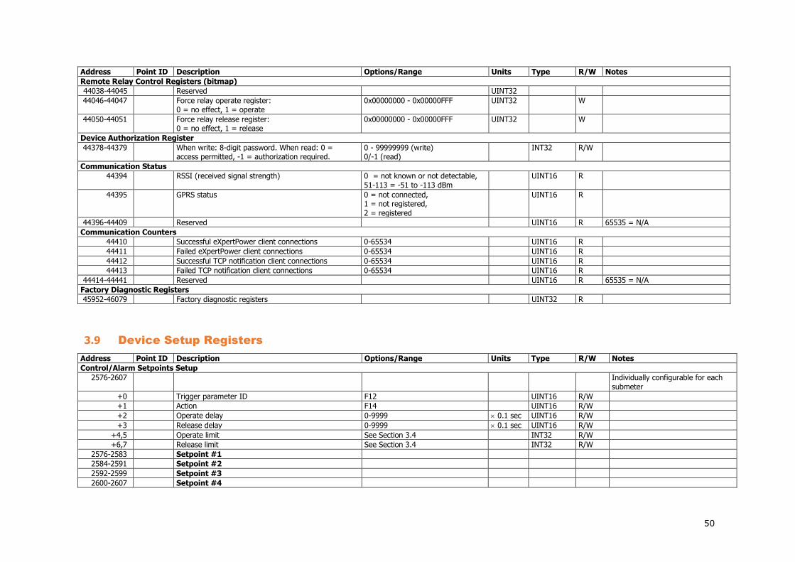
50
Address Point ID Description Options/Range Units Type R/W Notes Remote Relay Control Registers (bitmap)
44038-44045 Reserved UINT32
44046-44047 Force relay operate register: 0 = no effect, 1 = operate
0x00000000 - 0x00000FFF UINT32 W
44050-44051 Force relay release register: 0 = no effect, 1 = release
0x00000000 - 0x00000FFF UINT32 W
Device Authorization Register
44378-44379 When write: 8-digit password. When read: 0 = access permitted, -1 = authorization required.
0 - 99999999 (write) 0/-1 (read)
INT32 R/W
Communication Status
44394 RSSI (received signal strength) 0 = not known or not detectable, 51-113 = -51 to -113 dBm
UINT16 R
44395 GPRS status 0 = not connected, 1 = not registered, 2 = registered
UINT16 R
44396-44409 Reserved UINT16 R 65535 = N/A Communication Counters
44410 Successful eXpertPower client connections 0-65534 UINT16 R
44411 Failed eXpertPower client connections 0-65534 UINT16 R
44412 Successful TCP notification client connections 0-65534 UINT16 R
44413 Failed TCP notification client connections 0-65534 UINT16 R
44414-44441 Reserved UINT16 R 65535 = N/A Factory Diagnostic Registers
45952-46079 Factory diagnostic registers UINT32 R
3.9 Device Setup Registers
Address Point ID Description Options/Range Units Type R/W Notes Control/Alarm Setpoints Setup
2576-2607 Individually configurable for each submeter
+0 Trigger parameter ID F12 UINT16 R/W
+1 Action F14 UINT16 R/W
+2 Operate delay 0-9999 0.1 sec UINT16 R/W
+3 Release delay 0-9999 0.1 sec UINT16 R/W
+4,5 Operate limit See Section 3.4 INT32 R/W
+6,7 Release limit See Section 3.4 INT32 R/W
2576-2583 Setpoint #1
2584-2591 Setpoint #2
2592-2599 Setpoint #3
2600-2607 Setpoint #4

51
Address Point ID Description Options/Range Units Type R/W Notes Factory Device Settings and Identification
46080-46207 Shared across all submeters +0, 1 Device serial number UINT32 R
+2, 3 Device model ID 15400 UINT32 R
+4-11 Device model name “BFM II” CHAR16 R Null-terminated string +12-13 Device options (bitmap) UINT32 R
+14-19 Reserved UINT16 R
+20 Device firmware version number UINT16 R
+21 Device firmware build number UINT16 R
+22 RF modem firmware version number UINT16 R
+23 RF modem firmware build number UINT16 R
+24 Boot loader version number UINT16 R
+25 Boot loader build number UINT16 R
+26-31 Reserved UINT16 R
+32 V1-V3 inputs range 120, 277 V UINT16 R
+33 V1-V3 inputs overload 125 % UINT16 R
+34 Reserved UINT16 R
+35 Reserved UINT16 R
+36 I1-I3 inputs range 1, 5, 50 A UINT16 R
+37 I1-I3 inputs overload 200 % UINT16 R
+38-95 Reserved A UINT16 R
+96 Ethernet MAC address 0-1 0x0500 UINT16 R
+97 Ethernet MAC address 2-3 0x00F0 UINT16 R
+98 Ethernet MAC address 4-5 0x0000-0xFFFF UINT16 R
+99-128 Reserved UINT16 R
Basic Setup
46208-46271 Shared across all submeters +0 Wiring mode 1 = 4LN3 (4-wire WYE), 2 = 4LL3
(4-wire DELTA) UINT16 R/W
+1 PT ratio (primary to secondary ratio) 10 - 65000 0.1 UINT16 R/W
+2 PT secondary (Line-to-Line) 480 V UINT16 R/W
+3 Reserved UINT16 R/W
+4 Reserved UINT16 R/W
+5 CT primary current 1-10000 A UINT16 R/W
+6 CT secondary current 1, 5, 50 A UINT16 R/W
+7-16 Reserved UINT16 R/W
+17 Nominal line frequency 50, 60 Hz UINT16 R/W
+18-23 Reserved UINT16 R/W
+24 Maximum demand load current 0-10000 (0=CT primary current) A UINT16 R/W
+25-31 Reserved UINT16 R/W
Demands Setup
46240-46255 Shared across all submeters +0 Power block demand period 1, 2, 3, 5, 10, 15, 30, 60 min UINT16 R/W

52
Address Point ID Description Options/Range Units Type R/W Notes +1 Number of blocks in a sliding window 1-15 UINT16 R/W
+2-7 Reserved UINT16 R/W
+8 Volt demand period 0-9000 sec UINT16 R/W
+9 Ampere demand period 0-9000 sec UINT16 R/W
Device Options Setup
46256-46399 Shared across all submeters +0 Power calculation mode 0=using reactive power:
S = f(P,Q), 1=using non-active power: Q = f(S,P)
UINT16 R/W
+1 Energy roll value 2 = 0.1x10⁶, 3 = 0.1x10⁷, 4 = 0.1x10⁸, 5 = 0.1x10⁹
UINT16 R/W
+2 Reserved UINT16 R/W
+3 End of billing (TOU/Billing maximum demand reset) mode, bitmap
Bit 0 = 1 – automatic/monthly mode allowed Bit 1 = 1 - COM mode allowed Bit 2 = 1 - manual mode allowed
UINT16 R/W
+4 Tariff control 0 = via a calendar scheduler, 0x4000 = via communications, 0x0100-0x0107 = via tariff inputs DI1-DI72 (bits 0:2 denote the first digital input index used)
UINT16 R/W
+5 Number of tariffs 1-8 (does not have effect with a calendar tariff control option)
UINT16 R/W When read with a calendar tariff control option, indicates the actual number of tariffs selected in TOU profiles
+7 Energy test mode 0 = disabled, 1 = Wh pulse test, 2 = varh pulse test
UINT16 R/W
+8 Wh LED pulse rate, Wh/pulse 1 – 10000 0.01Wh UINT16 R/W
+9 Reserved UINT16 R/W
+10 Wh LED pulse source 0 = disabled, 1-60 = submeter UINT16 R/W
+11-14 Reserved
+15 Number of decimal places for energy registers 0-4 UINT16 R/W Default 4 +16-143 Reserved UINT16 R/W
Local Settings
46400-46415 Shared across all submeters +0 Local time offset, min 0-+/-720 INT16 R/W Offset in minutes from UTC
(Universal Coordinated or Greenwich Mean time)
+1 Daylight savings time (DST) option 0=DST disabled (standard time only), 1=DST enabled
UINT16 R/W

53
Address Point ID Description Options/Range Units Type R/W Notes +2 DST start month 1-12 UINT16 R/W
+3 DST start week of the month 1=1st, 2=2nd, 3=3rd, 4=4th week, 5=the last week of the month
UINT16 R/W
+4 DST start weekday 1-7 (1=Sun, 7=Sat) UINT16 R/W
+5 DST end month 1-12 UINT16 R/W
+6 DST end week of the month 1=1st, 2=2nd, 3=3rd, 4=4th week, 5=the last week of the month
UINT16 R/W
+7 DST end weekday 1-7 (1=Sun, 7=Sat) UINT16 R/W
+8 Reserved UINT16 R/W
+9 Country code ITU country calling code UINT16 R/W
+10 DST start hour 1-6 UINT16 R/W
+11 DST end hour 1-6 UINT16 R/W
+12-15 Reserved UINT16
Clock Setup and Status
46416-46447 Shared across all submeters +0,1 Local time, in seconds, since Jan 1, 1970 F1 sec UINT32 R/W
+2,3 Fractional seconds, µsec µsec UINT32 R/W
+4 Fractional seconds, milliseconds 0-999 ms UINT16 R/W
+5 Seconds 0-59 UINT16 R/W
+6 Minutes 0-59 UINT16 R/W
+7 Hour 0-23 UINT16 R/W
+8 Day of month 1-31 UINT16 R/W
+9 Month 1-12 UINT16 R/W
+10 Year (calendar year minus 2000) 0-99 UINT16 R/W
+11 Weekday 1-7 (1=Sun, 7=Sat) UINT16 R
+12 Daylight savings time status 0=standard time is active, 1=daylight savings time is active
UINT16 R
+13-31 Reserved UINT16
Communication Ports Setup
46448-46575 Shared across all submeters +0 Communication protocol 0 = Modbus RTU, 1 = Modbus
ASCII, 2 = DNP3.0, UINT16 R/W
+1 Interface 0 = RS-232, 1 = RS-422, 2 = RS-485, 4 = Modem
UINT16 R/W
+2 Device address Modbus: 1-247 DNP3.0: 0–65532
UINT16 R/W
+3 Baud rate 1 = 300 bps, 2 = 600 bps, 3 = 1200 bps, 4 = 2400 bps, 5 = 4800 bps, 6 = 9600 bps, 7 = 19200 bps, 8 = 38400 bps, 9 = 57600 bps, 10 = 115200 bps
UINT16 R/W
+4 Data format 0 = 7 bits/even parity, UINT16 R/W
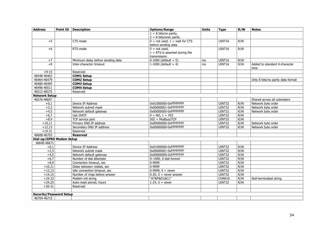
54
Address Point ID Description Options/Range Units Type R/W Notes 1 = 8 bits/no parity, 2 = 8 bits/even parity
+5 CTS mode 0 = not used, 1 = wait for CTS before sending data
UINT16 R/W
+6 RTS mode 0 = not used, 1 = RTS is asserted during the transmission
UINT16 R/W
+7 Minimum delay before sending data 0-1000 (default = 5) ms UINT16 R/W
+8 Inter-character timeout 1-1000 (default = 4) ms UINT16 R/W Added to standard 4-character time
+9-15 Reserved
46448-46463 COM1 Setup
46464-46479 COM2 Setup Only 8 bits/no parity data format 46480-46495 COM3 Setup
46496-46511 COM4 Setup
46512-46575 Reserved
Network Setup
46576-46607 Shared across all submeters +0,1 Device IP Address 0x01000000-0xFFFFFFFF UINT32 R/W Network byte order +2,3 Network subnet mask 0x00000001-0xFFFFFFFF UINT32 R/W Network byte order +4,5 Network default gateway 0x00000000-0xFFFFFFFF UINT32 R/W Network byte order +6,7 Use DHCP 0 = NO, 1 = YES UINT32 R/W
+8.9 TCP service port 502 = Modbus/TCP UINT32 R/W
+10,11 Primary DNS IP address 0x00000000-0xFFFFFFFF UINT32 R/W Network byte order +12,13 Secondary DNS IP address 0x00000000-0xFFFFFFFF UINT32 R/W Network byte order +14-31 Reserved
46608-46703 Reserved
Dial-up/GPRS Modem Setup
46640-46671
+0,1 Device IP Address 0x01000000-0xFFFFFFFF UINT32 R/W
+2,3 Network subnet mask 0x00000001-0xFFFFFFFF UINT32 R/W
+4,5 Network default gateway 0x00000000-0xFFFFFFFF UINT32 R/W
+6,7 Number of dial attempts 0–1000, 0-dial forever UINT32 R/W
+8,9 Connection timeout, sec 0-9999 UINT32 R/W
+10,11 Delay between redials, sec 0-9999 UINT32 R/W
+12,13 Idle connection timeout, sec 0-9999, 0 = never UINT32 R/W
+14,15 Number of rings before answer 0-20, 0 = never answer UINT32 R/W
+16-23 Modem init string “AT&F&D1&C1” CHAR16 R/W Null-terminated string
+24,25 Auto-reset period, hours 1-24, 0 = never UINT32 R/W
+26-31 Reserved
Security/Password Setup
46704-46715
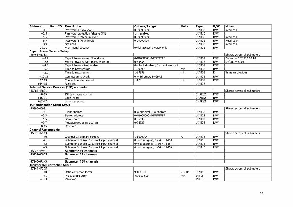
55
Address Point ID Description Options/Range Units Type R/W Notes +0,1 Password 1 (Low level) 0-99999999 UINT32 R/W Read as 0
+2,3 Password protection (always ON) 1 = enabled UINT16 R/W
+4,5 Password 2 (Medium level) 0-99999999 UINT32 R/W Read as 0
+6,7 Password 3 (High level) 0-99999999 UINT32 R/W Read as 0
+8,9 Not used UINT32 R/W Read as 0
+10,11 Front panel security 0=full access, 1=view only UINT32 R/W
Expert Power Service Setup
46768-46783 Shared across all submeters +0,1 Expert Power server IP Address 0x01000000-0xFFFFFFFF UINT32 R/W Default = 207.232.60.18
+2,3 Expert Power server TCP service port 0-65535 UINT32 R/W Default = 5001
+4,5 Expert Power client enabled 0=client disabled, 1=client enabled UINT32 R/W
+6,7 Time to next session 1-99999 min UINT32 R/W
+8,9 Time to next session 1-99999 min UINT32 R Same as previous
+10,11 Connection network 0 = Ethernet, 1=GPRS UINT32 R/W
+12,13 Connection idle timeout 1-120 min UINT32 R/W
+14-15 Reserved UINT32
Internet Service Provider (ISP) accounts
46784-46831 Shared across all submeters +0-15 ISP telephone number CHAR32 R/W
+16-31 Login name CHAR32 R/W
+32-47 Login password CHAR32 R/W
TCP Notification Client Setup
46896-46991 Shared across all submeters +0,1 Client enabled 0 = disabled, 1 = enabled UINT32 R/W
+2,3 Server address 0x01000000-0xFFFFFFFF UINT32 R/W
+4,5 Server port 0-65535 UINT32 R/W
+6,7 Message exchange address 0-65535 UINT32 R/W
+8-15 Reserved
Channel Assignments
46928-47143 Shared across all submeters +0 Channel CT primary current 1-10000 A A UINT16 R/W
+1 Submeter’s phase L1 current input channel 0=not assigned, 1-54 = I1-I54 UINT16 R/W
+2 Submeter’s phase L2 current input channel 0=not assigned, 1-54 = I1-I54 UINT16 R/W
+3 Submeter’s phase L3 current input channel 0=not assigned, 1-54 = I1-I54 UINT16 R/W
46928-46931 Submeter #1 channels
46932-46935 Submeter #2 channels
…
47140-47143 Submeter #54 channels
Transformer Correction Setup
47144-47375 Shared across all submeters +0 Ratio correction factor 900-1100 0.001 UINT16 R/W
+1 Phase angle error -600 to 600 min INT16 R/W
+2, 3 Reserved INT16 R/W

56
Address Point ID Description Options/Range Units Type R/W Notes 47144-47147 V1 transformer correction
47148-47151 V2 transformer correction
47152-47155 V3 transformer correction
47156-47159 Reserved
47160-47163 I1 transformer correction
47164-47167 I2 transformer correction
… …
47372-47375 I54 transformer correction
Submeter ID name Setup
47400-47407 Submeter #1 ID name CHAR16 R/W
47408-47415 Submeter #2 ID name CHAR16 R/W
… … CHAR16 R/W
47824-47831 Submeter #54 ID name CHAR16 R/W
47832-47839 Virtual meter #1 ID name CHAR16 R/W
47840-47847 Virtual meter #2 ID name CHAR16 R/W
… … CHAR16 R/W
47872-47879 Virtual meter #6 ID name CHAR16 R/W
Data Log #1 Setup
54006-55541 Individually configurable for each submeter
+0 Data log parameter #1 ID 0x0000-0xFFFF UINT16 R/W
+1 Data log parameter #2 ID 0x0000-0xFFFF UINT16 R/W
+2 Data log parameter #3 ID 0x0000-0xFFFF UINT16 R/W
+3 Data log parameter #4 ID 0x0000-0xFFFF UINT16 R/W
+4 Data log parameter #5 ID 0x0000-0xFFFF UINT16 R/W
+5 Data log parameter #6 ID 0x0000-0xFFFF UINT16 R/W
+6 Data log parameter #7 ID 0x0000-0xFFFF UINT16 R/W
+7 Data log parameter #8 ID 0x0000-0xFFFF UINT16 R/W
+8 Data log parameter #9 ID 0x0000-0xFFFF UINT16 R/W
+9 Data log parameter #10 ID 0x0000-0xFFFF UINT16 R/W
+10 Data log parameter #11 ID 0x0000-0xFFFF UINT16 R/W
+11 Data log parameter #12 ID 0x0000-0xFFFF UINT16 R/W
+12 Data log parameter #13 ID 0x0000-0xFFFF UINT16 R/W
+13 Data log parameter #14 ID 0x0000-0xFFFF UINT16 R/W
+14 Data log parameter #15 ID 0x0000-0xFFFF UINT16 R/W
+15 Data log parameter #16 ID 0x0000-0xFFFF UINT16 R/W
+16-31 Reserved UINT16 R/W
Data Log #16 (Profile Data Log) Setup
54486-54517 Shared across all submeters 54486-54517 Data log #16 Setup (Energy/TOU daily profile) Auto-configured
TOU Daily Profile Setup
55574-55701 Shared across all submeters +0 1st tariff change F10 UINT16 R/W

57
Address Point ID Description Options/Range Units Type R/W Notes +1 2nd tariff change F10 UINT16 R/W
+2 3rd tariff change F10 UINT16 R/W
+3 4th tariff change F10 UINT16 R/W
+4 5th tariff change F10 UINT16 R/W
+5 6th tariff change F10 UINT16 R/W
+6 7th tariff change F10 UINT16 R/W
+7 8th tariff change F10 UINT16 R/W
55574-55581 Daily profile #1: Season 1, Day type 1
55582-55589 Daily profile #2: Season 1, Day type 2
55590-55597 Daily profile #3: Season 1, Day type 3
55598-55605 Daily profile #4: Season 1, Day type 4
55606-55613 Daily profile #5: Season 2, Day type 1
55614-55621 Daily profile #6: Season 2, Day type 2
55622-55629 Daily profile #7: Season 2, Day type 3
55630-55637 Daily profile #8: Season 2, Day type 4
55638-55645 Daily profile #9: Season 3, Day type 1
55646-55653 Daily profile #10: Season 3, Day type 2
55654-55661 Daily profile #11: Season 3, Day type 3
55662-55669 Daily profile #12: Season 3, Day type 4
55670-55677 Daily profile #13: Season 4, Day type 1
55678-55685 Daily profile #14: Season 4, Day type 2
55686-55693 Daily profile #15: Season 4, Day type 3
55694-55701 Daily profile #16: Season 4, Day type 4
55702-55711 Reserved
TOU Calendar Setup
55712-56031 Shared across all submeters +0-9 Calendar entry record R/W
+0 Daily profile 0-3 = Season 1, Day types 0-3 4-7 = Season 2, Day types 0-3 8-11 = Season 3, Day types 0-3 12-15 = Season 4, Day types 0-3
UINT16 R/W
+1 Week of month 0=all, 1=1st, 2=2nd, 3=3rd, 4=4th, 5=last week of the month
UINT16 R/W
+2 Weekday 0=all, 1-7 (Sun=1, Sat=7) UINT16 R/W
+3 Till Weekday 0=all, 1-7 (Sun=1, Sat=7) UINT16 R/W
+4 Month 0=all, 1-12=January - December UINT16 R/W
+5 Day of month 0=all, 1-31=day 1-31 UINT16 R/W
+6 Till Month 0=all, 1-12=January - December UINT16 R/W
+7 Till Day of month 0=all, 1-31=day 1-31 UINT16 R/W
+8-9 Reserved UINT16 R/W
55712-55721 Calendar entry #1
55722-55731 Calendar entry #2
55732-55741 Calendar entry #3

58
Address Point ID Description Options/Range Units Type R/W Notes …
56022-56031 Calendar entry #32
56032-56191 Reserved
Billing Rates Setup
56192-56200 Not password protected
+0 Register 1 billing rate, total, per unit F15 UINT16 R/W
+1 Register 2 billing rate, total, per unit F15 1 UINT16 R/W
+2 Register 3 billing rate, total, per unit F15 UINT16 R/W
+3 Register 4 billing rate, total, per unit F15 UINT16 R/W
+4 Register 5 billing rate, total, per unit F15 UINT16 R/W
+5 Register 6 billing rate, total, per unit F15 UINT16 R/W
+6 Register 7 billing rate, total, per unit F15 UINT16 R/W
+7 Register 8 billing rate, total, per unit F15 UINT16 R/W
+8 CO2 emission factor kg/kWh
UINT16 R/W
Billing/TOU Registers Setup
56672-56927 Shared across all submeters +0 Not used UINT16 R/W
+1 Units of measurement F15 UINT16 R/W
+2 Flags Bit 0: TOU enabled Bit 1: Use profile enabled Bit 2: Max. Demand profile enabled Bit 3: Summary (total) profile enabled (set automatically)
UINT16 R/W
+3 Not used 0 UINT16 R/W
56672-56675 Register #1 Setup
56676-56679 Register #2 Setup
56680-56683 Register #3 Setup
56684-56687 Register #4 Setup
56688-56691 Register #5 Setup
56692-56695 Register #6 Setup
56696-56699 Register #7 Setup
56700-56703 Register #8 Setup
Billing/TOU Registers Source Setup
56928-57183 Shared across all submeters +0 Energy source ID F11 UINT16 R/W
+1 Target summary register/submeter 0-3=register #1-4, 0x7F00-0x7F3B=submeter #1-#60
UINT16 R/W
+2, 3 Multiplier 0-1000000 0.001 INT32 R/W
56928-56931 Energy Source #1
56932-56935 Energy Source #2
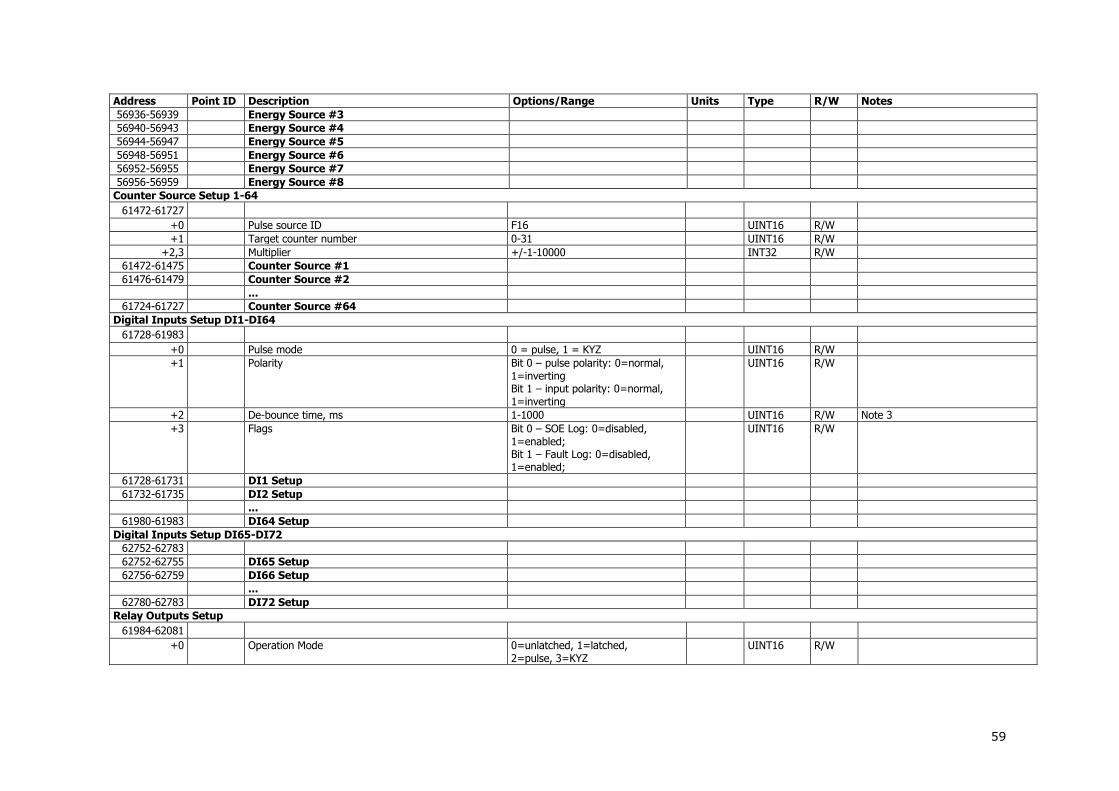
59
Address Point ID Description Options/Range Units Type R/W Notes 56936-56939 Energy Source #3
56940-56943 Energy Source #4
56944-56947 Energy Source #5
56948-56951 Energy Source #6
56952-56955 Energy Source #7
56956-56959 Energy Source #8
Counter Source Setup 1-64
61472-61727
+0 Pulse source ID F16 UINT16 R/W
+1 Target counter number 0-31 UINT16 R/W
+2,3 Multiplier +/-1-10000 INT32 R/W
61472-61475 Counter Source #1
61476-61479 Counter Source #2
...
61724-61727 Counter Source #64
Digital Inputs Setup DI1-DI64
61728-61983
+0 Pulse mode 0 = pulse, 1 = KYZ UINT16 R/W
+1 Polarity Bit 0 – pulse polarity: 0=normal, 1=inverting Bit 1 – input polarity: 0=normal, 1=inverting
UINT16 R/W
+2 De-bounce time, ms 1-1000 UINT16 R/W Note 3
+3 Flags Bit 0 – SOE Log: 0=disabled, 1=enabled; Bit 1 – Fault Log: 0=disabled, 1=enabled;
UINT16 R/W
61728-61731 DI1 Setup
61732-61735 DI2 Setup
...
61980-61983 DI64 Setup
Digital Inputs Setup DI65-DI72
62752-62783
62752-62755 DI65 Setup
62756-62759 DI66 Setup
...
62780-62783 DI72 Setup
Relay Outputs Setup
61984-62081
+0 Operation Mode 0=unlatched, 1=latched, 2=pulse, 3=KYZ
UINT16 R/W
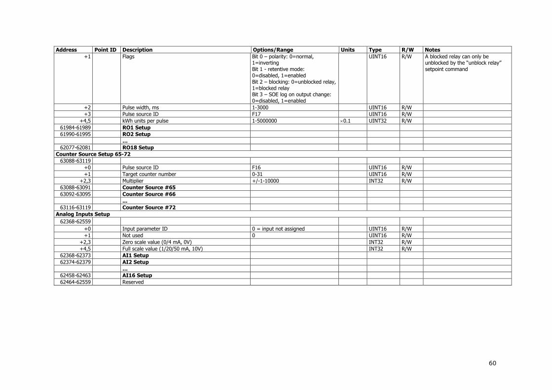
60
Address Point ID Description Options/Range Units Type R/W Notes +1 Flags Bit 0 – polarity: 0=normal,
1=inverting Bit 1 - retentive mode: 0=disabled, 1=enabled Bit 2 – blocking: 0=unblocked relay, 1=blocked relay Bit 3 – SOE log on output change: 0=disabled, 1=enabled
UINT16 R/W A blocked relay can only be unblocked by the “unblock relay” setpoint command
+2 Pulse width, ms 1-3000 UINT16 R/W
+3 Pulse source ID F17 UINT16 R/W
+4,5 kWh units per pulse 1-5000000 0.1 UINT32 R/W
61984-61989 RO1 Setup
61990-61995 RO2 Setup
…
62077-62081 RO18 Setup
Counter Source Setup 65-72
63088-63119
+0 Pulse source ID F16 UINT16 R/W
+1 Target counter number 0-31 UINT16 R/W
+2,3 Multiplier +/-1-10000 INT32 R/W
63088-63091 Counter Source #65
63092-63095 Counter Source #66
...
63116-63119 Counter Source #72
Analog Inputs Setup
62368-62559
+0 Input parameter ID 0 = input not assigned UINT16 R/W
+1 Not used 0 UINT16 R/W
+2,3 Zero scale value (0/4 mA, 0V) INT32 R/W
+4,5 Full scale value (1/20/50 mA, 10V) INT32 R/W
62368-62373 AI1 Setup
62374-62379 AI2 Setup
…
62458-62463 AI16 Setup
62464-62559 Reserved

61
3.10 Expansion I/O Slots Configuration
Address Point ID Description Options/Range Units Type R/W Notes
Expansion I/O Slots Configuration Info
63008-63071 Expansion I/O Slots Configuration Info
+0 I/O module type Bitmap UINT16 R Note 2
+1 Number of I/Os on the slot 0-32 UINT16 R
+2 First I/O number on the slot 0-127 UINT16 R Note 1
+3 Last I/O number on the slot 0-127 UINT16 R Note 1
63008-63011 I/O Slot #1 Configuration
63012-63015 I/O Slot #2 Configuration
63016-63019 I/O Slot #3 Configuration
63020-63023 I/O Slot #4 Configuration
63024-63071 Reserved
Expansion I/O Modules Type Info
63072-63119 Expansion I/O Modules Type Info
+0 Number of I/O modules of this type 0-14 UINT16 R
+1 Total number of I/O's of this type 0-128 UINT16 R
+2 Not used UINT16 R
+3 Not used 0 UINT16 R
63072-63075 DI Module Type Info
63076-63079 RO Module Type Info
63080-63083 AI Module Type Info
63084-63087 AO Module Type Info
63088-63119 Reserved
NOTES:
1. I/O numbers of expansion I/O modules are automatically assigned in the order of connection. The connection order is counted for each I/O module type separately. If the I/O module position is changed but its order in the chain of the modules of the same type is preserved, then all I/Os on the module will retain their I/O numbers. On the dual AI/AO module, both AI and AO will have same logical I/O range.
2. The type of a module in the corresponding slot position, number of I/Os on the module and their I/O numbers can be read through the I/O Slots Configuration Info registers. I/O module type register contains bit-mapped information on the module type and its options in bits D7:D0 as shown in the Table below.

62
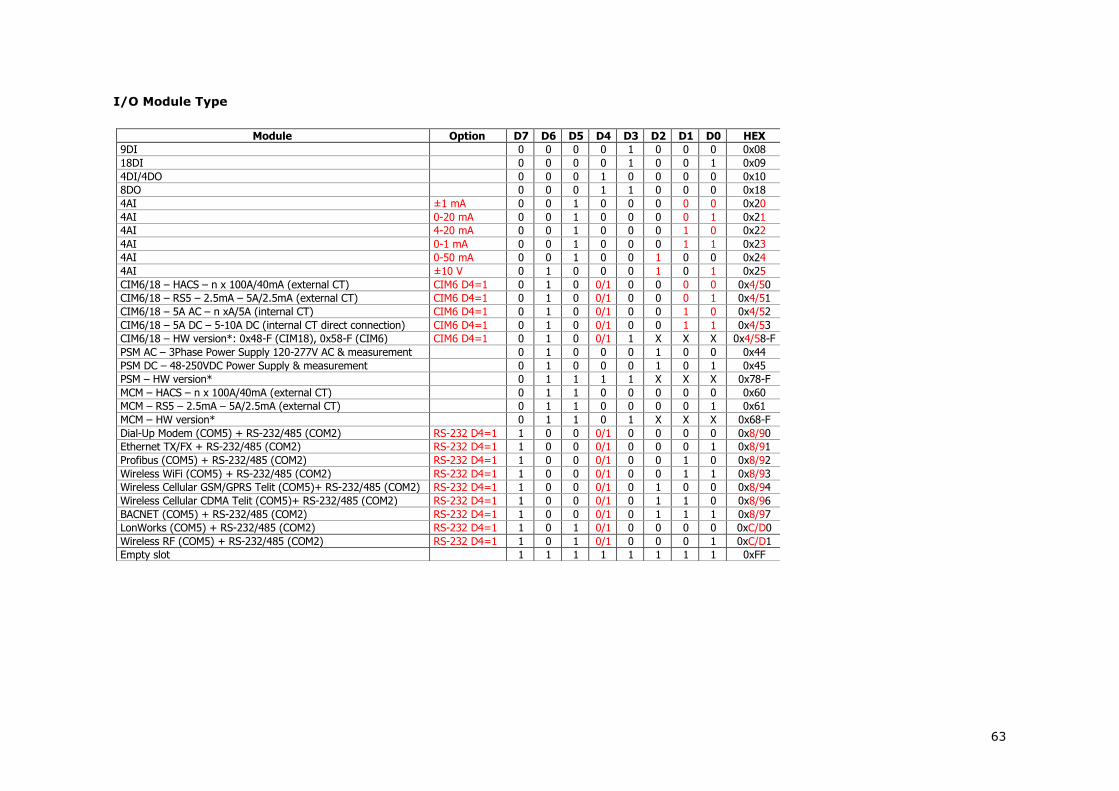
63
I/O Module Type
Module Option D7 D6 D5 D4 D3 D2 D1 D0 HEX 9DI 0 0 0 0 1 0 0 0 0x08 18DI 0 0 0 0 1 0 0 1 0x09 4DI/4DO 0 0 0 1 0 0 0 0 0x10 8DO 0 0 0 1 1 0 0 0 0x18 4AI ±1 mA 0 0 1 0 0 0 0 0 0x20 4AI 0-20 mA 0 0 1 0 0 0 0 1 0x21 4AI 4-20 mA 0 0 1 0 0 0 1 0 0x22 4AI 0-1 mA 0 0 1 0 0 0 1 1 0x23 4AI 0-50 mA 0 0 1 0 0 1 0 0 0x24 4AI ±10 V 0 1 0 0 0 1 0 1 0x25 CIM6/18 – HACS – n x 100A/40mA (external CT) CIM6 D4=1 0 1 0 0/1 0 0 0 0 0x4/50 CIM6/18 – RS5 – 2.5mA – 5A/2.5mA (external CT) CIM6 D4=1 0 1 0 0/1 0 0 0 1 0x4/51 CIM6/18 – 5A AC – n xA/5A (internal CT) CIM6 D4=1 0 1 0 0/1 0 0 1 0 0x4/52 CIM6/18 – 5A DC – 5-10A DC (internal CT direct connection) CIM6 D4=1 0 1 0 0/1 0 0 1 1 0x4/53 CIM6/18 – HW version*: 0x48-F (CIM18), 0x58-F (CIM6) CIM6 D4=1 0 1 0 0/1 1 X X X 0x4/58-F PSM AC – 3Phase Power Supply 120-277V AC & measurement 0 1 0 0 0 1 0 0 0x44 PSM DC – 48-250VDC Power Supply & measurement 0 1 0 0 0 1 0 1 0x45 PSM – HW version* 0 1 1 1 1 X X X 0x78-F MCM – HACS – n x 100A/40mA (external CT) 0 1 1 0 0 0 0 0 0x60 MCM – RS5 – 2.5mA – 5A/2.5mA (external CT) 0 1 1 0 0 0 0 1 0x61 MCM – HW version* 0 1 1 0 1 X X X 0x68-F Dial-Up Modem (COM5) + RS-232/485 (COM2) RS-232 D4=1 1 0 0 0/1 0 0 0 0 0x8/90 Ethernet TX/FX + RS-232/485 (COM2) RS-232 D4=1 1 0 0 0/1 0 0 0 1 0x8/91 Profibus (COM5) + RS-232/485 (COM2) RS-232 D4=1 1 0 0 0/1 0 0 1 0 0x8/92 Wireless WiFi (COM5) + RS-232/485 (COM2) RS-232 D4=1 1 0 0 0/1 0 0 1 1 0x8/93 Wireless Cellular GSM/GPRS Telit (COM5)+ RS-232/485 (COM2) RS-232 D4=1 1 0 0 0/1 0 1 0 0 0x8/94 Wireless Cellular CDMA Telit (COM5)+ RS-232/485 (COM2) RS-232 D4=1 1 0 0 0/1 0 1 1 0 0x8/96 BACNET (COM5) + RS-232/485 (COM2) RS-232 D4=1 1 0 0 0/1 0 1 1 1 0x8/97 LonWorks (COM5) + RS-232/485 (COM2) RS-232 D4=1 1 0 1 0/1 0 0 0 0 0xC/D0 Wireless RF (COM5) + RS-232/485 (COM2) RS-232 D4=1 1 0 1 0/1 0 0 0 1 0xC/D1 Empty slot 1 1 1 1 1 1 1 1 0xFF

64
3.11 File Transfer Blocks
Address Point ID Description Options/Range Units Type R/W Notes File Transfer Control Blocks
63120-63151 File Request Block
+0 File function 1 = ACK - acknowledgement 3 = set file position 5 = reset file position 7 = find 11 = read file
UINT16 R/W 1 - clears the file transfer block 3 - changes the file position 5 - sets the file position at the first (oldest) record 7 - finds a record matching an event or/and time (see Note 3) 11 - opens the file for reading from the present file position
+1 File ID F2 UINT16 R/W
+2 Section number (functions 3, 5, 11) 0-31, 0xFFFF = use channel ID UINT16 R/W
+3 Section channel ID (functions 3, 5, 11) F6, F7 UINT16 R/W
+4 Record sequence number (functions 3, 11) 0-65535 UINT16 R/W The record sequence number with function 11 does not change the file position (see Note 2).
+5 Request variation (function 11) 0 UINT16 R/W See file response headings +6 Find key: N/A UINT16 R/W
+7 Find key: N/A UINT16 R/W
+8,9 Find key: Start time, seconds since 1/1/1970 F1 sec UINT32 R/W Note 3 +10,11 Find key: Start time, fractional seconds in µsec µsec UINT32 R/W Note 3 +12,13 Find key: End time, seconds since 1/1/1970 F1 sec UINT32 R/W Note 3 +14,15 Find key: End time, fractional seconds in µsec µsec UINT32 R/W Note 3 +16-31 Reserved UINT16 R/W
63152-64943 File Response Block
Data transfer area [0 – 1791] UINT16 R
64944-64951 File Info Request Block
+0 File function 9 = read file info UINT16 R/W
+1 File ID F2 UINT16 R/W
+2 Section number 0-31, 0xFFFF = use channel ID UINT16 R/W
+3 Section channel ID F6, F7 UINT16 R/W
+4 Not used 0 UINT16 R/W
+5 Request variation 0, 1, 2 UINT16 R/W
+6-7 Reserved UINT16 R/W
64952-65151 File Info Response Block
Data transfer area [0 - 199] UINT16 R
NOTES:
1. File sections for partitioned (multi-section) files, like Billing/TOU profile log files, can be requested either by a section number, or by a section channel ID. If a section number is set to 0xFFFF, the section channel ID will be used to identify the section. The section number will be returned in the response block. If a section number is written, then the corresponding channel ID will be returned in the file response block.

65
2. The record sequence number with function 11 (Read-File) does not change the file position and is used only as a reference to track the order of records. The file transfer block will continue to hold the same data until it is acknowledged, or until the file position is explicitly moved to another record. For multi-section, the Read-File request, which addresses a different file section, will refill the transfer block with data of the record from the requested file section with the identical sequence number. After acknowledgment, the file position will be moved to the next record.
3. Function 7 (Find) puts into the file request block the sequence number of the first record in the file that matches the event time. Any one of the find keys can be omitted by setting it to 0. If one or a number of find keys are omitted, the device will use the remaining keys to locate the matching record. If the record could not be found, the device responds to the write request with the exception code 3 (illegal data). The status of the operation can be read through the file status word in the file info block.
File Response Blocks
Address Point ID Description Options/Range Units Type R/W Notes File Info Response Block (Variation 0 – File info)
64952-64959 Block Heading
+0 File function 9 UINT16 R
+1 File ID 16 UINT16 R
+2 Section number 0-31 UINT16 R
+3 Section channel ID F6, F7 UINT16 R
+4 Number of records in the block 1 UINT16 R
+5 Record size, words 36 UINT16 R
+6 Request variation 0 UINT16 R
+7 Reserved 0 UINT16 R
64960-64997 File Info
+0 File type 0 UINT16 R
+1 File attributes F3 UINT16 R
+2 File (section) status F4 UNT16 R
+3 Number of sections in the file 0-32 UINT16 R 0 = non-partitioned file +4,5 File channel mask (channels 1-32), bitmap F8, F9 UINT32 R
+6,7 File channel mask (channels 33-64), bitmap F8, F9 UINT32 R
+8 Number of records in the file 0-65535 UINT16 R
+9 Number of records until the end of the file 0-65535 UINT16 R
+10 Current record (read position) sequence number 0-65535 UINT16 R
+11 Current write position sequence number 0-65535 UINT16 R
+12 First (oldest) record sequence number 0-65535 UINT16 R
+13 Last (newest) record sequence number 0-65535 UINT16 R
+14,15 Last record time, seconds since 1/1/1970 F1 sec UINT32 R
+16,17 Last record time, fractional seconds µsec UINT32 R
+18,19 First record time, seconds since 1/1/1970 F1 sec UINT32 R
+20,21 First record time, fractional seconds µsec UINT32 R
+22,23 Not used 0 UINT32 R
+24,25 Not used 0 µsec UINT32 R
+26,27 Not used 0 sec UINT32 R
+28,29 Not used 0 µsec UINT32 R
+30 Maximum number of records 0-65535 UINT16 R
+31 Number of parameters per data section record 0-16 UINT16 R
+32 Section record size, bytes Byte UINT16 R
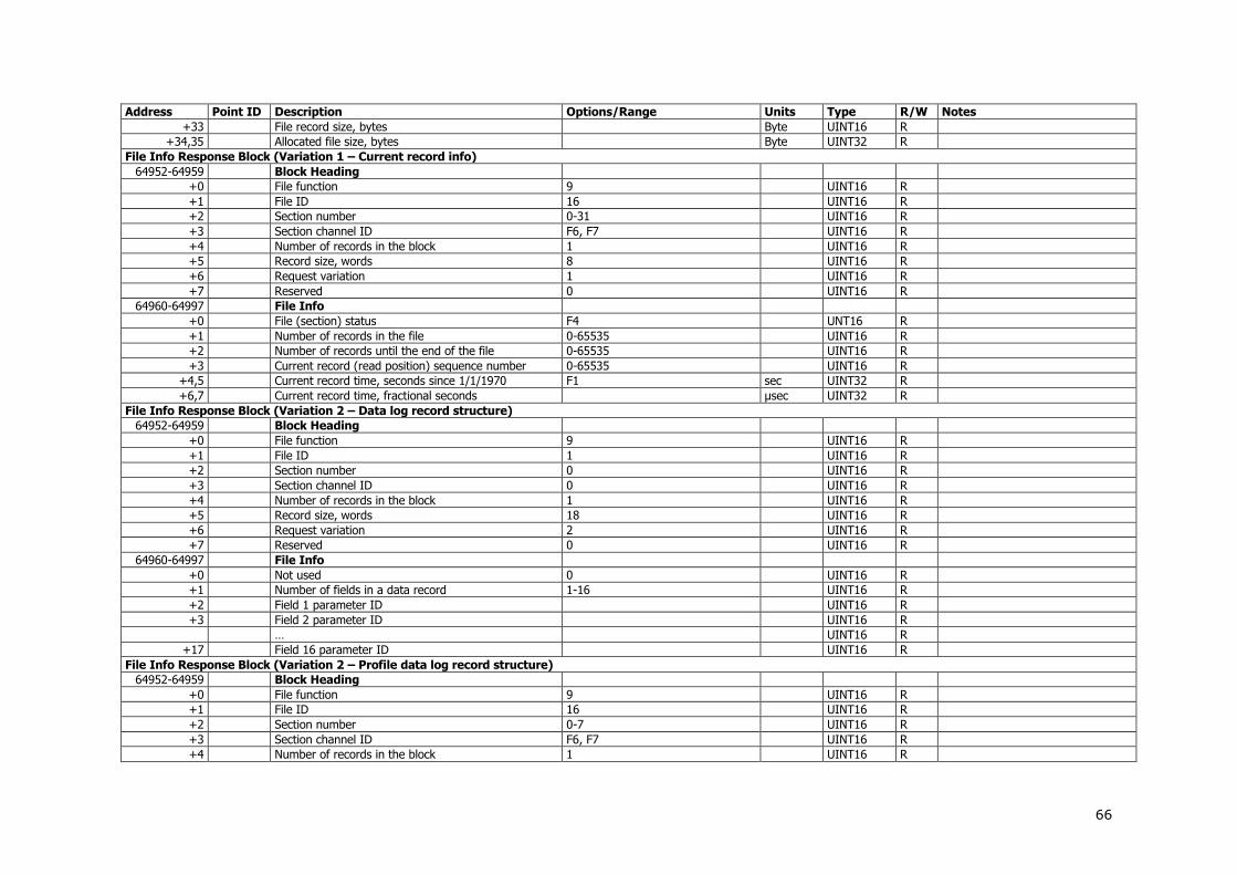
66
Address Point ID Description Options/Range Units Type R/W Notes +33 File record size, bytes Byte UINT16 R
+34,35 Allocated file size, bytes Byte UINT32 R
File Info Response Block (Variation 1 – Current record info)
64952-64959 Block Heading
+0 File function 9 UINT16 R
+1 File ID 16 UINT16 R
+2 Section number 0-31 UINT16 R
+3 Section channel ID F6, F7 UINT16 R
+4 Number of records in the block 1 UINT16 R
+5 Record size, words 8 UINT16 R
+6 Request variation 1 UINT16 R
+7 Reserved 0 UINT16 R
64960-64997 File Info
+0 File (section) status F4 UNT16 R
+1 Number of records in the file 0-65535 UINT16 R
+2 Number of records until the end of the file 0-65535 UINT16 R
+3 Current record (read position) sequence number 0-65535 UINT16 R
+4,5 Current record time, seconds since 1/1/1970 F1 sec UINT32 R
+6,7 Current record time, fractional seconds µsec UINT32 R
File Info Response Block (Variation 2 – Data log record structure)
64952-64959 Block Heading
+0 File function 9 UINT16 R
+1 File ID 1 UINT16 R
+2 Section number 0 UINT16 R
+3 Section channel ID 0 UINT16 R
+4 Number of records in the block 1 UINT16 R
+5 Record size, words 18 UINT16 R
+6 Request variation 2 UINT16 R
+7 Reserved 0 UINT16 R
64960-64997 File Info
+0 Not used 0 UINT16 R
+1 Number of fields in a data record 1-16 UINT16 R
+2 Field 1 parameter ID UINT16 R
+3 Field 2 parameter ID UINT16 R
… UINT16 R
+17 Field 16 parameter ID UINT16 R
File Info Response Block (Variation 2 – Profile data log record structure)
64952-64959 Block Heading
+0 File function 9 UINT16 R
+1 File ID 16 UINT16 R
+2 Section number 0-7 UINT16 R
+3 Section channel ID F6, F7 UINT16 R
+4 Number of records in the block 1 UINT16 R

67
Address Point ID Description Options/Range Units Type R/W Notes +5 Record size, words 18 UINT16 R
+6 Request variation 2 UINT16 R
+7 Reserved 0 UINT16 R
64960-64997 File Info
+0 Not used 0 UINT16
+1 Number of fields in a data record 1-9 UINT16
+2 Field 1 parameter ID 0-0xFFFF UINT16
+3 Field 2 parameter ID 0-0xFFFF UINT16
… UINT16
+10 Field 9 parameter ID 0-0xFFFF UINT16
Event Log Response Block
63152-63159 Block Heading
+0 Last file function 1, 3, 5, 11 UINT16 R
+1 File ID 0 UINT16 R
+2 Section number 0 UINT16 R
+3 Section channel ID 0 UINT16 R
+4 Number of records in the block 1-32 UINT16 R
+5 Record size, words 12 UINT16 R
+6 Request variation 0 UINT16 R
+7 Reserved 0 UINT16 R
63160-63543 Event Log Records
+0 Record status F5 INT16 R
+1 Record sequence number 0-65535 UINT16 R
+2,3 Trigger time, seconds since 1/1/1970 F1 sec UINT32 R
+4,5 Trigger time, fractional seconds in µsec µsec UINT32 R
+6 Event number 1-65535 UINT16 R
+7 Event point/source ID F19 UINT16 R
+8 Event effect F20 UINT16 R
+9 Reserved 0 UINT16 R
+10,11 Value triggered INT32 R
63160-63171 Record #1
...
63532-63543 Record #32
Data Log Response Block
63152-63159 Block Heading
+0 Last file function 1, 3, 5, 11 UINT16 R
+1 File ID 1 UINT16 R
+2 Section number 0 UINT16 R
+3 Section channel ID 0 UINT16 R
+4 Number of records in the block 1-16 UINT16 R
+5 Record size, words 8 + 2 Number of parameters UINT16 R
+6 Request variation 0 UINT16 R
+7 Reserved 0 UINT16 R

68
Address Point ID Description Options/Range Units Type R/W Notes 63160-64439 Data Log Records
+0 Record status F5 INT16 R
+1 Record sequence number 0-65535 UINT16 R
+2,3 Record time, seconds since 1/1/1970 F1 sec UINT32 R
+4,5 Record time, fractional seconds in µsec µsec UINT32 R
+6 Trigger event type F22 INT16 R
+7 Trigger event number 0 UINT16 R
+8,9 Log value #1 INT32 R
+10,11 Log value #2 INT32 R
… R
63160-… Record #1 (variable length)
...
Record #16 (variable length)
Profile Data Log Response Block
63152-63159 Block Heading
+0 Last file function 1, 3, 5, 11 UINT16 R
+1 File ID 16 UINT16 R
+2 Section number 0-7 UINT16 R
+3 Section channel ID F6 UINT16 R
+4 Number of records in the block 1-16 UINT16 R
+5 Record size, words 10-18 UINT16 R
+6 Request variation 0 UINT16 R
+7 Reserved 0 UINT16 R
63160-64439 Data Log Records
+0 Record status F5 INT16 R
+1 Record sequence number 0 - 65535 UINT16 R
+2,3 Record time, seconds since 1/1/1970 F1 sec UINT32 R
+4,5 Record time, fractional seconds in µsec µsec UINT32 R
+6 Trigger event type 0 INT16 R
+7 Trigger event number 0 UINT16 R
+8,9 Log value #1 Total (summary) register INT32 R
+10,11 Log value #2 Tariff #1 register INT32 R
+12,13 Log value #3 Tariff #2 register INT32 R
+14,15 Log value #4 Tariff #3 register INT32 R
+16,17 Log value #5 Tariff #4 register INT32 R
+18,19 Log value #6 Tariff #5 register INT32 R
+20,21 Log value #7 Tariff #6 register INT32 R
+22,23 Log value #7 Tariff #5 register INT32 R
+24,25 Log value #8 Tariff #6 register INT32 R
63160-… Record #1 (variable length)
...
Record #16 (variable length)
RT Waveform Response Block (as EM133-R)

69
Address Point ID Description Options/Range Units Type R/W Notes 63152-63159 Block Heading
+0 Last file function 1, 3, 5, 11 UINT16 R
+1 File ID 128 UINT16 R
+2 Section number 0-9 UINT16 R
+3 Section channel ID F7 UINT16 R
+4 Maximum number of records in the block 1 UINT16 R
+5 Record size, words 640 UINT16 R
+6 Request variation 0 UINT16 R
+7 Reserved 0 UINT16 R
63160-63799 Waveform Record
+0 Record status F5 INT16 R
+1 Record sequence number 0 UINT16 R
+2,3 Start time, seconds since 1/1/1970 F1 sec UINT32 R
+4,5 Start time, fractional seconds µsec UINT32 R
+6,7 Trigger time, seconds since 1/1/1970 F1 sec UINT32 R
+8,9 Trigger time, fractional seconds µsec UINT32 R
+10 Record series number 1-65535 UINT16 R
+11 Record serial number in a series 0-65535 UINT16 R
+12 Trigger event type 0 UINT16 R
+13 Trigger event number 0 UINT16 R
+14 Source point ID (generic) See Generic Data in Section 3.4 UINT16 R
+15 Trigger reference sample index 0–511 UINT16 R
+16 Sampling rate, µsec/sample 600-27000 0.1µsec
UINT16 R
+17 Sampling rate, samples/cycle 32, 64, 128 UINT16 R
+18 Sampling frequency 4500 – 6500 0.01Hz
UINT16 R
+19 Channel offset, sampling units 0 INT16 R
+20,21 Channel multiplier, primary units See Generic Data in Section 3.4 UINT32 R
+22 Channel divisor, sampling units 4095 UINT16 R
+23 Length of a sample series, data points 512 UINT16 R
+24-127 Not used 0 UINT16 R
+128 Sample Series
+128-639 Sample data series points [0...511] -4096 - 4095 INT16 R 1
1 To restore the original sampled data in the channel units (e.g., Volts, Amps), the following conversion should be applied:
DivisorChannel
MultiplierChannel)OffsetChannelSampleData(]unitsprimary[DataSampled

70
NOTE:
If you read the block through a TCP connection and change a file ID or the number of records in the block, your assignments for the transfer block will be effective only within the current connection socket. Since the device cannot guarantee that your next connection will be made through the same socket, you should not make any assumptions regarding the present block settings. When you open a new connection, always check the block heading before accessing data records.
3.12 Billing/TOU Daily Profile Data Log
File Channel/Section 1
Record Field No. 2
Point Label Point ID
Description Range Units 3 Type Notes
0/0 Energy Register #1
1 REG1 0x1780 Summary (total) energy reading 0-999,999,999 U4 UINT32
2 TRF1 0x7000 Tariff #1 energy reading 0-999,999,999 U4 UINT32
3 TRF2 0x7001 Tariff #2 energy reading 0-999,999,999 U4 UINT32
4 TRF3 0x7002 Tariff #3 energy reading 0-999,999,999 U4 UINT32
5 TRF4 0x7003 Tariff #4 energy reading 0-999,999,999 U4 UINT32
6 TRF5 0x7004 Tariff #5 energy reading 0-999,999,999 U4 UINT32
7 TRF6 0x7005 Tariff #6 energy reading 0-999,999,999 U4 UINT32
8 TRF7 0x7006 Tariff #7 energy reading 0-999,999,999 U4 UINT32
9 TRF8 0x7007 Tariff #8 energy reading 0-999,999,999 U4 UINT32
… …
7/7 Energy Register #8
1 REG8 0x1787 Summary (total) energy reading 0-999,999,999 U4 UINT32
2 TRF1 0x7000 Tariff #1 energy reading 0-999,999,999 U4 UINT32
3 TRF2 0x7001 Tariff #2 energy reading 0-999,999,999 U4 UINT32
4 TRF3 0x7002 Tariff #3 energy reading 0-999,999,999 U4 UINT32
5 TRF4 0x7003 Tariff #4 energy reading 0-999,999,999 U4 UINT32
6 TRF5 0x7004 Tariff #5 energy reading 0-999,999,999 U4 UINT32
7 TRF6 0x7005 Tariff #6 energy reading 0-999,999,999 U4 UINT32
8 TRF7 0x7006 Tariff #7 energy reading 0-999,999,999 U4 UINT32
9 TRF8 0x7007 Tariff #8 energy reading 0-999,999,999 U4 UINT32
16/4 Daily Maximum Demand Register #1
1 REG1 MD 0x4780 Summary (total) max. demand reading 0-Pmax U3 UINT32
2 TRF1 MD 0x7100 Tariff #1 max. demand reading 0-Pmax U3 UINT32
3 TRF2 MD 0x7101 Tariff #2 max. demand reading 0-Pmax U3 UINT32
4 TRF3 MD 0x7102 Tariff #3 max. demand reading 0-Pmax U3 UINT32
5 TRF4 MD 0x7103 Tariff #4 max. demand reading 0-Pmax U3 UINT32
6 TRF5 MD 0x7104 Tariff #5 max. demand reading 0-Pmax U3 UINT32
7 TRF6 MD 0x7105 Tariff #6 max. demand reading 0-Pmax U3 UINT32
8 TRF7 MD 0x7106 Tariff #7 max. demand reading 0-Pmax U3 UINT32
9 TRF8 MD 0x7107 Tariff #8 max. demand reading 0-Pmax U3 UINT32
… …

71
File Channel/Section 1
Record Field No. 2
Point Label Point ID
Description Range Units 3 Type Notes
23/11 Daily Maximum Demand Register #8
1 REG8 MD 0x4787 Summary (total) max. demand reading 0-Pmax U3 UINT32
2 TRF1 MD 0x7100 Tariff #1 max. demand reading 0-Pmax U3 UINT32
3 TRF2 MD 0x7101 Tariff #2 max. demand reading 0-Pmax U3 UINT32
4 TRF3 MD 0x7102 Tariff #3 max. demand reading 0-Pmax U3 UINT32
5 TRF4 MD 0x7103 Tariff #4 max. demand reading 0-Pmax U3 UINT32
6 TRF5 MD 0x7104 Tariff #5 max. demand reading 0-Pmax U3 UINT32
7 TRF6 MD 0x7105 Tariff #6 max. demand reading 0-Pmax U3 UINT32
8 TRF7 MD 0x7106 Tariff #7 max. demand reading 0-Pmax U3 UINT32
9 TRF8 MD 0x7107 Tariff #8 max. demand reading 0-Pmax U3 UINT32
1 An energy use profile section is allocated for registers for which a source input is selected in the Billing/TOU Register setup and for which energy use profile is enabled. A maximum
demand profile section is allocated for registers for which maximum demand profile is enabled in the Billing/TOU Register setup. Not configured sections/channels are not available for download. Refer to the file channel mask in the file info for configured channels.
2 The number of parameters in a section is automatically configured depending on the number of actually used tariffs selected in the TOU Daily Profiles.
3 For power scale and units, refer to Section 4 ”Data Scales and Units”.

72
4. Data Scales and Units
Code Condition Value/Range Notes
Data Scales
Vmax Voltage scale PT Ratio, V 1 Imax CT Primary current 2, A
Pmax Vmax Imax 2, W 2 Data Units
U1 PT Ratio = 1 0.1 V
PT Ratio > 1 1 V
U2 0.01 A
U3 PT Ratio = 1 0.001 kW/kvar/kVA
PT Ratio > 1 1 kW/kvar/kVA
U4 10-d x register measurement unit (see F15 in Section 5). d = 0-4 –number of decimal places for energy registers (see Device Options Setup)
1 The default Voltage scale is 600V. You can change it via the Device Data Scale setup (see Section 3.1) or via the Device Options setup in PAS.
2 Pmax is rounded to whole kilowatts. With PT=1.0, if Pmax is greater than 9,999,000 W, it is truncated to 9,999,000 W.

73
5. Data Formats
Format Code
Value Description Notes
Timestamp
F1 Local time in a UNIX-style format. Represents the number of seconds since midnight (00:00:00), January 1, 1970. The time is valid after January 1, 2000.
File ID
F2 0 Event log
1 Data log
16 Daily profile log file
File Attributes
F3 Bit 0 0=Non-wrap (stop when filled), 1=Wrap-around (circular file)
Bit 5 = 1 TOU daily profile log
File Status Word
F4 Bit 0 = 1 The last record of the file is being read
Bit 8 = 1 File is empty
Bit 9 = 1 Reading after EOF
Bit 10 = 1 Corrupted record (CRC error)
Bit 11 = 1 No file section found for the requested channel
Bit 12 = 1 Reading after the end of a data block
Bit 13 = 1 File is not accessible
Bit 14 = 1 Record not found
Bit 15 = 1 Generic read error (with one of the bits 8-14)
File Record Status Word
F5 Bit 0 = 1 The last record of the file is being read
Bit 8 = 1 File is empty
Bit 9 = 1 Reading after EOF
Bit 10 = 1 Corrupted record (CRC error)
Bit 11 = 1 No file section found for the requested channel
Bit 12 = 1 Reading after the end of a data block
Bit 13 = 1 File is not accessible
Bit 14 = 1 Record not found
Bit 15 = 1 Generic read error (with one of the bits 8-14)
Billing/TOU Profile Log Channel ID
F6 0-7 Billing/TOU energy registers #1-#8
16-23 Billing/TOU maximum demand registers #1-#8
Waveform Log Channel ID
F7 0 V1/V12
1 V2/V23
2 V3/V31
4 I1
5 I2
6 I3
Billing/TOU Profile Log Channel Mask
F8 Bit 0:15 = 1 Billing/TOU energy registers #1-#8
Bit 16:31 = 1 Billing/TOU maximum demand registers #1-#8
Waveform Channel Mask
F9 Bit 0 = 1 Channel V1/V12
Bit 1 = 1 Channel V2/V23
Bit 2 = 1 Channel V3/V31
Bit 3 = 1 N/A
Bit 4 = 1 Channel I1
Bit 5 = 1 Channel I2
Bit 6 = 1 Channel I3
TOU Tariff Change Time
F10 Bits 8:15 = 0-7 Tariff number #1-#8
Bits 2:7 = 0-23 Tariff start hour
Bits 0:1 = 0-3 Tariff start quarter of an hour
Billing Register Source ID
F11 0x0000 None
0x0700-0x0747 Pulse input DI1-DI72
0x1700 kWh import
0x1701 kWh export
0x1704 kvarh import
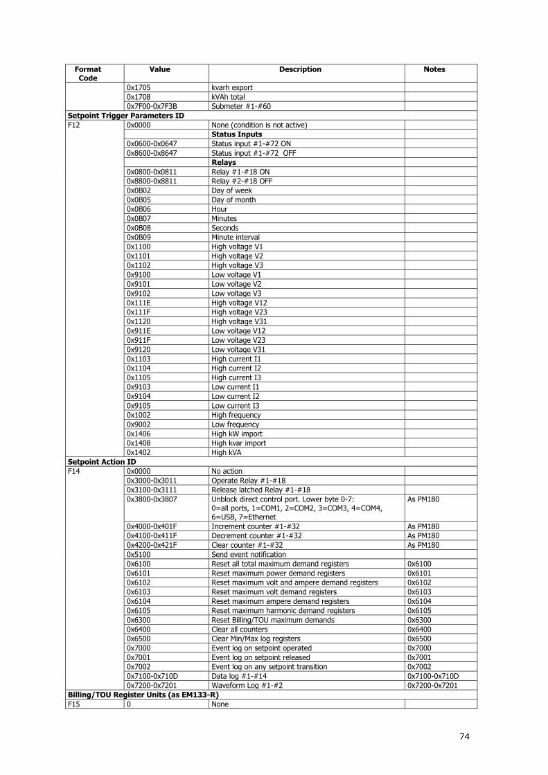
74
Format Code
Value Description Notes
0x1705 kvarh export
0x1708 kVAh total
0x7F00-0x7F3B Submeter #1-#60
Setpoint Trigger Parameters ID
F12 0x0000 None (condition is not active)
Status Inputs
0x0600-0x0647 Status input #1-#72 ON
0x8600-0x8647 Status input #1-#72 OFF
Relays
0x0800-0x0811 Relay #1-#18 ON
0x8800-0x8811 Relay #2-#18 OFF
0x0B02 Day of week
0x0B05 Day of month
0x0B06 Hour
0x0B07 Minutes
0x0B08 Seconds
0x0B09 Minute interval
0x1100 High voltage V1
0x1101 High voltage V2
0x1102 High voltage V3
0x9100 Low voltage V1
0x9101 Low voltage V2
0x9102 Low voltage V3
0x111E High voltage V12
0x111F High voltage V23
0x1120 High voltage V31
0x911E Low voltage V12
0x911F Low voltage V23
0x9120 Low voltage V31
0x1103 High current I1
0x1104 High current I2
0x1105 High current I3
0x9103 Low current I1
0x9104 Low current I2
0x9105 Low current I3
0x1002 High frequency
0x9002 Low frequency
0x1406 High kW import
0x1408 High kvar import
0x1402 High kVA
Setpoint Action ID
F14 0x0000 No action
0x3000-0x3011 Operate Relay #1-#18
0x3100-0x3111 Release latched Relay #1-#18
0x3800-0x3807 Unblock direct control port. Lower byte 0-7: 0=all ports, 1=COM1, 2=COM2, 3=COM3, 4=COM4, 6=USB, 7=Ethernet
As PM180
0x4000-0x401F Increment counter #1-#32 As PM180
0x4100-0x411F Decrement counter #1-#32 As PM180
0x4200-0x421F Clear counter #1-#32 As PM180
0x5100 Send event notification
0x6100 Reset all total maximum demand registers 0x6100
0x6101 Reset maximum power demand registers 0x6101
0x6102 Reset maximum volt and ampere demand registers 0x6102
0x6103 Reset maximum volt demand registers 0x6103
0x6104 Reset maximum ampere demand registers 0x6104
0x6105 Reset maximum harmonic demand registers 0x6105
0x6300 Reset Billing/TOU maximum demands 0x6300
0x6400 Clear all counters 0x6400
0x6500 Clear Min/Max log registers 0x6500
0x7000 Event log on setpoint operated 0x7000
0x7001 Event log on setpoint released 0x7001
0x7002 Event log on any setpoint transition 0x7002
0x7100-0x710D Data log #1-#14 0x7100-0x710D
0x7200-0x7201 Waveform Log #1-#2 0x7200-0x7201
Billing/TOU Register Units (as EM133-R)
F15 0 None

75
Format Code
Value Description Notes
1 kWh
2 kvarh
3 kVAh
4 m3
5 CF (cubic feet)
6 CCF (hundred cubic feet)
7 kL
8 MJ
Counter Source ID
F16 0x0000 None
0x0700-0x0747 Pulse input DI1-DI72
Relay Output Pulse Source ID
F17 0x0000 None
0x0400 kWh Import pulse
0x0401 kWh Export pulse
0x0402 kWh Total pulse
0x0403 kvarh Import pulse
0x0404 kvarh Export pulse
0x0405 kvarh Total pulse
0x0406 kVAh pulse
0x0407 Start of power demand interval pulse
0x0408 Start of tariff interval pulse
Event Source/Point ID
F19 Setpoint Operation Events
0x0000-0x59FF Trigger parameter ID
0x6400-0xFFFF Trigger parameter ID
Setpoint Action Events
0x5A00-0x5A0F Setpoint #1-#16
Communications Events
0x5B00-0x5BFF Data/Function point ID (low byte, see F21)
Self-Check Diagnostics Events
0x5D00-0x5DFF Data/Function point ID (low byte, see F21)
Self-Update Events
0x5E08 RTC DST/Standard time update
Run-time Error
0x6014 Library error
0x6015 RTOS Kernel error
0x6016 Task error
Hardware Diagnostics Events 0x6201 Permanent fault
0x6202 RAM/Data error
0x6203 CPU watchdog reset
0x6204 DSP/Sampling fault
0x6205 CPU exception
0x6206 Reserved
0x6207 Software watchdog reset
0x620E Expanded memory fault (Event effect = File ID + 1)
0x620F CPU EEPROM fault
0x6210 AC board EEPROM fault
0x6211 I/O board EEPROM fault
External Events
0x6300 Power down 0x6308 Power up
0x6309 External reset
0x6320 SNTP server failed 4
0x6321 SNTP server reconnected 4
Event Effect ID
F20 Communications/Self-check Events
0x0000 None
0x6000 Total energy registers cleared
0x6100 Maximum demands cleared
0x6101 Power maximum demands cleared
0x6102 Volt/Ampere maximum demands cleared
0x6103 Volt maximum demands cleared
0x6104 Ampere maximum demands cleared
0x6200 TOU energy registers cleared

76
Format Code
Value Description Notes
0x6300 TOU demand registers cleared
0x6A00-0x6A10 Log file cleared (low byte = File ID)
0x6B06 Communication counters cleared
0xF100-0xF10F Setpoint cleared (low byte = setpoint ID)
0xF200 Setup/Data cleared
0xF300 Setup reset (set by default)
0xF400 Setup changed
0xF500 RTC set
Setpoint Operation Events
0xE100-0xE11F Setpoint operated (low byte = setpoint ID)
0xE200-0xE21F Setpoint released (low byte = setpoint ID)
Setpoint Action Events
See F14 Setpoint action ID
Data/Function Point ID
F21 Data Location
0x03 Data memory
0x04 Factory setup
0x05 Access/Password setup
0x06 Basic setup
0x07 Communications setup
0x08 Real-time clock
0x09 Digital inputs setup
0x0E Timers setup
0x10 Event/alarm setpoints
0x12 User assignable register map
0x14 Data log setup
0x15 File/Memory setup
0x16 TOU energy registers setup
0x18 TOU daily profiles
0x19 TOU calendar
0x1D RO Setup
0x1C User selectable options
0x23 Calibration registers
0x24 Date/Time Setup
0x25 Net setup
0x2A Device mode control
0x2B Channels setup
0x2B-0x3F Reserved
Event Type ID
F22 0x0000 SP: Generic setpoint event
0x0001-0x0010 SP1-SP16: Setpoint #1-#16 event
Device Diagnostics
F23
Bit 0 = 1 Critical error
Bit 1 = 1 Permanent fault (critical error)
Bit 2 = 1 RAM/Data error
Bit 3 = 1 CPU watchdog reset
Bit 4 = 1 DSP/Sampling fault
Bit 5 = 1 CPU exception
Bit 6 Reserved
Bit 7 = 1 Software watchdog reset
Bit 8 = 1 Power down
Bit 9 = 1 Device reset
Bit 10 = 1 Configuration reset
Bit 11 = 1 RTC fault (critical error)
Bit 12 = 1 Configuration fault (critical error)
Bit 13 Reserved
Bit 14 = 1 Expanded memory fault
Bit 15 = 1 CPU EEPROM fault
Bit 16 = 1 AC board EEPROM fault
Bit 17 = 1 I/O board EEPROM fault
Bit 18 Reserved
Bit 19 Reserved
Bit 20 = 1 C Library error
Bit 21 = 1 RTOS Kernel error
Bit 22 = 1 Task error
Bit 23 Reserved

77
4 The event value field shows the server IP address in a network byte order

78
6. BFM II Parameters for Data Monitoring and Logging
The following table lists parameters measured by the meter that are available for data logging and monitoring through communications for each feeder. The left column shows data abbreviations used in PAS. Parameter groups are highlighted in bold.
Energy and PWR DMD import is calculated and registered Only if defined (TOU and data log)
Designation Description NONE None (stub, read as zero) RT PHASE 1-Cycle Phase Values V1 V1 V2 V2 V3 V3 I1 I1 Current I2 I2 Current I3 I3 Current Power and PF with sign
kW L1 kW L1 kW L2 kW L2 kW L3 kW L3 kvar L1 kvar L1 kvar L2 kvar L2 kvar L3 kvar L3 kVA L1 kVA L1 kVA L2 kVA L2 kVA L3 kVA L3 PF L1 Power factor L1 PF L2 Power factor L2 PF L3 Power factor L3 V12 V12 Voltage V23 V23 Voltage V31 V31 Voltage RT TOTAL 1-Cycle Total Values kW Total kW kvar Total kvar kVA Total kVA PF Total PF RT AUX 1-Cycle Auxiliary Values V UNB% Voltage unbalance 2 In In (neutral) Current 3 FREQ Frequency AVR PHASE 1-Second Phase Values 1 V1 V1 Voltage V2 V2 Voltage V3 V3 Voltage I1 I1 Current I2 I2 Current I3 I3 Current Power and PF with sign
kW L1 kW L1 kW L2 kW L2 kW L3 kW L3 kvar L1 kvar L1 kvar L2 kvar L2 kvar L3 kvar L3

79
Designation Description kVA L1 kVA L1 kVA L2 kVA L2 kVA L3 kVA L3 PF L1 Power factor L1 PF L2 Power factor L2 PF L3 Power factor L3 V12 V12 Voltage V23 V23 Voltage V31 V31 Voltage AVR TOTAL 1-Second Total Values 1 kW Total kW kvar Total kvar kVA Total kVA PF Total PF Power and PF with sign
AVR AUX 1-Second Auxiliary Values 1 V UNB% Voltage unbalance 2 In In (neutral) Current 3 FREQ Frequency DEMANDS Present Demands 1 V1 DMD V1 Volt demand V2 DMD V2 Volt demand V3 DMD V3 Volt demand I1 DMD I1 Ampere demand I2 DMD I2 Ampere demand I3 DMD I3 Ampere demand kW IMP SD kW import sliding window demand kvar IMP SD kvar import sliding window demand kVA IMP SD kVA import sliding window demand kW IMP ACC DMD kW import accumulated demand kvar IMP ACC DMD kvar import accumulated demand kVA IMP ACC DMD kVA import accumulated demand kW IMP PRD DMD kW import predicted sliding window demand kvar IMP PRD DMD kvar import predicted sliding window demand kVA IMP PRD DMD kVA import predicted sliding window demand kW EXP SD kW Export sliding window demand kvar EXP SD kvar Export sliding window demand kVA EXP SD kVA Export sliding window demand kW EXP ACC DMD kW Export accumulated demand kvar EXP ACC DMD kvar Export accumulated demand kVA EXP ACC DMD kVA Export accumulated demand kW EXP PRD DMD kW Export predicted sliding window demand kvar EXP PRD DMD kvar Export predicted sliding window demand kVA EXP PRD DMD kVA Export predicted sliding window demand SUMM ACC DMD Summary (TOU Total) Accumulated Demands SUM REG1 ACC DMD Summary register #1 demand SUM REG2 ACC DMD Summary register #2 demand SUM REG3 ACC DMD Summary register #3 demand SUM REG4 ACC DMD Summary register #4 demand SUMM SW DMD Summary (TOU Total) Sliding Demands 1 SUM REG1 SW DMD Summary register #1 demand SUM REG2 SW DMD Summary register #2 demand SUM REG3 SW DMD Summary register #3 demand SUM REG4 SW DMD Summary register #4 demand ENERGY Submeter Energy 1 kWh IMP kWh import kvarh IMP kvarh import kVAh IMP kVAh import kWh EXP kWh export kvarh EXP kvarh export

80
Designation Description kVAh EXP kVAh export KWh NET KWh netto Kvarh NET Kvarh netto KVAh TOT KVAh total SUMMARY REGS Summary (TOU Total) Energy Registers 1 SUM REG1 Summary energy register #1 SUM REG2 Summary energy register #2 SUM REG3 Summary energy register #3 SUM REG4 Summary energy register #4 SUM REG5 Summary energy register #5 SUM REG6 Summary energy register #6 SUM REG7 Summary energy register #7 SUM REG8 Summary energy register #8 MAX DMD Maximum Demands V1 DMD MAX V1 Maximum volt demand V2 DMD MAX V2 Maximum volt demand V3 DMD MAX V3 Maximum volt demand I1 DMD MAX I1 Maximum ampere demand I2 DMD MAX I2 Maximum ampere demand I3 DMD MAX I3 Maximum ampere demand kW IMP SD MAX Maximum kW import sliding window demand kW EXP SD MAX Maximum kW export sliding window demand kvar IMP SD MAX Maximum kvar import sliding window demand kvar EXP SD MAX Maximum kvar export sliding window demand kVA IMP SD MAX Maximum kVA import sliding window demand kVA EXP SD MAX Maximum kVA export sliding window demand MAX SUMMARY DMD Maximum Summary (TOU Total) Demands SUM REG1 DMD MAX Summary register #1 maximum demand SUM REG2 DMD MAX Summary register #2 maximum demand SUM REG3 DMD MAX Summary register #3 maximum demand SUM REG4 DMD MAX Summary register #4 maximum demand SUM REG5 DMD MAX Summary register #5 maximum demand SUM REG6 DMD MAX Summary register #6 maximum demand SUM REG7 DMD MAX Summary register #7 maximum demand SUM REG8 DMD MAX Summary register #8 maximum demand TOU PRMS TOU Parameters ACTIVE TARIFF Active TOU tariff ACTIVE PROFILE Active TOU profile TOU REG1 TOU Energy Register #1 1 – (8 tariffs) TOU REG1 TRF1 Tariff #1 register TOU REG1 TRF2 Tariff #2 register TOU REG1 TRF3 Tariff #3 register TOU REG1 TRF4 Tariff #4 register TOU REG1 TRF5 Tariff #5 register TOU REG1 TRF6 Tariff #6 register TOU REG1 TRF7 Tariff #7 register TOU REG1 TRF8 Tariff #8 register TOU REG2 TOU Energy Register #2 1 TOU REG2 TRF1 Tariff #1 register TOU REG2 TRF2 Tariff #2 register TOU REG2 TRF3 Tariff #3 register TOU REG2 TRF4 Tariff #4 register TOU REG2 TRF5 Tariff #5 register TOU REG2 TRF6 Tariff #6 register TOU REG2 TRF7 Tariff #7 register TOU REG2 TRF8 Tariff #8 register TOU REG3 TOU Energy Register #3 1 TOU REG3 TRF1 Tariff #1 register TOU REG3 TRF2 Tariff #2 register TOU REG3 TRF3 Tariff #3 register TOU REG3 TRF4 Tariff #4 register TOU REG3 TRF5 Tariff #5 register TOU REG3 TRF6 Tariff #6 register TOU REG3 TRF7 Tariff #7 register TOU REG3 TRF8 Tariff #8 register TOU REG4 TOU Energy Register #4 1 TOU REG4 TRF1 Tariff #1 register

81
Designation Description TOU REG4 TRF2 Tariff #2 register TOU REG4 TRF3 Tariff #3 register TOU REG4 TRF4 Tariff #4 register TOU REG4 TRF5 Tariff #5 register TOU REG4 TRF6 Tariff #6 register TOU REG4 TRF7 Tariff #7 register TOU REG4 TRF8 Tariff #8 register TOU REG5 TOU Energy Register #5 1 TOU REG5 TRF1 Tariff #1 register TOU REG5 TRF2 Tariff #2 register TOU REG5 TRF3 Tariff #3 register TOU REG5 TRF4 Tariff #4 register TOU REG5 TRF5 Tariff #5 register TOU REG5 TRF6 Tariff #6 register TOU REG5 TRF7 Tariff #7 register TOU REG5 TRF8 Tariff #8 register TOU REG6 TOU Energy Register #6 1 TOU REG6 TRF1 Tariff #1 register TOU REG6 TRF2 Tariff #2 register TOU REG6 TRF3 Tariff #3 register TOU REG6 TRF4 Tariff #4 register TOU REG6 TRF5 Tariff #5 register TOU REG6 TRF6 Tariff #6 register TOU REG6 TRF7 Tariff #7 register TOU REG6 TRF8 Tariff #8 register TOU REG7 TOU Energy Register #7 1 TOU REG7 TRF1 Tariff #1 register TOU REG7 TRF2 Tariff #2 register TOU REG7 TRF3 Tariff #3 register TOU REG7 TRF4 Tariff #4 register TOU REG7 TRF5 Tariff #5 register TOU REG7 TRF6 Tariff #6 register TOU REG7 TRF7 Tariff #7 register TOU REG7 TRF8 Tariff #8 register TOU REG8 TOU Energy Register #8 1 TOU REG8 TRF1 Tariff #1 register TOU REG8 TRF2 Tariff #2 register TOU REG8 TRF3 Tariff #3 register TOU REG8 TRF4 Tariff #4 register TOU REG8 TRF5 Tariff #5 register TOU REG8 TRF6 Tariff #6 register TOU REG8 TRF7 Tariff #7 register TOU REG8 TRF8 Tariff #8 register TOU MAX DMD REG1 TOU Maximum Demand Register #1 1 DMD1 TRF1 MAX Tariff #1 register DMD1 TRF2 MAX Tariff #2 register DMD1 TRF3 MAX Tariff #3 register DMD1 TRF4 MAX Tariff #4 register DMD1 TRF5 MAX Tariff #5 register DMD1 TRF6 MAX Tariff #6 register DMD1 TRF7 MAX Tariff #7 register DMD1 TRF8 MAX Tariff #8 register TOU MAX DMD REG2 TOU Maximum Demand Register #2 1 DMD2 TRF1 MAX Tariff #1 register DMD2 TRF2 MAX Tariff #2 register DMD2 TRF3 MAX Tariff #3 register DMD2 TRF4 MAX Tariff #4 register DMD2 TRF5 MAX Tariff #5 register DMD2 TRF6 MAX Tariff #6 register DMD2 TRF7 MAX Tariff #7 register DMD2 TRF8 MAX Tariff #8 register TOU MAX DMD REG3 TOU Maximum Demand Register #3 1 DMD3 TRF1 MAX Tariff #1 register DMD3 TRF2 MAX Tariff #2 register DMD3 TRF3 MAX Tariff #3 register DMD3 TRF4 MAX Tariff #4 register DMD3 TRF5 MAX Tariff #5 register

82
Designation Description DMD3 TRF6 MAX Tariff #6 register DMD3 TRF7 MAX Tariff #7 register DMD3 TRF8 MAX Tariff #8 register TOU MAX DMD REG4 TOU Maximum Demand Register #4 1 DMD4 TRF1 MAX Tariff #1 register DMD4 TRF2 MAX Tariff #2 register DMD4 TRF3 MAX Tariff #3 register DMD4 TRF4 MAX Tariff #4 register DMD4 TRF5 MAX Tariff #5 register DMD4 TRF6 MAX Tariff #6 register DMD4 TRF7 MAX Tariff #7 register DMD4 TRF8 MAX Tariff #8 register TOU MAX DMD REG5 TOU Maximum Demand Register #5 1 DMD5 TRF1 MAX Tariff #1 register DMD5 TRF2 MAX Tariff #2 register DMD5 TRF3 MAX Tariff #3 register DMD5 TRF4 MAX Tariff #4 register DMD5 TRF5 MAX Tariff #5 register DMD5 TRF6 MAX Tariff #6 register DMD5 TRF7 MAX Tariff #7 register DMD5 TRF8 MAX Tariff #8 register TOU MAX DMD REG6 TOU Maximum Demand Register #6 1 DMD6 TRF1 MAX Tariff #1 register DMD6 TRF2 MAX Tariff #2 register DMD6 TRF3 MAX Tariff #3 register DMD6 TRF4 MAX Tariff #4 register DMD6 TRF5 MAX Tariff #5 register DMD6 TRF6 MAX Tariff #6 register DMD6 TRF7 MAX Tariff #7 register DMD6 TRF8 MAX Tariff #8 register TOU MAX DMD REG7 TOU Maximum Demand Register #7 1 DMD7 TRF1 MAX Tariff #1 register DMD7 TRF2 MAX Tariff #2 register DMD7 TRF3 MAX Tariff #3 register DMD7 TRF4 MAX Tariff #4 register DMD7 TRF5 MAX Tariff #5 register DMD7 TRF6 MAX Tariff #6 register DMD7 TRF7 MAX Tariff #7 register DMD7 TRF8 MAX Tariff #8 register TOU MAX DMD REG8 TOU Maximum Demand Register #8 1 DMD8 TRF1 MAX Tariff #1 register DMD8 TRF2 MAX Tariff #2 register DMD8 TRF3 MAX Tariff #3 register DMD8 TRF4 MAX Tariff #4 register DMD8 TRF5 MAX Tariff #5 register DMD8 TRF6 MAX Tariff #6 register DMD8 TRF7 MAX Tariff #7 register DMD8 TRF8 MAX Tariff #8 register MIN/MAX LOGGING 1-second averaged values 1 V1 MIN V1 Minimum V2 MIN V2 Minimum V3 MIN V3 Minimum I1 MIN I1 Minimum I2 MIN I2 Minimum I3 MIN I3 Minimum KW MIN KW Minimum Kvar MIN Kvar Minimum KVA MIN KVA Minimum Frequency MIN Frequency Minimum V1 MAX V1 Maximum V2 MAX V2 Maximum V3 MAX V3 Maximum I1 MAX I1 Maximum I2 MAX I2 Maximum I3 MAX I3 Maximum KW MAX KW Maximum Kvar MAX Kvar Maximum

83
Designation Description KVA MAX KVA Maximum Frequency MAX Frequency Maximum HARMONICS 1-second average 1 V1 THD V1 Voltage THD V2 THD V2 Voltage THD V3 THD V3 Voltage THD PULSE COUNTERS Gas/Water billing 1 CNT1 Counter 1 ………
CNT72 Counter 72 DI/DO STATUS
DI1 – DI9 Digital Input 1 - Digital Input 9 Status DI10 – DI18 Digital Input 10 - Digital Input 18 Status D19 – DI27 Digital Input 19 - Digital Input 27 Status DI28 – DI36 Digital Input 28 - Digital Input 36 Status DI37 – DI45 Digital Input 37 - Digital Input 45 Status DI46 – DI54 Digital Input 46 - Digital Input 54 Status DI55 – DI63 Digital Input 55 - Digital Input 63 Status DI64 – DI72 Digital Input 64 - Digital Input 72 Status DO1 – DO9 Relay output 1 - Relay output 9 DO10 – D18 Relay output 10 - Relay output 18 ANALOG INPUTS
AI1 Analog Input 1 AI2 Analog Input 2 AI3 Analog Input 3 AI4 Analog Input 4 AI5 Analog Input 5 AI6 Analog Input 6 AI7 Analog Input 7 AI8 Analog Input 8 PHASE ROTATON
DAY AND TIME
1 - Available for data logging
2 - Available for three-phase feeders only
3 - Available for three-phase feeders with neutral wire
Notes. 1. Parameters in this table are available for three-phase feeder having 4LN wiring configuration. 2. At two-phase feeder the parameters of phase L3 are absent 3. At single phase feeder the parameters of phase L2, L3 are absent and the total
Parameters have the same values as Parameters of L1 phase
Additional data for one three phase feeder selected by special menu (phase II)
Designation Description HARMONICS 1-second average I1 THD I1 Current THD I2 THD I2 Current THD I3 THD I3 Current THD I1 TDD I1 Current TDD I2 TDD I2 Current TDD I3 TDD I3 Current TDD I1 K-F I1 Current K-Factor I2 K-F I2 Current K-Factor I3 K-F I3 Current K-Factor V1% HD02 … V1% HD40 Voltage harmonics V1 up to 40-th order
V2% HD02 … V2% HD40 Voltage harmonics V2 up to 40-th order
V3% HD02 … V3% HD40 Voltage harmonics V3 up to 40-th order
I1% HD02 … I1% HD40 Current harmonics I1 up to 40-th order
I2% HD02 … I2% HD40 Current harmonics I2 up to 40-th order
I3% HD02 … I3% HD40 Current harmonics I3 up to 40-th order
Fundamental Components
V1 MAG Voltage magnitude L1 H01 V2 MAG Voltage magnitude L2 H01

84
Designation Description V3 MAG Voltage magnitude L3 H01 I1 MAG Current magnitude L1 H01 I2 MAG Current magnitude L2 H01 I3 MAG Current magnitude L3 H01 V1 ANG Voltage angle L1 H01 V2 ANG Voltage angle L2 H01 V3 ANG Voltage angle L3 H01 I1 ANG Current angle L1 H01 I2 ANG Current angle L2 H01 I3 ANG Current angle L3 H01 KW L1 H01 Fundamental kW L1 KW L2 H01 Fundamental kW L2 KW L3 H01 Fundamental kW L3 Kvar L1 H01 Fundamental kvar L1 Kvar L2 H01 Fundamental kvar L2 Kvar L3 H01 Fundamental kvar L3 KVA L1 H01 Fundamental kVA L1 KVA L1 H01 Fundamental kVA L2 KVA L1 H01 Fundamental kVA L3 PF L1 H01 Displacement PF L1 PF L2 H01 Displacement PF L2 PF L3 H01 Displacement PF L3 KW TOT H01 Total kW H01 Kvar TOT H01 Total kvar H01 KVA TOT H01 Total kVA H01 PF TOT H01 Total Displacement PF

85
7. Setpoints Triggers and Actions
Setpoints Triggers
Designation Description AC FEEDERS
NONE None (condition is not active) MINUTE INTERVAL Minute intervals (10, 15, 30, 60 min)
synchronized with the clock
DAY OF WEEK Day of week
YEAR Year
MONTH Month of the year
DAY OF MONTH Day of month
HOURS Hours
MINUTES Minutes
HIGH V1 High V1 voltage HIGH V2 High V2 voltage HIGH V3 High V3 voltage LOW V1 Low V1 voltage LOW V2 Low V2 voltage LOW V3 Low V3 voltage HIGH V12 High V12 voltage HIGH V23 High V23 voltage HIGH V31 High V31 voltage LOW V12 Low V12 voltage LOW V23 Low V23 voltage LOW V31 Low V31 voltage HIGH I1 High I1 current HIGH I2 High I2 current HIGH I3 High I3 current LOW I1 Low I1 current LOW I2 Low I2 current LOW I3 Low I3 current HIGH V1 THD High V1 voltage THD HIGH V2 THD High V2 voltage THD HIGH V3 THD High V3 voltage THD HIGH I1 THD High I1 voltage THD (for selected feeder only) HIGH I2 THD High I2 voltage THD (for selected feeder only) HIGH I3 THD High I3 voltage THD (for selected feeder only) V UNB% Voltage unbalance In In (neutral) Current HIGH FREQ High frequency LOW FREQ Low frequency HIGH kW High kW HIGH kVA High kVA DI1-DI72
DC FEEDERS (phase III) HIGH V DC High DC voltage LOW V DC Low DC voltage HIGH I DC High DC current
Setpoints Actions
Designation Description NONE None (no action) EVENT LOG Log to Event Log DATA LOG #1 Log to Data Log file #1 Clear VOLT/AMP DMD Clear volt/ampere maximum demand
Clear PWR DMD Clear maximum power demand
Clear ALL DMD Clear all maximum demand
Clear TOU DMD Clear TOU maximum demand
Clear Min/Max log Clear minimum/maximum demand log
POWER QUALITY LOG phase II DATA LOG #2 Log to Data Log file #2 (for selected feeder
only) additional data log @ phase II RELAY OUTPUT #1 up to #18

86
Designation Description Waveform #1 3 voltage and 3 current channels, 16 cycles. 64
samples per cycle (for selected feeder only)
Power Quality Setpoints phase II
Parameter Setpoint Voltage Dip (0.7 – 0.95) Vn, default 0.9Vn Voltage swell (1.05- 1.2) Vn, default 1.1Vn Voltage THD (2-10)%, default 8% (according to V DMD
period) Voltage unbalance
(1-5)%, default 2%
Frequency 95-105%, default 1%

87
8. Display Views
The BFMII display will have multiple-page screen modes for viewing numerous measurement
parameters shown in the following tables. Navigate through the screen modes to display the required parameters (see BFM II HMI Requirements V1.4).