Embed Size (px)
Citation preview

1
BPI 1200 Combustion Safety


More explicitMore on how to do, not just interpretation
Clarified best practice intentionsSpecifies ambient CO monitor vs using combustion analyzer
Aligned with existing standardsRESNETANSI
Does not exclude appliances from testingProvisions for unvented & solid fuel burning
BPI 1200
ANSI – A Better Standard
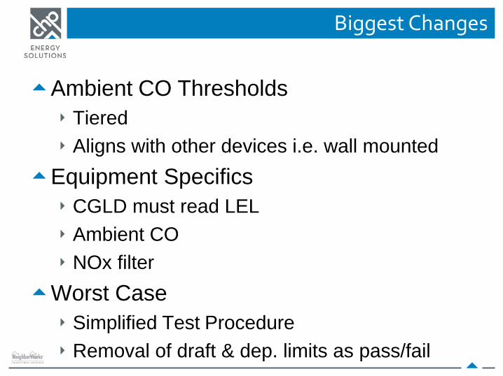
Ambient CO ThresholdsTieredAligns with other devices i.e. wall mounted
Equipment SpecificsCGLD must read LEL Ambient CONOx filter
Worst CaseSimplified Test ProcedureRemoval of draft & dep. limits as pass/fail
Biggest Changes
Ambient CO Measurements
5

Ambient CO Action Levels
6

Worst Case Spillage
7
• Drill necessary test holes in flue pipe
• Turn off kill switch or set to pilot
• Fire the unit!– Set thermostat to heat mode,
15°F above ambient indoor temp or run hot water at sinks.
– When ready to fire, flip kill switch to “ON”
– Start your stopwatch when the unit fires
– Look out for flame rollout– Use smoke pencil to check spillage
for the appropriate amount of time

Spillage and CO – Warm Vent
8

Spillage and CO – Cold Vent
9

Testing Combined Flues
10
• Fire the appliance with the smallest Btu capacity first
– Check for spillage
– Measure draft
• Fire larger appliance(s) in order of Btu capacity
– Check for spillage
– Re-check spillage for every appliance

Testing Combined Flues
11

Testing Combined Flues
12

Which Tests Per Category
13
CategoryI
CategoryIII
Category IV
Spillage Yes No No
Undiluted CO Yes Yes Yes
Where to Test
14
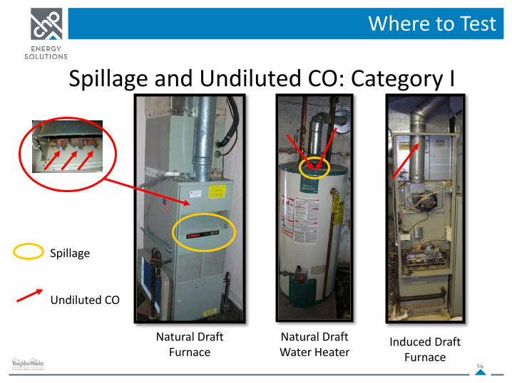
Spillage and Undiluted CO: Category I
Natural Draft Furnace
Natural Draft Water Heater
Induced Draft Furnace
Spillage
Undiluted CO

Where to Test
15
Spillage on Induced Draft Furnaces

Where to Test
16
Spillage, Draft, and Undiluted CO: Fuel Oil Furnace
Spillage
Undiluted CO
Barometric Damper

Where to Test
17
Spillage, Draft, and Undiluted CO: Category I
Natural Draft Space Heater
Floor Furnace
Spillage

Where to Test
18
• Measure Undiluted CO at the flue pipe outlet
• BPI Protocols prohibits drilling Cat III or IV systems.
• There is no spillage testing for these.
Condensing PVC flue
Direct Vent Concentric Flue Pipe
Undiluted CO
Undiluted CO: Category III/IV

Interpreting Results
19
• Compare results with BPI standards to determine whether the combustion appliance has reached any action levels.
– Did spillage fail? Under which condition?
– Undiluted CO Limits Exceeded?
• Make recommendations according to BPI standards

CAZ Depressurization
20

Problems with Venting?
21
• Poor chimney/flue design
• Obstructions in the flue
• Lack of makeup Air
• High negative pressure in the combustion zone

CAZ Depressurization Problems
22
• Worst case depressurization must be brought within acceptable limits as part of the work scope. Possible causes:– Exhaust fan lacks makeup air
– Pressure imbalances in home HVAC
– Duct leakage
– Lack of CAZ makeup air
– Insufficient CAZ volume
– Holes in ceiling (stack effect)

Relieving CAZ Depressurization
23
• Seal duct leaks
• Fix holes in top of envelope to stop stack effect
• Provide high-low ventilation for combustion closet
• Provide makeup air for large exhaust fans
• Balance room pressures using jumper ducts/transfer grilles
• Add a chimney exhaust system
• Add a power vent
• Switch to sealed combustion
• Fuel switch to electric heat pump/water heater

CO Thresholds
24

CO Air-Free
25

CO Action Levels
26

Testing Gas Ovens and Ranges
27
• Gas stoves have different testing protocols than other combustion appliances
• Stoves are only evaluated for CO output and gas leaks

Gas Sniffing Stoves
28
• Pull out the bottom drawer to sniff gas lines. Do NOT pull stove from wall!
• Do not fire stove if gas leaks are present

Range Top Inspection
29
• Light burners in sequence
– Record any problems with auto-lighting
• Visually inspect flame for;
– Blue color
– Non-pulsing (consistent)
– Yellow flame indicates flame impingement or bad fuel mixture

Gas Oven Test Preparation
30
• Continue monitoring ambient CO
• Keep kitchen exhaust running – if recirculating – keep running and window open
• Remove all items (debris) from oven and stove top
• Turn on oven to hottest setting (500°F) – do not turn on self clean feature!

Gas Oven Testing
31

Gas Oven Testing
32

Diagnostic Guide

Worst Case CAZ Depressurization Worksheet

Worst Case CAZ Depressurization Worksheet

Worst Case CAZ Depressurization Worksheet
If over 70 ppm of Carbon Monoxide is detected inside,
evacuate the house, and ventilate it until CO levels have dropped before re-entering to identify the
problem.

Worst Case CAZ Depressurization Worksheet

Each furnace manufacturer includes a recommended range of temperature rise on the data plate.
Duct Diagnostics
The Temperature Rise Test can identify issues with the furnace or the duct system such as..Incorrect furnace fan speedImproper duct sizing or restrictions 38

Return
Supply
(Supply temp) – (Return temp) = Temp rise
120°F
70°F
120°F – 70°F = 50°F
Measuring Temperature Rise
39
Filte
r

Worst Case CAZ Depressurization Worksheet

Worst Case CAZ Depressurization Worksheet

SAFETY – COMBUSTION DIAGNOSTICS
Bedroom
Bedroom Living Room
Kitchen/Dining AreaBathIf the CAZ had a solid door, where
Where is the CAZ?
42
Vented Combustion Appliance

SAFETY – COMBUSTION DIAGNOSTICS
Bedroom
Bedroom
Bath
If the CAZ had no door, where would the CAZ be?
Vented Combustion
Appliance Living Room
Kitchen/Dining Area
Where is the CAZ?
43

Worst Case CAZ Depressurization Worksheet
Hall closetNo
YesNo
YesNo
No
0 ppm640ft3
2000ft3

Worst Case CAZ Depressurization Worksheet
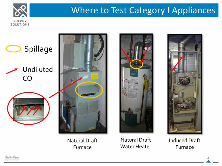
Where to Test Category I Appliances
46
Natural Draft Furnace
Natural Draft Water Heater
Induced Draft Furnace
Spillage
Undiluted CO

Where to Test
47
Spillage, Draft, and Undiluted CO: Fuel Oil Furnace
Spillage
Undiluted CO
Barometric Damper

All fuel oil devices should be tested for soot with a smoke pumper.
A value of 1 or lower is desiredTesting anything over a 1 can damage test equipment
Measuring System Efficiency
Oil System Smoke Test
48
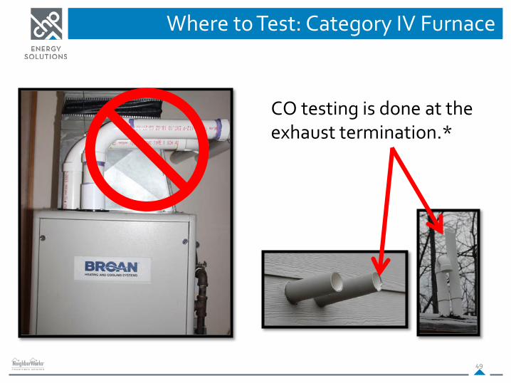
Where to Test: Category IV Furnace
49
CO testing is done at the exhaust termination.*

Worst-case for a Gas Pack?
50

Where to Test: Mobile Home
51
Inner Liner
Outer Liner

Worst Case CAZ Depressurization Worksheet

SAFETY – COMBUSTION DIAGNOSTICS
You are in the CAZVented
Combustion Appliance
Bedroom
Bedroom Living Room
Kitchen/Dining AreaBath
Fan Fan
Setting Up the Manometer for CAZ
53
You are not in the CAZ

Worst Case CAZ Depressurization Worksheet

Worst Case CAZ Depressurization Worksheet
55

Worst Case CAZ Depressurization Worksheet

Worst Case CAZ Depressurization Worksheet

Worst Case CAZ Depressurization Worksheet

Worst Case CAZ Depressurization Worksheet

Worst Case CAZ Depressurization Worksheet
70 ppm CO Ambient

Worst Case CAZ Depressurization Worksheet
Warm Vent vs. Cold Vent
Cold vent pertains to a combustion appliance that is turned OFF.
Warm vent pertains to a combustion appliance that is turned ON.

Worst Case CAZ Depressurization Worksheet
Where to document spillage, ambient CO and CO AF for combustion appliances.
BPI guidelines for causes and alleviation of CAZ depressurization

Worst Case CAZ Depressurization Worksheet
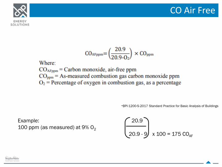
CO Air Free
-BPI-1200-S-2017 Standard Practice for Basic Analysis of Buildings
Example: 20.9100 ppm (as measured) at 9% O2
20.9 - 9 x 100 = 175 COAF


![102 BPI v BPI Employees Union-Davao Chapter [Full Text]](https://img.dokumen.tips/doc/110x75/577cd0261a28ab9e78918703/102-bpi-v-bpi-employees-union-davao-chapter-full-text.jpg)