Embed Size (px)
Citation preview
1
Bipolar Junction Transistors (BJT)
Signal amplification is important in many applications, such as telecommunications. Before the advent of
transistors, signal amplification was accomplished using vacuum tubes. Transistors are much smaller and do not need a long warm-up time needed with vacuum tubes.
The invention of the bipolar junction transistor started a revolution which placed electronics on a path of
miniaturization; a fact that would have been impossible with vacuum tubes.
In summary, the transistor and subsequently the integrated circuit must certainly qualify as two of the
greatest inventions of the twentieth century.
2
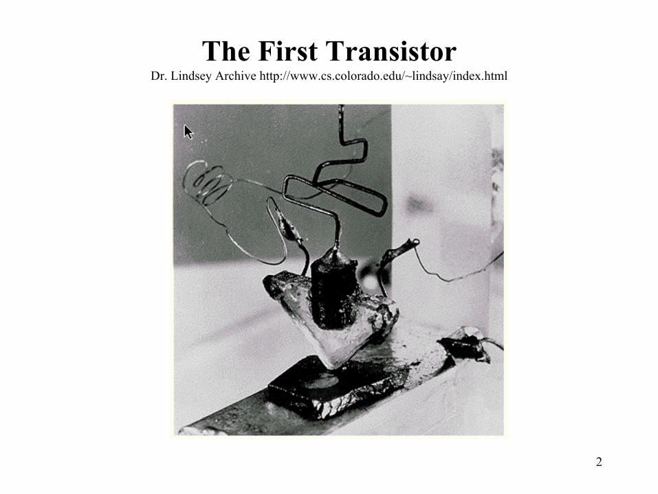
The First TransistorDr. Lindsey Archive http://www.cs.colorado.edu/~lindsay/index.html
3
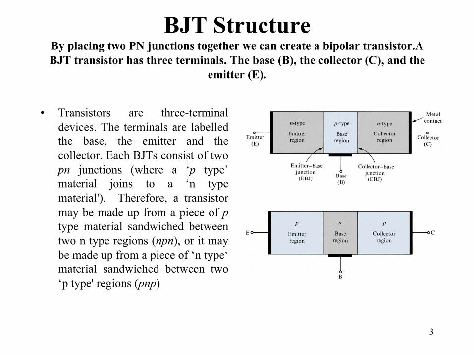
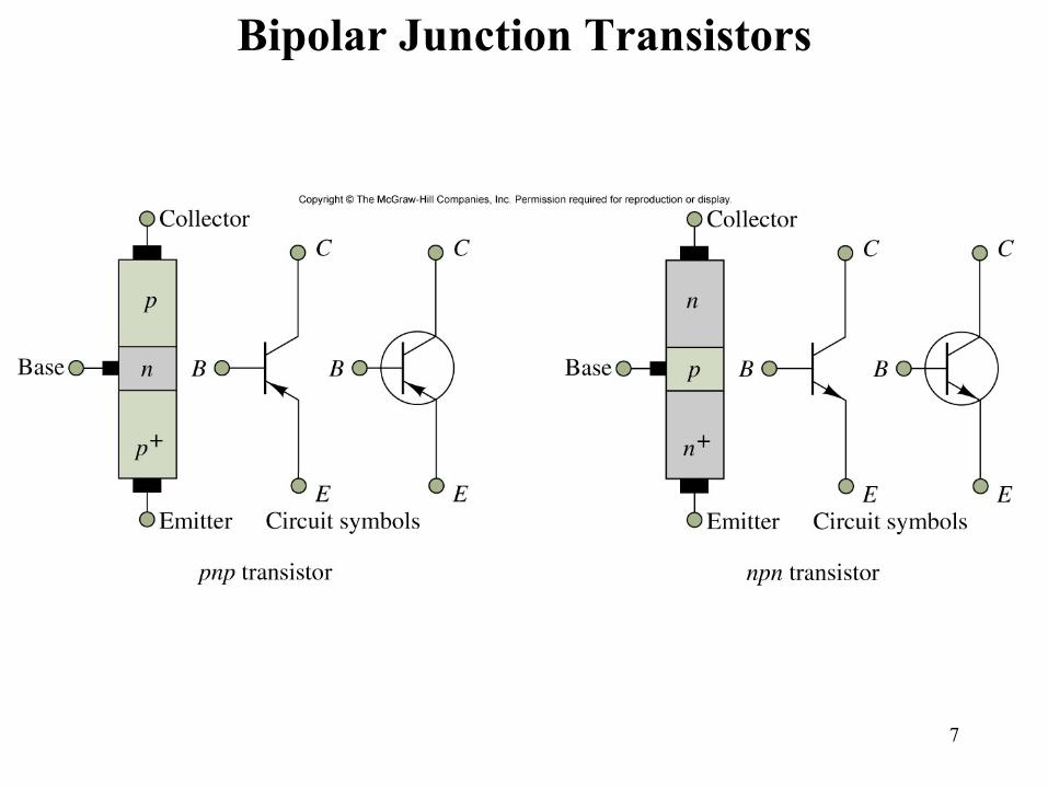
BJT StructureBy placing two PN junctions together we can create a bipolar transistor.A BJT transistor has three terminals. The base (B), the collector (C), and the
emitter (E).
• Transistors are three-terminal devices. The terminals are labelled the base, the emitter and the collector. Each BJTs consist of two pn junctions (where a ‘p type’ material joins to a ‘n type material'). Therefore, a transistor may be made up from a piece of ptype material sandwiched between two n type regions (npn), or it may be made up from a piece of ‘n type‘ material sandwiched between two ‘p type' regions (pnp)
4
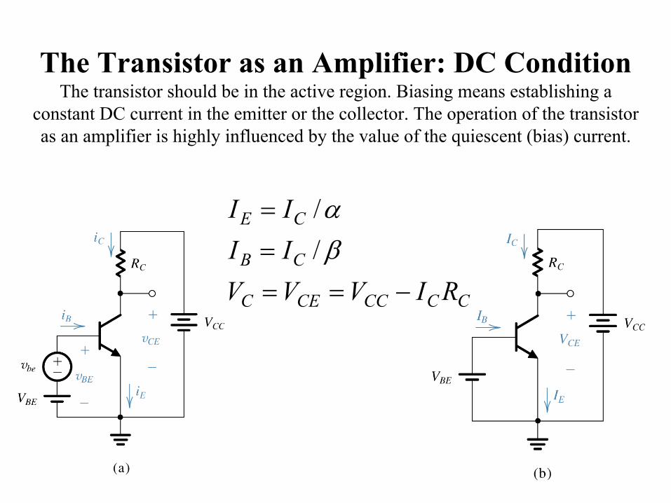
The Transistor as an Amplifier: DC ConditionThe transistor should be in the active region. Biasing means establishing a
constant DC current in the emitter or the collector. The operation of the transistor as an amplifier is highly influenced by the value of the quiescent (bias) current.
CCCCCEC
CB
CE
RIVVVIIII
−====
βα
//
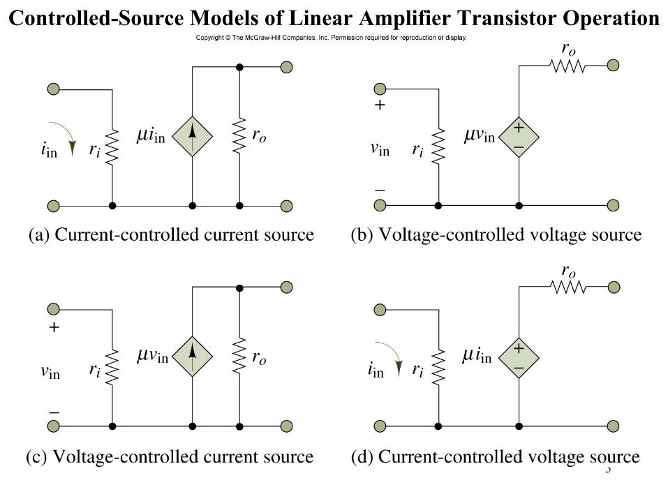
5Figure 10.1
Controlled-Source Models of Linear Amplifier Transistor Operation

6Figur
e 10.2
Models of Ideal Transistor Switches
7
Figure 10.4
Bipolar Junction Transistors
8
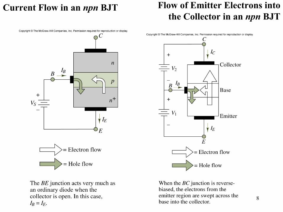
Figure 10.5, 10.6
Current Flow in an npn BJT Flow of Emitter Electrons into the Collector in an npn BJT
9
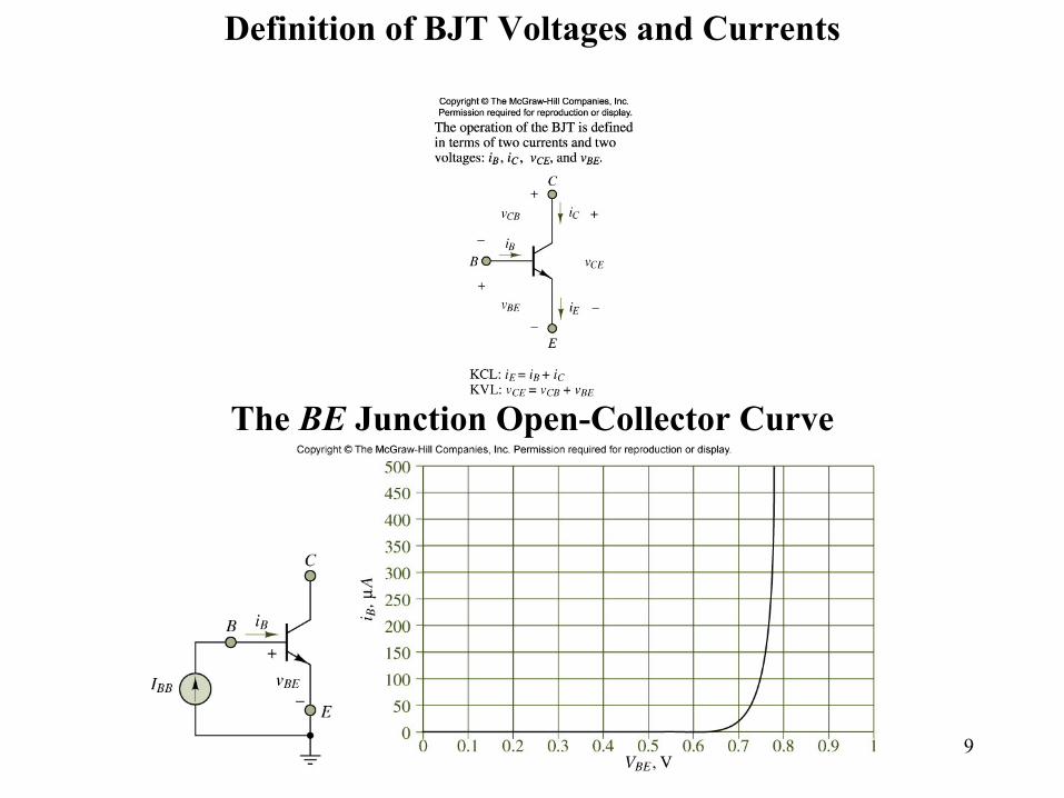
Figure 10.7, 10.8
Definition of BJT Voltages and Currents
The BE Junction Open-Collector Curve
10
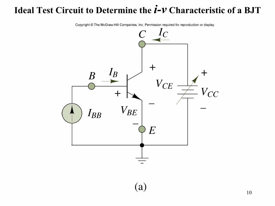
Figure 10.9
Ideal Test Circuit to Determine the i-v Characteristic of a BJT

11
Figure 10.10
Determination of the Operation Region of a BJT
12
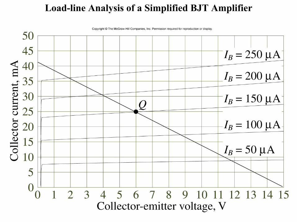
Figure
10.13
Load-line Analysis of a Simplified BJT Amplifier

13
Figure 10.15, 10.16
Circuit Illustrating the Amplification Effect in a BJT
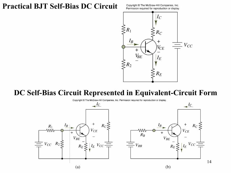
14
Figure 10.20, 10.21
Practical BJT Self-Bias DC Circuit
DC Self-Bias Circuit Represented in Equivalent-Circuit Form

15
• The basic principle involves the use of the voltage between two terminals to control the current flowing in the third terminal.
• Current is conducted by both electrons and holes, therefore the name bipolar.
• α is called the common-base current gain.
• β is called the common-emitter current gain.
( )
( )
ααβ
βββ
αα
αα
ββ
−=
+==+
=−==
==
==
=
1
1;1
1;
/
/
/
BEBC
EEBEC
VvSCE
VvSCB
VvsC
iiii
iiiii
eIii
eIii
eIi
TBE
TBE
TBE
16
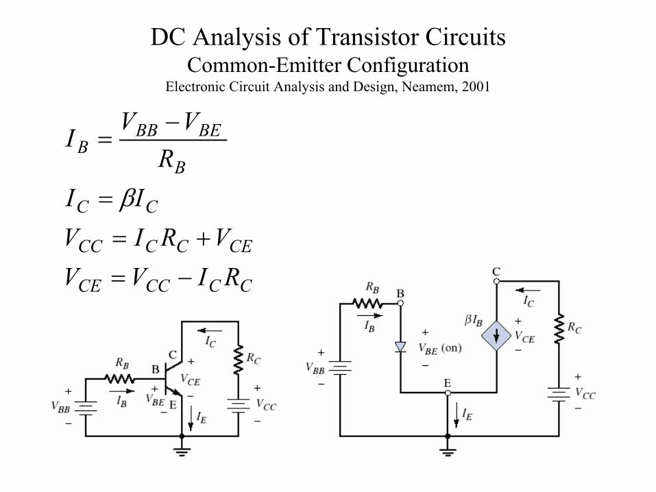
DC Analysis of Transistor CircuitsCommon-Emitter Configuration
Electronic Circuit Analysis and Design, Neamem, 2001
CCCCCE
CECCCC
CC
B
BEBBB
RIVVVRIV
IIR
VVI
−=+=
=
−=
β

17
Example: Calculate the base, collector, and emitter currents and the CE voltage for the following
committer circuit when β = 200, VBE = 0.7(Electronic Circuit Analysis and Design, Neamem)
18
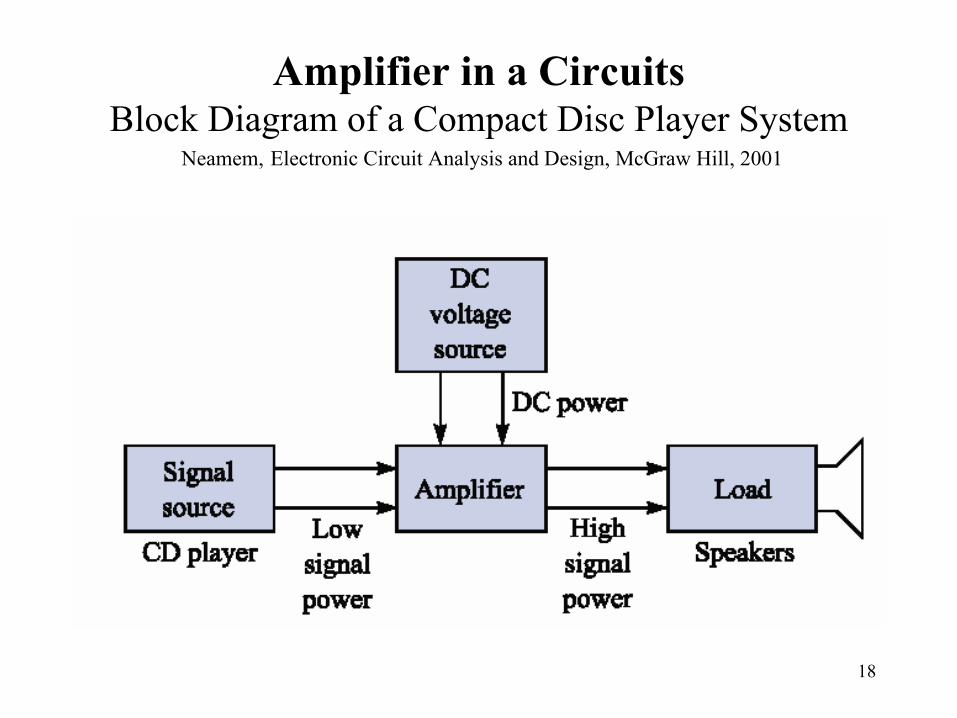
Amplifier in a CircuitsBlock Diagram of a Compact Disc Player System
Neamem, Electronic Circuit Analysis and Design, McGraw Hill, 2001