Embed Size (px)
Citation preview

THERMO-ELECTRO-MECHANICAL INVESTIGATION OF VOLTAGE DROP IN ANODE ASSEMBLY USING FINITE ELEMENT METHOD
E. Jeddi1, D. Marceau1, L. I. Kiss1, Lyne St-Georges1, D. Laroche2, L. Hacini2
1 University Research Centre on Aluminium (CURAL) - Aluminium Research Centre (RE-GAL) - University of Quebec at Chicoutimi (UQAC), Canada ([email protected])
2 Rio Tinto Alcan (Arvida Research and Development Center), Jonquière (Quebec), Canada
Abstract. In today’s context, aluminum producers strive to improve their position regarding energy consumption and production costs. To do so, mathematical modeling offers a good way to study the behavior of the cell during its life. In this paper, a fully-coupled, thermo-electro-mechanical (TEM) model of a whole hexapod anode assembly is presented. The par-ametric finite element (FE) model was developed using APDL™ (ANSYS® Parametric Design Language) and was solved with a FESh++ TEM application to simulate the thermal and elec-trical effects of the reduction process on the anode assembly. A half block submodel of the full anode assembly model was used for the analysis in order to achieve a better understanding of the system and to evaluate the hypothesis of lowering the anodic voltage drop in the anode assembly through a simple change in the stub diameter. After calibration with the experi-mental results, sensitivity analysis (SA) was carried out to investigate the impact of changes of some critical parameters on the initial air gap at the cast iron to carbon interface and con-sequently on the total voltage drop in the system. These critical parameters were: effective stub temperature at cast iron solidification, stub diameter and coefficient of thermal expan-sion (CTE) which showed they have marginal or remarkable impact on the total voltage drop depending on the operating temperature.
Keywords: Aluminum Production, Anode Assembly, Voltage Drop, Electrical Contact Re-sistance, Numerical Modeling and Simulation, Finite Elements Method.
1. INTRODUCTION
Aluminum is produced using an electrolysis process, called Hall-Héroult, which is very expensive since it uses a large amount of electrical energy. Figure 1 shows reduction cells of a smelter. It can be seen that each cell contain 24 anode assembly. The number of anode assemblies can be different for different technologies. The electrical current passes through several materials and components of the electrolytic cell causing voltage drop, espe-cially when it faces interfaces between two different components. The process is a combina-tion of many physical phenomena of which thermal, electrical, chemical and mechanical are
Blucher Mechanical Engineering ProceedingsMay 2014, vol. 1 , num. 1www.proceedings.blucher.com.br/evento/10wccm
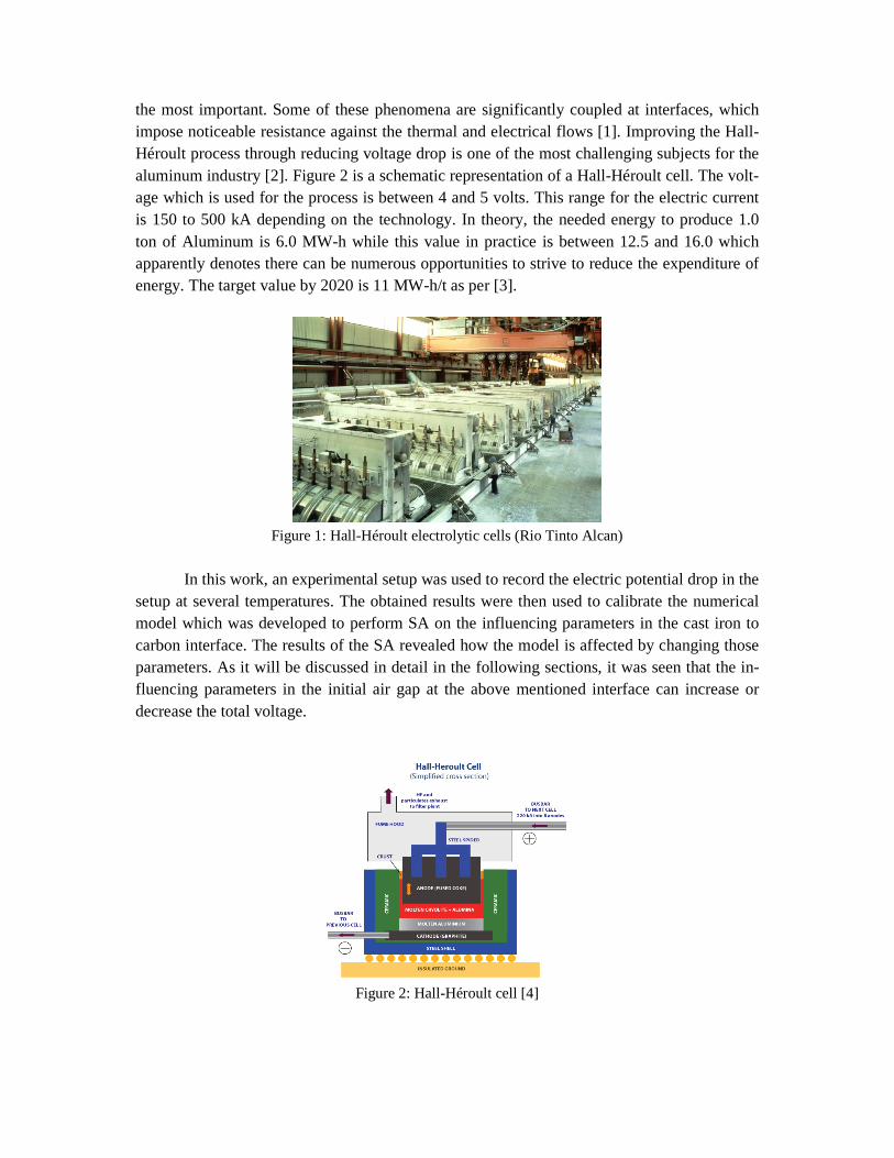
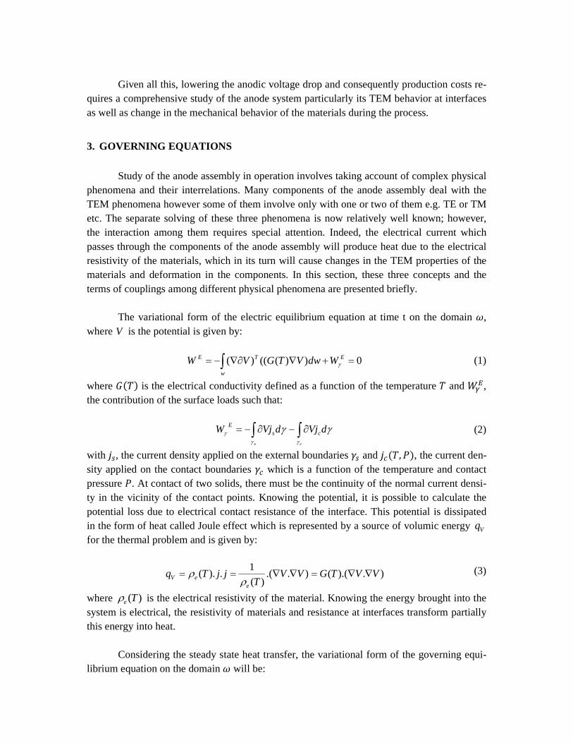
the most important. Some of these phenomena are significantly coupled at interfaces, which impose noticeable resistance against the thermal and electrical flows [1]. Improving the Hall-Héroult process through reducing voltage drop is one of the most challenging subjects for the aluminum industry [2]. Figure 2 is a schematic representation of a Hall-Héroult cell. The volt-age which is used for the process is between 4 and 5 volts. This range for the electric current is 150 to 500 kA depending on the technology. In theory, the needed energy to produce 1.0 ton of Aluminum is 6.0 MW-h while this value in practice is between 12.5 and 16.0 which apparently denotes there can be numerous opportunities to strive to reduce the expenditure of energy. The target value by 2020 is 11 MW-h/t as per [3].
Figure 1: Hall-Héroult electrolytic cells (Rio Tinto Alcan)
In this work, an experimental setup was used to record the electric potential drop in the
setup at several temperatures. The obtained results were then used to calibrate the numerical model which was developed to perform SA on the influencing parameters in the cast iron to carbon interface. The results of the SA revealed how the model is affected by changing those parameters. As it will be discussed in detail in the following sections, it was seen that the in-fluencing parameters in the initial air gap at the above mentioned interface can increase or decrease the total voltage.
Figure 2: Hall-Héroult cell [4]

2. THE PROBLEM
Voltage drop in anode assembly is highly important since it is directly associated with the production costs. Up to 25% of the anodic voltage drop is attributed to the steel/cast iron/carbon area [5]. Cast iron is used to connect the steel stubs of the anode hangers (superior part) to the carbon anodes used in the reduction cells. The process of connecting and fixing carbon anodes to the superior part, which can be seen in Figure 3, is called rodding or sealing. Anodes have specially designed holes, so called stub holes, into which steel stubs are posi-tioned and molten iron is cast to connect and fix the stubs to the carbon blocks. Since cast iron does not wet carbon, an air gap at the cast iron to carbon interface opens up once cast iron solidifies in anode sealing (rodding) process. The interface causes thermal and electrical con-tact resistance which plays a key role during aluminum smelting.
Figure 3: Rodding (sealing) process
Electric current causes heat generation as it flows through a conductor. This is known
as Joule effect which makes solid components to expand due to the generated heat. The ex-pansion changes the contact condition at the interfaces so that if there was not any contact beforehand, contact may be established or if there was already established contact, it may change its condition since contact pressure increases. Higher contact pressure creates more contact points which facilitate more flow to pass. In other words, the more contact points are created, the less contact resistance is caused at the interfaces. The more electric current pass-es, the more heat is generated and the more thermal expansion occurs and consequently the more pressure is applied at the interfaces. Excessive pressure may cause critical mechanical deformation which consequently may lead into damage or may change the operation status. As it can be noted, there are interrelations among all of the influencing phenomena in the electrolysis process.
In the anode assembly, the region in which carbon block(s) is fixed to the superior part by cast iron is delicate due to the complexity of the stub hole and cast iron (connector) ge-ometry as well as dealing with TEM contact. It is clear that contact problems are sensitive to solve owing to their nonlinear nature. Thus, in the numerical study, proper initial condition is a key to start on the right foot. One of the initial conditions that significantly affect the contact

distribution and consequently the final results is the initial air gap between cast iron and car-bon. In plain language, no matter how good a numerical model is at analyzing the TEM con-tact problems, a non-realistic air gap can be an inauspicious beginning for the analysis and even, successful global convergence may not be promising.
The first efforts to build a model to solve the problems of reduction cells and alumi-num production process go back to 1980s [see 6]. There have been several analyses carried out recently to reduce the voltage drop in the anode assembly through different approaches nevertheless most of them could not simulate the anode system and reduction process ade-quately due to many geometrical simplifications and lack of considering all of the thermal, electrical and mechanical phenomena simultaneously.
Richard was the first to develop an ANSYS® based TEM anode stub hole model [16,7]. Unfortunately the ANSYS® version, available at the time, was not supporting thermo-electro-mechanical contact elements, preventing the development of a fully coupled model. Following Richard’s initial effort, Goulet developed a fully coupled TEM model based on the in-house object-oriented finite element code FESh++ [2, 16, 8]. FESh++ supports the imple-mentation of complex material constitutive laws, e.g. for carbon-based materials, thus it is extremely useful to carry out fundamental research work [for FESh++ see 9, 10].
In 2009, four models were presented. Kandev and Fortin presented a simplified ther-mo-electrical model and indicated that it appeared the fully coupled TEM anode model with displacement and Joule heat effect had not been solved to that date. The goal of the presented numerical modeling was to examine general electrical and thermal field distributions in the stub anode connection and to validate the agreement between the experimental results and the simulation, in preparation for the completion of the 3D TEM anode model [see 11]. This sim-plified TE numerical model could not be used for stub hole design optimization or interface gap analysis.
Hugues et al. presented a 3D TEM anode model. Once more, they stated that electrical contact resistance had not been taken into account in a TEM model of a whole anode to that date. In their paper, published in TMS 2009 [see 2], it was mentioned that the dominant pa-rameter affecting the anode is the initial cast iron/carbon gap and that its initial magnitude is a problem to determine. The authors used the law taken by Richard in which the air gap is cal-culated as a function of steel stub radius.
Wangxing et al. presented a very simplified TE model [see 12]. In 2010, Dupuis pre-sented his model as an ANSYS® based TEM anode stub hole design tool [see 7]. Using his demo model, he concluded that the traditional constant resistance setup (typical value of 2 micro-ohm m2) and the pressure-temperature dependent contact resistance setup predict al-most the same voltage drop. Instead of creating an air gap directly in the mesh geometry at room temperature and specifying the ambient temperature as reference temperature for the thermal expansion, he built a similar geometry with no air gap and specified three different temperatures as reference temperatures for three materials (steel stub, cast iron and anode carbon) which were the average temperatures of each material when cast iron solidifies. Per-sonally, he found this method quite practical since it allows the user to analyze a great number of geometries without having to cogitate about what would be the air gap at room tempera-ture. Nevertheless its applicability is yet to be proved.
Given all this, lowering the anodic voltage drop and consequently production costs re-
quires a comprehensive study of the anode system particularly its TEM behavior at interfaces as well as change in the mechanical behavior of the materials during the process.
3. GOVERNING EQUATIONS
Study of the anode assembly in operation involves taking account of complex physical phenomena and their interrelations. Many components of the anode assembly deal with the TEM phenomena however some of them involve only with one or two of them e.g. TE or TM etc. The separate solving of these three phenomena is now relatively well known; however, the interaction among them requires special attention. Indeed, the electrical current which passes through the components of the anode assembly will produce heat due to the electrical resistivity of the materials, which in its turn will cause changes in the TEM properties of the materials and deformation in the components. In this section, these three concepts and the terms of couplings among different physical phenomena are presented briefly.
The variational form of the electric equilibrium equation at time t on the domain �,
where V is the potential is given by:
∫ =+∇∇∂−=w
ETE WdwVTGVW 0))((()( γ (1)
where ���� is the electrical conductivity defined as a function of the temperature � and ���, the contribution of the surface loads such that:
∫∫ ∂−∂−=cs
dVjdVjW csE
γγγ γγ (2)
with ��, the current density applied on the external boundaries �� and ��(�,), the current den-sity applied on the contact boundaries �� which is a function of the temperature and contact pressure . At contact of two solids, there must be the continuity of the normal current densi-ty in the vicinity of the contact points. Knowing the potential, it is possible to calculate the potential loss due to electrical contact resistance of the interface. This potential is dissipated in the form of heat called Joule effect which is represented by a source of volumic energy Vq for the thermal problem and is given by:
).).(()..()(
1.).( VVTGVV
TjjTq
eeV ∇∇=∇∇==
ρρ (3)
where )(Teρ is the electrical resistivity of the material. Knowing the energy brought into the system is electrical, the resistivity of materials and resistance at interfaces transform partially this energy into heat.
Considering the steady state heat transfer, the variational form of the governing equi-librium equation on the domain � will be:

0),()()( =∂++∇∇∂−= ∫∫ dwVTqTWTdwTKTW VTTT
ωωγ (4)
where (�) represents the thermal conductivity of the material and ���, the contribution of any kind of surface thermal loads such that:
∫∫ ∂++∂=cs
dTqdqqTW cradconvT
γγγ γγ)( (5)
with ����� and ��, respectively the convective and radiative thermal flux applied on exter-nal boundaries �� and ��(�,), the thermal flux applied on the contact boundaries ��. Finally, the variational form of the governing equilibrium equation associated with the mechanical problem on the domain � is given by:
0=∂−+∂= ∫∫ ⇒
dwfuWdwDW vTMTMr
ωγ
ω
σ (6)
where �, and � represent the displacement vector, the strain and the stress tensors respec-tively and ��, the volumic forces exerted on �. The term ��� includes the contributions of surface loads such that:
γγγγ
γ dfudfuW cT
sTM
cs
rr ∫∫ ∂+∂−= (7)
with ��, the distributed load applied on external boundaries �� and ��, the contact stress com-puted at the contact boundaries ��. Equations (1) to (7) define a strongly coupled TEM non-linear problem. The details associated with the development of these equations including the linearization of the residual form can be founded in Goulet [see 8]. After FE discretization, the compact global matricial form of the equations can be expressed as:
−=
∆∆∆
U
V
T
UUUT
VUVVVT
TUTVTT
R
R
R
U
V
T
KK
KKK
KKK
0
(8)
where ��, � and �� represent the residual expressions corresponding to the thermal, electri-cal and mechanical problems respectively. From the stiffness matrix, it can be seen that the thermal, electrical and mechanical phenomena are coupled at the interfaces. � and �� measure the impact of the changes in the voltage and contact pressure on the temperature which correspond to the Joule’s effect and thermal contact resistance respectively. Regarding the electrical equations, the terms � and � are associated to the impact of the changes in the temperature and contact pressure on electrical properties including electrical contact re-sistance. Finally, the term �� includes the impact of the changes in the temperature on the mechanical properties as well as on the thermal expansion. Figure 4 illustrates all of the men-tioned couplings at the interfaces.

Figure 4: Interrelations among the physical phenomena
As it can be seen, the problem is highly coupled at the interfaces. The TEM problem
can be solved through different methods. The Newton-Raphson solution technique was used to solve the nonlinear problem at each time step until convergence. Since the linearized sys-tem of equations gives a correction for each field simultaneously, the time needed to solve the model is less than that needed to solve a weakly coupled one. Nevertheless, it requires more memory due to simultaneous solving of sub-problems. Backward Euler time integration scheme was used for time stepping aspect.
4. FINITE ELEMENT MODEL
4.1. Features of the model
Primarily, a full anode assembly model was developed to perform various analyses. The fully parametric model has features such as: superior part displacement and rotation which cause cast iron connectors with angle-variant thicknesses, pancakes formation (cast iron below the stub), cast iron flutes design (shape) and carbon consumption.
In order to calibrate the numerical model as well as fulfilling analyses to investigate the phenomena taking place in the steel/cast iron/carbon region during operation, a half block model with one stub was extracted from the full model for the sake of simplicity. Figure 5 depicts the geometry of the full model and its components. Figure 6 demonstrates the half block model. It should be noticed that a support has been added to the bottom of the one stub model to adequately represent the mechanical boundary conditions at the bottom of the car-bon bloc.
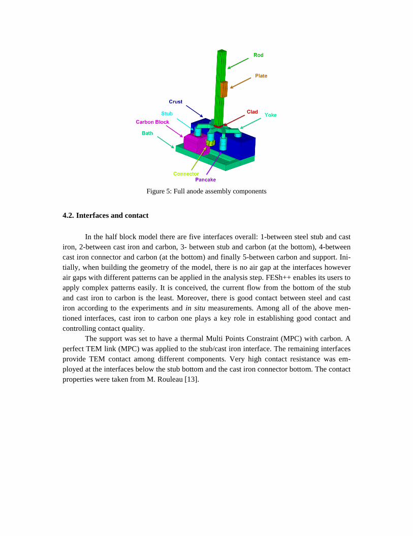
Figure 5: Full anode assembly components
4.2. Interfaces and contact
In the half block model there are five interfaces overall: 1-between steel stub and cast iron, 2-between cast iron and carbon, 3- between stub and carbon (at the bottom), 4-between cast iron connector and carbon (at the bottom) and finally 5-between carbon and support. Ini-tially, when building the geometry of the model, there is no air gap at the interfaces however air gaps with different patterns can be applied in the analysis step. FESh++ enables its users to apply complex patterns easily. It is conceived, the current flow from the bottom of the stub and cast iron to carbon is the least. Moreover, there is good contact between steel and cast iron according to the experiments and in situ measurements. Among all of the above men-tioned interfaces, cast iron to carbon one plays a key role in establishing good contact and controlling contact quality.
The support was set to have a thermal Multi Points Constraint (MPC) with carbon. A perfect TEM link (MPC) was applied to the stub/cast iron interface. The remaining interfaces provide TEM contact among different components. Very high contact resistance was em-ployed at the interfaces below the stub bottom and the cast iron connector bottom. The contact properties were taken from M. Rouleau [13].
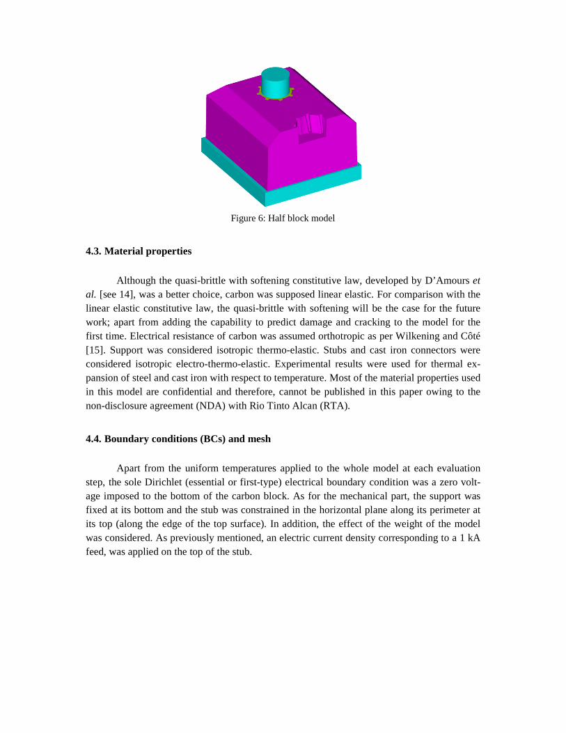
Figure 6: Half block model
4.3. Material properties
Although the quasi-brittle with softening constitutive law, developed by D’Amours et al. [see 14], was a better choice, carbon was supposed linear elastic. For comparison with the linear elastic constitutive law, the quasi-brittle with softening will be the case for the future work; apart from adding the capability to predict damage and cracking to the model for the first time. Electrical resistance of carbon was assumed orthotropic as per Wilkening and Côté [15]. Support was considered isotropic thermo-elastic. Stubs and cast iron connectors were considered isotropic electro-thermo-elastic. Experimental results were used for thermal ex-pansion of steel and cast iron with respect to temperature. Most of the material properties used in this model are confidential and therefore, cannot be published in this paper owing to the non-disclosure agreement (NDA) with Rio Tinto Alcan (RTA).
4.4. Boundary conditions (BCs) and mesh
Apart from the uniform temperatures applied to the whole model at each evaluation step, the sole Dirichlet (essential or first-type) electrical boundary condition was a zero volt-age imposed to the bottom of the carbon block. As for the mechanical part, the support was fixed at its bottom and the stub was constrained in the horizontal plane along its perimeter at its top (along the edge of the top surface). In addition, the effect of the weight of the model was considered. As previously mentioned, an electric current density corresponding to a 1 kA feed, was applied on the top of the stub.

Figure 7: Mesh of the connector and carbon block
The overall number of elements and nodes of the model are 63239 and 65803 respec-
tively. Table 1 presents a summary of the finite element mesh composition of the model.
Table 1: Mesh composition
Component Element Type Number of elements Solid Linear Hexahedral, 3D Coupled Filed Solid 58041
Contact Linear Shell 10739 BCs Linear Shell 7115
4.5. Solution strategy
To simulate the experimental setup adequately, a uniform temperature of 400°C was applied to the model and then the current density was applied on the top of the stub. The re-sults generated by the simulations were recorded at the temperatures from 400°C to 900°C with a constant increment of 100°C and finally at 950°C. A bisection technique was used to avoid divergence of the Newton-Raphson solution technique during highly nonlinear se-quences. On average, each simulation took approximately 9 hours using CURAL’s high per-formance computing facility.
5. INITIAL AIR GAP
Although modeling and simulation of the anode assembly or some other parts of the Hall-Héroult cell has begun years ago, there is not much work on predicting the initial air gap at the cast iron to carbon interface. Richard et al., in their paper in 2009 [see 16], used a pair of linear functions to predict the air gap and applied it to some extent. These equations are defined such as:
� � ��������������� � �� (9)
� � � � � � ������ ������ � �� (10)

where α is the secant thermal expansion coefficient; Tph, the effective stub temperature at cast iron solidification;T0, the ambient temperature; t, the thickness of cast iron and Ts is the solidification temperature of cast iron. It can be noted the gap is affected by different types of variables: Rstub and t are the geometrical (design) impact; α�����, α�������� and Ts are the material properties impact; and, Tph and T0 are the rodding (sealing) process impact. In practice, there is not much room to change T0; however, Tph has a noticeable impact on the final air gap size. Practically all of the variables in the above mentioned equations are determined for a given anode assembly except Tph, which is complex to measure. To evaluate Tph, the numerical results, obtained through a systematically varying Tph, are compared to the experimental ones until a good agreement is achieved. This is why Tph is employed as a calibration parameter. Richard et al., as a first approximation, considered a uniform (constant) gap for different zones (cylindrical portion, tip of flutes and sides of flutes), while a more realistic application requires the employment of a linearly varying magnitude of gap along the height of the cast iron connector. They concluded that the magnitude of the air gap between cast iron and carbon had a significant impact on the predicted voltage drop, as it controls the resultant contact quality at the carbon to cast iron interface [16]. In the present paper, equations (9) and (10) are the aforementioned ones that were also used in this work, but to a full extent. Considering the geometry of the cast iron connector in Figure 8, the gap magnitude will change linearly from its top to the bottom, due to changing thickness of cast iron along its height. Furthermore, the gap magnitude on the tip of flutes, at a certain level along the height, will be larger since cast iron is thicker, compared to the cylindrical portion thickness at the same level. Equation (9) calculates the radial contraction of stub, which is added to the radial contraction of cast iron to estimate the total gap at a certain level. Lateral gap of flutes are not influenced by the stub shrinkage. To estimate the size of the initial air gap on the sides of the flutes, equation (10) is used withγ � 0. Since the resultant value will be the entire amount of lateral contraction, only half of the value must be applied on each side.
Figure 8: Cast iron connector geometry
6. CALIBRATION
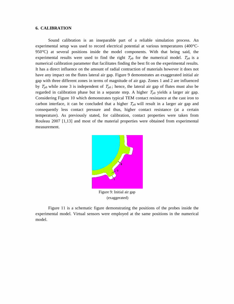
Sound calibration is an inseparable part of a reliable simulation process. An experimental setup was used to record electrical potential at various temperatures (400°C-950°C) at several positions inside the model components. With that being said, the experimental results were used to find the right Tph for the numerical model. Tph is a numerical calibration parameter that facilitates finding the best fit on the experimental results. It has a direct influence on the amount of radial contraction of materials however it does not have any impact on the flutes lateral air gap. Figure 9 demonstrates an exaggerated initial air gap with three different zones in terms of magnitude of air gap. Zones 1 and 2 are influenced by Tph while zone 3 is independent of Tph ; hence, the lateral air gap of flutes must also be regarded in calibration phase but in a separate step. A higher Tph yields a larger air gap. Considering Figure 10 which demonstrates typical TEM contact resistance at the cast iron to carbon interface, it can be concluded that a higher Tph will result in a larger air gap and consequently less contact pressure and thus, higher contact resistance (at a certain temperature). As previously stated, for calibration, contact properties were taken from Rouleau 2007 [1,13] and most of the material properties were obtained from experimental measurement.
Figure 9: Initial air gap
(exaggerated)
Figure 11 is a schematic figure demonstrating the positions of the probes inside the experimental model. Virtual sensors were employed at the same positions in the numerical model.
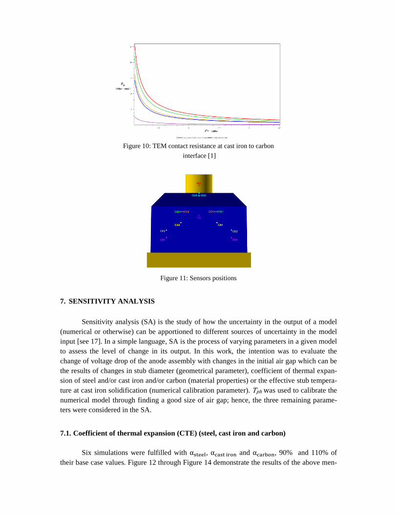
Figure 10: TEM contact resistance at cast iron to carbon
interface [1]
Figure 11: Sensors positions
7. SENSITIVITY ANALYSIS
Sensitivity analysis (SA) is the study of how the uncertainty in the output of a model (numerical or otherwise) can be apportioned to different sources of uncertainty in the model input [see 17]. In a simple language, SA is the process of varying parameters in a given model to assess the level of change in its output. In this work, the intention was to evaluate the change of voltage drop of the anode assembly with changes in the initial air gap which can be the results of changes in stub diameter (geometrical parameter), coefficient of thermal expan-sion of steel and/or cast iron and/or carbon (material properties) or the effective stub tempera-ture at cast iron solidification (numerical calibration parameter). Tph was used to calibrate the numerical model through finding a good size of air gap; hence, the three remaining parame-ters were considered in the SA.
7.1. Coefficient of thermal expansion (CTE) (steel, cast iron and carbon)
Six simulations were fulfilled with ����, ������� and �����, 90% and 110% of their base case values. Figure 12 through Figure 14 demonstrate the results of the above men-
tioned SA. It should be kept in mind that the CTE of steel and cast iron have an influence on the initial air gap therefore the initial air gap must be recalculated for the SA cases (90% and 110% cases). Also the CTE of carbon may have an impact on the geometry of the stub hole, in the rodding process; thus, the thickness of cast iron may change. In this study, the geometry of the stub hole was assumed intact (during rodding process) since the CTE of carbon is not as large as those of steel and cast iron and therefore, the impact is negligible. Nonetheless, the CTE of carbon, if changed, can result in a change in the geometry of the stub hole. Apparent-ly, different stub hole dimensions ensue from the thermal expansion will create different con-tact compared to the base case. With different contact status, the voltage drop will change accordingly. With that being said, SA was also performed on the CTE of carbon to investigate its impact on the total voltage drop.
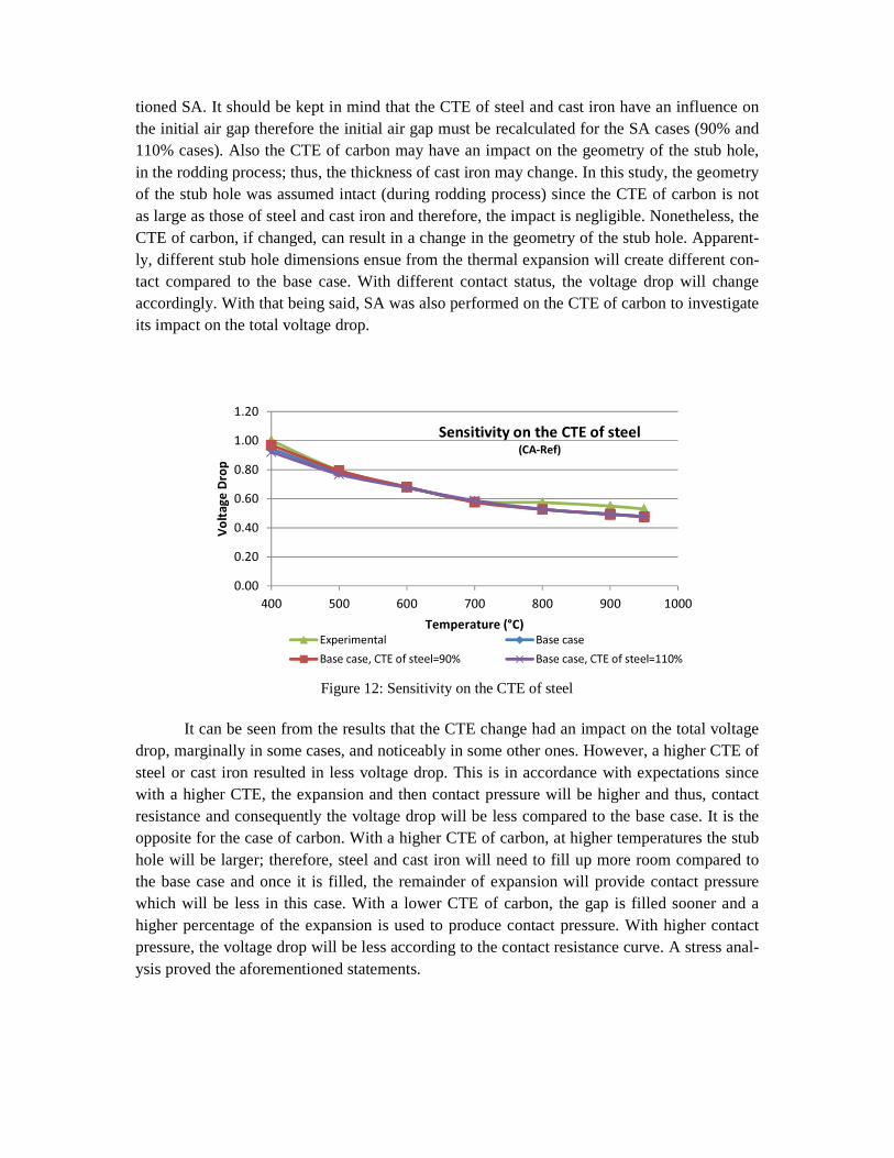
Figure 12: Sensitivity on the CTE of steel
It can be seen from the results that the CTE change had an impact on the total voltage
drop, marginally in some cases, and noticeably in some other ones. However, a higher CTE of steel or cast iron resulted in less voltage drop. This is in accordance with expectations since with a higher CTE, the expansion and then contact pressure will be higher and thus, contact resistance and consequently the voltage drop will be less compared to the base case. It is the opposite for the case of carbon. With a higher CTE of carbon, at higher temperatures the stub hole will be larger; therefore, steel and cast iron will need to fill up more room compared to the base case and once it is filled, the remainder of expansion will provide contact pressure which will be less in this case. With a lower CTE of carbon, the gap is filled sooner and a higher percentage of the expansion is used to produce contact pressure. With higher contact pressure, the voltage drop will be less according to the contact resistance curve. A stress anal-ysis proved the aforementioned statements.
0.00
0.20
0.40
0.60
0.80
1.00
1.20
400 500 600 700 800 900 1000
Volta
ge Dr
op
Temperature (°C)
Sensitivity on the CTE of steel(CA-Ref)
Experimental Base caseBase case, CTE of steel=90% Base case, CTE of steel=110%
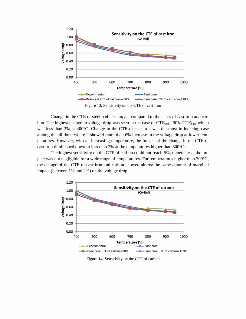
Figure 13: Sensitivity on the CTE of cast iron
Change in the CTE of steel had less impact compared to the cases of cast iron and car-
bon. The highest change in voltage drop was seen in the case of CTEsteel=90% CTEbase which was less than 3% at 400°C. Change in the CTE of cast iron was the most influencing case among the all three where it showed more than 6% increase in the voltage drop at lower tem-peratures. However, with an increasing temperature, the impact of the change in the CTE of cast iron diminished down to less than 2% at the temperatures higher than 800°C.
The highest sensitivity on the CTE of carbon could not reach 6%; nonetheless, the im-pact was not negligible for a wide range of temperatures. For temperatures higher than 700°C, the change of the CTE of cast iron and carbon showed almost the same amount of marginal impact (between 1% and 2%) on the voltage drop.
Figure 14: Sensitivity on the CTE of carbon
0.00
0.20
0.40
0.60
0.80
1.00
1.20
400 500 600 700 800 900 1000
Volta
ge Dr
op
Temperature (°C)
Sensitivity on the CTE of cast iron(CA-Ref)
Experimental Base caseBase case,CTE of cast iron=90% Base case,CTE of cast iron=110%
0.00
0.20
0.40
0.60
0.80
1.00
1.20
400 500 600 700 800 900 1000
Volta
ge Dr
op
Temperature (°C)
Sensitivity on the CTE of carbon(CA-Ref)
Experimental Base caseBase case,CTE of carbon=90% Base case,CTE of carbon=110%
7.2. Stub diameter
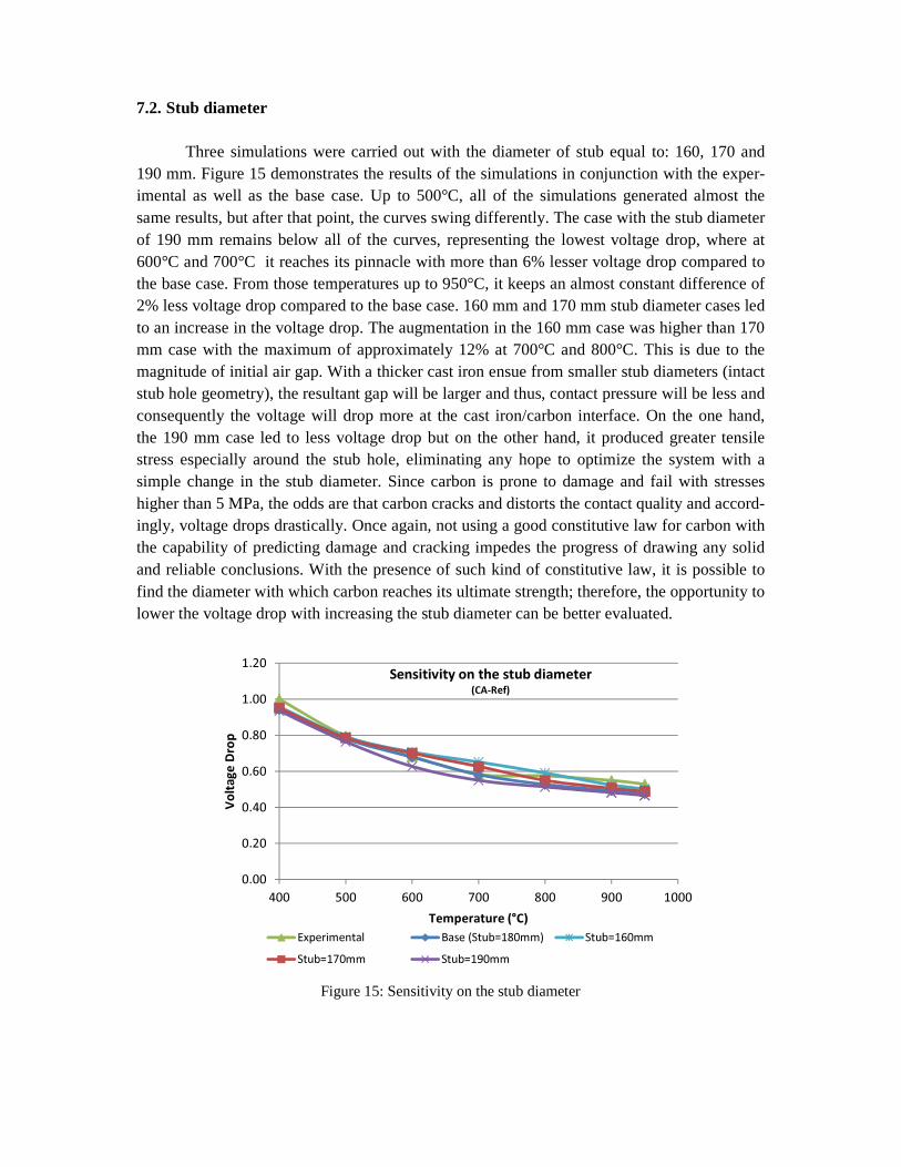
Three simulations were carried out with the diameter of stub equal to: 160, 170 and 190 mm. Figure 15 demonstrates the results of the simulations in conjunction with the exper-imental as well as the base case. Up to 500°C, all of the simulations generated almost the same results, but after that point, the curves swing differently. The case with the stub diameter of 190 mm remains below all of the curves, representing the lowest voltage drop, where at 600°C and 700°C it reaches its pinnacle with more than 6% lesser voltage drop compared to the base case. From those temperatures up to 950°C, it keeps an almost constant difference of 2% less voltage drop compared to the base case. 160 mm and 170 mm stub diameter cases led to an increase in the voltage drop. The augmentation in the 160 mm case was higher than 170 mm case with the maximum of approximately 12% at 700°C and 800°C. This is due to the magnitude of initial air gap. With a thicker cast iron ensue from smaller stub diameters (intact stub hole geometry), the resultant gap will be larger and thus, contact pressure will be less and consequently the voltage will drop more at the cast iron/carbon interface. On the one hand, the 190 mm case led to less voltage drop but on the other hand, it produced greater tensile stress especially around the stub hole, eliminating any hope to optimize the system with a simple change in the stub diameter. Since carbon is prone to damage and fail with stresses higher than 5 MPa, the odds are that carbon cracks and distorts the contact quality and accord-ingly, voltage drops drastically. Once again, not using a good constitutive law for carbon with the capability of predicting damage and cracking impedes the progress of drawing any solid and reliable conclusions. With the presence of such kind of constitutive law, it is possible to find the diameter with which carbon reaches its ultimate strength; therefore, the opportunity to lower the voltage drop with increasing the stub diameter can be better evaluated.
Figure 15: Sensitivity on the stub diameter
0.00
0.20
0.40
0.60
0.80
1.00
1.20
400 500 600 700 800 900 1000
Volta
ge Dr
op
Temperature (°C)
Sensitivity on the stub diameter(CA-Ref)
Experimental Base (Stub=180mm) Stub=160mmStub=170mm Stub=190mm
8. CONCLUSION
This paper deals with the development of a fully-coupled, parametric, TEM finite ele-ment model of a hexapod anode assembly which has been built using APDL™ (ANSYS® Parametric Design Language) to predict the voltage drop in the anode assembly under various material and geometrical conditions. An experimental setup was used to record the electrical potential, at several positions in the model and at different temperatures. A half block numeri-cal model was extracted from the full anode assembly model to simulate the experimental setup. It was firstly calibrated with FESh++; and then, was used to carry out some sensitivity analyses on some influencing parameters in the initial air gap between cast iron and carbon. The calibrated model was assumed as the base model and systematically varying parameters were employed in the SA to better understand their effect on the voltage drop especially at the interface.
The model showed high sensitivity at lower temperatures whereas its sensitivity di-minished with an increasing temperature. Among steel, cast iron and carbon, the model showed the least sensitivity to the CTE change of steel whereas a 10% increase in the CTE of cast iron generated a considerably less voltage drop, compared to the base case. A 10% de-crease in the CTE of cast iron resulted otherwise with a possibility of an 8% increase in the total voltage drop at 700°C. It was proved that the CTE of carbon plays an important role in reaching good contact especially at the temperatures up to 700°C. A smaller CTE of carbon produced less voltage drop with less thermal expanding compared to the base case resulting higher contact pressure. However it led to higher tensile stress around stub hole.
Stub diameters of 160 and 170 mm caused higher voltage drop compared to the base case. Stub diameter of 190 mm produced the least voltage drop, but an excessive increase of tensile stress around stub hole questioned the reliability of this strategy to lower the voltage drop at the interface. Moreover, not using a realistic constitutive law for carbon, while it al-ready exist and implemented in FESh++, providing the prediction of cracking and damage, once again was a serious problem in the process of coming to sound and decisive conclusions.
From the results generated by the model, it can be noted that the model is an excellent tool to solve complex problems after good calibration. In addition, it was shown that numeri-cal study is an invaluable approach to analyze and investigate the complex phenomena which can be used for optimization purposes with the least time and costs required.
Utilization of a realistic carbon constitutive law (quasi-brittle with softening) is an on-going work since this work once more emphasized the need for employment of it instead of a simple linear one. Particularly, for optimization purposes, lack of good stress and material damage and failure measurement is a serious problem that has not been solved to date.
9. ACKNOWLEDGEMENT
A part of the research presented in this paper was funded by the Fonds québécois de la recherche sur la nature et les technologies by the intermediary of the Aluminium Research Centre – REGAL and Natural Sciences and Engineering Research Council of Canada (NSERC). The authors acknowledge their financial help greatly. Rio Tinto Alcan (RTA) and
particularly our industrial partners from RTA are warmly thanked for sharing their experi-mental and in situ results with us.
10. REFERENCES
[1] L. St-Georges, L. I. Kiss, M. Rouleau, Evaluation of Contact Resistance in Electrodes of Hall-Heroult Process, TMS Light Metals 2009, Pages 1103-1108 [2] H. Fortin, M. Fafard, N. Kandev, and P. Goulet, FEM Analysis of Voltage Drop in the Anode Assembly, TMS Light Metals 2009, Pages 1055-1060 [3] D. Marceau, S. Pilote, M. Désilets, J-F Bilodeau, L. Hacini, Y. Caratini, Advanced Nu-merical Simulation of the Thermo-Electro-Chemo-Mechanical Behaviour of Hall-Héroult Cells Under Electrical Preheating, TMS Light Metals 2011, Pages 1041-1046 [4] Hall-Heroult process, http://en.wikipedia.org/wiki/Hall%E2%80%93H%C3%A9roult_process, website consulted on 18 Feb. 2010 [5] R.W. Peterson, Proc. TMS Light Met. 1 (1978) 367 [6] http://www.genisim.com/download/epfl2004.htm, consulted on the 3rd April 2010 [7] M. Dupuis, Development and Application of an ANSYS® Based Thermo-Electro-Mechanical Anode Stub Hole Design Tool, TMS Light Metals 2010, Pages 433-438 [8] P. Goulet, Modélisation du Comportement Thermo-Électro-Mécanique des Interfaces de Contact d'une Cuve de Hall-Héroult, Ph. D. Thesis, Laval University, Quebec, Canada (2004) [9] D. Marceau, P. Goulet, D. Richard, M. Fafard, FESh++, Une Nouvelle Approche Orientée Objet pour la Simulation par Éléments Finis des Problèmes Multiphysiques. Giens, France 2005 - 7ème Colloque National en Calcul des Structures, pages 303-308 [10] M. Désilets, D. Marceau & M. Fafard, “START-Cuve: Thermo-Electro-Mechanical Transient Simulation Applied to Electrical Preheating of a Hall-Héroult Cell”, TMS Light Metals, 2003, Pages 247-254. [11] N. Kandev, H. Fortin, Electrical Losses in the Stub-Anode Connection: Computer Mod-eling and Laboratory Characterization, TMS Light Metals 2009, Pages 1061-1066
[12] W. Li, J. Zhou, Y. Zhou, Numerical Analysis of the Anode Voltage Drop of a Reduction Cell, TMS Light Metals 2009, Pages 1169-1171 [13] M. Rouleau, Caractérisation thermo-électro-mécanique des interfaces fonte-acier-carbone dans une cuve d'électrolyse. Master’s dissertation, UQAC (2007)

[14] G. D’Amours, M. Fafard, A. Gakwaya & A. Mirchi, Multi-Axial Mechanical Behavior of the Carbon Cathode: Understanding, Modeling and Identification, TMS Light Metals, 2003, page 633-639. [15] S. Wilkening, J. Côté, Problems of the Stub – Anode Connection, TMS Light Metals 2007, Pages 865-873 [16] D. Richard, P. Goulet, O. Trempe, M. Dupuis and M. Fafard, Challenges in Stub Hole Optimisation of Cast Iron Rodded Anodes, TMS, 2009, Pages 1067-1072 [17] http://en.wikipedia.org/wiki/Sensitivity_analysis, consulted on the 11th March 2012


