Embed Size (px)
DESCRIPTION
Adit Channel Bank
Citation preview
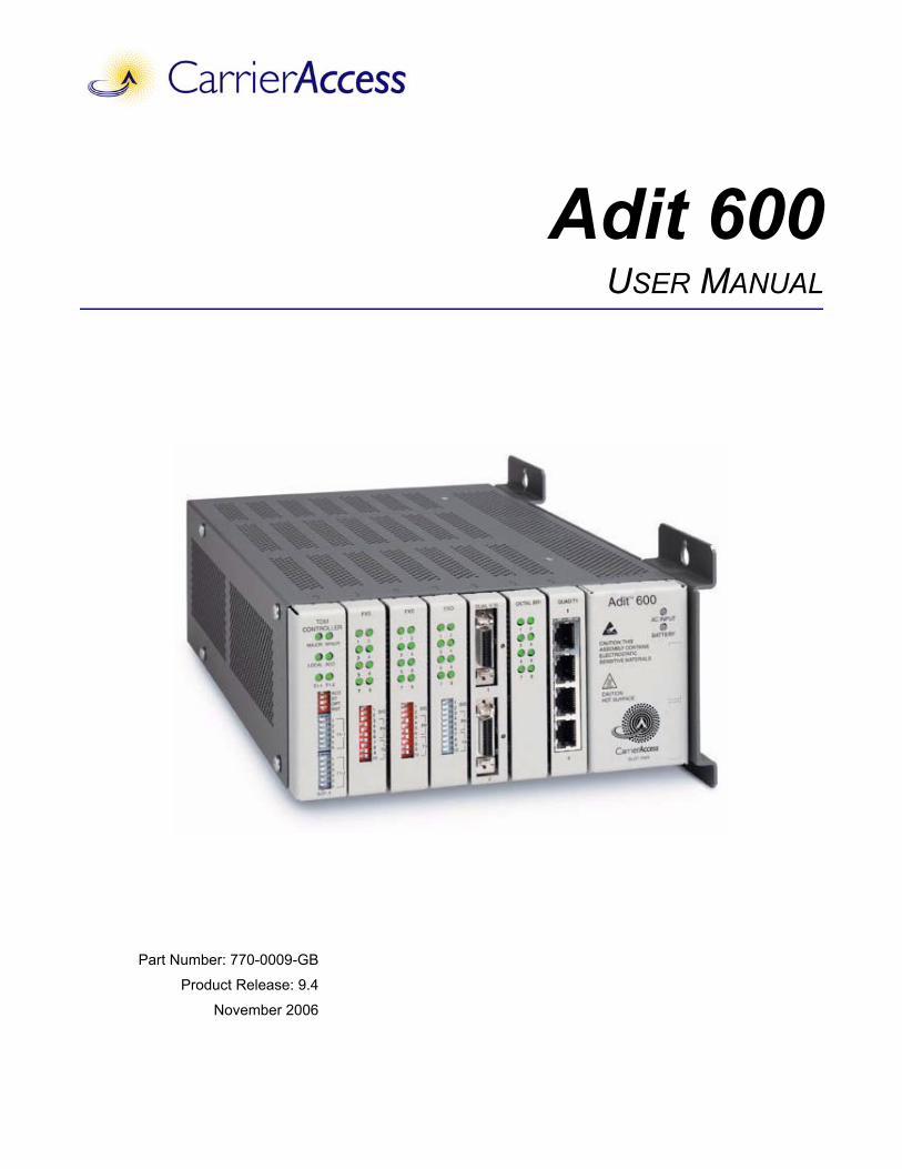
Adit 600USER MANUAL
Part Number: 770-0009-GB
Product Release: 9.4
November 2006
Copyright 2006 Carrier Access Corporation. All rights reserved.
The information presented in this manual is subject to change without notice and does not represent a commitment on the part of Carrier Access Corporation. The hardware and software described herein are furnished under a license or non-disclosure agreement. The hardware, software, and manual may be used or copied only in accordance with the terms of this agreement. It is against the law to reproduce, transmit, transcribe, store in a retrieval system, or translate into any medium - electronic, mechanical, magnetic, optical, chemical, manual, or otherwise - any part of this manual or software supplied with the Adit 600 for any purpose other than the purchaser’s personal use without the express written permission of Carrier Access Corporation.
Adit, Access Navigator, NetworkValet and the Carrier Access logo are registered trademarks of Carrier Access Corporation. All other brand or product names are trademarks or registration trademarks of their respective companies or organizations.
Contact Information:
Carrier Access Corporation5395 Pearl ParkwayBoulder, CO 80301-2490Corporate Phone: (303) 442-5455Fax: (303) 443-5908www.carrieraccess.com
Customer Support Direct: E-mail: [email protected]
Supporting Software Versions:
Adit 600 Controller 9.4
IP Router 1.8
CMG Router 2.7
Terminal Server Router 1.3
PREFACE
PrefaceCompliance
Safety of Information Technology EquipmentThe Adit 600 is safety certified by MET Laboratories, Inc. and is compliant with the following safety standards:
WARNING! THIS DEVICE IS REQUIRED TO HAVE A PERMANENT EARTH GROUND CONNECTION. SEE CHASSIS GROUND CONNECTOR ON PAGE 3-7 FOR GROUNDING REQUIREMENTS.
FCC Requirements, Part 15This device complies with Part 15 of the FCC Rules. Operation is subject to the following two conditions:
This device may not cause harmful interference, and
This device must accept any interference received, including interference that may cause undesired operation
This equipment has been tested and found to comply with the limits for a Class A digital device pursuant to Part 15 of the Federal Communications Rules. These limits are designed to provide reasonable protection against harmful interference when equipment is operated in a commercial environment. This equipment generates, uses, and can radiate radio frequency energy, and if not installed and used in accordance with the instruction manual may cause harmful interference to radio communications. Operation of this equipment in a residential area is likely to cause harmful interference, in which case the user will be required to correct the interference at the user’s own expense.
NOTE: See Compliant Installation on page 3-2 for installation instructions to meet FCC Part 15 requirements.
UL60950 3rd Edition
CSA C22.2 No. 60950 3rd Edition
EN60950:2000
AN/NZS 60950 3rd Edition
IEC 60950 3rd Edition
iv Adit 600 - Release 9.4
Preface
FCC Requirements, Part 68This equipment complies with Part 68 of the FCC rules and the requirements adopted by the ACTA. On the rear panel of this equipment is a label that contains, among other information, a product identifier in the format US:AAAEQ##TXXXX. If requested, this number must be provided to the telephone company.
FCC Registration Number: US: 2Z6DW03B65743Ringer Equivalence Number (REN): 0.3BService Center in the USA: Carrier Access Corporation
5395 Pearl ParkwayBoulder, CO 80301-2490
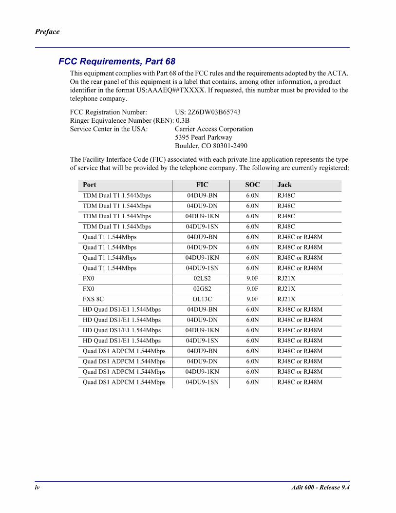
The Facility Interface Code (FIC) associated with each private line application represents the type of service that will be provided by the telephone company. The following are currently registered:
Port FIC SOC JackTDM Dual T1 1.544Mbps 04DU9-BN 6.0N RJ48CTDM Dual T1 1.544Mbps 04DU9-DN 6.0N RJ48CTDM Dual T1 1.544Mbps 04DU9-1KN 6.0N RJ48CTDM Dual T1 1.544Mbps 04DU9-1SN 6.0N RJ48C Quad T1 1.544Mbps 04DU9-BN 6.0N RJ48C or RJ48MQuad T1 1.544Mbps 04DU9-DN 6.0N RJ48C or RJ48MQuad T1 1.544Mbps 04DU9-1KN 6.0N RJ48C or RJ48MQuad T1 1.544Mbps 04DU9-1SN 6.0N RJ48C or RJ48MFX0 02LS2 9.0F RJ21XFX0 02GS2 9.0F RJ21XFXS 8C OL13C 9.0F RJ21XHD Quad DS1/E1 1.544Mbps 04DU9-BN 6.0N RJ48C or RJ48MHD Quad DS1/E1 1.544Mbps 04DU9-DN 6.0N RJ48C or RJ48MHD Quad DS1/E1 1.544Mbps 04DU9-1KN 6.0N RJ48C or RJ48MHD Quad DS1/E1 1.544Mbps 04DU9-1SN 6.0N RJ48C or RJ48MQuad DS1 ADPCM 1.544Mbps 04DU9-BN 6.0N RJ48C or RJ48MQuad DS1 ADPCM 1.544Mbps 04DU9-DN 6.0N RJ48C or RJ48MQuad DS1 ADPCM 1.544Mbps 04DU9-1KN 6.0N RJ48C or RJ48MQuad DS1 ADPCM 1.544Mbps 04DU9-1SN 6.0N RJ48C or RJ48M
Adit 600 - Release 9.4 v
Preface
Plug and Jack StatementA plug and jack used to connect this equipment to the premises wiring and telephone network must comply with the applicable FCC Part 68 rules and requirements adopted by the ACTA. A compliant telephone cord and modular plug is provided with this product. It is designed to be connected to a compatible modular jack that is also compliant. See installation instructions for details.
Ringer Equivalence Number (REN)The REN is used to determine the number of devices that may be connected to a telephone line. Excessive RENs on a telephone line may result in the devices not ringing in response to an incoming call. In most areas, the sum of the RENs should not exceed five (5.0). To be certain of the number of devices that may be connected to a line, as determined by the total RENs, contact the local telephone company. The REN for this product is part of the product identifier that has the format US:AAAEQ##TXXXX. The digits represented by ## are the REN without a decimal point.
If the Adit 600 causes harm to the telephone network, the telephone company will notify you in advance. If advance notice proves impractical, the telephone company will notify the customer as soon as possible. Also, you will be advised of your right to file a complaint with the FCC if you believe such action is necessary.
The telephone company may make changes in its facilities, equipment operations, or procedures that could affect the operation of the Adit 600. If this occurs, the telephone company will provide advance notice so that you may make necessary modifications to maintain uninterrupted service.
If you experience trouble with the Adit 600, please first contact the distributor or dealer from which you purchased the product and then, as a second point of contact, contact Carrier Access Corporation for repair and/or warranty information.
If the trouble is causing harm to the telephone network, the telephone company may request that you remove the Adit 600 from the network until the problem is resolved. User repairs must not be made. Doing so will void the warranty.
Do not install the Adit 600 on public coin service provided by the telephone company. Connection to Party Line service is subject to state tariffs. (Contact your state public utilities commission for further information.)
To minimize damage caused by local lightning strikes and other electrical surges, it is recommended that the customer install an AC surge arrestor in the AC outlet to which the Adit 600 is connected.

vi Adit 600 - Release 9.4
Preface
Industry Canada ICES-003EnglishThis class A digital apparatus complies with Canadian ICES-003.
FrenchCet appareil numérique de la classe A est conforme à la norme NMB-003 du Canada.
NOTE: See Installation Instructions and Ferrite Beads (Europe, Australia and Canada) on page 3-4.
Industry Canada CS-03This equipment meets the applicable Industry Canada Terminal Equipment Technical Specifications. This is confirmed by the registration number. The abbreviation, IC, before the registration number signifies that registration was performed based on a Declaration of Conformity indicating that Industry Canada technical specifications were met. It does not imply that Industry Canada approved the equipment.
The Ringer Equivalence Number (REN) for this terminal equipment is 0.3. The REN assigned to each terminal equipment provides an indication of the maximum number of terminals allowed to be connected to a telephone interface. The termination on an interface may consist of any combination of devices subject only to the requirement that the sum of the Ringer Equivalence Numbers of all the devices does not exceed five.
Before installing this equipment, users should ensure that it is permissible to be connected to the facilities of the local telephone company. The equipment must also be installed using an acceptable method of connection. The customer should be aware that compliance with the above conditions may not prevent degradation of service in some situations.
Repairs to certified equipment should be coordinated by a representative designated by the supplier. Any repairs or alternations made by the user to this equipment, or equipment malfunctions, may give the telecommunications company cause to request the user to disconnect the equipment.
Users should ensure for their own protection that the electrical ground connections of the power utility, telephone lines and internal metallic water pipe system, if present, are connected together. This precaution may be particularly important in rural areas.
CAUTION! USERS SHOULD NOT ATTEMPT TO MAKE SUCH CONNECTIONS THEMSELVES, BUT SHOULD CONTACT THE APPROPRIATE ELECTRIC INSPECTION AUTHORITY, OR ELECTRICIAN, AS APPROPRIATE.
Europe EN55022 and AS/NZS CISPR22
WARNING! THIS IS A CLASS A PRODUCT. IN A DOMESTIC ENVIRONMENT THIS PRODUCT MAY CAUSE RADIO INTERFERENCE IN WHICH THE USER MAY BE REQUIRED TO TAKE ADEQUATE MEASURES.
NOTE: See Installation Instructions and Ferrite Beads (Europe, Australia and Canada) on page 3-4.

Adit 600 - Release 9.4 vii
Preface
viii Adit 600 - Release 9.4
Preface
Safety Information
CAUTION! ALWAYS USE CAUTION WHEN INSTALLING TELEPHONE LINES. READ THE CAUTIONS BELOW FOR DETAILS ON SAFETY GUIDELINES TO PREVENT INJURY.
Never touch uninsulated telephone wires and terminals unless the telephone line has been disconnected at the Network Interface (NI) as voltage potentials as high as 300 VAC may be present across the transmit and receive pairs
Only use No. 26 AWG or larger telecommunication line cord, to reduce the risk of fire Never install telephone wiring during a lightning storm Never install telephone jacks in wet locations unless the jack is specifically designed for
wet locations Refer to the installation section of this manual for a safe and proper installation procedure.
All wiring external to this equipment should follow the current provision of the National Electrical Code
NoticesThis manual contains important information and warnings that must be followed to ensure safe operation of the equipment.
DANGER! A DANGER NOTICE INDICATES THE PRESENCE OF A HAZARD THAT CAN OR WILL CAUSE DEATH OR SEVERE PERSONAL INJURY IF THE HAZARD IS NOT AVOIDED.
CAUTION! A CAUTION NOTICE INDICATES THE POSSIBILITY OF INTERRUPTING NETWORK SERVICE IF THE HAZARD IS NOT AVOIDED.
WARNING! A WARNING NOTICE INDICATES THE POSSIBILITY OF EQUIPMENT DAMAGE IF THE HAZARD IS NOT AVOIDED.
NOTE: A Note indicates information to help you understand how to perform a procedure or how the system works. Notes should be read before performing the required action.

Adit 600 - Release 9.4 ix
Preface
Electrostatic Discharge (ESD) PrecautionsESD can damage processors, circuit cards, and other electronic components. Always observe the following precautions before installing a system component.
1. Do not remove a component from its protective packaging until ready to install.2. Wear a wrist grounding strap and attach it to a metal part of the system unit before handling
components. If a wrist strap is not available, maintain contact with the system unit throughout any procedure requiring ESD protection.
WARNING! INTEGRATED CIRCUITS (ICS) ARE EXTREMELY SUSCEPTIBLE TO ELECTROSTATIC DISCHARGE. UNLESS YOU ARE A QUALIFIED SERVICE TECHNICIAN WHO USES TOOLS AND TECHNIQUES THAT CONFORM TO ACCEPTED INDUSTRY PRACTICES, DO NOT HANDLE ICS.
The ESD warning label appears on packages and storage bags that contain static-sensitive products and components.
x Adit 600 - Release 9.4
Preface
WarrantyCarrier Access warrants to BUYER that Product Hardware will be free from substantial defect in material and workmanship under normal use in accordance with its Documentation and given proper installation and maintenance for period of five years from the date of shipment by Carrier Access.
Carrier Access warrants that the Licensed Software, when used as permitted under its License Terms and in accordance with the instructions and configurations described in the Documentation (including use on Carrier Access product or a computer hardware and operating system platform supported by Carrier Access), will operate substantially as described in the Documentation for a period of ninety (90) days after date of shipment of the Licensed Software to BUYER.
This warranty shall not apply to Products or Software that have been either resold or transferred from BUYER to any other party. Any such transfer voids the above warranty and related licenses. Carrier Access offers expanded product care beyond what is covered by the warranty through different support plans. The plans are designed to maximize network availability through advance replacement for defective equipment. Please contact your Carrier Access representative for support program details.
Warranty ProcedureBUYER must promptly notify Carrier Access of any defect in the Product or Software and comply with Carrier Access' return/repair policy and procedures. Carrier Access or its agent will have the right to inspect the Product or workmanship on BUYER's premises. With respect to a warranty defect in Product hardware reported to Carrier Access by BUYER during the warranty period, Carrier Access, as its sole obligation and BUYER's exclusive remedy for any breach of warranty, will use commercially reasonable efforts, at its option, to:
a. repair, replace, or service at its factory or on the BUYER's premises the Product, or component therein, or workmanship found to be defective so that the Product hardware operates substantially in accordance with Carrier Access Documentation; or
b. credit BUYER for the Product in accordance with Carrier Access's depreciation policy.
With respect to a warranty defect in the Licensed Software reported to Carrier Access by BUYER during the 90-day software warranty period, Carrier Access, at its own expense and as its sole obligation and BUYER's exclusive remedy for any breach of the software warranty, will use commercially reasonable efforts to, at its option,
a. correct any reproducible error in the Licensed Software, or b. replace the defective Licensed Software, as follows:
Should a Severity 1 or 2 warranty defect with the Software occur during the 90-day warranty period, Carrier Access will provide, in its sole determination, either1. software to resolve the defect to be downloaded into the affected units by the BUYER or 2. a documented workaround to address the issue.
Severity 1 issues are failures of the Licensed Software to comply with the Carrier Access software specifications and that completely or severely affect the Carrier Access Product and its traffic or service capacity, or maintenance or monitoring capabilities. Severity 2 issues are failures of the Licensed Software to comply with the Carrier Access software specifications and that result in a major degradation of the Carrier Access Product so as to impact its system or service performance, or significant impairments to network operator control or effectiveness. Should a Severity 3 warranty defect with the Licensed Software occur during the 90-day warranty period, Carrier Access will provide assistance to Buyer to determine if a solution or workaround will be provided in a subsequent software release following the reported issue.

Adit 600 - Release 9.4 xi
Preface
Severity 3 issues are defined as failures of the Licensed Software to comply with the Carrier Access software specifications but that do not significantly impair the function or service of the Carrier Access Product or the system. Determination of Severity 1, 2 or 3 shall be made solely by Carrier Access following receipt of the reported problem. Refurbished material may be used to repair or replace the Product. BUYER shall bear the risk of loss for Products or Software returned to Carrier Access for repair, replacement, or service, and the same must be shipped pre-paid by BUYER.
Requests for warranty services and troubleshooting must be made to, and will be provided by, the Carrier Access Customer Support Center via telephone during the warranty period and during normal business hours. Normal business hours for Carrier Access Customer Support Center are 7:00 a.m. to 6:00 p.m. Mountain Standard Time, Monday through Friday, excluding weekends and standard Carrier Access recognized holidays.
Limitation of Warranty & Limitation of RemediesCorrection of defects by repair, replacement, or service will be at Carrier Access's option and constitute Carrier Access' sole obligation and BUYER's sole and exclusive remedy under the limited warranty. Any such error correction or replacement provided to BUYER does not extend the original warranty period for hardware or software, respectively.
Carrier Access assumes no warranty or other liability with respect to defects in the Product or Software caused by:
a. modification, repair, storage, installation, operation, or maintenance of the Product or Software by anyone other than Carrier Access or its agent, or as authorized and in accordance with the Carrier Access Documentation; or
b. the negligent, unlawful or other improper use or storage of the Product or Software, including its use with incompatible equipment or software; or
c. fire, explosion, power failures, acts of God, or any other cause beyond Carrier Access' reasonable control; or
d. handling or transportation after title of the Product passes to BUYER.
Other manufacturer's equipment or software purchased by Carrier Access and resold to BUYER will be limited to that manufacturer's warranty. Carrier Access assumes no warranty liability for other manufacturer's equipment or software furnished by BUYER.
BUYER UNDERSTANDS AND AGREES AS FOLLOWS: Except for the limited warranty set forth above, the Product, License Software and all services performed by Carrier Access hereunder are provided "as is," without representations or warranties of any kind. Carrier Access does not warrant that the Product, License Software, any hardware or software, or any update, upgrade, fix or workaround furnished to BUYER will meet BUYER's requirements, that the operation thereof, including any maintenance or major releases thereto will be uninterrupted or error-free.
THE WARRANTIES IN THIS AGREEMENT REPLACE ALL OTHER WARRANTIES, EXPRESSED OR IMPLIED, AND ALL OTHER OBLIGATIONS OR LIABILITIES OF CARRIER ACCESS, INCLUDING ANY WARRANTIES OF MERCHANTABILITY, FITNESS FOR A PARTICULAR PURPOSE, NONINFRINGEMENT AND/OR ANY IMPLIED WARRANTIES ARISING OUT OF COURSE OF PERFORMANCE OR COURSE OF DEALING. ALL OTHER WARRANTIES ARE DISCLAIMED AND EXCLUDED BY CARRIER ACCESS.
xii Adit 600 - Release 9.4
Preface
THE REMEDIES CONTAINED IN THIS AGREEMENT WILL BE THE SOLE AND EXCLUSIVE REMEDIES WHETHER IN CONTRACT, TORT, OR OTHERWISE, AND CARRIER ACCESS WILL NOT BE LIABLE FOR INJURIES OR DAMAGES TO PERSONS OR PROPERTY RESULTING FROM ANY CAUSE WHATSOEVER, WITH THE EXCEPTION OF INJURIES OR DAMAGES CAUSED BY THE GROSS NEGLIGENCE OF CARRIER ACCESS. THIS LIMITATION APPLIES TO ALL SERVICES, SOFTWARE, AND PRODUCTS DURING AND AFTER THE WARRANTY PERIOD. IN NO EVENT WILL CARRIER ACCESS BE LIABLE FOR ANY SPECIAL, INCIDENTAL, OR CONSEQUENTIAL DAMAGES, LOSS OF DATA, OR COMMERCIAL LOSSES EVEN IF CARRIER ACCESS HAS BEEN ADVISED THEREOF.
No agent, BUYER, or representative is authorized to make any warranties on behalf of Carrier Access or to assume for Carrier Access any other liability in connection with any of Carrier Access's Products, software, or services.
The foregoing summarizes Carrier Access' entire product and software warranties, which are subject to change without notice.
Warranty Product ReturnsBefore returning any equipment to Carrier Access Corporation, first contact the distributor or dealer from which you purchased the product.
A Return Material Authorization (RMA) number is required for all equipment returned to Carrier Access Corporation. Call Carrier Access Corporation Customer Support at (800) 786-9929 or (303) 442-5455 for RMA number, repair/warranty information and shipping instructions. Be prepared to provide the following information:
Carrier Access Corporation serial number(s) from the system chassis or circuit card(s)
Name of distributor or dealer from which you purchased the product
Description of defect
TABLE OF CONTENTS
PrefaceCompliance . . . . . . . . . . . . . . . . . . . . . . . . . . . . . . . . . . . . . . . . . . . . . . . . . iii
Safety of Information Technology Equipment . . . . . . . . . . . . . . . . . . iiiFCC Requirements, Part 15 . . . . . . . . . . . . . . . . . . . . . . . . . . . . . . . . . iiiFCC Requirements, Part 68 . . . . . . . . . . . . . . . . . . . . . . . . . . . . . . . . . ivIndustry Canada ICES-003 . . . . . . . . . . . . . . . . . . . . . . . . . . . . . . . . . viIndustry Canada CS-03 . . . . . . . . . . . . . . . . . . . . . . . . . . . . . . . . . . . . viEurope EN55022 and AS/NZS CISPR22 . . . . . . . . . . . . . . . . . . . . . . vi
Safety Information . . . . . . . . . . . . . . . . . . . . . . . . . . . . . . . . . . . . . . . . . . viiiNotices . . . . . . . . . . . . . . . . . . . . . . . . . . . . . . . . . . . . . . . . . . . . . . . . . . . viiiElectrostatic Discharge (ESD) Precautions . . . . . . . . . . . . . . . . . . . . . . . . . ixWarranty . . . . . . . . . . . . . . . . . . . . . . . . . . . . . . . . . . . . . . . . . . . . . . . . . . . .x
Warranty Procedure . . . . . . . . . . . . . . . . . . . . . . . . . . . . . . . . . . . . . . . .xLimitation of Warranty & Limitation of Remedies . . . . . . . . . . . . . . . xiWarranty Product Returns . . . . . . . . . . . . . . . . . . . . . . . . . . . . . . . . . .xii
1 Adit 600 Base PlatformOverview . . . . . . . . . . . . . . . . . . . . . . . . . . . . . . . . . . . . . . . . . . . . . . . . . . 1-2Features . . . . . . . . . . . . . . . . . . . . . . . . . . . . . . . . . . . . . . . . . . . . . . . . . . . 1-2Controllers . . . . . . . . . . . . . . . . . . . . . . . . . . . . . . . . . . . . . . . . . . . . . . . . . 1-3Service Cards . . . . . . . . . . . . . . . . . . . . . . . . . . . . . . . . . . . . . . . . . . . . . . . 1-4
Four-Wire E&M/TO Service card . . . . . . . . . . . . . . . . . . . . . . . . . . . 1-4FXS Service cards. . . . . . . . . . . . . . . . . . . . . . . . . . . . . . . . . . . . . . . . 1-4FXO Service card . . . . . . . . . . . . . . . . . . . . . . . . . . . . . . . . . . . . . . . . 1-4ISDN BRI Service cards . . . . . . . . . . . . . . . . . . . . . . . . . . . . . . . . . . . 1-4OCU-DP Service cards . . . . . . . . . . . . . . . . . . . . . . . . . . . . . . . . . . . . 1-4P-Phone Service card . . . . . . . . . . . . . . . . . . . . . . . . . . . . . . . . . . . . . 1-4POTS Service card . . . . . . . . . . . . . . . . . . . . . . . . . . . . . . . . . . . . . . . 1-4Quad DS1 ADPCM Service card . . . . . . . . . . . . . . . . . . . . . . . . . . . . 1-5Quad T1 Service card . . . . . . . . . . . . . . . . . . . . . . . . . . . . . . . . . . . . . 1-5Quad E1 Service card . . . . . . . . . . . . . . . . . . . . . . . . . . . . . . . . . . . . . 1-5Quad DS1/E1 Service card . . . . . . . . . . . . . . . . . . . . . . . . . . . . . . . . . 1-5RS-232 Service card . . . . . . . . . . . . . . . . . . . . . . . . . . . . . . . . . . . . . . 1-5V.35 and V.35/54 Service cards . . . . . . . . . . . . . . . . . . . . . . . . . . . . . 1-5IP Router Service card . . . . . . . . . . . . . . . . . . . . . . . . . . . . . . . . . . . . 1-5Customer Media Gateway (CMG) Router Service cards . . . . . . . . . . 1-5Terminal Server Router (TSR) Service card. . . . . . . . . . . . . . . . . . . . 1-5
Power Supplies. . . . . . . . . . . . . . . . . . . . . . . . . . . . . . . . . . . . . . . . . . . . . . 1-6115 VAC/-48 VDC Power Supply/Charger . . . . . . . . . . . . . . . . . . . . 1-6230 VAC/-48 VDC Power Supply/Charger . . . . . . . . . . . . . . . . . . . . 1-624 VDC Power Supply . . . . . . . . . . . . . . . . . . . . . . . . . . . . . . . . . . . . 1-6
Local and Remote Management . . . . . . . . . . . . . . . . . . . . . . . . . . . . . . . . 1-6
Table of Contents
xiv Adit 600 - Release 9.4
Table of Contents
Technical Specifications . . . . . . . . . . . . . . . . . . . . . . . . . . . . . . . . . . . . . . 1-7Platform Features . . . . . . . . . . . . . . . . . . . . . . . . . . . . . . . . . . . . . . . . 1-7Basic System . . . . . . . . . . . . . . . . . . . . . . . . . . . . . . . . . . . . . . . . . . . 1-7Management. . . . . . . . . . . . . . . . . . . . . . . . . . . . . . . . . . . . . . . . . . . . 1-7Management Ports . . . . . . . . . . . . . . . . . . . . . . . . . . . . . . . . . . . . . . . 1-7Network Interface . . . . . . . . . . . . . . . . . . . . . . . . . . . . . . . . . . . . . . . 1-7Network Standards. . . . . . . . . . . . . . . . . . . . . . . . . . . . . . . . . . . . . . . 1-7Clocking . . . . . . . . . . . . . . . . . . . . . . . . . . . . . . . . . . . . . . . . . . . . . . . 1-8Alarms . . . . . . . . . . . . . . . . . . . . . . . . . . . . . . . . . . . . . . . . . . . . . . . . 1-8Testing and Diagnostics . . . . . . . . . . . . . . . . . . . . . . . . . . . . . . . . . . . 1-8Power . . . . . . . . . . . . . . . . . . . . . . . . . . . . . . . . . . . . . . . . . . . . . . . . . 1-8Rear Chassis Interfaces . . . . . . . . . . . . . . . . . . . . . . . . . . . . . . . . . . . 1-8Regulatory Approvals . . . . . . . . . . . . . . . . . . . . . . . . . . . . . . . . . . . . 1-9Physical Information . . . . . . . . . . . . . . . . . . . . . . . . . . . . . . . . . . . . . 1-9
Chassis. . . . . . . . . . . . . . . . . . . . . . . . . . . . . . . . . . . . . . . . . . . . . . . . . . . 1-10
2 Physical InstallationUnpacking and Inspection. . . . . . . . . . . . . . . . . . . . . . . . . . . . . . . . . . . . . 2-2Installation Environment . . . . . . . . . . . . . . . . . . . . . . . . . . . . . . . . . . . . . . 2-2Assembly of Adit 600 . . . . . . . . . . . . . . . . . . . . . . . . . . . . . . . . . . . . . . . . 2-3Wall Mounting . . . . . . . . . . . . . . . . . . . . . . . . . . . . . . . . . . . . . . . . . . . . . 2-4Adit 600 Speedway (Optional Feature). . . . . . . . . . . . . . . . . . . . . . . . . . . 2-5Rack Mounting (Optional Feature) . . . . . . . . . . . . . . . . . . . . . . . . . . . . . . 2-6
3 Electrical Installation/CablingCompliant Installation . . . . . . . . . . . . . . . . . . . . . . . . . . . . . . . . . . . . . . . . 3-2
Ferrite Beads (US) . . . . . . . . . . . . . . . . . . . . . . . . . . . . . . . . . . . . . . . 3-3Ferrite Beads (Europe, Australia and Canada). . . . . . . . . . . . . . . . . . 3-4
Chassis Connectors and Buttons . . . . . . . . . . . . . . . . . . . . . . . . . . . . . . . . 3-6Connectors. . . . . . . . . . . . . . . . . . . . . . . . . . . . . . . . . . . . . . . . . . . . . . . . . 3-6
Chassis Ground Connector. . . . . . . . . . . . . . . . . . . . . . . . . . . . . . . . . 3-7Power Reset . . . . . . . . . . . . . . . . . . . . . . . . . . . . . . . . . . . . . . . . . . . . 3-7Power Connections . . . . . . . . . . . . . . . . . . . . . . . . . . . . . . . . . . . . . . 3-7Fuse Recommendations . . . . . . . . . . . . . . . . . . . . . . . . . . . . . . . . . . . 3-7Power Cord DC . . . . . . . . . . . . . . . . . . . . . . . . . . . . . . . . . . . . . . . . . 3-9External Alarm Connector . . . . . . . . . . . . . . . . . . . . . . . . . . . . . . . . 3-1025-Pair Telco Connectors. . . . . . . . . . . . . . . . . . . . . . . . . . . . . . . . . 3-11RS-232 Craft Port (Female DB-9) . . . . . . . . . . . . . . . . . . . . . . . . . . 3-13T1 and E1 Connection Ports . . . . . . . . . . . . . . . . . . . . . . . . . . . . . . 3-1410Base-T Ethernet . . . . . . . . . . . . . . . . . . . . . . . . . . . . . . . . . . . . . . 3-14
Adit 600 - Release 9.4 xv
Table of Contents
4 ConfigurationSetting up a CLI Connection . . . . . . . . . . . . . . . . . . . . . . . . . . . . . . . . . . . 4-2Setup Login Security . . . . . . . . . . . . . . . . . . . . . . . . . . . . . . . . . . . . . . . . . 4-3System Information . . . . . . . . . . . . . . . . . . . . . . . . . . . . . . . . . . . . . . . . . . 4-4Basic System Setup . . . . . . . . . . . . . . . . . . . . . . . . . . . . . . . . . . . . . . . . . . 4-5
Initial Setup. . . . . . . . . . . . . . . . . . . . . . . . . . . . . . . . . . . . . . . . . . . . . 4-5Security Setup . . . . . . . . . . . . . . . . . . . . . . . . . . . . . . . . . . . . . . . . . . . 4-5DS1/T1 Setup . . . . . . . . . . . . . . . . . . . . . . . . . . . . . . . . . . . . . . . . . . . 4-5E1 Setup . . . . . . . . . . . . . . . . . . . . . . . . . . . . . . . . . . . . . . . . . . . . . . . 4-6DS0/Channel Setup. . . . . . . . . . . . . . . . . . . . . . . . . . . . . . . . . . . . . . . 4-6Analog Port Setup . . . . . . . . . . . . . . . . . . . . . . . . . . . . . . . . . . . . . . . . 4-64-Wire E&M Setup. . . . . . . . . . . . . . . . . . . . . . . . . . . . . . . . . . . . . . . 4-7Establish a Static Channel Connection . . . . . . . . . . . . . . . . . . . . . . . . 4-7ISDN BRI Service Setup . . . . . . . . . . . . . . . . . . . . . . . . . . . . . . . . . . 4-8OCU-DP Card Setup. . . . . . . . . . . . . . . . . . . . . . . . . . . . . . . . . . . . . . 4-8ADPCM Card Setup . . . . . . . . . . . . . . . . . . . . . . . . . . . . . . . . . . . . . . 4-9V.35 Port Setup. . . . . . . . . . . . . . . . . . . . . . . . . . . . . . . . . . . . . . . . . . 4-9Change the IP Address of the DS0 Management Channel . . . . . . . . . 4-9Upgrade the Adit 600 Software . . . . . . . . . . . . . . . . . . . . . . . . . . . . 4-10Upgrade the Router (IP, CMG or TSR) Software . . . . . . . . . . . . . . 4-10
Basic Router Setups . . . . . . . . . . . . . . . . . . . . . . . . . . . . . . . . . . . . . . . . . 4-11Basic Setup . . . . . . . . . . . . . . . . . . . . . . . . . . . . . . . . . . . . . . . . . . . . 4-11PPP Internet Connection and Public IP Address Routing . . . . . . . . 4-12Frame Relay Internet Connection and Public IP Address Routing . 4-13Internet Connection using PPP, NAT/PAT and Firewall Filters . . . 4-14Internet Connection using NAT and Static NAT Addresses . . . . . . 4-15Back-to-Back with PPP . . . . . . . . . . . . . . . . . . . . . . . . . . . . . . . . . . 4-16Back-to-Back with Multi-Link PPP . . . . . . . . . . . . . . . . . . . . . . . . . 4-17Back-to-Back with Frame Relay. . . . . . . . . . . . . . . . . . . . . . . . . . . . 4-18Basic VoIP Setup (CMG Router Only) . . . . . . . . . . . . . . . . . . . . . . 4-20
Configuration Restrictions . . . . . . . . . . . . . . . . . . . . . . . . . . . . . . . . . . . . 4-22Proxy Restriction . . . . . . . . . . . . . . . . . . . . . . . . . . . . . . . . . . . . . . . 4-22
Install Country Specific Ringer Tones. . . . . . . . . . . . . . . . . . . . . . . . . . . 4-23Quick Configuration Reload . . . . . . . . . . . . . . . . . . . . . . . . . . . . . . . . . . 4-24DS0 Management Channel Setup . . . . . . . . . . . . . . . . . . . . . . . . . . . . . . 4-26
Equipment Required . . . . . . . . . . . . . . . . . . . . . . . . . . . . . . . . . . . . . 4-27Set IP Configuration of PC . . . . . . . . . . . . . . . . . . . . . . . . . . . . . . . . 4-29Configuring the Adit Router . . . . . . . . . . . . . . . . . . . . . . . . . . . . . . . 4-29Testing the DS0 Management Channel . . . . . . . . . . . . . . . . . . . . . . 4-39
Basic P-Phone Configuration Setup. . . . . . . . . . . . . . . . . . . . . . . . . . . . . 4-40Equipment required for this setup. . . . . . . . . . . . . . . . . . . . . . . . . . . 4-40Installation . . . . . . . . . . . . . . . . . . . . . . . . . . . . . . . . . . . . . . . . . . . . 4-40Configure Adit and Router at CO . . . . . . . . . . . . . . . . . . . . . . . . . . . 4-42Configure IP Router in Adit 600. . . . . . . . . . . . . . . . . . . . . . . . . . . . 4-43Configuration of the Adit 600 at Remote Site . . . . . . . . . . . . . . . . . 4-50Testing the DS0 Management Channel . . . . . . . . . . . . . . . . . . . . . . 4-51

xvi Adit 600 - Release 9.4
Table of Contents
5 CLI CommandsAdit 600 CLI Syntax . . . . . . . . . . . . . . . . . . . . . . . . . . . . . . . . . . . . . . . . . 5-2Command Line Interface Help . . . . . . . . . . . . . . . . . . . . . . . . . . . . . . . . . 5-2
? or help . . . . . . . . . . . . . . . . . . . . . . . . . . . . . . . . . . . . . . . . . . . . . . . 5-2[TAB] usage for word or command completion . . . . . . . . . . . . . . . . 5-3
CLI Commands . . . . . . . . . . . . . . . . . . . . . . . . . . . . . . . . . . . . . . . . . . . . . 5-4aco (Alarm Cut Off) . . . . . . . . . . . . . . . . . . . . . . . . . . . . . . . . . . . . . . . . . 5-5add . . . . . . . . . . . . . . . . . . . . . . . . . . . . . . . . . . . . . . . . . . . . . . . . . . . . . . 5-6
add (ds1) ais . . . . . . . . . . . . . . . . . . . . . . . . . . . . . . . . . . . . . . . . . . . . 5-7add (router) dhcp server option . . . . . . . . . . . . . . . . . . . . . . . . . . . . . 5-8add (router) dns proxy . . . . . . . . . . . . . . . . . . . . . . . . . . . . . . . . . . . . 5-9add (router) remote. . . . . . . . . . . . . . . . . . . . . . . . . . . . . . . . . . . . . . . 5-9add (router) snmp community . . . . . . . . . . . . . . . . . . . . . . . . . . . . . 5-10add (router) snmp trap . . . . . . . . . . . . . . . . . . . . . . . . . . . . . . . . . . . 5-10add (router) static dns host . . . . . . . . . . . . . . . . . . . . . . . . . . . . . . . . 5-11add (router) uploaduser . . . . . . . . . . . . . . . . . . . . . . . . . . . . . . . . . . 5-11add (router-lan) filter . . . . . . . . . . . . . . . . . . . . . . . . . . . . . . . . . . . . 5-12add (router-lan) secondary ip address . . . . . . . . . . . . . . . . . . . . . . . 5-14add (router-lan) static . . . . . . . . . . . . . . . . . . . . . . . . . . . . . . . . . . . . 5-15add (router-wan) firewall . . . . . . . . . . . . . . . . . . . . . . . . . . . . . . . . . 5-17add (router-wan) gre network . . . . . . . . . . . . . . . . . . . . . . . . . . . . . 5-18add (router-wan) nat bypass . . . . . . . . . . . . . . . . . . . . . . . . . . . . . . . 5-19add (router-wan) static . . . . . . . . . . . . . . . . . . . . . . . . . . . . . . . . . . . 5-20add user . . . . . . . . . . . . . . . . . . . . . . . . . . . . . . . . . . . . . . . . . . . . . . 5-22
alarms . . . . . . . . . . . . . . . . . . . . . . . . . . . . . . . . . . . . . . . . . . . . . . . . . . . 5-23clear . . . . . . . . . . . . . . . . . . . . . . . . . . . . . . . . . . . . . . . . . . . . . . . . . . . . 5-24
clear (ds1). . . . . . . . . . . . . . . . . . . . . . . . . . . . . . . . . . . . . . . . . . . . . 5-25clear (e1) . . . . . . . . . . . . . . . . . . . . . . . . . . . . . . . . . . . . . . . . . . . . . 5-26clear key . . . . . . . . . . . . . . . . . . . . . . . . . . . . . . . . . . . . . . . . . . . . . . 5-26clear log . . . . . . . . . . . . . . . . . . . . . . . . . . . . . . . . . . . . . . . . . . . . . . 5-27clear (ocudp) performance . . . . . . . . . . . . . . . . . . . . . . . . . . . . . . . . 5-27clear (router) ip address table. . . . . . . . . . . . . . . . . . . . . . . . . . . . . . 5-27clear (router) log. . . . . . . . . . . . . . . . . . . . . . . . . . . . . . . . . . . . . . . . 5-27clear (router) mac address table . . . . . . . . . . . . . . . . . . . . . . . . . . . . 5-28clear (router) mgcp stats. . . . . . . . . . . . . . . . . . . . . . . . . . . . . . . . . . 5-28clear (router) performance . . . . . . . . . . . . . . . . . . . . . . . . . . . . . . . . 5-28
connect . . . . . . . . . . . . . . . . . . . . . . . . . . . . . . . . . . . . . . . . . . . . . . . . . . 5-29connect (bri) [4:1 mode] . . . . . . . . . . . . . . . . . . . . . . . . . . . . . . . . . 5-29Channel Associated Signaling (CAS) Conversions . . . . . . . . . . . . . 5-30connect (router-trunk) (t1) . . . . . . . . . . . . . . . . . . . . . . . . . . . . . . . . 5-31connect (card-trunk) (card-trunk). . . . . . . . . . . . . . . . . . . . . . . . . . . 5-32connect (router-voice) (t1|fxs) . . . . . . . . . . . . . . . . . . . . . . . . . . . . . 5-33
delete . . . . . . . . . . . . . . . . . . . . . . . . . . . . . . . . . . . . . . . . . . . . . . . . . . . 5-34delete (ds1) ais . . . . . . . . . . . . . . . . . . . . . . . . . . . . . . . . . . . . . . . . . 5-35delete (router) dhcp server option . . . . . . . . . . . . . . . . . . . . . . . . . . 5-35delete (router) dns proxy . . . . . . . . . . . . . . . . . . . . . . . . . . . . . . . . . 5-36
Adit 600 - Release 9.4 xvii
Table of Contents
delete (router) remote . . . . . . . . . . . . . . . . . . . . . . . . . . . . . . . . . . . . 5-36delete (router) snmp community. . . . . . . . . . . . . . . . . . . . . . . . . . . . 5-37delete (router) snmp trap. . . . . . . . . . . . . . . . . . . . . . . . . . . . . . . . . . 5-37delete (router) static dns host . . . . . . . . . . . . . . . . . . . . . . . . . . . . . . 5-38delete (router) uploaduser . . . . . . . . . . . . . . . . . . . . . . . . . . . . . . . . . 5-38delete (router-lan) filter. . . . . . . . . . . . . . . . . . . . . . . . . . . . . . . . . . . 5-39delete (router-lan) secondary ip address . . . . . . . . . . . . . . . . . . . . . . 5-39delete (router-lan) static . . . . . . . . . . . . . . . . . . . . . . . . . . . . . . . . . . 5-40delete (router-wan) firewall . . . . . . . . . . . . . . . . . . . . . . . . . . . . . . . 5-42delete (router-wan) gre network . . . . . . . . . . . . . . . . . . . . . . . . . . . . 5-42delete (router-wan) nat bypass . . . . . . . . . . . . . . . . . . . . . . . . . . . . . 5-43delete (router-wan) static . . . . . . . . . . . . . . . . . . . . . . . . . . . . . . . . . 5-43delete user . . . . . . . . . . . . . . . . . . . . . . . . . . . . . . . . . . . . . . . . . . . . . 5-45
disconnect . . . . . . . . . . . . . . . . . . . . . . . . . . . . . . . . . . . . . . . . . . . . . . . . 5-46disconnect . . . . . . . . . . . . . . . . . . . . . . . . . . . . . . . . . . . . . . . . . . . . . 5-46
exit . . . . . . . . . . . . . . . . . . . . . . . . . . . . . . . . . . . . . . . . . . . . . . . . . . . . . . 5-46install . . . . . . . . . . . . . . . . . . . . . . . . . . . . . . . . . . . . . . . . . . . . . . . . . . . . 5-47
install (slot) router. . . . . . . . . . . . . . . . . . . . . . . . . . . . . . . . . . . . . . . 5-47load . . . . . . . . . . . . . . . . . . . . . . . . . . . . . . . . . . . . . . . . . . . . . . . . . . . . . 5-48
load tftp . . . . . . . . . . . . . . . . . . . . . . . . . . . . . . . . . . . . . . . . . . . . . . . 5-48load xmodem. . . . . . . . . . . . . . . . . . . . . . . . . . . . . . . . . . . . . . . . . . . 5-49
log . . . . . . . . . . . . . . . . . . . . . . . . . . . . . . . . . . . . . . . . . . . . . . . . . . . . . . 5-50ping . . . . . . . . . . . . . . . . . . . . . . . . . . . . . . . . . . . . . . . . . . . . . . . . . . . . . 5-51print . . . . . . . . . . . . . . . . . . . . . . . . . . . . . . . . . . . . . . . . . . . . . . . . . . . . . 5-52
print config . . . . . . . . . . . . . . . . . . . . . . . . . . . . . . . . . . . . . . . . . . . . 5-52print help . . . . . . . . . . . . . . . . . . . . . . . . . . . . . . . . . . . . . . . . . . . . . . 5-52
rename (router) . . . . . . . . . . . . . . . . . . . . . . . . . . . . . . . . . . . . . . . . . . . . 5-53reset . . . . . . . . . . . . . . . . . . . . . . . . . . . . . . . . . . . . . . . . . . . . . . . . . . . . . 5-54
reset . . . . . . . . . . . . . . . . . . . . . . . . . . . . . . . . . . . . . . . . . . . . . . . . . . 5-54reset (router) . . . . . . . . . . . . . . . . . . . . . . . . . . . . . . . . . . . . . . . . . . . 5-54reset (router) coldboot. . . . . . . . . . . . . . . . . . . . . . . . . . . . . . . . . . . . 5-54
restore . . . . . . . . . . . . . . . . . . . . . . . . . . . . . . . . . . . . . . . . . . . . . . . . . . . 5-55restore defaults . . . . . . . . . . . . . . . . . . . . . . . . . . . . . . . . . . . . . . . . . 5-55
rtrping . . . . . . . . . . . . . . . . . . . . . . . . . . . . . . . . . . . . . . . . . . . . . . . . . . . 5-56set . . . . . . . . . . . . . . . . . . . . . . . . . . . . . . . . . . . . . . . . . . . . . . . . . . . . . . 5-57
set (4-wire e&m). . . . . . . . . . . . . . . . . . . . . . . . . . . . . . . . . . . . . . . . 5-59set alarms . . . . . . . . . . . . . . . . . . . . . . . . . . . . . . . . . . . . . . . . . . . . . 5-59set autoexit . . . . . . . . . . . . . . . . . . . . . . . . . . . . . . . . . . . . . . . . . . . . 5-60set (bri) . . . . . . . . . . . . . . . . . . . . . . . . . . . . . . . . . . . . . . . . . . . . . . . 5-60set (bri) autoactivate . . . . . . . . . . . . . . . . . . . . . . . . . . . . . . . . . . . . . 5-62set (bri) mode . . . . . . . . . . . . . . . . . . . . . . . . . . . . . . . . . . . . . . . . . . 5-62set (bri) pmsync . . . . . . . . . . . . . . . . . . . . . . . . . . . . . . . . . . . . . . . . 5-63set clock . . . . . . . . . . . . . . . . . . . . . . . . . . . . . . . . . . . . . . . . . . . . . . 5-63set date . . . . . . . . . . . . . . . . . . . . . . . . . . . . . . . . . . . . . . . . . . . . . . . 5-64set (ds0). . . . . . . . . . . . . . . . . . . . . . . . . . . . . . . . . . . . . . . . . . . . . . . 5-64set (ds1). . . . . . . . . . . . . . . . . . . . . . . . . . . . . . . . . . . . . . . . . . . . . . . 5-66
xviii Adit 600 - Release 9.4
Table of Contents
set (ds1 card) . . . . . . . . . . . . . . . . . . . . . . . . . . . . . . . . . . . . . . . . . . 5-72set (e1) . . . . . . . . . . . . . . . . . . . . . . . . . . . . . . . . . . . . . . . . . . . . . . . 5-74set (e1 card) spantype. . . . . . . . . . . . . . . . . . . . . . . . . . . . . . . . . . . . 5-77set ethernet ip address . . . . . . . . . . . . . . . . . . . . . . . . . . . . . . . . . . . 5-78set (fxo) . . . . . . . . . . . . . . . . . . . . . . . . . . . . . . . . . . . . . . . . . . . . . . 5-78set (fxs). . . . . . . . . . . . . . . . . . . . . . . . . . . . . . . . . . . . . . . . . . . . . . . 5-79set (fxs8c/fxs8B/fxs8A/fxs5G) . . . . . . . . . . . . . . . . . . . . . . . . . . . . 5-80set (fxsINTL) . . . . . . . . . . . . . . . . . . . . . . . . . . . . . . . . . . . . . . . . . . 5-81set (fxsPS) . . . . . . . . . . . . . . . . . . . . . . . . . . . . . . . . . . . . . . . . . . . . 5-81set id . . . . . . . . . . . . . . . . . . . . . . . . . . . . . . . . . . . . . . . . . . . . . . . . . 5-82set idle . . . . . . . . . . . . . . . . . . . . . . . . . . . . . . . . . . . . . . . . . . . . . . . 5-82set ip gateway. . . . . . . . . . . . . . . . . . . . . . . . . . . . . . . . . . . . . . . . . . 5-82set ipds0 . . . . . . . . . . . . . . . . . . . . . . . . . . . . . . . . . . . . . . . . . . . . . . 5-83set key . . . . . . . . . . . . . . . . . . . . . . . . . . . . . . . . . . . . . . . . . . . . . . . 5-83set local . . . . . . . . . . . . . . . . . . . . . . . . . . . . . . . . . . . . . . . . . . . . . . 5-84set login auth . . . . . . . . . . . . . . . . . . . . . . . . . . . . . . . . . . . . . . . . . . 5-84set login support . . . . . . . . . . . . . . . . . . . . . . . . . . . . . . . . . . . . . . . . 5-84set ntp . . . . . . . . . . . . . . . . . . . . . . . . . . . . . . . . . . . . . . . . . . . . . . . . 5-85set (ocudp) . . . . . . . . . . . . . . . . . . . . . . . . . . . . . . . . . . . . . . . . . . . . 5-87set (p-phone) . . . . . . . . . . . . . . . . . . . . . . . . . . . . . . . . . . . . . . . . . . 5-90set radius . . . . . . . . . . . . . . . . . . . . . . . . . . . . . . . . . . . . . . . . . . . . . 5-90set (router) autologout . . . . . . . . . . . . . . . . . . . . . . . . . . . . . . . . . . . 5-92set (router) cdr . . . . . . . . . . . . . . . . . . . . . . . . . . . . . . . . . . . . . . . . . 5-92set (router) compander . . . . . . . . . . . . . . . . . . . . . . . . . . . . . . . . . . . 5-92set (router) default . . . . . . . . . . . . . . . . . . . . . . . . . . . . . . . . . . . . . . 5-93set (router) dhcp . . . . . . . . . . . . . . . . . . . . . . . . . . . . . . . . . . . . . . . . 5-93set (router) dialplan timeout . . . . . . . . . . . . . . . . . . . . . . . . . . . . . . . 5-99set (router) dns . . . . . . . . . . . . . . . . . . . . . . . . . . . . . . . . . . . . . . . . 5-100set (router) dns server. . . . . . . . . . . . . . . . . . . . . . . . . . . . . . . . . . . 5-101set (router) enhanced security . . . . . . . . . . . . . . . . . . . . . . . . . . . . 5-101set (router) hookflash . . . . . . . . . . . . . . . . . . . . . . . . . . . . . . . . . . . 5-102set (router) lmi . . . . . . . . . . . . . . . . . . . . . . . . . . . . . . . . . . . . . . . . 5-102set (router) lmi poll . . . . . . . . . . . . . . . . . . . . . . . . . . . . . . . . . . . . 5-102set (router) log . . . . . . . . . . . . . . . . . . . . . . . . . . . . . . . . . . . . . . . . 5-103set (router) login auth. . . . . . . . . . . . . . . . . . . . . . . . . . . . . . . . . . . 5-103set (router) login prompt . . . . . . . . . . . . . . . . . . . . . . . . . . . . . . . . 5-104set (router) mgcp . . . . . . . . . . . . . . . . . . . . . . . . . . . . . . . . . . . . . . 5-104set (router) ntp . . . . . . . . . . . . . . . . . . . . . . . . . . . . . . . . . . . . . . . . 5-121set (router) password . . . . . . . . . . . . . . . . . . . . . . . . . . . . . . . . . . . 5-122set (router) port. . . . . . . . . . . . . . . . . . . . . . . . . . . . . . . . . . . . . . . . 5-123set (router) ppp auth . . . . . . . . . . . . . . . . . . . . . . . . . . . . . . . . . . . . 5-129set (router) ppp security . . . . . . . . . . . . . . . . . . . . . . . . . . . . . . . . . 5-131set (router) priority tos . . . . . . . . . . . . . . . . . . . . . . . . . . . . . . . . . . 5-132set (router) proxy . . . . . . . . . . . . . . . . . . . . . . . . . . . . . . . . . . . . . . 5-134set (router) reboot. . . . . . . . . . . . . . . . . . . . . . . . . . . . . . . . . . . . . . 5-136
Adit 600 - Release 9.4 xix
Table of Contents
set (router) rip . . . . . . . . . . . . . . . . . . . . . . . . . . . . . . . . . . . . . . . . . 5-136set (router) snmp . . . . . . . . . . . . . . . . . . . . . . . . . . . . . . . . . . . . . . . 5-137set (router) stp . . . . . . . . . . . . . . . . . . . . . . . . . . . . . . . . . . . . . . . . . 5-138set (router) syslog . . . . . . . . . . . . . . . . . . . . . . . . . . . . . . . . . . . . . . 5-140set (router) voip. . . . . . . . . . . . . . . . . . . . . . . . . . . . . . . . . . . . . . . . 5-142set (router-lan) collision . . . . . . . . . . . . . . . . . . . . . . . . . . . . . . . . . 5-150set (router-lan) filter forward . . . . . . . . . . . . . . . . . . . . . . . . . . . . . 5-151set (router-lan) framing. . . . . . . . . . . . . . . . . . . . . . . . . . . . . . . . . . 5-151set (router-lan) gateway . . . . . . . . . . . . . . . . . . . . . . . . . . . . . . . . . 5-152set (router-lan) ip address . . . . . . . . . . . . . . . . . . . . . . . . . . . . . . . . 5-152set (router-lan) ipx network . . . . . . . . . . . . . . . . . . . . . . . . . . . . . . 5-153set (router-lan) phy . . . . . . . . . . . . . . . . . . . . . . . . . . . . . . . . . . . . . 5-153set (router-lan) rip . . . . . . . . . . . . . . . . . . . . . . . . . . . . . . . . . . . . . . 5-154set (router-lan) stp . . . . . . . . . . . . . . . . . . . . . . . . . . . . . . . . . . . . . . 5-155set (router-lan) up/down . . . . . . . . . . . . . . . . . . . . . . . . . . . . . . . . . 5-156set (router-trunk) encapsulation . . . . . . . . . . . . . . . . . . . . . . . . . . . 5-157set (router-trunk) multilink group . . . . . . . . . . . . . . . . . . . . . . . . . . 5-157set (router-trunk) speed . . . . . . . . . . . . . . . . . . . . . . . . . . . . . . . . . . 5-158set (router-trunk) up/down . . . . . . . . . . . . . . . . . . . . . . . . . . . . . . . 5-158set (router-trunk) voice bandwidth limit . . . . . . . . . . . . . . . . . . . . . 5-159set (router-voice) algorithm preference . . . . . . . . . . . . . . . . . . . . . 5-160set (router-voice) cpd . . . . . . . . . . . . . . . . . . . . . . . . . . . . . . . . . . . 5-161set (router-voice) default. . . . . . . . . . . . . . . . . . . . . . . . . . . . . . . . . 5-161set (router-voice) dialplan timeout . . . . . . . . . . . . . . . . . . . . . . . . . 5-162set (router-voice) down. . . . . . . . . . . . . . . . . . . . . . . . . . . . . . . . . . 5-163set (router-voice) dtmfrelay . . . . . . . . . . . . . . . . . . . . . . . . . . . . . . 5-163set (router-voice) echo cancellation . . . . . . . . . . . . . . . . . . . . . . . . 5-164set (router-voice) echo tail . . . . . . . . . . . . . . . . . . . . . . . . . . . . . . . 5-164set (router-voice) endpoint prefix . . . . . . . . . . . . . . . . . . . . . . . . . . 5-165set (router-voice) endpoint suffix . . . . . . . . . . . . . . . . . . . . . . . . . . 5-165set (router-voice) fax. . . . . . . . . . . . . . . . . . . . . . . . . . . . . . . . . . . . 5-166set (router-voice) log start. . . . . . . . . . . . . . . . . . . . . . . . . . . . . . . . 5-166set (router-voice) log stop . . . . . . . . . . . . . . . . . . . . . . . . . . . . . . . . 5-167set (router-voice) modem . . . . . . . . . . . . . . . . . . . . . . . . . . . . . . . . 5-167set (router-voice) rfc2833 . . . . . . . . . . . . . . . . . . . . . . . . . . . . . . . . 5-168set (router-voice) rxgain . . . . . . . . . . . . . . . . . . . . . . . . . . . . . . . . . 5-171set (router-voice) signaling . . . . . . . . . . . . . . . . . . . . . . . . . . . . . . . 5-171set (router-voice) silence. . . . . . . . . . . . . . . . . . . . . . . . . . . . . . . . . 5-172set (router-voice) slash . . . . . . . . . . . . . . . . . . . . . . . . . . . . . . . . . . 5-172set (router-voice) tos . . . . . . . . . . . . . . . . . . . . . . . . . . . . . . . . . . . . 5-173set (router-voice) txgain . . . . . . . . . . . . . . . . . . . . . . . . . . . . . . . . . 5-173set (router-voice) up . . . . . . . . . . . . . . . . . . . . . . . . . . . . . . . . . . . . 5-174set (router-wan) dlci . . . . . . . . . . . . . . . . . . . . . . . . . . . . . . . . . . . . 5-174set (router-wan) gre. . . . . . . . . . . . . . . . . . . . . . . . . . . . . . . . . . . . . 5-175set (router-wan) ip. . . . . . . . . . . . . . . . . . . . . . . . . . . . . . . . . . . . . . 5-176
xx Adit 600 - Release 9.4
Table of Contents
set (router-wan) ip address . . . . . . . . . . . . . . . . . . . . . . . . . . . . . . . 5-176set (router-wan) ipx . . . . . . . . . . . . . . . . . . . . . . . . . . . . . . . . . . . . 5-177set (router-wan) mlppp. . . . . . . . . . . . . . . . . . . . . . . . . . . . . . . . . . 5-177set (router-wan) nat . . . . . . . . . . . . . . . . . . . . . . . . . . . . . . . . . . . . 5-178set (router-wan) other. . . . . . . . . . . . . . . . . . . . . . . . . . . . . . . . . . . 5-179set (router-wan) ppp . . . . . . . . . . . . . . . . . . . . . . . . . . . . . . . . . . . . 5-180set (router-wan) rip. . . . . . . . . . . . . . . . . . . . . . . . . . . . . . . . . . . . . 5-181set (router-wan) stp . . . . . . . . . . . . . . . . . . . . . . . . . . . . . . . . . . . . 5-182set (router-wan) trunk. . . . . . . . . . . . . . . . . . . . . . . . . . . . . . . . . . . 5-183set (router-wan) up/down . . . . . . . . . . . . . . . . . . . . . . . . . . . . . . . . 5-184set (rs232). . . . . . . . . . . . . . . . . . . . . . . . . . . . . . . . . . . . . . . . . . . . 5-184set screen . . . . . . . . . . . . . . . . . . . . . . . . . . . . . . . . . . . . . . . . . . . . 5-185set snmp . . . . . . . . . . . . . . . . . . . . . . . . . . . . . . . . . . . . . . . . . . . . . 5-186set syslog . . . . . . . . . . . . . . . . . . . . . . . . . . . . . . . . . . . . . . . . . . . . 5-187set time . . . . . . . . . . . . . . . . . . . . . . . . . . . . . . . . . . . . . . . . . . . . . . 5-189set time daylightsavings . . . . . . . . . . . . . . . . . . . . . . . . . . . . . . . . . 5-189set user . . . . . . . . . . . . . . . . . . . . . . . . . . . . . . . . . . . . . . . . . . . . . . 5-189set (v35) . . . . . . . . . . . . . . . . . . . . . . . . . . . . . . . . . . . . . . . . . . . . . 5-191set (v54) . . . . . . . . . . . . . . . . . . . . . . . . . . . . . . . . . . . . . . . . . . . . . 5-192set verification . . . . . . . . . . . . . . . . . . . . . . . . . . . . . . . . . . . . . . . . 5-193
show . . . . . . . . . . . . . . . . . . . . . . . . . . . . . . . . . . . . . . . . . . . . . . . . . . . 5-194show (4-wire e&m) . . . . . . . . . . . . . . . . . . . . . . . . . . . . . . . . . . . . 5-196show (adpcm). . . . . . . . . . . . . . . . . . . . . . . . . . . . . . . . . . . . . . . . . 5-197show autoexit . . . . . . . . . . . . . . . . . . . . . . . . . . . . . . . . . . . . . . . . . 5-198show (bri) . . . . . . . . . . . . . . . . . . . . . . . . . . . . . . . . . . . . . . . . . . . . 5-198show clock . . . . . . . . . . . . . . . . . . . . . . . . . . . . . . . . . . . . . . . . . . . 5-199show connect . . . . . . . . . . . . . . . . . . . . . . . . . . . . . . . . . . . . . . . . . 5-199show connect adpcm . . . . . . . . . . . . . . . . . . . . . . . . . . . . . . . . . . . 5-200show date . . . . . . . . . . . . . . . . . . . . . . . . . . . . . . . . . . . . . . . . . . . . 5-200show (ds0) . . . . . . . . . . . . . . . . . . . . . . . . . . . . . . . . . . . . . . . . . . . 5-201show (ds1) . . . . . . . . . . . . . . . . . . . . . . . . . . . . . . . . . . . . . . . . . . . 5-202show (e1) . . . . . . . . . . . . . . . . . . . . . . . . . . . . . . . . . . . . . . . . . . . . 5-203show ethernet . . . . . . . . . . . . . . . . . . . . . . . . . . . . . . . . . . . . . . . . . 5-204show features . . . . . . . . . . . . . . . . . . . . . . . . . . . . . . . . . . . . . . . . . 5-204show (fxo) . . . . . . . . . . . . . . . . . . . . . . . . . . . . . . . . . . . . . . . . . . . 5-204show (fxs). . . . . . . . . . . . . . . . . . . . . . . . . . . . . . . . . . . . . . . . . . . . 5-205show (fxs8C/fxs8B/fxs8A/fxs5G) . . . . . . . . . . . . . . . . . . . . . . . . . 5-206show (fxsINTL) . . . . . . . . . . . . . . . . . . . . . . . . . . . . . . . . . . . . . . . 5-207show (fxsPS) . . . . . . . . . . . . . . . . . . . . . . . . . . . . . . . . . . . . . . . . . 5-207show id . . . . . . . . . . . . . . . . . . . . . . . . . . . . . . . . . . . . . . . . . . . . . . 5-208show idle . . . . . . . . . . . . . . . . . . . . . . . . . . . . . . . . . . . . . . . . . . . . 5-208show image . . . . . . . . . . . . . . . . . . . . . . . . . . . . . . . . . . . . . . . . . . 5-208show impedance. . . . . . . . . . . . . . . . . . . . . . . . . . . . . . . . . . . . . . . 5-209show ip . . . . . . . . . . . . . . . . . . . . . . . . . . . . . . . . . . . . . . . . . . . . . . 5-209show ipds0 . . . . . . . . . . . . . . . . . . . . . . . . . . . . . . . . . . . . . . . . . . . 5-210show local . . . . . . . . . . . . . . . . . . . . . . . . . . . . . . . . . . . . . . . . . . . 5-210

Adit 600 - Release 9.4 xxi
Table of Contents
show login. . . . . . . . . . . . . . . . . . . . . . . . . . . . . . . . . . . . . . . . . . . . 5-210show ntp . . . . . . . . . . . . . . . . . . . . . . . . . . . . . . . . . . . . . . . . . . . . . 5-210show (ocudp). . . . . . . . . . . . . . . . . . . . . . . . . . . . . . . . . . . . . . . . . . 5-211show (p-phone) . . . . . . . . . . . . . . . . . . . . . . . . . . . . . . . . . . . . . . . . 5-211show radius . . . . . . . . . . . . . . . . . . . . . . . . . . . . . . . . . . . . . . . . . . . 5-212show (router). . . . . . . . . . . . . . . . . . . . . . . . . . . . . . . . . . . . . . . . . . 5-213show (router) dhcp . . . . . . . . . . . . . . . . . . . . . . . . . . . . . . . . . . . . . 5-215show (router) dhcp client . . . . . . . . . . . . . . . . . . . . . . . . . . . . . . . . 5-216show (router) dhcp server leases. . . . . . . . . . . . . . . . . . . . . . . . . . . 5-216show (router) dns . . . . . . . . . . . . . . . . . . . . . . . . . . . . . . . . . . . . . . 5-217show (router) dns proxy . . . . . . . . . . . . . . . . . . . . . . . . . . . . . . . . . 5-217show (router) lmi . . . . . . . . . . . . . . . . . . . . . . . . . . . . . . . . . . . . . . 5-218show (router) log. . . . . . . . . . . . . . . . . . . . . . . . . . . . . . . . . . . . . . . 5-218show (router) mgcp. . . . . . . . . . . . . . . . . . . . . . . . . . . . . . . . . . . . . 5-219show (router) mgcp algorithmname . . . . . . . . . . . . . . . . . . . . . . . . 5-220show (router) ntp. . . . . . . . . . . . . . . . . . . . . . . . . . . . . . . . . . . . . . . 5-220show (router) port . . . . . . . . . . . . . . . . . . . . . . . . . . . . . . . . . . . . . . 5-221show (router) ppp . . . . . . . . . . . . . . . . . . . . . . . . . . . . . . . . . . . . . . 5-222show (router) rip . . . . . . . . . . . . . . . . . . . . . . . . . . . . . . . . . . . . . . . 5-222show (router) snmp . . . . . . . . . . . . . . . . . . . . . . . . . . . . . . . . . . . . . 5-223show (router) stp . . . . . . . . . . . . . . . . . . . . . . . . . . . . . . . . . . . . . . . 5-223show (router) syslog . . . . . . . . . . . . . . . . . . . . . . . . . . . . . . . . . . . . 5-224show (router) uploaduser . . . . . . . . . . . . . . . . . . . . . . . . . . . . . . . . 5-224show (router) voip . . . . . . . . . . . . . . . . . . . . . . . . . . . . . . . . . . . . . 5-225show (router-lan). . . . . . . . . . . . . . . . . . . . . . . . . . . . . . . . . . . . . . . 5-226show (router-lan) collision . . . . . . . . . . . . . . . . . . . . . . . . . . . . . . . 5-227show (router-lan) filter . . . . . . . . . . . . . . . . . . . . . . . . . . . . . . . . . . 5-228show (router-lan) static . . . . . . . . . . . . . . . . . . . . . . . . . . . . . . . . . . 5-229show (router-lan) stp . . . . . . . . . . . . . . . . . . . . . . . . . . . . . . . . . . . . 5-231show (router-trunk) . . . . . . . . . . . . . . . . . . . . . . . . . . . . . . . . . . . . . 5-231show (router-voice). . . . . . . . . . . . . . . . . . . . . . . . . . . . . . . . . . . . . 5-232show (router-wan). . . . . . . . . . . . . . . . . . . . . . . . . . . . . . . . . . . . . . 5-233show (router-wan) firewall . . . . . . . . . . . . . . . . . . . . . . . . . . . . . . . 5-234show (router-wan) nat bypass . . . . . . . . . . . . . . . . . . . . . . . . . . . . . 5-234show (router-wan) ppp . . . . . . . . . . . . . . . . . . . . . . . . . . . . . . . . . . 5-235show (router-wan) static ip address . . . . . . . . . . . . . . . . . . . . . . . . 5-235show (router-wan) static ip network . . . . . . . . . . . . . . . . . . . . . . . . 5-236show (router-wan) static ipx network . . . . . . . . . . . . . . . . . . . . . . . 5-236show (router-wan) static mac address. . . . . . . . . . . . . . . . . . . . . . . 5-237show (router-wan) static nat address . . . . . . . . . . . . . . . . . . . . . . . 5-237show (router-wan) stp . . . . . . . . . . . . . . . . . . . . . . . . . . . . . . . . . . . 5-238show (router-wan) trunk . . . . . . . . . . . . . . . . . . . . . . . . . . . . . . . . . 5-238show (rs232) . . . . . . . . . . . . . . . . . . . . . . . . . . . . . . . . . . . . . . . . . . 5-239show screen. . . . . . . . . . . . . . . . . . . . . . . . . . . . . . . . . . . . . . . . . . . 5-239show snmp . . . . . . . . . . . . . . . . . . . . . . . . . . . . . . . . . . . . . . . . . . . 5-239

xxii Adit 600 - Release 9.4
Table of Contents
show syslog . . . . . . . . . . . . . . . . . . . . . . . . . . . . . . . . . . . . . . . . . . 5-240show test (fxs8C/fxs8B). . . . . . . . . . . . . . . . . . . . . . . . . . . . . . . . . 5-240show time . . . . . . . . . . . . . . . . . . . . . . . . . . . . . . . . . . . . . . . . . . . . 5-240show users . . . . . . . . . . . . . . . . . . . . . . . . . . . . . . . . . . . . . . . . . . . 5-241show (v35) . . . . . . . . . . . . . . . . . . . . . . . . . . . . . . . . . . . . . . . . . . . 5-241show (v54) . . . . . . . . . . . . . . . . . . . . . . . . . . . . . . . . . . . . . . . . . . . 5-242
status . . . . . . . . . . . . . . . . . . . . . . . . . . . . . . . . . . . . . . . . . . . . . . . . . . . 5-243status (4-wire e&m) . . . . . . . . . . . . . . . . . . . . . . . . . . . . . . . . . . . . 5-244status (adpcm) . . . . . . . . . . . . . . . . . . . . . . . . . . . . . . . . . . . . . . . . 5-244status (adpcm) performance . . . . . . . . . . . . . . . . . . . . . . . . . . . . . . 5-245status (adpcm) performance history. . . . . . . . . . . . . . . . . . . . . . . . 5-246status (bri) . . . . . . . . . . . . . . . . . . . . . . . . . . . . . . . . . . . . . . . . . . . 5-247status clock. . . . . . . . . . . . . . . . . . . . . . . . . . . . . . . . . . . . . . . . . . . 5-248status (ds0) . . . . . . . . . . . . . . . . . . . . . . . . . . . . . . . . . . . . . . . . . . . 5-248status (ds1) . . . . . . . . . . . . . . . . . . . . . . . . . . . . . . . . . . . . . . . . . . . 5-249status (e1) . . . . . . . . . . . . . . . . . . . . . . . . . . . . . . . . . . . . . . . . . . . . 5-249status equipment. . . . . . . . . . . . . . . . . . . . . . . . . . . . . . . . . . . . . . . 5-250status (fxo) . . . . . . . . . . . . . . . . . . . . . . . . . . . . . . . . . . . . . . . . . . . 5-251status (fxs) . . . . . . . . . . . . . . . . . . . . . . . . . . . . . . . . . . . . . . . . . . . 5-251status (fxs8C/fxs8B/fxs8A/fxs5G). . . . . . . . . . . . . . . . . . . . . . . . . 5-252status (fxsINTL). . . . . . . . . . . . . . . . . . . . . . . . . . . . . . . . . . . . . . . 5-253status (fxsPS) . . . . . . . . . . . . . . . . . . . . . . . . . . . . . . . . . . . . . . . . . 5-253status ipds0. . . . . . . . . . . . . . . . . . . . . . . . . . . . . . . . . . . . . . . . . . . 5-254status (ocudp) . . . . . . . . . . . . . . . . . . . . . . . . . . . . . . . . . . . . . . . . . 5-254status (ocudp) performance . . . . . . . . . . . . . . . . . . . . . . . . . . . . . . 5-255status (ocudp) performance history . . . . . . . . . . . . . . . . . . . . . . . . 5-255status (p-phone) . . . . . . . . . . . . . . . . . . . . . . . . . . . . . . . . . . . . . . . 5-256status (router) . . . . . . . . . . . . . . . . . . . . . . . . . . . . . . . . . . . . . . . . . 5-256status (router) alarms . . . . . . . . . . . . . . . . . . . . . . . . . . . . . . . . . . . 5-257status (router) channels . . . . . . . . . . . . . . . . . . . . . . . . . . . . . . . . . 5-257status (router) dhcp client lease . . . . . . . . . . . . . . . . . . . . . . . . . . . 5-258status (router) dns. . . . . . . . . . . . . . . . . . . . . . . . . . . . . . . . . . . . . . 5-259status (router) events . . . . . . . . . . . . . . . . . . . . . . . . . . . . . . . . . . . 5-260status (router) ip address table . . . . . . . . . . . . . . . . . . . . . . . . . . . . 5-261status (router) ip network table . . . . . . . . . . . . . . . . . . . . . . . . . . . 5-262status (router) ipx network table . . . . . . . . . . . . . . . . . . . . . . . . . . 5-263status (router) ipx server table . . . . . . . . . . . . . . . . . . . . . . . . . . . . 5-264status (router) log . . . . . . . . . . . . . . . . . . . . . . . . . . . . . . . . . . . . . . 5-265status (router) mac address table . . . . . . . . . . . . . . . . . . . . . . . . . . 5-265status (router) mgcp . . . . . . . . . . . . . . . . . . . . . . . . . . . . . . . . . . . . 5-266status (router) performance . . . . . . . . . . . . . . . . . . . . . . . . . . . . . . 5-267status (router) stp . . . . . . . . . . . . . . . . . . . . . . . . . . . . . . . . . . . . . . 5-268status (router-lan) . . . . . . . . . . . . . . . . . . . . . . . . . . . . . . . . . . . . . . 5-268status (router-trunk) . . . . . . . . . . . . . . . . . . . . . . . . . . . . . . . . . . . . 5-269status (router-voice) . . . . . . . . . . . . . . . . . . . . . . . . . . . . . . . . . . . . 5-270status (rs232) . . . . . . . . . . . . . . . . . . . . . . . . . . . . . . . . . . . . . . . . . 5-272
Adit 600 - Release 9.4 xxiii
Table of Contents
status sessions . . . . . . . . . . . . . . . . . . . . . . . . . . . . . . . . . . . . . . . . . 5-272status (v35) . . . . . . . . . . . . . . . . . . . . . . . . . . . . . . . . . . . . . . . . . . . 5-273status (v54) . . . . . . . . . . . . . . . . . . . . . . . . . . . . . . . . . . . . . . . . . . . 5-274
store . . . . . . . . . . . . . . . . . . . . . . . . . . . . . . . . . . . . . . . . . . . . . . . . . . . . 5-275switch . . . . . . . . . . . . . . . . . . . . . . . . . . . . . . . . . . . . . . . . . . . . . . . . . . 5-276
switch activeimage . . . . . . . . . . . . . . . . . . . . . . . . . . . . . . . . . . . . . 5-276telnet . . . . . . . . . . . . . . . . . . . . . . . . . . . . . . . . . . . . . . . . . . . . . . . . . . . 5-277
telnet (router) . . . . . . . . . . . . . . . . . . . . . . . . . . . . . . . . . . . . . . . . . 5-277test . . . . . . . . . . . . . . . . . . . . . . . . . . . . . . . . . . . . . . . . . . . . . . . . . . . . . 5-278
test (fxs8C/fxs8B) . . . . . . . . . . . . . . . . . . . . . . . . . . . . . . . . . . . . . . 5-278trace route . . . . . . . . . . . . . . . . . . . . . . . . . . . . . . . . . . . . . . . . . . . . . . . 5-279
tracert (router) . . . . . . . . . . . . . . . . . . . . . . . . . . . . . . . . . . . . . . . . . 5-279
6 T1 Controller CardOverview . . . . . . . . . . . . . . . . . . . . . . . . . . . . . . . . . . . . . . . . . . . . . . . . . . 6-2Features . . . . . . . . . . . . . . . . . . . . . . . . . . . . . . . . . . . . . . . . . . . . . . . . . . . 6-3Technical Specifications . . . . . . . . . . . . . . . . . . . . . . . . . . . . . . . . . . . . . . 6-3
Controller Software Required. . . . . . . . . . . . . . . . . . . . . . . . . . . . . . . 6-3Product Includes . . . . . . . . . . . . . . . . . . . . . . . . . . . . . . . . . . . . . . . . . 6-3Management . . . . . . . . . . . . . . . . . . . . . . . . . . . . . . . . . . . . . . . . . . . . 6-4Network T1 Interface . . . . . . . . . . . . . . . . . . . . . . . . . . . . . . . . . . . . . 6-4Service Interfaces Supported . . . . . . . . . . . . . . . . . . . . . . . . . . . . . . . 6-5Network Standards . . . . . . . . . . . . . . . . . . . . . . . . . . . . . . . . . . . . . . . 6-5Clocking . . . . . . . . . . . . . . . . . . . . . . . . . . . . . . . . . . . . . . . . . . . . . . . 6-5Alarms. . . . . . . . . . . . . . . . . . . . . . . . . . . . . . . . . . . . . . . . . . . . . . . . . 6-5Testing and Diagnostics . . . . . . . . . . . . . . . . . . . . . . . . . . . . . . . . . . . 6-5Power Consumption . . . . . . . . . . . . . . . . . . . . . . . . . . . . . . . . . . . . . . 6-6Regulatory Approvals . . . . . . . . . . . . . . . . . . . . . . . . . . . . . . . . . . . . . 6-6Physical . . . . . . . . . . . . . . . . . . . . . . . . . . . . . . . . . . . . . . . . . . . . . . . . 6-6
Configuration . . . . . . . . . . . . . . . . . . . . . . . . . . . . . . . . . . . . . . . . . . . . . . . 6-7CLI Commands. . . . . . . . . . . . . . . . . . . . . . . . . . . . . . . . . . . . . . . . . . 6-7DIP Switch Settings . . . . . . . . . . . . . . . . . . . . . . . . . . . . . . . . . . . . . . 6-8
LEDs . . . . . . . . . . . . . . . . . . . . . . . . . . . . . . . . . . . . . . . . . . . . . . . . . . . . . 6-9DS0 Management (IP over DS0) . . . . . . . . . . . . . . . . . . . . . . . . . . . . . . . 6-10TR-08 Mode 1 . . . . . . . . . . . . . . . . . . . . . . . . . . . . . . . . . . . . . . . . . . . . . 6-11
7 E1 Controller CardOverview . . . . . . . . . . . . . . . . . . . . . . . . . . . . . . . . . . . . . . . . . . . . . . . . . . 7-2Features . . . . . . . . . . . . . . . . . . . . . . . . . . . . . . . . . . . . . . . . . . . . . . . . . . . 7-2Technical Specifications . . . . . . . . . . . . . . . . . . . . . . . . . . . . . . . . . . . . . . 7-3
Controller Software Required. . . . . . . . . . . . . . . . . . . . . . . . . . . . . . . 7-3Product Includes . . . . . . . . . . . . . . . . . . . . . . . . . . . . . . . . . . . . . . . . . 7-3Management . . . . . . . . . . . . . . . . . . . . . . . . . . . . . . . . . . . . . . . . . . . . 7-3Network E1 Interface . . . . . . . . . . . . . . . . . . . . . . . . . . . . . . . . . . . . . 7-4Service Interfaces Supported . . . . . . . . . . . . . . . . . . . . . . . . . . . . . . . 7-4Network Standards . . . . . . . . . . . . . . . . . . . . . . . . . . . . . . . . . . . . . . . 7-4Clocking . . . . . . . . . . . . . . . . . . . . . . . . . . . . . . . . . . . . . . . . . . . . . . . 7-4
xxiv Adit 600 - Release 9.4
Table of Contents
Alarms . . . . . . . . . . . . . . . . . . . . . . . . . . . . . . . . . . . . . . . . . . . . . . . . 7-5Testing and Diagnostics . . . . . . . . . . . . . . . . . . . . . . . . . . . . . . . . . . . 7-5Power Consumption. . . . . . . . . . . . . . . . . . . . . . . . . . . . . . . . . . . . . . 7-5Regulatory Approvals . . . . . . . . . . . . . . . . . . . . . . . . . . . . . . . . . . . . 7-5Physical . . . . . . . . . . . . . . . . . . . . . . . . . . . . . . . . . . . . . . . . . . . . . . . 7-5
Configuration . . . . . . . . . . . . . . . . . . . . . . . . . . . . . . . . . . . . . . . . . . . . . . 7-6CLI Commands . . . . . . . . . . . . . . . . . . . . . . . . . . . . . . . . . . . . . . . . . 7-6DIP Switch Settings . . . . . . . . . . . . . . . . . . . . . . . . . . . . . . . . . . . . . . 7-7
LEDs . . . . . . . . . . . . . . . . . . . . . . . . . . . . . . . . . . . . . . . . . . . . . . . . . . . . . 7-8
8 4-Wire E&M/TO CardOverview . . . . . . . . . . . . . . . . . . . . . . . . . . . . . . . . . . . . . . . . . . . . . . . . . . 8-2Features . . . . . . . . . . . . . . . . . . . . . . . . . . . . . . . . . . . . . . . . . . . . . . . . . . . 8-3Technical Specifications . . . . . . . . . . . . . . . . . . . . . . . . . . . . . . . . . . . . . . 8-3
Controller Software Required . . . . . . . . . . . . . . . . . . . . . . . . . . . . . . 8-3E&M/TO Interface . . . . . . . . . . . . . . . . . . . . . . . . . . . . . . . . . . . . . . . 8-3Transmission Performance. . . . . . . . . . . . . . . . . . . . . . . . . . . . . . . . . 8-3Network Standards. . . . . . . . . . . . . . . . . . . . . . . . . . . . . . . . . . . . . . . 8-3Clocking . . . . . . . . . . . . . . . . . . . . . . . . . . . . . . . . . . . . . . . . . . . . . . . 8-4Alarms . . . . . . . . . . . . . . . . . . . . . . . . . . . . . . . . . . . . . . . . . . . . . . . . 8-4Power . . . . . . . . . . . . . . . . . . . . . . . . . . . . . . . . . . . . . . . . . . . . . . . . . 8-4Regulatory Approvals . . . . . . . . . . . . . . . . . . . . . . . . . . . . . . . . . . . . 8-4Physical . . . . . . . . . . . . . . . . . . . . . . . . . . . . . . . . . . . . . . . . . . . . . . . 8-4
Card Configuration . . . . . . . . . . . . . . . . . . . . . . . . . . . . . . . . . . . . . . . . . . 8-4CLI Commands . . . . . . . . . . . . . . . . . . . . . . . . . . . . . . . . . . . . . . . . . 8-4
LEDs . . . . . . . . . . . . . . . . . . . . . . . . . . . . . . . . . . . . . . . . . . . . . . . . . . . . . 8-5Connector Pinouts . . . . . . . . . . . . . . . . . . . . . . . . . . . . . . . . . . . . . . . . . . . 8-5
RJ-45 Connector . . . . . . . . . . . . . . . . . . . . . . . . . . . . . . . . . . . . . . . . 8-5Operating Modes . . . . . . . . . . . . . . . . . . . . . . . . . . . . . . . . . . . . . . . . . . . . 8-6
Normal Mode . . . . . . . . . . . . . . . . . . . . . . . . . . . . . . . . . . . . . . . . . . . 8-6Tandem Mode . . . . . . . . . . . . . . . . . . . . . . . . . . . . . . . . . . . . . . . . . . 8-6TO (Transmit Only) Mode. . . . . . . . . . . . . . . . . . . . . . . . . . . . . . . . . 8-6
Signaling Types. . . . . . . . . . . . . . . . . . . . . . . . . . . . . . . . . . . . . . . . . . . . . 8-7Jumpers Settings . . . . . . . . . . . . . . . . . . . . . . . . . . . . . . . . . . . . . . . . . . . . 8-8Normal and Tandem Cables . . . . . . . . . . . . . . . . . . . . . . . . . . . . . . . . . . . 8-8
9 FXO Voice CardOverview . . . . . . . . . . . . . . . . . . . . . . . . . . . . . . . . . . . . . . . . . . . . . . . . . . 9-2Features . . . . . . . . . . . . . . . . . . . . . . . . . . . . . . . . . . . . . . . . . . . . . . . . . . . 9-3Technical Specifications . . . . . . . . . . . . . . . . . . . . . . . . . . . . . . . . . . . . . . 9-3
Controller Software Required . . . . . . . . . . . . . . . . . . . . . . . . . . . . . . 9-3FXO Transmission Performance . . . . . . . . . . . . . . . . . . . . . . . . . . . . 9-3FXO Signaling Performance . . . . . . . . . . . . . . . . . . . . . . . . . . . . . . . 9-4Regulatory Approvals . . . . . . . . . . . . . . . . . . . . . . . . . . . . . . . . . . . . 9-4Physical . . . . . . . . . . . . . . . . . . . . . . . . . . . . . . . . . . . . . . . . . . . . . . . 9-4
Adit 600 - Release 9.4 xxv
Table of Contents
Card Configuration . . . . . . . . . . . . . . . . . . . . . . . . . . . . . . . . . . . . . . . . . . 9-5CLI Commands. . . . . . . . . . . . . . . . . . . . . . . . . . . . . . . . . . . . . . . . . . 9-5DIP Switch Settings . . . . . . . . . . . . . . . . . . . . . . . . . . . . . . . . . . . . . . 9-6
LEDs . . . . . . . . . . . . . . . . . . . . . . . . . . . . . . . . . . . . . . . . . . . . . . . . . . . . . 9-6Channel Associated Signaling (CAS) Conversions . . . . . . . . . . . . . . . . . . 9-7
10 FXS Voice CardOverview . . . . . . . . . . . . . . . . . . . . . . . . . . . . . . . . . . . . . . . . . . . . . . . . . 10-2Features . . . . . . . . . . . . . . . . . . . . . . . . . . . . . . . . . . . . . . . . . . . . . . . . . . 10-2Technical Specifications (FXS 8C) . . . . . . . . . . . . . . . . . . . . . . . . . . . . . 10-3
Controller Software Required. . . . . . . . . . . . . . . . . . . . . . . . . . . . . . 10-3FXS Transmission Performance . . . . . . . . . . . . . . . . . . . . . . . . . . . . 10-3FXS Signaling Performance . . . . . . . . . . . . . . . . . . . . . . . . . . . . . . . 10-4GR-909 Line Tests . . . . . . . . . . . . . . . . . . . . . . . . . . . . . . . . . . . . . . 10-4Power . . . . . . . . . . . . . . . . . . . . . . . . . . . . . . . . . . . . . . . . . . . . . . . . 10-4Regulatory Approvals . . . . . . . . . . . . . . . . . . . . . . . . . . . . . . . . . . . . 10-4Physical . . . . . . . . . . . . . . . . . . . . . . . . . . . . . . . . . . . . . . . . . . . . . . . 10-4
Card Configuration . . . . . . . . . . . . . . . . . . . . . . . . . . . . . . . . . . . . . . . . . 10-5CLI Commands. . . . . . . . . . . . . . . . . . . . . . . . . . . . . . . . . . . . . . . . . 10-5
LEDs . . . . . . . . . . . . . . . . . . . . . . . . . . . . . . . . . . . . . . . . . . . . . . . . . . . . 10-6Channel Associated Signaling (CAS) Conversions . . . . . . . . . . . . . . . . . 10-7Obsolete FXS Cards. . . . . . . . . . . . . . . . . . . . . . . . . . . . . . . . . . . . . . . . . 10-8
FXS 8B . . . . . . . . . . . . . . . . . . . . . . . . . . . . . . . . . . . . . . . . . . . . . . . 10-8FXS 8A . . . . . . . . . . . . . . . . . . . . . . . . . . . . . . . . . . . . . . . . . . . . . . . 10-8FXS 5G . . . . . . . . . . . . . . . . . . . . . . . . . . . . . . . . . . . . . . . . . . . . . . . 10-8FXS (4G Version) . . . . . . . . . . . . . . . . . . . . . . . . . . . . . . . . . . . . . . . 10-8E1 - FXS Voice Card . . . . . . . . . . . . . . . . . . . . . . . . . . . . . . . . . . . . 10-8Technical Specifications (Obsolete FXS Cards) . . . . . . . . . . . . . . . 10-9DIP Switch Settings . . . . . . . . . . . . . . . . . . . . . . . . . . . . . . . . . . . . 10-11LEDs . . . . . . . . . . . . . . . . . . . . . . . . . . . . . . . . . . . . . . . . . . . . . . . . 10-12Identifying FXS 4G and 5G Cards . . . . . . . . . . . . . . . . . . . . . . . . . 10-12
11 ISDN BRI CardOverview . . . . . . . . . . . . . . . . . . . . . . . . . . . . . . . . . . . . . . . . . . . . . . . . . 11-2
ISDN BRI . . . . . . . . . . . . . . . . . . . . . . . . . . . . . . . . . . . . . . . . . . . . . 11-23-DS0 BRITE Mode . . . . . . . . . . . . . . . . . . . . . . . . . . . . . . . . . . . . . 11-24:1 TDM Mode . . . . . . . . . . . . . . . . . . . . . . . . . . . . . . . . . . . . . . . . . 11-3
Features . . . . . . . . . . . . . . . . . . . . . . . . . . . . . . . . . . . . . . . . . . . . . . . . . . 11-3Technical Specifications . . . . . . . . . . . . . . . . . . . . . . . . . . . . . . . . . . . . . 11-4
Controller Software Required. . . . . . . . . . . . . . . . . . . . . . . . . . . . . . 11-4Product Includes . . . . . . . . . . . . . . . . . . . . . . . . . . . . . . . . . . . . . . . . 11-4Management . . . . . . . . . . . . . . . . . . . . . . . . . . . . . . . . . . . . . . . . . . . 11-4Network Interface . . . . . . . . . . . . . . . . . . . . . . . . . . . . . . . . . . . . . . . 11-4Network Standards . . . . . . . . . . . . . . . . . . . . . . . . . . . . . . . . . . . . . . 11-4Clocking . . . . . . . . . . . . . . . . . . . . . . . . . . . . . . . . . . . . . . . . . . . . . . 11-5Testing & Diagnostics . . . . . . . . . . . . . . . . . . . . . . . . . . . . . . . . . . . 11-5Product Supports. . . . . . . . . . . . . . . . . . . . . . . . . . . . . . . . . . . . . . . . 11-5
xxvi Adit 600 - Release 9.4
Table of Contents
Power . . . . . . . . . . . . . . . . . . . . . . . . . . . . . . . . . . . . . . . . . . . . . . . . 11-5Regulatory Approvals . . . . . . . . . . . . . . . . . . . . . . . . . . . . . . . . . . . 11-5Physical . . . . . . . . . . . . . . . . . . . . . . . . . . . . . . . . . . . . . . . . . . . . . . 11-5
Card Configuration . . . . . . . . . . . . . . . . . . . . . . . . . . . . . . . . . . . . . . . . . 11-6CLI Commands . . . . . . . . . . . . . . . . . . . . . . . . . . . . . . . . . . . . . . . . 11-6
LEDs . . . . . . . . . . . . . . . . . . . . . . . . . . . . . . . . . . . . . . . . . . . . . . . . . . . . 11-7Connector Pinouts . . . . . . . . . . . . . . . . . . . . . . . . . . . . . . . . . . . . . . . . . . 11-8
25-Pair Telco Connectors. . . . . . . . . . . . . . . . . . . . . . . . . . . . . . . . . 11-8
12 OCU-DP CardOverview . . . . . . . . . . . . . . . . . . . . . . . . . . . . . . . . . . . . . . . . . . . . . . . . . 12-2
Customer Premise Application . . . . . . . . . . . . . . . . . . . . . . . . . . . . 12-3SS7 Backhaul Application . . . . . . . . . . . . . . . . . . . . . . . . . . . . . . . . 12-3
Features . . . . . . . . . . . . . . . . . . . . . . . . . . . . . . . . . . . . . . . . . . . . . . . . . . 12-4Technical Specifications . . . . . . . . . . . . . . . . . . . . . . . . . . . . . . . . . . . . . 12-4
Controller Software Required . . . . . . . . . . . . . . . . . . . . . . . . . . . . . 12-4Service Interface . . . . . . . . . . . . . . . . . . . . . . . . . . . . . . . . . . . . . . . 12-4Network Interface . . . . . . . . . . . . . . . . . . . . . . . . . . . . . . . . . . . . . . 12-4Loopbacks . . . . . . . . . . . . . . . . . . . . . . . . . . . . . . . . . . . . . . . . . . . . 12-5Clocking . . . . . . . . . . . . . . . . . . . . . . . . . . . . . . . . . . . . . . . . . . . . . . 12-5Power Consumption. . . . . . . . . . . . . . . . . . . . . . . . . . . . . . . . . . . . . 12-5Regulatory Approvals . . . . . . . . . . . . . . . . . . . . . . . . . . . . . . . . . . . 12-5Physical . . . . . . . . . . . . . . . . . . . . . . . . . . . . . . . . . . . . . . . . . . . . . . 12-5
Card Configuration . . . . . . . . . . . . . . . . . . . . . . . . . . . . . . . . . . . . . . . . . 12-6CLI Commands . . . . . . . . . . . . . . . . . . . . . . . . . . . . . . . . . . . . . . . . 12-6Basic Setup. . . . . . . . . . . . . . . . . . . . . . . . . . . . . . . . . . . . . . . . . . . . 12-7
LEDs . . . . . . . . . . . . . . . . . . . . . . . . . . . . . . . . . . . . . . . . . . . . . . . . . . . . 12-7Jumper Settings . . . . . . . . . . . . . . . . . . . . . . . . . . . . . . . . . . . . . . . . . . . . 12-8Alarms . . . . . . . . . . . . . . . . . . . . . . . . . . . . . . . . . . . . . . . . . . . . . . . . . . . 12-9Line Rates/Line Lengths . . . . . . . . . . . . . . . . . . . . . . . . . . . . . . . . . . . . . 12-9Connector Pinouts . . . . . . . . . . . . . . . . . . . . . . . . . . . . . . . . . . . . . . . . . 12-10
DDS RJ-48S. . . . . . . . . . . . . . . . . . . . . . . . . . . . . . . . . . . . . . . . . . 12-1025-Pair Telco Connector . . . . . . . . . . . . . . . . . . . . . . . . . . . . . . . . 12-10
13 P-Phone CardOverview . . . . . . . . . . . . . . . . . . . . . . . . . . . . . . . . . . . . . . . . . . . . . . . . . 13-2 Features . . . . . . . . . . . . . . . . . . . . . . . . . . . . . . . . . . . . . . . . . . . . . . . . . 13-2
Supported Base P-Phone Features . . . . . . . . . . . . . . . . . . . . . . . . . . 13-3Supported Optional P-Phone Features . . . . . . . . . . . . . . . . . . . . . . . 13-3
Technical Specifications . . . . . . . . . . . . . . . . . . . . . . . . . . . . . . . . . . . . . 13-4Controller Software Required . . . . . . . . . . . . . . . . . . . . . . . . . . . . . 13-4Capabilities. . . . . . . . . . . . . . . . . . . . . . . . . . . . . . . . . . . . . . . . . . . . 13-4FXS Transmission Performance . . . . . . . . . . . . . . . . . . . . . . . . . . . 13-4Management. . . . . . . . . . . . . . . . . . . . . . . . . . . . . . . . . . . . . . . . . . . 13-4Network Interfaces . . . . . . . . . . . . . . . . . . . . . . . . . . . . . . . . . . . . . . 13-4Network Standards. . . . . . . . . . . . . . . . . . . . . . . . . . . . . . . . . . . . . . 13-4Interoperability. . . . . . . . . . . . . . . . . . . . . . . . . . . . . . . . . . . . . . . . . 13-4Clocking . . . . . . . . . . . . . . . . . . . . . . . . . . . . . . . . . . . . . . . . . . . . . . 13-5
Adit 600 - Release 9.4 xxvii
Table of Contents
Alarms. . . . . . . . . . . . . . . . . . . . . . . . . . . . . . . . . . . . . . . . . . . . . . . . 13-5Testing and Diagnostics . . . . . . . . . . . . . . . . . . . . . . . . . . . . . . . . . . 13-5Power . . . . . . . . . . . . . . . . . . . . . . . . . . . . . . . . . . . . . . . . . . . . . . . . 13-5Regulatory Approvals . . . . . . . . . . . . . . . . . . . . . . . . . . . . . . . . . . . . 13-5Physical . . . . . . . . . . . . . . . . . . . . . . . . . . . . . . . . . . . . . . . . . . . . . . . 13-5
Card Configuration . . . . . . . . . . . . . . . . . . . . . . . . . . . . . . . . . . . . . . . . . 13-6CLI Commands. . . . . . . . . . . . . . . . . . . . . . . . . . . . . . . . . . . . . . . . . 13-6DIP Switch Settings . . . . . . . . . . . . . . . . . . . . . . . . . . . . . . . . . . . . . 13-7
LEDs . . . . . . . . . . . . . . . . . . . . . . . . . . . . . . . . . . . . . . . . . . . . . . . . . . . . 13-7
14 Single Channel POTS CardOverview . . . . . . . . . . . . . . . . . . . . . . . . . . . . . . . . . . . . . . . . . . . . . . . . . 14-2Features . . . . . . . . . . . . . . . . . . . . . . . . . . . . . . . . . . . . . . . . . . . . . . . . . . 14-2Technical Specifications . . . . . . . . . . . . . . . . . . . . . . . . . . . . . . . . . . . . . 14-2
Controller Software Required. . . . . . . . . . . . . . . . . . . . . . . . . . . . . . 14-2FXS Transmission Performance . . . . . . . . . . . . . . . . . . . . . . . . . . . . 14-2FXS Signaling Performance . . . . . . . . . . . . . . . . . . . . . . . . . . . . . . . 14-2Regulatory Approvals . . . . . . . . . . . . . . . . . . . . . . . . . . . . . . . . . . . . 14-3Physical . . . . . . . . . . . . . . . . . . . . . . . . . . . . . . . . . . . . . . . . . . . . . . . 14-3Environment . . . . . . . . . . . . . . . . . . . . . . . . . . . . . . . . . . . . . . . . . . . 14-3
Card Configuration . . . . . . . . . . . . . . . . . . . . . . . . . . . . . . . . . . . . . . . . . 14-4CLI Commands. . . . . . . . . . . . . . . . . . . . . . . . . . . . . . . . . . . . . . . . . 14-4Basic Configuration . . . . . . . . . . . . . . . . . . . . . . . . . . . . . . . . . . . . . 14-4
Connector Pinouts . . . . . . . . . . . . . . . . . . . . . . . . . . . . . . . . . . . . . . . . . . 14-5RJ-11 Connector . . . . . . . . . . . . . . . . . . . . . . . . . . . . . . . . . . . . . . . 14-5
LEDs . . . . . . . . . . . . . . . . . . . . . . . . . . . . . . . . . . . . . . . . . . . . . . . . . . . . 14-5
15 Power Supply115 VAC/-48 VDC Power Supply/Charger. . . . . . . . . . . . . . . . . . . . . . . 15-2
Features . . . . . . . . . . . . . . . . . . . . . . . . . . . . . . . . . . . . . . . . . . . . . . . 15-2Technical Specifications . . . . . . . . . . . . . . . . . . . . . . . . . . . . . . . . . . 15-2Input Power. . . . . . . . . . . . . . . . . . . . . . . . . . . . . . . . . . . . . . . . . . . . 15-4115 VAC LEDs. . . . . . . . . . . . . . . . . . . . . . . . . . . . . . . . . . . . . . . . . 15-4
230 VAC/-48 VDC Power Supply/Charger. . . . . . . . . . . . . . . . . . . . . . . 15-5Features . . . . . . . . . . . . . . . . . . . . . . . . . . . . . . . . . . . . . . . . . . . . . . . 15-5Technical Specifications . . . . . . . . . . . . . . . . . . . . . . . . . . . . . . . . . . 15-5Input Power. . . . . . . . . . . . . . . . . . . . . . . . . . . . . . . . . . . . . . . . . . . . 15-7230 VAC LEDs. . . . . . . . . . . . . . . . . . . . . . . . . . . . . . . . . . . . . . . . . 15-7
24 VDC Power Supply. . . . . . . . . . . . . . . . . . . . . . . . . . . . . . . . . . . . . . . 15-8Features . . . . . . . . . . . . . . . . . . . . . . . . . . . . . . . . . . . . . . . . . . . . . . . 15-8Technical Specifications . . . . . . . . . . . . . . . . . . . . . . . . . . . . . . . . . . 15-8Input Power. . . . . . . . . . . . . . . . . . . . . . . . . . . . . . . . . . . . . . . . . . . 15-10Chassis Ground . . . . . . . . . . . . . . . . . . . . . . . . . . . . . . . . . . . . . . . . 15-1024 VDC LEDs. . . . . . . . . . . . . . . . . . . . . . . . . . . . . . . . . . . . . . . . . 15-11
Ringer Waveform Options . . . . . . . . . . . . . . . . . . . . . . . . . . . . . . . . . . . 15-12Replacing a Power Supply . . . . . . . . . . . . . . . . . . . . . . . . . . . . . . . . . . . 15-16

xxviii Adit 600 - Release 9.4
Table of Contents
16 Quad DS1 ADPCM CardOverview . . . . . . . . . . . . . . . . . . . . . . . . . . . . . . . . . . . . . . . . . . . . . . . . . 16-2Features . . . . . . . . . . . . . . . . . . . . . . . . . . . . . . . . . . . . . . . . . . . . . . . . . . 16-2Technical Specifications . . . . . . . . . . . . . . . . . . . . . . . . . . . . . . . . . . . . . 16-3
T1 Controller Software Required. . . . . . . . . . . . . . . . . . . . . . . . . . . 16-3T1 Interface . . . . . . . . . . . . . . . . . . . . . . . . . . . . . . . . . . . . . . . . . . . 16-3ADPCM Signaling . . . . . . . . . . . . . . . . . . . . . . . . . . . . . . . . . . . . . . 16-3Management. . . . . . . . . . . . . . . . . . . . . . . . . . . . . . . . . . . . . . . . . . . 16-3Synchronization . . . . . . . . . . . . . . . . . . . . . . . . . . . . . . . . . . . . . . . . 16-3Network Standards. . . . . . . . . . . . . . . . . . . . . . . . . . . . . . . . . . . . . . 16-3Clocking . . . . . . . . . . . . . . . . . . . . . . . . . . . . . . . . . . . . . . . . . . . . . . 16-4Alarms . . . . . . . . . . . . . . . . . . . . . . . . . . . . . . . . . . . . . . . . . . . . . . . 16-4Testing and Diagnostics . . . . . . . . . . . . . . . . . . . . . . . . . . . . . . . . . . 16-4Power Consumption. . . . . . . . . . . . . . . . . . . . . . . . . . . . . . . . . . . . . 16-4Regulatory Approvals . . . . . . . . . . . . . . . . . . . . . . . . . . . . . . . . . . . 16-4Environment. . . . . . . . . . . . . . . . . . . . . . . . . . . . . . . . . . . . . . . . . . . 16-4Physical . . . . . . . . . . . . . . . . . . . . . . . . . . . . . . . . . . . . . . . . . . . . . . 16-4
Card Configuration . . . . . . . . . . . . . . . . . . . . . . . . . . . . . . . . . . . . . . . . . 16-5CLI Commands . . . . . . . . . . . . . . . . . . . . . . . . . . . . . . . . . . . . . . . . 16-5Basic Setup. . . . . . . . . . . . . . . . . . . . . . . . . . . . . . . . . . . . . . . . . . . . 16-6Cross Connects. . . . . . . . . . . . . . . . . . . . . . . . . . . . . . . . . . . . . . . . . 16-7
Jumper Settings . . . . . . . . . . . . . . . . . . . . . . . . . . . . . . . . . . . . . . . . . . . . 16-8Connector Pinouts . . . . . . . . . . . . . . . . . . . . . . . . . . . . . . . . . . . . . . . . . . 16-9
RJ-48 Connector . . . . . . . . . . . . . . . . . . . . . . . . . . . . . . . . . . . . . . . 16-9LEDs . . . . . . . . . . . . . . . . . . . . . . . . . . . . . . . . . . . . . . . . . . . . . . . . . . . . 16-9
17 Quad T1, Quad E1 & Quad DS1/E1 CardsOverview . . . . . . . . . . . . . . . . . . . . . . . . . . . . . . . . . . . . . . . . . . . . . . . . . 17-2
Hardened Quad DS1/E1 Service card . . . . . . . . . . . . . . . . . . . . . . . 17-2Quad T1 Service card. . . . . . . . . . . . . . . . . . . . . . . . . . . . . . . . . . . . 17-2Quad E1 Service card. . . . . . . . . . . . . . . . . . . . . . . . . . . . . . . . . . . . 17-2
Features . . . . . . . . . . . . . . . . . . . . . . . . . . . . . . . . . . . . . . . . . . . . . . . . . . 17-3Technical Specifications . . . . . . . . . . . . . . . . . . . . . . . . . . . . . . . . . . . . . 17-4
T1 Controller Software Required. . . . . . . . . . . . . . . . . . . . . . . . . . . 17-4E1 Controller Software Required. . . . . . . . . . . . . . . . . . . . . . . . . . . 17-4Card Interface. . . . . . . . . . . . . . . . . . . . . . . . . . . . . . . . . . . . . . . . . . 17-4T1 Interface (specific) . . . . . . . . . . . . . . . . . . . . . . . . . . . . . . . . . . . 17-4E1 Interface (specific) . . . . . . . . . . . . . . . . . . . . . . . . . . . . . . . . . . . 17-4Network Interface . . . . . . . . . . . . . . . . . . . . . . . . . . . . . . . . . . . . . . 17-5Network Standards. . . . . . . . . . . . . . . . . . . . . . . . . . . . . . . . . . . . . . 17-5Clocking . . . . . . . . . . . . . . . . . . . . . . . . . . . . . . . . . . . . . . . . . . . . . . 17-5Alarms . . . . . . . . . . . . . . . . . . . . . . . . . . . . . . . . . . . . . . . . . . . . . . . 17-5Testing and Diagnostics . . . . . . . . . . . . . . . . . . . . . . . . . . . . . . . . . . 17-5Power Consumption. . . . . . . . . . . . . . . . . . . . . . . . . . . . . . . . . . . . . 17-5Regulatory Approvals . . . . . . . . . . . . . . . . . . . . . . . . . . . . . . . . . . . 17-6Physical . . . . . . . . . . . . . . . . . . . . . . . . . . . . . . . . . . . . . . . . . . . . . . 17-6

Adit 600 - Release 9.4 xxix
Table of Contents
Card Configuration . . . . . . . . . . . . . . . . . . . . . . . . . . . . . . . . . . . . . . . . . 17-6CLI Commands. . . . . . . . . . . . . . . . . . . . . . . . . . . . . . . . . . . . . . . . . 17-6
Jumper Settings . . . . . . . . . . . . . . . . . . . . . . . . . . . . . . . . . . . . . . . . . . . . 17-8Connector Pinouts . . . . . . . . . . . . . . . . . . . . . . . . . . . . . . . . . . . . . . . . . . 17-9
25-pin Telco Connector . . . . . . . . . . . . . . . . . . . . . . . . . . . . . . . . . . 17-9RJ-48 Connector . . . . . . . . . . . . . . . . . . . . . . . . . . . . . . . . . . . . . . 17-11
LEDs . . . . . . . . . . . . . . . . . . . . . . . . . . . . . . . . . . . . . . . . . . . . . . . . . . . 17-11
18 Router (IP) CardOverview . . . . . . . . . . . . . . . . . . . . . . . . . . . . . . . . . . . . . . . . . . . . . . . . . 18-2Features . . . . . . . . . . . . . . . . . . . . . . . . . . . . . . . . . . . . . . . . . . . . . . . . . . 18-3Technical Specifications . . . . . . . . . . . . . . . . . . . . . . . . . . . . . . . . . . . . . 18-3
Controller Software Required. . . . . . . . . . . . . . . . . . . . . . . . . . . . . . 18-3Management . . . . . . . . . . . . . . . . . . . . . . . . . . . . . . . . . . . . . . . . . . . 18-3WAN Interface . . . . . . . . . . . . . . . . . . . . . . . . . . . . . . . . . . . . . . . . . 18-4LAN Interface . . . . . . . . . . . . . . . . . . . . . . . . . . . . . . . . . . . . . . . . . . 18-4Routing . . . . . . . . . . . . . . . . . . . . . . . . . . . . . . . . . . . . . . . . . . . . . . . 18-4Bridging . . . . . . . . . . . . . . . . . . . . . . . . . . . . . . . . . . . . . . . . . . . . . . 18-4Router Performance . . . . . . . . . . . . . . . . . . . . . . . . . . . . . . . . . . . . . 18-4Advanced Capabilities . . . . . . . . . . . . . . . . . . . . . . . . . . . . . . . . . . . 18-4Frame Relay . . . . . . . . . . . . . . . . . . . . . . . . . . . . . . . . . . . . . . . . . . . 18-4Filtering. . . . . . . . . . . . . . . . . . . . . . . . . . . . . . . . . . . . . . . . . . . . . . . 18-4Security . . . . . . . . . . . . . . . . . . . . . . . . . . . . . . . . . . . . . . . . . . . . . . . 18-5MIBs . . . . . . . . . . . . . . . . . . . . . . . . . . . . . . . . . . . . . . . . . . . . . . . . . 18-5Clocking . . . . . . . . . . . . . . . . . . . . . . . . . . . . . . . . . . . . . . . . . . . . . . 18-5Testing and Diagnostics . . . . . . . . . . . . . . . . . . . . . . . . . . . . . . . . . . 18-5Power . . . . . . . . . . . . . . . . . . . . . . . . . . . . . . . . . . . . . . . . . . . . . . . . 18-5Regulatory Approvals . . . . . . . . . . . . . . . . . . . . . . . . . . . . . . . . . . . . 18-5Physical . . . . . . . . . . . . . . . . . . . . . . . . . . . . . . . . . . . . . . . . . . . . . . . 18-5
Card Configuration . . . . . . . . . . . . . . . . . . . . . . . . . . . . . . . . . . . . . . . . . 18-6CLI Commands. . . . . . . . . . . . . . . . . . . . . . . . . . . . . . . . . . . . . . . . . 18-6
Connector Pinouts . . . . . . . . . . . . . . . . . . . . . . . . . . . . . . . . . . . . . . . . . 18-1210Base-T Ethernet . . . . . . . . . . . . . . . . . . . . . . . . . . . . . . . . . . . . . 18-12
LEDs . . . . . . . . . . . . . . . . . . . . . . . . . . . . . . . . . . . . . . . . . . . . . . . . . . . 18-12
19 Router (CMG) CardOverview . . . . . . . . . . . . . . . . . . . . . . . . . . . . . . . . . . . . . . . . . . . . . . . . . 19-2
There are three versions of the CMG Router:. . . . . . . . . . . . . . . . . . 19-2Features . . . . . . . . . . . . . . . . . . . . . . . . . . . . . . . . . . . . . . . . . . . . . . . . . . 19-2Technical Specifications . . . . . . . . . . . . . . . . . . . . . . . . . . . . . . . . . . . . . 19-3
T1 or E1 Controller Software Required . . . . . . . . . . . . . . . . . . . . . . 19-3Management . . . . . . . . . . . . . . . . . . . . . . . . . . . . . . . . . . . . . . . . . . . 19-3Voice and Packet Interfaces . . . . . . . . . . . . . . . . . . . . . . . . . . . . . . . 19-3Voice Processing and Mediation . . . . . . . . . . . . . . . . . . . . . . . . . . . 19-3Simultaneous Call Limits . . . . . . . . . . . . . . . . . . . . . . . . . . . . . . . . . 19-4Fax and Modem Relay . . . . . . . . . . . . . . . . . . . . . . . . . . . . . . . . . . . 19-4Routing and Policy Management . . . . . . . . . . . . . . . . . . . . . . . . . . . 19-5

xxx Adit 600 - Release 9.4
Table of Contents
Router Performance . . . . . . . . . . . . . . . . . . . . . . . . . . . . . . . . . . . . . 19-5Softswitch Call Control and Signaling. . . . . . . . . . . . . . . . . . . . . . . 19-5Services Enabled (under Softswitch Control) . . . . . . . . . . . . . . . . . 19-5Softswitch/Call Agent Interoperability . . . . . . . . . . . . . . . . . . . . . . 19-5Network Standards. . . . . . . . . . . . . . . . . . . . . . . . . . . . . . . . . . . . . . 19-5Power . . . . . . . . . . . . . . . . . . . . . . . . . . . . . . . . . . . . . . . . . . . . . . . . 19-6Regulatory Approvals . . . . . . . . . . . . . . . . . . . . . . . . . . . . . . . . . . . 19-6Physical . . . . . . . . . . . . . . . . . . . . . . . . . . . . . . . . . . . . . . . . . . . . . . 19-6
Card Configuration . . . . . . . . . . . . . . . . . . . . . . . . . . . . . . . . . . . . . . . . . 19-7CLI Commands . . . . . . . . . . . . . . . . . . . . . . . . . . . . . . . . . . . . . . . . 19-7
Connector Pinout. . . . . . . . . . . . . . . . . . . . . . . . . . . . . . . . . . . . . . . . . . 19-1610Base-T Ethernet . . . . . . . . . . . . . . . . . . . . . . . . . . . . . . . . . . . . . 19-16
LEDs . . . . . . . . . . . . . . . . . . . . . . . . . . . . . . . . . . . . . . . . . . . . . . . . . . . 19-16
20 Terminal Server Router CardOverview . . . . . . . . . . . . . . . . . . . . . . . . . . . . . . . . . . . . . . . . . . . . . . . . . 20-2
Quad TSR with TBOS . . . . . . . . . . . . . . . . . . . . . . . . . . . . . . . . . . . 20-2Features . . . . . . . . . . . . . . . . . . . . . . . . . . . . . . . . . . . . . . . . . . . . . . . . . . 20-2
Additional Features on a TSR Card with TBOS . . . . . . . . . . . . . . . 20-3Technical Specifications . . . . . . . . . . . . . . . . . . . . . . . . . . . . . . . . . . . . . 20-3
Controller Software Required . . . . . . . . . . . . . . . . . . . . . . . . . . . . . 20-3Management. . . . . . . . . . . . . . . . . . . . . . . . . . . . . . . . . . . . . . . . . . . 20-3WAN Interface . . . . . . . . . . . . . . . . . . . . . . . . . . . . . . . . . . . . . . . . . 20-3LAN Interface . . . . . . . . . . . . . . . . . . . . . . . . . . . . . . . . . . . . . . . . . 20-3RS-232 Interface . . . . . . . . . . . . . . . . . . . . . . . . . . . . . . . . . . . . . . . 20-4Routing. . . . . . . . . . . . . . . . . . . . . . . . . . . . . . . . . . . . . . . . . . . . . . . 20-4Bridging . . . . . . . . . . . . . . . . . . . . . . . . . . . . . . . . . . . . . . . . . . . . . . 20-4Performance . . . . . . . . . . . . . . . . . . . . . . . . . . . . . . . . . . . . . . . . . . . 20-4Advanced Capabilities . . . . . . . . . . . . . . . . . . . . . . . . . . . . . . . . . . . 20-4Frame Relay . . . . . . . . . . . . . . . . . . . . . . . . . . . . . . . . . . . . . . . . . . . 20-4Filtering . . . . . . . . . . . . . . . . . . . . . . . . . . . . . . . . . . . . . . . . . . . . . . 20-4Security . . . . . . . . . . . . . . . . . . . . . . . . . . . . . . . . . . . . . . . . . . . . . . 20-5MIBs. . . . . . . . . . . . . . . . . . . . . . . . . . . . . . . . . . . . . . . . . . . . . . . . . 20-5Equipment Supported for TBOS-to-SNMP Conversion . . . . . . . . . 20-5Testing and Diagnostics . . . . . . . . . . . . . . . . . . . . . . . . . . . . . . . . . . 20-5Power . . . . . . . . . . . . . . . . . . . . . . . . . . . . . . . . . . . . . . . . . . . . . . . . 20-5Regulatory Approvals . . . . . . . . . . . . . . . . . . . . . . . . . . . . . . . . . . . 20-5Physical . . . . . . . . . . . . . . . . . . . . . . . . . . . . . . . . . . . . . . . . . . . . . . 20-5
Card Configuration . . . . . . . . . . . . . . . . . . . . . . . . . . . . . . . . . . . . . . . . . 20-6CLI Commands . . . . . . . . . . . . . . . . . . . . . . . . . . . . . . . . . . . . . . . . 20-6
Connector Pinout. . . . . . . . . . . . . . . . . . . . . . . . . . . . . . . . . . . . . . . . . . 20-1310Base-T Ethernet . . . . . . . . . . . . . . . . . . . . . . . . . . . . . . . . . . . . . 20-13RS-232 . . . . . . . . . . . . . . . . . . . . . . . . . . . . . . . . . . . . . . . . . . . . . . 20-13TSR Card Jumpers . . . . . . . . . . . . . . . . . . . . . . . . . . . . . . . . . . . . . 20-14
LEDs . . . . . . . . . . . . . . . . . . . . . . . . . . . . . . . . . . . . . . . . . . . . . . . . . . . 20-15

Adit 600 - Release 9.4 xxxi
Table of Contents
21 RS-232 CardOverview . . . . . . . . . . . . . . . . . . . . . . . . . . . . . . . . . . . . . . . . . . . . . . . . . 21-2
RS-232 Service Card (hardened) . . . . . . . . . . . . . . . . . . . . . . . . . . . 21-2Features . . . . . . . . . . . . . . . . . . . . . . . . . . . . . . . . . . . . . . . . . . . . . . . . . . 21-2Technical Specifications . . . . . . . . . . . . . . . . . . . . . . . . . . . . . . . . . . . . . 21-3
Controller Software Required. . . . . . . . . . . . . . . . . . . . . . . . . . . . . . 21-3Service Interface . . . . . . . . . . . . . . . . . . . . . . . . . . . . . . . . . . . . . . . . 21-3Network Interface . . . . . . . . . . . . . . . . . . . . . . . . . . . . . . . . . . . . . . . 21-3Clocking . . . . . . . . . . . . . . . . . . . . . . . . . . . . . . . . . . . . . . . . . . . . . . 21-3Testing and Diagnostics . . . . . . . . . . . . . . . . . . . . . . . . . . . . . . . . . . 21-3Power . . . . . . . . . . . . . . . . . . . . . . . . . . . . . . . . . . . . . . . . . . . . . . . . 21-3Accessories . . . . . . . . . . . . . . . . . . . . . . . . . . . . . . . . . . . . . . . . . . . . 21-3Regulatory Approvals . . . . . . . . . . . . . . . . . . . . . . . . . . . . . . . . . . . . 21-3Physical . . . . . . . . . . . . . . . . . . . . . . . . . . . . . . . . . . . . . . . . . . . . . . . 21-3
Card Configuration . . . . . . . . . . . . . . . . . . . . . . . . . . . . . . . . . . . . . . . . . 21-4CLI Commands. . . . . . . . . . . . . . . . . . . . . . . . . . . . . . . . . . . . . . . . . 21-4
LEDs . . . . . . . . . . . . . . . . . . . . . . . . . . . . . . . . . . . . . . . . . . . . . . . . . . . . 21-5Connector Pinouts . . . . . . . . . . . . . . . . . . . . . . . . . . . . . . . . . . . . . . . . . . 21-5
Connector Adapter . . . . . . . . . . . . . . . . . . . . . . . . . . . . . . . . . . . . . . 21-6DA-26S Connector Pin Assignments . . . . . . . . . . . . . . . . . . . . . . . . 21-6
22 V.35 and V.35/V.54 CardsOverview . . . . . . . . . . . . . . . . . . . . . . . . . . . . . . . . . . . . . . . . . . . . . . . . . 22-2
V.35 Service Card. . . . . . . . . . . . . . . . . . . . . . . . . . . . . . . . . . . . . . . 22-2V.35/54 and Hardened V.35/54 Service Cards. . . . . . . . . . . . . . . . . 22-2
Features . . . . . . . . . . . . . . . . . . . . . . . . . . . . . . . . . . . . . . . . . . . . . . . . . . 22-3Additional V.54 Features . . . . . . . . . . . . . . . . . . . . . . . . . . . . . . . . . 22-3
Technical Specifications . . . . . . . . . . . . . . . . . . . . . . . . . . . . . . . . . . . . . 22-3Controller Software Required. . . . . . . . . . . . . . . . . . . . . . . . . . . . . . 22-3Service Interface . . . . . . . . . . . . . . . . . . . . . . . . . . . . . . . . . . . . . . . . 22-3Network Interface . . . . . . . . . . . . . . . . . . . . . . . . . . . . . . . . . . . . . . . 22-3Clocking . . . . . . . . . . . . . . . . . . . . . . . . . . . . . . . . . . . . . . . . . . . . . . 22-3Testing and Diagnostics (V.35/54 card) . . . . . . . . . . . . . . . . . . . . . . 22-4Power . . . . . . . . . . . . . . . . . . . . . . . . . . . . . . . . . . . . . . . . . . . . . . . . 22-4Regulatory Approvals . . . . . . . . . . . . . . . . . . . . . . . . . . . . . . . . . . . . 22-4Physical . . . . . . . . . . . . . . . . . . . . . . . . . . . . . . . . . . . . . . . . . . . . . . . 22-4Accessories . . . . . . . . . . . . . . . . . . . . . . . . . . . . . . . . . . . . . . . . . . . . 22-4
Card Configuration . . . . . . . . . . . . . . . . . . . . . . . . . . . . . . . . . . . . . . . . . 22-5CLI Commands. . . . . . . . . . . . . . . . . . . . . . . . . . . . . . . . . . . . . . . . . 22-5
LEDs . . . . . . . . . . . . . . . . . . . . . . . . . . . . . . . . . . . . . . . . . . . . . . . . . . . . 22-6Cables. . . . . . . . . . . . . . . . . . . . . . . . . . . . . . . . . . . . . . . . . . . . . . . . . . . . 22-6Connector Pinouts . . . . . . . . . . . . . . . . . . . . . . . . . . . . . . . . . . . . . . . . . . 22-7
V.35 DCE (DB-26) . . . . . . . . . . . . . . . . . . . . . . . . . . . . . . . . . . . . . . 22-7
xxxii Adit 600 - Release 9.4
Table of Contents
23 MaintenanceSoftware Upgrade . . . . . . . . . . . . . . . . . . . . . . . . . . . . . . . . . . . . . . . . . . 23-2
Minimum Version Levels . . . . . . . . . . . . . . . . . . . . . . . . . . . . . . . . 23-2Determining Boot Code Software Level . . . . . . . . . . . . . . . . . . . . . 23-2Upgrading System and Router Software via TFTP . . . . . . . . . . . . . 23-2Upgrading System and Router Software via TFTP using Proxy . . . 23-3Upgrading Software Levels via X-Modem . . . . . . . . . . . . . . . . . . . 23-4
Backup Adit 600 Configuration . . . . . . . . . . . . . . . . . . . . . . . . . . . . . . . 23-5Save Controller Configuration . . . . . . . . . . . . . . . . . . . . . . . . . . . . . 23-5Load Controller Configuration. . . . . . . . . . . . . . . . . . . . . . . . . . . . . 23-6
Replace Controller Card . . . . . . . . . . . . . . . . . . . . . . . . . . . . . . . . . . . . . 23-7Hot Swap Service Card . . . . . . . . . . . . . . . . . . . . . . . . . . . . . . . . . . . . . . 23-7
A Regulatory Approvals
B SNMP InterfaceOverview . . . . . . . . . . . . . . . . . . . . . . . . . . . . . . . . . . . . . . . . . . . . . . . . . . B-2SNMP Basics. . . . . . . . . . . . . . . . . . . . . . . . . . . . . . . . . . . . . . . . . . . . . . . B-2
Security . . . . . . . . . . . . . . . . . . . . . . . . . . . . . . . . . . . . . . . . . . . . . . . B-2MIB Structure . . . . . . . . . . . . . . . . . . . . . . . . . . . . . . . . . . . . . . . . . . B-2
Enterprise MIB Support . . . . . . . . . . . . . . . . . . . . . . . . . . . . . . . . . . . . . . B-3Router Enterprise MIB Support . . . . . . . . . . . . . . . . . . . . . . . . . . . . . . . . B-4Public MIB Support . . . . . . . . . . . . . . . . . . . . . . . . . . . . . . . . . . . . . . . . . B-5Router Public MIB Support. . . . . . . . . . . . . . . . . . . . . . . . . . . . . . . . . . . . B-6MIB Loading Order. . . . . . . . . . . . . . . . . . . . . . . . . . . . . . . . . . . . . . . . . . B-7Adit 600 Trap Support. . . . . . . . . . . . . . . . . . . . . . . . . . . . . . . . . . . . . . . . B-8
Standard Traps . . . . . . . . . . . . . . . . . . . . . . . . . . . . . . . . . . . . . . . . . . B-8Enterprise Traps . . . . . . . . . . . . . . . . . . . . . . . . . . . . . . . . . . . . . . . . . B-9
C Diagnostics & TroubleshootingAlarms . . . . . . . . . . . . . . . . . . . . . . . . . . . . . . . . . . . . . . . . . . . . . . . . . . . . C-2
Test Alarm . . . . . . . . . . . . . . . . . . . . . . . . . . . . . . . . . . . . . . . . . . . . . C-2Identify Alarm . . . . . . . . . . . . . . . . . . . . . . . . . . . . . . . . . . . . . . . . . . C-2
Logs. . . . . . . . . . . . . . . . . . . . . . . . . . . . . . . . . . . . . . . . . . . . . . . . . . . . . . C-5Status and Performance. . . . . . . . . . . . . . . . . . . . . . . . . . . . . . . . . . . . . . . C-6Loopbacks Overview. . . . . . . . . . . . . . . . . . . . . . . . . . . . . . . . . . . . . . . . . C-7
DS1/E1 Loopbacks . . . . . . . . . . . . . . . . . . . . . . . . . . . . . . . . . . . . . . C-8V.35 Loopbacks . . . . . . . . . . . . . . . . . . . . . . . . . . . . . . . . . . . . . . . . C-14V.35/V.54 Loop . . . . . . . . . . . . . . . . . . . . . . . . . . . . . . . . . . . . . . . . C-17V.54 Equipment Loopback . . . . . . . . . . . . . . . . . . . . . . . . . . . . . . . C-19OCU-DP Loopbacks . . . . . . . . . . . . . . . . . . . . . . . . . . . . . . . . . . . . C-21
Router Diagnostics and Performance Tools . . . . . . . . . . . . . . . . . . . . . . C-25Verification . . . . . . . . . . . . . . . . . . . . . . . . . . . . . . . . . . . . . . . . . . . C-25Statistics . . . . . . . . . . . . . . . . . . . . . . . . . . . . . . . . . . . . . . . . . . . . . . C-25System Reports . . . . . . . . . . . . . . . . . . . . . . . . . . . . . . . . . . . . . . . . C-26

Adit 600 - Release 9.4 xxxiii
Table of Contents
D Protocol TypesProtocol Number in Firewall Filters . . . . . . . . . . . . . . . . . . . . . . . . . . . . .D-2Ethernet Protocol Types. . . . . . . . . . . . . . . . . . . . . . . . . . . . . . . . . . . . . . .D-6
Glossary
Index

xxxiv Adit 600 - Release 9.4
Table of Contents
CHAPTER 1Adit 600 Base Platform
In this Chapter
Overview
Features
Controllers
Service Cards
Power Supplies
Local and Remote Management
Technical Specifications
Chassis
1-2 Adit 600 - Release 9.4
Adit 600 Base PlatformOverview
OverviewThe Adit 600 Multi-service Delivery Terminal is the ideal solution for delivering carrier-quality broadband voice and data services to small and medium-sized businesses. It enables ILECs, CLECs, wireless mobility carriers, MSOs, and IXCs to offer their customers a wide variety of voice and high-speed data services using the most economical broadband transport.The Adit 600 defines a new class of equipment that combines multi-network access and multi-service delivery into one platform. The result is an extremely cost-effective, compact, and flexible solution that enables service providers to deliver business voice, IP, high-speed data, and private line services using the most economical broadband access available over wireline and wireless networks.The modular Adit 600 platform supports the needs of service providers faced with a changing array of network technologies, transport media, and customer service interfaces. Its expandable architecture allows service providers to scale across service types, network architectures, and bandwidth requirements to fit a dynamic service delivery environment.Hot-swappable service cards provide the physical, electrical, and logical connections for analog line terminations, PBX interfaces, LAN to WAN connectivity, serial interfaces, and network access. Customer interface types include Routed Ethernet, FXS, FXO/DPT, V.35, V.35/V.54, RS-232, OCU-DP, ISDN BRI, Terminal Server Router (TSR), P-Phone (Meridian Digital Centrex), Single-channel POTS, and T1 or E1. Any service card can be placed in any of the six available slots. New revenue-generating services can be added easily by installing a new card.In addition, the Customer Media Gateway (CMG) Service Card enables the Adit 600 to provide a cost-effective migration path to IP-based softswitching infrastructures using the MGCP protocol for existing TDM-based infrastructures, greenfield deployments, and multi-tenant unit (MTU) VoIP applications.
Features
Allows any service connection or network access line to be deployed in any slotProvides integrated 18 T1 or E1 port digital cross-connect for service grooming and restorationFlexibly provisions a broad variety of services within a single Adit 600 chassis occupying just 2 rack units of equipment space:- 18 E1s/T1s, or 12 V.35 connections, or 24 OCU-DP terminations, or 12 synchronous RS-232
connections - 6 10/100Base-TX IP routers, or 24 10/100Base-TX Ethernet ports, or asynchronous RS-232
remote management ports - 48 analog FXS or FXO lines, or 48 P-Phone channels, or 40 ISDN BRI channelsSupplies integrated dual T1/E1 CSU/DSUs and SNMP management on the ControllerSupport for VoIP services through the Customer Media Gateway (CMG) Service Card Enables remote SNMP and Telnet provisioning, monitoring, and testing of services and network conditionsSupports GR-303 remote terminal management from Access Navigator host software

Adit 600 - Release 9.4 1-3
Adit 600 Base PlatformControllers
ControllersThe Controllers manage all service cards installed in the unit and have an integrated Dual T1/E1 CSU/DSU functionality and an integrated 1/0 DS0 digital cross-connect for service grooming. Currently there are two Controllers for the Adit 600:
Dual T1 ControllerDual E1 Controller
There is a wide variety of service cards, however all cards do not operate with both the T1 and E1 Controllers. The following chart identifies which cards can be installed in a system with each Controller. Note: many of these cards require a minimum software level on the Controller, see Technical Specifications in the specific card chapter.
Service Card/Power Supply E1 Controller T1 Controller4-Wire E&M X XFXO X XFXS 4G XFXS 5G X XFXS 8A XFXS 8B X XFXS 8C X XFXS International (E1 FXS) X ISDN BRI X XOCU-DP XP-Phone XPOTS (without modem) X XRS-232 (limited configuration) XV.35 and V.35/54 cards X XIP Router X XCMG Router X XCMG-02 Router X XTerminal Server Router X XQuad DS1 ADPCM XQuad T1 XQuad E1 XQuad DS1/E1 (hardened) X X
1-4 Adit 600 - Release 9.4
Adit 600 Base PlatformService Cards
Service CardsAll Service cards are hot-swapable and can be installed in any of the 6 service slots of the Adit 600 chassis.
Four-Wire E&M/TO Service cardThe Four-Wire E&M/TO service card provides four analog voice connections with standard RJ-48 jacks, one for each analog port. The card digitizes the analog signal and maps the four analog voice ports from 4-wire radios, telephone switches, or data modems into four DS0 time slots of a T1 or E1 access link.
FXS Service cardsThe FXS service card is an 8 port Foreign Exchange Station line card. Delivers either outside phone lines or on-premise customer business line services from T1 access circuits. Currently there are multiple versions of this card for various applications, see Chapter 10, FXS Voice Card for additional information.
FXO Service cardThe FXO service card is an 8 port Foreign Exchange Office (FXO) or Dial Pulse Termination (DPT) line card. Delivers high-density provisioning of Direct Inward Dialing (DID) or FX0 telephone services from T1 or E1 access circuits.
ISDN BRI Service cardsThe ISDN Basic Rate Interface (BRI) service card is available in a Dual, Quad or Octal port option. The ISDN BRI service delivery interfaces enable delivery of high-density, standards based, ISDN BRI services of T1 access circuits.
OCU-DP Service cardsThe OCU-DP service card is available in a Single or Quad port option. The OCU-DP interface service allows Digital Data Service (DDS) circuit terminations on the Adit 600 platform. Provides the electrical and physical termination of a 4-wire DDS baseband connection which interfaces with a remote CSU/DSU.
P-Phone Service cardThe Octal P-Phone (EBS) service card enables service providers to deliver Centrex services via existing Nortel Electronic Business Set (EBS/P-Phone) telephones. This card installed in the Adit 600 is hosted from a Access Navigator via GR-303 from a Nortel DMS Class 5 Switch.
POTS Service cardA Single Channel POTS service card provides wireless service providers a standard FXS voice circuit for communications, with the operations support group under conditions where the cell site radios are being serviced.
Adit 600 - Release 9.4 1-5
Adit 600 Base PlatformService Cards
Quad DS1 ADPCM Service cardThe 4 port T1 service card can compress and groom voice traffic, which increases bandwidth utilization and reduces costs. Using Adaptive Differential Pulse Code Modulation (ADPCM), this card compresses selected voice timeslots from one of the T1 ports.
Quad T1 Service cardThe 4 port T1 service card enables cost-effective provisioning and expansion of T1 bandwidth with full non-blocking digital cross-connection of all timeslots to any Adit service card. In a Adit 600 with T1 Controller, up to 432 DS0 user capacity.
Quad E1 Service cardThe 4 port E1 service card enables cost-effective provisioning and expansion of E1 bandwidth with full non-blocking digital cross-connection of all timeslots to any Adit service card. In a Adit 600 with E1 Controller, up to 558 DS0 user capacity.
Quad DS1/E1 Service card This service card is a combined, hardened version, of the Quad E1 and the T1 Service card above, and is configured for DS1 or E1 with a single CLI command.
RS-232 Service cardThe Dual port RS-232 service card provides support for RS-232 synchronous data transport at selectable data rates over a DS0 channel on the Adit 600.
V.35 and V.35/54 Service cardsThe Dual port V.35 interface service card provides connectivity to high-speed serial synchronous Data Terminal Equipment (DTE) devices.
IP Router Service cardThe Single port Router card that provides up to 60 DS0s of bandwidth or up to 24 WANS connections per Router card.
Customer Media Gateway (CMG) Router Service cardsThe CMG Router cards provide all IP Router card functions and features, along with VoIP features.
Terminal Server Router (TSR) Service cardThe Terminal Server Router card provides all IP Router card functions and features, with the added features of a selectable four port RS-232 and 10/100Base-TX Ethernet switch with dedicated routing functionality.

1-6 Adit 600 - Release 9.4
Adit 600 Base PlatformPower Supplies
Power Supplies115 VAC/-48 VDC Power Supply/ChargerEnables the Adit 600 to be powered from either 115 VAC or -48 VDC sources, and includes an integral battery charger and ringing generator.
230 VAC/-48 VDC Power Supply/ChargerEnables the Adit 600 to be powered from either 230 VAC or -48 VDC sources, and includes an integral battery charger and ringing generator.
24 VDC Power SupplyProvides the Adit 600 with a +24 VDC power source.
Local and Remote ManagementThe Controller cards have several local and remote management options available. Front-panel LEDs quickly communicate alarm, system and line status. The cards can be configured and managed locally through the RS-232 or Ethernet management connections using a Command Line Interface (CLI). A number of remote management options are available to reduce truck roll costs for most maintenance and troubleshooting activities. The in-band DS0 management channel on the controller delivers 64 Kbps remote access to the Adit 600 without incurring additional facilities costs. Alternatively, as separate Ethernet facility can be deployed to support out-of-band SNMP network management. Remote configuration, monitoring, maintenance, and troubleshooting tasks are further simplified from the central Network Operation Center (NOC) using the graphical interfaces of the NetworkValet EMS.
Adit 600 - Release 9.4 1-7
Adit 600 Base PlatformTechnical Specifications
Technical SpecificationsPlatform Features
Wide selection of service cardsHot-swapable service cardsIntegrated 1:0 Digital Cross Connect Switching with 18 full T1/E1s
Basic SystemThe Adit 600 basic configuration has the following:
Two T1/E1 network interfacesMaximum capacity of 48 voice channels, on 6 eight-channel cards6 x universal service cardsStatus and alarming LEDs
ManagementSNMP management over 10Base-T or dedicated DS0Remote management over T1 ESF Facility Data Link or dedicated DS0
Management PortsRS-232 Craft Port for connection through any VT100 terminal, PC, or modem for remote management using Command Line Interface (CLI)10BaseT Ethernet Port for management of the Controller card
Network InterfaceT1/E1Framing: SF (D4) or ESFLine code for T1: B8ZS and AMIFraming for T1: SF (D4) or ESFFraming for E1: 16 Frame with or without CRCLine code for E1: AMI and HDB3
Network StandardsANSI/TIA T1.403 ESF FDLT1.403-1995

1-8 Adit 600 - Release 9.4
Adit 600 Base PlatformTechnical Specifications
ClockingT1/E1 loop timing with hold-overInternal 4E Stratum clock with hold-over
AlarmsExternal Alarm: 6-pin connector (rear), 1 input, 2 outputs for major/minor alarms T1: LOS, BPV, Yellow, LOF/AIS
Testing and DiagnosticsT1 loop codeV.54 loop codes, QRSS, 2047, 220-1, 215-1 test patterns
PowerStandard 115VAC/-48VDC Power Supply/Charger Optional 24/-48VDC Power SupplyOptions 230VAC/-48VDC Power Supply/Charger
Rear Chassis Interfaces1 x RS-232 DB-9 female jack1 x 2 pin modular plug for AC or DC power feeds (depending on power supply installed)1 x 2 pin modular plug for -48 V/Battery (with 115V Power Supply installed)1 x 10/100Base-T Ethernet RJ-45 jack2 x RJ-48C jacks2 x 6 pin modular receptacle for alarm relay output2 x 25 pin Telco connectors2 x 3/16 inch threaded stud for grounding
Adit 600 - Release 9.4 1-9
Adit 600 Base PlatformTechnical Specifications
Regulatory ApprovalsUSA
UL60950FCC Part 15, Class AFCC Part 68
Canada CSA C22.2 No. 60950-00ICES-003, Class ACS-03
European Union EN55022, Class AEN60950EN6100-3-2, HarmonicsEN6100-3-3, FlickerEN55024, ImmunityEN 300 386 V1/3/1, CPECTR12 and 13
Brazil Anatel Certification
Australia/New ZealandA-Tick
Physical InformationDimensions: 3.5 in. (H-2 RU) x 8.5 in. (W) x 12 in. (D) 8.9 cm (H) x 21.6 cm (W) x 30.5 cm (D)
Weight: 7 lbs. (3.2 kg) base unit (with Power Supply and Controller

1-10 Adit 600 - Release 9.4
Adit 600 Base PlatformChassis
Chassis
8.5 in (1/2 RU)
3.5 in
Service Card Slots
(2 RU)
Mounting Bracket
10Base-TManagementPort
-48 VDC/Battery
RS-232
2 T1/E1
115VAC or
Interfaces on Controller
ManagementPort
Tip & RingTelcoConnector(Lines 1-24)
Tip & RingTelcoConnector(Lines 25-48)
Power SupplyController
Power InputAlarmManagementPort
-24VDC Power Input

CHAPTER 2Physical Installation
In this Chapter
Unpacking and Inspection - Installation Environment
Assembly of Adit 600
Wall Mounting
Adit 600 Speedway (Optional Feature)
Rack Mounting (Optional Feature)

2-2 Adit 600 - Release 9.4
Physical InstallationUnpacking and Inspection
Unpacking and Inspection
WARNING! OBSERVE PRECAUTIONS FOR HANDLING ELECTROSTATIC DEVICES.
1. Inspect containers for damage during shipment. Report any damage to the freight carrier for possible insurance claims.
2. Compare packing list with office records. Report any discrepancies to the office.3. Open shipping containers, be careful not to damage contents.4. Inspect contents and report any damage.5. If equipment must be returned for any reason, carefully repack equipment in the original
shipping container with original packing materials if possible. 6. If equipment is to be installed later, replace equipment in original shipping container and store
in a safe place until ready to install.
Installation EnvironmentThe environment in which you are installing the Adit 600 must meet the following conditions:
Operating temperature range: 32° to 104° F (0° to 40° C)Storage temperature range: -40° to 158° F (-40° to 70° C)Cooling method is by free air convection, requires long axis of unit to be mounted horizontallyMaximum operating altitude: 10,000 ft. (3,048 m)Maximum non-operating altitude: 40,000 ft. (12,192 m)Relative humidity (non-condensing) range: 0 to 95%
For operation outside the defined environment requirements, the Adit 600 must be placed in an environmentally controlled enclosure.
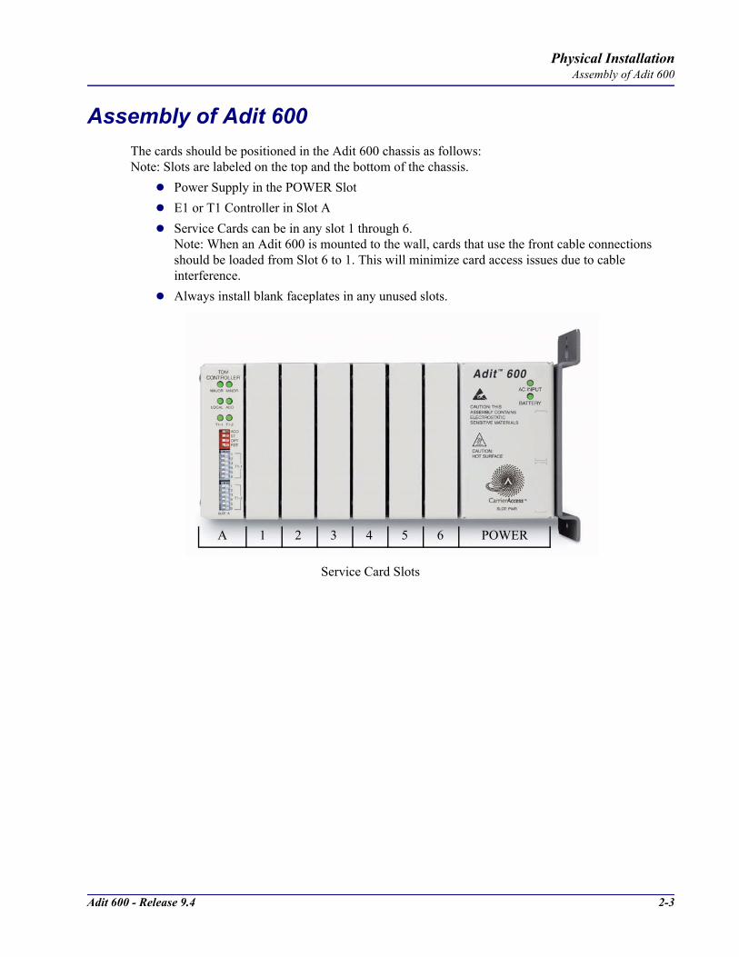
Adit 600 - Release 9.4 2-3
Physical InstallationAssembly of Adit 600
Assembly of Adit 600The cards should be positioned in the Adit 600 chassis as follows:Note: Slots are labeled on the top and the bottom of the chassis.
Power Supply in the POWER SlotE1 or T1 Controller in Slot AService Cards can be in any slot 1 through 6. Note: When an Adit 600 is mounted to the wall, cards that use the front cable connections should be loaded from Slot 6 to 1. This will minimize card access issues due to cable interference. Always install blank faceplates in any unused slots.
Service Card Slots
1 2 3 4 5 6A POWER

2-4 Adit 600 - Release 9.4
Physical InstallationWall Mounting
Wall MountingBefore beginning the mounting process, verify that the area meets the following requirements:
A stable environmentClean and free from extremes of temperature, shock, vibration and EMIMeets the all installation environment requirements, see Installation Environment on page 2-2.
The Adit 600 is delivered with a mounting bracket attached for quick and easy wall mounting, as shown in the illustration above.To install the unit to the wall, attach the unit using the four screws provided, one at each bracket foot.
NOTE: Do not mount the Adit 600 in any other orientation as show above.
Leave at least 3.5"above and belowthe Adit 600 foradequate ventilation
Mounting BracketLeave adequate clearanceat the back for access toconnectors
Leave at least 14" atthe front of the unit for access to cards and DIP switches
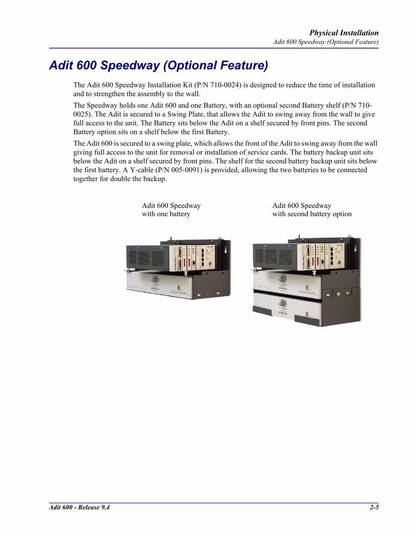
Adit 600 - Release 9.4 2-5
Physical InstallationAdit 600 Speedway (Optional Feature)
Adit 600 Speedway (Optional Feature)The Adit 600 Speedway Installation Kit (P/N 710-0024) is designed to reduce the time of installation and to strengthen the assembly to the wall.The Speedway holds one Adit 600 and one Battery, with an optional second Battery shelf (P/N 710-0025). The Adit is secured to a Swing Plate, that allows the Adit to swing away from the wall to give full access to the unit. The Battery sits below the Adit on a shelf secured by front pins. The second Battery option sits on a shelf below the first Battery. The Adit 600 is secured to a swing plate, which allows the front of the Adit to swing away from the wall giving full access to the unit for removal or installation of service cards. The battery backup unit sits below the Adit on a shelf secured by front pins. The shelf for the second battery backup unit sits below the first battery. A Y-cable (P/N 005-0091) is provided, allowing the two batteries to be connected together for double the backup.
Adit 600 Speedway with one battery
Adit 600 Speedway with second battery option
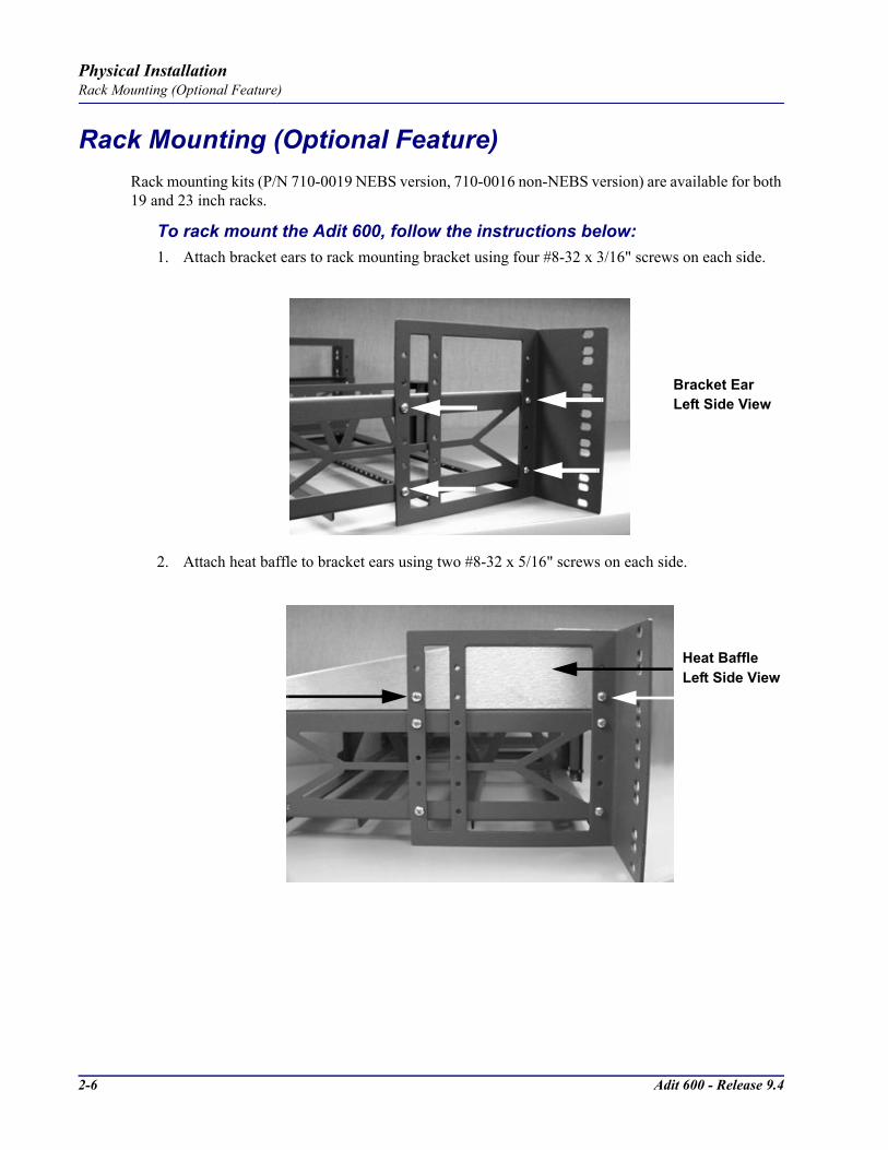
2-6 Adit 600 - Release 9.4
Physical InstallationRack Mounting (Optional Feature)
Rack Mounting (Optional Feature)Rack mounting kits (P/N 710-0019 NEBS version, 710-0016 non-NEBS version) are available for both 19 and 23 inch racks.
To rack mount the Adit 600, follow the instructions below:1. Attach bracket ears to rack mounting bracket using four #8-32 x 3/16" screws on each side.
2. Attach heat baffle to bracket ears using two #8-32 x 5/16" screws on each side.
Bracket EarLeft Side View
Heat BaffleLeft Side View

Adit 600 - Release 9.4 2-7
Physical InstallationRack Mounting (Optional Feature)
3. Attach rack mounting bracket ears to rack using two #12-24 x 5/8" rack mounting screws on each side.
4. Remove wall mount and screws from Adit 600 unit.
5. Slide the Adit 600 unit into rack mounting bracket.
6. Swing the front latch up to secure the Adit 600 unit(s), and tighten thumbscrew.
Front View
Thumbscrew
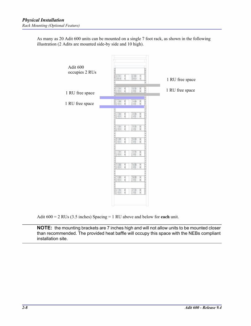
2-8 Adit 600 - Release 9.4
Physical InstallationRack Mounting (Optional Feature)
As many as 20 Adit 600 units can be mounted on a single 7 foot rack, as shown in the following illustration (2 Adits are mounted side-by side and 10 high).
Adit 600 = 2 RUs (3.5 inches) Spacing = 1 RU above and below for each unit.
NOTE: the mounting brackets are 7 inches high and will not allow units to be mounted closer than recommended. The provided heat baffle will occupy this space with the NEBs compliant installation site.
Adit 600occupies 2 RUs
1 RU free space
1 RU free space
1 RU free space
1 RU free space

CHAPTER 3Electrical Installation/Cabling
In this Chapter
Compliant Installation
Chassis Connectors and Buttons
Connectors

3-2 Adit 600 - Release 9.4
Electrical Installation/CablingCompliant Installation
Compliant Installation
1. Connect all of the signal cables as shown in the illustration above, and secure them with a plastic tie. Dress the signal cables toward the left of the Adit 600.
2. If using the 115V Power Supply, connect the -48 VDC battery power cable.3. Secure the ground lugs to the terminals using the nuts provided.4. Secure the power cable and the ground cable with a plastic tie (not included). Keep these cables
separate from the signal cables.5. Terminate each signal cable to its appropriate connector. 6. Secure signal cables using the holes along the bottom of the rack and plastic ties (not included).
NOTE: It is important that the Signal Cables are secured separately from the Power Cables, for proper equipment operation.
WARNING! ADDITIONAL PRIMARY PROTECTION IS REQUIRED WHEN CONNECTING T1/E1 OR FXS INTERFACES TO EXPOSED OFF-PREMISE COMMUNICATION CONDUCTORS. SECONDARY OVERVOLTAGE AND OVERCURRENT PROTECTION IS PROVIDED ON THESE INTERFACES FOR LIGHTNING SURGE, AC POWER CONTACT AND INDUCTION. IT WILL BE THE RESPONSIBILITY OF THE INSTALLER TO UTILIZE LISTED PRIMARY PROTECTORS AND FOLLOW INSTALLATION REQUIREMENTS PER LOCAL OR NATIONAL REGULATIONS.
Power Cord
-48 VDC Battery Power
Alarm Wiring
Signal Cables
Power Cables
Grounding Cable
Ferrite Bead
with cable loop
RS-232 craft port25-pair telco connector
25-pair telco connector
10Base-T EthernetT1/E1 connectors
Ferrite Beads
are in red
US
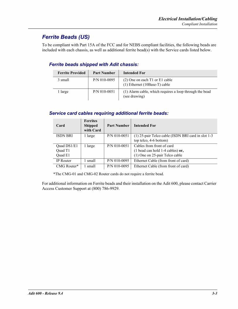
Adit 600 - Release 9.4 3-3
Electrical Installation/CablingCompliant Installation
Ferrite Beads (US)To be compliant with Part 15A of the FCC and for NEBS compliant facilities, the following beads are included with each chassis, as well as additional ferrite bead(s) with the Service cards listed below.
Ferrite beads shipped with Adit chassis:
Service card cables requiring additional ferrite beads:
*The CMG-01 and CMG-02 Router cards do not require a ferrite bead.
For additional information on Ferrite beads and their installation on the Adit 600, please contact Carrier Access Customer Support at (800) 786-9929.
Ferrite Provided Part Number Intended For
3 small P/N 010-0095 (2) One on each T1 or E1 cable (1) Ethernet (10Base-T) cable
1 large P/N 010-0051 (1) Alarm cable, which requires a loop through the bead (see drawing)
CardFerrites Shipped with Card
Part Number Intended For
ISDN BRI 1 large P/N 010-0051 (1) 25-pair Telco cable (ISDN BRI card in slot 1-3 top telco, 4-6 bottom)
Quad DS1/E1Quad T1Quad E1
1 large P/N 010-0051 Cables from front of card (1 bead can hold 1-4 cables) or,(1) One on 25-pair Telco cable
IP Router 1 small P/N 010-0095 Ethernet Cable (from front of card)CMG Router* 1 small P/N 010-0095 Ethernet Cable (from front of card)
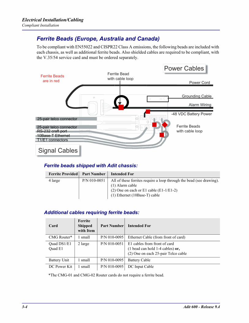
3-4 Adit 600 - Release 9.4
Electrical Installation/CablingCompliant Installation
Ferrite Beads (Europe, Australia and Canada)To be compliant with EN55022 and CISPR22 Class A emissions, the following beads are included with each chassis, as well as additional ferrite beads. Also shielded cables are required to be compliant, with the V.35/54 service card and must be ordered separately.
Ferrite beads shipped with Adit chassis:
Additional cables requiring ferrite beads:
*The CMG-01 and CMG-02 Router cards do not require a ferrite bead.
Ferrite Provided Part Number Intended For4 large P/N 010-0051 All of these ferrites require a loop through the bead (see drawing).
(1) Alarm cable(2) One on each or E1 cable (E1-1/E1-2)(1) Ethernet (10Base-T) cable
CardFerrite Shipped with Item
Part Number Intended For
CMG Router* 1 small P/N 010-0095 Ethernet Cable (from front of card)Quad DS1/E1Quad E1
2 large P/N 010-0051 E1 cables from front of card (1 bead can hold 1-4 cables) or,(2) One on each 25-pair Telco cable
Battery Unit 1 small P/N 010-0095 Battery CableDC Power Kit 1 small P/N 010-0095 DC Input Cable
Power Cord
-48 VDC Battery Power
Alarm Wiring
Signal Cables
Power Cables
Grounding Cable
Ferrite Bead
with cable loop
RS-232 craft port25-pair telco connector
25-pair telco connector
10Base-T EthernetT1/E1 connectors
Ferrite Beads
are in red
Ferrite Beads
with cable loop

Adit 600 - Release 9.4 3-5
Electrical Installation/CablingCompliant Installation
Shielded Cable (order separately):
For additional information on Ferrite beads and their installation on the Adit 600, please contact Carrier Access Customer Support at (800) 786-9929.
Card Part Number Intended ForV.35/54 (HD) P/N 005-0008 D-sub Male to Winchester Male, 10 ft.
P/N 005-0009 D-sub Male to Winchester Male, 25 ft.P/N 005-0010 D-sub Male to Winchester Male, 50 ft.P/N 005-0014 D-sub Male to Winchester Female, 10 ft.P/N 005-0068 D-sub Male to Winchester Female, 25 ft.P/N 005-0069 D-sub Male to Winchester Female, 50 ft.

3-6 Adit 600 - Release 9.4
Electrical Installation/CablingChassis Connectors and Buttons
Chassis Connectors and ButtonsThe following illustrations show all connectors on the back of the Adit 600.
ConnectorsThe following are the Adit 600 interface connectors:
T1-1/E1-1 and T1-2/E1-2 line connection ports each equipped with standard RJ-48C 8-pin connector jackRS-232 craft port connectorTip and Ring Analog Interfaces equipped with standard 25-pair Telco Connectors10Base-T Ethernet port to be connected to a remote management tool such as Telnet or an SNMP-based Network Management System with an RJ-45 8-pin connector jackExternal Alarm ConnectorGround Lugs
Ground TerminalsAlarms
AC or DC Power Connector
-48V/Battery
Ethernet
T1-2/E1-2 T1/E1
RS-232 Craft Port25-Pair Telco Connectors
T1-1/E1-1
[10Base-T]
Connectors
Reset
(AC shown below)

Adit 600 - Release 9.4 3-7
Electrical Installation/CablingConnectors
Chassis Ground ConnectorWARNING! THIS EQUIPMENT IS REQUIRED TO HAVE A PERMANENT GROUND CONNECTION. IF CONNECTED TO EXPOSED OUTDOOR COMMUNICATION CONDUCTORS, A #6 AWG COPPER WIRE MUST BE PERMANENTLY CONNECTED FROM AN APPROVED GROUNDING ELECTRODE TO THE CHASSIS GROUND LUG. OTHERWISE, A #14 AWG COPPER WIRE MAY BE UTILIZED. INSTALL THE GROUNDING CONDUCTOR IN ACCORDANCE WITH NATIONAL OR LOCAL REGULATIONS.
1. Route wire (#6 or #8 AWG copper) from building ground to lug on Adit 600.2. Strip insulation off wire end, if necessary.
3. Loosen compression screw until opening is large enough to accept ground wire.4. Insert ground wire into lug barrel, beneath compression plate and tighten compression screw.5. Attach ground lug to chassis
Power ResetThis is a resetable circuit breaker. If at any time there is a short or power surge on the incoming AC/DC line, the breaker will trip to protect the Power supply from damage.
Power ConnectionsThere are four power supplies available for the Adit 600.
115 VAC/-48 VDC230 VAC/-48 VDC24/-48 VDC24 VDC with -48 Output
These power supplies have different connectors as shown in the following sections. For additional information, see Chapter 15, Power Supply.
Fuse RecommendationsIf the power connector is wired to a fuse panel, use:
Power Applied Recommended Fuse Rating Expected Operating Environment
120 VAC 3 Amp Slow-Blow CPE, desktop environment
-48 VDC 3 Amp Slow-Blow High density MTY with battery backup (UPS)
230 VAC 2 Amp Slow-Blow International environment
24 VAC 5 Amp Slow-Blow CO or wireless market
Ground Lug
CompressionScrew
Lug Barrel
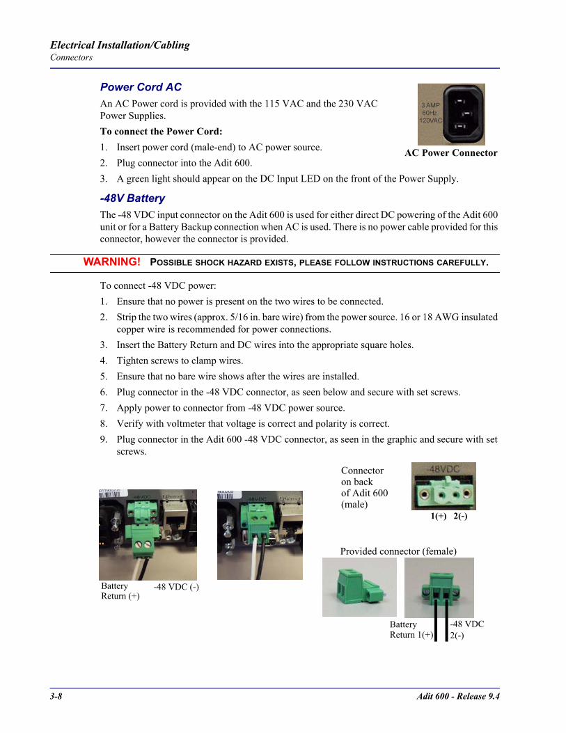
3-8 Adit 600 - Release 9.4
Electrical Installation/CablingConnectors
Power Cord ACAn AC Power cord is provided with the 115 VAC and the 230 VAC Power Supplies.To connect the Power Cord:1. Insert power cord (male-end) to AC power source.2. Plug connector into the Adit 600.3. A green light should appear on the DC Input LED on the front of the Power Supply.
-48V Battery The -48 VDC input connector on the Adit 600 is used for either direct DC powering of the Adit 600 unit or for a Battery Backup connection when AC is used. There is no power cable provided for this connector, however the connector is provided.
WARNING! POSSIBLE SHOCK HAZARD EXISTS, PLEASE FOLLOW INSTRUCTIONS CAREFULLY.
To connect -48 VDC power: 1. Ensure that no power is present on the two wires to be connected.2. Strip the two wires (approx. 5/16 in. bare wire) from the power source. 16 or 18 AWG insulated
copper wire is recommended for power connections.3. Insert the Battery Return and DC wires into the appropriate square holes.4. Tighten screws to clamp wires.5. Ensure that no bare wire shows after the wires are installed. 6. Plug connector in the -48 VDC connector, as seen below and secure with set screws. 7. Apply power to connector from -48 VDC power source.8. Verify with voltmeter that voltage is correct and polarity is correct.9. Plug connector in the Adit 600 -48 VDC connector, as seen in the graphic and secure with set
screws.
AC Power Connector
1(+) 2(-)
Connector
Provided connector (female)
of Adit 600on back
(male)
Battery -48 VDC2(-)
Battery Return (+)
-48 VDC (-)
Return 1(+)
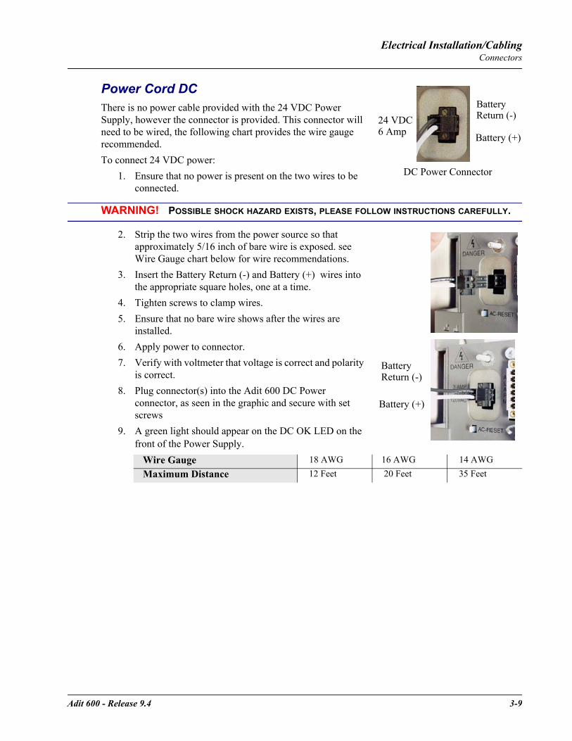
Adit 600 - Release 9.4 3-9
Electrical Installation/CablingConnectors
Power Cord DCThere is no power cable provided with the 24 VDC Power Supply, however the connector is provided. This connector will need to be wired, the following chart provides the wire gauge recommended.To connect 24 VDC power:
1. Ensure that no power is present on the two wires to be connected.
WARNING! POSSIBLE SHOCK HAZARD EXISTS, PLEASE FOLLOW INSTRUCTIONS CAREFULLY.
2. Strip the two wires from the power source so that approximately 5/16 inch of bare wire is exposed. see Wire Gauge chart below for wire recommendations.
3. Insert the Battery Return (-) and Battery (+) wires into the appropriate square holes, one at a time.
4. Tighten screws to clamp wires.5. Ensure that no bare wire shows after the wires are
installed. 6. Apply power to connector.7. Verify with voltmeter that voltage is correct and polarity
is correct.8. Plug connector(s) into the Adit 600 DC Power
connector, as seen in the graphic and secure with set screws
9. A green light should appear on the DC OK LED on the front of the Power Supply.
Wire Gauge 18 AWG 16 AWG 14 AWGMaximum Distance 12 Feet 20 Feet 35 Feet
24 VDC6 Amp
Battery
Battery (+)
DC Power Connector
Return (-)
Battery (+)
Battery Return (-)
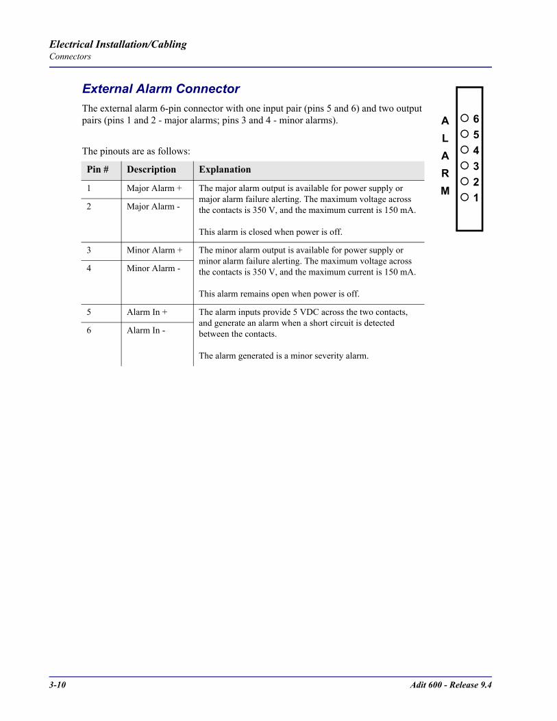
3-10 Adit 600 - Release 9.4
Electrical Installation/CablingConnectors
External Alarm ConnectorThe external alarm 6-pin connector with one input pair (pins 5 and 6) and two output pairs (pins 1 and 2 - major alarms; pins 3 and 4 - minor alarms).
The pinouts are as follows:
Pin # Description Explanation
1 Major Alarm + The major alarm output is available for power supply or major alarm failure alerting. The maximum voltage across the contacts is 350 V, and the maximum current is 150 mA.
This alarm is closed when power is off.
2 Major Alarm -
3 Minor Alarm + The minor alarm output is available for power supply or minor alarm failure alerting. The maximum voltage across the contacts is 350 V, and the maximum current is 150 mA.
This alarm remains open when power is off.
4 Minor Alarm -
5 Alarm In + The alarm inputs provide 5 VDC across the two contacts, and generate an alarm when a short circuit is detected between the contacts.
The alarm generated is a minor severity alarm.
6 Alarm In -
654321
ALARM
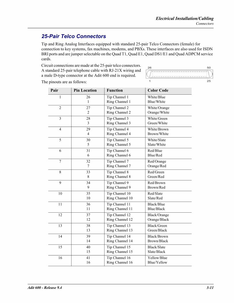
Adit 600 - Release 9.4 3-11
Electrical Installation/CablingConnectors
25-Pair Telco ConnectorsTip and Ring Analog Interfaces equipped with standard 25-pair Telco Connectors (female) for connection to key systems, fax machines, modems, and PBXs. These interfaces are also used for ISDN BRI ports and are jumper selectable on the Quad T1, Quad E1, Quad DS1/E1 and Quad ADPCM service cards.Circuit connections are made at the 25-pair telco connectors. A standard 25-pair telephone cable with RJ-21X wiring and a male D-type connector at the Adit 600 end is required. The pinouts are as follows:
Pair Pin Location Function Color Code1 26
1Tip Channel 1 Ring Channel 1
White/BlueBlue/White
2 27 2
Tip Channel 2 Ring Channel 2
White/OrangeOrange/White
3 283
Tip Channel 3Ring Channel 3
White/GreenGreen/White
4 294
Tip Channel 4 Ring Channel 4
White/BrownBrown/White
5 305
Tip Channel 5 Ring Channel 5
White/SlateSlate/White
6 316
Tip Channel 6 Ring Channel 6
Red/BlueBlue/Red
7 327
Tip Channel 7 Ring Channel 7
Red/OrangeOrange/Red
8 338
Tip Channel 8 Ring Channel 8
Red/GreenGreen/Red
9 349
Tip Channel 9 Ring Channel 9
Red/BrownBrown/Red
10 3510
Tip Channel 10 Ring Channel 10
Red/SlateSlate/Red
11 3611
Tip Channel 11 Ring Channel 11
Black/BlueBlue/Black
12 3712
Tip Channel 12 Ring Channel 12
Black/OrangeOrange/Black
13 3813
Tip Channel 13 Ring Channel 13
Black/GreenGreen/Black
14 3914
Tip Channel 14 Ring Channel 14
Black/BrownBrown/Black
15 4015
Tip Channel 15 Ring Channel 15
Black/SlateSlate/Black
16 4116
Tip Channel 16 Ring Channel 16
Yellow/BlueBlue/Yellow
50
25
26
1
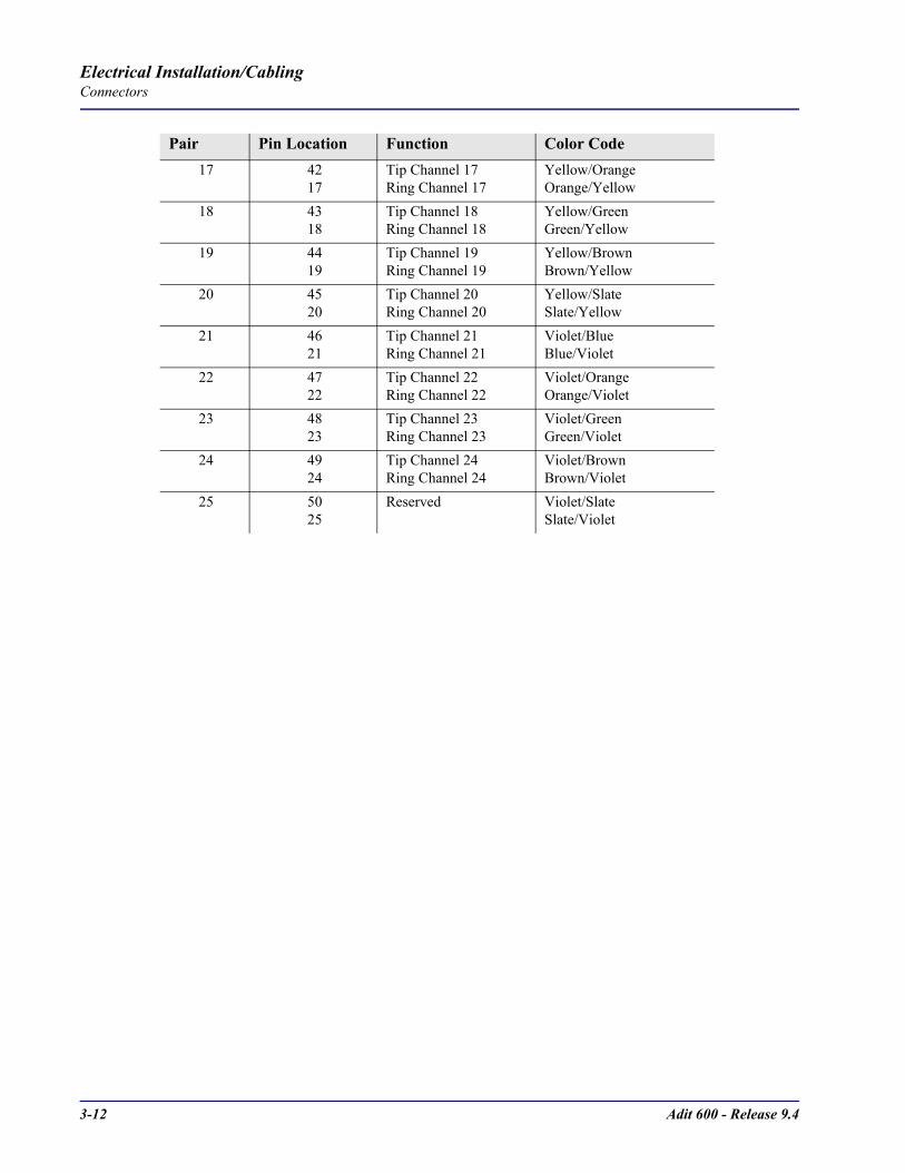
3-12 Adit 600 - Release 9.4
Electrical Installation/CablingConnectors
Pair Pin Location Function Color Code17 42
17Tip Channel 17 Ring Channel 17
Yellow/OrangeOrange/Yellow
18 4318
Tip Channel 18 Ring Channel 18
Yellow/GreenGreen/Yellow
19 4419
Tip Channel 19 Ring Channel 19
Yellow/BrownBrown/Yellow
20 4520
Tip Channel 20 Ring Channel 20
Yellow/SlateSlate/Yellow
21 4621
Tip Channel 21 Ring Channel 21
Violet/BlueBlue/Violet
22 4722
Tip Channel 22 Ring Channel 22
Violet/OrangeOrange/Violet
23 4823
Tip Channel 23 Ring Channel 23
Violet/GreenGreen/Violet
24 49 24
Tip Channel 24Ring Channel 24
Violet/BrownBrown/Violet
25 50 25
Reserved Violet/SlateSlate/Violet
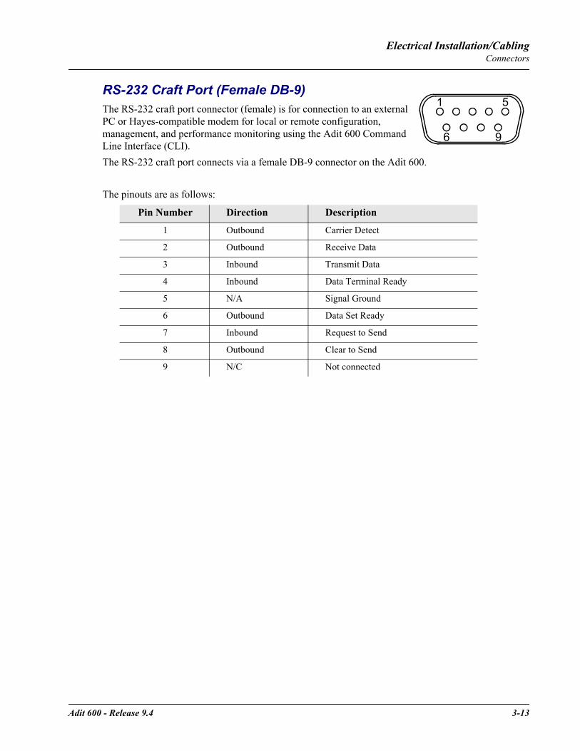
Adit 600 - Release 9.4 3-13
Electrical Installation/CablingConnectors
RS-232 Craft Port (Female DB-9)The RS-232 craft port connector (female) is for connection to an external PC or Hayes-compatible modem for local or remote configuration, management, and performance monitoring using the Adit 600 Command Line Interface (CLI).The RS-232 craft port connects via a female DB-9 connector on the Adit 600.
The pinouts are as follows:
Pin Number Direction Description
1 Outbound Carrier Detect
2 Outbound Receive Data
3 Inbound Transmit Data
4 Inbound Data Terminal Ready
5 N/A Signal Ground
6 Outbound Data Set Ready
7 Inbound Request to Send
8 Outbound Clear to Send
9 N/C Not connected
1 5
6 9

3-14 Adit 600 - Release 9.4
Electrical Installation/CablingConnectors
T1 and E1 Connection PortsThe T1 and E1 connection ports are each equipped with a standard RJ-48C (female) on the Adit 600 unit. The pinouts are as follows:
T1/E1 (RJ-48C)
10Base-T Ethernet The 10Base-T Ethernet (female) port to connect to a remote management tool such as Telnet or an SNMP-based Network Management System. Note a LINK LED on the back of the unit displays green when the system has a good ethernet link.The pinouts are as follows:
Ethernet (RJ-45)
Pin Name Description 1 Receive Ring Receive from DS1 network2 Receive Tip Receive from DS1 network3 N/C Not connected4 Transmit Ring To DS1 network5 Transmit Tip To DS1 network6 -8 N/C Not connected
Pin Name Description 1 Receive + Receive from network2 Receive - Receive from network3 Transmit + Transmit to network4-5 N/C Not connected 6 Transmit - Transmit to network7-8 N/C Not connected
1 8
1 8
CHAPTER 4Configuration
In this ChapterSetting up a CLI ConnectionSetup Login SecuritySystem InformationBasic System Setup- Initial Setup- Security Setup- DS1/T1 Setup- E1 Setup- DS0/Channel Setup- Analog Port Setup- 4-Wire E&M Setup- Establish a Static Channel Connection- ISDN BRI Service Setup- OCU-DP Card Setup- ADPCM Card Setup- V.35 Port Setup- Change the IP Address of the DS0 Management Channel- Upgrade the Adit 600 Software- Upgrade the Router (IP, CMG or TSR) SoftwareBasic Router SetupsConfiguration RestrictionsInstall Country Specific Ringer TonesQuick Configuration ReloadDS0 Management Channel SetupBasic P-Phone Configuration Setup

4-2 Adit 600 - Release 9.4
ConfigurationSetting up a CLI Connection
Setting up a CLI Connection
NOTE: Default IP address of the Adit 600 Controller (T1/E1) is 10.0.0.10.
To connect with CLI, set up the connection: If connecting via the ethernet 10Base-T connection, use a Telnet TCP/IP program to access the CLI. This requires an IP address of the Controller. The Controllers are shipped with the IP address set to 10.0.0.10, if this address has been changed and is not known, use HyperTerm to access the Controller and use the CLI command show ip. If an IP address needs to be set use the CLI command set ethernet ip address.If connecting via RS-232, the port settings should be set to: Bits per second: 9600 Data bits: 8Parity: None Stop bits: 1Flow control: None
Set your Terminal Emulation to: VT100
NOTE: When using Tera Term TCP/IP, CLI commands will not be recognized until the following setup is completed.
In Tera Term go to Setup/Terminal.Set the New-line/Transmit value"CR+LF".
Local vs. Remote ConfigurationFor remote configuration via the CLI, use the set local off command.

Adit 600 - Release 9.4 4-3
ConfigurationSetup Login Security
Setup Login SecurityThe default for the system is to have no login. A login should be setup, as soon as possible, for security reasons.To set up security on the Adit 600 perform the following:
1. Open a CLI session (either through Telnet, HyperTerm, or other). 2. Add a user. See add user on page 5-22
Note: The first user added should always be an administrator level (full-access). This administrator then manages subsequent users added.
3. Set user Access Level. See set user level on page 5-189.4. Set user Password. See set user password on page 5-190.5. User the exit command to end the session, and select [Enter] to log back in.
The following shows this process:> add user "helen"OK
> show users User Level Last Login Logged In
helen 1 00:00:00 00/00/0000 0
* indicates self
> set user "helen" password New Password: **** New Password again: ****
OK
> exitLogging out of Carrier Access - Adit 600
Carrier Access - Adit 600
07:46:34 08/18/2005
Login: helen Password: ****
Status Equipment:
BootCode Version: 2.00
CardType Status SW Vers CLEI
-------- ------ ------- ----
SLOT A E1x2 Present 9.4.0 SIUXSS0EAASLOT 1 FXOx8 Present 1.12 SIIXPV0DAA
SLOT 2 FXSx8 Present 1.09 SIC3GJ0CAA
SLOT 3 CMGx1 Present 2.70 SIIX270DAASLOT 4 V35x2 Present 1.05 SIC3HK0CAA
SLOT 5 BRIx8 Present 1.11 SIIXUX0DAA
SLOT 6 T1E1x4H Present 2.01 NOT_AVAIL

4-4 Adit 600 - Release 9.4
ConfigurationSystem Information
.
.
.
Show Autoexit:
Autoexit is on; timeout is 20 minutes.
>
System InformationOnce a management session has been initiated (Telnet or HyperTerm) the system information will be displayed similar to the following:
NOTE: CLEI codes are only displayed after system bootup or with the command status equipment as seen below.
Carrier Access - Adit 600
00:00:17 08/01/2004
Status Equipment:BootCode Version: 2.00
CardType Status SW Vers CLEI
SLOT A T1x2 Present 9.2.0 SIC3DH0CAASLOT 1 T1E1x4H Present 2.01 NOT_AVAIL
SLOT 2 FXSx8 Present 1.09 SIC3GJ0CAA
SLOT 3 RTRx1 Present 1.80 SIIASS0BAASLOT 4 CMGx1 Present 2.30 SIIX270DAA
SLOT 5 CMG-02x1 Present 2.40 SIIX270DAA
SLOT 6 V35x2 Present SIC3HK0CAA
Alarms:
Time Date Severity Description 00:00:21 08/01/2004 Major 4:1-CMG Ethernet Link Down 00:00:20 08/01/2004 Major 5:1-RTR Ethernet Link Down 00:00:20 08/01/2004 Major 6:1-TSR Ethernet Link Down 00:00:05 08/01/2004 Major A:2-DS1 Loss Of Signal 00:00:05 08/01/2004 Major A:1-DS1 Loss Of SignalTotal=5
Status Sessions: Session User Login Port
* TELNET1 10.10.1.1
* indicates current session
Show Autoexit:
Autoexit is on; timeout is 20 minutes.WARNING: System in LOCAL mode. Use 'set local off' to turn it off.

Adit 600 - Release 9.4 4-5
ConfigurationBasic System Setup
Basic System SetupFollowing is a quick reference to some of the common tasks in configuring the Adit 600.
Initial SetupUse the following commands for your initial setup, for further information see the specific command listed in Chapter 5, CLI Commands.
Security SetupUse the following commands to set up the security on the Adit 600. See the set user command for details.
DS1/T1 SetupUse the following commands to set up a DS1. See the set (ds1) command for more details.
Command Description
set local off Disables DIP switches.
set date mm/dd/yyyy Set the date used for event logging
set time hh:mm:ss Set the time used for event logging
set id "id-name" Set a system ID name
set clock1 slot:port internal Set the primary clock source
set clock2 slot:port internal Set the secondary clock source
set ethernet ip address ip-addr mask
Set the Ethernet IP address and mask.
set ip gateway ip-addr Set the IP gateway, in the standard IP address format
Command Description
set user "user-name" level 1-3 Specify the user name and the security level
set user "user-name" password Set a password for the user
Command Description
set ds1-addr up Activate the port of the DS1 (slot:port)
set ds1-addr id "id-string" Set the identification string
set ds1-addr lbo 1-9 Set the line buildout value for the DS1
set ds1-addr linecode ami|b8zs Set the linecode for the DS1
set ds1-addr framing d4|esf| tr8afdl|tr8anofdl|tr8b
Set the framing option for the DS1
set ds1-addr loopdetect on|off Set the detection/reaction to CSU loopcodes
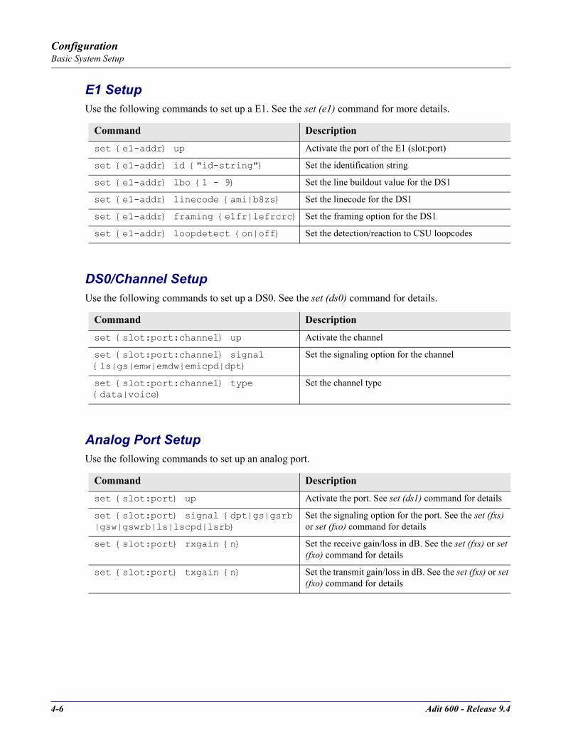
4-6 Adit 600 - Release 9.4
ConfigurationBasic System Setup
E1 SetupUse the following commands to set up a E1. See the set (e1) command for more details.
DS0/Channel SetupUse the following commands to set up a DS0. See the set (ds0) command for details.
Analog Port SetupUse the following commands to set up an analog port.
Command Description
set e1-addr up Activate the port of the E1 (slot:port)
set e1-addr id "id-string" Set the identification string
set e1-addr lbo 1 - 9 Set the line buildout value for the DS1
set e1-addr linecode ami|b8zs Set the linecode for the DS1
set e1-addr framing e1fr|lefrcrc Set the framing option for the DS1
set e1-addr loopdetect on|off Set the detection/reaction to CSU loopcodes
Command Description
set slot:port:channel up Activate the channel
set slot:port:channel signal ls|gs|emw|emdw|emicpd|dpt
Set the signaling option for the channel
set slot:port:channel type data|voice
Set the channel type
Command Description
set slot:port up Activate the port. See set (ds1) command for details
set slot:port signal dpt|gs|gsrb |gsw|gswrb|ls|lscpd|lsrb
Set the signaling option for the port. See the set (fxs) or set (fxo) command for details
set slot:port rxgain n Set the receive gain/loss in dB. See the set (fxs) or set (fxo) command for details
set slot:port txgain n Set the transmit gain/loss in dB. See the set (fxs) or set (fxo) command for details
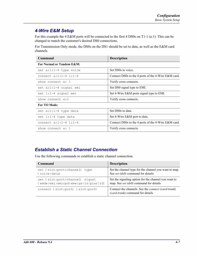
Adit 600 - Release 9.4 4-7
ConfigurationBasic System Setup
4-Wire E&M SetupFor this example the 4 E&M ports will be connected to the first 4 DS0s on T1-1 (a:1). This can be changed to match the customer's desired DS0 connections. For Transmission Only mode, the DS0s on the DS1 should be set to data, as well as the E&M card channels.
Establish a Static Channel ConnectionUse the following commands to establish a static channel connection.
Command Description
For Normal or Tandem E&M:
set a:1:1-4 type voice Set DS0s to voice.
connect a:1:1-4 1:1-4 Connect DS0s to the 4 ports of the 4-Wire E&M card.
show connect a: 1 Verify cross connects.
set a:1:1-4 signal emi Set DS0 signal type to EMI.
set 1:1-4 signal emi Set 4-Wire E&M ports signal type to EMI.
show connect a:1 Verify cross connects.
For TO Mode:
set a:1:1-4 type data Set DS0s to data.
set 1:1-4 type data Set 4-Wire E&M port to data.
connect a:1:1-4 1:1-4 Connect DS0s to the 4 ports of the 4-Wire E&M card.
show connect a: 1 Verify cross connects.
Command Description
set slot:port:channel type voice|data
Set the channel type for the channel you want to map. See set (ds0) command for details
set slot:port:channel signal emdw|emi|emicpd|emw|gs|ls|plar|r2
Set the signaling option for the channel you want to map. See set (ds0) command for details
connect slot:port slot:port Connect the channels. See the connect (card-trunk) (card-trunk) command for details

4-8 Adit 600 - Release 9.4
ConfigurationBasic System Setup
ISDN BRI Service SetupUse the following commands to set up a ISDN BRI Service. See the set (bri) command for details.
OCU-DP Card SetupThe following is a basic setup for the OCU-DP card.
Command Description
set slot:port up Put the ISDN line In-Service
set slot mode lt3ds0|lt4to1tdm|nt3ds0
Set the ISDN mode
set slot:port crv 1-768 Set the Call Reference Value. Note: value must be the same as the Access Navigator
set slot:port threshold day|hour es|ses
Set the threshold for the IDSN lines
set slot pmsync adit|switch Set the source for performance monitoring synchronization
set slot:port autoactivate on|off
Only used in 4 to 1 mode. Establishes the D channel when the FDL link can not be used
Command Description
set ocudp-addr baud 2400|4800 |9600|19200|38400|56000*|64000
Set the OCU-DP Baud rate. Where ocudp-addr = slot:port of the OCU-DP card to apply the configuration settings to
set ocudp-addr up Set the OCU-DP port 1 up
show ocudp_card-addr Show the OCU-DP card settings. Where ocudp_card-addr = slot of the OCU-DP card
disconnect a Disconnects all connections to slot a (controller)
set ds0-addr type data Sets a DS0 data signaling type
connect ds0-addr ocudp-addr Connects DS0 (in previous step) to OCU-DP port (in previous step)
show connect (ocudp_card-addr Displays connect information for OCU-DP card
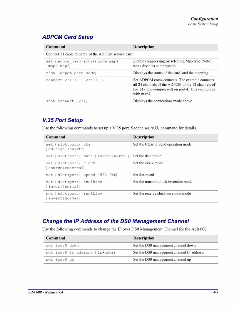
Adit 600 - Release 9.4 4-9
ConfigurationBasic System Setup
ADPCM Card Setup
V.35 Port SetupUse the following commands to set up a V.35 port. See the set (v35) command for details.
Change the IP Address of the DS0 Management ChannelUse the following commands to change the IP over DS0 Management Channel for the Adit 600.
Command Description
Connect T1 cable to port 1 of the ADPCM service card
set adpcm_card-addrnone|map1 |map2|map3
Enable compressing by selecting Map type. Note: none disables compression.
show (adpcm_card-addr Displays the status of the card, and the mapping.
connect 2:1:1-12 2:4:1-12 Set ADPCM cross-connects. The example connects all 24 channels of the ADPCM to the 12 channels of the T1 (now compressed) on port 4. This example is with map2
show connect 2:1) Displays the connections made above.
Command Description
set slot:port cts cd|high|low|rts
Set the Clear to Send operation mode
set slot:port data invert|normal Set the data mode
set slot:port clock source|external
Set the clock mode
set slot:port speed 56K|64K Set the speed
set slot:port txclkinv invert|normal
Set the transmit clock inversion mode
set slot:port rxclkinv invert|normal
Set the receive clock inversion mode
Command Description
set ipds0 down Set the DS0 management channel down
set ipds0 ip address ip-addr Set the DS0 management channel IP address.
set ipds0 up Set the DS0 management channel up

4-10 Adit 600 - Release 9.4
ConfigurationBasic System Setup
Upgrade the Adit 600 SoftwareUse the following commands to determine the system software level, then upgrade the software to the latest version.
Upgrade the Router (IP, CMG or TSR) SoftwareUse the following commands to determine the Router card software level, then upgrade the software to the latest version.
Command Description
status equipment Determine the system software level. The Slot A line (SW Vers) will display the current software level
load tftp ip-addr "file-name" (or load xmodem)
Load the new system software to the Adit 600. See the load tftp and load xmodem command for more information. Note: must have TFTP running in the background
Command Description
status equipment Determine the Router software level. The Router Slot line (SW Vers) will display the current software level
load router-slot tftp ip-addr "file-name"
Load the new Router software to the Adit Router card. See the load tftp command for more information. Note: must have TFTP running in the background
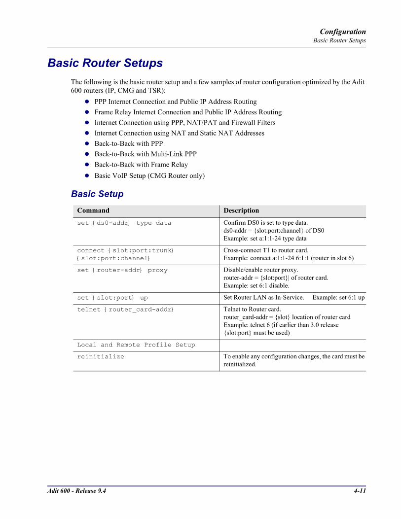
Adit 600 - Release 9.4 4-11
ConfigurationBasic Router Setups
Basic Router SetupsThe following is the basic router setup and a few samples of router configuration optimized by the Adit 600 routers (IP, CMG and TSR):
PPP Internet Connection and Public IP Address RoutingFrame Relay Internet Connection and Public IP Address RoutingInternet Connection using PPP, NAT/PAT and Firewall FiltersInternet Connection using NAT and Static NAT AddressesBack-to-Back with PPPBack-to-Back with Multi-Link PPPBack-to-Back with Frame RelayBasic VoIP Setup (CMG Router only)
Basic SetupCommand Description
set ds0-addr type data Confirm DS0 is set to type data. ds0-addr = slot:port:channel of DS0Example: set a:1:1-24 type data
connect slot:port:trunk slot:port:channel
Cross-connect T1 to router card.Example: connect a:1:1-24 6:1:1 (router in slot 6)
set router-addr proxy Disable/enable router proxy. router-addr = slot:port| of router card. Example: set 6:1 disable.
set slot:port up Set Router LAN as In-Service. Example: set 6:1 up
telnet router_card-addr Telnet to Router card.router_card-addr = slot location of router cardExample: telnet 6 (if earlier than 3.0 release slot:port must be used)
Local and Remote Profile Setup
reinitialize To enable any configuration changes, the card must be reinitialized.
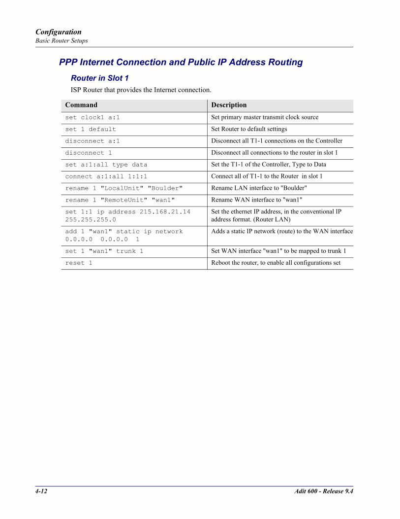
4-12 Adit 600 - Release 9.4
ConfigurationBasic Router Setups
PPP Internet Connection and Public IP Address RoutingRouter in Slot 1ISP Router that provides the Internet connection.
Command Description
set clock1 a:1 Set primary master transmit clock source
set 1 default Set Router to default settings
disconnect a:1 Disconnect all T1-1 connections on the Controller
disconnect 1 Disconnect all connections to the router in slot 1
set a:1:all type data Set the T1-1 of the Controller, Type to Data
connect a:1:all 1:1:1 Connect all of T1-1 to the Router in slot 1
rename 1 "LocalUnit" "Boulder" Rename LAN interface to "Boulder"
rename 1 "RemoteUnit" "wan1" Rename WAN interface to "wan1"
set 1:1 ip address 215.168.21.14 255.255.255.0
Set the ethernet IP address, in the conventional IP address format. (Router LAN)
add 1 "wan1" static ip network 0.0.0.0 0.0.0.0 1
Adds a static IP network (route) to the WAN interface
set 1 "wan1" trunk 1 Set WAN interface "wan1" to be mapped to trunk 1
reset 1 Reboot the router, to enable all configurations set
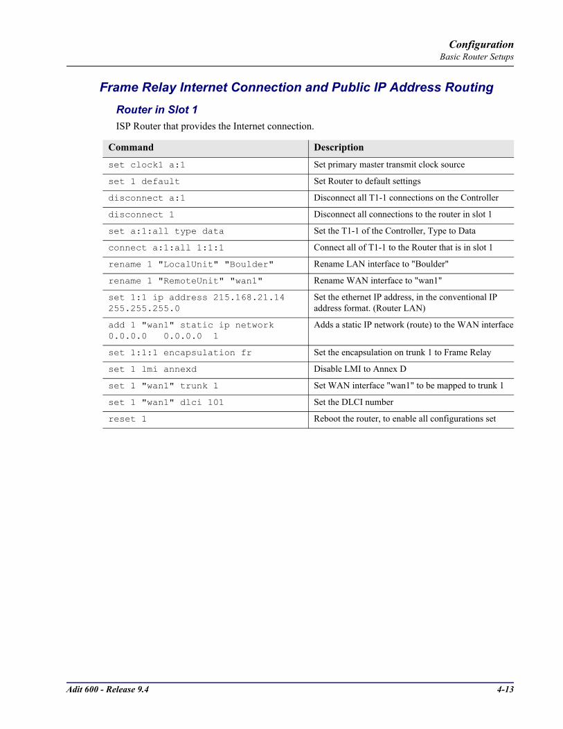
Adit 600 - Release 9.4 4-13
ConfigurationBasic Router Setups
Frame Relay Internet Connection and Public IP Address RoutingRouter in Slot 1ISP Router that provides the Internet connection.
Command Description
set clock1 a:1 Set primary master transmit clock source
set 1 default Set Router to default settings
disconnect a:1 Disconnect all T1-1 connections on the Controller
disconnect 1 Disconnect all connections to the router in slot 1
set a:1:all type data Set the T1-1 of the Controller, Type to Data
connect a:1:all 1:1:1 Connect all of T1-1 to the Router that is in slot 1
rename 1 "LocalUnit" "Boulder" Rename LAN interface to "Boulder"
rename 1 "RemoteUnit" "wan1" Rename WAN interface to "wan1"
set 1:1 ip address 215.168.21.14 255.255.255.0
Set the ethernet IP address, in the conventional IP address format. (Router LAN)
add 1 "wan1" static ip network 0.0.0.0 0.0.0.0 1
Adds a static IP network (route) to the WAN interface
set 1:1:1 encapsulation fr Set the encapsulation on trunk 1 to Frame Relay
set 1 lmi annexd Disable LMI to Annex D
set 1 "wan1" trunk 1 Set WAN interface "wan1" to be mapped to trunk 1
set 1 "wan1" dlci 101 Set the DLCI number
reset 1 Reboot the router, to enable all configurations set
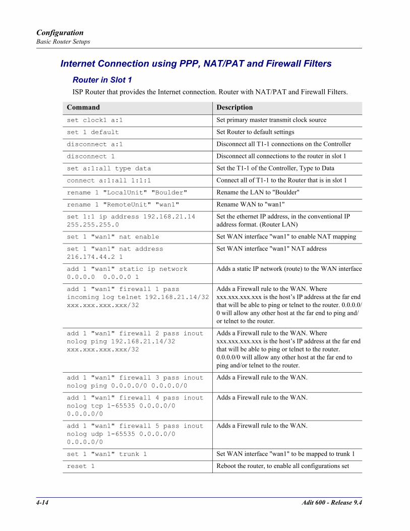
4-14 Adit 600 - Release 9.4
ConfigurationBasic Router Setups
Internet Connection using PPP, NAT/PAT and Firewall FiltersRouter in Slot 1ISP Router that provides the Internet connection. Router with NAT/PAT and Firewall Filters.
Command Description
set clock1 a:1 Set primary master transmit clock source
set 1 default Set Router to default settings
disconnect a:1 Disconnect all T1-1 connections on the Controller
disconnect 1 Disconnect all connections to the router in slot 1
set a:1:all type data Set the T1-1 of the Controller, Type to Data
connect a:1:all 1:1:1 Connect all of T1-1 to the Router that is in slot 1
rename 1 "LocalUnit" "Boulder" Rename the LAN to "Boulder"
rename 1 "RemoteUnit" "wan1" Rename WAN to "wan1"
set 1:1 ip address 192.168.21.14 255.255.255.0
Set the ethernet IP address, in the conventional IP address format. (Router LAN)
set 1 "wan1" nat enable Set WAN interface "wan1" to enable NAT mapping
set 1 "wan1" nat address 216.174.44.2 1
Set WAN interface "wan1" NAT address
add 1 "wan1" static ip network 0.0.0.0 0.0.0.0 1
Adds a static IP network (route) to the WAN interface
add 1 "wan1" firewall 1 pass incoming log telnet 192.168.21.14/32 xxx.xxx.xxx.xxx/32
Adds a Firewall rule to the WAN. Where xxx.xxx.xxx.xxx is the host’s IP address at the far end that will be able to ping or telnet to the router. 0.0.0.0/0 will allow any other host at the far end to ping and/or telnet to the router.
add 1 "wan1" firewall 2 pass inout nolog ping 192.168.21.14/32 xxx.xxx.xxx.xxx/32
Adds a Firewall rule to the WAN. Where xxx.xxx.xxx.xxx is the host’s IP address at the far end that will be able to ping or telnet to the router. 0.0.0.0/0 will allow any other host at the far end to ping and/or telnet to the router.
add 1 "wan1" firewall 3 pass inout nolog ping 0.0.0.0/0 0.0.0.0/0
Adds a Firewall rule to the WAN.
add 1 "wan1" firewall 4 pass inout nolog tcp 1-65535 0.0.0.0/0 0.0.0.0/0
Adds a Firewall rule to the WAN.
add 1 "wan1" firewall 5 pass inout nolog udp 1-65535 0.0.0.0/0 0.0.0.0/0
Adds a Firewall rule to the WAN.
set 1 "wan1" trunk 1 Set WAN interface "wan1" to be mapped to trunk 1
reset 1 Reboot the router, to enable all configurations set
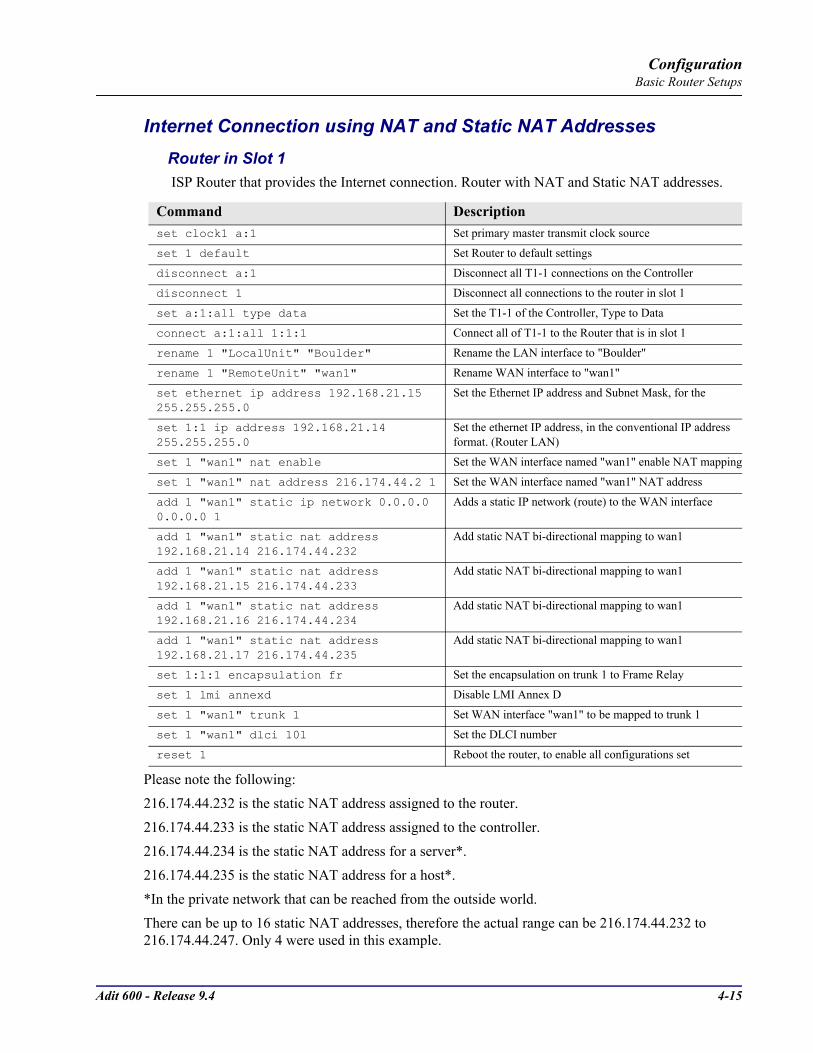
Adit 600 - Release 9.4 4-15
ConfigurationBasic Router Setups
Internet Connection using NAT and Static NAT AddressesRouter in Slot 1 ISP Router that provides the Internet connection. Router with NAT and Static NAT addresses.
Please note the following:216.174.44.232 is the static NAT address assigned to the router. 216.174.44.233 is the static NAT address assigned to the controller.216.174.44.234 is the static NAT address for a server*.216.174.44.235 is the static NAT address for a host*.*In the private network that can be reached from the outside world.There can be up to 16 static NAT addresses, therefore the actual range can be 216.174.44.232 to 216.174.44.247. Only 4 were used in this example.
Command Descriptionset clock1 a:1 Set primary master transmit clock source
set 1 default Set Router to default settings
disconnect a:1 Disconnect all T1-1 connections on the Controller
disconnect 1 Disconnect all connections to the router in slot 1
set a:1:all type data Set the T1-1 of the Controller, Type to Data
connect a:1:all 1:1:1 Connect all of T1-1 to the Router that is in slot 1
rename 1 "LocalUnit" "Boulder" Rename the LAN interface to "Boulder"
rename 1 "RemoteUnit" "wan1" Rename WAN interface to "wan1"
set ethernet ip address 192.168.21.15 255.255.255.0
Set the Ethernet IP address and Subnet Mask, for the
set 1:1 ip address 192.168.21.14 255.255.255.0
Set the ethernet IP address, in the conventional IP address format. (Router LAN)
set 1 "wan1" nat enable Set the WAN interface named "wan1" enable NAT mapping
set 1 "wan1" nat address 216.174.44.2 1 Set the WAN interface named "wan1" NAT address
add 1 "wan1" static ip network 0.0.0.0 0.0.0.0 1
Adds a static IP network (route) to the WAN interface
add 1 "wan1" static nat address 192.168.21.14 216.174.44.232
Add static NAT bi-directional mapping to wan1
add 1 "wan1" static nat address 192.168.21.15 216.174.44.233
Add static NAT bi-directional mapping to wan1
add 1 "wan1" static nat address 192.168.21.16 216.174.44.234
Add static NAT bi-directional mapping to wan1
add 1 "wan1" static nat address 192.168.21.17 216.174.44.235
Add static NAT bi-directional mapping to wan1
set 1:1:1 encapsulation fr Set the encapsulation on trunk 1 to Frame Relay
set 1 lmi annexd Disable LMI Annex D
set 1 "wan1" trunk 1 Set WAN interface "wan1" to be mapped to trunk 1
set 1 "wan1" dlci 101 Set the DLCI number
reset 1 Reboot the router, to enable all configurations set
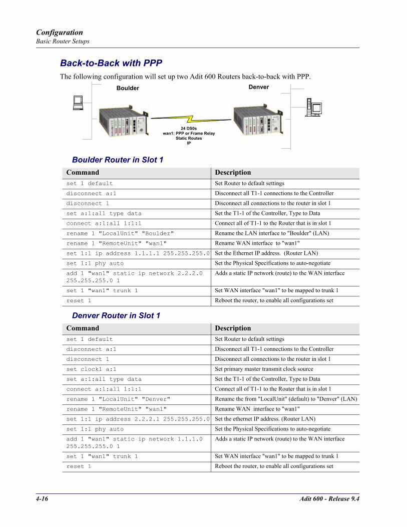
4-16 Adit 600 - Release 9.4
ConfigurationBasic Router Setups
Back-to-Back with PPPThe following configuration will set up two Adit 600 Routers back-to-back with PPP.
Boulder Router in Slot 1
Denver Router in Slot 1
Command Descriptionset 1 default Set Router to default settings
disconnect a:1 Disconnect all T1-1 connections to the Controller
disconnect 1 Disconnect all connections to the router in slot 1
set a:1:all type data Set the T1-1 of the Controller, Type to Data
connect a:1:all 1:1:1 Connect all of T1-1 to the Router that is in slot 1
rename 1 "LocalUnit" "Boulder" Rename the LAN interface to "Boulder" (LAN)
rename 1 "RemoteUnit" "wan1" Rename WAN interface to "wan1"
set 1:1 ip address 1.1.1.1 255.255.255.0 Set the Ethernet IP address. (Router LAN)
set 1:1 phy auto Set the Physical Specifications to auto-negotiate
add 1 "wan1" static ip network 2.2.2.0 255.255.255.0 1
Adds a static IP network (route) to the WAN interface
set 1 "wan1" trunk 1 Set WAN interface "wan1" to be mapped to trunk 1
reset 1 Reboot the router, to enable all configurations set
Command Descriptionset 1 default Set Router to default settings
disconnect a:1 Disconnect all T1-1 connections to the Controller
disconnect 1 Disconnect all connections to the router in slot 1
set clock1 a:1 Set primary master transmit clock source
set a:1:all type data Set the T1-1 of the Controller, Type to Data
connect a:1:all 1:1:1 Connect all of T1-1 to the Router that is in slot 1
rename 1 "LocalUnit" "Denver" Rename the from "LocalUnit" (default) to "Denver" (LAN)
rename 1 "RemoteUnit" "wan1" Rename WAN interface to "wan1"
set 1:1 ip address 2.2.2.1 255.255.255.0 Set the ethernet IP address. (Router LAN)
set 1:1 phy auto Set the Physical Specifications to auto-negotiate
add 1 "wan1" static ip network 1.1.1.0 255.255.255.0 1
Adds a static IP network (route) to the WAN interface
set 1 "wan1" trunk 1 Set WAN interface "wan1" to be mapped to trunk 1
reset 1 Reboot the router, to enable all configurations set
Boulder1.1.1.1/24
Denver2.2.2.1 / 24
24 DS0swan1: PPP or Frame Relay
Static RoutesIP
Boulder Denver

Adit 600 - Release 9.4 4-17
ConfigurationBasic Router Setups
Back-to-Back with Multi-Link PPPThe following configuration will set up two Adit 600 Routers back-to-back with Multi-Link PPP.
Boulder Router in Slot 1
Denver Router in Slot 1
Command Description
set 1 default Set Router to default settings
disconnect a:1 Disconnect all T1-1 connections to the Controller
disconnect 1 Disconnect all connections to the router in slot 1
set a:1:all type data Set the T1-1 of the Controller, Type to Data
connect a:1:all 1:1:1 Connect all of T1-1 to the Router that is in slot 1
connect a:2:all 1:1:2 Connect all of T1-1 to the Router that is in slot 1
rename 1 "LocalUnit" "Boulder" Rename the LAN interface to "Boulder" (LAN)
set 1:1:1-2 multilink group 1 Set the multilink group 1
rename 1 "RemoteUnit" "wan1" Rename WAN interface to "wan1"
set 1:1 ip address 1.1.1.1 255.255.255.0
Set the Ethernet IP address, in the conventional IP address format. (Router LAN)
add 1 "wan1" static ip network 2.2.2.0 255.255.255.0 1
Adds a static IP network (route) to the WAN interface
set 1 "wan1" trunk multilink group 1 Set the WAN interface named "wan1" to be mapped to trunk multilink group 1
reset 1 Reboot the router, to enable all configurations set
Command Descriptionset 1 default Set Router to default settings
disconnect a:1 Disconnect all connections to the T1 on the Controller (slot a)
disconnect 1 Disconnect all connections to the router in slot 1
set clock1 a:1 Set primary master transmit clock source
set a:1:all type data Set the T1-1 of the Controller, Type to Data
connect a:1:all 1:1:1 Connect all of T1-1 to the Router that is in slot 1
connect a:2:all 1:1:2 Connect all of T1-1 to the Router that is in slot 1
rename 1 "LocalUnit" "Denver" Rename the Adit 600 from "LocalUnit" (default) to "Denver" (LAN)
set 1:1:1-2 multilink group 1 Set the multilink group 1
rename 1 "RemoteUnit" "wan1" Rename WAN #1 from "RemoteUnit" (default) to "wan1"
set 1:1 ip address 2.2.2.1 255.255.255.0 Set the ethernet IP address, in the conventional IP address format. (Router LAN)
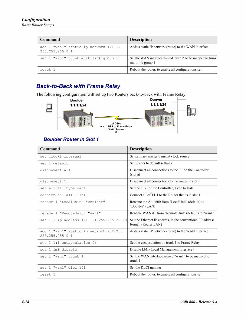
4-18 Adit 600 - Release 9.4
ConfigurationBasic Router Setups
Back-to-Back with Frame RelayThe following configuration will set up two Routers back-to-back with Frame Relay.
Boulder Router in Slot 1
add 1 "wan1" static ip network 1.1.1.0 255.255.255.0 1
Adds a static IP network (route) to the WAN interface
set 1 "wan1" trunk multilink group 1 Set the WAN interface named "wan1" to be mapped to trunk multilink group 1
reset 1 Reboot the router, to enable all configurations set
Command Descriptionset clock1 internal Set primary master transmit clock source
set 1 default Set Router to default settings
disconnect a:1 Disconnect all connections to the T1 on the Controller (slot a)
disconnect 1 Disconnect all connections to the router in slot 1
set a:1:all type data Set the T1-1 of the Controller, Type to Data
connect a:1:all 1:1:1 Connect all of T1-1 to the Router that is in slot 1
rename 1 "LocalUnit" "Boulder" Rename the Adit 600 from "LocalUnit" (default) to "Boulder" (LAN)
rename 1 "RemoteUnit" "wan1" Rename WAN #1 from "RemoteUnit" (default) to "wan1"
set 1:1 ip address 1.1.1.1 255.255.255.0 Set the Ethernet IP address, in the conventional IP address format. (Router LAN)
add 1 "wan1" static ip network 2.2.2.0 255.255.255.0 1
Adds a static IP network (route) to the WAN interface
set 1:1:1 encapsulation fr Set the encapsulation on trunk 1 to Frame Relay
set 1 lmi disable Disable LMI (Local Management Interface)
set 1 "wan1" trunk 1 Set the WAN interface named "wan1" to be mapped to trunk 1
set 1 "wan1" dlci 101 Set the DLCI number
reset 1 Reboot the router, to enable all configurations set
Command Description
Boulder1.1.1.1/24
Denver2.2.2.1 / 24
24 DS0swan1: PPP or Frame Relay
Static RoutesIP
Boulder 1.1.1.1/24
Denver 1.1.1.1/24

Adit 600 - Release 9.4 4-19
ConfigurationBasic Router Setups
Denver Router in Slot 3
Command Descriptionset 3 default Set Router to default settings
disconnect a:1 Disconnect all connections to the T1 on the Controller (slot a)
disconnect 3 Disconnect all connections to the router in slot 1
set clock1 a:1 Set primary master transmit clock source
set a:1:all type data Set the T1-1 of the Controller, Type to Data
connect a:1:all 3:1:1 Connect all of T1-1 to the Router that is in slot 1
rename 3 "LocalUnit" "Denver" Rename the Adit 600 from "LocalUnit" (default) to "Denver" (LAN)
rename 3 "RemoteUnit" "wan1" Rename WAN #1 from "RemoteUnit" (default) to "wan1"
set 3:1 ip address 2.2.2.1 255.255.255.0 Set the ethernet IP address, in the conventional IP address format. (Router LAN)
add 3 "wan1" static ip network 1.1.1.0 255.255.255.0 1
Adds a static IP network (route) to the WAN interface
set 3:1:1 encapsulation fr Set the encapsulation on trunk 1 to Frame Relay
set 3 lmi disable Disable LMI (Local Management Interface)
set 3 "wan1" trunk 1 Set the WAN interface named "wan1" to be mapped to trunk 1
set 3 "wan1" dlci 101 Set the DLCI number
reset 3 Reboot the router, to enable all configurations set

4-20 Adit 600 - Release 9.4
ConfigurationBasic Router Setups
Basic VoIP Setup (CMG Router Only)
This example is with an Adit 600 with the following cards installed:Controller Card (4.0 or higher)
CMG Router Card, 1.0 or higher (example - slot 6)
3 FXS Cards, 1.03 or higher (example - slots 1, 2 and 3). Cards are configured for Loop Start POTS lines.
OverviewAdit 600: the DS0s supporting the bundled service delivery will be cross-connected to the CMG cardAdit 600: the CMG voice channels are connected to the FXS channelsAdit 600 CMG: the VoIP parameters and data parameters are configuredAdit 600 uses endpoint prefix "aaln" and endpoint suffix "1-48" i.e. channel 1 would be suffix "1", channel 5 would be suffix "5"
Command Descriptionset local off Set the controller to use CLI commands
disconnect a:1 Disconnect all connections to the T1-1 on the Controller (slot a)
disconnect 1 Disconnect all connections to the FXS card in slot 1
disconnect 2 Disconnect all connections to the FXS card in slot 2
disconnect 3 Disconnect all connections to the FXS card in slot 3
disconnect 6 Disconnect all connections to the router card in slot 6
set a:1 up Set the T1 on the controller up
set a:1 fdl none Disable FDL output messages on the DS1
Adit 600 Implementation in VoIP Application

Adit 600 - Release 9.4 4-21
ConfigurationBasic Router Setups
set a:1 lbo 1 Sets the DS1 Line Build Out to 0-133 feet
set a:1 framing esf Sets the DS1 to Extended Superframe (ESF) framing
set a:1 id "CAC DS1# A:1" Sets the DS1 ID to "CAC DS1# A:1"
set a:1 linecode b8zs Sets the DS1 line coding to B8ZS.
set a:1 loopdetect on Enables the detection of CSU loop code on the DS1
set a:1:all type data Set the T1-1 of the Controller, Type to Data
set a:2 down Set the T1-2 as Out-of-Service
set clock1 a:1 Set primary master transmit clock source
set clock2 internal Set secondary clock source
set a:2 up Set the T1-2 as In-Service
connect a:1:1-24 6:1:1 Connect Data DS0s to the CMG card
connect 6:1:1:1-8 1:1-8 Connect CMG voice ports to FXS ports
connect 6:1:1:9-16 2:1-8 Connect CMG voice ports to FXS ports
connect 6:1:1:17-24 3:1-8 Connect CMG voice ports to FXS ports
set verification off Disable verification prompts
set 6:1:1 encapsulation ppp Set Router trunk encapsulations to Point-to-Point Protocol.
set 6:1:1 up Set Router trunk as In-Service
set 6:1 ip address ip-addr mask
Set Router IP Address and Subnet Mask
set 6:1 up Set Router as In-Service
add 6 "RemoteAdit" static ip network ip-addr mask next-hop-ip-addr 1
Set router WAN static ip network. Metric set as 1, normally indicates a direct network
set 6 "RemoteAdit" trunk 1 Set router WAN trunk to port 1
set 6 "RemoteAdit" up Set router WAN as In-Service
set 6 log last detail Set the router log to add new entries and display the log in detail
set 6 mgcp callagent address ip-addr
Set the IP Address to be used by MGCP to access the call agent
set 6 mgcp up Set the MGCP as In-Service
set 6:1:1:1-24 log start both Start logging events to the CMG text log, for MGCP protocol events and errors
reset Reset the CMG card, to apply all configurations
Command Description

4-22 Adit 600 - Release 9.4
ConfigurationConfiguration Restrictions
Configuration Restrictions The Adit 600 can have up to 4 DS0 data streams. The following service cards reserve 1 data stream for each card installed:
Quad DS1/E1Quad E1Quad T1Quad DS1 ADPCM CMG Router (using WANs)
Therefore if a combination of 4 of any of the above service cards are installed in a Adit chassis, the remaining 2 slots MUST be left empty.If a combination of 3 of the above service cards are installed in a chassis:
Remaining 3 slots can have 2 V.35 cards and the 3rd slot MUST be empty, orRemaining 3 slots can be used for any cards supported on the Adit platform that are not listed above.
Below are a few examples of card combinations for the Adit 600 that this scenario applies.
NOTE: The Adit 600 can support more than 4 CMG cards in a chassis, if they are not setup to use WANs. For further information please contact Carrier Access Customer Support.
Proxy RestrictionWhen more than one router is in use (CMG, TSR, or IP router cards), multiple proxies may be established, but the Adit 600 limits Telnet sessions to just one of them at a time. See the set (router) proxy command on page 134 for information about setting up a proxy.
Slot 1 Slot 2 Slot 3 Slot 4 Slot 5 Slot 6Example 1 Quad T1 Quad T1 Quad T1 Quad T1 Empty EmptyExample 2 Quad T1 Quad T1 Quad T1 V.35 V.35 EmptyExample 3 Quad T1 Quad T1 Quad T1 CMG Empty EmptyExample 4 Quad T1 Quad T1 ADPCM ADPCM Empty EmptyExample 5 Quad T1 Quad T1 Quad T1 FXS FXS FXO

Adit 600 - Release 9.4 4-23
ConfigurationInstall Country Specific Ringer Tones
Install Country Specific Ringer Tones The CMG Router card ships with a set of call progress tones that are played to a VoIP endpoint at the direction of an external MGCP call agent. By default the call progress tones are defined to match the United States standard call progress tones. The CMG Router card ships with a set of call progress tone files that allow call progress tone definitions for a number of other countries to be used.Tones are loaded via TFTP directly to the CMG Router card. All supported country tones are provided on the software CD with the CMG Router.Once a tone file is loaded into a CMG Router card it will remain in effect until replaced by another. It is not removed when the CMG Router card is set back to its default settings.
NOTE: Use of ringer tones requires Adit 600 Controller release 5.0 or higher and CMG Router release 1.1 or higher.
Syntax: load cmg_card-addr tftp ip-addr "tone_file"
Example: load 2 tftp 192.168.43.52 "brazil.tdb"
Adit E1> status equipmentBootCode Version: 1.29
CardType Status SW Vers CLEISLOT A E1x2 Present 8.0.0 SIUXSS0EAA
SLOT 1 FXOx8 Not Present
SLOT 2 CMGx1 Present 2.11 SIIX270DAASLOT 3 V35x2 Present SIC3HK0CAA
SLOT 4 E1x4 Not Present
SLOT 5 E1x4 Not PresentSLOT 6 FXSx8 Not Present
Adit E1> load 2 tftp 192.168.43.52 "brazil.tdb"
Filename: brazil.tdb
Source IP Address: 192.168.43.52Target IP Address: 192.168.3.192
Target Card Slot: 2
Target Card Type: CMGx1
'load tftp' will be executed with the above parameters.
A TFTP server must be running on the host system.
Do you really want to do this? y
Card software download in progress. Please be patient...
Software transfer command completed.
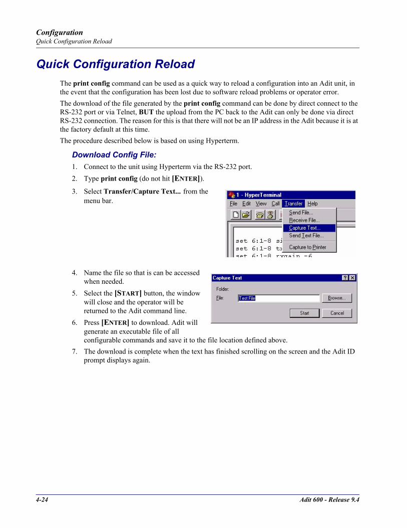
4-24 Adit 600 - Release 9.4
ConfigurationQuick Configuration Reload
Quick Configuration ReloadThe print config command can be used as a quick way to reload a configuration into an Adit unit, in the event that the configuration has been lost due to software reload problems or operator error.The download of the file generated by the print config command can be done by direct connect to the RS-232 port or via Telnet, BUT the upload from the PC back to the Adit can only be done via direct RS-232 connection. The reason for this is that there will not be an IP address in the Adit because it is at the factory default at this time.The procedure described below is based on using Hyperterm.
Download Config File:1. Connect to the unit using Hyperterm via the RS-232 port.2. Type print config (do not hit [ENTER]). 3. Select Transfer/Capture Text... from the
menu bar.
4. Name the file so that is can be accessed when needed.
5. Select the [START] button, the window will close and the operator will be returned to the Adit command line.
6. Press [ENTER] to download. Adit will generate an executable file of all configurable commands and save it to the file location defined above.
7. The download is complete when the text has finished scrolling on the screen and the Adit ID prompt displays again.
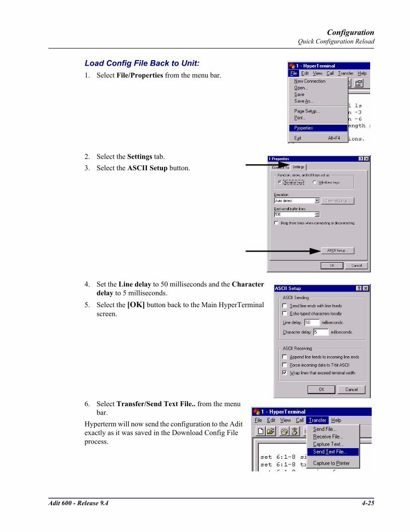
Adit 600 - Release 9.4 4-25
ConfigurationQuick Configuration Reload
Load Config File Back to Unit:1. Select File/Properties from the menu bar.
2. Select the Settings tab.3. Select the ASCII Setup button.
4. Set the Line delay to 50 milliseconds and the Character delay to 5 milliseconds.
5. Select the [OK] button back to the Main HyperTerminal screen.
6. Select Transfer/Send Text File.. from the menu bar.
Hyperterm will now send the configuration to the Adit exactly as it was saved in the Download Config File process.
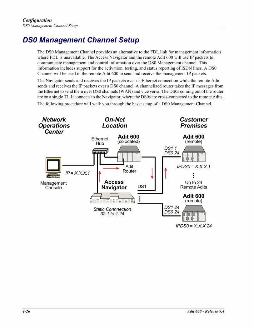
4-26 Adit 600 - Release 9.4
ConfigurationDS0 Management Channel Setup
DS0 Management Channel SetupThe DS0 Management Channel provides an alternative to the FDL link for management information where FDL is unavailable. The Access Navigator and the remote Adit 600 will use IP packets to communicate management and control information over the DS0 Management channel. This information includes support for the activation, testing, and status reporting of ISDN lines. A DS0 Channel will be used in the remote Adit 600 to send and receive the management IP packets.The Navigator sends and receives the IP packets over its Ethernet connection while the remote Adit sends and receives the IP packets over a DS0 channel. A channelized router takes the IP messages from the Ethernet to send them over DS0 channels (WAN) and vice versa. The DS0s coming out of the router are on a single T1. It connects to the Navigator, where the DS0s are cross-connected to the remote Adits. The following procedure will walk you through the basic setup of a DS0 Management Channel.
DS1 STATUS
ACCESSNAVIGATOR
CARRI ER ACCESSCORPORATION
12
34
56
78
910
1112
1314
1516
1718
1920
2122
2324
2526
2728
2930
3132
POWERACO(PUSH)
CONTROLLER AACTIVE
CRITACO
MAJORMINOR
POWERACO
(PUSH)
CONTROLLER BACTI VE
CRITACO
MAJORMINOR
Adit 600
DS1 1DS0 24
Adit 600
AccessNavigator
NetworkOperations
Center
ManagementConsole
On-NetLocation
CustomerPremises
Adit 600
EthernetHub
DS1 24DS0 24 Adit 600
IP = X.X.X.1IPDS0 = X.X.X.1
Static Connnection32:1 to 1:24
IPDS0 = X.X.X.24
Adit 600
Adit 600
AditRouter
(colocated) (remote)
(remote)
Up to 24Remote AditsDS1
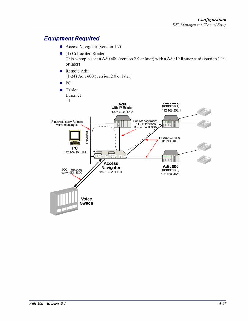
Adit 600 - Release 9.4 4-27
ConfigurationDS0 Management Channel Setup
Equipment RequiredAccess Navigator (version 1.7)(1) Collocated RouterThis example uses a Adit 600 (version 2.0 or later) with a Adit IP Router card (version 1.10 or later)Remote Adit(1-24) Adit 600 (version 2.0 or later)PCCablesEthernetT1 Adit 600
AccessNavigator
Adit 600
Adit 600
Adit 600
Aditwith IP Router (remote #1)
(remote #2)
Adit 600
DS1 STATUS
ACCESSNAVIGATOR
CARRIER ACCESSCORPORATION
12
34
56
78
910
1112
1314
1516
1718
1920
2122
2324
2526
2728
2930
3132
POWERACO
(PUSH)
CONTROLLER AACTIVE
CRITACO
MAJORMINOR
POWERACO
(PUSH)
CONTROLLER BACTIVE
CRITACO
MAJORMINOR
IP packets carry RemoteMgmt messages
One ManagementT1 DS0 for eachRemote Adit 600
VoiceSwitch
T1 DS0 carryingIP Packets
EOC messagescarry ISDN EOC 192.168.201.100
192.168.201.101
PC192.168.201.102
192.168.202.1
192.168.202.2
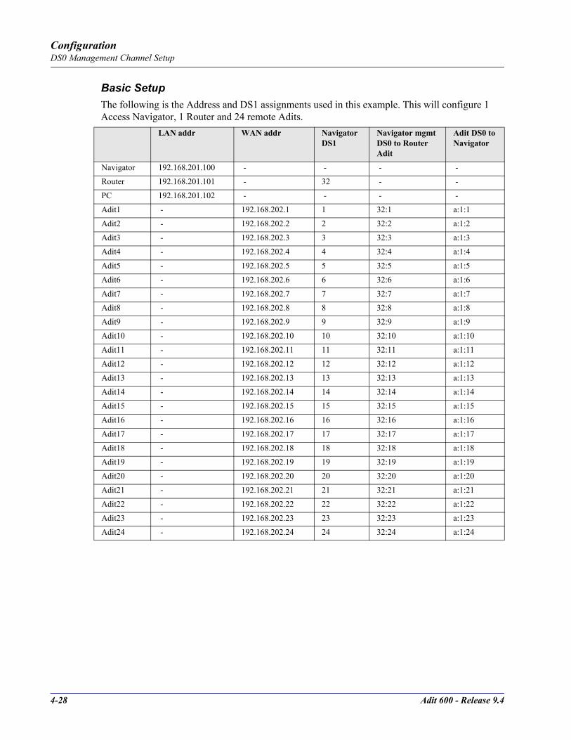
4-28 Adit 600 - Release 9.4
ConfigurationDS0 Management Channel Setup
Basic SetupThe following is the Address and DS1 assignments used in this example. This will configure 1 Access Navigator, 1 Router and 24 remote Adits.
LAN addr WAN addr Navigator DS1
Navigator mgmt DS0 to Router Adit
Adit DS0 to Navigator
Navigator 192.168.201.100 - - - -
Router 192.168.201.101 - 32 - -
PC 192.168.201.102 - - - -
Adit1 - 192.168.202.1 1 32:1 a:1:1
Adit2 - 192.168.202.2 2 32:2 a:1:2
Adit3 - 192.168.202.3 3 32:3 a:1:3
Adit4 - 192.168.202.4 4 32:4 a:1:4
Adit5 - 192.168.202.5 5 32:5 a:1:5
Adit6 - 192.168.202.6 6 32:6 a:1:6
Adit7 - 192.168.202.7 7 32:7 a:1:7
Adit8 - 192.168.202.8 8 32:8 a:1:8
Adit9 - 192.168.202.9 9 32:9 a:1:9
Adit10 - 192.168.202.10 10 32:10 a:1:10
Adit11 - 192.168.202.11 11 32:11 a:1:11
Adit12 - 192.168.202.12 12 32:12 a:1:12
Adit13 - 192.168.202.13 13 32:13 a:1:13
Adit14 - 192.168.202.14 14 32:14 a:1:14
Adit15 - 192.168.202.15 15 32:15 a:1:15
Adit16 - 192.168.202.16 16 32:16 a:1:16
Adit17 - 192.168.202.17 17 32:17 a:1:17
Adit18 - 192.168.202.18 18 32:18 a:1:18
Adit19 - 192.168.202.19 19 32:19 a:1:19
Adit20 - 192.168.202.20 20 32:20 a:1:20
Adit21 - 192.168.202.21 21 32:21 a:1:21
Adit22 - 192.168.202.22 22 32:22 a:1:22
Adit23 - 192.168.202.23 23 32:23 a:1:23
Adit24 - 192.168.202.24 24 32:24 a:1:24

Adit 600 - Release 9.4 4-29
ConfigurationDS0 Management Channel Setup
Set IP Configuration of PC1. Set IP Address to 192.168.201.1022. Set Gateway to 192.168.201.101 (Router LAN Address)
Configuring the Adit Router
NOTE: The Remote Adit WAN address MUST have a different subnet than the Adit Controller Ethernet address.
WAN ConnectionsThe following WAN connections are made from a default condition with one (1) Adit Router card installed set with factory defaults.
NOTE: An Adit IP Router is capable of managing 24 virtual WAN connections through T1-1 or T1-2 of the Controller card. If support of more than 24 Adits is required, a Quad T1 and a Router(s) can be added for additional support (only on a collocated router, not on a remote Adit).
1. From the CLI execute the following command to connect one DS0 to each one of the 24 WANs.
Command Description
set local off Sets the Adit to be configured through CLI
set a:1 down Sets the T1-1 as Out-of-Service
disconnect a Disconnects all connections to slot a (controller)
set a:1:1-24 type data Sets all DS0s on T1-1 to data signaling type
connect a:1:1 1:1:1 Connects first DS0 of T1-1 of the controller to port 1, WAN 1 of the Router in slot 1.
connect a:1:2 1:1:2 Connects second DS0 of T1-1 of the controller to port 1, WAN 2 of the Router in slot 1.
connect a:1:3 1:1:3 Up to 24 WAN connections (a:1:24 1:1:24)
set a:1 up Sets the T1-1 as In-Service

4-30 Adit 600 - Release 9.4
ConfigurationDS0 Management Channel Setup
Add and Enable all Remote Adits Needed
Telnet into Router1. From the CLI execute a Telnet command to the Router.
Telnet slot:[port]
Example: telnet 1
The example will Telnet into the router located in slot 1.
2. Enter password (default is "admin") and select [ENTER].3. Select Terminal Emulation (scroll with [TAB]) and select [ENTER].
Once you are in the router, the [TAB] key will move you through the menus and the [SPACEBAR] will scroll you through selections in < >.
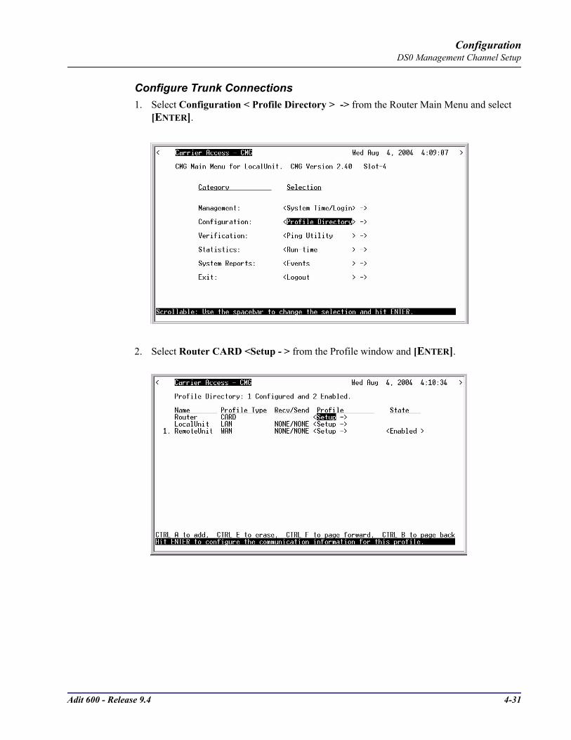
Adit 600 - Release 9.4 4-31
ConfigurationDS0 Management Channel Setup
Configure Trunk Connections1. Select Configuration < Profile Directory > -> from the Router Main Menu and select
[ENTER].
2. Select Router CARD <Setup - > from the Profile window and [ENTER].
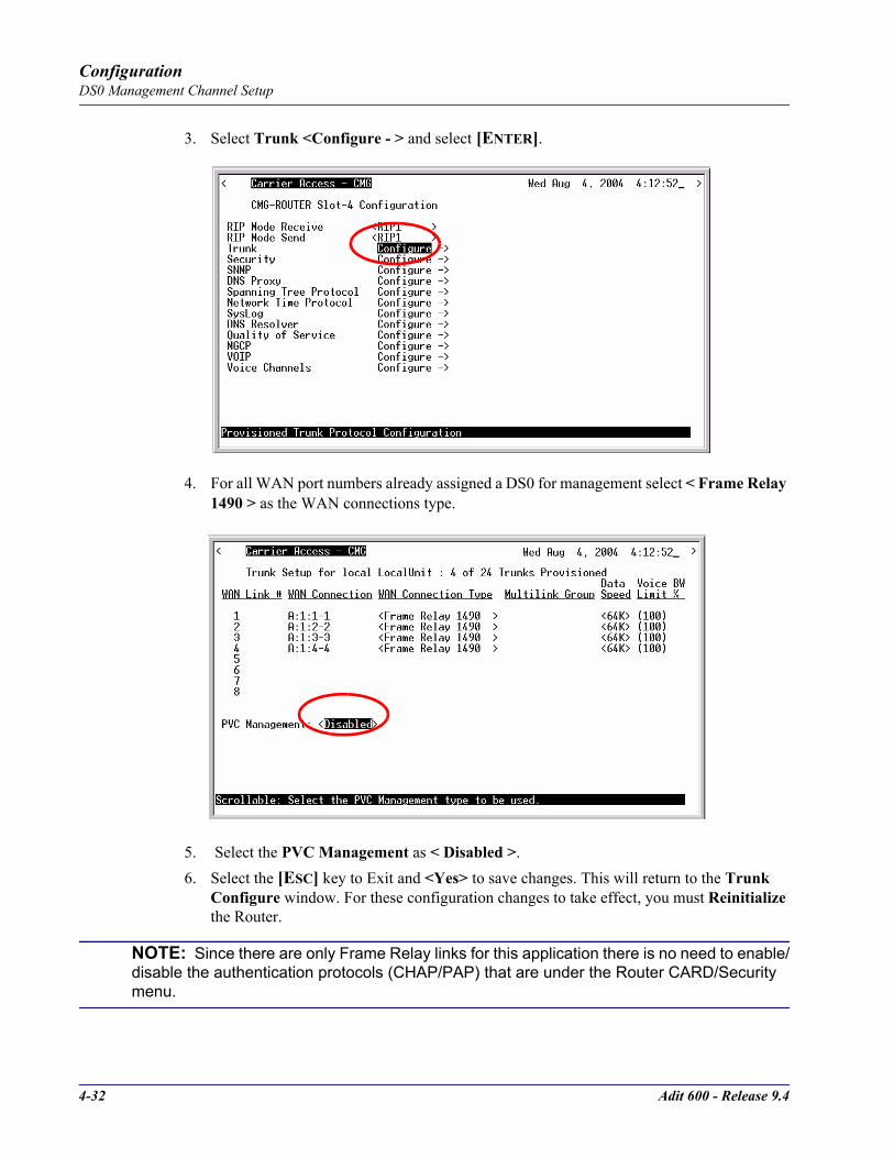
4-32 Adit 600 - Release 9.4
ConfigurationDS0 Management Channel Setup
3. Select Trunk <Configure - > and select [ENTER].
4. For all WAN port numbers already assigned a DS0 for management select < Frame Relay 1490 > as the WAN connections type.
5. Select the PVC Management as < Disabled >.6. Select the [ESC] key to Exit and <Yes> to save changes. This will return to the Trunk
Configure window. For these configuration changes to take effect, you must Reinitialize the Router.
NOTE: Since there are only Frame Relay links for this application there is no need to enable/disable the authentication protocols (CHAP/PAP) that are under the Router CARD/Security menu.
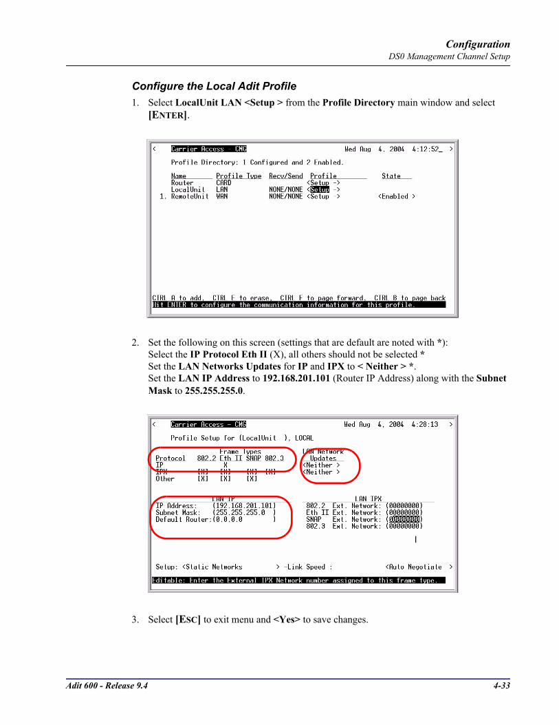
Adit 600 - Release 9.4 4-33
ConfigurationDS0 Management Channel Setup
Configure the Local Adit Profile1. Select LocalUnit LAN <Setup > from the Profile Directory main window and select
[ENTER].
2. Set the following on this screen (settings that are default are noted with *):Select the IP Protocol Eth II (X), all others should not be selected * Set the LAN Networks Updates for IP and IPX to < Neither > *. Set the LAN IP Address to 192.168.201.101 (Router IP Address) along with the Subnet Mask to 255.255.255.0.
3. Select [ESC] to exit menu and <Yes> to save changes.

4-34 Adit 600 - Release 9.4
ConfigurationDS0 Management Channel Setup
Create a Remote Adit Profile for all Remotes1. Select RemoteUnit WAN <Setup > from the Profile Directory main window and select
[ENTER].
2. Set the following on this screen (settings that are default are noted with *):Rename RemoteAdit (default name) to Adit1. Set WAN Networks Updates for IP to <Never> *.Set WAN IP: Numbered to <No> *.
3. [TAB] to Setup: <Static/VPN Networks > (scroll to this selection if it is not displayed) and select [ENTER].
NOTE: If the IP Protocol is set to <Bridge > this option will not be available.

Adit 600 - Release 9.4 4-35
ConfigurationDS0 Management Channel Setup
4. Set Setup Static: to <IP Networks> (scroll to this selection if it is not displayed).
5. Select [CTRL A] to add a Static IP Address.6. Set the IP Address to 192.168.202.1 (Adit1 WAN address)
Set the Subnet Mask to 255.255.255.255
NOTE: After inserting the IP address and [TAB], the subnet field will automatically fill with 255.255.255.0. You must retype the entire address of 255.255.255.255.
7. Set the Metric to (1).8. Select [ESC] to exit and <Yes> to save changes.9. On the Remote Profile setup window select Setup: <Trunk Port > and [ENTER].
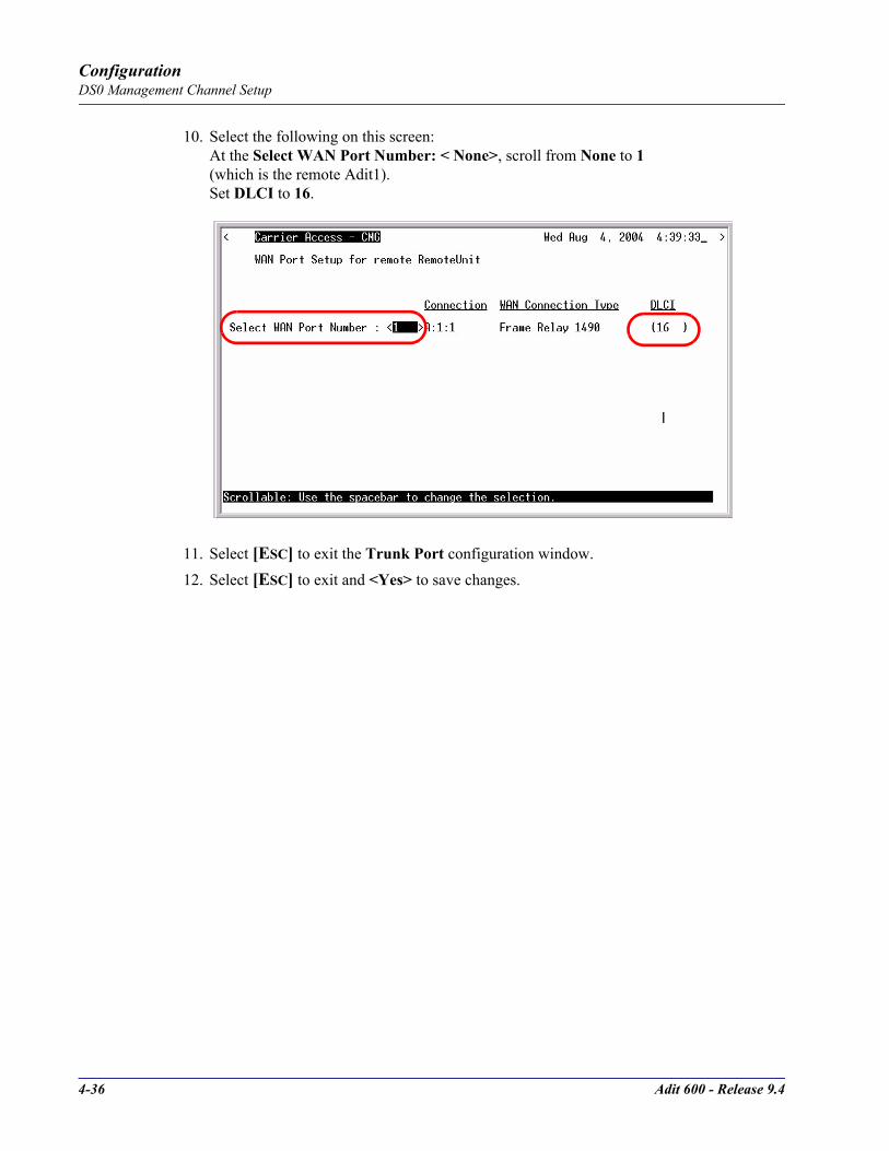
4-36 Adit 600 - Release 9.4
ConfigurationDS0 Management Channel Setup
10. Select the following on this screen:At the Select WAN Port Number: < None>, scroll from None to 1 (which is the remote Adit1). Set DLCI to 16.
11. Select [ESC] to exit the Trunk Port configuration window.12. Select [ESC] to exit and <Yes> to save changes.

Adit 600 - Release 9.4 4-37
ConfigurationDS0 Management Channel Setup
Reinitialize the Router1. Select Exit <Reinitialize > from the Router main window and select [ENTER].
2. Select <YES> and select [ENTER] to Reinitialize the Router Card. This will save all the changes recently made to the Router.

4-38 Adit 600 - Release 9.4
ConfigurationDS0 Management Channel Setup
Configuration of Remote AditsNote: The Ethernet cannot be connected to the Remote Adit during the setup of the DS0.Use the following commands to setup the IP over DS0 Management Channel for each Remote Adit 600. connect to the Adit1, use the following CLI commands to setup the DS0 Management Channel.Note: the following commands are assuming that the Remote Adits are set to factory defaults.
Command Description
set local off Sets the Adit to be configured through CLI
set a:1 down Sets the T1-1 as Out-of-Service
disconnect a Disconnects all connections to slot A (Controller), assuming there are not any established cross-connects that need to remain.
set a:1:24 type data Sets all DS0s on T1-1 to data signaling type
set ipds0 assign a:1:24 Assigns the DS0 as the IP management channel
set ipds0 ip address 192.168.202.1 255.255.255.0
Set the DS0 management channel IP address (the Adit1 WAN address is inserted here)
set ipds0 up Set the DS0 management channel up
set snmp nms1 xxx.xxx.xxx.xxx Sends alarms to server. Sends alarms to server. xxx.xxx.xxx.xxx is the IP Address of the server.
show connect a:1 Displays connections to T1-1 of the controller
show ipds0 Displays the configurations of the DS0 mgmt channel
status ipds0 Will display the operational status (up/down) of the DS0 management channel to the Navigator
set a:1 up Sets the T1-1 as In-Service
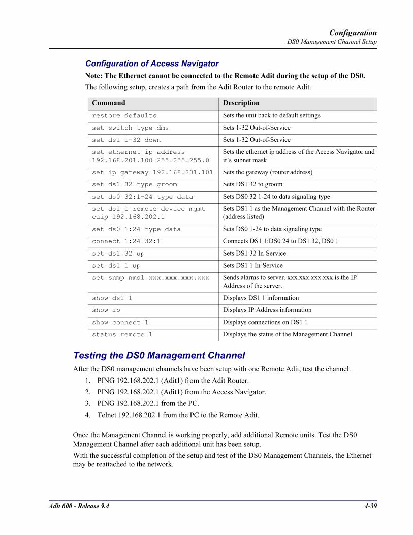
Adit 600 - Release 9.4 4-39
ConfigurationDS0 Management Channel Setup
Configuration of Access NavigatorNote: The Ethernet cannot be connected to the Remote Adit during the setup of the DS0.The following setup, creates a path from the Adit Router to the remote Adit.
Testing the DS0 Management ChannelAfter the DS0 management channels have been setup with one Remote Adit, test the channel.
1. PING 192.168.202.1 (Adit1) from the Adit Router.2. PING 192.168.202.1 (Adit1) from the Access Navigator.3. PING 192.168.202.1 from the PC.4. Telnet 192.168.202.1 from the PC to the Remote Adit.
Once the Management Channel is working properly, add additional Remote units. Test the DS0 Management Channel after each additional unit has been setup. With the successful completion of the setup and test of the DS0 Management Channels, the Ethernet may be reattached to the network.
Command Description
restore defaults Sets the unit back to default settings
set switch type dms Sets 1-32 Out-of-Service
set ds1 1-32 down Sets 1-32 Out-of-Service
set ethernet ip address 192.168.201.100 255.255.255.0
Sets the ethernet ip address of the Access Navigator and it’s subnet mask
set ip gateway 192.168.201.101 Sets the gateway (router address)
set ds1 32 type groom Sets DS1 32 to groom
set ds0 32:1-24 type data Sets DS0 32 1-24 to data signaling type
set ds1 1 remote device mgmt caip 192.168.202.1
Sets DS1 1 as the Management Channel with the Router (address listed)
set ds0 1:24 type data Sets DS0 1-24 to data signaling type
connect 1:24 32:1 Connects DS1 1:DS0 24 to DS1 32, DS0 1
set ds1 32 up Sets DS1 32 In-Service
set ds1 1 up Sets DS1 1 In-Service
set snmp nms1 xxx.xxx.xxx.xxx Sends alarms to server. xxx.xxx.xxx.xxx is the IP Address of the server.
show ds1 1 Displays DS1 1 information
show ip Displays IP Address information
show connect 1 Displays connections on DS1 1
status remote 1 Displays the status of the Management Channel

4-40 Adit 600 - Release 9.4
ConfigurationBasic P-Phone Configuration Setup
Basic P-Phone Configuration SetupThe following is the basic P-Phone setup of the Adit 600. For more information on this service card see Chapter 13, P-Phone Card.
Equipment required for this setup(1) Adit 600 with T1 Controller (Rel 6.0), (3) P-Phone Service cards(1) Adit 600 with T1 Controller, (1) IP Router Service cardThe collocated Adit 600 must have the following software levels: - T1 Controller Release 5.0 or higher - Router can be any one of the following: • IP Router Card - Release 1.5 or higher • Terminal Server Router Card - Release 1.0 or higher • CMG Router Card - Release 1.1 or higher(1) Access Navigator GR-303 with P-Phone (release 1.8 or higher)Nortel DMS SwitchP-Phones
Installation1. Install Adit 600 at Remote site following the directions in Chapter 2 and 3 of the User Manual.2. Install P-Phone Service cards into the Remote Adit 600 chassis.3. Connect P-Phones to the Adit 600.4. Install Adit 600 (w/router) and Access Navigator at the CO following the installation directions
in the User Manuals.
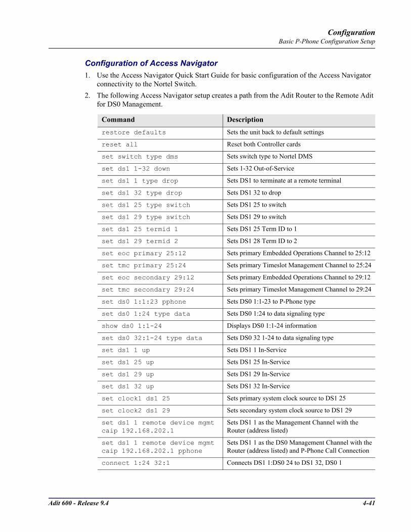
Adit 600 - Release 9.4 4-41
ConfigurationBasic P-Phone Configuration Setup
Configuration of Access Navigator1. Use the Access Navigator Quick Start Guide for basic configuration of the Access Navigator
connectivity to the Nortel Switch.2. The following Access Navigator setup creates a path from the Adit Router to the Remote Adit
for DS0 Management.
Command Description
restore defaults Sets the unit back to default settings
reset all Reset both Controller cards
set switch type dms Sets switch type to Nortel DMS
set ds1 1-32 down Sets 1-32 Out-of-Service
set ds1 1 type drop Sets DS1 to terminate at a remote terminal
set ds1 32 type drop Sets DS1 32 to drop
set ds1 25 type switch Sets DS1 25 to switch
set ds1 29 type switch Sets DS1 29 to switch
set ds1 25 termid 1 Sets DS1 25 Term ID to 1
set ds1 29 termid 2 Sets DS1 28 Term ID to 2
set eoc primary 25:12 Sets primary Embedded Operations Channel to 25:12
set tmc primary 25:24 Sets primary Timeslot Management Channel to 25:24
set eoc secondary 29:12 Sets primary Embedded Operations Channel to 29:12
set tmc secondary 29:24 Sets primary Timeslot Management Channel to 29:24
set ds0 1:1:23 pphone Sets DS0 1:1-23 to P-Phone type
set ds0 1:24 type data Sets DS0 1:24 to data signaling type
show ds0 1:1-24 Displays DS0 1:1-24 information
set ds0 32:1-24 type data Sets DS0 32 1-24 to data signaling type
set ds1 1 up Sets DS1 1 In-Service
set ds1 25 up Sets DS1 25 In-Service
set ds1 29 up Sets DS1 29 In-Service
set ds1 32 up Sets DS1 32 In-Service
set clock1 ds1 25 Sets primary system clock source to DS1 25
set clock2 ds1 29 Sets secondary system clock source to DS1 29
set ds1 1 remote device mgmt caip 192.168.202.1
Sets DS1 1 as the Management Channel with the Router (address listed)
set ds1 1 remote device mgmt caip 192.168.202.1 pphone
Sets DS1 1 as the DS0 Management Channel with the Router (address listed) and P-Phone Call Connection
connect 1:24 32:1 Connects DS1 1:DS0 24 to DS1 32, DS0 1

4-42 Adit 600 - Release 9.4
ConfigurationBasic P-Phone Configuration Setup
Configure Adit and Router at CODirect connect to the CLI via RS-232. Follow the commands for "Initial Setup" below.
set ethernet ip address 192.168.201.100 255.255.255.0
Sets the ethernet ip address of the Access Navigator and it’s subnet mask
set ip gateway 192.168.201.101 Sets the gateway (router address)
show ds1 1 Displays DS1 1 information
show ip Displays IP Address information
status remote 1 Displays the status of the Management Channel
show connect 1 Displays connections on DS1 1
status tmc Displays the status of the TMC
status eoc Displays the status of the EOC
Command Description
restore defaults Sets the unit back to default settings
reset Resets the system
set 1 default Sets the Router in Slot 1 to its default settings
set local off Disables DIP switches
set date mm/dd/yyyy Set the date used for event logging
set time hh:mm:ss Set the time used for event logging
set id "id-name" Set a system ID name
set clock1 a:1 Set the primary clock source to a:1
set clock2 internal Set the secondary clock source to internal
set a:2 down Sets the T1-2 as Out-of-Service
disconnect a Disconnect all connections to slot A (Controller)
set a:1:1-24 type data Sets all DS0s on T1-1 to data signaling type
connect a:1:1 1:1:1 Connects first DS0 of T1-1 of the controller to port 1, WAN 1 of the Router in slot 1.
set ethernet ip address ip-addr mask
Set Ethernet IP address, in IP address format
set ip gateway ip-addr Set IP gateway, in the conventional IP address format
show ip Displays the IP information
Command Description
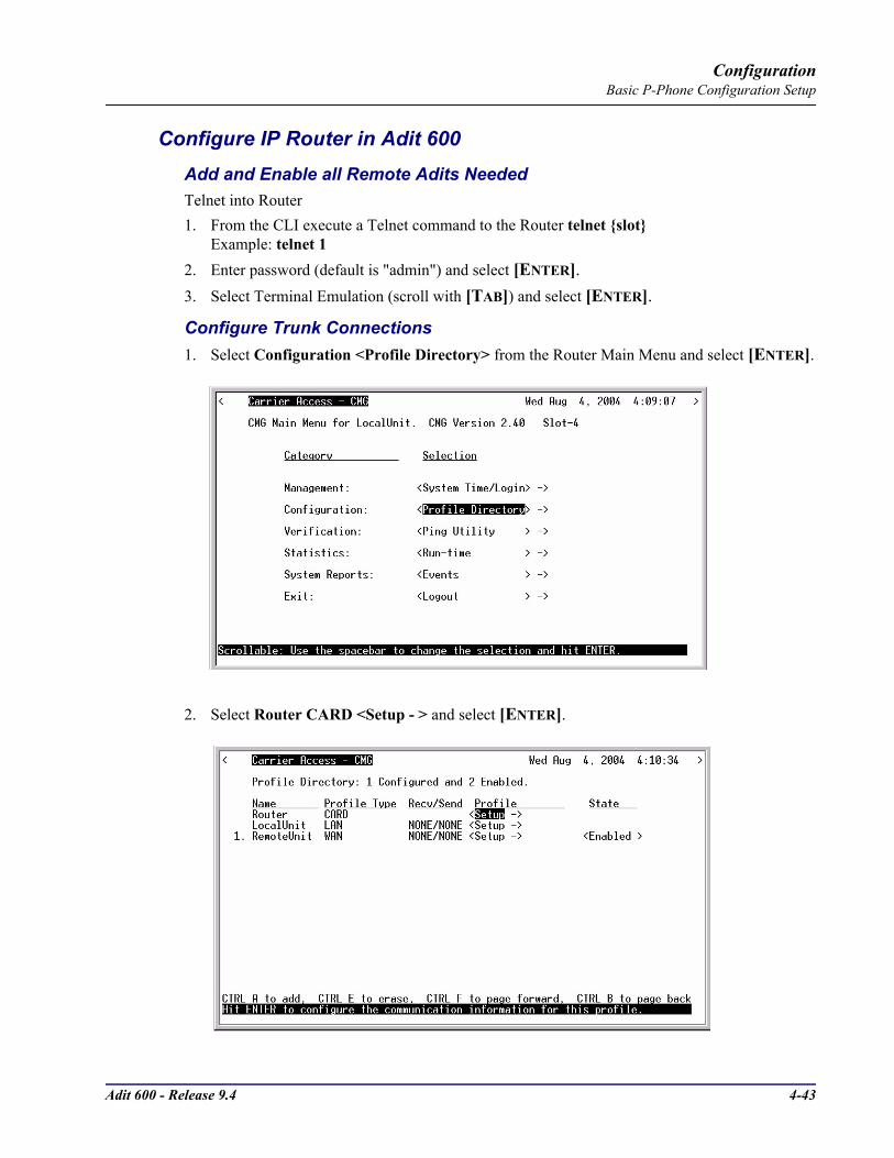
Adit 600 - Release 9.4 4-43
ConfigurationBasic P-Phone Configuration Setup
Configure IP Router in Adit 600Add and Enable all Remote Adits NeededTelnet into Router1. From the CLI execute a Telnet command to the Router telnet slot
Example: telnet 12. Enter password (default is "admin") and select [ENTER].3. Select Terminal Emulation (scroll with [TAB]) and select [ENTER].
Configure Trunk Connections1. Select Configuration <Profile Directory> from the Router Main Menu and select [ENTER].
2. Select Router CARD <Setup - > and select [ENTER].

4-44 Adit 600 - Release 9.4
ConfigurationBasic P-Phone Configuration Setup
3. Select Trunk Configure - > and select [ENTER].
4. Set the WAN Connection Type to <Frame Relay 1490>, and PVC Management: to <Disabled>. Scroll with the [SPACEBAR] to select options.Note: settings will not take effect until the Router is Reinitialized.
5. Select [ESC] to exit and <Yes> to save changes.

Adit 600 - Release 9.4 4-45
ConfigurationBasic P-Phone Configuration Setup
Configure Trunk Connections1. Select LocalUnit LAN <Setup - > and select [ENTER].
2. Set the following:IP Protocol Eth II (with an X), all others should not be selected (default)LAN Networks Updates for IP and IPX to <Neither> (default)LAN IP Address to xxx.xxx.xxx.xxx (Router IP Address).LAN IP Subnet Mask to xxx.xxx.xxx.xxx.
3. Select [ESC] to exit and <Yes> to save changes.

4-46 Adit 600 - Release 9.4
ConfigurationBasic P-Phone Configuration Setup
Create a Remote Profile for all Adit Remotes1. Select LocalUnit WAN <Setup - > and select [ENTER].
2. Set the following:Rename the Profile RemoteUnit (example is RemoteAdit 1)WAN Networks Updates for IP to <Never> (default)WAN IP Numbered to <No> (default)
3. [TAB] to Setup: <Static/VPN Networks> (scroll to this selection if it is not displayed, and select [ENTER].
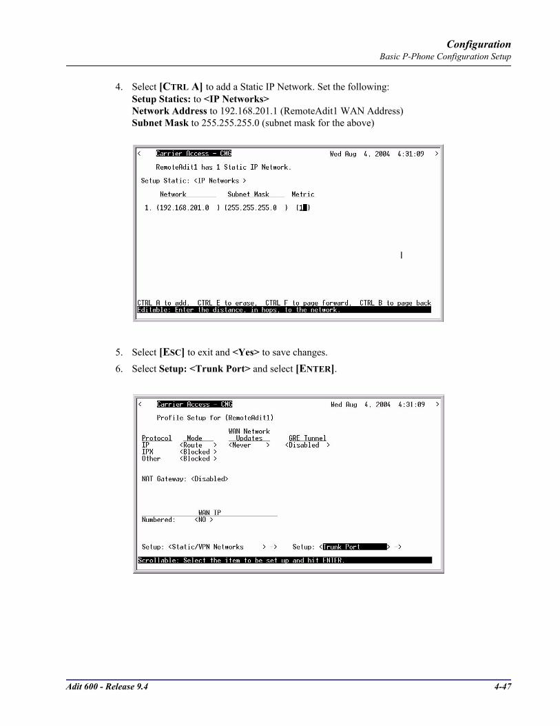
Adit 600 - Release 9.4 4-47
ConfigurationBasic P-Phone Configuration Setup
4. Select [CTRL A] to add a Static IP Network. Set the following:Setup Statics: to <IP Networks>Network Address to 192.168.201.1 (RemoteAdit1 WAN Address)Subnet Mask to 255.255.255.0 (subnet mask for the above)
5. Select [ESC] to exit and <Yes> to save changes.6. Select Setup: <Trunk Port> and select [ENTER].

4-48 Adit 600 - Release 9.4
ConfigurationBasic P-Phone Configuration Setup
7. Set the following:Scroll Select WAN Port Number from <None> to <1>Set DLCI to (16)
8. Select [ESC] to exit the Trunk Port window.9. Select [ESC] to exit and <Yes> to save changes.10. Select [ESC] to exit the Profile Directory and return to the Main Router window.

Adit 600 - Release 9.4 4-49
ConfigurationBasic P-Phone Configuration Setup
Reinitialize the Router1. On the Main Router window, select Exit <Logout > and scroll with the [SPACEBAR] to
<Reinitialize> and select [ENTER].
2. Scroll the <NO> with the [SPACEBAR] to <YES>, and press [ENTER].

4-50 Adit 600 - Release 9.4
ConfigurationBasic P-Phone Configuration Setup
Configuration of the Adit 600 at Remote SiteDirect connect to CLI via RS-232. Use the following commands for your initial setup. Note: P-Phones are installed in slots 1, 2 and 3.
Command Description
restore defaults Sets the unit back to default settings
set local off Disables DIP switches
set date mm/dd/yyyy Set the date used for event logging
set time hh:mm:ss Set the time used for event logging
set id "id-name" Set a system ID name
set clock1 a:1 Set the primary clock source to a:1
set clock2 internal Set the secondary clock source to internal
set a:2 down Sets the T1-2 as Out-of-Service
disconnect a Disconnect all connections to slot A (Controller)
set a:1:1-24 type data Sets all DS0s on T1-1 to data signaling type
connect a:1:1-8 1:1-8 Connects a:1:1-8 of the Controller to 1-8 of the P-Phone in slot 1.
connect a:1:9-16 2:1-8 Connects a:1:9-16 of the Controller to 1-8 of the P-Phone in slot 2.
connect a:1:17-23 3:1-8 Connects a:1:17-23 of the Controller to 1-8 of the P-Phone in slot 3.
set 1:1 crv 1 Set the P-Phone CRV, slot 1 port 1 to 1
set 1:2 crv 2 Set the P-Phone CRV, slot 1 port 1 to 2
set 1:3 crv 3 Set the P-Phone CRV, slot 1 port 1 to 3
set 1:4 crv 4 Set the P-Phone CRV, slot 1 port 1 to 4
set 1:5 crv 5 Set the P-Phone CRV, slot 1 port 1 to 5
set 1:6 crv 6 Set the P-Phone CRV, slot 1 port 1 to 6
set 1:7 crv 7 Set the P-Phone CRV, slot 1 port 1 to 7
set 1:8 crv 8 Set the P-Phone CRV, slot 1 port 1 to 8
set 2:1 crv 9 Set the P-Phone CRV, slot 2 port 1 to 9
set 2:2 crv 10 Set the P-Phone CRV, slot 2 port 1 to 10
set 2:3 crv 11 Set the P-Phone CRV, slot 2 port 1 to 11
set 2:4 crv 12 Set the P-Phone CRV, slot 2 port 1 to 12
set 2:5 crv 13 Set the P-Phone CRV, slot 2 port 1 to 13
set 2:5 crv 13 Set the P-Phone CRV, slot 2 port 1 to 13
set 2:6 crv 14 Set the P-Phone CRV, slot 2 port 1 to 14
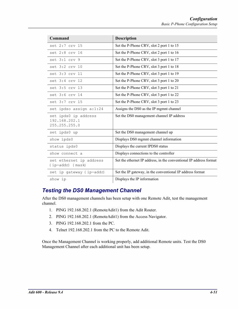
Adit 600 - Release 9.4 4-51
ConfigurationBasic P-Phone Configuration Setup
Testing the DS0 Management ChannelAfter the DS0 management channels has been setup with one Remote Adit, test the management channel.
1. PING 192.168.202.1 (RemoteAdit1) from the Adit Router.2. PING 192.168.202.1 (RemoteAdit1) from the Access Navigator.3. PING 192.168.202.1 from the PC.4. Telnet 192.168.202.1 from the PC to the Remote Adit.
Once the Management Channel is working properly, add additional Remote units. Test the DS0 Management Channel after each additional unit has been setup.
Command Description
set 2:7 crv 15 Set the P-Phone CRV, slot 2 port 1 to 15
set 2:8 crv 16 Set the P-Phone CRV, slot 2 port 1 to 16
set 3:1 crv 9 Set the P-Phone CRV, slot 3 port 1 to 17
set 3:2 crv 10 Set the P-Phone CRV, slot 3 port 1 to 18
set 3:3 crv 11 Set the P-Phone CRV, slot 3 port 1 to 19
set 3:4 crv 12 Set the P-Phone CRV, slot 3 port 1 to 20
set 3:5 crv 13 Set the P-Phone CRV, slot 3 port 1 to 21
set 3:6 crv 14 Set the P-Phone CRV, slot 3 port 1 to 22
set 3:7 crv 15 Set the P-Phone CRV, slot 3 port 1 to 23
set ipdso assign a:1:24 Assigns the DS0 as the IP mgmnt channel
set ipds0 ip address 192.168.202.1 255.255.255.0
Set the DS0 management channel IP address
set ipds0 up Set the DS0 management channel up
show ipds0 Displays DS0 mgmnt channel information
status ipds0 Displays the current IPDS0 status
show connect a Displays connections to the controller
set ethernet ip address ip-addr mask
Set the ethernet IP address, in the conventional IP address format
set ip gateway ip-addr Set the IP gateway, in the conventional IP address format
show ip Displays the IP information

4-52 Adit 600 - Release 9.4
ConfigurationBasic P-Phone Configuration Setup

CHAPTER 5CLI Commands
In this Chapter
Adit 600 CLI Syntax
Command Line Interface Help
CLI Commands

5-2 Adit 600 - Release 9.4
CLI CommandsAdit 600 CLI Syntax
Adit 600 CLI SyntaxThe Adit 600 general syntax is:
Adit 600> command [object] [setting] [modifier]
Symbols used in the Adit 600 CLI syntax are as follows:Any items listed in brackets or [ ] are variables set by the user. implies mandatory parameters [ ] implies optional parameters | = indicates (separates) more than one option (= or)
Example: set radius server 1|2|3 address ip-addr [port] In this example it is required to select one of the server options (1, 2 or 3) and to enter an IP address. The port number is an optional parameter.
Command Line Interface HelpDuring a CLI session, help is available at any time.
? or helpType a ? (or "help" before a command) at any time for quick command information> add ?
add ..................... Create users or profiles rtr_card-addr ...... Create profile, object or service on a router rtr_lan-addr ....... Create object or service on the router LAN user ................. Create user with manager level access.
NOTE: The scrolling feature, will always scroll through the command/options in alphabetical order.

Adit 600 - Release 9.4 5-3
CLI CommandsCommand Line Interface Help
[TAB] usage for word or command completionUse [TAB] for command word completion: > sh [TAB] > show
Use [TAB] to view command levels: > [TAB] will scroll through the base commands > aco [TAB] > add [TAB] > alarms [TAB] > clear [TAB] > connect [TAB] > delete ... etc.
Use [TAB] to view command options, add a space after the base command with the use of the [TAB] feature, scroll through all available options for this command: > set [TAB] will scroll through the set commands, with each <TAB> > set alarms [TAB] > set autoexit [TAB] > set clock1 ... etc.
If another space is placed after the command and [TAB] is pressed again, the next command level will display (if any): > set snmp [TAB] will scroll through all the set SNMP options > set snmp contact [TAB] > set snmp getcom [TAB] > set snmp location [TAB] > set snmp name ... etc.
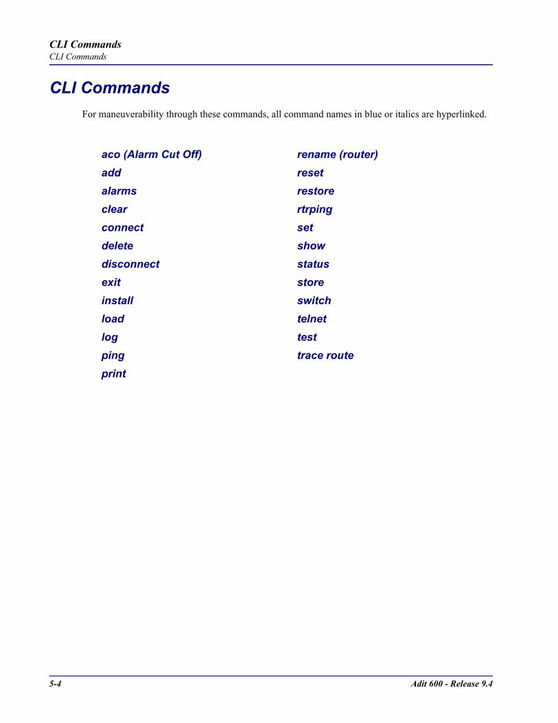
5-4 Adit 600 - Release 9.4
CLI CommandsCLI Commands
CLI CommandsFor maneuverability through these commands, all command names in blue or italics are hyperlinked.
aco (Alarm Cut Off) rename (router)add resetalarms restoreclear rtrpingconnect setdelete showdisconnect statusexit storeinstall switchload telnetlog testping trace routeprint
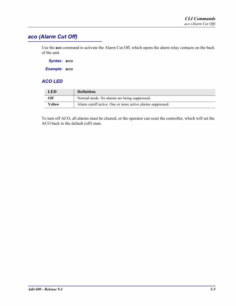
Adit 600 - Release 9.4 5-5
CLI Commandsaco (Alarm Cut Off)
aco (Alarm Cut Off)
Use the aco command to activate the Alarm Cut Off, which opens the alarm relay contacts on the back of the unit.
Syntax: aco
Example: aco
ACO LED
To turn off ACO, all alarms must be cleared, or the operator can reset the controller, which will set the ACO back to the default (off) state.
LED DefinitionOff Normal mode. No alarms are being suppressed.Yellow Alarm cutoff active. One or more active alarms suppressed.

5-6 Adit 600 - Release 9.4
CLI Commandsadd
add
Use the add command to create users, interfaces, services or profiles.See the following sections for detailed information on the following add commands
add (ds1) ais
add (router) dhcp server option
add (router) dns proxy
add (router) remote
add (router) snmp community
add (router) snmp trap
add (router) static dns host
add (router) uploaduser
add (router-lan) filter
add (router-lan) secondary ip address
add (router-lan) static
add (router-wan) firewall
add (router-wan) gre network
add (router-wan) nat bypass
add (router-wan) static
add user
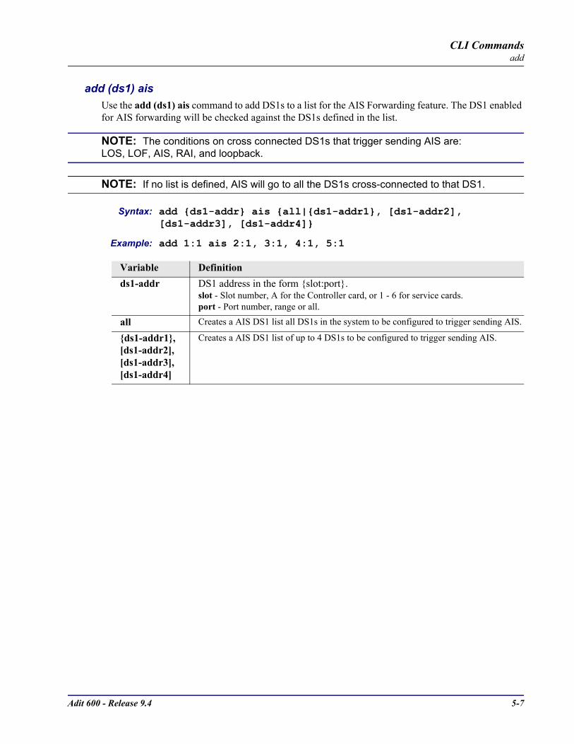
Adit 600 - Release 9.4 5-7
CLI Commandsadd
add (ds1) aisUse the add (ds1) ais command to add DS1s to a list for the AIS Forwarding feature. The DS1 enabled for AIS forwarding will be checked against the DS1s defined in the list.
NOTE: The conditions on cross connected DS1s that trigger sending AIS are:LOS, LOF, AIS, RAI, and loopback.
NOTE: If no list is defined, AIS will go to all the DS1s cross-connected to that DS1.
Syntax: add ds1-addr ais all|ds1-addr1, [ds1-addr2], [ds1-addr3], [ds1-addr4]
Example: add 1:1 ais 2:1, 3:1, 4:1, 5:1
Variable Definitionds1-addr DS1 address in the form slot:port.
slot - Slot number, A for the Controller card, or 1 - 6 for service cards.port - Port number, range or all.
all Creates a AIS DS1 list all DS1s in the system to be configured to trigger sending AIS.
ds1-addr1, [ds1-addr2], [ds1-addr3], [ds1-addr4]
Creates a AIS DS1 list of up to 4 DS1s to be configured to trigger sending AIS.
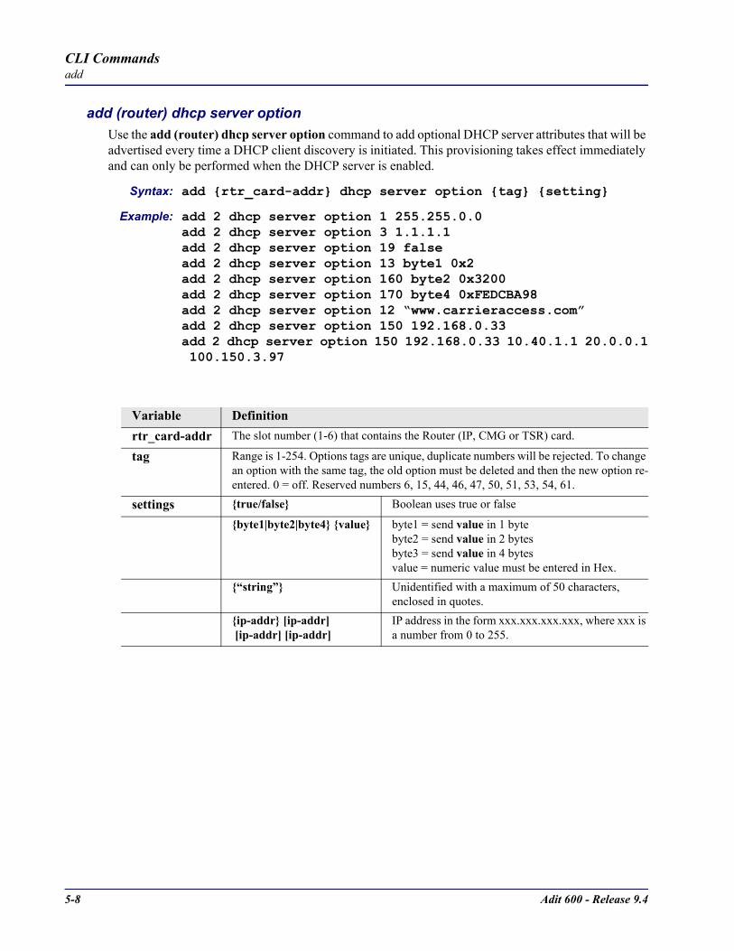
5-8 Adit 600 - Release 9.4
CLI Commandsadd
add (router) dhcp server optionUse the add (router) dhcp server option command to add optional DHCP server attributes that will be advertised every time a DHCP client discovery is initiated. This provisioning takes effect immediately and can only be performed when the DHCP server is enabled.
Syntax: add rtr_card-addr dhcp server option tag setting
Example: add 2 dhcp server option 1 255.255.0.0add 2 dhcp server option 3 1.1.1.1add 2 dhcp server option 19 falseadd 2 dhcp server option 13 byte1 0x2add 2 dhcp server option 160 byte2 0x3200add 2 dhcp server option 170 byte4 0xFEDCBA98add 2 dhcp server option 12 “www.carrieraccess.com”add 2 dhcp server option 150 192.168.0.33add 2 dhcp server option 150 192.168.0.33 10.40.1.1 20.0.0.1 100.150.3.97
Variable Definitionrtr_card-addr The slot number (1-6) that contains the Router (IP, CMG or TSR) card.
tag Range is 1-254. Options tags are unique, duplicate numbers will be rejected. To change an option with the same tag, the old option must be deleted and then the new option re-entered. 0 = off. Reserved numbers 6, 15, 44, 46, 47, 50, 51, 53, 54, 61.
settings true/false Boolean uses true or false
byte1|byte2|byte4 value byte1 = send value in 1 bytebyte2 = send value in 2 bytesbyte3 = send value in 4 bytesvalue = numeric value must be entered in Hex.
“string” Unidentified with a maximum of 50 characters, enclosed in quotes.
ip-addr [ip-addr] [ip-addr] [ip-addr]
IP address in the form xxx.xxx.xxx.xxx, where xxx is a number from 0 to 255.

Adit 600 - Release 9.4 5-9
CLI Commandsadd
add (router) dns proxyUse the add (router) dns proxy command to enable DNS proxy and add a remote DNS server address to the specified Router card.
Syntax: add rtr_card-addr dns proxy “domain-name” ip-addr “profile-name”
Example: add 2 dns proxy “Domain1” 192.168.100.245 “Texas”Example will add a DNS proxy server “Domain1” with address 192.168.100.245 to the WAN named “Texas” on the Router in slot 2.
add (router) remote Use the add (router) remote command to add a remote WAN profile to the WAN profile table on the specified Router card.
Syntax: add rtr_card-addr remote “profile-name”
Example: add 6 remote “Texas” The example will add a remote WAN named “Texas” to the WAN profile table for the Router in slot 6.
Variable Definitionrtr_card-addr The slot number (1-6) that contains the Router (IP, CMG or TSR) card.
domain-name The domain name for the external DNS server. Name must be enclosed in quotes, with a maximum length of 42 characters.
ip-addr The IP address of the external DNS server, in the form of xxx.xxx.xxx.xxx, where xxx is between 0-255.
profile-name The profile name for the Router interface that is used to reach this destination. Name must be enclosed in quotes, with a maximum length of 11 characters.
Variable Definitionrtr_card-addr The slot number (1-6) that contains the Router (IP, CMG or TSR) card.
profile-name The name of the remote WAN profile to add with a maximum length of 11 characters. This name must be enclosed in quotes.

5-10 Adit 600 - Release 9.4
CLI Commandsadd
add (router) snmp communityUse the add (router) snmp community command to add a SNMP community to an interface on the specified Router card.
Syntax: add rtr_card-addr snmp community both|read|write “community-name” ip-addr
Example: add 2 snmp community both “commune” 192.168.100.245The example will allow the host 192.168.100.245 read/write access to the Router card SNMP agent using the community name “commune”. The Router is located in slot 2.
add (router) snmp trapUse the add (router) snmp trap command to specify a destination to send SNMP trap messages for the specified Router card.
Syntax: add rtr_card-addr snmp trap “community-name” ip-addr “profile-name”
Example: add 3 snmp trap “commune” 192.168.100.245 “RemoteAdit”The example will add a trap destination of 192.168.100.245 on the interface "RemoteAdit" and use the community name "commune" on the Router in slot 3.
Variable Definitionrtr_card-addr The slot number (1-6) that contains the Router (IP, CMG or TSR) card.
both Will set the community to be read/write.
read Will set the community to be read-only.
write Will set the community to be write-only.
community-name
Community Name to add, with a maximum length of 10 characters, enclosed in quotes.
ip-addr The IP address of the host that can access the SNMP agent via this community, in the form of xxx.xxx.xxx.xxx, where xxx is between 0-255. The address “0.0.0.0” allows any host.
Variable Definitionrtr_card-addr The slot number (1-6) that contains the Router (IP, CMG or TSR) card.
community-name
The community name to use in each trap message, with a maximum of 10 characters.
ip-addr The IP address of the destination trap to add, in the form of xxx.xxx.xxx.xxx, where xxx is between 0-255.
profile-name The profile name for the Router interface that is used to reach this destination. Maximum of 11 characters and this name must be enclosed in quotes.
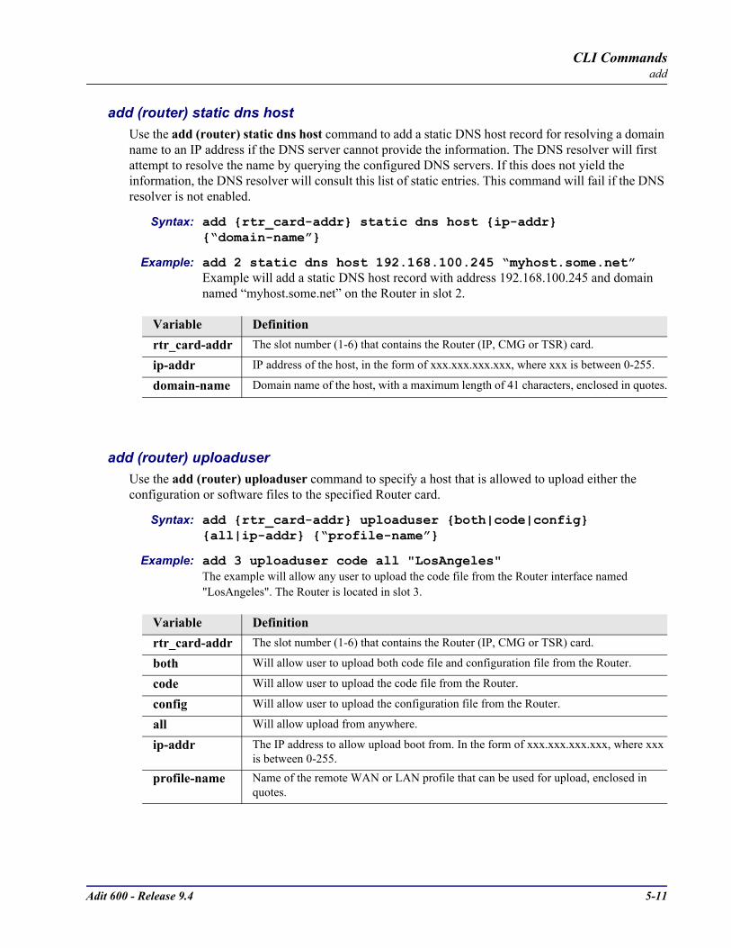
Adit 600 - Release 9.4 5-11
CLI Commandsadd
add (router) static dns hostUse the add (router) static dns host command to add a static DNS host record for resolving a domain name to an IP address if the DNS server cannot provide the information. The DNS resolver will first attempt to resolve the name by querying the configured DNS servers. If this does not yield the information, the DNS resolver will consult this list of static entries. This command will fail if the DNS resolver is not enabled.
Syntax: add rtr_card-addr static dns host ip-addr “domain-name”
Example: add 2 static dns host 192.168.100.245 “myhost.some.net”Example will add a static DNS host record with address 192.168.100.245 and domain named “myhost.some.net” on the Router in slot 2.
add (router) uploaduserUse the add (router) uploaduser command to specify a host that is allowed to upload either the configuration or software files to the specified Router card.
Syntax: add rtr_card-addr uploaduser both|code|config all|ip-addr “profile-name”
Example: add 3 uploaduser code all "LosAngeles" The example will allow any user to upload the code file from the Router interface named "LosAngeles". The Router is located in slot 3.
Variable Definitionrtr_card-addr The slot number (1-6) that contains the Router (IP, CMG or TSR) card.
ip-addr IP address of the host, in the form of xxx.xxx.xxx.xxx, where xxx is between 0-255.
domain-name Domain name of the host, with a maximum length of 41 characters, enclosed in quotes.
Variable Definitionrtr_card-addr The slot number (1-6) that contains the Router (IP, CMG or TSR) card.
both Will allow user to upload both code file and configuration file from the Router.
code Will allow user to upload the code file from the Router.
config Will allow user to upload the configuration file from the Router.
all Will allow upload from anywhere.
ip-addr The IP address to allow upload boot from. In the form of xxx.xxx.xxx.xxx, where xxx is between 0-255.
profile-name Name of the remote WAN or LAN profile that can be used for upload, enclosed in quotes.

5-12 Adit 600 - Release 9.4
CLI Commandsadd
add (router-lan) filter Use the add (router-lan) filter commands to add filters to the specified LAN interface.
add (router-lan) filter addressUse the add (router-lan) filter address command to add an address filter to the table of Layer 2 filters applied to the specified LAN interface.
Syntax: add rtr_lan-addr filter address both|destination|source mac-addr “filter-name”
Example: add 2:1 filter address both 0x00e09700e9cd “Server1” rtr_lan-addr
Variable Definitionrtr_lan-addr Router (IP, CMG or TSR) address is in the form slot:port or slot “profile-name”.
slot - The slot number (1-6) that contains the Router card.port - Port number of the Router.profile-name - The profile name for the Router interface. Name must be enclosed in quotes, with a maximum length of 11 characters.
both Filter by both source and destination.
destination Filter by destination only.
source Filter by source only.
all Will allow upload from anywhere.
mac-addr The MAC address to add to the learned address table for the LAN, in the form a 6-octet HEX value, 0xxxxxxxxxxxx. Please note that the MAC address is preceeded by a 0x.
filter-name A symbolic name given to identify a filter rule. This name must be enclosed in quotes, with a maximum of 8 characters.
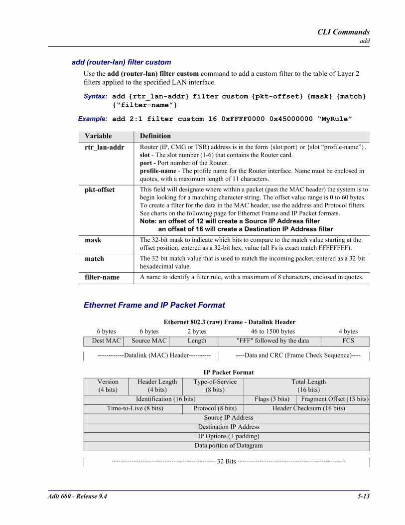
Adit 600 - Release 9.4 5-13
CLI Commandsadd
add (router-lan) filter customUse the add (router-lan) filter custom command to add a custom filter to the table of Layer 2 filters applied to the specified LAN interface.
Syntax: add rtr_lan-addr filter custom pkt-offset mask match “filter-name”
Example: add 2:1 filter custom 16 0xFFFF0000 0x45000000 “MyRule”
Ethernet Frame and IP Packet Format
Variable Definitionrtr_lan-addr Router (IP, CMG or TSR) address is in the form slot:port or slot “profile-name”.
slot - The slot number (1-6) that contains the Router card.port - Port number of the Router.profile-name - The profile name for the Router interface. Name must be enclosed in quotes, with a maximum length of 11 characters.
pkt-offset This field will designate where within a packet (past the MAC header) the system is to begin looking for a matching character string. The offset value range is 0 to 60 bytes. To create a filter for the data in the MAC header, use the address and Protocol filters. See charts on the following page for Ethernet Frame and IP Packet formats.Note: an offset of 12 will create a Source IP Address filter an offset of 16 will create a Destination IP Address filter
mask The 32-bit mask to indicate which bits to compare to the match value starting at the offset position. entered as a 32-bit hex. value (all Fs is exact match FFFFFFFF).
match The 32-bit match value that is used to match the incoming packet, entered as a 32-bit hexadecimal value.
filter-name A name to identify a filter rule, with a maximum of 8 characters, enclosed in quotes.
Ethernet 802.3 (raw) Frame - Datalink Header6 bytes 6 bytes 2 bytes 46 to 1500 bytes 4 bytes
Dest MAC Source MAC Length "FFF" followed by the data FCS
------------Datalink (MAC) Header---------- ----Data and CRC (Frame Check Sequence)----
IP Packet FormatVersion(4 bits)
Header Length(4 bits)
Type-of-Service(8 bits)
Total Length(16 bits)
Identification (16 bits) Flags (3 bits) Fragment Offset (13 bits)Time-to-Live (8 bits) Protocol (8 bits) Header Checksum (16 bits)
Source IP AddressDestination IP AddressIP Options (+ padding)
Data portion of Datagram
----------------------------------------------- 32 Bits -------------------------------------------------
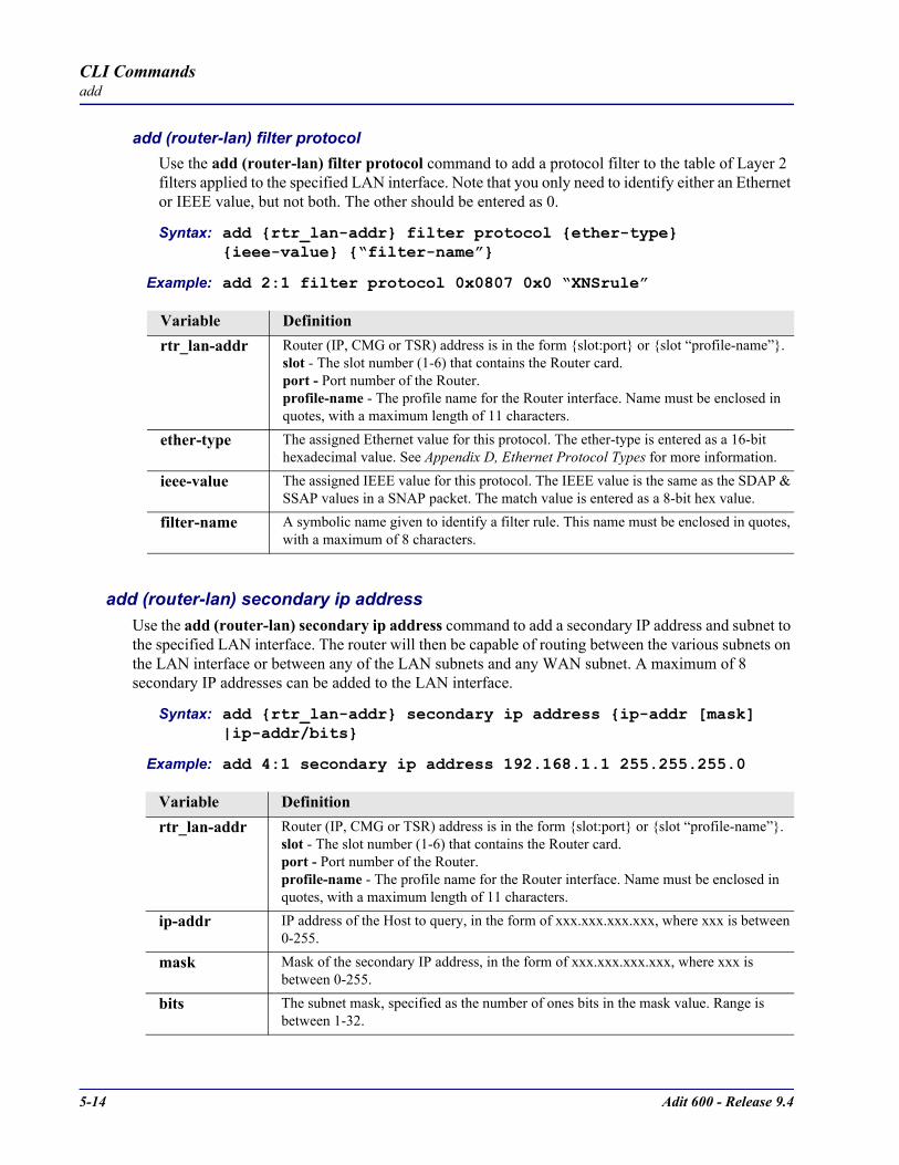
5-14 Adit 600 - Release 9.4
CLI Commandsadd
add (router-lan) filter protocolUse the add (router-lan) filter protocol command to add a protocol filter to the table of Layer 2 filters applied to the specified LAN interface. Note that you only need to identify either an Ethernet or IEEE value, but not both. The other should be entered as 0.
Syntax: add rtr_lan-addr filter protocol ether-type ieee-value “filter-name”
Example: add 2:1 filter protocol 0x0807 0x0 “XNSrule”
add (router-lan) secondary ip addressUse the add (router-lan) secondary ip address command to add a secondary IP address and subnet to the specified LAN interface. The router will then be capable of routing between the various subnets on the LAN interface or between any of the LAN subnets and any WAN subnet. A maximum of 8 secondary IP addresses can be added to the LAN interface.
Syntax: add rtr_lan-addr secondary ip address ip-addr [mask] |ip-addr/bits
Example: add 4:1 secondary ip address 192.168.1.1 255.255.255.0
Variable Definitionrtr_lan-addr Router (IP, CMG or TSR) address is in the form slot:port or slot “profile-name”.
slot - The slot number (1-6) that contains the Router card.port - Port number of the Router.profile-name - The profile name for the Router interface. Name must be enclosed in quotes, with a maximum length of 11 characters.
ether-type The assigned Ethernet value for this protocol. The ether-type is entered as a 16-bit hexadecimal value. See Appendix D, Ethernet Protocol Types for more information.
ieee-value The assigned IEEE value for this protocol. The IEEE value is the same as the SDAP & SSAP values in a SNAP packet. The match value is entered as a 8-bit hex value.
filter-name A symbolic name given to identify a filter rule. This name must be enclosed in quotes, with a maximum of 8 characters.
Variable Definitionrtr_lan-addr Router (IP, CMG or TSR) address is in the form slot:port or slot “profile-name”.
slot - The slot number (1-6) that contains the Router card.port - Port number of the Router.profile-name - The profile name for the Router interface. Name must be enclosed in quotes, with a maximum length of 11 characters.
ip-addr IP address of the Host to query, in the form of xxx.xxx.xxx.xxx, where xxx is between 0-255.
mask Mask of the secondary IP address, in the form of xxx.xxx.xxx.xxx, where xxx is between 0-255.
bits The subnet mask, specified as the number of ones bits in the mask value. Range is between 1-32.
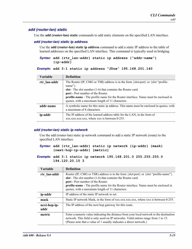
Adit 600 - Release 9.4 5-15
CLI Commandsadd
add (router-lan) static Use the add (router-lan) static commands to add static elements on the specified LAN interface.
add (router-lan) static ip addressUse the add (router-lan) static ip address command to add a static IP address to the table of learned addresses on the specified LAN interface. This command is typically used in bridging.
Syntax: add rtr_lan-addr static ip address “addr-name” ip-addr
Example: add 3:1 static ip address “JDoe” 195.168.201.140
add (router-lan) static ip networkUse the add (router-lan) static ip network command to add a static IP network (route) to the specified LAN interface.
Syntax: add rtr_lan-addr static ip network ip-addr mask next-hop-ip-addr [metric]
Example: add 3:1 static ip network 195.168.201.0 255.255.255.0 194.120.20.15 3
Variable Definitionrtr_lan-addr The Router (IP, CMG or TSR) address is in the form slot:port or slot “profile-
name”.slot - The slot number (1-6) that contains the Router card.port - Port number of the Router.profile-name - The profile name for the Router interface. Name must be enclosed in quotes, with a maximum length of 11 characters.
addr-name A symbolic name for this static ip address. This name must be enclosed in quotes, with a maximum of 8 characters.
ip-addr The IP address of the learned address table for the LAN, in the form of xxx.xxx.xxx.xxx, where xxx is between 0-255.
Variable Definitionrtr_lan-addr Router (IP, CMG or TSR) address is in the form slot:port or slot “profile-name”.
slot - The slot number (1-6) that contains the Router card.port - Port number of the Router.profile-name - The profile name for the Router interface. Name must be enclosed in quotes, with a maximum length of 11 characters.
ip-addr IP address of the static IP network to set.
mask Static IP network Mask, in the form of xxx.xxx.xxx.xxx, where xxx is between 0-255.
next-hop-ip-addr
The IP address of the next hop gateway for this route.
metric Enter a numeric value indicating the distance from your local network to the destination network. This field is only used on IP networks. Valid entries range from 1 to 15. (Please note that a value of 1 usually indicates a direct network.)
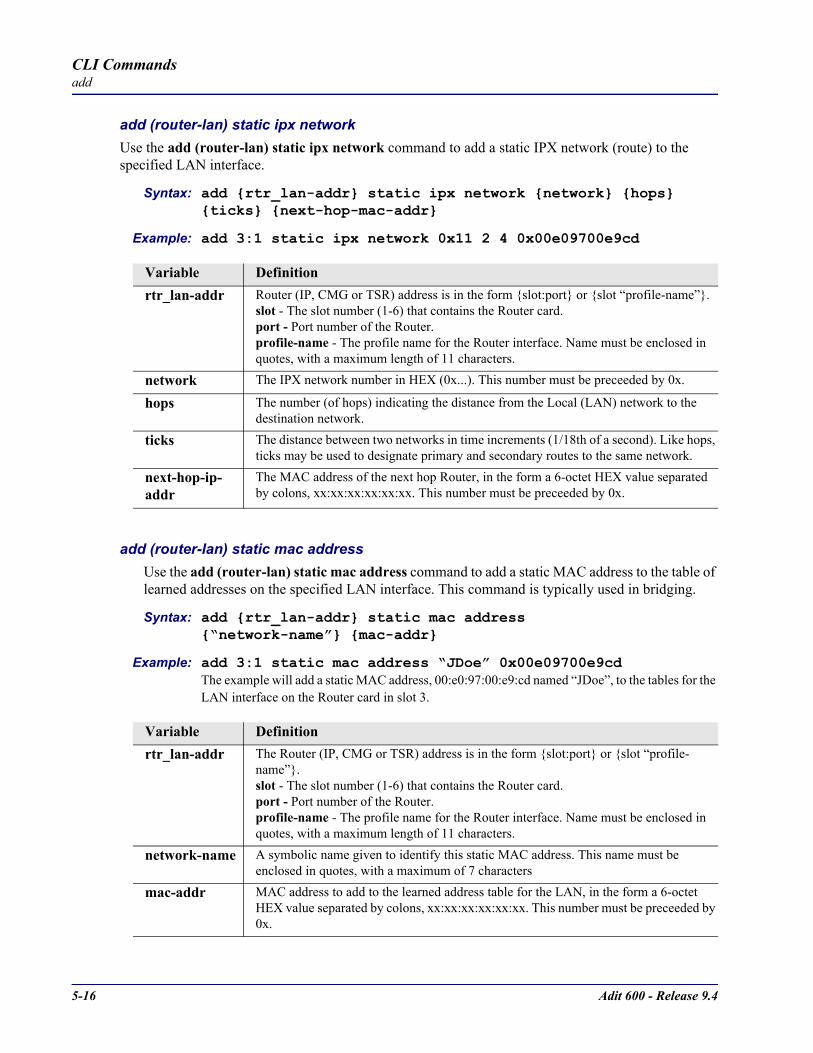
5-16 Adit 600 - Release 9.4
CLI Commandsadd
add (router-lan) static ipx networkUse the add (router-lan) static ipx network command to add a static IPX network (route) to the specified LAN interface.
Syntax: add rtr_lan-addr static ipx network network hops ticks next-hop-mac-addr
Example: add 3:1 static ipx network 0x11 2 4 0x00e09700e9cd
add (router-lan) static mac addressUse the add (router-lan) static mac address command to add a static MAC address to the table of learned addresses on the specified LAN interface. This command is typically used in bridging.
Syntax: add rtr_lan-addr static mac address “network-name” mac-addr
Example: add 3:1 static mac address “JDoe” 0x00e09700e9cd The example will add a static MAC address, 00:e0:97:00:e9:cd named “JDoe”, to the tables for the LAN interface on the Router card in slot 3.
Variable Definitionrtr_lan-addr Router (IP, CMG or TSR) address is in the form slot:port or slot “profile-name”.
slot - The slot number (1-6) that contains the Router card.port - Port number of the Router.profile-name - The profile name for the Router interface. Name must be enclosed in quotes, with a maximum length of 11 characters.
network The IPX network number in HEX (0x...). This number must be preceeded by 0x.
hops The number (of hops) indicating the distance from the Local (LAN) network to the destination network.
ticks The distance between two networks in time increments (1/18th of a second). Like hops, ticks may be used to designate primary and secondary routes to the same network.
next-hop-ip-addr
The MAC address of the next hop Router, in the form a 6-octet HEX value separated by colons, xx:xx:xx:xx:xx:xx. This number must be preceeded by 0x.
Variable Definitionrtr_lan-addr The Router (IP, CMG or TSR) address is in the form slot:port or slot “profile-
name”.slot - The slot number (1-6) that contains the Router card.port - Port number of the Router.profile-name - The profile name for the Router interface. Name must be enclosed in quotes, with a maximum length of 11 characters.
network-name A symbolic name given to identify this static MAC address. This name must be enclosed in quotes, with a maximum of 7 characters
mac-addr MAC address to add to the learned address table for the LAN, in the form a 6-octet HEX value separated by colons, xx:xx:xx:xx:xx:xx. This number must be preceeded by 0x.
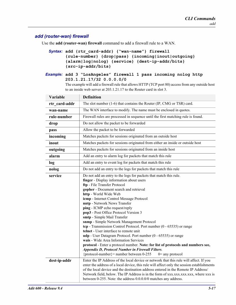
Adit 600 - Release 9.4 5-17
CLI Commandsadd
add (router-wan) firewallUse the add (router-wan) firewall command to add a firewall rule to a WAN.
Syntax: add rtr_card-addr “wan-name” firewall rule-number drop|pass incoming|inout|outgoing alarm|log|nolog service dest-ip-addr/bits src-ip-addr/bits
Example: add 3 “LosAngeles” firewall 1 pass incoming nolog http 203.1.21.17/32 0.0.0.0/0 The example will add a firewall rule that allows HTTP (TCP port 80) access from any outside host to an inside web server at 203.1.21.17 to the Router card in slot 3.
Variable Definitionrtr_card-addr The slot number (1-6) that contains the Router (IP, CMG or TSR) card.
wan-name The WAN interface to modify. The name must be enclosed in quotes.
rule-number Firewall rules are processed in sequence until the first matching rule is found.
drop Do not allow the packet to be forwarded
pass Allow the packet to be forwarded
incoming Matches packets for sessions originated from an outside host
inout Matches packets for sessions originated from either an inside or outside host
outgoing Matches packets for sessions originated from an inside host
alarm Add an entry to alarm log for packets that match this rule
log Add an entry to event log for packets that match this rule
nolog Do not add an entry to the logs for packets that match this rule
service Do not add an entry to the logs for packets that match this rule.finger - Display information about usersftp - File Transfer Protocolgopher - Document search and retrievalhttp - World Wide Webicmp - Internet Control Message Protocolnntp - Network News Transferping - ICMP echo request/replypop3 - Post Office Protocol Version 3smtp - Simple Mail Transfersnmp - Simple Network Management Protocoltcp - Transmission Control Protocol. Port number (0 - 65535) or rangetelnet - User interface to remote unitudp - User Datagram Protocol. Port number (0 - 65535) or rangewais - Wide Area Information Servicesprotocol - Enter a protocol number. Note: for list of protocols and numbers see, Appendix D, Protocol Number in Firewall Filters.protocol-number= number between 0-255 0= any protocol
dest-ip-addr Enter the IP Address of the local device or network that this rule will affect. If you enter the address of a local device, this rule will affect only the session establishments of the local device and the destination address entered in the Remote IP Address/Network field, below. The IP Address is in the form of xxx.xxx.xxx.xxx, where xxx is between 0-255. Note: the address 0.0.0.0/0 matches any address.
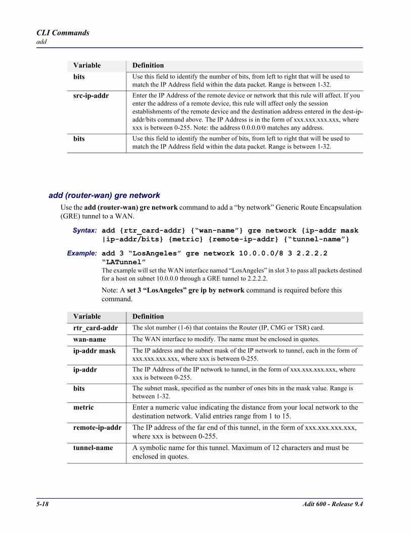
5-18 Adit 600 - Release 9.4
CLI Commandsadd
add (router-wan) gre networkUse the add (router-wan) gre network command to add a “by network” Generic Route Encapsulation (GRE) tunnel to a WAN.
Syntax: add rtr_card-addr “wan-name” gre network ip-addr mask |ip-addr/bits metric remote-ip-addr “tunnel-name”
Example: add 3 “LosAngeles” gre network 10.0.0.0/8 3 2.2.2.2 “LATunnel” The example will set the WAN interface named “LosAngeles” in slot 3 to pass all packets destined for a host on subnet 10.0.0.0 through a GRE tunnel to 2.2.2.2.
Note: A set 3 “LosAngeles” gre ip by network command is required before this command.
bits Use this field to identify the number of bits, from left to right that will be used to match the IP Address field within the data packet. Range is between 1-32.
src-ip-addr Enter the IP Address of the remote device or network that this rule will affect. If you enter the address of a remote device, this rule will affect only the session establishments of the remote device and the destination address entered in the dest-ip-addr/bits command above. The IP Address is in the form of xxx.xxx.xxx.xxx, where xxx is between 0-255. Note: the address 0.0.0.0/0 matches any address.
bits Use this field to identify the number of bits, from left to right that will be used to match the IP Address field within the data packet. Range is between 1-32.
Variable Definitionrtr_card-addr The slot number (1-6) that contains the Router (IP, CMG or TSR) card.
wan-name The WAN interface to modify. The name must be enclosed in quotes.
ip-addr mask The IP address and the subnet mask of the IP network to tunnel, each in the form of xxx.xxx.xxx.xxx, where xxx is between 0-255.
ip-addr The IP Address of the IP network to tunnel, in the form of xxx.xxx.xxx.xxx, where xxx is between 0-255.
bits The subnet mask, specified as the number of ones bits in the mask value. Range is between 1-32.
metric Enter a numeric value indicating the distance from your local network to the destination network. Valid entries range from 1 to 15.
remote-ip-addr The IP address of the far end of this tunnel, in the form of xxx.xxx.xxx.xxx, where xxx is between 0-255.
tunnel-name A symbolic name for this tunnel. Maximum of 12 characters and must be enclosed in quotes.
Variable Definition
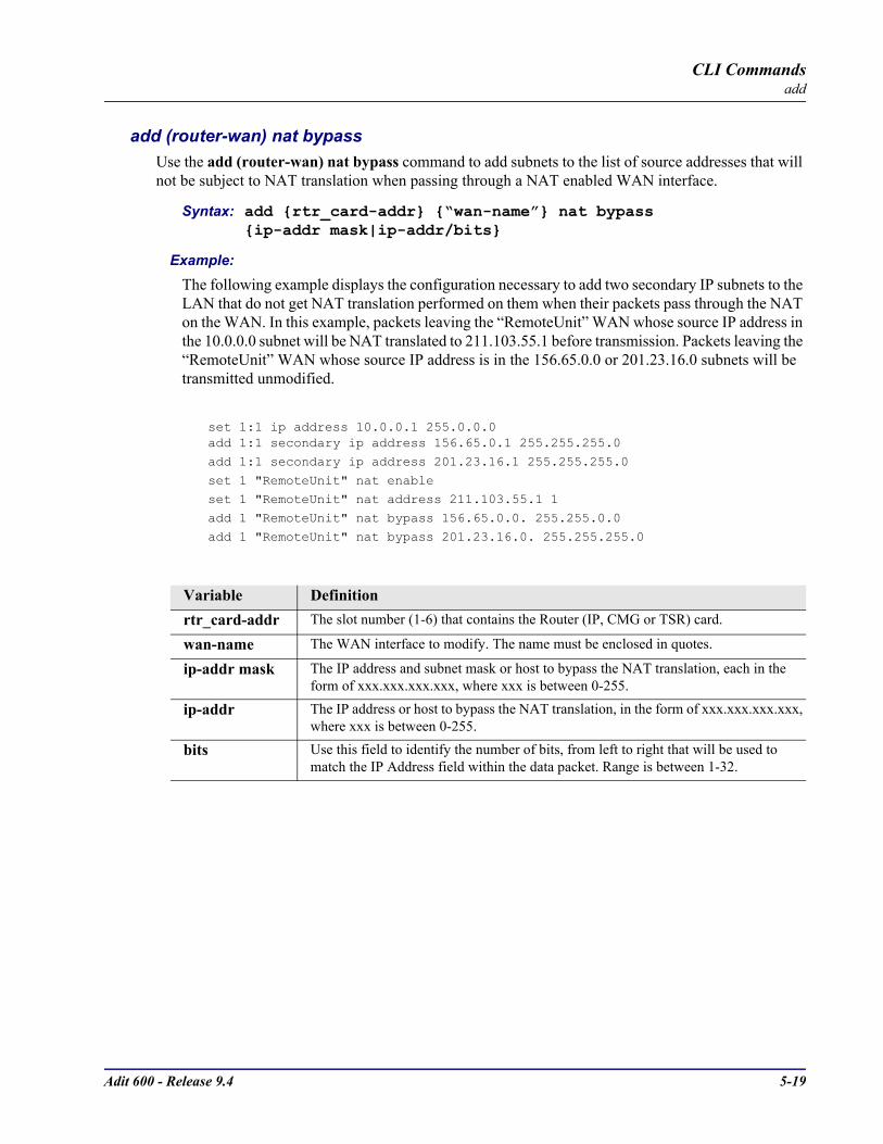
Adit 600 - Release 9.4 5-19
CLI Commandsadd
add (router-wan) nat bypassUse the add (router-wan) nat bypass command to add subnets to the list of source addresses that will not be subject to NAT translation when passing through a NAT enabled WAN interface.
Syntax: add rtr_card-addr “wan-name” nat bypass ip-addr mask|ip-addr/bits
Example:The following example displays the configuration necessary to add two secondary IP subnets to the LAN that do not get NAT translation performed on them when their packets pass through the NAT on the WAN. In this example, packets leaving the “RemoteUnit” WAN whose source IP address in the 10.0.0.0 subnet will be NAT translated to 211.103.55.1 before transmission. Packets leaving the “RemoteUnit” WAN whose source IP address is in the 156.65.0.0 or 201.23.16.0 subnets will be transmitted unmodified.
set 1:1 ip address 10.0.0.1 255.0.0.0add 1:1 secondary ip address 156.65.0.1 255.255.255.0
add 1:1 secondary ip address 201.23.16.1 255.255.255.0
set 1 "RemoteUnit" nat enableset 1 "RemoteUnit" nat address 211.103.55.1 1
add 1 "RemoteUnit" nat bypass 156.65.0.0. 255.255.0.0
add 1 "RemoteUnit" nat bypass 201.23.16.0. 255.255.255.0
Variable Definitionrtr_card-addr The slot number (1-6) that contains the Router (IP, CMG or TSR) card.
wan-name The WAN interface to modify. The name must be enclosed in quotes.
ip-addr mask The IP address and subnet mask or host to bypass the NAT translation, each in the form of xxx.xxx.xxx.xxx, where xxx is between 0-255.
ip-addr The IP address or host to bypass the NAT translation, in the form of xxx.xxx.xxx.xxx, where xxx is between 0-255.
bits Use this field to identify the number of bits, from left to right that will be used to match the IP Address field within the data packet. Range is between 1-32.
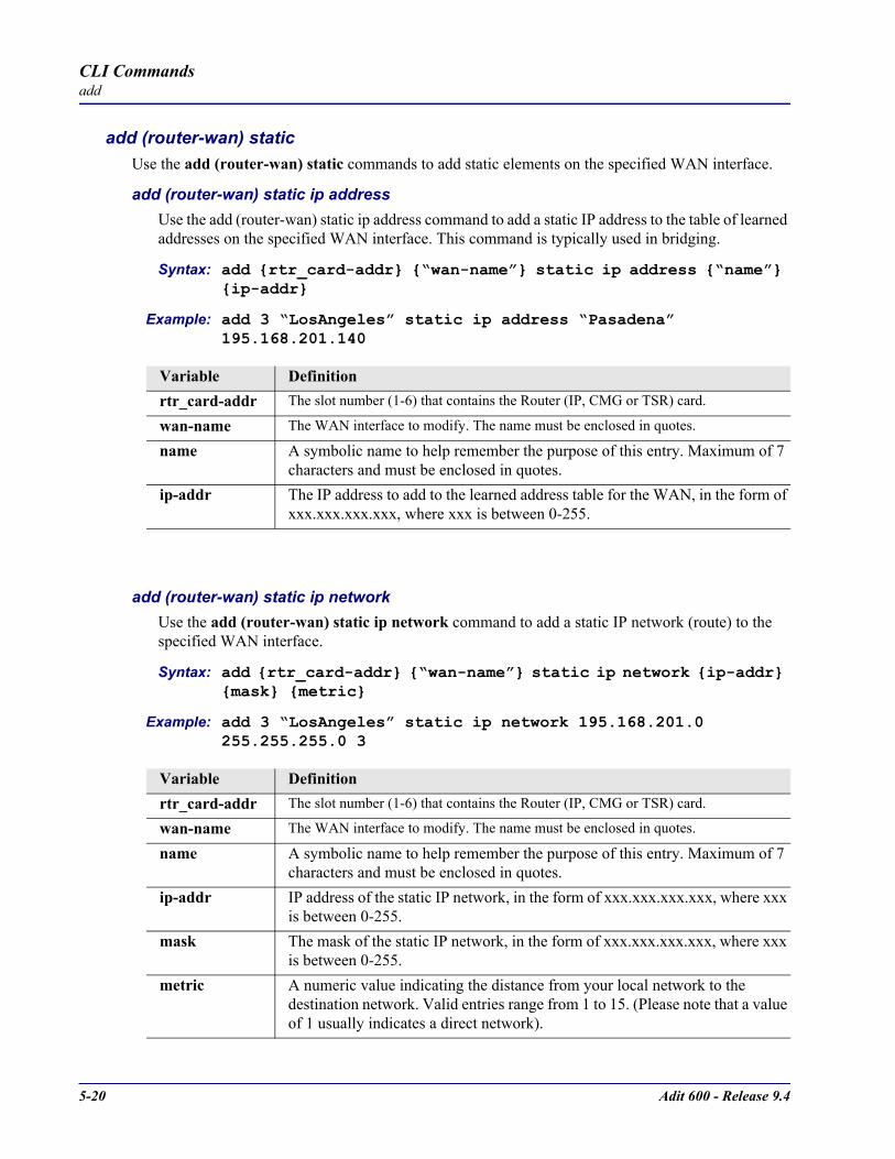
5-20 Adit 600 - Release 9.4
CLI Commandsadd
add (router-wan) staticUse the add (router-wan) static commands to add static elements on the specified WAN interface.
add (router-wan) static ip addressUse the add (router-wan) static ip address command to add a static IP address to the table of learned addresses on the specified WAN interface. This command is typically used in bridging.
Syntax: add rtr_card-addr “wan-name” static ip address “name” ip-addr
Example: add 3 “LosAngeles” static ip address “Pasadena” 195.168.201.140
add (router-wan) static ip networkUse the add (router-wan) static ip network command to add a static IP network (route) to the specified WAN interface.
Syntax: add rtr_card-addr “wan-name” static ip network ip-addr mask metric
Example: add 3 “LosAngeles” static ip network 195.168.201.0 255.255.255.0 3
Variable Definitionrtr_card-addr The slot number (1-6) that contains the Router (IP, CMG or TSR) card.
wan-name The WAN interface to modify. The name must be enclosed in quotes.
name A symbolic name to help remember the purpose of this entry. Maximum of 7 characters and must be enclosed in quotes.
ip-addr The IP address to add to the learned address table for the WAN, in the form of xxx.xxx.xxx.xxx, where xxx is between 0-255.
Variable Definitionrtr_card-addr The slot number (1-6) that contains the Router (IP, CMG or TSR) card.
wan-name The WAN interface to modify. The name must be enclosed in quotes.
name A symbolic name to help remember the purpose of this entry. Maximum of 7 characters and must be enclosed in quotes.
ip-addr IP address of the static IP network, in the form of xxx.xxx.xxx.xxx, where xxx is between 0-255.
mask The mask of the static IP network, in the form of xxx.xxx.xxx.xxx, where xxx is between 0-255.
metric A numeric value indicating the distance from your local network to the destination network. Valid entries range from 1 to 15. (Please note that a value of 1 usually indicates a direct network).

Adit 600 - Release 9.4 5-21
CLI Commandsadd
add (router-wan) static ipx networkUse the add (router-wan) static ipx network command to add a static IPX network (route) to the specified WAN interface.
Syntax: add rtr_card-addr “wan-name” static ipx network network hops ticks
Example: add 3 “LosAngeles” static ipx network 0x11 2 4
add (router-wan) static mac addressUse the add (router-wan) static mac address command to add a static MAC address to the table of learned addresses on the specified WAN interface. This command is typically used in bridging.
Syntax: add rtr_card-addr “wan-name” static mac address “name” mac-addr
Example: add 3 “LosAngeles” static mac address “JDoe” x000e09700e9cd
Variable Definitionrtr_card-addr The slot number (1-6) that contains the Router (IP, CMG or TSR) card.
wan-name The WAN interface to modify. The name must be enclosed in quotes.
network The IPX network number in HEX (0x...).hops The numeric value (of hops) indicating the distance from your Local (LAN)
network to the destination network.The numeric value (of hops) indicating the distance from your Local (LAN) network to the destination network.
ticks The distance between two networks as measured in time increments (1/18th of a second). Like hops, ticks may be used to designate primary and secondary routes to the same network. Although both the hops and ticks values are considered when determining routing priority, for Novell networks, the tick value is considered first.
Variable Definitionrtr_card-addr The slot number (1-6) that contains the Router (IP, CMG or TSR) card.
wan-name The WAN interface to modify. The name must be enclosed in quotes.
name A symbolic name to help remember the purpose of this entry. This name is a maximum of 7 characters and must be enclosed in quotes.
mac-addr The MAC address to add to the learned address table for the LAN, in the form a 6-octet HEX value, 0xxxxxxxxxxxx. Please note that the MAC address is preceeded by a 0x.
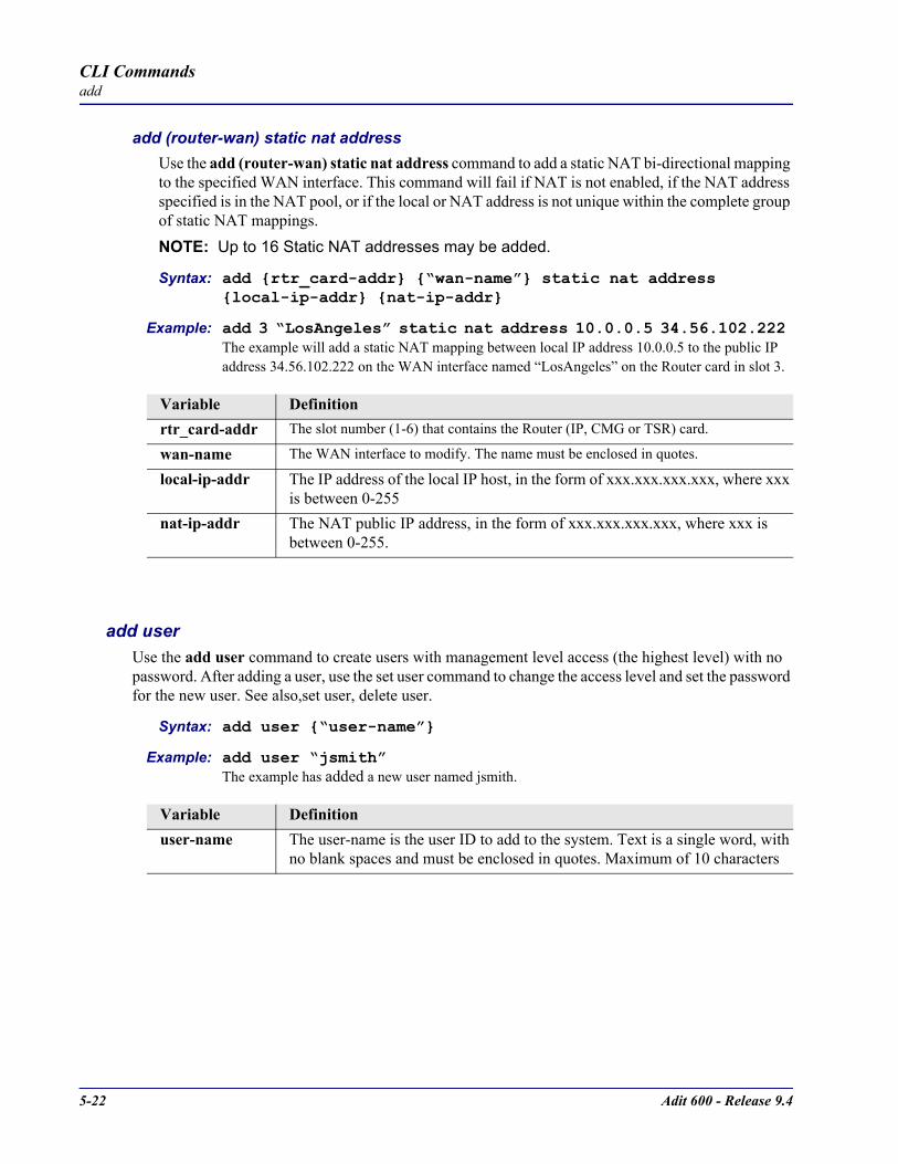
5-22 Adit 600 - Release 9.4
CLI Commandsadd
add (router-wan) static nat addressUse the add (router-wan) static nat address command to add a static NAT bi-directional mapping to the specified WAN interface. This command will fail if NAT is not enabled, if the NAT address specified is in the NAT pool, or if the local or NAT address is not unique within the complete group of static NAT mappings. NOTE: Up to 16 Static NAT addresses may be added.
Syntax: add rtr_card-addr “wan-name” static nat address local-ip-addr nat-ip-addr
Example: add 3 “LosAngeles” static nat address 10.0.0.5 34.56.102.222 The example will add a static NAT mapping between local IP address 10.0.0.5 to the public IP address 34.56.102.222 on the WAN interface named “LosAngeles” on the Router card in slot 3.
add userUse the add user command to create users with management level access (the highest level) with no password. After adding a user, use the set user command to change the access level and set the password for the new user. See also,set user, delete user.
Syntax: add user “user-name”
Example: add user “jsmith”The example has added a new user named jsmith.
Variable Definitionrtr_card-addr The slot number (1-6) that contains the Router (IP, CMG or TSR) card.
wan-name The WAN interface to modify. The name must be enclosed in quotes.
local-ip-addr The IP address of the local IP host, in the form of xxx.xxx.xxx.xxx, where xxx is between 0-255
nat-ip-addr The NAT public IP address, in the form of xxx.xxx.xxx.xxx, where xxx is between 0-255.
Variable Definitionuser-name The user-name is the user ID to add to the system. Text is a single word, with
no blank spaces and must be enclosed in quotes. Maximum of 10 characters
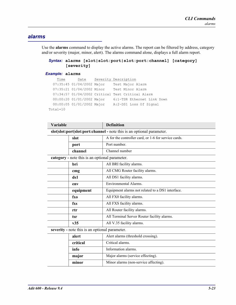
Adit 600 - Release 9.4 5-23
CLI Commandsalarms
alarms
Use the alarms command to display the active alarms. The report can be filtered by address, category and/or severity (major, minor, alert). The alarms command alone, displays a full alarm report.
Syntax: alarms [slot|slot:port|slot:port:channel] [category] [severity]
Example: alarms Time Date Severity Description
07:35:45 01/04/2002 Major Test Major Alarm 07:35:21 01/04/2002 Minor Test Minor Alarm
07:34:57 01/04/2002 Critical Test Critical Alarm
00:00:20 01/01/2002 Major 6:1-TSR Ethernet Link Down 00:00:05 01/01/2002 Major A:2-DS1 Loss Of Signal
Total=10
Variable Definitionslot|slot:port|slot:port:channel - note this is an optional parameter.
slot A for the controller card, or 1-6 for service cards.
port Port number.
channel Channel number
category - note this is an optional parameter.bri All BRI facility alarms.
cmg All CMG Router facility alarms.
ds1 All DS1 facility alarms.
env Environmental Alarms.
equipment Equipment alarms not related to a DS1 interface.
fxo All FX0 facility alarms.
fxs All FXS facility alarms.
rtr All Router facility alarms.
tsr All Terminal Server Router facility alarms.
v35 All V.35 facility alarms.
severity - note this is an optional parameter.alert Alert alarms (threshold crossing).
critical Critical alarms.
info Information alarms.
major Major alarms (service effecting).
minor Minor alarms (non-service affecting).

5-24 Adit 600 - Release 9.4
CLI Commandsclear
clear
User the clear command to clear logs, performance data and tables.
clear (ds1)
clear (e1)
clear key
clear log
clear (ocudp) performance
clear (router) ip address table
clear (router) log
clear (router) mac address table
clear (router) mgcp stats
clear (router) performance

Adit 600 - Release 9.4 5-25
CLI Commandsclear
clear (ds1)Use the clear (ds1) command to clear specified DS1 performance data.
Syntax: clear ds1-addr performance setting
Example: clear a:1 performance all
Variable Definitionds1-addr DS1 address in the format slot:port.
slot A for the controller card, or 1-6 for service cards.
port Port number range or all.
setting all Clear all performance data
bes Clear bes (bursty errored seconds) performance data.
css Clear css (controlled slip seconds) performance data.
dm Clear dm (degraded minutes) performance data.
es Clear es (errored seconds) performance data.
lcv Clear lcv (line code violations) performance data.
les Clear les (line errored seconds) performance data.
pcv Clear pcv (path code violations) performance data.
sefs Clear sefs (severely errored frame seconds) performance data.
ses Clear ses (severely errored seconds) performance data.
uas Clear uas (unavailable seconds) performance data.

5-26 Adit 600 - Release 9.4
CLI Commandsclear
clear (e1)Use the clear (e1) command to clear specified DS1 performance data.
Syntax: clear e1-addr performance setting
Example: clear a:1 performance all
clear keyUse the clear key command to remove a specific keyed feature. To acquire a feature key code, contact Carrier Access Customer Support.
Syntax: clear [rtr_card-addr] key “key-code”
Example: clear key “q0B8yma2IsSL+1BarY0u”
Variable Definitione1-addr E1 address in the format slot:port.
slot A for the E1 controller card, or 1-6 for service cards (Quad E1).
port Port number range or all.
setting all Clear all performance data
bes Clear bes (bursty errored seconds) performance data.
css Clear css (controlled slip seconds) performance data.
dm Clear dm (degraded minutes) performance data.
es Clear es (errored seconds) performance data.
lcv Clear lcv (line code violations) performance data.
les Clear les (line errored seconds) performance data.
pcv Clear pcv (path code violations) performance data.
sefs Clear sefs (severely errored frame seconds) performance data.
ses Clear ses (severely errored seconds) performance data.
uas Clear uas (unavailable seconds) performance data.
Variable Definitionrtr_card-addr The slot number (1-6) that contains the Router (IP, CMG or TSR) card. This optional
parameter is used for router specific keyed features.
key-code The key code is entered to enable the specific feature.
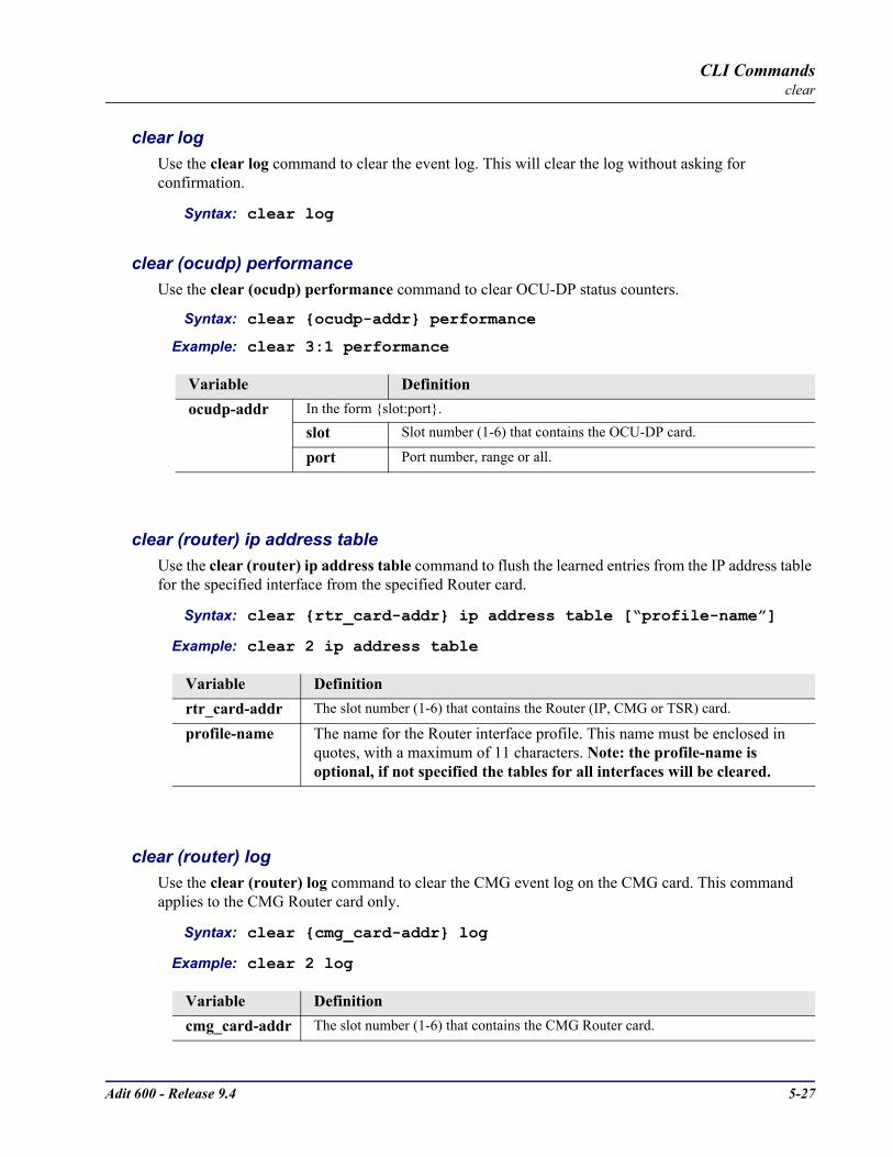
Adit 600 - Release 9.4 5-27
CLI Commandsclear
clear logUse the clear log command to clear the event log. This will clear the log without asking for confirmation.
Syntax: clear log
clear (ocudp) performanceUse the clear (ocudp) performance command to clear OCU-DP status counters.
Syntax: clear ocudp-addr performance
Example: clear 3:1 performance
clear (router) ip address tableUse the clear (router) ip address table command to flush the learned entries from the IP address table for the specified interface from the specified Router card.
Syntax: clear rtr_card-addr ip address table [“profile-name”]
Example: clear 2 ip address table
clear (router) logUse the clear (router) log command to clear the CMG event log on the CMG card. This command applies to the CMG Router card only.
Syntax: clear cmg_card-addr log
Example: clear 2 log
Variable Definitionocudp-addr In the form slot:port.
slot Slot number (1-6) that contains the OCU-DP card.
port Port number, range or all.
Variable Definitionrtr_card-addr The slot number (1-6) that contains the Router (IP, CMG or TSR) card.
profile-name The name for the Router interface profile. This name must be enclosed in quotes, with a maximum of 11 characters. Note: the profile-name is optional, if not specified the tables for all interfaces will be cleared.
Variable Definitioncmg_card-addr The slot number (1-6) that contains the CMG Router card.
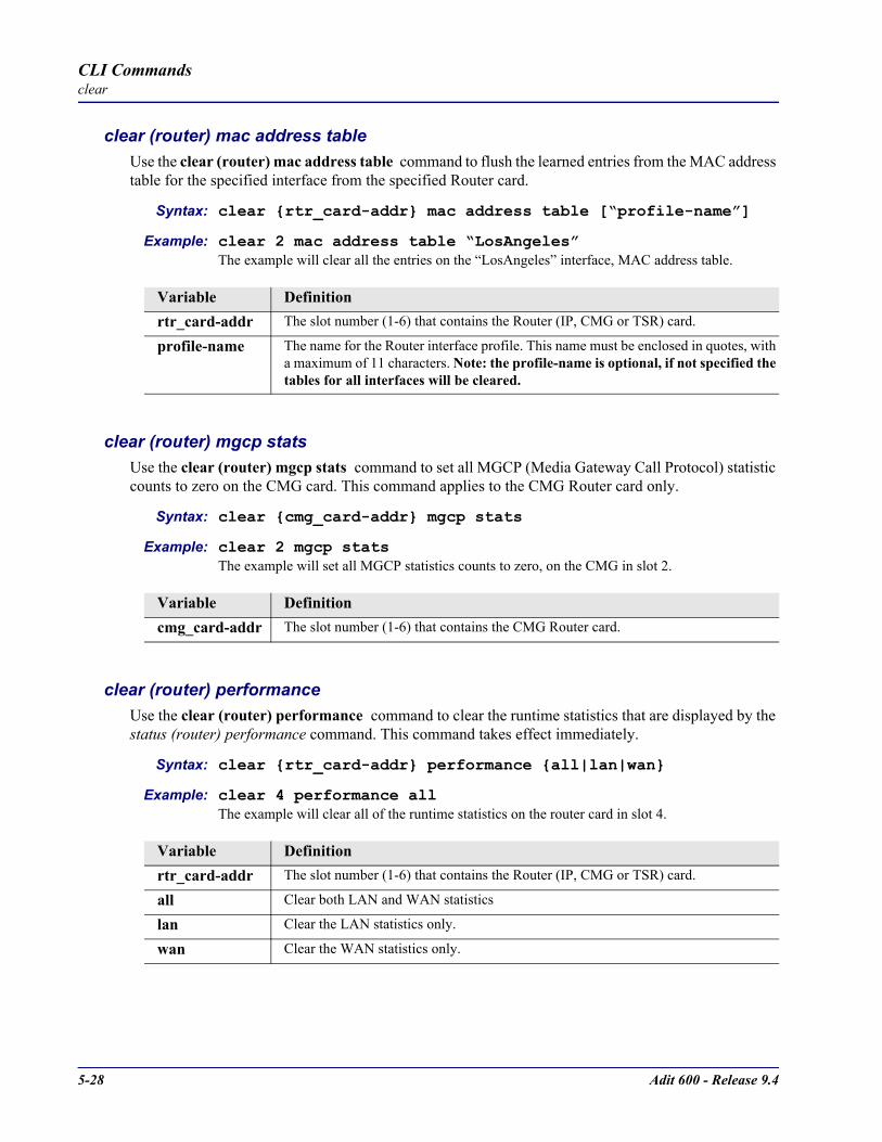
5-28 Adit 600 - Release 9.4
CLI Commandsclear
clear (router) mac address tableUse the clear (router) mac address table command to flush the learned entries from the MAC address table for the specified interface from the specified Router card.
Syntax: clear rtr_card-addr mac address table [“profile-name”]
Example: clear 2 mac address table “LosAngeles”The example will clear all the entries on the “LosAngeles” interface, MAC address table.
clear (router) mgcp statsUse the clear (router) mgcp stats command to set all MGCP (Media Gateway Call Protocol) statistic counts to zero on the CMG card. This command applies to the CMG Router card only.
Syntax: clear cmg_card-addr mgcp stats
Example: clear 2 mgcp statsThe example will set all MGCP statistics counts to zero, on the CMG in slot 2.
clear (router) performanceUse the clear (router) performance command to clear the runtime statistics that are displayed by the status (router) performance command. This command takes effect immediately.
Syntax: clear rtr_card-addr performance all|lan|wan
Example: clear 4 performance allThe example will clear all of the runtime statistics on the router card in slot 4.
Variable Definitionrtr_card-addr The slot number (1-6) that contains the Router (IP, CMG or TSR) card.
profile-name The name for the Router interface profile. This name must be enclosed in quotes, with a maximum of 11 characters. Note: the profile-name is optional, if not specified the tables for all interfaces will be cleared.
Variable Definitioncmg_card-addr The slot number (1-6) that contains the CMG Router card.
Variable Definitionrtr_card-addr The slot number (1-6) that contains the Router (IP, CMG or TSR) card.
all Clear both LAN and WAN statistics
lan Clear the LAN statistics only.
wan Clear the WAN statistics only.
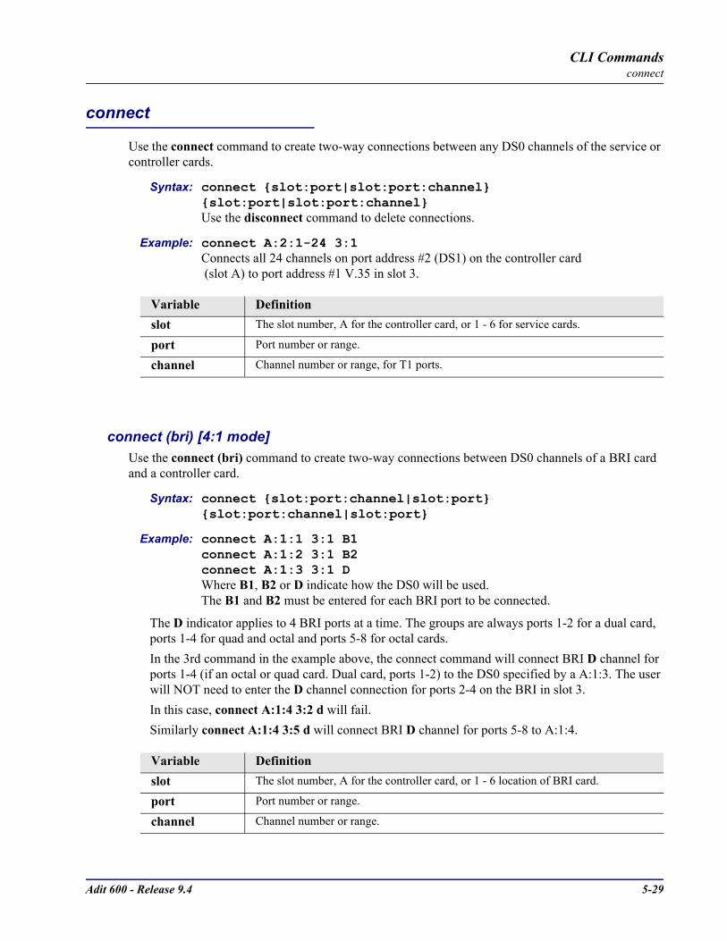
Adit 600 - Release 9.4 5-29
CLI Commandsconnect
connect
Use the connect command to create two-way connections between any DS0 channels of the service or controller cards.
Syntax: connect slot:port|slot:port:channel slot:port|slot:port:channelUse the disconnect command to delete connections.
Example: connect A:2:1-24 3:1Connects all 24 channels on port address #2 (DS1) on the controller card (slot A) to port address #1 V.35 in slot 3.
connect (bri) [4:1 mode]Use the connect (bri) command to create two-way connections between DS0 channels of a BRI card and a controller card.
Syntax: connect slot:port:channel|slot:port slot:port:channel|slot:port
Example: connect A:1:1 3:1 B1connect A:1:2 3:1 B2connect A:1:3 3:1 DWhere B1, B2 or D indicate how the DS0 will be used.The B1 and B2 must be entered for each BRI port to be connected.
The D indicator applies to 4 BRI ports at a time. The groups are always ports 1-2 for a dual card, ports 1-4 for quad and octal and ports 5-8 for octal cards.In the 3rd command in the example above, the connect command will connect BRI D channel for ports 1-4 (if an octal or quad card. Dual card, ports 1-2) to the DS0 specified by a A:1:3. The user will NOT need to enter the D channel connection for ports 2-4 on the BRI in slot 3. In this case, connect A:1:4 3:2 d will fail.Similarly connect A:1:4 3:5 d will connect BRI D channel for ports 5-8 to A:1:4.
Variable Definitionslot The slot number, A for the controller card, or 1 - 6 for service cards.
port Port number or range.
channel Channel number or range, for T1 ports.
Variable Definitionslot The slot number, A for the controller card, or 1 - 6 location of BRI card.
port Port number or range.
channel Channel number or range.
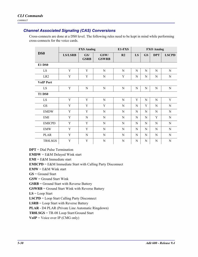
5-30 Adit 600 - Release 9.4
CLI Commandsconnect
Channel Associated Signaling (CAS) ConversionsCross-connects are done at a DS0 level. The following rules need to be kept in mind while performing cross-connects for the voice cards.
DPT = Dial Pulse TerminationEMDW = E&M Delayed Wink startEMI = E&M Immediate start EMICPD = E&M Immediate Start with Calling Party DisconnectEMW = E&M Wink startGS = Ground StartGSW = Ground Start WinkGSRB = Ground Start with Reverse BatteryGSWRB = Ground Start Wink with Reverse BatteryLS = Loop StartLSCPD = Loop Start Calling Party DisconnectLSRB = Loop Start with Reverse BatteryPLAR - D4 PLAR (Private Line Automatic Ringdown) TR8LSGS = TR-08 Loop Start/Ground StartVoIP = Voice over IP (CMG only)
DS0FXS Analog E1-FXS FXO Analog
LS/LSRB GS/GSRB
GSW/GSWRB
R2 LS GS DPT LSCPD
E1 DS0
LS Y Y N N N N N N
LR2 Y Y N Y N N N N
VoIP Port
LS Y N N N N N N N
T1 DS0
LS Y Y N N Y N N Y
GS Y Y Y N N Y N N
EMDW Y Y N N N N N N
EMI Y N N N N N Y N
EMICPD Y Y N N N N N N
EMW Y Y N N N N N N
PLAR Y N N N N N N N
TR8LSGS Y Y N N N N N N

Adit 600 - Release 9.4 5-31
CLI Commandsconnect
connect (router-trunk) (t1)Use the connect (router-trunk) (t1) command to create a two-way connection (WAN) between the Router port trunk connections and any DS0 channels of the service card or Controller.
Syntax: connect slot:port|slot:port:channel rtr_trunk-addrUse the disconnect command to delete connections.
Example: connect A:2:1-12 5:1:1Connects 12 channels on port address #2 (DS1) on the controller card (slot A) to trunk 1 on the Router in slot 5.
Variable Definitionslot The slot number, A for the controller card, or 1 - 6 for service cards.
port Port number or range (port must be a T1).
channel Channel number or range, for T1 ports.
rtr_trunk-addr The Router (IP, CMG or TSR) trunk address is in the form slot:port:trunk.
slot The slot number (1-6) that contains the Router (CMG, IP or TSR) card.
port Port number of the TSR is 1. Note: there are 4 physical ports on the TSR, but only one logical one used for addressing.
trunk Trunk number for this port, 1-24.

5-32 Adit 600 - Release 9.4
CLI Commandsconnect
connect (card-trunk) (card-trunk)Use the connect (card-trunk) (card-trunk) command for configuring card-to-card WAN cross-connects between two Router cards or between a Router card and a V.35 card.
Syntax: connect rtr_trunk-addr rtr_trunk-addr|v35-addr ds0-number
Example: connect 3:1:2 4:1:3 12Connects WAN trunk number 2 of a Router card in slot 3 to WAN trunk number 3 of a Router card in slot 4 using 12 DS0s.
Example: connect 3:1:2 5:1 12Connects WAN trunk number 2 of a Router card in slot 3 to port 1 of V.35 card in slot 5 using 12 DS0s.
Variable Definitionrtr_trunk-addr The Router (IP, CMG or TSR) trunk address is in the form slot:port:trunk.
slot The slot number (1-6) that contains the Router (CMG, IP or CMG) card.
port Port number of the TSR is 1. Note: there are 4 physical ports on the TSR, but only one logical one used for addressing.
trunk Trunk number for this port, 1-24.
v35-addr The V.35 trunk address is in the form slot:port
slot The slot number (1-6) that contains a V.35 card.
port Port number (1-2).
ds0-number The number of DS0s to connect (1-60).

Adit 600 - Release 9.4 5-33
CLI Commandsconnect
connect (router-voice) (t1|fxs)Use the connect (router-voice) (t1|fxs) command to create two-way connections between the CMG voice channels and DS0 channels of an FXS or T1 service card or controller T1. The CMG only supports connections between CMG voice channels and FXS or T1 DS0s utilizing loop start signaling.
Syntax: connect cmg_voice-addr slot:port|slot:port:channelUse the disconnect command to delete connections.
Example: connect A:2:1-12 5:1:1:1-12Connects 12 channels on port address #2 (DS1) on the controller card (slot A) to the first 12 voice channels on the CMG in slot 5.
Variable Definitioncmg_voice-addr In the form slot:voip:channel
slot The slot number (1-6) that contains the CMG card.
voip To designate VoIP 1:1 is used.
channel Channel number for the router is 1-48, range or all
slot The slot number, A for the controller card, or 1 - 6 for service cards.
port Port number or range (port must be a T1).
channel Channel number or range, for T1 ports.
5-34 Adit 600 - Release 9.4
CLI Commandsdelete
delete
Use the delete command to remove users, interfaces, services or profiles.See the following sections for detailed information on the following delete commands
delete (ds1) ais
delete (router) dhcp server option
delete (router) dns proxy
delete (router) remote
delete (router) snmp community
delete (router) snmp trap
delete (router) static dns host
delete (router) uploaduser
delete (router-lan) filter
delete (router-lan) secondary ip address
delete (router-lan) static
delete (router-wan) firewall
delete (router-wan) gre network
delete (router-wan) nat bypass
delete (router-wan) static
delete user

Adit 600 - Release 9.4 5-35
CLI Commandsdelete
delete (ds1) aisUse the delete (ds1) ais command to delete DS1s from the AIS DS1 list. The DS1 that is AIS enabled will be checked against the DS1s defined in the list.
NOTE: If no DS1s are defined, and AIS is enabled, the default will be all the DS1s in the system. If all DS1s are removed from the lit the default of all the DS1s in the system will be applied.
Syntax: delete ds1-addr ais ds1-addr1, [ds1-addr2], [ds1-addr3], [ds1-addr4]
Example: delete 1:1 ais 2:1
delete (router) dhcp server optionUse the delete (router) dhcp server option command To add optional DHCP server attributes that will be advertised very time a DHCP client discovery is initiated. This provisioning takes effect immediately and can only be performed when the DHCP server is enabled.
Syntax: delete rtr_card-addr dhcp server option tag
Example: add 2 dhcp server option 13
Variable Definitionds1-addr DS1 address in the form slot:port.
slot - Slot number, A for the Controller card, or 1 - 6 for service cards.port - Port number, range or all.
ds1-addr1, [ds1-addr2], [ds1-addr3], [ds1-addr4]
Deletes a AIS DS1 list of up to 4 DS1s to be configured to trigger sending AIS.
Variable Definitionrtr_card-addr The slot number (1-6) that contains the Router (IP, CMG or TSR) card.
tag An existing tag to be removed. Use the show (router) dhcp command to see current options.

5-36 Adit 600 - Release 9.4
CLI Commandsdelete
delete (router) dns proxyUse the delete (router) dns proxy command to remove a remote DNS server address from the specified Router card. If this command is directed to delete the only a DNS proxy server address then DNS proxy is disabled.
Syntax: delete rtr_card-addr dns proxy ip-addr “profile-name”
Example: delete 2 dns proxy 192.168.100.245 “Texas”
delete (router) remoteUse the delete (router) remote command to delete a remote WAN profile from the WAN profile table on the specified Router card.
Syntax: delete rtr_card-addr remote “profile-name”
Example: delete 6 remote “Texas”
Variable Definitionrtr_card-addr The slot number (1-6) that contains the Router (IP, CMG or TSR) card.
ip-addr IP address of the external DNS server, in the form of xxx.xxx.xxx.xxx, where xxx is between 0-255.
profile-name The profile name for the Router interface that is used to reach this destination. Name must be enclosed in quotes, with a maximum length of 11 characters.
Variable Definitionrtr_card-addr The slot number (1-6) that contains the Router (IP, CMG or TSR) card.
profile-name The name of the remote WAN profile to delete. This name must be enclosed in quotes, with a maximum of 12 characters.

Adit 600 - Release 9.4 5-37
CLI Commandsdelete
delete (router) snmp communityUse the delete (router) snmp community command to delete an SNMP community entry on the specified Router card.
Syntax: delete rtr_card-addr snmp community “community-name” ip-addr
Example: delete 2 snmp community “commune” 192.168.100.245The example will delete the previously added SNMP community named “commune” from the Router in slot 2.
delete (router) snmp trapUse the delete (router) snmp trap command to delete a trap destination from the specified Router card.
Syntax: delete rtr_card-addr snmp trap “community-name” ip-addr
Example: delete 2 snmp trap “commune” 192.168.100.245The example will delete the previously added SNMP community named “commune” from the Router in slot 2.
Variable Definitionrtr_card-addr The slot number (1-6) that contains the Router (IP, CMG or TSR) card.
community-name
The name of an existing community, enclosed in quotes.
ip-addr The IP address of the host that can access the SNMP agent via this community, in the form of xxx.xxx.xxx.xxx, where xxx is between 0-255. The address “0.0.0.0” allows any host
Variable Definitionrtr_card-addr The slot number (1-6) that contains the Router (IP, CMG or TSR) card.
community-name
The name of an existing community, enclosed in quotes.
ip-addr The IP address of the destination trap to delete, in the form of xxx.xxx.xxx.xxx, where xxx is between 0-255.

5-38 Adit 600 - Release 9.4
CLI Commandsdelete
delete (router) static dns hostUse the delete (router) static dns host command to delete a static DNS host record.
Syntax: delete rtr_card-addr static dns host ip-addr “domain-name”
Example: delete 2 dns host 192.168.100.245 “myhost.some.net”Example will delete a DNS host entry with address 192.168.100.245 and domain named “myhost.come.net” on the Router in slot 2.
delete (router) uploaduserUse the delete (router) uploaduser command to remove an existing host that is allowed to upload either the configuration or software files to the specified Router card.
Syntax: delete rtr_card-addr uploaduser all|ip-addr “profile-name”
Example: delete 3 uploaduser “LosAngeles” The example will remove any user for upload of a code file from the Router interface named “LosAngeles”. The Router is located in slot 3.
Variable Definitionrtr_card-addr The slot number (1-6) that contains the Router (IP, CMG or TSR) card.
ip-addr The IP address of the host, in the form of xxx.xxx.xxx.xxx, where xxx is between 0-255.
domain-name The domain name of the host. Name must be enclosed in quotes, with a maximum length of 41 characters.
Variable Definitionrtr_card-addr The slot number (1-6) that contains the Router (IP, CMG or TSR) card.
all Will delete all upload users.
ip-addr Host IP address, in the form of xxx.xxx.xxx.xxx, where xxx is between 0-255.
profile-name The name of the remote WAN or LAN profile specified in the entry to be removed. This name must be enclosed in quotes
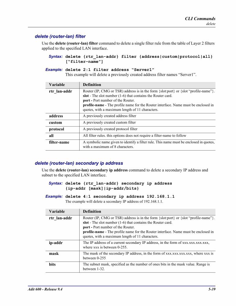
Adit 600 - Release 9.4 5-39
CLI Commandsdelete
delete (router-lan) filterUse the delete (router-lan) filter command to delete a single filter rule from the table of Layer 2 filters applied to the specified LAN interface.
Syntax: delete rtr_lan-addr filter address|custom|protocol|all [“filter-name”]
Example: delete 2:1 filter address “Server1”This example will delete a previously created address filter names “Server1”.
delete (router-lan) secondary ip addressUse the delete (router-lan) secondary ip address command to delete a secondary IP address and subnet to the specified LAN interface.
Syntax: delete rtr_lan-addr secondary ip address ip-addr [mask]|ip-addr/bits
Example: delete 4:1 secondary ip address 192.168.1.1The example will delete a secondary IP address of 192.168.1.1.
Variable Definitionrtr_lan-addr Router (IP, CMG or TSR) address is in the form slot:port or slot “profile-name”.
slot - The slot number (1-6) that contains the Router card.port - Port number of the Router.profile-name - The profile name for the Router interface. Name must be enclosed in quotes, with a maximum length of 11 characters.
address A previously created address filter
custom A previously created custom filter
protocol A previously created protocol filter
all All filter rules. this options does not require a filter-name to follow
filter-name A symbolic name given to identify a filter rule. This name must be enclosed in quotes, with a maximum of 8 characters.
Variable Definitionrtr_lan-addr Router (IP, CMG or TSR) address is in the form slot:port or slot “profile-name”.
slot - The slot number (1-6) that contains the Router card.port - Port number of the Router.profile-name - The profile name for the Router interface. Name must be enclosed in quotes, with a maximum length of 11 characters.
ip-addr The IP address of a current secondary IP address, in the form of xxx.xxx.xxx.xxx, where xxx is between 0-255.
mask The mask of the secondary IP address, in the form of xxx.xxx.xxx.xxx, where xxx is between 0-255
bits The subnet mask, specified as the number of ones bits in the mask value. Range is between 1-32.
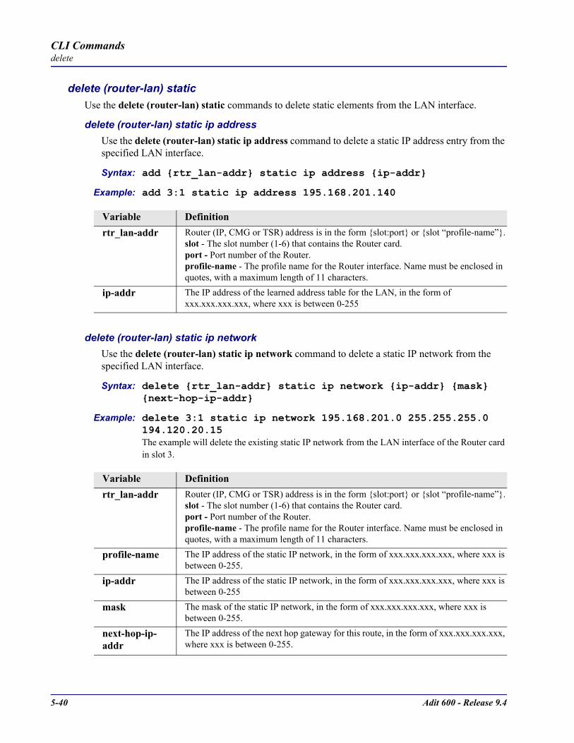
5-40 Adit 600 - Release 9.4
CLI Commandsdelete
delete (router-lan) staticUse the delete (router-lan) static commands to delete static elements from the LAN interface.
delete (router-lan) static ip addressUse the delete (router-lan) static ip address command to delete a static IP address entry from the specified LAN interface.
Syntax: add rtr_lan-addr static ip address ip-addr
Example: add 3:1 static ip address 195.168.201.140
delete (router-lan) static ip networkUse the delete (router-lan) static ip network command to delete a static IP network from the specified LAN interface.
Syntax: delete rtr_lan-addr static ip network ip-addr mask next-hop-ip-addr
Example: delete 3:1 static ip network 195.168.201.0 255.255.255.0 194.120.20.15The example will delete the existing static IP network from the LAN interface of the Router card in slot 3.
Variable Definitionrtr_lan-addr Router (IP, CMG or TSR) address is in the form slot:port or slot “profile-name”.
slot - The slot number (1-6) that contains the Router card.port - Port number of the Router.profile-name - The profile name for the Router interface. Name must be enclosed in quotes, with a maximum length of 11 characters.
ip-addr The IP address of the learned address table for the LAN, in the form of xxx.xxx.xxx.xxx, where xxx is between 0-255
Variable Definitionrtr_lan-addr Router (IP, CMG or TSR) address is in the form slot:port or slot “profile-name”.
slot - The slot number (1-6) that contains the Router card.port - Port number of the Router.profile-name - The profile name for the Router interface. Name must be enclosed in quotes, with a maximum length of 11 characters.
profile-name The IP address of the static IP network, in the form of xxx.xxx.xxx.xxx, where xxx is between 0-255.
ip-addr The IP address of the static IP network, in the form of xxx.xxx.xxx.xxx, where xxx is between 0-255
mask The mask of the static IP network, in the form of xxx.xxx.xxx.xxx, where xxx is between 0-255.
next-hop-ip-addr
The IP address of the next hop gateway for this route, in the form of xxx.xxx.xxx.xxx, where xxx is between 0-255.
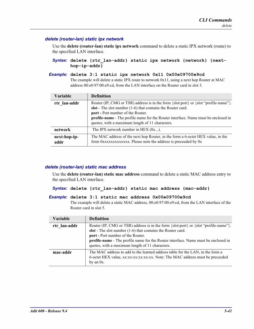
Adit 600 - Release 9.4 5-41
CLI Commandsdelete
delete (router-lan) static ipx networkUse the delete (router-lan) static ipx network command to delete a static IPX network (route) to the specified LAN interface.
Syntax: delete rtr_lan-addr static ipx network network next-hop-ip-addr
Example: delete 3:1 static ipx network 0x11 0x00e09700e9cd The example will delete a static IPX route to network 0x11, using a next hop Router at MAC address 00:e0:97:00:e9:cd, from the LAN interface on the Router card in slot 3.
delete (router-lan) static mac addressUse the delete (router-lan) static mac address command to delete a static MAC address entry to the specified LAN interface.
Syntax: delete rtr_lan-addr static mac address mac-addr
Example: delete 3:1 static mac address 0x00e09700e9cd The example will delete a static MAC address, 00:e0:97:00:e9:cd, from the LAN interface of the Router card in slot 5.
Variable Definitionrtr_lan-addr Router (IP, CMG or TSR) address is in the form slot:port or slot “profile-name”.
slot - The slot number (1-6) that contains the Router card.port - Port number of the Router.profile-name - The profile name for the Router interface. Name must be enclosed in quotes, with a maximum length of 11 characters.
network The IPX network number in HEX (0x...).
next-hop-ip-addr
The MAC address of the next hop Router, in the form a 6-octet HEX value, in the form 0xxxxxxxxxxxxx. Please note the address is preceeded by 0x
Variable Definitionrtr_lan-addr Router (IP, CMG or TSR) address is in the form slot:port or slot “profile-name”.
slot - The slot number (1-6) that contains the Router card.port - Port number of the Router.profile-name - The profile name for the Router interface. Name must be enclosed in quotes, with a maximum length of 11 characters.
mac-addr The MAC address to add to the learned address table for the LAN, in the form a 6-octet HEX value, xx:xx:xx:xx:xx:xx. Note: The MAC address must be preceeded by an 0x.
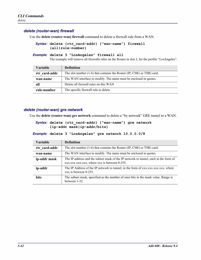
5-42 Adit 600 - Release 9.4
CLI Commandsdelete
delete (router-wan) firewallUse the delete (router-wan) firewall command to delete a firewall rule from a WAN.
Syntax: delete rtr_card-addr “wan-name” firewall all|rule-number
Example: delete 3 “LosAngeles” firewall all The example will remove all firewalls rules on the Router in slot 3, for the profile “LosAngeles”.
delete (router-wan) gre networkUse the delete (router-wan) gre network command to delete a “by network” GRE tunnel to a WAN.
Syntax: delete rtr_card-addr “wan-name” gre network ip-addr mask|ip-addr/bits
Example: delete 3 “LosAngeles” gre network 10.0.0.0/8
Variable Definitionrtr_card-addr The slot number (1-6) that contains the Router (IP, CMG or TSR) card.
wan-name The WAN interface to modify. The name must be enclosed in quotes.
all Delete all firewall rules on this WAN
rule-number The specific firewall rule to delete
Variable Definitionrtr_card-addr The slot number (1-6) that contains the Router (IP, CMG or TSR) card.
wan-name The WAN interface to modify. The name must be enclosed in quotes.
ip-addr mask The IP address and the subnet mask of the IP network to tunnel, each in the form of xxx.xxx.xxx.xxx, where xxx is between 0-255.
ip-addr The IP Address of the IP network to tunnel, in the form of xxx.xxx.xxx.xxx, where xxx is between 0-255.
bits The subnet mask, specified as the number of ones bits in the mask value. Range is between 1-32.

Adit 600 - Release 9.4 5-43
CLI Commandsdelete
delete (router-wan) nat bypassUse the delete (router-wan) nat bypass command to delete an IP subnet or host from the list of the source addresses that will not be subject to NAT Translation when passing through a NAT enabled WAN interface.
Syntax: delete rtr_card-addr “wan-name” nat bypass ip-addr
Example: delete 1 “RemoteUnit” nat bypass 156.65.0.0
delete (router-wan) staticUse the delete (router-wan) static commands to delete a static element from the WAN interface.
delete (router-wan) static ip addressUse the delete (router-wan) static ip address command to delete a static IP address on the specified WAN interface.
Syntax: delete rtr_card-addr “wan-name” static ip address ip-addr
Example: delete 3 “LosAngeles” static ip address 195.168.201.140 The example will delete a static IP address, 192.168.201.140 from the WAN interface named “LosAngeles” on the Router card in slot 3.
Variable Definitionrtr_card-addr The slot number (1-6) that contains the Router (IP, CMG or TSR) card.
wan-name The WAN interface to modify. The name must be enclosed in quotes.
ip-addr The IP Address of the Host to delete, in the form of xxx.xxx.xxx.xxx, where xxx is between 0-255.
Variable Definitionrtr_card-addr The slot number (1-6) that contains the Router (IP, CMG or TSR) card.
wan-name The WAN interface to modify. The name must be enclosed in quotes.
ip-addr The IP Address to delete from the WAN, in the form of xxx.xxx.xxx.xxx, where xxx is between 0-255.
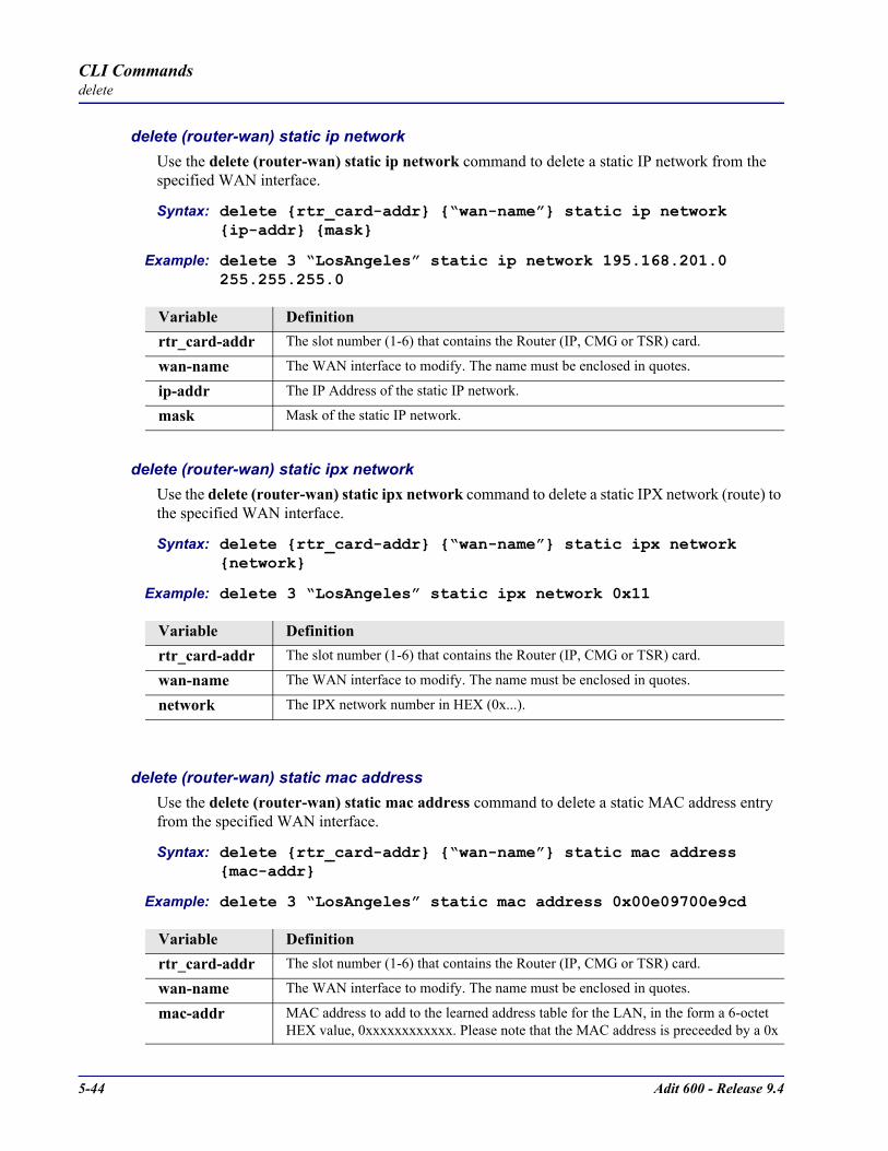
5-44 Adit 600 - Release 9.4
CLI Commandsdelete
delete (router-wan) static ip networkUse the delete (router-wan) static ip network command to delete a static IP network from the specified WAN interface.
Syntax: delete rtr_card-addr “wan-name” static ip network ip-addr mask
Example: delete 3 “LosAngeles” static ip network 195.168.201.0 255.255.255.0
delete (router-wan) static ipx networkUse the delete (router-wan) static ipx network command to delete a static IPX network (route) to the specified WAN interface.
Syntax: delete rtr_card-addr “wan-name” static ipx network network
Example: delete 3 “LosAngeles” static ipx network 0x11
delete (router-wan) static mac addressUse the delete (router-wan) static mac address command to delete a static MAC address entry from the specified WAN interface.
Syntax: delete rtr_card-addr “wan-name” static mac address mac-addr
Example: delete 3 “LosAngeles” static mac address 0x00e09700e9cd
Variable Definitionrtr_card-addr The slot number (1-6) that contains the Router (IP, CMG or TSR) card.
wan-name The WAN interface to modify. The name must be enclosed in quotes.
ip-addr The IP Address of the static IP network.
mask Mask of the static IP network.
Variable Definitionrtr_card-addr The slot number (1-6) that contains the Router (IP, CMG or TSR) card.
wan-name The WAN interface to modify. The name must be enclosed in quotes.
network The IPX network number in HEX (0x...).
Variable Definitionrtr_card-addr The slot number (1-6) that contains the Router (IP, CMG or TSR) card.
wan-name The WAN interface to modify. The name must be enclosed in quotes.
mac-addr MAC address to add to the learned address table for the LAN, in the form a 6-octet HEX value, 0xxxxxxxxxxxx. Please note that the MAC address is preceeded by a 0x
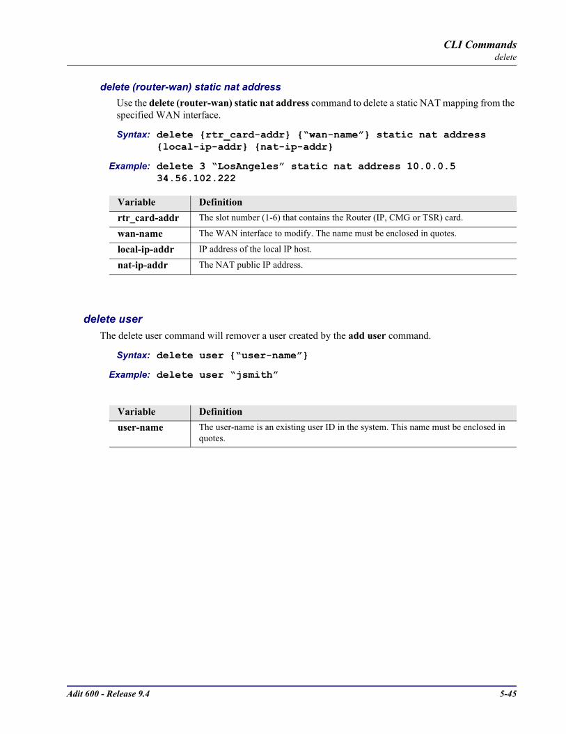
Adit 600 - Release 9.4 5-45
CLI Commandsdelete
delete (router-wan) static nat addressUse the delete (router-wan) static nat address command to delete a static NAT mapping from the specified WAN interface.
Syntax: delete rtr_card-addr “wan-name” static nat address local-ip-addr nat-ip-addr
Example: delete 3 “LosAngeles” static nat address 10.0.0.5 34.56.102.222
delete userThe delete user command will remover a user created by the add user command.
Syntax: delete user “user-name”
Example: delete user “jsmith”
Variable Definitionrtr_card-addr The slot number (1-6) that contains the Router (IP, CMG or TSR) card.
wan-name The WAN interface to modify. The name must be enclosed in quotes.
local-ip-addr IP address of the local IP host.
nat-ip-addr The NAT public IP address.
Variable Definitionuser-name The user-name is an existing user ID in the system. This name must be enclosed in
quotes.

5-46 Adit 600 - Release 9.4
CLI Commandsdisconnect
disconnect
disconnectRemove a connection created using the connect command.
Syntax: disconnect slot|slot:port|slot:port:channel|slot:port:trunk
Example: disconnect A:2:1-24 3:1Disconnects all 24 channels on port address #2 (DS1) on the controller card (slot A) to port address #1 V.35 in slot 3.
NOTE: The operator can remove connections for all of a slot slot, a port within a slot slot:port, or for specific channel slot:port:channel
exit
Use the exit command to log out of the Command Line Interface (CLI). Syntax: exit
Example: > exitLogging out of Carrier Access - Adit Product Line
Variable Definitionslot The slot number, A for the controller card, or 1 - 6 for service cards.
port Port number or range.
channel Channel number or range, for T1/E1 ports.
trunk Trunk number for this port, 1-24.
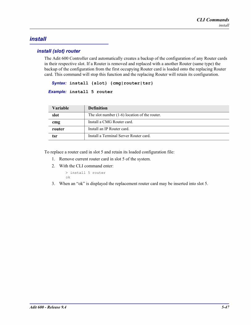
Adit 600 - Release 9.4 5-47
CLI Commandsinstall
install
install (slot) routerThe Adit 600 Controller card automatically creates a backup of the configuration of any Router cards in their respective slot. If a Router is removed and replaced with a another Router (same type) the backup of the configuration from the first occupying Router card is loaded onto the replacing Router card. This command will stop this function and the replacing Router will retain its configuration.
Syntax: install slot cmg|router|tsr
Example: install 5 router
To replace a router card in slot 5 and retain its loaded configuration file:1. Remove current router card in slot 5 of the system.2. With the CLI command enter:
> install 5 router ok
3. When an “ok” is displayed the replacement router card may be inserted into slot 5.
Variable Definitionslot The slot number (1-6) location of the router.
cmg Install a CMG Router card.
router Install an IP Router card.
tsr Install a Terminal Server Router card.
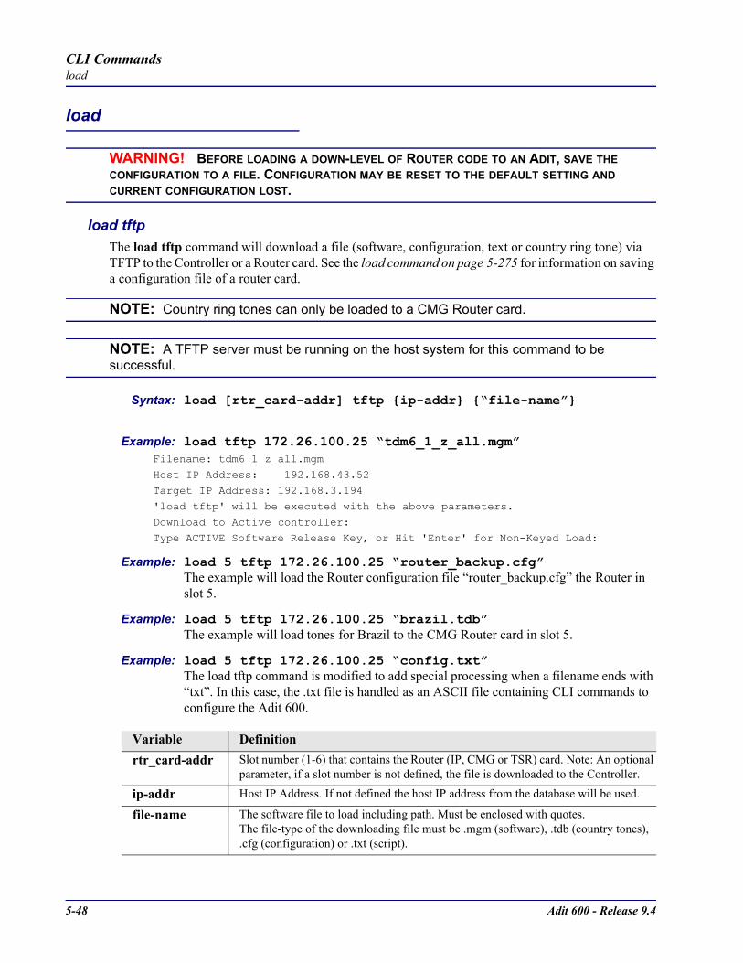
5-48 Adit 600 - Release 9.4
CLI Commandsload
load
WARNING! BEFORE LOADING A DOWN-LEVEL OF ROUTER CODE TO AN ADIT, SAVE THE CONFIGURATION TO A FILE. CONFIGURATION MAY BE RESET TO THE DEFAULT SETTING AND CURRENT CONFIGURATION LOST.
load tftp The load tftp command will download a file (software, configuration, text or country ring tone) via TFTP to the Controller or a Router card. See the load command on page 5-275 for information on saving a configuration file of a router card.
NOTE: Country ring tones can only be loaded to a CMG Router card.
NOTE: A TFTP server must be running on the host system for this command to be successful.
Syntax: load [rtr_card-addr] tftp ip-addr “file-name”
Example: load tftp 172.26.100.25 “tdm6_1_z_all.mgm”Filename: tdm6_1_z_all.mgm
Host IP Address: 192.168.43.52
Target IP Address: 192.168.3.194'load tftp' will be executed with the above parameters.
Download to Active controller:
Type ACTIVE Software Release Key, or Hit 'Enter' for Non-Keyed Load:
Example: load 5 tftp 172.26.100.25 “router_backup.cfg”The example will load the Router configuration file “router_backup.cfg” the Router in slot 5.
Example: load 5 tftp 172.26.100.25 “brazil.tdb”The example will load tones for Brazil to the CMG Router card in slot 5.
Example: load 5 tftp 172.26.100.25 “config.txt”The load tftp command is modified to add special processing when a filename ends with “txt”. In this case, the .txt file is handled as an ASCII file containing CLI commands to configure the Adit 600.
Variable Definitionrtr_card-addr Slot number (1-6) that contains the Router (IP, CMG or TSR) card. Note: An optional
parameter, if a slot number is not defined, the file is downloaded to the Controller.
ip-addr Host IP Address. If not defined the host IP address from the database will be used.
file-name The software file to load including path. Must be enclosed with quotes. The file-type of the downloading file must be .mgm (software), .tdb (country tones), .cfg (configuration) or .txt (script).
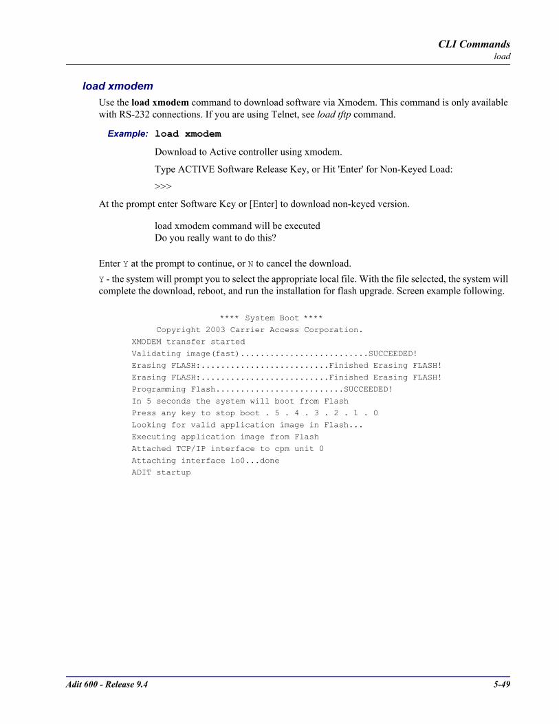
Adit 600 - Release 9.4 5-49
CLI Commandsload
load xmodemUse the load xmodem command to download software via Xmodem. This command is only available with RS-232 connections. If you are using Telnet, see load tftp command.
Example: load xmodem
Download to Active controller using xmodem.
Type ACTIVE Software Release Key, or Hit 'Enter' for Non-Keyed Load:
>>>
At the prompt enter Software Key or [Enter] to download non-keyed version.
load xmodem command will be executedDo you really want to do this?
Enter Y at the prompt to continue, or N to cancel the download.Y - the system will prompt you to select the appropriate local file. With the file selected, the system will complete the download, reboot, and run the installation for flash upgrade. Screen example following.
**** System Boot **** Copyright 2003 Carrier Access Corporation.
XMODEM transfer started
Validating image(fast)..........................SUCCEEDED!Erasing FLASH:..........................Finished Erasing FLASH!
Erasing FLASH:..........................Finished Erasing FLASH!
Programming Flash..........................SUCCEEDED!In 5 seconds the system will boot from Flash
Press any key to stop boot . 5 . 4 . 3 . 2 . 1 . 0
Looking for valid application image in Flash...Executing application image from Flash
Attached TCP/IP interface to cpm unit 0
Attaching interface lo0...doneADIT startup

5-50 Adit 600 - Release 9.4
CLI Commandslog
log
logDisplays the event log. Where the optional variables used to narrow down the log displayed. The log command without any options displays a full log.
Syntax: log [slot|slot:port|slot:port:channel] [category] [severity]
Example: log Time Date Severity Description
00:00:15 01/01/2002 Major 4:1-CMG Ethernet Link Down 00:00:12 01/01/2002 Info 3-FXOx8 Card Detected 00:00:06 01/01/2002 Major A:2-DS1 Loss Of Signal 00:00:05 01/01/2002 Info 4-CMGx1 Card Detected 00:00:02 01/01/2002 Info A-T1x2 Card Detected 00:00:02 01/01/2002 Info System PowerupTotal=6
Variable Definitionslot The slot number, A for the controller card, or 1-6 for service cards.
port Port number (not a range).
channel Channel number or range.
category The slot number, A for the controller card, or 1-6 for service cards.
bri All BRI facility events.
cmg ALL CMG Router facility events
ds1 All DS1 facility events.
env Environmental events.
equipment Equipment events not related to a DS1 interface.
fxo All FXO facility events.
fxs All FXS facility events.
rtr All IP Router facility events.
tsr All Terminal Server Router facility events.
v35 All V.35 facility events.
severity The slot number, A for the controller card, or 1-6 for service cards.
alert Alert events (threshold crossing)
critical Critical events
info Information events
major Major events (service effecting)
minor Minor events (non-service affecting)
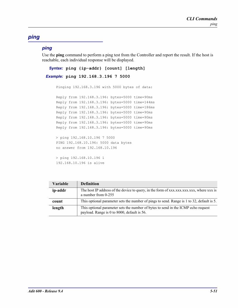
Adit 600 - Release 9.4 5-51
CLI Commandsping
ping
pingUse the ping command to perform a ping test from the Controller and report the result. If the host is reachable, each individual response will be displayed.
Syntax: ping ip-addr [count] [length]
Example: ping 192.168.3.196 7 5000
Pinging 192.168.3.196 with 5000 bytes of data:
Reply from 192.168.3.196: bytes=5000 time=90ms
Reply from 192.168.3.196: bytes=5000 time=144ms
Reply from 192.168.3.196: bytes=5000 time=186msReply from 192.168.3.196: bytes=5000 time=90ms
Reply from 192.168.3.196: bytes=5000 time=90ms
Reply from 192.168.3.196: bytes=5000 time=90msReply from 192.168.3.196: bytes=5000 time=90ms
> ping 192.168.10.196 7 5000PING 192.168.10.196: 5000 data bytes
no answer from 192.168.10.196
> ping 192.168.10.196 1
192.168.10.196 is alive
Variable Definitionip-addr The host IP address of the device to query, in the form of xxx.xxx.xxx.xxx, where xxx is
a number from 0-255
count This optional parameter sets the number of pings to send. Range is 1 to 32, default is 5.
length This optional parameter sets the number of bytes to send in the ICMP echo request payload. Range is 0 to 8000, default is 56.

5-52 Adit 600 - Release 9.4
CLI Commandsprint
Use the print command to display the help information or print the configuration file.
Syntax: print config|help
print configPrint the configuration file for the Adit 600. The operator may then save this to a text file, which can be sent to another Adit 600 to automatically configure the system.
Syntax: print config [rtr_card-addr]
Example: print config 5
-set verification off-set 5 password view password is manual-set 5 password config password is manual-set 5 password admin password is manual-set 5 enhanced security enable is manual-set 5 password security password is manualdelete 5 remote "RemoteUnit"rename 5 "LocalUnit" "LocalAdit"set 5:1 ip address 192.168.3.195 255.255.255.0set 5:1 upadd 5 remote "RemoteAdit"reset 5
Example: print configThis example would produce a configuration file of the Controller.
1. While in a Telnet session to an Adit 600 select Terminal/Start Logging.
2. Name the file.3. Type the CLI command print config.4. Select Terminal/Stop Logging.
See Load Controller Configuration on page 23-6 for instructions to reload configuration to Controller.
print helpPrint the complete help file to the screen.
Syntax: print help
Example: print helpThis example would print the entire help text, which can be scrolled though with Enter or Spacebar.
Variable Definitionrtr_card-addr The slot number (1-6) that contains the Router (IP, CMG or TSR) card. This is an
optional parameter, if a slot is not defined, the downloaded will be to the Controller.
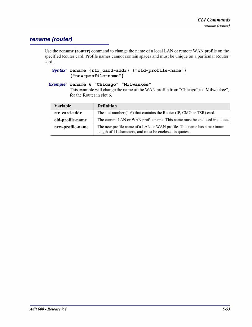
Adit 600 - Release 9.4 5-53
CLI Commandsrename (router)
rename (router)
Use the rename (router) command to change the name of a local LAN or remote WAN profile on the specified Router card. Profile names cannot contain spaces and must be unique on a particular Router card.
Syntax: rename rtr_card-addr “old-profile-name” “new-profile-name”
Example: rename 6 “Chicago” “Milwaukee”This example will change the name of the WAN profile from “Chicago” to “Milwaukee”, for the Router in slot 6.
Variable Definitionrtr_card-addr The slot number (1-6) that contains the Router (IP, CMG or TSR) card.
old-profile-name The current LAN or WAN profile name. This name must be enclosed in quotes.
new-profile-name The new profile name of a LAN or WAN profile. This name has a maximum length of 11 characters, and must be enclosed in quotes.

5-54 Adit 600 - Release 9.4
CLI Commandsreset
reset
resetUse the reset command to reboot the system.
Syntax: reset
Example: reset
Do you really want to reset (y/n)? y **** System Boot ****
Copyright 1999,2000 Carrier Access Corporation.
WARNING! THE COMMAND reset IS A SERVICE AFFECTING COMMAND.
reset (router)Use the reset (router) command to reboot the Router. All new configuration since the last reset will be in use.
Syntax: reset rtr_card-addr
Example: reset 1Do you really want to do this ? yOKThe example will reboot the Router card in slot 1.
reset (router) coldbootUse the reset (router) coldboot command to reboot the Router. This will reboot including a power cycle to the Router card.
Syntax: reset rtr_card-addr coldboot
Example: reset 2 coldbootOK
The example will coldboot the Router card in slot 2.
Variable Definitionrtr_card-addr The slot number (1-6) that contains the Router (IP, CMG or TSR) card.
Variable Definitionrtr_card-addr The slot number (1-6) that contains the Router (IP, CMG or TSR) card.
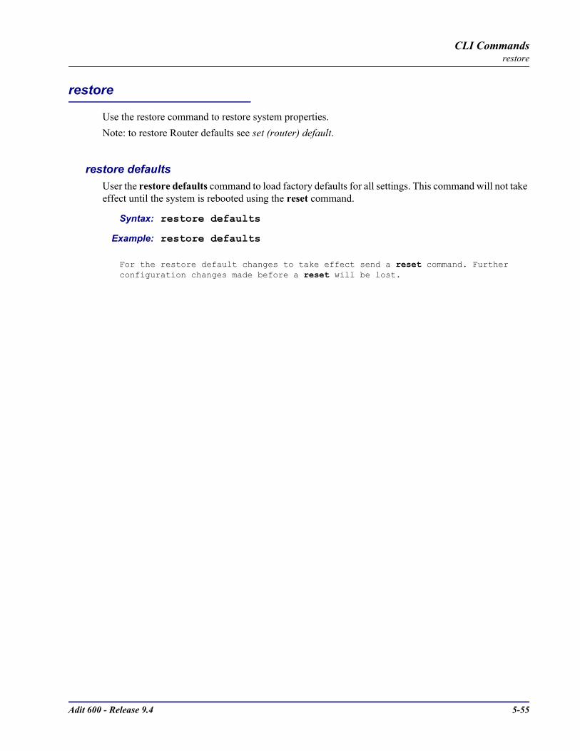
Adit 600 - Release 9.4 5-55
CLI Commandsrestore
restore
Use the restore command to restore system properties.Note: to restore Router defaults see set (router) default.
restore defaultsUser the restore defaults command to load factory defaults for all settings. This command will not take effect until the system is rebooted using the reset command.
Syntax: restore defaults
Example: restore defaults
For the restore default changes to take effect send a reset command. Further configuration changes made before a reset will be lost.
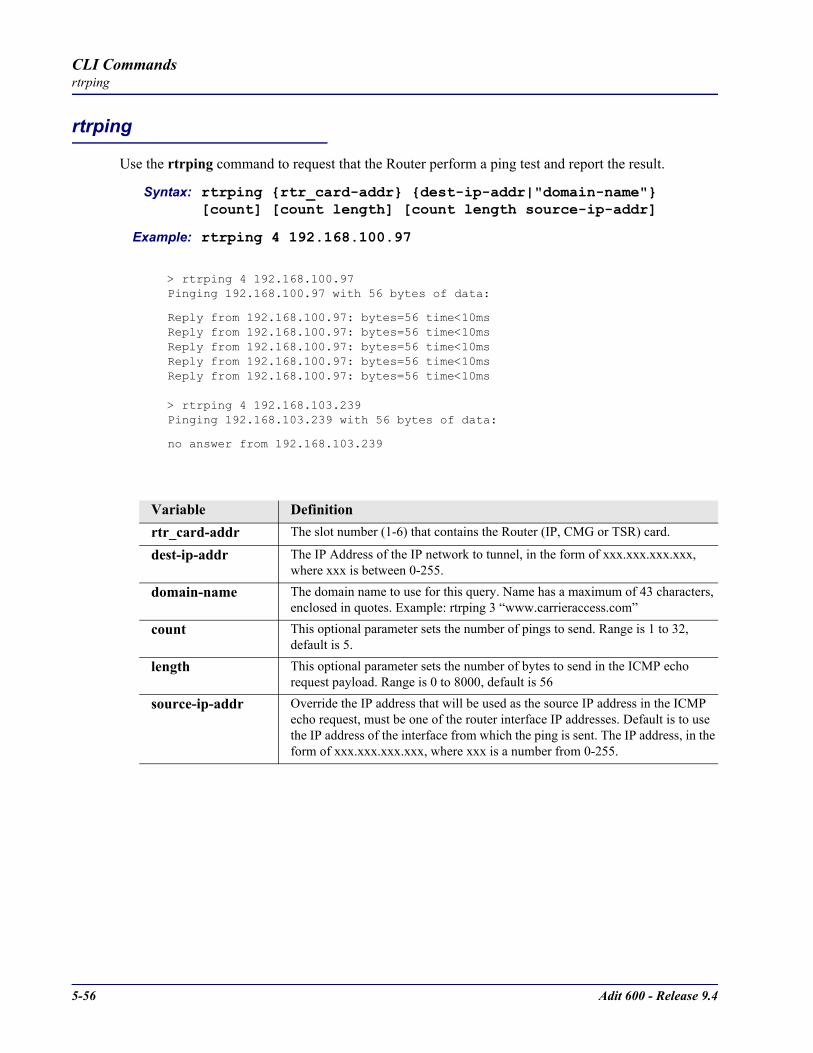
5-56 Adit 600 - Release 9.4
CLI Commandsrtrping
rtrping
Use the rtrping command to request that the Router perform a ping test and report the result.
Syntax: rtrping rtr_card-addr dest-ip-addr|"domain-name" [count] [count length] [count length source-ip-addr]
Example: rtrping 4 192.168.100.97
> rtrping 4 192.168.100.97Pinging 192.168.100.97 with 56 bytes of data:
Reply from 192.168.100.97: bytes=56 time<10msReply from 192.168.100.97: bytes=56 time<10msReply from 192.168.100.97: bytes=56 time<10msReply from 192.168.100.97: bytes=56 time<10msReply from 192.168.100.97: bytes=56 time<10ms
> rtrping 4 192.168.103.239Pinging 192.168.103.239 with 56 bytes of data:
no answer from 192.168.103.239
Variable Definitionrtr_card-addr The slot number (1-6) that contains the Router (IP, CMG or TSR) card.
dest-ip-addr The IP Address of the IP network to tunnel, in the form of xxx.xxx.xxx.xxx, where xxx is between 0-255.
domain-name The domain name to use for this query. Name has a maximum of 43 characters, enclosed in quotes. Example: rtrping 3 “www.carrieraccess.com”
count This optional parameter sets the number of pings to send. Range is 1 to 32, default is 5.
length This optional parameter sets the number of bytes to send in the ICMP echo request payload. Range is 0 to 8000, default is 56
source-ip-addr Override the IP address that will be used as the source IP address in the ICMP echo request, must be one of the router interface IP addresses. Default is to use the IP address of the interface from which the ping is sent. The IP address, in the form of xxx.xxx.xxx.xxx, where xxx is a number from 0-255.

Adit 600 - Release 9.4 5-57
CLI Commandsset
set
set (4-wire e&m) set radiusset alarms set (router) autologoutset autoexit set (router) cdrset (bri) set (router) companderset (bri) autoactivate set (router) defaultset (bri) mode set (router) dhcpset (bri) pmsync set (router) dialplan timeoutset clock set (router) dnsset date set (router) dns serverset (ds0) set (router) enhanced securityset (ds1) set (router) hookflashset (ds1 card) set (router) lmiset (e1) set (router) lmi pollset (e1 card) spantype set (router) logset ethernet ip address set (router) login authset (fxo) set (router) login promptset (fxs) set (router) mgcpset (fxs8c/fxs8B/fxs8A/fxs5G) set (router) ntpset (fxsINTL) set (router) passwordset (fxsPS) set (router) portset id set (router) ppp authset idle set (router) ppp securityset ip gateway set (router) priority tosset ipds0 set (router) proxyset key set (router) rebootset local set (router) ripset login auth set (router) snmpset login support set (router) stpset ntp set (router) syslogset (ocudp) set (router) voipset (p-phone) set (router-lan) collision
5-58 Adit 600 - Release 9.4
CLI Commandsset
set (router-lan) filter forward set (router-voice) signalingset (router-lan) framing set (router-voice) silenceset (router-lan) gateway set (router-voice) slashset (router-lan) ip address set (router-voice) tosset (router-lan) ipx network set (router-voice) txgainset (router-lan) phy set (router-voice) upset (router-lan) rip set (router-wan) dlciset (router-lan) stp set (router-wan) greset (router-lan) up/down set (router-wan) ipset (router-trunk) encapsulation set (router-wan) ip addressset (router-trunk) multilink group set (router-wan) ipxset (router-trunk) speed set (router-wan) mlpppset (router-trunk) up/down set (router-wan) natset (router-trunk) voice bandwidth limit set (router-wan) otherset (router-voice) algorithm preference set (router-wan) pppset (router-voice) cpd set (router-wan) ripset (router-voice) default set (router-wan) stpset (router-voice) dialplan timeout set (router-wan) trunkset (router-voice) down set (router-wan) up/downset (router-voice) dtmfrelay set (rs232)set (router-voice) echo cancellation set screenset (router-voice) echo tail set snmpset (router-voice) endpoint prefix set syslogset (router-voice) endpoint suffix set timeset (router-voice) fax set time daylightsavingsset (router-voice) log start set userset (router-voice) log stop set (v35)set (router-voice) modem set (v54)set (router-voice) rfc2833 set verificationset (router-voice) rxgain
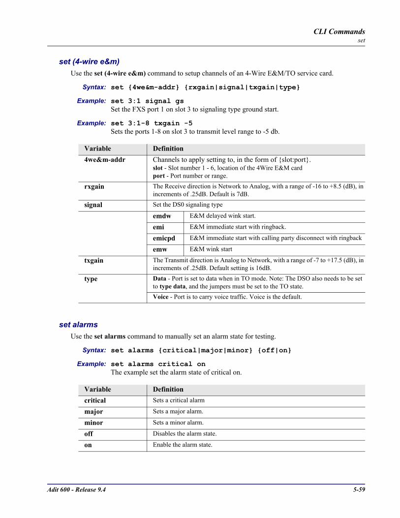
Adit 600 - Release 9.4 5-59
CLI Commandsset
set (4-wire e&m)Use the set (4-wire e&m) command to setup channels of an 4-Wire E&M/TO service card.
Syntax: set 4we&m-addr rxgain|signal|txgain|type
Example: set 3:1 signal gsSet the FXS port 1 on slot 3 to signaling type ground start.
Example: set 3:1-8 txgain -5Sets the ports 1-8 on slot 3 to transmit level range to -5 db.
set alarmsUse the set alarms command to manually set an alarm state for testing.
Syntax: set alarms critical|major|minor off|on
Example: set alarms critical onThe example set the alarm state of critical on.
Variable Definition4we&m-addr Channels to apply setting to, in the form of slot:port.
slot - Slot number 1 - 6, location of the 4Wire E&M cardport - Port number or range.
rxgain The Receive direction is Network to Analog, with a range of -16 to +8.5 (dB), in increments of .25dB. Default is 7dB.
signal Set the DS0 signaling type
emdw E&M delayed wink start.
emi E&M immediate start with ringback.
emicpd E&M immediate start with calling party disconnect with ringback
emw E&M wink start
txgain The Transmit direction is Analog to Network, with a range of -7 to +17.5 (dB), in increments of .25dB. Default setting is 16dB.
type Data - Port is set to data when in TO mode. Note: The DSO also needs to be set to type data, and the jumpers must be set to the TO state.Voice - Port is to carry voice traffic. Voice is the default.
Variable Definitioncritical Sets a critical alarm
major Sets a major alarm.
minor Sets a minor alarm.
off Disables the alarm state.
on Enable the alarm state.
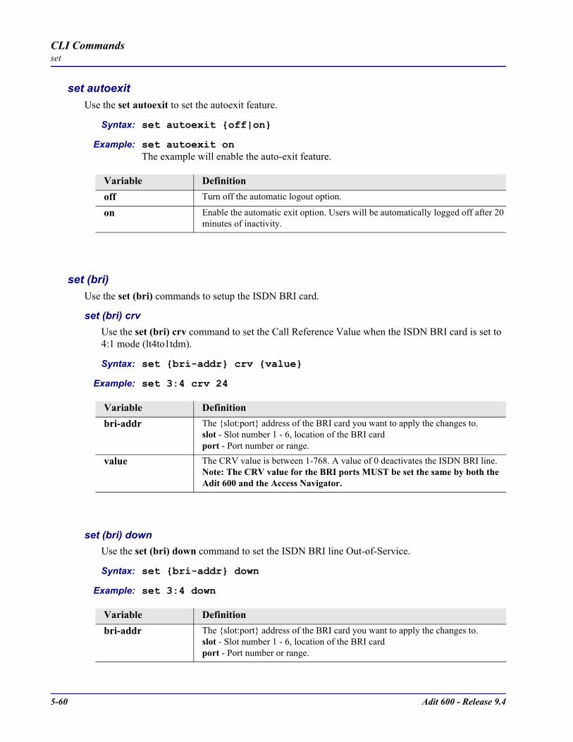
5-60 Adit 600 - Release 9.4
CLI Commandsset
set autoexitUse the set autoexit to set the autoexit feature.
Syntax: set autoexit off|on
Example: set autoexit onThe example will enable the auto-exit feature.
set (bri)Use the set (bri) commands to setup the ISDN BRI card.
set (bri) crvUse the set (bri) crv command to set the Call Reference Value when the ISDN BRI card is set to 4:1 mode (lt4to1tdm).
Syntax: set bri-addr crv value
Example: set 3:4 crv 24
set (bri) downUse the set (bri) down command to set the ISDN BRI line Out-of-Service.
Syntax: set bri-addr down
Example: set 3:4 down
Variable Definitionoff Turn off the automatic logout option.
on Enable the automatic exit option. Users will be automatically logged off after 20 minutes of inactivity.
Variable Definitionbri-addr The slot:port address of the BRI card you want to apply the changes to.
slot - Slot number 1 - 6, location of the BRI cardport - Port number or range.
value The CRV value is between 1-768. A value of 0 deactivates the ISDN BRI line. Note: The CRV value for the BRI ports MUST be set the same by both the Adit 600 and the Access Navigator.
Variable Definitionbri-addr The slot:port address of the BRI card you want to apply the changes to.
slot - Slot number 1 - 6, location of the BRI cardport - Port number or range.

Adit 600 - Release 9.4 5-61
CLI Commandsset
set (bri) thresholdUse the set (bri) threshold command to set default thresholds for ISDN lines.
Syntax: set bri-addr threshold day|hour es|ses value
Example: set 3:4 threshold day es 240
set (bri) upUse the set (bri) up command to set the ISDN BRI line In-Service.
Syntax: set bri-addr up
Example: set 3:4 up
Variable Definitionbri-addr The slot:port address of the BRI card you want to apply the changes to.
slot - Slot number 1 - 6, location of the BRI cardport - Port number or range.
up Put the ISDN line In-Service.
day Set the threshold for Errored Seconds (ES)
hour Set the thresholds for hourly intervals.
es Set the threshold for Errored Seconds (ES)
ses Set the threshold for Severely Errored Seconds (SES)
value Range is 1 - 65535 seconds.
Variable Definitionbri-addr The slot:port address of the BRI card you want to apply the changes to.
slot - Slot number 1 - 6, location of the BRI cardport - Port number or range.

5-62 Adit 600 - Release 9.4
CLI Commandsset
set (bri) autoactivateUse the set (bri) autoactivate command to set the auto-activate option for the card. This option can only be enabled while in 4 to 1 TDM LT Mode.This option is used to establish the D channel when the FDL link can not be used. If Auto-activation is enabled, all commands initiated by the Switch and normally processed over the FDL will be ignored, commands to control Loop Back or Corrupt CRC tests will also be ignored. The Adit 600 will not be capable of reporting to the Switch any changes in the ISDN line status, such as Loss of Signal, on an automatically activated line. Status changes and alarms will be available through Adit 600 CLI.
Syntax: set bri_card-addr autoactivate off|on
Example: set 3 autoactivate onTo set the auto-activate on for the card in slot 3.
set (bri) modeUse the set (bri) mode command to set the mode for the ISDN BRI Service.
Syntax: set bri_card-addr mode lt3do0|lt4to1tdm|nt3ds0
Example: set 4 mode nt3ds0To set the BRI card in slot 4 to use 3 DS0 LUNT
Variable Definitionbri_card-addr The slot number (1-6) that contains the BRI card.
off Turn off the automatic-activation feature
on Enable the automatic-activation feature
Variable Definitionbri_card-addr The slot number (1-6) that contains the BRI card.
lt3ds0 Set BRI to 3 DS0 LULT, used primarily for a subscriber line.
lt4to1tdm Set the BRI mode to 4 to 1 TDM LULT.
nt3ds0 Set BRI mode to 3 DS0 LUNT, used primarily for a central office connection.
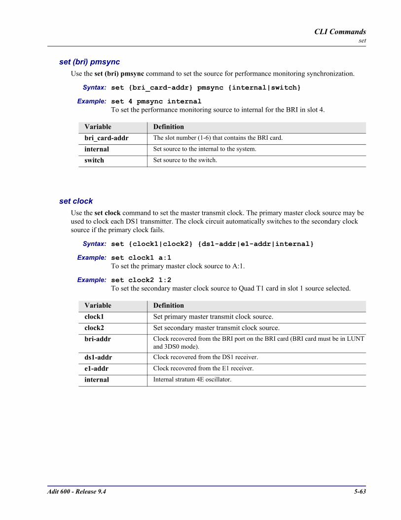
Adit 600 - Release 9.4 5-63
CLI Commandsset
set (bri) pmsyncUse the set (bri) pmsync command to set the source for performance monitoring synchronization.
Syntax: set bri_card-addr pmsync internal|switch
Example: set 4 pmsync internalTo set the performance monitoring source to internal for the BRI in slot 4.
set clock Use the set clock command to set the master transmit clock. The primary master clock source may be used to clock each DS1 transmitter. The clock circuit automatically switches to the secondary clock source if the primary clock fails.
Syntax: set clock1|clock2 ds1-addr|e1-addr|internal
Example: set clock1 a:1 To set the primary master clock source to A:1.
Example: set clock2 1:2 To set the secondary master clock source to Quad T1 card in slot 1 source selected.
Variable Definitionbri_card-addr The slot number (1-6) that contains the BRI card.
internal Set source to the internal to the system.
switch Set source to the switch.
Variable Definitionclock1 Set primary master transmit clock source.clock2 Set secondary master transmit clock source.bri-addr Clock recovered from the BRI port on the BRI card (BRI card must be in LUNT
and 3DS0 mode).
ds1-addr Clock recovered from the DS1 receiver.
e1-addr Clock recovered from the E1 receiver.
internal Internal stratum 4E oscillator.
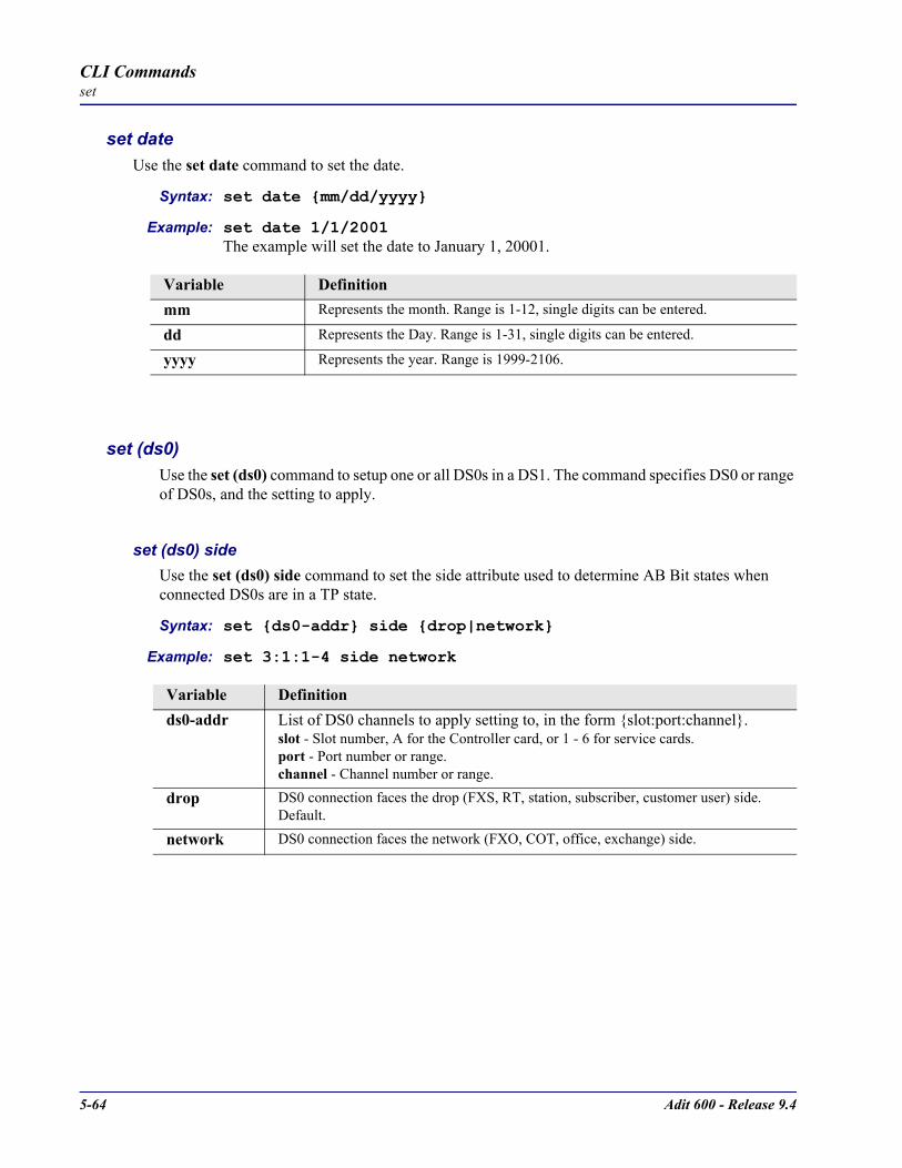
5-64 Adit 600 - Release 9.4
CLI Commandsset
set dateUse the set date command to set the date.
Syntax: set date mm/dd/yyyy
Example: set date 1/1/2001The example will set the date to January 1, 20001.
set (ds0)Use the set (ds0) command to setup one or all DS0s in a DS1. The command specifies DS0 or range of DS0s, and the setting to apply.
set (ds0) sideUse the set (ds0) side command to set the side attribute used to determine AB Bit states when connected DS0s are in a TP state.
Syntax: set ds0-addr side drop|network
Example: set 3:1:1-4 side network
Variable Definitionmm Represents the month. Range is 1-12, single digits can be entered.
dd Represents the Day. Range is 1-31, single digits can be entered.
yyyy Represents the year. Range is 1999-2106.
Variable Definitionds0-addr List of DS0 channels to apply setting to, in the form slot:port:channel.
slot - Slot number, A for the Controller card, or 1 - 6 for service cards.port - Port number or range.channel - Channel number or range.
drop DS0 connection faces the drop (FXS, RT, station, subscriber, customer user) side. Default.
network DS0 connection faces the network (FXO, COT, office, exchange) side.
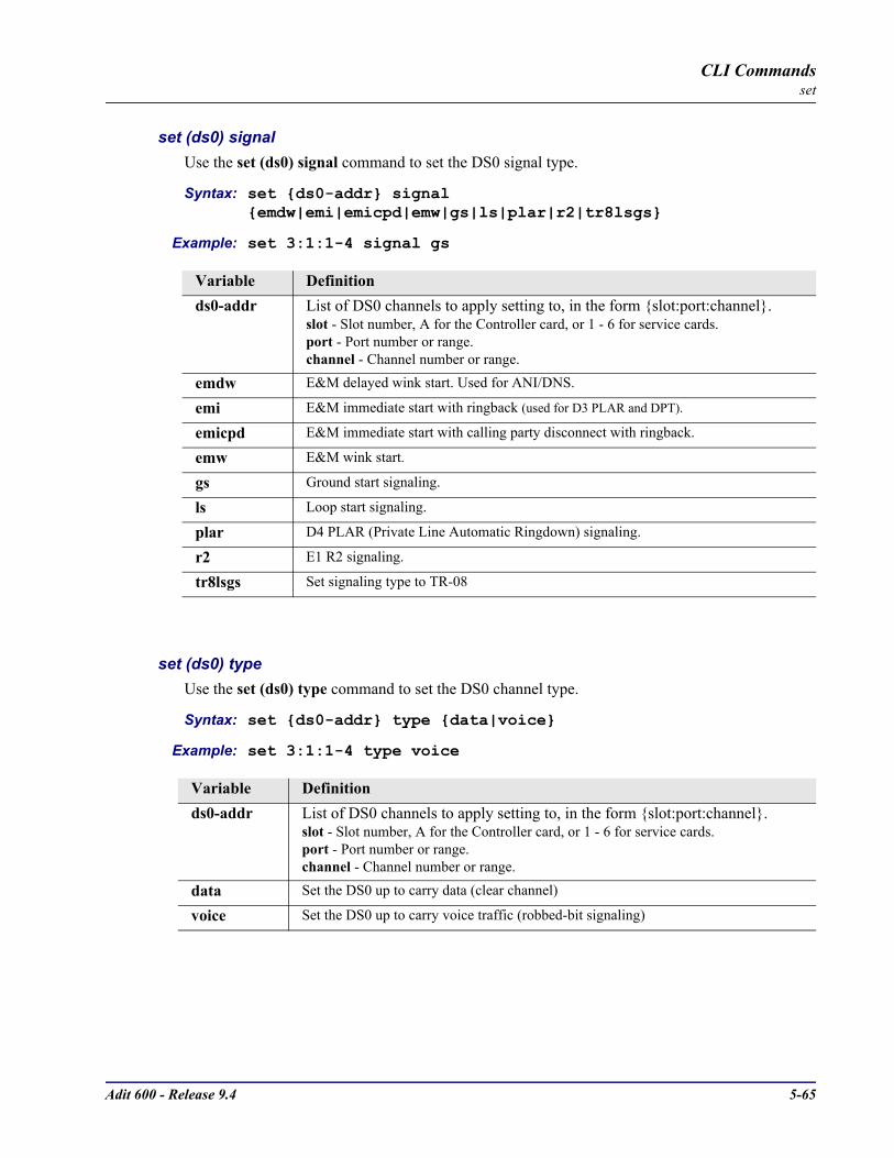
Adit 600 - Release 9.4 5-65
CLI Commandsset
set (ds0) signalUse the set (ds0) signal command to set the DS0 signal type.
Syntax: set ds0-addr signal emdw|emi|emicpd|emw|gs|ls|plar|r2|tr8lsgs
Example: set 3:1:1-4 signal gs
set (ds0) typeUse the set (ds0) type command to set the DS0 channel type.
Syntax: set ds0-addr type data|voice
Example: set 3:1:1-4 type voice
Variable Definitionds0-addr List of DS0 channels to apply setting to, in the form slot:port:channel.
slot - Slot number, A for the Controller card, or 1 - 6 for service cards.port - Port number or range.channel - Channel number or range.
emdw E&M delayed wink start. Used for ANI/DNS.
emi E&M immediate start with ringback (used for D3 PLAR and DPT).
emicpd E&M immediate start with calling party disconnect with ringback.
emw E&M wink start.
gs Ground start signaling.
ls Loop start signaling.
plar D4 PLAR (Private Line Automatic Ringdown) signaling.
r2 E1 R2 signaling.
tr8lsgs Set signaling type to TR-08
Variable Definitionds0-addr List of DS0 channels to apply setting to, in the form slot:port:channel.
slot - Slot number, A for the Controller card, or 1 - 6 for service cards.port - Port number or range.channel - Channel number or range.
data Set the DS0 up to carry data (clear channel)
voice Set the DS0 up to carry voice traffic (robbed-bit signaling)
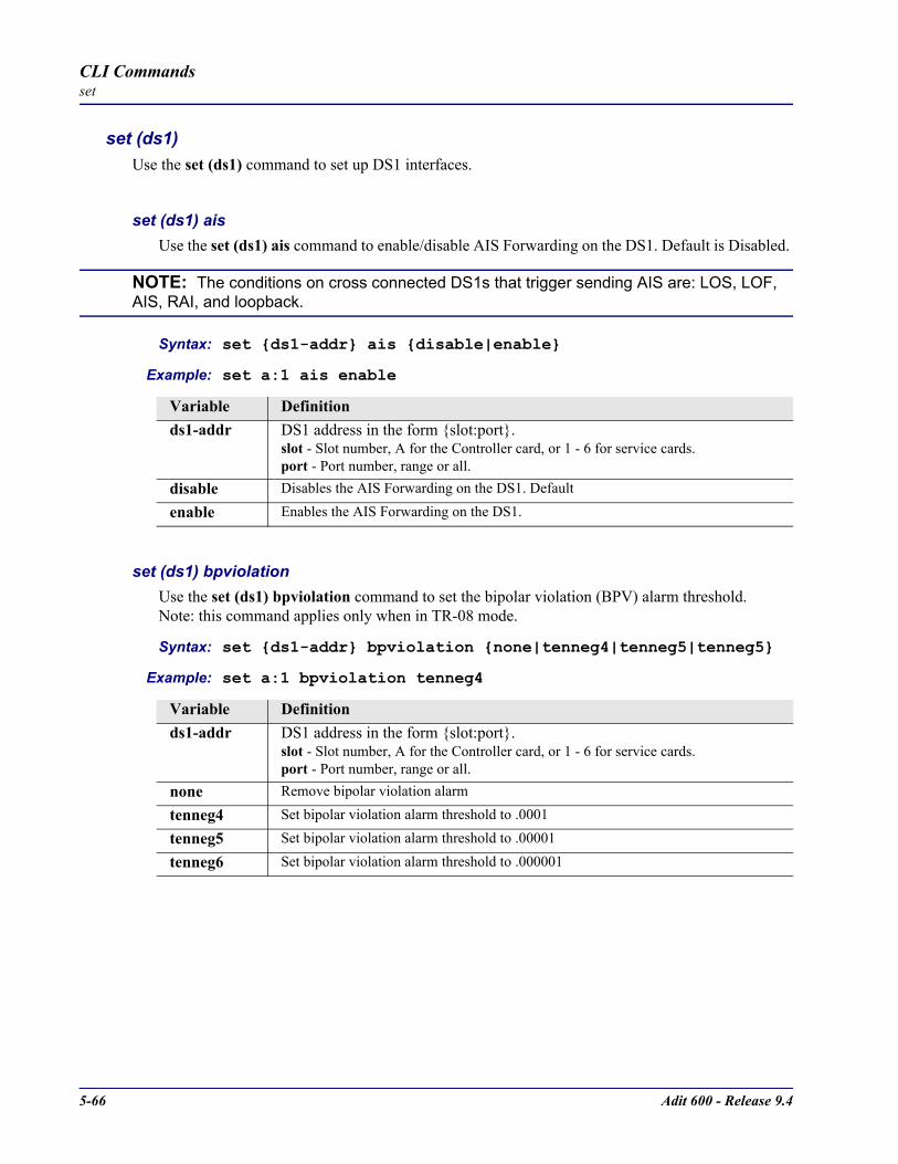
5-66 Adit 600 - Release 9.4
CLI Commandsset
set (ds1)Use the set (ds1) command to set up DS1 interfaces.
set (ds1) aisUse the set (ds1) ais command to enable/disable AIS Forwarding on the DS1. Default is Disabled.
NOTE: The conditions on cross connected DS1s that trigger sending AIS are: LOS, LOF, AIS, RAI, and loopback.
Syntax: set ds1-addr ais disable|enable
Example: set a:1 ais enable
set (ds1) bpviolationUse the set (ds1) bpviolation command to set the bipolar violation (BPV) alarm threshold. Note: this command applies only when in TR-08 mode.
Syntax: set ds1-addr bpviolation none|tenneg4|tenneg5|tenneg5
Example: set a:1 bpviolation tenneg4
Variable Definitionds1-addr DS1 address in the form slot:port.
slot - Slot number, A for the Controller card, or 1 - 6 for service cards.port - Port number, range or all.
disable Disables the AIS Forwarding on the DS1. Default
enable Enables the AIS Forwarding on the DS1.
Variable Definitionds1-addr DS1 address in the form slot:port.
slot - Slot number, A for the Controller card, or 1 - 6 for service cards.port - Port number, range or all.
none Remove bipolar violation alarm
tenneg4 Set bipolar violation alarm threshold to .0001
tenneg5 Set bipolar violation alarm threshold to .00001
tenneg6 Set bipolar violation alarm threshold to .000001

Adit 600 - Release 9.4 5-67
CLI Commandsset
set (ds1) downUse the set (ds1) down command to set the DS1 as Out-of-Service.
Syntax: set ds1-addr down
Example: set a:1 down
set (ds1) equipmentUse the set (ds1) equipment command to set the equipment loopback on a DS1. Note: this feature is only available through Quad T1/E1 cards. It is not available on the Controllers.
Syntax: set ds1-addr equipment loopdown|loopup
Example: set a:1 equipment loopup
set (ds1) fdlUse the set (ds1) fdl command to set the Facilities Data Link (FDL) capabilities.
Syntax: set ds1-addr fdl none|alm13|alm16|t1403
Example: set a:1 fdl alm13
Variable Definitionds1-addr DS1 address in the form slot:port.
slot - Slot number, A for the Controller card, or 1 - 6 for service cards.port - Port number, range or all.
Variable Definitionds1-addr DS1 address in the form slot:port.
slot - Slot number, A for the Controller card, or 1 - 6 for service cards.port - Port number, range or all.
loopdown Disable equipment loopback on the DS1
loopup Enable equipment loopback on the DS1
Variable Definitionds1-addr DS1 address in the form slot:port.
slot - Slot number, A for the Controller card, or 1 - 6 for service cards.port - Port number, range or all.
none Disable FDL output messages.
alm13 Enable TR-08 alarm 13 FDL messages.
alm16 Enable TR-08 alarm 16 FDL messages.
t1403 Enable T1.403 FDL performance messages.
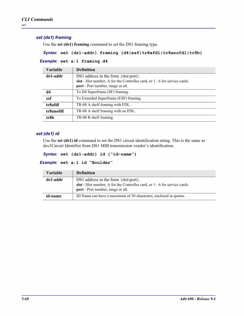
5-68 Adit 600 - Release 9.4
CLI Commandsset
set (ds1) framingUse the set (ds1) framing command to set the DS1 framing type.
Syntax: set ds1-addr framing d4|esf|tr8afdl|tr8anofdl|tr8b
Example: set a:1 framing d4
set (ds1) idUse the set (ds1) id command to set the DS1 circuit identification string. This is the same as dsx1Circuit Identifier from DS1 MIB transmission vendor’s identification.
Syntax: set ds1-addr id “id-name”
Example: set a:1 id “Boulder”
Variable Definitionds1-addr DS1 address in the form slot:port.
slot - Slot number, A for the Controller card, or 1 - 6 for service cards.port - Port number, range or all.
d4 To D4 Superframe (SF) framing.
esf To Extended Superframe (ESF) framing.
tr8afdl TR-08 A shelf framing with FDL.
tr8anofdl TR-08 A shelf framing with no FDL.
tr8b TR-08 B shelf framing.
Variable Definitionds1-addr DS1 address in the form slot:port.
slot - Slot number, A for the Controller card, or 1 - 6 for service cards.port - Port number, range or all.
id-name ID Name can have a maximum of 30 characters, enclosed in quotes.
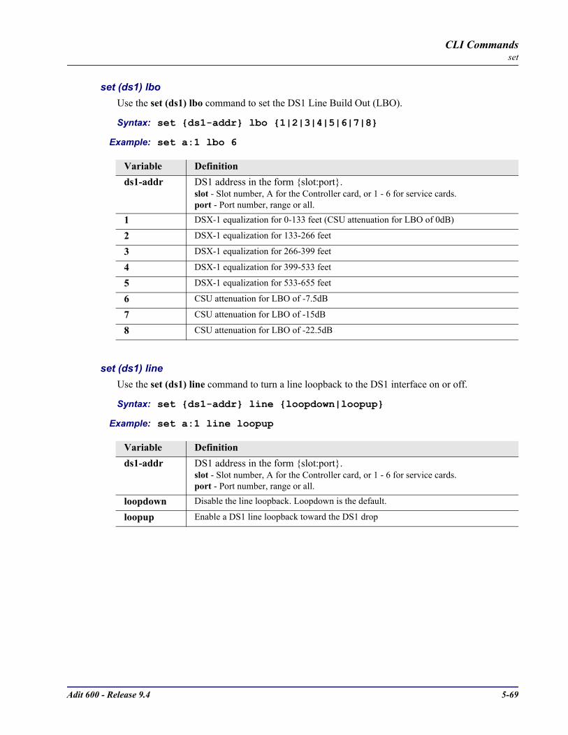
Adit 600 - Release 9.4 5-69
CLI Commandsset
set (ds1) lboUse the set (ds1) lbo command to set the DS1 Line Build Out (LBO).
Syntax: set ds1-addr lbo 1|2|3|4|5|6|7|8
Example: set a:1 lbo 6
set (ds1) lineUse the set (ds1) line command to turn a line loopback to the DS1 interface on or off.
Syntax: set ds1-addr line loopdown|loopup
Example: set a:1 line loopup
Variable Definitionds1-addr DS1 address in the form slot:port.
slot - Slot number, A for the Controller card, or 1 - 6 for service cards.port - Port number, range or all.
1 DSX-1 equalization for 0-133 feet (CSU attenuation for LBO of 0dB)
2 DSX-1 equalization for 133-266 feet
3 DSX-1 equalization for 266-399 feet
4 DSX-1 equalization for 399-533 feet
5 DSX-1 equalization for 533-655 feet
6 CSU attenuation for LBO of -7.5dB
7 CSU attenuation for LBO of -15dB
8 CSU attenuation for LBO of -22.5dB
Variable Definitionds1-addr DS1 address in the form slot:port.
slot - Slot number, A for the Controller card, or 1 - 6 for service cards.port - Port number, range or all.
loopdown Disable the line loopback. Loopdown is the default.
loopup Enable a DS1 line loopback toward the DS1 drop

5-70 Adit 600 - Release 9.4
CLI Commandsset
set (ds1) linecodeUse the set (ds1) linecode command to set the DS1 interface line coding.
Syntax: set ds1-addr linecode ami|b8zs
Example: set a:1 linecode ami
set (ds1) loopdetectUse the set (ds1) loopdetect command to enable detection of CSU and NIU loop code (10000 for loopup; 10100 for loopdown).
Syntax: set ds1-addr loopdetect csu|niu|off
Example: set a:1 loopdetect csu
Variable Definitionds1-addr DS1 address in the form slot:port.
slot - Slot number, A for the Controller card, or 1 - 6 for service cards.port - Port number, range or all.
ami Alternate Mark Inversion line coding
b8zs Binary 8 Zero Substitution line coding. Default is B8ZS.
Variable Definitionds1-addr DS1 address in the form slot:port.
slot - Slot number, A for the Controller card, or 1 - 6 for service cards.port - Port number, range or all.
csu Enable detection of CSU loop codes.
niu Enable detection of NIU loop codes.Note: Adit 600 (8.0) does not support NIU Loopback on DS1 cards with an earlier software version than listed below: Quad DS1 ADPCM - 1.13 Quad T1 - 1.82 Hardened Quad T1 - 2.26Note: To display card version use status equipment CLI command
off Disable detection of loop codes.
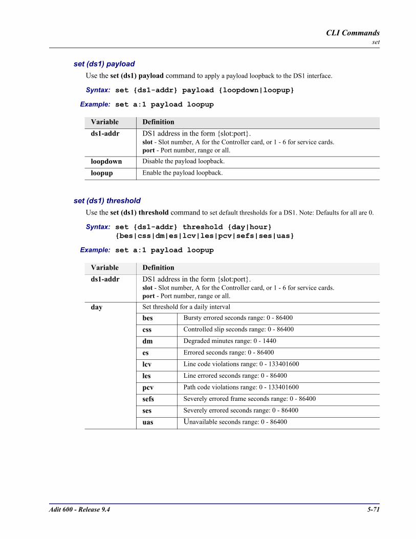
Adit 600 - Release 9.4 5-71
CLI Commandsset
set (ds1) payloadUse the set (ds1) payload command to apply a payload loopback to the DS1 interface.
Syntax: set ds1-addr payload loopdown|loopup
Example: set a:1 payload loopup
set (ds1) thresholdUse the set (ds1) threshold command to set default thresholds for a DS1. Note: Defaults for all are 0.
Syntax: set ds1-addr threshold day|hour bes|css|dm|es|lcv|les|pcv|sefs|ses|uas
Example: set a:1 payload loopup
Variable Definitionds1-addr DS1 address in the form slot:port.
slot - Slot number, A for the Controller card, or 1 - 6 for service cards.port - Port number, range or all.
loopdown Disable the payload loopback.
loopup Enable the payload loopback.
Variable Definitionds1-addr DS1 address in the form slot:port.
slot - Slot number, A for the Controller card, or 1 - 6 for service cards.port - Port number, range or all.
day Set threshold for a daily interval
bes Bursty errored seconds range: 0 - 86400
css Controlled slip seconds range: 0 - 86400
dm Degraded minutes range: 0 - 1440
es Errored seconds range: 0 - 86400
lcv Line code violations range: 0 - 133401600
les Line errored seconds range: 0 - 86400
pcv Path code violations range: 0 - 133401600
sefs Severely errored frame seconds range: 0 - 86400
ses Severely errored seconds range: 0 - 86400
uas Unavailable seconds range: 0 - 86400

5-72 Adit 600 - Release 9.4
CLI Commandsset
set (ds1) upUse the set (ds1) up command to set the DS1 as In-Service.
Syntax: set ds1-addr up
Example: set a:1 up
set (ds1 card)Use the set (ds1 card) commands to configure DS1 card types. These commands apply to the Quad DS1/E1 (hardened) and Quad DS1 ADPCM (hardened) service cards.
set (ds1 card) spantypeUse the set (ds1 card) spantype command to set the span type (T1 or E1) on the DS1/E1 type card.
Syntax: set ds1_card-addr e1span|t1span
Example: set 6 e1spanTo set the Quad DS1/E1 card in slot 6 to E1 mode.
hour Set threshold for a 15 minute interval
bes Bursty errored seconds range: 0 - 900
css Controlled slip seconds range: 0 - 900
dm Degraded minutes range: 0 - 15
es Errored seconds range: 0 - 900
lcv Line code violations range: 0 - 1389600
les Line errored seconds range: 0 - 900
pcv Path code violations range: 0 - 1389600
sefs Severely errored frame seconds range: 0 - 900
ses Severely errored seconds range: 0 - 900
uas Unavailable seconds range: 0 - 900
Variable Definitionds1-addr DS1 address in the form slot:port.
slot - Slot number, A for the Controller card, or 1 - 6 for service cards.port - Port number, range or all.
Variable Definitionds1_card-addr The slot number (1-6) that contains a DS1 type card (Quad DS1/E1 or Quad DS1
ADPCM service card).e1span Enables E1 capability on this card.
t1span Enables T1 capability on this card. (Default)
Variable Definition

Adit 600 - Release 9.4 5-73
CLI Commandsset
set (ds1 card) adpcm mapUse the set (ds1 card) adpcm map command to set compression map on the Quad DS1 ADPCM card.
Syntax: set adpcm_card-addr adpcm none|map1|map2|map3
Example: set 5 adpcm map1
Variable Definitionadpcm_card-addr The slot number (1-6) that contains the Quad DS1 ADPCM card
none None will disable compression on the card. Default.
map1, map2, map3
Map setting, see chart below
MAP 1 MAP 2 MAP 3DS0 X-Port Backplane X-Port Backplane X-Port Backplane
Number Analog Bus Analog Bus Analog Bus1 32n X1/2 32n X1/2 32n X1/22 32n X3/4 32n X3/4 32n X3/43 32n X5/6 32n X5/6 32n X5/64 32n X7/8 32n X7/8 32n X7/85 32n X9/10 32n X9/10 32n X9/106 32n X11/12 32n X11/12 32n X11/127 32n X14/15 32n X13/14 32n X13/148 32n X16/17 32n X15/16 32n X15/169 32n X18/19 32n X17/18 32n X17/1810 32n X20/21 32n X19/20 32n X19/2011 32n X22/23 32n X21/22 32n X21/2212 32n X24 32n X23/24 32n X2413 - Not Avail 32n 32n14 32n 32n 32n15 32n 32n 32n16 32n 32n 32n17 32n 32n 32n18 32n 32n 32n19 32n 32n 32n20 32n 32n 32n21 32n 32n 32n22 32n 32n 32n23 32n 32n - Not Avail24 64n 32n 64n

5-74 Adit 600 - Release 9.4
CLI Commandsset
set (e1)Use the set (e1) command to set up E1s. The command specifies a range of interfaces/settings to apply.
Syntax: set e1-addr setting
set (e1) downUse the set (e1) down command to set the E1 as Out-of-Service.
Syntax: set e1-addr down
Example: set a:1 down
set (e1) equipmentUse the set (e1) equipment command to set an equipment loopback to the E1 interface on or off.
Syntax: set e1-addr equipment loopdown|loopup
Example: set a:1 equipment loopup
set (e1) framingUse the set (e1) framing command to set the E1 framing type.
Syntax: set e1-addr framing e1fr|e1frcrc
Example: set a:1 framing e1fr
Variable Definitione1-addr E1 address in the form slot:port.
slot - Slot number, A for the Controller card, or 1 - 6 for service cards (Quad E1).port - Port number, range or all.
Variable Definitione1-addr E1 address in the form slot:port.
slot - Slot number, A for the Controller card, or 1 - 6 for service cards (Quad E1).port - Port number, range or all.
loopdown Disable equipment loopback. Loopdown is the default.
loopup Enable equipment loopback
Variable Definitione1-addr E1 address in the form slot:port.
slot - Slot number, A for the Controller card, or 1 - 6 for service cards (Quad E1).port - Port number, range or all.
e1fr To E1 Framing with no CRC (dual frame)e1frcrc To E1 16 frame with CRC-4

Adit 600 - Release 9.4 5-75
CLI Commandsset
set (e1) lineUse the set (e1) line command to turn a line loopback to the E1 interface on or off.
Syntax: set e1-addr line loopdown|loopup
Example: set a:1 line loopup
set (e1) linecodeUse the set (e1) linecode command to set the E1 interface line coding.
Syntax: set e1-addr linecode ami|hdb3
Example: set a:1 linecode ami
set (e1) nationalUse the set (e1) national command to set the E1 national bits. This setting should be left at the default (1) unless your country requires the bit to be set to 0.
Syntax: set e1-addr national sa4|sa5|sa6|sa7|sa8 0|1
Example: set a:1 national sa4 1
Variable Definitione1-addr E1 address in the form slot:port.
slot - Slot number, A for the Controller card, or 1 - 6 for service cards (Quad E1).port - Port number, range or all.
loopdown Disable line loopback. Loopdown is the default.
loopup Enable line loopback
Variable Definitione1-addr E1 address in the form slot:port.
slot - Slot number, A for the Controller card, or 1 - 6 for service cards (Quad E1).port - Port number, range or all.
ami Alternate Mark Inversion line codinghdb3 High Density Bipolar 3.
Variable Definitione1-addr E1 address in the form slot:port.
slot - Slot number, A for the Controller card, or 1 - 6 for service cards (Quad E1).port - Port number, range or all.
sa4 Set the E1 national Sa4 bitsa5 Set the E1 national Sa5 bitsa6 Set the E1 national Sa6 bitsa7 Set the E1 national Sa7 bitsa8 Set the E1 national Sa8 bit0|1 Set the bit
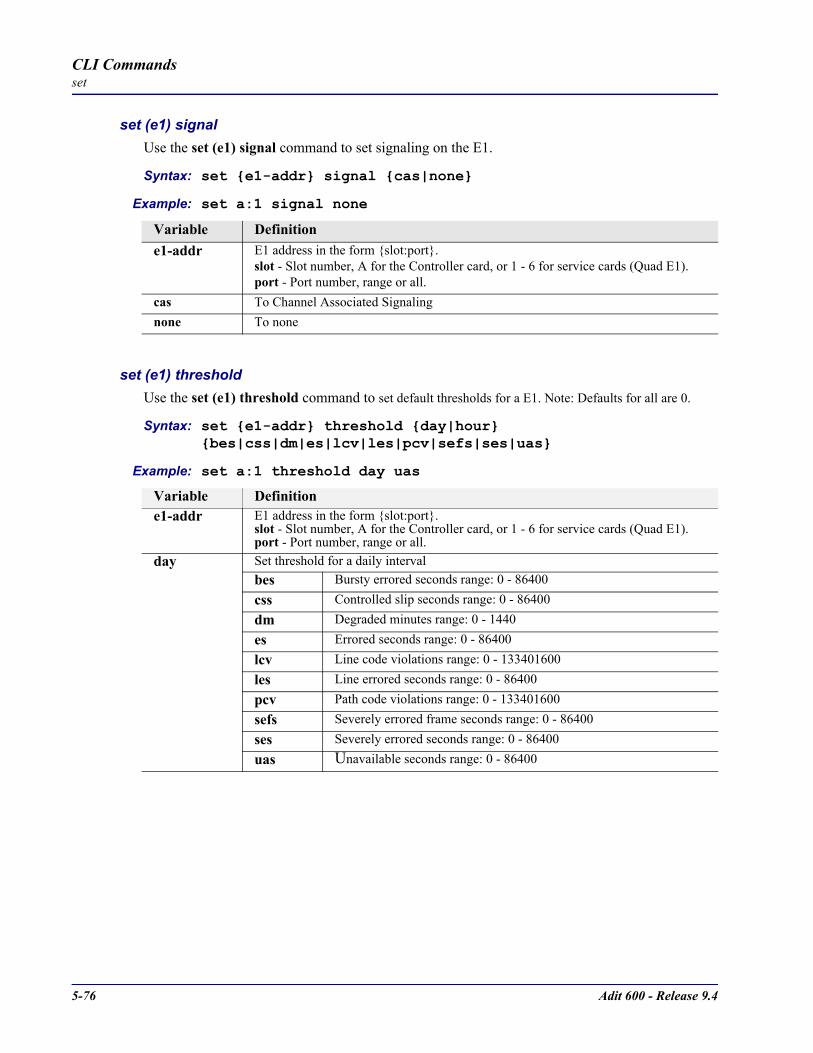
5-76 Adit 600 - Release 9.4
CLI Commandsset
set (e1) signalUse the set (e1) signal command to set signaling on the E1.
Syntax: set e1-addr signal cas|none
Example: set a:1 signal none
set (e1) thresholdUse the set (e1) threshold command to set default thresholds for a E1. Note: Defaults for all are 0.
Syntax: set e1-addr threshold day|hour bes|css|dm|es|lcv|les|pcv|sefs|ses|uas
Example: set a:1 threshold day uas
Variable Definitione1-addr E1 address in the form slot:port.
slot - Slot number, A for the Controller card, or 1 - 6 for service cards (Quad E1).port - Port number, range or all.
cas To Channel Associated Signalingnone To none
Variable Definitione1-addr E1 address in the form slot:port.
slot - Slot number, A for the Controller card, or 1 - 6 for service cards (Quad E1).port - Port number, range or all.
day Set threshold for a daily intervalbes Bursty errored seconds range: 0 - 86400css Controlled slip seconds range: 0 - 86400dm Degraded minutes range: 0 - 1440es Errored seconds range: 0 - 86400lcv Line code violations range: 0 - 133401600 les Line errored seconds range: 0 - 86400 pcv Path code violations range: 0 - 133401600sefs Severely errored frame seconds range: 0 - 86400 ses Severely errored seconds range: 0 - 86400 uas Unavailable seconds range: 0 - 86400
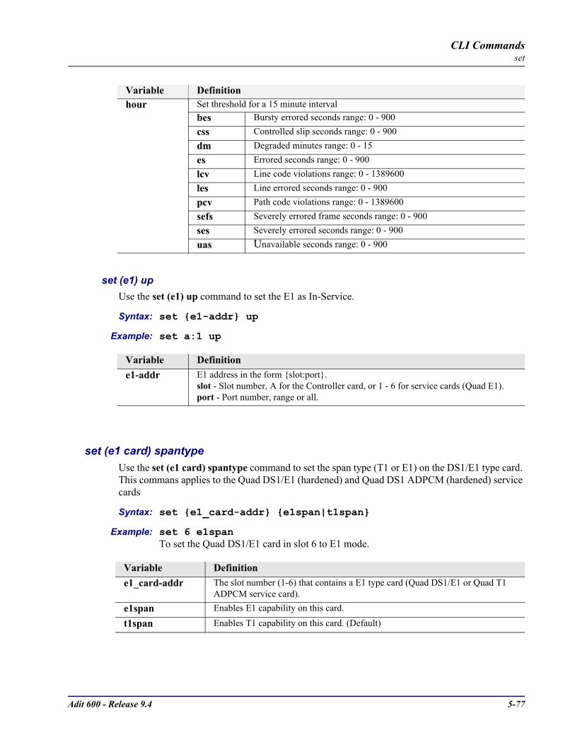
Adit 600 - Release 9.4 5-77
CLI Commandsset
set (e1) upUse the set (e1) up command to set the E1 as In-Service.
Syntax: set e1-addr up
Example: set a:1 up
set (e1 card) spantypeUse the set (e1 card) spantype command to set the span type (T1 or E1) on the DS1/E1 type card. This commans applies to the Quad DS1/E1 (hardened) and Quad DS1 ADPCM (hardened) service cards
Syntax: set e1_card-addr e1span|t1span
Example: set 6 e1spanTo set the Quad DS1/E1 card in slot 6 to E1 mode.
hour Set threshold for a 15 minute intervalbes Bursty errored seconds range: 0 - 900 css Controlled slip seconds range: 0 - 900 dm Degraded minutes range: 0 - 15es Errored seconds range: 0 - 900 lcv Line code violations range: 0 - 1389600 les Line errored seconds range: 0 - 900pcv Path code violations range: 0 - 1389600sefs Severely errored frame seconds range: 0 - 900 ses Severely errored seconds range: 0 - 900 uas Unavailable seconds range: 0 - 900
Variable Definitione1-addr E1 address in the form slot:port.
slot - Slot number, A for the Controller card, or 1 - 6 for service cards (Quad E1).port - Port number, range or all.
Variable Definitione1_card-addr The slot number (1-6) that contains a E1 type card (Quad DS1/E1 or Quad T1
ADPCM service card).e1span Enables E1 capability on this card.
t1span Enables T1 capability on this card. (Default)
Variable Definition
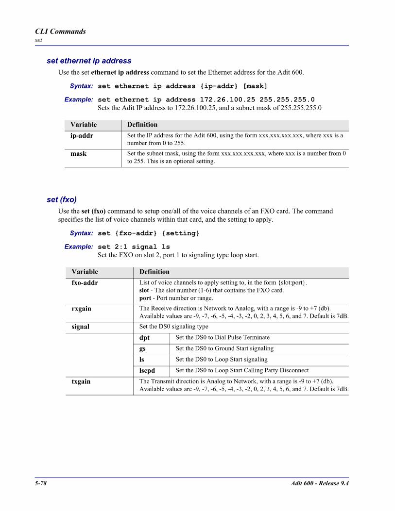
5-78 Adit 600 - Release 9.4
CLI Commandsset
set ethernet ip addressUse the set ethernet ip address command to set the Ethernet address for the Adit 600.
Syntax: set ethernet ip address ip-addr [mask]
Example: set ethernet ip address 172.26.100.25 255.255.255.0Sets the Adit IP address to 172.26.100.25, and a subnet mask of 255.255.255.0
set (fxo) Use the set (fxo) command to setup one/all of the voice channels of an FXO card. The command specifies the list of voice channels within that card, and the setting to apply.
Syntax: set fxo-addr setting
Example: set 2:1 signal lsSet the FXO on slot 2, port 1 to signaling type loop start.
Variable Definitionip-addr Set the IP address for the Adit 600, using the form xxx.xxx.xxx.xxx, where xxx is a
number from 0 to 255.
mask Set the subnet mask, using the form xxx.xxx.xxx.xxx, where xxx is a number from 0 to 255. This is an optional setting.
Variable Definitionfxo-addr List of voice channels to apply setting to, in the form slot:port.
slot - The slot number (1-6) that contains the FXO card.port - Port number or range.
rxgain The Receive direction is Network to Analog, with a range is -9 to +7 (db). Available values are -9, -7, -6, -5, -4, -3, -2, 0, 2, 3, 4, 5, 6, and 7. Default is 7dB.
signal Set the DS0 signaling type
dpt Set the DS0 to Dial Pulse Terminate
gs Set the DS0 to Ground Start signaling
ls Set the DS0 to Loop Start signaling
lscpd Set the DS0 to Loop Start Calling Party Disconnect
txgain The Transmit direction is Analog to Network, with a range is -9 to +7 (db). Available values are -9, -7, -6, -5, -4, -3, -2, 0, 2, 3, 4, 5, 6, and 7. Default is 7dB.

Adit 600 - Release 9.4 5-79
CLI Commandsset
set (fxs)Use the set (fxs) command to set up voice channels of an FXS card. The command specifies the list of voice channels within that FXS card and the setting to apply.
Syntax: set fxs-addr setting
Example: set 3:1 signal gsSet the FXS port 1 on slot 3 to signaling type ground start.
Example: set 3:1-8 txgain -5Sets the FXS ports 1-8 on slot 3 to transmit level range to -5 dB.
Variable Definitionfxs-addr List of voice channels to apply setting to, in the form slot:port.
slot - Slot number 1 - 6, location of the FXS cardsport - Port number or range.
linelength Set the length of the line. Whenever possible, use the short loop setting, a loop set too long may overheat the unit, possibly reducing reliability
long For longer analog loops (up to 3 miles for 26 AWG and 4.8 miles for 24 AWG). Tip/Ring voltage on a long loop is -54 VDC at all times. Using a long line length value on a shorter loop can cause overheating and reduce the reliability
short For shorter analog loops (up to 1.6 miles for 26 AWG and 2.6 miles for 24 AWG). Tip/Ring voltage on a short loop is -54 VDC while on-hook and -37 VDC while off-hook. This is the default value.
rxgain The Receive direction is Network to Analog, with a range of -9 to +7 (dB). Available values are -9, -7, -6, -5, -4, -3, -2, 0, 2, 3, 4, 5, 6, and 7. Default setting is -6 dB
signal Set the DS0 signaling type
ls Set the DS0 to Loop Start signaling
gs Set the DS0 to Ground Start signaling
txgain The Transmit direction is Analog to Network, with a range of -9 to +7 (dB). Available values are -9, -7, -6, -5, -4, -3, -2, 0, 2, 3, 4, 5, 6, and 7. Default setting is -3 dB
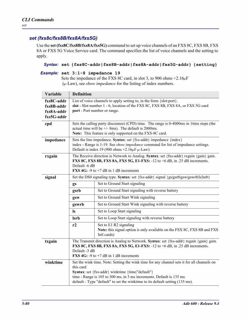
5-80 Adit 600 - Release 9.4
CLI Commandsset
set (fxs8c/fxs8B/fxs8A/fxs5G)Use the set (fxs8C/fxs8B/fxs8A/fxs5G) command to set up voice channels of an FXS 8C, FXS 8B, FXS 8A or FXS 5G Voice Service card. The command specifies the list of voice channels and the setting to apply.
Syntax: set fxs8C-addr|fxs8B-addr|fxs8A-addr|fxs5G-addr setting
Example: set 3:1-8 impedance 19Sets the impedance of the FXS 8C card, in slot 3, to 900 ohms +2.16µF (µ-Law), see show impedance for the listing of index numbers.
Variable Definitionfxs8C-addrfxs8B-addrfxs8A-addrfxs5G-addr
List of voice channels to apply setting to, in the form slot:port.slot - Slot number 1 - 6, location of the FXS 8C, FXS 8B, FXS 8A, or FXS 5G cardport - Port number or range.
cpd Sets the calling party disconnect (CPD) time. The range is 0-4000ms in 16ms steps (the actual time will be +/- 8ms). The default is 2000ms.Note: This feature is only supported on the FXS-8C card.
impedance Sets the line impedance. Syntax: set fxs-addr impedance indexindex - Range is 1-19. See show impedance command for list of impedance settings. Default is index 19 (900 ohms +2.16µF µ-Law).
rxgain The Receive direction is Network to Analog. Syntax: set fxs-addr rxgain gain gain. FXS 8C, FXS 8B, FXS 8A, FXS 5G, E1-FXS: -12 to +6 dB, in .25 dB increments. Default -6 dBFXS 4G: -9 to +7 dB in 1 dB increments
signal Set the DS0 signaling type. Syntax: set fxs-addr signal gs|gsrb|gsw|gswrb|ls|lsrb
gs Set to Ground Start signaling
gsrb Set to Ground Start signaling with reverse battery
gsw Set to Ground Start Wink signaling
gswrb Set to Ground Start Wink signaling with reverse battery
ls Set to Loop Start signaling
lsrb Set to Loop Start signaling with reverse battery
r2 Set to E1 R2 signaling Note: this signal option is only available on the FSX 8C, FXS 8B and FXS Intl cards)
txgain The Transmit direction is Analog to Network. Syntax: set fxs-addr txgain gain gain.FXS 8C, FXS 8B, FXS 8A, FXS 5G, E1-FXS: -12 to +6 dB, in .25 dB increments. Default -3 dBFXS 4G: -9 to +7 dB in 1 dB increments
winktime Set the wink time. Note: Setting the wink time for any channel sets it for all channels on this cardSyntax: set fxs-addr winktime time|"default"time - Range is 105 to 300 ms, in 3 ms increments. Default is 135 ms.default - Type "default" to set the winktime to its default setting (135 ms).

Adit 600 - Release 9.4 5-81
CLI Commandsset
set (fxsINTL)Use the set (fxsINTL) command to setup voice channels of an FXS card, International Version.
Syntax: set fxsINTL-addr setting
Example: set 3:1-8 impedance 18
set (fxsPS)Use the set (fxsPS) command to setup voice channels of an Single Channel POTS card (FXS PS). The command specifies the list of voice channels, and the setting to apply.
Syntax: set fxsPS-addr setting
Example: set 3:1 signal ls
Variable DefinitionfxsINTL-addr List of voice channels to apply setting to, in the form slot:port.
slot - Slot number 1 - 6, location of the FXS INTL cardsport - Port number or range.
impedance Sets the line impedance. Syntax: set fxsINTL-addr impedance indexindex - Range is 1-19. See show impedance command for list of impedance settings. Default is index 19 (900 ohms +2.16µF µ-Law).
rxgain The Receive direction is Network to Analog. Syntax: set fxsINTL-addr rxgain gaingain - range is -12 to +6 dB, in .25 dB increments. Default is -6 dB
signal Set the DS0 signaling type. Syntax: set fxsINTL-addr signal r2
r2 Set to E1 R2 signaling
txgain The Transmit direction is Analog to Network. Syntax: set fxsINTL-addr txgain gaingain - range is -12 to +6 dB, in .25 dB increments. Default is -3 dB
Variable DefinitionfxsPS-addr List of voice channels to apply setting to, in the form slot:port.
slot - Slot number 1 - 6, location of the FXS PS cardsport - Port number or range.
impedance Sets the line impedance. Syntax: set fxsPS-addr impedance indexindex - Range is 1-19. See show impedance command for list of impedance settings. Default is index 19 (900 ohms +2.16µF µ-Law).
rxgain The Receive direction is Network to Analog. Syntax: set fxsPS-addr rxgain gaingain - range is -12 to +6 dB, in .25 dB increments. Default is -6 dB
signal Set the DS0 signaling type. Syntax: set fxsPS-addr signal ls
ls Set to Loop Start signaling
txgain The Transmit direction is Analog to Network.Syntax: set fxsPS-addr txgain gaingain - range is -12 to +6 dB, in .25 dB increments. Default is -3 dB
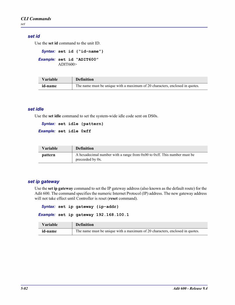
5-82 Adit 600 - Release 9.4
CLI Commandsset
set idUse the set id command to the unit ID.
Syntax: set id “id-name”
Example: set id “ADIT600”ADIT600>
set idleUse the set idle command to set the system-wide idle code sent on DS0s.
Syntax: set idle pattern
Example: set idle 0xff
set ip gatewayUse the set ip gateway command to set the IP gateway address (also known as the default route) for the Adit 600. The command specifies the numeric Internet Protocol (IP) address. The new gateway address will not take effect until Controller is reset (reset command).
Syntax: set ip gateway ip-addr
Example: set ip gateway 192.168.100.1
Variable Definitionid-name The name must be unique with a maximum of 20 characters, enclosed in quotes.
Variable Definitionpattern A hexadecimal number with a range from 0x00 to 0xff. This number must be
preceeded by 0x.
Variable Definitionid-name The name must be unique with a maximum of 20 characters, enclosed in quotes.
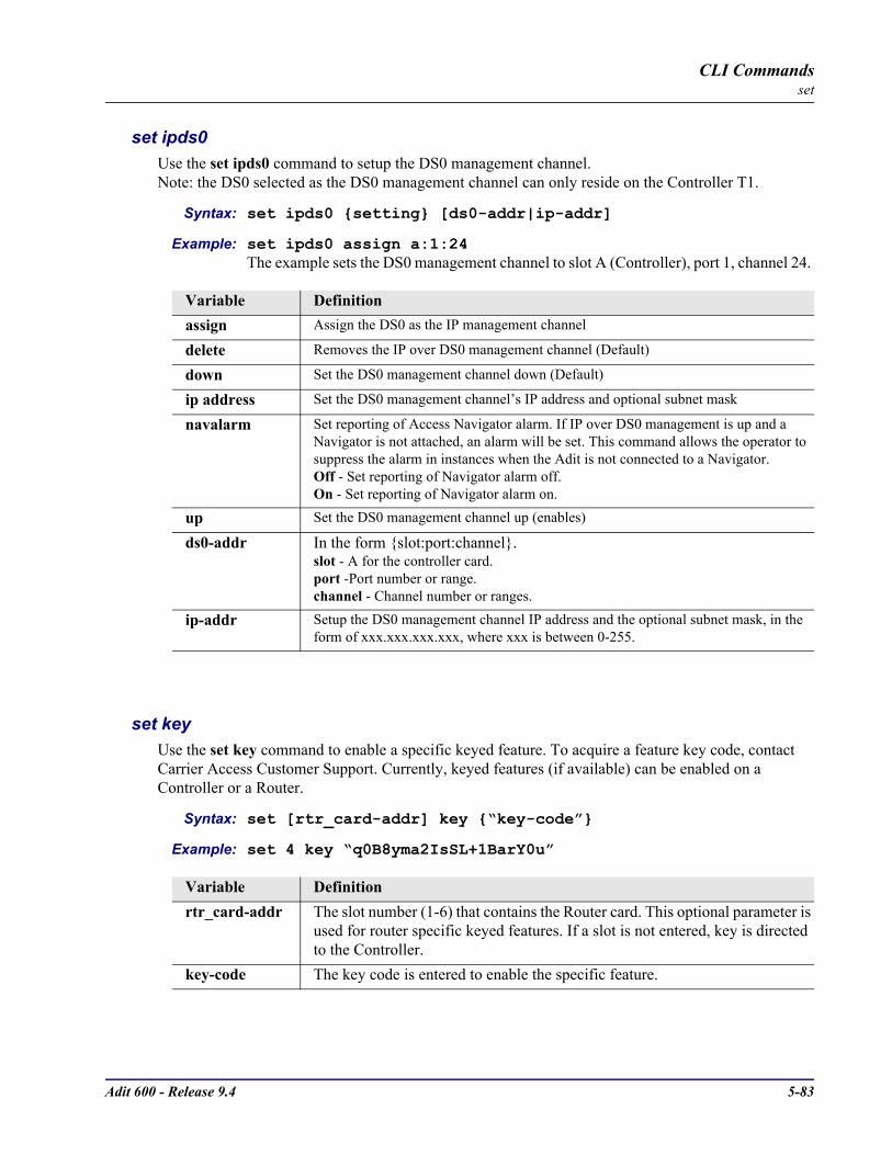
Adit 600 - Release 9.4 5-83
CLI Commandsset
set ipds0Use the set ipds0 command to setup the DS0 management channel. Note: the DS0 selected as the DS0 management channel can only reside on the Controller T1.
Syntax: set ipds0 setting [ds0-addr|ip-addr]
Example: set ipds0 assign a:1:24The example sets the DS0 management channel to slot A (Controller), port 1, channel 24.
set keyUse the set key command to enable a specific keyed feature. To acquire a feature key code, contact Carrier Access Customer Support. Currently, keyed features (if available) can be enabled on a Controller or a Router.
Syntax: set [rtr_card-addr] key “key-code”
Example: set 4 key “q0B8yma2IsSL+1BarY0u”
Variable Definitionassign Assign the DS0 as the IP management channel
delete Removes the IP over DS0 management channel (Default)
down Set the DS0 management channel down (Default)
ip address Set the DS0 management channel’s IP address and optional subnet mask
navalarm Set reporting of Access Navigator alarm. If IP over DS0 management is up and a Navigator is not attached, an alarm will be set. This command allows the operator to suppress the alarm in instances when the Adit is not connected to a Navigator.Off - Set reporting of Navigator alarm off.On - Set reporting of Navigator alarm on.
up Set the DS0 management channel up (enables)
ds0-addr In the form slot:port:channel.slot - A for the controller card.port -Port number or range.channel - Channel number or ranges.
ip-addr Setup the DS0 management channel IP address and the optional subnet mask, in the form of xxx.xxx.xxx.xxx, where xxx is between 0-255.
Variable Definitionrtr_card-addr The slot number (1-6) that contains the Router card. This optional parameter is
used for router specific keyed features. If a slot is not entered, key is directed to the Controller.
key-code The key code is entered to enable the specific feature.

5-84 Adit 600 - Release 9.4
CLI Commandsset
set localUse the set local command to enable or disable local DIP switch settings. The LOCAL LED on the Controller, will display an green light indicator if Local is set to ON. Note: set local will not effect the ACO, ST, OPT or RST switches on the controller.
Syntax: set local on|off
Example: set local off
set login authUse the set login auth command to set the authentication method for controller logins, with local database or external RADIUS servers. When set to RADIUS the controller will try the RADIUS servers first, if no servers reply to the request, the controller will use its local database of users to authenticate the login. A set login authentication to RADIUS will fail without a minimum of 1 RADIUS server configured.
Syntax: set login auth local|radius
Example: set login auth radiusThe example will set the login authentication process to RADIUS.
set login supportUse the set login support command to enable/disable the internal login accounts for Carrier Access Support personnel for the Controller and Router cards (IP, CMG, TSR).
Syntax: set login support disable|enable
Example: set login support disableThe example will prohibit logins via Carrier Access Support passwords.
Variable Definitionon To configure the Adit 600 using the DIP switches.
off To configure using the Command Line Interface (CLI).
Variable Definitionlocal Authenticate user logins via the controller database (Default).
radius Authenticate user logins via the external RADIUS servers.
Variable Definitiondisable Prohibit logins via Carrier Access Support passwords.
enable Allow logins via Carrier Access Support passwords.

Adit 600 - Release 9.4 5-85
CLI Commandsset
set ntpUse the set ntp commands to configure the Network Time Protocol functions.
set ntp disableUse the set ntp disable command to disable Network Time Protocol (NTP) processing (RFC 2030). The initial default for this processing is disabled.
Syntax: set ntp disable
Example: set ntp disableThe example will stop NTP processing on the Controller.
set ntp enableUse the set ntp enable command to enable both Network Time Protocol (NTP) processing(RFC 2030). The initial default for this processing is disabled.
Syntax: set ntp enable
Example: set ntp enableThe example will start NTP processing on the Controller.
set ntp pollUse the set ntp poll command to specify the polling frequency when operating in unicast polled mode. When the NTP server address is configured to a non-zero value this setting will cause the Controller NTP client to issue a unicast NTP request to the configured NTP server at this frequency.
Syntax: set ntp poll seconds
Example: set ntp poll 120The example will poll the NTP server every 2 minutes.
Variable Definitionseconds The time between polls. Range is 16 - 1024 seconds, with a default of 16.

5-86 Adit 600 - Release 9.4
CLI Commandsset
set ntp server addressUse the set ntp server address command to specify the IP address of the NTP server.
Syntax: set ntp server address ip-addr
Example: set ntp server address 192.168.23.56The example will the IP address to be used to access the NTP server to 192.168.23.56.
set ntp timezoneUse the set ntp timezone command to specify the timezone offset to GMT for this controller.
Syntax: set ntp timezone hour-offset [minute-offset]
Example: set ntp timezone -5The example will set the time zone offset to be -5:00 from GMT (Greenwich Mean Time), which equates to Eastern Standard Time.
Variable Definitionip-addr The IP address of the NTP server for unicast polling, in the form of xxx.xxx.xxx.xxx,
where xxx is between 0-255, or 0.0.0.0 for listening to broadcasts. The default is 0.0.0.0.
Variable Definitionhour-offset Offset from GMT in hours. Range is from -12 - 12, with a default of 0.
minute-offset An optional parameter which sets the offset from GMT in minutes. Range is from 0 - 59, with a default of 0. This is used for half hour time zones.

Adit 600 - Release 9.4 5-87
CLI Commandsset
set (ocudp)Use the set (ocudp) commands to configure the OCU-DP service cards.
set (ocudp) baudUse the set (ocudp) baud command to configure the Baud Rate for OCU-DP ports.
Syntax: set ocudp-addr baud 2400|4800|9600|19200|38400|56000 [sw56|sw56cp]|64000
Example: set 3:2 baud 2400Set the baud rate on port 2 to 2400, on the OCU-DP card in slot 3
set (ocudp) loopbackUse the set (ocudp) loopback command to manually set OCU/CSU loopback tests.
Syntax: set ocudp-addr loopback csu|ocu loopdown|loopup
Example: set 3:2 loopback csu loopdown
Variable Definitionocudp-addr The slot:port address of the OCUDP card.
slot - Slot number (1-6) where the OCUDP card is locatedport - Port number or range.
2400 Set OCU-DP baud rate to 24004800 Set OCU-DP baud rate to 48009600 Set OCU-DP baud rate to 960019200 Set OCU-DP baud rate to 1920038400 Set OCU-DP baud rate to 3840056000* Set OCU-DP baud rate to 56000 (Default)
sw56 Set to switched 56 servicesw56cp Set to switched 56 service with call progress capability. Sends
special call progress CMI codes to DSU.64000 Set OCU-DP baud rate to 64000
Variable Definitionocudp-addr The slot:port address of the OCUDP card.
slot - Slot number (1-6) where the OCUDP card is locatedport - Port number or range.
csu Set CSU manual loopback tests
ocu Set OCU manual loopback tests
loopdown Stop CSU/OCU manual loopback test (Default).
loopup Start CSU/OCU manual loopback test
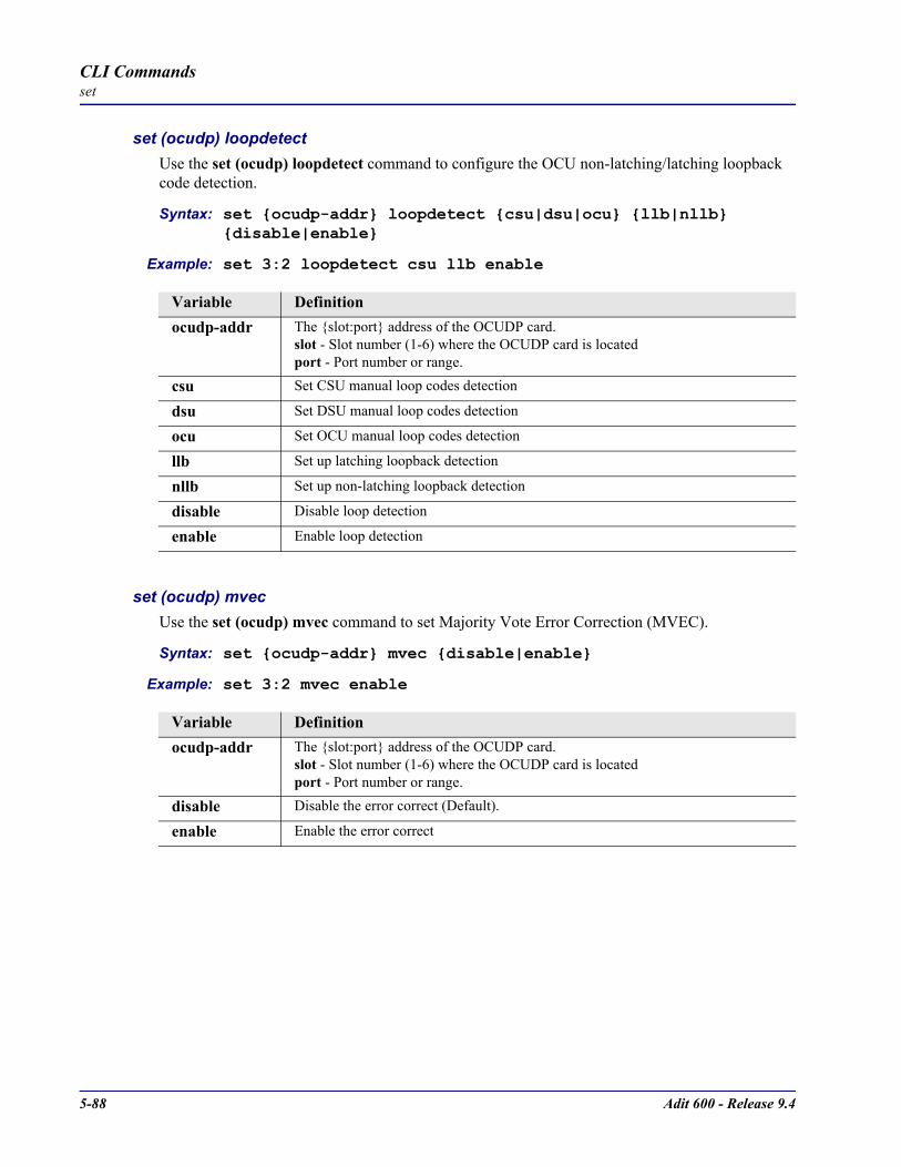
5-88 Adit 600 - Release 9.4
CLI Commandsset
set (ocudp) loopdetectUse the set (ocudp) loopdetect command to configure the OCU non-latching/latching loopback code detection.
Syntax: set ocudp-addr loopdetect csu|dsu|ocu llb|nllb disable|enable
Example: set 3:2 loopdetect csu llb enable
set (ocudp) mvecUse the set (ocudp) mvec command to set Majority Vote Error Correction (MVEC).
Syntax: set ocudp-addr mvec disable|enable
Example: set 3:2 mvec enable
Variable Definitionocudp-addr The slot:port address of the OCUDP card.
slot - Slot number (1-6) where the OCUDP card is locatedport - Port number or range.
csu Set CSU manual loop codes detection
dsu Set DSU manual loop codes detection
ocu Set OCU manual loop codes detection
llb Set up latching loopback detection
nllb Set up non-latching loopback detection
disable Disable loop detection
enable Enable loop detection
Variable Definitionocudp-addr The slot:port address of the OCUDP card.
slot - Slot number (1-6) where the OCUDP card is locatedport - Port number or range.
disable Disable the error correct (Default).
enable Enable the error correct

Adit 600 - Release 9.4 5-89
CLI Commandsset
set (ocudp) secondaryUse the set (ocudp) secondary command to configure the secondary channel service.
Syntax: set ocudp-addr secondary disable|enable
Example: set 3:2 secondary enable
set (ocudp) selftestUse the set (ocudp) selftest command to initiate the OCU-DP card to perform a self test. This request will display a message to wait 8 seconds before requesting selftest status with the status command.
Syntax: set ocudp-addr selftest
Example: set 3:2 selftest
set (ocudp) up/downUse the set (ocudp) up/down command to put the OCU-DP line In or Out-of-Service.
Syntax: set ocudp-addr down|up
Example: set 3:2 up
Set the OCU-DP card in slot 3, port 2 as In-Service.
Variable Definitionocudp-addr The slot:port address of the OCUDP card.
slot - Slot number (1-6) where the OCUDP card is locatedport - Port number or range.
disable Disable the secondary channel service (Default).
enable Enable the secondary channel service
Variable Definitionocudp-addr The slot:port address of the OCUDP card.
slot - Slot number (1-6) where the OCUDP card is locatedport - Port number or range.
Variable Definitionocudp-addr The slot:port address of the OCUDP card.
slot - Slot number (1-6) where the OCUDP card is locatedport - Port number or range.
down Set OCU-DP port as Out-of-Service
up Set OCU-DP port as In-Service
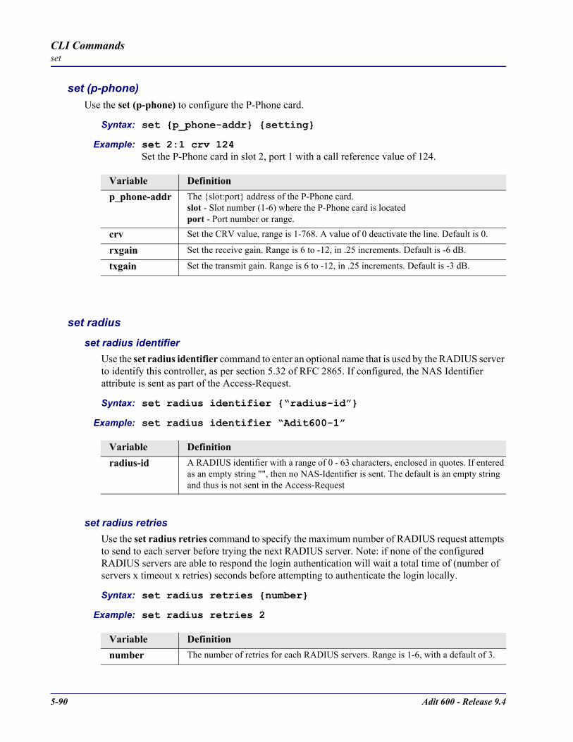
5-90 Adit 600 - Release 9.4
CLI Commandsset
set (p-phone)Use the set (p-phone) to configure the P-Phone card.
Syntax: set p_phone-addr setting
Example: set 2:1 crv 124Set the P-Phone card in slot 2, port 1 with a call reference value of 124.
set radius
set radius identifierUse the set radius identifier command to enter an optional name that is used by the RADIUS server to identify this controller, as per section 5.32 of RFC 2865. If configured, the NAS Identifier attribute is sent as part of the Access-Request.
Syntax: set radius identifier “radius-id”
Example: set radius identifier “Adit600-1”
set radius retriesUse the set radius retries command to specify the maximum number of RADIUS request attempts to send to each server before trying the next RADIUS server. Note: if none of the configured RADIUS servers are able to respond the login authentication will wait a total time of (number of servers x timeout x retries) seconds before attempting to authenticate the login locally.
Syntax: set radius retries number
Example: set radius retries 2
Variable Definitionp_phone-addr The slot:port address of the P-Phone card.
slot - Slot number (1-6) where the P-Phone card is locatedport - Port number or range.
crv Set the CRV value, range is 1-768. A value of 0 deactivate the line. Default is 0.
rxgain Set the receive gain. Range is 6 to -12, in .25 increments. Default is -6 dB.
txgain Set the transmit gain. Range is 6 to -12, in .25 increments. Default is -3 dB.
Variable Definitionradius-id A RADIUS identifier with a range of 0 - 63 characters, enclosed in quotes. If entered
as an empty string "", then no NAS-Identifier is sent. The default is an empty string and thus is not sent in the Access-Request
Variable Definitionnumber The number of retries for each RADIUS servers. Range is 1-6, with a default of 3.

Adit 600 - Release 9.4 5-91
CLI Commandsset
set radius server addressUse the set radius server address command to specify the IP address of the external RADIUS server to use for RADIUS login authentication. Up to 3 different RADIUS servers can be configured, with queries sent to each in succession until one of them sends a reply.
Syntax: set radius server 1|2|3 address ip-addr [port]
Example: set radius server 1 address 192.168.23.56
set radius server secretUse the set radius server secret command to specify shared secret that the controller RADIUS client and the RADIUS server use to authenticate the RADIUS requests and replies.
Syntax: set radius server 1|2|3 secret “secret”
Example: set radius server 1 secret "secret"
set radius timeoutUse the set radius timeout command to specify the maximum number of seconds to wait for a reply after each RADIUS request before sending the next attempt. Note: if none of the configured RADIUS servers are able to respond the login authentication will wait a total time of (number of servers x timeout x retries) seconds before attempting to authenticate the login locally.
Syntax: set radius timeout seconds
Example: set radius timeout 2
Variable Definition1|2|3 The RADIUS server entry to modify.
ip-addr Set the IP address of the RADIUS server, in the form xxx.xxx.xxx.xxx, where xxx is a number from 0 to 255, or 0.0.0.0 to disable this entry. The default is 0.0.0.0 (unused). Note: all 3 RADIUS servers cannot be set to 0.0.0.0 if any login auth settings are set to RADIUS
port This is an optional parameter. UDP port to be used to send the RADIUS queries. Default is 1812
Variable Definition1|2|3 The RADIUS server entry to modify.
secret An ASCII string with a range of 1 - 31 characters, enclosed in quotes. Default is an empty string "".
Variable Definitionseconds The number of seconds to wait for a reply after each request before the next attempt.
Range is 1 - 6, with a default of 3 seconds.

5-92 Adit 600 - Release 9.4
CLI Commandsset
set (router) autologoutUse the set (router) autologout command to set the period of time of inactivity after which the user will be automatically logged-out of a Telnet session.
Syntax: set rtr_card-addr autologout minutes
Example: set 3 autologout 0
set (router) cdrUse the set (router) cdr command to enable or disable Call Detail Recording (CDR) for the specified CMG card. Call Detail records can be viewed using the show (router) log command. This command applies to the CMG Router card only.
Syntax: set cmg_card-addr cdr disable|enable
Example: set 1 cdr enable
set (router) companderUse the set (router) compander command to set the companding algorithm to use with the PCM (G.711) voice stream to/from the TDM side of a connection. The default companding algorithm is mu-law. The companding algorithm chosen for the CMG must match the companding used on the associated TDM-side connected interface channel, i.e. FXS ports and/or T1/E1 channels. This command applies to the CMG Router card only.
Syntax: set cmg_card-addr compander alaw|mulaw
Example: set 1 compander alaw
Variable Definitionrtr_card-addr The slot number (1-6) that contains the Router (IP, CMG or TSR) card.
minutes The minutes of inactivity before auto-logout occurs. Range is 0-255. An entry of “0” will disable the auto-logout timer.
Variable Definitioncmg_card-addr The slot number (1-6) that contains the CMG Router card
disable Disable Call Detail Recording.
enable Enable Call Detail Recording.
Variable Definitioncmg_card-addr The slot number (1-6) that contains the CMG Router card
alaw The companding algorithm used in Europe and elsewhere.
mulaw The companding algorithm used in North America.
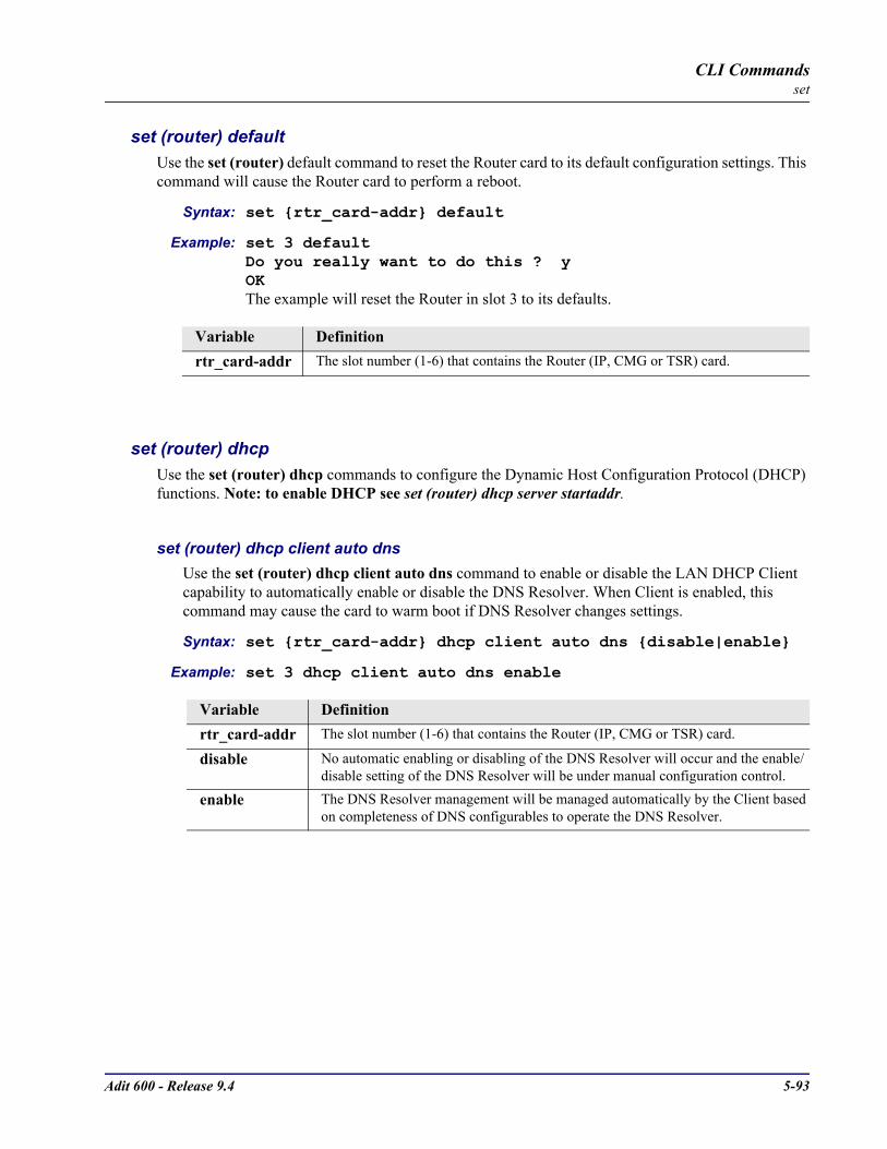
Adit 600 - Release 9.4 5-93
CLI Commandsset
set (router) defaultUse the set (router) default command to reset the Router card to its default configuration settings. This command will cause the Router card to perform a reboot.
Syntax: set rtr_card-addr default
Example: set 3 defaultDo you really want to do this ? yOKThe example will reset the Router in slot 3 to its defaults.
set (router) dhcp Use the set (router) dhcp commands to configure the Dynamic Host Configuration Protocol (DHCP) functions. Note: to enable DHCP see set (router) dhcp server startaddr.
set (router) dhcp client auto dnsUse the set (router) dhcp client auto dns command to enable or disable the LAN DHCP Client capability to automatically enable or disable the DNS Resolver. When Client is enabled, this command may cause the card to warm boot if DNS Resolver changes settings.
Syntax: set rtr_card-addr dhcp client auto dns disable|enable
Example: set 3 dhcp client auto dns enable
Variable Definitionrtr_card-addr The slot number (1-6) that contains the Router (IP, CMG or TSR) card.
Variable Definitionrtr_card-addr The slot number (1-6) that contains the Router (IP, CMG or TSR) card.
disable No automatic enabling or disabling of the DNS Resolver will occur and the enable/disable setting of the DNS Resolver will be under manual configuration control.
enable The DNS Resolver management will be managed automatically by the Client based on completeness of DNS configurables to operate the DNS Resolver.
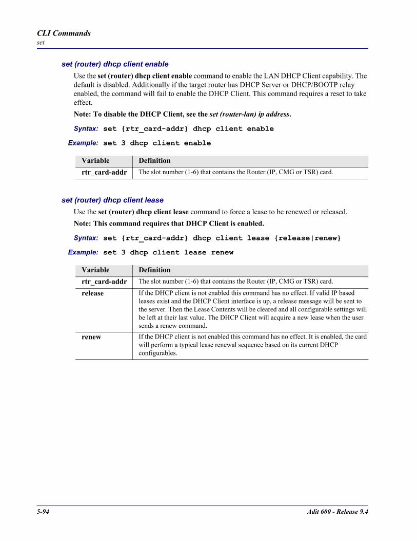
5-94 Adit 600 - Release 9.4
CLI Commandsset
set (router) dhcp client enableUse the set (router) dhcp client enable command to enable the LAN DHCP Client capability. The default is disabled. Additionally if the target router has DHCP Server or DHCP/BOOTP relay enabled, the command will fail to enable the DHCP Client. This command requires a reset to take effect.Note: To disable the DHCP Client, see the set (router-lan) ip address.
Syntax: set rtr_card-addr dhcp client enable
Example: set 3 dhcp client enable
set (router) dhcp client leaseUse the set (router) dhcp client lease command to force a lease to be renewed or released. Note: This command requires that DHCP Client is enabled.
Syntax: set rtr_card-addr dhcp client lease release|renew
Example: set 3 dhcp client lease renew
Variable Definitionrtr_card-addr The slot number (1-6) that contains the Router (IP, CMG or TSR) card.
Variable Definitionrtr_card-addr The slot number (1-6) that contains the Router (IP, CMG or TSR) card.
release If the DHCP client is not enabled this command has no effect. If valid IP based leases exist and the DHCP Client interface is up, a release message will be sent to the server. Then the Lease Contents will be cleared and all configurable settings will be left at their last value. The DHCP Client will acquire a new lease when the user sends a renew command.
renew If the DHCP client is not enabled this command has no effect. It is enabled, the card will perform a typical lease renewal sequence based on its current DHCP configurables.
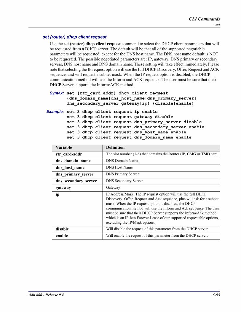
Adit 600 - Release 9.4 5-95
CLI Commandsset
set (router) dhcp client requestUse the set (router) dhcp client request command to select the DHCP client parameters that will be requested from a DHCP server. The default will be that all of the supported negotiable parameters will be requested, except for the DNS host name. The DNS host name default is NOT to be requested. The possible negotiated parameters are: IP, gateway, DNS primary or secondary servers, DNS host name and DNS domain name. These setting will take effect immediately. Please note that selecting the IP request option will use the full DHCP Discovery, Offer, Request and ACK sequence, and will request a subnet mask. When the IP request option is disabled, the DHCP communication method will use the Inform and ACK sequence. The user must be sure that their DHCP Server supports the Inform/ACK method.
Syntax: set rtr_card-addr dhcp client request dns_domain_name|dns_host_name|dns_primary_server|dns_secondary_server|gateway|ip disable|enable
Example: set 3 dhcp client request ip enableset 3 dhcp client request gateway disableset 3 dhcp client request dns_primary_server disableset 3 dhcp client request dns_secondary_server enableset 3 dhcp client request dns_host_name enableset 3 dhcp client request dns_domain_name enable
Variable Definitionrtr_card-addr The slot number (1-6) that contains the Router (IP, CMG or TSR) card.
dns_domain_name DNS Domain Name
dns_host_name DNS Host Name
dns_primary_server DNS Primary Server
dns_secondary_server DNS Secondary Server
gateway Gateway
ip IP Address/Mask. The IP request option will use the full DHCP Discovery, Offer, Request and Ack sequence, plus will ask for a subnet mask. When the IP request option is disabled, the DHCP communication method will use the Inform and Ack sequence. The user must be sure that their DHCP Server supports the Inform/Ack method, which is an IP-less Forever Lease of our supported requestable options, excluding the IP/Mask options.
disable Will disable the request of this parameter from the DHCP server.
enable Will enable the request of this parameter from the DHCP server.

5-96 Adit 600 - Release 9.4
CLI Commandsset
set (router) dhcp client transmit packet broadcast bitUse the set (router) dhcp client request command to set or clear the broadcast bit in all transmit packets to DHCP Servers. This is especially important when other Servers and/or Agent in the DHCP mix need to use broadcast IP destination to get back to our Client.
Syntax: set rtr_card-addr dhcp client transmit broadcast bit disable|enable
Example: set 3 dhcp client transmit packet broadcast bit disable
set (router) dhcp disableUse the set (router) dhcp disable command to disable both DHCP server and DHCP relay functionality for the specified Router card.
Syntax: set rtr_card-addr dhcp disable
Example: set 3 dhcp disableThe example will set the Router in slot 3 to disable DHCP.
set (router) dhcp relay serverUse the set (router) dhcp relay server command to enable a DHCP relay and assigns a DHCP server address for the specified Router card.
Syntax: set rtr_card-addr dhcp relay server server-number ip-addr “profile-name”
Example: set 3 dhcp relay server 1 134.200.3.45 “remotewan”
Variable Definitionrtr_card-addr The slot number (1-6) that contains the Router (IP, CMG or TSR) card.
disable Will clear the broadcast bit in all transmit packets.
enable Will set the broadcast bit in all transmit packets. Default is enabled.
Variable Definitionrtr_card-addr The slot number (1-6) that contains the Router (IP, CMG or TSR) card.
Variable Definitionrtr_card-addr The slot number (1-6) that contains the Router (IP, CMG or TSR) card.
server-number The server number (1 or 2) to specify.
ip-addr The IP address of the server to relay to, in the form of xxx.xxx.xxx.xxx, where xxx is between 0-255.
profile-name The profile name for the Router interface that is used to reach this destination. This name must be enclosed in quotes, with a maximum of 11 characters.

Adit 600 - Release 9.4 5-97
CLI Commandsset
set (router) dhcp server dnsserverUse the set (router) dhcp server dnsserver command to set the IP address of up to 4 DNS servers that the DHCP server will inform the clients of.
Syntax: set rtr_card-addr dhcp server dnsserver number ip-addr
Example: set 5 dhcp server dnsserver 4 122.104.33.220
set (router) dhcp server domainUse the set (router) dhcp server domain command to select the domain name to provide to DHCP clients.
Syntax: set rtr_card-addr dhcp server domain “domain-name”
Example: set 5 dhcp server domain “carrieraccess.com”
set (router) dhcp server durationUse the set (router) dhcp server duration command to set the lease duration that the DHCP server applies to client assignments.
Syntax: set rtr_card-addr dhcp server duration hours:minutes
Example: set 5 dhcp server duration 3:45
Variable Definitionrtr_card-addr The slot number (1-6) that contains the Router (IP, CMG or TSR) card.
number The DNS server entry, 1-4.
ip-add The address of the DNS server, in the form of xxx.xxx.xxx.xxx, where xxx is between 0-255.
Variable Definitionrtr_card-addr The slot number (1-6) that contains the Router (IP, CMG or TSR) card.
domain-name The domain name, with a maximum of 43 characters. Name must be enclosed in quotes.
Variable Definitionrtr_card-addr The slot number (1-6) that contains the Router (IP, CMG or TSR) card.
hours:minutes The lease duration in hours and minutes. hours = 1-999minutes = 1-59.
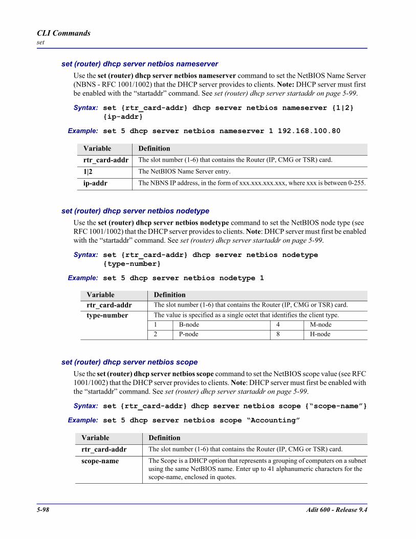
5-98 Adit 600 - Release 9.4
CLI Commandsset
set (router) dhcp server netbios nameserverUse the set (router) dhcp server netbios nameserver command to set the NetBIOS Name Server (NBNS - RFC 1001/1002) that the DHCP server provides to clients. Note: DHCP server must first be enabled with the “startaddr” command. See set (router) dhcp server startaddr on page 5-99.
Syntax: set rtr_card-addr dhcp server netbios nameserver 1|2 ip-addr
Example: set 5 dhcp server netbios nameserver 1 192.168.100.80
set (router) dhcp server netbios nodetypeUse the set (router) dhcp server netbios nodetype command to set the NetBIOS node type (see RFC 1001/1002) that the DHCP server provides to clients. Note: DHCP server must first be enabled with the “startaddr” command. See set (router) dhcp server startaddr on page 5-99.
Syntax: set rtr_card-addr dhcp server netbios nodetype type-number
Example: set 5 dhcp server netbios nodetype 1
set (router) dhcp server netbios scopeUse the set (router) dhcp server netbios scope command to set the NetBIOS scope value (see RFC 1001/1002) that the DHCP server provides to clients. Note: DHCP server must first be enabled with the “startaddr” command. See set (router) dhcp server startaddr on page 5-99.
Syntax: set rtr_card-addr dhcp server netbios scope “scope-name”
Example: set 5 dhcp server netbios scope “Accounting”
Variable Definitionrtr_card-addr The slot number (1-6) that contains the Router (IP, CMG or TSR) card.
1|2 The NetBIOS Name Server entry.
ip-addr The NBNS IP address, in the form of xxx.xxx.xxx.xxx, where xxx is between 0-255.
Variable Definitionrtr_card-addr The slot number (1-6) that contains the Router (IP, CMG or TSR) card.type-number The value is specified as a single octet that identifies the client type.
1 B-node 4 M-node2 P-node 8 H-node
Variable Definitionrtr_card-addr The slot number (1-6) that contains the Router (IP, CMG or TSR) card.
scope-name The Scope is a DHCP option that represents a grouping of computers on a subnet using the same NetBIOS name. Enter up to 41 alphanumeric characters for the scope-name, enclosed in quotes.

Adit 600 - Release 9.4 5-99
CLI Commandsset
set (router) dhcp server startaddrUse the set (router) dhcp server startaddr command to enable the DHCP server on the specified Router card with a defined start IP Address and number of addresses in the pool.
Syntax: set rtr_card-addr dhcp server startaddr ip-addr count
Example: set 4 dhcp server startaddr 134.200.3.1 254
set (router) dialplan timeoutUse the set (router) dialplan timeout commands to configure the dial plan on the CMG Router card. A CMG dial plan is responsible for user dialing timeouts and digit maps. These commands apply to the CMG Router card only.
set (router) dialplan timeout interdigit longUse the set (router) dialplan timeout interdigit long command to set the total time allowed between dialed digits after the first, unless short timing is in effect. If the originator does not dial the next digit in this time period, the call is torn down. This command takes effect after the router card has been reset. This command applies to the CMG Router card only.
Syntax: set cmg_card-addr dialplan timeout interdigit long seconds
Example: set 6 dialplan timeout interdigit long 30
Variable Definitionrtr_card-addr The slot number (1-6) that contains the Router (IP, CMG or TSR) card.
ip-addr The starting address of the client address pool, in the form of xxx.xxx.xxx.xxx, where xxx is between 0-255
count The number of IP addresses in the client address pool (1-254).
Variable Definitioncmg_card-addr The slot number (1-6) that contains the CMG Router card.
seconds The number of seconds (1-60). The default is 16.
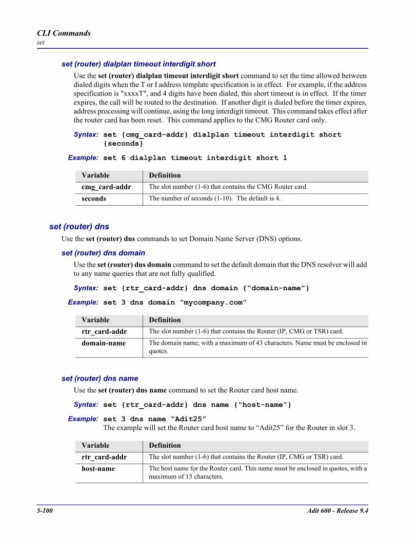
5-100 Adit 600 - Release 9.4
CLI Commandsset
set (router) dialplan timeout interdigit shortUse the set (router) dialplan timeout interdigit short command to set the time allowed between dialed digits when the T or I address template specification is in effect. For example, if the address specification is "xxxxT", and 4 digits have been dialed, this short timeout is in effect. If the timer expires, the call will be routed to the destination. If another digit is dialed before the timer expires, address processing will continue, using the long interdigit timeout. This command takes effect after the router card has been reset. This command applies to the CMG Router card only.
Syntax: set cmg_card-addr dialplan timeout interdigit short seconds
Example: set 6 dialplan timeout interdigit short 1
set (router) dns Use the set (router) dns commands to set Domain Name Server (DNS) options.
set (router) dns domainUse the set (router) dns domain command to set the default domain that the DNS resolver will add to any name queries that are not fully qualified.
Syntax: set rtr_card-addr dns domain “domain-name”
Example: set 3 dns domain “mycompany.com”
set (router) dns nameUse the set (router) dns name command to set the Router card host name.
Syntax: set rtr_card-addr dns name “host-name”
Example: set 3 dns name “Adit25”The example will set the Router card host name to “Adit25” for the Router in slot 3.
Variable Definitioncmg_card-addr The slot number (1-6) that contains the CMG Router card.
seconds The number of seconds (1-10). The default is 4.
Variable Definitionrtr_card-addr The slot number (1-6) that contains the Router (IP, CMG or TSR) card.
domain-name The domain name, with a maximum of 43 characters. Name must be enclosed in quotes.
Variable Definitionrtr_card-addr The slot number (1-6) that contains the Router (IP, CMG or TSR) card.
host-name The host name for the Router card. This name must be enclosed in quotes, with a maximum of 15 characters.
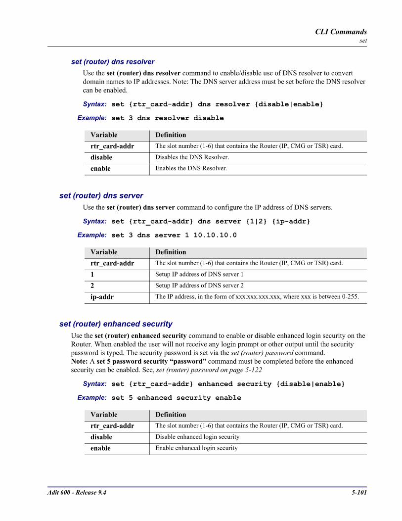
Adit 600 - Release 9.4 5-101
CLI Commandsset
set (router) dns resolverUse the set (router) dns resolver command to enable/disable use of DNS resolver to convert domain names to IP addresses. Note: The DNS server address must be set before the DNS resolver can be enabled.
Syntax: set rtr_card-addr dns resolver disable|enable
Example: set 3 dns resolver disable
set (router) dns serverUse the set (router) dns server command to configure the IP address of DNS servers.
Syntax: set rtr_card-addr dns server 1|2 ip-addr
Example: set 3 dns server 1 10.10.10.0
set (router) enhanced securityUse the set (router) enhanced security command to enable or disable enhanced login security on the Router. When enabled the user will not receive any login prompt or other output until the security password is typed. The security password is set via the set (router) password command.Note: A set 5 password security “password” command must be completed before the enhanced security can be enabled. See, set (router) password on page 5-122
Syntax: set rtr_card-addr enhanced security disable|enable
Example: set 5 enhanced security enable
Variable Definitionrtr_card-addr The slot number (1-6) that contains the Router (IP, CMG or TSR) card.
disable Disables the DNS Resolver.
enable Enables the DNS Resolver.
Variable Definitionrtr_card-addr The slot number (1-6) that contains the Router (IP, CMG or TSR) card.
1 Setup IP address of DNS server 1
2 Setup IP address of DNS server 2
ip-addr The IP address, in the form of xxx.xxx.xxx.xxx, where xxx is between 0-255.
Variable Definitionrtr_card-addr The slot number (1-6) that contains the Router (IP, CMG or TSR) card.
disable Disable enhanced login security
enable Enable enhanced login security

5-102 Adit 600 - Release 9.4
CLI Commandsset
set (router) hookflashUse the set (router) hookflash command to specify the flash maximum time in milliseconds. This is the time beyond which a disconnect, rather than a hookflash event, is declared. Flash event processing may be turned off by setting this parameter to zero. This command applies to the CMG Router card only.
Syntax: set cmg_card-addr hookflash milliseconds
Example: set 5 hookflash 500
set (router) lmiUse the set (router) lmi command to specify the Local Management Interface (LMI) protocol to use for the specified Router card.
Syntax: set rtr_card-addr lmi annexd|disable|lmi
Example: set 5 lmi annexd
set (router) lmi pollUse the set (router) lmi poll command to specify the Local Management Interface (LMI) polling count for the specified Router card.
Syntax: set rtr_card-addr lmi poll counter|interval value
Example: set 5 lmi poll counter 15
Variable Definitioncmg_card-addr The slot number (1-6) that contains the CMG card.
milliseconds Maximum flash length, between 500 and 1500 milliseconds, or 0. Default is 1500 milliseconds
Variable Definitionrtr_card-addr The slot number (1-6) that contains the Router (IP, CMG or TSR) card.
annexd Set LMI to Annex D.
disable Disable LMI on the Router.
lmi Set LMI to LMI rev1 (DLCI 1023)
Variable Definitionrtr_card-addr The slot number (1-6) that contains the Router (IP, CMG or TSR) card.
counter Set the LMI count. value = count of how many link status enquiries can go un-responded before the link is declared down. Range is 0-255.
interval Set LMI period value = LMI polling period. Range is 0-255 seconds.

Adit 600 - Release 9.4 5-103
CLI Commandsset
set (router) logUse the set (router) log command to set whether the CMG text log will continuously add new log entries by over-writing the oldest entries, or will stop adding new log entries after the log is full. Entering this command will cause the log to be cleared. This command applies to the CMG Router card only.
Syntax: set cmg_card-addr log first|last [detail]
Example: set 5 log last detail
set (router) login authUse the set (router) login auth command to specify how login authentication for this router should be performed. The router supports a configuration setting for each router card to determine how the router card logins are to be authenticated, as per one of the following choices: authenticate router logins from the router card local database (default), authenticate router logins by having the controller send a RADIUS access-request message to the controller’s RADIUS servers, or authenticate router logins identically to controller logins. The last choice will cause the router logins to be authenticated either via RADIUS or the controller’s database of users and passwords, as configured for the controller. This configuration is done with Controller CLI only (no menu support).
Syntax: set rtr_card-addr login auth controller|local|radius
Example: set 5 login auth controller
Variable Definitioncmg_card-addr The slot number (1-6) that contains the CMG card.
first Stop adding new entries when log is full (Default)
last Always add new entries, overwrite old entries.
detail Will display the log entries in greater detail, which will cause less entries to fit in the log.
Variable Definitionrtr_card-addr The slot number (1-6) that contains the Router (IP, CMG or TSR) card.
controller Use the Controller login authentication.
local Authenticate user logins via the router database (Default).
radius Authenticate user logins via the Controller’s RADIUS servers.

5-104 Adit 600 - Release 9.4
CLI Commandsset
set (router) login promptUse the set (router) login prompt command to enable or disable the suppression of the Router login prompt for a user that telnets in from the Controller CLI. The user level of the current Controller user will be passed to the Router card at the time the telnet starts. This configuration allows a single login and authentication at the controller to apply to Router telnet sessions as well as the usual Controller CLI. This command applies to the IP Router card only.
Syntax: set rtr_card-addr login prompt disable|enable
Example: set 5 login prompt disable
set (router) mgcp Use the set (router) mgcp command to setup Media Gateway Call Protocol (MGCP) parameters. This command applies to the CMG Router card only.
set (router) mgcp addressformatThe set (router) mgcp addressformat is an interoperability command. It is used to remove or put square brackets around IP Addresses in transmitted MGCP commands. The standard convention and default setting is to have the brackets. The CMG is capable of receiving either format regardless of this setting. This command applies to the CMG Router card only.
Syntax: set cmg_card-addr mgcp addressformat brackets|nobrackets
Example: set 1 mgcp addressformat nobrackets
Variable Definitionrtr_card-addr The slot number (1-6) that contains the Router (IP, CMG or TSR) card.
disable Do not present a login prompt.
enable Present a login prompt. Default.
Variable Definitioncmg_card-addr The slot number (1-6) that contains the CMG card.
brackets MGCP will place brackets around IP addresses (Default)
nobrackets MGCP will not place brackets around IP addresses
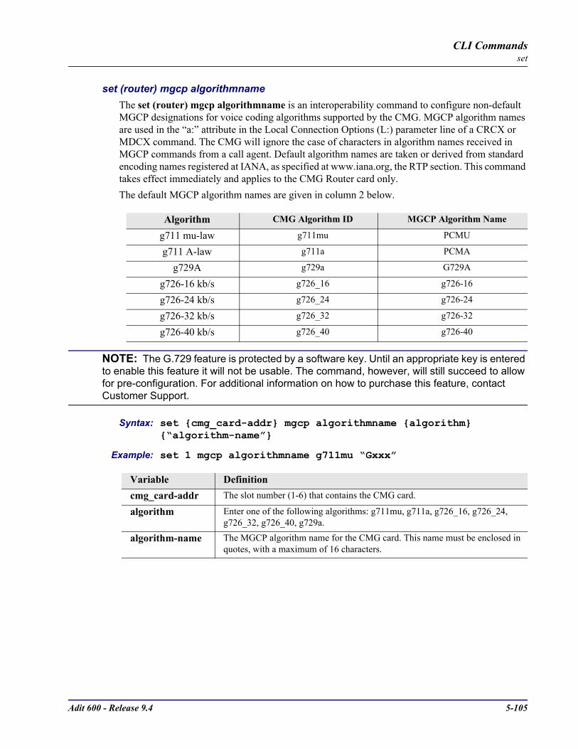
Adit 600 - Release 9.4 5-105
CLI Commandsset
set (router) mgcp algorithmnameThe set (router) mgcp algorithmname is an interoperability command to configure non-default MGCP designations for voice coding algorithms supported by the CMG. MGCP algorithm names are used in the “a:” attribute in the Local Connection Options (L:) parameter line of a CRCX or MDCX command. The CMG will ignore the case of characters in algorithm names received in MGCP commands from a call agent. Default algorithm names are taken or derived from standard encoding names registered at IANA, as specified at www.iana.org, the RTP section. This command takes effect immediately and applies to the CMG Router card only.The default MGCP algorithm names are given in column 2 below.
NOTE: The G.729 feature is protected by a software key. Until an appropriate key is entered to enable this feature it will not be usable. The command, however, will still succeed to allow for pre-configuration. For additional information on how to purchase this feature, contact Customer Support.
Syntax: set cmg_card-addr mgcp algorithmname algorithm “algorithm-name”
Example: set 1 mgcp algorithmname g711mu “Gxxx”
Algorithm CMG Algorithm ID MGCP Algorithm Name
g711 mu-law g711mu PCMU
g711 A-law g711a PCMA
g729A g729a G729A
g726-16 kb/s g726_16 g726-16
g726-24 kb/s g726_24 g726-24
g726-32 kb/s g726_32 g726-32
g726-40 kb/s g726_40 g726-40
Variable Definitioncmg_card-addr The slot number (1-6) that contains the CMG card.
algorithm Enter one of the following algorithms: g711mu, g711a, g726_16, g726_24, g726_32, g726_40, g729a.
algorithm-name The MGCP algorithm name for the CMG card. This name must be enclosed in quotes, with a maximum of 16 characters.
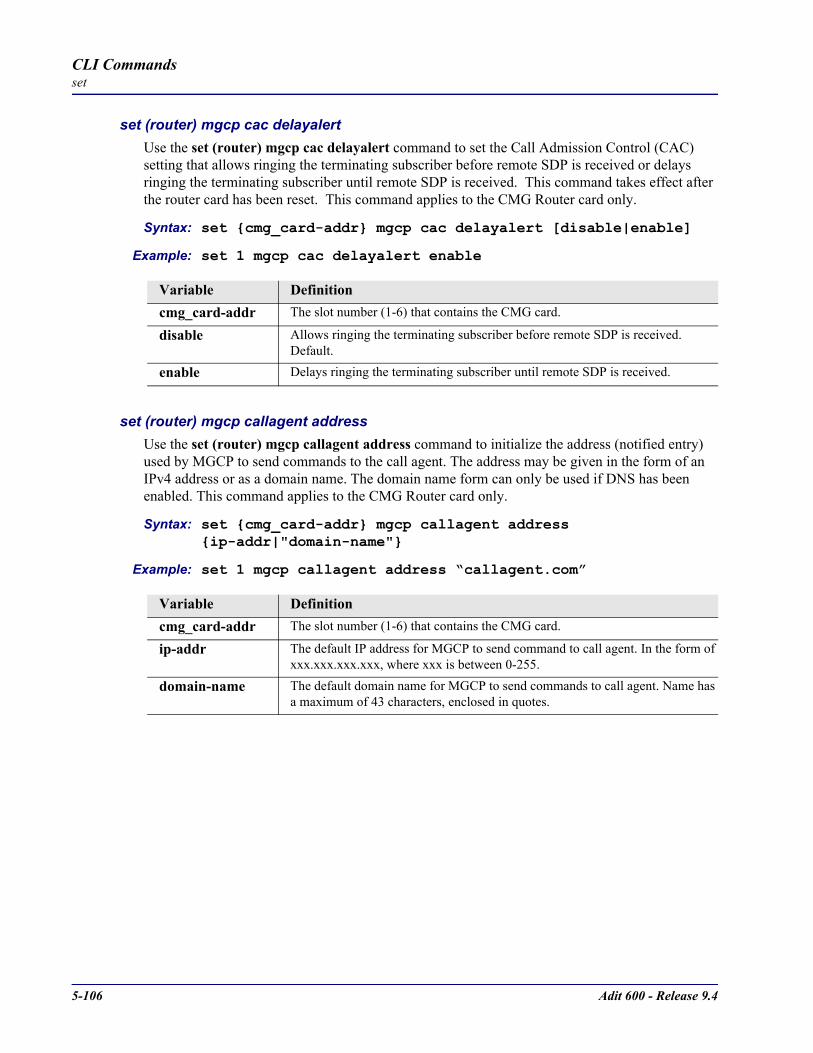
5-106 Adit 600 - Release 9.4
CLI Commandsset
set (router) mgcp cac delayalertUse the set (router) mgcp cac delayalert command to set the Call Admission Control (CAC) setting that allows ringing the terminating subscriber before remote SDP is received or delays ringing the terminating subscriber until remote SDP is received. This command takes effect after the router card has been reset. This command applies to the CMG Router card only.
Syntax: set cmg_card-addr mgcp cac delayalert [disable|enable]
Example: set 1 mgcp cac delayalert enable
set (router) mgcp callagent addressUse the set (router) mgcp callagent address command to initialize the address (notified entry) used by MGCP to send commands to the call agent. The address may be given in the form of an IPv4 address or as a domain name. The domain name form can only be used if DNS has been enabled. This command applies to the CMG Router card only.
Syntax: set cmg_card-addr mgcp callagent address ip-addr|"domain-name"
Example: set 1 mgcp callagent address “callagent.com”
Variable Definitioncmg_card-addr The slot number (1-6) that contains the CMG card.
disable Allows ringing the terminating subscriber before remote SDP is received. Default.
enable Delays ringing the terminating subscriber until remote SDP is received.
Variable Definitioncmg_card-addr The slot number (1-6) that contains the CMG card.
ip-addr The default IP address for MGCP to send command to call agent. In the form of xxx.xxx.xxx.xxx, where xxx is between 0-255.
domain-name The default domain name for MGCP to send commands to call agent. Name has a maximum of 43 characters, enclosed in quotes.

Adit 600 - Release 9.4 5-107
CLI Commandsset
set (router) mgcp callagent filterUse the set (router) mgcp callagent filter command to prevent the CMG from accepting MGCP messages from call agents except those that have been explicitly configured via the set (router) mgcp callagent address or set (router) mgcp callagent secondary address command. This command takes effect immediately.
Syntax: set cmg_card-addr mgcp callagent filter disable|enable
Example: set 1 mgcp callagent filter enable
set (router) mgcp callagent portUse the set (router) mgcp callagent port command to initialize the UDP port (notified entity port) to be used by MGCP to send commands to the call agent. Note: the MGCP specification RFC2705 suggests a port number of 2727 for the call agent. This is the default that the CMG uses to communicate with a call agent. However, many MGCP implementations use the port 2427, making it the same as the usual MGCP port of a gateway. If one is having trouble reaching the call agent, one should probably try configuring the port to 2727. This command applies to the CMG Router card only.
Syntax: set cmg_card-addr mgcp callagent port port-number
Example: set 1 mgcp callagent port 2427
Variable Definitioncmg_card-addr The slot number (1-6) that contains the CMG card.
disable Accept MGCP messages from all IP addresses.
enable Ignore MGCP messages from IP addresses that are not those of the configured call agents.
Variable Definitioncmg_card-addr The slot number (1-6) that contains the CMG card.
port-number Port number for MGCP on the call agent. Range is from 1025 to 65535. Default 2727.

5-108 Adit 600 - Release 9.4
CLI Commandsset
set (router) mgcp callagent secondary addressUse the set (router) mgcp callagent address command for configuring a secondary call agent address that will be tried if the primary call agent does not reply to the notifications. The secondary call agent address will function in the same fashion as would multiple IP addresses returned in a domain name query. See RFC 2705 for a detailed discussion of how multiple call agents are handled by MGCP gateways. The address may be given in the form of an IPv4 address or as a domain name. The domain name form can only be used if DNS has been enabled. This command takes effect after the card had been reset.
Syntax: set cmg_card-addr mgcp callagent secondary address ip-addr|"domain-name"
Example: set 1 mgcp callagent secondary address "callagent.carrieraccess.com"
set (router) mgcp callagent secondary portUse the set (router) mgcp callagent port command for configuring the port number for the secondary call agent that will be tried if the primary call agent does not reply to the notifications. This command takes effect after the card has been reset.
Syntax: set cmg_card-addr mgcp callagent secondary port port-num
Example: set 1 mgcp callagent secondary port 5000
Variable Definitioncmg_card-addr The slot number (1-6) that contains the CMG card.
ip-addr The secondary call agent IP address for MGCP to send commands to. In the form of xxx.xxx.xxx.xxx, where xxx is between 0-255.
domain-name Secondary call agent domain-name for MGCP to send command to. The name must be enclosed in quotes.
Variable Definitioncmg_card-addr The slot number (1-6) that contains the CMG card.
port-num Default port number for MGCP on the secondary call agent. Range from 0 to 65535, with a default of 2727.
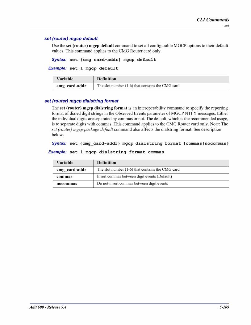
Adit 600 - Release 9.4 5-109
CLI Commandsset
set (router) mgcp defaultUse the set (router) mgcp default command to set all configurable MGCP options to their default values. This command applies to the CMG Router card only.
Syntax: set cmg_card-addr mgcp default
Example: set 1 mgcp default
set (router) mgcp dialstring formatThe set (router) mgcp dialstring format is an interoperability command to specify the reporting format of dialed digit strings in the Observed Events parameter of MGCP NTFY messages. Either the individual digits are separated by commas or not. The default, which is the recommended usage, is to separate digits with commas. This command applies to the CMG Router card only. Note: The set (router) mgcp package default command also affects the dialstring format. See description below.
Syntax: set cmg_card-addr mgcp dialstring format commas|nocommas
Example: set 1 mgcp dialstring format commas
Variable Definitioncmg_card-addr The slot number (1-6) that contains the CMG card.
Variable Definitioncmg_card-addr The slot number (1-6) that contains the CMG card.
commas Insert commas between digit events (Default)
nocommas Do not insert commas between digit events
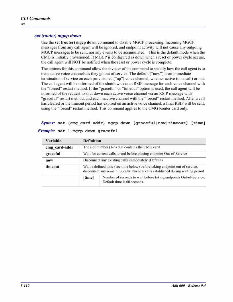
5-110 Adit 600 - Release 9.4
CLI Commandsset
set (router) mgcp downUse the set (router) mgcp down command to disable MGCP processing. Incoming MGCP messages from any call agent will be ignored, and endpoint activity will not cause any outgoing MGCP messages to be sent, nor any events to be accumulated. This is the default mode when the CMG is initially provisioned. If MGCP is configured as down when a reset or power cycle occurs, the call agent will NOT be notified when the reset or power cycle is complete.The options for this command allow the invoker of the command to specify how the call agent is to treat active voice channels as they go out of service. The default (“now”) is an immediate termination of service on each provisioned (“up”) voice channel, whether active (on a call) or not. The call agent will be informed of the shutdown via an RSIP message for each voice channel with the “forced” restart method. If the “graceful” or “timeout” option is used, the call agent will be informed of the request to shut down each active voice channel via an RSIP message with “graceful” restart method, and each inactive channel with the “forced” restart method. After a call has cleared or the timeout period has expired on an active voice channel, a final RSIP will be sent, using the “forced” restart method. This command applies to the CMG Router card only.
Syntax: set cmg_card-addr mgcp down [graceful|now|timeout] [time]
Example: set 1 mgcp down graceful
Variable Definitioncmg_card-addr The slot number (1-6) that contains the CMG card.
graceful Wait for current calls to end before placing endpoint Out-of-Service
now Disconnect any existing calls immediately (Default)
timeout Wait a defined time (see time below) before taking endpoint out of service, disconnect any remaining calls. No new calls established during waiting period
[time] Number of seconds to wait before taking endpoints Out-of-Service. Default time is 60 seconds.

Adit 600 - Release 9.4 5-111
CLI Commandsset
set (router) mgcp gatewayidUse the set (router) mgcp gatewayid command to set the gateway name or IP address to be used in MGCP command header lines and the SDP. By default, the gateway ID that will be used is the domain name of the CMG if DNS is enabled or the IP address of the LAN or WAN interface used to communicate with the call agent. The user may set an explicit name or address by entering it in the command. The domain name form can only be used if DNS has been enabled. This command applies to the CMG Router card only.
Syntax: set cmg_card-addr mgcp gatewayid default|ip-addr |”domain-name”
Example: set 1 mgcp gatewayid “gateway1.carrieraccess.com”
set (router) mgcp keepaliveUse the set (router) mgcp keepalive command to configure a keepalive timer that will cause the CMG to resend RSIP restart messages on expiration. When enabled, this countdown timer is reset every time an MGCP message is received from the call agent. On expiration, the CMG will react by starting periodic transmission of a wildcard RSIP restart MGCP message to each of the configured call agents until it is acknowledged. This command takes effect immediately.Note: If the keepalive timer is enabled (and its value it not set to zero) and the RSIP wildcard setting is enabled (see set (router) mgcp rsipwildcard on page 5-117), the CMG sends wildcard RSIP messages to each endpoint. If the RSIP wildcard setting is disabled, the CMG sends individual RSIP messages without wildcards to the endpoints. Keepalive RSIP restarts are not sent during an active call.
Syntax: set cmg_card-addr mgcp keepalive disable|minutes
Example: set 1 mgcp keepalive 5
Variable Definitioncmg_card-addr The slot number (1-6) that contains the CMG card.
default Use the DNS domain name or the IP address configured for the WAN or LAN interface
ip-addr Use the IP address for the gateway ID in the MGCP header. In the form of xxx.xxx.xxx.xxx, where xxx is between 0-255.
domain-name Use the name for the gateway ID in the MGCP header. Name has a maximum of 41 characters and is enclosed in quotes.
Variable Definitioncmg_card-addr The slot number (1-6) that contains the CMG card.
disable Disables the MGCP keep-alive timer. Default is disable.
minutes The number of minutes for the countdown timer. Range is 0 - 255, where 0 will also disable the timer.
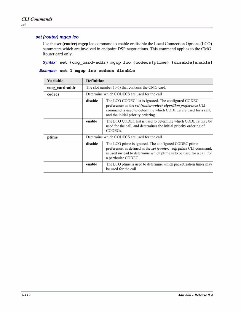
5-112 Adit 600 - Release 9.4
CLI Commandsset
set (router) mgcp lcoUse the set (router) mgcp lco command to enable or disable the Local Connection Options (LCO) parameters which are involved in endpoint DSP negotiations. This command applies to the CMG Router card only.
Syntax: set cmg_card-addr mgcp lco codecs|ptime disable|enable
Example: set 1 mgcp lco codecs disable
Variable Definitioncmg_card-addr The slot number (1-6) that contains the CMG card.
codecs Determine which CODECS are used for the call
disable The LCO CODEC list is ignored. The configured CODEC preferences in the set (router-voice) algorithm preference CLI command is used to determine which CODECs are used for a call, and the initial priority ordering
enable The LCO CODEC list is used to determine which CODECs may be used for the call, and determines the initial priority ordering of CODECs.
ptime Determine which CODECS are used for the call
disable The LCO ptime is ignored. The configured CODEC ptime preference, as defined in the set (router) voip ptime CLI command, is used instead to determine which ptime is to be used for a call, for a particular CODEC.
enable The LCO ptime is used to determine which packetization times may be used for the call.

Adit 600 - Release 9.4 5-113
CLI Commandsset
set (router) mgcp package defaultThe set (router) mgcp package default is an interoperability command to set the default signal/event package to be used for the IETF version of MGCP. The default for this default is the DTMF (D) package. In the NCS version of MGCP, the default package is always the Line (L) package. This parameter does not apply to the NCS version of MGCP, whose default package is always the Line (L) package. For whichever package is made the default, the package name is not required in the softswitch-to-gateway MGCP parameter lines R, S, or T. In the gateway-to-softswitch O (observed events) parameter line, if the default package is set to DTMF(D), no package name is prepended to reported dialstring or digit events. In all other cases for observed events O, the package name is prepended (i.e. the L and G package names are always prepended in observed events). This command applies to the CMG Router card only.
Syntax: set cmg_card-addr mgcp package default d|g|l
Example: set 1 mgcp package default g
Variable Definitioncmg_card-addr The slot number (1-6) that contains the CMG card.
d Make the DTMF (D) package the default
g Make the General (G) package the default
l Make the Line (L) package the default

5-114 Adit 600 - Release 9.4
CLI Commandsset
set (router) mgcp parsemodeThe set (router) mgcp parsemode is an interoperability command to set the strictness with which incoming MGCP messages are parsed. If parsemode is set to lenient, then some incoming messages which may contain protocol errors for the configured protocol version, or contain requests to perform unavailable functions, may not produce an error response, if the message can be interpreted correctly, and/or if the requested unavailable function is unimportant to the desired operation. The verbose option behaves the same as the lenient, except that log entries are added to record the fact that it occurred. The strict option enforces all protocol requirements and function availability by means of an error return code. The default parse mode is lenient. This is done to account for certain softswitch implementations which do not strictly adhere to the protocol spec, or for which certain services would not work if a particular request for an unavailable benign function were to be rejected. Use of “lenient” parsemode can lead to “mysterious” problems if there is a serious protocol mismatch between the call agent and CMG. It is recommended that the parsemode be set to “strict” or “verbose” when one is attempting to determine why softswitch-CMG communications do not seem to allow CMG voice calls to be made or services to be activated. This command applies to the CMG Router card only.
Syntax: set cmg_card-addr mgcp parsemode lenient|strict|verbose
Example: set 1 mgcp parsemode strict
set (router) mgcp piggybackThe set (router) mgcp piggyback is a interoperability command to set allow/disallow the sending of more than one MGCP command in the same message. Some call agents support piggybacking, and some do not. The gateway will always support the processing of received piggybacked commands. The default, for greatest interoperability is to disable the sending of piggybacked commands. Enabling of piggybacking can improve MGCP throughput and provide simpler processing when an endpoint is in the quarantine state. This command applies to the CMG Router card only.
Syntax: set cmg_card-addr mgcp piggyback disable|enable
Example: set 1 mgcp piggyback enable
Variable Definitioncmg_card-addr The slot number (1-6) that contains the CMG card.
lenient Do not return an error response in benign situations (Default)
strict Return an error response for protocol errors or requests for unavailable functions
verbose Do not return an error response in benign situations, but log the event
Variable Definitioncmg_card-addr The slot number (1-6) that contains the CMG card.
disable Disallow sending of piggyback commands (Default)
enable Allow sending of piggybacked commands

Adit 600 - Release 9.4 5-115
CLI Commandsset
set (router) mgcp portUse the set (router) mgcp port command to set the gateway’s UDP port for receiving MGCP commands. The default port is 2427. The port number may be set to any 16-bit number, but must not interfere with standard port numbers of other TCP or UDP applications.This command applies to the CMG Router card only.
Syntax: set cmg_card-addr mgcp port port-number
Example: set 1 mgcp port 5000
set (router) mgcp protocolidUse the set (router) mgcp protocolid command to configure a global protocol ID string which will override the default protocol ID string used in MGCP command lines. This command applies to the CMG Router card only.
Syntax: set cmg_card-addr mgcp protocolid default|“id-name”
Example: set 1 mgcp protocolid “MGCP 1.0 CACS”
If the protocol ID setting is set to “default” or the null string (""), then the following default strings will be used depending on the configured MGCP version.
Variable Definitioncmg_card-addr The slot number (1-6) that contains the CMG card.
port-number The port number range is from 1025 to 65535.
Variable Definitioncmg_card-addr The slot number (1-6) that contains the CMG card.
default Use the default protocol ID string
“id-name” Override the default protocol ID string with this string. Identifier of up to 20 characters, enclosed in quotes.
MGCP Version Default Protocol IDietf10 MGCP 1.0ietf01 MGCP 0.1ncs MGCP 0.1 NCS 1.0
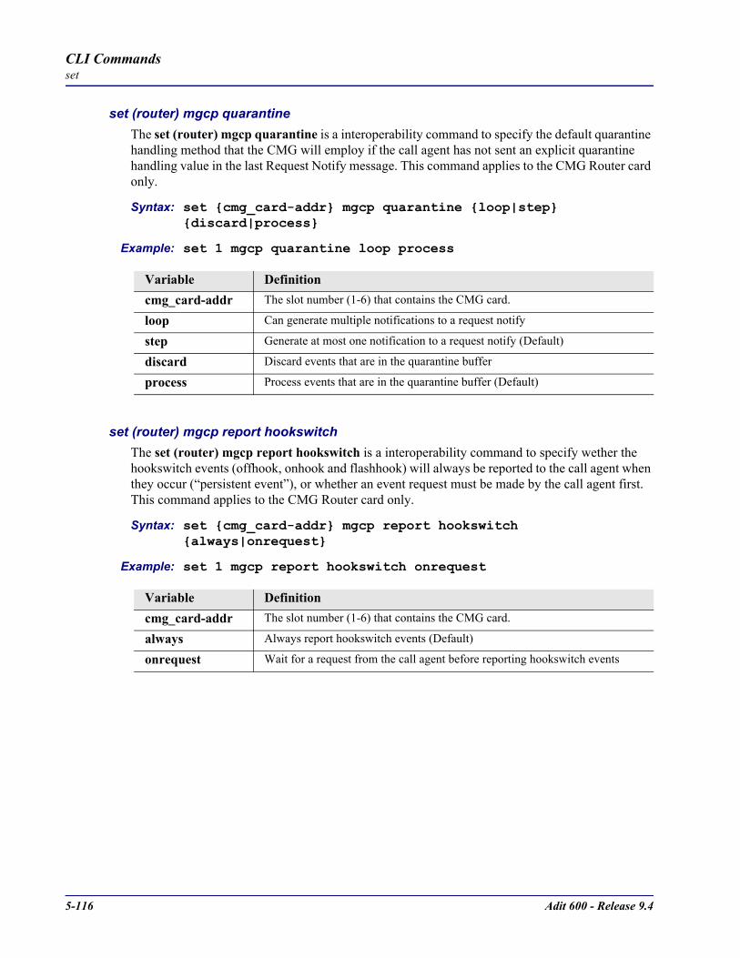
5-116 Adit 600 - Release 9.4
CLI Commandsset
set (router) mgcp quarantineThe set (router) mgcp quarantine is a interoperability command to specify the default quarantine handling method that the CMG will employ if the call agent has not sent an explicit quarantine handling value in the last Request Notify message. This command applies to the CMG Router card only.
Syntax: set cmg_card-addr mgcp quarantine loop|step discard|process
Example: set 1 mgcp quarantine loop process
set (router) mgcp report hookswitchThe set (router) mgcp report hookswitch is a interoperability command to specify wether the hookswitch events (offhook, onhook and flashhook) will always be reported to the call agent when they occur (“persistent event”), or whether an event request must be made by the call agent first. This command applies to the CMG Router card only.
Syntax: set cmg_card-addr mgcp report hookswitch always|onrequest
Example: set 1 mgcp report hookswitch onrequest
Variable Definitioncmg_card-addr The slot number (1-6) that contains the CMG card.
loop Can generate multiple notifications to a request notify
step Generate at most one notification to a request notify (Default)
discard Discard events that are in the quarantine buffer
process Process events that are in the quarantine buffer (Default)
Variable Definitioncmg_card-addr The slot number (1-6) that contains the CMG card.
always Always report hookswitch events (Default)
onrequest Wait for a request from the call agent before reporting hookswitch events

Adit 600 - Release 9.4 5-117
CLI Commandsset
set (router) mgcp retriesUse the set (router) mgcp retries command to specify the number of times an MGCP command is retransmitted if there is no response from a call agent. After the last retry, if another message timeout occurs, the endpoint will enter a disconnected mode.
Syntax: set cmg_card-addr mgcp retries value
Example: set 1 mgcp retries 4
set (router) mgcp rsipwildcardThe set (router) mgcp rsipwildcard command to configure whether the CMG card should send a single wildcard RSIP or individual RSIPs for each endpoint, at those times when all endpoints are transitioning. The CMG will default to individual RSIPs. If the wildcard RSIP setting is enabled, the CMG will send an RSIP with the wildcard endpoint ID when it transitions all of the endpoints. The call agent can then use AUEPs to determine individual endpoint status. The CMG transitions all of the endpoints when it sets MGCP up or down or when it is about to reboot or has just finished booting. Individual RSIPs will always be sent when an endpoint is going to transition up or down independent from the other endpoints, such as when a CLI command sets an endpoint up or down, or when the disconnected state has occurred. This command applies to the CMG Router card only.
Syntax: set cmg_card-addr mgcp rsipwildcard disable|enable
Example: set 1 mgcp rispwildcard enable
Variable Definitioncmg_card-addr The slot number (1-6) that contains the CMG card.
value The value range is 0 - 10.
Variable Definitioncmg_card-addr The slot number (1-6) that contains the CMG card.
disable Send individual RSIPs.
enable Send wildcard RSIP. (Default)
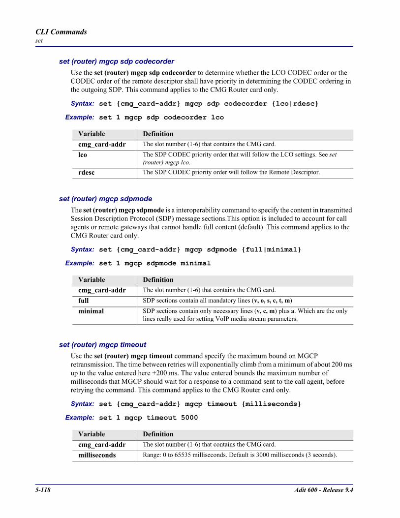
5-118 Adit 600 - Release 9.4
CLI Commandsset
set (router) mgcp sdp codecorderUse the set (router) mgcp sdp codecorder to determine whether the LCO CODEC order or the CODEC order of the remote descriptor shall have priority in determining the CODEC ordering in the outgoing SDP. This command applies to the CMG Router card only.
Syntax: set cmg_card-addr mgcp sdp codecorder lco|rdesc
Example: set 1 mgcp sdp codecorder lco
set (router) mgcp sdpmodeThe set (router) mgcp sdpmode is a interoperability command to specify the content in transmitted Session Description Protocol (SDP) message sections.This option is included to account for call agents or remote gateways that cannot handle full content (default). This command applies to the CMG Router card only.
Syntax: set cmg_card-addr mgcp sdpmode full|minimal
Example: set 1 mgcp sdpmode minimal
set (router) mgcp timeoutUse the set (router) mgcp timeout command specify the maximum bound on MGCP retransmission. The time between retries will exponentially climb from a minimum of about 200 ms up to the value entered here +200 ms. The value entered bounds the maximum number of milliseconds that MGCP should wait for a response to a command sent to the call agent, before retrying the command. This command applies to the CMG Router card only.
Syntax: set cmg_card-addr mgcp timeout milliseconds
Example: set 1 mgcp timeout 5000
Variable Definitioncmg_card-addr The slot number (1-6) that contains the CMG card.
lco The SDP CODEC priority order that will follow the LCO settings. See set (router) mgcp lco.
rdesc The SDP CODEC priority order will follow the Remote Descriptor.
Variable Definitioncmg_card-addr The slot number (1-6) that contains the CMG card.
full SDP sections contain all mandatory lines (v, o, s, c, t, m)
minimal SDP sections contain only necessary lines (v, c, m) plus a. Which are the only lines really used for setting VoIP media stream parameters.
Variable Definitioncmg_card-addr The slot number (1-6) that contains the CMG card.
milliseconds Range: 0 to 65535 milliseconds. Default is 3000 milliseconds (3 seconds).
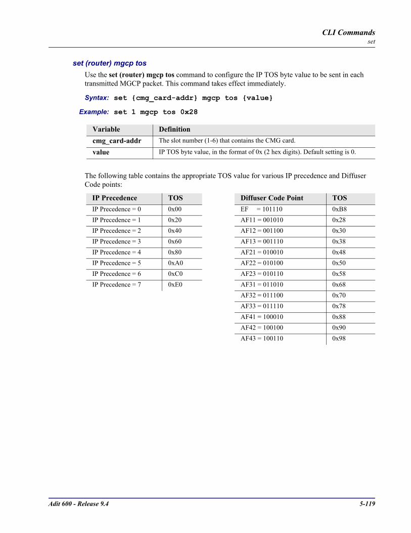
Adit 600 - Release 9.4 5-119
CLI Commandsset
set (router) mgcp tosUse the set (router) mgcp tos command to configure the IP TOS byte value to be sent in each transmitted MGCP packet. This command takes effect immediately.
Syntax: set cmg_card-addr mgcp tos value
Example: set 1 mgcp tos 0x28
The following table contains the appropriate TOS value for various IP precedence and Diffuser Code points:
Variable Definitioncmg_card-addr The slot number (1-6) that contains the CMG card.
value IP TOS byte value, in the format of 0x (2 hex digits). Default setting is 0.
IP Precedence TOS Diffuser Code Point TOSIP Precedence = 0 0x00 EF = 101110 0xB8IP Precedence = 1 0x20 AF11 = 001010 0x28IP Precedence = 2 0x40 AF12 = 001100 0x30IP Precedence = 3 0x60 AF13 = 001110 0x38IP Precedence = 4 0x80 AF21 = 010010 0x48IP Precedence = 5 0xA0 AF22 = 010100 0x50IP Precedence = 6 0xC0 AF23 = 010110 0x58IP Precedence = 7 0xE0 AF31 = 011010 0x68
AF32 = 011100 0x70AF33 = 011110 0x78AF41 = 100010 0x88AF42 = 100100 0x90AF43 = 100110 0x98
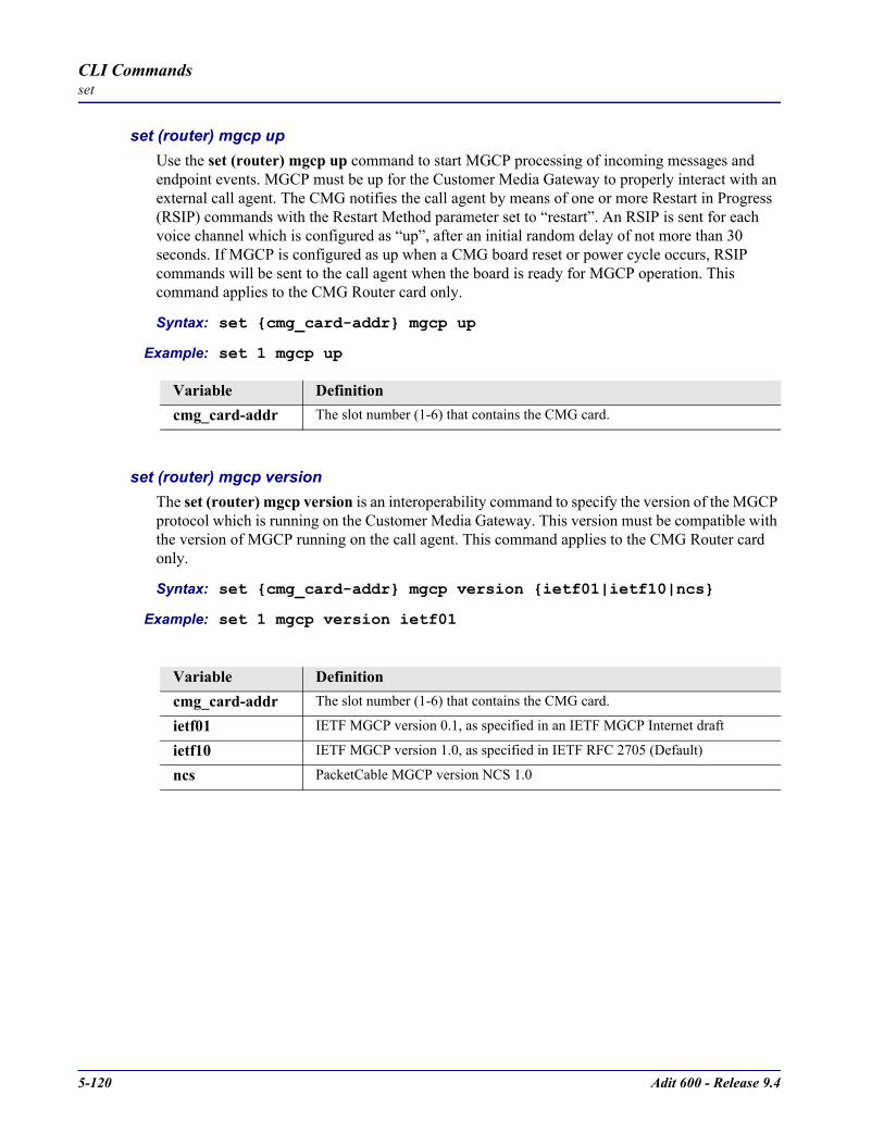
5-120 Adit 600 - Release 9.4
CLI Commandsset
set (router) mgcp upUse the set (router) mgcp up command to start MGCP processing of incoming messages and endpoint events. MGCP must be up for the Customer Media Gateway to properly interact with an external call agent. The CMG notifies the call agent by means of one or more Restart in Progress (RSIP) commands with the Restart Method parameter set to “restart”. An RSIP is sent for each voice channel which is configured as “up”, after an initial random delay of not more than 30 seconds. If MGCP is configured as up when a CMG board reset or power cycle occurs, RSIP commands will be sent to the call agent when the board is ready for MGCP operation. This command applies to the CMG Router card only.
Syntax: set cmg_card-addr mgcp up
Example: set 1 mgcp up
set (router) mgcp versionThe set (router) mgcp version is an interoperability command to specify the version of the MGCP protocol which is running on the Customer Media Gateway. This version must be compatible with the version of MGCP running on the call agent. This command applies to the CMG Router card only.
Syntax: set cmg_card-addr mgcp version ietf01|ietf10|ncs
Example: set 1 mgcp version ietf01
Variable Definitioncmg_card-addr The slot number (1-6) that contains the CMG card.
Variable Definitioncmg_card-addr The slot number (1-6) that contains the CMG card.
ietf01 IETF MGCP version 0.1, as specified in an IETF MGCP Internet draft
ietf10 IETF MGCP version 1.0, as specified in IETF RFC 2705 (Default)
ncs PacketCable MGCP version NCS 1.0

Adit 600 - Release 9.4 5-121
CLI Commandsset
set (router) ntp Use the set (router) ntp command to setup Network Time Protocol (NTP) parameters.
set (router) ntp enable/disableUse the set (router) ntp enable/disable command to enable/disable NTP processing.
Syntax: set rtr_card-addr ntp disable|enable
Example: set 1 ntp enable
set (router) ntp pollUse the set (router) ntp poll command to specify polling of the NTP server every defined number of seconds.
Syntax: set rtr_card-addr ntp poll seconds
Example: set 1 ntp poll 120
set (router) ntp serverUse the set (router) ntp server command to specify the IP address or domain name of the NTP server.
Syntax: set rtr_card-addr ntp server ip-addr|"domain-name"
Example: set 1 ntp server 10.10.10.0
Variable Definitionrtr_card-addr The slot number (1-6) that contains the Router (IP, CMG or TSR) card.
disable Disable NTP processing
enable Enable NTP processing
Variable Definitionrtr_card-addr The slot number (1-6) that contains the Router (IP, CMG or TSR) card.
seconds The number of seconds between polls. Seconds range is 16 to 1024. Default is 16.
Variable Definitionrtr_card-addr The slot number (1-6) that contains the Router (IP, CMG or TSR) card.
ip-addr The IP address of the NTP server, in the form of xxx.xxx.xxx.xxx, where xxx is between 0-255. Setting the NTP server value to 0.0.0.0 will cause the router to listen to and process NTP broadcasts.
domain-name Domain name of the NTP server, with a maximum length of 43 characters, enclosed in quotes.

5-122 Adit 600 - Release 9.4
CLI Commandsset
set (router) ntp timezoneUse the set (router) ntp timezone command to specify the timezone offset relative to GMT for this Router.
Syntax: set rtr_card-addr ntp timezone hour-offset [minute-offset]
Example: set 1 ntp timezone -5
set (router) passwordUse the set (router) password command to manage password access on the specified Router card.
Syntax: set rtr_card-addr password setting “password”
Example: set 5 password view “Fred”
Variable Definitionrtr_card-addr The slot number (1-6) that contains the Router (IP, CMG or TSR) card.
hour-offset Used to calculate gateway time from GMT. The hour-offset range is -12 to 12.
minute-offset Used to calculate gateway time from GMT. The minute-offset range is 0 to 60.
Variable Definitionrtr_card-addr The slot number (1-6) that contains the Router (IP, CMG or TSR) card.
admin Set Administration level password on the Router.
config Set Configuration level password on the Router.
security Set Security level password on the Router.
view Set View level password on the Router.
password A password with a maximum of 15 characters. Password must be enclosed in quotes, and is case-sensitive.
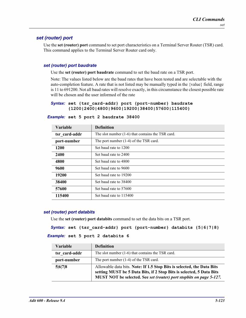
Adit 600 - Release 9.4 5-123
CLI Commandsset
set (router) portUse the set (router) port command to set port characteristics on a Terminal Server Router (TSR) card. This command applies to the Terminal Server Router card only.
set (router) port baudrateUse the set (router) port baudrate command to set the baud rate on a TSR port.Note: The values listed below are the baud rates that have been tested and are selectable with the auto-completion feature. A rate that is not listed may be manually typed in the value field, range is 11 to 691200. Not all baud rates will resolve exactly, in this circumstance the closest possible rate will be chosen and the user informed of the rate
Syntax: set tsr_card-addr port port-number baudrate 1200|2400|4800|9600|19200|38400|57600|115400
Example: set 5 port 2 baudrate 38400
set (router) port databitsUse the set (router) port databits command to set the data bits on a TSR port.
Syntax: set tsr_card-addr port port-number databits 5|6|7|8
Example: set 5 port 2 databits 6
Variable Definitiontsr_card-addr The slot number (1-6) that contains the TSR card.
port-number The port number (1-4) of the TSR card.
1200 Set baud rate to 1200
2400 Set baud rate to 2400
4800 Set baud rate to 4800
9600 Set baud rate to 9600
19200 Set baud rate to 19200
38400 Set baud rate to 38400
57600 Set baud rate to 57600
115400 Set baud rate to 115400
Variable Definitiontsr_card-addr The slot number (1-6) that contains the TSR card.
port-number The port number (1-4) of the TSR card.
5|6|7|8 Allowable data bits. Note: If 1.5 Stop Bits is selected, the Data Bits setting MUST be 5 Data Bits, if 2 Stop Bits is selected, 5 Data Bits MUST NOT be selected. See set (router) port stopbits on page 5-127.

5-124 Adit 600 - Release 9.4
CLI Commandsset
set (router) port dsr low resetUse the set (router) port dsr low reset command to cause a RE-232 session to terminate when DSR (Data Set Ready) goes low. This setting can be issued when the card is physically strapped for Ethernet, but has not effect. This setting also only goes into effect when the DSR signal is high. This setting can be done for any application type but is only active for termserv and rawtcp modes.
Syntax: set tsr_card-addr port port-number dsr low reset disable|enable
Example: set 5 port 2 dsr low reset enable
set (router) port flowcontrolUse the set (router) port flowcontrol command to set the flow control on a TSR port. This command controls the transfer of messages or characters between two points in a data network to prevent congestion, or loss of data when the receiving device’s buffer begins to reach its capacity.
Syntax: set tsr_card-addr port port-number flowcontrol setting
Example: set 5 port 2 flowcontrol none
Variable Definitiontsr_card-addr The slot number (1-6) that contains the TSR card.
port-number The port number (1-4) of the TSR card.
disable Disable will not use the reset feature. Default
enable Enable causes the session to teardown when DSR goes low.
Variable Definitiontsr_card-addr The slot number (1-6) that contains the TSR card.
port-number The port number (1-4) of the TSR card.
none Set flow control to none
rtscts Set flow control to hardware
xonxoff Set flow control to xonxoff

Adit 600 - Release 9.4 5-125
CLI Commandsset
set (router) port inactivity timerUse the set (router) port inactivity timer command to set the inactivity timeout for a RS-232 session. This setting can be issued when the card is physically strapped for Ethernet, bus has no effect. When this timer is set, the socket will be reset when no data is sent or received on the port for the number of minutes the timer is set to. This timer can be set for any application type, but is only active for termserv and rawtcp modes.
Syntax: set tsr_card-addr port port-number inactivity timer disable|time
Example: set 5 port 2 inactivity timer 30
set (router) port ipUse the set (router) port ip command to set an IP address for a TSR port.
Syntax: set tsr_card-addr port port-number ip ip-addr
Example: set 5 port 2 ip 192.100.1.1
set (router) port nameUse the set (router) port name command to set define name for a TSR port.
Syntax: set tsr_card-addr port port-number name “name”
Example: set 5 port 2 name “portname”
Variable Definitiontsr_card-addr The slot number (1-6) that contains the TSR card.
port-number The port number (1-4) of the TSR card.
disable Disable will not use a inactivity timer. Default.
time The inactivity timer will cause the session to timeout and teardown when a value is entered. Range is 1 - 999.
Variable Definitiontsr_card-addr The slot number (1-6) that contains the TSR card.
port-number The port number (1-4) of the TSR card.
ip-addr The IP address for the defined port, in the form of xxx.xxx.xxx.xxx, where xxx is between 0-255.
Variable Definitiontsr_card-addr The slot number (1-6) that contains the TSR card.
port-number The port number (1-4) of the TSR card.
name Port identifier, with up to 15 characters, enclosed in quotes.
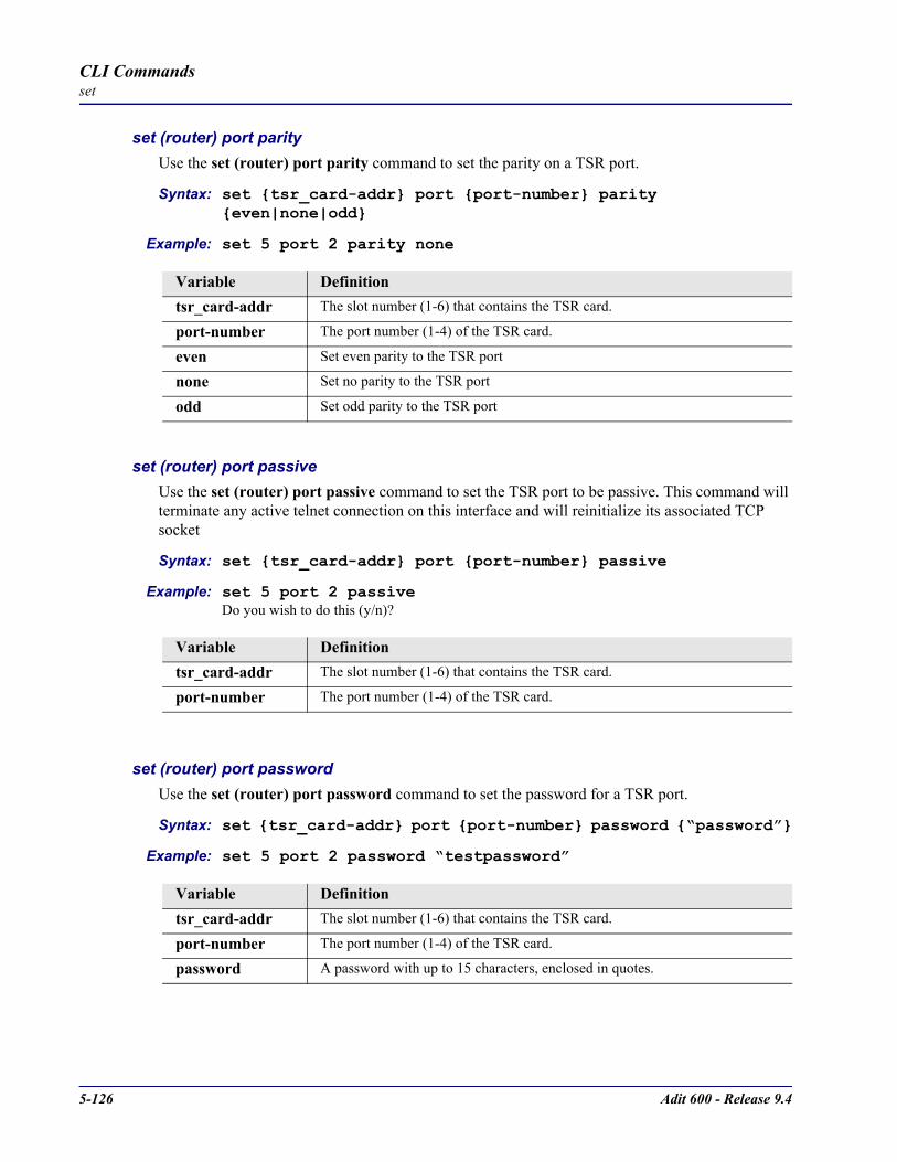
5-126 Adit 600 - Release 9.4
CLI Commandsset
set (router) port parityUse the set (router) port parity command to set the parity on a TSR port.
Syntax: set tsr_card-addr port port-number parity even|none|odd
Example: set 5 port 2 parity none
set (router) port passiveUse the set (router) port passive command to set the TSR port to be passive. This command will terminate any active telnet connection on this interface and will reinitialize its associated TCP socket
Syntax: set tsr_card-addr port port-number passive
Example: set 5 port 2 passiveDo you wish to do this (y/n)?
set (router) port passwordUse the set (router) port password command to set the password for a TSR port.
Syntax: set tsr_card-addr port port-number password “password”
Example: set 5 port 2 password “testpassword”
Variable Definitiontsr_card-addr The slot number (1-6) that contains the TSR card.
port-number The port number (1-4) of the TSR card.
even Set even parity to the TSR port
none Set no parity to the TSR port
odd Set odd parity to the TSR port
Variable Definitiontsr_card-addr The slot number (1-6) that contains the TSR card.
port-number The port number (1-4) of the TSR card.
Variable Definitiontsr_card-addr The slot number (1-6) that contains the TSR card.
port-number The port number (1-4) of the TSR card.
password A password with up to 15 characters, enclosed in quotes.

Adit 600 - Release 9.4 5-127
CLI Commandsset
set (router) port promptUse the set (router) port prompt command to set the password for a TSR port.
Syntax: set tsr_card-addr port port-number prompt disable|enable
Example: set 5 port 2 prompt enable
set (router) port protocolportUse the set (router) port protocolport command to set the protocol port on a TSR port.
Syntax: set tsr_card-addr port port-number protocolport protocol-port
Example: set 5 port 2 protocolport 0
set (router) port stopbitsUse the set (router) port stopbits command to set the number of stop bits on a TSR port. The stop bit is an interval at the end of each Asynchronous Character that allows the receiving computer to pause before the start of the next character.
Syntax: set tsr_card-addr port port-number stopbits 1|1.5|2
Example: set 5 port 2 stopbits 1
Variable Definitiontsr_card-addr The slot number (1-6) that contains the TSR card.
port-number The port number (1-4) of the TSR card.
disable Disable Authentication Prompt on a TSR port.
enable Set the Authentication Prompt on a TSR port.
Variable Definitiontsr_card-addr The slot number (1-6) that contains the TSR card.
port-number The port number (1-4) of the TSR card.
protocol-port 0-65535 of the TSR port. 0 is the wildcard, any port designator.
Variable Definitiontsr_card-addr The slot number (1-6) that contains the TSR card.
port-number The port number (1-4) of the TSR card.
1|1.5|2 Stop bits values available. Note: If 1.5 Stop Bits is selected, the Data Bits setting MUST be 5 Data Bits, if 2 Stop Bits is selected, 5 Data Bits MUST NOT be selected. See set (router) port stopbits on page 5-127.

5-128 Adit 600 - Release 9.4
CLI Commandsset
set (router) port tbos map descriptionUse the set (router) port tbos map description command to set a description attribute for one of the eight available TBOS displays. This setting can be issued when the card is physically strapped for Ethernet, but has no effect. This setting can be done for any application type but is only used when type is set to TBOS.Note: this command is only available on a TSR card that has TBOS feature enabled.
Syntax: set tsr_card-addr port port-number tbos map map-addr description “text-string”
Example: set 5 port 2 tbos map 4 description “Site 7, St. Louis, MO”
set (router) port tbos map displayUse the set (router) port tbos map display command to set a TBOS (Telemetry Byte Oriented Serial) display map value for one of the eight TBOS display available for monitoring equipment. This setting can be issued when the card is physically strapped for Ethernet, but has no effect. This setting can be done for any application type but is only used when type is set to TBOS.Note: this command is only available on a TSR card that has TBOS feature enabled.
Syntax: set tsr_card-addr port port-number tbos map map-addr display device|none
Example: set 5 port 2 tbos map 4 display lynx_ds3
Variable Definitiontsr_card-addr The slot number (1-6) that contains the TSR card.
port-number The port number (1-4) of the TSR card.
map-addr One of the eight TBOS displays available for monitoring equipment. Range is 1 - 8.
test-string The TBOS map description command assigns a text string (0 - 19 characters) to a designated display number. Default is an empty string ("").
Variable Definitiontsr_card-addr The slot number (1-6) that contains the TSR card.
port-number The port number (1-4) of the TSR card.
map-addr One of the eight TBOS displays available for monitoring equipment. Range is 1 - 8.
device-type alcatel_mdr_4000 Alcatel MDR-4000 radio for monitoring lynx_1_4_port_prot_sw Proxium Lynx radiolynx_8_port_prot_sw Proxium Lynx radiolynx_ds3 Proxium Lynx radiolynx_hd_31145_10 Proxium Lynx radiolynx_hd_31145_1f Proxium Lynx radio
none None will disable monitoring for that TBOS display.

Adit 600 - Release 9.4 5-129
CLI Commandsset
set (router) port typeUse the set (router) port type command to set the application being used for a RS-232 (serial) port. This setting can be issued when the card is physically strapped for Ethernet, but has no effect. This command applies to the TSR only.
Syntax: set tsr_card-addr port port-number type termserv|rawtcp|tbos
Example: set 5 port 2 type tbos
set (router) ppp authUse the set (router) ppp auth command to configure the PPP (Point-to-Point Protocol) authentication on the specified Router card.
set (router) ppp auth byremote protocol
Syntax: set rtr_card-addr ppp auth byremote protocol chap|none|pap
Example: set 5 ppp auth byremote protocol none
Variable Definitiontsr_card-addr The slot number (1-6) that contains the TSR card.
port-number The port number (1-4) of the TSR card.
termserv Terminal server. Default.
rawtcp Raw TCP.
tbos TBOS (Telemetry Byte Oriented Serial). Note: this setting requires TBOS feature to be enabled on the TSR service card. Contact Customer Support for information on purchasing this software keyed feature.
Variable Definitionrtr_card-addr The slot number (1-6) that contains the Router (IP, CMG or TSR) card.
chap Set to the CHAP protocol.
none The remote PPP device cannot authenticate this Adit (Default).
pap Set to the PAP protocol.

5-130 Adit 600 - Release 9.4
CLI Commandsset
set (router) ppp auth byremote secret
Syntax: set rtr_card-addr ppp auth byremote secret “password”
Example: set 5 ppp auth byremote secret “public”The example will set the PPP authentication secret password for the Router in slot 5 to “public”
Note: A set (router) ppp auth by remote protocol command must be completed before this command can be implemented.
set (router) ppp auth byremote user
Syntax: set rtr_card-addr ppp auth byremote user profilename|”protocol-name”
Example: set 5 ppp auth byremote user profilenameThe example will set the PPP authentication user name for the Router in slot 5 to equal the profile name.
Note: A set (router) ppp auth byremote protocol command must be completed before this command can be implemented.
Variable Definitionrtr_card-addr The slot number (1-6) that contains the Router (IP, CMG or TSR) card.
password A password with a maximum of 15 characters. Password must be enclosed in quotes.
Variable Definitionrtr_card-addr The slot number (1-6) that contains the Router (IP, CMG or TSR) card.
profilename Use the profile name as the CHAP or PAP user name.
protocol-name The CHAP or PAP user name. A maximum of 16 characters, enclosed in quotes.

Adit 600 - Release 9.4 5-131
CLI Commandsset
set (router) ppp auth ofremote protocol
Syntax: set rtr_card-addr ppp auth ofremote protocol chap|none|pap
Example: set 5 ppp auth ofremote protocol noneThe example will set the Router in slot 5 to not allow PPP authentication of this Adit by the router.
set (router) ppp securityUse the set (router) ppp security command to set up the local external security server, that the Router will use to authenticate remote PPP devices.
set (router) ppp security address
Syntax: set rtr_card-addr ppp security address ip-addr
Example: set 5 ppp security address 10.1.1.1Note: A set (router) ppp security server command must be completed before this command can be implemented.
set (router) ppp security password
Syntax: set rtr_card-addr ppp security password “password”
Example: set 5 ppp security password “public”Note: A set (router) ppp auth by remote protocol command must be completed before this command can be set.
Variable Definitionrtr_card-addr The slot number (1-6) that contains the Router (IP, CMG or TSR) card.
chap Set to the CHAP protocol.
none The remote PPP device cannot authenticate this Adit (Default).
pap Set to the PAP protocol.
Variable Definitionrtr_card-addr The slot number (1-6) that contains the Router (IP, CMG or TSR) card.
ip-addr The IP address, in the form of xxx.xxx.xxx.xxx, where xxx is between 0-255.
Variable Definitionrtr_card-addr The slot number (1-6) that contains the Router (IP, CMG or TSR) card.
password A password with a maximum of 15 characters. Password must be enclosed in quotes.
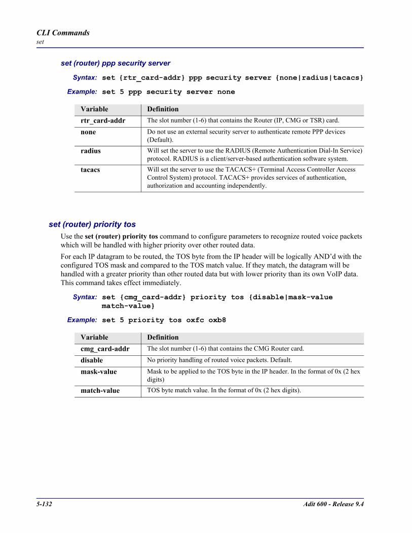
5-132 Adit 600 - Release 9.4
CLI Commandsset
set (router) ppp security server
Syntax: set rtr_card-addr ppp security server none|radius|tacacs
Example: set 5 ppp security server none
set (router) priority tosUse the set (router) priority tos command to configure parameters to recognize routed voice packets which will be handled with higher priority over other routed data. For each IP datagram to be routed, the TOS byte from the IP header will be logically AND’d with the configured TOS mask and compared to the TOS match value. If they match, the datagram will be handled with a greater priority than other routed data but with lower priority than its own VoIP data. This command takes effect immediately.
Syntax: set cmg_card-addr priority tos disable|mask-value match-value
Example: set 5 priority tos oxfc oxb8
Variable Definitionrtr_card-addr The slot number (1-6) that contains the Router (IP, CMG or TSR) card.
none Do not use an external security server to authenticate remote PPP devices (Default).
radius Will set the server to use the RADIUS (Remote Authentication Dial-In Service) protocol. RADIUS is a client/server-based authentication software system.
tacacs Will set the server to use the TACACS+ (Terminal Access Controller Access Control System) protocol. TACACS+ provides services of authentication, authorization and accounting independently.
Variable Definitioncmg_card-addr The slot number (1-6) that contains the CMG Router card.
disable No priority handling of routed voice packets. Default.
mask-value Mask to be applied to the TOS byte in the IP header. In the format of 0x (2 hex digits)
match-value TOS byte match value. In the format of 0x (2 hex digits).

Adit 600 - Release 9.4 5-133
CLI Commandsset
The following table contains the appropriate TOS mask and match for various IP precedence and DiffServ code points:
IP Precedence Mask TOS DiffServ Codepoint Mask TOSIP Precedence = 0 0xE0 0x00 EF = 101110 0xFC 0xB8IP Precedence = 1 0xE0 0x20 AF11 = 001010 0xFC 0x28IP Precedence = 2 0xE0 0x40 AF12 = 001100 0xFC 0x30IP Precedence = 3 0xE0 0x60 AF13 = 001110 0xFC 0x38IP Precedence = 4 0xE0 0x80 AF21 = 010010 0xFC 0x48IP Precedence = 5 0xE0 0xA0 AF22 = 010100 0xFC 0x50IP Precedence = 6 0xE0 0xC0 AF23 = 010110 0xFC 0x58IP Precedence = 7 0xE0 0xE0 AF31 = 011010 0xFC 0x68
AF32 = 011100 0xFC 0x70AF33 = 011110 0xFC 0x78AF41 = 100010 0xFC 0x88AF42 = 100100 0xFC 0x90AF43 = 100110 0xFC 0x98
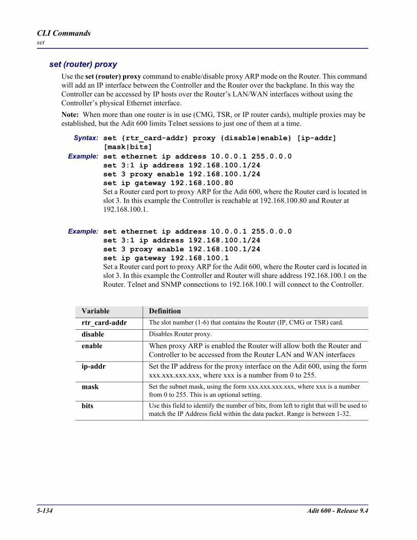
5-134 Adit 600 - Release 9.4
CLI Commandsset
set (router) proxyUse the set (router) proxy command to enable/disable proxy ARP mode on the Router. This command will add an IP interface between the Controller and the Router over the backplane. In this way the Controller can be accessed by IP hosts over the Router’s LAN/WAN interfaces without using the Controller’s physical Ethernet interface.Note: When more than one router is in use (CMG, TSR, or IP router cards), multiple proxies may be established, but the Adit 600 limits Telnet sessions to just one of them at a time.
Syntax: set rtr_card-addr proxy disable|enable [ip-addr] [mask|bits]
Example: set ethernet ip address 10.0.0.1 255.0.0.0set 3:1 ip address 192.168.100.1/24set 3 proxy enable 192.168.100.1/24set ip gateway 192.168.100.80Set a Router card port to proxy ARP for the Adit 600, where the Router card is located in slot 3. In this example the Controller is reachable at 192.168.100.80 and Router at 192.168.100.1.
Example: set ethernet ip address 10.0.0.1 255.0.0.0set 3:1 ip address 192.168.100.1/24set 3 proxy enable 192.168.100.1/24set ip gateway 192.168.100.1Set a Router card port to proxy ARP for the Adit 600, where the Router card is located in slot 3. In this example the Controller and Router will share address 192.168.100.1 on the Router. Telnet and SNMP connections to 192.168.100.1 will connect to the Controller.
Variable Definitionrtr_card-addr The slot number (1-6) that contains the Router (IP, CMG or TSR) card.
disable Disables Router proxy.
enable When proxy ARP is enabled the Router will allow both the Router and Controller to be accessed from the Router LAN and WAN interfaces
ip-addr Set the IP address for the proxy interface on the Adit 600, using the form xxx.xxx.xxx.xxx, where xxx is a number from 0 to 255.
mask Set the subnet mask, using the form xxx.xxx.xxx.xxx, where xxx is a number from 0 to 255. This is an optional setting.
bits Use this field to identify the number of bits, from left to right that will be used to match the IP Address field within the data packet. Range is between 1-32.

Adit 600 - Release 9.4 5-135
CLI Commandsset
There are numerous cases of IP address assignments for the proxy and each case causes slightly different behavior:
Proxy address is in the same subnet as the Controller LAN address. If the Controller Ethernet IP address and the proxy IP address are in the same subnet, either since both addresses are the same or they fall into the same subnet based on address and mask, the Controller will attempt to use the Ethernet interface to send packets to other hosts in that subnet. Once an external host has sent a packet to the Controller that arrives on the proxy interface, the Controller will then use the proxy interface for all communication to that host.Proxy address is in a different subnet than the Controller LAN address. If the Controller Ethernet IP address and the proxy IP address are in different subnets based on address and mask, then the Controller will use either the Ethernet interface or proxy interface to send packets to other hosts, based on which subnet the host is in or, which subnet the IP gateway is on.Proxy address is equal to one of the Router’s numbered IP addresses. If the Controller proxy IP address is equal to one of the Router’s own numbered IP addresses or equal to one of the Router’s static NAT addresses that maps to one of the Router’s numbered IP addresses, then the Controller and Router will appear to be a single IP host to devices on any of the Router’s interfaces.This is a very useful mode that will make the Controller and Router appear to be a single IP device. When working in this mode, all management traffic directed to the Router will be forwarded internally to the Controller instead. This includes Telnet, SNMP, Adit-Navigator socket applications. When configured this way, an external host Telnet to the Router will go to the Controller login prompt and CLI.
If the proxy interface is to be the primary IP interface between the Controller and other hosts, then it is highly recommended that the IP gateway be set to the same address as the proxy address. This will make the proxy interface the default route for IP datagrams.It is highly recommended for optimum connectability, that the Controller’s proxy IP address be a unique host address in one of the Router subnets or be equal to one of the Router IP addresses if the user wishes to have both devices share a single IP address, and that the IP gateway address be set to equal the proxy address.

5-136 Adit 600 - Release 9.4
CLI Commandsset
set (router) rebootUse the set (router) reboot command to set automatic reboot after an upload of code or configuration file.
Syntax: set rtr_card-addr reboot both|code|config disable|enable
Example: set 5 reboot both disable
set (router) ripUse the set (router) rip command to specify RIP packets to transmit and receive.
Syntax: set rtr_card-addr rip recv|send v1|v1and2|v2
Example: set 3 rip recv v1
Variable Definitionrtr_card-addr The slot number (1-6) that contains the Router (IP, CMG or TSR) card.
code Automatic reboot after code upload
config Automatic reboot after configuration upload
disable Will disable automatic reboot
enable Will enable the automatic reboot after upload of a file
Variable Definitionrtr_card-addr The slot number (1-6) that contains the Router (IP, CMG or TSR) card.
recv Set RIP receive version
send Set RIP send version
v1 Set RIP to version 1
v1and2 Set RIP to version 1 and version 2
v2 Set RIP to version 2

Adit 600 - Release 9.4 5-137
CLI Commandsset
set (router) snmpUse the set (router) snmp command to set the SNMP contact, location and name on the specified Router card.
set (router) snmp contactUse the set (router) snmp contact command to set the value of sysContact on the Router card.
Syntax: set rtr_card-addr snmp contact “contact-name”
Example: set 1 snmp contact “John Doe”
set (router) snmp locationUse the set (router) snmp location command to set the value of sysLocation on the Router card.
Syntax: set rtr_card-addr snmp location “location-name”
Example: set 1 snmp location “Newark”
set (router) snmp nameUse the set (router) snmp name command to set the value of sysName on the Router card.
Syntax: set rtr_card-addr snmp name “system-name”
Example: set 1 snmp name “AditRouters”
Variable Definitionrtr_card-addr The slot number (1-6) that contains the Router (IP, CMG or TSR) card.
contact-name The value of sysContact, with a maximum of 64 ASCII characters. Name must be enclosed in quotes.
Variable Definitionrtr_card-addr The slot number (1-6) that contains the Router (IP, CMG or TSR) card.
location-name The value of sysLocation, with a maximum of 64 ASCII characters. Name must be enclosed in quotes.
Variable Definitionrtr_card-addr The slot number (1-6) that contains the Router (IP, CMG or TSR) card.
system-name The value of sysName, with a maximum of 64 ASCII characters. Name must be enclosed in quotes.
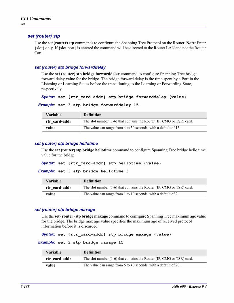
5-138 Adit 600 - Release 9.4
CLI Commandsset
set (router) stpUse the set (router) stp commands to configure the Spanning Tree Protocol on the Router. Note: Enter slot only. If slot:port is entered the command will be directed to the Router LAN and not the Router Card.
set (router) stp bridge forwarddelayUse the set (router) stp bridge forwarddelay command to configure Spanning Tree bridge forward delay value for the bridge. The bridge forward delay is the time spent by a Port in the Listening or Learning States before the transitioning to the Learning or Forwarding State, respectively.
Syntax: set rtr_card-addr stp bridge forwarddelay value
Example: set 3 stp bridge forwarddelay 15
set (router) stp bridge hellotimeUse the set (router) stp bridge hellotime command to configure Spanning Tree bridge hello time value for the bridge.
Syntax: set rtr_card-addr stp hellotime value
Example: set 3 stp bridge hellotime 3
set (router) stp bridge maxageUse the set (router) stp bridge maxage command to configure Spanning Tree maximum age value for the bridge. The bridge max age value specifies the maximum age of received protocol information before it is discarded.
Syntax: set rtr_card-addr stp bridge maxage value
Example: set 3 stp bridge maxage 15
Variable Definitionrtr_card-addr The slot number (1-6) that contains the Router (IP, CMG or TSR) card.
value The value can range from 4 to 30 seconds, with a default of 15.
Variable Definitionrtr_card-addr The slot number (1-6) that contains the Router (IP, CMG or TSR) card.
value The value can range from 1 to 10 seconds, with a default of 2.
Variable Definitionrtr_card-addr The slot number (1-6) that contains the Router (IP, CMG or TSR) card.
value The value can range from 6 to 40 seconds, with a default of 20.

Adit 600 - Release 9.4 5-139
CLI Commandsset
set (router) stp bridge priorityUse the set (router) stp bridge priority command to configure Spanning Tree priority value for the bridge.
Syntax: set rtr_card-addr stp priority value
Example: set 3 stp bridge priority 32768
set (router) stp enable/disableUse the set (router) stp enable/disable command to enable and disable Spanning Tree Protocol on the Router.
Syntax: set rtr_card-addr stp disable|enable
Example: set 3 stp enable
Variable Definitionrtr_card-addr The slot number (1-6) that contains the Router (IP, CMG or TSR) card.
value The value can range from 0 to 65535, with a default of 32768.
Variable Definitionrtr_card-addr The slot number (1-6) that contains the Router (IP, CMG or TSR) card. Note:
Enter slot only. If slot:port is entered the command will be directed to the Router LAN and not the Router Card.
disable Disable Spanning Tree protocol
enable Enable Spanning Tree protocol
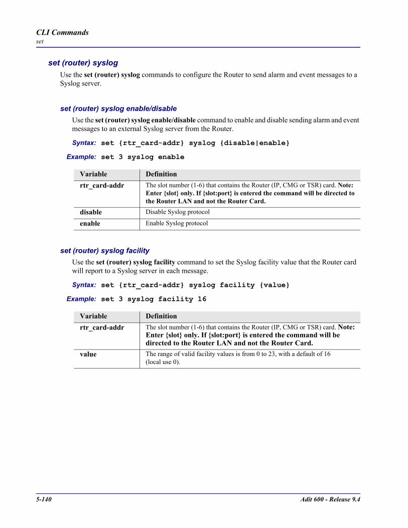
5-140 Adit 600 - Release 9.4
CLI Commandsset
set (router) syslogUse the set (router) syslog commands to configure the Router to send alarm and event messages to a Syslog server.
set (router) syslog enable/disableUse the set (router) syslog enable/disable command to enable and disable sending alarm and event messages to an external Syslog server from the Router.
Syntax: set rtr_card-addr syslog disable|enable
Example: set 3 syslog enable
set (router) syslog facilityUse the set (router) syslog facility command to set the Syslog facility value that the Router card will report to a Syslog server in each message.
Syntax: set rtr_card-addr syslog facility value
Example: set 3 syslog facility 16
Variable Definitionrtr_card-addr The slot number (1-6) that contains the Router (IP, CMG or TSR) card. Note:
Enter slot only. If slot:port is entered the command will be directed to the Router LAN and not the Router Card.
disable Disable Syslog protocol
enable Enable Syslog protocol
Variable Definitionrtr_card-addr The slot number (1-6) that contains the Router (IP, CMG or TSR) card. Note:
Enter slot only. If slot:port is entered the command will be directed to the Router LAN and not the Router Card.
value The range of valid facility values is from 0 to 23, with a default of 16(local use 0).
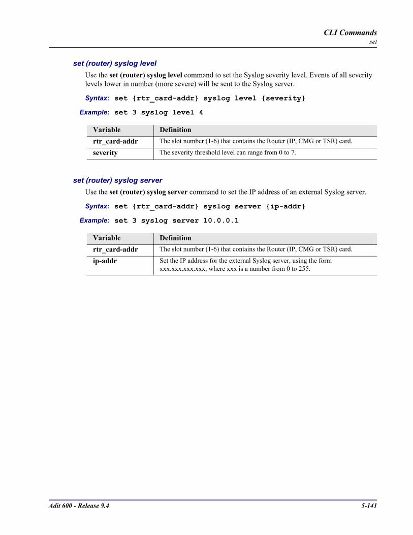
Adit 600 - Release 9.4 5-141
CLI Commandsset
set (router) syslog levelUse the set (router) syslog level command to set the Syslog severity level. Events of all severity levels lower in number (more severe) will be sent to the Syslog server.
Syntax: set rtr_card-addr syslog level severity
Example: set 3 syslog level 4
set (router) syslog serverUse the set (router) syslog server command to set the IP address of an external Syslog server.
Syntax: set rtr_card-addr syslog server ip-addr
Example: set 3 syslog server 10.0.0.1
Variable Definitionrtr_card-addr The slot number (1-6) that contains the Router (IP, CMG or TSR) card.
severity The severity threshold level can range from 0 to 7.
Variable Definitionrtr_card-addr The slot number (1-6) that contains the Router (IP, CMG or TSR) card.
ip-addr Set the IP address for the external Syslog server, using the form xxx.xxx.xxx.xxx, where xxx is a number from 0 to 255.
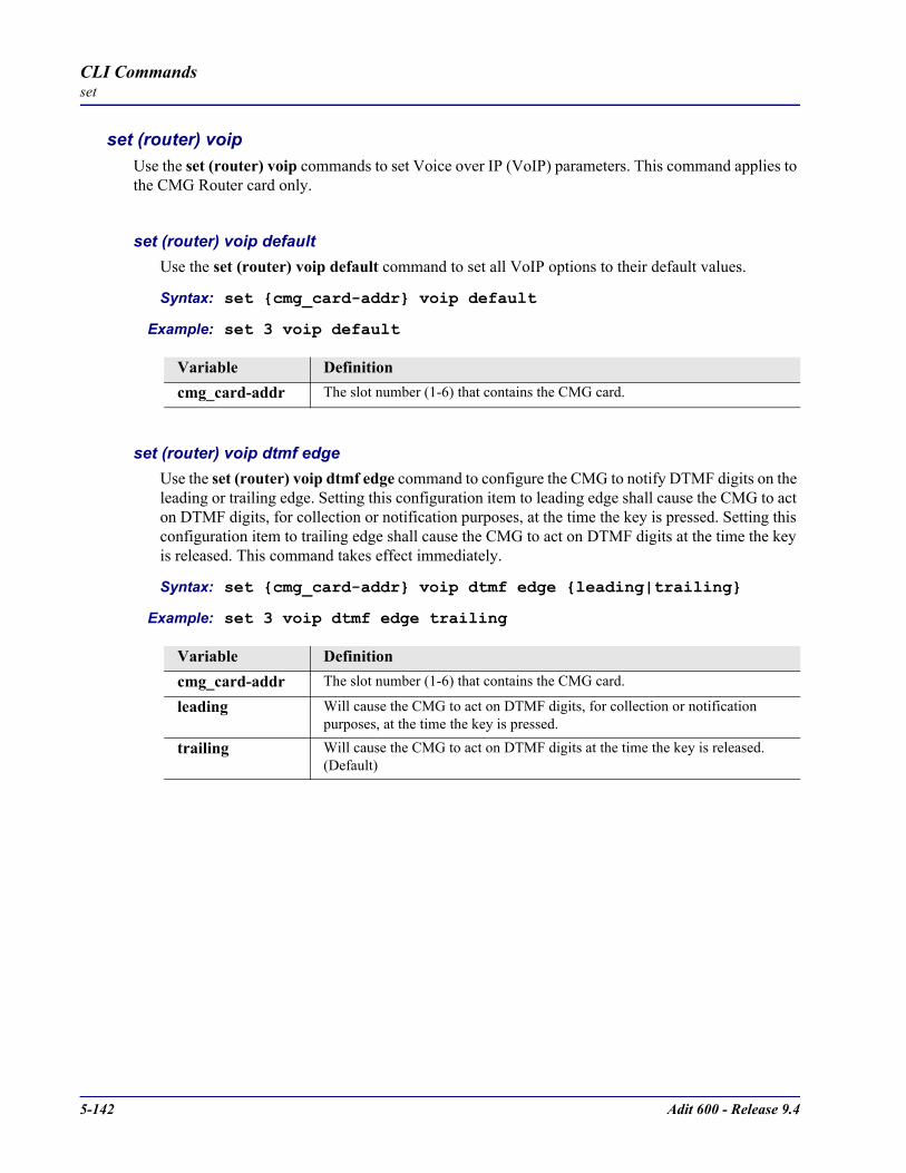
5-142 Adit 600 - Release 9.4
CLI Commandsset
set (router) voipUse the set (router) voip commands to set Voice over IP (VoIP) parameters. This command applies to the CMG Router card only.
set (router) voip defaultUse the set (router) voip default command to set all VoIP options to their default values.
Syntax: set cmg_card-addr voip default
Example: set 3 voip default
set (router) voip dtmf edgeUse the set (router) voip dtmf edge command to configure the CMG to notify DTMF digits on the leading or trailing edge. Setting this configuration item to leading edge shall cause the CMG to act on DTMF digits, for collection or notification purposes, at the time the key is pressed. Setting this configuration item to trailing edge shall cause the CMG to act on DTMF digits at the time the key is released. This command takes effect immediately.
Syntax: set cmg_card-addr voip dtmf edge leading|trailing
Example: set 3 voip dtmf edge trailing
Variable Definitioncmg_card-addr The slot number (1-6) that contains the CMG card.
Variable Definitioncmg_card-addr The slot number (1-6) that contains the CMG card.
leading Will cause the CMG to act on DTMF digits, for collection or notification purposes, at the time the key is pressed.
trailing Will cause the CMG to act on DTMF digits at the time the key is released. (Default)
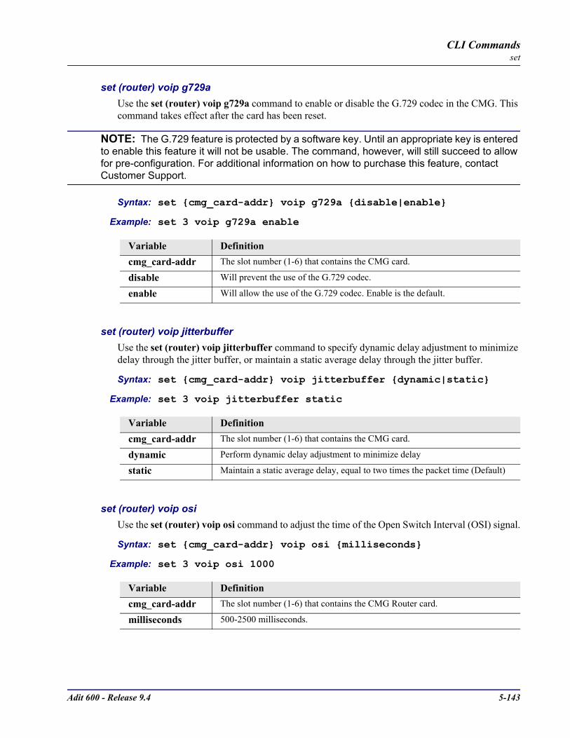
Adit 600 - Release 9.4 5-143
CLI Commandsset
set (router) voip g729aUse the set (router) voip g729a command to enable or disable the G.729 codec in the CMG. This command takes effect after the card has been reset.
NOTE: The G.729 feature is protected by a software key. Until an appropriate key is entered to enable this feature it will not be usable. The command, however, will still succeed to allow for pre-configuration. For additional information on how to purchase this feature, contact Customer Support.
Syntax: set cmg_card-addr voip g729a disable|enable
Example: set 3 voip g729a enable
set (router) voip jitterbufferUse the set (router) voip jitterbuffer command to specify dynamic delay adjustment to minimize delay through the jitter buffer, or maintain a static average delay through the jitter buffer.
Syntax: set cmg_card-addr voip jitterbuffer dynamic|static
Example: set 3 voip jitterbuffer static
set (router) voip osiUse the set (router) voip osi command to adjust the time of the Open Switch Interval (OSI) signal.
Syntax: set cmg_card-addr voip osi milliseconds
Example: set 3 voip osi 1000
Variable Definitioncmg_card-addr The slot number (1-6) that contains the CMG card.
disable Will prevent the use of the G.729 codec.
enable Will allow the use of the G.729 codec. Enable is the default.
Variable Definitioncmg_card-addr The slot number (1-6) that contains the CMG card.
dynamic Perform dynamic delay adjustment to minimize delay
static Maintain a static average delay, equal to two times the packet time (Default)
Variable Definitioncmg_card-addr The slot number (1-6) that contains the CMG Router card.
milliseconds 500-2500 milliseconds.

5-144 Adit 600 - Release 9.4
CLI Commandsset
set (router) voip packingUse the set (router) voip packing command to configure the packing order for g726 voice coding algorithms. The new default packing order for each voice coding algorithm is Big Endian. Note that when upgrading from CMG version 1.0 the packing order for G.726-32 will be Little Endian until changed by the user to load defaults is issued.This command applies to the CMG Router card only.
Syntax: set cmg_card-addr voip packing g726_40|g726_32|g726_24|g726_16 bigendian|littleendian
Example: set 3 voip packing g726_32 bigendian
set (router) voip payload typeUse the set (router) voip payload type command to configure whether or not the CMG will process RTP packets with invalid payload types in the RTP header. This command applies to the CMG Router card only.
Syntax: set cmg_card-addr voip payload type lenient|strict
Example: set 3 voip payload type lenient
Variable Definitioncmg_card-addr The slot number (1-6) that contains the CMG card.
g726_40 G.726 coding for voice channels at 40 Kbps
g726_32 G.726 coding for voice channels at 32 Kbps
g726_24 G.726 coding for voice channels at 24 Kbps
g726_16 G.726 coding for voice channels at 16 Kbps
bigendian Use big-endian packing for this codec
littleendian Use little-endian packing for this codec
Variable Definitioncmg_card-addr The slot number (1-6) that contains the CMG card.
lenient Process packets with invalid payload type
strict Do not process packets with invalid payload type (Default)

Adit 600 - Release 9.4 5-145
CLI Commandsset
set (router) voip ptimeUse the set (router) voip ptime command to specify the default packetization time for the specified algorithm. The packetization time determines the frequency at which RTP packets are transmitted. The MGCP call agent may override the new default set by this command on a call-by-call basis. At the end of a call, the configured default is back in force. This command takes effect immediately.
NOTE: The G.729 feature is protected by a software key. Until an appropriate key is entered to enable this feature is will not be usable. The command, however, will still succeed to allow for pre-configuration. For additional information on how to purchase this feature, contact Customer Support.
Syntax: set cmg_card-addr voip ptime g711a|g711mu|g726_16 |g726_24|g726_32|g726_40|g729a|all time
Example: set 3 voip ptime g711mu 20
set (router) voip rtcp cnameUse the set (router) voip rtcp cname command to specify the name to be used for the CNAME field of Real Time Conferencing Protocol (RTCP) packets.
Syntax: set cmg_card-addr voip rtcp cname gatewayid|”name”
Example: set 3 voip rtcp cname gatewayid
Variable Definitioncmg_card-addr The slot number (1-6) that contains the CMG card.
g711a Set packetization time for G.711 A-law
g711mu Set packetization time for G.711 mu-law
g726_16 Set packetization time for G.726 16 Kbps
g726_24 Set packetization time for G.726 24 Kbps
g726_32 Set packetization time for G.726 32 Kbps
g726_40 Set packetization time for G.726 40 Kbps
g729a Set packetization time for G.729 8 Kbps
all Set packetization time for all algorithms
time Default packetization time in milliseconds. Valid values are 10, 20, 30, 40, 50, 60, 70, or 80 milliseconds. Where 40 through 80 are only valid for g729a
Variable Definitioncmg_card-addr The slot number (1-6) that contains the CMG card.
gatewayid Use the gateway ID in the CNAME. Default.
name Identifying the gateway, maximum 63 characters, enclosed in quotes.

5-146 Adit 600 - Release 9.4
CLI Commandsset
set (router) voip rtcp intervalUse the set (router) voip rtcp interval command to specify the time interval between RTCP reports.
Syntax: set cmg_card-addr voip rtcp interval seconds
Example: set 3 voip rtcp interval 0
set (router) voip rtp baseportUse the set (router) voip rtp baseport command to specify the base UDP port to be used when allocating ports for transmitting or receiving RTP (Realtime Transport Protocol) packet streams in VoIP calls. All ports allocated for RTP, including the base port, must be even-numbered. Each allocated RTP port number will be equal to the base port plus some even offset. The odd port number just above each allocated RTP port will be used for sending or receiving RTCP packets, which contain reports of packet and performance statistics for the associated RTP. The CMG will reserve a block of 288 consecutive ports starting at this port for RTP and RTCP.
Syntax: set cmg_card-addr voip rtp baseport port-number
Example: set 5 voip rtp baseport 10000
Variable Definitioncmg_card-addr The slot number (1-6) that contains the CMG card.
seconds Interval time is in seconds, range is 0 to 255. If zero, RTCP reporting is turned off. Default is 5 seconds.
Variable Definitioncmg_card-addr The slot number (1-6) that contains the CMG card.
port-number The port number range is from 0 to 65535. Default is 30000.

Adit 600 - Release 9.4 5-147
CLI Commandsset
set (router) voip rtpmapUse the set (router) voip rtpmap command to specify the dynamic payload type and name to be used for a specific algorithm in the Session Description Protocol (SDP) part of MGCP connection commands. This command takes effect immediately. The defaults are:
NOTE: In accordance with current IANA assignments (www.iana.org, RTP section), G.726-32 kb/s is assigned a (non-dynamic) payload type of 2, G.711 mu-law is assigned payload type 0, and G.711 A-law is assigned payload type 8. (a dynamic payload type to G.726-32 can be assigned by means of the above command, in case of conflict with payload type 2, formerly assigned to G.721, in RFC 1890.) Only one payload type and DSP name may be assigned per algorithm.
NOTE: The G.729 feature is protected by a software key. Until an appropriate key is entered to enable this feature is will not be usable. The command, however, will still succeed to allow for pre-configuration. For additional information on how to purchase this feature, contact Customer Support.
Syntax: set cmg_card-addr voip rtpmap dtmf_relay|g711a|g711mu| g726_16|g726_24|g726_32|g726_40|g729a|nse type “name”
Example: set 3 voip rtpmap g726_16 96 “G.726-16”
Algorithm Payload Type SDP Name
G.726-16 kb/s 102 G726-16
G.726-24 kb/s 97 G726-24
G.726-40 kb/s 98 G726-40
G.729A 18 G729A
Variable Definitioncmg_card-addr The slot number (1-6) that contains the CMG card.
dtmf_relay Set payload type and name for the DTMF Relay.
g711a Set payload type and name for G.711 A-law.
g711mu Set payload type and name for G.726 µ-law.
g726_16 Set payload type and name for G.726 16kbps.
g726_24 Set payload type and name for G.726 24kbps.
g726_32 Set payload type and name for G.726 32kbps.
g726_40 Set payload type and name for G.726 40kbps.
g729a Set payload type and name for G.729 A.
nse Set payload type and name for the Named Service Event (NSE). Type ranges is 98-119, with a default of 100.
type RTP dynamic payload type, Range is 0 - 12, unless otherwise listed above.
name Identifier up to 15 characters, enclosed in quotes.

5-148 Adit 600 - Release 9.4
CLI Commandsset
set (router) voip sdpaddressUse the set (router) voip sdpaddress command to set the address value to be used for the origin and connection lines in the SDP.
Syntax: set cmg_card-addr voip sdpaddress gatewayid|domain-name|ip|ip-addr
Example: set 3 voip sdpaddress domainname
set (router) voip t38 ecmUse the set (router) voip t38 ecm command to enable or disable the CMG's fax T.38 Error Correction Mode (ECM) capability during fax negotiation for the entire card. This command requires a reset to take effect.
Syntax: set cmg_card-addr voip t38 ecm disable|enable
Example: set 3 voip t38 ecm enable
Variable Definitioncmg_card-addr The slot number (1-6) that contains the CMG card.
domainname Use the DNS domain name if DNS is enabled or DMG IP address if DNS is disabled.
gatewayid Use the MGCP gateway ID.
ip Use the CMG IP address.
ip-addr Use this IP address, in the form xxx.xxx.xxx.xxx, where xxx is a number from0 - 255.
Variable Definitiondisable Disable the CMG’s fax T.38 error correction mode.
enable This setting allows the user to accept/attempt ECM T38 negotiation. It should be noted that when ECM is enabled, the fax call might train at a lower speed, thus lengthening the overall fax call time. Enable is the default.
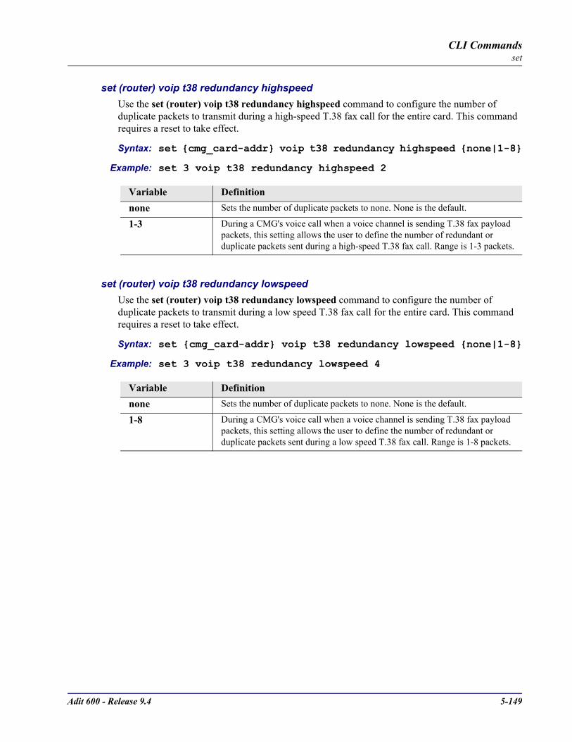
Adit 600 - Release 9.4 5-149
CLI Commandsset
set (router) voip t38 redundancy highspeedUse the set (router) voip t38 redundancy highspeed command to configure the number of duplicate packets to transmit during a high-speed T.38 fax call for the entire card. This command requires a reset to take effect.
Syntax: set cmg_card-addr voip t38 redundancy highspeed none|1-8
Example: set 3 voip t38 redundancy highspeed 2
set (router) voip t38 redundancy lowspeedUse the set (router) voip t38 redundancy lowspeed command to configure the number of duplicate packets to transmit during a low speed T.38 fax call for the entire card. This command requires a reset to take effect.
Syntax: set cmg_card-addr voip t38 redundancy lowspeed none|1-8
Example: set 3 voip t38 redundancy lowspeed 4
Variable Definitionnone Sets the number of duplicate packets to none. None is the default.
1-3 During a CMG's voice call when a voice channel is sending T.38 fax payload packets, this setting allows the user to define the number of redundant or duplicate packets sent during a high-speed T.38 fax call. Range is 1-3 packets.
Variable Definitionnone Sets the number of duplicate packets to none. None is the default.
1-8 During a CMG's voice call when a voice channel is sending T.38 fax payload packets, this setting allows the user to define the number of redundant or duplicate packets sent during a low speed T.38 fax call. Range is 1-8 packets.
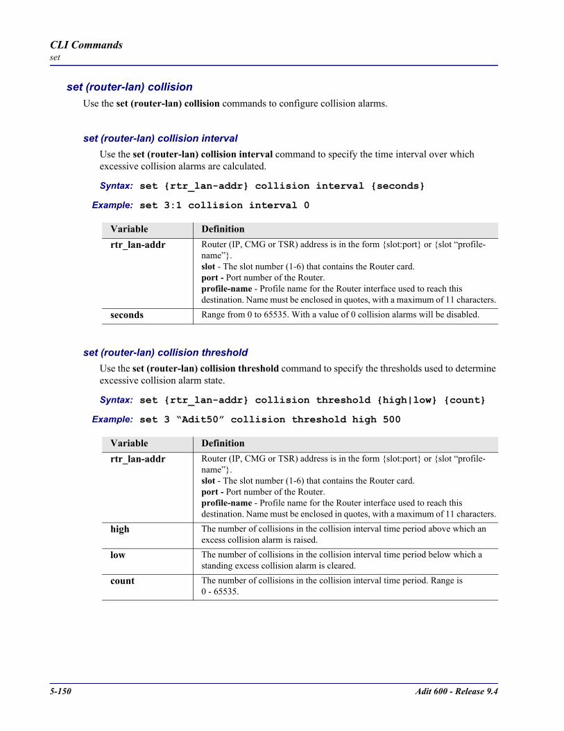
5-150 Adit 600 - Release 9.4
CLI Commandsset
set (router-lan) collision Use the set (router-lan) collision commands to configure collision alarms.
set (router-lan) collision interval Use the set (router-lan) collision interval command to specify the time interval over which excessive collision alarms are calculated.
Syntax: set rtr_lan-addr collision interval seconds
Example: set 3:1 collision interval 0
set (router-lan) collision threshold Use the set (router-lan) collision threshold command to specify the thresholds used to determine excessive collision alarm state.
Syntax: set rtr_lan-addr collision threshold high|low count
Example: set 3 “Adit50” collision threshold high 500
Variable Definitionrtr_lan-addr Router (IP, CMG or TSR) address is in the form slot:port or slot “profile-
name”.slot - The slot number (1-6) that contains the Router card.port - Port number of the Router.profile-name - Profile name for the Router interface used to reach this destination. Name must be enclosed in quotes, with a maximum of 11 characters.
seconds Range from 0 to 65535. With a value of 0 collision alarms will be disabled.
Variable Definitionrtr_lan-addr Router (IP, CMG or TSR) address is in the form slot:port or slot “profile-
name”.slot - The slot number (1-6) that contains the Router card.port - Port number of the Router.profile-name - Profile name for the Router interface used to reach this destination. Name must be enclosed in quotes, with a maximum of 11 characters.
high The number of collisions in the collision interval time period above which an excess collision alarm is raised.
low The number of collisions in the collision interval time period below which a standing excess collision alarm is cleared.
count The number of collisions in the collision interval time period. Range is 0 - 65535.
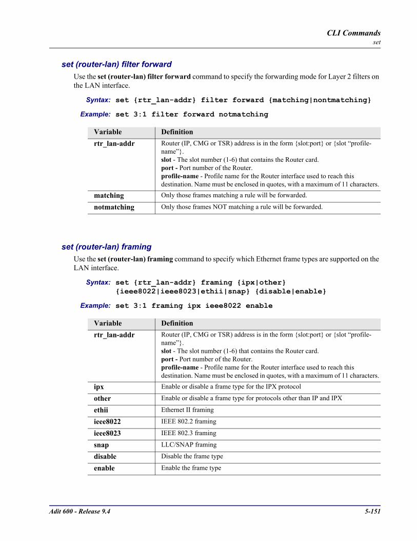
Adit 600 - Release 9.4 5-151
CLI Commandsset
set (router-lan) filter forwardUse the set (router-lan) filter forward command to specify the forwarding mode for Layer 2 filters on the LAN interface.
Syntax: set rtr_lan-addr filter forward matching|nontmatching
Example: set 3:1 filter forward notmatching
set (router-lan) framingUse the set (router-lan) framing command to specify which Ethernet frame types are supported on the LAN interface.
Syntax: set rtr_lan-addr framing ipx|other ieee8022|ieee8023|ethii|snap disable|enable
Example: set 3:1 framing ipx ieee8022 enable
Variable Definitionrtr_lan-addr Router (IP, CMG or TSR) address is in the form slot:port or slot “profile-
name”.slot - The slot number (1-6) that contains the Router card.port - Port number of the Router.profile-name - Profile name for the Router interface used to reach this destination. Name must be enclosed in quotes, with a maximum of 11 characters.
matching Only those frames matching a rule will be forwarded.
notmatching Only those frames NOT matching a rule will be forwarded.
Variable Definitionrtr_lan-addr Router (IP, CMG or TSR) address is in the form slot:port or slot “profile-
name”.slot - The slot number (1-6) that contains the Router card.port - Port number of the Router.profile-name - Profile name for the Router interface used to reach this destination. Name must be enclosed in quotes, with a maximum of 11 characters.
ipx Enable or disable a frame type for the IPX protocol
other Enable or disable a frame type for protocols other than IP and IPX
ethii Ethernet II framing
ieee8022 IEEE 802.2 framing
ieee8023 IEEE 802.3 framing
snap LLC/SNAP framing
disable Disable the frame type
enable Enable the frame type

5-152 Adit 600 - Release 9.4
CLI Commandsset
set (router-lan) gatewayUse the set (router-lan) gateway command to specify a default IP gateway for the specified LAN interface. If there is no static network entry to 0.0.0.0, then this address is used as the default gateway for packets with no explicit route.
Syntax: set rtr_lan-addr gateway ip-addr
Example: set 3:1 gateway 192.168.201.144
set (router-lan) ip addressUse the set (router-lan) ip address command to specify an IP address for the specified LAN interface. When first installed the Router card’s LAN interface has a default IP address of 10.0.0.1 with subnet mask of 255.0.0.0.
Syntax: set rtr_lan-addr ip address ip-addr [mask]
Example: set 3:1 ip address 192.168.202.244 255.255.255.0
Variable Definitionrtr_lan-addr Router (IP, CMG or TSR) address is in the form slot:port or slot “profile-
name”.slot - The slot number (1-6) that contains the Router card.port - Port number of the Router.profile-name - Profile name for the Router interface used to reach this destination. Name must be enclosed in quotes, with a maximum of 11 characters.
ip-addr The IP address of the gateway, in the form of xxx.xxx.xxx.xxx, where xxx is between 0-255.
Variable Definitionrtr_lan-addr Router (IP, CMG or TSR) address is in the form slot:port or slot “profile-
name”.slot - The slot number (1-6) that contains the Router card.port - Port number of the Router.profile-name - Profile name for the Router interface used to reach this destination. Name must be enclosed in quotes, with a maximum of 11 characters.
ip-addr The Router IP address, in the form of xxx.xxx.xxx.xxx, where xxx is between 0-255.
mask The subnet mask, in the form of xxx.xxx.xxx.xxx, where xxx is between 0-255
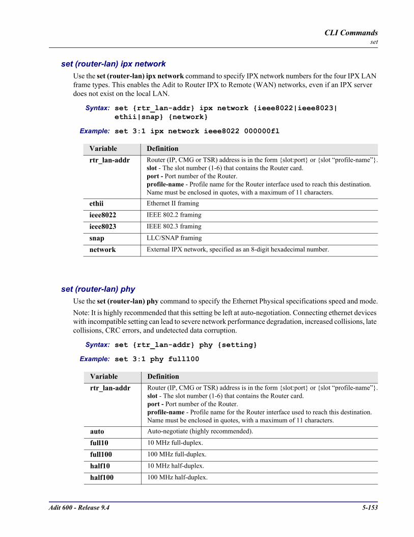
Adit 600 - Release 9.4 5-153
CLI Commandsset
set (router-lan) ipx networkUse the set (router-lan) ipx network command to specify IPX network numbers for the four IPX LAN frame types. This enables the Adit to Router IPX to Remote (WAN) networks, even if an IPX server does not exist on the local LAN.
Syntax: set rtr_lan-addr ipx network ieee8022|ieee8023| ethii|snap network
Example: set 3:1 ipx network ieee8022 000000fl
set (router-lan) phyUse the set (router-lan) phy command to specify the Ethernet Physical specifications speed and mode.Note: It is highly recommended that this setting be left at auto-negotiation. Connecting ethernet devices with incompatible setting can lead to severe network performance degradation, increased collisions, late collisions, CRC errors, and undetected data corruption.
Syntax: set rtr_lan-addr phy setting
Example: set 3:1 phy full100
Variable Definitionrtr_lan-addr Router (IP, CMG or TSR) address is in the form slot:port or slot “profile-name”.
slot - The slot number (1-6) that contains the Router card.port - Port number of the Router.profile-name - Profile name for the Router interface used to reach this destination. Name must be enclosed in quotes, with a maximum of 11 characters.
ethii Ethernet II framing
ieee8022 IEEE 802.2 framing
ieee8023 IEEE 802.3 framing
snap LLC/SNAP framing
network External IPX network, specified as an 8-digit hexadecimal number.
Variable Definitionrtr_lan-addr Router (IP, CMG or TSR) address is in the form slot:port or slot “profile-name”.
slot - The slot number (1-6) that contains the Router card.port - Port number of the Router.profile-name - Profile name for the Router interface used to reach this destination. Name must be enclosed in quotes, with a maximum of 11 characters.
auto Auto-negotiate (highly recommended).
full10 10 MHz full-duplex.
full100 100 MHz full-duplex.
half10 10 MHz half-duplex.
half100 100 MHz half-duplex.
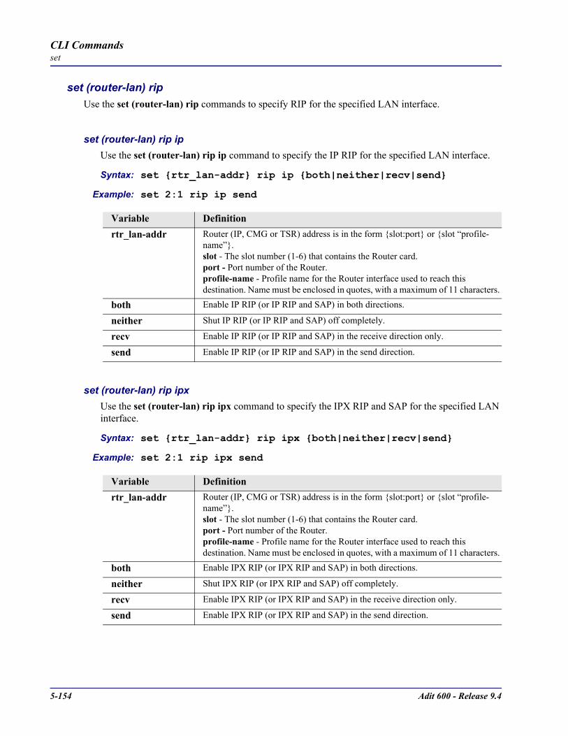
5-154 Adit 600 - Release 9.4
CLI Commandsset
set (router-lan) ripUse the set (router-lan) rip commands to specify RIP for the specified LAN interface.
set (router-lan) rip ip Use the set (router-lan) rip ip command to specify the IP RIP for the specified LAN interface.
Syntax: set rtr_lan-addr rip ip both|neither|recv|send
Example: set 2:1 rip ip send
set (router-lan) rip ipx Use the set (router-lan) rip ipx command to specify the IPX RIP and SAP for the specified LAN interface.
Syntax: set rtr_lan-addr rip ipx both|neither|recv|send
Example: set 2:1 rip ipx send
Variable Definitionrtr_lan-addr Router (IP, CMG or TSR) address is in the form slot:port or slot “profile-
name”.slot - The slot number (1-6) that contains the Router card.port - Port number of the Router.profile-name - Profile name for the Router interface used to reach this destination. Name must be enclosed in quotes, with a maximum of 11 characters.
both Enable IP RIP (or IP RIP and SAP) in both directions.
neither Shut IP RIP (or IP RIP and SAP) off completely.
recv Enable IP RIP (or IP RIP and SAP) in the receive direction only.
send Enable IP RIP (or IP RIP and SAP) in the send direction.
Variable Definitionrtr_lan-addr Router (IP, CMG or TSR) address is in the form slot:port or slot “profile-
name”.slot - The slot number (1-6) that contains the Router card.port - Port number of the Router.profile-name - Profile name for the Router interface used to reach this destination. Name must be enclosed in quotes, with a maximum of 11 characters.
both Enable IPX RIP (or IPX RIP and SAP) in both directions.
neither Shut IPX RIP (or IPX RIP and SAP) off completely.
recv Enable IPX RIP (or IPX RIP and SAP) in the receive direction only.
send Enable IPX RIP (or IPX RIP and SAP) in the send direction.

Adit 600 - Release 9.4 5-155
CLI Commandsset
set (router-lan) stpUse the set (router-lan) stp commands to configure the Spanning Tree Protocol on this interface.
set (router-lan) stp enable/disableUse the set (router-lan) stp enable/disable command to enable/disable Spanning Tree Protocol on this interface. To enable STP on an interface it must be enabled globally with the set (router) stp enable command.
Syntax: set rtr_lan-addr stp disable|enable
Example: set 3:1 stp enable
set (router-lan) stp port costUse the set (router-lan) stp port cost command to configure Spanning Tree path cost value for this bridge port.
Syntax: set rtr_lan-addr stp port cost port-cost-value
Example: set 3:1 stp port cost 100
Variable Definitionrtr_lan-addr Router (IP, CMG or TSR) address is in the form slot:port or slot “profile-
name”.slot - The slot number (1-6) that contains the Router card.port - Port number of the Router.profile-name - Profile name for the Router interface used to reach this destination. Name must be enclosed in quotes, with a maximum of 11 characters.
disable Disable Spanning Tree on this interface.
enable Enable Spanning Tree on this interface.
Variable Definitionrtr_lan-addr Router (IP, CMG or TSR) address is in the form slot:port or slot “profile-
name”.slot - The slot number (1-6) that contains the Router card.port - Port number of the Router.profile-name - Profile name for the Router interface used to reach this destination. Name must be enclosed in quotes, with a maximum of 11 characters.
port-cost-value The value can range from 1 to 65535, higher values represent slower data paths. For a 100 Mb LAN a value of 19 is recommended. For a 10 Mb LAN a value of 100 is recommended
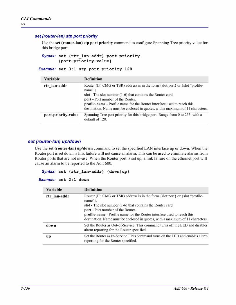
5-156 Adit 600 - Release 9.4
CLI Commandsset
set (router-lan) stp port priorityUse the set (router-lan) stp port priority command to configure Spanning Tree priority value for this bridge port.
Syntax: set rtr_lan-addr port priority port-priority-value
Example: set 3:1 stp port priority 128
set (router-lan) up/downUse the set (router-lan) up/down command to set the specified LAN interface up or down. When the Router port is set down, a link failure will not cause an alarm. This can be used to eliminate alarms from Router ports that are not in-use. When the Router port is set up, a link failure on the ethernet port will cause an alarm to be reported to the Adit 600.
Syntax: set rtr_lan-addr down|up
Example: set 2:1 down
Variable Definitionrtr_lan-addr Router (IP, CMG or TSR) address is in the form slot:port or slot “profile-
name”.slot - The slot number (1-6) that contains the Router card.port - Port number of the Router.profile-name - Profile name for the Router interface used to reach this destination. Name must be enclosed in quotes, with a maximum of 11 characters.
port-priority-value Spanning Tree port priority for this bridge port. Range from 0 to 255, with a default of 128.
Variable Definitionrtr_lan-addr Router (IP, CMG or TSR) address is in the form slot:port or slot “profile-
name”.slot - The slot number (1-6) that contains the Router card.port - Port number of the Router.profile-name - Profile name for the Router interface used to reach this destination. Name must be enclosed in quotes, with a maximum of 11 characters.
down Set the Router as Out-of-Service. This command turns off the LED and disables alarm reporting for the Router specified.
up Set the Router as In-Service. This command turns on the LED and enables alarm reporting for the Router specified.
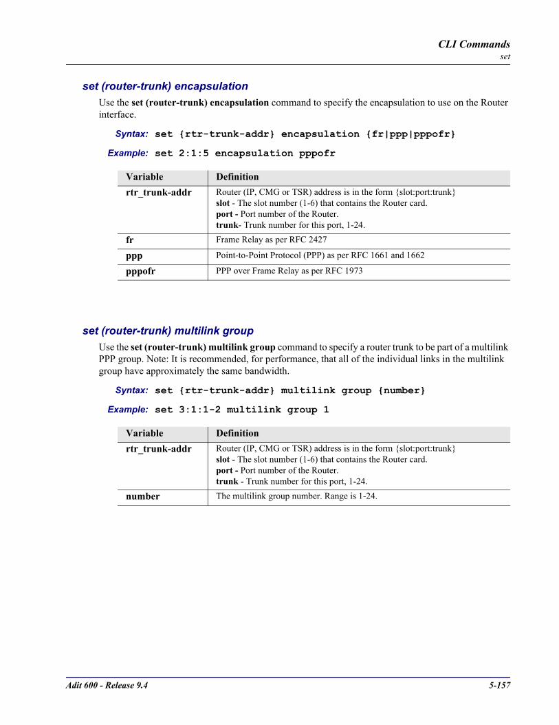
Adit 600 - Release 9.4 5-157
CLI Commandsset
set (router-trunk) encapsulationUse the set (router-trunk) encapsulation command to specify the encapsulation to use on the Router interface.
Syntax: set rtr-trunk-addr encapsulation fr|ppp|pppofr
Example: set 2:1:5 encapsulation pppofr
set (router-trunk) multilink groupUse the set (router-trunk) multilink group command to specify a router trunk to be part of a multilink PPP group. Note: It is recommended, for performance, that all of the individual links in the multilink group have approximately the same bandwidth.
Syntax: set rtr-trunk-addr multilink group number
Example: set 3:1:1-2 multilink group 1
Variable Definitionrtr_trunk-addr Router (IP, CMG or TSR) address is in the form slot:port:trunk
slot - The slot number (1-6) that contains the Router card.port - Port number of the Router.trunk- Trunk number for this port, 1-24.
fr Frame Relay as per RFC 2427
ppp Point-to-Point Protocol (PPP) as per RFC 1661 and 1662
pppofr PPP over Frame Relay as per RFC 1973
Variable Definitionrtr_trunk-addr Router (IP, CMG or TSR) address is in the form slot:port:trunk
slot - The slot number (1-6) that contains the Router card.port - Port number of the Router.trunk - Trunk number for this port, 1-24.
number The multilink group number. Range is 1-24.
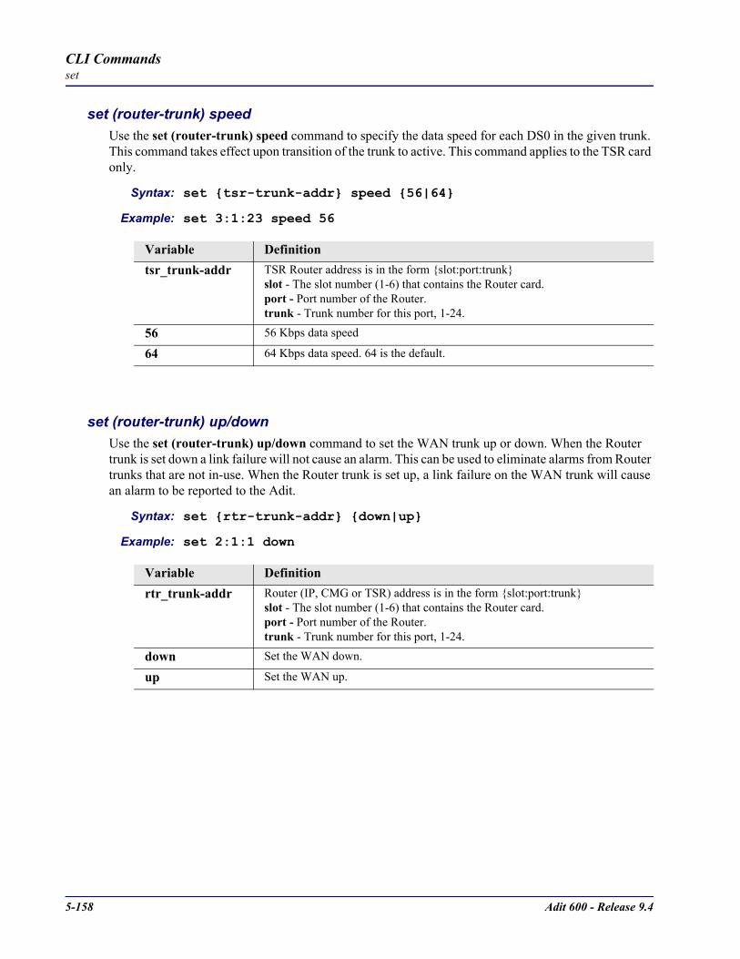
5-158 Adit 600 - Release 9.4
CLI Commandsset
set (router-trunk) speedUse the set (router-trunk) speed command to specify the data speed for each DS0 in the given trunk. This command takes effect upon transition of the trunk to active. This command applies to the TSR card only.
Syntax: set tsr-trunk-addr speed 56|64
Example: set 3:1:23 speed 56
set (router-trunk) up/downUse the set (router-trunk) up/down command to set the WAN trunk up or down. When the Router trunk is set down a link failure will not cause an alarm. This can be used to eliminate alarms from Router trunks that are not in-use. When the Router trunk is set up, a link failure on the WAN trunk will cause an alarm to be reported to the Adit.
Syntax: set rtr-trunk-addr down|up
Example: set 2:1:1 down
Variable Definitiontsr_trunk-addr TSR Router address is in the form slot:port:trunk
slot - The slot number (1-6) that contains the Router card.port - Port number of the Router.trunk - Trunk number for this port, 1-24.
56 56 Kbps data speed
64 64 Kbps data speed. 64 is the default.
Variable Definitionrtr_trunk-addr Router (IP, CMG or TSR) address is in the form slot:port:trunk
slot - The slot number (1-6) that contains the Router card.port - Port number of the Router.trunk - Trunk number for this port, 1-24.
down Set the WAN down.
up Set the WAN up.

Adit 600 - Release 9.4 5-159
CLI Commandsset
set (router-trunk) voice bandwidth limitUse the set (router-trunk) voice bandwidth limit command to specify the maximum percentage of bandwidth on this trunk that voice calls are allowed to consume. The remaining percentage of the bandwidth on a CMG trunk to be reserved for routed or bridged data. Routed or bridged data is allowed to use any available bandwidth, but it is carried at a lower priority than the voice. If the bandwidth required to carry an additional VoIP call will put the total bandwidth used by VoIP calls above that allowed for voice on the trunk, then the call will be denied and the caller will hear the all-circuits-busy tone. This command applies to the CMG Router card only.
Syntax: set cmg-trunk-addr voice bandwidth limit percent
Example: set 2:1:1 voice bandwidth limit 90
Variable Definitioncmg_trunk-addr CMG Router address is in the form slot:port:trunk
slot - The slot number (1-6) that contains the Router card.port - Port number of the Router.trunk - Trunk number for this port, 1-24.
percent The maximum percentage of VoIP bandwidth. Range is 0 - 100.

5-160 Adit 600 - Release 9.4
CLI Commandsset
set (router-voice) algorithm preferenceUse the set (router-voice) algorithm preference command to specify the list of voice coding algorithms which will be supported for VoIP calls, on the specified voice channel(s). More than one algorithm can be listed, and they should be in order of preference. The default algorithm preference list contains all supported codecs in the order shown below. This command takes effect immediately, and applies to the CMG Router card only.
NOTE: The G.729 feature is protected by a software key. Until an appropriate key is entered to enable this codec will not appear in the available codec list used in the MGCP and DSP messages and negotiation. The command, however, will still succeed to allow for pre-configuration.
Syntax: set cmg_voice-addr algorithm preference alg-choice1 [alg-choice2] [alg-choice3]...
Example: set 2:1:1:1-24 algorithm preference g726_32 g711mu
Variable Definitioncmg_voice-addr In the form slot:voip:channel
slot - The slot number (1-6) that contains the CMG card.voip - To designate VoIP 1:1 is used.channel - Channel number for the router is 1-48, range or all
Algorithms Algorithms are listed in order of preference. Algorithms are used from the following list and can only be listed once.
g711a G.711 A-law PCM - 64 kb/s
g711mu G.711 mu-law PCM - 56 or 64 kb/s
g729a G.729 CS-ACELP - 8 kb/s
g726_40 G.726 ADPCM - 40 kb/s
g726_32 G.726 ADPCM - 32 kb/s
g726_24 G.726 ADPCM - 24 kb/s
g726_16 G.726 ADPCM - 16 kb/s

Adit 600 - Release 9.4 5-161
CLI Commandsset
set (router-voice) cpdUse the set (router-voice) cpd command for configuring how calling party disconnect should be signaled to an endpoint. Calling party disconnect is signaled to a voice endpoint by generating an Open Switch Interval (OSI) ABCD signaling bit pattern. On analog POTS lines this causes the loop to be opened for this interval. The duration of this OSI signal is configurable via the set (router) voip osi command. When set to “disabled” the CMG will never sent the OSI signal to the endpoint. This is appropriate for normal POTS telephones with no automated devices attached. When set to “osi” the CMG will issue the OSI signal to the endpoint only when an L/osi signal request is received from the call agent. This is appropriate when working with a call agent that requests L/osi, but only for endpoints that have automated equipment attached, such as voice mail systems, auto-answering modems, or fax machines. When set to “enabled” the CMG will issue the OSI signal to the endpoint when an L/osi signal request is received from the call agent or after the last connection on that endpoint is deleted. This is appropriate when working with a call agent that does not request L/osi, but only for endpoints that have automated equipment attached, such as voice mail systems, auto-answering modems, or fax machines. This command take effect immediately and applies to the CMG Router card only.
Syntax: set cmg_voice-addr cpd disable|enable|osi
Example: set 2:1:1:1-4 cpd enable
set (router-voice) defaultUse the set (router-voice) default command to reset all CLI accessible options for one or more CMG voice channels to their defaults. Defaults are set for algorithm preference, compander, echo cancellation, echo tail, endpoint prefix, endpoint suffix, silence suppression and TOS. This command applies to the CMG Router card only.
Syntax: set cmg_voice-addr default
Example: set 2:1:1:1-4 default
Variable Definitioncmg_voice-addr In the form slot:voip:channel
slot - The slot number (1-6) that contains the CMG card.voip - To designate VoIP 1:1 is used.channel - Channel number for the router is 1-48, range or all
disabled Do not play CPD on endpoint. Disable is the default.
enable Play CPD on the OSI signal or after the last connection is deleted on endpoint.
osi Play CPD on the OSI signal only.
Variable Definitioncmg_voice-addr In the form slot:voip:channel
slot - The slot number (1-6) that contains the CMG card.voip - To designate VoIP 1:1 is used.channel - Channel number for the router is 1-48, range or all
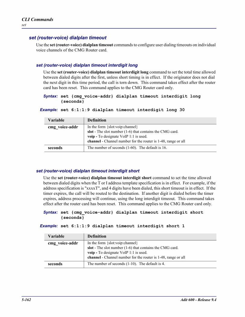
5-162 Adit 600 - Release 9.4
CLI Commandsset
set (router-voice) dialplan timeoutUse the set (router-voice) dialplan timeout commands to configure user dialing timeouts on individual voice channels of the CMG Router card.
set (router-voice) dialplan timeout interdigit longUse the set (router-voice) dialplan timeout interdigit long command to set the total time allowed between dialed digits after the first, unless short timing is in effect. If the originator does not dial the next digit in this time period, the call is torn down. This command takes effect after the router card has been reset. This command applies to the CMG Router card only.
Syntax: set cmg_voice-addr dialplan timeout interdigit long seconds
Example: set 6:1:1:9 dialplan timeout interdigit long 30
set (router-voice) dialplan timeout interdigit shortUse the set (router-voice) dialplan timeout interdigit short command to set the time allowed between dialed digits when the T or I address template specification is in effect. For example, if the address specification is "xxxxT", and 4 digits have been dialed, this short timeout is in effect. If the timer expires, the call will be routed to the destination. If another digit is dialed before the timer expires, address processing will continue, using the long interdigit timeout. This command takes effect after the router card has been reset. This command applies to the CMG Router card only.
Syntax: set cmg_voice-addr dialplan timeout interdigit short seconds
Example: set 6:1:1:9 dialplan timeout interdigit short 1
Variable Definitioncmg_voice-addr In the form slot:voip:channel
slot - The slot number (1-6) that contains the CMG card.voip - To designate VoIP 1:1 is used.channel - Channel number for the router is 1-48, range or all
seconds The number of seconds (1-60). The default is 16.
Variable Definitioncmg_voice-addr In the form slot:voip:channel
slot - The slot number (1-6) that contains the CMG card.voip - To designate VoIP 1:1 is used.channel - Channel number for the router is 1-48, range or all
seconds The number of seconds (1-10). The default is 4.
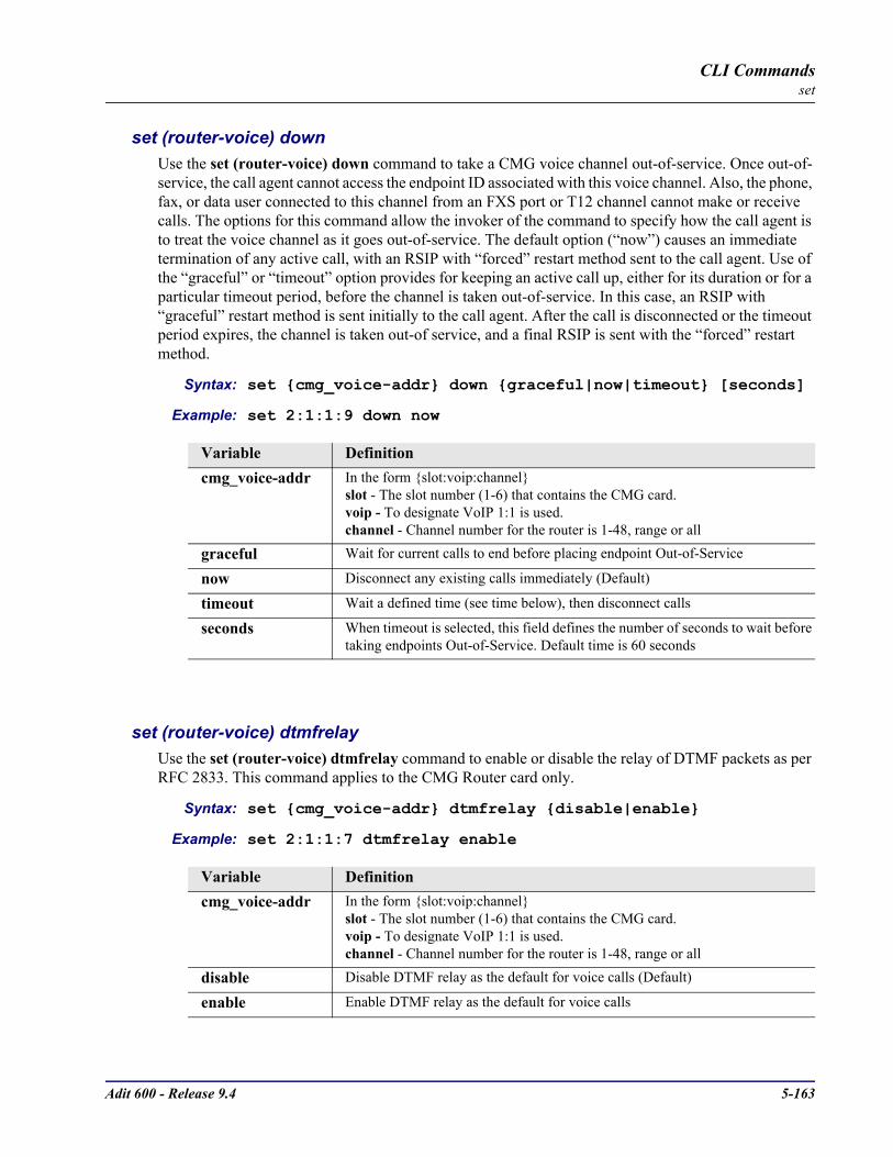
Adit 600 - Release 9.4 5-163
CLI Commandsset
set (router-voice) downUse the set (router-voice) down command to take a CMG voice channel out-of-service. Once out-of-service, the call agent cannot access the endpoint ID associated with this voice channel. Also, the phone, fax, or data user connected to this channel from an FXS port or T12 channel cannot make or receive calls. The options for this command allow the invoker of the command to specify how the call agent is to treat the voice channel as it goes out-of-service. The default option (“now”) causes an immediate termination of any active call, with an RSIP with “forced” restart method sent to the call agent. Use of the “graceful” or “timeout” option provides for keeping an active call up, either for its duration or for a particular timeout period, before the channel is taken out-of-service. In this case, an RSIP with “graceful” restart method is sent initially to the call agent. After the call is disconnected or the timeout period expires, the channel is taken out-of service, and a final RSIP is sent with the “forced” restart method.
Syntax: set cmg_voice-addr down graceful|now|timeout [seconds]
Example: set 2:1:1:9 down now
set (router-voice) dtmfrelayUse the set (router-voice) dtmfrelay command to enable or disable the relay of DTMF packets as per RFC 2833. This command applies to the CMG Router card only.
Syntax: set cmg_voice-addr dtmfrelay disable|enable
Example: set 2:1:1:7 dtmfrelay enable
Variable Definitioncmg_voice-addr In the form slot:voip:channel
slot - The slot number (1-6) that contains the CMG card.voip - To designate VoIP 1:1 is used.channel - Channel number for the router is 1-48, range or all
graceful Wait for current calls to end before placing endpoint Out-of-Service
now Disconnect any existing calls immediately (Default)
timeout Wait a defined time (see time below), then disconnect calls
seconds When timeout is selected, this field defines the number of seconds to wait before taking endpoints Out-of-Service. Default time is 60 seconds
Variable Definitioncmg_voice-addr In the form slot:voip:channel
slot - The slot number (1-6) that contains the CMG card.voip - To designate VoIP 1:1 is used.channel - Channel number for the router is 1-48, range or all
disable Disable DTMF relay as the default for voice calls (Default)
enable Enable DTMF relay as the default for voice calls
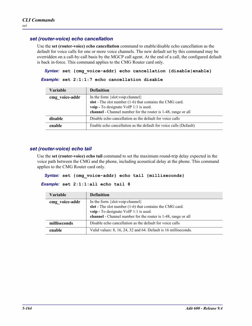
5-164 Adit 600 - Release 9.4
CLI Commandsset
set (router-voice) echo cancellationUse the set (router-voice) echo cancellation command to enable/disable echo cancellation as the default for voice calls for one or more voice channels. The new default set by this command may be overridden on a call-by-call basis by the MGCP call agent. At the end of a call, the configured default is back in-force. This command applies to the CMG Router card only.
Syntax: set cmg_voice-addr echo cancellation disable|enable
Example: set 2:1:1:7 echo cancellation disable
set (router-voice) echo tailUse the set (router-voice) echo tail command to set the maximum round-trip delay expected in the voice path between the CMG and the phone, including acoustical delay at the phone. This command applies to the CMG Router card only.
Syntax: set cmg_voice-addr echo tail milliseconds
Example: set 2:1:1:all echo tail 8
Variable Definitioncmg_voice-addr In the form slot:voip:channel
slot - The slot number (1-6) that contains the CMG card.voip - To designate VoIP 1:1 is used.channel - Channel number for the router is 1-48, range or all
disable Disable echo cancellation as the default for voice calls
enable Enable echo cancellation as the default for voice calls (Default)
Variable Definitioncmg_voice-addr In the form slot:voip:channel
slot - The slot number (1-6) that contains the CMG card.voip - To designate VoIP 1:1 is used.channel - Channel number for the router is 1-48, range or all
milliseconds Disable echo cancellation as the default for voice calls
enable Valid values: 8, 16, 24, 32 and 64. Default is 16 milliseconds.

Adit 600 - Release 9.4 5-165
CLI Commandsset
set (router-voice) endpoint prefixUse the set (router-voice) endpoint prefix command to set the common part of the MGCP endpoint name for one or more voice channels. The default prefix is “aaln”. Note the endpoint prefix is combined with the endpoint suffix to form a complete MGCP endpoint name in the form “prefix/suffix” (slash is added) for each voice channel. These names are used by a call agent to address the channel. The prefix part of the name is to indicate the type of voice channel. This command applies to the CMG Router card only.
Syntax: set cmg_voice-addr endpoint prefix “prefix”
Example: set 2:1:1:all endpoint prefix “ds0”
set (router-voice) endpoint suffixUse the set (router-voice) endpoint suffix command to set the variable part of the MGCP endpoint name for one or more voice channels. The default suffix is the voice channel number. Note: the endpoint prefix is combined with the endpoint suffix to form a complete MGCP endpoint name for each voice channel. If the defaults are used, the endpoint names are “aaln/1”, aaln/2”, “aaln/3”, etc. These names are used by a call agent to address the channel. This command applies to the CMG Router card only.
Syntax: set cmg_voice-addr endpoint suffix “suffix”
Example: set 2:1:1:3 endpoint suffix “bob”
Variable Definitioncmg_voice-addr In the form slot:voip:channel
slot - The slot number (1-6) that contains the CMG card.voip - To designate VoIP 1:1 is used.channel - Channel number for the router is 1-48, range or all
prefix An identifier with a maximum of 16 characters, enclosed in quotes.
Variable Definitioncmg_voice-addr In the form slot:voip:channel
slot - The slot number (1-6) that contains the CMG card.voip - To designate VoIP 1:1 is used.channel - Channel number for the router is 1-48, range or all
suffix An identifier with a maximum of 16 characters, enclosed in quotes.

5-166 Adit 600 - Release 9.4
CLI Commandsset
set (router-voice) faxUse the set (router-voice) fax command to set the fax handling method for this endpoint. This command takes effect whenever an endpoint transitions from down to up. Note: The use of T.38 Fax Relay is dependent upon G.729 configuration.
Syntax: set cmg_voice-addr fax none|bypass|t38|t38reserved
Example: set 2:1:1:3 fax bypass
set (router-voice) log startUse the set (router-voice) log start command to start logging events to the CMG text log, for the particular voice channels specified. Events are currently of two types, errors and MGCP. This command does not clear the log before enabling new events. The events to be logged are defined separately for each voice channel. (ie: one may start error logging for all channels, then set error plus MGCP logging for one specific channel). This command applies to the CMG Router card only.
Syntax: set cmg_voice-addr log start both|errors|mgcp
Example: set 2:1:1:8 log start both
Variable Definitioncmg_voice-addr In the form slot:voip:channel:
slot - The slot number (1-6) that contains the CMG card.voip - To designate VoIP 1:1 is used.channel - Channel number for the router is 1-48, range or all
none A fax call is treated as a normal voice call. No special processing or codec re-negotiation is used. (Default.)
bypass Will cause the line to transmit in G.711 mode, with silence suppression disabled, on detection of fax tone.
t38 Will use T.38 relay if no more than 5 channels are already using T.38 at the same time. Note: All 48 channels can be set to T.38, but there is a limit to the number of concurrent T.38 sessions per card type:CMG - There is a maximum of 6 concurrent channelsCMG-02 - There is a maximum of 12 concurrent channels
t38reserved This line will always be able to use T.38 relay. Note: there is a limit of channels that can be configured for T.38 Reserved per card type.CMG - 6 channelsCMG-02 - 12 channels
Variable Definitioncmg_voice-addr In the form slot:voip:channel
slot - The slot number (1-6) that contains the CMG card.voip - To designate VoIP 1:1 is used.channel - Channel number for the router is 1-48, range or all
both Record MGCP protocol events and errors
errors Record protocol and other errors only
mgcp Record MGCP protocol events only
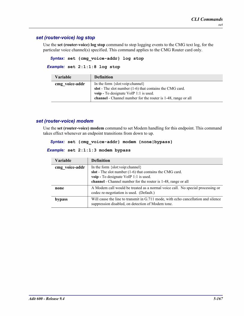
Adit 600 - Release 9.4 5-167
CLI Commandsset
set (router-voice) log stopUse the set (router-voice) log stop command to stop logging events to the CMG text log, for the particular voice channel(s) specified. This command applies to the CMG Router card only.
Syntax: set cmg_voice-addr log stop
Example: set 2:1:1:8 log stop
set (router-voice) modemUse the set (router-voice) modem command to set Modem handling for this endpoint. This command takes effect whenever an endpoint transitions from down to up.
Syntax: set cmg_voice-addr modem none|bypass
Example: set 2:1:1:3 modem bypass
Variable Definitioncmg_voice-addr In the form slot:voip:channel
slot - The slot number (1-6) that contains the CMG card.voip - To designate VoIP 1:1 is used.channel - Channel number for the router is 1-48, range or all
Variable Definitioncmg_voice-addr In the form slot:voip:channel
slot - The slot number (1-6) that contains the CMG card.voip - To designate VoIP 1:1 is used.channel - Channel number for the router is 1-48, range or all
none A Modem call would be treated as a normal voice call. No special processing or codec re-negotiation is used. (Default.)
bypass Will cause the line to transmit in G.711 mode, with echo cancellation and silence suppression disabled, on detection of Modem tone.

5-168 Adit 600 - Release 9.4
CLI Commandsset
set (router-voice) rfc2833
set (router-voice) rfc2833 signalsUse the set (router-voice) rfc2833 signals command to set the signaling method embedded in the RTP flow. This command takes effect immediately when an endpoint is idle or when the endpoint transitions from up to down. This command applies to the CMG Router card only.
Syntax: set cmg_voice-addr rfc2833 signals abcd|disable
Example: set 2:1:1:10 rfc2833 signals abcd
set (router-voice) rfc2833 payloadtypeUse the set (router-voice) rfc2833 payloadtype command to set the signaling payload value for this endpoint. This command takes effect immediately when an endpoint is idle or when the endpoint transitions from up to down. This command applies to the CMG Router card only.
Syntax: set cmg_voice-addr rfc2833 payloadtype default|number
Example: set 2:1:1:10 rfc2833 payloadtype 97
Variable Definitioncmg_voice-addr In the form slot:voip:channel
slot - The slot number (1-6) that contains the CMG card.voip - To designate VoIP 1:1 is used.channel - Channel number for the router is 1-48, range or all
abcd Use abcd signaling in RTP payloads
disable Disable signaling in RTP payloads. Default.
Variable Definitioncmg_voice-addr In the form slot:voip:channel
slot - The slot number (1-6) that contains the CMG card.voip - To designate VoIP 1:1 is used.channel - Channel number for the router is 1-48, range or all
default Sets the payload type to the DTMF Relay payload type value (normally 97). This setting is the default.
number Range between 94 - 127.

Adit 600 - Release 9.4 5-169
CLI Commandsset
set (router-voice) rfc2833 repeat countUse the set (router-voice) rfc2833 repeat count command to set the number of initial RTP message repeats at the time of transition. This command takes effect immediately when an endpoint is idle or when the endpoint transitions from up to down. This command applies to the CMG Router card only.
Syntax: set cmg_voice-addr rfc2833 repeat count value
Example: set 2:1:1:10 rfc2833 repeat count 2
Variable Definitioncmg_voice-addr In the form slot:voip:channel
slot - The slot number (1-6) that contains the CMG card.voip - To designate VoIP 1:1 is used.channel - Channel number for the router is 1-48, range or all
value Set the number of initial RTP message repeats at the time of signal transition. Range is 0 - 10 repeats. Default is 2. Note: A repeat of 2 times, in essence is a message, followed by 2 repeats.
To support interoperability with the Lucent iMerge trunking gateway, set this value to 0. A value of 0 invokes the proprietary iMerge RTP Multiplex mode. In this mode, the RFC2833 triple-redundancy mechanism is disabled. In the iMerge RTP Multiplex mode, the following rules apply:
The RFC2833 repeat count, repeat interval, and refresh interval settings do not apply. These settings are only used for the RFC2833 triple-redundancy mechanism.The RFC2833 trunk ABCD signaling events supported by the iMerge RTP Multiplex mode are RING-ON, RING-ON (end), ON-HOOK, ON-HOOK (end). The signaling events OFF-HOOK and RING-OFF are invalid. This is because for iMerge RTP Multiplex mode, the RTP events are terminated with the "end" bit in the second byte of the RTP message. The equivalent RTP event that represents OFF-HOOK for this mode is an ON-HOOK with the "end" bit set in the second byte (Second byte is 0x80). Similarly, the RTP event that represents the RING-OFF from the trunk gateway is a RING-ON RTP event with the "end" bit set in the second byte.RTP ABCD signaling events and voice packets are mutually exclusive. That is, RTP events completely squelch the voice packets. Receiving voice packets at the trunk gateway implies the far end is OFF-HOOK, but it is not interpreted as OFF-HOOK. Ringing can proceed for between 8 and 16 seconds. Voice Packets at the CMG implies RING-OFF. Events are transmitted and received at the voice packetization rate.RTP ABCD signaling is not refreshed periodically.After 16 seconds or less, the CMG will terminate a constant RING-ON RTP ABCD signaling event. This will prevent the ringing forever condition when Ethernet connectivity is lost.
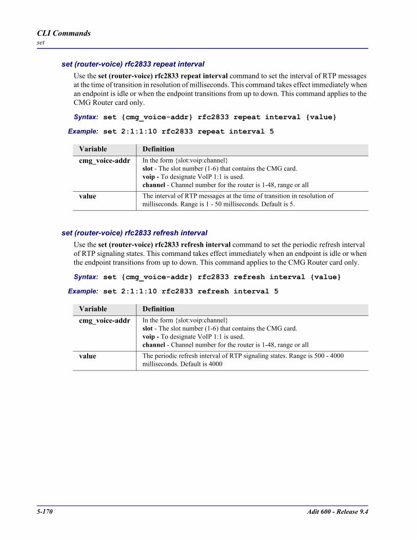
5-170 Adit 600 - Release 9.4
CLI Commandsset
set (router-voice) rfc2833 repeat intervalUse the set (router-voice) rfc2833 repeat interval command to set the interval of RTP messages at the time of transition in resolution of milliseconds. This command takes effect immediately when an endpoint is idle or when the endpoint transitions from up to down. This command applies to the CMG Router card only.
Syntax: set cmg_voice-addr rfc2833 repeat interval value
Example: set 2:1:1:10 rfc2833 repeat interval 5
set (router-voice) rfc2833 refresh intervalUse the set (router-voice) rfc2833 refresh interval command to set the periodic refresh interval of RTP signaling states. This command takes effect immediately when an endpoint is idle or when the endpoint transitions from up to down. This command applies to the CMG Router card only.
Syntax: set cmg_voice-addr rfc2833 refresh interval value
Example: set 2:1:1:10 rfc2833 refresh interval 5
Variable Definitioncmg_voice-addr In the form slot:voip:channel
slot - The slot number (1-6) that contains the CMG card.voip - To designate VoIP 1:1 is used.channel - Channel number for the router is 1-48, range or all
value The interval of RTP messages at the time of transition in resolution of milliseconds. Range is 1 - 50 milliseconds. Default is 5.
Variable Definitioncmg_voice-addr In the form slot:voip:channel
slot - The slot number (1-6) that contains the CMG card.voip - To designate VoIP 1:1 is used.channel - Channel number for the router is 1-48, range or all
value The periodic refresh interval of RTP signaling states. Range is 500 - 4000 milliseconds. Default is 4000

Adit 600 - Release 9.4 5-171
CLI Commandsset
set (router-voice) rxgainUse the set (router-voice) rxgain command to set gain on the receive side (TDM-to-packet) voice path for the specified voice channel(s). This gain setting can be overridden by the call agent on a call-by-call basis. This command applies to the CMG Router card only.
Syntax: set cmg_voice-addr rxgain gain
Example: set 2:1:1:10 rxgain -3
set (router-voice) signalingUse the set (router-voice) signaling command to set the signaling protocol (FXS loop start or FXS ground start) used by a CMG Router TDM voice endpoint. This command applies to the CMG Router card only.
Syntax: set cmg_voice-addr signaling fxsls|fxsgs
Example: set 2:1:1:all signaling fxsgs
Variable Definitioncmg_voice-addr In the form slot:voip:channel
slot - The slot number (1-6) that contains the CMG card.voip - To designate VoIP 1:1 is used.channel - Channel number for the router is 1-48, range or all
gain Gain range is -14 to 14 dB. Default gain is 0 dB
Variable Definitioncmg_voice-addr In the form slot:voip:channel
slot - The slot number (1-6) that contains the CMG card.voip - To designate VoIP 1:1 is used.channel - Channel number for the router is 1-48, range or all
fxsls FXS loop start signaling. (Default)
fxsgs FXS ground start signaling.
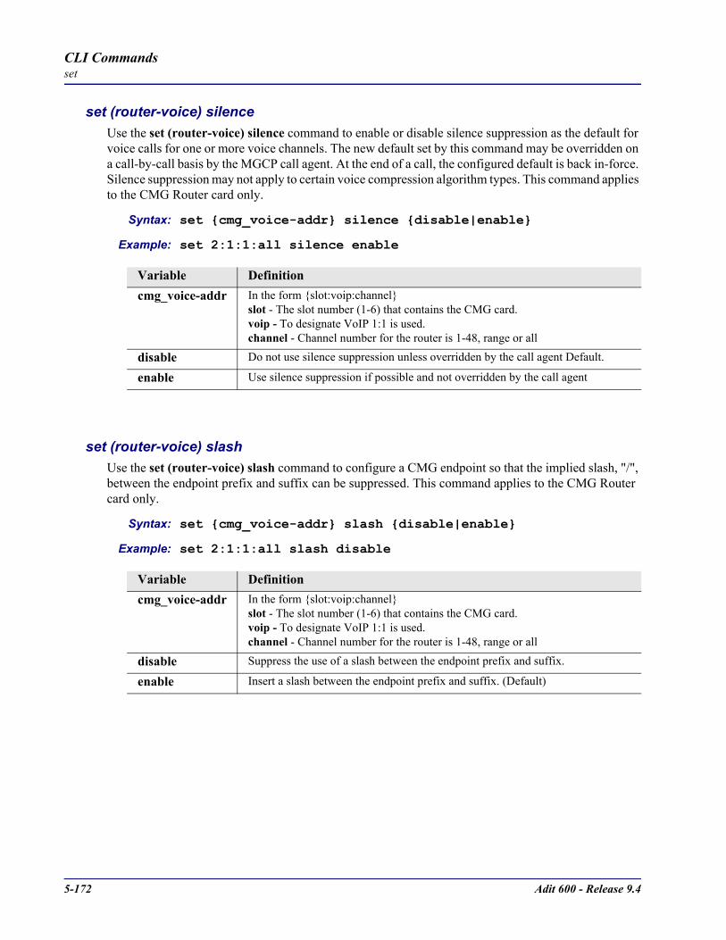
5-172 Adit 600 - Release 9.4
CLI Commandsset
set (router-voice) silenceUse the set (router-voice) silence command to enable or disable silence suppression as the default for voice calls for one or more voice channels. The new default set by this command may be overridden on a call-by-call basis by the MGCP call agent. At the end of a call, the configured default is back in-force. Silence suppression may not apply to certain voice compression algorithm types. This command applies to the CMG Router card only.
Syntax: set cmg_voice-addr silence disable|enable
Example: set 2:1:1:all silence enable
set (router-voice) slashUse the set (router-voice) slash command to configure a CMG endpoint so that the implied slash, "/", between the endpoint prefix and suffix can be suppressed. This command applies to the CMG Router card only.
Syntax: set cmg_voice-addr slash disable|enable
Example: set 2:1:1:all slash disable
Variable Definitioncmg_voice-addr In the form slot:voip:channel
slot - The slot number (1-6) that contains the CMG card.voip - To designate VoIP 1:1 is used.channel - Channel number for the router is 1-48, range or all
disable Do not use silence suppression unless overridden by the call agent Default.
enable Use silence suppression if possible and not overridden by the call agent
Variable Definitioncmg_voice-addr In the form slot:voip:channel
slot - The slot number (1-6) that contains the CMG card.voip - To designate VoIP 1:1 is used.channel - Channel number for the router is 1-48, range or all
disable Suppress the use of a slash between the endpoint prefix and suffix.
enable Insert a slash between the endpoint prefix and suffix. (Default)

Adit 600 - Release 9.4 5-173
CLI Commandsset
set (router-voice) tosUse the set (router-voice) tos command to set the default value for the Type of Service (TOS) byte in the IP header of outgoing VoIP packets for the specified channel(s). This value may be overridden by the call agent on a call-by-call basis. This command applies to the CMG Router card only.
Syntax: set cmg_voice-addr tos 2-hex-digits
Example: set 2:1:1:all tos 0xA0
set (router-voice) txgainUse the set (router-voice) txgain command to set the gain on the transmit side (packet-to-TDM) voice path for the specified voice channel(s). This gain setting can be overridden by the call agent on a call-by-call basis. This command applies to the CMG Router card only.
Syntax: set cmg_voice-addr txgain gain
Example: set 2:1:1:9 txgain 6
Variable Definitioncmg_voice-addr In the form slot:voip:channel
slot - The slot number (1-6) that contains the CMG card.voip - To designate VoIP 1:1 is used.channel - Channel number for the router is 1-48, range or all
2-hex-digits Specified bits to be sent in TOS byte. The first (leftmost) 3 bits represent the “precedence” or priority. Bit 4 (from the left) indicates optimize for delay. Bit 5 indicates optimize for throughput. Bit 6 indicates optimize for reliability.
Variable Definitioncmg_voice-addr In the form slot:voip:channel
slot - The slot number (1-6) that contains the CMG card.voip - To designate VoIP 1:1 is used.channel - Channel number for the router is 1-48, range or all
gain Gain range is -14 to 14 dB. Default is 0 dB.

5-174 Adit 600 - Release 9.4
CLI Commandsset
set (router-voice) upUse the set (router-voice) up command to bring a voice channel back into service. This will cause an RSIP message to be sent to the call agent, with the “restart” value for the Restart Method parameter. It will also enable the processing of TDM-side events (eg: offhook) which are either requested by the call agent or are defined as persistent events see set (router) mgcp report hookswitch. This command applies to the CMG Router card only.
Syntax: set cmg_voice-addr up
Example: set 2:1:1:2 up
set (router-wan) dlciUse the set (router-wan) dlci command to set the DLCI (Data Link Connection Identifier) for a specified WAN interface.
Syntax: set rtr_card-addr “wan-name” dlci value
Example: set 1 “LosAngeles” dlci 16
Variable Definitioncmg_voice-addr In the form slot:voip:channel
slot - The slot number (1-6) that contains the CMG card.voip - To designate VoIP 1:1 is used.channel - Channel number for the router is 1-48, range or all
Variable Definitionrtr_card-addr The slot number (1-6) that contains the Router (IP, CMG or TSR) card.
wan-name The WAN interface to modify. The name must be enclosed in quotes.
value DLCI value to use, 16-1022.

Adit 600 - Release 9.4 5-175
CLI Commandsset
set (router-wan) greUse the set (router-wan) gre command to configure Generic Routing Encapsulation tunneling for a specified WAN interface.
set (router-wan) gre addressUse the set (router-wan) gre address command to configure the IP addresses for GRE tunneling for a specified WAN interface. Note: A set 3 “LosAngeles” gre ip all command is required before this command.
Syntax: set rtr_card-addr “wan-name” gre address local_ip-addr [remote-ip-addr] [“tunnel-name”]
Example: set 3 “LosAngeles” gre address 10.0.0.0 20.0.0.0 “LATunnel”
set (router-wan) gre ipUse the set (router-wan) gre ip command to configure the GRE tunneling of the IP protocol for a specified WAN interface.
Syntax: set rtr_card-addr “wan-name” gre ip all|bynetwork|disable
Example: set 3 “LosAngeles” gre ip all
Variable Definitionrtr_card-addr The slot number (1-6) that contains the Router (IP, CMG or TSR) card.
wan-name The WAN interface to modify. The name must be enclosed in quotes.
local-ip-addr The IP Address of the local end of the tunnel, in the form of xxx.xxx.xxx.xxx, where xxx is between 0-255.
remote-ip-addr The IP Address of the far end of the tunnel, required if GRE tunneling is set to All, prohibited if GRE tunneling is set to By Network. In the form of xxx.xxx.xxx.xxx, where xxx is between 0-255.
tunnel-name A symbolic name to give to this tunnel, required if GRE tunneling is set to All, prohibited if GRE tunneling is set to By Network. Up to 12 characters, enclosed in quotes.
Variable Definitionrtr_card-addr The slot number (1-6) that contains the Router (IP, CMG or TSR) card.
wan-name The WAN interface to modify. The name must be enclosed in quotes.
all Tunnel all packets on this interface to the tunnel destination address.bynetwork Tunnel packets based on their destination address by matching GRE network entries,
see add (router-wan) gre network command.disable Disable GRE tunneling.
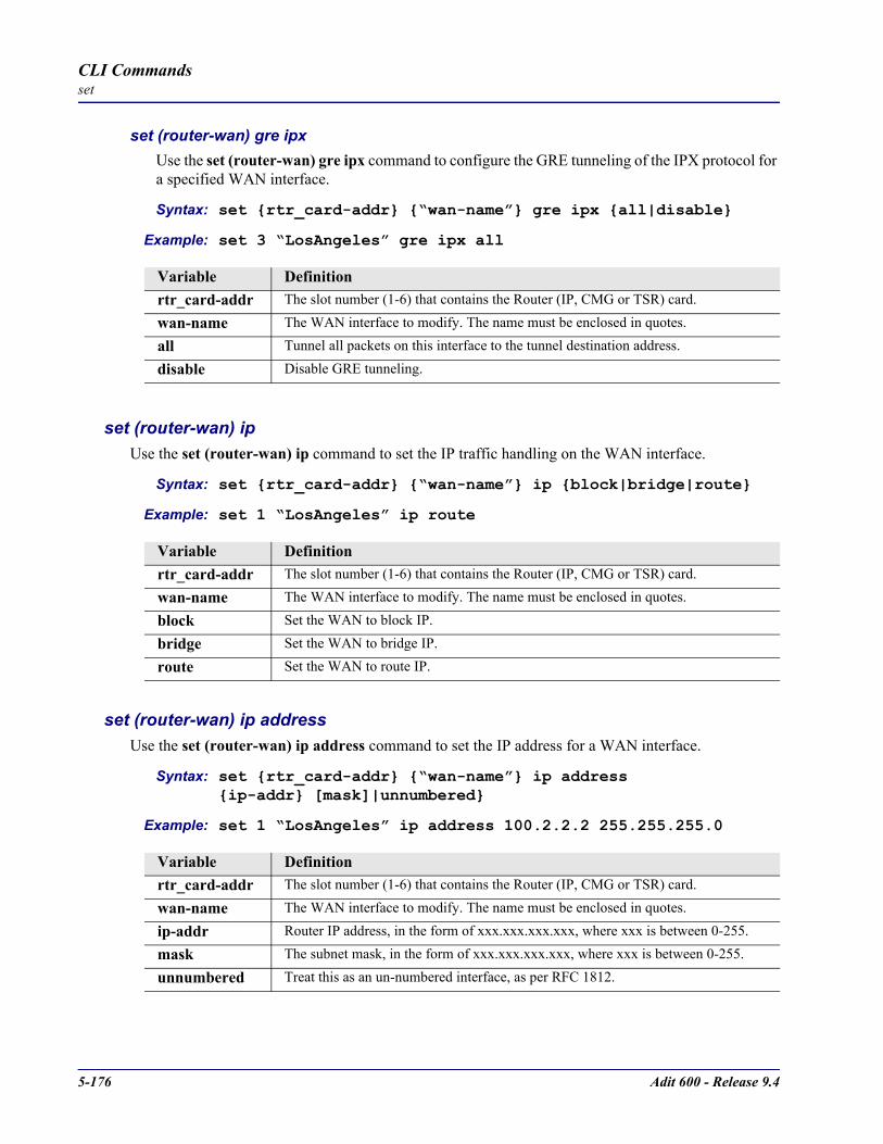
5-176 Adit 600 - Release 9.4
CLI Commandsset
set (router-wan) gre ipxUse the set (router-wan) gre ipx command to configure the GRE tunneling of the IPX protocol for a specified WAN interface.
Syntax: set rtr_card-addr “wan-name” gre ipx all|disable
Example: set 3 “LosAngeles” gre ipx all
set (router-wan) ipUse the set (router-wan) ip command to set the IP traffic handling on the WAN interface.
Syntax: set rtr_card-addr “wan-name” ip block|bridge|route
Example: set 1 “LosAngeles” ip route
set (router-wan) ip addressUse the set (router-wan) ip address command to set the IP address for a WAN interface.
Syntax: set rtr_card-addr “wan-name” ip address ip-addr [mask]|unnumbered
Example: set 1 “LosAngeles” ip address 100.2.2.2 255.255.255.0
Variable Definitionrtr_card-addr The slot number (1-6) that contains the Router (IP, CMG or TSR) card.
wan-name The WAN interface to modify. The name must be enclosed in quotes.
all Tunnel all packets on this interface to the tunnel destination address.
disable Disable GRE tunneling.
Variable Definitionrtr_card-addr The slot number (1-6) that contains the Router (IP, CMG or TSR) card.
wan-name The WAN interface to modify. The name must be enclosed in quotes.
block Set the WAN to block IP.
bridge Set the WAN to bridge IP.
route Set the WAN to route IP.
Variable Definitionrtr_card-addr The slot number (1-6) that contains the Router (IP, CMG or TSR) card.
wan-name The WAN interface to modify. The name must be enclosed in quotes.
ip-addr Router IP address, in the form of xxx.xxx.xxx.xxx, where xxx is between 0-255.
mask The subnet mask, in the form of xxx.xxx.xxx.xxx, where xxx is between 0-255.
unnumbered Treat this as an un-numbered interface, as per RFC 1812.

Adit 600 - Release 9.4 5-177
CLI Commandsset
set (router-wan) ipxUse the set (router-wan) ipx command to set the IPX traffic handling on the WAN interface.
Syntax: set rtr_card-addr “wan-name” ipx setting
Example: set 1 “LosAngeles” ipx bridge
set (router-wan) mlpppUse the set (router) mlppp command to configure the WAN Multi-link PPP.
set (router-wan) mlppp qos interleave Use the set (router-wan) mlppp qos interleave command to enable a WAN Profile that is using MLPPP trunks to additionally use Link Fragmentation and Interleaving (LFI) style QOS priority-driven interleaving on its MLPPP links. This command takes effect immediately. This command is typically combined with IP TOS priority settings to identify packet flows that need to be prioritized over non-TOS matched flows, such that the prioritized flows will be transmitted using PPP to alleviate MLPPP out of sequence issues.
Syntax: set rtr_card-addr “wan-name” mlppp qos interleave disable|enable
Example: set 5 “LosAngeles” mlppp qos interleave disable
Variable Definitionrtr_card-addr The slot number (1-6) that contains the Router (IP, CMG or TSR) card.
wan-name The WAN interface to modify. The name must be enclosed in quotes.
block Set the WAN to block IPX.
bridge Set the WAN to bridge IPX with optimized local advertising IPX servers and networks.
optimize Setting to optimize enables the Adit to use Carrier Access’ network optimization feature, which ensures that only necessary data is transmitted over the WAN connection. The Adit will initiate IPX learning mode. Learning mode is effective for optimizing bandwidth usage for IPX RIP, SAP, serialization and watchdog (IPX and SPX) packets. If you choose this option, the Adit will initiate learning mode in order to gain knowledge of local and remote networks and services. Once it knows of remote networks and services, it can advertise the information on the local LAN on behalf of the remote networks and servers.
Variable Definitionrtr_card-addr The slot number (1-6) that contains the Router (IP, CMG or TSR) card.
wan-name The WAN interface to modify. The name must be enclosed in quotes.
disable Disables Link Fragmentation and Interleaving. Disable is the default.
enable Enables the Link Fragmentation and Interleaving.

5-178 Adit 600 - Release 9.4
CLI Commandsset
set (router-wan) mlppp fragmentation size Use the set (router-wan) mlppp fragmentation size command to configure a WAN Profile, that is using MLPPP trunks, to a desired per-link fragmentation size. Fragmentation is typically used in conjunction with interleaving to set the maximum fragment size of low priority packets, in order to regulate the maximum time a low priority packet can delay a high priority packet. The size should be reduced only when needful, since it takes time for fragmentation and reassembly of packets at each end of the Wan. When the user sets the size to 1600 bytes, this is the same as having no fragmentation, since the MTU of each MLPPP link is 1600 bytes.
Syntax: set rtr_card-addr “wan-name” mlppp fragmentation size size
Example: set 5 “LosAngeles” mlppp fragmentation size
set (router-wan) natUse the set (router-wan) nat commands to configure Network Address Translation (NAT) on a specified WAN interface.
set (router-wan) nat addressUse the set (router-wan) nat address command to configure Network Address Translation (NAT) public addresses for a specified WAN interface.
Syntax: set rtr_card-addr “wan-name” nat address assigned|ip-addr [count]
Example: set 1 “LosAngeles” nat address 201.17.172.11 8
Variable Definitionrtr_card-addr The slot number (1-6) that contains the Router (IP, CMG or TSR) card.
wan-name The WAN interface to modify. The name must be enclosed in quotes.
size Fragmentation size. Range is 320 to 1600 bytes, with a default of 1600.
Variable Definitionrtr_card-addr The slot number (1-6) that contains the Router (IP, CMG or TSR) card.
wan-name The WAN interface to modify. The name must be enclosed in quotes.
assigned The NAT address assigned by remote.
ip-addr The Router IP address, in the form of xxx.xxx.xxx.xxx, where xxx is between 0-255.
count An optional field defining the number of public addresses in the NAT pool. Default is 1.
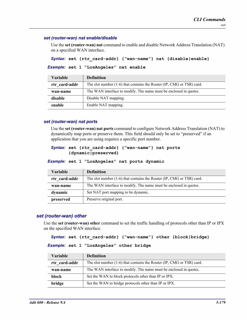
Adit 600 - Release 9.4 5-179
CLI Commandsset
set (router-wan) nat enable/disableUse the set (router-wan) nat command to enable and disable Network Address Translation (NAT) on a specified WAN interface.
Syntax: set rtr_card-addr “wan-name” nat disable|enable
Example: set 1 “LosAngeles” nat enable
set (router-wan) nat portsUse the set (router-wan) nat ports command to configure Network Address Translation (NAT) to dynamically map ports or preserve them. This field should only be set to “preserved” if an application that you are using requires a specific port number.
Syntax: set rtr_card-addr “wan-name” nat ports dynamic|preserved
Example: set 1 “LosAngeles” nat ports dynamic
set (router-wan) otherUse the set (router-wan) other command to set the traffic handling of protocols other than IP or IPX on the specified WAN interface.
Syntax: set rtr_card-addr “wan-name” other block|bridge
Example: set 1 “LosAngeles” other bridge
Variable Definitionrtr_card-addr The slot number (1-6) that contains the Router (IP, CMG or TSR) card.
wan-name The WAN interface to modify. The name must be enclosed in quotes.
disable Disable NAT mapping.
enable Enable NAT mapping.
Variable Definitionrtr_card-addr The slot number (1-6) that contains the Router (IP, CMG or TSR) card.
wan-name The WAN interface to modify. The name must be enclosed in quotes.
dynamic Set NAT port mapping to be dynamic.
preserved Preserve original port.
Variable Definitionrtr_card-addr The slot number (1-6) that contains the Router (IP, CMG or TSR) card.
wan-name The WAN interface to modify. The name must be enclosed in quotes.
block Set the WAN to block protocols other than IP or IPX.
bridge Set the WAN to bridge protocols other than IP or IPX.
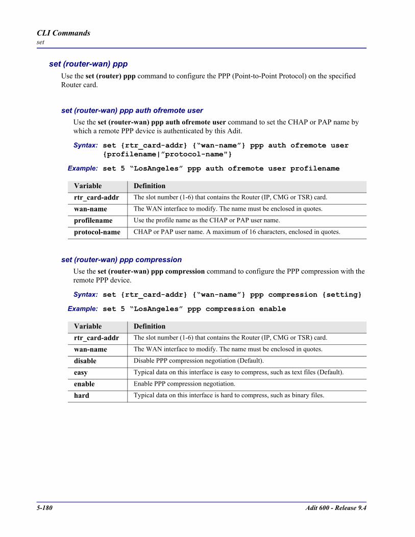
5-180 Adit 600 - Release 9.4
CLI Commandsset
set (router-wan) pppUse the set (router) ppp command to configure the PPP (Point-to-Point Protocol) on the specified Router card.
set (router-wan) ppp auth ofremote userUse the set (router-wan) ppp auth ofremote user command to set the CHAP or PAP name by which a remote PPP device is authenticated by this Adit.
Syntax: set rtr_card-addr “wan-name” ppp auth ofremote user profilename|”protocol-name"
Example: set 5 “LosAngeles” ppp auth ofremote user profilename
set (router-wan) ppp compressionUse the set (router-wan) ppp compression command to configure the PPP compression with the remote PPP device.
Syntax: set rtr_card-addr “wan-name” ppp compression setting
Example: set 5 “LosAngeles” ppp compression enable
Variable Definitionrtr_card-addr The slot number (1-6) that contains the Router (IP, CMG or TSR) card.
wan-name The WAN interface to modify. The name must be enclosed in quotes.
profilename Use the profile name as the CHAP or PAP user name.
protocol-name CHAP or PAP user name. A maximum of 16 characters, enclosed in quotes.
Variable Definitionrtr_card-addr The slot number (1-6) that contains the Router (IP, CMG or TSR) card.
wan-name The WAN interface to modify. The name must be enclosed in quotes.
disable Disable PPP compression negotiation (Default).
easy Typical data on this interface is easy to compress, such as text files (Default).
enable Enable PPP compression negotiation.
hard Typical data on this interface is hard to compress, such as binary files.
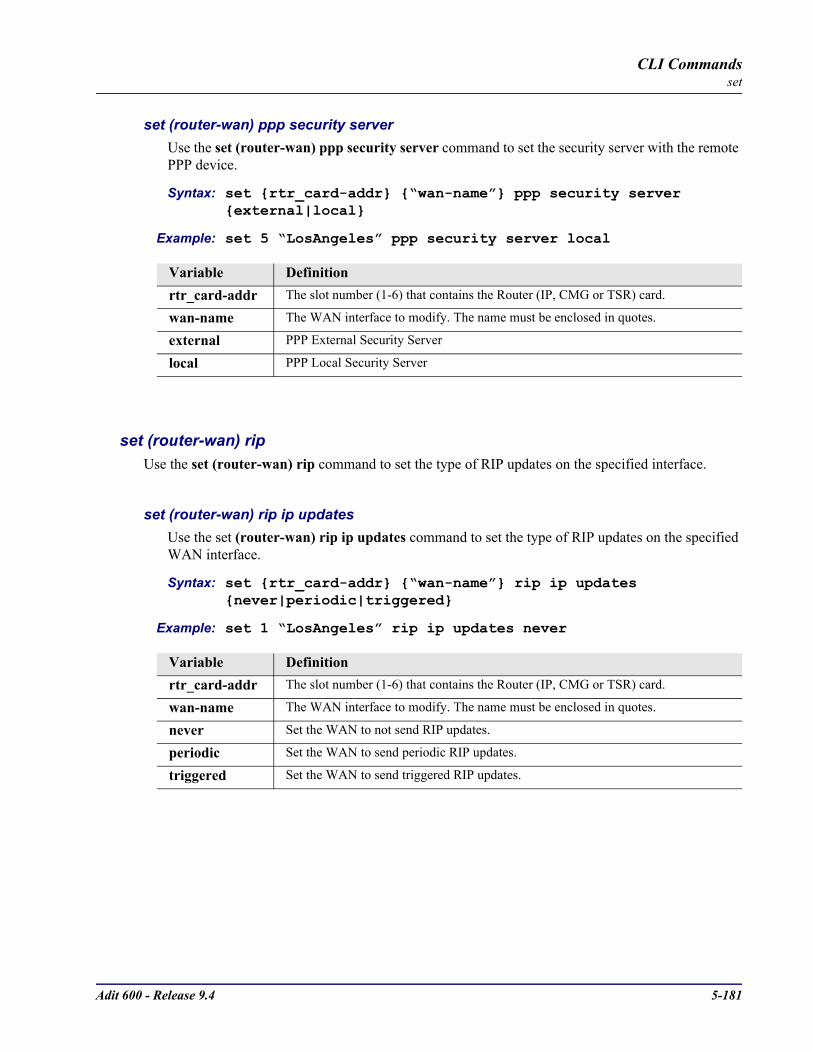
Adit 600 - Release 9.4 5-181
CLI Commandsset
set (router-wan) ppp security serverUse the set (router-wan) ppp security server command to set the security server with the remote PPP device.
Syntax: set rtr_card-addr “wan-name” ppp security server external|local
Example: set 5 “LosAngeles” ppp security server local
set (router-wan) ripUse the set (router-wan) rip command to set the type of RIP updates on the specified interface.
set (router-wan) rip ip updatesUse the set (router-wan) rip ip updates command to set the type of RIP updates on the specified WAN interface.
Syntax: set rtr_card-addr “wan-name” rip ip updates never|periodic|triggered
Example: set 1 “LosAngeles” rip ip updates never
Variable Definitionrtr_card-addr The slot number (1-6) that contains the Router (IP, CMG or TSR) card.
wan-name The WAN interface to modify. The name must be enclosed in quotes.
external PPP External Security Server
local PPP Local Security Server
Variable Definitionrtr_card-addr The slot number (1-6) that contains the Router (IP, CMG or TSR) card.
wan-name The WAN interface to modify. The name must be enclosed in quotes.
never Set the WAN to not send RIP updates.
periodic Set the WAN to send periodic RIP updates.
triggered Set the WAN to send triggered RIP updates.

5-182 Adit 600 - Release 9.4
CLI Commandsset
set (router-wan) rip ipx updatesUse the set (router-wan) rip ipx updates command to set the type of IPX RIP updates on the specified WAN interface.
Syntax: set rtr_card-addr “wan-name” rip ipx updates never|periodic|triggered
Example: set 1 “LosAngeles” rip ipx updates never
set (router-wan) stpUse the set (router-wan) stp commands to configure Spanning Tree Protocol on the WAN interface.
set (router-wan) stp enable/disableUse the set (router-wan) stp enable/disable command to enable and disable Spanning Tree Protocol on this interface. To enable Spanning Tree on an interface it must first be enabled globally with the set (router) stp enable command and the WAN must be set to bridge the IP protocol.
Syntax: set rtr_card-addr “wan-name” stp disable|enable
Example: set 3 stp enable
Variable Definitionrtr_card-addr The slot number (1-6) that contains the Router (IP, CMG or TSR) card.
wan-name The WAN interface to modify. The name must be enclosed in quotes.
never Set the WAN to not send RIP updates.
periodic Set the WAN to send periodic RIP updates.
triggered Set the WAN to send triggered RIP updates.
Variable Definitionrtr_card-addr The slot number (1-6) that contains the Router (IP, CMG or TSR) card.
wan-name The WAN interface to modify. The name must be enclosed in quotes.
disable Disable Spanning Tree on this interface.
enable Enable Spanning Tree on this interface.
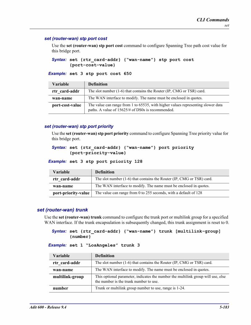
Adit 600 - Release 9.4 5-183
CLI Commandsset
set (router-wan) stp port costUse the set (router-wan) stp port cost command to configure Spanning Tree path cost value for this bridge port.
Syntax: set rtr_card-addr “wan-name” stp port cost port-cost-value
Example: set 3 stp port cost 650
set (router-wan) stp port priorityUse the set (router-wan) stp port priority command to configure Spanning Tree priority value for this bridge port.
Syntax: set rtr_card-addr “wan-name” port priority port-priority-value
Example: set 3 stp port priority 128
set (router-wan) trunkUse the set (router-wan) trunk command to configure the trunk port or multilink group for a specified WAN interface. If the trunk encapsulation is subsequently changed, this trunk assignment is reset to 0.
Syntax: set rtr_card-addr “wan-name” trunk [multilink-group] number
Example: set 1 “LosAngeles” trunk 3
Variable Definitionrtr_card-addr The slot number (1-6) that contains the Router (IP, CMG or TSR) card.
wan-name The WAN interface to modify. The name must be enclosed in quotes.
port-cost-value The value can range from 1 to 65535, with higher values representing slower data paths. A value of 15625/# of DS0s is recommended.
Variable Definitionrtr_card-addr The slot number (1-6) that contains the Router (IP, CMG or TSR) card.
wan-name The WAN interface to modify. The name must be enclosed in quotes.
port-priority-value The value can range from 0 to 255 seconds, with a default of 128
Variable Definitionrtr_card-addr The slot number (1-6) that contains the Router (IP, CMG or TSR) card.
wan-name The WAN interface to modify. The name must be enclosed in quotes.
multilink-group This optional parameter, indicates the number the multilink group will use, else the number is the trunk number to use.
number Trunk or multilink group number to use, range is 1-24.

5-184 Adit 600 - Release 9.4
CLI Commandsset
set (router-wan) up/downUse the set (router-wan) up/down command to set the specified WAN interface up or down.
Syntax: set rtr_card-addr “wan-name” down|up
Example: set 1 “LosAngeles” up
set (rs232)Use the set (rs232) command to setup RS-232 ports. The command specifies the range of channels within that card, and the setting to apply.
Syntax: set rs232-addr setting
Example: set 6:1 baudrate 4800
Variable Definitionrtr_card-addr The slot number (1-6) that contains the Router (IP, CMG or TSR) card.
wan-name The WAN interface to modify. The name must be enclosed in quotes.
down Set the Router WAN to disabled.
up Set the Router WAN to enabled.
Variable Definitionrs232-addr In the form of slot:port.
slot - slot (1-6) location of a RS-232 card.port - Port number or range.
baudrate
Set the baud rates for the RS-232 ports.
2400 Set baud rate to 2400 bps
4800 Set baud rate to 4800 bps
9600 Set baud rate to 9600 bps
56000 Set baud rate to 56000 bps
64000 Set baud rate to 64000 bps
cts Set the Clear To Send operation mode to one of the following:
cd Follow CD
high Force CTS high
low Force CTS low
remote Follow state of remote handshake line. Not valid at 64 kbps
rts Follow RTS

Adit 600 - Release 9.4 5-185
CLI Commandsset
set screenUse the set screen command to set the height of the scrolling output screen, in number of lines. For example, if the screen height is set to 40 lines, the Command Line Interface (CLI) will print the maximum of 40 lines of a long output before pausing. To set the screen to scroll without pausing, set the screen height to 0.
Syntax: set screen screen-height|off Where screen-height is the number of lines in the scrolling output screen.
dcd Set the Data Carrier Detect (DCD) operation mode:
remote Follow state of remote handshake line. Not valid at 64000 bps
sw Follow software control
equipment Sets the RS-232 port to equipment loopback, which loops the transmit RS-232 signal back toward the RS-232 receive (towards T1)
loopdown disable equipment loopback
loopup enable equipment loopback
line Sets the RS-232 port to line loopback, which loops the received RS-232 signal toward the RS-232 transmit (away from T1)
loopdown disable line loopback
loopup enable line loopback
rts Set the Request To Send (RTS) operation mode:
dte Follow Data Terminal Equipment (DTE)
high Force RTS high
low Force RTS low
Variable Definition
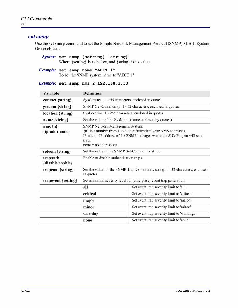
5-186 Adit 600 - Release 9.4
CLI Commandsset
set snmpUse the set snmp command to set the Simple Network Management Protocol (SNMP) MIB-II System Group objects.
Syntax: set snmp setting stringWhere setting is as below, and string is its value.
Example: set snmp name "ADIT 1"To set the SNMP system name to "ADIT 1"
Example: set snmp nms 2 192.168.3.50
Variable Definitioncontact string SysContact. 1 - 255 characters, enclosed in quotes
getcom string SNMP Get-Community. 1 - 32 characters, enclosed in quotes
location string SysLocation. 1 - 255 characters, enclosed in quotes
name string Set the value of the SysName (name enclosed by quotes).
nms n ip-addr|none
SNMP Network Management System.n is a number from 1 to 3, to differentiate your NMS addresses.IP-addr = IP address of the SNMP manager where the SNMP agent will send traps none = no address set.
setcom string Set the value of the SNMP Set-Community string.
trapauth disable|enable
Enable or disable authentication traps.
trapcom string Set the value for the SNMP Trap-Community string. 1 - 32 characters, enclosed in quotes
trapevent setting Set minimum severity level for (enterprise) event trap generation.
all Set event trap severity limit to 'all'.
critical Set event trap severity limit to 'critical'.
major Set event trap severity limit to 'major'.
minor Set event trap severity limit to 'minor'.
warning Set event trap severity limit to 'warning'.
none Set event trap severity limit to 'none'.
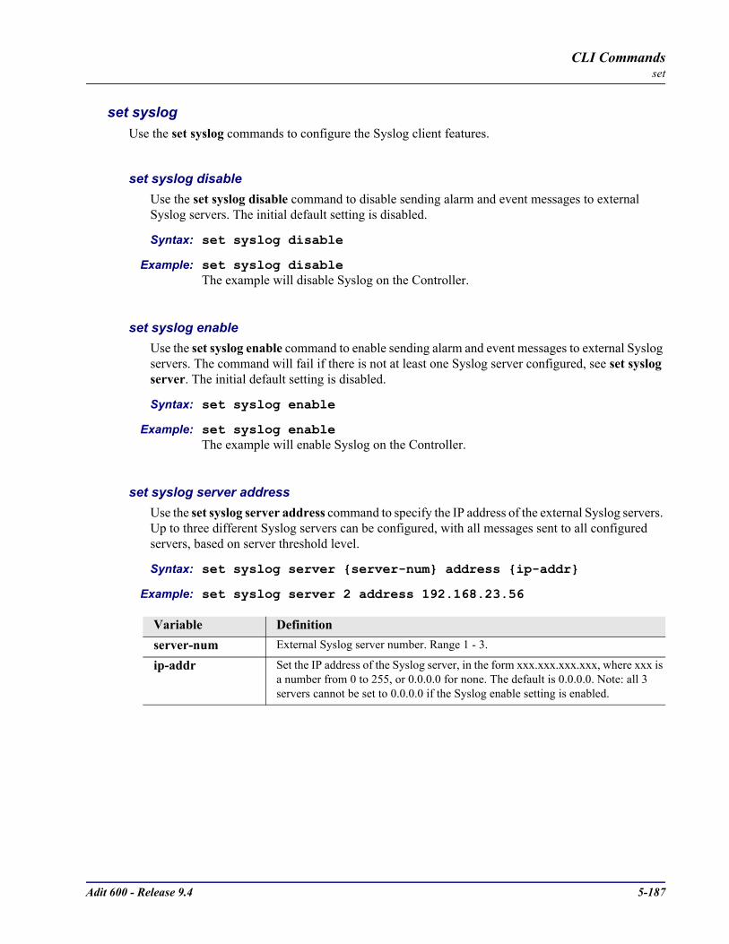
Adit 600 - Release 9.4 5-187
CLI Commandsset
set syslogUse the set syslog commands to configure the Syslog client features.
set syslog disableUse the set syslog disable command to disable sending alarm and event messages to external Syslog servers. The initial default setting is disabled.
Syntax: set syslog disable
Example: set syslog disableThe example will disable Syslog on the Controller.
set syslog enableUse the set syslog enable command to enable sending alarm and event messages to external Syslog servers. The command will fail if there is not at least one Syslog server configured, see set syslog server. The initial default setting is disabled.
Syntax: set syslog enable
Example: set syslog enableThe example will enable Syslog on the Controller.
set syslog server addressUse the set syslog server address command to specify the IP address of the external Syslog servers. Up to three different Syslog servers can be configured, with all messages sent to all configured servers, based on server threshold level.
Syntax: set syslog server server-num address ip-addr
Example: set syslog server 2 address 192.168.23.56
Variable Definitionserver-num External Syslog server number. Range 1 - 3.
ip-addr Set the IP address of the Syslog server, in the form xxx.xxx.xxx.xxx, where xxx is a number from 0 to 255, or 0.0.0.0 for none. The default is 0.0.0.0. Note: all 3 servers cannot be set to 0.0.0.0 if the Syslog enable setting is enabled.

5-188 Adit 600 - Release 9.4
CLI Commandsset
set syslog server facilityUse the set syslog server facility command to specify the Syslog facility value that the controller will report to the Syslog server in each message.
Syntax: set syslog server all|server-num facility value
Example: set syslog server 2 facility 18
set syslog server levelUse the set syslog server level command to set the Syslog severity level threshold. Events of all severity levels will be sent to the Syslog server.
Syntax: set syslog all|server-num level severity
Example: set syslog server all level 4
Variable Definitionall Sets all (1-3) external Syslog servers.
server-num External Syslog server number. Range 1 - 3.
value The facility value to report in the Syslog messages sent to the server. Range is 0 - 23, with a default of 16.
Variable Definitionall Sets all (1-3) external Syslog servers.
server-num External Syslog server number. Range 1 - 3.
value The facility value to report in the Syslog messages sent to the server. Range is 0 - 23, with a default of 16.
severity The Syslog severity level threshold. Range 0 - 7, with a default of 3.0-1 - 2 - Only critical alarms will be sent3 - Only critical and major alarms will be sent4 - Only critical, major and minor alarms will be sent5 - Only critical, major, minor alarms and alert events will be sent6 - Only critical, major, minor alarms, alert and informational events will be sent7 -

Adit 600 - Release 9.4 5-189
CLI Commandsset
set timeUse the set time command to set the time.
Syntax: set time hh:mm:ss
Example: set time 12:00:00The example will set the time to 12 noon.
set time daylightsavingsUse the set time daylightsavings command to enable or disable automatic adjustment of the system clock for Daylight Savings Time.
Syntax: set time daylightsavings disable|enable
Example: set time daylightsavings enableThe example enables automatic adjustment for Daylight Savings Time.
set userUse the set user command to modify attributes for a specific user that have been created with the add user command.
set user levelUse the set user level command to set the user access level.
Syntax: set user “user-name” level 1|2|3
Example: set user “paul” level 2
Variable Definitionhh:mm:ss The time in hours, minutes, and seconds, using a 24-hour clock.
Variable Definitiondisable Disables automatic adjustment for Daylight Savings Time. (Default.)
enable Enables automatic adjustment for Daylight Savings Time.
Variable Definitionuser-name The user-name is a user ID to add to the system. Text is a single word,
with no blank spaces and must be enclosed in quotes.Level 1 Manager has full access to ALL commands. Typically, there is only one
designated user at this levelLevel 2 Operator has access to all commands except for the add user and set user
commandsLevel 3 Monitor (read only) has access to commands that display reports and status

5-190 Adit 600 - Release 9.4
CLI Commandsset
set user passwordUse the set user password to set the password for this user.
Syntax: set user “user-name” password
Example: set user “john” password New Password: **
New Password again: **
Variable Definitionuser-name The user-name is a user ID to add to the system. Text is a single word,
with no blank spaces and must be enclosed in quotes.
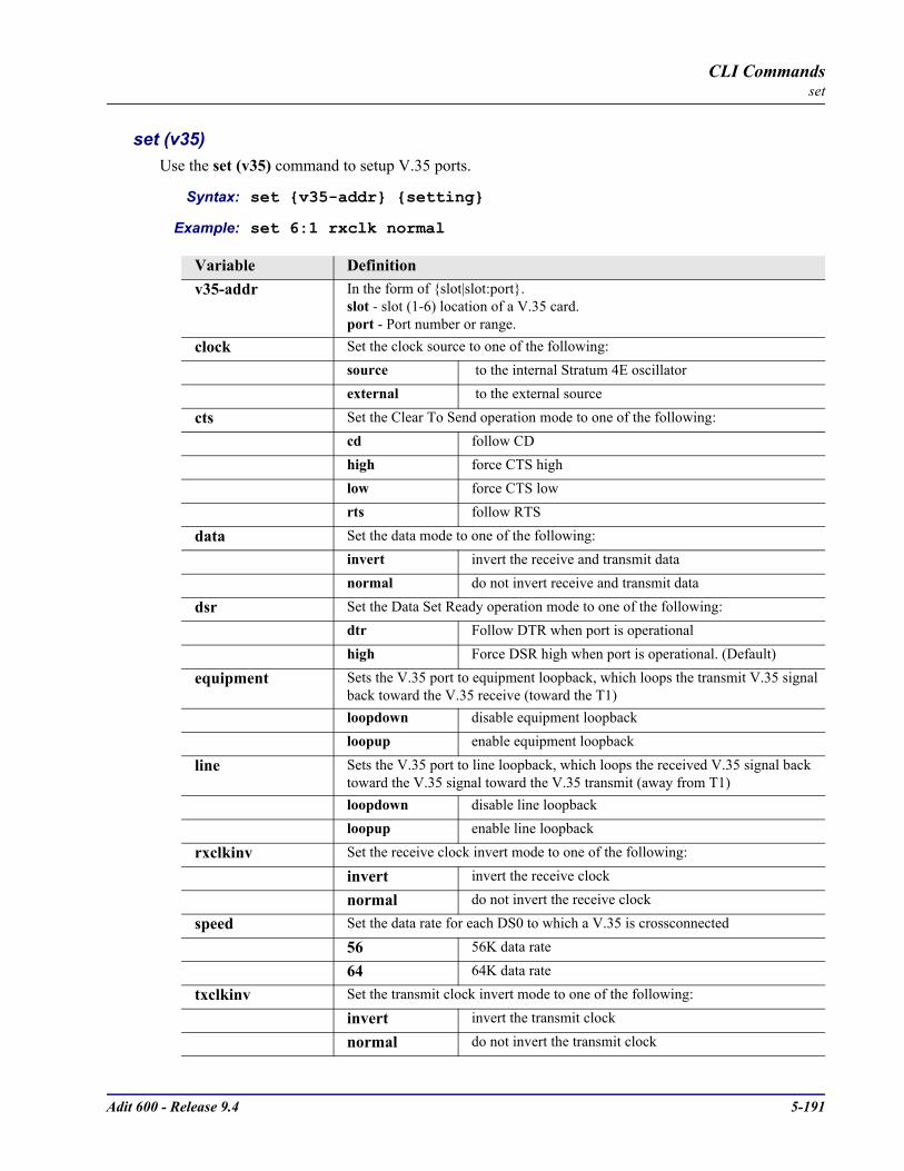
Adit 600 - Release 9.4 5-191
CLI Commandsset
set (v35)Use the set (v35) command to setup V.35 ports.
Syntax: set v35-addr setting
Example: set 6:1 rxclk normal
Variable Definitionv35-addr In the form of slot|slot:port.
slot - slot (1-6) location of a V.35 card.port - Port number or range.
clock Set the clock source to one of the following:
source to the internal Stratum 4E oscillator
external to the external source
cts Set the Clear To Send operation mode to one of the following:cd follow CDhigh force CTS highlow force CTS lowrts follow RTS
data Set the data mode to one of the following:invert invert the receive and transmit datanormal do not invert receive and transmit data
dsr Set the Data Set Ready operation mode to one of the following:dtr Follow DTR when port is operationalhigh Force DSR high when port is operational. (Default)
equipment Sets the V.35 port to equipment loopback, which loops the transmit V.35 signal back toward the V.35 receive (toward the T1)loopdown disable equipment loopbackloopup enable equipment loopback
line Sets the V.35 port to line loopback, which loops the received V.35 signal back toward the V.35 signal toward the V.35 transmit (away from T1)loopdown disable line loopbackloopup enable line loopback
rxclkinv Set the receive clock invert mode to one of the following:
invert invert the receive clock
normal do not invert the receive clock
speed Set the data rate for each DS0 to which a V.35 is crossconnected
56 56K data rate
64 64K data rate
txclkinv Set the transmit clock invert mode to one of the following:
invert invert the transmit clock
normal do not invert the transmit clock

5-192 Adit 600 - Release 9.4
CLI Commandsset
set (v54)Use the set (v54) command to setup V.54 Loopback Test Parameters. The command specifies the range of channels within that card, and the setting to apply.
Syntax: set v54-addr v54 setting [off|on] [n] [nnn]
Example: set 6:1 v54 equipment clear
Variable Definitionv54-addr In the form of slot|slot:port.
slot - slot (1-6) location of a V.35/54 card.port - Port number or range.
equipment Set the V.54 Equipment (Tx) parameters:
address Syntax: set v54-addr v54 equipment address nnn Set V.54 loop test address nnn. nnn = must be one of the following:0 - 255.1, 3, 5, 7, 9, 11, 13, 15,17, 19, 21, 23, 25, 27, 29, 31, 37, 39, 43, 45, 47, 51, 53, 55, 59, 61, 63, 85, 87, 91, 95, 111, 119, 127, 255 (255 disables). See chart below.
clear Syntax: setv54-addr v54 equipment clearClear the bit error rate counters during BER test
ignoreack Syntax: set v54-addr v54 equipment ignoreack off|onIgnore V.54 ACK check [off|on]Ignore acknowledge from remote equipment. This allows potential testing with non-compliant equipment by ignoring the acknowledge phase. WARNING: When choosing this option, the V.35 card will no longer be compliant with the V.54 specification. Use for debug purposes only.
loopdown Syntax: set v54-addr v54 equipment loopdown Stop the test sequence
loopup Syntax: se tv54-addr v54 equipment loopup Start the test sequence
pattern Syntax: set v54-addr v54 equipment pattern nSet V.54 test pattern n is from the following:0 = QRSS pattern (Default)1 = 2047 pattern2 = 215 -1 pattern3 = 220 -1 pattern (QRSS with no bit stuffing)
prepcnt Syntax: set v54-addr v54 equipment prepcnt nnnSet V.54 Rx prep-pattern count nnnnnn = number of times that the preparatory pattern must be received to be recognized.
network Set the V.54 Network loop address.
address Syntax: set v54-addr v54 network address nnnSet the address of the port to nnn.nnn = must be one of the following:1, 3, 5, 7, 9, 11, 13, 15,17, 19, 21, 23, 25, 27, 29, 31, 37, 39, 43, 45, 47, 51, 53, 55, 59, 61, 63, 85, 87, 91, 95, 111, 119, 127, 255 (255 disables). See chart below.
disable Syntax: set v54-addr v54 network disable. Disable V.54 loop test
enable Syntax: set v54-addr v54 network enable Enable V.54 loop test
prepcnt Syntax: set v54-addr v54 network prepcnt nnnSets the preparatory pattern response count.nnn = number of times that the preparatory pattern must be received to be recognized.
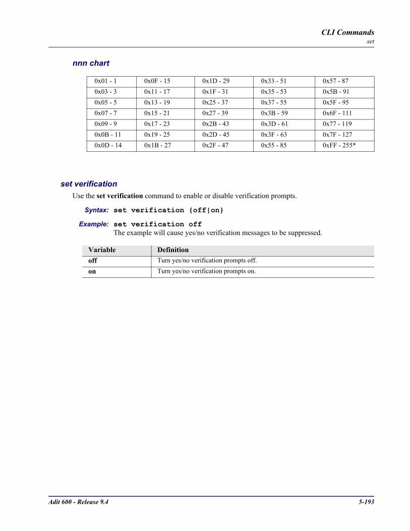
Adit 600 - Release 9.4 5-193
CLI Commandsset
nnn chart
set verificationUse the set verification command to enable or disable verification prompts.
Syntax: set verification off|on
Example: set verification offThe example will cause yes/no verification messages to be suppressed.
0x01 - 1 0x0F - 15 0x1D - 29 0x33 - 51 0x57 - 87 0x03 - 3 0x11 - 17 0x1F - 31 0x35 - 53 0x5B - 91 0x05 - 5 0x13 - 19 0x25 - 37 0x37 - 55 0x5F - 95 0x07 - 7 0x15 - 21 0x27 - 39 0x3B - 59 0x6F - 111 0x09 - 9 0x17 - 23 0x2B - 43 0x3D - 61 0x77 - 119 0x0B - 11 0x19 - 25 0x2D - 45 0x3F - 63 0x7F - 127 0x0D - 14 0x1B - 27 0x2F - 47 0x55 - 85 0xFF - 255*
Variable Definitionoff Turn yes/no verification prompts off.
on Turn yes/no verification prompts on.
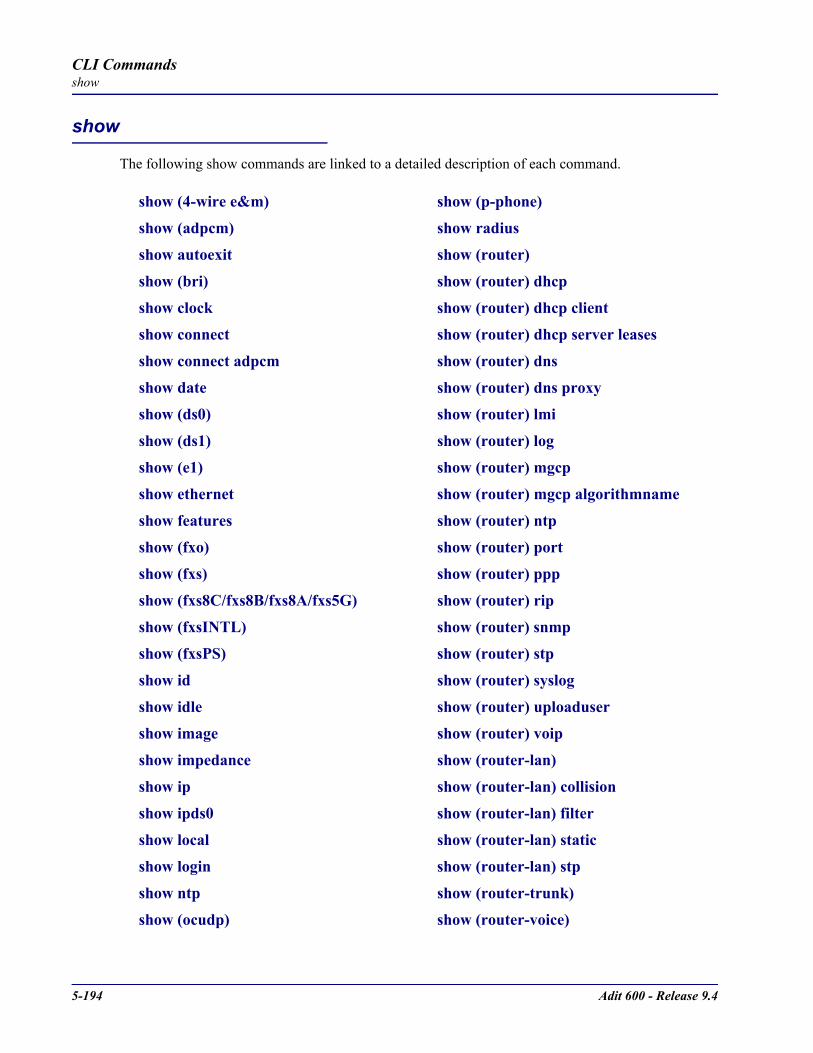
5-194 Adit 600 - Release 9.4
CLI Commandsshow
show
The following show commands are linked to a detailed description of each command.
show (4-wire e&m) show (p-phone)
show (adpcm) show radius
show autoexit show (router)
show (bri) show (router) dhcp
show clock show (router) dhcp client
show connect show (router) dhcp server leases
show connect adpcm show (router) dns
show date show (router) dns proxy
show (ds0) show (router) lmi
show (ds1) show (router) log
show (e1) show (router) mgcp
show ethernet show (router) mgcp algorithmname
show features show (router) ntp
show (fxo) show (router) port
show (fxs) show (router) ppp
show (fxs8C/fxs8B/fxs8A/fxs5G) show (router) rip
show (fxsINTL) show (router) snmp
show (fxsPS) show (router) stp
show id show (router) syslog
show idle show (router) uploaduser
show image show (router) voip
show impedance show (router-lan)
show ip show (router-lan) collision
show ipds0 show (router-lan) filter
show local show (router-lan) static
show login show (router-lan) stp
show ntp show (router-trunk)
show (ocudp) show (router-voice)

Adit 600 - Release 9.4 5-195
CLI Commandsshow
show (router-wan) show (router-wan) trunk
show (router-wan) firewall show (rs232)
show (router-wan) nat bypass show screen
show (router-wan) ppp show snmp
show (router-wan) static ip address show syslog
show (router-wan) static ip network show test (fxs8C/fxs8B)
show (router-wan) static ipx network show time
show (router-wan) static mac address show users
show (router-wan) static nat address show (v35)
show (router-wan) stp show (v54)

5-196 Adit 600 - Release 9.4
CLI Commandsshow
show (4-wire e&m)The show (4we&m) command displays the settings for 4-Wire E&M card.
Syntax: show 4we&m-addr
Example: show 4:1
> show 4:1
SLOT 4:
Settings for 4 Wire E&M Port 1: Type: Voice
RxGain: 7db
TxGain: 16db Signaling: EMI
Variable Definition4we&m-addr In the form of slot or slot:port. Note if only the slot is listed all ports will be
displayed.slot - Slot (1-6) where the 4-Wire E&M card is located. port - Port number, range or "all".
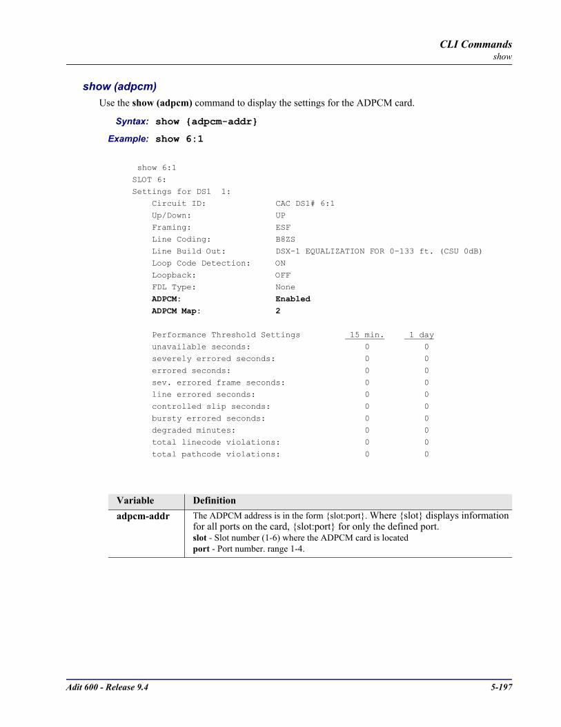
Adit 600 - Release 9.4 5-197
CLI Commandsshow
show (adpcm)Use the show (adpcm) command to display the settings for the ADPCM card.
Syntax: show adpcm-addr
Example: show 6:1
show 6:1
SLOT 6:
Settings for DS1 1: Circuit ID: CAC DS1# 6:1
Up/Down: UP
Framing: ESF Line Coding: B8ZS
Line Build Out: DSX-1 EQUALIZATION FOR 0-133 ft. (CSU 0dB)
Loop Code Detection: ON
Loopback: OFF FDL Type: None
ADPCM: Enabled ADPCM Map: 2
Performance Threshold Settings 15 min. 1 day
unavailable seconds: 0 0 severely errored seconds: 0 0
errored seconds: 0 0
sev. errored frame seconds: 0 0 line errored seconds: 0 0
controlled slip seconds: 0 0
bursty errored seconds: 0 0 degraded minutes: 0 0
total linecode violations: 0 0
total pathcode violations: 0 0
Variable Definitionadpcm-addr The ADPCM address is in the form slot:port. Where slot displays information
for all ports on the card, slot:port for only the defined port.slot - Slot number (1-6) where the ADPCM card is located port - Port number. range 1-4.

5-198 Adit 600 - Release 9.4
CLI Commandsshow
show autoexitUse the show autoexit command to display whether autoexit is on or off. If on, the time-out period is displayed.
Syntax: show autoexit
Example: show autoexit> show autoexitAutoexit is off.
show (bri)Use the show (bri) command to display settings for BRIs.
Syntax: show bri-addr
Example: show 3:1The example will display the settings for port 1 (BRI) on slot 3.
> show 3:1
SLOT 3:Settings for BRI Port 1:
Mode: LT4TO1TDM
Up/Down: UP CRV: 31
Performance Sync Source: ADIT
Auto Activate: OFF
Performance Threshold Settings 1 hour 1 day
------ ------ errored seconds: 40 100
severely errored seconds: 10 25
Variable Definitionbri-addr The BRI address in the form of slot port. Where slot displays connections for
an entire slot, slot:port for a port within a given slot.slot - The slot number (1-6) that contains the BRI cardport - Port number, range or “all”

Adit 600 - Release 9.4 5-199
CLI Commandsshow
show clockThe show clock command displays the primary and secondary clocks.
Syntax: show clock
Example: show clockIn the following example, the primary clock source is in slot A (Controller card), DS1 2; and the secondary clock source is in slot 6 (BRI card), DS1 1.
> show clock
Primary Master Transmit Clock Source: Slot A DS1 2
Secondary Master Transmit Clock Source: Slot 6 BRI 1
show connectThe show connect command displays the static connections for channels and ports.
Syntax: show connect slot|slot:port|slot:port:channel
Example: show connect a:1:1-4
> show connect a:1:1-4 From Desc Desc To
----------- ------------------ ----------------- ---------
A:01:01 DATA DS0 <--> WAN DATA 64K 2:01:01 A:01:02 DATA DS0 <--> WAN DATA 64K 2:01:02
A:01:03 DATA DS0 <--> WAN DATA 64K 2:01:03
A:01:04 DATA DS0 <--> WAN DATA 64K 2:01:04
Variable Definitionslot The slot number, A for the controller card, or 1 - 6 for service cards.
port Port number, range or all.
channel Channel number, range or all.

5-200 Adit 600 - Release 9.4
CLI Commandsshow
show connect adpcmThe show connect adpcm command displays the connections for the ADPCM port.
Syntax: show connect adpcm adpcm-addr
Example: show connect 1:1
> show connect adpcm 1:1
From Desc Desc To
-------------- ------------- ------------- ---------- 1:01:01(01/02) DATA DS0 <--> DS0 DATA 1:04:01
1:01:02(03/04) DATA DS0 <--> DS0 DATA 1:04:02
1:01:03(05/06) DATA DS0 <--> DS0 DATA 1:04:03 1:01:04(07/08) DATA DS0 <--> DS0 DATA 1:04:04
1:01:05(09/10) DATA DS0 <--> DS0 DATA 1:04:05
1:01:06(11/12) DATA DS0 <--> DS0 DATA 1:04:06
1:01:07(13/14) DATA DS0 <--> DS0 DATA 1:04:07 1:01:08(15/16) DATA DS0 <--> DS0 DATA 1:04:08
1:01:09(17/18) DATA DS0 <--> DS0 DATA 1:04:09
1:01:10(19/20) DATA DS0 <--> DS0 DATA 1:04:10 1:01:11(21/22) DATA DS0 <--> DS0 DATA 1:04:11
1:01:12(23/24) DATA DS0 <--> DS0 DATA 1:04:12
show dateThe show date command displays the date in dd/mm/yyyy format.
Example: show date
> show date
date: 08/10/2002
Variable Definitionadpcm-addr The ADPCM address is in the form slot:port.
slot - Slot number (1-6) where the ADPCM card is located port - Port number. range 1-4.

Adit 600 - Release 9.4 5-201
CLI Commandsshow
show (ds0)The show (ds0) command displays settings for DS0s.
Syntax: show ds0-addr
Example: show a:1:1In the following example, the show (ds0) command has queried slot A (Controller card), port 1, channel 1.
> show a:1:1
SLOT A:
Settings for DS1 1: channel 1:
Type: VOICE
Signaling: LS
Interface Side: NETWORK
Variable Definitionds0-addr DS0 address in the format slot:port:channel.
slot A for the controller card, or 1 - 6 for service cards.
port Port number or range.
channel Channel number, range or all.

5-202 Adit 600 - Release 9.4
CLI Commandsshow
show (ds1)The show (ds1) command displays settings for DS1s.
Syntax: show ds1-addr
Example: show a:1In the following example, the query show a:1 has returned the following DS1 settings for slot A (the controller card), port 1.
Adit 600> show 1:1
SLOT 1:Settings for DS1 1:
Circuit ID: CAC DS1# 1:1
Up/Down: UP Framing: ESF
Line Coding: B8ZS
Line Build Out: DSX-1 EQUALIZATION FOR 0-133 ft. (CSU 0dB)
Loop Code Detection: CSU Loopback: OFF
FDL Type: None
AIS Forwarding: Disabled AIS List: all
Performance Threshold Settings 15 min. 1 day --------- ----------
unavailable seconds: 0 0
severely errored seconds: 0 0 errored seconds: 0 0
sev. errored frame seconds: 0 0
line errored seconds: 0 0 controlled slip seconds: 0 0
bursty errored seconds: 0 0
degraded minutes: 0 0 total linecode violations: 0 0
total pathcode violations: 0 0
Variable Definitionds1-addr DS1 address in the format slot or slot:port.
slot A for the controller, or 1 - 6 for service cards containing a Quad T1, or Quad DS1/E1 card.
port Port number, range or "all". Note: if the port is not defined, all ports will be listed.

Adit 600 - Release 9.4 5-203
CLI Commandsshow
show (e1)The show (e1) command displays settings for E1s.
Syntax: show e1-addr
Example: show 6:1In the following example, the query show 6:1 has returned the following E1 settings for slot 6, port 1.
> show 6:1
SLOT 6:Settings for E1 1:
Up/Down: UP
Framing: E1FRCRC Signaling: CAS
Line Coding: HDB3
Loopback: OFF
Performance Threshold Settings 15 min. 1 day
--------- ----------
unavailable seconds: 0 0 severely errored seconds: 0 0
errored seconds: 0 0
sev. errored frame seconds: 0 0 line errored seconds: 0 0
controlled slip seconds: 0 0
bursty errored seconds: 0 0 degraded minutes: 0 0
total linecode violations: 0 0
total pathcode violations: 0 0
Variable Definitione1-addr E1 address in the format slot:port.
slot A for the controller (E1), or 1 - 6 for service cards containing a Quad E1 or Quad DS1/E1 card.
port Port number or range.

5-204 Adit 600 - Release 9.4
CLI Commandsshow
show ethernetThe show ethernet command displays ethernet and IP settings.
Syntax: show ethernet
Example: show ethernet
IP Address and Mask: 198.162.3.196 255.255.255.0
IP Address of the Gateway: 192.168.3.202
MAC Address: 00:E0:97:00:A9:33
show featuresThe show features command displays ethernet and IP settings.
Example: show [rtr_card-addr] features
Example: show features
Activated Features:
**No Active Features
show (fxo)The show (fxo) command displays the settings for FXOs.
Syntax: show fxo-addr
Example: show 1:1
SLOT 1:
Settings for FXO: channel 1: Type: VOICE
Signaling: LS
RxGain: -6 dB TxGain: -3 dB
Variable Definitionrtr_card-addr The slot number (1-6) that contains the Router (IP, CMG or TSR) card.
Variable Definitionfxo-addr In the form of slot or slot:port. Note if only slot is listed, all ports will be displayed
slot - The slot number (1-6) of the Adit chassis that contains the FXO cardport - Port number, range or “all”.

Adit 600 - Release 9.4 5-205
CLI Commandsshow
show (fxs)The show (fxs) command displays the settings for all FXS ports.
Syntax: show fxs-addr
Example: show 4:1The example shows settings for port on slot 2.
> show 4:1
SLOT 4:
Settings for FXS: channel 1: Type: VOICE
Signaling: LS
RxGain: -6 dB
TxGain: -3 dB LineLength: SHORT
Variable Definitionfxs-addr In the form of slot or slot:port. Note if only slot is listed, all ports will be displayed
slot - The slot number (1-6) of the Adit chassis that contains the FXS cardport - Port number, range or “all”.
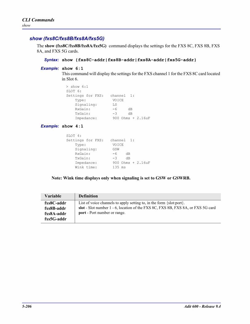
5-206 Adit 600 - Release 9.4
CLI Commandsshow
show (fxs8C/fxs8B/fxs8A/fxs5G)The show (fxs8C/fxs8B/fxs8A/fxs5G) command displays the settings for the FXS 8C, FXS 8B, FXS 8A, and FXS 5G cards.
Syntax: show fxs8C-addr|fxs8B-addr|fxs8A-addr|fxs5G-addr
Example: show 6:1This command will display the settings for the FXS channel 1 for the FXS 8C card located in Slot 6.> show 6:1SLOT 6:Settings for FXS: channel 1: Type: VOICE Signaling: LS RxGain: -6 dB TxGain: -3 dB Impedance: 900 Ohms + 2.16uF
Example: show 4:1
SLOT 4:Settings for FXS: channel 1: Type: VOICE Signaling: GSW RxGain: -6 dB TxGain: -3 dB Impedance: 900 Ohms + 2.16uF Wink time: 135 ms
Note: Wink time displays only when signaling is set to GSW or GSWRB.
Variable Definitionfxs8C-addrfxs8B-addrfxs8A-addrfxs5G-addr
List of voice channels to apply setting to, in the form slot:port.slot - Slot number 1 - 6, location of the FXS 8C, FXS 8B, FXS 8A, or FXS 5G cardport - Port number or range.
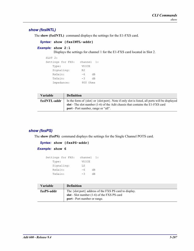
Adit 600 - Release 9.4 5-207
CLI Commandsshow
show (fxsINTL)The show (fxsINTL) command displays the settings for the E1-FXS card.
Syntax: show fxsINTL-addr
Example: show 2:1Displays the settings for channel 1 for the E1-FXS card located in Slot 2.
SLOT 2:
Settings for FXS: channel 1:
Type: VOICE Signaling: R2
RxGain: -6 dB
TxGain: -3 dB Impedance: 900 Ohms
show (fxsPS)The show (fxsPS) command displays the settings for the Single Channel POTS card.
Syntax: show fxsPS-addr
Example: show 6
Settings for FXS: channel 1:
Type: VOICE Signaling: LS
RxGain: -6 dB
TxGain: -3 dB
Variable DefinitionfxsINTL-addr In the form of slot or slot:port. Note if only slot is listed, all ports will be displayed
slot - The slot number (1-6) of the Adit chassis that contains the E1-FXS cardport - Port number, range or “all”.
Variable DefinitionfxsPS-addr The slot:port address of the FXS PS card to display.
slot - Slot number (1-6) of the FXS PS cardport - Port number or range.
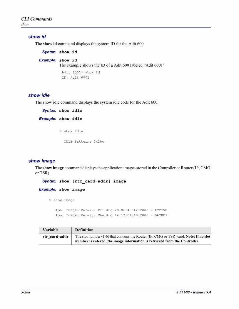
5-208 Adit 600 - Release 9.4
CLI Commandsshow
show idThe show id command displays the system ID for the Adit 600.
Syntax: show id
Example: show idThe example shows the ID of a Adit 600 labeled “Adit 6001"
Adit 6001> show id
ID: Adit 6001
show idleThe show idle command displays the system idle code for the Adit 600.
Syntax: show idle
Example: show idle
> show idle
IDLE Pattern: 0x2bc
show imageThe show image command displays the application images stored in the Controller or Router (IP, CMG or TSR).
Syntax: show [rtr_card-addr] image
Example: show image
> show image
Ape. Image: Ver=7.0 Fri Aug 29 06:40:42 2003 - ACTIVE
App. Image: Ver=7.0 Thu Aug 14 13:01:18 2003 - BACKUP
Variable Definitionrtr_card-addr The slot number (1-6) that contains the Router (IP, CMG or TSR) card. Note: If no slot
number is entered, the image information is retrieved from the Controller.

Adit 600 - Release 9.4 5-209
CLI Commandsshow
show impedanceThe show impedance command displays the impedance settings for FXS 5G, FXS 8A and E1-FXS service cards.
Syntax: show impedance
Example: show impedance
Index Impedance CODEC Country
1 120 Ohms + (.110µF || 820 Ohms) A-law Norway 2 150 Ohms + (.047µF || 510 Ohms) A-law Malaysia 3 150 Ohms + (.072µF || 830 Ohms) A-law Belgium 4 200 Ohms + (.100µF || 680 Ohms) A-law China 5 215 Ohms + (.137µF || 1k Ohms) A-law France 6 220 Ohms + (.115µF || 820 Ohms) A-law Austria, Germany, Mexico, Switzerland
7 220 Ohms + (.120µF || 820 Ohms) A-law Australia 8 270 Ohms + (.120µF || 910 Ohms) A-law Finland 9 300 Ohms + (.220µF || 1k Ohms) A-law United Kingdom 10 370 Ohms + (.310µF || 620 Ohms) A-law New Zealand 11 400 Ohms + (.033µF || 500 Ohms) A-law Denmark 12 400 Ohms + (.050µF || 500 Ohms) A-law Greece 13 600 Ohms A-law Korea, Indonesia, Italy, Poland,
Russia, Spain,
Thailand, China 14 600 Ohms + 1.00µF µ-law Japan 15 600 Ohms + 1.50µF A-law Saudi Arabia 16 600 Ohms + 2.16µF µ-law Korea 17 800 Ohms A-law Netherlands
18 900 Ohms A-law Brazil
19 900 Ohms + 2.16µF µ-law USA, Taiwan
Note: In general, µ-Law settings are used for T1 applications, A-Law settings are used for E1 applications.
show ipThe show ip command displays the IP Address information for the Adit 600.
Syntax: show ip
Example: show ip
> show ip
IP Address and Mask: 192.168.3.193 255.255.255.0
IP Address of the Gateway: 192.168.3.202 OK
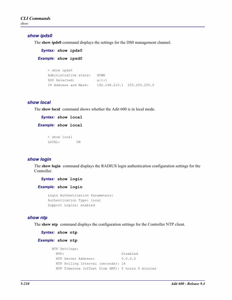
5-210 Adit 600 - Release 9.4
CLI Commandsshow
show ipds0The show ipds0 command displays the settings for the DS0 management channel.
Syntax: show ipds0
Example: show ipsd0
> show ipds0
Administrative state: DOWN
DS0 Selected: a:1:1IP Address and Mask: 192.168.210.1 255.255.255.0
show localThe show local command shows whether the Adit 600 is in local mode.
Syntax: show local
Example: show local
> show local
LOCAL: ON
show loginThe show login command displays the RADIUS login authentication configuration settings for the Controller.
Syntax: show login
Example: show login
Login Authentication Parameters:Authentication Type: local
Support Logins: enabled
show ntpThe show ntp command displays the configuration settings for the Controller NTP client.
Syntax: show ntp
Example: show ntp
NTP Settings: NTP: Disabled
NTP Server Address: 0.0.0.0
NTP Polling Interval (seconds): 16 NTP Timezone (offset from GMT): 0 hours 0 minutes

Adit 600 - Release 9.4 5-211
CLI Commandsshow
show (ocudp) Use the show (ocudp) to display baud, loopdetect, error correction, switched and enhanced switched service and secondary channel provisioning.
Syntax: show ocudp-addr
Example: show 2:1
SLOT 2:
Settings for OCUDP Port 1: Up/Down: UP
Baudrate: 56000
Loopdetect Types Enabled: CSU Non-Latching
DSU Non-Latching
OCU Non-Latching
Error Correction: DISABLE Secondary Channel: DISABLE
show (p-phone)Use the show (p-phone) to display the P-Phone settings.
Syntax: show p_phone-addr
Example: show 2:1
SLOT 2:
Settings for EBS Port 1:
RxGain: -6db TxGain: -3db
CRV Number: 0
Variable Definitionocudp-addr The slot:port address of the OCUDP card to display.
slot - Slot number (1-6) where the OCUDP card is locatedport - Port number or range. If no port is specified, all ports will be displayed.
Variable Definitionp_phone-addr The slot:port address of the P-Phone card to display.
slot - Slot number (1-6) where the P-Phone card is locatedport - Port number or range. If no port is specified, all ports will be displayed.

5-212 Adit 600 - Release 9.4
CLI Commandsshow
show radiusThe show radius command displays the RADIUS configuration settings for the Controller.
Syntax: show radius
Example: show radius
RADIUS Configuration Parameters:
Authentication: enabled for Slot 4
Slot 5
NAS Identifier: Retry count: 3
Timeout (sec): 3
Server(1) : UNUSED
Server(2) : UNUSED Server(3) : UNUSED

Adit 600 - Release 9.4 5-213
CLI Commandsshow
show (router)The show (router) command displays the settings for the Router card.
Syntax: show rtr_card-addr
Example: show 5> show 5
SLOT 5:Login Settings for Router:
Authentication: Local
Login Prompt: Enabled
LMI Settings for Router:
LMI: Disabled
RIP Setting for Router:
RIP Mode Receive: RIP1
RIP Mode Send: RIP1
PPP Authentication/Security Settings for Router:
Authentication by Remote: Protocol: None
User ID: Local Profile Name
Authentication of Remote:
Protocol: None
Local Security Server:
Type: None
PPP Statistics for Slot-5:
Up/Down Rx Rx Tx TxRemote Name State Time Packets Octets Packets Octets
RemoteAdit DOWN 1h27m16s 0 0 0 0
SNMP Settings for Router:
SNMP Communities:
Name Address Access public 0.0.0.0 Read
SNMP Trap Destinations: Name Address Location
public 0.0.0.0 Local LAN
Name: unknown
Contact: unknown
Location: unknown
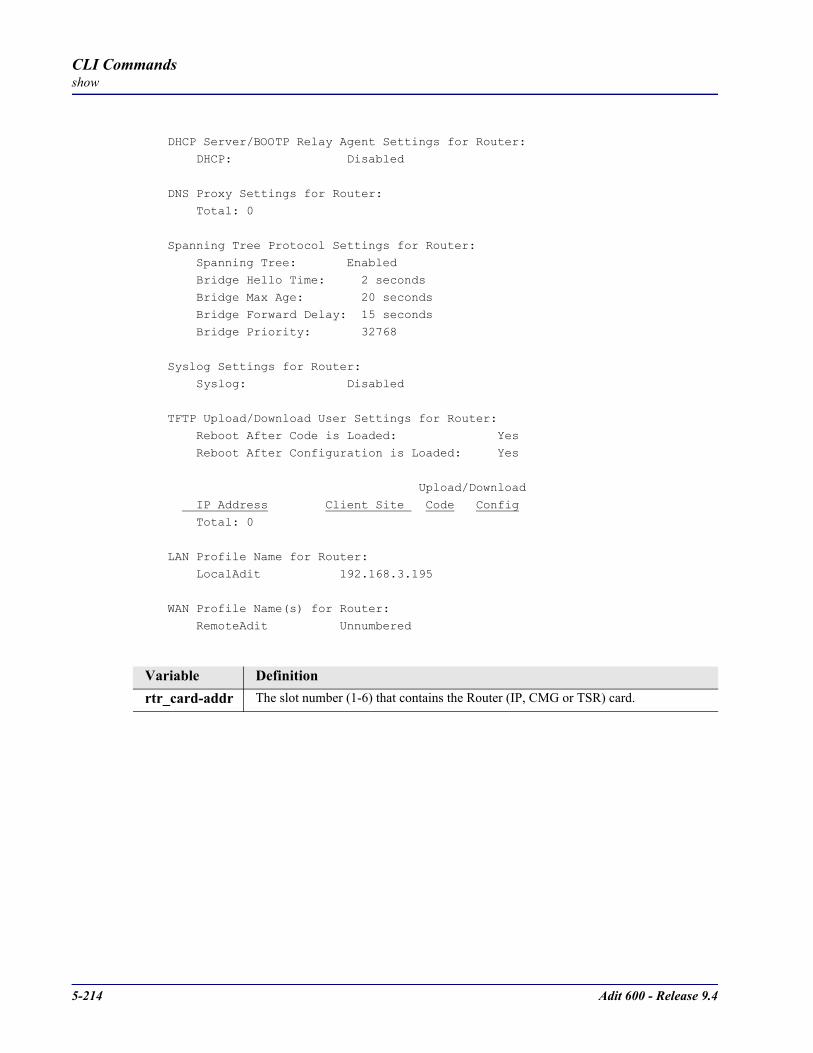
5-214 Adit 600 - Release 9.4
CLI Commandsshow
DHCP Server/BOOTP Relay Agent Settings for Router: DHCP: Disabled
DNS Proxy Settings for Router: Total: 0
Spanning Tree Protocol Settings for Router: Spanning Tree: Enabled
Bridge Hello Time: 2 seconds
Bridge Max Age: 20 seconds Bridge Forward Delay: 15 seconds
Bridge Priority: 32768
Syslog Settings for Router: Syslog: Disabled
TFTP Upload/Download User Settings for Router: Reboot After Code is Loaded: Yes
Reboot After Configuration is Loaded: Yes
Upload/Download
IP Address Client Site Code Config
Total: 0
LAN Profile Name for Router:
LocalAdit 192.168.3.195
WAN Profile Name(s) for Router:
RemoteAdit Unnumbered
Variable Definitionrtr_card-addr The slot number (1-6) that contains the Router (IP, CMG or TSR) card.
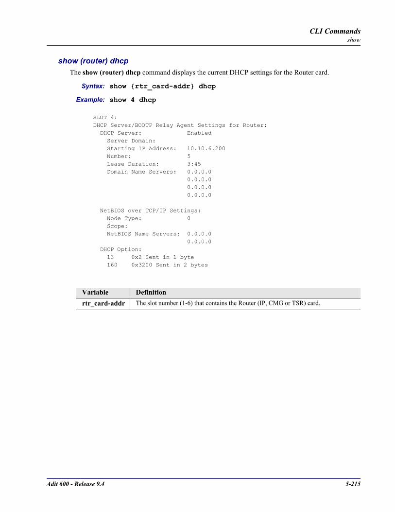
Adit 600 - Release 9.4 5-215
CLI Commandsshow
show (router) dhcpThe show (router) dhcp command displays the current DHCP settings for the Router card.
Syntax: show rtr_card-addr dhcp
Example: show 4 dhcp
SLOT 4:DHCP Server/BOOTP Relay Agent Settings for Router: DHCP Server: Enabled Server Domain: Starting IP Address: 10.10.6.200 Number: 5 Lease Duration: 3:45 Domain Name Servers: 0.0.0.0 0.0.0.0 0.0.0.0 0.0.0.0
NetBIOS over TCP/IP Settings: Node Type: 0 Scope: NetBIOS Name Servers: 0.0.0.0 0.0.0.0 DHCP Option: 13 0x2 Sent in 1 byte 160 0x3200 Sent in 2 bytes
Variable Definitionrtr_card-addr The slot number (1-6) that contains the Router (IP, CMG or TSR) card.

5-216 Adit 600 - Release 9.4
CLI Commandsshow
show (router) dhcp clientThe show (router) dhcp client command displays the current DHCP Client settings.
Syntax: show rtr_card-addr dhcp client
Example: show 4 dhcp client
DHCP Client enabledAuto DNS enabledTx Broadcast Packet enabledIp/Mask Request enabledGateway Request enabledHost Name Request disabledDomain Name Request enabledDNS Primary Server Request enabledDNS Secondary Server Request disabled
show (router) dhcp server leasesThe show (router) dhcp server leases command displays the current DHCP settings for the Router card.
Syntax: show rtr_card-addr dhcp server leases
Example: show 4 dhcp server leases
DHCP SERVER LEASES REPORT Slot-4 DHCP Server Leases: Used=0 Avail=5
# State IP ClientId Expires HostName
No DHCP Leases In Use.
Variable Definitionrtr_card-addr The slot number (1-6) that contains the Router (IP, CMG or TSR) card.
Variable Definitionrtr_card-addr The slot number (1-6) that contains the Router (IP, CMG or TSR) card.

Adit 600 - Release 9.4 5-217
CLI Commandsshow
show (router) dnsThe show (router) dns command displays the current DNS setup for the Router card.
Syntax: show rtr_card-addr dns
Example: show 3 dns
SLOT 5:
DNS Settings:
DNS Resolver: Disabled DNS Server 1 IP Address: 0.0.0.0
DNS Server 2 IP Address: 0.0.0.0
DNS Host Name: DNS Default Domain:
DNS Static Host List:
Total: 0
show (router) dns proxyThe show (router) dns proxy command displays the current DNS Proxy setup for the Router card.
Syntax: show rtr_card-addr dns proxy
Example: show 5 dns proxy
SLOT 5:DNS Proxy Settings for Router:
Total: 0
Variable Definitionrtr_card-addr The slot number (1-6) that contains the Router (IP, CMG or TSR) card.
Variable Definitionrtr_card-addr The slot number (1-6) that contains the Router (IP, CMG or TSR) card.
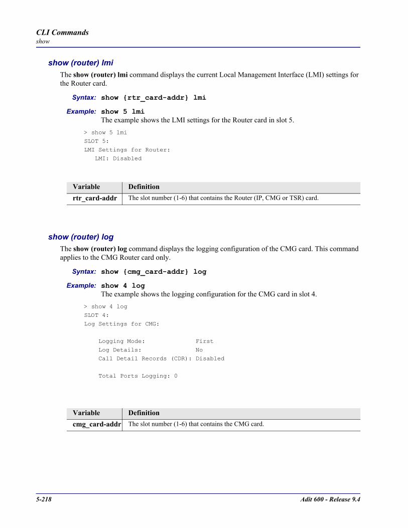
5-218 Adit 600 - Release 9.4
CLI Commandsshow
show (router) lmiThe show (router) lmi command displays the current Local Management Interface (LMI) settings for the Router card.
Syntax: show rtr_card-addr lmi
Example: show 5 lmiThe example shows the LMI settings for the Router card in slot 5.
> show 5 lmi
SLOT 5:LMI Settings for Router:
LMI: Disabled
show (router) logThe show (router) log command displays the logging configuration of the CMG card. This command applies to the CMG Router card only.
Syntax: show cmg_card-addr log
Example: show 4 logThe example shows the logging configuration for the CMG card in slot 4.
> show 4 log
SLOT 4:
Log Settings for CMG:
Logging Mode: First
Log Details: No Call Detail Records (CDR): Disabled
Total Ports Logging: 0
Variable Definitionrtr_card-addr The slot number (1-6) that contains the Router (IP, CMG or TSR) card.
Variable Definitioncmg_card-addr The slot number (1-6) that contains the CMG card.

Adit 600 - Release 9.4 5-219
CLI Commandsshow
show (router) mgcpThe show (router) mgcp command to display all options set through set (router) mgcp commands. This command applies to the CMG Router card only.
Syntax: show cmg_card-addr mgcp
Example: show 4 mgcp
SLOT 4:
MGCP Settings for CMG:
Activation, Addressing, and Transactions: MGCP State: Down
Call Agent IP Address: 0.0.0.0
Call Agent Domain Name: (not applicable)
Call Agent MGCP Port: 2727 Gateway MGCP Port: 2427
MGCP Gateway ID: Default
Response Timeout (ms): 3000 Max Retries: 3
Interoperability Settings:
Version: IETF 1.0 Hookswitch Reporting: Always
Default IETF Event Package: D
Piggybacking: Disabled Address Format: Brackets
Dialstring Format: Commas
SDP Mode: Full Parse Mode: Lenient
Quarantine: Step Process
Voice Algorithm Names for Local Connection Options (LCO):
CMG Algorithm ID MGCP LCO Name
g711mu
g711a g726_16
g726_24
g726_32 g726_40
Variable Definitioncmg_card-addr The slot number (1-6) that contains the CMG card.

5-220 Adit 600 - Release 9.4
CLI Commandsshow
show (router) mgcp algorithmnameThe show (router) mgcp algorithmname command to display all MGCP designations for voice coding algorithms supported by the CMG. This displays the CLI defined name, if any, and the default for each algorithm. MGCP algorithm names are used in the "a:" attribute in the Local Connection Options (L:) parameter line of a CRCX or MDCX command. This command applies to the CMG Router card only.
Syntax: show cmg_card-addr mgcp algorithmname
Example: show 4 mgcp algorithmname
SLOT 4:MGCP Voice Algorithm Names for CMG Local Connection Options (LCO):
CMG Algorithm ID MGCP LCO Name g711mu
g711a
g726_16
g726_24 g726_32
g726_40
show (router) ntpThe show (router) ntp command displays settings for NTP options.
Syntax: show rtr_card-addr ntp
Example: show 4 ntp
SLOT 4:NTP Settings for CMG:
NTP: Disabled
NTP Server: 0.0.0.0 NTP Interval (seconds):120
NTP Timezone (offset from GMT):0 hours 0 minutes
Variable Definitioncmg_card-addr The slot number (1-6) that contains the CMG card.
Variable Definitionrtr_card-addr The slot number (1-6) that contains the Router (IP, CMG or TSR) card.

Adit 600 - Release 9.4 5-221
CLI Commandsshow
show (router) portThe show (router) port command displays the current TSR ports configuration. This command applies to the Terminal Server Router card only.
Syntax: show tsr_card-addr port
Example: show 1 port
SLOT 1:
Port Profiles for Terminal Server Router:
Port 1
Name: none
Type: RS-232 Asynchronous Settings
Socket: 10.10.11.1:23 TCP
Baud Rate 9600
Data Bits 8 Stop Bits 1
No Parity
No Flowcontrol
Port 2
Name: none Type: RS-232
Asynchronous Settings
Socket: 10.10.11.2:23 TCP Baud Rate 9600
Data Bits 8
Stop Bits 1 No Parity
No Flowcontrol
Port 3
Name: none
Type: Ethernet
Port 4
Name: none Type: Ethernet
Variable Definitiontsr_card-addr The slot number (1-6) that contains the TSR card.
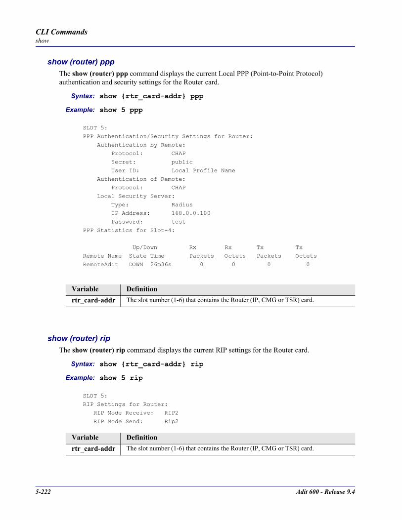
5-222 Adit 600 - Release 9.4
CLI Commandsshow
show (router) pppThe show (router) ppp command displays the current Local PPP (Point-to-Point Protocol) authentication and security settings for the Router card.
Syntax: show rtr_card-addr ppp
Example: show 5 ppp
SLOT 5:
PPP Authentication/Security Settings for Router:
Authentication by Remote: Protocol: CHAP
Secret: public
User ID: Local Profile Name
Authentication of Remote: Protocol: CHAP
Local Security Server:
Type: Radius IP Address: 168.0.0.100
Password: test
PPP Statistics for Slot-4:
Up/Down Rx Rx Tx Tx
Remote Name State Time Packets Octets Packets OctetsRemoteAdit DOWN 26m36s 0 0 0 0
show (router) ripThe show (router) rip command displays the current RIP settings for the Router card.
Syntax: show rtr_card-addr rip
Example: show 5 rip
SLOT 5:RIP Settings for Router:
RIP Mode Receive: RIP2
RIP Mode Send: Rip2
Variable Definitionrtr_card-addr The slot number (1-6) that contains the Router (IP, CMG or TSR) card.
Variable Definitionrtr_card-addr The slot number (1-6) that contains the Router (IP, CMG or TSR) card.

Adit 600 - Release 9.4 5-223
CLI Commandsshow
show (router) snmpThe show (router) snmp command displays the current SNMP settings for the specified Router card.
Syntax: show rtr_card-addr snmp
Example: show 5 snmp
> show 5 snmpSLOT 5:
SNMP Settings for Router:
SNMP Communities: Name Address Access
public 0.0.0.0 Read
SNMP Trap Destinations:
Name Address Location public 0.0.0.0 Local LAN
Statistics Averaging Interval: 1 min.
Name: unknown Contact: unknown Location: unknown
show (router) stpThe show (router) stp command displays the current Spanning Tree Protocol settings for the specified Router card.
Syntax: show rtr_card-addr stp
Example: show 5 stp> show 5 stp
SLOT 5:Spanning Tree Protocol Settings for Router:
Spanning Tree: Enabled
Bridge Hello Time: 2 seconds Bridge Max Age: 20 seconds
Bridge Forward Delay: 15 seconds
Bridge Priority: 32768
Variable Definitionrtr_card-addr The slot number (1-6) that contains the Router (IP, CMG or TSR) card.
Variable Definitionrtr_card-addr The slot number (1-6) that contains the Router (IP, CMG or TSR) card.

5-224 Adit 600 - Release 9.4
CLI Commandsshow
show (router) syslogThe show (router) syslog command displays the current Syslog setup for the Router card.
Syntax: show rtr_card-addr syslog
Example: show 5 syslog> show 5 syslog
SLOT 5:Syslog Settings for Router:
Syslog: Enabled
Facility: 20 Level: 3
Server IP Address: 192.168.3.3
show (router) uploaduser The show uploaduser command displays the current list of users allowed to upload and download configuration and code files.
Syntax: show rtr_card-addr uploaduser
Example: show 5 uploaduser
> show 5 uploaduserSLOT 5:
TFTP Upload/Download User Settings for Router:
Reboot After Code is Loaded: Yes Reboot After Configuration is Loaded: Yes
Upload/Download IP Address Client Site Code Config
Any Adit1 X X
Total: 1
Variable Definitionrtr_card-addr The slot number (1-6) that contains the Router (IP, CMG or TSR) card.
Variable Definitionrtr_card-addr The slot number (1-6) that contains the Router (IP, CMG or TSR) card.

Adit 600 - Release 9.4 5-225
CLI Commandsshow
show (router) voip The show voip command displays the current settings for all VoIP parameters. This command applies to the CMG Router card only.
Syntax: show cmg_card-addr voip
Example: show 4 voip
> show 4 voip
SLOT 4:
VoIP Settings for CMG:
VoIP Configuration:
RTP Baseport: 30000
RTCP CNAME: Default Gateway ID RTCP Interval (seconds): 5
Jitterbuffer Mode: Static
Flash Timeout (milliseconds): 1500 Compander: A-Law
Call Detail Records: Disabled
Voice Algorithm SDP Identification and Ptimes:
RTP RTP CMG ID SDP Name Payload Type Ptime
------------- --------------- -------------- --------------
g711mu pcmu 0 20 g711a pcma 8 20
g726_16 g726-16 96 20
g726_24 g726-24 98 20 g726_32 g726-32 2 20
g726_40 g726-40 99 20
dtmf_relay telephone-event 97 20
Variable Definitioncmg_card-addr The slot number (1-6) that contains the CMG card.

5-226 Adit 600 - Release 9.4
CLI Commandsshow
show (router-lan)The show (router-lan) command displays the settings for the Router card.
Syntax: show rtr_lan-addr
Example: show 4:1SLOT 4:Settings for RTR LAN 1: Profile Name: LocalAdit Up/Down: UP Proxy: Disabled Physical link: Automatic MAC Address: 00:E0:97:01:E3:A2
IP Settings: IP Address and Mask: 192.168.3.193 255.255.255.0 Default Router: 192.168.3.202 Enabled Frame Types: Ethernet II RIP Direction: Send Secondary IP Addresses and Masks: 192.168.1.1 255.255.255.0 IPX Settings: Enabled Frame Types: None RIP Direction: Send 802.2 Ext. Network: 00000000 Eth II Ext. Network: 00000000 SNAP Ext. Network: 00000000 802.3 Ext. Network: 00000000 Other Settings: Enabled Frame Types: NoneLAN Collision Threshold Settings for LocalAdit: Sample Interval: 10 Collision High Threshold: 500 Collision Low Threshold: 10LAN Spanning Tree Protocol Settings for LocalAdit: Spanning Tree: DisabledStatic IP Network Settings for LocalAdit: Total: 0 Static IPX Network Settings for LocalAdit: Total: 0
Static IP Address Settings for LocalAdit: Total: 0Static MAC Address Settings for LocalAdit: Total: 0LAN Filters Enabled for LocalAdit: Forward Mode: Forward ALL Frames NOT Matching Filters
Filter Type Source/Dest Filter Name Total: 0
LAN MAC Address Filters Defined for LocalAdit: Total: 0LAN Protocol Filters Defined for LocalAdit: Total: 0LAN Custom Filters Enabled Defined for LocalAdit: Total: 0
Variable Definitionrtr_lan-addr Router (IP, CMG or TSR) address is in the form slot:port or slot "profile-name".
slot - The slot number (1-6) that contains the Router card.port - Port number of the Router.profile-name - Profile name for the Router interface used to reach this destination. Name must be enclosed in quotes, with a maximum of 11 characters.
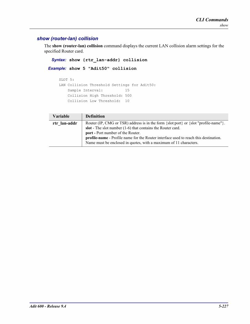
Adit 600 - Release 9.4 5-227
CLI Commandsshow
show (router-lan) collisionThe show (router-lan) collision command displays the current LAN collision alarm settings for the specified Router card.
Syntax: show rtr_lan-addr collision
Example: show 5 "Adit50" collision
SLOT 5:
LAN Collision Threshold Settings for Adit50:
Sample Interval: 15 Collision High Threshold: 500
Collision Low Threshold: 10
Variable Definitionrtr_lan-addr Router (IP, CMG or TSR) address is in the form slot:port or slot "profile-name".
slot - The slot number (1-6) that contains the Router card.port - Port number of the Router.profile-name - Profile name for the Router interface used to reach this destination. Name must be enclosed in quotes, with a maximum of 11 characters.

5-228 Adit 600 - Release 9.4
CLI Commandsshow
show (router-lan) filterThe show (router-lan) filter command displays the current LAN Layer 2 data filters applied to the LAN on the specified Router card.
Syntax: show rtr_lan-addr filter [address|all|custom|protocol]
Example: show 5:1 filter
SLOT 5:
LAN Filters Enabled for Adit50: Forward Mode: Forward ALL Frames NOT Matching Filters
Filter Type Source/Dest Filter Name
Protocol XNSrule Protocol XNSrule
Total: 2
Example: show 5:1 filter all
SLOT 5:
LAN MAC Address Filters Defined for Adit50: Total: 0
LAN Protocol Filters Defined for Adit50:
Protocol Name Ethernet Value IEEE Value SPANTRE 0 42
XNSrule 807 0
XNSrule 807 0 Total: 3
LAN Custom Filters Enabled Defined for Adit50:
Total: 0
Variable Definitionrtr_lan-addr Router (IP, CMG or TSR) address is in the form slot:port or slot "profile-name".
slot - The slot number (1-6) that contains the Router card.port - Port number of the Router.profile-name - Profile name for the Router interface used to reach this destination. Name must be enclosed in quotes, with a maximum of 11 characters.
address Display Address filters only.
custom Display Custom filters only.
protocol Display Protocol filters only.
all Display all the defined filters.

Adit 600 - Release 9.4 5-229
CLI Commandsshow
show (router-lan) staticThe show (router-lan) static commands to display the current list of static entries for the LAN on the specified Router card.
show (router-lan) static ip addressThe show (router-lan) static ip address command displays the current list of static IP address entries for the LAN on the specified Router card.
Syntax: show rtr_lan-addr static ip address
Example: show 5:1 static ip address
SLOT 5:
Static IP Address Settings for Adit50:
Device Name IP Address
Adit122 120.0.0.10 Total: 1
show (router-lan) static ip networkThe show (router-lan) static ip network command displays the current list of static IP network entries for the LAN on the specified Router card.
Syntax: show rtr_lan-addr static ip network
Example: show 5:1 static ip network
SLOT 5:
Static IP Network Settings for Adit50:
Network Subnet Mask Metric Next Gateway
100.0.0.0 255.0.0.0 1 192.136.43.52
Total: 1
Variable Definitionrtr_lan-addr Router (IP, CMG or TSR) address is in the form slot:port or slot "profile-name".
slot - The slot number (1-6) that contains the Router card.port - Port number of the Router.profile-name - Profile name for the Router interface used to reach this destination. Name must be enclosed in quotes, with a maximum of 11 characters.
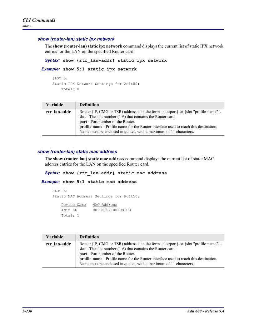
5-230 Adit 600 - Release 9.4
CLI Commandsshow
show (router-lan) static ipx networkThe show (router-lan) static ipx network command displays the current list of static IPX network entries for the LAN on the specified Router card.
Syntax: show rtr_lan-addr static ipx network
Example: show 5:1 static ipx network
SLOT 5:
Static IPX Network Settings for Adit50:
Total: 0
show (router-lan) static mac addressThe show (router-lan) static mac address command displays the current list of static MAC address entries for the LAN on the specified Router card.
Syntax: show rtr_lan-addr static mac address
Example: show 5:1 static mac address
SLOT 5:
Static MAC Address Settings for Adit50:
Device Name MAC Address
Adit 66 00:E0:97:00:E9:CD
Total: 1
Variable Definitionrtr_lan-addr Router (IP, CMG or TSR) address is in the form slot:port or slot "profile-name".
slot - The slot number (1-6) that contains the Router card.port - Port number of the Router.profile-name - Profile name for the Router interface used to reach this destination. Name must be enclosed in quotes, with a maximum of 11 characters.
Variable Definitionrtr_lan-addr Router (IP, CMG or TSR) address is in the form slot:port or slot "profile-name".
slot - The slot number (1-6) that contains the Router card.port - Port number of the Router.profile-name - Profile name for the Router interface used to reach this destination. Name must be enclosed in quotes, with a maximum of 11 characters.

Adit 600 - Release 9.4 5-231
CLI Commandsshow
show (router-lan) stpThe show (router-lan) stp command displays the current Spanning Tree Protocol settings for the specified LAN interface.
Syntax: show rtr_lan-addr stp
Example: show 5:1 stp
SLOT 5:
LAN Spanning Tree Protocol Settings for Adit1:
Spanning Tree: Disabled
show (router-trunk)The show (router-trunk) command displays current settings for the specified trunk.
Syntax: show rtr_trunk-addr
Example: show 5:1:1The example displays the settings of trunk 1 for the Router card on slot 5.
> show 5:1:1
SLOT 5:
Settings for RTR 1 Trunk 1: Up/Down: UP
Speed: 64k
Variable Definitionrtr_lan-addr Router (IP, CMG or TSR) address is in the form slot:port or slot “profile-name”.
slot - The slot number (1-6) that contains the Router card.port - Port number of the Router.profile-name - Profile name for the Router interface used to reach this destination. Name must be enclosed in quotes, with a maximum of 11 characters.
Variable Definitionrtr_trunk-addr The Router (IP, CMG or TSR) trunk address is in the form slot:port:trunk.
slot The slot number (1-6) that contains the Router (CMG, IP or CMG) card.
port Port number or range.
trunk Trunk number for this port, 1-24.
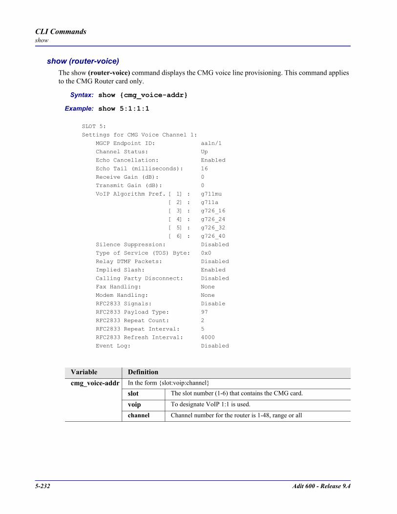
5-232 Adit 600 - Release 9.4
CLI Commandsshow
show (router-voice) The show (router-voice) command displays the CMG voice line provisioning. This command applies to the CMG Router card only.
Syntax: show cmg_voice-addr
Example: show 5:1:1:1
SLOT 5:
Settings for CMG Voice Channel 1:
MGCP Endpoint ID: aaln/1 Channel Status: Up
Echo Cancellation: Enabled
Echo Tail (milliseconds): 16
Receive Gain (dB): 0 Transmit Gain (dB): 0
VoIP Algorithm Pref. [ 1] : g711mu
[ 2] : g711a [ 3] : g726_16
[ 4] : g726_24
[ 5] : g726_32 [ 6] : g726_40
Silence Suppression: Disabled
Type of Service (TOS) Byte: 0x0 Relay DTMF Packets: Disabled
Implied Slash: Enabled
Calling Party Disconnect: Disabled Fax Handling: None
Modem Handling: None
RFC2833 Signals: Disable RFC2833 Payload Type: 97
RFC2833 Repeat Count: 2
RFC2833 Repeat Interval: 5 RFC2833 Refresh Interval: 4000
Event Log: Disabled
Variable Definitioncmg_voice-addr In the form slot:voip:channel
slot The slot number (1-6) that contains the CMG card.
voip To designate VoIP 1:1 is used.
channel Channel number for the router is 1-48, range or all

Adit 600 - Release 9.4 5-233
CLI Commandsshow
show (router-wan)The show (router-wan) command displays the current configuration for the specified WAN interface.
Syntax: show rtr_card-addr “wan-name”
Example: show 5 “LosAngeles”
SLOT 5:Settings for RTR WAN LosAngeles: State: Enabled IP Settings: Mode: Route WAN Network Updates: Never GRE Tunneling: Disabled IPX Settings: Mode: Blocked Other Settings: Mode: Blocked NAT Gateway: Enabled NAT Port Numbers: Dynamic NAT Address: Assigned by RemoteWAN PPP Authentication/Security Settings for LosAngeles: Authentication of Remote User: User ID: Remote Profile Name: LosAngeles Security Server: Local Compression: Disabled Typical Data: Easy to CompressWAN Trunk Setting for LosAngeles: WAN Port Number: 1 Connection Type: PPPWAN Spanning Tree Protocol Settings for LosAngeles: Spanning Tree: DisabledWAN Static IP Network Settings for LosAngeles: Total: 0WAN Static IPX Network Settings for LosAngeles:
Network Hops Ticks Next IPX RouterWAN Static IP Address Settings for LosAngeles: Total: 0WAN Static MAC Address Settings for LosAngeles: Total: 0
WAN Static NAT Address Settings for LosAngeles: Total: 0WAN Firewall Settings for LosAngeles:
Variable Definitionrtr_card-addr The slot number (1-6) that contains the Router (IP, CMG or TSR) card.
wan-name The WAN interface to modify. The name must be enclosed in quotes.

5-234 Adit 600 - Release 9.4
CLI Commandsshow
show (router-wan) firewallThe show (router-wan) firewall command displays the current firewall filter settings for the specified WAN interface.
Syntax: show rtr_card-addr “wan-name” firewall
Example: show 5 “LosAngeles” firewall
SLOT 5:
WAN Firewall Settings for LosAngeles:
Service(s) LAN Device(s) WAN Device(s) Log
1. SMTP 192.0.0.0/8 ==> 192.0.0.0/8 Log
2. Telnet 100.0.0.0/24 ==> 200.0.0.0/24 AlmLast ! Any * <== ==> *
show (router-wan) nat bypassUse the show (router-wan) nat bypass command to see the current list of NAT bypass entries for the WAN interface on the specified Router card.
Syntax: show rtr_card-addr “wan-name” nat bypass
Example: show 2 “RemoteUnit” nat bypass
SLOT 2:
WAN NAT Bypass Address Settings for RemoteAdit:
IP Address Netmask
156.65.0.0 255.255.255.0 201.23.16.0 255.255.255.0
Total: 2
Variable Definitionrtr_card-addr The slot number (1-6) that contains the Router (IP, CMG or TSR) card.
wan-name The WAN interface to modify. The name must be enclosed in quotes.
Variable Definitionrtr_card-addr The slot number (1-6) that contains the Router (IP, CMG or TSR) card.
wan-name The WAN interface to modify. The name must be enclosed in quotes.

Adit 600 - Release 9.4 5-235
CLI Commandsshow
show (router-wan) pppThe show (router-wan) ppp command displays the current PPP (Point-to-Point Protocol) settings for the specified WAN interface.
Syntax: show rtr_card-addr “wan-name” ppp
Example: show 5 “LosAngeles” ppp
> show 5 “LosAngeles” ppp
SLOT 5:
WAN PPP Authentication/Security Settings for LosAngeles: Authentication of Remote User:
User ID: Remote Profile Name: LosAngeles
Security Server: Local
Compression: Disabled Typical Data: Easy to Compress
PPP Statistics for Slot-4:
Up/Down Rx Rx Tx Tx
Remote Name State Time Packets Octets Packets Octets
RemoteAdit DOWN 26m36s 0 0 0 0
show (router-wan) static ip addressThe show (router-wan) static ip address command displays the current list of static IP address entries for the specified WAN interface.
Syntax: show rtr_card-addr “wan-name” static ip address
Example: show 5 “LosAngeles” static ip address
> show 5 “LosAngeles” static ip address
SLOT 5:WAN Static IP Address Settings for LosAngeles:
Total: 0
Variable Definitionrtr_card-addr The slot number (1-6) that contains the Router (IP, CMG or TSR) card.
wan-name The WAN interface to modify. The name must be enclosed in quotes.
Variable Definitionrtr_card-addr The slot number (1-6) that contains the Router (IP, CMG or TSR) card.
wan-name The WAN interface to modify. The name must be enclosed in quotes.
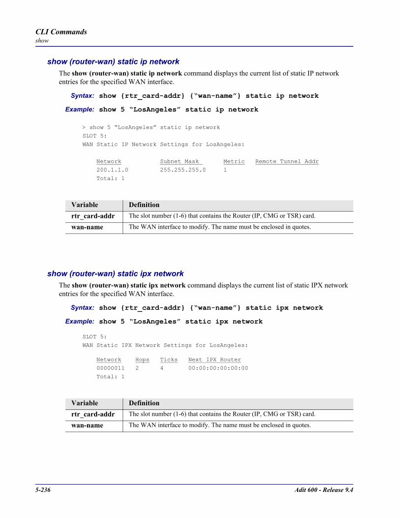
5-236 Adit 600 - Release 9.4
CLI Commandsshow
show (router-wan) static ip networkThe show (router-wan) static ip network command displays the current list of static IP network entries for the specified WAN interface.
Syntax: show rtr_card-addr “wan-name” static ip network
Example: show 5 “LosAngeles” static ip network
> show 5 “LosAngeles” static ip network
SLOT 5:
WAN Static IP Network Settings for LosAngeles:
Network Subnet Mask Metric Remote Tunnel Addr
200.1.1.0 255.255.255.0 1
Total: 1
show (router-wan) static ipx networkThe show (router-wan) static ipx network command displays the current list of static IPX network entries for the specified WAN interface.
Syntax: show rtr_card-addr “wan-name” static ipx network
Example: show 5 “LosAngeles” static ipx network
SLOT 5:
WAN Static IPX Network Settings for LosAngeles:
Network Hops Ticks Next IPX Router
00000011 2 4 00:00:00:00:00:00
Total: 1
Variable Definitionrtr_card-addr The slot number (1-6) that contains the Router (IP, CMG or TSR) card.
wan-name The WAN interface to modify. The name must be enclosed in quotes.
Variable Definitionrtr_card-addr The slot number (1-6) that contains the Router (IP, CMG or TSR) card.
wan-name The WAN interface to modify. The name must be enclosed in quotes.

Adit 600 - Release 9.4 5-237
CLI Commandsshow
show (router-wan) static mac addressThe show (router-wan) static mac address command displays the current list of static IP MAC address entries for the specified WAN interface.
Syntax: show rtr_card-addr "wan-name" static mac address
Example: show 5 "LosAngeles" static mac address
SLOT 5:WAN Static MAC Address Settings for LosAngeles:
Device Name MAC Address Adit32 00:E0:97:00:E9:CD
Total: 1
show (router-wan) static nat addressThe show (router-wan) static nat address command displays the current static NAT address entries for the specified WAN interface.
Syntax: show rtr_card-addr "wan-name" static nat address
Example: show 5 "LosAngeles" static nat address
> show 5 "RemoteUnit" static nat address
SLOT 5:
WAN Static NAT Address Settings for RemoteUnit: Total: 0
Variable Definitionrtr_card-addr The slot number (1-6) that contains the Router (IP, CMG or TSR) card.
wan-name The WAN interface to modify. The name must be enclosed in quotes.
Variable Definitionrtr_card-addr The slot number (1-6) that contains the Router (IP, CMG or TSR) card.
wan-name The WAN interface to modify. The name must be enclosed in quotes.

5-238 Adit 600 - Release 9.4
CLI Commandsshow
show (router-wan) stpThe show (router-wan) stp command displays the current Spanning Tree Protocol settings for the specified WAN interface.
Syntax: show rtr_card-addr "wan-name" stp
Example: show 5 "LosAngeles" stp
> show 5 "LosAngeles" stp
SLOT 5:
WAN Spanning Tree Protocol Settings for LosAngeles: Spanning Tree: Enabled
Port Cost: 651 seconds
Port Priority: 128 seconds
show (router-wan) trunkThe show (router-wan) trunk command displays the current trunk assignment for the specified WAN interface.
Syntax: show rtr_card-addr "wan-name" trunk
Example: show 5 "LosAngeles" trunk
> show 5 "LosAngeles" trunkSLOT 5:
WAN Trunk Setting for LosAngeles:
WAN Port Number: 1 Connection Type: PPP
Variable Definitionrtr_card-addr The slot number (1-6) that contains the Router (IP, CMG or TSR) card.
wan-name The WAN interface to modify. The name must be enclosed in quotes.
Variable Definitionrtr_card-addr The slot number (1-6) that contains the Router (IP, CMG or TSR) card.
wan-name The WAN interface to modify. The name must be enclosed in quotes.
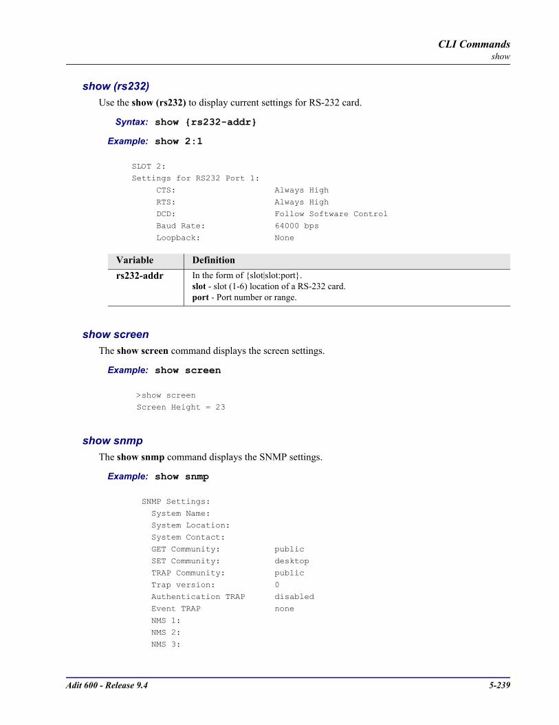
Adit 600 - Release 9.4 5-239
CLI Commandsshow
show (rs232)Use the show (rs232) to display current settings for RS-232 card.
Syntax: show rs232-addr
Example: show 2:1
SLOT 2:Settings for RS232 Port 1:
CTS: Always High
RTS: Always High DCD: Follow Software Control
Baud Rate: 64000 bps
Loopback: None
show screenThe show screen command displays the screen settings.
Example: show screen
>show screen Screen Height = 23
show snmpThe show snmp command displays the SNMP settings.
Example: show snmp
SNMP Settings:
System Name: System Location:
System Contact:
GET Community: public SET Community: desktop
TRAP Community: public
Trap version: 0 Authentication TRAP disabled
Event TRAP none
NMS 1: NMS 2:
NMS 3:
Variable Definitionrs232-addr In the form of slot|slot:port.
slot - slot (1-6) location of a RS-232 card.port - Port number or range.
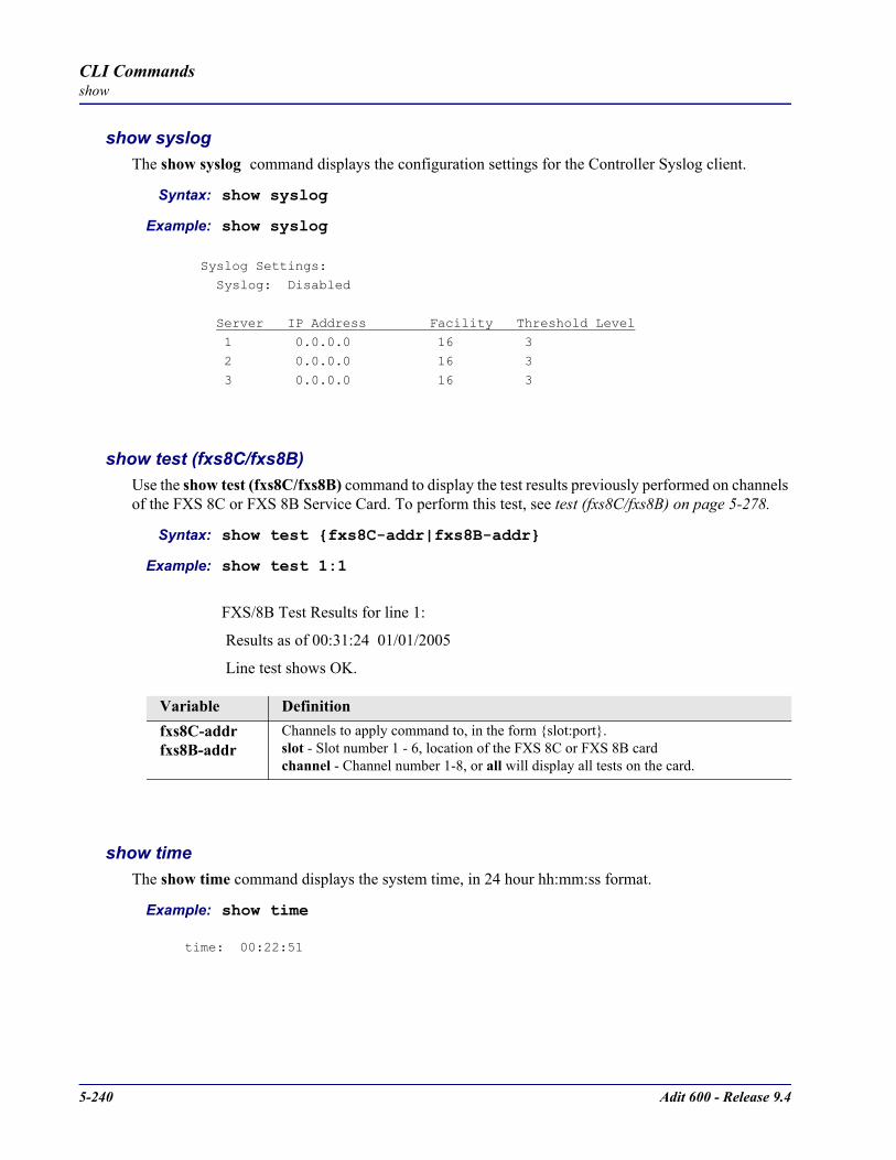
5-240 Adit 600 - Release 9.4
CLI Commandsshow
show syslogThe show syslog command displays the configuration settings for the Controller Syslog client.
Syntax: show syslog
Example: show syslog
Syslog Settings: Syslog: Disabled
Server IP Address Facility Threshold Level 1 0.0.0.0 16 3
2 0.0.0.0 16 3
3 0.0.0.0 16 3
show test (fxs8C/fxs8B)Use the show test (fxs8C/fxs8B) command to display the test results previously performed on channels of the FXS 8C or FXS 8B Service Card. To perform this test, see test (fxs8C/fxs8B) on page 5-278.
Syntax: show test fxs8C-addr|fxs8B-addr
Example: show test 1:1
FXS/8B Test Results for line 1:
Results as of 00:31:24 01/01/2005
Line test shows OK.
show timeThe show time command displays the system time, in 24 hour hh:mm:ss format.
Example: show time
time: 00:22:51
Variable Definitionfxs8C-addrfxs8B-addr
Channels to apply command to, in the form slot:port.slot - Slot number 1 - 6, location of the FXS 8C or FXS 8B cardchannel - Channel number 1-8, or all will display all tests on the card.
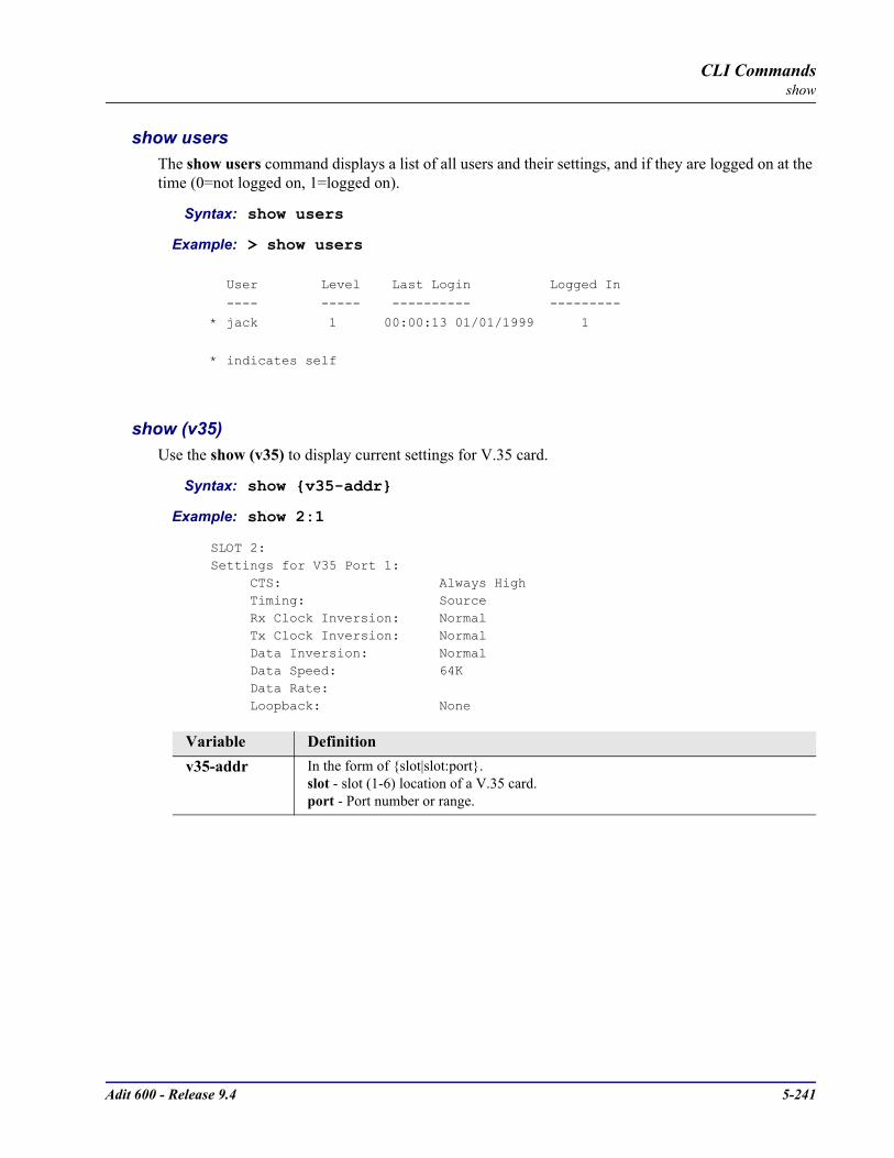
Adit 600 - Release 9.4 5-241
CLI Commandsshow
show users The show users command displays a list of all users and their settings, and if they are logged on at the time (0=not logged on, 1=logged on).
Syntax: show users
Example: > show users
User Level Last Login Logged In
---- ----- ---------- ---------
* jack 1 00:00:13 01/01/1999 1
* indicates self
show (v35)Use the show (v35) to display current settings for V.35 card.
Syntax: show v35-addr
Example: show 2:1
SLOT 2:Settings for V35 Port 1: CTS: Always High Timing: Source Rx Clock Inversion: Normal Tx Clock Inversion: Normal Data Inversion: Normal Data Speed: 64K Data Rate: Loopback: None
Variable Definitionv35-addr In the form of slot|slot:port.
slot - slot (1-6) location of a V.35 card.port - Port number or range.
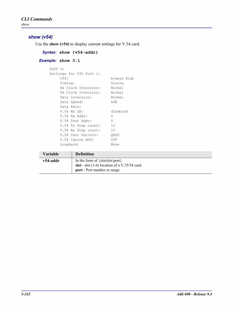
5-242 Adit 600 - Release 9.4
CLI Commandsshow
show (v54)Use the show (v54) to display current settings for V.54 card.
Syntax: show v54-addr
Example: show 3:1
SLOT 3:Settings for V35 Port 1: CTS: Always High Timing: Source Rx Clock Inversion: Normal Tx Clock Inversion: Normal Data Inversion: Normal Data Speed: 64K Data Rate: V.54 Rx LB: disabled V.54 Rx Addr: 0 V.54 Test Addr: 0 V.54 Tx Prep count: 15 V.54 Rx Prep count: 15 V.54 Test Pattern: QRSS V.54 Ignore ACK: OFF Loopback: None
Variable Definitionv54-addr In the form of slot|slot:port.
slot - slot (1-6) location of a V.35/54 card.port - Port number or range.

Adit 600 - Release 9.4 5-243
CLI Commandsstatus
status
Use the status command to see the status of the system clocks, DS0s, DS1s, equipment, and the DS0 Management Channel.
status (4-wire e&m) status (router) alarms
status (adpcm) status (router) channels
status (adpcm) performance status (router) dhcp client lease
status (adpcm) performance history status (router) dns
status (bri) status (router) events
status clock status (router) ip address table
status (ds0) status (router) ip network table
status (ds1) status (router) ipx network table
status (e1) status (router) ipx server table
status equipment status (router) log
status (fxo) status (router) mac address table
status (fxs) status (router) mgcp
status (fxs8C/fxs8B/fxs8A/fxs5G) status (router) performance
status (fxsINTL) status (router) stp
status (fxsPS) status (router-lan)
status ipds0 status (router-trunk)
status (ocudp) status (router-voice)
status (ocudp) performance status (rs232)
status (ocudp) performance history status sessions
status (p-phone) status (v35)
status (router) status (v54)

5-244 Adit 600 - Release 9.4
CLI Commandsstatus
status (4-wire e&m)The status (4we&m) command displays the settings for 4-Wire E&M card.
Syntax: status 4we&m-addr
Example: status 4
> status 4
4W-E&M Rx AB Tx AB Signal TP4:1
4:2
4:34:4
status (adpcm)Use the status (adpcm) command to display the status information for the ADPCM card.
Syntax: status adpcm-addr
Example: status 6:1
> status 6:1
SLOT 6:Status for DS1 1:
Receive: Loss of Signal
Transmit: RAI/Yellow Alarm Loopback: OFF
Variable Definition4we&m-addr In the form of slot or slot:port. Note if only the slot is listed all ports will be
displayed.slot - Slot (1-6) where the 4-Wire E&M card is located. port - Port number, range or “all”.
Variable Definitionadpcm-addr The ADPCM address is in the form slot|slot:port. Where slot displays information
for all ports on the card, slot:port for only the defined port.slot - Slot number (1-6) where the ADPCM card is located port - Port number. range 1-4. If no port is entered all ports will be displayed.

Adit 600 - Release 9.4 5-245
CLI Commandsstatus
status (adpcm) performanceUse the status (adpcm) performance command to display the performance statistics for the current (15 min) and previous (15 min, hour and day) information for the ADPCM card.
Syntax: status adpcm-addr performance
Example: status 6:1 performance
> status 5:1 performance
SLOT 5:
Performance Statistics for DS1 1:
current previous
15 min. 15 min. 1 hour 1 dayunavailable seconds:719 0 0 0
severely errored seconds:0 0 0 0
errored seconds:0 0 0 0
sev. errored frame seconds:0 0 0 0line errored seconds:0 0 0 0
controlled slip seconds:0 0 0 0
bursty errored seconds:0 0 0 0
degraded minutes:0 0 0 0
total linecode violations:0 0 0 0total pathcode violations:0 0 0 0
elapsed time in current 15 min. interval: 11:59valid 15 min. intervals in hour:0
valid 15 min. intervals in Day:0
* - indicates threshold has been crossed.
Variable Definitionadpcm-addr The ADPCM address is in the form slot:port.
slot - Slot number (1-6) where the ADPCM card is located port - Port number, range or all.

5-246 Adit 600 - Release 9.4
CLI Commandsstatus
status (adpcm) performance historyUse the status (adpcm) performance history command to display performance statistics for the current 15 minute interval and all previous 15 minute intervals (up to a total of 96) for the ADPCM card.
Syntax: status adpcm-addr performance history
Example: status 6:1 performance history
> status 6:1 performance history
SLOT 6:Performance Statistics for DS1 1:
UAS SES ES SEFS LES CSS BES DM LCV PCVcurr. interval: 317 0 0 0 0 0 0 0 0 0
prev. intvl 1: 900 0 0 0 0 0 0 0 0 0
prev. intvl 2: 900 0 0 0 0 0 0 0 0 0
prev. intvl 3: 900 0 0 0 0 0 0 0 0 0prev. intvl 4: 900 0 0 0 0 0 0 0 0 0
.
.
.
prev. intvl 93: 900 0 0 0 0 0 0 0 0 0
prev. intvl 94: 900 0 0 0 0 0 0 0 0 0prev. intvl 95: 900 0 0 0 0 0 0 0 0 0
prev. intvl 96: 900 0 0 0 0 0 0 0 0 0
totals: 21181 0 0 0 0 0 0 0 0 0
elapsed time in current 15 min. interval: 5:17
valid 15 min. intervals in data: 96
Variable Definitionadpcm-addr The ADPCM address is in the form slot:port.
slot - Slot number (1-6) where the ADPCM card is located port - Port number, range or all.
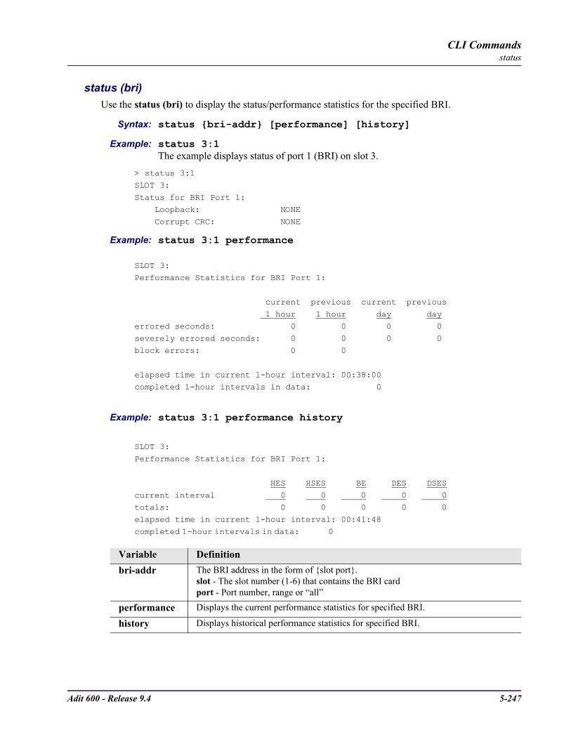
Adit 600 - Release 9.4 5-247
CLI Commandsstatus
status (bri)Use the status (bri) to display the status/performance statistics for the specified BRI.
Syntax: status bri-addr [performance] [history]
Example: status 3:1The example displays status of port 1 (BRI) on slot 3.
> status 3:1
SLOT 3:
Status for BRI Port 1: Loopback: NONE
Corrupt CRC: NONE
Example: status 3:1 performance
SLOT 3:Performance Statistics for BRI Port 1:
current previous current previous 1 hour 1 hour day day
errored seconds: 0 0 0 0
severely errored seconds: 0 0 0 0block errors: 0 0
elapsed time in current 1-hour interval: 00:38:00completed 1-hour intervals in data: 0
Example: status 3:1 performance history
SLOT 3:
Performance Statistics for BRI Port 1:
HES HSES BE DES DSES
current interval 0 0 0 0 0totals: 0 0 0 0 0
elapsed time in current 1-hour interval: 00:41:48
completed 1-hour intervals in data: 0
Variable Definitionbri-addr The BRI address in the form of slot port.
slot - The slot number (1-6) that contains the BRI cardport - Port number, range or “all”
performance Displays the current performance statistics for specified BRI.
history Displays historical performance statistics for specified BRI.

5-248 Adit 600 - Release 9.4
CLI Commandsstatus
status clockUse the status clock command to display the current status of both the selected primary and secondary clocks.
Syntax: status clock
Example: status clock
Active Clock Source: Secondary
Primary: Clock Source: Slot A DS1 1
Clock Status: Out of Service
Secondary:
Clock Source: Internal Clock Status: In Service
status (ds0)Use the status (ds0) command to display the current status of the specified DS0.
Syntax: status ds0-addr
Example: status a:1:1Displays the current status of the DS0s on port 1 on slot A (controller card), port 1, channel 1.
> status a:1:1
DS0 Rx AB Tx AB Signal T1 TP
--- ----- ----- ------ --------- --A:1:1 11 01 EMW Traffic N
Display DescriptionsRx AB - AB bits received by the FXS or FXO portTx AB - AB bits transmitted by the FXS or FXO portSignal - Signaling mode for which the port is configuredT1 - T1 StatusTP - Trunk Processing
Variable Definitionds0-addr In the form of slot port:channel.
slot - A for the controller card, or 1 - 6 for service cards.port - Port number or range.channel - Channel number or range, for T1 ports.

Adit 600 - Release 9.4 5-249
CLI Commandsstatus
status (ds1)Use the status (ds1) command to display the current status of the specified DS1.
Syntax: status ds1-addr [performance] [history]
Example: status a:1SLOT A:
Status for DS1 1: Receive: Traffic
Transmit: Traffic
Loopback: OFF
status (e1)Use the status (e1) command to display the current status of the specified E1.
Syntax: status e1-addr [performance] [history]
Example: status 6:1
> status 6:1
SLOT 6:
Status for E1 1: Receive: Loss of Signal
Transmit: RAI/Yellow Alarm
Loopback: OFF
Variable Definitionds1-addr In the form of slot port.
slot - A for the controller card, or 1 - 6 for service cards.port - Port number or range.
performance Display current performance statistics for the specified port or ports.
history Display historical performance statistics for the specified port or ports.
Variable Definitione1-addr In the form of slot port.
slot - A for the controller card, or 1 - 6 for service cards.port - Port number or range.
performance Display current performance statistics for the specified port or ports.
history Display historical performance statistics for the specified port or ports.

5-250 Adit 600 - Release 9.4
CLI Commandsstatus
status equipmentUse the status equipment command to display current equipment information of the Adit 600.
Syntax: status equipment [slot]
Example: status equipment
BootCode Version: 2.00
CardType Status SW Vers CLEI
SLOT A T1x2 Present 9.0 SIC3DH0CAASLOT 1 FXOx8 Present 1.12 SIIXPV0DAASLOT 2 FXSx8 Present 1.09 SIC3GJ0CAASLOT 3 FXOx8 Present 1.12 SIIXPV0DAASLOT 4 RTRx1 Present 1.80 SIIASS0BAASLOT 5 T1x4 Present 1.73 SIIXFWBDAASLOT 6 V35x2 Present 2.01 SIC3HK0CAA
Example: status equipment a
SLOT ACardType: T1x2 Adit 600 ControllerStatus: PresentBootCode Version: 2.00SW Revision: 9.0.0CLEI: SIC3DH0CAALOCAL: OFFSwitch Settings: Alarms Contacts Enabled FOR DS1 #1 B8ZS Linecode Loopback Off ESF framing with Loop Start or Ground Start signaling FOR DS1 #2 B8ZS Linecode Loopback Off ESF framing with Loop Start or Ground Start signaling
Example: status equipment 4
SLOT 4CardType: RTRx1Status: PresentSW Revision: 1.80KBootCode Version: 2.22FPGA Revision: 1.08CLEI: SIIASS0BAALOCAL: OFF
Variable Definitionslot If a slot number is not entered, the status of the all slots will be displayed.
A for the controller card, or 1 - 6 for service cards.
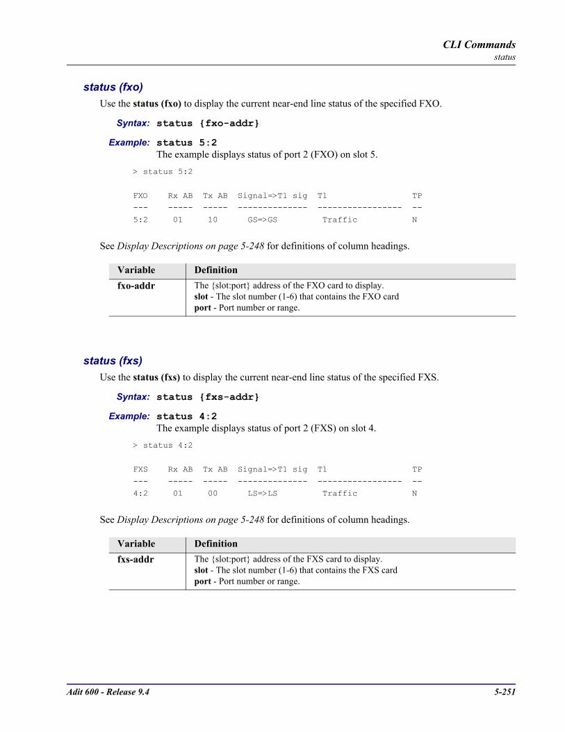
Adit 600 - Release 9.4 5-251
CLI Commandsstatus
status (fxo)Use the status (fxo) to display the current near-end line status of the specified FXO.
Syntax: status fxo-addr
Example: status 5:2The example displays status of port 2 (FXO) on slot 5.
> status 5:2
FXO Rx AB Tx AB Signal=>T1 sig T1 TP--- ----- ----- -------------- ----------------- --
5:2 01 10 GS=>GS Traffic N
See Display Descriptions on page 5-248 for definitions of column headings.
status (fxs)Use the status (fxs) to display the current near-end line status of the specified FXS.
Syntax: status fxs-addr
Example: status 4:2The example displays status of port 2 (FXS) on slot 4.
> status 4:2
FXS Rx AB Tx AB Signal=>T1 sig T1 TP
--- ----- ----- -------------- ----------------- --
4:2 01 00 LS=>LS Traffic N
See Display Descriptions on page 5-248 for definitions of column headings.
Variable Definitionfxo-addr The slot:port address of the FXO card to display.
slot - The slot number (1-6) that contains the FXO cardport - Port number or range.
Variable Definitionfxs-addr The slot:port address of the FXS card to display.
slot - The slot number (1-6) that contains the FXS cardport - Port number or range.
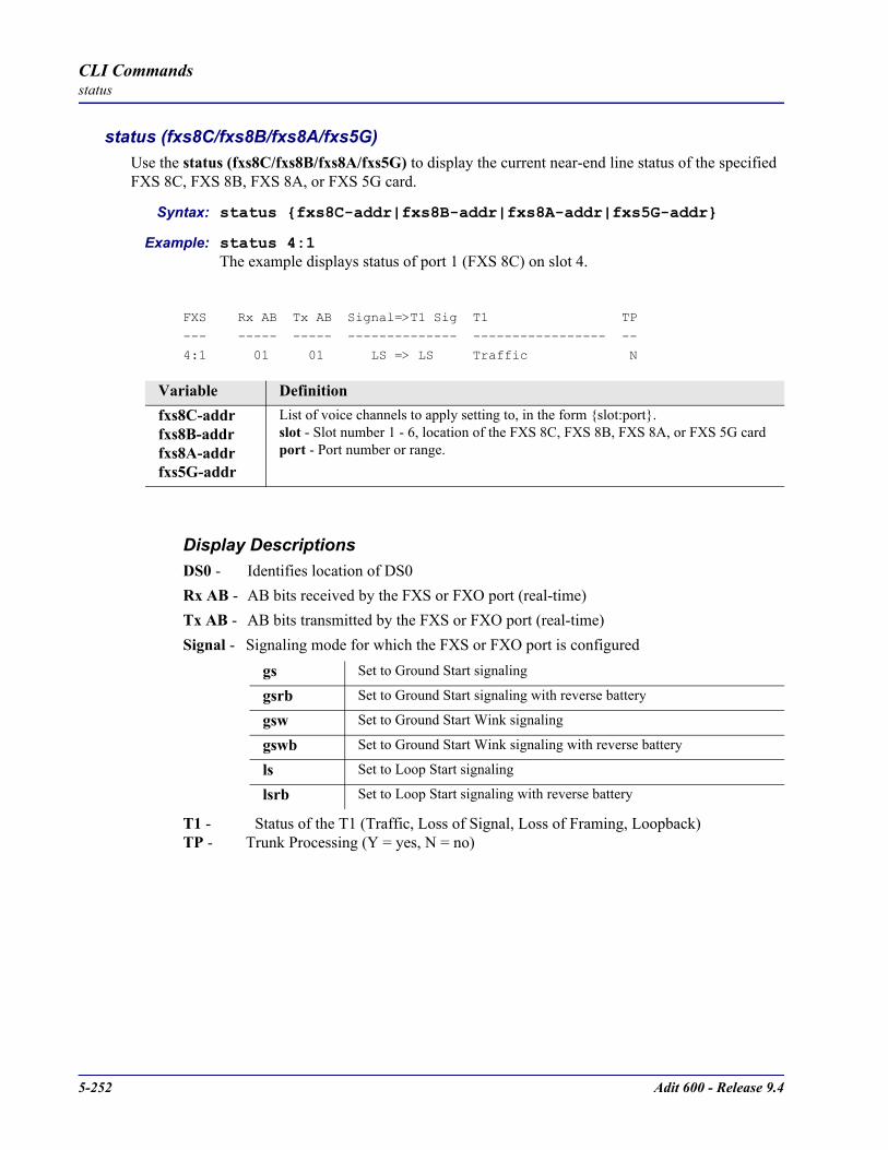
5-252 Adit 600 - Release 9.4
CLI Commandsstatus
status (fxs8C/fxs8B/fxs8A/fxs5G)Use the status (fxs8C/fxs8B/fxs8A/fxs5G) to display the current near-end line status of the specified FXS 8C, FXS 8B, FXS 8A, or FXS 5G card.
Syntax: status fxs8C-addr|fxs8B-addr|fxs8A-addr|fxs5G-addr
Example: status 4:1The example displays status of port 1 (FXS 8C) on slot 4.
FXS Rx AB Tx AB Signal=>T1 Sig T1 TP
--- ----- ----- -------------- ----------------- --
4:1 01 01 LS => LS Traffic N
Display DescriptionsDS0 - Identifies location of DS0Rx AB - AB bits received by the FXS or FXO port (real-time)Tx AB - AB bits transmitted by the FXS or FXO port (real-time)Signal - Signaling mode for which the FXS or FXO port is configured
T1 - Status of the T1 (Traffic, Loss of Signal, Loss of Framing, Loopback)TP - Trunk Processing (Y = yes, N = no)
Variable Definitionfxs8C-addrfxs8B-addrfxs8A-addrfxs5G-addr
List of voice channels to apply setting to, in the form slot:port.slot - Slot number 1 - 6, location of the FXS 8C, FXS 8B, FXS 8A, or FXS 5G cardport - Port number or range.
gs Set to Ground Start signaling
gsrb Set to Ground Start signaling with reverse battery
gsw Set to Ground Start Wink signaling
gswb Set to Ground Start Wink signaling with reverse battery
ls Set to Loop Start signaling
lsrb Set to Loop Start signaling with reverse battery

Adit 600 - Release 9.4 5-253
CLI Commandsstatus
status (fxsINTL)Use the status (fxsINTL) to display the current near-end line status of the specified E1-FXS card.
Syntax: status fxsINTL-addr
Example: status 2:1
FXS Rx AB Tx AB Signal=>E1 Sig E1 TP
2:1 01 01 R2 Traffic N
Display DescriptionsDS0 - Identifies location of DS0Rx AB - AB bits received by the FXS or FXO port (real-time)Tx AB - AB bits transmitted by the FXS or FXO port (real-time)Signal - Signaling mode for which the FXS or FXO port is configured
E1 - Status of the E1 (Traffic, Loss of Signal, Loss of Framing, Loopback)TP - Trunk Processing (Y = yes, N = no)
status (fxsPS)Use the status (fxsPS) to display the current near-end line status of the FXS PS card.
Syntax: status fxsPS-addr
Example: status 4:1> status 4:1
FXS Rx AB Tx AB Signal=>T1 Sig T1 TP4:1 01 01 LS => LS Traffic N
Variable DefinitionfxsINTL-addr The slot:port address of the FXS INTL card to display.
slot - The slot number (1-6) of the Adit chassis that contains the E1-FXS cardport - Port number or range.
r2 Set to E1 R2 signaling
Variable DefinitionfxsPS-addr The slot:port address of the FXS PS card to display.
slot - Slot number (1-6) of the FXS PS cardport - Port number or range.

5-254 Adit 600 - Release 9.4
CLI Commandsstatus
status ipds0 Use the status ipds0 command to display the current status of the DS0 management channel.
Syntax: status ipds0
Example: status ipds0
> status ipds0Operational state: DOWN
status (ocudp) Use the status (ocudp) command to displaystatus for selftest and loopbacks.
Syntax: status ocudp-addr
Example: status 2:1
SLOT 2:
Status for OCUDP Port 1:
Selftest: Results as of 23:25:48 01/07/2001
Datapath: PASS
FPGA: PASS OCU: PASS
OCU Manual Loopback: NONE
CSU Manual Loopback: NONE
OCU NonLatching Loopback: NONE
DSU NonLatching Loopback: NONE
CSU NonLatching Loopback: NONE
OCU Latching Loopback: NONE
DSU Latching Loopback: NONE
CSU Latching Loopback: NONE
Variable Definitionocudp-addr The slot:port address of the OCUDP card to display.
slot - Slot number (1-6) where the OCUDP card is locatedport - Port number or range.
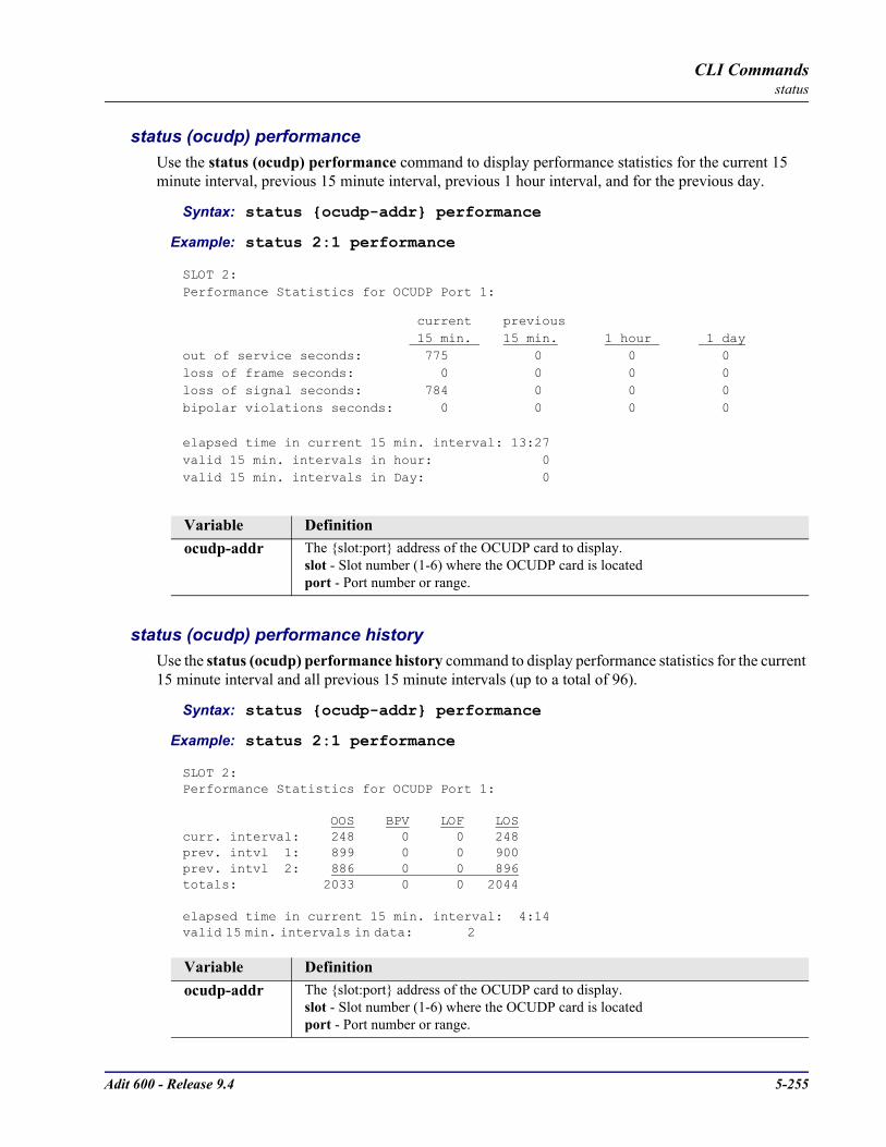
Adit 600 - Release 9.4 5-255
CLI Commandsstatus
status (ocudp) performanceUse the status (ocudp) performance command to display performance statistics for the current 15 minute interval, previous 15 minute interval, previous 1 hour interval, and for the previous day.
Syntax: status ocudp-addr performance
Example: status 2:1 performance
SLOT 2:Performance Statistics for OCUDP Port 1:
current previous 15 min. 15 min. 1 hour 1 dayout of service seconds: 775 0 0 0loss of frame seconds: 0 0 0 0loss of signal seconds: 784 0 0 0bipolar violations seconds: 0 0 0 0
elapsed time in current 15 min. interval: 13:27valid 15 min. intervals in hour: 0valid 15 min. intervals in Day: 0
status (ocudp) performance historyUse the status (ocudp) performance history command to display performance statistics for the current 15 minute interval and all previous 15 minute intervals (up to a total of 96).
Syntax: status ocudp-addr performance
Example: status 2:1 performance
SLOT 2:Performance Statistics for OCUDP Port 1:
OOS BPV LOF LOScurr. interval: 248 0 0 248prev. intvl 1: 899 0 0 900prev. intvl 2: 886 0 0 896totals: 2033 0 0 2044
elapsed time in current 15 min. interval: 4:14valid 15 min. intervals in data: 2
Variable Definitionocudp-addr The slot:port address of the OCUDP card to display.
slot - Slot number (1-6) where the OCUDP card is locatedport - Port number or range.
Variable Definitionocudp-addr The slot:port address of the OCUDP card to display.
slot - Slot number (1-6) where the OCUDP card is locatedport - Port number or range.
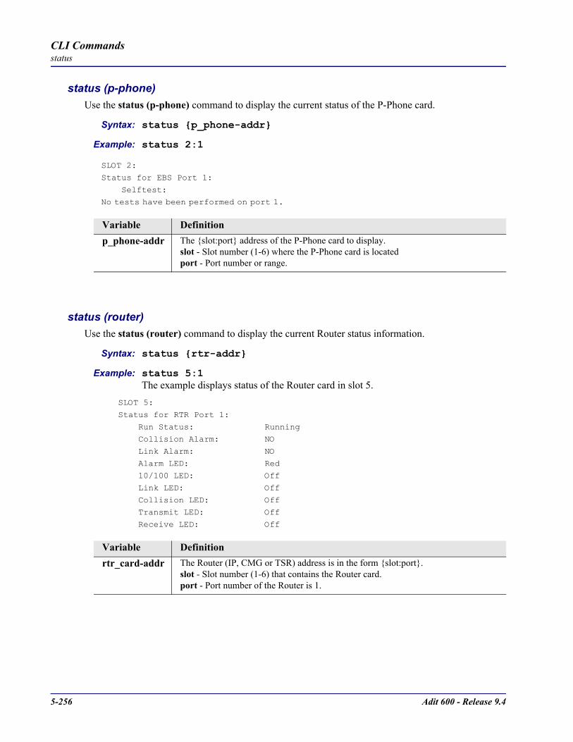
5-256 Adit 600 - Release 9.4
CLI Commandsstatus
status (p-phone)Use the status (p-phone) command to display the current status of the P-Phone card.
Syntax: status p_phone-addr
Example: status 2:1
SLOT 2:
Status for EBS Port 1:
Selftest:No tests have been performed on port 1.
status (router)Use the status (router) command to display the current Router status information.
Syntax: status rtr-addr
Example: status 5:1The example displays status of the Router card in slot 5.
SLOT 5:
Status for RTR Port 1:
Run Status: Running Collision Alarm: NO
Link Alarm: NO
Alarm LED: Red 10/100 LED: Off
Link LED: Off
Collision LED: Off Transmit LED: Off
Receive LED: Off
Variable Definitionp_phone-addr The slot:port address of the P-Phone card to display.
slot - Slot number (1-6) where the P-Phone card is locatedport - Port number or range.
Variable Definitionrtr_card-addr The Router (IP, CMG or TSR) address is in the form slot:port.
slot - Slot number (1-6) that contains the Router card.port - Port number of the Router is 1.

Adit 600 - Release 9.4 5-257
CLI Commandsstatus
status (router) alarmsUse the status (router) alarms command to display the current alarm log from the specified Router card.
Syntax: status rtr_card-addr alarms
Example: status 5 alarms
ROUTER BLADE ALARM LOG REPORT Slot-5
Time Message Count
Jan 4 22:26:47.0 Ethernet Link 5:1 Down.
status (router) channelsUse the status (router) channels command to display a condensed status report of all voice channel endpoints. This command applies to the CMG Router card only.
Syntax: status cmg_card-addr channels
Example: status 3 channels
CMG VoIP Channel Status - Slot 3 MGCP: Down Call Agent: 0.0.0.0/2727 Endpoint Prefix: aaln/ # STATUS SIG CONN # STATUS SIG CONN # STATUS SIG CONN 1-Down FXSL ....... 17-Down FXSL ....... 33-Down FXSL ....... 2-Down FXSL ....... 18-Down FXSL ....... 34-Down FXSL ....... 3-Down FXSL ....... 19-Down FXSL ....... 35-Down FXSL ....... 4-Down FXSL ....... 20-Down FXSL ....... 36-Down FXSL ....... 5-Down FXSL ....... 21-Down FXSL ....... 37-Down FXSL ....... 6-Down FXSL ....... 22-Down FXSL ....... 38-Down FXSL ....... 7-Down FXSL ....... 23-Down FXSL ....... 39-Down FXSL ....... 8-Down FXSL ....... 24-Down FXSL ....... 40-Down FXSL ....... 9-Down FXSL ....... 25-Down FXSL ....... 41-Down FXSL .......10-Down FXSL ....... 26-Down FXSL ....... 42-Down FXSL .......11-Down FXSL ....... 27-Down FXSL ....... 43-Down FXSL .......12-Down FXSL ....... 28-Down FXSL ....... 44-Down FXSL .......13-Down FXSL ....... 29-Down FXSL ....... 45-Down FXSL .......14-Down FXSL ....... 30-Down FXSL ....... 46-Down FXSL .......15-Down FXSL ....... 31-Down FXSL ....... 47-Down FXSL .......16-Down FXSL ....... 32-Down FXSL ....... 48-Down FXSL .......
Variable Definitionrtr_card-addr The slot number (1-6) that contains the Router (IP, CMG or TSR) card.
Variable Definitioncmg_card-addr The slot number (1-6) that contains the CMG Router card.
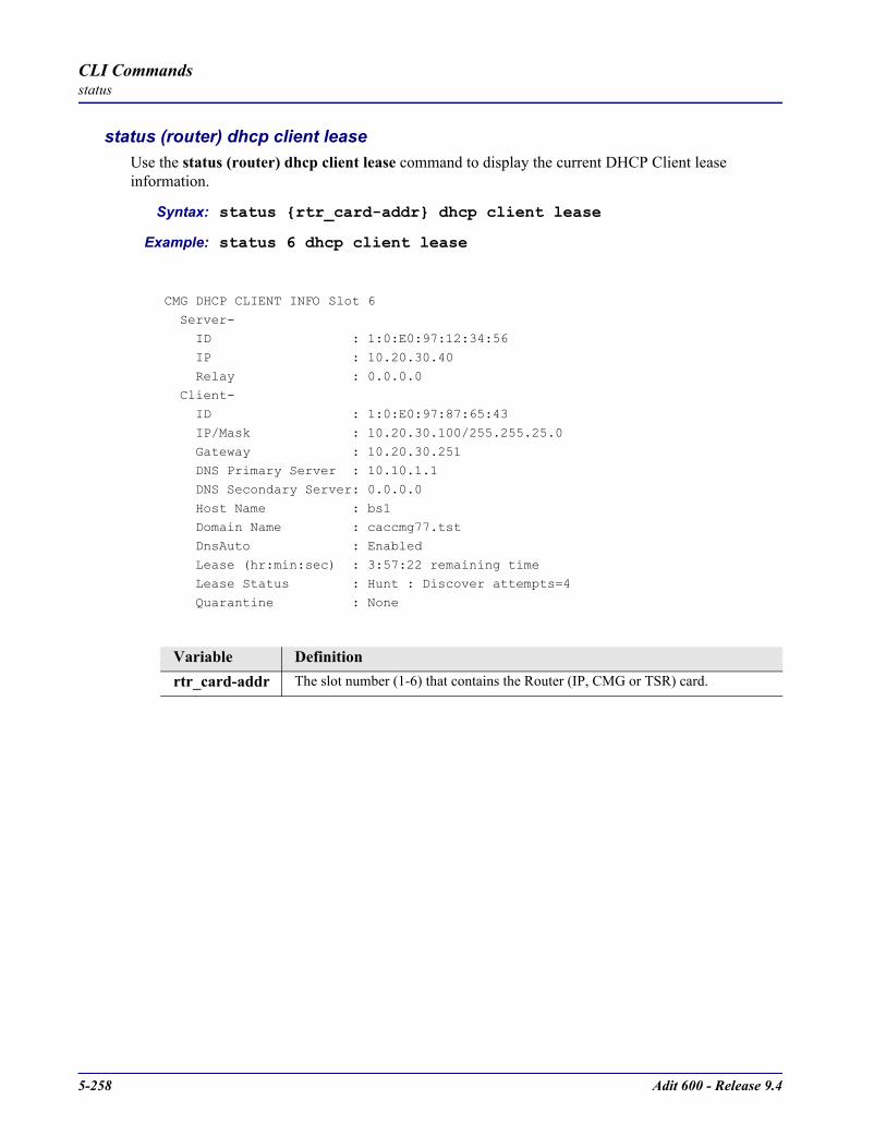
5-258 Adit 600 - Release 9.4
CLI Commandsstatus
status (router) dhcp client leaseUse the status (router) dhcp client lease command to display the current DHCP Client lease information.
Syntax: status rtr_card-addr dhcp client lease
Example: status 6 dhcp client lease
CMG DHCP CLIENT INFO Slot 6
Server- ID : 1:0:E0:97:12:34:56
IP : 10.20.30.40
Relay : 0.0.0.0
Client- ID : 1:0:E0:97:87:65:43
IP/Mask : 10.20.30.100/255.255.25.0
Gateway : 10.20.30.251 DNS Primary Server : 10.10.1.1
DNS Secondary Server: 0.0.0.0
Host Name : bs1 Domain Name : caccmg77.tst
DnsAuto : Enabled
Lease (hr:min:sec) : 3:57:22 remaining time Lease Status : Hunt : Discover attempts=4
Quarantine : None
Variable Definitionrtr_card-addr The slot number (1-6) that contains the Router (IP, CMG or TSR) card.
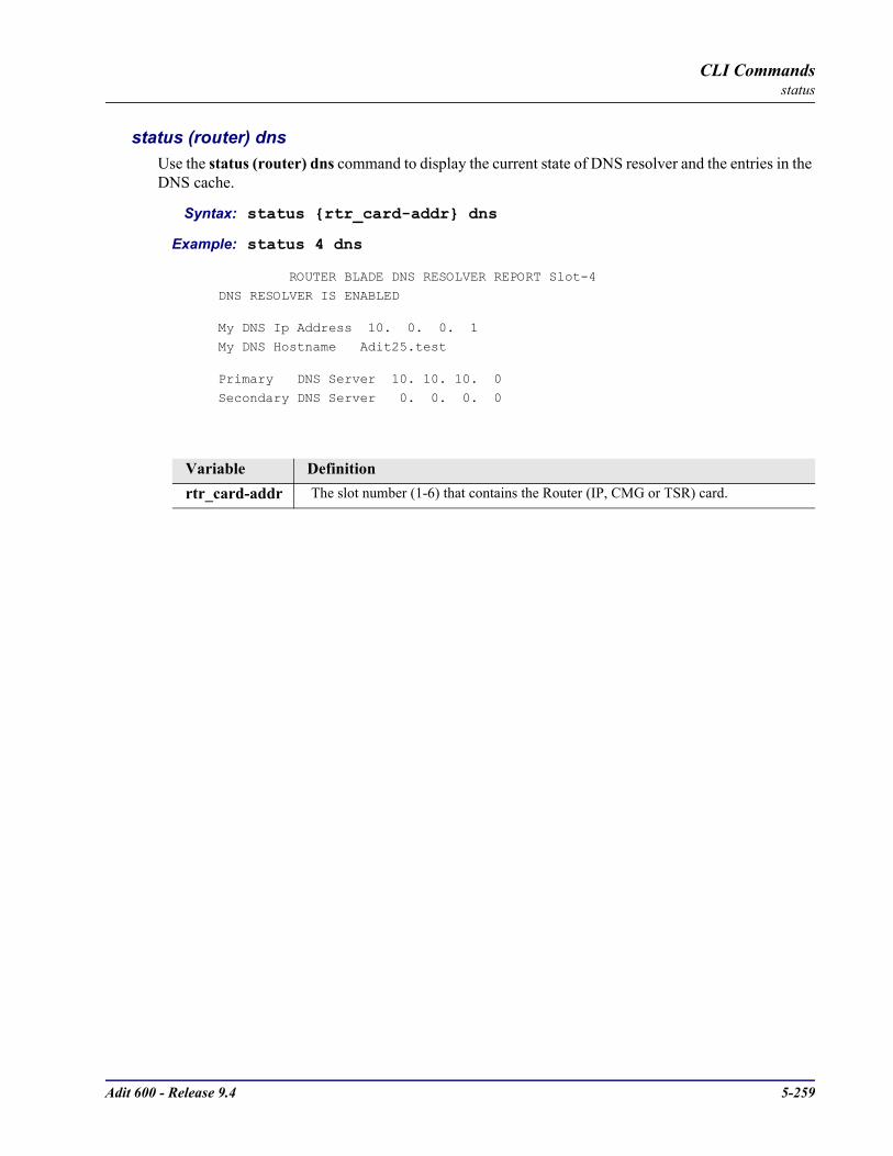
Adit 600 - Release 9.4 5-259
CLI Commandsstatus
status (router) dnsUse the status (router) dns command to display the current state of DNS resolver and the entries in the DNS cache.
Syntax: status rtr_card-addr dns
Example: status 4 dns
ROUTER BLADE DNS RESOLVER REPORT Slot-4
DNS RESOLVER IS ENABLED
My DNS Ip Address 10. 0. 0. 1
My DNS Hostname Adit25.test
Primary DNS Server 10. 10. 10. 0
Secondary DNS Server 0. 0. 0. 0
Variable Definitionrtr_card-addr The slot number (1-6) that contains the Router (IP, CMG or TSR) card.

5-260 Adit 600 - Release 9.4
CLI Commandsstatus
status (router) eventsUse the status (router) events command to display the current event log from the specified Router card.
Syntax: status rtr_card-addr events
Example: status 5 events
ROUTER BLADE EVENTS LOG REPORT Slot-5Time Message CountJan 10 0:56:44.8 Download EVE.RPT by ControllerJan 10 0:54:27.4 Download complete in 0.0 secs [17440 bps]Jan 10 0:54:27.4 Download ALM.RPT by ControllerJan 10 0:14:23.5 ADMIN login terminatedJan 10 0:14:21.8 Download complete in 0.1 secs [61600 bps]Jan 10 0:14:21.7 Download config.cfg by ControllerJan 10 0:14:21.6 Send CFG Change Notice to Controller - PASSJan 10 0:14:20.7 NVRAM Flash Task Wakeup Event SentJan 10 0:10:56.5 Login accepted at ADMIN levelJan 10 0:03:29.9 ADMIN login terminatedJan 10 0:03:28.5 Download complete in 0.1 secs [60880 bps]Jan 10 0:03:28.4 Download config.cfg by ControllerJan 10 0:03:28.3 Send CFG Change Notice to Controller - PASSJan 10 0:03:27.4 NVRAM Flash Task Wakeup Event SentJan 10 0:02:48.7 Login accepted at ADMIN levelJan 9 23:29:34.5 Download complete in 0.1 secs [60160 bps]Jan 9 23:29:34.3 Download config.cfg by ControllerJan 9 23:29:34.3 Send CFG Change Notice to Controller - PASSJan 9 23:29:33.4 NVRAM Flash Task Wakeup Event SentJan 9 23:28:35.7 Download complete in 0.1 secs [60000 bps]Jan 9 23:28:35.5 Download config.cfg by Controller
Variable Definitionrtr_card-addr The slot number (1-6) that contains the Router (IP, CMG or TSR) card.

Adit 600 - Release 9.4 5-261
CLI Commandsstatus
status (router) ip address tableUse the status (router) ip address table command to display the current IP address table for the specified Router card.
Syntax: status rtr_card-addr ip address table [“profile-name”]
Example: status 5 ip address table
ROUTER BLADE IP ADDRESSES REPORT Slot-5
Adit50 has learned 2 IP Addresses from 1 Port. Display: <IP Address > Learned From: <All Ports >
Port Name IP Address MAC Address
1. Local LAN Static 120.0.0.10 2. Local LAN Direct 192.168.3.196 00E09701E574
Example: status 5 ip address table "Adit50"
ROUTER BLADE IP ADDRESSES REPORT Slot-5
Adit50 has learned 2 IP Addresses
Display: <IP Address > Learned From: <Local LAN >
IP Address MAC Address
1. Static 120.0.0.10
2. Direct 192.168.3.196 00E09701E574
Variable Definitionrtr_card-addr The slot number (1-6) that contains the Router (IP, CMG or TSR) card.
profile-name The profile name for the Router interface that is used to reach this destination. Name must be enclosed in quotes, with a maximum length of 11 characters.

5-262 Adit 600 - Release 9.4
CLI Commandsstatus
status (router) ip network tableUse the status (router) ip network table command to display the current table of learned IP Networks for the specified interface on the Router card.
Syntax: status rtr_card-addr ip network table [“profile-name”]
Example: status 5 ip network table
ROUTER BLADE IP NETWORKS REPORT Slot-5
Total Entries-3 on 2 Ports
Display: <IP Networks > Learned From: <All Ports >
Network Subnet Mask Metric Next Gateway Port Name
1. Static 200.1.1.0 255.255.255.0 1 LosAngeles
2. Static 100.0.0.0 255.0.0.0 1 192.136.43.52 Local LAN 3. Direct 192.168.3.0 255.255.255.0 1 192.168.3.196 Local LAN
Example: status 5 ip network table “Adit50”
ROUTER BLADE IP NETWORKS REPORT Slot-5Total Entries-2 on Local LAN
Display: <IP Networks > Learned From: <Local LAN >
Network Subnet Mask Metric Next Gateway Frame
1. Static 100.0.0.0 255.0.0.0 1 192.136.43.52 Eth II
2. Direct 192.168.3.0 255.255.255.0 1 192.168.3.196 Eth II
Variable Definitionrtr_card-addr The slot number (1-6) that contains the Router (IP, CMG or TSR) card.
profile-name The profile name for the Router interface that is used to reach this destination. Name must be enclosed in quotes, with a maximum length of 11 characters.

Adit 600 - Release 9.4 5-263
CLI Commandsstatus
status (router) ipx network tableUse the status (router) ipx network table command to display the current table of learned IPX Networks for the specified interface on the Router card.
Syntax: status rtr_card-addr ipx network table [“profile-name”]
Example: status 5 ipx network table
ROUTER BLADE IPX NETWORKS REPORT Slot-5
Total Entries-4 on 1 Ports
Display: <IPX Networks> Learned From: <All Ports >
Network Hops Ticks Next IPX Router Port Name Frame Type
1. Static 00000011 2 4 LosAngeles 802.3
2. Static 00000011 2 4 LosAngeles 802.2 3. Static 00000011 2 4 LosAngeles SNAP
4. Static 00000011 2 4 LosAngeles Eth II
Example: status 5 ipx network table “Adit50”
ROUTER BLADE IPX NETWORKS REPORT Slot-5
Total Entries-0 on Local LANDisplay: <IPX Networks> Learned From: <Local LAN >
Network Hops Ticks Next IPX Router Frame Type No Records to Display...
Variable Definitionrtr_card-addr The slot number (1-6) that contains the Router (IP, CMG or TSR) card.
profile-name The profile name for the Router interface that is used to reach this destination. Name must be enclosed in quotes, with a maximum length of 11 characters.

5-264 Adit 600 - Release 9.4
CLI Commandsstatus
status (router) ipx server tableUse the status (router) ipx server table command to display the current table of learned IPX Servers for the specified interface on the Router card.
Syntax: status rtr_card-addr ipx server table [“profile-name”]
Example: status 4 ipx server table
ROUTER BLADE IPX SERVERS REPORT Slot-4
Total Entries-0 on 0 PortsDisplay: <IPX Servers > Learned From: <All Ports >
Network Hops Type Name Port Name Frame Type
No Records to Display...
Example: status 5 ipx server table “Adit50”
ROUTER BLADE IPX SERVERS REPORT Slot-5
Total Entries-0 on Local LAN
Display: <IPX Servers > Learned From: <Local LAN >
Network Hops Type Name Frame Type
No Records to Display...
Variable Definitionrtr_card-addr The slot number (1-6) that contains the Router (IP, CMG or TSR) card.
profile-name The profile name for the Router interface that is used to reach this destination. Name must be enclosed in quotes, with a maximum length of 11 characters.

Adit 600 - Release 9.4 5-265
CLI Commandsstatus
status (router) logUse the status (router) log command to display the log of all CMG events. This command applies to the CMG Router card only.
Syntax: status cmg_card-addr log [“profile-name”]
Example: status 5 log
CMG LOG REPORT Slot-5
Date Time Event Type Trans ID Chan Event DescriptionJan 1 0:00:21 Error 1 DSP Online
status (router) mac address tableUse the status (router) mac address table command to display the current table of learned MAC Addresses for the specified interface on the Router card.
Syntax: status rtr_card-addr mac address table [“profile-name”]
Example: status 5 mac address table
ROUTER BLADE MAC ADDRESSES REPORT Slot-5
Adit50 has learned 2 MAC Addresses from 1 Port. Display: <MAC Address> Learned From: <All Ports >
Port Name MAC Address
1. Local LAN Direct 00E09701E574 2. Local LAN Static 00E09700E9CD
Example: status 5 mac address table “Adit50”
ROUTER BLADE MAC ADDRESSES REPORT Slot-5
Adit50 has learned 2 MAC Addresses Display: <MAC Address> Learned From: <Local LAN >
MAC Address
1. Direct 00E09701E574 2. Static 00E09700E9CD
Variable Definitioncmg_card-addr The slot number (1-6) that contains the CMG card.
profile-name The profile name for the Router interface that is used to reach this destination. Name must be enclosed in quotes, with a maximum length of 11 characters.
Variable Definitionrtr_card-addr The slot number (1-6) that contains the Router (IP, CMG or TSR) card.
profile-name The profile name for the Router interface that is used to reach this destination. Name must be enclosed in quotes, with a maximum length of 11 characters.

5-266 Adit 600 - Release 9.4
CLI Commandsstatus
status (router) mgcpUse the status (router) mgcp command to display counts of all MGCP sent and received return codes, internal errors and other statistics. This command applies to the CMG Router card only.
Syntax: status cmg_card-addr mgcp
Example: status 4 mgcp
CMG MGCP REPORT Slot-4
MGCP Status and Statistics
Call Agent Communications State: Connected
Statistics: Item Count Item Count
------------------- ----- ------------------- -----
MGCP: Tot Msgs Sent 0 Sent Msgs not ACKed 0
Tot Msgs Rcvd 0 Errored Msgs Rcvd 0
Tot ACKs Sent 0 Prot Err ACKs Sent 0 Tot ACKs Rcvd 0 Negative ACKs Rcvd 0
Msg Retries 0
Total Protocol Errors: 0
Return Codes Sent Rcvd Description ------------ ----- ----- -----------------------------------
None
Variable Definitioncmg_card-addr The CMG Router card slot number (1 - 6).
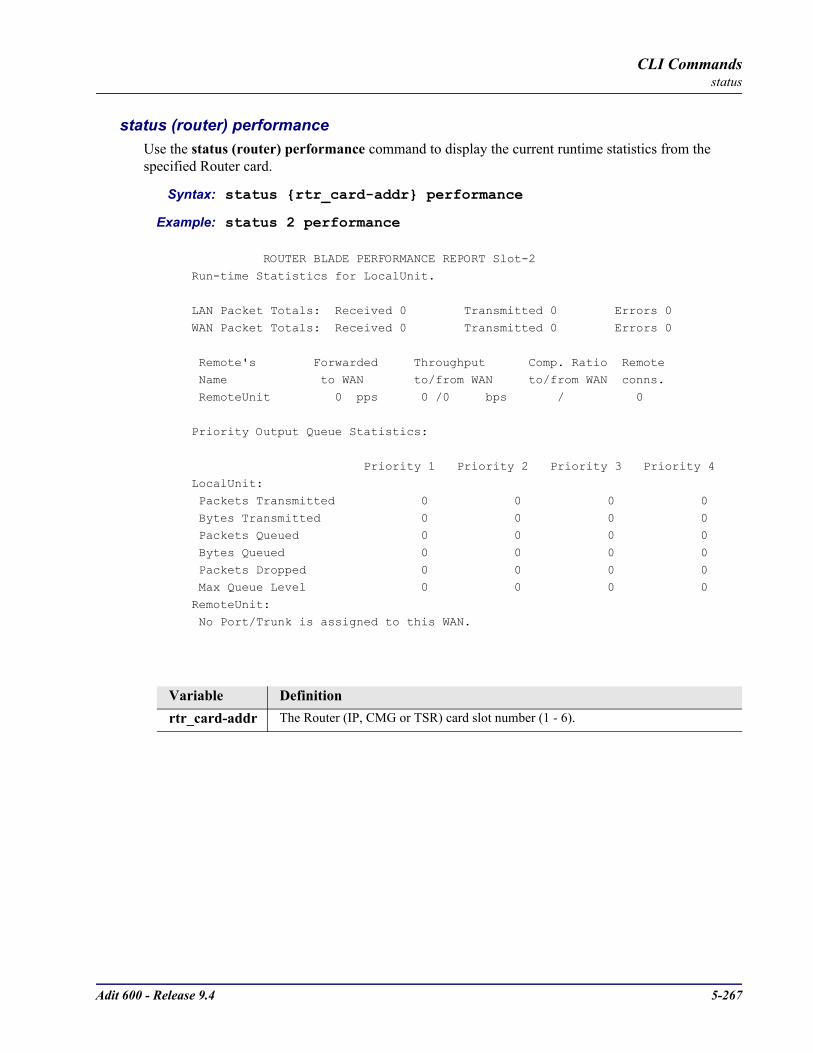
Adit 600 - Release 9.4 5-267
CLI Commandsstatus
status (router) performanceUse the status (router) performance command to display the current runtime statistics from the specified Router card.
Syntax: status rtr_card-addr performance
Example: status 2 performance
ROUTER BLADE PERFORMANCE REPORT Slot-2
Run-time Statistics for LocalUnit.
LAN Packet Totals: Received 0 Transmitted 0 Errors 0
WAN Packet Totals: Received 0 Transmitted 0 Errors 0
Remote's Forwarded Throughput Comp. Ratio Remote Name to WAN to/from WAN to/from WAN conns.
RemoteUnit 0 pps 0 /0 bps / 0
Priority Output Queue Statistics:
Priority 1 Priority 2 Priority 3 Priority 4LocalUnit:
Packets Transmitted 0 0 0 0
Bytes Transmitted 0 0 0 0 Packets Queued 0 0 0 0
Bytes Queued 0 0 0 0
Packets Dropped 0 0 0 0 Max Queue Level 0 0 0 0
RemoteUnit:
No Port/Trunk is assigned to this WAN.
Variable Definitionrtr_card-addr The Router (IP, CMG or TSR) card slot number (1 - 6).
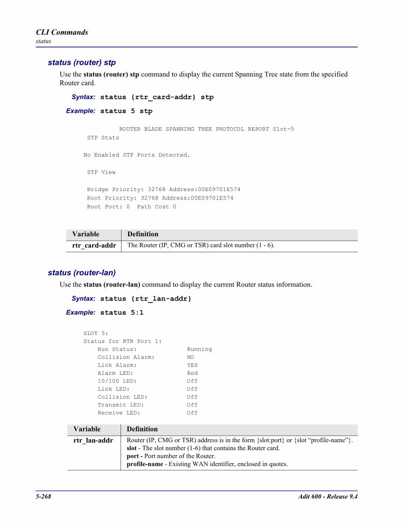
5-268 Adit 600 - Release 9.4
CLI Commandsstatus
status (router) stpUse the status (router) stp command to display the current Spanning Tree state from the specified Router card.
Syntax: status rtr_card-addr stp
Example: status 5 stp
ROUTER BLADE SPANNING TREE PROTOCOL REPORT Slot-5
STP Stats
No Enabled STP Ports Detected.
STP View
Bridge Priority: 32768 Address:00E09701E574
Root Priority: 32768 Address:00E09701E574
Root Port: 0 Path Cost 0
status (router-lan)Use the status (router-lan) command to display the current Router status information.
Syntax: status rtr_lan-addr
Example: status 5:1
SLOT 5:Status for RTR Port 1: Run Status: Running Collision Alarm: NO Link Alarm: YES Alarm LED: Red 10/100 LED: Off Link LED: Off Collision LED: Off Transmit LED: Off Receive LED: Off
Variable Definitionrtr_card-addr The Router (IP, CMG or TSR) card slot number (1 - 6).
Variable Definitionrtr_lan-addr Router (IP, CMG or TSR) address is in the form slot:port or slot “profile-name”.
slot - The slot number (1-6) that contains the Router card.port - Port number of the Router.profile-name - Existing WAN identifier, enclosed in quotes.
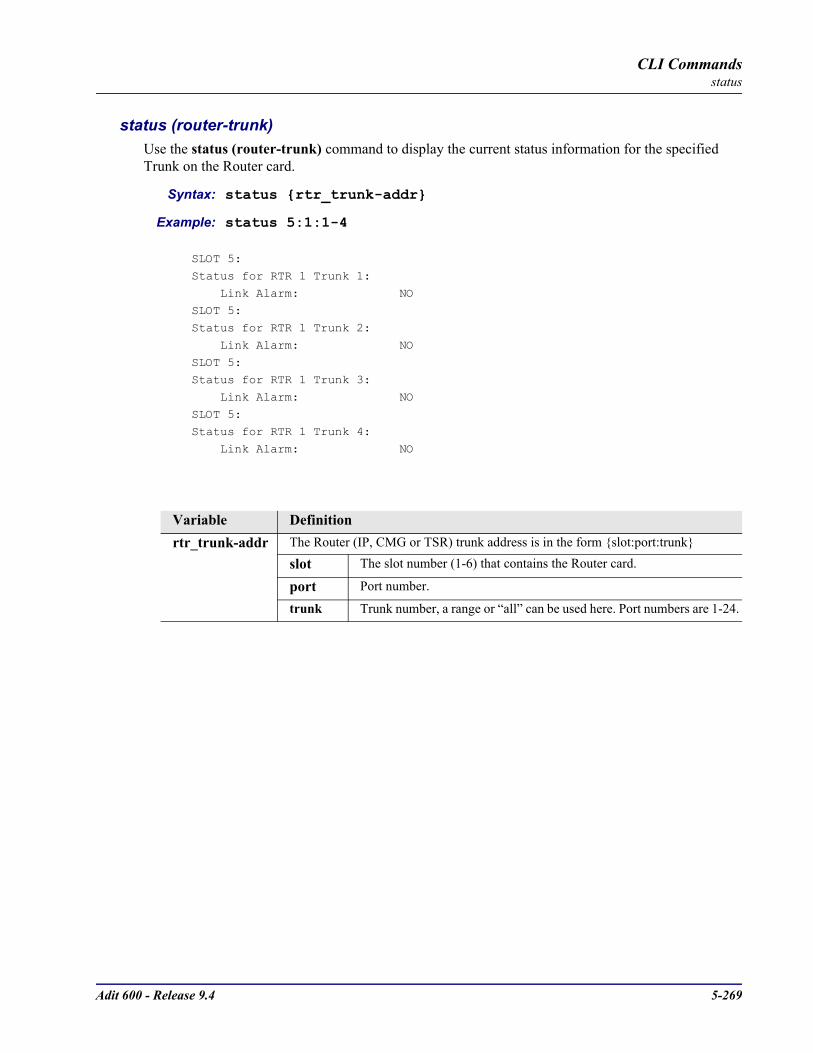
Adit 600 - Release 9.4 5-269
CLI Commandsstatus
status (router-trunk)Use the status (router-trunk) command to display the current status information for the specified Trunk on the Router card.
Syntax: status rtr_trunk-addr
Example: status 5:1:1-4
SLOT 5:
Status for RTR 1 Trunk 1:
Link Alarm: NOSLOT 5:
Status for RTR 1 Trunk 2:
Link Alarm: NO
SLOT 5:Status for RTR 1 Trunk 3:
Link Alarm: NO
SLOT 5:Status for RTR 1 Trunk 4:
Link Alarm: NO
Variable Definitionrtr_trunk-addr The Router (IP, CMG or TSR) trunk address is in the form slot:port:trunk
slot The slot number (1-6) that contains the Router card.
port Port number.
trunk Trunk number, a range or “all” can be used here. Port numbers are 1-24.

5-270 Adit 600 - Release 9.4
CLI Commandsstatus
status (router-voice)Use the status (router-voice) command to display the status of service, calls, signaling, connections, call agent communications and telephony statistics for a CMG Router voice channel. This command applies to the CMG Router card only.
Syntax: status cmg_voice-addr
Example: status 5:1:1:3
CMG VoIP CHANNEL REPORT Slot-5
VoIP Channel 3: Endpoint ID: aaln/3 Admin State: Normal Oper State: Normal Call State: Call In Progress Call Direction: Incoming
Signaling Status: Hookswitch State: Off Hook Last Events Requested: L/hd(N) Current Digit Map: x.[#T]
Call/Connection Status for Connection ID 1: Leg # In Conference: 0 Call ID: 1 Caller ID Number: Caller ID Name: RTP Payload Type: 0 Connection Mode: Receive Only Local RTP Socket: 192.168.24.193:30000 Remote RTP Socket: 0.0.0.0:0 Algorithm In Use: None Rx Gain 0 dB Tx Gain 0 dB Connection Statistics Packets Sent: 0 Packets Rcvd: 0 Payld Octets Sent: 0 Payld Octets Rcvd: 0 Dropped Packets: 0 Jitter: 0 Delay: 0
Call Agent Communications Status for this Endpoint: Notified Entity: [192.168.24.228]:2427 Comm State: Up Last Cmd Rcvd: CRCX From: 192.168.24.228:2427 Last Cmd Sent: NTFY
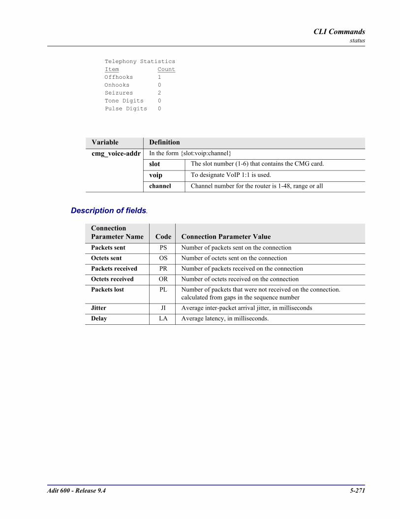
Adit 600 - Release 9.4 5-271
CLI Commandsstatus
Telephony Statistics Item Count Offhooks 1 Onhooks 0 Seizures 2 Tone Digits 0 Pulse Digits 0
Description of fields.
Variable Definitioncmg_voice-addr In the form slot:voip:channel
slot The slot number (1-6) that contains the CMG card.
voip To designate VoIP 1:1 is used.
channel Channel number for the router is 1-48, range or all
Connection Parameter Name Code Connection Parameter ValuePackets sent PS Number of packets sent on the connectionOctets sent OS Number of octets sent on the connectionPackets received PR Number of packets received on the connectionOctets received OR Number of octets received on the connectionPackets lost PL Number of packets that were not received on the connection.
calculated from gaps in the sequence numberJitter JI Average inter-packet arrival jitter, in millisecondsDelay LA Average latency, in milliseconds.
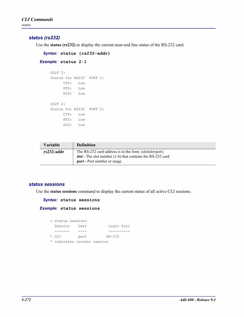
5-272 Adit 600 - Release 9.4
CLI Commandsstatus
status (rs232)Use the status (rs232) to display the current near-end line status of the RS-232 card.
Syntax: status rs232-addr
Example: status 2:1
SLOT 2:Status for RS232 PORT 1:
CTS: Low
RTS: Low DCD: Low
SLOT 2:
Status for RS232 PORT 2: CTS: Low
RTS: Low
DCD: Low
status sessionsUse the status sessions command to display the current status of all active CLI sessions.
Syntax: status sessions
Example: status sessions
> status sessions Session User Login Port
------- ---- ----------
* CLI paul RS-232* indicates current session
Variable Definitionrs232-addr The RS-232 card address is in the form slot|slot:port
slot - The slot number (1-6) that contains the RS-232 cardport - Port number or range.

Adit 600 - Release 9.4 5-273
CLI Commandsstatus
status (v35)Use the status (v35) to display the current near-end line status of the V.35 card.
Syntax: status v35-addr
Example: status 2:1The example displays status of port 1 (V.35) on slot 2
> status 2:1
SLOT 2:
Status for V35 PORT 1: DCD: Low
CTS Low
DSR: Low RTS: Low
DTR: Low
Display DescriptionsDCD - Data Carrier Detect indicates port is receiving a carrier signalCTS - Clear to Send indicates port is ready to receive dataDSR - Data Set Ready indicates port is ready to send dataRTS - Request to SendDTR - Data Terminal Ready
Variable Definitionv35-addr The V.35 card address is in the form slot|slot:port
slot - The slot number (1-6) that contains the V.35 cardport - Port number or range.
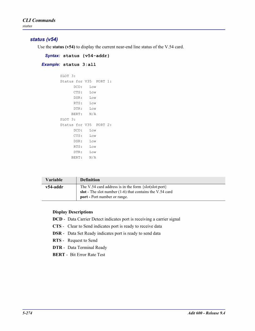
5-274 Adit 600 - Release 9.4
CLI Commandsstatus
status (v54)Use the status (v54) to display the current near-end line status of the V.54 card.
Syntax: status v54-addr
Example: status 3:all
SLOT 3:Status for V35 PORT 1:
DCD: Low
CTS: Low DSR: Low
RTS: Low
DTR: Low
BERT: N/ASLOT 3:
Status for V35 PORT 2:
DCD: Low CTS: Low
DSR: Low
RTS: Low DTR: Low
BERT: N/A
Display DescriptionsDCD - Data Carrier Detect indicates port is receiving a carrier signalCTS - Clear to Send indicates port is ready to receive dataDSR - Data Set Ready indicates port is ready to send dataRTS - Request to SendDTR - Data Terminal ReadyBERT - Bit Error Rate Test
Variable Definitionv54-addr The V.54 card address is in the form slot|slot:port
slot - The slot number (1-6) that contains the V.54 cardport - Port number or range.
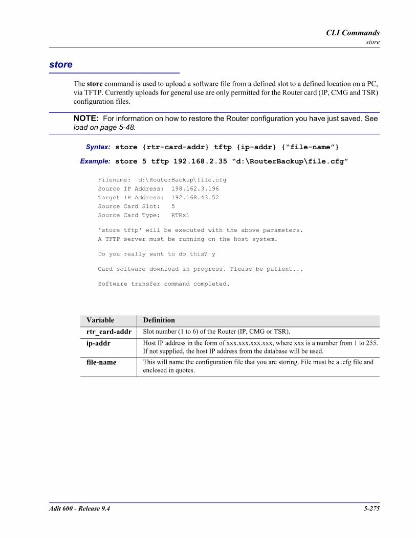
Adit 600 - Release 9.4 5-275
CLI Commandsstore
store
The store command is used to upload a software file from a defined slot to a defined location on a PC, via TFTP. Currently uploads for general use are only permitted for the Router card (IP, CMG and TSR) configuration files.
NOTE: For information on how to restore the Router configuration you have just saved. See load on page 5-48.
Syntax: store rtr-card-addr tftp ip-addr “file-name”
Example: store 5 tftp 192.168.2.35 “d:\RouterBackup\file.cfg”
Filename: d:\RouterBackup\file.cfg
Source IP Address: 198.162.3.196
Target IP Address: 192.168.43.52Source Card Slot: 5
Source Card Type: RTRx1
'store tftp' will be executed with the above parameters.A TFTP server must be running on the host system.
Do you really want to do this? y
Card software download in progress. Please be patient...
Software transfer command completed.
Variable Definitionrtr_card-addr Slot number (1 to 6) of the Router (IP, CMG or TSR).
ip-addr Host IP address in the form of xxx.xxx.xxx.xxx, where xxx is a number from 1 to 255. If not supplied, the host IP address from the database will be used.
file-name This will name the configuration file that you are storing. File must be a .cfg file and enclosed in quotes.
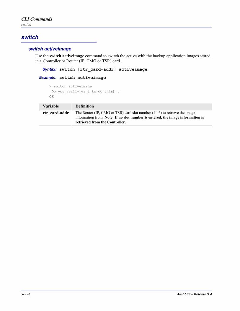
5-276 Adit 600 - Release 9.4
CLI Commandsswitch
switch
switch activeimageUse the switch activeimage command to switch the active with the backup application images stored in a Controller or Router (IP, CMG or TSR) card.
Syntax: switch [rtr_card-addr] activeimage
Example: switch activeimage
> switch activeimage
Do you really want to do this? y
OK
Variable Definitionrtr_card-addr The Router (IP, CMG or TSR) card slot number (1 - 6) to retrieve the image
information from. Note: If no slot number is entered, the image information is retrieved from the Controller.
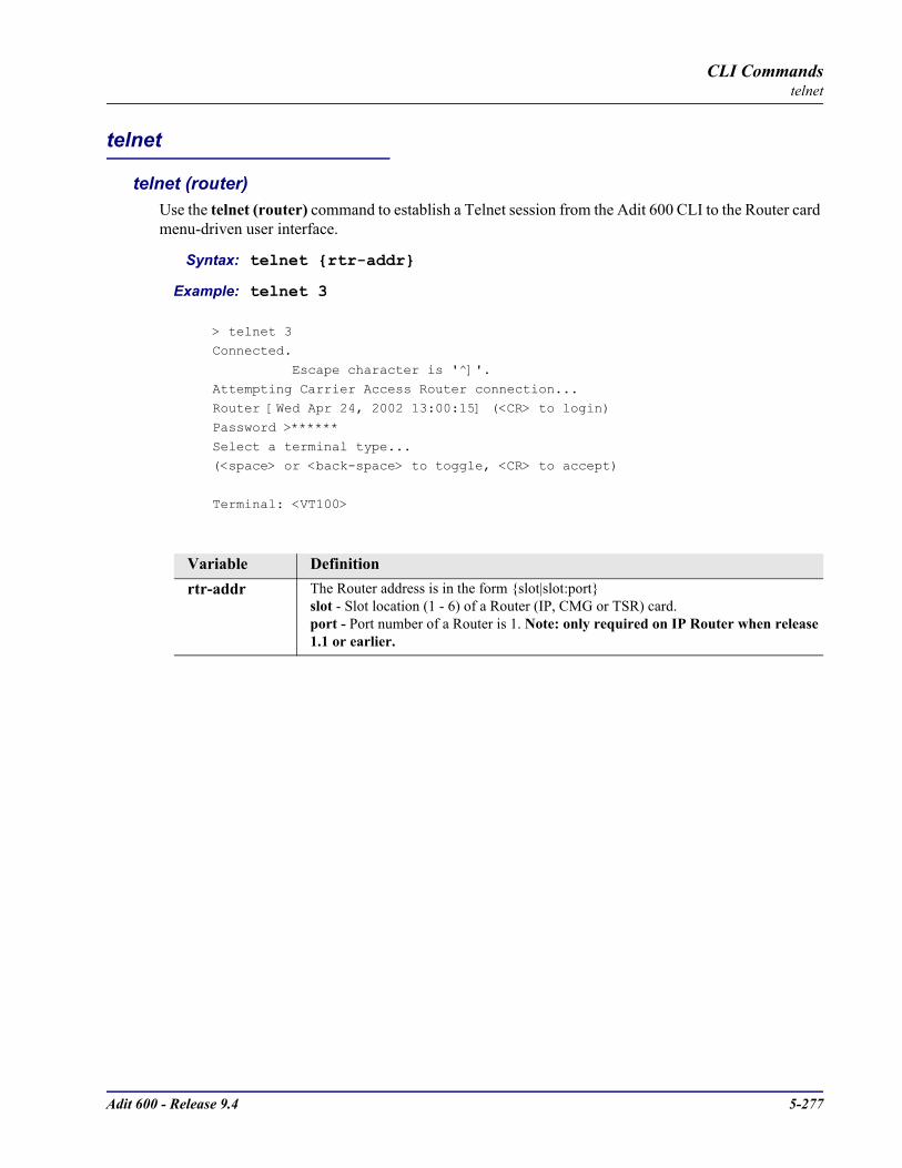
Adit 600 - Release 9.4 5-277
CLI Commandstelnet
telnet
telnet (router)Use the telnet (router) command to establish a Telnet session from the Adit 600 CLI to the Router card menu-driven user interface.
Syntax: telnet rtr-addr
Example: telnet 3
> telnet 3Connected.
Escape character is '^]'.
Attempting Carrier Access Router connection...Router [Wed Apr 24, 2002 13:00:15] (<CR> to login)
Password >******
Select a terminal type...(<space> or <back-space> to toggle, <CR> to accept)
Terminal: <VT100>
Variable Definitionrtr-addr The Router address is in the form slot|slot:port
slot - Slot location (1 - 6) of a Router (IP, CMG or TSR) card.port - Port number of a Router is 1. Note: only required on IP Router when release 1.1 or earlier.

5-278 Adit 600 - Release 9.4
CLI Commandstest
test
test (fxs8C/fxs8B)Use the test (fxs8C/fxs8B) command to test the channels on the FXS 8C or FXS 8B Service Card. Note: only one channel can be tested at a time. This process should take approximately 20 seconds. The following is a list of tests that will be run on the channel. The tests cannot be selected to execute individually but must be executed as a set. If one test in the set fails all tests stop and will not continue to the next test. If all tests in the set pass only a single OK indication will be displayed. They will be executed in the following order:
1. Hazardous Potential Test2. Foreign Electromotive Force Test3. Resistive Faults Test 4. Receiver Off Hook Test
Note: for test results see show test (fxs8C/fxs8B) on page 5-240.
Syntax: test fxs8C-addr|fxs8B-addr
Example: test 1:1Results will be available in approximately 20 seconds.
OK
Variable Definitionfxs8C-addrfxs8B-addr
List of voice channels to apply setting to, in the form slot:port.slot - Slot number 1 - 6, location of the FXS 8C or FXS 8B cardchannel - Channel number 1-8.

Adit 600 - Release 9.4 5-279
CLI Commandstrace route
trace route
tracert (router)Use the tracert (router) command to invoke a Trace Route to a host device on a network of a IP, CMG or TSR Router. Trace Route responses will be returned to user screen as each hop host device response packet is received or the timeout return data is provided for a hop. The output will have DNS names only if DNS resolver is enabled and DNS server can resolve host IP. The optional parameters [ttlbeg] and [ttlmax] allow the user to define the range of hops the trace route will query. A response with a * indicates no response from the host.
Syntax: tracert rtr_card-addr ip-addr|"domain-name" [icmp|udp] [src-ip] [ttlbeg] [ttlmax] [udp-port]
Example: tracert 2 10.40.15.70 udp
Example: tracert 3 "www.google.com" ICMP 192.168.100.100 1 32
Tracert 3 www.google.com 192.168.100.100 5 32 in progress… Hops Ave. Host 1 <10 ms 99.90.9.254 nat1xt-tw-gw.carrieraccess.com 2 <10 ms 65.243.6.17 3 10 ms 137.39.6.200 4 20 ms 152.63.101.134 0.so-3-1-0.XL2.DFW9.ALTER.NET 5 20 ms 152.63.102.6 0.so-0-0-0.XR2.DFW9.ALTER.NET 6 10 ms 152.63.100.221 184.ATM7-0.BR4.DFW9.ALTER.NET 7 * * 8 10 ms 208.172.130.104 agr4-loopback.Dallas.cw.net 9 10 ms 208.172.139.9 dcr1-so-0-2-0.Dallas.cw.net 10 580 ms 216.33.153.188 csr1-ve241.SantaClarasc3.cw.net 11 60 ms 64.68.64.210 this.is.an.device.name.2.long.2show.all.of.name... 12 70 ms 216.239.47.2 13 60 ms 216.239.33.101 www.google.comTrace Terminated: 13 Hops, Hop range 1-13
Variable Definitionrtr_card-addr The slot number (1-6) that contains the Router (IP, CMG or TSR) card
ip-addr The IP address for trace route to use for this query, in the form of xxx.xxx.xxx.xxx, where xxx is between 0-255.
domain-name The domain name for the external DNS server. Name must be enclosed in quotes, with a maximum length of 42 characters.
icmp Internet Control Message Protocol (ICMP) method of trace routing is the most widely used and has the best reliability. This is the default
udp User Datagram Protocol (UDP) method requires that all devices in the chain of the trace route support probes on the particular UDP port. This method is not recommended.
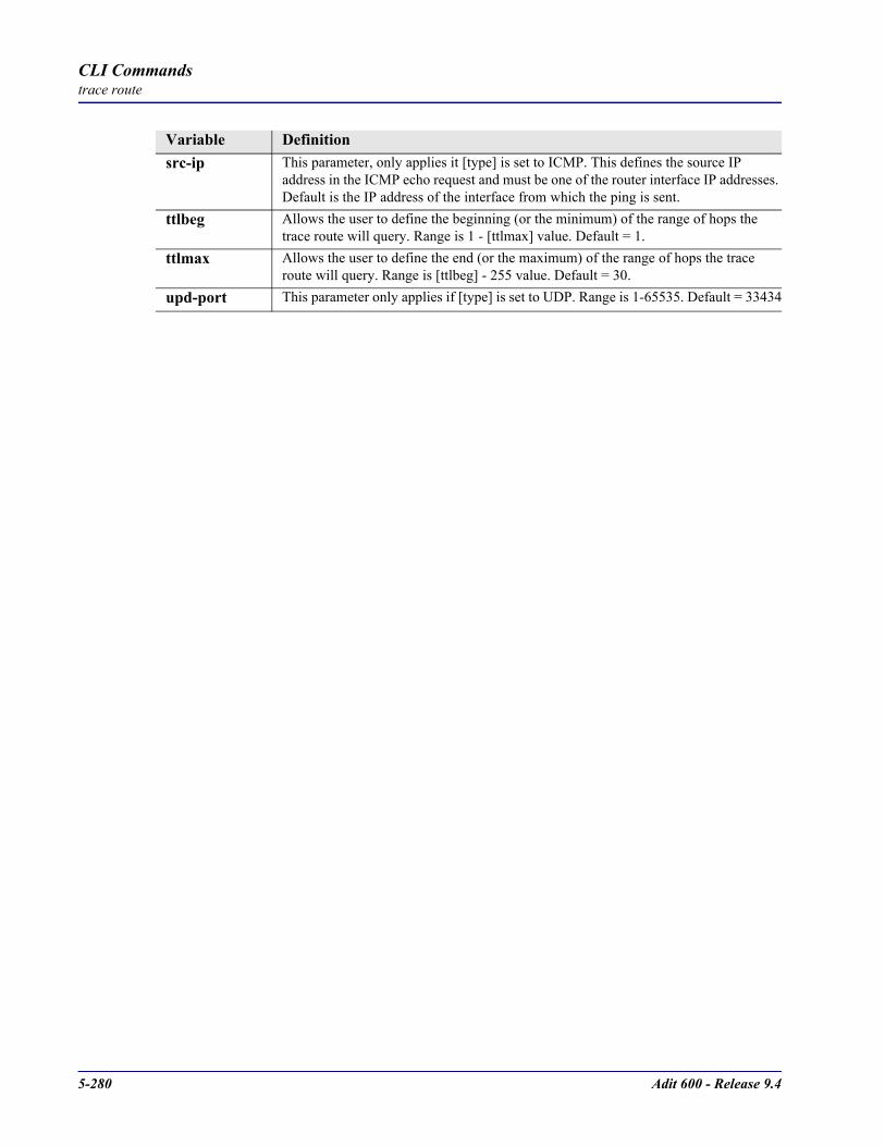
5-280 Adit 600 - Release 9.4
CLI Commandstrace route
Variable Definitionsrc-ip This parameter, only applies it [type] is set to ICMP. This defines the source IP
address in the ICMP echo request and must be one of the router interface IP addresses. Default is the IP address of the interface from which the ping is sent.
ttlbeg Allows the user to define the beginning (or the minimum) of the range of hops the trace route will query. Range is 1 - [ttlmax] value. Default = 1.
ttlmax Allows the user to define the end (or the maximum) of the range of hops the trace route will query. Range is [ttlbeg] - 255 value. Default = 30.
upd-port This parameter only applies if [type] is set to UDP. Range is 1-65535. Default = 33434
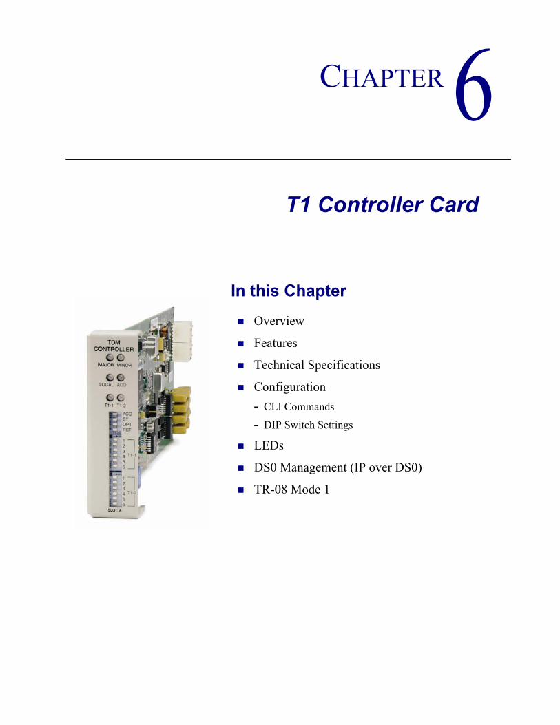
CHAPTER 6T1 Controller Card
In this Chapter
Overview
Features
Technical Specifications
Configuration- CLI Commands
- DIP Switch Settings
LEDs
DS0 Management (IP over DS0)
TR-08 Mode 1

6-2 Adit 600 - Release 9.4
T1 Controller CardOverview
OverviewThe Adit 600 with the Dual T1 Controller Card offers a cost-effective, compact solution that delivers a wide range of services from both wireline and wireless access networks. The T1 Controller Card includes two T1 ports with integrated CSUs and a built-in 1/0 cross-connect matrix providing full, non-blocking connectivity between the T1 Controller Card and any of the six service card slots. The total T1 capacity can be increased to 18 network access trunks or drop-and-insert user connections by adding a full complement of Quad T1 Service Cards. The Adit 600 offers a modular design that includes the T1 Controller Card (required) and an array of available service cards. This flexibility allows the Adit 600 to function in a variety of applications, including:
1 to 18 T1 multi-service digital cross-connect system GR-303/TR-08/DLC remote terminal 48 FXS/FXO/DPT channel bank40 FXS Voice over IP (VoIP) Customer Media Gateway (CMG) Service card40 ISDN BRI shelf6 Ethernet IP Router/WAN nest24-port RS-232 and Ethernet with TSR Service Card12 V.35 or synchronous RS-232 port drop-and-insert CSU/DSU24 OCU-DP digital data service (DDS) delivery device47-station P-Phone (EBS) terminal6 Single-Channel POTS
The modular Adit 600 platform also allows service providers to scale across service types, network architectures, and bandwidth requirements to fit a dynamic service delivery environment. Service cards provide the physical, electrical, and logical connections for either customer service demarcations or network access. Customer interface types include Routed Ethernet, IP Router, TSR Card, FXS, FXO/DPT, V.35, V.35/V.54, RS-232, OCU-DP, ISDN BRI, P-Phone (Electronic Business Set), and T1. Any service card can be placed in any of the six available slots. In addition, the CMG Service Card enables the Adit 600 to provide a cost-effective VoIP conversion of telephone lines or dual T1 interfaces.The T1 Controller Card has several local and remote management options available. The card can be configured and managed locally using the front-panel DIP switches or the Command Line Interface (CLI). Front-panel LEDs quickly communicate alarm and T1 line status, as well as mode of operation. Remote management is accomplished directly either over an in-band DS0 management channel or via a separate SNMP Ethernet connection. Alternatively, remote management can be accomplished through the Access Navigator over the Facility Data Link (FDL) or an in-band dedicated DS0.

Adit 600 - Release 9.4 6-3
T1 Controller CardFeatures
Features Allows any service connection or network access line to be deployed in any slotProvides integrated 18 T1 port digital cross-connect for service grooming and restorationSupplies integrated dual T1 CSU/DSUs and SNMP management on the ControllerSupport for VoIP services through the Customer Media Gateway (CMG) Service Card Enables remote SNMP and Telnet provisioning, monitoring, and testing of services and network conditionsDelivers remote management via T1, FDL, in-band IP, external Ethernet or RS-232Provides GR-303 remote terminal management from Access Navigator host software
Technical Specifications
Controller Software RequiredRelease 9.4 is required to support all the features listed in this manual.
Product Includes18 T1 port built-in, non-blocking 1/0 Digital Cross-connect SystemRobbed-bit (voice) and clear channel (data) signaling on the same T1TR-08 signaling configured as either AB, BB, A or BIntegral dual T1 ports that support drop-and-insert applicationsT1.231 performance monitoring statistics: Ninety-six 15 minute segments (24 hour period)Performance Report MessagesPBX trunk signaling, E&M to loop start and ground start conversionAnalog voice signaling, CLASS features such as Call Waiting, Call Forwarding, Calling Party Disconnect and DNIS/DIDFront-panel LED indicators for T1 status, major and minor alarms, remote/local management mode, and Alarm Cut-Off statusController support for IP router card code download through its Ethernet management portConfigurations automatically stored in non-volatile memoryD4 PLAR to loop start conversionRemote Provisioning and Management (RPM)- Supports RPM over FDL with Access Navigator release 1.5 or higherRADIUS Login AuthenticationSyslogNTP

6-4 Adit 600 - Release 9.4
T1 Controller CardTechnical Specifications
ManagementLocal- Simple setup using front panel DIP switches for channel bank applications- RS-232 craft port interface drives up to 50 ft. (15.24 m) cable, and provides a Command Line
Interface (CLI) using ASCII terminal or PC with terminal emulation software, modem using XMODEM or PPP sessions
Remote- 10Base-T Ethernet management port provides
• Local IP management connectivity• RJ-45 connector mounted on rear panel of chassis• 10Base-T link LED status indicator• IP management over a dedicated DS0 bearer channel
- CLI management from Access Navigator (Rel. 1.7 or higher) through T1 FDLIntegrated TFTP client for remote download of controller software upgradesSNMP agent, supporting MIB objects:
CLI offers three levels of password controlled securityPerformance Report Messages
Network T1 InterfaceSelectable single or dual T1 ports operating at 1.544 Mbps ±50 bpsSF (D4) and ESF framingAMI or B8ZS line codingShort or long-haul loop settingsIntegrated CSU functionLine build out (DSX-1): 655 feetReceive sensitive (DS1): 0 to -22.5 dBJitter and wander ITU-T B.824 (3/93)Channel status LEDsTwo RJ-48C connectors on rear panel of chassisSolid-state (fuseless) overvoltage and overcurrent T1 line protection meets Telcordia GR-1089-CORE intra-building lightning/power cross limitsCAS signaling options
- RFC 1213 (MIB-II) - RFC 2493- RFC 1659 (V.35) - RFC 2494 (DS0-MIB)- RFC 1907 (SNMPv2-MIB) - RFC 2495 (DS1-MIB)- RFC 2011 (IP-MIB) - RFC 2571 (SNMP)- RFC 2233 (IF-MIB)
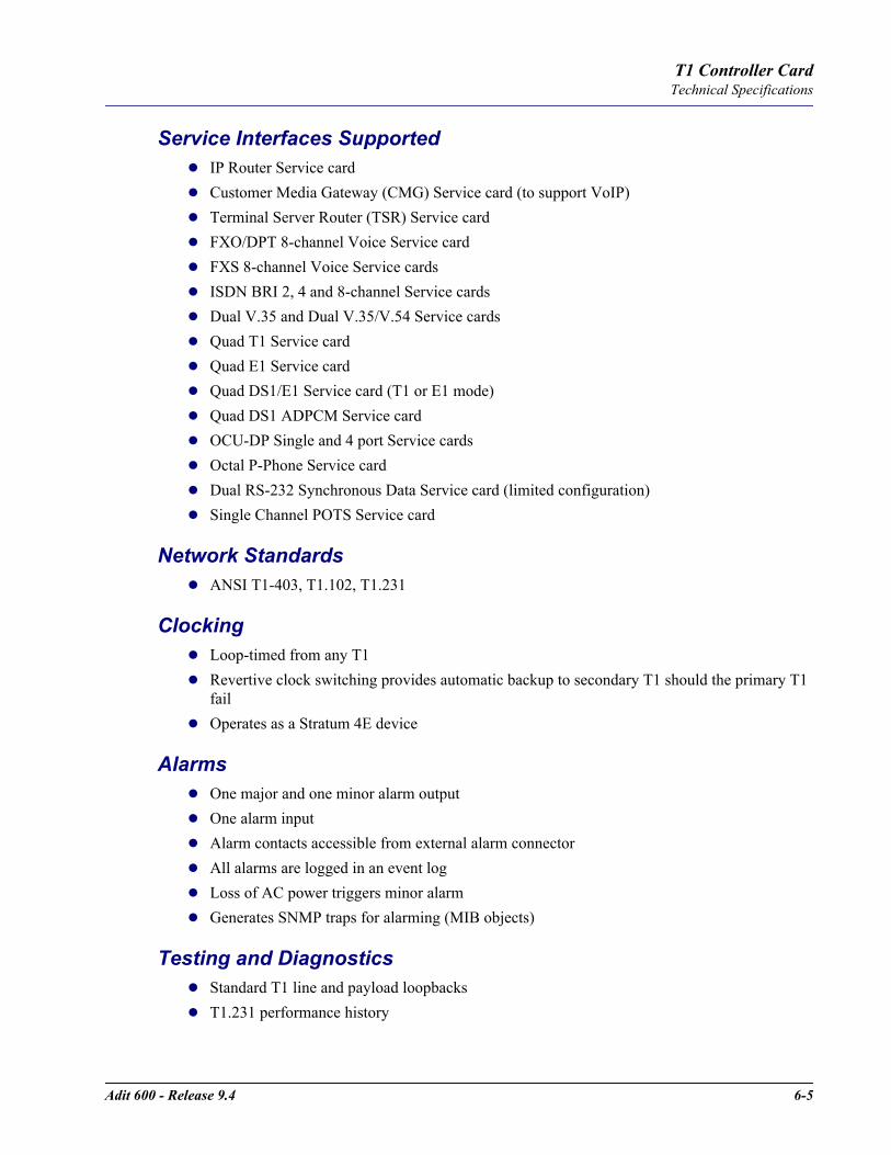
Adit 600 - Release 9.4 6-5
T1 Controller CardTechnical Specifications
Service Interfaces SupportedIP Router Service cardCustomer Media Gateway (CMG) Service card (to support VoIP)Terminal Server Router (TSR) Service cardFXO/DPT 8-channel Voice Service cardFXS 8-channel Voice Service cardsISDN BRI 2, 4 and 8-channel Service cardsDual V.35 and Dual V.35/V.54 Service cardsQuad T1 Service cardQuad E1 Service cardQuad DS1/E1 Service card (T1 or E1 mode)Quad DS1 ADPCM Service cardOCU-DP Single and 4 port Service cardsOctal P-Phone Service cardDual RS-232 Synchronous Data Service card (limited configuration)Single Channel POTS Service card
Network StandardsANSI T1-403, T1.102, T1.231
ClockingLoop-timed from any T1Revertive clock switching provides automatic backup to secondary T1 should the primary T1 failOperates as a Stratum 4E device
AlarmsOne major and one minor alarm outputOne alarm inputAlarm contacts accessible from external alarm connectorAll alarms are logged in an event logLoss of AC power triggers minor alarm Generates SNMP traps for alarming (MIB objects)
Testing and DiagnosticsStandard T1 line and payload loopbacksT1.231 performance history

6-6 Adit 600 - Release 9.4
T1 Controller CardTechnical Specifications
Power Consumption4 W maximum
Regulatory ApprovalsSee Appendix A, Regulatory Approvals for information on the T1 Controller card.
PhysicalDimensions: 3.5 in. (H) x 1 in. (W) x 11.25 in. (D) 8.9 cm (H) x 2.5 cm (W) x 28.6 cm (D)Weight: 5.7 oz. (.16 kg)
For information on Adit 600 Environment required, see Installation Environment on page 2-2.
Adit 600 - Release 9.4 6-7
T1 Controller CardConfiguration
ConfigurationOptions on the Controller card are set by the DIP switches, or the Command Line Interface (CLI).
NOTE: The default IP address for the Adit Controller is 10.0.0.10.
CLI CommandsThe following commands are used to configure the Controller card. For detailed information on these commands, see Chapter 5, CLI Commands.
connectCreates two-way connections between channels
disconnectRemoves a connection created by the connect command
set clockSets the primary and secondary transmit clock
set dateSets the date for the system
set (ds1)Sets up the DS1 interfaces (up, down, bpviolation, fdl, framing, id string, lbo, line loopup, linecode, loopdetect, payload, threshold)
set ipds0Sets up the DS0 management channel (assign, disable, down, IP address, up)
show (ds1)Displays current settings for DS1 (circuit ID, up, down, framing, line coding, clock source, line build out, loop code detection, loop back, fdl type)
show ipds0Displays the settings for the DS0 management channel
status (ds1)Displays the status of the DS1 (receive, transmit, loopback)
status ipds0Display the status of the DS0 management channel
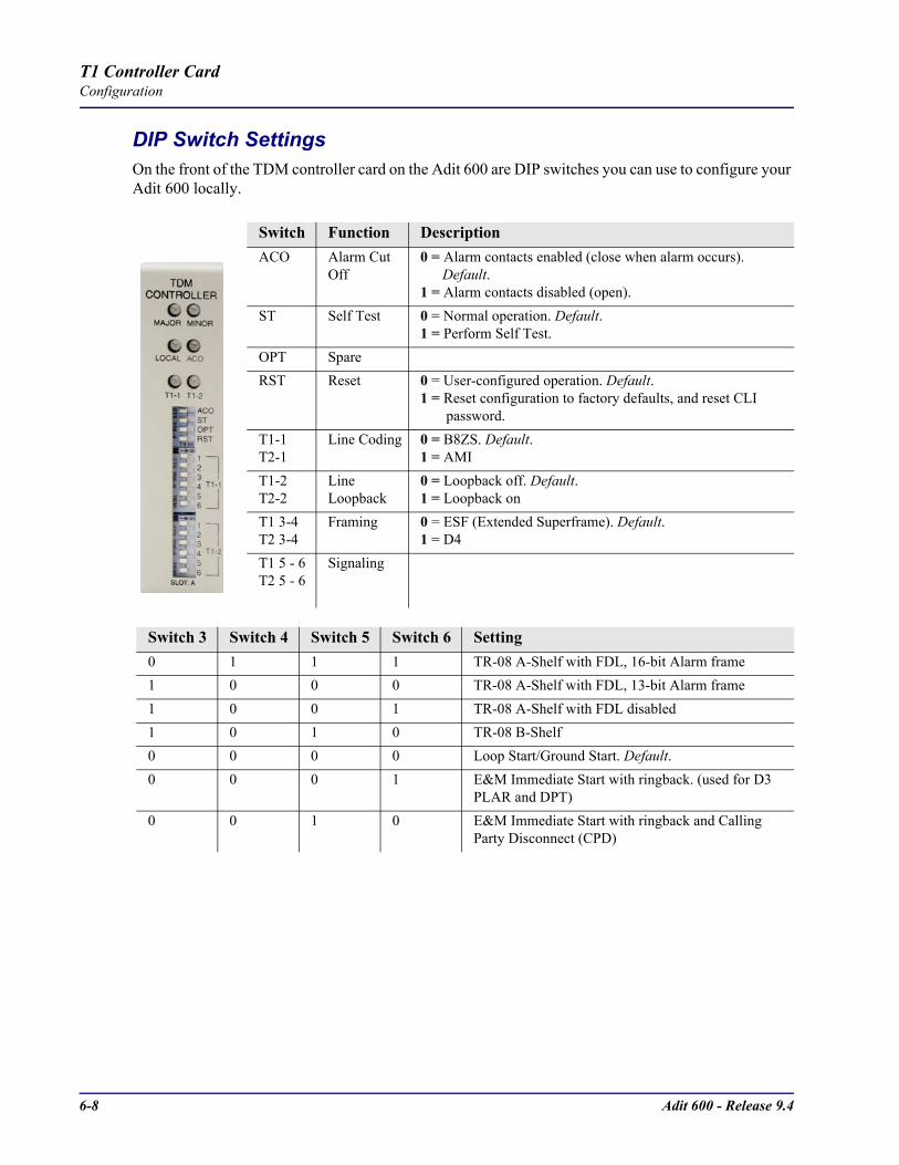
6-8 Adit 600 - Release 9.4
T1 Controller CardConfiguration
DIP Switch SettingsOn the front of the TDM controller card on the Adit 600 are DIP switches you can use to configure your Adit 600 locally.
Switch Function DescriptionACO Alarm Cut
Off0 = Alarm contacts enabled (close when alarm occurs). Default.1 = Alarm contacts disabled (open).
ST Self Test 0 = Normal operation. Default.1 = Perform Self Test.
OPT SpareRST Reset 0 = User-configured operation. Default.
1 = Reset configuration to factory defaults, and reset CLI password.
T1-1T2-1
Line Coding 0 = B8ZS. Default.1 = AMI
T1-2T2-2
Line Loopback
0 = Loopback off. Default.1 = Loopback on
T1 3-4T2 3-4
Framing 0 = ESF (Extended Superframe). Default.1 = D4
T1 5 - 6T2 5 - 6
Signaling
Switch 3 Switch 4 Switch 5 Switch 6 Setting0 1 1 1 TR-08 A-Shelf with FDL, 16-bit Alarm frame 1 0 0 0 TR-08 A-Shelf with FDL, 13-bit Alarm frame1 0 0 1 TR-08 A-Shelf with FDL disabled 1 0 1 0 TR-08 B-Shelf 0 0 0 0 Loop Start/Ground Start. Default. 0 0 0 1 E&M Immediate Start with ringback. (used for D3
PLAR and DPT) 0 0 1 0 E&M Immediate Start with ringback and Calling
Party Disconnect (CPD)

Adit 600 - Release 9.4 6-9
T1 Controller CardLEDs
LEDsThe T1 Controller has a set of six LEDs you can use to troubleshoot your Adit 600. The table below describes each LED.
LED State DescriptionMAJOR Off No major alarms present
Red Major alarm presentMINOR Off No minor alarms present
Yellow Minor alarms presentLOCAL Off Remote mode (DIP switches disabled)
Green Local mode (DIP switches enabled)ACO Off Normal mode. No alarms are being suppressed.
Yellow Alarm cutoff active. One or more active alarms suppressed.
T1-1 and T1-2
Off Off lineGreen NormalRed Loss of Signal (LOS) detectedYellow Bipolar Violation (BPV) detectedFlashing Green Loopback activeFlashing Red Loss of Frame (LOF) or Alarm Indication Signal
(AIS) detectedFlashing Yellow
Yellow alarm (Remote Alarm Indication) detected.0 (Off) 1 (On)

6-10 Adit 600 - Release 9.4
T1 Controller CardDS0 Management (IP over DS0)
DS0 Management (IP over DS0)The DS0 Management Channel provides an alternative to the FDL link for management information for those customer deployments where FDL is unavailable. The Access Navigator (Carrier Access) and the remote Adit 600 will use IP packets to communicate management and control information over the DS0 Management Channel. This information includes support for the activation, testing, and status reporting for ISDN lines. A DS0 Channel will be used in the remote Adit 600 to send and receive the management IP packets. An Adit equipped with IP routing capabilities and co-located with the Navigator will be used to forward the IP packets between the remote Adit and the Navigator. The co-located Adit 600 with IP routing capabilities is required due to Navigator bandwidth limitations. In the Navigator, the Ethernet port will be used to exchange these packets.
At the remote Adit a single DS0 will be configured to exchange management information with Navigator. The DS0 will be cross-connected at the Navigator to a DS0 at the router. The Router will also be connected to the Navigator via an Ethernet connection. The Router will forward IP packets between the management DS0 and the Ethernet. The Router will support multiple Navigators through its Ethernet port and multiple Adit 600s through individual DS0 channels.Each Navigator and each Adit 600 will be configured with a unique IP address reachable by the router. The DS0 Channel will be configured in the Adit 600. In the Navigator, the cross connects between the remote Adit 600 and the router (Adit) will be statically configured. For each remote Adit 600 supported by the Navigator a selection of an FDL or DS0 Management channel must also be made. Selection of the DS0 Management Channel will require the IP address of the remote Adit 600.The DS0 Management Channel will be used to exchange BRI activation, deactivation, and status reporting messages between the Navigator and the remote Adit 600. All commands initiated by the Switch will be forwarded by the Navigator over the DS0 Management Channel and will be processed by the Adit 600, including commands to control Loop Back or Corrupt CRC tests. The Adit 600 will report change in status, such as Loss of Signal over the DS0 Management Channel. The Navigator will forward this information to the Switch via GR-303 EOC messages.
AccessNavigator
Adit 600
Adit 600
Adit 600(remote #2)
Adit 600
DS1 STATUS
ACCESSNAVIGATOR
CARRIER ACCESSCORPORATION
12
34
56
78
910
1112
1314
1516
1718
1920
2122
2324
2526
2728
2930
3132
POWERACO
(PUSH)
CONTROLLER AACTIVE
CRI TACO
MAJORMINOR
POWERACO
(PUSH)
CONTROLLER BACTIVE
CRI TACO
MAJORMINOR
IP packets carry RemoteMgmt messages
One ManagementT1 DS0 for eachRemote Adit 600
VoiceSwitch
T1 DS0 carryingIP Packets
EOC messagescarry ISDN EOC 192.168.201.100
192.168.201.101
PC192.168.201.102
192.168.202.1
192.168.202.2
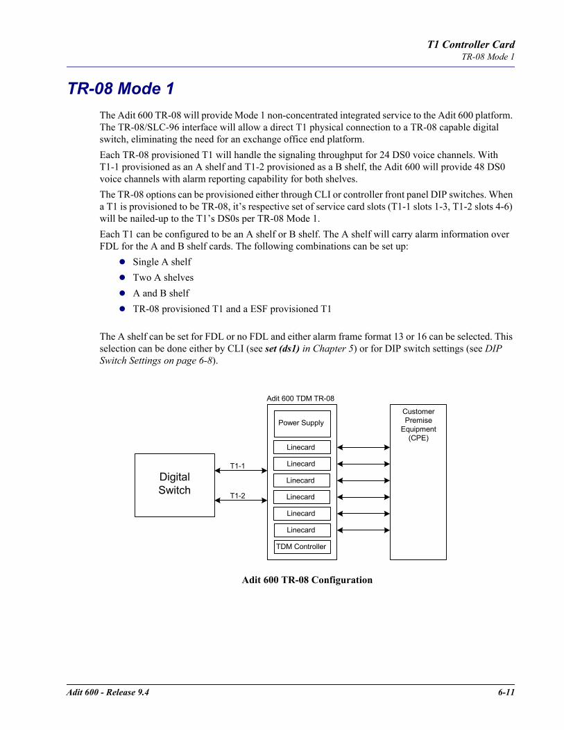
Adit 600 - Release 9.4 6-11
T1 Controller CardTR-08 Mode 1
TR-08 Mode 1The Adit 600 TR-08 will provide Mode 1 non-concentrated integrated service to the Adit 600 platform. The TR-08/SLC-96 interface will allow a direct T1 physical connection to a TR-08 capable digital switch, eliminating the need for an exchange office end platform.Each TR-08 provisioned T1 will handle the signaling throughput for 24 DS0 voice channels. With T1-1 provisioned as an A shelf and T1-2 provisioned as a B shelf, the Adit 600 will provide 48 DS0 voice channels with alarm reporting capability for both shelves.The TR-08 options can be provisioned either through CLI or controller front panel DIP switches. When a T1 is provisioned to be TR-08, it’s respective set of service card slots (T1-1 slots 1-3, T1-2 slots 4-6) will be nailed-up to the T1’s DS0s per TR-08 Mode 1. Each T1 can be configured to be an A shelf or B shelf. The A shelf will carry alarm information over FDL for the A and B shelf cards. The following combinations can be set up:
Single A shelfTwo A shelvesA and B shelfTR-08 provisioned T1 and a ESF provisioned T1
The A shelf can be set for FDL or no FDL and either alarm frame format 13 or 16 can be selected. This selection can be done either by CLI (see set (ds1) in Chapter 5) or for DIP switch settings (see DIP Switch Settings on page 6-8).
Adit 600 TR-08 Configuration
DigitalSwitch
TDM Controller
Linecard
Linecard
Linecard
Linecard
Linecard
Linecard
Power Supply
T1-1
T1-2
CustomerPremise
Equipment(CPE)
Adit 600 TDM TR-08

6-12 Adit 600 - Release 9.4
T1 Controller CardTR-08 Mode 1

CHAPTER 7E1 Controller Card
In this Chapter
Overview
Features
Technical Specifications
Configuration- CLI Commands
- DIP Switch Settings
LEDs
7-2 Adit 600 - Release 9.4
E1 Controller CardOverview
OverviewThe Adit 600 with the Dual E1 Controller card offers a cost-effective, compact solution to deliver a wide range of services from both wireline and wireless access networks. The E1 Controller includes two E1 ports with integrated CSUs and a built-in 558 timeslot (DS0) 1/0 cross-connect matrix. This provides full non-blocking connectivity between the E1 Controller card and any of the six Adit 600 service card slots. The total E1 capacity can be increased to 18 network access trunks or drop-and-insert user connections by adding a full complement of four Quad E1 service cards.The Adit 600 offers a modular design that includes the Dual E1 Controller (required) and an array of available service cards. This flexibility allows the Adit 600 to function in a variety of applications, including:
1 to 18 E1 port multi-service Digital Cross-connect System (DCS)40 ISDN BRI shelf120 WAN connection IP router2 to 12 V.35 port drop-and-insert CSU/DSU
The modular Adit 600 platform also allows service providers to scale across service types and bandwidth requirements to fit a dynamic service delivery environment. Service cards provide the physical, electrical, and logical connections for either customer service demarcations or network access. Customer interface types include Routed Ethernet, FXS, FXO, E&M/TO, V.35, ISN BRI and E1. Any service card can be placed in any of the six available slots. The E1 Controller card has several local and remote management options available. The card can be configured and managed locally using the front-panel DIP switches, the Command Line Interface (CLI), or with future releases of the Valet GUI configuration tool. Front-panel LEDs quickly communicate alarm and E1 line status, as well as mode of operation. Remote management is accomplished directly over either in-band DS0 management channel or via a separate SNMP network management facility. Remote configuration, maintenance and troubleshooting tasks are simplified by the graphical interfaces of the NetworkValet Enhanced Management System (EMS).
FeaturesSupports up to 18 E1s (4 Quad E1s plus the two E1s natively on the controller) Any service connection or network access line in any slotCapacity for control of 48 analog voice lines, 40 ISDN BRIs, 18 E1s, or 12 V.35s in an Adit 600 chassisIncludes integration of Dual E1 functionality and Ethernet SNMP managementRemote SNMP GUI or Telnet provisioning, monitoring, and testing of services and networkSupports Voice Over IP Media Gateway Router for implementing softswitch services at business locationsSupports standard E1 line loopback
Adit 600 - Release 9.4 7-3
E1 Controller CardTechnical Specifications
Technical SpecificationsController Software Required
Release 3.2 or higher to support an E1 Controller card.Release 9.4 to support all of the features listed in this manual.
Product IncludesBuilt-in non-blocking 512 DS0 digital cross-connect systemVoice and Data on the same E1Integral dual E1 ports that support drop-and-insert applicationsRFC 2495 performance monitoring statisticsFront-panel LED indicators for E1 status, major and minor alarms, remote/local management mode, and Alarm Cut-Off statusController support for IP router card code download through its Ethernet management portConfigurations automatically stored in non-volatile memorySNMP agent, supporting MIB objects:
ManagementLocal- Simple setup using front panel DIP switches for channel bank applications- RS-232 craft port interface drives up to 50 ft. (15.24 m) cable, and provides a Command Line
Interface (CLI) using ASCII terminal or PC with terminal emulation software, modem using XMODEM or PPP sessions
Remote- 10Base-T Ethernet management port provides
• Local IP management connectivity• RJ-45 connector mounted on rear panel of chassis• 10Base-T link LED status indicator• IP management over a dedicated DS0 bearer channel
Integrated TFTP client for remote download of controller software upgradesCLI offers three levels of password controlled security
- RFC 1213 (MIB-II) - RFC 2011 (IP-MIB) - RFC 2494 (DS0-MIB)
- RFC 1659 (V.35) - RFC 2233 (IF-MIB) - RFC 2495 (DS1/E1-MIB)
- RFC 1907 (SNMPv2-MIB)
7-4 Adit 600 - Release 9.4
E1 Controller CardTechnical Specifications
Network E1 InterfaceSelectable single or dual E1 ports operating at 2.048 Mbps ±100 bpsExpansion to 18 E1s in a single chassis using Quad E1 Service cardsE1 Double Framed and E1 Multi-Frame (CRC-4) framingAMI or HDB3 line codingGeneric R2, no signaling and CAS signaling optionsLoop Up (on)/ Loop Down (off) line loopback settings24-hour or 15-minute performance thresholdIntegrated CSU functionReceive sensitive (DS1): 0 to -22.5 dBTwo RJ-48C connectors on rear panel of chassisSolid-state (fuseless) overvoltage and overcurrent protection
Service Interfaces Supported IP Router card Customer Media Gateway (CMG) Service cardTerminal Server Router (TSR) Service card4-Wire E&M/TO Service cardFXO Voice Service cardFXS 8-channel Voice Service cardsISDN BRI 2, 4 and 8-channel Service cards (3 DS0 mode only)Dual V.35 and V.35/V.54 Service cardsQuad T1 Service cardQuad E1 Service cardQuad DS1/E1 Service card (T1 or E1 mode)Quad DS1 ADPCM Service cardSingle Channel POTS Service card
Network StandardsITU-T G.703, G.704, G.821/G.823CTR 12 & 13
ClockingE1 network loop timingE1 transmit circuits derive timing from 8.192 MHz backplaneRevertive clock switching provides automatic backup to secondary E1 should the primary E1 failOperates as a Stratum 4E device

Adit 600 - Release 9.4 7-5
E1 Controller CardTechnical Specifications
AlarmsE1 alarms per ITU-T G.732One major and one minor alarm outputOne alarm inputAlarm contacts accessible from external alarm connectorAll alarms are logged in an event logLoss of AC power triggers minor alarm Generates SNMP traps for alarming (MIB objects)
Testing and DiagnosticsStandard E1 line loopbacksIntegrated FXS/GS loop testingRFC 2495 performance history
Power Consumption4 W maximum
Regulatory ApprovalsSee Appendix A, Regulatory Approvals for information on the E1 Controller card.
PhysicalDimensions: 3.5 in. (H) x 1 in. (W) x 11.25 in. (D) 8.9 cm (H) x 2.5 cm (W) x 28.6 cm (D)Weight: 5.7 oz. (.16 kg)
For information on Adit 600 Environment required, see Installation Environment on page 2-2.

7-6 Adit 600 - Release 9.4
E1 Controller CardConfiguration
ConfigurationOptions on the E1 Controller card are set by the DIP switches or Command Line Interface (CLI).
NOTE: The default IP address for the Adit Controller is 10.0.0.10.
CLI CommandsThe following commands are used to configure the E1 Controller card. For detailed information on these commands, see Chapter 5, CLI Commands.
connectCreates two-way connections between channels
disconnectRemoves a connection created by the connect command
set clockSets the primary and secondary transmit clock
set dateSets the date for the system
set (e1)Sets up the E1 interfaces (up, down, framing, line, linecode and signaling)
show (e1)Displays current settings for E1 (up, down, framing, line coding, loop back and signaling)
status (e1)Displays the status of the E1 (receive, transmit and loopback)
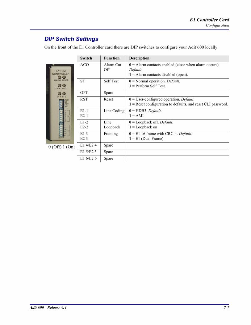
Adit 600 - Release 9.4 7-7
E1 Controller CardConfiguration
DIP Switch SettingsOn the front of the E1 Controller card there are DIP switches to configure your Adit 600 locally.
Switch Function DescriptionACO Alarm Cut
Off0 = Alarm contacts enabled (close when alarm occurs). Default.1 = Alarm contacts disabled (open).
ST Self Test 0 = Normal operation. Default.1 = Perform Self Test.
OPT SpareRST Reset 0 = User-configured operation. Default.
1 = Reset configuration to defaults, and reset CLI password.E1-1E2-1
Line Coding 0 = HDB3. Default.1 = AMI
E1-2E2-2
Line Loopback
0 = Loopback off. Default.1 = Loopback on
E1 3E2 3
Framing 0 = E1 16 frame with CRC-4. Default.1 = E1 (Dual Frame)
E1 4/E2 4 SpareE1 5/E2 5 SpareE1 6/E2 6 Spare
0 (Off) 1 (On)
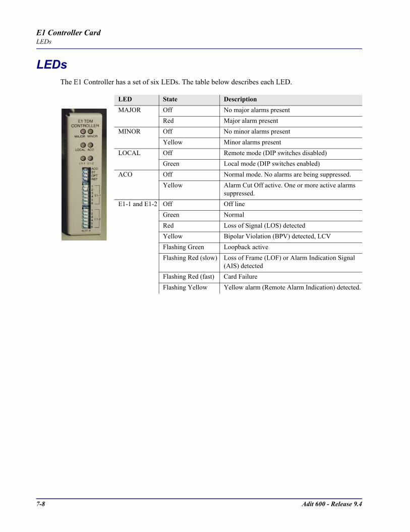
7-8 Adit 600 - Release 9.4
E1 Controller CardLEDs
LEDsThe E1 Controller has a set of six LEDs. The table below describes each LED.
LED State DescriptionMAJOR Off No major alarms present
Red Major alarm presentMINOR Off No minor alarms present
Yellow Minor alarms presentLOCAL Off Remote mode (DIP switches disabled)
Green Local mode (DIP switches enabled)ACO Off Normal mode. No alarms are being suppressed.
Yellow Alarm Cut Off active. One or more active alarms suppressed.
E1-1 and E1-2 Off Off lineGreen NormalRed Loss of Signal (LOS) detectedYellow Bipolar Violation (BPV) detected, LCVFlashing Green Loopback activeFlashing Red (slow) Loss of Frame (LOF) or Alarm Indication Signal
(AIS) detectedFlashing Red (fast) Card FailureFlashing Yellow Yellow alarm (Remote Alarm Indication) detected.
CHAPTER 84-Wire E&M/TO Card
In this Chapter
Overview
Features
Technical Specifications
Card Configuration- CLI Commands
LEDs
Connector Pinouts- RJ-45 Connector
Operating Modes
Signaling Types
Jumpers Settings
Normal and Tandem Cables
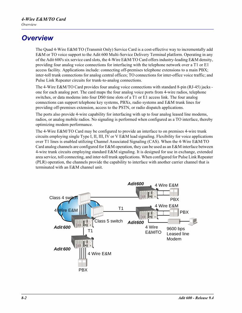
8-2 Adit 600 - Release 9.4
4-Wire E&M/TO CardOverview
Overview The Quad 4-Wire E&M/TO (Transmit Only) Service Card is a cost-effective way to incrementally add E&M or TO voice support to the Adit 600 Multi-Service Delivery Terminal platform. Operating in any of the Adit 600's six service card slots, the 4-Wire E&M/TO Card offers industry-leading E&M density, providing four analog voice connections for interfacing with the telephone network over a T1 or E1 access facility. Applications include: connecting off-premises telephone extensions to a main PBX; inter-toll trunk connections for analog central offices; TO connections for inter-office voice traffic; and Pulse Link Repeater circuits for trunk-to-analog connections.The 4-Wire E&M/TO Card provides four analog voice connections with standard 8-pin (RJ-45) jacks - one for each analog port. The card maps the four analog voice ports from 4-wire radios, telephone switches, or data modems into four DS0 time slots of a T1 or E1 access link. The four analog connections can support telephone key systems, PBXs, radio systems and E&M trunk lines for providing off-premises extension, access to the PSTN, or radio dispatch applications.The ports also provide 4-wire capability for interfacing with up to four analog leased line modems, radios, or analog mobile radios. No signaling is performed when configured as a TO interface, thereby optimizing modem performance.The 4-Wire E&M/TO Card may be configured to provide an interface to on premises 4-wire trunk circuits employing single Type I, II, III, IV or V E&M lead signaling. Flexibility for voice applications over T1 lines is enabled utilizing Channel Associated Signaling (CAS). When the 4-Wire E&M/TO Card analog channels are configured for E&M operation, they can be used as an E&M interface between 4-wire trunk circuits employing standard E&M signaling. It is designed for use in exchange, extended area service, toll connecting, and inter-toll trunk applications. When configured for Pulse Link Repeater (PLR) operation, the channels provide the capability to interface with another carrier channel that is terminated with an E&M channel unit.
PBX
......
T1
T1
4 Wire E&M
4 Wire E&M
4 Wire E&M
PBX
9600 bpsLeased lineModem
PBX
4 WireE&M/TO
4 Wire E&M
Adit 600
Adit 600
Adit 600
Adit 600
Class 5 switch
Class 4 switch

Adit 600 - Release 9.4 8-3
4-Wire E&M/TO CardFeatures
FeaturesTransmit and Receive gain/loss configurable per channelRX gain range 16/-8.5 dB, TX gain range -7/+17.5 dB per G.712 paragraph 2.1Mix E&M and TO services on same Service CardForward and reverse loopbacksAllows digital cross-connection (DCS) of all timeslots to any T1/E1 port
Technical SpecificationsController Software RequiredT1 Controller
Release 8.0 or higher is required for the 4-Wire E&M/TO service cardE1 Controller
Release 9.4 or higher is required for the 4-Wire E&M/TO service card– µ-Law only
E&M/TO Interface4 Selectable E&M/TO portsSystem capacity: 6 Quad 4-Wire E&M/TO Service cardsFront access RJ-45 (8-pin) connectorsImpedance in each Tip/Ring pair 600ΩMaximum signaling lead resistance equipment to equipment is 150ΩMeets ANSI Standard T1.409.2002Signaling Type I, II, III, IV, and VNormal/Tandem/TO ModesTransmit and Receive gain/loss configurable per channel
Transmission PerformanceReceive channel idle noise <18 dBrnCOTransmit channel idle noise <22 dBrnCOTerminating impedance: 600 ΩLoop range: 150 Ω per conductorReceive gain: adjustable from 16 dB to -8.5 dB in .25 incrementsTransmit gain: adjustable from -7 dB to 17.5 dB in .25 increments
Network StandardsANSI T1.409.2002RX gain range -16/+8.5 dB. TX gain -7/+17 dB per G.712 paragraph 2.1
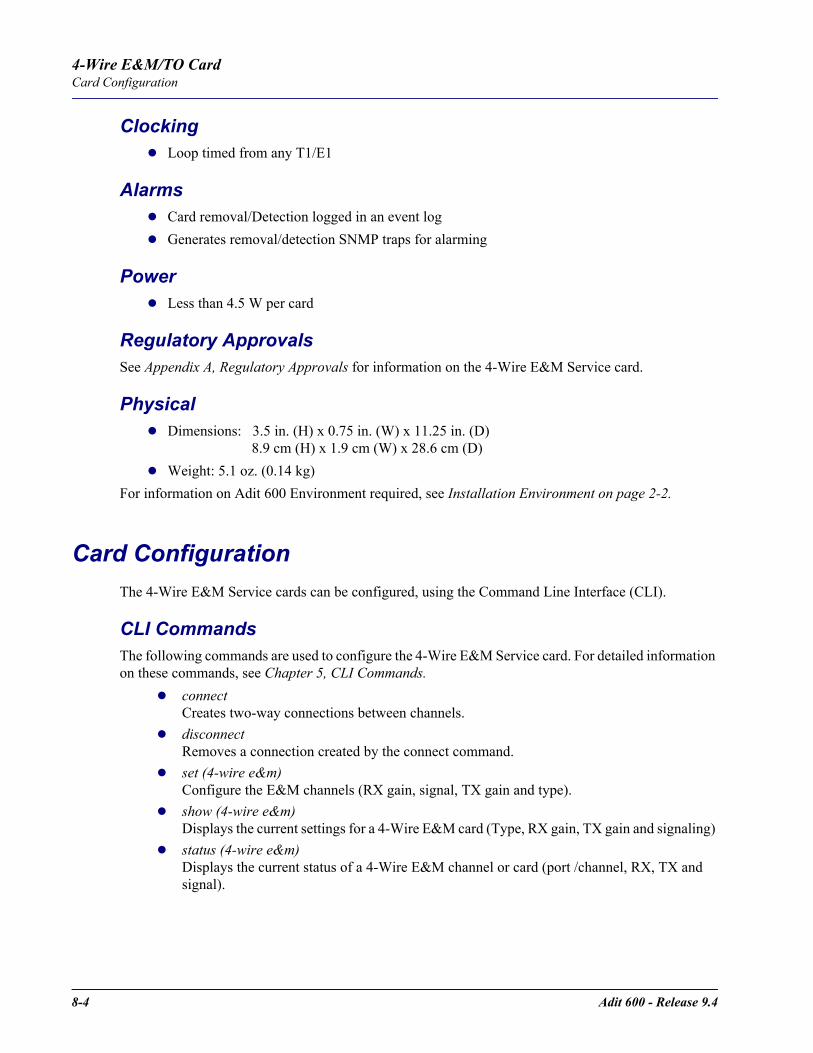
8-4 Adit 600 - Release 9.4
4-Wire E&M/TO CardCard Configuration
ClockingLoop timed from any T1/E1
AlarmsCard removal/Detection logged in an event logGenerates removal/detection SNMP traps for alarming
PowerLess than 4.5 W per card
Regulatory ApprovalsSee Appendix A, Regulatory Approvals for information on the 4-Wire E&M Service card.
PhysicalDimensions: 3.5 in. (H) x 0.75 in. (W) x 11.25 in. (D) 8.9 cm (H) x 1.9 cm (W) x 28.6 cm (D)Weight: 5.1 oz. (0.14 kg)
For information on Adit 600 Environment required, see Installation Environment on page 2-2.
Card ConfigurationThe 4-Wire E&M Service cards can be configured, using the Command Line Interface (CLI).
CLI CommandsThe following commands are used to configure the 4-Wire E&M Service card. For detailed information on these commands, see Chapter 5, CLI Commands.
connectCreates two-way connections between channels.
disconnectRemoves a connection created by the connect command.
set (4-wire e&m)Configure the E&M channels (RX gain, signal, TX gain and type).
show (4-wire e&m)Displays the current settings for a 4-Wire E&M card (Type, RX gain, TX gain and signaling)
status (4-wire e&m)Displays the current status of a 4-Wire E&M channel or card (port /channel, RX, TX and signal).
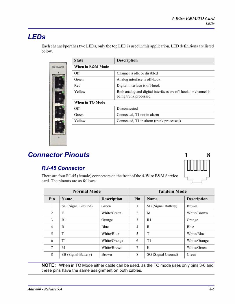
Adit 600 - Release 9.4 8-5
4-Wire E&M/TO CardLEDs
LEDsEach channel/port has two LEDs, only the top LED is used in this application. LED definitions are listed below.
Connector Pinouts
RJ-45 Connector There are four RJ-45 (female) connectors on the front of the 4-Wire E&M Service card. The pinouts are as follows:
NOTE: When in TO Mode either cable can be used, as the TO mode uses only pins 3-6 and these pins have the same assignment on both cables.
State DescriptionWhen in E&M Mode
Off Channel is idle or disabledGreen Analog interface is off-hookRed Digital interface is off-hookYellow Both analog and digital interfaces are off-hook, or channel is
being trunk processedWhen in TO ModeOff DisconnectedGreen Connected, T1 not in alarmYellow Connected, T1 in alarm (trunk processed)
Normal Mode Tandem ModePin Name Description Pin Name Description
1 SG (Signal Ground) Green 1 SB (Signal Battery) Brown
2 E White/Green 2 M White/Brown
3 R1 Orange 3 R1 Orange
4 R Blue 4 R Blue
5 T White/Blue 5 T White/Blue
6 T1 White/Orange 6 T1 White/Orange
7 M White/Brown 7 E White/Green
8 SB (Signal Battery) Brown 8 SG (Signal Ground) Green
1 8

8-6 Adit 600 - Release 9.4
4-Wire E&M/TO CardOperating Modes
Operating ModesThe are 3 mode types for the 4-Wire E&M/TO card, and can be set on a per port basis.
Normal ModeIn normal mode the card is operating as Channel Equipment (normal multiplexer mode). Normal mode is the default mode for this card.
Tandem ModeIn Tandem Mode the card is operating as Switching Equipment for back-to-back tandem applications (sometimes referred to as Reverse E&M or Pulse Link Repeater).
TO (Transmit Only) ModeThe Transmission Only (TO) mode provides dedicated 4-Wire transmit and receive signals to radio and modem equipment. Transmission Only uses the identical 4-Wire E&M physical interface, but suppresses the A/B bit-robbed signaling, maximizing the transmission performance per channel for dedicated operations.
NOTE: For each of these mode there is a corresponding jumper setting and cable. Please see the following section for additional information.
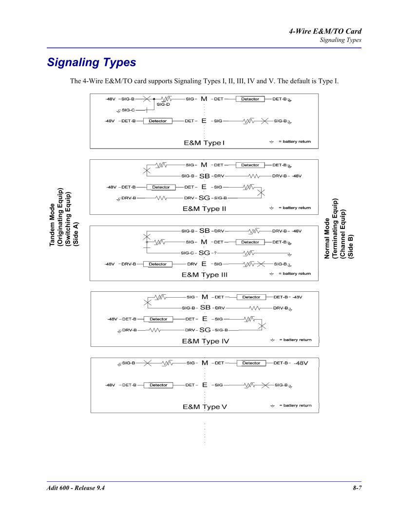
Adit 600 - Release 9.4 8-7
4-Wire E&M/TO CardSignaling Types
Signaling TypesThe 4-Wire E&M/TO card supports Signaling Types I, II, III, IV and V. The default is Type I.
Tand
em M
ode
(Orig
inat
ing
Equi
p)(S
witc
hing
Equ
ip)
(Sid
e A
)
Nor
mal
Mod
e(T
erm
inat
ing
Equi
p)(C
hann
el E
quip
)(S
ide
B)

8-8 Adit 600 - Release 9.4
4-Wire E&M/TO CardJumpers Settings
Jumpers SettingsThe 4-Wire E&M/TO service card is equipped with jumpers to set the Mode (Normal, Tandem or TO), and the Signaling Type for the Normal and Tandem modes (Signaling Types I, II, III, IV and V). The default setting is E&M Normal, Signaling Type I.There is a set of jumpers for each port (channel). The following graphics show the location of the jumpers on the card, and the settings for all options.
Normal and Tandem CablesFor the E&M/TO card two cables are available to meet the Normal and Tandem Modes. These cables are as follows:
NOTE: When in TO Mode either cable can be used.
4-Wire E&M/TO Service Card Cables
P/N Description
005-0216-0001 Normal Mode Cable. 10 Feet, RJ-45 8 position connector.
005-0217-0001 Tandem Mode Cable. 10 Feet, RJ-45 8 position connector.
TOE&M
TANDEME&M
NORMALTYPE
I
II
III
IV
V
Front of Service Card

CHAPTER 9FXO Voice Card
In this Chapter
Overview
Features
Technical Specifications
Card Configuration- CLI Commands
- DIP Switch Settings
LEDs
Channel Associated Signaling (CAS) Conversions

9-2 Adit 600 - Release 9.4
FXO Voice CardOverview
OverviewThe FXO Voice Service card provides high-density provisioning of reliable Foreign Exchange Office (FXO) or Direct Inward Dialing (DID) telephone services. Eight FXO or Dial Pulse Terminate (DPT) telephone line channels can be deployed on each FXO Service card. These cards can be inserted into any slot of the Adit 600 six-slot chassis, and up to 96 lines in two side-by-side chassis occupying just two rack units of space.The FXO function sinks battery current and detects ringing voltage originating from the central office or PBX line, enabling the transport of dial tone and calling features to remote locations. When configured as a DPT interface, the channels sink and detect forward and reverse line current, emulating the functions of a central office DID line. DID service provides the necessary dialed digits to ring a telephone extension directly through a PBX, without requiring attendant intervention. DPT and FXO functions are also used with Automatic Call Distributor (ACD), voice mail, and Computer Telephony Integration (CTI) applications.A unique range of software-controlled signaling capabilities connects virtually any type of 2-wire battery-sink telephone line service. Supported features include caller ID, calling party disconnect, distinctive ringing, ground start, and E&M signaling conversion. Automatic impedance balancing provides echo-free service connections across a wide range of customer equipment and line conditions. V.90 transmission ensures optimal dial-up modem performance.As a component of the Adit 600 platform, the FX0 Service card as several local and remote management options available through the Adit 600 Controller. The card can be locally configured and managed using the front-panel DIP switches, the Command Line Interface (CLI) or the Valet GUI configuration tool. Front-panel LEDs indicate call progress and channel status. Remote management is accomplished either through the Access Navigator over the Facility Data Link (FDL) or an in-band dedicated DS0.

Adit 600 - Release 9.4 9-3
FXO Voice CardFeatures
FeaturesDelivers FXO or DID telephone services from T1 or E1 access circuitsSupports CLASS services including Caller ID, Calling Party Disconnect and Distinctive RingingProvides up to 48 FXO or DPT voice lines in one chassis, or up to 96 lines in two side-by-side Adit 600s occupying two rack units of equipment space (19 in. rack)Complies with NEBS Level 3 standards for loop range and ringing protection for end office and customer premisesOffers fuseless overvoltage and overcurrent protection to minimize service calls from lightning and power cross incidents
Technical Specifications
Controller Software RequiredT1 Controller
Release 1.2.2 or higher is requiredE1 Controller
Release 9.4 or higher is required– µ-Law only
FXO Transmission PerformanceReturn Loss: ERL > 26 dB, SRL > 18 dB with respect to 900Ω + 2.16µFTranshybrid Loss: ERL > 26 dB, SRL > 18 dB with respect to 900Ω + 2.16µFIdle Noise: A/D < 16 dBrnC0, D/A, 12 dBrnC0Crosstalk Coupling: < 70 dB at 0 dBrn0Signal/Distortion: > 35 dB with 1004 Hz, 0 dBm0 inputOverload: +3.0 dBm/900ΩFrequency Response: +0.3 dB -1.0 dB from 300 to 3400 HzEncoding: µ-law 255 for U.S. and Canada as defined in CCITT G.711 and G.712Terminating Impedance: 900Ω + 2.16µF Transmit Gain/Loss: +7 to -9 dB, switch selectable per card Receive Gain/Loss: +7 to -9 dB, switch selectable per card Modem Support: Full compatibility with V.90 modems
9-4 Adit 600 - Release 9.4
FXO Voice CardTechnical Specifications
FXO Signaling PerformanceDC Loop Range: > 1600Ω loop or ground startRinger Equivalency Number (REN): 0.4B (AC)Ringing Voltage Detection: detects Class A ringing follows distinctive ringingFXO DC Resistance: 100ΩMaximum DC: 150 mAOvervoltage: UL 1950, FCC Part 68 lightning protectionOvercurrent: 600 V rms, 60 AmpsProtection: solid-state (fuseless) overvoltage and over current protectionTermination Type: FXO loop start or ground start, switch selectable per card or via management interface per channelSignaling Selection: DPT functionality enabled/disabled on all 8 channelsAddress Signaling: DTMF or dial pulseCalling Party Disconnect: detects and forwards current interruption to disconnect answering devices and modems
Regulatory ApprovalsSee Appendix A, Regulatory Approvals for information on the FX0 Service card.
PhysicalConnections made on RJ21-X telco connector rear panelDimensions: 3.5 in. (H) x 0.75 in. (W) x 11.25 in. (D) 8.9 cm (H) x 1.9 cm (W) x 28.6 cm (D)Weight: 9.1 oz. (.26 kg)
For information on Adit 600 Environment required, see Installation Environment on page 2-2.
Adit 600 - Release 9.4 9-5
FXO Voice CardCard Configuration
Card ConfigurationThe FXO voice card can be configured, using DIP switches on the card, to support either FXO loop start or FXO ground start signaling, with various transmit and receive attenuation options.Note that the attenuation settings you configure via DIP switches apply to all eight channels on a card. If you want different attenuation options for individual channels, use the Command Line Interface to configure your FXO channels.
CLI CommandsThe following commands are used to configure the FXO card. For detailed information on these commands, see Chapter 5, CLI Commands.
connectCreates two-way connections between channels
disconnectRemoves a connection created by the connect command
set (fxo)To setup the voice channels parameters (rx gain, signal, tx gain)
show (fxo)Displays the settings (type, signaling, RxGain, TxGain) for the FXO
status (ds0)Displays the status (AB bits received, AB bits transmitted, signal, trunk processing) of the DS0s (AB Bit Monitoring)
status (fxo)Displays the status (AB bits received, AB bits transmitted, signal, T1/E1 activity, trunk processing) of the specified FXO (AB Bit Monitoring)

9-6 Adit 600 - Release 9.4
FXO Voice CardLEDs
DIP Switch SettingsEach FXO card contains ten DIP switches that can be used to select signaling options for all eight channels.
LEDsEach FXO port on a card has its own LED, described in the table below.
Switch Function Description Note1-2 Signal
Type1 20 0 = FXO Loop Start1 0 = FXO Ground Start0 1 = DPT (use with E&M setting on T1)1 1 = FXO Loop Start with Calling Party Disconnect
3-6 Receive Gain/Loss
3 4 5 6 These settings allow for receive gain and losses of -9, -7, -6, -5, -4, -3, -2, 0, 2, 3, 4, 5, 6, and 7. +9 (1110) is not available.
0 0 0 0 = 0 dB0 0 0 1 = -9 dB0 0 1 0 = +2 dB0 1 0 0 = +3 dB1 0 0 0 = +4 dB
7-10 Transmit Gain/Loss
7 8 9 10 These settings allow for transmit gain and losses of -9, -7, -6, -5, -4, -3, -2, 0, 2, 3, 4, 5, 6, and 7. +9 (1110) is not available.
0 0 0 0 = 0 dB0 0 0 1 = -9 dB0 0 1 0 = +2 dB0 1 0 0 = +3 dB1 0 0 0 = +4 dB
State Loop Start Meaning
Ground Start Meaning Dial Pulse Termination Meaning
Off N/A Idle (tip open) Idle (loop open)Green Idle Tip ground (incoming seizure) Incoming seizureRed N/A Ring ground (outgoing seizure) Loop closure (outgoing seizure)Yellow Call in progress Call in progress Call in progress (reverse battery)Flashing green
Ringing Ringing N/A

Adit 600 - Release 9.4 9-7
FXO Voice CardChannel Associated Signaling (CAS) Conversions
Channel Associated Signaling (CAS) ConversionsCross-connects are done at a DS0 level. The following rules need to be kept in mind while performing cross-connects for a FXO voice card.
DPT = Dial Pulse TerminationEMDW = E&M Delayed Wink startEMI = E&M Immediate start EMICPD = E&M Immediate Start with Calling Party DisconnectEMW = E&M Wink startGS = Ground StartGSRB = Ground Start with Reverse BatteryLS = Loop StartLSCPD = Loop Start Calling Party DisconnectLSRB = Loop Start with Reverse BatteryVoIP = Voice over IP (CMG only)
DS0FXO Analog
LS GS DPT LSCPDE1 DS0
LS N N N NVoIP Port
LS N N N NT1 DS0
LS Y N N YGS N Y N NEMDW N N N NEMI N N Y NEMICPD N N N NEMW N N N N

9-8 Adit 600 - Release 9.4
FXO Voice CardChannel Associated Signaling (CAS) Conversions

CHAPTER 10FXS Voice Card
In this Chapter
Overview
Features
Technical Specifications (FXS 8C)
Card Configuration- CLI Commands
LEDs
Channel Associated Signaling (CAS) Conversions
Obsolete FXS Cards- Technical Specifications (Obsolete FXS Cards)
- DIP Switch Settings
- LEDs
- Identifying FXS 4G and 5G Cards

10-2 Adit 600 - Release 9.4
FXS Voice CardOverview
OverviewThe FXS 8C 8-Channel voice Service card provides support for high-density provisioning of reliable telephone services and the ability to perform FXS remote line testing. Also GR-909 loop tests are supported minimizing diagnostic and down time. The FXS 8C card includes Calling Party Disconnect (CPD) timing parameterization. CPD provisioning is provided through CLI and SNMP management functions.An Adit 600 platform can be equipped with up to six FXS 8C cards to deliver up to 48 FXS telephone lines. The lines can be configured as FXS loop-start or ground-start interfaces, which can be used to deploy either external phone lines, or on-premises customer business line services from T1 access lines.A unique range of software-controlled signaling capabilities designed into the FXS voice service cards connect virtually any type of 2-wire battery-feed telephone line service. Supported features include caller ID, calling party disconnect, distinctive ringing, ground start, and E&M signaling conversion. V.90 transmission is supported for optimal dial-up modem performance.
WARNING! THE FXS POTS INTERFACES ARE INTENDED TO BE PROTECTED FROM INCIDENTAL LIGHTNING OR AC POWER LINE CROSS WITH EXTERNAL 3MIL CARBON BLOCKS OR EQUIVALENT WHEN CONNECTING TO EXPOSED OFF-PREMISE COMMUNICATION CONDUCTORS. IT WILL BE THE RESPONSIBILITY OF THE INSTALLER TO UTILIZE THE APPROPRIATE PRIMARY PROTECTION AND INSTALLATION REQUIREMENTS PER NATIONAL ELECTRIC CODE OR THE NETWORK AUTHORITY.
FeaturesProvides overvoltage and overcurrent protection to minimize service calls from lightning and power cross incidentsMinimizes power consumption for high-density service delivery with automatic battery voltage switchingProvides up to 48 FXS voice lines in one chassis or up to 96 lines in two side-by-side Adit 600s occupying just two rack units of equipment space (19-inch rack)Ringing voltage/cadence generation and ring trip detectionLoop hold and programmable impedance and termination for international complianceSelectable µ-Law and A-Law encodingProvides integrated GR-909 line test capabilitiesSupports migration from TDM to VoIP service delivery while preserving existing capital investment
NOTE: From Release 6.1.2 and higher, the FXS card will provide a fast busy indication if a subscriber is off hook and the supporting T1 DS0 is in a trunk processing state.
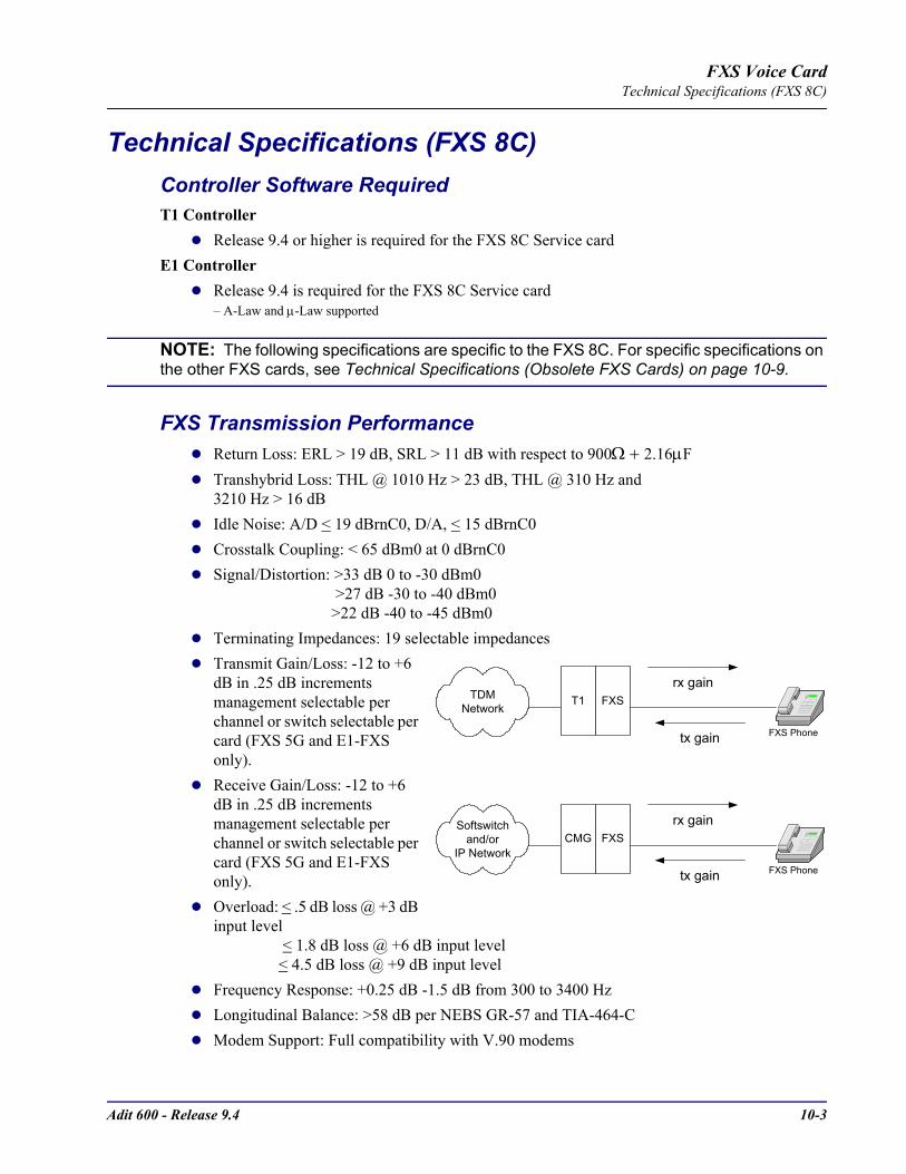
Adit 600 - Release 9.4 10-3
FXS Voice CardTechnical Specifications (FXS 8C)
Technical Specifications (FXS 8C)Controller Software RequiredT1 Controller
Release 9.4 or higher is required for the FXS 8C Service cardE1 Controller
Release 9.4 is required for the FXS 8C Service card– A-Law and µ-Law supported
NOTE: The following specifications are specific to the FXS 8C. For specific specifications on the other FXS cards, see Technical Specifications (Obsolete FXS Cards) on page 10-9.
FXS Transmission PerformanceReturn Loss: ERL > 19 dB, SRL > 11 dB with respect to 900Ω + 2.16µFTranshybrid Loss: THL @ 1010 Hz > 23 dB, THL @ 310 Hz and 3210 Hz > 16 dBIdle Noise: A/D < 19 dBrnC0, D/A, < 15 dBrnC0Crosstalk Coupling: < 65 dBm0 at 0 dBrnC0Signal/Distortion: >33 dB 0 to -30 dBm0 >27 dB -30 to -40 dBm0 >22 dB -40 to -45 dBm0Terminating Impedances: 19 selectable impedances Transmit Gain/Loss: -12 to +6 dB in .25 dB increments management selectable per channel or switch selectable per card (FXS 5G and E1-FXS only).Receive Gain/Loss: -12 to +6 dB in .25 dB increments management selectable per channel or switch selectable per card (FXS 5G and E1-FXS only).Overload: < .5 dB loss @ +3 dB input level < 1.8 dB loss @ +6 dB input level < 4.5 dB loss @ +9 dB input levelFrequency Response: +0.25 dB -1.5 dB from 300 to 3400 Hz Longitudinal Balance: >58 dB per NEBS GR-57 and TIA-464-CModem Support: Full compatibility with V.90 modems
FXS Phone
CMG FXSrx gain
tx gain
Softswitchand/or
IP Network
FXS Phone
T1 FXSrx gain
tx gain
TDMNetwork

10-4 Adit 600 - Release 9.4
FXS Voice CardTechnical Specifications (FXS 8C)
FXS Signaling PerformanceDC Loop Range: 1700Ω Loop Feed: Nominal 27mA current limit with automatic battery switchingOff-Hook Detection: Detects tip or ring currents > 14mARing Ground: Detects ring ground currents > 33mARinging Voltage: All-channel simultaneous ringing power, 85 V rms, 20 HzMaximum Ringers: 5 REN, FCC Class B ringersInternal Ringing Cadence: Ringing cadence is 2 seconds on, 4 seconds off for E&M wink start conversion modesControl Technique: Solid-state with no mechanical relaysOvercurrent: 600 V rms, 60 AmpsSupports CLASS features (i.e. calling party ID, 3-way calling, distinctive ringing)Calling Party Disconnect: Calling party (forward) disconnect provides 2 second current interruption to disconnect answering devices and modems - requires E&M signaling service on the T1FXS Signaling: FXS loopstart or groundstart with LS/GS selection per channel FXSDN Signaling: E&M immediate or wink start to either loopstart or groundstart conversion with ringback tone for carrier services such as Megacom®, Flexpath®, DSS®, VPN®, VNET®, etc. Wink delay for advanced ANI/DNIS 800 number services
GR-909 Line TestsHazardous potential (foreign DC voltage)Foreign electromotive force (foreign AC voltage)Resistive faults (resistance tip-ring, tip-GND (ground), ring-GNDReceiver off-hook (differentiated from a short tip-ring)
Power15 W maximum
Regulatory ApprovalsSee Appendix A, Regulatory Approvals for information on the FXS Service cards.
PhysicalDimensions: 3.5 in. (H) x 0.75 in. (W) x 11.25 in. (D) 8.9 cm (H) x 1.9 cm (W) x 28.6 cm (D)Weight: 5.8 oz. (.16 kg)
For information on Adit 600 environment required, see Installation Environment on page 2-2.
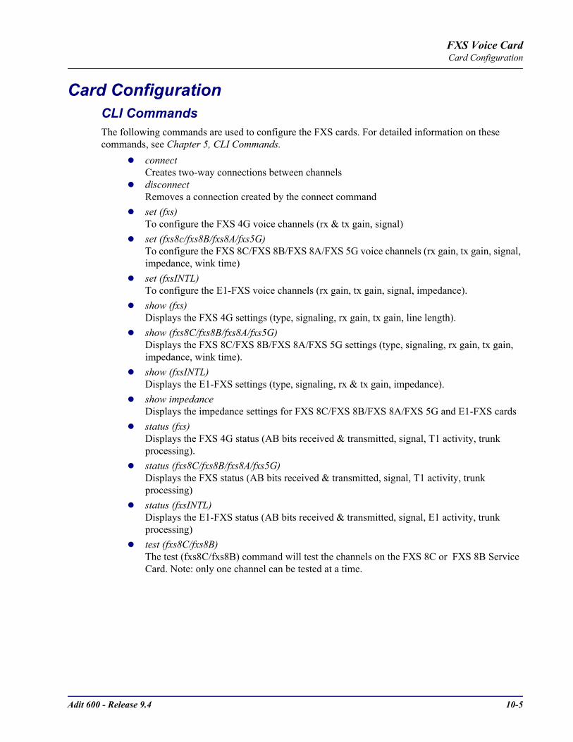
Adit 600 - Release 9.4 10-5
FXS Voice CardCard Configuration
Card Configuration CLI CommandsThe following commands are used to configure the FXS cards. For detailed information on these commands, see Chapter 5, CLI Commands.
connectCreates two-way connections between channels
disconnectRemoves a connection created by the connect command
set (fxs)To configure the FXS 4G voice channels (rx & tx gain, signal)
set (fxs8c/fxs8B/fxs8A/fxs5G)To configure the FXS 8C/FXS 8B/FXS 8A/FXS 5G voice channels (rx gain, tx gain, signal, impedance, wink time)
set (fxsINTL)To configure the E1-FXS voice channels (rx gain, tx gain, signal, impedance).
show (fxs)Displays the FXS 4G settings (type, signaling, rx gain, tx gain, line length).
show (fxs8C/fxs8B/fxs8A/fxs5G)Displays the FXS 8C/FXS 8B/FXS 8A/FXS 5G settings (type, signaling, rx gain, tx gain, impedance, wink time).
show (fxsINTL)Displays the E1-FXS settings (type, signaling, rx & tx gain, impedance).
show impedanceDisplays the impedance settings for FXS 8C/FXS 8B/FXS 8A/FXS 5G and E1-FXS cards
status (fxs)Displays the FXS 4G status (AB bits received & transmitted, signal, T1 activity, trunk processing).
status (fxs8C/fxs8B/fxs8A/fxs5G)Displays the FXS status (AB bits received & transmitted, signal, T1 activity, trunk processing)
status (fxsINTL)Displays the E1-FXS status (AB bits received & transmitted, signal, E1 activity, trunk processing)
test (fxs8C/fxs8B)The test (fxs8C/fxs8B) command will test the channels on the FXS 8C or FXS 8B Service Card. Note: only one channel can be tested at a time.

10-6 Adit 600 - Release 9.4
FXS Voice CardLEDs
LEDsEach FXS port has a corresponding LED, described in the table below. This chart applies to all the FXS service cards.
State Loop Start Meaning Ground Start Meaning
Off N/A Idle (tip open)
Green Idle Tip ground (incoming seizure)
Red Note: This can be seen with Forward Disconnect (tip open)
Ring ground (outgoing seizure)
Yellow Call in progress Call in progress
Flashing green Ringing Ringing
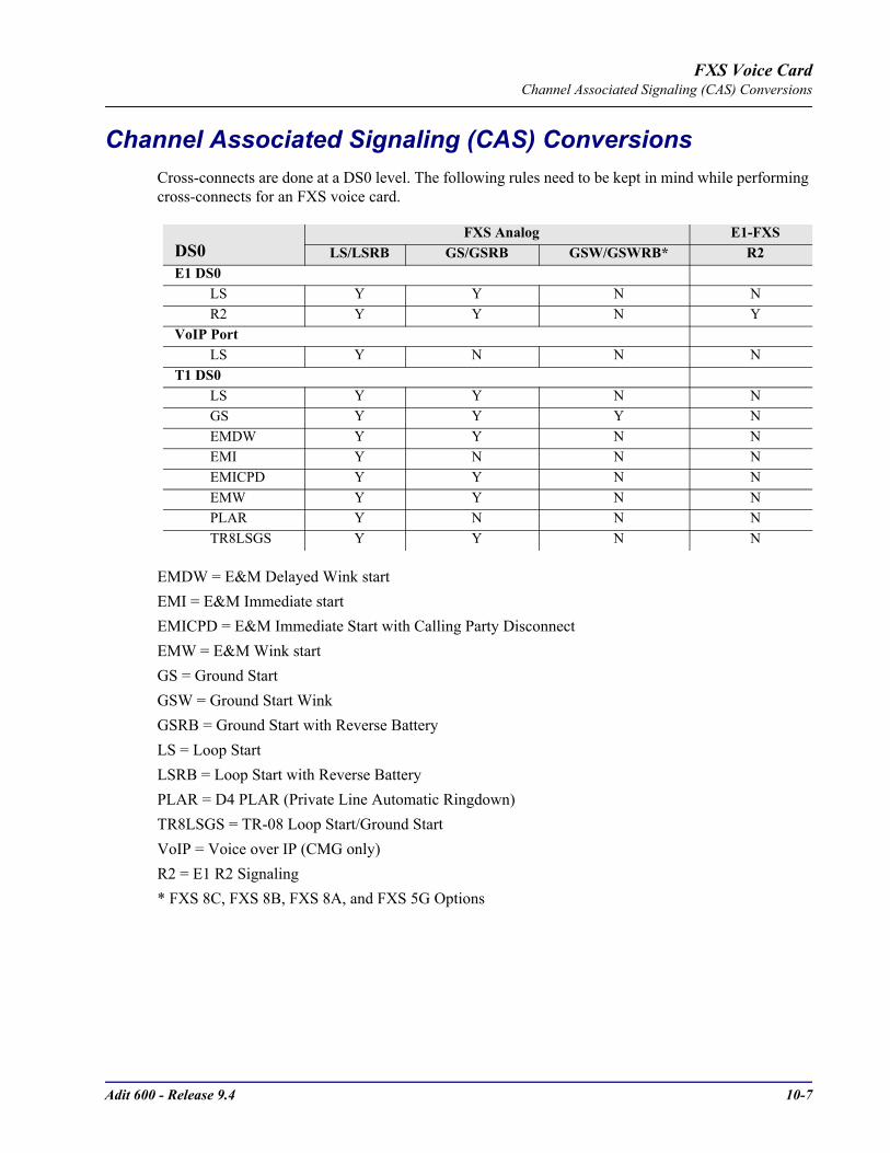
Adit 600 - Release 9.4 10-7
FXS Voice CardChannel Associated Signaling (CAS) Conversions
Channel Associated Signaling (CAS) ConversionsCross-connects are done at a DS0 level. The following rules need to be kept in mind while performing cross-connects for an FXS voice card.
EMDW = E&M Delayed Wink startEMI = E&M Immediate start EMICPD = E&M Immediate Start with Calling Party DisconnectEMW = E&M Wink startGS = Ground StartGSW = Ground Start WinkGSRB = Ground Start with Reverse BatteryLS = Loop StartLSRB = Loop Start with Reverse BatteryPLAR = D4 PLAR (Private Line Automatic Ringdown)TR8LSGS = TR-08 Loop Start/Ground StartVoIP = Voice over IP (CMG only)R2 = E1 R2 Signaling* FXS 8C, FXS 8B, FXS 8A, and FXS 5G Options
DS0FXS Analog E1-FXS
LS/LSRB GS/GSRB GSW/GSWRB* R2E1 DS0
LS Y Y N NR2 Y Y N Y
VoIP PortLS Y N N N
T1 DS0LS Y Y N NGS Y Y Y NEMDW Y Y N NEMI Y N N NEMICPD Y Y N NEMW Y Y N NPLAR Y N N NTR8LSGS Y Y N N
10-8 Adit 600 - Release 9.4
FXS Voice CardObsolete FXS Cards
Obsolete FXS CardsThe FXS 8C Service card supports all the features of the following cards and is supported by both the T1 and E1 Controllers. The following card information is provided if you have older cards installed in your Adit 600. For any additional information, contact Carrier Access Customer Support.
FXS 8BProvides the same functions as the FXS 8C card except for the Calling Party Disconnect (CPD) timing parameterization capability.
FXS 8AThe On-Premises FXS service card is optimized for connection to intra-building, non-exposed wiring.
FXS 5GThe FXS 5G Voice card is designed for outdoor loops that meets the stringent requirements for off-premises loop termination with its industry-leading fuseless design.
FXS (4G Version)The original FXS Service card (4G) has the basic FXS features. This is a legacy product and is supported, but no longer available to purchase.
NOTE: The FXS (4G) and FXS 5G card faceplates are both labeled "FXS", therefore the FXS 5G card has a label on the card portion identifying it as the 5G card along with a warning of the required Controller software level.
E1 - FXS Voice CardThe E1 FXS Voice card is a FXS 5G card with the following signaling only:
R2 signaling for international applications
WARNING! THE INTERNATIONAL E1-FXS VOICE INTERFACES ARE INTENDED TO BE PROTECTED FROM INCIDENTAL LIGHTNING OR AC POWER LINE CROSS WITH EXTERNAL 3-ELEMENT GAS DISCHARGE TUBES OR EQUIVALENT WHEN CONNECTED TO EXPOSED OFF-PREMISE COMMUNICATION CONDUCTORS. IT WILL BE THE RESPONSIBILITY OF THE INSTALLER TO UTILIZE THE APPROPRIATE PRIMARY PROTECTION AND INSTALLATION REQUIREMENTS PER NATIONAL OR LOCAL REGULATIONS.

Adit 600 - Release 9.4 10-9
FXS Voice CardObsolete FXS Cards
Technical Specifications (Obsolete FXS Cards)Controller Software RequiredT1 Controller
Release 1.2.2 or higher is required for the FXS (4G) Service cardRelease 1.50 or higher is required for the FXS 5G Service cardRelease 6.1.1 or higher is required for the FXS 8A Service cardRelease 9.1 or higher is required for the FXS 8B Service cardThe E1 - FXS Service card is not supported by the T1 Controller
E1 ControllerRelease 3.2 is required for FXS 5G and E1-FXS Service cardsThe FXS (4G) and FXS 8A service cards are not supported by the E1 Controller
FXS Transmission PerformanceReturn Loss:
- FXS 8B: ERL > 19 dB, SRL > 11 dB with respect to 900Ω + 2.16µF- FXS 8A, FXS 5G, FXS 4G, E1-FXS: ERL > 26 dB, SRL > 18 dB with respect to 900Ω + 2.16µF
Transhybrid Loss: THL @ 1010 Hz > 23 dB, THL @ 310 Hz and 3210 Hz > 16 dBIdle Noise:
- FXS 8B: A/D < 19 dBrnC0, D/A, < 15 dBrnC0- FXS 8A, FXS 5G, FXS 4G, E1-FXS: A/D < 19 dBrnC0, D/A, < 14 dBrnC0
Crosstalk Coupling: < 65 dBm0 at 0 dBrnC0Signal/Distortion: >33 dB 0 to -30 dBm0 >27 dB -30 to -40 dBm0 >22 dB -40 to -45 dBm0Terminating Impedances: 19 selectable impedances Transmit Gain/Loss:- FXS 8B, FXS 8A, FXS 5G, E1-FXS: -12 to +6 dB in .25 dB increments management selectable per
channel or switch selectable per card (FXS 5G and E1-FXS only).- FXS 4G: -9 to +7 dB in 1 dB increments management selectable per channel, or switch selectable per
card.Receive Gain/Loss:
- FXS 8B, FXS 8A, FXS 5G, E1-FXS: -12 to +6 dB in .25 dB increments management selectable per channel or switch selectable per card (FXS 5G and E1-FXS only).
- FXS 4G: -9 to +7 dB in 1 dB increments management selectable per channel, or switch selectable per card.
Overload: < .5 dB loss @ +3 dB input level < 1.8 dB loss @ +6 dB input level < 4.5 dB loss @ +9 dB input level
10-10 Adit 600 - Release 9.4
FXS Voice CardObsolete FXS Cards
Frequency Response:- FXS 8B: +0.25 dB -1.5 dB from 300 to 3400 Hz - FXS 8A, FXS 5G, FXS 4G, E1-FXS: +0 dB -1.0 dB from 310 to 3210 Hz Longitudinal Balance:- FXS 8B: >58 dB per NEBS GR-57 and TIA-464-C- FXS 8A, FXS 5G, FXS 4G, E1-FXS: >63 dB per IEEE 455 and NEBS GR-57Modem Support: Full compatibility with V.90 modems
FXS Signaling PerformanceDC Loop Range:- FXS 8B: 1700Ω - FXS 8A, FXS 5G, FXS 4G, E1-FXS: 1250Ω Loop Feed: Nominal 27mA current limit with automatic battery switchingOff-Hook Detection:- FXS 8B: Detects tip or ring currents > 14mA- FXS 8A, FXS 5G, FXS 4G, E1-FXS: Detects tip or ring currents > 6mARing Ground:- FXS 8B: Detects ring ground currents > 33mA- FXS 8A, FXS 5G, FXS 4G, E1-FXS: Detects ring ground currents > 8mARinging Voltage: All-channel simultaneous ringing power, 85 V rms, 20 HzMaximum Ringers:- FXS 8B: 5 REN, FCC Class B ringers- FXS 8A, FXS 5G, FXS 4G, E1-FXS: 2.5 REN, FCC Class B ringersInternal Ringing Cadence: Ringing cadence is 2 seconds on, 4 seconds off for E&M wink start conversion modesControl Technique: Solid-state with no mechanical relaysOvercurrent: 600 V rms, 60 AmpsSupports CLASS features (i.e. calling party ID, 3-way calling, distinctive ringing)Calling Party Disconnect: Calling party (forward) disconnect provides 2 second current interruption to disconnect answering devices and modems - requires E&M signaling service on the T1FXS Signaling: FXS loopstart or groundstart with LS/GS selection per channel FXSDN Signaling: E&M immediate or wink start to either loopstart or groundstart conversion with ringback tone for carrier services such as Megacom®, Flexpath®, DSS®, VPN®, VNET®, etc. Wink delay for advanced ANI/DNIS 800 number services
Regulatory ApprovalsSee Appendix A, Regulatory Approvals for information on the FXS Service cards.

Adit 600 - Release 9.4 10-11
FXS Voice CardObsolete FXS Cards
PhysicalDimensions: 3.5 in. (H) x 0.75 in. (W) x 11.25 in. (D) 8.9 cm (H) x 1.9 cm (W) x 28.6 cm (D)Weight: FXS 4G - 9.6 oz. (.27 kg) FXS 8B, FXS 8A, FXS 5G, and E1-FXS - 5.8 oz. (.16 kg)
For information on Adit 600 environment required, see Installation Environment on page 2-2.
DIP Switch SettingsNote: DIP Switches are only on the following FXS Voice Service cards: FXS (4G) FXS 5G E1-FXS
The DIP switches on the card, to support either FXS loopstart or FXS groundstart signaling, with various transmit and receive attenuation options (the FXS 8A does not have any DIP switches).Note: The attenuation settings configured via DIP switches apply to all eight channels. For different attenuation options for individual channels, use the CLI.
NOTE: The FXS channels default to a short loop setting (up to 1.6 miles for 26 AWG, and 2.6 miles for 24 AWG). To set an FXS channel to have a long loop setting, see set (fxs) command in CLI Commands.
Switch Function Description Note1-2 Signal
Type1 20 0 = FXS Loop Start1 0 = FXS Ground Start
FXS and FXS5G cardNote: FXS 8A has no DIP Switches
00 = R2 E1-FXS card3-6 Receive
Gain/Loss
3 4 5 6 These settings allow for receive gain and losses of -9, -7, -6, -5, -4, -3, -2, 0, 2, 3, 4, 5, and 6. +9 (1110) is not available.Maximum setting on the 5G is +6 dB.
0 0 0 0 = 0 dB0 0 0 1 = -9 dB0 0 1 0 = +2 dB0 1 0 0 = +3 dB1 0 0 0 = +4 dB
7-10 Transmit Gain/Loss
7 8 9 10 These settings allow for transmit gain and losses of -9, -7, -6, -5, -4, -3, -2, 0, 2, 3, 4, 5, and 6. +9 (1110) is not available.Maximum setting on the 5G is +6 dB.
0 0 0 0 = 0 dB0 0 0 1 = -9 dB0 0 1 0 = +2 dB0 1 0 0 = +3 dB1 0 0 0 = +4 dB
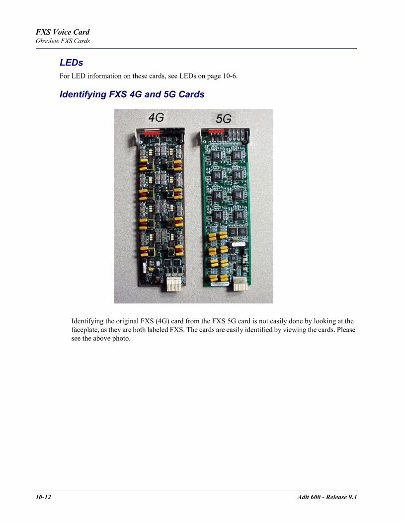
10-12 Adit 600 - Release 9.4
FXS Voice CardObsolete FXS Cards
LEDsFor LED information on these cards, see LEDs on page 10-6.
Identifying FXS 4G and 5G Cards
Identifying the original FXS (4G) card from the FXS 5G card is not easily done by looking at the faceplate, as they are both labeled FXS. The cards are easily identified by viewing the cards. Please see the above photo.

CHAPTER 11ISDN BRI Card
In this Chapter
Overview
Features
Technical Specifications
Card Configuration- CLI Commands
- LEDs
Connector Pinouts- 25-Pair Telco Connectors
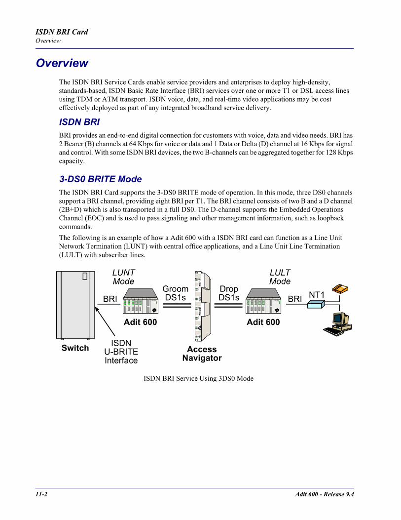
11-2 Adit 600 - Release 9.4
ISDN BRI CardOverview
OverviewThe ISDN BRI Service Cards enable service providers and enterprises to deploy high-density, standards-based, ISDN Basic Rate Interface (BRI) services over one or more T1 or DSL access lines using TDM or ATM transport. ISDN voice, data, and real-time video applications may be cost effectively deployed as part of any integrated broadband service delivery.
ISDN BRIBRI provides an end-to-end digital connection for customers with voice, data and video needs. BRI has 2 Bearer (B) channels at 64 Kbps for voice or data and 1 Data or Delta (D) channel at 16 Kbps for signal and control. With some ISDN BRI devices, the two B-channels can be aggregated together for 128 Kbps capacity.
3-DS0 BRITE ModeThe ISDN BRI Card supports the 3-DS0 BRITE mode of operation. In this mode, three DS0 channels support a BRI channel, providing eight BRI per T1. The BRI channel consists of two B and a D channel (2B+D) which is also transported in a full DS0. The D-channel supports the Embedded Operations Channel (EOC) and is used to pass signaling and other management information, such as loopback commands.The following is an example of how a Adit 600 with a ISDN BRI card can function as a Line Unit Network Termination (LUNT) with central office applications, and a Line Unit Line Termination (LULT) with subscriber lines.
ISDN BRI Service Using 3DS0 Mode
DropDS1s
AccessNavigator
ISDNU-BRITEInterface
GroomDS1s
LUNTMode
Switch
Adit 600
NT1A D IT 60 0 BRI
Adit 600
A D IT 60 0BRI
LULTMode

Adit 600 - Release 9.4 11-3
ISDN BRI CardFeatures
4:1 TDM ModeIn the 4:1 Subrate D-Channel Mode, up to 10 BRI channels are carried over each T1 line. Four 16 Kbps D-channels are multiplexed into each DS0. The Access Navigator GR-303, in conjunction with the Adit Customer Service Terminal (CST), functions as an Integrated GR-303 Digital Loop Carrier system using this mode. Standard 4:1 D-Channel concentration is utilized from the GR-303 interface of a Class 5 switch. EOC management information from the switch is supported.The following is an example of how a Adit 600 with a ISDN BRI card can function as with the Access Navigator in the 4:1 TDM Mode.
FeaturesEnables carriers to economically bundle ISDN with all other services at 64 Kbps or 128 Kbps over T1 access linesConfigurable as either Line Unit Line Terminal (LULT) for interfacing to ISDN switch interfaces at the central office, or Line Unit Network Terminal (LUNT) for customer premises deploymentProvides direct NTU service demarcation for ISDN video conferencing, 128 Kbps dial-up Internet, point-of-sale terminals, and ISDN Centrex or telephone applicationsEnables high service density with up to 40 ISDN BRI lines from 4 T1 lines in a single Adit 600 chassis, or up to 80 ISDN BRI lines in two chassis occupying two rack units of equipment space (19-inch rack)Provides economic deployment of ISDN services with on-premises T1 concentration via the Access Navigator/GR-303 host to provision 40 to 240 ISDN BRI channels over 3 to 8 T1 access linesOffers solid-state fuseless protection for central office NEBS compliance and customer premises FCC and UL safety requirements
ISDN BRI Service Using 4:1 TDM Mode
DropDS1s
AccessNavigator
GR-303Interface
Group
SwitchDS1s
Switch
Adit 600
NT1A D IT 60 0 BRI
LULTMode
11-4 Adit 600 - Release 9.4
ISDN BRI CardTechnical Specifications
Technical Specifications
Controller Software RequiredT1 Controller
Release 1.2.2 or higher is requiredE1 Controller
Release 3.2 or higher is required
Product IncludesConfigurable as Line Unit Line Terminal (LULT) or Line Unit Network Terminal (LUNT)Works with all standard Carrier Serving Area (CSA) loops - maximum 18,000 ft. range (#26 AWG copper)Supports standard Telcordia 3-DS0 or 4:1 TDM modesLine coding: 2Line Rate: 160 Kbps (80 kbaud)Front-panel multi-function LEDs provide out-of-Service, LOS/Self-test fail, ES/SES detected, Sync, Loopback, and Normal indicationsInteroperable with other standards-based ISDN BRI equipmentB1, B2, and 2B+D payload loopbacks supportedMaximum bridged tap length is 2.5 kft. (762 m)Rear-accessed U-interface connections
ManagementStandard ISDN SNMP MIB supported
Network Interface3 DS0 mode: Uses 3 contiguous DSO channels per ISDN BRI channel on T14:1 TDM mode: T1 to Access Navigator/GR-303
Network StandardsTelcordia TR-NWT-000397 (1993)Telcordia TR-TSY-000821 (1991)Telcordia TR-TSY-000829 (1989)ANSI T1.1992ITU-T Q.920, Q.921
Adit 600 - Release 9.4 11-5
ISDN BRI CardTechnical Specifications
ClockingLoop timing derived from Channel 1 of ISDN BRI card or any Adit 600 T1 line
Testing & DiagnosticsInitiates 2B+D, B1, or B2 loopbacks toward the BRI at the NT1Performs self test at power up3 DSO mode: supports external loopback testing via EOC messages from the switch4:1 TDM mode: supports external loopback testing through CLI commands or as commanded by switch
Product SupportsTR-821 alarmsTR-397/TR-829/TR-821 Generic Segmented Performance MonitoringTR-829 multi-EOC messages in 3 DS0 and 4:1 TDM modesMetallic DC test signature in Line Unit Network Terminal (LUNT) mode
PowerMaximum power input: 6 W (8 port)Solid-state fuseless protection
Regulatory ApprovalsSee Appendix A, Regulatory Approvals for information on the ISDN BRI Service card.
PhysicalDimensions: 3.5 in. (H) x 0.75 in. (W) x 11.25 in. (D) 8.9 cm (H) x 1.9 cm (W) x 28.6 cm (D)Weight: 6.9 oz. (.20 kg)
For information on Adit 600 Environment required, see Installation Environment on page 2-2.

11-6 Adit 600 - Release 9.4
ISDN BRI CardCard Configuration
Card Configuration BRI card options are set with the Command Line Interface (CLI). For additional information on these commands, see Chapter 5, CLI Commands.
CLI Commands connect
Creates two-way connections between channels disconnect
Removes a connection created by the connect command set (bri)
Setup of ISDN ports (up/down, threshold, call reference value) set (bri) autoactivate
Set up the ISDN circuits when the FDL link cannot be used set (bri) mode
Set up ISDN cards mode of operation (3-DS0 or 4:1) set (bri) pmsync
Set up the BRI card source for performance monitoring synchronization set (ds0)
For cross-connect to ISDN, must be data type status (ds1)
Displays line status or performance statistics of a specific DS1 set clock
Set the primary and secondary (clock1/clock2) master transmit clock source show (bri)
Displays BRI port configuration show clock
Displays actual clock source show (ds1)
Displays DS1 configuration status (bri)
Displays port status or performance statistics for the specified BRI status clock
Displays actual clock status and source

Adit 600 - Release 9.4 11-7
ISDN BRI CardLEDs
LEDsThere is an LED for each ISDN BRI on a card. The function for each LED is listed below:
State Description
Off Line U-interface is attempting synchronization, or BRI is out of service.
Red Line alarm (LOS or self test failure)
Yellow ES or SES has occurred.
Flashing yellow Line U-interface is synchronized with customer equipment, but is not passing customer data.
Flashing green Line U-interface is in external loopback toward the switch at the unit.
Green Normal (Line U-interface is active and transparently passing customer data.)
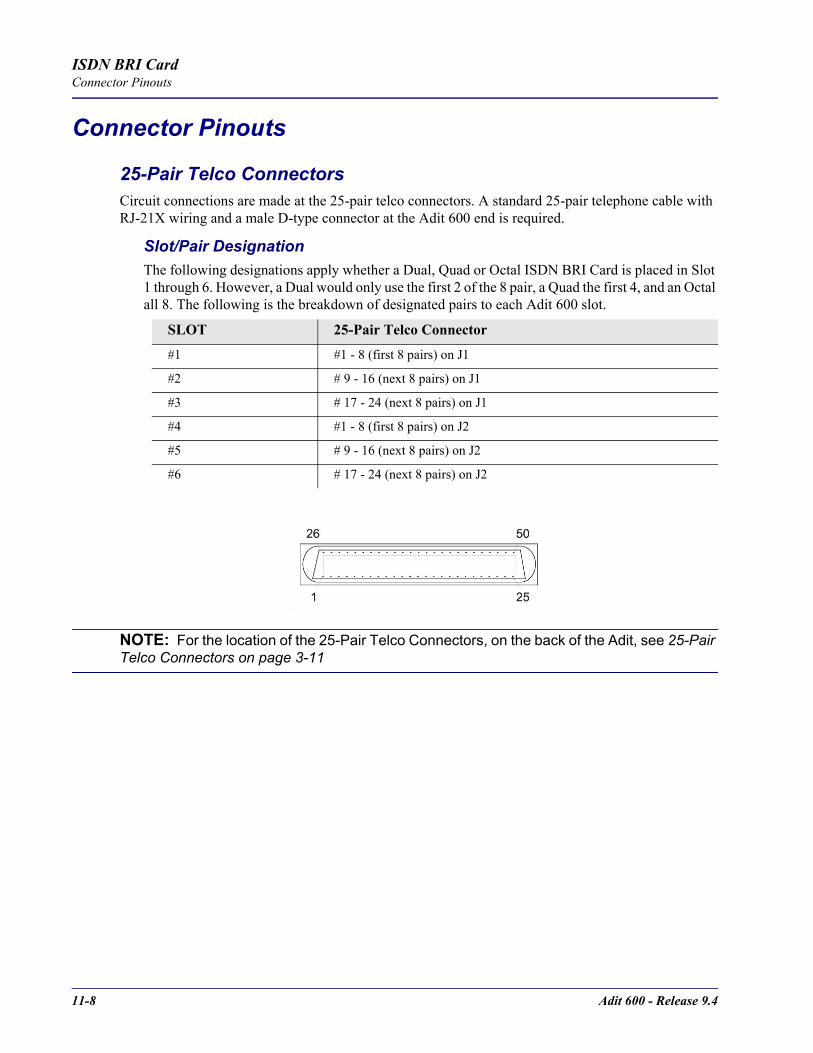
11-8 Adit 600 - Release 9.4
ISDN BRI CardConnector Pinouts
Connector Pinouts
25-Pair Telco ConnectorsCircuit connections are made at the 25-pair telco connectors. A standard 25-pair telephone cable with RJ-21X wiring and a male D-type connector at the Adit 600 end is required.
Slot/Pair DesignationThe following designations apply whether a Dual, Quad or Octal ISDN BRI Card is placed in Slot 1 through 6. However, a Dual would only use the first 2 of the 8 pair, a Quad the first 4, and an Octal all 8. The following is the breakdown of designated pairs to each Adit 600 slot.
NOTE: For the location of the 25-Pair Telco Connectors, on the back of the Adit, see 25-Pair Telco Connectors on page 3-11
SLOT 25-Pair Telco Connector
#1 #1 - 8 (first 8 pairs) on J1
#2 # 9 - 16 (next 8 pairs) on J1
#3 # 17 - 24 (next 8 pairs) on J1
#4 #1 - 8 (first 8 pairs) on J2
#5 # 9 - 16 (next 8 pairs) on J2
#6 # 17 - 24 (next 8 pairs) on J2

Adit 600 - Release 9.4 11-9
ISDN BRI CardConnector Pinouts
25-Pair Telco Connector PinoutsPair Pin Location Function Color Code
SLO
T 1
on J1
or S
LOT
4 on
J2
1 26 1
Tip Channel 1 Ring Channel 1
WhiteBlue
2 27 2
Tip Channel 2 Ring Channel 2
WhiteOrange
3 283
Tip Channel 3Ring Channel 3
WhiteGreen
4 294
Tip Channel 4 Ring Channel 4
WhiteBrown
5 305
Tip Channel 5 Ring Channel 5
WhiteSlate
6 316
Tip Channel 6 Ring Channel 6
RedBlue
7 327
Tip Channel 7 Ring Channel 7
RedOrange
8 338
Tip Channel 8 Ring Channel 8
RedGreen
SLO
T 2
on J1
or S
LOT
5 on
J2
9 349
Tip Channel 9 Ring Channel 9
RedBrown
10 3510
Tip Channel 10 Ring Channel 10
RedSlate
11 3611
Tip Channel 11 Ring Channel 11
BlackBlue
12 3712
Tip Channel 12 Ring Channel 12
BlackOrange
13 3813
Tip Channel 13 Ring Channel 13
BlackGreen
14 3914
Tip Channel 14 Ring Channel 14
BlackBrown
15 4015
Tip Channel 15 Ring Channel 15
Black Slate
16 4116
Tip Channel 16 Ring Channel 16
YellowBlue
SLO
T 3
on J1
or S
LOT
6 on
J2
17 4217
Tip Channel 17 Ring Channel 17
YellowOrange
18 4318
Tip Channel 18 Ring Channel 18
YellowGreen
19 4419
Tip Channel 19 Ring Channel 19
YellowBrown
20 4520
Tip Channel 20 Ring Channel 20
YellowSlate
21 4621
Tip Channel 21 Ring Channel 21
VioletBlue
22 4722
Tip Channel 22 Ring Channel 22
VioletOrange
23 4823
Tip Channel 23 Ring Channel 23
VioletGreen
24 49 24
Tip Channel 24Ring Channel 24
VioletBrown
25 50 25
Reserved VioletSlate

11-10 Adit 600 - Release 9.4
ISDN BRI CardConnector Pinouts

CHAPTER 12OCU-DP Card
In this Chapter
Overview
Features
Technical Specifications
Card Configuration- CLI Commands
- Basic Setup
LEDs
Jumper Settings
Alarms
Line Rates/Line Lengths
Connector Pinouts- DDS RJ-48S
- 25-Pair Telco Connector
12-2 Adit 600 - Release 9.4
OCU-DP CardOverview
OverviewThe Single Port and Quad Port all-rate OCU-DP Service Cards provide electrical and physical termination of the 4-wire Digital Data Service (DDS) that is traditionally used to interconnect lower-speed serial synchronous Data Terminal Equipment (DTE) devices such as routers, Frame Relay Access Devices (FRAD), or video conferencing equipment. Now DDS can be integrated with DS0 voice, fractional T1 data, ISDN, and IP services – over multiple T1s. This enables service providers to deliver transport for legacy enterprise data networking or Common Channel Signaling (CCS) circuits commonly used in Signaling System 7 (SS7) telephone networks using one card for all standard DDS types. Plus, it can be used as a replacement for low-density, unmanaged D4 channel banks.The OCU-DP Service cards provide scalable, independently configurable, synchronous data service rates from 2.4 Kbps to 64 Kbps, including Switched 56 Kbps data rates. Up to six OCU-DP cards can be inserted into any of the service card slots of the Adit 600, providing up to 24 DDS connections. These cards enable industry leading density and cost per port at Central Offices (COs) hub and collocations (COLOs) and cell sites.For example, the Adit 600 OCU-DP ports can be groomed and mapped into any of the T1 ports of the Controller. The Adit 600's digital cross-connect functionality offers DS0 service grooming, T1 drop-and-insert, and voice access integration not available in traditional multiplexers.The OCU-DP Service cards have several local and remote management options available through the Controllers. Cards can be locally configured and managed using the Command Line Interface (CLI). Remote management is accomplished directly over either an in-band DS0 management channel or a separate SNMP network connection, alternatively, remote management can be achieved through the Access Navigator over the Facility Data Link (FDL) or an in-band dedicated DS0. Remote management will be further simplified using the graphical configuration, and management and maintenance interfaces available in future releases of the NetworkValet Enhanced Management System (EMS).

Adit 600 - Release 9.4 12-3
OCU-DP CardOverview
Customer Premise ApplicationIn this model, the carrier deploys the Adit 600 in conjunction with DDS DSU/CSUs to provide standards-based DDS access for customer data terminal needs. In essence, the Adit 600 integrates the DDS capabilities that were traditionally served by D4 or DLC Remote Terminal equipment into a customer premise multi-service solution.
SS7 Backhaul ApplicationIn this application, the carrier uses the OCU to transfer signaling and call information between MSCs.
CAC Confidential
OCU DP
ADIT 600 2.4 - 72 KBPS
DSU/CSU
Local Loop: 4-wire DDS
Bipolar AMI, RZPSTN
T1 RS-232
or V.35
Line Rates
Primary Channel / Primary and Secondary
Only Channel
64 KBPS / 72 KBPS
56 KBPS / 72 KBPS
38.4 KBPS / 51.2 KBPS
19.2 KBPS / 25.6 KBPS
9.6 KBPS / 12.8 KBPS
4.8 KBPS / 6.4 KBPS
2.4 KBPS / 3.2 KBPS
DS0A data channel format
-45 dB maximum loop loss, all ratesFour RJ-48S 4-wirekeyed jacks
Primary Secondary

12-4 Adit 600 - Release 9.4
OCU-DP CardFeatures
FeaturesProvides available baseband data rates from 2.4 to 72 KbpsSupports primary and secondary channel services, 64K clear channel service, and 4-wire Switched-56 serviceComplies with AT&T Pub. 62310Offers Bipolar Violation (BPV), Loss of Frame (LOF-DDSII), Loss of Signal (LOS) and Out-of-Service (OOS) performance counters: 15 minute, 1 hour and 24 hour intervals availableOffers BPV, OOS, LOF and LOS selectable alarm thresholdsSupplies built-in self-tests including data path and RAM test status and TDM and CSU failuresSupports DDS network control codes for OCU, CSU and DSU latching and non-latching service loopbacksSupports system timing from any T1 line and provides it to the connected DTE Deploys up to 24 OCU-DP service ports in a single chassis, or a total of 48 OCU-DP service ports in two side-by-side Adit 600s occupying just two rack units of equipment space (19 inch rack)
Technical Specifications
Controller Software RequiredT1 Controller
Release 3.2 or higher is requiredE1 Controller
The OCU-DP service cards are not supported by the E1 Controller card
Service InterfaceSingle-port OCU-DP interface
- One RJ-48S front-panel jack- Strap selections for rear-panel RJ-21X telco connector
Four-port OCU-DP interface- Four RJ-48S front-panel jack- Strap selections for rear-panel RJ-21X telco connector
Network InterfaceEach OCU port DS0 cross-connected to T1 port
Adit 600 - Release 9.4 12-5
OCU-DP CardTechnical Specifications
LoopbacksOCU, CSU and DSU:
Manual loopbacks activate via CLINon-latching loopbacks activate via network codeLatching loopbacks activate via network code
ClockingLoop-timed from any T1 in the platformSources clock to the DTE device
Power Consumption6 W maximum, Four Port OCU-DP card3 W maximum, Single Port OCU-DP card
Regulatory ApprovalsSee Appendix A, Regulatory Approvals for information on the OCU-DP Service cards.
PhysicalDimensions: 3.5 in. (H) x 0.75 in. (W) x 11.25 in. (D) 8.9 cm (H) x 1.9 cm (W) x 28.6 cm (D)Weight: 5.7 oz. (.16 kg)
For information on Adit 600 Environment required, see Installation Environment on page 2-2.
12-6 Adit 600 - Release 9.4
OCU-DP CardCard Configuration
Card Configuration OCU-DP card options are set with the Command Line Interface (CLI). For additional information on these commands, see Chapter 5, CLI Commands.
CLI CommandsConfiguration Commands set (ocudp) baud
Set up OCU-DP port baud rate set (ocudp) loopdetect
Set OCU-DP non-latching/latching loopback code detection set (ocudp) mvec
Set Majority Vote Error Correction (MVEC) set (ocudp) secondary
Set up the secondary channel service set (ocudp) up/down
Set the OCU-DP line In or Out-of-Service.
Test Commands set (ocudp) loopback
Set the manual loopback tests set (ocudp) selftest
Start the OCU-DP self test
OCU-DP Status Commands show (ocudp)
Displays OCU-DP card configuration (baud, loopdetect, error correction, switched and enhanced switched service and secondary channel provisioning)
status (ocudp)Displays the status or performance statistics of the OCU-DP card (OOS, LOF, LOS and BPV seconds)
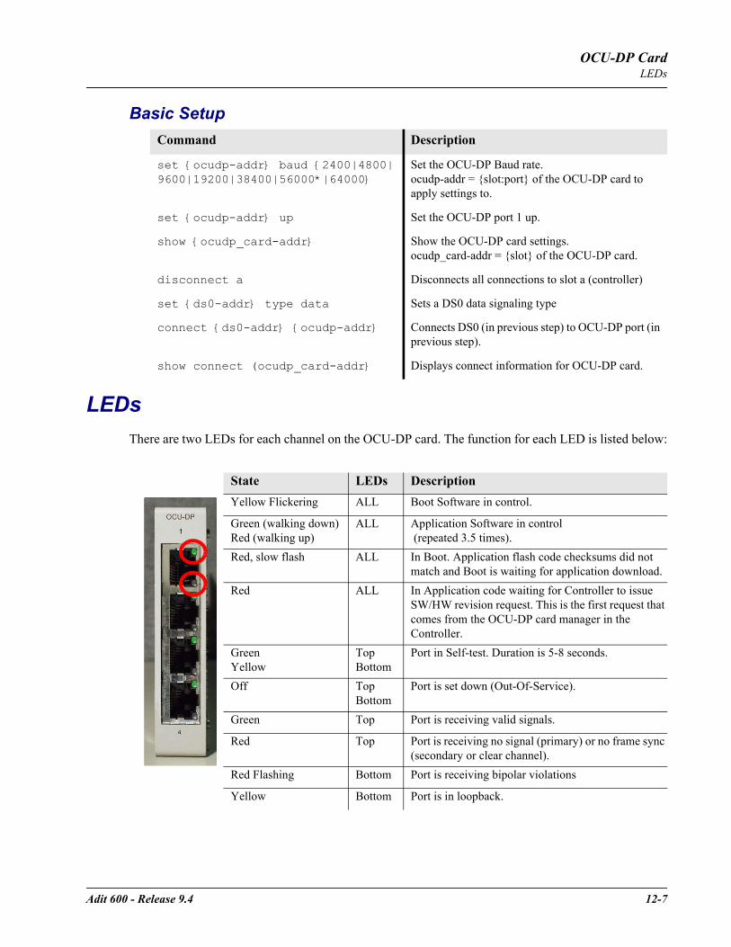
Adit 600 - Release 9.4 12-7
OCU-DP CardLEDs
Basic Setup
LEDsThere are two LEDs for each channel on the OCU-DP card. The function for each LED is listed below:
Command Description
set ocudp-addr baud 2400|4800|9600|19200|38400|56000*|64000
Set the OCU-DP Baud rate. ocudp-addr = slot:port of the OCU-DP card to apply settings to.
set ocudp-addr up Set the OCU-DP port 1 up.
show ocudp_card-addr Show the OCU-DP card settings. ocudp_card-addr = slot of the OCU-DP card.
disconnect a Disconnects all connections to slot a (controller)
set ds0-addr type data Sets a DS0 data signaling type
connect ds0-addr ocudp-addr Connects DS0 (in previous step) to OCU-DP port (in previous step).
show connect (ocudp_card-addr Displays connect information for OCU-DP card.
State LEDs DescriptionYellow Flickering ALL Boot Software in control.
Green (walking down) Red (walking up)
ALL Application Software in control (repeated 3.5 times).
Red, slow flash ALL In Boot. Application flash code checksums did not match and Boot is waiting for application download.
Red ALL In Application code waiting for Controller to issue SW/HW revision request. This is the first request that comes from the OCU-DP card manager in the Controller.
GreenYellow
TopBottom
Port in Self-test. Duration is 5-8 seconds.
Off TopBottom
Port is set down (Out-Of-Service).
Green Top Port is receiving valid signals.
Red Top Port is receiving no signal (primary) or no frame sync (secondary or clear channel).
Red Flashing Bottom Port is receiving bipolar violations
Yellow Bottom Port is in loopback.
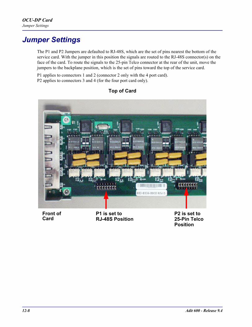
12-8 Adit 600 - Release 9.4
OCU-DP CardJumper Settings
Jumper SettingsThe P1 and P2 Jumpers are defaulted to RJ-48S, which are the set of pins nearest the bottom of the service card. With the jumper in this position the signals are routed to the RJ-48S connector(s) on the face of the card. To route the signals to the 25-pin Telco connector at the rear of the unit, move the jumpers to the backplane position, which is the set of pins toward the top of the service card. P1 applies to connectors 1 and 2 (connector 2 only with the 4 port card).P2 applies to connectors 3 and 4 (for the four port card only).
P1 is set to P2 is set to25-Pin TelcoRJ-48S PositionPosition
Top of Card
Front ofCard
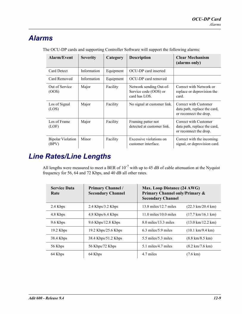
Adit 600 - Release 9.4 12-9
OCU-DP CardAlarms
AlarmsThe OCU-DP cards and supporting Controller Software will support the following alarms:
Line Rates/Line LengthsAll lengths were measured to meet a BER of 10-7 with up to 45 dB of cable attenuation at the Nyquist frequency for 56, 64 and 72 Kbps, and 40 dB all other rates.
Alarm/Event Severity Category Description Clear Mechanism(alarms only)
Card Detect Information Equipment OCU-DP card inserted
Card Removed Information Equipment OCU-DP card removed
Out of Service (OOS)
Major Facility Network sending Out-of-Service code (OOS) or card has LOS.
Correct with Network or replace or deprovision the card.
Los of Signal (LOS)
Major Facility No signal at customer link. Correct with Customer data path, replace the card, or reconnect the drop.
Los of Frame (LOF)
Major Facility Framing patter not detected at customer link.
Correct with Customer data path, replace the card, or reconnect the drop.
Bipolar Violation (BPV)
Minor Facility Excessive violations on customer interface.
Correct with the incoming signal, or deprovision card.
Service Data Rate
Primary Channel /Secondary Channel
Max. Loop Distance (24 AWG)Primary Channel only/Primary & Secondary Channel
2.4 Kbps 2.4 Kbps/3.2 Kbps 13.8 miles/12.7 miles (22.3 km/20.4 km)
4.8 Kbps 4.8 Kbps/6.4 Kbps 11.0 miles/10.0 miles (17.7 km/16.1 km)
9.6 Kbps 9.6 Kbps/12.8 Kbps 8.0 miles/13.3 miles (13.0 km/12.2 km)
19.2 Kbps 19.2 Kbps/25.6 Kbps 6.3 miles/5.9 miles (10.1 km/9.4 km)
38.4 Kbps 38.4 Kbps/51.2 Kbps 5.5 miles/5.3 miles (8.8 km/8.5 km)
56 Kbps 56 Kbps/72 Kbps 5.1 miles/4.7 miles (8.2 km/7.6 km)
64 Kbps 64 Kbps 4.7 miles (7.6 km)
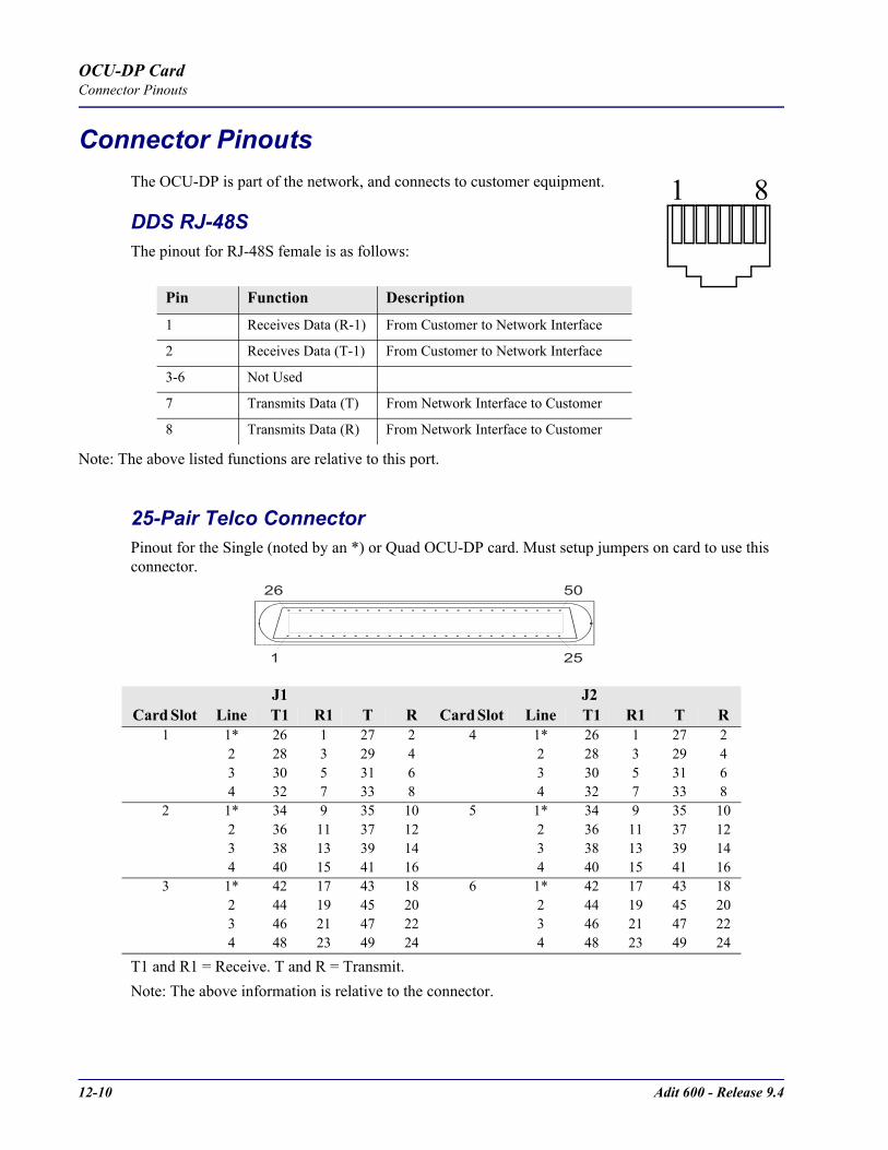
12-10 Adit 600 - Release 9.4
OCU-DP CardConnector Pinouts
Connector PinoutsThe OCU-DP is part of the network, and connects to customer equipment.
DDS RJ-48SThe pinout for RJ-48S female is as follows:
Note: The above listed functions are relative to this port.
25-Pair Telco ConnectorPinout for the Single (noted by an *) or Quad OCU-DP card. Must setup jumpers on card to use this connector.
T1 and R1 = Receive. T and R = Transmit. Note: The above information is relative to the connector.
Pin Function Description
1 Receives Data (R-1) From Customer to Network Interface
2 Receives Data (T-1) From Customer to Network Interface
3-6 Not Used
7 Transmits Data (T) From Network Interface to Customer
8 Transmits Data (R) From Network Interface to Customer
J1 J2Card Slot Line T1 R1 T R Card Slot Line T1 R1 T R
1 1* 26 1 27 2 4 1* 26 1 27 22 28 3 29 4 2 28 3 29 43 30 5 31 6 3 30 5 31 64 32 7 33 8 4 32 7 33 8
2 1* 34 9 35 10 5 1* 34 9 35 102 36 11 37 12 2 36 11 37 123 38 13 39 14 3 38 13 39 144 40 15 41 16 4 40 15 41 16
3 1* 42 17 43 18 6 1* 42 17 43 182 44 19 45 20 2 44 19 45 203 46 21 47 22 3 46 21 47 224 48 23 49 24 4 48 23 49 24
1 8
50
25
26
1

CHAPTER 13P-Phone Card
In this Chapter
Overview
Features
Technical Specifications
Card Configuration- CLI Commands
- DIP Switch Settings
LEDs
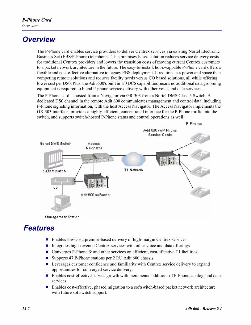
13-2 Adit 600 - Release 9.4
P-Phone CardOverview
OverviewThe P-Phone card enables service providers to deliver Centrex services via existing Nortel Electronic Business Set (EBS/P-Phone) telephones. This premises-based solution reduces service delivery costs for traditional Centrex providers and lowers the transition costs of moving current Centrex customers to a packet network architecture in the future. The easy-to-install, hot-swappable P-Phone card offers a flexible and cost-effective alternative to legacy EBS deployment. It requires less power and space than competing remote solutions and reduces facility needs versus CO based solutions, all while offering lower cost per DS0. Plus, the Adit 600's built in 1/0 DCS capabilities means no additional data grooming equipment is required to blend P-phone service delivery with other voice and data services.The P-Phone card is hosted from a Navigator via GR-303 from a Nortel DMS Class 5 Switch. A dedicated DS0 channel in the remote Adit 600 communicates management and control data, including P-Phone signaling information, with the host Access Navigator. The Access Navigator implements the GR-303 interface, provides a highly-efficient, concentrated interface for the P-Phone traffic into the switch, and supports switch-hosted P-Phone status and control operations as well.
FeaturesEnables low-cost, premise-based delivery of high-margin Centrex servicesIntegrates high-revenue Centrex services with other voice and data offeringsConverges P-Phone & and other services on efficient, cost-effective T1 facilities.Supports 47 P-Phone stations per 2 RU Adit 600 chassisLeverages customer confidence and familiarity with Centrex service delivery to expand opportunities for converged service delivery. Enables cost-effective service growth with incremental additions of P-Phone, analog, and data services. Enables cost-effective, phased migration to a softswitch-based packet network architecture with future softswitch support.
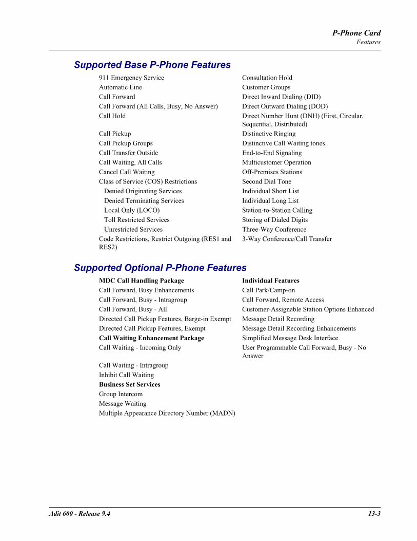
Adit 600 - Release 9.4 13-3
P-Phone CardFeatures
Supported Base P-Phone Features
Supported Optional P-Phone Features
911 Emergency Service Consultation HoldAutomatic Line Customer GroupsCall Forward Direct Inward Dialing (DID)Call Forward (All Calls, Busy, No Answer) Direct Outward Dialing (DOD)Call Hold Direct Number Hunt (DNH) (First, Circular,
Sequential, Distributed)Call Pickup Distinctive RingingCall Pickup Groups Distinctive Call Waiting tonesCall Transfer Outside End-to-End SignalingCall Waiting, All Calls Multicustomer OperationCancel Call Waiting Off-Premises StationsClass of Service (COS) Restrictions Second Dial Tone Denied Originating Services Individual Short List Denied Terminating Services Individual Long List Local Only (LOCO) Station-to-Station Calling Toll Restricted Services Storing of Dialed Digits Unrestricted Services Three-Way ConferenceCode Restrictions, Restrict Outgoing (RES1 and RES2)
3-Way Conference/Call Transfer
MDC Call Handling Package Individual FeaturesCall Forward, Busy Enhancements Call Park/Camp-onCall Forward, Busy - Intragroup Call Forward, Remote AccessCall Forward, Busy - All Customer-Assignable Station Options EnhancedDirected Call Pickup Features, Barge-in Exempt Message Detail RecordingDirected Call Pickup Features, Exempt Message Detail Recording EnhancementsCall Waiting Enhancement Package Simplified Message Desk InterfaceCall Waiting - Incoming Only User Programmable Call Forward, Busy - No
AnswerCall Waiting - IntragroupInhibit Call WaitingBusiness Set ServicesGroup IntercomMessage WaitingMultiple Appearance Directory Number (MADN)
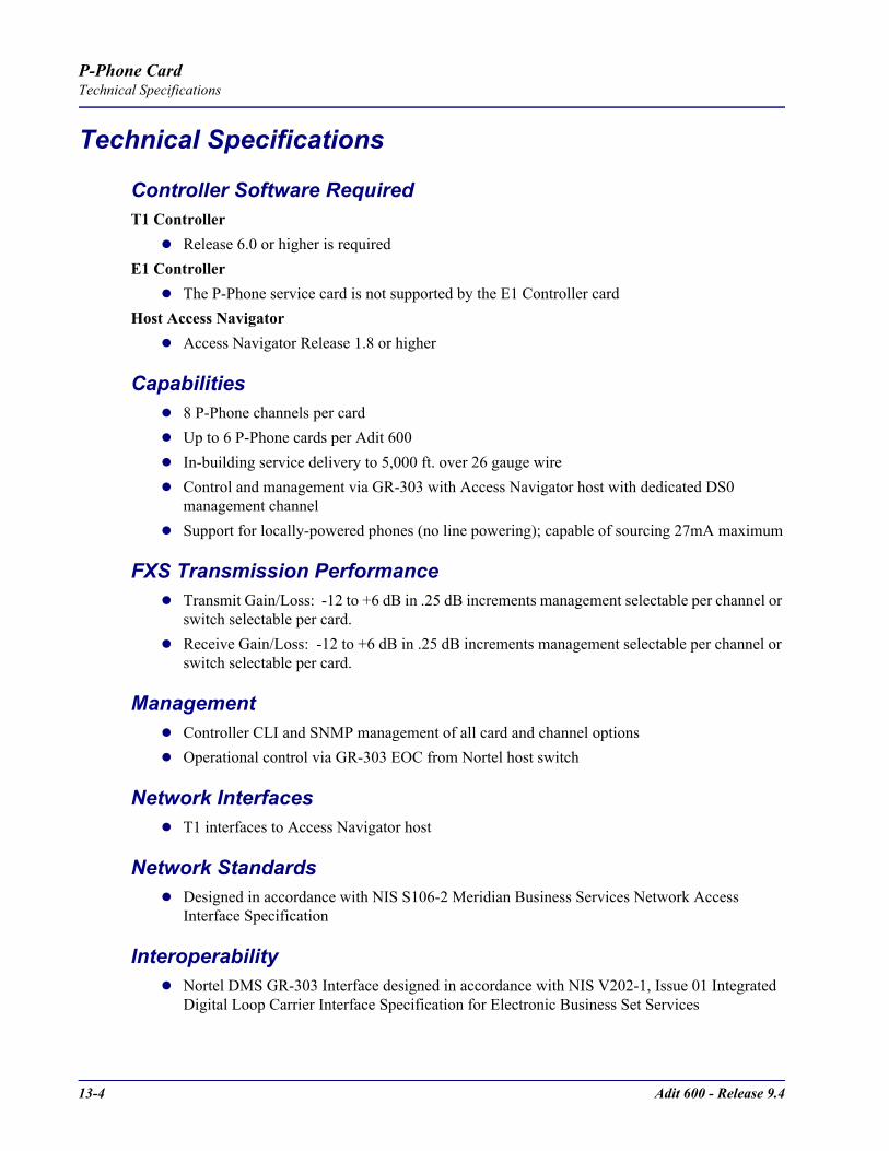
13-4 Adit 600 - Release 9.4
P-Phone CardTechnical Specifications
Technical Specifications
Controller Software RequiredT1 Controller
Release 6.0 or higher is requiredE1 Controller
The P-Phone service card is not supported by the E1 Controller cardHost Access Navigator
Access Navigator Release 1.8 or higher
Capabilities8 P-Phone channels per cardUp to 6 P-Phone cards per Adit 600In-building service delivery to 5,000 ft. over 26 gauge wireControl and management via GR-303 with Access Navigator host with dedicated DS0 management channelSupport for locally-powered phones (no line powering); capable of sourcing 27mA maximum
FXS Transmission PerformanceTransmit Gain/Loss: -12 to +6 dB in .25 dB increments management selectable per channel or switch selectable per card.Receive Gain/Loss: -12 to +6 dB in .25 dB increments management selectable per channel or switch selectable per card.
ManagementController CLI and SNMP management of all card and channel optionsOperational control via GR-303 EOC from Nortel host switch
Network InterfacesT1 interfaces to Access Navigator host
Network StandardsDesigned in accordance with NIS S106-2 Meridian Business Services Network Access Interface Specification
InteroperabilityNortel DMS GR-303 Interface designed in accordance with NIS V202-1, Issue 01 Integrated Digital Loop Carrier Interface Specification for Electronic Business Set Services

Adit 600 - Release 9.4 13-5
P-Phone CardTechnical Specifications
ClockingDerived from Adit platform, typically from a network T1
AlarmsDetects and reports the loss of call control channel to host Access NavigatorCard self-test alarm indicating card failureDetects and reports that power on self-test has failed
Testing and DiagnosticsRemote (P-Phone handset) loopbacks controlled via GR-303 EOCExcessive collision detection indicating possible handset failure
Power2.5 W nominal, plus 150 MW per active P-Phone channelInternal solid-state protection
Regulatory ApprovalsSee Appendix A, Regulatory Approvals for information on the P-Phone Service card.
PhysicalDimensions: 3.5 in. (H) x 0.75 in. (W) x 11.25 in. (D) 8.9 cm (H) x 1.9 cm (W) x 28.6 cm (D)Weight: 5.9 oz. (.17 kg)
For information on Adit 600 Environment required, see Installation Environment on page 2-2.
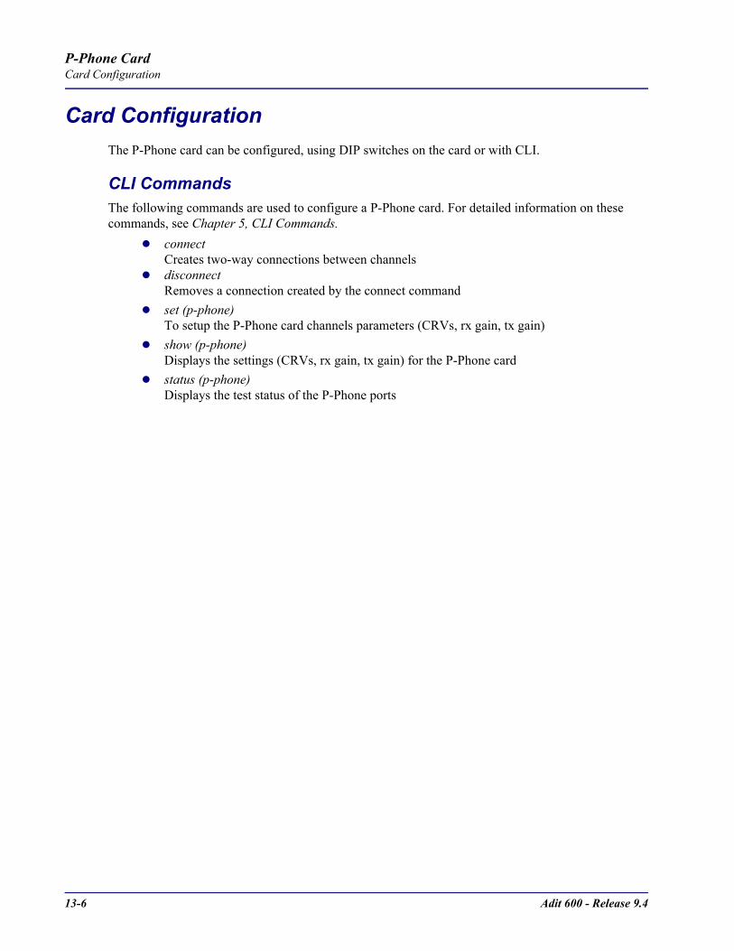
13-6 Adit 600 - Release 9.4
P-Phone CardCard Configuration
Card ConfigurationThe P-Phone card can be configured, using DIP switches on the card or with CLI.
CLI CommandsThe following commands are used to configure a P-Phone card. For detailed information on these commands, see Chapter 5, CLI Commands.
connectCreates two-way connections between channels
disconnectRemoves a connection created by the connect command
set (p-phone)To setup the P-Phone card channels parameters (CRVs, rx gain, tx gain)
show (p-phone)Displays the settings (CRVs, rx gain, tx gain) for the P-Phone card
status (p-phone)Displays the test status of the P-Phone ports

Adit 600 - Release 9.4 13-7
P-Phone CardLEDs
DIP Switch SettingsEach P-Phone card contains ten DIP switches that can be used to select gain options for all eight channels.
LEDsEach P-Phone channel has a corresponding LED, described in the table below.
Switch Function Description Note
1-2 Not in use
3-6 Receive Gain/Loss
3 4 5 6 These settings allow for receive gain and losses of -9, -7, -6, -5, -4, -3, -2, 0, 2, 3, 4, 5, and 6. +9 (1110) is not available.+7 (1100) is not available. Maximum setting on the P-Phone is +6 dB.
0 0 0 0 = 0 dB0 0 0 1 = -9 dB0 0 1 0 = +2 dB0 1 0 0 = +3 dB1 0 0 0 = +4 dB
7-10 Transmit Gain/Loss
7 8 9 10 These settings allow for transmit gain and losses of -9, -7, -6, -5, -4, -3, -2, 0, 2, 3, 4, 5, and 6. +9 (1110) is not available.+7 (1100) is not available. Maximum setting on the P-Phone is +6 dB.
0 0 0 0 = 0 dB0 0 0 1 = -9 dB0 0 1 0 = +2 dB0 1 0 0 = +3 dB1 0 0 0 = +4 dB
State Line State
Off No P-Phone connected
Green No call in process
Flashing Green Alert (Ringing)
Yellow Call in progress
Flashing Yellow P-Phone Loopback in Progress
Flashing Red Self-test failed

13-8 Adit 600 - Release 9.4
P-Phone CardLEDs
CHAPTER 14Single Channel POTS Card
In this Chapter
Overview
Features
Technical Specifications
Card Configuration- CLI Commands
Connector Pinouts
LEDs
14-2 Adit 600 - Release 9.4
Single Channel POTS CardOverview
OverviewThe Order Wire Single-Channel POTS Service card give service providers a standard FXS voice circuit. The cards can be used for communications with the operations support group under conditions where remote locations are being serviced or for providing a voice line without installing an additional external two-wire POTS line from a local carrier. The POTS Service Card features a single RJ-11 telecom connection. The POTS Service card can be inserted into any service card slot of the Adit 600 and is configured using CLI.
FeaturesProvides a lifeline order wire connection for communications from the remote cell sites during radio maintenanceOffers solid-state overvoltage and fuseless overcurrent protection from lightning and power cross incidents
Technical Specifications
Controller Software RequiredT1 Controller
Release 6.1 or higher is required to support the POTS Service cardE1 Controller
Release 6.1 or higher is required to support the POTS Service card– µ-Law only
FXS Transmission PerformanceReturn Loss: ERL > 26 dB at 1010 Hz, with respect to 900Ω + 2.16µFIdle Noise: 25 dBrnC0Terminating Impedance: 900Ω + 2.16µF Gain/Loss at 1010 Hz: -1 to 0 dBLongitudinal Balance: >50 dB
FXS Signaling PerformanceDC Loop Range: < 1 Kft 25GaLoop Feed: Nominal -48 VDC with 26mA current limit Ringing Voltage: 40 V rms, 20 HzMaximum Ringers: 2 REN, FCC Class B ringersFXS Signaling: FXS loop start Ringer Equivalency Number (REN): 0.0 by definition

Adit 600 - Release 9.4 14-3
Single Channel POTS CardTechnical Specifications
Regulatory ApprovalsSee Appendix A, Regulatory Approvals for information on the Single Channel POTS Service card.
PhysicalPOTS connections are through front panel RJ-11Dimensions: 3.5 in. (H) x 0.75 in. (W) x 11.25 in. (D) 8.9 cm (H) x 1.9 cm (W) x 28.6 cm (D)Weight: 5.1 oz. (0.14 kg)
EnvironmentIn addition to the systems environment requirements, the following applies to the Single Channel POTS card. For additional information see Installation Environment on page 2-2.
Operating temperature range: -40° to 149° F (-40° to 65° C)
14-4 Adit 600 - Release 9.4
Single Channel POTS CardCard Configuration
Card ConfigurationThe Single Channel POTS card can be configured, using CLI commands.
CLI CommandsThe following commands are used to configure the POTS cards. For detailed information on these commands, see Chapter 5, CLI Commands.
connectCreates two-way connections between channels
disconnectRemoves a connection created by the connect command
set (fxsPS)To setup the voice channels parameters (rx gain, signal, tx gain).
show (fxsPS)Displays the settings (type, signaling, rx gain, tx gain) for the FXS PS card.
status (fxsPS)Displays the status (AB bits received, AB bits transmitted, signal, T1 activity, trunk processing) of the specified FXS PS card.
Basic ConfigurationSet Up the Single Channel POTS LineUse the following commands to set up a Single Channel POTS Line.
Command Descriptionset a:1:1 type voice Set the DSO to voice. See set (ds0) for details.
connect a:1:1 8:1 Connect the DSO A:1:1 to port 1 of the Single Channel POTS card in slot 8. See the set (fxsPS) command for details.Assign this DS0 a phone lineConnect phoneTest phone for dial-tone

Adit 600 - Release 9.4 14-5
Single Channel POTS CardConnector Pinouts
Connector Pinouts
RJ-11 Connector There is one RJ-11 (female) connector on the POTS card. The pinouts are as follows:
LEDsThe POTS channel LED (left) status is described in the table below.
The second LED (right) is a status LED is not used on this card.
Pin Name Description 1 - 2 N/C Not connected3 R Ring4 T Tip5 - 6 N/C Not connected
State Loop Start MeaningOff Calling Party DisconnectGreen IdleRed N/AYellow Call in progressFlashing green Ringing
1 6

14-6 Adit 600 - Release 9.4
Single Channel POTS CardLEDs

CHAPTER 15Power Supply
In this Chapter
115 VAC/-48 VDC Power Supply/Charger
230 VAC/-48 VDC Power Supply/Charger
24 VDC Power Supply
Ringer Waveform Options
Replacing a Power Supply
15-2 Adit 600 - Release 9.4
Power Supply115 VAC/-48 VDC Power Supply/Charger
115 VAC/-48 VDC Power Supply/ChargerThe 115 VAC/-48 VDC Power Supply and Charger enables the Adit 600 to be powered from either 115 VAC or -48 VDC sources, and includes an integral battery charger and ringing generator. Integrating AC and DC power options, battery charger and ringing generator functions in the Adit chassis dramatically reduces installation time, space and cost requirements and inventory considerations in comparison to separate power conversion or Uninterruptable Power Systems (UPS) equipment.Front-panel LEDs provide easy-to-read indications of power input, battery status and alarms. Remote notification to network operations and to monitoring centers of loss of AC input or low DC input voltage is available via SNMP or through the NetworkValet EMS. Should a loss of input voltage occur, the Adit 600 automatically switches over to the optional Carrier Access Battery Backup Unit without power interruption. The compact Battery Backup Unit can power the Adit 600 for up to eight hours, providing a complete solution compliant with lifeline service requirements. This eliminates the need for an expensive and bulky UPS.The ringing generator provides 25 Ringer Equivalence Number (REN) output, supporting up to 48 FXS simultaneous ringing lines with normal cadence ringing. Three ringer waveform shapes and three selectable ringer frequencies ensure performance over a wide range of outside line or customer premises applications.
FeaturesEnables Adit 600 to be powered from 115 VAC or -48 VDC sourceIntegral battery charger for use with optional Carrier Access Battery Backup UnitAutomatic switchover to Battery Backup Unit without power interruptionSelectable ringer frequency settings of 20, 25 and 50 HzIntegrated 25 REN ringing generator supports high capacity applicationsAutomatic switchover to Battery Backup Unit without power interruptionInstalls quickly and easily with fully connectorized designSolid-state fuseless protection for Central Office NEBS and customer premises FCC and UL safety requirements
Technical SpecificationsAC Electrical Input
115 VAC (95 to 132 VAC, 57 to 63 Hz), 2.5 A rms, 130 W maximumMaximum inrush current: 24 A peak at 132 VACRear-panel mounted circuit breaker operates for overcurrent conditions greater than 4 AFront-panel AC INPUT status LED

Adit 600 - Release 9.4 15-3
Power Supply115 VAC/-48 VDC Power Supply/Charger
DC Electrical Input -48 DC (-40 to -60 V), 2.1 ADC, 90 W maximumMaximum cold start inrush current: 30 A peak at -60 VDCSolid-state input overcurrent protection trips at 2.5 A at 68º F (20º C)Extended mode: jumper option enables Adit 600 startup at low battery input voltage
Electrical Output -37 VDC (short loop)/ -54 DC (long loop), talk battery, 1.45 A maximum-54 VDC battery charger output, 0.5 A maximum+5 VDC, 9 A maximumAutomatic switchover to battery backup without power interruption
Battery Charger Front-panel battery status LEDBattery charging output limited to 0.5 A maximum
AlarmsGenerates minor alarm contact closure on External Alarm Connector when
AC input voltage is not present or circuit breaker is open -48 VDC battery input voltage magnitude is low or absent
Ringing GeneratorsNominal 85 V rms (108 V rms max)Referenced to -54 VDC (-60 VDC max) outputSupports three jumper-selectable ringer waveform shapesDrives 25 REN indefinitely with minimum output voltage of 65 V rms at normal ringer cadenceRinger frequency is selectable, 20 25 or 50 Hz ± 15%Overload protected
Regulatory ApprovalsSee Appendix A, Regulatory Approvals for information on the 115VAC Power Supply.
Interface ConnectorsIEC-320, 15 A 3-prong AC power receptacleRear PCB connector: Adit 600 backplane
PhysicalDimensions: 3.5 in. (H) x 2 in. (W) x 12 in. (D) 8.9 cm (H) x 5.1 cm (W) x 30.5 cm (D)Weight: 1 lb. 6 oz. (0.62 kg)
For information on Adit 600 Environment required, see Installation Environment on page 2-2.
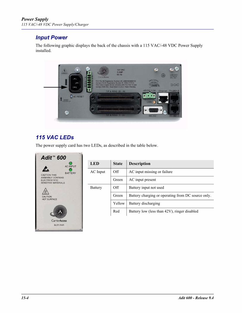
15-4 Adit 600 - Release 9.4
Power Supply115 VAC/-48 VDC Power Supply/Charger
Input PowerThe following graphic displays the back of the chassis with a 115 VAC/-48 VDC Power Supply installed.
115 VAC LEDsThe power supply card has two LEDs, as described in the table below.
LED State Description
AC Input Off AC input missing or failure
Green AC input present
Battery Off Battery input not used
Green Battery charging or operating from DC source only.
Yellow Battery discharging
Red Battery low (less than 42V), ringer disabled

Adit 600 - Release 9.4 15-5
Power Supply230 VAC/-48 VDC Power Supply/Charger
230 VAC/-48 VDC Power Supply/ChargerThe 230 VAC Power Supply/Charger enables the Adit 600 to be powered from either 230 VAC or -48 VDC sources, and includes an integral battery charger and ring generator. Integrating AC and DC power options, battery charger, and ring generator functions in the Adit chassis dramatically reduces installation time, space and cost requirements, and inventory considerations in comparison to separate power conversion or Uninterruptable Power Systems (UPS) equipment.Front-panel LEDs provide easy-to-read indications of power input, battery status, and alarms. Remote notification to network operations and monitoring centers of loss of AC input or low DC input voltage is available via SNMP. Should a loss of input voltage occur, the Adit 600 automatically switches over to the optional Carrier Access Battery Backup Unit, without power interruption. The compact Battery Backup Unit can power a fully loaded Adit 600 for up to eight hours, providing a complete solution compliant with lifeline service requirements. This eliminates the need for expensive and bulky UPS.The ring generator provides 25 Ringer Equivalence Number (REN) output, supporting up to 48 FXS simultaneous ringing lines with normal cadence ringing. Three ringer waveform shapes and three selectable ringer frequencies ensure performance over a wide range of applications.
Features Single unit enables Adit 600 to be powered from 230 VAC or -48 VDC source Integral battery charger for use with optional Carrier Access Battery Backup Unit Automatic switchover to Battery Backup Unit without power interruption Integrated 25 REN ringing generator supports high capacity applications LED status and monitoring, and remote alarming capabilities ensure service availability Fully connectorized design ensures quick and simple installation
Technical SpecificationsAC Electrical Input
230 VAC (190 to 254 VAC, 47 to 63 Hz), 2.5 A rms, 130 W maximumMaximum inrush current: 18 A peak at 254 VACRear-panel mounted circuit breaker operates for overcurrent conditions greater than 2 AFront-panel AC INPUT status LED
DC Electrical Input -48 DC (-40 to -60 V), 2.1 ADC, 90 W maximumMaximum cold start inrush current: 30 A peak at -60 VDCSolid-state input overcurrent protection trips at 2.5 A at 68º F (20º C)
15-6 Adit 600 - Release 9.4
Power Supply230 VAC/-48 VDC Power Supply/Charger
Electrical Output -37 VDC (short loop)/ -54 DC (long loop), talk battery, 1.45 A maximum-54 VDC battery charger output, 0.5 A maximum+5 VDC, 9 A maximumAutomatic switchover to battery backup without power interruption
Battery Charger Front-panel battery status LEDBattery charging output limited to 0.5 A maximum
AlarmsGenerates minor alarm contact closure on External Alarm Connector when
AC input voltage is not present or circuit breaker is open -48 VDC battery input voltage magnitude is low or absent
Ringing GeneratorsNominal 85 V rms (108 V rms max)Referenced to -54 VDC (-60 VDC max) outputSupports three jumper-selectable ringer waveform shapesDrives 25 REN indefinitely with minimum output voltage of 65 V rms at normal ringer cadenceRinger frequency is selectable 20, 25 or 50 Hz ± 15%Overload protected
Interface ConnectorsIEC-320, 15 A 3-prong AC power receptacleRear PCB connector: Adit 600 backplane
Regulatory ApprovalsSee Appendix A, Regulatory Approvals for information on the 230VAC Power Supply.
PhysicalDimensions: 3.5 in. (H) x 2 in. (W) x 12 in. (D) 8.9 cm (H) x 5.1 cm (W) x 30.5 cm (D)Weight: 1 lb. 6 oz. (0.62 kg)
For information on Adit 600 Environment required, see Installation Environment on page 2-2.
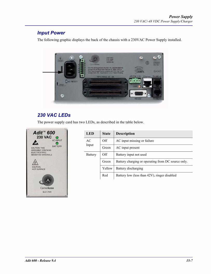
Adit 600 - Release 9.4 15-7
Power Supply230 VAC/-48 VDC Power Supply/Charger
Input PowerThe following graphic displays the back of the chassis with a 230VAC Power Supply installed.
230 VAC LEDsThe power supply card has two LEDs, as described in the table below.
LED State Description
AC Input
Off AC input missing or failure
Green AC input present
Battery Off Battery input not used
Green Battery charging or operating from DC source only.
Yellow Battery discharging
Red Battery low (less than 42V), ringer disabled

15-8 Adit 600 - Release 9.4
Power Supply24 VDC Power Supply
24 VDC Power SupplyThe 24 VDC Power Supply delivers +24 VDC power to the Adit 600. This power supply integrates +24 VDC power with a ringing generator in the Adit chassis to dramatically reduce installation time, space requirements and costs compared to separate +24 to -48 VDC power conversion equipment for wireless equipment bays or other +24 VDC applications.Front panel LEDs provide easy-to-read power status and alarms. The power supply can remotely notify network operations and monitoring centers of low VDC output through the Adit SNMP. The ringing generator provides 25 Ringer Equivalence Number (REN) output, supporting up to 48 FXS simultaneous ringing lines with normal cadence. Three waveform shapes and software selectable operation with short or long loops ensure performance across a wide range of customer premises applications.
FeaturesProvides the Adit 600 with a +24 VDC power sourceIntegrated 25 REN ringing generator supports high capacity applicationsRinger frequency selection of 20, 25 and 50 HzThe high voltage ring generator provides the ringing signal required for telecommunication networks in North America and selected foreign countriesLED status, monitoring, and remote alarming capabilities ensure service availabilityInstalls quickly and easily with fully connectorized designMeets Central Office NEBS and customer premises UL safety requirements with circuit breaker input protection
Technical SpecificationsElectrical Input
+24 (21 to 29) VDC, +6 ADC, 90 W output maximumStartup at +23.5 V maximumLow voltage shutdown at +18 V minimumHigh voltage shutdown at +30 V minimum
Electrical Output -37 VDC (short loop)/ -54 VDC (long loop), software selectable, 1.45 A maximum+5 VDC, 9 A maximum
AlarmsGenerates minor alarm contact closure on External Alarm Connector when -54 VDC output voltage magnitude is low
Adit 600 - Release 9.4 15-9
Power Supply24 VDC Power Supply
Ringing GeneratorsNominal 80 V rms (108 V rms max)Supports three jumper-selectable ringer waveform shapesDrives 25 REN indefinitely with minimum output voltage of 65 V rms at normal ringer cadenceRinger frequency is selectable, 20 25 or 50 Hz ± 15%Overload protected
Interface ConnectorsTwo position +24 V input connectorRear PCB connector: Adit 600 backplane
Regulatory ApprovalsSee Appendix A, Regulatory Approvals for information on the 24VDC Power Supply.
PhysicalDimensions: 3.5 in. (H) x 2 in. (W) x 12 in. (D) 8.9 cm (H) x 5.1 cm (W) x 30.5 cm (D)Weight: 1 lb. 9 oz. (0.71 kg)
For information on Adit 600 Environment required, see Installation Environment on page 2-2.

15-10 Adit 600 - Release 9.4
Power Supply24 VDC Power Supply
Input PowerThe following graphic displays the back of the chassis with a 24VDC Power Supply installed. The labels have been added for additional information regarding the power input connector. There is no power cable provided with the 24VDC Power Supply, however the connector is provided. This connector will need to be wired, the following chart lists the wire gauge recommended.
Chassis GroundConnect Ground Lugs to permanent Earthing ground. See Chassis Ground Connector on page 3-7 for more information.
Wire Gauge Maximum Distance
18 AWG 12 Feet
16 AWG 20 Feet
14 AWG 35 Feet
Ground Lugs Power Input

Adit 600 - Release 9.4 15-11
Power Supply24 VDC Power Supply
24 VDC LEDsThe power supply card has two LEDs, as described in the table below.
LED State Description
DC OK Off DC input missing or failure
Green DC input present
-48 Battery Low
Off Normal
Red VDC is low (less than 42 VDC), ringer disabled
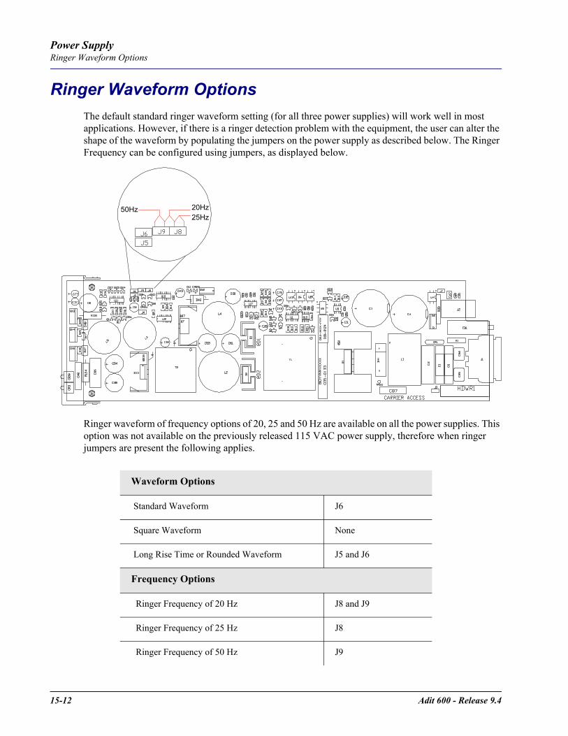
15-12 Adit 600 - Release 9.4
Power SupplyRinger Waveform Options
Ringer Waveform OptionsThe default standard ringer waveform setting (for all three power supplies) will work well in most applications. However, if there is a ringer detection problem with the equipment, the user can alter the shape of the waveform by populating the jumpers on the power supply as described below. The Ringer Frequency can be configured using jumpers, as displayed below.
Ringer waveform of frequency options of 20, 25 and 50 Hz are available on all the power supplies. This option was not available on the previously released 115 VAC power supply, therefore when ringer jumpers are present the following applies.
Waveform Options
Standard Waveform J6
Square Waveform None
Long Rise Time or Rounded Waveform J5 and J6
Frequency Options
Ringer Frequency of 20 Hz J8 and J9
Ringer Frequency of 25 Hz J8
Ringer Frequency of 50 Hz J9
50Hz 20Hz25Hz
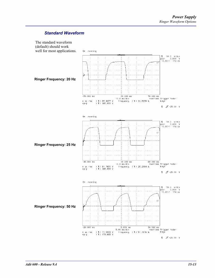
Adit 600 - Release 9.4 15-13
Power SupplyRinger Waveform Options
Standard Waveform
The standard waveform (default) should work well for most applications.
Ringer Frequency: 20 Hz
Ringer Frequency: 25 Hz
Ringer Frequency: 50 Hz

15-14 Adit 600 - Release 9.4
Power SupplyRinger Waveform Options
Square Waveform
Ringer Frequency: 20 Hz
Ringer Frequency: 25 Hz
Ringer Frequency: 50 Hz

Adit 600 - Release 9.4 15-15
Power SupplyRinger Waveform Options
Long Rise Time or Rounded Waveform
Ringer Frequency: 20 Hz
Ringer Frequency: 25 Hz
Ringer Frequency: 50 Hz

15-16 Adit 600 - Release 9.4
Power SupplyReplacing a Power Supply
Replacing a Power Supply
1. Disconnect power cord from the unit.2. Remove nut and lock washer from power supply retention stud located directly above power
cord socket.3. Remove power supply by grasping faceplate at top and bottom and pulling power supply
straight out of the case.4. When installing the power supply, be certain to engage top and bottom edges of power supply
circuit board in the card guides located 1 1/4 inches inside the front opening of the case.5. Slowly slide the power supply into the slot while making sure that
- the power supply retention stud aligns with and passes through its attachment hole in the rear of the case, and - the connector is correctly aligned to its mating connector on the backplane.
6. Press gently on the faceplate of the power supply to ensure that the connector is fully seated.7. Replace nut and lock washer on the power supply retention stud.
NOTE: Reconnect the power cord to the unit.
FrontBack
Faceplate
Nut and lock washer
Power CordConnector

CHAPTER 16Quad DS1 ADPCM Card
In this Chapter
Overview
Features
Technical Specifications
Card Configuration- CLI Commands
- Cross Connects
- Basic Setup
Jumper Settings
Connector Pinouts- RJ-48 Connector
LEDs

16-2 Adit 600 - Release 9.4
Quad DS1 ADPCM CardOverview
OverviewThe Quad DS1 ADPCM Service card is a component of the Adit 600, and provides an intelligent, compact device that can compress and groom traffic, which increases bandwidth utilization and reduces costs. Using Adaptive Differential Pulse Code Modulation (ADPCM), the ADPCM Service card compresses selected timeslots from one of the T1 ports. Compression maps are CLI configurable for the ADPCM port.The ADPCM Service card is capable of packing two DS0s into a single DS0 and functions simultaneously as a digital cross-connect switch for grooming, bypassing or switching any combination of 64 kbps timeslots. It supports four T1 circuits and includes integral T1 CSU circuitry. V.35/RS-530 high-speed data ports, for integral DSU operation, can be added to the platform with the Dual V.35 Service Card and gives users the ability to drop-and-insert local data into available timeslots.The ADPCM Service card utilizes industry-standard ADPCM compression techniques to increase the capacity of T1 links. It offers flexible timeslot assignments for mapping and configuration of compressed and non-compressed clear channels to groom data to meet network traffic requirements between remote cell sites and the Mobile Switching Center (MSC). Data and digital traffic (i.e., GSM, CDMA, and TDMA) can ride along with compressed traffic over standard T1 circuits for supporting mixed analog and digital cellular sites.
WARNING! THERE IS A RESTRICTION AS TO THE NUMBER OF QUAD DS1 ADPCM CARDS THAT CAN BE INSTALLED IN AN ADIT. PLEASE SEE CONFIGURATION RESTRICTIONS ON PAGE 4-22 FOR MORE INFORMATION.
NOTE: There are 4 ports on a DS1 ADPCM Service card, only port 1 supports the ADPCM function.
Features32 Kbps ADPCM compressionGrooms the voice and data mix from selectable channel control optionsSupports up to 14.4 Kbps analog encoded data4 DS1/T1 interfaces with integrated CSU, (DSX1 or DS1 port selections)Operates end-to-end with existing transcoder equipment at the MSCOne modular integrated platform for DS1, V.35, POTS, 10/100 interfaces
Adit 600 - Release 9.4 16-3
Quad DS1 ADPCM CardTechnical Specifications
Technical Specifications
T1 Controller Software RequiredRelease 7.0 or higher is required for the Quad DS1 ADPCM service card
T1 Interface4 T1 ports operating at 1.544 Mbps ±50 bpsT1 Port 1 provides ADPCM compression capabilityExpansion to 18 T1 ports in a single chassis using Quad T1 or Quad DS1 ADPCM Service cardsSF (D4) or ESF framing, AMI or B8ZS line coding (DS1 operation)Short-haul or long-haul loop settings for T14 RJ-48C or 25-pin Telco (selectable)T1 Line Interface: T1-CSU or T1-DSX (field selectable)Line Build Out (DSX-1): 655 feetReceive Sensitive (DS1): 0 to -22 dB @ 772KHz ALBOOutput Level (DS1): Selectable at 0 to -22 dBJitter: meets AT&T Pub. TR-62411Solid-state fuseless overvoltage and overcurrent line protectionChannel status LEDsLess than 3 ms signaling latencyLess than 10 ms overall system signaling latency
ADPCM SignalingClear Channel Signaling passed on 64K clear channel24-channel 32 Kbps ADPCM compression
ManagementManaged by Adit 600 Controller Craft or SNMP Interface
SynchronizationProvides reference clock to backplane from selected T1
Network StandardsRFC 2495ANSI T1.403-1995, T1.231-1993ITU G.703, G.704
16-4 Adit 600 - Release 9.4
Quad DS1 ADPCM CardTechnical Specifications
ClockingLoop-timed from any T1Revertive or non-revertive clock switching provides automatic backup to secondary T1 should the primary T1 failOperates as a Stratum 4E device as defined by Telcordia GR-1244-CORE and AT&T TR 62411
AlarmsSupport standard T1.403 alarmsLOS (Loss of Signal), Red, Yellow, BlueESF Performance Error Count ThresholdTiming LossAll alarms are logged in an event logLoss of power triggers minor alarmGenerates SNMP traps for alarming
Testing and DiagnosticsT1.403 payload loopbacks (ESF only)T1.403 remote and local line loopbacks (ESF and SF)T1.231 Performance History (15 minute intervals, 24 hour totals)T1.403 Performance Report Messages (PRMs)
Power ConsumptionLess than 4.5 W per card
Regulatory ApprovalsSee Appendix A, Regulatory Approvals for information on the Quad DS1 ADPCM Service card.
EnvironmentFor systems environment requirements, see Installation Environment on page 2-2.
PhysicalDimensions: 3.5 in. (H) x 0.75 in. (W) x 11.25 in. (D) 8.9 cm (H) x 1.9 cm (W) x 28.6 cm (D)Weight: 5.1 oz. (0.14 kg)

Adit 600 - Release 9.4 16-5
Quad DS1 ADPCM CardCard Configuration
Card ConfigurationAll options on the this Service card are set using the Command Line Interface (CLI).
CLI CommandsThe following commands are used to configure the Quad DS1 ADPCM card. For detailed information on these commands, see Chapter 5, CLI Commands.
connectCreates two-way connections between channels.
disconnectRemoves a connection created by the connect command.
set (ds1 card) adpcm mapSets the compression map on the ADPCM card (none, map 1, map 2 or map 3).
set (ds1)Sets up the DS1 interfaces (clock, up, down, fdl, framing, id string, lbo, line, linecode, loopdetect).
show (adpcm)Displays current settings for the ADPCM card (circuit ID, up.down, framing, line coding, line build out, loop code detection, loop back, fdl type, ADPCM, ADPCM Map).
show connect adpcmDisplays the connections for the ADPCM port.
show (ds1)Displays current settings for DS1.
status (adpcm)Displays the status of the ADPCM card (receive, transmit, loopback).
status (ds1)Displays the status of the DS1 (receive, transmit, loopback).

16-6 Adit 600 - Release 9.4
Quad DS1 ADPCM CardCard Configuration
Basic SetupBefore configuring the DS1 ADPCM card, there are some basics that need to be considered:
All DS0s to be compressed reside on T1 number 1 of the ADPCM cardCompressed data and uncompressed data can be transported at the same time.All DS0s to be compressed must be set to type data.
The following is a basic setup:
Command Description
Connect T1 cable to port 1 of the ADPCM service card
set adpcm_card-addr adpcm none|map1|map2|map3
Enable compressing by selecting Map type. Note: none disables compression. See the following section on Maps.
show (adpcm_card-addr Displays the status of the card, and the mapping.
set 2:1:1-12 type data Set the channel (DS0) type to data on the ADPCM channels. See set (ds0) command for more information.
set 2:4:1-12 type data Set the channel (DS0) type to data on the channels for cross-connect. See set (ds0) command for more information.
connect 2:1:1-12 2:4:1-12 Set cross-connects.The example connects all 24 channels of the ADPCM to the 12 channels of the T1 (now compressed) on port 4. Example is with map2
show connect adpcm 2:1) Displays the connections made above.
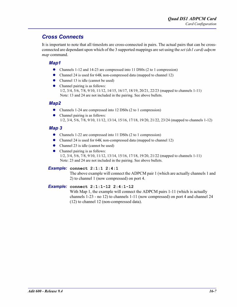
Adit 600 - Release 9.4 16-7
Quad DS1 ADPCM CardCard Configuration
Cross ConnectsIt is important to note that all timeslots are cross-connected in pairs. The actual pairs that can be cross-connected are dependant upon which of the 3 supported mappings are set using the set (ds1 card) adpcm map command.
Map1 Channels 1-12 and 14-23 are compressed into 11 DS0s (2 to 1 compression) Channel 24 is used for 64K non-compressed data (mapped to channel 12) Channel 13 is idle (cannot be used) Channel pairing is as follows:
1/2, 3/4, 5/6, 7/8, 9/10, 11/12, 14/15, 16/17, 18/19, 20/21, 22/23 (mapped to channels 1-11)Note: 13 and 24 are not included in the pairing. See above bullets.
Map2 Channels 1-24 are compressed into 12 DS0s (2 to 1 compression) Channel pairing is as follows:
1/2, 3/4, 5/6, 7/8, 9/10, 11/12, 13/14, 15/16, 17/18, 19/20, 21/22, 23/24 (mapped to channels 1-12)
Map 3 Channels 1-22 are compressed into 11 DS0s (2 to 1 compression) Channel 24 is used for 64K non-compressed data (mapped to channel 12) Channel 23 is idle (cannot be used) Channel pairing is as follows:
1/2, 3/4, 5/6, 7/8, 9/10, 11/12, 13/14, 15/16, 17/18, 19/20, 21/22 (mapped to channels 1-11)Note: 23 and 24 are not included in the pairing. See above bullets.
Example: connect 2:1:1 2:4:1The above example will connect the ADPCM pair 1 (which are actually channels 1 and 2) to channel 1 (now compressed) on port 4.
Example: connect 2:1:1-12 2:4:1-12With Map 1, the example will connect the ADPCM pairs 1-11 (which is actually channels 1-23 - no 12) to channels 1-11 (now compressed) on port 4 and channel 24 (12) to channel 12 (non-compressed data).
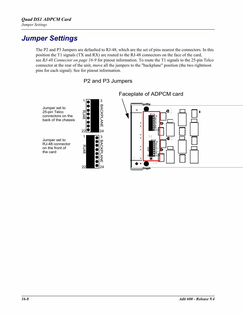
16-8 Adit 600 - Release 9.4
Quad DS1 ADPCM CardJumper Settings
Jumper SettingsThe P2 and P3 Jumpers are defaulted to RJ-48, which are the set of pins nearest the connectors. In this position the T1 signals (TX and RX) are routed to the RJ-48 connectors on the face of the card, see RJ-48 Connector on page 16-9 for pinout information. To route the T1 signals to the 25-pin Telco connector at the rear of the unit, move all the jumpers to the "backplane" position (the two rightmost pins for each signal). See for pinout information.
P2 and P3 Jumpers
Faceplate of ADPCM card
P3
P23
24
1
22
3
24
1
BA
CK
PLA
NE
BA
CK
PLA
NE
1
22 24
3
1
22 24
3
RJ48
RJ48
Jumper set to RJ-48 connector on the front of the card
Jumper set to 25-pin Telcoconnectors on the back of the chassis
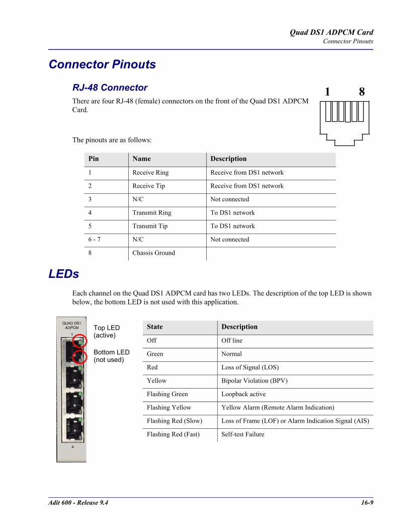
Adit 600 - Release 9.4 16-9
Quad DS1 ADPCM CardConnector Pinouts
Connector Pinouts
RJ-48 Connector There are four RJ-48 (female) connectors on the front of the Quad DS1 ADPCM Card.
The pinouts are as follows:
LEDsEach channel on the Quad DS1 ADPCM card has two LEDs. The description of the top LED is shown below, the bottom LED is not used with this application.
Pin Name Description
1 Receive Ring Receive from DS1 network
2 Receive Tip Receive from DS1 network
3 N/C Not connected
4 Transmit Ring To DS1 network
5 Transmit Tip To DS1 network
6 - 7 N/C Not connected
8 Chassis Ground
State Description
Off Off line
Green Normal
Red Loss of Signal (LOS)
Yellow Bipolar Violation (BPV)
Flashing Green Loopback active
Flashing Yellow Yellow Alarm (Remote Alarm Indication)
Flashing Red (Slow) Loss of Frame (LOF) or Alarm Indication Signal (AIS)
Flashing Red (Fast) Self-test Failure
1 8
Top LED (active)
Bottom LED (not used)

16-10 Adit 600 - Release 9.4
Quad DS1 ADPCM CardLEDs
CHAPTER 17Quad T1, Quad E1 &Quad DS1/E1 Cards
In this Chapter
Overview
Features
Technical Specifications
Card Configuration- CLI Commands
Jumper Settings
Connector Pinouts- 25-pin Telco Connector
- RJ-48 Connector
LEDs

17-2 Adit 600 - Release 9.4
Quad T1, Quad E1 & Quad DS1/E1 CardsOverview
OverviewThe Quad DS1/E1 Service cards enable wireless service providers to cost-effectively provision and expand network bandwidth, and groom available DS0s onto other T1/E1 tributaries for optimal T1/E1 bandwidth utilization. Supported in the Adit 600 the cards can be inserted into any service card slot. They provide full 1/0 cross-connect capability, drop-and-insert functionality, and support fractional and full T1/E1 services, as well as DS0 trunking.When fully equipped with four Quad DS1/E1 Service cards plus a Dual T1 or E1 Controller Card, an Adit 600 can support up to 18 T1 or E1 ports enabling the Adit to function as mini-DCS with DS0 voice interfaces. In wireless applications, this available bandwidth enables the Adit 600 to cost-effectively address fixed-wireless service distribution, mobile wireless backhaul and daisy-chained DS0 distribution to remote cell sites. In wireline applications, the DS1/E1 cards enable service providers and enterprise network managers to cost-effectively provision and expand network bandwidth or drop-side T1 bandwidth. This available bandwidth allows the Adit 600 to cost-effectively address small-to-medium size business requirements, multi-tenant units, as well as end-office applications. The DS1/E1 cards can be locally or remotely managed as a component of the Adit 600 platform. The card can be configured using a Command Line Interface (CLI).
WARNING! THERE IS A RESTRICTION AS TO THE NUMBER OF QUAD DS1/E1 CARDS THAT CAN BE INSTALLED IN AN ADIT. PLEASE SEE CONFIGURATION RESTRICTIONS ON PAGE 4-20 FOR MORE INFORMATION.
The following are the current available Quad DS1/E1 cards:
Hardened Quad DS1/E1 Service cardThe Hardened Quad DS1/E1 Service card has been specifically hardened to stand up to the extreme environmental conditions commonly associated with wireless cell site deployments. This card is configurable to DS1 or E1 with a single CLI command, regardless of Controller type. Configured as a Quad DS1 service card the following DS1/T1 Service card specifications will apply to this card. When configured as a Quad E1 service card, the following E1 Service card specifications will apply to this card.
Quad T1 Service cardThe 4 port T1 service card enables cost-effective provisioning and expansion of T1 bandwidth with full non-blocking digital cross-connection of all timeslots to any Adit service card. This card requires an Adit system with an T1 Controller.
Quad E1 Service cardThe 4 port E1 service card enables cost-effective provisioning and expansion of E1 bandwidth with full non-blocking digital cross-connection of all timeslots to any Adit service card. This card requires an Adit system with an E1 Controller.

Adit 600 - Release 9.4 17-3
Quad T1, Quad E1 & Quad DS1/E1 CardsFeatures
FeaturesUp to four DS1/E1 service cards can be installed in the Adit 600 for up to 18 DS1s/E1s, allowing the platform to act as a mini-DSCThe DS1/E1 service cards can be mixed to combine DCS functionality with a variety of other voice and data services in a single platformIntegrates T1 CSU functionality with FCC registration for direct connection to T1 linesSupports B8ZS or AMI encoding and SF (D4) or ESF framing for T1Local, Line and Payload loopbacksPerforms framing and coding conversions between T1 portsOffers flexible system clock timing, which may be derived from or provided to any T1Insert up to four Quad DS1/E1 Service cards plus the two ports from the T1 or E1 Controller in a single Adit 600 for a total of 18 T1s/CSUs per chassisAllows full non-blocking digital cross-connection (DCS) of all timeslots to any Adit service cardSupports ESF performance reporting Offers secondary solid-state fuseless protection to lightning and power cross incidents

17-4 Adit 600 - Release 9.4
Quad T1, Quad E1 & Quad DS1/E1 CardsTechnical Specifications
Technical SpecificationsT1 Controller Software Required
Quad T1 service card requires release 1.3.1Quad E1 service card is not supported with the T1 ControllerQuad DS1/E1 service card requires release 7.0. Supported when in T1 mode.
E1 Controller Software RequiredQuad T1 service card is not supported with the E1 Controller Quad E1 service card requires release 3.2 Quad DS1/E1 service card requires release 7.0. Supported when in E1 mode.
Card InterfaceShort-haul or long-haul loop settings24-hour or 15-minute performance thresholdJitter: meets AT&T Pub. TR-62411Solid-state fuseless overvoltage and overcurrent line protectionChannel status LEDsFront or rear connections:- Front: uses faceplate-mounted RJ-48C connectors- Rear: uses rear-panel RJ-21X connectors
Less than 3 ms signaling latencyLess than 10 ms overall Adit system signaling latency
T1 Interface (specific)4 selectable T1 ports operating at 1.544 Mbps ±50 bpsSelectable B8ZS or AMI encodingSF (D4) or ESF framing T1 line interface: T1-CSU or T1-DSX (field selectable)Line Build Out (DSX-1): 655 feetReceive Sensitive: 0 to -22.5 dB @ 772 KHz ALBOOutput Level: Selectable at 0 to -22dB
E1 Interface (specific)4 selectable E1 ports operating at 2.048 Mbps ±100 bpsHDB3 encodingE1 Double Framed and E1 Multi-Framed (CDC-4) framingCAS and Digital R2 signaling

Adit 600 - Release 9.4 17-5
Quad T1, Quad E1 & Quad DS1/E1 CardsTechnical Specifications
Network InterfaceThe Quad DS1/E1 Service cards may be configured as either a network or drop-side interface
Network Standards
ClockingLoop-timed from any T1/E1Revertive clock switching provides automatic backup to secondary T1/E1 should the primary T1/E1 failOperates as a Stratum 4E device
AlarmsSupport standard T1.403 alarms (DS1/T1)Supports standard G.732 alarms (E1)
Testing and DiagnosticsDS1/T1
T1.403 payload loopbacks (ESF only)T1.403 remote and local line loopbacks (ESF and SF)T1.231 Performance History (15 minute intervals, 24 hour totals)T1.203 Performance Report Messages (PRMs)
E1Standard E1 line loopbackLoop Up (on)/Loop Down (Off) line loopback settingRFC 2495 performance history
Power ConsumptionQuad DS1/E1 (hardened) card: less than 4.5 W per cardQuad T1 card: less than 3 W per cardQuad E1 card: less than 5 W per card
DS1/T1 E1T1.107 ITU-T G.703T1.102 ITU-T G.704T1.203 CTR 12 & 13T1.231T1.403

17-6 Adit 600 - Release 9.4
Quad T1, Quad E1 & Quad DS1/E1 CardsCard Configuration
Regulatory ApprovalsSee Appendix A, Regulatory Approvals for information on the Quad DS1/E1 Service cards.
PhysicalDimensions: 3.5 in. (H) x 0.75 in. (W) x 11.25 in. (D) 8.9 cm (H) x 1.9 cm (W) x 28.6 cm (D)Weight: 5.1 oz. (0.14 kg)
For information on Adit 600 Environment required, see Installation Environment on page 2-2.
Card ConfigurationAll options on the Quad DS1/E1 cards are set using either the Command Line Interface (CLI) except for setting the option of using the Telco connector, which is done with a jumper. The default for the connectors are the RJ-48s on the front of the service card, however by moving the jumpers to the backplane, the Telco connectors on the back of the unit are enabled. See Jumper Settings on page 17-8 for more information.
CLI CommandsThe following commands are used to configure the Quad DS1/E1 cards. For detailed information on these commands, see Chapter 5, CLI Commands.
connectCreates two-way connections between channels.
disconnectRemoves a connection created by the connect command.
set (ds0)Set up one or all DS0s in a DS1. The command specifies DS0 or range of DS0s, and the setting to apply.
set (ds1)Sets up the DS1 interfaces (clock, up, down, equipment loopup, fdl, framing, id string, lbo, line loopup, linecode, loopdetect, payload loopup, threshold).
set (e1)Sets up the E1 interfaces (clock, up, down, framing, line, linecode and signaling).
set (ds1 card) spantypeTo configure a Quad DS1/E1 service card for T1 or E1 mode.
set lsbackupDefines the backup protection slot.
set lsprotect manualSets the manual mode control for protected ports.
set lsprotect nonrevertiveDefines the port non-revertive status and priority level.
set lsprotect removeRemoves port from protected mode.
Adit 600 - Release 9.4 17-7
Quad T1, Quad E1 & Quad DS1/E1 CardsCard Configuration
set lsprotect revertiveDefines the port revertive status and priority level.
show (ds1)Displays current settings for DS1 (circuit ID, up.down, framing, line coding, clock source, line build out, loop code detection, loop back, fdl type).
show (e1)Displays current settings for E1 (up, down, framing, line coding, clock source, loop back and signaling).
show lsprotectDisplays the low speed protection settings.
status (ds1)Displays the status of the DS1 (receive, transmit, loopback).
status (e1)Displays the status of the E1 (receive, transmit and loopback)
status lsprotectDisplays the current status of the low speed protection cards.
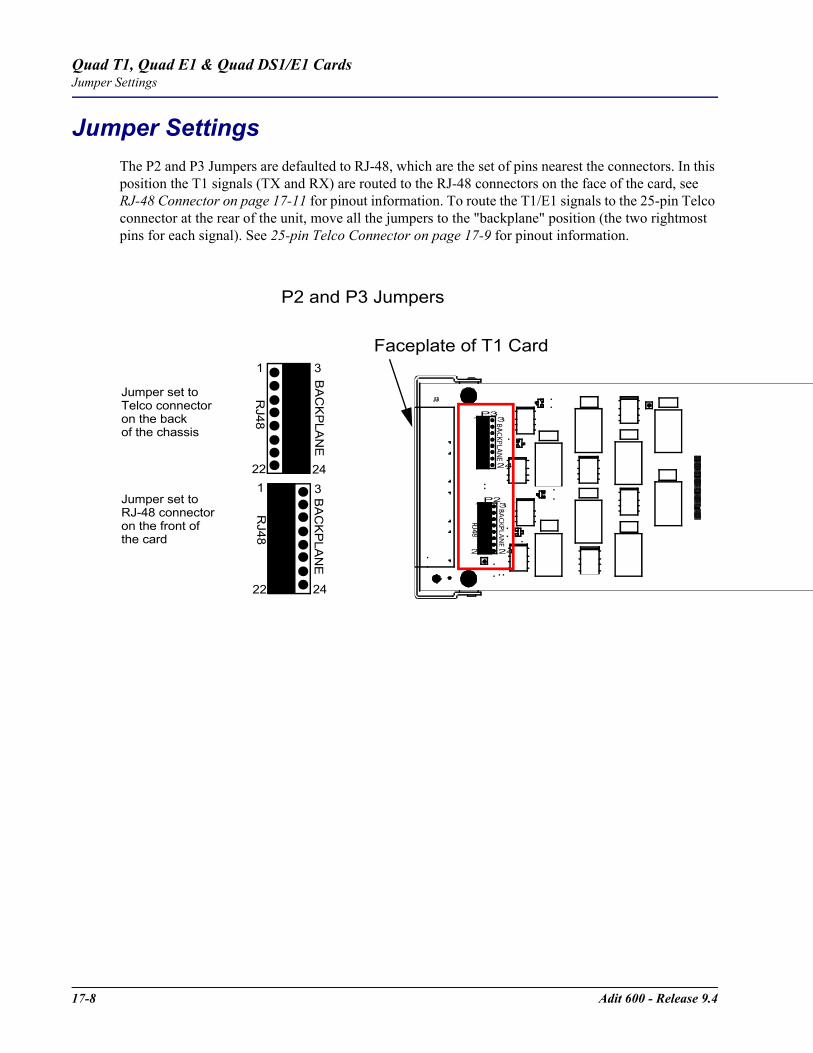
17-8 Adit 600 - Release 9.4
Quad T1, Quad E1 & Quad DS1/E1 CardsJumper Settings
Jumper SettingsThe P2 and P3 Jumpers are defaulted to RJ-48, which are the set of pins nearest the connectors. In this position the T1 signals (TX and RX) are routed to the RJ-48 connectors on the face of the card, see RJ-48 Connector on page 17-11 for pinout information. To route the T1/E1 signals to the 25-pin Telco connector at the rear of the unit, move all the jumpers to the "backplane" position (the two rightmost pins for each signal). See 25-pin Telco Connector on page 17-9 for pinout information.
P2 and P3 Jumpers
Faceplate of T1 Card
P3
P23
24
1
22
3
24
1
BA
CK
PLA
NE
BA
CK
PLA
NE
1
22 24
3
1
22 24
3
RJ48
RJ48
Jumper set to RJ-48 connector on the front of the card
Jumper set to Telco connectoron the back of the chassis
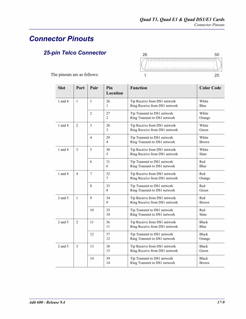
Adit 600 - Release 9.4 17-9
Quad T1, Quad E1 & Quad DS1/E1 CardsConnector Pinouts
Connector Pinouts
25-pin Telco Connector
The pinouts are as follows:
Slot Port Pair Pin Location
Function Color Code
1 and 4 1 1 26 1
Tip Receive from DS1 networkRing Receive from DS1 network
WhiteBlue
2 27 2
Tip Transmit to DS1 networkRing Transmit to DS1 network
WhiteOrange
1 and 4 2 3 283
Tip Receive from DS1 networkRing Receive from DS1 network
WhiteGreen
4 294
Tip Transmit to DS1 networkRing Transmit to DS1 network
WhiteBrown
1 and 4 3 5 305
Tip Receive from DS1 network Ring Receive from DS1 network
WhiteSlate
6 316
Tip Transmit to DS1 network Ring Transmit to DS1 network
RedBlue
1 and 4 4 7 327
Tip Receive from DS1 network Ring Receive from DS1 network
RedOrange
8 338
Tip Transmit to DS1 network Ring Transmit to DS1 network
RedGreen
2 and 5 1 9 349
Tip Receive from DS1 network Ring Receive from DS1 network
RedBrown
10 3510
Tip Transmit to DS1 network Ring Transmit to DS1 network
RedSlate
2 and 5 2 11 3611
Tip Receive from DS1 network Ring Receive from DS1 network
BlackBlue
12 3712
Tip Transmit to DS1 networkRing Transmit to DS1 network
BlackOrange
2 and 5 3 13 3813
Tip Receive from DS1 network Ring Receive from DS1 network
BlackGreen
14 3914
Tip Transmit to DS1 networkRing Transmit to DS1 network
BlackBrown
50
25
26
1
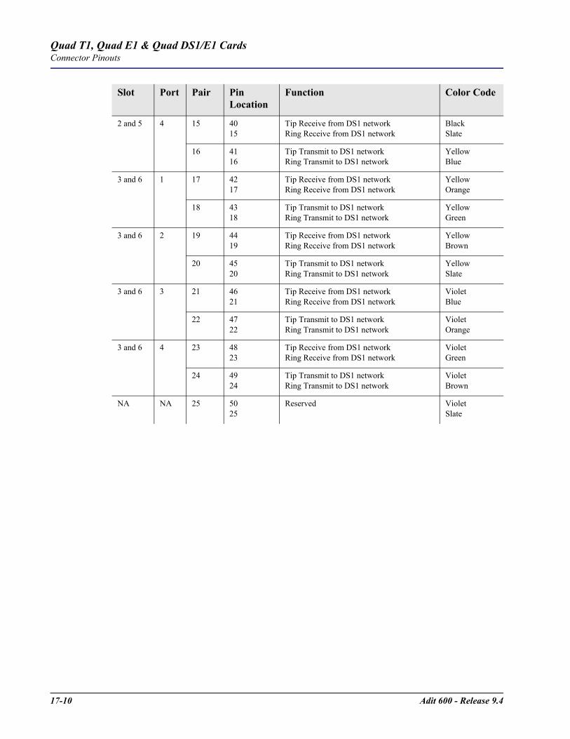
17-10 Adit 600 - Release 9.4
Quad T1, Quad E1 & Quad DS1/E1 CardsConnector Pinouts
2 and 5 4 15 4015
Tip Receive from DS1 network Ring Receive from DS1 network
Black Slate
16 4116
Tip Transmit to DS1 networkRing Transmit to DS1 network
YellowBlue
3 and 6 1 17 4217
Tip Receive from DS1 network Ring Receive from DS1 network
YellowOrange
18 4318
Tip Transmit to DS1 network Ring Transmit to DS1 network
YellowGreen
3 and 6 2 19 4419
Tip Receive from DS1 network Ring Receive from DS1 network
YellowBrown
20 4520
Tip Transmit to DS1 network Ring Transmit to DS1 network
YellowSlate
3 and 6 3 21 4621
Tip Receive from DS1 network Ring Receive from DS1 network
VioletBlue
22 4722
Tip Transmit to DS1 networkRing Transmit to DS1 network
VioletOrange
3 and 6 4 23 4823
Tip Receive from DS1 network Ring Receive from DS1 network
VioletGreen
24 49 24
Tip Transmit to DS1 networkRing Transmit to DS1 network
VioletBrown
NA NA 25 50 25
Reserved VioletSlate
Slot Port Pair Pin Location
Function Color Code
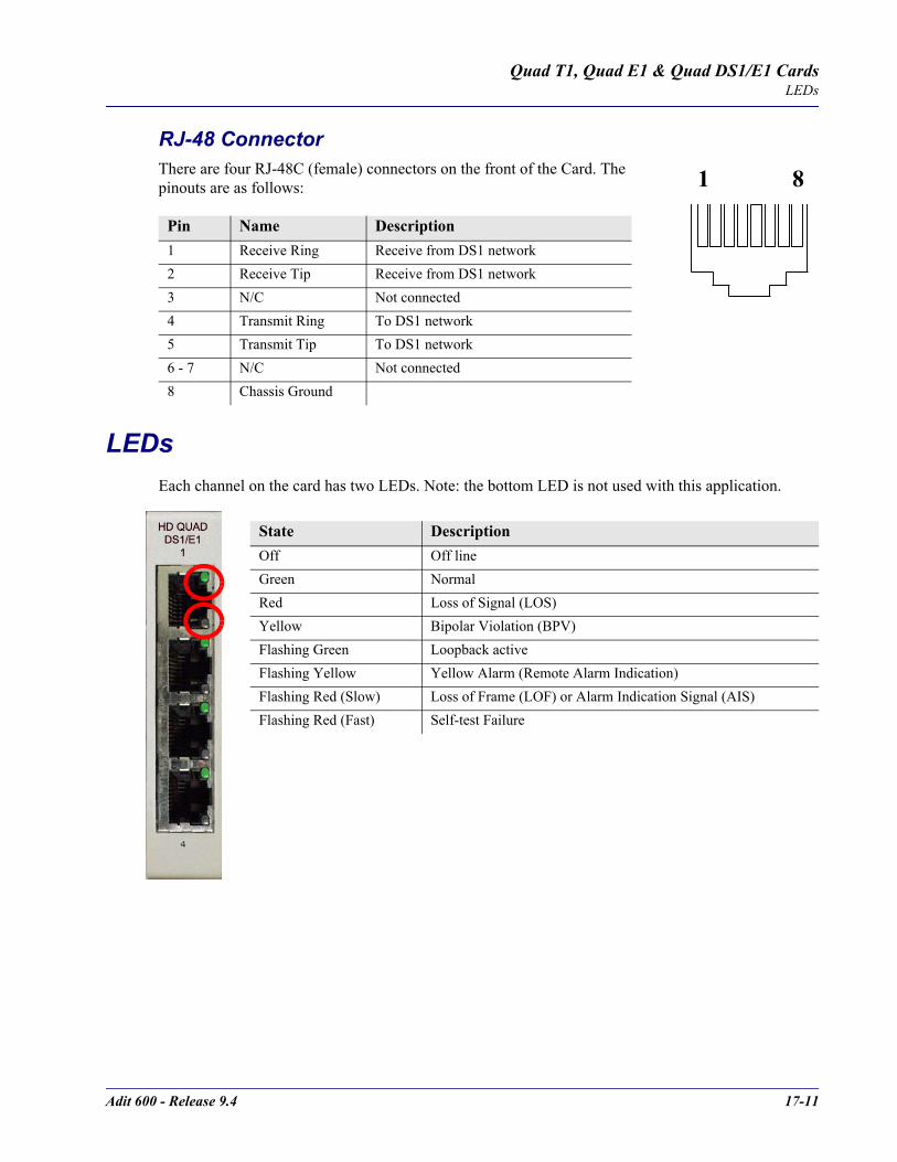
Adit 600 - Release 9.4 17-11
Quad T1, Quad E1 & Quad DS1/E1 CardsLEDs
RJ-48 Connector There are four RJ-48C (female) connectors on the front of the Card. The pinouts are as follows:
LEDsEach channel on the card has two LEDs. Note: the bottom LED is not used with this application.
Pin Name Description 1 Receive Ring Receive from DS1 network2 Receive Tip Receive from DS1 network3 N/C Not connected4 Transmit Ring To DS1 network5 Transmit Tip To DS1 network6 - 7 N/C Not connected8 Chassis Ground
State DescriptionOff Off lineGreen Normal Red Loss of Signal (LOS)Yellow Bipolar Violation (BPV)Flashing Green Loopback activeFlashing Yellow Yellow Alarm (Remote Alarm Indication)Flashing Red (Slow) Loss of Frame (LOF) or Alarm Indication Signal (AIS)Flashing Red (Fast) Self-test Failure
1 8

17-12 Adit 600 - Release 9.4
Quad T1, Quad E1 & Quad DS1/E1 CardsLEDs
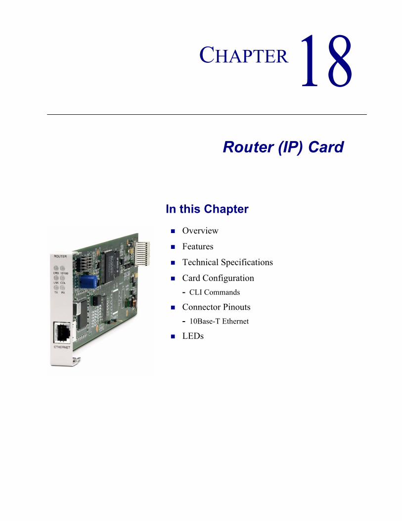
CHAPTER 18Router (IP) Card
In this Chapter
Overview
Features
Technical Specifications
Card Configuration- CLI Commands
Connector Pinouts- 10Base-T Ethernet
LEDs
18-2 Adit 600 - Release 9.4
Router (IP) CardOverview
OverviewThe fast-changing world of IP services requires products with the capability to generate new value-added revenues. The IP Router Service card offers the performance and expandability of a dedicated router in a low-cost solution with simple integrated management through the Adit platform.Unlike other internal routing solutions that support software-based routing by adding bundles to the system software, the IP Router card employs a dedicated processor to ensure high performance and product feature expansion. It delivers high-speed Internet and Intranet connectivity to small and medium-sized businesses, as well as remote and branch office users. A powerful set of standard features includes IP and IPX routing, Layer 2 bridging, ML-PPP, networking security, and management capabilities to integrate services in the digital last mile.The Adit 600's supports up to six IP Router cards, in any slot, or other combinations of services. This flexibility enables service providers to target multi-tenant units with a single device that supports business-class voice, Internet access and data services. The addition Multi-Link Point-to-Point Protocol (ML-PPP) to the IP Router card ensures that service providers can continue to support the growing needs of customers, beyond one or two T1s/E1s.The IP Router card simplifies delivery of data networking solutions by leveraging the advantages of the Adit 600 battery backup and single IP management, while reducing costly cabling expense through a direct 10/100Base-TX Ethernet interface connection. IP Router cards are easily managed through the Adit 600 user interface, identified by a single IP address. With this capability, multiple cards within a single Adit 600 can be configured, monitored and maintained through one unique IP address, speeding installation and simplifying management tasks.The IP Router card is SNMP, CLI or menu-driven manageable. Management connectivity is provided either through the user data port connection on the IP Router card, the local RS-232 craft port, the Ethernet management port, or the dedicated management channel on the T1 Controller. The Router Service card configuration information can be uploaded to the NOC while router code upgrades are loaded to the Router card. The uploading and downloading is accomplished through the Ethernet management port and/or the user data connection. In addition, the CLI management option enables management configuration information to be created offline and loaded into the system either via a script or TFTP.
Adit 600 - Release 9.4 18-3
Router (IP) CardFeatures
FeaturesSupplies auto-sensing 10/100Base-TX EthernetSupports up to 6 router cards per Adit 600 chassis
- Multi-point networking with up to 24 WAN connections per router- Each WAN connection can be provisioned with multiple DS0s- Deliver more than two T1s bandwidth per Router card; up to 60 DS0s per Router card- Enables multiple T1/E1 facilities to function as a single IP WAN interface using ML-
PPP for bandwidth scalability beyond a single T1Ensures high performance and feature expansion through dedicated IP Router card processorEnables management via menu-driven user interface or CLI Router interfaceSupports packet filtering and Spanning Tree ProtocolAllows Network Address Translation (NAT) and Port Address Translation (PAT)Supports Dynamic Host Configuration Protocol (DHCP)Delivers a minimum of 3,000 packets per secondRADIUS Login Authentication
Technical Specifications
Controller Software RequiredT1 Controller
Release 3.0 or higher is requiredE1 Controller
Release 3.2 or higher is required
ManagementMenu-driven over RS-232 and CLIPing, SNMP, Telnet over IPEthernet management portIP management connection via T1 FDL, Ethernet and DS0 bearer channelCode download via TFTPConfiguration upload and download via TFTP
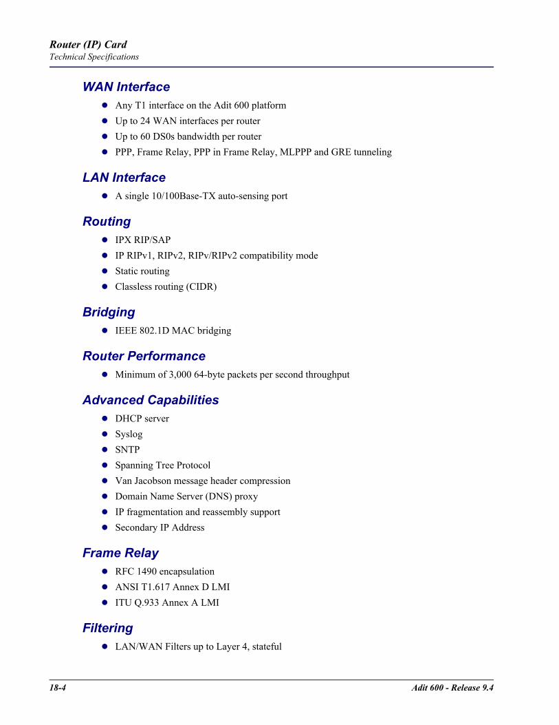
18-4 Adit 600 - Release 9.4
Router (IP) CardTechnical Specifications
WAN InterfaceAny T1 interface on the Adit 600 platformUp to 24 WAN interfaces per routerUp to 60 DS0s bandwidth per routerPPP, Frame Relay, PPP in Frame Relay, MLPPP and GRE tunneling
LAN InterfaceA single 10/100Base-TX auto-sensing port
RoutingIPX RIP/SAPIP RIPv1, RIPv2, RIPv/RIPv2 compatibility modeStatic routingClassless routing (CIDR)
BridgingIEEE 802.1D MAC bridging
Router PerformanceMinimum of 3,000 64-byte packets per second throughput
Advanced CapabilitiesDHCP serverSyslogSNTPSpanning Tree ProtocolVan Jacobson message header compressionDomain Name Server (DNS) proxyIP fragmentation and reassembly supportSecondary IP Address
Frame RelayRFC 1490 encapsulationANSI T1.617 Annex D LMIITU Q.933 Annex A LMI
FilteringLAN/WAN Filters up to Layer 4, stateful
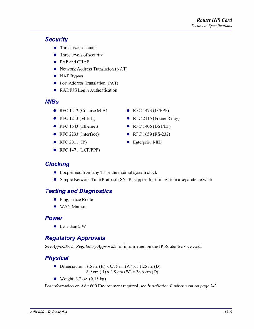
Adit 600 - Release 9.4 18-5
Router (IP) CardTechnical Specifications
SecurityThree user accountsThree levels of securityPAP and CHAPNetwork Address Translation (NAT)NAT BypassPort Address Translation (PAT)RADIUS Login Authentication
MIBs
ClockingLoop-timed from any T1 or the internal system clockSimple Network Time Protocol (SNTP) support for timing from a separate network
Testing and DiagnosticsPing, Trace RouteWAN Monitor
PowerLess than 2 W
Regulatory ApprovalsSee Appendix A, Regulatory Approvals for information on the IP Router Service card.
PhysicalDimensions: 3.5 in. (H) x 0.75 in. (W) x 11.25 in. (D) 8.9 cm (H) x 1.9 cm (W) x 28.6 cm (D)Weight: 5.2 oz. (0.15 kg)
For information on Adit 600 Environment required, see Installation Environment on page 2-2.
RFC 1212 (Concise MIB) RFC 1473 (IP/PPP)
RFC 1213 (MIB II) RFC 2115 (Frame Relay)
RFC 1643 (Ethernet) RFC 1406 (DS1/E1)
RFC 2233 (Interface) RFC 1659 (RS-232)
RFC 2011 (IP) Enterprise MIB
RFC 1471 (LCP/PPP)

18-6 Adit 600 - Release 9.4
Router (IP) CardCard Configuration
Card ConfigurationThe IP Router has the option of configuration through CLI or the Router menu-driven user interface, which is accessed through Telnet. The following CLI commands are all Router related. For information on the IP Router menu-driven user interface, see the IP Router User Manual.
NOTE: The default IP address for the IP Router is 10.0.0.1.
CLI CommandsFor detailed information on the following Router commands, see Chapter 5, CLI Commands.
add (router) dhcp server optionAdd optional DHCP server attributes that will be advertised every time a DHCP client discovery is initiated
add (router) dns proxyEnable DNS proxy and add a remote DNS server address to the router card
add (router) remoteAdd a remote WAN profile to the WAN profile table
add (router) snmp communityAdd a SNMP community to an interface on the router card
add (router) snmp trapTo specify a destination to send SNMP trap messages
add (router) uploaduserTo specify a host that is allowed to upload configuration/software files
add (router-lan) filterAdd address filters (address, custom, protocol) to the table of Layer 2 filters applied to the specified LAN interface
add (router-lan) staticAdd static elements on the specific LAN interface (IP address, IP network, IPX network, MAC address).
add (router-wan) firewallAdd a firewall rule to a WAN.
add (router-wan) gre networkAdd a "by network" GRE tunnel to a WAN.
add (router-wan) nat bypassAdd subnets to the list of source addresses that will not be subject to NAT translation when passing through a NAT enabled WAN interface.
add (router-wan) staticAdd static elements to the specified WAN interface (IP address, IP network, IPX network, MAC address and NAT address).
clear (router) ip address tableFlush the learned entries from the IP address table for the specific interface from the specified Router card.

Adit 600 - Release 9.4 18-7
Router (IP) CardCard Configuration
clear (router) mac address tableFlush the learned entries from the MAC address table for the specific interface from the specified router card.
connect (router-trunk) (t1)Creates two-way connections between the router port trunk connections and any DS0 channels of the service card or Controller.
delete (router) dns proxyRemove a remote DNS server address from the specified Router card.
delete (router) remoteDelete a remote WAN profile from the WAN profile table.
delete (router) snmp communityDelete an SNMP community entry.
delete (router) snmp trapDelete a trap destination from the router card.
delete (router) uploaduserRemove an existing authorized uploaduser.
delete (router-lan) filterRemove a a single filter rule from the table of Layer 2 filters applied to the specified LAN interface.
delete (router-lan) staticRemove a static element from the LAN interface (IP address, IP network, IPS network and MAC address).
delete (router-wan) firewallRemove a firewall rule from a WAN.
delete (router-wan) gre networkRemove a "by network" GRE tunnel to a WAN.
delete (router-wan) nat bypassDelete an IP subnet or host from the list of source addresses that will not be subject to NAT translation when passing through a NAT enabled WAN interface.
delete (router-wan) staticRemove a static element from the WAN interface (IP address, IP network, IP network, MAC address).
disconnect slot:port:trunkRemoves a connection created by the connect trunk-addrt1-addr
install (slot) routerWill prepare the controller for the insertion of a new router card that will keep its currently loaded configuration.
load tftpWill download software via TFTP to the Controller or the Router card.
WARNING! BEFORE LOADING A DOWN-LEVEL OF ROUTER CODE TO AN ADIT, SAVE THE CONFIGURATION TO A FILE. CONFIGURATION MAY BE RESET TO THE DEFAULT SETTING AND CURRENT CONFIGURATION LOST.
rename (router) (router-wan/lan)Change the name of a remote WAN or local LAN profile on the Router card.
18-8 Adit 600 - Release 9.4
Router (IP) CardCard Configuration
reset (router)Reboot the Router. All new configuration will be in-use.
rtrpingRouter will perform a ping test and report the result.
set (router) autologoutSet the period of time on inactivity after which the user will be automatically logged-out of a Telnet session
set (router) defaultReset the Router card to its default configuration settings.
set (router) dhcpDisable both DHCP server and DHCP relay functionality for the Router.
set (router) dnsConfigure the Domain Name Server (DNS) options.
set (router) enhanced securityEnable/disable enhanced login security on the Router
set (router) lmiSpecify the Local Management Interface (LMI) protocol to use for the Router.
set (router) logSet password access on the Router card (access level, password)
set (router) login authSets how login authentication for this router should be performed
set (router) login promptEnable/disable the suppression of the Router login prompt for a user that telnets in from the Controller CLI
set (router) ntpSet Network Time Protocol (NTP) parameters
set (router) passwordManage password access on the specified Router card
set (router) ppp authSet the PPP authentication on the specified Router card
set (router) ppp securitySet up the local external security server which the Router card will use to authenticate remote PPP devices
set (router) proxyConfigures Router in-use basics (up, down and proxy).
set (router) rebootSet automatic reboot after an upload of code or configuration file.
set (router) ripSpecify version of RIP packets to transmit and receive.
set (router) snmpSet the value of sysContact, sysLocation and sysName on the Router.
set (router) stpSetup the Spanning Tree Protocol on the Router.

Adit 600 - Release 9.4 18-9
Router (IP) CardCard Configuration
set (router) syslogConfigure the Router to send alarm and event messages to a Syslog server
set (router-lan) collisionSet the collision alarms (interval and threshold).
set (router-lan) filter forwardSet the forwarding mode for Layer 2 filters added to the specified LAN interface.
set (router-lan) framingSet which ethernet frame types are supported on the Router LAN interface.
set (router-lan) gatewaySpecify a default IP gateway for the specified LAN interface.
set (router-lan) ip addressSpecify an IP address for the specified LAN interface.
set (router-lan) ipx networkSpecify an IPX network numbers for the four IPX LAN frame types.
set (router-lan) phySpecify the ethernet PHY (physical specifications) speed and mode.
set (router-lan) ripSet the IP RIP for the LAN interface.
set (router-lan) stpSetup the Spanning Tree Protocol on this interface.
set (router-lan) up/downSet the LAN interface up or down.
set (router-trunk) encapsulationSpecify the encapsulation to use on the Router interface.
set (router-trunk) multilink groupSpecify that a trunk is part of a multilink PPP group
set (router-trunk) up/downSet the Router trunk up or down.
set (router-wan) dlciConfigure the DLCI for a specified WAN interface that will be using a frame relay encapsulated trunk.
set (router-wan) greConfigure the GRE tunneling for a specified WAN interface.
set (router-wan) ipSet the IP traffic handling on the WAN interface.
set (router-wan) ip addressSet the IP address for a WAN interface.
set (router-wan) ipxSet the IPX traffic handling on the specified WAN interface.
set (router-wan) natConfigure Network Address Translation (NAT) on a specified WAN interface.
set (router-wan) otherSet traffic handling of protocols other than IP or IPX on the specified WAN interface.

18-10 Adit 600 - Release 9.4
Router (IP) CardCard Configuration
set (router-wan) pppConfigure PPP on the specified Router card.
set (router-wan) ripSet the type or RIP updates on the WAN interface.
set (router-wan) stpConfigure the Spanning Tree Protocol on the WAN interface.
set (router-wan) trunkConfigure the trunk port for a specified WAN interface.
set (router-wan) up/downSet the specified WAN interface up or down.
show (router)Displays the current Router settings (DHCP, DNS proxy, LMI, PPP, RIP, SNMP, STP, syslog and uploaduser).
show (router) dhcpDisplays the current DHCP settings for the Router
show (router) dnsDisplays the current DNS setup for the router card
show (router) dns proxyDisplays the current DNS Proxy setup for the router card
show (router) lmiDisplays the current Local Management Interface (LMI) settings
show (router) ntpDisplays the settings for NTP options
show (router) pppDisplays the current Local PPP (Point-to-Point Protocol) authentication and security settings for the router
show (router) ripDisplays the current RIP settings for the Router
show (router) snmpDisplays the current SNMP settings for the Router
show (router) stpDisplays the current Spanning Tree Protocol settings for the router
show (router) syslogDisplays the current Syslog setup for the router
show (router) uploaduserDisplays the current list of users allowed to upload and download configuration and code files
show (router-lan)Displays the settings for the router card
show (router-lan) collisionDisplays the current LAN collision alarm settings for the router
show (router-lan) filterDisplays the current LAN Layer 2 data filters applied to the LAN on the router

Adit 600 - Release 9.4 18-11
Router (IP) CardCard Configuration
show (router-lan) staticDisplays the current list of static entries for the LAN on the router
show (router-lan) stpDisplays the current Spanning Tree Protocol settings for the LAN interface
show (router-wan)Displays the current Router WAN settings (firewall, PPP, static entries, STP and trunk).
show (router-wan) nat bypassDisplays the current list of NAT bypass entries for the WAN interface on the specified Router card.
status (router)Displays the current Router status information
status (router) channelsDisplays a condensed status report of all voice channel endpoints
status (router) dnsDisplays the current state of the DNS resolver and entries in the DNS cache
status (router) eventsDisplays the current event log from the router
status (router) ip address tableDisplays the current IP address table for the specified Router
status (router) ip network tableDisplays the current table of learned IP Networks for the specified interface on the router card
status (router) ipx network tableDisplays the current table of learned IPX Networks for the specified interface on the router card
status (router) ipx server tableDisplays the current table of learned IPX Servers for the specified interface
status (router) mac address tableDisplays the current table of learned MAC Addresses for the specified interface on the router card
status (router) performanceDisplays the current runtime statistics from the specified router
status (router) stpDisplays the current Spanning Tree state from the specified router
status (router-lan)Displays the current Router status information
status (router-trunk)Displays the current status for the specified trunk on the Router card.
storeSave a software file from a defined slot to a defined location on a PC, via TFTP.
telnet (router)Establish a Telnet session from the Adit 600 CLI to the Router port user interface.
trace routeWill invoke a Trace Route to a host device on a network of a this Router.

18-12 Adit 600 - Release 9.4
Router (IP) CardConnector Pinouts
Connector Pinouts
10Base-T EthernetThe pinout for the RJ-48C (female) connector on the front of the card is as follows:
LEDsThe following chart describes each LED, and it’s state, of the Router card.
Pin Name Description 1 Receive + Receive from network2 Receive - Receive from network3 Transmit + Transmit to network4 N/C Not connected 5 N/C Not connected 6 Transmit - Transmit to network7 N/C Not connected 8 N/C Not connected
LED State DescriptionCRD Off Loss of power
Green No current alarmsRed Alarm state active. See alarm log for causeRed Flashing Self-test or Boot in-processYellow Flashing Card is saving data to flash RAM, do not power down
10/100 Off 10 Mb ethernetGreen 100 Mb ethernet
LNK Off No ethernet linkGreen Good ethernet link
COL
Off No current ethernet transmit collisionsYellow Ethernet collisions have occurred and have not dropped to
minimum level Yellow Flashing Ethernet collision occurring
TX Off No ethernet transmit activityGreen Ethernet transmit activity
RX Off No current ethernet receive activity
Green Current ethernet receive activity
1 8
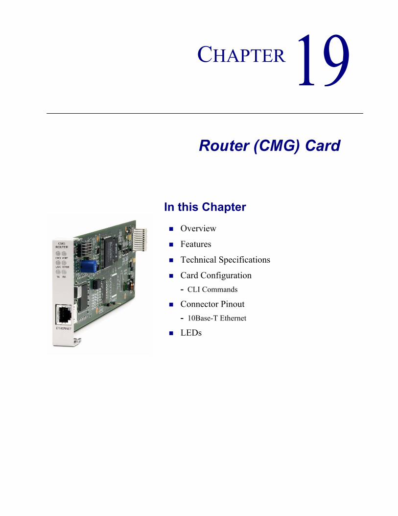
CHAPTER 19Router (CMG) Card
In this Chapter
Overview
Features
Technical Specifications
Card Configuration- CLI Commands
Connector Pinout- 10Base-T Ethernet
LEDs

19-2 Adit 600 - Release 9.4
Router (CMG) CardOverview
OverviewThe Customer Media Gateway Service Cards, combined with the Adit 600 Multi-service Delivery Terminal, enable high-capacity, converged IP service delivery while supporting the service provider's TDM to IP migration strategy. With the CMG the Adit 600 can be configured as an IP Services Delivery Terminal that enables carrier-class services for Small- and Medium-sized Businesses (SMBs). In addition, the Adit 600's remote management capabilities enable service providers to realize operational cost efficiencies by reducing time required for problem resolution, and by minimizing or eliminating costly truck rolls. The Adit 600 CMG solutions provide VoIP mediation for up to 48 simultaneous calls (g.711, g.726, g.729a). Layer 3 Quality of Service (QoS) features provide the necessary traffic prioritization to ensure carrier-class voice quality over an IP network. In addition routed data services are supported.The high-capacity, cost-effective, carrier-class features of the CMG enable a migration from traditional circuit switched services to VoIP. The CMG Service Card delivers a new generation of converged IP services for small- and medium-sized businesses while still hosting traditional TDM services. The result is a cost-effective solution for service providers seeking to migrate from traditional Class 4 or 5 architectures to next-generation IP networks. Our standards-based call control implementation has resulted in extensive interoperability experience with industry leading softswitches and gateways.
There are three versions of the CMG Router:CMG Service Card - The original CMG Router Service card.CMG-01 Service Card - An enhanced version of the CMG Router card. CMG-02 Service Card - The CMG-02 Router Service card, which is designed with a dual DSP configuration.
WARNING! THERE IS A RESTRICTION AS TO THE NUMBER OF CMG CARDS THAT CAN BE INSTALLED IN AN ADIT. PLEASE SEE CONFIGURATION RESTRICTIONS ON PAGE 4-22 FOR MORE INFORMATION.
Features Up to 48 simultaneous voice channels (G.711, G.726, G.729a) Up to 8 T1s or 6 E1s in a single Adit 600 chassis Supports MGCP line side applicationsSupports T.38 Fax Relay, auto-detect/fall-backEnables a variety of Centrex and CLASS servicesWAN capabilities include T1, E1 and 10/100Base-T (2xT1/E1 WAN capacity)WAN routing with QoS mechanisms for voice traffic and routed data prioritizationSupports voice/fax/modem calls

Adit 600 - Release 9.4 19-3
Router (CMG) CardTechnical Specifications
Technical Specifications
T1 or E1 Controller Software RequiredAdit 600 release 4.0 or higher to support a CMG Service cardAdit 600 release 9.4 or higher to support a CMG-01 Service cardAdit 600 release 9.0 or higher to support a CMG-02 Service cardTone file loading requires Adit 600 release 5.0 and CMG release 1.10 or higher
ManagementCLI support through Controller via RS-232 or TelnetMenu-driven over RS-232 connection or TelnetPing, SNMP, Telnet supportEthernet management portIP management connection via Ethernet, IP/DS0 bearer channel and in-band WANSoftware upgradeable via TFTPConfiguration upload and download via TFTP
Voice and Packet InterfacesVoice/Fax/Modem - up to 48 designated FXS or DS0 channelsLAN - 10/100Base-TX port on cardWAN - designated Adit 600 Ethernet or T1/E1lines and channel groups (PPP, Frame Relay, PPP over Frame Relay, MLPPP)Internal - backplane cross-connect interfaces to other data cards (CMG, IP Router, TSR or V.35)
Voice Processing and MediationVoice coding using G.711, G.726-16, G.726-24, G.726-32, G.726-40, G.729 Capacity: G.711, G.726, G.729a - 48 channels with 20 msec or greater packet time - 24 channels with 10 msec or greater packet timeG.168 echo cancellation (up to 64 ms)RTP packetization (over UDP/IP)TOS prioritization160 ms jitter buffer, dynamic delay adjustmentRTCP performance reportingCall progress tone and cadence generation via provisionable tone filesDTMF Relay as per RFC2833
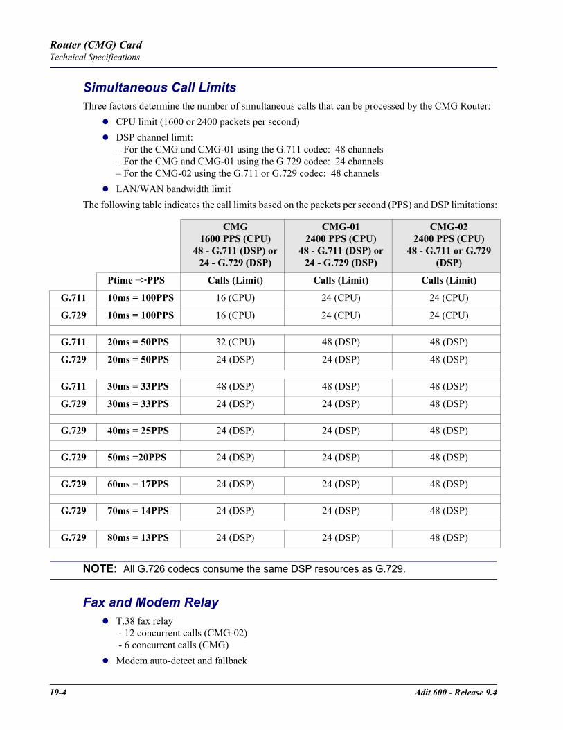
19-4 Adit 600 - Release 9.4
Router (CMG) CardTechnical Specifications
Simultaneous Call LimitsThree factors determine the number of simultaneous calls that can be processed by the CMG Router:
CPU limit (1600 or 2400 packets per second)DSP channel limit:– For the CMG and CMG-01 using the G.711 codec: 48 channels– For the CMG and CMG-01 using the G.729 codec: 24 channels– For the CMG-02 using the G.711 or G.729 codec: 48 channelsLAN/WAN bandwidth limit
The following table indicates the call limits based on the packets per second (PPS) and DSP limitations:
NOTE: All G.726 codecs consume the same DSP resources as G.729.
Fax and Modem RelayT.38 fax relay - 12 concurrent calls (CMG-02) - 6 concurrent calls (CMG)Modem auto-detect and fallback
CMG1600 PPS (CPU)
48 - G.711 (DSP) or24 - G.729 (DSP)
CMG-012400 PPS (CPU)
48 - G.711 (DSP) or24 - G.729 (DSP)
CMG-022400 PPS (CPU)
48 - G.711 or G.729 (DSP)
Ptime =>PPS Calls (Limit) Calls (Limit) Calls (Limit)
G.711 10ms = 100PPS 16 (CPU) 24 (CPU) 24 (CPU)
G.729 10ms = 100PPS 16 (CPU) 24 (CPU) 24 (CPU)
G.711 20ms = 50PPS 32 (CPU) 48 (DSP) 48 (DSP)
G.729 20ms = 50PPS 24 (DSP) 24 (DSP) 48 (DSP)
G.711 30ms = 33PPS 48 (DSP) 48 (DSP) 48 (DSP)
G.729 30ms = 33PPS 24 (DSP) 24 (DSP) 48 (DSP)
G.729 40ms = 25PPS 24 (DSP) 24 (DSP) 48 (DSP)
G.729 50ms =20PPS 24 (DSP) 24 (DSP) 48 (DSP)
G.729 60ms = 17PPS 24 (DSP) 24 (DSP) 48 (DSP)
G.729 70ms = 14PPS 24 (DSP) 24 (DSP) 48 (DSP)
G.729 80ms = 13PPS 24 (DSP) 24 (DSP) 48 (DSP)

Adit 600 - Release 9.4 19-5
Router (CMG) CardTechnical Specifications
Routing and Policy ManagementIP RIP V1/2, IPX RIP/SAP, RIP V1/2 static routing and Classless Inter-Domain Routing (CIDR)PAP and CHAPNAT, NAT Bypass and PATDNS ProxySpanning Tree ProtocolFirewall filteringVoice prioritization with ToS configurationDHCP Client/Server/RelayBootP RelayTrace RouteSyslogSNTPSecondary IP addresses
Router PerformanceUp to 3.84 Mbps (60 DS0s) full-duplex IP WAN bandwidth5,000 192-byte packets per second See IP Router Service card for additional information on routing features and specifications
Softswitch Call Control and SignalingMGCP (IETF RFC 2705 and NCS 1.0)MGCP IETF Version 0.1, 1.0, 1.0bis
Services Enabled (under Softswitch Control)Basic callingCaller ID, Call waiting, call forwarding, voice mailHold/transfer, conference using external bridgeMany other Centrex and CLASS servicesDistinctive ringing
Softswitch/Call Agent InteroperabilityInteroperable with the leading softswitches
Network StandardsANSI, CCITT, IEEE 802.3, IEEE 802.1DIETF - RFC 2705, others per router card

19-6 Adit 600 - Release 9.4
Router (CMG) CardTechnical Specifications
PowerDissipation: approx. 6 WInternal solid-state (fuseless) protectionFan free operation
Regulatory ApprovalsSee Appendix A, Regulatory Approvals for information on the CMG Router Service card.
PhysicalDimensions: 3.5 in. (H) x 0.75 in. (W) x 11.25 in. (D) 8.9 cm (H) x 1.9 cm (W) x 28.6 cm (D)Weight: 5.2 oz. (0.15 kg)
For information on Adit 600 Environment required, see Installation Environment on page 2-2.

Adit 600 - Release 9.4 19-7
Router (CMG) CardCard Configuration
Card ConfigurationThe CMG Service card has the option of configuration through CLI or the Router menu-driven user interface, which is accessed through Telnet. The following CLI commands are all router related. For information on the Router menu-driven user interface, see the CMG Router User Manual.
NOTE: The default IP address for the Adit CMG Router is 10.0.0.1.
CLI CommandsMany of the router features can be configured directly with CLI commands.For detailed information on the following Router commands, see Chapter 5, CLI Commands.
Minimum Configuration RequiredThe CMG Service card requires an external call agent to operate as an MGCP-controlled media gateway or IAD.The gateway must contact the call agent, on power up or reset. Therefore, the following configuration commands MUST be used to enter the call agent’s IP address or domain name.
set rtr_card-addr mgcp callagent address ip-addr
set rtr_card-addr mgcp up
All other CLI commands listed below MAY be used to set CMG options, but may not be necessary, since the defaults have been chosen to meet the most common expected uses. Some configuration may be necessary for proper interoperation with a given call agent. add (router) dhcp server option
Add optional DHCP server attributes that will be advertised every time a DHCP client discovery is initiated
add (router) dns proxyEnable DNS proxy and add a remote DNS server address to the router card
add (router) remoteAdd a remote WAN profile to the WAN profile table
add (router) snmp communityAdd a SNMP community to an interface on the router card
add (router) snmp trapSpecify a destination to send SNMP trap messages
add (router) static dns hostAdd a static DNS host record
add (router) uploaduserSpecify a host that is allowed to upload configuration/software files
add (router-lan) filterAdd an address filter to the table of Layer 2 filter applied to the specified LAN interface
add (router-lan) secondary ip addressAdd a secondary IP address and subnet to the specified LAN interface
add (router-lan) staticAdd static elements on the specified LAN interface
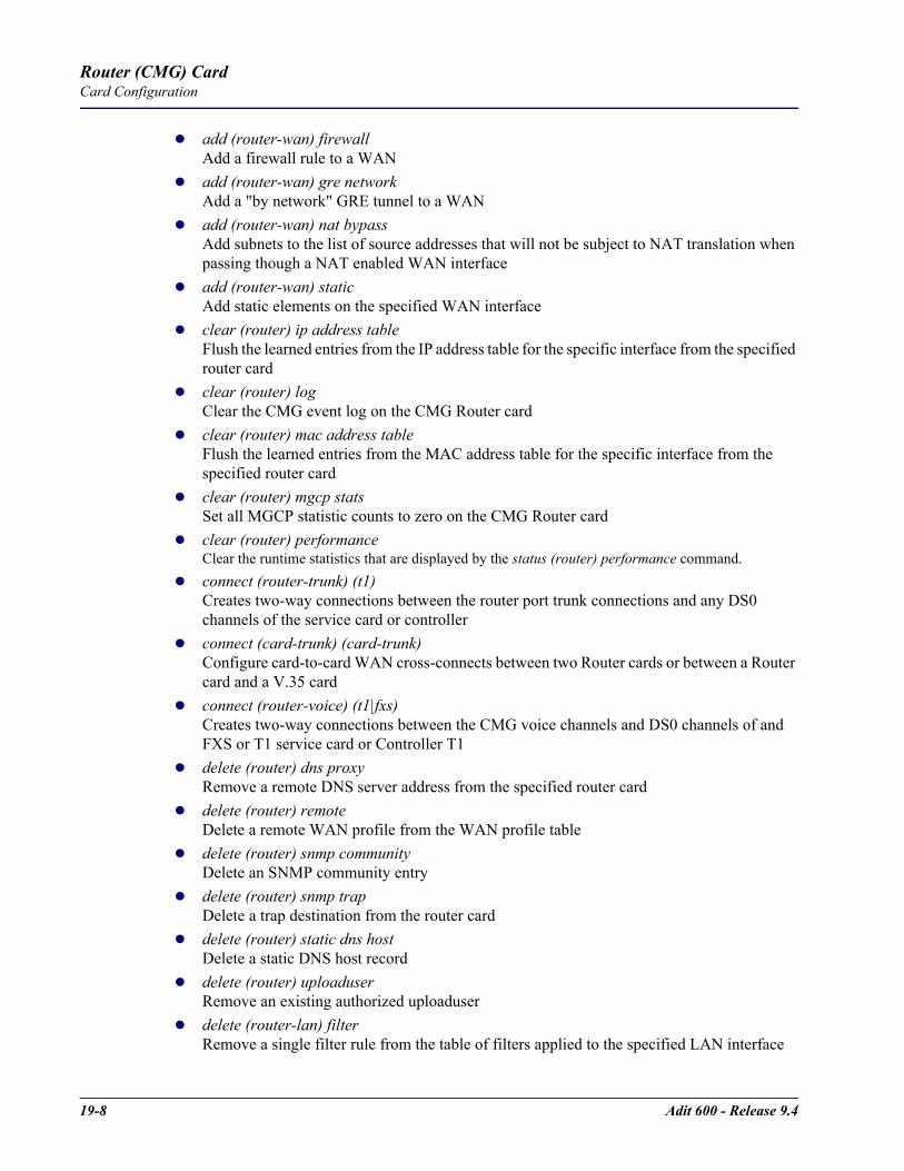
19-8 Adit 600 - Release 9.4
Router (CMG) CardCard Configuration
add (router-wan) firewallAdd a firewall rule to a WAN
add (router-wan) gre networkAdd a "by network" GRE tunnel to a WAN
add (router-wan) nat bypassAdd subnets to the list of source addresses that will not be subject to NAT translation when passing though a NAT enabled WAN interface
add (router-wan) staticAdd static elements on the specified WAN interface
clear (router) ip address tableFlush the learned entries from the IP address table for the specific interface from the specified router card
clear (router) logClear the CMG event log on the CMG Router card
clear (router) mac address tableFlush the learned entries from the MAC address table for the specific interface from the specified router card
clear (router) mgcp statsSet all MGCP statistic counts to zero on the CMG Router card
clear (router) performanceClear the runtime statistics that are displayed by the status (router) performance command.
connect (router-trunk) (t1)Creates two-way connections between the router port trunk connections and any DS0 channels of the service card or controller
connect (card-trunk) (card-trunk)Configure card-to-card WAN cross-connects between two Router cards or between a Router card and a V.35 card
connect (router-voice) (t1|fxs)Creates two-way connections between the CMG voice channels and DS0 channels of and FXS or T1 service card or Controller T1
delete (router) dns proxyRemove a remote DNS server address from the specified router card
delete (router) remoteDelete a remote WAN profile from the WAN profile table
delete (router) snmp communityDelete an SNMP community entry
delete (router) snmp trapDelete a trap destination from the router card
delete (router) static dns hostDelete a static DNS host record
delete (router) uploaduserRemove an existing authorized uploaduser
delete (router-lan) filterRemove a single filter rule from the table of filters applied to the specified LAN interface
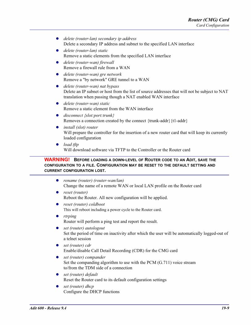
Adit 600 - Release 9.4 19-9
Router (CMG) CardCard Configuration
delete (router-lan) secondary ip addressDelete a secondary IP address and subnet to the specified LAN interface
delete (router-lan) staticRemove a static elements from the specified LAN interface
delete (router-wan) firewallRemove a firewall rule from a WAN
delete (router-wan) gre networkRemove a "by network" GRE tunnel to a WAN
delete (router-wan) nat bypassDelete an IP subnet or host from the list of source addresses that will not be subject to NAT translation when passing though a NAT enabled WAN interface
delete (router-wan) staticRemove a static element from the WAN interface
disconnect slot:port:trunkRemoves a connection created by the connect trunk-addrt1-addr
install (slot) routerWill prepare the controller for the insertion of a new router card that will keep its currently loaded configuration
load tftpWill download software via TFTP to the Controller or the Router card
WARNING! BEFORE LOADING A DOWN-LEVEL OF ROUTER CODE TO AN ADIT, SAVE THE CONFIGURATION TO A FILE. CONFIGURATION MAY BE RESET TO THE DEFAULT SETTING AND CURRENT CONFIGURATION LOST.
rename (router) (router-wan/lan)Change the name of a remote WAN or local LAN profile on the Router card
reset (router)Reboot the Router. All new configuration will be applied.
reset (router) coldbootThis will reboot including a power cycle to the Router card.
rtrpingRouter will perform a ping test and report the result.
set (router) autologoutSet the period of time on inactivity after which the user will be automatically logged-out of a telnet session
set (router) cdrEnable/disable Call Detail Recording (CDR) for the CMG card
set (router) companderSet the companding algorithm to use with the PCM (G.711) voice stream to/from the TDM side of a connection
set (router) defaultReset the Router card to its default configuration settings
set (router) dhcpConfigure the DHCP functions

19-10 Adit 600 - Release 9.4
Router (CMG) CardCard Configuration
set (router) dnsSet the CMG Domain Name Server (DNS) options
set (router) enhanced securityEnable/disable enhanced login security on the Router
set (router) hookflashSpecify the flash maximum time
set (router) lmiSpecify the Local Management Interface (LMI) protocol to use for the Router
set (router) logSet whether the CMG text log will continuously add new log entries by over-writing the oldest entries, or will stop adding new log entries after the log is full.
set (router) login authSets how login authentication for this router should be performed
set (router) login promptEnable/disable the suppression of the Router login prompt for a user that telnets in from the Controller CLI
set (router) mgcpSet Media Gateway Call Protocol (MGCP) parameters.
set (router) ntpSet Network Time Protocol (NTP) parameters
set (router) passwordManage password access on the specified Router card
set (router) ppp authConfigure the PPP (Point-to-Point Protocol) authentication
set (router) ppp securitySet the local external security server that the router will use to authenticate remote PPP devices
set (router) priority tosConfigure parameters that will be used to recognize routed voice packets which will be handled with higher priority over other routed data
set (router) proxyEnable/disable proxy ARP mode
set (router) rebootSet automatic reboot after an upload of code or configuration file
set (router) ripSpecify version of RIP packets to transmit and receive
set (router) snmpSet the SNMP contact, location, name and statistics averaging interval
set (router) stpConfigure the Spanning Tree Protocol on the router
set (router) syslogConfigure the Router to send alarm and event messages to a Syslog server
set (router) voipSet the Voice Over IP (VoIP) parameters
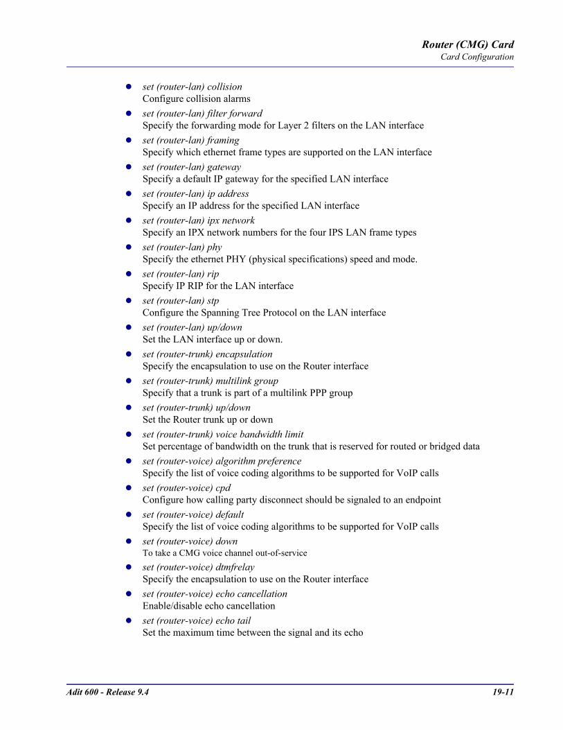
Adit 600 - Release 9.4 19-11
Router (CMG) CardCard Configuration
set (router-lan) collisionConfigure collision alarms
set (router-lan) filter forwardSpecify the forwarding mode for Layer 2 filters on the LAN interface
set (router-lan) framingSpecify which ethernet frame types are supported on the LAN interface
set (router-lan) gatewaySpecify a default IP gateway for the specified LAN interface
set (router-lan) ip addressSpecify an IP address for the specified LAN interface
set (router-lan) ipx networkSpecify an IPX network numbers for the four IPS LAN frame types
set (router-lan) phySpecify the ethernet PHY (physical specifications) speed and mode.
set (router-lan) ripSpecify IP RIP for the LAN interface
set (router-lan) stpConfigure the Spanning Tree Protocol on the LAN interface
set (router-lan) up/downSet the LAN interface up or down.
set (router-trunk) encapsulationSpecify the encapsulation to use on the Router interface
set (router-trunk) multilink groupSpecify that a trunk is part of a multilink PPP group
set (router-trunk) up/downSet the Router trunk up or down
set (router-trunk) voice bandwidth limitSet percentage of bandwidth on the trunk that is reserved for routed or bridged data
set (router-voice) algorithm preferenceSpecify the list of voice coding algorithms to be supported for VoIP calls
set (router-voice) cpdConfigure how calling party disconnect should be signaled to an endpoint
set (router-voice) defaultSpecify the list of voice coding algorithms to be supported for VoIP calls
set (router-voice) downTo take a CMG voice channel out-of-service
set (router-voice) dtmfrelaySpecify the encapsulation to use on the Router interface
set (router-voice) echo cancellationEnable/disable echo cancellation
set (router-voice) echo tailSet the maximum time between the signal and its echo
19-12 Adit 600 - Release 9.4
Router (CMG) CardCard Configuration
set (router-voice) endpoint prefixSet the prefix of the MGCP endpoint names
set (router-voice) endpoint suffixSet the suffix of the MGCP endpoint names
set (router-voice) faxSet the fax call handling method
set (router-voice) log startTo start logging events to the CMG text log
set (router-voice) log stopTo stop logging events to the CMG text log
set (router-voice) modemSet the modem call handling method
set (router-voice) rxgainSet gain on receive side for voice channel
set (router-voice) silenceEnable/disable silence suppression
set (router-voice) slashSuppresses the implied slash "/" between the endpoint prefix and suffix
set (router-voice) tosSet gain on transmit side for voice channel
set (router-voice) txgainSet the gain on the transmit side (TDM-to-packet) voice path
set (router-voice) upSet the specified voice channel up or down
set (router-wan) dlciConfigure the DLCI for a specified WAN interface that will be using a frame relay encapsulated trunk
set (router-wan) greConfigure the GRE tunneling for a specified WAN interface
set (router-wan) ipSet the IP traffic handling on the WAN interface
set (router-wan) ip addressSet the IP address for a WAN interface
set (router-wan) ipxSet the IPX traffic handling on the specified WAN interface
set (router-wan) natConfigure Network Address Translation (NAT) on a specified WAN interface
set (router-wan) otherSet the traffic handling of protocols other than IP or IPX on the specified WAN interface
set (router-wan) pppConfigure the PPP (Point-to-Point Protocol) on the specified router card
set (router-wan) ripSet the type or RIP updates on the WAN interface
Adit 600 - Release 9.4 19-13
Router (CMG) CardCard Configuration
set (router-wan) stpConfigure the Spanning Tree Protocol on the specified WAN
set (router-wan) trunkConfigure the trunk port for a specified WAN interface
set (router-wan) up/downSet the specified WAN interface up or down
show (router)Displays the current Router settings
show (router) dhcpDisplays the current DHCP settings for the Router
show (router) dnsDisplays the current DNS setup for the router card
show (router) dns proxyDisplays the current DNS Proxy setup for the router card
show (router) lmiDisplays the current Local Management Interface (LMI) settings
show (router) logDisplays the logging configuration of the CMG Router card
show (router) mgcpDisplays the setting for MGCP options
show (router) mgcp algorithmnameDisplays the designations for coding algorithms
show (router) ntpDisplays the settings for NTP options
show (router) pppDisplays the current Local PPP (Point-to-Point Protocol) authentication and security settings for the router
show (router) ripDisplays the current RIP settings for the Router
show (router) snmpDisplays the current SNMP settings for the Router
show (router) stpDisplays the current Spanning Tree Protocol settings for the router
show (router) syslogDisplays the current Syslog setup for the router
show (router) uploaduserDisplays the current list of users allowed to upload and download configuration and code files
show (router) voipDisplays the current settings for all VOIP parameters
show (router-lan)Displays the settings for the router card
19-14 Adit 600 - Release 9.4
Router (CMG) CardCard Configuration
show (router-lan) collisionDisplays the current LAN collision alarm settings for the router
show (router-lan) filterDisplays current LAN Layer 2 data filters applied to the LAN on the router
show (router-lan) staticDisplays the current list of static entries for the LAN on the router
show (router-lan) stpDisplays the current Spanning Tree Protocol settings for the LAN interface
show (router-trunk)Displays the current trunk settings for the Router
show (router-voice)Displays the CMG voice line provisioning
show (router-wan)Displays the current configuration settings for the specified WAN interface
show (router-wan) firewallDisplays the current firewall filter settings for the specified WAN interface
show (router-wan) nat bypassDisplays the current list of NAT bypass entries for the WAN interface
show (router-wan) pppDisplays the current PPP (Point-to-Point Protocol) settings for the specified WAN interface
show (router-wan) static ip addressDisplays the current list of static IP address entries for the specified WAN interface
show (router-wan) static ip networkDisplays the current list of static IP network entries for the specified WAN interface
show (router-wan) static ipx networkDisplays the current list of static IPX network entries for the specified WAN interface
show (router-wan) static mac addressDisplays the current list of static IP MAC network entries for the specified WAN interface
show (router-wan) static nat addressDisplays current static NAT address entries for the specified WAN interface
show (router-wan) stpDisplays current Spanning Tree Protocol settings for the specified WAN interface
show (router-wan) trunkDisplays the current trunk assignment for the specified WAN interface
status (router)Displays the current Router status information
status (router) alarmsDisplays the current alarm log from the router
status (router) channelsDisplays a condensed status report of all voice channel endpoints
status (router) dnsDisplays the current state of the DNS resolver and entries in the DNS cache

Adit 600 - Release 9.4 19-15
Router (CMG) CardCard Configuration
status (router) eventsDisplays the current event log from the router
status (router) ip address tableDisplays the current IP address table for the specified Router
status (router) ip network tableDisplays the current table of learned IP Networks for the specified interface on the router card
status (router) ipx network tableDisplays the current table of learned IPX Networks for the interface on the router card
status (router) ipx server tableDisplays the current table of learned IPX Servers for the specified interface
status (router) logDisplays the current log of all CMG events
status (router) mac address tableDisplays the current table of learned MAC Addresses for the interface on the router card
status (router) mgcpDisplays the current table of counts of all MGCP sent and received return codes, internal errors and other statistics
status (router) performanceDisplays the current runtime statistics from the specified router
status (router) stpDisplays the current Spanning Tree state from the specified router
status (router-lan)Displays the current Router status information
status (router-trunk)Displays the current status information for the specified Trunk on the router
status (router-voice)Displays the current status of service, calls signaling, connections, call agent communications and telephony statistics for a CMG Router voice channel
storeSave a software file from a defined slot to a defined location on a PC, via TFTP
telnet (router)Establish a Telnet session from the Adit 600 CLI to the Router port user interface
trace routeWill invoke a Trace Route to a host device on a network of a this Router.
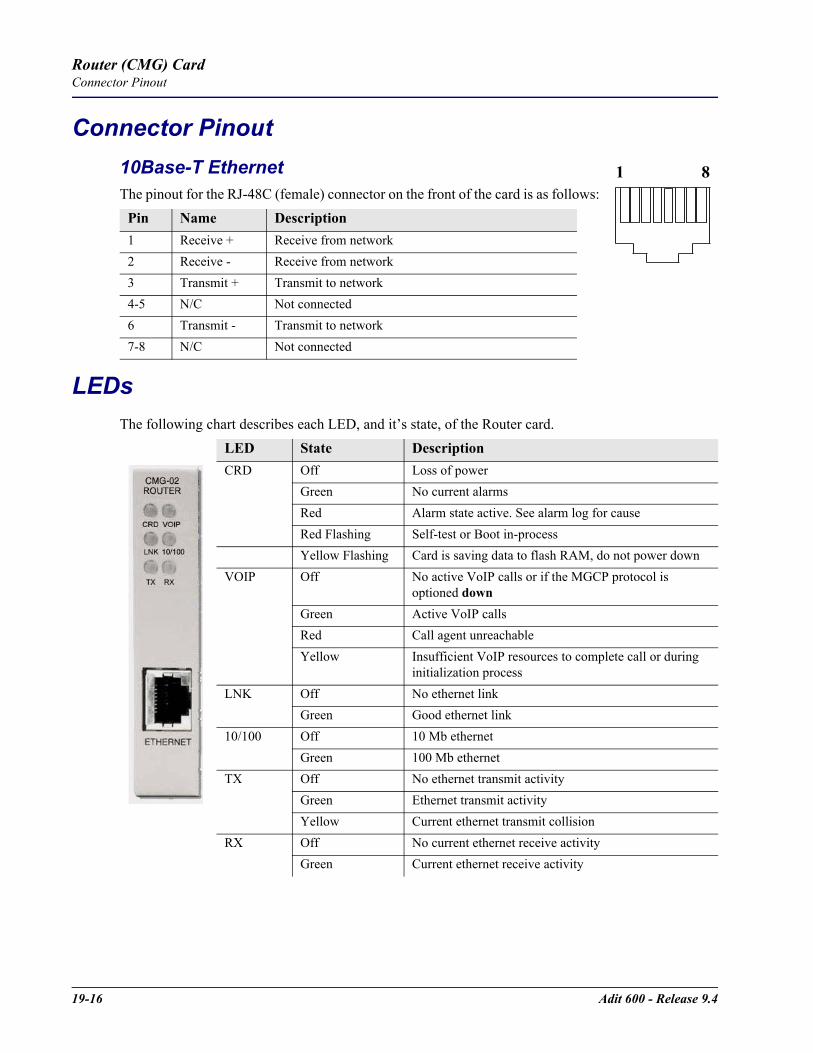
19-16 Adit 600 - Release 9.4
Router (CMG) CardConnector Pinout
Connector Pinout10Base-T EthernetThe pinout for the RJ-48C (female) connector on the front of the card is as follows:
LEDsThe following chart describes each LED, and it’s state, of the Router card.
Pin Name Description 1 Receive + Receive from network2 Receive - Receive from network3 Transmit + Transmit to network4-5 N/C Not connected 6 Transmit - Transmit to network7-8 N/C Not connected
LED State DescriptionCRD Off Loss of power
Green No current alarmsRed Alarm state active. See alarm log for causeRed Flashing Self-test or Boot in-processYellow Flashing Card is saving data to flash RAM, do not power down
VOIP
Off No active VoIP calls or if the MGCP protocol is optioned down
Green Active VoIP callsRed Call agent unreachableYellow Insufficient VoIP resources to complete call or during
initialization processLNK Off No ethernet link
Green Good ethernet link10/100 Off 10 Mb ethernet
Green 100 Mb ethernetTX Off No ethernet transmit activity
Green Ethernet transmit activityYellow Current ethernet transmit collision
RX Off No current ethernet receive activityGreen Current ethernet receive activity
1 8

CHAPTER 20Terminal Server Router Card
In this Chapter
Overview
Features
Technical Specifications
Card Configuration- CLI Commands
Connector Pinout- 10Base-T Ethernet
LEDs
20-2 Adit 600 - Release 9.4
Terminal Server Router CardOverview
OverviewThe Quad-Port Terminal Server Router (TSR) card combines the performance and expand ability of a selectable four-port RS-232 and 10/100Base-TX Ethernet switch with dedicated routing functionality in a low-cost solution to help wireless service providers remotely manage cell site LMU and switching devices, and deliver routing capabilities needed to offer 3G applications services. The ability to remotely manage these cell site devices significantly reduces maintenance truck rolls costs, and enables the wireless service provider to focus their efforts on expanding their cell site coverage for increased revenues.The TSR card employs a dedicated processor to ensure high performance and product feature expansion. A powerful set of standard features includes IP and IPX routing, Layer 2 bridging, ML-PPP, networking security and management capabilities to integrate services in the digital last mile. The four RJ-45 ports can be configured as either RS-232 or 10/100Base-TX Ethernet connections to support remote device management from the Network Operations Center (NOC) or 3G routed data applications services. The Adit 600’s modular design supports up to six TSR cards.The TSR card is SNMP or Command Line Interface (CLI) manageable. Management connectivity is provided either by directly through the user data port connection on the TSR card, or through the Controller cards as a component of the Adit 600 platform.
Quad TSR with TBOSThe Quad-Port Terminal Server Router (TSR) card with TBOS-to-SNMP conversion, offers a fully integrated solution to convert and transport TBOS alarms. The TBOS data received on the TSR card’s RS-232 ports are stored and made available via SNMP GETs. Alarms from TBOS-monitored equipment are converted to SNMP traps and transported over the WAN DS0 to the Network Operation Center's SNMP Trap Manager. This eliminates the need for a separate TBOS alarm monitoring system for fixed microwave backhaul systems and reduces bandwidth expense. Up to 8 TBOS devices can be cascaded off a single TSR RS-232 port.
FeaturesEnables remote management of cell site resourcesSupplies 4 selectable RS-232 asynchronous or 10/100Base-T Ethernet connections per cardSupports up to 6 Router cards per Adit 600 chassis- Multi-point networking with up to 24 WAN connections per router- Each WAN connection can be provisioned with multiple DS0s- Deliver more than 2 T1s bandwidth per Router card; up to 60 DS0s per Router card
Ensures high performance and feature expansion Enables management via menu-driven or CLI Router interfaceSupports packet filtering and Spanning Tree ProtocolAllows network address and port translation (NAT, PAT)Enables multiple T1 facilities to function as a single IP WAN interface using ML-PPP for bandwidth scalability beyond a single T1Supports Dynamic Host Configuration Protocol (DHCP)

Adit 600 - Release 9.4 20-3
Terminal Server Router CardTechnical Specifications
Additional Features on a TSR Card with TBOSDecodes the TBOS protocol to recover the individual alarm data pointsSNMP traps based upon changes to monitored alarm conditionsSupports SNMP traps and GETs for the monitored alarm dataDaisy chain up to 8 TBOS displays off 1 TSR RS-232 port
Technical Specifications
Controller Software RequiredT1 or E1 Controller
Release 4.1 or higher to support a TSR Service cardRelease 7.0 or higher to support a TSR Service card with TBOSTSR release 1.3 or higher to support all features listed in this chapter
ManagementCLI driven via RS-232 or EthernetMenu-driven via RS-232 or Ethernet, see the Terminal Server Router User Manual for information on the Menu-driven softwareSNMPPing, Trace RouteEthernet management portIP management DS0 bearer channelCode download via TFTPConfiguration upload and download via TFTP
WAN InterfaceAny T1/E1 interface on the Adit 600 platformUp to 24 WAN interfaces per TSR cardUp to 60 DS0s bandwidth per TSR cardPPP, Frame Relay, PPP in Frame Relay, ML-PPP and GRE tunneling
LAN InterfaceUp to 4 10/100Base-T auto-sensing/auto-MDIX ports8-pin RJ-45 modular jacks
20-4 Adit 600 - Release 9.4
Terminal Server Router CardTechnical Specifications
RS-232 InterfaceUp to 4 RS-232 DCE portsSelectable asynchronous data rates and data parameters8-pin RJ-45 modular jacksRJ-45-to-DB9 adapter cable available
RoutingIPX RIP/SAPIP RIPv1, RIPv2, RIPv/RIPv2 compatibility modeStatic routingClassless routing (CIDR)
BridgingIEEE 802.1D MAC bridging, using the Spanning Tree Algorithm and Protocol
PerformanceMinimum of 3,000 64-byte packets per second throughput
Advanced CapabilitiesDHCP server, BOOTP RelaySyslogDomain Name Server (DNS) proxyDNS resolverSimple Network Time Protocol (SNTP) support for timing from a separate network serverSecondary IP AddressRS-232 terminal serverRS-232 TBOS support: RS-422 TBOS support can be provided using an external RS-232 to RS-422 converter
Frame RelayRFC 1490 encapsulationANSI T1.617 Annex D LMIITU Q.933 Annex A LMI
FilteringLAN/WAN Filters up to Layer 4, stateful

Adit 600 - Release 9.4 20-5
Terminal Server Router CardTechnical Specifications
SecurityThree user accountsThree levels of securityPAP and CHAPNetwork Address Translation (NAT)NAT BypassPort Address Translation (PAT)
MIBs
Equipment Supported for TBOS-to-SNMP ConversionProxim Lynx.sc Microwave Radio Models 31250, 31600, 31250, 31650Proxim Lynx.HD Microwave Radio Models 31350-10, 31850-10, 31145-10, 31145-FProxim Lynx DS-3 Microwave Radio Models 27710-91, 27750-91Proxim Lynx Hot Standby Protection Switch Models 31455, 31420Alcatel MDR-4000 Microwave Digital Radio
Testing and DiagnosticsPing, Trace RouteWAN monitor
PowerLess than 5 W
Regulatory ApprovalsSee Appendix A, Regulatory Approvals for information on the Terminal Server Router Service card.
PhysicalDimensions: 3.5 in. (H) x 0.75 in. (W) x 11.25 in. (D) 8.9 cm (H) x 1.9 cm (W) x 28.6 cm (D)Weight: 5.2 oz. (0.15 kg)
For information on Adit 600 Environment required, see Installation Environment on page 2-2.
RFC 1212 (Concise MIB) RFC 1659 (RS-232)RFC 1213 (MIB II) RFC 2011 (IP)RFC 1406 (DS1/E1) RFC 2115 (Frame Relay)RFC 1471 (LCP/PPP) RFC 2233 (Interface)RFC 1473 (IP/PPP) Enterprise MIB, including equipment-specific MIBs to
support GET operation on TBOS-monitored RFC 1643 (Ethernet)

20-6 Adit 600 - Release 9.4
Terminal Server Router CardCard Configuration
Card ConfigurationThe Terminal Server Router card has the option of configuration through CLI or the TSR Menu-drive software, which is accessed through Telnet. The following CLI commands are all TSR related. For information on the TSR Menu-driven software, see the Terminal Server Router User Manual.
NOTE: The default IP address for the IP Router is 10.0.0.1.
NOTE: With this release TBOS features are set with the TSR Menu-driven software. See the Terminal Server Router User Manual for more information.
CLI CommandsMany of the router features can be configured directly with CLI commands. For configuration of features not covered with CLI commands, the operator must use the TSR Menu-driven software. All commands listed are hyperlinked to Chapter 5, CLI Commands, for detailed information.
add (router) dhcp server optionEnable DNS proxy and add a remote DNS server address to the Router card
add (router) remoteAdd a remote WAN profile to the WAN profile table
add (router) snmp communityAdd a SNMP community to an interface on the Router card
add (router) snmp trapTo specify a destination to send SNMP trap messages
add (router) static dns hostAdd a static DNS host record for resolving a domain name to an IP address, if the DNS server cannot provide the information
add (router) uploaduserTo specify a host that is allowed to upload configuration/software files
add (router-lan) filter addressAdd an address filter to the table of Layer 2 filter applied specified LAN interface
add (router-lan) filter customAdd a custom filter to the table of Layer 2 filter applied specified LAN interface
add (router-lan) filter protocolAdd a protocol filter to the table of Layer 2 filter applied specified LAN interface
add (router-lan) secondary ip addressAdd a secondary IP address and subnet to the specified LAN interface
add (router-lan) staticAdd a static elements on the specified LAN interface
add (router-wan) firewallAdd a firewall rule to a WAN
add (router-wan) gre networkAdd a "by network" GRE tunnel to a WAN
Adit 600 - Release 9.4 20-7
Terminal Server Router CardCard Configuration
add (router-wan) nat bypassAdd subnets to the list of source addresses that will not be subject to NAT translation when passing though a NAT enabled WAN interface
add (router-wan) staticAdd a static IP address to the table of learned addresses on the WAN interface. This command is typically used in bridging
add (router-wan) static nat addressAdd a static NAT bi-directional mapping to the WAN interface
clear (router) ip address tableFlush the learned entries from the IP address table for the specific interface from the specified Router card
clear (router) mac address tableFlush the learned entries from the MAC address table for the specific interface from the specified Router card
clear (router) mac address tableFlush the learned entries from the MAC address table for the specific interface from the specified Router card
clear (router) performanceClear the runtime statistics that are displayed by the status (router) performance command
connect (router-trunk) (t1)Creates two-way connections between the router port trunk connections and any DS0 channels of the service card or controller
connect (card-trunk) (card-trunk)Configure card-to-card WAN cross-connects between two Router cards or between a Router card and a V.35 card
delete (router) dns proxyRemove a remote DNS server address from the specified Router card
delete (router) remoteDelete a remote WAN profile from the WAN profile table
delete (router) snmp communityDelete an SNMP community entry
delete (router) snmp trapDelete a trap destination from the Router card
delete (router) static dns hostDelete a static DNS host record
delete (router) uploaduserRemove an existing authorized uploaduser.
delete (router-lan) filterRemove a a single filter rule from the table of Layer 2 filters applied to the specified LAN interface
delete (router-lan) secondary ip addressDelete a secondary IP address and subnet to the specified LAN interface
delete (router-lan) staticRemove a static element from the LAN interface

20-8 Adit 600 - Release 9.4
Terminal Server Router CardCard Configuration
delete (router-wan) firewallRemove a firewall rule from a WAN
delete (router-wan) gre networkRemove a "by network" GRE tunnel to a WAN
delete (router-wan) nat bypassDelete an IP subnet or host from the list of source addresses that will not be subject to NAT translation when passing though a NAT enabled WAN interface
delete (router-wan) staticRemove a static element on the WAN interface
disconnect slot:port:trunkRemoves a connection created by the connect trunk-addrt1-addr
install (slot) routerWill prepare the controller for the insertion of a new router card that will keep its currently loaded configuration
load tftpWill download software via TFTP to the Controller or the Router card
WARNING! BEFORE LOADING A DOWN-LEVEL OF ROUTER CODE TO AN ADIT, SAVE THE CONFIGURATION TO A FILE. CONFIGURATION MAY BE RESET TO THE DEFAULT SETTING AND CURRENT CONFIGURATION LOST.
rename (router) (router-wan/lan)Change the name of a remote WAN or local LAN profile on the Router card
reset (router)Reboot the Router. All new configuration since the last configuration will be in-use
rtrpingRouter will perform a ping test and report the result
set (router) autologoutSet the period of time on inactivity after which the user will be automatically logged-out of a Telnet session
set (router) defaultReset the Router card to its default configuration settings
set (router) dhcpConfigure the DHCP functions
set (router) dnsConfigure the Domain Name Server (DNS) options.
set (router) enhanced securityEnable/disable enhanced login security on the Router
set (router) lmiSpecify the Local Management Interface (LMI) protocol for the Router
set (router) login authSets how login authentication for this router should be performed
set (router) login promptEnable/disable the suppression of the Router login prompt for a user that telnets in from the Controller CLI
Adit 600 - Release 9.4 20-9
Terminal Server Router CardCard Configuration
set (router) ntpSet Network Time Protocol (NTP) parameters
set (router) passwordManage password access on the specified Router card
set (router) portSet port characteristics on a TSR card
set (router) ppp authConfigure the PPP authentication on the Router Card
set (router) proxyConfigures Router in-use basics (up, down and proxy)
set (router) rebootSet automatic reboot after an upload of code or configuration file
set (router) ripSpecify version of RIP packets to transmit and receive
set (router) snmpSet the SNMP contact, location and name on the specified Router card
set (router) stpConfigure the Spanning Tree Protocol on the Router
set (router) syslogConfigure the Router to send alarm and event messages to a Syslog server
set (router-lan) collisionConfigure collision alarms
set (router-lan) filter forwardSpecify the forwarding mode for Layer 2 filters on the LAN interface
set (router-lan) framingSpecify which ethernet frame types are supported on the LAN interface
set (router-lan) gatewaySpecify a default IP gateway for the specified LAN interface
set (router-lan) ip addressSpecify an IP address for the specified LAN interface
set (router-lan) ipx networkSpecify an IPX network numbers for the four IPS LAN frame types
set (router-lan) phySpecify the Ethernet PHY (physical specifications) speed and mode
set (router-lan) ripSpecify IP RIP for the LAN interface
set (router-lan) stpConfigure the Spanning Tree Protocol on the LAN interface
set (router-lan) up/downSet the LAN interface up or down
set (router-trunk) encapsulationSpecify the encapsulation to use on the Router interface
20-10 Adit 600 - Release 9.4
Terminal Server Router CardCard Configuration
set (router-trunk) multilink groupSpecify a router trunk to be part of a multilink PPP group
set (router-trunk) speedSpecify the data speed of each DS0 (56 or 64K)
set (router-trunk) up/downSet the TSR trunk up or down
set (router-wan) dlciConfigure the DLCI for a specified WAN interface that will be using a frame relay encapsulated trunk
set (router-wan) greConfigure the GRE tunneling for a specified WAN interface
set (router-wan) ipSet the IP traffic handling on the WAN interface
set (router-wan) ip addressSet the IP address for a WAN interface
set (router-wan) ipxSet the IPX traffic handling on the specified WAN interface
set (router-wan) natConfigure Network Address Translation (NAT) on a specified WAN interface
set (router-wan) otherSet the traffic handling of protocols other than IP or IPX on the specified WAN interface
set (router-wan) pppConfigure the PPP (Point-to-Point Protocol) on the specified router card
set (router-wan) ripSet the type or RIP updates on the WAN interface
set (router-wan) stpConfigure the trunk port for a specified WAN interface
set (router-wan) trunkConfigure the trunk port for a specified WAN interface
set (router-wan) up/downSet the specified WAN interface up or down
show (router)Displays the current Router settings
show (router) dhcpDisplays the current DHCP settings for the Router card
show (router) dnsDisplays the current DNS setup for the router card
show (router) dns proxyDisplays the current DNS Proxy setup for the router card
show (router) lmiDisplays the current Local Management Interface (LMI) settings for the Router card
show (router) ntpDisplays the settings for NTP options
Adit 600 - Release 9.4 20-11
Terminal Server Router CardCard Configuration
show (router) portDisplays the current TSR port configuration
show (router) pppDisplays the current Local PPP (Point-to-Point Protocol) authentication and security settings for the router
show (router) ripDisplays the current RIP settings for the Router card
show (router) snmpDisplays the current SNMP settings for the Router card
show (router) stpDisplays the current Spanning Tree Protocol settings for the router
show (router) syslogDisplays the current Syslog setup for the router
show (router) uploaduserDisplays the current list of users allowed to upload and download configuration and code files
show (router-lan)Displays the settings for the router card
show (router-lan) collisionDisplays the current LAN collision alarm settings for the router
show (router-lan) filterDisplays the current LAN Layer 2 data filters applied to the LAN on the router
show (router-lan) staticDisplays the current list of static entries for the LAN on the router
show (router-lan) stpDisplays the current Spanning Tree Protocol settings for the LAN interface
show (router-wan)Displays the current configuration settings for the specified WAN interface
show (router-wan) firewallDisplays the current firewall filter settings for the specified WAN interface
show (router-wan) nat bypassDisplays the current list of NAT bypass entries for the WAN interface
show (router-wan) pppDisplays the current PPP (Point-to-Point Protocol) settings for the specified WAN interface
show (router-wan) static ip addressDisplays the current list of static IP address entries for the specified WAN interface
show (router-wan) static ip networkDisplays the current list of static IP network entries for the specified WAN interface
show (router-wan) static ipx networkDisplays the current list of static IPX network entries for the specified WAN interface
show (router-wan) static mac addressDisplays the current list of static IP MAC network entries for the specified WAN interface

20-12 Adit 600 - Release 9.4
Terminal Server Router CardCard Configuration
show (router-wan) static nat addressDisplays the current static NAT address entries for the specified WAN interface
show (router-wan) stpDisplays the current Spanning Tree Protocol settings for the specified WAN interface
show (router-wan) trunkDisplays the current trunk assignment for the specified WAN interface
status (router)Displays the current Router status information
status (router) alarmsDisplays the current alarm log from the router
status (router) channelsDisplays a condensed status report of all voice channel endpoints
status (router) dnsDisplays the current state of the DNS resolver and entries in the DNS cache
status (router) eventsDisplays the current event log from the router
status (router) ip address tableDisplays the current IP address table for the specified Router
status (router) ip network tableDisplays the current table of learned IP Networks for the specified interface on the router card
status (router) ipx network tableDisplays the current table of learned IPX Networks for the specified interface on the router card
status (router) ipx server tableDisplays the current table of learned IPX Servers for the specified interface
status (router) mac address tableDisplays the current table of learned MAC Addresses for the specified interface on the router card
status (router) performanceDisplays the current runtime statistics from the specified router
status (router) stpDisplays the current Spanning Tree state from the specified router
status (router-lan)Displays the current Router status information
status (router-trunk)Displays the current status for the specified WAN
storeSave a software file from a defined slot to a defined location on a PC, via TFTP
test (fxs8C/fxs8B)Establish a Telnet session from the Adit 600 CLI to the TSR Router user interface
trace routeWill invoke a Trace Route to a host device on a network of a this Router.

Adit 600 - Release 9.4 20-13
Terminal Server Router CardConnector Pinout
Connector Pinout10Base-T EthernetThe pinout for the RJ-48C (female) connectors on the front of the card are as follows:
RS-232If the card is set to use the RS-232 connector (with jumpers) use the following RS-232 pinouts. There is a RS-232 to DB-9 converter cable available, P/N 005-0106.The pinout is as follows:
Pin Name Description 1 Receive + Receive from network2 Receive - Receive from network3 Transmit + Transmit to network4 - 5 N/C Not connected 6 Transmit - Transmit to network7 - 8 N/C Not connected
RJ-45 DB-9 RS-2321 8 CTS (Input)2 7 RTS (Output)3 6 DSR (Input)4 3 TXD (Output)5 2 RXD (Input)6 1 DCD (Input)7 4 DTR (Output)8 5 SG (Filtered)
N/A 9 RI (Not Used)
1 8
1 5
6 9
1 8
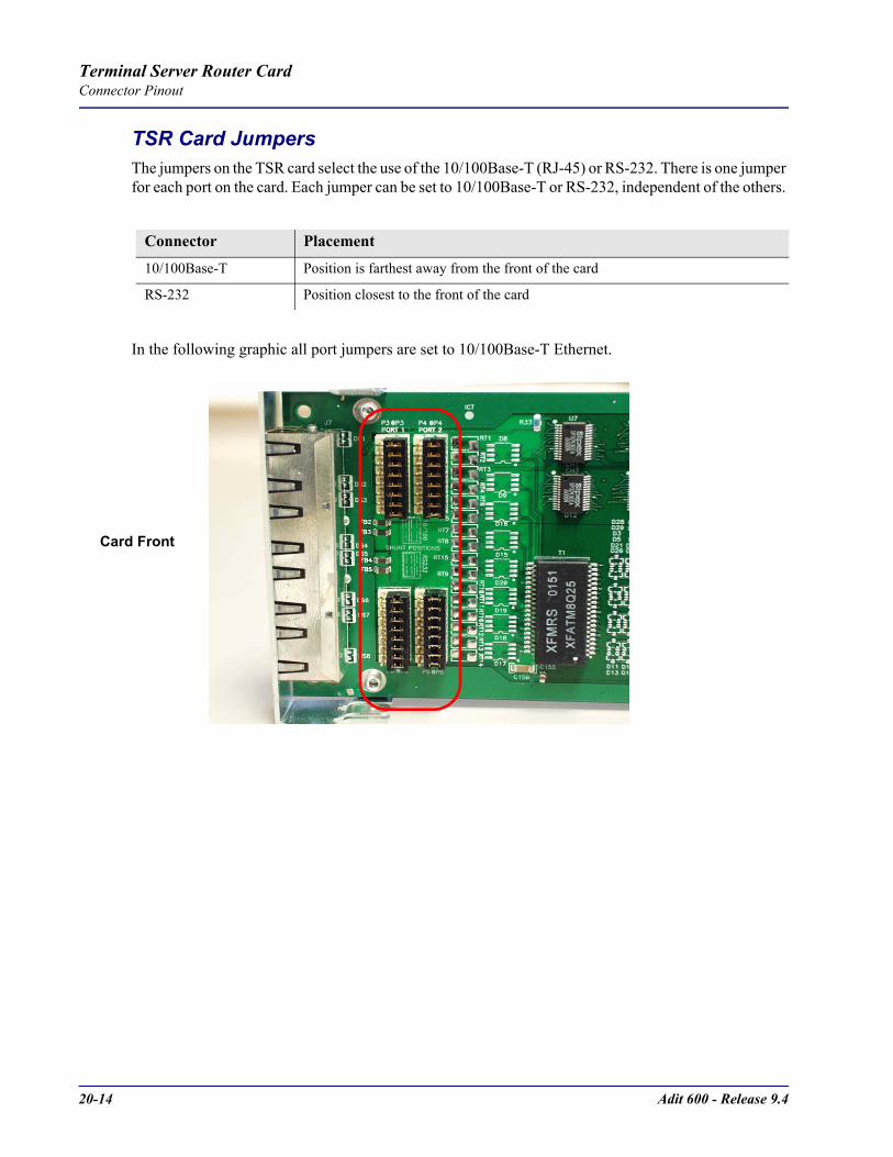
20-14 Adit 600 - Release 9.4
Terminal Server Router CardConnector Pinout
TSR Card JumpersThe jumpers on the TSR card select the use of the 10/100Base-T (RJ-45) or RS-232. There is one jumper for each port on the card. Each jumper can be set to 10/100Base-T or RS-232, independent of the others.
In the following graphic all port jumpers are set to 10/100Base-T Ethernet.
Connector Placement
10/100Base-T Position is farthest away from the front of the card
RS-232 Position closest to the front of the card
Card Front

Adit 600 - Release 9.4 20-15
Terminal Server Router CardLEDs
LEDsThe Terminal Server Router card has 2 LEDs per port.
At Power-up
Normal Operation
Port Set for Ethernet Top LED indicates 100M Link, Bottom LED indicates 10M Link
Port Set for RS-232
TOP LED Bottom LED DescriptionOff Off At Power Up/Boot = Loss of powerRed Red Card is inoperativeFlashing Red Flashing Red Self-test or Boot in-process
TOP LED Bottom LED DescriptionGreen Solid (Link) Green Solid (Link) Port set for Ethernet - see belowFlashing Red Flashing Red Self-test or Boot in-process
State DescriptionOff No Ethernet linkGreen Link but no activityRed Flashing Current Ethernet collisionGreen Flashing Current Ethernet receiveYellow Flashing Current Ethernet transmit
TOP LED Bottom LED DescriptionYellow Off No ActivityYellow Flashing Yellow Current transmitYellow Flashing Green Current receive

20-16 Adit 600 - Release 9.4
Terminal Server Router CardLEDs

CHAPTER 21RS-232 Card
In this Chapter
Overview- RS-232 Service Card (hardened)
- Features
Features
Technical Specifications
Card Configuration- CLI Commands
LEDs
Connector Pinouts- Connector Adapter
- DA-26S Connector Pin Assignments
21-2 Adit 600 - Release 9.4
RS-232 CardOverview
Overview
RS-232 Service Card (hardened)The Dual RS-232 Service Card allows service providers to provision connectivity to RS-232 serial synchronous Data Terminal Equipment (DTE) devices commonly deployed in cell sites and customer locations. RS-232 service connections supporting frame relay or transparent bit streams can be configured over one or more T1 access lines to deliver 2.4, 4.8, 9.6, 56 and 64 Kbps bandwidths to frame relay access devices, controllers, computers and data routing equipment. This Service Card has been specifically hardened to stand up to the extreme environmental conditions commonly associated with cell sites, outside cabinets, and central office deployments.The Dual RS-232 Service Card provides scalable, data service capacity to grow as bandwidth requirements increase. Up to six Dual RS-232 Service Cards can be equipped in an Adit 600 chassis, providing up to 12 RS-232 connections from any network T1 connected to the Adit 600 platform. Integrated Digital Cross-connect System (DCS) capability supports service grooming and full drop-and-insert functions not available in traditional CSU/DSU offerings. RS-232 ports on each card can be mapped to a DS0 of a T1/E1 network and may operate simultaneously at any supported speed (i.e., 2.4, 4.8, 9.6, 56 and 64 Kbps). Clocking is derived from the Adit 600 and the source connected to it. To allow support for a wide range of data networking applications, clocking is supplied to the connected DTE. Additionally, each RS-232 port supports loopback control via the Command Line Interface (CLI) to troubleshoot service from the network or the end device connected to the RS-232 electrical interface.The Dual RS-232 Service Card can be locally or remotely managed as a component of the Adit 600 platform. The card can be configured using a CLI.
FeaturesProvides common RS-232 data rates up to 64 Kbps on each port Supports full non-blocking cross-connection of all timeslots to any T1 access lineEnables up to 12 RS-232 ports to be equipped in a single Adit 600 platformSupports adaptation and transport over TDM facilitiesIntegral loopback diagnostic features
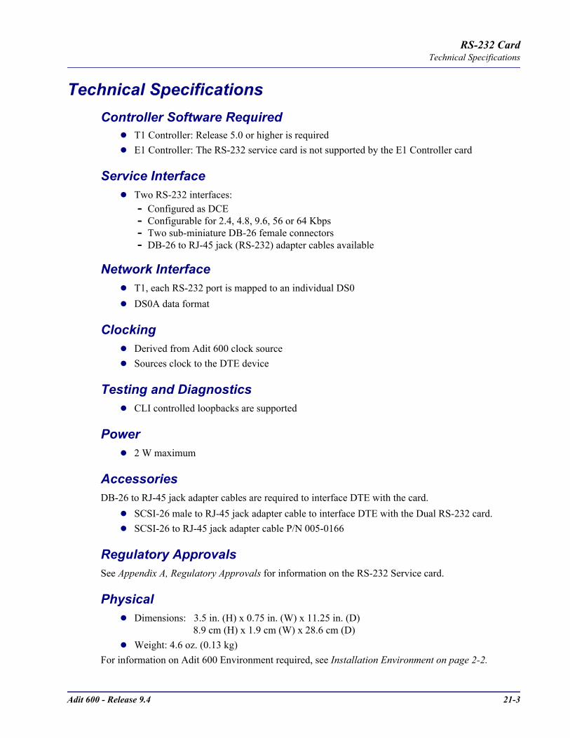
Adit 600 - Release 9.4 21-3
RS-232 CardTechnical Specifications
Technical SpecificationsController Software Required
T1 Controller: Release 5.0 or higher is requiredE1 Controller: The RS-232 service card is not supported by the E1 Controller card
Service InterfaceTwo RS-232 interfaces:- Configured as DCE- Configurable for 2.4, 4.8, 9.6, 56 or 64 Kbps- Two sub-miniature DB-26 female connectors- DB-26 to RJ-45 jack (RS-232) adapter cables available
Network InterfaceT1, each RS-232 port is mapped to an individual DS0DS0A data format
ClockingDerived from Adit 600 clock sourceSources clock to the DTE device
Testing and DiagnosticsCLI controlled loopbacks are supported
Power2 W maximum
AccessoriesDB-26 to RJ-45 jack adapter cables are required to interface DTE with the card.
SCSI-26 male to RJ-45 jack adapter cable to interface DTE with the Dual RS-232 card. SCSI-26 to RJ-45 jack adapter cable P/N 005-0166
Regulatory ApprovalsSee Appendix A, Regulatory Approvals for information on the RS-232 Service card.
PhysicalDimensions: 3.5 in. (H) x 0.75 in. (W) x 11.25 in. (D) 8.9 cm (H) x 1.9 cm (W) x 28.6 cm (D)Weight: 4.6 oz. (0.13 kg)
For information on Adit 600 Environment required, see Installation Environment on page 2-2.

21-4 Adit 600 - Release 9.4
RS-232 CardCard Configuration
Card ConfigurationThe RS-232 Service cards can be configured, using the Command Line Interface (CLI).
CLI CommandsThe following commands are used to configure the RS-232 Service card. For detailed information on these commands, see Chapter 5, CLI Commands.
connectCreates two-way connections between channels.
disconnectRemoves a connection created by the connect command.
set (rs232)Setup of channels of a RS-232 card (baud rate, clear to send, data carrier detect, equipment, line, request to send).
show (rs232)Displays the current settings for RS-232 (clear to send, request to send, data carrier detect, baud rate, loopback)
status (rs232)Displays the current status of the specified RS-232 (clear to send, request to send, data carrier detect).

Adit 600 - Release 9.4 21-5
RS-232 CardLEDs
LEDsEach RS-232 port has its own LED, as shown in the table below.
Connector PinoutsAn adapter cable or connector is needed to provide a standard RJ-45 jack from the front panel DB-26 connector. The RJ-45 shall be pinned-out as follows (matches DTS product interface) to minimize the customer transition from DTS FlexT to Adit.
State DescriptionOff No T1 AssignmentGreen Normal (CD/RTS) ActiveRed CD inactive (T1-side failure)Yellow RTS inactive (equipment-side failure)Flashing Yellow Loopback toward T1 or equipment loop testFlashing Green Loopback toward equipment or network loop test
RJ-45 Pin No Signal Direction1 RTS From DTE2 TXC To DTE3 RXD To DTE4 TXD From DTE5 CTS To DTE6 DCD To DTE7 RXC To DTE8 Signal Ground

21-6 Adit 600 - Release 9.4
RS-232 CardConnector Pinouts
Connector Adapter
DA-26S Connector Pin Assignments
Pin No Signal Direction Pin No Signal Direction1 Not Used 14 Not Used2 Not Used 15 Not Used3 Not Used 16 Not Used4 RTS Input 17 Not Used5 CTS Output 18 Not Used6 DCD Output 19 Not Used7 SIG GND 20 TXD Input8 TXC/RXC Output 21 Not Used9 Not Used 22 RXD Output
10 Not Used 23 Not Used11 Not Used 24 Not Used12 Not Used 25 Not Used13 Not Used 26 Not Used
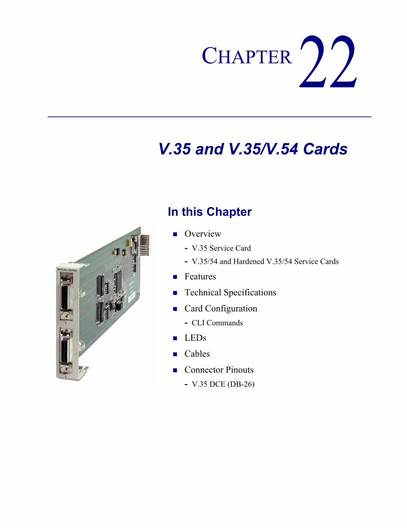
CHAPTER 22V.35 and V.35/V.54 Cards
In this Chapter
Overview- V.35 Service Card
- V.35/54 and Hardened V.35/54 Service Cards
Features
Technical Specifications
Card Configuration- CLI Commands
LEDs
Cables
Connector Pinouts- V.35 DCE (DB-26)

22-2 Adit 600 - Release 9.4
V.35 and V.35/V.54 CardsOverview
Overview
V.35 Service CardThe V.35 Service card enables service providers and enterprise network managers to provision connectivity to high-speed serial synchronous Data Terminal Equipment (DTE) devices such as routers, Frame Relay Access Devices (FRAD) and video conferencing equipment. The V.35 Service card provides scalable high-speed data service capacity to grow with user needs. Up to six V.35 cards can be inserted into any slot of the Adit 600 Customer Service Terminal, providing up to 12 fractional T1 V.35 connections from two T1 network connections. Two Adit Quad T1 Network Access/Drop-and-Insert cards allow eight T1s with full T1 CSU/DSU functionality to be terminated to eight V.35 ports in a single Adit 600 chassis. The Adit’s digital cross-connect functionality offers service grooming, T1 drop-and-insert, and voice access integration that are not available in traditional CSU/DSU offerings.Each V.35 port supports any n x 56/64 Kbps rate up to 1.536 Mbps. Both ports may operate simultaneously at any supported speed. Flexible clocking allows loop timing from any T1 line and provide system clocking to the connected DTE, supporting a wide range of data networking applications. Local and remote management options for the V.35 cards are available through the Adit 600 Controller. The cards can be locally configured and managed using either the CLI or the Valet graphical configuration tool. Remote management of the V.35 card is accomplished either through the Access Navigator over the Facility Data Link (FDL) or an in-band dedicated DS0, or by the NetworkValet Enhanced Management System (EMS) over an SNMP connection from the Network Operations Center (NOC).
V.35/54 and Hardened V.35/54 Service CardsAdditionally, each V.35 port supports V.54 loopback test capabilities. This feature enables V.54 loopback pattern recognition, generation and timing control to troubleshoot service from the network or the end device to the V.35 electrical interface. Four standard Bit Error Rate Test (BERT) patterns and an error counter are provided for testing.
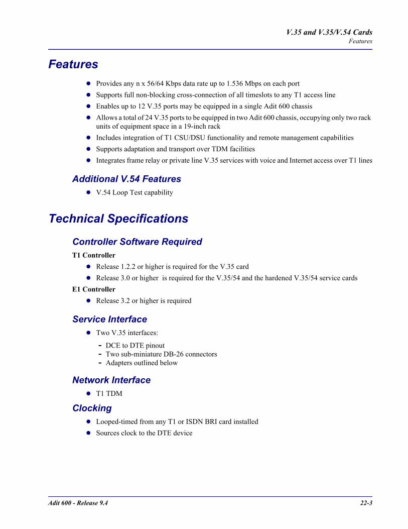
Adit 600 - Release 9.4 22-3
V.35 and V.35/V.54 CardsFeatures
FeaturesProvides any n x 56/64 Kbps data rate up to 1.536 Mbps on each portSupports full non-blocking cross-connection of all timeslots to any T1 access lineEnables up to 12 V.35 ports may be equipped in a single Adit 600 chassisAllows a total of 24 V.35 ports to be equipped in two Adit 600 chassis, occupying only two rack units of equipment space in a 19-inch rackIncludes integration of T1 CSU/DSU functionality and remote management capabilitiesSupports adaptation and transport over TDM facilitiesIntegrates frame relay or private line V.35 services with voice and Internet access over T1 lines
Additional V.54 FeaturesV.54 Loop Test capability
Technical Specifications
Controller Software RequiredT1 Controller
Release 1.2.2 or higher is required for the V.35 cardRelease 3.0 or higher is required for the V.35/54 and the hardened V.35/54 service cards
E1 ControllerRelease 3.2 or higher is required
Service InterfaceTwo V.35 interfaces:
- DCE to DTE pinout- Two sub-miniature DB-26 connectors- Adapters outlined below
Network InterfaceT1 TDM
ClockingLooped-timed from any T1 or ISDN BRI card installedSources clock to the DTE device
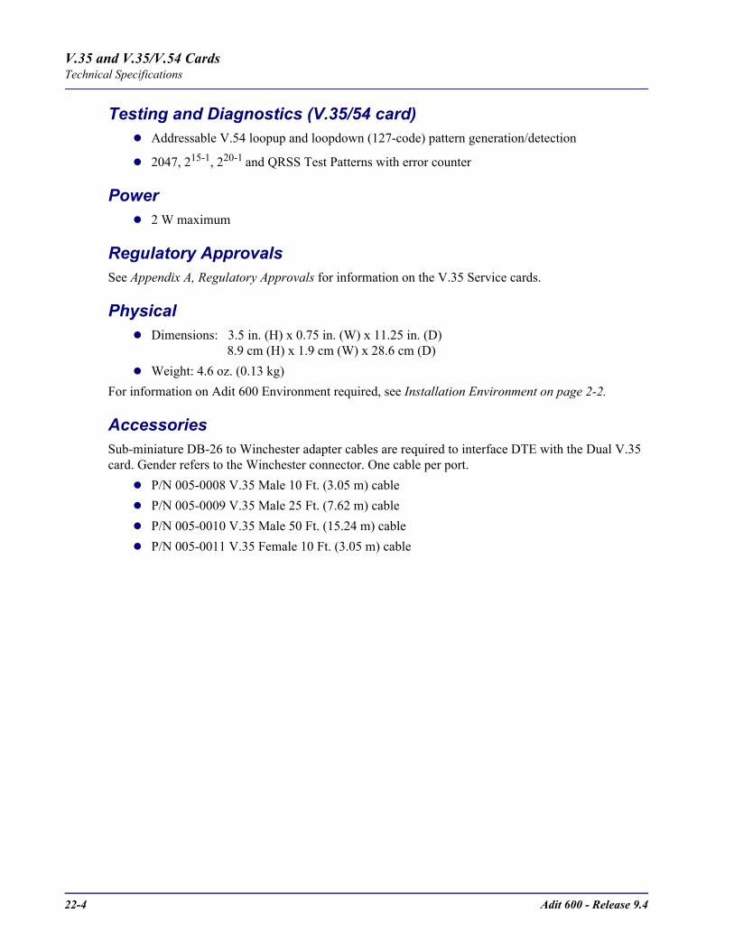
22-4 Adit 600 - Release 9.4
V.35 and V.35/V.54 CardsTechnical Specifications
Testing and Diagnostics (V.35/54 card)Addressable V.54 loopup and loopdown (127-code) pattern generation/detection
2047, 215-1, 220-1 and QRSS Test Patterns with error counter
Power2 W maximum
Regulatory ApprovalsSee Appendix A, Regulatory Approvals for information on the V.35 Service cards.
PhysicalDimensions: 3.5 in. (H) x 0.75 in. (W) x 11.25 in. (D) 8.9 cm (H) x 1.9 cm (W) x 28.6 cm (D)Weight: 4.6 oz. (0.13 kg)
For information on Adit 600 Environment required, see Installation Environment on page 2-2.
AccessoriesSub-miniature DB-26 to Winchester adapter cables are required to interface DTE with the Dual V.35 card. Gender refers to the Winchester connector. One cable per port.
P/N 005-0008 V.35 Male 10 Ft. (3.05 m) cableP/N 005-0009 V.35 Male 25 Ft. (7.62 m) cableP/N 005-0010 V.35 Male 50 Ft. (15.24 m) cableP/N 005-0011 V.35 Female 10 Ft. (3.05 m) cable

Adit 600 - Release 9.4 22-5
V.35 and V.35/V.54 CardsCard Configuration
Card ConfigurationThe V.35 Service cards can be configured, using the Command Line Interface (CLI) or the Valet GUI provisioning tool.
CLI CommandsThe following commands are used to configure the V.35 Service cards. For detailed information on these commands, see Chapter 5, CLI Commands.
connectCreates two-way connections between channels.
disconnectRemoves a connection created by the connect command.
set (v35)Setup of channels of a V.35 card (clock, clear to send, data, equipment, line, receive clock invert, speed, transmit clock invert).
set (v54)Set the V.54 loopback test parameters.
show (v35)Displays the current settings for V.35 (clear to send, timing, Rx clock inversion, Tx clock inversion, data inversion, data speed, data rate, loopback)
show (v54)Displays the current settings for V.54 (CTS, timing, Rx clock inversion, Tx clock inversion, data inversion, data speed, data rate, Rx LB, Rx Addr, test address, Tx Prep count, Rx Prep count, test pattern, ignore ACK, loopback)
status (v35)Displays the current status of the specified V.35 (data terminal ready, request to send, data carrier detect, clear to send, data set ready).
status (v54)Displays the current near-end line status of the specified V.54 (DCD, CTS, DSR, RTS, DTR, BERT).
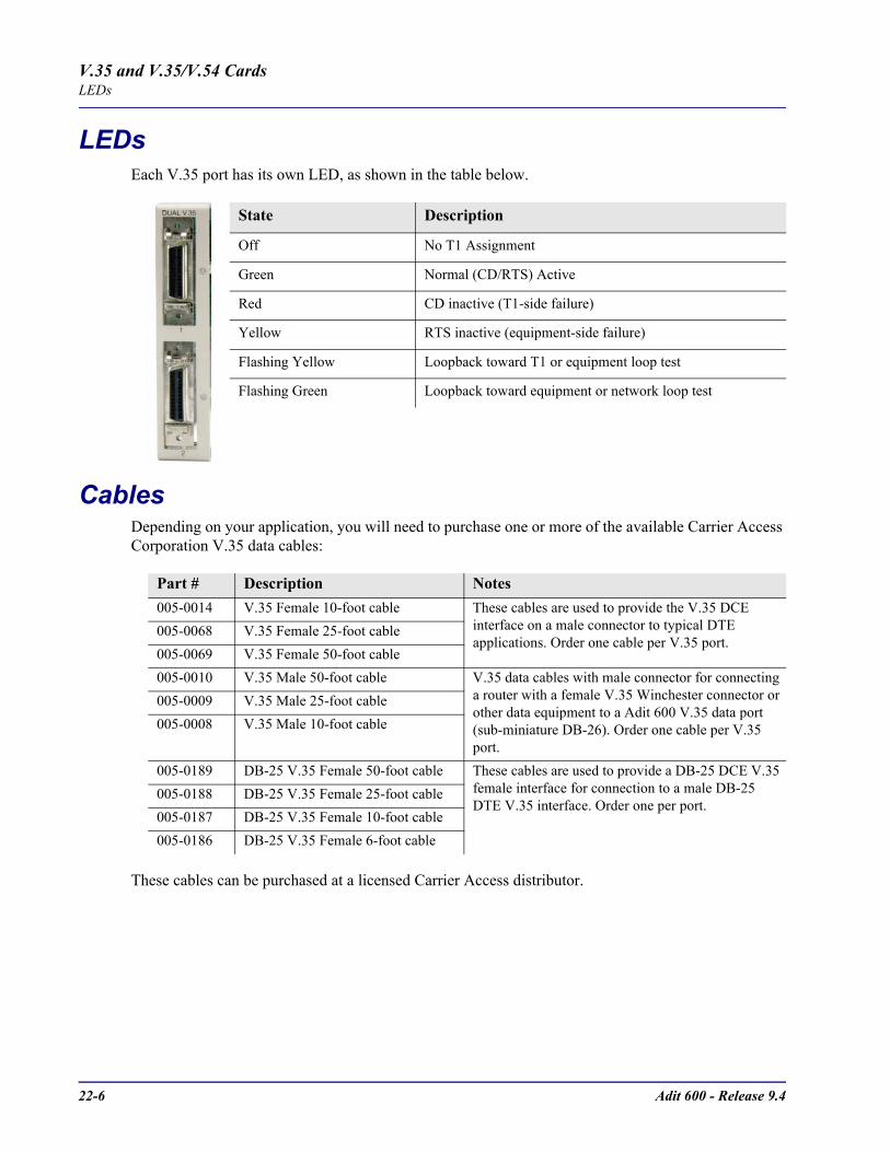
22-6 Adit 600 - Release 9.4
V.35 and V.35/V.54 CardsLEDs
LEDsEach V.35 port has its own LED, as shown in the table below.
CablesDepending on your application, you will need to purchase one or more of the available Carrier Access Corporation V.35 data cables:
These cables can be purchased at a licensed Carrier Access distributor.
State Description
Off No T1 Assignment
Green Normal (CD/RTS) Active
Red CD inactive (T1-side failure)
Yellow RTS inactive (equipment-side failure)
Flashing Yellow Loopback toward T1 or equipment loop test
Flashing Green Loopback toward equipment or network loop test
Part # Description Notes005-0014 V.35 Female 10-foot cable These cables are used to provide the V.35 DCE
interface on a male connector to typical DTE applications. Order one cable per V.35 port.
005-0068 V.35 Female 25-foot cable005-0069 V.35 Female 50-foot cable005-0010 V.35 Male 50-foot cable V.35 data cables with male connector for connecting
a router with a female V.35 Winchester connector or other data equipment to a Adit 600 V.35 data port (sub-miniature DB-26). Order one cable per V.35 port.
005-0009 V.35 Male 25-foot cable005-0008 V.35 Male 10-foot cable
005-0189 DB-25 V.35 Female 50-foot cable These cables are used to provide a DB-25 DCE V.35 female interface for connection to a male DB-25 DTE V.35 interface. Order one per port.
005-0188 DB-25 V.35 Female 25-foot cable005-0187 DB-25 V.35 Female 10-foot cable005-0186 DB-25 V.35 Female 6-foot cable

Adit 600 - Release 9.4 22-7
V.35 and V.35/V.54 CardsConnector Pinouts
Connector Pinouts
V.35 DCE (DB-26)The V.35 DCE data port connection is made at the sub-miniature DB-26 connector on the Adit 600 using the 10-foot, 25-foot, or 50 foot Carrier Access DTE V.35 cable equipped with a sub-miniature DB-26 connector and a 34-pin Winchester connector.This cable is used to connect the Adit 600 V.35 DCE data ports to synchronous V.35 DTE data sources up to 1.536 Mbps, all rates (1-24) Nx56 or Nx64 channel-rate progression.The Carrier Access Corporation V.35 data cables are built according to the pin assignments listed below:
Sub-miniature DB-26
Signal Winchester 34-pin (female)
Paired Signals
1 (+ Shield) ← Protective Ground → A ]7 ← Signal Ground → B
2 ← Transmit Data A ⎯ P ]14 ← Transmit Data B ⎯ S
3 ⎯ Receive Data A → R ]16 ⎯ Receive Data B → T
4 ← RTS ⎯ C ]20 ← DTR ⎯ H
5 ⎯ CTS → D ]6 ⎯ DSR → E
12 ⎯ Test Mode → K ]8 ⎯ CD (RLSD) → F
11 ← External Clock A ⎯ U ]24 ← External Clock B ⎯ W
Sub-miniature DB-26
Signal Winchester 34-pin (female)
Paired Signals
10 ⎯ Xmit Clock A → Y ]23 ⎯ Xmit Clock B → AA
15 ⎯ Receive Clock A → V ]17 ⎯ Receive Clock B → X
22 ← Local Loopback ⎯ J ]25 ← Remote Loopback ⎯ BB
9, 13, 18 Open Pins/No Contact L, N, NN
19, 21, 26 Open Pins/No Contact

22-8 Adit 600 - Release 9.4
V.35 and V.35/V.54 CardsConnector Pinouts

CHAPTER 23Maintenance
In this Chapter
Software Upgrade- Minimum Version Levels
- Determining Boot Code Software Level
- Upgrading System and Router Software via TFTP
- Upgrading System and Router Software via TFTP using Proxy
- Upgrading Software Levels via X-Modem
Backup Adit 600 Configuration- Save Controller Configuration
- Load Controller Configuration
Replace Controller Card
Hot Swap Service Card
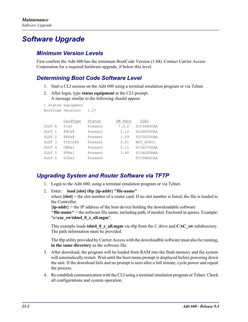
23-2 Adit 600 - Release 9.4
MaintenanceSoftware Upgrade
Software Upgrade
Minimum Version LevelsFirst confirm the Adit 600 has the minimum BootCode Version (1.04). Contact Carrier Access Corporation for a required hardware upgrade, if below this level.
Determining Boot Code Software Level1. Start a CLI session on the Adit 600 using a terminal emulation program or via Telnet.2. After login, type status equipment at the CLI prompt.
A message similar to the following should appear:> status equipment
BootCode Version: 1.27
CardType Status SW Vers CLEI
SLOT A T1x2 Present 7.0.2 SIC3DH0CAA
SLOT 1 FXOx8 Present 1.12 SIIXPV0DAASLOT 2 FXSx8 Present 1.09 SIC3GJ0CAA
SLOT 3 T1E1x4H Present 2.01 NOT_AVAIL
SLOT 4 CMGx1 Present 2.11 SIIX270DAASLOT 5 RTRx1 Present 1.60 SIIASS0BAA
SLOT 6 V35x2 Present SIC3HK0CAA
Upgrading System and Router Software via TFTP1. Login to the Adit 600, using a terminal emulation program or via Telnet.2. Enter: load [slot] tftp ip-addr "file-name"
where [slot] = the slot number of a router card. If no slot number is listed, the file is loaded to the Controller.ip-addr = the IP address of the host device holding the downloadable software"file-name" = the software file name, including path, if needed. Enclosed in quotes. Example: "c:\cac_sw\tdm4_0_z_all.mgm".
This example loads tdm4_0_z_all.mgm via tftp from the C drive and CAC_sw subdirectory. The path information must be provided.
The tftp utility provided by Carrier Access with the downloadble software must also be running, in the same directory as the software file.
3. After download, the program will be loaded from RAM into the flash memory and the system will automatically restart. Wait until the boot menu prompt is displayed before powering down the unit. If the download fails and no prompt is seen after a full minute, cycle power and repeat the process.
4. Re-establish communication with the CLI using a terminal emulation program or Telnet. Check all configurations and system operation.
Adit 600 - Release 9.4 23-3
MaintenanceSoftware Upgrade
Upgrading System and Router Software via TFTP using ProxyRequired: - Router Service card (IP, CMG or TSR) release 1.32 or higher - Controller software 3.2 or higher - Ethernet cable connected to port on front of Router card
1. Set up the Proxy with the following commands set ethernet ip address ip-addr [mask]set rtr_lan-addr ip address ip-addr [mask]set rtr_card-addr proxy enable ip-addr [mask]set ip gateway ip-addr
Example: (example with router in slot 3)set ethernet ip address 10.0.0.1 255.0.0.0set 3:1 ip address 192.168.100.1/24set 3 proxy enable 192.168.100.80/24set ip gateway 192.168.100.80
NOTE: See Chapter 5, CLI Commands for more information on these commands.
1. Login to the Adit 600 using the Proxy IP address, (example: 192.168.100.80) using a terminal emulation program or via Telnet.
2. Enter: load [slot] tftp ip-addr "file-name"where [slot] = the slot number of a router card. If no slot number is listed, the file is loaded to the Controller.ip-addr = the IP address of the host device holding the downloadable software"file-name" = the software file name, including path, if needed. Enclosed in quotes. Example: "c:\cac_sw\tdm4_0_z_all.mgm".
This example loads tdm4_0_z_all.mgm via tftp from the C drive and CAC_sw subdirectory. The path information must be provided.
The tftp utility provided by Carrier Access with the downloadble software must also be running, in the same directory as the software file.
3. After download, the program will be loaded from RAM into the flash memory and the system will automatically restart. Wait until the boot menu prompt is displayed before powering down the unit. If the download fails and no prompt is seen after a full minute, cycle power and repeat the process.
4. Re-establish communication with the CLI using a terminal emulation program or Telnet. Check all configurations and system operation.
23-4 Adit 600 - Release 9.4
MaintenanceSoftware Upgrade
Upgrading Software Levels via X-Modem1. Login to the Adit 600.2. Enter: load xmodem to download the application from the binary file. This will start the
system looking for an xmodem download. The Adit 600 will prompt you to send the file. Use one of the following methods:
Using HyperTerminalPull down the Transfer menuSelect Send File Provide the filename (and path if required), confirm that the xmodem protocol is used for the transfer, and start the download with the Send buttonA window will show the progress of the download.
Using ProcommPull down the File menuSelect Connection Directory Under the Data tab, use the Basic Options button to confirm that the xmodem protocol is used for file transfersPull down the Data menu, select Send File, provide the filename, and start the download
Another Terminal Emulation ProgramWhen using another terminal emulation program, confirm the use of xmodem protocol at 9600 baud, provide filename (and path) and initiate the download.
3. The binary file name is usually in the format: Adit.pkt. At 9600 baud, the file transfer will take approximately 20 minutes.
4. After download, the program will be loaded from RAM into the flash memory and the system will automatically restart. Wait until the boot menu prompt is displayed before powering down the unit. If the download fails and no prompt is seen after a full minute, cycle power and repeat the process.
5. Re-establish communication with the CLI using a terminal emulation program. Check all configurations and system operation.

Adit 600 - Release 9.4 23-5
MaintenanceBackup Adit 600 Configuration
Backup Adit 600 ConfigurationA text file from the current configuration can be generated to reload in the event the configuration has been lost due to card or software problems. The download of the file, generated by the print config command, can be done by direct connect to the RS-232 port or via Telnet. The upload of the file from the PC back to the Adit 600 can only be done via direct RS-232 connection. This is because the Adit 600 will be at factory default and an IP address is not assigned to the Adit 600.
Save Controller ConfigurationThe following example is shown with a HyperTerm session, with Telnet selections in parenthesis, other programs may be used and the process is similar, however the menu selections may be different.
1. Start a HyperTerm session to an Adit 600.2. Type the CLI command print config and do not hit [ENTER].3. Type select Transfer/Capture Text from the drop-down menu.
(Telnet - Terminal/Start Logging)4. Name the file, select OK.5. Return to the CLI command print config and hit [ENTER].
This process will exclude the print config command itself, from the configuration file you are creating.
6. (Telnet - Select Terminal/Stop Logging).7. Save configuration file as a .txt file, if necessary (Telnet will create a .log file, which will need
to be "saved as" a .txt file).

23-6 Adit 600 - Release 9.4
MaintenanceBackup Adit 600 Configuration
Load Controller Configuration1. Open HyperTerm session with the Adit 600 unit. 2. In HyperTerm, select File/Properties/Settings/ASCII Setup.
3. Set the Line delay to 500 ms and the Character delay to 5 ms.4. Select OK to save ASCII Setup and OK to save HyperTerm Properties.5. Select Transfer/Send Text File.6. Select .txt file from previous steps.7. Click Open.8. Configuration will load.

Adit 600 - Release 9.4 23-7
MaintenanceReplace Controller Card
Replace Controller Card
WARNING! SERVICE WILL BE INTERRUPTED WITH THE PROCESS OF CHANGING OUT A CONTROLLER CARD.
It is not necessary to power down a unit to replace a Controller, however if you would like to load the configuration file to the new Controller card you must backup the configuration file before this process.
1. Backup Controller Configuration, see Save Controller Configuration on page 23-5.2. Remove Controller card, gently slide the Service card straight out of the slot.3. Replace Controller card, gently slide the new Service card into the empty slot.4. Ensure that the new card is seated firmly into the connector at the back of the unit.5. Load Controller Configuration, see Load Controller Configuration on page 23-6
Hot Swap Service CardTo Hot-Swap (replace) a service card while the unit is powered on, follow the steps below:
1. Gently slide the Service card straight out of the slot.2. Gently slide the new Service card into the empty slot.3. Ensure that the new card is fastened securely into the connector at the back of the unit.

23-8 Adit 600 - Release 9.4
MaintenanceHot Swap Service Card

APPENDIX ARegulatory Approvals
In this Appendix
This appendix contains a chart of all the components of the Adit 600 and their Regulatory Approvals.
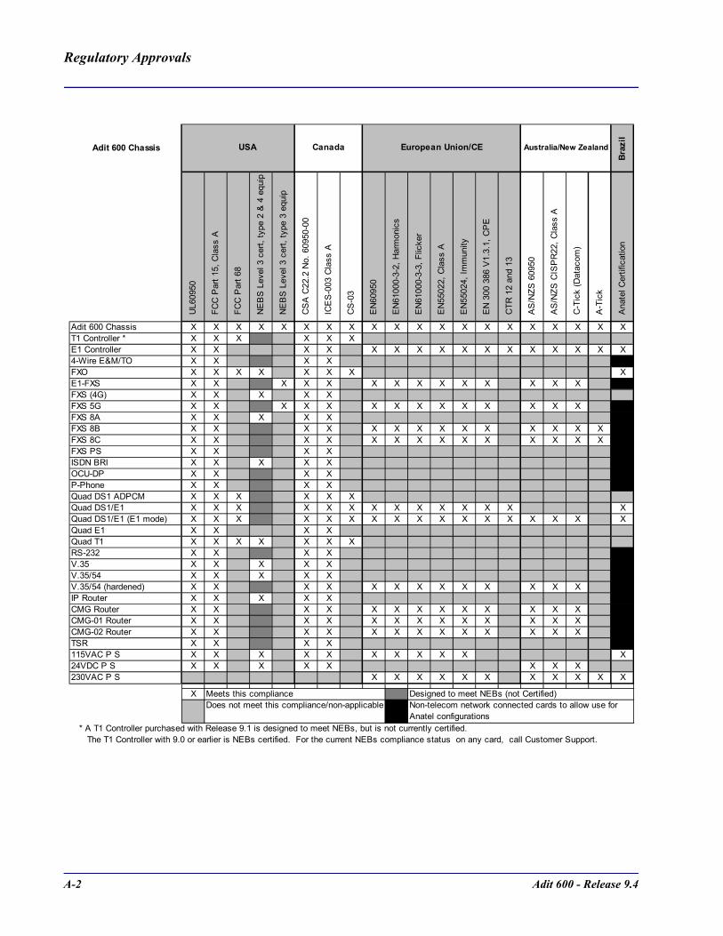
A-2 Adit 600 - Release 9.4
Regulatory Approvals
Adit 600 Chassis
Braz
il
UL6
0950
FC
C P
art 1
5, C
lass
A
FC
C P
art 6
8
NE
BS
Lev
el 3
cer
t, ty
pe 2
& 4
equ
ip
NE
BS
Lev
el 3
cer
t, ty
pe 3
equ
ip
CS
A C
22.2
No.
609
50-0
0
IC
ES
-003
Cla
ss A
CS
-03
EN
6095
0
EN
6100
0-3-
2, H
arm
onic
s
EN
6100
0-3-
3, F
licke
r
EN
5502
2, C
lass
A
EN
5502
4, Im
mun
ity
EN
300
386
V1.
3.1,
CP
E
CTR
12
and
13
AS
/NZS
609
50
AS
/NZS
CIS
PR
22, C
lass
A
C-T
ick
(Dat
acom
)
A-T
ick
Ana
tel C
ertif
icat
ion
Adit 600 Chassis X X X X X X X X X X X X X X X X X X X XT1 Controller * X X X X X X E1 Controller X X X X X X X X X X X X X X X X4-Wire E&M/TO X X X XFXO X X X X X X X XE1-FXS X X X X X X X X X X X X X XFXS (4G) X X X X XFXS 5G X X X X X X X X X X X X X XFXS 8A X X X X XFXS 8B X X X X X X X X X X X X X XFXS 8C X X X X X X X X X X X X X XFXS PS X X X XISDN BRI X X X X XOCU-DP X X X XP-Phone X X X XQuad DS1 ADPCM X X X X X XQuad DS1/E1 X X X X X X X X X X X X X XQuad DS1/E1 (E1 mode) X X X X X X X X X X X X X X X X XQuad E1 X X X XQuad T1 X X X X X X XRS-232 X X X XV.35 X X X X XV.35/54 X X X X XV.35/54 (hardened) X X X X X X X X X X X X XIP Router X X X X XCMG Router X X X X X X X X X X X X XCMG-01 Router X X X X X X X X X X X X XCMG-02 Router X X X X X X X X X X X X XTSR X X X X115VAC P S X X X X X X X X X X X24VDC P S X X X X X X X X230VAC P S X X X X X X X X X X X
X Meets this compliance
* A T1 Controller purchased with Release 9.1 is designed to meet NEBs, but is not currently certified. The T1 Controller with 9.0 or earlier is NEBs certified. For the current NEBs compliance status on any card, call Customer Support.
Australia/New Zealand
Non-telecom network connected cards to allow use for Anatel configurations
Does not meet this compliance/non-applicable
Canada European Union/CE USA
Designed to meet NEBs (not Certified)
APPENDIX BSNMP Interface
In this Appendix
Overview
SNMP Basics
Enterprise MIB Support
Router Enterprise MIB Support
Public MIB Support
Router Public MIB Support
MIB Loading Order
Adit 600 Trap Support
B-2 Adit 600 - Release 9.4
SNMP InterfaceOverview
OverviewThe Simple Network Management Protocol (SNMP) enables network operations centers (NOCs) to monitor and manage network elements across an internetwork. The Adit 600 supports SNMP through its Ethernet port, which provides access to the carrier’s TCP/IP management network.
SNMP BasicsSNMP is a protocol used to manage network equipment over TCP/IP networks. It works by exchanging information between an SNMP Manager (NMS) and an SNMP Agent in the network equipment.
SecurityRecommended actions concerning SNMP for Carrier Access Products residing on properly secured networks:
1. Use Proprietary SNMP Community Strings - Procedure to change Community strings outlined in the following CLI commands:
set (router) snmp on page 5-137set snmp on page 5-186
2. Segregate/Filter Network Management traffic from public domains - Filtering must be accomplished at network access points to properly protect managed devices. Filtering should be accomplished in accordance with local policies
3. Filter of SNMP traffic at network access points - SNMP vulnerabilities exist when SNMP traffic is not filtered at network access points. Filtering should be accomplished in accordance with local policies
For a more complete treatment of SNMP vulnerabilities and security recommendations, please refer to Carrier Access document PTN-02-003: Response to CERT Advisory CA-2002-03 Multiple Vulnerabilities in Many Implementations of the Simple Network Management Protocol (SNMP), or contact Carrier Access Customer Support.
MIB StructureThe SNMP Agent displays network information in a Management Information Base (MIB). MIBs are machine-to-machine interfaces that arrange and present information according to industry standards such as RFC 1213. MIBs are tree-like structures comprising nodes and leaves. Nodes are branch points used to divide information into categories. Leaves have object values that can be examined and changed. Common MIB objects include system names, performance statistics, and control values.
Control values are typically Integer types. This enables the object’s value to represent a specific control selection. Selections are usually written in the “name(value)” format. For example, the selection “closed(1)” means that the “closed” state is indicated by a value of “1”.
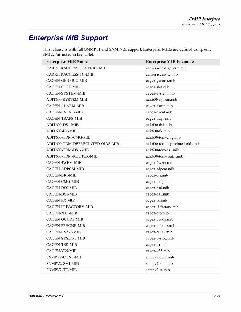
Adit 600 - Release 9.4 B-3
SNMP InterfaceEnterprise MIB Support
Enterprise MIB SupportThis release is with full SNMPv1 and SNMPv2c support. Enterprise MIBs are defined using only SMIv2 (as noted in the table).
Enterprise MIB Name Enterprise MIB FilenameCARRIERACCESS-GENERIC- MIB carrieraccess-generic.mibCARRIERACCESS-TC-MIB carrieraccess-tc.mibCAGEN-GENERIC-MIB cagen-generic.mibCAGEN-SLOT-MIB cagen-slot.mibCAGEN-SYSTEM-MIB cagen-system.mibADIT600-SYSTEM-MIB adit600-system.mibCAGEN-ALARM-MIB cagen-alarm.mibCAGEN-EVENT-MIB cagen-event.mibCAGEN-TRAPS-MIB cagen-traps.mibADIT600-DS1-MIB adit600-ds1.mibADIT600-FX-MIB adit600-fx.mibADIT600-TDM-CMG-MIB adit600-tdm-cmg.mibADIT600-TDM-DEPRECIATED-OIDS-MIB adit600-tdm-depreciated-oids.mibADIT600-TDM-DS1-MIB adit600-tdm-ds1.mibADIT600-TDM-ROUTER-MIB adit600-tdm-router.mibCAGEN-4WEM-MIB cagen-4wem.mibCAGEN-ADPCM-MIB cagen-adpcm.mibCAGEN-BRI-MIB cagen-bri.mibCAGEN-CMG-MIB cagen-cmg.mibCAGEN-DS0-MIB cagen-ds0.mibCAGEN-DS1-MIB cagen-ds1.mibCAGEN-FX-MIB cagen-fx.mibCAGEN-IF-FACTORY-MIB cagen-if-factory.mibCAGEN-NTP-MIB cagen-ntp.mibCAGEN-OCUDP-MIB cagen-ocudp.mibCAGEN-PPHONE-MIB cagen-pphone.mibCAGEN-RS232-MIB cagen-rs232.mibCAGEN-SYSLOG-MIB cagen-syslog.mibCAGEN-TSR-MIB cagen-tsr.mibCAGEN-V35-MIB cagen-v35.mibSNMPV2-CONF-MIB snmpv2-conf.mibSNMPV2-SMI-MIB snmpv2-smi.mibSNMPV2-TC-MIB snmpv2-tc.mib

B-4 Adit 600 - Release 9.4
SNMP InterfaceRouter Enterprise MIB Support
Router Enterprise MIB SupportEnterprise MIB Name Enterprise MIB Filename
Router SpecificCAGENROUTER-MIB caGenRouter.mibCAGENROUTER-CARDPROFILE-MIB caGenRouter-CardProfile.mibCAGENROUTER-DNS-MIB caGenRouter-DNS.mibCAGENROUTER-FILTERS-MIB caGenRouter-Filters.mibCAGENROUTER-LANPROFILE-MIB caGenRouter-LanProfile.mibCAGENROUTER-MANAGEMENT-MIB CAGenRouter-Mgt.mibCAGENROUTER-NTTPPROFILE-MIB caGenRouter-NTPProfile.mibCAGENROUTER-REPORTS-MIB caGenRouter-Reports.mibCAGENROUTER-SPANTREE-MIB caGenRouter-SpanTree.mibCAGENROUTER-STATIC-MIB caGenRouter-Static.mibCAGENROUTER-TC-MIB caGenRouter-tc.mibCAGENROUTER-TRUNK-MIB caGenRouter-trunk.mibCAGENROUTER-WANPROFILE-MIB caGenRouter-WanProfile.mib
CMG SpecificCA-CMG-CARD-MIB ca-cmg-card.mibCAGENCMG-ALGO-MIB caGenCmg-algo.mibCAGENCMG-DIALPLAN-MIB caGenCmg-dialplan.mibCAGENCMG-MGCP-MIB caGenCmg-mgcp.mibCAGENCMGCARD-TC-MIB caGenCmg-tc.mibCAGENCMG-SIPCARD-MIB caGenCmg-sip.mibCAGENCMG-TRUNK-MIB caGenCmg-trunk.mibCAGENCMG-VCHAN-MIB caGenCmg-vchan.mibCAGENCMG-VOIP-MIB caGenCmg-voip.mib
TSR SpecificCAGENTSR-MIB caGen-tsr.mib
Common with ControllerCARRIERACCESS-GENERIC-MIB carrieraccess-generic.mibCARRIERACCESS-TC-MIB carrieraccess-tc.mibCAGEN-GENERIC-MIB cagen-generic.mibCAGEN-SYSTEM-MIB cagen-system.mib

Adit 600 - Release 9.4 B-5
SNMP InterfacePublic MIB Support
Public MIB SupportMIB Table CommentsRFC1155 (RFC-1155-SMI-MIB)RFC1212 (RFC-1212-MIB)RFC1213 (RFC-1213-MIB) system tcp
interfaces udpip snmpicmp
egp not supported
RFC1215 (RFC-1215-MIB)RFC1215-TRAP (RFC-1215-TRAP-MIB)RFC1659 (RFC1659-MIB) rs232PortTable
rs232SyncPortTablers232InSigTablers232OutSigTable
Supports V.35 CardRs232AsnycPortTable not supported
RFC1907 (SNMPv2-MIB) systemsysORTablesnmp
SMIv2 Extension of RFC1213
RFC2011 (IP-MIB) ipipAddrTableipNetToMediaTableicmp
SMIv2 Extension of RFC1213
RFC2233 (IF-MIB) ifTableifXTableifStackTable
IfTestTable, ifRcvAddressTable not supported
IANAifType-MIB IANAifType Used by RFC2233; no objects
RFC2493 (PerHist-TC-MIB) Performance History TC Defines textual conventions; no objects
RFC2494 (DS0-MIB, DS0BUNDLE-MIB)
dsx0ConfigTabledsx0ChanMappingTabledsx0BundleTable
Dsx0BondingTable not supported
RFC2495 (DS1-MIB) dsx1ConfigTabledsx1CurrentTabledsx1IntervalTabledsx1TotalTable
Far End Tables and Fractional Table not supported
RFC2571 (SNMP-FRAMEWORK-MIB)
SNMP TC Defines textual conventions1 no objects
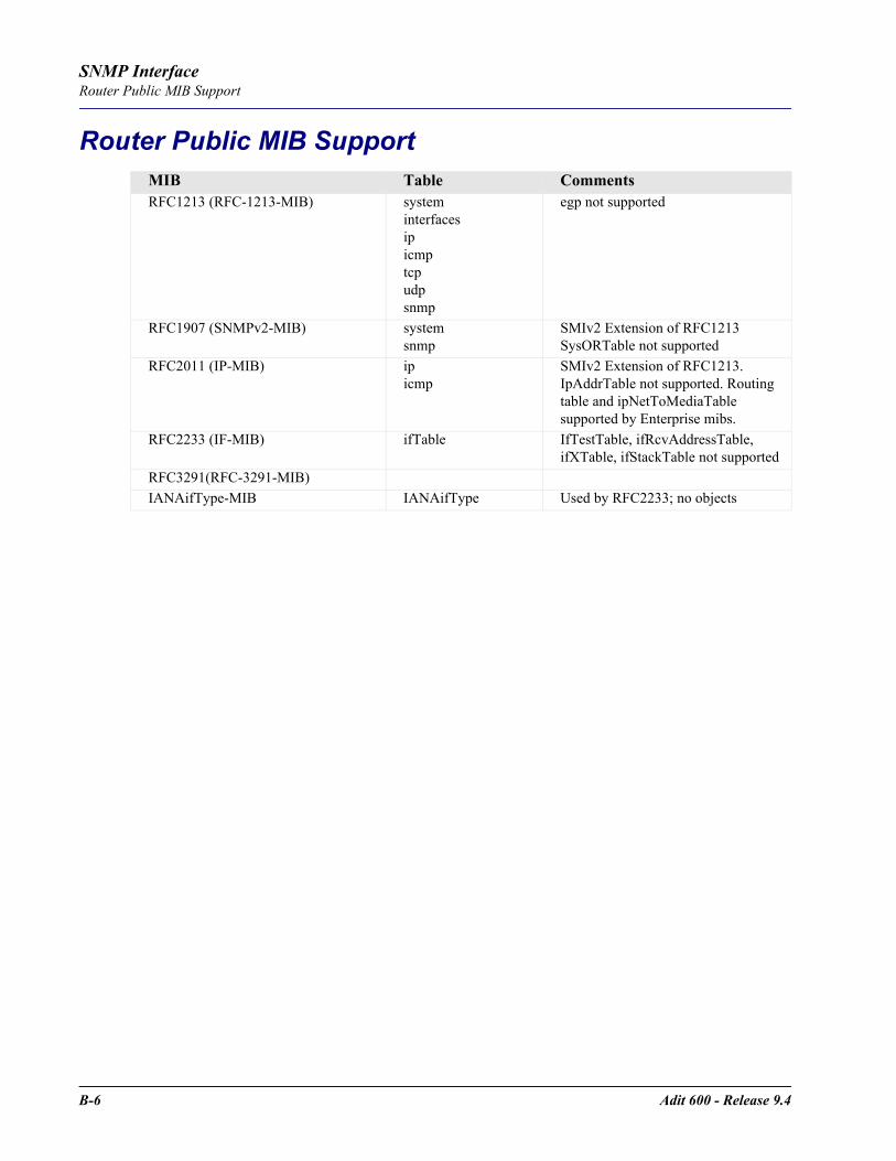
B-6 Adit 600 - Release 9.4
SNMP InterfaceRouter Public MIB Support
Router Public MIB SupportMIB Table CommentsRFC1213 (RFC-1213-MIB) system
interfacesipicmptcpudpsnmp
egp not supported
RFC1907 (SNMPv2-MIB) systemsnmp
SMIv2 Extension of RFC1213 SysORTable not supported
RFC2011 (IP-MIB) ipicmp
SMIv2 Extension of RFC1213.IpAddrTable not supported. Routing table and ipNetToMediaTable supported by Enterprise mibs.
RFC2233 (IF-MIB) ifTable IfTestTable, ifRcvAddressTable, ifXTable, ifStackTable not supported
RFC3291(RFC-3291-MIB) IANAifType-MIB IANAifType Used by RFC2233; no objects

Adit 600 - Release 9.4 B-7
SNMP InterfaceMIB Loading Order
MIB Loading OrderThe following is the recommended MIB loading order for the Adit 600. Many standard MIBs may already be loaded, it is not necessary to load them again.
1. rfc1212.mib 29. cagen-v35.mib2. rfc1213.mib 30. adit600-system.mib3. rfc1907.mib 31. adit600-ds1.mib4. rfc2233.mib 32. adit600-tdm-ds1.mib5. rfc1659.mib 33. adit600-fx.mib6. rfc2011.mib 34. adit600-tdm-router.mib7. rfc2493.mib 35. caGen-ocudp.mib8. rfc2494.mib 36. caGenRouter.mib9. rfc2495.mib 37. caGenRouter-trunk.mib10. rfc2571.mib 38. caGenRouter-WanProfile.mib11. rfc3291.mib 39. caGenRouter-CardProfile.mib12. rfc1155-smi.mib 40. caGenRouter-DNS.mib13. SNMPv2-CONF.mib 41. caGenRouter-Filters.mib14. SNMPv2-SMI.mib 42. caGenRouter-LanProfile.mib15. SNMPv2-TC.mib 43. caGenRouter-Mgt.mib16. carrieraccess-generic.mib 44. caGenRouter-NTPProfile.mib17. carrieraccess-tc.mib 45. caGenRouter-Reports.mib18. cagen-generic.mib 46. caGenRouter-SpanTree.mib19. IANAifType-MIB.mib 47. caGenRouter-Static.mib20. cagen-slot.mib 48. caGenRouter-tc.mib21. cagen-alarm.mib 49. caGen-cmg-card.mib22. cagen-event.mib 50. caGenCmg-algo.mib23. cagen-system.mib 51. caGenCmg-mgcp.mib24. cagen-ds0.mib 52. caGenCmg-tc.mib25. cagen-ds1.mib 53. caGenCmg-trunk.mib26. cagen-bri.mib 54. caGenCmg-vchan.mib27. cagen-fx.mib 55. caGenCmg-voip.mib28. cagen-traps.mib 56. caGenCmg-dialplan.mib
57. caGenCmg-sip.mib
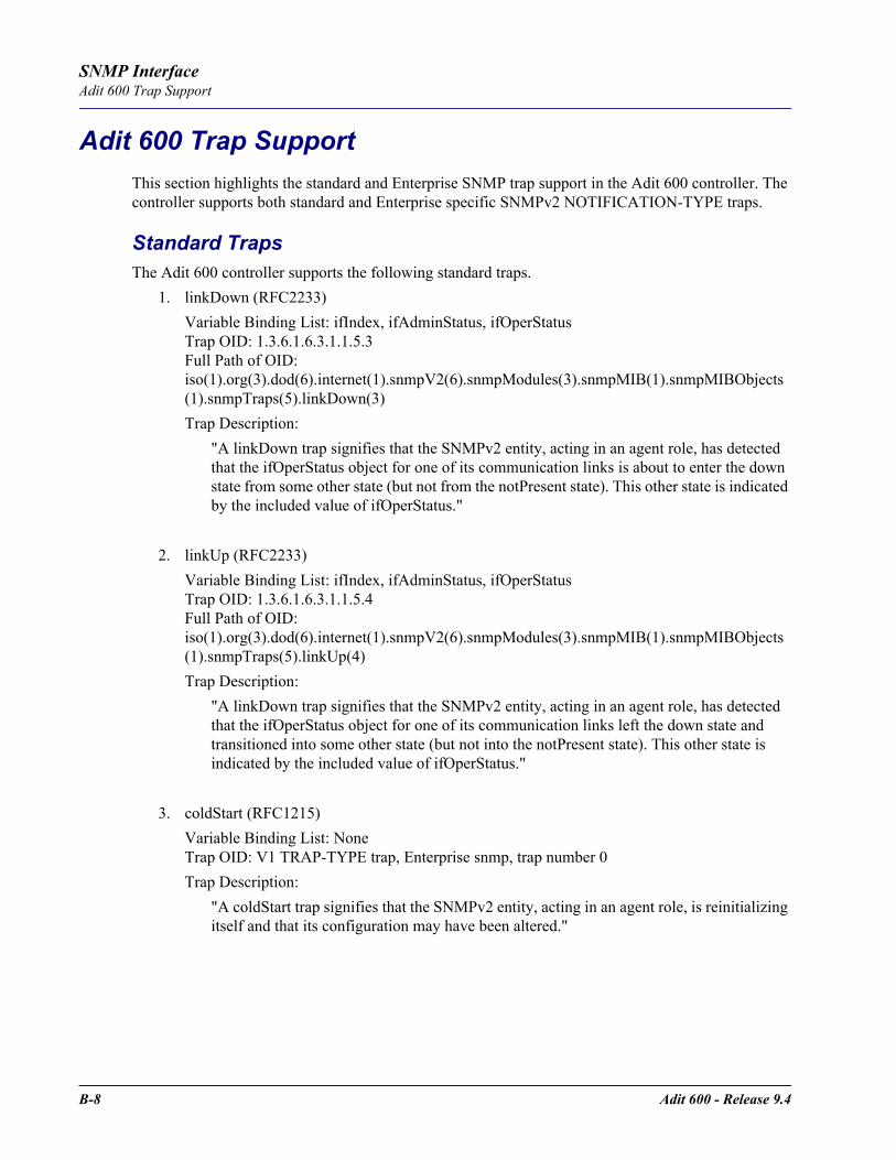
B-8 Adit 600 - Release 9.4
SNMP InterfaceAdit 600 Trap Support
Adit 600 Trap SupportThis section highlights the standard and Enterprise SNMP trap support in the Adit 600 controller. The controller supports both standard and Enterprise specific SNMPv2 NOTIFICATION-TYPE traps.
Standard TrapsThe Adit 600 controller supports the following standard traps.
1. linkDown (RFC2233)Variable Binding List: ifIndex, ifAdminStatus, ifOperStatusTrap OID: 1.3.6.1.6.3.1.1.5.3Full Path of OID:iso(1).org(3).dod(6).internet(1).snmpV2(6).snmpModules(3).snmpMIB(1).snmpMIBObjects(1).snmpTraps(5).linkDown(3)Trap Description:
"A linkDown trap signifies that the SNMPv2 entity, acting in an agent role, has detected that the ifOperStatus object for one of its communication links is about to enter the down state from some other state (but not from the notPresent state). This other state is indicated by the included value of ifOperStatus."
2. linkUp (RFC2233)Variable Binding List: ifIndex, ifAdminStatus, ifOperStatusTrap OID: 1.3.6.1.6.3.1.1.5.4Full Path of OID:iso(1).org(3).dod(6).internet(1).snmpV2(6).snmpModules(3).snmpMIB(1).snmpMIBObjects(1).snmpTraps(5).linkUp(4)Trap Description:
"A linkDown trap signifies that the SNMPv2 entity, acting in an agent role, has detected that the ifOperStatus object for one of its communication links left the down state and transitioned into some other state (but not into the notPresent state). This other state is indicated by the included value of ifOperStatus."
3. coldStart (RFC1215)Variable Binding List: None Trap OID: V1 TRAP-TYPE trap, Enterprise snmp, trap number 0Trap Description:
"A coldStart trap signifies that the SNMPv2 entity, acting in an agent role, is reinitializing itself and that its configuration may have been altered."

Adit 600 - Release 9.4 B-9
SNMP InterfaceAdit 600 Trap Support
4. authenticationFailure (RFC1907)Variable Binding List: None Trap OID: 1.3.6.1.6.3.1.1.5.5Full Path of OID:iso(1).org(3).dod(6).internet(1).snmpV2(6).snmpModules(3).snmpMIB(1).snmpMIBObjects(1).snmpTraps(5).authenticationFailure(5)Trap Description:
"An authenticationFailure trap signifies that the SNMPv2 entity, acting in an agent role, has received a protocol message that is not properly authenticated. While all implementations of the SNMPv2 must be capable of generating this trap, the snmpEnableAuthenTraps object indicates whether this trap will be generated."
Enterprise TrapsThe Adit 600 controller supports the following enterprise specific traps. All enterprise traps are defined in the CA-TRAPS-MIB (cagen-traps.mib) Most variable bindings are imported from the CA-EVENT-MIB (cagen-event.mib).
1. caGenEventLogTrapVariable Binding List: caGenEventLogIndex, caGenEventSeverity, caGenEventCategory, caGenEventCode, caGenEventDateTrap OID: 1.3.6.1.4.1.964.3.4.1.100.0.1Full Path of OID:iso(1).org(3).dod(6).internet(1).private(4).enterprises(1).carrieraccess(964).products(3).caGen(4).caGeneric(1).caGenTraps(100).caGenEventsV2(0).caGenEventLogTrap(1)Trap Description:
"An event has been logged into the device's Event Log.Note: caGenEventInfoParam[1|2|3] are optional variable bindings."
2. caGenMajorPortAlarmFailureVariable Binding List: caGenEventCategory, caGenEventCode, ifIndex,caGenSlotCardType, caGenPortLoc, caGenEventAdditionalTextTrap OID: 1.3.6.1.4.1.964.3.4.1.100.0.2Full Path of OID:iso(1).org(3).dod(6).internet(1).private(4).enterprises(1).carrieraccess(964).products(3).caGen(4).caGeneric(1).caGenTraps(100).caGenEventsV2(0).caGenMajorPortAlarmFailure(2)Trap Description:
"A major communication failure has been detected. The 'caGenEventCode' variable holds the particular type of failure from this set:
If the ifIndex has a name, 'caGenEventAdditionalText' reports it for all ifTypes."
Alarm Indication Signal Loss Of SignalBipolar Violation Loss Of Signal No Dying GaspLine Coding Violation Remote Alarm IndicationLoss Of Frame Link DownLoss Of RTS Call Connection Down
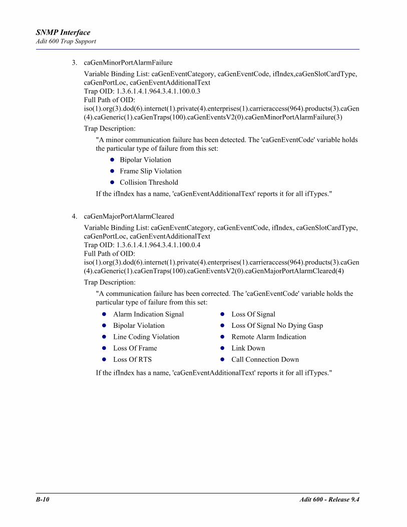
B-10 Adit 600 - Release 9.4
SNMP InterfaceAdit 600 Trap Support
3. caGenMinorPortAlarmFailureVariable Binding List: caGenEventCategory, caGenEventCode, ifIndex,caGenSlotCardType, caGenPortLoc, caGenEventAdditionalTextTrap OID: 1.3.6.1.4.1.964.3.4.1.100.0.3Full Path of OID:iso(1).org(3).dod(6).internet(1).private(4).enterprises(1).carrieraccess(964).products(3).caGen(4).caGeneric(1).caGenTraps(100).caGenEventsV2(0).caGenMinorPortAlarmFailure(3)Trap Description:
"A minor communication failure has been detected. The 'caGenEventCode' variable holds the particular type of failure from this set:
Bipolar ViolationFrame Slip ViolationCollision Threshold
If the ifIndex has a name, 'caGenEventAdditionalText' reports it for all ifTypes."
4. caGenMajorPortAlarmClearedVariable Binding List: caGenEventCategory, caGenEventCode, ifIndex, caGenSlotCardType, caGenPortLoc, caGenEventAdditionalTextTrap OID: 1.3.6.1.4.1.964.3.4.1.100.0.4Full Path of OID:iso(1).org(3).dod(6).internet(1).private(4).enterprises(1).carrieraccess(964).products(3).caGen(4).caGeneric(1).caGenTraps(100).caGenEventsV2(0).caGenMajorPortAlarmCleared(4)Trap Description:
"A communication failure has been corrected. The 'caGenEventCode' variable holds the particular type of failure from this set:
If the ifIndex has a name, 'caGenEventAdditionalText' reports it for all ifTypes."
Alarm Indication Signal Loss Of Signal Bipolar Violation Loss Of Signal No Dying Gasp Line Coding Violation Remote Alarm Indication Loss Of Frame Link Down Loss Of RTS Call Connection Down

Adit 600 - Release 9.4 B-11
SNMP InterfaceAdit 600 Trap Support
5. caGenPortAlarmThresholdVariable Binding List: caGenEventCategory, caGenEventCode, caGenEventInfoParam1, ifIndex, caGenSlotCardType, caGenPortLoc, caGenEventAdditionalTextTrap OID: 1.3.6.1.4.1.964.3.4.1.100.0.5Full Path of OID:iso(1).org(3).dod(6).internet(1).private(4).enterprises(1).carrieraccess(964).products(3).caGen(4).caGeneric(1).caGenTraps(100).caGenEventsV2(0).caGenPortAlarmThreshold(5)Trap Description:
"A performance threshold violation has occurred. The 'caGenEventCode' variable holds the particular type of threshold from this set:
If the ifIndex has a name, 'caGenEventAdditionalText' reports it for all ifTypes."
6. caGenCriticalUserAlarmInputDetectedVariable Binding List: caGenEventCategory, caGenEventInfoParam1Trap OID: 1.3.6.1.4.1.964.3.4.1.100.0.6Full Path of OID:iso(1).org(3).dod(6).internet(1).private(4).enterprises(1).carrieraccess(964).products(3).caGen(4).caGeneric(1).caGenTraps(100).caGenEventsV2(0).caGenCriticalUserAlarmInputDetected(6)Trap Description:
"A critical user alarm input has been detected. 'caGenEventInfoParam1' indicates which user alarm input has tripped."
7. caGenMajorUserAlarmInputDetectedVariable Binding List: caGenEventCategory, caGenEventInfoParam1Trap OID: 1.3.6.1.4.1.964.3.4.1.100.0.7Full Path of OID:iso(1).org(3).dod(6).internet(1).private(4).enterprises(1).carrieraccess(964).products(3).caGen(4).caGeneric(1).caGenTraps(100).caGenEventsV2(0).caGenMajorUserAlarmInputDetected(7)Trap Description:
"A major user alarm input has been detected. 'caGenEventInfoParam1' indicates which user alarm input has tripped."
Bursty Errored Seconds Threshold Line Errored Seconds Threshold Controlled Slip Seconds Threshold Path Coding Violations Threshold Degraded Minutes Threshold Severely Errored Framing Second Threshold Errored Seconds Threshold Severely Errored Seconds Threshold Line Coding Violations Threshold Unavailable Seconds Threshold
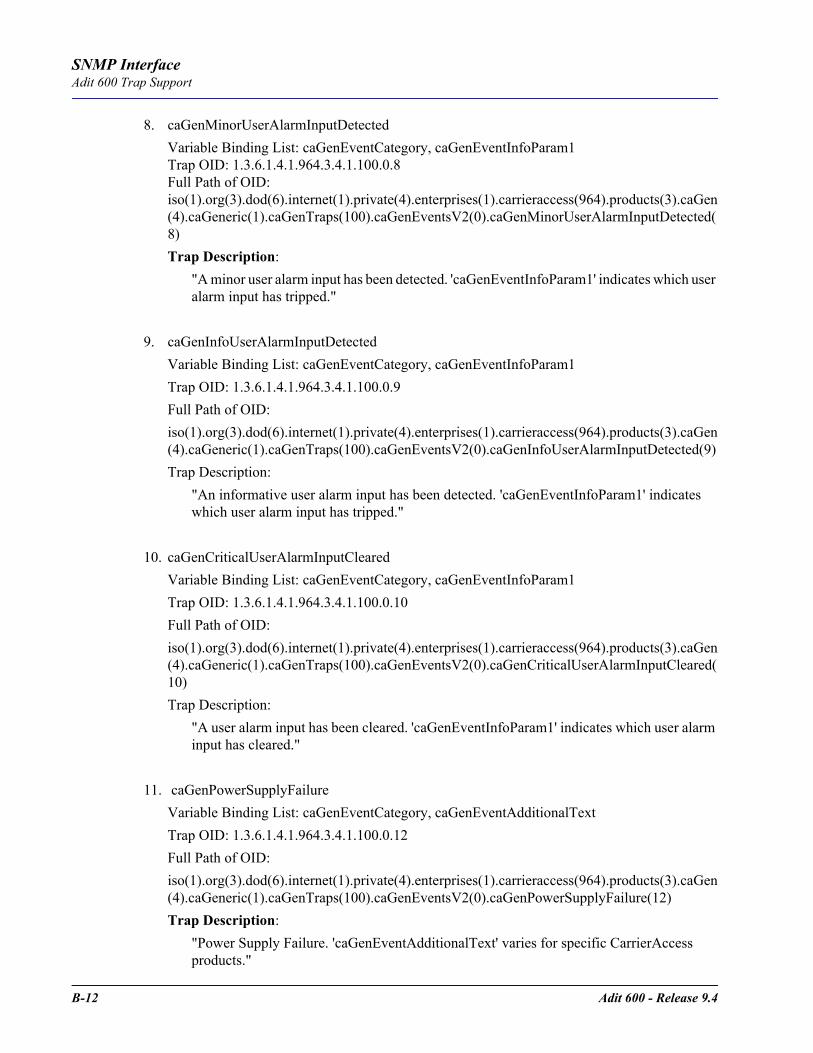
B-12 Adit 600 - Release 9.4
SNMP InterfaceAdit 600 Trap Support
8. caGenMinorUserAlarmInputDetectedVariable Binding List: caGenEventCategory, caGenEventInfoParam1Trap OID: 1.3.6.1.4.1.964.3.4.1.100.0.8Full Path of OID:iso(1).org(3).dod(6).internet(1).private(4).enterprises(1).carrieraccess(964).products(3).caGen(4).caGeneric(1).caGenTraps(100).caGenEventsV2(0).caGenMinorUserAlarmInputDetected(8)Trap Description:
"A minor user alarm input has been detected. 'caGenEventInfoParam1' indicates which user alarm input has tripped."
9. caGenInfoUserAlarmInputDetectedVariable Binding List: caGenEventCategory, caGenEventInfoParam1Trap OID: 1.3.6.1.4.1.964.3.4.1.100.0.9Full Path of OID:iso(1).org(3).dod(6).internet(1).private(4).enterprises(1).carrieraccess(964).products(3).caGen(4).caGeneric(1).caGenTraps(100).caGenEventsV2(0).caGenInfoUserAlarmInputDetected(9)Trap Description:
"An informative user alarm input has been detected. 'caGenEventInfoParam1' indicates which user alarm input has tripped."
10. caGenCriticalUserAlarmInputClearedVariable Binding List: caGenEventCategory, caGenEventInfoParam1Trap OID: 1.3.6.1.4.1.964.3.4.1.100.0.10Full Path of OID:iso(1).org(3).dod(6).internet(1).private(4).enterprises(1).carrieraccess(964).products(3).caGen(4).caGeneric(1).caGenTraps(100).caGenEventsV2(0).caGenCriticalUserAlarmInputCleared(10)Trap Description:
"A user alarm input has been cleared. 'caGenEventInfoParam1' indicates which user alarm input has cleared."
11. caGenPowerSupplyFailureVariable Binding List: caGenEventCategory, caGenEventAdditionalTextTrap OID: 1.3.6.1.4.1.964.3.4.1.100.0.12Full Path of OID:iso(1).org(3).dod(6).internet(1).private(4).enterprises(1).carrieraccess(964).products(3).caGen(4).caGeneric(1).caGenTraps(100).caGenEventsV2(0).caGenPowerSupplyFailure(12)Trap Description:
"Power Supply Failure. 'caGenEventAdditionalText' varies for specific CarrierAccess products."
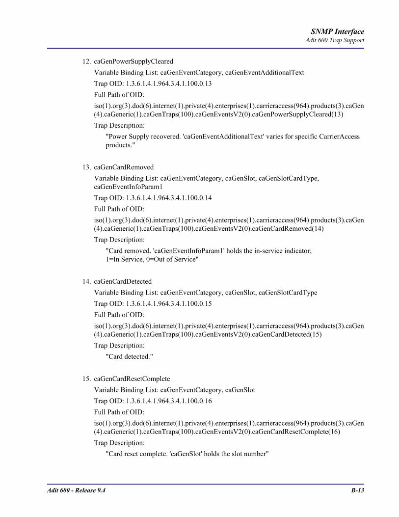
Adit 600 - Release 9.4 B-13
SNMP InterfaceAdit 600 Trap Support
12. caGenPowerSupplyClearedVariable Binding List: caGenEventCategory, caGenEventAdditionalTextTrap OID: 1.3.6.1.4.1.964.3.4.1.100.0.13Full Path of OID:iso(1).org(3).dod(6).internet(1).private(4).enterprises(1).carrieraccess(964).products(3).caGen(4).caGeneric(1).caGenTraps(100).caGenEventsV2(0).caGenPowerSupplyCleared(13)Trap Description:
"Power Supply recovered. 'caGenEventAdditionalText' varies for specific CarrierAccess products."
13. caGenCardRemovedVariable Binding List: caGenEventCategory, caGenSlot, caGenSlotCardType, caGenEventInfoParam1Trap OID: 1.3.6.1.4.1.964.3.4.1.100.0.14Full Path of OID:iso(1).org(3).dod(6).internet(1).private(4).enterprises(1).carrieraccess(964).products(3).caGen(4).caGeneric(1).caGenTraps(100).caGenEventsV2(0).caGenCardRemoved(14)Trap Description:
"Card removed. 'caGenEventInfoParam1' holds the in-service indicator;1=In Service, 0=Out of Service"
14. caGenCardDetectedVariable Binding List: caGenEventCategory, caGenSlot, caGenSlotCardTypeTrap OID: 1.3.6.1.4.1.964.3.4.1.100.0.15Full Path of OID:iso(1).org(3).dod(6).internet(1).private(4).enterprises(1).carrieraccess(964).products(3).caGen(4).caGeneric(1).caGenTraps(100).caGenEventsV2(0).caGenCardDetected(15)Trap Description:
"Card detected."
15. caGenCardResetCompleteVariable Binding List: caGenEventCategory, caGenSlotTrap OID: 1.3.6.1.4.1.964.3.4.1.100.0.16Full Path of OID:iso(1).org(3).dod(6).internet(1).private(4).enterprises(1).carrieraccess(964).products(3).caGen(4).caGeneric(1).caGenTraps(100).caGenEventsV2(0).caGenCardResetComplete(16)Trap Description:
"Card reset complete. 'caGenSlot' holds the slot number"

B-14 Adit 600 - Release 9.4
SNMP InterfaceAdit 600 Trap Support
16. caGenCardFailureVariable Binding List: caGenEventCategory, caGenSlot, caGenSlotCardType, caGenEventInfoParam1Trap OID: 1.3.6.1.4.1.964.3.4.1.100.0.19Full Path of OID:iso(1).org(3).dod(6).internet(1).private(4).enterprises(1).carrieraccess(964).products(3).caGen(4).caGeneric(1).caGenTraps(100).caGenEventsV2(0).caGenCardFailure(19)Trap Description:
"This would mostly be used for reporting problems during power up.'caGenEventInfoParam1' could hold a reason code such as self test failure, insufficient bandwidth on the backplane. The category would be 'system'."
17. caGenMinorPortAlarmClearedVariable Binding List: caGenEventCategory, caGenEventCode, ifIndex, caGenSlotCardType, caGenPortLoc, caGenEventAdditionalTextTrap OID: 1.3.6.1.4.1.964.3.4.1.100.0.22Full Path of OID:iso(1).org(3).dod(6).internet(1).private(4).enterprises(1).carrieraccess(964).products(3).caGen(4).caGeneric(1).caGenTraps(100).caGenEventsV2(0).caGenMinorPortAlarmCleared(22)Trap Description:
"A communication failure has been corrected. The 'caGenEventCode' variableholds the particular type of failure from this set:
Bipolar ViolationFrame Slip ViolationCollision Threshold
If the ifIndex has a name, 'caGenEventAdditionalText' reports it for all ifTypes."
18. caGenMajorUserAlarmInputClearedVariable Binding List: caGenEventCategory, caGenEventInfoParam1Trap OID: 1.3.6.1.4.1.964.3.4.1.100.0.23Full Path of OID:iso(1).org(3).dod(6).internet(1).private(4).enterprises(1).carrieraccess(964).products(3).caGen(4).caGeneric(1).caGenTraps(100).caGenEventsV2(0).caGenMajorUserAlarmInputCleared(23)Trap Description:
"A major user alarm input has been cleared. 'caGenEventInfoParam1' indicates which user alarm input has cleared."

Adit 600 - Release 9.4 B-15
SNMP InterfaceAdit 600 Trap Support
19. caGenMinorUserAlarmInputClearedVariable Binding List: caGenEventCategory, caGenEventInfoParam1Trap OID: 1.3.6.1.4.1.964.3.4.1.100.0.24Full Path of OID:iso(1).org(3).dod(6).internet(1).private(4).enterprises(1).carrieraccess(964).products(3).caGen(4).caGeneric(1).caGenTraps(100).caGenEventsV2(0).caGenMinorUserAlarmInputCleared(24)Trap Description:
"A minor user alarm input has been cleared. 'caGenEventInfoParam1' indicates which user alarm input has cleared."
20. caGenInfoUserAlarmInputClearedVariable Binding List: caGenEventCategory, caGenEventInfoParam1Trap OID: 1.3.6.1.4.1.964.3.4.1.100.0.25Full Path of OID:iso(1).org(3).dod(6).internet(1).private(4).enterprises(1).carrieraccess(964).products(3).caGen(4).caGeneric(1).caGenTraps(100).caGenEventsV2(0).caGenInfoUserAlarmInputCleared(25)Trap Description:
"A informative user alarm input has been cleared. 'caGenEventInfoParam1' indicates which user alarm input has cleared."

B-16 Adit 600 - Release 9.4
SNMP InterfaceAdit 600 Trap Support

APPENDIX CDiagnostics & Troubleshooting
In this Appendix
Alarms
Logs
Status and Performance
Loopbacks Overview- DS1/E1 Loopbacks
- V.35 Loopbacks
- V.35/V.54 Loop
- V.54 Equipment Loopback
- OCU-DP Loopbacks
Router Diagnostics and Performance Tools

C-2 Adit 600 - Release 9.4
Diagnostics & TroubleshootingAlarms
AlarmsTest AlarmThe Adit 600 alarm functions can be manually tested using the following command for setting critical, major and minor alarms. Turning alarms on or off will produce alarm messages and log entries stating the alarm event was manually set/cleared by the user.
Syntax: set alarms critical|major|minor off|on
Identify AlarmAlarm indicatorsLEDs - When an Alarm is triggered, the LED will display a red/yellow indicator light, which will stay on until the Alarm is cleared. The following is the LED information for the T1 Controller card. For LED information for the specific service card see the specific chapter for that card.
LED State DescriptionMAJOR Off No major alarms present
Red Major alarm present
MINOR Off No minor alarms present
Yellow Minor alarms present
LOCAL Off Remote mode (DIP switches disabled)
Green Local mode (DIP switches enabled)
ACO Off Normal mode. No alarms are being suppressed.
Yellow Alarm cutoff active. One or more active alarms suppressed.
T1-1 and T1-2
Off Off line
Green Normal
Red Loss of Signal (LOS) detected
Yellow Bipolar Violation (BPV) detected
Flashing Green
Loopback active
Flashing Red Loss of Frame (LOF) or Alarm Indication Signal (AIS) detected
Flashing Yellow
Yellow alarm (Remote Alarm Indication) detected.

Adit 600 - Release 9.4 C-3
Diagnostics & TroubleshootingAlarms
The following are hyperlinks to all the card LED information:
T1 Controller Card, LEDs
E1 Controller Card, LEDs
4-Wire E&M/TO Card, LEDs
FXO Voice Card, LEDs
FXS Voice Card, LEDs
ISDN BRI Card, LEDs
OCU-DP Card, LEDs
P-Phone Card, LEDs
Quad DS1 ADPCM Card, LEDs
Quad T1, Quad E1 & Quad DS1/E1 Cards, LEDs
Single Channel POTS Card, LEDs
Router (IP) Card, LEDs
Router (CMG) Card, LEDs
Terminal Server Router Card, LEDs
RS-232 Card, LEDs
V.35 and V.35/V.54 Cards, LEDs
Power Supply, 115 VAC LEDs
Power Supply, 230 VAC LEDs
Power Supply, 24 VDC LEDs

C-4 Adit 600 - Release 9.4
Diagnostics & TroubleshootingAlarms
Display AlarmsUse the alarms command to display the active alarms. Each alarm is related to a particular address and has a severity category (major, minor, critical, alert). The report can be filtered by port address and/or severity.
Syntax: alarms [slot|slot:port|slot:port:channel] [category] [severity]
> alarms
Time Date Severity Description
07:35:45 01/04/2002 Major Test Major Alarm 07:35:21 01/04/2002 Minor Test Minor Alarm
07:34:57 01/04/2002 Critical Test Critical Alarm
07:30:39 01/04/2002 Major 1:1-OCUDP Out of Service 03:50:55 01/04/2002 Major 1:1-OCUDP Loss of Signal
00:00:20 01/01/2002 Major 6:1-TSR Ethernet Link Down
00:00:20 01/01/2002 Major 4:1-CMG Ethernet Link Down
00:00:20 01/01/2002 Major 5:1-RTR Ethernet Link Down 00:00:05 01/01/2002 Major A:2-DS1 Loss Of Signal
00:00:05 01/01/2002 Major A:1-DS1 Loss Of Signal
Total=10
Category = bri|ds1|env|equipment|fxo|fxs|rtr|v35
Severity = alert|critical|info|major|minor
Clear AlarmOnce an alarm is identified then the process of clearing it can begin.
Silence Alarm, if necessary (Alarm Cut Off CLI command: aco)Check ConnectionCheck Cable, replace if necessaryCheck hardware and replace if necessaryCall Customer Support

Adit 600 - Release 9.4 C-5
Diagnostics & TroubleshootingLogs
LogsDisplay the event log to view a log of all system events, or narrow the view to only display specific information.
Syntax: log [slot|slot:port] [category] [severity]
Example: log Time Date Severity Description
00:00:15 01/01/2002 Major 4:1-CMG Ethernet Link Down 00:00:12 01/01/2002 Info 3-FXOx8 Card Detected 00:00:12 01/01/2002 Info 2-FXS5Gx8 Card Detected 00:00:06 01/01/2002 Major A:2-DS1 Loss Of Signal 00:00:05 01/01/2002 Info 4-CMGx1 Card Detected 00:00:02 01/01/2002 Info A-T1x2 Card Detected 00:00:02 01/01/2002 Info System Powerup
Total=7
Category = bri|ds1|env|equipment|fxo|fxs|rtr|v35
Severity = alert|critical|info|major|minor
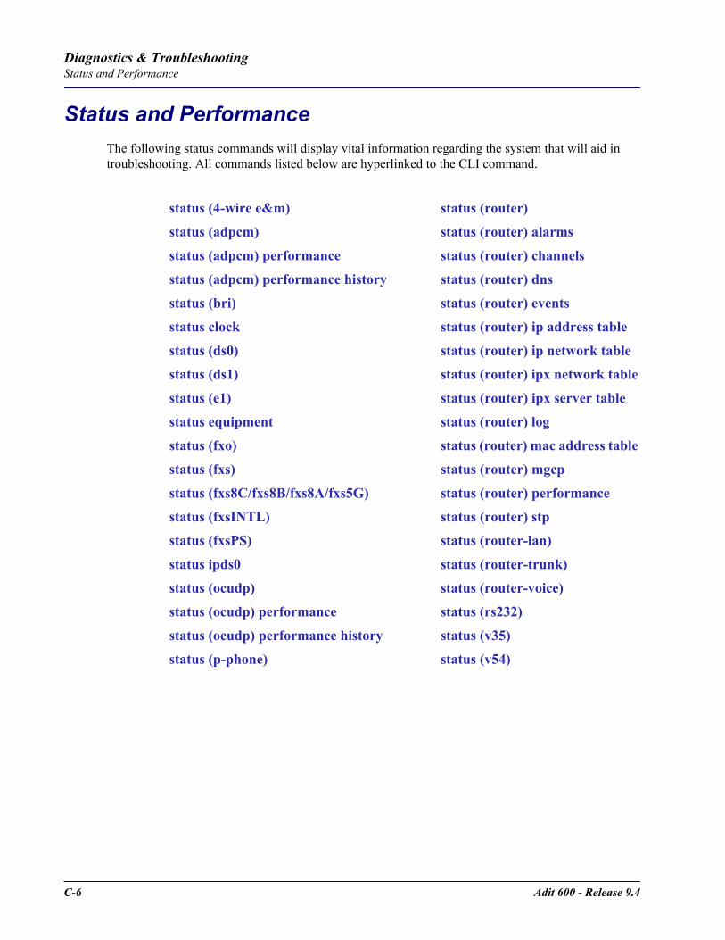
C-6 Adit 600 - Release 9.4
Diagnostics & TroubleshootingStatus and Performance
Status and PerformanceThe following status commands will display vital information regarding the system that will aid in troubleshooting. All commands listed below are hyperlinked to the CLI command.
status (4-wire e&m) status (router)
status (adpcm) status (router) alarms
status (adpcm) performance status (router) channels
status (adpcm) performance history status (router) dns
status (bri) status (router) events
status clock status (router) ip address table
status (ds0) status (router) ip network table
status (ds1) status (router) ipx network table
status (e1) status (router) ipx server table
status equipment status (router) log
status (fxo) status (router) mac address table
status (fxs) status (router) mgcp
status (fxs8C/fxs8B/fxs8A/fxs5G) status (router) performance
status (fxsINTL) status (router) stp
status (fxsPS) status (router-lan)
status ipds0 status (router-trunk)
status (ocudp) status (router-voice)
status (ocudp) performance status (rs232)
status (ocudp) performance history status (v35)
status (p-phone) status (v54)

Adit 600 - Release 9.4 C-7
Diagnostics & TroubleshootingLoopbacks Overview
Loopbacks OverviewA loopback test is a diagnostic procedure in which a signal is transmitted and returned to the sending device after passing through all or a portion of a network or circuit. The returned signal is compared with the transmitted signal in order to evaluate the integrity of the equipment or transmission path. The following are the Loopbacks available.T1/E1 Loopbacks
OCU-DP LoopbacksManual OCU LoopbackManual CSU LoopbackOCU Latching LoopbackCSU Latching LoopbackDSU Latching LoopbackDSU Non-Latching LoopbackCSU Non-Latching LoopbackOCU Non-Latching LoopbackOCU Manual LoopbackCSU Manual Loopback
Card Line Equipment Payload CSU NIUController T1 Yes No Yes Yes Yes (if ≥ vers 8.0)Quad T1 Yes Yes Yes Yes NoQuad DS1/E1 (1.82) Yes Yes Yes Yes Yes (if ≥ vers 1.82)Quad DS1 ADPCM (1.13) Yes Yes Yes Yes Yes (if ≥ vers 1.13)Controller E1 Yes No No No YesQuad E1 Yes No No No YesV.35 T1 Yes Yes No No NoV.35 E1 Yes Yes No No NoV.54 T1 Yes Yes No No NoV.54 E1 Yes Yes No No No

C-8 Adit 600 - Release 9.4
Diagnostics & TroubleshootingLoopbacks Overview
DS1/E1 LoopbacksNote: T1/E1 LEDs flash green during any DS1/E1 loopback.
DS1 Line LoopLoops at DS1/E1 (at framer), signal not reframed. Have DS1/E1 vendor check for framing/errors.Enable Line Loopback
> set a:1 line loopup
OK
View Status of LoopbackDS1 Status> status a:1
SLOT A:
Status for DS1 1: Receive: Traffic
Transmit: Traffic
Loopback: LINE
E1 Status> status a:1SLOT A:
Status for E1 1:
Receive: Loss of Framing Transmit: RAI/Yellow Alarm
Loopback: LINE
Disable Line Loopback> set a:1 line loopdownOK
View Status of LoopbackDS1 Status> status a:1SLOT A:
Status for DS1 1:
Receive: Traffic Transmit: Traffic
Loopback: OFF
E1 Status> status a:1
SLOT A:Status for E1 1:
Receive: Traffic
Transmit: Traffic Loopback: OFF
T1/E1
Adit 600
LocalDCE
V.35
Loops DS1/E1 as shownSignal Not Reframed
LocalDTE
FXS
Telephone
DS1Network

Adit 600 - Release 9.4 C-9
Diagnostics & TroubleshootingLoopbacks Overview
DS1 Payload LoopLoops at DS1 (in framer) and reframes the T1. Have DS1 vendor check for framing/errors.
Enable Payload Loopback> set a:1 payload loopupOK
View Status of Loopback > status a:1
SLOT A:
Status for DS1 1: Receive: Traffic
Transmit: Traffic
Loopback: PAYLOAD
Disable Payload Loopback> set a:1 payload loopdown
OK
View Status of Loopback > status a:1SLOT A:
Status for DS1 1:
Receive: Traffic Transmit: Traffic
Loopback: OFF
T1
Adit 600
LocalDCE
V.35
Loops DS1 as shownReframes the T1
LocalDTE
FXS
Telephone
DS1Network
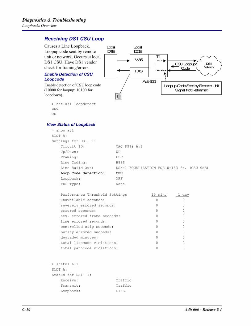
C-10 Adit 600 - Release 9.4
Diagnostics & TroubleshootingLoopbacks Overview
Receiving DS1 CSU LoopCauses a Line Loopback. Loopup code sent by remote unit or network. Occurs at local DS1 CSU. Have DS1 vendor check for framing/errors.Enable Detection of CSU LoopcodeEnable detection of CSU loop code (10000 for loopup; 10100 for loopdown).
> set a:1 loopdetect csu
OK
View Status of Loopback> show a:1
SLOT A:Settings for DS1 1:
Circuit ID: CAC DS1# A:1
Up/Down: UP Framing: ESF
Line Coding: B8ZS
Line Build Out: DSX-1 EQUALIZATION FOR 0-133 ft. (CSU 0dB) Loop Code Detection: CSU Loopback: OFF
FDL Type: None
Performance Threshold Settings 15 min. 1 day
unavailable seconds: 0 0 severely errored seconds: 0 0
errored seconds: 0 0
sev. errored frame seconds: 0 0 line errored seconds: 0 0
controlled slip seconds: 0 0
bursty errored seconds: 0 0 degraded minutes: 0 0
total linecode violations: 0 0
total pathcode violations: 0 0
> status a:1SLOT A:
Status for DS1 1:
Receive: Traffic Transmit: Traffic
Loopback: LINE
T1
Adit 600
LocalDCE
V.35
Loopup Code Sent by Remote UnitSignal Not Reframed
LocalDTE
FXS
Telephone
DS1Network
CSU LoopupCode
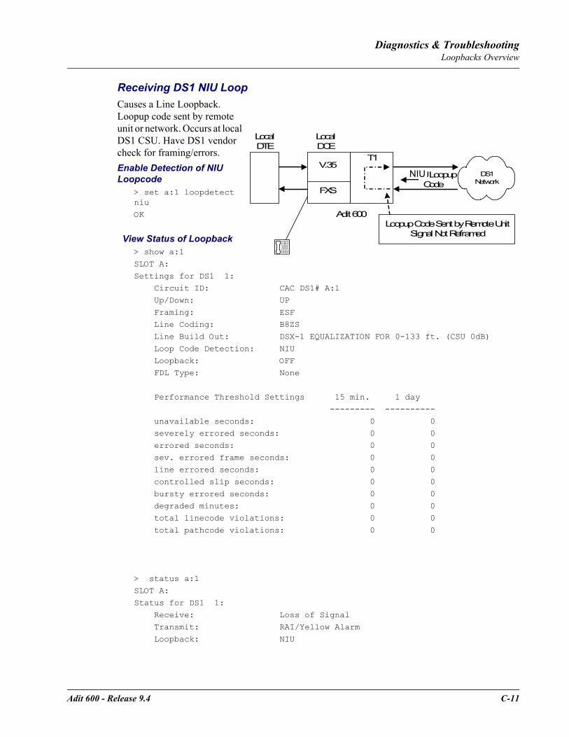
Adit 600 - Release 9.4 C-11
Diagnostics & TroubleshootingLoopbacks Overview
Receiving DS1 NIU LoopCauses a Line Loopback. Loopup code sent by remote unit or network. Occurs at local DS1 CSU. Have DS1 vendor check for framing/errors.Enable Detection of NIU Loopcode
> set a:1 loopdetect niuOK
View Status of Loopback> show a:1
SLOT A:
Settings for DS1 1: Circuit ID: CAC DS1# A:1
Up/Down: UP
Framing: ESF Line Coding: B8ZS
Line Build Out: DSX-1 EQUALIZATION FOR 0-133 ft. (CSU 0dB)
Loop Code Detection: NIU Loopback: OFF
FDL Type: None
Performance Threshold Settings 15 min. 1 day
--------- ----------
unavailable seconds: 0 0 severely errored seconds: 0 0
errored seconds: 0 0
sev. errored frame seconds: 0 0 line errored seconds: 0 0
controlled slip seconds: 0 0
bursty errored seconds: 0 0 degraded minutes: 0 0
total linecode violations: 0 0
total pathcode violations: 0 0
> status a:1
SLOT A:
Status for DS1 1: Receive: Loss of Signal
Transmit: RAI/Yellow Alarm
Loopback: NIU
T1
Adit 600
LocalDCE
V.35
Loopup Code Sent by Remote UnitSignal Not Reframed
LocalDTE
FXS
Telephone
DS1Network
CSU LoopupCode
NIU
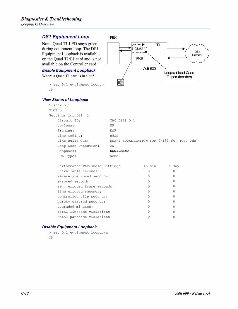
C-12 Adit 600 - Release 9.4
Diagnostics & TroubleshootingLoopbacks Overview
DS1 Equipment LoopNote: Quad T1 LED stays green during equipment loop. The DS1 Equipment Loopback is available on the Quad T1/E1 card and is not available on the Controller card.Enable Equipment LoopbackWhere a Quad T1 card is in slot 5.
> set 5:1 equipment loopup
OK
View Status of Loopback> show 5:1
SLOT 5:
Settings for DS1 1:
Circuit ID: CAC DS1# 5:1 Up/Down: UP
Framing: ESF
Line Coding: B8ZS Line Build Out: DSX-1 EQUALIZATION FOR 0-133 ft. (CSU 0dB)
Loop Code Detection: ON
Loopback: EQUIPMENT FDL Type: None
Performance Threshold Settings 15 min. 1 day unavailable seconds: 0 0
severely errored seconds: 0 0
errored seconds: 0 0 sev. errored frame seconds: 0 0
line errored seconds: 0 0
controlled slip seconds: 0 0 bursty errored seconds: 0 0
degraded minutes: 0 0
total linecode violations: 0 0 total pathcode violations: 0 0
Disable Equipment Loopback > set 5:1 equipment loopdown
OK
T1
Adit 600
Quad T1
Loops at local QuadT1 port (location)
PBX
FXS
Telephone
DS1Network
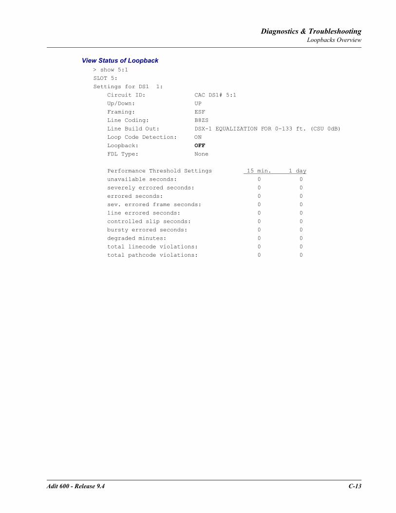
Adit 600 - Release 9.4 C-13
Diagnostics & TroubleshootingLoopbacks Overview
View Status of Loopback > show 5:1
SLOT 5:
Settings for DS1 1: Circuit ID: CAC DS1# 5:1
Up/Down: UP
Framing: ESF Line Coding: B8ZS
Line Build Out: DSX-1 EQUALIZATION FOR 0-133 ft. (CSU 0dB)
Loop Code Detection: ON Loopback: OFF FDL Type: None
Performance Threshold Settings 15 min. 1 day
unavailable seconds: 0 0
severely errored seconds: 0 0
errored seconds: 0 0 sev. errored frame seconds: 0 0
line errored seconds: 0 0
controlled slip seconds: 0 0 bursty errored seconds: 0 0
degraded minutes: 0 0
total linecode violations: 0 0 total pathcode violations: 0 0
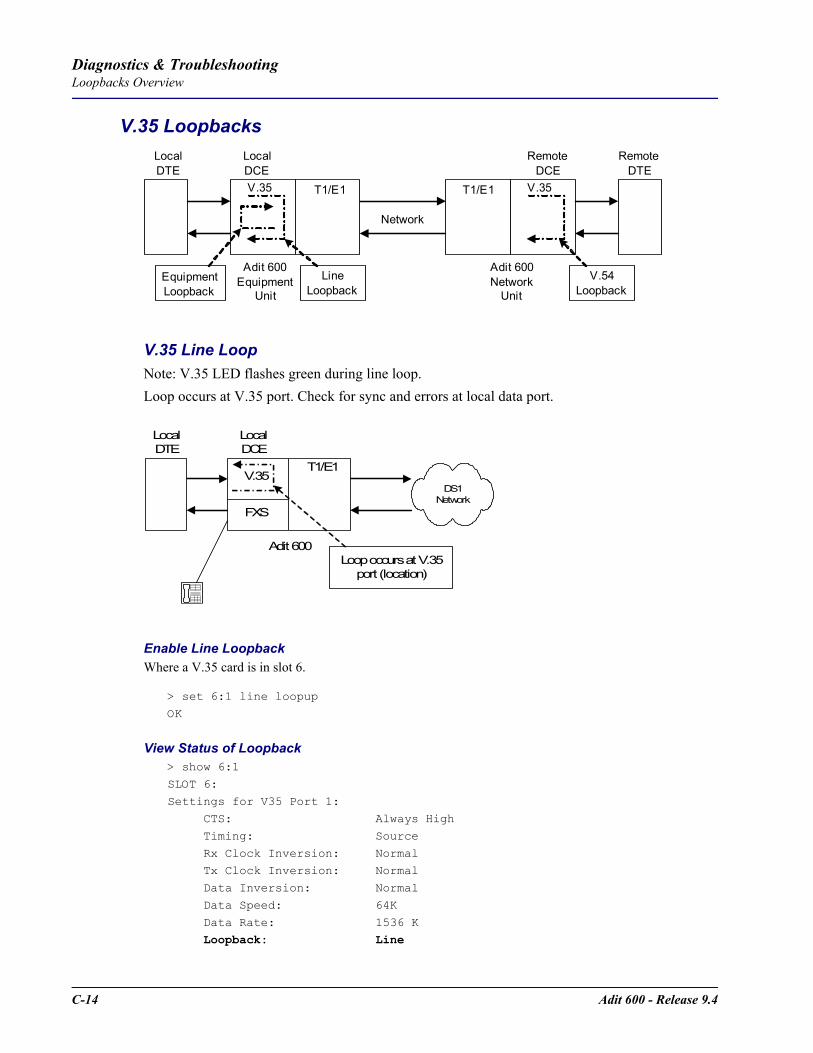
C-14 Adit 600 - Release 9.4
Diagnostics & TroubleshootingLoopbacks Overview
V.35 Loopbacks
V.35 Line LoopNote: V.35 LED flashes green during line loop.Loop occurs at V.35 port. Check for sync and errors at local data port.
Enable Line LoopbackWhere a V.35 card is in slot 6.
> set 6:1 line loopup
OK
View Status of Loopback > show 6:1
SLOT 6:
Settings for V35 Port 1: CTS: Always High
Timing: Source
Rx Clock Inversion: Normal Tx Clock Inversion: Normal
Data Inversion: Normal
Data Speed: 64K
Data Rate: 1536 K Loopback: Line
T1/E1
Network
T1/E1
LocalDTE
Adit 600Equipment
Unit
LocalDCEV.35
LineLoopback
Adit 600Network
Unit
RemoteDTE
RemoteDCE
V.54Loopback
V.35
EquipmentLoopback
T1/E1
Adit 600
LocalDCE
V.35
Loop occurs at V.35port (location)
LocalDTE
FXS
Telephone
DS1Network
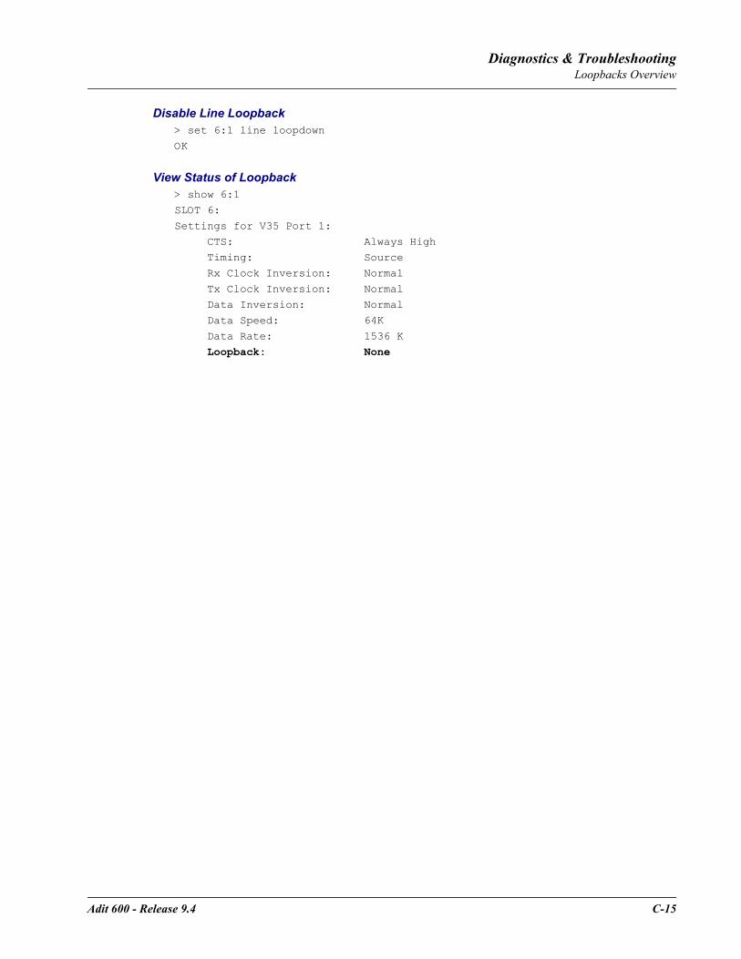
Adit 600 - Release 9.4 C-15
Diagnostics & TroubleshootingLoopbacks Overview
Disable Line Loopback > set 6:1 line loopdown
OK
View Status of Loopback > show 6:1SLOT 6:
Settings for V35 Port 1:
CTS: Always High Timing: Source
Rx Clock Inversion: Normal
Tx Clock Inversion: Normal Data Inversion: Normal
Data Speed: 64K
Data Rate: 1536 K
Loopback: None
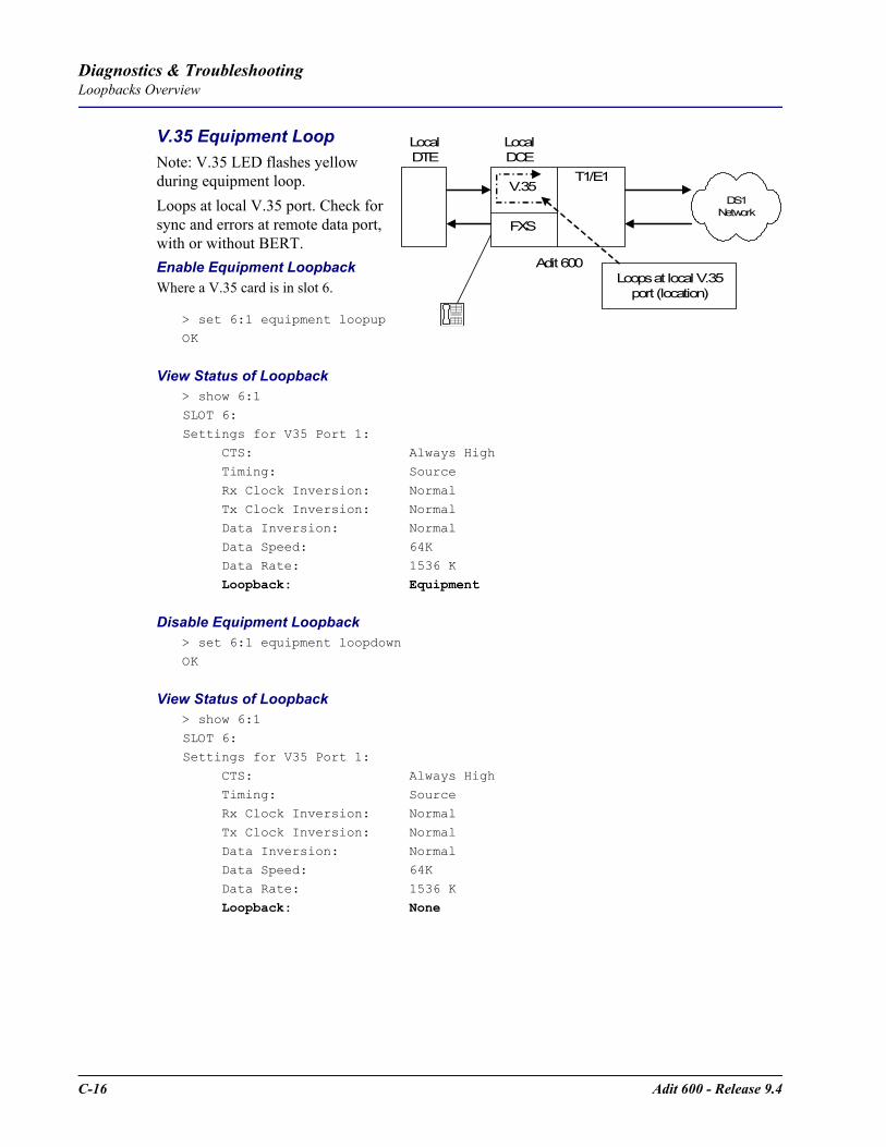
C-16 Adit 600 - Release 9.4
Diagnostics & TroubleshootingLoopbacks Overview
V.35 Equipment LoopNote: V.35 LED flashes yellow during equipment loop.Loops at local V.35 port. Check for sync and errors at remote data port, with or without BERT.Enable Equipment LoopbackWhere a V.35 card is in slot 6.
> set 6:1 equipment loopupOK
View Status of Loopback > show 6:1
SLOT 6:
Settings for V35 Port 1: CTS: Always High
Timing: Source
Rx Clock Inversion: Normal Tx Clock Inversion: Normal
Data Inversion: Normal
Data Speed: 64K Data Rate: 1536 K
Loopback: Equipment
Disable Equipment Loopback > set 6:1 equipment loopdownOK
View Status of Loopback > show 6:1
SLOT 6:Settings for V35 Port 1:
CTS: Always High
Timing: Source Rx Clock Inversion: Normal
Tx Clock Inversion: Normal
Data Inversion: Normal Data Speed: 64K
Data Rate: 1536 K
Loopback: None
T1/E1
Adit 600
LocalDCE
V.35
Loops at local V.35port (location)
LocalDTE
FXS
Telephone
DS1Network
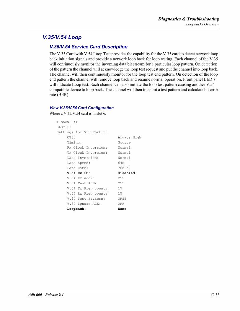
Adit 600 - Release 9.4 C-17
Diagnostics & TroubleshootingLoopbacks Overview
V.35/V.54 LoopV.35/V.54 Service Card DescriptionThe V.35 Card with V.54 Loop Test provides the capability for the V.35 card to detect network loop back initiation signals and provide a network loop back for loop testing. Each channel of the V.35 will continuously monitor the incoming data bit stream for a particular loop pattern. On detection of the pattern the channel will acknowledge the loop test request and put the channel into loop back. The channel will then continuously monitor for the loop test end pattern. On detection of the loop end pattern the channel will remove loop back and resume normal operation. Front panel LED’s will indicate Loop test. Each channel can also initiate the loop test pattern causing another V.54 compatible device to loop back. The channel will then transmit a test pattern and calculate bit error rate (BER).
View V.35/V.54 Card ConfigurationWhere a V.35/V.54 card is in slot 6.
> show 6:1
SLOT 6:Settings for V35 Port 1:
CTS: Always High
Timing: Source Rx Clock Inversion: Normal
Tx Clock Inversion: Normal
Data Inversion: Normal Data Speed: 64K
Data Rate: 768 K
V.54 Rx LB: disabled V.54 Rx Addr: 255
V.54 Test Addr: 255
V.54 Tx Prep count: 15 V.54 Rx Prep count: 15
V.54 Test Pattern: QRSS
V.54 Ignore ACK: OFF Loopback: None

C-18 Adit 600 - Release 9.4
Diagnostics & TroubleshootingLoopbacks Overview
V.54 LoopNote: Local LED flashes yellow, remote LED flashes green.
Enable V.54 LoopWhere a V.35/V.54 card is in slot 6.
> set 6:1 v54 network enableOK
View Status of Loopback > show 6:1SLOT 6:Settings for V35 Port 1: CTS: Always High Timing: Source Rx Clock Inversion: Normal Tx Clock Inversion: Normal Data Inversion: Normal Data Speed: 64K Data Rate: 768 K V.54 Rx LB: enabled V.54 Rx Addr: 255 V.54 Test Addr: 255 V.54 Tx Prep count: 15 V.54 Rx Prep count: 15 V.54 Test Pattern: QRSS V.54 Ignore ACK: OFF Loopback: None
Transmit V.54 Loopup
Receive V.54 Loopup
T1/E1
Network
T1/E1
LocalDTE
Adit 600Equipment
Unit
LocalDCEV.35
Adit 600Network
Unit
RemoteDTE
RemoteDCE
V.35
Local unit sendV.54 loop up
code, loop occursat remote data
port
T1/E1
Network
T1/E1
LocalDTE
Adit 600Equipment
Unit
LocalDCEV.35
Adit 600Network
Unit
RemoteDTE
RemoteDCE
V.35
Remote unit ornetwork sends
V.54 loop up code,loop occurs atlocal data port
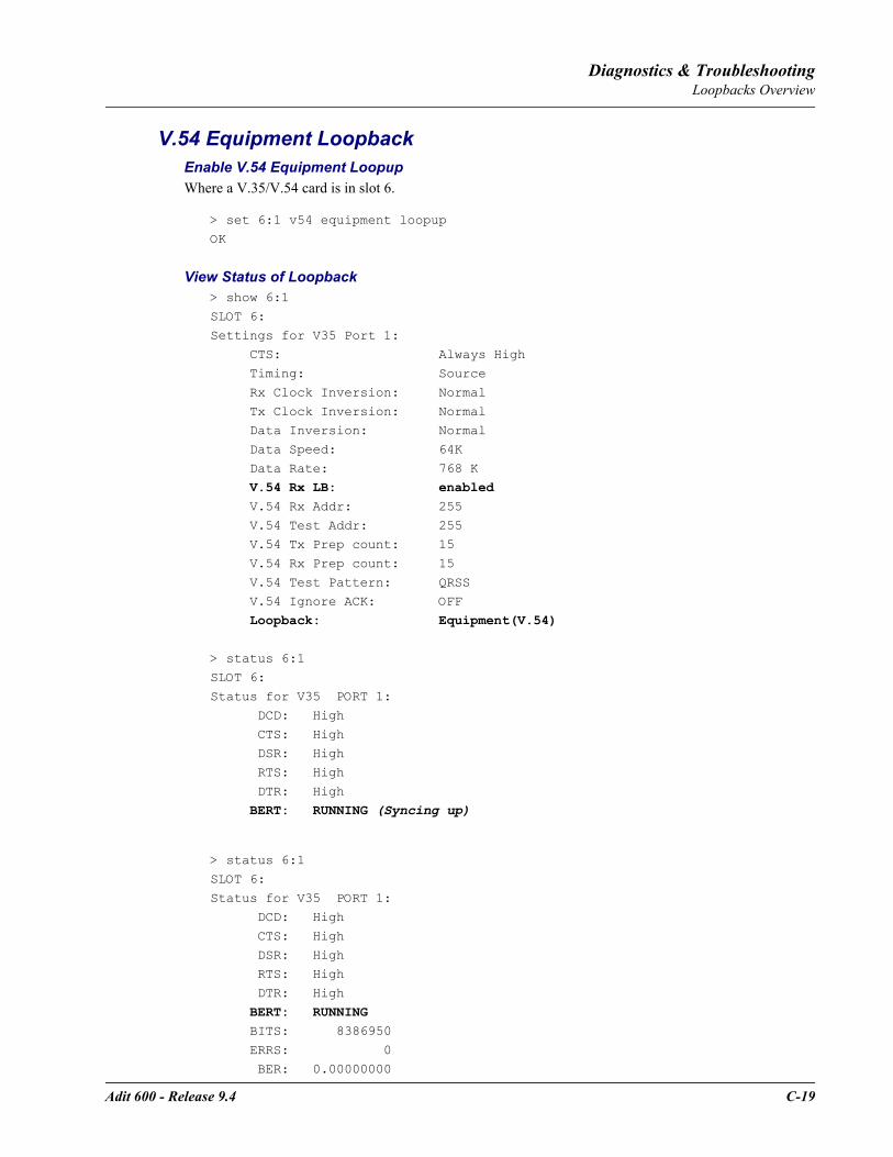
Adit 600 - Release 9.4 C-19
Diagnostics & TroubleshootingLoopbacks Overview
V.54 Equipment LoopbackEnable V.54 Equipment LoopupWhere a V.35/V.54 card is in slot 6.
> set 6:1 v54 equipment loopup
OK
View Status of Loopback > show 6:1
SLOT 6:
Settings for V35 Port 1: CTS: Always High
Timing: Source
Rx Clock Inversion: Normal
Tx Clock Inversion: Normal Data Inversion: Normal
Data Speed: 64K
Data Rate: 768 K V.54 Rx LB: enabled V.54 Rx Addr: 255
V.54 Test Addr: 255 V.54 Tx Prep count: 15
V.54 Rx Prep count: 15
V.54 Test Pattern: QRSS V.54 Ignore ACK: OFF
Loopback: Equipment(V.54)
> status 6:1
SLOT 6:
Status for V35 PORT 1: DCD: High
CTS: High
DSR: High RTS: High
DTR: High
BERT: RUNNING (Syncing up)
> status 6:1
SLOT 6:
Status for V35 PORT 1: DCD: High
CTS: High
DSR: High RTS: High
DTR: High
BERT: RUNNING BITS: 8386950
ERRS: 0
BER: 0.00000000

C-20 Adit 600 - Release 9.4
Diagnostics & TroubleshootingLoopbacks Overview
Disable V.54 Equipment Loopup> set 6:1 v54 equipment loopdown
OK
View Status of Loopback > status 6:1
SLOT 6:
Status for V35 PORT 1: DCD: High
CTS: High
DSR: High RTS: High
DTR: High
BERT: Complete BITS: 109030350 ERRS: 0
BER: 0.00000000
BERT DATE: 1/5/2001 01:39:18
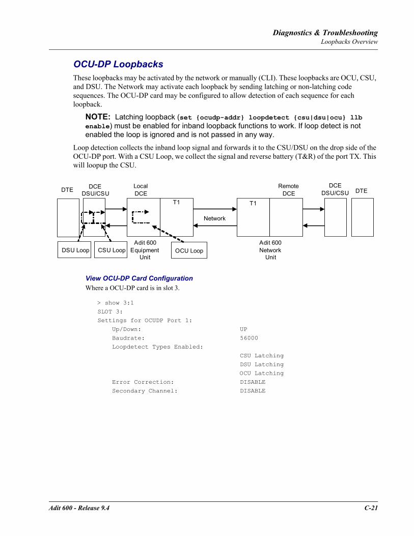
Adit 600 - Release 9.4 C-21
Diagnostics & TroubleshootingLoopbacks Overview
OCU-DP LoopbacksThese loopbacks may be activated by the network or manually (CLI). These loopbacks are OCU, CSU, and DSU. The Network may activate each loopback by sending latching or non-latching code sequences. The OCU-DP card may be configured to allow detection of each sequence for each loopback.
NOTE: Latching loopback (set ocudp-addr loopdetect csu|dsu|ocu llb enable) must be enabled for inband loopback functions to work. If loop detect is not enabled the loop is ignored and is not passed in any way.
Loop detection collects the inband loop signal and forwards it to the CSU/DSU on the drop side of the OCU-DP port. With a CSU Loop, we collect the signal and reverse battery (T&R) of the port TX. This will loopup the CSU.
View OCU-DP Card ConfigurationWhere a OCU-DP card is in slot 3.
> show 3:1
SLOT 3:Settings for OCUDP Port 1:
Up/Down: UP
Baudrate: 56000 Loopdetect Types Enabled:
CSU Latching
DSU Latching OCU Latching
Error Correction: DISABLE
Secondary Channel: DISABLE
T1
Network
T1
DTE
Adit 600Equipment
Unit
LocalDCE
Adit 600Network
Unit
RemoteDCE
DCEDSU/CSU
DCEDSU/CSU DTE
DSU Loop CSU Loop OCU Loop

C-22 Adit 600 - Release 9.4
Diagnostics & TroubleshootingLoopbacks Overview
Non-Latching LoopdetectEnable OCU-DP Non-Latching LoopdetectWhere a OCU-DP card is in slot 3.
> set 3:1 loopdetect ocu nllb enableOK
> set 3:1 loopdetect csu nllb enableOK
> set 3:1 loopdetect dsu nllb enableOK
View Status of Loopdetect > show 3:1
SLOT 3:Settings for OCUDP Port 1:
Up/Down: UP
Baudrate: 56000 Loopdetect Types Enabled:
CSU Latching
CSU Non-Latching DSU Latching
DSU Non-Latching OCU Latching OCU Non-Latching Error Correction: DISABLE
Secondary Channel: DISABLE
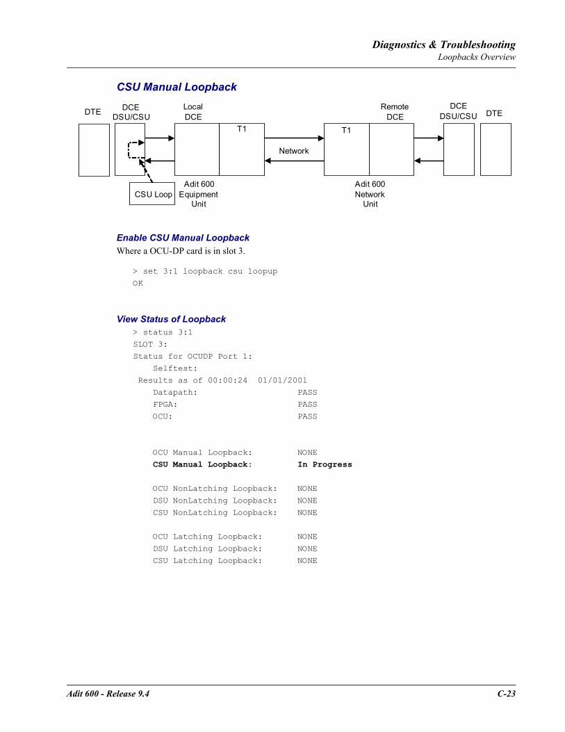
Adit 600 - Release 9.4 C-23
Diagnostics & TroubleshootingLoopbacks Overview
CSU Manual Loopback
Enable CSU Manual LoopbackWhere a OCU-DP card is in slot 3.
> set 3:1 loopback csu loopup
OK
View Status of Loopback > status 3:1
SLOT 3:
Status for OCUDP Port 1: Selftest:
Results as of 00:00:24 01/01/2001
Datapath: PASS FPGA: PASS
OCU: PASS
OCU Manual Loopback: NONE
CSU Manual Loopback: In Progress
OCU NonLatching Loopback: NONE
DSU NonLatching Loopback: NONE
CSU NonLatching Loopback: NONE
OCU Latching Loopback: NONE
DSU Latching Loopback: NONE CSU Latching Loopback: NONE
T1
Network
T1
DTE
Adit 600Equipment
Unit
LocalDCE
Adit 600Network
Unit
RemoteDCE
DCEDSU/CSU
DCEDSU/CSU DTE
CSU Loop
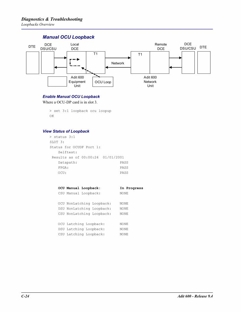
C-24 Adit 600 - Release 9.4
Diagnostics & TroubleshootingLoopbacks Overview
Manual OCU Loopback
Enable Manual OCU LoopbackWhere a OCU-DP card is in slot 3.
> set 3:1 loopback ocu loopup
OK
View Status of Loopback > status 3:1
SLOT 3:
Status for OCUDP Port 1: Selftest:
Results as of 00:00:24 01/01/2001
Datapath: PASS FPGA: PASS
OCU: PASS
OCU Manual Loopback: In Progress CSU Manual Loopback: NONE
OCU NonLatching Loopback: NONE
DSU NonLatching Loopback: NONE CSU NonLatching Loopback: NONE
OCU Latching Loopback: NONE DSU Latching Loopback: NONE
CSU Latching Loopback: NONE
T1
Network
T1
DTE
Adit 600Equipment
Unit
LocalDCE
Adit 600Network
Unit
RemoteDCE
DCEDSU/CSU
DCEDSU/CSU DTE
OCU Loop
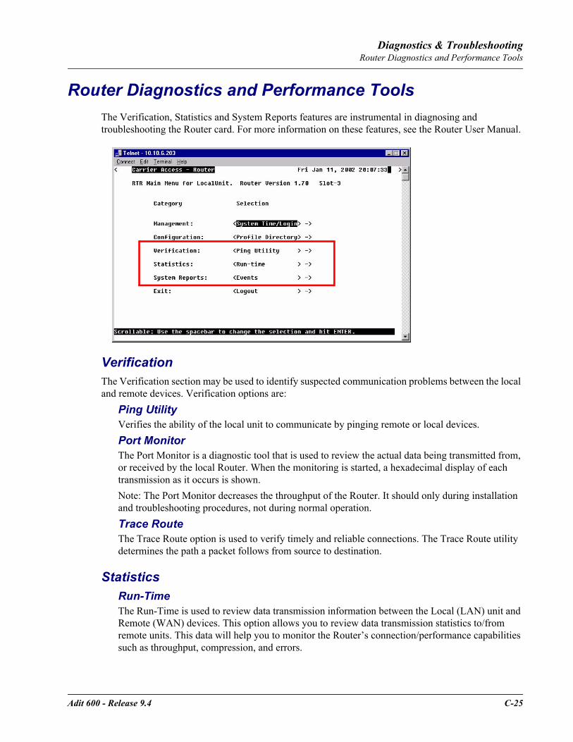
Adit 600 - Release 9.4 C-25
Diagnostics & TroubleshootingRouter Diagnostics and Performance Tools
Router Diagnostics and Performance ToolsThe Verification, Statistics and System Reports features are instrumental in diagnosing and troubleshooting the Router card. For more information on these features, see the Router User Manual.
VerificationThe Verification section may be used to identify suspected communication problems between the local and remote devices. Verification options are:
Ping UtilityVerifies the ability of the local unit to communicate by pinging remote or local devices. Port MonitorThe Port Monitor is a diagnostic tool that is used to review the actual data being transmitted from, or received by the local Router. When the monitoring is started, a hexadecimal display of each transmission as it occurs is shown.Note: The Port Monitor decreases the throughput of the Router. It should only during installation and troubleshooting procedures, not during normal operation.Trace RouteThe Trace Route option is used to verify timely and reliable connections. The Trace Route utility determines the path a packet follows from source to destination.
StatisticsRun-TimeThe Run-Time is used to review data transmission information between the Local (LAN) unit and Remote (WAN) devices. This option allows you to review data transmission statistics to/from remote units. This data will help you to monitor the Router’s connection/performance capabilities such as throughput, compression, and errors.

C-26 Adit 600 - Release 9.4
Diagnostics & TroubleshootingRouter Diagnostics and Performance Tools
System ReportsThe System Reports menu presents data that may be useful in identifying WAN communication problems.
EventsThe Events listing offers on-going historical activity for the Router, while the Alarm listing indicates events that suggest further investigation.
AlarmsThis screen provides a listing of any Alarms that have occurred on the Router. When an Alarm is triggered, the Router LED (labeled CRD) will display a red indicator light, which will stay on until the Alarm is cleared. Each Alarm is listed separately and the Count field will display a value of 1.
Network/ServersBy sending out IPX and IP RIP (Routing Information Protocol) and IPX SAP (Service Advertising Protocol) packets and monitoring RIP and SAP packets from other devices, the Router will learn about other servers and networks. The Router will constantly monitor RIP and SAP packets to ensure that the status of the network or server has changed. Should a RIP or SAP packet indicate a change in status, the Router would update the data in the table and send the information to all enabled remotes to exchange the updated data.
Address TablesThe MAC Address and IP Address Tables, along with Network Tables are used to determine if and where the Router should send packets.

APPENDIX DProtocol Types
In this Appendix
Protocol Number in Firewall Filters
Ethernet Protocol Types
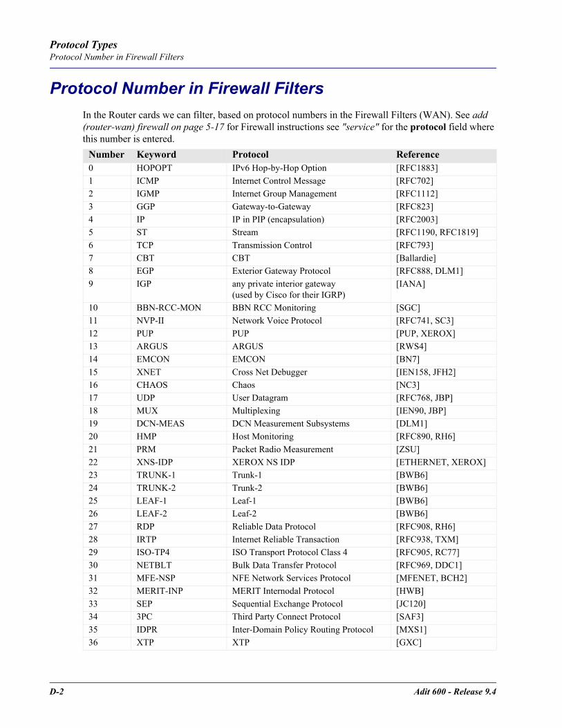
D-2 Adit 600 - Release 9.4
Protocol TypesProtocol Number in Firewall Filters
Protocol Number in Firewall FiltersIn the Router cards we can filter, based on protocol numbers in the Firewall Filters (WAN). See add (router-wan) firewall on page 5-17 for Firewall instructions see "service" for the protocol field where this number is entered.
Number Keyword Protocol Reference0 HOPOPT IPv6 Hop-by-Hop Option [RFC1883]1 ICMP Internet Control Message [RFC702]2 IGMP Internet Group Management [RFC1112]3 GGP Gateway-to-Gateway [RFC823]4 IP IP in PIP (encapsulation) [RFC2003]5 ST Stream [RFC1190, RFC1819]6 TCP Transmission Control [RFC793]7 CBT CBT [Ballardie]8 EGP Exterior Gateway Protocol [RFC888, DLM1]9 IGP any private interior gateway
(used by Cisco for their IGRP)[IANA]
10 BBN-RCC-MON BBN RCC Monitoring [SGC]11 NVP-II Network Voice Protocol [RFC741, SC3]12 PUP PUP [PUP, XEROX]13 ARGUS ARGUS [RWS4]14 EMCON EMCON [BN7]15 XNET Cross Net Debugger [IEN158, JFH2]16 CHAOS Chaos [NC3]17 UDP User Datagram [RFC768, JBP]18 MUX Multiplexing [IEN90, JBP]19 DCN-MEAS DCN Measurement Subsystems [DLM1]20 HMP Host Monitoring [RFC890, RH6]21 PRM Packet Radio Measurement [ZSU]22 XNS-IDP XEROX NS IDP [ETHERNET, XEROX]23 TRUNK-1 Trunk-1 [BWB6]24 TRUNK-2 Trunk-2 [BWB6]25 LEAF-1 Leaf-1 [BWB6]26 LEAF-2 Leaf-2 [BWB6]27 RDP Reliable Data Protocol [RFC908, RH6]28 IRTP Internet Reliable Transaction [RFC938, TXM]29 ISO-TP4 ISO Transport Protocol Class 4 [RFC905, RC77]30 NETBLT Bulk Data Transfer Protocol [RFC969, DDC1]31 MFE-NSP NFE Network Services Protocol [MFENET, BCH2]32 MERIT-INP MERIT Internodal Protocol [HWB]33 SEP Sequential Exchange Protocol [JC120]34 3PC Third Party Connect Protocol [SAF3]35 IDPR Inter-Domain Policy Routing Protocol [MXS1]36 XTP XTP [GXC]
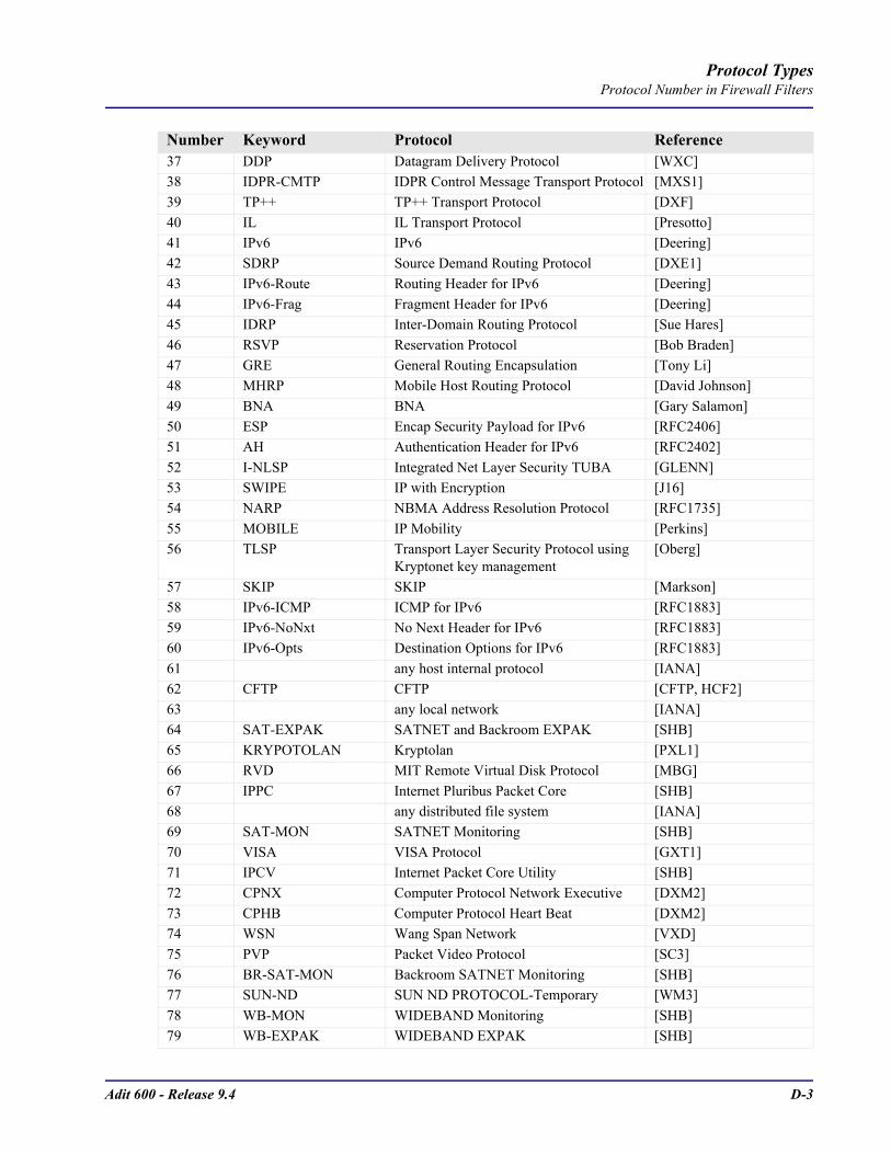
Adit 600 - Release 9.4 D-3
Protocol TypesProtocol Number in Firewall Filters
37 DDP Datagram Delivery Protocol [WXC]38 IDPR-CMTP IDPR Control Message Transport Protocol [MXS1]39 TP++ TP++ Transport Protocol [DXF]40 IL IL Transport Protocol [Presotto]41 IPv6 IPv6 [Deering]42 SDRP Source Demand Routing Protocol [DXE1]43 IPv6-Route Routing Header for IPv6 [Deering]44 IPv6-Frag Fragment Header for IPv6 [Deering]45 IDRP Inter-Domain Routing Protocol [Sue Hares]46 RSVP Reservation Protocol [Bob Braden]47 GRE General Routing Encapsulation [Tony Li]48 MHRP Mobile Host Routing Protocol [David Johnson]49 BNA BNA [Gary Salamon]50 ESP Encap Security Payload for IPv6 [RFC2406]51 AH Authentication Header for IPv6 [RFC2402]52 I-NLSP Integrated Net Layer Security TUBA [GLENN]53 SWIPE IP with Encryption [J16]54 NARP NBMA Address Resolution Protocol [RFC1735]55 MOBILE IP Mobility [Perkins]56 TLSP Transport Layer Security Protocol using
Kryptonet key management[Oberg]
57 SKIP SKIP [Markson]58 IPv6-ICMP ICMP for IPv6 [RFC1883]59 IPv6-NoNxt No Next Header for IPv6 [RFC1883]60 IPv6-Opts Destination Options for IPv6 [RFC1883]61 any host internal protocol [IANA]62 CFTP CFTP [CFTP, HCF2]63 any local network [IANA]64 SAT-EXPAK SATNET and Backroom EXPAK [SHB]65 KRYPOTOLAN Kryptolan [PXL1]66 RVD MIT Remote Virtual Disk Protocol [MBG]67 IPPC Internet Pluribus Packet Core [SHB]68 any distributed file system [IANA]69 SAT-MON SATNET Monitoring [SHB]70 VISA VISA Protocol [GXT1]71 IPCV Internet Packet Core Utility [SHB]72 CPNX Computer Protocol Network Executive [DXM2]73 CPHB Computer Protocol Heart Beat [DXM2]74 WSN Wang Span Network [VXD]75 PVP Packet Video Protocol [SC3]76 BR-SAT-MON Backroom SATNET Monitoring [SHB]77 SUN-ND SUN ND PROTOCOL-Temporary [WM3]78 WB-MON WIDEBAND Monitoring [SHB]79 WB-EXPAK WIDEBAND EXPAK [SHB]
Number Keyword Protocol Reference

D-4 Adit 600 - Release 9.4
Protocol TypesProtocol Number in Firewall Filters
80 ISO-IP ISO Internet Protocol [MTR]81 VMTP VMTP [DRC3]82 SECURE-VMTP SECURE-VMTP [DRC3]83 VINES VINES [BXH]84 TTP TTP [JXS]85 NSFNET-IGP NSFNET-IGP [HWB]86 DGP Dissimilar Gateway Protocol [DGP, ML109]87 TCF TCF [GAL5]88 EIGRP EIGRP [CISCO, GXS]89 OSPFIGP OSPFIGP [RFC1583, JTM4]90 Sprite-RPC Sprite RPC Protocol [SPRITE, BXW]91 LARP Locus Address Resolution Protocol [BXH]92 MTP Multicast Transport Protocol [SXA]93 AX.25 AZ.25 Frames [BK29]94 IPIP IP-within-IP Encapsulation Protocol [JI6]95 MICP Mobile Internetworking Control Pro [JI6]96 SCC-SP Semaphore Communications Sec. Pro. [HXH]97 ETHERIP Ethernet-within-IP Encapsulation [RFC3378]98 ENCAP Encapsulation Header [FRC1241, RXB3]99 any private encryption scheme [IANA]100 GMTP GMTP [RXB5]101 IFMP Ipsilon Flow Management Protocol [Hinden]102 PNNI PNNI over IP [Callon]103 PIM Protocol Independent Multicast [Farinacci]104 ARIS ARIS [Feldman]105 SCPS SCPS [Durst]106 QNX QNX [Hunter]107 A/N Active Networks [Braden]108 IPComp IP Payload Compression Protocol [RFC2393]109 SNP Sitara Networks Protocol [Sridhar]110 Compaq-Peer Compaq Peer Protocol [Volpe]111 IPX-in-IP IPX in IP [Lee]112 VRRP Virtual Router Redundancy Protocol [Hinden]113 PGM PBM Reliable Transport Protocol [Speakman]114 any 0-hop protocol [IANA]115 L2TP Layer Two Tunneling Protocol [Aboba]116 DDX D-II Data Exchange (DDX) [Worley]117 IATP Interactive Agent Transfer Protocol [Murphy]118 STP Schedule Transfer Protocol [JMP]119 SRP SpectraLink Radio Protocol [Hamilton]120 UTI UTI [Lothberg]121 SMP SMP [Ekblad]122 SM SM [Crowcroft]
Number Keyword Protocol Reference
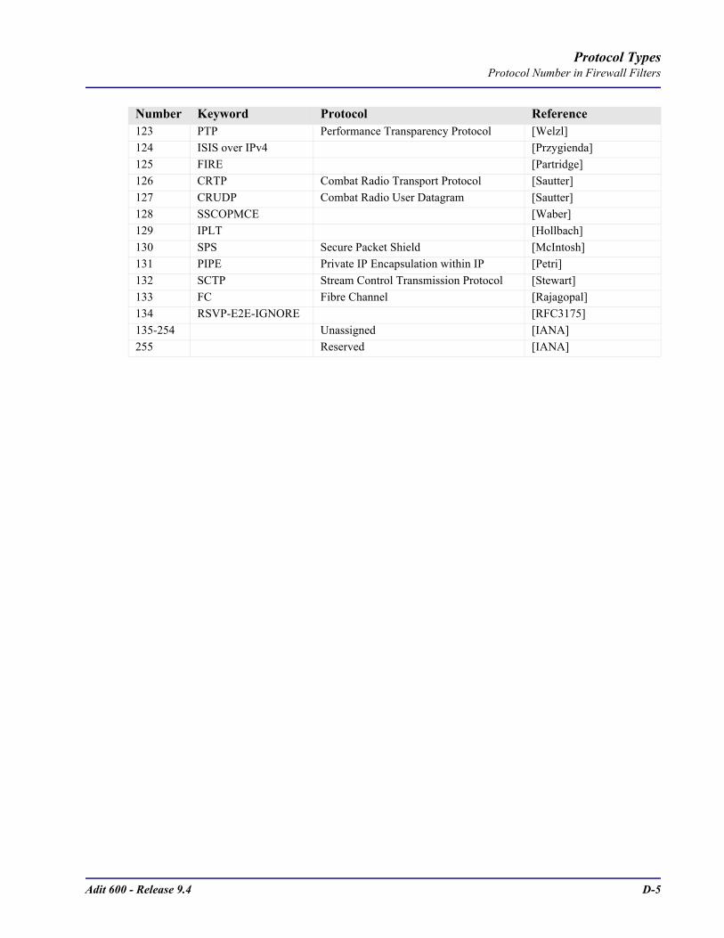
Adit 600 - Release 9.4 D-5
Protocol TypesProtocol Number in Firewall Filters
123 PTP Performance Transparency Protocol [Welzl]124 ISIS over IPv4 [Przygienda]125 FIRE [Partridge]126 CRTP Combat Radio Transport Protocol [Sautter]127 CRUDP Combat Radio User Datagram [Sautter]128 SSCOPMCE [Waber]129 IPLT [Hollbach]130 SPS Secure Packet Shield [McIntosh]131 PIPE Private IP Encapsulation within IP [Petri]132 SCTP Stream Control Transmission Protocol [Stewart]133 FC Fibre Channel [Rajagopal]134 RSVP-E2E-IGNORE [RFC3175]135-254 Unassigned [IANA]255 Reserved [IANA]
Number Keyword Protocol Reference

D-6 Adit 600 - Release 9.4
Protocol TypesEthernet Protocol Types
Ethernet Protocol TypesThis table defines the protocol types that would used by the LAN Protocol filters. The associated Hex number is entered into the Ethernet Value field. See, add (router-lan) filter protocol on page 5-14, under ether-type for the CLI field that this number is entered.
HEX DESCRIPTION
0000-05DC IEEE 802.3 Length Field (0-1500 decimal)
1010-01FF Experimental (for development) Conflicts with 802.3 length fields
0200 Xerox PUP - Conflicts with 802.3 length fields
0201 PUP Address Translation - Conflicts with 802.3 length fields
0600 Xeros XNS IDP
0800 DOD IP
0801 X.75 Internet
0802 NBS Internet
0803 ECMA Internet
0804 CHAOSnet
0805 X.25 Level 3
0806 ARP (for IP and for CHAOS)
0807 SNX Compatibility
081C Symbolics Private
0888-088A Xyplex
0900 Ungermann-Bass network debugger
0A00 Xerox 802.3 PUP
0A01 PUP 802.3 Address Translation
0BAD Banyan Systems Inc.
1000 Berkeley trailer negotiation
1001-100F Berkeley Trailer encapsulation
1600 VALID
4242 BXS Basic Block Protocol
5208 BBN Simnet Private
6000 DEC Unassigned
6001 DEC MOP Dump/Load Assistance
6002 DEC MOP Remote Console
6003 DEC DECnet Phase IV
6004 DEC LAT
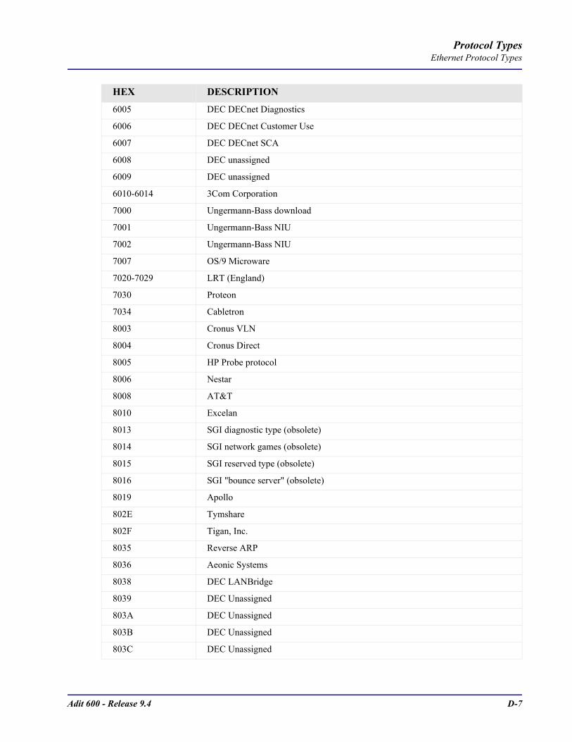
Adit 600 - Release 9.4 D-7
Protocol TypesEthernet Protocol Types
6005 DEC DECnet Diagnostics
6006 DEC DECnet Customer Use
6007 DEC DECnet SCA
6008 DEC unassigned
6009 DEC unassigned
6010-6014 3Com Corporation
7000 Ungermann-Bass download
7001 Ungermann-Bass NIU
7002 Ungermann-Bass NIU
7007 OS/9 Microware
7020-7029 LRT (England)
7030 Proteon
7034 Cabletron
8003 Cronus VLN
8004 Cronus Direct
8005 HP Probe protocol
8006 Nestar
8008 AT&T
8010 Excelan
8013 SGI diagnostic type (obsolete)
8014 SGI network games (obsolete)
8015 SGI reserved type (obsolete)
8016 SGI "bounce server" (obsolete)
8019 Apollo
802E Tymshare
802F Tigan, Inc.
8035 Reverse ARP
8036 Aeonic Systems
8038 DEC LANBridge
8039 DEC Unassigned
803A DEC Unassigned
803B DEC Unassigned
803C DEC Unassigned
HEX DESCRIPTION

D-8 Adit 600 - Release 9.4
Protocol TypesEthernet Protocol Types
803D DEC Ethernet CSMA/CD Encryption Protocol
803E DEC Unassigned
803F DEC LAN Traffic Monitor
8040 DEC Unassigned
8041 DEC Unassigned
8042 DEC Unassigned
8044 Planning Research Corporation
8046 AT&T
8047 AT&T
8049 ExperData (France)
805B VMTP (Versatile Message Transaction Protocol, RFC-1045, Stanford)
805C Stanford V Kernel production, Version 6.0
805D Evans & Sutherland
8060 Little Machines
8062 Counterpoint Computers
8065 University of Massachusetts, Amherst
8066 University of Massachusetts, Amherst
8067 Vecco Integrated Automation
8068 General Dynamics
8069 AT&T
806A Autophon (Switzerland)
806C ComDesign
806D Compugraphic Corporation
806E-8077 Landmark Graphics Corporation
807A Matra (France)
807B Dansk Data Elektronic A/S (Denmark)
807C Merit Internodal
807D VitaLink Communications
807E VitaLink Communications
807F VitaLink Communications
8080 VitaLink Communications bridge
8081 Counterpoint Computers
8082 Counterpoint Computers
HEX DESCRIPTION

Adit 600 - Release 9.4 D-9
Protocol TypesEthernet Protocol Types
8083 Counterpoint Computers
8088 Xyplex
8089 Xyplex
808A Xyplex
809B Kinetics Ethertalk-Appletalk over Ethernet
809C Datability
809D Datability
809E Datability
809F Spider Systems, Ltd. (England)
80A3 Nixdorf Computer (West Germany)
80A4-80B3 Siemens Gammasonics Inc.
80C0 Digital Communication Associates
80C1 Digital Communication Associates
80C2 Digital Communication Associates
80C3 Digital Communication Associates
80C6 Pacer Software
80C7 Applitek Corporation
80C8-80CC Integraph Corporation
80CD Harris Corporation
80CE Harris Corporation
80CF-80D2 Taylor Inst.
80D3 Rosemount Corporation
80D4 Rosemount Corporation
80D5 IBM SNA Services over Ethernet
80DD Varian Associates
80DE Integrated Solutions TRFS (Transparent Remote File System)
80DF Integrated Solutions
80E0-80E3 Allen-Bradley
80E4-80F0 Datability
80F2 Retix
80F3 Kinetics, AppleTalk ARP (AARP)
80F4 Kinetics
80F5 Kinetics
HEX DESCRIPTION
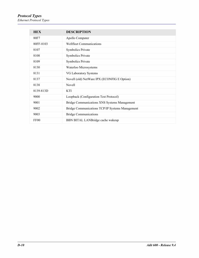
D-10 Adit 600 - Release 9.4
Protocol TypesEthernet Protocol Types
80F7 Apollo Computer
80FF-8103 Wellfleet Communications
8107 Symbolics Private
8108 Symbolics Private
8109 Symbolics Private
8130 Waterloo Microsystems
8131 VG Laboratory Systems
8137 Novell (old) NetWare IPX (ECONFIG E Option)
8138 Novell
8139-813D KTI
9000 Loopback (Configuration Test Protocol)
9001 Bridge Communications XNS Systems Management
9002 Bridge Communications TCP/IP Systems Management
9003 Bridge Communications
FF00 BBN BITAL LANBridge cache wakeup
HEX DESCRIPTION

GLOSSARY
ADPCM Adaptive Differential Pulse Code Modulation
AIS Alarm Indication Signal
AMI Automatic Mark Inversion
ARP Address Resolution Protocol
ATM Asynchronous Transfer Mode
B8ZS Bipolar with 8 Zero Substitution
BER Bit Error Rate
BERT Bit Error Rate Tester
BES Burst Errored Seconds
BIT Binary Digit
bps Bits Per Second
BPV Bipolar Violation
BRI Basic Rate Interface
CAS Channel Associated Signaling
CCS Common Channel Signaling
CHAP Challenge Handshake Authentication Protocol
CIDR Classless Inter-Domain Routing
CLASS Custom Local Area Signaling Service
CLEI Common Language Equipment Identification
CLI Command Line Interface
CMG Customer Media Gateway
CNG Also called Auto Fax Tone or Calling Tone
CO Central Office
Glossary
Glossary-2 Adit 600 - Release 9.4
GlossaryCPE
CPE Customer Provided Equipment
CRC Cyclic Redundancy Check
CRV Call Reference Value
CSU Channel Service Unit
CTS Clear To Send
D4 The fourth generation channel bank
dB decibel
DCS Digital Signal Processor
DDS Digital Data Service
DHCP Dynamic Host Configuration Protocol
DLC Digital Loop Carrier
DLCI Data Link Connection Identifier
DNS Domain Naming System
DS0 Digital Signal Level Zero (64 kbps) (1 voice channel)
DS1 Digital Signal Level 1 (1.544 Mbps)
DSR Data Set Ready signal
DSU Digital Service Unit/Data service Unit
DTE Data Terminal Equipment
DTMF Dual Tone Multi-Frequency
DTR Data Terminal Ready signal.
E1 The European counterpart to T1, which transmits at 2.048 Mbits/sec
E&M Ear and Mouth - a 4-wire analog voice transport with supervisory signaling.
ES Errored Seconds
ESF Extended Superframe
FDL Facilities Data Link
FX Foreign Exchange
Adit 600 - Release 9.4 Glossary-3
GlossaryFXO
FXO Foreign Exchange Office
FXS Foreign Exchange Station
GS Ground Start
GMT Greenwich Mean Time
GRE Generic Routing Encapsulation
IETF Internet Engineering Task Force
IP Internet Protocol
IPX Internet Packet eXchange
ISDN BRI Integrated Services Digital Network.
LAN Local Area Network
LLC Logical Link Control
LBO Line Build Out
LMI Local Management Interface
LS Loop Start
LULT Line Unit Line Termination
LUNT Line Unit Network Termination
Mbps Million Bits Per Second
MGCP Media Gateway Control Protocol
MLPPP Multilink PPP
MUX Multiplexer
MVEC Majority Vote Error Correction
NAT Network Address Translation
NCS Network-based Call Signaling
NEBS Network Equipment Building Standards
NIU Network Interface Unit
NTP Network Time Protocol
Glossary-4 Adit 600 - Release 9.4
GlossaryOCU-DP
OCU-DP Office Channel Unit - Data Port
PAP Password Authentication Protocol
PHY Physical specifications
PPP Point-to-Point Protocol.
PVC Permanent Virtual Circuit
QoS Quality of Service
RADIUS Remote Authentication Dial-In Service.
RIP Routing Information Protocol.
RTCP Real Time Conferencing Protocol.
RTP Realtime Transport Protocol
SAP Service Access Point.
RTS Request To Send
SDP Session Description Protocol.
SNMP Simple Network Management Protocol.
STP Spanning Tree Protocol.
T1 Trunk Level 1.
TBOS Telemetry Byte Oriented Serial.
TACACS+ Terminal Access Controller Access Control System.
TDM Time Division Multiplex.
TFTP Trivial File Transfer Protocol.
TOS Type of Service
TSR Terminal Server Router
VC MUX Virtual Channel Multiplexer
VOIP Voice over IP.
WAN Wide Area Network.
VC Virtual Channel.
Adit 600 - Release 9.4 Glossary-5
Glossary4-Wire E&M
4-Wire E&M A 4-wire analog voice transport with supervisory signaling.
10Base-T The most widely installed Ethernet local area networks (LANs) use ordinary telephone twisted-pair wire. When used on Ethernet, this carrier medium is known at 10BASE-T. 10BASE-T supports Ethernet’s 10 Mbps transmission speed.
100Base-TX Also called "Fast Ethernet," it is a 100 Mbps version of Ethernet. 100Base-T transmits at 100 Mbps rather than 10 Mbps. Like regular Ethernet, Fast Ethernet is a shared media LAN. All nodes share the 100 Mbps bandwidth. 100Base-TX uses two pairs of Category 5 cabling, one pair for transmission, one pair for receiving.
ADPCM Adaptive Differential Pulse Code Modulation. A speech coding method which uses fewer bits than the traditional PCM (Pulse Code Modulation). ADPCM allows encoding of voice signals in half the space PCM allows.
Alarm Indication Signal (AIS)
AIS, is formerly known as a Blue Alarm or Blue Signal. AIS is a signal that is transmitted downstream as an alert that an upstream failure has been detected.
analog The telephone transmission of voice, video or image. Telephone transmission and/or switching that is not digital.
Annex D A frame relay standard extension dealing with the communication and signaling between customer premises and equipment and frame relay network equipment for the purpose of querying network status information.
Asynchronous Transfer Mode
Very high speed transmission technology. ATM is a high bandwidth, low-delay, connection-oriented, packet-like switching and multiplexijng technique. Usable capacity is segmented into 53-byte fixed-size cells, consisting of header and information fields, allocated to services on demand. The term "asynchronous" applies, as each cell is presented to the network on a "start-stop" basis - in other words, asynchronously.
bandwidth The width of a communications channel. Analog is typically measured in Hertz (cycles per second), a voice conversation is typically measured in bits per second.
Bipolar 8-Zero Substitution
B8ZS. A coding scheme that maintains ones density.
bipolar violation BPV. A violation is declared for AMI if two successive pulses have the same polarity.
Bit Contraction of the words "binary" and "digit".
Bit Error Rate The number of erred bits divided by the total number of bits.
Basic Rate Interface Basic Rate Interface (2b+d) in ISDN.
Channel Service Unit The interface to the T1 line that terminates the local loop.
Classless Inter-Domain Routing
CIDR is a new addressing scheme for the Internet which allows for more efficient allocation of IP addresses than the old Class A, B, and C address scheme.
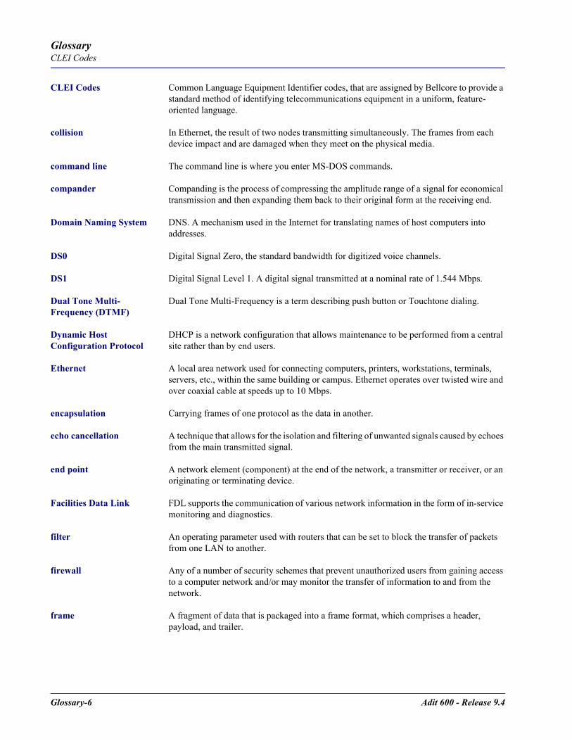
Glossary-6 Adit 600 - Release 9.4
GlossaryCLEI Codes
CLEI Codes Common Language Equipment Identifier codes, that are assigned by Bellcore to provide a standard method of identifying telecommunications equipment in a uniform, feature-oriented language.
collision In Ethernet, the result of two nodes transmitting simultaneously. The frames from each device impact and are damaged when they meet on the physical media.
command line The command line is where you enter MS-DOS commands.
compander Companding is the process of compressing the amplitude range of a signal for economical transmission and then expanding them back to their original form at the receiving end.
Domain Naming System DNS. A mechanism used in the Internet for translating names of host computers into addresses.
DS0 Digital Signal Zero, the standard bandwidth for digitized voice channels.
DS1 Digital Signal Level 1. A digital signal transmitted at a nominal rate of 1.544 Mbps.
Dual Tone Multi-Frequency (DTMF)
Dual Tone Multi-Frequency is a term describing push button or Touchtone dialing.
Dynamic Host Configuration Protocol
DHCP is a network configuration that allows maintenance to be performed from a central site rather than by end users.
Ethernet A local area network used for connecting computers, printers, workstations, terminals, servers, etc., within the same building or campus. Ethernet operates over twisted wire and over coaxial cable at speeds up to 10 Mbps.
encapsulation Carrying frames of one protocol as the data in another.
echo cancellation A technique that allows for the isolation and filtering of unwanted signals caused by echoes from the main transmitted signal.
end point A network element (component) at the end of the network, a transmitter or receiver, or an originating or terminating device.
Facilities Data Link FDL supports the communication of various network information in the form of in-service monitoring and diagnostics.
filter An operating parameter used with routers that can be set to block the transfer of packets from one LAN to another.
firewall Any of a number of security schemes that prevent unauthorized users from gaining access to a computer network and/or may monitor the transfer of information to and from the network.
frame A fragment of data that is packaged into a frame format, which comprises a header, payload, and trailer.

Adit 600 - Release 9.4 Glossary-7
GlossaryForeign Exchange
Foreign Exchange A Central Office trunk which has access to a distant central office. Dial Tone is returned from that distant Central Office, and a location can be reached in the area of the foreign Central Office by dialing a local number. This will provide easier access for customers in that area and calls may be made anywhere in the foreign exchange area for a flat rate.
Foreign Exchange Service
Foreign exchange (FX) service is a service that can be ordered from the telephone company that provides local telephone service from a central office which is outside (foreign to) the subscriber’s exchange area. Simply, a user can pick up the phone in one city and receive a dial tone in the foreign city. This kind of connection is provided by a type of trunk called foreign exchange (FX) trunk. FX trunk signaling can be provided over analog or T-1 links. Connecting POTS telephones to a computer telephony system via T-1 links requires a channel bank configured with FX type connections.
G.168 Echo cancellation
G.711 Describes the 64-kbps PCM voice coding technique. In G.711, encoded voice is already in the correct format for digital voice delivery in the PSTN or through PBXs. Described in the ITU-T standard in its G-series recommendations.
G.726 Describes ADPCM coding at 40, 32, 24, and 16 kbps. ADPCM-encoded voice can be interchanged between packet voice, PSTN, and PBX networks if the PBX networks are configured to support ADPCM. Described in the ITU-T standard in its G-series recommendations.
G.729 Describes CELP compression where voice is coded into 8-kbps streams. There are two variations of this standard (G.729 and G.729 Annex A) that differ mainly in computational complexity; both provide speech quality similar to 32-kbps ADPCM. Described in the ITU-T standard in its G-series recommendations.
gateway An entrance and exit into a communications network
GRE tunneling Generic Routing Encapsulation tunneling is a Layer 2 protocol that can tunnel multi-protocol traffic over IP Networks.
ground A physical connection to the earth or other reference point.
ground start A method of signaling on subscriber trunks in which one side of the two wire trunk (typically the ring conductor of Tip and Ring) is momentarily grounded to get dial tone
High Density Bipolar 3 HDB3. A bipolar coding method that does not allow more than 3 consecutive zeros.
hops Each individual short trip that packets make from router to router, as they are routed to their destination.
impedance The total opposition a circuit offers to the flow of alternating current. It is measured in ohms and the lower the ohmic value, the better the quality of the conductor
Integrated Services Digital Network
ISDN BRI, which is 144,000 bits per second and designed for the desktop.

Glossary-8 Adit 600 - Release 9.4
GlossaryLocal Area Network
Local Area Network LAN. A short distance data communications network (typically within a building or campus) used to link together computers and peripheral devices under some form of standard control.
layer 2 In the OSI 7 layer model, layer 2 is the Data Link layer. This layer deals with procedures and protocols from operating the communications lines. It also has a way of detecting and correcting message errors
Line Build Out LBO. T1 circuits require the last span to lose 15-22.5 dB, a selectable out put attenuation is generally required of DTE equipment.
Local Link Control A protocol developed by the IEEE 802.2 committee for data-link-level transmission control
Local Management Interface
A specification for the use of frame-relay products that define a method of exchanging status information between devices such as routers
latching OCU-DP loopback
loopback A diagnostic test in which a signal is transmitted across a medium while the sending device waits for its return.
MAC Address The address for a device as it is identified at the Media Access Control layer in the network architecture
mapping In network operations, the logical association of one set of values, such as addresses on one network, with quantities or values of another set, such as devices on another network.
Media Gateway Control Protocol
MGCP. A control and signal standard for the conversion of audio signals carried on telephone circuits (PSTN) to data packets carried over the Internet or other packet networks.
MLPPP MultiLink PPP. An extension to the point-to-point protocol that enables two channels to be linked together to double the throughput. It is used for ISDN transmission and channel bonding
multiplexer Electronic equipment which allows two or more signals to pass over one communications circuit. The circuit may be analog or digital
MUX See multiplexer
MVEC Majority Vote Error Correction
nonlatching OCU-DP loopback
NTP Network Time Protocol, developed to maintain a common sense of time among Internet hosts around the world. Many systems on the Internet run NTP, and have the same time (relative to Greenwich Mean Time).
OCU-DP Office Channel Unit - Data Port. A channel bank unit used to interface between the channel bank and a customer’s DDS CSU or DSU.

Adit 600 - Release 9.4 Glossary-9
GlossaryP-Phone
P-Phone Also known as EBS (Enhanced Business Service) is an analog Centrex offering provided by Northern Telecom. It operates over a single-pair subscriber loop, providing normal full duplex audio conversations and a secondary 8 Khz half-duplex amplitude shift-keyed signal, which is used to transmit signaling information to and from the Northern Telecom-equipped central office.
packet A packet consists of the data to be transmitted and certain control information.
PAP Password Authentication Protocol
PAT Port Address Translation
PHY PHY as in physical specifications. OSI Physical Layer, which provides for transmission of cells over a physical medium connecting two ATM devices.
ping Packet InterNet Grouper. PING is a program used to test whether a particular network destination on the Internet is online (i.e. working) by repeatedly bouncing a "signal" off a specified address and seeing how long that signal takes to complete the round trip. No return signal - site is down or unreachable. Portion is returned - trouble with the connection.
PLAR Private Line, Automatic Ringdown. A leased voice circuit that connects two single instruments together. When either handset is lifted, the other instrument automatically rings.
PPP Point-to-Point Protocol. An 8-bit serial interconnection protocol which allows a computing device, such as a PC, to connect as a TCP/IP host to a network through an asynchronous port.
protocol Procedure or set of rules.
PVC Permanent Virtual Circuit. A PVC is a permanent channel connection between two ATM devices. PVC’s allow network transmissions to be started without having to first establish a connection with the end point ATM device. When a PVC is constructed, the end points of the connection will agree upon a path in which data will travel, and therefore agree upon the route that data will travel to reach its destination.
QoS Quality of Service.
RADIUS Remote Authentication Dial-In Service. RADIUS is a client/server-based authentication software system. The software supports remote access applications, allowing an organization to maintain user profiles in a centralized database residing on an authentication server which can be shared by multiple remote access servers.
RIP Routing Information Protocol. RIP is based on distance vector algorithms that measure the shortest path between two points on a network, based on the addresses of the originating and destination devices. The shortest path is determined by the number of "hops" between those points. Each router maintains a routing table, or routing database, of known addresses and routes; each router periodically broadcasts the contents of its table to neighboring routers in order that the entire network can maintain a synchronized database.
robbed bit A type of analog signaling that will occasionally steal information bits used for circuit signaling coding.

Glossary-10 Adit 600 - Release 9.4
GlossaryRTCP
RTCP Real-Time Conferencing Protocol. Supports real-time conferencing for large groups on the internet. It has source identification and support for audio and video bridges/gateways. Supports multicast-to-unicast translators.
RTP Realtime Transport Protocol. An IETF standard for streaming realtime multimedia over IP in packets. Supports transport of real-time data like interactive voice and video over packet switched networks.
SAP Service Access Point.
silence suppression A term used in voice compression for transmission whereby silence in the voice conversation is filled with other transmissions (data, video, imaging, etc.).
SNMP Simple Network Management Protocol. SNMP is the most common method by which network managements applications can query a management agent using a supported MIB (Management Information Base). SNMP operates at the OSI application layer.
spanning tree Spanning Tree Protocol is a link management protocol that provides path redundancy while preventing undesirable loops in the network. For an Ethernet network to function properly, only one active path can exist between two stations.
SDP Session Description Protocol.
T1 Trunk Level 1. A digital transmission link with a total signaling speed of 1.544 Mbps. T-1 is a standard for the digital transmission in North America.
TACACS+ Terminal Access Controller Access Control System.
TBOS Telemetry Byte Oriented Serial. TBOS is an alarm monitoring and control prototype for telephone network equipment.
telnet An Internet standard protocol that enables a computer to function as a terminal working from a remote computer
TDM Time Division Multiplex. A technique for transmitting a number of separate data, voice and/or video signals simultaneously over one communications medium by quickly interleaving a piece of each signal one after another.
TFTP Trivial File Transfer Protocol.
ticks The distance between two networks, measured in time increments. Ticks may be used to designate primary and secondary routes to the same network.
trunk A communication line between two switching systems.
tunneling To provide a secure, temporary path over the Internet.
VC MUX Virtual Channel Multiplexer
VoIP Voice over IP.

Adit 600 - Release 9.4 Glossary-11
GlossaryWAN
WAN Wide Area Network.
VC Virtual Channel.

Glossary-12 Adit 600 - Release 9.4
GlossaryVC
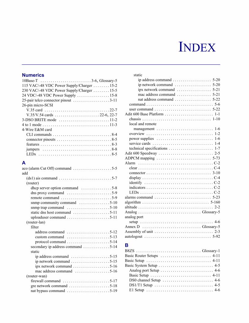
INDEX
Numerics10Base-T . . . . . . . . . . . . . . . . . . . . . . . . . 3-6, Glossary-5115 VAC/-48 VDC Power Supply/Charger . . . . . . . . 15-2230 VAC/-48 VDC Power Supply/Charger . . . . . . . . 15-524 VDC/-48 VDC Power Supply . . . . . . . . . . . . . . . . 15-825-pair telco connector pinout . . . . . . . . . . . . . . . . . . 3-1126-pin micro-SCSI
V.35 card . . . . . . . . . . . . . . . . . . . . . . . . . . . . . . . . 22-7V.35/V.54 cards . . . . . . . . . . . . . . . . . . . . . . 22-6, 22-7
3-DSO BRITE mode . . . . . . . . . . . . . . . . . . . . . . . . . 11-24 to 1 mode . . . . . . . . . . . . . . . . . . . . . . . . . . . . . . . . . 11-34-Wire E&M card
CLI commands . . . . . . . . . . . . . . . . . . . . . . . . . . . . . 8-4connector pinouts . . . . . . . . . . . . . . . . . . . . . . . . . . . 8-5features . . . . . . . . . . . . . . . . . . . . . . . . . . . . . . . . . . . 8-3jumpers . . . . . . . . . . . . . . . . . . . . . . . . . . . . . . . . . . 8-8LEDs . . . . . . . . . . . . . . . . . . . . . . . . . . . . . . . . . . . . 8-5
Aaco (alarm Cut Off) command . . . . . . . . . . . . . . . . . . . 5-5add
(ds1) ais command . . . . . . . . . . . . . . . . . . . . . . . . . . 5-7(router)
dhcp server option command . . . . . . . . . . . . . . . 5-8dns proxy command . . . . . . . . . . . . . . . . . . . . . . 5-9remote command . . . . . . . . . . . . . . . . . . . . . . . . . 5-9snmp community command . . . . . . . . . . . . . . . 5-10snmp trap command . . . . . . . . . . . . . . . . . . . . . 5-10static dns host command . . . . . . . . . . . . . . . . . . 5-11uploaduser command . . . . . . . . . . . . . . . . . . . . . 5-11
(router-lan)filter
address command . . . . . . . . . . . . . . . . . . . . . 5-12custom command . . . . . . . . . . . . . . . . . . . . . 5-13protocol command . . . . . . . . . . . . . . . . . . . . . 5-14
secondary ip address command . . . . . . . . . . . . . 5-14static
ip address command . . . . . . . . . . . . . . . . . . . 5-15ip network command . . . . . . . . . . . . . . . . . . . 5-15ipx network command . . . . . . . . . . . . . . . . . . 5-16mac address command . . . . . . . . . . . . . . . . . 5-16
(router-wan)firewall command . . . . . . . . . . . . . . . . . . . . . . . 5-17gre network command . . . . . . . . . . . . . . . . . . . . 5-18nat bypass command . . . . . . . . . . . . . . . . . . . . . 5-19
staticip address command . . . . . . . . . . . . . . . . . . . 5-20ip network command . . . . . . . . . . . . . . . . . . 5-20ipx network command . . . . . . . . . . . . . . . . . 5-21mac address command . . . . . . . . . . . . . . . . . 5-21nat address command . . . . . . . . . . . . . . . . . . 5-22
command . . . . . . . . . . . . . . . . . . . . . . . . . . . . . . . . . 5-6user command . . . . . . . . . . . . . . . . . . . . . . . . . . . . 5-22
Adit 600 Base Platform . . . . . . . . . . . . . . . . . . . . . . . . 1-1chassis . . . . . . . . . . . . . . . . . . . . . . . . . . . . . . . . . . 1-10local and remote
management . . . . . . . . . . . . . . . . . . . . . . . . . . . . 1-6overview . . . . . . . . . . . . . . . . . . . . . . . . . . . . . . . . . 1-2power supplies . . . . . . . . . . . . . . . . . . . . . . . . . . . . 1-6service cards . . . . . . . . . . . . . . . . . . . . . . . . . . . . . . 1-4technical specifications . . . . . . . . . . . . . . . . . . . . . . 1-7
Adit 600 Speedway . . . . . . . . . . . . . . . . . . . . . . . . . . . 2-5ADPCM mapping . . . . . . . . . . . . . . . . . . . . . . . . . . . 5-73Alarm . . . . . . . . . . . . . . . . . . . . . . . . . . . . . . . . . . . . . C-2
clear . . . . . . . . . . . . . . . . . . . . . . . . . . . . . . . . . . . . . C-4connector . . . . . . . . . . . . . . . . . . . . . . . . . . . . . . . . 3-10display . . . . . . . . . . . . . . . . . . . . . . . . . . . . . . . . . . . C-4identify . . . . . . . . . . . . . . . . . . . . . . . . . . . . . . . . . . C-2indicators . . . . . . . . . . . . . . . . . . . . . . . . . . . . . . . . . C-2LEDs . . . . . . . . . . . . . . . . . . . . . . . . . . . . . . . . . . . . C-2
alarms command . . . . . . . . . . . . . . . . . . . . . . . . . . . . 5-23algorithm . . . . . . . . . . . . . . . . . . . . . . . . . . . . . . . . . 5-160altitude . . . . . . . . . . . . . . . . . . . . . . . . . . . . . . . . . . . . . 2-2Analog . . . . . . . . . . . . . . . . . . . . . . . . . . . . . . . Glossary-5analog port
setup . . . . . . . . . . . . . . . . . . . . . . . . . . . . . . . . . . . . 4-6Annex D . . . . . . . . . . . . . . . . . . . . . . . . . . . . . Glossary-5Assembly of unit . . . . . . . . . . . . . . . . . . . . . . . . . . . . . 2-3autologout . . . . . . . . . . . . . . . . . . . . . . . . . . . . . . . . . 5-92
BB8ZS . . . . . . . . . . . . . . . . . . . . . . . . . . . . . . . . Glossary-1Basic Router Setups . . . . . . . . . . . . . . . . . . . . . . . . . 4-11Basic Setup . . . . . . . . . . . . . . . . . . . . . . . . . . . . . . . . 4-11Basic System Setup . . . . . . . . . . . . . . . . . . . . . . . . . . . 4-5
Analog port Setup . . . . . . . . . . . . . . . . . . . . . . . . . . 4-6Basic Setup . . . . . . . . . . . . . . . . . . . . . . . . . . . . . . 4-11DS0 channel Setup . . . . . . . . . . . . . . . . . . . . . . . . . 4-6DS1/T1 Setup . . . . . . . . . . . . . . . . . . . . . . . . . . . . . 4-5E1 Setup . . . . . . . . . . . . . . . . . . . . . . . . . . . . . . . . . 4-6
Index
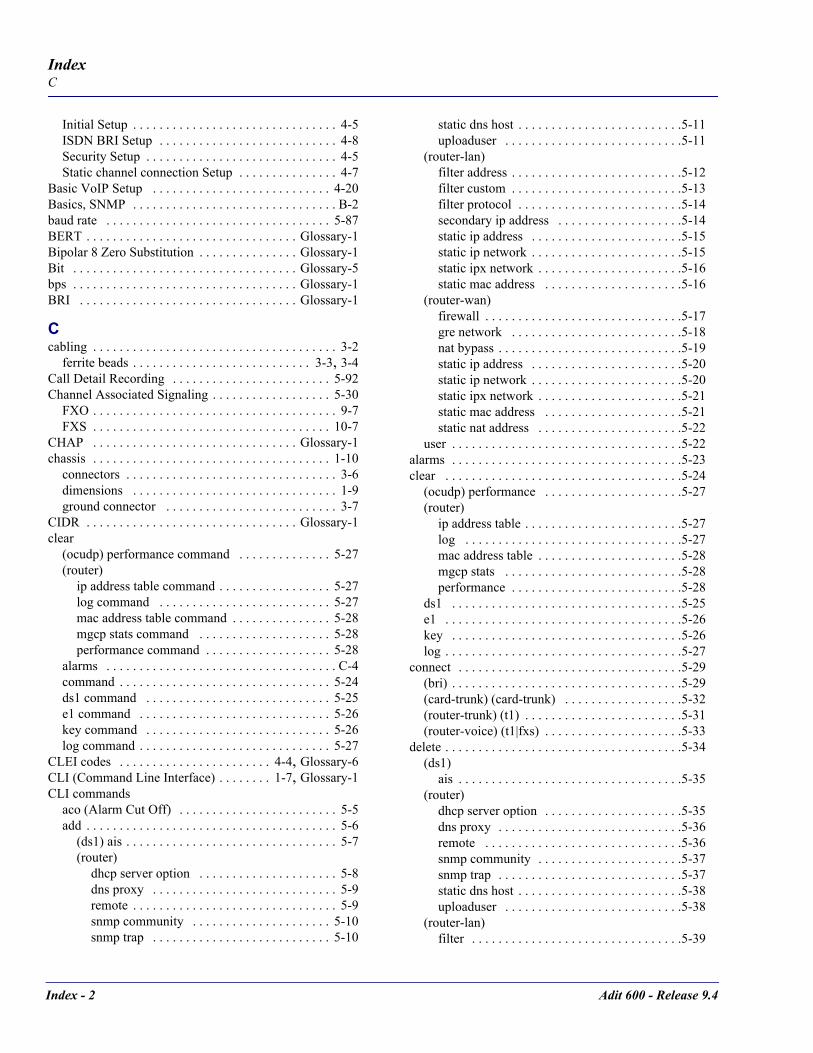
Index - 2 Adit 600 - Release 9.4
IndexC
Initial Setup . . . . . . . . . . . . . . . . . . . . . . . . . . . . . . . 4-5ISDN BRI Setup . . . . . . . . . . . . . . . . . . . . . . . . . . . 4-8Security Setup . . . . . . . . . . . . . . . . . . . . . . . . . . . . . 4-5Static channel connection Setup . . . . . . . . . . . . . . . 4-7
Basic VoIP Setup . . . . . . . . . . . . . . . . . . . . . . . . . . . 4-20Basics, SNMP . . . . . . . . . . . . . . . . . . . . . . . . . . . . . . . B-2baud rate . . . . . . . . . . . . . . . . . . . . . . . . . . . . . . . . . . 5-87BERT . . . . . . . . . . . . . . . . . . . . . . . . . . . . . . . . Glossary-1Bipolar 8 Zero Substitution . . . . . . . . . . . . . . . Glossary-1Bit . . . . . . . . . . . . . . . . . . . . . . . . . . . . . . . . . . Glossary-5bps . . . . . . . . . . . . . . . . . . . . . . . . . . . . . . . . . . Glossary-1BRI . . . . . . . . . . . . . . . . . . . . . . . . . . . . . . . . . Glossary-1
Ccabling . . . . . . . . . . . . . . . . . . . . . . . . . . . . . . . . . . . . . 3-2
ferrite beads . . . . . . . . . . . . . . . . . . . . . . . . . . . 3-3, 3-4Call Detail Recording . . . . . . . . . . . . . . . . . . . . . . . . 5-92Channel Associated Signaling . . . . . . . . . . . . . . . . . . 5-30
FXO . . . . . . . . . . . . . . . . . . . . . . . . . . . . . . . . . . . . . 9-7FXS . . . . . . . . . . . . . . . . . . . . . . . . . . . . . . . . . . . . 10-7
CHAP . . . . . . . . . . . . . . . . . . . . . . . . . . . . . . . Glossary-1chassis . . . . . . . . . . . . . . . . . . . . . . . . . . . . . . . . . . . . 1-10
connectors . . . . . . . . . . . . . . . . . . . . . . . . . . . . . . . . 3-6dimensions . . . . . . . . . . . . . . . . . . . . . . . . . . . . . . . 1-9ground connector . . . . . . . . . . . . . . . . . . . . . . . . . . 3-7
CIDR . . . . . . . . . . . . . . . . . . . . . . . . . . . . . . . . Glossary-1clear
(ocudp) performance command . . . . . . . . . . . . . . 5-27(router)
ip address table command . . . . . . . . . . . . . . . . . 5-27log command . . . . . . . . . . . . . . . . . . . . . . . . . . 5-27mac address table command . . . . . . . . . . . . . . . 5-28mgcp stats command . . . . . . . . . . . . . . . . . . . . 5-28performance command . . . . . . . . . . . . . . . . . . . 5-28
alarms . . . . . . . . . . . . . . . . . . . . . . . . . . . . . . . . . . . C-4command . . . . . . . . . . . . . . . . . . . . . . . . . . . . . . . . 5-24ds1 command . . . . . . . . . . . . . . . . . . . . . . . . . . . . 5-25e1 command . . . . . . . . . . . . . . . . . . . . . . . . . . . . . 5-26key command . . . . . . . . . . . . . . . . . . . . . . . . . . . . 5-26log command . . . . . . . . . . . . . . . . . . . . . . . . . . . . . 5-27
CLEI codes . . . . . . . . . . . . . . . . . . . . . . . 4-4, Glossary-6CLI (Command Line Interface) . . . . . . . . 1-7, Glossary-1CLI commands
aco (Alarm Cut Off) . . . . . . . . . . . . . . . . . . . . . . . . 5-5add . . . . . . . . . . . . . . . . . . . . . . . . . . . . . . . . . . . . . . 5-6
(ds1) ais . . . . . . . . . . . . . . . . . . . . . . . . . . . . . . . . 5-7(router)
dhcp server option . . . . . . . . . . . . . . . . . . . . . 5-8dns proxy . . . . . . . . . . . . . . . . . . . . . . . . . . . . 5-9remote . . . . . . . . . . . . . . . . . . . . . . . . . . . . . . . 5-9snmp community . . . . . . . . . . . . . . . . . . . . . 5-10snmp trap . . . . . . . . . . . . . . . . . . . . . . . . . . . 5-10
static dns host . . . . . . . . . . . . . . . . . . . . . . . . .5-11uploaduser . . . . . . . . . . . . . . . . . . . . . . . . . . .5-11
(router-lan)filter address . . . . . . . . . . . . . . . . . . . . . . . . . .5-12filter custom . . . . . . . . . . . . . . . . . . . . . . . . . .5-13filter protocol . . . . . . . . . . . . . . . . . . . . . . . . .5-14secondary ip address . . . . . . . . . . . . . . . . . . .5-14static ip address . . . . . . . . . . . . . . . . . . . . . . .5-15static ip network . . . . . . . . . . . . . . . . . . . . . . .5-15static ipx network . . . . . . . . . . . . . . . . . . . . . .5-16static mac address . . . . . . . . . . . . . . . . . . . . .5-16
(router-wan)firewall . . . . . . . . . . . . . . . . . . . . . . . . . . . . . .5-17gre network . . . . . . . . . . . . . . . . . . . . . . . . . .5-18nat bypass . . . . . . . . . . . . . . . . . . . . . . . . . . . .5-19static ip address . . . . . . . . . . . . . . . . . . . . . . .5-20static ip network . . . . . . . . . . . . . . . . . . . . . . .5-20static ipx network . . . . . . . . . . . . . . . . . . . . . .5-21static mac address . . . . . . . . . . . . . . . . . . . . .5-21static nat address . . . . . . . . . . . . . . . . . . . . . .5-22
user . . . . . . . . . . . . . . . . . . . . . . . . . . . . . . . . . . .5-22alarms . . . . . . . . . . . . . . . . . . . . . . . . . . . . . . . . . . .5-23clear . . . . . . . . . . . . . . . . . . . . . . . . . . . . . . . . . . . .5-24
(ocudp) performance . . . . . . . . . . . . . . . . . . . . .5-27(router)
ip address table . . . . . . . . . . . . . . . . . . . . . . . .5-27log . . . . . . . . . . . . . . . . . . . . . . . . . . . . . . . . .5-27mac address table . . . . . . . . . . . . . . . . . . . . . .5-28mgcp stats . . . . . . . . . . . . . . . . . . . . . . . . . . .5-28performance . . . . . . . . . . . . . . . . . . . . . . . . . .5-28
ds1 . . . . . . . . . . . . . . . . . . . . . . . . . . . . . . . . . . .5-25e1 . . . . . . . . . . . . . . . . . . . . . . . . . . . . . . . . . . . .5-26key . . . . . . . . . . . . . . . . . . . . . . . . . . . . . . . . . . .5-26log . . . . . . . . . . . . . . . . . . . . . . . . . . . . . . . . . . . .5-27
connect . . . . . . . . . . . . . . . . . . . . . . . . . . . . . . . . . .5-29(bri) . . . . . . . . . . . . . . . . . . . . . . . . . . . . . . . . . . .5-29(card-trunk) (card-trunk) . . . . . . . . . . . . . . . . . .5-32(router-trunk) (t1) . . . . . . . . . . . . . . . . . . . . . . . .5-31(router-voice) (t1|fxs) . . . . . . . . . . . . . . . . . . . . .5-33
delete . . . . . . . . . . . . . . . . . . . . . . . . . . . . . . . . . . . .5-34(ds1)
ais . . . . . . . . . . . . . . . . . . . . . . . . . . . . . . . . . .5-35(router)
dhcp server option . . . . . . . . . . . . . . . . . . . . .5-35dns proxy . . . . . . . . . . . . . . . . . . . . . . . . . . . .5-36remote . . . . . . . . . . . . . . . . . . . . . . . . . . . . . .5-36snmp community . . . . . . . . . . . . . . . . . . . . . .5-37snmp trap . . . . . . . . . . . . . . . . . . . . . . . . . . . .5-37static dns host . . . . . . . . . . . . . . . . . . . . . . . . .5-38uploaduser . . . . . . . . . . . . . . . . . . . . . . . . . . .5-38
(router-lan)filter . . . . . . . . . . . . . . . . . . . . . . . . . . . . . . . .5-39

Adit 600 - Release 9.4 Index - 3
IndexC
secondary ip address . . . . . . . . . . . . . . . . . . . 5-39static ip address . . . . . . . . . . . . . . . . . . . . . . . 5-40static ip network . . . . . . . . . . . . . . . . . . . . . . 5-40static ipx network . . . . . . . . . . . . . . . . . . . . . 5-41static mac address . . . . . . . . . . . . . . . . . . . . . 5-41
(router-wan)firewall . . . . . . . . . . . . . . . . . . . . . . . . . . . . . 5-42gre network . . . . . . . . . . . . . . . . . . . . . . . . . . 5-42nat bypass . . . . . . . . . . . . . . . . . . . . . . . . . . . 5-43static ip address . . . . . . . . . . . . . . . . . . . . . . . 5-43static ip network . . . . . . . . . . . . . . . . . . . . . . 5-44static ipx network . . . . . . . . . . . . . . . . . . . . . 5-44static mac address . . . . . . . . . . . . . . . . . . . . . 5-44static nat address . . . . . . . . . . . . . . . . . . . . . . 5-45
user . . . . . . . . . . . . . . . . . . . . . . . . . . . . . . . . . . 5-45disconnect . . . . . . . . . . . . . . . . . . . . . . . . . . . . . . . 5-46exit . . . . . . . . . . . . . . . . . . . . . . . . . . . . . . . . . . . . . 5-46install (slot) router . . . . . . . . . . . . . . . . . . . . . . . . . 5-47load
tftp . . . . . . . . . . . . . . . . . . . . . . . . . . . . . . . . . . . 5-48xmodem . . . . . . . . . . . . . . . . . . . . . . . . . . . . . . . 5-49
log . . . . . . . . . . . . . . . . . . . . . . . . . . . . . . . . . . . . . 5-50ping . . . . . . . . . . . . . . . . . . . . . . . . . . . . . . . . . . . . 5-51print
config . . . . . . . . . . . . . . . . . . . . . . . . . . . . . . . . . 5-52help . . . . . . . . . . . . . . . . . . . . . . . . . . . . . . . . . . 5-52
rename (router) . . . . . . . . . . . . . . . . . . . . . . . . . . . 5-53reset . . . . . . . . . . . . . . . . . . . . . . . . . . . . . . . . . . . . 5-54
(router) . . . . . . . . . . . . . . . . . . . . . . . . . . . . . . . . 5-54(router) coldboot . . . . . . . . . . . . . . . . . . . . . . . . 5-54
restore defaults . . . . . . . . . . . . . . . . . . . . . . . . . . . . 5-55rtrping . . . . . . . . . . . . . . . . . . . . . . . . . . . . . . . . . . 5-56set . . . . . . . . . . . . . . . . . . . . . . . . . . . . . . . . . . . . . . 5-57
(4-wire e&m) . . . . . . . . . . . . . . . . . . . . . . . . . . . 5-59(bri) . . . . . . . . . . . . . . . . . . . . . . . . . . . . . . . . . . 5-60
autoactivate . . . . . . . . . . . . . . . . . . . . . . . . . . 5-62crv . . . . . . . . . . . . . . . . . . . . . . . . . . . . . . . . . 5-60down . . . . . . . . . . . . . . . . . . . . . . . . . . . . . . . 5-60mode . . . . . . . . . . . . . . . . . . . . . . . . . . . . . . . 5-62pmsync . . . . . . . . . . . . . . . . . . . . . . . . . . . . . 5-63threshold . . . . . . . . . . . . . . . . . . . . . . . . . . . . 5-61up . . . . . . . . . . . . . . . . . . . . . . . . . . . . . . . . . . 5-61
(ds0) . . . . . . . . . . . . . . . . . . . . . . . . . . . . . . . . . . 5-64(ds0)side . . . . . . . . . . . . . . . . . . . . . . . . . . . . . . 5-64(ds0)signal . . . . . . . . . . . . . . . . . . . . . . . . . . . . . 5-65(ds0)type . . . . . . . . . . . . . . . . . . . . . . . . . . . . . . 5-65(ds1 card) . . . . . . . . . . . . . . . . . . . . . . . . . . . . . . 5-72
adpcm map . . . . . . . . . . . . . . . . . . . . . . . . . . 5-73t1/e1 spantype . . . . . . . . . . . . . . . . . . . . . . . . 5-72
(ds1) . . . . . . . . . . . . . . . . . . . . . . . . . . . . . . . . . . 5-66ais . . . . . . . . . . . . . . . . . . . . . . . . . . . . . . . . . 5-66bpviolation . . . . . . . . . . . . . . . . . . . . . . . . . . 5-66
down . . . . . . . . . . . . . . . . . . . . . . . . . . . . . . . 5-67equipment . . . . . . . . . . . . . . . . . . . . . . . . . . . 5-67fdl . . . . . . . . . . . . . . . . . . . . . . . . . . . . . . . . . 5-67framing . . . . . . . . . . . . . . . . . . . . . . . . . . . . . 5-68id . . . . . . . . . . . . . . . . . . . . . . . . . . . . . . . . . . 5-68lbo . . . . . . . . . . . . . . . . . . . . . . . . . . . . . . . . . 5-69line . . . . . . . . . . . . . . . . . . . . . . . . . . . . . . . . 5-69linecode . . . . . . . . . . . . . . . . . . . . . . . . . . . . 5-70loopdetect . . . . . . . . . . . . . . . . . . . . . . . . . . . 5-70payload . . . . . . . . . . . . . . . . . . . . . . . . . . . . . 5-71threshold . . . . . . . . . . . . . . . . . . . . . . . . . . . . 5-71up . . . . . . . . . . . . . . . . . . . . . . . . . . . . . . . . . 5-72
(e1 card)t1/e1 spantype . . . . . . . . . . . . . . . . . . . . . . . . 5-77
(e1) . . . . . . . . . . . . . . . . . . . . . . . . . . . . . . . . . . 5-74down . . . . . . . . . . . . . . . . . . . . . . . . . . . . . . . 5-74equipment . . . . . . . . . . . . . . . . . . . . . . . . . . . 5-74framing . . . . . . . . . . . . . . . . . . . . . . . . . . . . . 5-74line . . . . . . . . . . . . . . . . . . . . . . . . . . . . . . . . 5-75linecode . . . . . . . . . . . . . . . . . . . . . . . . . . . . 5-75national . . . . . . . . . . . . . . . . . . . . . . . . . . . . . 5-75signal . . . . . . . . . . . . . . . . . . . . . . . . . . . . . . 5-76threshold . . . . . . . . . . . . . . . . . . . . . . . . . . . . 5-76up . . . . . . . . . . . . . . . . . . . . . . . . . . . . . . . . . 5-77
(fxo) . . . . . . . . . . . . . . . . . . . . . . . . . . . . . . . . . 5-78(fxs) . . . . . . . . . . . . . . . . . . . . . . . . . . . . . . . . . . 5-79(fxs5G) . . . . . . . . . . . . . . . . . . . . . . . . . . . . . . . 5-80(fxs8A) . . . . . . . . . . . . . . . . . . . . . . . . . . . . . . . 5-80(fxs8B) . . . . . . . . . . . . . . . . . . . . . . . . . . . . . . . 5-80(fxsINTL) . . . . . . . . . . . . . . . . . . . . . . . . . . . . . 5-81(fxsPS) . . . . . . . . . . . . . . . . . . . . . . . . . . . . . . . 5-81(ocudp) . . . . . . . . . . . . . . . . . . . . . . . . . . . . . . . 5-87
baud . . . . . . . . . . . . . . . . . . . . . . . . . . . . . . . 5-87loopback . . . . . . . . . . . . . . . . . . . . . . . . . . . . 5-87loopdetect . . . . . . . . . . . . . . . . . . . . . . . . . . . 5-88mvec . . . . . . . . . . . . . . . . . . . . . . . . . . . . . . . 5-88secondary . . . . . . . . . . . . . . . . . . . . . . . . . . . 5-89selftest . . . . . . . . . . . . . . . . . . . . . . . . . . . . . . 5-89up/down . . . . . . . . . . . . . . . . . . . . . . . . . . . . 5-89
(p-phone) . . . . . . . . . . . . . . . . . . . . . . . . . . . . . . 5-90(router)
autologout . . . . . . . . . . . . . . . . . . . . . . . . . . . 5-92cdr . . . . . . . . . . . . . . . . . . . . . . . . . . . . . . . . . 5-92compander . . . . . . . . . . . . . . . . . . . . . . . . . . 5-92default . . . . . . . . . . . . . . . . . . . . . . . . . . . . . . 5-93dhcp . . . . . . . . . . . . . . . . . . . . . . . . . . . . . . . 5-93
disable . . . . . . . . . . . . . . . . . . . . . . . . . . . 5-96relay server . . . . . . . . . . . . . . . . . . . . . . . . 5-96server dnsserver . . . . . . . . . . . . . . . . . . . . 5-97server domain . . . . . . . . . . . . . . . . . . . . . . 5-97server duration . . . . . . . . . . . . . . . . . . . . . 5-97server netbios nameserver . . . . . . . . . . . . 5-98

Index - 4 Adit 600 - Release 9.4
IndexC
server netbios nodetype . . . . . . . . . . . . . . 5-98server netbios scope . . . . . . . . . . . . . . . . . 5-98server startaddr . . . . . . . . . . . . . . . . . . . . . 5-99
dhcp clientauto dns . . . . . . . . . . . . . . . . . . . . . . . . . . 5-93enable . . . . . . . . . . . . . . . . . . . . . . . . . . . . 5-94lease . . . . . . . . . . . . . . . . . . . . . . . . . . . . . 5-94request . . . . . . . . . . . . . . . . . . . . . . . . . . . 5-95transmit packet broadcast bit . . . . . . . . . . 5-96
dialplan timeout . . . . . . . . . . . . . . . . . . . . . . 5-99interdigit long . . . . . . . . . . . . . . . . . . . . . . 5-99interdigit short . . . . . . . . . . . . . . . . . . . . 5-100
dns . . . . . . . . . . . . . . . . . . . . . . . . . . . . . . . 5-100domain . . . . . . . . . . . . . . . . . . . . . . . . . . 5-100name . . . . . . . . . . . . . . . . . . . . . . . . . . . . 5-100resolver . . . . . . . . . . . . . . . . . . . . . . . . . . 5-101server . . . . . . . . . . . . . . . . . . . . . . . . . . . 5-101
enhanced security . . . . . . . . . . . . . . . . . . . . 5-101hookflash . . . . . . . . . . . . . . . . . . . . . . . . . . 5-102lmi . . . . . . . . . . . . . . . . . . . . . . . . . . . . . . . . 5-102
poll . . . . . . . . . . . . . . . . . . . . . . . . . . . . . 5-102log . . . . . . . . . . . . . . . . . . . . . . . . . . . . . . . . 5-103login auth . . . . . . . . . . . . . . . . . . . . . . . . . . 5-103login prompt . . . . . . . . . . . . . . . . . . . . . . . . 5-104mgcp . . . . . . . . . . . . . . . . . . . . . . . . . . . . . . 5-104
addressformat . . . . . . . . . . . . . . . . . . . . . 5-104algorithmname . . . . . . . . . . . . . . . . . . . . 5-105cac delayalert . . . . . . . . . . . . . . . . . . . . . 5-106callagent address . . . . . . . . . . . . . . . . . . 5-106callagent filter . . . . . . . . . . . . . . . . . . . . 5-107callagent port . . . . . . . . . . . . . . . . . . . . . 5-107callagent secondary address . . . . . . . . . . 5-108callagent secondary port . . . . . . . . . . . . . 5-108default . . . . . . . . . . . . . . . . . . . . . . . . . . 5-109dialstring format . . . . . . . . . . . . . . . . . . . 5-109down . . . . . . . . . . . . . . . . . . . . . . . . . . . . 5-110gatewayid . . . . . . . . . . . . . . . . . . . . . . . . 5-111keepalive . . . . . . . . . . . . . . . . . . . . . . . . 5-111lco . . . . . . . . . . . . . . . . . . . . . . . . . . . . . . 5-112package default . . . . . . . . . . . . . . . . . . . 5-113parsemode . . . . . . . . . . . . . . . . . . . . . . . 5-114piggyback . . . . . . . . . . . . . . . . . . . . . . . . 5-114port . . . . . . . . . . . . . . . . . . . . . . . . . . . . . 5-115protocolid . . . . . . . . . . . . . . . . . . . . . . . . 5-115quarantine . . . . . . . . . . . . . . . . . . . . . . . . 5-116report hookswitch . . . . . . . . . . . . . . . . . . 5-116retries . . . . . . . . . . . . . . . . . . . . . . . . . . . 5-117rsipwildcard . . . . . . . . . . . . . . . . . . . . . . 5-117sdp codecorder . . . . . . . . . . . . . . . . . . . . 5-118sdpmode . . . . . . . . . . . . . . . . . . . . . . . . . 5-118timeout . . . . . . . . . . . . . . . . . . . . . . . . . . 5-118tos . . . . . . . . . . . . . . . . . . . . . . . . . . . . . . 5-119
up . . . . . . . . . . . . . . . . . . . . . . . . . . . . . . .5-120version . . . . . . . . . . . . . . . . . . . . . . . . . . .5-120
ntp . . . . . . . . . . . . . . . . . . . . . . . . . . . . . . . .5-121enable/disable . . . . . . . . . . . . . . . . . . . . .5-121poll . . . . . . . . . . . . . . . . . . . . . . . . . . . . . .5-121server . . . . . . . . . . . . . . . . . . . . . . . . . . . .5-121timezone . . . . . . . . . . . . . . . . . . . . . . . . .5-122
password . . . . . . . . . . . . . . . . . . . . . . . . . . .5-122port . . . . . . . . . . . . . . . . . . . . . . . . . . . . . . . .5-123
baudrate . . . . . . . . . . . . . . . . . . . . . . . . . .5-123databits . . . . . . . . . . . . . . . . . . . . . . . . . . .5-123dsr low reset . . . . . . . . . . . . . . . . . . . . . . .5-124flowcontrol . . . . . . . . . . . . . . . . . . . . . . .5-124inactivity timer . . . . . . . . . . . . . . . . . . . . .5-125ip . . . . . . . . . . . . . . . . . . . . . . . . . . . . . . .5-125name . . . . . . . . . . . . . . . . . . . . . . . . . . . .5-125parity . . . . . . . . . . . . . . . . . . . . . . . . . . . .5-126passive . . . . . . . . . . . . . . . . . . . . . . . . . . .5-126password . . . . . . . . . . . . . . . . . . . . . . . . .5-126prompt . . . . . . . . . . . . . . . . . . . . . . . . . . .5-127protocolport . . . . . . . . . . . . . . . . . . . . . . .5-127stopbits . . . . . . . . . . . . . . . . . . . . . . . . . . .5-127tbos map description . . . . . . . . . . . . . . . .5-128tbos map display . . . . . . . . . . . . . . . . . . .5-128type . . . . . . . . . . . . . . . . . . . . . . . . . . . . .5-129
ppp auth . . . . . . . . . . . . . . . . . . . . . . . . . . . .5-129byremote protocol . . . . . . . . . . . . . . . . . .5-129byremote secret . . . . . . . . . . . . . . . . . . . .5-130byremote user . . . . . . . . . . . . . . . . . . . . .5-130ofremote protocol . . . . . . . . . . . . . . . . . .5-131
ppp security . . . . . . . . . . . . . . . . . . . . . . . . .5-131address . . . . . . . . . . . . . . . . . . . . . . . . . . .5-131password . . . . . . . . . . . . . . . . . . . . . . . . .5-131server . . . . . . . . . . . . . . . . . . . . . . . . . . . .5-132
priority tos . . . . . . . . . . . . . . . . . . . . . . . . . .5-132proxy . . . . . . . . . . . . . . . . . . . . . . . . . . . . . .5-134reboot . . . . . . . . . . . . . . . . . . . . . . . . . . . . . .5-136rip . . . . . . . . . . . . . . . . . . . . . . . . . . . . . . . . .5-136snmp . . . . . . . . . . . . . . . . . . . . . . . . . . . . . . .5-137
contact . . . . . . . . . . . . . . . . . . . . . . . . . . .5-137location . . . . . . . . . . . . . . . . . . . . . . . . . .5-137name . . . . . . . . . . . . . . . . . . . . . . . . . . . .5-137
stp . . . . . . . . . . . . . . . . . . . . . . . . . . . . . . . . .5-138bridge forwarddelay . . . . . . . . . . . . . . . . .5-138bridge hellotime . . . . . . . . . . . . . . . . . . . .5-138bridge maxage . . . . . . . . . . . . . . . . . . . . .5-138bridge priority . . . . . . . . . . . . . . . . . . . . .5-139enable/disable . . . . . . . . . . . . . . . . . . . . .5-139
syslog . . . . . . . . . . . . . . . . . . . . . . . . . . . . . .5-140enable/disable . . . . . . . . . . . . . . . . . . . . .5-140facility . . . . . . . . . . . . . . . . . . . . . . . . . . .5-140level . . . . . . . . . . . . . . . . . . . . . . . . . . . . .5-141

Adit 600 - Release 9.4 Index - 5
IndexC
server . . . . . . . . . . . . . . . . . . . . . . . . . . . . 5-141voip . . . . . . . . . . . . . . . . . . . . . . . . . . . . . . . 5-142
default . . . . . . . . . . . . . . . . . . . . . . . . . . . 5-142dtmf edge . . . . . . . . . . . . . . . . . . . . . . . . 5-142g729a . . . . . . . . . . . . . . . . . . . . . . . . . . . . 5-143jitterbuffer . . . . . . . . . . . . . . . . . . . . . . . . 5-143osi . . . . . . . . . . . . . . . . . . . . . . . . . . . . . . 5-143packing . . . . . . . . . . . . . . . . . . . . . . . . . . 5-144payload type . . . . . . . . . . . . . . . . . . . . . . 5-144ptime . . . . . . . . . . . . . . . . . . . . . . . . . . . . 5-145rtcp
cname . . . . . . . . . . . . . . . . . . . . . . . . . 5-145interval . . . . . . . . . . . . . . . . . . . . . . . . 5-146
rtp baseport . . . . . . . . . . . . . . . . . . . . . . . 5-146rtpmap . . . . . . . . . . . . . . . . . . . . . . . . . . . 5-147sdpaddress . . . . . . . . . . . . . . . . . . . . . . . . 5-148t38 ecm . . . . . . . . . . . . . . . . . . . . . . . . . . 5-148t38 redundancy highspeed . . . . . . . . . . . 5-149t38 redundancy lowspeed . . . . . . . . . . . . 5-149
(router-lan)collision . . . . . . . . . . . . . . . . . . . . . . . . . . . . 5-150
interval . . . . . . . . . . . . . . . . . . . . . . . . . . 5-150threshold . . . . . . . . . . . . . . . . . . . . . . . . . 5-150
filter forward . . . . . . . . . . . . . . . . . . . . . . . . 5-151framing . . . . . . . . . . . . . . . . . . . . . . . . . . . . 5-151gateway . . . . . . . . . . . . . . . . . . . . . . . . . . . . 5-152ip address . . . . . . . . . . . . . . . . . . . . . . . . . . . 5-152ipx network . . . . . . . . . . . . . . . . . . . . . . . . . 5-153phy . . . . . . . . . . . . . . . . . . . . . . . . . . . . . . . . 5-153rip . . . . . . . . . . . . . . . . . . . . . . . . . . . . . . . . 5-154
ip . . . . . . . . . . . . . . . . . . . . . . . . . . . . . . . 5-154ipx . . . . . . . . . . . . . . . . . . . . . . . . . . . . . . 5-154
stp . . . . . . . . . . . . . . . . . . . . . . . . . . . . . . . . 5-155enable/disable . . . . . . . . . . . . . . . . . . . . . 5-155port cost . . . . . . . . . . . . . . . . . . . . . . . . . . 5-155port priority . . . . . . . . . . . . . . . . . . . . . . . 5-156
up/down . . . . . . . . . . . . . . . . . . . . . . . . . . . . 5-156(router-trunk)
encapsulation . . . . . . . . . . . . . . . . . . . . . . . . 5-157multilink group . . . . . . . . . . . . . . . . . . . . . . 5-157speed . . . . . . . . . . . . . . . . . . . . . . . . . . . . . . 5-158up/down . . . . . . . . . . . . . . . . . . . . . . . . . . . . 5-158
(router-voice)algorithm preference . . . . . . . . . . . . . . . . . . 5-160cpd . . . . . . . . . . . . . . . . . . . . . . . . . . . . . . . . 5-161default . . . . . . . . . . . . . . . . . . . . . . . . . . . . . 5-161dialplan timeout . . . . . . . . . . . . . . . . . . . . . . 5-162
interdigit long . . . . . . . . . . . . . . . . . . . . . 5-162interdigit short . . . . . . . . . . . . . . . . . . . . . 5-162
down . . . . . . . . . . . . . . . . . . . . . . . . . . . . . . 5-163dtmfrelay . . . . . . . . . . . . . . . . . . . . . . . . . . . 5-163echo cancellation . . . . . . . . . . . . . . . . . . . . . 5-164
echo tail . . . . . . . . . . . . . . . . . . . . . . . . . . . 5-164endpoint prefix . . . . . . . . . . . . . . . . . . . . . . 5-165endpoint suffix . . . . . . . . . . . . . . . . . . . . . . 5-165fax . . . . . . . . . . . . . . . . . . . . . . . . . . . . . . . . 5-166log start . . . . . . . . . . . . . . . . . . . . . . . . . . . . 5-166log stop . . . . . . . . . . . . . . . . . . . . . . . . . . . . 5-167modem . . . . . . . . . . . . . . . . . . . . . . . . . . . . 5-167rfc2833 . . . . . . . . . . . . . . . . . . . . . . . . . . . . 5-168
payloadtype . . . . . . . . . . . . . . . . . . . . . . 5-168refresh interval . . . . . . . . . . . . . . . . . . . . 5-170repeat count . . . . . . . . . . . . . . . . . . . . . . 5-169repeat interval . . . . . . . . . . . . . . . . . . . . . 5-170signals . . . . . . . . . . . . . . . . . . . . . . . . . . . 5-168
rxgain . . . . . . . . . . . . . . . . . . . . . . . . . . . . . 5-171signaling . . . . . . . . . . . . . . . . . . . . . . . . . . . 5-171silence . . . . . . . . . . . . . . . . . . . . . . . . . . . . . 5-172slash . . . . . . . . . . . . . . . . . . . . . . . . . . . . . . 5-172tos . . . . . . . . . . . . . . . . . . . . . . . . . . . . . . . . 5-173txgain . . . . . . . . . . . . . . . . . . . . . . . . . . . . . 5-173up . . . . . . . . . . . . . . . . . . . . . . . . . . . . . . . . 5-174voice bandwidth limit . . . . . . . . . . . . . . . . . 5-159
(router-wan)dlci . . . . . . . . . . . . . . . . . . . . . . . . . . . . . . . 5-174ip . . . . . . . . . . . . . . . . . . . . . . . . . . . . . . . . . 5-176ip address . . . . . . . . . . . . . . . . . . . . . . . . . . 5-176ipx . . . . . . . . . . . . . . . . . . . . . . . . . . . . . . . . 5-177mlppp . . . . . . . . . . . . . . . . . . . . . . . . . . . . . 5-177
fragmentation size . . . . . . . . . . . . . . . . . 5-178qos interleave . . . . . . . . . . . . . . . . . . . . . 5-177
nat . . . . . . . . . . . . . . . . . . . . . . . . . . . . . . . . 5-178address . . . . . . . . . . . . . . . . . . . . . . . . . . 5-178enable/disable . . . . . . . . . . . . . . . . . . . . . 5-179ports . . . . . . . . . . . . . . . . . . . . . . . . . . . . 5-179
other . . . . . . . . . . . . . . . . . . . . . . . . . . . . . . 5-179ppp . . . . . . . . . . . . . . . . . . . . . . . . . . . . . . . 5-180
auth ofremote user . . . . . . . . . . . . . . . . . 5-180compression . . . . . . . . . . . . . . . . . . . . . . 5-180security server . . . . . . . . . . . . . . . . . . . . 5-181
rip . . . . . . . . . . . . . . . . . . . . . . . . . . . . . . . . 5-181ip updates . . . . . . . . . . . . . . . . . . . . . . . . 5-181ipx updates . . . . . . . . . . . . . . . . . . . . . . . 5-182
stp . . . . . . . . . . . . . . . . . . . . . . . . . . . . . . . . 5-182enable/disable . . . . . . . . . . . . . . . . . . . . . 5-182port cost . . . . . . . . . . . . . . . . . . . . . . . . . 5-183port priority . . . . . . . . . . . . . . . . . . . . . . 5-183
trunk . . . . . . . . . . . . . . . . . . . . . . . . . . . . . . 5-183up/down . . . . . . . . . . . . . . . . . . . . . . . . . . . 5-184
(rs232) . . . . . . . . . . . . . . . . . . . . . . . . . . . . . . . 5-184(v35) . . . . . . . . . . . . . . . . . . . . . . . . . . . . . . . . 5-191(v54) . . . . . . . . . . . . . . . . . . . . . . . . . . . . . . . . 5-192alarms . . . . . . . . . . . . . . . . . . . . . . . . . . . . . . . . 5-59autoexit . . . . . . . . . . . . . . . . . . . . . . . . . . . . . . . 5-60

Index - 6 Adit 600 - Release 9.4
IndexC
clock . . . . . . . . . . . . . . . . . . . . . . . . . . . . . . . . . 5-63date . . . . . . . . . . . . . . . . . . . . . . . . . . . . . . . . . . 5-64ethernet ip address . . . . . . . . . . . . . . . . . . . . . . 5-78id . . . . . . . . . . . . . . . . . . . . . . . . . . . . . . . . . . . . 5-82idle . . . . . . . . . . . . . . . . . . . . . . . . . . . . . . . . . . 5-82ip gateway . . . . . . . . . . . . . . . . . . . . . . . . . . . . . 5-82ipds0 . . . . . . . . . . . . . . . . . . . . . . . . . . . . . . . . . 5-83key . . . . . . . . . . . . . . . . . . . . . . . . . . . . . . . . . . 5-83local . . . . . . . . . . . . . . . . . . . . . . . . . . . . . . . . . 5-84login auth . . . . . . . . . . . . . . . . . . . . . . . . . . . . . 5-84login support . . . . . . . . . . . . . . . . . . . . . . . . . . . 5-84ntp . . . . . . . . . . . . . . . . . . . . . . . . . . . . . . . . . . . 5-85
disable . . . . . . . . . . . . . . . . . . . . . . . . . . . . . . 5-85enable . . . . . . . . . . . . . . . . . . . . . . . . . . . . . . 5-85poll . . . . . . . . . . . . . . . . . . . . . . . . . . . . . . . . 5-85server address . . . . . . . . . . . . . . . . . . . . . . . . 5-86timezone . . . . . . . . . . . . . . . . . . . . . . . . . . . . 5-86
radius identifier . . . . . . . . . . . . . . . . . . . . . . . . . 5-90radius retries . . . . . . . . . . . . . . . . . . . . . . . . . . . 5-90radius server address . . . . . . . . . . . . . . . . . . . . . 5-91radius server secret . . . . . . . . . . . . . . . . . . . . . . 5-91radius timeout . . . . . . . . . . . . . . . . . . . . . . . . . . 5-91screen . . . . . . . . . . . . . . . . . . . . . . . . . . . . . . . 5-185snmp . . . . . . . . . . . . . . . . . . . . . . . . . . . . . . . . 5-186syslog . . . . . . . . . . . . . . . . . . . . . . . . . . . . . . . 5-187
disable . . . . . . . . . . . . . . . . . . . . . . . . . . . . . 5-187enable . . . . . . . . . . . . . . . . . . . . . . . . . . . . . 5-187server address . . . . . . . . . . . . . . . . . . . . . . . 5-187server facility . . . . . . . . . . . . . . . . . . . . . . . 5-188server level . . . . . . . . . . . . . . . . . . . . . . . . . 5-188
time . . . . . . . . . . . . . . . . . . . . . . . . . . . . . . . . . 5-189time daylightsavings . . . . . . . . . . . . . . . . . . . . 5-189user
level . . . . . . . . . . . . . . . . . . . . . . . . . . . . . . 5-189password . . . . . . . . . . . . . . . . . . . . . . . . . . . 5-190
verification . . . . . . . . . . . . . . . . . . . . . . . . . . . 5-193show . . . . . . . . . . . . . . . . . . . . . . . . . . . . . . . . . . 5-194
(4w e&m) . . . . . . . . . . . . . . . . . . . . . . . . . . . . 5-196(bri) . . . . . . . . . . . . . . . . . . . . . . . . . . . . . . . . . 5-198(ds0) . . . . . . . . . . . . . . . . . . . . . . . . . . . . . . . . 5-201(ds1) . . . . . . . . . . . . . . . . . . . . . . . . . . . . . . . . 5-202(e1) . . . . . . . . . . . . . . . . . . . . . . . . . . . . . . . . . 5-203(fxo) . . . . . . . . . . . . . . . . . . . . . . . . . . . . . . . . 5-204(fxs) . . . . . . . . . . . . . . . . . . . . . . . . . . . . . . . . . 5-205(fxs5G) . . . . . . . . . . . . . . . . . . . . . . . . . . . . . . 5-206(fxs8A) . . . . . . . . . . . . . . . . . . . . . . . . . . . . . . 5-206(fxs8B) . . . . . . . . . . . . . . . . . . . . . . . . . . . . . . 5-206(fxs8C) . . . . . . . . . . . . . . . . . . . . . . . . . . . . . . 5-206(fxsINTL) . . . . . . . . . . . . . . . . . . . . . . . . . . . . 5-207(fxsPS) . . . . . . . . . . . . . . . . . . . . . . . . . . . . . . 5-207(ocudp) . . . . . . . . . . . . . . . . . . . . . . . . . . . . . . 5-211(p-phone) . . . . . . . . . . . . . . . . . . . . . . . . . . . . 5-211
(router) . . . . . . . . . . . . . . . . . . . . . . . . . . . . . . .5-213dhcp . . . . . . . . . . . . . . . . . . . . . . . . . . . . . . .5-215
server leases . . . . . . . . . . . . . . . . . . . . . . .5-216dhcp client . . . . . . . . . . . . . . . . . . . . . . . . . .5-216dns . . . . . . . . . . . . . . . . . . . . . . . . . . . . . . . .5-217dns proxy . . . . . . . . . . . . . . . . . . . . . . . . . . .5-217lmi . . . . . . . . . . . . . . . . . . . . . . . . . . . . . . . .5-218log . . . . . . . . . . . . . . . . . . . . . . . . . . . . . . . .5-218mgcp . . . . . . . . . . . . . . . . . . . . . . . . . . . . . . .5-219
algorithmname . . . . . . . . . . . . . . . . . . . . .5-220ntp . . . . . . . . . . . . . . . . . . . . . . . . . . . . . . . .5-220port . . . . . . . . . . . . . . . . . . . . . . . . . . . . . . . .5-221ppp . . . . . . . . . . . . . . . . . . . . . . . . . . . . . . . .5-222rip . . . . . . . . . . . . . . . . . . . . . . . . . . . . . . . . .5-222snmp . . . . . . . . . . . . . . . . . . . . . . . . . . . . . . .5-223stp . . . . . . . . . . . . . . . . . . . . . . . . . . . . . . . . .5-223syslog . . . . . . . . . . . . . . . . . . . . . . . . . . . . . .5-224uploaduser . . . . . . . . . . . . . . . . . . . . . . . . . .5-224voip . . . . . . . . . . . . . . . . . . . . . . . . . . . . . . .5-225
(router-lan) . . . . . . . . . . . . . . . . . . . . . . . . . . . .5-226collision . . . . . . . . . . . . . . . . . . . . . . . . . . . .5-227filter . . . . . . . . . . . . . . . . . . . . . . . . . . . . . . .5-228static . . . . . . . . . . . . . . . . . . . . . . . . . . . . . . .5-229
ip address . . . . . . . . . . . . . . . . . . . . . . . . .5-229ip network . . . . . . . . . . . . . . . . . . . . . . . .5-229ipx network . . . . . . . . . . . . . . . . . . . . . . .5-230mac address . . . . . . . . . . . . . . . . . . . . . . .5-230
stp . . . . . . . . . . . . . . . . . . . . . . . . . . . . . . . . .5-231(router-trunk) . . . . . . . . . . . . . . . . . . . . . . . . . .5-231(router-voice) . . . . . . . . . . . . . . . . . . . . . . . . . .5-232(router-wan) . . . . . . . . . . . . . . . . . . . . . . . . . . .5-233
firewall . . . . . . . . . . . . . . . . . . . . . . . . . . . . .5-234nat bypass . . . . . . . . . . . . . . . . . . . . . . . . . . .5-234ppp . . . . . . . . . . . . . . . . . . . . . . . . . . . . . . . .5-235static ip address . . . . . . . . . . . . . . . . . . . . . .5-235static ip network . . . . . . . . . . . . . . . . . . . . . .5-236static ipx network . . . . . . . . . . . . . . . . . . . . .5-236static mac address . . . . . . . . . . . . . . . . . . . .5-237stp . . . . . . . . . . . . . . . . . . . . . . . . . . . . . . . . .5-238trunk . . . . . . . . . . . . . . . . . . . . . . . . . . . . . . .5-238
(rs232) . . . . . . . . . . . . . . . . . . . . . . . . . . . . . . .5-239(v35) . . . . . . . . . . . . . . . . . . . . . . . . . . . . . . . . .5-241(v54) . . . . . . . . . . . . . . . . . . . . . . . . . . . . . . . . .5-242adpcm . . . . . . . . . . . . . . . . . . . . . . . . . . . . . . . .5-197autoexit . . . . . . . . . . . . . . . . . . . . . . . . . . . . . . .5-198clock . . . . . . . . . . . . . . . . . . . . . . . . . . . . . . . . .5-199connect . . . . . . . . . . . . . . . . . . . . . . . . . . . . . . .5-199connect adpcm . . . . . . . . . . . . . . . . . . . . . . . . .5-200date . . . . . . . . . . . . . . . . . . . . . . . . . . . . . . . . . .5-200ethernet . . . . . . . . . . . . . . . . . . . . . . . . . . . . . . .5-204features . . . . . . . . . . . . . . . . . . . . . . . . . . . . . . .5-204id . . . . . . . . . . . . . . . . . . . . . . . . . . . . . . . . . . . .5-208

Adit 600 - Release 9.4 Index - 7
IndexC
idle . . . . . . . . . . . . . . . . . . . . . . . . . . . . . . . . . . 5-208image . . . . . . . . . . . . . . . . . . . . . . . . . . . . . . . . 5-208impedance . . . . . . . . . . . . . . . . . . . . . . . . . . . . 5-209ip . . . . . . . . . . . . . . . . . . . . . . . . . . . . . . . . . . . 5-209ipds0 . . . . . . . . . . . . . . . . . . . . . . . . . . . . . . . . 5-210local . . . . . . . . . . . . . . . . . . . . . . . . . . . . . . . . . 5-210login . . . . . . . . . . . . . . . . . . . . . . . . . . . . . . . . . 5-210ntp . . . . . . . . . . . . . . . . . . . . . . . . . . . . . . . . . . 5-210radius . . . . . . . . . . . . . . . . . . . . . . . . . . . . . . . . 5-212screen . . . . . . . . . . . . . . . . . . . . . . . . . . . . . . . . 5-239snmp . . . . . . . . . . . . . . . . . . . . . . . . . . . . . . . . 5-239syslog . . . . . . . . . . . . . . . . . . . . . . . . . . . . . . . . 5-240test (fxs8B) . . . . . . . . . . . . . . . . . . . . . . . . . . . 5-240test (fxs8C) . . . . . . . . . . . . . . . . . . . . . . . . . . . 5-240time . . . . . . . . . . . . . . . . . . . . . . . . . . . . . . . . . 5-240users . . . . . . . . . . . . . . . . . . . . . . . . . . . . . . . . . 5-241
status . . . . . . . . . . . . . . . . . . . . . . . . . . . . . . . . . . 5-243(4w e&m) . . . . . . . . . . . . . . . . . . . . . . . . . . . . 5-244(adpcm) . . . . . . . . . . . . . . . . . . . . . . . . . . . . . . 5-244
performance . . . . . . . . . . . . . . . . . . . . . . . . . 5-245performance history . . . . . . . . . . . . . . . . . . 5-246
(bri) . . . . . . . . . . . . . . . . . . . . . . . . . . . . . . . . . 5-247(ds0) . . . . . . . . . . . . . . . . . . . . . . . . . . . . . . . . . 5-248(ds1) . . . . . . . . . . . . . . . . . . . . . . . . . . . . . . . . . 5-249(e1) . . . . . . . . . . . . . . . . . . . . . . . . . . . . . . . . . . 5-249(fxo) . . . . . . . . . . . . . . . . . . . . . . . . . . . . . . . . . 5-251(fxs) . . . . . . . . . . . . . . . . . . . . . . . . . . . . . . . . . 5-251(fxs5G) . . . . . . . . . . . . . . . . . . . . . . . . . . . . . . . 5-252(fxs8A) . . . . . . . . . . . . . . . . . . . . . . . . . . . . . . . 5-252(fxs8B) . . . . . . . . . . . . . . . . . . . . . . . . . . . . . . . 5-252(fxs8C) . . . . . . . . . . . . . . . . . . . . . . . . . . . . . . . 5-252(fxsINTL) . . . . . . . . . . . . . . . . . . . . . . . . . . . . 5-253(fxsPS) . . . . . . . . . . . . . . . . . . . . . . . . . . . . . . . 5-253(ocudp) . . . . . . . . . . . . . . . . . . . . . . . . . . . . . . . 5-254
performance . . . . . . . . . . . . . . . . . . . . . . . . . 5-255performance history . . . . . . . . . . . . . . . . . . 5-255
(p-phone) . . . . . . . . . . . . . . . . . . . . . . . . . . . . . 5-256(router) . . . . . . . . . . . . . . . . . . . . . . . . . . . . . . . 5-256
alarms . . . . . . . . . . . . . . . . . . . . . . . . . . . . . 5-257channels . . . . . . . . . . . . . . . . . . . . . . . . . . . . 5-257dhcp client lease . . . . . . . . . . . . . . . . . . . . . 5-258dns . . . . . . . . . . . . . . . . . . . . . . . . . . . . . . . . 5-259events . . . . . . . . . . . . . . . . . . . . . . . . . . . . . . 5-260ip address table . . . . . . . . . . . . . . . . . . . . . . 5-261ip network table . . . . . . . . . . . . . . . . . . . . . . 5-262ipx network table . . . . . . . . . . . . . . . . . . . . . 5-263ipx server table . . . . . . . . . . . . . . . . . . . . . . 5-264log . . . . . . . . . . . . . . . . . . . . . . . . . . . . . . . . 5-265mac address table . . . . . . . . . . . . . . . . . . . . 5-265mgcp . . . . . . . . . . . . . . . . . . . . . . . . . . . . . . 5-266performance . . . . . . . . . . . . . . . . . . . . . . . . . 5-267stp . . . . . . . . . . . . . . . . . . . . . . . . . . . . . . . . 5-268
(router-lan) . . . . . . . . . . . . . . . . . . . . . . . . . . . 5-268(router-trunk) . . . . . . . . . . . . . . . . . . . . . . . . . 5-269(router-voice) . . . . . . . . . . . . . . . . . . . . . . . . . 5-270(rs232) . . . . . . . . . . . . . . . . . . . . . . . . . . . . . . . 5-272(v35) . . . . . . . . . . . . . . . . . . . . . . . . . . . . . . . . 5-273(v54) . . . . . . . . . . . . . . . . . . . . . . . . . . . . . . . . 5-274clock . . . . . . . . . . . . . . . . . . . . . . . . . . . . . . . . 5-248equipment . . . . . . . . . . . . . . . . . . . . . . . . . . . . 5-250ipds0 . . . . . . . . . . . . . . . . . . . . . . . . . . . . . . . . 5-254sessions . . . . . . . . . . . . . . . . . . . . . . . . . . . . . . 5-272
store . . . . . . . . . . . . . . . . . . . . . . . . . . . . . . . . . . . 5-275switch
activeimage . . . . . . . . . . . . . . . . . . . . . . . . . . . 5-276telnet
(router) . . . . . . . . . . . . . . . . . . . . . . . . 5-277, 5-279test
(fxs8B) . . . . . . . . . . . . . . . . . . . . . . . . . . . . . . 5-278(fxs8C) . . . . . . . . . . . . . . . . . . . . . . . . . . . . . . 5-278
CLI connection . . . . . . . . . . . . . . . . . . . . . . . . . . 4-2, 4-3clock
set . . . . . . . . . . . . . . . . . . . . . . . . . . . . . . . . . . . . . 5-63show . . . . . . . . . . . . . . . . . . . . . . . . . . . . . . . . . . 5-199status . . . . . . . . . . . . . . . . . . . . . . . . . . . . . . . . . . 5-248
CMG Router cardCLI commands . . . . . . . . . . . . . . . . . . . . . . . . . . . 19-7connector pinouts . . . . . . . . . . . . . . . . . . . . . . . . 19-16features . . . . . . . . . . . . . . . . . . . . . . . . . . . . . . . . . 19-2LEDs . . . . . . . . . . . . . . . . . . . . . . . . . . . . . . . . . . 19-16overview . . . . . . . . . . . . . . . . . . . . . . . . . . . . . . . . 19-2technical specifications . . . . . . . . . . . . . . . . . . . . . 19-3
Command Line . . . . . . . . . . . . . . . . . . . . . . . . Glossary-6Command Line Interface (CLI) . . . . . . . . . . . . . . . . . . 1-7compander . . . . . . . . . . . . . . . . . . . . . . . . . . . . . . . . . 5-92compliant installation . . . . . . . . . . . . . . . . . . . . . . . . . 3-2configuration
restrictions . . . . . . . . . . . . . . . . . . . . . . . . . . . . . . . 4-22configuration reload . . . . . . . . . . . . . . . . . . . . . . . . . 4-24connect
(bri) command . . . . . . . . . . . . . . . . . . . . . . . . . . . . 5-29(card-trunk) (card-trunk) command . . . . . . . . . . . 5-32(router-trunk) (t1) command . . . . . . . . . . . . . . . . . 5-31(router-voice) (t1|fxs) command . . . . . . . . . . . . . . 5-33BRI 4 to 1 mode . . . . . . . . . . . . . . . . . . . . . . . . . . 5-29command . . . . . . . . . . . . . . . . . . . . . . . . . . . . . . . . 5-29
connectors25-pair telco . . . . . . . . . . . . . . . . . . . . . . . . . . . . . 3-11chassis . . . . . . . . . . . . . . . . . . . . . . . . . . . . . . . . . . . 3-6chassis ground . . . . . . . . . . . . . . . . . . . . . . . . . . . . . 3-7DB-9 . . . . . . . . . . . . . . . . . . . . . . . . . . . . . . . . . . . 3-13external alarm . . . . . . . . . . . . . . . . . . . . . . . . . . . . 3-10interface . . . . . . . . . . . . . . . . . . . . . . . . . . . . . . . . . . 3-6power . . . . . . . . . . . . . . . . . . . . . . . . . . . . . . . . . . . . 3-9

Index - 8 Adit 600 - Release 9.4
IndexD
RS-232 . . . . . . . . . . . . . . . . . . . . . . . . . . . . . . . . . 3-13Controller card
E1 . . . . . . . . . . . . . . . . . . . . . . . . . . . . . . . . . . . . . . 7-1CLI commands . . . . . . . . . . . . . . . . . . . . . . . . . . 7-6configuration . . . . . . . . . . . . . . . . . . . . . . . . . . . . 7-6DIP switch settings . . . . . . . . . . . . . . . . . . . . . . . 7-7features . . . . . . . . . . . . . . . . . . . . . . . . . . . . . . . . 7-2LEDs . . . . . . . . . . . . . . . . . . . . . . . . . . . . . . . . . . 7-8overview . . . . . . . . . . . . . . . . . . . . . . . . . . . . . . . 7-2
T1 . . . . . . . . . . . . . . . . . . . . . . . . . . . . . . . . . . . . . . 6-1CLI commands . . . . . . . . . . . . . . . . . . . . . . . . . . 6-7configuration . . . . . . . . . . . . . . . . . . . . . . . . . . . . 6-7DIP switch settings . . . . . . . . . . . . . . . . . . . . . . . 6-8features . . . . . . . . . . . . . . . . . . . . . . . . . . . . . . . . 6-3LEDs . . . . . . . . . . . . . . . . . . . . . . . . . . . . . . . . . . 6-9overview . . . . . . . . . . . . . . . . . . . . . . . . . . . . . . . 6-2
cooling method . . . . . . . . . . . . . . . . . . . . . . . . . . . . . . 2-2country specific ringer tones . . . . . . . . . . . . . . . . . . . 4-23crossconnect . . . . . . . . . . . . . . . . . . . . . . . . . . . . . . . 5-29
channel associated signaling (CAS) Conversion . 5-30CSU Manual loopback . . . . . . . . . . . . . . . . . . . . . . . C-23
Ddate
set . . . . . . . . . . . . . . . . . . . . . . . . . . . . . . . . . . . . . 5-64show . . . . . . . . . . . . . . . . . . . . . . . . . . . . . . . . . . 5-200
DCEdata port V.35 card . . . . . . . . . . . . . . . . . . . . . . . . 22-7
delete(ds1)
ais command . . . . . . . . . . . . . . . . . . . . . . . . . . . 5-35(router)
dhcp server option command . . . . . . . . . . . . . . 5-35dns proxy command . . . . . . . . . . . . . . . . . . . . . 5-36remote command . . . . . . . . . . . . . . . . . . . . . . . 5-36snmp community command . . . . . . . . . . . . . . . 5-37snmp trap command . . . . . . . . . . . . . . . . . . . . . 5-37static dns host command . . . . . . . . . . . . . . . . . . 5-38uploaduser command . . . . . . . . . . . . . . . . . . . . 5-38
(router-lan)filter command . . . . . . . . . . . . . . . . . . . . . . . . . 5-39secondary ip address command . . . . . . . . . . . . 5-39static ip address command . . . . . . . . . . . . . . . . 5-40static ip network command . . . . . . . . . . . . . . . . 5-40static ipx network command . . . . . . . . . . . . . . . 5-41static mac address command . . . . . . . . . . . . . . 5-41
(router-wan)firewall command . . . . . . . . . . . . . . . . . . . . . . . 5-42gre network command . . . . . . . . . . . . . . . . . . . 5-42nat bypass command . . . . . . . . . . . . . . . . . . . . . 5-43static ip address command . . . . . . . . . . . . . . . . 5-43static ip network command . . . . . . . . . . . . . . . . 5-44
static ipx network command . . . . . . . . . . . . . . .5-44static mac address command . . . . . . . . . . . . . . .5-44static nat address command . . . . . . . . . . . . . . . .5-45
command . . . . . . . . . . . . . . . . . . . . . . . . . . . . . . . .5-34user command . . . . . . . . . . . . . . . . . . . . . . . . . . . . .5-45
DHCP . . . . . . . . . . . . . . . . . . . . . . . . . . . . . . . Glossary-2Diagnostics and Performance Tools
Alarms . . . . . . . . . . . . . . . . . . . . . . . . . . . . . . . . . . C-2Logs . . . . . . . . . . . . . . . . . . . . . . . . . . . . . . . . . . . . C-5loopback . . . . . . . . . . . . . . . . . . . . . . . . . . . . . . . . . C-7Router . . . . . . . . . . . . . . . . . . . . . . . . . . . . . . . . . . C-25Status and Performance . . . . . . . . . . . . . . . . . . . . . C-6
dimensions . . . . . . . . . . . . . . . . . . . . . . . . . . . . . . . . . .1-9DIP switches
E1 controller card . . . . . . . . . . . . . . . . . . . . . . . . . . .7-7FXO voice card . . . . . . . . . . . . . . . . . . . . . . . . . . . . .9-6FXS voice cards . . . . . . . . . . . . . . . . . . . . . . . . . .10-11P-Phone card . . . . . . . . . . . . . . . . . . . . . . . . . . . . . .13-7T1 controller card . . . . . . . . . . . . . . . . . . . . . . . . . . .6-8
disconnect command . . . . . . . . . . . . . . . . . . . . . . . . . .5-46display alarms . . . . . . . . . . . . . . . . . . . . . . . . . . . . . . . C-4DS0 . . . . . . . . . . . . . . . . . . . . . . . Glossary-2, Glossary-6
channel setup . . . . . . . . . . . . . . . . . . . . . . . . . . . . . .4-6status . . . . . . . . . . . . . . . . . . . . . . . . . . . . . . . . . . .5-248
DS1 . . . . . . . . . . . . . . . . . . . . . . . . . . . . . . 5-30, 9-7, 10-7Equipment Loop . . . . . . . . . . . . . . . . . . . . . . . . . . C-12Line Loop . . . . . . . . . . . . . . . . . . . . . . . . . . . . . . . . C-8loopback . . . . . . . . . . . . . . . . . . . . . . . . C-8, C-9, C-12
Receiving DS1 CSU Loop . . . . . . . . . . . . . . . . C-11Receiving DS1 NIU Loop . . . . . . . . . . . . . . . . C-10
Payload Loop . . . . . . . . . . . . . . . . . . . . . . . . . . . . . C-9setup . . . . . . . . . . . . . . . . . . . . . . . . . . . . . . . . . . . . .4-5status . . . . . . . . . . . . . . . . . . . . . . . . . . . . . . . . . . .5-249
DTE V.35 cable . . . . . . . . . . . . . . . . . . . . . . . . . . . . .22-7D-type mating connector . . . . . . . . . . . . . . . . . . . . . .11-8
EE1
connector pinout . . . . . . . . . . . . . . . . . . . . . . . . . . .3-14Controller card . . . . . . . . . . . . . . . . . . . . . . . . . . . . .7-1
CLI commands . . . . . . . . . . . . . . . . . . . . . . . . . . .7-6configuration . . . . . . . . . . . . . . . . . . . . . . . . . . . .7-6DIP switch settings . . . . . . . . . . . . . . . . . . . . . . . .7-7features . . . . . . . . . . . . . . . . . . . . . . . . . . . . . . . . .7-2LEDs . . . . . . . . . . . . . . . . . . . . . . . . . . . . . . . . . .7-8overview . . . . . . . . . . . . . . . . . . . . . . . . . . . . . . . .7-2technical specifications . . . . . . . . . . . . . . . . . . . .7-3
setup . . . . . . . . . . . . . . . . . . . . . . . . . . . . . . . . . . . . .4-6status . . . . . . . . . . . . . . . . . . . . . . . . . . . . . . . . . . .5-249
Enable CSU Manual Loopback . . . . . . . . . . . C-23, C-24Enable Manual OCU Loopback . . . . . . . . . . . . . . . . C-24encapsulation . . . . . . . . . . . . . . . . . . . . . . . . . . . . . .5-157
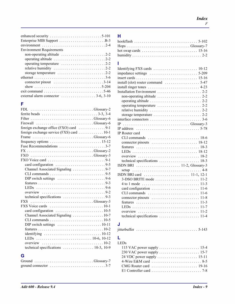
Adit 600 - Release 9.4 Index - 9
IndexF
enhanced security . . . . . . . . . . . . . . . . . . . . . . . . . . . 5-101Enterprise MIB Support . . . . . . . . . . . . . . . . . . . . . . . .B-3environment . . . . . . . . . . . . . . . . . . . . . . . . . . . . . . . . . 2-4Environment Requirements
non-operating altitude . . . . . . . . . . . . . . . . . . . . . . . 2-2operating altitude . . . . . . . . . . . . . . . . . . . . . . . . . . . 2-2operating temperature . . . . . . . . . . . . . . . . . . . . . . . 2-2relative humidity . . . . . . . . . . . . . . . . . . . . . . . . . . . 2-2storage temperature . . . . . . . . . . . . . . . . . . . . . . . . . 2-2
ethernet . . . . . . . . . . . . . . . . . . . . . . . . . . . . . . . . . . . . . 3-6connector pinout . . . . . . . . . . . . . . . . . . . . . . . . . . 3-14show . . . . . . . . . . . . . . . . . . . . . . . . . . . . . . . . . . . 5-204
exit command . . . . . . . . . . . . . . . . . . . . . . . . . . . . . . . 5-46external alarm connector . . . . . . . . . . . . . . . . . . 3-6, 3-10
FFDL . . . . . . . . . . . . . . . . . . . . . . . . . . . . . . . . . Glossary-2ferrite beads . . . . . . . . . . . . . . . . . . . . . . . . . . . . . 3-3, 3-4Filter . . . . . . . . . . . . . . . . . . . . . . . . . . . . . . . . . Glossary-6Firewall . . . . . . . . . . . . . . . . . . . . . . . . . . . . . . Glossary-6foreign exchange office (FXO) card . . . . . . . . . . . . . . 9-1foreign exchange service (FXS) card . . . . . . . . . . . . . 10-1Frame . . . . . . . . . . . . . . . . . . . . . . . . . . . . . . . . Glossary-6frequency options . . . . . . . . . . . . . . . . . . . . . . . . . . . 15-12Fuse Recommendations . . . . . . . . . . . . . . . . . . . . . . . . 3-7FX . . . . . . . . . . . . . . . . . . . . . . . . . . . . . . . . . . . Glossary-2FXO . . . . . . . . . . . . . . . . . . . . . . . . . . . . . . . . . Glossary-3FXO Voice card . . . . . . . . . . . . . . . . . . . . . . . . . . . . . . 9-1
card configuration . . . . . . . . . . . . . . . . . . . . . . . . . . 9-5Channel Associated Signaling . . . . . . . . . . . . . . . . . 9-7CLI commands . . . . . . . . . . . . . . . . . . . . . . . . . . . . . 9-5DIP switch settings . . . . . . . . . . . . . . . . . . . . . . . . . 9-6features . . . . . . . . . . . . . . . . . . . . . . . . . . . . . . . . . . . 9-3LEDs . . . . . . . . . . . . . . . . . . . . . . . . . . . . . . . . . . . . 9-6overview . . . . . . . . . . . . . . . . . . . . . . . . . . . . . . . . . 9-2technical specifications . . . . . . . . . . . . . . . . . . . . . . 9-3
FXS . . . . . . . . . . . . . . . . . . . . . . . . . . . . . . . . . Glossary-3FXS Voice cards . . . . . . . . . . . . . . . . . . . . . . . . . . . . 10-1
card configuration . . . . . . . . . . . . . . . . . . . . . . . . . 10-5Channel Associated Signaling . . . . . . . . . . . . . . . . 10-7CLI commands . . . . . . . . . . . . . . . . . . . . . . . . . . . . 10-5DIP switch settings . . . . . . . . . . . . . . . . . . . . . . . 10-11features . . . . . . . . . . . . . . . . . . . . . . . . . . . . . . . . . . 10-2identifying . . . . . . . . . . . . . . . . . . . . . . . . . . . . . . 10-12LEDs . . . . . . . . . . . . . . . . . . . . . . . . . . . . . 10-6, 10-12overview . . . . . . . . . . . . . . . . . . . . . . . . . . . . . . . . 10-2technical specifications . . . . . . . . . . . . . . . . 10-3, 10-9
GGround . . . . . . . . . . . . . . . . . . . . . . . . . . . . . . . Glossary-7ground connector . . . . . . . . . . . . . . . . . . . . . . . . . . . . . 3-7
Hhookflash . . . . . . . . . . . . . . . . . . . . . . . . . . . . . . . . . 5-102Hops . . . . . . . . . . . . . . . . . . . . . . . . . . . . . . . . . Glossary-7hot swap cards . . . . . . . . . . . . . . . . . . . . . . . . . . . . . 15-16humidity . . . . . . . . . . . . . . . . . . . . . . . . . . . . . . . . . . . . 2-2
IIdentifying FXS cards . . . . . . . . . . . . . . . . . . . . . . . 10-12impedance settings . . . . . . . . . . . . . . . . . . . . . . . . . 5-209insert cards . . . . . . . . . . . . . . . . . . . . . . . . . . . . . . . . 15-16install (slot) router command . . . . . . . . . . . . . . . . . . 5-47install ringer tones . . . . . . . . . . . . . . . . . . . . . . . . . . . 4-23Installation Environment . . . . . . . . . . . . . . . . . . . . . . . 2-2
non-operating altitude . . . . . . . . . . . . . . . . . . . . . . . 2-2operating altitude . . . . . . . . . . . . . . . . . . . . . . . . . . . 2-2operating temperature . . . . . . . . . . . . . . . . . . . . . . . 2-2relative humidity . . . . . . . . . . . . . . . . . . . . . . . . . . . 2-2storage temperature . . . . . . . . . . . . . . . . . . . . . . . . . 2-2
interface connectors . . . . . . . . . . . . . . . . . . . . . . . . . . . 3-6IP . . . . . . . . . . . . . . . . . . . . . . . . . . . . . . . . . . . Glossary-3IP address . . . . . . . . . . . . . . . . . . . . . . . . . . . . . . . . . 5-78IP Router card
CLI commands . . . . . . . . . . . . . . . . . . . . . . . . . . . 18-6connector pinouts . . . . . . . . . . . . . . . . . . . . . . . . 18-12features . . . . . . . . . . . . . . . . . . . . . . . . . . . . . . . . . 18-3LEDs . . . . . . . . . . . . . . . . . . . . . . . . . . . . . . . . . . 18-12overview . . . . . . . . . . . . . . . . . . . . . . . . . . . . . . . . 18-2technical specifications . . . . . . . . . . . . . . . . . . . . . 18-3
ISDN BRI . . . . . . . . . . . . . . . . . . . . . . . 11-2, Glossary-3setup . . . . . . . . . . . . . . . . . . . . . . . . . . . . . . . . . . . . 4-8
ISDN BRI card . . . . . . . . . . . . . . . . . . . . . . . . 11-1, 12-13-DSO BRITE mode . . . . . . . . . . . . . . . . . . . . . . . 11-24 to 1 mode . . . . . . . . . . . . . . . . . . . . . . . . . . . . . . 11-3card configuration . . . . . . . . . . . . . . . . . . . . . . . . . 11-6CLI commands . . . . . . . . . . . . . . . . . . . . . . . . . . . 11-6connector pinouts . . . . . . . . . . . . . . . . . . . . . . . . . 11-8features . . . . . . . . . . . . . . . . . . . . . . . . . . . . . . . . . 11-3LEDs . . . . . . . . . . . . . . . . . . . . . . . . . . . . . . . . . . . 11-7overview . . . . . . . . . . . . . . . . . . . . . . . . . . . . . . . . 11-2technical specifications . . . . . . . . . . . . . . . . . . . . . 11-4
Jjitterbuffer . . . . . . . . . . . . . . . . . . . . . . . . . . . . . . . . 5-143
LLEDs
115 VAC power supply . . . . . . . . . . . . . . . . . . . . . 15-4230 VAC power supply . . . . . . . . . . . . . . . . . . . . . 15-724 VDC power supply . . . . . . . . . . . . . . . . . . . . . 15-114-Wire E&M card . . . . . . . . . . . . . . . . . . . . . . . . . . 8-5CMG Router card . . . . . . . . . . . . . . . . . . . . . . . . 19-16E1 Controller card . . . . . . . . . . . . . . . . . . . . . . . . . . 7-8

Index - 10 Adit 600 - Release 9.4
IndexM
FXO voice card . . . . . . . . . . . . . . . . . . . . . . . . . . . . 9-6FXS voice cards . . . . . . . . . . . . . . . . . . . . 10-6, 10-12IP Router card . . . . . . . . . . . . . . . . . . . . . . . . . . . 18-12ISDN BRI card . . . . . . . . . . . . . . . . . . . . . . . . . . . 11-7OCU-DP card . . . . . . . . . . . . . . . . . . . . . . . . . . . . 12-7POTS card . . . . . . . . . . . . . . . . . . . . . . . . . . . . . . . 14-5P-Phone card . . . . . . . . . . . . . . . . . . . . . . . . . . . . . 13-7Quad DS1 ADPCM . . . . . . . . . . . . . . . . . . . . . . . . 16-9Quad T1 . . . . . . . . . . . . . . . . . . . . . . . . . . . . . . . 17-11RS-232 card . . . . . . . . . . . . . . . . . . . . . . . . . . . . . 21-5T1 Controller card . . . . . . . . . . . . . . . . . . . . . . . . . . 6-9TSR card . . . . . . . . . . . . . . . . . . . . . . . . . . . . . . . 20-15V.35 cards . . . . . . . . . . . . . . . . . . . . . . . . . . . . . . . 22-6
Line UnitLT (LULT) . . . . . . . . . . . . . . . . . . . . . . . . . . . . . . 11-3NT-1 . . . . . . . . . . . . . . . . . . . . . . . . . . . . . . . . . . . 11-3
LMI . . . . . . . . . . . . . . . . . . . . . . . . . . . 5-102, Glossary-3load
tftp command . . . . . . . . . . . . . . . . . . . . . . . . . . . . 5-48xmodem command . . . . . . . . . . . . . . . . . . . . . . . . 5-49
local and remotemanagement . . . . . . . . . . . . . . . . . . . . . . . . . . . . . . 1-6network management . . . . . . . . . . . . . . . . . . . . . . . 1-6
log command . . . . . . . . . . . . . . . . . . . . . . . . . . . . . . . 5-50Logs . . . . . . . . . . . . . . . . . . . . . . . . . . . . . . . . . . . . . . . C-5long rise waveform . . . . . . . . . . . . . . . . . . . . . . . . . 15-15loopback . . . . . . . . . . . . . . . . . . . . . . . . . C-7, Glossary-8
CSU Manual . . . . . . . . . . . . . . . . . . . . . . . . . . . . . C-23DS1 . . . . . . . . . . . . . . . . . . . . . . . . . . . . . . . . . . . . . C-8
Equipment Loop . . . . . . . . . . . . . . . . . . . . . . . . C-12Line Loop . . . . . . . . . . . . . . . . . . . . . . . . . . . . . . C-8Payload Loop . . . . . . . . . . . . . . . . . . . . . . . . . . . C-9
Enable CSU Manual Loopback . . . . . . . . .C-23, C-24Enable Manual OCU Loopback . . . . . . . . . . . . . . C-24Receiving DS1 CSU Loop . . . . . . . . . . . . . . . . . . C-11Receiving DS1 NIU Loop . . . . . . . . . . . . . . . . . . . C-10V.35 Equipment Loop . . . . . . . . . . . . . . . . . . . . . . C-16V.35 Line Loop . . . . . . . . . . . . . . . . . . . . . . . . . . . C-14V.35/V.54 Loop . . . . . . . . . . . . . . . . . . . . . . . . . . C-17V.54 Equipment . . . . . . . . . . . . . . . . . . . . . . . . . . C-19
LULT . . . . . . . . . . . . . . . . . . . . . . . . . . . 11-3, Glossary-3LUNT . . . . . . . . . . . . . . . . . . . . . . . . . . 11-3, Glossary-3
MMbps . . . . . . . . . . . . . . . . . . . . . . . . . . . . . . . . Glossary-3MGCP . . . . . . . . . . . . . . . . . . . . . . . . . . . . . 5-104, 5-266MIB . . . . . . . . . . . . . . . . . . . . . . . . . . . . . . . . . . . . . . . B-2
Enterprise support . . . . . . . . . . . . . . . . . . . . . . . . . . B-3loading order . . . . . . . . . . . . . . . . . . . . . . . . . . . . . . B-7public support . . . . . . . . . . . . . . . . . . . . . . . . . . . . . B-5router Enterprise support . . . . . . . . . . . . . . . . . . . . . B-4router public support . . . . . . . . . . . . . . . . . . . . . . . . B-6
Structure . . . . . . . . . . . . . . . . . . . . . . . . . . . . . . . . . B-2MIB Loading Order . . . . . . . . . . . . . . . . . . . . . . . . . . B-7mounting
rack . . . . . . . . . . . . . . . . . . . . . . . . . . . . . . . . . . . . . .2-6wall bracket . . . . . . . . . . . . . . . . . . . . . . . . . . . . . . .2-4
Nnetwork management . . . . . . . . . . . . . . . . . . . . . . . . . .1-6non-operating altitude . . . . . . . . . . . . . . . . . . . . . . . . . .2-2
OOCU-DP card . . . . . . . . . . . . . . . . . . . . . . . . . . . . . . .12-1
alarms . . . . . . . . . . . . . . . . . . . . . . . . . . . . . . . . . . .12-9basic setup . . . . . . . . . . . . . . . . . . . . . . . . . . . . . . .12-7card configuration . . . . . . . . . . . . . . . . . . . . . . . . . .12-6CLI commands . . . . . . . . . . . . . . . . . . . . . . . . . . . .12-6connector pinouts . . . . . . . . . . . . . . . . . . . . . . . . .12-10
RJ-48S . . . . . . . . . . . . . . . . . . . . . . . . . . . . . . .12-10features . . . . . . . . . . . . . . . . . . . . . . . . . . . . . . . . . .12-4jumper settings . . . . . . . . . . . . . . . . . . . . . . . . . . . .12-8LEDs . . . . . . . . . . . . . . . . . . . . . . . . . . . . . . . . . . . .12-7line rates/line lengths . . . . . . . . . . . . . . . . . . . . . . .12-9overview . . . . . . . . . . . . . . . . . . . . . . . . . . . . . . . . .12-2technical specifications . . . . . . . . . . . . . . . . . . . . . .12-4
OCU-DP LoopbackEnable CSU Manual Loopback . . . . . . . . . C-23, C-24Enable Manual OCU Loopback . . . . . . . . . . . . . . C-24Non-latching loopdetect . . . . . . . . . . . . . . . . . . . . C-22
OCU-DP Loopbacks . . . . . . . . . . . . . . . . . . . . . . . . . C-21operating
altitude . . . . . . . . . . . . . . . . . . . . . . . . . . . . . . . . . . .2-2temperature range . . . . . . . . . . . . . . . . . . . . . . . . . . .2-2
Ppacket time . . . . . . . . . . . . . . . . . . . . . . . . . . . . . . . .5-145PAP . . . . . . . . . . . . . . . . . . . . . . . Glossary-4, Glossary-9password
ppp . . . . . . . . . . . . . . . . . . . . . . . . . . . . . . . . . . . .5-131router . . . . . . . . . . . . . . . . . . . . . . . . . . . . . . . . . . .5-122user . . . . . . . . . . . . . . . . . . . . . . . . . . . . . . . . . . . .5-190
Physical Information . . . . . . . . . . . . . . . . . . . . . . . . . . .1-9ping . . . . . . . . . . . . . . . . . . . . . . . . . . . . . . . . . Glossary-9
command . . . . . . . . . . . . . . . . . . . . . . . . . . . . . . . .5-51pinouts . . . . . . . . . . . . . . . . . . . . . . . . . . . . . . . . .8-5, 16-9
10Base-T Ethernet . . . . . . . . . . . . 18-12, 19-16, 20-1325-pin telco . . . . . . . . . . . . . . . . . . . . . . . . .12-10, 17-94-Wire E&M card . . . . . . . . . . . . . . . . . . . . . . . . . . .8-5CMG Router card . . . . . . . . . . . . . . . . . . . . . . . . .19-16DB-26 . . . . . . . . . . . . . . . . . . . . . . . . . . . . . . . . . . .22-7DB-9 . . . . . . . . . . . . . . . . . . . . . . . . . . . . . . . . . . . .3-13external alarm connector . . . . . . . . . . . . . . . . . . . .3-10IP Router card . . . . . . . . . . . . . . . . . . . . . . . . . . . .18-12
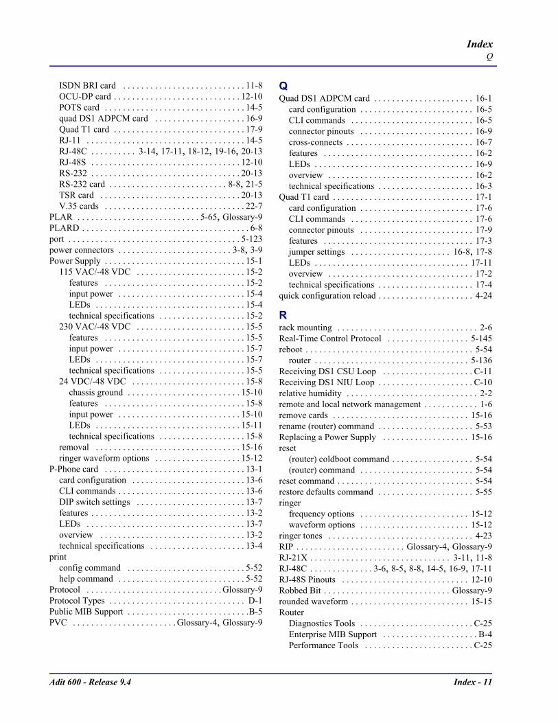
Adit 600 - Release 9.4 Index - 11
IndexQ
ISDN BRI card . . . . . . . . . . . . . . . . . . . . . . . . . . . 11-8OCU-DP card . . . . . . . . . . . . . . . . . . . . . . . . . . . . 12-10POTS card . . . . . . . . . . . . . . . . . . . . . . . . . . . . . . . 14-5quad DS1 ADPCM card . . . . . . . . . . . . . . . . . . . . 16-9Quad T1 card . . . . . . . . . . . . . . . . . . . . . . . . . . . . . 17-9RJ-11 . . . . . . . . . . . . . . . . . . . . . . . . . . . . . . . . . . . 14-5RJ-48C . . . . . . . . . . 3-14, 17-11, 18-12, 19-16, 20-13RJ-48S . . . . . . . . . . . . . . . . . . . . . . . . . . . . . . . . . 12-10RS-232 . . . . . . . . . . . . . . . . . . . . . . . . . . . . . . . . . 20-13RS-232 card . . . . . . . . . . . . . . . . . . . . . . . . . . 8-8, 21-5TSR card . . . . . . . . . . . . . . . . . . . . . . . . . . . . . . . 20-13V.35 cards . . . . . . . . . . . . . . . . . . . . . . . . . . . . . . . 22-7
PLAR . . . . . . . . . . . . . . . . . . . . . . . . . . . 5-65, Glossary-9PLARD . . . . . . . . . . . . . . . . . . . . . . . . . . . . . . . . . . . . . 6-8port . . . . . . . . . . . . . . . . . . . . . . . . . . . . . . . . . . . . . . 5-123power connectors . . . . . . . . . . . . . . . . . . . . . . . . . 3-8, 3-9Power Supply . . . . . . . . . . . . . . . . . . . . . . . . . . . . . . . 15-1
115 VAC/-48 VDC . . . . . . . . . . . . . . . . . . . . . . . . 15-2features . . . . . . . . . . . . . . . . . . . . . . . . . . . . . . . 15-2input power . . . . . . . . . . . . . . . . . . . . . . . . . . . . 15-4LEDs . . . . . . . . . . . . . . . . . . . . . . . . . . . . . . . . . 15-4technical specifications . . . . . . . . . . . . . . . . . . . 15-2
230 VAC/-48 VDC . . . . . . . . . . . . . . . . . . . . . . . . 15-5features . . . . . . . . . . . . . . . . . . . . . . . . . . . . . . . 15-5input power . . . . . . . . . . . . . . . . . . . . . . . . . . . . 15-7LEDs . . . . . . . . . . . . . . . . . . . . . . . . . . . . . . . . . 15-7technical specifications . . . . . . . . . . . . . . . . . . . 15-5
24 VDC/-48 VDC . . . . . . . . . . . . . . . . . . . . . . . . . 15-8chassis ground . . . . . . . . . . . . . . . . . . . . . . . . . 15-10features . . . . . . . . . . . . . . . . . . . . . . . . . . . . . . . 15-8input power . . . . . . . . . . . . . . . . . . . . . . . . . . . 15-10LEDs . . . . . . . . . . . . . . . . . . . . . . . . . . . . . . . . 15-11technical specifications . . . . . . . . . . . . . . . . . . . 15-8
removal . . . . . . . . . . . . . . . . . . . . . . . . . . . . . . . . 15-16ringer waveform options . . . . . . . . . . . . . . . . . . . 15-12
P-Phone card . . . . . . . . . . . . . . . . . . . . . . . . . . . . . . . 13-1card configuration . . . . . . . . . . . . . . . . . . . . . . . . . 13-6CLI commands . . . . . . . . . . . . . . . . . . . . . . . . . . . . 13-6DIP switch settings . . . . . . . . . . . . . . . . . . . . . . . . 13-7features . . . . . . . . . . . . . . . . . . . . . . . . . . . . . . . . . . 13-2LEDs . . . . . . . . . . . . . . . . . . . . . . . . . . . . . . . . . . . 13-7overview . . . . . . . . . . . . . . . . . . . . . . . . . . . . . . . . 13-2technical specifications . . . . . . . . . . . . . . . . . . . . . 13-4
printconfig command . . . . . . . . . . . . . . . . . . . . . . . . . . 5-52help command . . . . . . . . . . . . . . . . . . . . . . . . . . . . 5-52
Protocol . . . . . . . . . . . . . . . . . . . . . . . . . . . . . . Glossary-9Protocol Types . . . . . . . . . . . . . . . . . . . . . . . . . . . . . . D-1Public MIB Support . . . . . . . . . . . . . . . . . . . . . . . . . . .B-5PVC . . . . . . . . . . . . . . . . . . . . . . . Glossary-4, Glossary-9
QQuad DS1 ADPCM card . . . . . . . . . . . . . . . . . . . . . . 16-1
card configuration . . . . . . . . . . . . . . . . . . . . . . . . . 16-5CLI commands . . . . . . . . . . . . . . . . . . . . . . . . . . . 16-5connector pinouts . . . . . . . . . . . . . . . . . . . . . . . . . 16-9cross-connects . . . . . . . . . . . . . . . . . . . . . . . . . . . . 16-7features . . . . . . . . . . . . . . . . . . . . . . . . . . . . . . . . . 16-2LEDs . . . . . . . . . . . . . . . . . . . . . . . . . . . . . . . . . . . 16-9overview . . . . . . . . . . . . . . . . . . . . . . . . . . . . . . . . 16-2technical specifications . . . . . . . . . . . . . . . . . . . . . 16-3
Quad T1 card . . . . . . . . . . . . . . . . . . . . . . . . . . . . . . . 17-1card configuration . . . . . . . . . . . . . . . . . . . . . . . . . 17-6CLI commands . . . . . . . . . . . . . . . . . . . . . . . . . . . 17-6connector pinouts . . . . . . . . . . . . . . . . . . . . . . . . . 17-9features . . . . . . . . . . . . . . . . . . . . . . . . . . . . . . . . . 17-3jumper settings . . . . . . . . . . . . . . . . . . . . . . 16-8, 17-8LEDs . . . . . . . . . . . . . . . . . . . . . . . . . . . . . . . . . . 17-11overview . . . . . . . . . . . . . . . . . . . . . . . . . . . . . . . . 17-2technical specifications . . . . . . . . . . . . . . . . . . . . . 17-4
quick configuration reload . . . . . . . . . . . . . . . . . . . . . 4-24
Rrack mounting . . . . . . . . . . . . . . . . . . . . . . . . . . . . . . . 2-6Real-Time Control Protocol . . . . . . . . . . . . . . . . . . 5-145reboot . . . . . . . . . . . . . . . . . . . . . . . . . . . . . . . . . . . . . 5-54
router . . . . . . . . . . . . . . . . . . . . . . . . . . . . . . . . . . 5-136Receiving DS1 CSU Loop . . . . . . . . . . . . . . . . . . . . C-11Receiving DS1 NIU Loop . . . . . . . . . . . . . . . . . . . . . C-10relative humidity . . . . . . . . . . . . . . . . . . . . . . . . . . . . . 2-2remote and local network management . . . . . . . . . . . . 1-6remove cards . . . . . . . . . . . . . . . . . . . . . . . . . . . . . . 15-16rename (router) command . . . . . . . . . . . . . . . . . . . . . 5-53Replacing a Power Supply . . . . . . . . . . . . . . . . . . . 15-16reset
(router) coldboot command . . . . . . . . . . . . . . . . . . 5-54(router) command . . . . . . . . . . . . . . . . . . . . . . . . . 5-54
reset command . . . . . . . . . . . . . . . . . . . . . . . . . . . . . . 5-54restore defaults command . . . . . . . . . . . . . . . . . . . . . 5-55ringer
frequency options . . . . . . . . . . . . . . . . . . . . . . . . 15-12waveform options . . . . . . . . . . . . . . . . . . . . . . . . 15-12
ringer tones . . . . . . . . . . . . . . . . . . . . . . . . . . . . . . . . 4-23RIP . . . . . . . . . . . . . . . . . . . . . . . . Glossary-4, Glossary-9RJ-21X . . . . . . . . . . . . . . . . . . . . . . . . . . . . . . . 3-11, 11-8RJ-48C . . . . . . . . . . . . . . 3-6, 8-5, 8-8, 14-5, 16-9, 17-11RJ-48S Pinouts . . . . . . . . . . . . . . . . . . . . . . . . . . . . 12-10Robbed Bit . . . . . . . . . . . . . . . . . . . . . . . . . . . . Glossary-9rounded waveform . . . . . . . . . . . . . . . . . . . . . . . . . . 15-15Router
Diagnostics Tools . . . . . . . . . . . . . . . . . . . . . . . . . C-25Enterprise MIB Support . . . . . . . . . . . . . . . . . . . . . B-4Performance Tools . . . . . . . . . . . . . . . . . . . . . . . . C-25
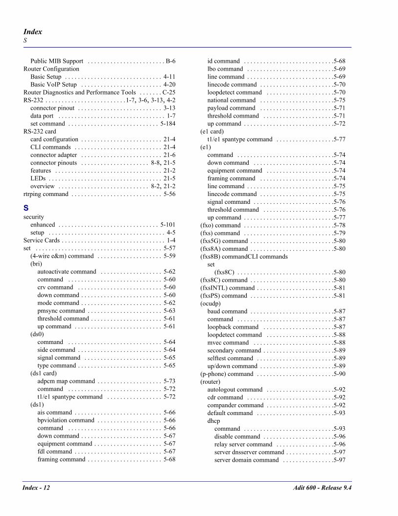
Index - 12 Adit 600 - Release 9.4
IndexS
Public MIB Support . . . . . . . . . . . . . . . . . . . . . . . . B-6Router Configuration
Basic Setup . . . . . . . . . . . . . . . . . . . . . . . . . . . . . . 4-11Basic VoIP Setup . . . . . . . . . . . . . . . . . . . . . . . . . 4-20
Router Diagnostics and Performance Tools . . . . . . . C-25RS-232 . . . . . . . . . . . . . . . . . . . . . . . . .1-7, 3-6, 3-13, 4-2
connector pinout . . . . . . . . . . . . . . . . . . . . . . . . . . 3-13data port . . . . . . . . . . . . . . . . . . . . . . . . . . . . . . . . . 1-7set command . . . . . . . . . . . . . . . . . . . . . . . . . . . . 5-184
RS-232 cardcard configuration . . . . . . . . . . . . . . . . . . . . . . . . . 21-4CLI commands . . . . . . . . . . . . . . . . . . . . . . . . . . . 21-4connector adapter . . . . . . . . . . . . . . . . . . . . . . . . . 21-6connector pinouts . . . . . . . . . . . . . . . . . . . . . 8-8, 21-5features . . . . . . . . . . . . . . . . . . . . . . . . . . . . . . . . . 21-2LEDs . . . . . . . . . . . . . . . . . . . . . . . . . . . . . . . . . . . 21-5overview . . . . . . . . . . . . . . . . . . . . . . . . . . . . 8-2, 21-2
rtrping command . . . . . . . . . . . . . . . . . . . . . . . . . . . . 5-56
Ssecurity
enhanced . . . . . . . . . . . . . . . . . . . . . . . . . . . . . . . 5-101setup . . . . . . . . . . . . . . . . . . . . . . . . . . . . . . . . . . . . 4-5
Service Cards . . . . . . . . . . . . . . . . . . . . . . . . . . . . . . . . 1-4set . . . . . . . . . . . . . . . . . . . . . . . . . . . . . . . . . . . . . . . 5-57
(4-wire e&m) command . . . . . . . . . . . . . . . . . . . . 5-59(bri)
autoactivate command . . . . . . . . . . . . . . . . . . . 5-62command . . . . . . . . . . . . . . . . . . . . . . . . . . . . . 5-60crv command . . . . . . . . . . . . . . . . . . . . . . . . . . 5-60down command . . . . . . . . . . . . . . . . . . . . . . . . . 5-60mode command . . . . . . . . . . . . . . . . . . . . . . . . . 5-62pmsync command . . . . . . . . . . . . . . . . . . . . . . . 5-63threshold command . . . . . . . . . . . . . . . . . . . . . . 5-61up command . . . . . . . . . . . . . . . . . . . . . . . . . . . 5-61
(ds0)command . . . . . . . . . . . . . . . . . . . . . . . . . . . . . 5-64side command . . . . . . . . . . . . . . . . . . . . . . . . . . 5-64signal command . . . . . . . . . . . . . . . . . . . . . . . . 5-65type command . . . . . . . . . . . . . . . . . . . . . . . . . . 5-65
(ds1 card)adpcm map command . . . . . . . . . . . . . . . . . . . . 5-73command . . . . . . . . . . . . . . . . . . . . . . . . . . . . . 5-72t1/e1 spantype command . . . . . . . . . . . . . . . . . 5-72
(ds1)ais command . . . . . . . . . . . . . . . . . . . . . . . . . . . 5-66bpviolation command . . . . . . . . . . . . . . . . . . . . 5-66command . . . . . . . . . . . . . . . . . . . . . . . . . . . . . 5-66down command . . . . . . . . . . . . . . . . . . . . . . . . . 5-67equipment command . . . . . . . . . . . . . . . . . . . . . 5-67fdl command . . . . . . . . . . . . . . . . . . . . . . . . . . . 5-67framing command . . . . . . . . . . . . . . . . . . . . . . . 5-68
id command . . . . . . . . . . . . . . . . . . . . . . . . . . . .5-68lbo command . . . . . . . . . . . . . . . . . . . . . . . . . . .5-69line command . . . . . . . . . . . . . . . . . . . . . . . . . . .5-69linecode command . . . . . . . . . . . . . . . . . . . . . . .5-70loopdetect command . . . . . . . . . . . . . . . . . . . . .5-70national command . . . . . . . . . . . . . . . . . . . . . . .5-75payload command . . . . . . . . . . . . . . . . . . . . . . .5-71threshold command . . . . . . . . . . . . . . . . . . . . . .5-71up command . . . . . . . . . . . . . . . . . . . . . . . . . . . .5-72
(e1 card)t1/e1 spantype command . . . . . . . . . . . . . . . . . .5-77
(e1)command . . . . . . . . . . . . . . . . . . . . . . . . . . . . . .5-74down command . . . . . . . . . . . . . . . . . . . . . . . . .5-74equipment command . . . . . . . . . . . . . . . . . . . . .5-74framing command . . . . . . . . . . . . . . . . . . . . . . .5-74line command . . . . . . . . . . . . . . . . . . . . . . . . . . .5-75linecode command . . . . . . . . . . . . . . . . . . . . . . .5-75signal command . . . . . . . . . . . . . . . . . . . . . . . . .5-76threshold command . . . . . . . . . . . . . . . . . . . . . .5-76up command . . . . . . . . . . . . . . . . . . . . . . . . . . . .5-77
(fxo) command . . . . . . . . . . . . . . . . . . . . . . . . . . . .5-78(fxs) command . . . . . . . . . . . . . . . . . . . . . . . . . . . .5-79(fxs5G) command . . . . . . . . . . . . . . . . . . . . . . . . . .5-80(fxs8A) command . . . . . . . . . . . . . . . . . . . . . . . . . .5-80(fxs8B) commandCLI commands
set(fxs8C) . . . . . . . . . . . . . . . . . . . . . . . . . . . . . .5-80
(fxs8C) command . . . . . . . . . . . . . . . . . . . . . . . . . .5-80(fxsINTL) command . . . . . . . . . . . . . . . . . . . . . . . .5-81(fxsPS) command . . . . . . . . . . . . . . . . . . . . . . . . . .5-81(ocudp)
baud command . . . . . . . . . . . . . . . . . . . . . . . . . .5-87command . . . . . . . . . . . . . . . . . . . . . . . . . . . . . .5-87loopback command . . . . . . . . . . . . . . . . . . . . . .5-87loopdetect command . . . . . . . . . . . . . . . . . . . . .5-88mvec command . . . . . . . . . . . . . . . . . . . . . . . . .5-88secondary command . . . . . . . . . . . . . . . . . . . . . .5-89selftest command . . . . . . . . . . . . . . . . . . . . . . . .5-89up/down command . . . . . . . . . . . . . . . . . . . . . . .5-89
(p-phone) command . . . . . . . . . . . . . . . . . . . . . . . .5-90(router)
autologout command . . . . . . . . . . . . . . . . . . . . .5-92cdr command . . . . . . . . . . . . . . . . . . . . . . . . . . .5-92compander command . . . . . . . . . . . . . . . . . . . . .5-92default command . . . . . . . . . . . . . . . . . . . . . . . .5-93dhcp
command . . . . . . . . . . . . . . . . . . . . . . . . . . . .5-93disable command . . . . . . . . . . . . . . . . . . . . . .5-96relay server command . . . . . . . . . . . . . . . . . .5-96server dnsserver command . . . . . . . . . . . . . . .5-97server domain command . . . . . . . . . . . . . . . .5-97
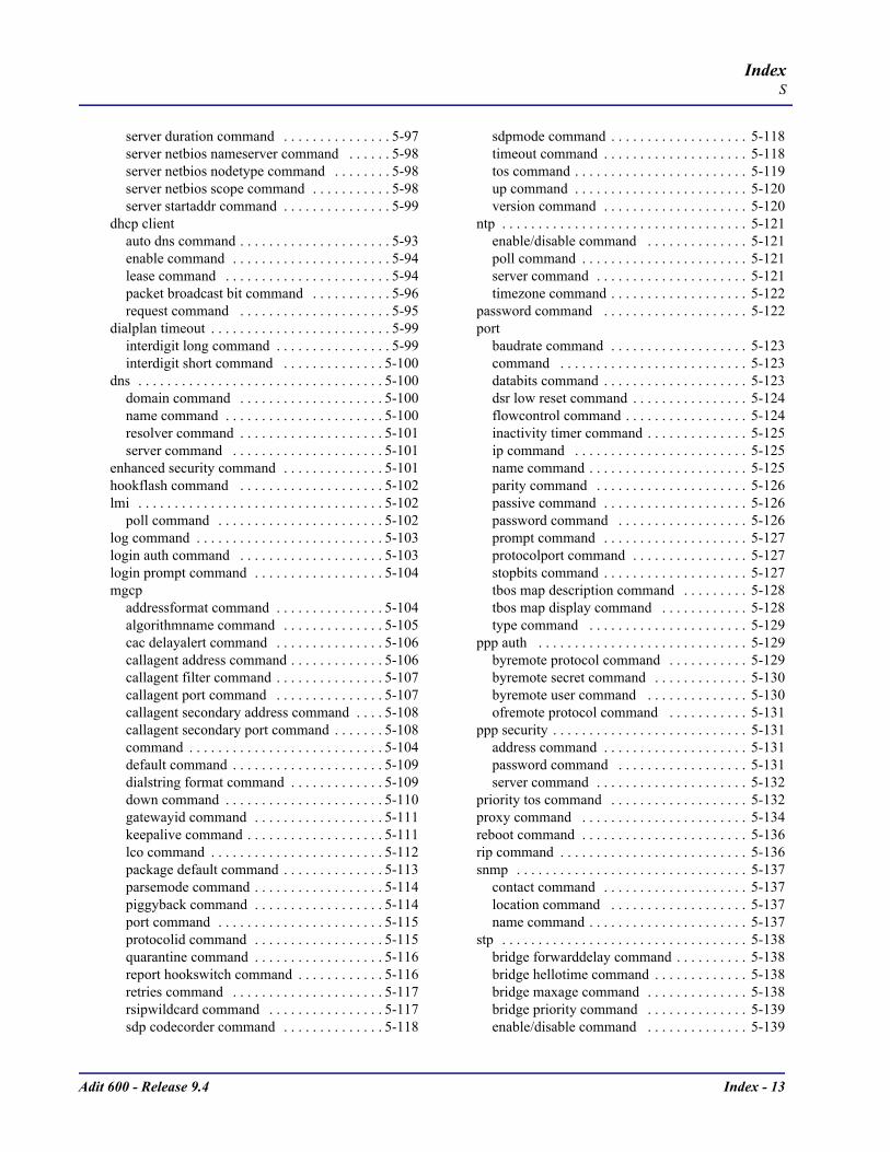
Adit 600 - Release 9.4 Index - 13
IndexS
server duration command . . . . . . . . . . . . . . . 5-97server netbios nameserver command . . . . . . 5-98server netbios nodetype command . . . . . . . . 5-98server netbios scope command . . . . . . . . . . . 5-98server startaddr command . . . . . . . . . . . . . . . 5-99
dhcp clientauto dns command . . . . . . . . . . . . . . . . . . . . . 5-93enable command . . . . . . . . . . . . . . . . . . . . . . 5-94lease command . . . . . . . . . . . . . . . . . . . . . . . 5-94packet broadcast bit command . . . . . . . . . . . 5-96request command . . . . . . . . . . . . . . . . . . . . . 5-95
dialplan timeout . . . . . . . . . . . . . . . . . . . . . . . . . 5-99interdigit long command . . . . . . . . . . . . . . . . 5-99interdigit short command . . . . . . . . . . . . . . 5-100
dns . . . . . . . . . . . . . . . . . . . . . . . . . . . . . . . . . . 5-100domain command . . . . . . . . . . . . . . . . . . . . 5-100name command . . . . . . . . . . . . . . . . . . . . . . 5-100resolver command . . . . . . . . . . . . . . . . . . . . 5-101server command . . . . . . . . . . . . . . . . . . . . . 5-101
enhanced security command . . . . . . . . . . . . . . 5-101hookflash command . . . . . . . . . . . . . . . . . . . . 5-102lmi . . . . . . . . . . . . . . . . . . . . . . . . . . . . . . . . . . 5-102
poll command . . . . . . . . . . . . . . . . . . . . . . . 5-102log command . . . . . . . . . . . . . . . . . . . . . . . . . . 5-103login auth command . . . . . . . . . . . . . . . . . . . . 5-103login prompt command . . . . . . . . . . . . . . . . . . 5-104mgcp
addressformat command . . . . . . . . . . . . . . . 5-104algorithmname command . . . . . . . . . . . . . . 5-105cac delayalert command . . . . . . . . . . . . . . . 5-106callagent address command . . . . . . . . . . . . . 5-106callagent filter command . . . . . . . . . . . . . . . 5-107callagent port command . . . . . . . . . . . . . . . 5-107callagent secondary address command . . . . 5-108callagent secondary port command . . . . . . . 5-108command . . . . . . . . . . . . . . . . . . . . . . . . . . . 5-104default command . . . . . . . . . . . . . . . . . . . . . 5-109dialstring format command . . . . . . . . . . . . . 5-109down command . . . . . . . . . . . . . . . . . . . . . . 5-110gatewayid command . . . . . . . . . . . . . . . . . . 5-111keepalive command . . . . . . . . . . . . . . . . . . . 5-111lco command . . . . . . . . . . . . . . . . . . . . . . . . 5-112package default command . . . . . . . . . . . . . . 5-113parsemode command . . . . . . . . . . . . . . . . . . 5-114piggyback command . . . . . . . . . . . . . . . . . . 5-114port command . . . . . . . . . . . . . . . . . . . . . . . 5-115protocolid command . . . . . . . . . . . . . . . . . . 5-115quarantine command . . . . . . . . . . . . . . . . . . 5-116report hookswitch command . . . . . . . . . . . . 5-116retries command . . . . . . . . . . . . . . . . . . . . . 5-117rsipwildcard command . . . . . . . . . . . . . . . . 5-117sdp codecorder command . . . . . . . . . . . . . . 5-118
sdpmode command . . . . . . . . . . . . . . . . . . . 5-118timeout command . . . . . . . . . . . . . . . . . . . . 5-118tos command . . . . . . . . . . . . . . . . . . . . . . . . 5-119up command . . . . . . . . . . . . . . . . . . . . . . . . 5-120version command . . . . . . . . . . . . . . . . . . . . 5-120
ntp . . . . . . . . . . . . . . . . . . . . . . . . . . . . . . . . . . 5-121enable/disable command . . . . . . . . . . . . . . 5-121poll command . . . . . . . . . . . . . . . . . . . . . . . 5-121server command . . . . . . . . . . . . . . . . . . . . . 5-121timezone command . . . . . . . . . . . . . . . . . . . 5-122
password command . . . . . . . . . . . . . . . . . . . . 5-122port
baudrate command . . . . . . . . . . . . . . . . . . . 5-123command . . . . . . . . . . . . . . . . . . . . . . . . . . 5-123databits command . . . . . . . . . . . . . . . . . . . . 5-123dsr low reset command . . . . . . . . . . . . . . . . 5-124flowcontrol command . . . . . . . . . . . . . . . . . 5-124inactivity timer command . . . . . . . . . . . . . . 5-125ip command . . . . . . . . . . . . . . . . . . . . . . . . 5-125name command . . . . . . . . . . . . . . . . . . . . . . 5-125parity command . . . . . . . . . . . . . . . . . . . . . 5-126passive command . . . . . . . . . . . . . . . . . . . . 5-126password command . . . . . . . . . . . . . . . . . . 5-126prompt command . . . . . . . . . . . . . . . . . . . . 5-127protocolport command . . . . . . . . . . . . . . . . 5-127stopbits command . . . . . . . . . . . . . . . . . . . . 5-127tbos map description command . . . . . . . . . 5-128tbos map display command . . . . . . . . . . . . 5-128type command . . . . . . . . . . . . . . . . . . . . . . 5-129
ppp auth . . . . . . . . . . . . . . . . . . . . . . . . . . . . . 5-129byremote protocol command . . . . . . . . . . . 5-129byremote secret command . . . . . . . . . . . . . 5-130byremote user command . . . . . . . . . . . . . . 5-130ofremote protocol command . . . . . . . . . . . 5-131
ppp security . . . . . . . . . . . . . . . . . . . . . . . . . . . 5-131address command . . . . . . . . . . . . . . . . . . . . 5-131password command . . . . . . . . . . . . . . . . . . 5-131server command . . . . . . . . . . . . . . . . . . . . . 5-132
priority tos command . . . . . . . . . . . . . . . . . . . 5-132proxy command . . . . . . . . . . . . . . . . . . . . . . . 5-134reboot command . . . . . . . . . . . . . . . . . . . . . . . 5-136rip command . . . . . . . . . . . . . . . . . . . . . . . . . . 5-136snmp . . . . . . . . . . . . . . . . . . . . . . . . . . . . . . . . 5-137
contact command . . . . . . . . . . . . . . . . . . . . 5-137location command . . . . . . . . . . . . . . . . . . . 5-137name command . . . . . . . . . . . . . . . . . . . . . . 5-137
stp . . . . . . . . . . . . . . . . . . . . . . . . . . . . . . . . . . 5-138bridge forwarddelay command . . . . . . . . . . 5-138bridge hellotime command . . . . . . . . . . . . . 5-138bridge maxage command . . . . . . . . . . . . . . 5-138bridge priority command . . . . . . . . . . . . . . 5-139enable/disable command . . . . . . . . . . . . . . 5-139

Index - 14 Adit 600 - Release 9.4
IndexS
syslog . . . . . . . . . . . . . . . . . . . . . . . . . . . . . . . 5-140enable/disable command . . . . . . . . . . . . . . 5-140facility command . . . . . . . . . . . . . . . . . . . . 5-140level command . . . . . . . . . . . . . . . . . . . . . . 5-141server command . . . . . . . . . . . . . . . . . . . . . 5-141
voip . . . . . . . . . . . . . . . . . . . . . . . . . . . . . . . . . 5-142default command . . . . . . . . . . . . . . . . . . . . 5-142dtmf edge command . . . . . . . . . . . . . . . . . . 5-142g729a command . . . . . . . . . . . . . . . . . . . . . 5-143jitterbuffer command . . . . . . . . . . . . . . . . . 5-143osi command . . . . . . . . . . . . . . . . . . . . . . . 5-143packing command . . . . . . . . . . . . . . . . . . . 5-144payload type command . . . . . . . . . . . . . . . . 5-144ptime command . . . . . . . . . . . . . . . . . . . . . 5-145rtcp
cname command . . . . . . . . . . . . . . . . . . 5-145rtp baseport command . . . . . . . . . . . . . . . . 5-146rtpmap command . . . . . . . . . . . . . . . . . . . . 5-147sdpaddress command . . . . . . . . . . . . . . . . . 5-148t38 ecm command . . . . . . . . . . . . . . . . . . . 5-148t38 redundancy highspeed command . . . . . 5-149t38 redundancy lowspeed command . . . . . 5-149
voip rtcpinterval command . . . . . . . . . . . . . . . . . . . . 5-146
(router-lan)collision . . . . . . . . . . . . . . . . . . . . . . . . . . . . . 5-150
interval command . . . . . . . . . . . . . . . . . . . . 5-150threshold command . . . . . . . . . . . . . . . . . . 5-150
filter forward command . . . . . . . . . . . . . . . . . 5-151framing command . . . . . . . . . . . . . . . . . . . . . . 5-151gateway command . . . . . . . . . . . . . . . . . . . . . 5-152ip address command . . . . . . . . . . . . . . . . . . . . 5-152ipx network command . . . . . . . . . . . . . . . . . . 5-153name - see rename command . . . . . . . . . . . . . . 5-53phy command . . . . . . . . . . . . . . . . . . . . . . . . . 5-153rip
command . . . . . . . . . . . . . . . . . . . . . . . . . . 5-154ip command . . . . . . . . . . . . . . . . . . . . . . . . 5-154ipx command . . . . . . . . . . . . . . . . . . . . . . . 5-154
stpenable/disable command . . . . . . . . . . . . . . 5-155port cost command . . . . . . . . . . . . . . . . . . . 5-155port priority command . . . . . . . . . . . . . . . . 5-156
stp command . . . . . . . . . . . . . . . . . . . . . . . . . . 5-155up/down command . . . . . . . . . . . . . . . . . . . . . 5-156
(router-trunk)encapsulation command . . . . . . . . . . . . . . . . . 5-157multilink group command . . . . . . . . . . . . . . . 5-157speed command . . . . . . . . . . . . . . . . . . . . . . . 5-158up/down command . . . . . . . . . . . . . . . . . . . . . 5-158
(router-voice)algorithm preference command . . . . . . . . . . . 5-160
cpd command . . . . . . . . . . . . . . . . . . . . . . . . . .5-161default command . . . . . . . . . . . . . . . . . . . . . . .5-161dialplan timeout . . . . . . . . . . . . . . . . . . . . . . . .5-162
interdigit long command . . . . . . . . . . . . . . .5-162interdigit short command . . . . . . . . . . . . . . .5-162
down command . . . . . . . . . . . . . . . . . . . . . . . .5-163dtmfrelay command . . . . . . . . . . . . . . . . . . . . .5-163echo cancellation command . . . . . . . . . . . . . . .5-164echo tail command . . . . . . . . . . . . . . . . . . . . . .5-164endpoint prefix command . . . . . . . . . . . . . . . .5-165endpoint suffix command . . . . . . . . . . . . . . . . .5-165fax command . . . . . . . . . . . . . . . . . . . . . . . . . .5-166log start command . . . . . . . . . . . . . . . . . . . . . .5-166log stop command . . . . . . . . . . . . . . . . . . . . . .5-167modem command . . . . . . . . . . . . . . . . . . . . . . .5-167rfc2833
command . . . . . . . . . . . . . . . . . . . . . . . . . . .5-168payloadtype command . . . . . . . . . . . . . . . . .5-168refresh interval command . . . . . . . . . . . . . .5-170repeat count command . . . . . . . . . . . . . . . . .5-169repeat interval command . . . . . . . . . . . . . . .5-170signals command . . . . . . . . . . . . . . . . . . . . .5-168
rxgain command . . . . . . . . . . . . . . . . . . . . . . . .5-171signaling command . . . . . . . . . . . . . . . . . . . . .5-171silence command . . . . . . . . . . . . . . . . . . . . . . .5-172slash command . . . . . . . . . . . . . . . . . . . . . . . . .5-172tos command . . . . . . . . . . . . . . . . . . . . . . . . . .5-173txgain command . . . . . . . . . . . . . . . . . . . . . . . .5-173up command . . . . . . . . . . . . . . . . . . . . . . . . . . .5-174voice bandwidth limit command . . . . . . . . . . .5-159
(router-wan)dlci command . . . . . . . . . . . . . . . . . . . . . . . . . .5-174ip address command . . . . . . . . . . . . . . . . . . . . .5-176ip command . . . . . . . . . . . . . . . . . . . . . . . . . . .5-176ipx command . . . . . . . . . . . . . . . . . . . . . . . . . .5-177mlppp command . . . . . . . . . . . . . . . . . . . . . . . .5-177name - see rename command . . . . . . . . . . . . . . .5-53nat
address command . . . . . . . . . . . . . . . . . . . . .5-178command . . . . . . . . . . . . . . . . . . . . . . . . . . .5-178enable/disable command . . . . . . . . . . . . . . .5-179ports command . . . . . . . . . . . . . . . . . . . . . . .5-179
other command . . . . . . . . . . . . . . . . . . . . . . . . .5-179ppp
auth ofremote user command . . . . . . . . . . . .5-180command . . . . . . . . . . . . . . . . . . . . . . . . . . .5-180compression command . . . . . . . . . . . . . . . .5-180fragmentation size command . . . . . . . . . . . .5-178qos interleave command . . . . . . . . . . . . . . .5-177security server command . . . . . . . . . . . . . . .5-181
ripcommand . . . . . . . . . . . . . . . . . . . . . . . . . . .5-181

Adit 600 - Release 9.4 Index - 15
IndexS
ip updates command . . . . . . . . . . . . . . . . . . 5-181ipx updates command . . . . . . . . . . . . . . . . . 5-182
stpcommand . . . . . . . . . . . . . . . . . . . . . . . . . . . 5-182enable/disable command . . . . . . . . . . . . . . . 5-182port cost command . . . . . . . . . . . . . . . . . . . 5-183port priority command . . . . . . . . . . . . . . . . . 5-183
trunk command . . . . . . . . . . . . . . . . . . . . . . . . 5-183up/down command . . . . . . . . . . . . . . . . . . . . . 5-184
(rs232) command . . . . . . . . . . . . . . . . . . . . . . . . . 5-184(v35) command . . . . . . . . . . . . . . . . . . . . . . . . . . 5-191(v54) command . . . . . . . . . . . . . . . . . . . . . . . . . . 5-192alarms command . . . . . . . . . . . . . . . . . . . . . . . . . . 5-59autoexit command . . . . . . . . . . . . . . . . . . . . . . . . . 5-60clock command . . . . . . . . . . . . . . . . . . . . . . . . . . . 5-63command . . . . . . . . . . . . . . . . . . . . . . . . . . . . . . . . 5-57date command . . . . . . . . . . . . . . . . . . . . . . . . . . . . 5-64ethernet ip address command . . . . . . . . . . . . . . . . . 5-78FXO transmit and receive levels . . . . . . . . . . . . . . . 9-1FXS transmit and receive levels . . . . 10-1, 13-1, 14-1id command . . . . . . . . . . . . . . . . . . . . . . . . . . . . . . 5-82idle command . . . . . . . . . . . . . . . . . . . . . . . . . . . . . 5-82ip gateway command . . . . . . . . . . . . . . . . . . . . . . . 5-82ipds0 command . . . . . . . . . . . . . . . . . . . . . . . . . . . 5-83key command . . . . . . . . . . . . . . . . . . . . . . . . . . . . . 5-83local command . . . . . . . . . . . . . . . . . . . . . . . . . . . . 5-84login auth command . . . . . . . . . . . . . . . . . . . . . . . 5-84login support command . . . . . . . . . . . . . . . . . . . . . 5-84ntp
command . . . . . . . . . . . . . . . . . . . . . . . . . . . . . . 5-85disable command . . . . . . . . . . . . . . . . . . . . . . . . 5-85enable command . . . . . . . . . . . . . . . . . . . . . . . . 5-85poll command . . . . . . . . . . . . . . . . . . . . . . . . . . 5-85server address command . . . . . . . . . . . . . . . . . . 5-86timezone command . . . . . . . . . . . . . . . . . . . . . . 5-86
radiusidentifier command . . . . . . . . . . . . . . . . . . . . . . 5-90retries command . . . . . . . . . . . . . . . . . . . . . . . . 5-90server address command . . . . . . . . . . . . . . . . . . 5-91server secret command . . . . . . . . . . . . . . . . . . . 5-91timeout command . . . . . . . . . . . . . . . . . . . . . . . 5-91
screen command . . . . . . . . . . . . . . . . . . . . . . . . . 5-185snmp command . . . . . . . . . . . . . . . . . . . . . . . . . . 5-186syslog
command . . . . . . . . . . . . . . . . . . . . . . . . . . . . . 5-187disable command . . . . . . . . . . . . . . . . . . . . . . . 5-187enable command . . . . . . . . . . . . . . . . . . . . . . . 5-187server address command . . . . . . . . . . . . . . . . . 5-187server facility command . . . . . . . . . . . . . . . . . 5-188server level command . . . . . . . . . . . . . . . . . . . 5-188
time command . . . . . . . . . . . . . . . . . . . . . . . . . . . 5-189time daylightsavings command . . . . . . . . . . . . . . 5-189
userlevel command . . . . . . . . . . . . . . . . . . . . . . . . 5-189password command . . . . . . . . . . . . . . . . . . . . 5-190
verification command . . . . . . . . . . . . . . . . . . . . . 5-193set (router) voip
rtcpinterval command . . . . . . . . . . . . . . . . . . . . . . 5-146
rtp baseport command . . . . . . . . . . . . . . . . . . . . . 5-146rtpmap command . . . . . . . . . . . . . . . . . . . . . . . . . 5-147sdpaddress command . . . . . . . . . . . . . . . . . . . . . 5-148t38 ecm command . . . . . . . . . . . . . . . . . . . . . . . . 5-148t38 redundancy highspeed command . . . . . . . . . 5-149t38 redundancy lowspeed command . . . . . . . . . . 5-149
Setupanalog port . . . . . . . . . . . . . . . . . . . . . . . . . . . . . . . . 4-6DS0 channel . . . . . . . . . . . . . . . . . . . . . . . . . . . . . . 4-6DS1/T1 . . . . . . . . . . . . . . . . . . . . . . . . . . . . . . . . . . 4-5E1 . . . . . . . . . . . . . . . . . . . . . . . . . . . . . . . . . . . . . . 4-6initial . . . . . . . . . . . . . . . . . . . . . . . . . . . . . . . . . . . . 4-5ISDN BRI . . . . . . . . . . . . . . . . . . . . . . . . . . . . . . . . 4-8security . . . . . . . . . . . . . . . . . . . . . . . . . . . . . . . . . . 4-5Static channel connection . . . . . . . . . . . . . . . . . . . . 4-7
show . . . . . . . . . . . . . . . . . . . . . . . . . . . . . . . . . . . . . 5-194(4w e&m) command . . . . . . . . . . . . . . . . . . . . . . 5-196(bri) command . . . . . . . . . . . . . . . . . . . . . . . . . . . 5-198(ds0) command . . . . . . . . . . . . . . . . . . . . . . . . . . 5-201(ds1) command . . . . . . . . . . . . . . . . . . . . . . . . . . 5-202(e1) command . . . . . . . . . . . . . . . . . . . . . . . . . . . 5-203(fxo) command . . . . . . . . . . . . . . . . . . . . . . . . . . 5-204(fxs) command . . . . . . . . . . . . . . . . . . . . . . . . . . 5-205(fxs5G) command . . . . . . . . . . . . . . . . . . . . . . . . 5-206(fxs8A) command . . . . . . . . . . . . . . . . . . . . . . . . 5-206(fxs8B) command . . . . . . . . . . . . . . . . . . . . . . . . 5-206(fxs8C) command . . . . . . . . . . . . . . . . . . . . . . . . 5-206(fxsINTL) command . . . . . . . . . . . . . . . . . . . . . . 5-207(fxsPS) command . . . . . . . . . . . . . . . . . . . . . . . . 5-207(ocudp) command . . . . . . . . . . . . . . . . . . . . . . . . 5-211(p-phone) command . . . . . . . . . . . . . . . . . . . . . . 5-211(router) . . . . . . . . . . . . . . . . . . . . . . . . . . . . . . . . 5-213
dhcpclient command . . . . . . . . . . . . . . . . . . . . . 5-216command . . . . . . . . . . . . . . . . . . . . . . . . . . 5-215server leases command . . . . . . . . . . . . . . . . 5-216
dnscommand . . . . . . . . . . . . . . . . . . . . . . . . . . 5-217proxy command . . . . . . . . . . . . . . . . . . . . . 5-217
lmi command . . . . . . . . . . . . . . . . . . . . . . . . . 5-218log command . . . . . . . . . . . . . . . . . . . . . . . . . 5-218mgcp . . . . . . . . . . . . . . . . . . . . . . . . . . . . . . . . 5-219
algorithmname command . . . . . . . . . . . . . . 5-220ntp command . . . . . . . . . . . . . . . . . . . . . . . . . 5-220port command . . . . . . . . . . . . . . . . . . . . . . . . . 5-221
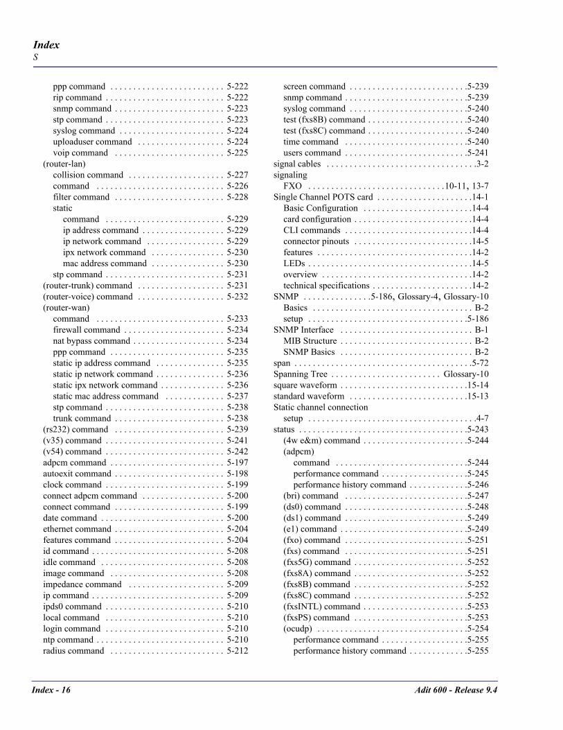
Index - 16 Adit 600 - Release 9.4
IndexS
ppp command . . . . . . . . . . . . . . . . . . . . . . . . . 5-222rip command . . . . . . . . . . . . . . . . . . . . . . . . . . 5-222snmp command . . . . . . . . . . . . . . . . . . . . . . . . 5-223stp command . . . . . . . . . . . . . . . . . . . . . . . . . . 5-223syslog command . . . . . . . . . . . . . . . . . . . . . . . 5-224uploaduser command . . . . . . . . . . . . . . . . . . . 5-224voip command . . . . . . . . . . . . . . . . . . . . . . . . 5-225
(router-lan)collision command . . . . . . . . . . . . . . . . . . . . . 5-227command . . . . . . . . . . . . . . . . . . . . . . . . . . . . 5-226filter command . . . . . . . . . . . . . . . . . . . . . . . . 5-228static
command . . . . . . . . . . . . . . . . . . . . . . . . . . 5-229ip address command . . . . . . . . . . . . . . . . . . 5-229ip network command . . . . . . . . . . . . . . . . . 5-229ipx network command . . . . . . . . . . . . . . . . 5-230mac address command . . . . . . . . . . . . . . . . 5-230
stp command . . . . . . . . . . . . . . . . . . . . . . . . . . 5-231(router-trunk) command . . . . . . . . . . . . . . . . . . . 5-231(router-voice) command . . . . . . . . . . . . . . . . . . . 5-232(router-wan)
command . . . . . . . . . . . . . . . . . . . . . . . . . . . . 5-233firewall command . . . . . . . . . . . . . . . . . . . . . . 5-234nat bypass command . . . . . . . . . . . . . . . . . . . . 5-234ppp command . . . . . . . . . . . . . . . . . . . . . . . . . 5-235static ip address command . . . . . . . . . . . . . . . 5-235static ip network command . . . . . . . . . . . . . . . 5-236static ipx network command . . . . . . . . . . . . . . 5-236static mac address command . . . . . . . . . . . . . 5-237stp command . . . . . . . . . . . . . . . . . . . . . . . . . . 5-238trunk command . . . . . . . . . . . . . . . . . . . . . . . . 5-238
(rs232) command . . . . . . . . . . . . . . . . . . . . . . . . 5-239(v35) command . . . . . . . . . . . . . . . . . . . . . . . . . . 5-241(v54) command . . . . . . . . . . . . . . . . . . . . . . . . . . 5-242adpcm command . . . . . . . . . . . . . . . . . . . . . . . . . 5-197autoexit command . . . . . . . . . . . . . . . . . . . . . . . . 5-198clock command . . . . . . . . . . . . . . . . . . . . . . . . . . 5-199connect adpcm command . . . . . . . . . . . . . . . . . . 5-200connect command . . . . . . . . . . . . . . . . . . . . . . . . 5-199date command . . . . . . . . . . . . . . . . . . . . . . . . . . . 5-200ethernet command . . . . . . . . . . . . . . . . . . . . . . . . 5-204features command . . . . . . . . . . . . . . . . . . . . . . . . 5-204id command . . . . . . . . . . . . . . . . . . . . . . . . . . . . . 5-208idle command . . . . . . . . . . . . . . . . . . . . . . . . . . . 5-208image command . . . . . . . . . . . . . . . . . . . . . . . . . 5-208impedance command . . . . . . . . . . . . . . . . . . . . . 5-209ip command . . . . . . . . . . . . . . . . . . . . . . . . . . . . . 5-209ipds0 command . . . . . . . . . . . . . . . . . . . . . . . . . . 5-210local command . . . . . . . . . . . . . . . . . . . . . . . . . . 5-210login command . . . . . . . . . . . . . . . . . . . . . . . . . . 5-210ntp command . . . . . . . . . . . . . . . . . . . . . . . . . . . . 5-210radius command . . . . . . . . . . . . . . . . . . . . . . . . . 5-212
screen command . . . . . . . . . . . . . . . . . . . . . . . . . .5-239snmp command . . . . . . . . . . . . . . . . . . . . . . . . . . .5-239syslog command . . . . . . . . . . . . . . . . . . . . . . . . . .5-240test (fxs8B) command . . . . . . . . . . . . . . . . . . . . . .5-240test (fxs8C) command . . . . . . . . . . . . . . . . . . . . . .5-240time command . . . . . . . . . . . . . . . . . . . . . . . . . . .5-240users command . . . . . . . . . . . . . . . . . . . . . . . . . . .5-241
signal cables . . . . . . . . . . . . . . . . . . . . . . . . . . . . . . . . .3-2signaling
FXO . . . . . . . . . . . . . . . . . . . . . . . . . . . . . .10-11, 13-7Single Channel POTS card . . . . . . . . . . . . . . . . . . . . .14-1
Basic Configuration . . . . . . . . . . . . . . . . . . . . . . . .14-4card configuration . . . . . . . . . . . . . . . . . . . . . . . . . .14-4CLI commands . . . . . . . . . . . . . . . . . . . . . . . . . . . .14-4connector pinouts . . . . . . . . . . . . . . . . . . . . . . . . . .14-5features . . . . . . . . . . . . . . . . . . . . . . . . . . . . . . . . . .14-2LEDs . . . . . . . . . . . . . . . . . . . . . . . . . . . . . . . . . . . .14-5overview . . . . . . . . . . . . . . . . . . . . . . . . . . . . . . . . .14-2technical specifications . . . . . . . . . . . . . . . . . . . . . .14-2
SNMP . . . . . . . . . . . . . . .5-186, Glossary-4, Glossary-10Basics . . . . . . . . . . . . . . . . . . . . . . . . . . . . . . . . . . . B-2setup . . . . . . . . . . . . . . . . . . . . . . . . . . . . . . . . . . .5-186
SNMP Interface . . . . . . . . . . . . . . . . . . . . . . . . . . . . . B-1MIB Structure . . . . . . . . . . . . . . . . . . . . . . . . . . . . . B-2SNMP Basics . . . . . . . . . . . . . . . . . . . . . . . . . . . . . B-2
span . . . . . . . . . . . . . . . . . . . . . . . . . . . . . . . . . . . . . . .5-72Spanning Tree . . . . . . . . . . . . . . . . . . . . . . . . Glossary-10square waveform . . . . . . . . . . . . . . . . . . . . . . . . . . . .15-14standard waveform . . . . . . . . . . . . . . . . . . . . . . . . . .15-13Static channel connection
setup . . . . . . . . . . . . . . . . . . . . . . . . . . . . . . . . . . . . .4-7status . . . . . . . . . . . . . . . . . . . . . . . . . . . . . . . . . . . . .5-243
(4w e&m) command . . . . . . . . . . . . . . . . . . . . . . .5-244(adpcm)
command . . . . . . . . . . . . . . . . . . . . . . . . . . . . .5-244performance command . . . . . . . . . . . . . . . . . . .5-245performance history command . . . . . . . . . . . . .5-246
(bri) command . . . . . . . . . . . . . . . . . . . . . . . . . . .5-247(ds0) command . . . . . . . . . . . . . . . . . . . . . . . . . . .5-248(ds1) command . . . . . . . . . . . . . . . . . . . . . . . . . . .5-249(e1) command . . . . . . . . . . . . . . . . . . . . . . . . . . . .5-249(fxo) command . . . . . . . . . . . . . . . . . . . . . . . . . . .5-251(fxs) command . . . . . . . . . . . . . . . . . . . . . . . . . . .5-251(fxs5G) command . . . . . . . . . . . . . . . . . . . . . . . . .5-252(fxs8A) command . . . . . . . . . . . . . . . . . . . . . . . . .5-252(fxs8B) command . . . . . . . . . . . . . . . . . . . . . . . . .5-252(fxs8C) command . . . . . . . . . . . . . . . . . . . . . . . . .5-252(fxsINTL) command . . . . . . . . . . . . . . . . . . . . . . .5-253(fxsPS) command . . . . . . . . . . . . . . . . . . . . . . . . .5-253(ocudp) . . . . . . . . . . . . . . . . . . . . . . . . . . . . . . . . .5-254
performance command . . . . . . . . . . . . . . . . . . .5-255performance history command . . . . . . . . . . . . .5-255
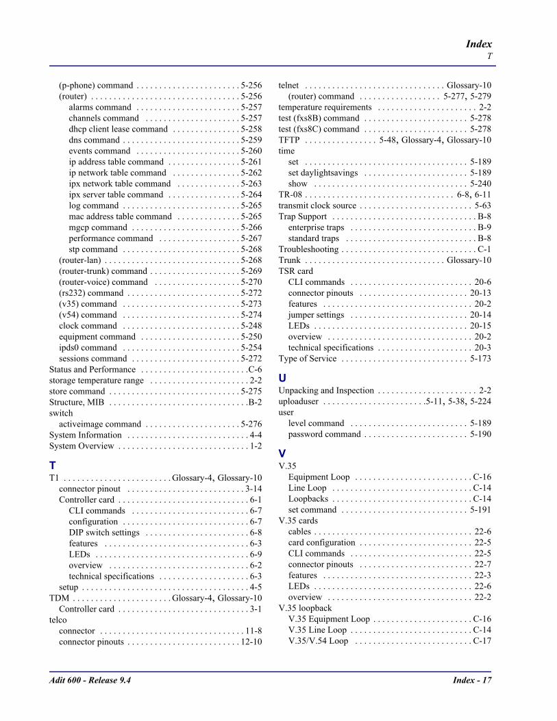
Adit 600 - Release 9.4 Index - 17
IndexT
(p-phone) command . . . . . . . . . . . . . . . . . . . . . . . 5-256(router) . . . . . . . . . . . . . . . . . . . . . . . . . . . . . . . . . 5-256
alarms command . . . . . . . . . . . . . . . . . . . . . . . 5-257channels command . . . . . . . . . . . . . . . . . . . . . 5-257dhcp client lease command . . . . . . . . . . . . . . . 5-258dns command . . . . . . . . . . . . . . . . . . . . . . . . . . 5-259events command . . . . . . . . . . . . . . . . . . . . . . . 5-260ip address table command . . . . . . . . . . . . . . . . 5-261ip network table command . . . . . . . . . . . . . . . 5-262ipx network table command . . . . . . . . . . . . . . 5-263ipx server table command . . . . . . . . . . . . . . . . 5-264log command . . . . . . . . . . . . . . . . . . . . . . . . . . 5-265mac address table command . . . . . . . . . . . . . . 5-265mgcp command . . . . . . . . . . . . . . . . . . . . . . . . 5-266performance command . . . . . . . . . . . . . . . . . . 5-267stp command . . . . . . . . . . . . . . . . . . . . . . . . . . 5-268
(router-lan) . . . . . . . . . . . . . . . . . . . . . . . . . . . . . . 5-268(router-trunk) command . . . . . . . . . . . . . . . . . . . . 5-269(router-voice) command . . . . . . . . . . . . . . . . . . . 5-270(rs232) command . . . . . . . . . . . . . . . . . . . . . . . . . 5-272(v35) command . . . . . . . . . . . . . . . . . . . . . . . . . . 5-273(v54) command . . . . . . . . . . . . . . . . . . . . . . . . . . 5-274clock command . . . . . . . . . . . . . . . . . . . . . . . . . . 5-248equipment command . . . . . . . . . . . . . . . . . . . . . . 5-250ipds0 command . . . . . . . . . . . . . . . . . . . . . . . . . . 5-254sessions command . . . . . . . . . . . . . . . . . . . . . . . . 5-272
Status and Performance . . . . . . . . . . . . . . . . . . . . . . . .C-6storage temperature range . . . . . . . . . . . . . . . . . . . . . . 2-2store command . . . . . . . . . . . . . . . . . . . . . . . . . . . . . 5-275Structure, MIB . . . . . . . . . . . . . . . . . . . . . . . . . . . . . . .B-2switch
activeimage command . . . . . . . . . . . . . . . . . . . . . 5-276System Information . . . . . . . . . . . . . . . . . . . . . . . . . . . 4-4System Overview . . . . . . . . . . . . . . . . . . . . . . . . . . . . . 1-2
TT1 . . . . . . . . . . . . . . . . . . . . . . . . Glossary-4, Glossary-10
connector pinout . . . . . . . . . . . . . . . . . . . . . . . . . . 3-14Controller card . . . . . . . . . . . . . . . . . . . . . . . . . . . . . 6-1
CLI commands . . . . . . . . . . . . . . . . . . . . . . . . . . 6-7configuration . . . . . . . . . . . . . . . . . . . . . . . . . . . . 6-7DIP switch settings . . . . . . . . . . . . . . . . . . . . . . . 6-8features . . . . . . . . . . . . . . . . . . . . . . . . . . . . . . . . 6-3LEDs . . . . . . . . . . . . . . . . . . . . . . . . . . . . . . . . . . 6-9overview . . . . . . . . . . . . . . . . . . . . . . . . . . . . . . . 6-2technical specifications . . . . . . . . . . . . . . . . . . . . 6-3
setup . . . . . . . . . . . . . . . . . . . . . . . . . . . . . . . . . . . . . 4-5TDM . . . . . . . . . . . . . . . . . . . . . . Glossary-4, Glossary-10
Controller card . . . . . . . . . . . . . . . . . . . . . . . . . . . . . 3-1telco
connector . . . . . . . . . . . . . . . . . . . . . . . . . . . . . . . . 11-8connector pinouts . . . . . . . . . . . . . . . . . . . . . . . . . 12-10
telnet . . . . . . . . . . . . . . . . . . . . . . . . . . . . . . . Glossary-10(router) command . . . . . . . . . . . . . . . . . . 5-277, 5-279
temperature requirements . . . . . . . . . . . . . . . . . . . . . . 2-2test (fxs8B) command . . . . . . . . . . . . . . . . . . . . . . . 5-278test (fxs8C) command . . . . . . . . . . . . . . . . . . . . . . . 5-278TFTP . . . . . . . . . . . . . . . . 5-48, Glossary-4, Glossary-10time
set . . . . . . . . . . . . . . . . . . . . . . . . . . . . . . . . . . . . 5-189set daylightsavings . . . . . . . . . . . . . . . . . . . . . . . 5-189show . . . . . . . . . . . . . . . . . . . . . . . . . . . . . . . . . . 5-240
TR-08 . . . . . . . . . . . . . . . . . . . . . . . . . . . . . . . . . 6-8, 6-11transmit clock source . . . . . . . . . . . . . . . . . . . . . . . . . 5-63Trap Support . . . . . . . . . . . . . . . . . . . . . . . . . . . . . . . . B-8
enterprise traps . . . . . . . . . . . . . . . . . . . . . . . . . . . . B-9standard traps . . . . . . . . . . . . . . . . . . . . . . . . . . . . . B-8
Troubleshooting . . . . . . . . . . . . . . . . . . . . . . . . . . . . . . C-1Trunk . . . . . . . . . . . . . . . . . . . . . . . . . . . . . . . Glossary-10TSR card
CLI commands . . . . . . . . . . . . . . . . . . . . . . . . . . . 20-6connector pinouts . . . . . . . . . . . . . . . . . . . . . . . . 20-13features . . . . . . . . . . . . . . . . . . . . . . . . . . . . . . . . . 20-2jumper settings . . . . . . . . . . . . . . . . . . . . . . . . . . 20-14LEDs . . . . . . . . . . . . . . . . . . . . . . . . . . . . . . . . . . 20-15overview . . . . . . . . . . . . . . . . . . . . . . . . . . . . . . . . 20-2technical specifications . . . . . . . . . . . . . . . . . . . . . 20-3
Type of Service . . . . . . . . . . . . . . . . . . . . . . . . . . . . 5-173
UUnpacking and Inspection . . . . . . . . . . . . . . . . . . . . . . 2-2uploaduser . . . . . . . . . . . . . . . . . . . . . . .5-11, 5-38, 5-224user
level command . . . . . . . . . . . . . . . . . . . . . . . . . . 5-189password command . . . . . . . . . . . . . . . . . . . . . . . 5-190
VV.35
Equipment Loop . . . . . . . . . . . . . . . . . . . . . . . . . . C-16Line Loop . . . . . . . . . . . . . . . . . . . . . . . . . . . . . . . C-14Loopbacks . . . . . . . . . . . . . . . . . . . . . . . . . . . . . . . C-14set command . . . . . . . . . . . . . . . . . . . . . . . . . . . . 5-191
V.35 cardscables . . . . . . . . . . . . . . . . . . . . . . . . . . . . . . . . . . . 22-6card configuration . . . . . . . . . . . . . . . . . . . . . . . . . 22-5CLI commands . . . . . . . . . . . . . . . . . . . . . . . . . . . 22-5connector pinouts . . . . . . . . . . . . . . . . . . . . . . . . . 22-7features . . . . . . . . . . . . . . . . . . . . . . . . . . . . . . . . . 22-3LEDs . . . . . . . . . . . . . . . . . . . . . . . . . . . . . . . . . . . 22-6overview . . . . . . . . . . . . . . . . . . . . . . . . . . . . . . . . 22-2
V.35 loopbackV.35 Equipment Loop . . . . . . . . . . . . . . . . . . . . . . C-16V.35 Line Loop . . . . . . . . . . . . . . . . . . . . . . . . . . . C-14V.35/V.54 Loop . . . . . . . . . . . . . . . . . . . . . . . . . . C-17
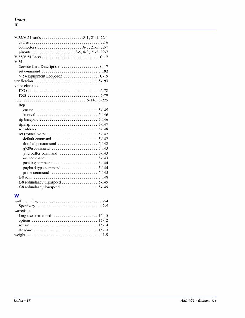
Index - 18 Adit 600 - Release 9.4
IndexW
V.35/V.54 cards . . . . . . . . . . . . . . . . . . . . .8-1, 21-1, 22-1cables . . . . . . . . . . . . . . . . . . . . . . . . . . . . . . . . . . . 22-6connectors . . . . . . . . . . . . . . . . . . . . . . .8-5, 21-5, 22-7pinouts . . . . . . . . . . . . . . . . . . . . . .8-5, 8-8, 21-5, 22-7
V.35/V.54 Loop . . . . . . . . . . . . . . . . . . . . . . . . . . . . . C-17V.54
Service Card Description . . . . . . . . . . . . . . . . . . . C-17set command . . . . . . . . . . . . . . . . . . . . . . . . . . . . 5-192V.54 Equipment Loopback . . . . . . . . . . . . . . . . . . C-19
verification . . . . . . . . . . . . . . . . . . . . . . . . . . . . . . . 5-193voice channels
FXO . . . . . . . . . . . . . . . . . . . . . . . . . . . . . . . . . . . . 5-78FXS . . . . . . . . . . . . . . . . . . . . . . . . . . . . . . . . . . . . 5-79
voip . . . . . . . . . . . . . . . . . . . . . . . . . . . . . . . 5-146, 5-225rtcp
cname . . . . . . . . . . . . . . . . . . . . . . . . . . . . . . . 5-145interval . . . . . . . . . . . . . . . . . . . . . . . . . . . . . . 5-146
rtp baseport . . . . . . . . . . . . . . . . . . . . . . . . . . . . . 5-146rtpmap . . . . . . . . . . . . . . . . . . . . . . . . . . . . . . . . . 5-147sdpaddress . . . . . . . . . . . . . . . . . . . . . . . . . . . . . . 5-148set (router) voip . . . . . . . . . . . . . . . . . . . . . . . . . . 5-142
default command . . . . . . . . . . . . . . . . . . . . . . 5-142dtmf edge command . . . . . . . . . . . . . . . . . . . . 5-142g729a command . . . . . . . . . . . . . . . . . . . . . . . 5-143jitterbuffer command . . . . . . . . . . . . . . . . . . . 5-143osi command . . . . . . . . . . . . . . . . . . . . . . . . . . 5-143packing command . . . . . . . . . . . . . . . . . . . . . . 5-144payload type command . . . . . . . . . . . . . . . . . . 5-144ptime command . . . . . . . . . . . . . . . . . . . . . . . 5-145
t38 ecm . . . . . . . . . . . . . . . . . . . . . . . . . . . . . . . . 5-148t38 redundancy highspeed . . . . . . . . . . . . . . . . . . 5-149t38 redundancy lowspeed . . . . . . . . . . . . . . . . . . 5-149
Wwall mounting . . . . . . . . . . . . . . . . . . . . . . . . . . . . . . . 2-4
Speedway . . . . . . . . . . . . . . . . . . . . . . . . . . . . . . . . 2-5waveform
long rise or rounded . . . . . . . . . . . . . . . . . . . . . . 15-15options . . . . . . . . . . . . . . . . . . . . . . . . . . . . . . . . . 15-12square . . . . . . . . . . . . . . . . . . . . . . . . . . . . . . . . . 15-14standard . . . . . . . . . . . . . . . . . . . . . . . . . . . . . . . . 15-13
weight . . . . . . . . . . . . . . . . . . . . . . . . . . . . . . . . . . . . . 1-9