Embed Size (px)
Citation preview
8102019 Adit 600 Quick Start 10-1-1
httpslidepdfcomreaderfulladit-600-quick-start-10-1-1 154
Adit 600 QUICK S TART GUIDE
Part Number 002-0104-1420
Product Release 1011
August 2009
8102019 Adit 600 Quick Start 10-1-1
httpslidepdfcomreaderfulladit-600-quick-start-10-1-1 254
Copyright copy 2009 Force10 Networks Inc All rights reserved
Force10 Networksreg reserves the right to change modify revise this publication without notice
The hardware and software described herein are furnished under a license or non-disclosure agreement The hardware
software and manual may be used or copied only in accordance with the terms of this agreement It is against the law to
reproduce transmit transcribe store in a retrieval system or translate into any medium - electronic mechanical
magnetic optical chemical manual or otherwise - any part of this manual or software supplied with the product for any
purpose other than the purchaserrsquos personal use without the express written permission of Force10 Networks Inc
Trademarks
Adit Access Navigator Force10 Networks and NetworkValet are registered trademarks of Force10 Networks Inc
Force10 and the Force10 logo are trademarks of Force10 Networks Inc or its affiliates in the United States and other
countries and are protected by US and international copyright laws All other brand and product names are trademarks
or registered trademarks of their respective holders
Statement of Conditions
In the interest of improving internal design operational function andor reliability Force10 Networks reserves the right
to make changes to products described in this document without notice Force10 Networks does not assume any liability
that may occur due to the use or application of the product(s) described herein
Supporting Software Versions
Adit 600 Controller 1011
IP Router 297
CMG Router 297
Terminal Server Router 297
Multi-Service Router (MSR) 21
Corporate Contact Information
Force10 Networks Inc
350 Holger Way
San Jose CA 95134-1362
Phone +1 (866) 571-2600 or +1 (408) 571-3500
wwwForce10Networkscom
Technical Assistance Center
E-mail access-supportForce10Networkscom
Phone (US) 866-887-4638
Phone (InternationalDirect) 1-707-665-4355
8102019 Adit 600 Quick Start 10-1-1
httpslidepdfcomreaderfulladit-600-quick-start-10-1-1 354
8102019 Adit 600 Quick Start 10-1-1
httpslidepdfcomreaderfulladit-600-quick-start-10-1-1 454
2 Adit 600 - Release 1011
Preface
Electrostatic Discharge (ESD) Precautions
ESD can damage processors circuit cards and other electronic components Always
observe the following precautions before installing a system component
1 Do not remove a component from its protective packaging until ready to install
it
2 Wear a wrist grounding strap and attach it to a metal part of the system unit
before handling components If a wrist strap is not available maintain contact
with the system unit throughout any procedure requiring ESD protection
WARNING INTEGRATED CIRCUITS (ICS) ARE EXTREMELY SUSCEPTIBLE TO ELECTROSTATIC DISCHARGE UNLESS YOU ARE A QUALIFIED SERVICE TECHNICIAN WHO USES TOOLS AND TECHNIQUES THAT CONFORM TO ACCEPTED INDUSTRY PRACTICES DO NOT HANDLE ICS
The ESD warning label appears on packages and storage bags
that contain static-sensitive products and components
8102019 Adit 600 Quick Start 10-1-1
httpslidepdfcomreaderfulladit-600-quick-start-10-1-1 554
QUICK START
Quick Start
In this Guide
Unpacking and Inspection Installation Environment
Assembly of Adit 600
Wall Mounting
Compliant Installation
Chassis Connectors and Buttons
Interface Connectors
Management Options
Configuration
Controller Card LEDs
Power Supply LEDs
Service Card LEDs
8102019 Adit 600 Quick Start 10-1-1
httpslidepdfcomreaderfulladit-600-quick-start-10-1-1 654
4 Adit 600 - Release 1011
Quick Start Unpacking and Inspection
Unpacking and Inspection
WARNING OBSERVE PRECAUTIONS FOR HANDLING ELECTROSTATIC DEVICES
1 Inspect containers for damage during shipment Report any damage to the
freight carrier for possible insurance claims
2 Compare packing list with office records Report any discrepancies to the
office
3 Open shipping containers be careful not to damage contents
4 Inspect contents and report any damage
5 If equipment must be returned for any reason carefully repack equipment inthe original shipping container with original packing materials if possible
6 If equipment is to be installed later replace equipment in original shipping
container and store in a safe place until ready to install
Installation Environment The environment in which you are installing the Adit 600 must meet the following
conditions
Operating temperature range 32deg to 104deg F (0deg to 40deg C)
Storage temperature range -40deg to 158deg F (-40deg to 70deg C)
Cooling method is by free air convection requires long axis of unit to bemounted horizontally
Maximum operating altitude 10000 ft (3048 m)
Maximum non-operating altitude 40000 ft (12192 m)
Relative humidity (non-condensing) range 0 to 95
For operation outside the defined environment requirements the Adit 600 must be
placed in an environmentally controlled enclosure
8102019 Adit 600 Quick Start 10-1-1
httpslidepdfcomreaderfulladit-600-quick-start-10-1-1 754
Adit 600 - Release 1011 5
Quick Start Assembly of Adit 600
Assembly of Adit 600
NOTE E1 is not supported in this release of the Adit 600 Controller It will be
supported in a future release
The cards should be positioned in the Adit 600 chassis as follows Note Slots are labeled on the top and the bottom of the chassis
Power Supply in the POWER Slot
E1 or T1 Controller in Slot A
Service Cards can be in any slot 1 through 6
Note When an Adit 600 is mounted to the wall cards that use the front cable
connections should be loaded from Slot 6 to 1 This will minimize card accessissues due to cable interference
Always install blank faceplates in any unused slots
Service Card Slots
1 2 3 4 5 6A POWER
8102019 Adit 600 Quick Start 10-1-1
httpslidepdfcomreaderfulladit-600-quick-start-10-1-1 854
6 Adit 600 - Release 1011
Quick Start Wall Mounting
Wall Mounting
Before beginning the mounting process verify that the area meets the following
requirements
A stable environment
Clean and free from extremes of temperature shock vibration and EMI
Meets all installation environment requirements see Installation Environment
on page 3-4
The Adit 600 is delivered with a mounting bracket attached for quick and easy wall
mounting as shown in the illustration above
To install the unit to the wall attach the unit using the four screws provided one at each
bracket foot
NOTE Do not mount the Adit 600 in any other orientation than show above
Leave at least 35above and belowthe Unit for adequate ventilation
Mounting BracketLeave adequate clearanceat the back for access toconnectors
Leave at least 14 atthe front of the unit foraccess to cards andDIP switches
8102019 Adit 600 Quick Start 10-1-1
httpslidepdfcomreaderfulladit-600-quick-start-10-1-1 954
Adit 600 - Release 1011 7
Quick Start Compliant Installation
Compliant Installation
1 Connect all of the signal cables as shown in the illustration above and secure
them with a plastic tie Dress the signal cables toward the left of the Adit 600
2 If using the 115V Power Supply connect the -48 VDC battery power cable
3 Secure the ground lugs to the terminals using the nuts provided
4 Secure the power cable and the ground cable with a plastic tie (not included)
Keep these cables separate from the signal cables
5 Terminate each signal cable to its appropriate connector
6 Secure signal cables using the holes along the bottom of the rack and plastic
ties (not included)
WARNING ADDITIONAL PRIMARY PROTECTION IS REQUIRED WHEN CONNECTING T1E1 OR FXS INTERFACES TO EXPOSED OFF-PREMISE COMMUNICATION CONDUCTORS SECONDARY OVERVOLTAGE AND OVERCURRENT PROTECTION IS
PROVIDED ON THESE INTERFACES FOR LIGHTNING SURGE AC POWER CONTACT AND INDUCTION IT WILL BE THE RESPONSIBILITY OF THE INSTALLER TO UTILIZE LISTED PRIMARY PROTECTORS AND FOLLOW INSTALLATION REQUIREMENTS PER LOCAL OR NATIONAL REGULATIONS
Power Cord
-48 VDC Battery Power
Alarm Wiring
Signal Cables
Power Cables
Grounding Cable
Ferrite Bead
with cable loop
RS-232 craft port
25-pair telco connector
25-pair telco connector
10Base-T EthernetT1E1 connectors
Ferrite Beads
are in red
US
8102019 Adit 600 Quick Start 10-1-1
httpslidepdfcomreaderfulladit-600-quick-start-10-1-1 1054
8 Adit 600 - Release 1011
Quick Start Compliant Installation
NOTE It is important that the Signal Cables are secured separately from thePower Cables for proper equipment operation
Ferrite Beads (US)
NOTE E1 is not supported in this release of the Adit 600 Controller It will besupported in a future release
To be compliant with Part 15A of the FCC and for NEBS compliant facilities the
following ferrite beads are required for the chassis and service cards listed below
Ferrite beads for Adit 600 chassis
Service card cables requiring ferrite beads
The CMG-01 and CMG-02 Router cards do not require a ferrite bead
For additional information on ferrite beads and their installation on the Adit 600 please
contact Force10 Networks Customer Support at 1-866-887-4638 (US) or 1-707-665-
4355 (InternationalDirect)
Ferrite Part Number Intended For
3 small PN 010-0095 (2) One on each T1 or E1 cable
(1) Ethernet (10Base-T) cable
1 large PN 010-0051 (1) Alarm cable which requires a loop
through the bead (see drawing)
Card Ferrite Part Number Intended For
ISDN BRI 1 large PN 010-0051 (1) 25-pair Telco cable (ISDN BRI
card in slot 1-3 top telco 4-6 bottom)
Quad DS1E1Quad T1
Quad E1
1 large PN 010-0051 Cables from front of card(1 bead can hold 1-4 cables) or
(1) One on 25-pair Telco cable
IP Router 1 small PN 010-0095 Ethernet Cable (from front of card)
CMG Router 1 small PN 010-0095 Ethernet Cable (from front of card)
8102019 Adit 600 Quick Start 10-1-1
httpslidepdfcomreaderfulladit-600-quick-start-10-1-1 1154
Adit 600 - Release 1011 9
Quick Start Compliant Installation
Ferrite Beads (Europe Australia and Canada)
NOTE E1 is not supported in this release of the Adit 600 Controller It will besupported in a future release
To be compliant with EN55022 and CISPR22 Class A emissions the following beads
are required for the chassis and components listed below Also shielded cables arerequired for the V3554 service card and must be ordered separately
Power Cord
-48 VDC Battery Power
Alarm Wiring
Signal Cables
Power Cables
Grounding Cable
Ferrite Bead
with cable loop
RS-232 craft port25-pair telco connector
25-pair telco connector
10Base-T EthernetT1E1 connectors
Ferrite Beads
are in red
Ferrite Beads
with cable loop
8102019 Adit 600 Quick Start 10-1-1
httpslidepdfcomreaderfulladit-600-quick-start-10-1-1 1254
10 Adit 600 - Release 1011
Quick Start Compliant Installation
Ferrite beads for Adit 600 chassis
Additional components requiring ferrite beads
The CMG-01 and CMG-02 Router cards do not require a ferrite bead
Shielded Cable (order separately)
For additional information on Ferrite beads and their installation on the Adit 600 please contact Force10 Networks Customer Support at 1-866-887-4638 (US) or 1-
707-665-4355 (InternationalDirect)
Ferrite Part Number Intended For
4 large PN 010-0051 All of these ferrites require a loop through the
bead (see drawing)
(1) Alarm cable
(2) One on each or E1 cable (E1-1E1-2)
(1) Ethernet (10Base-T) cable
Card Ferrite Part Number Intended For
CMG Router 1 small PN 010-0095 Ethernet Cable (from front of card)
Quad DS1E1Quad E1
2 large PN 010-0051 E1 cables from front of Quad E1card
(1 bead can hold 1-4 cables) or
(2) One on each 25-pair Telco cable
Battery Unit 1 small PN 010-0095 Battery Cable
DC Power Kit 1 small PN 010-0095 DC Input Cable
Card Part Number Intended For
V3554 (HD) PN 005-0008 D-sub Male to Winchester Male 10 ft
PN 005-0009 D-sub Male to Winchester Male 25 ftPN 005-0010 D-sub Male to Winchester Male 50 ft
PN 005-0014 D-sub Male to Winchester Female 10 ft
PN 005-0068 D-sub Male to Winchester Female 25 ft
PN 005-0069 D-sub Male to Winchester Female 50 ft
8102019 Adit 600 Quick Start 10-1-1
httpslidepdfcomreaderfulladit-600-quick-start-10-1-1 1354
Adit 600 - Release 1011 11
Quick Start Chassis Connectors and Buttons
Chassis Connectors and Buttons
The following illustrations show all connectors on the back of the Adit 600
Interface Connectors
The following are the Adit 600 interface connectors
T1-1E1-1 and T1-2E1-2 line connection ports each equipped with standard
RJ-48C 8-pin connector jack
RS-232 craft port connector
Tip and Ring Analog Interfaces equipped with standard 25-pair Telco
Connectors
10Base-T Ethernet port to be connected to a remote management tool such as
Telnet or an SNMP-based Network Management System with an RJ-45 8-pin
connector jack
External Alarm Connector
Ground Lugs
Ground Terminals
Alarms
AC or DC Power Connector
-48VBattery
Ethernet
T1-2E1-2T1E1
RS-232 Craft Port25-Pair Telco Connectors
T1-1E1-1
[10Base-T]
Connectors
Reset
(AC shown below)
8102019 Adit 600 Quick Start 10-1-1
httpslidepdfcomreaderfulladit-600-quick-start-10-1-1 1454
12 Adit 600 - Release 1011
Quick Start Interface Connectors
Chassis Ground Connector
WARNING THIS EQUIPMENT IS REQUIRED TO HAVE A PERMANENT GROUND CONNECTION IF CONNECTED TO EXPOSED OUTDOOR COMMUNICATION CONDUCTORS A 6 AWG COPPER WIRE MUST BE PERMANENTLY CONNECTED FROM AN APPROVED GROUNDING ELECTRODE TO THE CHASSIS GROUND LUG
OTHERWISE A 14 AWG COPPER WIRE MAY BE UTILIZED INSTALL THE GROUNDING CONDUCTOR IN ACCORDANCE WITH NATIONAL OR LOCAL REGULATIONS
1 Route wire (6 or 8 AWG copper) from building ground to lug on Adit 600
2 Strip insulation off wire end if necessary
3 Loosen compression screw until opening is large enough to accept ground
wire
4 Insert ground wire into lug barrel beneath compression plate and tighten
compression screw
5 Attach ground lug to chassis
Ground Terminals
Ground Lug
Compression
ScrewLug Barrel
8102019 Adit 600 Quick Start 10-1-1
httpslidepdfcomreaderfulladit-600-quick-start-10-1-1 1554
Adit 600 - Release 1011 13
Quick Start Interface Connectors
Power Reset
This is a resetable circuit breaker If at any time there is a short or power
surge on the incoming ACDC line the breaker will trip to protect the
Power supply from damage
Power Connections
There are four power supplies available for the Adit 600
115 VAC-48 VDC
230 VAC-48 VDC
24-48 VDC
24 VDC with -48 Output
These power supplies have different connectors as shown in the following Foradditional information see Chapter 15 Power Supply of the Adit 600 User Manual
Fuse Recommendation
When using -48 VDC input power use a 35 Amp fast-acting fuse if the power
connector is wired to a fuse panel
Power Cord AC An AC Power cord is provided with the 115 VAC and the
230 VAC Power Supplies
To connect the Power Cord
1 Insert power cord (male-end) to AC power source
2 Plug connector into the Adit 6003 A green light should appear on the DC Input LED on the front of the Power
Supply
AC Power Connector
8102019 Adit 600 Quick Start 10-1-1
httpslidepdfcomreaderfulladit-600-quick-start-10-1-1 1654
14 Adit 600 - Release 1011
Quick Start Interface Connectors
-48V Battery
The -48 VDC input connector on the Adit 600 is used for either direct DC powering
of the Adit 600 unit or for a Battery Backup connection when AC is used There is
no power cable provided for this connector however the connector is provided
WARNING POSSIBLE SHOCK HAZARD EXISTS PLEASE FOLLOW INSTRUCTIONS
CAREFULLY
To connect -48 VDC power
1 Ensure that no power is present on the two wires to be connected
2 Strip the two wires (approx 516 in bare wire) from the power source 16 or 18 AWG insulated copper wire is recommended for power connections
3 Insert the Battery Return and DC wires into the appropriate square holes
4 Tighten screws to clamp wires
5 Ensure that no bare wire shows after the wires are installed
6 Plug connector in the -48 VDC connector as seen below and secure with set
screws
7 Apply power to connector from -48 VDC power source
8 Verify with voltmeter that voltage is correct and polarity is correct
8102019 Adit 600 Quick Start 10-1-1
httpslidepdfcomreaderfulladit-600-quick-start-10-1-1 1754
Adit 600 - Release 1011 15
Quick Start Interface Connectors
9 Plug connector in the Adit 600 -48 VDC connector as seen in the graphic andsecure with set screws
Power Cord DC
There is no power cable provided with the 24
VDC Power Supply however the connector is
provided This connector will need to be wired
the following chart prides the wire gauge
recommendedTo connect 24 VDC power
1 Ensure that no power is present on the two wires to be connected
WARNING POSSIBLE SHOCK HAZARD EXISTS PLEASE FOLLOW INSTRUCTIONS CAREFULLY
1(+) 2(-)
Connector
Provided connector (female)
of Adit 600on back
(male)
Battery -48 VDC
2(-)
BatteryReturn (+)
-48 VDC (-)
Return 1(+)
24 VDC6 Amp
Battery
Battery (+)
DC Power Connector
Return (-)
8102019 Adit 600 Quick Start 10-1-1
httpslidepdfcomreaderfulladit-600-quick-start-10-1-1 1854
16 Adit 600 - Release 1011
Quick Start Interface Connectors
2 Strip the two wires from the powersource so that approximately 516 inch
of bare wire is exposed see Wire Gauge
chart below for wire recommendations
3 Insert the Battery Return (-) and Battery
(+) wires into the appropriate square
holes one at a time4 Tighten screws to clamp wires
5 Ensure that no bare wire shows after the
wires are installed
6 Apply power to connector
7 Verify with voltmeter that voltage is
correct and polarity is correct
8 Plug connector(s) into the Adit 600 DC
Power connector as seen in the graphic
and secure with set screws
9 A green light should appear on the DC OK LED on the front of the Power
Supply
Wire Gauge 18 AWG 16 AWG 14 AWG
Maximum Distance 12 Feet 20 Feet 35 Feet
Battery (+)
BatteryReturn (-)
8102019 Adit 600 Quick Start 10-1-1
httpslidepdfcomreaderfulladit-600-quick-start-10-1-1 1954
Adit 600 - Release 1011 17
Quick Start Interface Connectors
External Alarm Connector
The external alarm 6-pin connector with one input pair (pins 5 and 6)
and two output pairs (pins 1 and 2 - major alarms pins 3 and 4 - minor
alarms)
The pinouts are as follows
Pin Description Explanation
1 Major Alarm + The major alarm output is available for power supply or
major alarm failure alerting The maximum voltage across
the contacts is 350 V and the maximum current is 150 mA
This alarm is closed when power is off
2 Major Alarm -
3 Minor Alarm + The minor alarm output is available for power supply or
minor alarm failure alerting The maximum voltage across
the contacts is 350 V and the maximum current is 150 mA
This alarm remains open when power is off
4 Minor Alarm -
5 Alarm In + The alarm inputs provide 5 VDC across the two contactsand generate an alarm when a short circuit is detected
between the contacts
The alarm generated is a minor severity alarm
6 Alarm In -
6
5
4
3
2
1
A
L
A
R
M
8102019 Adit 600 Quick Start 10-1-1
httpslidepdfcomreaderfulladit-600-quick-start-10-1-1 2054
18 Adit 600 - Release 1011
Quick Start Interface Connectors
25-Pair Telco ConnectorsTip and Ring Analog Interfaces equipped with standard 25-pair Telco Connectors
(female) for connection to key systems fax machines modems and PBXs These
interfaces are also used for ISDN BRI ports and are jumper selectable on the Quad T1
Quad E1 Quad DS1E1 and Quad ADPCM service cards
Circuit connections are made at the 25-pair
telco connectors A standard 25-pairtelephone cable with RJ-21X wiring and a
male D-type connector at the Adit 600 end
is required
The pinouts are as follows
Pair Pin Location Function Color Code
1 26
1
Tip Channel 1
Ring Channel 1
WhiteBlue
BlueWhite
2 27
2
Tip Channel 2
Ring Channel 2
WhiteOrange
OrangeWhite
3 28
3
Tip Channel 3
Ring Channel 3
WhiteGreen
GreenWhite
4 29
4
Tip Channel 4
Ring Channel 4
WhiteBrown
BrownWhite
5 30
5
Tip Channel 5
Ring Channel 5
WhiteSlate
SlateWhite
6 31
6
Tip Channel 6
Ring Channel 6
RedBlue
BlueRed
7 327
Tip Channel 7Ring Channel 7
RedOrangeOrangeRed
8 33
8
Tip Channel 8
Ring Channel 8
RedGreen
GreenRed
9 34
9
Tip Channel 9
Ring Channel 9
RedBrown
BrownRed
10 3510
Tip Channel 10Ring Channel 10
RedSlateSlateRed
50
25
26
1
8102019 Adit 600 Quick Start 10-1-1
httpslidepdfcomreaderfulladit-600-quick-start-10-1-1 2154
Adit 600 - Release 1011 19
Quick Start Interface Connectors
Pair Pin Location Function Color Code
11 36
11
Tip Channel 11
Ring Channel 11
BlackBlue
BlueBlack
12 37
12
Tip Channel 12
Ring Channel 12
BlackOrange
OrangeBlack
13 38
13
Tip Channel 13
Ring Channel 13
BlackGreen
GreenBlack
14 39
14
Tip Channel 14
Ring Channel 14
BlackBrown
BrownBlack
15 40
15
Tip Channel 15
Ring Channel 15
BlackSlate
SlateBlack
16 41
16
Tip Channel 16
Ring Channel 16
YellowBlue
BlueYellow17 42
17
Tip Channel 17
Ring Channel 17
YellowOrange
OrangeYellow
18 43
18
Tip Channel 18
Ring Channel 18
YellowGreen
GreenYellow
19 44
19
Tip Channel 19
Ring Channel 19
YellowBrown
BrownYellow
20 45
20
Tip Channel 20
Ring Channel 20
YellowSlate
SlateYellow
21 46
21
Tip Channel 21
Ring Channel 21
VioletBlue
BlueViolet
22 47
22
Tip Channel 22
Ring Channel 22
VioletOrange
OrangeViolet
23 48
23
Tip Channel 23
Ring Channel 23
VioletGreen
GreenViolet
24 49
24
Tip Channel 24
Ring Channel 24
VioletBrown
BrownViolet
25 50
25
Reserved VioletSlate
SlateViolet
8102019 Adit 600 Quick Start 10-1-1
httpslidepdfcomreaderfulladit-600-quick-start-10-1-1 2254
20 Adit 600 - Release 1011
Quick Start Interface Connectors
RS-232 Craft Port (Female DB-9)The RS-232 craft port connector (female) is for connection to an external PC or Hayes-
compatible modem for local or remote configuration management and performance
monitoring using the Adit 600 Command Line Interface (CLI)
The RS-232 craft port connects via a
female DB-9 connector on the Adit 600
The pinouts are as follows
Pin Number Direction Description
1 Outbound Carrier Detect
2 Outbound Receive Data
3 Inbound Transmit Data
4 Inbound Data Terminal Ready
5 NA Signal Ground
6 Outbound Data Set Ready
7 Inbound Request to Send
8 Outbound Clear to Send
9 NC Not connected
1 5
6 9
8102019 Adit 600 Quick Start 10-1-1
httpslidepdfcomreaderfulladit-600-quick-start-10-1-1 2354
8102019 Adit 600 Quick Start 10-1-1
httpslidepdfcomreaderfulladit-600-quick-start-10-1-1 2454
22 Adit 600 - Release 1011
Quick Start Interface Connectors
10Base-T Ethernet
The 10Base-T Ethernet (female) port to connect to a remote
management tool such as Telnet or an SNMP-based Network
Management System Note A LINK LED on the back of the unit
displays green when the system has a good Ethernet link
The pinouts are as follows
Ethernet (RJ-45)
NOTE This Ethernet port uses a hub pinout Use a straight-through cableto connect a PC
Pin Name Description
1 Receive + Receive from network
2 Receive - Receive from network
3 Transmit + Transmit to network
4 - 5 NC Not connected
6 Transmit - Transmit to network
7 NC Not connected
8 NC Not connected
1 8
8102019 Adit 600 Quick Start 10-1-1
httpslidepdfcomreaderfulladit-600-quick-start-10-1-1 2554
Adit 600 - Release 1011 23
Quick Start Management Options
Management Options
Options for managing the Adit 600 are as follows
Local using CLI Telnet SNMP or DIP Switches (Controller and voice cards)
Remotely over an in-band DS0 or through the Access Navigator over the FDL
or an in-band DS0
This Quick Start Guide focuses on the CLI and DIP switches If you need further
information on other management options please refer to the Adit 600 User Manual
Command Line Interface (CLI)
You can access the CLI using either of the following methods
Telnet via Ethernet (10Base-T) RS-232 connected to the DB-9 port
Setting up a CLI Connection
If connecting via the Ethernet 10Base-T connection use a Telnet TCPIP
program to access the CLI This requires the IP address of the Controller
Controllers are shipped with the IP address set to 100010 If this address has been changed and is not known use HyperTerm to access the Controller and
use the CLI command show ip If an IP address needs to be set use the CLI
command set ethernet ip address
If connecting via RS-232 the port settings should be set to
Bits per second 9600 Data bits 8
Parity None Stop bits 1Flow control None
Set your Terminal Emulation to VT100
By default the Adit 600 is set for local configuration (using DIP switches) Use
the set local off command to enable the use of CLI commands
8102019 Adit 600 Quick Start 10-1-1
httpslidepdfcomreaderfulladit-600-quick-start-10-1-1 2654
8102019 Adit 600 Quick Start 10-1-1
httpslidepdfcomreaderfulladit-600-quick-start-10-1-1 2754
Adit 600 - Release 1011 25
Quick Start Configuration
ConfigurationThe following basic setups and upgrades for the Adit 600 are shown using CLI
commands For more information on CLI commands and configurations see the Adit
600 User Manual
Initial Setup
Basic Security Setup
DS1T1 Setup
E1 Setup
DS0Channel Setup
Analog Port Setup
4-Wire EampM Setup
Establish a Static Channel Connection
ISDN BRI Service Setup
OCU-DP Card Setup
ADPCM Card Setup
V35 Port Setup
Change the IP Address of the DS0 Management Channel
Upgrade the Adit 600 Software
Upgrade the Router Card Software
Basic Router Setup
8102019 Adit 600 Quick Start 10-1-1
httpslidepdfcomreaderfulladit-600-quick-start-10-1-1 2854
26 Adit 600 - Release 1011
Quick Start Configuration
Initial SetupUse the following commands for your initial setup For further information see the Adit
600 User Manual
Command Description
set local off Disables DIP switches
set date mmddyyyy Set the date used for event logging
set time hhmmss Set the time used for event logging
set id id-name Set a system ID name
set clock1 slotportinternal
Set the primary clock source
set clock2 slotportinternal
Set the secondary clock source
set ethernet ip addressip-addr mask
Set the ethernet IP address in the
conventional IP address format
set ip gateway ip-addr Set the IP gateway in the conventional IP
address format
8102019 Adit 600 Quick Start 10-1-1
httpslidepdfcomreaderfulladit-600-quick-start-10-1-1 2954
Adit 600 - Release 1011 27
Quick Start Configuration
Basic Security SetupUse the following commands to set up the security on the Adit 600 For further
information see the Adit 600 User Manual
Command Description
set password length
long|short
Set user password length requirement
add user ldquouser-namerdquo[password ldquopasswordrdquo]
Add user and password as necessary
set user user-name level1-3
Specify the userrsquos security level
set user user-namepassword Setchange password for the user asnecessary
8102019 Adit 600 Quick Start 10-1-1
httpslidepdfcomreaderfulladit-600-quick-start-10-1-1 3054
28 Adit 600 - Release 1011
Quick Start Configuration
DS1T1 SetupUse the following commands to set up a DS1 See the set (ds1) command for more
details
Command Description
set ds1-addr up Activate the port of the DS1 (slotport)
set ds1-addr id id-string
Set the identification string
set ds1-addr lbo 1-9 Set the line buildout value for the DS1
set ds1-addr linecodeami|b8zs
Set the linecode for the DS1
set ds1-addr framing d4|esf|tr8afdl|tr8anofdl|tr8b
Set the framing option for the DS1
set ds1-addr loopdetecton|off
Set the detectionreaction to CSU loopcodes
Q i k S
8102019 Adit 600 Quick Start 10-1-1
httpslidepdfcomreaderfulladit-600-quick-start-10-1-1 3154
Adit 600 - Release 1011 29
Quick Start Configuration
E1 Setup
NOTE E1 is not supported in this release of the Adit 600 Controller It will besupported in a future release
Use the following commands to set up an E1 See the set (e1) command for more
details
DS0Channel Setup
Use the following commands to set up a DS0 See the set (ds0) command for details
Command Description
set e1-addr up Activate the port of the E1 (slotport)
set e1-addr id id-string Set the identification string
set e1-addr lbo 1 - 9 Set the line buildout value for the E1
set e1-addr linecodeami|hdb3
Set the linecode for the E1
set e1-addr framinge1fr|lefrcrc
Set the framing option for the E1
set e1-addr loopdetecton|off
Set the detectionreaction to CSU loopcodes
Command Description
set slotportchannel up Activate the channel
set slotportchannel signalls|gs|emw|emdw|emicpd|dpt
Set the signaling option for the channel
set slotportchannel typedata|voice Set the channel type
Q i k St t
8102019 Adit 600 Quick Start 10-1-1
httpslidepdfcomreaderfulladit-600-quick-start-10-1-1 3254
30 Adit 600 - Release 1011
Quick Start Configuration
Analog Port SetupUse the following commands to set up an analog port
Command Description
set slotport up Activate the port See set (ds1) command for
details
set slotport signal dpt|gs|gsrb|gsw|gswrb|ls|lscpd|lsrb
Set the signaling option for the port See the
set (fxs) or set (fxo) command for details
set slotport rxgain n Set the receive gainloss in dB See the set
(fxs) or set (fxo) command for details
set slotport txgain n Set the transmit gainloss in dB See the set
(fxs) or set (fxo) command for details
Quick Start
8102019 Adit 600 Quick Start 10-1-1
httpslidepdfcomreaderfulladit-600-quick-start-10-1-1 3354
Adit 600 - Release 1011 31
Quick Start Configuration
4-Wire EampM SetupFor this example the 4 EampM ports will be connected to the first 4 DS0s on T1-1 (a1)
This can be changed to match the customers desired DS0 connections
For Transmission Only mode the DS0s on the DS1 should be set to data as well as the
EampM card channels
Command Description
For Normal or Tandem EampM
set a11-4 type voice Set DS0s to voice
set connect a11-4 11-4 Connect DS0s to the 4 ports of the 4-
Wire EampM card
show connect a 1 Verify cross connects
set a11-4 signal emi Set DS0 signal type to EMI
set 11-4 signal emi Set 4-Wire EampM ports signal type to
EMI
show connect a1 Verify cross connects
For TO Mode
set a11-4 type data Set DS0s to data
set 11-4 type data Set 4-Wire EampM port to data
set connect a11-4 11-4 Connect DS0s to the 4 ports of the 4-
Wire EampM card
show connect a 1 Verify cross connects
Quick Start
8102019 Adit 600 Quick Start 10-1-1
httpslidepdfcomreaderfulladit-600-quick-start-10-1-1 3454
32 Adit 600 - Release 1011
Quick Start Configuration
Establish a Static Channel ConnectionUse the following commands to establish a static channel connection
ISDN BRI Service Setup
Use the following commands to set up a ISDN BRI Service See the set (bri) command
for details
Command Description
set slotportchannel typevoice|data
Set the channel type for the channel to
map See set (ds0) command for details
set slotportchannel signalls|gs|emw|emdw|emicpd|dpt
Set the channel signaling option See set
(ds0) command for details
connect slotportslotport
Connect the channels See the connect
(card-trunk) (card-trunk) command
Command Description
set slotport up Put the ISDN line In-Service
set slot modelt3ds0|lt4to1tdm|nt3ds0
Set the ISDN mode
set slotport crv 1-768 Set the Call Reference Value Note
value must be the same as the Access
Navigator
set slotport thresholdday|hour es|ses
Set the threshold for the IDSN lines
set slot pmsyncadit|switch
Set the source for performance
monitoring synchronization
set slotport autoactivate
on|off
Only used in 4-to-1 mode Establishes
the D channel when the FDL link can not
be used
Quick Start
8102019 Adit 600 Quick Start 10-1-1
httpslidepdfcomreaderfulladit-600-quick-start-10-1-1 3554
Adit 600 - Release 1011 33
Quick Start Configuration
OCU-DP Card SetupThe following is a basic setup for the OCU-DP card
ADPCM Card Setup
Command Description
set ocudp-addr baud2400|4800|9600|19200|38400|
56000|64000
Set the OCU-DP Baud rate
Where ocudp-addr = slotport of the
OCU-DP card to apply settings to
set ocudp-addr up Set the OCU-DP port 1 up
show ocudp_card-addr Show the OCU-DP card settings
Where ocudp_card-addr = slot of the
OCU-DP card
disconnect a Disconnects all connections to slot a
(controller)
set ds0-addr type data Sets a DS0 data signaling type
connect ds0-addrocudp-addr
Connects DS0 (in previous step) to OCU-DP
port (in previous step)
show connect
(ocudp_card-addr
Displays connect information for OCU-DP
card
Command Description
Connect T1 cable to port 1 of the ADPCM service card
set adpcm_card-addrnone|map1|map2|map3
Enable compressing by selecting Map type Notenone disables compression
show (adpcm_card-addr Displays the status of the card and the mapping
connect 211-12 241-12 Set ADPCM cross-connects The example
connects all 24 channels of the ADPCM to the 12
channels of the T1 (now compressed) on port 4
This example is with map2show connect 21) Displays the connections made above
8102019 Adit 600 Quick Start 10-1-1
httpslidepdfcomreaderfulladit-600-quick-start-10-1-1 3654
Quick Start
8102019 Adit 600 Quick Start 10-1-1
httpslidepdfcomreaderfulladit-600-quick-start-10-1-1 3754
Adit 600 - Release 1011 35
QConfiguration
Upgrade the Adit 600 SoftwareUse the following commands to determine the system software level then upgrade the
software to the latest version
Command Description
status equipment Determine the system software level The
Slot A line (SW Vers) will display thecurrent software level
load tftp ip-addr file-name (or load xmodem)
Load the new controller system software See
the load tftp and load xmodem command for
more information
Note A TFTP server must be running onthe host system You can use any TFTP
server utility you wish One example isthe program TFTPD32 which can bedownloaded free-of-charge attftpd32jouninnettftpd32html
Quick Start
8102019 Adit 600 Quick Start 10-1-1
httpslidepdfcomreaderfulladit-600-quick-start-10-1-1 3854
36 Adit 600 - Release 1011
Configuration
Upgrade the Router Card SoftwareUse the following commands to determine the Router card software level then upgrade
the software to the latest version
NOTE For additional information about upgrading MSR card software see
the following manuals-Adit 600 User Manual -Adit 3000 Series and Multi-Service Router (MSR) Card GUI Reference Manual
-Adit 3000 Series and Multi-Service Router (MSR) Card CLI Reference Manual
Command Description
status equipment Determine the Router software level The
Router Slot line (SW Vers) will display thecurrent software level
load rtr_card-addr tftpip-addr file-name
Load the new Router software to a Router
card See the load tftp command for more
information
Note A TFTP server must be running onthe host system You can use any TFTP
server utility you wish One example isthe program TFTPD32 which can bedownloaded free-of-charge attftpd32jouninnettftpd32html
8102019 Adit 600 Quick Start 10-1-1
httpslidepdfcomreaderfulladit-600-quick-start-10-1-1 3954
8102019 Adit 600 Quick Start 10-1-1
httpslidepdfcomreaderfulladit-600-quick-start-10-1-1 4054
Quick Start C t ll C d LED
8102019 Adit 600 Quick Start 10-1-1
httpslidepdfcomreaderfulladit-600-quick-start-10-1-1 4154
Adit 600 - Release 1011 39
Controller Card LEDs
E1 Controller Card
NOTE E1 is not supported in this release It will be supported in a futurerelease
The E1 Controller has a set of six LEDs The table below describes each LED
LED State Description
MAJOR Off No major alarms present
Red Major alarm present
MINOR Off No minor alarms present
Yellow Minor alarms present
LOCAL Off Remote mode (DIP switches disabled)
Green Local mode (DIP switches enabled)
ACO Off Normal mode No alarms are being
suppressed
Yellow Alarm Cut Off active One or more active
alarms suppressed
E1-1 and
E1-2
Off Off line
Green Normal
Red Loss of Signal (LOS) detected
Yellow Bipolar Violation (BPV) detected LCV
Flashing Green Loopback active
Flashing Red
(slow)
Loss of Frame (LOF) or Alarm Indication
Signal (AIS) detected
Flashing Red
(fast)
Card Failure
Flashing Yellow Yellow alarm (Remote Alarm Indication)detected
Quick Start Power Supply LEDs
8102019 Adit 600 Quick Start 10-1-1
httpslidepdfcomreaderfulladit-600-quick-start-10-1-1 4254
40 Adit 600 - Release 1011
Power Supply LEDs
Power Supply LEDs115 VAC-48 VDC and 230 VAC-48 VDC Power Supplies
The power supply card has two LEDs as described in the table
below
24 VDC-48 VDC Power Supply
The power supply card has two LEDs as described in the table below
LED State Description
AC Input Off AC input missing or failure
Green AC input present
Battery Off Battery input not used
Green Battery charging or operating from DC
source only
Yellow Battery discharging
Red Battery low (less than 42V) ringer disabled
LED State Description
DC OK Off DC input missing or failure
Green DC input present
-48 Battery
Low
Off Normal
Red VDC is low (less than 42 VDC)
ringer disabled
Quick Start Service Card LEDs
8102019 Adit 600 Quick Start 10-1-1
httpslidepdfcomreaderfulladit-600-quick-start-10-1-1 4354
Adit 600 - Release 1011 41
Service Card LEDs
Service Card LEDs 4-Wire EampM Card
FXO Card
FXS Card
ISDN BRI Card
OCU-DP Card
P-Phone Card
Single Channel POTS Card
Quad DS1 ADPCM Service Card
Quad DS1E1 and Quad T1 Cards
Quad E1 Card
IP Router Card
CMG Router Card
Terminal Server Router Card
MSR Card
RS-232 and V35V54 Cards
Discontinued cards
RS-232 discontinued
Quick Start Service Card LEDs
8102019 Adit 600 Quick Start 10-1-1
httpslidepdfcomreaderfulladit-600-quick-start-10-1-1 4454
42 Adit 600 - Release 1011
Service Card LEDs
4-Wire EampM Card Each channelport has two LEDs Only the top LED is used in this application LED
definitions are listed below
State Description
When in EampM Mode
Off Channel is idle or disabled
Green Analog interface is off-hook
Red Digital interface is off-hook
Yellow Both analog and digital interfaces are off-hook or channel is
being trunk processed
When in TO Mode
Off DisconnectedGreen Connected T1E1 not in alarm
Yellow Connected T1E1 in alarm (trunk processed)
Quick Start Service Card LEDs
8102019 Adit 600 Quick Start 10-1-1
httpslidepdfcomreaderfulladit-600-quick-start-10-1-1 4554
Adit 600 - Release 1011 43
FXO Card Each port on the FXO card has its own LED as described in the table below
FXS Card
There is an LED for each port on the FXS card as described in the table below
State Loop Start
Meaning
Ground Start Meaning Dial Pulse Termination
Meaning
Off NA Idle (tip open) Idle (loop open)
Green Idle Tip ground (incoming seizure) Incoming seizure
Red NA Ring ground (outgoing
seizure)
Loop closure (outgoing seizure)
Yellow Call in
progress
Call in progress Call in progress (reverse battery)
Flashing
Green
Ringing Ringing NA
State Loop Start Meaning Ground Start Meaning
Off NA Idle (tip open)
Green Idle Tip ground (incoming seizure)
Red Note This can be seen with
Forward Disconnect (tip open)
Ring ground (outgoing seizure)
Yellow Call in progress Call in progress
Flashing green Ringing Ringing
Quick Start Service Card LEDs
8102019 Adit 600 Quick Start 10-1-1
httpslidepdfcomreaderfulladit-600-quick-start-10-1-1 4654
44 Adit 600 - Release 1011
ISDN BRI Card There is an LED for each ISDN BRI on a card as described in the table below
OCU-DP Card Each channel has two LEDs described in the table below
State Description
Off Line U-interface is attempting synchronization or BRI is Out-of-Service
Red Line alarm (LOS or self test failure)
Yellow ES or SES has occurred
Flashing yellow Line U-interface is synchronized with customer equipment but is not passing
customer data
Flashing green Line U-interface is in external loopback toward the switch at the unit
Green Normal (Line U-interface is active and transparently passing customer data)
State Description
Yellow Flickering ALL Boot Software in control
Green (walking down)
Red (walking up)
ALL Application Software in control
(repeated 35 times)
Red slow flash ALL In Boot Application flash code checksums did not match and
Boot is waiting for application download
Red ALL In Application code waiting for Controller to issue SWHW
revision request This is the first request that comes from the
OCU-DP card manager in the ControllerGreen
Yellow
Top
Bottom
Port in Self-test Duration is 5-8 seconds
Off Top
Bottom
Port is set down (Out-Of-Service)
Green Top Port is receiving valid signals
Red Top Port is receiving no signal (primary) or no frame sync
(secondary or clear channel)Red Flashing Bottom Port is receiving bipolar violations
Yellow Bottom Port is in loopback
Quick Start Service Card LEDs
8102019 Adit 600 Quick Start 10-1-1
httpslidepdfcomreaderfulladit-600-quick-start-10-1-1 4754
Adit 600 - Release 1011 45
P-Phone Card Each P-Phone channel has a corresponding LED described in the table below
State Line State
Off No P-Phone connected
Green No call in process
Flashing Green Alert (Ringing)
Yellow Call in progress
Flashing Yellow P-Phone Loopback in Progress
Flashing Red Self-test failed
Quick Start Service Card LEDs
8102019 Adit 600 Quick Start 10-1-1
httpslidepdfcomreaderfulladit-600-quick-start-10-1-1 4854
46 Adit 600 - Release 1011
Single Channel POTS Card The POTS channel LED (left) status is described in the table below
The second LED (right) is a status LED is not used on this card
Quad DS1 ADPCM Service Card
Each channel on the Quad DS1 ADPCM card has two LEDs The
description of the top LED is shown below the bottom LED is notused with this application
State Loop Start Meaning
Off Calling Party Disconnect
Green Idle
Red NA
Yellow Call in progress
Flashing green Ringing
State Description
Off Off line
Green Normal
Red Loss of Signal (LOS)
Yellow Bipolar Violation (BPV)Flashing Green Loopback active
Flashing Yellow Yellow Alarm
(Remote Alarm Indication)
Flashing Red (Slow) Loss of Frame (LOF) or Alarm Indication Signal (AIS)
Flashing Red (Fast) Self-test Failure
Top LED(active)
Bottom LED(not used)
Quick Start Service Card LEDs
8102019 Adit 600 Quick Start 10-1-1
httpslidepdfcomreaderfulladit-600-quick-start-10-1-1 4954
Adit 600 - Release 1011 47
Quad DS1E1 and Quad T1 CardsEach channel on the Quad T1E1 cards have two LEDs The description
of the top LED is shown below the bottom LED is not used with this
application
State Description
Off Off line
Green Normal
Red Loss of Signal (LOS)
Yellow Bipolar Violation (BPV)
Flashing Green Loopback active
Flashing Yellow Yellow Alarm (Remote Alarm Indication)
Flashing Red (Slow) Loss of Frame (LOF) or Alarm Indication Signal (AIS)
Flashing Red (Fast) Self-test Failure
Quick Start Service Card LEDs
8102019 Adit 600 Quick Start 10-1-1
httpslidepdfcomreaderfulladit-600-quick-start-10-1-1 5054
48 Adit 600 - Release 1011
IP Router Card The following chart describes each LED and its state
LED State Description
CRD Off Loss of power
Green No current alarms
Red Alarm state active See alarm log for cause
Red Flashing Self-test or Boot in-process
Yellow Flashing Card is saving data to flash RAM do not power down
10100 Off 10 Mb ethernet
Green 100 Mb ethernet
LNK Off No ethernet link
Green Good ethernet link
COL
Off No current ethernet transmit collisions
Yellow Ethernet collisions have occurred and have not dropped
to minimum level
Yellow Flashing Ethernet collision occurring
TX Off No ethernet transmit activity
Green Ethernet transmit activity
RX Off No current ethernet receive activity
Green Current ethernet receive activity
Quick Start Service Card LEDs
8102019 Adit 600 Quick Start 10-1-1
httpslidepdfcomreaderfulladit-600-quick-start-10-1-1 5154
Adit 600 - Release 1011 49
CMG Router Card The following chart describes each LED and its state
LED State Description
CRD Off Loss of power
Green No current alarms
Red Alarm state active See alarm log for causeRed Flashing Self-test or Boot in-process
Yellow Flashing Card is saving data to flash RAM do not power down
VOIP
Off No active VoIP calls or if the MGCP protocol is
optioned down
Green Active VoIP calls
Red Call agent unreachable
Yellow Insufficient VoIP resources to complete call
LNK Off No Ethernet link
Green Good Ethernet link
10100 Off 10 Mb Ethernet
Green 100 Mb Ethernet
TX Off No Ethernet transmit activityGreen Ethernet transmit activity
Yellow Current Ethernet transmit collision
RX Off No current Ethernet receive activity
Green Current Ethernet receive activity
Quick Start Service Card LEDs
8102019 Adit 600 Quick Start 10-1-1
httpslidepdfcomreaderfulladit-600-quick-start-10-1-1 5254
50 Adit 600 - Release 1011
Terminal Server Router Card The Terminal Server Router card has 2 LEDs per port
At Power-up
Normal Operation
Port Set for Ethernet
Top LED indicates 100M Link Bottom LED indicates 10M Link
Port Set for RS-232
TOP LED Bottom LED Description
Off Off At Power UpBoot = Loss of power
Red Red Card is inoperative
Flashing Red Flashing Red Self-test or Boot in-process
TOP LED Bottom LED Description
Green Solid (Link) Green Solid (Link) Port set for Ethernet - see below
Flashing Red Flashing Red Self-test or Boot in-process
State Description
Off No Ethernet link
Green Link but no activity
Red Flashing Current Ethernet collision
Green Flashing Current Ethernet receive
Yellow Flashing Current Ethernet transmit
TOP LED Bottom LED Description
Yellow Off No Activity
Yellow Flashing Yellow Current transmit
Yellow Flashing Green Current receive
Quick Start Service Card LEDs
8102019 Adit 600 Quick Start 10-1-1
httpslidepdfcomreaderfulladit-600-quick-start-10-1-1 5354
Adit 600 - Release 1011 51
MSR Card The following chart describes the MSR cardrsquos LEDs
LED State Description
CRD Off Loss of power
Green No current alarms
Red Alarm state active See alarm log for cause
Red Flashing Self-test or boot in process
Yellow Flashing Card is saving data to flash RAM do not power
down
VOIP
Off No SIP proxy or registration attempts for all lines
have succeeded but no calls are active
Green Active VoIP call(s)
Red Inability to reach the SIP proxy or negative response
to register attempts from all lines
Yellow Register attempts from some lines have succeeded
but not for all lines
ETH1 and
ETH2
Top LED
Off 10 Mbitsec down or not connected
Green 100 Mbitsec
ETH1 and
ETH2
Bottom LED
Off Link down
Green Link up
Flashing Green Traffic on link
Yellow Collision status
Quick Start Service Card LEDs
8102019 Adit 600 Quick Start 10-1-1
httpslidepdfcomreaderfulladit-600-quick-start-10-1-1 5454
52 Adit 600 - Release 1011
RS-232 and V35V54 Cards Each port has its own LED as described in the table below
State Description
Off No T1 Assignment
Green Normal (CDRTS) Active
Red CD inactive (T1-side failure)
Yellow RTS inactive (equipment-side failure)
Flashing Yellow Loopback toward T1 or equipment loop test
Flashing Green Loopback toward equipment or network loop test
8102019 Adit 600 Quick Start 10-1-1
httpslidepdfcomreaderfulladit-600-quick-start-10-1-1 254
Copyright copy 2009 Force10 Networks Inc All rights reserved
Force10 Networksreg reserves the right to change modify revise this publication without notice
The hardware and software described herein are furnished under a license or non-disclosure agreement The hardware
software and manual may be used or copied only in accordance with the terms of this agreement It is against the law to
reproduce transmit transcribe store in a retrieval system or translate into any medium - electronic mechanical
magnetic optical chemical manual or otherwise - any part of this manual or software supplied with the product for any
purpose other than the purchaserrsquos personal use without the express written permission of Force10 Networks Inc
Trademarks
Adit Access Navigator Force10 Networks and NetworkValet are registered trademarks of Force10 Networks Inc
Force10 and the Force10 logo are trademarks of Force10 Networks Inc or its affiliates in the United States and other
countries and are protected by US and international copyright laws All other brand and product names are trademarks
or registered trademarks of their respective holders
Statement of Conditions
In the interest of improving internal design operational function andor reliability Force10 Networks reserves the right
to make changes to products described in this document without notice Force10 Networks does not assume any liability
that may occur due to the use or application of the product(s) described herein
Supporting Software Versions
Adit 600 Controller 1011
IP Router 297
CMG Router 297
Terminal Server Router 297
Multi-Service Router (MSR) 21
Corporate Contact Information
Force10 Networks Inc
350 Holger Way
San Jose CA 95134-1362
Phone +1 (866) 571-2600 or +1 (408) 571-3500
wwwForce10Networkscom
Technical Assistance Center
E-mail access-supportForce10Networkscom
Phone (US) 866-887-4638
Phone (InternationalDirect) 1-707-665-4355
8102019 Adit 600 Quick Start 10-1-1
httpslidepdfcomreaderfulladit-600-quick-start-10-1-1 354
8102019 Adit 600 Quick Start 10-1-1
httpslidepdfcomreaderfulladit-600-quick-start-10-1-1 454
2 Adit 600 - Release 1011
Preface
Electrostatic Discharge (ESD) Precautions
ESD can damage processors circuit cards and other electronic components Always
observe the following precautions before installing a system component
1 Do not remove a component from its protective packaging until ready to install
it
2 Wear a wrist grounding strap and attach it to a metal part of the system unit
before handling components If a wrist strap is not available maintain contact
with the system unit throughout any procedure requiring ESD protection
WARNING INTEGRATED CIRCUITS (ICS) ARE EXTREMELY SUSCEPTIBLE TO ELECTROSTATIC DISCHARGE UNLESS YOU ARE A QUALIFIED SERVICE TECHNICIAN WHO USES TOOLS AND TECHNIQUES THAT CONFORM TO ACCEPTED INDUSTRY PRACTICES DO NOT HANDLE ICS
The ESD warning label appears on packages and storage bags
that contain static-sensitive products and components
8102019 Adit 600 Quick Start 10-1-1
httpslidepdfcomreaderfulladit-600-quick-start-10-1-1 554
QUICK START
Quick Start
In this Guide
Unpacking and Inspection Installation Environment
Assembly of Adit 600
Wall Mounting
Compliant Installation
Chassis Connectors and Buttons
Interface Connectors
Management Options
Configuration
Controller Card LEDs
Power Supply LEDs
Service Card LEDs
8102019 Adit 600 Quick Start 10-1-1
httpslidepdfcomreaderfulladit-600-quick-start-10-1-1 654
4 Adit 600 - Release 1011
Quick Start Unpacking and Inspection
Unpacking and Inspection
WARNING OBSERVE PRECAUTIONS FOR HANDLING ELECTROSTATIC DEVICES
1 Inspect containers for damage during shipment Report any damage to the
freight carrier for possible insurance claims
2 Compare packing list with office records Report any discrepancies to the
office
3 Open shipping containers be careful not to damage contents
4 Inspect contents and report any damage
5 If equipment must be returned for any reason carefully repack equipment inthe original shipping container with original packing materials if possible
6 If equipment is to be installed later replace equipment in original shipping
container and store in a safe place until ready to install
Installation Environment The environment in which you are installing the Adit 600 must meet the following
conditions
Operating temperature range 32deg to 104deg F (0deg to 40deg C)
Storage temperature range -40deg to 158deg F (-40deg to 70deg C)
Cooling method is by free air convection requires long axis of unit to bemounted horizontally
Maximum operating altitude 10000 ft (3048 m)
Maximum non-operating altitude 40000 ft (12192 m)
Relative humidity (non-condensing) range 0 to 95
For operation outside the defined environment requirements the Adit 600 must be
placed in an environmentally controlled enclosure
8102019 Adit 600 Quick Start 10-1-1
httpslidepdfcomreaderfulladit-600-quick-start-10-1-1 754
Adit 600 - Release 1011 5
Quick Start Assembly of Adit 600
Assembly of Adit 600
NOTE E1 is not supported in this release of the Adit 600 Controller It will be
supported in a future release
The cards should be positioned in the Adit 600 chassis as follows Note Slots are labeled on the top and the bottom of the chassis
Power Supply in the POWER Slot
E1 or T1 Controller in Slot A
Service Cards can be in any slot 1 through 6
Note When an Adit 600 is mounted to the wall cards that use the front cable
connections should be loaded from Slot 6 to 1 This will minimize card accessissues due to cable interference
Always install blank faceplates in any unused slots
Service Card Slots
1 2 3 4 5 6A POWER
8102019 Adit 600 Quick Start 10-1-1
httpslidepdfcomreaderfulladit-600-quick-start-10-1-1 854
6 Adit 600 - Release 1011
Quick Start Wall Mounting
Wall Mounting
Before beginning the mounting process verify that the area meets the following
requirements
A stable environment
Clean and free from extremes of temperature shock vibration and EMI
Meets all installation environment requirements see Installation Environment
on page 3-4
The Adit 600 is delivered with a mounting bracket attached for quick and easy wall
mounting as shown in the illustration above
To install the unit to the wall attach the unit using the four screws provided one at each
bracket foot
NOTE Do not mount the Adit 600 in any other orientation than show above
Leave at least 35above and belowthe Unit for adequate ventilation
Mounting BracketLeave adequate clearanceat the back for access toconnectors
Leave at least 14 atthe front of the unit foraccess to cards andDIP switches
8102019 Adit 600 Quick Start 10-1-1
httpslidepdfcomreaderfulladit-600-quick-start-10-1-1 954
Adit 600 - Release 1011 7
Quick Start Compliant Installation
Compliant Installation
1 Connect all of the signal cables as shown in the illustration above and secure
them with a plastic tie Dress the signal cables toward the left of the Adit 600
2 If using the 115V Power Supply connect the -48 VDC battery power cable
3 Secure the ground lugs to the terminals using the nuts provided
4 Secure the power cable and the ground cable with a plastic tie (not included)
Keep these cables separate from the signal cables
5 Terminate each signal cable to its appropriate connector
6 Secure signal cables using the holes along the bottom of the rack and plastic
ties (not included)
WARNING ADDITIONAL PRIMARY PROTECTION IS REQUIRED WHEN CONNECTING T1E1 OR FXS INTERFACES TO EXPOSED OFF-PREMISE COMMUNICATION CONDUCTORS SECONDARY OVERVOLTAGE AND OVERCURRENT PROTECTION IS
PROVIDED ON THESE INTERFACES FOR LIGHTNING SURGE AC POWER CONTACT AND INDUCTION IT WILL BE THE RESPONSIBILITY OF THE INSTALLER TO UTILIZE LISTED PRIMARY PROTECTORS AND FOLLOW INSTALLATION REQUIREMENTS PER LOCAL OR NATIONAL REGULATIONS
Power Cord
-48 VDC Battery Power
Alarm Wiring
Signal Cables
Power Cables
Grounding Cable
Ferrite Bead
with cable loop
RS-232 craft port
25-pair telco connector
25-pair telco connector
10Base-T EthernetT1E1 connectors
Ferrite Beads
are in red
US
8102019 Adit 600 Quick Start 10-1-1
httpslidepdfcomreaderfulladit-600-quick-start-10-1-1 1054
8 Adit 600 - Release 1011
Quick Start Compliant Installation
NOTE It is important that the Signal Cables are secured separately from thePower Cables for proper equipment operation
Ferrite Beads (US)
NOTE E1 is not supported in this release of the Adit 600 Controller It will besupported in a future release
To be compliant with Part 15A of the FCC and for NEBS compliant facilities the
following ferrite beads are required for the chassis and service cards listed below
Ferrite beads for Adit 600 chassis
Service card cables requiring ferrite beads
The CMG-01 and CMG-02 Router cards do not require a ferrite bead
For additional information on ferrite beads and their installation on the Adit 600 please
contact Force10 Networks Customer Support at 1-866-887-4638 (US) or 1-707-665-
4355 (InternationalDirect)
Ferrite Part Number Intended For
3 small PN 010-0095 (2) One on each T1 or E1 cable
(1) Ethernet (10Base-T) cable
1 large PN 010-0051 (1) Alarm cable which requires a loop
through the bead (see drawing)
Card Ferrite Part Number Intended For
ISDN BRI 1 large PN 010-0051 (1) 25-pair Telco cable (ISDN BRI
card in slot 1-3 top telco 4-6 bottom)
Quad DS1E1Quad T1
Quad E1
1 large PN 010-0051 Cables from front of card(1 bead can hold 1-4 cables) or
(1) One on 25-pair Telco cable
IP Router 1 small PN 010-0095 Ethernet Cable (from front of card)
CMG Router 1 small PN 010-0095 Ethernet Cable (from front of card)
8102019 Adit 600 Quick Start 10-1-1
httpslidepdfcomreaderfulladit-600-quick-start-10-1-1 1154
Adit 600 - Release 1011 9
Quick Start Compliant Installation
Ferrite Beads (Europe Australia and Canada)
NOTE E1 is not supported in this release of the Adit 600 Controller It will besupported in a future release
To be compliant with EN55022 and CISPR22 Class A emissions the following beads
are required for the chassis and components listed below Also shielded cables arerequired for the V3554 service card and must be ordered separately
Power Cord
-48 VDC Battery Power
Alarm Wiring
Signal Cables
Power Cables
Grounding Cable
Ferrite Bead
with cable loop
RS-232 craft port25-pair telco connector
25-pair telco connector
10Base-T EthernetT1E1 connectors
Ferrite Beads
are in red
Ferrite Beads
with cable loop
8102019 Adit 600 Quick Start 10-1-1
httpslidepdfcomreaderfulladit-600-quick-start-10-1-1 1254
10 Adit 600 - Release 1011
Quick Start Compliant Installation
Ferrite beads for Adit 600 chassis
Additional components requiring ferrite beads
The CMG-01 and CMG-02 Router cards do not require a ferrite bead
Shielded Cable (order separately)
For additional information on Ferrite beads and their installation on the Adit 600 please contact Force10 Networks Customer Support at 1-866-887-4638 (US) or 1-
707-665-4355 (InternationalDirect)
Ferrite Part Number Intended For
4 large PN 010-0051 All of these ferrites require a loop through the
bead (see drawing)
(1) Alarm cable
(2) One on each or E1 cable (E1-1E1-2)
(1) Ethernet (10Base-T) cable
Card Ferrite Part Number Intended For
CMG Router 1 small PN 010-0095 Ethernet Cable (from front of card)
Quad DS1E1Quad E1
2 large PN 010-0051 E1 cables from front of Quad E1card
(1 bead can hold 1-4 cables) or
(2) One on each 25-pair Telco cable
Battery Unit 1 small PN 010-0095 Battery Cable
DC Power Kit 1 small PN 010-0095 DC Input Cable
Card Part Number Intended For
V3554 (HD) PN 005-0008 D-sub Male to Winchester Male 10 ft
PN 005-0009 D-sub Male to Winchester Male 25 ftPN 005-0010 D-sub Male to Winchester Male 50 ft
PN 005-0014 D-sub Male to Winchester Female 10 ft
PN 005-0068 D-sub Male to Winchester Female 25 ft
PN 005-0069 D-sub Male to Winchester Female 50 ft
8102019 Adit 600 Quick Start 10-1-1
httpslidepdfcomreaderfulladit-600-quick-start-10-1-1 1354
Adit 600 - Release 1011 11
Quick Start Chassis Connectors and Buttons
Chassis Connectors and Buttons
The following illustrations show all connectors on the back of the Adit 600
Interface Connectors
The following are the Adit 600 interface connectors
T1-1E1-1 and T1-2E1-2 line connection ports each equipped with standard
RJ-48C 8-pin connector jack
RS-232 craft port connector
Tip and Ring Analog Interfaces equipped with standard 25-pair Telco
Connectors
10Base-T Ethernet port to be connected to a remote management tool such as
Telnet or an SNMP-based Network Management System with an RJ-45 8-pin
connector jack
External Alarm Connector
Ground Lugs
Ground Terminals
Alarms
AC or DC Power Connector
-48VBattery
Ethernet
T1-2E1-2T1E1
RS-232 Craft Port25-Pair Telco Connectors
T1-1E1-1
[10Base-T]
Connectors
Reset
(AC shown below)
8102019 Adit 600 Quick Start 10-1-1
httpslidepdfcomreaderfulladit-600-quick-start-10-1-1 1454
12 Adit 600 - Release 1011
Quick Start Interface Connectors
Chassis Ground Connector
WARNING THIS EQUIPMENT IS REQUIRED TO HAVE A PERMANENT GROUND CONNECTION IF CONNECTED TO EXPOSED OUTDOOR COMMUNICATION CONDUCTORS A 6 AWG COPPER WIRE MUST BE PERMANENTLY CONNECTED FROM AN APPROVED GROUNDING ELECTRODE TO THE CHASSIS GROUND LUG
OTHERWISE A 14 AWG COPPER WIRE MAY BE UTILIZED INSTALL THE GROUNDING CONDUCTOR IN ACCORDANCE WITH NATIONAL OR LOCAL REGULATIONS
1 Route wire (6 or 8 AWG copper) from building ground to lug on Adit 600
2 Strip insulation off wire end if necessary
3 Loosen compression screw until opening is large enough to accept ground
wire
4 Insert ground wire into lug barrel beneath compression plate and tighten
compression screw
5 Attach ground lug to chassis
Ground Terminals
Ground Lug
Compression
ScrewLug Barrel
8102019 Adit 600 Quick Start 10-1-1
httpslidepdfcomreaderfulladit-600-quick-start-10-1-1 1554
Adit 600 - Release 1011 13
Quick Start Interface Connectors
Power Reset
This is a resetable circuit breaker If at any time there is a short or power
surge on the incoming ACDC line the breaker will trip to protect the
Power supply from damage
Power Connections
There are four power supplies available for the Adit 600
115 VAC-48 VDC
230 VAC-48 VDC
24-48 VDC
24 VDC with -48 Output
These power supplies have different connectors as shown in the following Foradditional information see Chapter 15 Power Supply of the Adit 600 User Manual
Fuse Recommendation
When using -48 VDC input power use a 35 Amp fast-acting fuse if the power
connector is wired to a fuse panel
Power Cord AC An AC Power cord is provided with the 115 VAC and the
230 VAC Power Supplies
To connect the Power Cord
1 Insert power cord (male-end) to AC power source
2 Plug connector into the Adit 6003 A green light should appear on the DC Input LED on the front of the Power
Supply
AC Power Connector
8102019 Adit 600 Quick Start 10-1-1
httpslidepdfcomreaderfulladit-600-quick-start-10-1-1 1654
14 Adit 600 - Release 1011
Quick Start Interface Connectors
-48V Battery
The -48 VDC input connector on the Adit 600 is used for either direct DC powering
of the Adit 600 unit or for a Battery Backup connection when AC is used There is
no power cable provided for this connector however the connector is provided
WARNING POSSIBLE SHOCK HAZARD EXISTS PLEASE FOLLOW INSTRUCTIONS
CAREFULLY
To connect -48 VDC power
1 Ensure that no power is present on the two wires to be connected
2 Strip the two wires (approx 516 in bare wire) from the power source 16 or 18 AWG insulated copper wire is recommended for power connections
3 Insert the Battery Return and DC wires into the appropriate square holes
4 Tighten screws to clamp wires
5 Ensure that no bare wire shows after the wires are installed
6 Plug connector in the -48 VDC connector as seen below and secure with set
screws
7 Apply power to connector from -48 VDC power source
8 Verify with voltmeter that voltage is correct and polarity is correct
8102019 Adit 600 Quick Start 10-1-1
httpslidepdfcomreaderfulladit-600-quick-start-10-1-1 1754
Adit 600 - Release 1011 15
Quick Start Interface Connectors
9 Plug connector in the Adit 600 -48 VDC connector as seen in the graphic andsecure with set screws
Power Cord DC
There is no power cable provided with the 24
VDC Power Supply however the connector is
provided This connector will need to be wired
the following chart prides the wire gauge
recommendedTo connect 24 VDC power
1 Ensure that no power is present on the two wires to be connected
WARNING POSSIBLE SHOCK HAZARD EXISTS PLEASE FOLLOW INSTRUCTIONS CAREFULLY
1(+) 2(-)
Connector
Provided connector (female)
of Adit 600on back
(male)
Battery -48 VDC
2(-)
BatteryReturn (+)
-48 VDC (-)
Return 1(+)
24 VDC6 Amp
Battery
Battery (+)
DC Power Connector
Return (-)
8102019 Adit 600 Quick Start 10-1-1
httpslidepdfcomreaderfulladit-600-quick-start-10-1-1 1854
16 Adit 600 - Release 1011
Quick Start Interface Connectors
2 Strip the two wires from the powersource so that approximately 516 inch
of bare wire is exposed see Wire Gauge
chart below for wire recommendations
3 Insert the Battery Return (-) and Battery
(+) wires into the appropriate square
holes one at a time4 Tighten screws to clamp wires
5 Ensure that no bare wire shows after the
wires are installed
6 Apply power to connector
7 Verify with voltmeter that voltage is
correct and polarity is correct
8 Plug connector(s) into the Adit 600 DC
Power connector as seen in the graphic
and secure with set screws
9 A green light should appear on the DC OK LED on the front of the Power
Supply
Wire Gauge 18 AWG 16 AWG 14 AWG
Maximum Distance 12 Feet 20 Feet 35 Feet
Battery (+)
BatteryReturn (-)
8102019 Adit 600 Quick Start 10-1-1
httpslidepdfcomreaderfulladit-600-quick-start-10-1-1 1954
Adit 600 - Release 1011 17
Quick Start Interface Connectors
External Alarm Connector
The external alarm 6-pin connector with one input pair (pins 5 and 6)
and two output pairs (pins 1 and 2 - major alarms pins 3 and 4 - minor
alarms)
The pinouts are as follows
Pin Description Explanation
1 Major Alarm + The major alarm output is available for power supply or
major alarm failure alerting The maximum voltage across
the contacts is 350 V and the maximum current is 150 mA
This alarm is closed when power is off
2 Major Alarm -
3 Minor Alarm + The minor alarm output is available for power supply or
minor alarm failure alerting The maximum voltage across
the contacts is 350 V and the maximum current is 150 mA
This alarm remains open when power is off
4 Minor Alarm -
5 Alarm In + The alarm inputs provide 5 VDC across the two contactsand generate an alarm when a short circuit is detected
between the contacts
The alarm generated is a minor severity alarm
6 Alarm In -
6
5
4
3
2
1
A
L
A
R
M
8102019 Adit 600 Quick Start 10-1-1
httpslidepdfcomreaderfulladit-600-quick-start-10-1-1 2054
18 Adit 600 - Release 1011
Quick Start Interface Connectors
25-Pair Telco ConnectorsTip and Ring Analog Interfaces equipped with standard 25-pair Telco Connectors
(female) for connection to key systems fax machines modems and PBXs These
interfaces are also used for ISDN BRI ports and are jumper selectable on the Quad T1
Quad E1 Quad DS1E1 and Quad ADPCM service cards
Circuit connections are made at the 25-pair
telco connectors A standard 25-pairtelephone cable with RJ-21X wiring and a
male D-type connector at the Adit 600 end
is required
The pinouts are as follows
Pair Pin Location Function Color Code
1 26
1
Tip Channel 1
Ring Channel 1
WhiteBlue
BlueWhite
2 27
2
Tip Channel 2
Ring Channel 2
WhiteOrange
OrangeWhite
3 28
3
Tip Channel 3
Ring Channel 3
WhiteGreen
GreenWhite
4 29
4
Tip Channel 4
Ring Channel 4
WhiteBrown
BrownWhite
5 30
5
Tip Channel 5
Ring Channel 5
WhiteSlate
SlateWhite
6 31
6
Tip Channel 6
Ring Channel 6
RedBlue
BlueRed
7 327
Tip Channel 7Ring Channel 7
RedOrangeOrangeRed
8 33
8
Tip Channel 8
Ring Channel 8
RedGreen
GreenRed
9 34
9
Tip Channel 9
Ring Channel 9
RedBrown
BrownRed
10 3510
Tip Channel 10Ring Channel 10
RedSlateSlateRed
50
25
26
1
8102019 Adit 600 Quick Start 10-1-1
httpslidepdfcomreaderfulladit-600-quick-start-10-1-1 2154
Adit 600 - Release 1011 19
Quick Start Interface Connectors
Pair Pin Location Function Color Code
11 36
11
Tip Channel 11
Ring Channel 11
BlackBlue
BlueBlack
12 37
12
Tip Channel 12
Ring Channel 12
BlackOrange
OrangeBlack
13 38
13
Tip Channel 13
Ring Channel 13
BlackGreen
GreenBlack
14 39
14
Tip Channel 14
Ring Channel 14
BlackBrown
BrownBlack
15 40
15
Tip Channel 15
Ring Channel 15
BlackSlate
SlateBlack
16 41
16
Tip Channel 16
Ring Channel 16
YellowBlue
BlueYellow17 42
17
Tip Channel 17
Ring Channel 17
YellowOrange
OrangeYellow
18 43
18
Tip Channel 18
Ring Channel 18
YellowGreen
GreenYellow
19 44
19
Tip Channel 19
Ring Channel 19
YellowBrown
BrownYellow
20 45
20
Tip Channel 20
Ring Channel 20
YellowSlate
SlateYellow
21 46
21
Tip Channel 21
Ring Channel 21
VioletBlue
BlueViolet
22 47
22
Tip Channel 22
Ring Channel 22
VioletOrange
OrangeViolet
23 48
23
Tip Channel 23
Ring Channel 23
VioletGreen
GreenViolet
24 49
24
Tip Channel 24
Ring Channel 24
VioletBrown
BrownViolet
25 50
25
Reserved VioletSlate
SlateViolet
8102019 Adit 600 Quick Start 10-1-1
httpslidepdfcomreaderfulladit-600-quick-start-10-1-1 2254
20 Adit 600 - Release 1011
Quick Start Interface Connectors
RS-232 Craft Port (Female DB-9)The RS-232 craft port connector (female) is for connection to an external PC or Hayes-
compatible modem for local or remote configuration management and performance
monitoring using the Adit 600 Command Line Interface (CLI)
The RS-232 craft port connects via a
female DB-9 connector on the Adit 600
The pinouts are as follows
Pin Number Direction Description
1 Outbound Carrier Detect
2 Outbound Receive Data
3 Inbound Transmit Data
4 Inbound Data Terminal Ready
5 NA Signal Ground
6 Outbound Data Set Ready
7 Inbound Request to Send
8 Outbound Clear to Send
9 NC Not connected
1 5
6 9
8102019 Adit 600 Quick Start 10-1-1
httpslidepdfcomreaderfulladit-600-quick-start-10-1-1 2354
8102019 Adit 600 Quick Start 10-1-1
httpslidepdfcomreaderfulladit-600-quick-start-10-1-1 2454
22 Adit 600 - Release 1011
Quick Start Interface Connectors
10Base-T Ethernet
The 10Base-T Ethernet (female) port to connect to a remote
management tool such as Telnet or an SNMP-based Network
Management System Note A LINK LED on the back of the unit
displays green when the system has a good Ethernet link
The pinouts are as follows
Ethernet (RJ-45)
NOTE This Ethernet port uses a hub pinout Use a straight-through cableto connect a PC
Pin Name Description
1 Receive + Receive from network
2 Receive - Receive from network
3 Transmit + Transmit to network
4 - 5 NC Not connected
6 Transmit - Transmit to network
7 NC Not connected
8 NC Not connected
1 8
8102019 Adit 600 Quick Start 10-1-1
httpslidepdfcomreaderfulladit-600-quick-start-10-1-1 2554
Adit 600 - Release 1011 23
Quick Start Management Options
Management Options
Options for managing the Adit 600 are as follows
Local using CLI Telnet SNMP or DIP Switches (Controller and voice cards)
Remotely over an in-band DS0 or through the Access Navigator over the FDL
or an in-band DS0
This Quick Start Guide focuses on the CLI and DIP switches If you need further
information on other management options please refer to the Adit 600 User Manual
Command Line Interface (CLI)
You can access the CLI using either of the following methods
Telnet via Ethernet (10Base-T) RS-232 connected to the DB-9 port
Setting up a CLI Connection
If connecting via the Ethernet 10Base-T connection use a Telnet TCPIP
program to access the CLI This requires the IP address of the Controller
Controllers are shipped with the IP address set to 100010 If this address has been changed and is not known use HyperTerm to access the Controller and
use the CLI command show ip If an IP address needs to be set use the CLI
command set ethernet ip address
If connecting via RS-232 the port settings should be set to
Bits per second 9600 Data bits 8
Parity None Stop bits 1Flow control None
Set your Terminal Emulation to VT100
By default the Adit 600 is set for local configuration (using DIP switches) Use
the set local off command to enable the use of CLI commands
8102019 Adit 600 Quick Start 10-1-1
httpslidepdfcomreaderfulladit-600-quick-start-10-1-1 2654
8102019 Adit 600 Quick Start 10-1-1
httpslidepdfcomreaderfulladit-600-quick-start-10-1-1 2754
Adit 600 - Release 1011 25
Quick Start Configuration
ConfigurationThe following basic setups and upgrades for the Adit 600 are shown using CLI
commands For more information on CLI commands and configurations see the Adit
600 User Manual
Initial Setup
Basic Security Setup
DS1T1 Setup
E1 Setup
DS0Channel Setup
Analog Port Setup
4-Wire EampM Setup
Establish a Static Channel Connection
ISDN BRI Service Setup
OCU-DP Card Setup
ADPCM Card Setup
V35 Port Setup
Change the IP Address of the DS0 Management Channel
Upgrade the Adit 600 Software
Upgrade the Router Card Software
Basic Router Setup
8102019 Adit 600 Quick Start 10-1-1
httpslidepdfcomreaderfulladit-600-quick-start-10-1-1 2854
26 Adit 600 - Release 1011
Quick Start Configuration
Initial SetupUse the following commands for your initial setup For further information see the Adit
600 User Manual
Command Description
set local off Disables DIP switches
set date mmddyyyy Set the date used for event logging
set time hhmmss Set the time used for event logging
set id id-name Set a system ID name
set clock1 slotportinternal
Set the primary clock source
set clock2 slotportinternal
Set the secondary clock source
set ethernet ip addressip-addr mask
Set the ethernet IP address in the
conventional IP address format
set ip gateway ip-addr Set the IP gateway in the conventional IP
address format
8102019 Adit 600 Quick Start 10-1-1
httpslidepdfcomreaderfulladit-600-quick-start-10-1-1 2954
Adit 600 - Release 1011 27
Quick Start Configuration
Basic Security SetupUse the following commands to set up the security on the Adit 600 For further
information see the Adit 600 User Manual
Command Description
set password length
long|short
Set user password length requirement
add user ldquouser-namerdquo[password ldquopasswordrdquo]
Add user and password as necessary
set user user-name level1-3
Specify the userrsquos security level
set user user-namepassword Setchange password for the user asnecessary
8102019 Adit 600 Quick Start 10-1-1
httpslidepdfcomreaderfulladit-600-quick-start-10-1-1 3054
28 Adit 600 - Release 1011
Quick Start Configuration
DS1T1 SetupUse the following commands to set up a DS1 See the set (ds1) command for more
details
Command Description
set ds1-addr up Activate the port of the DS1 (slotport)
set ds1-addr id id-string
Set the identification string
set ds1-addr lbo 1-9 Set the line buildout value for the DS1
set ds1-addr linecodeami|b8zs
Set the linecode for the DS1
set ds1-addr framing d4|esf|tr8afdl|tr8anofdl|tr8b
Set the framing option for the DS1
set ds1-addr loopdetecton|off
Set the detectionreaction to CSU loopcodes
Q i k S
8102019 Adit 600 Quick Start 10-1-1
httpslidepdfcomreaderfulladit-600-quick-start-10-1-1 3154
Adit 600 - Release 1011 29
Quick Start Configuration
E1 Setup
NOTE E1 is not supported in this release of the Adit 600 Controller It will besupported in a future release
Use the following commands to set up an E1 See the set (e1) command for more
details
DS0Channel Setup
Use the following commands to set up a DS0 See the set (ds0) command for details
Command Description
set e1-addr up Activate the port of the E1 (slotport)
set e1-addr id id-string Set the identification string
set e1-addr lbo 1 - 9 Set the line buildout value for the E1
set e1-addr linecodeami|hdb3
Set the linecode for the E1
set e1-addr framinge1fr|lefrcrc
Set the framing option for the E1
set e1-addr loopdetecton|off
Set the detectionreaction to CSU loopcodes
Command Description
set slotportchannel up Activate the channel
set slotportchannel signalls|gs|emw|emdw|emicpd|dpt
Set the signaling option for the channel
set slotportchannel typedata|voice Set the channel type
Q i k St t
8102019 Adit 600 Quick Start 10-1-1
httpslidepdfcomreaderfulladit-600-quick-start-10-1-1 3254
30 Adit 600 - Release 1011
Quick Start Configuration
Analog Port SetupUse the following commands to set up an analog port
Command Description
set slotport up Activate the port See set (ds1) command for
details
set slotport signal dpt|gs|gsrb|gsw|gswrb|ls|lscpd|lsrb
Set the signaling option for the port See the
set (fxs) or set (fxo) command for details
set slotport rxgain n Set the receive gainloss in dB See the set
(fxs) or set (fxo) command for details
set slotport txgain n Set the transmit gainloss in dB See the set
(fxs) or set (fxo) command for details
Quick Start
8102019 Adit 600 Quick Start 10-1-1
httpslidepdfcomreaderfulladit-600-quick-start-10-1-1 3354
Adit 600 - Release 1011 31
Quick Start Configuration
4-Wire EampM SetupFor this example the 4 EampM ports will be connected to the first 4 DS0s on T1-1 (a1)
This can be changed to match the customers desired DS0 connections
For Transmission Only mode the DS0s on the DS1 should be set to data as well as the
EampM card channels
Command Description
For Normal or Tandem EampM
set a11-4 type voice Set DS0s to voice
set connect a11-4 11-4 Connect DS0s to the 4 ports of the 4-
Wire EampM card
show connect a 1 Verify cross connects
set a11-4 signal emi Set DS0 signal type to EMI
set 11-4 signal emi Set 4-Wire EampM ports signal type to
EMI
show connect a1 Verify cross connects
For TO Mode
set a11-4 type data Set DS0s to data
set 11-4 type data Set 4-Wire EampM port to data
set connect a11-4 11-4 Connect DS0s to the 4 ports of the 4-
Wire EampM card
show connect a 1 Verify cross connects
Quick Start
8102019 Adit 600 Quick Start 10-1-1
httpslidepdfcomreaderfulladit-600-quick-start-10-1-1 3454
32 Adit 600 - Release 1011
Quick Start Configuration
Establish a Static Channel ConnectionUse the following commands to establish a static channel connection
ISDN BRI Service Setup
Use the following commands to set up a ISDN BRI Service See the set (bri) command
for details
Command Description
set slotportchannel typevoice|data
Set the channel type for the channel to
map See set (ds0) command for details
set slotportchannel signalls|gs|emw|emdw|emicpd|dpt
Set the channel signaling option See set
(ds0) command for details
connect slotportslotport
Connect the channels See the connect
(card-trunk) (card-trunk) command
Command Description
set slotport up Put the ISDN line In-Service
set slot modelt3ds0|lt4to1tdm|nt3ds0
Set the ISDN mode
set slotport crv 1-768 Set the Call Reference Value Note
value must be the same as the Access
Navigator
set slotport thresholdday|hour es|ses
Set the threshold for the IDSN lines
set slot pmsyncadit|switch
Set the source for performance
monitoring synchronization
set slotport autoactivate
on|off
Only used in 4-to-1 mode Establishes
the D channel when the FDL link can not
be used
Quick Start
8102019 Adit 600 Quick Start 10-1-1
httpslidepdfcomreaderfulladit-600-quick-start-10-1-1 3554
Adit 600 - Release 1011 33
Quick Start Configuration
OCU-DP Card SetupThe following is a basic setup for the OCU-DP card
ADPCM Card Setup
Command Description
set ocudp-addr baud2400|4800|9600|19200|38400|
56000|64000
Set the OCU-DP Baud rate
Where ocudp-addr = slotport of the
OCU-DP card to apply settings to
set ocudp-addr up Set the OCU-DP port 1 up
show ocudp_card-addr Show the OCU-DP card settings
Where ocudp_card-addr = slot of the
OCU-DP card
disconnect a Disconnects all connections to slot a
(controller)
set ds0-addr type data Sets a DS0 data signaling type
connect ds0-addrocudp-addr
Connects DS0 (in previous step) to OCU-DP
port (in previous step)
show connect
(ocudp_card-addr
Displays connect information for OCU-DP
card
Command Description
Connect T1 cable to port 1 of the ADPCM service card
set adpcm_card-addrnone|map1|map2|map3
Enable compressing by selecting Map type Notenone disables compression
show (adpcm_card-addr Displays the status of the card and the mapping
connect 211-12 241-12 Set ADPCM cross-connects The example
connects all 24 channels of the ADPCM to the 12
channels of the T1 (now compressed) on port 4
This example is with map2show connect 21) Displays the connections made above
8102019 Adit 600 Quick Start 10-1-1
httpslidepdfcomreaderfulladit-600-quick-start-10-1-1 3654
Quick Start
8102019 Adit 600 Quick Start 10-1-1
httpslidepdfcomreaderfulladit-600-quick-start-10-1-1 3754
Adit 600 - Release 1011 35
QConfiguration
Upgrade the Adit 600 SoftwareUse the following commands to determine the system software level then upgrade the
software to the latest version
Command Description
status equipment Determine the system software level The
Slot A line (SW Vers) will display thecurrent software level
load tftp ip-addr file-name (or load xmodem)
Load the new controller system software See
the load tftp and load xmodem command for
more information
Note A TFTP server must be running onthe host system You can use any TFTP
server utility you wish One example isthe program TFTPD32 which can bedownloaded free-of-charge attftpd32jouninnettftpd32html
Quick Start
8102019 Adit 600 Quick Start 10-1-1
httpslidepdfcomreaderfulladit-600-quick-start-10-1-1 3854
36 Adit 600 - Release 1011
Configuration
Upgrade the Router Card SoftwareUse the following commands to determine the Router card software level then upgrade
the software to the latest version
NOTE For additional information about upgrading MSR card software see
the following manuals-Adit 600 User Manual -Adit 3000 Series and Multi-Service Router (MSR) Card GUI Reference Manual
-Adit 3000 Series and Multi-Service Router (MSR) Card CLI Reference Manual
Command Description
status equipment Determine the Router software level The
Router Slot line (SW Vers) will display thecurrent software level
load rtr_card-addr tftpip-addr file-name
Load the new Router software to a Router
card See the load tftp command for more
information
Note A TFTP server must be running onthe host system You can use any TFTP
server utility you wish One example isthe program TFTPD32 which can bedownloaded free-of-charge attftpd32jouninnettftpd32html
8102019 Adit 600 Quick Start 10-1-1
httpslidepdfcomreaderfulladit-600-quick-start-10-1-1 3954
8102019 Adit 600 Quick Start 10-1-1
httpslidepdfcomreaderfulladit-600-quick-start-10-1-1 4054
Quick Start C t ll C d LED
8102019 Adit 600 Quick Start 10-1-1
httpslidepdfcomreaderfulladit-600-quick-start-10-1-1 4154
Adit 600 - Release 1011 39
Controller Card LEDs
E1 Controller Card
NOTE E1 is not supported in this release It will be supported in a futurerelease
The E1 Controller has a set of six LEDs The table below describes each LED
LED State Description
MAJOR Off No major alarms present
Red Major alarm present
MINOR Off No minor alarms present
Yellow Minor alarms present
LOCAL Off Remote mode (DIP switches disabled)
Green Local mode (DIP switches enabled)
ACO Off Normal mode No alarms are being
suppressed
Yellow Alarm Cut Off active One or more active
alarms suppressed
E1-1 and
E1-2
Off Off line
Green Normal
Red Loss of Signal (LOS) detected
Yellow Bipolar Violation (BPV) detected LCV
Flashing Green Loopback active
Flashing Red
(slow)
Loss of Frame (LOF) or Alarm Indication
Signal (AIS) detected
Flashing Red
(fast)
Card Failure
Flashing Yellow Yellow alarm (Remote Alarm Indication)detected
Quick Start Power Supply LEDs
8102019 Adit 600 Quick Start 10-1-1
httpslidepdfcomreaderfulladit-600-quick-start-10-1-1 4254
40 Adit 600 - Release 1011
Power Supply LEDs
Power Supply LEDs115 VAC-48 VDC and 230 VAC-48 VDC Power Supplies
The power supply card has two LEDs as described in the table
below
24 VDC-48 VDC Power Supply
The power supply card has two LEDs as described in the table below
LED State Description
AC Input Off AC input missing or failure
Green AC input present
Battery Off Battery input not used
Green Battery charging or operating from DC
source only
Yellow Battery discharging
Red Battery low (less than 42V) ringer disabled
LED State Description
DC OK Off DC input missing or failure
Green DC input present
-48 Battery
Low
Off Normal
Red VDC is low (less than 42 VDC)
ringer disabled
Quick Start Service Card LEDs
8102019 Adit 600 Quick Start 10-1-1
httpslidepdfcomreaderfulladit-600-quick-start-10-1-1 4354
Adit 600 - Release 1011 41
Service Card LEDs
Service Card LEDs 4-Wire EampM Card
FXO Card
FXS Card
ISDN BRI Card
OCU-DP Card
P-Phone Card
Single Channel POTS Card
Quad DS1 ADPCM Service Card
Quad DS1E1 and Quad T1 Cards
Quad E1 Card
IP Router Card
CMG Router Card
Terminal Server Router Card
MSR Card
RS-232 and V35V54 Cards
Discontinued cards
RS-232 discontinued
Quick Start Service Card LEDs
8102019 Adit 600 Quick Start 10-1-1
httpslidepdfcomreaderfulladit-600-quick-start-10-1-1 4454
42 Adit 600 - Release 1011
Service Card LEDs
4-Wire EampM Card Each channelport has two LEDs Only the top LED is used in this application LED
definitions are listed below
State Description
When in EampM Mode
Off Channel is idle or disabled
Green Analog interface is off-hook
Red Digital interface is off-hook
Yellow Both analog and digital interfaces are off-hook or channel is
being trunk processed
When in TO Mode
Off DisconnectedGreen Connected T1E1 not in alarm
Yellow Connected T1E1 in alarm (trunk processed)
Quick Start Service Card LEDs
8102019 Adit 600 Quick Start 10-1-1
httpslidepdfcomreaderfulladit-600-quick-start-10-1-1 4554
Adit 600 - Release 1011 43
FXO Card Each port on the FXO card has its own LED as described in the table below
FXS Card
There is an LED for each port on the FXS card as described in the table below
State Loop Start
Meaning
Ground Start Meaning Dial Pulse Termination
Meaning
Off NA Idle (tip open) Idle (loop open)
Green Idle Tip ground (incoming seizure) Incoming seizure
Red NA Ring ground (outgoing
seizure)
Loop closure (outgoing seizure)
Yellow Call in
progress
Call in progress Call in progress (reverse battery)
Flashing
Green
Ringing Ringing NA
State Loop Start Meaning Ground Start Meaning
Off NA Idle (tip open)
Green Idle Tip ground (incoming seizure)
Red Note This can be seen with
Forward Disconnect (tip open)
Ring ground (outgoing seizure)
Yellow Call in progress Call in progress
Flashing green Ringing Ringing
Quick Start Service Card LEDs
8102019 Adit 600 Quick Start 10-1-1
httpslidepdfcomreaderfulladit-600-quick-start-10-1-1 4654
44 Adit 600 - Release 1011
ISDN BRI Card There is an LED for each ISDN BRI on a card as described in the table below
OCU-DP Card Each channel has two LEDs described in the table below
State Description
Off Line U-interface is attempting synchronization or BRI is Out-of-Service
Red Line alarm (LOS or self test failure)
Yellow ES or SES has occurred
Flashing yellow Line U-interface is synchronized with customer equipment but is not passing
customer data
Flashing green Line U-interface is in external loopback toward the switch at the unit
Green Normal (Line U-interface is active and transparently passing customer data)
State Description
Yellow Flickering ALL Boot Software in control
Green (walking down)
Red (walking up)
ALL Application Software in control
(repeated 35 times)
Red slow flash ALL In Boot Application flash code checksums did not match and
Boot is waiting for application download
Red ALL In Application code waiting for Controller to issue SWHW
revision request This is the first request that comes from the
OCU-DP card manager in the ControllerGreen
Yellow
Top
Bottom
Port in Self-test Duration is 5-8 seconds
Off Top
Bottom
Port is set down (Out-Of-Service)
Green Top Port is receiving valid signals
Red Top Port is receiving no signal (primary) or no frame sync
(secondary or clear channel)Red Flashing Bottom Port is receiving bipolar violations
Yellow Bottom Port is in loopback
Quick Start Service Card LEDs
8102019 Adit 600 Quick Start 10-1-1
httpslidepdfcomreaderfulladit-600-quick-start-10-1-1 4754
Adit 600 - Release 1011 45
P-Phone Card Each P-Phone channel has a corresponding LED described in the table below
State Line State
Off No P-Phone connected
Green No call in process
Flashing Green Alert (Ringing)
Yellow Call in progress
Flashing Yellow P-Phone Loopback in Progress
Flashing Red Self-test failed
Quick Start Service Card LEDs
8102019 Adit 600 Quick Start 10-1-1
httpslidepdfcomreaderfulladit-600-quick-start-10-1-1 4854
46 Adit 600 - Release 1011
Single Channel POTS Card The POTS channel LED (left) status is described in the table below
The second LED (right) is a status LED is not used on this card
Quad DS1 ADPCM Service Card
Each channel on the Quad DS1 ADPCM card has two LEDs The
description of the top LED is shown below the bottom LED is notused with this application
State Loop Start Meaning
Off Calling Party Disconnect
Green Idle
Red NA
Yellow Call in progress
Flashing green Ringing
State Description
Off Off line
Green Normal
Red Loss of Signal (LOS)
Yellow Bipolar Violation (BPV)Flashing Green Loopback active
Flashing Yellow Yellow Alarm
(Remote Alarm Indication)
Flashing Red (Slow) Loss of Frame (LOF) or Alarm Indication Signal (AIS)
Flashing Red (Fast) Self-test Failure
Top LED(active)
Bottom LED(not used)
Quick Start Service Card LEDs
8102019 Adit 600 Quick Start 10-1-1
httpslidepdfcomreaderfulladit-600-quick-start-10-1-1 4954
Adit 600 - Release 1011 47
Quad DS1E1 and Quad T1 CardsEach channel on the Quad T1E1 cards have two LEDs The description
of the top LED is shown below the bottom LED is not used with this
application
State Description
Off Off line
Green Normal
Red Loss of Signal (LOS)
Yellow Bipolar Violation (BPV)
Flashing Green Loopback active
Flashing Yellow Yellow Alarm (Remote Alarm Indication)
Flashing Red (Slow) Loss of Frame (LOF) or Alarm Indication Signal (AIS)
Flashing Red (Fast) Self-test Failure
Quick Start Service Card LEDs
8102019 Adit 600 Quick Start 10-1-1
httpslidepdfcomreaderfulladit-600-quick-start-10-1-1 5054
48 Adit 600 - Release 1011
IP Router Card The following chart describes each LED and its state
LED State Description
CRD Off Loss of power
Green No current alarms
Red Alarm state active See alarm log for cause
Red Flashing Self-test or Boot in-process
Yellow Flashing Card is saving data to flash RAM do not power down
10100 Off 10 Mb ethernet
Green 100 Mb ethernet
LNK Off No ethernet link
Green Good ethernet link
COL
Off No current ethernet transmit collisions
Yellow Ethernet collisions have occurred and have not dropped
to minimum level
Yellow Flashing Ethernet collision occurring
TX Off No ethernet transmit activity
Green Ethernet transmit activity
RX Off No current ethernet receive activity
Green Current ethernet receive activity
Quick Start Service Card LEDs
8102019 Adit 600 Quick Start 10-1-1
httpslidepdfcomreaderfulladit-600-quick-start-10-1-1 5154
Adit 600 - Release 1011 49
CMG Router Card The following chart describes each LED and its state
LED State Description
CRD Off Loss of power
Green No current alarms
Red Alarm state active See alarm log for causeRed Flashing Self-test or Boot in-process
Yellow Flashing Card is saving data to flash RAM do not power down
VOIP
Off No active VoIP calls or if the MGCP protocol is
optioned down
Green Active VoIP calls
Red Call agent unreachable
Yellow Insufficient VoIP resources to complete call
LNK Off No Ethernet link
Green Good Ethernet link
10100 Off 10 Mb Ethernet
Green 100 Mb Ethernet
TX Off No Ethernet transmit activityGreen Ethernet transmit activity
Yellow Current Ethernet transmit collision
RX Off No current Ethernet receive activity
Green Current Ethernet receive activity
Quick Start Service Card LEDs
8102019 Adit 600 Quick Start 10-1-1
httpslidepdfcomreaderfulladit-600-quick-start-10-1-1 5254
50 Adit 600 - Release 1011
Terminal Server Router Card The Terminal Server Router card has 2 LEDs per port
At Power-up
Normal Operation
Port Set for Ethernet
Top LED indicates 100M Link Bottom LED indicates 10M Link
Port Set for RS-232
TOP LED Bottom LED Description
Off Off At Power UpBoot = Loss of power
Red Red Card is inoperative
Flashing Red Flashing Red Self-test or Boot in-process
TOP LED Bottom LED Description
Green Solid (Link) Green Solid (Link) Port set for Ethernet - see below
Flashing Red Flashing Red Self-test or Boot in-process
State Description
Off No Ethernet link
Green Link but no activity
Red Flashing Current Ethernet collision
Green Flashing Current Ethernet receive
Yellow Flashing Current Ethernet transmit
TOP LED Bottom LED Description
Yellow Off No Activity
Yellow Flashing Yellow Current transmit
Yellow Flashing Green Current receive
Quick Start Service Card LEDs
8102019 Adit 600 Quick Start 10-1-1
httpslidepdfcomreaderfulladit-600-quick-start-10-1-1 5354
Adit 600 - Release 1011 51
MSR Card The following chart describes the MSR cardrsquos LEDs
LED State Description
CRD Off Loss of power
Green No current alarms
Red Alarm state active See alarm log for cause
Red Flashing Self-test or boot in process
Yellow Flashing Card is saving data to flash RAM do not power
down
VOIP
Off No SIP proxy or registration attempts for all lines
have succeeded but no calls are active
Green Active VoIP call(s)
Red Inability to reach the SIP proxy or negative response
to register attempts from all lines
Yellow Register attempts from some lines have succeeded
but not for all lines
ETH1 and
ETH2
Top LED
Off 10 Mbitsec down or not connected
Green 100 Mbitsec
ETH1 and
ETH2
Bottom LED
Off Link down
Green Link up
Flashing Green Traffic on link
Yellow Collision status
Quick Start Service Card LEDs
8102019 Adit 600 Quick Start 10-1-1
httpslidepdfcomreaderfulladit-600-quick-start-10-1-1 5454
52 Adit 600 - Release 1011
RS-232 and V35V54 Cards Each port has its own LED as described in the table below
State Description
Off No T1 Assignment
Green Normal (CDRTS) Active
Red CD inactive (T1-side failure)
Yellow RTS inactive (equipment-side failure)
Flashing Yellow Loopback toward T1 or equipment loop test
Flashing Green Loopback toward equipment or network loop test

8102019 Adit 600 Quick Start 10-1-1
httpslidepdfcomreaderfulladit-600-quick-start-10-1-1 354
8102019 Adit 600 Quick Start 10-1-1
httpslidepdfcomreaderfulladit-600-quick-start-10-1-1 454
2 Adit 600 - Release 1011
Preface
Electrostatic Discharge (ESD) Precautions
ESD can damage processors circuit cards and other electronic components Always
observe the following precautions before installing a system component
1 Do not remove a component from its protective packaging until ready to install
it
2 Wear a wrist grounding strap and attach it to a metal part of the system unit
before handling components If a wrist strap is not available maintain contact
with the system unit throughout any procedure requiring ESD protection
WARNING INTEGRATED CIRCUITS (ICS) ARE EXTREMELY SUSCEPTIBLE TO ELECTROSTATIC DISCHARGE UNLESS YOU ARE A QUALIFIED SERVICE TECHNICIAN WHO USES TOOLS AND TECHNIQUES THAT CONFORM TO ACCEPTED INDUSTRY PRACTICES DO NOT HANDLE ICS
The ESD warning label appears on packages and storage bags
that contain static-sensitive products and components
8102019 Adit 600 Quick Start 10-1-1
httpslidepdfcomreaderfulladit-600-quick-start-10-1-1 554
QUICK START
Quick Start
In this Guide
Unpacking and Inspection Installation Environment
Assembly of Adit 600
Wall Mounting
Compliant Installation
Chassis Connectors and Buttons
Interface Connectors
Management Options
Configuration
Controller Card LEDs
Power Supply LEDs
Service Card LEDs
8102019 Adit 600 Quick Start 10-1-1
httpslidepdfcomreaderfulladit-600-quick-start-10-1-1 654
4 Adit 600 - Release 1011
Quick Start Unpacking and Inspection
Unpacking and Inspection
WARNING OBSERVE PRECAUTIONS FOR HANDLING ELECTROSTATIC DEVICES
1 Inspect containers for damage during shipment Report any damage to the
freight carrier for possible insurance claims
2 Compare packing list with office records Report any discrepancies to the
office
3 Open shipping containers be careful not to damage contents
4 Inspect contents and report any damage
5 If equipment must be returned for any reason carefully repack equipment inthe original shipping container with original packing materials if possible
6 If equipment is to be installed later replace equipment in original shipping
container and store in a safe place until ready to install
Installation Environment The environment in which you are installing the Adit 600 must meet the following
conditions
Operating temperature range 32deg to 104deg F (0deg to 40deg C)
Storage temperature range -40deg to 158deg F (-40deg to 70deg C)
Cooling method is by free air convection requires long axis of unit to bemounted horizontally
Maximum operating altitude 10000 ft (3048 m)
Maximum non-operating altitude 40000 ft (12192 m)
Relative humidity (non-condensing) range 0 to 95
For operation outside the defined environment requirements the Adit 600 must be
placed in an environmentally controlled enclosure
8102019 Adit 600 Quick Start 10-1-1
httpslidepdfcomreaderfulladit-600-quick-start-10-1-1 754
Adit 600 - Release 1011 5
Quick Start Assembly of Adit 600
Assembly of Adit 600
NOTE E1 is not supported in this release of the Adit 600 Controller It will be
supported in a future release
The cards should be positioned in the Adit 600 chassis as follows Note Slots are labeled on the top and the bottom of the chassis
Power Supply in the POWER Slot
E1 or T1 Controller in Slot A
Service Cards can be in any slot 1 through 6
Note When an Adit 600 is mounted to the wall cards that use the front cable
connections should be loaded from Slot 6 to 1 This will minimize card accessissues due to cable interference
Always install blank faceplates in any unused slots
Service Card Slots
1 2 3 4 5 6A POWER
8102019 Adit 600 Quick Start 10-1-1
httpslidepdfcomreaderfulladit-600-quick-start-10-1-1 854
6 Adit 600 - Release 1011
Quick Start Wall Mounting
Wall Mounting
Before beginning the mounting process verify that the area meets the following
requirements
A stable environment
Clean and free from extremes of temperature shock vibration and EMI
Meets all installation environment requirements see Installation Environment
on page 3-4
The Adit 600 is delivered with a mounting bracket attached for quick and easy wall
mounting as shown in the illustration above
To install the unit to the wall attach the unit using the four screws provided one at each
bracket foot
NOTE Do not mount the Adit 600 in any other orientation than show above
Leave at least 35above and belowthe Unit for adequate ventilation
Mounting BracketLeave adequate clearanceat the back for access toconnectors
Leave at least 14 atthe front of the unit foraccess to cards andDIP switches
8102019 Adit 600 Quick Start 10-1-1
httpslidepdfcomreaderfulladit-600-quick-start-10-1-1 954
Adit 600 - Release 1011 7
Quick Start Compliant Installation
Compliant Installation
1 Connect all of the signal cables as shown in the illustration above and secure
them with a plastic tie Dress the signal cables toward the left of the Adit 600
2 If using the 115V Power Supply connect the -48 VDC battery power cable
3 Secure the ground lugs to the terminals using the nuts provided
4 Secure the power cable and the ground cable with a plastic tie (not included)
Keep these cables separate from the signal cables
5 Terminate each signal cable to its appropriate connector
6 Secure signal cables using the holes along the bottom of the rack and plastic
ties (not included)
WARNING ADDITIONAL PRIMARY PROTECTION IS REQUIRED WHEN CONNECTING T1E1 OR FXS INTERFACES TO EXPOSED OFF-PREMISE COMMUNICATION CONDUCTORS SECONDARY OVERVOLTAGE AND OVERCURRENT PROTECTION IS
PROVIDED ON THESE INTERFACES FOR LIGHTNING SURGE AC POWER CONTACT AND INDUCTION IT WILL BE THE RESPONSIBILITY OF THE INSTALLER TO UTILIZE LISTED PRIMARY PROTECTORS AND FOLLOW INSTALLATION REQUIREMENTS PER LOCAL OR NATIONAL REGULATIONS
Power Cord
-48 VDC Battery Power
Alarm Wiring
Signal Cables
Power Cables
Grounding Cable
Ferrite Bead
with cable loop
RS-232 craft port
25-pair telco connector
25-pair telco connector
10Base-T EthernetT1E1 connectors
Ferrite Beads
are in red
US
8102019 Adit 600 Quick Start 10-1-1
httpslidepdfcomreaderfulladit-600-quick-start-10-1-1 1054
8 Adit 600 - Release 1011
Quick Start Compliant Installation
NOTE It is important that the Signal Cables are secured separately from thePower Cables for proper equipment operation
Ferrite Beads (US)
NOTE E1 is not supported in this release of the Adit 600 Controller It will besupported in a future release
To be compliant with Part 15A of the FCC and for NEBS compliant facilities the
following ferrite beads are required for the chassis and service cards listed below
Ferrite beads for Adit 600 chassis
Service card cables requiring ferrite beads
The CMG-01 and CMG-02 Router cards do not require a ferrite bead
For additional information on ferrite beads and their installation on the Adit 600 please
contact Force10 Networks Customer Support at 1-866-887-4638 (US) or 1-707-665-
4355 (InternationalDirect)
Ferrite Part Number Intended For
3 small PN 010-0095 (2) One on each T1 or E1 cable
(1) Ethernet (10Base-T) cable
1 large PN 010-0051 (1) Alarm cable which requires a loop
through the bead (see drawing)
Card Ferrite Part Number Intended For
ISDN BRI 1 large PN 010-0051 (1) 25-pair Telco cable (ISDN BRI
card in slot 1-3 top telco 4-6 bottom)
Quad DS1E1Quad T1
Quad E1
1 large PN 010-0051 Cables from front of card(1 bead can hold 1-4 cables) or
(1) One on 25-pair Telco cable
IP Router 1 small PN 010-0095 Ethernet Cable (from front of card)
CMG Router 1 small PN 010-0095 Ethernet Cable (from front of card)
8102019 Adit 600 Quick Start 10-1-1
httpslidepdfcomreaderfulladit-600-quick-start-10-1-1 1154
Adit 600 - Release 1011 9
Quick Start Compliant Installation
Ferrite Beads (Europe Australia and Canada)
NOTE E1 is not supported in this release of the Adit 600 Controller It will besupported in a future release
To be compliant with EN55022 and CISPR22 Class A emissions the following beads
are required for the chassis and components listed below Also shielded cables arerequired for the V3554 service card and must be ordered separately
Power Cord
-48 VDC Battery Power
Alarm Wiring
Signal Cables
Power Cables
Grounding Cable
Ferrite Bead
with cable loop
RS-232 craft port25-pair telco connector
25-pair telco connector
10Base-T EthernetT1E1 connectors
Ferrite Beads
are in red
Ferrite Beads
with cable loop
8102019 Adit 600 Quick Start 10-1-1
httpslidepdfcomreaderfulladit-600-quick-start-10-1-1 1254
10 Adit 600 - Release 1011
Quick Start Compliant Installation
Ferrite beads for Adit 600 chassis
Additional components requiring ferrite beads
The CMG-01 and CMG-02 Router cards do not require a ferrite bead
Shielded Cable (order separately)
For additional information on Ferrite beads and their installation on the Adit 600 please contact Force10 Networks Customer Support at 1-866-887-4638 (US) or 1-
707-665-4355 (InternationalDirect)
Ferrite Part Number Intended For
4 large PN 010-0051 All of these ferrites require a loop through the
bead (see drawing)
(1) Alarm cable
(2) One on each or E1 cable (E1-1E1-2)
(1) Ethernet (10Base-T) cable
Card Ferrite Part Number Intended For
CMG Router 1 small PN 010-0095 Ethernet Cable (from front of card)
Quad DS1E1Quad E1
2 large PN 010-0051 E1 cables from front of Quad E1card
(1 bead can hold 1-4 cables) or
(2) One on each 25-pair Telco cable
Battery Unit 1 small PN 010-0095 Battery Cable
DC Power Kit 1 small PN 010-0095 DC Input Cable
Card Part Number Intended For
V3554 (HD) PN 005-0008 D-sub Male to Winchester Male 10 ft
PN 005-0009 D-sub Male to Winchester Male 25 ftPN 005-0010 D-sub Male to Winchester Male 50 ft
PN 005-0014 D-sub Male to Winchester Female 10 ft
PN 005-0068 D-sub Male to Winchester Female 25 ft
PN 005-0069 D-sub Male to Winchester Female 50 ft
8102019 Adit 600 Quick Start 10-1-1
httpslidepdfcomreaderfulladit-600-quick-start-10-1-1 1354
Adit 600 - Release 1011 11
Quick Start Chassis Connectors and Buttons
Chassis Connectors and Buttons
The following illustrations show all connectors on the back of the Adit 600
Interface Connectors
The following are the Adit 600 interface connectors
T1-1E1-1 and T1-2E1-2 line connection ports each equipped with standard
RJ-48C 8-pin connector jack
RS-232 craft port connector
Tip and Ring Analog Interfaces equipped with standard 25-pair Telco
Connectors
10Base-T Ethernet port to be connected to a remote management tool such as
Telnet or an SNMP-based Network Management System with an RJ-45 8-pin
connector jack
External Alarm Connector
Ground Lugs
Ground Terminals
Alarms
AC or DC Power Connector
-48VBattery
Ethernet
T1-2E1-2T1E1
RS-232 Craft Port25-Pair Telco Connectors
T1-1E1-1
[10Base-T]
Connectors
Reset
(AC shown below)
8102019 Adit 600 Quick Start 10-1-1
httpslidepdfcomreaderfulladit-600-quick-start-10-1-1 1454
12 Adit 600 - Release 1011
Quick Start Interface Connectors
Chassis Ground Connector
WARNING THIS EQUIPMENT IS REQUIRED TO HAVE A PERMANENT GROUND CONNECTION IF CONNECTED TO EXPOSED OUTDOOR COMMUNICATION CONDUCTORS A 6 AWG COPPER WIRE MUST BE PERMANENTLY CONNECTED FROM AN APPROVED GROUNDING ELECTRODE TO THE CHASSIS GROUND LUG
OTHERWISE A 14 AWG COPPER WIRE MAY BE UTILIZED INSTALL THE GROUNDING CONDUCTOR IN ACCORDANCE WITH NATIONAL OR LOCAL REGULATIONS
1 Route wire (6 or 8 AWG copper) from building ground to lug on Adit 600
2 Strip insulation off wire end if necessary
3 Loosen compression screw until opening is large enough to accept ground
wire
4 Insert ground wire into lug barrel beneath compression plate and tighten
compression screw
5 Attach ground lug to chassis
Ground Terminals
Ground Lug
Compression
ScrewLug Barrel
8102019 Adit 600 Quick Start 10-1-1
httpslidepdfcomreaderfulladit-600-quick-start-10-1-1 1554
Adit 600 - Release 1011 13
Quick Start Interface Connectors
Power Reset
This is a resetable circuit breaker If at any time there is a short or power
surge on the incoming ACDC line the breaker will trip to protect the
Power supply from damage
Power Connections
There are four power supplies available for the Adit 600
115 VAC-48 VDC
230 VAC-48 VDC
24-48 VDC
24 VDC with -48 Output
These power supplies have different connectors as shown in the following Foradditional information see Chapter 15 Power Supply of the Adit 600 User Manual
Fuse Recommendation
When using -48 VDC input power use a 35 Amp fast-acting fuse if the power
connector is wired to a fuse panel
Power Cord AC An AC Power cord is provided with the 115 VAC and the
230 VAC Power Supplies
To connect the Power Cord
1 Insert power cord (male-end) to AC power source
2 Plug connector into the Adit 6003 A green light should appear on the DC Input LED on the front of the Power
Supply
AC Power Connector
8102019 Adit 600 Quick Start 10-1-1
httpslidepdfcomreaderfulladit-600-quick-start-10-1-1 1654
14 Adit 600 - Release 1011
Quick Start Interface Connectors
-48V Battery
The -48 VDC input connector on the Adit 600 is used for either direct DC powering
of the Adit 600 unit or for a Battery Backup connection when AC is used There is
no power cable provided for this connector however the connector is provided
WARNING POSSIBLE SHOCK HAZARD EXISTS PLEASE FOLLOW INSTRUCTIONS
CAREFULLY
To connect -48 VDC power
1 Ensure that no power is present on the two wires to be connected
2 Strip the two wires (approx 516 in bare wire) from the power source 16 or 18 AWG insulated copper wire is recommended for power connections
3 Insert the Battery Return and DC wires into the appropriate square holes
4 Tighten screws to clamp wires
5 Ensure that no bare wire shows after the wires are installed
6 Plug connector in the -48 VDC connector as seen below and secure with set
screws
7 Apply power to connector from -48 VDC power source
8 Verify with voltmeter that voltage is correct and polarity is correct
8102019 Adit 600 Quick Start 10-1-1
httpslidepdfcomreaderfulladit-600-quick-start-10-1-1 1754
Adit 600 - Release 1011 15
Quick Start Interface Connectors
9 Plug connector in the Adit 600 -48 VDC connector as seen in the graphic andsecure with set screws
Power Cord DC
There is no power cable provided with the 24
VDC Power Supply however the connector is
provided This connector will need to be wired
the following chart prides the wire gauge
recommendedTo connect 24 VDC power
1 Ensure that no power is present on the two wires to be connected
WARNING POSSIBLE SHOCK HAZARD EXISTS PLEASE FOLLOW INSTRUCTIONS CAREFULLY
1(+) 2(-)
Connector
Provided connector (female)
of Adit 600on back
(male)
Battery -48 VDC
2(-)
BatteryReturn (+)
-48 VDC (-)
Return 1(+)
24 VDC6 Amp
Battery
Battery (+)
DC Power Connector
Return (-)
8102019 Adit 600 Quick Start 10-1-1
httpslidepdfcomreaderfulladit-600-quick-start-10-1-1 1854
16 Adit 600 - Release 1011
Quick Start Interface Connectors
2 Strip the two wires from the powersource so that approximately 516 inch
of bare wire is exposed see Wire Gauge
chart below for wire recommendations
3 Insert the Battery Return (-) and Battery
(+) wires into the appropriate square
holes one at a time4 Tighten screws to clamp wires
5 Ensure that no bare wire shows after the
wires are installed
6 Apply power to connector
7 Verify with voltmeter that voltage is
correct and polarity is correct
8 Plug connector(s) into the Adit 600 DC
Power connector as seen in the graphic
and secure with set screws
9 A green light should appear on the DC OK LED on the front of the Power
Supply
Wire Gauge 18 AWG 16 AWG 14 AWG
Maximum Distance 12 Feet 20 Feet 35 Feet
Battery (+)
BatteryReturn (-)
8102019 Adit 600 Quick Start 10-1-1
httpslidepdfcomreaderfulladit-600-quick-start-10-1-1 1954
Adit 600 - Release 1011 17
Quick Start Interface Connectors
External Alarm Connector
The external alarm 6-pin connector with one input pair (pins 5 and 6)
and two output pairs (pins 1 and 2 - major alarms pins 3 and 4 - minor
alarms)
The pinouts are as follows
Pin Description Explanation
1 Major Alarm + The major alarm output is available for power supply or
major alarm failure alerting The maximum voltage across
the contacts is 350 V and the maximum current is 150 mA
This alarm is closed when power is off
2 Major Alarm -
3 Minor Alarm + The minor alarm output is available for power supply or
minor alarm failure alerting The maximum voltage across
the contacts is 350 V and the maximum current is 150 mA
This alarm remains open when power is off
4 Minor Alarm -
5 Alarm In + The alarm inputs provide 5 VDC across the two contactsand generate an alarm when a short circuit is detected
between the contacts
The alarm generated is a minor severity alarm
6 Alarm In -
6
5
4
3
2
1
A
L
A
R
M
8102019 Adit 600 Quick Start 10-1-1
httpslidepdfcomreaderfulladit-600-quick-start-10-1-1 2054
18 Adit 600 - Release 1011
Quick Start Interface Connectors
25-Pair Telco ConnectorsTip and Ring Analog Interfaces equipped with standard 25-pair Telco Connectors
(female) for connection to key systems fax machines modems and PBXs These
interfaces are also used for ISDN BRI ports and are jumper selectable on the Quad T1
Quad E1 Quad DS1E1 and Quad ADPCM service cards
Circuit connections are made at the 25-pair
telco connectors A standard 25-pairtelephone cable with RJ-21X wiring and a
male D-type connector at the Adit 600 end
is required
The pinouts are as follows
Pair Pin Location Function Color Code
1 26
1
Tip Channel 1
Ring Channel 1
WhiteBlue
BlueWhite
2 27
2
Tip Channel 2
Ring Channel 2
WhiteOrange
OrangeWhite
3 28
3
Tip Channel 3
Ring Channel 3
WhiteGreen
GreenWhite
4 29
4
Tip Channel 4
Ring Channel 4
WhiteBrown
BrownWhite
5 30
5
Tip Channel 5
Ring Channel 5
WhiteSlate
SlateWhite
6 31
6
Tip Channel 6
Ring Channel 6
RedBlue
BlueRed
7 327
Tip Channel 7Ring Channel 7
RedOrangeOrangeRed
8 33
8
Tip Channel 8
Ring Channel 8
RedGreen
GreenRed
9 34
9
Tip Channel 9
Ring Channel 9
RedBrown
BrownRed
10 3510
Tip Channel 10Ring Channel 10
RedSlateSlateRed
50
25
26
1
8102019 Adit 600 Quick Start 10-1-1
httpslidepdfcomreaderfulladit-600-quick-start-10-1-1 2154
Adit 600 - Release 1011 19
Quick Start Interface Connectors
Pair Pin Location Function Color Code
11 36
11
Tip Channel 11
Ring Channel 11
BlackBlue
BlueBlack
12 37
12
Tip Channel 12
Ring Channel 12
BlackOrange
OrangeBlack
13 38
13
Tip Channel 13
Ring Channel 13
BlackGreen
GreenBlack
14 39
14
Tip Channel 14
Ring Channel 14
BlackBrown
BrownBlack
15 40
15
Tip Channel 15
Ring Channel 15
BlackSlate
SlateBlack
16 41
16
Tip Channel 16
Ring Channel 16
YellowBlue
BlueYellow17 42
17
Tip Channel 17
Ring Channel 17
YellowOrange
OrangeYellow
18 43
18
Tip Channel 18
Ring Channel 18
YellowGreen
GreenYellow
19 44
19
Tip Channel 19
Ring Channel 19
YellowBrown
BrownYellow
20 45
20
Tip Channel 20
Ring Channel 20
YellowSlate
SlateYellow
21 46
21
Tip Channel 21
Ring Channel 21
VioletBlue
BlueViolet
22 47
22
Tip Channel 22
Ring Channel 22
VioletOrange
OrangeViolet
23 48
23
Tip Channel 23
Ring Channel 23
VioletGreen
GreenViolet
24 49
24
Tip Channel 24
Ring Channel 24
VioletBrown
BrownViolet
25 50
25
Reserved VioletSlate
SlateViolet
8102019 Adit 600 Quick Start 10-1-1
httpslidepdfcomreaderfulladit-600-quick-start-10-1-1 2254
20 Adit 600 - Release 1011
Quick Start Interface Connectors
RS-232 Craft Port (Female DB-9)The RS-232 craft port connector (female) is for connection to an external PC or Hayes-
compatible modem for local or remote configuration management and performance
monitoring using the Adit 600 Command Line Interface (CLI)
The RS-232 craft port connects via a
female DB-9 connector on the Adit 600
The pinouts are as follows
Pin Number Direction Description
1 Outbound Carrier Detect
2 Outbound Receive Data
3 Inbound Transmit Data
4 Inbound Data Terminal Ready
5 NA Signal Ground
6 Outbound Data Set Ready
7 Inbound Request to Send
8 Outbound Clear to Send
9 NC Not connected
1 5
6 9
8102019 Adit 600 Quick Start 10-1-1
httpslidepdfcomreaderfulladit-600-quick-start-10-1-1 2354
8102019 Adit 600 Quick Start 10-1-1
httpslidepdfcomreaderfulladit-600-quick-start-10-1-1 2454
22 Adit 600 - Release 1011
Quick Start Interface Connectors
10Base-T Ethernet
The 10Base-T Ethernet (female) port to connect to a remote
management tool such as Telnet or an SNMP-based Network
Management System Note A LINK LED on the back of the unit
displays green when the system has a good Ethernet link
The pinouts are as follows
Ethernet (RJ-45)
NOTE This Ethernet port uses a hub pinout Use a straight-through cableto connect a PC
Pin Name Description
1 Receive + Receive from network
2 Receive - Receive from network
3 Transmit + Transmit to network
4 - 5 NC Not connected
6 Transmit - Transmit to network
7 NC Not connected
8 NC Not connected
1 8
8102019 Adit 600 Quick Start 10-1-1
httpslidepdfcomreaderfulladit-600-quick-start-10-1-1 2554
Adit 600 - Release 1011 23
Quick Start Management Options
Management Options
Options for managing the Adit 600 are as follows
Local using CLI Telnet SNMP or DIP Switches (Controller and voice cards)
Remotely over an in-band DS0 or through the Access Navigator over the FDL
or an in-band DS0
This Quick Start Guide focuses on the CLI and DIP switches If you need further
information on other management options please refer to the Adit 600 User Manual
Command Line Interface (CLI)
You can access the CLI using either of the following methods
Telnet via Ethernet (10Base-T) RS-232 connected to the DB-9 port
Setting up a CLI Connection
If connecting via the Ethernet 10Base-T connection use a Telnet TCPIP
program to access the CLI This requires the IP address of the Controller
Controllers are shipped with the IP address set to 100010 If this address has been changed and is not known use HyperTerm to access the Controller and
use the CLI command show ip If an IP address needs to be set use the CLI
command set ethernet ip address
If connecting via RS-232 the port settings should be set to
Bits per second 9600 Data bits 8
Parity None Stop bits 1Flow control None
Set your Terminal Emulation to VT100
By default the Adit 600 is set for local configuration (using DIP switches) Use
the set local off command to enable the use of CLI commands
8102019 Adit 600 Quick Start 10-1-1
httpslidepdfcomreaderfulladit-600-quick-start-10-1-1 2654
8102019 Adit 600 Quick Start 10-1-1
httpslidepdfcomreaderfulladit-600-quick-start-10-1-1 2754
Adit 600 - Release 1011 25
Quick Start Configuration
ConfigurationThe following basic setups and upgrades for the Adit 600 are shown using CLI
commands For more information on CLI commands and configurations see the Adit
600 User Manual
Initial Setup
Basic Security Setup
DS1T1 Setup
E1 Setup
DS0Channel Setup
Analog Port Setup
4-Wire EampM Setup
Establish a Static Channel Connection
ISDN BRI Service Setup
OCU-DP Card Setup
ADPCM Card Setup
V35 Port Setup
Change the IP Address of the DS0 Management Channel
Upgrade the Adit 600 Software
Upgrade the Router Card Software
Basic Router Setup
8102019 Adit 600 Quick Start 10-1-1
httpslidepdfcomreaderfulladit-600-quick-start-10-1-1 2854
26 Adit 600 - Release 1011
Quick Start Configuration
Initial SetupUse the following commands for your initial setup For further information see the Adit
600 User Manual
Command Description
set local off Disables DIP switches
set date mmddyyyy Set the date used for event logging
set time hhmmss Set the time used for event logging
set id id-name Set a system ID name
set clock1 slotportinternal
Set the primary clock source
set clock2 slotportinternal
Set the secondary clock source
set ethernet ip addressip-addr mask
Set the ethernet IP address in the
conventional IP address format
set ip gateway ip-addr Set the IP gateway in the conventional IP
address format
8102019 Adit 600 Quick Start 10-1-1
httpslidepdfcomreaderfulladit-600-quick-start-10-1-1 2954
Adit 600 - Release 1011 27
Quick Start Configuration
Basic Security SetupUse the following commands to set up the security on the Adit 600 For further
information see the Adit 600 User Manual
Command Description
set password length
long|short
Set user password length requirement
add user ldquouser-namerdquo[password ldquopasswordrdquo]
Add user and password as necessary
set user user-name level1-3
Specify the userrsquos security level
set user user-namepassword Setchange password for the user asnecessary
8102019 Adit 600 Quick Start 10-1-1
httpslidepdfcomreaderfulladit-600-quick-start-10-1-1 3054
28 Adit 600 - Release 1011
Quick Start Configuration
DS1T1 SetupUse the following commands to set up a DS1 See the set (ds1) command for more
details
Command Description
set ds1-addr up Activate the port of the DS1 (slotport)
set ds1-addr id id-string
Set the identification string
set ds1-addr lbo 1-9 Set the line buildout value for the DS1
set ds1-addr linecodeami|b8zs
Set the linecode for the DS1
set ds1-addr framing d4|esf|tr8afdl|tr8anofdl|tr8b
Set the framing option for the DS1
set ds1-addr loopdetecton|off
Set the detectionreaction to CSU loopcodes
Q i k S
8102019 Adit 600 Quick Start 10-1-1
httpslidepdfcomreaderfulladit-600-quick-start-10-1-1 3154
Adit 600 - Release 1011 29
Quick Start Configuration
E1 Setup
NOTE E1 is not supported in this release of the Adit 600 Controller It will besupported in a future release
Use the following commands to set up an E1 See the set (e1) command for more
details
DS0Channel Setup
Use the following commands to set up a DS0 See the set (ds0) command for details
Command Description
set e1-addr up Activate the port of the E1 (slotport)
set e1-addr id id-string Set the identification string
set e1-addr lbo 1 - 9 Set the line buildout value for the E1
set e1-addr linecodeami|hdb3
Set the linecode for the E1
set e1-addr framinge1fr|lefrcrc
Set the framing option for the E1
set e1-addr loopdetecton|off
Set the detectionreaction to CSU loopcodes
Command Description
set slotportchannel up Activate the channel
set slotportchannel signalls|gs|emw|emdw|emicpd|dpt
Set the signaling option for the channel
set slotportchannel typedata|voice Set the channel type
Q i k St t
8102019 Adit 600 Quick Start 10-1-1
httpslidepdfcomreaderfulladit-600-quick-start-10-1-1 3254
30 Adit 600 - Release 1011
Quick Start Configuration
Analog Port SetupUse the following commands to set up an analog port
Command Description
set slotport up Activate the port See set (ds1) command for
details
set slotport signal dpt|gs|gsrb|gsw|gswrb|ls|lscpd|lsrb
Set the signaling option for the port See the
set (fxs) or set (fxo) command for details
set slotport rxgain n Set the receive gainloss in dB See the set
(fxs) or set (fxo) command for details
set slotport txgain n Set the transmit gainloss in dB See the set
(fxs) or set (fxo) command for details
Quick Start
8102019 Adit 600 Quick Start 10-1-1
httpslidepdfcomreaderfulladit-600-quick-start-10-1-1 3354
Adit 600 - Release 1011 31
Quick Start Configuration
4-Wire EampM SetupFor this example the 4 EampM ports will be connected to the first 4 DS0s on T1-1 (a1)
This can be changed to match the customers desired DS0 connections
For Transmission Only mode the DS0s on the DS1 should be set to data as well as the
EampM card channels
Command Description
For Normal or Tandem EampM
set a11-4 type voice Set DS0s to voice
set connect a11-4 11-4 Connect DS0s to the 4 ports of the 4-
Wire EampM card
show connect a 1 Verify cross connects
set a11-4 signal emi Set DS0 signal type to EMI
set 11-4 signal emi Set 4-Wire EampM ports signal type to
EMI
show connect a1 Verify cross connects
For TO Mode
set a11-4 type data Set DS0s to data
set 11-4 type data Set 4-Wire EampM port to data
set connect a11-4 11-4 Connect DS0s to the 4 ports of the 4-
Wire EampM card
show connect a 1 Verify cross connects
Quick Start
8102019 Adit 600 Quick Start 10-1-1
httpslidepdfcomreaderfulladit-600-quick-start-10-1-1 3454
32 Adit 600 - Release 1011
Quick Start Configuration
Establish a Static Channel ConnectionUse the following commands to establish a static channel connection
ISDN BRI Service Setup
Use the following commands to set up a ISDN BRI Service See the set (bri) command
for details
Command Description
set slotportchannel typevoice|data
Set the channel type for the channel to
map See set (ds0) command for details
set slotportchannel signalls|gs|emw|emdw|emicpd|dpt
Set the channel signaling option See set
(ds0) command for details
connect slotportslotport
Connect the channels See the connect
(card-trunk) (card-trunk) command
Command Description
set slotport up Put the ISDN line In-Service
set slot modelt3ds0|lt4to1tdm|nt3ds0
Set the ISDN mode
set slotport crv 1-768 Set the Call Reference Value Note
value must be the same as the Access
Navigator
set slotport thresholdday|hour es|ses
Set the threshold for the IDSN lines
set slot pmsyncadit|switch
Set the source for performance
monitoring synchronization
set slotport autoactivate
on|off
Only used in 4-to-1 mode Establishes
the D channel when the FDL link can not
be used
Quick Start
8102019 Adit 600 Quick Start 10-1-1
httpslidepdfcomreaderfulladit-600-quick-start-10-1-1 3554
Adit 600 - Release 1011 33
Quick Start Configuration
OCU-DP Card SetupThe following is a basic setup for the OCU-DP card
ADPCM Card Setup
Command Description
set ocudp-addr baud2400|4800|9600|19200|38400|
56000|64000
Set the OCU-DP Baud rate
Where ocudp-addr = slotport of the
OCU-DP card to apply settings to
set ocudp-addr up Set the OCU-DP port 1 up
show ocudp_card-addr Show the OCU-DP card settings
Where ocudp_card-addr = slot of the
OCU-DP card
disconnect a Disconnects all connections to slot a
(controller)
set ds0-addr type data Sets a DS0 data signaling type
connect ds0-addrocudp-addr
Connects DS0 (in previous step) to OCU-DP
port (in previous step)
show connect
(ocudp_card-addr
Displays connect information for OCU-DP
card
Command Description
Connect T1 cable to port 1 of the ADPCM service card
set adpcm_card-addrnone|map1|map2|map3
Enable compressing by selecting Map type Notenone disables compression
show (adpcm_card-addr Displays the status of the card and the mapping
connect 211-12 241-12 Set ADPCM cross-connects The example
connects all 24 channels of the ADPCM to the 12
channels of the T1 (now compressed) on port 4
This example is with map2show connect 21) Displays the connections made above
8102019 Adit 600 Quick Start 10-1-1
httpslidepdfcomreaderfulladit-600-quick-start-10-1-1 3654
Quick Start
8102019 Adit 600 Quick Start 10-1-1
httpslidepdfcomreaderfulladit-600-quick-start-10-1-1 3754
Adit 600 - Release 1011 35
QConfiguration
Upgrade the Adit 600 SoftwareUse the following commands to determine the system software level then upgrade the
software to the latest version
Command Description
status equipment Determine the system software level The
Slot A line (SW Vers) will display thecurrent software level
load tftp ip-addr file-name (or load xmodem)
Load the new controller system software See
the load tftp and load xmodem command for
more information
Note A TFTP server must be running onthe host system You can use any TFTP
server utility you wish One example isthe program TFTPD32 which can bedownloaded free-of-charge attftpd32jouninnettftpd32html
Quick Start
8102019 Adit 600 Quick Start 10-1-1
httpslidepdfcomreaderfulladit-600-quick-start-10-1-1 3854
36 Adit 600 - Release 1011
Configuration
Upgrade the Router Card SoftwareUse the following commands to determine the Router card software level then upgrade
the software to the latest version
NOTE For additional information about upgrading MSR card software see
the following manuals-Adit 600 User Manual -Adit 3000 Series and Multi-Service Router (MSR) Card GUI Reference Manual
-Adit 3000 Series and Multi-Service Router (MSR) Card CLI Reference Manual
Command Description
status equipment Determine the Router software level The
Router Slot line (SW Vers) will display thecurrent software level
load rtr_card-addr tftpip-addr file-name
Load the new Router software to a Router
card See the load tftp command for more
information
Note A TFTP server must be running onthe host system You can use any TFTP
server utility you wish One example isthe program TFTPD32 which can bedownloaded free-of-charge attftpd32jouninnettftpd32html
8102019 Adit 600 Quick Start 10-1-1
httpslidepdfcomreaderfulladit-600-quick-start-10-1-1 3954
8102019 Adit 600 Quick Start 10-1-1
httpslidepdfcomreaderfulladit-600-quick-start-10-1-1 4054
Quick Start C t ll C d LED
8102019 Adit 600 Quick Start 10-1-1
httpslidepdfcomreaderfulladit-600-quick-start-10-1-1 4154
Adit 600 - Release 1011 39
Controller Card LEDs
E1 Controller Card
NOTE E1 is not supported in this release It will be supported in a futurerelease
The E1 Controller has a set of six LEDs The table below describes each LED
LED State Description
MAJOR Off No major alarms present
Red Major alarm present
MINOR Off No minor alarms present
Yellow Minor alarms present
LOCAL Off Remote mode (DIP switches disabled)
Green Local mode (DIP switches enabled)
ACO Off Normal mode No alarms are being
suppressed
Yellow Alarm Cut Off active One or more active
alarms suppressed
E1-1 and
E1-2
Off Off line
Green Normal
Red Loss of Signal (LOS) detected
Yellow Bipolar Violation (BPV) detected LCV
Flashing Green Loopback active
Flashing Red
(slow)
Loss of Frame (LOF) or Alarm Indication
Signal (AIS) detected
Flashing Red
(fast)
Card Failure
Flashing Yellow Yellow alarm (Remote Alarm Indication)detected
Quick Start Power Supply LEDs
8102019 Adit 600 Quick Start 10-1-1
httpslidepdfcomreaderfulladit-600-quick-start-10-1-1 4254
40 Adit 600 - Release 1011
Power Supply LEDs
Power Supply LEDs115 VAC-48 VDC and 230 VAC-48 VDC Power Supplies
The power supply card has two LEDs as described in the table
below
24 VDC-48 VDC Power Supply
The power supply card has two LEDs as described in the table below
LED State Description
AC Input Off AC input missing or failure
Green AC input present
Battery Off Battery input not used
Green Battery charging or operating from DC
source only
Yellow Battery discharging
Red Battery low (less than 42V) ringer disabled
LED State Description
DC OK Off DC input missing or failure
Green DC input present
-48 Battery
Low
Off Normal
Red VDC is low (less than 42 VDC)
ringer disabled
Quick Start Service Card LEDs
8102019 Adit 600 Quick Start 10-1-1
httpslidepdfcomreaderfulladit-600-quick-start-10-1-1 4354
Adit 600 - Release 1011 41
Service Card LEDs
Service Card LEDs 4-Wire EampM Card
FXO Card
FXS Card
ISDN BRI Card
OCU-DP Card
P-Phone Card
Single Channel POTS Card
Quad DS1 ADPCM Service Card
Quad DS1E1 and Quad T1 Cards
Quad E1 Card
IP Router Card
CMG Router Card
Terminal Server Router Card
MSR Card
RS-232 and V35V54 Cards
Discontinued cards
RS-232 discontinued
Quick Start Service Card LEDs
8102019 Adit 600 Quick Start 10-1-1
httpslidepdfcomreaderfulladit-600-quick-start-10-1-1 4454
42 Adit 600 - Release 1011
Service Card LEDs
4-Wire EampM Card Each channelport has two LEDs Only the top LED is used in this application LED
definitions are listed below
State Description
When in EampM Mode
Off Channel is idle or disabled
Green Analog interface is off-hook
Red Digital interface is off-hook
Yellow Both analog and digital interfaces are off-hook or channel is
being trunk processed
When in TO Mode
Off DisconnectedGreen Connected T1E1 not in alarm
Yellow Connected T1E1 in alarm (trunk processed)
Quick Start Service Card LEDs
8102019 Adit 600 Quick Start 10-1-1
httpslidepdfcomreaderfulladit-600-quick-start-10-1-1 4554
Adit 600 - Release 1011 43
FXO Card Each port on the FXO card has its own LED as described in the table below
FXS Card
There is an LED for each port on the FXS card as described in the table below
State Loop Start
Meaning
Ground Start Meaning Dial Pulse Termination
Meaning
Off NA Idle (tip open) Idle (loop open)
Green Idle Tip ground (incoming seizure) Incoming seizure
Red NA Ring ground (outgoing
seizure)
Loop closure (outgoing seizure)
Yellow Call in
progress
Call in progress Call in progress (reverse battery)
Flashing
Green
Ringing Ringing NA
State Loop Start Meaning Ground Start Meaning
Off NA Idle (tip open)
Green Idle Tip ground (incoming seizure)
Red Note This can be seen with
Forward Disconnect (tip open)
Ring ground (outgoing seizure)
Yellow Call in progress Call in progress
Flashing green Ringing Ringing
Quick Start Service Card LEDs
8102019 Adit 600 Quick Start 10-1-1
httpslidepdfcomreaderfulladit-600-quick-start-10-1-1 4654
44 Adit 600 - Release 1011
ISDN BRI Card There is an LED for each ISDN BRI on a card as described in the table below
OCU-DP Card Each channel has two LEDs described in the table below
State Description
Off Line U-interface is attempting synchronization or BRI is Out-of-Service
Red Line alarm (LOS or self test failure)
Yellow ES or SES has occurred
Flashing yellow Line U-interface is synchronized with customer equipment but is not passing
customer data
Flashing green Line U-interface is in external loopback toward the switch at the unit
Green Normal (Line U-interface is active and transparently passing customer data)
State Description
Yellow Flickering ALL Boot Software in control
Green (walking down)
Red (walking up)
ALL Application Software in control
(repeated 35 times)
Red slow flash ALL In Boot Application flash code checksums did not match and
Boot is waiting for application download
Red ALL In Application code waiting for Controller to issue SWHW
revision request This is the first request that comes from the
OCU-DP card manager in the ControllerGreen
Yellow
Top
Bottom
Port in Self-test Duration is 5-8 seconds
Off Top
Bottom
Port is set down (Out-Of-Service)
Green Top Port is receiving valid signals
Red Top Port is receiving no signal (primary) or no frame sync
(secondary or clear channel)Red Flashing Bottom Port is receiving bipolar violations
Yellow Bottom Port is in loopback
Quick Start Service Card LEDs
8102019 Adit 600 Quick Start 10-1-1
httpslidepdfcomreaderfulladit-600-quick-start-10-1-1 4754
Adit 600 - Release 1011 45
P-Phone Card Each P-Phone channel has a corresponding LED described in the table below
State Line State
Off No P-Phone connected
Green No call in process
Flashing Green Alert (Ringing)
Yellow Call in progress
Flashing Yellow P-Phone Loopback in Progress
Flashing Red Self-test failed
Quick Start Service Card LEDs
8102019 Adit 600 Quick Start 10-1-1
httpslidepdfcomreaderfulladit-600-quick-start-10-1-1 4854
46 Adit 600 - Release 1011
Single Channel POTS Card The POTS channel LED (left) status is described in the table below
The second LED (right) is a status LED is not used on this card
Quad DS1 ADPCM Service Card
Each channel on the Quad DS1 ADPCM card has two LEDs The
description of the top LED is shown below the bottom LED is notused with this application
State Loop Start Meaning
Off Calling Party Disconnect
Green Idle
Red NA
Yellow Call in progress
Flashing green Ringing
State Description
Off Off line
Green Normal
Red Loss of Signal (LOS)
Yellow Bipolar Violation (BPV)Flashing Green Loopback active
Flashing Yellow Yellow Alarm
(Remote Alarm Indication)
Flashing Red (Slow) Loss of Frame (LOF) or Alarm Indication Signal (AIS)
Flashing Red (Fast) Self-test Failure
Top LED(active)
Bottom LED(not used)
Quick Start Service Card LEDs
8102019 Adit 600 Quick Start 10-1-1
httpslidepdfcomreaderfulladit-600-quick-start-10-1-1 4954
Adit 600 - Release 1011 47
Quad DS1E1 and Quad T1 CardsEach channel on the Quad T1E1 cards have two LEDs The description
of the top LED is shown below the bottom LED is not used with this
application
State Description
Off Off line
Green Normal
Red Loss of Signal (LOS)
Yellow Bipolar Violation (BPV)
Flashing Green Loopback active
Flashing Yellow Yellow Alarm (Remote Alarm Indication)
Flashing Red (Slow) Loss of Frame (LOF) or Alarm Indication Signal (AIS)
Flashing Red (Fast) Self-test Failure
Quick Start Service Card LEDs
8102019 Adit 600 Quick Start 10-1-1
httpslidepdfcomreaderfulladit-600-quick-start-10-1-1 5054
48 Adit 600 - Release 1011
IP Router Card The following chart describes each LED and its state
LED State Description
CRD Off Loss of power
Green No current alarms
Red Alarm state active See alarm log for cause
Red Flashing Self-test or Boot in-process
Yellow Flashing Card is saving data to flash RAM do not power down
10100 Off 10 Mb ethernet
Green 100 Mb ethernet
LNK Off No ethernet link
Green Good ethernet link
COL
Off No current ethernet transmit collisions
Yellow Ethernet collisions have occurred and have not dropped
to minimum level
Yellow Flashing Ethernet collision occurring
TX Off No ethernet transmit activity
Green Ethernet transmit activity
RX Off No current ethernet receive activity
Green Current ethernet receive activity
Quick Start Service Card LEDs
8102019 Adit 600 Quick Start 10-1-1
httpslidepdfcomreaderfulladit-600-quick-start-10-1-1 5154
Adit 600 - Release 1011 49
CMG Router Card The following chart describes each LED and its state
LED State Description
CRD Off Loss of power
Green No current alarms
Red Alarm state active See alarm log for causeRed Flashing Self-test or Boot in-process
Yellow Flashing Card is saving data to flash RAM do not power down
VOIP
Off No active VoIP calls or if the MGCP protocol is
optioned down
Green Active VoIP calls
Red Call agent unreachable
Yellow Insufficient VoIP resources to complete call
LNK Off No Ethernet link
Green Good Ethernet link
10100 Off 10 Mb Ethernet
Green 100 Mb Ethernet
TX Off No Ethernet transmit activityGreen Ethernet transmit activity
Yellow Current Ethernet transmit collision
RX Off No current Ethernet receive activity
Green Current Ethernet receive activity
Quick Start Service Card LEDs
8102019 Adit 600 Quick Start 10-1-1
httpslidepdfcomreaderfulladit-600-quick-start-10-1-1 5254
50 Adit 600 - Release 1011
Terminal Server Router Card The Terminal Server Router card has 2 LEDs per port
At Power-up
Normal Operation
Port Set for Ethernet
Top LED indicates 100M Link Bottom LED indicates 10M Link
Port Set for RS-232
TOP LED Bottom LED Description
Off Off At Power UpBoot = Loss of power
Red Red Card is inoperative
Flashing Red Flashing Red Self-test or Boot in-process
TOP LED Bottom LED Description
Green Solid (Link) Green Solid (Link) Port set for Ethernet - see below
Flashing Red Flashing Red Self-test or Boot in-process
State Description
Off No Ethernet link
Green Link but no activity
Red Flashing Current Ethernet collision
Green Flashing Current Ethernet receive
Yellow Flashing Current Ethernet transmit
TOP LED Bottom LED Description
Yellow Off No Activity
Yellow Flashing Yellow Current transmit
Yellow Flashing Green Current receive
Quick Start Service Card LEDs
8102019 Adit 600 Quick Start 10-1-1
httpslidepdfcomreaderfulladit-600-quick-start-10-1-1 5354
Adit 600 - Release 1011 51
MSR Card The following chart describes the MSR cardrsquos LEDs
LED State Description
CRD Off Loss of power
Green No current alarms
Red Alarm state active See alarm log for cause
Red Flashing Self-test or boot in process
Yellow Flashing Card is saving data to flash RAM do not power
down
VOIP
Off No SIP proxy or registration attempts for all lines
have succeeded but no calls are active
Green Active VoIP call(s)
Red Inability to reach the SIP proxy or negative response
to register attempts from all lines
Yellow Register attempts from some lines have succeeded
but not for all lines
ETH1 and
ETH2
Top LED
Off 10 Mbitsec down or not connected
Green 100 Mbitsec
ETH1 and
ETH2
Bottom LED
Off Link down
Green Link up
Flashing Green Traffic on link
Yellow Collision status
Quick Start Service Card LEDs
8102019 Adit 600 Quick Start 10-1-1
httpslidepdfcomreaderfulladit-600-quick-start-10-1-1 5454
52 Adit 600 - Release 1011
RS-232 and V35V54 Cards Each port has its own LED as described in the table below
State Description
Off No T1 Assignment
Green Normal (CDRTS) Active
Red CD inactive (T1-side failure)
Yellow RTS inactive (equipment-side failure)
Flashing Yellow Loopback toward T1 or equipment loop test
Flashing Green Loopback toward equipment or network loop test
8102019 Adit 600 Quick Start 10-1-1
httpslidepdfcomreaderfulladit-600-quick-start-10-1-1 654
4 Adit 600 - Release 1011
Quick Start Unpacking and Inspection
Unpacking and Inspection
WARNING OBSERVE PRECAUTIONS FOR HANDLING ELECTROSTATIC DEVICES
1 Inspect containers for damage during shipment Report any damage to the
freight carrier for possible insurance claims
2 Compare packing list with office records Report any discrepancies to the
office
3 Open shipping containers be careful not to damage contents
4 Inspect contents and report any damage
5 If equipment must be returned for any reason carefully repack equipment inthe original shipping container with original packing materials if possible
6 If equipment is to be installed later replace equipment in original shipping
container and store in a safe place until ready to install
Installation Environment The environment in which you are installing the Adit 600 must meet the following
conditions
Operating temperature range 32deg to 104deg F (0deg to 40deg C)
Storage temperature range -40deg to 158deg F (-40deg to 70deg C)
Cooling method is by free air convection requires long axis of unit to bemounted horizontally
Maximum operating altitude 10000 ft (3048 m)
Maximum non-operating altitude 40000 ft (12192 m)
Relative humidity (non-condensing) range 0 to 95
For operation outside the defined environment requirements the Adit 600 must be
placed in an environmentally controlled enclosure
8102019 Adit 600 Quick Start 10-1-1
httpslidepdfcomreaderfulladit-600-quick-start-10-1-1 754
Adit 600 - Release 1011 5
Quick Start Assembly of Adit 600
Assembly of Adit 600
NOTE E1 is not supported in this release of the Adit 600 Controller It will be
supported in a future release
The cards should be positioned in the Adit 600 chassis as follows Note Slots are labeled on the top and the bottom of the chassis
Power Supply in the POWER Slot
E1 or T1 Controller in Slot A
Service Cards can be in any slot 1 through 6
Note When an Adit 600 is mounted to the wall cards that use the front cable
connections should be loaded from Slot 6 to 1 This will minimize card accessissues due to cable interference
Always install blank faceplates in any unused slots
Service Card Slots
1 2 3 4 5 6A POWER
8102019 Adit 600 Quick Start 10-1-1
httpslidepdfcomreaderfulladit-600-quick-start-10-1-1 854
6 Adit 600 - Release 1011
Quick Start Wall Mounting
Wall Mounting
Before beginning the mounting process verify that the area meets the following
requirements
A stable environment
Clean and free from extremes of temperature shock vibration and EMI
Meets all installation environment requirements see Installation Environment
on page 3-4
The Adit 600 is delivered with a mounting bracket attached for quick and easy wall
mounting as shown in the illustration above
To install the unit to the wall attach the unit using the four screws provided one at each
bracket foot
NOTE Do not mount the Adit 600 in any other orientation than show above
Leave at least 35above and belowthe Unit for adequate ventilation
Mounting BracketLeave adequate clearanceat the back for access toconnectors
Leave at least 14 atthe front of the unit foraccess to cards andDIP switches
8102019 Adit 600 Quick Start 10-1-1
httpslidepdfcomreaderfulladit-600-quick-start-10-1-1 954
Adit 600 - Release 1011 7
Quick Start Compliant Installation
Compliant Installation
1 Connect all of the signal cables as shown in the illustration above and secure
them with a plastic tie Dress the signal cables toward the left of the Adit 600
2 If using the 115V Power Supply connect the -48 VDC battery power cable
3 Secure the ground lugs to the terminals using the nuts provided
4 Secure the power cable and the ground cable with a plastic tie (not included)
Keep these cables separate from the signal cables
5 Terminate each signal cable to its appropriate connector
6 Secure signal cables using the holes along the bottom of the rack and plastic
ties (not included)
WARNING ADDITIONAL PRIMARY PROTECTION IS REQUIRED WHEN CONNECTING T1E1 OR FXS INTERFACES TO EXPOSED OFF-PREMISE COMMUNICATION CONDUCTORS SECONDARY OVERVOLTAGE AND OVERCURRENT PROTECTION IS
PROVIDED ON THESE INTERFACES FOR LIGHTNING SURGE AC POWER CONTACT AND INDUCTION IT WILL BE THE RESPONSIBILITY OF THE INSTALLER TO UTILIZE LISTED PRIMARY PROTECTORS AND FOLLOW INSTALLATION REQUIREMENTS PER LOCAL OR NATIONAL REGULATIONS
Power Cord
-48 VDC Battery Power
Alarm Wiring
Signal Cables
Power Cables
Grounding Cable
Ferrite Bead
with cable loop
RS-232 craft port
25-pair telco connector
25-pair telco connector
10Base-T EthernetT1E1 connectors
Ferrite Beads
are in red
US
8102019 Adit 600 Quick Start 10-1-1
httpslidepdfcomreaderfulladit-600-quick-start-10-1-1 1054
8 Adit 600 - Release 1011
Quick Start Compliant Installation
NOTE It is important that the Signal Cables are secured separately from thePower Cables for proper equipment operation
Ferrite Beads (US)
NOTE E1 is not supported in this release of the Adit 600 Controller It will besupported in a future release
To be compliant with Part 15A of the FCC and for NEBS compliant facilities the
following ferrite beads are required for the chassis and service cards listed below
Ferrite beads for Adit 600 chassis
Service card cables requiring ferrite beads
The CMG-01 and CMG-02 Router cards do not require a ferrite bead
For additional information on ferrite beads and their installation on the Adit 600 please
contact Force10 Networks Customer Support at 1-866-887-4638 (US) or 1-707-665-
4355 (InternationalDirect)
Ferrite Part Number Intended For
3 small PN 010-0095 (2) One on each T1 or E1 cable
(1) Ethernet (10Base-T) cable
1 large PN 010-0051 (1) Alarm cable which requires a loop
through the bead (see drawing)
Card Ferrite Part Number Intended For
ISDN BRI 1 large PN 010-0051 (1) 25-pair Telco cable (ISDN BRI
card in slot 1-3 top telco 4-6 bottom)
Quad DS1E1Quad T1
Quad E1
1 large PN 010-0051 Cables from front of card(1 bead can hold 1-4 cables) or
(1) One on 25-pair Telco cable
IP Router 1 small PN 010-0095 Ethernet Cable (from front of card)
CMG Router 1 small PN 010-0095 Ethernet Cable (from front of card)
8102019 Adit 600 Quick Start 10-1-1
httpslidepdfcomreaderfulladit-600-quick-start-10-1-1 1154
Adit 600 - Release 1011 9
Quick Start Compliant Installation
Ferrite Beads (Europe Australia and Canada)
NOTE E1 is not supported in this release of the Adit 600 Controller It will besupported in a future release
To be compliant with EN55022 and CISPR22 Class A emissions the following beads
are required for the chassis and components listed below Also shielded cables arerequired for the V3554 service card and must be ordered separately
Power Cord
-48 VDC Battery Power
Alarm Wiring
Signal Cables
Power Cables
Grounding Cable
Ferrite Bead
with cable loop
RS-232 craft port25-pair telco connector
25-pair telco connector
10Base-T EthernetT1E1 connectors
Ferrite Beads
are in red
Ferrite Beads
with cable loop
8102019 Adit 600 Quick Start 10-1-1
httpslidepdfcomreaderfulladit-600-quick-start-10-1-1 1254
10 Adit 600 - Release 1011
Quick Start Compliant Installation
Ferrite beads for Adit 600 chassis
Additional components requiring ferrite beads
The CMG-01 and CMG-02 Router cards do not require a ferrite bead
Shielded Cable (order separately)
For additional information on Ferrite beads and their installation on the Adit 600 please contact Force10 Networks Customer Support at 1-866-887-4638 (US) or 1-
707-665-4355 (InternationalDirect)
Ferrite Part Number Intended For
4 large PN 010-0051 All of these ferrites require a loop through the
bead (see drawing)
(1) Alarm cable
(2) One on each or E1 cable (E1-1E1-2)
(1) Ethernet (10Base-T) cable
Card Ferrite Part Number Intended For
CMG Router 1 small PN 010-0095 Ethernet Cable (from front of card)
Quad DS1E1Quad E1
2 large PN 010-0051 E1 cables from front of Quad E1card
(1 bead can hold 1-4 cables) or
(2) One on each 25-pair Telco cable
Battery Unit 1 small PN 010-0095 Battery Cable
DC Power Kit 1 small PN 010-0095 DC Input Cable
Card Part Number Intended For
V3554 (HD) PN 005-0008 D-sub Male to Winchester Male 10 ft
PN 005-0009 D-sub Male to Winchester Male 25 ftPN 005-0010 D-sub Male to Winchester Male 50 ft
PN 005-0014 D-sub Male to Winchester Female 10 ft
PN 005-0068 D-sub Male to Winchester Female 25 ft
PN 005-0069 D-sub Male to Winchester Female 50 ft
8102019 Adit 600 Quick Start 10-1-1
httpslidepdfcomreaderfulladit-600-quick-start-10-1-1 1354
Adit 600 - Release 1011 11
Quick Start Chassis Connectors and Buttons
Chassis Connectors and Buttons
The following illustrations show all connectors on the back of the Adit 600
Interface Connectors
The following are the Adit 600 interface connectors
T1-1E1-1 and T1-2E1-2 line connection ports each equipped with standard
RJ-48C 8-pin connector jack
RS-232 craft port connector
Tip and Ring Analog Interfaces equipped with standard 25-pair Telco
Connectors
10Base-T Ethernet port to be connected to a remote management tool such as
Telnet or an SNMP-based Network Management System with an RJ-45 8-pin
connector jack
External Alarm Connector
Ground Lugs
Ground Terminals
Alarms
AC or DC Power Connector
-48VBattery
Ethernet
T1-2E1-2T1E1
RS-232 Craft Port25-Pair Telco Connectors
T1-1E1-1
[10Base-T]
Connectors
Reset
(AC shown below)
8102019 Adit 600 Quick Start 10-1-1
httpslidepdfcomreaderfulladit-600-quick-start-10-1-1 1454
12 Adit 600 - Release 1011
Quick Start Interface Connectors
Chassis Ground Connector
WARNING THIS EQUIPMENT IS REQUIRED TO HAVE A PERMANENT GROUND CONNECTION IF CONNECTED TO EXPOSED OUTDOOR COMMUNICATION CONDUCTORS A 6 AWG COPPER WIRE MUST BE PERMANENTLY CONNECTED FROM AN APPROVED GROUNDING ELECTRODE TO THE CHASSIS GROUND LUG
OTHERWISE A 14 AWG COPPER WIRE MAY BE UTILIZED INSTALL THE GROUNDING CONDUCTOR IN ACCORDANCE WITH NATIONAL OR LOCAL REGULATIONS
1 Route wire (6 or 8 AWG copper) from building ground to lug on Adit 600
2 Strip insulation off wire end if necessary
3 Loosen compression screw until opening is large enough to accept ground
wire
4 Insert ground wire into lug barrel beneath compression plate and tighten
compression screw
5 Attach ground lug to chassis
Ground Terminals
Ground Lug
Compression
ScrewLug Barrel
8102019 Adit 600 Quick Start 10-1-1
httpslidepdfcomreaderfulladit-600-quick-start-10-1-1 1554
Adit 600 - Release 1011 13
Quick Start Interface Connectors
Power Reset
This is a resetable circuit breaker If at any time there is a short or power
surge on the incoming ACDC line the breaker will trip to protect the
Power supply from damage
Power Connections
There are four power supplies available for the Adit 600
115 VAC-48 VDC
230 VAC-48 VDC
24-48 VDC
24 VDC with -48 Output
These power supplies have different connectors as shown in the following Foradditional information see Chapter 15 Power Supply of the Adit 600 User Manual
Fuse Recommendation
When using -48 VDC input power use a 35 Amp fast-acting fuse if the power
connector is wired to a fuse panel
Power Cord AC An AC Power cord is provided with the 115 VAC and the
230 VAC Power Supplies
To connect the Power Cord
1 Insert power cord (male-end) to AC power source
2 Plug connector into the Adit 6003 A green light should appear on the DC Input LED on the front of the Power
Supply
AC Power Connector
8102019 Adit 600 Quick Start 10-1-1
httpslidepdfcomreaderfulladit-600-quick-start-10-1-1 1654
14 Adit 600 - Release 1011
Quick Start Interface Connectors
-48V Battery
The -48 VDC input connector on the Adit 600 is used for either direct DC powering
of the Adit 600 unit or for a Battery Backup connection when AC is used There is
no power cable provided for this connector however the connector is provided
WARNING POSSIBLE SHOCK HAZARD EXISTS PLEASE FOLLOW INSTRUCTIONS
CAREFULLY
To connect -48 VDC power
1 Ensure that no power is present on the two wires to be connected
2 Strip the two wires (approx 516 in bare wire) from the power source 16 or 18 AWG insulated copper wire is recommended for power connections
3 Insert the Battery Return and DC wires into the appropriate square holes
4 Tighten screws to clamp wires
5 Ensure that no bare wire shows after the wires are installed
6 Plug connector in the -48 VDC connector as seen below and secure with set
screws
7 Apply power to connector from -48 VDC power source
8 Verify with voltmeter that voltage is correct and polarity is correct
8102019 Adit 600 Quick Start 10-1-1
httpslidepdfcomreaderfulladit-600-quick-start-10-1-1 1754
Adit 600 - Release 1011 15
Quick Start Interface Connectors
9 Plug connector in the Adit 600 -48 VDC connector as seen in the graphic andsecure with set screws
Power Cord DC
There is no power cable provided with the 24
VDC Power Supply however the connector is
provided This connector will need to be wired
the following chart prides the wire gauge
recommendedTo connect 24 VDC power
1 Ensure that no power is present on the two wires to be connected
WARNING POSSIBLE SHOCK HAZARD EXISTS PLEASE FOLLOW INSTRUCTIONS CAREFULLY
1(+) 2(-)
Connector
Provided connector (female)
of Adit 600on back
(male)
Battery -48 VDC
2(-)
BatteryReturn (+)
-48 VDC (-)
Return 1(+)
24 VDC6 Amp
Battery
Battery (+)
DC Power Connector
Return (-)
8102019 Adit 600 Quick Start 10-1-1
httpslidepdfcomreaderfulladit-600-quick-start-10-1-1 1854
16 Adit 600 - Release 1011
Quick Start Interface Connectors
2 Strip the two wires from the powersource so that approximately 516 inch
of bare wire is exposed see Wire Gauge
chart below for wire recommendations
3 Insert the Battery Return (-) and Battery
(+) wires into the appropriate square
holes one at a time4 Tighten screws to clamp wires
5 Ensure that no bare wire shows after the
wires are installed
6 Apply power to connector
7 Verify with voltmeter that voltage is
correct and polarity is correct
8 Plug connector(s) into the Adit 600 DC
Power connector as seen in the graphic
and secure with set screws
9 A green light should appear on the DC OK LED on the front of the Power
Supply
Wire Gauge 18 AWG 16 AWG 14 AWG
Maximum Distance 12 Feet 20 Feet 35 Feet
Battery (+)
BatteryReturn (-)
8102019 Adit 600 Quick Start 10-1-1
httpslidepdfcomreaderfulladit-600-quick-start-10-1-1 1954
Adit 600 - Release 1011 17
Quick Start Interface Connectors
External Alarm Connector
The external alarm 6-pin connector with one input pair (pins 5 and 6)
and two output pairs (pins 1 and 2 - major alarms pins 3 and 4 - minor
alarms)
The pinouts are as follows
Pin Description Explanation
1 Major Alarm + The major alarm output is available for power supply or
major alarm failure alerting The maximum voltage across
the contacts is 350 V and the maximum current is 150 mA
This alarm is closed when power is off
2 Major Alarm -
3 Minor Alarm + The minor alarm output is available for power supply or
minor alarm failure alerting The maximum voltage across
the contacts is 350 V and the maximum current is 150 mA
This alarm remains open when power is off
4 Minor Alarm -
5 Alarm In + The alarm inputs provide 5 VDC across the two contactsand generate an alarm when a short circuit is detected
between the contacts
The alarm generated is a minor severity alarm
6 Alarm In -
6
5
4
3
2
1
A
L
A
R
M
8102019 Adit 600 Quick Start 10-1-1
httpslidepdfcomreaderfulladit-600-quick-start-10-1-1 2054
18 Adit 600 - Release 1011
Quick Start Interface Connectors
25-Pair Telco ConnectorsTip and Ring Analog Interfaces equipped with standard 25-pair Telco Connectors
(female) for connection to key systems fax machines modems and PBXs These
interfaces are also used for ISDN BRI ports and are jumper selectable on the Quad T1
Quad E1 Quad DS1E1 and Quad ADPCM service cards
Circuit connections are made at the 25-pair
telco connectors A standard 25-pairtelephone cable with RJ-21X wiring and a
male D-type connector at the Adit 600 end
is required
The pinouts are as follows
Pair Pin Location Function Color Code
1 26
1
Tip Channel 1
Ring Channel 1
WhiteBlue
BlueWhite
2 27
2
Tip Channel 2
Ring Channel 2
WhiteOrange
OrangeWhite
3 28
3
Tip Channel 3
Ring Channel 3
WhiteGreen
GreenWhite
4 29
4
Tip Channel 4
Ring Channel 4
WhiteBrown
BrownWhite
5 30
5
Tip Channel 5
Ring Channel 5
WhiteSlate
SlateWhite
6 31
6
Tip Channel 6
Ring Channel 6
RedBlue
BlueRed
7 327
Tip Channel 7Ring Channel 7
RedOrangeOrangeRed
8 33
8
Tip Channel 8
Ring Channel 8
RedGreen
GreenRed
9 34
9
Tip Channel 9
Ring Channel 9
RedBrown
BrownRed
10 3510
Tip Channel 10Ring Channel 10
RedSlateSlateRed
50
25
26
1
8102019 Adit 600 Quick Start 10-1-1
httpslidepdfcomreaderfulladit-600-quick-start-10-1-1 2154
Adit 600 - Release 1011 19
Quick Start Interface Connectors
Pair Pin Location Function Color Code
11 36
11
Tip Channel 11
Ring Channel 11
BlackBlue
BlueBlack
12 37
12
Tip Channel 12
Ring Channel 12
BlackOrange
OrangeBlack
13 38
13
Tip Channel 13
Ring Channel 13
BlackGreen
GreenBlack
14 39
14
Tip Channel 14
Ring Channel 14
BlackBrown
BrownBlack
15 40
15
Tip Channel 15
Ring Channel 15
BlackSlate
SlateBlack
16 41
16
Tip Channel 16
Ring Channel 16
YellowBlue
BlueYellow17 42
17
Tip Channel 17
Ring Channel 17
YellowOrange
OrangeYellow
18 43
18
Tip Channel 18
Ring Channel 18
YellowGreen
GreenYellow
19 44
19
Tip Channel 19
Ring Channel 19
YellowBrown
BrownYellow
20 45
20
Tip Channel 20
Ring Channel 20
YellowSlate
SlateYellow
21 46
21
Tip Channel 21
Ring Channel 21
VioletBlue
BlueViolet
22 47
22
Tip Channel 22
Ring Channel 22
VioletOrange
OrangeViolet
23 48
23
Tip Channel 23
Ring Channel 23
VioletGreen
GreenViolet
24 49
24
Tip Channel 24
Ring Channel 24
VioletBrown
BrownViolet
25 50
25
Reserved VioletSlate
SlateViolet
8102019 Adit 600 Quick Start 10-1-1
httpslidepdfcomreaderfulladit-600-quick-start-10-1-1 2254
20 Adit 600 - Release 1011
Quick Start Interface Connectors
RS-232 Craft Port (Female DB-9)The RS-232 craft port connector (female) is for connection to an external PC or Hayes-
compatible modem for local or remote configuration management and performance
monitoring using the Adit 600 Command Line Interface (CLI)
The RS-232 craft port connects via a
female DB-9 connector on the Adit 600
The pinouts are as follows
Pin Number Direction Description
1 Outbound Carrier Detect
2 Outbound Receive Data
3 Inbound Transmit Data
4 Inbound Data Terminal Ready
5 NA Signal Ground
6 Outbound Data Set Ready
7 Inbound Request to Send
8 Outbound Clear to Send
9 NC Not connected
1 5
6 9
8102019 Adit 600 Quick Start 10-1-1
httpslidepdfcomreaderfulladit-600-quick-start-10-1-1 2354
8102019 Adit 600 Quick Start 10-1-1
httpslidepdfcomreaderfulladit-600-quick-start-10-1-1 2454
22 Adit 600 - Release 1011
Quick Start Interface Connectors
10Base-T Ethernet
The 10Base-T Ethernet (female) port to connect to a remote
management tool such as Telnet or an SNMP-based Network
Management System Note A LINK LED on the back of the unit
displays green when the system has a good Ethernet link
The pinouts are as follows
Ethernet (RJ-45)
NOTE This Ethernet port uses a hub pinout Use a straight-through cableto connect a PC
Pin Name Description
1 Receive + Receive from network
2 Receive - Receive from network
3 Transmit + Transmit to network
4 - 5 NC Not connected
6 Transmit - Transmit to network
7 NC Not connected
8 NC Not connected
1 8
8102019 Adit 600 Quick Start 10-1-1
httpslidepdfcomreaderfulladit-600-quick-start-10-1-1 2554
Adit 600 - Release 1011 23
Quick Start Management Options
Management Options
Options for managing the Adit 600 are as follows
Local using CLI Telnet SNMP or DIP Switches (Controller and voice cards)
Remotely over an in-band DS0 or through the Access Navigator over the FDL
or an in-band DS0
This Quick Start Guide focuses on the CLI and DIP switches If you need further
information on other management options please refer to the Adit 600 User Manual
Command Line Interface (CLI)
You can access the CLI using either of the following methods
Telnet via Ethernet (10Base-T) RS-232 connected to the DB-9 port
Setting up a CLI Connection
If connecting via the Ethernet 10Base-T connection use a Telnet TCPIP
program to access the CLI This requires the IP address of the Controller
Controllers are shipped with the IP address set to 100010 If this address has been changed and is not known use HyperTerm to access the Controller and
use the CLI command show ip If an IP address needs to be set use the CLI
command set ethernet ip address
If connecting via RS-232 the port settings should be set to
Bits per second 9600 Data bits 8
Parity None Stop bits 1Flow control None
Set your Terminal Emulation to VT100
By default the Adit 600 is set for local configuration (using DIP switches) Use
the set local off command to enable the use of CLI commands
8102019 Adit 600 Quick Start 10-1-1
httpslidepdfcomreaderfulladit-600-quick-start-10-1-1 2654
8102019 Adit 600 Quick Start 10-1-1
httpslidepdfcomreaderfulladit-600-quick-start-10-1-1 2754
Adit 600 - Release 1011 25
Quick Start Configuration
ConfigurationThe following basic setups and upgrades for the Adit 600 are shown using CLI
commands For more information on CLI commands and configurations see the Adit
600 User Manual
Initial Setup
Basic Security Setup
DS1T1 Setup
E1 Setup
DS0Channel Setup
Analog Port Setup
4-Wire EampM Setup
Establish a Static Channel Connection
ISDN BRI Service Setup
OCU-DP Card Setup
ADPCM Card Setup
V35 Port Setup
Change the IP Address of the DS0 Management Channel
Upgrade the Adit 600 Software
Upgrade the Router Card Software
Basic Router Setup
8102019 Adit 600 Quick Start 10-1-1
httpslidepdfcomreaderfulladit-600-quick-start-10-1-1 2854
26 Adit 600 - Release 1011
Quick Start Configuration
Initial SetupUse the following commands for your initial setup For further information see the Adit
600 User Manual
Command Description
set local off Disables DIP switches
set date mmddyyyy Set the date used for event logging
set time hhmmss Set the time used for event logging
set id id-name Set a system ID name
set clock1 slotportinternal
Set the primary clock source
set clock2 slotportinternal
Set the secondary clock source
set ethernet ip addressip-addr mask
Set the ethernet IP address in the
conventional IP address format
set ip gateway ip-addr Set the IP gateway in the conventional IP
address format
8102019 Adit 600 Quick Start 10-1-1
httpslidepdfcomreaderfulladit-600-quick-start-10-1-1 2954
Adit 600 - Release 1011 27
Quick Start Configuration
Basic Security SetupUse the following commands to set up the security on the Adit 600 For further
information see the Adit 600 User Manual
Command Description
set password length
long|short
Set user password length requirement
add user ldquouser-namerdquo[password ldquopasswordrdquo]
Add user and password as necessary
set user user-name level1-3
Specify the userrsquos security level
set user user-namepassword Setchange password for the user asnecessary
8102019 Adit 600 Quick Start 10-1-1
httpslidepdfcomreaderfulladit-600-quick-start-10-1-1 3054
28 Adit 600 - Release 1011
Quick Start Configuration
DS1T1 SetupUse the following commands to set up a DS1 See the set (ds1) command for more
details
Command Description
set ds1-addr up Activate the port of the DS1 (slotport)
set ds1-addr id id-string
Set the identification string
set ds1-addr lbo 1-9 Set the line buildout value for the DS1
set ds1-addr linecodeami|b8zs
Set the linecode for the DS1
set ds1-addr framing d4|esf|tr8afdl|tr8anofdl|tr8b
Set the framing option for the DS1
set ds1-addr loopdetecton|off
Set the detectionreaction to CSU loopcodes
Q i k S
8102019 Adit 600 Quick Start 10-1-1
httpslidepdfcomreaderfulladit-600-quick-start-10-1-1 3154
Adit 600 - Release 1011 29
Quick Start Configuration
E1 Setup
NOTE E1 is not supported in this release of the Adit 600 Controller It will besupported in a future release
Use the following commands to set up an E1 See the set (e1) command for more
details
DS0Channel Setup
Use the following commands to set up a DS0 See the set (ds0) command for details
Command Description
set e1-addr up Activate the port of the E1 (slotport)
set e1-addr id id-string Set the identification string
set e1-addr lbo 1 - 9 Set the line buildout value for the E1
set e1-addr linecodeami|hdb3
Set the linecode for the E1
set e1-addr framinge1fr|lefrcrc
Set the framing option for the E1
set e1-addr loopdetecton|off
Set the detectionreaction to CSU loopcodes
Command Description
set slotportchannel up Activate the channel
set slotportchannel signalls|gs|emw|emdw|emicpd|dpt
Set the signaling option for the channel
set slotportchannel typedata|voice Set the channel type
Q i k St t
8102019 Adit 600 Quick Start 10-1-1
httpslidepdfcomreaderfulladit-600-quick-start-10-1-1 3254
30 Adit 600 - Release 1011
Quick Start Configuration
Analog Port SetupUse the following commands to set up an analog port
Command Description
set slotport up Activate the port See set (ds1) command for
details
set slotport signal dpt|gs|gsrb|gsw|gswrb|ls|lscpd|lsrb
Set the signaling option for the port See the
set (fxs) or set (fxo) command for details
set slotport rxgain n Set the receive gainloss in dB See the set
(fxs) or set (fxo) command for details
set slotport txgain n Set the transmit gainloss in dB See the set
(fxs) or set (fxo) command for details
Quick Start
8102019 Adit 600 Quick Start 10-1-1
httpslidepdfcomreaderfulladit-600-quick-start-10-1-1 3354
Adit 600 - Release 1011 31
Quick Start Configuration
4-Wire EampM SetupFor this example the 4 EampM ports will be connected to the first 4 DS0s on T1-1 (a1)
This can be changed to match the customers desired DS0 connections
For Transmission Only mode the DS0s on the DS1 should be set to data as well as the
EampM card channels
Command Description
For Normal or Tandem EampM
set a11-4 type voice Set DS0s to voice
set connect a11-4 11-4 Connect DS0s to the 4 ports of the 4-
Wire EampM card
show connect a 1 Verify cross connects
set a11-4 signal emi Set DS0 signal type to EMI
set 11-4 signal emi Set 4-Wire EampM ports signal type to
EMI
show connect a1 Verify cross connects
For TO Mode
set a11-4 type data Set DS0s to data
set 11-4 type data Set 4-Wire EampM port to data
set connect a11-4 11-4 Connect DS0s to the 4 ports of the 4-
Wire EampM card
show connect a 1 Verify cross connects
Quick Start
8102019 Adit 600 Quick Start 10-1-1
httpslidepdfcomreaderfulladit-600-quick-start-10-1-1 3454
32 Adit 600 - Release 1011
Quick Start Configuration
Establish a Static Channel ConnectionUse the following commands to establish a static channel connection
ISDN BRI Service Setup
Use the following commands to set up a ISDN BRI Service See the set (bri) command
for details
Command Description
set slotportchannel typevoice|data
Set the channel type for the channel to
map See set (ds0) command for details
set slotportchannel signalls|gs|emw|emdw|emicpd|dpt
Set the channel signaling option See set
(ds0) command for details
connect slotportslotport
Connect the channels See the connect
(card-trunk) (card-trunk) command
Command Description
set slotport up Put the ISDN line In-Service
set slot modelt3ds0|lt4to1tdm|nt3ds0
Set the ISDN mode
set slotport crv 1-768 Set the Call Reference Value Note
value must be the same as the Access
Navigator
set slotport thresholdday|hour es|ses
Set the threshold for the IDSN lines
set slot pmsyncadit|switch
Set the source for performance
monitoring synchronization
set slotport autoactivate
on|off
Only used in 4-to-1 mode Establishes
the D channel when the FDL link can not
be used
Quick Start
8102019 Adit 600 Quick Start 10-1-1
httpslidepdfcomreaderfulladit-600-quick-start-10-1-1 3554
Adit 600 - Release 1011 33
Quick Start Configuration
OCU-DP Card SetupThe following is a basic setup for the OCU-DP card
ADPCM Card Setup
Command Description
set ocudp-addr baud2400|4800|9600|19200|38400|
56000|64000
Set the OCU-DP Baud rate
Where ocudp-addr = slotport of the
OCU-DP card to apply settings to
set ocudp-addr up Set the OCU-DP port 1 up
show ocudp_card-addr Show the OCU-DP card settings
Where ocudp_card-addr = slot of the
OCU-DP card
disconnect a Disconnects all connections to slot a
(controller)
set ds0-addr type data Sets a DS0 data signaling type
connect ds0-addrocudp-addr
Connects DS0 (in previous step) to OCU-DP
port (in previous step)
show connect
(ocudp_card-addr
Displays connect information for OCU-DP
card
Command Description
Connect T1 cable to port 1 of the ADPCM service card
set adpcm_card-addrnone|map1|map2|map3
Enable compressing by selecting Map type Notenone disables compression
show (adpcm_card-addr Displays the status of the card and the mapping
connect 211-12 241-12 Set ADPCM cross-connects The example
connects all 24 channels of the ADPCM to the 12
channels of the T1 (now compressed) on port 4
This example is with map2show connect 21) Displays the connections made above
8102019 Adit 600 Quick Start 10-1-1
httpslidepdfcomreaderfulladit-600-quick-start-10-1-1 3654
Quick Start
8102019 Adit 600 Quick Start 10-1-1
httpslidepdfcomreaderfulladit-600-quick-start-10-1-1 3754
Adit 600 - Release 1011 35
QConfiguration
Upgrade the Adit 600 SoftwareUse the following commands to determine the system software level then upgrade the
software to the latest version
Command Description
status equipment Determine the system software level The
Slot A line (SW Vers) will display thecurrent software level
load tftp ip-addr file-name (or load xmodem)
Load the new controller system software See
the load tftp and load xmodem command for
more information
Note A TFTP server must be running onthe host system You can use any TFTP
server utility you wish One example isthe program TFTPD32 which can bedownloaded free-of-charge attftpd32jouninnettftpd32html
Quick Start
8102019 Adit 600 Quick Start 10-1-1
httpslidepdfcomreaderfulladit-600-quick-start-10-1-1 3854
36 Adit 600 - Release 1011
Configuration
Upgrade the Router Card SoftwareUse the following commands to determine the Router card software level then upgrade
the software to the latest version
NOTE For additional information about upgrading MSR card software see
the following manuals-Adit 600 User Manual -Adit 3000 Series and Multi-Service Router (MSR) Card GUI Reference Manual
-Adit 3000 Series and Multi-Service Router (MSR) Card CLI Reference Manual
Command Description
status equipment Determine the Router software level The
Router Slot line (SW Vers) will display thecurrent software level
load rtr_card-addr tftpip-addr file-name
Load the new Router software to a Router
card See the load tftp command for more
information
Note A TFTP server must be running onthe host system You can use any TFTP
server utility you wish One example isthe program TFTPD32 which can bedownloaded free-of-charge attftpd32jouninnettftpd32html
8102019 Adit 600 Quick Start 10-1-1
httpslidepdfcomreaderfulladit-600-quick-start-10-1-1 3954
8102019 Adit 600 Quick Start 10-1-1
httpslidepdfcomreaderfulladit-600-quick-start-10-1-1 4054
Quick Start C t ll C d LED
8102019 Adit 600 Quick Start 10-1-1
httpslidepdfcomreaderfulladit-600-quick-start-10-1-1 4154
Adit 600 - Release 1011 39
Controller Card LEDs
E1 Controller Card
NOTE E1 is not supported in this release It will be supported in a futurerelease
The E1 Controller has a set of six LEDs The table below describes each LED
LED State Description
MAJOR Off No major alarms present
Red Major alarm present
MINOR Off No minor alarms present
Yellow Minor alarms present
LOCAL Off Remote mode (DIP switches disabled)
Green Local mode (DIP switches enabled)
ACO Off Normal mode No alarms are being
suppressed
Yellow Alarm Cut Off active One or more active
alarms suppressed
E1-1 and
E1-2
Off Off line
Green Normal
Red Loss of Signal (LOS) detected
Yellow Bipolar Violation (BPV) detected LCV
Flashing Green Loopback active
Flashing Red
(slow)
Loss of Frame (LOF) or Alarm Indication
Signal (AIS) detected
Flashing Red
(fast)
Card Failure
Flashing Yellow Yellow alarm (Remote Alarm Indication)detected
Quick Start Power Supply LEDs
8102019 Adit 600 Quick Start 10-1-1
httpslidepdfcomreaderfulladit-600-quick-start-10-1-1 4254
40 Adit 600 - Release 1011
Power Supply LEDs
Power Supply LEDs115 VAC-48 VDC and 230 VAC-48 VDC Power Supplies
The power supply card has two LEDs as described in the table
below
24 VDC-48 VDC Power Supply
The power supply card has two LEDs as described in the table below
LED State Description
AC Input Off AC input missing or failure
Green AC input present
Battery Off Battery input not used
Green Battery charging or operating from DC
source only
Yellow Battery discharging
Red Battery low (less than 42V) ringer disabled
LED State Description
DC OK Off DC input missing or failure
Green DC input present
-48 Battery
Low
Off Normal
Red VDC is low (less than 42 VDC)
ringer disabled
Quick Start Service Card LEDs
8102019 Adit 600 Quick Start 10-1-1
httpslidepdfcomreaderfulladit-600-quick-start-10-1-1 4354
Adit 600 - Release 1011 41
Service Card LEDs
Service Card LEDs 4-Wire EampM Card
FXO Card
FXS Card
ISDN BRI Card
OCU-DP Card
P-Phone Card
Single Channel POTS Card
Quad DS1 ADPCM Service Card
Quad DS1E1 and Quad T1 Cards
Quad E1 Card
IP Router Card
CMG Router Card
Terminal Server Router Card
MSR Card
RS-232 and V35V54 Cards
Discontinued cards
RS-232 discontinued
Quick Start Service Card LEDs
8102019 Adit 600 Quick Start 10-1-1
httpslidepdfcomreaderfulladit-600-quick-start-10-1-1 4454
42 Adit 600 - Release 1011
Service Card LEDs
4-Wire EampM Card Each channelport has two LEDs Only the top LED is used in this application LED
definitions are listed below
State Description
When in EampM Mode
Off Channel is idle or disabled
Green Analog interface is off-hook
Red Digital interface is off-hook
Yellow Both analog and digital interfaces are off-hook or channel is
being trunk processed
When in TO Mode
Off DisconnectedGreen Connected T1E1 not in alarm
Yellow Connected T1E1 in alarm (trunk processed)
Quick Start Service Card LEDs
8102019 Adit 600 Quick Start 10-1-1
httpslidepdfcomreaderfulladit-600-quick-start-10-1-1 4554
Adit 600 - Release 1011 43
FXO Card Each port on the FXO card has its own LED as described in the table below
FXS Card
There is an LED for each port on the FXS card as described in the table below
State Loop Start
Meaning
Ground Start Meaning Dial Pulse Termination
Meaning
Off NA Idle (tip open) Idle (loop open)
Green Idle Tip ground (incoming seizure) Incoming seizure
Red NA Ring ground (outgoing
seizure)
Loop closure (outgoing seizure)
Yellow Call in
progress
Call in progress Call in progress (reverse battery)
Flashing
Green
Ringing Ringing NA
State Loop Start Meaning Ground Start Meaning
Off NA Idle (tip open)
Green Idle Tip ground (incoming seizure)
Red Note This can be seen with
Forward Disconnect (tip open)
Ring ground (outgoing seizure)
Yellow Call in progress Call in progress
Flashing green Ringing Ringing
Quick Start Service Card LEDs
8102019 Adit 600 Quick Start 10-1-1
httpslidepdfcomreaderfulladit-600-quick-start-10-1-1 4654
44 Adit 600 - Release 1011
ISDN BRI Card There is an LED for each ISDN BRI on a card as described in the table below
OCU-DP Card Each channel has two LEDs described in the table below
State Description
Off Line U-interface is attempting synchronization or BRI is Out-of-Service
Red Line alarm (LOS or self test failure)
Yellow ES or SES has occurred
Flashing yellow Line U-interface is synchronized with customer equipment but is not passing
customer data
Flashing green Line U-interface is in external loopback toward the switch at the unit
Green Normal (Line U-interface is active and transparently passing customer data)
State Description
Yellow Flickering ALL Boot Software in control
Green (walking down)
Red (walking up)
ALL Application Software in control
(repeated 35 times)
Red slow flash ALL In Boot Application flash code checksums did not match and
Boot is waiting for application download
Red ALL In Application code waiting for Controller to issue SWHW
revision request This is the first request that comes from the
OCU-DP card manager in the ControllerGreen
Yellow
Top
Bottom
Port in Self-test Duration is 5-8 seconds
Off Top
Bottom
Port is set down (Out-Of-Service)
Green Top Port is receiving valid signals
Red Top Port is receiving no signal (primary) or no frame sync
(secondary or clear channel)Red Flashing Bottom Port is receiving bipolar violations
Yellow Bottom Port is in loopback
Quick Start Service Card LEDs
8102019 Adit 600 Quick Start 10-1-1
httpslidepdfcomreaderfulladit-600-quick-start-10-1-1 4754
Adit 600 - Release 1011 45
P-Phone Card Each P-Phone channel has a corresponding LED described in the table below
State Line State
Off No P-Phone connected
Green No call in process
Flashing Green Alert (Ringing)
Yellow Call in progress
Flashing Yellow P-Phone Loopback in Progress
Flashing Red Self-test failed
Quick Start Service Card LEDs
8102019 Adit 600 Quick Start 10-1-1
httpslidepdfcomreaderfulladit-600-quick-start-10-1-1 4854
46 Adit 600 - Release 1011
Single Channel POTS Card The POTS channel LED (left) status is described in the table below
The second LED (right) is a status LED is not used on this card
Quad DS1 ADPCM Service Card
Each channel on the Quad DS1 ADPCM card has two LEDs The
description of the top LED is shown below the bottom LED is notused with this application
State Loop Start Meaning
Off Calling Party Disconnect
Green Idle
Red NA
Yellow Call in progress
Flashing green Ringing
State Description
Off Off line
Green Normal
Red Loss of Signal (LOS)
Yellow Bipolar Violation (BPV)Flashing Green Loopback active
Flashing Yellow Yellow Alarm
(Remote Alarm Indication)
Flashing Red (Slow) Loss of Frame (LOF) or Alarm Indication Signal (AIS)
Flashing Red (Fast) Self-test Failure
Top LED(active)
Bottom LED(not used)
Quick Start Service Card LEDs
8102019 Adit 600 Quick Start 10-1-1
httpslidepdfcomreaderfulladit-600-quick-start-10-1-1 4954
Adit 600 - Release 1011 47
Quad DS1E1 and Quad T1 CardsEach channel on the Quad T1E1 cards have two LEDs The description
of the top LED is shown below the bottom LED is not used with this
application
State Description
Off Off line
Green Normal
Red Loss of Signal (LOS)
Yellow Bipolar Violation (BPV)
Flashing Green Loopback active
Flashing Yellow Yellow Alarm (Remote Alarm Indication)
Flashing Red (Slow) Loss of Frame (LOF) or Alarm Indication Signal (AIS)
Flashing Red (Fast) Self-test Failure
Quick Start Service Card LEDs
8102019 Adit 600 Quick Start 10-1-1
httpslidepdfcomreaderfulladit-600-quick-start-10-1-1 5054
48 Adit 600 - Release 1011
IP Router Card The following chart describes each LED and its state
LED State Description
CRD Off Loss of power
Green No current alarms
Red Alarm state active See alarm log for cause
Red Flashing Self-test or Boot in-process
Yellow Flashing Card is saving data to flash RAM do not power down
10100 Off 10 Mb ethernet
Green 100 Mb ethernet
LNK Off No ethernet link
Green Good ethernet link
COL
Off No current ethernet transmit collisions
Yellow Ethernet collisions have occurred and have not dropped
to minimum level
Yellow Flashing Ethernet collision occurring
TX Off No ethernet transmit activity
Green Ethernet transmit activity
RX Off No current ethernet receive activity
Green Current ethernet receive activity
Quick Start Service Card LEDs
8102019 Adit 600 Quick Start 10-1-1
httpslidepdfcomreaderfulladit-600-quick-start-10-1-1 5154
Adit 600 - Release 1011 49
CMG Router Card The following chart describes each LED and its state
LED State Description
CRD Off Loss of power
Green No current alarms
Red Alarm state active See alarm log for causeRed Flashing Self-test or Boot in-process
Yellow Flashing Card is saving data to flash RAM do not power down
VOIP
Off No active VoIP calls or if the MGCP protocol is
optioned down
Green Active VoIP calls
Red Call agent unreachable
Yellow Insufficient VoIP resources to complete call
LNK Off No Ethernet link
Green Good Ethernet link
10100 Off 10 Mb Ethernet
Green 100 Mb Ethernet
TX Off No Ethernet transmit activityGreen Ethernet transmit activity
Yellow Current Ethernet transmit collision
RX Off No current Ethernet receive activity
Green Current Ethernet receive activity
Quick Start Service Card LEDs
8102019 Adit 600 Quick Start 10-1-1
httpslidepdfcomreaderfulladit-600-quick-start-10-1-1 5254
50 Adit 600 - Release 1011
Terminal Server Router Card The Terminal Server Router card has 2 LEDs per port
At Power-up
Normal Operation
Port Set for Ethernet
Top LED indicates 100M Link Bottom LED indicates 10M Link
Port Set for RS-232
TOP LED Bottom LED Description
Off Off At Power UpBoot = Loss of power
Red Red Card is inoperative
Flashing Red Flashing Red Self-test or Boot in-process
TOP LED Bottom LED Description
Green Solid (Link) Green Solid (Link) Port set for Ethernet - see below
Flashing Red Flashing Red Self-test or Boot in-process
State Description
Off No Ethernet link
Green Link but no activity
Red Flashing Current Ethernet collision
Green Flashing Current Ethernet receive
Yellow Flashing Current Ethernet transmit
TOP LED Bottom LED Description
Yellow Off No Activity
Yellow Flashing Yellow Current transmit
Yellow Flashing Green Current receive
Quick Start Service Card LEDs
8102019 Adit 600 Quick Start 10-1-1
httpslidepdfcomreaderfulladit-600-quick-start-10-1-1 5354
Adit 600 - Release 1011 51
MSR Card The following chart describes the MSR cardrsquos LEDs
LED State Description
CRD Off Loss of power
Green No current alarms
Red Alarm state active See alarm log for cause
Red Flashing Self-test or boot in process
Yellow Flashing Card is saving data to flash RAM do not power
down
VOIP
Off No SIP proxy or registration attempts for all lines
have succeeded but no calls are active
Green Active VoIP call(s)
Red Inability to reach the SIP proxy or negative response
to register attempts from all lines
Yellow Register attempts from some lines have succeeded
but not for all lines
ETH1 and
ETH2
Top LED
Off 10 Mbitsec down or not connected
Green 100 Mbitsec
ETH1 and
ETH2
Bottom LED
Off Link down
Green Link up
Flashing Green Traffic on link
Yellow Collision status
Quick Start Service Card LEDs
8102019 Adit 600 Quick Start 10-1-1
httpslidepdfcomreaderfulladit-600-quick-start-10-1-1 5454
52 Adit 600 - Release 1011
RS-232 and V35V54 Cards Each port has its own LED as described in the table below
State Description
Off No T1 Assignment
Green Normal (CDRTS) Active
Red CD inactive (T1-side failure)
Yellow RTS inactive (equipment-side failure)
Flashing Yellow Loopback toward T1 or equipment loop test
Flashing Green Loopback toward equipment or network loop test
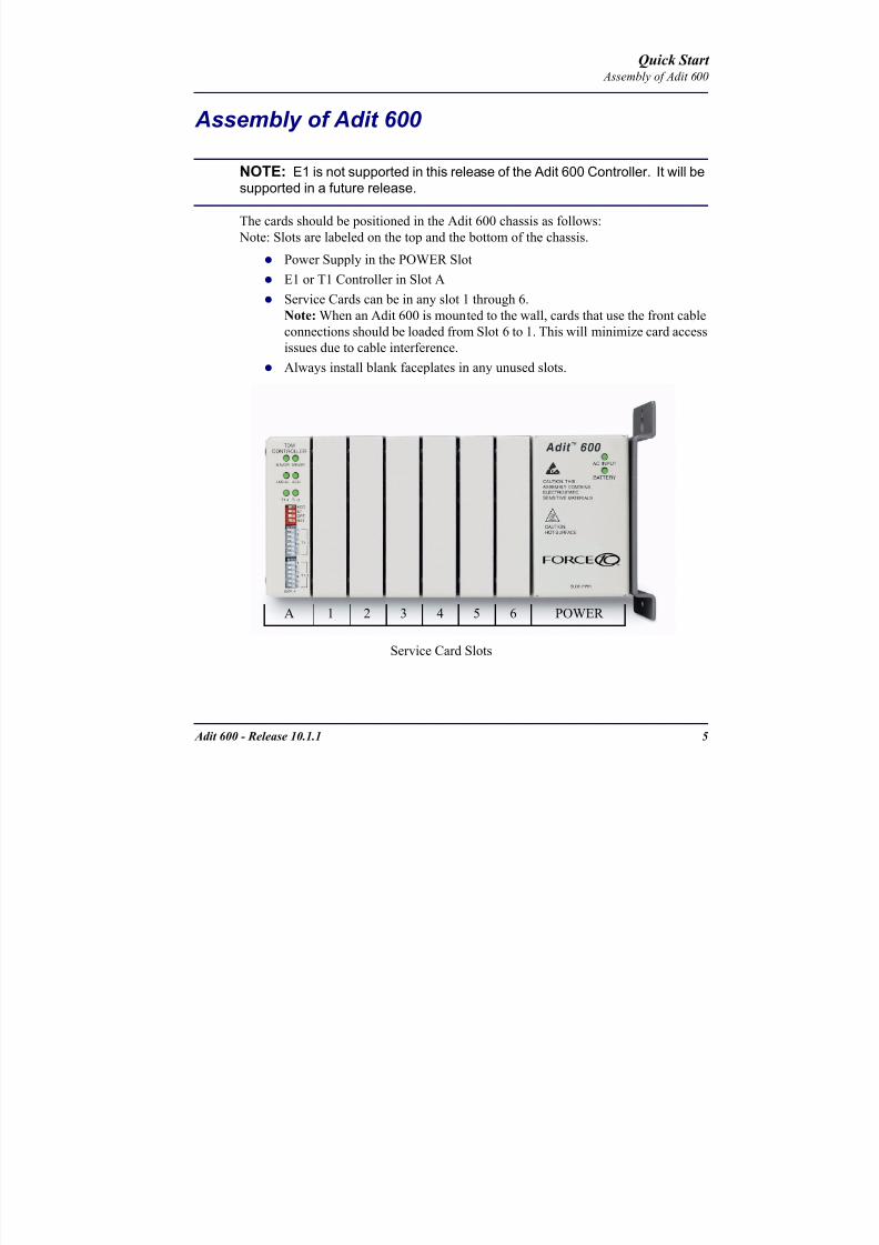
8102019 Adit 600 Quick Start 10-1-1
httpslidepdfcomreaderfulladit-600-quick-start-10-1-1 754
Adit 600 - Release 1011 5
Quick Start Assembly of Adit 600
Assembly of Adit 600
NOTE E1 is not supported in this release of the Adit 600 Controller It will be
supported in a future release
The cards should be positioned in the Adit 600 chassis as follows Note Slots are labeled on the top and the bottom of the chassis
Power Supply in the POWER Slot
E1 or T1 Controller in Slot A
Service Cards can be in any slot 1 through 6
Note When an Adit 600 is mounted to the wall cards that use the front cable
connections should be loaded from Slot 6 to 1 This will minimize card accessissues due to cable interference
Always install blank faceplates in any unused slots
Service Card Slots
1 2 3 4 5 6A POWER
8102019 Adit 600 Quick Start 10-1-1
httpslidepdfcomreaderfulladit-600-quick-start-10-1-1 854
6 Adit 600 - Release 1011
Quick Start Wall Mounting
Wall Mounting
Before beginning the mounting process verify that the area meets the following
requirements
A stable environment
Clean and free from extremes of temperature shock vibration and EMI
Meets all installation environment requirements see Installation Environment
on page 3-4
The Adit 600 is delivered with a mounting bracket attached for quick and easy wall
mounting as shown in the illustration above
To install the unit to the wall attach the unit using the four screws provided one at each
bracket foot
NOTE Do not mount the Adit 600 in any other orientation than show above
Leave at least 35above and belowthe Unit for adequate ventilation
Mounting BracketLeave adequate clearanceat the back for access toconnectors
Leave at least 14 atthe front of the unit foraccess to cards andDIP switches
8102019 Adit 600 Quick Start 10-1-1
httpslidepdfcomreaderfulladit-600-quick-start-10-1-1 954
Adit 600 - Release 1011 7
Quick Start Compliant Installation
Compliant Installation
1 Connect all of the signal cables as shown in the illustration above and secure
them with a plastic tie Dress the signal cables toward the left of the Adit 600
2 If using the 115V Power Supply connect the -48 VDC battery power cable
3 Secure the ground lugs to the terminals using the nuts provided
4 Secure the power cable and the ground cable with a plastic tie (not included)
Keep these cables separate from the signal cables
5 Terminate each signal cable to its appropriate connector
6 Secure signal cables using the holes along the bottom of the rack and plastic
ties (not included)
WARNING ADDITIONAL PRIMARY PROTECTION IS REQUIRED WHEN CONNECTING T1E1 OR FXS INTERFACES TO EXPOSED OFF-PREMISE COMMUNICATION CONDUCTORS SECONDARY OVERVOLTAGE AND OVERCURRENT PROTECTION IS
PROVIDED ON THESE INTERFACES FOR LIGHTNING SURGE AC POWER CONTACT AND INDUCTION IT WILL BE THE RESPONSIBILITY OF THE INSTALLER TO UTILIZE LISTED PRIMARY PROTECTORS AND FOLLOW INSTALLATION REQUIREMENTS PER LOCAL OR NATIONAL REGULATIONS
Power Cord
-48 VDC Battery Power
Alarm Wiring
Signal Cables
Power Cables
Grounding Cable
Ferrite Bead
with cable loop
RS-232 craft port
25-pair telco connector
25-pair telco connector
10Base-T EthernetT1E1 connectors
Ferrite Beads
are in red
US
8102019 Adit 600 Quick Start 10-1-1
httpslidepdfcomreaderfulladit-600-quick-start-10-1-1 1054
8 Adit 600 - Release 1011
Quick Start Compliant Installation
NOTE It is important that the Signal Cables are secured separately from thePower Cables for proper equipment operation
Ferrite Beads (US)
NOTE E1 is not supported in this release of the Adit 600 Controller It will besupported in a future release
To be compliant with Part 15A of the FCC and for NEBS compliant facilities the
following ferrite beads are required for the chassis and service cards listed below
Ferrite beads for Adit 600 chassis
Service card cables requiring ferrite beads
The CMG-01 and CMG-02 Router cards do not require a ferrite bead
For additional information on ferrite beads and their installation on the Adit 600 please
contact Force10 Networks Customer Support at 1-866-887-4638 (US) or 1-707-665-
4355 (InternationalDirect)
Ferrite Part Number Intended For
3 small PN 010-0095 (2) One on each T1 or E1 cable
(1) Ethernet (10Base-T) cable
1 large PN 010-0051 (1) Alarm cable which requires a loop
through the bead (see drawing)
Card Ferrite Part Number Intended For
ISDN BRI 1 large PN 010-0051 (1) 25-pair Telco cable (ISDN BRI
card in slot 1-3 top telco 4-6 bottom)
Quad DS1E1Quad T1
Quad E1
1 large PN 010-0051 Cables from front of card(1 bead can hold 1-4 cables) or
(1) One on 25-pair Telco cable
IP Router 1 small PN 010-0095 Ethernet Cable (from front of card)
CMG Router 1 small PN 010-0095 Ethernet Cable (from front of card)
8102019 Adit 600 Quick Start 10-1-1
httpslidepdfcomreaderfulladit-600-quick-start-10-1-1 1154
Adit 600 - Release 1011 9
Quick Start Compliant Installation
Ferrite Beads (Europe Australia and Canada)
NOTE E1 is not supported in this release of the Adit 600 Controller It will besupported in a future release
To be compliant with EN55022 and CISPR22 Class A emissions the following beads
are required for the chassis and components listed below Also shielded cables arerequired for the V3554 service card and must be ordered separately
Power Cord
-48 VDC Battery Power
Alarm Wiring
Signal Cables
Power Cables
Grounding Cable
Ferrite Bead
with cable loop
RS-232 craft port25-pair telco connector
25-pair telco connector
10Base-T EthernetT1E1 connectors
Ferrite Beads
are in red
Ferrite Beads
with cable loop
8102019 Adit 600 Quick Start 10-1-1
httpslidepdfcomreaderfulladit-600-quick-start-10-1-1 1254
10 Adit 600 - Release 1011
Quick Start Compliant Installation
Ferrite beads for Adit 600 chassis
Additional components requiring ferrite beads
The CMG-01 and CMG-02 Router cards do not require a ferrite bead
Shielded Cable (order separately)
For additional information on Ferrite beads and their installation on the Adit 600 please contact Force10 Networks Customer Support at 1-866-887-4638 (US) or 1-
707-665-4355 (InternationalDirect)
Ferrite Part Number Intended For
4 large PN 010-0051 All of these ferrites require a loop through the
bead (see drawing)
(1) Alarm cable
(2) One on each or E1 cable (E1-1E1-2)
(1) Ethernet (10Base-T) cable
Card Ferrite Part Number Intended For
CMG Router 1 small PN 010-0095 Ethernet Cable (from front of card)
Quad DS1E1Quad E1
2 large PN 010-0051 E1 cables from front of Quad E1card
(1 bead can hold 1-4 cables) or
(2) One on each 25-pair Telco cable
Battery Unit 1 small PN 010-0095 Battery Cable
DC Power Kit 1 small PN 010-0095 DC Input Cable
Card Part Number Intended For
V3554 (HD) PN 005-0008 D-sub Male to Winchester Male 10 ft
PN 005-0009 D-sub Male to Winchester Male 25 ftPN 005-0010 D-sub Male to Winchester Male 50 ft
PN 005-0014 D-sub Male to Winchester Female 10 ft
PN 005-0068 D-sub Male to Winchester Female 25 ft
PN 005-0069 D-sub Male to Winchester Female 50 ft
8102019 Adit 600 Quick Start 10-1-1
httpslidepdfcomreaderfulladit-600-quick-start-10-1-1 1354
Adit 600 - Release 1011 11
Quick Start Chassis Connectors and Buttons
Chassis Connectors and Buttons
The following illustrations show all connectors on the back of the Adit 600
Interface Connectors
The following are the Adit 600 interface connectors
T1-1E1-1 and T1-2E1-2 line connection ports each equipped with standard
RJ-48C 8-pin connector jack
RS-232 craft port connector
Tip and Ring Analog Interfaces equipped with standard 25-pair Telco
Connectors
10Base-T Ethernet port to be connected to a remote management tool such as
Telnet or an SNMP-based Network Management System with an RJ-45 8-pin
connector jack
External Alarm Connector
Ground Lugs
Ground Terminals
Alarms
AC or DC Power Connector
-48VBattery
Ethernet
T1-2E1-2T1E1
RS-232 Craft Port25-Pair Telco Connectors
T1-1E1-1
[10Base-T]
Connectors
Reset
(AC shown below)
8102019 Adit 600 Quick Start 10-1-1
httpslidepdfcomreaderfulladit-600-quick-start-10-1-1 1454
12 Adit 600 - Release 1011
Quick Start Interface Connectors
Chassis Ground Connector
WARNING THIS EQUIPMENT IS REQUIRED TO HAVE A PERMANENT GROUND CONNECTION IF CONNECTED TO EXPOSED OUTDOOR COMMUNICATION CONDUCTORS A 6 AWG COPPER WIRE MUST BE PERMANENTLY CONNECTED FROM AN APPROVED GROUNDING ELECTRODE TO THE CHASSIS GROUND LUG
OTHERWISE A 14 AWG COPPER WIRE MAY BE UTILIZED INSTALL THE GROUNDING CONDUCTOR IN ACCORDANCE WITH NATIONAL OR LOCAL REGULATIONS
1 Route wire (6 or 8 AWG copper) from building ground to lug on Adit 600
2 Strip insulation off wire end if necessary
3 Loosen compression screw until opening is large enough to accept ground
wire
4 Insert ground wire into lug barrel beneath compression plate and tighten
compression screw
5 Attach ground lug to chassis
Ground Terminals
Ground Lug
Compression
ScrewLug Barrel
8102019 Adit 600 Quick Start 10-1-1
httpslidepdfcomreaderfulladit-600-quick-start-10-1-1 1554
Adit 600 - Release 1011 13
Quick Start Interface Connectors
Power Reset
This is a resetable circuit breaker If at any time there is a short or power
surge on the incoming ACDC line the breaker will trip to protect the
Power supply from damage
Power Connections
There are four power supplies available for the Adit 600
115 VAC-48 VDC
230 VAC-48 VDC
24-48 VDC
24 VDC with -48 Output
These power supplies have different connectors as shown in the following Foradditional information see Chapter 15 Power Supply of the Adit 600 User Manual
Fuse Recommendation
When using -48 VDC input power use a 35 Amp fast-acting fuse if the power
connector is wired to a fuse panel
Power Cord AC An AC Power cord is provided with the 115 VAC and the
230 VAC Power Supplies
To connect the Power Cord
1 Insert power cord (male-end) to AC power source
2 Plug connector into the Adit 6003 A green light should appear on the DC Input LED on the front of the Power
Supply
AC Power Connector
8102019 Adit 600 Quick Start 10-1-1
httpslidepdfcomreaderfulladit-600-quick-start-10-1-1 1654
14 Adit 600 - Release 1011
Quick Start Interface Connectors
-48V Battery
The -48 VDC input connector on the Adit 600 is used for either direct DC powering
of the Adit 600 unit or for a Battery Backup connection when AC is used There is
no power cable provided for this connector however the connector is provided
WARNING POSSIBLE SHOCK HAZARD EXISTS PLEASE FOLLOW INSTRUCTIONS
CAREFULLY
To connect -48 VDC power
1 Ensure that no power is present on the two wires to be connected
2 Strip the two wires (approx 516 in bare wire) from the power source 16 or 18 AWG insulated copper wire is recommended for power connections
3 Insert the Battery Return and DC wires into the appropriate square holes
4 Tighten screws to clamp wires
5 Ensure that no bare wire shows after the wires are installed
6 Plug connector in the -48 VDC connector as seen below and secure with set
screws
7 Apply power to connector from -48 VDC power source
8 Verify with voltmeter that voltage is correct and polarity is correct
8102019 Adit 600 Quick Start 10-1-1
httpslidepdfcomreaderfulladit-600-quick-start-10-1-1 1754
Adit 600 - Release 1011 15
Quick Start Interface Connectors
9 Plug connector in the Adit 600 -48 VDC connector as seen in the graphic andsecure with set screws
Power Cord DC
There is no power cable provided with the 24
VDC Power Supply however the connector is
provided This connector will need to be wired
the following chart prides the wire gauge
recommendedTo connect 24 VDC power
1 Ensure that no power is present on the two wires to be connected
WARNING POSSIBLE SHOCK HAZARD EXISTS PLEASE FOLLOW INSTRUCTIONS CAREFULLY
1(+) 2(-)
Connector
Provided connector (female)
of Adit 600on back
(male)
Battery -48 VDC
2(-)
BatteryReturn (+)
-48 VDC (-)
Return 1(+)
24 VDC6 Amp
Battery
Battery (+)
DC Power Connector
Return (-)
8102019 Adit 600 Quick Start 10-1-1
httpslidepdfcomreaderfulladit-600-quick-start-10-1-1 1854
16 Adit 600 - Release 1011
Quick Start Interface Connectors
2 Strip the two wires from the powersource so that approximately 516 inch
of bare wire is exposed see Wire Gauge
chart below for wire recommendations
3 Insert the Battery Return (-) and Battery
(+) wires into the appropriate square
holes one at a time4 Tighten screws to clamp wires
5 Ensure that no bare wire shows after the
wires are installed
6 Apply power to connector
7 Verify with voltmeter that voltage is
correct and polarity is correct
8 Plug connector(s) into the Adit 600 DC
Power connector as seen in the graphic
and secure with set screws
9 A green light should appear on the DC OK LED on the front of the Power
Supply
Wire Gauge 18 AWG 16 AWG 14 AWG
Maximum Distance 12 Feet 20 Feet 35 Feet
Battery (+)
BatteryReturn (-)
8102019 Adit 600 Quick Start 10-1-1
httpslidepdfcomreaderfulladit-600-quick-start-10-1-1 1954
Adit 600 - Release 1011 17
Quick Start Interface Connectors
External Alarm Connector
The external alarm 6-pin connector with one input pair (pins 5 and 6)
and two output pairs (pins 1 and 2 - major alarms pins 3 and 4 - minor
alarms)
The pinouts are as follows
Pin Description Explanation
1 Major Alarm + The major alarm output is available for power supply or
major alarm failure alerting The maximum voltage across
the contacts is 350 V and the maximum current is 150 mA
This alarm is closed when power is off
2 Major Alarm -
3 Minor Alarm + The minor alarm output is available for power supply or
minor alarm failure alerting The maximum voltage across
the contacts is 350 V and the maximum current is 150 mA
This alarm remains open when power is off
4 Minor Alarm -
5 Alarm In + The alarm inputs provide 5 VDC across the two contactsand generate an alarm when a short circuit is detected
between the contacts
The alarm generated is a minor severity alarm
6 Alarm In -
6
5
4
3
2
1
A
L
A
R
M
8102019 Adit 600 Quick Start 10-1-1
httpslidepdfcomreaderfulladit-600-quick-start-10-1-1 2054
18 Adit 600 - Release 1011
Quick Start Interface Connectors
25-Pair Telco ConnectorsTip and Ring Analog Interfaces equipped with standard 25-pair Telco Connectors
(female) for connection to key systems fax machines modems and PBXs These
interfaces are also used for ISDN BRI ports and are jumper selectable on the Quad T1
Quad E1 Quad DS1E1 and Quad ADPCM service cards
Circuit connections are made at the 25-pair
telco connectors A standard 25-pairtelephone cable with RJ-21X wiring and a
male D-type connector at the Adit 600 end
is required
The pinouts are as follows
Pair Pin Location Function Color Code
1 26
1
Tip Channel 1
Ring Channel 1
WhiteBlue
BlueWhite
2 27
2
Tip Channel 2
Ring Channel 2
WhiteOrange
OrangeWhite
3 28
3
Tip Channel 3
Ring Channel 3
WhiteGreen
GreenWhite
4 29
4
Tip Channel 4
Ring Channel 4
WhiteBrown
BrownWhite
5 30
5
Tip Channel 5
Ring Channel 5
WhiteSlate
SlateWhite
6 31
6
Tip Channel 6
Ring Channel 6
RedBlue
BlueRed
7 327
Tip Channel 7Ring Channel 7
RedOrangeOrangeRed
8 33
8
Tip Channel 8
Ring Channel 8
RedGreen
GreenRed
9 34
9
Tip Channel 9
Ring Channel 9
RedBrown
BrownRed
10 3510
Tip Channel 10Ring Channel 10
RedSlateSlateRed
50
25
26
1
8102019 Adit 600 Quick Start 10-1-1
httpslidepdfcomreaderfulladit-600-quick-start-10-1-1 2154
Adit 600 - Release 1011 19
Quick Start Interface Connectors
Pair Pin Location Function Color Code
11 36
11
Tip Channel 11
Ring Channel 11
BlackBlue
BlueBlack
12 37
12
Tip Channel 12
Ring Channel 12
BlackOrange
OrangeBlack
13 38
13
Tip Channel 13
Ring Channel 13
BlackGreen
GreenBlack
14 39
14
Tip Channel 14
Ring Channel 14
BlackBrown
BrownBlack
15 40
15
Tip Channel 15
Ring Channel 15
BlackSlate
SlateBlack
16 41
16
Tip Channel 16
Ring Channel 16
YellowBlue
BlueYellow17 42
17
Tip Channel 17
Ring Channel 17
YellowOrange
OrangeYellow
18 43
18
Tip Channel 18
Ring Channel 18
YellowGreen
GreenYellow
19 44
19
Tip Channel 19
Ring Channel 19
YellowBrown
BrownYellow
20 45
20
Tip Channel 20
Ring Channel 20
YellowSlate
SlateYellow
21 46
21
Tip Channel 21
Ring Channel 21
VioletBlue
BlueViolet
22 47
22
Tip Channel 22
Ring Channel 22
VioletOrange
OrangeViolet
23 48
23
Tip Channel 23
Ring Channel 23
VioletGreen
GreenViolet
24 49
24
Tip Channel 24
Ring Channel 24
VioletBrown
BrownViolet
25 50
25
Reserved VioletSlate
SlateViolet
8102019 Adit 600 Quick Start 10-1-1
httpslidepdfcomreaderfulladit-600-quick-start-10-1-1 2254
20 Adit 600 - Release 1011
Quick Start Interface Connectors
RS-232 Craft Port (Female DB-9)The RS-232 craft port connector (female) is for connection to an external PC or Hayes-
compatible modem for local or remote configuration management and performance
monitoring using the Adit 600 Command Line Interface (CLI)
The RS-232 craft port connects via a
female DB-9 connector on the Adit 600
The pinouts are as follows
Pin Number Direction Description
1 Outbound Carrier Detect
2 Outbound Receive Data
3 Inbound Transmit Data
4 Inbound Data Terminal Ready
5 NA Signal Ground
6 Outbound Data Set Ready
7 Inbound Request to Send
8 Outbound Clear to Send
9 NC Not connected
1 5
6 9
8102019 Adit 600 Quick Start 10-1-1
httpslidepdfcomreaderfulladit-600-quick-start-10-1-1 2354
8102019 Adit 600 Quick Start 10-1-1
httpslidepdfcomreaderfulladit-600-quick-start-10-1-1 2454
22 Adit 600 - Release 1011
Quick Start Interface Connectors
10Base-T Ethernet
The 10Base-T Ethernet (female) port to connect to a remote
management tool such as Telnet or an SNMP-based Network
Management System Note A LINK LED on the back of the unit
displays green when the system has a good Ethernet link
The pinouts are as follows
Ethernet (RJ-45)
NOTE This Ethernet port uses a hub pinout Use a straight-through cableto connect a PC
Pin Name Description
1 Receive + Receive from network
2 Receive - Receive from network
3 Transmit + Transmit to network
4 - 5 NC Not connected
6 Transmit - Transmit to network
7 NC Not connected
8 NC Not connected
1 8
8102019 Adit 600 Quick Start 10-1-1
httpslidepdfcomreaderfulladit-600-quick-start-10-1-1 2554
Adit 600 - Release 1011 23
Quick Start Management Options
Management Options
Options for managing the Adit 600 are as follows
Local using CLI Telnet SNMP or DIP Switches (Controller and voice cards)
Remotely over an in-band DS0 or through the Access Navigator over the FDL
or an in-band DS0
This Quick Start Guide focuses on the CLI and DIP switches If you need further
information on other management options please refer to the Adit 600 User Manual
Command Line Interface (CLI)
You can access the CLI using either of the following methods
Telnet via Ethernet (10Base-T) RS-232 connected to the DB-9 port
Setting up a CLI Connection
If connecting via the Ethernet 10Base-T connection use a Telnet TCPIP
program to access the CLI This requires the IP address of the Controller
Controllers are shipped with the IP address set to 100010 If this address has been changed and is not known use HyperTerm to access the Controller and
use the CLI command show ip If an IP address needs to be set use the CLI
command set ethernet ip address
If connecting via RS-232 the port settings should be set to
Bits per second 9600 Data bits 8
Parity None Stop bits 1Flow control None
Set your Terminal Emulation to VT100
By default the Adit 600 is set for local configuration (using DIP switches) Use
the set local off command to enable the use of CLI commands
8102019 Adit 600 Quick Start 10-1-1
httpslidepdfcomreaderfulladit-600-quick-start-10-1-1 2654
8102019 Adit 600 Quick Start 10-1-1
httpslidepdfcomreaderfulladit-600-quick-start-10-1-1 2754
Adit 600 - Release 1011 25
Quick Start Configuration
ConfigurationThe following basic setups and upgrades for the Adit 600 are shown using CLI
commands For more information on CLI commands and configurations see the Adit
600 User Manual
Initial Setup
Basic Security Setup
DS1T1 Setup
E1 Setup
DS0Channel Setup
Analog Port Setup
4-Wire EampM Setup
Establish a Static Channel Connection
ISDN BRI Service Setup
OCU-DP Card Setup
ADPCM Card Setup
V35 Port Setup
Change the IP Address of the DS0 Management Channel
Upgrade the Adit 600 Software
Upgrade the Router Card Software
Basic Router Setup
8102019 Adit 600 Quick Start 10-1-1
httpslidepdfcomreaderfulladit-600-quick-start-10-1-1 2854
26 Adit 600 - Release 1011
Quick Start Configuration
Initial SetupUse the following commands for your initial setup For further information see the Adit
600 User Manual
Command Description
set local off Disables DIP switches
set date mmddyyyy Set the date used for event logging
set time hhmmss Set the time used for event logging
set id id-name Set a system ID name
set clock1 slotportinternal
Set the primary clock source
set clock2 slotportinternal
Set the secondary clock source
set ethernet ip addressip-addr mask
Set the ethernet IP address in the
conventional IP address format
set ip gateway ip-addr Set the IP gateway in the conventional IP
address format
8102019 Adit 600 Quick Start 10-1-1
httpslidepdfcomreaderfulladit-600-quick-start-10-1-1 2954
Adit 600 - Release 1011 27
Quick Start Configuration
Basic Security SetupUse the following commands to set up the security on the Adit 600 For further
information see the Adit 600 User Manual
Command Description
set password length
long|short
Set user password length requirement
add user ldquouser-namerdquo[password ldquopasswordrdquo]
Add user and password as necessary
set user user-name level1-3
Specify the userrsquos security level
set user user-namepassword Setchange password for the user asnecessary
8102019 Adit 600 Quick Start 10-1-1
httpslidepdfcomreaderfulladit-600-quick-start-10-1-1 3054
28 Adit 600 - Release 1011
Quick Start Configuration
DS1T1 SetupUse the following commands to set up a DS1 See the set (ds1) command for more
details
Command Description
set ds1-addr up Activate the port of the DS1 (slotport)
set ds1-addr id id-string
Set the identification string
set ds1-addr lbo 1-9 Set the line buildout value for the DS1
set ds1-addr linecodeami|b8zs
Set the linecode for the DS1
set ds1-addr framing d4|esf|tr8afdl|tr8anofdl|tr8b
Set the framing option for the DS1
set ds1-addr loopdetecton|off
Set the detectionreaction to CSU loopcodes
Q i k S
8102019 Adit 600 Quick Start 10-1-1
httpslidepdfcomreaderfulladit-600-quick-start-10-1-1 3154
Adit 600 - Release 1011 29
Quick Start Configuration
E1 Setup
NOTE E1 is not supported in this release of the Adit 600 Controller It will besupported in a future release
Use the following commands to set up an E1 See the set (e1) command for more
details
DS0Channel Setup
Use the following commands to set up a DS0 See the set (ds0) command for details
Command Description
set e1-addr up Activate the port of the E1 (slotport)
set e1-addr id id-string Set the identification string
set e1-addr lbo 1 - 9 Set the line buildout value for the E1
set e1-addr linecodeami|hdb3
Set the linecode for the E1
set e1-addr framinge1fr|lefrcrc
Set the framing option for the E1
set e1-addr loopdetecton|off
Set the detectionreaction to CSU loopcodes
Command Description
set slotportchannel up Activate the channel
set slotportchannel signalls|gs|emw|emdw|emicpd|dpt
Set the signaling option for the channel
set slotportchannel typedata|voice Set the channel type
Q i k St t
8102019 Adit 600 Quick Start 10-1-1
httpslidepdfcomreaderfulladit-600-quick-start-10-1-1 3254
30 Adit 600 - Release 1011
Quick Start Configuration
Analog Port SetupUse the following commands to set up an analog port
Command Description
set slotport up Activate the port See set (ds1) command for
details
set slotport signal dpt|gs|gsrb|gsw|gswrb|ls|lscpd|lsrb
Set the signaling option for the port See the
set (fxs) or set (fxo) command for details
set slotport rxgain n Set the receive gainloss in dB See the set
(fxs) or set (fxo) command for details
set slotport txgain n Set the transmit gainloss in dB See the set
(fxs) or set (fxo) command for details
Quick Start
8102019 Adit 600 Quick Start 10-1-1
httpslidepdfcomreaderfulladit-600-quick-start-10-1-1 3354
Adit 600 - Release 1011 31
Quick Start Configuration
4-Wire EampM SetupFor this example the 4 EampM ports will be connected to the first 4 DS0s on T1-1 (a1)
This can be changed to match the customers desired DS0 connections
For Transmission Only mode the DS0s on the DS1 should be set to data as well as the
EampM card channels
Command Description
For Normal or Tandem EampM
set a11-4 type voice Set DS0s to voice
set connect a11-4 11-4 Connect DS0s to the 4 ports of the 4-
Wire EampM card
show connect a 1 Verify cross connects
set a11-4 signal emi Set DS0 signal type to EMI
set 11-4 signal emi Set 4-Wire EampM ports signal type to
EMI
show connect a1 Verify cross connects
For TO Mode
set a11-4 type data Set DS0s to data
set 11-4 type data Set 4-Wire EampM port to data
set connect a11-4 11-4 Connect DS0s to the 4 ports of the 4-
Wire EampM card
show connect a 1 Verify cross connects
Quick Start
8102019 Adit 600 Quick Start 10-1-1
httpslidepdfcomreaderfulladit-600-quick-start-10-1-1 3454
32 Adit 600 - Release 1011
Quick Start Configuration
Establish a Static Channel ConnectionUse the following commands to establish a static channel connection
ISDN BRI Service Setup
Use the following commands to set up a ISDN BRI Service See the set (bri) command
for details
Command Description
set slotportchannel typevoice|data
Set the channel type for the channel to
map See set (ds0) command for details
set slotportchannel signalls|gs|emw|emdw|emicpd|dpt
Set the channel signaling option See set
(ds0) command for details
connect slotportslotport
Connect the channels See the connect
(card-trunk) (card-trunk) command
Command Description
set slotport up Put the ISDN line In-Service
set slot modelt3ds0|lt4to1tdm|nt3ds0
Set the ISDN mode
set slotport crv 1-768 Set the Call Reference Value Note
value must be the same as the Access
Navigator
set slotport thresholdday|hour es|ses
Set the threshold for the IDSN lines
set slot pmsyncadit|switch
Set the source for performance
monitoring synchronization
set slotport autoactivate
on|off
Only used in 4-to-1 mode Establishes
the D channel when the FDL link can not
be used
Quick Start
8102019 Adit 600 Quick Start 10-1-1
httpslidepdfcomreaderfulladit-600-quick-start-10-1-1 3554
Adit 600 - Release 1011 33
Quick Start Configuration
OCU-DP Card SetupThe following is a basic setup for the OCU-DP card
ADPCM Card Setup
Command Description
set ocudp-addr baud2400|4800|9600|19200|38400|
56000|64000
Set the OCU-DP Baud rate
Where ocudp-addr = slotport of the
OCU-DP card to apply settings to
set ocudp-addr up Set the OCU-DP port 1 up
show ocudp_card-addr Show the OCU-DP card settings
Where ocudp_card-addr = slot of the
OCU-DP card
disconnect a Disconnects all connections to slot a
(controller)
set ds0-addr type data Sets a DS0 data signaling type
connect ds0-addrocudp-addr
Connects DS0 (in previous step) to OCU-DP
port (in previous step)
show connect
(ocudp_card-addr
Displays connect information for OCU-DP
card
Command Description
Connect T1 cable to port 1 of the ADPCM service card
set adpcm_card-addrnone|map1|map2|map3
Enable compressing by selecting Map type Notenone disables compression
show (adpcm_card-addr Displays the status of the card and the mapping
connect 211-12 241-12 Set ADPCM cross-connects The example
connects all 24 channels of the ADPCM to the 12
channels of the T1 (now compressed) on port 4
This example is with map2show connect 21) Displays the connections made above
8102019 Adit 600 Quick Start 10-1-1
httpslidepdfcomreaderfulladit-600-quick-start-10-1-1 3654
Quick Start
8102019 Adit 600 Quick Start 10-1-1
httpslidepdfcomreaderfulladit-600-quick-start-10-1-1 3754
Adit 600 - Release 1011 35
QConfiguration
Upgrade the Adit 600 SoftwareUse the following commands to determine the system software level then upgrade the
software to the latest version
Command Description
status equipment Determine the system software level The
Slot A line (SW Vers) will display thecurrent software level
load tftp ip-addr file-name (or load xmodem)
Load the new controller system software See
the load tftp and load xmodem command for
more information
Note A TFTP server must be running onthe host system You can use any TFTP
server utility you wish One example isthe program TFTPD32 which can bedownloaded free-of-charge attftpd32jouninnettftpd32html
Quick Start
8102019 Adit 600 Quick Start 10-1-1
httpslidepdfcomreaderfulladit-600-quick-start-10-1-1 3854
36 Adit 600 - Release 1011
Configuration
Upgrade the Router Card SoftwareUse the following commands to determine the Router card software level then upgrade
the software to the latest version
NOTE For additional information about upgrading MSR card software see
the following manuals-Adit 600 User Manual -Adit 3000 Series and Multi-Service Router (MSR) Card GUI Reference Manual
-Adit 3000 Series and Multi-Service Router (MSR) Card CLI Reference Manual
Command Description
status equipment Determine the Router software level The
Router Slot line (SW Vers) will display thecurrent software level
load rtr_card-addr tftpip-addr file-name
Load the new Router software to a Router
card See the load tftp command for more
information
Note A TFTP server must be running onthe host system You can use any TFTP
server utility you wish One example isthe program TFTPD32 which can bedownloaded free-of-charge attftpd32jouninnettftpd32html
8102019 Adit 600 Quick Start 10-1-1
httpslidepdfcomreaderfulladit-600-quick-start-10-1-1 3954
8102019 Adit 600 Quick Start 10-1-1
httpslidepdfcomreaderfulladit-600-quick-start-10-1-1 4054
Quick Start C t ll C d LED
8102019 Adit 600 Quick Start 10-1-1
httpslidepdfcomreaderfulladit-600-quick-start-10-1-1 4154
Adit 600 - Release 1011 39
Controller Card LEDs
E1 Controller Card
NOTE E1 is not supported in this release It will be supported in a futurerelease
The E1 Controller has a set of six LEDs The table below describes each LED
LED State Description
MAJOR Off No major alarms present
Red Major alarm present
MINOR Off No minor alarms present
Yellow Minor alarms present
LOCAL Off Remote mode (DIP switches disabled)
Green Local mode (DIP switches enabled)
ACO Off Normal mode No alarms are being
suppressed
Yellow Alarm Cut Off active One or more active
alarms suppressed
E1-1 and
E1-2
Off Off line
Green Normal
Red Loss of Signal (LOS) detected
Yellow Bipolar Violation (BPV) detected LCV
Flashing Green Loopback active
Flashing Red
(slow)
Loss of Frame (LOF) or Alarm Indication
Signal (AIS) detected
Flashing Red
(fast)
Card Failure
Flashing Yellow Yellow alarm (Remote Alarm Indication)detected
Quick Start Power Supply LEDs
8102019 Adit 600 Quick Start 10-1-1
httpslidepdfcomreaderfulladit-600-quick-start-10-1-1 4254
40 Adit 600 - Release 1011
Power Supply LEDs
Power Supply LEDs115 VAC-48 VDC and 230 VAC-48 VDC Power Supplies
The power supply card has two LEDs as described in the table
below
24 VDC-48 VDC Power Supply
The power supply card has two LEDs as described in the table below
LED State Description
AC Input Off AC input missing or failure
Green AC input present
Battery Off Battery input not used
Green Battery charging or operating from DC
source only
Yellow Battery discharging
Red Battery low (less than 42V) ringer disabled
LED State Description
DC OK Off DC input missing or failure
Green DC input present
-48 Battery
Low
Off Normal
Red VDC is low (less than 42 VDC)
ringer disabled
Quick Start Service Card LEDs
8102019 Adit 600 Quick Start 10-1-1
httpslidepdfcomreaderfulladit-600-quick-start-10-1-1 4354
Adit 600 - Release 1011 41
Service Card LEDs
Service Card LEDs 4-Wire EampM Card
FXO Card
FXS Card
ISDN BRI Card
OCU-DP Card
P-Phone Card
Single Channel POTS Card
Quad DS1 ADPCM Service Card
Quad DS1E1 and Quad T1 Cards
Quad E1 Card
IP Router Card
CMG Router Card
Terminal Server Router Card
MSR Card
RS-232 and V35V54 Cards
Discontinued cards
RS-232 discontinued
Quick Start Service Card LEDs
8102019 Adit 600 Quick Start 10-1-1
httpslidepdfcomreaderfulladit-600-quick-start-10-1-1 4454
42 Adit 600 - Release 1011
Service Card LEDs
4-Wire EampM Card Each channelport has two LEDs Only the top LED is used in this application LED
definitions are listed below
State Description
When in EampM Mode
Off Channel is idle or disabled
Green Analog interface is off-hook
Red Digital interface is off-hook
Yellow Both analog and digital interfaces are off-hook or channel is
being trunk processed
When in TO Mode
Off DisconnectedGreen Connected T1E1 not in alarm
Yellow Connected T1E1 in alarm (trunk processed)
Quick Start Service Card LEDs
8102019 Adit 600 Quick Start 10-1-1
httpslidepdfcomreaderfulladit-600-quick-start-10-1-1 4554
Adit 600 - Release 1011 43
FXO Card Each port on the FXO card has its own LED as described in the table below
FXS Card
There is an LED for each port on the FXS card as described in the table below
State Loop Start
Meaning
Ground Start Meaning Dial Pulse Termination
Meaning
Off NA Idle (tip open) Idle (loop open)
Green Idle Tip ground (incoming seizure) Incoming seizure
Red NA Ring ground (outgoing
seizure)
Loop closure (outgoing seizure)
Yellow Call in
progress
Call in progress Call in progress (reverse battery)
Flashing
Green
Ringing Ringing NA
State Loop Start Meaning Ground Start Meaning
Off NA Idle (tip open)
Green Idle Tip ground (incoming seizure)
Red Note This can be seen with
Forward Disconnect (tip open)
Ring ground (outgoing seizure)
Yellow Call in progress Call in progress
Flashing green Ringing Ringing
Quick Start Service Card LEDs
8102019 Adit 600 Quick Start 10-1-1
httpslidepdfcomreaderfulladit-600-quick-start-10-1-1 4654
44 Adit 600 - Release 1011
ISDN BRI Card There is an LED for each ISDN BRI on a card as described in the table below
OCU-DP Card Each channel has two LEDs described in the table below
State Description
Off Line U-interface is attempting synchronization or BRI is Out-of-Service
Red Line alarm (LOS or self test failure)
Yellow ES or SES has occurred
Flashing yellow Line U-interface is synchronized with customer equipment but is not passing
customer data
Flashing green Line U-interface is in external loopback toward the switch at the unit
Green Normal (Line U-interface is active and transparently passing customer data)
State Description
Yellow Flickering ALL Boot Software in control
Green (walking down)
Red (walking up)
ALL Application Software in control
(repeated 35 times)
Red slow flash ALL In Boot Application flash code checksums did not match and
Boot is waiting for application download
Red ALL In Application code waiting for Controller to issue SWHW
revision request This is the first request that comes from the
OCU-DP card manager in the ControllerGreen
Yellow
Top
Bottom
Port in Self-test Duration is 5-8 seconds
Off Top
Bottom
Port is set down (Out-Of-Service)
Green Top Port is receiving valid signals
Red Top Port is receiving no signal (primary) or no frame sync
(secondary or clear channel)Red Flashing Bottom Port is receiving bipolar violations
Yellow Bottom Port is in loopback
Quick Start Service Card LEDs
8102019 Adit 600 Quick Start 10-1-1
httpslidepdfcomreaderfulladit-600-quick-start-10-1-1 4754
Adit 600 - Release 1011 45
P-Phone Card Each P-Phone channel has a corresponding LED described in the table below
State Line State
Off No P-Phone connected
Green No call in process
Flashing Green Alert (Ringing)
Yellow Call in progress
Flashing Yellow P-Phone Loopback in Progress
Flashing Red Self-test failed
Quick Start Service Card LEDs
8102019 Adit 600 Quick Start 10-1-1
httpslidepdfcomreaderfulladit-600-quick-start-10-1-1 4854
46 Adit 600 - Release 1011
Single Channel POTS Card The POTS channel LED (left) status is described in the table below
The second LED (right) is a status LED is not used on this card
Quad DS1 ADPCM Service Card
Each channel on the Quad DS1 ADPCM card has two LEDs The
description of the top LED is shown below the bottom LED is notused with this application
State Loop Start Meaning
Off Calling Party Disconnect
Green Idle
Red NA
Yellow Call in progress
Flashing green Ringing
State Description
Off Off line
Green Normal
Red Loss of Signal (LOS)
Yellow Bipolar Violation (BPV)Flashing Green Loopback active
Flashing Yellow Yellow Alarm
(Remote Alarm Indication)
Flashing Red (Slow) Loss of Frame (LOF) or Alarm Indication Signal (AIS)
Flashing Red (Fast) Self-test Failure
Top LED(active)
Bottom LED(not used)
Quick Start Service Card LEDs
8102019 Adit 600 Quick Start 10-1-1
httpslidepdfcomreaderfulladit-600-quick-start-10-1-1 4954
Adit 600 - Release 1011 47
Quad DS1E1 and Quad T1 CardsEach channel on the Quad T1E1 cards have two LEDs The description
of the top LED is shown below the bottom LED is not used with this
application
State Description
Off Off line
Green Normal
Red Loss of Signal (LOS)
Yellow Bipolar Violation (BPV)
Flashing Green Loopback active
Flashing Yellow Yellow Alarm (Remote Alarm Indication)
Flashing Red (Slow) Loss of Frame (LOF) or Alarm Indication Signal (AIS)
Flashing Red (Fast) Self-test Failure
Quick Start Service Card LEDs
8102019 Adit 600 Quick Start 10-1-1
httpslidepdfcomreaderfulladit-600-quick-start-10-1-1 5054
48 Adit 600 - Release 1011
IP Router Card The following chart describes each LED and its state
LED State Description
CRD Off Loss of power
Green No current alarms
Red Alarm state active See alarm log for cause
Red Flashing Self-test or Boot in-process
Yellow Flashing Card is saving data to flash RAM do not power down
10100 Off 10 Mb ethernet
Green 100 Mb ethernet
LNK Off No ethernet link
Green Good ethernet link
COL
Off No current ethernet transmit collisions
Yellow Ethernet collisions have occurred and have not dropped
to minimum level
Yellow Flashing Ethernet collision occurring
TX Off No ethernet transmit activity
Green Ethernet transmit activity
RX Off No current ethernet receive activity
Green Current ethernet receive activity
Quick Start Service Card LEDs
8102019 Adit 600 Quick Start 10-1-1
httpslidepdfcomreaderfulladit-600-quick-start-10-1-1 5154
Adit 600 - Release 1011 49
CMG Router Card The following chart describes each LED and its state
LED State Description
CRD Off Loss of power
Green No current alarms
Red Alarm state active See alarm log for causeRed Flashing Self-test or Boot in-process
Yellow Flashing Card is saving data to flash RAM do not power down
VOIP
Off No active VoIP calls or if the MGCP protocol is
optioned down
Green Active VoIP calls
Red Call agent unreachable
Yellow Insufficient VoIP resources to complete call
LNK Off No Ethernet link
Green Good Ethernet link
10100 Off 10 Mb Ethernet
Green 100 Mb Ethernet
TX Off No Ethernet transmit activityGreen Ethernet transmit activity
Yellow Current Ethernet transmit collision
RX Off No current Ethernet receive activity
Green Current Ethernet receive activity
Quick Start Service Card LEDs
8102019 Adit 600 Quick Start 10-1-1
httpslidepdfcomreaderfulladit-600-quick-start-10-1-1 5254
50 Adit 600 - Release 1011
Terminal Server Router Card The Terminal Server Router card has 2 LEDs per port
At Power-up
Normal Operation
Port Set for Ethernet
Top LED indicates 100M Link Bottom LED indicates 10M Link
Port Set for RS-232
TOP LED Bottom LED Description
Off Off At Power UpBoot = Loss of power
Red Red Card is inoperative
Flashing Red Flashing Red Self-test or Boot in-process
TOP LED Bottom LED Description
Green Solid (Link) Green Solid (Link) Port set for Ethernet - see below
Flashing Red Flashing Red Self-test or Boot in-process
State Description
Off No Ethernet link
Green Link but no activity
Red Flashing Current Ethernet collision
Green Flashing Current Ethernet receive
Yellow Flashing Current Ethernet transmit
TOP LED Bottom LED Description
Yellow Off No Activity
Yellow Flashing Yellow Current transmit
Yellow Flashing Green Current receive
Quick Start Service Card LEDs
8102019 Adit 600 Quick Start 10-1-1
httpslidepdfcomreaderfulladit-600-quick-start-10-1-1 5354
Adit 600 - Release 1011 51
MSR Card The following chart describes the MSR cardrsquos LEDs
LED State Description
CRD Off Loss of power
Green No current alarms
Red Alarm state active See alarm log for cause
Red Flashing Self-test or boot in process
Yellow Flashing Card is saving data to flash RAM do not power
down
VOIP
Off No SIP proxy or registration attempts for all lines
have succeeded but no calls are active
Green Active VoIP call(s)
Red Inability to reach the SIP proxy or negative response
to register attempts from all lines
Yellow Register attempts from some lines have succeeded
but not for all lines
ETH1 and
ETH2
Top LED
Off 10 Mbitsec down or not connected
Green 100 Mbitsec
ETH1 and
ETH2
Bottom LED
Off Link down
Green Link up
Flashing Green Traffic on link
Yellow Collision status
Quick Start Service Card LEDs
8102019 Adit 600 Quick Start 10-1-1
httpslidepdfcomreaderfulladit-600-quick-start-10-1-1 5454
52 Adit 600 - Release 1011
RS-232 and V35V54 Cards Each port has its own LED as described in the table below
State Description
Off No T1 Assignment
Green Normal (CDRTS) Active
Red CD inactive (T1-side failure)
Yellow RTS inactive (equipment-side failure)
Flashing Yellow Loopback toward T1 or equipment loop test
Flashing Green Loopback toward equipment or network loop test
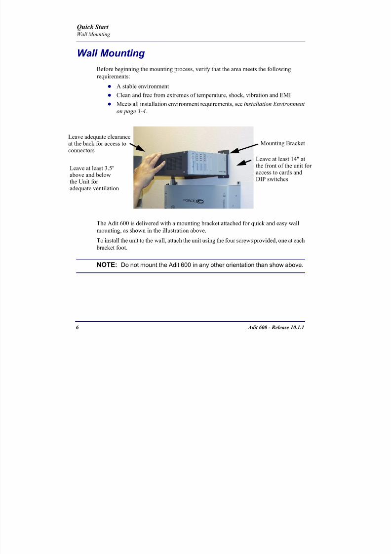
8102019 Adit 600 Quick Start 10-1-1
httpslidepdfcomreaderfulladit-600-quick-start-10-1-1 954
Adit 600 - Release 1011 7
Quick Start Compliant Installation
Compliant Installation
1 Connect all of the signal cables as shown in the illustration above and secure
them with a plastic tie Dress the signal cables toward the left of the Adit 600
2 If using the 115V Power Supply connect the -48 VDC battery power cable
3 Secure the ground lugs to the terminals using the nuts provided
4 Secure the power cable and the ground cable with a plastic tie (not included)
Keep these cables separate from the signal cables
5 Terminate each signal cable to its appropriate connector
6 Secure signal cables using the holes along the bottom of the rack and plastic
ties (not included)
WARNING ADDITIONAL PRIMARY PROTECTION IS REQUIRED WHEN CONNECTING T1E1 OR FXS INTERFACES TO EXPOSED OFF-PREMISE COMMUNICATION CONDUCTORS SECONDARY OVERVOLTAGE AND OVERCURRENT PROTECTION IS
PROVIDED ON THESE INTERFACES FOR LIGHTNING SURGE AC POWER CONTACT AND INDUCTION IT WILL BE THE RESPONSIBILITY OF THE INSTALLER TO UTILIZE LISTED PRIMARY PROTECTORS AND FOLLOW INSTALLATION REQUIREMENTS PER LOCAL OR NATIONAL REGULATIONS
Power Cord
-48 VDC Battery Power
Alarm Wiring
Signal Cables
Power Cables
Grounding Cable
Ferrite Bead
with cable loop
RS-232 craft port
25-pair telco connector
25-pair telco connector
10Base-T EthernetT1E1 connectors
Ferrite Beads
are in red
US
8102019 Adit 600 Quick Start 10-1-1
httpslidepdfcomreaderfulladit-600-quick-start-10-1-1 1054
8 Adit 600 - Release 1011
Quick Start Compliant Installation
NOTE It is important that the Signal Cables are secured separately from thePower Cables for proper equipment operation
Ferrite Beads (US)
NOTE E1 is not supported in this release of the Adit 600 Controller It will besupported in a future release
To be compliant with Part 15A of the FCC and for NEBS compliant facilities the
following ferrite beads are required for the chassis and service cards listed below
Ferrite beads for Adit 600 chassis
Service card cables requiring ferrite beads
The CMG-01 and CMG-02 Router cards do not require a ferrite bead
For additional information on ferrite beads and their installation on the Adit 600 please
contact Force10 Networks Customer Support at 1-866-887-4638 (US) or 1-707-665-
4355 (InternationalDirect)
Ferrite Part Number Intended For
3 small PN 010-0095 (2) One on each T1 or E1 cable
(1) Ethernet (10Base-T) cable
1 large PN 010-0051 (1) Alarm cable which requires a loop
through the bead (see drawing)
Card Ferrite Part Number Intended For
ISDN BRI 1 large PN 010-0051 (1) 25-pair Telco cable (ISDN BRI
card in slot 1-3 top telco 4-6 bottom)
Quad DS1E1Quad T1
Quad E1
1 large PN 010-0051 Cables from front of card(1 bead can hold 1-4 cables) or
(1) One on 25-pair Telco cable
IP Router 1 small PN 010-0095 Ethernet Cable (from front of card)
CMG Router 1 small PN 010-0095 Ethernet Cable (from front of card)
8102019 Adit 600 Quick Start 10-1-1
httpslidepdfcomreaderfulladit-600-quick-start-10-1-1 1154
Adit 600 - Release 1011 9
Quick Start Compliant Installation
Ferrite Beads (Europe Australia and Canada)
NOTE E1 is not supported in this release of the Adit 600 Controller It will besupported in a future release
To be compliant with EN55022 and CISPR22 Class A emissions the following beads
are required for the chassis and components listed below Also shielded cables arerequired for the V3554 service card and must be ordered separately
Power Cord
-48 VDC Battery Power
Alarm Wiring
Signal Cables
Power Cables
Grounding Cable
Ferrite Bead
with cable loop
RS-232 craft port25-pair telco connector
25-pair telco connector
10Base-T EthernetT1E1 connectors
Ferrite Beads
are in red
Ferrite Beads
with cable loop
8102019 Adit 600 Quick Start 10-1-1
httpslidepdfcomreaderfulladit-600-quick-start-10-1-1 1254
10 Adit 600 - Release 1011
Quick Start Compliant Installation
Ferrite beads for Adit 600 chassis
Additional components requiring ferrite beads
The CMG-01 and CMG-02 Router cards do not require a ferrite bead
Shielded Cable (order separately)
For additional information on Ferrite beads and their installation on the Adit 600 please contact Force10 Networks Customer Support at 1-866-887-4638 (US) or 1-
707-665-4355 (InternationalDirect)
Ferrite Part Number Intended For
4 large PN 010-0051 All of these ferrites require a loop through the
bead (see drawing)
(1) Alarm cable
(2) One on each or E1 cable (E1-1E1-2)
(1) Ethernet (10Base-T) cable
Card Ferrite Part Number Intended For
CMG Router 1 small PN 010-0095 Ethernet Cable (from front of card)
Quad DS1E1Quad E1
2 large PN 010-0051 E1 cables from front of Quad E1card
(1 bead can hold 1-4 cables) or
(2) One on each 25-pair Telco cable
Battery Unit 1 small PN 010-0095 Battery Cable
DC Power Kit 1 small PN 010-0095 DC Input Cable
Card Part Number Intended For
V3554 (HD) PN 005-0008 D-sub Male to Winchester Male 10 ft
PN 005-0009 D-sub Male to Winchester Male 25 ftPN 005-0010 D-sub Male to Winchester Male 50 ft
PN 005-0014 D-sub Male to Winchester Female 10 ft
PN 005-0068 D-sub Male to Winchester Female 25 ft
PN 005-0069 D-sub Male to Winchester Female 50 ft
8102019 Adit 600 Quick Start 10-1-1
httpslidepdfcomreaderfulladit-600-quick-start-10-1-1 1354
Adit 600 - Release 1011 11
Quick Start Chassis Connectors and Buttons
Chassis Connectors and Buttons
The following illustrations show all connectors on the back of the Adit 600
Interface Connectors
The following are the Adit 600 interface connectors
T1-1E1-1 and T1-2E1-2 line connection ports each equipped with standard
RJ-48C 8-pin connector jack
RS-232 craft port connector
Tip and Ring Analog Interfaces equipped with standard 25-pair Telco
Connectors
10Base-T Ethernet port to be connected to a remote management tool such as
Telnet or an SNMP-based Network Management System with an RJ-45 8-pin
connector jack
External Alarm Connector
Ground Lugs
Ground Terminals
Alarms
AC or DC Power Connector
-48VBattery
Ethernet
T1-2E1-2T1E1
RS-232 Craft Port25-Pair Telco Connectors
T1-1E1-1
[10Base-T]
Connectors
Reset
(AC shown below)
8102019 Adit 600 Quick Start 10-1-1
httpslidepdfcomreaderfulladit-600-quick-start-10-1-1 1454
12 Adit 600 - Release 1011
Quick Start Interface Connectors
Chassis Ground Connector
WARNING THIS EQUIPMENT IS REQUIRED TO HAVE A PERMANENT GROUND CONNECTION IF CONNECTED TO EXPOSED OUTDOOR COMMUNICATION CONDUCTORS A 6 AWG COPPER WIRE MUST BE PERMANENTLY CONNECTED FROM AN APPROVED GROUNDING ELECTRODE TO THE CHASSIS GROUND LUG
OTHERWISE A 14 AWG COPPER WIRE MAY BE UTILIZED INSTALL THE GROUNDING CONDUCTOR IN ACCORDANCE WITH NATIONAL OR LOCAL REGULATIONS
1 Route wire (6 or 8 AWG copper) from building ground to lug on Adit 600
2 Strip insulation off wire end if necessary
3 Loosen compression screw until opening is large enough to accept ground
wire
4 Insert ground wire into lug barrel beneath compression plate and tighten
compression screw
5 Attach ground lug to chassis
Ground Terminals
Ground Lug
Compression
ScrewLug Barrel
8102019 Adit 600 Quick Start 10-1-1
httpslidepdfcomreaderfulladit-600-quick-start-10-1-1 1554
Adit 600 - Release 1011 13
Quick Start Interface Connectors
Power Reset
This is a resetable circuit breaker If at any time there is a short or power
surge on the incoming ACDC line the breaker will trip to protect the
Power supply from damage
Power Connections
There are four power supplies available for the Adit 600
115 VAC-48 VDC
230 VAC-48 VDC
24-48 VDC
24 VDC with -48 Output
These power supplies have different connectors as shown in the following Foradditional information see Chapter 15 Power Supply of the Adit 600 User Manual
Fuse Recommendation
When using -48 VDC input power use a 35 Amp fast-acting fuse if the power
connector is wired to a fuse panel
Power Cord AC An AC Power cord is provided with the 115 VAC and the
230 VAC Power Supplies
To connect the Power Cord
1 Insert power cord (male-end) to AC power source
2 Plug connector into the Adit 6003 A green light should appear on the DC Input LED on the front of the Power
Supply
AC Power Connector
8102019 Adit 600 Quick Start 10-1-1
httpslidepdfcomreaderfulladit-600-quick-start-10-1-1 1654
14 Adit 600 - Release 1011
Quick Start Interface Connectors
-48V Battery
The -48 VDC input connector on the Adit 600 is used for either direct DC powering
of the Adit 600 unit or for a Battery Backup connection when AC is used There is
no power cable provided for this connector however the connector is provided
WARNING POSSIBLE SHOCK HAZARD EXISTS PLEASE FOLLOW INSTRUCTIONS
CAREFULLY
To connect -48 VDC power
1 Ensure that no power is present on the two wires to be connected
2 Strip the two wires (approx 516 in bare wire) from the power source 16 or 18 AWG insulated copper wire is recommended for power connections
3 Insert the Battery Return and DC wires into the appropriate square holes
4 Tighten screws to clamp wires
5 Ensure that no bare wire shows after the wires are installed
6 Plug connector in the -48 VDC connector as seen below and secure with set
screws
7 Apply power to connector from -48 VDC power source
8 Verify with voltmeter that voltage is correct and polarity is correct
8102019 Adit 600 Quick Start 10-1-1
httpslidepdfcomreaderfulladit-600-quick-start-10-1-1 1754
Adit 600 - Release 1011 15
Quick Start Interface Connectors
9 Plug connector in the Adit 600 -48 VDC connector as seen in the graphic andsecure with set screws
Power Cord DC
There is no power cable provided with the 24
VDC Power Supply however the connector is
provided This connector will need to be wired
the following chart prides the wire gauge
recommendedTo connect 24 VDC power
1 Ensure that no power is present on the two wires to be connected
WARNING POSSIBLE SHOCK HAZARD EXISTS PLEASE FOLLOW INSTRUCTIONS CAREFULLY
1(+) 2(-)
Connector
Provided connector (female)
of Adit 600on back
(male)
Battery -48 VDC
2(-)
BatteryReturn (+)
-48 VDC (-)
Return 1(+)
24 VDC6 Amp
Battery
Battery (+)
DC Power Connector
Return (-)
8102019 Adit 600 Quick Start 10-1-1
httpslidepdfcomreaderfulladit-600-quick-start-10-1-1 1854
16 Adit 600 - Release 1011
Quick Start Interface Connectors
2 Strip the two wires from the powersource so that approximately 516 inch
of bare wire is exposed see Wire Gauge
chart below for wire recommendations
3 Insert the Battery Return (-) and Battery
(+) wires into the appropriate square
holes one at a time4 Tighten screws to clamp wires
5 Ensure that no bare wire shows after the
wires are installed
6 Apply power to connector
7 Verify with voltmeter that voltage is
correct and polarity is correct
8 Plug connector(s) into the Adit 600 DC
Power connector as seen in the graphic
and secure with set screws
9 A green light should appear on the DC OK LED on the front of the Power
Supply
Wire Gauge 18 AWG 16 AWG 14 AWG
Maximum Distance 12 Feet 20 Feet 35 Feet
Battery (+)
BatteryReturn (-)
8102019 Adit 600 Quick Start 10-1-1
httpslidepdfcomreaderfulladit-600-quick-start-10-1-1 1954
Adit 600 - Release 1011 17
Quick Start Interface Connectors
External Alarm Connector
The external alarm 6-pin connector with one input pair (pins 5 and 6)
and two output pairs (pins 1 and 2 - major alarms pins 3 and 4 - minor
alarms)
The pinouts are as follows
Pin Description Explanation
1 Major Alarm + The major alarm output is available for power supply or
major alarm failure alerting The maximum voltage across
the contacts is 350 V and the maximum current is 150 mA
This alarm is closed when power is off
2 Major Alarm -
3 Minor Alarm + The minor alarm output is available for power supply or
minor alarm failure alerting The maximum voltage across
the contacts is 350 V and the maximum current is 150 mA
This alarm remains open when power is off
4 Minor Alarm -
5 Alarm In + The alarm inputs provide 5 VDC across the two contactsand generate an alarm when a short circuit is detected
between the contacts
The alarm generated is a minor severity alarm
6 Alarm In -
6
5
4
3
2
1
A
L
A
R
M
8102019 Adit 600 Quick Start 10-1-1
httpslidepdfcomreaderfulladit-600-quick-start-10-1-1 2054
18 Adit 600 - Release 1011
Quick Start Interface Connectors
25-Pair Telco ConnectorsTip and Ring Analog Interfaces equipped with standard 25-pair Telco Connectors
(female) for connection to key systems fax machines modems and PBXs These
interfaces are also used for ISDN BRI ports and are jumper selectable on the Quad T1
Quad E1 Quad DS1E1 and Quad ADPCM service cards
Circuit connections are made at the 25-pair
telco connectors A standard 25-pairtelephone cable with RJ-21X wiring and a
male D-type connector at the Adit 600 end
is required
The pinouts are as follows
Pair Pin Location Function Color Code
1 26
1
Tip Channel 1
Ring Channel 1
WhiteBlue
BlueWhite
2 27
2
Tip Channel 2
Ring Channel 2
WhiteOrange
OrangeWhite
3 28
3
Tip Channel 3
Ring Channel 3
WhiteGreen
GreenWhite
4 29
4
Tip Channel 4
Ring Channel 4
WhiteBrown
BrownWhite
5 30
5
Tip Channel 5
Ring Channel 5
WhiteSlate
SlateWhite
6 31
6
Tip Channel 6
Ring Channel 6
RedBlue
BlueRed
7 327
Tip Channel 7Ring Channel 7
RedOrangeOrangeRed
8 33
8
Tip Channel 8
Ring Channel 8
RedGreen
GreenRed
9 34
9
Tip Channel 9
Ring Channel 9
RedBrown
BrownRed
10 3510
Tip Channel 10Ring Channel 10
RedSlateSlateRed
50
25
26
1
8102019 Adit 600 Quick Start 10-1-1
httpslidepdfcomreaderfulladit-600-quick-start-10-1-1 2154
Adit 600 - Release 1011 19
Quick Start Interface Connectors
Pair Pin Location Function Color Code
11 36
11
Tip Channel 11
Ring Channel 11
BlackBlue
BlueBlack
12 37
12
Tip Channel 12
Ring Channel 12
BlackOrange
OrangeBlack
13 38
13
Tip Channel 13
Ring Channel 13
BlackGreen
GreenBlack
14 39
14
Tip Channel 14
Ring Channel 14
BlackBrown
BrownBlack
15 40
15
Tip Channel 15
Ring Channel 15
BlackSlate
SlateBlack
16 41
16
Tip Channel 16
Ring Channel 16
YellowBlue
BlueYellow17 42
17
Tip Channel 17
Ring Channel 17
YellowOrange
OrangeYellow
18 43
18
Tip Channel 18
Ring Channel 18
YellowGreen
GreenYellow
19 44
19
Tip Channel 19
Ring Channel 19
YellowBrown
BrownYellow
20 45
20
Tip Channel 20
Ring Channel 20
YellowSlate
SlateYellow
21 46
21
Tip Channel 21
Ring Channel 21
VioletBlue
BlueViolet
22 47
22
Tip Channel 22
Ring Channel 22
VioletOrange
OrangeViolet
23 48
23
Tip Channel 23
Ring Channel 23
VioletGreen
GreenViolet
24 49
24
Tip Channel 24
Ring Channel 24
VioletBrown
BrownViolet
25 50
25
Reserved VioletSlate
SlateViolet
8102019 Adit 600 Quick Start 10-1-1
httpslidepdfcomreaderfulladit-600-quick-start-10-1-1 2254
20 Adit 600 - Release 1011
Quick Start Interface Connectors
RS-232 Craft Port (Female DB-9)The RS-232 craft port connector (female) is for connection to an external PC or Hayes-
compatible modem for local or remote configuration management and performance
monitoring using the Adit 600 Command Line Interface (CLI)
The RS-232 craft port connects via a
female DB-9 connector on the Adit 600
The pinouts are as follows
Pin Number Direction Description
1 Outbound Carrier Detect
2 Outbound Receive Data
3 Inbound Transmit Data
4 Inbound Data Terminal Ready
5 NA Signal Ground
6 Outbound Data Set Ready
7 Inbound Request to Send
8 Outbound Clear to Send
9 NC Not connected
1 5
6 9
8102019 Adit 600 Quick Start 10-1-1
httpslidepdfcomreaderfulladit-600-quick-start-10-1-1 2354
8102019 Adit 600 Quick Start 10-1-1
httpslidepdfcomreaderfulladit-600-quick-start-10-1-1 2454
22 Adit 600 - Release 1011
Quick Start Interface Connectors
10Base-T Ethernet
The 10Base-T Ethernet (female) port to connect to a remote
management tool such as Telnet or an SNMP-based Network
Management System Note A LINK LED on the back of the unit
displays green when the system has a good Ethernet link
The pinouts are as follows
Ethernet (RJ-45)
NOTE This Ethernet port uses a hub pinout Use a straight-through cableto connect a PC
Pin Name Description
1 Receive + Receive from network
2 Receive - Receive from network
3 Transmit + Transmit to network
4 - 5 NC Not connected
6 Transmit - Transmit to network
7 NC Not connected
8 NC Not connected
1 8
8102019 Adit 600 Quick Start 10-1-1
httpslidepdfcomreaderfulladit-600-quick-start-10-1-1 2554
Adit 600 - Release 1011 23
Quick Start Management Options
Management Options
Options for managing the Adit 600 are as follows
Local using CLI Telnet SNMP or DIP Switches (Controller and voice cards)
Remotely over an in-band DS0 or through the Access Navigator over the FDL
or an in-band DS0
This Quick Start Guide focuses on the CLI and DIP switches If you need further
information on other management options please refer to the Adit 600 User Manual
Command Line Interface (CLI)
You can access the CLI using either of the following methods
Telnet via Ethernet (10Base-T) RS-232 connected to the DB-9 port
Setting up a CLI Connection
If connecting via the Ethernet 10Base-T connection use a Telnet TCPIP
program to access the CLI This requires the IP address of the Controller
Controllers are shipped with the IP address set to 100010 If this address has been changed and is not known use HyperTerm to access the Controller and
use the CLI command show ip If an IP address needs to be set use the CLI
command set ethernet ip address
If connecting via RS-232 the port settings should be set to
Bits per second 9600 Data bits 8
Parity None Stop bits 1Flow control None
Set your Terminal Emulation to VT100
By default the Adit 600 is set for local configuration (using DIP switches) Use
the set local off command to enable the use of CLI commands
8102019 Adit 600 Quick Start 10-1-1
httpslidepdfcomreaderfulladit-600-quick-start-10-1-1 2654
8102019 Adit 600 Quick Start 10-1-1
httpslidepdfcomreaderfulladit-600-quick-start-10-1-1 2754
Adit 600 - Release 1011 25
Quick Start Configuration
ConfigurationThe following basic setups and upgrades for the Adit 600 are shown using CLI
commands For more information on CLI commands and configurations see the Adit
600 User Manual
Initial Setup
Basic Security Setup
DS1T1 Setup
E1 Setup
DS0Channel Setup
Analog Port Setup
4-Wire EampM Setup
Establish a Static Channel Connection
ISDN BRI Service Setup
OCU-DP Card Setup
ADPCM Card Setup
V35 Port Setup
Change the IP Address of the DS0 Management Channel
Upgrade the Adit 600 Software
Upgrade the Router Card Software
Basic Router Setup
8102019 Adit 600 Quick Start 10-1-1
httpslidepdfcomreaderfulladit-600-quick-start-10-1-1 2854
26 Adit 600 - Release 1011
Quick Start Configuration
Initial SetupUse the following commands for your initial setup For further information see the Adit
600 User Manual
Command Description
set local off Disables DIP switches
set date mmddyyyy Set the date used for event logging
set time hhmmss Set the time used for event logging
set id id-name Set a system ID name
set clock1 slotportinternal
Set the primary clock source
set clock2 slotportinternal
Set the secondary clock source
set ethernet ip addressip-addr mask
Set the ethernet IP address in the
conventional IP address format
set ip gateway ip-addr Set the IP gateway in the conventional IP
address format
8102019 Adit 600 Quick Start 10-1-1
httpslidepdfcomreaderfulladit-600-quick-start-10-1-1 2954
Adit 600 - Release 1011 27
Quick Start Configuration
Basic Security SetupUse the following commands to set up the security on the Adit 600 For further
information see the Adit 600 User Manual
Command Description
set password length
long|short
Set user password length requirement
add user ldquouser-namerdquo[password ldquopasswordrdquo]
Add user and password as necessary
set user user-name level1-3
Specify the userrsquos security level
set user user-namepassword Setchange password for the user asnecessary
8102019 Adit 600 Quick Start 10-1-1
httpslidepdfcomreaderfulladit-600-quick-start-10-1-1 3054
28 Adit 600 - Release 1011
Quick Start Configuration
DS1T1 SetupUse the following commands to set up a DS1 See the set (ds1) command for more
details
Command Description
set ds1-addr up Activate the port of the DS1 (slotport)
set ds1-addr id id-string
Set the identification string
set ds1-addr lbo 1-9 Set the line buildout value for the DS1
set ds1-addr linecodeami|b8zs
Set the linecode for the DS1
set ds1-addr framing d4|esf|tr8afdl|tr8anofdl|tr8b
Set the framing option for the DS1
set ds1-addr loopdetecton|off
Set the detectionreaction to CSU loopcodes
Q i k S
8102019 Adit 600 Quick Start 10-1-1
httpslidepdfcomreaderfulladit-600-quick-start-10-1-1 3154
Adit 600 - Release 1011 29
Quick Start Configuration
E1 Setup
NOTE E1 is not supported in this release of the Adit 600 Controller It will besupported in a future release
Use the following commands to set up an E1 See the set (e1) command for more
details
DS0Channel Setup
Use the following commands to set up a DS0 See the set (ds0) command for details
Command Description
set e1-addr up Activate the port of the E1 (slotport)
set e1-addr id id-string Set the identification string
set e1-addr lbo 1 - 9 Set the line buildout value for the E1
set e1-addr linecodeami|hdb3
Set the linecode for the E1
set e1-addr framinge1fr|lefrcrc
Set the framing option for the E1
set e1-addr loopdetecton|off
Set the detectionreaction to CSU loopcodes
Command Description
set slotportchannel up Activate the channel
set slotportchannel signalls|gs|emw|emdw|emicpd|dpt
Set the signaling option for the channel
set slotportchannel typedata|voice Set the channel type
Q i k St t
8102019 Adit 600 Quick Start 10-1-1
httpslidepdfcomreaderfulladit-600-quick-start-10-1-1 3254
30 Adit 600 - Release 1011
Quick Start Configuration
Analog Port SetupUse the following commands to set up an analog port
Command Description
set slotport up Activate the port See set (ds1) command for
details
set slotport signal dpt|gs|gsrb|gsw|gswrb|ls|lscpd|lsrb
Set the signaling option for the port See the
set (fxs) or set (fxo) command for details
set slotport rxgain n Set the receive gainloss in dB See the set
(fxs) or set (fxo) command for details
set slotport txgain n Set the transmit gainloss in dB See the set
(fxs) or set (fxo) command for details
Quick Start
8102019 Adit 600 Quick Start 10-1-1
httpslidepdfcomreaderfulladit-600-quick-start-10-1-1 3354
Adit 600 - Release 1011 31
Quick Start Configuration
4-Wire EampM SetupFor this example the 4 EampM ports will be connected to the first 4 DS0s on T1-1 (a1)
This can be changed to match the customers desired DS0 connections
For Transmission Only mode the DS0s on the DS1 should be set to data as well as the
EampM card channels
Command Description
For Normal or Tandem EampM
set a11-4 type voice Set DS0s to voice
set connect a11-4 11-4 Connect DS0s to the 4 ports of the 4-
Wire EampM card
show connect a 1 Verify cross connects
set a11-4 signal emi Set DS0 signal type to EMI
set 11-4 signal emi Set 4-Wire EampM ports signal type to
EMI
show connect a1 Verify cross connects
For TO Mode
set a11-4 type data Set DS0s to data
set 11-4 type data Set 4-Wire EampM port to data
set connect a11-4 11-4 Connect DS0s to the 4 ports of the 4-
Wire EampM card
show connect a 1 Verify cross connects
Quick Start
8102019 Adit 600 Quick Start 10-1-1
httpslidepdfcomreaderfulladit-600-quick-start-10-1-1 3454
32 Adit 600 - Release 1011
Quick Start Configuration
Establish a Static Channel ConnectionUse the following commands to establish a static channel connection
ISDN BRI Service Setup
Use the following commands to set up a ISDN BRI Service See the set (bri) command
for details
Command Description
set slotportchannel typevoice|data
Set the channel type for the channel to
map See set (ds0) command for details
set slotportchannel signalls|gs|emw|emdw|emicpd|dpt
Set the channel signaling option See set
(ds0) command for details
connect slotportslotport
Connect the channels See the connect
(card-trunk) (card-trunk) command
Command Description
set slotport up Put the ISDN line In-Service
set slot modelt3ds0|lt4to1tdm|nt3ds0
Set the ISDN mode
set slotport crv 1-768 Set the Call Reference Value Note
value must be the same as the Access
Navigator
set slotport thresholdday|hour es|ses
Set the threshold for the IDSN lines
set slot pmsyncadit|switch
Set the source for performance
monitoring synchronization
set slotport autoactivate
on|off
Only used in 4-to-1 mode Establishes
the D channel when the FDL link can not
be used
Quick Start
8102019 Adit 600 Quick Start 10-1-1
httpslidepdfcomreaderfulladit-600-quick-start-10-1-1 3554
Adit 600 - Release 1011 33
Quick Start Configuration
OCU-DP Card SetupThe following is a basic setup for the OCU-DP card
ADPCM Card Setup
Command Description
set ocudp-addr baud2400|4800|9600|19200|38400|
56000|64000
Set the OCU-DP Baud rate
Where ocudp-addr = slotport of the
OCU-DP card to apply settings to
set ocudp-addr up Set the OCU-DP port 1 up
show ocudp_card-addr Show the OCU-DP card settings
Where ocudp_card-addr = slot of the
OCU-DP card
disconnect a Disconnects all connections to slot a
(controller)
set ds0-addr type data Sets a DS0 data signaling type
connect ds0-addrocudp-addr
Connects DS0 (in previous step) to OCU-DP
port (in previous step)
show connect
(ocudp_card-addr
Displays connect information for OCU-DP
card
Command Description
Connect T1 cable to port 1 of the ADPCM service card
set adpcm_card-addrnone|map1|map2|map3
Enable compressing by selecting Map type Notenone disables compression
show (adpcm_card-addr Displays the status of the card and the mapping
connect 211-12 241-12 Set ADPCM cross-connects The example
connects all 24 channels of the ADPCM to the 12
channels of the T1 (now compressed) on port 4
This example is with map2show connect 21) Displays the connections made above
8102019 Adit 600 Quick Start 10-1-1
httpslidepdfcomreaderfulladit-600-quick-start-10-1-1 3654
Quick Start
8102019 Adit 600 Quick Start 10-1-1
httpslidepdfcomreaderfulladit-600-quick-start-10-1-1 3754
Adit 600 - Release 1011 35
QConfiguration
Upgrade the Adit 600 SoftwareUse the following commands to determine the system software level then upgrade the
software to the latest version
Command Description
status equipment Determine the system software level The
Slot A line (SW Vers) will display thecurrent software level
load tftp ip-addr file-name (or load xmodem)
Load the new controller system software See
the load tftp and load xmodem command for
more information
Note A TFTP server must be running onthe host system You can use any TFTP
server utility you wish One example isthe program TFTPD32 which can bedownloaded free-of-charge attftpd32jouninnettftpd32html
Quick Start
8102019 Adit 600 Quick Start 10-1-1
httpslidepdfcomreaderfulladit-600-quick-start-10-1-1 3854
36 Adit 600 - Release 1011
Configuration
Upgrade the Router Card SoftwareUse the following commands to determine the Router card software level then upgrade
the software to the latest version
NOTE For additional information about upgrading MSR card software see
the following manuals-Adit 600 User Manual -Adit 3000 Series and Multi-Service Router (MSR) Card GUI Reference Manual
-Adit 3000 Series and Multi-Service Router (MSR) Card CLI Reference Manual
Command Description
status equipment Determine the Router software level The
Router Slot line (SW Vers) will display thecurrent software level
load rtr_card-addr tftpip-addr file-name
Load the new Router software to a Router
card See the load tftp command for more
information
Note A TFTP server must be running onthe host system You can use any TFTP
server utility you wish One example isthe program TFTPD32 which can bedownloaded free-of-charge attftpd32jouninnettftpd32html
8102019 Adit 600 Quick Start 10-1-1
httpslidepdfcomreaderfulladit-600-quick-start-10-1-1 3954
8102019 Adit 600 Quick Start 10-1-1
httpslidepdfcomreaderfulladit-600-quick-start-10-1-1 4054
Quick Start C t ll C d LED
8102019 Adit 600 Quick Start 10-1-1
httpslidepdfcomreaderfulladit-600-quick-start-10-1-1 4154
Adit 600 - Release 1011 39
Controller Card LEDs
E1 Controller Card
NOTE E1 is not supported in this release It will be supported in a futurerelease
The E1 Controller has a set of six LEDs The table below describes each LED
LED State Description
MAJOR Off No major alarms present
Red Major alarm present
MINOR Off No minor alarms present
Yellow Minor alarms present
LOCAL Off Remote mode (DIP switches disabled)
Green Local mode (DIP switches enabled)
ACO Off Normal mode No alarms are being
suppressed
Yellow Alarm Cut Off active One or more active
alarms suppressed
E1-1 and
E1-2
Off Off line
Green Normal
Red Loss of Signal (LOS) detected
Yellow Bipolar Violation (BPV) detected LCV
Flashing Green Loopback active
Flashing Red
(slow)
Loss of Frame (LOF) or Alarm Indication
Signal (AIS) detected
Flashing Red
(fast)
Card Failure
Flashing Yellow Yellow alarm (Remote Alarm Indication)detected
Quick Start Power Supply LEDs
8102019 Adit 600 Quick Start 10-1-1
httpslidepdfcomreaderfulladit-600-quick-start-10-1-1 4254
40 Adit 600 - Release 1011
Power Supply LEDs
Power Supply LEDs115 VAC-48 VDC and 230 VAC-48 VDC Power Supplies
The power supply card has two LEDs as described in the table
below
24 VDC-48 VDC Power Supply
The power supply card has two LEDs as described in the table below
LED State Description
AC Input Off AC input missing or failure
Green AC input present
Battery Off Battery input not used
Green Battery charging or operating from DC
source only
Yellow Battery discharging
Red Battery low (less than 42V) ringer disabled
LED State Description
DC OK Off DC input missing or failure
Green DC input present
-48 Battery
Low
Off Normal
Red VDC is low (less than 42 VDC)
ringer disabled
Quick Start Service Card LEDs
8102019 Adit 600 Quick Start 10-1-1
httpslidepdfcomreaderfulladit-600-quick-start-10-1-1 4354
Adit 600 - Release 1011 41
Service Card LEDs
Service Card LEDs 4-Wire EampM Card
FXO Card
FXS Card
ISDN BRI Card
OCU-DP Card
P-Phone Card
Single Channel POTS Card
Quad DS1 ADPCM Service Card
Quad DS1E1 and Quad T1 Cards
Quad E1 Card
IP Router Card
CMG Router Card
Terminal Server Router Card
MSR Card
RS-232 and V35V54 Cards
Discontinued cards
RS-232 discontinued
Quick Start Service Card LEDs
8102019 Adit 600 Quick Start 10-1-1
httpslidepdfcomreaderfulladit-600-quick-start-10-1-1 4454
42 Adit 600 - Release 1011
Service Card LEDs
4-Wire EampM Card Each channelport has two LEDs Only the top LED is used in this application LED
definitions are listed below
State Description
When in EampM Mode
Off Channel is idle or disabled
Green Analog interface is off-hook
Red Digital interface is off-hook
Yellow Both analog and digital interfaces are off-hook or channel is
being trunk processed
When in TO Mode
Off DisconnectedGreen Connected T1E1 not in alarm
Yellow Connected T1E1 in alarm (trunk processed)
Quick Start Service Card LEDs
8102019 Adit 600 Quick Start 10-1-1
httpslidepdfcomreaderfulladit-600-quick-start-10-1-1 4554
Adit 600 - Release 1011 43
FXO Card Each port on the FXO card has its own LED as described in the table below
FXS Card
There is an LED for each port on the FXS card as described in the table below
State Loop Start
Meaning
Ground Start Meaning Dial Pulse Termination
Meaning
Off NA Idle (tip open) Idle (loop open)
Green Idle Tip ground (incoming seizure) Incoming seizure
Red NA Ring ground (outgoing
seizure)
Loop closure (outgoing seizure)
Yellow Call in
progress
Call in progress Call in progress (reverse battery)
Flashing
Green
Ringing Ringing NA
State Loop Start Meaning Ground Start Meaning
Off NA Idle (tip open)
Green Idle Tip ground (incoming seizure)
Red Note This can be seen with
Forward Disconnect (tip open)
Ring ground (outgoing seizure)
Yellow Call in progress Call in progress
Flashing green Ringing Ringing
Quick Start Service Card LEDs
8102019 Adit 600 Quick Start 10-1-1
httpslidepdfcomreaderfulladit-600-quick-start-10-1-1 4654
44 Adit 600 - Release 1011
ISDN BRI Card There is an LED for each ISDN BRI on a card as described in the table below
OCU-DP Card Each channel has two LEDs described in the table below
State Description
Off Line U-interface is attempting synchronization or BRI is Out-of-Service
Red Line alarm (LOS or self test failure)
Yellow ES or SES has occurred
Flashing yellow Line U-interface is synchronized with customer equipment but is not passing
customer data
Flashing green Line U-interface is in external loopback toward the switch at the unit
Green Normal (Line U-interface is active and transparently passing customer data)
State Description
Yellow Flickering ALL Boot Software in control
Green (walking down)
Red (walking up)
ALL Application Software in control
(repeated 35 times)
Red slow flash ALL In Boot Application flash code checksums did not match and
Boot is waiting for application download
Red ALL In Application code waiting for Controller to issue SWHW
revision request This is the first request that comes from the
OCU-DP card manager in the ControllerGreen
Yellow
Top
Bottom
Port in Self-test Duration is 5-8 seconds
Off Top
Bottom
Port is set down (Out-Of-Service)
Green Top Port is receiving valid signals
Red Top Port is receiving no signal (primary) or no frame sync
(secondary or clear channel)Red Flashing Bottom Port is receiving bipolar violations
Yellow Bottom Port is in loopback
Quick Start Service Card LEDs
8102019 Adit 600 Quick Start 10-1-1
httpslidepdfcomreaderfulladit-600-quick-start-10-1-1 4754
Adit 600 - Release 1011 45
P-Phone Card Each P-Phone channel has a corresponding LED described in the table below
State Line State
Off No P-Phone connected
Green No call in process
Flashing Green Alert (Ringing)
Yellow Call in progress
Flashing Yellow P-Phone Loopback in Progress
Flashing Red Self-test failed
Quick Start Service Card LEDs
8102019 Adit 600 Quick Start 10-1-1
httpslidepdfcomreaderfulladit-600-quick-start-10-1-1 4854
46 Adit 600 - Release 1011
Single Channel POTS Card The POTS channel LED (left) status is described in the table below
The second LED (right) is a status LED is not used on this card
Quad DS1 ADPCM Service Card
Each channel on the Quad DS1 ADPCM card has two LEDs The
description of the top LED is shown below the bottom LED is notused with this application
State Loop Start Meaning
Off Calling Party Disconnect
Green Idle
Red NA
Yellow Call in progress
Flashing green Ringing
State Description
Off Off line
Green Normal
Red Loss of Signal (LOS)
Yellow Bipolar Violation (BPV)Flashing Green Loopback active
Flashing Yellow Yellow Alarm
(Remote Alarm Indication)
Flashing Red (Slow) Loss of Frame (LOF) or Alarm Indication Signal (AIS)
Flashing Red (Fast) Self-test Failure
Top LED(active)
Bottom LED(not used)
Quick Start Service Card LEDs
8102019 Adit 600 Quick Start 10-1-1
httpslidepdfcomreaderfulladit-600-quick-start-10-1-1 4954
Adit 600 - Release 1011 47
Quad DS1E1 and Quad T1 CardsEach channel on the Quad T1E1 cards have two LEDs The description
of the top LED is shown below the bottom LED is not used with this
application
State Description
Off Off line
Green Normal
Red Loss of Signal (LOS)
Yellow Bipolar Violation (BPV)
Flashing Green Loopback active
Flashing Yellow Yellow Alarm (Remote Alarm Indication)
Flashing Red (Slow) Loss of Frame (LOF) or Alarm Indication Signal (AIS)
Flashing Red (Fast) Self-test Failure
Quick Start Service Card LEDs
8102019 Adit 600 Quick Start 10-1-1
httpslidepdfcomreaderfulladit-600-quick-start-10-1-1 5054
48 Adit 600 - Release 1011
IP Router Card The following chart describes each LED and its state
LED State Description
CRD Off Loss of power
Green No current alarms
Red Alarm state active See alarm log for cause
Red Flashing Self-test or Boot in-process
Yellow Flashing Card is saving data to flash RAM do not power down
10100 Off 10 Mb ethernet
Green 100 Mb ethernet
LNK Off No ethernet link
Green Good ethernet link
COL
Off No current ethernet transmit collisions
Yellow Ethernet collisions have occurred and have not dropped
to minimum level
Yellow Flashing Ethernet collision occurring
TX Off No ethernet transmit activity
Green Ethernet transmit activity
RX Off No current ethernet receive activity
Green Current ethernet receive activity
Quick Start Service Card LEDs
8102019 Adit 600 Quick Start 10-1-1
httpslidepdfcomreaderfulladit-600-quick-start-10-1-1 5154
Adit 600 - Release 1011 49
CMG Router Card The following chart describes each LED and its state
LED State Description
CRD Off Loss of power
Green No current alarms
Red Alarm state active See alarm log for causeRed Flashing Self-test or Boot in-process
Yellow Flashing Card is saving data to flash RAM do not power down
VOIP
Off No active VoIP calls or if the MGCP protocol is
optioned down
Green Active VoIP calls
Red Call agent unreachable
Yellow Insufficient VoIP resources to complete call
LNK Off No Ethernet link
Green Good Ethernet link
10100 Off 10 Mb Ethernet
Green 100 Mb Ethernet
TX Off No Ethernet transmit activityGreen Ethernet transmit activity
Yellow Current Ethernet transmit collision
RX Off No current Ethernet receive activity
Green Current Ethernet receive activity
Quick Start Service Card LEDs
8102019 Adit 600 Quick Start 10-1-1
httpslidepdfcomreaderfulladit-600-quick-start-10-1-1 5254
50 Adit 600 - Release 1011
Terminal Server Router Card The Terminal Server Router card has 2 LEDs per port
At Power-up
Normal Operation
Port Set for Ethernet
Top LED indicates 100M Link Bottom LED indicates 10M Link
Port Set for RS-232
TOP LED Bottom LED Description
Off Off At Power UpBoot = Loss of power
Red Red Card is inoperative
Flashing Red Flashing Red Self-test or Boot in-process
TOP LED Bottom LED Description
Green Solid (Link) Green Solid (Link) Port set for Ethernet - see below
Flashing Red Flashing Red Self-test or Boot in-process
State Description
Off No Ethernet link
Green Link but no activity
Red Flashing Current Ethernet collision
Green Flashing Current Ethernet receive
Yellow Flashing Current Ethernet transmit
TOP LED Bottom LED Description
Yellow Off No Activity
Yellow Flashing Yellow Current transmit
Yellow Flashing Green Current receive
Quick Start Service Card LEDs
8102019 Adit 600 Quick Start 10-1-1
httpslidepdfcomreaderfulladit-600-quick-start-10-1-1 5354
Adit 600 - Release 1011 51
MSR Card The following chart describes the MSR cardrsquos LEDs
LED State Description
CRD Off Loss of power
Green No current alarms
Red Alarm state active See alarm log for cause
Red Flashing Self-test or boot in process
Yellow Flashing Card is saving data to flash RAM do not power
down
VOIP
Off No SIP proxy or registration attempts for all lines
have succeeded but no calls are active
Green Active VoIP call(s)
Red Inability to reach the SIP proxy or negative response
to register attempts from all lines
Yellow Register attempts from some lines have succeeded
but not for all lines
ETH1 and
ETH2
Top LED
Off 10 Mbitsec down or not connected
Green 100 Mbitsec
ETH1 and
ETH2
Bottom LED
Off Link down
Green Link up
Flashing Green Traffic on link
Yellow Collision status
Quick Start Service Card LEDs
8102019 Adit 600 Quick Start 10-1-1
httpslidepdfcomreaderfulladit-600-quick-start-10-1-1 5454
52 Adit 600 - Release 1011
RS-232 and V35V54 Cards Each port has its own LED as described in the table below
State Description
Off No T1 Assignment
Green Normal (CDRTS) Active
Red CD inactive (T1-side failure)
Yellow RTS inactive (equipment-side failure)
Flashing Yellow Loopback toward T1 or equipment loop test
Flashing Green Loopback toward equipment or network loop test
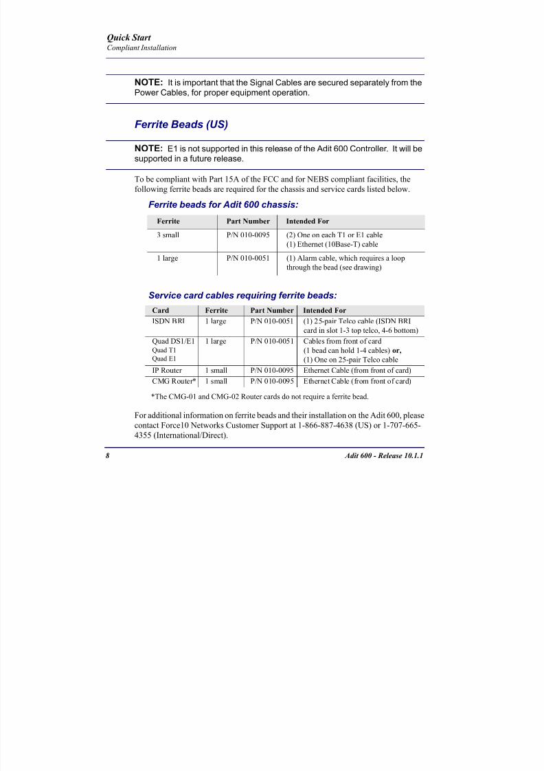
8102019 Adit 600 Quick Start 10-1-1
httpslidepdfcomreaderfulladit-600-quick-start-10-1-1 1054
8 Adit 600 - Release 1011
Quick Start Compliant Installation
NOTE It is important that the Signal Cables are secured separately from thePower Cables for proper equipment operation
Ferrite Beads (US)
NOTE E1 is not supported in this release of the Adit 600 Controller It will besupported in a future release
To be compliant with Part 15A of the FCC and for NEBS compliant facilities the
following ferrite beads are required for the chassis and service cards listed below
Ferrite beads for Adit 600 chassis
Service card cables requiring ferrite beads
The CMG-01 and CMG-02 Router cards do not require a ferrite bead
For additional information on ferrite beads and their installation on the Adit 600 please
contact Force10 Networks Customer Support at 1-866-887-4638 (US) or 1-707-665-
4355 (InternationalDirect)
Ferrite Part Number Intended For
3 small PN 010-0095 (2) One on each T1 or E1 cable
(1) Ethernet (10Base-T) cable
1 large PN 010-0051 (1) Alarm cable which requires a loop
through the bead (see drawing)
Card Ferrite Part Number Intended For
ISDN BRI 1 large PN 010-0051 (1) 25-pair Telco cable (ISDN BRI
card in slot 1-3 top telco 4-6 bottom)
Quad DS1E1Quad T1
Quad E1
1 large PN 010-0051 Cables from front of card(1 bead can hold 1-4 cables) or
(1) One on 25-pair Telco cable
IP Router 1 small PN 010-0095 Ethernet Cable (from front of card)
CMG Router 1 small PN 010-0095 Ethernet Cable (from front of card)
8102019 Adit 600 Quick Start 10-1-1
httpslidepdfcomreaderfulladit-600-quick-start-10-1-1 1154
Adit 600 - Release 1011 9
Quick Start Compliant Installation
Ferrite Beads (Europe Australia and Canada)
NOTE E1 is not supported in this release of the Adit 600 Controller It will besupported in a future release
To be compliant with EN55022 and CISPR22 Class A emissions the following beads
are required for the chassis and components listed below Also shielded cables arerequired for the V3554 service card and must be ordered separately
Power Cord
-48 VDC Battery Power
Alarm Wiring
Signal Cables
Power Cables
Grounding Cable
Ferrite Bead
with cable loop
RS-232 craft port25-pair telco connector
25-pair telco connector
10Base-T EthernetT1E1 connectors
Ferrite Beads
are in red
Ferrite Beads
with cable loop
8102019 Adit 600 Quick Start 10-1-1
httpslidepdfcomreaderfulladit-600-quick-start-10-1-1 1254
10 Adit 600 - Release 1011
Quick Start Compliant Installation
Ferrite beads for Adit 600 chassis
Additional components requiring ferrite beads
The CMG-01 and CMG-02 Router cards do not require a ferrite bead
Shielded Cable (order separately)
For additional information on Ferrite beads and their installation on the Adit 600 please contact Force10 Networks Customer Support at 1-866-887-4638 (US) or 1-
707-665-4355 (InternationalDirect)
Ferrite Part Number Intended For
4 large PN 010-0051 All of these ferrites require a loop through the
bead (see drawing)
(1) Alarm cable
(2) One on each or E1 cable (E1-1E1-2)
(1) Ethernet (10Base-T) cable
Card Ferrite Part Number Intended For
CMG Router 1 small PN 010-0095 Ethernet Cable (from front of card)
Quad DS1E1Quad E1
2 large PN 010-0051 E1 cables from front of Quad E1card
(1 bead can hold 1-4 cables) or
(2) One on each 25-pair Telco cable
Battery Unit 1 small PN 010-0095 Battery Cable
DC Power Kit 1 small PN 010-0095 DC Input Cable
Card Part Number Intended For
V3554 (HD) PN 005-0008 D-sub Male to Winchester Male 10 ft
PN 005-0009 D-sub Male to Winchester Male 25 ftPN 005-0010 D-sub Male to Winchester Male 50 ft
PN 005-0014 D-sub Male to Winchester Female 10 ft
PN 005-0068 D-sub Male to Winchester Female 25 ft
PN 005-0069 D-sub Male to Winchester Female 50 ft
8102019 Adit 600 Quick Start 10-1-1
httpslidepdfcomreaderfulladit-600-quick-start-10-1-1 1354
Adit 600 - Release 1011 11
Quick Start Chassis Connectors and Buttons
Chassis Connectors and Buttons
The following illustrations show all connectors on the back of the Adit 600
Interface Connectors
The following are the Adit 600 interface connectors
T1-1E1-1 and T1-2E1-2 line connection ports each equipped with standard
RJ-48C 8-pin connector jack
RS-232 craft port connector
Tip and Ring Analog Interfaces equipped with standard 25-pair Telco
Connectors
10Base-T Ethernet port to be connected to a remote management tool such as
Telnet or an SNMP-based Network Management System with an RJ-45 8-pin
connector jack
External Alarm Connector
Ground Lugs
Ground Terminals
Alarms
AC or DC Power Connector
-48VBattery
Ethernet
T1-2E1-2T1E1
RS-232 Craft Port25-Pair Telco Connectors
T1-1E1-1
[10Base-T]
Connectors
Reset
(AC shown below)
8102019 Adit 600 Quick Start 10-1-1
httpslidepdfcomreaderfulladit-600-quick-start-10-1-1 1454
12 Adit 600 - Release 1011
Quick Start Interface Connectors
Chassis Ground Connector
WARNING THIS EQUIPMENT IS REQUIRED TO HAVE A PERMANENT GROUND CONNECTION IF CONNECTED TO EXPOSED OUTDOOR COMMUNICATION CONDUCTORS A 6 AWG COPPER WIRE MUST BE PERMANENTLY CONNECTED FROM AN APPROVED GROUNDING ELECTRODE TO THE CHASSIS GROUND LUG
OTHERWISE A 14 AWG COPPER WIRE MAY BE UTILIZED INSTALL THE GROUNDING CONDUCTOR IN ACCORDANCE WITH NATIONAL OR LOCAL REGULATIONS
1 Route wire (6 or 8 AWG copper) from building ground to lug on Adit 600
2 Strip insulation off wire end if necessary
3 Loosen compression screw until opening is large enough to accept ground
wire
4 Insert ground wire into lug barrel beneath compression plate and tighten
compression screw
5 Attach ground lug to chassis
Ground Terminals
Ground Lug
Compression
ScrewLug Barrel
8102019 Adit 600 Quick Start 10-1-1
httpslidepdfcomreaderfulladit-600-quick-start-10-1-1 1554
Adit 600 - Release 1011 13
Quick Start Interface Connectors
Power Reset
This is a resetable circuit breaker If at any time there is a short or power
surge on the incoming ACDC line the breaker will trip to protect the
Power supply from damage
Power Connections
There are four power supplies available for the Adit 600
115 VAC-48 VDC
230 VAC-48 VDC
24-48 VDC
24 VDC with -48 Output
These power supplies have different connectors as shown in the following Foradditional information see Chapter 15 Power Supply of the Adit 600 User Manual
Fuse Recommendation
When using -48 VDC input power use a 35 Amp fast-acting fuse if the power
connector is wired to a fuse panel
Power Cord AC An AC Power cord is provided with the 115 VAC and the
230 VAC Power Supplies
To connect the Power Cord
1 Insert power cord (male-end) to AC power source
2 Plug connector into the Adit 6003 A green light should appear on the DC Input LED on the front of the Power
Supply
AC Power Connector
8102019 Adit 600 Quick Start 10-1-1
httpslidepdfcomreaderfulladit-600-quick-start-10-1-1 1654
14 Adit 600 - Release 1011
Quick Start Interface Connectors
-48V Battery
The -48 VDC input connector on the Adit 600 is used for either direct DC powering
of the Adit 600 unit or for a Battery Backup connection when AC is used There is
no power cable provided for this connector however the connector is provided
WARNING POSSIBLE SHOCK HAZARD EXISTS PLEASE FOLLOW INSTRUCTIONS
CAREFULLY
To connect -48 VDC power
1 Ensure that no power is present on the two wires to be connected
2 Strip the two wires (approx 516 in bare wire) from the power source 16 or 18 AWG insulated copper wire is recommended for power connections
3 Insert the Battery Return and DC wires into the appropriate square holes
4 Tighten screws to clamp wires
5 Ensure that no bare wire shows after the wires are installed
6 Plug connector in the -48 VDC connector as seen below and secure with set
screws
7 Apply power to connector from -48 VDC power source
8 Verify with voltmeter that voltage is correct and polarity is correct
8102019 Adit 600 Quick Start 10-1-1
httpslidepdfcomreaderfulladit-600-quick-start-10-1-1 1754
Adit 600 - Release 1011 15
Quick Start Interface Connectors
9 Plug connector in the Adit 600 -48 VDC connector as seen in the graphic andsecure with set screws
Power Cord DC
There is no power cable provided with the 24
VDC Power Supply however the connector is
provided This connector will need to be wired
the following chart prides the wire gauge
recommendedTo connect 24 VDC power
1 Ensure that no power is present on the two wires to be connected
WARNING POSSIBLE SHOCK HAZARD EXISTS PLEASE FOLLOW INSTRUCTIONS CAREFULLY
1(+) 2(-)
Connector
Provided connector (female)
of Adit 600on back
(male)
Battery -48 VDC
2(-)
BatteryReturn (+)
-48 VDC (-)
Return 1(+)
24 VDC6 Amp
Battery
Battery (+)
DC Power Connector
Return (-)
8102019 Adit 600 Quick Start 10-1-1
httpslidepdfcomreaderfulladit-600-quick-start-10-1-1 1854
16 Adit 600 - Release 1011
Quick Start Interface Connectors
2 Strip the two wires from the powersource so that approximately 516 inch
of bare wire is exposed see Wire Gauge
chart below for wire recommendations
3 Insert the Battery Return (-) and Battery
(+) wires into the appropriate square
holes one at a time4 Tighten screws to clamp wires
5 Ensure that no bare wire shows after the
wires are installed
6 Apply power to connector
7 Verify with voltmeter that voltage is
correct and polarity is correct
8 Plug connector(s) into the Adit 600 DC
Power connector as seen in the graphic
and secure with set screws
9 A green light should appear on the DC OK LED on the front of the Power
Supply
Wire Gauge 18 AWG 16 AWG 14 AWG
Maximum Distance 12 Feet 20 Feet 35 Feet
Battery (+)
BatteryReturn (-)
8102019 Adit 600 Quick Start 10-1-1
httpslidepdfcomreaderfulladit-600-quick-start-10-1-1 1954
Adit 600 - Release 1011 17
Quick Start Interface Connectors
External Alarm Connector
The external alarm 6-pin connector with one input pair (pins 5 and 6)
and two output pairs (pins 1 and 2 - major alarms pins 3 and 4 - minor
alarms)
The pinouts are as follows
Pin Description Explanation
1 Major Alarm + The major alarm output is available for power supply or
major alarm failure alerting The maximum voltage across
the contacts is 350 V and the maximum current is 150 mA
This alarm is closed when power is off
2 Major Alarm -
3 Minor Alarm + The minor alarm output is available for power supply or
minor alarm failure alerting The maximum voltage across
the contacts is 350 V and the maximum current is 150 mA
This alarm remains open when power is off
4 Minor Alarm -
5 Alarm In + The alarm inputs provide 5 VDC across the two contactsand generate an alarm when a short circuit is detected
between the contacts
The alarm generated is a minor severity alarm
6 Alarm In -
6
5
4
3
2
1
A
L
A
R
M
8102019 Adit 600 Quick Start 10-1-1
httpslidepdfcomreaderfulladit-600-quick-start-10-1-1 2054
18 Adit 600 - Release 1011
Quick Start Interface Connectors
25-Pair Telco ConnectorsTip and Ring Analog Interfaces equipped with standard 25-pair Telco Connectors
(female) for connection to key systems fax machines modems and PBXs These
interfaces are also used for ISDN BRI ports and are jumper selectable on the Quad T1
Quad E1 Quad DS1E1 and Quad ADPCM service cards
Circuit connections are made at the 25-pair
telco connectors A standard 25-pairtelephone cable with RJ-21X wiring and a
male D-type connector at the Adit 600 end
is required
The pinouts are as follows
Pair Pin Location Function Color Code
1 26
1
Tip Channel 1
Ring Channel 1
WhiteBlue
BlueWhite
2 27
2
Tip Channel 2
Ring Channel 2
WhiteOrange
OrangeWhite
3 28
3
Tip Channel 3
Ring Channel 3
WhiteGreen
GreenWhite
4 29
4
Tip Channel 4
Ring Channel 4
WhiteBrown
BrownWhite
5 30
5
Tip Channel 5
Ring Channel 5
WhiteSlate
SlateWhite
6 31
6
Tip Channel 6
Ring Channel 6
RedBlue
BlueRed
7 327
Tip Channel 7Ring Channel 7
RedOrangeOrangeRed
8 33
8
Tip Channel 8
Ring Channel 8
RedGreen
GreenRed
9 34
9
Tip Channel 9
Ring Channel 9
RedBrown
BrownRed
10 3510
Tip Channel 10Ring Channel 10
RedSlateSlateRed
50
25
26
1
8102019 Adit 600 Quick Start 10-1-1
httpslidepdfcomreaderfulladit-600-quick-start-10-1-1 2154
Adit 600 - Release 1011 19
Quick Start Interface Connectors
Pair Pin Location Function Color Code
11 36
11
Tip Channel 11
Ring Channel 11
BlackBlue
BlueBlack
12 37
12
Tip Channel 12
Ring Channel 12
BlackOrange
OrangeBlack
13 38
13
Tip Channel 13
Ring Channel 13
BlackGreen
GreenBlack
14 39
14
Tip Channel 14
Ring Channel 14
BlackBrown
BrownBlack
15 40
15
Tip Channel 15
Ring Channel 15
BlackSlate
SlateBlack
16 41
16
Tip Channel 16
Ring Channel 16
YellowBlue
BlueYellow17 42
17
Tip Channel 17
Ring Channel 17
YellowOrange
OrangeYellow
18 43
18
Tip Channel 18
Ring Channel 18
YellowGreen
GreenYellow
19 44
19
Tip Channel 19
Ring Channel 19
YellowBrown
BrownYellow
20 45
20
Tip Channel 20
Ring Channel 20
YellowSlate
SlateYellow
21 46
21
Tip Channel 21
Ring Channel 21
VioletBlue
BlueViolet
22 47
22
Tip Channel 22
Ring Channel 22
VioletOrange
OrangeViolet
23 48
23
Tip Channel 23
Ring Channel 23
VioletGreen
GreenViolet
24 49
24
Tip Channel 24
Ring Channel 24
VioletBrown
BrownViolet
25 50
25
Reserved VioletSlate
SlateViolet
8102019 Adit 600 Quick Start 10-1-1
httpslidepdfcomreaderfulladit-600-quick-start-10-1-1 2254
20 Adit 600 - Release 1011
Quick Start Interface Connectors
RS-232 Craft Port (Female DB-9)The RS-232 craft port connector (female) is for connection to an external PC or Hayes-
compatible modem for local or remote configuration management and performance
monitoring using the Adit 600 Command Line Interface (CLI)
The RS-232 craft port connects via a
female DB-9 connector on the Adit 600
The pinouts are as follows
Pin Number Direction Description
1 Outbound Carrier Detect
2 Outbound Receive Data
3 Inbound Transmit Data
4 Inbound Data Terminal Ready
5 NA Signal Ground
6 Outbound Data Set Ready
7 Inbound Request to Send
8 Outbound Clear to Send
9 NC Not connected
1 5
6 9
8102019 Adit 600 Quick Start 10-1-1
httpslidepdfcomreaderfulladit-600-quick-start-10-1-1 2354
8102019 Adit 600 Quick Start 10-1-1
httpslidepdfcomreaderfulladit-600-quick-start-10-1-1 2454
22 Adit 600 - Release 1011
Quick Start Interface Connectors
10Base-T Ethernet
The 10Base-T Ethernet (female) port to connect to a remote
management tool such as Telnet or an SNMP-based Network
Management System Note A LINK LED on the back of the unit
displays green when the system has a good Ethernet link
The pinouts are as follows
Ethernet (RJ-45)
NOTE This Ethernet port uses a hub pinout Use a straight-through cableto connect a PC
Pin Name Description
1 Receive + Receive from network
2 Receive - Receive from network
3 Transmit + Transmit to network
4 - 5 NC Not connected
6 Transmit - Transmit to network
7 NC Not connected
8 NC Not connected
1 8
8102019 Adit 600 Quick Start 10-1-1
httpslidepdfcomreaderfulladit-600-quick-start-10-1-1 2554
Adit 600 - Release 1011 23
Quick Start Management Options
Management Options
Options for managing the Adit 600 are as follows
Local using CLI Telnet SNMP or DIP Switches (Controller and voice cards)
Remotely over an in-band DS0 or through the Access Navigator over the FDL
or an in-band DS0
This Quick Start Guide focuses on the CLI and DIP switches If you need further
information on other management options please refer to the Adit 600 User Manual
Command Line Interface (CLI)
You can access the CLI using either of the following methods
Telnet via Ethernet (10Base-T) RS-232 connected to the DB-9 port
Setting up a CLI Connection
If connecting via the Ethernet 10Base-T connection use a Telnet TCPIP
program to access the CLI This requires the IP address of the Controller
Controllers are shipped with the IP address set to 100010 If this address has been changed and is not known use HyperTerm to access the Controller and
use the CLI command show ip If an IP address needs to be set use the CLI
command set ethernet ip address
If connecting via RS-232 the port settings should be set to
Bits per second 9600 Data bits 8
Parity None Stop bits 1Flow control None
Set your Terminal Emulation to VT100
By default the Adit 600 is set for local configuration (using DIP switches) Use
the set local off command to enable the use of CLI commands
8102019 Adit 600 Quick Start 10-1-1
httpslidepdfcomreaderfulladit-600-quick-start-10-1-1 2654
8102019 Adit 600 Quick Start 10-1-1
httpslidepdfcomreaderfulladit-600-quick-start-10-1-1 2754
Adit 600 - Release 1011 25
Quick Start Configuration
ConfigurationThe following basic setups and upgrades for the Adit 600 are shown using CLI
commands For more information on CLI commands and configurations see the Adit
600 User Manual
Initial Setup
Basic Security Setup
DS1T1 Setup
E1 Setup
DS0Channel Setup
Analog Port Setup
4-Wire EampM Setup
Establish a Static Channel Connection
ISDN BRI Service Setup
OCU-DP Card Setup
ADPCM Card Setup
V35 Port Setup
Change the IP Address of the DS0 Management Channel
Upgrade the Adit 600 Software
Upgrade the Router Card Software
Basic Router Setup
8102019 Adit 600 Quick Start 10-1-1
httpslidepdfcomreaderfulladit-600-quick-start-10-1-1 2854
26 Adit 600 - Release 1011
Quick Start Configuration
Initial SetupUse the following commands for your initial setup For further information see the Adit
600 User Manual
Command Description
set local off Disables DIP switches
set date mmddyyyy Set the date used for event logging
set time hhmmss Set the time used for event logging
set id id-name Set a system ID name
set clock1 slotportinternal
Set the primary clock source
set clock2 slotportinternal
Set the secondary clock source
set ethernet ip addressip-addr mask
Set the ethernet IP address in the
conventional IP address format
set ip gateway ip-addr Set the IP gateway in the conventional IP
address format
8102019 Adit 600 Quick Start 10-1-1
httpslidepdfcomreaderfulladit-600-quick-start-10-1-1 2954
Adit 600 - Release 1011 27
Quick Start Configuration
Basic Security SetupUse the following commands to set up the security on the Adit 600 For further
information see the Adit 600 User Manual
Command Description
set password length
long|short
Set user password length requirement
add user ldquouser-namerdquo[password ldquopasswordrdquo]
Add user and password as necessary
set user user-name level1-3
Specify the userrsquos security level
set user user-namepassword Setchange password for the user asnecessary
8102019 Adit 600 Quick Start 10-1-1
httpslidepdfcomreaderfulladit-600-quick-start-10-1-1 3054
28 Adit 600 - Release 1011
Quick Start Configuration
DS1T1 SetupUse the following commands to set up a DS1 See the set (ds1) command for more
details
Command Description
set ds1-addr up Activate the port of the DS1 (slotport)
set ds1-addr id id-string
Set the identification string
set ds1-addr lbo 1-9 Set the line buildout value for the DS1
set ds1-addr linecodeami|b8zs
Set the linecode for the DS1
set ds1-addr framing d4|esf|tr8afdl|tr8anofdl|tr8b
Set the framing option for the DS1
set ds1-addr loopdetecton|off
Set the detectionreaction to CSU loopcodes
Q i k S
8102019 Adit 600 Quick Start 10-1-1
httpslidepdfcomreaderfulladit-600-quick-start-10-1-1 3154
Adit 600 - Release 1011 29
Quick Start Configuration
E1 Setup
NOTE E1 is not supported in this release of the Adit 600 Controller It will besupported in a future release
Use the following commands to set up an E1 See the set (e1) command for more
details
DS0Channel Setup
Use the following commands to set up a DS0 See the set (ds0) command for details
Command Description
set e1-addr up Activate the port of the E1 (slotport)
set e1-addr id id-string Set the identification string
set e1-addr lbo 1 - 9 Set the line buildout value for the E1
set e1-addr linecodeami|hdb3
Set the linecode for the E1
set e1-addr framinge1fr|lefrcrc
Set the framing option for the E1
set e1-addr loopdetecton|off
Set the detectionreaction to CSU loopcodes
Command Description
set slotportchannel up Activate the channel
set slotportchannel signalls|gs|emw|emdw|emicpd|dpt
Set the signaling option for the channel
set slotportchannel typedata|voice Set the channel type
Q i k St t
8102019 Adit 600 Quick Start 10-1-1
httpslidepdfcomreaderfulladit-600-quick-start-10-1-1 3254
30 Adit 600 - Release 1011
Quick Start Configuration
Analog Port SetupUse the following commands to set up an analog port
Command Description
set slotport up Activate the port See set (ds1) command for
details
set slotport signal dpt|gs|gsrb|gsw|gswrb|ls|lscpd|lsrb
Set the signaling option for the port See the
set (fxs) or set (fxo) command for details
set slotport rxgain n Set the receive gainloss in dB See the set
(fxs) or set (fxo) command for details
set slotport txgain n Set the transmit gainloss in dB See the set
(fxs) or set (fxo) command for details
Quick Start
8102019 Adit 600 Quick Start 10-1-1
httpslidepdfcomreaderfulladit-600-quick-start-10-1-1 3354
Adit 600 - Release 1011 31
Quick Start Configuration
4-Wire EampM SetupFor this example the 4 EampM ports will be connected to the first 4 DS0s on T1-1 (a1)
This can be changed to match the customers desired DS0 connections
For Transmission Only mode the DS0s on the DS1 should be set to data as well as the
EampM card channels
Command Description
For Normal or Tandem EampM
set a11-4 type voice Set DS0s to voice
set connect a11-4 11-4 Connect DS0s to the 4 ports of the 4-
Wire EampM card
show connect a 1 Verify cross connects
set a11-4 signal emi Set DS0 signal type to EMI
set 11-4 signal emi Set 4-Wire EampM ports signal type to
EMI
show connect a1 Verify cross connects
For TO Mode
set a11-4 type data Set DS0s to data
set 11-4 type data Set 4-Wire EampM port to data
set connect a11-4 11-4 Connect DS0s to the 4 ports of the 4-
Wire EampM card
show connect a 1 Verify cross connects
Quick Start
8102019 Adit 600 Quick Start 10-1-1
httpslidepdfcomreaderfulladit-600-quick-start-10-1-1 3454
32 Adit 600 - Release 1011
Quick Start Configuration
Establish a Static Channel ConnectionUse the following commands to establish a static channel connection
ISDN BRI Service Setup
Use the following commands to set up a ISDN BRI Service See the set (bri) command
for details
Command Description
set slotportchannel typevoice|data
Set the channel type for the channel to
map See set (ds0) command for details
set slotportchannel signalls|gs|emw|emdw|emicpd|dpt
Set the channel signaling option See set
(ds0) command for details
connect slotportslotport
Connect the channels See the connect
(card-trunk) (card-trunk) command
Command Description
set slotport up Put the ISDN line In-Service
set slot modelt3ds0|lt4to1tdm|nt3ds0
Set the ISDN mode
set slotport crv 1-768 Set the Call Reference Value Note
value must be the same as the Access
Navigator
set slotport thresholdday|hour es|ses
Set the threshold for the IDSN lines
set slot pmsyncadit|switch
Set the source for performance
monitoring synchronization
set slotport autoactivate
on|off
Only used in 4-to-1 mode Establishes
the D channel when the FDL link can not
be used
Quick Start
8102019 Adit 600 Quick Start 10-1-1
httpslidepdfcomreaderfulladit-600-quick-start-10-1-1 3554
Adit 600 - Release 1011 33
Quick Start Configuration
OCU-DP Card SetupThe following is a basic setup for the OCU-DP card
ADPCM Card Setup
Command Description
set ocudp-addr baud2400|4800|9600|19200|38400|
56000|64000
Set the OCU-DP Baud rate
Where ocudp-addr = slotport of the
OCU-DP card to apply settings to
set ocudp-addr up Set the OCU-DP port 1 up
show ocudp_card-addr Show the OCU-DP card settings
Where ocudp_card-addr = slot of the
OCU-DP card
disconnect a Disconnects all connections to slot a
(controller)
set ds0-addr type data Sets a DS0 data signaling type
connect ds0-addrocudp-addr
Connects DS0 (in previous step) to OCU-DP
port (in previous step)
show connect
(ocudp_card-addr
Displays connect information for OCU-DP
card
Command Description
Connect T1 cable to port 1 of the ADPCM service card
set adpcm_card-addrnone|map1|map2|map3
Enable compressing by selecting Map type Notenone disables compression
show (adpcm_card-addr Displays the status of the card and the mapping
connect 211-12 241-12 Set ADPCM cross-connects The example
connects all 24 channels of the ADPCM to the 12
channels of the T1 (now compressed) on port 4
This example is with map2show connect 21) Displays the connections made above
8102019 Adit 600 Quick Start 10-1-1
httpslidepdfcomreaderfulladit-600-quick-start-10-1-1 3654
Quick Start
8102019 Adit 600 Quick Start 10-1-1
httpslidepdfcomreaderfulladit-600-quick-start-10-1-1 3754
Adit 600 - Release 1011 35
QConfiguration
Upgrade the Adit 600 SoftwareUse the following commands to determine the system software level then upgrade the
software to the latest version
Command Description
status equipment Determine the system software level The
Slot A line (SW Vers) will display thecurrent software level
load tftp ip-addr file-name (or load xmodem)
Load the new controller system software See
the load tftp and load xmodem command for
more information
Note A TFTP server must be running onthe host system You can use any TFTP
server utility you wish One example isthe program TFTPD32 which can bedownloaded free-of-charge attftpd32jouninnettftpd32html
Quick Start
8102019 Adit 600 Quick Start 10-1-1
httpslidepdfcomreaderfulladit-600-quick-start-10-1-1 3854
36 Adit 600 - Release 1011
Configuration
Upgrade the Router Card SoftwareUse the following commands to determine the Router card software level then upgrade
the software to the latest version
NOTE For additional information about upgrading MSR card software see
the following manuals-Adit 600 User Manual -Adit 3000 Series and Multi-Service Router (MSR) Card GUI Reference Manual
-Adit 3000 Series and Multi-Service Router (MSR) Card CLI Reference Manual
Command Description
status equipment Determine the Router software level The
Router Slot line (SW Vers) will display thecurrent software level
load rtr_card-addr tftpip-addr file-name
Load the new Router software to a Router
card See the load tftp command for more
information
Note A TFTP server must be running onthe host system You can use any TFTP
server utility you wish One example isthe program TFTPD32 which can bedownloaded free-of-charge attftpd32jouninnettftpd32html
8102019 Adit 600 Quick Start 10-1-1
httpslidepdfcomreaderfulladit-600-quick-start-10-1-1 3954
8102019 Adit 600 Quick Start 10-1-1
httpslidepdfcomreaderfulladit-600-quick-start-10-1-1 4054
Quick Start C t ll C d LED
8102019 Adit 600 Quick Start 10-1-1
httpslidepdfcomreaderfulladit-600-quick-start-10-1-1 4154
Adit 600 - Release 1011 39
Controller Card LEDs
E1 Controller Card
NOTE E1 is not supported in this release It will be supported in a futurerelease
The E1 Controller has a set of six LEDs The table below describes each LED
LED State Description
MAJOR Off No major alarms present
Red Major alarm present
MINOR Off No minor alarms present
Yellow Minor alarms present
LOCAL Off Remote mode (DIP switches disabled)
Green Local mode (DIP switches enabled)
ACO Off Normal mode No alarms are being
suppressed
Yellow Alarm Cut Off active One or more active
alarms suppressed
E1-1 and
E1-2
Off Off line
Green Normal
Red Loss of Signal (LOS) detected
Yellow Bipolar Violation (BPV) detected LCV
Flashing Green Loopback active
Flashing Red
(slow)
Loss of Frame (LOF) or Alarm Indication
Signal (AIS) detected
Flashing Red
(fast)
Card Failure
Flashing Yellow Yellow alarm (Remote Alarm Indication)detected
Quick Start Power Supply LEDs
8102019 Adit 600 Quick Start 10-1-1
httpslidepdfcomreaderfulladit-600-quick-start-10-1-1 4254
40 Adit 600 - Release 1011
Power Supply LEDs
Power Supply LEDs115 VAC-48 VDC and 230 VAC-48 VDC Power Supplies
The power supply card has two LEDs as described in the table
below
24 VDC-48 VDC Power Supply
The power supply card has two LEDs as described in the table below
LED State Description
AC Input Off AC input missing or failure
Green AC input present
Battery Off Battery input not used
Green Battery charging or operating from DC
source only
Yellow Battery discharging
Red Battery low (less than 42V) ringer disabled
LED State Description
DC OK Off DC input missing or failure
Green DC input present
-48 Battery
Low
Off Normal
Red VDC is low (less than 42 VDC)
ringer disabled
Quick Start Service Card LEDs
8102019 Adit 600 Quick Start 10-1-1
httpslidepdfcomreaderfulladit-600-quick-start-10-1-1 4354
Adit 600 - Release 1011 41
Service Card LEDs
Service Card LEDs 4-Wire EampM Card
FXO Card
FXS Card
ISDN BRI Card
OCU-DP Card
P-Phone Card
Single Channel POTS Card
Quad DS1 ADPCM Service Card
Quad DS1E1 and Quad T1 Cards
Quad E1 Card
IP Router Card
CMG Router Card
Terminal Server Router Card
MSR Card
RS-232 and V35V54 Cards
Discontinued cards
RS-232 discontinued
Quick Start Service Card LEDs
8102019 Adit 600 Quick Start 10-1-1
httpslidepdfcomreaderfulladit-600-quick-start-10-1-1 4454
42 Adit 600 - Release 1011
Service Card LEDs
4-Wire EampM Card Each channelport has two LEDs Only the top LED is used in this application LED
definitions are listed below
State Description
When in EampM Mode
Off Channel is idle or disabled
Green Analog interface is off-hook
Red Digital interface is off-hook
Yellow Both analog and digital interfaces are off-hook or channel is
being trunk processed
When in TO Mode
Off DisconnectedGreen Connected T1E1 not in alarm
Yellow Connected T1E1 in alarm (trunk processed)
Quick Start Service Card LEDs
8102019 Adit 600 Quick Start 10-1-1
httpslidepdfcomreaderfulladit-600-quick-start-10-1-1 4554
Adit 600 - Release 1011 43
FXO Card Each port on the FXO card has its own LED as described in the table below
FXS Card
There is an LED for each port on the FXS card as described in the table below
State Loop Start
Meaning
Ground Start Meaning Dial Pulse Termination
Meaning
Off NA Idle (tip open) Idle (loop open)
Green Idle Tip ground (incoming seizure) Incoming seizure
Red NA Ring ground (outgoing
seizure)
Loop closure (outgoing seizure)
Yellow Call in
progress
Call in progress Call in progress (reverse battery)
Flashing
Green
Ringing Ringing NA
State Loop Start Meaning Ground Start Meaning
Off NA Idle (tip open)
Green Idle Tip ground (incoming seizure)
Red Note This can be seen with
Forward Disconnect (tip open)
Ring ground (outgoing seizure)
Yellow Call in progress Call in progress
Flashing green Ringing Ringing
Quick Start Service Card LEDs
8102019 Adit 600 Quick Start 10-1-1
httpslidepdfcomreaderfulladit-600-quick-start-10-1-1 4654
44 Adit 600 - Release 1011
ISDN BRI Card There is an LED for each ISDN BRI on a card as described in the table below
OCU-DP Card Each channel has two LEDs described in the table below
State Description
Off Line U-interface is attempting synchronization or BRI is Out-of-Service
Red Line alarm (LOS or self test failure)
Yellow ES or SES has occurred
Flashing yellow Line U-interface is synchronized with customer equipment but is not passing
customer data
Flashing green Line U-interface is in external loopback toward the switch at the unit
Green Normal (Line U-interface is active and transparently passing customer data)
State Description
Yellow Flickering ALL Boot Software in control
Green (walking down)
Red (walking up)
ALL Application Software in control
(repeated 35 times)
Red slow flash ALL In Boot Application flash code checksums did not match and
Boot is waiting for application download
Red ALL In Application code waiting for Controller to issue SWHW
revision request This is the first request that comes from the
OCU-DP card manager in the ControllerGreen
Yellow
Top
Bottom
Port in Self-test Duration is 5-8 seconds
Off Top
Bottom
Port is set down (Out-Of-Service)
Green Top Port is receiving valid signals
Red Top Port is receiving no signal (primary) or no frame sync
(secondary or clear channel)Red Flashing Bottom Port is receiving bipolar violations
Yellow Bottom Port is in loopback
Quick Start Service Card LEDs
8102019 Adit 600 Quick Start 10-1-1
httpslidepdfcomreaderfulladit-600-quick-start-10-1-1 4754
Adit 600 - Release 1011 45
P-Phone Card Each P-Phone channel has a corresponding LED described in the table below
State Line State
Off No P-Phone connected
Green No call in process
Flashing Green Alert (Ringing)
Yellow Call in progress
Flashing Yellow P-Phone Loopback in Progress
Flashing Red Self-test failed
Quick Start Service Card LEDs
8102019 Adit 600 Quick Start 10-1-1
httpslidepdfcomreaderfulladit-600-quick-start-10-1-1 4854
46 Adit 600 - Release 1011
Single Channel POTS Card The POTS channel LED (left) status is described in the table below
The second LED (right) is a status LED is not used on this card
Quad DS1 ADPCM Service Card
Each channel on the Quad DS1 ADPCM card has two LEDs The
description of the top LED is shown below the bottom LED is notused with this application
State Loop Start Meaning
Off Calling Party Disconnect
Green Idle
Red NA
Yellow Call in progress
Flashing green Ringing
State Description
Off Off line
Green Normal
Red Loss of Signal (LOS)
Yellow Bipolar Violation (BPV)Flashing Green Loopback active
Flashing Yellow Yellow Alarm
(Remote Alarm Indication)
Flashing Red (Slow) Loss of Frame (LOF) or Alarm Indication Signal (AIS)
Flashing Red (Fast) Self-test Failure
Top LED(active)
Bottom LED(not used)
Quick Start Service Card LEDs
8102019 Adit 600 Quick Start 10-1-1
httpslidepdfcomreaderfulladit-600-quick-start-10-1-1 4954
Adit 600 - Release 1011 47
Quad DS1E1 and Quad T1 CardsEach channel on the Quad T1E1 cards have two LEDs The description
of the top LED is shown below the bottom LED is not used with this
application
State Description
Off Off line
Green Normal
Red Loss of Signal (LOS)
Yellow Bipolar Violation (BPV)
Flashing Green Loopback active
Flashing Yellow Yellow Alarm (Remote Alarm Indication)
Flashing Red (Slow) Loss of Frame (LOF) or Alarm Indication Signal (AIS)
Flashing Red (Fast) Self-test Failure
Quick Start Service Card LEDs
8102019 Adit 600 Quick Start 10-1-1
httpslidepdfcomreaderfulladit-600-quick-start-10-1-1 5054
48 Adit 600 - Release 1011
IP Router Card The following chart describes each LED and its state
LED State Description
CRD Off Loss of power
Green No current alarms
Red Alarm state active See alarm log for cause
Red Flashing Self-test or Boot in-process
Yellow Flashing Card is saving data to flash RAM do not power down
10100 Off 10 Mb ethernet
Green 100 Mb ethernet
LNK Off No ethernet link
Green Good ethernet link
COL
Off No current ethernet transmit collisions
Yellow Ethernet collisions have occurred and have not dropped
to minimum level
Yellow Flashing Ethernet collision occurring
TX Off No ethernet transmit activity
Green Ethernet transmit activity
RX Off No current ethernet receive activity
Green Current ethernet receive activity
Quick Start Service Card LEDs
8102019 Adit 600 Quick Start 10-1-1
httpslidepdfcomreaderfulladit-600-quick-start-10-1-1 5154
Adit 600 - Release 1011 49
CMG Router Card The following chart describes each LED and its state
LED State Description
CRD Off Loss of power
Green No current alarms
Red Alarm state active See alarm log for causeRed Flashing Self-test or Boot in-process
Yellow Flashing Card is saving data to flash RAM do not power down
VOIP
Off No active VoIP calls or if the MGCP protocol is
optioned down
Green Active VoIP calls
Red Call agent unreachable
Yellow Insufficient VoIP resources to complete call
LNK Off No Ethernet link
Green Good Ethernet link
10100 Off 10 Mb Ethernet
Green 100 Mb Ethernet
TX Off No Ethernet transmit activityGreen Ethernet transmit activity
Yellow Current Ethernet transmit collision
RX Off No current Ethernet receive activity
Green Current Ethernet receive activity
Quick Start Service Card LEDs
8102019 Adit 600 Quick Start 10-1-1
httpslidepdfcomreaderfulladit-600-quick-start-10-1-1 5254
50 Adit 600 - Release 1011
Terminal Server Router Card The Terminal Server Router card has 2 LEDs per port
At Power-up
Normal Operation
Port Set for Ethernet
Top LED indicates 100M Link Bottom LED indicates 10M Link
Port Set for RS-232
TOP LED Bottom LED Description
Off Off At Power UpBoot = Loss of power
Red Red Card is inoperative
Flashing Red Flashing Red Self-test or Boot in-process
TOP LED Bottom LED Description
Green Solid (Link) Green Solid (Link) Port set for Ethernet - see below
Flashing Red Flashing Red Self-test or Boot in-process
State Description
Off No Ethernet link
Green Link but no activity
Red Flashing Current Ethernet collision
Green Flashing Current Ethernet receive
Yellow Flashing Current Ethernet transmit
TOP LED Bottom LED Description
Yellow Off No Activity
Yellow Flashing Yellow Current transmit
Yellow Flashing Green Current receive
Quick Start Service Card LEDs
8102019 Adit 600 Quick Start 10-1-1
httpslidepdfcomreaderfulladit-600-quick-start-10-1-1 5354
Adit 600 - Release 1011 51
MSR Card The following chart describes the MSR cardrsquos LEDs
LED State Description
CRD Off Loss of power
Green No current alarms
Red Alarm state active See alarm log for cause
Red Flashing Self-test or boot in process
Yellow Flashing Card is saving data to flash RAM do not power
down
VOIP
Off No SIP proxy or registration attempts for all lines
have succeeded but no calls are active
Green Active VoIP call(s)
Red Inability to reach the SIP proxy or negative response
to register attempts from all lines
Yellow Register attempts from some lines have succeeded
but not for all lines
ETH1 and
ETH2
Top LED
Off 10 Mbitsec down or not connected
Green 100 Mbitsec
ETH1 and
ETH2
Bottom LED
Off Link down
Green Link up
Flashing Green Traffic on link
Yellow Collision status
Quick Start Service Card LEDs
8102019 Adit 600 Quick Start 10-1-1
httpslidepdfcomreaderfulladit-600-quick-start-10-1-1 5454
52 Adit 600 - Release 1011
RS-232 and V35V54 Cards Each port has its own LED as described in the table below
State Description
Off No T1 Assignment
Green Normal (CDRTS) Active
Red CD inactive (T1-side failure)
Yellow RTS inactive (equipment-side failure)
Flashing Yellow Loopback toward T1 or equipment loop test
Flashing Green Loopback toward equipment or network loop test
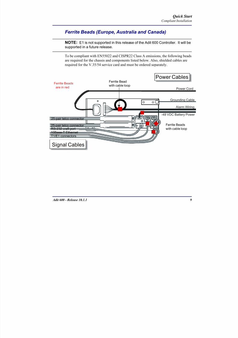
8102019 Adit 600 Quick Start 10-1-1
httpslidepdfcomreaderfulladit-600-quick-start-10-1-1 1154
Adit 600 - Release 1011 9
Quick Start Compliant Installation
Ferrite Beads (Europe Australia and Canada)
NOTE E1 is not supported in this release of the Adit 600 Controller It will besupported in a future release
To be compliant with EN55022 and CISPR22 Class A emissions the following beads
are required for the chassis and components listed below Also shielded cables arerequired for the V3554 service card and must be ordered separately
Power Cord
-48 VDC Battery Power
Alarm Wiring
Signal Cables
Power Cables
Grounding Cable
Ferrite Bead
with cable loop
RS-232 craft port25-pair telco connector
25-pair telco connector
10Base-T EthernetT1E1 connectors
Ferrite Beads
are in red
Ferrite Beads
with cable loop
8102019 Adit 600 Quick Start 10-1-1
httpslidepdfcomreaderfulladit-600-quick-start-10-1-1 1254
10 Adit 600 - Release 1011
Quick Start Compliant Installation
Ferrite beads for Adit 600 chassis
Additional components requiring ferrite beads
The CMG-01 and CMG-02 Router cards do not require a ferrite bead
Shielded Cable (order separately)
For additional information on Ferrite beads and their installation on the Adit 600 please contact Force10 Networks Customer Support at 1-866-887-4638 (US) or 1-
707-665-4355 (InternationalDirect)
Ferrite Part Number Intended For
4 large PN 010-0051 All of these ferrites require a loop through the
bead (see drawing)
(1) Alarm cable
(2) One on each or E1 cable (E1-1E1-2)
(1) Ethernet (10Base-T) cable
Card Ferrite Part Number Intended For
CMG Router 1 small PN 010-0095 Ethernet Cable (from front of card)
Quad DS1E1Quad E1
2 large PN 010-0051 E1 cables from front of Quad E1card
(1 bead can hold 1-4 cables) or
(2) One on each 25-pair Telco cable
Battery Unit 1 small PN 010-0095 Battery Cable
DC Power Kit 1 small PN 010-0095 DC Input Cable
Card Part Number Intended For
V3554 (HD) PN 005-0008 D-sub Male to Winchester Male 10 ft
PN 005-0009 D-sub Male to Winchester Male 25 ftPN 005-0010 D-sub Male to Winchester Male 50 ft
PN 005-0014 D-sub Male to Winchester Female 10 ft
PN 005-0068 D-sub Male to Winchester Female 25 ft
PN 005-0069 D-sub Male to Winchester Female 50 ft
8102019 Adit 600 Quick Start 10-1-1
httpslidepdfcomreaderfulladit-600-quick-start-10-1-1 1354
Adit 600 - Release 1011 11
Quick Start Chassis Connectors and Buttons
Chassis Connectors and Buttons
The following illustrations show all connectors on the back of the Adit 600
Interface Connectors
The following are the Adit 600 interface connectors
T1-1E1-1 and T1-2E1-2 line connection ports each equipped with standard
RJ-48C 8-pin connector jack
RS-232 craft port connector
Tip and Ring Analog Interfaces equipped with standard 25-pair Telco
Connectors
10Base-T Ethernet port to be connected to a remote management tool such as
Telnet or an SNMP-based Network Management System with an RJ-45 8-pin
connector jack
External Alarm Connector
Ground Lugs
Ground Terminals
Alarms
AC or DC Power Connector
-48VBattery
Ethernet
T1-2E1-2T1E1
RS-232 Craft Port25-Pair Telco Connectors
T1-1E1-1
[10Base-T]
Connectors
Reset
(AC shown below)
8102019 Adit 600 Quick Start 10-1-1
httpslidepdfcomreaderfulladit-600-quick-start-10-1-1 1454
12 Adit 600 - Release 1011
Quick Start Interface Connectors
Chassis Ground Connector
WARNING THIS EQUIPMENT IS REQUIRED TO HAVE A PERMANENT GROUND CONNECTION IF CONNECTED TO EXPOSED OUTDOOR COMMUNICATION CONDUCTORS A 6 AWG COPPER WIRE MUST BE PERMANENTLY CONNECTED FROM AN APPROVED GROUNDING ELECTRODE TO THE CHASSIS GROUND LUG
OTHERWISE A 14 AWG COPPER WIRE MAY BE UTILIZED INSTALL THE GROUNDING CONDUCTOR IN ACCORDANCE WITH NATIONAL OR LOCAL REGULATIONS
1 Route wire (6 or 8 AWG copper) from building ground to lug on Adit 600
2 Strip insulation off wire end if necessary
3 Loosen compression screw until opening is large enough to accept ground
wire
4 Insert ground wire into lug barrel beneath compression plate and tighten
compression screw
5 Attach ground lug to chassis
Ground Terminals
Ground Lug
Compression
ScrewLug Barrel
8102019 Adit 600 Quick Start 10-1-1
httpslidepdfcomreaderfulladit-600-quick-start-10-1-1 1554
Adit 600 - Release 1011 13
Quick Start Interface Connectors
Power Reset
This is a resetable circuit breaker If at any time there is a short or power
surge on the incoming ACDC line the breaker will trip to protect the
Power supply from damage
Power Connections
There are four power supplies available for the Adit 600
115 VAC-48 VDC
230 VAC-48 VDC
24-48 VDC
24 VDC with -48 Output
These power supplies have different connectors as shown in the following Foradditional information see Chapter 15 Power Supply of the Adit 600 User Manual
Fuse Recommendation
When using -48 VDC input power use a 35 Amp fast-acting fuse if the power
connector is wired to a fuse panel
Power Cord AC An AC Power cord is provided with the 115 VAC and the
230 VAC Power Supplies
To connect the Power Cord
1 Insert power cord (male-end) to AC power source
2 Plug connector into the Adit 6003 A green light should appear on the DC Input LED on the front of the Power
Supply
AC Power Connector
8102019 Adit 600 Quick Start 10-1-1
httpslidepdfcomreaderfulladit-600-quick-start-10-1-1 1654
14 Adit 600 - Release 1011
Quick Start Interface Connectors
-48V Battery
The -48 VDC input connector on the Adit 600 is used for either direct DC powering
of the Adit 600 unit or for a Battery Backup connection when AC is used There is
no power cable provided for this connector however the connector is provided
WARNING POSSIBLE SHOCK HAZARD EXISTS PLEASE FOLLOW INSTRUCTIONS
CAREFULLY
To connect -48 VDC power
1 Ensure that no power is present on the two wires to be connected
2 Strip the two wires (approx 516 in bare wire) from the power source 16 or 18 AWG insulated copper wire is recommended for power connections
3 Insert the Battery Return and DC wires into the appropriate square holes
4 Tighten screws to clamp wires
5 Ensure that no bare wire shows after the wires are installed
6 Plug connector in the -48 VDC connector as seen below and secure with set
screws
7 Apply power to connector from -48 VDC power source
8 Verify with voltmeter that voltage is correct and polarity is correct
8102019 Adit 600 Quick Start 10-1-1
httpslidepdfcomreaderfulladit-600-quick-start-10-1-1 1754
Adit 600 - Release 1011 15
Quick Start Interface Connectors
9 Plug connector in the Adit 600 -48 VDC connector as seen in the graphic andsecure with set screws
Power Cord DC
There is no power cable provided with the 24
VDC Power Supply however the connector is
provided This connector will need to be wired
the following chart prides the wire gauge
recommendedTo connect 24 VDC power
1 Ensure that no power is present on the two wires to be connected
WARNING POSSIBLE SHOCK HAZARD EXISTS PLEASE FOLLOW INSTRUCTIONS CAREFULLY
1(+) 2(-)
Connector
Provided connector (female)
of Adit 600on back
(male)
Battery -48 VDC
2(-)
BatteryReturn (+)
-48 VDC (-)
Return 1(+)
24 VDC6 Amp
Battery
Battery (+)
DC Power Connector
Return (-)
8102019 Adit 600 Quick Start 10-1-1
httpslidepdfcomreaderfulladit-600-quick-start-10-1-1 1854
16 Adit 600 - Release 1011
Quick Start Interface Connectors
2 Strip the two wires from the powersource so that approximately 516 inch
of bare wire is exposed see Wire Gauge
chart below for wire recommendations
3 Insert the Battery Return (-) and Battery
(+) wires into the appropriate square
holes one at a time4 Tighten screws to clamp wires
5 Ensure that no bare wire shows after the
wires are installed
6 Apply power to connector
7 Verify with voltmeter that voltage is
correct and polarity is correct
8 Plug connector(s) into the Adit 600 DC
Power connector as seen in the graphic
and secure with set screws
9 A green light should appear on the DC OK LED on the front of the Power
Supply
Wire Gauge 18 AWG 16 AWG 14 AWG
Maximum Distance 12 Feet 20 Feet 35 Feet
Battery (+)
BatteryReturn (-)
8102019 Adit 600 Quick Start 10-1-1
httpslidepdfcomreaderfulladit-600-quick-start-10-1-1 1954
Adit 600 - Release 1011 17
Quick Start Interface Connectors
External Alarm Connector
The external alarm 6-pin connector with one input pair (pins 5 and 6)
and two output pairs (pins 1 and 2 - major alarms pins 3 and 4 - minor
alarms)
The pinouts are as follows
Pin Description Explanation
1 Major Alarm + The major alarm output is available for power supply or
major alarm failure alerting The maximum voltage across
the contacts is 350 V and the maximum current is 150 mA
This alarm is closed when power is off
2 Major Alarm -
3 Minor Alarm + The minor alarm output is available for power supply or
minor alarm failure alerting The maximum voltage across
the contacts is 350 V and the maximum current is 150 mA
This alarm remains open when power is off
4 Minor Alarm -
5 Alarm In + The alarm inputs provide 5 VDC across the two contactsand generate an alarm when a short circuit is detected
between the contacts
The alarm generated is a minor severity alarm
6 Alarm In -
6
5
4
3
2
1
A
L
A
R
M
8102019 Adit 600 Quick Start 10-1-1
httpslidepdfcomreaderfulladit-600-quick-start-10-1-1 2054
18 Adit 600 - Release 1011
Quick Start Interface Connectors
25-Pair Telco ConnectorsTip and Ring Analog Interfaces equipped with standard 25-pair Telco Connectors
(female) for connection to key systems fax machines modems and PBXs These
interfaces are also used for ISDN BRI ports and are jumper selectable on the Quad T1
Quad E1 Quad DS1E1 and Quad ADPCM service cards
Circuit connections are made at the 25-pair
telco connectors A standard 25-pairtelephone cable with RJ-21X wiring and a
male D-type connector at the Adit 600 end
is required
The pinouts are as follows
Pair Pin Location Function Color Code
1 26
1
Tip Channel 1
Ring Channel 1
WhiteBlue
BlueWhite
2 27
2
Tip Channel 2
Ring Channel 2
WhiteOrange
OrangeWhite
3 28
3
Tip Channel 3
Ring Channel 3
WhiteGreen
GreenWhite
4 29
4
Tip Channel 4
Ring Channel 4
WhiteBrown
BrownWhite
5 30
5
Tip Channel 5
Ring Channel 5
WhiteSlate
SlateWhite
6 31
6
Tip Channel 6
Ring Channel 6
RedBlue
BlueRed
7 327
Tip Channel 7Ring Channel 7
RedOrangeOrangeRed
8 33
8
Tip Channel 8
Ring Channel 8
RedGreen
GreenRed
9 34
9
Tip Channel 9
Ring Channel 9
RedBrown
BrownRed
10 3510
Tip Channel 10Ring Channel 10
RedSlateSlateRed
50
25
26
1
8102019 Adit 600 Quick Start 10-1-1
httpslidepdfcomreaderfulladit-600-quick-start-10-1-1 2154
Adit 600 - Release 1011 19
Quick Start Interface Connectors
Pair Pin Location Function Color Code
11 36
11
Tip Channel 11
Ring Channel 11
BlackBlue
BlueBlack
12 37
12
Tip Channel 12
Ring Channel 12
BlackOrange
OrangeBlack
13 38
13
Tip Channel 13
Ring Channel 13
BlackGreen
GreenBlack
14 39
14
Tip Channel 14
Ring Channel 14
BlackBrown
BrownBlack
15 40
15
Tip Channel 15
Ring Channel 15
BlackSlate
SlateBlack
16 41
16
Tip Channel 16
Ring Channel 16
YellowBlue
BlueYellow17 42
17
Tip Channel 17
Ring Channel 17
YellowOrange
OrangeYellow
18 43
18
Tip Channel 18
Ring Channel 18
YellowGreen
GreenYellow
19 44
19
Tip Channel 19
Ring Channel 19
YellowBrown
BrownYellow
20 45
20
Tip Channel 20
Ring Channel 20
YellowSlate
SlateYellow
21 46
21
Tip Channel 21
Ring Channel 21
VioletBlue
BlueViolet
22 47
22
Tip Channel 22
Ring Channel 22
VioletOrange
OrangeViolet
23 48
23
Tip Channel 23
Ring Channel 23
VioletGreen
GreenViolet
24 49
24
Tip Channel 24
Ring Channel 24
VioletBrown
BrownViolet
25 50
25
Reserved VioletSlate
SlateViolet
8102019 Adit 600 Quick Start 10-1-1
httpslidepdfcomreaderfulladit-600-quick-start-10-1-1 2254
20 Adit 600 - Release 1011
Quick Start Interface Connectors
RS-232 Craft Port (Female DB-9)The RS-232 craft port connector (female) is for connection to an external PC or Hayes-
compatible modem for local or remote configuration management and performance
monitoring using the Adit 600 Command Line Interface (CLI)
The RS-232 craft port connects via a
female DB-9 connector on the Adit 600
The pinouts are as follows
Pin Number Direction Description
1 Outbound Carrier Detect
2 Outbound Receive Data
3 Inbound Transmit Data
4 Inbound Data Terminal Ready
5 NA Signal Ground
6 Outbound Data Set Ready
7 Inbound Request to Send
8 Outbound Clear to Send
9 NC Not connected
1 5
6 9
8102019 Adit 600 Quick Start 10-1-1
httpslidepdfcomreaderfulladit-600-quick-start-10-1-1 2354
8102019 Adit 600 Quick Start 10-1-1
httpslidepdfcomreaderfulladit-600-quick-start-10-1-1 2454
22 Adit 600 - Release 1011
Quick Start Interface Connectors
10Base-T Ethernet
The 10Base-T Ethernet (female) port to connect to a remote
management tool such as Telnet or an SNMP-based Network
Management System Note A LINK LED on the back of the unit
displays green when the system has a good Ethernet link
The pinouts are as follows
Ethernet (RJ-45)
NOTE This Ethernet port uses a hub pinout Use a straight-through cableto connect a PC
Pin Name Description
1 Receive + Receive from network
2 Receive - Receive from network
3 Transmit + Transmit to network
4 - 5 NC Not connected
6 Transmit - Transmit to network
7 NC Not connected
8 NC Not connected
1 8
8102019 Adit 600 Quick Start 10-1-1
httpslidepdfcomreaderfulladit-600-quick-start-10-1-1 2554
Adit 600 - Release 1011 23
Quick Start Management Options
Management Options
Options for managing the Adit 600 are as follows
Local using CLI Telnet SNMP or DIP Switches (Controller and voice cards)
Remotely over an in-band DS0 or through the Access Navigator over the FDL
or an in-band DS0
This Quick Start Guide focuses on the CLI and DIP switches If you need further
information on other management options please refer to the Adit 600 User Manual
Command Line Interface (CLI)
You can access the CLI using either of the following methods
Telnet via Ethernet (10Base-T) RS-232 connected to the DB-9 port
Setting up a CLI Connection
If connecting via the Ethernet 10Base-T connection use a Telnet TCPIP
program to access the CLI This requires the IP address of the Controller
Controllers are shipped with the IP address set to 100010 If this address has been changed and is not known use HyperTerm to access the Controller and
use the CLI command show ip If an IP address needs to be set use the CLI
command set ethernet ip address
If connecting via RS-232 the port settings should be set to
Bits per second 9600 Data bits 8
Parity None Stop bits 1Flow control None
Set your Terminal Emulation to VT100
By default the Adit 600 is set for local configuration (using DIP switches) Use
the set local off command to enable the use of CLI commands
8102019 Adit 600 Quick Start 10-1-1
httpslidepdfcomreaderfulladit-600-quick-start-10-1-1 2654
8102019 Adit 600 Quick Start 10-1-1
httpslidepdfcomreaderfulladit-600-quick-start-10-1-1 2754
Adit 600 - Release 1011 25
Quick Start Configuration
ConfigurationThe following basic setups and upgrades for the Adit 600 are shown using CLI
commands For more information on CLI commands and configurations see the Adit
600 User Manual
Initial Setup
Basic Security Setup
DS1T1 Setup
E1 Setup
DS0Channel Setup
Analog Port Setup
4-Wire EampM Setup
Establish a Static Channel Connection
ISDN BRI Service Setup
OCU-DP Card Setup
ADPCM Card Setup
V35 Port Setup
Change the IP Address of the DS0 Management Channel
Upgrade the Adit 600 Software
Upgrade the Router Card Software
Basic Router Setup
8102019 Adit 600 Quick Start 10-1-1
httpslidepdfcomreaderfulladit-600-quick-start-10-1-1 2854
26 Adit 600 - Release 1011
Quick Start Configuration
Initial SetupUse the following commands for your initial setup For further information see the Adit
600 User Manual
Command Description
set local off Disables DIP switches
set date mmddyyyy Set the date used for event logging
set time hhmmss Set the time used for event logging
set id id-name Set a system ID name
set clock1 slotportinternal
Set the primary clock source
set clock2 slotportinternal
Set the secondary clock source
set ethernet ip addressip-addr mask
Set the ethernet IP address in the
conventional IP address format
set ip gateway ip-addr Set the IP gateway in the conventional IP
address format
8102019 Adit 600 Quick Start 10-1-1
httpslidepdfcomreaderfulladit-600-quick-start-10-1-1 2954
Adit 600 - Release 1011 27
Quick Start Configuration
Basic Security SetupUse the following commands to set up the security on the Adit 600 For further
information see the Adit 600 User Manual
Command Description
set password length
long|short
Set user password length requirement
add user ldquouser-namerdquo[password ldquopasswordrdquo]
Add user and password as necessary
set user user-name level1-3
Specify the userrsquos security level
set user user-namepassword Setchange password for the user asnecessary
8102019 Adit 600 Quick Start 10-1-1
httpslidepdfcomreaderfulladit-600-quick-start-10-1-1 3054
28 Adit 600 - Release 1011
Quick Start Configuration
DS1T1 SetupUse the following commands to set up a DS1 See the set (ds1) command for more
details
Command Description
set ds1-addr up Activate the port of the DS1 (slotport)
set ds1-addr id id-string
Set the identification string
set ds1-addr lbo 1-9 Set the line buildout value for the DS1
set ds1-addr linecodeami|b8zs
Set the linecode for the DS1
set ds1-addr framing d4|esf|tr8afdl|tr8anofdl|tr8b
Set the framing option for the DS1
set ds1-addr loopdetecton|off
Set the detectionreaction to CSU loopcodes
Q i k S
8102019 Adit 600 Quick Start 10-1-1
httpslidepdfcomreaderfulladit-600-quick-start-10-1-1 3154
Adit 600 - Release 1011 29
Quick Start Configuration
E1 Setup
NOTE E1 is not supported in this release of the Adit 600 Controller It will besupported in a future release
Use the following commands to set up an E1 See the set (e1) command for more
details
DS0Channel Setup
Use the following commands to set up a DS0 See the set (ds0) command for details
Command Description
set e1-addr up Activate the port of the E1 (slotport)
set e1-addr id id-string Set the identification string
set e1-addr lbo 1 - 9 Set the line buildout value for the E1
set e1-addr linecodeami|hdb3
Set the linecode for the E1
set e1-addr framinge1fr|lefrcrc
Set the framing option for the E1
set e1-addr loopdetecton|off
Set the detectionreaction to CSU loopcodes
Command Description
set slotportchannel up Activate the channel
set slotportchannel signalls|gs|emw|emdw|emicpd|dpt
Set the signaling option for the channel
set slotportchannel typedata|voice Set the channel type
Q i k St t
8102019 Adit 600 Quick Start 10-1-1
httpslidepdfcomreaderfulladit-600-quick-start-10-1-1 3254
30 Adit 600 - Release 1011
Quick Start Configuration
Analog Port SetupUse the following commands to set up an analog port
Command Description
set slotport up Activate the port See set (ds1) command for
details
set slotport signal dpt|gs|gsrb|gsw|gswrb|ls|lscpd|lsrb
Set the signaling option for the port See the
set (fxs) or set (fxo) command for details
set slotport rxgain n Set the receive gainloss in dB See the set
(fxs) or set (fxo) command for details
set slotport txgain n Set the transmit gainloss in dB See the set
(fxs) or set (fxo) command for details
Quick Start
8102019 Adit 600 Quick Start 10-1-1
httpslidepdfcomreaderfulladit-600-quick-start-10-1-1 3354
Adit 600 - Release 1011 31
Quick Start Configuration
4-Wire EampM SetupFor this example the 4 EampM ports will be connected to the first 4 DS0s on T1-1 (a1)
This can be changed to match the customers desired DS0 connections
For Transmission Only mode the DS0s on the DS1 should be set to data as well as the
EampM card channels
Command Description
For Normal or Tandem EampM
set a11-4 type voice Set DS0s to voice
set connect a11-4 11-4 Connect DS0s to the 4 ports of the 4-
Wire EampM card
show connect a 1 Verify cross connects
set a11-4 signal emi Set DS0 signal type to EMI
set 11-4 signal emi Set 4-Wire EampM ports signal type to
EMI
show connect a1 Verify cross connects
For TO Mode
set a11-4 type data Set DS0s to data
set 11-4 type data Set 4-Wire EampM port to data
set connect a11-4 11-4 Connect DS0s to the 4 ports of the 4-
Wire EampM card
show connect a 1 Verify cross connects
Quick Start
8102019 Adit 600 Quick Start 10-1-1
httpslidepdfcomreaderfulladit-600-quick-start-10-1-1 3454
32 Adit 600 - Release 1011
Quick Start Configuration
Establish a Static Channel ConnectionUse the following commands to establish a static channel connection
ISDN BRI Service Setup
Use the following commands to set up a ISDN BRI Service See the set (bri) command
for details
Command Description
set slotportchannel typevoice|data
Set the channel type for the channel to
map See set (ds0) command for details
set slotportchannel signalls|gs|emw|emdw|emicpd|dpt
Set the channel signaling option See set
(ds0) command for details
connect slotportslotport
Connect the channels See the connect
(card-trunk) (card-trunk) command
Command Description
set slotport up Put the ISDN line In-Service
set slot modelt3ds0|lt4to1tdm|nt3ds0
Set the ISDN mode
set slotport crv 1-768 Set the Call Reference Value Note
value must be the same as the Access
Navigator
set slotport thresholdday|hour es|ses
Set the threshold for the IDSN lines
set slot pmsyncadit|switch
Set the source for performance
monitoring synchronization
set slotport autoactivate
on|off
Only used in 4-to-1 mode Establishes
the D channel when the FDL link can not
be used
Quick Start
8102019 Adit 600 Quick Start 10-1-1
httpslidepdfcomreaderfulladit-600-quick-start-10-1-1 3554
Adit 600 - Release 1011 33
Quick Start Configuration
OCU-DP Card SetupThe following is a basic setup for the OCU-DP card
ADPCM Card Setup
Command Description
set ocudp-addr baud2400|4800|9600|19200|38400|
56000|64000
Set the OCU-DP Baud rate
Where ocudp-addr = slotport of the
OCU-DP card to apply settings to
set ocudp-addr up Set the OCU-DP port 1 up
show ocudp_card-addr Show the OCU-DP card settings
Where ocudp_card-addr = slot of the
OCU-DP card
disconnect a Disconnects all connections to slot a
(controller)
set ds0-addr type data Sets a DS0 data signaling type
connect ds0-addrocudp-addr
Connects DS0 (in previous step) to OCU-DP
port (in previous step)
show connect
(ocudp_card-addr
Displays connect information for OCU-DP
card
Command Description
Connect T1 cable to port 1 of the ADPCM service card
set adpcm_card-addrnone|map1|map2|map3
Enable compressing by selecting Map type Notenone disables compression
show (adpcm_card-addr Displays the status of the card and the mapping
connect 211-12 241-12 Set ADPCM cross-connects The example
connects all 24 channels of the ADPCM to the 12
channels of the T1 (now compressed) on port 4
This example is with map2show connect 21) Displays the connections made above
8102019 Adit 600 Quick Start 10-1-1
httpslidepdfcomreaderfulladit-600-quick-start-10-1-1 3654
Quick Start
8102019 Adit 600 Quick Start 10-1-1
httpslidepdfcomreaderfulladit-600-quick-start-10-1-1 3754
Adit 600 - Release 1011 35
QConfiguration
Upgrade the Adit 600 SoftwareUse the following commands to determine the system software level then upgrade the
software to the latest version
Command Description
status equipment Determine the system software level The
Slot A line (SW Vers) will display thecurrent software level
load tftp ip-addr file-name (or load xmodem)
Load the new controller system software See
the load tftp and load xmodem command for
more information
Note A TFTP server must be running onthe host system You can use any TFTP
server utility you wish One example isthe program TFTPD32 which can bedownloaded free-of-charge attftpd32jouninnettftpd32html
Quick Start
8102019 Adit 600 Quick Start 10-1-1
httpslidepdfcomreaderfulladit-600-quick-start-10-1-1 3854
36 Adit 600 - Release 1011
Configuration
Upgrade the Router Card SoftwareUse the following commands to determine the Router card software level then upgrade
the software to the latest version
NOTE For additional information about upgrading MSR card software see
the following manuals-Adit 600 User Manual -Adit 3000 Series and Multi-Service Router (MSR) Card GUI Reference Manual
-Adit 3000 Series and Multi-Service Router (MSR) Card CLI Reference Manual
Command Description
status equipment Determine the Router software level The
Router Slot line (SW Vers) will display thecurrent software level
load rtr_card-addr tftpip-addr file-name
Load the new Router software to a Router
card See the load tftp command for more
information
Note A TFTP server must be running onthe host system You can use any TFTP
server utility you wish One example isthe program TFTPD32 which can bedownloaded free-of-charge attftpd32jouninnettftpd32html
8102019 Adit 600 Quick Start 10-1-1
httpslidepdfcomreaderfulladit-600-quick-start-10-1-1 3954
8102019 Adit 600 Quick Start 10-1-1
httpslidepdfcomreaderfulladit-600-quick-start-10-1-1 4054
Quick Start C t ll C d LED
8102019 Adit 600 Quick Start 10-1-1
httpslidepdfcomreaderfulladit-600-quick-start-10-1-1 4154
Adit 600 - Release 1011 39
Controller Card LEDs
E1 Controller Card
NOTE E1 is not supported in this release It will be supported in a futurerelease
The E1 Controller has a set of six LEDs The table below describes each LED
LED State Description
MAJOR Off No major alarms present
Red Major alarm present
MINOR Off No minor alarms present
Yellow Minor alarms present
LOCAL Off Remote mode (DIP switches disabled)
Green Local mode (DIP switches enabled)
ACO Off Normal mode No alarms are being
suppressed
Yellow Alarm Cut Off active One or more active
alarms suppressed
E1-1 and
E1-2
Off Off line
Green Normal
Red Loss of Signal (LOS) detected
Yellow Bipolar Violation (BPV) detected LCV
Flashing Green Loopback active
Flashing Red
(slow)
Loss of Frame (LOF) or Alarm Indication
Signal (AIS) detected
Flashing Red
(fast)
Card Failure
Flashing Yellow Yellow alarm (Remote Alarm Indication)detected
Quick Start Power Supply LEDs
8102019 Adit 600 Quick Start 10-1-1
httpslidepdfcomreaderfulladit-600-quick-start-10-1-1 4254
40 Adit 600 - Release 1011
Power Supply LEDs
Power Supply LEDs115 VAC-48 VDC and 230 VAC-48 VDC Power Supplies
The power supply card has two LEDs as described in the table
below
24 VDC-48 VDC Power Supply
The power supply card has two LEDs as described in the table below
LED State Description
AC Input Off AC input missing or failure
Green AC input present
Battery Off Battery input not used
Green Battery charging or operating from DC
source only
Yellow Battery discharging
Red Battery low (less than 42V) ringer disabled
LED State Description
DC OK Off DC input missing or failure
Green DC input present
-48 Battery
Low
Off Normal
Red VDC is low (less than 42 VDC)
ringer disabled
Quick Start Service Card LEDs
8102019 Adit 600 Quick Start 10-1-1
httpslidepdfcomreaderfulladit-600-quick-start-10-1-1 4354
Adit 600 - Release 1011 41
Service Card LEDs
Service Card LEDs 4-Wire EampM Card
FXO Card
FXS Card
ISDN BRI Card
OCU-DP Card
P-Phone Card
Single Channel POTS Card
Quad DS1 ADPCM Service Card
Quad DS1E1 and Quad T1 Cards
Quad E1 Card
IP Router Card
CMG Router Card
Terminal Server Router Card
MSR Card
RS-232 and V35V54 Cards
Discontinued cards
RS-232 discontinued
Quick Start Service Card LEDs
8102019 Adit 600 Quick Start 10-1-1
httpslidepdfcomreaderfulladit-600-quick-start-10-1-1 4454
42 Adit 600 - Release 1011
Service Card LEDs
4-Wire EampM Card Each channelport has two LEDs Only the top LED is used in this application LED
definitions are listed below
State Description
When in EampM Mode
Off Channel is idle or disabled
Green Analog interface is off-hook
Red Digital interface is off-hook
Yellow Both analog and digital interfaces are off-hook or channel is
being trunk processed
When in TO Mode
Off DisconnectedGreen Connected T1E1 not in alarm
Yellow Connected T1E1 in alarm (trunk processed)
Quick Start Service Card LEDs
8102019 Adit 600 Quick Start 10-1-1
httpslidepdfcomreaderfulladit-600-quick-start-10-1-1 4554
Adit 600 - Release 1011 43
FXO Card Each port on the FXO card has its own LED as described in the table below
FXS Card
There is an LED for each port on the FXS card as described in the table below
State Loop Start
Meaning
Ground Start Meaning Dial Pulse Termination
Meaning
Off NA Idle (tip open) Idle (loop open)
Green Idle Tip ground (incoming seizure) Incoming seizure
Red NA Ring ground (outgoing
seizure)
Loop closure (outgoing seizure)
Yellow Call in
progress
Call in progress Call in progress (reverse battery)
Flashing
Green
Ringing Ringing NA
State Loop Start Meaning Ground Start Meaning
Off NA Idle (tip open)
Green Idle Tip ground (incoming seizure)
Red Note This can be seen with
Forward Disconnect (tip open)
Ring ground (outgoing seizure)
Yellow Call in progress Call in progress
Flashing green Ringing Ringing
Quick Start Service Card LEDs
8102019 Adit 600 Quick Start 10-1-1
httpslidepdfcomreaderfulladit-600-quick-start-10-1-1 4654
44 Adit 600 - Release 1011
ISDN BRI Card There is an LED for each ISDN BRI on a card as described in the table below
OCU-DP Card Each channel has two LEDs described in the table below
State Description
Off Line U-interface is attempting synchronization or BRI is Out-of-Service
Red Line alarm (LOS or self test failure)
Yellow ES or SES has occurred
Flashing yellow Line U-interface is synchronized with customer equipment but is not passing
customer data
Flashing green Line U-interface is in external loopback toward the switch at the unit
Green Normal (Line U-interface is active and transparently passing customer data)
State Description
Yellow Flickering ALL Boot Software in control
Green (walking down)
Red (walking up)
ALL Application Software in control
(repeated 35 times)
Red slow flash ALL In Boot Application flash code checksums did not match and
Boot is waiting for application download
Red ALL In Application code waiting for Controller to issue SWHW
revision request This is the first request that comes from the
OCU-DP card manager in the ControllerGreen
Yellow
Top
Bottom
Port in Self-test Duration is 5-8 seconds
Off Top
Bottom
Port is set down (Out-Of-Service)
Green Top Port is receiving valid signals
Red Top Port is receiving no signal (primary) or no frame sync
(secondary or clear channel)Red Flashing Bottom Port is receiving bipolar violations
Yellow Bottom Port is in loopback
Quick Start Service Card LEDs
8102019 Adit 600 Quick Start 10-1-1
httpslidepdfcomreaderfulladit-600-quick-start-10-1-1 4754
Adit 600 - Release 1011 45
P-Phone Card Each P-Phone channel has a corresponding LED described in the table below
State Line State
Off No P-Phone connected
Green No call in process
Flashing Green Alert (Ringing)
Yellow Call in progress
Flashing Yellow P-Phone Loopback in Progress
Flashing Red Self-test failed
Quick Start Service Card LEDs
8102019 Adit 600 Quick Start 10-1-1
httpslidepdfcomreaderfulladit-600-quick-start-10-1-1 4854
46 Adit 600 - Release 1011
Single Channel POTS Card The POTS channel LED (left) status is described in the table below
The second LED (right) is a status LED is not used on this card
Quad DS1 ADPCM Service Card
Each channel on the Quad DS1 ADPCM card has two LEDs The
description of the top LED is shown below the bottom LED is notused with this application
State Loop Start Meaning
Off Calling Party Disconnect
Green Idle
Red NA
Yellow Call in progress
Flashing green Ringing
State Description
Off Off line
Green Normal
Red Loss of Signal (LOS)
Yellow Bipolar Violation (BPV)Flashing Green Loopback active
Flashing Yellow Yellow Alarm
(Remote Alarm Indication)
Flashing Red (Slow) Loss of Frame (LOF) or Alarm Indication Signal (AIS)
Flashing Red (Fast) Self-test Failure
Top LED(active)
Bottom LED(not used)
Quick Start Service Card LEDs
8102019 Adit 600 Quick Start 10-1-1
httpslidepdfcomreaderfulladit-600-quick-start-10-1-1 4954
Adit 600 - Release 1011 47
Quad DS1E1 and Quad T1 CardsEach channel on the Quad T1E1 cards have two LEDs The description
of the top LED is shown below the bottom LED is not used with this
application
State Description
Off Off line
Green Normal
Red Loss of Signal (LOS)
Yellow Bipolar Violation (BPV)
Flashing Green Loopback active
Flashing Yellow Yellow Alarm (Remote Alarm Indication)
Flashing Red (Slow) Loss of Frame (LOF) or Alarm Indication Signal (AIS)
Flashing Red (Fast) Self-test Failure
Quick Start Service Card LEDs
8102019 Adit 600 Quick Start 10-1-1
httpslidepdfcomreaderfulladit-600-quick-start-10-1-1 5054
48 Adit 600 - Release 1011
IP Router Card The following chart describes each LED and its state
LED State Description
CRD Off Loss of power
Green No current alarms
Red Alarm state active See alarm log for cause
Red Flashing Self-test or Boot in-process
Yellow Flashing Card is saving data to flash RAM do not power down
10100 Off 10 Mb ethernet
Green 100 Mb ethernet
LNK Off No ethernet link
Green Good ethernet link
COL
Off No current ethernet transmit collisions
Yellow Ethernet collisions have occurred and have not dropped
to minimum level
Yellow Flashing Ethernet collision occurring
TX Off No ethernet transmit activity
Green Ethernet transmit activity
RX Off No current ethernet receive activity
Green Current ethernet receive activity
Quick Start Service Card LEDs
8102019 Adit 600 Quick Start 10-1-1
httpslidepdfcomreaderfulladit-600-quick-start-10-1-1 5154
Adit 600 - Release 1011 49
CMG Router Card The following chart describes each LED and its state
LED State Description
CRD Off Loss of power
Green No current alarms
Red Alarm state active See alarm log for causeRed Flashing Self-test or Boot in-process
Yellow Flashing Card is saving data to flash RAM do not power down
VOIP
Off No active VoIP calls or if the MGCP protocol is
optioned down
Green Active VoIP calls
Red Call agent unreachable
Yellow Insufficient VoIP resources to complete call
LNK Off No Ethernet link
Green Good Ethernet link
10100 Off 10 Mb Ethernet
Green 100 Mb Ethernet
TX Off No Ethernet transmit activityGreen Ethernet transmit activity
Yellow Current Ethernet transmit collision
RX Off No current Ethernet receive activity
Green Current Ethernet receive activity
Quick Start Service Card LEDs
8102019 Adit 600 Quick Start 10-1-1
httpslidepdfcomreaderfulladit-600-quick-start-10-1-1 5254
50 Adit 600 - Release 1011
Terminal Server Router Card The Terminal Server Router card has 2 LEDs per port
At Power-up
Normal Operation
Port Set for Ethernet
Top LED indicates 100M Link Bottom LED indicates 10M Link
Port Set for RS-232
TOP LED Bottom LED Description
Off Off At Power UpBoot = Loss of power
Red Red Card is inoperative
Flashing Red Flashing Red Self-test or Boot in-process
TOP LED Bottom LED Description
Green Solid (Link) Green Solid (Link) Port set for Ethernet - see below
Flashing Red Flashing Red Self-test or Boot in-process
State Description
Off No Ethernet link
Green Link but no activity
Red Flashing Current Ethernet collision
Green Flashing Current Ethernet receive
Yellow Flashing Current Ethernet transmit
TOP LED Bottom LED Description
Yellow Off No Activity
Yellow Flashing Yellow Current transmit
Yellow Flashing Green Current receive
Quick Start Service Card LEDs
8102019 Adit 600 Quick Start 10-1-1
httpslidepdfcomreaderfulladit-600-quick-start-10-1-1 5354
Adit 600 - Release 1011 51
MSR Card The following chart describes the MSR cardrsquos LEDs
LED State Description
CRD Off Loss of power
Green No current alarms
Red Alarm state active See alarm log for cause
Red Flashing Self-test or boot in process
Yellow Flashing Card is saving data to flash RAM do not power
down
VOIP
Off No SIP proxy or registration attempts for all lines
have succeeded but no calls are active
Green Active VoIP call(s)
Red Inability to reach the SIP proxy or negative response
to register attempts from all lines
Yellow Register attempts from some lines have succeeded
but not for all lines
ETH1 and
ETH2
Top LED
Off 10 Mbitsec down or not connected
Green 100 Mbitsec
ETH1 and
ETH2
Bottom LED
Off Link down
Green Link up
Flashing Green Traffic on link
Yellow Collision status
Quick Start Service Card LEDs
8102019 Adit 600 Quick Start 10-1-1
httpslidepdfcomreaderfulladit-600-quick-start-10-1-1 5454
52 Adit 600 - Release 1011
RS-232 and V35V54 Cards Each port has its own LED as described in the table below
State Description
Off No T1 Assignment
Green Normal (CDRTS) Active
Red CD inactive (T1-side failure)
Yellow RTS inactive (equipment-side failure)
Flashing Yellow Loopback toward T1 or equipment loop test
Flashing Green Loopback toward equipment or network loop test
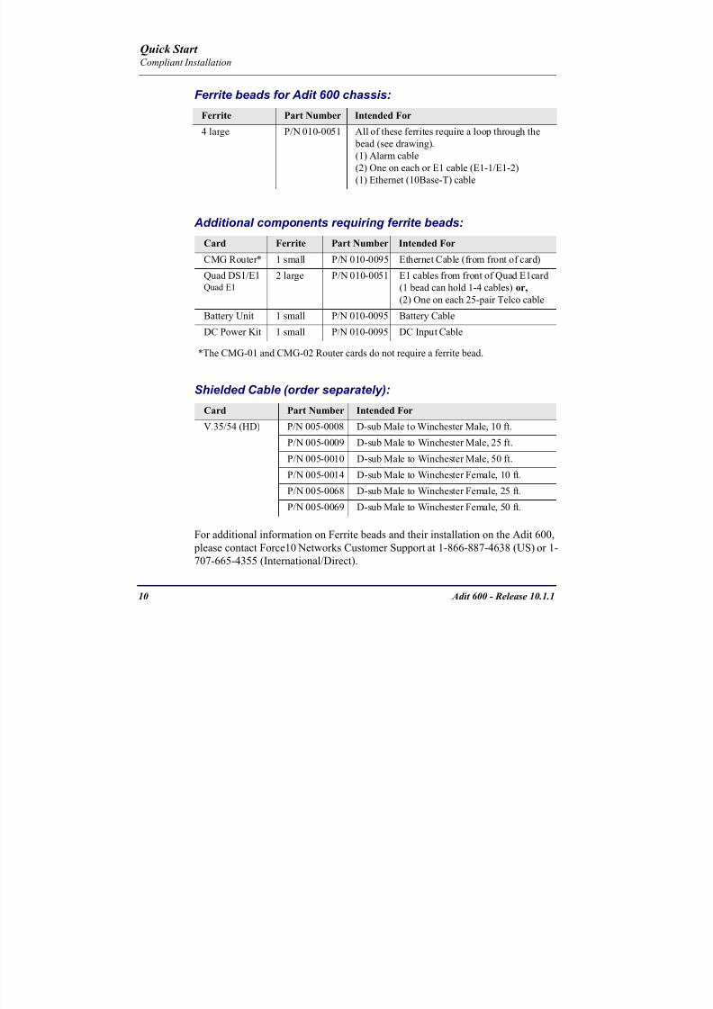
8102019 Adit 600 Quick Start 10-1-1
httpslidepdfcomreaderfulladit-600-quick-start-10-1-1 1254
10 Adit 600 - Release 1011
Quick Start Compliant Installation
Ferrite beads for Adit 600 chassis
Additional components requiring ferrite beads
The CMG-01 and CMG-02 Router cards do not require a ferrite bead
Shielded Cable (order separately)
For additional information on Ferrite beads and their installation on the Adit 600 please contact Force10 Networks Customer Support at 1-866-887-4638 (US) or 1-
707-665-4355 (InternationalDirect)
Ferrite Part Number Intended For
4 large PN 010-0051 All of these ferrites require a loop through the
bead (see drawing)
(1) Alarm cable
(2) One on each or E1 cable (E1-1E1-2)
(1) Ethernet (10Base-T) cable
Card Ferrite Part Number Intended For
CMG Router 1 small PN 010-0095 Ethernet Cable (from front of card)
Quad DS1E1Quad E1
2 large PN 010-0051 E1 cables from front of Quad E1card
(1 bead can hold 1-4 cables) or
(2) One on each 25-pair Telco cable
Battery Unit 1 small PN 010-0095 Battery Cable
DC Power Kit 1 small PN 010-0095 DC Input Cable
Card Part Number Intended For
V3554 (HD) PN 005-0008 D-sub Male to Winchester Male 10 ft
PN 005-0009 D-sub Male to Winchester Male 25 ftPN 005-0010 D-sub Male to Winchester Male 50 ft
PN 005-0014 D-sub Male to Winchester Female 10 ft
PN 005-0068 D-sub Male to Winchester Female 25 ft
PN 005-0069 D-sub Male to Winchester Female 50 ft
8102019 Adit 600 Quick Start 10-1-1
httpslidepdfcomreaderfulladit-600-quick-start-10-1-1 1354
Adit 600 - Release 1011 11
Quick Start Chassis Connectors and Buttons
Chassis Connectors and Buttons
The following illustrations show all connectors on the back of the Adit 600
Interface Connectors
The following are the Adit 600 interface connectors
T1-1E1-1 and T1-2E1-2 line connection ports each equipped with standard
RJ-48C 8-pin connector jack
RS-232 craft port connector
Tip and Ring Analog Interfaces equipped with standard 25-pair Telco
Connectors
10Base-T Ethernet port to be connected to a remote management tool such as
Telnet or an SNMP-based Network Management System with an RJ-45 8-pin
connector jack
External Alarm Connector
Ground Lugs
Ground Terminals
Alarms
AC or DC Power Connector
-48VBattery
Ethernet
T1-2E1-2T1E1
RS-232 Craft Port25-Pair Telco Connectors
T1-1E1-1
[10Base-T]
Connectors
Reset
(AC shown below)
8102019 Adit 600 Quick Start 10-1-1
httpslidepdfcomreaderfulladit-600-quick-start-10-1-1 1454
12 Adit 600 - Release 1011
Quick Start Interface Connectors
Chassis Ground Connector
WARNING THIS EQUIPMENT IS REQUIRED TO HAVE A PERMANENT GROUND CONNECTION IF CONNECTED TO EXPOSED OUTDOOR COMMUNICATION CONDUCTORS A 6 AWG COPPER WIRE MUST BE PERMANENTLY CONNECTED FROM AN APPROVED GROUNDING ELECTRODE TO THE CHASSIS GROUND LUG
OTHERWISE A 14 AWG COPPER WIRE MAY BE UTILIZED INSTALL THE GROUNDING CONDUCTOR IN ACCORDANCE WITH NATIONAL OR LOCAL REGULATIONS
1 Route wire (6 or 8 AWG copper) from building ground to lug on Adit 600
2 Strip insulation off wire end if necessary
3 Loosen compression screw until opening is large enough to accept ground
wire
4 Insert ground wire into lug barrel beneath compression plate and tighten
compression screw
5 Attach ground lug to chassis
Ground Terminals
Ground Lug
Compression
ScrewLug Barrel
8102019 Adit 600 Quick Start 10-1-1
httpslidepdfcomreaderfulladit-600-quick-start-10-1-1 1554
Adit 600 - Release 1011 13
Quick Start Interface Connectors
Power Reset
This is a resetable circuit breaker If at any time there is a short or power
surge on the incoming ACDC line the breaker will trip to protect the
Power supply from damage
Power Connections
There are four power supplies available for the Adit 600
115 VAC-48 VDC
230 VAC-48 VDC
24-48 VDC
24 VDC with -48 Output
These power supplies have different connectors as shown in the following Foradditional information see Chapter 15 Power Supply of the Adit 600 User Manual
Fuse Recommendation
When using -48 VDC input power use a 35 Amp fast-acting fuse if the power
connector is wired to a fuse panel
Power Cord AC An AC Power cord is provided with the 115 VAC and the
230 VAC Power Supplies
To connect the Power Cord
1 Insert power cord (male-end) to AC power source
2 Plug connector into the Adit 6003 A green light should appear on the DC Input LED on the front of the Power
Supply
AC Power Connector
8102019 Adit 600 Quick Start 10-1-1
httpslidepdfcomreaderfulladit-600-quick-start-10-1-1 1654
14 Adit 600 - Release 1011
Quick Start Interface Connectors
-48V Battery
The -48 VDC input connector on the Adit 600 is used for either direct DC powering
of the Adit 600 unit or for a Battery Backup connection when AC is used There is
no power cable provided for this connector however the connector is provided
WARNING POSSIBLE SHOCK HAZARD EXISTS PLEASE FOLLOW INSTRUCTIONS
CAREFULLY
To connect -48 VDC power
1 Ensure that no power is present on the two wires to be connected
2 Strip the two wires (approx 516 in bare wire) from the power source 16 or 18 AWG insulated copper wire is recommended for power connections
3 Insert the Battery Return and DC wires into the appropriate square holes
4 Tighten screws to clamp wires
5 Ensure that no bare wire shows after the wires are installed
6 Plug connector in the -48 VDC connector as seen below and secure with set
screws
7 Apply power to connector from -48 VDC power source
8 Verify with voltmeter that voltage is correct and polarity is correct
8102019 Adit 600 Quick Start 10-1-1
httpslidepdfcomreaderfulladit-600-quick-start-10-1-1 1754
Adit 600 - Release 1011 15
Quick Start Interface Connectors
9 Plug connector in the Adit 600 -48 VDC connector as seen in the graphic andsecure with set screws
Power Cord DC
There is no power cable provided with the 24
VDC Power Supply however the connector is
provided This connector will need to be wired
the following chart prides the wire gauge
recommendedTo connect 24 VDC power
1 Ensure that no power is present on the two wires to be connected
WARNING POSSIBLE SHOCK HAZARD EXISTS PLEASE FOLLOW INSTRUCTIONS CAREFULLY
1(+) 2(-)
Connector
Provided connector (female)
of Adit 600on back
(male)
Battery -48 VDC
2(-)
BatteryReturn (+)
-48 VDC (-)
Return 1(+)
24 VDC6 Amp
Battery
Battery (+)
DC Power Connector
Return (-)
8102019 Adit 600 Quick Start 10-1-1
httpslidepdfcomreaderfulladit-600-quick-start-10-1-1 1854
16 Adit 600 - Release 1011
Quick Start Interface Connectors
2 Strip the two wires from the powersource so that approximately 516 inch
of bare wire is exposed see Wire Gauge
chart below for wire recommendations
3 Insert the Battery Return (-) and Battery
(+) wires into the appropriate square
holes one at a time4 Tighten screws to clamp wires
5 Ensure that no bare wire shows after the
wires are installed
6 Apply power to connector
7 Verify with voltmeter that voltage is
correct and polarity is correct
8 Plug connector(s) into the Adit 600 DC
Power connector as seen in the graphic
and secure with set screws
9 A green light should appear on the DC OK LED on the front of the Power
Supply
Wire Gauge 18 AWG 16 AWG 14 AWG
Maximum Distance 12 Feet 20 Feet 35 Feet
Battery (+)
BatteryReturn (-)
8102019 Adit 600 Quick Start 10-1-1
httpslidepdfcomreaderfulladit-600-quick-start-10-1-1 1954
Adit 600 - Release 1011 17
Quick Start Interface Connectors
External Alarm Connector
The external alarm 6-pin connector with one input pair (pins 5 and 6)
and two output pairs (pins 1 and 2 - major alarms pins 3 and 4 - minor
alarms)
The pinouts are as follows
Pin Description Explanation
1 Major Alarm + The major alarm output is available for power supply or
major alarm failure alerting The maximum voltage across
the contacts is 350 V and the maximum current is 150 mA
This alarm is closed when power is off
2 Major Alarm -
3 Minor Alarm + The minor alarm output is available for power supply or
minor alarm failure alerting The maximum voltage across
the contacts is 350 V and the maximum current is 150 mA
This alarm remains open when power is off
4 Minor Alarm -
5 Alarm In + The alarm inputs provide 5 VDC across the two contactsand generate an alarm when a short circuit is detected
between the contacts
The alarm generated is a minor severity alarm
6 Alarm In -
6
5
4
3
2
1
A
L
A
R
M
8102019 Adit 600 Quick Start 10-1-1
httpslidepdfcomreaderfulladit-600-quick-start-10-1-1 2054
18 Adit 600 - Release 1011
Quick Start Interface Connectors
25-Pair Telco ConnectorsTip and Ring Analog Interfaces equipped with standard 25-pair Telco Connectors
(female) for connection to key systems fax machines modems and PBXs These
interfaces are also used for ISDN BRI ports and are jumper selectable on the Quad T1
Quad E1 Quad DS1E1 and Quad ADPCM service cards
Circuit connections are made at the 25-pair
telco connectors A standard 25-pairtelephone cable with RJ-21X wiring and a
male D-type connector at the Adit 600 end
is required
The pinouts are as follows
Pair Pin Location Function Color Code
1 26
1
Tip Channel 1
Ring Channel 1
WhiteBlue
BlueWhite
2 27
2
Tip Channel 2
Ring Channel 2
WhiteOrange
OrangeWhite
3 28
3
Tip Channel 3
Ring Channel 3
WhiteGreen
GreenWhite
4 29
4
Tip Channel 4
Ring Channel 4
WhiteBrown
BrownWhite
5 30
5
Tip Channel 5
Ring Channel 5
WhiteSlate
SlateWhite
6 31
6
Tip Channel 6
Ring Channel 6
RedBlue
BlueRed
7 327
Tip Channel 7Ring Channel 7
RedOrangeOrangeRed
8 33
8
Tip Channel 8
Ring Channel 8
RedGreen
GreenRed
9 34
9
Tip Channel 9
Ring Channel 9
RedBrown
BrownRed
10 3510
Tip Channel 10Ring Channel 10
RedSlateSlateRed
50
25
26
1
8102019 Adit 600 Quick Start 10-1-1
httpslidepdfcomreaderfulladit-600-quick-start-10-1-1 2154
Adit 600 - Release 1011 19
Quick Start Interface Connectors
Pair Pin Location Function Color Code
11 36
11
Tip Channel 11
Ring Channel 11
BlackBlue
BlueBlack
12 37
12
Tip Channel 12
Ring Channel 12
BlackOrange
OrangeBlack
13 38
13
Tip Channel 13
Ring Channel 13
BlackGreen
GreenBlack
14 39
14
Tip Channel 14
Ring Channel 14
BlackBrown
BrownBlack
15 40
15
Tip Channel 15
Ring Channel 15
BlackSlate
SlateBlack
16 41
16
Tip Channel 16
Ring Channel 16
YellowBlue
BlueYellow17 42
17
Tip Channel 17
Ring Channel 17
YellowOrange
OrangeYellow
18 43
18
Tip Channel 18
Ring Channel 18
YellowGreen
GreenYellow
19 44
19
Tip Channel 19
Ring Channel 19
YellowBrown
BrownYellow
20 45
20
Tip Channel 20
Ring Channel 20
YellowSlate
SlateYellow
21 46
21
Tip Channel 21
Ring Channel 21
VioletBlue
BlueViolet
22 47
22
Tip Channel 22
Ring Channel 22
VioletOrange
OrangeViolet
23 48
23
Tip Channel 23
Ring Channel 23
VioletGreen
GreenViolet
24 49
24
Tip Channel 24
Ring Channel 24
VioletBrown
BrownViolet
25 50
25
Reserved VioletSlate
SlateViolet
8102019 Adit 600 Quick Start 10-1-1
httpslidepdfcomreaderfulladit-600-quick-start-10-1-1 2254
20 Adit 600 - Release 1011
Quick Start Interface Connectors
RS-232 Craft Port (Female DB-9)The RS-232 craft port connector (female) is for connection to an external PC or Hayes-
compatible modem for local or remote configuration management and performance
monitoring using the Adit 600 Command Line Interface (CLI)
The RS-232 craft port connects via a
female DB-9 connector on the Adit 600
The pinouts are as follows
Pin Number Direction Description
1 Outbound Carrier Detect
2 Outbound Receive Data
3 Inbound Transmit Data
4 Inbound Data Terminal Ready
5 NA Signal Ground
6 Outbound Data Set Ready
7 Inbound Request to Send
8 Outbound Clear to Send
9 NC Not connected
1 5
6 9
8102019 Adit 600 Quick Start 10-1-1
httpslidepdfcomreaderfulladit-600-quick-start-10-1-1 2354
8102019 Adit 600 Quick Start 10-1-1
httpslidepdfcomreaderfulladit-600-quick-start-10-1-1 2454
22 Adit 600 - Release 1011
Quick Start Interface Connectors
10Base-T Ethernet
The 10Base-T Ethernet (female) port to connect to a remote
management tool such as Telnet or an SNMP-based Network
Management System Note A LINK LED on the back of the unit
displays green when the system has a good Ethernet link
The pinouts are as follows
Ethernet (RJ-45)
NOTE This Ethernet port uses a hub pinout Use a straight-through cableto connect a PC
Pin Name Description
1 Receive + Receive from network
2 Receive - Receive from network
3 Transmit + Transmit to network
4 - 5 NC Not connected
6 Transmit - Transmit to network
7 NC Not connected
8 NC Not connected
1 8
8102019 Adit 600 Quick Start 10-1-1
httpslidepdfcomreaderfulladit-600-quick-start-10-1-1 2554
Adit 600 - Release 1011 23
Quick Start Management Options
Management Options
Options for managing the Adit 600 are as follows
Local using CLI Telnet SNMP or DIP Switches (Controller and voice cards)
Remotely over an in-band DS0 or through the Access Navigator over the FDL
or an in-band DS0
This Quick Start Guide focuses on the CLI and DIP switches If you need further
information on other management options please refer to the Adit 600 User Manual
Command Line Interface (CLI)
You can access the CLI using either of the following methods
Telnet via Ethernet (10Base-T) RS-232 connected to the DB-9 port
Setting up a CLI Connection
If connecting via the Ethernet 10Base-T connection use a Telnet TCPIP
program to access the CLI This requires the IP address of the Controller
Controllers are shipped with the IP address set to 100010 If this address has been changed and is not known use HyperTerm to access the Controller and
use the CLI command show ip If an IP address needs to be set use the CLI
command set ethernet ip address
If connecting via RS-232 the port settings should be set to
Bits per second 9600 Data bits 8
Parity None Stop bits 1Flow control None
Set your Terminal Emulation to VT100
By default the Adit 600 is set for local configuration (using DIP switches) Use
the set local off command to enable the use of CLI commands
8102019 Adit 600 Quick Start 10-1-1
httpslidepdfcomreaderfulladit-600-quick-start-10-1-1 2654
8102019 Adit 600 Quick Start 10-1-1
httpslidepdfcomreaderfulladit-600-quick-start-10-1-1 2754
Adit 600 - Release 1011 25
Quick Start Configuration
ConfigurationThe following basic setups and upgrades for the Adit 600 are shown using CLI
commands For more information on CLI commands and configurations see the Adit
600 User Manual
Initial Setup
Basic Security Setup
DS1T1 Setup
E1 Setup
DS0Channel Setup
Analog Port Setup
4-Wire EampM Setup
Establish a Static Channel Connection
ISDN BRI Service Setup
OCU-DP Card Setup
ADPCM Card Setup
V35 Port Setup
Change the IP Address of the DS0 Management Channel
Upgrade the Adit 600 Software
Upgrade the Router Card Software
Basic Router Setup
8102019 Adit 600 Quick Start 10-1-1
httpslidepdfcomreaderfulladit-600-quick-start-10-1-1 2854
26 Adit 600 - Release 1011
Quick Start Configuration
Initial SetupUse the following commands for your initial setup For further information see the Adit
600 User Manual
Command Description
set local off Disables DIP switches
set date mmddyyyy Set the date used for event logging
set time hhmmss Set the time used for event logging
set id id-name Set a system ID name
set clock1 slotportinternal
Set the primary clock source
set clock2 slotportinternal
Set the secondary clock source
set ethernet ip addressip-addr mask
Set the ethernet IP address in the
conventional IP address format
set ip gateway ip-addr Set the IP gateway in the conventional IP
address format
8102019 Adit 600 Quick Start 10-1-1
httpslidepdfcomreaderfulladit-600-quick-start-10-1-1 2954
Adit 600 - Release 1011 27
Quick Start Configuration
Basic Security SetupUse the following commands to set up the security on the Adit 600 For further
information see the Adit 600 User Manual
Command Description
set password length
long|short
Set user password length requirement
add user ldquouser-namerdquo[password ldquopasswordrdquo]
Add user and password as necessary
set user user-name level1-3
Specify the userrsquos security level
set user user-namepassword Setchange password for the user asnecessary
8102019 Adit 600 Quick Start 10-1-1
httpslidepdfcomreaderfulladit-600-quick-start-10-1-1 3054
28 Adit 600 - Release 1011
Quick Start Configuration
DS1T1 SetupUse the following commands to set up a DS1 See the set (ds1) command for more
details
Command Description
set ds1-addr up Activate the port of the DS1 (slotport)
set ds1-addr id id-string
Set the identification string
set ds1-addr lbo 1-9 Set the line buildout value for the DS1
set ds1-addr linecodeami|b8zs
Set the linecode for the DS1
set ds1-addr framing d4|esf|tr8afdl|tr8anofdl|tr8b
Set the framing option for the DS1
set ds1-addr loopdetecton|off
Set the detectionreaction to CSU loopcodes
Q i k S
8102019 Adit 600 Quick Start 10-1-1
httpslidepdfcomreaderfulladit-600-quick-start-10-1-1 3154
Adit 600 - Release 1011 29
Quick Start Configuration
E1 Setup
NOTE E1 is not supported in this release of the Adit 600 Controller It will besupported in a future release
Use the following commands to set up an E1 See the set (e1) command for more
details
DS0Channel Setup
Use the following commands to set up a DS0 See the set (ds0) command for details
Command Description
set e1-addr up Activate the port of the E1 (slotport)
set e1-addr id id-string Set the identification string
set e1-addr lbo 1 - 9 Set the line buildout value for the E1
set e1-addr linecodeami|hdb3
Set the linecode for the E1
set e1-addr framinge1fr|lefrcrc
Set the framing option for the E1
set e1-addr loopdetecton|off
Set the detectionreaction to CSU loopcodes
Command Description
set slotportchannel up Activate the channel
set slotportchannel signalls|gs|emw|emdw|emicpd|dpt
Set the signaling option for the channel
set slotportchannel typedata|voice Set the channel type
Q i k St t
8102019 Adit 600 Quick Start 10-1-1
httpslidepdfcomreaderfulladit-600-quick-start-10-1-1 3254
30 Adit 600 - Release 1011
Quick Start Configuration
Analog Port SetupUse the following commands to set up an analog port
Command Description
set slotport up Activate the port See set (ds1) command for
details
set slotport signal dpt|gs|gsrb|gsw|gswrb|ls|lscpd|lsrb
Set the signaling option for the port See the
set (fxs) or set (fxo) command for details
set slotport rxgain n Set the receive gainloss in dB See the set
(fxs) or set (fxo) command for details
set slotport txgain n Set the transmit gainloss in dB See the set
(fxs) or set (fxo) command for details
Quick Start
8102019 Adit 600 Quick Start 10-1-1
httpslidepdfcomreaderfulladit-600-quick-start-10-1-1 3354
Adit 600 - Release 1011 31
Quick Start Configuration
4-Wire EampM SetupFor this example the 4 EampM ports will be connected to the first 4 DS0s on T1-1 (a1)
This can be changed to match the customers desired DS0 connections
For Transmission Only mode the DS0s on the DS1 should be set to data as well as the
EampM card channels
Command Description
For Normal or Tandem EampM
set a11-4 type voice Set DS0s to voice
set connect a11-4 11-4 Connect DS0s to the 4 ports of the 4-
Wire EampM card
show connect a 1 Verify cross connects
set a11-4 signal emi Set DS0 signal type to EMI
set 11-4 signal emi Set 4-Wire EampM ports signal type to
EMI
show connect a1 Verify cross connects
For TO Mode
set a11-4 type data Set DS0s to data
set 11-4 type data Set 4-Wire EampM port to data
set connect a11-4 11-4 Connect DS0s to the 4 ports of the 4-
Wire EampM card
show connect a 1 Verify cross connects
Quick Start
8102019 Adit 600 Quick Start 10-1-1
httpslidepdfcomreaderfulladit-600-quick-start-10-1-1 3454
32 Adit 600 - Release 1011
Quick Start Configuration
Establish a Static Channel ConnectionUse the following commands to establish a static channel connection
ISDN BRI Service Setup
Use the following commands to set up a ISDN BRI Service See the set (bri) command
for details
Command Description
set slotportchannel typevoice|data
Set the channel type for the channel to
map See set (ds0) command for details
set slotportchannel signalls|gs|emw|emdw|emicpd|dpt
Set the channel signaling option See set
(ds0) command for details
connect slotportslotport
Connect the channels See the connect
(card-trunk) (card-trunk) command
Command Description
set slotport up Put the ISDN line In-Service
set slot modelt3ds0|lt4to1tdm|nt3ds0
Set the ISDN mode
set slotport crv 1-768 Set the Call Reference Value Note
value must be the same as the Access
Navigator
set slotport thresholdday|hour es|ses
Set the threshold for the IDSN lines
set slot pmsyncadit|switch
Set the source for performance
monitoring synchronization
set slotport autoactivate
on|off
Only used in 4-to-1 mode Establishes
the D channel when the FDL link can not
be used
Quick Start
8102019 Adit 600 Quick Start 10-1-1
httpslidepdfcomreaderfulladit-600-quick-start-10-1-1 3554
Adit 600 - Release 1011 33
Quick Start Configuration
OCU-DP Card SetupThe following is a basic setup for the OCU-DP card
ADPCM Card Setup
Command Description
set ocudp-addr baud2400|4800|9600|19200|38400|
56000|64000
Set the OCU-DP Baud rate
Where ocudp-addr = slotport of the
OCU-DP card to apply settings to
set ocudp-addr up Set the OCU-DP port 1 up
show ocudp_card-addr Show the OCU-DP card settings
Where ocudp_card-addr = slot of the
OCU-DP card
disconnect a Disconnects all connections to slot a
(controller)
set ds0-addr type data Sets a DS0 data signaling type
connect ds0-addrocudp-addr
Connects DS0 (in previous step) to OCU-DP
port (in previous step)
show connect
(ocudp_card-addr
Displays connect information for OCU-DP
card
Command Description
Connect T1 cable to port 1 of the ADPCM service card
set adpcm_card-addrnone|map1|map2|map3
Enable compressing by selecting Map type Notenone disables compression
show (adpcm_card-addr Displays the status of the card and the mapping
connect 211-12 241-12 Set ADPCM cross-connects The example
connects all 24 channels of the ADPCM to the 12
channels of the T1 (now compressed) on port 4
This example is with map2show connect 21) Displays the connections made above
8102019 Adit 600 Quick Start 10-1-1
httpslidepdfcomreaderfulladit-600-quick-start-10-1-1 3654
Quick Start
8102019 Adit 600 Quick Start 10-1-1
httpslidepdfcomreaderfulladit-600-quick-start-10-1-1 3754
Adit 600 - Release 1011 35
QConfiguration
Upgrade the Adit 600 SoftwareUse the following commands to determine the system software level then upgrade the
software to the latest version
Command Description
status equipment Determine the system software level The
Slot A line (SW Vers) will display thecurrent software level
load tftp ip-addr file-name (or load xmodem)
Load the new controller system software See
the load tftp and load xmodem command for
more information
Note A TFTP server must be running onthe host system You can use any TFTP
server utility you wish One example isthe program TFTPD32 which can bedownloaded free-of-charge attftpd32jouninnettftpd32html
Quick Start
8102019 Adit 600 Quick Start 10-1-1
httpslidepdfcomreaderfulladit-600-quick-start-10-1-1 3854
36 Adit 600 - Release 1011
Configuration
Upgrade the Router Card SoftwareUse the following commands to determine the Router card software level then upgrade
the software to the latest version
NOTE For additional information about upgrading MSR card software see
the following manuals-Adit 600 User Manual -Adit 3000 Series and Multi-Service Router (MSR) Card GUI Reference Manual
-Adit 3000 Series and Multi-Service Router (MSR) Card CLI Reference Manual
Command Description
status equipment Determine the Router software level The
Router Slot line (SW Vers) will display thecurrent software level
load rtr_card-addr tftpip-addr file-name
Load the new Router software to a Router
card See the load tftp command for more
information
Note A TFTP server must be running onthe host system You can use any TFTP
server utility you wish One example isthe program TFTPD32 which can bedownloaded free-of-charge attftpd32jouninnettftpd32html
8102019 Adit 600 Quick Start 10-1-1
httpslidepdfcomreaderfulladit-600-quick-start-10-1-1 3954
8102019 Adit 600 Quick Start 10-1-1
httpslidepdfcomreaderfulladit-600-quick-start-10-1-1 4054
Quick Start C t ll C d LED
8102019 Adit 600 Quick Start 10-1-1
httpslidepdfcomreaderfulladit-600-quick-start-10-1-1 4154
Adit 600 - Release 1011 39
Controller Card LEDs
E1 Controller Card
NOTE E1 is not supported in this release It will be supported in a futurerelease
The E1 Controller has a set of six LEDs The table below describes each LED
LED State Description
MAJOR Off No major alarms present
Red Major alarm present
MINOR Off No minor alarms present
Yellow Minor alarms present
LOCAL Off Remote mode (DIP switches disabled)
Green Local mode (DIP switches enabled)
ACO Off Normal mode No alarms are being
suppressed
Yellow Alarm Cut Off active One or more active
alarms suppressed
E1-1 and
E1-2
Off Off line
Green Normal
Red Loss of Signal (LOS) detected
Yellow Bipolar Violation (BPV) detected LCV
Flashing Green Loopback active
Flashing Red
(slow)
Loss of Frame (LOF) or Alarm Indication
Signal (AIS) detected
Flashing Red
(fast)
Card Failure
Flashing Yellow Yellow alarm (Remote Alarm Indication)detected
Quick Start Power Supply LEDs
8102019 Adit 600 Quick Start 10-1-1
httpslidepdfcomreaderfulladit-600-quick-start-10-1-1 4254
40 Adit 600 - Release 1011
Power Supply LEDs
Power Supply LEDs115 VAC-48 VDC and 230 VAC-48 VDC Power Supplies
The power supply card has two LEDs as described in the table
below
24 VDC-48 VDC Power Supply
The power supply card has two LEDs as described in the table below
LED State Description
AC Input Off AC input missing or failure
Green AC input present
Battery Off Battery input not used
Green Battery charging or operating from DC
source only
Yellow Battery discharging
Red Battery low (less than 42V) ringer disabled
LED State Description
DC OK Off DC input missing or failure
Green DC input present
-48 Battery
Low
Off Normal
Red VDC is low (less than 42 VDC)
ringer disabled
Quick Start Service Card LEDs
8102019 Adit 600 Quick Start 10-1-1
httpslidepdfcomreaderfulladit-600-quick-start-10-1-1 4354
Adit 600 - Release 1011 41
Service Card LEDs
Service Card LEDs 4-Wire EampM Card
FXO Card
FXS Card
ISDN BRI Card
OCU-DP Card
P-Phone Card
Single Channel POTS Card
Quad DS1 ADPCM Service Card
Quad DS1E1 and Quad T1 Cards
Quad E1 Card
IP Router Card
CMG Router Card
Terminal Server Router Card
MSR Card
RS-232 and V35V54 Cards
Discontinued cards
RS-232 discontinued
Quick Start Service Card LEDs
8102019 Adit 600 Quick Start 10-1-1
httpslidepdfcomreaderfulladit-600-quick-start-10-1-1 4454
42 Adit 600 - Release 1011
Service Card LEDs
4-Wire EampM Card Each channelport has two LEDs Only the top LED is used in this application LED
definitions are listed below
State Description
When in EampM Mode
Off Channel is idle or disabled
Green Analog interface is off-hook
Red Digital interface is off-hook
Yellow Both analog and digital interfaces are off-hook or channel is
being trunk processed
When in TO Mode
Off DisconnectedGreen Connected T1E1 not in alarm
Yellow Connected T1E1 in alarm (trunk processed)
Quick Start Service Card LEDs
8102019 Adit 600 Quick Start 10-1-1
httpslidepdfcomreaderfulladit-600-quick-start-10-1-1 4554
Adit 600 - Release 1011 43
FXO Card Each port on the FXO card has its own LED as described in the table below
FXS Card
There is an LED for each port on the FXS card as described in the table below
State Loop Start
Meaning
Ground Start Meaning Dial Pulse Termination
Meaning
Off NA Idle (tip open) Idle (loop open)
Green Idle Tip ground (incoming seizure) Incoming seizure
Red NA Ring ground (outgoing
seizure)
Loop closure (outgoing seizure)
Yellow Call in
progress
Call in progress Call in progress (reverse battery)
Flashing
Green
Ringing Ringing NA
State Loop Start Meaning Ground Start Meaning
Off NA Idle (tip open)
Green Idle Tip ground (incoming seizure)
Red Note This can be seen with
Forward Disconnect (tip open)
Ring ground (outgoing seizure)
Yellow Call in progress Call in progress
Flashing green Ringing Ringing
Quick Start Service Card LEDs
8102019 Adit 600 Quick Start 10-1-1
httpslidepdfcomreaderfulladit-600-quick-start-10-1-1 4654
44 Adit 600 - Release 1011
ISDN BRI Card There is an LED for each ISDN BRI on a card as described in the table below
OCU-DP Card Each channel has two LEDs described in the table below
State Description
Off Line U-interface is attempting synchronization or BRI is Out-of-Service
Red Line alarm (LOS or self test failure)
Yellow ES or SES has occurred
Flashing yellow Line U-interface is synchronized with customer equipment but is not passing
customer data
Flashing green Line U-interface is in external loopback toward the switch at the unit
Green Normal (Line U-interface is active and transparently passing customer data)
State Description
Yellow Flickering ALL Boot Software in control
Green (walking down)
Red (walking up)
ALL Application Software in control
(repeated 35 times)
Red slow flash ALL In Boot Application flash code checksums did not match and
Boot is waiting for application download
Red ALL In Application code waiting for Controller to issue SWHW
revision request This is the first request that comes from the
OCU-DP card manager in the ControllerGreen
Yellow
Top
Bottom
Port in Self-test Duration is 5-8 seconds
Off Top
Bottom
Port is set down (Out-Of-Service)
Green Top Port is receiving valid signals
Red Top Port is receiving no signal (primary) or no frame sync
(secondary or clear channel)Red Flashing Bottom Port is receiving bipolar violations
Yellow Bottom Port is in loopback
Quick Start Service Card LEDs
8102019 Adit 600 Quick Start 10-1-1
httpslidepdfcomreaderfulladit-600-quick-start-10-1-1 4754
Adit 600 - Release 1011 45
P-Phone Card Each P-Phone channel has a corresponding LED described in the table below
State Line State
Off No P-Phone connected
Green No call in process
Flashing Green Alert (Ringing)
Yellow Call in progress
Flashing Yellow P-Phone Loopback in Progress
Flashing Red Self-test failed
Quick Start Service Card LEDs
8102019 Adit 600 Quick Start 10-1-1
httpslidepdfcomreaderfulladit-600-quick-start-10-1-1 4854
46 Adit 600 - Release 1011
Single Channel POTS Card The POTS channel LED (left) status is described in the table below
The second LED (right) is a status LED is not used on this card
Quad DS1 ADPCM Service Card
Each channel on the Quad DS1 ADPCM card has two LEDs The
description of the top LED is shown below the bottom LED is notused with this application
State Loop Start Meaning
Off Calling Party Disconnect
Green Idle
Red NA
Yellow Call in progress
Flashing green Ringing
State Description
Off Off line
Green Normal
Red Loss of Signal (LOS)
Yellow Bipolar Violation (BPV)Flashing Green Loopback active
Flashing Yellow Yellow Alarm
(Remote Alarm Indication)
Flashing Red (Slow) Loss of Frame (LOF) or Alarm Indication Signal (AIS)
Flashing Red (Fast) Self-test Failure
Top LED(active)
Bottom LED(not used)
Quick Start Service Card LEDs
8102019 Adit 600 Quick Start 10-1-1
httpslidepdfcomreaderfulladit-600-quick-start-10-1-1 4954
Adit 600 - Release 1011 47
Quad DS1E1 and Quad T1 CardsEach channel on the Quad T1E1 cards have two LEDs The description
of the top LED is shown below the bottom LED is not used with this
application
State Description
Off Off line
Green Normal
Red Loss of Signal (LOS)
Yellow Bipolar Violation (BPV)
Flashing Green Loopback active
Flashing Yellow Yellow Alarm (Remote Alarm Indication)
Flashing Red (Slow) Loss of Frame (LOF) or Alarm Indication Signal (AIS)
Flashing Red (Fast) Self-test Failure
Quick Start Service Card LEDs
8102019 Adit 600 Quick Start 10-1-1
httpslidepdfcomreaderfulladit-600-quick-start-10-1-1 5054
48 Adit 600 - Release 1011
IP Router Card The following chart describes each LED and its state
LED State Description
CRD Off Loss of power
Green No current alarms
Red Alarm state active See alarm log for cause
Red Flashing Self-test or Boot in-process
Yellow Flashing Card is saving data to flash RAM do not power down
10100 Off 10 Mb ethernet
Green 100 Mb ethernet
LNK Off No ethernet link
Green Good ethernet link
COL
Off No current ethernet transmit collisions
Yellow Ethernet collisions have occurred and have not dropped
to minimum level
Yellow Flashing Ethernet collision occurring
TX Off No ethernet transmit activity
Green Ethernet transmit activity
RX Off No current ethernet receive activity
Green Current ethernet receive activity
Quick Start Service Card LEDs
8102019 Adit 600 Quick Start 10-1-1
httpslidepdfcomreaderfulladit-600-quick-start-10-1-1 5154
Adit 600 - Release 1011 49
CMG Router Card The following chart describes each LED and its state
LED State Description
CRD Off Loss of power
Green No current alarms
Red Alarm state active See alarm log for causeRed Flashing Self-test or Boot in-process
Yellow Flashing Card is saving data to flash RAM do not power down
VOIP
Off No active VoIP calls or if the MGCP protocol is
optioned down
Green Active VoIP calls
Red Call agent unreachable
Yellow Insufficient VoIP resources to complete call
LNK Off No Ethernet link
Green Good Ethernet link
10100 Off 10 Mb Ethernet
Green 100 Mb Ethernet
TX Off No Ethernet transmit activityGreen Ethernet transmit activity
Yellow Current Ethernet transmit collision
RX Off No current Ethernet receive activity
Green Current Ethernet receive activity
Quick Start Service Card LEDs
8102019 Adit 600 Quick Start 10-1-1
httpslidepdfcomreaderfulladit-600-quick-start-10-1-1 5254
50 Adit 600 - Release 1011
Terminal Server Router Card The Terminal Server Router card has 2 LEDs per port
At Power-up
Normal Operation
Port Set for Ethernet
Top LED indicates 100M Link Bottom LED indicates 10M Link
Port Set for RS-232
TOP LED Bottom LED Description
Off Off At Power UpBoot = Loss of power
Red Red Card is inoperative
Flashing Red Flashing Red Self-test or Boot in-process
TOP LED Bottom LED Description
Green Solid (Link) Green Solid (Link) Port set for Ethernet - see below
Flashing Red Flashing Red Self-test or Boot in-process
State Description
Off No Ethernet link
Green Link but no activity
Red Flashing Current Ethernet collision
Green Flashing Current Ethernet receive
Yellow Flashing Current Ethernet transmit
TOP LED Bottom LED Description
Yellow Off No Activity
Yellow Flashing Yellow Current transmit
Yellow Flashing Green Current receive
Quick Start Service Card LEDs
8102019 Adit 600 Quick Start 10-1-1
httpslidepdfcomreaderfulladit-600-quick-start-10-1-1 5354
Adit 600 - Release 1011 51
MSR Card The following chart describes the MSR cardrsquos LEDs
LED State Description
CRD Off Loss of power
Green No current alarms
Red Alarm state active See alarm log for cause
Red Flashing Self-test or boot in process
Yellow Flashing Card is saving data to flash RAM do not power
down
VOIP
Off No SIP proxy or registration attempts for all lines
have succeeded but no calls are active
Green Active VoIP call(s)
Red Inability to reach the SIP proxy or negative response
to register attempts from all lines
Yellow Register attempts from some lines have succeeded
but not for all lines
ETH1 and
ETH2
Top LED
Off 10 Mbitsec down or not connected
Green 100 Mbitsec
ETH1 and
ETH2
Bottom LED
Off Link down
Green Link up
Flashing Green Traffic on link
Yellow Collision status
Quick Start Service Card LEDs
8102019 Adit 600 Quick Start 10-1-1
httpslidepdfcomreaderfulladit-600-quick-start-10-1-1 5454
52 Adit 600 - Release 1011
RS-232 and V35V54 Cards Each port has its own LED as described in the table below
State Description
Off No T1 Assignment
Green Normal (CDRTS) Active
Red CD inactive (T1-side failure)
Yellow RTS inactive (equipment-side failure)
Flashing Yellow Loopback toward T1 or equipment loop test
Flashing Green Loopback toward equipment or network loop test
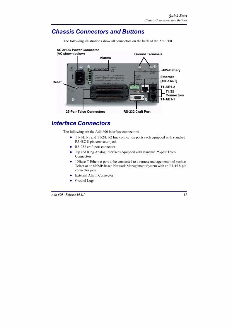
8102019 Adit 600 Quick Start 10-1-1
httpslidepdfcomreaderfulladit-600-quick-start-10-1-1 1354
Adit 600 - Release 1011 11
Quick Start Chassis Connectors and Buttons
Chassis Connectors and Buttons
The following illustrations show all connectors on the back of the Adit 600
Interface Connectors
The following are the Adit 600 interface connectors
T1-1E1-1 and T1-2E1-2 line connection ports each equipped with standard
RJ-48C 8-pin connector jack
RS-232 craft port connector
Tip and Ring Analog Interfaces equipped with standard 25-pair Telco
Connectors
10Base-T Ethernet port to be connected to a remote management tool such as
Telnet or an SNMP-based Network Management System with an RJ-45 8-pin
connector jack
External Alarm Connector
Ground Lugs
Ground Terminals
Alarms
AC or DC Power Connector
-48VBattery
Ethernet
T1-2E1-2T1E1
RS-232 Craft Port25-Pair Telco Connectors
T1-1E1-1
[10Base-T]
Connectors
Reset
(AC shown below)
8102019 Adit 600 Quick Start 10-1-1
httpslidepdfcomreaderfulladit-600-quick-start-10-1-1 1454
12 Adit 600 - Release 1011
Quick Start Interface Connectors
Chassis Ground Connector
WARNING THIS EQUIPMENT IS REQUIRED TO HAVE A PERMANENT GROUND CONNECTION IF CONNECTED TO EXPOSED OUTDOOR COMMUNICATION CONDUCTORS A 6 AWG COPPER WIRE MUST BE PERMANENTLY CONNECTED FROM AN APPROVED GROUNDING ELECTRODE TO THE CHASSIS GROUND LUG
OTHERWISE A 14 AWG COPPER WIRE MAY BE UTILIZED INSTALL THE GROUNDING CONDUCTOR IN ACCORDANCE WITH NATIONAL OR LOCAL REGULATIONS
1 Route wire (6 or 8 AWG copper) from building ground to lug on Adit 600
2 Strip insulation off wire end if necessary
3 Loosen compression screw until opening is large enough to accept ground
wire
4 Insert ground wire into lug barrel beneath compression plate and tighten
compression screw
5 Attach ground lug to chassis
Ground Terminals
Ground Lug
Compression
ScrewLug Barrel
8102019 Adit 600 Quick Start 10-1-1
httpslidepdfcomreaderfulladit-600-quick-start-10-1-1 1554
Adit 600 - Release 1011 13
Quick Start Interface Connectors
Power Reset
This is a resetable circuit breaker If at any time there is a short or power
surge on the incoming ACDC line the breaker will trip to protect the
Power supply from damage
Power Connections
There are four power supplies available for the Adit 600
115 VAC-48 VDC
230 VAC-48 VDC
24-48 VDC
24 VDC with -48 Output
These power supplies have different connectors as shown in the following Foradditional information see Chapter 15 Power Supply of the Adit 600 User Manual
Fuse Recommendation
When using -48 VDC input power use a 35 Amp fast-acting fuse if the power
connector is wired to a fuse panel
Power Cord AC An AC Power cord is provided with the 115 VAC and the
230 VAC Power Supplies
To connect the Power Cord
1 Insert power cord (male-end) to AC power source
2 Plug connector into the Adit 6003 A green light should appear on the DC Input LED on the front of the Power
Supply
AC Power Connector
8102019 Adit 600 Quick Start 10-1-1
httpslidepdfcomreaderfulladit-600-quick-start-10-1-1 1654
14 Adit 600 - Release 1011
Quick Start Interface Connectors
-48V Battery
The -48 VDC input connector on the Adit 600 is used for either direct DC powering
of the Adit 600 unit or for a Battery Backup connection when AC is used There is
no power cable provided for this connector however the connector is provided
WARNING POSSIBLE SHOCK HAZARD EXISTS PLEASE FOLLOW INSTRUCTIONS
CAREFULLY
To connect -48 VDC power
1 Ensure that no power is present on the two wires to be connected
2 Strip the two wires (approx 516 in bare wire) from the power source 16 or 18 AWG insulated copper wire is recommended for power connections
3 Insert the Battery Return and DC wires into the appropriate square holes
4 Tighten screws to clamp wires
5 Ensure that no bare wire shows after the wires are installed
6 Plug connector in the -48 VDC connector as seen below and secure with set
screws
7 Apply power to connector from -48 VDC power source
8 Verify with voltmeter that voltage is correct and polarity is correct
8102019 Adit 600 Quick Start 10-1-1
httpslidepdfcomreaderfulladit-600-quick-start-10-1-1 1754
Adit 600 - Release 1011 15
Quick Start Interface Connectors
9 Plug connector in the Adit 600 -48 VDC connector as seen in the graphic andsecure with set screws
Power Cord DC
There is no power cable provided with the 24
VDC Power Supply however the connector is
provided This connector will need to be wired
the following chart prides the wire gauge
recommendedTo connect 24 VDC power
1 Ensure that no power is present on the two wires to be connected
WARNING POSSIBLE SHOCK HAZARD EXISTS PLEASE FOLLOW INSTRUCTIONS CAREFULLY
1(+) 2(-)
Connector
Provided connector (female)
of Adit 600on back
(male)
Battery -48 VDC
2(-)
BatteryReturn (+)
-48 VDC (-)
Return 1(+)
24 VDC6 Amp
Battery
Battery (+)
DC Power Connector
Return (-)
8102019 Adit 600 Quick Start 10-1-1
httpslidepdfcomreaderfulladit-600-quick-start-10-1-1 1854
16 Adit 600 - Release 1011
Quick Start Interface Connectors
2 Strip the two wires from the powersource so that approximately 516 inch
of bare wire is exposed see Wire Gauge
chart below for wire recommendations
3 Insert the Battery Return (-) and Battery
(+) wires into the appropriate square
holes one at a time4 Tighten screws to clamp wires
5 Ensure that no bare wire shows after the
wires are installed
6 Apply power to connector
7 Verify with voltmeter that voltage is
correct and polarity is correct
8 Plug connector(s) into the Adit 600 DC
Power connector as seen in the graphic
and secure with set screws
9 A green light should appear on the DC OK LED on the front of the Power
Supply
Wire Gauge 18 AWG 16 AWG 14 AWG
Maximum Distance 12 Feet 20 Feet 35 Feet
Battery (+)
BatteryReturn (-)
8102019 Adit 600 Quick Start 10-1-1
httpslidepdfcomreaderfulladit-600-quick-start-10-1-1 1954
Adit 600 - Release 1011 17
Quick Start Interface Connectors
External Alarm Connector
The external alarm 6-pin connector with one input pair (pins 5 and 6)
and two output pairs (pins 1 and 2 - major alarms pins 3 and 4 - minor
alarms)
The pinouts are as follows
Pin Description Explanation
1 Major Alarm + The major alarm output is available for power supply or
major alarm failure alerting The maximum voltage across
the contacts is 350 V and the maximum current is 150 mA
This alarm is closed when power is off
2 Major Alarm -
3 Minor Alarm + The minor alarm output is available for power supply or
minor alarm failure alerting The maximum voltage across
the contacts is 350 V and the maximum current is 150 mA
This alarm remains open when power is off
4 Minor Alarm -
5 Alarm In + The alarm inputs provide 5 VDC across the two contactsand generate an alarm when a short circuit is detected
between the contacts
The alarm generated is a minor severity alarm
6 Alarm In -
6
5
4
3
2
1
A
L
A
R
M
8102019 Adit 600 Quick Start 10-1-1
httpslidepdfcomreaderfulladit-600-quick-start-10-1-1 2054
18 Adit 600 - Release 1011
Quick Start Interface Connectors
25-Pair Telco ConnectorsTip and Ring Analog Interfaces equipped with standard 25-pair Telco Connectors
(female) for connection to key systems fax machines modems and PBXs These
interfaces are also used for ISDN BRI ports and are jumper selectable on the Quad T1
Quad E1 Quad DS1E1 and Quad ADPCM service cards
Circuit connections are made at the 25-pair
telco connectors A standard 25-pairtelephone cable with RJ-21X wiring and a
male D-type connector at the Adit 600 end
is required
The pinouts are as follows
Pair Pin Location Function Color Code
1 26
1
Tip Channel 1
Ring Channel 1
WhiteBlue
BlueWhite
2 27
2
Tip Channel 2
Ring Channel 2
WhiteOrange
OrangeWhite
3 28
3
Tip Channel 3
Ring Channel 3
WhiteGreen
GreenWhite
4 29
4
Tip Channel 4
Ring Channel 4
WhiteBrown
BrownWhite
5 30
5
Tip Channel 5
Ring Channel 5
WhiteSlate
SlateWhite
6 31
6
Tip Channel 6
Ring Channel 6
RedBlue
BlueRed
7 327
Tip Channel 7Ring Channel 7
RedOrangeOrangeRed
8 33
8
Tip Channel 8
Ring Channel 8
RedGreen
GreenRed
9 34
9
Tip Channel 9
Ring Channel 9
RedBrown
BrownRed
10 3510
Tip Channel 10Ring Channel 10
RedSlateSlateRed
50
25
26
1
8102019 Adit 600 Quick Start 10-1-1
httpslidepdfcomreaderfulladit-600-quick-start-10-1-1 2154
Adit 600 - Release 1011 19
Quick Start Interface Connectors
Pair Pin Location Function Color Code
11 36
11
Tip Channel 11
Ring Channel 11
BlackBlue
BlueBlack
12 37
12
Tip Channel 12
Ring Channel 12
BlackOrange
OrangeBlack
13 38
13
Tip Channel 13
Ring Channel 13
BlackGreen
GreenBlack
14 39
14
Tip Channel 14
Ring Channel 14
BlackBrown
BrownBlack
15 40
15
Tip Channel 15
Ring Channel 15
BlackSlate
SlateBlack
16 41
16
Tip Channel 16
Ring Channel 16
YellowBlue
BlueYellow17 42
17
Tip Channel 17
Ring Channel 17
YellowOrange
OrangeYellow
18 43
18
Tip Channel 18
Ring Channel 18
YellowGreen
GreenYellow
19 44
19
Tip Channel 19
Ring Channel 19
YellowBrown
BrownYellow
20 45
20
Tip Channel 20
Ring Channel 20
YellowSlate
SlateYellow
21 46
21
Tip Channel 21
Ring Channel 21
VioletBlue
BlueViolet
22 47
22
Tip Channel 22
Ring Channel 22
VioletOrange
OrangeViolet
23 48
23
Tip Channel 23
Ring Channel 23
VioletGreen
GreenViolet
24 49
24
Tip Channel 24
Ring Channel 24
VioletBrown
BrownViolet
25 50
25
Reserved VioletSlate
SlateViolet
8102019 Adit 600 Quick Start 10-1-1
httpslidepdfcomreaderfulladit-600-quick-start-10-1-1 2254
20 Adit 600 - Release 1011
Quick Start Interface Connectors
RS-232 Craft Port (Female DB-9)The RS-232 craft port connector (female) is for connection to an external PC or Hayes-
compatible modem for local or remote configuration management and performance
monitoring using the Adit 600 Command Line Interface (CLI)
The RS-232 craft port connects via a
female DB-9 connector on the Adit 600
The pinouts are as follows
Pin Number Direction Description
1 Outbound Carrier Detect
2 Outbound Receive Data
3 Inbound Transmit Data
4 Inbound Data Terminal Ready
5 NA Signal Ground
6 Outbound Data Set Ready
7 Inbound Request to Send
8 Outbound Clear to Send
9 NC Not connected
1 5
6 9
8102019 Adit 600 Quick Start 10-1-1
httpslidepdfcomreaderfulladit-600-quick-start-10-1-1 2354
8102019 Adit 600 Quick Start 10-1-1
httpslidepdfcomreaderfulladit-600-quick-start-10-1-1 2454
22 Adit 600 - Release 1011
Quick Start Interface Connectors
10Base-T Ethernet
The 10Base-T Ethernet (female) port to connect to a remote
management tool such as Telnet or an SNMP-based Network
Management System Note A LINK LED on the back of the unit
displays green when the system has a good Ethernet link
The pinouts are as follows
Ethernet (RJ-45)
NOTE This Ethernet port uses a hub pinout Use a straight-through cableto connect a PC
Pin Name Description
1 Receive + Receive from network
2 Receive - Receive from network
3 Transmit + Transmit to network
4 - 5 NC Not connected
6 Transmit - Transmit to network
7 NC Not connected
8 NC Not connected
1 8
8102019 Adit 600 Quick Start 10-1-1
httpslidepdfcomreaderfulladit-600-quick-start-10-1-1 2554
Adit 600 - Release 1011 23
Quick Start Management Options
Management Options
Options for managing the Adit 600 are as follows
Local using CLI Telnet SNMP or DIP Switches (Controller and voice cards)
Remotely over an in-band DS0 or through the Access Navigator over the FDL
or an in-band DS0
This Quick Start Guide focuses on the CLI and DIP switches If you need further
information on other management options please refer to the Adit 600 User Manual
Command Line Interface (CLI)
You can access the CLI using either of the following methods
Telnet via Ethernet (10Base-T) RS-232 connected to the DB-9 port
Setting up a CLI Connection
If connecting via the Ethernet 10Base-T connection use a Telnet TCPIP
program to access the CLI This requires the IP address of the Controller
Controllers are shipped with the IP address set to 100010 If this address has been changed and is not known use HyperTerm to access the Controller and
use the CLI command show ip If an IP address needs to be set use the CLI
command set ethernet ip address
If connecting via RS-232 the port settings should be set to
Bits per second 9600 Data bits 8
Parity None Stop bits 1Flow control None
Set your Terminal Emulation to VT100
By default the Adit 600 is set for local configuration (using DIP switches) Use
the set local off command to enable the use of CLI commands
8102019 Adit 600 Quick Start 10-1-1
httpslidepdfcomreaderfulladit-600-quick-start-10-1-1 2654
8102019 Adit 600 Quick Start 10-1-1
httpslidepdfcomreaderfulladit-600-quick-start-10-1-1 2754
Adit 600 - Release 1011 25
Quick Start Configuration
ConfigurationThe following basic setups and upgrades for the Adit 600 are shown using CLI
commands For more information on CLI commands and configurations see the Adit
600 User Manual
Initial Setup
Basic Security Setup
DS1T1 Setup
E1 Setup
DS0Channel Setup
Analog Port Setup
4-Wire EampM Setup
Establish a Static Channel Connection
ISDN BRI Service Setup
OCU-DP Card Setup
ADPCM Card Setup
V35 Port Setup
Change the IP Address of the DS0 Management Channel
Upgrade the Adit 600 Software
Upgrade the Router Card Software
Basic Router Setup
8102019 Adit 600 Quick Start 10-1-1
httpslidepdfcomreaderfulladit-600-quick-start-10-1-1 2854
26 Adit 600 - Release 1011
Quick Start Configuration
Initial SetupUse the following commands for your initial setup For further information see the Adit
600 User Manual
Command Description
set local off Disables DIP switches
set date mmddyyyy Set the date used for event logging
set time hhmmss Set the time used for event logging
set id id-name Set a system ID name
set clock1 slotportinternal
Set the primary clock source
set clock2 slotportinternal
Set the secondary clock source
set ethernet ip addressip-addr mask
Set the ethernet IP address in the
conventional IP address format
set ip gateway ip-addr Set the IP gateway in the conventional IP
address format
8102019 Adit 600 Quick Start 10-1-1
httpslidepdfcomreaderfulladit-600-quick-start-10-1-1 2954
Adit 600 - Release 1011 27
Quick Start Configuration
Basic Security SetupUse the following commands to set up the security on the Adit 600 For further
information see the Adit 600 User Manual
Command Description
set password length
long|short
Set user password length requirement
add user ldquouser-namerdquo[password ldquopasswordrdquo]
Add user and password as necessary
set user user-name level1-3
Specify the userrsquos security level
set user user-namepassword Setchange password for the user asnecessary
8102019 Adit 600 Quick Start 10-1-1
httpslidepdfcomreaderfulladit-600-quick-start-10-1-1 3054
28 Adit 600 - Release 1011
Quick Start Configuration
DS1T1 SetupUse the following commands to set up a DS1 See the set (ds1) command for more
details
Command Description
set ds1-addr up Activate the port of the DS1 (slotport)
set ds1-addr id id-string
Set the identification string
set ds1-addr lbo 1-9 Set the line buildout value for the DS1
set ds1-addr linecodeami|b8zs
Set the linecode for the DS1
set ds1-addr framing d4|esf|tr8afdl|tr8anofdl|tr8b
Set the framing option for the DS1
set ds1-addr loopdetecton|off
Set the detectionreaction to CSU loopcodes
Q i k S
8102019 Adit 600 Quick Start 10-1-1
httpslidepdfcomreaderfulladit-600-quick-start-10-1-1 3154
Adit 600 - Release 1011 29
Quick Start Configuration
E1 Setup
NOTE E1 is not supported in this release of the Adit 600 Controller It will besupported in a future release
Use the following commands to set up an E1 See the set (e1) command for more
details
DS0Channel Setup
Use the following commands to set up a DS0 See the set (ds0) command for details
Command Description
set e1-addr up Activate the port of the E1 (slotport)
set e1-addr id id-string Set the identification string
set e1-addr lbo 1 - 9 Set the line buildout value for the E1
set e1-addr linecodeami|hdb3
Set the linecode for the E1
set e1-addr framinge1fr|lefrcrc
Set the framing option for the E1
set e1-addr loopdetecton|off
Set the detectionreaction to CSU loopcodes
Command Description
set slotportchannel up Activate the channel
set slotportchannel signalls|gs|emw|emdw|emicpd|dpt
Set the signaling option for the channel
set slotportchannel typedata|voice Set the channel type
Q i k St t
8102019 Adit 600 Quick Start 10-1-1
httpslidepdfcomreaderfulladit-600-quick-start-10-1-1 3254
30 Adit 600 - Release 1011
Quick Start Configuration
Analog Port SetupUse the following commands to set up an analog port
Command Description
set slotport up Activate the port See set (ds1) command for
details
set slotport signal dpt|gs|gsrb|gsw|gswrb|ls|lscpd|lsrb
Set the signaling option for the port See the
set (fxs) or set (fxo) command for details
set slotport rxgain n Set the receive gainloss in dB See the set
(fxs) or set (fxo) command for details
set slotport txgain n Set the transmit gainloss in dB See the set
(fxs) or set (fxo) command for details
Quick Start
8102019 Adit 600 Quick Start 10-1-1
httpslidepdfcomreaderfulladit-600-quick-start-10-1-1 3354
Adit 600 - Release 1011 31
Quick Start Configuration
4-Wire EampM SetupFor this example the 4 EampM ports will be connected to the first 4 DS0s on T1-1 (a1)
This can be changed to match the customers desired DS0 connections
For Transmission Only mode the DS0s on the DS1 should be set to data as well as the
EampM card channels
Command Description
For Normal or Tandem EampM
set a11-4 type voice Set DS0s to voice
set connect a11-4 11-4 Connect DS0s to the 4 ports of the 4-
Wire EampM card
show connect a 1 Verify cross connects
set a11-4 signal emi Set DS0 signal type to EMI
set 11-4 signal emi Set 4-Wire EampM ports signal type to
EMI
show connect a1 Verify cross connects
For TO Mode
set a11-4 type data Set DS0s to data
set 11-4 type data Set 4-Wire EampM port to data
set connect a11-4 11-4 Connect DS0s to the 4 ports of the 4-
Wire EampM card
show connect a 1 Verify cross connects
Quick Start
8102019 Adit 600 Quick Start 10-1-1
httpslidepdfcomreaderfulladit-600-quick-start-10-1-1 3454
32 Adit 600 - Release 1011
Quick Start Configuration
Establish a Static Channel ConnectionUse the following commands to establish a static channel connection
ISDN BRI Service Setup
Use the following commands to set up a ISDN BRI Service See the set (bri) command
for details
Command Description
set slotportchannel typevoice|data
Set the channel type for the channel to
map See set (ds0) command for details
set slotportchannel signalls|gs|emw|emdw|emicpd|dpt
Set the channel signaling option See set
(ds0) command for details
connect slotportslotport
Connect the channels See the connect
(card-trunk) (card-trunk) command
Command Description
set slotport up Put the ISDN line In-Service
set slot modelt3ds0|lt4to1tdm|nt3ds0
Set the ISDN mode
set slotport crv 1-768 Set the Call Reference Value Note
value must be the same as the Access
Navigator
set slotport thresholdday|hour es|ses
Set the threshold for the IDSN lines
set slot pmsyncadit|switch
Set the source for performance
monitoring synchronization
set slotport autoactivate
on|off
Only used in 4-to-1 mode Establishes
the D channel when the FDL link can not
be used
Quick Start
8102019 Adit 600 Quick Start 10-1-1
httpslidepdfcomreaderfulladit-600-quick-start-10-1-1 3554
Adit 600 - Release 1011 33
Quick Start Configuration
OCU-DP Card SetupThe following is a basic setup for the OCU-DP card
ADPCM Card Setup
Command Description
set ocudp-addr baud2400|4800|9600|19200|38400|
56000|64000
Set the OCU-DP Baud rate
Where ocudp-addr = slotport of the
OCU-DP card to apply settings to
set ocudp-addr up Set the OCU-DP port 1 up
show ocudp_card-addr Show the OCU-DP card settings
Where ocudp_card-addr = slot of the
OCU-DP card
disconnect a Disconnects all connections to slot a
(controller)
set ds0-addr type data Sets a DS0 data signaling type
connect ds0-addrocudp-addr
Connects DS0 (in previous step) to OCU-DP
port (in previous step)
show connect
(ocudp_card-addr
Displays connect information for OCU-DP
card
Command Description
Connect T1 cable to port 1 of the ADPCM service card
set adpcm_card-addrnone|map1|map2|map3
Enable compressing by selecting Map type Notenone disables compression
show (adpcm_card-addr Displays the status of the card and the mapping
connect 211-12 241-12 Set ADPCM cross-connects The example
connects all 24 channels of the ADPCM to the 12
channels of the T1 (now compressed) on port 4
This example is with map2show connect 21) Displays the connections made above
8102019 Adit 600 Quick Start 10-1-1
httpslidepdfcomreaderfulladit-600-quick-start-10-1-1 3654
Quick Start
8102019 Adit 600 Quick Start 10-1-1
httpslidepdfcomreaderfulladit-600-quick-start-10-1-1 3754
Adit 600 - Release 1011 35
QConfiguration
Upgrade the Adit 600 SoftwareUse the following commands to determine the system software level then upgrade the
software to the latest version
Command Description
status equipment Determine the system software level The
Slot A line (SW Vers) will display thecurrent software level
load tftp ip-addr file-name (or load xmodem)
Load the new controller system software See
the load tftp and load xmodem command for
more information
Note A TFTP server must be running onthe host system You can use any TFTP
server utility you wish One example isthe program TFTPD32 which can bedownloaded free-of-charge attftpd32jouninnettftpd32html
Quick Start
8102019 Adit 600 Quick Start 10-1-1
httpslidepdfcomreaderfulladit-600-quick-start-10-1-1 3854
36 Adit 600 - Release 1011
Configuration
Upgrade the Router Card SoftwareUse the following commands to determine the Router card software level then upgrade
the software to the latest version
NOTE For additional information about upgrading MSR card software see
the following manuals-Adit 600 User Manual -Adit 3000 Series and Multi-Service Router (MSR) Card GUI Reference Manual
-Adit 3000 Series and Multi-Service Router (MSR) Card CLI Reference Manual
Command Description
status equipment Determine the Router software level The
Router Slot line (SW Vers) will display thecurrent software level
load rtr_card-addr tftpip-addr file-name
Load the new Router software to a Router
card See the load tftp command for more
information
Note A TFTP server must be running onthe host system You can use any TFTP
server utility you wish One example isthe program TFTPD32 which can bedownloaded free-of-charge attftpd32jouninnettftpd32html
8102019 Adit 600 Quick Start 10-1-1
httpslidepdfcomreaderfulladit-600-quick-start-10-1-1 3954
8102019 Adit 600 Quick Start 10-1-1
httpslidepdfcomreaderfulladit-600-quick-start-10-1-1 4054
Quick Start C t ll C d LED
8102019 Adit 600 Quick Start 10-1-1
httpslidepdfcomreaderfulladit-600-quick-start-10-1-1 4154
Adit 600 - Release 1011 39
Controller Card LEDs
E1 Controller Card
NOTE E1 is not supported in this release It will be supported in a futurerelease
The E1 Controller has a set of six LEDs The table below describes each LED
LED State Description
MAJOR Off No major alarms present
Red Major alarm present
MINOR Off No minor alarms present
Yellow Minor alarms present
LOCAL Off Remote mode (DIP switches disabled)
Green Local mode (DIP switches enabled)
ACO Off Normal mode No alarms are being
suppressed
Yellow Alarm Cut Off active One or more active
alarms suppressed
E1-1 and
E1-2
Off Off line
Green Normal
Red Loss of Signal (LOS) detected
Yellow Bipolar Violation (BPV) detected LCV
Flashing Green Loopback active
Flashing Red
(slow)
Loss of Frame (LOF) or Alarm Indication
Signal (AIS) detected
Flashing Red
(fast)
Card Failure
Flashing Yellow Yellow alarm (Remote Alarm Indication)detected
Quick Start Power Supply LEDs
8102019 Adit 600 Quick Start 10-1-1
httpslidepdfcomreaderfulladit-600-quick-start-10-1-1 4254
40 Adit 600 - Release 1011
Power Supply LEDs
Power Supply LEDs115 VAC-48 VDC and 230 VAC-48 VDC Power Supplies
The power supply card has two LEDs as described in the table
below
24 VDC-48 VDC Power Supply
The power supply card has two LEDs as described in the table below
LED State Description
AC Input Off AC input missing or failure
Green AC input present
Battery Off Battery input not used
Green Battery charging or operating from DC
source only
Yellow Battery discharging
Red Battery low (less than 42V) ringer disabled
LED State Description
DC OK Off DC input missing or failure
Green DC input present
-48 Battery
Low
Off Normal
Red VDC is low (less than 42 VDC)
ringer disabled
Quick Start Service Card LEDs
8102019 Adit 600 Quick Start 10-1-1
httpslidepdfcomreaderfulladit-600-quick-start-10-1-1 4354
Adit 600 - Release 1011 41
Service Card LEDs
Service Card LEDs 4-Wire EampM Card
FXO Card
FXS Card
ISDN BRI Card
OCU-DP Card
P-Phone Card
Single Channel POTS Card
Quad DS1 ADPCM Service Card
Quad DS1E1 and Quad T1 Cards
Quad E1 Card
IP Router Card
CMG Router Card
Terminal Server Router Card
MSR Card
RS-232 and V35V54 Cards
Discontinued cards
RS-232 discontinued
Quick Start Service Card LEDs
8102019 Adit 600 Quick Start 10-1-1
httpslidepdfcomreaderfulladit-600-quick-start-10-1-1 4454
42 Adit 600 - Release 1011
Service Card LEDs
4-Wire EampM Card Each channelport has two LEDs Only the top LED is used in this application LED
definitions are listed below
State Description
When in EampM Mode
Off Channel is idle or disabled
Green Analog interface is off-hook
Red Digital interface is off-hook
Yellow Both analog and digital interfaces are off-hook or channel is
being trunk processed
When in TO Mode
Off DisconnectedGreen Connected T1E1 not in alarm
Yellow Connected T1E1 in alarm (trunk processed)
Quick Start Service Card LEDs
8102019 Adit 600 Quick Start 10-1-1
httpslidepdfcomreaderfulladit-600-quick-start-10-1-1 4554
Adit 600 - Release 1011 43
FXO Card Each port on the FXO card has its own LED as described in the table below
FXS Card
There is an LED for each port on the FXS card as described in the table below
State Loop Start
Meaning
Ground Start Meaning Dial Pulse Termination
Meaning
Off NA Idle (tip open) Idle (loop open)
Green Idle Tip ground (incoming seizure) Incoming seizure
Red NA Ring ground (outgoing
seizure)
Loop closure (outgoing seizure)
Yellow Call in
progress
Call in progress Call in progress (reverse battery)
Flashing
Green
Ringing Ringing NA
State Loop Start Meaning Ground Start Meaning
Off NA Idle (tip open)
Green Idle Tip ground (incoming seizure)
Red Note This can be seen with
Forward Disconnect (tip open)
Ring ground (outgoing seizure)
Yellow Call in progress Call in progress
Flashing green Ringing Ringing
Quick Start Service Card LEDs
8102019 Adit 600 Quick Start 10-1-1
httpslidepdfcomreaderfulladit-600-quick-start-10-1-1 4654
44 Adit 600 - Release 1011
ISDN BRI Card There is an LED for each ISDN BRI on a card as described in the table below
OCU-DP Card Each channel has two LEDs described in the table below
State Description
Off Line U-interface is attempting synchronization or BRI is Out-of-Service
Red Line alarm (LOS or self test failure)
Yellow ES or SES has occurred
Flashing yellow Line U-interface is synchronized with customer equipment but is not passing
customer data
Flashing green Line U-interface is in external loopback toward the switch at the unit
Green Normal (Line U-interface is active and transparently passing customer data)
State Description
Yellow Flickering ALL Boot Software in control
Green (walking down)
Red (walking up)
ALL Application Software in control
(repeated 35 times)
Red slow flash ALL In Boot Application flash code checksums did not match and
Boot is waiting for application download
Red ALL In Application code waiting for Controller to issue SWHW
revision request This is the first request that comes from the
OCU-DP card manager in the ControllerGreen
Yellow
Top
Bottom
Port in Self-test Duration is 5-8 seconds
Off Top
Bottom
Port is set down (Out-Of-Service)
Green Top Port is receiving valid signals
Red Top Port is receiving no signal (primary) or no frame sync
(secondary or clear channel)Red Flashing Bottom Port is receiving bipolar violations
Yellow Bottom Port is in loopback
Quick Start Service Card LEDs
8102019 Adit 600 Quick Start 10-1-1
httpslidepdfcomreaderfulladit-600-quick-start-10-1-1 4754
Adit 600 - Release 1011 45
P-Phone Card Each P-Phone channel has a corresponding LED described in the table below
State Line State
Off No P-Phone connected
Green No call in process
Flashing Green Alert (Ringing)
Yellow Call in progress
Flashing Yellow P-Phone Loopback in Progress
Flashing Red Self-test failed
Quick Start Service Card LEDs
8102019 Adit 600 Quick Start 10-1-1
httpslidepdfcomreaderfulladit-600-quick-start-10-1-1 4854
46 Adit 600 - Release 1011
Single Channel POTS Card The POTS channel LED (left) status is described in the table below
The second LED (right) is a status LED is not used on this card
Quad DS1 ADPCM Service Card
Each channel on the Quad DS1 ADPCM card has two LEDs The
description of the top LED is shown below the bottom LED is notused with this application
State Loop Start Meaning
Off Calling Party Disconnect
Green Idle
Red NA
Yellow Call in progress
Flashing green Ringing
State Description
Off Off line
Green Normal
Red Loss of Signal (LOS)
Yellow Bipolar Violation (BPV)Flashing Green Loopback active
Flashing Yellow Yellow Alarm
(Remote Alarm Indication)
Flashing Red (Slow) Loss of Frame (LOF) or Alarm Indication Signal (AIS)
Flashing Red (Fast) Self-test Failure
Top LED(active)
Bottom LED(not used)
Quick Start Service Card LEDs
8102019 Adit 600 Quick Start 10-1-1
httpslidepdfcomreaderfulladit-600-quick-start-10-1-1 4954
Adit 600 - Release 1011 47
Quad DS1E1 and Quad T1 CardsEach channel on the Quad T1E1 cards have two LEDs The description
of the top LED is shown below the bottom LED is not used with this
application
State Description
Off Off line
Green Normal
Red Loss of Signal (LOS)
Yellow Bipolar Violation (BPV)
Flashing Green Loopback active
Flashing Yellow Yellow Alarm (Remote Alarm Indication)
Flashing Red (Slow) Loss of Frame (LOF) or Alarm Indication Signal (AIS)
Flashing Red (Fast) Self-test Failure
Quick Start Service Card LEDs
8102019 Adit 600 Quick Start 10-1-1
httpslidepdfcomreaderfulladit-600-quick-start-10-1-1 5054
48 Adit 600 - Release 1011
IP Router Card The following chart describes each LED and its state
LED State Description
CRD Off Loss of power
Green No current alarms
Red Alarm state active See alarm log for cause
Red Flashing Self-test or Boot in-process
Yellow Flashing Card is saving data to flash RAM do not power down
10100 Off 10 Mb ethernet
Green 100 Mb ethernet
LNK Off No ethernet link
Green Good ethernet link
COL
Off No current ethernet transmit collisions
Yellow Ethernet collisions have occurred and have not dropped
to minimum level
Yellow Flashing Ethernet collision occurring
TX Off No ethernet transmit activity
Green Ethernet transmit activity
RX Off No current ethernet receive activity
Green Current ethernet receive activity
Quick Start Service Card LEDs
8102019 Adit 600 Quick Start 10-1-1
httpslidepdfcomreaderfulladit-600-quick-start-10-1-1 5154
Adit 600 - Release 1011 49
CMG Router Card The following chart describes each LED and its state
LED State Description
CRD Off Loss of power
Green No current alarms
Red Alarm state active See alarm log for causeRed Flashing Self-test or Boot in-process
Yellow Flashing Card is saving data to flash RAM do not power down
VOIP
Off No active VoIP calls or if the MGCP protocol is
optioned down
Green Active VoIP calls
Red Call agent unreachable
Yellow Insufficient VoIP resources to complete call
LNK Off No Ethernet link
Green Good Ethernet link
10100 Off 10 Mb Ethernet
Green 100 Mb Ethernet
TX Off No Ethernet transmit activityGreen Ethernet transmit activity
Yellow Current Ethernet transmit collision
RX Off No current Ethernet receive activity
Green Current Ethernet receive activity
Quick Start Service Card LEDs
8102019 Adit 600 Quick Start 10-1-1
httpslidepdfcomreaderfulladit-600-quick-start-10-1-1 5254
50 Adit 600 - Release 1011
Terminal Server Router Card The Terminal Server Router card has 2 LEDs per port
At Power-up
Normal Operation
Port Set for Ethernet
Top LED indicates 100M Link Bottom LED indicates 10M Link
Port Set for RS-232
TOP LED Bottom LED Description
Off Off At Power UpBoot = Loss of power
Red Red Card is inoperative
Flashing Red Flashing Red Self-test or Boot in-process
TOP LED Bottom LED Description
Green Solid (Link) Green Solid (Link) Port set for Ethernet - see below
Flashing Red Flashing Red Self-test or Boot in-process
State Description
Off No Ethernet link
Green Link but no activity
Red Flashing Current Ethernet collision
Green Flashing Current Ethernet receive
Yellow Flashing Current Ethernet transmit
TOP LED Bottom LED Description
Yellow Off No Activity
Yellow Flashing Yellow Current transmit
Yellow Flashing Green Current receive
Quick Start Service Card LEDs
8102019 Adit 600 Quick Start 10-1-1
httpslidepdfcomreaderfulladit-600-quick-start-10-1-1 5354
Adit 600 - Release 1011 51
MSR Card The following chart describes the MSR cardrsquos LEDs
LED State Description
CRD Off Loss of power
Green No current alarms
Red Alarm state active See alarm log for cause
Red Flashing Self-test or boot in process
Yellow Flashing Card is saving data to flash RAM do not power
down
VOIP
Off No SIP proxy or registration attempts for all lines
have succeeded but no calls are active
Green Active VoIP call(s)
Red Inability to reach the SIP proxy or negative response
to register attempts from all lines
Yellow Register attempts from some lines have succeeded
but not for all lines
ETH1 and
ETH2
Top LED
Off 10 Mbitsec down or not connected
Green 100 Mbitsec
ETH1 and
ETH2
Bottom LED
Off Link down
Green Link up
Flashing Green Traffic on link
Yellow Collision status
Quick Start Service Card LEDs
8102019 Adit 600 Quick Start 10-1-1
httpslidepdfcomreaderfulladit-600-quick-start-10-1-1 5454
52 Adit 600 - Release 1011
RS-232 and V35V54 Cards Each port has its own LED as described in the table below
State Description
Off No T1 Assignment
Green Normal (CDRTS) Active
Red CD inactive (T1-side failure)
Yellow RTS inactive (equipment-side failure)
Flashing Yellow Loopback toward T1 or equipment loop test
Flashing Green Loopback toward equipment or network loop test
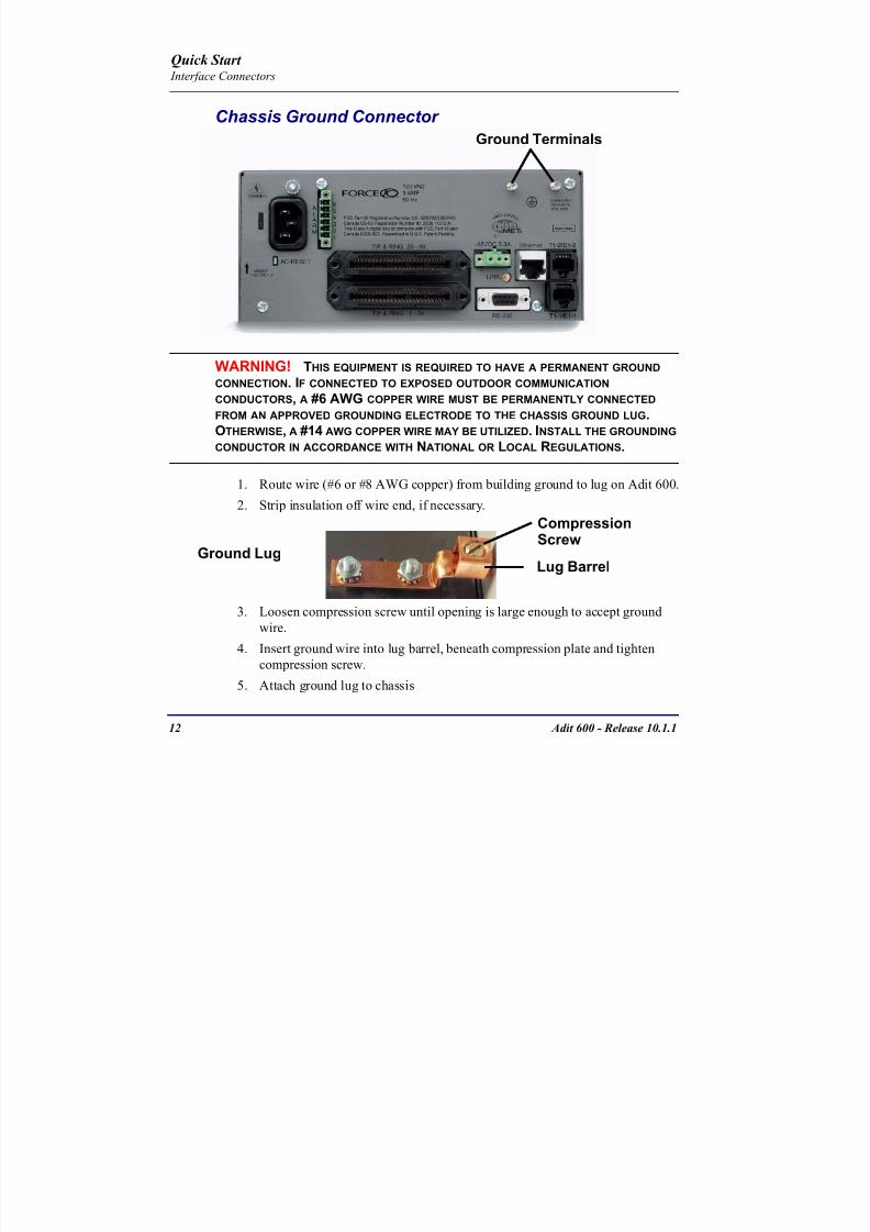
8102019 Adit 600 Quick Start 10-1-1
httpslidepdfcomreaderfulladit-600-quick-start-10-1-1 1454
12 Adit 600 - Release 1011
Quick Start Interface Connectors
Chassis Ground Connector
WARNING THIS EQUIPMENT IS REQUIRED TO HAVE A PERMANENT GROUND CONNECTION IF CONNECTED TO EXPOSED OUTDOOR COMMUNICATION CONDUCTORS A 6 AWG COPPER WIRE MUST BE PERMANENTLY CONNECTED FROM AN APPROVED GROUNDING ELECTRODE TO THE CHASSIS GROUND LUG
OTHERWISE A 14 AWG COPPER WIRE MAY BE UTILIZED INSTALL THE GROUNDING CONDUCTOR IN ACCORDANCE WITH NATIONAL OR LOCAL REGULATIONS
1 Route wire (6 or 8 AWG copper) from building ground to lug on Adit 600
2 Strip insulation off wire end if necessary
3 Loosen compression screw until opening is large enough to accept ground
wire
4 Insert ground wire into lug barrel beneath compression plate and tighten
compression screw
5 Attach ground lug to chassis
Ground Terminals
Ground Lug
Compression
ScrewLug Barrel
8102019 Adit 600 Quick Start 10-1-1
httpslidepdfcomreaderfulladit-600-quick-start-10-1-1 1554
Adit 600 - Release 1011 13
Quick Start Interface Connectors
Power Reset
This is a resetable circuit breaker If at any time there is a short or power
surge on the incoming ACDC line the breaker will trip to protect the
Power supply from damage
Power Connections
There are four power supplies available for the Adit 600
115 VAC-48 VDC
230 VAC-48 VDC
24-48 VDC
24 VDC with -48 Output
These power supplies have different connectors as shown in the following Foradditional information see Chapter 15 Power Supply of the Adit 600 User Manual
Fuse Recommendation
When using -48 VDC input power use a 35 Amp fast-acting fuse if the power
connector is wired to a fuse panel
Power Cord AC An AC Power cord is provided with the 115 VAC and the
230 VAC Power Supplies
To connect the Power Cord
1 Insert power cord (male-end) to AC power source
2 Plug connector into the Adit 6003 A green light should appear on the DC Input LED on the front of the Power
Supply
AC Power Connector
8102019 Adit 600 Quick Start 10-1-1
httpslidepdfcomreaderfulladit-600-quick-start-10-1-1 1654
14 Adit 600 - Release 1011
Quick Start Interface Connectors
-48V Battery
The -48 VDC input connector on the Adit 600 is used for either direct DC powering
of the Adit 600 unit or for a Battery Backup connection when AC is used There is
no power cable provided for this connector however the connector is provided
WARNING POSSIBLE SHOCK HAZARD EXISTS PLEASE FOLLOW INSTRUCTIONS
CAREFULLY
To connect -48 VDC power
1 Ensure that no power is present on the two wires to be connected
2 Strip the two wires (approx 516 in bare wire) from the power source 16 or 18 AWG insulated copper wire is recommended for power connections
3 Insert the Battery Return and DC wires into the appropriate square holes
4 Tighten screws to clamp wires
5 Ensure that no bare wire shows after the wires are installed
6 Plug connector in the -48 VDC connector as seen below and secure with set
screws
7 Apply power to connector from -48 VDC power source
8 Verify with voltmeter that voltage is correct and polarity is correct
8102019 Adit 600 Quick Start 10-1-1
httpslidepdfcomreaderfulladit-600-quick-start-10-1-1 1754
Adit 600 - Release 1011 15
Quick Start Interface Connectors
9 Plug connector in the Adit 600 -48 VDC connector as seen in the graphic andsecure with set screws
Power Cord DC
There is no power cable provided with the 24
VDC Power Supply however the connector is
provided This connector will need to be wired
the following chart prides the wire gauge
recommendedTo connect 24 VDC power
1 Ensure that no power is present on the two wires to be connected
WARNING POSSIBLE SHOCK HAZARD EXISTS PLEASE FOLLOW INSTRUCTIONS CAREFULLY
1(+) 2(-)
Connector
Provided connector (female)
of Adit 600on back
(male)
Battery -48 VDC
2(-)
BatteryReturn (+)
-48 VDC (-)
Return 1(+)
24 VDC6 Amp
Battery
Battery (+)
DC Power Connector
Return (-)
8102019 Adit 600 Quick Start 10-1-1
httpslidepdfcomreaderfulladit-600-quick-start-10-1-1 1854
16 Adit 600 - Release 1011
Quick Start Interface Connectors
2 Strip the two wires from the powersource so that approximately 516 inch
of bare wire is exposed see Wire Gauge
chart below for wire recommendations
3 Insert the Battery Return (-) and Battery
(+) wires into the appropriate square
holes one at a time4 Tighten screws to clamp wires
5 Ensure that no bare wire shows after the
wires are installed
6 Apply power to connector
7 Verify with voltmeter that voltage is
correct and polarity is correct
8 Plug connector(s) into the Adit 600 DC
Power connector as seen in the graphic
and secure with set screws
9 A green light should appear on the DC OK LED on the front of the Power
Supply
Wire Gauge 18 AWG 16 AWG 14 AWG
Maximum Distance 12 Feet 20 Feet 35 Feet
Battery (+)
BatteryReturn (-)
8102019 Adit 600 Quick Start 10-1-1
httpslidepdfcomreaderfulladit-600-quick-start-10-1-1 1954
Adit 600 - Release 1011 17
Quick Start Interface Connectors
External Alarm Connector
The external alarm 6-pin connector with one input pair (pins 5 and 6)
and two output pairs (pins 1 and 2 - major alarms pins 3 and 4 - minor
alarms)
The pinouts are as follows
Pin Description Explanation
1 Major Alarm + The major alarm output is available for power supply or
major alarm failure alerting The maximum voltage across
the contacts is 350 V and the maximum current is 150 mA
This alarm is closed when power is off
2 Major Alarm -
3 Minor Alarm + The minor alarm output is available for power supply or
minor alarm failure alerting The maximum voltage across
the contacts is 350 V and the maximum current is 150 mA
This alarm remains open when power is off
4 Minor Alarm -
5 Alarm In + The alarm inputs provide 5 VDC across the two contactsand generate an alarm when a short circuit is detected
between the contacts
The alarm generated is a minor severity alarm
6 Alarm In -
6
5
4
3
2
1
A
L
A
R
M
8102019 Adit 600 Quick Start 10-1-1
httpslidepdfcomreaderfulladit-600-quick-start-10-1-1 2054
18 Adit 600 - Release 1011
Quick Start Interface Connectors
25-Pair Telco ConnectorsTip and Ring Analog Interfaces equipped with standard 25-pair Telco Connectors
(female) for connection to key systems fax machines modems and PBXs These
interfaces are also used for ISDN BRI ports and are jumper selectable on the Quad T1
Quad E1 Quad DS1E1 and Quad ADPCM service cards
Circuit connections are made at the 25-pair
telco connectors A standard 25-pairtelephone cable with RJ-21X wiring and a
male D-type connector at the Adit 600 end
is required
The pinouts are as follows
Pair Pin Location Function Color Code
1 26
1
Tip Channel 1
Ring Channel 1
WhiteBlue
BlueWhite
2 27
2
Tip Channel 2
Ring Channel 2
WhiteOrange
OrangeWhite
3 28
3
Tip Channel 3
Ring Channel 3
WhiteGreen
GreenWhite
4 29
4
Tip Channel 4
Ring Channel 4
WhiteBrown
BrownWhite
5 30
5
Tip Channel 5
Ring Channel 5
WhiteSlate
SlateWhite
6 31
6
Tip Channel 6
Ring Channel 6
RedBlue
BlueRed
7 327
Tip Channel 7Ring Channel 7
RedOrangeOrangeRed
8 33
8
Tip Channel 8
Ring Channel 8
RedGreen
GreenRed
9 34
9
Tip Channel 9
Ring Channel 9
RedBrown
BrownRed
10 3510
Tip Channel 10Ring Channel 10
RedSlateSlateRed
50
25
26
1
8102019 Adit 600 Quick Start 10-1-1
httpslidepdfcomreaderfulladit-600-quick-start-10-1-1 2154
Adit 600 - Release 1011 19
Quick Start Interface Connectors
Pair Pin Location Function Color Code
11 36
11
Tip Channel 11
Ring Channel 11
BlackBlue
BlueBlack
12 37
12
Tip Channel 12
Ring Channel 12
BlackOrange
OrangeBlack
13 38
13
Tip Channel 13
Ring Channel 13
BlackGreen
GreenBlack
14 39
14
Tip Channel 14
Ring Channel 14
BlackBrown
BrownBlack
15 40
15
Tip Channel 15
Ring Channel 15
BlackSlate
SlateBlack
16 41
16
Tip Channel 16
Ring Channel 16
YellowBlue
BlueYellow17 42
17
Tip Channel 17
Ring Channel 17
YellowOrange
OrangeYellow
18 43
18
Tip Channel 18
Ring Channel 18
YellowGreen
GreenYellow
19 44
19
Tip Channel 19
Ring Channel 19
YellowBrown
BrownYellow
20 45
20
Tip Channel 20
Ring Channel 20
YellowSlate
SlateYellow
21 46
21
Tip Channel 21
Ring Channel 21
VioletBlue
BlueViolet
22 47
22
Tip Channel 22
Ring Channel 22
VioletOrange
OrangeViolet
23 48
23
Tip Channel 23
Ring Channel 23
VioletGreen
GreenViolet
24 49
24
Tip Channel 24
Ring Channel 24
VioletBrown
BrownViolet
25 50
25
Reserved VioletSlate
SlateViolet
8102019 Adit 600 Quick Start 10-1-1
httpslidepdfcomreaderfulladit-600-quick-start-10-1-1 2254
20 Adit 600 - Release 1011
Quick Start Interface Connectors
RS-232 Craft Port (Female DB-9)The RS-232 craft port connector (female) is for connection to an external PC or Hayes-
compatible modem for local or remote configuration management and performance
monitoring using the Adit 600 Command Line Interface (CLI)
The RS-232 craft port connects via a
female DB-9 connector on the Adit 600
The pinouts are as follows
Pin Number Direction Description
1 Outbound Carrier Detect
2 Outbound Receive Data
3 Inbound Transmit Data
4 Inbound Data Terminal Ready
5 NA Signal Ground
6 Outbound Data Set Ready
7 Inbound Request to Send
8 Outbound Clear to Send
9 NC Not connected
1 5
6 9
8102019 Adit 600 Quick Start 10-1-1
httpslidepdfcomreaderfulladit-600-quick-start-10-1-1 2354
8102019 Adit 600 Quick Start 10-1-1
httpslidepdfcomreaderfulladit-600-quick-start-10-1-1 2454
22 Adit 600 - Release 1011
Quick Start Interface Connectors
10Base-T Ethernet
The 10Base-T Ethernet (female) port to connect to a remote
management tool such as Telnet or an SNMP-based Network
Management System Note A LINK LED on the back of the unit
displays green when the system has a good Ethernet link
The pinouts are as follows
Ethernet (RJ-45)
NOTE This Ethernet port uses a hub pinout Use a straight-through cableto connect a PC
Pin Name Description
1 Receive + Receive from network
2 Receive - Receive from network
3 Transmit + Transmit to network
4 - 5 NC Not connected
6 Transmit - Transmit to network
7 NC Not connected
8 NC Not connected
1 8
8102019 Adit 600 Quick Start 10-1-1
httpslidepdfcomreaderfulladit-600-quick-start-10-1-1 2554
Adit 600 - Release 1011 23
Quick Start Management Options
Management Options
Options for managing the Adit 600 are as follows
Local using CLI Telnet SNMP or DIP Switches (Controller and voice cards)
Remotely over an in-band DS0 or through the Access Navigator over the FDL
or an in-band DS0
This Quick Start Guide focuses on the CLI and DIP switches If you need further
information on other management options please refer to the Adit 600 User Manual
Command Line Interface (CLI)
You can access the CLI using either of the following methods
Telnet via Ethernet (10Base-T) RS-232 connected to the DB-9 port
Setting up a CLI Connection
If connecting via the Ethernet 10Base-T connection use a Telnet TCPIP
program to access the CLI This requires the IP address of the Controller
Controllers are shipped with the IP address set to 100010 If this address has been changed and is not known use HyperTerm to access the Controller and
use the CLI command show ip If an IP address needs to be set use the CLI
command set ethernet ip address
If connecting via RS-232 the port settings should be set to
Bits per second 9600 Data bits 8
Parity None Stop bits 1Flow control None
Set your Terminal Emulation to VT100
By default the Adit 600 is set for local configuration (using DIP switches) Use
the set local off command to enable the use of CLI commands
8102019 Adit 600 Quick Start 10-1-1
httpslidepdfcomreaderfulladit-600-quick-start-10-1-1 2654
8102019 Adit 600 Quick Start 10-1-1
httpslidepdfcomreaderfulladit-600-quick-start-10-1-1 2754
Adit 600 - Release 1011 25
Quick Start Configuration
ConfigurationThe following basic setups and upgrades for the Adit 600 are shown using CLI
commands For more information on CLI commands and configurations see the Adit
600 User Manual
Initial Setup
Basic Security Setup
DS1T1 Setup
E1 Setup
DS0Channel Setup
Analog Port Setup
4-Wire EampM Setup
Establish a Static Channel Connection
ISDN BRI Service Setup
OCU-DP Card Setup
ADPCM Card Setup
V35 Port Setup
Change the IP Address of the DS0 Management Channel
Upgrade the Adit 600 Software
Upgrade the Router Card Software
Basic Router Setup
8102019 Adit 600 Quick Start 10-1-1
httpslidepdfcomreaderfulladit-600-quick-start-10-1-1 2854
26 Adit 600 - Release 1011
Quick Start Configuration
Initial SetupUse the following commands for your initial setup For further information see the Adit
600 User Manual
Command Description
set local off Disables DIP switches
set date mmddyyyy Set the date used for event logging
set time hhmmss Set the time used for event logging
set id id-name Set a system ID name
set clock1 slotportinternal
Set the primary clock source
set clock2 slotportinternal
Set the secondary clock source
set ethernet ip addressip-addr mask
Set the ethernet IP address in the
conventional IP address format
set ip gateway ip-addr Set the IP gateway in the conventional IP
address format
8102019 Adit 600 Quick Start 10-1-1
httpslidepdfcomreaderfulladit-600-quick-start-10-1-1 2954
Adit 600 - Release 1011 27
Quick Start Configuration
Basic Security SetupUse the following commands to set up the security on the Adit 600 For further
information see the Adit 600 User Manual
Command Description
set password length
long|short
Set user password length requirement
add user ldquouser-namerdquo[password ldquopasswordrdquo]
Add user and password as necessary
set user user-name level1-3
Specify the userrsquos security level
set user user-namepassword Setchange password for the user asnecessary
8102019 Adit 600 Quick Start 10-1-1
httpslidepdfcomreaderfulladit-600-quick-start-10-1-1 3054
28 Adit 600 - Release 1011
Quick Start Configuration
DS1T1 SetupUse the following commands to set up a DS1 See the set (ds1) command for more
details
Command Description
set ds1-addr up Activate the port of the DS1 (slotport)
set ds1-addr id id-string
Set the identification string
set ds1-addr lbo 1-9 Set the line buildout value for the DS1
set ds1-addr linecodeami|b8zs
Set the linecode for the DS1
set ds1-addr framing d4|esf|tr8afdl|tr8anofdl|tr8b
Set the framing option for the DS1
set ds1-addr loopdetecton|off
Set the detectionreaction to CSU loopcodes
Q i k S
8102019 Adit 600 Quick Start 10-1-1
httpslidepdfcomreaderfulladit-600-quick-start-10-1-1 3154
Adit 600 - Release 1011 29
Quick Start Configuration
E1 Setup
NOTE E1 is not supported in this release of the Adit 600 Controller It will besupported in a future release
Use the following commands to set up an E1 See the set (e1) command for more
details
DS0Channel Setup
Use the following commands to set up a DS0 See the set (ds0) command for details
Command Description
set e1-addr up Activate the port of the E1 (slotport)
set e1-addr id id-string Set the identification string
set e1-addr lbo 1 - 9 Set the line buildout value for the E1
set e1-addr linecodeami|hdb3
Set the linecode for the E1
set e1-addr framinge1fr|lefrcrc
Set the framing option for the E1
set e1-addr loopdetecton|off
Set the detectionreaction to CSU loopcodes
Command Description
set slotportchannel up Activate the channel
set slotportchannel signalls|gs|emw|emdw|emicpd|dpt
Set the signaling option for the channel
set slotportchannel typedata|voice Set the channel type
Q i k St t
8102019 Adit 600 Quick Start 10-1-1
httpslidepdfcomreaderfulladit-600-quick-start-10-1-1 3254
30 Adit 600 - Release 1011
Quick Start Configuration
Analog Port SetupUse the following commands to set up an analog port
Command Description
set slotport up Activate the port See set (ds1) command for
details
set slotport signal dpt|gs|gsrb|gsw|gswrb|ls|lscpd|lsrb
Set the signaling option for the port See the
set (fxs) or set (fxo) command for details
set slotport rxgain n Set the receive gainloss in dB See the set
(fxs) or set (fxo) command for details
set slotport txgain n Set the transmit gainloss in dB See the set
(fxs) or set (fxo) command for details
Quick Start
8102019 Adit 600 Quick Start 10-1-1
httpslidepdfcomreaderfulladit-600-quick-start-10-1-1 3354
Adit 600 - Release 1011 31
Quick Start Configuration
4-Wire EampM SetupFor this example the 4 EampM ports will be connected to the first 4 DS0s on T1-1 (a1)
This can be changed to match the customers desired DS0 connections
For Transmission Only mode the DS0s on the DS1 should be set to data as well as the
EampM card channels
Command Description
For Normal or Tandem EampM
set a11-4 type voice Set DS0s to voice
set connect a11-4 11-4 Connect DS0s to the 4 ports of the 4-
Wire EampM card
show connect a 1 Verify cross connects
set a11-4 signal emi Set DS0 signal type to EMI
set 11-4 signal emi Set 4-Wire EampM ports signal type to
EMI
show connect a1 Verify cross connects
For TO Mode
set a11-4 type data Set DS0s to data
set 11-4 type data Set 4-Wire EampM port to data
set connect a11-4 11-4 Connect DS0s to the 4 ports of the 4-
Wire EampM card
show connect a 1 Verify cross connects
Quick Start
8102019 Adit 600 Quick Start 10-1-1
httpslidepdfcomreaderfulladit-600-quick-start-10-1-1 3454
32 Adit 600 - Release 1011
Quick Start Configuration
Establish a Static Channel ConnectionUse the following commands to establish a static channel connection
ISDN BRI Service Setup
Use the following commands to set up a ISDN BRI Service See the set (bri) command
for details
Command Description
set slotportchannel typevoice|data
Set the channel type for the channel to
map See set (ds0) command for details
set slotportchannel signalls|gs|emw|emdw|emicpd|dpt
Set the channel signaling option See set
(ds0) command for details
connect slotportslotport
Connect the channels See the connect
(card-trunk) (card-trunk) command
Command Description
set slotport up Put the ISDN line In-Service
set slot modelt3ds0|lt4to1tdm|nt3ds0
Set the ISDN mode
set slotport crv 1-768 Set the Call Reference Value Note
value must be the same as the Access
Navigator
set slotport thresholdday|hour es|ses
Set the threshold for the IDSN lines
set slot pmsyncadit|switch
Set the source for performance
monitoring synchronization
set slotport autoactivate
on|off
Only used in 4-to-1 mode Establishes
the D channel when the FDL link can not
be used
Quick Start
8102019 Adit 600 Quick Start 10-1-1
httpslidepdfcomreaderfulladit-600-quick-start-10-1-1 3554
Adit 600 - Release 1011 33
Quick Start Configuration
OCU-DP Card SetupThe following is a basic setup for the OCU-DP card
ADPCM Card Setup
Command Description
set ocudp-addr baud2400|4800|9600|19200|38400|
56000|64000
Set the OCU-DP Baud rate
Where ocudp-addr = slotport of the
OCU-DP card to apply settings to
set ocudp-addr up Set the OCU-DP port 1 up
show ocudp_card-addr Show the OCU-DP card settings
Where ocudp_card-addr = slot of the
OCU-DP card
disconnect a Disconnects all connections to slot a
(controller)
set ds0-addr type data Sets a DS0 data signaling type
connect ds0-addrocudp-addr
Connects DS0 (in previous step) to OCU-DP
port (in previous step)
show connect
(ocudp_card-addr
Displays connect information for OCU-DP
card
Command Description
Connect T1 cable to port 1 of the ADPCM service card
set adpcm_card-addrnone|map1|map2|map3
Enable compressing by selecting Map type Notenone disables compression
show (adpcm_card-addr Displays the status of the card and the mapping
connect 211-12 241-12 Set ADPCM cross-connects The example
connects all 24 channels of the ADPCM to the 12
channels of the T1 (now compressed) on port 4
This example is with map2show connect 21) Displays the connections made above
8102019 Adit 600 Quick Start 10-1-1
httpslidepdfcomreaderfulladit-600-quick-start-10-1-1 3654
Quick Start
8102019 Adit 600 Quick Start 10-1-1
httpslidepdfcomreaderfulladit-600-quick-start-10-1-1 3754
Adit 600 - Release 1011 35
QConfiguration
Upgrade the Adit 600 SoftwareUse the following commands to determine the system software level then upgrade the
software to the latest version
Command Description
status equipment Determine the system software level The
Slot A line (SW Vers) will display thecurrent software level
load tftp ip-addr file-name (or load xmodem)
Load the new controller system software See
the load tftp and load xmodem command for
more information
Note A TFTP server must be running onthe host system You can use any TFTP
server utility you wish One example isthe program TFTPD32 which can bedownloaded free-of-charge attftpd32jouninnettftpd32html
Quick Start
8102019 Adit 600 Quick Start 10-1-1
httpslidepdfcomreaderfulladit-600-quick-start-10-1-1 3854
36 Adit 600 - Release 1011
Configuration
Upgrade the Router Card SoftwareUse the following commands to determine the Router card software level then upgrade
the software to the latest version
NOTE For additional information about upgrading MSR card software see
the following manuals-Adit 600 User Manual -Adit 3000 Series and Multi-Service Router (MSR) Card GUI Reference Manual
-Adit 3000 Series and Multi-Service Router (MSR) Card CLI Reference Manual
Command Description
status equipment Determine the Router software level The
Router Slot line (SW Vers) will display thecurrent software level
load rtr_card-addr tftpip-addr file-name
Load the new Router software to a Router
card See the load tftp command for more
information
Note A TFTP server must be running onthe host system You can use any TFTP
server utility you wish One example isthe program TFTPD32 which can bedownloaded free-of-charge attftpd32jouninnettftpd32html
8102019 Adit 600 Quick Start 10-1-1
httpslidepdfcomreaderfulladit-600-quick-start-10-1-1 3954
8102019 Adit 600 Quick Start 10-1-1
httpslidepdfcomreaderfulladit-600-quick-start-10-1-1 4054
Quick Start C t ll C d LED
8102019 Adit 600 Quick Start 10-1-1
httpslidepdfcomreaderfulladit-600-quick-start-10-1-1 4154
Adit 600 - Release 1011 39
Controller Card LEDs
E1 Controller Card
NOTE E1 is not supported in this release It will be supported in a futurerelease
The E1 Controller has a set of six LEDs The table below describes each LED
LED State Description
MAJOR Off No major alarms present
Red Major alarm present
MINOR Off No minor alarms present
Yellow Minor alarms present
LOCAL Off Remote mode (DIP switches disabled)
Green Local mode (DIP switches enabled)
ACO Off Normal mode No alarms are being
suppressed
Yellow Alarm Cut Off active One or more active
alarms suppressed
E1-1 and
E1-2
Off Off line
Green Normal
Red Loss of Signal (LOS) detected
Yellow Bipolar Violation (BPV) detected LCV
Flashing Green Loopback active
Flashing Red
(slow)
Loss of Frame (LOF) or Alarm Indication
Signal (AIS) detected
Flashing Red
(fast)
Card Failure
Flashing Yellow Yellow alarm (Remote Alarm Indication)detected
Quick Start Power Supply LEDs
8102019 Adit 600 Quick Start 10-1-1
httpslidepdfcomreaderfulladit-600-quick-start-10-1-1 4254
40 Adit 600 - Release 1011
Power Supply LEDs
Power Supply LEDs115 VAC-48 VDC and 230 VAC-48 VDC Power Supplies
The power supply card has two LEDs as described in the table
below
24 VDC-48 VDC Power Supply
The power supply card has two LEDs as described in the table below
LED State Description
AC Input Off AC input missing or failure
Green AC input present
Battery Off Battery input not used
Green Battery charging or operating from DC
source only
Yellow Battery discharging
Red Battery low (less than 42V) ringer disabled
LED State Description
DC OK Off DC input missing or failure
Green DC input present
-48 Battery
Low
Off Normal
Red VDC is low (less than 42 VDC)
ringer disabled
Quick Start Service Card LEDs
8102019 Adit 600 Quick Start 10-1-1
httpslidepdfcomreaderfulladit-600-quick-start-10-1-1 4354
Adit 600 - Release 1011 41
Service Card LEDs
Service Card LEDs 4-Wire EampM Card
FXO Card
FXS Card
ISDN BRI Card
OCU-DP Card
P-Phone Card
Single Channel POTS Card
Quad DS1 ADPCM Service Card
Quad DS1E1 and Quad T1 Cards
Quad E1 Card
IP Router Card
CMG Router Card
Terminal Server Router Card
MSR Card
RS-232 and V35V54 Cards
Discontinued cards
RS-232 discontinued
Quick Start Service Card LEDs
8102019 Adit 600 Quick Start 10-1-1
httpslidepdfcomreaderfulladit-600-quick-start-10-1-1 4454
42 Adit 600 - Release 1011
Service Card LEDs
4-Wire EampM Card Each channelport has two LEDs Only the top LED is used in this application LED
definitions are listed below
State Description
When in EampM Mode
Off Channel is idle or disabled
Green Analog interface is off-hook
Red Digital interface is off-hook
Yellow Both analog and digital interfaces are off-hook or channel is
being trunk processed
When in TO Mode
Off DisconnectedGreen Connected T1E1 not in alarm
Yellow Connected T1E1 in alarm (trunk processed)
Quick Start Service Card LEDs
8102019 Adit 600 Quick Start 10-1-1
httpslidepdfcomreaderfulladit-600-quick-start-10-1-1 4554
Adit 600 - Release 1011 43
FXO Card Each port on the FXO card has its own LED as described in the table below
FXS Card
There is an LED for each port on the FXS card as described in the table below
State Loop Start
Meaning
Ground Start Meaning Dial Pulse Termination
Meaning
Off NA Idle (tip open) Idle (loop open)
Green Idle Tip ground (incoming seizure) Incoming seizure
Red NA Ring ground (outgoing
seizure)
Loop closure (outgoing seizure)
Yellow Call in
progress
Call in progress Call in progress (reverse battery)
Flashing
Green
Ringing Ringing NA
State Loop Start Meaning Ground Start Meaning
Off NA Idle (tip open)
Green Idle Tip ground (incoming seizure)
Red Note This can be seen with
Forward Disconnect (tip open)
Ring ground (outgoing seizure)
Yellow Call in progress Call in progress
Flashing green Ringing Ringing
Quick Start Service Card LEDs
8102019 Adit 600 Quick Start 10-1-1
httpslidepdfcomreaderfulladit-600-quick-start-10-1-1 4654
44 Adit 600 - Release 1011
ISDN BRI Card There is an LED for each ISDN BRI on a card as described in the table below
OCU-DP Card Each channel has two LEDs described in the table below
State Description
Off Line U-interface is attempting synchronization or BRI is Out-of-Service
Red Line alarm (LOS or self test failure)
Yellow ES or SES has occurred
Flashing yellow Line U-interface is synchronized with customer equipment but is not passing
customer data
Flashing green Line U-interface is in external loopback toward the switch at the unit
Green Normal (Line U-interface is active and transparently passing customer data)
State Description
Yellow Flickering ALL Boot Software in control
Green (walking down)
Red (walking up)
ALL Application Software in control
(repeated 35 times)
Red slow flash ALL In Boot Application flash code checksums did not match and
Boot is waiting for application download
Red ALL In Application code waiting for Controller to issue SWHW
revision request This is the first request that comes from the
OCU-DP card manager in the ControllerGreen
Yellow
Top
Bottom
Port in Self-test Duration is 5-8 seconds
Off Top
Bottom
Port is set down (Out-Of-Service)
Green Top Port is receiving valid signals
Red Top Port is receiving no signal (primary) or no frame sync
(secondary or clear channel)Red Flashing Bottom Port is receiving bipolar violations
Yellow Bottom Port is in loopback
Quick Start Service Card LEDs
8102019 Adit 600 Quick Start 10-1-1
httpslidepdfcomreaderfulladit-600-quick-start-10-1-1 4754
Adit 600 - Release 1011 45
P-Phone Card Each P-Phone channel has a corresponding LED described in the table below
State Line State
Off No P-Phone connected
Green No call in process
Flashing Green Alert (Ringing)
Yellow Call in progress
Flashing Yellow P-Phone Loopback in Progress
Flashing Red Self-test failed
Quick Start Service Card LEDs
8102019 Adit 600 Quick Start 10-1-1
httpslidepdfcomreaderfulladit-600-quick-start-10-1-1 4854
46 Adit 600 - Release 1011
Single Channel POTS Card The POTS channel LED (left) status is described in the table below
The second LED (right) is a status LED is not used on this card
Quad DS1 ADPCM Service Card
Each channel on the Quad DS1 ADPCM card has two LEDs The
description of the top LED is shown below the bottom LED is notused with this application
State Loop Start Meaning
Off Calling Party Disconnect
Green Idle
Red NA
Yellow Call in progress
Flashing green Ringing
State Description
Off Off line
Green Normal
Red Loss of Signal (LOS)
Yellow Bipolar Violation (BPV)Flashing Green Loopback active
Flashing Yellow Yellow Alarm
(Remote Alarm Indication)
Flashing Red (Slow) Loss of Frame (LOF) or Alarm Indication Signal (AIS)
Flashing Red (Fast) Self-test Failure
Top LED(active)
Bottom LED(not used)
Quick Start Service Card LEDs
8102019 Adit 600 Quick Start 10-1-1
httpslidepdfcomreaderfulladit-600-quick-start-10-1-1 4954
Adit 600 - Release 1011 47
Quad DS1E1 and Quad T1 CardsEach channel on the Quad T1E1 cards have two LEDs The description
of the top LED is shown below the bottom LED is not used with this
application
State Description
Off Off line
Green Normal
Red Loss of Signal (LOS)
Yellow Bipolar Violation (BPV)
Flashing Green Loopback active
Flashing Yellow Yellow Alarm (Remote Alarm Indication)
Flashing Red (Slow) Loss of Frame (LOF) or Alarm Indication Signal (AIS)
Flashing Red (Fast) Self-test Failure
Quick Start Service Card LEDs
8102019 Adit 600 Quick Start 10-1-1
httpslidepdfcomreaderfulladit-600-quick-start-10-1-1 5054
48 Adit 600 - Release 1011
IP Router Card The following chart describes each LED and its state
LED State Description
CRD Off Loss of power
Green No current alarms
Red Alarm state active See alarm log for cause
Red Flashing Self-test or Boot in-process
Yellow Flashing Card is saving data to flash RAM do not power down
10100 Off 10 Mb ethernet
Green 100 Mb ethernet
LNK Off No ethernet link
Green Good ethernet link
COL
Off No current ethernet transmit collisions
Yellow Ethernet collisions have occurred and have not dropped
to minimum level
Yellow Flashing Ethernet collision occurring
TX Off No ethernet transmit activity
Green Ethernet transmit activity
RX Off No current ethernet receive activity
Green Current ethernet receive activity
Quick Start Service Card LEDs
8102019 Adit 600 Quick Start 10-1-1
httpslidepdfcomreaderfulladit-600-quick-start-10-1-1 5154
Adit 600 - Release 1011 49
CMG Router Card The following chart describes each LED and its state
LED State Description
CRD Off Loss of power
Green No current alarms
Red Alarm state active See alarm log for causeRed Flashing Self-test or Boot in-process
Yellow Flashing Card is saving data to flash RAM do not power down
VOIP
Off No active VoIP calls or if the MGCP protocol is
optioned down
Green Active VoIP calls
Red Call agent unreachable
Yellow Insufficient VoIP resources to complete call
LNK Off No Ethernet link
Green Good Ethernet link
10100 Off 10 Mb Ethernet
Green 100 Mb Ethernet
TX Off No Ethernet transmit activityGreen Ethernet transmit activity
Yellow Current Ethernet transmit collision
RX Off No current Ethernet receive activity
Green Current Ethernet receive activity
Quick Start Service Card LEDs
8102019 Adit 600 Quick Start 10-1-1
httpslidepdfcomreaderfulladit-600-quick-start-10-1-1 5254
50 Adit 600 - Release 1011
Terminal Server Router Card The Terminal Server Router card has 2 LEDs per port
At Power-up
Normal Operation
Port Set for Ethernet
Top LED indicates 100M Link Bottom LED indicates 10M Link
Port Set for RS-232
TOP LED Bottom LED Description
Off Off At Power UpBoot = Loss of power
Red Red Card is inoperative
Flashing Red Flashing Red Self-test or Boot in-process
TOP LED Bottom LED Description
Green Solid (Link) Green Solid (Link) Port set for Ethernet - see below
Flashing Red Flashing Red Self-test or Boot in-process
State Description
Off No Ethernet link
Green Link but no activity
Red Flashing Current Ethernet collision
Green Flashing Current Ethernet receive
Yellow Flashing Current Ethernet transmit
TOP LED Bottom LED Description
Yellow Off No Activity
Yellow Flashing Yellow Current transmit
Yellow Flashing Green Current receive
Quick Start Service Card LEDs
8102019 Adit 600 Quick Start 10-1-1
httpslidepdfcomreaderfulladit-600-quick-start-10-1-1 5354
Adit 600 - Release 1011 51
MSR Card The following chart describes the MSR cardrsquos LEDs
LED State Description
CRD Off Loss of power
Green No current alarms
Red Alarm state active See alarm log for cause
Red Flashing Self-test or boot in process
Yellow Flashing Card is saving data to flash RAM do not power
down
VOIP
Off No SIP proxy or registration attempts for all lines
have succeeded but no calls are active
Green Active VoIP call(s)
Red Inability to reach the SIP proxy or negative response
to register attempts from all lines
Yellow Register attempts from some lines have succeeded
but not for all lines
ETH1 and
ETH2
Top LED
Off 10 Mbitsec down or not connected
Green 100 Mbitsec
ETH1 and
ETH2
Bottom LED
Off Link down
Green Link up
Flashing Green Traffic on link
Yellow Collision status
Quick Start Service Card LEDs
8102019 Adit 600 Quick Start 10-1-1
httpslidepdfcomreaderfulladit-600-quick-start-10-1-1 5454
52 Adit 600 - Release 1011
RS-232 and V35V54 Cards Each port has its own LED as described in the table below
State Description
Off No T1 Assignment
Green Normal (CDRTS) Active
Red CD inactive (T1-side failure)
Yellow RTS inactive (equipment-side failure)
Flashing Yellow Loopback toward T1 or equipment loop test
Flashing Green Loopback toward equipment or network loop test
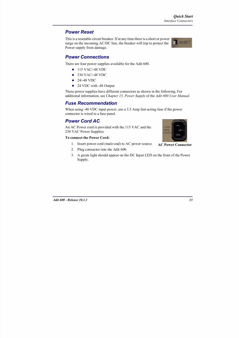
8102019 Adit 600 Quick Start 10-1-1
httpslidepdfcomreaderfulladit-600-quick-start-10-1-1 1554
Adit 600 - Release 1011 13
Quick Start Interface Connectors
Power Reset
This is a resetable circuit breaker If at any time there is a short or power
surge on the incoming ACDC line the breaker will trip to protect the
Power supply from damage
Power Connections
There are four power supplies available for the Adit 600
115 VAC-48 VDC
230 VAC-48 VDC
24-48 VDC
24 VDC with -48 Output
These power supplies have different connectors as shown in the following Foradditional information see Chapter 15 Power Supply of the Adit 600 User Manual
Fuse Recommendation
When using -48 VDC input power use a 35 Amp fast-acting fuse if the power
connector is wired to a fuse panel
Power Cord AC An AC Power cord is provided with the 115 VAC and the
230 VAC Power Supplies
To connect the Power Cord
1 Insert power cord (male-end) to AC power source
2 Plug connector into the Adit 6003 A green light should appear on the DC Input LED on the front of the Power
Supply
AC Power Connector
8102019 Adit 600 Quick Start 10-1-1
httpslidepdfcomreaderfulladit-600-quick-start-10-1-1 1654
14 Adit 600 - Release 1011
Quick Start Interface Connectors
-48V Battery
The -48 VDC input connector on the Adit 600 is used for either direct DC powering
of the Adit 600 unit or for a Battery Backup connection when AC is used There is
no power cable provided for this connector however the connector is provided
WARNING POSSIBLE SHOCK HAZARD EXISTS PLEASE FOLLOW INSTRUCTIONS
CAREFULLY
To connect -48 VDC power
1 Ensure that no power is present on the two wires to be connected
2 Strip the two wires (approx 516 in bare wire) from the power source 16 or 18 AWG insulated copper wire is recommended for power connections
3 Insert the Battery Return and DC wires into the appropriate square holes
4 Tighten screws to clamp wires
5 Ensure that no bare wire shows after the wires are installed
6 Plug connector in the -48 VDC connector as seen below and secure with set
screws
7 Apply power to connector from -48 VDC power source
8 Verify with voltmeter that voltage is correct and polarity is correct
8102019 Adit 600 Quick Start 10-1-1
httpslidepdfcomreaderfulladit-600-quick-start-10-1-1 1754
Adit 600 - Release 1011 15
Quick Start Interface Connectors
9 Plug connector in the Adit 600 -48 VDC connector as seen in the graphic andsecure with set screws
Power Cord DC
There is no power cable provided with the 24
VDC Power Supply however the connector is
provided This connector will need to be wired
the following chart prides the wire gauge
recommendedTo connect 24 VDC power
1 Ensure that no power is present on the two wires to be connected
WARNING POSSIBLE SHOCK HAZARD EXISTS PLEASE FOLLOW INSTRUCTIONS CAREFULLY
1(+) 2(-)
Connector
Provided connector (female)
of Adit 600on back
(male)
Battery -48 VDC
2(-)
BatteryReturn (+)
-48 VDC (-)
Return 1(+)
24 VDC6 Amp
Battery
Battery (+)
DC Power Connector
Return (-)
8102019 Adit 600 Quick Start 10-1-1
httpslidepdfcomreaderfulladit-600-quick-start-10-1-1 1854
16 Adit 600 - Release 1011
Quick Start Interface Connectors
2 Strip the two wires from the powersource so that approximately 516 inch
of bare wire is exposed see Wire Gauge
chart below for wire recommendations
3 Insert the Battery Return (-) and Battery
(+) wires into the appropriate square
holes one at a time4 Tighten screws to clamp wires
5 Ensure that no bare wire shows after the
wires are installed
6 Apply power to connector
7 Verify with voltmeter that voltage is
correct and polarity is correct
8 Plug connector(s) into the Adit 600 DC
Power connector as seen in the graphic
and secure with set screws
9 A green light should appear on the DC OK LED on the front of the Power
Supply
Wire Gauge 18 AWG 16 AWG 14 AWG
Maximum Distance 12 Feet 20 Feet 35 Feet
Battery (+)
BatteryReturn (-)
8102019 Adit 600 Quick Start 10-1-1
httpslidepdfcomreaderfulladit-600-quick-start-10-1-1 1954
Adit 600 - Release 1011 17
Quick Start Interface Connectors
External Alarm Connector
The external alarm 6-pin connector with one input pair (pins 5 and 6)
and two output pairs (pins 1 and 2 - major alarms pins 3 and 4 - minor
alarms)
The pinouts are as follows
Pin Description Explanation
1 Major Alarm + The major alarm output is available for power supply or
major alarm failure alerting The maximum voltage across
the contacts is 350 V and the maximum current is 150 mA
This alarm is closed when power is off
2 Major Alarm -
3 Minor Alarm + The minor alarm output is available for power supply or
minor alarm failure alerting The maximum voltage across
the contacts is 350 V and the maximum current is 150 mA
This alarm remains open when power is off
4 Minor Alarm -
5 Alarm In + The alarm inputs provide 5 VDC across the two contactsand generate an alarm when a short circuit is detected
between the contacts
The alarm generated is a minor severity alarm
6 Alarm In -
6
5
4
3
2
1
A
L
A
R
M
8102019 Adit 600 Quick Start 10-1-1
httpslidepdfcomreaderfulladit-600-quick-start-10-1-1 2054
18 Adit 600 - Release 1011
Quick Start Interface Connectors
25-Pair Telco ConnectorsTip and Ring Analog Interfaces equipped with standard 25-pair Telco Connectors
(female) for connection to key systems fax machines modems and PBXs These
interfaces are also used for ISDN BRI ports and are jumper selectable on the Quad T1
Quad E1 Quad DS1E1 and Quad ADPCM service cards
Circuit connections are made at the 25-pair
telco connectors A standard 25-pairtelephone cable with RJ-21X wiring and a
male D-type connector at the Adit 600 end
is required
The pinouts are as follows
Pair Pin Location Function Color Code
1 26
1
Tip Channel 1
Ring Channel 1
WhiteBlue
BlueWhite
2 27
2
Tip Channel 2
Ring Channel 2
WhiteOrange
OrangeWhite
3 28
3
Tip Channel 3
Ring Channel 3
WhiteGreen
GreenWhite
4 29
4
Tip Channel 4
Ring Channel 4
WhiteBrown
BrownWhite
5 30
5
Tip Channel 5
Ring Channel 5
WhiteSlate
SlateWhite
6 31
6
Tip Channel 6
Ring Channel 6
RedBlue
BlueRed
7 327
Tip Channel 7Ring Channel 7
RedOrangeOrangeRed
8 33
8
Tip Channel 8
Ring Channel 8
RedGreen
GreenRed
9 34
9
Tip Channel 9
Ring Channel 9
RedBrown
BrownRed
10 3510
Tip Channel 10Ring Channel 10
RedSlateSlateRed
50
25
26
1
8102019 Adit 600 Quick Start 10-1-1
httpslidepdfcomreaderfulladit-600-quick-start-10-1-1 2154
Adit 600 - Release 1011 19
Quick Start Interface Connectors
Pair Pin Location Function Color Code
11 36
11
Tip Channel 11
Ring Channel 11
BlackBlue
BlueBlack
12 37
12
Tip Channel 12
Ring Channel 12
BlackOrange
OrangeBlack
13 38
13
Tip Channel 13
Ring Channel 13
BlackGreen
GreenBlack
14 39
14
Tip Channel 14
Ring Channel 14
BlackBrown
BrownBlack
15 40
15
Tip Channel 15
Ring Channel 15
BlackSlate
SlateBlack
16 41
16
Tip Channel 16
Ring Channel 16
YellowBlue
BlueYellow17 42
17
Tip Channel 17
Ring Channel 17
YellowOrange
OrangeYellow
18 43
18
Tip Channel 18
Ring Channel 18
YellowGreen
GreenYellow
19 44
19
Tip Channel 19
Ring Channel 19
YellowBrown
BrownYellow
20 45
20
Tip Channel 20
Ring Channel 20
YellowSlate
SlateYellow
21 46
21
Tip Channel 21
Ring Channel 21
VioletBlue
BlueViolet
22 47
22
Tip Channel 22
Ring Channel 22
VioletOrange
OrangeViolet
23 48
23
Tip Channel 23
Ring Channel 23
VioletGreen
GreenViolet
24 49
24
Tip Channel 24
Ring Channel 24
VioletBrown
BrownViolet
25 50
25
Reserved VioletSlate
SlateViolet
8102019 Adit 600 Quick Start 10-1-1
httpslidepdfcomreaderfulladit-600-quick-start-10-1-1 2254
20 Adit 600 - Release 1011
Quick Start Interface Connectors
RS-232 Craft Port (Female DB-9)The RS-232 craft port connector (female) is for connection to an external PC or Hayes-
compatible modem for local or remote configuration management and performance
monitoring using the Adit 600 Command Line Interface (CLI)
The RS-232 craft port connects via a
female DB-9 connector on the Adit 600
The pinouts are as follows
Pin Number Direction Description
1 Outbound Carrier Detect
2 Outbound Receive Data
3 Inbound Transmit Data
4 Inbound Data Terminal Ready
5 NA Signal Ground
6 Outbound Data Set Ready
7 Inbound Request to Send
8 Outbound Clear to Send
9 NC Not connected
1 5
6 9
8102019 Adit 600 Quick Start 10-1-1
httpslidepdfcomreaderfulladit-600-quick-start-10-1-1 2354
8102019 Adit 600 Quick Start 10-1-1
httpslidepdfcomreaderfulladit-600-quick-start-10-1-1 2454
22 Adit 600 - Release 1011
Quick Start Interface Connectors
10Base-T Ethernet
The 10Base-T Ethernet (female) port to connect to a remote
management tool such as Telnet or an SNMP-based Network
Management System Note A LINK LED on the back of the unit
displays green when the system has a good Ethernet link
The pinouts are as follows
Ethernet (RJ-45)
NOTE This Ethernet port uses a hub pinout Use a straight-through cableto connect a PC
Pin Name Description
1 Receive + Receive from network
2 Receive - Receive from network
3 Transmit + Transmit to network
4 - 5 NC Not connected
6 Transmit - Transmit to network
7 NC Not connected
8 NC Not connected
1 8
8102019 Adit 600 Quick Start 10-1-1
httpslidepdfcomreaderfulladit-600-quick-start-10-1-1 2554
Adit 600 - Release 1011 23
Quick Start Management Options
Management Options
Options for managing the Adit 600 are as follows
Local using CLI Telnet SNMP or DIP Switches (Controller and voice cards)
Remotely over an in-band DS0 or through the Access Navigator over the FDL
or an in-band DS0
This Quick Start Guide focuses on the CLI and DIP switches If you need further
information on other management options please refer to the Adit 600 User Manual
Command Line Interface (CLI)
You can access the CLI using either of the following methods
Telnet via Ethernet (10Base-T) RS-232 connected to the DB-9 port
Setting up a CLI Connection
If connecting via the Ethernet 10Base-T connection use a Telnet TCPIP
program to access the CLI This requires the IP address of the Controller
Controllers are shipped with the IP address set to 100010 If this address has been changed and is not known use HyperTerm to access the Controller and
use the CLI command show ip If an IP address needs to be set use the CLI
command set ethernet ip address
If connecting via RS-232 the port settings should be set to
Bits per second 9600 Data bits 8
Parity None Stop bits 1Flow control None
Set your Terminal Emulation to VT100
By default the Adit 600 is set for local configuration (using DIP switches) Use
the set local off command to enable the use of CLI commands
8102019 Adit 600 Quick Start 10-1-1
httpslidepdfcomreaderfulladit-600-quick-start-10-1-1 2654
8102019 Adit 600 Quick Start 10-1-1
httpslidepdfcomreaderfulladit-600-quick-start-10-1-1 2754
Adit 600 - Release 1011 25
Quick Start Configuration
ConfigurationThe following basic setups and upgrades for the Adit 600 are shown using CLI
commands For more information on CLI commands and configurations see the Adit
600 User Manual
Initial Setup
Basic Security Setup
DS1T1 Setup
E1 Setup
DS0Channel Setup
Analog Port Setup
4-Wire EampM Setup
Establish a Static Channel Connection
ISDN BRI Service Setup
OCU-DP Card Setup
ADPCM Card Setup
V35 Port Setup
Change the IP Address of the DS0 Management Channel
Upgrade the Adit 600 Software
Upgrade the Router Card Software
Basic Router Setup
8102019 Adit 600 Quick Start 10-1-1
httpslidepdfcomreaderfulladit-600-quick-start-10-1-1 2854
26 Adit 600 - Release 1011
Quick Start Configuration
Initial SetupUse the following commands for your initial setup For further information see the Adit
600 User Manual
Command Description
set local off Disables DIP switches
set date mmddyyyy Set the date used for event logging
set time hhmmss Set the time used for event logging
set id id-name Set a system ID name
set clock1 slotportinternal
Set the primary clock source
set clock2 slotportinternal
Set the secondary clock source
set ethernet ip addressip-addr mask
Set the ethernet IP address in the
conventional IP address format
set ip gateway ip-addr Set the IP gateway in the conventional IP
address format
8102019 Adit 600 Quick Start 10-1-1
httpslidepdfcomreaderfulladit-600-quick-start-10-1-1 2954
Adit 600 - Release 1011 27
Quick Start Configuration
Basic Security SetupUse the following commands to set up the security on the Adit 600 For further
information see the Adit 600 User Manual
Command Description
set password length
long|short
Set user password length requirement
add user ldquouser-namerdquo[password ldquopasswordrdquo]
Add user and password as necessary
set user user-name level1-3
Specify the userrsquos security level
set user user-namepassword Setchange password for the user asnecessary
8102019 Adit 600 Quick Start 10-1-1
httpslidepdfcomreaderfulladit-600-quick-start-10-1-1 3054
28 Adit 600 - Release 1011
Quick Start Configuration
DS1T1 SetupUse the following commands to set up a DS1 See the set (ds1) command for more
details
Command Description
set ds1-addr up Activate the port of the DS1 (slotport)
set ds1-addr id id-string
Set the identification string
set ds1-addr lbo 1-9 Set the line buildout value for the DS1
set ds1-addr linecodeami|b8zs
Set the linecode for the DS1
set ds1-addr framing d4|esf|tr8afdl|tr8anofdl|tr8b
Set the framing option for the DS1
set ds1-addr loopdetecton|off
Set the detectionreaction to CSU loopcodes
Q i k S
8102019 Adit 600 Quick Start 10-1-1
httpslidepdfcomreaderfulladit-600-quick-start-10-1-1 3154
Adit 600 - Release 1011 29
Quick Start Configuration
E1 Setup
NOTE E1 is not supported in this release of the Adit 600 Controller It will besupported in a future release
Use the following commands to set up an E1 See the set (e1) command for more
details
DS0Channel Setup
Use the following commands to set up a DS0 See the set (ds0) command for details
Command Description
set e1-addr up Activate the port of the E1 (slotport)
set e1-addr id id-string Set the identification string
set e1-addr lbo 1 - 9 Set the line buildout value for the E1
set e1-addr linecodeami|hdb3
Set the linecode for the E1
set e1-addr framinge1fr|lefrcrc
Set the framing option for the E1
set e1-addr loopdetecton|off
Set the detectionreaction to CSU loopcodes
Command Description
set slotportchannel up Activate the channel
set slotportchannel signalls|gs|emw|emdw|emicpd|dpt
Set the signaling option for the channel
set slotportchannel typedata|voice Set the channel type
Q i k St t
8102019 Adit 600 Quick Start 10-1-1
httpslidepdfcomreaderfulladit-600-quick-start-10-1-1 3254
30 Adit 600 - Release 1011
Quick Start Configuration
Analog Port SetupUse the following commands to set up an analog port
Command Description
set slotport up Activate the port See set (ds1) command for
details
set slotport signal dpt|gs|gsrb|gsw|gswrb|ls|lscpd|lsrb
Set the signaling option for the port See the
set (fxs) or set (fxo) command for details
set slotport rxgain n Set the receive gainloss in dB See the set
(fxs) or set (fxo) command for details
set slotport txgain n Set the transmit gainloss in dB See the set
(fxs) or set (fxo) command for details
Quick Start
8102019 Adit 600 Quick Start 10-1-1
httpslidepdfcomreaderfulladit-600-quick-start-10-1-1 3354
Adit 600 - Release 1011 31
Quick Start Configuration
4-Wire EampM SetupFor this example the 4 EampM ports will be connected to the first 4 DS0s on T1-1 (a1)
This can be changed to match the customers desired DS0 connections
For Transmission Only mode the DS0s on the DS1 should be set to data as well as the
EampM card channels
Command Description
For Normal or Tandem EampM
set a11-4 type voice Set DS0s to voice
set connect a11-4 11-4 Connect DS0s to the 4 ports of the 4-
Wire EampM card
show connect a 1 Verify cross connects
set a11-4 signal emi Set DS0 signal type to EMI
set 11-4 signal emi Set 4-Wire EampM ports signal type to
EMI
show connect a1 Verify cross connects
For TO Mode
set a11-4 type data Set DS0s to data
set 11-4 type data Set 4-Wire EampM port to data
set connect a11-4 11-4 Connect DS0s to the 4 ports of the 4-
Wire EampM card
show connect a 1 Verify cross connects
Quick Start
8102019 Adit 600 Quick Start 10-1-1
httpslidepdfcomreaderfulladit-600-quick-start-10-1-1 3454
32 Adit 600 - Release 1011
Quick Start Configuration
Establish a Static Channel ConnectionUse the following commands to establish a static channel connection
ISDN BRI Service Setup
Use the following commands to set up a ISDN BRI Service See the set (bri) command
for details
Command Description
set slotportchannel typevoice|data
Set the channel type for the channel to
map See set (ds0) command for details
set slotportchannel signalls|gs|emw|emdw|emicpd|dpt
Set the channel signaling option See set
(ds0) command for details
connect slotportslotport
Connect the channels See the connect
(card-trunk) (card-trunk) command
Command Description
set slotport up Put the ISDN line In-Service
set slot modelt3ds0|lt4to1tdm|nt3ds0
Set the ISDN mode
set slotport crv 1-768 Set the Call Reference Value Note
value must be the same as the Access
Navigator
set slotport thresholdday|hour es|ses
Set the threshold for the IDSN lines
set slot pmsyncadit|switch
Set the source for performance
monitoring synchronization
set slotport autoactivate
on|off
Only used in 4-to-1 mode Establishes
the D channel when the FDL link can not
be used
Quick Start
8102019 Adit 600 Quick Start 10-1-1
httpslidepdfcomreaderfulladit-600-quick-start-10-1-1 3554
Adit 600 - Release 1011 33
Quick Start Configuration
OCU-DP Card SetupThe following is a basic setup for the OCU-DP card
ADPCM Card Setup
Command Description
set ocudp-addr baud2400|4800|9600|19200|38400|
56000|64000
Set the OCU-DP Baud rate
Where ocudp-addr = slotport of the
OCU-DP card to apply settings to
set ocudp-addr up Set the OCU-DP port 1 up
show ocudp_card-addr Show the OCU-DP card settings
Where ocudp_card-addr = slot of the
OCU-DP card
disconnect a Disconnects all connections to slot a
(controller)
set ds0-addr type data Sets a DS0 data signaling type
connect ds0-addrocudp-addr
Connects DS0 (in previous step) to OCU-DP
port (in previous step)
show connect
(ocudp_card-addr
Displays connect information for OCU-DP
card
Command Description
Connect T1 cable to port 1 of the ADPCM service card
set adpcm_card-addrnone|map1|map2|map3
Enable compressing by selecting Map type Notenone disables compression
show (adpcm_card-addr Displays the status of the card and the mapping
connect 211-12 241-12 Set ADPCM cross-connects The example
connects all 24 channels of the ADPCM to the 12
channels of the T1 (now compressed) on port 4
This example is with map2show connect 21) Displays the connections made above
8102019 Adit 600 Quick Start 10-1-1
httpslidepdfcomreaderfulladit-600-quick-start-10-1-1 3654
Quick Start
8102019 Adit 600 Quick Start 10-1-1
httpslidepdfcomreaderfulladit-600-quick-start-10-1-1 3754
Adit 600 - Release 1011 35
QConfiguration
Upgrade the Adit 600 SoftwareUse the following commands to determine the system software level then upgrade the
software to the latest version
Command Description
status equipment Determine the system software level The
Slot A line (SW Vers) will display thecurrent software level
load tftp ip-addr file-name (or load xmodem)
Load the new controller system software See
the load tftp and load xmodem command for
more information
Note A TFTP server must be running onthe host system You can use any TFTP
server utility you wish One example isthe program TFTPD32 which can bedownloaded free-of-charge attftpd32jouninnettftpd32html
Quick Start
8102019 Adit 600 Quick Start 10-1-1
httpslidepdfcomreaderfulladit-600-quick-start-10-1-1 3854
36 Adit 600 - Release 1011
Configuration
Upgrade the Router Card SoftwareUse the following commands to determine the Router card software level then upgrade
the software to the latest version
NOTE For additional information about upgrading MSR card software see
the following manuals-Adit 600 User Manual -Adit 3000 Series and Multi-Service Router (MSR) Card GUI Reference Manual
-Adit 3000 Series and Multi-Service Router (MSR) Card CLI Reference Manual
Command Description
status equipment Determine the Router software level The
Router Slot line (SW Vers) will display thecurrent software level
load rtr_card-addr tftpip-addr file-name
Load the new Router software to a Router
card See the load tftp command for more
information
Note A TFTP server must be running onthe host system You can use any TFTP
server utility you wish One example isthe program TFTPD32 which can bedownloaded free-of-charge attftpd32jouninnettftpd32html
8102019 Adit 600 Quick Start 10-1-1
httpslidepdfcomreaderfulladit-600-quick-start-10-1-1 3954
8102019 Adit 600 Quick Start 10-1-1
httpslidepdfcomreaderfulladit-600-quick-start-10-1-1 4054
Quick Start C t ll C d LED
8102019 Adit 600 Quick Start 10-1-1
httpslidepdfcomreaderfulladit-600-quick-start-10-1-1 4154
Adit 600 - Release 1011 39
Controller Card LEDs
E1 Controller Card
NOTE E1 is not supported in this release It will be supported in a futurerelease
The E1 Controller has a set of six LEDs The table below describes each LED
LED State Description
MAJOR Off No major alarms present
Red Major alarm present
MINOR Off No minor alarms present
Yellow Minor alarms present
LOCAL Off Remote mode (DIP switches disabled)
Green Local mode (DIP switches enabled)
ACO Off Normal mode No alarms are being
suppressed
Yellow Alarm Cut Off active One or more active
alarms suppressed
E1-1 and
E1-2
Off Off line
Green Normal
Red Loss of Signal (LOS) detected
Yellow Bipolar Violation (BPV) detected LCV
Flashing Green Loopback active
Flashing Red
(slow)
Loss of Frame (LOF) or Alarm Indication
Signal (AIS) detected
Flashing Red
(fast)
Card Failure
Flashing Yellow Yellow alarm (Remote Alarm Indication)detected
Quick Start Power Supply LEDs
8102019 Adit 600 Quick Start 10-1-1
httpslidepdfcomreaderfulladit-600-quick-start-10-1-1 4254
40 Adit 600 - Release 1011
Power Supply LEDs
Power Supply LEDs115 VAC-48 VDC and 230 VAC-48 VDC Power Supplies
The power supply card has two LEDs as described in the table
below
24 VDC-48 VDC Power Supply
The power supply card has two LEDs as described in the table below
LED State Description
AC Input Off AC input missing or failure
Green AC input present
Battery Off Battery input not used
Green Battery charging or operating from DC
source only
Yellow Battery discharging
Red Battery low (less than 42V) ringer disabled
LED State Description
DC OK Off DC input missing or failure
Green DC input present
-48 Battery
Low
Off Normal
Red VDC is low (less than 42 VDC)
ringer disabled
Quick Start Service Card LEDs
8102019 Adit 600 Quick Start 10-1-1
httpslidepdfcomreaderfulladit-600-quick-start-10-1-1 4354
Adit 600 - Release 1011 41
Service Card LEDs
Service Card LEDs 4-Wire EampM Card
FXO Card
FXS Card
ISDN BRI Card
OCU-DP Card
P-Phone Card
Single Channel POTS Card
Quad DS1 ADPCM Service Card
Quad DS1E1 and Quad T1 Cards
Quad E1 Card
IP Router Card
CMG Router Card
Terminal Server Router Card
MSR Card
RS-232 and V35V54 Cards
Discontinued cards
RS-232 discontinued
Quick Start Service Card LEDs
8102019 Adit 600 Quick Start 10-1-1
httpslidepdfcomreaderfulladit-600-quick-start-10-1-1 4454
42 Adit 600 - Release 1011
Service Card LEDs
4-Wire EampM Card Each channelport has two LEDs Only the top LED is used in this application LED
definitions are listed below
State Description
When in EampM Mode
Off Channel is idle or disabled
Green Analog interface is off-hook
Red Digital interface is off-hook
Yellow Both analog and digital interfaces are off-hook or channel is
being trunk processed
When in TO Mode
Off DisconnectedGreen Connected T1E1 not in alarm
Yellow Connected T1E1 in alarm (trunk processed)
Quick Start Service Card LEDs
8102019 Adit 600 Quick Start 10-1-1
httpslidepdfcomreaderfulladit-600-quick-start-10-1-1 4554
Adit 600 - Release 1011 43
FXO Card Each port on the FXO card has its own LED as described in the table below
FXS Card
There is an LED for each port on the FXS card as described in the table below
State Loop Start
Meaning
Ground Start Meaning Dial Pulse Termination
Meaning
Off NA Idle (tip open) Idle (loop open)
Green Idle Tip ground (incoming seizure) Incoming seizure
Red NA Ring ground (outgoing
seizure)
Loop closure (outgoing seizure)
Yellow Call in
progress
Call in progress Call in progress (reverse battery)
Flashing
Green
Ringing Ringing NA
State Loop Start Meaning Ground Start Meaning
Off NA Idle (tip open)
Green Idle Tip ground (incoming seizure)
Red Note This can be seen with
Forward Disconnect (tip open)
Ring ground (outgoing seizure)
Yellow Call in progress Call in progress
Flashing green Ringing Ringing
Quick Start Service Card LEDs
8102019 Adit 600 Quick Start 10-1-1
httpslidepdfcomreaderfulladit-600-quick-start-10-1-1 4654
44 Adit 600 - Release 1011
ISDN BRI Card There is an LED for each ISDN BRI on a card as described in the table below
OCU-DP Card Each channel has two LEDs described in the table below
State Description
Off Line U-interface is attempting synchronization or BRI is Out-of-Service
Red Line alarm (LOS or self test failure)
Yellow ES or SES has occurred
Flashing yellow Line U-interface is synchronized with customer equipment but is not passing
customer data
Flashing green Line U-interface is in external loopback toward the switch at the unit
Green Normal (Line U-interface is active and transparently passing customer data)
State Description
Yellow Flickering ALL Boot Software in control
Green (walking down)
Red (walking up)
ALL Application Software in control
(repeated 35 times)
Red slow flash ALL In Boot Application flash code checksums did not match and
Boot is waiting for application download
Red ALL In Application code waiting for Controller to issue SWHW
revision request This is the first request that comes from the
OCU-DP card manager in the ControllerGreen
Yellow
Top
Bottom
Port in Self-test Duration is 5-8 seconds
Off Top
Bottom
Port is set down (Out-Of-Service)
Green Top Port is receiving valid signals
Red Top Port is receiving no signal (primary) or no frame sync
(secondary or clear channel)Red Flashing Bottom Port is receiving bipolar violations
Yellow Bottom Port is in loopback
Quick Start Service Card LEDs
8102019 Adit 600 Quick Start 10-1-1
httpslidepdfcomreaderfulladit-600-quick-start-10-1-1 4754
Adit 600 - Release 1011 45
P-Phone Card Each P-Phone channel has a corresponding LED described in the table below
State Line State
Off No P-Phone connected
Green No call in process
Flashing Green Alert (Ringing)
Yellow Call in progress
Flashing Yellow P-Phone Loopback in Progress
Flashing Red Self-test failed
Quick Start Service Card LEDs
8102019 Adit 600 Quick Start 10-1-1
httpslidepdfcomreaderfulladit-600-quick-start-10-1-1 4854
46 Adit 600 - Release 1011
Single Channel POTS Card The POTS channel LED (left) status is described in the table below
The second LED (right) is a status LED is not used on this card
Quad DS1 ADPCM Service Card
Each channel on the Quad DS1 ADPCM card has two LEDs The
description of the top LED is shown below the bottom LED is notused with this application
State Loop Start Meaning
Off Calling Party Disconnect
Green Idle
Red NA
Yellow Call in progress
Flashing green Ringing
State Description
Off Off line
Green Normal
Red Loss of Signal (LOS)
Yellow Bipolar Violation (BPV)Flashing Green Loopback active
Flashing Yellow Yellow Alarm
(Remote Alarm Indication)
Flashing Red (Slow) Loss of Frame (LOF) or Alarm Indication Signal (AIS)
Flashing Red (Fast) Self-test Failure
Top LED(active)
Bottom LED(not used)
Quick Start Service Card LEDs
8102019 Adit 600 Quick Start 10-1-1
httpslidepdfcomreaderfulladit-600-quick-start-10-1-1 4954
Adit 600 - Release 1011 47
Quad DS1E1 and Quad T1 CardsEach channel on the Quad T1E1 cards have two LEDs The description
of the top LED is shown below the bottom LED is not used with this
application
State Description
Off Off line
Green Normal
Red Loss of Signal (LOS)
Yellow Bipolar Violation (BPV)
Flashing Green Loopback active
Flashing Yellow Yellow Alarm (Remote Alarm Indication)
Flashing Red (Slow) Loss of Frame (LOF) or Alarm Indication Signal (AIS)
Flashing Red (Fast) Self-test Failure
Quick Start Service Card LEDs
8102019 Adit 600 Quick Start 10-1-1
httpslidepdfcomreaderfulladit-600-quick-start-10-1-1 5054
48 Adit 600 - Release 1011
IP Router Card The following chart describes each LED and its state
LED State Description
CRD Off Loss of power
Green No current alarms
Red Alarm state active See alarm log for cause
Red Flashing Self-test or Boot in-process
Yellow Flashing Card is saving data to flash RAM do not power down
10100 Off 10 Mb ethernet
Green 100 Mb ethernet
LNK Off No ethernet link
Green Good ethernet link
COL
Off No current ethernet transmit collisions
Yellow Ethernet collisions have occurred and have not dropped
to minimum level
Yellow Flashing Ethernet collision occurring
TX Off No ethernet transmit activity
Green Ethernet transmit activity
RX Off No current ethernet receive activity
Green Current ethernet receive activity
Quick Start Service Card LEDs
8102019 Adit 600 Quick Start 10-1-1
httpslidepdfcomreaderfulladit-600-quick-start-10-1-1 5154
Adit 600 - Release 1011 49
CMG Router Card The following chart describes each LED and its state
LED State Description
CRD Off Loss of power
Green No current alarms
Red Alarm state active See alarm log for causeRed Flashing Self-test or Boot in-process
Yellow Flashing Card is saving data to flash RAM do not power down
VOIP
Off No active VoIP calls or if the MGCP protocol is
optioned down
Green Active VoIP calls
Red Call agent unreachable
Yellow Insufficient VoIP resources to complete call
LNK Off No Ethernet link
Green Good Ethernet link
10100 Off 10 Mb Ethernet
Green 100 Mb Ethernet
TX Off No Ethernet transmit activityGreen Ethernet transmit activity
Yellow Current Ethernet transmit collision
RX Off No current Ethernet receive activity
Green Current Ethernet receive activity
Quick Start Service Card LEDs
8102019 Adit 600 Quick Start 10-1-1
httpslidepdfcomreaderfulladit-600-quick-start-10-1-1 5254
50 Adit 600 - Release 1011
Terminal Server Router Card The Terminal Server Router card has 2 LEDs per port
At Power-up
Normal Operation
Port Set for Ethernet
Top LED indicates 100M Link Bottom LED indicates 10M Link
Port Set for RS-232
TOP LED Bottom LED Description
Off Off At Power UpBoot = Loss of power
Red Red Card is inoperative
Flashing Red Flashing Red Self-test or Boot in-process
TOP LED Bottom LED Description
Green Solid (Link) Green Solid (Link) Port set for Ethernet - see below
Flashing Red Flashing Red Self-test or Boot in-process
State Description
Off No Ethernet link
Green Link but no activity
Red Flashing Current Ethernet collision
Green Flashing Current Ethernet receive
Yellow Flashing Current Ethernet transmit
TOP LED Bottom LED Description
Yellow Off No Activity
Yellow Flashing Yellow Current transmit
Yellow Flashing Green Current receive
Quick Start Service Card LEDs
8102019 Adit 600 Quick Start 10-1-1
httpslidepdfcomreaderfulladit-600-quick-start-10-1-1 5354
Adit 600 - Release 1011 51
MSR Card The following chart describes the MSR cardrsquos LEDs
LED State Description
CRD Off Loss of power
Green No current alarms
Red Alarm state active See alarm log for cause
Red Flashing Self-test or boot in process
Yellow Flashing Card is saving data to flash RAM do not power
down
VOIP
Off No SIP proxy or registration attempts for all lines
have succeeded but no calls are active
Green Active VoIP call(s)
Red Inability to reach the SIP proxy or negative response
to register attempts from all lines
Yellow Register attempts from some lines have succeeded
but not for all lines
ETH1 and
ETH2
Top LED
Off 10 Mbitsec down or not connected
Green 100 Mbitsec
ETH1 and
ETH2
Bottom LED
Off Link down
Green Link up
Flashing Green Traffic on link
Yellow Collision status
Quick Start Service Card LEDs
8102019 Adit 600 Quick Start 10-1-1
httpslidepdfcomreaderfulladit-600-quick-start-10-1-1 5454
52 Adit 600 - Release 1011
RS-232 and V35V54 Cards Each port has its own LED as described in the table below
State Description
Off No T1 Assignment
Green Normal (CDRTS) Active
Red CD inactive (T1-side failure)
Yellow RTS inactive (equipment-side failure)
Flashing Yellow Loopback toward T1 or equipment loop test
Flashing Green Loopback toward equipment or network loop test
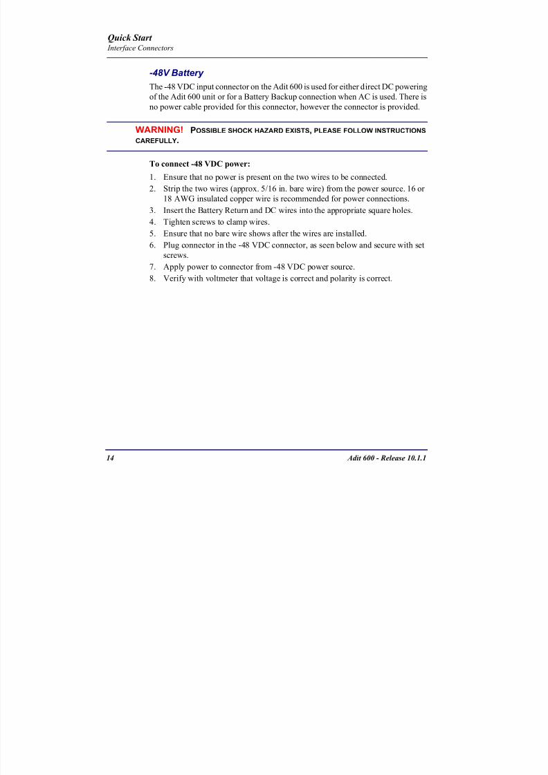
8102019 Adit 600 Quick Start 10-1-1
httpslidepdfcomreaderfulladit-600-quick-start-10-1-1 1754
Adit 600 - Release 1011 15
Quick Start Interface Connectors
9 Plug connector in the Adit 600 -48 VDC connector as seen in the graphic andsecure with set screws
Power Cord DC
There is no power cable provided with the 24
VDC Power Supply however the connector is
provided This connector will need to be wired
the following chart prides the wire gauge
recommendedTo connect 24 VDC power
1 Ensure that no power is present on the two wires to be connected
WARNING POSSIBLE SHOCK HAZARD EXISTS PLEASE FOLLOW INSTRUCTIONS CAREFULLY
1(+) 2(-)
Connector
Provided connector (female)
of Adit 600on back
(male)
Battery -48 VDC
2(-)
BatteryReturn (+)
-48 VDC (-)
Return 1(+)
24 VDC6 Amp
Battery
Battery (+)
DC Power Connector
Return (-)
8102019 Adit 600 Quick Start 10-1-1
httpslidepdfcomreaderfulladit-600-quick-start-10-1-1 1854
16 Adit 600 - Release 1011
Quick Start Interface Connectors
2 Strip the two wires from the powersource so that approximately 516 inch
of bare wire is exposed see Wire Gauge
chart below for wire recommendations
3 Insert the Battery Return (-) and Battery
(+) wires into the appropriate square
holes one at a time4 Tighten screws to clamp wires
5 Ensure that no bare wire shows after the
wires are installed
6 Apply power to connector
7 Verify with voltmeter that voltage is
correct and polarity is correct
8 Plug connector(s) into the Adit 600 DC
Power connector as seen in the graphic
and secure with set screws
9 A green light should appear on the DC OK LED on the front of the Power
Supply
Wire Gauge 18 AWG 16 AWG 14 AWG
Maximum Distance 12 Feet 20 Feet 35 Feet
Battery (+)
BatteryReturn (-)
8102019 Adit 600 Quick Start 10-1-1
httpslidepdfcomreaderfulladit-600-quick-start-10-1-1 1954
Adit 600 - Release 1011 17
Quick Start Interface Connectors
External Alarm Connector
The external alarm 6-pin connector with one input pair (pins 5 and 6)
and two output pairs (pins 1 and 2 - major alarms pins 3 and 4 - minor
alarms)
The pinouts are as follows
Pin Description Explanation
1 Major Alarm + The major alarm output is available for power supply or
major alarm failure alerting The maximum voltage across
the contacts is 350 V and the maximum current is 150 mA
This alarm is closed when power is off
2 Major Alarm -
3 Minor Alarm + The minor alarm output is available for power supply or
minor alarm failure alerting The maximum voltage across
the contacts is 350 V and the maximum current is 150 mA
This alarm remains open when power is off
4 Minor Alarm -
5 Alarm In + The alarm inputs provide 5 VDC across the two contactsand generate an alarm when a short circuit is detected
between the contacts
The alarm generated is a minor severity alarm
6 Alarm In -
6
5
4
3
2
1
A
L
A
R
M
8102019 Adit 600 Quick Start 10-1-1
httpslidepdfcomreaderfulladit-600-quick-start-10-1-1 2054
18 Adit 600 - Release 1011
Quick Start Interface Connectors
25-Pair Telco ConnectorsTip and Ring Analog Interfaces equipped with standard 25-pair Telco Connectors
(female) for connection to key systems fax machines modems and PBXs These
interfaces are also used for ISDN BRI ports and are jumper selectable on the Quad T1
Quad E1 Quad DS1E1 and Quad ADPCM service cards
Circuit connections are made at the 25-pair
telco connectors A standard 25-pairtelephone cable with RJ-21X wiring and a
male D-type connector at the Adit 600 end
is required
The pinouts are as follows
Pair Pin Location Function Color Code
1 26
1
Tip Channel 1
Ring Channel 1
WhiteBlue
BlueWhite
2 27
2
Tip Channel 2
Ring Channel 2
WhiteOrange
OrangeWhite
3 28
3
Tip Channel 3
Ring Channel 3
WhiteGreen
GreenWhite
4 29
4
Tip Channel 4
Ring Channel 4
WhiteBrown
BrownWhite
5 30
5
Tip Channel 5
Ring Channel 5
WhiteSlate
SlateWhite
6 31
6
Tip Channel 6
Ring Channel 6
RedBlue
BlueRed
7 327
Tip Channel 7Ring Channel 7
RedOrangeOrangeRed
8 33
8
Tip Channel 8
Ring Channel 8
RedGreen
GreenRed
9 34
9
Tip Channel 9
Ring Channel 9
RedBrown
BrownRed
10 3510
Tip Channel 10Ring Channel 10
RedSlateSlateRed
50
25
26
1
8102019 Adit 600 Quick Start 10-1-1
httpslidepdfcomreaderfulladit-600-quick-start-10-1-1 2154
Adit 600 - Release 1011 19
Quick Start Interface Connectors
Pair Pin Location Function Color Code
11 36
11
Tip Channel 11
Ring Channel 11
BlackBlue
BlueBlack
12 37
12
Tip Channel 12
Ring Channel 12
BlackOrange
OrangeBlack
13 38
13
Tip Channel 13
Ring Channel 13
BlackGreen
GreenBlack
14 39
14
Tip Channel 14
Ring Channel 14
BlackBrown
BrownBlack
15 40
15
Tip Channel 15
Ring Channel 15
BlackSlate
SlateBlack
16 41
16
Tip Channel 16
Ring Channel 16
YellowBlue
BlueYellow17 42
17
Tip Channel 17
Ring Channel 17
YellowOrange
OrangeYellow
18 43
18
Tip Channel 18
Ring Channel 18
YellowGreen
GreenYellow
19 44
19
Tip Channel 19
Ring Channel 19
YellowBrown
BrownYellow
20 45
20
Tip Channel 20
Ring Channel 20
YellowSlate
SlateYellow
21 46
21
Tip Channel 21
Ring Channel 21
VioletBlue
BlueViolet
22 47
22
Tip Channel 22
Ring Channel 22
VioletOrange
OrangeViolet
23 48
23
Tip Channel 23
Ring Channel 23
VioletGreen
GreenViolet
24 49
24
Tip Channel 24
Ring Channel 24
VioletBrown
BrownViolet
25 50
25
Reserved VioletSlate
SlateViolet
8102019 Adit 600 Quick Start 10-1-1
httpslidepdfcomreaderfulladit-600-quick-start-10-1-1 2254
20 Adit 600 - Release 1011
Quick Start Interface Connectors
RS-232 Craft Port (Female DB-9)The RS-232 craft port connector (female) is for connection to an external PC or Hayes-
compatible modem for local or remote configuration management and performance
monitoring using the Adit 600 Command Line Interface (CLI)
The RS-232 craft port connects via a
female DB-9 connector on the Adit 600
The pinouts are as follows
Pin Number Direction Description
1 Outbound Carrier Detect
2 Outbound Receive Data
3 Inbound Transmit Data
4 Inbound Data Terminal Ready
5 NA Signal Ground
6 Outbound Data Set Ready
7 Inbound Request to Send
8 Outbound Clear to Send
9 NC Not connected
1 5
6 9
8102019 Adit 600 Quick Start 10-1-1
httpslidepdfcomreaderfulladit-600-quick-start-10-1-1 2354
8102019 Adit 600 Quick Start 10-1-1
httpslidepdfcomreaderfulladit-600-quick-start-10-1-1 2454
22 Adit 600 - Release 1011
Quick Start Interface Connectors
10Base-T Ethernet
The 10Base-T Ethernet (female) port to connect to a remote
management tool such as Telnet or an SNMP-based Network
Management System Note A LINK LED on the back of the unit
displays green when the system has a good Ethernet link
The pinouts are as follows
Ethernet (RJ-45)
NOTE This Ethernet port uses a hub pinout Use a straight-through cableto connect a PC
Pin Name Description
1 Receive + Receive from network
2 Receive - Receive from network
3 Transmit + Transmit to network
4 - 5 NC Not connected
6 Transmit - Transmit to network
7 NC Not connected
8 NC Not connected
1 8
8102019 Adit 600 Quick Start 10-1-1
httpslidepdfcomreaderfulladit-600-quick-start-10-1-1 2554
Adit 600 - Release 1011 23
Quick Start Management Options
Management Options
Options for managing the Adit 600 are as follows
Local using CLI Telnet SNMP or DIP Switches (Controller and voice cards)
Remotely over an in-band DS0 or through the Access Navigator over the FDL
or an in-band DS0
This Quick Start Guide focuses on the CLI and DIP switches If you need further
information on other management options please refer to the Adit 600 User Manual
Command Line Interface (CLI)
You can access the CLI using either of the following methods
Telnet via Ethernet (10Base-T) RS-232 connected to the DB-9 port
Setting up a CLI Connection
If connecting via the Ethernet 10Base-T connection use a Telnet TCPIP
program to access the CLI This requires the IP address of the Controller
Controllers are shipped with the IP address set to 100010 If this address has been changed and is not known use HyperTerm to access the Controller and
use the CLI command show ip If an IP address needs to be set use the CLI
command set ethernet ip address
If connecting via RS-232 the port settings should be set to
Bits per second 9600 Data bits 8
Parity None Stop bits 1Flow control None
Set your Terminal Emulation to VT100
By default the Adit 600 is set for local configuration (using DIP switches) Use
the set local off command to enable the use of CLI commands
8102019 Adit 600 Quick Start 10-1-1
httpslidepdfcomreaderfulladit-600-quick-start-10-1-1 2654
8102019 Adit 600 Quick Start 10-1-1
httpslidepdfcomreaderfulladit-600-quick-start-10-1-1 2754
Adit 600 - Release 1011 25
Quick Start Configuration
ConfigurationThe following basic setups and upgrades for the Adit 600 are shown using CLI
commands For more information on CLI commands and configurations see the Adit
600 User Manual
Initial Setup
Basic Security Setup
DS1T1 Setup
E1 Setup
DS0Channel Setup
Analog Port Setup
4-Wire EampM Setup
Establish a Static Channel Connection
ISDN BRI Service Setup
OCU-DP Card Setup
ADPCM Card Setup
V35 Port Setup
Change the IP Address of the DS0 Management Channel
Upgrade the Adit 600 Software
Upgrade the Router Card Software
Basic Router Setup
8102019 Adit 600 Quick Start 10-1-1
httpslidepdfcomreaderfulladit-600-quick-start-10-1-1 2854
26 Adit 600 - Release 1011
Quick Start Configuration
Initial SetupUse the following commands for your initial setup For further information see the Adit
600 User Manual
Command Description
set local off Disables DIP switches
set date mmddyyyy Set the date used for event logging
set time hhmmss Set the time used for event logging
set id id-name Set a system ID name
set clock1 slotportinternal
Set the primary clock source
set clock2 slotportinternal
Set the secondary clock source
set ethernet ip addressip-addr mask
Set the ethernet IP address in the
conventional IP address format
set ip gateway ip-addr Set the IP gateway in the conventional IP
address format
8102019 Adit 600 Quick Start 10-1-1
httpslidepdfcomreaderfulladit-600-quick-start-10-1-1 2954
Adit 600 - Release 1011 27
Quick Start Configuration
Basic Security SetupUse the following commands to set up the security on the Adit 600 For further
information see the Adit 600 User Manual
Command Description
set password length
long|short
Set user password length requirement
add user ldquouser-namerdquo[password ldquopasswordrdquo]
Add user and password as necessary
set user user-name level1-3
Specify the userrsquos security level
set user user-namepassword Setchange password for the user asnecessary
8102019 Adit 600 Quick Start 10-1-1
httpslidepdfcomreaderfulladit-600-quick-start-10-1-1 3054
28 Adit 600 - Release 1011
Quick Start Configuration
DS1T1 SetupUse the following commands to set up a DS1 See the set (ds1) command for more
details
Command Description
set ds1-addr up Activate the port of the DS1 (slotport)
set ds1-addr id id-string
Set the identification string
set ds1-addr lbo 1-9 Set the line buildout value for the DS1
set ds1-addr linecodeami|b8zs
Set the linecode for the DS1
set ds1-addr framing d4|esf|tr8afdl|tr8anofdl|tr8b
Set the framing option for the DS1
set ds1-addr loopdetecton|off
Set the detectionreaction to CSU loopcodes
Q i k S
8102019 Adit 600 Quick Start 10-1-1
httpslidepdfcomreaderfulladit-600-quick-start-10-1-1 3154
Adit 600 - Release 1011 29
Quick Start Configuration
E1 Setup
NOTE E1 is not supported in this release of the Adit 600 Controller It will besupported in a future release
Use the following commands to set up an E1 See the set (e1) command for more
details
DS0Channel Setup
Use the following commands to set up a DS0 See the set (ds0) command for details
Command Description
set e1-addr up Activate the port of the E1 (slotport)
set e1-addr id id-string Set the identification string
set e1-addr lbo 1 - 9 Set the line buildout value for the E1
set e1-addr linecodeami|hdb3
Set the linecode for the E1
set e1-addr framinge1fr|lefrcrc
Set the framing option for the E1
set e1-addr loopdetecton|off
Set the detectionreaction to CSU loopcodes
Command Description
set slotportchannel up Activate the channel
set slotportchannel signalls|gs|emw|emdw|emicpd|dpt
Set the signaling option for the channel
set slotportchannel typedata|voice Set the channel type
Q i k St t
8102019 Adit 600 Quick Start 10-1-1
httpslidepdfcomreaderfulladit-600-quick-start-10-1-1 3254
30 Adit 600 - Release 1011
Quick Start Configuration
Analog Port SetupUse the following commands to set up an analog port
Command Description
set slotport up Activate the port See set (ds1) command for
details
set slotport signal dpt|gs|gsrb|gsw|gswrb|ls|lscpd|lsrb
Set the signaling option for the port See the
set (fxs) or set (fxo) command for details
set slotport rxgain n Set the receive gainloss in dB See the set
(fxs) or set (fxo) command for details
set slotport txgain n Set the transmit gainloss in dB See the set
(fxs) or set (fxo) command for details
Quick Start
8102019 Adit 600 Quick Start 10-1-1
httpslidepdfcomreaderfulladit-600-quick-start-10-1-1 3354
Adit 600 - Release 1011 31
Quick Start Configuration
4-Wire EampM SetupFor this example the 4 EampM ports will be connected to the first 4 DS0s on T1-1 (a1)
This can be changed to match the customers desired DS0 connections
For Transmission Only mode the DS0s on the DS1 should be set to data as well as the
EampM card channels
Command Description
For Normal or Tandem EampM
set a11-4 type voice Set DS0s to voice
set connect a11-4 11-4 Connect DS0s to the 4 ports of the 4-
Wire EampM card
show connect a 1 Verify cross connects
set a11-4 signal emi Set DS0 signal type to EMI
set 11-4 signal emi Set 4-Wire EampM ports signal type to
EMI
show connect a1 Verify cross connects
For TO Mode
set a11-4 type data Set DS0s to data
set 11-4 type data Set 4-Wire EampM port to data
set connect a11-4 11-4 Connect DS0s to the 4 ports of the 4-
Wire EampM card
show connect a 1 Verify cross connects
Quick Start
8102019 Adit 600 Quick Start 10-1-1
httpslidepdfcomreaderfulladit-600-quick-start-10-1-1 3454
32 Adit 600 - Release 1011
Quick Start Configuration
Establish a Static Channel ConnectionUse the following commands to establish a static channel connection
ISDN BRI Service Setup
Use the following commands to set up a ISDN BRI Service See the set (bri) command
for details
Command Description
set slotportchannel typevoice|data
Set the channel type for the channel to
map See set (ds0) command for details
set slotportchannel signalls|gs|emw|emdw|emicpd|dpt
Set the channel signaling option See set
(ds0) command for details
connect slotportslotport
Connect the channels See the connect
(card-trunk) (card-trunk) command
Command Description
set slotport up Put the ISDN line In-Service
set slot modelt3ds0|lt4to1tdm|nt3ds0
Set the ISDN mode
set slotport crv 1-768 Set the Call Reference Value Note
value must be the same as the Access
Navigator
set slotport thresholdday|hour es|ses
Set the threshold for the IDSN lines
set slot pmsyncadit|switch
Set the source for performance
monitoring synchronization
set slotport autoactivate
on|off
Only used in 4-to-1 mode Establishes
the D channel when the FDL link can not
be used
Quick Start
8102019 Adit 600 Quick Start 10-1-1
httpslidepdfcomreaderfulladit-600-quick-start-10-1-1 3554
Adit 600 - Release 1011 33
Quick Start Configuration
OCU-DP Card SetupThe following is a basic setup for the OCU-DP card
ADPCM Card Setup
Command Description
set ocudp-addr baud2400|4800|9600|19200|38400|
56000|64000
Set the OCU-DP Baud rate
Where ocudp-addr = slotport of the
OCU-DP card to apply settings to
set ocudp-addr up Set the OCU-DP port 1 up
show ocudp_card-addr Show the OCU-DP card settings
Where ocudp_card-addr = slot of the
OCU-DP card
disconnect a Disconnects all connections to slot a
(controller)
set ds0-addr type data Sets a DS0 data signaling type
connect ds0-addrocudp-addr
Connects DS0 (in previous step) to OCU-DP
port (in previous step)
show connect
(ocudp_card-addr
Displays connect information for OCU-DP
card
Command Description
Connect T1 cable to port 1 of the ADPCM service card
set adpcm_card-addrnone|map1|map2|map3
Enable compressing by selecting Map type Notenone disables compression
show (adpcm_card-addr Displays the status of the card and the mapping
connect 211-12 241-12 Set ADPCM cross-connects The example
connects all 24 channels of the ADPCM to the 12
channels of the T1 (now compressed) on port 4
This example is with map2show connect 21) Displays the connections made above
8102019 Adit 600 Quick Start 10-1-1
httpslidepdfcomreaderfulladit-600-quick-start-10-1-1 3654
Quick Start
8102019 Adit 600 Quick Start 10-1-1
httpslidepdfcomreaderfulladit-600-quick-start-10-1-1 3754
Adit 600 - Release 1011 35
QConfiguration
Upgrade the Adit 600 SoftwareUse the following commands to determine the system software level then upgrade the
software to the latest version
Command Description
status equipment Determine the system software level The
Slot A line (SW Vers) will display thecurrent software level
load tftp ip-addr file-name (or load xmodem)
Load the new controller system software See
the load tftp and load xmodem command for
more information
Note A TFTP server must be running onthe host system You can use any TFTP
server utility you wish One example isthe program TFTPD32 which can bedownloaded free-of-charge attftpd32jouninnettftpd32html
Quick Start
8102019 Adit 600 Quick Start 10-1-1
httpslidepdfcomreaderfulladit-600-quick-start-10-1-1 3854
36 Adit 600 - Release 1011
Configuration
Upgrade the Router Card SoftwareUse the following commands to determine the Router card software level then upgrade
the software to the latest version
NOTE For additional information about upgrading MSR card software see
the following manuals-Adit 600 User Manual -Adit 3000 Series and Multi-Service Router (MSR) Card GUI Reference Manual
-Adit 3000 Series and Multi-Service Router (MSR) Card CLI Reference Manual
Command Description
status equipment Determine the Router software level The
Router Slot line (SW Vers) will display thecurrent software level
load rtr_card-addr tftpip-addr file-name
Load the new Router software to a Router
card See the load tftp command for more
information
Note A TFTP server must be running onthe host system You can use any TFTP
server utility you wish One example isthe program TFTPD32 which can bedownloaded free-of-charge attftpd32jouninnettftpd32html
8102019 Adit 600 Quick Start 10-1-1
httpslidepdfcomreaderfulladit-600-quick-start-10-1-1 3954
8102019 Adit 600 Quick Start 10-1-1
httpslidepdfcomreaderfulladit-600-quick-start-10-1-1 4054
Quick Start C t ll C d LED
8102019 Adit 600 Quick Start 10-1-1
httpslidepdfcomreaderfulladit-600-quick-start-10-1-1 4154
Adit 600 - Release 1011 39
Controller Card LEDs
E1 Controller Card
NOTE E1 is not supported in this release It will be supported in a futurerelease
The E1 Controller has a set of six LEDs The table below describes each LED
LED State Description
MAJOR Off No major alarms present
Red Major alarm present
MINOR Off No minor alarms present
Yellow Minor alarms present
LOCAL Off Remote mode (DIP switches disabled)
Green Local mode (DIP switches enabled)
ACO Off Normal mode No alarms are being
suppressed
Yellow Alarm Cut Off active One or more active
alarms suppressed
E1-1 and
E1-2
Off Off line
Green Normal
Red Loss of Signal (LOS) detected
Yellow Bipolar Violation (BPV) detected LCV
Flashing Green Loopback active
Flashing Red
(slow)
Loss of Frame (LOF) or Alarm Indication
Signal (AIS) detected
Flashing Red
(fast)
Card Failure
Flashing Yellow Yellow alarm (Remote Alarm Indication)detected
Quick Start Power Supply LEDs
8102019 Adit 600 Quick Start 10-1-1
httpslidepdfcomreaderfulladit-600-quick-start-10-1-1 4254
40 Adit 600 - Release 1011
Power Supply LEDs
Power Supply LEDs115 VAC-48 VDC and 230 VAC-48 VDC Power Supplies
The power supply card has two LEDs as described in the table
below
24 VDC-48 VDC Power Supply
The power supply card has two LEDs as described in the table below
LED State Description
AC Input Off AC input missing or failure
Green AC input present
Battery Off Battery input not used
Green Battery charging or operating from DC
source only
Yellow Battery discharging
Red Battery low (less than 42V) ringer disabled
LED State Description
DC OK Off DC input missing or failure
Green DC input present
-48 Battery
Low
Off Normal
Red VDC is low (less than 42 VDC)
ringer disabled
Quick Start Service Card LEDs
8102019 Adit 600 Quick Start 10-1-1
httpslidepdfcomreaderfulladit-600-quick-start-10-1-1 4354
Adit 600 - Release 1011 41
Service Card LEDs
Service Card LEDs 4-Wire EampM Card
FXO Card
FXS Card
ISDN BRI Card
OCU-DP Card
P-Phone Card
Single Channel POTS Card
Quad DS1 ADPCM Service Card
Quad DS1E1 and Quad T1 Cards
Quad E1 Card
IP Router Card
CMG Router Card
Terminal Server Router Card
MSR Card
RS-232 and V35V54 Cards
Discontinued cards
RS-232 discontinued
Quick Start Service Card LEDs
8102019 Adit 600 Quick Start 10-1-1
httpslidepdfcomreaderfulladit-600-quick-start-10-1-1 4454
42 Adit 600 - Release 1011
Service Card LEDs
4-Wire EampM Card Each channelport has two LEDs Only the top LED is used in this application LED
definitions are listed below
State Description
When in EampM Mode
Off Channel is idle or disabled
Green Analog interface is off-hook
Red Digital interface is off-hook
Yellow Both analog and digital interfaces are off-hook or channel is
being trunk processed
When in TO Mode
Off DisconnectedGreen Connected T1E1 not in alarm
Yellow Connected T1E1 in alarm (trunk processed)
Quick Start Service Card LEDs
8102019 Adit 600 Quick Start 10-1-1
httpslidepdfcomreaderfulladit-600-quick-start-10-1-1 4554
Adit 600 - Release 1011 43
FXO Card Each port on the FXO card has its own LED as described in the table below
FXS Card
There is an LED for each port on the FXS card as described in the table below
State Loop Start
Meaning
Ground Start Meaning Dial Pulse Termination
Meaning
Off NA Idle (tip open) Idle (loop open)
Green Idle Tip ground (incoming seizure) Incoming seizure
Red NA Ring ground (outgoing
seizure)
Loop closure (outgoing seizure)
Yellow Call in
progress
Call in progress Call in progress (reverse battery)
Flashing
Green
Ringing Ringing NA
State Loop Start Meaning Ground Start Meaning
Off NA Idle (tip open)
Green Idle Tip ground (incoming seizure)
Red Note This can be seen with
Forward Disconnect (tip open)
Ring ground (outgoing seizure)
Yellow Call in progress Call in progress
Flashing green Ringing Ringing
Quick Start Service Card LEDs
8102019 Adit 600 Quick Start 10-1-1
httpslidepdfcomreaderfulladit-600-quick-start-10-1-1 4654
44 Adit 600 - Release 1011
ISDN BRI Card There is an LED for each ISDN BRI on a card as described in the table below
OCU-DP Card Each channel has two LEDs described in the table below
State Description
Off Line U-interface is attempting synchronization or BRI is Out-of-Service
Red Line alarm (LOS or self test failure)
Yellow ES or SES has occurred
Flashing yellow Line U-interface is synchronized with customer equipment but is not passing
customer data
Flashing green Line U-interface is in external loopback toward the switch at the unit
Green Normal (Line U-interface is active and transparently passing customer data)
State Description
Yellow Flickering ALL Boot Software in control
Green (walking down)
Red (walking up)
ALL Application Software in control
(repeated 35 times)
Red slow flash ALL In Boot Application flash code checksums did not match and
Boot is waiting for application download
Red ALL In Application code waiting for Controller to issue SWHW
revision request This is the first request that comes from the
OCU-DP card manager in the ControllerGreen
Yellow
Top
Bottom
Port in Self-test Duration is 5-8 seconds
Off Top
Bottom
Port is set down (Out-Of-Service)
Green Top Port is receiving valid signals
Red Top Port is receiving no signal (primary) or no frame sync
(secondary or clear channel)Red Flashing Bottom Port is receiving bipolar violations
Yellow Bottom Port is in loopback
Quick Start Service Card LEDs
8102019 Adit 600 Quick Start 10-1-1
httpslidepdfcomreaderfulladit-600-quick-start-10-1-1 4754
Adit 600 - Release 1011 45
P-Phone Card Each P-Phone channel has a corresponding LED described in the table below
State Line State
Off No P-Phone connected
Green No call in process
Flashing Green Alert (Ringing)
Yellow Call in progress
Flashing Yellow P-Phone Loopback in Progress
Flashing Red Self-test failed
Quick Start Service Card LEDs
8102019 Adit 600 Quick Start 10-1-1
httpslidepdfcomreaderfulladit-600-quick-start-10-1-1 4854
46 Adit 600 - Release 1011
Single Channel POTS Card The POTS channel LED (left) status is described in the table below
The second LED (right) is a status LED is not used on this card
Quad DS1 ADPCM Service Card
Each channel on the Quad DS1 ADPCM card has two LEDs The
description of the top LED is shown below the bottom LED is notused with this application
State Loop Start Meaning
Off Calling Party Disconnect
Green Idle
Red NA
Yellow Call in progress
Flashing green Ringing
State Description
Off Off line
Green Normal
Red Loss of Signal (LOS)
Yellow Bipolar Violation (BPV)Flashing Green Loopback active
Flashing Yellow Yellow Alarm
(Remote Alarm Indication)
Flashing Red (Slow) Loss of Frame (LOF) or Alarm Indication Signal (AIS)
Flashing Red (Fast) Self-test Failure
Top LED(active)
Bottom LED(not used)
Quick Start Service Card LEDs
8102019 Adit 600 Quick Start 10-1-1
httpslidepdfcomreaderfulladit-600-quick-start-10-1-1 4954
Adit 600 - Release 1011 47
Quad DS1E1 and Quad T1 CardsEach channel on the Quad T1E1 cards have two LEDs The description
of the top LED is shown below the bottom LED is not used with this
application
State Description
Off Off line
Green Normal
Red Loss of Signal (LOS)
Yellow Bipolar Violation (BPV)
Flashing Green Loopback active
Flashing Yellow Yellow Alarm (Remote Alarm Indication)
Flashing Red (Slow) Loss of Frame (LOF) or Alarm Indication Signal (AIS)
Flashing Red (Fast) Self-test Failure
Quick Start Service Card LEDs
8102019 Adit 600 Quick Start 10-1-1
httpslidepdfcomreaderfulladit-600-quick-start-10-1-1 5054
48 Adit 600 - Release 1011
IP Router Card The following chart describes each LED and its state
LED State Description
CRD Off Loss of power
Green No current alarms
Red Alarm state active See alarm log for cause
Red Flashing Self-test or Boot in-process
Yellow Flashing Card is saving data to flash RAM do not power down
10100 Off 10 Mb ethernet
Green 100 Mb ethernet
LNK Off No ethernet link
Green Good ethernet link
COL
Off No current ethernet transmit collisions
Yellow Ethernet collisions have occurred and have not dropped
to minimum level
Yellow Flashing Ethernet collision occurring
TX Off No ethernet transmit activity
Green Ethernet transmit activity
RX Off No current ethernet receive activity
Green Current ethernet receive activity
Quick Start Service Card LEDs
8102019 Adit 600 Quick Start 10-1-1
httpslidepdfcomreaderfulladit-600-quick-start-10-1-1 5154
Adit 600 - Release 1011 49
CMG Router Card The following chart describes each LED and its state
LED State Description
CRD Off Loss of power
Green No current alarms
Red Alarm state active See alarm log for causeRed Flashing Self-test or Boot in-process
Yellow Flashing Card is saving data to flash RAM do not power down
VOIP
Off No active VoIP calls or if the MGCP protocol is
optioned down
Green Active VoIP calls
Red Call agent unreachable
Yellow Insufficient VoIP resources to complete call
LNK Off No Ethernet link
Green Good Ethernet link
10100 Off 10 Mb Ethernet
Green 100 Mb Ethernet
TX Off No Ethernet transmit activityGreen Ethernet transmit activity
Yellow Current Ethernet transmit collision
RX Off No current Ethernet receive activity
Green Current Ethernet receive activity
Quick Start Service Card LEDs
8102019 Adit 600 Quick Start 10-1-1
httpslidepdfcomreaderfulladit-600-quick-start-10-1-1 5254
50 Adit 600 - Release 1011
Terminal Server Router Card The Terminal Server Router card has 2 LEDs per port
At Power-up
Normal Operation
Port Set for Ethernet
Top LED indicates 100M Link Bottom LED indicates 10M Link
Port Set for RS-232
TOP LED Bottom LED Description
Off Off At Power UpBoot = Loss of power
Red Red Card is inoperative
Flashing Red Flashing Red Self-test or Boot in-process
TOP LED Bottom LED Description
Green Solid (Link) Green Solid (Link) Port set for Ethernet - see below
Flashing Red Flashing Red Self-test or Boot in-process
State Description
Off No Ethernet link
Green Link but no activity
Red Flashing Current Ethernet collision
Green Flashing Current Ethernet receive
Yellow Flashing Current Ethernet transmit
TOP LED Bottom LED Description
Yellow Off No Activity
Yellow Flashing Yellow Current transmit
Yellow Flashing Green Current receive
Quick Start Service Card LEDs
8102019 Adit 600 Quick Start 10-1-1
httpslidepdfcomreaderfulladit-600-quick-start-10-1-1 5354
Adit 600 - Release 1011 51
MSR Card The following chart describes the MSR cardrsquos LEDs
LED State Description
CRD Off Loss of power
Green No current alarms
Red Alarm state active See alarm log for cause
Red Flashing Self-test or boot in process
Yellow Flashing Card is saving data to flash RAM do not power
down
VOIP
Off No SIP proxy or registration attempts for all lines
have succeeded but no calls are active
Green Active VoIP call(s)
Red Inability to reach the SIP proxy or negative response
to register attempts from all lines
Yellow Register attempts from some lines have succeeded
but not for all lines
ETH1 and
ETH2
Top LED
Off 10 Mbitsec down or not connected
Green 100 Mbitsec
ETH1 and
ETH2
Bottom LED
Off Link down
Green Link up
Flashing Green Traffic on link
Yellow Collision status
Quick Start Service Card LEDs
8102019 Adit 600 Quick Start 10-1-1
httpslidepdfcomreaderfulladit-600-quick-start-10-1-1 5454
52 Adit 600 - Release 1011
RS-232 and V35V54 Cards Each port has its own LED as described in the table below
State Description
Off No T1 Assignment
Green Normal (CDRTS) Active
Red CD inactive (T1-side failure)
Yellow RTS inactive (equipment-side failure)
Flashing Yellow Loopback toward T1 or equipment loop test
Flashing Green Loopback toward equipment or network loop test
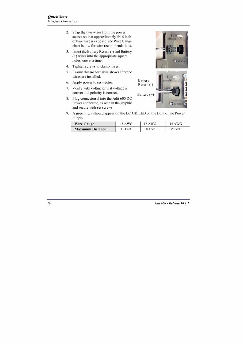
8102019 Adit 600 Quick Start 10-1-1
httpslidepdfcomreaderfulladit-600-quick-start-10-1-1 1854
16 Adit 600 - Release 1011
Quick Start Interface Connectors
2 Strip the two wires from the powersource so that approximately 516 inch
of bare wire is exposed see Wire Gauge
chart below for wire recommendations
3 Insert the Battery Return (-) and Battery
(+) wires into the appropriate square
holes one at a time4 Tighten screws to clamp wires
5 Ensure that no bare wire shows after the
wires are installed
6 Apply power to connector
7 Verify with voltmeter that voltage is
correct and polarity is correct
8 Plug connector(s) into the Adit 600 DC
Power connector as seen in the graphic
and secure with set screws
9 A green light should appear on the DC OK LED on the front of the Power
Supply
Wire Gauge 18 AWG 16 AWG 14 AWG
Maximum Distance 12 Feet 20 Feet 35 Feet
Battery (+)
BatteryReturn (-)
8102019 Adit 600 Quick Start 10-1-1
httpslidepdfcomreaderfulladit-600-quick-start-10-1-1 1954
Adit 600 - Release 1011 17
Quick Start Interface Connectors
External Alarm Connector
The external alarm 6-pin connector with one input pair (pins 5 and 6)
and two output pairs (pins 1 and 2 - major alarms pins 3 and 4 - minor
alarms)
The pinouts are as follows
Pin Description Explanation
1 Major Alarm + The major alarm output is available for power supply or
major alarm failure alerting The maximum voltage across
the contacts is 350 V and the maximum current is 150 mA
This alarm is closed when power is off
2 Major Alarm -
3 Minor Alarm + The minor alarm output is available for power supply or
minor alarm failure alerting The maximum voltage across
the contacts is 350 V and the maximum current is 150 mA
This alarm remains open when power is off
4 Minor Alarm -
5 Alarm In + The alarm inputs provide 5 VDC across the two contactsand generate an alarm when a short circuit is detected
between the contacts
The alarm generated is a minor severity alarm
6 Alarm In -
6
5
4
3
2
1
A
L
A
R
M
8102019 Adit 600 Quick Start 10-1-1
httpslidepdfcomreaderfulladit-600-quick-start-10-1-1 2054
18 Adit 600 - Release 1011
Quick Start Interface Connectors
25-Pair Telco ConnectorsTip and Ring Analog Interfaces equipped with standard 25-pair Telco Connectors
(female) for connection to key systems fax machines modems and PBXs These
interfaces are also used for ISDN BRI ports and are jumper selectable on the Quad T1
Quad E1 Quad DS1E1 and Quad ADPCM service cards
Circuit connections are made at the 25-pair
telco connectors A standard 25-pairtelephone cable with RJ-21X wiring and a
male D-type connector at the Adit 600 end
is required
The pinouts are as follows
Pair Pin Location Function Color Code
1 26
1
Tip Channel 1
Ring Channel 1
WhiteBlue
BlueWhite
2 27
2
Tip Channel 2
Ring Channel 2
WhiteOrange
OrangeWhite
3 28
3
Tip Channel 3
Ring Channel 3
WhiteGreen
GreenWhite
4 29
4
Tip Channel 4
Ring Channel 4
WhiteBrown
BrownWhite
5 30
5
Tip Channel 5
Ring Channel 5
WhiteSlate
SlateWhite
6 31
6
Tip Channel 6
Ring Channel 6
RedBlue
BlueRed
7 327
Tip Channel 7Ring Channel 7
RedOrangeOrangeRed
8 33
8
Tip Channel 8
Ring Channel 8
RedGreen
GreenRed
9 34
9
Tip Channel 9
Ring Channel 9
RedBrown
BrownRed
10 3510
Tip Channel 10Ring Channel 10
RedSlateSlateRed
50
25
26
1
8102019 Adit 600 Quick Start 10-1-1
httpslidepdfcomreaderfulladit-600-quick-start-10-1-1 2154
Adit 600 - Release 1011 19
Quick Start Interface Connectors
Pair Pin Location Function Color Code
11 36
11
Tip Channel 11
Ring Channel 11
BlackBlue
BlueBlack
12 37
12
Tip Channel 12
Ring Channel 12
BlackOrange
OrangeBlack
13 38
13
Tip Channel 13
Ring Channel 13
BlackGreen
GreenBlack
14 39
14
Tip Channel 14
Ring Channel 14
BlackBrown
BrownBlack
15 40
15
Tip Channel 15
Ring Channel 15
BlackSlate
SlateBlack
16 41
16
Tip Channel 16
Ring Channel 16
YellowBlue
BlueYellow17 42
17
Tip Channel 17
Ring Channel 17
YellowOrange
OrangeYellow
18 43
18
Tip Channel 18
Ring Channel 18
YellowGreen
GreenYellow
19 44
19
Tip Channel 19
Ring Channel 19
YellowBrown
BrownYellow
20 45
20
Tip Channel 20
Ring Channel 20
YellowSlate
SlateYellow
21 46
21
Tip Channel 21
Ring Channel 21
VioletBlue
BlueViolet
22 47
22
Tip Channel 22
Ring Channel 22
VioletOrange
OrangeViolet
23 48
23
Tip Channel 23
Ring Channel 23
VioletGreen
GreenViolet
24 49
24
Tip Channel 24
Ring Channel 24
VioletBrown
BrownViolet
25 50
25
Reserved VioletSlate
SlateViolet
8102019 Adit 600 Quick Start 10-1-1
httpslidepdfcomreaderfulladit-600-quick-start-10-1-1 2254
20 Adit 600 - Release 1011
Quick Start Interface Connectors
RS-232 Craft Port (Female DB-9)The RS-232 craft port connector (female) is for connection to an external PC or Hayes-
compatible modem for local or remote configuration management and performance
monitoring using the Adit 600 Command Line Interface (CLI)
The RS-232 craft port connects via a
female DB-9 connector on the Adit 600
The pinouts are as follows
Pin Number Direction Description
1 Outbound Carrier Detect
2 Outbound Receive Data
3 Inbound Transmit Data
4 Inbound Data Terminal Ready
5 NA Signal Ground
6 Outbound Data Set Ready
7 Inbound Request to Send
8 Outbound Clear to Send
9 NC Not connected
1 5
6 9
8102019 Adit 600 Quick Start 10-1-1
httpslidepdfcomreaderfulladit-600-quick-start-10-1-1 2354
8102019 Adit 600 Quick Start 10-1-1
httpslidepdfcomreaderfulladit-600-quick-start-10-1-1 2454
22 Adit 600 - Release 1011
Quick Start Interface Connectors
10Base-T Ethernet
The 10Base-T Ethernet (female) port to connect to a remote
management tool such as Telnet or an SNMP-based Network
Management System Note A LINK LED on the back of the unit
displays green when the system has a good Ethernet link
The pinouts are as follows
Ethernet (RJ-45)
NOTE This Ethernet port uses a hub pinout Use a straight-through cableto connect a PC
Pin Name Description
1 Receive + Receive from network
2 Receive - Receive from network
3 Transmit + Transmit to network
4 - 5 NC Not connected
6 Transmit - Transmit to network
7 NC Not connected
8 NC Not connected
1 8
8102019 Adit 600 Quick Start 10-1-1
httpslidepdfcomreaderfulladit-600-quick-start-10-1-1 2554
Adit 600 - Release 1011 23
Quick Start Management Options
Management Options
Options for managing the Adit 600 are as follows
Local using CLI Telnet SNMP or DIP Switches (Controller and voice cards)
Remotely over an in-band DS0 or through the Access Navigator over the FDL
or an in-band DS0
This Quick Start Guide focuses on the CLI and DIP switches If you need further
information on other management options please refer to the Adit 600 User Manual
Command Line Interface (CLI)
You can access the CLI using either of the following methods
Telnet via Ethernet (10Base-T) RS-232 connected to the DB-9 port
Setting up a CLI Connection
If connecting via the Ethernet 10Base-T connection use a Telnet TCPIP
program to access the CLI This requires the IP address of the Controller
Controllers are shipped with the IP address set to 100010 If this address has been changed and is not known use HyperTerm to access the Controller and
use the CLI command show ip If an IP address needs to be set use the CLI
command set ethernet ip address
If connecting via RS-232 the port settings should be set to
Bits per second 9600 Data bits 8
Parity None Stop bits 1Flow control None
Set your Terminal Emulation to VT100
By default the Adit 600 is set for local configuration (using DIP switches) Use
the set local off command to enable the use of CLI commands
8102019 Adit 600 Quick Start 10-1-1
httpslidepdfcomreaderfulladit-600-quick-start-10-1-1 2654
8102019 Adit 600 Quick Start 10-1-1
httpslidepdfcomreaderfulladit-600-quick-start-10-1-1 2754
Adit 600 - Release 1011 25
Quick Start Configuration
ConfigurationThe following basic setups and upgrades for the Adit 600 are shown using CLI
commands For more information on CLI commands and configurations see the Adit
600 User Manual
Initial Setup
Basic Security Setup
DS1T1 Setup
E1 Setup
DS0Channel Setup
Analog Port Setup
4-Wire EampM Setup
Establish a Static Channel Connection
ISDN BRI Service Setup
OCU-DP Card Setup
ADPCM Card Setup
V35 Port Setup
Change the IP Address of the DS0 Management Channel
Upgrade the Adit 600 Software
Upgrade the Router Card Software
Basic Router Setup
8102019 Adit 600 Quick Start 10-1-1
httpslidepdfcomreaderfulladit-600-quick-start-10-1-1 2854
26 Adit 600 - Release 1011
Quick Start Configuration
Initial SetupUse the following commands for your initial setup For further information see the Adit
600 User Manual
Command Description
set local off Disables DIP switches
set date mmddyyyy Set the date used for event logging
set time hhmmss Set the time used for event logging
set id id-name Set a system ID name
set clock1 slotportinternal
Set the primary clock source
set clock2 slotportinternal
Set the secondary clock source
set ethernet ip addressip-addr mask
Set the ethernet IP address in the
conventional IP address format
set ip gateway ip-addr Set the IP gateway in the conventional IP
address format
8102019 Adit 600 Quick Start 10-1-1
httpslidepdfcomreaderfulladit-600-quick-start-10-1-1 2954
Adit 600 - Release 1011 27
Quick Start Configuration
Basic Security SetupUse the following commands to set up the security on the Adit 600 For further
information see the Adit 600 User Manual
Command Description
set password length
long|short
Set user password length requirement
add user ldquouser-namerdquo[password ldquopasswordrdquo]
Add user and password as necessary
set user user-name level1-3
Specify the userrsquos security level
set user user-namepassword Setchange password for the user asnecessary
8102019 Adit 600 Quick Start 10-1-1
httpslidepdfcomreaderfulladit-600-quick-start-10-1-1 3054
28 Adit 600 - Release 1011
Quick Start Configuration
DS1T1 SetupUse the following commands to set up a DS1 See the set (ds1) command for more
details
Command Description
set ds1-addr up Activate the port of the DS1 (slotport)
set ds1-addr id id-string
Set the identification string
set ds1-addr lbo 1-9 Set the line buildout value for the DS1
set ds1-addr linecodeami|b8zs
Set the linecode for the DS1
set ds1-addr framing d4|esf|tr8afdl|tr8anofdl|tr8b
Set the framing option for the DS1
set ds1-addr loopdetecton|off
Set the detectionreaction to CSU loopcodes
Q i k S
8102019 Adit 600 Quick Start 10-1-1
httpslidepdfcomreaderfulladit-600-quick-start-10-1-1 3154
Adit 600 - Release 1011 29
Quick Start Configuration
E1 Setup
NOTE E1 is not supported in this release of the Adit 600 Controller It will besupported in a future release
Use the following commands to set up an E1 See the set (e1) command for more
details
DS0Channel Setup
Use the following commands to set up a DS0 See the set (ds0) command for details
Command Description
set e1-addr up Activate the port of the E1 (slotport)
set e1-addr id id-string Set the identification string
set e1-addr lbo 1 - 9 Set the line buildout value for the E1
set e1-addr linecodeami|hdb3
Set the linecode for the E1
set e1-addr framinge1fr|lefrcrc
Set the framing option for the E1
set e1-addr loopdetecton|off
Set the detectionreaction to CSU loopcodes
Command Description
set slotportchannel up Activate the channel
set slotportchannel signalls|gs|emw|emdw|emicpd|dpt
Set the signaling option for the channel
set slotportchannel typedata|voice Set the channel type
Q i k St t
8102019 Adit 600 Quick Start 10-1-1
httpslidepdfcomreaderfulladit-600-quick-start-10-1-1 3254
30 Adit 600 - Release 1011
Quick Start Configuration
Analog Port SetupUse the following commands to set up an analog port
Command Description
set slotport up Activate the port See set (ds1) command for
details
set slotport signal dpt|gs|gsrb|gsw|gswrb|ls|lscpd|lsrb
Set the signaling option for the port See the
set (fxs) or set (fxo) command for details
set slotport rxgain n Set the receive gainloss in dB See the set
(fxs) or set (fxo) command for details
set slotport txgain n Set the transmit gainloss in dB See the set
(fxs) or set (fxo) command for details
Quick Start
8102019 Adit 600 Quick Start 10-1-1
httpslidepdfcomreaderfulladit-600-quick-start-10-1-1 3354
Adit 600 - Release 1011 31
Quick Start Configuration
4-Wire EampM SetupFor this example the 4 EampM ports will be connected to the first 4 DS0s on T1-1 (a1)
This can be changed to match the customers desired DS0 connections
For Transmission Only mode the DS0s on the DS1 should be set to data as well as the
EampM card channels
Command Description
For Normal or Tandem EampM
set a11-4 type voice Set DS0s to voice
set connect a11-4 11-4 Connect DS0s to the 4 ports of the 4-
Wire EampM card
show connect a 1 Verify cross connects
set a11-4 signal emi Set DS0 signal type to EMI
set 11-4 signal emi Set 4-Wire EampM ports signal type to
EMI
show connect a1 Verify cross connects
For TO Mode
set a11-4 type data Set DS0s to data
set 11-4 type data Set 4-Wire EampM port to data
set connect a11-4 11-4 Connect DS0s to the 4 ports of the 4-
Wire EampM card
show connect a 1 Verify cross connects
Quick Start
8102019 Adit 600 Quick Start 10-1-1
httpslidepdfcomreaderfulladit-600-quick-start-10-1-1 3454
32 Adit 600 - Release 1011
Quick Start Configuration
Establish a Static Channel ConnectionUse the following commands to establish a static channel connection
ISDN BRI Service Setup
Use the following commands to set up a ISDN BRI Service See the set (bri) command
for details
Command Description
set slotportchannel typevoice|data
Set the channel type for the channel to
map See set (ds0) command for details
set slotportchannel signalls|gs|emw|emdw|emicpd|dpt
Set the channel signaling option See set
(ds0) command for details
connect slotportslotport
Connect the channels See the connect
(card-trunk) (card-trunk) command
Command Description
set slotport up Put the ISDN line In-Service
set slot modelt3ds0|lt4to1tdm|nt3ds0
Set the ISDN mode
set slotport crv 1-768 Set the Call Reference Value Note
value must be the same as the Access
Navigator
set slotport thresholdday|hour es|ses
Set the threshold for the IDSN lines
set slot pmsyncadit|switch
Set the source for performance
monitoring synchronization
set slotport autoactivate
on|off
Only used in 4-to-1 mode Establishes
the D channel when the FDL link can not
be used
Quick Start
8102019 Adit 600 Quick Start 10-1-1
httpslidepdfcomreaderfulladit-600-quick-start-10-1-1 3554
Adit 600 - Release 1011 33
Quick Start Configuration
OCU-DP Card SetupThe following is a basic setup for the OCU-DP card
ADPCM Card Setup
Command Description
set ocudp-addr baud2400|4800|9600|19200|38400|
56000|64000
Set the OCU-DP Baud rate
Where ocudp-addr = slotport of the
OCU-DP card to apply settings to
set ocudp-addr up Set the OCU-DP port 1 up
show ocudp_card-addr Show the OCU-DP card settings
Where ocudp_card-addr = slot of the
OCU-DP card
disconnect a Disconnects all connections to slot a
(controller)
set ds0-addr type data Sets a DS0 data signaling type
connect ds0-addrocudp-addr
Connects DS0 (in previous step) to OCU-DP
port (in previous step)
show connect
(ocudp_card-addr
Displays connect information for OCU-DP
card
Command Description
Connect T1 cable to port 1 of the ADPCM service card
set adpcm_card-addrnone|map1|map2|map3
Enable compressing by selecting Map type Notenone disables compression
show (adpcm_card-addr Displays the status of the card and the mapping
connect 211-12 241-12 Set ADPCM cross-connects The example
connects all 24 channels of the ADPCM to the 12
channels of the T1 (now compressed) on port 4
This example is with map2show connect 21) Displays the connections made above
8102019 Adit 600 Quick Start 10-1-1
httpslidepdfcomreaderfulladit-600-quick-start-10-1-1 3654
Quick Start
8102019 Adit 600 Quick Start 10-1-1
httpslidepdfcomreaderfulladit-600-quick-start-10-1-1 3754
Adit 600 - Release 1011 35
QConfiguration
Upgrade the Adit 600 SoftwareUse the following commands to determine the system software level then upgrade the
software to the latest version
Command Description
status equipment Determine the system software level The
Slot A line (SW Vers) will display thecurrent software level
load tftp ip-addr file-name (or load xmodem)
Load the new controller system software See
the load tftp and load xmodem command for
more information
Note A TFTP server must be running onthe host system You can use any TFTP
server utility you wish One example isthe program TFTPD32 which can bedownloaded free-of-charge attftpd32jouninnettftpd32html
Quick Start
8102019 Adit 600 Quick Start 10-1-1
httpslidepdfcomreaderfulladit-600-quick-start-10-1-1 3854
36 Adit 600 - Release 1011
Configuration
Upgrade the Router Card SoftwareUse the following commands to determine the Router card software level then upgrade
the software to the latest version
NOTE For additional information about upgrading MSR card software see
the following manuals-Adit 600 User Manual -Adit 3000 Series and Multi-Service Router (MSR) Card GUI Reference Manual
-Adit 3000 Series and Multi-Service Router (MSR) Card CLI Reference Manual
Command Description
status equipment Determine the Router software level The
Router Slot line (SW Vers) will display thecurrent software level
load rtr_card-addr tftpip-addr file-name
Load the new Router software to a Router
card See the load tftp command for more
information
Note A TFTP server must be running onthe host system You can use any TFTP
server utility you wish One example isthe program TFTPD32 which can bedownloaded free-of-charge attftpd32jouninnettftpd32html
8102019 Adit 600 Quick Start 10-1-1
httpslidepdfcomreaderfulladit-600-quick-start-10-1-1 3954
8102019 Adit 600 Quick Start 10-1-1
httpslidepdfcomreaderfulladit-600-quick-start-10-1-1 4054
Quick Start C t ll C d LED
8102019 Adit 600 Quick Start 10-1-1
httpslidepdfcomreaderfulladit-600-quick-start-10-1-1 4154
Adit 600 - Release 1011 39
Controller Card LEDs
E1 Controller Card
NOTE E1 is not supported in this release It will be supported in a futurerelease
The E1 Controller has a set of six LEDs The table below describes each LED
LED State Description
MAJOR Off No major alarms present
Red Major alarm present
MINOR Off No minor alarms present
Yellow Minor alarms present
LOCAL Off Remote mode (DIP switches disabled)
Green Local mode (DIP switches enabled)
ACO Off Normal mode No alarms are being
suppressed
Yellow Alarm Cut Off active One or more active
alarms suppressed
E1-1 and
E1-2
Off Off line
Green Normal
Red Loss of Signal (LOS) detected
Yellow Bipolar Violation (BPV) detected LCV
Flashing Green Loopback active
Flashing Red
(slow)
Loss of Frame (LOF) or Alarm Indication
Signal (AIS) detected
Flashing Red
(fast)
Card Failure
Flashing Yellow Yellow alarm (Remote Alarm Indication)detected
Quick Start Power Supply LEDs
8102019 Adit 600 Quick Start 10-1-1
httpslidepdfcomreaderfulladit-600-quick-start-10-1-1 4254
40 Adit 600 - Release 1011
Power Supply LEDs
Power Supply LEDs115 VAC-48 VDC and 230 VAC-48 VDC Power Supplies
The power supply card has two LEDs as described in the table
below
24 VDC-48 VDC Power Supply
The power supply card has two LEDs as described in the table below
LED State Description
AC Input Off AC input missing or failure
Green AC input present
Battery Off Battery input not used
Green Battery charging or operating from DC
source only
Yellow Battery discharging
Red Battery low (less than 42V) ringer disabled
LED State Description
DC OK Off DC input missing or failure
Green DC input present
-48 Battery
Low
Off Normal
Red VDC is low (less than 42 VDC)
ringer disabled
Quick Start Service Card LEDs
8102019 Adit 600 Quick Start 10-1-1
httpslidepdfcomreaderfulladit-600-quick-start-10-1-1 4354
Adit 600 - Release 1011 41
Service Card LEDs
Service Card LEDs 4-Wire EampM Card
FXO Card
FXS Card
ISDN BRI Card
OCU-DP Card
P-Phone Card
Single Channel POTS Card
Quad DS1 ADPCM Service Card
Quad DS1E1 and Quad T1 Cards
Quad E1 Card
IP Router Card
CMG Router Card
Terminal Server Router Card
MSR Card
RS-232 and V35V54 Cards
Discontinued cards
RS-232 discontinued
Quick Start Service Card LEDs
8102019 Adit 600 Quick Start 10-1-1
httpslidepdfcomreaderfulladit-600-quick-start-10-1-1 4454
42 Adit 600 - Release 1011
Service Card LEDs
4-Wire EampM Card Each channelport has two LEDs Only the top LED is used in this application LED
definitions are listed below
State Description
When in EampM Mode
Off Channel is idle or disabled
Green Analog interface is off-hook
Red Digital interface is off-hook
Yellow Both analog and digital interfaces are off-hook or channel is
being trunk processed
When in TO Mode
Off DisconnectedGreen Connected T1E1 not in alarm
Yellow Connected T1E1 in alarm (trunk processed)
Quick Start Service Card LEDs
8102019 Adit 600 Quick Start 10-1-1
httpslidepdfcomreaderfulladit-600-quick-start-10-1-1 4554
Adit 600 - Release 1011 43
FXO Card Each port on the FXO card has its own LED as described in the table below
FXS Card
There is an LED for each port on the FXS card as described in the table below
State Loop Start
Meaning
Ground Start Meaning Dial Pulse Termination
Meaning
Off NA Idle (tip open) Idle (loop open)
Green Idle Tip ground (incoming seizure) Incoming seizure
Red NA Ring ground (outgoing
seizure)
Loop closure (outgoing seizure)
Yellow Call in
progress
Call in progress Call in progress (reverse battery)
Flashing
Green
Ringing Ringing NA
State Loop Start Meaning Ground Start Meaning
Off NA Idle (tip open)
Green Idle Tip ground (incoming seizure)
Red Note This can be seen with
Forward Disconnect (tip open)
Ring ground (outgoing seizure)
Yellow Call in progress Call in progress
Flashing green Ringing Ringing
Quick Start Service Card LEDs
8102019 Adit 600 Quick Start 10-1-1
httpslidepdfcomreaderfulladit-600-quick-start-10-1-1 4654
44 Adit 600 - Release 1011
ISDN BRI Card There is an LED for each ISDN BRI on a card as described in the table below
OCU-DP Card Each channel has two LEDs described in the table below
State Description
Off Line U-interface is attempting synchronization or BRI is Out-of-Service
Red Line alarm (LOS or self test failure)
Yellow ES or SES has occurred
Flashing yellow Line U-interface is synchronized with customer equipment but is not passing
customer data
Flashing green Line U-interface is in external loopback toward the switch at the unit
Green Normal (Line U-interface is active and transparently passing customer data)
State Description
Yellow Flickering ALL Boot Software in control
Green (walking down)
Red (walking up)
ALL Application Software in control
(repeated 35 times)
Red slow flash ALL In Boot Application flash code checksums did not match and
Boot is waiting for application download
Red ALL In Application code waiting for Controller to issue SWHW
revision request This is the first request that comes from the
OCU-DP card manager in the ControllerGreen
Yellow
Top
Bottom
Port in Self-test Duration is 5-8 seconds
Off Top
Bottom
Port is set down (Out-Of-Service)
Green Top Port is receiving valid signals
Red Top Port is receiving no signal (primary) or no frame sync
(secondary or clear channel)Red Flashing Bottom Port is receiving bipolar violations
Yellow Bottom Port is in loopback
Quick Start Service Card LEDs
8102019 Adit 600 Quick Start 10-1-1
httpslidepdfcomreaderfulladit-600-quick-start-10-1-1 4754
Adit 600 - Release 1011 45
P-Phone Card Each P-Phone channel has a corresponding LED described in the table below
State Line State
Off No P-Phone connected
Green No call in process
Flashing Green Alert (Ringing)
Yellow Call in progress
Flashing Yellow P-Phone Loopback in Progress
Flashing Red Self-test failed
Quick Start Service Card LEDs
8102019 Adit 600 Quick Start 10-1-1
httpslidepdfcomreaderfulladit-600-quick-start-10-1-1 4854
46 Adit 600 - Release 1011
Single Channel POTS Card The POTS channel LED (left) status is described in the table below
The second LED (right) is a status LED is not used on this card
Quad DS1 ADPCM Service Card
Each channel on the Quad DS1 ADPCM card has two LEDs The
description of the top LED is shown below the bottom LED is notused with this application
State Loop Start Meaning
Off Calling Party Disconnect
Green Idle
Red NA
Yellow Call in progress
Flashing green Ringing
State Description
Off Off line
Green Normal
Red Loss of Signal (LOS)
Yellow Bipolar Violation (BPV)Flashing Green Loopback active
Flashing Yellow Yellow Alarm
(Remote Alarm Indication)
Flashing Red (Slow) Loss of Frame (LOF) or Alarm Indication Signal (AIS)
Flashing Red (Fast) Self-test Failure
Top LED(active)
Bottom LED(not used)
Quick Start Service Card LEDs
8102019 Adit 600 Quick Start 10-1-1
httpslidepdfcomreaderfulladit-600-quick-start-10-1-1 4954
Adit 600 - Release 1011 47
Quad DS1E1 and Quad T1 CardsEach channel on the Quad T1E1 cards have two LEDs The description
of the top LED is shown below the bottom LED is not used with this
application
State Description
Off Off line
Green Normal
Red Loss of Signal (LOS)
Yellow Bipolar Violation (BPV)
Flashing Green Loopback active
Flashing Yellow Yellow Alarm (Remote Alarm Indication)
Flashing Red (Slow) Loss of Frame (LOF) or Alarm Indication Signal (AIS)
Flashing Red (Fast) Self-test Failure
Quick Start Service Card LEDs
8102019 Adit 600 Quick Start 10-1-1
httpslidepdfcomreaderfulladit-600-quick-start-10-1-1 5054
48 Adit 600 - Release 1011
IP Router Card The following chart describes each LED and its state
LED State Description
CRD Off Loss of power
Green No current alarms
Red Alarm state active See alarm log for cause
Red Flashing Self-test or Boot in-process
Yellow Flashing Card is saving data to flash RAM do not power down
10100 Off 10 Mb ethernet
Green 100 Mb ethernet
LNK Off No ethernet link
Green Good ethernet link
COL
Off No current ethernet transmit collisions
Yellow Ethernet collisions have occurred and have not dropped
to minimum level
Yellow Flashing Ethernet collision occurring
TX Off No ethernet transmit activity
Green Ethernet transmit activity
RX Off No current ethernet receive activity
Green Current ethernet receive activity
Quick Start Service Card LEDs
8102019 Adit 600 Quick Start 10-1-1
httpslidepdfcomreaderfulladit-600-quick-start-10-1-1 5154
Adit 600 - Release 1011 49
CMG Router Card The following chart describes each LED and its state
LED State Description
CRD Off Loss of power
Green No current alarms
Red Alarm state active See alarm log for causeRed Flashing Self-test or Boot in-process
Yellow Flashing Card is saving data to flash RAM do not power down
VOIP
Off No active VoIP calls or if the MGCP protocol is
optioned down
Green Active VoIP calls
Red Call agent unreachable
Yellow Insufficient VoIP resources to complete call
LNK Off No Ethernet link
Green Good Ethernet link
10100 Off 10 Mb Ethernet
Green 100 Mb Ethernet
TX Off No Ethernet transmit activityGreen Ethernet transmit activity
Yellow Current Ethernet transmit collision
RX Off No current Ethernet receive activity
Green Current Ethernet receive activity
Quick Start Service Card LEDs
8102019 Adit 600 Quick Start 10-1-1
httpslidepdfcomreaderfulladit-600-quick-start-10-1-1 5254
50 Adit 600 - Release 1011
Terminal Server Router Card The Terminal Server Router card has 2 LEDs per port
At Power-up
Normal Operation
Port Set for Ethernet
Top LED indicates 100M Link Bottom LED indicates 10M Link
Port Set for RS-232
TOP LED Bottom LED Description
Off Off At Power UpBoot = Loss of power
Red Red Card is inoperative
Flashing Red Flashing Red Self-test or Boot in-process
TOP LED Bottom LED Description
Green Solid (Link) Green Solid (Link) Port set for Ethernet - see below
Flashing Red Flashing Red Self-test or Boot in-process
State Description
Off No Ethernet link
Green Link but no activity
Red Flashing Current Ethernet collision
Green Flashing Current Ethernet receive
Yellow Flashing Current Ethernet transmit
TOP LED Bottom LED Description
Yellow Off No Activity
Yellow Flashing Yellow Current transmit
Yellow Flashing Green Current receive
Quick Start Service Card LEDs
8102019 Adit 600 Quick Start 10-1-1
httpslidepdfcomreaderfulladit-600-quick-start-10-1-1 5354
Adit 600 - Release 1011 51
MSR Card The following chart describes the MSR cardrsquos LEDs
LED State Description
CRD Off Loss of power
Green No current alarms
Red Alarm state active See alarm log for cause
Red Flashing Self-test or boot in process
Yellow Flashing Card is saving data to flash RAM do not power
down
VOIP
Off No SIP proxy or registration attempts for all lines
have succeeded but no calls are active
Green Active VoIP call(s)
Red Inability to reach the SIP proxy or negative response
to register attempts from all lines
Yellow Register attempts from some lines have succeeded
but not for all lines
ETH1 and
ETH2
Top LED
Off 10 Mbitsec down or not connected
Green 100 Mbitsec
ETH1 and
ETH2
Bottom LED
Off Link down
Green Link up
Flashing Green Traffic on link
Yellow Collision status
Quick Start Service Card LEDs
8102019 Adit 600 Quick Start 10-1-1
httpslidepdfcomreaderfulladit-600-quick-start-10-1-1 5454
52 Adit 600 - Release 1011
RS-232 and V35V54 Cards Each port has its own LED as described in the table below
State Description
Off No T1 Assignment
Green Normal (CDRTS) Active
Red CD inactive (T1-side failure)
Yellow RTS inactive (equipment-side failure)
Flashing Yellow Loopback toward T1 or equipment loop test
Flashing Green Loopback toward equipment or network loop test
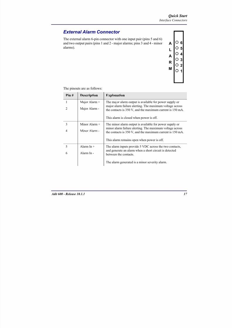
8102019 Adit 600 Quick Start 10-1-1
httpslidepdfcomreaderfulladit-600-quick-start-10-1-1 2054
18 Adit 600 - Release 1011
Quick Start Interface Connectors
25-Pair Telco ConnectorsTip and Ring Analog Interfaces equipped with standard 25-pair Telco Connectors
(female) for connection to key systems fax machines modems and PBXs These
interfaces are also used for ISDN BRI ports and are jumper selectable on the Quad T1
Quad E1 Quad DS1E1 and Quad ADPCM service cards
Circuit connections are made at the 25-pair
telco connectors A standard 25-pairtelephone cable with RJ-21X wiring and a
male D-type connector at the Adit 600 end
is required
The pinouts are as follows
Pair Pin Location Function Color Code
1 26
1
Tip Channel 1
Ring Channel 1
WhiteBlue
BlueWhite
2 27
2
Tip Channel 2
Ring Channel 2
WhiteOrange
OrangeWhite
3 28
3
Tip Channel 3
Ring Channel 3
WhiteGreen
GreenWhite
4 29
4
Tip Channel 4
Ring Channel 4
WhiteBrown
BrownWhite
5 30
5
Tip Channel 5
Ring Channel 5
WhiteSlate
SlateWhite
6 31
6
Tip Channel 6
Ring Channel 6
RedBlue
BlueRed
7 327
Tip Channel 7Ring Channel 7
RedOrangeOrangeRed
8 33
8
Tip Channel 8
Ring Channel 8
RedGreen
GreenRed
9 34
9
Tip Channel 9
Ring Channel 9
RedBrown
BrownRed
10 3510
Tip Channel 10Ring Channel 10
RedSlateSlateRed
50
25
26
1
8102019 Adit 600 Quick Start 10-1-1
httpslidepdfcomreaderfulladit-600-quick-start-10-1-1 2154
Adit 600 - Release 1011 19
Quick Start Interface Connectors
Pair Pin Location Function Color Code
11 36
11
Tip Channel 11
Ring Channel 11
BlackBlue
BlueBlack
12 37
12
Tip Channel 12
Ring Channel 12
BlackOrange
OrangeBlack
13 38
13
Tip Channel 13
Ring Channel 13
BlackGreen
GreenBlack
14 39
14
Tip Channel 14
Ring Channel 14
BlackBrown
BrownBlack
15 40
15
Tip Channel 15
Ring Channel 15
BlackSlate
SlateBlack
16 41
16
Tip Channel 16
Ring Channel 16
YellowBlue
BlueYellow17 42
17
Tip Channel 17
Ring Channel 17
YellowOrange
OrangeYellow
18 43
18
Tip Channel 18
Ring Channel 18
YellowGreen
GreenYellow
19 44
19
Tip Channel 19
Ring Channel 19
YellowBrown
BrownYellow
20 45
20
Tip Channel 20
Ring Channel 20
YellowSlate
SlateYellow
21 46
21
Tip Channel 21
Ring Channel 21
VioletBlue
BlueViolet
22 47
22
Tip Channel 22
Ring Channel 22
VioletOrange
OrangeViolet
23 48
23
Tip Channel 23
Ring Channel 23
VioletGreen
GreenViolet
24 49
24
Tip Channel 24
Ring Channel 24
VioletBrown
BrownViolet
25 50
25
Reserved VioletSlate
SlateViolet
8102019 Adit 600 Quick Start 10-1-1
httpslidepdfcomreaderfulladit-600-quick-start-10-1-1 2254
20 Adit 600 - Release 1011
Quick Start Interface Connectors
RS-232 Craft Port (Female DB-9)The RS-232 craft port connector (female) is for connection to an external PC or Hayes-
compatible modem for local or remote configuration management and performance
monitoring using the Adit 600 Command Line Interface (CLI)
The RS-232 craft port connects via a
female DB-9 connector on the Adit 600
The pinouts are as follows
Pin Number Direction Description
1 Outbound Carrier Detect
2 Outbound Receive Data
3 Inbound Transmit Data
4 Inbound Data Terminal Ready
5 NA Signal Ground
6 Outbound Data Set Ready
7 Inbound Request to Send
8 Outbound Clear to Send
9 NC Not connected
1 5
6 9
8102019 Adit 600 Quick Start 10-1-1
httpslidepdfcomreaderfulladit-600-quick-start-10-1-1 2354
8102019 Adit 600 Quick Start 10-1-1
httpslidepdfcomreaderfulladit-600-quick-start-10-1-1 2454
22 Adit 600 - Release 1011
Quick Start Interface Connectors
10Base-T Ethernet
The 10Base-T Ethernet (female) port to connect to a remote
management tool such as Telnet or an SNMP-based Network
Management System Note A LINK LED on the back of the unit
displays green when the system has a good Ethernet link
The pinouts are as follows
Ethernet (RJ-45)
NOTE This Ethernet port uses a hub pinout Use a straight-through cableto connect a PC
Pin Name Description
1 Receive + Receive from network
2 Receive - Receive from network
3 Transmit + Transmit to network
4 - 5 NC Not connected
6 Transmit - Transmit to network
7 NC Not connected
8 NC Not connected
1 8
8102019 Adit 600 Quick Start 10-1-1
httpslidepdfcomreaderfulladit-600-quick-start-10-1-1 2554
Adit 600 - Release 1011 23
Quick Start Management Options
Management Options
Options for managing the Adit 600 are as follows
Local using CLI Telnet SNMP or DIP Switches (Controller and voice cards)
Remotely over an in-band DS0 or through the Access Navigator over the FDL
or an in-band DS0
This Quick Start Guide focuses on the CLI and DIP switches If you need further
information on other management options please refer to the Adit 600 User Manual
Command Line Interface (CLI)
You can access the CLI using either of the following methods
Telnet via Ethernet (10Base-T) RS-232 connected to the DB-9 port
Setting up a CLI Connection
If connecting via the Ethernet 10Base-T connection use a Telnet TCPIP
program to access the CLI This requires the IP address of the Controller
Controllers are shipped with the IP address set to 100010 If this address has been changed and is not known use HyperTerm to access the Controller and
use the CLI command show ip If an IP address needs to be set use the CLI
command set ethernet ip address
If connecting via RS-232 the port settings should be set to
Bits per second 9600 Data bits 8
Parity None Stop bits 1Flow control None
Set your Terminal Emulation to VT100
By default the Adit 600 is set for local configuration (using DIP switches) Use
the set local off command to enable the use of CLI commands
8102019 Adit 600 Quick Start 10-1-1
httpslidepdfcomreaderfulladit-600-quick-start-10-1-1 2654
8102019 Adit 600 Quick Start 10-1-1
httpslidepdfcomreaderfulladit-600-quick-start-10-1-1 2754
Adit 600 - Release 1011 25
Quick Start Configuration
ConfigurationThe following basic setups and upgrades for the Adit 600 are shown using CLI
commands For more information on CLI commands and configurations see the Adit
600 User Manual
Initial Setup
Basic Security Setup
DS1T1 Setup
E1 Setup
DS0Channel Setup
Analog Port Setup
4-Wire EampM Setup
Establish a Static Channel Connection
ISDN BRI Service Setup
OCU-DP Card Setup
ADPCM Card Setup
V35 Port Setup
Change the IP Address of the DS0 Management Channel
Upgrade the Adit 600 Software
Upgrade the Router Card Software
Basic Router Setup
8102019 Adit 600 Quick Start 10-1-1
httpslidepdfcomreaderfulladit-600-quick-start-10-1-1 2854
26 Adit 600 - Release 1011
Quick Start Configuration
Initial SetupUse the following commands for your initial setup For further information see the Adit
600 User Manual
Command Description
set local off Disables DIP switches
set date mmddyyyy Set the date used for event logging
set time hhmmss Set the time used for event logging
set id id-name Set a system ID name
set clock1 slotportinternal
Set the primary clock source
set clock2 slotportinternal
Set the secondary clock source
set ethernet ip addressip-addr mask
Set the ethernet IP address in the
conventional IP address format
set ip gateway ip-addr Set the IP gateway in the conventional IP
address format
8102019 Adit 600 Quick Start 10-1-1
httpslidepdfcomreaderfulladit-600-quick-start-10-1-1 2954
Adit 600 - Release 1011 27
Quick Start Configuration
Basic Security SetupUse the following commands to set up the security on the Adit 600 For further
information see the Adit 600 User Manual
Command Description
set password length
long|short
Set user password length requirement
add user ldquouser-namerdquo[password ldquopasswordrdquo]
Add user and password as necessary
set user user-name level1-3
Specify the userrsquos security level
set user user-namepassword Setchange password for the user asnecessary
8102019 Adit 600 Quick Start 10-1-1
httpslidepdfcomreaderfulladit-600-quick-start-10-1-1 3054
28 Adit 600 - Release 1011
Quick Start Configuration
DS1T1 SetupUse the following commands to set up a DS1 See the set (ds1) command for more
details
Command Description
set ds1-addr up Activate the port of the DS1 (slotport)
set ds1-addr id id-string
Set the identification string
set ds1-addr lbo 1-9 Set the line buildout value for the DS1
set ds1-addr linecodeami|b8zs
Set the linecode for the DS1
set ds1-addr framing d4|esf|tr8afdl|tr8anofdl|tr8b
Set the framing option for the DS1
set ds1-addr loopdetecton|off
Set the detectionreaction to CSU loopcodes
Q i k S
8102019 Adit 600 Quick Start 10-1-1
httpslidepdfcomreaderfulladit-600-quick-start-10-1-1 3154
Adit 600 - Release 1011 29
Quick Start Configuration
E1 Setup
NOTE E1 is not supported in this release of the Adit 600 Controller It will besupported in a future release
Use the following commands to set up an E1 See the set (e1) command for more
details
DS0Channel Setup
Use the following commands to set up a DS0 See the set (ds0) command for details
Command Description
set e1-addr up Activate the port of the E1 (slotport)
set e1-addr id id-string Set the identification string
set e1-addr lbo 1 - 9 Set the line buildout value for the E1
set e1-addr linecodeami|hdb3
Set the linecode for the E1
set e1-addr framinge1fr|lefrcrc
Set the framing option for the E1
set e1-addr loopdetecton|off
Set the detectionreaction to CSU loopcodes
Command Description
set slotportchannel up Activate the channel
set slotportchannel signalls|gs|emw|emdw|emicpd|dpt
Set the signaling option for the channel
set slotportchannel typedata|voice Set the channel type
Q i k St t
8102019 Adit 600 Quick Start 10-1-1
httpslidepdfcomreaderfulladit-600-quick-start-10-1-1 3254
30 Adit 600 - Release 1011
Quick Start Configuration
Analog Port SetupUse the following commands to set up an analog port
Command Description
set slotport up Activate the port See set (ds1) command for
details
set slotport signal dpt|gs|gsrb|gsw|gswrb|ls|lscpd|lsrb
Set the signaling option for the port See the
set (fxs) or set (fxo) command for details
set slotport rxgain n Set the receive gainloss in dB See the set
(fxs) or set (fxo) command for details
set slotport txgain n Set the transmit gainloss in dB See the set
(fxs) or set (fxo) command for details
Quick Start
8102019 Adit 600 Quick Start 10-1-1
httpslidepdfcomreaderfulladit-600-quick-start-10-1-1 3354
Adit 600 - Release 1011 31
Quick Start Configuration
4-Wire EampM SetupFor this example the 4 EampM ports will be connected to the first 4 DS0s on T1-1 (a1)
This can be changed to match the customers desired DS0 connections
For Transmission Only mode the DS0s on the DS1 should be set to data as well as the
EampM card channels
Command Description
For Normal or Tandem EampM
set a11-4 type voice Set DS0s to voice
set connect a11-4 11-4 Connect DS0s to the 4 ports of the 4-
Wire EampM card
show connect a 1 Verify cross connects
set a11-4 signal emi Set DS0 signal type to EMI
set 11-4 signal emi Set 4-Wire EampM ports signal type to
EMI
show connect a1 Verify cross connects
For TO Mode
set a11-4 type data Set DS0s to data
set 11-4 type data Set 4-Wire EampM port to data
set connect a11-4 11-4 Connect DS0s to the 4 ports of the 4-
Wire EampM card
show connect a 1 Verify cross connects
Quick Start
8102019 Adit 600 Quick Start 10-1-1
httpslidepdfcomreaderfulladit-600-quick-start-10-1-1 3454
32 Adit 600 - Release 1011
Quick Start Configuration
Establish a Static Channel ConnectionUse the following commands to establish a static channel connection
ISDN BRI Service Setup
Use the following commands to set up a ISDN BRI Service See the set (bri) command
for details
Command Description
set slotportchannel typevoice|data
Set the channel type for the channel to
map See set (ds0) command for details
set slotportchannel signalls|gs|emw|emdw|emicpd|dpt
Set the channel signaling option See set
(ds0) command for details
connect slotportslotport
Connect the channels See the connect
(card-trunk) (card-trunk) command
Command Description
set slotport up Put the ISDN line In-Service
set slot modelt3ds0|lt4to1tdm|nt3ds0
Set the ISDN mode
set slotport crv 1-768 Set the Call Reference Value Note
value must be the same as the Access
Navigator
set slotport thresholdday|hour es|ses
Set the threshold for the IDSN lines
set slot pmsyncadit|switch
Set the source for performance
monitoring synchronization
set slotport autoactivate
on|off
Only used in 4-to-1 mode Establishes
the D channel when the FDL link can not
be used
Quick Start
8102019 Adit 600 Quick Start 10-1-1
httpslidepdfcomreaderfulladit-600-quick-start-10-1-1 3554
Adit 600 - Release 1011 33
Quick Start Configuration
OCU-DP Card SetupThe following is a basic setup for the OCU-DP card
ADPCM Card Setup
Command Description
set ocudp-addr baud2400|4800|9600|19200|38400|
56000|64000
Set the OCU-DP Baud rate
Where ocudp-addr = slotport of the
OCU-DP card to apply settings to
set ocudp-addr up Set the OCU-DP port 1 up
show ocudp_card-addr Show the OCU-DP card settings
Where ocudp_card-addr = slot of the
OCU-DP card
disconnect a Disconnects all connections to slot a
(controller)
set ds0-addr type data Sets a DS0 data signaling type
connect ds0-addrocudp-addr
Connects DS0 (in previous step) to OCU-DP
port (in previous step)
show connect
(ocudp_card-addr
Displays connect information for OCU-DP
card
Command Description
Connect T1 cable to port 1 of the ADPCM service card
set adpcm_card-addrnone|map1|map2|map3
Enable compressing by selecting Map type Notenone disables compression
show (adpcm_card-addr Displays the status of the card and the mapping
connect 211-12 241-12 Set ADPCM cross-connects The example
connects all 24 channels of the ADPCM to the 12
channels of the T1 (now compressed) on port 4
This example is with map2show connect 21) Displays the connections made above
8102019 Adit 600 Quick Start 10-1-1
httpslidepdfcomreaderfulladit-600-quick-start-10-1-1 3654
Quick Start
8102019 Adit 600 Quick Start 10-1-1
httpslidepdfcomreaderfulladit-600-quick-start-10-1-1 3754
Adit 600 - Release 1011 35
QConfiguration
Upgrade the Adit 600 SoftwareUse the following commands to determine the system software level then upgrade the
software to the latest version
Command Description
status equipment Determine the system software level The
Slot A line (SW Vers) will display thecurrent software level
load tftp ip-addr file-name (or load xmodem)
Load the new controller system software See
the load tftp and load xmodem command for
more information
Note A TFTP server must be running onthe host system You can use any TFTP
server utility you wish One example isthe program TFTPD32 which can bedownloaded free-of-charge attftpd32jouninnettftpd32html
Quick Start
8102019 Adit 600 Quick Start 10-1-1
httpslidepdfcomreaderfulladit-600-quick-start-10-1-1 3854
36 Adit 600 - Release 1011
Configuration
Upgrade the Router Card SoftwareUse the following commands to determine the Router card software level then upgrade
the software to the latest version
NOTE For additional information about upgrading MSR card software see
the following manuals-Adit 600 User Manual -Adit 3000 Series and Multi-Service Router (MSR) Card GUI Reference Manual
-Adit 3000 Series and Multi-Service Router (MSR) Card CLI Reference Manual
Command Description
status equipment Determine the Router software level The
Router Slot line (SW Vers) will display thecurrent software level
load rtr_card-addr tftpip-addr file-name
Load the new Router software to a Router
card See the load tftp command for more
information
Note A TFTP server must be running onthe host system You can use any TFTP
server utility you wish One example isthe program TFTPD32 which can bedownloaded free-of-charge attftpd32jouninnettftpd32html
8102019 Adit 600 Quick Start 10-1-1
httpslidepdfcomreaderfulladit-600-quick-start-10-1-1 3954
8102019 Adit 600 Quick Start 10-1-1
httpslidepdfcomreaderfulladit-600-quick-start-10-1-1 4054
Quick Start C t ll C d LED
8102019 Adit 600 Quick Start 10-1-1
httpslidepdfcomreaderfulladit-600-quick-start-10-1-1 4154
Adit 600 - Release 1011 39
Controller Card LEDs
E1 Controller Card
NOTE E1 is not supported in this release It will be supported in a futurerelease
The E1 Controller has a set of six LEDs The table below describes each LED
LED State Description
MAJOR Off No major alarms present
Red Major alarm present
MINOR Off No minor alarms present
Yellow Minor alarms present
LOCAL Off Remote mode (DIP switches disabled)
Green Local mode (DIP switches enabled)
ACO Off Normal mode No alarms are being
suppressed
Yellow Alarm Cut Off active One or more active
alarms suppressed
E1-1 and
E1-2
Off Off line
Green Normal
Red Loss of Signal (LOS) detected
Yellow Bipolar Violation (BPV) detected LCV
Flashing Green Loopback active
Flashing Red
(slow)
Loss of Frame (LOF) or Alarm Indication
Signal (AIS) detected
Flashing Red
(fast)
Card Failure
Flashing Yellow Yellow alarm (Remote Alarm Indication)detected
Quick Start Power Supply LEDs
8102019 Adit 600 Quick Start 10-1-1
httpslidepdfcomreaderfulladit-600-quick-start-10-1-1 4254
40 Adit 600 - Release 1011
Power Supply LEDs
Power Supply LEDs115 VAC-48 VDC and 230 VAC-48 VDC Power Supplies
The power supply card has two LEDs as described in the table
below
24 VDC-48 VDC Power Supply
The power supply card has two LEDs as described in the table below
LED State Description
AC Input Off AC input missing or failure
Green AC input present
Battery Off Battery input not used
Green Battery charging or operating from DC
source only
Yellow Battery discharging
Red Battery low (less than 42V) ringer disabled
LED State Description
DC OK Off DC input missing or failure
Green DC input present
-48 Battery
Low
Off Normal
Red VDC is low (less than 42 VDC)
ringer disabled
Quick Start Service Card LEDs
8102019 Adit 600 Quick Start 10-1-1
httpslidepdfcomreaderfulladit-600-quick-start-10-1-1 4354
Adit 600 - Release 1011 41
Service Card LEDs
Service Card LEDs 4-Wire EampM Card
FXO Card
FXS Card
ISDN BRI Card
OCU-DP Card
P-Phone Card
Single Channel POTS Card
Quad DS1 ADPCM Service Card
Quad DS1E1 and Quad T1 Cards
Quad E1 Card
IP Router Card
CMG Router Card
Terminal Server Router Card
MSR Card
RS-232 and V35V54 Cards
Discontinued cards
RS-232 discontinued
Quick Start Service Card LEDs
8102019 Adit 600 Quick Start 10-1-1
httpslidepdfcomreaderfulladit-600-quick-start-10-1-1 4454
42 Adit 600 - Release 1011
Service Card LEDs
4-Wire EampM Card Each channelport has two LEDs Only the top LED is used in this application LED
definitions are listed below
State Description
When in EampM Mode
Off Channel is idle or disabled
Green Analog interface is off-hook
Red Digital interface is off-hook
Yellow Both analog and digital interfaces are off-hook or channel is
being trunk processed
When in TO Mode
Off DisconnectedGreen Connected T1E1 not in alarm
Yellow Connected T1E1 in alarm (trunk processed)
Quick Start Service Card LEDs
8102019 Adit 600 Quick Start 10-1-1
httpslidepdfcomreaderfulladit-600-quick-start-10-1-1 4554
Adit 600 - Release 1011 43
FXO Card Each port on the FXO card has its own LED as described in the table below
FXS Card
There is an LED for each port on the FXS card as described in the table below
State Loop Start
Meaning
Ground Start Meaning Dial Pulse Termination
Meaning
Off NA Idle (tip open) Idle (loop open)
Green Idle Tip ground (incoming seizure) Incoming seizure
Red NA Ring ground (outgoing
seizure)
Loop closure (outgoing seizure)
Yellow Call in
progress
Call in progress Call in progress (reverse battery)
Flashing
Green
Ringing Ringing NA
State Loop Start Meaning Ground Start Meaning
Off NA Idle (tip open)
Green Idle Tip ground (incoming seizure)
Red Note This can be seen with
Forward Disconnect (tip open)
Ring ground (outgoing seizure)
Yellow Call in progress Call in progress
Flashing green Ringing Ringing
Quick Start Service Card LEDs
8102019 Adit 600 Quick Start 10-1-1
httpslidepdfcomreaderfulladit-600-quick-start-10-1-1 4654
44 Adit 600 - Release 1011
ISDN BRI Card There is an LED for each ISDN BRI on a card as described in the table below
OCU-DP Card Each channel has two LEDs described in the table below
State Description
Off Line U-interface is attempting synchronization or BRI is Out-of-Service
Red Line alarm (LOS or self test failure)
Yellow ES or SES has occurred
Flashing yellow Line U-interface is synchronized with customer equipment but is not passing
customer data
Flashing green Line U-interface is in external loopback toward the switch at the unit
Green Normal (Line U-interface is active and transparently passing customer data)
State Description
Yellow Flickering ALL Boot Software in control
Green (walking down)
Red (walking up)
ALL Application Software in control
(repeated 35 times)
Red slow flash ALL In Boot Application flash code checksums did not match and
Boot is waiting for application download
Red ALL In Application code waiting for Controller to issue SWHW
revision request This is the first request that comes from the
OCU-DP card manager in the ControllerGreen
Yellow
Top
Bottom
Port in Self-test Duration is 5-8 seconds
Off Top
Bottom
Port is set down (Out-Of-Service)
Green Top Port is receiving valid signals
Red Top Port is receiving no signal (primary) or no frame sync
(secondary or clear channel)Red Flashing Bottom Port is receiving bipolar violations
Yellow Bottom Port is in loopback
Quick Start Service Card LEDs
8102019 Adit 600 Quick Start 10-1-1
httpslidepdfcomreaderfulladit-600-quick-start-10-1-1 4754
Adit 600 - Release 1011 45
P-Phone Card Each P-Phone channel has a corresponding LED described in the table below
State Line State
Off No P-Phone connected
Green No call in process
Flashing Green Alert (Ringing)
Yellow Call in progress
Flashing Yellow P-Phone Loopback in Progress
Flashing Red Self-test failed
Quick Start Service Card LEDs
8102019 Adit 600 Quick Start 10-1-1
httpslidepdfcomreaderfulladit-600-quick-start-10-1-1 4854
46 Adit 600 - Release 1011
Single Channel POTS Card The POTS channel LED (left) status is described in the table below
The second LED (right) is a status LED is not used on this card
Quad DS1 ADPCM Service Card
Each channel on the Quad DS1 ADPCM card has two LEDs The
description of the top LED is shown below the bottom LED is notused with this application
State Loop Start Meaning
Off Calling Party Disconnect
Green Idle
Red NA
Yellow Call in progress
Flashing green Ringing
State Description
Off Off line
Green Normal
Red Loss of Signal (LOS)
Yellow Bipolar Violation (BPV)Flashing Green Loopback active
Flashing Yellow Yellow Alarm
(Remote Alarm Indication)
Flashing Red (Slow) Loss of Frame (LOF) or Alarm Indication Signal (AIS)
Flashing Red (Fast) Self-test Failure
Top LED(active)
Bottom LED(not used)
Quick Start Service Card LEDs
8102019 Adit 600 Quick Start 10-1-1
httpslidepdfcomreaderfulladit-600-quick-start-10-1-1 4954
Adit 600 - Release 1011 47
Quad DS1E1 and Quad T1 CardsEach channel on the Quad T1E1 cards have two LEDs The description
of the top LED is shown below the bottom LED is not used with this
application
State Description
Off Off line
Green Normal
Red Loss of Signal (LOS)
Yellow Bipolar Violation (BPV)
Flashing Green Loopback active
Flashing Yellow Yellow Alarm (Remote Alarm Indication)
Flashing Red (Slow) Loss of Frame (LOF) or Alarm Indication Signal (AIS)
Flashing Red (Fast) Self-test Failure
Quick Start Service Card LEDs
8102019 Adit 600 Quick Start 10-1-1
httpslidepdfcomreaderfulladit-600-quick-start-10-1-1 5054
48 Adit 600 - Release 1011
IP Router Card The following chart describes each LED and its state
LED State Description
CRD Off Loss of power
Green No current alarms
Red Alarm state active See alarm log for cause
Red Flashing Self-test or Boot in-process
Yellow Flashing Card is saving data to flash RAM do not power down
10100 Off 10 Mb ethernet
Green 100 Mb ethernet
LNK Off No ethernet link
Green Good ethernet link
COL
Off No current ethernet transmit collisions
Yellow Ethernet collisions have occurred and have not dropped
to minimum level
Yellow Flashing Ethernet collision occurring
TX Off No ethernet transmit activity
Green Ethernet transmit activity
RX Off No current ethernet receive activity
Green Current ethernet receive activity
Quick Start Service Card LEDs
8102019 Adit 600 Quick Start 10-1-1
httpslidepdfcomreaderfulladit-600-quick-start-10-1-1 5154
Adit 600 - Release 1011 49
CMG Router Card The following chart describes each LED and its state
LED State Description
CRD Off Loss of power
Green No current alarms
Red Alarm state active See alarm log for causeRed Flashing Self-test or Boot in-process
Yellow Flashing Card is saving data to flash RAM do not power down
VOIP
Off No active VoIP calls or if the MGCP protocol is
optioned down
Green Active VoIP calls
Red Call agent unreachable
Yellow Insufficient VoIP resources to complete call
LNK Off No Ethernet link
Green Good Ethernet link
10100 Off 10 Mb Ethernet
Green 100 Mb Ethernet
TX Off No Ethernet transmit activityGreen Ethernet transmit activity
Yellow Current Ethernet transmit collision
RX Off No current Ethernet receive activity
Green Current Ethernet receive activity
Quick Start Service Card LEDs
8102019 Adit 600 Quick Start 10-1-1
httpslidepdfcomreaderfulladit-600-quick-start-10-1-1 5254
50 Adit 600 - Release 1011
Terminal Server Router Card The Terminal Server Router card has 2 LEDs per port
At Power-up
Normal Operation
Port Set for Ethernet
Top LED indicates 100M Link Bottom LED indicates 10M Link
Port Set for RS-232
TOP LED Bottom LED Description
Off Off At Power UpBoot = Loss of power
Red Red Card is inoperative
Flashing Red Flashing Red Self-test or Boot in-process
TOP LED Bottom LED Description
Green Solid (Link) Green Solid (Link) Port set for Ethernet - see below
Flashing Red Flashing Red Self-test or Boot in-process
State Description
Off No Ethernet link
Green Link but no activity
Red Flashing Current Ethernet collision
Green Flashing Current Ethernet receive
Yellow Flashing Current Ethernet transmit
TOP LED Bottom LED Description
Yellow Off No Activity
Yellow Flashing Yellow Current transmit
Yellow Flashing Green Current receive
Quick Start Service Card LEDs
8102019 Adit 600 Quick Start 10-1-1
httpslidepdfcomreaderfulladit-600-quick-start-10-1-1 5354
Adit 600 - Release 1011 51
MSR Card The following chart describes the MSR cardrsquos LEDs
LED State Description
CRD Off Loss of power
Green No current alarms
Red Alarm state active See alarm log for cause
Red Flashing Self-test or boot in process
Yellow Flashing Card is saving data to flash RAM do not power
down
VOIP
Off No SIP proxy or registration attempts for all lines
have succeeded but no calls are active
Green Active VoIP call(s)
Red Inability to reach the SIP proxy or negative response
to register attempts from all lines
Yellow Register attempts from some lines have succeeded
but not for all lines
ETH1 and
ETH2
Top LED
Off 10 Mbitsec down or not connected
Green 100 Mbitsec
ETH1 and
ETH2
Bottom LED
Off Link down
Green Link up
Flashing Green Traffic on link
Yellow Collision status
Quick Start Service Card LEDs
8102019 Adit 600 Quick Start 10-1-1
httpslidepdfcomreaderfulladit-600-quick-start-10-1-1 5454
52 Adit 600 - Release 1011
RS-232 and V35V54 Cards Each port has its own LED as described in the table below
State Description
Off No T1 Assignment
Green Normal (CDRTS) Active
Red CD inactive (T1-side failure)
Yellow RTS inactive (equipment-side failure)
Flashing Yellow Loopback toward T1 or equipment loop test
Flashing Green Loopback toward equipment or network loop test
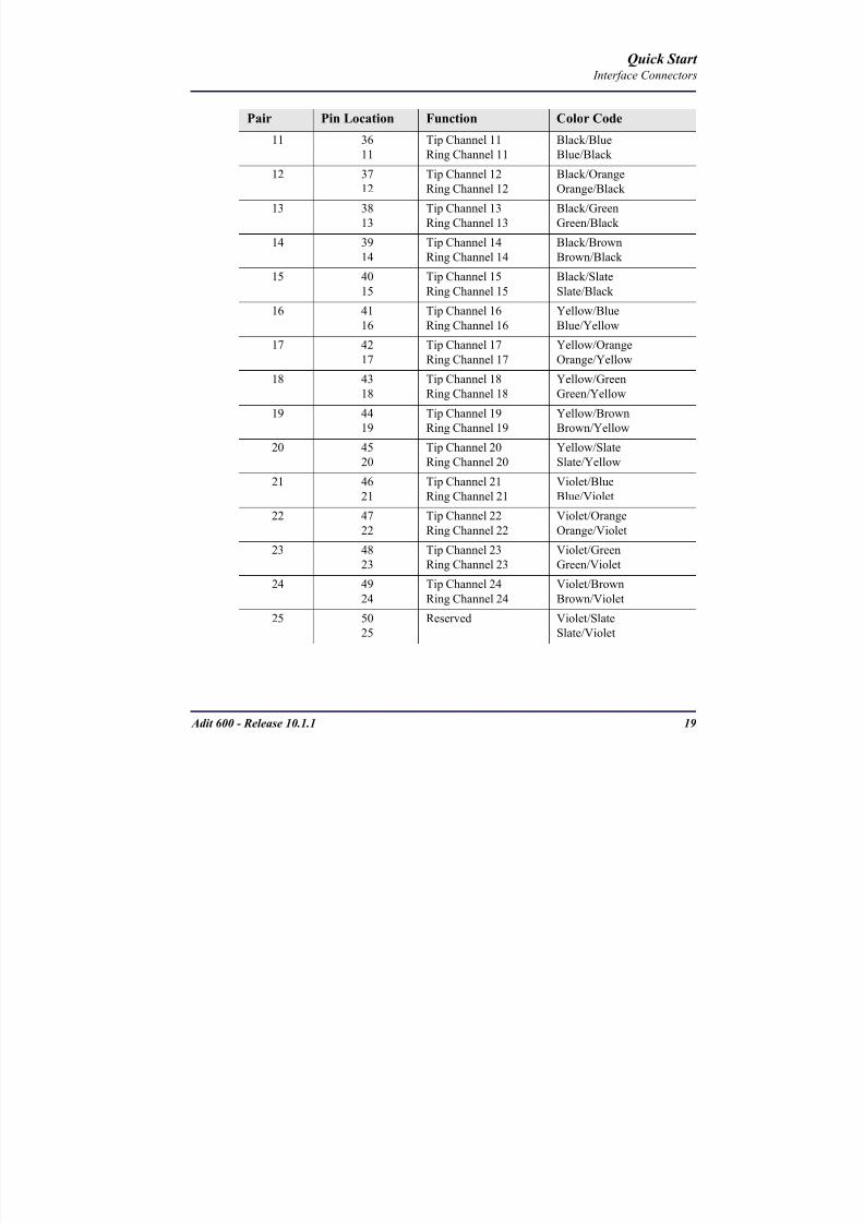
8102019 Adit 600 Quick Start 10-1-1
httpslidepdfcomreaderfulladit-600-quick-start-10-1-1 2254
20 Adit 600 - Release 1011
Quick Start Interface Connectors
RS-232 Craft Port (Female DB-9)The RS-232 craft port connector (female) is for connection to an external PC or Hayes-
compatible modem for local or remote configuration management and performance
monitoring using the Adit 600 Command Line Interface (CLI)
The RS-232 craft port connects via a
female DB-9 connector on the Adit 600
The pinouts are as follows
Pin Number Direction Description
1 Outbound Carrier Detect
2 Outbound Receive Data
3 Inbound Transmit Data
4 Inbound Data Terminal Ready
5 NA Signal Ground
6 Outbound Data Set Ready
7 Inbound Request to Send
8 Outbound Clear to Send
9 NC Not connected
1 5
6 9
8102019 Adit 600 Quick Start 10-1-1
httpslidepdfcomreaderfulladit-600-quick-start-10-1-1 2354
8102019 Adit 600 Quick Start 10-1-1
httpslidepdfcomreaderfulladit-600-quick-start-10-1-1 2454
22 Adit 600 - Release 1011
Quick Start Interface Connectors
10Base-T Ethernet
The 10Base-T Ethernet (female) port to connect to a remote
management tool such as Telnet or an SNMP-based Network
Management System Note A LINK LED on the back of the unit
displays green when the system has a good Ethernet link
The pinouts are as follows
Ethernet (RJ-45)
NOTE This Ethernet port uses a hub pinout Use a straight-through cableto connect a PC
Pin Name Description
1 Receive + Receive from network
2 Receive - Receive from network
3 Transmit + Transmit to network
4 - 5 NC Not connected
6 Transmit - Transmit to network
7 NC Not connected
8 NC Not connected
1 8
8102019 Adit 600 Quick Start 10-1-1
httpslidepdfcomreaderfulladit-600-quick-start-10-1-1 2554
Adit 600 - Release 1011 23
Quick Start Management Options
Management Options
Options for managing the Adit 600 are as follows
Local using CLI Telnet SNMP or DIP Switches (Controller and voice cards)
Remotely over an in-band DS0 or through the Access Navigator over the FDL
or an in-band DS0
This Quick Start Guide focuses on the CLI and DIP switches If you need further
information on other management options please refer to the Adit 600 User Manual
Command Line Interface (CLI)
You can access the CLI using either of the following methods
Telnet via Ethernet (10Base-T) RS-232 connected to the DB-9 port
Setting up a CLI Connection
If connecting via the Ethernet 10Base-T connection use a Telnet TCPIP
program to access the CLI This requires the IP address of the Controller
Controllers are shipped with the IP address set to 100010 If this address has been changed and is not known use HyperTerm to access the Controller and
use the CLI command show ip If an IP address needs to be set use the CLI
command set ethernet ip address
If connecting via RS-232 the port settings should be set to
Bits per second 9600 Data bits 8
Parity None Stop bits 1Flow control None
Set your Terminal Emulation to VT100
By default the Adit 600 is set for local configuration (using DIP switches) Use
the set local off command to enable the use of CLI commands
8102019 Adit 600 Quick Start 10-1-1
httpslidepdfcomreaderfulladit-600-quick-start-10-1-1 2654
8102019 Adit 600 Quick Start 10-1-1
httpslidepdfcomreaderfulladit-600-quick-start-10-1-1 2754
Adit 600 - Release 1011 25
Quick Start Configuration
ConfigurationThe following basic setups and upgrades for the Adit 600 are shown using CLI
commands For more information on CLI commands and configurations see the Adit
600 User Manual
Initial Setup
Basic Security Setup
DS1T1 Setup
E1 Setup
DS0Channel Setup
Analog Port Setup
4-Wire EampM Setup
Establish a Static Channel Connection
ISDN BRI Service Setup
OCU-DP Card Setup
ADPCM Card Setup
V35 Port Setup
Change the IP Address of the DS0 Management Channel
Upgrade the Adit 600 Software
Upgrade the Router Card Software
Basic Router Setup
8102019 Adit 600 Quick Start 10-1-1
httpslidepdfcomreaderfulladit-600-quick-start-10-1-1 2854
26 Adit 600 - Release 1011
Quick Start Configuration
Initial SetupUse the following commands for your initial setup For further information see the Adit
600 User Manual
Command Description
set local off Disables DIP switches
set date mmddyyyy Set the date used for event logging
set time hhmmss Set the time used for event logging
set id id-name Set a system ID name
set clock1 slotportinternal
Set the primary clock source
set clock2 slotportinternal
Set the secondary clock source
set ethernet ip addressip-addr mask
Set the ethernet IP address in the
conventional IP address format
set ip gateway ip-addr Set the IP gateway in the conventional IP
address format
8102019 Adit 600 Quick Start 10-1-1
httpslidepdfcomreaderfulladit-600-quick-start-10-1-1 2954
Adit 600 - Release 1011 27
Quick Start Configuration
Basic Security SetupUse the following commands to set up the security on the Adit 600 For further
information see the Adit 600 User Manual
Command Description
set password length
long|short
Set user password length requirement
add user ldquouser-namerdquo[password ldquopasswordrdquo]
Add user and password as necessary
set user user-name level1-3
Specify the userrsquos security level
set user user-namepassword Setchange password for the user asnecessary
8102019 Adit 600 Quick Start 10-1-1
httpslidepdfcomreaderfulladit-600-quick-start-10-1-1 3054
28 Adit 600 - Release 1011
Quick Start Configuration
DS1T1 SetupUse the following commands to set up a DS1 See the set (ds1) command for more
details
Command Description
set ds1-addr up Activate the port of the DS1 (slotport)
set ds1-addr id id-string
Set the identification string
set ds1-addr lbo 1-9 Set the line buildout value for the DS1
set ds1-addr linecodeami|b8zs
Set the linecode for the DS1
set ds1-addr framing d4|esf|tr8afdl|tr8anofdl|tr8b
Set the framing option for the DS1
set ds1-addr loopdetecton|off
Set the detectionreaction to CSU loopcodes
Q i k S
8102019 Adit 600 Quick Start 10-1-1
httpslidepdfcomreaderfulladit-600-quick-start-10-1-1 3154
Adit 600 - Release 1011 29
Quick Start Configuration
E1 Setup
NOTE E1 is not supported in this release of the Adit 600 Controller It will besupported in a future release
Use the following commands to set up an E1 See the set (e1) command for more
details
DS0Channel Setup
Use the following commands to set up a DS0 See the set (ds0) command for details
Command Description
set e1-addr up Activate the port of the E1 (slotport)
set e1-addr id id-string Set the identification string
set e1-addr lbo 1 - 9 Set the line buildout value for the E1
set e1-addr linecodeami|hdb3
Set the linecode for the E1
set e1-addr framinge1fr|lefrcrc
Set the framing option for the E1
set e1-addr loopdetecton|off
Set the detectionreaction to CSU loopcodes
Command Description
set slotportchannel up Activate the channel
set slotportchannel signalls|gs|emw|emdw|emicpd|dpt
Set the signaling option for the channel
set slotportchannel typedata|voice Set the channel type
Q i k St t
8102019 Adit 600 Quick Start 10-1-1
httpslidepdfcomreaderfulladit-600-quick-start-10-1-1 3254
30 Adit 600 - Release 1011
Quick Start Configuration
Analog Port SetupUse the following commands to set up an analog port
Command Description
set slotport up Activate the port See set (ds1) command for
details
set slotport signal dpt|gs|gsrb|gsw|gswrb|ls|lscpd|lsrb
Set the signaling option for the port See the
set (fxs) or set (fxo) command for details
set slotport rxgain n Set the receive gainloss in dB See the set
(fxs) or set (fxo) command for details
set slotport txgain n Set the transmit gainloss in dB See the set
(fxs) or set (fxo) command for details
Quick Start
8102019 Adit 600 Quick Start 10-1-1
httpslidepdfcomreaderfulladit-600-quick-start-10-1-1 3354
Adit 600 - Release 1011 31
Quick Start Configuration
4-Wire EampM SetupFor this example the 4 EampM ports will be connected to the first 4 DS0s on T1-1 (a1)
This can be changed to match the customers desired DS0 connections
For Transmission Only mode the DS0s on the DS1 should be set to data as well as the
EampM card channels
Command Description
For Normal or Tandem EampM
set a11-4 type voice Set DS0s to voice
set connect a11-4 11-4 Connect DS0s to the 4 ports of the 4-
Wire EampM card
show connect a 1 Verify cross connects
set a11-4 signal emi Set DS0 signal type to EMI
set 11-4 signal emi Set 4-Wire EampM ports signal type to
EMI
show connect a1 Verify cross connects
For TO Mode
set a11-4 type data Set DS0s to data
set 11-4 type data Set 4-Wire EampM port to data
set connect a11-4 11-4 Connect DS0s to the 4 ports of the 4-
Wire EampM card
show connect a 1 Verify cross connects
Quick Start
8102019 Adit 600 Quick Start 10-1-1
httpslidepdfcomreaderfulladit-600-quick-start-10-1-1 3454
32 Adit 600 - Release 1011
Quick Start Configuration
Establish a Static Channel ConnectionUse the following commands to establish a static channel connection
ISDN BRI Service Setup
Use the following commands to set up a ISDN BRI Service See the set (bri) command
for details
Command Description
set slotportchannel typevoice|data
Set the channel type for the channel to
map See set (ds0) command for details
set slotportchannel signalls|gs|emw|emdw|emicpd|dpt
Set the channel signaling option See set
(ds0) command for details
connect slotportslotport
Connect the channels See the connect
(card-trunk) (card-trunk) command
Command Description
set slotport up Put the ISDN line In-Service
set slot modelt3ds0|lt4to1tdm|nt3ds0
Set the ISDN mode
set slotport crv 1-768 Set the Call Reference Value Note
value must be the same as the Access
Navigator
set slotport thresholdday|hour es|ses
Set the threshold for the IDSN lines
set slot pmsyncadit|switch
Set the source for performance
monitoring synchronization
set slotport autoactivate
on|off
Only used in 4-to-1 mode Establishes
the D channel when the FDL link can not
be used
Quick Start
8102019 Adit 600 Quick Start 10-1-1
httpslidepdfcomreaderfulladit-600-quick-start-10-1-1 3554
Adit 600 - Release 1011 33
Quick Start Configuration
OCU-DP Card SetupThe following is a basic setup for the OCU-DP card
ADPCM Card Setup
Command Description
set ocudp-addr baud2400|4800|9600|19200|38400|
56000|64000
Set the OCU-DP Baud rate
Where ocudp-addr = slotport of the
OCU-DP card to apply settings to
set ocudp-addr up Set the OCU-DP port 1 up
show ocudp_card-addr Show the OCU-DP card settings
Where ocudp_card-addr = slot of the
OCU-DP card
disconnect a Disconnects all connections to slot a
(controller)
set ds0-addr type data Sets a DS0 data signaling type
connect ds0-addrocudp-addr
Connects DS0 (in previous step) to OCU-DP
port (in previous step)
show connect
(ocudp_card-addr
Displays connect information for OCU-DP
card
Command Description
Connect T1 cable to port 1 of the ADPCM service card
set adpcm_card-addrnone|map1|map2|map3
Enable compressing by selecting Map type Notenone disables compression
show (adpcm_card-addr Displays the status of the card and the mapping
connect 211-12 241-12 Set ADPCM cross-connects The example
connects all 24 channels of the ADPCM to the 12
channels of the T1 (now compressed) on port 4
This example is with map2show connect 21) Displays the connections made above
8102019 Adit 600 Quick Start 10-1-1
httpslidepdfcomreaderfulladit-600-quick-start-10-1-1 3654
Quick Start
8102019 Adit 600 Quick Start 10-1-1
httpslidepdfcomreaderfulladit-600-quick-start-10-1-1 3754
Adit 600 - Release 1011 35
QConfiguration
Upgrade the Adit 600 SoftwareUse the following commands to determine the system software level then upgrade the
software to the latest version
Command Description
status equipment Determine the system software level The
Slot A line (SW Vers) will display thecurrent software level
load tftp ip-addr file-name (or load xmodem)
Load the new controller system software See
the load tftp and load xmodem command for
more information
Note A TFTP server must be running onthe host system You can use any TFTP
server utility you wish One example isthe program TFTPD32 which can bedownloaded free-of-charge attftpd32jouninnettftpd32html
Quick Start
8102019 Adit 600 Quick Start 10-1-1
httpslidepdfcomreaderfulladit-600-quick-start-10-1-1 3854
36 Adit 600 - Release 1011
Configuration
Upgrade the Router Card SoftwareUse the following commands to determine the Router card software level then upgrade
the software to the latest version
NOTE For additional information about upgrading MSR card software see
the following manuals-Adit 600 User Manual -Adit 3000 Series and Multi-Service Router (MSR) Card GUI Reference Manual
-Adit 3000 Series and Multi-Service Router (MSR) Card CLI Reference Manual
Command Description
status equipment Determine the Router software level The
Router Slot line (SW Vers) will display thecurrent software level
load rtr_card-addr tftpip-addr file-name
Load the new Router software to a Router
card See the load tftp command for more
information
Note A TFTP server must be running onthe host system You can use any TFTP
server utility you wish One example isthe program TFTPD32 which can bedownloaded free-of-charge attftpd32jouninnettftpd32html
8102019 Adit 600 Quick Start 10-1-1
httpslidepdfcomreaderfulladit-600-quick-start-10-1-1 3954
8102019 Adit 600 Quick Start 10-1-1
httpslidepdfcomreaderfulladit-600-quick-start-10-1-1 4054
Quick Start C t ll C d LED
8102019 Adit 600 Quick Start 10-1-1
httpslidepdfcomreaderfulladit-600-quick-start-10-1-1 4154
Adit 600 - Release 1011 39
Controller Card LEDs
E1 Controller Card
NOTE E1 is not supported in this release It will be supported in a futurerelease
The E1 Controller has a set of six LEDs The table below describes each LED
LED State Description
MAJOR Off No major alarms present
Red Major alarm present
MINOR Off No minor alarms present
Yellow Minor alarms present
LOCAL Off Remote mode (DIP switches disabled)
Green Local mode (DIP switches enabled)
ACO Off Normal mode No alarms are being
suppressed
Yellow Alarm Cut Off active One or more active
alarms suppressed
E1-1 and
E1-2
Off Off line
Green Normal
Red Loss of Signal (LOS) detected
Yellow Bipolar Violation (BPV) detected LCV
Flashing Green Loopback active
Flashing Red
(slow)
Loss of Frame (LOF) or Alarm Indication
Signal (AIS) detected
Flashing Red
(fast)
Card Failure
Flashing Yellow Yellow alarm (Remote Alarm Indication)detected
Quick Start Power Supply LEDs
8102019 Adit 600 Quick Start 10-1-1
httpslidepdfcomreaderfulladit-600-quick-start-10-1-1 4254
40 Adit 600 - Release 1011
Power Supply LEDs
Power Supply LEDs115 VAC-48 VDC and 230 VAC-48 VDC Power Supplies
The power supply card has two LEDs as described in the table
below
24 VDC-48 VDC Power Supply
The power supply card has two LEDs as described in the table below
LED State Description
AC Input Off AC input missing or failure
Green AC input present
Battery Off Battery input not used
Green Battery charging or operating from DC
source only
Yellow Battery discharging
Red Battery low (less than 42V) ringer disabled
LED State Description
DC OK Off DC input missing or failure
Green DC input present
-48 Battery
Low
Off Normal
Red VDC is low (less than 42 VDC)
ringer disabled
Quick Start Service Card LEDs
8102019 Adit 600 Quick Start 10-1-1
httpslidepdfcomreaderfulladit-600-quick-start-10-1-1 4354
Adit 600 - Release 1011 41
Service Card LEDs
Service Card LEDs 4-Wire EampM Card
FXO Card
FXS Card
ISDN BRI Card
OCU-DP Card
P-Phone Card
Single Channel POTS Card
Quad DS1 ADPCM Service Card
Quad DS1E1 and Quad T1 Cards
Quad E1 Card
IP Router Card
CMG Router Card
Terminal Server Router Card
MSR Card
RS-232 and V35V54 Cards
Discontinued cards
RS-232 discontinued
Quick Start Service Card LEDs
8102019 Adit 600 Quick Start 10-1-1
httpslidepdfcomreaderfulladit-600-quick-start-10-1-1 4454
42 Adit 600 - Release 1011
Service Card LEDs
4-Wire EampM Card Each channelport has two LEDs Only the top LED is used in this application LED
definitions are listed below
State Description
When in EampM Mode
Off Channel is idle or disabled
Green Analog interface is off-hook
Red Digital interface is off-hook
Yellow Both analog and digital interfaces are off-hook or channel is
being trunk processed
When in TO Mode
Off DisconnectedGreen Connected T1E1 not in alarm
Yellow Connected T1E1 in alarm (trunk processed)
Quick Start Service Card LEDs
8102019 Adit 600 Quick Start 10-1-1
httpslidepdfcomreaderfulladit-600-quick-start-10-1-1 4554
Adit 600 - Release 1011 43
FXO Card Each port on the FXO card has its own LED as described in the table below
FXS Card
There is an LED for each port on the FXS card as described in the table below
State Loop Start
Meaning
Ground Start Meaning Dial Pulse Termination
Meaning
Off NA Idle (tip open) Idle (loop open)
Green Idle Tip ground (incoming seizure) Incoming seizure
Red NA Ring ground (outgoing
seizure)
Loop closure (outgoing seizure)
Yellow Call in
progress
Call in progress Call in progress (reverse battery)
Flashing
Green
Ringing Ringing NA
State Loop Start Meaning Ground Start Meaning
Off NA Idle (tip open)
Green Idle Tip ground (incoming seizure)
Red Note This can be seen with
Forward Disconnect (tip open)
Ring ground (outgoing seizure)
Yellow Call in progress Call in progress
Flashing green Ringing Ringing
Quick Start Service Card LEDs
8102019 Adit 600 Quick Start 10-1-1
httpslidepdfcomreaderfulladit-600-quick-start-10-1-1 4654
44 Adit 600 - Release 1011
ISDN BRI Card There is an LED for each ISDN BRI on a card as described in the table below
OCU-DP Card Each channel has two LEDs described in the table below
State Description
Off Line U-interface is attempting synchronization or BRI is Out-of-Service
Red Line alarm (LOS or self test failure)
Yellow ES or SES has occurred
Flashing yellow Line U-interface is synchronized with customer equipment but is not passing
customer data
Flashing green Line U-interface is in external loopback toward the switch at the unit
Green Normal (Line U-interface is active and transparently passing customer data)
State Description
Yellow Flickering ALL Boot Software in control
Green (walking down)
Red (walking up)
ALL Application Software in control
(repeated 35 times)
Red slow flash ALL In Boot Application flash code checksums did not match and
Boot is waiting for application download
Red ALL In Application code waiting for Controller to issue SWHW
revision request This is the first request that comes from the
OCU-DP card manager in the ControllerGreen
Yellow
Top
Bottom
Port in Self-test Duration is 5-8 seconds
Off Top
Bottom
Port is set down (Out-Of-Service)
Green Top Port is receiving valid signals
Red Top Port is receiving no signal (primary) or no frame sync
(secondary or clear channel)Red Flashing Bottom Port is receiving bipolar violations
Yellow Bottom Port is in loopback
Quick Start Service Card LEDs
8102019 Adit 600 Quick Start 10-1-1
httpslidepdfcomreaderfulladit-600-quick-start-10-1-1 4754
Adit 600 - Release 1011 45
P-Phone Card Each P-Phone channel has a corresponding LED described in the table below
State Line State
Off No P-Phone connected
Green No call in process
Flashing Green Alert (Ringing)
Yellow Call in progress
Flashing Yellow P-Phone Loopback in Progress
Flashing Red Self-test failed
Quick Start Service Card LEDs
8102019 Adit 600 Quick Start 10-1-1
httpslidepdfcomreaderfulladit-600-quick-start-10-1-1 4854
46 Adit 600 - Release 1011
Single Channel POTS Card The POTS channel LED (left) status is described in the table below
The second LED (right) is a status LED is not used on this card
Quad DS1 ADPCM Service Card
Each channel on the Quad DS1 ADPCM card has two LEDs The
description of the top LED is shown below the bottom LED is notused with this application
State Loop Start Meaning
Off Calling Party Disconnect
Green Idle
Red NA
Yellow Call in progress
Flashing green Ringing
State Description
Off Off line
Green Normal
Red Loss of Signal (LOS)
Yellow Bipolar Violation (BPV)Flashing Green Loopback active
Flashing Yellow Yellow Alarm
(Remote Alarm Indication)
Flashing Red (Slow) Loss of Frame (LOF) or Alarm Indication Signal (AIS)
Flashing Red (Fast) Self-test Failure
Top LED(active)
Bottom LED(not used)
Quick Start Service Card LEDs
8102019 Adit 600 Quick Start 10-1-1
httpslidepdfcomreaderfulladit-600-quick-start-10-1-1 4954
Adit 600 - Release 1011 47
Quad DS1E1 and Quad T1 CardsEach channel on the Quad T1E1 cards have two LEDs The description
of the top LED is shown below the bottom LED is not used with this
application
State Description
Off Off line
Green Normal
Red Loss of Signal (LOS)
Yellow Bipolar Violation (BPV)
Flashing Green Loopback active
Flashing Yellow Yellow Alarm (Remote Alarm Indication)
Flashing Red (Slow) Loss of Frame (LOF) or Alarm Indication Signal (AIS)
Flashing Red (Fast) Self-test Failure
Quick Start Service Card LEDs
8102019 Adit 600 Quick Start 10-1-1
httpslidepdfcomreaderfulladit-600-quick-start-10-1-1 5054
48 Adit 600 - Release 1011
IP Router Card The following chart describes each LED and its state
LED State Description
CRD Off Loss of power
Green No current alarms
Red Alarm state active See alarm log for cause
Red Flashing Self-test or Boot in-process
Yellow Flashing Card is saving data to flash RAM do not power down
10100 Off 10 Mb ethernet
Green 100 Mb ethernet
LNK Off No ethernet link
Green Good ethernet link
COL
Off No current ethernet transmit collisions
Yellow Ethernet collisions have occurred and have not dropped
to minimum level
Yellow Flashing Ethernet collision occurring
TX Off No ethernet transmit activity
Green Ethernet transmit activity
RX Off No current ethernet receive activity
Green Current ethernet receive activity
Quick Start Service Card LEDs
8102019 Adit 600 Quick Start 10-1-1
httpslidepdfcomreaderfulladit-600-quick-start-10-1-1 5154
Adit 600 - Release 1011 49
CMG Router Card The following chart describes each LED and its state
LED State Description
CRD Off Loss of power
Green No current alarms
Red Alarm state active See alarm log for causeRed Flashing Self-test or Boot in-process
Yellow Flashing Card is saving data to flash RAM do not power down
VOIP
Off No active VoIP calls or if the MGCP protocol is
optioned down
Green Active VoIP calls
Red Call agent unreachable
Yellow Insufficient VoIP resources to complete call
LNK Off No Ethernet link
Green Good Ethernet link
10100 Off 10 Mb Ethernet
Green 100 Mb Ethernet
TX Off No Ethernet transmit activityGreen Ethernet transmit activity
Yellow Current Ethernet transmit collision
RX Off No current Ethernet receive activity
Green Current Ethernet receive activity
Quick Start Service Card LEDs
8102019 Adit 600 Quick Start 10-1-1
httpslidepdfcomreaderfulladit-600-quick-start-10-1-1 5254
50 Adit 600 - Release 1011
Terminal Server Router Card The Terminal Server Router card has 2 LEDs per port
At Power-up
Normal Operation
Port Set for Ethernet
Top LED indicates 100M Link Bottom LED indicates 10M Link
Port Set for RS-232
TOP LED Bottom LED Description
Off Off At Power UpBoot = Loss of power
Red Red Card is inoperative
Flashing Red Flashing Red Self-test or Boot in-process
TOP LED Bottom LED Description
Green Solid (Link) Green Solid (Link) Port set for Ethernet - see below
Flashing Red Flashing Red Self-test or Boot in-process
State Description
Off No Ethernet link
Green Link but no activity
Red Flashing Current Ethernet collision
Green Flashing Current Ethernet receive
Yellow Flashing Current Ethernet transmit
TOP LED Bottom LED Description
Yellow Off No Activity
Yellow Flashing Yellow Current transmit
Yellow Flashing Green Current receive
Quick Start Service Card LEDs
8102019 Adit 600 Quick Start 10-1-1
httpslidepdfcomreaderfulladit-600-quick-start-10-1-1 5354
Adit 600 - Release 1011 51
MSR Card The following chart describes the MSR cardrsquos LEDs
LED State Description
CRD Off Loss of power
Green No current alarms
Red Alarm state active See alarm log for cause
Red Flashing Self-test or boot in process
Yellow Flashing Card is saving data to flash RAM do not power
down
VOIP
Off No SIP proxy or registration attempts for all lines
have succeeded but no calls are active
Green Active VoIP call(s)
Red Inability to reach the SIP proxy or negative response
to register attempts from all lines
Yellow Register attempts from some lines have succeeded
but not for all lines
ETH1 and
ETH2
Top LED
Off 10 Mbitsec down or not connected
Green 100 Mbitsec
ETH1 and
ETH2
Bottom LED
Off Link down
Green Link up
Flashing Green Traffic on link
Yellow Collision status
Quick Start Service Card LEDs
8102019 Adit 600 Quick Start 10-1-1
httpslidepdfcomreaderfulladit-600-quick-start-10-1-1 5454
52 Adit 600 - Release 1011
RS-232 and V35V54 Cards Each port has its own LED as described in the table below
State Description
Off No T1 Assignment
Green Normal (CDRTS) Active
Red CD inactive (T1-side failure)
Yellow RTS inactive (equipment-side failure)
Flashing Yellow Loopback toward T1 or equipment loop test
Flashing Green Loopback toward equipment or network loop test
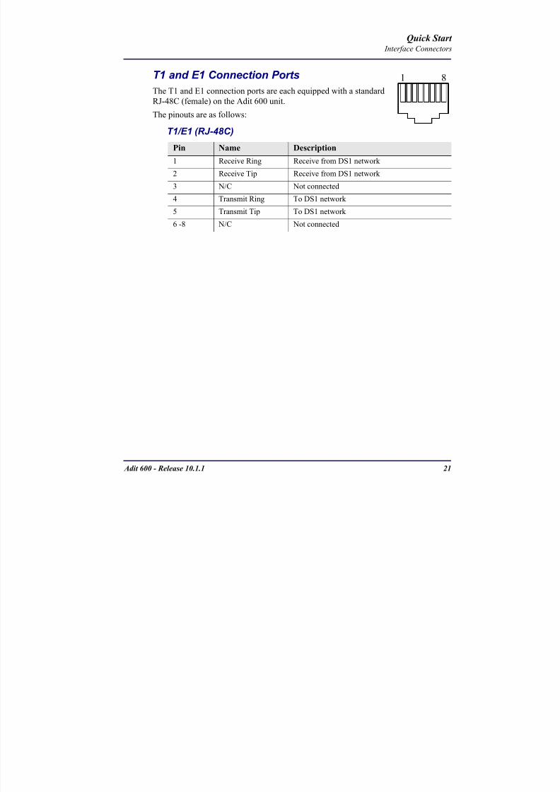
8102019 Adit 600 Quick Start 10-1-1
httpslidepdfcomreaderfulladit-600-quick-start-10-1-1 2354
8102019 Adit 600 Quick Start 10-1-1
httpslidepdfcomreaderfulladit-600-quick-start-10-1-1 2454
22 Adit 600 - Release 1011
Quick Start Interface Connectors
10Base-T Ethernet
The 10Base-T Ethernet (female) port to connect to a remote
management tool such as Telnet or an SNMP-based Network
Management System Note A LINK LED on the back of the unit
displays green when the system has a good Ethernet link
The pinouts are as follows
Ethernet (RJ-45)
NOTE This Ethernet port uses a hub pinout Use a straight-through cableto connect a PC
Pin Name Description
1 Receive + Receive from network
2 Receive - Receive from network
3 Transmit + Transmit to network
4 - 5 NC Not connected
6 Transmit - Transmit to network
7 NC Not connected
8 NC Not connected
1 8
8102019 Adit 600 Quick Start 10-1-1
httpslidepdfcomreaderfulladit-600-quick-start-10-1-1 2554
Adit 600 - Release 1011 23
Quick Start Management Options
Management Options
Options for managing the Adit 600 are as follows
Local using CLI Telnet SNMP or DIP Switches (Controller and voice cards)
Remotely over an in-band DS0 or through the Access Navigator over the FDL
or an in-band DS0
This Quick Start Guide focuses on the CLI and DIP switches If you need further
information on other management options please refer to the Adit 600 User Manual
Command Line Interface (CLI)
You can access the CLI using either of the following methods
Telnet via Ethernet (10Base-T) RS-232 connected to the DB-9 port
Setting up a CLI Connection
If connecting via the Ethernet 10Base-T connection use a Telnet TCPIP
program to access the CLI This requires the IP address of the Controller
Controllers are shipped with the IP address set to 100010 If this address has been changed and is not known use HyperTerm to access the Controller and
use the CLI command show ip If an IP address needs to be set use the CLI
command set ethernet ip address
If connecting via RS-232 the port settings should be set to
Bits per second 9600 Data bits 8
Parity None Stop bits 1Flow control None
Set your Terminal Emulation to VT100
By default the Adit 600 is set for local configuration (using DIP switches) Use
the set local off command to enable the use of CLI commands
8102019 Adit 600 Quick Start 10-1-1
httpslidepdfcomreaderfulladit-600-quick-start-10-1-1 2654
8102019 Adit 600 Quick Start 10-1-1
httpslidepdfcomreaderfulladit-600-quick-start-10-1-1 2754
Adit 600 - Release 1011 25
Quick Start Configuration
ConfigurationThe following basic setups and upgrades for the Adit 600 are shown using CLI
commands For more information on CLI commands and configurations see the Adit
600 User Manual
Initial Setup
Basic Security Setup
DS1T1 Setup
E1 Setup
DS0Channel Setup
Analog Port Setup
4-Wire EampM Setup
Establish a Static Channel Connection
ISDN BRI Service Setup
OCU-DP Card Setup
ADPCM Card Setup
V35 Port Setup
Change the IP Address of the DS0 Management Channel
Upgrade the Adit 600 Software
Upgrade the Router Card Software
Basic Router Setup
8102019 Adit 600 Quick Start 10-1-1
httpslidepdfcomreaderfulladit-600-quick-start-10-1-1 2854
26 Adit 600 - Release 1011
Quick Start Configuration
Initial SetupUse the following commands for your initial setup For further information see the Adit
600 User Manual
Command Description
set local off Disables DIP switches
set date mmddyyyy Set the date used for event logging
set time hhmmss Set the time used for event logging
set id id-name Set a system ID name
set clock1 slotportinternal
Set the primary clock source
set clock2 slotportinternal
Set the secondary clock source
set ethernet ip addressip-addr mask
Set the ethernet IP address in the
conventional IP address format
set ip gateway ip-addr Set the IP gateway in the conventional IP
address format
8102019 Adit 600 Quick Start 10-1-1
httpslidepdfcomreaderfulladit-600-quick-start-10-1-1 2954
Adit 600 - Release 1011 27
Quick Start Configuration
Basic Security SetupUse the following commands to set up the security on the Adit 600 For further
information see the Adit 600 User Manual
Command Description
set password length
long|short
Set user password length requirement
add user ldquouser-namerdquo[password ldquopasswordrdquo]
Add user and password as necessary
set user user-name level1-3
Specify the userrsquos security level
set user user-namepassword Setchange password for the user asnecessary
8102019 Adit 600 Quick Start 10-1-1
httpslidepdfcomreaderfulladit-600-quick-start-10-1-1 3054
28 Adit 600 - Release 1011
Quick Start Configuration
DS1T1 SetupUse the following commands to set up a DS1 See the set (ds1) command for more
details
Command Description
set ds1-addr up Activate the port of the DS1 (slotport)
set ds1-addr id id-string
Set the identification string
set ds1-addr lbo 1-9 Set the line buildout value for the DS1
set ds1-addr linecodeami|b8zs
Set the linecode for the DS1
set ds1-addr framing d4|esf|tr8afdl|tr8anofdl|tr8b
Set the framing option for the DS1
set ds1-addr loopdetecton|off
Set the detectionreaction to CSU loopcodes
Q i k S
8102019 Adit 600 Quick Start 10-1-1
httpslidepdfcomreaderfulladit-600-quick-start-10-1-1 3154
Adit 600 - Release 1011 29
Quick Start Configuration
E1 Setup
NOTE E1 is not supported in this release of the Adit 600 Controller It will besupported in a future release
Use the following commands to set up an E1 See the set (e1) command for more
details
DS0Channel Setup
Use the following commands to set up a DS0 See the set (ds0) command for details
Command Description
set e1-addr up Activate the port of the E1 (slotport)
set e1-addr id id-string Set the identification string
set e1-addr lbo 1 - 9 Set the line buildout value for the E1
set e1-addr linecodeami|hdb3
Set the linecode for the E1
set e1-addr framinge1fr|lefrcrc
Set the framing option for the E1
set e1-addr loopdetecton|off
Set the detectionreaction to CSU loopcodes
Command Description
set slotportchannel up Activate the channel
set slotportchannel signalls|gs|emw|emdw|emicpd|dpt
Set the signaling option for the channel
set slotportchannel typedata|voice Set the channel type
Q i k St t
8102019 Adit 600 Quick Start 10-1-1
httpslidepdfcomreaderfulladit-600-quick-start-10-1-1 3254
30 Adit 600 - Release 1011
Quick Start Configuration
Analog Port SetupUse the following commands to set up an analog port
Command Description
set slotport up Activate the port See set (ds1) command for
details
set slotport signal dpt|gs|gsrb|gsw|gswrb|ls|lscpd|lsrb
Set the signaling option for the port See the
set (fxs) or set (fxo) command for details
set slotport rxgain n Set the receive gainloss in dB See the set
(fxs) or set (fxo) command for details
set slotport txgain n Set the transmit gainloss in dB See the set
(fxs) or set (fxo) command for details
Quick Start
8102019 Adit 600 Quick Start 10-1-1
httpslidepdfcomreaderfulladit-600-quick-start-10-1-1 3354
Adit 600 - Release 1011 31
Quick Start Configuration
4-Wire EampM SetupFor this example the 4 EampM ports will be connected to the first 4 DS0s on T1-1 (a1)
This can be changed to match the customers desired DS0 connections
For Transmission Only mode the DS0s on the DS1 should be set to data as well as the
EampM card channels
Command Description
For Normal or Tandem EampM
set a11-4 type voice Set DS0s to voice
set connect a11-4 11-4 Connect DS0s to the 4 ports of the 4-
Wire EampM card
show connect a 1 Verify cross connects
set a11-4 signal emi Set DS0 signal type to EMI
set 11-4 signal emi Set 4-Wire EampM ports signal type to
EMI
show connect a1 Verify cross connects
For TO Mode
set a11-4 type data Set DS0s to data
set 11-4 type data Set 4-Wire EampM port to data
set connect a11-4 11-4 Connect DS0s to the 4 ports of the 4-
Wire EampM card
show connect a 1 Verify cross connects
Quick Start
8102019 Adit 600 Quick Start 10-1-1
httpslidepdfcomreaderfulladit-600-quick-start-10-1-1 3454
32 Adit 600 - Release 1011
Quick Start Configuration
Establish a Static Channel ConnectionUse the following commands to establish a static channel connection
ISDN BRI Service Setup
Use the following commands to set up a ISDN BRI Service See the set (bri) command
for details
Command Description
set slotportchannel typevoice|data
Set the channel type for the channel to
map See set (ds0) command for details
set slotportchannel signalls|gs|emw|emdw|emicpd|dpt
Set the channel signaling option See set
(ds0) command for details
connect slotportslotport
Connect the channels See the connect
(card-trunk) (card-trunk) command
Command Description
set slotport up Put the ISDN line In-Service
set slot modelt3ds0|lt4to1tdm|nt3ds0
Set the ISDN mode
set slotport crv 1-768 Set the Call Reference Value Note
value must be the same as the Access
Navigator
set slotport thresholdday|hour es|ses
Set the threshold for the IDSN lines
set slot pmsyncadit|switch
Set the source for performance
monitoring synchronization
set slotport autoactivate
on|off
Only used in 4-to-1 mode Establishes
the D channel when the FDL link can not
be used
Quick Start
8102019 Adit 600 Quick Start 10-1-1
httpslidepdfcomreaderfulladit-600-quick-start-10-1-1 3554
Adit 600 - Release 1011 33
Quick Start Configuration
OCU-DP Card SetupThe following is a basic setup for the OCU-DP card
ADPCM Card Setup
Command Description
set ocudp-addr baud2400|4800|9600|19200|38400|
56000|64000
Set the OCU-DP Baud rate
Where ocudp-addr = slotport of the
OCU-DP card to apply settings to
set ocudp-addr up Set the OCU-DP port 1 up
show ocudp_card-addr Show the OCU-DP card settings
Where ocudp_card-addr = slot of the
OCU-DP card
disconnect a Disconnects all connections to slot a
(controller)
set ds0-addr type data Sets a DS0 data signaling type
connect ds0-addrocudp-addr
Connects DS0 (in previous step) to OCU-DP
port (in previous step)
show connect
(ocudp_card-addr
Displays connect information for OCU-DP
card
Command Description
Connect T1 cable to port 1 of the ADPCM service card
set adpcm_card-addrnone|map1|map2|map3
Enable compressing by selecting Map type Notenone disables compression
show (adpcm_card-addr Displays the status of the card and the mapping
connect 211-12 241-12 Set ADPCM cross-connects The example
connects all 24 channels of the ADPCM to the 12
channels of the T1 (now compressed) on port 4
This example is with map2show connect 21) Displays the connections made above
8102019 Adit 600 Quick Start 10-1-1
httpslidepdfcomreaderfulladit-600-quick-start-10-1-1 3654
Quick Start
8102019 Adit 600 Quick Start 10-1-1
httpslidepdfcomreaderfulladit-600-quick-start-10-1-1 3754
Adit 600 - Release 1011 35
QConfiguration
Upgrade the Adit 600 SoftwareUse the following commands to determine the system software level then upgrade the
software to the latest version
Command Description
status equipment Determine the system software level The
Slot A line (SW Vers) will display thecurrent software level
load tftp ip-addr file-name (or load xmodem)
Load the new controller system software See
the load tftp and load xmodem command for
more information
Note A TFTP server must be running onthe host system You can use any TFTP
server utility you wish One example isthe program TFTPD32 which can bedownloaded free-of-charge attftpd32jouninnettftpd32html
Quick Start
8102019 Adit 600 Quick Start 10-1-1
httpslidepdfcomreaderfulladit-600-quick-start-10-1-1 3854
36 Adit 600 - Release 1011
Configuration
Upgrade the Router Card SoftwareUse the following commands to determine the Router card software level then upgrade
the software to the latest version
NOTE For additional information about upgrading MSR card software see
the following manuals-Adit 600 User Manual -Adit 3000 Series and Multi-Service Router (MSR) Card GUI Reference Manual
-Adit 3000 Series and Multi-Service Router (MSR) Card CLI Reference Manual
Command Description
status equipment Determine the Router software level The
Router Slot line (SW Vers) will display thecurrent software level
load rtr_card-addr tftpip-addr file-name
Load the new Router software to a Router
card See the load tftp command for more
information
Note A TFTP server must be running onthe host system You can use any TFTP
server utility you wish One example isthe program TFTPD32 which can bedownloaded free-of-charge attftpd32jouninnettftpd32html
8102019 Adit 600 Quick Start 10-1-1
httpslidepdfcomreaderfulladit-600-quick-start-10-1-1 3954
8102019 Adit 600 Quick Start 10-1-1
httpslidepdfcomreaderfulladit-600-quick-start-10-1-1 4054
Quick Start C t ll C d LED
8102019 Adit 600 Quick Start 10-1-1
httpslidepdfcomreaderfulladit-600-quick-start-10-1-1 4154
Adit 600 - Release 1011 39
Controller Card LEDs
E1 Controller Card
NOTE E1 is not supported in this release It will be supported in a futurerelease
The E1 Controller has a set of six LEDs The table below describes each LED
LED State Description
MAJOR Off No major alarms present
Red Major alarm present
MINOR Off No minor alarms present
Yellow Minor alarms present
LOCAL Off Remote mode (DIP switches disabled)
Green Local mode (DIP switches enabled)
ACO Off Normal mode No alarms are being
suppressed
Yellow Alarm Cut Off active One or more active
alarms suppressed
E1-1 and
E1-2
Off Off line
Green Normal
Red Loss of Signal (LOS) detected
Yellow Bipolar Violation (BPV) detected LCV
Flashing Green Loopback active
Flashing Red
(slow)
Loss of Frame (LOF) or Alarm Indication
Signal (AIS) detected
Flashing Red
(fast)
Card Failure
Flashing Yellow Yellow alarm (Remote Alarm Indication)detected
Quick Start Power Supply LEDs
8102019 Adit 600 Quick Start 10-1-1
httpslidepdfcomreaderfulladit-600-quick-start-10-1-1 4254
40 Adit 600 - Release 1011
Power Supply LEDs
Power Supply LEDs115 VAC-48 VDC and 230 VAC-48 VDC Power Supplies
The power supply card has two LEDs as described in the table
below
24 VDC-48 VDC Power Supply
The power supply card has two LEDs as described in the table below
LED State Description
AC Input Off AC input missing or failure
Green AC input present
Battery Off Battery input not used
Green Battery charging or operating from DC
source only
Yellow Battery discharging
Red Battery low (less than 42V) ringer disabled
LED State Description
DC OK Off DC input missing or failure
Green DC input present
-48 Battery
Low
Off Normal
Red VDC is low (less than 42 VDC)
ringer disabled
Quick Start Service Card LEDs
8102019 Adit 600 Quick Start 10-1-1
httpslidepdfcomreaderfulladit-600-quick-start-10-1-1 4354
Adit 600 - Release 1011 41
Service Card LEDs
Service Card LEDs 4-Wire EampM Card
FXO Card
FXS Card
ISDN BRI Card
OCU-DP Card
P-Phone Card
Single Channel POTS Card
Quad DS1 ADPCM Service Card
Quad DS1E1 and Quad T1 Cards
Quad E1 Card
IP Router Card
CMG Router Card
Terminal Server Router Card
MSR Card
RS-232 and V35V54 Cards
Discontinued cards
RS-232 discontinued
Quick Start Service Card LEDs
8102019 Adit 600 Quick Start 10-1-1
httpslidepdfcomreaderfulladit-600-quick-start-10-1-1 4454
42 Adit 600 - Release 1011
Service Card LEDs
4-Wire EampM Card Each channelport has two LEDs Only the top LED is used in this application LED
definitions are listed below
State Description
When in EampM Mode
Off Channel is idle or disabled
Green Analog interface is off-hook
Red Digital interface is off-hook
Yellow Both analog and digital interfaces are off-hook or channel is
being trunk processed
When in TO Mode
Off DisconnectedGreen Connected T1E1 not in alarm
Yellow Connected T1E1 in alarm (trunk processed)
Quick Start Service Card LEDs
8102019 Adit 600 Quick Start 10-1-1
httpslidepdfcomreaderfulladit-600-quick-start-10-1-1 4554
Adit 600 - Release 1011 43
FXO Card Each port on the FXO card has its own LED as described in the table below
FXS Card
There is an LED for each port on the FXS card as described in the table below
State Loop Start
Meaning
Ground Start Meaning Dial Pulse Termination
Meaning
Off NA Idle (tip open) Idle (loop open)
Green Idle Tip ground (incoming seizure) Incoming seizure
Red NA Ring ground (outgoing
seizure)
Loop closure (outgoing seizure)
Yellow Call in
progress
Call in progress Call in progress (reverse battery)
Flashing
Green
Ringing Ringing NA
State Loop Start Meaning Ground Start Meaning
Off NA Idle (tip open)
Green Idle Tip ground (incoming seizure)
Red Note This can be seen with
Forward Disconnect (tip open)
Ring ground (outgoing seizure)
Yellow Call in progress Call in progress
Flashing green Ringing Ringing
Quick Start Service Card LEDs
8102019 Adit 600 Quick Start 10-1-1
httpslidepdfcomreaderfulladit-600-quick-start-10-1-1 4654
44 Adit 600 - Release 1011
ISDN BRI Card There is an LED for each ISDN BRI on a card as described in the table below
OCU-DP Card Each channel has two LEDs described in the table below
State Description
Off Line U-interface is attempting synchronization or BRI is Out-of-Service
Red Line alarm (LOS or self test failure)
Yellow ES or SES has occurred
Flashing yellow Line U-interface is synchronized with customer equipment but is not passing
customer data
Flashing green Line U-interface is in external loopback toward the switch at the unit
Green Normal (Line U-interface is active and transparently passing customer data)
State Description
Yellow Flickering ALL Boot Software in control
Green (walking down)
Red (walking up)
ALL Application Software in control
(repeated 35 times)
Red slow flash ALL In Boot Application flash code checksums did not match and
Boot is waiting for application download
Red ALL In Application code waiting for Controller to issue SWHW
revision request This is the first request that comes from the
OCU-DP card manager in the ControllerGreen
Yellow
Top
Bottom
Port in Self-test Duration is 5-8 seconds
Off Top
Bottom
Port is set down (Out-Of-Service)
Green Top Port is receiving valid signals
Red Top Port is receiving no signal (primary) or no frame sync
(secondary or clear channel)Red Flashing Bottom Port is receiving bipolar violations
Yellow Bottom Port is in loopback
Quick Start Service Card LEDs
8102019 Adit 600 Quick Start 10-1-1
httpslidepdfcomreaderfulladit-600-quick-start-10-1-1 4754
Adit 600 - Release 1011 45
P-Phone Card Each P-Phone channel has a corresponding LED described in the table below
State Line State
Off No P-Phone connected
Green No call in process
Flashing Green Alert (Ringing)
Yellow Call in progress
Flashing Yellow P-Phone Loopback in Progress
Flashing Red Self-test failed
Quick Start Service Card LEDs
8102019 Adit 600 Quick Start 10-1-1
httpslidepdfcomreaderfulladit-600-quick-start-10-1-1 4854
46 Adit 600 - Release 1011
Single Channel POTS Card The POTS channel LED (left) status is described in the table below
The second LED (right) is a status LED is not used on this card
Quad DS1 ADPCM Service Card
Each channel on the Quad DS1 ADPCM card has two LEDs The
description of the top LED is shown below the bottom LED is notused with this application
State Loop Start Meaning
Off Calling Party Disconnect
Green Idle
Red NA
Yellow Call in progress
Flashing green Ringing
State Description
Off Off line
Green Normal
Red Loss of Signal (LOS)
Yellow Bipolar Violation (BPV)Flashing Green Loopback active
Flashing Yellow Yellow Alarm
(Remote Alarm Indication)
Flashing Red (Slow) Loss of Frame (LOF) or Alarm Indication Signal (AIS)
Flashing Red (Fast) Self-test Failure
Top LED(active)
Bottom LED(not used)
Quick Start Service Card LEDs
8102019 Adit 600 Quick Start 10-1-1
httpslidepdfcomreaderfulladit-600-quick-start-10-1-1 4954
Adit 600 - Release 1011 47
Quad DS1E1 and Quad T1 CardsEach channel on the Quad T1E1 cards have two LEDs The description
of the top LED is shown below the bottom LED is not used with this
application
State Description
Off Off line
Green Normal
Red Loss of Signal (LOS)
Yellow Bipolar Violation (BPV)
Flashing Green Loopback active
Flashing Yellow Yellow Alarm (Remote Alarm Indication)
Flashing Red (Slow) Loss of Frame (LOF) or Alarm Indication Signal (AIS)
Flashing Red (Fast) Self-test Failure
Quick Start Service Card LEDs
8102019 Adit 600 Quick Start 10-1-1
httpslidepdfcomreaderfulladit-600-quick-start-10-1-1 5054
48 Adit 600 - Release 1011
IP Router Card The following chart describes each LED and its state
LED State Description
CRD Off Loss of power
Green No current alarms
Red Alarm state active See alarm log for cause
Red Flashing Self-test or Boot in-process
Yellow Flashing Card is saving data to flash RAM do not power down
10100 Off 10 Mb ethernet
Green 100 Mb ethernet
LNK Off No ethernet link
Green Good ethernet link
COL
Off No current ethernet transmit collisions
Yellow Ethernet collisions have occurred and have not dropped
to minimum level
Yellow Flashing Ethernet collision occurring
TX Off No ethernet transmit activity
Green Ethernet transmit activity
RX Off No current ethernet receive activity
Green Current ethernet receive activity
Quick Start Service Card LEDs
8102019 Adit 600 Quick Start 10-1-1
httpslidepdfcomreaderfulladit-600-quick-start-10-1-1 5154
Adit 600 - Release 1011 49
CMG Router Card The following chart describes each LED and its state
LED State Description
CRD Off Loss of power
Green No current alarms
Red Alarm state active See alarm log for causeRed Flashing Self-test or Boot in-process
Yellow Flashing Card is saving data to flash RAM do not power down
VOIP
Off No active VoIP calls or if the MGCP protocol is
optioned down
Green Active VoIP calls
Red Call agent unreachable
Yellow Insufficient VoIP resources to complete call
LNK Off No Ethernet link
Green Good Ethernet link
10100 Off 10 Mb Ethernet
Green 100 Mb Ethernet
TX Off No Ethernet transmit activityGreen Ethernet transmit activity
Yellow Current Ethernet transmit collision
RX Off No current Ethernet receive activity
Green Current Ethernet receive activity
Quick Start Service Card LEDs
8102019 Adit 600 Quick Start 10-1-1
httpslidepdfcomreaderfulladit-600-quick-start-10-1-1 5254
50 Adit 600 - Release 1011
Terminal Server Router Card The Terminal Server Router card has 2 LEDs per port
At Power-up
Normal Operation
Port Set for Ethernet
Top LED indicates 100M Link Bottom LED indicates 10M Link
Port Set for RS-232
TOP LED Bottom LED Description
Off Off At Power UpBoot = Loss of power
Red Red Card is inoperative
Flashing Red Flashing Red Self-test or Boot in-process
TOP LED Bottom LED Description
Green Solid (Link) Green Solid (Link) Port set for Ethernet - see below
Flashing Red Flashing Red Self-test or Boot in-process
State Description
Off No Ethernet link
Green Link but no activity
Red Flashing Current Ethernet collision
Green Flashing Current Ethernet receive
Yellow Flashing Current Ethernet transmit
TOP LED Bottom LED Description
Yellow Off No Activity
Yellow Flashing Yellow Current transmit
Yellow Flashing Green Current receive
Quick Start Service Card LEDs
8102019 Adit 600 Quick Start 10-1-1
httpslidepdfcomreaderfulladit-600-quick-start-10-1-1 5354
Adit 600 - Release 1011 51
MSR Card The following chart describes the MSR cardrsquos LEDs
LED State Description
CRD Off Loss of power
Green No current alarms
Red Alarm state active See alarm log for cause
Red Flashing Self-test or boot in process
Yellow Flashing Card is saving data to flash RAM do not power
down
VOIP
Off No SIP proxy or registration attempts for all lines
have succeeded but no calls are active
Green Active VoIP call(s)
Red Inability to reach the SIP proxy or negative response
to register attempts from all lines
Yellow Register attempts from some lines have succeeded
but not for all lines
ETH1 and
ETH2
Top LED
Off 10 Mbitsec down or not connected
Green 100 Mbitsec
ETH1 and
ETH2
Bottom LED
Off Link down
Green Link up
Flashing Green Traffic on link
Yellow Collision status
Quick Start Service Card LEDs
8102019 Adit 600 Quick Start 10-1-1
httpslidepdfcomreaderfulladit-600-quick-start-10-1-1 5454
52 Adit 600 - Release 1011
RS-232 and V35V54 Cards Each port has its own LED as described in the table below
State Description
Off No T1 Assignment
Green Normal (CDRTS) Active
Red CD inactive (T1-side failure)
Yellow RTS inactive (equipment-side failure)
Flashing Yellow Loopback toward T1 or equipment loop test
Flashing Green Loopback toward equipment or network loop test
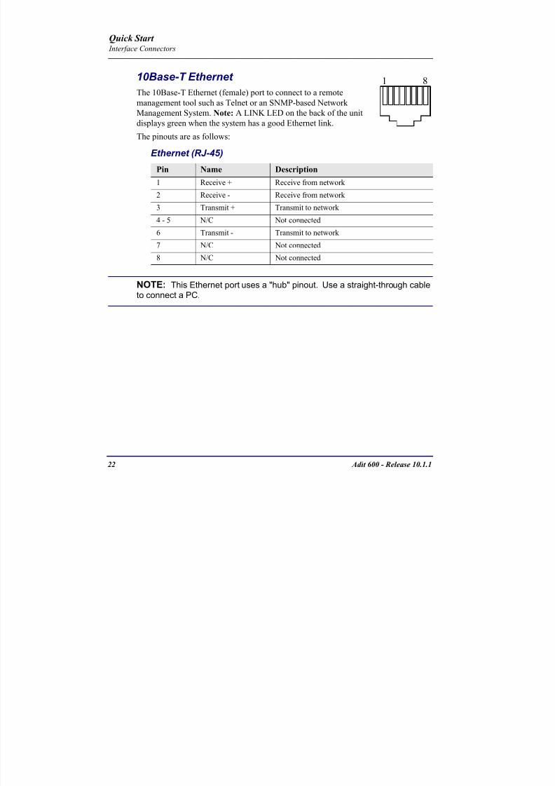
8102019 Adit 600 Quick Start 10-1-1
httpslidepdfcomreaderfulladit-600-quick-start-10-1-1 2454
22 Adit 600 - Release 1011
Quick Start Interface Connectors
10Base-T Ethernet
The 10Base-T Ethernet (female) port to connect to a remote
management tool such as Telnet or an SNMP-based Network
Management System Note A LINK LED on the back of the unit
displays green when the system has a good Ethernet link
The pinouts are as follows
Ethernet (RJ-45)
NOTE This Ethernet port uses a hub pinout Use a straight-through cableto connect a PC
Pin Name Description
1 Receive + Receive from network
2 Receive - Receive from network
3 Transmit + Transmit to network
4 - 5 NC Not connected
6 Transmit - Transmit to network
7 NC Not connected
8 NC Not connected
1 8
8102019 Adit 600 Quick Start 10-1-1
httpslidepdfcomreaderfulladit-600-quick-start-10-1-1 2554
Adit 600 - Release 1011 23
Quick Start Management Options
Management Options
Options for managing the Adit 600 are as follows
Local using CLI Telnet SNMP or DIP Switches (Controller and voice cards)
Remotely over an in-band DS0 or through the Access Navigator over the FDL
or an in-band DS0
This Quick Start Guide focuses on the CLI and DIP switches If you need further
information on other management options please refer to the Adit 600 User Manual
Command Line Interface (CLI)
You can access the CLI using either of the following methods
Telnet via Ethernet (10Base-T) RS-232 connected to the DB-9 port
Setting up a CLI Connection
If connecting via the Ethernet 10Base-T connection use a Telnet TCPIP
program to access the CLI This requires the IP address of the Controller
Controllers are shipped with the IP address set to 100010 If this address has been changed and is not known use HyperTerm to access the Controller and
use the CLI command show ip If an IP address needs to be set use the CLI
command set ethernet ip address
If connecting via RS-232 the port settings should be set to
Bits per second 9600 Data bits 8
Parity None Stop bits 1Flow control None
Set your Terminal Emulation to VT100
By default the Adit 600 is set for local configuration (using DIP switches) Use
the set local off command to enable the use of CLI commands
8102019 Adit 600 Quick Start 10-1-1
httpslidepdfcomreaderfulladit-600-quick-start-10-1-1 2654
8102019 Adit 600 Quick Start 10-1-1
httpslidepdfcomreaderfulladit-600-quick-start-10-1-1 2754
Adit 600 - Release 1011 25
Quick Start Configuration
ConfigurationThe following basic setups and upgrades for the Adit 600 are shown using CLI
commands For more information on CLI commands and configurations see the Adit
600 User Manual
Initial Setup
Basic Security Setup
DS1T1 Setup
E1 Setup
DS0Channel Setup
Analog Port Setup
4-Wire EampM Setup
Establish a Static Channel Connection
ISDN BRI Service Setup
OCU-DP Card Setup
ADPCM Card Setup
V35 Port Setup
Change the IP Address of the DS0 Management Channel
Upgrade the Adit 600 Software
Upgrade the Router Card Software
Basic Router Setup
8102019 Adit 600 Quick Start 10-1-1
httpslidepdfcomreaderfulladit-600-quick-start-10-1-1 2854
26 Adit 600 - Release 1011
Quick Start Configuration
Initial SetupUse the following commands for your initial setup For further information see the Adit
600 User Manual
Command Description
set local off Disables DIP switches
set date mmddyyyy Set the date used for event logging
set time hhmmss Set the time used for event logging
set id id-name Set a system ID name
set clock1 slotportinternal
Set the primary clock source
set clock2 slotportinternal
Set the secondary clock source
set ethernet ip addressip-addr mask
Set the ethernet IP address in the
conventional IP address format
set ip gateway ip-addr Set the IP gateway in the conventional IP
address format
8102019 Adit 600 Quick Start 10-1-1
httpslidepdfcomreaderfulladit-600-quick-start-10-1-1 2954
Adit 600 - Release 1011 27
Quick Start Configuration
Basic Security SetupUse the following commands to set up the security on the Adit 600 For further
information see the Adit 600 User Manual
Command Description
set password length
long|short
Set user password length requirement
add user ldquouser-namerdquo[password ldquopasswordrdquo]
Add user and password as necessary
set user user-name level1-3
Specify the userrsquos security level
set user user-namepassword Setchange password for the user asnecessary
8102019 Adit 600 Quick Start 10-1-1
httpslidepdfcomreaderfulladit-600-quick-start-10-1-1 3054
28 Adit 600 - Release 1011
Quick Start Configuration
DS1T1 SetupUse the following commands to set up a DS1 See the set (ds1) command for more
details
Command Description
set ds1-addr up Activate the port of the DS1 (slotport)
set ds1-addr id id-string
Set the identification string
set ds1-addr lbo 1-9 Set the line buildout value for the DS1
set ds1-addr linecodeami|b8zs
Set the linecode for the DS1
set ds1-addr framing d4|esf|tr8afdl|tr8anofdl|tr8b
Set the framing option for the DS1
set ds1-addr loopdetecton|off
Set the detectionreaction to CSU loopcodes
Q i k S
8102019 Adit 600 Quick Start 10-1-1
httpslidepdfcomreaderfulladit-600-quick-start-10-1-1 3154
Adit 600 - Release 1011 29
Quick Start Configuration
E1 Setup
NOTE E1 is not supported in this release of the Adit 600 Controller It will besupported in a future release
Use the following commands to set up an E1 See the set (e1) command for more
details
DS0Channel Setup
Use the following commands to set up a DS0 See the set (ds0) command for details
Command Description
set e1-addr up Activate the port of the E1 (slotport)
set e1-addr id id-string Set the identification string
set e1-addr lbo 1 - 9 Set the line buildout value for the E1
set e1-addr linecodeami|hdb3
Set the linecode for the E1
set e1-addr framinge1fr|lefrcrc
Set the framing option for the E1
set e1-addr loopdetecton|off
Set the detectionreaction to CSU loopcodes
Command Description
set slotportchannel up Activate the channel
set slotportchannel signalls|gs|emw|emdw|emicpd|dpt
Set the signaling option for the channel
set slotportchannel typedata|voice Set the channel type
Q i k St t
8102019 Adit 600 Quick Start 10-1-1
httpslidepdfcomreaderfulladit-600-quick-start-10-1-1 3254
30 Adit 600 - Release 1011
Quick Start Configuration
Analog Port SetupUse the following commands to set up an analog port
Command Description
set slotport up Activate the port See set (ds1) command for
details
set slotport signal dpt|gs|gsrb|gsw|gswrb|ls|lscpd|lsrb
Set the signaling option for the port See the
set (fxs) or set (fxo) command for details
set slotport rxgain n Set the receive gainloss in dB See the set
(fxs) or set (fxo) command for details
set slotport txgain n Set the transmit gainloss in dB See the set
(fxs) or set (fxo) command for details
Quick Start
8102019 Adit 600 Quick Start 10-1-1
httpslidepdfcomreaderfulladit-600-quick-start-10-1-1 3354
Adit 600 - Release 1011 31
Quick Start Configuration
4-Wire EampM SetupFor this example the 4 EampM ports will be connected to the first 4 DS0s on T1-1 (a1)
This can be changed to match the customers desired DS0 connections
For Transmission Only mode the DS0s on the DS1 should be set to data as well as the
EampM card channels
Command Description
For Normal or Tandem EampM
set a11-4 type voice Set DS0s to voice
set connect a11-4 11-4 Connect DS0s to the 4 ports of the 4-
Wire EampM card
show connect a 1 Verify cross connects
set a11-4 signal emi Set DS0 signal type to EMI
set 11-4 signal emi Set 4-Wire EampM ports signal type to
EMI
show connect a1 Verify cross connects
For TO Mode
set a11-4 type data Set DS0s to data
set 11-4 type data Set 4-Wire EampM port to data
set connect a11-4 11-4 Connect DS0s to the 4 ports of the 4-
Wire EampM card
show connect a 1 Verify cross connects
Quick Start
8102019 Adit 600 Quick Start 10-1-1
httpslidepdfcomreaderfulladit-600-quick-start-10-1-1 3454
32 Adit 600 - Release 1011
Quick Start Configuration
Establish a Static Channel ConnectionUse the following commands to establish a static channel connection
ISDN BRI Service Setup
Use the following commands to set up a ISDN BRI Service See the set (bri) command
for details
Command Description
set slotportchannel typevoice|data
Set the channel type for the channel to
map See set (ds0) command for details
set slotportchannel signalls|gs|emw|emdw|emicpd|dpt
Set the channel signaling option See set
(ds0) command for details
connect slotportslotport
Connect the channels See the connect
(card-trunk) (card-trunk) command
Command Description
set slotport up Put the ISDN line In-Service
set slot modelt3ds0|lt4to1tdm|nt3ds0
Set the ISDN mode
set slotport crv 1-768 Set the Call Reference Value Note
value must be the same as the Access
Navigator
set slotport thresholdday|hour es|ses
Set the threshold for the IDSN lines
set slot pmsyncadit|switch
Set the source for performance
monitoring synchronization
set slotport autoactivate
on|off
Only used in 4-to-1 mode Establishes
the D channel when the FDL link can not
be used
Quick Start
8102019 Adit 600 Quick Start 10-1-1
httpslidepdfcomreaderfulladit-600-quick-start-10-1-1 3554
Adit 600 - Release 1011 33
Quick Start Configuration
OCU-DP Card SetupThe following is a basic setup for the OCU-DP card
ADPCM Card Setup
Command Description
set ocudp-addr baud2400|4800|9600|19200|38400|
56000|64000
Set the OCU-DP Baud rate
Where ocudp-addr = slotport of the
OCU-DP card to apply settings to
set ocudp-addr up Set the OCU-DP port 1 up
show ocudp_card-addr Show the OCU-DP card settings
Where ocudp_card-addr = slot of the
OCU-DP card
disconnect a Disconnects all connections to slot a
(controller)
set ds0-addr type data Sets a DS0 data signaling type
connect ds0-addrocudp-addr
Connects DS0 (in previous step) to OCU-DP
port (in previous step)
show connect
(ocudp_card-addr
Displays connect information for OCU-DP
card
Command Description
Connect T1 cable to port 1 of the ADPCM service card
set adpcm_card-addrnone|map1|map2|map3
Enable compressing by selecting Map type Notenone disables compression
show (adpcm_card-addr Displays the status of the card and the mapping
connect 211-12 241-12 Set ADPCM cross-connects The example
connects all 24 channels of the ADPCM to the 12
channels of the T1 (now compressed) on port 4
This example is with map2show connect 21) Displays the connections made above
8102019 Adit 600 Quick Start 10-1-1
httpslidepdfcomreaderfulladit-600-quick-start-10-1-1 3654
Quick Start
8102019 Adit 600 Quick Start 10-1-1
httpslidepdfcomreaderfulladit-600-quick-start-10-1-1 3754
Adit 600 - Release 1011 35
QConfiguration
Upgrade the Adit 600 SoftwareUse the following commands to determine the system software level then upgrade the
software to the latest version
Command Description
status equipment Determine the system software level The
Slot A line (SW Vers) will display thecurrent software level
load tftp ip-addr file-name (or load xmodem)
Load the new controller system software See
the load tftp and load xmodem command for
more information
Note A TFTP server must be running onthe host system You can use any TFTP
server utility you wish One example isthe program TFTPD32 which can bedownloaded free-of-charge attftpd32jouninnettftpd32html
Quick Start
8102019 Adit 600 Quick Start 10-1-1
httpslidepdfcomreaderfulladit-600-quick-start-10-1-1 3854
36 Adit 600 - Release 1011
Configuration
Upgrade the Router Card SoftwareUse the following commands to determine the Router card software level then upgrade
the software to the latest version
NOTE For additional information about upgrading MSR card software see
the following manuals-Adit 600 User Manual -Adit 3000 Series and Multi-Service Router (MSR) Card GUI Reference Manual
-Adit 3000 Series and Multi-Service Router (MSR) Card CLI Reference Manual
Command Description
status equipment Determine the Router software level The
Router Slot line (SW Vers) will display thecurrent software level
load rtr_card-addr tftpip-addr file-name
Load the new Router software to a Router
card See the load tftp command for more
information
Note A TFTP server must be running onthe host system You can use any TFTP
server utility you wish One example isthe program TFTPD32 which can bedownloaded free-of-charge attftpd32jouninnettftpd32html
8102019 Adit 600 Quick Start 10-1-1
httpslidepdfcomreaderfulladit-600-quick-start-10-1-1 3954
8102019 Adit 600 Quick Start 10-1-1
httpslidepdfcomreaderfulladit-600-quick-start-10-1-1 4054
Quick Start C t ll C d LED
8102019 Adit 600 Quick Start 10-1-1
httpslidepdfcomreaderfulladit-600-quick-start-10-1-1 4154
Adit 600 - Release 1011 39
Controller Card LEDs
E1 Controller Card
NOTE E1 is not supported in this release It will be supported in a futurerelease
The E1 Controller has a set of six LEDs The table below describes each LED
LED State Description
MAJOR Off No major alarms present
Red Major alarm present
MINOR Off No minor alarms present
Yellow Minor alarms present
LOCAL Off Remote mode (DIP switches disabled)
Green Local mode (DIP switches enabled)
ACO Off Normal mode No alarms are being
suppressed
Yellow Alarm Cut Off active One or more active
alarms suppressed
E1-1 and
E1-2
Off Off line
Green Normal
Red Loss of Signal (LOS) detected
Yellow Bipolar Violation (BPV) detected LCV
Flashing Green Loopback active
Flashing Red
(slow)
Loss of Frame (LOF) or Alarm Indication
Signal (AIS) detected
Flashing Red
(fast)
Card Failure
Flashing Yellow Yellow alarm (Remote Alarm Indication)detected
Quick Start Power Supply LEDs
8102019 Adit 600 Quick Start 10-1-1
httpslidepdfcomreaderfulladit-600-quick-start-10-1-1 4254
40 Adit 600 - Release 1011
Power Supply LEDs
Power Supply LEDs115 VAC-48 VDC and 230 VAC-48 VDC Power Supplies
The power supply card has two LEDs as described in the table
below
24 VDC-48 VDC Power Supply
The power supply card has two LEDs as described in the table below
LED State Description
AC Input Off AC input missing or failure
Green AC input present
Battery Off Battery input not used
Green Battery charging or operating from DC
source only
Yellow Battery discharging
Red Battery low (less than 42V) ringer disabled
LED State Description
DC OK Off DC input missing or failure
Green DC input present
-48 Battery
Low
Off Normal
Red VDC is low (less than 42 VDC)
ringer disabled
Quick Start Service Card LEDs
8102019 Adit 600 Quick Start 10-1-1
httpslidepdfcomreaderfulladit-600-quick-start-10-1-1 4354
Adit 600 - Release 1011 41
Service Card LEDs
Service Card LEDs 4-Wire EampM Card
FXO Card
FXS Card
ISDN BRI Card
OCU-DP Card
P-Phone Card
Single Channel POTS Card
Quad DS1 ADPCM Service Card
Quad DS1E1 and Quad T1 Cards
Quad E1 Card
IP Router Card
CMG Router Card
Terminal Server Router Card
MSR Card
RS-232 and V35V54 Cards
Discontinued cards
RS-232 discontinued
Quick Start Service Card LEDs
8102019 Adit 600 Quick Start 10-1-1
httpslidepdfcomreaderfulladit-600-quick-start-10-1-1 4454
42 Adit 600 - Release 1011
Service Card LEDs
4-Wire EampM Card Each channelport has two LEDs Only the top LED is used in this application LED
definitions are listed below
State Description
When in EampM Mode
Off Channel is idle or disabled
Green Analog interface is off-hook
Red Digital interface is off-hook
Yellow Both analog and digital interfaces are off-hook or channel is
being trunk processed
When in TO Mode
Off DisconnectedGreen Connected T1E1 not in alarm
Yellow Connected T1E1 in alarm (trunk processed)
Quick Start Service Card LEDs
8102019 Adit 600 Quick Start 10-1-1
httpslidepdfcomreaderfulladit-600-quick-start-10-1-1 4554
Adit 600 - Release 1011 43
FXO Card Each port on the FXO card has its own LED as described in the table below
FXS Card
There is an LED for each port on the FXS card as described in the table below
State Loop Start
Meaning
Ground Start Meaning Dial Pulse Termination
Meaning
Off NA Idle (tip open) Idle (loop open)
Green Idle Tip ground (incoming seizure) Incoming seizure
Red NA Ring ground (outgoing
seizure)
Loop closure (outgoing seizure)
Yellow Call in
progress
Call in progress Call in progress (reverse battery)
Flashing
Green
Ringing Ringing NA
State Loop Start Meaning Ground Start Meaning
Off NA Idle (tip open)
Green Idle Tip ground (incoming seizure)
Red Note This can be seen with
Forward Disconnect (tip open)
Ring ground (outgoing seizure)
Yellow Call in progress Call in progress
Flashing green Ringing Ringing
Quick Start Service Card LEDs
8102019 Adit 600 Quick Start 10-1-1
httpslidepdfcomreaderfulladit-600-quick-start-10-1-1 4654
44 Adit 600 - Release 1011
ISDN BRI Card There is an LED for each ISDN BRI on a card as described in the table below
OCU-DP Card Each channel has two LEDs described in the table below
State Description
Off Line U-interface is attempting synchronization or BRI is Out-of-Service
Red Line alarm (LOS or self test failure)
Yellow ES or SES has occurred
Flashing yellow Line U-interface is synchronized with customer equipment but is not passing
customer data
Flashing green Line U-interface is in external loopback toward the switch at the unit
Green Normal (Line U-interface is active and transparently passing customer data)
State Description
Yellow Flickering ALL Boot Software in control
Green (walking down)
Red (walking up)
ALL Application Software in control
(repeated 35 times)
Red slow flash ALL In Boot Application flash code checksums did not match and
Boot is waiting for application download
Red ALL In Application code waiting for Controller to issue SWHW
revision request This is the first request that comes from the
OCU-DP card manager in the ControllerGreen
Yellow
Top
Bottom
Port in Self-test Duration is 5-8 seconds
Off Top
Bottom
Port is set down (Out-Of-Service)
Green Top Port is receiving valid signals
Red Top Port is receiving no signal (primary) or no frame sync
(secondary or clear channel)Red Flashing Bottom Port is receiving bipolar violations
Yellow Bottom Port is in loopback
Quick Start Service Card LEDs
8102019 Adit 600 Quick Start 10-1-1
httpslidepdfcomreaderfulladit-600-quick-start-10-1-1 4754
Adit 600 - Release 1011 45
P-Phone Card Each P-Phone channel has a corresponding LED described in the table below
State Line State
Off No P-Phone connected
Green No call in process
Flashing Green Alert (Ringing)
Yellow Call in progress
Flashing Yellow P-Phone Loopback in Progress
Flashing Red Self-test failed
Quick Start Service Card LEDs
8102019 Adit 600 Quick Start 10-1-1
httpslidepdfcomreaderfulladit-600-quick-start-10-1-1 4854
46 Adit 600 - Release 1011
Single Channel POTS Card The POTS channel LED (left) status is described in the table below
The second LED (right) is a status LED is not used on this card
Quad DS1 ADPCM Service Card
Each channel on the Quad DS1 ADPCM card has two LEDs The
description of the top LED is shown below the bottom LED is notused with this application
State Loop Start Meaning
Off Calling Party Disconnect
Green Idle
Red NA
Yellow Call in progress
Flashing green Ringing
State Description
Off Off line
Green Normal
Red Loss of Signal (LOS)
Yellow Bipolar Violation (BPV)Flashing Green Loopback active
Flashing Yellow Yellow Alarm
(Remote Alarm Indication)
Flashing Red (Slow) Loss of Frame (LOF) or Alarm Indication Signal (AIS)
Flashing Red (Fast) Self-test Failure
Top LED(active)
Bottom LED(not used)
Quick Start Service Card LEDs
8102019 Adit 600 Quick Start 10-1-1
httpslidepdfcomreaderfulladit-600-quick-start-10-1-1 4954
Adit 600 - Release 1011 47
Quad DS1E1 and Quad T1 CardsEach channel on the Quad T1E1 cards have two LEDs The description
of the top LED is shown below the bottom LED is not used with this
application
State Description
Off Off line
Green Normal
Red Loss of Signal (LOS)
Yellow Bipolar Violation (BPV)
Flashing Green Loopback active
Flashing Yellow Yellow Alarm (Remote Alarm Indication)
Flashing Red (Slow) Loss of Frame (LOF) or Alarm Indication Signal (AIS)
Flashing Red (Fast) Self-test Failure
Quick Start Service Card LEDs
8102019 Adit 600 Quick Start 10-1-1
httpslidepdfcomreaderfulladit-600-quick-start-10-1-1 5054
48 Adit 600 - Release 1011
IP Router Card The following chart describes each LED and its state
LED State Description
CRD Off Loss of power
Green No current alarms
Red Alarm state active See alarm log for cause
Red Flashing Self-test or Boot in-process
Yellow Flashing Card is saving data to flash RAM do not power down
10100 Off 10 Mb ethernet
Green 100 Mb ethernet
LNK Off No ethernet link
Green Good ethernet link
COL
Off No current ethernet transmit collisions
Yellow Ethernet collisions have occurred and have not dropped
to minimum level
Yellow Flashing Ethernet collision occurring
TX Off No ethernet transmit activity
Green Ethernet transmit activity
RX Off No current ethernet receive activity
Green Current ethernet receive activity
Quick Start Service Card LEDs
8102019 Adit 600 Quick Start 10-1-1
httpslidepdfcomreaderfulladit-600-quick-start-10-1-1 5154
Adit 600 - Release 1011 49
CMG Router Card The following chart describes each LED and its state
LED State Description
CRD Off Loss of power
Green No current alarms
Red Alarm state active See alarm log for causeRed Flashing Self-test or Boot in-process
Yellow Flashing Card is saving data to flash RAM do not power down
VOIP
Off No active VoIP calls or if the MGCP protocol is
optioned down
Green Active VoIP calls
Red Call agent unreachable
Yellow Insufficient VoIP resources to complete call
LNK Off No Ethernet link
Green Good Ethernet link
10100 Off 10 Mb Ethernet
Green 100 Mb Ethernet
TX Off No Ethernet transmit activityGreen Ethernet transmit activity
Yellow Current Ethernet transmit collision
RX Off No current Ethernet receive activity
Green Current Ethernet receive activity
Quick Start Service Card LEDs
8102019 Adit 600 Quick Start 10-1-1
httpslidepdfcomreaderfulladit-600-quick-start-10-1-1 5254
50 Adit 600 - Release 1011
Terminal Server Router Card The Terminal Server Router card has 2 LEDs per port
At Power-up
Normal Operation
Port Set for Ethernet
Top LED indicates 100M Link Bottom LED indicates 10M Link
Port Set for RS-232
TOP LED Bottom LED Description
Off Off At Power UpBoot = Loss of power
Red Red Card is inoperative
Flashing Red Flashing Red Self-test or Boot in-process
TOP LED Bottom LED Description
Green Solid (Link) Green Solid (Link) Port set for Ethernet - see below
Flashing Red Flashing Red Self-test or Boot in-process
State Description
Off No Ethernet link
Green Link but no activity
Red Flashing Current Ethernet collision
Green Flashing Current Ethernet receive
Yellow Flashing Current Ethernet transmit
TOP LED Bottom LED Description
Yellow Off No Activity
Yellow Flashing Yellow Current transmit
Yellow Flashing Green Current receive
Quick Start Service Card LEDs
8102019 Adit 600 Quick Start 10-1-1
httpslidepdfcomreaderfulladit-600-quick-start-10-1-1 5354
Adit 600 - Release 1011 51
MSR Card The following chart describes the MSR cardrsquos LEDs
LED State Description
CRD Off Loss of power
Green No current alarms
Red Alarm state active See alarm log for cause
Red Flashing Self-test or boot in process
Yellow Flashing Card is saving data to flash RAM do not power
down
VOIP
Off No SIP proxy or registration attempts for all lines
have succeeded but no calls are active
Green Active VoIP call(s)
Red Inability to reach the SIP proxy or negative response
to register attempts from all lines
Yellow Register attempts from some lines have succeeded
but not for all lines
ETH1 and
ETH2
Top LED
Off 10 Mbitsec down or not connected
Green 100 Mbitsec
ETH1 and
ETH2
Bottom LED
Off Link down
Green Link up
Flashing Green Traffic on link
Yellow Collision status
Quick Start Service Card LEDs
8102019 Adit 600 Quick Start 10-1-1
httpslidepdfcomreaderfulladit-600-quick-start-10-1-1 5454
52 Adit 600 - Release 1011
RS-232 and V35V54 Cards Each port has its own LED as described in the table below
State Description
Off No T1 Assignment
Green Normal (CDRTS) Active
Red CD inactive (T1-side failure)
Yellow RTS inactive (equipment-side failure)
Flashing Yellow Loopback toward T1 or equipment loop test
Flashing Green Loopback toward equipment or network loop test
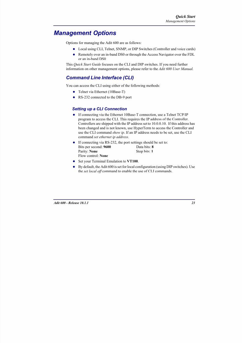
8102019 Adit 600 Quick Start 10-1-1
httpslidepdfcomreaderfulladit-600-quick-start-10-1-1 2554
Adit 600 - Release 1011 23
Quick Start Management Options
Management Options
Options for managing the Adit 600 are as follows
Local using CLI Telnet SNMP or DIP Switches (Controller and voice cards)
Remotely over an in-band DS0 or through the Access Navigator over the FDL
or an in-band DS0
This Quick Start Guide focuses on the CLI and DIP switches If you need further
information on other management options please refer to the Adit 600 User Manual
Command Line Interface (CLI)
You can access the CLI using either of the following methods
Telnet via Ethernet (10Base-T) RS-232 connected to the DB-9 port
Setting up a CLI Connection
If connecting via the Ethernet 10Base-T connection use a Telnet TCPIP
program to access the CLI This requires the IP address of the Controller
Controllers are shipped with the IP address set to 100010 If this address has been changed and is not known use HyperTerm to access the Controller and
use the CLI command show ip If an IP address needs to be set use the CLI
command set ethernet ip address
If connecting via RS-232 the port settings should be set to
Bits per second 9600 Data bits 8
Parity None Stop bits 1Flow control None
Set your Terminal Emulation to VT100
By default the Adit 600 is set for local configuration (using DIP switches) Use
the set local off command to enable the use of CLI commands
8102019 Adit 600 Quick Start 10-1-1
httpslidepdfcomreaderfulladit-600-quick-start-10-1-1 2654
8102019 Adit 600 Quick Start 10-1-1
httpslidepdfcomreaderfulladit-600-quick-start-10-1-1 2754
Adit 600 - Release 1011 25
Quick Start Configuration
ConfigurationThe following basic setups and upgrades for the Adit 600 are shown using CLI
commands For more information on CLI commands and configurations see the Adit
600 User Manual
Initial Setup
Basic Security Setup
DS1T1 Setup
E1 Setup
DS0Channel Setup
Analog Port Setup
4-Wire EampM Setup
Establish a Static Channel Connection
ISDN BRI Service Setup
OCU-DP Card Setup
ADPCM Card Setup
V35 Port Setup
Change the IP Address of the DS0 Management Channel
Upgrade the Adit 600 Software
Upgrade the Router Card Software
Basic Router Setup
8102019 Adit 600 Quick Start 10-1-1
httpslidepdfcomreaderfulladit-600-quick-start-10-1-1 2854
26 Adit 600 - Release 1011
Quick Start Configuration
Initial SetupUse the following commands for your initial setup For further information see the Adit
600 User Manual
Command Description
set local off Disables DIP switches
set date mmddyyyy Set the date used for event logging
set time hhmmss Set the time used for event logging
set id id-name Set a system ID name
set clock1 slotportinternal
Set the primary clock source
set clock2 slotportinternal
Set the secondary clock source
set ethernet ip addressip-addr mask
Set the ethernet IP address in the
conventional IP address format
set ip gateway ip-addr Set the IP gateway in the conventional IP
address format
8102019 Adit 600 Quick Start 10-1-1
httpslidepdfcomreaderfulladit-600-quick-start-10-1-1 2954
Adit 600 - Release 1011 27
Quick Start Configuration
Basic Security SetupUse the following commands to set up the security on the Adit 600 For further
information see the Adit 600 User Manual
Command Description
set password length
long|short
Set user password length requirement
add user ldquouser-namerdquo[password ldquopasswordrdquo]
Add user and password as necessary
set user user-name level1-3
Specify the userrsquos security level
set user user-namepassword Setchange password for the user asnecessary
8102019 Adit 600 Quick Start 10-1-1
httpslidepdfcomreaderfulladit-600-quick-start-10-1-1 3054
28 Adit 600 - Release 1011
Quick Start Configuration
DS1T1 SetupUse the following commands to set up a DS1 See the set (ds1) command for more
details
Command Description
set ds1-addr up Activate the port of the DS1 (slotport)
set ds1-addr id id-string
Set the identification string
set ds1-addr lbo 1-9 Set the line buildout value for the DS1
set ds1-addr linecodeami|b8zs
Set the linecode for the DS1
set ds1-addr framing d4|esf|tr8afdl|tr8anofdl|tr8b
Set the framing option for the DS1
set ds1-addr loopdetecton|off
Set the detectionreaction to CSU loopcodes
Q i k S
8102019 Adit 600 Quick Start 10-1-1
httpslidepdfcomreaderfulladit-600-quick-start-10-1-1 3154
Adit 600 - Release 1011 29
Quick Start Configuration
E1 Setup
NOTE E1 is not supported in this release of the Adit 600 Controller It will besupported in a future release
Use the following commands to set up an E1 See the set (e1) command for more
details
DS0Channel Setup
Use the following commands to set up a DS0 See the set (ds0) command for details
Command Description
set e1-addr up Activate the port of the E1 (slotport)
set e1-addr id id-string Set the identification string
set e1-addr lbo 1 - 9 Set the line buildout value for the E1
set e1-addr linecodeami|hdb3
Set the linecode for the E1
set e1-addr framinge1fr|lefrcrc
Set the framing option for the E1
set e1-addr loopdetecton|off
Set the detectionreaction to CSU loopcodes
Command Description
set slotportchannel up Activate the channel
set slotportchannel signalls|gs|emw|emdw|emicpd|dpt
Set the signaling option for the channel
set slotportchannel typedata|voice Set the channel type
Q i k St t
8102019 Adit 600 Quick Start 10-1-1
httpslidepdfcomreaderfulladit-600-quick-start-10-1-1 3254
30 Adit 600 - Release 1011
Quick Start Configuration
Analog Port SetupUse the following commands to set up an analog port
Command Description
set slotport up Activate the port See set (ds1) command for
details
set slotport signal dpt|gs|gsrb|gsw|gswrb|ls|lscpd|lsrb
Set the signaling option for the port See the
set (fxs) or set (fxo) command for details
set slotport rxgain n Set the receive gainloss in dB See the set
(fxs) or set (fxo) command for details
set slotport txgain n Set the transmit gainloss in dB See the set
(fxs) or set (fxo) command for details
Quick Start
8102019 Adit 600 Quick Start 10-1-1
httpslidepdfcomreaderfulladit-600-quick-start-10-1-1 3354
Adit 600 - Release 1011 31
Quick Start Configuration
4-Wire EampM SetupFor this example the 4 EampM ports will be connected to the first 4 DS0s on T1-1 (a1)
This can be changed to match the customers desired DS0 connections
For Transmission Only mode the DS0s on the DS1 should be set to data as well as the
EampM card channels
Command Description
For Normal or Tandem EampM
set a11-4 type voice Set DS0s to voice
set connect a11-4 11-4 Connect DS0s to the 4 ports of the 4-
Wire EampM card
show connect a 1 Verify cross connects
set a11-4 signal emi Set DS0 signal type to EMI
set 11-4 signal emi Set 4-Wire EampM ports signal type to
EMI
show connect a1 Verify cross connects
For TO Mode
set a11-4 type data Set DS0s to data
set 11-4 type data Set 4-Wire EampM port to data
set connect a11-4 11-4 Connect DS0s to the 4 ports of the 4-
Wire EampM card
show connect a 1 Verify cross connects
Quick Start
8102019 Adit 600 Quick Start 10-1-1
httpslidepdfcomreaderfulladit-600-quick-start-10-1-1 3454
32 Adit 600 - Release 1011
Quick Start Configuration
Establish a Static Channel ConnectionUse the following commands to establish a static channel connection
ISDN BRI Service Setup
Use the following commands to set up a ISDN BRI Service See the set (bri) command
for details
Command Description
set slotportchannel typevoice|data
Set the channel type for the channel to
map See set (ds0) command for details
set slotportchannel signalls|gs|emw|emdw|emicpd|dpt
Set the channel signaling option See set
(ds0) command for details
connect slotportslotport
Connect the channels See the connect
(card-trunk) (card-trunk) command
Command Description
set slotport up Put the ISDN line In-Service
set slot modelt3ds0|lt4to1tdm|nt3ds0
Set the ISDN mode
set slotport crv 1-768 Set the Call Reference Value Note
value must be the same as the Access
Navigator
set slotport thresholdday|hour es|ses
Set the threshold for the IDSN lines
set slot pmsyncadit|switch
Set the source for performance
monitoring synchronization
set slotport autoactivate
on|off
Only used in 4-to-1 mode Establishes
the D channel when the FDL link can not
be used
Quick Start
8102019 Adit 600 Quick Start 10-1-1
httpslidepdfcomreaderfulladit-600-quick-start-10-1-1 3554
Adit 600 - Release 1011 33
Quick Start Configuration
OCU-DP Card SetupThe following is a basic setup for the OCU-DP card
ADPCM Card Setup
Command Description
set ocudp-addr baud2400|4800|9600|19200|38400|
56000|64000
Set the OCU-DP Baud rate
Where ocudp-addr = slotport of the
OCU-DP card to apply settings to
set ocudp-addr up Set the OCU-DP port 1 up
show ocudp_card-addr Show the OCU-DP card settings
Where ocudp_card-addr = slot of the
OCU-DP card
disconnect a Disconnects all connections to slot a
(controller)
set ds0-addr type data Sets a DS0 data signaling type
connect ds0-addrocudp-addr
Connects DS0 (in previous step) to OCU-DP
port (in previous step)
show connect
(ocudp_card-addr
Displays connect information for OCU-DP
card
Command Description
Connect T1 cable to port 1 of the ADPCM service card
set adpcm_card-addrnone|map1|map2|map3
Enable compressing by selecting Map type Notenone disables compression
show (adpcm_card-addr Displays the status of the card and the mapping
connect 211-12 241-12 Set ADPCM cross-connects The example
connects all 24 channels of the ADPCM to the 12
channels of the T1 (now compressed) on port 4
This example is with map2show connect 21) Displays the connections made above
8102019 Adit 600 Quick Start 10-1-1
httpslidepdfcomreaderfulladit-600-quick-start-10-1-1 3654
Quick Start
8102019 Adit 600 Quick Start 10-1-1
httpslidepdfcomreaderfulladit-600-quick-start-10-1-1 3754
Adit 600 - Release 1011 35
QConfiguration
Upgrade the Adit 600 SoftwareUse the following commands to determine the system software level then upgrade the
software to the latest version
Command Description
status equipment Determine the system software level The
Slot A line (SW Vers) will display thecurrent software level
load tftp ip-addr file-name (or load xmodem)
Load the new controller system software See
the load tftp and load xmodem command for
more information
Note A TFTP server must be running onthe host system You can use any TFTP
server utility you wish One example isthe program TFTPD32 which can bedownloaded free-of-charge attftpd32jouninnettftpd32html
Quick Start
8102019 Adit 600 Quick Start 10-1-1
httpslidepdfcomreaderfulladit-600-quick-start-10-1-1 3854
36 Adit 600 - Release 1011
Configuration
Upgrade the Router Card SoftwareUse the following commands to determine the Router card software level then upgrade
the software to the latest version
NOTE For additional information about upgrading MSR card software see
the following manuals-Adit 600 User Manual -Adit 3000 Series and Multi-Service Router (MSR) Card GUI Reference Manual
-Adit 3000 Series and Multi-Service Router (MSR) Card CLI Reference Manual
Command Description
status equipment Determine the Router software level The
Router Slot line (SW Vers) will display thecurrent software level
load rtr_card-addr tftpip-addr file-name
Load the new Router software to a Router
card See the load tftp command for more
information
Note A TFTP server must be running onthe host system You can use any TFTP
server utility you wish One example isthe program TFTPD32 which can bedownloaded free-of-charge attftpd32jouninnettftpd32html
8102019 Adit 600 Quick Start 10-1-1
httpslidepdfcomreaderfulladit-600-quick-start-10-1-1 3954
8102019 Adit 600 Quick Start 10-1-1
httpslidepdfcomreaderfulladit-600-quick-start-10-1-1 4054
Quick Start C t ll C d LED
8102019 Adit 600 Quick Start 10-1-1
httpslidepdfcomreaderfulladit-600-quick-start-10-1-1 4154
Adit 600 - Release 1011 39
Controller Card LEDs
E1 Controller Card
NOTE E1 is not supported in this release It will be supported in a futurerelease
The E1 Controller has a set of six LEDs The table below describes each LED
LED State Description
MAJOR Off No major alarms present
Red Major alarm present
MINOR Off No minor alarms present
Yellow Minor alarms present
LOCAL Off Remote mode (DIP switches disabled)
Green Local mode (DIP switches enabled)
ACO Off Normal mode No alarms are being
suppressed
Yellow Alarm Cut Off active One or more active
alarms suppressed
E1-1 and
E1-2
Off Off line
Green Normal
Red Loss of Signal (LOS) detected
Yellow Bipolar Violation (BPV) detected LCV
Flashing Green Loopback active
Flashing Red
(slow)
Loss of Frame (LOF) or Alarm Indication
Signal (AIS) detected
Flashing Red
(fast)
Card Failure
Flashing Yellow Yellow alarm (Remote Alarm Indication)detected
Quick Start Power Supply LEDs
8102019 Adit 600 Quick Start 10-1-1
httpslidepdfcomreaderfulladit-600-quick-start-10-1-1 4254
40 Adit 600 - Release 1011
Power Supply LEDs
Power Supply LEDs115 VAC-48 VDC and 230 VAC-48 VDC Power Supplies
The power supply card has two LEDs as described in the table
below
24 VDC-48 VDC Power Supply
The power supply card has two LEDs as described in the table below
LED State Description
AC Input Off AC input missing or failure
Green AC input present
Battery Off Battery input not used
Green Battery charging or operating from DC
source only
Yellow Battery discharging
Red Battery low (less than 42V) ringer disabled
LED State Description
DC OK Off DC input missing or failure
Green DC input present
-48 Battery
Low
Off Normal
Red VDC is low (less than 42 VDC)
ringer disabled
Quick Start Service Card LEDs
8102019 Adit 600 Quick Start 10-1-1
httpslidepdfcomreaderfulladit-600-quick-start-10-1-1 4354
Adit 600 - Release 1011 41
Service Card LEDs
Service Card LEDs 4-Wire EampM Card
FXO Card
FXS Card
ISDN BRI Card
OCU-DP Card
P-Phone Card
Single Channel POTS Card
Quad DS1 ADPCM Service Card
Quad DS1E1 and Quad T1 Cards
Quad E1 Card
IP Router Card
CMG Router Card
Terminal Server Router Card
MSR Card
RS-232 and V35V54 Cards
Discontinued cards
RS-232 discontinued
Quick Start Service Card LEDs
8102019 Adit 600 Quick Start 10-1-1
httpslidepdfcomreaderfulladit-600-quick-start-10-1-1 4454
42 Adit 600 - Release 1011
Service Card LEDs
4-Wire EampM Card Each channelport has two LEDs Only the top LED is used in this application LED
definitions are listed below
State Description
When in EampM Mode
Off Channel is idle or disabled
Green Analog interface is off-hook
Red Digital interface is off-hook
Yellow Both analog and digital interfaces are off-hook or channel is
being trunk processed
When in TO Mode
Off DisconnectedGreen Connected T1E1 not in alarm
Yellow Connected T1E1 in alarm (trunk processed)
Quick Start Service Card LEDs
8102019 Adit 600 Quick Start 10-1-1
httpslidepdfcomreaderfulladit-600-quick-start-10-1-1 4554
Adit 600 - Release 1011 43
FXO Card Each port on the FXO card has its own LED as described in the table below
FXS Card
There is an LED for each port on the FXS card as described in the table below
State Loop Start
Meaning
Ground Start Meaning Dial Pulse Termination
Meaning
Off NA Idle (tip open) Idle (loop open)
Green Idle Tip ground (incoming seizure) Incoming seizure
Red NA Ring ground (outgoing
seizure)
Loop closure (outgoing seizure)
Yellow Call in
progress
Call in progress Call in progress (reverse battery)
Flashing
Green
Ringing Ringing NA
State Loop Start Meaning Ground Start Meaning
Off NA Idle (tip open)
Green Idle Tip ground (incoming seizure)
Red Note This can be seen with
Forward Disconnect (tip open)
Ring ground (outgoing seizure)
Yellow Call in progress Call in progress
Flashing green Ringing Ringing
Quick Start Service Card LEDs
8102019 Adit 600 Quick Start 10-1-1
httpslidepdfcomreaderfulladit-600-quick-start-10-1-1 4654
44 Adit 600 - Release 1011
ISDN BRI Card There is an LED for each ISDN BRI on a card as described in the table below
OCU-DP Card Each channel has two LEDs described in the table below
State Description
Off Line U-interface is attempting synchronization or BRI is Out-of-Service
Red Line alarm (LOS or self test failure)
Yellow ES or SES has occurred
Flashing yellow Line U-interface is synchronized with customer equipment but is not passing
customer data
Flashing green Line U-interface is in external loopback toward the switch at the unit
Green Normal (Line U-interface is active and transparently passing customer data)
State Description
Yellow Flickering ALL Boot Software in control
Green (walking down)
Red (walking up)
ALL Application Software in control
(repeated 35 times)
Red slow flash ALL In Boot Application flash code checksums did not match and
Boot is waiting for application download
Red ALL In Application code waiting for Controller to issue SWHW
revision request This is the first request that comes from the
OCU-DP card manager in the ControllerGreen
Yellow
Top
Bottom
Port in Self-test Duration is 5-8 seconds
Off Top
Bottom
Port is set down (Out-Of-Service)
Green Top Port is receiving valid signals
Red Top Port is receiving no signal (primary) or no frame sync
(secondary or clear channel)Red Flashing Bottom Port is receiving bipolar violations
Yellow Bottom Port is in loopback
Quick Start Service Card LEDs
8102019 Adit 600 Quick Start 10-1-1
httpslidepdfcomreaderfulladit-600-quick-start-10-1-1 4754
Adit 600 - Release 1011 45
P-Phone Card Each P-Phone channel has a corresponding LED described in the table below
State Line State
Off No P-Phone connected
Green No call in process
Flashing Green Alert (Ringing)
Yellow Call in progress
Flashing Yellow P-Phone Loopback in Progress
Flashing Red Self-test failed
Quick Start Service Card LEDs
8102019 Adit 600 Quick Start 10-1-1
httpslidepdfcomreaderfulladit-600-quick-start-10-1-1 4854
46 Adit 600 - Release 1011
Single Channel POTS Card The POTS channel LED (left) status is described in the table below
The second LED (right) is a status LED is not used on this card
Quad DS1 ADPCM Service Card
Each channel on the Quad DS1 ADPCM card has two LEDs The
description of the top LED is shown below the bottom LED is notused with this application
State Loop Start Meaning
Off Calling Party Disconnect
Green Idle
Red NA
Yellow Call in progress
Flashing green Ringing
State Description
Off Off line
Green Normal
Red Loss of Signal (LOS)
Yellow Bipolar Violation (BPV)Flashing Green Loopback active
Flashing Yellow Yellow Alarm
(Remote Alarm Indication)
Flashing Red (Slow) Loss of Frame (LOF) or Alarm Indication Signal (AIS)
Flashing Red (Fast) Self-test Failure
Top LED(active)
Bottom LED(not used)
Quick Start Service Card LEDs
8102019 Adit 600 Quick Start 10-1-1
httpslidepdfcomreaderfulladit-600-quick-start-10-1-1 4954
Adit 600 - Release 1011 47
Quad DS1E1 and Quad T1 CardsEach channel on the Quad T1E1 cards have two LEDs The description
of the top LED is shown below the bottom LED is not used with this
application
State Description
Off Off line
Green Normal
Red Loss of Signal (LOS)
Yellow Bipolar Violation (BPV)
Flashing Green Loopback active
Flashing Yellow Yellow Alarm (Remote Alarm Indication)
Flashing Red (Slow) Loss of Frame (LOF) or Alarm Indication Signal (AIS)
Flashing Red (Fast) Self-test Failure
Quick Start Service Card LEDs
8102019 Adit 600 Quick Start 10-1-1
httpslidepdfcomreaderfulladit-600-quick-start-10-1-1 5054
48 Adit 600 - Release 1011
IP Router Card The following chart describes each LED and its state
LED State Description
CRD Off Loss of power
Green No current alarms
Red Alarm state active See alarm log for cause
Red Flashing Self-test or Boot in-process
Yellow Flashing Card is saving data to flash RAM do not power down
10100 Off 10 Mb ethernet
Green 100 Mb ethernet
LNK Off No ethernet link
Green Good ethernet link
COL
Off No current ethernet transmit collisions
Yellow Ethernet collisions have occurred and have not dropped
to minimum level
Yellow Flashing Ethernet collision occurring
TX Off No ethernet transmit activity
Green Ethernet transmit activity
RX Off No current ethernet receive activity
Green Current ethernet receive activity
Quick Start Service Card LEDs
8102019 Adit 600 Quick Start 10-1-1
httpslidepdfcomreaderfulladit-600-quick-start-10-1-1 5154
Adit 600 - Release 1011 49
CMG Router Card The following chart describes each LED and its state
LED State Description
CRD Off Loss of power
Green No current alarms
Red Alarm state active See alarm log for causeRed Flashing Self-test or Boot in-process
Yellow Flashing Card is saving data to flash RAM do not power down
VOIP
Off No active VoIP calls or if the MGCP protocol is
optioned down
Green Active VoIP calls
Red Call agent unreachable
Yellow Insufficient VoIP resources to complete call
LNK Off No Ethernet link
Green Good Ethernet link
10100 Off 10 Mb Ethernet
Green 100 Mb Ethernet
TX Off No Ethernet transmit activityGreen Ethernet transmit activity
Yellow Current Ethernet transmit collision
RX Off No current Ethernet receive activity
Green Current Ethernet receive activity
Quick Start Service Card LEDs
8102019 Adit 600 Quick Start 10-1-1
httpslidepdfcomreaderfulladit-600-quick-start-10-1-1 5254
50 Adit 600 - Release 1011
Terminal Server Router Card The Terminal Server Router card has 2 LEDs per port
At Power-up
Normal Operation
Port Set for Ethernet
Top LED indicates 100M Link Bottom LED indicates 10M Link
Port Set for RS-232
TOP LED Bottom LED Description
Off Off At Power UpBoot = Loss of power
Red Red Card is inoperative
Flashing Red Flashing Red Self-test or Boot in-process
TOP LED Bottom LED Description
Green Solid (Link) Green Solid (Link) Port set for Ethernet - see below
Flashing Red Flashing Red Self-test or Boot in-process
State Description
Off No Ethernet link
Green Link but no activity
Red Flashing Current Ethernet collision
Green Flashing Current Ethernet receive
Yellow Flashing Current Ethernet transmit
TOP LED Bottom LED Description
Yellow Off No Activity
Yellow Flashing Yellow Current transmit
Yellow Flashing Green Current receive
Quick Start Service Card LEDs
8102019 Adit 600 Quick Start 10-1-1
httpslidepdfcomreaderfulladit-600-quick-start-10-1-1 5354
Adit 600 - Release 1011 51
MSR Card The following chart describes the MSR cardrsquos LEDs
LED State Description
CRD Off Loss of power
Green No current alarms
Red Alarm state active See alarm log for cause
Red Flashing Self-test or boot in process
Yellow Flashing Card is saving data to flash RAM do not power
down
VOIP
Off No SIP proxy or registration attempts for all lines
have succeeded but no calls are active
Green Active VoIP call(s)
Red Inability to reach the SIP proxy or negative response
to register attempts from all lines
Yellow Register attempts from some lines have succeeded
but not for all lines
ETH1 and
ETH2
Top LED
Off 10 Mbitsec down or not connected
Green 100 Mbitsec
ETH1 and
ETH2
Bottom LED
Off Link down
Green Link up
Flashing Green Traffic on link
Yellow Collision status
Quick Start Service Card LEDs
8102019 Adit 600 Quick Start 10-1-1
httpslidepdfcomreaderfulladit-600-quick-start-10-1-1 5454
52 Adit 600 - Release 1011
RS-232 and V35V54 Cards Each port has its own LED as described in the table below
State Description
Off No T1 Assignment
Green Normal (CDRTS) Active
Red CD inactive (T1-side failure)
Yellow RTS inactive (equipment-side failure)
Flashing Yellow Loopback toward T1 or equipment loop test
Flashing Green Loopback toward equipment or network loop test
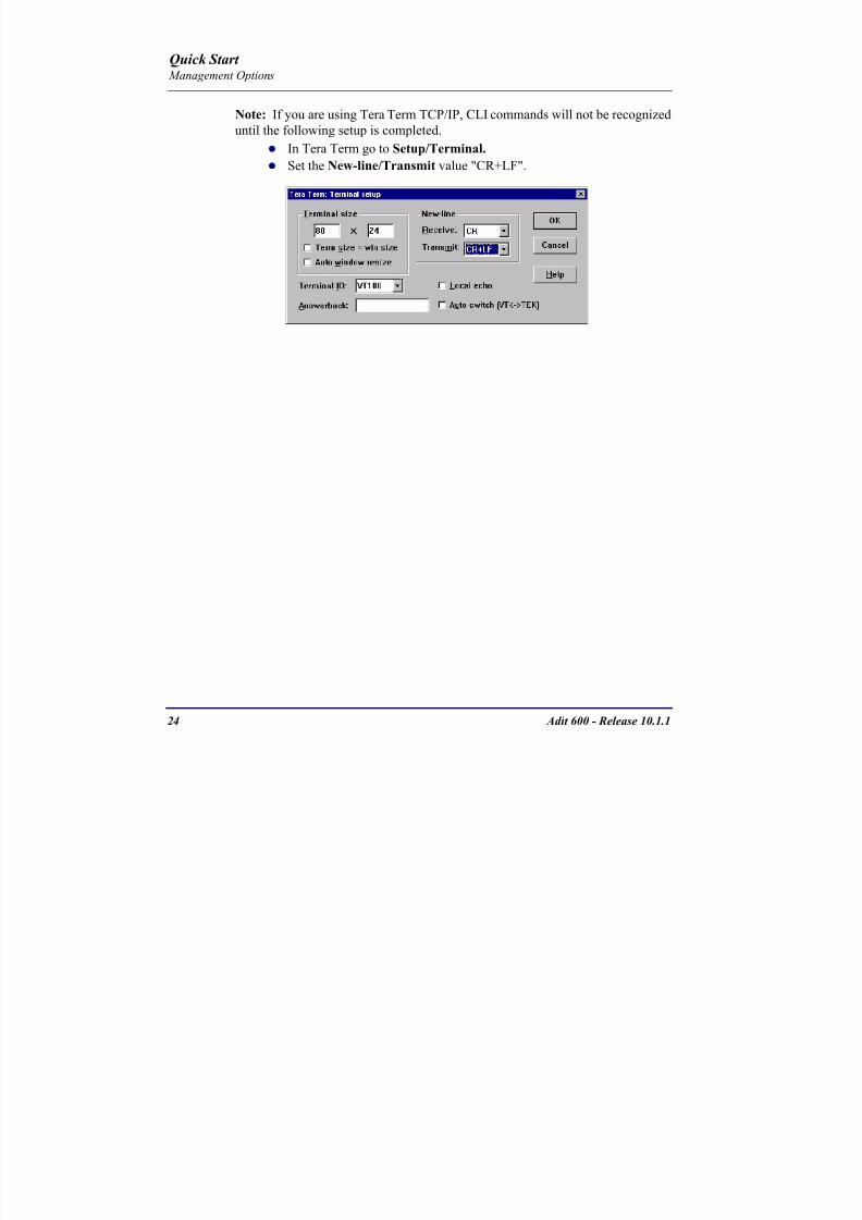
8102019 Adit 600 Quick Start 10-1-1
httpslidepdfcomreaderfulladit-600-quick-start-10-1-1 2654
8102019 Adit 600 Quick Start 10-1-1
httpslidepdfcomreaderfulladit-600-quick-start-10-1-1 2754
Adit 600 - Release 1011 25
Quick Start Configuration
ConfigurationThe following basic setups and upgrades for the Adit 600 are shown using CLI
commands For more information on CLI commands and configurations see the Adit
600 User Manual
Initial Setup
Basic Security Setup
DS1T1 Setup
E1 Setup
DS0Channel Setup
Analog Port Setup
4-Wire EampM Setup
Establish a Static Channel Connection
ISDN BRI Service Setup
OCU-DP Card Setup
ADPCM Card Setup
V35 Port Setup
Change the IP Address of the DS0 Management Channel
Upgrade the Adit 600 Software
Upgrade the Router Card Software
Basic Router Setup
8102019 Adit 600 Quick Start 10-1-1
httpslidepdfcomreaderfulladit-600-quick-start-10-1-1 2854
26 Adit 600 - Release 1011
Quick Start Configuration
Initial SetupUse the following commands for your initial setup For further information see the Adit
600 User Manual
Command Description
set local off Disables DIP switches
set date mmddyyyy Set the date used for event logging
set time hhmmss Set the time used for event logging
set id id-name Set a system ID name
set clock1 slotportinternal
Set the primary clock source
set clock2 slotportinternal
Set the secondary clock source
set ethernet ip addressip-addr mask
Set the ethernet IP address in the
conventional IP address format
set ip gateway ip-addr Set the IP gateway in the conventional IP
address format
8102019 Adit 600 Quick Start 10-1-1
httpslidepdfcomreaderfulladit-600-quick-start-10-1-1 2954
Adit 600 - Release 1011 27
Quick Start Configuration
Basic Security SetupUse the following commands to set up the security on the Adit 600 For further
information see the Adit 600 User Manual
Command Description
set password length
long|short
Set user password length requirement
add user ldquouser-namerdquo[password ldquopasswordrdquo]
Add user and password as necessary
set user user-name level1-3
Specify the userrsquos security level
set user user-namepassword Setchange password for the user asnecessary
8102019 Adit 600 Quick Start 10-1-1
httpslidepdfcomreaderfulladit-600-quick-start-10-1-1 3054
28 Adit 600 - Release 1011
Quick Start Configuration
DS1T1 SetupUse the following commands to set up a DS1 See the set (ds1) command for more
details
Command Description
set ds1-addr up Activate the port of the DS1 (slotport)
set ds1-addr id id-string
Set the identification string
set ds1-addr lbo 1-9 Set the line buildout value for the DS1
set ds1-addr linecodeami|b8zs
Set the linecode for the DS1
set ds1-addr framing d4|esf|tr8afdl|tr8anofdl|tr8b
Set the framing option for the DS1
set ds1-addr loopdetecton|off
Set the detectionreaction to CSU loopcodes
Q i k S
8102019 Adit 600 Quick Start 10-1-1
httpslidepdfcomreaderfulladit-600-quick-start-10-1-1 3154
Adit 600 - Release 1011 29
Quick Start Configuration
E1 Setup
NOTE E1 is not supported in this release of the Adit 600 Controller It will besupported in a future release
Use the following commands to set up an E1 See the set (e1) command for more
details
DS0Channel Setup
Use the following commands to set up a DS0 See the set (ds0) command for details
Command Description
set e1-addr up Activate the port of the E1 (slotport)
set e1-addr id id-string Set the identification string
set e1-addr lbo 1 - 9 Set the line buildout value for the E1
set e1-addr linecodeami|hdb3
Set the linecode for the E1
set e1-addr framinge1fr|lefrcrc
Set the framing option for the E1
set e1-addr loopdetecton|off
Set the detectionreaction to CSU loopcodes
Command Description
set slotportchannel up Activate the channel
set slotportchannel signalls|gs|emw|emdw|emicpd|dpt
Set the signaling option for the channel
set slotportchannel typedata|voice Set the channel type
Q i k St t
8102019 Adit 600 Quick Start 10-1-1
httpslidepdfcomreaderfulladit-600-quick-start-10-1-1 3254
30 Adit 600 - Release 1011
Quick Start Configuration
Analog Port SetupUse the following commands to set up an analog port
Command Description
set slotport up Activate the port See set (ds1) command for
details
set slotport signal dpt|gs|gsrb|gsw|gswrb|ls|lscpd|lsrb
Set the signaling option for the port See the
set (fxs) or set (fxo) command for details
set slotport rxgain n Set the receive gainloss in dB See the set
(fxs) or set (fxo) command for details
set slotport txgain n Set the transmit gainloss in dB See the set
(fxs) or set (fxo) command for details
Quick Start
8102019 Adit 600 Quick Start 10-1-1
httpslidepdfcomreaderfulladit-600-quick-start-10-1-1 3354
Adit 600 - Release 1011 31
Quick Start Configuration
4-Wire EampM SetupFor this example the 4 EampM ports will be connected to the first 4 DS0s on T1-1 (a1)
This can be changed to match the customers desired DS0 connections
For Transmission Only mode the DS0s on the DS1 should be set to data as well as the
EampM card channels
Command Description
For Normal or Tandem EampM
set a11-4 type voice Set DS0s to voice
set connect a11-4 11-4 Connect DS0s to the 4 ports of the 4-
Wire EampM card
show connect a 1 Verify cross connects
set a11-4 signal emi Set DS0 signal type to EMI
set 11-4 signal emi Set 4-Wire EampM ports signal type to
EMI
show connect a1 Verify cross connects
For TO Mode
set a11-4 type data Set DS0s to data
set 11-4 type data Set 4-Wire EampM port to data
set connect a11-4 11-4 Connect DS0s to the 4 ports of the 4-
Wire EampM card
show connect a 1 Verify cross connects
Quick Start
8102019 Adit 600 Quick Start 10-1-1
httpslidepdfcomreaderfulladit-600-quick-start-10-1-1 3454
32 Adit 600 - Release 1011
Quick Start Configuration
Establish a Static Channel ConnectionUse the following commands to establish a static channel connection
ISDN BRI Service Setup
Use the following commands to set up a ISDN BRI Service See the set (bri) command
for details
Command Description
set slotportchannel typevoice|data
Set the channel type for the channel to
map See set (ds0) command for details
set slotportchannel signalls|gs|emw|emdw|emicpd|dpt
Set the channel signaling option See set
(ds0) command for details
connect slotportslotport
Connect the channels See the connect
(card-trunk) (card-trunk) command
Command Description
set slotport up Put the ISDN line In-Service
set slot modelt3ds0|lt4to1tdm|nt3ds0
Set the ISDN mode
set slotport crv 1-768 Set the Call Reference Value Note
value must be the same as the Access
Navigator
set slotport thresholdday|hour es|ses
Set the threshold for the IDSN lines
set slot pmsyncadit|switch
Set the source for performance
monitoring synchronization
set slotport autoactivate
on|off
Only used in 4-to-1 mode Establishes
the D channel when the FDL link can not
be used
Quick Start
8102019 Adit 600 Quick Start 10-1-1
httpslidepdfcomreaderfulladit-600-quick-start-10-1-1 3554
Adit 600 - Release 1011 33
Quick Start Configuration
OCU-DP Card SetupThe following is a basic setup for the OCU-DP card
ADPCM Card Setup
Command Description
set ocudp-addr baud2400|4800|9600|19200|38400|
56000|64000
Set the OCU-DP Baud rate
Where ocudp-addr = slotport of the
OCU-DP card to apply settings to
set ocudp-addr up Set the OCU-DP port 1 up
show ocudp_card-addr Show the OCU-DP card settings
Where ocudp_card-addr = slot of the
OCU-DP card
disconnect a Disconnects all connections to slot a
(controller)
set ds0-addr type data Sets a DS0 data signaling type
connect ds0-addrocudp-addr
Connects DS0 (in previous step) to OCU-DP
port (in previous step)
show connect
(ocudp_card-addr
Displays connect information for OCU-DP
card
Command Description
Connect T1 cable to port 1 of the ADPCM service card
set adpcm_card-addrnone|map1|map2|map3
Enable compressing by selecting Map type Notenone disables compression
show (adpcm_card-addr Displays the status of the card and the mapping
connect 211-12 241-12 Set ADPCM cross-connects The example
connects all 24 channels of the ADPCM to the 12
channels of the T1 (now compressed) on port 4
This example is with map2show connect 21) Displays the connections made above
8102019 Adit 600 Quick Start 10-1-1
httpslidepdfcomreaderfulladit-600-quick-start-10-1-1 3654
Quick Start
8102019 Adit 600 Quick Start 10-1-1
httpslidepdfcomreaderfulladit-600-quick-start-10-1-1 3754
Adit 600 - Release 1011 35
QConfiguration
Upgrade the Adit 600 SoftwareUse the following commands to determine the system software level then upgrade the
software to the latest version
Command Description
status equipment Determine the system software level The
Slot A line (SW Vers) will display thecurrent software level
load tftp ip-addr file-name (or load xmodem)
Load the new controller system software See
the load tftp and load xmodem command for
more information
Note A TFTP server must be running onthe host system You can use any TFTP
server utility you wish One example isthe program TFTPD32 which can bedownloaded free-of-charge attftpd32jouninnettftpd32html
Quick Start
8102019 Adit 600 Quick Start 10-1-1
httpslidepdfcomreaderfulladit-600-quick-start-10-1-1 3854
36 Adit 600 - Release 1011
Configuration
Upgrade the Router Card SoftwareUse the following commands to determine the Router card software level then upgrade
the software to the latest version
NOTE For additional information about upgrading MSR card software see
the following manuals-Adit 600 User Manual -Adit 3000 Series and Multi-Service Router (MSR) Card GUI Reference Manual
-Adit 3000 Series and Multi-Service Router (MSR) Card CLI Reference Manual
Command Description
status equipment Determine the Router software level The
Router Slot line (SW Vers) will display thecurrent software level
load rtr_card-addr tftpip-addr file-name
Load the new Router software to a Router
card See the load tftp command for more
information
Note A TFTP server must be running onthe host system You can use any TFTP
server utility you wish One example isthe program TFTPD32 which can bedownloaded free-of-charge attftpd32jouninnettftpd32html
8102019 Adit 600 Quick Start 10-1-1
httpslidepdfcomreaderfulladit-600-quick-start-10-1-1 3954
8102019 Adit 600 Quick Start 10-1-1
httpslidepdfcomreaderfulladit-600-quick-start-10-1-1 4054
Quick Start C t ll C d LED
8102019 Adit 600 Quick Start 10-1-1
httpslidepdfcomreaderfulladit-600-quick-start-10-1-1 4154
Adit 600 - Release 1011 39
Controller Card LEDs
E1 Controller Card
NOTE E1 is not supported in this release It will be supported in a futurerelease
The E1 Controller has a set of six LEDs The table below describes each LED
LED State Description
MAJOR Off No major alarms present
Red Major alarm present
MINOR Off No minor alarms present
Yellow Minor alarms present
LOCAL Off Remote mode (DIP switches disabled)
Green Local mode (DIP switches enabled)
ACO Off Normal mode No alarms are being
suppressed
Yellow Alarm Cut Off active One or more active
alarms suppressed
E1-1 and
E1-2
Off Off line
Green Normal
Red Loss of Signal (LOS) detected
Yellow Bipolar Violation (BPV) detected LCV
Flashing Green Loopback active
Flashing Red
(slow)
Loss of Frame (LOF) or Alarm Indication
Signal (AIS) detected
Flashing Red
(fast)
Card Failure
Flashing Yellow Yellow alarm (Remote Alarm Indication)detected
Quick Start Power Supply LEDs
8102019 Adit 600 Quick Start 10-1-1
httpslidepdfcomreaderfulladit-600-quick-start-10-1-1 4254
40 Adit 600 - Release 1011
Power Supply LEDs
Power Supply LEDs115 VAC-48 VDC and 230 VAC-48 VDC Power Supplies
The power supply card has two LEDs as described in the table
below
24 VDC-48 VDC Power Supply
The power supply card has two LEDs as described in the table below
LED State Description
AC Input Off AC input missing or failure
Green AC input present
Battery Off Battery input not used
Green Battery charging or operating from DC
source only
Yellow Battery discharging
Red Battery low (less than 42V) ringer disabled
LED State Description
DC OK Off DC input missing or failure
Green DC input present
-48 Battery
Low
Off Normal
Red VDC is low (less than 42 VDC)
ringer disabled
Quick Start Service Card LEDs
8102019 Adit 600 Quick Start 10-1-1
httpslidepdfcomreaderfulladit-600-quick-start-10-1-1 4354
Adit 600 - Release 1011 41
Service Card LEDs
Service Card LEDs 4-Wire EampM Card
FXO Card
FXS Card
ISDN BRI Card
OCU-DP Card
P-Phone Card
Single Channel POTS Card
Quad DS1 ADPCM Service Card
Quad DS1E1 and Quad T1 Cards
Quad E1 Card
IP Router Card
CMG Router Card
Terminal Server Router Card
MSR Card
RS-232 and V35V54 Cards
Discontinued cards
RS-232 discontinued
Quick Start Service Card LEDs
8102019 Adit 600 Quick Start 10-1-1
httpslidepdfcomreaderfulladit-600-quick-start-10-1-1 4454
42 Adit 600 - Release 1011
Service Card LEDs
4-Wire EampM Card Each channelport has two LEDs Only the top LED is used in this application LED
definitions are listed below
State Description
When in EampM Mode
Off Channel is idle or disabled
Green Analog interface is off-hook
Red Digital interface is off-hook
Yellow Both analog and digital interfaces are off-hook or channel is
being trunk processed
When in TO Mode
Off DisconnectedGreen Connected T1E1 not in alarm
Yellow Connected T1E1 in alarm (trunk processed)
Quick Start Service Card LEDs
8102019 Adit 600 Quick Start 10-1-1
httpslidepdfcomreaderfulladit-600-quick-start-10-1-1 4554
Adit 600 - Release 1011 43
FXO Card Each port on the FXO card has its own LED as described in the table below
FXS Card
There is an LED for each port on the FXS card as described in the table below
State Loop Start
Meaning
Ground Start Meaning Dial Pulse Termination
Meaning
Off NA Idle (tip open) Idle (loop open)
Green Idle Tip ground (incoming seizure) Incoming seizure
Red NA Ring ground (outgoing
seizure)
Loop closure (outgoing seizure)
Yellow Call in
progress
Call in progress Call in progress (reverse battery)
Flashing
Green
Ringing Ringing NA
State Loop Start Meaning Ground Start Meaning
Off NA Idle (tip open)
Green Idle Tip ground (incoming seizure)
Red Note This can be seen with
Forward Disconnect (tip open)
Ring ground (outgoing seizure)
Yellow Call in progress Call in progress
Flashing green Ringing Ringing
Quick Start Service Card LEDs
8102019 Adit 600 Quick Start 10-1-1
httpslidepdfcomreaderfulladit-600-quick-start-10-1-1 4654
44 Adit 600 - Release 1011
ISDN BRI Card There is an LED for each ISDN BRI on a card as described in the table below
OCU-DP Card Each channel has two LEDs described in the table below
State Description
Off Line U-interface is attempting synchronization or BRI is Out-of-Service
Red Line alarm (LOS or self test failure)
Yellow ES or SES has occurred
Flashing yellow Line U-interface is synchronized with customer equipment but is not passing
customer data
Flashing green Line U-interface is in external loopback toward the switch at the unit
Green Normal (Line U-interface is active and transparently passing customer data)
State Description
Yellow Flickering ALL Boot Software in control
Green (walking down)
Red (walking up)
ALL Application Software in control
(repeated 35 times)
Red slow flash ALL In Boot Application flash code checksums did not match and
Boot is waiting for application download
Red ALL In Application code waiting for Controller to issue SWHW
revision request This is the first request that comes from the
OCU-DP card manager in the ControllerGreen
Yellow
Top
Bottom
Port in Self-test Duration is 5-8 seconds
Off Top
Bottom
Port is set down (Out-Of-Service)
Green Top Port is receiving valid signals
Red Top Port is receiving no signal (primary) or no frame sync
(secondary or clear channel)Red Flashing Bottom Port is receiving bipolar violations
Yellow Bottom Port is in loopback
Quick Start Service Card LEDs
8102019 Adit 600 Quick Start 10-1-1
httpslidepdfcomreaderfulladit-600-quick-start-10-1-1 4754
Adit 600 - Release 1011 45
P-Phone Card Each P-Phone channel has a corresponding LED described in the table below
State Line State
Off No P-Phone connected
Green No call in process
Flashing Green Alert (Ringing)
Yellow Call in progress
Flashing Yellow P-Phone Loopback in Progress
Flashing Red Self-test failed
Quick Start Service Card LEDs
8102019 Adit 600 Quick Start 10-1-1
httpslidepdfcomreaderfulladit-600-quick-start-10-1-1 4854
46 Adit 600 - Release 1011
Single Channel POTS Card The POTS channel LED (left) status is described in the table below
The second LED (right) is a status LED is not used on this card
Quad DS1 ADPCM Service Card
Each channel on the Quad DS1 ADPCM card has two LEDs The
description of the top LED is shown below the bottom LED is notused with this application
State Loop Start Meaning
Off Calling Party Disconnect
Green Idle
Red NA
Yellow Call in progress
Flashing green Ringing
State Description
Off Off line
Green Normal
Red Loss of Signal (LOS)
Yellow Bipolar Violation (BPV)Flashing Green Loopback active
Flashing Yellow Yellow Alarm
(Remote Alarm Indication)
Flashing Red (Slow) Loss of Frame (LOF) or Alarm Indication Signal (AIS)
Flashing Red (Fast) Self-test Failure
Top LED(active)
Bottom LED(not used)
Quick Start Service Card LEDs
8102019 Adit 600 Quick Start 10-1-1
httpslidepdfcomreaderfulladit-600-quick-start-10-1-1 4954
Adit 600 - Release 1011 47
Quad DS1E1 and Quad T1 CardsEach channel on the Quad T1E1 cards have two LEDs The description
of the top LED is shown below the bottom LED is not used with this
application
State Description
Off Off line
Green Normal
Red Loss of Signal (LOS)
Yellow Bipolar Violation (BPV)
Flashing Green Loopback active
Flashing Yellow Yellow Alarm (Remote Alarm Indication)
Flashing Red (Slow) Loss of Frame (LOF) or Alarm Indication Signal (AIS)
Flashing Red (Fast) Self-test Failure
Quick Start Service Card LEDs
8102019 Adit 600 Quick Start 10-1-1
httpslidepdfcomreaderfulladit-600-quick-start-10-1-1 5054
48 Adit 600 - Release 1011
IP Router Card The following chart describes each LED and its state
LED State Description
CRD Off Loss of power
Green No current alarms
Red Alarm state active See alarm log for cause
Red Flashing Self-test or Boot in-process
Yellow Flashing Card is saving data to flash RAM do not power down
10100 Off 10 Mb ethernet
Green 100 Mb ethernet
LNK Off No ethernet link
Green Good ethernet link
COL
Off No current ethernet transmit collisions
Yellow Ethernet collisions have occurred and have not dropped
to minimum level
Yellow Flashing Ethernet collision occurring
TX Off No ethernet transmit activity
Green Ethernet transmit activity
RX Off No current ethernet receive activity
Green Current ethernet receive activity
Quick Start Service Card LEDs
8102019 Adit 600 Quick Start 10-1-1
httpslidepdfcomreaderfulladit-600-quick-start-10-1-1 5154
Adit 600 - Release 1011 49
CMG Router Card The following chart describes each LED and its state
LED State Description
CRD Off Loss of power
Green No current alarms
Red Alarm state active See alarm log for causeRed Flashing Self-test or Boot in-process
Yellow Flashing Card is saving data to flash RAM do not power down
VOIP
Off No active VoIP calls or if the MGCP protocol is
optioned down
Green Active VoIP calls
Red Call agent unreachable
Yellow Insufficient VoIP resources to complete call
LNK Off No Ethernet link
Green Good Ethernet link
10100 Off 10 Mb Ethernet
Green 100 Mb Ethernet
TX Off No Ethernet transmit activityGreen Ethernet transmit activity
Yellow Current Ethernet transmit collision
RX Off No current Ethernet receive activity
Green Current Ethernet receive activity
Quick Start Service Card LEDs
8102019 Adit 600 Quick Start 10-1-1
httpslidepdfcomreaderfulladit-600-quick-start-10-1-1 5254
50 Adit 600 - Release 1011
Terminal Server Router Card The Terminal Server Router card has 2 LEDs per port
At Power-up
Normal Operation
Port Set for Ethernet
Top LED indicates 100M Link Bottom LED indicates 10M Link
Port Set for RS-232
TOP LED Bottom LED Description
Off Off At Power UpBoot = Loss of power
Red Red Card is inoperative
Flashing Red Flashing Red Self-test or Boot in-process
TOP LED Bottom LED Description
Green Solid (Link) Green Solid (Link) Port set for Ethernet - see below
Flashing Red Flashing Red Self-test or Boot in-process
State Description
Off No Ethernet link
Green Link but no activity
Red Flashing Current Ethernet collision
Green Flashing Current Ethernet receive
Yellow Flashing Current Ethernet transmit
TOP LED Bottom LED Description
Yellow Off No Activity
Yellow Flashing Yellow Current transmit
Yellow Flashing Green Current receive
Quick Start Service Card LEDs
8102019 Adit 600 Quick Start 10-1-1
httpslidepdfcomreaderfulladit-600-quick-start-10-1-1 5354
Adit 600 - Release 1011 51
MSR Card The following chart describes the MSR cardrsquos LEDs
LED State Description
CRD Off Loss of power
Green No current alarms
Red Alarm state active See alarm log for cause
Red Flashing Self-test or boot in process
Yellow Flashing Card is saving data to flash RAM do not power
down
VOIP
Off No SIP proxy or registration attempts for all lines
have succeeded but no calls are active
Green Active VoIP call(s)
Red Inability to reach the SIP proxy or negative response
to register attempts from all lines
Yellow Register attempts from some lines have succeeded
but not for all lines
ETH1 and
ETH2
Top LED
Off 10 Mbitsec down or not connected
Green 100 Mbitsec
ETH1 and
ETH2
Bottom LED
Off Link down
Green Link up
Flashing Green Traffic on link
Yellow Collision status
Quick Start Service Card LEDs
8102019 Adit 600 Quick Start 10-1-1
httpslidepdfcomreaderfulladit-600-quick-start-10-1-1 5454
52 Adit 600 - Release 1011
RS-232 and V35V54 Cards Each port has its own LED as described in the table below
State Description
Off No T1 Assignment
Green Normal (CDRTS) Active
Red CD inactive (T1-side failure)
Yellow RTS inactive (equipment-side failure)
Flashing Yellow Loopback toward T1 or equipment loop test
Flashing Green Loopback toward equipment or network loop test
8102019 Adit 600 Quick Start 10-1-1
httpslidepdfcomreaderfulladit-600-quick-start-10-1-1 2754
Adit 600 - Release 1011 25
Quick Start Configuration
ConfigurationThe following basic setups and upgrades for the Adit 600 are shown using CLI
commands For more information on CLI commands and configurations see the Adit
600 User Manual
Initial Setup
Basic Security Setup
DS1T1 Setup
E1 Setup
DS0Channel Setup
Analog Port Setup
4-Wire EampM Setup
Establish a Static Channel Connection
ISDN BRI Service Setup
OCU-DP Card Setup
ADPCM Card Setup
V35 Port Setup
Change the IP Address of the DS0 Management Channel
Upgrade the Adit 600 Software
Upgrade the Router Card Software
Basic Router Setup
8102019 Adit 600 Quick Start 10-1-1
httpslidepdfcomreaderfulladit-600-quick-start-10-1-1 2854
26 Adit 600 - Release 1011
Quick Start Configuration
Initial SetupUse the following commands for your initial setup For further information see the Adit
600 User Manual
Command Description
set local off Disables DIP switches
set date mmddyyyy Set the date used for event logging
set time hhmmss Set the time used for event logging
set id id-name Set a system ID name
set clock1 slotportinternal
Set the primary clock source
set clock2 slotportinternal
Set the secondary clock source
set ethernet ip addressip-addr mask
Set the ethernet IP address in the
conventional IP address format
set ip gateway ip-addr Set the IP gateway in the conventional IP
address format
8102019 Adit 600 Quick Start 10-1-1
httpslidepdfcomreaderfulladit-600-quick-start-10-1-1 2954
Adit 600 - Release 1011 27
Quick Start Configuration
Basic Security SetupUse the following commands to set up the security on the Adit 600 For further
information see the Adit 600 User Manual
Command Description
set password length
long|short
Set user password length requirement
add user ldquouser-namerdquo[password ldquopasswordrdquo]
Add user and password as necessary
set user user-name level1-3
Specify the userrsquos security level
set user user-namepassword Setchange password for the user asnecessary
8102019 Adit 600 Quick Start 10-1-1
httpslidepdfcomreaderfulladit-600-quick-start-10-1-1 3054
28 Adit 600 - Release 1011
Quick Start Configuration
DS1T1 SetupUse the following commands to set up a DS1 See the set (ds1) command for more
details
Command Description
set ds1-addr up Activate the port of the DS1 (slotport)
set ds1-addr id id-string
Set the identification string
set ds1-addr lbo 1-9 Set the line buildout value for the DS1
set ds1-addr linecodeami|b8zs
Set the linecode for the DS1
set ds1-addr framing d4|esf|tr8afdl|tr8anofdl|tr8b
Set the framing option for the DS1
set ds1-addr loopdetecton|off
Set the detectionreaction to CSU loopcodes
Q i k S
8102019 Adit 600 Quick Start 10-1-1
httpslidepdfcomreaderfulladit-600-quick-start-10-1-1 3154
Adit 600 - Release 1011 29
Quick Start Configuration
E1 Setup
NOTE E1 is not supported in this release of the Adit 600 Controller It will besupported in a future release
Use the following commands to set up an E1 See the set (e1) command for more
details
DS0Channel Setup
Use the following commands to set up a DS0 See the set (ds0) command for details
Command Description
set e1-addr up Activate the port of the E1 (slotport)
set e1-addr id id-string Set the identification string
set e1-addr lbo 1 - 9 Set the line buildout value for the E1
set e1-addr linecodeami|hdb3
Set the linecode for the E1
set e1-addr framinge1fr|lefrcrc
Set the framing option for the E1
set e1-addr loopdetecton|off
Set the detectionreaction to CSU loopcodes
Command Description
set slotportchannel up Activate the channel
set slotportchannel signalls|gs|emw|emdw|emicpd|dpt
Set the signaling option for the channel
set slotportchannel typedata|voice Set the channel type
Q i k St t
8102019 Adit 600 Quick Start 10-1-1
httpslidepdfcomreaderfulladit-600-quick-start-10-1-1 3254
30 Adit 600 - Release 1011
Quick Start Configuration
Analog Port SetupUse the following commands to set up an analog port
Command Description
set slotport up Activate the port See set (ds1) command for
details
set slotport signal dpt|gs|gsrb|gsw|gswrb|ls|lscpd|lsrb
Set the signaling option for the port See the
set (fxs) or set (fxo) command for details
set slotport rxgain n Set the receive gainloss in dB See the set
(fxs) or set (fxo) command for details
set slotport txgain n Set the transmit gainloss in dB See the set
(fxs) or set (fxo) command for details
Quick Start
8102019 Adit 600 Quick Start 10-1-1
httpslidepdfcomreaderfulladit-600-quick-start-10-1-1 3354
Adit 600 - Release 1011 31
Quick Start Configuration
4-Wire EampM SetupFor this example the 4 EampM ports will be connected to the first 4 DS0s on T1-1 (a1)
This can be changed to match the customers desired DS0 connections
For Transmission Only mode the DS0s on the DS1 should be set to data as well as the
EampM card channels
Command Description
For Normal or Tandem EampM
set a11-4 type voice Set DS0s to voice
set connect a11-4 11-4 Connect DS0s to the 4 ports of the 4-
Wire EampM card
show connect a 1 Verify cross connects
set a11-4 signal emi Set DS0 signal type to EMI
set 11-4 signal emi Set 4-Wire EampM ports signal type to
EMI
show connect a1 Verify cross connects
For TO Mode
set a11-4 type data Set DS0s to data
set 11-4 type data Set 4-Wire EampM port to data
set connect a11-4 11-4 Connect DS0s to the 4 ports of the 4-
Wire EampM card
show connect a 1 Verify cross connects
Quick Start
8102019 Adit 600 Quick Start 10-1-1
httpslidepdfcomreaderfulladit-600-quick-start-10-1-1 3454
32 Adit 600 - Release 1011
Quick Start Configuration
Establish a Static Channel ConnectionUse the following commands to establish a static channel connection
ISDN BRI Service Setup
Use the following commands to set up a ISDN BRI Service See the set (bri) command
for details
Command Description
set slotportchannel typevoice|data
Set the channel type for the channel to
map See set (ds0) command for details
set slotportchannel signalls|gs|emw|emdw|emicpd|dpt
Set the channel signaling option See set
(ds0) command for details
connect slotportslotport
Connect the channels See the connect
(card-trunk) (card-trunk) command
Command Description
set slotport up Put the ISDN line In-Service
set slot modelt3ds0|lt4to1tdm|nt3ds0
Set the ISDN mode
set slotport crv 1-768 Set the Call Reference Value Note
value must be the same as the Access
Navigator
set slotport thresholdday|hour es|ses
Set the threshold for the IDSN lines
set slot pmsyncadit|switch
Set the source for performance
monitoring synchronization
set slotport autoactivate
on|off
Only used in 4-to-1 mode Establishes
the D channel when the FDL link can not
be used
Quick Start
8102019 Adit 600 Quick Start 10-1-1
httpslidepdfcomreaderfulladit-600-quick-start-10-1-1 3554
Adit 600 - Release 1011 33
Quick Start Configuration
OCU-DP Card SetupThe following is a basic setup for the OCU-DP card
ADPCM Card Setup
Command Description
set ocudp-addr baud2400|4800|9600|19200|38400|
56000|64000
Set the OCU-DP Baud rate
Where ocudp-addr = slotport of the
OCU-DP card to apply settings to
set ocudp-addr up Set the OCU-DP port 1 up
show ocudp_card-addr Show the OCU-DP card settings
Where ocudp_card-addr = slot of the
OCU-DP card
disconnect a Disconnects all connections to slot a
(controller)
set ds0-addr type data Sets a DS0 data signaling type
connect ds0-addrocudp-addr
Connects DS0 (in previous step) to OCU-DP
port (in previous step)
show connect
(ocudp_card-addr
Displays connect information for OCU-DP
card
Command Description
Connect T1 cable to port 1 of the ADPCM service card
set adpcm_card-addrnone|map1|map2|map3
Enable compressing by selecting Map type Notenone disables compression
show (adpcm_card-addr Displays the status of the card and the mapping
connect 211-12 241-12 Set ADPCM cross-connects The example
connects all 24 channels of the ADPCM to the 12
channels of the T1 (now compressed) on port 4
This example is with map2show connect 21) Displays the connections made above
8102019 Adit 600 Quick Start 10-1-1
httpslidepdfcomreaderfulladit-600-quick-start-10-1-1 3654
Quick Start
8102019 Adit 600 Quick Start 10-1-1
httpslidepdfcomreaderfulladit-600-quick-start-10-1-1 3754
Adit 600 - Release 1011 35
QConfiguration
Upgrade the Adit 600 SoftwareUse the following commands to determine the system software level then upgrade the
software to the latest version
Command Description
status equipment Determine the system software level The
Slot A line (SW Vers) will display thecurrent software level
load tftp ip-addr file-name (or load xmodem)
Load the new controller system software See
the load tftp and load xmodem command for
more information
Note A TFTP server must be running onthe host system You can use any TFTP
server utility you wish One example isthe program TFTPD32 which can bedownloaded free-of-charge attftpd32jouninnettftpd32html
Quick Start
8102019 Adit 600 Quick Start 10-1-1
httpslidepdfcomreaderfulladit-600-quick-start-10-1-1 3854
36 Adit 600 - Release 1011
Configuration
Upgrade the Router Card SoftwareUse the following commands to determine the Router card software level then upgrade
the software to the latest version
NOTE For additional information about upgrading MSR card software see
the following manuals-Adit 600 User Manual -Adit 3000 Series and Multi-Service Router (MSR) Card GUI Reference Manual
-Adit 3000 Series and Multi-Service Router (MSR) Card CLI Reference Manual
Command Description
status equipment Determine the Router software level The
Router Slot line (SW Vers) will display thecurrent software level
load rtr_card-addr tftpip-addr file-name
Load the new Router software to a Router
card See the load tftp command for more
information
Note A TFTP server must be running onthe host system You can use any TFTP
server utility you wish One example isthe program TFTPD32 which can bedownloaded free-of-charge attftpd32jouninnettftpd32html
8102019 Adit 600 Quick Start 10-1-1
httpslidepdfcomreaderfulladit-600-quick-start-10-1-1 3954
8102019 Adit 600 Quick Start 10-1-1
httpslidepdfcomreaderfulladit-600-quick-start-10-1-1 4054
Quick Start C t ll C d LED
8102019 Adit 600 Quick Start 10-1-1
httpslidepdfcomreaderfulladit-600-quick-start-10-1-1 4154
Adit 600 - Release 1011 39
Controller Card LEDs
E1 Controller Card
NOTE E1 is not supported in this release It will be supported in a futurerelease
The E1 Controller has a set of six LEDs The table below describes each LED
LED State Description
MAJOR Off No major alarms present
Red Major alarm present
MINOR Off No minor alarms present
Yellow Minor alarms present
LOCAL Off Remote mode (DIP switches disabled)
Green Local mode (DIP switches enabled)
ACO Off Normal mode No alarms are being
suppressed
Yellow Alarm Cut Off active One or more active
alarms suppressed
E1-1 and
E1-2
Off Off line
Green Normal
Red Loss of Signal (LOS) detected
Yellow Bipolar Violation (BPV) detected LCV
Flashing Green Loopback active
Flashing Red
(slow)
Loss of Frame (LOF) or Alarm Indication
Signal (AIS) detected
Flashing Red
(fast)
Card Failure
Flashing Yellow Yellow alarm (Remote Alarm Indication)detected
Quick Start Power Supply LEDs
8102019 Adit 600 Quick Start 10-1-1
httpslidepdfcomreaderfulladit-600-quick-start-10-1-1 4254
40 Adit 600 - Release 1011
Power Supply LEDs
Power Supply LEDs115 VAC-48 VDC and 230 VAC-48 VDC Power Supplies
The power supply card has two LEDs as described in the table
below
24 VDC-48 VDC Power Supply
The power supply card has two LEDs as described in the table below
LED State Description
AC Input Off AC input missing or failure
Green AC input present
Battery Off Battery input not used
Green Battery charging or operating from DC
source only
Yellow Battery discharging
Red Battery low (less than 42V) ringer disabled
LED State Description
DC OK Off DC input missing or failure
Green DC input present
-48 Battery
Low
Off Normal
Red VDC is low (less than 42 VDC)
ringer disabled
Quick Start Service Card LEDs
8102019 Adit 600 Quick Start 10-1-1
httpslidepdfcomreaderfulladit-600-quick-start-10-1-1 4354
Adit 600 - Release 1011 41
Service Card LEDs
Service Card LEDs 4-Wire EampM Card
FXO Card
FXS Card
ISDN BRI Card
OCU-DP Card
P-Phone Card
Single Channel POTS Card
Quad DS1 ADPCM Service Card
Quad DS1E1 and Quad T1 Cards
Quad E1 Card
IP Router Card
CMG Router Card
Terminal Server Router Card
MSR Card
RS-232 and V35V54 Cards
Discontinued cards
RS-232 discontinued
Quick Start Service Card LEDs
8102019 Adit 600 Quick Start 10-1-1
httpslidepdfcomreaderfulladit-600-quick-start-10-1-1 4454
42 Adit 600 - Release 1011
Service Card LEDs
4-Wire EampM Card Each channelport has two LEDs Only the top LED is used in this application LED
definitions are listed below
State Description
When in EampM Mode
Off Channel is idle or disabled
Green Analog interface is off-hook
Red Digital interface is off-hook
Yellow Both analog and digital interfaces are off-hook or channel is
being trunk processed
When in TO Mode
Off DisconnectedGreen Connected T1E1 not in alarm
Yellow Connected T1E1 in alarm (trunk processed)
Quick Start Service Card LEDs
8102019 Adit 600 Quick Start 10-1-1
httpslidepdfcomreaderfulladit-600-quick-start-10-1-1 4554
Adit 600 - Release 1011 43
FXO Card Each port on the FXO card has its own LED as described in the table below
FXS Card
There is an LED for each port on the FXS card as described in the table below
State Loop Start
Meaning
Ground Start Meaning Dial Pulse Termination
Meaning
Off NA Idle (tip open) Idle (loop open)
Green Idle Tip ground (incoming seizure) Incoming seizure
Red NA Ring ground (outgoing
seizure)
Loop closure (outgoing seizure)
Yellow Call in
progress
Call in progress Call in progress (reverse battery)
Flashing
Green
Ringing Ringing NA
State Loop Start Meaning Ground Start Meaning
Off NA Idle (tip open)
Green Idle Tip ground (incoming seizure)
Red Note This can be seen with
Forward Disconnect (tip open)
Ring ground (outgoing seizure)
Yellow Call in progress Call in progress
Flashing green Ringing Ringing
Quick Start Service Card LEDs
8102019 Adit 600 Quick Start 10-1-1
httpslidepdfcomreaderfulladit-600-quick-start-10-1-1 4654
44 Adit 600 - Release 1011
ISDN BRI Card There is an LED for each ISDN BRI on a card as described in the table below
OCU-DP Card Each channel has two LEDs described in the table below
State Description
Off Line U-interface is attempting synchronization or BRI is Out-of-Service
Red Line alarm (LOS or self test failure)
Yellow ES or SES has occurred
Flashing yellow Line U-interface is synchronized with customer equipment but is not passing
customer data
Flashing green Line U-interface is in external loopback toward the switch at the unit
Green Normal (Line U-interface is active and transparently passing customer data)
State Description
Yellow Flickering ALL Boot Software in control
Green (walking down)
Red (walking up)
ALL Application Software in control
(repeated 35 times)
Red slow flash ALL In Boot Application flash code checksums did not match and
Boot is waiting for application download
Red ALL In Application code waiting for Controller to issue SWHW
revision request This is the first request that comes from the
OCU-DP card manager in the ControllerGreen
Yellow
Top
Bottom
Port in Self-test Duration is 5-8 seconds
Off Top
Bottom
Port is set down (Out-Of-Service)
Green Top Port is receiving valid signals
Red Top Port is receiving no signal (primary) or no frame sync
(secondary or clear channel)Red Flashing Bottom Port is receiving bipolar violations
Yellow Bottom Port is in loopback
Quick Start Service Card LEDs
8102019 Adit 600 Quick Start 10-1-1
httpslidepdfcomreaderfulladit-600-quick-start-10-1-1 4754
Adit 600 - Release 1011 45
P-Phone Card Each P-Phone channel has a corresponding LED described in the table below
State Line State
Off No P-Phone connected
Green No call in process
Flashing Green Alert (Ringing)
Yellow Call in progress
Flashing Yellow P-Phone Loopback in Progress
Flashing Red Self-test failed
Quick Start Service Card LEDs
8102019 Adit 600 Quick Start 10-1-1
httpslidepdfcomreaderfulladit-600-quick-start-10-1-1 4854
46 Adit 600 - Release 1011
Single Channel POTS Card The POTS channel LED (left) status is described in the table below
The second LED (right) is a status LED is not used on this card
Quad DS1 ADPCM Service Card
Each channel on the Quad DS1 ADPCM card has two LEDs The
description of the top LED is shown below the bottom LED is notused with this application
State Loop Start Meaning
Off Calling Party Disconnect
Green Idle
Red NA
Yellow Call in progress
Flashing green Ringing
State Description
Off Off line
Green Normal
Red Loss of Signal (LOS)
Yellow Bipolar Violation (BPV)Flashing Green Loopback active
Flashing Yellow Yellow Alarm
(Remote Alarm Indication)
Flashing Red (Slow) Loss of Frame (LOF) or Alarm Indication Signal (AIS)
Flashing Red (Fast) Self-test Failure
Top LED(active)
Bottom LED(not used)
Quick Start Service Card LEDs
8102019 Adit 600 Quick Start 10-1-1
httpslidepdfcomreaderfulladit-600-quick-start-10-1-1 4954
Adit 600 - Release 1011 47
Quad DS1E1 and Quad T1 CardsEach channel on the Quad T1E1 cards have two LEDs The description
of the top LED is shown below the bottom LED is not used with this
application
State Description
Off Off line
Green Normal
Red Loss of Signal (LOS)
Yellow Bipolar Violation (BPV)
Flashing Green Loopback active
Flashing Yellow Yellow Alarm (Remote Alarm Indication)
Flashing Red (Slow) Loss of Frame (LOF) or Alarm Indication Signal (AIS)
Flashing Red (Fast) Self-test Failure
Quick Start Service Card LEDs
8102019 Adit 600 Quick Start 10-1-1
httpslidepdfcomreaderfulladit-600-quick-start-10-1-1 5054
48 Adit 600 - Release 1011
IP Router Card The following chart describes each LED and its state
LED State Description
CRD Off Loss of power
Green No current alarms
Red Alarm state active See alarm log for cause
Red Flashing Self-test or Boot in-process
Yellow Flashing Card is saving data to flash RAM do not power down
10100 Off 10 Mb ethernet
Green 100 Mb ethernet
LNK Off No ethernet link
Green Good ethernet link
COL
Off No current ethernet transmit collisions
Yellow Ethernet collisions have occurred and have not dropped
to minimum level
Yellow Flashing Ethernet collision occurring
TX Off No ethernet transmit activity
Green Ethernet transmit activity
RX Off No current ethernet receive activity
Green Current ethernet receive activity
Quick Start Service Card LEDs
8102019 Adit 600 Quick Start 10-1-1
httpslidepdfcomreaderfulladit-600-quick-start-10-1-1 5154
Adit 600 - Release 1011 49
CMG Router Card The following chart describes each LED and its state
LED State Description
CRD Off Loss of power
Green No current alarms
Red Alarm state active See alarm log for causeRed Flashing Self-test or Boot in-process
Yellow Flashing Card is saving data to flash RAM do not power down
VOIP
Off No active VoIP calls or if the MGCP protocol is
optioned down
Green Active VoIP calls
Red Call agent unreachable
Yellow Insufficient VoIP resources to complete call
LNK Off No Ethernet link
Green Good Ethernet link
10100 Off 10 Mb Ethernet
Green 100 Mb Ethernet
TX Off No Ethernet transmit activityGreen Ethernet transmit activity
Yellow Current Ethernet transmit collision
RX Off No current Ethernet receive activity
Green Current Ethernet receive activity
Quick Start Service Card LEDs
8102019 Adit 600 Quick Start 10-1-1
httpslidepdfcomreaderfulladit-600-quick-start-10-1-1 5254
50 Adit 600 - Release 1011
Terminal Server Router Card The Terminal Server Router card has 2 LEDs per port
At Power-up
Normal Operation
Port Set for Ethernet
Top LED indicates 100M Link Bottom LED indicates 10M Link
Port Set for RS-232
TOP LED Bottom LED Description
Off Off At Power UpBoot = Loss of power
Red Red Card is inoperative
Flashing Red Flashing Red Self-test or Boot in-process
TOP LED Bottom LED Description
Green Solid (Link) Green Solid (Link) Port set for Ethernet - see below
Flashing Red Flashing Red Self-test or Boot in-process
State Description
Off No Ethernet link
Green Link but no activity
Red Flashing Current Ethernet collision
Green Flashing Current Ethernet receive
Yellow Flashing Current Ethernet transmit
TOP LED Bottom LED Description
Yellow Off No Activity
Yellow Flashing Yellow Current transmit
Yellow Flashing Green Current receive
Quick Start Service Card LEDs
8102019 Adit 600 Quick Start 10-1-1
httpslidepdfcomreaderfulladit-600-quick-start-10-1-1 5354
Adit 600 - Release 1011 51
MSR Card The following chart describes the MSR cardrsquos LEDs
LED State Description
CRD Off Loss of power
Green No current alarms
Red Alarm state active See alarm log for cause
Red Flashing Self-test or boot in process
Yellow Flashing Card is saving data to flash RAM do not power
down
VOIP
Off No SIP proxy or registration attempts for all lines
have succeeded but no calls are active
Green Active VoIP call(s)
Red Inability to reach the SIP proxy or negative response
to register attempts from all lines
Yellow Register attempts from some lines have succeeded
but not for all lines
ETH1 and
ETH2
Top LED
Off 10 Mbitsec down or not connected
Green 100 Mbitsec
ETH1 and
ETH2
Bottom LED
Off Link down
Green Link up
Flashing Green Traffic on link
Yellow Collision status
Quick Start Service Card LEDs
8102019 Adit 600 Quick Start 10-1-1
httpslidepdfcomreaderfulladit-600-quick-start-10-1-1 5454
52 Adit 600 - Release 1011
RS-232 and V35V54 Cards Each port has its own LED as described in the table below
State Description
Off No T1 Assignment
Green Normal (CDRTS) Active
Red CD inactive (T1-side failure)
Yellow RTS inactive (equipment-side failure)
Flashing Yellow Loopback toward T1 or equipment loop test
Flashing Green Loopback toward equipment or network loop test
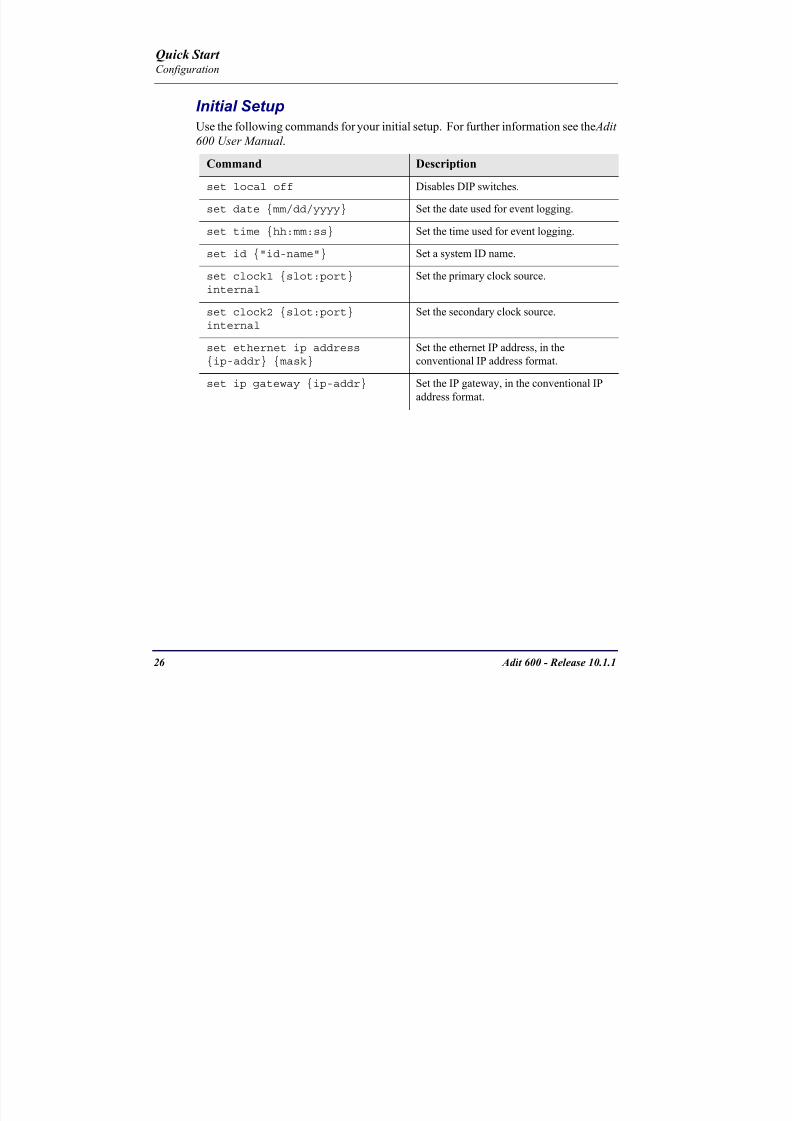
8102019 Adit 600 Quick Start 10-1-1
httpslidepdfcomreaderfulladit-600-quick-start-10-1-1 2854
26 Adit 600 - Release 1011
Quick Start Configuration
Initial SetupUse the following commands for your initial setup For further information see the Adit
600 User Manual
Command Description
set local off Disables DIP switches
set date mmddyyyy Set the date used for event logging
set time hhmmss Set the time used for event logging
set id id-name Set a system ID name
set clock1 slotportinternal
Set the primary clock source
set clock2 slotportinternal
Set the secondary clock source
set ethernet ip addressip-addr mask
Set the ethernet IP address in the
conventional IP address format
set ip gateway ip-addr Set the IP gateway in the conventional IP
address format
8102019 Adit 600 Quick Start 10-1-1
httpslidepdfcomreaderfulladit-600-quick-start-10-1-1 2954
Adit 600 - Release 1011 27
Quick Start Configuration
Basic Security SetupUse the following commands to set up the security on the Adit 600 For further
information see the Adit 600 User Manual
Command Description
set password length
long|short
Set user password length requirement
add user ldquouser-namerdquo[password ldquopasswordrdquo]
Add user and password as necessary
set user user-name level1-3
Specify the userrsquos security level
set user user-namepassword Setchange password for the user asnecessary
8102019 Adit 600 Quick Start 10-1-1
httpslidepdfcomreaderfulladit-600-quick-start-10-1-1 3054
28 Adit 600 - Release 1011
Quick Start Configuration
DS1T1 SetupUse the following commands to set up a DS1 See the set (ds1) command for more
details
Command Description
set ds1-addr up Activate the port of the DS1 (slotport)
set ds1-addr id id-string
Set the identification string
set ds1-addr lbo 1-9 Set the line buildout value for the DS1
set ds1-addr linecodeami|b8zs
Set the linecode for the DS1
set ds1-addr framing d4|esf|tr8afdl|tr8anofdl|tr8b
Set the framing option for the DS1
set ds1-addr loopdetecton|off
Set the detectionreaction to CSU loopcodes
Q i k S
8102019 Adit 600 Quick Start 10-1-1
httpslidepdfcomreaderfulladit-600-quick-start-10-1-1 3154
Adit 600 - Release 1011 29
Quick Start Configuration
E1 Setup
NOTE E1 is not supported in this release of the Adit 600 Controller It will besupported in a future release
Use the following commands to set up an E1 See the set (e1) command for more
details
DS0Channel Setup
Use the following commands to set up a DS0 See the set (ds0) command for details
Command Description
set e1-addr up Activate the port of the E1 (slotport)
set e1-addr id id-string Set the identification string
set e1-addr lbo 1 - 9 Set the line buildout value for the E1
set e1-addr linecodeami|hdb3
Set the linecode for the E1
set e1-addr framinge1fr|lefrcrc
Set the framing option for the E1
set e1-addr loopdetecton|off
Set the detectionreaction to CSU loopcodes
Command Description
set slotportchannel up Activate the channel
set slotportchannel signalls|gs|emw|emdw|emicpd|dpt
Set the signaling option for the channel
set slotportchannel typedata|voice Set the channel type
Q i k St t
8102019 Adit 600 Quick Start 10-1-1
httpslidepdfcomreaderfulladit-600-quick-start-10-1-1 3254
30 Adit 600 - Release 1011
Quick Start Configuration
Analog Port SetupUse the following commands to set up an analog port
Command Description
set slotport up Activate the port See set (ds1) command for
details
set slotport signal dpt|gs|gsrb|gsw|gswrb|ls|lscpd|lsrb
Set the signaling option for the port See the
set (fxs) or set (fxo) command for details
set slotport rxgain n Set the receive gainloss in dB See the set
(fxs) or set (fxo) command for details
set slotport txgain n Set the transmit gainloss in dB See the set
(fxs) or set (fxo) command for details
Quick Start
8102019 Adit 600 Quick Start 10-1-1
httpslidepdfcomreaderfulladit-600-quick-start-10-1-1 3354
Adit 600 - Release 1011 31
Quick Start Configuration
4-Wire EampM SetupFor this example the 4 EampM ports will be connected to the first 4 DS0s on T1-1 (a1)
This can be changed to match the customers desired DS0 connections
For Transmission Only mode the DS0s on the DS1 should be set to data as well as the
EampM card channels
Command Description
For Normal or Tandem EampM
set a11-4 type voice Set DS0s to voice
set connect a11-4 11-4 Connect DS0s to the 4 ports of the 4-
Wire EampM card
show connect a 1 Verify cross connects
set a11-4 signal emi Set DS0 signal type to EMI
set 11-4 signal emi Set 4-Wire EampM ports signal type to
EMI
show connect a1 Verify cross connects
For TO Mode
set a11-4 type data Set DS0s to data
set 11-4 type data Set 4-Wire EampM port to data
set connect a11-4 11-4 Connect DS0s to the 4 ports of the 4-
Wire EampM card
show connect a 1 Verify cross connects
Quick Start
8102019 Adit 600 Quick Start 10-1-1
httpslidepdfcomreaderfulladit-600-quick-start-10-1-1 3454
32 Adit 600 - Release 1011
Quick Start Configuration
Establish a Static Channel ConnectionUse the following commands to establish a static channel connection
ISDN BRI Service Setup
Use the following commands to set up a ISDN BRI Service See the set (bri) command
for details
Command Description
set slotportchannel typevoice|data
Set the channel type for the channel to
map See set (ds0) command for details
set slotportchannel signalls|gs|emw|emdw|emicpd|dpt
Set the channel signaling option See set
(ds0) command for details
connect slotportslotport
Connect the channels See the connect
(card-trunk) (card-trunk) command
Command Description
set slotport up Put the ISDN line In-Service
set slot modelt3ds0|lt4to1tdm|nt3ds0
Set the ISDN mode
set slotport crv 1-768 Set the Call Reference Value Note
value must be the same as the Access
Navigator
set slotport thresholdday|hour es|ses
Set the threshold for the IDSN lines
set slot pmsyncadit|switch
Set the source for performance
monitoring synchronization
set slotport autoactivate
on|off
Only used in 4-to-1 mode Establishes
the D channel when the FDL link can not
be used
Quick Start
8102019 Adit 600 Quick Start 10-1-1
httpslidepdfcomreaderfulladit-600-quick-start-10-1-1 3554
Adit 600 - Release 1011 33
Quick Start Configuration
OCU-DP Card SetupThe following is a basic setup for the OCU-DP card
ADPCM Card Setup
Command Description
set ocudp-addr baud2400|4800|9600|19200|38400|
56000|64000
Set the OCU-DP Baud rate
Where ocudp-addr = slotport of the
OCU-DP card to apply settings to
set ocudp-addr up Set the OCU-DP port 1 up
show ocudp_card-addr Show the OCU-DP card settings
Where ocudp_card-addr = slot of the
OCU-DP card
disconnect a Disconnects all connections to slot a
(controller)
set ds0-addr type data Sets a DS0 data signaling type
connect ds0-addrocudp-addr
Connects DS0 (in previous step) to OCU-DP
port (in previous step)
show connect
(ocudp_card-addr
Displays connect information for OCU-DP
card
Command Description
Connect T1 cable to port 1 of the ADPCM service card
set adpcm_card-addrnone|map1|map2|map3
Enable compressing by selecting Map type Notenone disables compression
show (adpcm_card-addr Displays the status of the card and the mapping
connect 211-12 241-12 Set ADPCM cross-connects The example
connects all 24 channels of the ADPCM to the 12
channels of the T1 (now compressed) on port 4
This example is with map2show connect 21) Displays the connections made above
8102019 Adit 600 Quick Start 10-1-1
httpslidepdfcomreaderfulladit-600-quick-start-10-1-1 3654
Quick Start
8102019 Adit 600 Quick Start 10-1-1
httpslidepdfcomreaderfulladit-600-quick-start-10-1-1 3754
Adit 600 - Release 1011 35
QConfiguration
Upgrade the Adit 600 SoftwareUse the following commands to determine the system software level then upgrade the
software to the latest version
Command Description
status equipment Determine the system software level The
Slot A line (SW Vers) will display thecurrent software level
load tftp ip-addr file-name (or load xmodem)
Load the new controller system software See
the load tftp and load xmodem command for
more information
Note A TFTP server must be running onthe host system You can use any TFTP
server utility you wish One example isthe program TFTPD32 which can bedownloaded free-of-charge attftpd32jouninnettftpd32html
Quick Start
8102019 Adit 600 Quick Start 10-1-1
httpslidepdfcomreaderfulladit-600-quick-start-10-1-1 3854
36 Adit 600 - Release 1011
Configuration
Upgrade the Router Card SoftwareUse the following commands to determine the Router card software level then upgrade
the software to the latest version
NOTE For additional information about upgrading MSR card software see
the following manuals-Adit 600 User Manual -Adit 3000 Series and Multi-Service Router (MSR) Card GUI Reference Manual
-Adit 3000 Series and Multi-Service Router (MSR) Card CLI Reference Manual
Command Description
status equipment Determine the Router software level The
Router Slot line (SW Vers) will display thecurrent software level
load rtr_card-addr tftpip-addr file-name
Load the new Router software to a Router
card See the load tftp command for more
information
Note A TFTP server must be running onthe host system You can use any TFTP
server utility you wish One example isthe program TFTPD32 which can bedownloaded free-of-charge attftpd32jouninnettftpd32html
8102019 Adit 600 Quick Start 10-1-1
httpslidepdfcomreaderfulladit-600-quick-start-10-1-1 3954
8102019 Adit 600 Quick Start 10-1-1
httpslidepdfcomreaderfulladit-600-quick-start-10-1-1 4054
Quick Start C t ll C d LED
8102019 Adit 600 Quick Start 10-1-1
httpslidepdfcomreaderfulladit-600-quick-start-10-1-1 4154
Adit 600 - Release 1011 39
Controller Card LEDs
E1 Controller Card
NOTE E1 is not supported in this release It will be supported in a futurerelease
The E1 Controller has a set of six LEDs The table below describes each LED
LED State Description
MAJOR Off No major alarms present
Red Major alarm present
MINOR Off No minor alarms present
Yellow Minor alarms present
LOCAL Off Remote mode (DIP switches disabled)
Green Local mode (DIP switches enabled)
ACO Off Normal mode No alarms are being
suppressed
Yellow Alarm Cut Off active One or more active
alarms suppressed
E1-1 and
E1-2
Off Off line
Green Normal
Red Loss of Signal (LOS) detected
Yellow Bipolar Violation (BPV) detected LCV
Flashing Green Loopback active
Flashing Red
(slow)
Loss of Frame (LOF) or Alarm Indication
Signal (AIS) detected
Flashing Red
(fast)
Card Failure
Flashing Yellow Yellow alarm (Remote Alarm Indication)detected
Quick Start Power Supply LEDs
8102019 Adit 600 Quick Start 10-1-1
httpslidepdfcomreaderfulladit-600-quick-start-10-1-1 4254
40 Adit 600 - Release 1011
Power Supply LEDs
Power Supply LEDs115 VAC-48 VDC and 230 VAC-48 VDC Power Supplies
The power supply card has two LEDs as described in the table
below
24 VDC-48 VDC Power Supply
The power supply card has two LEDs as described in the table below
LED State Description
AC Input Off AC input missing or failure
Green AC input present
Battery Off Battery input not used
Green Battery charging or operating from DC
source only
Yellow Battery discharging
Red Battery low (less than 42V) ringer disabled
LED State Description
DC OK Off DC input missing or failure
Green DC input present
-48 Battery
Low
Off Normal
Red VDC is low (less than 42 VDC)
ringer disabled
Quick Start Service Card LEDs
8102019 Adit 600 Quick Start 10-1-1
httpslidepdfcomreaderfulladit-600-quick-start-10-1-1 4354
Adit 600 - Release 1011 41
Service Card LEDs
Service Card LEDs 4-Wire EampM Card
FXO Card
FXS Card
ISDN BRI Card
OCU-DP Card
P-Phone Card
Single Channel POTS Card
Quad DS1 ADPCM Service Card
Quad DS1E1 and Quad T1 Cards
Quad E1 Card
IP Router Card
CMG Router Card
Terminal Server Router Card
MSR Card
RS-232 and V35V54 Cards
Discontinued cards
RS-232 discontinued
Quick Start Service Card LEDs
8102019 Adit 600 Quick Start 10-1-1
httpslidepdfcomreaderfulladit-600-quick-start-10-1-1 4454
42 Adit 600 - Release 1011
Service Card LEDs
4-Wire EampM Card Each channelport has two LEDs Only the top LED is used in this application LED
definitions are listed below
State Description
When in EampM Mode
Off Channel is idle or disabled
Green Analog interface is off-hook
Red Digital interface is off-hook
Yellow Both analog and digital interfaces are off-hook or channel is
being trunk processed
When in TO Mode
Off DisconnectedGreen Connected T1E1 not in alarm
Yellow Connected T1E1 in alarm (trunk processed)
Quick Start Service Card LEDs
8102019 Adit 600 Quick Start 10-1-1
httpslidepdfcomreaderfulladit-600-quick-start-10-1-1 4554
Adit 600 - Release 1011 43
FXO Card Each port on the FXO card has its own LED as described in the table below
FXS Card
There is an LED for each port on the FXS card as described in the table below
State Loop Start
Meaning
Ground Start Meaning Dial Pulse Termination
Meaning
Off NA Idle (tip open) Idle (loop open)
Green Idle Tip ground (incoming seizure) Incoming seizure
Red NA Ring ground (outgoing
seizure)
Loop closure (outgoing seizure)
Yellow Call in
progress
Call in progress Call in progress (reverse battery)
Flashing
Green
Ringing Ringing NA
State Loop Start Meaning Ground Start Meaning
Off NA Idle (tip open)
Green Idle Tip ground (incoming seizure)
Red Note This can be seen with
Forward Disconnect (tip open)
Ring ground (outgoing seizure)
Yellow Call in progress Call in progress
Flashing green Ringing Ringing
Quick Start Service Card LEDs
8102019 Adit 600 Quick Start 10-1-1
httpslidepdfcomreaderfulladit-600-quick-start-10-1-1 4654
44 Adit 600 - Release 1011
ISDN BRI Card There is an LED for each ISDN BRI on a card as described in the table below
OCU-DP Card Each channel has two LEDs described in the table below
State Description
Off Line U-interface is attempting synchronization or BRI is Out-of-Service
Red Line alarm (LOS or self test failure)
Yellow ES or SES has occurred
Flashing yellow Line U-interface is synchronized with customer equipment but is not passing
customer data
Flashing green Line U-interface is in external loopback toward the switch at the unit
Green Normal (Line U-interface is active and transparently passing customer data)
State Description
Yellow Flickering ALL Boot Software in control
Green (walking down)
Red (walking up)
ALL Application Software in control
(repeated 35 times)
Red slow flash ALL In Boot Application flash code checksums did not match and
Boot is waiting for application download
Red ALL In Application code waiting for Controller to issue SWHW
revision request This is the first request that comes from the
OCU-DP card manager in the ControllerGreen
Yellow
Top
Bottom
Port in Self-test Duration is 5-8 seconds
Off Top
Bottom
Port is set down (Out-Of-Service)
Green Top Port is receiving valid signals
Red Top Port is receiving no signal (primary) or no frame sync
(secondary or clear channel)Red Flashing Bottom Port is receiving bipolar violations
Yellow Bottom Port is in loopback
Quick Start Service Card LEDs
8102019 Adit 600 Quick Start 10-1-1
httpslidepdfcomreaderfulladit-600-quick-start-10-1-1 4754
Adit 600 - Release 1011 45
P-Phone Card Each P-Phone channel has a corresponding LED described in the table below
State Line State
Off No P-Phone connected
Green No call in process
Flashing Green Alert (Ringing)
Yellow Call in progress
Flashing Yellow P-Phone Loopback in Progress
Flashing Red Self-test failed
Quick Start Service Card LEDs
8102019 Adit 600 Quick Start 10-1-1
httpslidepdfcomreaderfulladit-600-quick-start-10-1-1 4854
46 Adit 600 - Release 1011
Single Channel POTS Card The POTS channel LED (left) status is described in the table below
The second LED (right) is a status LED is not used on this card
Quad DS1 ADPCM Service Card
Each channel on the Quad DS1 ADPCM card has two LEDs The
description of the top LED is shown below the bottom LED is notused with this application
State Loop Start Meaning
Off Calling Party Disconnect
Green Idle
Red NA
Yellow Call in progress
Flashing green Ringing
State Description
Off Off line
Green Normal
Red Loss of Signal (LOS)
Yellow Bipolar Violation (BPV)Flashing Green Loopback active
Flashing Yellow Yellow Alarm
(Remote Alarm Indication)
Flashing Red (Slow) Loss of Frame (LOF) or Alarm Indication Signal (AIS)
Flashing Red (Fast) Self-test Failure
Top LED(active)
Bottom LED(not used)
Quick Start Service Card LEDs
8102019 Adit 600 Quick Start 10-1-1
httpslidepdfcomreaderfulladit-600-quick-start-10-1-1 4954
Adit 600 - Release 1011 47
Quad DS1E1 and Quad T1 CardsEach channel on the Quad T1E1 cards have two LEDs The description
of the top LED is shown below the bottom LED is not used with this
application
State Description
Off Off line
Green Normal
Red Loss of Signal (LOS)
Yellow Bipolar Violation (BPV)
Flashing Green Loopback active
Flashing Yellow Yellow Alarm (Remote Alarm Indication)
Flashing Red (Slow) Loss of Frame (LOF) or Alarm Indication Signal (AIS)
Flashing Red (Fast) Self-test Failure
Quick Start Service Card LEDs
8102019 Adit 600 Quick Start 10-1-1
httpslidepdfcomreaderfulladit-600-quick-start-10-1-1 5054
48 Adit 600 - Release 1011
IP Router Card The following chart describes each LED and its state
LED State Description
CRD Off Loss of power
Green No current alarms
Red Alarm state active See alarm log for cause
Red Flashing Self-test or Boot in-process
Yellow Flashing Card is saving data to flash RAM do not power down
10100 Off 10 Mb ethernet
Green 100 Mb ethernet
LNK Off No ethernet link
Green Good ethernet link
COL
Off No current ethernet transmit collisions
Yellow Ethernet collisions have occurred and have not dropped
to minimum level
Yellow Flashing Ethernet collision occurring
TX Off No ethernet transmit activity
Green Ethernet transmit activity
RX Off No current ethernet receive activity
Green Current ethernet receive activity
Quick Start Service Card LEDs
8102019 Adit 600 Quick Start 10-1-1
httpslidepdfcomreaderfulladit-600-quick-start-10-1-1 5154
Adit 600 - Release 1011 49
CMG Router Card The following chart describes each LED and its state
LED State Description
CRD Off Loss of power
Green No current alarms
Red Alarm state active See alarm log for causeRed Flashing Self-test or Boot in-process
Yellow Flashing Card is saving data to flash RAM do not power down
VOIP
Off No active VoIP calls or if the MGCP protocol is
optioned down
Green Active VoIP calls
Red Call agent unreachable
Yellow Insufficient VoIP resources to complete call
LNK Off No Ethernet link
Green Good Ethernet link
10100 Off 10 Mb Ethernet
Green 100 Mb Ethernet
TX Off No Ethernet transmit activityGreen Ethernet transmit activity
Yellow Current Ethernet transmit collision
RX Off No current Ethernet receive activity
Green Current Ethernet receive activity
Quick Start Service Card LEDs
8102019 Adit 600 Quick Start 10-1-1
httpslidepdfcomreaderfulladit-600-quick-start-10-1-1 5254
50 Adit 600 - Release 1011
Terminal Server Router Card The Terminal Server Router card has 2 LEDs per port
At Power-up
Normal Operation
Port Set for Ethernet
Top LED indicates 100M Link Bottom LED indicates 10M Link
Port Set for RS-232
TOP LED Bottom LED Description
Off Off At Power UpBoot = Loss of power
Red Red Card is inoperative
Flashing Red Flashing Red Self-test or Boot in-process
TOP LED Bottom LED Description
Green Solid (Link) Green Solid (Link) Port set for Ethernet - see below
Flashing Red Flashing Red Self-test or Boot in-process
State Description
Off No Ethernet link
Green Link but no activity
Red Flashing Current Ethernet collision
Green Flashing Current Ethernet receive
Yellow Flashing Current Ethernet transmit
TOP LED Bottom LED Description
Yellow Off No Activity
Yellow Flashing Yellow Current transmit
Yellow Flashing Green Current receive
Quick Start Service Card LEDs
8102019 Adit 600 Quick Start 10-1-1
httpslidepdfcomreaderfulladit-600-quick-start-10-1-1 5354
Adit 600 - Release 1011 51
MSR Card The following chart describes the MSR cardrsquos LEDs
LED State Description
CRD Off Loss of power
Green No current alarms
Red Alarm state active See alarm log for cause
Red Flashing Self-test or boot in process
Yellow Flashing Card is saving data to flash RAM do not power
down
VOIP
Off No SIP proxy or registration attempts for all lines
have succeeded but no calls are active
Green Active VoIP call(s)
Red Inability to reach the SIP proxy or negative response
to register attempts from all lines
Yellow Register attempts from some lines have succeeded
but not for all lines
ETH1 and
ETH2
Top LED
Off 10 Mbitsec down or not connected
Green 100 Mbitsec
ETH1 and
ETH2
Bottom LED
Off Link down
Green Link up
Flashing Green Traffic on link
Yellow Collision status
Quick Start Service Card LEDs
8102019 Adit 600 Quick Start 10-1-1
httpslidepdfcomreaderfulladit-600-quick-start-10-1-1 5454
52 Adit 600 - Release 1011
RS-232 and V35V54 Cards Each port has its own LED as described in the table below
State Description
Off No T1 Assignment
Green Normal (CDRTS) Active
Red CD inactive (T1-side failure)
Yellow RTS inactive (equipment-side failure)
Flashing Yellow Loopback toward T1 or equipment loop test
Flashing Green Loopback toward equipment or network loop test
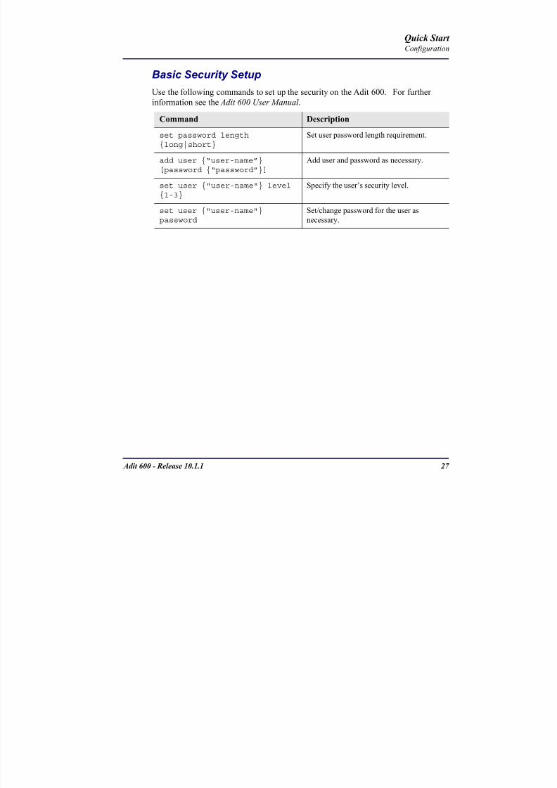
8102019 Adit 600 Quick Start 10-1-1
httpslidepdfcomreaderfulladit-600-quick-start-10-1-1 2954
Adit 600 - Release 1011 27
Quick Start Configuration
Basic Security SetupUse the following commands to set up the security on the Adit 600 For further
information see the Adit 600 User Manual
Command Description
set password length
long|short
Set user password length requirement
add user ldquouser-namerdquo[password ldquopasswordrdquo]
Add user and password as necessary
set user user-name level1-3
Specify the userrsquos security level
set user user-namepassword Setchange password for the user asnecessary
8102019 Adit 600 Quick Start 10-1-1
httpslidepdfcomreaderfulladit-600-quick-start-10-1-1 3054
28 Adit 600 - Release 1011
Quick Start Configuration
DS1T1 SetupUse the following commands to set up a DS1 See the set (ds1) command for more
details
Command Description
set ds1-addr up Activate the port of the DS1 (slotport)
set ds1-addr id id-string
Set the identification string
set ds1-addr lbo 1-9 Set the line buildout value for the DS1
set ds1-addr linecodeami|b8zs
Set the linecode for the DS1
set ds1-addr framing d4|esf|tr8afdl|tr8anofdl|tr8b
Set the framing option for the DS1
set ds1-addr loopdetecton|off
Set the detectionreaction to CSU loopcodes
Q i k S
8102019 Adit 600 Quick Start 10-1-1
httpslidepdfcomreaderfulladit-600-quick-start-10-1-1 3154
Adit 600 - Release 1011 29
Quick Start Configuration
E1 Setup
NOTE E1 is not supported in this release of the Adit 600 Controller It will besupported in a future release
Use the following commands to set up an E1 See the set (e1) command for more
details
DS0Channel Setup
Use the following commands to set up a DS0 See the set (ds0) command for details
Command Description
set e1-addr up Activate the port of the E1 (slotport)
set e1-addr id id-string Set the identification string
set e1-addr lbo 1 - 9 Set the line buildout value for the E1
set e1-addr linecodeami|hdb3
Set the linecode for the E1
set e1-addr framinge1fr|lefrcrc
Set the framing option for the E1
set e1-addr loopdetecton|off
Set the detectionreaction to CSU loopcodes
Command Description
set slotportchannel up Activate the channel
set slotportchannel signalls|gs|emw|emdw|emicpd|dpt
Set the signaling option for the channel
set slotportchannel typedata|voice Set the channel type
Q i k St t
8102019 Adit 600 Quick Start 10-1-1
httpslidepdfcomreaderfulladit-600-quick-start-10-1-1 3254
30 Adit 600 - Release 1011
Quick Start Configuration
Analog Port SetupUse the following commands to set up an analog port
Command Description
set slotport up Activate the port See set (ds1) command for
details
set slotport signal dpt|gs|gsrb|gsw|gswrb|ls|lscpd|lsrb
Set the signaling option for the port See the
set (fxs) or set (fxo) command for details
set slotport rxgain n Set the receive gainloss in dB See the set
(fxs) or set (fxo) command for details
set slotport txgain n Set the transmit gainloss in dB See the set
(fxs) or set (fxo) command for details
Quick Start
8102019 Adit 600 Quick Start 10-1-1
httpslidepdfcomreaderfulladit-600-quick-start-10-1-1 3354
Adit 600 - Release 1011 31
Quick Start Configuration
4-Wire EampM SetupFor this example the 4 EampM ports will be connected to the first 4 DS0s on T1-1 (a1)
This can be changed to match the customers desired DS0 connections
For Transmission Only mode the DS0s on the DS1 should be set to data as well as the
EampM card channels
Command Description
For Normal or Tandem EampM
set a11-4 type voice Set DS0s to voice
set connect a11-4 11-4 Connect DS0s to the 4 ports of the 4-
Wire EampM card
show connect a 1 Verify cross connects
set a11-4 signal emi Set DS0 signal type to EMI
set 11-4 signal emi Set 4-Wire EampM ports signal type to
EMI
show connect a1 Verify cross connects
For TO Mode
set a11-4 type data Set DS0s to data
set 11-4 type data Set 4-Wire EampM port to data
set connect a11-4 11-4 Connect DS0s to the 4 ports of the 4-
Wire EampM card
show connect a 1 Verify cross connects
Quick Start
8102019 Adit 600 Quick Start 10-1-1
httpslidepdfcomreaderfulladit-600-quick-start-10-1-1 3454
32 Adit 600 - Release 1011
Quick Start Configuration
Establish a Static Channel ConnectionUse the following commands to establish a static channel connection
ISDN BRI Service Setup
Use the following commands to set up a ISDN BRI Service See the set (bri) command
for details
Command Description
set slotportchannel typevoice|data
Set the channel type for the channel to
map See set (ds0) command for details
set slotportchannel signalls|gs|emw|emdw|emicpd|dpt
Set the channel signaling option See set
(ds0) command for details
connect slotportslotport
Connect the channels See the connect
(card-trunk) (card-trunk) command
Command Description
set slotport up Put the ISDN line In-Service
set slot modelt3ds0|lt4to1tdm|nt3ds0
Set the ISDN mode
set slotport crv 1-768 Set the Call Reference Value Note
value must be the same as the Access
Navigator
set slotport thresholdday|hour es|ses
Set the threshold for the IDSN lines
set slot pmsyncadit|switch
Set the source for performance
monitoring synchronization
set slotport autoactivate
on|off
Only used in 4-to-1 mode Establishes
the D channel when the FDL link can not
be used
Quick Start
8102019 Adit 600 Quick Start 10-1-1
httpslidepdfcomreaderfulladit-600-quick-start-10-1-1 3554
Adit 600 - Release 1011 33
Quick Start Configuration
OCU-DP Card SetupThe following is a basic setup for the OCU-DP card
ADPCM Card Setup
Command Description
set ocudp-addr baud2400|4800|9600|19200|38400|
56000|64000
Set the OCU-DP Baud rate
Where ocudp-addr = slotport of the
OCU-DP card to apply settings to
set ocudp-addr up Set the OCU-DP port 1 up
show ocudp_card-addr Show the OCU-DP card settings
Where ocudp_card-addr = slot of the
OCU-DP card
disconnect a Disconnects all connections to slot a
(controller)
set ds0-addr type data Sets a DS0 data signaling type
connect ds0-addrocudp-addr
Connects DS0 (in previous step) to OCU-DP
port (in previous step)
show connect
(ocudp_card-addr
Displays connect information for OCU-DP
card
Command Description
Connect T1 cable to port 1 of the ADPCM service card
set adpcm_card-addrnone|map1|map2|map3
Enable compressing by selecting Map type Notenone disables compression
show (adpcm_card-addr Displays the status of the card and the mapping
connect 211-12 241-12 Set ADPCM cross-connects The example
connects all 24 channels of the ADPCM to the 12
channels of the T1 (now compressed) on port 4
This example is with map2show connect 21) Displays the connections made above
8102019 Adit 600 Quick Start 10-1-1
httpslidepdfcomreaderfulladit-600-quick-start-10-1-1 3654
Quick Start
8102019 Adit 600 Quick Start 10-1-1
httpslidepdfcomreaderfulladit-600-quick-start-10-1-1 3754
Adit 600 - Release 1011 35
QConfiguration
Upgrade the Adit 600 SoftwareUse the following commands to determine the system software level then upgrade the
software to the latest version
Command Description
status equipment Determine the system software level The
Slot A line (SW Vers) will display thecurrent software level
load tftp ip-addr file-name (or load xmodem)
Load the new controller system software See
the load tftp and load xmodem command for
more information
Note A TFTP server must be running onthe host system You can use any TFTP
server utility you wish One example isthe program TFTPD32 which can bedownloaded free-of-charge attftpd32jouninnettftpd32html
Quick Start
8102019 Adit 600 Quick Start 10-1-1
httpslidepdfcomreaderfulladit-600-quick-start-10-1-1 3854
36 Adit 600 - Release 1011
Configuration
Upgrade the Router Card SoftwareUse the following commands to determine the Router card software level then upgrade
the software to the latest version
NOTE For additional information about upgrading MSR card software see
the following manuals-Adit 600 User Manual -Adit 3000 Series and Multi-Service Router (MSR) Card GUI Reference Manual
-Adit 3000 Series and Multi-Service Router (MSR) Card CLI Reference Manual
Command Description
status equipment Determine the Router software level The
Router Slot line (SW Vers) will display thecurrent software level
load rtr_card-addr tftpip-addr file-name
Load the new Router software to a Router
card See the load tftp command for more
information
Note A TFTP server must be running onthe host system You can use any TFTP
server utility you wish One example isthe program TFTPD32 which can bedownloaded free-of-charge attftpd32jouninnettftpd32html
8102019 Adit 600 Quick Start 10-1-1
httpslidepdfcomreaderfulladit-600-quick-start-10-1-1 3954
8102019 Adit 600 Quick Start 10-1-1
httpslidepdfcomreaderfulladit-600-quick-start-10-1-1 4054
Quick Start C t ll C d LED
8102019 Adit 600 Quick Start 10-1-1
httpslidepdfcomreaderfulladit-600-quick-start-10-1-1 4154
Adit 600 - Release 1011 39
Controller Card LEDs
E1 Controller Card
NOTE E1 is not supported in this release It will be supported in a futurerelease
The E1 Controller has a set of six LEDs The table below describes each LED
LED State Description
MAJOR Off No major alarms present
Red Major alarm present
MINOR Off No minor alarms present
Yellow Minor alarms present
LOCAL Off Remote mode (DIP switches disabled)
Green Local mode (DIP switches enabled)
ACO Off Normal mode No alarms are being
suppressed
Yellow Alarm Cut Off active One or more active
alarms suppressed
E1-1 and
E1-2
Off Off line
Green Normal
Red Loss of Signal (LOS) detected
Yellow Bipolar Violation (BPV) detected LCV
Flashing Green Loopback active
Flashing Red
(slow)
Loss of Frame (LOF) or Alarm Indication
Signal (AIS) detected
Flashing Red
(fast)
Card Failure
Flashing Yellow Yellow alarm (Remote Alarm Indication)detected
Quick Start Power Supply LEDs
8102019 Adit 600 Quick Start 10-1-1
httpslidepdfcomreaderfulladit-600-quick-start-10-1-1 4254
40 Adit 600 - Release 1011
Power Supply LEDs
Power Supply LEDs115 VAC-48 VDC and 230 VAC-48 VDC Power Supplies
The power supply card has two LEDs as described in the table
below
24 VDC-48 VDC Power Supply
The power supply card has two LEDs as described in the table below
LED State Description
AC Input Off AC input missing or failure
Green AC input present
Battery Off Battery input not used
Green Battery charging or operating from DC
source only
Yellow Battery discharging
Red Battery low (less than 42V) ringer disabled
LED State Description
DC OK Off DC input missing or failure
Green DC input present
-48 Battery
Low
Off Normal
Red VDC is low (less than 42 VDC)
ringer disabled
Quick Start Service Card LEDs
8102019 Adit 600 Quick Start 10-1-1
httpslidepdfcomreaderfulladit-600-quick-start-10-1-1 4354
Adit 600 - Release 1011 41
Service Card LEDs
Service Card LEDs 4-Wire EampM Card
FXO Card
FXS Card
ISDN BRI Card
OCU-DP Card
P-Phone Card
Single Channel POTS Card
Quad DS1 ADPCM Service Card
Quad DS1E1 and Quad T1 Cards
Quad E1 Card
IP Router Card
CMG Router Card
Terminal Server Router Card
MSR Card
RS-232 and V35V54 Cards
Discontinued cards
RS-232 discontinued
Quick Start Service Card LEDs
8102019 Adit 600 Quick Start 10-1-1
httpslidepdfcomreaderfulladit-600-quick-start-10-1-1 4454
42 Adit 600 - Release 1011
Service Card LEDs
4-Wire EampM Card Each channelport has two LEDs Only the top LED is used in this application LED
definitions are listed below
State Description
When in EampM Mode
Off Channel is idle or disabled
Green Analog interface is off-hook
Red Digital interface is off-hook
Yellow Both analog and digital interfaces are off-hook or channel is
being trunk processed
When in TO Mode
Off DisconnectedGreen Connected T1E1 not in alarm
Yellow Connected T1E1 in alarm (trunk processed)
Quick Start Service Card LEDs
8102019 Adit 600 Quick Start 10-1-1
httpslidepdfcomreaderfulladit-600-quick-start-10-1-1 4554
Adit 600 - Release 1011 43
FXO Card Each port on the FXO card has its own LED as described in the table below
FXS Card
There is an LED for each port on the FXS card as described in the table below
State Loop Start
Meaning
Ground Start Meaning Dial Pulse Termination
Meaning
Off NA Idle (tip open) Idle (loop open)
Green Idle Tip ground (incoming seizure) Incoming seizure
Red NA Ring ground (outgoing
seizure)
Loop closure (outgoing seizure)
Yellow Call in
progress
Call in progress Call in progress (reverse battery)
Flashing
Green
Ringing Ringing NA
State Loop Start Meaning Ground Start Meaning
Off NA Idle (tip open)
Green Idle Tip ground (incoming seizure)
Red Note This can be seen with
Forward Disconnect (tip open)
Ring ground (outgoing seizure)
Yellow Call in progress Call in progress
Flashing green Ringing Ringing
Quick Start Service Card LEDs
8102019 Adit 600 Quick Start 10-1-1
httpslidepdfcomreaderfulladit-600-quick-start-10-1-1 4654
44 Adit 600 - Release 1011
ISDN BRI Card There is an LED for each ISDN BRI on a card as described in the table below
OCU-DP Card Each channel has two LEDs described in the table below
State Description
Off Line U-interface is attempting synchronization or BRI is Out-of-Service
Red Line alarm (LOS or self test failure)
Yellow ES or SES has occurred
Flashing yellow Line U-interface is synchronized with customer equipment but is not passing
customer data
Flashing green Line U-interface is in external loopback toward the switch at the unit
Green Normal (Line U-interface is active and transparently passing customer data)
State Description
Yellow Flickering ALL Boot Software in control
Green (walking down)
Red (walking up)
ALL Application Software in control
(repeated 35 times)
Red slow flash ALL In Boot Application flash code checksums did not match and
Boot is waiting for application download
Red ALL In Application code waiting for Controller to issue SWHW
revision request This is the first request that comes from the
OCU-DP card manager in the ControllerGreen
Yellow
Top
Bottom
Port in Self-test Duration is 5-8 seconds
Off Top
Bottom
Port is set down (Out-Of-Service)
Green Top Port is receiving valid signals
Red Top Port is receiving no signal (primary) or no frame sync
(secondary or clear channel)Red Flashing Bottom Port is receiving bipolar violations
Yellow Bottom Port is in loopback
Quick Start Service Card LEDs
8102019 Adit 600 Quick Start 10-1-1
httpslidepdfcomreaderfulladit-600-quick-start-10-1-1 4754
Adit 600 - Release 1011 45
P-Phone Card Each P-Phone channel has a corresponding LED described in the table below
State Line State
Off No P-Phone connected
Green No call in process
Flashing Green Alert (Ringing)
Yellow Call in progress
Flashing Yellow P-Phone Loopback in Progress
Flashing Red Self-test failed
Quick Start Service Card LEDs
8102019 Adit 600 Quick Start 10-1-1
httpslidepdfcomreaderfulladit-600-quick-start-10-1-1 4854
46 Adit 600 - Release 1011
Single Channel POTS Card The POTS channel LED (left) status is described in the table below
The second LED (right) is a status LED is not used on this card
Quad DS1 ADPCM Service Card
Each channel on the Quad DS1 ADPCM card has two LEDs The
description of the top LED is shown below the bottom LED is notused with this application
State Loop Start Meaning
Off Calling Party Disconnect
Green Idle
Red NA
Yellow Call in progress
Flashing green Ringing
State Description
Off Off line
Green Normal
Red Loss of Signal (LOS)
Yellow Bipolar Violation (BPV)Flashing Green Loopback active
Flashing Yellow Yellow Alarm
(Remote Alarm Indication)
Flashing Red (Slow) Loss of Frame (LOF) or Alarm Indication Signal (AIS)
Flashing Red (Fast) Self-test Failure
Top LED(active)
Bottom LED(not used)
Quick Start Service Card LEDs
8102019 Adit 600 Quick Start 10-1-1
httpslidepdfcomreaderfulladit-600-quick-start-10-1-1 4954
Adit 600 - Release 1011 47
Quad DS1E1 and Quad T1 CardsEach channel on the Quad T1E1 cards have two LEDs The description
of the top LED is shown below the bottom LED is not used with this
application
State Description
Off Off line
Green Normal
Red Loss of Signal (LOS)
Yellow Bipolar Violation (BPV)
Flashing Green Loopback active
Flashing Yellow Yellow Alarm (Remote Alarm Indication)
Flashing Red (Slow) Loss of Frame (LOF) or Alarm Indication Signal (AIS)
Flashing Red (Fast) Self-test Failure
Quick Start Service Card LEDs
8102019 Adit 600 Quick Start 10-1-1
httpslidepdfcomreaderfulladit-600-quick-start-10-1-1 5054
48 Adit 600 - Release 1011
IP Router Card The following chart describes each LED and its state
LED State Description
CRD Off Loss of power
Green No current alarms
Red Alarm state active See alarm log for cause
Red Flashing Self-test or Boot in-process
Yellow Flashing Card is saving data to flash RAM do not power down
10100 Off 10 Mb ethernet
Green 100 Mb ethernet
LNK Off No ethernet link
Green Good ethernet link
COL
Off No current ethernet transmit collisions
Yellow Ethernet collisions have occurred and have not dropped
to minimum level
Yellow Flashing Ethernet collision occurring
TX Off No ethernet transmit activity
Green Ethernet transmit activity
RX Off No current ethernet receive activity
Green Current ethernet receive activity
Quick Start Service Card LEDs
8102019 Adit 600 Quick Start 10-1-1
httpslidepdfcomreaderfulladit-600-quick-start-10-1-1 5154
Adit 600 - Release 1011 49
CMG Router Card The following chart describes each LED and its state
LED State Description
CRD Off Loss of power
Green No current alarms
Red Alarm state active See alarm log for causeRed Flashing Self-test or Boot in-process
Yellow Flashing Card is saving data to flash RAM do not power down
VOIP
Off No active VoIP calls or if the MGCP protocol is
optioned down
Green Active VoIP calls
Red Call agent unreachable
Yellow Insufficient VoIP resources to complete call
LNK Off No Ethernet link
Green Good Ethernet link
10100 Off 10 Mb Ethernet
Green 100 Mb Ethernet
TX Off No Ethernet transmit activityGreen Ethernet transmit activity
Yellow Current Ethernet transmit collision
RX Off No current Ethernet receive activity
Green Current Ethernet receive activity
Quick Start Service Card LEDs
8102019 Adit 600 Quick Start 10-1-1
httpslidepdfcomreaderfulladit-600-quick-start-10-1-1 5254
50 Adit 600 - Release 1011
Terminal Server Router Card The Terminal Server Router card has 2 LEDs per port
At Power-up
Normal Operation
Port Set for Ethernet
Top LED indicates 100M Link Bottom LED indicates 10M Link
Port Set for RS-232
TOP LED Bottom LED Description
Off Off At Power UpBoot = Loss of power
Red Red Card is inoperative
Flashing Red Flashing Red Self-test or Boot in-process
TOP LED Bottom LED Description
Green Solid (Link) Green Solid (Link) Port set for Ethernet - see below
Flashing Red Flashing Red Self-test or Boot in-process
State Description
Off No Ethernet link
Green Link but no activity
Red Flashing Current Ethernet collision
Green Flashing Current Ethernet receive
Yellow Flashing Current Ethernet transmit
TOP LED Bottom LED Description
Yellow Off No Activity
Yellow Flashing Yellow Current transmit
Yellow Flashing Green Current receive
Quick Start Service Card LEDs
8102019 Adit 600 Quick Start 10-1-1
httpslidepdfcomreaderfulladit-600-quick-start-10-1-1 5354
Adit 600 - Release 1011 51
MSR Card The following chart describes the MSR cardrsquos LEDs
LED State Description
CRD Off Loss of power
Green No current alarms
Red Alarm state active See alarm log for cause
Red Flashing Self-test or boot in process
Yellow Flashing Card is saving data to flash RAM do not power
down
VOIP
Off No SIP proxy or registration attempts for all lines
have succeeded but no calls are active
Green Active VoIP call(s)
Red Inability to reach the SIP proxy or negative response
to register attempts from all lines
Yellow Register attempts from some lines have succeeded
but not for all lines
ETH1 and
ETH2
Top LED
Off 10 Mbitsec down or not connected
Green 100 Mbitsec
ETH1 and
ETH2
Bottom LED
Off Link down
Green Link up
Flashing Green Traffic on link
Yellow Collision status
Quick Start Service Card LEDs
8102019 Adit 600 Quick Start 10-1-1
httpslidepdfcomreaderfulladit-600-quick-start-10-1-1 5454
52 Adit 600 - Release 1011
RS-232 and V35V54 Cards Each port has its own LED as described in the table below
State Description
Off No T1 Assignment
Green Normal (CDRTS) Active
Red CD inactive (T1-side failure)
Yellow RTS inactive (equipment-side failure)
Flashing Yellow Loopback toward T1 or equipment loop test
Flashing Green Loopback toward equipment or network loop test
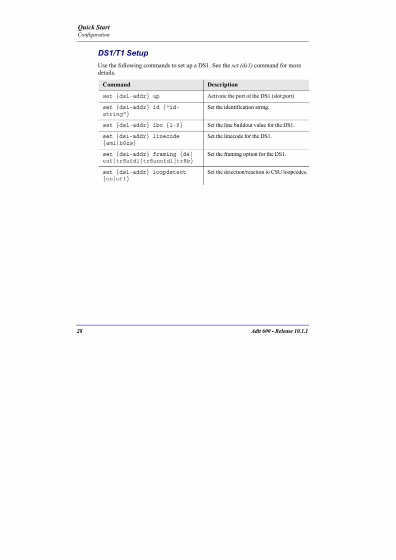
8102019 Adit 600 Quick Start 10-1-1
httpslidepdfcomreaderfulladit-600-quick-start-10-1-1 3054
28 Adit 600 - Release 1011
Quick Start Configuration
DS1T1 SetupUse the following commands to set up a DS1 See the set (ds1) command for more
details
Command Description
set ds1-addr up Activate the port of the DS1 (slotport)
set ds1-addr id id-string
Set the identification string
set ds1-addr lbo 1-9 Set the line buildout value for the DS1
set ds1-addr linecodeami|b8zs
Set the linecode for the DS1
set ds1-addr framing d4|esf|tr8afdl|tr8anofdl|tr8b
Set the framing option for the DS1
set ds1-addr loopdetecton|off
Set the detectionreaction to CSU loopcodes
Q i k S
8102019 Adit 600 Quick Start 10-1-1
httpslidepdfcomreaderfulladit-600-quick-start-10-1-1 3154
Adit 600 - Release 1011 29
Quick Start Configuration
E1 Setup
NOTE E1 is not supported in this release of the Adit 600 Controller It will besupported in a future release
Use the following commands to set up an E1 See the set (e1) command for more
details
DS0Channel Setup
Use the following commands to set up a DS0 See the set (ds0) command for details
Command Description
set e1-addr up Activate the port of the E1 (slotport)
set e1-addr id id-string Set the identification string
set e1-addr lbo 1 - 9 Set the line buildout value for the E1
set e1-addr linecodeami|hdb3
Set the linecode for the E1
set e1-addr framinge1fr|lefrcrc
Set the framing option for the E1
set e1-addr loopdetecton|off
Set the detectionreaction to CSU loopcodes
Command Description
set slotportchannel up Activate the channel
set slotportchannel signalls|gs|emw|emdw|emicpd|dpt
Set the signaling option for the channel
set slotportchannel typedata|voice Set the channel type
Q i k St t
8102019 Adit 600 Quick Start 10-1-1
httpslidepdfcomreaderfulladit-600-quick-start-10-1-1 3254
30 Adit 600 - Release 1011
Quick Start Configuration
Analog Port SetupUse the following commands to set up an analog port
Command Description
set slotport up Activate the port See set (ds1) command for
details
set slotport signal dpt|gs|gsrb|gsw|gswrb|ls|lscpd|lsrb
Set the signaling option for the port See the
set (fxs) or set (fxo) command for details
set slotport rxgain n Set the receive gainloss in dB See the set
(fxs) or set (fxo) command for details
set slotport txgain n Set the transmit gainloss in dB See the set
(fxs) or set (fxo) command for details
Quick Start
8102019 Adit 600 Quick Start 10-1-1
httpslidepdfcomreaderfulladit-600-quick-start-10-1-1 3354
Adit 600 - Release 1011 31
Quick Start Configuration
4-Wire EampM SetupFor this example the 4 EampM ports will be connected to the first 4 DS0s on T1-1 (a1)
This can be changed to match the customers desired DS0 connections
For Transmission Only mode the DS0s on the DS1 should be set to data as well as the
EampM card channels
Command Description
For Normal or Tandem EampM
set a11-4 type voice Set DS0s to voice
set connect a11-4 11-4 Connect DS0s to the 4 ports of the 4-
Wire EampM card
show connect a 1 Verify cross connects
set a11-4 signal emi Set DS0 signal type to EMI
set 11-4 signal emi Set 4-Wire EampM ports signal type to
EMI
show connect a1 Verify cross connects
For TO Mode
set a11-4 type data Set DS0s to data
set 11-4 type data Set 4-Wire EampM port to data
set connect a11-4 11-4 Connect DS0s to the 4 ports of the 4-
Wire EampM card
show connect a 1 Verify cross connects
Quick Start
8102019 Adit 600 Quick Start 10-1-1
httpslidepdfcomreaderfulladit-600-quick-start-10-1-1 3454
32 Adit 600 - Release 1011
Quick Start Configuration
Establish a Static Channel ConnectionUse the following commands to establish a static channel connection
ISDN BRI Service Setup
Use the following commands to set up a ISDN BRI Service See the set (bri) command
for details
Command Description
set slotportchannel typevoice|data
Set the channel type for the channel to
map See set (ds0) command for details
set slotportchannel signalls|gs|emw|emdw|emicpd|dpt
Set the channel signaling option See set
(ds0) command for details
connect slotportslotport
Connect the channels See the connect
(card-trunk) (card-trunk) command
Command Description
set slotport up Put the ISDN line In-Service
set slot modelt3ds0|lt4to1tdm|nt3ds0
Set the ISDN mode
set slotport crv 1-768 Set the Call Reference Value Note
value must be the same as the Access
Navigator
set slotport thresholdday|hour es|ses
Set the threshold for the IDSN lines
set slot pmsyncadit|switch
Set the source for performance
monitoring synchronization
set slotport autoactivate
on|off
Only used in 4-to-1 mode Establishes
the D channel when the FDL link can not
be used
Quick Start
8102019 Adit 600 Quick Start 10-1-1
httpslidepdfcomreaderfulladit-600-quick-start-10-1-1 3554
Adit 600 - Release 1011 33
Quick Start Configuration
OCU-DP Card SetupThe following is a basic setup for the OCU-DP card
ADPCM Card Setup
Command Description
set ocudp-addr baud2400|4800|9600|19200|38400|
56000|64000
Set the OCU-DP Baud rate
Where ocudp-addr = slotport of the
OCU-DP card to apply settings to
set ocudp-addr up Set the OCU-DP port 1 up
show ocudp_card-addr Show the OCU-DP card settings
Where ocudp_card-addr = slot of the
OCU-DP card
disconnect a Disconnects all connections to slot a
(controller)
set ds0-addr type data Sets a DS0 data signaling type
connect ds0-addrocudp-addr
Connects DS0 (in previous step) to OCU-DP
port (in previous step)
show connect
(ocudp_card-addr
Displays connect information for OCU-DP
card
Command Description
Connect T1 cable to port 1 of the ADPCM service card
set adpcm_card-addrnone|map1|map2|map3
Enable compressing by selecting Map type Notenone disables compression
show (adpcm_card-addr Displays the status of the card and the mapping
connect 211-12 241-12 Set ADPCM cross-connects The example
connects all 24 channels of the ADPCM to the 12
channels of the T1 (now compressed) on port 4
This example is with map2show connect 21) Displays the connections made above
8102019 Adit 600 Quick Start 10-1-1
httpslidepdfcomreaderfulladit-600-quick-start-10-1-1 3654
Quick Start
8102019 Adit 600 Quick Start 10-1-1
httpslidepdfcomreaderfulladit-600-quick-start-10-1-1 3754
Adit 600 - Release 1011 35
QConfiguration
Upgrade the Adit 600 SoftwareUse the following commands to determine the system software level then upgrade the
software to the latest version
Command Description
status equipment Determine the system software level The
Slot A line (SW Vers) will display thecurrent software level
load tftp ip-addr file-name (or load xmodem)
Load the new controller system software See
the load tftp and load xmodem command for
more information
Note A TFTP server must be running onthe host system You can use any TFTP
server utility you wish One example isthe program TFTPD32 which can bedownloaded free-of-charge attftpd32jouninnettftpd32html
Quick Start
8102019 Adit 600 Quick Start 10-1-1
httpslidepdfcomreaderfulladit-600-quick-start-10-1-1 3854
36 Adit 600 - Release 1011
Configuration
Upgrade the Router Card SoftwareUse the following commands to determine the Router card software level then upgrade
the software to the latest version
NOTE For additional information about upgrading MSR card software see
the following manuals-Adit 600 User Manual -Adit 3000 Series and Multi-Service Router (MSR) Card GUI Reference Manual
-Adit 3000 Series and Multi-Service Router (MSR) Card CLI Reference Manual
Command Description
status equipment Determine the Router software level The
Router Slot line (SW Vers) will display thecurrent software level
load rtr_card-addr tftpip-addr file-name
Load the new Router software to a Router
card See the load tftp command for more
information
Note A TFTP server must be running onthe host system You can use any TFTP
server utility you wish One example isthe program TFTPD32 which can bedownloaded free-of-charge attftpd32jouninnettftpd32html
8102019 Adit 600 Quick Start 10-1-1
httpslidepdfcomreaderfulladit-600-quick-start-10-1-1 3954
8102019 Adit 600 Quick Start 10-1-1
httpslidepdfcomreaderfulladit-600-quick-start-10-1-1 4054
Quick Start C t ll C d LED
8102019 Adit 600 Quick Start 10-1-1
httpslidepdfcomreaderfulladit-600-quick-start-10-1-1 4154
Adit 600 - Release 1011 39
Controller Card LEDs
E1 Controller Card
NOTE E1 is not supported in this release It will be supported in a futurerelease
The E1 Controller has a set of six LEDs The table below describes each LED
LED State Description
MAJOR Off No major alarms present
Red Major alarm present
MINOR Off No minor alarms present
Yellow Minor alarms present
LOCAL Off Remote mode (DIP switches disabled)
Green Local mode (DIP switches enabled)
ACO Off Normal mode No alarms are being
suppressed
Yellow Alarm Cut Off active One or more active
alarms suppressed
E1-1 and
E1-2
Off Off line
Green Normal
Red Loss of Signal (LOS) detected
Yellow Bipolar Violation (BPV) detected LCV
Flashing Green Loopback active
Flashing Red
(slow)
Loss of Frame (LOF) or Alarm Indication
Signal (AIS) detected
Flashing Red
(fast)
Card Failure
Flashing Yellow Yellow alarm (Remote Alarm Indication)detected
Quick Start Power Supply LEDs
8102019 Adit 600 Quick Start 10-1-1
httpslidepdfcomreaderfulladit-600-quick-start-10-1-1 4254
40 Adit 600 - Release 1011
Power Supply LEDs
Power Supply LEDs115 VAC-48 VDC and 230 VAC-48 VDC Power Supplies
The power supply card has two LEDs as described in the table
below
24 VDC-48 VDC Power Supply
The power supply card has two LEDs as described in the table below
LED State Description
AC Input Off AC input missing or failure
Green AC input present
Battery Off Battery input not used
Green Battery charging or operating from DC
source only
Yellow Battery discharging
Red Battery low (less than 42V) ringer disabled
LED State Description
DC OK Off DC input missing or failure
Green DC input present
-48 Battery
Low
Off Normal
Red VDC is low (less than 42 VDC)
ringer disabled
Quick Start Service Card LEDs
8102019 Adit 600 Quick Start 10-1-1
httpslidepdfcomreaderfulladit-600-quick-start-10-1-1 4354
Adit 600 - Release 1011 41
Service Card LEDs
Service Card LEDs 4-Wire EampM Card
FXO Card
FXS Card
ISDN BRI Card
OCU-DP Card
P-Phone Card
Single Channel POTS Card
Quad DS1 ADPCM Service Card
Quad DS1E1 and Quad T1 Cards
Quad E1 Card
IP Router Card
CMG Router Card
Terminal Server Router Card
MSR Card
RS-232 and V35V54 Cards
Discontinued cards
RS-232 discontinued
Quick Start Service Card LEDs
8102019 Adit 600 Quick Start 10-1-1
httpslidepdfcomreaderfulladit-600-quick-start-10-1-1 4454
42 Adit 600 - Release 1011
Service Card LEDs
4-Wire EampM Card Each channelport has two LEDs Only the top LED is used in this application LED
definitions are listed below
State Description
When in EampM Mode
Off Channel is idle or disabled
Green Analog interface is off-hook
Red Digital interface is off-hook
Yellow Both analog and digital interfaces are off-hook or channel is
being trunk processed
When in TO Mode
Off DisconnectedGreen Connected T1E1 not in alarm
Yellow Connected T1E1 in alarm (trunk processed)
Quick Start Service Card LEDs
8102019 Adit 600 Quick Start 10-1-1
httpslidepdfcomreaderfulladit-600-quick-start-10-1-1 4554
Adit 600 - Release 1011 43
FXO Card Each port on the FXO card has its own LED as described in the table below
FXS Card
There is an LED for each port on the FXS card as described in the table below
State Loop Start
Meaning
Ground Start Meaning Dial Pulse Termination
Meaning
Off NA Idle (tip open) Idle (loop open)
Green Idle Tip ground (incoming seizure) Incoming seizure
Red NA Ring ground (outgoing
seizure)
Loop closure (outgoing seizure)
Yellow Call in
progress
Call in progress Call in progress (reverse battery)
Flashing
Green
Ringing Ringing NA
State Loop Start Meaning Ground Start Meaning
Off NA Idle (tip open)
Green Idle Tip ground (incoming seizure)
Red Note This can be seen with
Forward Disconnect (tip open)
Ring ground (outgoing seizure)
Yellow Call in progress Call in progress
Flashing green Ringing Ringing
Quick Start Service Card LEDs
8102019 Adit 600 Quick Start 10-1-1
httpslidepdfcomreaderfulladit-600-quick-start-10-1-1 4654
44 Adit 600 - Release 1011
ISDN BRI Card There is an LED for each ISDN BRI on a card as described in the table below
OCU-DP Card Each channel has two LEDs described in the table below
State Description
Off Line U-interface is attempting synchronization or BRI is Out-of-Service
Red Line alarm (LOS or self test failure)
Yellow ES or SES has occurred
Flashing yellow Line U-interface is synchronized with customer equipment but is not passing
customer data
Flashing green Line U-interface is in external loopback toward the switch at the unit
Green Normal (Line U-interface is active and transparently passing customer data)
State Description
Yellow Flickering ALL Boot Software in control
Green (walking down)
Red (walking up)
ALL Application Software in control
(repeated 35 times)
Red slow flash ALL In Boot Application flash code checksums did not match and
Boot is waiting for application download
Red ALL In Application code waiting for Controller to issue SWHW
revision request This is the first request that comes from the
OCU-DP card manager in the ControllerGreen
Yellow
Top
Bottom
Port in Self-test Duration is 5-8 seconds
Off Top
Bottom
Port is set down (Out-Of-Service)
Green Top Port is receiving valid signals
Red Top Port is receiving no signal (primary) or no frame sync
(secondary or clear channel)Red Flashing Bottom Port is receiving bipolar violations
Yellow Bottom Port is in loopback
Quick Start Service Card LEDs
8102019 Adit 600 Quick Start 10-1-1
httpslidepdfcomreaderfulladit-600-quick-start-10-1-1 4754
Adit 600 - Release 1011 45
P-Phone Card Each P-Phone channel has a corresponding LED described in the table below
State Line State
Off No P-Phone connected
Green No call in process
Flashing Green Alert (Ringing)
Yellow Call in progress
Flashing Yellow P-Phone Loopback in Progress
Flashing Red Self-test failed
Quick Start Service Card LEDs
8102019 Adit 600 Quick Start 10-1-1
httpslidepdfcomreaderfulladit-600-quick-start-10-1-1 4854
46 Adit 600 - Release 1011
Single Channel POTS Card The POTS channel LED (left) status is described in the table below
The second LED (right) is a status LED is not used on this card
Quad DS1 ADPCM Service Card
Each channel on the Quad DS1 ADPCM card has two LEDs The
description of the top LED is shown below the bottom LED is notused with this application
State Loop Start Meaning
Off Calling Party Disconnect
Green Idle
Red NA
Yellow Call in progress
Flashing green Ringing
State Description
Off Off line
Green Normal
Red Loss of Signal (LOS)
Yellow Bipolar Violation (BPV)Flashing Green Loopback active
Flashing Yellow Yellow Alarm
(Remote Alarm Indication)
Flashing Red (Slow) Loss of Frame (LOF) or Alarm Indication Signal (AIS)
Flashing Red (Fast) Self-test Failure
Top LED(active)
Bottom LED(not used)
Quick Start Service Card LEDs
8102019 Adit 600 Quick Start 10-1-1
httpslidepdfcomreaderfulladit-600-quick-start-10-1-1 4954
Adit 600 - Release 1011 47
Quad DS1E1 and Quad T1 CardsEach channel on the Quad T1E1 cards have two LEDs The description
of the top LED is shown below the bottom LED is not used with this
application
State Description
Off Off line
Green Normal
Red Loss of Signal (LOS)
Yellow Bipolar Violation (BPV)
Flashing Green Loopback active
Flashing Yellow Yellow Alarm (Remote Alarm Indication)
Flashing Red (Slow) Loss of Frame (LOF) or Alarm Indication Signal (AIS)
Flashing Red (Fast) Self-test Failure
Quick Start Service Card LEDs
8102019 Adit 600 Quick Start 10-1-1
httpslidepdfcomreaderfulladit-600-quick-start-10-1-1 5054
48 Adit 600 - Release 1011
IP Router Card The following chart describes each LED and its state
LED State Description
CRD Off Loss of power
Green No current alarms
Red Alarm state active See alarm log for cause
Red Flashing Self-test or Boot in-process
Yellow Flashing Card is saving data to flash RAM do not power down
10100 Off 10 Mb ethernet
Green 100 Mb ethernet
LNK Off No ethernet link
Green Good ethernet link
COL
Off No current ethernet transmit collisions
Yellow Ethernet collisions have occurred and have not dropped
to minimum level
Yellow Flashing Ethernet collision occurring
TX Off No ethernet transmit activity
Green Ethernet transmit activity
RX Off No current ethernet receive activity
Green Current ethernet receive activity
Quick Start Service Card LEDs
8102019 Adit 600 Quick Start 10-1-1
httpslidepdfcomreaderfulladit-600-quick-start-10-1-1 5154
Adit 600 - Release 1011 49
CMG Router Card The following chart describes each LED and its state
LED State Description
CRD Off Loss of power
Green No current alarms
Red Alarm state active See alarm log for causeRed Flashing Self-test or Boot in-process
Yellow Flashing Card is saving data to flash RAM do not power down
VOIP
Off No active VoIP calls or if the MGCP protocol is
optioned down
Green Active VoIP calls
Red Call agent unreachable
Yellow Insufficient VoIP resources to complete call
LNK Off No Ethernet link
Green Good Ethernet link
10100 Off 10 Mb Ethernet
Green 100 Mb Ethernet
TX Off No Ethernet transmit activityGreen Ethernet transmit activity
Yellow Current Ethernet transmit collision
RX Off No current Ethernet receive activity
Green Current Ethernet receive activity
Quick Start Service Card LEDs
8102019 Adit 600 Quick Start 10-1-1
httpslidepdfcomreaderfulladit-600-quick-start-10-1-1 5254
50 Adit 600 - Release 1011
Terminal Server Router Card The Terminal Server Router card has 2 LEDs per port
At Power-up
Normal Operation
Port Set for Ethernet
Top LED indicates 100M Link Bottom LED indicates 10M Link
Port Set for RS-232
TOP LED Bottom LED Description
Off Off At Power UpBoot = Loss of power
Red Red Card is inoperative
Flashing Red Flashing Red Self-test or Boot in-process
TOP LED Bottom LED Description
Green Solid (Link) Green Solid (Link) Port set for Ethernet - see below
Flashing Red Flashing Red Self-test or Boot in-process
State Description
Off No Ethernet link
Green Link but no activity
Red Flashing Current Ethernet collision
Green Flashing Current Ethernet receive
Yellow Flashing Current Ethernet transmit
TOP LED Bottom LED Description
Yellow Off No Activity
Yellow Flashing Yellow Current transmit
Yellow Flashing Green Current receive
Quick Start Service Card LEDs
8102019 Adit 600 Quick Start 10-1-1
httpslidepdfcomreaderfulladit-600-quick-start-10-1-1 5354
Adit 600 - Release 1011 51
MSR Card The following chart describes the MSR cardrsquos LEDs
LED State Description
CRD Off Loss of power
Green No current alarms
Red Alarm state active See alarm log for cause
Red Flashing Self-test or boot in process
Yellow Flashing Card is saving data to flash RAM do not power
down
VOIP
Off No SIP proxy or registration attempts for all lines
have succeeded but no calls are active
Green Active VoIP call(s)
Red Inability to reach the SIP proxy or negative response
to register attempts from all lines
Yellow Register attempts from some lines have succeeded
but not for all lines
ETH1 and
ETH2
Top LED
Off 10 Mbitsec down or not connected
Green 100 Mbitsec
ETH1 and
ETH2
Bottom LED
Off Link down
Green Link up
Flashing Green Traffic on link
Yellow Collision status
Quick Start Service Card LEDs
8102019 Adit 600 Quick Start 10-1-1
httpslidepdfcomreaderfulladit-600-quick-start-10-1-1 5454
52 Adit 600 - Release 1011
RS-232 and V35V54 Cards Each port has its own LED as described in the table below
State Description
Off No T1 Assignment
Green Normal (CDRTS) Active
Red CD inactive (T1-side failure)
Yellow RTS inactive (equipment-side failure)
Flashing Yellow Loopback toward T1 or equipment loop test
Flashing Green Loopback toward equipment or network loop test
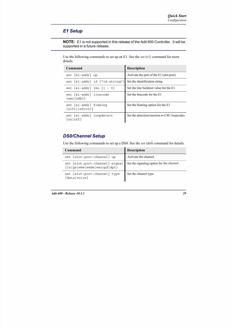
8102019 Adit 600 Quick Start 10-1-1
httpslidepdfcomreaderfulladit-600-quick-start-10-1-1 3154
Adit 600 - Release 1011 29
Quick Start Configuration
E1 Setup
NOTE E1 is not supported in this release of the Adit 600 Controller It will besupported in a future release
Use the following commands to set up an E1 See the set (e1) command for more
details
DS0Channel Setup
Use the following commands to set up a DS0 See the set (ds0) command for details
Command Description
set e1-addr up Activate the port of the E1 (slotport)
set e1-addr id id-string Set the identification string
set e1-addr lbo 1 - 9 Set the line buildout value for the E1
set e1-addr linecodeami|hdb3
Set the linecode for the E1
set e1-addr framinge1fr|lefrcrc
Set the framing option for the E1
set e1-addr loopdetecton|off
Set the detectionreaction to CSU loopcodes
Command Description
set slotportchannel up Activate the channel
set slotportchannel signalls|gs|emw|emdw|emicpd|dpt
Set the signaling option for the channel
set slotportchannel typedata|voice Set the channel type
Q i k St t
8102019 Adit 600 Quick Start 10-1-1
httpslidepdfcomreaderfulladit-600-quick-start-10-1-1 3254
30 Adit 600 - Release 1011
Quick Start Configuration
Analog Port SetupUse the following commands to set up an analog port
Command Description
set slotport up Activate the port See set (ds1) command for
details
set slotport signal dpt|gs|gsrb|gsw|gswrb|ls|lscpd|lsrb
Set the signaling option for the port See the
set (fxs) or set (fxo) command for details
set slotport rxgain n Set the receive gainloss in dB See the set
(fxs) or set (fxo) command for details
set slotport txgain n Set the transmit gainloss in dB See the set
(fxs) or set (fxo) command for details
Quick Start
8102019 Adit 600 Quick Start 10-1-1
httpslidepdfcomreaderfulladit-600-quick-start-10-1-1 3354
Adit 600 - Release 1011 31
Quick Start Configuration
4-Wire EampM SetupFor this example the 4 EampM ports will be connected to the first 4 DS0s on T1-1 (a1)
This can be changed to match the customers desired DS0 connections
For Transmission Only mode the DS0s on the DS1 should be set to data as well as the
EampM card channels
Command Description
For Normal or Tandem EampM
set a11-4 type voice Set DS0s to voice
set connect a11-4 11-4 Connect DS0s to the 4 ports of the 4-
Wire EampM card
show connect a 1 Verify cross connects
set a11-4 signal emi Set DS0 signal type to EMI
set 11-4 signal emi Set 4-Wire EampM ports signal type to
EMI
show connect a1 Verify cross connects
For TO Mode
set a11-4 type data Set DS0s to data
set 11-4 type data Set 4-Wire EampM port to data
set connect a11-4 11-4 Connect DS0s to the 4 ports of the 4-
Wire EampM card
show connect a 1 Verify cross connects
Quick Start
8102019 Adit 600 Quick Start 10-1-1
httpslidepdfcomreaderfulladit-600-quick-start-10-1-1 3454
32 Adit 600 - Release 1011
Quick Start Configuration
Establish a Static Channel ConnectionUse the following commands to establish a static channel connection
ISDN BRI Service Setup
Use the following commands to set up a ISDN BRI Service See the set (bri) command
for details
Command Description
set slotportchannel typevoice|data
Set the channel type for the channel to
map See set (ds0) command for details
set slotportchannel signalls|gs|emw|emdw|emicpd|dpt
Set the channel signaling option See set
(ds0) command for details
connect slotportslotport
Connect the channels See the connect
(card-trunk) (card-trunk) command
Command Description
set slotport up Put the ISDN line In-Service
set slot modelt3ds0|lt4to1tdm|nt3ds0
Set the ISDN mode
set slotport crv 1-768 Set the Call Reference Value Note
value must be the same as the Access
Navigator
set slotport thresholdday|hour es|ses
Set the threshold for the IDSN lines
set slot pmsyncadit|switch
Set the source for performance
monitoring synchronization
set slotport autoactivate
on|off
Only used in 4-to-1 mode Establishes
the D channel when the FDL link can not
be used
Quick Start
8102019 Adit 600 Quick Start 10-1-1
httpslidepdfcomreaderfulladit-600-quick-start-10-1-1 3554
Adit 600 - Release 1011 33
Quick Start Configuration
OCU-DP Card SetupThe following is a basic setup for the OCU-DP card
ADPCM Card Setup
Command Description
set ocudp-addr baud2400|4800|9600|19200|38400|
56000|64000
Set the OCU-DP Baud rate
Where ocudp-addr = slotport of the
OCU-DP card to apply settings to
set ocudp-addr up Set the OCU-DP port 1 up
show ocudp_card-addr Show the OCU-DP card settings
Where ocudp_card-addr = slot of the
OCU-DP card
disconnect a Disconnects all connections to slot a
(controller)
set ds0-addr type data Sets a DS0 data signaling type
connect ds0-addrocudp-addr
Connects DS0 (in previous step) to OCU-DP
port (in previous step)
show connect
(ocudp_card-addr
Displays connect information for OCU-DP
card
Command Description
Connect T1 cable to port 1 of the ADPCM service card
set adpcm_card-addrnone|map1|map2|map3
Enable compressing by selecting Map type Notenone disables compression
show (adpcm_card-addr Displays the status of the card and the mapping
connect 211-12 241-12 Set ADPCM cross-connects The example
connects all 24 channels of the ADPCM to the 12
channels of the T1 (now compressed) on port 4
This example is with map2show connect 21) Displays the connections made above
8102019 Adit 600 Quick Start 10-1-1
httpslidepdfcomreaderfulladit-600-quick-start-10-1-1 3654
Quick Start
8102019 Adit 600 Quick Start 10-1-1
httpslidepdfcomreaderfulladit-600-quick-start-10-1-1 3754
Adit 600 - Release 1011 35
QConfiguration
Upgrade the Adit 600 SoftwareUse the following commands to determine the system software level then upgrade the
software to the latest version
Command Description
status equipment Determine the system software level The
Slot A line (SW Vers) will display thecurrent software level
load tftp ip-addr file-name (or load xmodem)
Load the new controller system software See
the load tftp and load xmodem command for
more information
Note A TFTP server must be running onthe host system You can use any TFTP
server utility you wish One example isthe program TFTPD32 which can bedownloaded free-of-charge attftpd32jouninnettftpd32html
Quick Start
8102019 Adit 600 Quick Start 10-1-1
httpslidepdfcomreaderfulladit-600-quick-start-10-1-1 3854
36 Adit 600 - Release 1011
Configuration
Upgrade the Router Card SoftwareUse the following commands to determine the Router card software level then upgrade
the software to the latest version
NOTE For additional information about upgrading MSR card software see
the following manuals-Adit 600 User Manual -Adit 3000 Series and Multi-Service Router (MSR) Card GUI Reference Manual
-Adit 3000 Series and Multi-Service Router (MSR) Card CLI Reference Manual
Command Description
status equipment Determine the Router software level The
Router Slot line (SW Vers) will display thecurrent software level
load rtr_card-addr tftpip-addr file-name
Load the new Router software to a Router
card See the load tftp command for more
information
Note A TFTP server must be running onthe host system You can use any TFTP
server utility you wish One example isthe program TFTPD32 which can bedownloaded free-of-charge attftpd32jouninnettftpd32html
8102019 Adit 600 Quick Start 10-1-1
httpslidepdfcomreaderfulladit-600-quick-start-10-1-1 3954
8102019 Adit 600 Quick Start 10-1-1
httpslidepdfcomreaderfulladit-600-quick-start-10-1-1 4054
Quick Start C t ll C d LED
8102019 Adit 600 Quick Start 10-1-1
httpslidepdfcomreaderfulladit-600-quick-start-10-1-1 4154
Adit 600 - Release 1011 39
Controller Card LEDs
E1 Controller Card
NOTE E1 is not supported in this release It will be supported in a futurerelease
The E1 Controller has a set of six LEDs The table below describes each LED
LED State Description
MAJOR Off No major alarms present
Red Major alarm present
MINOR Off No minor alarms present
Yellow Minor alarms present
LOCAL Off Remote mode (DIP switches disabled)
Green Local mode (DIP switches enabled)
ACO Off Normal mode No alarms are being
suppressed
Yellow Alarm Cut Off active One or more active
alarms suppressed
E1-1 and
E1-2
Off Off line
Green Normal
Red Loss of Signal (LOS) detected
Yellow Bipolar Violation (BPV) detected LCV
Flashing Green Loopback active
Flashing Red
(slow)
Loss of Frame (LOF) or Alarm Indication
Signal (AIS) detected
Flashing Red
(fast)
Card Failure
Flashing Yellow Yellow alarm (Remote Alarm Indication)detected
Quick Start Power Supply LEDs
8102019 Adit 600 Quick Start 10-1-1
httpslidepdfcomreaderfulladit-600-quick-start-10-1-1 4254
40 Adit 600 - Release 1011
Power Supply LEDs
Power Supply LEDs115 VAC-48 VDC and 230 VAC-48 VDC Power Supplies
The power supply card has two LEDs as described in the table
below
24 VDC-48 VDC Power Supply
The power supply card has two LEDs as described in the table below
LED State Description
AC Input Off AC input missing or failure
Green AC input present
Battery Off Battery input not used
Green Battery charging or operating from DC
source only
Yellow Battery discharging
Red Battery low (less than 42V) ringer disabled
LED State Description
DC OK Off DC input missing or failure
Green DC input present
-48 Battery
Low
Off Normal
Red VDC is low (less than 42 VDC)
ringer disabled
Quick Start Service Card LEDs
8102019 Adit 600 Quick Start 10-1-1
httpslidepdfcomreaderfulladit-600-quick-start-10-1-1 4354
Adit 600 - Release 1011 41
Service Card LEDs
Service Card LEDs 4-Wire EampM Card
FXO Card
FXS Card
ISDN BRI Card
OCU-DP Card
P-Phone Card
Single Channel POTS Card
Quad DS1 ADPCM Service Card
Quad DS1E1 and Quad T1 Cards
Quad E1 Card
IP Router Card
CMG Router Card
Terminal Server Router Card
MSR Card
RS-232 and V35V54 Cards
Discontinued cards
RS-232 discontinued
Quick Start Service Card LEDs
8102019 Adit 600 Quick Start 10-1-1
httpslidepdfcomreaderfulladit-600-quick-start-10-1-1 4454
42 Adit 600 - Release 1011
Service Card LEDs
4-Wire EampM Card Each channelport has two LEDs Only the top LED is used in this application LED
definitions are listed below
State Description
When in EampM Mode
Off Channel is idle or disabled
Green Analog interface is off-hook
Red Digital interface is off-hook
Yellow Both analog and digital interfaces are off-hook or channel is
being trunk processed
When in TO Mode
Off DisconnectedGreen Connected T1E1 not in alarm
Yellow Connected T1E1 in alarm (trunk processed)
Quick Start Service Card LEDs
8102019 Adit 600 Quick Start 10-1-1
httpslidepdfcomreaderfulladit-600-quick-start-10-1-1 4554
Adit 600 - Release 1011 43
FXO Card Each port on the FXO card has its own LED as described in the table below
FXS Card
There is an LED for each port on the FXS card as described in the table below
State Loop Start
Meaning
Ground Start Meaning Dial Pulse Termination
Meaning
Off NA Idle (tip open) Idle (loop open)
Green Idle Tip ground (incoming seizure) Incoming seizure
Red NA Ring ground (outgoing
seizure)
Loop closure (outgoing seizure)
Yellow Call in
progress
Call in progress Call in progress (reverse battery)
Flashing
Green
Ringing Ringing NA
State Loop Start Meaning Ground Start Meaning
Off NA Idle (tip open)
Green Idle Tip ground (incoming seizure)
Red Note This can be seen with
Forward Disconnect (tip open)
Ring ground (outgoing seizure)
Yellow Call in progress Call in progress
Flashing green Ringing Ringing
Quick Start Service Card LEDs
8102019 Adit 600 Quick Start 10-1-1
httpslidepdfcomreaderfulladit-600-quick-start-10-1-1 4654
44 Adit 600 - Release 1011
ISDN BRI Card There is an LED for each ISDN BRI on a card as described in the table below
OCU-DP Card Each channel has two LEDs described in the table below
State Description
Off Line U-interface is attempting synchronization or BRI is Out-of-Service
Red Line alarm (LOS or self test failure)
Yellow ES or SES has occurred
Flashing yellow Line U-interface is synchronized with customer equipment but is not passing
customer data
Flashing green Line U-interface is in external loopback toward the switch at the unit
Green Normal (Line U-interface is active and transparently passing customer data)
State Description
Yellow Flickering ALL Boot Software in control
Green (walking down)
Red (walking up)
ALL Application Software in control
(repeated 35 times)
Red slow flash ALL In Boot Application flash code checksums did not match and
Boot is waiting for application download
Red ALL In Application code waiting for Controller to issue SWHW
revision request This is the first request that comes from the
OCU-DP card manager in the ControllerGreen
Yellow
Top
Bottom
Port in Self-test Duration is 5-8 seconds
Off Top
Bottom
Port is set down (Out-Of-Service)
Green Top Port is receiving valid signals
Red Top Port is receiving no signal (primary) or no frame sync
(secondary or clear channel)Red Flashing Bottom Port is receiving bipolar violations
Yellow Bottom Port is in loopback
Quick Start Service Card LEDs
8102019 Adit 600 Quick Start 10-1-1
httpslidepdfcomreaderfulladit-600-quick-start-10-1-1 4754
Adit 600 - Release 1011 45
P-Phone Card Each P-Phone channel has a corresponding LED described in the table below
State Line State
Off No P-Phone connected
Green No call in process
Flashing Green Alert (Ringing)
Yellow Call in progress
Flashing Yellow P-Phone Loopback in Progress
Flashing Red Self-test failed
Quick Start Service Card LEDs
8102019 Adit 600 Quick Start 10-1-1
httpslidepdfcomreaderfulladit-600-quick-start-10-1-1 4854
46 Adit 600 - Release 1011
Single Channel POTS Card The POTS channel LED (left) status is described in the table below
The second LED (right) is a status LED is not used on this card
Quad DS1 ADPCM Service Card
Each channel on the Quad DS1 ADPCM card has two LEDs The
description of the top LED is shown below the bottom LED is notused with this application
State Loop Start Meaning
Off Calling Party Disconnect
Green Idle
Red NA
Yellow Call in progress
Flashing green Ringing
State Description
Off Off line
Green Normal
Red Loss of Signal (LOS)
Yellow Bipolar Violation (BPV)Flashing Green Loopback active
Flashing Yellow Yellow Alarm
(Remote Alarm Indication)
Flashing Red (Slow) Loss of Frame (LOF) or Alarm Indication Signal (AIS)
Flashing Red (Fast) Self-test Failure
Top LED(active)
Bottom LED(not used)
Quick Start Service Card LEDs
8102019 Adit 600 Quick Start 10-1-1
httpslidepdfcomreaderfulladit-600-quick-start-10-1-1 4954
Adit 600 - Release 1011 47
Quad DS1E1 and Quad T1 CardsEach channel on the Quad T1E1 cards have two LEDs The description
of the top LED is shown below the bottom LED is not used with this
application
State Description
Off Off line
Green Normal
Red Loss of Signal (LOS)
Yellow Bipolar Violation (BPV)
Flashing Green Loopback active
Flashing Yellow Yellow Alarm (Remote Alarm Indication)
Flashing Red (Slow) Loss of Frame (LOF) or Alarm Indication Signal (AIS)
Flashing Red (Fast) Self-test Failure
Quick Start Service Card LEDs
8102019 Adit 600 Quick Start 10-1-1
httpslidepdfcomreaderfulladit-600-quick-start-10-1-1 5054
48 Adit 600 - Release 1011
IP Router Card The following chart describes each LED and its state
LED State Description
CRD Off Loss of power
Green No current alarms
Red Alarm state active See alarm log for cause
Red Flashing Self-test or Boot in-process
Yellow Flashing Card is saving data to flash RAM do not power down
10100 Off 10 Mb ethernet
Green 100 Mb ethernet
LNK Off No ethernet link
Green Good ethernet link
COL
Off No current ethernet transmit collisions
Yellow Ethernet collisions have occurred and have not dropped
to minimum level
Yellow Flashing Ethernet collision occurring
TX Off No ethernet transmit activity
Green Ethernet transmit activity
RX Off No current ethernet receive activity
Green Current ethernet receive activity
Quick Start Service Card LEDs
8102019 Adit 600 Quick Start 10-1-1
httpslidepdfcomreaderfulladit-600-quick-start-10-1-1 5154
Adit 600 - Release 1011 49
CMG Router Card The following chart describes each LED and its state
LED State Description
CRD Off Loss of power
Green No current alarms
Red Alarm state active See alarm log for causeRed Flashing Self-test or Boot in-process
Yellow Flashing Card is saving data to flash RAM do not power down
VOIP
Off No active VoIP calls or if the MGCP protocol is
optioned down
Green Active VoIP calls
Red Call agent unreachable
Yellow Insufficient VoIP resources to complete call
LNK Off No Ethernet link
Green Good Ethernet link
10100 Off 10 Mb Ethernet
Green 100 Mb Ethernet
TX Off No Ethernet transmit activityGreen Ethernet transmit activity
Yellow Current Ethernet transmit collision
RX Off No current Ethernet receive activity
Green Current Ethernet receive activity
Quick Start Service Card LEDs
8102019 Adit 600 Quick Start 10-1-1
httpslidepdfcomreaderfulladit-600-quick-start-10-1-1 5254
50 Adit 600 - Release 1011
Terminal Server Router Card The Terminal Server Router card has 2 LEDs per port
At Power-up
Normal Operation
Port Set for Ethernet
Top LED indicates 100M Link Bottom LED indicates 10M Link
Port Set for RS-232
TOP LED Bottom LED Description
Off Off At Power UpBoot = Loss of power
Red Red Card is inoperative
Flashing Red Flashing Red Self-test or Boot in-process
TOP LED Bottom LED Description
Green Solid (Link) Green Solid (Link) Port set for Ethernet - see below
Flashing Red Flashing Red Self-test or Boot in-process
State Description
Off No Ethernet link
Green Link but no activity
Red Flashing Current Ethernet collision
Green Flashing Current Ethernet receive
Yellow Flashing Current Ethernet transmit
TOP LED Bottom LED Description
Yellow Off No Activity
Yellow Flashing Yellow Current transmit
Yellow Flashing Green Current receive
Quick Start Service Card LEDs
8102019 Adit 600 Quick Start 10-1-1
httpslidepdfcomreaderfulladit-600-quick-start-10-1-1 5354
Adit 600 - Release 1011 51
MSR Card The following chart describes the MSR cardrsquos LEDs
LED State Description
CRD Off Loss of power
Green No current alarms
Red Alarm state active See alarm log for cause
Red Flashing Self-test or boot in process
Yellow Flashing Card is saving data to flash RAM do not power
down
VOIP
Off No SIP proxy or registration attempts for all lines
have succeeded but no calls are active
Green Active VoIP call(s)
Red Inability to reach the SIP proxy or negative response
to register attempts from all lines
Yellow Register attempts from some lines have succeeded
but not for all lines
ETH1 and
ETH2
Top LED
Off 10 Mbitsec down or not connected
Green 100 Mbitsec
ETH1 and
ETH2
Bottom LED
Off Link down
Green Link up
Flashing Green Traffic on link
Yellow Collision status
Quick Start Service Card LEDs
8102019 Adit 600 Quick Start 10-1-1
httpslidepdfcomreaderfulladit-600-quick-start-10-1-1 5454
52 Adit 600 - Release 1011
RS-232 and V35V54 Cards Each port has its own LED as described in the table below
State Description
Off No T1 Assignment
Green Normal (CDRTS) Active
Red CD inactive (T1-side failure)
Yellow RTS inactive (equipment-side failure)
Flashing Yellow Loopback toward T1 or equipment loop test
Flashing Green Loopback toward equipment or network loop test
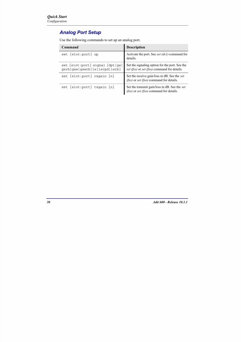
8102019 Adit 600 Quick Start 10-1-1
httpslidepdfcomreaderfulladit-600-quick-start-10-1-1 3254
30 Adit 600 - Release 1011
Quick Start Configuration
Analog Port SetupUse the following commands to set up an analog port
Command Description
set slotport up Activate the port See set (ds1) command for
details
set slotport signal dpt|gs|gsrb|gsw|gswrb|ls|lscpd|lsrb
Set the signaling option for the port See the
set (fxs) or set (fxo) command for details
set slotport rxgain n Set the receive gainloss in dB See the set
(fxs) or set (fxo) command for details
set slotport txgain n Set the transmit gainloss in dB See the set
(fxs) or set (fxo) command for details
Quick Start
8102019 Adit 600 Quick Start 10-1-1
httpslidepdfcomreaderfulladit-600-quick-start-10-1-1 3354
Adit 600 - Release 1011 31
Quick Start Configuration
4-Wire EampM SetupFor this example the 4 EampM ports will be connected to the first 4 DS0s on T1-1 (a1)
This can be changed to match the customers desired DS0 connections
For Transmission Only mode the DS0s on the DS1 should be set to data as well as the
EampM card channels
Command Description
For Normal or Tandem EampM
set a11-4 type voice Set DS0s to voice
set connect a11-4 11-4 Connect DS0s to the 4 ports of the 4-
Wire EampM card
show connect a 1 Verify cross connects
set a11-4 signal emi Set DS0 signal type to EMI
set 11-4 signal emi Set 4-Wire EampM ports signal type to
EMI
show connect a1 Verify cross connects
For TO Mode
set a11-4 type data Set DS0s to data
set 11-4 type data Set 4-Wire EampM port to data
set connect a11-4 11-4 Connect DS0s to the 4 ports of the 4-
Wire EampM card
show connect a 1 Verify cross connects
Quick Start
8102019 Adit 600 Quick Start 10-1-1
httpslidepdfcomreaderfulladit-600-quick-start-10-1-1 3454
32 Adit 600 - Release 1011
Quick Start Configuration
Establish a Static Channel ConnectionUse the following commands to establish a static channel connection
ISDN BRI Service Setup
Use the following commands to set up a ISDN BRI Service See the set (bri) command
for details
Command Description
set slotportchannel typevoice|data
Set the channel type for the channel to
map See set (ds0) command for details
set slotportchannel signalls|gs|emw|emdw|emicpd|dpt
Set the channel signaling option See set
(ds0) command for details
connect slotportslotport
Connect the channels See the connect
(card-trunk) (card-trunk) command
Command Description
set slotport up Put the ISDN line In-Service
set slot modelt3ds0|lt4to1tdm|nt3ds0
Set the ISDN mode
set slotport crv 1-768 Set the Call Reference Value Note
value must be the same as the Access
Navigator
set slotport thresholdday|hour es|ses
Set the threshold for the IDSN lines
set slot pmsyncadit|switch
Set the source for performance
monitoring synchronization
set slotport autoactivate
on|off
Only used in 4-to-1 mode Establishes
the D channel when the FDL link can not
be used
Quick Start
8102019 Adit 600 Quick Start 10-1-1
httpslidepdfcomreaderfulladit-600-quick-start-10-1-1 3554
Adit 600 - Release 1011 33
Quick Start Configuration
OCU-DP Card SetupThe following is a basic setup for the OCU-DP card
ADPCM Card Setup
Command Description
set ocudp-addr baud2400|4800|9600|19200|38400|
56000|64000
Set the OCU-DP Baud rate
Where ocudp-addr = slotport of the
OCU-DP card to apply settings to
set ocudp-addr up Set the OCU-DP port 1 up
show ocudp_card-addr Show the OCU-DP card settings
Where ocudp_card-addr = slot of the
OCU-DP card
disconnect a Disconnects all connections to slot a
(controller)
set ds0-addr type data Sets a DS0 data signaling type
connect ds0-addrocudp-addr
Connects DS0 (in previous step) to OCU-DP
port (in previous step)
show connect
(ocudp_card-addr
Displays connect information for OCU-DP
card
Command Description
Connect T1 cable to port 1 of the ADPCM service card
set adpcm_card-addrnone|map1|map2|map3
Enable compressing by selecting Map type Notenone disables compression
show (adpcm_card-addr Displays the status of the card and the mapping
connect 211-12 241-12 Set ADPCM cross-connects The example
connects all 24 channels of the ADPCM to the 12
channels of the T1 (now compressed) on port 4
This example is with map2show connect 21) Displays the connections made above
8102019 Adit 600 Quick Start 10-1-1
httpslidepdfcomreaderfulladit-600-quick-start-10-1-1 3654
Quick Start
8102019 Adit 600 Quick Start 10-1-1
httpslidepdfcomreaderfulladit-600-quick-start-10-1-1 3754
Adit 600 - Release 1011 35
QConfiguration
Upgrade the Adit 600 SoftwareUse the following commands to determine the system software level then upgrade the
software to the latest version
Command Description
status equipment Determine the system software level The
Slot A line (SW Vers) will display thecurrent software level
load tftp ip-addr file-name (or load xmodem)
Load the new controller system software See
the load tftp and load xmodem command for
more information
Note A TFTP server must be running onthe host system You can use any TFTP
server utility you wish One example isthe program TFTPD32 which can bedownloaded free-of-charge attftpd32jouninnettftpd32html
Quick Start
8102019 Adit 600 Quick Start 10-1-1
httpslidepdfcomreaderfulladit-600-quick-start-10-1-1 3854
36 Adit 600 - Release 1011
Configuration
Upgrade the Router Card SoftwareUse the following commands to determine the Router card software level then upgrade
the software to the latest version
NOTE For additional information about upgrading MSR card software see
the following manuals-Adit 600 User Manual -Adit 3000 Series and Multi-Service Router (MSR) Card GUI Reference Manual
-Adit 3000 Series and Multi-Service Router (MSR) Card CLI Reference Manual
Command Description
status equipment Determine the Router software level The
Router Slot line (SW Vers) will display thecurrent software level
load rtr_card-addr tftpip-addr file-name
Load the new Router software to a Router
card See the load tftp command for more
information
Note A TFTP server must be running onthe host system You can use any TFTP
server utility you wish One example isthe program TFTPD32 which can bedownloaded free-of-charge attftpd32jouninnettftpd32html
8102019 Adit 600 Quick Start 10-1-1
httpslidepdfcomreaderfulladit-600-quick-start-10-1-1 3954
8102019 Adit 600 Quick Start 10-1-1
httpslidepdfcomreaderfulladit-600-quick-start-10-1-1 4054
Quick Start C t ll C d LED
8102019 Adit 600 Quick Start 10-1-1
httpslidepdfcomreaderfulladit-600-quick-start-10-1-1 4154
Adit 600 - Release 1011 39
Controller Card LEDs
E1 Controller Card
NOTE E1 is not supported in this release It will be supported in a futurerelease
The E1 Controller has a set of six LEDs The table below describes each LED
LED State Description
MAJOR Off No major alarms present
Red Major alarm present
MINOR Off No minor alarms present
Yellow Minor alarms present
LOCAL Off Remote mode (DIP switches disabled)
Green Local mode (DIP switches enabled)
ACO Off Normal mode No alarms are being
suppressed
Yellow Alarm Cut Off active One or more active
alarms suppressed
E1-1 and
E1-2
Off Off line
Green Normal
Red Loss of Signal (LOS) detected
Yellow Bipolar Violation (BPV) detected LCV
Flashing Green Loopback active
Flashing Red
(slow)
Loss of Frame (LOF) or Alarm Indication
Signal (AIS) detected
Flashing Red
(fast)
Card Failure
Flashing Yellow Yellow alarm (Remote Alarm Indication)detected
Quick Start Power Supply LEDs
8102019 Adit 600 Quick Start 10-1-1
httpslidepdfcomreaderfulladit-600-quick-start-10-1-1 4254
40 Adit 600 - Release 1011
Power Supply LEDs
Power Supply LEDs115 VAC-48 VDC and 230 VAC-48 VDC Power Supplies
The power supply card has two LEDs as described in the table
below
24 VDC-48 VDC Power Supply
The power supply card has two LEDs as described in the table below
LED State Description
AC Input Off AC input missing or failure
Green AC input present
Battery Off Battery input not used
Green Battery charging or operating from DC
source only
Yellow Battery discharging
Red Battery low (less than 42V) ringer disabled
LED State Description
DC OK Off DC input missing or failure
Green DC input present
-48 Battery
Low
Off Normal
Red VDC is low (less than 42 VDC)
ringer disabled
Quick Start Service Card LEDs
8102019 Adit 600 Quick Start 10-1-1
httpslidepdfcomreaderfulladit-600-quick-start-10-1-1 4354
Adit 600 - Release 1011 41
Service Card LEDs
Service Card LEDs 4-Wire EampM Card
FXO Card
FXS Card
ISDN BRI Card
OCU-DP Card
P-Phone Card
Single Channel POTS Card
Quad DS1 ADPCM Service Card
Quad DS1E1 and Quad T1 Cards
Quad E1 Card
IP Router Card
CMG Router Card
Terminal Server Router Card
MSR Card
RS-232 and V35V54 Cards
Discontinued cards
RS-232 discontinued
Quick Start Service Card LEDs
8102019 Adit 600 Quick Start 10-1-1
httpslidepdfcomreaderfulladit-600-quick-start-10-1-1 4454
42 Adit 600 - Release 1011
Service Card LEDs
4-Wire EampM Card Each channelport has two LEDs Only the top LED is used in this application LED
definitions are listed below
State Description
When in EampM Mode
Off Channel is idle or disabled
Green Analog interface is off-hook
Red Digital interface is off-hook
Yellow Both analog and digital interfaces are off-hook or channel is
being trunk processed
When in TO Mode
Off DisconnectedGreen Connected T1E1 not in alarm
Yellow Connected T1E1 in alarm (trunk processed)
Quick Start Service Card LEDs
8102019 Adit 600 Quick Start 10-1-1
httpslidepdfcomreaderfulladit-600-quick-start-10-1-1 4554
Adit 600 - Release 1011 43
FXO Card Each port on the FXO card has its own LED as described in the table below
FXS Card
There is an LED for each port on the FXS card as described in the table below
State Loop Start
Meaning
Ground Start Meaning Dial Pulse Termination
Meaning
Off NA Idle (tip open) Idle (loop open)
Green Idle Tip ground (incoming seizure) Incoming seizure
Red NA Ring ground (outgoing
seizure)
Loop closure (outgoing seizure)
Yellow Call in
progress
Call in progress Call in progress (reverse battery)
Flashing
Green
Ringing Ringing NA
State Loop Start Meaning Ground Start Meaning
Off NA Idle (tip open)
Green Idle Tip ground (incoming seizure)
Red Note This can be seen with
Forward Disconnect (tip open)
Ring ground (outgoing seizure)
Yellow Call in progress Call in progress
Flashing green Ringing Ringing
Quick Start Service Card LEDs
8102019 Adit 600 Quick Start 10-1-1
httpslidepdfcomreaderfulladit-600-quick-start-10-1-1 4654
44 Adit 600 - Release 1011
ISDN BRI Card There is an LED for each ISDN BRI on a card as described in the table below
OCU-DP Card Each channel has two LEDs described in the table below
State Description
Off Line U-interface is attempting synchronization or BRI is Out-of-Service
Red Line alarm (LOS or self test failure)
Yellow ES or SES has occurred
Flashing yellow Line U-interface is synchronized with customer equipment but is not passing
customer data
Flashing green Line U-interface is in external loopback toward the switch at the unit
Green Normal (Line U-interface is active and transparently passing customer data)
State Description
Yellow Flickering ALL Boot Software in control
Green (walking down)
Red (walking up)
ALL Application Software in control
(repeated 35 times)
Red slow flash ALL In Boot Application flash code checksums did not match and
Boot is waiting for application download
Red ALL In Application code waiting for Controller to issue SWHW
revision request This is the first request that comes from the
OCU-DP card manager in the ControllerGreen
Yellow
Top
Bottom
Port in Self-test Duration is 5-8 seconds
Off Top
Bottom
Port is set down (Out-Of-Service)
Green Top Port is receiving valid signals
Red Top Port is receiving no signal (primary) or no frame sync
(secondary or clear channel)Red Flashing Bottom Port is receiving bipolar violations
Yellow Bottom Port is in loopback
Quick Start Service Card LEDs
8102019 Adit 600 Quick Start 10-1-1
httpslidepdfcomreaderfulladit-600-quick-start-10-1-1 4754
Adit 600 - Release 1011 45
P-Phone Card Each P-Phone channel has a corresponding LED described in the table below
State Line State
Off No P-Phone connected
Green No call in process
Flashing Green Alert (Ringing)
Yellow Call in progress
Flashing Yellow P-Phone Loopback in Progress
Flashing Red Self-test failed
Quick Start Service Card LEDs
8102019 Adit 600 Quick Start 10-1-1
httpslidepdfcomreaderfulladit-600-quick-start-10-1-1 4854
46 Adit 600 - Release 1011
Single Channel POTS Card The POTS channel LED (left) status is described in the table below
The second LED (right) is a status LED is not used on this card
Quad DS1 ADPCM Service Card
Each channel on the Quad DS1 ADPCM card has two LEDs The
description of the top LED is shown below the bottom LED is notused with this application
State Loop Start Meaning
Off Calling Party Disconnect
Green Idle
Red NA
Yellow Call in progress
Flashing green Ringing
State Description
Off Off line
Green Normal
Red Loss of Signal (LOS)
Yellow Bipolar Violation (BPV)Flashing Green Loopback active
Flashing Yellow Yellow Alarm
(Remote Alarm Indication)
Flashing Red (Slow) Loss of Frame (LOF) or Alarm Indication Signal (AIS)
Flashing Red (Fast) Self-test Failure
Top LED(active)
Bottom LED(not used)
Quick Start Service Card LEDs
8102019 Adit 600 Quick Start 10-1-1
httpslidepdfcomreaderfulladit-600-quick-start-10-1-1 4954
Adit 600 - Release 1011 47
Quad DS1E1 and Quad T1 CardsEach channel on the Quad T1E1 cards have two LEDs The description
of the top LED is shown below the bottom LED is not used with this
application
State Description
Off Off line
Green Normal
Red Loss of Signal (LOS)
Yellow Bipolar Violation (BPV)
Flashing Green Loopback active
Flashing Yellow Yellow Alarm (Remote Alarm Indication)
Flashing Red (Slow) Loss of Frame (LOF) or Alarm Indication Signal (AIS)
Flashing Red (Fast) Self-test Failure
Quick Start Service Card LEDs
8102019 Adit 600 Quick Start 10-1-1
httpslidepdfcomreaderfulladit-600-quick-start-10-1-1 5054
48 Adit 600 - Release 1011
IP Router Card The following chart describes each LED and its state
LED State Description
CRD Off Loss of power
Green No current alarms
Red Alarm state active See alarm log for cause
Red Flashing Self-test or Boot in-process
Yellow Flashing Card is saving data to flash RAM do not power down
10100 Off 10 Mb ethernet
Green 100 Mb ethernet
LNK Off No ethernet link
Green Good ethernet link
COL
Off No current ethernet transmit collisions
Yellow Ethernet collisions have occurred and have not dropped
to minimum level
Yellow Flashing Ethernet collision occurring
TX Off No ethernet transmit activity
Green Ethernet transmit activity
RX Off No current ethernet receive activity
Green Current ethernet receive activity
Quick Start Service Card LEDs
8102019 Adit 600 Quick Start 10-1-1
httpslidepdfcomreaderfulladit-600-quick-start-10-1-1 5154
Adit 600 - Release 1011 49
CMG Router Card The following chart describes each LED and its state
LED State Description
CRD Off Loss of power
Green No current alarms
Red Alarm state active See alarm log for causeRed Flashing Self-test or Boot in-process
Yellow Flashing Card is saving data to flash RAM do not power down
VOIP
Off No active VoIP calls or if the MGCP protocol is
optioned down
Green Active VoIP calls
Red Call agent unreachable
Yellow Insufficient VoIP resources to complete call
LNK Off No Ethernet link
Green Good Ethernet link
10100 Off 10 Mb Ethernet
Green 100 Mb Ethernet
TX Off No Ethernet transmit activityGreen Ethernet transmit activity
Yellow Current Ethernet transmit collision
RX Off No current Ethernet receive activity
Green Current Ethernet receive activity
Quick Start Service Card LEDs
8102019 Adit 600 Quick Start 10-1-1
httpslidepdfcomreaderfulladit-600-quick-start-10-1-1 5254
50 Adit 600 - Release 1011
Terminal Server Router Card The Terminal Server Router card has 2 LEDs per port
At Power-up
Normal Operation
Port Set for Ethernet
Top LED indicates 100M Link Bottom LED indicates 10M Link
Port Set for RS-232
TOP LED Bottom LED Description
Off Off At Power UpBoot = Loss of power
Red Red Card is inoperative
Flashing Red Flashing Red Self-test or Boot in-process
TOP LED Bottom LED Description
Green Solid (Link) Green Solid (Link) Port set for Ethernet - see below
Flashing Red Flashing Red Self-test or Boot in-process
State Description
Off No Ethernet link
Green Link but no activity
Red Flashing Current Ethernet collision
Green Flashing Current Ethernet receive
Yellow Flashing Current Ethernet transmit
TOP LED Bottom LED Description
Yellow Off No Activity
Yellow Flashing Yellow Current transmit
Yellow Flashing Green Current receive
Quick Start Service Card LEDs
8102019 Adit 600 Quick Start 10-1-1
httpslidepdfcomreaderfulladit-600-quick-start-10-1-1 5354
Adit 600 - Release 1011 51
MSR Card The following chart describes the MSR cardrsquos LEDs
LED State Description
CRD Off Loss of power
Green No current alarms
Red Alarm state active See alarm log for cause
Red Flashing Self-test or boot in process
Yellow Flashing Card is saving data to flash RAM do not power
down
VOIP
Off No SIP proxy or registration attempts for all lines
have succeeded but no calls are active
Green Active VoIP call(s)
Red Inability to reach the SIP proxy or negative response
to register attempts from all lines
Yellow Register attempts from some lines have succeeded
but not for all lines
ETH1 and
ETH2
Top LED
Off 10 Mbitsec down or not connected
Green 100 Mbitsec
ETH1 and
ETH2
Bottom LED
Off Link down
Green Link up
Flashing Green Traffic on link
Yellow Collision status
Quick Start Service Card LEDs
8102019 Adit 600 Quick Start 10-1-1
httpslidepdfcomreaderfulladit-600-quick-start-10-1-1 5454
52 Adit 600 - Release 1011
RS-232 and V35V54 Cards Each port has its own LED as described in the table below
State Description
Off No T1 Assignment
Green Normal (CDRTS) Active
Red CD inactive (T1-side failure)
Yellow RTS inactive (equipment-side failure)
Flashing Yellow Loopback toward T1 or equipment loop test
Flashing Green Loopback toward equipment or network loop test
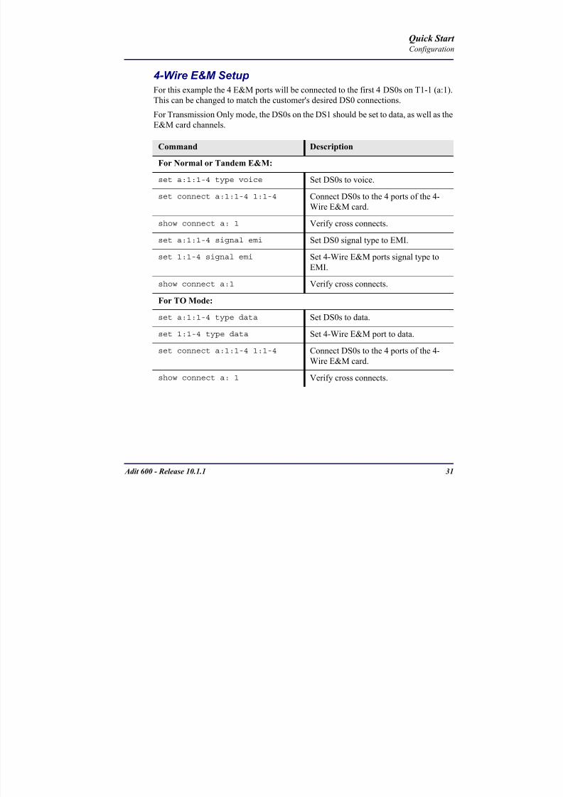
8102019 Adit 600 Quick Start 10-1-1
httpslidepdfcomreaderfulladit-600-quick-start-10-1-1 3354
Adit 600 - Release 1011 31
Quick Start Configuration
4-Wire EampM SetupFor this example the 4 EampM ports will be connected to the first 4 DS0s on T1-1 (a1)
This can be changed to match the customers desired DS0 connections
For Transmission Only mode the DS0s on the DS1 should be set to data as well as the
EampM card channels
Command Description
For Normal or Tandem EampM
set a11-4 type voice Set DS0s to voice
set connect a11-4 11-4 Connect DS0s to the 4 ports of the 4-
Wire EampM card
show connect a 1 Verify cross connects
set a11-4 signal emi Set DS0 signal type to EMI
set 11-4 signal emi Set 4-Wire EampM ports signal type to
EMI
show connect a1 Verify cross connects
For TO Mode
set a11-4 type data Set DS0s to data
set 11-4 type data Set 4-Wire EampM port to data
set connect a11-4 11-4 Connect DS0s to the 4 ports of the 4-
Wire EampM card
show connect a 1 Verify cross connects
Quick Start
8102019 Adit 600 Quick Start 10-1-1
httpslidepdfcomreaderfulladit-600-quick-start-10-1-1 3454
32 Adit 600 - Release 1011
Quick Start Configuration
Establish a Static Channel ConnectionUse the following commands to establish a static channel connection
ISDN BRI Service Setup
Use the following commands to set up a ISDN BRI Service See the set (bri) command
for details
Command Description
set slotportchannel typevoice|data
Set the channel type for the channel to
map See set (ds0) command for details
set slotportchannel signalls|gs|emw|emdw|emicpd|dpt
Set the channel signaling option See set
(ds0) command for details
connect slotportslotport
Connect the channels See the connect
(card-trunk) (card-trunk) command
Command Description
set slotport up Put the ISDN line In-Service
set slot modelt3ds0|lt4to1tdm|nt3ds0
Set the ISDN mode
set slotport crv 1-768 Set the Call Reference Value Note
value must be the same as the Access
Navigator
set slotport thresholdday|hour es|ses
Set the threshold for the IDSN lines
set slot pmsyncadit|switch
Set the source for performance
monitoring synchronization
set slotport autoactivate
on|off
Only used in 4-to-1 mode Establishes
the D channel when the FDL link can not
be used
Quick Start
8102019 Adit 600 Quick Start 10-1-1
httpslidepdfcomreaderfulladit-600-quick-start-10-1-1 3554
Adit 600 - Release 1011 33
Quick Start Configuration
OCU-DP Card SetupThe following is a basic setup for the OCU-DP card
ADPCM Card Setup
Command Description
set ocudp-addr baud2400|4800|9600|19200|38400|
56000|64000
Set the OCU-DP Baud rate
Where ocudp-addr = slotport of the
OCU-DP card to apply settings to
set ocudp-addr up Set the OCU-DP port 1 up
show ocudp_card-addr Show the OCU-DP card settings
Where ocudp_card-addr = slot of the
OCU-DP card
disconnect a Disconnects all connections to slot a
(controller)
set ds0-addr type data Sets a DS0 data signaling type
connect ds0-addrocudp-addr
Connects DS0 (in previous step) to OCU-DP
port (in previous step)
show connect
(ocudp_card-addr
Displays connect information for OCU-DP
card
Command Description
Connect T1 cable to port 1 of the ADPCM service card
set adpcm_card-addrnone|map1|map2|map3
Enable compressing by selecting Map type Notenone disables compression
show (adpcm_card-addr Displays the status of the card and the mapping
connect 211-12 241-12 Set ADPCM cross-connects The example
connects all 24 channels of the ADPCM to the 12
channels of the T1 (now compressed) on port 4
This example is with map2show connect 21) Displays the connections made above
8102019 Adit 600 Quick Start 10-1-1
httpslidepdfcomreaderfulladit-600-quick-start-10-1-1 3654
Quick Start
8102019 Adit 600 Quick Start 10-1-1
httpslidepdfcomreaderfulladit-600-quick-start-10-1-1 3754
Adit 600 - Release 1011 35
QConfiguration
Upgrade the Adit 600 SoftwareUse the following commands to determine the system software level then upgrade the
software to the latest version
Command Description
status equipment Determine the system software level The
Slot A line (SW Vers) will display thecurrent software level
load tftp ip-addr file-name (or load xmodem)
Load the new controller system software See
the load tftp and load xmodem command for
more information
Note A TFTP server must be running onthe host system You can use any TFTP
server utility you wish One example isthe program TFTPD32 which can bedownloaded free-of-charge attftpd32jouninnettftpd32html
Quick Start
8102019 Adit 600 Quick Start 10-1-1
httpslidepdfcomreaderfulladit-600-quick-start-10-1-1 3854
36 Adit 600 - Release 1011
Configuration
Upgrade the Router Card SoftwareUse the following commands to determine the Router card software level then upgrade
the software to the latest version
NOTE For additional information about upgrading MSR card software see
the following manuals-Adit 600 User Manual -Adit 3000 Series and Multi-Service Router (MSR) Card GUI Reference Manual
-Adit 3000 Series and Multi-Service Router (MSR) Card CLI Reference Manual
Command Description
status equipment Determine the Router software level The
Router Slot line (SW Vers) will display thecurrent software level
load rtr_card-addr tftpip-addr file-name
Load the new Router software to a Router
card See the load tftp command for more
information
Note A TFTP server must be running onthe host system You can use any TFTP
server utility you wish One example isthe program TFTPD32 which can bedownloaded free-of-charge attftpd32jouninnettftpd32html
8102019 Adit 600 Quick Start 10-1-1
httpslidepdfcomreaderfulladit-600-quick-start-10-1-1 3954
8102019 Adit 600 Quick Start 10-1-1
httpslidepdfcomreaderfulladit-600-quick-start-10-1-1 4054
Quick Start C t ll C d LED
8102019 Adit 600 Quick Start 10-1-1
httpslidepdfcomreaderfulladit-600-quick-start-10-1-1 4154
Adit 600 - Release 1011 39
Controller Card LEDs
E1 Controller Card
NOTE E1 is not supported in this release It will be supported in a futurerelease
The E1 Controller has a set of six LEDs The table below describes each LED
LED State Description
MAJOR Off No major alarms present
Red Major alarm present
MINOR Off No minor alarms present
Yellow Minor alarms present
LOCAL Off Remote mode (DIP switches disabled)
Green Local mode (DIP switches enabled)
ACO Off Normal mode No alarms are being
suppressed
Yellow Alarm Cut Off active One or more active
alarms suppressed
E1-1 and
E1-2
Off Off line
Green Normal
Red Loss of Signal (LOS) detected
Yellow Bipolar Violation (BPV) detected LCV
Flashing Green Loopback active
Flashing Red
(slow)
Loss of Frame (LOF) or Alarm Indication
Signal (AIS) detected
Flashing Red
(fast)
Card Failure
Flashing Yellow Yellow alarm (Remote Alarm Indication)detected
Quick Start Power Supply LEDs
8102019 Adit 600 Quick Start 10-1-1
httpslidepdfcomreaderfulladit-600-quick-start-10-1-1 4254
40 Adit 600 - Release 1011
Power Supply LEDs
Power Supply LEDs115 VAC-48 VDC and 230 VAC-48 VDC Power Supplies
The power supply card has two LEDs as described in the table
below
24 VDC-48 VDC Power Supply
The power supply card has two LEDs as described in the table below
LED State Description
AC Input Off AC input missing or failure
Green AC input present
Battery Off Battery input not used
Green Battery charging or operating from DC
source only
Yellow Battery discharging
Red Battery low (less than 42V) ringer disabled
LED State Description
DC OK Off DC input missing or failure
Green DC input present
-48 Battery
Low
Off Normal
Red VDC is low (less than 42 VDC)
ringer disabled
Quick Start Service Card LEDs
8102019 Adit 600 Quick Start 10-1-1
httpslidepdfcomreaderfulladit-600-quick-start-10-1-1 4354
Adit 600 - Release 1011 41
Service Card LEDs
Service Card LEDs 4-Wire EampM Card
FXO Card
FXS Card
ISDN BRI Card
OCU-DP Card
P-Phone Card
Single Channel POTS Card
Quad DS1 ADPCM Service Card
Quad DS1E1 and Quad T1 Cards
Quad E1 Card
IP Router Card
CMG Router Card
Terminal Server Router Card
MSR Card
RS-232 and V35V54 Cards
Discontinued cards
RS-232 discontinued
Quick Start Service Card LEDs
8102019 Adit 600 Quick Start 10-1-1
httpslidepdfcomreaderfulladit-600-quick-start-10-1-1 4454
42 Adit 600 - Release 1011
Service Card LEDs
4-Wire EampM Card Each channelport has two LEDs Only the top LED is used in this application LED
definitions are listed below
State Description
When in EampM Mode
Off Channel is idle or disabled
Green Analog interface is off-hook
Red Digital interface is off-hook
Yellow Both analog and digital interfaces are off-hook or channel is
being trunk processed
When in TO Mode
Off DisconnectedGreen Connected T1E1 not in alarm
Yellow Connected T1E1 in alarm (trunk processed)
Quick Start Service Card LEDs
8102019 Adit 600 Quick Start 10-1-1
httpslidepdfcomreaderfulladit-600-quick-start-10-1-1 4554
Adit 600 - Release 1011 43
FXO Card Each port on the FXO card has its own LED as described in the table below
FXS Card
There is an LED for each port on the FXS card as described in the table below
State Loop Start
Meaning
Ground Start Meaning Dial Pulse Termination
Meaning
Off NA Idle (tip open) Idle (loop open)
Green Idle Tip ground (incoming seizure) Incoming seizure
Red NA Ring ground (outgoing
seizure)
Loop closure (outgoing seizure)
Yellow Call in
progress
Call in progress Call in progress (reverse battery)
Flashing
Green
Ringing Ringing NA
State Loop Start Meaning Ground Start Meaning
Off NA Idle (tip open)
Green Idle Tip ground (incoming seizure)
Red Note This can be seen with
Forward Disconnect (tip open)
Ring ground (outgoing seizure)
Yellow Call in progress Call in progress
Flashing green Ringing Ringing
Quick Start Service Card LEDs
8102019 Adit 600 Quick Start 10-1-1
httpslidepdfcomreaderfulladit-600-quick-start-10-1-1 4654
44 Adit 600 - Release 1011
ISDN BRI Card There is an LED for each ISDN BRI on a card as described in the table below
OCU-DP Card Each channel has two LEDs described in the table below
State Description
Off Line U-interface is attempting synchronization or BRI is Out-of-Service
Red Line alarm (LOS or self test failure)
Yellow ES or SES has occurred
Flashing yellow Line U-interface is synchronized with customer equipment but is not passing
customer data
Flashing green Line U-interface is in external loopback toward the switch at the unit
Green Normal (Line U-interface is active and transparently passing customer data)
State Description
Yellow Flickering ALL Boot Software in control
Green (walking down)
Red (walking up)
ALL Application Software in control
(repeated 35 times)
Red slow flash ALL In Boot Application flash code checksums did not match and
Boot is waiting for application download
Red ALL In Application code waiting for Controller to issue SWHW
revision request This is the first request that comes from the
OCU-DP card manager in the ControllerGreen
Yellow
Top
Bottom
Port in Self-test Duration is 5-8 seconds
Off Top
Bottom
Port is set down (Out-Of-Service)
Green Top Port is receiving valid signals
Red Top Port is receiving no signal (primary) or no frame sync
(secondary or clear channel)Red Flashing Bottom Port is receiving bipolar violations
Yellow Bottom Port is in loopback
Quick Start Service Card LEDs
8102019 Adit 600 Quick Start 10-1-1
httpslidepdfcomreaderfulladit-600-quick-start-10-1-1 4754
Adit 600 - Release 1011 45
P-Phone Card Each P-Phone channel has a corresponding LED described in the table below
State Line State
Off No P-Phone connected
Green No call in process
Flashing Green Alert (Ringing)
Yellow Call in progress
Flashing Yellow P-Phone Loopback in Progress
Flashing Red Self-test failed
Quick Start Service Card LEDs
8102019 Adit 600 Quick Start 10-1-1
httpslidepdfcomreaderfulladit-600-quick-start-10-1-1 4854
46 Adit 600 - Release 1011
Single Channel POTS Card The POTS channel LED (left) status is described in the table below
The second LED (right) is a status LED is not used on this card
Quad DS1 ADPCM Service Card
Each channel on the Quad DS1 ADPCM card has two LEDs The
description of the top LED is shown below the bottom LED is notused with this application
State Loop Start Meaning
Off Calling Party Disconnect
Green Idle
Red NA
Yellow Call in progress
Flashing green Ringing
State Description
Off Off line
Green Normal
Red Loss of Signal (LOS)
Yellow Bipolar Violation (BPV)Flashing Green Loopback active
Flashing Yellow Yellow Alarm
(Remote Alarm Indication)
Flashing Red (Slow) Loss of Frame (LOF) or Alarm Indication Signal (AIS)
Flashing Red (Fast) Self-test Failure
Top LED(active)
Bottom LED(not used)
Quick Start Service Card LEDs
8102019 Adit 600 Quick Start 10-1-1
httpslidepdfcomreaderfulladit-600-quick-start-10-1-1 4954
Adit 600 - Release 1011 47
Quad DS1E1 and Quad T1 CardsEach channel on the Quad T1E1 cards have two LEDs The description
of the top LED is shown below the bottom LED is not used with this
application
State Description
Off Off line
Green Normal
Red Loss of Signal (LOS)
Yellow Bipolar Violation (BPV)
Flashing Green Loopback active
Flashing Yellow Yellow Alarm (Remote Alarm Indication)
Flashing Red (Slow) Loss of Frame (LOF) or Alarm Indication Signal (AIS)
Flashing Red (Fast) Self-test Failure
Quick Start Service Card LEDs
8102019 Adit 600 Quick Start 10-1-1
httpslidepdfcomreaderfulladit-600-quick-start-10-1-1 5054
48 Adit 600 - Release 1011
IP Router Card The following chart describes each LED and its state
LED State Description
CRD Off Loss of power
Green No current alarms
Red Alarm state active See alarm log for cause
Red Flashing Self-test or Boot in-process
Yellow Flashing Card is saving data to flash RAM do not power down
10100 Off 10 Mb ethernet
Green 100 Mb ethernet
LNK Off No ethernet link
Green Good ethernet link
COL
Off No current ethernet transmit collisions
Yellow Ethernet collisions have occurred and have not dropped
to minimum level
Yellow Flashing Ethernet collision occurring
TX Off No ethernet transmit activity
Green Ethernet transmit activity
RX Off No current ethernet receive activity
Green Current ethernet receive activity
Quick Start Service Card LEDs
8102019 Adit 600 Quick Start 10-1-1
httpslidepdfcomreaderfulladit-600-quick-start-10-1-1 5154
Adit 600 - Release 1011 49
CMG Router Card The following chart describes each LED and its state
LED State Description
CRD Off Loss of power
Green No current alarms
Red Alarm state active See alarm log for causeRed Flashing Self-test or Boot in-process
Yellow Flashing Card is saving data to flash RAM do not power down
VOIP
Off No active VoIP calls or if the MGCP protocol is
optioned down
Green Active VoIP calls
Red Call agent unreachable
Yellow Insufficient VoIP resources to complete call
LNK Off No Ethernet link
Green Good Ethernet link
10100 Off 10 Mb Ethernet
Green 100 Mb Ethernet
TX Off No Ethernet transmit activityGreen Ethernet transmit activity
Yellow Current Ethernet transmit collision
RX Off No current Ethernet receive activity
Green Current Ethernet receive activity
Quick Start Service Card LEDs
8102019 Adit 600 Quick Start 10-1-1
httpslidepdfcomreaderfulladit-600-quick-start-10-1-1 5254
50 Adit 600 - Release 1011
Terminal Server Router Card The Terminal Server Router card has 2 LEDs per port
At Power-up
Normal Operation
Port Set for Ethernet
Top LED indicates 100M Link Bottom LED indicates 10M Link
Port Set for RS-232
TOP LED Bottom LED Description
Off Off At Power UpBoot = Loss of power
Red Red Card is inoperative
Flashing Red Flashing Red Self-test or Boot in-process
TOP LED Bottom LED Description
Green Solid (Link) Green Solid (Link) Port set for Ethernet - see below
Flashing Red Flashing Red Self-test or Boot in-process
State Description
Off No Ethernet link
Green Link but no activity
Red Flashing Current Ethernet collision
Green Flashing Current Ethernet receive
Yellow Flashing Current Ethernet transmit
TOP LED Bottom LED Description
Yellow Off No Activity
Yellow Flashing Yellow Current transmit
Yellow Flashing Green Current receive
Quick Start Service Card LEDs
8102019 Adit 600 Quick Start 10-1-1
httpslidepdfcomreaderfulladit-600-quick-start-10-1-1 5354
Adit 600 - Release 1011 51
MSR Card The following chart describes the MSR cardrsquos LEDs
LED State Description
CRD Off Loss of power
Green No current alarms
Red Alarm state active See alarm log for cause
Red Flashing Self-test or boot in process
Yellow Flashing Card is saving data to flash RAM do not power
down
VOIP
Off No SIP proxy or registration attempts for all lines
have succeeded but no calls are active
Green Active VoIP call(s)
Red Inability to reach the SIP proxy or negative response
to register attempts from all lines
Yellow Register attempts from some lines have succeeded
but not for all lines
ETH1 and
ETH2
Top LED
Off 10 Mbitsec down or not connected
Green 100 Mbitsec
ETH1 and
ETH2
Bottom LED
Off Link down
Green Link up
Flashing Green Traffic on link
Yellow Collision status
Quick Start Service Card LEDs
8102019 Adit 600 Quick Start 10-1-1
httpslidepdfcomreaderfulladit-600-quick-start-10-1-1 5454
52 Adit 600 - Release 1011
RS-232 and V35V54 Cards Each port has its own LED as described in the table below
State Description
Off No T1 Assignment
Green Normal (CDRTS) Active
Red CD inactive (T1-side failure)
Yellow RTS inactive (equipment-side failure)
Flashing Yellow Loopback toward T1 or equipment loop test
Flashing Green Loopback toward equipment or network loop test
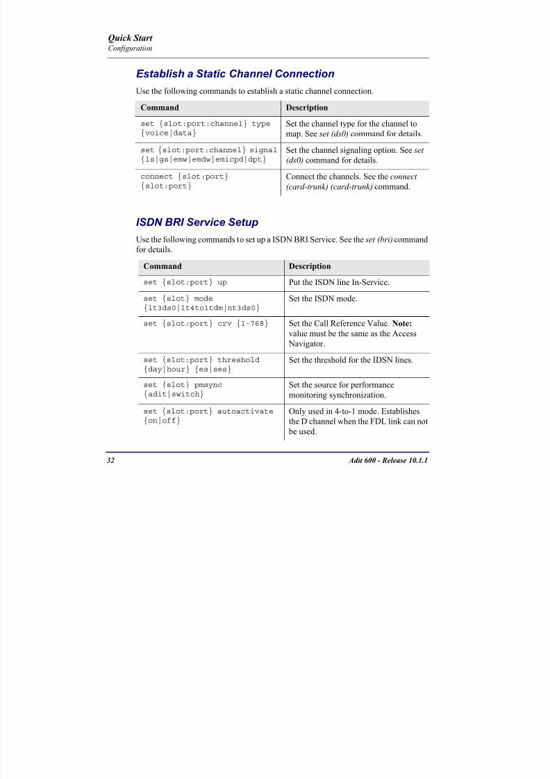
8102019 Adit 600 Quick Start 10-1-1
httpslidepdfcomreaderfulladit-600-quick-start-10-1-1 3454
32 Adit 600 - Release 1011
Quick Start Configuration
Establish a Static Channel ConnectionUse the following commands to establish a static channel connection
ISDN BRI Service Setup
Use the following commands to set up a ISDN BRI Service See the set (bri) command
for details
Command Description
set slotportchannel typevoice|data
Set the channel type for the channel to
map See set (ds0) command for details
set slotportchannel signalls|gs|emw|emdw|emicpd|dpt
Set the channel signaling option See set
(ds0) command for details
connect slotportslotport
Connect the channels See the connect
(card-trunk) (card-trunk) command
Command Description
set slotport up Put the ISDN line In-Service
set slot modelt3ds0|lt4to1tdm|nt3ds0
Set the ISDN mode
set slotport crv 1-768 Set the Call Reference Value Note
value must be the same as the Access
Navigator
set slotport thresholdday|hour es|ses
Set the threshold for the IDSN lines
set slot pmsyncadit|switch
Set the source for performance
monitoring synchronization
set slotport autoactivate
on|off
Only used in 4-to-1 mode Establishes
the D channel when the FDL link can not
be used
Quick Start
8102019 Adit 600 Quick Start 10-1-1
httpslidepdfcomreaderfulladit-600-quick-start-10-1-1 3554
Adit 600 - Release 1011 33
Quick Start Configuration
OCU-DP Card SetupThe following is a basic setup for the OCU-DP card
ADPCM Card Setup
Command Description
set ocudp-addr baud2400|4800|9600|19200|38400|
56000|64000
Set the OCU-DP Baud rate
Where ocudp-addr = slotport of the
OCU-DP card to apply settings to
set ocudp-addr up Set the OCU-DP port 1 up
show ocudp_card-addr Show the OCU-DP card settings
Where ocudp_card-addr = slot of the
OCU-DP card
disconnect a Disconnects all connections to slot a
(controller)
set ds0-addr type data Sets a DS0 data signaling type
connect ds0-addrocudp-addr
Connects DS0 (in previous step) to OCU-DP
port (in previous step)
show connect
(ocudp_card-addr
Displays connect information for OCU-DP
card
Command Description
Connect T1 cable to port 1 of the ADPCM service card
set adpcm_card-addrnone|map1|map2|map3
Enable compressing by selecting Map type Notenone disables compression
show (adpcm_card-addr Displays the status of the card and the mapping
connect 211-12 241-12 Set ADPCM cross-connects The example
connects all 24 channels of the ADPCM to the 12
channels of the T1 (now compressed) on port 4
This example is with map2show connect 21) Displays the connections made above
8102019 Adit 600 Quick Start 10-1-1
httpslidepdfcomreaderfulladit-600-quick-start-10-1-1 3654
Quick Start
8102019 Adit 600 Quick Start 10-1-1
httpslidepdfcomreaderfulladit-600-quick-start-10-1-1 3754
Adit 600 - Release 1011 35
QConfiguration
Upgrade the Adit 600 SoftwareUse the following commands to determine the system software level then upgrade the
software to the latest version
Command Description
status equipment Determine the system software level The
Slot A line (SW Vers) will display thecurrent software level
load tftp ip-addr file-name (or load xmodem)
Load the new controller system software See
the load tftp and load xmodem command for
more information
Note A TFTP server must be running onthe host system You can use any TFTP
server utility you wish One example isthe program TFTPD32 which can bedownloaded free-of-charge attftpd32jouninnettftpd32html
Quick Start
8102019 Adit 600 Quick Start 10-1-1
httpslidepdfcomreaderfulladit-600-quick-start-10-1-1 3854
36 Adit 600 - Release 1011
Configuration
Upgrade the Router Card SoftwareUse the following commands to determine the Router card software level then upgrade
the software to the latest version
NOTE For additional information about upgrading MSR card software see
the following manuals-Adit 600 User Manual -Adit 3000 Series and Multi-Service Router (MSR) Card GUI Reference Manual
-Adit 3000 Series and Multi-Service Router (MSR) Card CLI Reference Manual
Command Description
status equipment Determine the Router software level The
Router Slot line (SW Vers) will display thecurrent software level
load rtr_card-addr tftpip-addr file-name
Load the new Router software to a Router
card See the load tftp command for more
information
Note A TFTP server must be running onthe host system You can use any TFTP
server utility you wish One example isthe program TFTPD32 which can bedownloaded free-of-charge attftpd32jouninnettftpd32html
8102019 Adit 600 Quick Start 10-1-1
httpslidepdfcomreaderfulladit-600-quick-start-10-1-1 3954
8102019 Adit 600 Quick Start 10-1-1
httpslidepdfcomreaderfulladit-600-quick-start-10-1-1 4054
Quick Start C t ll C d LED
8102019 Adit 600 Quick Start 10-1-1
httpslidepdfcomreaderfulladit-600-quick-start-10-1-1 4154
Adit 600 - Release 1011 39
Controller Card LEDs
E1 Controller Card
NOTE E1 is not supported in this release It will be supported in a futurerelease
The E1 Controller has a set of six LEDs The table below describes each LED
LED State Description
MAJOR Off No major alarms present
Red Major alarm present
MINOR Off No minor alarms present
Yellow Minor alarms present
LOCAL Off Remote mode (DIP switches disabled)
Green Local mode (DIP switches enabled)
ACO Off Normal mode No alarms are being
suppressed
Yellow Alarm Cut Off active One or more active
alarms suppressed
E1-1 and
E1-2
Off Off line
Green Normal
Red Loss of Signal (LOS) detected
Yellow Bipolar Violation (BPV) detected LCV
Flashing Green Loopback active
Flashing Red
(slow)
Loss of Frame (LOF) or Alarm Indication
Signal (AIS) detected
Flashing Red
(fast)
Card Failure
Flashing Yellow Yellow alarm (Remote Alarm Indication)detected
Quick Start Power Supply LEDs
8102019 Adit 600 Quick Start 10-1-1
httpslidepdfcomreaderfulladit-600-quick-start-10-1-1 4254
40 Adit 600 - Release 1011
Power Supply LEDs
Power Supply LEDs115 VAC-48 VDC and 230 VAC-48 VDC Power Supplies
The power supply card has two LEDs as described in the table
below
24 VDC-48 VDC Power Supply
The power supply card has two LEDs as described in the table below
LED State Description
AC Input Off AC input missing or failure
Green AC input present
Battery Off Battery input not used
Green Battery charging or operating from DC
source only
Yellow Battery discharging
Red Battery low (less than 42V) ringer disabled
LED State Description
DC OK Off DC input missing or failure
Green DC input present
-48 Battery
Low
Off Normal
Red VDC is low (less than 42 VDC)
ringer disabled
Quick Start Service Card LEDs
8102019 Adit 600 Quick Start 10-1-1
httpslidepdfcomreaderfulladit-600-quick-start-10-1-1 4354
Adit 600 - Release 1011 41
Service Card LEDs
Service Card LEDs 4-Wire EampM Card
FXO Card
FXS Card
ISDN BRI Card
OCU-DP Card
P-Phone Card
Single Channel POTS Card
Quad DS1 ADPCM Service Card
Quad DS1E1 and Quad T1 Cards
Quad E1 Card
IP Router Card
CMG Router Card
Terminal Server Router Card
MSR Card
RS-232 and V35V54 Cards
Discontinued cards
RS-232 discontinued
Quick Start Service Card LEDs
8102019 Adit 600 Quick Start 10-1-1
httpslidepdfcomreaderfulladit-600-quick-start-10-1-1 4454
42 Adit 600 - Release 1011
Service Card LEDs
4-Wire EampM Card Each channelport has two LEDs Only the top LED is used in this application LED
definitions are listed below
State Description
When in EampM Mode
Off Channel is idle or disabled
Green Analog interface is off-hook
Red Digital interface is off-hook
Yellow Both analog and digital interfaces are off-hook or channel is
being trunk processed
When in TO Mode
Off DisconnectedGreen Connected T1E1 not in alarm
Yellow Connected T1E1 in alarm (trunk processed)
Quick Start Service Card LEDs
8102019 Adit 600 Quick Start 10-1-1
httpslidepdfcomreaderfulladit-600-quick-start-10-1-1 4554
Adit 600 - Release 1011 43
FXO Card Each port on the FXO card has its own LED as described in the table below
FXS Card
There is an LED for each port on the FXS card as described in the table below
State Loop Start
Meaning
Ground Start Meaning Dial Pulse Termination
Meaning
Off NA Idle (tip open) Idle (loop open)
Green Idle Tip ground (incoming seizure) Incoming seizure
Red NA Ring ground (outgoing
seizure)
Loop closure (outgoing seizure)
Yellow Call in
progress
Call in progress Call in progress (reverse battery)
Flashing
Green
Ringing Ringing NA
State Loop Start Meaning Ground Start Meaning
Off NA Idle (tip open)
Green Idle Tip ground (incoming seizure)
Red Note This can be seen with
Forward Disconnect (tip open)
Ring ground (outgoing seizure)
Yellow Call in progress Call in progress
Flashing green Ringing Ringing
Quick Start Service Card LEDs
8102019 Adit 600 Quick Start 10-1-1
httpslidepdfcomreaderfulladit-600-quick-start-10-1-1 4654
44 Adit 600 - Release 1011
ISDN BRI Card There is an LED for each ISDN BRI on a card as described in the table below
OCU-DP Card Each channel has two LEDs described in the table below
State Description
Off Line U-interface is attempting synchronization or BRI is Out-of-Service
Red Line alarm (LOS or self test failure)
Yellow ES or SES has occurred
Flashing yellow Line U-interface is synchronized with customer equipment but is not passing
customer data
Flashing green Line U-interface is in external loopback toward the switch at the unit
Green Normal (Line U-interface is active and transparently passing customer data)
State Description
Yellow Flickering ALL Boot Software in control
Green (walking down)
Red (walking up)
ALL Application Software in control
(repeated 35 times)
Red slow flash ALL In Boot Application flash code checksums did not match and
Boot is waiting for application download
Red ALL In Application code waiting for Controller to issue SWHW
revision request This is the first request that comes from the
OCU-DP card manager in the ControllerGreen
Yellow
Top
Bottom
Port in Self-test Duration is 5-8 seconds
Off Top
Bottom
Port is set down (Out-Of-Service)
Green Top Port is receiving valid signals
Red Top Port is receiving no signal (primary) or no frame sync
(secondary or clear channel)Red Flashing Bottom Port is receiving bipolar violations
Yellow Bottom Port is in loopback
Quick Start Service Card LEDs
8102019 Adit 600 Quick Start 10-1-1
httpslidepdfcomreaderfulladit-600-quick-start-10-1-1 4754
Adit 600 - Release 1011 45
P-Phone Card Each P-Phone channel has a corresponding LED described in the table below
State Line State
Off No P-Phone connected
Green No call in process
Flashing Green Alert (Ringing)
Yellow Call in progress
Flashing Yellow P-Phone Loopback in Progress
Flashing Red Self-test failed
Quick Start Service Card LEDs
8102019 Adit 600 Quick Start 10-1-1
httpslidepdfcomreaderfulladit-600-quick-start-10-1-1 4854
46 Adit 600 - Release 1011
Single Channel POTS Card The POTS channel LED (left) status is described in the table below
The second LED (right) is a status LED is not used on this card
Quad DS1 ADPCM Service Card
Each channel on the Quad DS1 ADPCM card has two LEDs The
description of the top LED is shown below the bottom LED is notused with this application
State Loop Start Meaning
Off Calling Party Disconnect
Green Idle
Red NA
Yellow Call in progress
Flashing green Ringing
State Description
Off Off line
Green Normal
Red Loss of Signal (LOS)
Yellow Bipolar Violation (BPV)Flashing Green Loopback active
Flashing Yellow Yellow Alarm
(Remote Alarm Indication)
Flashing Red (Slow) Loss of Frame (LOF) or Alarm Indication Signal (AIS)
Flashing Red (Fast) Self-test Failure
Top LED(active)
Bottom LED(not used)
Quick Start Service Card LEDs
8102019 Adit 600 Quick Start 10-1-1
httpslidepdfcomreaderfulladit-600-quick-start-10-1-1 4954
Adit 600 - Release 1011 47
Quad DS1E1 and Quad T1 CardsEach channel on the Quad T1E1 cards have two LEDs The description
of the top LED is shown below the bottom LED is not used with this
application
State Description
Off Off line
Green Normal
Red Loss of Signal (LOS)
Yellow Bipolar Violation (BPV)
Flashing Green Loopback active
Flashing Yellow Yellow Alarm (Remote Alarm Indication)
Flashing Red (Slow) Loss of Frame (LOF) or Alarm Indication Signal (AIS)
Flashing Red (Fast) Self-test Failure
Quick Start Service Card LEDs
8102019 Adit 600 Quick Start 10-1-1
httpslidepdfcomreaderfulladit-600-quick-start-10-1-1 5054
48 Adit 600 - Release 1011
IP Router Card The following chart describes each LED and its state
LED State Description
CRD Off Loss of power
Green No current alarms
Red Alarm state active See alarm log for cause
Red Flashing Self-test or Boot in-process
Yellow Flashing Card is saving data to flash RAM do not power down
10100 Off 10 Mb ethernet
Green 100 Mb ethernet
LNK Off No ethernet link
Green Good ethernet link
COL
Off No current ethernet transmit collisions
Yellow Ethernet collisions have occurred and have not dropped
to minimum level
Yellow Flashing Ethernet collision occurring
TX Off No ethernet transmit activity
Green Ethernet transmit activity
RX Off No current ethernet receive activity
Green Current ethernet receive activity
Quick Start Service Card LEDs
8102019 Adit 600 Quick Start 10-1-1
httpslidepdfcomreaderfulladit-600-quick-start-10-1-1 5154
Adit 600 - Release 1011 49
CMG Router Card The following chart describes each LED and its state
LED State Description
CRD Off Loss of power
Green No current alarms
Red Alarm state active See alarm log for causeRed Flashing Self-test or Boot in-process
Yellow Flashing Card is saving data to flash RAM do not power down
VOIP
Off No active VoIP calls or if the MGCP protocol is
optioned down
Green Active VoIP calls
Red Call agent unreachable
Yellow Insufficient VoIP resources to complete call
LNK Off No Ethernet link
Green Good Ethernet link
10100 Off 10 Mb Ethernet
Green 100 Mb Ethernet
TX Off No Ethernet transmit activityGreen Ethernet transmit activity
Yellow Current Ethernet transmit collision
RX Off No current Ethernet receive activity
Green Current Ethernet receive activity
Quick Start Service Card LEDs
8102019 Adit 600 Quick Start 10-1-1
httpslidepdfcomreaderfulladit-600-quick-start-10-1-1 5254
50 Adit 600 - Release 1011
Terminal Server Router Card The Terminal Server Router card has 2 LEDs per port
At Power-up
Normal Operation
Port Set for Ethernet
Top LED indicates 100M Link Bottom LED indicates 10M Link
Port Set for RS-232
TOP LED Bottom LED Description
Off Off At Power UpBoot = Loss of power
Red Red Card is inoperative
Flashing Red Flashing Red Self-test or Boot in-process
TOP LED Bottom LED Description
Green Solid (Link) Green Solid (Link) Port set for Ethernet - see below
Flashing Red Flashing Red Self-test or Boot in-process
State Description
Off No Ethernet link
Green Link but no activity
Red Flashing Current Ethernet collision
Green Flashing Current Ethernet receive
Yellow Flashing Current Ethernet transmit
TOP LED Bottom LED Description
Yellow Off No Activity
Yellow Flashing Yellow Current transmit
Yellow Flashing Green Current receive
Quick Start Service Card LEDs
8102019 Adit 600 Quick Start 10-1-1
httpslidepdfcomreaderfulladit-600-quick-start-10-1-1 5354
Adit 600 - Release 1011 51
MSR Card The following chart describes the MSR cardrsquos LEDs
LED State Description
CRD Off Loss of power
Green No current alarms
Red Alarm state active See alarm log for cause
Red Flashing Self-test or boot in process
Yellow Flashing Card is saving data to flash RAM do not power
down
VOIP
Off No SIP proxy or registration attempts for all lines
have succeeded but no calls are active
Green Active VoIP call(s)
Red Inability to reach the SIP proxy or negative response
to register attempts from all lines
Yellow Register attempts from some lines have succeeded
but not for all lines
ETH1 and
ETH2
Top LED
Off 10 Mbitsec down or not connected
Green 100 Mbitsec
ETH1 and
ETH2
Bottom LED
Off Link down
Green Link up
Flashing Green Traffic on link
Yellow Collision status
Quick Start Service Card LEDs
8102019 Adit 600 Quick Start 10-1-1
httpslidepdfcomreaderfulladit-600-quick-start-10-1-1 5454
52 Adit 600 - Release 1011
RS-232 and V35V54 Cards Each port has its own LED as described in the table below
State Description
Off No T1 Assignment
Green Normal (CDRTS) Active
Red CD inactive (T1-side failure)
Yellow RTS inactive (equipment-side failure)
Flashing Yellow Loopback toward T1 or equipment loop test
Flashing Green Loopback toward equipment or network loop test
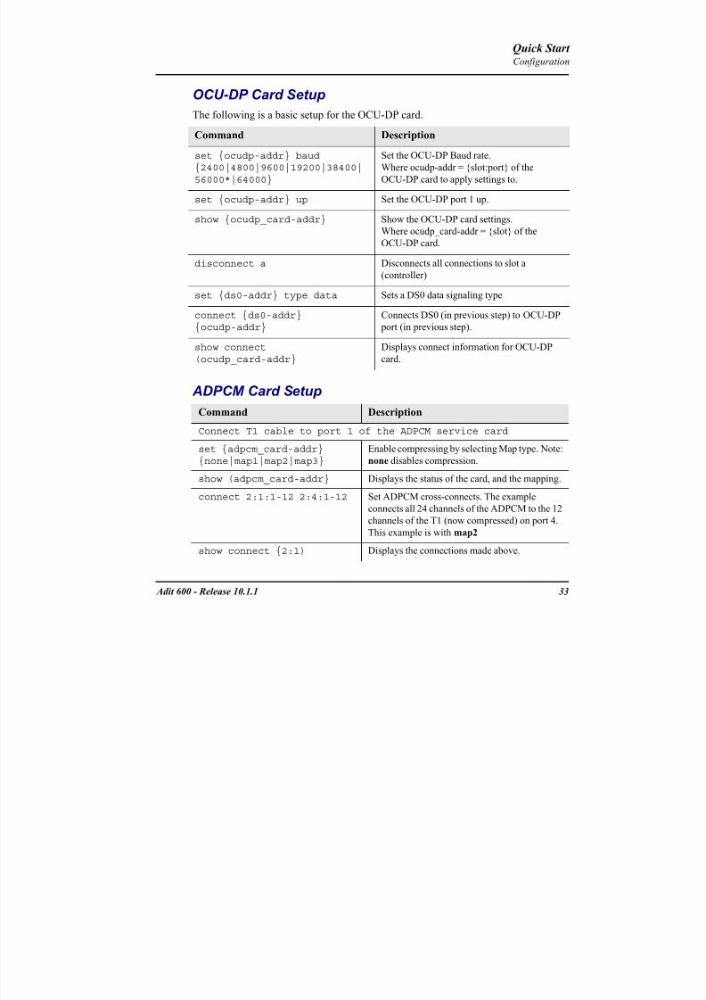
8102019 Adit 600 Quick Start 10-1-1
httpslidepdfcomreaderfulladit-600-quick-start-10-1-1 3654
Quick Start
8102019 Adit 600 Quick Start 10-1-1
httpslidepdfcomreaderfulladit-600-quick-start-10-1-1 3754
Adit 600 - Release 1011 35
QConfiguration
Upgrade the Adit 600 SoftwareUse the following commands to determine the system software level then upgrade the
software to the latest version
Command Description
status equipment Determine the system software level The
Slot A line (SW Vers) will display thecurrent software level
load tftp ip-addr file-name (or load xmodem)
Load the new controller system software See
the load tftp and load xmodem command for
more information
Note A TFTP server must be running onthe host system You can use any TFTP
server utility you wish One example isthe program TFTPD32 which can bedownloaded free-of-charge attftpd32jouninnettftpd32html
Quick Start
8102019 Adit 600 Quick Start 10-1-1
httpslidepdfcomreaderfulladit-600-quick-start-10-1-1 3854
36 Adit 600 - Release 1011
Configuration
Upgrade the Router Card SoftwareUse the following commands to determine the Router card software level then upgrade
the software to the latest version
NOTE For additional information about upgrading MSR card software see
the following manuals-Adit 600 User Manual -Adit 3000 Series and Multi-Service Router (MSR) Card GUI Reference Manual
-Adit 3000 Series and Multi-Service Router (MSR) Card CLI Reference Manual
Command Description
status equipment Determine the Router software level The
Router Slot line (SW Vers) will display thecurrent software level
load rtr_card-addr tftpip-addr file-name
Load the new Router software to a Router
card See the load tftp command for more
information
Note A TFTP server must be running onthe host system You can use any TFTP
server utility you wish One example isthe program TFTPD32 which can bedownloaded free-of-charge attftpd32jouninnettftpd32html
8102019 Adit 600 Quick Start 10-1-1
httpslidepdfcomreaderfulladit-600-quick-start-10-1-1 3954
8102019 Adit 600 Quick Start 10-1-1
httpslidepdfcomreaderfulladit-600-quick-start-10-1-1 4054
Quick Start C t ll C d LED
8102019 Adit 600 Quick Start 10-1-1
httpslidepdfcomreaderfulladit-600-quick-start-10-1-1 4154
Adit 600 - Release 1011 39
Controller Card LEDs
E1 Controller Card
NOTE E1 is not supported in this release It will be supported in a futurerelease
The E1 Controller has a set of six LEDs The table below describes each LED
LED State Description
MAJOR Off No major alarms present
Red Major alarm present
MINOR Off No minor alarms present
Yellow Minor alarms present
LOCAL Off Remote mode (DIP switches disabled)
Green Local mode (DIP switches enabled)
ACO Off Normal mode No alarms are being
suppressed
Yellow Alarm Cut Off active One or more active
alarms suppressed
E1-1 and
E1-2
Off Off line
Green Normal
Red Loss of Signal (LOS) detected
Yellow Bipolar Violation (BPV) detected LCV
Flashing Green Loopback active
Flashing Red
(slow)
Loss of Frame (LOF) or Alarm Indication
Signal (AIS) detected
Flashing Red
(fast)
Card Failure
Flashing Yellow Yellow alarm (Remote Alarm Indication)detected
Quick Start Power Supply LEDs
8102019 Adit 600 Quick Start 10-1-1
httpslidepdfcomreaderfulladit-600-quick-start-10-1-1 4254
40 Adit 600 - Release 1011
Power Supply LEDs
Power Supply LEDs115 VAC-48 VDC and 230 VAC-48 VDC Power Supplies
The power supply card has two LEDs as described in the table
below
24 VDC-48 VDC Power Supply
The power supply card has two LEDs as described in the table below
LED State Description
AC Input Off AC input missing or failure
Green AC input present
Battery Off Battery input not used
Green Battery charging or operating from DC
source only
Yellow Battery discharging
Red Battery low (less than 42V) ringer disabled
LED State Description
DC OK Off DC input missing or failure
Green DC input present
-48 Battery
Low
Off Normal
Red VDC is low (less than 42 VDC)
ringer disabled
Quick Start Service Card LEDs
8102019 Adit 600 Quick Start 10-1-1
httpslidepdfcomreaderfulladit-600-quick-start-10-1-1 4354
Adit 600 - Release 1011 41
Service Card LEDs
Service Card LEDs 4-Wire EampM Card
FXO Card
FXS Card
ISDN BRI Card
OCU-DP Card
P-Phone Card
Single Channel POTS Card
Quad DS1 ADPCM Service Card
Quad DS1E1 and Quad T1 Cards
Quad E1 Card
IP Router Card
CMG Router Card
Terminal Server Router Card
MSR Card
RS-232 and V35V54 Cards
Discontinued cards
RS-232 discontinued
Quick Start Service Card LEDs
8102019 Adit 600 Quick Start 10-1-1
httpslidepdfcomreaderfulladit-600-quick-start-10-1-1 4454
42 Adit 600 - Release 1011
Service Card LEDs
4-Wire EampM Card Each channelport has two LEDs Only the top LED is used in this application LED
definitions are listed below
State Description
When in EampM Mode
Off Channel is idle or disabled
Green Analog interface is off-hook
Red Digital interface is off-hook
Yellow Both analog and digital interfaces are off-hook or channel is
being trunk processed
When in TO Mode
Off DisconnectedGreen Connected T1E1 not in alarm
Yellow Connected T1E1 in alarm (trunk processed)
Quick Start Service Card LEDs
8102019 Adit 600 Quick Start 10-1-1
httpslidepdfcomreaderfulladit-600-quick-start-10-1-1 4554
Adit 600 - Release 1011 43
FXO Card Each port on the FXO card has its own LED as described in the table below
FXS Card
There is an LED for each port on the FXS card as described in the table below
State Loop Start
Meaning
Ground Start Meaning Dial Pulse Termination
Meaning
Off NA Idle (tip open) Idle (loop open)
Green Idle Tip ground (incoming seizure) Incoming seizure
Red NA Ring ground (outgoing
seizure)
Loop closure (outgoing seizure)
Yellow Call in
progress
Call in progress Call in progress (reverse battery)
Flashing
Green
Ringing Ringing NA
State Loop Start Meaning Ground Start Meaning
Off NA Idle (tip open)
Green Idle Tip ground (incoming seizure)
Red Note This can be seen with
Forward Disconnect (tip open)
Ring ground (outgoing seizure)
Yellow Call in progress Call in progress
Flashing green Ringing Ringing
Quick Start Service Card LEDs
8102019 Adit 600 Quick Start 10-1-1
httpslidepdfcomreaderfulladit-600-quick-start-10-1-1 4654
44 Adit 600 - Release 1011
ISDN BRI Card There is an LED for each ISDN BRI on a card as described in the table below
OCU-DP Card Each channel has two LEDs described in the table below
State Description
Off Line U-interface is attempting synchronization or BRI is Out-of-Service
Red Line alarm (LOS or self test failure)
Yellow ES or SES has occurred
Flashing yellow Line U-interface is synchronized with customer equipment but is not passing
customer data
Flashing green Line U-interface is in external loopback toward the switch at the unit
Green Normal (Line U-interface is active and transparently passing customer data)
State Description
Yellow Flickering ALL Boot Software in control
Green (walking down)
Red (walking up)
ALL Application Software in control
(repeated 35 times)
Red slow flash ALL In Boot Application flash code checksums did not match and
Boot is waiting for application download
Red ALL In Application code waiting for Controller to issue SWHW
revision request This is the first request that comes from the
OCU-DP card manager in the ControllerGreen
Yellow
Top
Bottom
Port in Self-test Duration is 5-8 seconds
Off Top
Bottom
Port is set down (Out-Of-Service)
Green Top Port is receiving valid signals
Red Top Port is receiving no signal (primary) or no frame sync
(secondary or clear channel)Red Flashing Bottom Port is receiving bipolar violations
Yellow Bottom Port is in loopback
Quick Start Service Card LEDs
8102019 Adit 600 Quick Start 10-1-1
httpslidepdfcomreaderfulladit-600-quick-start-10-1-1 4754
Adit 600 - Release 1011 45
P-Phone Card Each P-Phone channel has a corresponding LED described in the table below
State Line State
Off No P-Phone connected
Green No call in process
Flashing Green Alert (Ringing)
Yellow Call in progress
Flashing Yellow P-Phone Loopback in Progress
Flashing Red Self-test failed
Quick Start Service Card LEDs
8102019 Adit 600 Quick Start 10-1-1
httpslidepdfcomreaderfulladit-600-quick-start-10-1-1 4854
46 Adit 600 - Release 1011
Single Channel POTS Card The POTS channel LED (left) status is described in the table below
The second LED (right) is a status LED is not used on this card
Quad DS1 ADPCM Service Card
Each channel on the Quad DS1 ADPCM card has two LEDs The
description of the top LED is shown below the bottom LED is notused with this application
State Loop Start Meaning
Off Calling Party Disconnect
Green Idle
Red NA
Yellow Call in progress
Flashing green Ringing
State Description
Off Off line
Green Normal
Red Loss of Signal (LOS)
Yellow Bipolar Violation (BPV)Flashing Green Loopback active
Flashing Yellow Yellow Alarm
(Remote Alarm Indication)
Flashing Red (Slow) Loss of Frame (LOF) or Alarm Indication Signal (AIS)
Flashing Red (Fast) Self-test Failure
Top LED(active)
Bottom LED(not used)
Quick Start Service Card LEDs
8102019 Adit 600 Quick Start 10-1-1
httpslidepdfcomreaderfulladit-600-quick-start-10-1-1 4954
Adit 600 - Release 1011 47
Quad DS1E1 and Quad T1 CardsEach channel on the Quad T1E1 cards have two LEDs The description
of the top LED is shown below the bottom LED is not used with this
application
State Description
Off Off line
Green Normal
Red Loss of Signal (LOS)
Yellow Bipolar Violation (BPV)
Flashing Green Loopback active
Flashing Yellow Yellow Alarm (Remote Alarm Indication)
Flashing Red (Slow) Loss of Frame (LOF) or Alarm Indication Signal (AIS)
Flashing Red (Fast) Self-test Failure
Quick Start Service Card LEDs
8102019 Adit 600 Quick Start 10-1-1
httpslidepdfcomreaderfulladit-600-quick-start-10-1-1 5054
48 Adit 600 - Release 1011
IP Router Card The following chart describes each LED and its state
LED State Description
CRD Off Loss of power
Green No current alarms
Red Alarm state active See alarm log for cause
Red Flashing Self-test or Boot in-process
Yellow Flashing Card is saving data to flash RAM do not power down
10100 Off 10 Mb ethernet
Green 100 Mb ethernet
LNK Off No ethernet link
Green Good ethernet link
COL
Off No current ethernet transmit collisions
Yellow Ethernet collisions have occurred and have not dropped
to minimum level
Yellow Flashing Ethernet collision occurring
TX Off No ethernet transmit activity
Green Ethernet transmit activity
RX Off No current ethernet receive activity
Green Current ethernet receive activity
Quick Start Service Card LEDs
8102019 Adit 600 Quick Start 10-1-1
httpslidepdfcomreaderfulladit-600-quick-start-10-1-1 5154
Adit 600 - Release 1011 49
CMG Router Card The following chart describes each LED and its state
LED State Description
CRD Off Loss of power
Green No current alarms
Red Alarm state active See alarm log for causeRed Flashing Self-test or Boot in-process
Yellow Flashing Card is saving data to flash RAM do not power down
VOIP
Off No active VoIP calls or if the MGCP protocol is
optioned down
Green Active VoIP calls
Red Call agent unreachable
Yellow Insufficient VoIP resources to complete call
LNK Off No Ethernet link
Green Good Ethernet link
10100 Off 10 Mb Ethernet
Green 100 Mb Ethernet
TX Off No Ethernet transmit activityGreen Ethernet transmit activity
Yellow Current Ethernet transmit collision
RX Off No current Ethernet receive activity
Green Current Ethernet receive activity
Quick Start Service Card LEDs
8102019 Adit 600 Quick Start 10-1-1
httpslidepdfcomreaderfulladit-600-quick-start-10-1-1 5254
50 Adit 600 - Release 1011
Terminal Server Router Card The Terminal Server Router card has 2 LEDs per port
At Power-up
Normal Operation
Port Set for Ethernet
Top LED indicates 100M Link Bottom LED indicates 10M Link
Port Set for RS-232
TOP LED Bottom LED Description
Off Off At Power UpBoot = Loss of power
Red Red Card is inoperative
Flashing Red Flashing Red Self-test or Boot in-process
TOP LED Bottom LED Description
Green Solid (Link) Green Solid (Link) Port set for Ethernet - see below
Flashing Red Flashing Red Self-test or Boot in-process
State Description
Off No Ethernet link
Green Link but no activity
Red Flashing Current Ethernet collision
Green Flashing Current Ethernet receive
Yellow Flashing Current Ethernet transmit
TOP LED Bottom LED Description
Yellow Off No Activity
Yellow Flashing Yellow Current transmit
Yellow Flashing Green Current receive
Quick Start Service Card LEDs
8102019 Adit 600 Quick Start 10-1-1
httpslidepdfcomreaderfulladit-600-quick-start-10-1-1 5354
Adit 600 - Release 1011 51
MSR Card The following chart describes the MSR cardrsquos LEDs
LED State Description
CRD Off Loss of power
Green No current alarms
Red Alarm state active See alarm log for cause
Red Flashing Self-test or boot in process
Yellow Flashing Card is saving data to flash RAM do not power
down
VOIP
Off No SIP proxy or registration attempts for all lines
have succeeded but no calls are active
Green Active VoIP call(s)
Red Inability to reach the SIP proxy or negative response
to register attempts from all lines
Yellow Register attempts from some lines have succeeded
but not for all lines
ETH1 and
ETH2
Top LED
Off 10 Mbitsec down or not connected
Green 100 Mbitsec
ETH1 and
ETH2
Bottom LED
Off Link down
Green Link up
Flashing Green Traffic on link
Yellow Collision status
Quick Start Service Card LEDs
8102019 Adit 600 Quick Start 10-1-1
httpslidepdfcomreaderfulladit-600-quick-start-10-1-1 5454
52 Adit 600 - Release 1011
RS-232 and V35V54 Cards Each port has its own LED as described in the table below
State Description
Off No T1 Assignment
Green Normal (CDRTS) Active
Red CD inactive (T1-side failure)
Yellow RTS inactive (equipment-side failure)
Flashing Yellow Loopback toward T1 or equipment loop test
Flashing Green Loopback toward equipment or network loop test
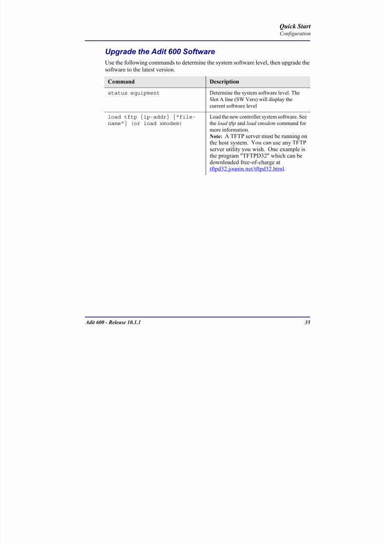
8102019 Adit 600 Quick Start 10-1-1
httpslidepdfcomreaderfulladit-600-quick-start-10-1-1 3754
Adit 600 - Release 1011 35
QConfiguration
Upgrade the Adit 600 SoftwareUse the following commands to determine the system software level then upgrade the
software to the latest version
Command Description
status equipment Determine the system software level The
Slot A line (SW Vers) will display thecurrent software level
load tftp ip-addr file-name (or load xmodem)
Load the new controller system software See
the load tftp and load xmodem command for
more information
Note A TFTP server must be running onthe host system You can use any TFTP
server utility you wish One example isthe program TFTPD32 which can bedownloaded free-of-charge attftpd32jouninnettftpd32html
Quick Start
8102019 Adit 600 Quick Start 10-1-1
httpslidepdfcomreaderfulladit-600-quick-start-10-1-1 3854
36 Adit 600 - Release 1011
Configuration
Upgrade the Router Card SoftwareUse the following commands to determine the Router card software level then upgrade
the software to the latest version
NOTE For additional information about upgrading MSR card software see
the following manuals-Adit 600 User Manual -Adit 3000 Series and Multi-Service Router (MSR) Card GUI Reference Manual
-Adit 3000 Series and Multi-Service Router (MSR) Card CLI Reference Manual
Command Description
status equipment Determine the Router software level The
Router Slot line (SW Vers) will display thecurrent software level
load rtr_card-addr tftpip-addr file-name
Load the new Router software to a Router
card See the load tftp command for more
information
Note A TFTP server must be running onthe host system You can use any TFTP
server utility you wish One example isthe program TFTPD32 which can bedownloaded free-of-charge attftpd32jouninnettftpd32html
8102019 Adit 600 Quick Start 10-1-1
httpslidepdfcomreaderfulladit-600-quick-start-10-1-1 3954
8102019 Adit 600 Quick Start 10-1-1
httpslidepdfcomreaderfulladit-600-quick-start-10-1-1 4054
Quick Start C t ll C d LED
8102019 Adit 600 Quick Start 10-1-1
httpslidepdfcomreaderfulladit-600-quick-start-10-1-1 4154
Adit 600 - Release 1011 39
Controller Card LEDs
E1 Controller Card
NOTE E1 is not supported in this release It will be supported in a futurerelease
The E1 Controller has a set of six LEDs The table below describes each LED
LED State Description
MAJOR Off No major alarms present
Red Major alarm present
MINOR Off No minor alarms present
Yellow Minor alarms present
LOCAL Off Remote mode (DIP switches disabled)
Green Local mode (DIP switches enabled)
ACO Off Normal mode No alarms are being
suppressed
Yellow Alarm Cut Off active One or more active
alarms suppressed
E1-1 and
E1-2
Off Off line
Green Normal
Red Loss of Signal (LOS) detected
Yellow Bipolar Violation (BPV) detected LCV
Flashing Green Loopback active
Flashing Red
(slow)
Loss of Frame (LOF) or Alarm Indication
Signal (AIS) detected
Flashing Red
(fast)
Card Failure
Flashing Yellow Yellow alarm (Remote Alarm Indication)detected
Quick Start Power Supply LEDs
8102019 Adit 600 Quick Start 10-1-1
httpslidepdfcomreaderfulladit-600-quick-start-10-1-1 4254
40 Adit 600 - Release 1011
Power Supply LEDs
Power Supply LEDs115 VAC-48 VDC and 230 VAC-48 VDC Power Supplies
The power supply card has two LEDs as described in the table
below
24 VDC-48 VDC Power Supply
The power supply card has two LEDs as described in the table below
LED State Description
AC Input Off AC input missing or failure
Green AC input present
Battery Off Battery input not used
Green Battery charging or operating from DC
source only
Yellow Battery discharging
Red Battery low (less than 42V) ringer disabled
LED State Description
DC OK Off DC input missing or failure
Green DC input present
-48 Battery
Low
Off Normal
Red VDC is low (less than 42 VDC)
ringer disabled
Quick Start Service Card LEDs
8102019 Adit 600 Quick Start 10-1-1
httpslidepdfcomreaderfulladit-600-quick-start-10-1-1 4354
Adit 600 - Release 1011 41
Service Card LEDs
Service Card LEDs 4-Wire EampM Card
FXO Card
FXS Card
ISDN BRI Card
OCU-DP Card
P-Phone Card
Single Channel POTS Card
Quad DS1 ADPCM Service Card
Quad DS1E1 and Quad T1 Cards
Quad E1 Card
IP Router Card
CMG Router Card
Terminal Server Router Card
MSR Card
RS-232 and V35V54 Cards
Discontinued cards
RS-232 discontinued
Quick Start Service Card LEDs
8102019 Adit 600 Quick Start 10-1-1
httpslidepdfcomreaderfulladit-600-quick-start-10-1-1 4454
42 Adit 600 - Release 1011
Service Card LEDs
4-Wire EampM Card Each channelport has two LEDs Only the top LED is used in this application LED
definitions are listed below
State Description
When in EampM Mode
Off Channel is idle or disabled
Green Analog interface is off-hook
Red Digital interface is off-hook
Yellow Both analog and digital interfaces are off-hook or channel is
being trunk processed
When in TO Mode
Off DisconnectedGreen Connected T1E1 not in alarm
Yellow Connected T1E1 in alarm (trunk processed)
Quick Start Service Card LEDs
8102019 Adit 600 Quick Start 10-1-1
httpslidepdfcomreaderfulladit-600-quick-start-10-1-1 4554
Adit 600 - Release 1011 43
FXO Card Each port on the FXO card has its own LED as described in the table below
FXS Card
There is an LED for each port on the FXS card as described in the table below
State Loop Start
Meaning
Ground Start Meaning Dial Pulse Termination
Meaning
Off NA Idle (tip open) Idle (loop open)
Green Idle Tip ground (incoming seizure) Incoming seizure
Red NA Ring ground (outgoing
seizure)
Loop closure (outgoing seizure)
Yellow Call in
progress
Call in progress Call in progress (reverse battery)
Flashing
Green
Ringing Ringing NA
State Loop Start Meaning Ground Start Meaning
Off NA Idle (tip open)
Green Idle Tip ground (incoming seizure)
Red Note This can be seen with
Forward Disconnect (tip open)
Ring ground (outgoing seizure)
Yellow Call in progress Call in progress
Flashing green Ringing Ringing
Quick Start Service Card LEDs
8102019 Adit 600 Quick Start 10-1-1
httpslidepdfcomreaderfulladit-600-quick-start-10-1-1 4654
44 Adit 600 - Release 1011
ISDN BRI Card There is an LED for each ISDN BRI on a card as described in the table below
OCU-DP Card Each channel has two LEDs described in the table below
State Description
Off Line U-interface is attempting synchronization or BRI is Out-of-Service
Red Line alarm (LOS or self test failure)
Yellow ES or SES has occurred
Flashing yellow Line U-interface is synchronized with customer equipment but is not passing
customer data
Flashing green Line U-interface is in external loopback toward the switch at the unit
Green Normal (Line U-interface is active and transparently passing customer data)
State Description
Yellow Flickering ALL Boot Software in control
Green (walking down)
Red (walking up)
ALL Application Software in control
(repeated 35 times)
Red slow flash ALL In Boot Application flash code checksums did not match and
Boot is waiting for application download
Red ALL In Application code waiting for Controller to issue SWHW
revision request This is the first request that comes from the
OCU-DP card manager in the ControllerGreen
Yellow
Top
Bottom
Port in Self-test Duration is 5-8 seconds
Off Top
Bottom
Port is set down (Out-Of-Service)
Green Top Port is receiving valid signals
Red Top Port is receiving no signal (primary) or no frame sync
(secondary or clear channel)Red Flashing Bottom Port is receiving bipolar violations
Yellow Bottom Port is in loopback
Quick Start Service Card LEDs
8102019 Adit 600 Quick Start 10-1-1
httpslidepdfcomreaderfulladit-600-quick-start-10-1-1 4754
Adit 600 - Release 1011 45
P-Phone Card Each P-Phone channel has a corresponding LED described in the table below
State Line State
Off No P-Phone connected
Green No call in process
Flashing Green Alert (Ringing)
Yellow Call in progress
Flashing Yellow P-Phone Loopback in Progress
Flashing Red Self-test failed
Quick Start Service Card LEDs
8102019 Adit 600 Quick Start 10-1-1
httpslidepdfcomreaderfulladit-600-quick-start-10-1-1 4854
46 Adit 600 - Release 1011
Single Channel POTS Card The POTS channel LED (left) status is described in the table below
The second LED (right) is a status LED is not used on this card
Quad DS1 ADPCM Service Card
Each channel on the Quad DS1 ADPCM card has two LEDs The
description of the top LED is shown below the bottom LED is notused with this application
State Loop Start Meaning
Off Calling Party Disconnect
Green Idle
Red NA
Yellow Call in progress
Flashing green Ringing
State Description
Off Off line
Green Normal
Red Loss of Signal (LOS)
Yellow Bipolar Violation (BPV)Flashing Green Loopback active
Flashing Yellow Yellow Alarm
(Remote Alarm Indication)
Flashing Red (Slow) Loss of Frame (LOF) or Alarm Indication Signal (AIS)
Flashing Red (Fast) Self-test Failure
Top LED(active)
Bottom LED(not used)
Quick Start Service Card LEDs
8102019 Adit 600 Quick Start 10-1-1
httpslidepdfcomreaderfulladit-600-quick-start-10-1-1 4954
Adit 600 - Release 1011 47
Quad DS1E1 and Quad T1 CardsEach channel on the Quad T1E1 cards have two LEDs The description
of the top LED is shown below the bottom LED is not used with this
application
State Description
Off Off line
Green Normal
Red Loss of Signal (LOS)
Yellow Bipolar Violation (BPV)
Flashing Green Loopback active
Flashing Yellow Yellow Alarm (Remote Alarm Indication)
Flashing Red (Slow) Loss of Frame (LOF) or Alarm Indication Signal (AIS)
Flashing Red (Fast) Self-test Failure
Quick Start Service Card LEDs
8102019 Adit 600 Quick Start 10-1-1
httpslidepdfcomreaderfulladit-600-quick-start-10-1-1 5054
48 Adit 600 - Release 1011
IP Router Card The following chart describes each LED and its state
LED State Description
CRD Off Loss of power
Green No current alarms
Red Alarm state active See alarm log for cause
Red Flashing Self-test or Boot in-process
Yellow Flashing Card is saving data to flash RAM do not power down
10100 Off 10 Mb ethernet
Green 100 Mb ethernet
LNK Off No ethernet link
Green Good ethernet link
COL
Off No current ethernet transmit collisions
Yellow Ethernet collisions have occurred and have not dropped
to minimum level
Yellow Flashing Ethernet collision occurring
TX Off No ethernet transmit activity
Green Ethernet transmit activity
RX Off No current ethernet receive activity
Green Current ethernet receive activity
Quick Start Service Card LEDs
8102019 Adit 600 Quick Start 10-1-1
httpslidepdfcomreaderfulladit-600-quick-start-10-1-1 5154
Adit 600 - Release 1011 49
CMG Router Card The following chart describes each LED and its state
LED State Description
CRD Off Loss of power
Green No current alarms
Red Alarm state active See alarm log for causeRed Flashing Self-test or Boot in-process
Yellow Flashing Card is saving data to flash RAM do not power down
VOIP
Off No active VoIP calls or if the MGCP protocol is
optioned down
Green Active VoIP calls
Red Call agent unreachable
Yellow Insufficient VoIP resources to complete call
LNK Off No Ethernet link
Green Good Ethernet link
10100 Off 10 Mb Ethernet
Green 100 Mb Ethernet
TX Off No Ethernet transmit activityGreen Ethernet transmit activity
Yellow Current Ethernet transmit collision
RX Off No current Ethernet receive activity
Green Current Ethernet receive activity
Quick Start Service Card LEDs
8102019 Adit 600 Quick Start 10-1-1
httpslidepdfcomreaderfulladit-600-quick-start-10-1-1 5254
50 Adit 600 - Release 1011
Terminal Server Router Card The Terminal Server Router card has 2 LEDs per port
At Power-up
Normal Operation
Port Set for Ethernet
Top LED indicates 100M Link Bottom LED indicates 10M Link
Port Set for RS-232
TOP LED Bottom LED Description
Off Off At Power UpBoot = Loss of power
Red Red Card is inoperative
Flashing Red Flashing Red Self-test or Boot in-process
TOP LED Bottom LED Description
Green Solid (Link) Green Solid (Link) Port set for Ethernet - see below
Flashing Red Flashing Red Self-test or Boot in-process
State Description
Off No Ethernet link
Green Link but no activity
Red Flashing Current Ethernet collision
Green Flashing Current Ethernet receive
Yellow Flashing Current Ethernet transmit
TOP LED Bottom LED Description
Yellow Off No Activity
Yellow Flashing Yellow Current transmit
Yellow Flashing Green Current receive
Quick Start Service Card LEDs
8102019 Adit 600 Quick Start 10-1-1
httpslidepdfcomreaderfulladit-600-quick-start-10-1-1 5354
Adit 600 - Release 1011 51
MSR Card The following chart describes the MSR cardrsquos LEDs
LED State Description
CRD Off Loss of power
Green No current alarms
Red Alarm state active See alarm log for cause
Red Flashing Self-test or boot in process
Yellow Flashing Card is saving data to flash RAM do not power
down
VOIP
Off No SIP proxy or registration attempts for all lines
have succeeded but no calls are active
Green Active VoIP call(s)
Red Inability to reach the SIP proxy or negative response
to register attempts from all lines
Yellow Register attempts from some lines have succeeded
but not for all lines
ETH1 and
ETH2
Top LED
Off 10 Mbitsec down or not connected
Green 100 Mbitsec
ETH1 and
ETH2
Bottom LED
Off Link down
Green Link up
Flashing Green Traffic on link
Yellow Collision status
Quick Start Service Card LEDs
8102019 Adit 600 Quick Start 10-1-1
httpslidepdfcomreaderfulladit-600-quick-start-10-1-1 5454
52 Adit 600 - Release 1011
RS-232 and V35V54 Cards Each port has its own LED as described in the table below
State Description
Off No T1 Assignment
Green Normal (CDRTS) Active
Red CD inactive (T1-side failure)
Yellow RTS inactive (equipment-side failure)
Flashing Yellow Loopback toward T1 or equipment loop test
Flashing Green Loopback toward equipment or network loop test
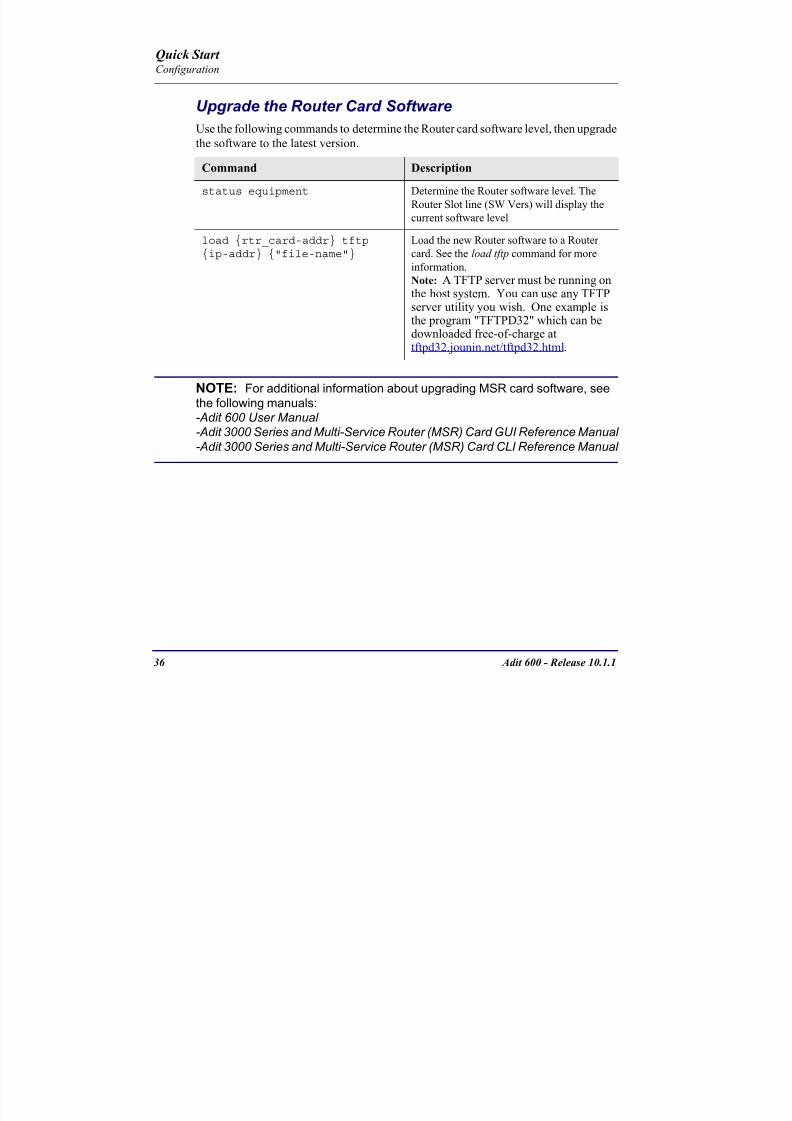
8102019 Adit 600 Quick Start 10-1-1
httpslidepdfcomreaderfulladit-600-quick-start-10-1-1 3854
36 Adit 600 - Release 1011
Configuration
Upgrade the Router Card SoftwareUse the following commands to determine the Router card software level then upgrade
the software to the latest version
NOTE For additional information about upgrading MSR card software see
the following manuals-Adit 600 User Manual -Adit 3000 Series and Multi-Service Router (MSR) Card GUI Reference Manual
-Adit 3000 Series and Multi-Service Router (MSR) Card CLI Reference Manual
Command Description
status equipment Determine the Router software level The
Router Slot line (SW Vers) will display thecurrent software level
load rtr_card-addr tftpip-addr file-name
Load the new Router software to a Router
card See the load tftp command for more
information
Note A TFTP server must be running onthe host system You can use any TFTP
server utility you wish One example isthe program TFTPD32 which can bedownloaded free-of-charge attftpd32jouninnettftpd32html
8102019 Adit 600 Quick Start 10-1-1
httpslidepdfcomreaderfulladit-600-quick-start-10-1-1 3954
8102019 Adit 600 Quick Start 10-1-1
httpslidepdfcomreaderfulladit-600-quick-start-10-1-1 4054
Quick Start C t ll C d LED
8102019 Adit 600 Quick Start 10-1-1
httpslidepdfcomreaderfulladit-600-quick-start-10-1-1 4154
Adit 600 - Release 1011 39
Controller Card LEDs
E1 Controller Card
NOTE E1 is not supported in this release It will be supported in a futurerelease
The E1 Controller has a set of six LEDs The table below describes each LED
LED State Description
MAJOR Off No major alarms present
Red Major alarm present
MINOR Off No minor alarms present
Yellow Minor alarms present
LOCAL Off Remote mode (DIP switches disabled)
Green Local mode (DIP switches enabled)
ACO Off Normal mode No alarms are being
suppressed
Yellow Alarm Cut Off active One or more active
alarms suppressed
E1-1 and
E1-2
Off Off line
Green Normal
Red Loss of Signal (LOS) detected
Yellow Bipolar Violation (BPV) detected LCV
Flashing Green Loopback active
Flashing Red
(slow)
Loss of Frame (LOF) or Alarm Indication
Signal (AIS) detected
Flashing Red
(fast)
Card Failure
Flashing Yellow Yellow alarm (Remote Alarm Indication)detected
Quick Start Power Supply LEDs
8102019 Adit 600 Quick Start 10-1-1
httpslidepdfcomreaderfulladit-600-quick-start-10-1-1 4254
40 Adit 600 - Release 1011
Power Supply LEDs
Power Supply LEDs115 VAC-48 VDC and 230 VAC-48 VDC Power Supplies
The power supply card has two LEDs as described in the table
below
24 VDC-48 VDC Power Supply
The power supply card has two LEDs as described in the table below
LED State Description
AC Input Off AC input missing or failure
Green AC input present
Battery Off Battery input not used
Green Battery charging or operating from DC
source only
Yellow Battery discharging
Red Battery low (less than 42V) ringer disabled
LED State Description
DC OK Off DC input missing or failure
Green DC input present
-48 Battery
Low
Off Normal
Red VDC is low (less than 42 VDC)
ringer disabled
Quick Start Service Card LEDs
8102019 Adit 600 Quick Start 10-1-1
httpslidepdfcomreaderfulladit-600-quick-start-10-1-1 4354
Adit 600 - Release 1011 41
Service Card LEDs
Service Card LEDs 4-Wire EampM Card
FXO Card
FXS Card
ISDN BRI Card
OCU-DP Card
P-Phone Card
Single Channel POTS Card
Quad DS1 ADPCM Service Card
Quad DS1E1 and Quad T1 Cards
Quad E1 Card
IP Router Card
CMG Router Card
Terminal Server Router Card
MSR Card
RS-232 and V35V54 Cards
Discontinued cards
RS-232 discontinued
Quick Start Service Card LEDs
8102019 Adit 600 Quick Start 10-1-1
httpslidepdfcomreaderfulladit-600-quick-start-10-1-1 4454
42 Adit 600 - Release 1011
Service Card LEDs
4-Wire EampM Card Each channelport has two LEDs Only the top LED is used in this application LED
definitions are listed below
State Description
When in EampM Mode
Off Channel is idle or disabled
Green Analog interface is off-hook
Red Digital interface is off-hook
Yellow Both analog and digital interfaces are off-hook or channel is
being trunk processed
When in TO Mode
Off DisconnectedGreen Connected T1E1 not in alarm
Yellow Connected T1E1 in alarm (trunk processed)
Quick Start Service Card LEDs
8102019 Adit 600 Quick Start 10-1-1
httpslidepdfcomreaderfulladit-600-quick-start-10-1-1 4554
Adit 600 - Release 1011 43
FXO Card Each port on the FXO card has its own LED as described in the table below
FXS Card
There is an LED for each port on the FXS card as described in the table below
State Loop Start
Meaning
Ground Start Meaning Dial Pulse Termination
Meaning
Off NA Idle (tip open) Idle (loop open)
Green Idle Tip ground (incoming seizure) Incoming seizure
Red NA Ring ground (outgoing
seizure)
Loop closure (outgoing seizure)
Yellow Call in
progress
Call in progress Call in progress (reverse battery)
Flashing
Green
Ringing Ringing NA
State Loop Start Meaning Ground Start Meaning
Off NA Idle (tip open)
Green Idle Tip ground (incoming seizure)
Red Note This can be seen with
Forward Disconnect (tip open)
Ring ground (outgoing seizure)
Yellow Call in progress Call in progress
Flashing green Ringing Ringing
Quick Start Service Card LEDs
8102019 Adit 600 Quick Start 10-1-1
httpslidepdfcomreaderfulladit-600-quick-start-10-1-1 4654
44 Adit 600 - Release 1011
ISDN BRI Card There is an LED for each ISDN BRI on a card as described in the table below
OCU-DP Card Each channel has two LEDs described in the table below
State Description
Off Line U-interface is attempting synchronization or BRI is Out-of-Service
Red Line alarm (LOS or self test failure)
Yellow ES or SES has occurred
Flashing yellow Line U-interface is synchronized with customer equipment but is not passing
customer data
Flashing green Line U-interface is in external loopback toward the switch at the unit
Green Normal (Line U-interface is active and transparently passing customer data)
State Description
Yellow Flickering ALL Boot Software in control
Green (walking down)
Red (walking up)
ALL Application Software in control
(repeated 35 times)
Red slow flash ALL In Boot Application flash code checksums did not match and
Boot is waiting for application download
Red ALL In Application code waiting for Controller to issue SWHW
revision request This is the first request that comes from the
OCU-DP card manager in the ControllerGreen
Yellow
Top
Bottom
Port in Self-test Duration is 5-8 seconds
Off Top
Bottom
Port is set down (Out-Of-Service)
Green Top Port is receiving valid signals
Red Top Port is receiving no signal (primary) or no frame sync
(secondary or clear channel)Red Flashing Bottom Port is receiving bipolar violations
Yellow Bottom Port is in loopback
Quick Start Service Card LEDs
8102019 Adit 600 Quick Start 10-1-1
httpslidepdfcomreaderfulladit-600-quick-start-10-1-1 4754
Adit 600 - Release 1011 45
P-Phone Card Each P-Phone channel has a corresponding LED described in the table below
State Line State
Off No P-Phone connected
Green No call in process
Flashing Green Alert (Ringing)
Yellow Call in progress
Flashing Yellow P-Phone Loopback in Progress
Flashing Red Self-test failed
Quick Start Service Card LEDs
8102019 Adit 600 Quick Start 10-1-1
httpslidepdfcomreaderfulladit-600-quick-start-10-1-1 4854
46 Adit 600 - Release 1011
Single Channel POTS Card The POTS channel LED (left) status is described in the table below
The second LED (right) is a status LED is not used on this card
Quad DS1 ADPCM Service Card
Each channel on the Quad DS1 ADPCM card has two LEDs The
description of the top LED is shown below the bottom LED is notused with this application
State Loop Start Meaning
Off Calling Party Disconnect
Green Idle
Red NA
Yellow Call in progress
Flashing green Ringing
State Description
Off Off line
Green Normal
Red Loss of Signal (LOS)
Yellow Bipolar Violation (BPV)Flashing Green Loopback active
Flashing Yellow Yellow Alarm
(Remote Alarm Indication)
Flashing Red (Slow) Loss of Frame (LOF) or Alarm Indication Signal (AIS)
Flashing Red (Fast) Self-test Failure
Top LED(active)
Bottom LED(not used)
Quick Start Service Card LEDs
8102019 Adit 600 Quick Start 10-1-1
httpslidepdfcomreaderfulladit-600-quick-start-10-1-1 4954
Adit 600 - Release 1011 47
Quad DS1E1 and Quad T1 CardsEach channel on the Quad T1E1 cards have two LEDs The description
of the top LED is shown below the bottom LED is not used with this
application
State Description
Off Off line
Green Normal
Red Loss of Signal (LOS)
Yellow Bipolar Violation (BPV)
Flashing Green Loopback active
Flashing Yellow Yellow Alarm (Remote Alarm Indication)
Flashing Red (Slow) Loss of Frame (LOF) or Alarm Indication Signal (AIS)
Flashing Red (Fast) Self-test Failure
Quick Start Service Card LEDs
8102019 Adit 600 Quick Start 10-1-1
httpslidepdfcomreaderfulladit-600-quick-start-10-1-1 5054
48 Adit 600 - Release 1011
IP Router Card The following chart describes each LED and its state
LED State Description
CRD Off Loss of power
Green No current alarms
Red Alarm state active See alarm log for cause
Red Flashing Self-test or Boot in-process
Yellow Flashing Card is saving data to flash RAM do not power down
10100 Off 10 Mb ethernet
Green 100 Mb ethernet
LNK Off No ethernet link
Green Good ethernet link
COL
Off No current ethernet transmit collisions
Yellow Ethernet collisions have occurred and have not dropped
to minimum level
Yellow Flashing Ethernet collision occurring
TX Off No ethernet transmit activity
Green Ethernet transmit activity
RX Off No current ethernet receive activity
Green Current ethernet receive activity
Quick Start Service Card LEDs
8102019 Adit 600 Quick Start 10-1-1
httpslidepdfcomreaderfulladit-600-quick-start-10-1-1 5154
Adit 600 - Release 1011 49
CMG Router Card The following chart describes each LED and its state
LED State Description
CRD Off Loss of power
Green No current alarms
Red Alarm state active See alarm log for causeRed Flashing Self-test or Boot in-process
Yellow Flashing Card is saving data to flash RAM do not power down
VOIP
Off No active VoIP calls or if the MGCP protocol is
optioned down
Green Active VoIP calls
Red Call agent unreachable
Yellow Insufficient VoIP resources to complete call
LNK Off No Ethernet link
Green Good Ethernet link
10100 Off 10 Mb Ethernet
Green 100 Mb Ethernet
TX Off No Ethernet transmit activityGreen Ethernet transmit activity
Yellow Current Ethernet transmit collision
RX Off No current Ethernet receive activity
Green Current Ethernet receive activity
Quick Start Service Card LEDs
8102019 Adit 600 Quick Start 10-1-1
httpslidepdfcomreaderfulladit-600-quick-start-10-1-1 5254
50 Adit 600 - Release 1011
Terminal Server Router Card The Terminal Server Router card has 2 LEDs per port
At Power-up
Normal Operation
Port Set for Ethernet
Top LED indicates 100M Link Bottom LED indicates 10M Link
Port Set for RS-232
TOP LED Bottom LED Description
Off Off At Power UpBoot = Loss of power
Red Red Card is inoperative
Flashing Red Flashing Red Self-test or Boot in-process
TOP LED Bottom LED Description
Green Solid (Link) Green Solid (Link) Port set for Ethernet - see below
Flashing Red Flashing Red Self-test or Boot in-process
State Description
Off No Ethernet link
Green Link but no activity
Red Flashing Current Ethernet collision
Green Flashing Current Ethernet receive
Yellow Flashing Current Ethernet transmit
TOP LED Bottom LED Description
Yellow Off No Activity
Yellow Flashing Yellow Current transmit
Yellow Flashing Green Current receive
Quick Start Service Card LEDs
8102019 Adit 600 Quick Start 10-1-1
httpslidepdfcomreaderfulladit-600-quick-start-10-1-1 5354
Adit 600 - Release 1011 51
MSR Card The following chart describes the MSR cardrsquos LEDs
LED State Description
CRD Off Loss of power
Green No current alarms
Red Alarm state active See alarm log for cause
Red Flashing Self-test or boot in process
Yellow Flashing Card is saving data to flash RAM do not power
down
VOIP
Off No SIP proxy or registration attempts for all lines
have succeeded but no calls are active
Green Active VoIP call(s)
Red Inability to reach the SIP proxy or negative response
to register attempts from all lines
Yellow Register attempts from some lines have succeeded
but not for all lines
ETH1 and
ETH2
Top LED
Off 10 Mbitsec down or not connected
Green 100 Mbitsec
ETH1 and
ETH2
Bottom LED
Off Link down
Green Link up
Flashing Green Traffic on link
Yellow Collision status
Quick Start Service Card LEDs
8102019 Adit 600 Quick Start 10-1-1
httpslidepdfcomreaderfulladit-600-quick-start-10-1-1 5454
52 Adit 600 - Release 1011
RS-232 and V35V54 Cards Each port has its own LED as described in the table below
State Description
Off No T1 Assignment
Green Normal (CDRTS) Active
Red CD inactive (T1-side failure)
Yellow RTS inactive (equipment-side failure)
Flashing Yellow Loopback toward T1 or equipment loop test
Flashing Green Loopback toward equipment or network loop test
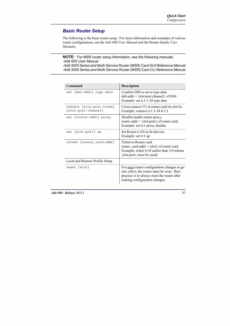
8102019 Adit 600 Quick Start 10-1-1
httpslidepdfcomreaderfulladit-600-quick-start-10-1-1 3954
8102019 Adit 600 Quick Start 10-1-1
httpslidepdfcomreaderfulladit-600-quick-start-10-1-1 4054
Quick Start C t ll C d LED
8102019 Adit 600 Quick Start 10-1-1
httpslidepdfcomreaderfulladit-600-quick-start-10-1-1 4154
Adit 600 - Release 1011 39
Controller Card LEDs
E1 Controller Card
NOTE E1 is not supported in this release It will be supported in a futurerelease
The E1 Controller has a set of six LEDs The table below describes each LED
LED State Description
MAJOR Off No major alarms present
Red Major alarm present
MINOR Off No minor alarms present
Yellow Minor alarms present
LOCAL Off Remote mode (DIP switches disabled)
Green Local mode (DIP switches enabled)
ACO Off Normal mode No alarms are being
suppressed
Yellow Alarm Cut Off active One or more active
alarms suppressed
E1-1 and
E1-2
Off Off line
Green Normal
Red Loss of Signal (LOS) detected
Yellow Bipolar Violation (BPV) detected LCV
Flashing Green Loopback active
Flashing Red
(slow)
Loss of Frame (LOF) or Alarm Indication
Signal (AIS) detected
Flashing Red
(fast)
Card Failure
Flashing Yellow Yellow alarm (Remote Alarm Indication)detected
Quick Start Power Supply LEDs
8102019 Adit 600 Quick Start 10-1-1
httpslidepdfcomreaderfulladit-600-quick-start-10-1-1 4254
40 Adit 600 - Release 1011
Power Supply LEDs
Power Supply LEDs115 VAC-48 VDC and 230 VAC-48 VDC Power Supplies
The power supply card has two LEDs as described in the table
below
24 VDC-48 VDC Power Supply
The power supply card has two LEDs as described in the table below
LED State Description
AC Input Off AC input missing or failure
Green AC input present
Battery Off Battery input not used
Green Battery charging or operating from DC
source only
Yellow Battery discharging
Red Battery low (less than 42V) ringer disabled
LED State Description
DC OK Off DC input missing or failure
Green DC input present
-48 Battery
Low
Off Normal
Red VDC is low (less than 42 VDC)
ringer disabled
Quick Start Service Card LEDs
8102019 Adit 600 Quick Start 10-1-1
httpslidepdfcomreaderfulladit-600-quick-start-10-1-1 4354
Adit 600 - Release 1011 41
Service Card LEDs
Service Card LEDs 4-Wire EampM Card
FXO Card
FXS Card
ISDN BRI Card
OCU-DP Card
P-Phone Card
Single Channel POTS Card
Quad DS1 ADPCM Service Card
Quad DS1E1 and Quad T1 Cards
Quad E1 Card
IP Router Card
CMG Router Card
Terminal Server Router Card
MSR Card
RS-232 and V35V54 Cards
Discontinued cards
RS-232 discontinued
Quick Start Service Card LEDs
8102019 Adit 600 Quick Start 10-1-1
httpslidepdfcomreaderfulladit-600-quick-start-10-1-1 4454
42 Adit 600 - Release 1011
Service Card LEDs
4-Wire EampM Card Each channelport has two LEDs Only the top LED is used in this application LED
definitions are listed below
State Description
When in EampM Mode
Off Channel is idle or disabled
Green Analog interface is off-hook
Red Digital interface is off-hook
Yellow Both analog and digital interfaces are off-hook or channel is
being trunk processed
When in TO Mode
Off DisconnectedGreen Connected T1E1 not in alarm
Yellow Connected T1E1 in alarm (trunk processed)
Quick Start Service Card LEDs
8102019 Adit 600 Quick Start 10-1-1
httpslidepdfcomreaderfulladit-600-quick-start-10-1-1 4554
Adit 600 - Release 1011 43
FXO Card Each port on the FXO card has its own LED as described in the table below
FXS Card
There is an LED for each port on the FXS card as described in the table below
State Loop Start
Meaning
Ground Start Meaning Dial Pulse Termination
Meaning
Off NA Idle (tip open) Idle (loop open)
Green Idle Tip ground (incoming seizure) Incoming seizure
Red NA Ring ground (outgoing
seizure)
Loop closure (outgoing seizure)
Yellow Call in
progress
Call in progress Call in progress (reverse battery)
Flashing
Green
Ringing Ringing NA
State Loop Start Meaning Ground Start Meaning
Off NA Idle (tip open)
Green Idle Tip ground (incoming seizure)
Red Note This can be seen with
Forward Disconnect (tip open)
Ring ground (outgoing seizure)
Yellow Call in progress Call in progress
Flashing green Ringing Ringing
Quick Start Service Card LEDs
8102019 Adit 600 Quick Start 10-1-1
httpslidepdfcomreaderfulladit-600-quick-start-10-1-1 4654
44 Adit 600 - Release 1011
ISDN BRI Card There is an LED for each ISDN BRI on a card as described in the table below
OCU-DP Card Each channel has two LEDs described in the table below
State Description
Off Line U-interface is attempting synchronization or BRI is Out-of-Service
Red Line alarm (LOS or self test failure)
Yellow ES or SES has occurred
Flashing yellow Line U-interface is synchronized with customer equipment but is not passing
customer data
Flashing green Line U-interface is in external loopback toward the switch at the unit
Green Normal (Line U-interface is active and transparently passing customer data)
State Description
Yellow Flickering ALL Boot Software in control
Green (walking down)
Red (walking up)
ALL Application Software in control
(repeated 35 times)
Red slow flash ALL In Boot Application flash code checksums did not match and
Boot is waiting for application download
Red ALL In Application code waiting for Controller to issue SWHW
revision request This is the first request that comes from the
OCU-DP card manager in the ControllerGreen
Yellow
Top
Bottom
Port in Self-test Duration is 5-8 seconds
Off Top
Bottom
Port is set down (Out-Of-Service)
Green Top Port is receiving valid signals
Red Top Port is receiving no signal (primary) or no frame sync
(secondary or clear channel)Red Flashing Bottom Port is receiving bipolar violations
Yellow Bottom Port is in loopback
Quick Start Service Card LEDs
8102019 Adit 600 Quick Start 10-1-1
httpslidepdfcomreaderfulladit-600-quick-start-10-1-1 4754
Adit 600 - Release 1011 45
P-Phone Card Each P-Phone channel has a corresponding LED described in the table below
State Line State
Off No P-Phone connected
Green No call in process
Flashing Green Alert (Ringing)
Yellow Call in progress
Flashing Yellow P-Phone Loopback in Progress
Flashing Red Self-test failed
Quick Start Service Card LEDs
8102019 Adit 600 Quick Start 10-1-1
httpslidepdfcomreaderfulladit-600-quick-start-10-1-1 4854
46 Adit 600 - Release 1011
Single Channel POTS Card The POTS channel LED (left) status is described in the table below
The second LED (right) is a status LED is not used on this card
Quad DS1 ADPCM Service Card
Each channel on the Quad DS1 ADPCM card has two LEDs The
description of the top LED is shown below the bottom LED is notused with this application
State Loop Start Meaning
Off Calling Party Disconnect
Green Idle
Red NA
Yellow Call in progress
Flashing green Ringing
State Description
Off Off line
Green Normal
Red Loss of Signal (LOS)
Yellow Bipolar Violation (BPV)Flashing Green Loopback active
Flashing Yellow Yellow Alarm
(Remote Alarm Indication)
Flashing Red (Slow) Loss of Frame (LOF) or Alarm Indication Signal (AIS)
Flashing Red (Fast) Self-test Failure
Top LED(active)
Bottom LED(not used)
Quick Start Service Card LEDs
8102019 Adit 600 Quick Start 10-1-1
httpslidepdfcomreaderfulladit-600-quick-start-10-1-1 4954
Adit 600 - Release 1011 47
Quad DS1E1 and Quad T1 CardsEach channel on the Quad T1E1 cards have two LEDs The description
of the top LED is shown below the bottom LED is not used with this
application
State Description
Off Off line
Green Normal
Red Loss of Signal (LOS)
Yellow Bipolar Violation (BPV)
Flashing Green Loopback active
Flashing Yellow Yellow Alarm (Remote Alarm Indication)
Flashing Red (Slow) Loss of Frame (LOF) or Alarm Indication Signal (AIS)
Flashing Red (Fast) Self-test Failure
Quick Start Service Card LEDs
8102019 Adit 600 Quick Start 10-1-1
httpslidepdfcomreaderfulladit-600-quick-start-10-1-1 5054
48 Adit 600 - Release 1011
IP Router Card The following chart describes each LED and its state
LED State Description
CRD Off Loss of power
Green No current alarms
Red Alarm state active See alarm log for cause
Red Flashing Self-test or Boot in-process
Yellow Flashing Card is saving data to flash RAM do not power down
10100 Off 10 Mb ethernet
Green 100 Mb ethernet
LNK Off No ethernet link
Green Good ethernet link
COL
Off No current ethernet transmit collisions
Yellow Ethernet collisions have occurred and have not dropped
to minimum level
Yellow Flashing Ethernet collision occurring
TX Off No ethernet transmit activity
Green Ethernet transmit activity
RX Off No current ethernet receive activity
Green Current ethernet receive activity
Quick Start Service Card LEDs
8102019 Adit 600 Quick Start 10-1-1
httpslidepdfcomreaderfulladit-600-quick-start-10-1-1 5154
Adit 600 - Release 1011 49
CMG Router Card The following chart describes each LED and its state
LED State Description
CRD Off Loss of power
Green No current alarms
Red Alarm state active See alarm log for causeRed Flashing Self-test or Boot in-process
Yellow Flashing Card is saving data to flash RAM do not power down
VOIP
Off No active VoIP calls or if the MGCP protocol is
optioned down
Green Active VoIP calls
Red Call agent unreachable
Yellow Insufficient VoIP resources to complete call
LNK Off No Ethernet link
Green Good Ethernet link
10100 Off 10 Mb Ethernet
Green 100 Mb Ethernet
TX Off No Ethernet transmit activityGreen Ethernet transmit activity
Yellow Current Ethernet transmit collision
RX Off No current Ethernet receive activity
Green Current Ethernet receive activity
Quick Start Service Card LEDs
8102019 Adit 600 Quick Start 10-1-1
httpslidepdfcomreaderfulladit-600-quick-start-10-1-1 5254
50 Adit 600 - Release 1011
Terminal Server Router Card The Terminal Server Router card has 2 LEDs per port
At Power-up
Normal Operation
Port Set for Ethernet
Top LED indicates 100M Link Bottom LED indicates 10M Link
Port Set for RS-232
TOP LED Bottom LED Description
Off Off At Power UpBoot = Loss of power
Red Red Card is inoperative
Flashing Red Flashing Red Self-test or Boot in-process
TOP LED Bottom LED Description
Green Solid (Link) Green Solid (Link) Port set for Ethernet - see below
Flashing Red Flashing Red Self-test or Boot in-process
State Description
Off No Ethernet link
Green Link but no activity
Red Flashing Current Ethernet collision
Green Flashing Current Ethernet receive
Yellow Flashing Current Ethernet transmit
TOP LED Bottom LED Description
Yellow Off No Activity
Yellow Flashing Yellow Current transmit
Yellow Flashing Green Current receive
Quick Start Service Card LEDs
8102019 Adit 600 Quick Start 10-1-1
httpslidepdfcomreaderfulladit-600-quick-start-10-1-1 5354
Adit 600 - Release 1011 51
MSR Card The following chart describes the MSR cardrsquos LEDs
LED State Description
CRD Off Loss of power
Green No current alarms
Red Alarm state active See alarm log for cause
Red Flashing Self-test or boot in process
Yellow Flashing Card is saving data to flash RAM do not power
down
VOIP
Off No SIP proxy or registration attempts for all lines
have succeeded but no calls are active
Green Active VoIP call(s)
Red Inability to reach the SIP proxy or negative response
to register attempts from all lines
Yellow Register attempts from some lines have succeeded
but not for all lines
ETH1 and
ETH2
Top LED
Off 10 Mbitsec down or not connected
Green 100 Mbitsec
ETH1 and
ETH2
Bottom LED
Off Link down
Green Link up
Flashing Green Traffic on link
Yellow Collision status
Quick Start Service Card LEDs
8102019 Adit 600 Quick Start 10-1-1
httpslidepdfcomreaderfulladit-600-quick-start-10-1-1 5454
52 Adit 600 - Release 1011
RS-232 and V35V54 Cards Each port has its own LED as described in the table below
State Description
Off No T1 Assignment
Green Normal (CDRTS) Active
Red CD inactive (T1-side failure)
Yellow RTS inactive (equipment-side failure)
Flashing Yellow Loopback toward T1 or equipment loop test
Flashing Green Loopback toward equipment or network loop test
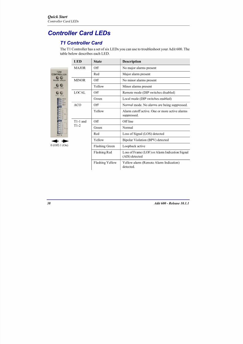
8102019 Adit 600 Quick Start 10-1-1
httpslidepdfcomreaderfulladit-600-quick-start-10-1-1 4154
Adit 600 - Release 1011 39
Controller Card LEDs
E1 Controller Card
NOTE E1 is not supported in this release It will be supported in a futurerelease
The E1 Controller has a set of six LEDs The table below describes each LED
LED State Description
MAJOR Off No major alarms present
Red Major alarm present
MINOR Off No minor alarms present
Yellow Minor alarms present
LOCAL Off Remote mode (DIP switches disabled)
Green Local mode (DIP switches enabled)
ACO Off Normal mode No alarms are being
suppressed
Yellow Alarm Cut Off active One or more active
alarms suppressed
E1-1 and
E1-2
Off Off line
Green Normal
Red Loss of Signal (LOS) detected
Yellow Bipolar Violation (BPV) detected LCV
Flashing Green Loopback active
Flashing Red
(slow)
Loss of Frame (LOF) or Alarm Indication
Signal (AIS) detected
Flashing Red
(fast)
Card Failure
Flashing Yellow Yellow alarm (Remote Alarm Indication)detected
Quick Start Power Supply LEDs
8102019 Adit 600 Quick Start 10-1-1
httpslidepdfcomreaderfulladit-600-quick-start-10-1-1 4254
40 Adit 600 - Release 1011
Power Supply LEDs
Power Supply LEDs115 VAC-48 VDC and 230 VAC-48 VDC Power Supplies
The power supply card has two LEDs as described in the table
below
24 VDC-48 VDC Power Supply
The power supply card has two LEDs as described in the table below
LED State Description
AC Input Off AC input missing or failure
Green AC input present
Battery Off Battery input not used
Green Battery charging or operating from DC
source only
Yellow Battery discharging
Red Battery low (less than 42V) ringer disabled
LED State Description
DC OK Off DC input missing or failure
Green DC input present
-48 Battery
Low
Off Normal
Red VDC is low (less than 42 VDC)
ringer disabled
Quick Start Service Card LEDs
8102019 Adit 600 Quick Start 10-1-1
httpslidepdfcomreaderfulladit-600-quick-start-10-1-1 4354
Adit 600 - Release 1011 41
Service Card LEDs
Service Card LEDs 4-Wire EampM Card
FXO Card
FXS Card
ISDN BRI Card
OCU-DP Card
P-Phone Card
Single Channel POTS Card
Quad DS1 ADPCM Service Card
Quad DS1E1 and Quad T1 Cards
Quad E1 Card
IP Router Card
CMG Router Card
Terminal Server Router Card
MSR Card
RS-232 and V35V54 Cards
Discontinued cards
RS-232 discontinued
Quick Start Service Card LEDs
8102019 Adit 600 Quick Start 10-1-1
httpslidepdfcomreaderfulladit-600-quick-start-10-1-1 4454
42 Adit 600 - Release 1011
Service Card LEDs
4-Wire EampM Card Each channelport has two LEDs Only the top LED is used in this application LED
definitions are listed below
State Description
When in EampM Mode
Off Channel is idle or disabled
Green Analog interface is off-hook
Red Digital interface is off-hook
Yellow Both analog and digital interfaces are off-hook or channel is
being trunk processed
When in TO Mode
Off DisconnectedGreen Connected T1E1 not in alarm
Yellow Connected T1E1 in alarm (trunk processed)
Quick Start Service Card LEDs
8102019 Adit 600 Quick Start 10-1-1
httpslidepdfcomreaderfulladit-600-quick-start-10-1-1 4554
Adit 600 - Release 1011 43
FXO Card Each port on the FXO card has its own LED as described in the table below
FXS Card
There is an LED for each port on the FXS card as described in the table below
State Loop Start
Meaning
Ground Start Meaning Dial Pulse Termination
Meaning
Off NA Idle (tip open) Idle (loop open)
Green Idle Tip ground (incoming seizure) Incoming seizure
Red NA Ring ground (outgoing
seizure)
Loop closure (outgoing seizure)
Yellow Call in
progress
Call in progress Call in progress (reverse battery)
Flashing
Green
Ringing Ringing NA
State Loop Start Meaning Ground Start Meaning
Off NA Idle (tip open)
Green Idle Tip ground (incoming seizure)
Red Note This can be seen with
Forward Disconnect (tip open)
Ring ground (outgoing seizure)
Yellow Call in progress Call in progress
Flashing green Ringing Ringing
Quick Start Service Card LEDs
8102019 Adit 600 Quick Start 10-1-1
httpslidepdfcomreaderfulladit-600-quick-start-10-1-1 4654
44 Adit 600 - Release 1011
ISDN BRI Card There is an LED for each ISDN BRI on a card as described in the table below
OCU-DP Card Each channel has two LEDs described in the table below
State Description
Off Line U-interface is attempting synchronization or BRI is Out-of-Service
Red Line alarm (LOS or self test failure)
Yellow ES or SES has occurred
Flashing yellow Line U-interface is synchronized with customer equipment but is not passing
customer data
Flashing green Line U-interface is in external loopback toward the switch at the unit
Green Normal (Line U-interface is active and transparently passing customer data)
State Description
Yellow Flickering ALL Boot Software in control
Green (walking down)
Red (walking up)
ALL Application Software in control
(repeated 35 times)
Red slow flash ALL In Boot Application flash code checksums did not match and
Boot is waiting for application download
Red ALL In Application code waiting for Controller to issue SWHW
revision request This is the first request that comes from the
OCU-DP card manager in the ControllerGreen
Yellow
Top
Bottom
Port in Self-test Duration is 5-8 seconds
Off Top
Bottom
Port is set down (Out-Of-Service)
Green Top Port is receiving valid signals
Red Top Port is receiving no signal (primary) or no frame sync
(secondary or clear channel)Red Flashing Bottom Port is receiving bipolar violations
Yellow Bottom Port is in loopback
Quick Start Service Card LEDs
8102019 Adit 600 Quick Start 10-1-1
httpslidepdfcomreaderfulladit-600-quick-start-10-1-1 4754
Adit 600 - Release 1011 45
P-Phone Card Each P-Phone channel has a corresponding LED described in the table below
State Line State
Off No P-Phone connected
Green No call in process
Flashing Green Alert (Ringing)
Yellow Call in progress
Flashing Yellow P-Phone Loopback in Progress
Flashing Red Self-test failed
Quick Start Service Card LEDs
8102019 Adit 600 Quick Start 10-1-1
httpslidepdfcomreaderfulladit-600-quick-start-10-1-1 4854
46 Adit 600 - Release 1011
Single Channel POTS Card The POTS channel LED (left) status is described in the table below
The second LED (right) is a status LED is not used on this card
Quad DS1 ADPCM Service Card
Each channel on the Quad DS1 ADPCM card has two LEDs The
description of the top LED is shown below the bottom LED is notused with this application
State Loop Start Meaning
Off Calling Party Disconnect
Green Idle
Red NA
Yellow Call in progress
Flashing green Ringing
State Description
Off Off line
Green Normal
Red Loss of Signal (LOS)
Yellow Bipolar Violation (BPV)Flashing Green Loopback active
Flashing Yellow Yellow Alarm
(Remote Alarm Indication)
Flashing Red (Slow) Loss of Frame (LOF) or Alarm Indication Signal (AIS)
Flashing Red (Fast) Self-test Failure
Top LED(active)
Bottom LED(not used)
Quick Start Service Card LEDs
8102019 Adit 600 Quick Start 10-1-1
httpslidepdfcomreaderfulladit-600-quick-start-10-1-1 4954
Adit 600 - Release 1011 47
Quad DS1E1 and Quad T1 CardsEach channel on the Quad T1E1 cards have two LEDs The description
of the top LED is shown below the bottom LED is not used with this
application
State Description
Off Off line
Green Normal
Red Loss of Signal (LOS)
Yellow Bipolar Violation (BPV)
Flashing Green Loopback active
Flashing Yellow Yellow Alarm (Remote Alarm Indication)
Flashing Red (Slow) Loss of Frame (LOF) or Alarm Indication Signal (AIS)
Flashing Red (Fast) Self-test Failure
Quick Start Service Card LEDs
8102019 Adit 600 Quick Start 10-1-1
httpslidepdfcomreaderfulladit-600-quick-start-10-1-1 5054
48 Adit 600 - Release 1011
IP Router Card The following chart describes each LED and its state
LED State Description
CRD Off Loss of power
Green No current alarms
Red Alarm state active See alarm log for cause
Red Flashing Self-test or Boot in-process
Yellow Flashing Card is saving data to flash RAM do not power down
10100 Off 10 Mb ethernet
Green 100 Mb ethernet
LNK Off No ethernet link
Green Good ethernet link
COL
Off No current ethernet transmit collisions
Yellow Ethernet collisions have occurred and have not dropped
to minimum level
Yellow Flashing Ethernet collision occurring
TX Off No ethernet transmit activity
Green Ethernet transmit activity
RX Off No current ethernet receive activity
Green Current ethernet receive activity
Quick Start Service Card LEDs
8102019 Adit 600 Quick Start 10-1-1
httpslidepdfcomreaderfulladit-600-quick-start-10-1-1 5154
Adit 600 - Release 1011 49
CMG Router Card The following chart describes each LED and its state
LED State Description
CRD Off Loss of power
Green No current alarms
Red Alarm state active See alarm log for causeRed Flashing Self-test or Boot in-process
Yellow Flashing Card is saving data to flash RAM do not power down
VOIP
Off No active VoIP calls or if the MGCP protocol is
optioned down
Green Active VoIP calls
Red Call agent unreachable
Yellow Insufficient VoIP resources to complete call
LNK Off No Ethernet link
Green Good Ethernet link
10100 Off 10 Mb Ethernet
Green 100 Mb Ethernet
TX Off No Ethernet transmit activityGreen Ethernet transmit activity
Yellow Current Ethernet transmit collision
RX Off No current Ethernet receive activity
Green Current Ethernet receive activity
Quick Start Service Card LEDs
8102019 Adit 600 Quick Start 10-1-1
httpslidepdfcomreaderfulladit-600-quick-start-10-1-1 5254
50 Adit 600 - Release 1011
Terminal Server Router Card The Terminal Server Router card has 2 LEDs per port
At Power-up
Normal Operation
Port Set for Ethernet
Top LED indicates 100M Link Bottom LED indicates 10M Link
Port Set for RS-232
TOP LED Bottom LED Description
Off Off At Power UpBoot = Loss of power
Red Red Card is inoperative
Flashing Red Flashing Red Self-test or Boot in-process
TOP LED Bottom LED Description
Green Solid (Link) Green Solid (Link) Port set for Ethernet - see below
Flashing Red Flashing Red Self-test or Boot in-process
State Description
Off No Ethernet link
Green Link but no activity
Red Flashing Current Ethernet collision
Green Flashing Current Ethernet receive
Yellow Flashing Current Ethernet transmit
TOP LED Bottom LED Description
Yellow Off No Activity
Yellow Flashing Yellow Current transmit
Yellow Flashing Green Current receive
Quick Start Service Card LEDs
8102019 Adit 600 Quick Start 10-1-1
httpslidepdfcomreaderfulladit-600-quick-start-10-1-1 5354
Adit 600 - Release 1011 51
MSR Card The following chart describes the MSR cardrsquos LEDs
LED State Description
CRD Off Loss of power
Green No current alarms
Red Alarm state active See alarm log for cause
Red Flashing Self-test or boot in process
Yellow Flashing Card is saving data to flash RAM do not power
down
VOIP
Off No SIP proxy or registration attempts for all lines
have succeeded but no calls are active
Green Active VoIP call(s)
Red Inability to reach the SIP proxy or negative response
to register attempts from all lines
Yellow Register attempts from some lines have succeeded
but not for all lines
ETH1 and
ETH2
Top LED
Off 10 Mbitsec down or not connected
Green 100 Mbitsec
ETH1 and
ETH2
Bottom LED
Off Link down
Green Link up
Flashing Green Traffic on link
Yellow Collision status
Quick Start Service Card LEDs
8102019 Adit 600 Quick Start 10-1-1
httpslidepdfcomreaderfulladit-600-quick-start-10-1-1 5454
52 Adit 600 - Release 1011
RS-232 and V35V54 Cards Each port has its own LED as described in the table below
State Description
Off No T1 Assignment
Green Normal (CDRTS) Active
Red CD inactive (T1-side failure)
Yellow RTS inactive (equipment-side failure)
Flashing Yellow Loopback toward T1 or equipment loop test
Flashing Green Loopback toward equipment or network loop test
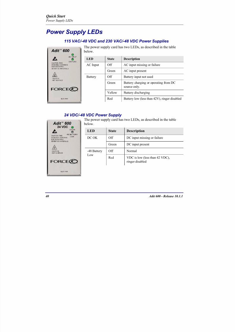
8102019 Adit 600 Quick Start 10-1-1
httpslidepdfcomreaderfulladit-600-quick-start-10-1-1 4354
Adit 600 - Release 1011 41
Service Card LEDs
Service Card LEDs 4-Wire EampM Card
FXO Card
FXS Card
ISDN BRI Card
OCU-DP Card
P-Phone Card
Single Channel POTS Card
Quad DS1 ADPCM Service Card
Quad DS1E1 and Quad T1 Cards
Quad E1 Card
IP Router Card
CMG Router Card
Terminal Server Router Card
MSR Card
RS-232 and V35V54 Cards
Discontinued cards
RS-232 discontinued
Quick Start Service Card LEDs
8102019 Adit 600 Quick Start 10-1-1
httpslidepdfcomreaderfulladit-600-quick-start-10-1-1 4454
42 Adit 600 - Release 1011
Service Card LEDs
4-Wire EampM Card Each channelport has two LEDs Only the top LED is used in this application LED
definitions are listed below
State Description
When in EampM Mode
Off Channel is idle or disabled
Green Analog interface is off-hook
Red Digital interface is off-hook
Yellow Both analog and digital interfaces are off-hook or channel is
being trunk processed
When in TO Mode
Off DisconnectedGreen Connected T1E1 not in alarm
Yellow Connected T1E1 in alarm (trunk processed)
Quick Start Service Card LEDs
8102019 Adit 600 Quick Start 10-1-1
httpslidepdfcomreaderfulladit-600-quick-start-10-1-1 4554
Adit 600 - Release 1011 43
FXO Card Each port on the FXO card has its own LED as described in the table below
FXS Card
There is an LED for each port on the FXS card as described in the table below
State Loop Start
Meaning
Ground Start Meaning Dial Pulse Termination
Meaning
Off NA Idle (tip open) Idle (loop open)
Green Idle Tip ground (incoming seizure) Incoming seizure
Red NA Ring ground (outgoing
seizure)
Loop closure (outgoing seizure)
Yellow Call in
progress
Call in progress Call in progress (reverse battery)
Flashing
Green
Ringing Ringing NA
State Loop Start Meaning Ground Start Meaning
Off NA Idle (tip open)
Green Idle Tip ground (incoming seizure)
Red Note This can be seen with
Forward Disconnect (tip open)
Ring ground (outgoing seizure)
Yellow Call in progress Call in progress
Flashing green Ringing Ringing
Quick Start Service Card LEDs
8102019 Adit 600 Quick Start 10-1-1
httpslidepdfcomreaderfulladit-600-quick-start-10-1-1 4654
44 Adit 600 - Release 1011
ISDN BRI Card There is an LED for each ISDN BRI on a card as described in the table below
OCU-DP Card Each channel has two LEDs described in the table below
State Description
Off Line U-interface is attempting synchronization or BRI is Out-of-Service
Red Line alarm (LOS or self test failure)
Yellow ES or SES has occurred
Flashing yellow Line U-interface is synchronized with customer equipment but is not passing
customer data
Flashing green Line U-interface is in external loopback toward the switch at the unit
Green Normal (Line U-interface is active and transparently passing customer data)
State Description
Yellow Flickering ALL Boot Software in control
Green (walking down)
Red (walking up)
ALL Application Software in control
(repeated 35 times)
Red slow flash ALL In Boot Application flash code checksums did not match and
Boot is waiting for application download
Red ALL In Application code waiting for Controller to issue SWHW
revision request This is the first request that comes from the
OCU-DP card manager in the ControllerGreen
Yellow
Top
Bottom
Port in Self-test Duration is 5-8 seconds
Off Top
Bottom
Port is set down (Out-Of-Service)
Green Top Port is receiving valid signals
Red Top Port is receiving no signal (primary) or no frame sync
(secondary or clear channel)Red Flashing Bottom Port is receiving bipolar violations
Yellow Bottom Port is in loopback
Quick Start Service Card LEDs
8102019 Adit 600 Quick Start 10-1-1
httpslidepdfcomreaderfulladit-600-quick-start-10-1-1 4754
Adit 600 - Release 1011 45
P-Phone Card Each P-Phone channel has a corresponding LED described in the table below
State Line State
Off No P-Phone connected
Green No call in process
Flashing Green Alert (Ringing)
Yellow Call in progress
Flashing Yellow P-Phone Loopback in Progress
Flashing Red Self-test failed
Quick Start Service Card LEDs
8102019 Adit 600 Quick Start 10-1-1
httpslidepdfcomreaderfulladit-600-quick-start-10-1-1 4854
46 Adit 600 - Release 1011
Single Channel POTS Card The POTS channel LED (left) status is described in the table below
The second LED (right) is a status LED is not used on this card
Quad DS1 ADPCM Service Card
Each channel on the Quad DS1 ADPCM card has two LEDs The
description of the top LED is shown below the bottom LED is notused with this application
State Loop Start Meaning
Off Calling Party Disconnect
Green Idle
Red NA
Yellow Call in progress
Flashing green Ringing
State Description
Off Off line
Green Normal
Red Loss of Signal (LOS)
Yellow Bipolar Violation (BPV)Flashing Green Loopback active
Flashing Yellow Yellow Alarm
(Remote Alarm Indication)
Flashing Red (Slow) Loss of Frame (LOF) or Alarm Indication Signal (AIS)
Flashing Red (Fast) Self-test Failure
Top LED(active)
Bottom LED(not used)
Quick Start Service Card LEDs
8102019 Adit 600 Quick Start 10-1-1
httpslidepdfcomreaderfulladit-600-quick-start-10-1-1 4954
Adit 600 - Release 1011 47
Quad DS1E1 and Quad T1 CardsEach channel on the Quad T1E1 cards have two LEDs The description
of the top LED is shown below the bottom LED is not used with this
application
State Description
Off Off line
Green Normal
Red Loss of Signal (LOS)
Yellow Bipolar Violation (BPV)
Flashing Green Loopback active
Flashing Yellow Yellow Alarm (Remote Alarm Indication)
Flashing Red (Slow) Loss of Frame (LOF) or Alarm Indication Signal (AIS)
Flashing Red (Fast) Self-test Failure
Quick Start Service Card LEDs
8102019 Adit 600 Quick Start 10-1-1
httpslidepdfcomreaderfulladit-600-quick-start-10-1-1 5054
48 Adit 600 - Release 1011
IP Router Card The following chart describes each LED and its state
LED State Description
CRD Off Loss of power
Green No current alarms
Red Alarm state active See alarm log for cause
Red Flashing Self-test or Boot in-process
Yellow Flashing Card is saving data to flash RAM do not power down
10100 Off 10 Mb ethernet
Green 100 Mb ethernet
LNK Off No ethernet link
Green Good ethernet link
COL
Off No current ethernet transmit collisions
Yellow Ethernet collisions have occurred and have not dropped
to minimum level
Yellow Flashing Ethernet collision occurring
TX Off No ethernet transmit activity
Green Ethernet transmit activity
RX Off No current ethernet receive activity
Green Current ethernet receive activity
Quick Start Service Card LEDs
8102019 Adit 600 Quick Start 10-1-1
httpslidepdfcomreaderfulladit-600-quick-start-10-1-1 5154
Adit 600 - Release 1011 49
CMG Router Card The following chart describes each LED and its state
LED State Description
CRD Off Loss of power
Green No current alarms
Red Alarm state active See alarm log for causeRed Flashing Self-test or Boot in-process
Yellow Flashing Card is saving data to flash RAM do not power down
VOIP
Off No active VoIP calls or if the MGCP protocol is
optioned down
Green Active VoIP calls
Red Call agent unreachable
Yellow Insufficient VoIP resources to complete call
LNK Off No Ethernet link
Green Good Ethernet link
10100 Off 10 Mb Ethernet
Green 100 Mb Ethernet
TX Off No Ethernet transmit activityGreen Ethernet transmit activity
Yellow Current Ethernet transmit collision
RX Off No current Ethernet receive activity
Green Current Ethernet receive activity
Quick Start Service Card LEDs
8102019 Adit 600 Quick Start 10-1-1
httpslidepdfcomreaderfulladit-600-quick-start-10-1-1 5254
50 Adit 600 - Release 1011
Terminal Server Router Card The Terminal Server Router card has 2 LEDs per port
At Power-up
Normal Operation
Port Set for Ethernet
Top LED indicates 100M Link Bottom LED indicates 10M Link
Port Set for RS-232
TOP LED Bottom LED Description
Off Off At Power UpBoot = Loss of power
Red Red Card is inoperative
Flashing Red Flashing Red Self-test or Boot in-process
TOP LED Bottom LED Description
Green Solid (Link) Green Solid (Link) Port set for Ethernet - see below
Flashing Red Flashing Red Self-test or Boot in-process
State Description
Off No Ethernet link
Green Link but no activity
Red Flashing Current Ethernet collision
Green Flashing Current Ethernet receive
Yellow Flashing Current Ethernet transmit
TOP LED Bottom LED Description
Yellow Off No Activity
Yellow Flashing Yellow Current transmit
Yellow Flashing Green Current receive
Quick Start Service Card LEDs
8102019 Adit 600 Quick Start 10-1-1
httpslidepdfcomreaderfulladit-600-quick-start-10-1-1 5354
Adit 600 - Release 1011 51
MSR Card The following chart describes the MSR cardrsquos LEDs
LED State Description
CRD Off Loss of power
Green No current alarms
Red Alarm state active See alarm log for cause
Red Flashing Self-test or boot in process
Yellow Flashing Card is saving data to flash RAM do not power
down
VOIP
Off No SIP proxy or registration attempts for all lines
have succeeded but no calls are active
Green Active VoIP call(s)
Red Inability to reach the SIP proxy or negative response
to register attempts from all lines
Yellow Register attempts from some lines have succeeded
but not for all lines
ETH1 and
ETH2
Top LED
Off 10 Mbitsec down or not connected
Green 100 Mbitsec
ETH1 and
ETH2
Bottom LED
Off Link down
Green Link up
Flashing Green Traffic on link
Yellow Collision status
Quick Start Service Card LEDs
8102019 Adit 600 Quick Start 10-1-1
httpslidepdfcomreaderfulladit-600-quick-start-10-1-1 5454
52 Adit 600 - Release 1011
RS-232 and V35V54 Cards Each port has its own LED as described in the table below
State Description
Off No T1 Assignment
Green Normal (CDRTS) Active
Red CD inactive (T1-side failure)
Yellow RTS inactive (equipment-side failure)
Flashing Yellow Loopback toward T1 or equipment loop test
Flashing Green Loopback toward equipment or network loop test
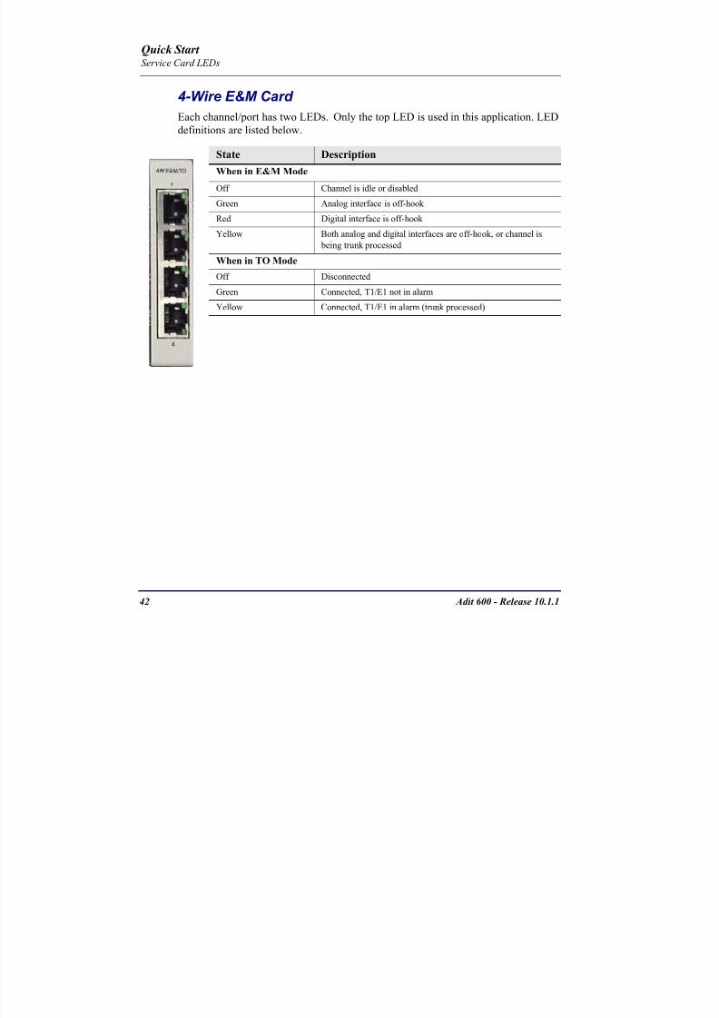
8102019 Adit 600 Quick Start 10-1-1
httpslidepdfcomreaderfulladit-600-quick-start-10-1-1 4554
Adit 600 - Release 1011 43
FXO Card Each port on the FXO card has its own LED as described in the table below
FXS Card
There is an LED for each port on the FXS card as described in the table below
State Loop Start
Meaning
Ground Start Meaning Dial Pulse Termination
Meaning
Off NA Idle (tip open) Idle (loop open)
Green Idle Tip ground (incoming seizure) Incoming seizure
Red NA Ring ground (outgoing
seizure)
Loop closure (outgoing seizure)
Yellow Call in
progress
Call in progress Call in progress (reverse battery)
Flashing
Green
Ringing Ringing NA
State Loop Start Meaning Ground Start Meaning
Off NA Idle (tip open)
Green Idle Tip ground (incoming seizure)
Red Note This can be seen with
Forward Disconnect (tip open)
Ring ground (outgoing seizure)
Yellow Call in progress Call in progress
Flashing green Ringing Ringing
Quick Start Service Card LEDs
8102019 Adit 600 Quick Start 10-1-1
httpslidepdfcomreaderfulladit-600-quick-start-10-1-1 4654
44 Adit 600 - Release 1011
ISDN BRI Card There is an LED for each ISDN BRI on a card as described in the table below
OCU-DP Card Each channel has two LEDs described in the table below
State Description
Off Line U-interface is attempting synchronization or BRI is Out-of-Service
Red Line alarm (LOS or self test failure)
Yellow ES or SES has occurred
Flashing yellow Line U-interface is synchronized with customer equipment but is not passing
customer data
Flashing green Line U-interface is in external loopback toward the switch at the unit
Green Normal (Line U-interface is active and transparently passing customer data)
State Description
Yellow Flickering ALL Boot Software in control
Green (walking down)
Red (walking up)
ALL Application Software in control
(repeated 35 times)
Red slow flash ALL In Boot Application flash code checksums did not match and
Boot is waiting for application download
Red ALL In Application code waiting for Controller to issue SWHW
revision request This is the first request that comes from the
OCU-DP card manager in the ControllerGreen
Yellow
Top
Bottom
Port in Self-test Duration is 5-8 seconds
Off Top
Bottom
Port is set down (Out-Of-Service)
Green Top Port is receiving valid signals
Red Top Port is receiving no signal (primary) or no frame sync
(secondary or clear channel)Red Flashing Bottom Port is receiving bipolar violations
Yellow Bottom Port is in loopback
Quick Start Service Card LEDs
8102019 Adit 600 Quick Start 10-1-1
httpslidepdfcomreaderfulladit-600-quick-start-10-1-1 4754
Adit 600 - Release 1011 45
P-Phone Card Each P-Phone channel has a corresponding LED described in the table below
State Line State
Off No P-Phone connected
Green No call in process
Flashing Green Alert (Ringing)
Yellow Call in progress
Flashing Yellow P-Phone Loopback in Progress
Flashing Red Self-test failed
Quick Start Service Card LEDs
8102019 Adit 600 Quick Start 10-1-1
httpslidepdfcomreaderfulladit-600-quick-start-10-1-1 4854
46 Adit 600 - Release 1011
Single Channel POTS Card The POTS channel LED (left) status is described in the table below
The second LED (right) is a status LED is not used on this card
Quad DS1 ADPCM Service Card
Each channel on the Quad DS1 ADPCM card has two LEDs The
description of the top LED is shown below the bottom LED is notused with this application
State Loop Start Meaning
Off Calling Party Disconnect
Green Idle
Red NA
Yellow Call in progress
Flashing green Ringing
State Description
Off Off line
Green Normal
Red Loss of Signal (LOS)
Yellow Bipolar Violation (BPV)Flashing Green Loopback active
Flashing Yellow Yellow Alarm
(Remote Alarm Indication)
Flashing Red (Slow) Loss of Frame (LOF) or Alarm Indication Signal (AIS)
Flashing Red (Fast) Self-test Failure
Top LED(active)
Bottom LED(not used)
Quick Start Service Card LEDs
8102019 Adit 600 Quick Start 10-1-1
httpslidepdfcomreaderfulladit-600-quick-start-10-1-1 4954
Adit 600 - Release 1011 47
Quad DS1E1 and Quad T1 CardsEach channel on the Quad T1E1 cards have two LEDs The description
of the top LED is shown below the bottom LED is not used with this
application
State Description
Off Off line
Green Normal
Red Loss of Signal (LOS)
Yellow Bipolar Violation (BPV)
Flashing Green Loopback active
Flashing Yellow Yellow Alarm (Remote Alarm Indication)
Flashing Red (Slow) Loss of Frame (LOF) or Alarm Indication Signal (AIS)
Flashing Red (Fast) Self-test Failure
Quick Start Service Card LEDs
8102019 Adit 600 Quick Start 10-1-1
httpslidepdfcomreaderfulladit-600-quick-start-10-1-1 5054
48 Adit 600 - Release 1011
IP Router Card The following chart describes each LED and its state
LED State Description
CRD Off Loss of power
Green No current alarms
Red Alarm state active See alarm log for cause
Red Flashing Self-test or Boot in-process
Yellow Flashing Card is saving data to flash RAM do not power down
10100 Off 10 Mb ethernet
Green 100 Mb ethernet
LNK Off No ethernet link
Green Good ethernet link
COL
Off No current ethernet transmit collisions
Yellow Ethernet collisions have occurred and have not dropped
to minimum level
Yellow Flashing Ethernet collision occurring
TX Off No ethernet transmit activity
Green Ethernet transmit activity
RX Off No current ethernet receive activity
Green Current ethernet receive activity
Quick Start Service Card LEDs
8102019 Adit 600 Quick Start 10-1-1
httpslidepdfcomreaderfulladit-600-quick-start-10-1-1 5154
Adit 600 - Release 1011 49
CMG Router Card The following chart describes each LED and its state
LED State Description
CRD Off Loss of power
Green No current alarms
Red Alarm state active See alarm log for causeRed Flashing Self-test or Boot in-process
Yellow Flashing Card is saving data to flash RAM do not power down
VOIP
Off No active VoIP calls or if the MGCP protocol is
optioned down
Green Active VoIP calls
Red Call agent unreachable
Yellow Insufficient VoIP resources to complete call
LNK Off No Ethernet link
Green Good Ethernet link
10100 Off 10 Mb Ethernet
Green 100 Mb Ethernet
TX Off No Ethernet transmit activityGreen Ethernet transmit activity
Yellow Current Ethernet transmit collision
RX Off No current Ethernet receive activity
Green Current Ethernet receive activity
Quick Start Service Card LEDs
8102019 Adit 600 Quick Start 10-1-1
httpslidepdfcomreaderfulladit-600-quick-start-10-1-1 5254
50 Adit 600 - Release 1011
Terminal Server Router Card The Terminal Server Router card has 2 LEDs per port
At Power-up
Normal Operation
Port Set for Ethernet
Top LED indicates 100M Link Bottom LED indicates 10M Link
Port Set for RS-232
TOP LED Bottom LED Description
Off Off At Power UpBoot = Loss of power
Red Red Card is inoperative
Flashing Red Flashing Red Self-test or Boot in-process
TOP LED Bottom LED Description
Green Solid (Link) Green Solid (Link) Port set for Ethernet - see below
Flashing Red Flashing Red Self-test or Boot in-process
State Description
Off No Ethernet link
Green Link but no activity
Red Flashing Current Ethernet collision
Green Flashing Current Ethernet receive
Yellow Flashing Current Ethernet transmit
TOP LED Bottom LED Description
Yellow Off No Activity
Yellow Flashing Yellow Current transmit
Yellow Flashing Green Current receive
Quick Start Service Card LEDs
8102019 Adit 600 Quick Start 10-1-1
httpslidepdfcomreaderfulladit-600-quick-start-10-1-1 5354
Adit 600 - Release 1011 51
MSR Card The following chart describes the MSR cardrsquos LEDs
LED State Description
CRD Off Loss of power
Green No current alarms
Red Alarm state active See alarm log for cause
Red Flashing Self-test or boot in process
Yellow Flashing Card is saving data to flash RAM do not power
down
VOIP
Off No SIP proxy or registration attempts for all lines
have succeeded but no calls are active
Green Active VoIP call(s)
Red Inability to reach the SIP proxy or negative response
to register attempts from all lines
Yellow Register attempts from some lines have succeeded
but not for all lines
ETH1 and
ETH2
Top LED
Off 10 Mbitsec down or not connected
Green 100 Mbitsec
ETH1 and
ETH2
Bottom LED
Off Link down
Green Link up
Flashing Green Traffic on link
Yellow Collision status
Quick Start Service Card LEDs
8102019 Adit 600 Quick Start 10-1-1
httpslidepdfcomreaderfulladit-600-quick-start-10-1-1 5454
52 Adit 600 - Release 1011
RS-232 and V35V54 Cards Each port has its own LED as described in the table below
State Description
Off No T1 Assignment
Green Normal (CDRTS) Active
Red CD inactive (T1-side failure)
Yellow RTS inactive (equipment-side failure)
Flashing Yellow Loopback toward T1 or equipment loop test
Flashing Green Loopback toward equipment or network loop test
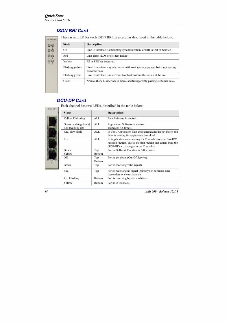
8102019 Adit 600 Quick Start 10-1-1
httpslidepdfcomreaderfulladit-600-quick-start-10-1-1 4754
Adit 600 - Release 1011 45
P-Phone Card Each P-Phone channel has a corresponding LED described in the table below
State Line State
Off No P-Phone connected
Green No call in process
Flashing Green Alert (Ringing)
Yellow Call in progress
Flashing Yellow P-Phone Loopback in Progress
Flashing Red Self-test failed
Quick Start Service Card LEDs
8102019 Adit 600 Quick Start 10-1-1
httpslidepdfcomreaderfulladit-600-quick-start-10-1-1 4854
46 Adit 600 - Release 1011
Single Channel POTS Card The POTS channel LED (left) status is described in the table below
The second LED (right) is a status LED is not used on this card
Quad DS1 ADPCM Service Card
Each channel on the Quad DS1 ADPCM card has two LEDs The
description of the top LED is shown below the bottom LED is notused with this application
State Loop Start Meaning
Off Calling Party Disconnect
Green Idle
Red NA
Yellow Call in progress
Flashing green Ringing
State Description
Off Off line
Green Normal
Red Loss of Signal (LOS)
Yellow Bipolar Violation (BPV)Flashing Green Loopback active
Flashing Yellow Yellow Alarm
(Remote Alarm Indication)
Flashing Red (Slow) Loss of Frame (LOF) or Alarm Indication Signal (AIS)
Flashing Red (Fast) Self-test Failure
Top LED(active)
Bottom LED(not used)
Quick Start Service Card LEDs
8102019 Adit 600 Quick Start 10-1-1
httpslidepdfcomreaderfulladit-600-quick-start-10-1-1 4954
Adit 600 - Release 1011 47
Quad DS1E1 and Quad T1 CardsEach channel on the Quad T1E1 cards have two LEDs The description
of the top LED is shown below the bottom LED is not used with this
application
State Description
Off Off line
Green Normal
Red Loss of Signal (LOS)
Yellow Bipolar Violation (BPV)
Flashing Green Loopback active
Flashing Yellow Yellow Alarm (Remote Alarm Indication)
Flashing Red (Slow) Loss of Frame (LOF) or Alarm Indication Signal (AIS)
Flashing Red (Fast) Self-test Failure
Quick Start Service Card LEDs
8102019 Adit 600 Quick Start 10-1-1
httpslidepdfcomreaderfulladit-600-quick-start-10-1-1 5054
48 Adit 600 - Release 1011
IP Router Card The following chart describes each LED and its state
LED State Description
CRD Off Loss of power
Green No current alarms
Red Alarm state active See alarm log for cause
Red Flashing Self-test or Boot in-process
Yellow Flashing Card is saving data to flash RAM do not power down
10100 Off 10 Mb ethernet
Green 100 Mb ethernet
LNK Off No ethernet link
Green Good ethernet link
COL
Off No current ethernet transmit collisions
Yellow Ethernet collisions have occurred and have not dropped
to minimum level
Yellow Flashing Ethernet collision occurring
TX Off No ethernet transmit activity
Green Ethernet transmit activity
RX Off No current ethernet receive activity
Green Current ethernet receive activity
Quick Start Service Card LEDs
8102019 Adit 600 Quick Start 10-1-1
httpslidepdfcomreaderfulladit-600-quick-start-10-1-1 5154
Adit 600 - Release 1011 49
CMG Router Card The following chart describes each LED and its state
LED State Description
CRD Off Loss of power
Green No current alarms
Red Alarm state active See alarm log for causeRed Flashing Self-test or Boot in-process
Yellow Flashing Card is saving data to flash RAM do not power down
VOIP
Off No active VoIP calls or if the MGCP protocol is
optioned down
Green Active VoIP calls
Red Call agent unreachable
Yellow Insufficient VoIP resources to complete call
LNK Off No Ethernet link
Green Good Ethernet link
10100 Off 10 Mb Ethernet
Green 100 Mb Ethernet
TX Off No Ethernet transmit activityGreen Ethernet transmit activity
Yellow Current Ethernet transmit collision
RX Off No current Ethernet receive activity
Green Current Ethernet receive activity
Quick Start Service Card LEDs
8102019 Adit 600 Quick Start 10-1-1
httpslidepdfcomreaderfulladit-600-quick-start-10-1-1 5254
50 Adit 600 - Release 1011
Terminal Server Router Card The Terminal Server Router card has 2 LEDs per port
At Power-up
Normal Operation
Port Set for Ethernet
Top LED indicates 100M Link Bottom LED indicates 10M Link
Port Set for RS-232
TOP LED Bottom LED Description
Off Off At Power UpBoot = Loss of power
Red Red Card is inoperative
Flashing Red Flashing Red Self-test or Boot in-process
TOP LED Bottom LED Description
Green Solid (Link) Green Solid (Link) Port set for Ethernet - see below
Flashing Red Flashing Red Self-test or Boot in-process
State Description
Off No Ethernet link
Green Link but no activity
Red Flashing Current Ethernet collision
Green Flashing Current Ethernet receive
Yellow Flashing Current Ethernet transmit
TOP LED Bottom LED Description
Yellow Off No Activity
Yellow Flashing Yellow Current transmit
Yellow Flashing Green Current receive
Quick Start Service Card LEDs
8102019 Adit 600 Quick Start 10-1-1
httpslidepdfcomreaderfulladit-600-quick-start-10-1-1 5354
Adit 600 - Release 1011 51
MSR Card The following chart describes the MSR cardrsquos LEDs
LED State Description
CRD Off Loss of power
Green No current alarms
Red Alarm state active See alarm log for cause
Red Flashing Self-test or boot in process
Yellow Flashing Card is saving data to flash RAM do not power
down
VOIP
Off No SIP proxy or registration attempts for all lines
have succeeded but no calls are active
Green Active VoIP call(s)
Red Inability to reach the SIP proxy or negative response
to register attempts from all lines
Yellow Register attempts from some lines have succeeded
but not for all lines
ETH1 and
ETH2
Top LED
Off 10 Mbitsec down or not connected
Green 100 Mbitsec
ETH1 and
ETH2
Bottom LED
Off Link down
Green Link up
Flashing Green Traffic on link
Yellow Collision status
Quick Start Service Card LEDs
8102019 Adit 600 Quick Start 10-1-1
httpslidepdfcomreaderfulladit-600-quick-start-10-1-1 5454
52 Adit 600 - Release 1011
RS-232 and V35V54 Cards Each port has its own LED as described in the table below
State Description
Off No T1 Assignment
Green Normal (CDRTS) Active
Red CD inactive (T1-side failure)
Yellow RTS inactive (equipment-side failure)
Flashing Yellow Loopback toward T1 or equipment loop test
Flashing Green Loopback toward equipment or network loop test
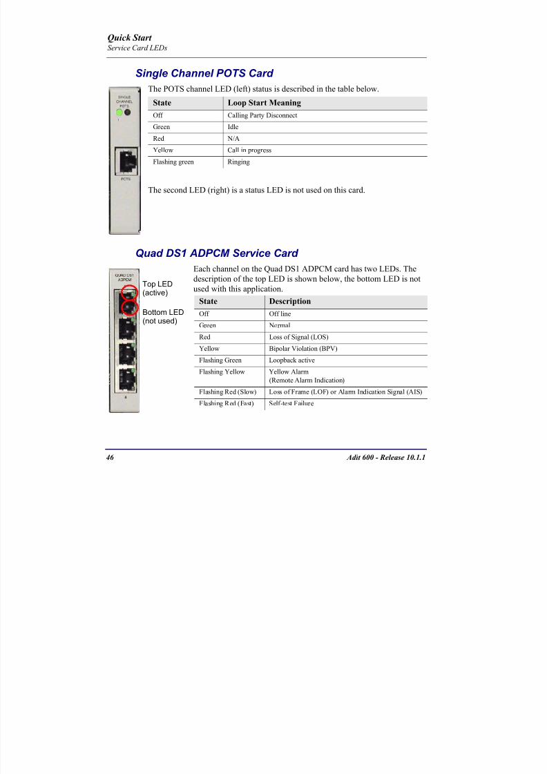
8102019 Adit 600 Quick Start 10-1-1
httpslidepdfcomreaderfulladit-600-quick-start-10-1-1 4954
Adit 600 - Release 1011 47
Quad DS1E1 and Quad T1 CardsEach channel on the Quad T1E1 cards have two LEDs The description
of the top LED is shown below the bottom LED is not used with this
application
State Description
Off Off line
Green Normal
Red Loss of Signal (LOS)
Yellow Bipolar Violation (BPV)
Flashing Green Loopback active
Flashing Yellow Yellow Alarm (Remote Alarm Indication)
Flashing Red (Slow) Loss of Frame (LOF) or Alarm Indication Signal (AIS)
Flashing Red (Fast) Self-test Failure
Quick Start Service Card LEDs
8102019 Adit 600 Quick Start 10-1-1
httpslidepdfcomreaderfulladit-600-quick-start-10-1-1 5054
48 Adit 600 - Release 1011
IP Router Card The following chart describes each LED and its state
LED State Description
CRD Off Loss of power
Green No current alarms
Red Alarm state active See alarm log for cause
Red Flashing Self-test or Boot in-process
Yellow Flashing Card is saving data to flash RAM do not power down
10100 Off 10 Mb ethernet
Green 100 Mb ethernet
LNK Off No ethernet link
Green Good ethernet link
COL
Off No current ethernet transmit collisions
Yellow Ethernet collisions have occurred and have not dropped
to minimum level
Yellow Flashing Ethernet collision occurring
TX Off No ethernet transmit activity
Green Ethernet transmit activity
RX Off No current ethernet receive activity
Green Current ethernet receive activity
Quick Start Service Card LEDs
8102019 Adit 600 Quick Start 10-1-1
httpslidepdfcomreaderfulladit-600-quick-start-10-1-1 5154
Adit 600 - Release 1011 49
CMG Router Card The following chart describes each LED and its state
LED State Description
CRD Off Loss of power
Green No current alarms
Red Alarm state active See alarm log for causeRed Flashing Self-test or Boot in-process
Yellow Flashing Card is saving data to flash RAM do not power down
VOIP
Off No active VoIP calls or if the MGCP protocol is
optioned down
Green Active VoIP calls
Red Call agent unreachable
Yellow Insufficient VoIP resources to complete call
LNK Off No Ethernet link
Green Good Ethernet link
10100 Off 10 Mb Ethernet
Green 100 Mb Ethernet
TX Off No Ethernet transmit activityGreen Ethernet transmit activity
Yellow Current Ethernet transmit collision
RX Off No current Ethernet receive activity
Green Current Ethernet receive activity
Quick Start Service Card LEDs
8102019 Adit 600 Quick Start 10-1-1
httpslidepdfcomreaderfulladit-600-quick-start-10-1-1 5254
50 Adit 600 - Release 1011
Terminal Server Router Card The Terminal Server Router card has 2 LEDs per port
At Power-up
Normal Operation
Port Set for Ethernet
Top LED indicates 100M Link Bottom LED indicates 10M Link
Port Set for RS-232
TOP LED Bottom LED Description
Off Off At Power UpBoot = Loss of power
Red Red Card is inoperative
Flashing Red Flashing Red Self-test or Boot in-process
TOP LED Bottom LED Description
Green Solid (Link) Green Solid (Link) Port set for Ethernet - see below
Flashing Red Flashing Red Self-test or Boot in-process
State Description
Off No Ethernet link
Green Link but no activity
Red Flashing Current Ethernet collision
Green Flashing Current Ethernet receive
Yellow Flashing Current Ethernet transmit
TOP LED Bottom LED Description
Yellow Off No Activity
Yellow Flashing Yellow Current transmit
Yellow Flashing Green Current receive
Quick Start Service Card LEDs
8102019 Adit 600 Quick Start 10-1-1
httpslidepdfcomreaderfulladit-600-quick-start-10-1-1 5354
Adit 600 - Release 1011 51
MSR Card The following chart describes the MSR cardrsquos LEDs
LED State Description
CRD Off Loss of power
Green No current alarms
Red Alarm state active See alarm log for cause
Red Flashing Self-test or boot in process
Yellow Flashing Card is saving data to flash RAM do not power
down
VOIP
Off No SIP proxy or registration attempts for all lines
have succeeded but no calls are active
Green Active VoIP call(s)
Red Inability to reach the SIP proxy or negative response
to register attempts from all lines
Yellow Register attempts from some lines have succeeded
but not for all lines
ETH1 and
ETH2
Top LED
Off 10 Mbitsec down or not connected
Green 100 Mbitsec
ETH1 and
ETH2
Bottom LED
Off Link down
Green Link up
Flashing Green Traffic on link
Yellow Collision status
Quick Start Service Card LEDs
8102019 Adit 600 Quick Start 10-1-1
httpslidepdfcomreaderfulladit-600-quick-start-10-1-1 5454
52 Adit 600 - Release 1011
RS-232 and V35V54 Cards Each port has its own LED as described in the table below
State Description
Off No T1 Assignment
Green Normal (CDRTS) Active
Red CD inactive (T1-side failure)
Yellow RTS inactive (equipment-side failure)
Flashing Yellow Loopback toward T1 or equipment loop test
Flashing Green Loopback toward equipment or network loop test
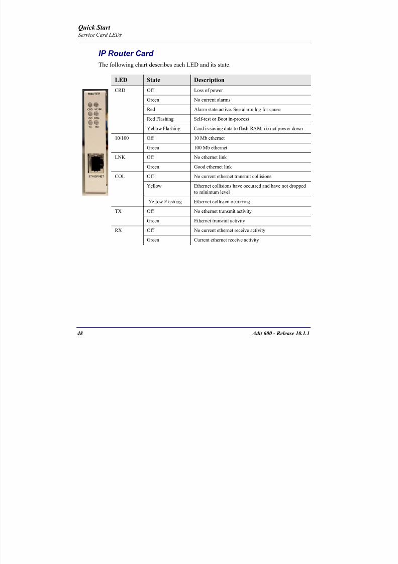
8102019 Adit 600 Quick Start 10-1-1
httpslidepdfcomreaderfulladit-600-quick-start-10-1-1 5154
Adit 600 - Release 1011 49
CMG Router Card The following chart describes each LED and its state
LED State Description
CRD Off Loss of power
Green No current alarms
Red Alarm state active See alarm log for causeRed Flashing Self-test or Boot in-process
Yellow Flashing Card is saving data to flash RAM do not power down
VOIP
Off No active VoIP calls or if the MGCP protocol is
optioned down
Green Active VoIP calls
Red Call agent unreachable
Yellow Insufficient VoIP resources to complete call
LNK Off No Ethernet link
Green Good Ethernet link
10100 Off 10 Mb Ethernet
Green 100 Mb Ethernet
TX Off No Ethernet transmit activityGreen Ethernet transmit activity
Yellow Current Ethernet transmit collision
RX Off No current Ethernet receive activity
Green Current Ethernet receive activity
Quick Start Service Card LEDs
8102019 Adit 600 Quick Start 10-1-1
httpslidepdfcomreaderfulladit-600-quick-start-10-1-1 5254
50 Adit 600 - Release 1011
Terminal Server Router Card The Terminal Server Router card has 2 LEDs per port
At Power-up
Normal Operation
Port Set for Ethernet
Top LED indicates 100M Link Bottom LED indicates 10M Link
Port Set for RS-232
TOP LED Bottom LED Description
Off Off At Power UpBoot = Loss of power
Red Red Card is inoperative
Flashing Red Flashing Red Self-test or Boot in-process
TOP LED Bottom LED Description
Green Solid (Link) Green Solid (Link) Port set for Ethernet - see below
Flashing Red Flashing Red Self-test or Boot in-process
State Description
Off No Ethernet link
Green Link but no activity
Red Flashing Current Ethernet collision
Green Flashing Current Ethernet receive
Yellow Flashing Current Ethernet transmit
TOP LED Bottom LED Description
Yellow Off No Activity
Yellow Flashing Yellow Current transmit
Yellow Flashing Green Current receive
Quick Start Service Card LEDs
8102019 Adit 600 Quick Start 10-1-1
httpslidepdfcomreaderfulladit-600-quick-start-10-1-1 5354
Adit 600 - Release 1011 51
MSR Card The following chart describes the MSR cardrsquos LEDs
LED State Description
CRD Off Loss of power
Green No current alarms
Red Alarm state active See alarm log for cause
Red Flashing Self-test or boot in process
Yellow Flashing Card is saving data to flash RAM do not power
down
VOIP
Off No SIP proxy or registration attempts for all lines
have succeeded but no calls are active
Green Active VoIP call(s)
Red Inability to reach the SIP proxy or negative response
to register attempts from all lines
Yellow Register attempts from some lines have succeeded
but not for all lines
ETH1 and
ETH2
Top LED
Off 10 Mbitsec down or not connected
Green 100 Mbitsec
ETH1 and
ETH2
Bottom LED
Off Link down
Green Link up
Flashing Green Traffic on link
Yellow Collision status
Quick Start Service Card LEDs
8102019 Adit 600 Quick Start 10-1-1
httpslidepdfcomreaderfulladit-600-quick-start-10-1-1 5454
52 Adit 600 - Release 1011
RS-232 and V35V54 Cards Each port has its own LED as described in the table below
State Description
Off No T1 Assignment
Green Normal (CDRTS) Active
Red CD inactive (T1-side failure)
Yellow RTS inactive (equipment-side failure)
Flashing Yellow Loopback toward T1 or equipment loop test
Flashing Green Loopback toward equipment or network loop test
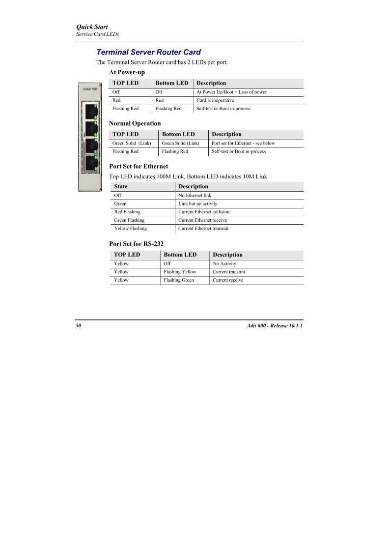
8102019 Adit 600 Quick Start 10-1-1
httpslidepdfcomreaderfulladit-600-quick-start-10-1-1 5254
50 Adit 600 - Release 1011
Terminal Server Router Card The Terminal Server Router card has 2 LEDs per port
At Power-up
Normal Operation
Port Set for Ethernet
Top LED indicates 100M Link Bottom LED indicates 10M Link
Port Set for RS-232
TOP LED Bottom LED Description
Off Off At Power UpBoot = Loss of power
Red Red Card is inoperative
Flashing Red Flashing Red Self-test or Boot in-process
TOP LED Bottom LED Description
Green Solid (Link) Green Solid (Link) Port set for Ethernet - see below
Flashing Red Flashing Red Self-test or Boot in-process
State Description
Off No Ethernet link
Green Link but no activity
Red Flashing Current Ethernet collision
Green Flashing Current Ethernet receive
Yellow Flashing Current Ethernet transmit
TOP LED Bottom LED Description
Yellow Off No Activity
Yellow Flashing Yellow Current transmit
Yellow Flashing Green Current receive
Quick Start Service Card LEDs
8102019 Adit 600 Quick Start 10-1-1
httpslidepdfcomreaderfulladit-600-quick-start-10-1-1 5354
Adit 600 - Release 1011 51
MSR Card The following chart describes the MSR cardrsquos LEDs
LED State Description
CRD Off Loss of power
Green No current alarms
Red Alarm state active See alarm log for cause
Red Flashing Self-test or boot in process
Yellow Flashing Card is saving data to flash RAM do not power
down
VOIP
Off No SIP proxy or registration attempts for all lines
have succeeded but no calls are active
Green Active VoIP call(s)
Red Inability to reach the SIP proxy or negative response
to register attempts from all lines
Yellow Register attempts from some lines have succeeded
but not for all lines
ETH1 and
ETH2
Top LED
Off 10 Mbitsec down or not connected
Green 100 Mbitsec
ETH1 and
ETH2
Bottom LED
Off Link down
Green Link up
Flashing Green Traffic on link
Yellow Collision status
Quick Start Service Card LEDs
8102019 Adit 600 Quick Start 10-1-1
httpslidepdfcomreaderfulladit-600-quick-start-10-1-1 5454
52 Adit 600 - Release 1011
RS-232 and V35V54 Cards Each port has its own LED as described in the table below
State Description
Off No T1 Assignment
Green Normal (CDRTS) Active
Red CD inactive (T1-side failure)
Yellow RTS inactive (equipment-side failure)
Flashing Yellow Loopback toward T1 or equipment loop test
Flashing Green Loopback toward equipment or network loop test
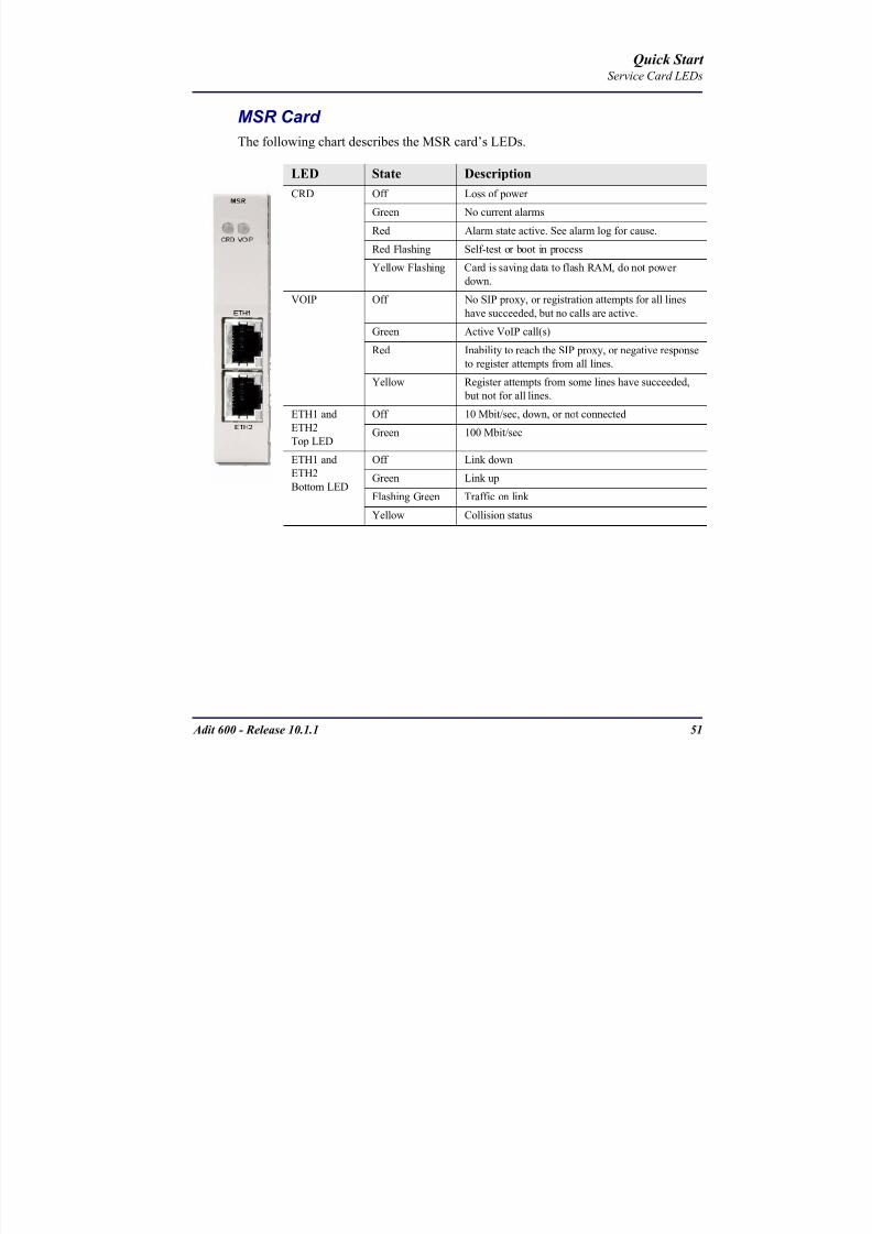
8102019 Adit 600 Quick Start 10-1-1
httpslidepdfcomreaderfulladit-600-quick-start-10-1-1 5454
52 Adit 600 - Release 1011
RS-232 and V35V54 Cards Each port has its own LED as described in the table below
State Description
Off No T1 Assignment
Green Normal (CDRTS) Active
Red CD inactive (T1-side failure)
Yellow RTS inactive (equipment-side failure)
Flashing Yellow Loopback toward T1 or equipment loop test
Flashing Green Loopback toward equipment or network loop test