Embed Size (px)
Citation preview
822 IEEE TRANSACTIONS ON WIRELESS COMMUNICATIONS, VOL. 2, NO. 4, JULY 2003
A Robust Timing and Frequency Synchronization forOFDM Systems
Hlaing Minn, Member, IEEE, Vijay K. Bhargava, Fellow, IEEE, and Khaled Ben Letaief, Fellow, IEEE
Abstract—A robust symbol-timing and carrier-frequencysynchronization scheme applicable to orthogonal frequency-di-vision-multiplexing systems is presented. The proposed methodis based on a training symbol specifically designed to have asteep rolloff timing metric. The proposed timing metric alsoprovides a robust sync detection capability. Both time domaintraining and frequency domain (FD) training are investigated.For FD training, maintaining a low peak-to-average power ratioof the training symbol was taken into consideration. The channelestimation scheme based on the designed training symbol wasalso incorporated in the system in order to give both fine-timingand frequency-offset estimates. For fine frequency estimation, twoapproaches are presented. The first one is based on the suppres-sion of the interference introduced in the frequency estimationprocess by the training symbol pattern in the context of multipathdispersive channels. The second one is based on the maximumlikelihood principle and does not suffer from any interference. Anew performance measure is introduced for timing estimation,which is based on the plot of signal to timing-error-inducedaverage interference power ratio against the timing estimateshift. A simple approach for finding the optimal setting of thetiming estimator is presented. Finally, the sync detection, timingestimation, frequency estimation, and bit-error-rate performanceof the proposed method are presented in a multipath Rayleighfading channel.
Index Terms—Frequency-offset estimation, orthogonal fre-quency-division multiplexing (OFDM), symbol-timing estimation,synchronization, training symbol.
I. INTRODUCTION
ORTHOGONAL frequency-division multiplexing(OFDM) has been of major interest for both wire-
line-based and wireless applications [1]–[3] due to its highdata rate transmission capability and its robustness to multipathdelay spread. However, OFDM systems are much more sensi-tive to synchronization errors than single carrier systems [4],[5]. Several approaches have been proposed for estimating thetime and frequency offset either jointly [6]–[8] or individually.See [9]–[12] for further notes on frequency-offset estimation
Manuscript received June 19, 2001; revised January 17, 2002; acceptedMarch 5, 2002. The editor coordinating the review of this paper and approvingit for publication is L. Hanzo. This work was supported in part by a StrategicProject Grant from the Natural Sciences and Engineering Research Council(NSERC) of Canada and in part by TELUS Mobility Cellular.
H. Minn is with the Erik Jonsson School of Engineering and Computer Sci-ence, University of Texas at Dallas, Richardson, TX 75083-0688 USA (e-mail:[email protected]).
V. K. Bhargava is with the Department of Electrical and Computer Engi-neering, University of British Columbia, Vancouver, BC V6T 1Z4, Canada(e-mail: [email protected]).
K. B. Letaief is with the Center for Wireless Information Technology, De-partment of Electrical and Electronic Engineering, The Hong Kong Universityof Science and Technology, Clear Water Bay, Kowloon, Hong Kong (e-mail:[email protected]).
Digital Object Identifier 10.1109/TWC.2003.814346
and to [13]–[16] on timing estimation. There are of numerousother relevant contributions in the literature and a good discus-sion on them can be found in the recent paper [28].
Most frequency and timing estimation methods exploit theperiodic nature of the time-domain signal by using a cyclicprefix [6], [8], [10], [13], or by designing the training symbolhaving repeated parts [7], [9], [12]. Regarding frequencyestimation, in [7], a training symbol containing two identicalhalves is used and the frequency acquisition range is1subcarrier spacing. In order to increase the frequency capturerange, a second training symbol is employed. A frequencyestimation scheme improving the solution of [7] is proposedin [12], where only one training symbol having identicalparts is required and the frequency acquisition range issubcarrier spacing. A robust timing synchronization schemeusing a training symbol having two identical parts has also beenproposed in [7]. However, the timing metric plateau inherentin [7] results in a large timing offset estimation variance. Thistiming metric plateau can be eliminated and, hence, the timingoffset estimation variance can be reduced by designing thetraining symbol such that it gives a more pronounced timingmetric trajectory [15]. For single carrier systems, in [17], theframe synchronization performance has been considerablyimproved by designing the training preambles to give a sharperpeak timing metric trajectory.
All of the above OFDM synchronization methods are asso-ciated with one or more of the following limitations or draw-backs: have a limited range of operation, address only one task,have a large estimation variance, lack robust sync detection ca-pability, and require extra overheads. To overcome these limita-tions, we investigate both timing and frequency synchronizationfor OFDM, particularly using only one training symbol (or onetraining block) in this paper. In this case, the training symbol isdesigned to have a sharp timing metric trajectory. In choosingthe timing metric, a robust sync detection capability has to betaken into consideration. We design the training symbol to becomposed of repeated identical parts with possible sign inver-sions. Our choice of this type of training symbol is based onthe following reasons. The periodicity or repetitive nature of thetraining symbol equips timing synchronization with robustnessagainst frequency offsets. Having multiple identical parts givesthe benefit of using the same training symbol for frequency syn-chronization, which can handle large frequency offsets. By de-signing the signs of the identical parts to give the sharpest pos-sible timing metric trajectory, the timing offset estimation canbe improved. Both OFDM-type training symbols (frequencydomain (FD) training) and single-carrier-type training blocks(time domain (TD) training) are investigated.
1536-1276/03$17.00 © 2003 IEEE

MINN et al.: ROBUST TIMING AND FREQUENCY SYNCHRONIZATION FOR OFDM SYSTEMS 823
We present a synchronization scheme, which provides bothtiming and frequency estimation as well as channel estimates.A specifically designed training symbol is used for bothtiming and frequency synchronization. Channel estimationbased on the designed training symbol is also incorporated inorder to give fine-timing and frequency-offset estimates. Finesynchronization can also be iteratively improved. The impact ofusing only one training symbol for both timing and frequencysynchronization is discussed and a number of approaches areproposed for further performance improvement. The syncdetection performance, timing synchronization performance,frequency synchronization performance, and bit-error-rate(BER) performance of the proposed method is evaluated bycomputer simulations.
Regarding our timing estimation performance measure in thecontext of OFDM, the additional interference power caused bytiming estimation might be considered, rather than the timingoffset estimation variance, since the former reflects the actualimpact of timing synchronization error on the system’s perfor-mance. However, the interference power may also depend on themean of the timing estimate. Hence, in this paper, we introducea more revealing performance measure for the timing character-ization of OFDM systems.
This paper is organized as follows. Section II describes thesystem considered. Section III briefly presents the OFDMsynchronization problem and the effects of synchronizationerrors. In Section IV, the proposed synchronization schemeis presented. Performance evaluation, simulation results, anddiscussions are provided in Section V. Finally, our conclusionsare provided in Section VI.
II. SYSTEM DESCRIPTION
The samples of the transmitted baseband OFDM signal, as-suming ideal Nyquist pulse shaping, can be expressed as
(1)where is the modulated data or subcarrier symbol,is the number of inverse fast Fourier transform (IFFT)points, is the number of subcarriers, is thenumber of guard samples, and . Consider a fre-quency selective multipath fading channel with path gains
(including possible paths with azero gain) and the corresponding path delays. We assumethat the path delays are sample-spaced (namely, ). Hence,
represents the discrete-time channel impulse response.At the receiver, there exist carrier-frequency offset, sampling
clock errors, and symbol-timing offset, which have to beestimated and compensated. Usually, the frequency offsetand timing errors are more dominant than the sampling clockinaccuracy. Hence, we will consider, in this paper, the car-rier-frequency and symbol-timing synchronization, assuminga perfect sampling clock. In this case, the received samplesbecome
(2)
where is the sample of zero-mean complex Gaussian noiseprocess with variance , is the carrier-frequency offset nor-malized by the subcarrier spacing, andis an arbitrary carrierphase factor. The timing point of the start of the FFT window isdetermined by the timing synchronization scheme to be at thesample where is a timing offset in units of OFDM sam-ples. In this paper, we consider only integer timing offsets. Ifnoninteger timing offsets and/or sampling clock errors need tobe considered for a particular system, the method of [16] maybe applied.
III. SYNCHRONIZATION
In OFDM systems, the main synchronization parameters tobe estimated are a sync flag indicating the presence of the signal(especially for burst-mode transmission), the starting time ofthe FFT window (timing synchronization), the frequency offsetdue to the inaccuracies of the transmitter and receiver oscilla-tors, and the Doppler shift of the mobile channel, as well as thechannel estimates if coherent reception is adopted. The sync flagcan be generated by automatic gain control (e.g., ramp-up indi-cation via power measurement and threshold decision) or usinga training symbol (which can also be used for timing synchro-nization and possibly frequency synchronization). For the lattercase, the same metric used for timing synchronization may beused together with the threshold decision, in order to generatethe sync flag. After detecting the presence of the signal, the othersync parameters are estimated. In the following, the effect oftiming synchronization errors is briefly described for the lateruse.
A. Effect of Timing Offset
Let the sample indexes of a perfectly synchronized OFDMsymbol be , the timing offsetbe , and the maximum channel delay spread be . Then, if
, the orthogonalityamong the subcarriers will not be destroyed and the timing offsetwill only introduce a phase rotation in every subcarrier symbol
at the FFT output as
(3)
where is the subcarrier index, is the channel’s frequencyresponse for the th subchannel, i.e., DFT , and
is a complex Gaussian noise term. For a coherent system,this phase rotation is compensated by the channel equalizationscheme, which views it as a channel-induced phase shift. If thetiming estimate is outside the above range, the orthogonalityamong the subcarriers will be destroyed by the resulting inter-symbol interference (ISI) and additional intersubchannel inter-ference (ICI) will be introduced as [21]
(4)
where
(5)

824 IEEE TRANSACTIONS ON WIRELESS COMMUNICATIONS, VOL. 2, NO. 4, JULY 2003
Fig. 1. Proposed synchronization scheme.
and constitutes both ISI and ICI terms. These terms can bemodeled as Gaussian noise having a power of (for unit signalpower on each subcarrier)
(6)
where for
else.
(7)
Similarly, for , we can have
else.(8)
Hence, the guard interval should be long enough for the timingestimate to lie within the above range. In a loose sense, thesmaller the variance of the timing estimator, the shorter theguard interval, and, hence, the lower the overhead. For the effectof carrier-frequency offset, see [21].
IV. PROPOSEDSYNCHRONIZATION METHOD
The scheme proposed for symbol-timing and frequencysynchronization of OFDM systems is shown in Fig. 1 where aspecifically designed training symbol is used. The sync flag isdetermined by the timing metric and an associated thresholddecision. In the following, we assume that the presence of thesignal has already been detected and, hence, the rest of thesynchronization part will be presented. First, coarse-timingestimation is performed based on the timing metric. It givesthe estimate of the start position of the FFT window for thetraining symbol. The frequency offset is estimated based on
the training symbol defined by the coarse-timing estimation.Frequency-offset compensation is then performed on thetraining symbol. Next, the channel impulse response is esti-mated based on the frequency offset compensated receivedtraining symbol. Given the channel estimation, the delay ofthe first channel path is found and added to the coarse-timingestimate to give a fine-timing estimate. The new trainingsymbol defined by the fine-timing estimate is used to estimatethe fine frequency offset. Hence, the fine synchronizationpart contains frequency-offset compensation, channel impulseresponse estimation, fine-timing offset estimation, and fine fre-quency-offset estimation. This fine synchronization procedurecan be repeated in order to achieve further improvements. Thechannel impulse response can then be estimated again after per-forming frequency-offset compensation on the training symboldefined by the fine-timing estimate. It may be directly used orfurther processed for employment in channel equalization, butfurther processing on the channel response estimate will notbe considered in this paper. It is also noted that the proposedsynchronization method is applicable to both continuous-modetransmission and burst-mode transmission since it does notutilize any property specific to a particular transmission modesuch as null interval in the burst-mode transmission. In oursimulations, we use a burst-mode transmission where thetraining symbol is preceded by noise samples and followed bydata symbols.
A. Proposed Timing Metric
A desirable property of a timing estimation scheme is its ro-bustness to the frequency offsets. If the training symbol has arepetitive structure, a timing estimation scheme which is ro-bust to frequency offset can be obtained by means of correla-tion among the repetitive parts. Hence, we consider a repeti-tive training structure in this paper. Assuming that the trainingsymbol is composed of two identical parts of samples each,then this type of training symbol with two repeated parts can beefficiently searched by minimizing the metric which calculatesthe squared averaged distance between the two considered re-ceived signal parts of length samples each as [18], [19]
(9)
where
(10)
(11)
It can be easily observed that the above metric is robustto any frequency offset. This minimum mean square error(MMSE)-type metric (9) shows almost the same timingestimation performance as the maximum likelihood (ML)estimate. (For detailed timing performance comparison, see[20].) However, the above metric and those in [20], except theSchmidl and Cox (S&C) metric of [7], do not consider syncdetection and are associated with a high false detection proba-bility. This fact can be observed from (9) as follows. Under a

MINN et al.: ROBUST TIMING AND FREQUENCY SYNCHRONIZATION FOR OFDM SYSTEMS 825
noiseless condition, will give a minimum metric value ofzero when is at the correct timing point and approximatelya maximum metric value of when is such that
do not correspond to thetraining symbol. When only noise is present, would givesome value close to zero since the correspondingwould be very small, hence, causing a false detection. Similarresult will be obtained when the transmitted data symbols are indeep fade. This high false detection probability can be reducedusing the normalized metric
(12)
Finding the minimum of is equivalent to finding the max-imum of
(13)
Under a noiseless condition, will give a maximum valueof one when is at the correct timing point and approximatelya minimum value of zero when is such that
do not correspond to the training symbol.When only noise is present, would be approximatelyequal to zero and would be much less than . Hence,would give a value close to zero and a false detection wouldbe avoided. Similar results will hold when the transmitted datasymbols are in deep fade.
In practice, instead of can be considered. Thetiming metric of (13) which was introduced in the context of twoidentical parts can be further generalized for a training symbolcontaining rather than two parts of samples each. In thiscase, the timing metric to be maximized can be expressed as
(14)
where
(15)
(16)
and , .In the above equation, denote
the signs of the repeated parts of the training symbol and willbe called the training symbol pattern in the rest of this contribu-tion. For 2 and for the training symbol pattern ,the timing metric of S&C is obtained if is approximatedby where . Hence, theS&C timing metric can be considered as an approximation ofthe proposed metric for the case of 2 and .
B. Training Symbol
The training symbol can be designed either for anOFDM-type FD training or single-carrier-type TD training[27]. The training symbol of S&C is of the FD-type and gives a
timing metric plateau which results in a high timing estimatorvariance. This can be avoided by designing the training symbolto have a steep rolloff timing metric trajectory. For example, theHiperLAN/2-type training symbol was designed for providinga steep rolloff timing metric trajectory [22]. On the other hand,it does not preserve the cyclic prefix structure of an OFDMsystem. In this paper, we will consider a training symbol thatpreserves the cyclic prefix structure. We design the trainingsymbol such that it is composed ofidentical parts to handlea frequency offset of up to subcarrier spacing and hasa specific pattern (signs) of the identical parts to give atiming metric having a steep rolloff trajectory. In our context,S&C uses an FD-type training with 2 and the pattern of
, while Morelli and Mengali (M&M) [12] use an FD-typetraining with and the pattern of all signs.
In order to avoid nonlinear distortion at the transmitter, thetraining symbol should be designed to have a low peak-to-av-erage power ratio (PAPR). Golay complementary sequences[23] are well known for having specific correlation propertieswhich translate into a low PAPR value (3 dB) when theyare mapped to the OFDM subcarriers [24]. Hence, a Golaycomplementary sequence is applied in our FD training symbolas follows. The repeated part has samples (for
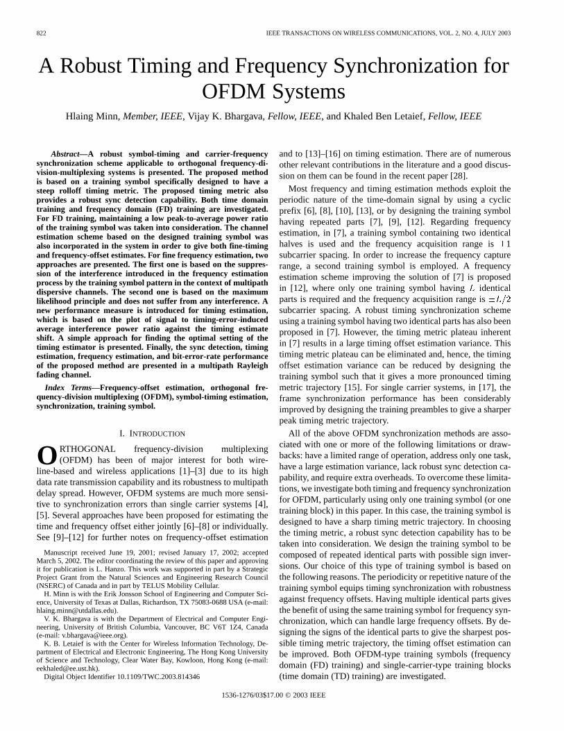
point IFFT and identical parts), and it is generated bythe -point IFFT of a length Golay complementarysequence. By contrast, for TD training, a length Golaycomplementary sequence is directly used in the TD as the basicrepeated part. In this case, it represents a constant amplitudetraining sequence. However, the cyclic prefix extension basedstructure is still maintained in the context of TD training. As anexample, let , 4, the bipolar representationof Golay complementary sequence of length 16 be, and thetime-domain repeated part of length 16 be. Then, for TDtraining and for FD training . In Fig. 2,the corresponding time-domain samples of the training symbol(excluding cyclic prefix) with the pattern , which canbe given by , are presented. The repeatedpart boundaries are indicated by dashed lines.
1) Training Symbol Pattern:Suppose that the trainingsymbol (excluding cyclic prefix) is composed of identicalparts as , where represents the re-peated part. If the timing metric given in (14) and (15) isused, then the best patterns (signs of the repeated parts) ofthe training symbol obtained by computer search are given inTable I for 10% cyclic prefix, and 4, 8, and 16. Thesepatterns were obtained by finding the patterns which give aminimum value of . In the computer search,
correspond to the training symboland the other are simply set to zero. In Fig. 3(a), theplots of for all possible patterns with 4 are shown.The patterns can be expressed as the bipolar form of the binaryrepresentation of the pattern sequence numbers shown onthe subplots. From Fig. 3(a), it can be observed that the bestpattern sequence numbers are 2, 7, 8, and 13. In Fig. 3(b),the corresponding values of are shown forall pattern sequence numbers. The pattern sequence numbers2, 7, 8, and 13 have the minimum value. It can be observedthat the minimum values generally correspond to the best
826 IEEE TRANSACTIONS ON WIRELESS COMMUNICATIONS, VOL. 2, NO. 4, JULY 2003
Fig. 2. Example of the time-domain samples of the 64-sample length training symbol defined by[�AAA AAA �AAA �AAA]. (The corresponding training symbolpattern is[�+��]. The cyclic prefix part is not shown.) (a) Real part for FD training. (b) Imaginary part for FD training. (c) TD training.
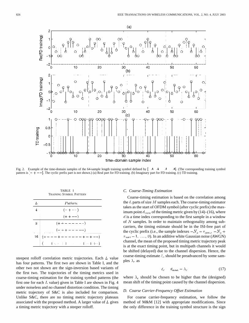
TABLE ITRAINING SYMBOL PATTERN
steepest rolloff correlation metric trajectories. Eachvaluehas four patterns. The first two are shown in Table I, and theother two not shown are the sign-inversion based variants ofthe first two. The trajectories of the timing metrics used incoarse-timing estimation for the training symbol patterns (thefirst one for each value) given in Table I are shown in Fig. 4under noiseless and no channel distortion condition. The timingmetric trajectory of S&C is also included for comparison.Unlike S&C, there are no timing metric trajectory plateausassociated with the proposed method. A larger value ofgivesa timing metric trajectory with a steeper rolloff.
C. Coarse-Timing Estimation
Coarse-timing estimation is based on the correlation amongthe parts of size samples each. The coarse-timing estimatortakes as the start of OFDM symbol (after cyclic prefix) the max-imum point of the timing metric given by (14)–(16), where
is a time index corresponding to the first sample in a windowof samples. In order to maintain orthogonality among sub-carriers, the timing estimate should be in the ISI-free part ofthe cyclic prefix (i.e., the sample indexes
). In an additive white Gaussian noise (AWGN)channel, the mean of the proposed timing metric trajectory peakis at the exact timing point, but in multipath channels it wouldbe shifted (delayed) due to the channel dispersion. Hence, thecoarse-timing estimate should be preadvanced by some sam-ples as
(17)
where should be chosen to be higher than the (designed)mean shift of the timing point caused by the channel dispersion.
D. Coarse Carrier-Frequency Offset Estimation
For coarse carrier-frequency estimation, we follow themethod of M&M [12] with appropriate modifications. Sincethe only difference in the training symbol structure is the sign

MINN et al.: ROBUST TIMING AND FREQUENCY SYNCHRONIZATION FOR OFDM SYSTEMS 827
Fig. 3. (a) Plot ofjP (d)j versusd=N corresponding to all possible patterns forL = 4. The patterns can be expressed as the bipolar representation of thesequence number shown on the subplots. (b) The corresponding plot of jP (d)j versus all patterns denoted by the sequence numbers.
pattern of identical parts, the training symbol defined by thetiming estimator is first modified to have the same structureas that proposed in M&M by multiplying the parts with
the sign pattern applied in the training symbol design. Then,the method of M&M is applied as follows. Let the modifiedtraining symbol defined by the coarse-timing estimate be

828 IEEE TRANSACTIONS ON WIRELESS COMMUNICATIONS, VOL. 2, NO. 4, JULY 2003
Fig. 4. Timing metric trajectory under noiseless conditions assuming nochannel distortion. (Time index 0 corresponds to the exact timing point.)
represented by . Then, the coarsefrequency-offset estimator is given by
(18)
where
(19)
(20)
(21)
and denotes modulo operation (it reduces to the in-terval ), is argument of , and is adesign parameter less than or equal to . The optimal valuefor is which will be used in our approach.
The frequency-offset estimation range is subcarrierspacing for a training symbol havingidentical parts. However,the range is not limited by the lengthof the sign pattern in ourdesign. For example, by designing the repeated part havingidentical subparts and using and ,the range becomes . This is because the range dependson the spacing between the correlating identical parts and isdefined by .
In a multipath dispersive channel, the repeated parts of thereceived training symbol will not be equal, even in the absenceof noise, due to the sign conversion in the transmitted trainingsymbol. This effect perturbs the repetitive nature of the receivedtraining symbol. For frequency estimation, the received trainingsymbol is multiplied with the sign pattern to restore the repeti-tive parts of all equal sign, but this sign flipping will not remedythe already channel-impaired repetitive parts. Hence, some in-terference is introduced to frequency estimation. Suppression ofthis interference will be addressed in the fine frequency-offsetestimation.
E. Channel Impulse Response Estimation
Assume that the channel response remains constant over atleast one OFDM symbol interval (quasi-static case), and let theinstantaneous path gains be . Let us definethe following:
diag
...(22)
where are the samplesof the transmitted training symbol (including the cyclic prefixpart), the corresponding re-ceived samples (excluding the cyclic prefix part),
the noise samples, andthe normalized fre-quency offset. The received sample vector can then be expressedas
(23)
Utilizing the frequency-offset estimatein place of , the MLchannel response estimate [25] can be realized by
(24)
where represents a Hermitian transpose, representsa generalized matrix inverse, and the phase factor has been ab-sorbed in the channel estimate.
In the above channel estimation, the knowledge of the max-imum channel delay spread is required. In practice, a designvalue has to be used. Moreover, due to the timing estima-tion error and the timing advance introduced in Section IV-C,the received training vector will be . The advancement ofthe timing offset estimate should be adjusted such thatbe-comes negative most of the time. Otherwise, it will not onlyintroduce ISI, but also miss some channel taps in the channelestimation and cause large channel estimation errors. Conse-quently, the designed channel estimate length should be longerthan the designed maximum channel delay spread plus the delayintroduced by timing estimate advancement. Let the designedchannel estimate length be (which may be set to the guardinterval length). By replacing with in (22), the channelresponse estimate is given by
(25)
where is the frequency-offset compensated re-ceived training vector defined by the timing estimate.
If the length of the basic repeated training symbol partis larger than the maximum channel delay spread, then thechannel estimation complexity can be reduced by combiningthe basic repeated parts as follows. Let us consider 4 and

MINN et al.: ROBUST TIMING AND FREQUENCY SYNCHRONIZATION FOR OFDM SYSTEMS 829
let the repeated parts of the received training symbol, afterfrequency-offset compensation, be . Then, fromthe training symbol pattern , it can be observedthat and are equivalently affected by the multipathfading environment. Similarly, and are equivalentlyaffected. Averaging over each set yieldsand . Note that the separate use ofand is an impact of the training symbol pattern. Definecomposed of as
...(26)
Then, the channel estimate based oncan be obtained as
(27)
while based on can be obtained in a similar fashion usingcomposed of . The final
channel estimate is taken as the average ofand as
(28)
A similar approach can be applied to 8 and 16 cases, if thelength of the repeated part is much larger than the maximumchannel delay spread. Throughout our simulations, (25) will beused for channel estimation.
F. Fine-Timing Estimation
The coarse-timing estimate would be, most of the time, be-fore the actual timing point due to the preadvancement. How-ever, even under noiseless conditions, the timing estimate wouldbe varying according to the time-varying nature of the channelresponse. Accordingly, at different snap shots, the channel esti-mates would be delayed by different amounts due to differenttiming offset errors. If the delay in the channel estimate canbe found, the effect of the time-varying channel response onthe timing estimation can be removed by simply delaying thecoarse-timing estimate by the same amount of the channel es-timate delay. In other words, the coarse-timing estimate can befine-tuned by adding the delay of the first actual channel tapfrom the channel estimate. A similar concept has been appliedin [16], where some pilot tones are used throughout the burst(hence, FD-based channel estimation), consecutive channelimpulse response estimates are averaged, and the first channeltap is found by some criteria. In our considered system withone training symbol, the channel estimation is based on onesnap-shot estimation in the TD, and a different criteria describedin the following is used for the first channel tap selection.
One way of finding the delay of the first actual channel tap isdescribed in the following. First, the strongest tap gain estimate
is found as .Then, the delay estimate of the first actual channel tapis givenby
(29)
where
if
otherwise.
(30)
is the channel energy estimate contained in a length-window starting from the tapwith a condition that the channelenergy estimate of tapshould be greater than some threshold.This condition reduces the probability of choosing a noise-onlytap as the first actual channel tap. The delay estimate of the firstactual channel tap given in (29) is essentially the starting tapindex whose associated energy is maximum. Due to thetiming advancement in the coarse stage, the actual channelimpulse response would be delayed by some amount. Sincethe channel estimate has taps and the designed maximumchannel delay spread is , the range of the starting tap indexof the energy window is , as described in (29).It should be noted that in order to keep the actual channel im-pulse response within the channel estimation length,should be smaller than .
In the above equation,is a threshold factor for selecting thefirst channel tap. Note thatshould be small if we do not wantto miss the first tap. However,should not be too small. Other-wise, the noise will increase the probability of wrongly pickingup the channel tap before the first tap. One way for findingfordifferent signal-to-noise ratio (SNR) values is given by (see theAppendix)
SNRSNR
(31)
where is a known value obtained from the simulation at SNRand is the threshold value for SNR.
The fine-timing estimate is obtained by adding the delay esti-mate of the first actual channel tap to the coarse-timing estimateas
(32)
where is a designed preadvancement to reduce the possibleISI. Without the preadvancement of, the fine-timing estimatewould be, most of the time, at the exact timing point. However,for the circumstances when the absolute gain ratio of the firsttap to the strongest tap is smaller than, the most likely chosenchannel tap as the first tap would be the second channel tap.Hence, should be at least the delay difference between thefirst and the second taps.
The preadvancement of fine-timing estimate may introduceinterference in the frequency-offset estimation. The reason isthat when the timing-advanced training symbol is multiplied bythe training symbol pattern, the offset caused by the timing ad-vancement would perturb the repeated structure of the trainingsymbol and introduce some interference. Hence, a better choiceof the received training symbol for frequency-offset estimationshould be defined by the fine-timing estimate without pread-vancement; namely, , and the fine-timing estimateis then advanced by , as in (32). In this way, the timing offset

830 IEEE TRANSACTIONS ON WIRELESS COMMUNICATIONS, VOL. 2, NO. 4, JULY 2003
error interference in the frequency-offset estimation can be re-duced and at the same time the ISI caused by the timing offseterror can be reduced by means of preadvancement.
G. Fine Frequency Estimation
As mentioned in the coarse frequency estimation section, thetraining symbol pattern can introduce some interference to fre-quency estimation. If this interference is not taken into consider-ation in the fine stage, the fine frequency estimation will inheritthe performance degradation. To suppress this interference, thedifferently affected received samples can be excluded from thefrequency estimation. For 4 and the training symbol pat-tern of , it can be observed that after multiplying thereceived training symbol with the training symbol pattern, thefirst ( ) received samples of the second and third repeatedparts are different from those of the other repeated parts, even inthe absence of noise. Hence, they impair the repeated structureand introduce the interference. By excluding them, the interfer-ence can be suppressed. In practice, the firstsamples (de-signed maximum channel delay spread) of the second and thirdrepeated parts may be excluded. The exclusion of those sam-ples can easily be done by masking them with zeros. Then, themodified procedure becomes zero masking, sign flipping, andapplying M&M. This zero-masking approach can be applied ifthe number of samples in the basis part is much larger than themaximum channel delay spread.
Another approach to avoid the interference is based on theML principle. Since fine-timing synchronization will most ofthe time give a perfect timing, we will assume that perfect timinghas been achieved. By replacingby the ML channel estimate(24), the ML frequency estimation can be obtained by maxi-mizing the following metric:
(33)
where , and is an matrix. Ifand , the above metric is exactly the same as
that described in [26].In the implementation of maximizing the metric, [26] used
point FFT in finding . Hence, the search space foris ap-proximately over the range of , and the resolutionbetween trial frequency-offset points is subcarrier spacing.In this paper, we make use of the information from the coarsefrequency estimation. Since the coarse frequency-offset esti-mate cannot be too far away from the actual frequency offset, welimit the search space foraround the coarse frequency-offsetestimate as follows:
(34)
The trial points for are taken at a resolution ofsubcarrier spacing within the search space; namely,
, where is the numberof trial points at one side of . The value of can be chosenaccording to the coarse frequency estimation performance. Forexample, if the error of the normalized coarse frequency-offsetestimate is expected to be less than 0.01 (which is usually thecase for good coarse frequency estimation methods at moderate
or high SNR values), may be set to 0.01 or a little larger (say)0.05. Finally, the final frequency-offset estimate is given by
if or
otherwise(35)
where is obtained by quadratic interpolation among thepoints , , and .
V. PERFORMANCE EVALUATION , SIMULATION
RESULTS AND DISCUSSION
A. Simulation Parameters
The performance of the proposed synchronization algo-rithm has been investigated by computer simulation. TheOFDM system parameters used are 1024 subcarriers, 1024point IFFT/FFT, and 10% guard interval (102 samples). Thesubcarrier modulation is quaternary phase-shift keying and acarrier-frequency offset of 6.2-subcarrier spacing is assumed.Unless stated otherwise, 10 000 simulation runs will be applied.For the training symbol pattern, the first one of the two patternsgiven in Table I is used for each value.
The channels considered are described in the following. Allchannels except AWGN channel have 16 taps with equal tapspacing of four samples. The Rayleigh fading channel has an ex-ponential power delay profile and the ratio of the first Rayleighfading tap to the last Rayleigh fading tap is set to 20 dB. TheRician fading channel has a Rician factor of four and the firsttap with delay zero is set as the direct path. The other taps areRayleigh fading taps with an exponential power delay profileand the ratio of the first Rayleigh fading tap to the last Rayleighfading tap is set to 20 dB. The static ISI channel has fixedtap gains and the tap gain powers are the same as those of theRayleigh fading channel.
The channel estimation length is set to the guard intervallength . The actual maximum channel delay spreadfor theconsidered multipath channels is 61. Since the designed max-imum channel delay spread should be at least equal to orlarger than , we set . In order to keep the channelimpulse response within the channel estimation length, both
and should be smaller than . Hence, we use. Due to the better timing estimation in the fine stage,
can be set to be smaller than. The selection of the valueof is described in our proposed timing performance mea-sure which will be described in Section V-C. In brief, canbe chosen from the interference-free interval which is shown inour proposed timing performance measure. Based on the abovereasons, we set . We estimate that the coarse normal-ized frequency-offset error would be less than 0.01 for moderateand high SNR values. Hence, we setto a little larger value0.05. Since frequency-offset trial points with a resolu-tion of subcarrier spacing are evaluated in the fine stage,a larger value of can give a slightly better frequency estima-tion performance, but with a higher complexity. Since we alsointerpolate as in (35), a frequency resolution of 0.005 is a rea-sonable value. Hence, we use the correspondingvalue of 10.We evaluated several trial values 0.8, 0.4, 0.2, 0.05, 0.01 for,the channel tap selection threshold at the SNR value of 10 dB.Since gives the best fine-timing estimation variance
MINN et al.: ROBUST TIMING AND FREQUENCY SYNCHRONIZATION FOR OFDM SYSTEMS 831
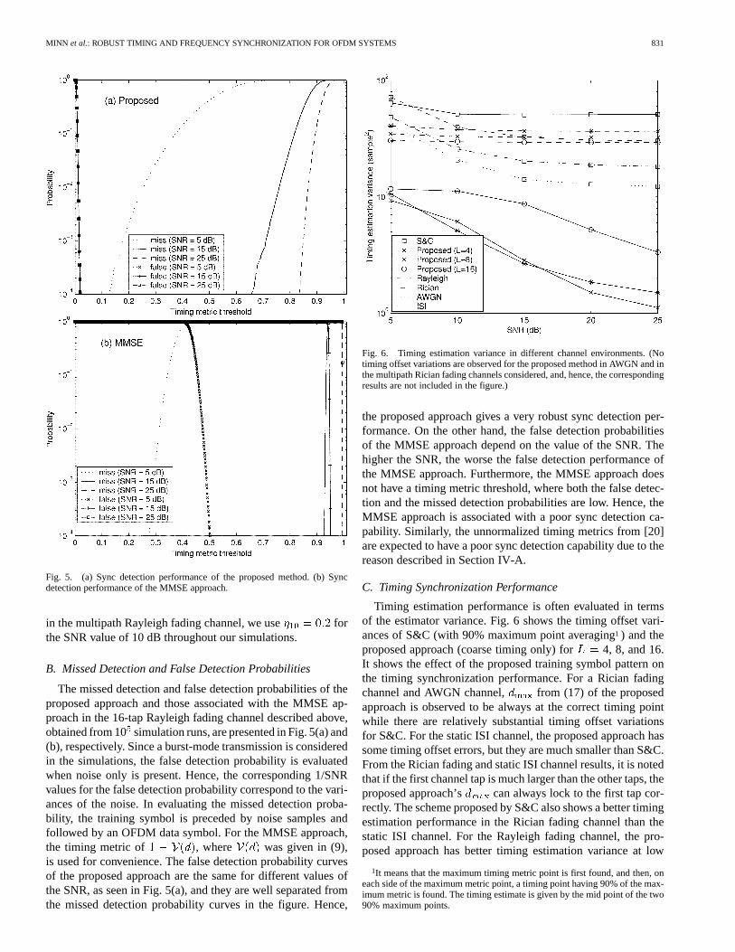
Fig. 5. (a) Sync detection performance of the proposed method. (b) Syncdetection performance of the MMSE approach.
in the multipath Rayleigh fading channel, we use forthe SNR value of 10 dB throughout our simulations.
B. Missed Detection and False Detection Probabilities
The missed detection and false detection probabilities of theproposed approach and those associated with the MMSE ap-proach in the 16-tap Rayleigh fading channel described above,obtained from 10simulation runs, are presented in Fig. 5(a) and(b), respectively. Since a burst-mode transmission is consideredin the simulations, the false detection probability is evaluatedwhen noise only is present. Hence, the corresponding 1/SNRvalues for the false detection probability correspond to the vari-ances of the noise. In evaluating the missed detection proba-bility, the training symbol is preceded by noise samples andfollowed by an OFDM data symbol. For the MMSE approach,the timing metric of , where was given in (9),is used for convenience. The false detection probability curvesof the proposed approach are the same for different values ofthe SNR, as seen in Fig. 5(a), and they are well separated fromthe missed detection probability curves in the figure. Hence,
Fig. 6. Timing estimation variance in different channel environments. (Notiming offset variations are observed for the proposed method in AWGN and inthe multipath Rician fading channels considered, and, hence, the correspondingresults are not included in the figure.)
the proposed approach gives a very robust sync detection per-formance. On the other hand, the false detection probabilitiesof the MMSE approach depend on the value of the SNR. Thehigher the SNR, the worse the false detection performance ofthe MMSE approach. Furthermore, the MMSE approach doesnot have a timing metric threshold, where both the false detec-tion and the missed detection probabilities are low. Hence, theMMSE approach is associated with a poor sync detection ca-pability. Similarly, the unnormalized timing metrics from [20]are expected to have a poor sync detection capability due to thereason described in Section IV-A.
C. Timing Synchronization Performance
Timing estimation performance is often evaluated in termsof the estimator variance. Fig. 6 shows the timing offset vari-ances of S&C (with 90% maximum point averaging1 ) and theproposed approach (coarse timing only) for 4, 8, and 16.It shows the effect of the proposed training symbol pattern onthe timing synchronization performance. For a Rician fadingchannel and AWGN channel, from (17) of the proposedapproach is observed to be always at the correct timing pointwhile there are relatively substantial timing offset variationsfor S&C. For the static ISI channel, the proposed approach hassome timing offset errors, but they are much smaller than S&C.From the Rician fading and static ISI channel results, it is notedthat if the first channel tap is much larger than the other taps, theproposed approach’s can always lock to the first tap cor-rectly. The scheme proposed by S&C also shows a better timingestimation performance in the Rician fading channel than thestatic ISI channel. For the Rayleigh fading channel, the pro-posed approach has better timing estimation variance at low
1It means that the maximum timing metric point is first found, and then, oneach side of the maximum metric point, a timing point having 90% of the max-imum metric is found. The timing estimate is given by the mid point of the two90% maximum points.

832 IEEE TRANSACTIONS ON WIRELESS COMMUNICATIONS, VOL. 2, NO. 4, JULY 2003
Fig. 7. SIR average interference power ratio and its approximate version versus timing estimate shift in the 16-tap Rayleigh fading channel at an SNR value of10 dB.
SNR values but comparable variance at high SNR values whencompared with S&C.
For AWGN, static ISI, and Rician channels, the timing esti-mation variance with reference to the first channel tap has somemeaning since the first tap represents the desired timing point.However, for the Rayleigh fading channel, all channel tap gainsare time-varying, and missing the first tap with negligible gainmay not result in a performance degradation. Hence, the timingestimation variance with reference to the first channel tap maynot represent a good performance measure in this case. More-over, for OFDM systems, as long as the timing estimate is withinthe ISI-free guard interval, the timing offset, regardless of itsvalue, will not degrade the system performance. Only when thetiming estimate falls outside the ISI-free guard interval, interfer-ence will be introduced. Hence, a more performance-orientedapproach of evaluating the timing synchronization performancefor a particular OFDM system would be the measure of interfer-ence power caused by the timing offsets. For each timing offset, the corresponding normalized interference power , nor-
malized by the signal power, can be calculated as
(36)
where and are given by (5) and (6), respectively.Let the distribution of the timing offset estimates for the con-
sidered system and channel be . The average normalizedinterference power caused by timing offset errors can then begiven by
(37)
The calculation of requires an instantaneous channel re-sponse (or instantaneous channel power gains) [see (5), (6), and(36)]. Furthermore, the interference power can depend on thetiming estimate shift . Note that in (17). Hence, itis not so easy to evaluate for different parameter settings ofthe timing estimator such as different timing estimate shifts.One way to circumvent this is to approximate calculationby which uses the channel power delay profile instead ofthe instantaneous channel power gains.
By assuming that the timing estimate is independent of theinstantaneous channel response,2 an approximation of fora timing estimate shift , denoted by , can be calculated as
(38)
From the above equation, the optimum timing estimate shiftfor a considered system and channel can be obtained by
(39)
Let us define the average signal to timing-error-induced in-terference power ratio SIR and its approximate ver-sion SIR . In Fig. 7, theSIR versus timing estimateshifts are plotted for S&C and the proposed method (4, FDtraining) for the Rayleigh fading channel at the SNR value of10 dB. Also included in the figure are the SIRvalues for thetiming estimate shifts of 50, 40, , 30 samples. It can beobserved that SIRandSIR are almost the same for S&C andthe coarse-timing stage of the proposed method, thus indicating
2Strictly speaking, this is not true.

MINN et al.: ROBUST TIMING AND FREQUENCY SYNCHRONIZATION FOR OFDM SYSTEMS 833
Fig. 8. Timing synchronization performance in terms ofSIR in the 16-tap Rayleigh fading channel at an SNR value of 5 dB.
that the proposed approximate performance measure is a closeapproximation.
For the proposed fine-timing stage with one iteration(“Fine ”) and two iterations (“Fine”), the actual values SIRat the timing estimate shifts of10 and 0 samples are greaterthan the approximate valuesSIR by some amount. This canbe explained as follows. The approximate expressionSIR isunder the assumption that the timing estimate is independentof the instantaneous channel response. However, the proposedfine stage utilizes the information from the channel estimation.Hence, the above assumption is not justified. It can be observedthat at these timing estimate shifts, the interference is caused bytiming offsets greater than zero. For the proposed fine-timingstage, this will most likely happen when the first channel tapgain is quite small. Consequently, the introduced interferencewhich depends on the first channel tap gain would be smallerthan the interference used inSIR where the power delayprofile is used. Despite some differences in values, the plots ofSIR andSIR for the fine stage show the same trend. Hence,it still gives useful information on what timing estimate shiftwould be suitable.
Fig. 7 demonstrates the importance of proper timing shift set-ting. It can also be observed that comparing two timing estima-tors, each with a fixed timing estimate shift, will not give thegeneral performance of the timing estimators. Each timing esti-mator has its own optimum timing estimate shift value(s). Theoptimum timing estimate shift for S&C in this case is at 14 sam-ples, which still introduces some interference. For the proposedcoarse-timing case, the optimum shift is at40 samples whereno interference is introduced. For the fine-timing stage, the in-
terference-free timing shift is within the interval from42 to16 samples.It should be mentioned that although the timing estimation
variance of 16 (coarse) case for the static ISI channel inFig. 6 is larger than 4 and 8 cases, evaluatingSIR versustiming estimate shifts plot at the SNR value of 10 dB gives aninterference-free interval of 35 samples (46 to 12) for both
16 and 8 cases, 28 samples (45 to 18) for 4 case.Due to space limitation, this is not shown. From this fact, it canbe stated that the timing estimation variance in OFDM systemmay not always result in a meaningful performance measure.
In Figs. 8–10, the timing estimation performance in theRayleigh fading channel in terms ofSIR are presented forS&C and the proposed method. Both FD training and TDtraining are evaluated for the proposed method with 4,8, and 16 cases. A close observation of these figures indicatesthat the proposed coarse-timing stage has better performancethan S&C, particularly at low SNR values. At high SNRvalues, S&C has a comparable performance to the proposedcoarse-timing stage. For example, at an SNR value of 25 dB,S&C has an interference-free timing shift interval of foursamples (15 to 18), and the proposed coarse-timing stage hasfive samples ( 41 to 37) for FD and nine samples (42 to
34) for TD. The coarse-timing stage with a larger value ofhas a larger interference-free interval. It can be ascribed
to the sharper timing metric trajectory for the largervalue.The fine-timing stages (“Fine” and “Fine ”) are observed togive significant improvement over the coarse-timing stage.Although the “Fine” case has generally a slight improvementover the “Fine” case, the performance gain is not significantand may not be justified for the associated complexity cost.

834 IEEE TRANSACTIONS ON WIRELESS COMMUNICATIONS, VOL. 2, NO. 4, JULY 2003
Fig. 9. Timing synchronization performance in terms ofSIR in the 16-tap Rayleigh fading channel at an SNR value of 15 dB.
Fig. 10. Timing synchronization performance in terms ofSIR in the 16-tap Rayleigh fading channel at an SNR value of 25 dB.
The fine stages with different values have almost the sameperformance, except at an SNR value of 5 dB, where the8case has some degradation. This fact indicates that the channelestimation at the fine-timing stage depends on thevalue or thetraining symbol pattern. Since the training symbol is of repeti-tive structure with some sign conversion, the channel estimate
can be a quite different one, rather than a delayed version, inthe presence of a large delay timing offset. Hence, it can resultin a wrong selection of the first channel tap and introduce sometiming error at the fine stage. This occasional occurrence is ob-served in the simulation of the 8 case at an SNR valueof 5 dB. In particular, “Fine” stage of 8 case with FD

MINN et al.: ROBUST TIMING AND FREQUENCY SYNCHRONIZATION FOR OFDM SYSTEMS 835
Fig. 11. Frequency estimation MSE performance of the proposed approaches withL = 4 in the 16-tap Rayleigh fading channel.
training shows such an occurrence but “Fine” stage is observedto be able to correct the corresponding timing error. However,“Fine ” stage of 8 case with TD training is unable to cor-rect it. Nevertheless, all these cases still have better performancethan S&C. It is also observed from Figs. 8–10 that TD traininghas a slightly better performance than FD training for all casesexcept the fine stage of 8 case at an SNR value of 5 dB.
D. Performance of Frequency Synchronization
The frequency synchronization performance can be evaluatedby the average normalized interference power(normalizedby the signal power) caused by frequency estimation errors. Thenormalized interference power caused by a normalized(by subcarrier spacing) frequency estimate errorcan be ap-proximated by [21]
(40)
Hence, can be calculated from the mean square error (MSE)of the normalized frequency-offset estimate mseas
mse (41)
It is noted that the frequency-offset estimation MSE directlytranslates into the average interference power caused by the fre-quency estimation errors while the variance of the timing offsetestimate does not directly translate into the interference powercaused by timing estimation errors. In the following, the fre-quency estimation MSE will be used as the performance mea-sure for the frequency synchronization.
Figs. 11 and 12 show the frequency estimation performancein the Rayleigh fading channel. The performance of M&M [12]using a training symbol with 16 identical parts (no sign flipping)under perfect timing synchronization is included as a reference.For the proposed scheme, the results are presented for the casesof coarse frequency estimation (“Coarse”), fine frequency esti-mation without zero masking (“Fine”), fine frequency estima-tion with zero masking (“zero mask”), and ML frequency esti-mation (“ML”). Only the results of the fine stage with one it-eration are presented since no noticeable difference is observedbetween one and two iterations.
All the fine stages have performance improvement over thecorresponding coarse stages. However, all fine cases which donot consider the interference effect have some performancedegradation if compared with M&M with perfect timing. Aninteresting observation from the results of “Fine” case withdifferent values is that the different training symbol patternshave different impacts on the frequency estimation perfor-mance. As previously mentioned, the training symbol patterncan introduce some interference in the frequency estimation ina dispersive channel. This interference seems to be larger forthe training symbol pattern of the 8 case, particularly withFD training, as can be observed in Fig. 12(a). Interestingly,TD training is much more robust to this kind of interferencethan FD training except for the 8 case at an SNR valueof 5 dB. An intuitive reason for the better performance of TDtraining is that the TD training sample energies are distributedevenly, and so do the average noise samples energies. Hence,the energy distribution of TD training is matched to that of thenoise, while FD training does not.

836 IEEE TRANSACTIONS ON WIRELESS COMMUNICATIONS, VOL. 2, NO. 4, JULY 2003
Fig. 12. Frequency estimation MSE performance of the proposed approaches withL = 8 and 16 in the 16-tap Rayleigh fading channel.
Fig. 13. BER performance comparison between the ideally synchronized system and the system using the proposed method (L = 4, FD training, zero masking)in the 16-tap Rayleigh fading channel.
In Fig. 11(b), the performance of the fine frequency estima-tion approaches, which consider the interference effect, are pre-
sented. In fact, the ML approach does not suffer from the in-terference effect. Both zero-masking approaches with FD and

MINN et al.: ROBUST TIMING AND FREQUENCY SYNCHRONIZATION FOR OFDM SYSTEMS 837
TD training have almost the same performance and this perfor-mance is very close to the performance of M&M with perfecttiming. Hence, zero masking appears to be an effective approachfor the system which uses only one FD training (with possiblesign flipping of the repetitive parts) for both timing and fre-quency synchronization and the length of one repetitive part isquite larger than the maximum channel delay spread. The MLapproach has even a better performance than M&M, particularlyat low SNR values. However, in Fig. 12, the ML schemes with
8 and 16 cases show some performance degradation at anSNR value of 5 dB if compared with 4 case. In fact, this isdue to the occasional occurrence of the coarse frequency-offsetestimates for which the search space isnot close enough to the actual frequency offset where we notethat 0.05 is used in the simulation. To confirm this fact,the ML approach for 8 and 16 cases at an SNR value of5 dB are evaluated for 1.5, and 10. The results ob-tained (not shown in the figure) are almost the same as that ofML with 4.
In general, TD training outperforms FD training. If only onetraining is used for both timing and frequency synchronization,the impact of the training symbol pattern can affect the fre-quency estimation performance. In this case, TD training orFD training with the zero-masking approach can be considered.If complexity is affordable, the ML approach can be consid-ered. If two training symbols are applied, one with the proposedtraining symbol pattern can be considered for timing synchro-nization using the proposed timing metric, and the other repeti-tive training without sign flipping can be considered for the fre-quency estimation using M&M. Also in this case, TD trainingis preferable over FD training.
E. BER Performance
Fig. 13 presents the BER performance comparison betweenthe system using the proposed method and the system havingideal timing and frequency synchronization with the samechannel estimation as in the proposed method. The consideredsystem uses FD training followed by an OFDM data symbol andthe channel is the multipath Rayleigh fading channel describedpreviously. In the proposed method, the zero-masking approachis used for fine frequency estimation. For SNR values of 25 dBand above, 100 000 simulation runs were used compared with10 000 simulation runs for the other SNR values. It can be seenthat for all SNR values, the proposed method has virtually thesame BER performance as the perfectly synchronized system.
VI. CONCLUSION
A robust symbol-timing and carrier-frequency synchro-nization method for OFDM systems in multipath fadingenvironments has been presented. The proposed method usesone specifically designed training symbol having a steep rollofftiming metric trajectory. This type of training symbol achievessome improvement in timing estimation for time-varying mul-tipath Rayleigh fading channels and much more improvement
in AWGN, Rician fading, and static dispersive channels. Thechannel estimation based on the designed training symbol isalso incorporated to give further improvement in timing andfrequency synchronization. This combined approach achievesconsiderable improvement by removing the time-varyingmultipath effect on timing synchronization. Using the trainingsymbol of identical parts with different signs, however, canintroduce interference in the frequency estimation based onthat training symbol. An approach of masking the interferedpart with zeros is shown to be an effective way for suppressingthe introduced interference in the frequency estimation. AnML frequency estimation which does not suffer from thisinterference is also described. From the simulation, using TDtraining is observed to be better than FD training.
For frequency estimation, MSE or frequency-error-intro-duced interference power reflects the frequency synchronizationperformance. However, for timing estimation, the plot of signalto (timing-error-induced) average interference power ratioSIR versus timing estimate shift for the considered system andchannel appears to be a more revealing performance measure.A close approximation of this SIRis also proposed using thechannel power delay profile. This approximation also yields asimple approach for finding the optimum setting of the timingestimator.
APPENDIX
This appendix outlines the main steps in obtaining (31). De-fine two random variables and as
corresponds to the first actual channel tap
is integer 0 (42)
(43)
and can be approximated as complex Gaussian vari-ables with zero means and variancesand , where
SNR
SNR(44)
where is the variance of theth channel tap gain,, and and are some constants 0.Now, our interest is to find Prob , . By
defining another random variable , we obtain
Prob Prob
(45)
Using SNR in the above equation resultsin (31).

838 IEEE TRANSACTIONS ON WIRELESS COMMUNICATIONS, VOL. 2, NO. 4, JULY 2003
REFERENCES
[1] H. Sari, G. Karam, and I. Jeanclaude, “Transmission techniques fordigital terrestrial TV broadcasting,”IEEE Commun. Mag., vol. 33, pp.100–109, Feb. 1995.
[2] U. Reimers, “Digital video broadcasting,”IEEE Commun. Mag., vol.36, pp. 104–110, June 1998.
[3] L. J. Cimini, Jr., J. C. Chuang, and N. R. Sollenberger, “Advanced cel-lular Internet services,”IEEE Commun. Mag., vol. 36, pp. 150–159, Oct.1998.
[4] T. Pollet, M. Van Bladel, and M. Moeneclaey, “BER sensitivity ofOFDM systems to carrier frequency offset and Wiener phase noise,”IEEE Trans. Commun., vol. 43, pp. 191–193, Feb./Mar./Apr. 1995.
[5] M. Gudmundson and P. O. Anderson, “Adjacent channel interference inan OFDM system,” inProc. Vehicular Technol. Conf., Atlanta, GA, May1996, pp. 918–922.
[6] J.-J. van de Beek, M. Sandell, and P. O. Börjesson, “ML estimation oftime and frequency offset in OFDM systems,”IEEE Trans. Signal Pro-cessing, vol. 45, pp. 1800–1805, July 1997.
[7] T. M. Schmidl and D. C. Cox, “Robust frequency and timing synchro-nization for OFDM,” IEEE Trans. Commun., vol. 45, pp. 1613–1621,Dec. 1997.
[8] M. Speth, D. Daecke, and H. Meyr, “Minimum overhead burst syn-chronization for OFDM based broadband transmission,” inProc. GlobalTelecommun. Conf., Sydney, Australia, Nov. 1998, pp. 2777–2782.
[9] P. H. Moose, “A technique for orthogonal frequency division multi-plexing frequency offset correction,”IEEE Trans. Commun., vol. 42, pp.2908–2914, Oct. 1994.
[10] F. Daffara and O. Adami, “A new frequency detector for orthogonalmulticarrier transmission techniques,” inProc. Vehicular Technol. Conf.,Chicago, IL, July 1995, pp. 804–809.
[11] H. Nogami and T. Nagashima, “A frequency and timing period acquisi-tion technique for OFDM systems,”IEICE Trans. Commun., vol. E79-B,no. 8, pp. 1135–1146, 1996.
[12] M. Morelli and U. Mengali, “An improved frequency offset estimatorfor OFDM applications,”IEEE Commun. Lett., vol. 3, pp. 75–77, Mar.1999.
[13] M. Speth, F. Classen, and H. Meyr, “Frame synchronization of OFDMsystems in frequency selective fading channels,” inProc. VehicularTechnol. Conf., Phoenix, AZ, May 1997, pp. 1807–1811.
[14] L. Hazy and M. El-Tanany, “Synchronization of OFDM systems overfrequency selective fading channels,” inProc. Vehicular Technol. Conf.,Phoenix, AZ, May 1997, pp. 2094–2098.
[15] H. Minn, M. Zeng, and V. K. Bhargava, “On timing offset estimation forOFDM systems,”IEEE Commun. Lett., vol. 4, pp. 242–244, July 2000.
[16] B. Yang, K. B. Letaief, R. S. Cheng, and Z. Cao, “Timing recoveryfor OFDM transmission,”IEEE J. Select. Areas Commun., vol. 18, pp.2278–2290, Nov. 2000.
[17] S. A. Fechtel and H. Meyr, “Improved frame synchronization for spon-taneous packet transmission over frequency-selective radio channels,”in Proc. PIMRC, The Hague, The Netherlands, 1994, pp. 353–357.
[18] A. Czylwik, “Synchronization for single carrier modulation with fre-quency domain equalization,” inProc. VTC, Ottawa, ON, Canada, 1998,pp. 2277–2281.
[19] P. R. Chevillat, D. Maiwald, and G. Ungerboeck, “Rapid training ofa voiceband data-modem receiver employing an equalizer with frac-tional-T spaced coefficients,”IEEE Trans. Commun., vol. COM-35, pp.869–876, Sept. 1987.
[20] S. H. Müller-Weinfurtner, “On the optimality of metrics for coarse framesynchronization in OFDM: A comparison,” inProc. PIMRC, Boston,MA, 1998, pp. 533–537.
[21] M. Speth, S. A. Fechtel, G. Fock, and H. Meyr, “Optimum receiverdesign for wireless broad-band systems using OFDM—Part I,”IEEETrans. Commun., vol. 47, pp. 1668–1677, Nov. 1999.
[22] “Broadband Radio Access Networks (BRAN); HIPERLAN Type 2;Physical (PHY) layer technical specification,” ETSI, ETSI TS 101 475v1.1.1 (2000-04).
[23] M. J. E. Golay, “Complementary series,”IRE Trans. Inform. Theory,vol. IT-7, pp. 82–87, Apr. 1961.
[24] R. D. J. van Nee, “OFDM codes for peak-to-average power reductionand error correction,” inProc. Global Telecommun. Conf., London,U.K., Nov. 1996, pp. 740–744.
[25] S. M. Kay,Fundamentals of Statistical Signal Processing: EstimationTheory. Englewood Cliffs, NJ: Prentice-Hall, 1993.
[26] M. Morelli and U. Mengalli, “Carrier-frequency estimation for trans-missions over selective channels,”IEEE Trans. Commun., vol. 48, pp.1580–1589, Sept. 2000.
[27] U. Lambrette, M. Speth, and H. Meyr, “OFDM burst frequency synchro-nization by single carrier training data,”IEEE Commun. Lett., vol. 1, pp.46–48, Mar. 1997.
[28] T. Keller, L. Piazzo, P. Mandarini, and L. Hanzo, “Orthogonal frequencydivision multiplex synchronization techniques for frequency-selec-tive fading channels,”IEEE J. Select. Areas Commun., vol. 19, pp.999–1008, June 2001.
Hlaing Minn (S’99–M’01) received the B.E.degree in electronics from the Yangon Institute ofTechnology, Yangon, Myanmar, in 1995, the M.Eng.degree in telecommunications from the Asian In-stitute of Technology (AIT), Bangkok, Thailand, in1997, and the Ph.D. degree in electrical engineeringfrom the University of Victoria, Victoria, BC,Canada, in 2001.
He was with the Telecommunications Program atthe Asian Institute of Technology, as a LaboratorySupervisor during 1998. He was a Research Assis-
tant from 1999 to 2001 and a Research Fellow during 2002 in the Departmentof Electrical and Computer Engineering at the University of Victoria. SinceSeptember 2002, he has been an Assistant Professor with the Erik JonssonSchool of Engineering and Computer Science, the University of Texas at Dallas,Richardson, TX. His research interests include wireless communications,signal processing, and error-control coding, detection, and estimation.
Vijay K. Bhargava (S’70–M’74–SM’82–F’92)received the B.Sc., M.Sc., and Ph.D. degrees fromQueen’s University, Kingston, ON, Canada in 1970,1972, and 1974, respectively.
Currently, he is a Professor and Head of theDepartment of Electrical and Computer Engineeringat the University of British Columbia, Vancouver,BC, Canada. Previously, he was with the Universityof Victoria (1984–2003) and with Concordia Uni-versity in Montréal (1976–1984). He is a coauthor ofthe bookDigital Communications by Satellite(New
York: Wiley, 1981), coeditor ofReed–Solomon Codes and Their Applications(New York: IEEE, 1994), and coeditor ofCommunications, Information andNetwork Security(Boston, MA: Kluwer, 2002). His research interests are inmultimedia wireless communications.
Dr. Bhargava is very active in the IEEE and was nominated by the IEEEBoard of Directors for the Office of IEEE President-Elect. Currently, he serveson the Board of the IEEE Communications Society. He is an Editor for theIEEE TRANSACTIONS ONCOMMUNICATIONS and the IEEE TRANSACTIONS ON
WIRELESSCOMMUNICATIONS. He is a Past President of the IEEE InformationTheory Society. He is a Fellow of the B.C. Advanced Systems Institute, Engi-neering Institute of Canada (EIC), and the Royal Society of Canada. He is arecipient of the IEEE Centennial Medal (1984), IEEE Canada’s McNaughtonGold Medal (1995), the IEEE Haraden Pratt Award (1999), the IEEE Third Mil-lennium Medal (2000), and the IEEE Graduate Teaching Award (2002).

MINN et al.: ROBUST TIMING AND FREQUENCY SYNCHRONIZATION FOR OFDM SYSTEMS 839
Khaled Ben Letaief (S’85–M’86–SM’97–F’03)received the B.S. degree (with distinction) and theM.S. and Ph.D. degrees from Purdue University,West Lafayette, IN, in 1984, 1986, and 1990,respectively, all in electrical engineering.
From January 1985 and as a Graduate Instructorin the School of Electrical Engineering at PurdueUniversity, he has taught courses in communicationsand electronics. From 1990 to September 1993, hewas a faculty member in the Department of Electricaland Electronic Engineering at the University of
Melbourne, Australia, where he was also a Member of the Center for SensorSignal and Information Systems. Since September 1993, he has been withthe Department of Electrical and Electronic Engineering at The Hong KongUniversity of Science and Technology (HKUST), Hong Kong, where he isnow a Professor and Head. His current research interests include wirelessand mobile communications, OFDM, space–time processing for wirelesssystems, multiuser detection, wireless multimedia communications, andCDMA systems.
Dr. Letaief was appointed the founding Editor-in-Chief of the IEEETRANSACTIONS ON WIRELESS COMMUNICATIONS, in January 2002. Hehas served on the Editorial Boards of other journals including the IEEETRANSACTIONS ON COMMUNICATIONS, IEEE Communications Magazine,Wireless Personal Communications, and IEEE JOURNAL ON SELECTED AREAS
IN COMMUNICATIONS—WIRELESS SERIES (as Editor-in-Chief). He served asthe Technical Program Chair of the 1998 IEEE Globecom Mini-Conferenceon Communications Theory, held in Sydney, Australia. He is also the Co-Chairof the 2001 IEEE ICC Communications Theory Symposium, held in Helsinki,Finland. He is currently serving as Vice-Chair of the IEEE CommunicationsSociety Technical Committee on Personal Communications. He is alsocurrently the Vice chair of Meeting and Conference Committee of the IEEECOMSOC Asia Pacific Board. In addition to his active research activities,he has also been a dedicated teacher committed to excellence in teachingand scholarship. He received the Mangoon Teaching Award from PurdueUniversity in 1990, the Teaching Excellence Appreciation Award by the Schoolof Engineering at HKUST in Spring 1995, Fall 1996, Fall 1997, and Spring1999, and the Michael G. Gale Medal for Distinguished Teaching (highestuniversity-wide teaching award and only one recipient/year is honored forhis/her contributions).