Embed Size (px)
Citation preview
SORInc.com | 913-888-2630 | Registered Quality System to ISO 9001 1/16Form 388 (03.17) ©SOR Inc.
are robust field-mounted instruments. The 102 pressure sensing assembly is a piston; the 103 pressure sensing assembly is a diaphragm-piston combination. The 102/103 can be configured for service in non-hazardous and hazardous locations. Switching elements are SPDT or DPDT. See Principle on page 2.
Application InformationBasic models with standard wetted parts are normally suitable for air, oil, water and non-corrosive process fluids. See the Quick Selection Guide on page 4.
Corrosive service and particular user requirements may require optional components. See How to Order on page 3.
The 102 is suited for low-to-high differential pressure process or fluid power applications where high and varying static pressures, high overrange, proof, shock pressure or cycle rates are expected. The 103 is suited for low-to-medium differential pressure process or fluid power applications where similar system behavior is expected.
103AD: Explosion Proof
102/103 differential pressure switches
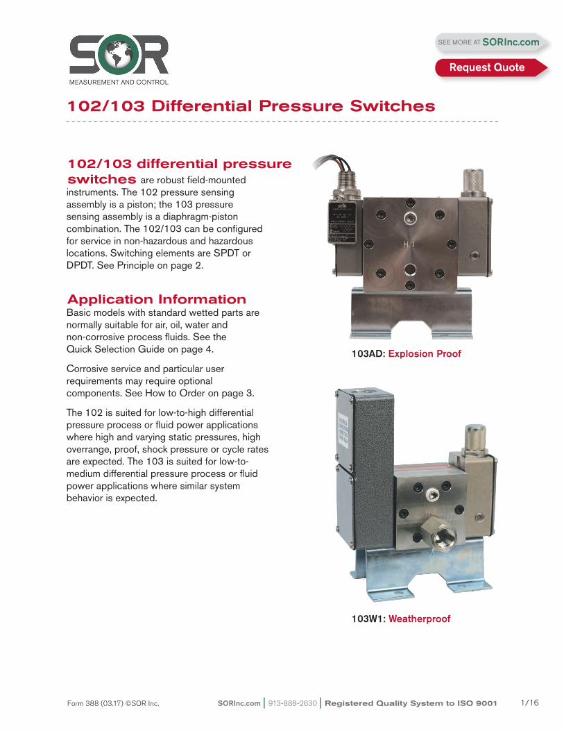
103W1: Weatherproof
102/103 Differential Pressure Switches
SEE MORE AT SORInc.com
Request Quote
Registered Quality System to ISO 9001 | 913-888-2630 | SORInc.com2/16 Form 388 (03.17) ©SOR Inc.
102/103Differential Pressure Switches Principle
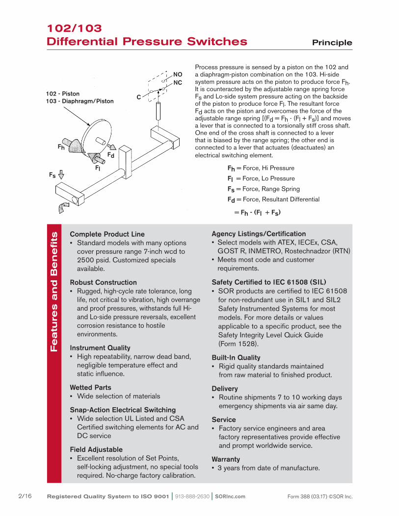
Fh = Force, Hi Pressure
Fl = Force, Lo Pressure
Fs = Force, Range Spring
Fd = Force, Resultant Differential = Fh - (Fl + Fs)
Process pressure is sensed by a piston on the 102 and a diaphragm-piston combination on the 103. Hi-side system pressure acts on the piston to produce force Fh. It is counteracted by the adjustable range spring force Fs and Lo-side system pressure acting on the backside of the piston to produce force Fl. The resultant force Fd acts on the piston and overcomes the force of the adjustable range spring [(Fd = Fh - (Fl + Fs)] and moves a lever that is connected to a torsionally stiff cross shaft. One end of the cross shaft is connected to a lever that is biased by the range spring; the other end is connected to a lever that actuates (deactuates) an electrical switching element.
Fh
FlFs
Fd
NCNO
C102 - Piston103 - Diaphragm/Piston
Featu
res a
nd B
en
efits Complete Product Line
Standard models with many options cover pressure range 7-inch wcd to 2500 psid. Customized specials available.
Robust Construction Rugged, high-cycle rate tolerance, long life, not critical to vibration, high overrange and proof pressures, withstands full Hi- and Lo-side pressure reversals, excellent corrosion resistance to hostile environments.
Instrument Quality• Highrepeatability,narrowdeadband, negligible temperature effect and static influence.
Wetted Parts Wide selection of materials
Snap-Action Electrical Switching Wide selection UL Listed and CSA Certified switching elements for AC and DC service
Field Adjustable Excellent resolution of Set Points, self-locking adjustment, no special tools required. No-charge factory calibration.
Agency Listings/Certification• Select models with ATEX, IECEx, CSA,
GOST R, INMETRO, Rostechnadzor (RTN)•Meetsmostcodeandcustomer requirements.
Safety Certified to IEC 61508 (SIL) SOR products are certified to IEC 61508
for non-redundant use in SIL1 and SIL2 Safety Instrumented Systems for most models. For more details or values
applicable to a specific product, see the Safety Integrity Level Quick Guide
(Form 1528).
Built-In Quality Rigid quality standards maintained from raw material to finished product.
Delivery Routine shipments 7 to 10 working days emergency shipments via air same day.
Service Factory service engineers and area factory represen tatives provide effective and prompt worldwide service.
Warranty•3 years from date of manufacture.

SORInc.com | 913-888-2630 | Registered Quality System to ISO 9001 3/16Form 388 (03.17) ©SOR Inc.
How to Order
102/103Differential Pressure Switches
Quick Selection GuideBasic 102/103 differential pressure switches with standard wetted parts are normally suitable for air, oil, water and non- corrosive process fluids. Refer to the Quick Selection Guide on page 4. Corrosive service and particular customer requirements may require optional components. Refer to How to Order on this page or the dedicated page to locate optional components, such as: housings, switching elements, diaphragm systems, pressure ports and accessories. Each position in the model number, except Accessories, must have a designator.
Model Number System
Piston Housing DiaphragmSwitching Element
Piston Spring Pressure Port Accessories
ApplicationsThe 102/103 differential pressure switches in this catalog are suitable for a wide variety of process and fluid power applications. Specific application requirements can normally be met by selecting optional components, such as switching elements and diaphragm systems. Certain applications may require customized specials. Consult the factory representative in your area or the factory. Weatherproof and explosion proof models with hermetically sealed switching element capsules are presented in this catalog. They are well suited for use in hazardous locations and extremely harsh environments.
How to OrderSteps 1 through 5 are required; Step 6 is optional. Orders must have complete model numbers, i.e., each component must have a designator.
Step 1: Select Adjustable Range according to Set Point (page 5).
Step 2: Select Housing for type of service (page 6).
Step 3: Select Electrical Switching Element for housing and electrical service (pages 5, 7 & 8).
Step 4: Select Diaphragm and O-Ring for process compatibility and containment (page 8).
Step 5: Select Pressure Port for process connection (page 9). Step 6: Select Accessories as required for service (page 9).
If Agency Listed, Certified or Approved pressure switches are required, see page 10 for components that must be specified.
103AD-EF212-N5-C1A-YY

Registered Quality System to ISO 9001 | 913-888-2630 | SORInc.com4/16 Form 388 (03.17) ©SOR Inc.
QuickSelection Guide
102/103Differential Pressure Switches
WeatherproofAdjustable Range
Increasing Differential Pressure
psid (in. wc)
Typical Dead BandExplosion Proof
K-Switchpsi (in. wc)
EF-Switchpsi (in. wc)Model Number Model Number
103W1 - K212 - N4 - C1A (7 to 100) (2.0) (6) 103AD - EF212 - N4 - C1A
103W1 - K502 - N4 - C1A (20 to 150) (5.0) (15) 103AD - EF502 - N4 - C1A
103W1 - K805 - N4 - C1A (100 to 1000) (14) (42) 103AD - EF805 - N4 - C1A
102W1 - K912 - P1-C1A 5 to 25 0.5 1.5 102AD - EF912 - P1 - C1A
102W1 - K903 - P1 - C1A 8 to 40 0.8 2.4 102AD - EF903 - P1 - C1A
102W1 - K905 - P1 - C1A 10 to 60 1.0 3.0 102AD - EF905 - P1 - C1A
102W1 - K603 - P1 - C1A 20 to 100 5.0 15 102AD - EF603 - P1 - C1A
102W1 - K403 - P1 - C1A 40 to 200 7.0 21 102AD - EF403 - P1 - C1A
102W1 - K405 - P1 - C1A 50 to 300 10 30 102AD - EF405 - P1 - C1A
102W1- K305 - P1 - C1A 100 to 500 17 51 102AD - EF305 - P1 - C1A
102W1 - K105 - P1 - C1A 500 to 2500 35 105 102AD - EF105 - P1 - C1A
Piston-Spring103-212
103-502, 805All others
Maximum System Pressure1500 psi3000 psi3000 psi
Maximum Differential Pressure
1500 psid1500 psid3000 psid
Proof Pressure1500 psi5000 psi5000 psi
Standard Construction
Housing W1 (weatherproof) Aluminum
AD (explosion proof) 316SS
Switching Element KSPDT 15A @ 250 VAC
EF SPDT 5A @ 250 VAC
Diaphragm N4 103-212 Teflon-Coated Polyimide
103-502 Kapton Polyimide Film
103-805 Kapton Polyimide Film
O-Ring P1 Buna-N
Pressure Port C1A 1/4” NPT(F); 316SS
Notes1. The typical dead band column is divided to show different values for the K switching element in the weatherproof housing and the EF switching element in the explosion-proof housing for use in hazardous locations and flammable atmospheres.2. Model 102-603 may have longer delivery than normal due to limited stock.
SORInc.com | 913-888-2630 | Registered Quality System to ISO 9001 5/16Form 388 (03.17) ©SOR Inc.
Step 1: Specifications
102/103Differential Pressure Switches
103AD-EF212-N5-C1A-YY
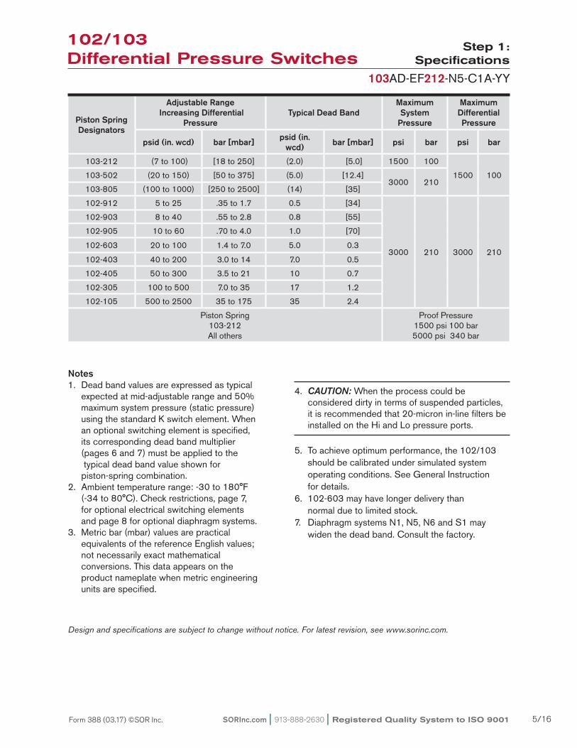
Notes1. Dead band values are expressed as typical expected at mid-adjustable range and 50% maximum system pressure (static pressure)
using the standard K switch element. When an optional switching element is specified, its corresponding dead band multiplier (pages 6 and 7) must be applied to the typical dead band value shown for
piston-spring combination.2. Ambient temperature range: -30 to 180°F
(-34 to 80°C). Check restrictions, page 7, for optional electrical switching elements and page 8 for optional diaphragm systems.
3. Metric bar (mbar) values are practical equivalents of the reference English values; not necessarily exact mathematical conversions. This data appears on the product nameplate when metric engineering units are specified.
4. CAUTION: When the process could be considered dirty in terms of suspended particles, it is recommended that 20-micron in-line filters be installed on the Hi and Lo pressure ports.
5. To achieve optimum performance, the 102/103 should be calibrated under simulated system operating conditions. See General Instruction
for details.6. 102-603 may have longer delivery than
normal due to limited stock.7. Diaphragm systems N1, N5, N6 and S1 may
widen the dead band. Consult the factory.
Piston Spring Designators
Adjustable Range Increasing Differential
PressureTypical Dead Band
Maximum System
Pressure
Maximum Differential Pressure
psid (in. wcd) bar [mbar] psid (in. wcd) bar [mbar] psi bar psi bar
103-212 (7 to 100) [18 to 250] (2.0) [5.0] 1500 100
1500 100103-502 (20 to 150) [50 to 375] (5.0) [12.4]3000 210
103-805 (100 to 1000) [250 to 2500] (14) [35]
102-912 5 to 25 .35 to 1.7 0.5 [34]
3000 210 3000 210
102-903 8 to 40 .55 to 2.8 0.8 [55]
102-905 10 to 60 .70 to 4.0 1.0 [70]
102-603 20 to 100 1.4 to 7.0 5.0 0.3
102-403 40 to 200 3.0 to 14 7.0 0.5
102-405 50 to 300 3.5 to 21 10 0.7
102-305 100 to 500 7.0 to 35 17 1.2
102-105 500 to 2500 35 to 175 35 2.4
Piston Spring103-212All others
Proof Pressure1500 psi 100 bar5000 psi 340 bar
Design and specifications are subject to change without notice. For latest revision, see www.sorinc.com.
Registered Quality System to ISO 9001 | 913-888-2630 | SORInc.com6/16 Form 388 (03.17) ©SOR Inc.
Dead Band Considerations
Step 2: Housing
102/103Differential Pressure Switches
103AD-EF212-N5-C1A-YY
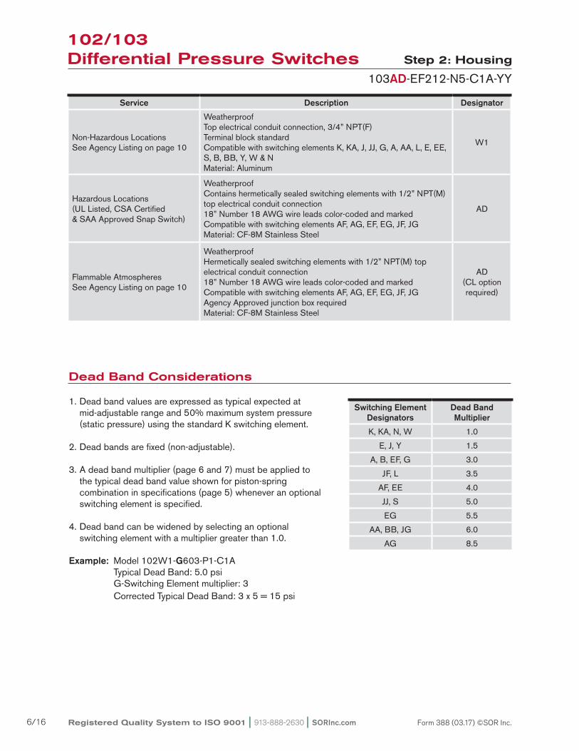
1. Dead band values are expressed as typical expected at mid-adjustable range and 50% maximum system pressure (static pressure) using the standard K switching element.
2. Dead bands are fixed (non-adjustable).
3. A dead band multiplier (page 6 and 7) must be applied to the typical dead band value shown for piston-spring combination in specifications (page 5) whenever an optional switching element is specified.
4. Dead band can be widened by selecting an optional switching element with a multiplier greater than 1.0.
Example: Model 102W1-G603-P1-C1A Typical Dead Band: 5.0 psi G-Switching Element multiplier: 3 Corrected Typical Dead Band: 3 x 5 = 15 psi
Service Description Designator
Non-Hazardous LocationsSee Agency Listing on page 10
WeatherproofTop electrical conduit connection, 3/4” NPT(F)Terminal block standardCompatible with switching elements K, KA, J, JJ, G, A, AA, L, E, EE, S, B, BB, Y, W & NMaterial: Aluminum
W1
Hazardous Locations(UL Listed, CSA Certified& SAA Approved Snap Switch)
WeatherproofContains hermetically sealed switching elements with 1/2” NPT(M) top electrical conduit connection18” Number 18 AWG wire leads color-coded and markedCompatible with switching elements AF, AG, EF, EG, JF, JGMaterial: CF-8M Stainless Steel
AD
Flammable AtmospheresSee Agency Listing on page 10
WeatherproofHermetically sealed switching elements with 1/2” NPT(M) top electrical conduit connection18” Number 18 AWG wire leads color-coded and markedCompatible with switching elements AF, AG, EF, EG, JF, JGAgency Approved junction box requiredMaterial: CF-8M Stainless Steel
AD(CL option required)
Switching Element Designators
Dead Band Multiplier
K, KA, N, W 1.0
E, J, Y 1.5
A, B, EF, G 3.0
JF, L 3.5
AF, EE 4.0
JJ, S 5.0
EG 5.5
AA, BB, JG 6.0
AG 8.5
SORInc.com | 913-888-2630 | Registered Quality System to ISO 9001 7/16Form 388 (03.17) ©SOR Inc.
Step 3: Switching Element
103AD-EF212-N5-C1A-YY
102/103Differential Pressure Switches
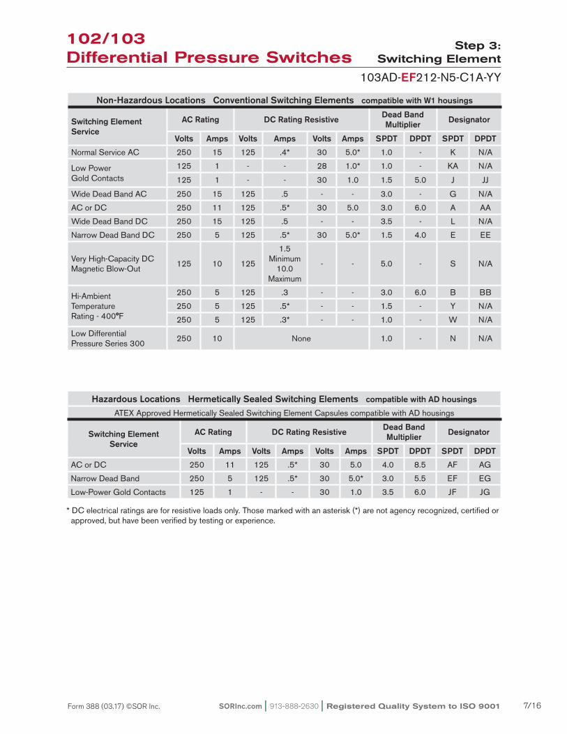
Non-Hazardous Locations Conventional Switching Elements compatible with W1 housings
Switching Element Service
AC Rating DC Rating Resistive Dead Band Multiplier Designator
Volts Amps Volts Amps Volts Amps SPDT DPDT SPDT DPDT
Normal Service AC 250 15 125 .4* 30 5.0* 1.0 - K N/A
Low PowerGold Contacts
125 1 - - 28 1.0* 1.0 - KA N/A
125 1 - - 30 1.0 1.5 5.0 J JJ
Wide Dead Band AC 250 15 125 .5 - - 3.0 - G N/A
AC or DC 250 11 125 .5* 30 5.0 3.0 6.0 A AA
Wide Dead Band DC 250 15 125 .5 - - 3.5 - L N/A
Narrow Dead Band DC 250 5 125 .5* 30 5.0* 1.5 4.0 E EE
Very High-Capacity DCMagnetic Blow-Out
125 10 125
1.5 Minimum
10.0 Maximum
- - 5.0 - S N/A
Hi-Ambient Temperature Rating - 400°F
250 5 125 .3 - - 3.0 6.0 B BB
250 5 125 .5* - - 1.5 - Y N/A
250 5 125 .3* - - 1.0 - W N/A
Low Differential Pressure Series 300
250 10 None 1.0 - N N/A
Hazardous Locations Hermetically Sealed Switching Elements compatible with AD housings
ATEX Approved Hermetically Sealed Switching Element Capsules compatible with AD housings
Switching Element Service
AC Rating DC Rating Resistive Dead Band Multiplier Designator
Volts Amps Volts Amps Volts Amps SPDT DPDT SPDT DPDT
AC or DC 250 11 125 .5* 30 5.0 4.0 8.5 AF AG
Narrow Dead Band 250 5 125 .5* 30 5.0* 3.0 5.5 EF EG
Low-Power Gold Contacts 125 1 - - 30 1.0 3.5 6.0 JF JG
* DC electrical ratings are for resistive loads only. Those marked with an asterisk (*) are not agency recognized, certified or approved, but have been verified by testing or experience.
Registered Quality System to ISO 9001 | 913-888-2630 | SORInc.com8/16 Form 388 (03.17) ©SOR Inc.
Step 4: Diaphragm/O-Ring
103AD-EF212-N5-C1A-YY
7. This table shows allowable minimum and maximum temperatures for o-rings.8. Diaphragm systems N1, N5, N6 and S1 may widen the dead
band. Consult the factory.
Step 3: Switching Element
103AD-EF212-N5-C1A-YY
102/103Differential Pressure Switches
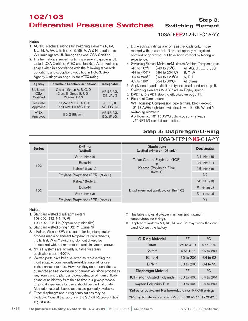
Notes1. AC/DC electrical ratings for switching elements K, KA, J, JJ, G, A, AA, L, E, EE, S, B, BB, V, W & N (used in the W1 housing) are UL Recognized and CSA Certified.2. The hermetically sealed switching element capsule is UL Listed, CSA Certified, ATEX and TestSafe Approved as a snap switch in accordance with the following table with conditions and exceptions specified in Note 3. See Agency Listings on page 10 for ATEX rating.
3. DC electrical ratings are for resistive loads only. Those marked with an asterisk (*) are not agency recognized, certified or approved, but have been verified by testing or experience.
4. Switching Element Minimum/Maximum Ambient Temperatures: -40 to 167°F (-40 to 75°C) AF, AG, EF, EG, JF, JG -65 to 400°F (-54 to 204°C) B, Y, W -65 to 250°F (-54 to 120°C) A, E, J -65 to 180°F (-54 to 80°C) All others5. Apply dead band multiplier to typical dead band on page 5.6. Switching elements W & Y have an Elgiloy spring.7. DPDT is 2-SPDT. See the Glossary on page 11.8. Electrical Connection: W1 Housing: Compression type terminal block except 18” 18 AWG high-temp wire leads with B, BB, W and Y switching elements. AD Housing: 18” 18 AWG color-coded wire leads 1/2” NPT(M) conduit connection.
Agency Hazardous Location Conditions Designator
UL Listed CSA
Certified
Class I, Group A, B, C, DClass II, Group E, F, G;
Division 1 & 2
AF, EF, AG, EG, JF, JG
TestSafe Approved
Ex s Zone 2 IIC T4 IP65Ex tD A22 T105°C IP65
AF, EF, JFAG, EG, JG
ATEX Approved
II 2 G EEx m IIAF, EF, AG, EG, JF, JG,
Series O-Ring(Wetted)
Diaphragm(wetted primary - 103 only) Designator
103
Viton (Note 3)Teflon Coated Polyimide (TCP)
orKapton (Polyimide Film)
(Note 1)
N1 (Note 8)
Buna-N N4 (Note 1)
Kalrez* (Note 3) N5 (Note 8)
Ethylene Propylene (EPR) (Note 3) N7
102
Kalrez* (Note 3)
Diaphragm not available on the 102
N6 (Note 8)
Buna-N P1 (Note 2)
Viton (Note 3) S1 (Note 8)Ethylene Propylene (EPR) (Note 3) Y1
O-Ring Material °F °C
Viton 32 to 400 0 to 204
Kalrez* 5 to 400 -15 to 204
Buna-N -30 to 200 -34 to 93
EPR** -30 to 200 -34 to 93
Diaphragm Material °F °C
TCP-Teflon Coated Polyimide -30 to 400 -34 to 204
Kapton Polyimide Film -30 to 400 -34 to 204
*Kalrez or equivalent Perfluoroelastomer (FFKM) o-rings
**Rating for steam service is -30 to 400 (-34°F to 204°C)
Notes1. Standard wetted diaphragm system 103-202, 212: N4 (TCP) 103-502, 805: N4 (Kapton polyimide film)2. Standard wetted o-ring 102: P1 (Buna-N)3. If Kalrez, Viton or EPA is selected for high-temperature
process media or ambient temperature requirements, the B, BB, W or Y switching element should be considered with reference to the table in Note 4, above.
4. N7, Y1 systems are normally suitable for steam applications up to 400°F.
5. Wetted parts have been selected as representing the most suitable, commercially available material for use in the service intended. However, they do not constitute a
guarantee against corrosion or permeation, since processes vary from plant to plant, and concentration of harmful fluids, gases or solids vary from time to time in a given process. Empirical experience by users should be the final guide. Alternate materials based on this are generally available.
6. Other diaphragm and o-ring combinations may be available. Consult the factory or the SOR® Representative
in your area.

SORInc.com | 913-888-2630 | Registered Quality System to ISO 9001 9/16Form 388 (03.17) ©SOR Inc.
Step 6: Accessories
103AD-EF212-N5-C1A-YY
102/103Differential Pressure Switches
Step 5: Pressure Port
103AD-EF212-N5-C1A-YY
Note: 1/2” NPT(F) is achieved by threading 1/4” NPT(F) increasing adapters into the standard body pressure ports. (Protrudes approximately 1-1/2” from the flush 1/4” NPT(F) Hi and Lo pressure ports.)
Connection Size Material Designator
1/4” NPT(F) 316SS CIA (standard)
1/2” NPT(F) 316SS C2A
Accessory / Option & Description Designator
Wetted parts are cleaned for oxygen service. BB
ATEX/IECEx approved. See the Agency Listings on page 10. CL
CSA Certified. Housing W1 has earth (ground lug). See the Agency Listings section. CS**
Canadian Registration Number (CRN) - Process ratings may be affected. Consult the factory for details. CV**
Sealed electrical lead adapter. Provides protection to housing interior and switching element from condensate in the electrical conduit and corrosive atmospheres. (W1 housing only: protrudes approximately 2” above housing.)
GG**
Universal terminal box, 1/2”NPT(F), 316SS. Explosion proof. ATEX/IECEx Certified Ex db IIC T4, T5, T6 Gb HB
Universal terminal box, M20 x 1.5(F), 316SS. Explosion proof. ATEX/IECEx Certified Ex db IIC T4, T5, T6 Gb HBME
Compliance to NACE Certification MR0175/ISO 15156. NC*
INMETRO approved. See the Agency Listings on page 10. NM
Pipe (stanchion) mounting kit for 1-1/2 to 2” pipe. Optional on 102; standard on 103. PK
Tag, fiber. Attached with plastic tie to housing. Stamped with customer-specified tagging information. PP
Powder coat epoxy coating. No coating on stainless steel parts or plated screws. (500 hours-salt spray). Not available with AD housing. PY
Tag, SS. Attached with SS wire to housing. Stamped with customer-specified tagging information. (2 lines, 18 characters and spaces per line.) RR
Explosion-proof and weathertight junction box with screw terminals. Aluminum. 3/4” NPT(F) top or right conduit connections as required. UL Listed or CSA Certified Class I, Group A, B, C, D; Class II, Group E, F, G; Division 1 & 2. Includes cover o-ring for weathertight applica-tions. (AD housing only.)
TB**
Oversize nameplate, SS. Permanently attached to housing. Stamped with customer-specified tagging information. TT
Fungicidal varnish. Covers exterior and interior except working parts. VV
X is used as a suffix to the model number for special requirements not keyed elsewhere in the model number by an X. Each X must be completely identified in the text of the order or inquiry. When more than one X is required, use X followed by the number of such items. For example: X3 means three separate, otherwise unidentifiable requirements.
X
Epoxy coating. Exterior only. Polyimide epoxy with 316SS pigment. (200 hours-salt spray) YY
Chained cover with captive screws to conform to former JIC specification. ZZ
* Consult the factory for materials other than 316/316L.** Not available with CL option.
Registered Quality System to ISO 9001 | 913-888-2630 | SORInc.com10/16 Form 388 (03.17) ©SOR Inc.
102/103Differential Pressure Switches Test Certificates
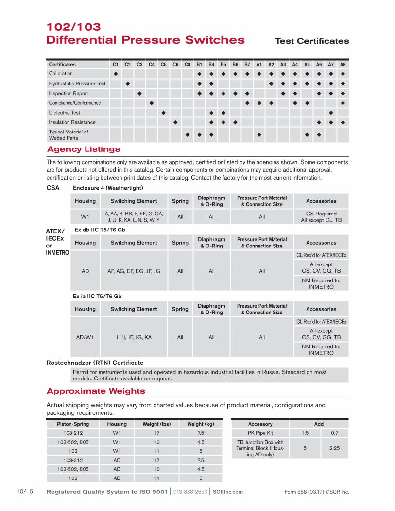
The following combinations only are available as approved, certified or listed by the agencies shown. Some components are for products not offered in this catalog. Certain components or combinations may acquire additional approval, certification or listing between print dates of this catalog. Contact the factory for the most current information.
CSA
ATEX/IECExor INMETRO
Approximate Weights
Actual shipping weights may vary from charted values because of product material, configurations and packaging requirements.
Accessory Add
PK Pipe Kit 1.5 0.7
TB Junction Box with Terminal Block (Hous-
ing AD only)5 2.25
Piston-Spring Housing Weight (lbs) Weight (kg)
103-212 W1 17 7.5
103-502, 805 W1 10 4.5
102 W1 11 5
103-212 AD 17 7.5
103-502, 805 AD 10 4.5
102 AD 11 5
Enclosure 4 (Weathertight)
Housing Switching Element Spring Diaphragm & O-Ring
Pressure Port Material & Connection Size Accessories
W1 A, AA, B, BB, E, EE, G, GA, J, JJ, K, KA, L, N, S, W, Y All All All CS Required
All except CL, TB
Ex db IIC T5/T6 Gb
Housing Switching Element Spring Diaphragm & O-Ring
Pressure Port Material & Connection Size Accessories
AD AF, AG, EF, EG, JF, JG All All All
CL Req’d for ATEX/IECEx
All except CS, CV, GG, TB
NM Required for INMETRO
Certificates C1 C2 C3 C4 C5 C6 C8 B1 B4 B5 B6 B7 A1 A2 A3 A4 A5 A6 A7 A8
Calibration ¿ ¿ ¿ ¿ ¿ ¿ ¿ ¿ ¿ ¿ ¿ ¿ ¿ ¿
Hydrostatic Pressure Test ¿ ¿ ¿ ¿ ¿ ¿ ¿ ¿ ¿ ¿
Inspection Report ¿ ¿ ¿ ¿ ¿ ¿ ¿ ¿ ¿ ¿ ¿
Compliance/Conformance ¿ ¿ ¿ ¿ ¿ ¿ ¿
Dielectric Test ¿ ¿ ¿ ¿
Insulation Resistance ¿ ¿ ¿ ¿ ¿ ¿ ¿
Typical Material of Wetted Parts ¿ ¿ ¿ ¿ ¿ ¿
Agency Listings
Ex ia IIC T5/T6 Gb
Housing Switching Element Spring Diaphragm & O-Ring
Pressure Port Material & Connection Size Accessories
AD/W1 J, JJ, JF, JG, KA All All All
CL Req’d for ATEX/IECEx
All except CS, CV, GG, TB
NM Required for INMETRO
Permit for instruments used and operated in hazardous industrial facilities in Russia. Standard on most models. Certificate available on request.
Rostechnadzor (RTN) Certificate

SORInc.com | 913-888-2630 | Registered Quality System to ISO 9001 11/16Form 388 (03.17) ©SOR Inc.
SOR recognizes that there is not an industry convention with respect to terminology and definitions pertinent to differential pressure switches. The following list applies to SOR Differential Pressure Switches.
102/103Differential Pressure Switches Glossary of Terms
Adjustable RangeThe span of differential pressure between upper and lower limits within which the differential pressure switch can be adjusted to actuate/deactuate. It is expressed for increasing differential pressure.
Dead BandThe difference in pressure between the increasing set point and the decreasing set point is expressed as “typical,” which is an average with the increasing set point at mid-adjustable range and 50% of maximum system pressure (static pressure) for a differential pressure switch with the standard K switching element. It is fixed (non-adjustable).
Differential Pressure SwitchA bi-stable electromechanical device that actuates/deactuates one or more electrical switching elements at a predetermined discrete differential pressure (set point) upon rising or falling differential pressure.
DPDT Switching ElementDPDT is two synchronized SPDT switching elements which actuate together at increasing set point and deactuate together at decreasing set point. Discrete SPDT switching elements allow two independent circuits to be switched; i.e., one AC and one DC.
The synchronization linkage is factory set, and is not field adjustable. Synchronization is verified by connecting test lamps to the switching elements and observing them go “On” simultaneously at actuation and “Off’ simultaneously at deactuation.
Maximum Differential PressureThe maximum difference in pressure that can be continuously applied between the HI and LO (LO and HI) pressure ports without causing permanent change of set point, leakage or material failure.
OverrangeThe maximum input pressure that can be continuously applied to the differential pressure switch without causing permanent change of set point, leakage or material failure.
Proof PressureThe maximum input pressure that can be continuously applied to the differential pressure switch without causing leakage or catastrophic material failure. Permanent change of set points may occur, or the device may be rendered inoperative.
RepeatabilityThe ability of a differential pressure switch to successively operate at a set point that is approached from a starting point in the same direction and returns to the starting point over consecutive cycles to establish a pressure profile. The closeness of the measured set point values is normally expressed as a percentage of full scale (maximum adjustable range differential pressure). Note: Values for repeatability are not shown in this catalog because it is necessary to know the pressure profile of a particular application.
Set PointThat discrete differential pressure at which the differential pressure switch is adjusted to actuate/deactuate on rising or falling differential pressure. It must fall within the adjustable range and be called out as increasing or decreas ing differential pressure.
SPDT Switching ElementSingle-Pole, Double-Throw (SPDT) has three connections: C — Common, NO — NormallyOpen and NC — Normally Closed, which allows the switch to be electrically connected to the circuit in either NO or NC state.
Registered Quality System to ISO 9001 | 913-888-2630 | SORInc.com12/16 Form 388 (03.17) ©SOR Inc.
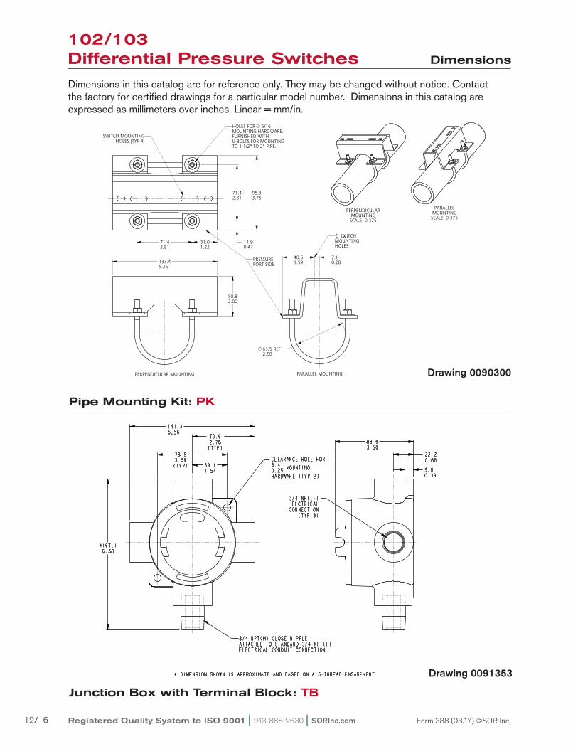
Pipe Mounting Kit: PK
Junction Box with Terminal Block: TB
Dimensions in this catalog are for reference only. They may be changed without notice. Contact the factory for certified drawings for a particular model number. Dimensions in this catalog are expressed as millimeters over inches. Linear = mm/in.
102/103Differential Pressure Switches
Dimensions
ISO-9001
14685 W 105TH ST LENEXA, KS 66215 USA913-888-2630SORINC.COM
71.42.81
95.33.75
71.42.81
31.01.22
11.90.47
50.82.00
133.45.25
40.51.59
7.10.28
63.5 REF2.50
Model Name: 0090300.ASSEM//+
PRODUCT CERTIFICATION DRAWINGALL DIMENSIONS ARE 1/16 INUNLESS OTHERWISE SPECIFIED
LINEAR = MMIN
DRAWN BY
J REHM CHECKED BY
M SMITH ENGINEER APPROVAL
S BOAL DATE
4/27/16 THIS DRAWING IS THE EXCLUSIVE PROPERTY OF SOR.
NO USE WHATSOEVER OF THE INFORMATION CONTAINEDHEREON, NOR REPRODUCTION IN WHOLE OR PART MAY BE
MADE WITHOUT THE EXPRESS WRITTEN PERMISSION OF SOR.
TITLE
DIM DWGPIPE MOUNTING KIT
EO NUMBER: 4935
SCALE: 0.75
DO NOT SCALE PRINT
DRAWING NUMBER REV
0090300 4
SHEET 1 OF 1DWG SIZE
B
MODEL # SALES ORDER # LINE ITEM # PURCHASE ORDER #SALES PAGE
PRESSUREPORT SIDE
PERPENDICULAR MOUNTING PARALLEL MOUNTING
HOLES FOR 5/16MOUNTING HARDWARE.FURNISHED WITHU-BOLTS FOR MOUNTINGTO 1-1/2" TO 2" PIPE.
SWITCH MOUNTINGHOLES (TYP 4)
PARALLELMOUNTINGSCALE 0.375
PERPENDICULARMOUNTINGSCALE 0.375
SWITCHMOUNTINGHOLES
Drawing 0090300
Drawing 0091353

SORInc.com | 913-888-2630 | Registered Quality System to ISO 9001 13/16Form 388 (03.17) ©SOR Inc.
ISO-9001
14685 W 105TH ST LENEXA, KS 66215 USA913-888-2630SORINC.COM
24.20.95
95.33.75
31.81.25
70.02.75
184.27.25
133.45.25
63.52.50
A
6.40.25
71.42.81
11.90.47
175.46.91
55.62.19
73.82.91
35.71.41
71.42.81
66.72.63
179.17.05
1/4 NPTF FLUSHING PORTBOTH SIDES
A
PROCESS CONNECTION1/4 NPTF STD1/2 NPTF OPTHI - NEAR SIDELO - FAR SIDE
LENGTH A
1/2 NPTFSHOWN
35.81.41
1/2 NPTM 34.81.37
Model Name: 0090493.ASSEM/4.1
PRODUCT CERTIFICATION DRAWINGALL DIMENSIONS ARE 1/16 INUNLESS OTHERWISE SPECIFIED
LINEAR = MMIN
DRAWN BY
K MITCHELLCHECKED BY
M SMITHENGINEER APPROVAL
J MODIGDATE
24 MAY 2016THIS DRAWING IS THE EXCLUSIVE PROPERTY OF SOR.
NO USE WHATSOEVER OF THE INFORMATION CONTAINEDHEREON, NOR REPRODUCTION IN WHOLE OR PART MAY BE
MADE WITHOUT THE EXPRESS WRITTEN PERMISSION OF SOR.
TITLE
DIMENSION DRAWING 103 AD/AS/JS 4 INCH BODY
EO NUMBER: 5309
SCALE: 0.60
DO NOT SCALE PRINT
DRAWING NUMBER REV
0090493 5
SHEET 1 OF 1DWG SIZE
B
MODEL # SALES ORDER # LINE ITEM # PURCHASE ORDER #SALES PAGE
ELECTRICALCONNECTION
1/2 NPTMSET POINT
ADJUSTMENT UNDERKNURLED CAP
4X 9.50.38
MOUNTING HOLES
FACTORY SEALED LEADSCOLOR CODED AND MARKED457.218.00 MINIMUM LENGTH
1
Reset Form
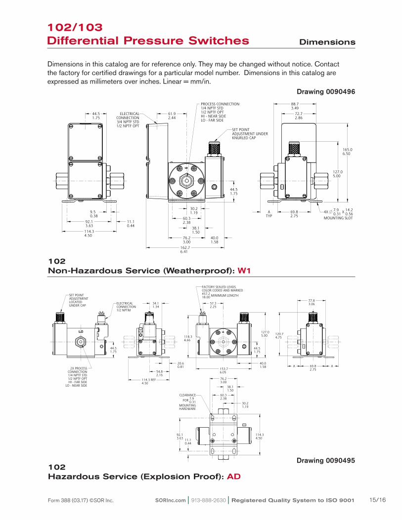
Dimensions in this catalog are for reference only. They may be changed without notice. Contact the factory for certified drawings for a particular model number. Dimensions in this catalog are expressed as millimeters over inches. Linear = mm/in.
103-212Non-Hazardous Service (Weatherproof): W1
102/103 Differential Pressure Switches Dimensions
Drawing 0090491
ISO-9001
14685 W 105TH ST LENEXA, KS 66215 USA913-888-2630SORINC.COM
24.20.95
222.18.75
74.62.94
A
184.27.25
42.11.66
6.40.25
71.42.81
95.33.75
12.00.47
55.62.19
73.82.91
35.71.41
71.42.81
66.72.63
133.45.25
188.17.41
63.52.50
A
PROCESS CONNECTION1/4 NPTF STD1/2 NPTF OPTHI - NEAR SIDELO - FAR SIDE
1/4 NPTF FLUSHING PORTBOTH SIDES
Model Name: 0090491.ASSEM/4/1+
PRODUCT CERTIFICATION DRAWINGALL DIMENSIONS ARE ±1/16 INUNLESS OTHERWISE SPECIFIED
MMLINEAR = IN
DRAWN BY
K MITCHELLCHECKED BY
M SMITHENGINEER APPROVAL
S BOALDATE
09 JAN 2012THIS DRAWING IS THE EXCLUSIVE PROPERTY OF SOR.
NO USE WHATSOEVER OF THE INFORMATION CONTAINEDHEREON, NOR REPRODUCTION IN WHOLE OR PART MAY BE
MADE WITHOUT THE EXPRESS WRITTEN PERMISSION OF SOR.
TITLE
DIMENSION DRAWING103 W1 4" BODY
EO NUMBER: 4935
SCALE: 0.53
DO NOT SCALE PRINT
DRAWING NUMBER REV
0090491 4
SHEET 1 OF 1DWG SIZE
B
MODEL # SALES ORDER # LINE ITEM # PURCHASE ORDER #SALES PAGE
LENGTH A
1/2 NPTFSHOWN
35.81.41
1/2 NPTM 34.81.37
ELECTRICALCONNECTION3/4 NPTF STD1/2 NPTF OPT
SET POINTADJUSTMENT UNDERKNURLED CAP
CLEARANCE FOR 7.90.31
MOUNTING HARDWARE
1
Reset Form
Drawing 0090493
103-212Hazardous Service (Explosion Proof): AD

Registered Quality System to ISO 9001 | 913-888-2630 | SORInc.com14/16 Form 388 (03.17) ©SOR Inc.
Dimensions in this catalog are for reference only. They may be changed without notice. Contact the factory for certified drawings for a particular model number. Dimensions in this catalog are expressed as millimeters over inches. Linear = mm/in.
102/103Differential Pressure Switches Dimensions
103-502, -805 Hazardous Service (Explosion Proof): AD
Drawing 0090490
Drawing 0090492
ISO-9001
14685 W 105TH ST LENEXA, KS 66215 USA913-888-2630SORINC.COM
11.50.45
A63.52.50
A
31.81.25
6.40.25
71.42.81
12.00.47
95.33.75
35.71.41
71.42.81
66.72.63
133.45.25
153.66.05
35.61.40
71.12.80
171.56.75
162.76.41
57.22.25
1/4 NPTF FLUSHING PORTBOTH SIDES
PROCESS CONNECTION1/4 NPTF STD1/2 NPTF OPTHI - NEAR SIDELO - FAR SIDE
Model Name: 0090492.ASSEM/5/0+
PRODUCT CERTIFICATION DRAWINGALL DIMENSIONS ARE ±1/16 INUNLESS OTHERWISE SPECIFIED
MMLINEAR = IN
DRAWN BY
K MITCHELLCHECKED BY
M SMITHENGINEER APPROVAL
J MODIGDATE
07 SEP 2011THIS DRAWING IS THE EXCLUSIVE PROPERTY OF SOR.
NO USE WHATSOEVER OF THE INFORMATION CONTAINEDHEREON, NOR REPRODUCTION IN WHOLE OR PART MAY BE
MADE WITHOUT THE EXPRESS WRITTEN PERMISSION OF SOR.
TITLE
DIMENSION DRAWING103 AD, AS, JS 3" BODY
EO NUMBER: 4935
SCALE: 0.60
DO NOT SCALE PRINT
DRAWING NUMBER REV
0090492 5
SHEET 1 OF 1DWG SIZE
B
MODEL # SALES ORDER # LINE ITEM # PURCHASE ORDER #SALES PAGE
LENGTH A
1/2 NPTFSHOWN
35.81.41
1/2 NPTM 34.81.37
FACTORY SEALED LEADSCOLOR CODED AND MARKED457.218.00 MINIMUM LENGTH
ELECTRICALCONNECTION1/2 NPTM
SET POINTADJUSTMENT UNDERKNURLED CAP
CLEARANCE FOR 7.90.31
MOUNTING HARDWARE
1
Reset Form
103-502, -805Non-Hazardous Service (Weatherproof): W1
SORInc.com | 913-888-2630 | Registered Quality System to ISO 9001 15/16Form 388 (03.17) ©SOR Inc.
Dimensions in this catalog are for reference only. They may be changed without notice. Contact the factory for certified drawings for a particular model number. Dimensions in this catalog are expressed as millimeters over inches. Linear = mm/in.
102/103Differential Pressure Switches Dimensions
Drawing 0090496
ISO-9001
14685 W 105TH ST LENEXA, KS 66215 USA913-888-2630SORINC.COM
72.72.86
40.01.58
44.51.75
61.92.44
88.73.49
165.06.50
69.82.75
127.05.00
44.51.75
114.34.50
76.23.00
162.76.41
PROCESS CONNECTION1/4 NPTF STD1/2 NPTF OPTHI - NEAR SIDELO - FAR SIDE
ATYP
9.50.38
11.10.44
92.13.63
30.21.19
60.32.38
38.11.50
LENGTH A
1/2 NPTFSHOWN
35.81.41
1/2 NPTM 34.81.37
PRODUCT CERTIFICATION DRAWINGALL DIMENSIONS ARE 1/16 INUNLESS OTHERWISE SPECIFIED
LINEAR = MMIN
DRAWN BY
L BROWNCHECKED BY
M SMITHENGINEER APPROVAL
J MODIGDATE
02-21-2017THIS DRAWING IS THE EXCLUSIVE PROPERTY OF SOR.
NO USE WHATSOEVER OF THE INFORMATION CONTAINEDHEREON, NOR REPRODUCTION IN WHOLE OR PART MAY BE
MADE WITHOUT THE EXPRESS WRITTEN PERMISSION OF SOR.
TITLE
DIM DWG 102 W1
EO NUMBER: 5381
SCALE: 0.56
DO NOT SCALE PRINT
DRAWING NUMBER REV
0090496 6
SHEET 1 OF 1DWG SIZE
B
MODEL # SALES ORDER # LINE ITEM # PURCHASE ORDER #SALES PAGE
Model Name: 0090496.ASSEM\6.1\2017-FEB-21 15:26
ELECTRICALCONNECTION3/4 NPTF STD1/2 NPTF OPT
SET POINTADJUSTMENT UNDERKNURLED CAP
4X 7.90.31 X 14.2
0.56MOUNTING SLOT
SCALE 0.31SCALE 0.31
1
Reset Form
ISO-9001
14685 W 105TH ST LENEXA, KS 66215 USA913-888-2630SORINC.COM
40.01.58 69.8
2.75
77.83.06
A
11.10.44
54.82.16
114.34.50
44.51.75
120.74.75
30.21.19
60.32.38
38.11.50
76.23.00
20.60.81 A
57.32.25
153.76.05
44.51.75
127.05.00118.3
4.66
34.11.34
92.13.63
114.3 REF4.50
2X PROCESSCONNECTION1/4 NPTF STD1/2 NPTF OPTHI - FAR SIDE
LO - NEAR SIDE
LENGTH A
1/2 NPTF 35.81.41 SHOWN
1/2 NPTM 34.81.37
PRODUCT CERTIFICATION DRAWINGALL DIMENSIONS ARE 1/16 INUNLESS OTHERWISE SPECIFIED
LINEAR = MMIN
DRAWN BY
L BROWNCHECKED BY
M SMITHENGINEER APPROVAL
J MODIGDATE
02-21-2017THIS DRAWING IS THE EXCLUSIVE PROPERTY OF SOR.
NO USE WHATSOEVER OF THE INFORMATION CONTAINEDHEREON, NOR REPRODUCTION IN WHOLE OR PART MAY BE
MADE WITHOUT THE EXPRESS WRITTEN PERMISSION OF SOR.
TITLE
DIM DWG 102 AD
EO NUMBER: 5381
SCALE: 0.50
DO NOT SCALE PRINT
DRAWING NUMBER REV
0090495 6
SHEET 1 OF 1DWG SIZE
B
MODEL # SALES ORDER # LINE ITEM # PURCHASE ORDER #SALES PAGE
Model Name: 0090495.ASSEM\6.1\2017-FEB-21 15:05
FACTORY SEALED LEADSCOLOR CODED AND MARKED457.218.00 MINIMUM LENGTH
ELECTRICALCONNECTION1/2 NPTM
SET POINTADJUSTMENTLOCATEDUNDER CAP
CLEARANCE
FOR 7.90.31
MOUNTINGHARDWARE
1
Reset Form
Drawing 0090495
102Non-Hazardous Service (Weatherproof): W1
102Hazardous Service (Explosion Proof): AD

Registered Quality System to ISO 9001 | 913-888-2630 | SORInc.com16/16 Form 388 (03.17) ©SOR Inc.
REGIONAL OFFICES
China
SOR China | Beijing, China | [email protected]
+86 (10) 5820 8767 | Fax +86 (10) 58 20 8770
Middle East
SOR Measurement & Control Equipment Trading DMCC | Dubai, UAE
[email protected] | +971 4 363 3637 | Fax + 1 913 312 3596
SOR Inc. | Lenexa, KS USA | 913-888-2630 | Fax 913-888-0767 | SORInc.com