Embed Size (px)
Citation preview
Maintenance Indicators
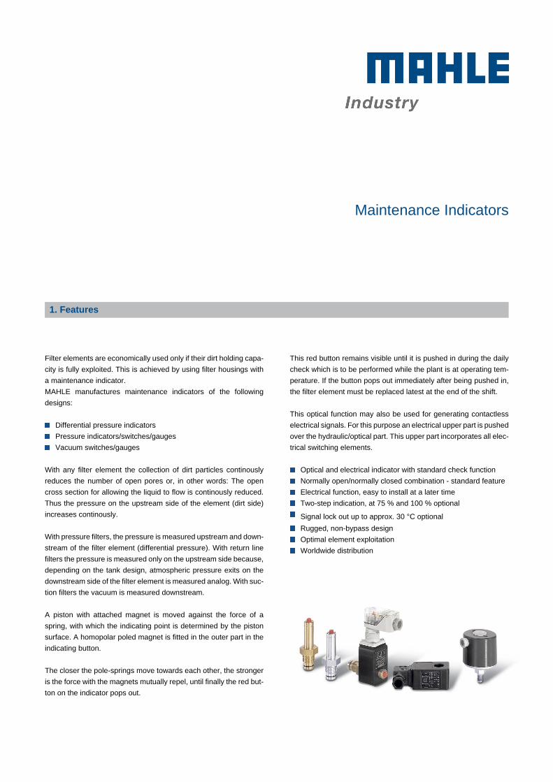
1. Features
-
-
Filter elements are economically used only if their dirt holding capa-
city is fully exploited. This is achieved by using filter housings with
a maintenance indicator.
MAHLE manufactures maintenance indicators of the following
designs:
-
Differential pressure indicators
Pressure indicators/switches/gauges
Vacuum switches/gauges
-
With any filter element the collection of dirt particles continously
reduces the number of open pores or, in other words: The open
cross section for allowing the liquid to flow is continously reduced.
Thus the pressure on the upstream side of the element (dirt side)
increases continously.
-
With pressure filters, the pressure is measured upstream and down-
stream of the filter element (differential pressure). With return line
filters the pressure is measured only on the upstream side because,
depending on the tank design, atmospheric pressure exits on the
downstream side of the filter element is measured analog. With suc-
tion filters the vacuum is measured downstream.
-
A piston with attached magnet is moved against the force of a
spring, with which the indicating point is determined by the piston
surface. A homopolar poled magnet is fitted in the outer part in the
indicating button.
-
The closer the pole-springs move towards each other, the stronger
is the force with the magnets mutually repel, until finally the red but-
ton on the indicator pops out.
-
-
This red button remains visible until it is pushed in during the daily
check which is to be performed while the plant is at operating tem-
perature. If the button pops out immediately after being pushed in,
the filter element must be replaced latest at the end of the shift.
-
This optical function may also be used for generating contactless
electrical signals. For this purpose an electrical upper part is pushed
over the hydraulic/optical part. This upper part incorporates all elec-
trical switching elements.
-
Optical and electrical indicator with standard check function
Normally open/normally closed combination - standard feature
Electrical function, easy to install at a later time
Two-step indication, at 75 % and 100 % optional
Signal lock out up to approx. 30 °C optional
Rugged, non-bypass design
Optimal element exploitation
Worldwide distribution
Maintenance Indicators 2
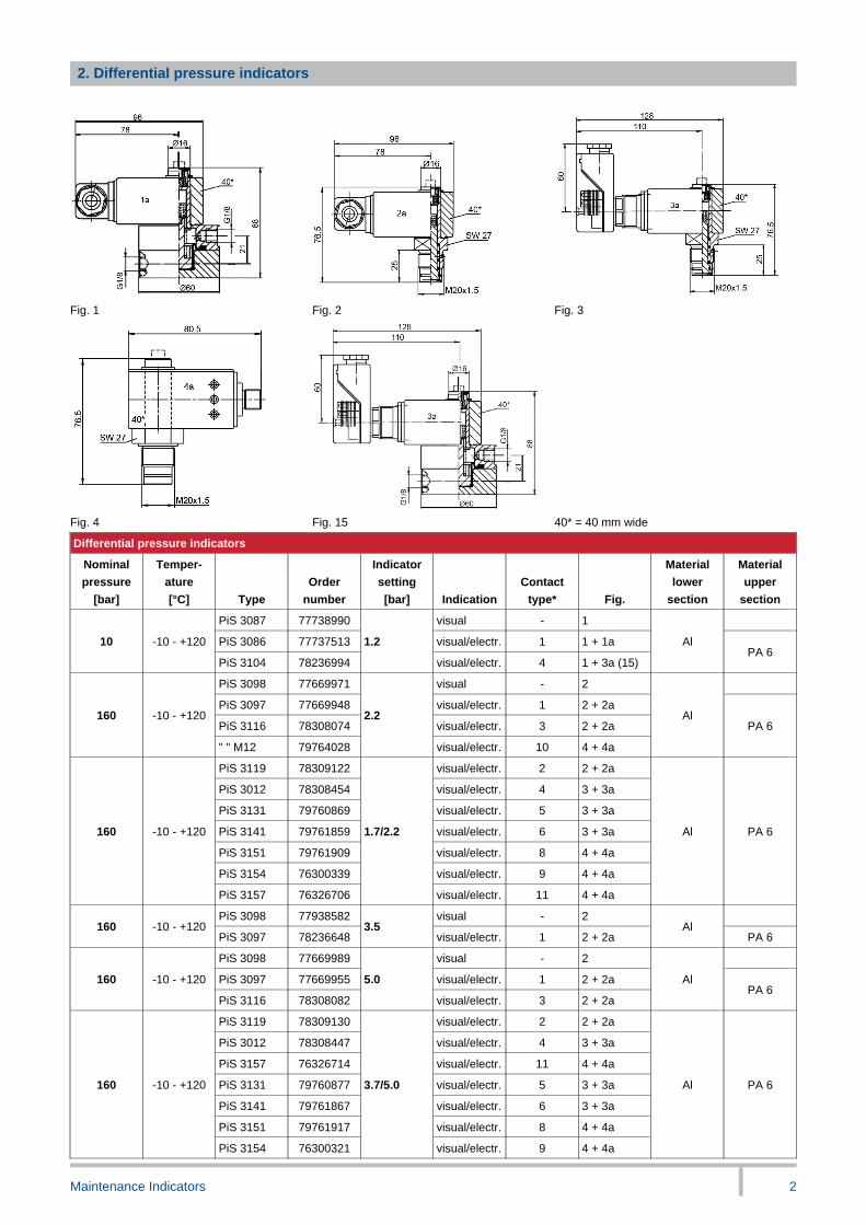
2. Differential pressure indicators
Fig. 1 Fig. 2 Fig. 3
Fig. 4 Fig. 15 40* = 40 mm wide
Differential pressure indicators
Nominal
pressure
[bar]
Temper-
ature
[°C] Type
Order
number
Indicator
setting
[bar] Indication
Contact
type* Fig.
Material
lower
section
Material
upper
section
PiS 3087 77738990 visual - 1
PiS 3086 77737513 visual/electr. 1 1 + 1a10 -10 - +120
PiS 3104 78236994
1.2
visual/electr. 4 1 + 3a (15)
AlPA 6
PiS 3098 77669971 visual - 2
PiS 3097 77669948 visual/electr. 1 2 + 2a
PiS 3116 78308074 visual/electr. 3 2 + 2a160 -10 - +120
" " M12 79764028
2.2
visual/electr. 10 4 + 4a
AlPA 6
PiS 3119 78309122 visual/electr. 2 2 + 2a
PiS 3012 78308454 visual/electr. 4 3 + 3a
PiS 3131 79760869 visual/electr. 5 3 + 3a
PiS 3141 79761859 visual/electr. 6 3 + 3a
PiS 3151 79761909 visual/electr. 8 4 + 4a
PiS 3154 76300339 visual/electr. 9 4 + 4a
160 -10 - +120
PiS 3157 76326706
1.7/2.2
visual/electr. 11 4 + 4a
Al PA 6
PiS 3098 77938582 visual - 2160 -10 - +120
PiS 3097 782366483.5
visual/electr. 1 2 + 2aAl
PA 6
PiS 3098 77669989 visual - 2
PiS 3097 77669955 visual/electr. 1 2 + 2a160 -10 - +120
PiS 3116 78308082
5.0
visual/electr. 3 2 + 2a
AlPA 6
PiS 3119 78309130 visual/electr. 2 2 + 2a
PiS 3012 78308447 visual/electr. 4 3 + 3a
PiS 3157 76326714 visual/electr. 11 4 + 4a
PiS 3131 79760877 visual/electr. 5 3 + 3a
PiS 3141 79761867 visual/electr. 6 3 + 3a
PiS 3151 79761917 visual/electr. 8 4 + 4a
160 -10 - +120
PiS 3154 76300321
3.7/5.0
visual/electr. 9 4 + 4a
Al PA 6
Maintenance Indicators 3
Differential pressure indicators
Nominal
pressure
[bar]
Temper-
ature
[°C] Type
Order
number
Indicator
setting
[bar] Indication
Contact-
type* Fig.
Material
lower
section
Material
upper
section
PiS 3093 77669898 visual - 2
PiS 3092 77669856 visual/electr. 1 2 + 2a400 -10 - +120
PiS 3115 78308041
2.2
visual/electr. 3 2 + 2a
CuZnPA 6
PiS 3105 77970387 visual/electr. 2 2 + 2a
PiS 3102 77942139 visual/electr. 4 3 + 3a
PiS 3132 79760919 visual/electr. 5 3 + 3a
PiS 3142 79761875 visual/electr. 6 3 + 3a
PiS 3152 79761925 visual/electr. 8 4 + 4a
PiS 3155 76300354 visual/electr. 9 4 + 4a
400 -10 - +120
PiS 3158 76326722
1.7/2.2
visual/electr. 11 4 + 4a
CuZn PA 6
PiS 3093 77669914 visual - 2
PiS 3092 77669864 visual/electr. 1 2 + 2a
PiS 3115 78308058 visual/electr. 3 2 + 2a400 -10 - +120
PiS 3115
M1279764010
5.0
visual/electr. 10 4 + 4a
CuZnPA 6
PiS 3105 77970395 visual/electr. 2 2 + 2a
PiS 3102 77942147 visual/electr. 4 3 + 3a
PiS 3155 76300362 visual/electr. 9 4 + 4a
PiS 3132 79760919 visual/electr. 5 3 + 3a
PiS 3142 79761883 visual/electr. 6 3 + 3a
PiS 3152 79761933 visual/electr. 8 4 + 4a
400 -10 - +120
PiS 3158 76326730
3.7/5.0
visual/electr. 11 4 + 4a
CuZn PA 6
PiS 3093 77669880 visual - 2
PiS 3092 77669872 visual/electr. 1 2 + 2a400 -10 - +120
PiS 3115 78308066
8
visual/electr. 3 2 + 2a
CuZnPA 6
PiS 3193 77844061 visual - 2
PiS 3192 78308488 visual/electr. 1 2 + 2a450 -10 - +120
PiS 3110 79353574
2.2
visual/electr. 7 3 + 3a
1.4301PA 6
PiS 3193 78308538 visual - 2
PiS 3192 78308546 visual/electr. 1 2 + 2a450 -10 - +120
PiS 3110 79353582
5.0
electrical 7 3 + 3a
1.4301PA 6
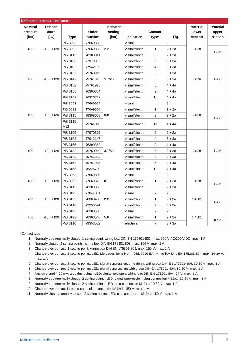
*Contact type
1 Normally open/normally closed; 1 setting point; wiring box DIN EN 175301-803; max. 250 V AC/200 V DC; max. 1 A
2 Normally closed; 2 setting points; wiring box DIN EN 175301-803; max. 150 V; max. 1 A
3 Change-over contact; 1 setting point; wiring box DIN EN 175301-803; max. 150 V; max. 1 A
4 Change-over contact; 2 setting points; LED; Mercedes Benz Norm DBL 9666 EA; wiring box DIN EN 175201-804; max. 10-30 V;
max. 1 A
5 Change-over contact; 2 setting points; LED; signal surpression; time delay; wiring box DIN EN 175201-804; 10-30 V; max. 1 A
6 Change-over contact; 2 setting points; LED; signal surpression; wiring box DIN EN 175201-804, 10-30 V; max. 1 A
7 Analog signal 4-20 mA; 2 setting points; LED; signal cold start; wiring box DIN EN 175201-804; 24 V; max. 1 A
8 Normally open/normally closed; 2 setting points; LED; signal surpression; plug connection M12x1; 10-30 V; max. 1 A
9 Normally open/normally closed; 2 setting points; LED; plug connection M12x1; 10-30 V; max. 1 A
10 Change-over contact;1 setting point; plug connection M12x1; 150 V; max. 1 A
11 Normally closed/normally closed; 2 setting points; LED; plug connection M12x1; 150 V; max. 1 A
Maintenance Indicators 4
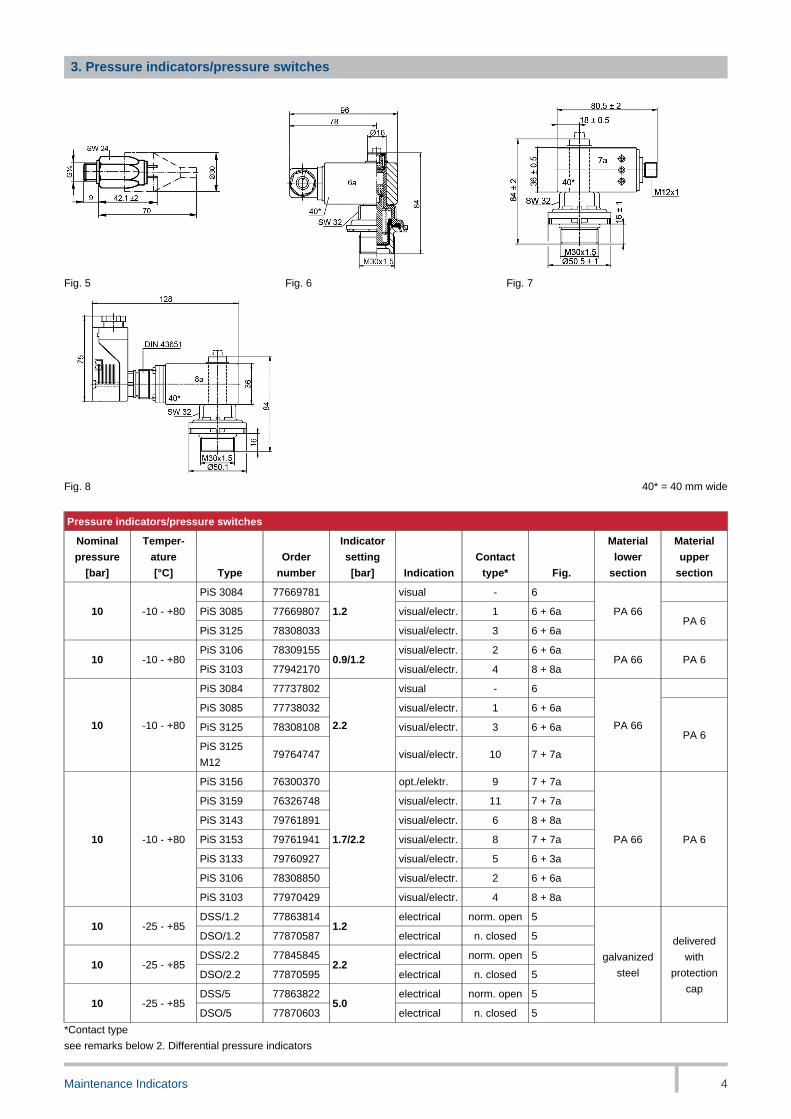
3. Pressure indicators/pressure switches
Fig. 5 Fig. 6 Fig. 7
Fig. 8 40* = 40 mm wide
Pressure indicators/pressure switches
Nominal
pressure
[bar]
Temper-
ature
[°C] Type
Order
number
Indicator
setting
[bar] Indication
Contact
type* Fig.
Material
lower
section
Material
upper
section
PiS 3084 77669781 visual - 6
PiS 3085 77669807 visual/electr. 1 6 + 6a10 -10 - +80
PiS 3125 78308033
1.2
visual/electr. 3 6 + 6a
PA 66PA 6
PiS 3106 78309155 visual/electr. 2 6 + 6a10 -10 - +80
PiS 3103 779421700.9/1.2
visual/electr. 4 8 + 8aPA 66 PA 6
PiS 3084 77737802 visual - 6
PiS 3085 77738032 visual/electr. 1 6 + 6a
PiS 3125 78308108 visual/electr. 3 6 + 6a10 -10 - +80
PiS 3125
M1279764747
2.2
visual/electr. 10 7 + 7a
PA 66PA 6
PiS 3156 76300370 opt./elektr. 9 7 + 7a
PiS 3159 76326748 visual/electr. 11 7 + 7a
PiS 3143 79761891 visual/electr. 6 8 + 8a
PiS 3153 79761941 visual/electr. 8 7 + 7a
PiS 3133 79760927 visual/electr. 5 6 + 3a
PiS 3106 78308850 visual/electr. 2 6 + 6a
10 -10 - +80
PiS 3103 77970429
1.7/2.2
visual/electr. 4 8 + 8a
PA 66 PA 6
DSS/1.2 77863814 electrical norm. open 510 -25 - +85
DSO/1.2 778705871.2
electrical n. closed 5
DSS/2.2 77845845 electrical norm. open 510 -25 - +85
DSO/2.2 778705952.2
electrical n. closed 5
DSS/5 77863822 electrical norm. open 510 -25 - +85
DSO/5 778706035.0
electrical n. closed 5
galvanized
steel
delivered
with
protection
cap
*Contact type
see remarks below 2. Differential pressure indicators

Maintenance Indicators 5
4. Vacuum/pressure gauges
Fig. 9 Fig. 10 Fig. 11
*1 = Green area/*2 = Red area *3 = Metering level
Vacuum/pressure gauges
Nominal
size
[NG] Type
Order
number
Indicating
range
[bar]
Connection
size Fig. Class Dial face
76345763 R1/8 conical 940
77545908-1 - +0.6
G1/8 9
Red/Green area
sep. line -0.25 bar
50
Vacuum
gauge77617558 -1 - 0 R¼ conical 10 white
50 Pressure
gauge78381998 0 - 6 R¼ conical 11
min. 2.5
Red/Green area
sep. line 2.2 bar
5. Vacuum switches
Fig. 12 Fig. 13
*G = Connection HES/HEO only for fluids, LES/LEO only for air
Vacuum switches
Permissible
over-
pressure
[bar]
Temper-
ature
[°C] Type
Order
number
Switch
setting[mbar]
Contact
type Fig.
Connection
*G
Material
lower
section
Material
upper
section
0.5 77669690 -15 - -80 G¼
1-10 - +70 PiS 3070
77669724 -50 - -600
single pole
change-
over switch,
snap-in joint
12G1/8
GD-Al PA 6
HES 2200
BP78308892
normally
open
HEO 2200
BP78308900
-200 ±10normally
closed
G1/8
outside
LES 250 I 78308918normally
open
0.1
-20 - +80
short-term
+120
LEO 250 I 78308926
-50 ±4normally
closed
13
M10x1
inside
GD-ZnAl PC
Maintenance Indicators 6
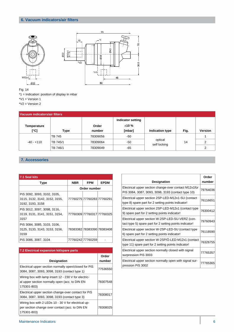
6. Vacuum indicators/air filters
Fig. 14
*1 = Indication: position of display in mbar
*V1 = Version 1
*V2 = Version 2
Vacuum indicators/air filters
Temperature
[°C] Type
Order
number
Indicator setting
±10 %
[mbar] Indication type Fig. Version
TB 745 78309056 -50 1
TB 745/1 78309064 -50 2-40 - +110
TB 746/1 78309049 -65
optical
self locking14
2
7. Accessories
7.1 Seal kits
Type NBR FPM EPDM
Order number
PiS 3092, 3093, 3102, 3105,
3115, 3132, 3142, 3152, 3155,
3192, 3193, 3158
77760275 77760283 77760291
PiS 3012, 3097, 3098, 3116,
3119, 3131, 3141, 3151, 3154,
3157
77760309 77760317 77760325
PiS 3084, 3085, 3103, 3106,
3125, 3133, 3143, 3153, 3156,
3159
78383382 78383390 78383408
PiS 3086, 3087, 3104 77760242 77760259 -
7.2 Electrical expansion kit/spare parts
Designation
Order
number
Electrical upper section normally open/closed for PiS
3084, 3087, 3093, 3098, 3193 (contact type 1)77536550
Wiring box with lamp insert 12 - 230 V for electric-
al upper section normally open (acc. to DIN EN
175301-803)
78307548
Electrical upper section change-over contact for PiS
3084, 3087, 3093, 3098, 3193 (contact type 3)78308017
Wiring box with 2 LEDs 10 - 30 V for electrical up-
per section change over contact (acc. to DIN EN
175301-803)
78308025
Designation
Order
number
Electrical upper section change-over contact M12x1für
PiS 3084, 3087, 3093, 3098, 3193 (contact type 10)79764036
Electrical upper section 2SP-LED-M12x1-SU (contact
type 8) spare part for 2 setting points indicator!76116651
Electrical upper section 2SP-LED-M12x1 (contact type
9) spare part for 2 setting points indicator!76300412
Electrical upper section W-2SP-LED-SU-VERZ (con-
tact type 5) spare part for 2 setting points indicator!79760943
Electrical upper section W-2SP-LED-SU (contact type
6) spare part for 2 setting points indicator!76118590
Electrical upper section W-2SP/Ö-LED-M12x1 (contact
type 11) spare part for 2 setting points indicator!76326755
Electrical upper section normally closed with signal
surpression PiS 300377765357
Electrical upper section normally open with signal sur-
pression PiS 300277765365
Maintenance Indicators 7
7.3 Mounting block for differential pressure indicators
(M20x1.5)
Designation
Order
number
Mounting block (St) 77809098
Mounting block (1.4301), 450 bar 77698517
7.4 Protection cap
Designation
Order
number
Protection cap for all visual pressure and dif-
ferential pressure indicators, -20 °C to +80 °C
Resistant to:
gasoil, purifying agent, insolation, dust, salt,
water, concret
78285330
R = clean side
S = dirt side
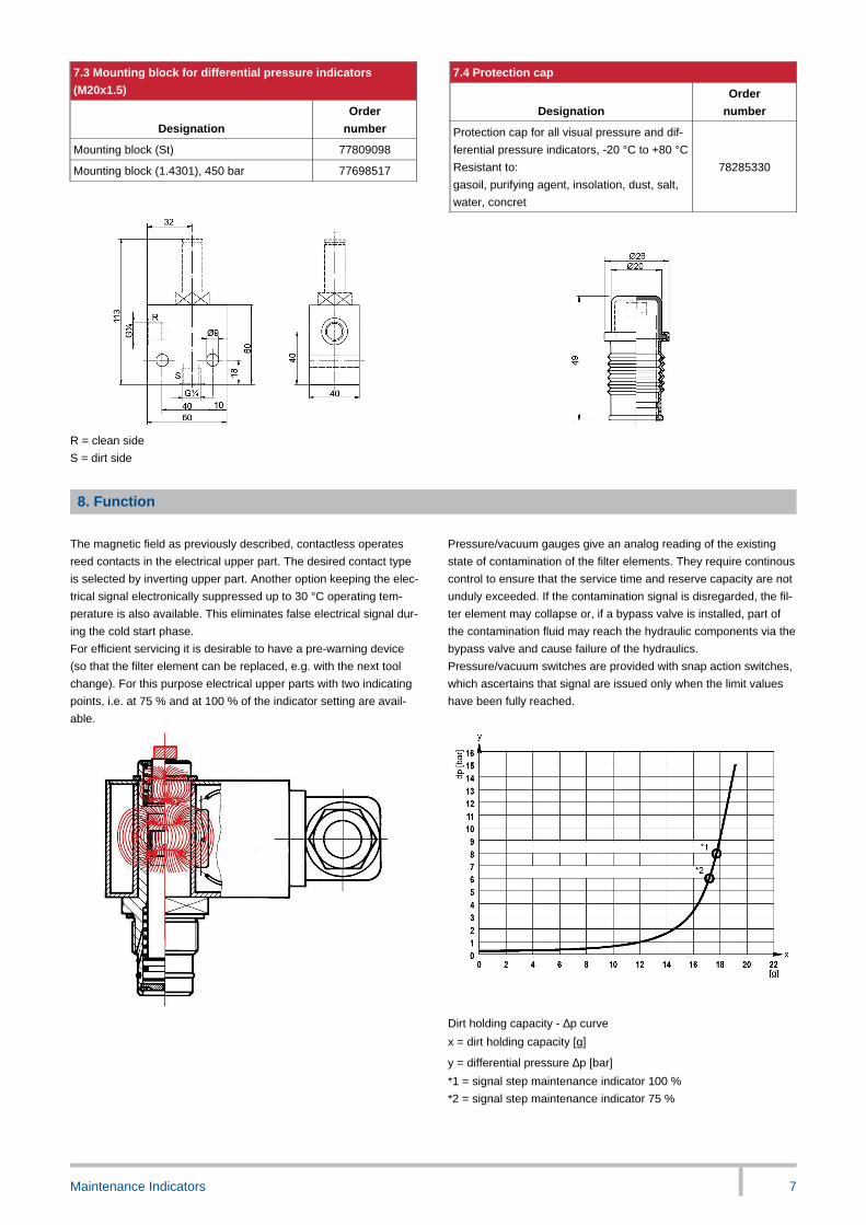
8. Function
The magnetic field as previously described, contactless operates
reed contacts in the electrical upper part. The desired contact type
is selected by inverting upper part. Another option keeping the elec-
trical signal electronically suppressed up to 30 °C operating tem-
perature is also available. This eliminates false electrical signal dur-
ing the cold start phase.
For efficient servicing it is desirable to have a pre-warning device
(so that the filter element can be replaced, e.g. with the next tool
change). For this purpose electrical upper parts with two indicating
points, i.e. at 75 % and at 100 % of the indicator setting are avail-
able.
Pressure/vacuum gauges give an analog reading of the existing
state of contamination of the filter elements. They require continous
control to ensure that the service time and reserve capacity are not
unduly exceeded. If the contamination signal is disregarded, the fil-
ter element may collapse or, if a bypass valve is installed, part of
the contamination fluid may reach the hydraulic components via the
bypass valve and cause failure of the hydraulics.
Pressure/vacuum switches are provided with snap action switches,
which ascertains that signal are issued only when the limit values
have been fully reached.
Dirt holding capacity - ∆p curve
x = dirt holding capacity [g]
y = differential pressure ∆p [bar]
*1 = signal step maintenance indicator 100 %
*2 = signal step maintenance indicator 75 %
Maintenance Indicators 8
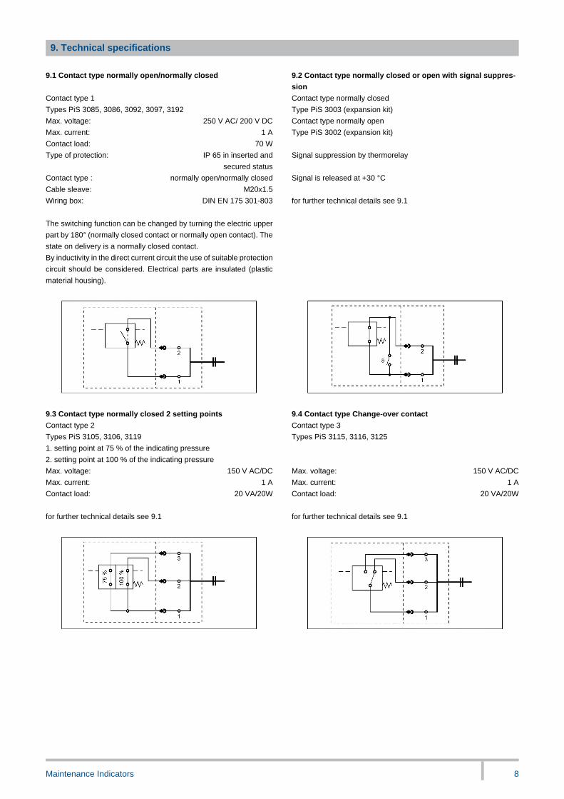
9. Technical specifications
9.1 Contact type normally open/normally closed 9.2 Contact type normally closed or open with signal suppres-
sion
Contact type 1 Contact type normally closed
Types PiS 3085, 3086, 3092, 3097, 3192 Type PiS 3003 (expansion kit)
Max. voltage: 250 V AC/ 200 V DC Contact type normally open
Max. current: 1 A Type PiS 3002 (expansion kit)
Contact load: 70 W
Type of protection: IP 65 in inserted and
secured status
Signal suppression by thermorelay
Contact type : normally open/normally closed Signal is released at +30 °C
Cable sleave: M20x1.5
Wiring box: DIN EN 175 301-803 for further technical details see 9.1
-
The switching function can be changed by turning the electric upper
part by 180° (normally closed contact or normally open contact). The
state on delivery is a normally closed contact.
By inductivity in the direct current circuit the use of suitable protection
circuit should be considered. Electrical parts are insulated (plastic
material housing).
-
9.3 Contact type normally closed 2 setting points 9.4 Contact type Change-over contact
Contact type 2 Contact type 3
Types PiS 3105, 3106, 3119 Types PiS 3115, 3116, 3125
1. setting point at 75 % of the indicating pressure
2. setting point at 100 % of the indicating pressure
Max. voltage: 150 V AC/DC Max. voltage: 150 V AC/DC
Max. current: 1 A Max. current: 1 A
Contact load: 20 VA/20W Contact load: 20 VA/20W
-
for further technical details see 9.1 for further technical details see 9.1
-
Maintenance Indicators 9
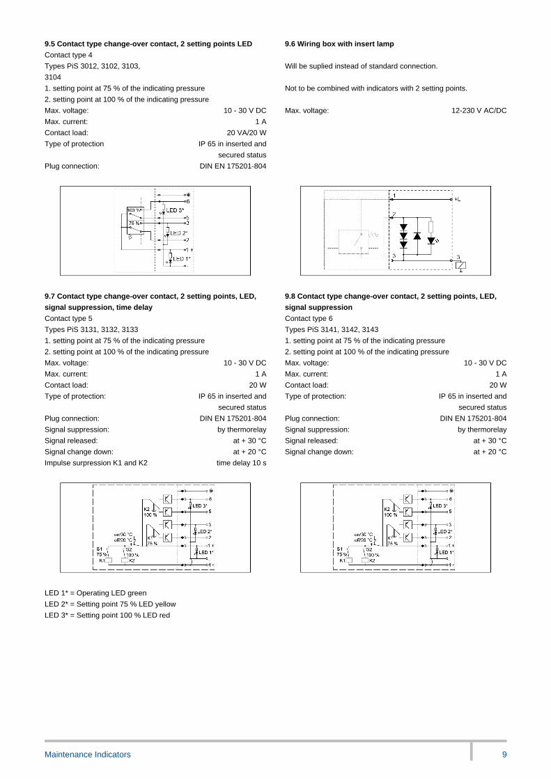
9.5 Contact type change-over contact, 2 setting points LED 9.6 Wiring box with insert lamp
Contact type 4
Types PiS 3012, 3102, 3103,
3104
Will be suplied instead of standard connection.
1. setting point at 75 % of the indicating pressure Not to be combined with indicators with 2 setting points.
2. setting point at 100 % of the indicating pressure
Max. voltage: 10 - 30 V DC Max. voltage: 12-230 V AC/DC
Max. current: 1 A
Contact load: 20 VA/20 W
Type of protection IP 65 in inserted and
secured status
Plug connection: DIN EN 175201-804
-
9.7 Contact type change-over contact, 2 setting points, LED,
signal suppression, time delay
9.8 Contact type change-over contact, 2 setting points, LED,
signal suppression
Contact type 5 Contact type 6
Types PiS 3131, 3132, 3133 Types PiS 3141, 3142, 3143
1. setting point at 75 % of the indicating pressure 1. setting point at 75 % of the indicating pressure
2. setting point at 100 % of the indicating pressure 2. setting point at 100 % of the indicating pressure
Max. voltage: 10 - 30 V DC Max. voltage: 10 - 30 V DC
Max. current: 1 A Max. current: 1 A
Contact load: 20 W Contact load: 20 W
Type of protection: IP 65 in inserted and
secured status
Type of protection: IP 65 in inserted and
secured status
Plug connection: DIN EN 175201-804 Plug connection: DIN EN 175201-804
Signal suppression: by thermorelay Signal suppression: by thermorelay
Signal released: at + 30 °C Signal released: at + 30 °C
Signal change down: at + 20 °C Signal change down: at + 20 °C
Impulse surpression K1 and K2 time delay 10 s
-
-
LED 1* = Operating LED green
LED 2* = Setting point 75 % LED yellow
LED 3* = Setting point 100 % LED red
Maintenance Indicators 10
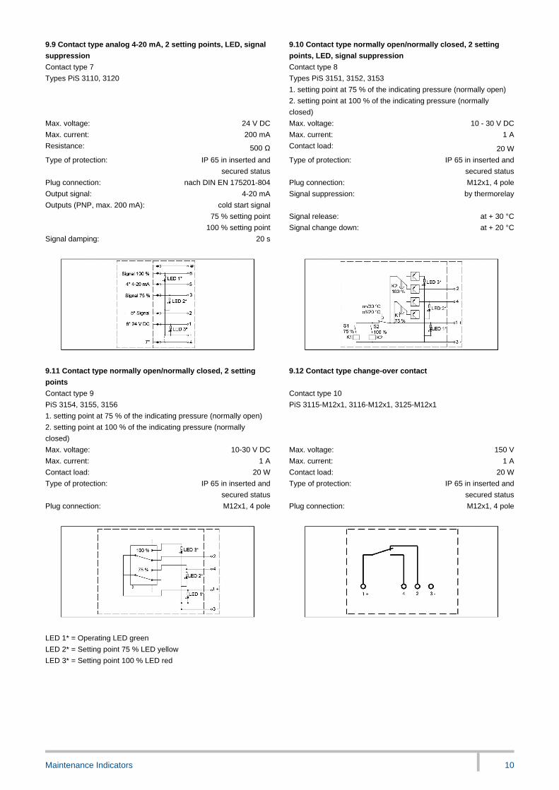
9.9 Contact type analog 4-20 mA, 2 setting points, LED, signal
suppression
9.10 Contact type normally open/normally closed, 2 setting
points, LED, signal suppression
Contact type 7 Contact type 8
Types PiS 3110, 3120 Types PiS 3151, 3152, 3153
1. setting point at 75 % of the indicating pressure (normally open)
2. setting point at 100 % of the indicating pressure (normally
closed)
Max. voltage: 24 V DC Max. voltage: 10 - 30 V DC
Max. current: 200 mA Max. current: 1 A
Resistance: 500 Ω Contact load: 20 W
Type of protection: IP 65 in inserted and
secured status
Type of protection: IP 65 in inserted and
secured status
Plug connection: nach DIN EN 175201-804 Plug connection: M12x1, 4 pole
Output signal: 4-20 mA Signal suppression: by thermorelay
Outputs (PNP, max. 200 mA): cold start signal
75 % setting point Signal release: at + 30 °C
100 % setting point Signal change down: at + 20 °C
Signal damping: 20 s
-
LEER
9.11 Contact type normally open/normally closed, 2 setting
points
9.12 Contact type change-over contact
Contact type 9 Contact type 10
PiS 3154, 3155, 3156 PiS 3115-M12x1, 3116-M12x1, 3125-M12x1
1. setting point at 75 % of the indicating pressure (normally open)
2. setting point at 100 % of the indicating pressure (normally
closed)
Max. voltage: 10-30 V DC Max. voltage: 150 V
Max. current: 1 A Max. current: 1 A
Contact load: 20 W Contact load: 20 W
Type of protection: IP 65 in inserted and
secured status
Type of protection: IP 65 in inserted and
secured status
Plug connection: M12x1, 4 pole Plug connection: M12x1, 4 pole
-
-
LED 1* = Operating LED green
LED 2* = Setting point 75 % LED yellow
LED 3* = Setting point 100 % LED red

Maintenance Indicators 11
9.13 Contact type normally closed, 2 setting points 9.14 Vacuum switch HES/LES
Contact type 11 Contact type normally open
Types PiS 3157, 3158, 3159
1. setting point at 75 % of the indicating pressure (normally closed) Electrical connection: AMP 6,3 DIN 43248
2. setting point at 100 % of the indicating pressure (normally
closed) bushings DIN 46247
Max. voltage: 10-30 V DC switch type 2 pole
Max. current: 1 A Contact load HES*: 42 V/6 W
Contact load: 20 W Contact load LES*: 24 V/6 W
Type of protection: IP 65 in inserted and
secured status
Type of protection: IP 54 - with protecting cap
Plug connection: M12x1, 4 pole
- * at resistive load
-
LED 1* = Operating LED green
LED 2* = Setting point 75 % LED yellow
LED 3* = Setting point 100 % LED red
9.15 Vacuum switch HEO/LEO 9.16 Vacuum switch PiS 3070
Contact type normally closed Contact type 1 pole change-over
contact
Contact load HEO*: 42 V/6 W Electrical connection: AMP 6,3 DIN 43248
Contact load LEO*: 24 V/6 W bushings DIN 46247
Max. voltage: 230 V AC/DC
* at resistive load Max. current: 6 A
Type of protection: IP 00 without cover
for further technical details see 9.14 IP 54 with cover
Position of installation: individual (position of installation
is to be adviced if setting pont is
adjusted)
-
-
1 = Supply line 3 = Normally closed contact
2 = Operating contact 4 = Adjusting screw
Maintenance Indicators 12
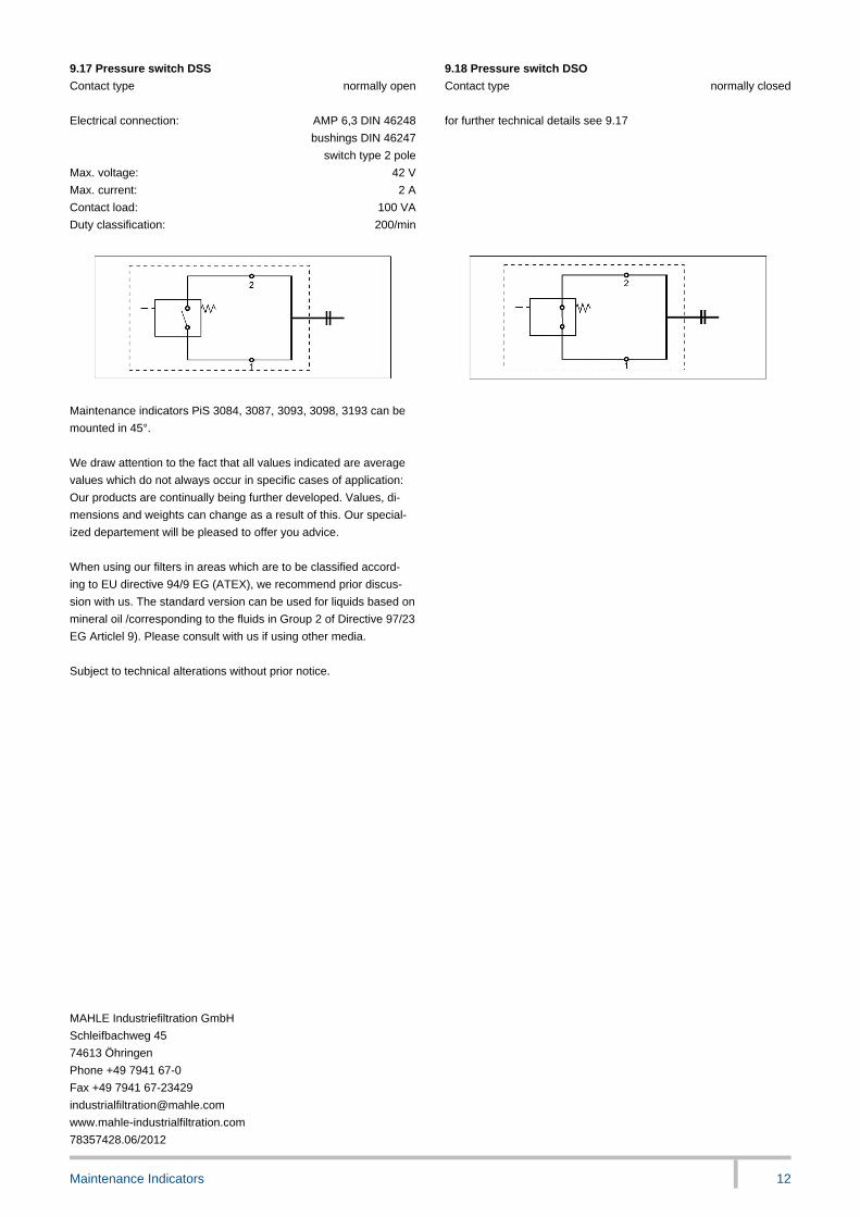
9.17 Pressure switch DSS 9.18 Pressure switch DSO
Contact type normally open Contact type normally closed
-
Electrical connection: AMP 6,3 DIN 46248 for further technical details see 9.17
bushings DIN 46247
switch type 2 pole
Max. voltage: 42 V
Max. current: 2 A
Contact load: 100 VA
Duty classification: 200/min
-
Maintenance indicators PiS 3084, 3087, 3093, 3098, 3193 can be
mounted in 45°.
-
We draw attention to the fact that all values indicated are average
values which do not always occur in specific cases of application:
Our products are continually being further developed. Values, di-
mensions and weights can change as a result of this. Our special-
ized departement will be pleased to offer you advice.
-
When using our filters in areas which are to be classified accord-
ing to EU directive 94/9 EG (ATEX), we recommend prior discus-
sion with us. The standard version can be used for liquids based on
mineral oil /corresponding to the fluids in Group 2 of Directive 97/23
EG Articlel 9). Please consult with us if using other media.
-
Subject to technical alterations without prior notice.
-
-
-
-
-
-
-
-
-
-
-
-
-
-
-
-
-
-
-
MAHLE Industriefiltration GmbH
Schleifbachweg 45
74613 Öhringen
Phone +49 7941 67-0
Fax +49 7941 67-23429
www.mahle-industrialfiltration.com
78357428.06/2012