Embed Size (px)
Citation preview
PRESSURE, DIFFERENTIAL PRESSURE,AND TEMPERATURE SWITCHES
12 Series1
2 S
erie
s
1 2 - B - 0 6
FeatureS
• 316 Stainless Steel Construction
• Hermetically Sealed Micro-switch
• Convenient Field Adjustment
• Belleville Actuated
• UL, cUL approved and ATEX compliant
• Dual Seal Certified
• Adjustable Ranges:
Pressure:1to12,500psi (68,9mbarto861,9bar)
DifferentialPressure: 0.7”wcdto150psid (1,7mbarto10,3bar)
Temperature:-130°Fto650°F (-90°Cto340°C)
Courtesy of Steven Engineering, Inc.-230 Ryan Way, South San Francisco, CA 94080-6370-Main Office: (650) 588-9200-Outside Local Area: (800) 258-9200-www.stevenengineering.com
2 w w w . u e o n l i n e . c o m 1 2 - B - 0 6
12 Series
12Serieshazardouslocationswitchesareidealforoperationintoughapplications where space is at a premium. A snap-action Bellevillespringassemblyisusedtoprovidevibrationresistanceandprolongedswitchlife.The316stainlesssteelenclosureandhermeticallysealedswitchprovideruggedprotectionfromtheenvironment.Approvedforuseinhazardouslocationsworldwide,the12Seriesisinstalledwithinapplications ranging from offshore oil rigs to rotating equipment,andmore.
Overview Features
• UL,cULandATEXapprovedforDiv.1orZone1hazardouslocations,CEcompliant
• DualsealcomplianttoANSI/ISA12.27.01
• PressureswitchwettedpartsareNACEMR-0175compliant
• Snap-actingBellevillespringforlonglife,vibrationresistanceandstability
• OptionalHastelloy®andMonel®sensormaterialforcorrosivemedia
• Optionalmedium-pressureandhigh-pressureautoclavepressureconnections
• Mountingbracketavailableforretrofitapplications
• 72"leadwires
• 3-yearwarranty
Optional cover locking ring prevents incidental tampering.
Differential Pressure Model with mounting bracket
12
Se
rie
s
Option M423 ATEXjunction box
Temperature switch
Option M513 UL/CSA junction box
Courtesy of Steven Engineering, Inc.-230 Ryan Way, South San Francisco, CA 94080-6370-Main Office: (650) 588-9200-Outside Local Area: (800) 258-9200-www.stevenengineering.com
1 2 - B - 0 6 w w w . u e o n l i n e . c o m 3
12 Series
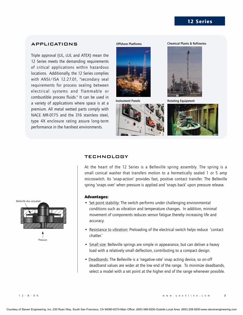
applicatiOns
Tripleapproval(UL,cULandATEX)meanthe12Seriesmeets thedemanding requirementsof critical applications within hazardouslocations.Additionally,the12Seriescomplieswith ANSI/ISA 12.27.01, "secondary sealrequirements for process sealing betweenelectr ical systems and f lammable orcombustibleprocessfluids." Itcanbeusedina variety of applications where space is at apremium.AllmetalwettedpartscomplywithNACE MR-0175 and the 316 stainless steel,type 4X enclosure rating assure long-termperformanceintheharshestenvironments.
Instrument Panels Rotating Equipment
Offshore Platforms Chemical Plants & Refineries
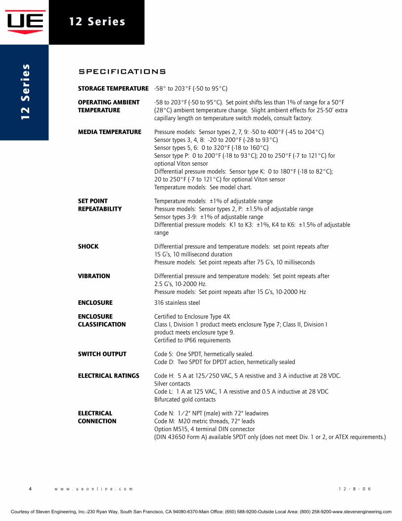
tecHnOlOGY
At the heart of the 12 Series is a Belleville spring assembly. The spring is asmall conical washer that transfers motion to a hermetically sealed 1 or 5 ampmicroswitch. Its ‘snap-action’ provides fast, positive contact transfer. The Bellevillespring‘snapsover’whenpressureisappliedand‘snapsback’uponpressurerelease.
advantages:• Setpointstability:Theswitchperformsunderchallengingenvironmental conditionssuchasvibrationandtemperaturechanges.Inaddition,minimal movementofcomponentsreducessensorfatiguetherebyincreasinglifeand accuracy.
• Resistancetovibration:Preloadingoftheelectricalswitchhelpsreduce‘contact chatter.’
• Smallsize:Bellevillespringsaresimpleinappearance,butcandeliveraheavy loadwitharelativelysmalldeflection,contributingtoacompactdesign.
•Deadbands:TheBellevilleisa‘negative-rate’snapactingdevice,soon-off deadbandvaluesarewideratthelowendoftherange.Tominimizedeadbands, selectamodelwithasetpointatthehigherendoftherangewheneverpossible.
PressureA
A
SECTION A-A SCALE 2 : 1
Bellevillediscactuated
Courtesy of Steven Engineering, Inc.-230 Ryan Way, South San Francisco, CA 94080-6370-Main Office: (650) 588-9200-Outside Local Area: (800) 258-9200-www.stevenengineering.com
4 w w w . u e o n l i n e . c o m 1 2 - B - 0 6
12 Series1
2 S
eri
es speciFicatiOns
Storage temperature -58°to203°F(-50to95°C)
operating ambient -58to203°F(-50to95°C).Setpointshiftslessthan1%ofrangefora50°Ftemperature (28°C)ambienttemperaturechange.Slightambienteffectsfor25-50’extra capillarylengthontemperatureswitchmodels,consultfactory.
media temperature Pressuremodels:Sensortypes2,7,9:-50to400°F(-45to204°C) Sensortypes3,4,8:-20to200°F(-28to93°C) Sensortypes5,6:0to320°F(-18to160°C) SensortypeP:0to200°F(-18to93°C);20to250°F(-7to121°C)for optionalVitonsensor Differentialpressuremodels:SensortypeK:0to180°F(-18to82°C); 20to250°F(-7to121°C)foroptionalVitonsensor Temperaturemodels:Seemodelchart.
Set point Temperaturemodels:±1%ofadjustablerangerepeatability Pressuremodels:Sensortypes2,P:±1.5%ofadjustablerange Sensortypes3-9:±1%ofadjustablerange Differentialpressuremodels:K1toK3:±1%,K4toK6:±1.5%ofadjustable range
Shock Differentialpressureandtemperaturemodels:setpointrepeatsafter 15G’s,10millisecondduration Pressuremodels:Setpointrepeatsafter75G’s,10milliseconds
Vibration Differentialpressureandtemperaturemodels:Setpointrepeatsafter 2.5G’s,10-2000Hz. Pressuremodels:Setpointrepeatsafter15G’s,10-2000Hz
encloSure 316stainlesssteel
encloSure CertifiedtoEnclosureType4XclaSSiFication ClassI,Division1productmeetsenclosureType7;ClassII,DivisionI productmeetsenclosuretype9. CertifiedtoIP66requirements
Switch output CodeS:OneSPDT,hermeticallysealed. CodeD:TwoSPDTforDPDTaction,hermeticallysealed
electrical ratingS CodeH:5Aat125/250VAC,5Aresistiveand3Ainductiveat28VDC. Silvercontacts CodeL:1Aat125VAC,1Aresistiveand0.5Ainductiveat28VDC Bifurcatedgoldcontacts
electrical CodeN:1/2"NPT(male)with72"leadwiresconnection CodeM:M20metricthreads,72"leads OptionM515,4terminalDINconnector (DIN43650FormA)availableSPDTonly(doesnotmeetDiv.1or2,orATEXrequirements.)
Courtesy of Steven Engineering, Inc.-230 Ryan Way, South San Francisco, CA 94080-6370-Main Office: (650) 588-9200-Outside Local Area: (800) 258-9200-www.stevenengineering.com
1 2 - B - 0 6 w w w . u e o n l i n e . c o m 5
12 Series
united StateS and canadaul listed, cul certifiedClassI,Division1and2,GroupsA,B,C&DClassII,Division1and2,GroupsE,F&GClassIIIClassI,Zone1,GroupIICEnclosureType4XPressure:UL508&698;CSAC22.2No.14,25&30-File#E40857DualsealcertifiedtoISA12.27.01(meetsCECsecondarysealrequirements)standardonstraightpressuremodelsonlyTemperature:UL873,1203;CSAC22.2No.24,25&30-File#E43374
european unionateX directive 94/9/ecII2GExdIICT6II2DExtDA21IP66T+85CTamb=-50°Cto+80°CULInternationalDEMKOA/S(N.B.#0539)Certificate#DEMKO08ATEX0717128XEN60079-0,60079-1,61241-0&61241-1
II1GEExiaIICT6(optional – code m405)Tamb=-50°Cto+60°CULInternationalDEMKOA/S(N.B.#0539)Certificate#DEMKO03ATEX0335063EN50014,50020&50284
pressure equipment directive (ped) 97/23/ecComplianttoPEDProductsratedlowerthan7.5psiareoutsidethescopeofthePED
low Voltage directive (lVd) 73/23/ec & 93/68/eecComplianttoLVDProductsratedlowerthan50VACand75VDCareoutsidethescopeoftheLVDTheLowVoltageDirectivedoesnotapplytoproductsforuseinhazardouslocations
ruSSiaGosgortechnadzorPermit(optional – code m406)0ExiaIICT6Tamb=-50°Cto+60°C1ExdIICT6XTamb=-56°Cto+85°CNANIOCCVECertificationCenterCertificate#ROSSUS.GB05.Bo2933GOSTR51330.0,51330.1,51330.10&51330.14
weight Temperaturemodels:approximately1lb14oz.(0,85kg) Pressuremodels:approximately12ounces(0,34kg) Differentialmodels:approximately3lb(1,4kg)
temperature Non-toxicoilfill;6feet304stainlesssteel.OptionallengthsavailableaSSembly
temperature Typically2%ofrangeunderlaboratoryconditionsdeadband (70°Fambientcirculatingbathatarateof1/2°Fperminutechange)
preSSure 1/2"NPT(female)or1/4"NPT(female).connection Differentialpressure:1/8"NPT(female) Optionalpressureconnectionsavailable,seepage11.
mounting Pressure:Maybepipemountedorbracketmountedusingkit62169-13 DifferentialPressure:Shouldbemountedusing2mountingholesonsensorbracket Temperature:Mountingkit62169-13shouldbespecifiedfornewinstallations
apprOvals
Courtesy of Steven Engineering, Inc.-230 Ryan Way, South San Francisco, CA 94080-6370-Main Office: (650) 588-9200-Outside Local Area: (800) 258-9200-www.stevenengineering.com
6 w w w . u e o n l i n e . c o m 1 2 - B - 0 6
12 Series1
2 S
eri
es
MOdel cHart
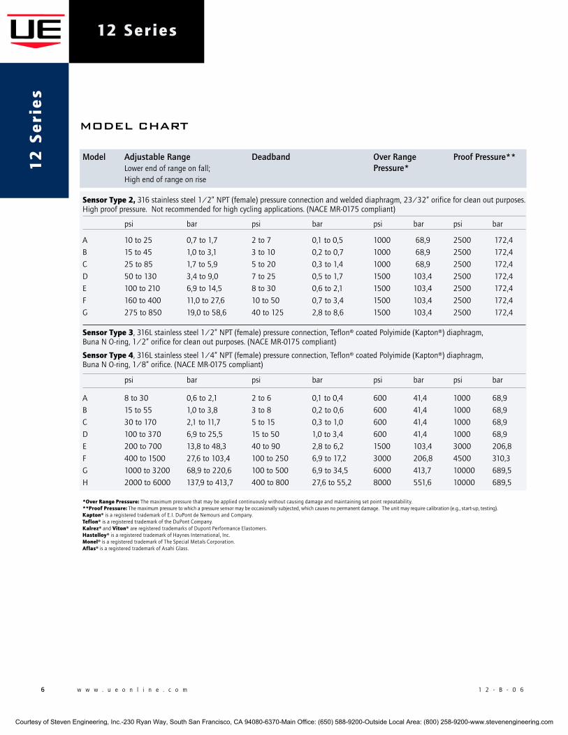
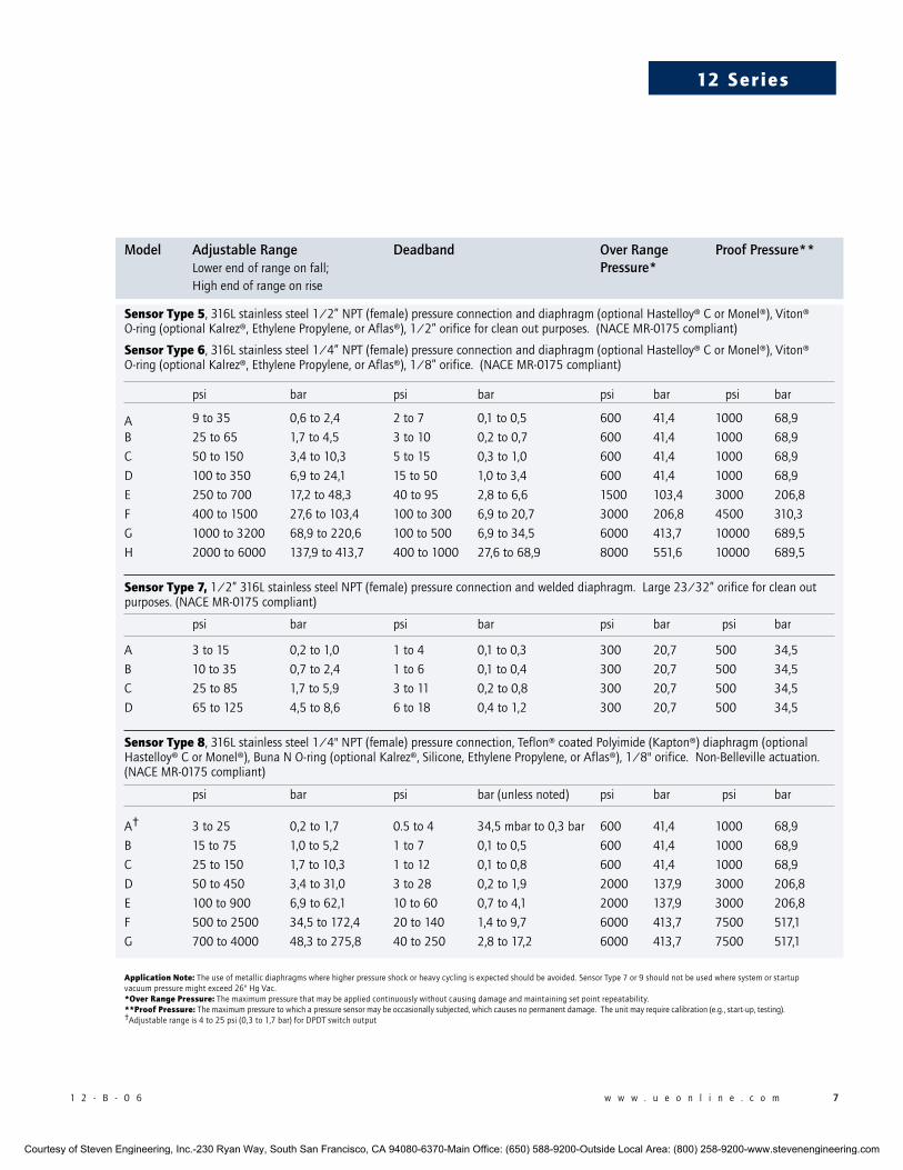
Model Adjustable Range Deadband Over Range Proof Pressure** Lowerendofrangeonfall; Pressure* Highendofrangeonrise
Sensor type 2,316stainlesssteel1/2”NPT(female)pressureconnectionandweldeddiaphragm,23/32”orificeforcleanoutpurposes.Highproofpressure.Notrecommendedforhighcyclingapplications.(NACEMR-0175compliant)
psi bar psi bar psi bar psi bar
A 10to25 0,7to1,7 2to7 0,1to0,5 1000 68,9 2500 172,4
B 15to45 1,0to3,1 3to10 0,2to0,7 1000 68,9 2500 172,4
C 25to85 1,7to5,9 5to20 0,3to1,4 1000 68,9 2500 172,4
D 50to130 3,4to9,0 7to25 0,5to1,7 1500 103,4 2500 172,4
E 100to210 6,9to14,5 8to30 0,6to2,1 1500 103,4 2500 172,4
F 160to400 11,0to27,6 10to50 0,7to3,4 1500 103,4 2500 172,4
G 275to850 19,0to58,6 40to125 2,8to8,6 1500 103,4 2500 172,4
Sensor type 3,316Lstainlesssteel1/2”NPT(female)pressureconnection,Teflon®coatedPolyimide(Kapton®)diaphragm, BunaNO-ring,1/2”orificeforcleanoutpurposes.(NACEMR-0175compliant)
Sensor type 4,316Lstainlesssteel1/4”NPT(female)pressureconnection,Teflon®coatedPolyimide(Kapton®)diaphragm, BunaNO-ring,1/8”orifice.(NACEMR-0175compliant)
psi bar psi bar psi bar psi bar
A 8to30 0,6to2,1 2to6 0,1to0,4 600 41,4 1000 68,9
B 15to55 1,0to3,8 3to8 0,2to0,6 600 41,4 1000 68,9
C 30to170 2,1to11,7 5to15 0,3to1,0 600 41,4 1000 68,9
D 100to370 6,9to25,5 15to50 1,0to3,4 600 41,4 1000 68,9
E 200to700 13,8to48,3 40to90 2,8to6,2 1500 103,4 3000 206,8
F 400to1500 27,6to103,4 100to250 6,9to17,2 3000 206,8 4500 310,3
G 1000to3200 68,9to220,6 100to500 6,9to34,5 6000 413,7 10000 689,5
H 2000to6000 137,9to413,7 400to800 27,6to55,2 8000 551,6 10000 689,5
*over range pressure: Themaximumpressurethatmaybeappliedcontinuouslywithoutcausingdamageandmaintainingsetpointrepeatability.**proof pressure:Themaximumpressuretowhichapressuresensormaybeoccasionallysubjected,whichcausesnopermanentdamage.Theunitmayrequirecalibration(e.g.,start-up,testing).kapton® isaregisteredtrademarkofE.I.DuPontdeNemoursandCompany.teflon® isaregisteredtrademarkoftheDuPontCompany.kalrez® and Viton®areregisteredtrademarksofDupontPerformanceElastomers.hastelloy® isaregisteredtrademarkofHaynesInternational,Inc.monel® isaregisteredtrademarkofTheSpecialMetalsCorporation.aflas® isaregisteredtrademarkofAsahiGlass.
Courtesy of Steven Engineering, Inc.-230 Ryan Way, South San Francisco, CA 94080-6370-Main Office: (650) 588-9200-Outside Local Area: (800) 258-9200-www.stevenengineering.com
1 2 - B - 0 6 w w w . u e o n l i n e . c o m 7
12 Series
Model Adjustable Range Deadband Over Range Proof Pressure** Lowerendofrangeonfall; Pressure* Highendofrangeonrise
Sensor type 5,316Lstainlesssteel1/2”NPT(female)pressureconnectionanddiaphragm(optionalHastelloy®CorMonel®),Viton®O-ring(optionalKalrez®,EthylenePropylene,orAflas®),1/2”orificeforcleanoutpurposes.(NACEMR-0175compliant)
Sensor type 6,316Lstainlesssteel1/4”NPT(female)pressureconnectionanddiaphragm(optionalHastelloy®CorMonel®),Viton®O-ring(optionalKalrez®,EthylenePropylene,orAflas®),1/8”orifice.(NACEMR-0175compliant)
psi bar psi bar psi bar psi bar
A 9to35 0,6to2,4 2to7 0,1to0,5 600 41,4 1000 68,9
B 25to65 1,7to4,5 3to10 0,2to0,7 600 41,4 1000 68,9
C 50to150 3,4to10,3 5to15 0,3to1,0 600 41,4 1000 68,9
D 100to350 6,9to24,1 15to50 1,0to3,4 600 41,4 1000 68,9
E 250to700 17,2to48,3 40to95 2,8to6,6 1500 103,4 3000 206,8
F 400to1500 27,6to103,4 100to300 6,9to20,7 3000 206,8 4500 310,3
G 1000to3200 68,9to220,6 100to500 6,9to34,5 6000 413,7 10000 689,5
H 2000to6000 137,9to413,7 400to1000 27,6to68,9 8000 551,6 10000 689,5
Sensor type 7,1/2”316LstainlesssteelNPT(female)pressureconnectionandweldeddiaphragm.Large23/32”orificeforcleanoutpurposes.(NACEMR-0175compliant)
psi bar psi bar psi bar psi bar
A 3to15 0,2to1,0 1to4 0,1to0,3 300 20,7 500 34,5
B 10to35 0,7to2,4 1to6 0,1to0,4 300 20,7 500 34,5
C 25to85 1,7to5,9 3to11 0,2to0,8 300 20,7 500 34,5
D 65to125 4,5to8,6 6to18 0,4to1,2 300 20,7 500 34,5
Sensor type 8,316Lstainlesssteel1/4"NPT(female)pressureconnection,Teflon®coatedPolyimide(Kapton®)diaphragm(optionalHastelloy®CorMonel®),BunaNO-ring(optionalKalrez®,Silicone,EthylenePropylene,orAflas®),1/8"orifice.Non-Bellevilleactuation.(NACEMR-0175compliant)
psi bar psi bar(unlessnoted) psi bar psi bar
A† 3to25 0,2to1,7 0.5to4 34,5mbarto0,3bar 600 41,4 1000 68,9
B 15to75 1,0to5,2 1to7 0,1to0,5 600 41,4 1000 68,9
C 25to150 1,7to10,3 1to12 0,1to0,8 600 41,4 1000 68,9
D 50to450 3,4to31,0 3to28 0,2to1,9 2000 137,9 3000 206,8
E 100to900 6,9to62,1 10to60 0,7to4,1 2000 137,9 3000 206,8
F 500to2500 34,5to172,4 20to140 1,4to9,7 6000 413,7 7500 517,1
G 700to4000 48,3to275,8 40to250 2,8to17,2 6000 413,7 7500 517,1
application note: Theuseofmetallicdiaphragmswherehigherpressureshockorheavycyclingisexpectedshouldbeavoided.SensorType7or9shouldnotbeusedwheresystemorstartupvacuumpressuremightexceed26"HgVac.*over range pressure: Themaximumpressurethatmaybeappliedcontinuouslywithoutcausingdamageandmaintainingsetpointrepeatability.**proof pressure: Themaximumpressuretowhichapressuresensormaybeoccasionallysubjected,whichcausesnopermanentdamage.Theunitmayrequirecalibration(e.g.,start-up,testing).†Adjustablerangeis4to25psi(0,3to1,7bar)forDPDTswitchoutput
Courtesy of Steven Engineering, Inc.-230 Ryan Way, South San Francisco, CA 94080-6370-Main Office: (650) 588-9200-Outside Local Area: (800) 258-9200-www.stevenengineering.com
8 w w w . u e o n l i n e . c o m 1 2 - B - 0 6
12 Series1
2 S
eri
es
MOdel cHart
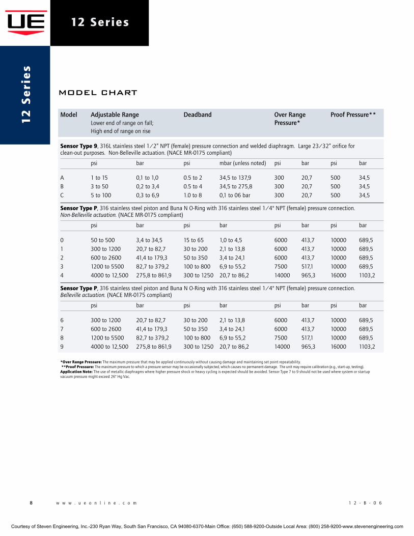
Model Adjustable Range Deadband Over Range Proof Pressure** Lowerendofrangeonfall; Pressure* Highendofrangeonrise
Sensor type 9,316Lstainlesssteel1/2”NPT(female)pressureconnectionandweldeddiaphragm.Large23/32”orificeforclean-outpurposes.Non-Bellevilleactuation.(NACEMR-0175compliant)
psi bar psi mbar(unlessnoted) psi bar psi bar
A 1to15 0,1to1,0 0.5to2 34,5to137,9 300 20,7 500 34,5
B 3to50 0,2to3,4 0.5to4 34,5to275,8 300 20,7 500 34,5
C 5to100 0,3to6,9 1.0to8 0,1to06bar 300 20,7 500 34,5
Sensor type p,316stainlesssteelpistonandBunaNO-Ringwith316stainlesssteel1/4"NPT(female)pressureconnection. Non-Belleville actuation. (NACEMR-0175compliant)
psi bar psi bar psi bar psi bar
0 50to500 3,4to34,5 15to65 1,0to4,5 6000 413,7 10000 689,5
1 300to1200 20,7to82,7 30to200 2,1to13,8 6000 413,7 10000 689,5
2 600to2600 41,4to179,3 50to350 3,4to24,1 6000 413,7 10000 689,5
3 1200to5500 82,7to379,2 100to800 6,9to55,2 7500 517,1 10000 689,5
4 4000to12,500 275,8to861,9 300to1250 20,7to86,2 14000 965,3 16000 1103,2
Sensor type p,316stainlesssteelpistonandBunaNO-Ringwith316stainlesssteel1/4"NPT(female)pressureconnection. Belleville actuation. (NACEMR-0175compliant)
psi bar psi bar psi bar psi bar
6 300to1200 20,7to82,7 30to200 2,1to13,8 6000 413,7 10000 689,5
7 600to2600 41,4to179,3 50to350 3,4to24,1 6000 413,7 10000 689,5
8 1200to5500 82,7to379,2 100to800 6,9to55,2 7500 517,1 10000 689,5
9 4000to12,500 275,8to861,9 300to1250 20,7to86,2 14000 965,3 16000 1103,2
*over range pressure: Themaximumpressurethatmaybeappliedcontinuouslywithoutcausingdamageandmaintainingsetpointrepeatability. **proof pressure:Themaximumpressuretowhichapressuresensormaybeoccasionallysubjected,whichcausesnopermanentdamage.Theunitmayrequirecalibration(e.g.,start-up,testing).application note: Theuseofmetallicdiaphragmswherehigherpressureshockorheavycyclingisexpectedshouldbeavoided.SensorType7to9shouldnotbeusedwheresystemorstartupvacuumpressuremightexceed26"HgVac.
Courtesy of Steven Engineering, Inc.-230 Ryan Way, South San Francisco, CA 94080-6370-Main Office: (650) 588-9200-Outside Local Area: (800) 258-9200-www.stevenengineering.com
1 2 - B - 0 6 w w w . u e o n l i n e . c o m 9
12 Series
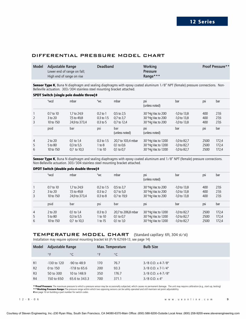
Model Adjustable Range Deadband Working Proof Pressure** Lowerendofrangeonfall; Pressure Highendofrangeonrise Range***
Sensor type k,BunaNdiaphragmandsealingdiaphragmswithepoxycoatedaluminum1/8”NPT(female)pressureconnections.Non-Bellevilleactuation.303/304stainlesssteelmountingbracketattached.
Spdt Switch (single pole double throw)‡
"wcd mbar "wc mbar psi bar psi bar (unlessnoted)
1 0.7to10 1,7to24,9 0.2to1 0,5to2,5 30"HgVacto200 -1,0to13,8 400 27,62 3to20 7,5to49,8 0.3to1.5 0,7to3,7 30"HgVacto200 -1,0to13,8 400 27,63 10to150 24,9to373,4 0.3to5 0,7to12,4 30"HgVacto200 -1,0to13,8 400 27,6
psid bar psi bar psi bar psi bar (unlessnoted) (unlessnoted)
4 2to20 0,1to1,4 0.3to1.5 20,7to103,4mbar 30"HgVacto1200 -1,0to82,7 2500 172,45 5to80 0,3to5,5 1to8 0,1to0,6 30"HgVacto1200 -1,0to82,7 2500 172,46 10to150 0,7to10,3 1to10 0,1to0,7 30"HgVacto1200 -1,0to82,7 2500 172,4
Sensor type k,BunaNdiaphragmandsealingdiaphragmswithepoxycoatedaluminumand1/8”NPT(female)pressureconnections.Non-Bellevilleactuation.303/304stainlesssteelmountingbracketattached.
dpdt Switch (double pole double throw)‡
"wcd mbar "wc mbar psi bar psi bar (unlessnoted)
1 0.7to10 1,7to24,9 0.2to1.5 0,5to3,7 30"HgVacto200 -1,0to13,8 400 27,62 3to20 7,5to49,8 0.3to2 0,7to5,0 30"HgVacto200 -1,0to13,8 400 27,63 10to150 24,9to373,4 0.3to8 0,7to19,9 30"HgVacto200 -1,0to13,8 400 27,6
psid bar psi bar psi bar psi bar
4 2to20 0,1to1,4 0.3to3 20,7to206,8mbar 30"HgVacto1200 -1,0to82,7 2500 172,45 5to80 0,3to5,5 1to10 0,1to0,7 30"HgVacto1200 -1,0to82,7 2500 172,46 10to150 0,7to10,3 1to15 0,1to1,0 30"HgVacto1200 -1,0to82,7 2500 172,4
teMperature MOdel cHart(Standardcapillary:6ft,304st/st)
Model Adjustable Range Max. Temperature Bulb Size
°F °C °F °C
R1 -130to120 -90to48.9 170 76.7 3/8O.D.x4-7⁄8"
R2 0to150 -17.8to65.6 200 93.3 3/8O.D.x7-1⁄4"
R3 50to300 10to148.9 350 176.7 3/8O.D.x4-7/8"
R4 150to650 65.6to343.3 700 371.1 3/8O.D.x4"
**proof pressure:Themaximumpressuretowhichapressuresensormaybeoccasionallysubjected,whichcausesnopermanentdamage.Theunitmayrequirecalibration(e.g.,start-up,testing)***working pressure range: Thepressurerangewithinwhichtwoopposingsensorscanbesafelyoperatedandstillmaintainsetpointadjustability.‡Seepage10onbuildingapartnumberforswitchcodes.
diFFerential pressure MOdel cHart
Installationmayrequireoptionalmountingbracketkit(P/N62169-13,seepage14)
Courtesy of Steven Engineering, Inc.-230 Ryan Way, South San Francisco, CA 94080-6370-Main Office: (650) 588-9200-Outside Local Area: (800) 258-9200-www.stevenengineering.com
10 w w w . u e o n l i n e . c o m 1 2 - B - 0 6
12 Series1
2 S
eri
es
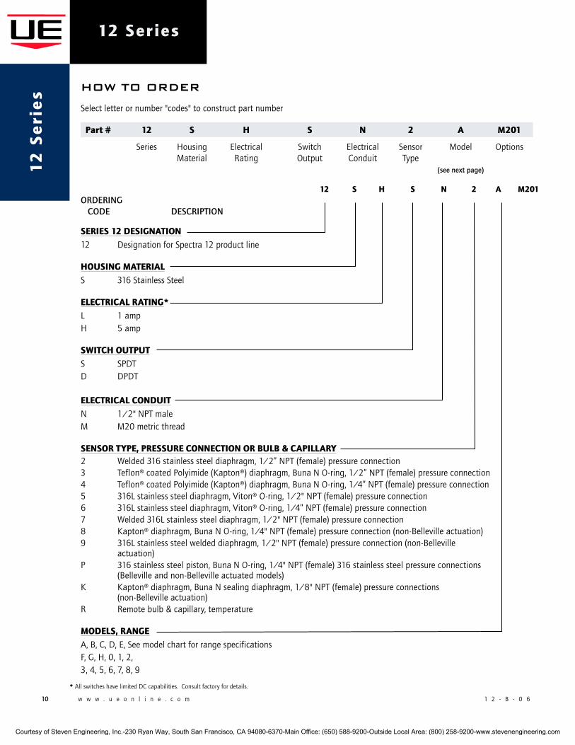
12 S h S n 2 a m201ORDERING CODE DESCRIPTION
SerieS 12 deSignation12 DesignationforSpectra12productline
houSing materialS 316StainlessSteel
electrical rating*L 1ampH 5amp
Switch outputS SPDTD DPDT
electrical conduitN 1/2"NPTmaleM M20metricthread
SenSor type, preSSure connection or bulb & capillary2 Welded316stainlesssteeldiaphragm,1/2”NPT(female)pressureconnection3 Teflon®coatedPolyimide(Kapton®)diaphragm,BunaNO-ring,1/2”NPT(female)pressureconnection4 Teflon®coatedPolyimide(Kapton®)diaphragm,BunaNO-ring,1/4”NPT(female)pressureconnection5 316Lstainlesssteeldiaphragm,Viton®O-ring,1/2"NPT(female)pressureconnection6 316Lstainlesssteeldiaphragm,Viton®O-ring,1/4”NPT(female)pressureconnection7 Welded316Lstainlesssteeldiaphragm,1/2"NPT(female)pressureconnection8 Kapton®diaphragm,BunaNO-ring,1/4"NPT(female)pressureconnection(non-Bellevilleactuation)9 316Lstainlesssteelweldeddiaphragm,1/2"NPT(female)pressureconnection(non-Belleville actuation)P 316stainlesssteelpiston,BunaNO-ring,1/4"NPT(female)316stainlesssteelpressureconnections (Bellevilleandnon-Bellevilleactuatedmodels)K Kapton®diaphragm,BunaNsealingdiaphragm,1/8"NPT(female)pressureconnections (non-Bellevilleactuation)R Remotebulb&capillary,temperature
modelS, rangeA,B,C,D,E,SeemodelchartforrangespecificationsF,G,H,0,1,2,3,4,5,6,7,8,9
HOw tO Order
Selectletterornumber"codes"toconstructpartnumber
*AllswitcheshavelimitedDCcapabilities.Consultfactoryfordetails.
part # 12 S h S n 2 a m201
Series Housing Electrical Switch Electrical Sensor Model Options Material Rating Output Conduit Type (see next page)
Courtesy of Steven Engineering, Inc.-230 Ryan Way, South San Francisco, CA 94080-6370-Main Office: (650) 588-9200-Outside Local Area: (800) 258-9200-www.stevenengineering.com
1 2 - B - 0 6 w w w . u e o n l i n e . c o m 11
12 Series
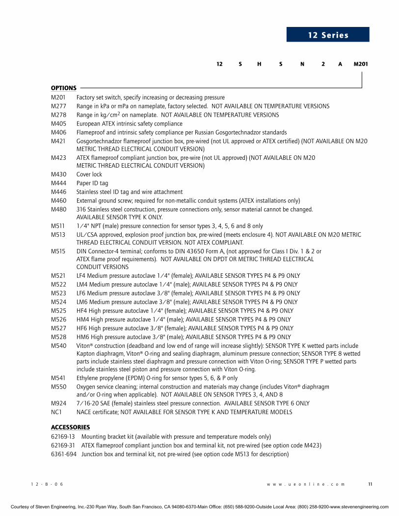
optionS M201 Factorysetswitch,specifyincreasingordecreasingpressureM277 RangeinkPaormPaonnameplate,factoryselected.NOTAVAILABLEONTEMPERATUREVERSIONSM278 Rangeinkg/cm2onnameplate.NOTAVAILABLEONTEMPERATUREVERSIONSM405 EuropeanATEXintrinsicsafetycomplianceM406 FlameproofandintrinsicsafetycomplianceperRussianGosgortechnadzorstandardsM421 Gosgortechnadzorflameproofjunctionbox,pre-wired(notULapprovedorATEXcertified)(NOTAVAILABLEONM20 METRICTHREADELECTRICALCONDUITVERSION)M423 ATEXflameproofcompliantjunctionbox,pre-wire(notULapproved)(NOTAVAILABLEONM20 METRICTHREADELECTRICALCONDUITVERSION)M430 CoverlockM444 PaperIDtagM446 StainlesssteelIDtagandwireattachmentM460 Externalgroundscrew;requiredfornon-metallicconduitsystems(ATEXinstallationsonly)M480 316Stainlesssteelconstruction,pressureconnectionsonly,sensormaterialcannotbechanged. AVAILABLESENSORTYPEKONLY.M511 1/4"NPT(male)pressureconnectionforsensortypes3,4,5,6and8onlyM513 UL/CSAapproved,explosionproofjunctionbox,pre-wired(meetsenclosure4).NOTAVAILABLEONM20METRIC THREADELECTRICALCONDUITVERSION.NOTATEXCOMPLIANT.M515 DINConnector-4terminal;conformstoDIN43650FormA,(notapprovedforClassIDiv.1&2or ATEXflameproofrequirements).NOTAVAILABLEONDPDTORMETRICTHREADELECTRICAL CONDUITVERSIONSM521 LF4Mediumpressureautoclave1/4"(female);AVAILABLESENSORTYPESP4&P9ONLYM522 LM4Mediumpressureautoclave1/4"(male);AVAILABLESENSORTYPESP4&P9ONLYM523 LF6Mediumpressureautoclave3/8"(female);AVAILABLESENSORTYPESP4&P9ONLYM524 LM6Mediumpressureautoclave3/8"(male);AVAILABLESENSORTYPESP4&P9ONLYM525 HF4Highpressureautoclave1/4"(female);AVAILABLESENSORTYPESP4&P9ONLYM526 HM4Highpressureautoclave1/4"(male);AVAILABLESENSORTYPESP4&P9ONLYM527 HF6Highpressureautoclave3/8"(female);AVAILABLESENSORTYPESP4&P9ONLYM528 HM6Highpressureautoclave3/8"(male);AVAILABLESENSORTYPESP4&P9ONLYM540 Viton®construction(deadbandandlowendofrangewillincreaseslightly):SENSORTYPEKwettedpartsinclude Kaptondiaphragm,Viton®O-ringandsealingdiaphragm,aluminumpressureconnection;SENSORTYPE8wetted partsincludestainlesssteeldiaphragmandpressureconnectionwithVitonO-ring;SENSORTYPEPwettedparts includestainlesssteelpistonandpressureconnectionwithVitonO-ring.M541 Ethylenepropylene(EPDM)O-ringforsensortypes5,6,&PonlyM550 Oxygenservicecleaning;internalconstructionandmaterialsmaychange(includesViton®diaphragm and/orO-ringwhenapplicable).NOTAVAILABLEONSENSORTYPES3,4,AND8M924 7/16-20SAE(female)stainlesssteelpressureconnection.AVAILABLESENSORTYPE6ONLYNC1 NACEcertificate;NOTAVAILABLEFORSENSORTYPEKANDTEMPERATUREMODELS
acceSSorieS62169-13Mountingbracketkit(availablewithpressureandtemperaturemodelsonly)62169-31ATEXflameproofcompliantjunctionboxandterminalkit,notpre-wired(seeoptioncodeM423)6361-694Junctionboxandterminalkit,notpre-wired(seeoptioncodeM513fordescription)
12 S h S n 2 a m201
Courtesy of Steven Engineering, Inc.-230 Ryan Way, South San Francisco, CA 94080-6370-Main Office: (650) 588-9200-Outside Local Area: (800) 258-9200-www.stevenengineering.com
12 w w w . u e o n l i n e . c o m 1 2 - B - 0 6
12 Series1
2 S
eri
es OptiOns FOr teMperature MOdels
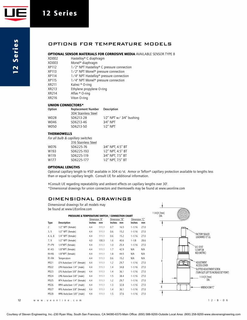
optional SenSor materialS For corroSiVe media AVAILABLESENSORTYPE8 XD002 Hastelloy®CdiaphragmXD003 Monel®diaphragmXP112 1/2"NPTHastelloy®CpressureconnectionXP113 1/2"NPTMonel®pressureconnectionXP114 1/4"NPTHastelloy®pressureconnectionXP115 1/4"NPTMonel®pressureconnectionXR211 Kalrez®O-ringXR213 EthylenepropyleneO-ringXR214 Aflas®O-ringXR216 VitonO-ring
union connectorS* Option Replacement Number Description 304StainlessSteelW028 SD6213-28 1⁄2”NPTw/3⁄4”bushingW046 SD6213-46 3⁄4”NPTW050 SD6213-50 1⁄2”NPT
thermowellS For all bulb & capillary switches 316StainlessSteelW076 SD6225-76 3⁄4”NPT,4.5”BT W193 SD6225-193 1⁄2”NPT,4.5”BT W119 SD6225-119 3⁄4”NPT,7.5”BT W177 SD6225-177 1⁄2”NPT,7.5”BT
optional lengthS Optionalcapillarylengthto‡50'availablein304st/st.ArmororTeflon®capillaryprotectionavailabletolengthslessthanorequaltocapillarylength.ConsultUEforadditionalinformation.
‡ConsultUEregardingrepeatabilityandambienteffectsoncapillarylengthsover30'.*Dimensionaldrawingsforunionconnectorsandthermowellsmaybefoundatwww.ueonline.com
diMensiOnal drawinGsDimensionaldrawingsforallmodelsmaybefoundatwww.UEonline.com
A
B
DIA.1-1/4 [31.7mm]
FACTORY SEALED LEADWIRES 72" LG.
E/C: ST/ST1/2 NPT OR M20 (METRIC)
ADJUSTMENT ACCESS COVER
WRENCH DIM “C”
SLOTTED ADJUSTMENT SCREW,(TURN SLOT LEFT TO INCREASE SET POINT)
DIA.1 1/4 [31.7mm]
PRESSURE&TEMPERATURESWITCH/CONNECTIONCHART Dimension “A” Dimension “B” Dimension “C”Type Description Inches mm Inches mm Inches mm2 1/2” NPT (female) 4.4 111.1 0.7 16.5 1-1/16 27.0
3, 5 1/2” NPT (female) 4.4 111.1 0.6 15.2 1-1/16 27.0
4, 6, 8 1/4” NPT (female) 4.4 111.1 0.6 15.2 1-1/16 27.0
7, 9 1/2” NPT (female) 4.0 100.3 1.6 40.6 1-1/8 28.6
P1-P9 1/4”NPT (female) 4.4 111.1 1.0 25.4 1-1/16 27.0
K1-K3 1/8”NPT (female) 4.4 111.1 1.7 42.9 N/A N/A
K4-K6 1/8”NPT (female) 4.4 111.1 1.8 44.5 N/A N/A
R1-R4 Temperature 4.4 111.1 0.6 15.2 N/A N/A
M521 LF4 Autoclave 1/4” (female) 4.4 111.1 1.2 29.7 1-1/16 27.0
M522 LM4 Autoclave 1/4” (male) 4.4 111.1 1.4 34.8 1-1/16 27.0
M523 LF6 Autoclave 3/8” (female) 4.4 111.1 1.4 36.1 1-1/16 27.0
M524 LM6 Autoclave 3/8” (male) 4.4 111.1 1.5 38.4 1-1/16 27.0
M525 HF4 Autoclave 1/4” (female) 4.4 111.1 1.2 29.7 1-1/16 27.0
M526 HM4 autoclave 1/4” (male) 4.4 111.1 1.3 32.8 1-1/16 27.0
M527 HF6 Autoclave 3/8” (female) 4.4 111.1 1.4 36.1 1-1/16 27.0
M528 HM6 Autoclave 3/8” (male) 4.4 111.1 1.5 37.6 1-1/16 27.0
Courtesy of Steven Engineering, Inc.-230 Ryan Way, South San Francisco, CA 94080-6370-Main Office: (650) 588-9200-Outside Local Area: (800) 258-9200-www.stevenengineering.com
1 2 - B - 0 6 w w w . u e o n l i n e . c o m 13
12 Series
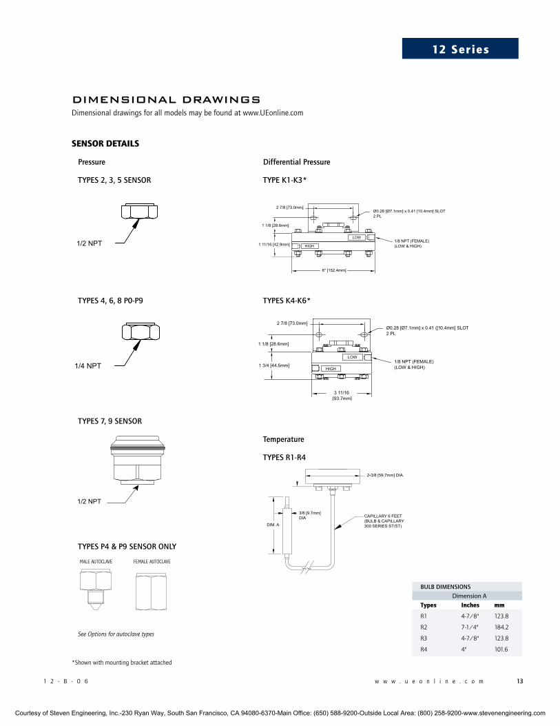
Pressure Differential Pressure
TYPES 2, 3, 5 SENSOR TYPE K1-K3*
TYPES 4, 6, 8 P0-P9 TYPES K4-K6*
TYPES 7, 9 SENSOR
Temperature
TYPES R1-R4
TYPES P4 & P9 SENSOR ONLY
See Options for autoclave types
BULB DIMENSIONSDimension A
types inches mm
R1 4-7/8" 123.8
R2 7-1/4" 184.2
R3 4-7/8" 123.8
R4 4" 101.6
SenSor detailS
diMensiOnal drawinGsDimensionaldrawingsforallmodelsmaybefoundatwww.UEonline.com
*Shownwithmountingbracketattached
MALE AUTOCLAVE FEMALE AUTOCLAVE
Courtesy of Steven Engineering, Inc.-230 Ryan Way, South San Francisco, CA 94080-6370-Main Office: (650) 588-9200-Outside Local Area: (800) 258-9200-www.stevenengineering.com
14 w w w . u e o n l i n e . c o m 1 2 - B - 0 6
12 Series1
2 S
eri
es
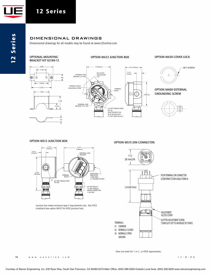
OPTIONAL MOUNTING BRACKET KIT 62169-13
OPTION M430 COVER LOCK
OPTION M423 ATEX JUNCTION BOX OPTION M513 UL JUNCTION BOX OPTION M460 EXTERNALGROUNDING SCREW
[21mm]
2-3/4 [70mm]
5-3/4 [146mm]
6-3/8[162mm]
3/4” NPT FEMALE PORTTYP 3PL
REMOVABLE PORT PLUG1 SIDE ONLY1/2” SQUARE SOCKET
TERMINAL BLOCK
3/4” NPT MALE X 1/2” NPT FEMALEUNION CONNECTOR1-3/8” HEX
INTERNAL CASEGROUND
13/16
1/2” NPT FEMALE PORTSQTY (2)JUNCTION BOX CAN BE ATTACHED WITH1/2” NPT PORT ON LEFT
TERMINAL BLOCK
INTERNAL CASEGROUND 5/16” HEX
4 [102mm] 2-3/4 [70mm]
[17mm]
4[102mm]
EXTERNAL CASE GROUND 5/16” HEX
NO ACCESSSEALED PORT2 PL
TERMINAL BLOCKMOUNTING SCREW
11/16
OPTION M513 JUNCTION BOX
Junctionboxmeetsenclosuretype4requirementsonly.NotATEXcompliant(seeoptionM423forATEXjunctionbox)
OPTION M515 DIN CONNECTOR.
ADJUSTMENT ACCESS COVER
SLOTTED ADJUSTMENT SCREW,(TURN SLOT LEFT TO INCREASE SET POINT)
FOUR TERMINAL DIN CONNECTOR(CONFORMS TO DIN 43650, FORM A)
2-3/4 [69.7mm]
1-1/2[38.1mm] DIA.
TERMINALS#1 COMMON#2 NORMALLY CLOSED#3 NORMALLY OPEN GROUND
DoesnotmeetDiv1or2,orATEXrequirements.
OPTION M460 EXTERNAL GROUNDING SCREW
OPTION M423 ATEX JUNCTION BOX OPTION M513 UL JUNCTION BOX OPTION M460 EXTERNALGROUNDING SCREW
[21mm]
2-3/4 [70mm]
5-3/4 [146mm]
6-3/8[162mm]
3/4” NPT FEMALE PORTTYP 3PL
REMOVABLE PORT PLUG1 SIDE ONLY1/2” SQUARE SOCKET
TERMINAL BLOCK
3/4” NPT MALE X 1/2” NPT FEMALEUNION CONNECTOR1-3/8” HEX
INTERNAL CASEGROUND
13/16
1/2” NPT FEMALE PORTSQTY (2)JUNCTION BOX CAN BE ATTACHED WITH1/2” NPT PORT ON LEFT
TERMINAL BLOCK
INTERNAL CASEGROUND 5/16” HEX
4 [102mm] 2-3/4 [70mm]
[17mm]
4[102mm]
EXTERNAL CASE GROUND 5/16” HEX
NO ACCESSSEALED PORT2 PL
TERMINAL BLOCKMOUNTING SCREW
11/16
OPTION M423 JUNCTION BOX
diMensiOnal drawinGsDimensionaldrawingsforallmodelsmaybefoundatwww.UEonline.com
Courtesy of Steven Engineering, Inc.-230 Ryan Way, South San Francisco, CA 94080-6370-Main Office: (650) 588-9200-Outside Local Area: (800) 258-9200-www.stevenengineering.com
1 2 - B - 0 6 w w w . u e o n l i n e . c o m 15
12 Series
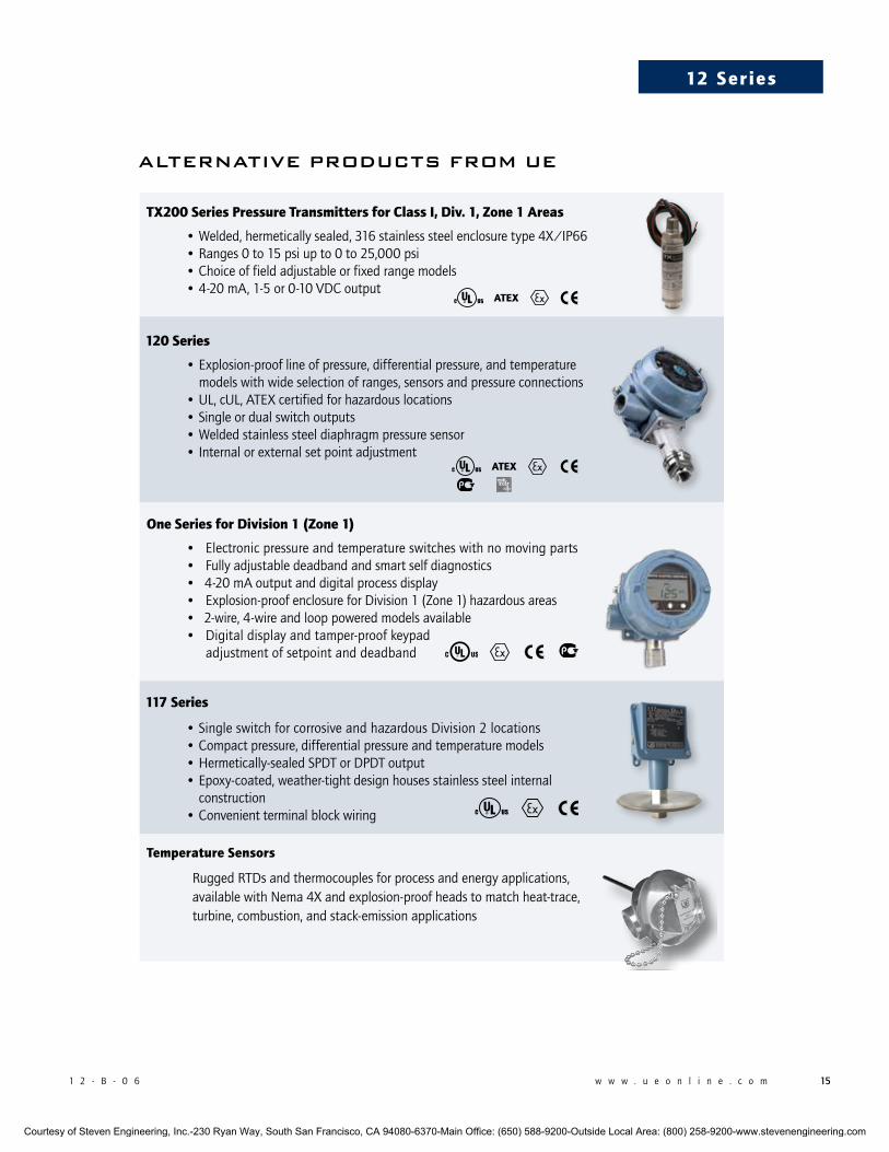
alternative prOducts FrOM ue
tX200 Series pressure transmitters for class i, div. 1, Zone 1 areas
•Welded,hermeticallysealed,316stainlesssteelenclosuretype4X/IP66•Ranges0to15psiupto0to25,000psi•Choiceoffieldadjustableorfixedrangemodels•4-20mA,1-5or0-10VDCoutput
120 Series
•Explosion-prooflineofpressure,differentialpressure,andtemperaturemodelswithwideselectionofranges,sensorsandpressureconnections
•UL,cUL,ATEXcertifiedforhazardouslocations•Singleordualswitchoutputs•Weldedstainlesssteeldiaphragmpressuresensor•Internalorexternalsetpointadjustment
one Series for division 1 (Zone 1)• Electronicpressureandtemperatureswitcheswithnomovingparts• Fullyadjustabledeadbandandsmartselfdiagnostics• 4-20mAoutputanddigitalprocessdisplay• Explosion-proofenclosureforDivision1(Zone1)hazardousareas• 2-wire,4-wireandlooppoweredmodelsavailable• Digitaldisplayandtamper-proofkeypad
adjustmentofsetpointanddeadband
117 Series
•SingleswitchforcorrosiveandhazardousDivision2locations•Compactpressure,differentialpressureandtemperaturemodels•Hermetically-sealedSPDTorDPDToutput•Epoxy-coated,weather-tightdesignhousesstainlesssteelinternalconstruction
•Convenientterminalblockwiring
temperature Sensors
RuggedRTDsandthermocouplesforprocessandenergyapplications,availablewithNema4Xandexplosion-proofheadstomatchheat-trace,turbine,combustion,andstack-emissionapplications
ateX
ateX
Courtesy of Steven Engineering, Inc.-230 Ryan Way, South San Francisco, CA 94080-6370-Main Office: (650) 588-9200-Outside Local Area: (800) 258-9200-www.stevenengineering.com
180DexterAvenue,P.O.Box9143Watertown,MA02471-9143USATelephone:617926-1000Fax:617926-2568http://www.ueonline.com
U N I T E D E L E C T R I C C O N T R O L S
CP07103500
Besuretovisitwww.ueonline.comforthelatestinformation.
international oFFiceS
CHINA UnitedElectricControls,Shanghai Room1011,10thFlr, HuaiHaiZhonghuaBuilding No.885,RenminRoad,LuwanDistrict Shanghai200010,P.R.China Phone:+8621-62558059 email:[email protected]
UnitedElectricControls,Beijing Room1006,JainhaoInternationalBldg. BlockD,No.116 Zizhuyuanlu,HaidianDistrict Beijing,China100089 Phone&Fax:+86-10-5893-0551 email:[email protected]
EASTERNEUROPE&SCANDINAVIA UnitedElectricControls 05-806Komorow Kujawska5,Poland Phone:+48224994804 email:[email protected]
GERMANY UnitedElectricControls AnDerZentlinde21 D-64711Erbach,Germany Phone:496-062-7400 email:[email protected]
INDIA UnitedElectricControls Houseno.7,KamalkunjSociety Nizampura, Baraoda(Gujarat),India Phone:+91(-265)-2788654 email:[email protected]
ASIA-PACIFIC UnitedElectricControls,FarEast No.1-2-2,2ndFloor Jalan4/101C CherasBusinessCentre 56100KualaLumpur,Malaysia Phone:603-9133-4122 email:[email protected]
MEXICO UnitedElectricControls Zacatecas#206,Suite20 ColGuadalupeCP89120 Tampico,TamaulipasMexico Phone:+52833-217-5201 email:[email protected]
RUSSIA UnitedElectricControls,Moscow Elninskayastr.,15-140 Moscow,121552Russia Phone:+7(495)792-88-06 email:[email protected]
u.S. SaleS oFFiceS
UnitedElectricControls 31OldStageRoad HamptonFalls,NH03844 Phone:617-899-1132 email:[email protected]
UnitedElectricControls 28N.WiseAve. Freeport,IL61032 Phone:815-341-2588 email:[email protected]
UnitedElectricControls 1022VineyardDrive Conyers,GA30013 Phone:770-335-9802 email:[email protected]
UnitedElectricControls 5829GrazingCourt Mason,OH45040 Phone:513-535-5486 email:[email protected]
UnitedElectricControls 102SalazarCourt Clayton,CA94517 Phone:925-408-5997 email:[email protected]
UnitedElectricControls 27SummitTerrace Sparta,NJ07871 Phone:973-271-2550 email:[email protected]
UnitedElectricControls 4306WhickhamDrive Fulshear,TX77441 Phone:832-457-6138 email:[email protected]
canada
EASTERN 68MosleyCrescent Brampton,Ontario CanadaL6Y5C8 Phone:905-455-5131 FAX:905-455-5131
recommended practiceS and warningS
UnitedElectricControlsCompany recommendscareful considerationof the following factors when specifying and installing UEpressure transmitters. Before installing a unit, the Installation andMaintenance instructions provided with unit must be read andunderstood.• Toavoiddamagingunit,proofpressureandmaximumtemperature
limits stated in literature and on nameplates must never beexceeded,evenbysurgesinthesystem.Operationoftheunituptomaximumpressureor temperature is acceptableona limitedbasis (i.e., start-up, testing) but continuous operationmust berestrictedtothedesignatedadjustablerange.Excessivecyclingatmaximumpressureortemperaturelimitscouldreducesensorlife.
• A back-up unit is necessary for applications where damage toaprimaryunit couldendanger life, limborproperty.Ahighorlowlimitswitchisnecessaryforapplicationswhereadangerousrunawayconditioncouldresult.
• Install unit where shock, vibration and ambient temperaturefluctuations will not damage unit or affect operation. Whenapplicable, orient unit so that moisture does not enter theenclosure via the electrical connection. When appropriate, thisentrypointshouldbesealedtopreventmoistureentry.
• Unitmustnotbealteredormodifiedaftershipment.ConsultUEifmodificationisnecessary.
• Monitoroperationtoobservewarningsignsofpossibledamagetounit,suchasdrift.Checkunitimmediately.
• Preventative maintenance and periodic testing is necessary forcritical applicationswhere damage could endanger property orpersonnel.
• Supplyvoltage stated in literatureandonnameplatemustnotbeexceeded.Overloadonatransmittercancausedamage,evenon the first cycle. Wire unit according to local and nationalelectrical codes, using wire size recommended in installationsheet.
• Donotmountunitinambienttemp.exceedingpublishedlimits.
limited warranty
Seller warrants that the product hereby purchased is, upon delivery,free from defects in material and workmanship and that any suchproduct which is found to be defective in such workmanship ormaterial will be repaired or replaced by Seller (Ex-works, Factory,Watertown,Massachusetts. INCOTERMS);provided,however, that thiswarranty applies only to equipment found to be so defective withina period of 36 months from the date of manufacture by the Seller.Seller shall not be obligated under this warranty for alleged defectswhich examination discloses are due to tampering, misuse, neglect,improper storage, and in any case where products are disassembledbyanyoneotherthanauthorizedSeller’s representatives.EXCEPTFORTHE LIMITED WARRANTY OF REPAIR AND REPLACEMENT STATEDABOVE, SELLER DISCLAIMS ALL WARRANTIES WHATSOEVER WITHRESPECTTOTHEPRODUCT, INCLUDINGALL IMPLIEDWARRANTIESOFMERCHANTABILITYORFITNESSFORANYPARTICULARPURPOSE.
limitation oF Seller’S liability
SELLER’SLIABILITYTOBUYERFORANYLOSSORCLAIM,INCLUDINGLIABILITY INCURRED IN CONNECTION WITH (I) BREACH OF ANYWARRANTY WHATSOEVER, EXPRESSED OR IMPLIED, (II) A BREACHOF CONTRACT, (III) A NEGLIGENT ACT OR ACTS (OR NEGLIGENTFAILURE TO ACT) COMMITTED BY SELLER, OR (IV) AN ACT FORWHICHSTRICTLIABILITYWILLBE INPUTTEDTOSELLER, ISLIMITEDTO THE “LIMITED WARRANTY” OF REPAIR AND/OR REPLACEMENTAS SO STATED IN OUR WARRANTY OF PRODUCT. IN NO EVENTSHALL THE SELLER BE LIABLE FOR ANY SPECIAL, INDIRECT,CONSEqUENTIAL OR OTHER DAMAGES OF A LIKE GENERALNATURE, INCLUDING, WITHOUT LIMITATION, LOSS OF PROFITS ORPRODUCTION, OR LOSS OR EXPENSES OF ANY NATURE INCURREDBYTHEBUYERORANYTHIRDPARTY.
Courtesy of Steven Engineering, Inc.-230 Ryan Way, South San Francisco, CA 94080-6370-Main Office: (650) 588-9200-Outside Local Area: (800) 258-9200-www.stevenengineering.com
1 2 0 - B - 0 6
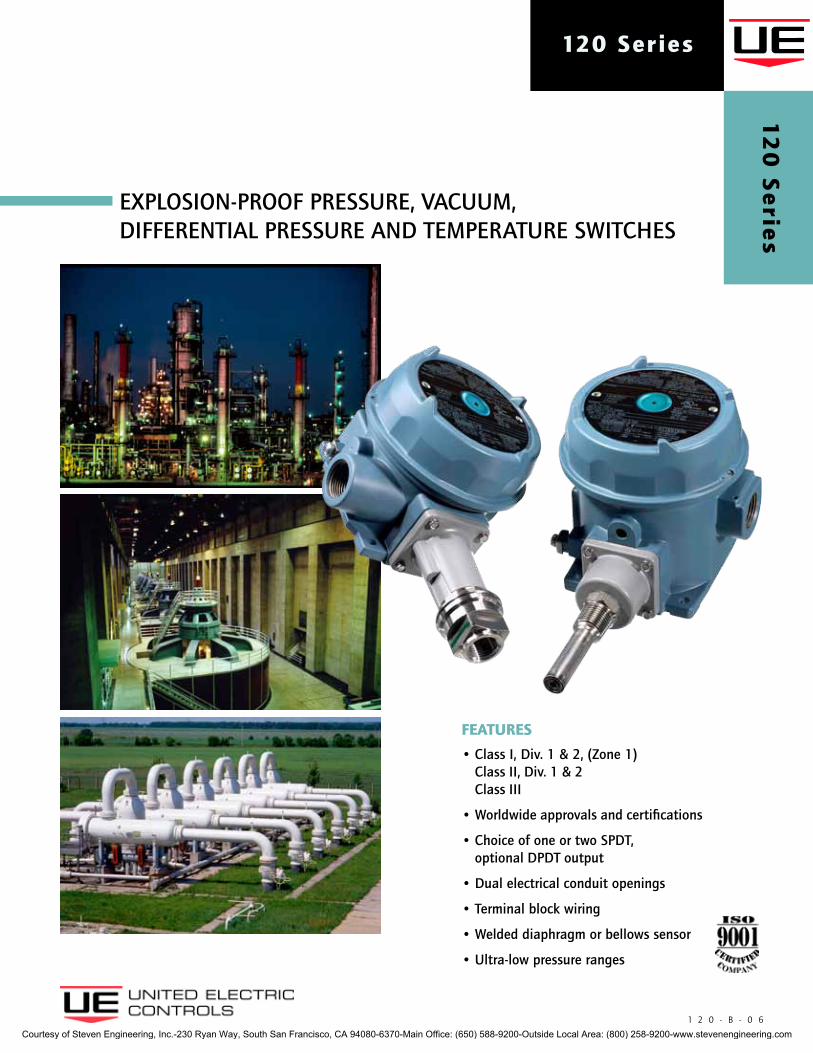
FEATURES
• Class I, Div. 1 & 2, (Zone 1) Class II, Div. 1 & 2 Class III
• Worldwide approvals and certifications
• Choice of one or two SPDT, optional DPDT output
• Dual electrical conduit openings
• Terminal block wiring
• Welded diaphragm or bellows sensor
• Ultra-low pressure ranges
EXPLOSION-PROOF PRESSURE, VACUUM, DIFFERENTIAL PRESSURE AND TEMPERATURE SWITCHES
120 Series1
20
Se
ries
Courtesy of Steven Engineering, Inc.-230 Ryan Way, South San Francisco, CA 94080-6370-Main Office: (650) 588-9200-Outside Local Area: (800) 258-9200-www.stevenengineering.com
2 w w w . u e o n l i n e . c o m 1 2 0 - B - 0 6
120 Series
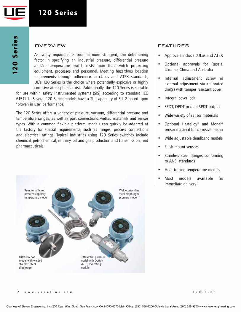
As safety requirements become more stringent, the determining factor in specifying an industrial pressure, differential pressure and/or temperature switch rests upon that switch protecting equipment, processes and personnel. Meeting hazardous location requirements through adherence to cULus and ATEX standards, UE’s 120 Series is the choice where potentially explosive or highly corrosive atmospheres exist. Additionally, the 120 Series is suitable
for use within safety instrumented systems (SIS) according to standard IEC 61511-1. Several 120 Series models have a SIL capability of SIL 2 based upon "proven in use" performance.
The 120 Series offers a variety of pressure, vacuum, differential pressure and temperature ranges, as well as port connections, wetted materials and sensor types. With a common flexible platform, models can quickly be adapted at the factory for special requirements, such as ranges, process connections and electrical ratings. Typical industries using 120 Series switches include chemical, petrochemical, refinery, oil and gas production and transmission, and pharmaceuticals.
overview features
12
0 S
eri
es
Ultra-low "wc model with welded stainless steel diaphragm
Differential pressure model with Option M210, Indicating module
Remote bulb and armored capillary temperature model
Welded stainless steel diaphragm pressure model
• Approvals include cULus and ATEX
• Optional approvals for Russia, Ukraine, China and Australia
• Internal adjustment screw or external adjustment via calibrated dial(s) with tamper resistant cover
• Integral cover lock
• SPDT, DPDT or dual SPDT output
• Wide variety of sensor materials
• Optional Hastelloy® and Monel® sensor material for corrosive media
• Wide adjustable deadband models
• Flush mount sensors
• Stainless steel flanges conforming to ANSI standards
• Heat tracing temperature models
• Most models available for immediate delivery!
Courtesy of Steven Engineering, Inc.-230 Ryan Way, South San Francisco, CA 94080-6370-Main Office: (650) 588-9200-Outside Local Area: (800) 258-9200-www.stevenengineering.com
1 2 0 - B - 0 6 w w w . u e o n l i n e . c o m 3
120 Series
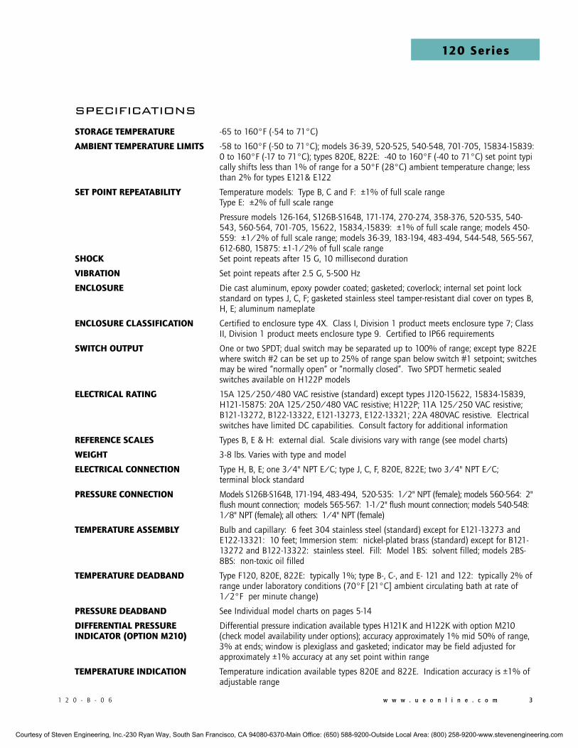
specificationsSToRAgE TEmpERATURE -65 to 160°F (-54 to 71°C)
AmbiEnT TEmpERATURE limiTS -58 to 160°F (-50 to 71°C); models 36-39, 520-525, 540-548, 701-705, 15834-15839: 0 to 160°F (-17 to 71°C); types 820E, 822E: -40 to 160°F (-40 to 71°C) set point typi cally shifts less than 1% of range for a 50°F (28°C) ambient temperature change; less than 2% for types E121& E122
SET poinT REpEATAbiliTy Temperature models: Type B, C and F: ±1% of full scale range Type E: ±2% of full scale range
Pressure models 126-164, S126B-S164B, 171-174, 270-274, 358-376, 520-535, 540- 543, 560-564, 701-705, 15622, 15834,-15839: ±1% of full scale range; models 450- 559: ±1/2% of full scale range; models 36-39, 183-194, 483-494, 544-548, 565-567, 612-680, 15875: ±1-1/2% of full scale rangeShock Set point repeats after 15 G, 10 millisecond duration
VibRATion Set point repeats after 2.5 G, 5-500 Hz
EncloSURE Die cast aluminum, epoxy powder coated; gasketed; coverlock; internal set point lock standard on types J, C, F; gasketed stainless steel tamper-resistant dial cover on types B, H, E; aluminum nameplate
EncloSURE clASSiFicATion Certified to enclosure type 4X. Class I, Division 1 product meets enclosure type 7; Class II, Division 1 product meets enclosure type 9. Certified to IP66 requirements
SwiTch oUTpUT One or two SPDT; dual switch may be separated up to 100% of range; except type 822E where switch #2 can be set up to 25% of range span below switch #1 setpoint; switches may be wired “normally open” or “normally closed”. Two SPDT hermetic sealed switches available on H122P models
ElEcTRicAl RATing 15A 125/250/480 VAC resistive (standard) except types J120-15622, 15834-15839, H121-15875: 20A 125/250/480 VAC resistive; H122P; 11A 125/250 VAC resistive; B121-13272, B122-13322, E121-13273, E122-13321; 22A 480VAC resistive. Electrical switches have limited DC capabilities. Consult factory for additional information
REFEREncE ScAlES Types B, E & H: external dial. Scale divisions vary with range (see model charts)
wEighT 3-8 lbs. Varies with type and model
ElEcTRicAl connEcTion Type H, B, E; one 3/4" NPT E/C; type J, C, F, 820E, 822E; two 3/4" NPT E/C; terminal block standard
pRESSURE connEcTion Models S126B-S164B, 171-194, 483-494, 520-535: 1/2" NPT (female); models 560-564: 2" flush mount connection; models 565-567: 1-1 ⁄ 2" flush mount connection; models 540-548: 1/8" NPT (female); all others: 1/4" NPT (female)
TEmpERATURE ASSEmbly Bulb and capillary: 6 feet 304 stainless steel (standard) except for E121-13273 and E122-13321: 10 feet; Immersion stem: nickel-plated brass (standard) except for B121- 13272 and B122-13322: stainless steel. Fill: Model 1BS: solvent filled; models 2BS- 8BS: non-toxic oil filled
TEmpERATURE dEAdbAnd Type F120, 820E, 822E: typically 1%; type B-, C-, and E- 121 and 122: typically 2% of range under laboratory conditions (70°F [21°C] ambient circulating bath at rate of 1/2°F per minute change)
pRESSURE dEAdbAnd See Individual model charts on pages 5-14
diFFEREnTiAl pRESSURE Differential pressure indication available types H121K and H122K with option M210 indicAToR (opTion m210) (check model availability under options); accuracy approximately 1% mid 50% of range, 3% at ends; window is plexiglass and gasketed; indicator may be field adjusted for approximately ±1% accuracy at any set point within range
TEmpERATURE indicATion Temperature indication available types 820E and 822E. Indication accuracy is ±1% of adjustable range
Courtesy of Steven Engineering, Inc.-230 Ryan Way, South San Francisco, CA 94080-6370-Main Office: (650) 588-9200-Outside Local Area: (800) 258-9200-www.stevenengineering.com

4 w w w . u e o n l i n e . c o m 1 2 0 - B - 0 6
120 Series1
20
Se
rie
s
agency approvalsUniTEd STATES And cAnAdAClass I, Division 1 and 2, Groups B, C & DClass II, Division 1 and 2, Groups E, F & GClass IIIClass I, Zone 1, Group IIB + H2 T6Enclosure Type 4XUL Listed, cUL CertifiedPressure: UL 50 & 698; CSA C22.2No. 25 & 30 - File # E40857Temperature: UL 50 & 698; CSA C22.2No. 25 & 30 - File # E43374
EURopEATEX directive (94/9/Ec)II 2 G Ex d IIC T6II 2 D Ex tD A21 IP66 T+85°CTamb = -40°C to +75°CUL International DEMKO A/S (N.B.# 0539)Certificate # DEMKO 09 ATEX 0815573XEN 60079-0, 60079-1, 61241-0 & 61241-1
II 1 G EEx ia IIC T6 (opTionAl – code m405)(not available types 820E, 822E)Tamb = -50°C to +60°CUL International DEMKO A/S (N.B.# 0539)Certificate # DEMKO 03 ATEX 0335063EN 50014, 50020 & 50284
pressure Equipment directive (pEd) (97/23/Ec)Compliant to PEDProducts rated lower than 7.5 psi are outside the scope of the PED
low Voltage directive (lVd) (73/23/Ec & 93/68/EEc)UEC compliant to LVDProducts rated lower than 50 VAC and 75 VDC are outside of the scope of the LVDThe Low Voltage Directive does not apply to products for use inhazardous locations
RUSSiAmodels 120, 121 and 122Gosgortechnadzor Permit (opTionAl – code m406)0ExiaIICT6Tamb = -50°C to +60°CNANIO CCVE Certification CenterCertificate # ROSS US.GB05.Bo2933GOST R 51330.0, 51330.1, 51330.10 & 51330.14
models 120, 121, 122, 820 & 8221ExdIICT6XTamb = -56°C to +85°C (models 120, 121 & 122)Tamb = -40°C to +71°C (models 820 & 822)NANIO CCVE Certification CenterCertificate # ROSS US.GB05.Bo2933GOST R 51330.0, 51330.1, 51330.10 & 51330.14
UkRAinEGosnadzorohrantruda Permit (opTionAl - code m404)1ExdIICT6XTamb = -56°C to +85°C (types 120, 121 & 122)Tamb = -40°C to +71°C (types 820 & 822)Certificate # 1867.04.30 - 31.62.4
chinACQST Certified (opTionAl – code m408)Exd IIC T6DIP A21 TA +85°CTamb. = -40°C to +75°CGB 3836.1, 3836.2 & 12476.1Pressure: Certificate # CNEx 09.2181XTemperature: Certificate # CNEx 09.2180X
globAl cERTiFicATion* (inclUdES AUSTRAliA)IECEx Certified (opTionAl – code m403)Ex d IIC T6Ex tD A21 IP66 T+85°CTamb. = -40°C to 75°CIEC 60079-0 & 60079-1, 61241-0 & 61241-1Certificate # IECEx UL 03.0001X
* See http://www.iecex.com/countries.htm for a list of participating members.
Courtesy of Steven Engineering, Inc.-230 Ryan Way, South San Francisco, CA 94080-6370-Main Office: (650) 588-9200-Outside Local Area: (800) 258-9200-www.stevenengineering.com
1 2 0 - B - 0 6 w w w . u e o n l i n e . c o m 5
120 Series
pressure model chart
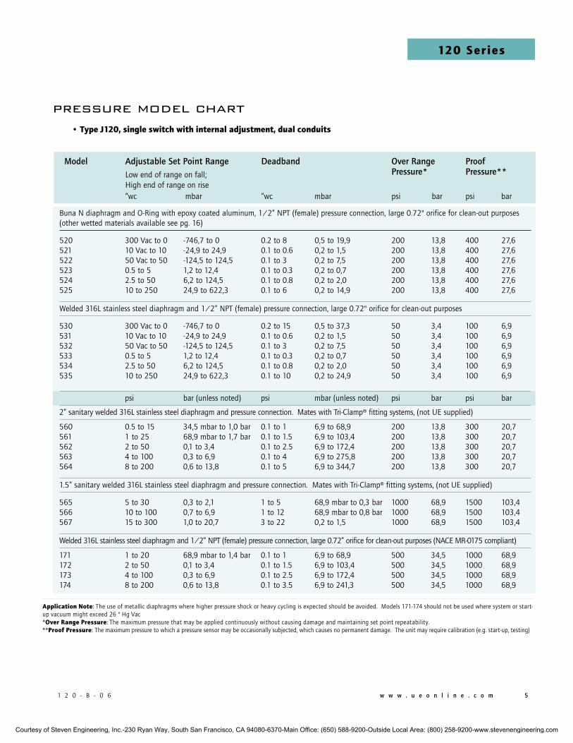
Buna N diaphragm and O-Ring with epoxy coated aluminum, 1/2” NPT (female) pressure connection, large 0.72" orifice for clean-out purposes (other wetted materials available see pg. 16)
520 300 Vac to 0 -746,7 to 0 0.2 to 8 0,5 to 19,9 200 13,8 400 27,6521 10 Vac to 10 -24,9 to 24,9 0.1 to 0.6 0,2 to 1,5 200 13,8 400 27,6522 50 Vac to 50 -124,5 to 124,5 0.1 to 3 0,2 to 7,5 200 13,8 400 27,6523 0.5 to 5 1,2 to 12,4 0.1 to 0.3 0,2 to 0,7 200 13,8 400 27,6524 2.5 to 50 6,2 to 124,5 0.1 to 0.8 0,2 to 2,0 200 13,8 400 27,6525 10 to 250 24,9 to 622,3 0.1 to 6 0,2 to 14,9 200 13,8 400 27,6
Welded 316L stainless steel diaphragm and 1/2” NPT (female) pressure connection, large 0.72" orifice for clean-out purposes
530 300 Vac to 0 -746,7 to 0 0.2 to 15 0,5 to 37,3 50 3,4 100 6,9 531 10 Vac to 10 -24,9 to 24,9 0.1 to 0.6 0,2 to 1,5 50 3,4 100 6,9 532 50 Vac to 50 -124,5 to 124,5 0.1 to 3 0,2 to 7,5 50 3,4 100 6,9533 0.5 to 5 1,2 to 12,4 0.1 to 0.3 0,2 to 0,7 50 3,4 100 6,9534 2.5 to 50 6,2 to 124,5 0.1 to 0.8 0,2 to 2,0 50 3,4 100 6,9535 10 to 250 24,9 to 622,3 0.1 to 10 0,2 to 24,9 50 3,4 100 6,9
psi bar (unless noted) psi mbar (unless noted) psi bar psi bar
2” sanitary welded 316L stainless steel diaphragm and pressure connection. Mates with Tri-Clamp® fitting systems, (not UE supplied)
560 0.5 to 15 34,5 mbar to 1,0 bar 0.1 to 1 6,9 to 68,9 200 13,8 300 20,7561 1 to 25 68,9 mbar to 1,7 bar 0.1 to 1.5 6,9 to 103,4 200 13,8 300 20,7562 2 to 50 0,1 to 3,4 0.1 to 2.5 6,9 to 172,4 200 13,8 300 20,7563 4 to 100 0,3 to 6,9 0.1 to 4 6,9 to 275,8 200 13,8 300 20,7564 8 to 200 0,6 to 13,8 0.1 to 5 6,9 to 344,7 200 13,8 300 20,7
1.5” sanitary welded 316L stainless steel diaphragm and pressure connection. Mates with Tri-Clamp® fitting systems, (not UE supplied)
565 5 to 30 0,3 to 2,1 1 to 5 68,9 mbar to 0,3 bar 1000 68,9 1500 103,4 566 10 to 100 0,7 to 6,9 1 to 12 68,9 mbar to 0,8 bar 1000 68,9 1500 103,4 567 15 to 300 1,0 to 20,7 3 to 22 0,2 to 1,5 1000 68,9 1500 103,4
Welded 316L stainless steel diaphragm and 1/2” NPT (female) pressure connection, large 0.72” orifice for clean-out purposes (NACE MR-0175 compliant)
171 1 to 20 68,9 mbar to 1,4 bar 0.1 to 1 6,9 to 68,9 500 34,5 1000 68,9172 2 to 50 0,1 to 3,4 0.1 to 1.5 6,9 to 103,4 500 34,5 1000 68,9173 4 to 100 0,3 to 6,9 0.1 to 2.5 6,9 to 172,4 500 34,5 1000 68,9174 8 to 200 0,6 to 13,8 0.1 to 3.5 6,9 to 241,3 500 34,5 1000 68,9
• Type J120, single switch with internal adjustment, dual conduits
Application note: The use of metallic diaphragms where higher pressure shock or heavy cycling is expected should be avoided. Models 171-174 should not be used where system or start-up vacuum might exceed 26 " Hg Vac *over Range pressure: The maximum pressure that may be applied continuously without causing damage and maintaining set point repeatability. **proof pressure: The maximum pressure to which a pressure sensor may be occasionally subjected, which causes no permanent damage. The unit may require calibration (e.g. start-up, testing)
Model Adjustable Set Point Range Deadband Over Range Proof Low end of range on fall; Pressure* Pressure** High end of range on rise
“wc mbar “wc mbar psi bar psi bar
Courtesy of Steven Engineering, Inc.-230 Ryan Way, South San Francisco, CA 94080-6370-Main Office: (650) 588-9200-Outside Local Area: (800) 258-9200-www.stevenengineering.com
6 w w w . u e o n l i n e . c o m 1 2 0 - B - 0 6
120 Series1
20
Se
rie
s
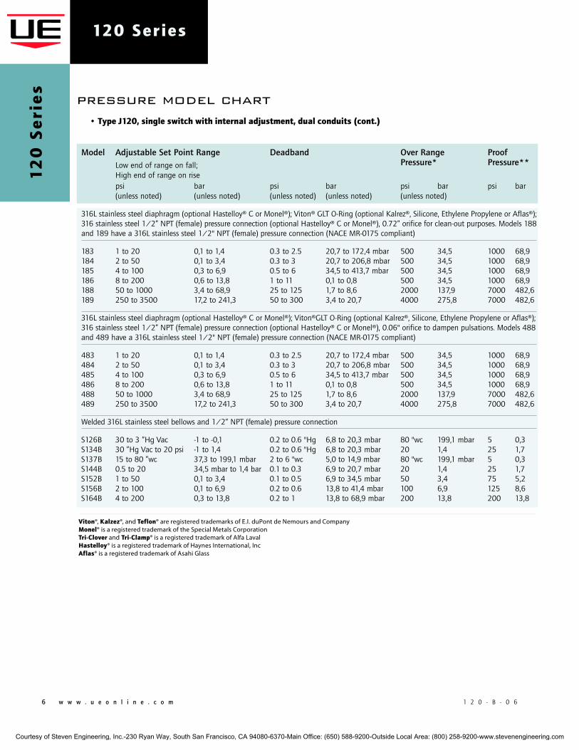
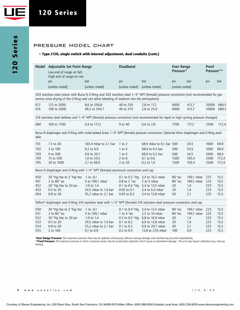
• Type J120, single switch with internal adjustment, dual conduits (cont.)
Model Adjustable Set Point Range Deadband Over Range Proof Low end of range on fall; Pressure* Pressure** High end of range on rise
psi bar psi bar psi bar psi bar (unless noted) (unless noted) (unless noted) (unless noted) (unless noted)
316L stainless steel diaphragm (optional Hastelloy® C or Monel®); Viton® GLT O-Ring (optional Kalrez®, Silicone, Ethylene Propylene or Aflas®); 316 stainless steel 1/2” NPT (female) pressure connection (optional Hastelloy® C or Monel®), 0.72” orifice for clean-out purposes. Models 188 and 189 have a 316L stainless steel 1/2" NPT (female) pressure connection (NACE MR-0175 compliant)
183 1 to 20 0,1 to 1,4 0.3 to 2.5 20,7 to 172,4 mbar 500 34,5 1000 68,9184 2 to 50 0,1 to 3,4 0.3 to 3 20,7 to 206,8 mbar 500 34,5 1000 68,9185 4 to 100 0,3 to 6,9 0.5 to 6 34,5 to 413,7 mbar 500 34,5 1000 68,9186 8 to 200 0,6 to 13,8 1 to 11 0,1 to 0,8 500 34,5 1000 68,9188 50 to 1000 3,4 to 68,9 25 to 125 1,7 to 8,6 2000 137,9 7000 482,6189 250 to 3500 17,2 to 241,3 50 to 300 3,4 to 20,7 4000 275,8 7000 482,6
316L stainless steel diaphragm (optional Hastelloy® C or Monel®); Viton®GLT O-Ring (optional Kalrez®, Silicone, Ethylene Propylene or Aflas®); 316 stainless steel 1/2” NPT (female) pressure connection (optional Hastelloy® C or Monel®), 0.06" orifice to dampen pulsations. Models 488 and 489 have a 316L stainless steel 1/2" NPT (female) pressure connection (NACE MR-0175 compliant)
483 1 to 20 0,1 to 1,4 0.3 to 2.5 20,7 to 172,4 mbar 500 34,5 1000 68,9 484 2 to 50 0,1 to 3,4 0.3 to 3 20,7 to 206,8 mbar 500 34,5 1000 68,9 485 4 to 100 0,3 to 6,9 0.5 to 6 34,5 to 413,7 mbar 500 34,5 1000 68,9 486 8 to 200 0,6 to 13,8 1 to 11 0,1 to 0,8 500 34,5 1000 68,9 488 50 to 1000 3,4 to 68,9 25 to 125 1,7 to 8,6 2000 137,9 7000 482,6 489 250 to 3500 17,2 to 241,3 50 to 300 3,4 to 20,7 4000 275,8 7000 482,6
Welded 316L stainless steel bellows and 1/2” NPT (female) pressure connection
S126B 30 to 3 ”Hg Vac -1 to -0,1 0.2 to 0.6 "Hg 6,8 to 20,3 mbar 80 "wc 199,1 mbar 5 0,3S134B 30 ”Hg Vac to 20 psi -1 to 1,4 0.2 to 0.6 "Hg 6,8 to 20,3 mbar 20 1,4 25 1,7S137B 15 to 80 ”wc 37,3 to 199,1 mbar 2 to 6 "wc 5,0 to 14,9 mbar 80 "wc 199,1 mbar 5 0,3S144B 0.5 to 20 34,5 mbar to 1,4 bar 0.1 to 0.3 6,9 to 20,7 mbar 20 1,4 25 1,7S152B 1 to 50 0,1 to 3,4 0.1 to 0.5 6,9 to 34,5 mbar 50 3,4 75 5,2S156B 2 to 100 0,1 to 6,9 0.2 to 0.6 13,8 to 41,4 mbar 100 6,9 125 8,6S164B 4 to 200 0,3 to 13,8 0.2 to 1 13,8 to 68,9 mbar 200 13,8 200 13,8
pressure model chart
Viton®, kalzez®, and Teflon® are registered trademarks of E.I. duPont de Nemours and Companymonel® is a registered trademark of the Special Metals Corporation Tri-clover and Tri-clamp® is a registered trademark of Alfa Lavalhastelloy® is a registered trademark of Haynes International, IncAflas® is a registered trademark of Asahi Glass
Courtesy of Steven Engineering, Inc.-230 Ryan Way, South San Francisco, CA 94080-6370-Main Office: (650) 588-9200-Outside Local Area: (800) 258-9200-www.stevenengineering.com
1 2 0 - B - 0 6 w w w . u e o n l i n e . c o m 7
120 Series
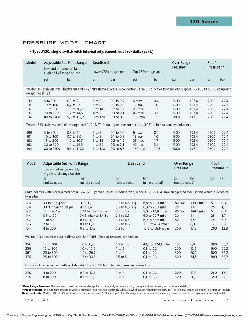
Model Adjustable Set Point Range Deadband Over Range Proof Low end of range on fall; Pressure* Pressure** High end of range on rise
psi bar psi bar psi bar psi bar (unless noted) (unless noted) (unless noted) (unless noted) (unless noted)
Brass bellows with nickel-plated brass 1/4” NPT (female) pressure connection; models 126 & 134 have zinc-plated steel spring which is exposed to media
126 30 to 3 ”Hg Vac -1 to -0,1 0.2 to 0.6 ”Hg 6,8 to 20,3 mbar 80 "wc 199,1 mbar 5 0,3134 30 ”Hg Vac to 20 psi -1 to 1,4 0.2 to 0.6 ”Hg 6,8 to 20,3 mbar 20 1,4 25 1,7137 15 to 80 ”wc 37,3 to 199,1 mbar 2 to 6 ”wc 5,0 to 14,9 mbar 80 "wc 199,1 mbar 5 0,3144 0.5 to 20 34,5 mbar to 1,4 bar 0.1 to 0.3 6,9 to 20,7 mbar 20 1,4 25 1,7152 1 to 50 0,1 to 3,4 0.1 to 0.5 6,9 to 34,5 mbar 50 3,4 75 5,2156 2 to 100 0,1 to 6,9 0.2 to 0.6 13,8 to 41,4 mbar 100 6,9 125 8,6164 4 to 200 0,3 to 13,8 0.2 to 1 13,8 to 68,9 mbar 200 13,8 200 13,8
Welded 316L stainless steel bellows and 1/4” NPT (female) pressure connection
356 15 to 100 1,0 to 6,9 0.7 to 1.8 48,3 to 124,1 mbar 100 6,9 800 55,2358 15 to 200 1,0 to 13,8 1 to 3 0,1 to 0,2 200 13,8 800 55,2361 20 to 300 1,4 to 20,7 1 to 4 0,1 to 0,3 300 20,7 800 55,2376 25 to 500 1,7 to 34,5 1.5 to 5 0,1 to 0,3 500 34,5 800 55,2
Phosphor bronze bellows with nickel-plated brass 1/4” NPT (female) pressure connection
270 4 to 200 0,3 to 13,8 1 to 4 0,1 to 0,3 200 13,8 250 17,2274 6 to 300 0,4 to 20,7 1 to 5 0,1 to 0,3 300 20,7 350 24,1
• Type J120, single switch with internal adjustment, dual conduits (cont.)
*over Range pressure: The maximum pressure that may be applied continuously without causing damage and maintaining set point repeatability. **proof pressure: The maximum pressure to which a pressure sensor may be occasionally subjected, which causes no permanent damage. The unit may require calibration (e.g. start-up, testing)deadband note: Models 190-194, 490-494 are expressed as the lower 75 % and top 25% of the range span because of the operating characteristics of the diaphragm sensor and switch.
pressure model chart
Model Adjustable Set Point Range Deadband Over Range Proof Low end of range on fall; Pressure* Pressure**
High end of range on rise Lower 75% range span Top 25% range span
psi bar psi bar psi bar psi bar psi bar
Welded 316 stainless steel diaphragm and 1/2” NPT (female) pressure connection, large 0.72” orifice for clean-out purposes (NACE MR-0175 compliant, except model 194)
190 5 to 30 0,3 to 2,1 1 to 3 0,1 to 0,2 6 max 0,4 1500 103,4 2500 172,4191 10 to 100 0,7 to 6,9 1 to 8 0,1 to 0,6 15 max 1,0 1500 103,4 2500 172,4192 15 to 300 1,0 to 20,7 3 to 18 0,2 to 1,2 25 max 1,7 1500 103,4 2500 172,4193 20 to 500 1,4 to 34,5 4 to 30 0,3 to 2,1 45 max 3,1 1500 103,4 2500 172,4194 80 to 1700 5,5 to 117,2 5 to 120 0,3 to 8,3 150 max 10,3 2000 137,9 2500 172,4
Welded 316 stainless steel diaphragm and 1/2” NPT (female) pressure connection, 0.06” orifice to dampen pulsations
490 5 to 30 0,3 to 2,1 1 to 3 0,1 to 0,2 6 max 0,4 1500 103,4 2500 172,4491 10 to 100 0,7 to 6,9 1 to 8 0,1 to 0,6 15 max 1,0 1500 103,4 2500 172,4492 15 to 300 1,0 to 20,7 3 to 18 0,2 to 1,2 25 max 1,7 1500 103,4 2500 172,4493 20 to 500 1,4 to 34,5 4 to 30 0,3 to 2,1 45 max 3,1 1500 103,4 2500 172,4494 80 to 1700 5,5 to 117,2 5 to 120 0,3 to 8,3 150 max 10,3 2000 137,9 2500 172,4
Courtesy of Steven Engineering, Inc.-230 Ryan Way, South San Francisco, CA 94080-6370-Main Office: (650) 588-9200-Outside Local Area: (800) 258-9200-www.stevenengineering.com
8 w w w . u e o n l i n e . c o m 1 2 0 - B - 0 6
120 Series1
20
Se
rie
s
Model Adjustable Set Point Range Deadband Over Range Proof Low end of range on fall; Pressure* Pressure** High end of range on rise
psi bar psi bar psi bar psi bar
(unless noted) (unless noted) (unless noted) (unless noted) (unless noted)
303 stainless steel piston with Buna N O-Ring and 303 stainless steel 1/4” NPT (female) pressure connection (not recommended for gas service since drying of the O-Ring seal can allow bleeding of medium into the atmosphere)
612 125 to 3000 8,6 to 206,8 40 to 250 2,8 to 17,2 6000 413,7 10000 689,5616 700 to 5000 48,3 to 344,7 40 to 375 2,8 to 25,9 6000 413,7 10000 689,5
316 stainless steel bellows and 1/4” NPT (female) pressure connection (not recommended for rapid or high cycling pressure changes)
680 100 to 1700 6,9 to 117,2 9 to 40 0,6 to 2,8 1700 117,2 2500 172,4
Buna N diaphragm and O-Ring with nickel-plated brass 1/4” NPT (female) pressure connection; Optional Viton diaphragm and O-Ring avail-able
701 1.5 to 30 103,4 mbar to 2,1 bar 1 to 2 68,9 mbar to 0,1 bar 500 34,5 1000 68.9
702 3 to 100 0,2 to 6,9 1 to 4 68,9 to 0,3 bar 500 34,5 1000 68,9
703 9 to 300 0,6 to 20,7 1 to 5 68,9 to 0,3 bar 500 34,5 1000 68,9704 15 to 500 1,0 to 34,5 2 to 8 0,1 to 0,6 1500 103,4 2500 172,4705 30 to 1000 2,1 to 68,9 3 to 20 0,2 to 1,4 1500 103,4 2500 172,4
Buna N diaphragm and O-Ring with 1/4” NPT (female) aluminum connection and cap
450 30 ”Hg Vac to 3 ”Hg Vac -1 to -0,1 0.1 to 0.3 ”Hg 3,4 to 10,2 mbar 80 "wc 199,1 mbar 225 15,5451 2 to 80” wc 5 to 199,1 mbar 0.8 to 2 ”wc 2 to 5 mbar 80 ”wc 199,1 mbar 225 15,5452 30 ”Hg Vac to 20 psi -1,0 to 1,4 0.1 to 0.4 ”Hg 3,4 to 13,5 mbar 20 1,4 225 15,5 453 0.5 to 20 34,5 mbar to 1,4 bar 0.05 to 0.1 3,4 to 6,9 mbar 20 1,4 225 15,5454 0.8 to 30 55,2 mbar to 2,1 bar 0.05 to 0.2 3,4 to 13,8 mbar 30 2,1 225 15,5
Teflon® diaphragm and O-Ring 316 stainless steel with 1/4” NPT (female) 316 stainless steel pressure connection and cap
550 30 "Hg Vac to 3 "Hg Vac -1 to -0,1 0.1 to 0.4 "Hg 3,4 to 13,5 mbar 80 "wc 199,1 mbar 225 15,5551 2 to 80 ”wc 5 to 199,1 mbar 1 to 4 "wc 2,5 to 10 mbar 80 "wc 199,1 mbar 225 15,5552 30 "Hg Vac to 20 psi -1,0 to 1,4 0.2 to 0.5 "Hg 6,8 to 16,9 mbar 20 1,4 225 15,5553 0.5 to 20 34,5 mbar to 1,4 bar 0.1 to 0.2 6,9 to 13,8 mbar 20 1,4 225 15,5554 0.8 to 30 55,2 mbar to 2,1 bar 0.1 to 0.3 6,9 to 20,7 mbar 30 2,1 225 15,5555 2 to 100 0,1 to 6,9 0.2 to 0.4 13,8 to 27,6 mbar 100 6,9 225 15,5
*over Range pressure: The maximum pressure that may be applied continuously without causing damage and maintaining set point repeatability. **proof pressure: The maximum pressure to which a pressure sensor may be occasionally subjected, which causes no permanent damage. The unit may require calibration (e.g. start-up, testing)
• Type J120, single switch with internal adjustment, dual conduits (cont.)
pressure model chart
Courtesy of Steven Engineering, Inc.-230 Ryan Way, South San Francisco, CA 94080-6370-Main Office: (650) 588-9200-Outside Local Area: (800) 258-9200-www.stevenengineering.com
1 2 0 - B - 0 6 w w w . u e o n l i n e . c o m 9
120 Series
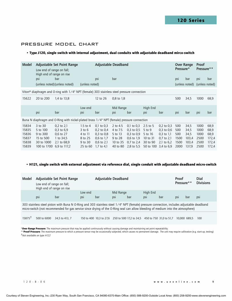
Model Adjustable Set Point Range Adjustable Deadband Over Range Proof Low end of range on fall; Pressure* Pressure** High end of range on rise
psi bar psi bar psi bar psi bar
(unless noted) (unless noted) (unless noted) (unless noted) (unless noted)
Viton® diaphragm and O-ring with 1/4" NPT (female) 303 stainless steel pressure connection
15622 20 to 200 1,4 to 13,8 12 to 26 0,8 to 1,8 500 34,5 1000 68,9
Low end Mid Range High End
psi bar psi bar psi bar psi bar psi bar psi bar
Buna N diaphragm and O-Ring with nickel-plated brass 1/4" NPT (female) pressure connection
15834 3 to 30 0,2 to 2,1 1.5 to 4 0,1 to 0,3 2 to 4.5 0,1 to 0,3 2.5 to 5 0,2 to 0,3 500 34,5 1000 68,915835 5 to 100 0,3 to 6,9 3 to 6 0,2 to 0,4 4 to 7.5 0,3 to 0,5 5 to 9 0,3 to 0,6 500 34,5 1000 68,915836 9 to 300 0,6 to 27 4 to 11 0,3 to 0,8 5 to 13 0,3 to 0,9 5 to 16 0,3 to 1,1 500 34,5 1000 68,915837 15 to 500 1 to 34,5 8 to 25 0,6 to 1,7 9 to 28 0,6 to 1,9 10 to 31 0,7 to 2,1 1500 103,4 2500 172,415838 30 to 1000 2,1 to 68,9 9 to 30 0,6 to 2,1 10 to 35 0,7 to 2,4 30 to 90 2,1 to 6,2 1500 103,4 2500 172,415839 100 to 1700 6,9 to 117,2 25 to 60 1,7 to 4,1 40 to 80 2,8 to 5,5 50 to 100 3,4 to 6,9 2000 137,9 2500 172,4
• Type J120, single switch with internal adjustment, dual conduits with adjustable deadband mirco-switch
pressure model chart
*over Range pressure: The maximum pressure that may be applied continuously without causing damage and maintaining set point repeatability.**proof pressure: The maximum pressure to which a pressure sensor may be occasionally subjected, which causes no permanent damage. The unit may require calibration (e.g. start-up, testing)†Not available on type H122
• h121, single switch with external adjustment via reference dial, single conduit with adjustable deadband micro-switch
Model Adjustable Set Point Range Adjustable Deadband Proof Dial Low end of range on fall; Pressure** Divisions High end of range on rise
Low end Mid Range High End
psi bar psi bar psi bar psi bar psi bar psi
303 stainless steel piston with Buna N O-Ring and 303 stainless steel 1/4" NPT (female) pressure connection, includes adjustable deadband micro-switch (not recommended for gas service since drying of the O-Ring seal can allow bleeding of medium into the atmosphere)
15875† 500 to 6000 34,5 to 413, 7 150 to 400 10,3 to 27,6 250 to 500 17,2 to 34,5 450 to 750 31,0 to 51,7 10,000 689,5 100
Courtesy of Steven Engineering, Inc.-230 Ryan Way, South San Francisco, CA 94080-6370-Main Office: (650) 588-9200-Outside Local Area: (800) 258-9200-www.stevenengineering.com
10 w w w . u e o n l i n e . c o m 1 2 0 - B - 0 6
120 Series1
20
Se
rie
s
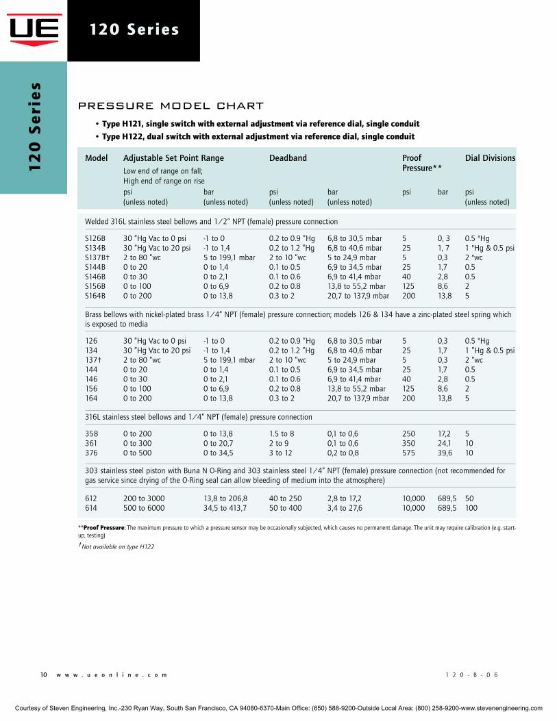
Model Adjustable Set Point Range Deadband Proof Dial Divisions Low end of range on fall; Pressure** High end of range on rise psi bar psi bar psi bar psi (unless noted) (unless noted) (unless noted) (unless noted) (unless noted) Welded 316L stainless steel bellows and 1/2” NPT (female) pressure connection
S126B 30 ”Hg Vac to 0 psi -1 to 0 0.2 to 0.9 ”Hg 6,8 to 30,5 mbar 5 0, 3 0.5 "HgS134B 30 ”Hg Vac to 20 psi -1 to 1,4 0.2 to 1.2 ”Hg 6,8 to 40,6 mbar 25 1, 7 1 "Hg & 0.5 psiS137B† 2 to 80 ”wc 5 to 199,1 mbar 2 to 10 ”wc 5 to 24,9 mbar 5 0,3 2 "wcS144B 0 to 20 0 to 1,4 0.1 to 0.5 6,9 to 34,5 mbar 25 1,7 0.5 S146B 0 to 30 0 to 2,1 0.1 to 0.6 6,9 to 41,4 mbar 40 2,8 0.5 S156B 0 to 100 0 to 6,9 0.2 to 0.8 13,8 to 55,2 mbar 125 8,6 2 S164B 0 to 200 0 to 13,8 0.3 to 2 20,7 to 137,9 mbar 200 13,8 5
Brass bellows with nickel-plated brass 1/4” NPT (female) pressure connection; models 126 & 134 have a zinc-plated steel spring which is exposed to media
126 30 ”Hg Vac to 0 psi -1 to 0 0.2 to 0.9 ”Hg 6,8 to 30,5 mbar 5 0,3 0.5 "Hg134 30 ”Hg Vac to 20 psi -1 to 1,4 0.2 to 1.2 ”Hg 6,8 to 40,6 mbar 25 1,7 1 ”Hg & 0.5 psi137† 2 to 80 ”wc 5 to 199,1 mbar 2 to 10 ”wc 5 to 24,9 mbar 5 0,3 2 ”wc144 0 to 20 0 to 1,4 0.1 to 0.5 6,9 to 34,5 mbar 25 1,7 0.5 146 0 to 30 0 to 2,1 0.1 to 0.6 6,9 to 41,4 mbar 40 2,8 0.5 156 0 to 100 0 to 6,9 0.2 to 0.8 13,8 to 55,2 mbar 125 8,6 2 164 0 to 200 0 to 13,8 0.3 to 2 20,7 to 137,9 mbar 200 13,8 5
316L stainless steel bellows and 1/4” NPT (female) pressure connection
358 0 to 200 0 to 13,8 1.5 to 8 0,1 to 0,6 250 17,2 5 361 0 to 300 0 to 20,7 2 to 9 0,1 to 0,6 350 24,1 10 376 0 to 500 0 to 34,5 3 to 12 0,2 to 0,8 575 39,6 10
303 stainless steel piston with Buna N O-Ring and 303 stainless steel 1/4” NPT (female) pressure connection (not recommended for gas service since drying of the O-Ring seal can allow bleeding of medium into the atmosphere)
612 200 to 3000 13,8 to 206,8 40 to 250 2,8 to 17,2 10,000 689,5 50 614 500 to 6000 34,5 to 413,7 50 to 400 3,4 to 27,6 10,000 689,5 100
pressure model chart• Type h121, single switch with external adjustment via reference dial, single conduit
• Type h122, dual switch with external adjustment via reference dial, single conduit
**proof pressure: The maximum pressure to which a pressure sensor may be occasionally subjected, which causes no permanent damage. The unit may require calibration (e.g. start-up, testing)
†Not available on type H122
Courtesy of Steven Engineering, Inc.-230 Ryan Way, South San Francisco, CA 94080-6370-Main Office: (650) 588-9200-Outside Local Area: (800) 258-9200-www.stevenengineering.com
1 2 0 - B - 0 6 w w w . u e o n l i n e . c o m 11
120 Series
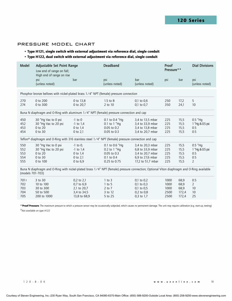
Phosphor bronze bellows with nickel-plated brass 1/4” NPT (female) pressure connection
270 0 to 200 0 to 13,8 1.5 to 8 0,1 to 0,6 250 17,2 5 274 0 to 300 0 to 20,7 2 to 10 0,1 to 0,7 350 24,1 10
Buna N diaphragm and O-Ring with aluminum 1/4” NPT (female) pressure connection and cap
450 30 ”Hg Vac to 0 psi -1 to 0 0.1 to 0.4 ”Hg 3,4 to 13,5 mbar 225 15,5 0.5 ”Hg452 30 ”Hg Vac to 20 psi -1 to 1,4 0.1 to 1 ”Hg 3,4 to 33,9 mbar 225 15,5 1 ”Hg & 0.5 psi453 0 to 20 0 to 1,4 0.05 to 0.2 3,4 to 13,8 mbar 225 15,5 0.5 454 0 to 30 0 to 2,1 0.05 to 0.3 3,4 to 20,7 mbar 225 15,5 0.5
Teflon® diaphragm and O-Ring with 316 stainless steel 1/4” NPT (female) pressure connection and cap
550 30 ”Hg Vac to 0 psi -1 to 0, 0.1 to 0.6 ”Hg 3,4 to 20,3 mbar 225 15,5 0.5 ”Hg552 30 ”Hg Vac to 20 psi -1 to 1,4 0.2 to 1 ”Hg 6,8 to 33,9 mbar 225 15,5 1 ”Hg & 0.5 psi 553 0 to 20 0 to 1,4 0.05 to 0.3 3,4 to 20,7 mbar 225 15,5 0.5554 0 to 30 0 to 2,1 0.1 to 0.4 6,9 to 27,6 mbar 225 15,5 0.5 555 0 to 100 0 to 6,9 0.25 to 0.75 17,2 to 51,7 mbar 225 15,5 2
Buna N diaphragm and O-Ring with nickel-plated brass 1/4” NPT (female) pressure connection; Optional Viton diaphragm and O-Ring available (models 701-703)
701† 3 to 30 0,2 to 2,1 1 to 3 0,1 to 0,2 1000 68,9 0.5 702 10 to 100 0,7 to 6,9 1 to 5 0,1 to 0,3 1000 68,9 2703 30 to 300 2,1 to 20,7 2 to 7 0,1 to 0,5 1000 68,9 10 704 50 to 500 3,4 to 34,5 3 to 12 0,2 to 0,8 2500 172,4 10 705 200 to 1000 13,8 to 68,9 5 to 25 0,3 to 1,7 2500 172,4 25
**proof pressure: The maximum pressure to which a pressure sensor may be occasionally subjected, which causes no permanent damage. The unit may require calibration (e.g. start-up, testing)
†Not available on type H122
• Type h121, single switch with external adjustment via reference dial, single conduit
• Type h122, dual switch with external adjustment via reference dial, single conduit
Model Adjustable Set Point Range Deadband Proof Dial Divisions Low end of range on fall; Pressure** High end of range on rise
psi bar psi bar psi bar psi (unless noted) (unless noted) (unless noted) (unless noted)
pressure model chart
Courtesy of Steven Engineering, Inc.-230 Ryan Way, South San Francisco, CA 94080-6370-Main Office: (650) 588-9200-Outside Local Area: (800) 258-9200-www.stevenengineering.com
12 w w w . u e o n l i n e . c o m 1 2 0 - B - 0 6
120 Series1
20
Se
rie
s
Model Adjustable Set Point Range Deadband Proof Dial Divisions Low end of range on fall; Pressure** High end of range on rise
psi bar psi mbar psi bar psi (unless noted) (unless noted) (unless noted) (unless noted) (unless noted) Welded 316L stainless steel bellows and 1/2” NPT (female) pressure connection
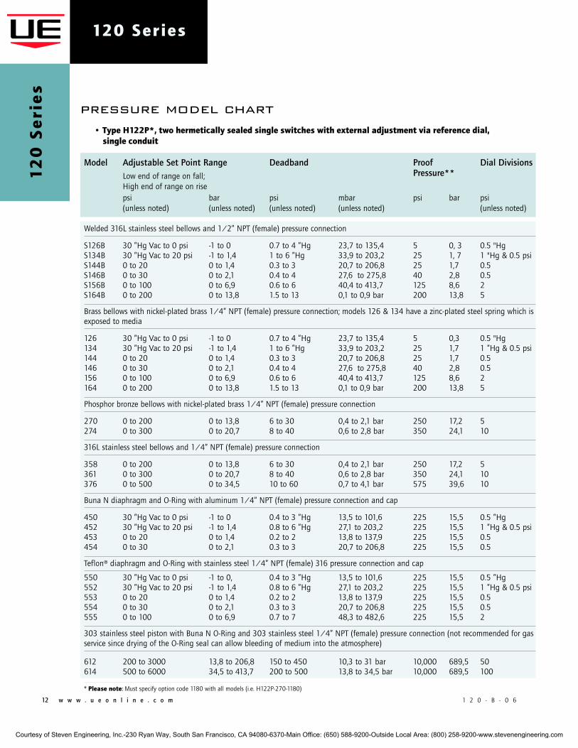
S126B 30 ”Hg Vac to 0 psi -1 to 0 0.7 to 4 ”Hg 23,7 to 135,4 5 0, 3 0.5 "HgS134B 30 ”Hg Vac to 20 psi -1 to 1,4 1 to 6 ”Hg 33,9 to 203,2 25 1, 7 1 "Hg & 0.5 psiS144B 0 to 20 0 to 1,4 0.3 to 3 20,7 to 206,8 25 1,7 0.5 S146B 0 to 30 0 to 2,1 0.4 to 4 27,6 to 275,8 40 2,8 0.5 S156B 0 to 100 0 to 6,9 0.6 to 6 40,4 to 413,7 125 8,6 2 S164B 0 to 200 0 to 13,8 1.5 to 13 0,1 to 0,9 bar 200 13,8 5
Brass bellows with nickel-plated brass 1/4” NPT (female) pressure connection; models 126 & 134 have a zinc-plated steel spring which is exposed to media
126 30 ”Hg Vac to 0 psi -1 to 0 0.7 to 4 ”Hg 23,7 to 135,4 5 0,3 0.5 "Hg134 30 ”Hg Vac to 20 psi -1 to 1,4 1 to 6 ”Hg 33,9 to 203,2 25 1,7 1 ”Hg & 0.5 psi144 0 to 20 0 to 1,4 0.3 to 3 20,7 to 206,8 25 1,7 0.5 146 0 to 30 0 to 2,1 0.4 to 4 27,6 to 275,8 40 2,8 0.5 156 0 to 100 0 to 6,9 0.6 to 6 40,4 to 413,7 125 8,6 2 164 0 to 200 0 to 13,8 1.5 to 13 0,1 to 0,9 bar 200 13,8 5
Phosphor bronze bellows with nickel-plated brass 1/4” NPT (female) pressure connection
270 0 to 200 0 to 13,8 6 to 30 0,4 to 2,1 bar 250 17,2 5 274 0 to 300 0 to 20,7 8 to 40 0,6 to 2,8 bar 350 24,1 10
316L stainless steel bellows and 1/4” NPT (female) pressure connection
358 0 to 200 0 to 13,8 6 to 30 0,4 to 2,1 bar 250 17,2 5 361 0 to 300 0 to 20,7 8 to 40 0,6 to 2,8 bar 350 24,1 10 376 0 to 500 0 to 34,5 10 to 60 0,7 to 4,1 bar 575 39,6 10
Buna N diaphragm and O-Ring with aluminum 1/4” NPT (female) pressure connection and cap
450 30 ”Hg Vac to 0 psi -1 to 0 0.4 to 3 ”Hg 13,5 to 101,6 225 15,5 0.5 ”Hg452 30 ”Hg Vac to 20 psi -1 to 1,4 0.8 to 6 ”Hg 27,1 to 203,2 225 15,5 1 ”Hg & 0.5 psi453 0 to 20 0 to 1,4 0.2 to 2 13,8 to 137,9 225 15,5 0.5 454 0 to 30 0 to 2,1 0.3 to 3 20,7 to 206,8 225 15,5 0.5
Teflon® diaphragm and O-Ring with stainless steel 1/4” NPT (female) 316 pressure connection and cap
550 30 ”Hg Vac to 0 psi -1 to 0, 0.4 to 3 ”Hg 13,5 to 101,6 225 15,5 0.5 ”Hg552 30 ”Hg Vac to 20 psi -1 to 1,4 0.8 to 6 ”Hg 27,1 to 203,2 225 15,5 1 ”Hg & 0.5 psi 553 0 to 20 0 to 1,4 0.2 to 2 13,8 to 137,9 225 15,5 0.5554 0 to 30 0 to 2,1 0.3 to 3 20,7 to 206,8 225 15,5 0.5 555 0 to 100 0 to 6,9 0.7 to 7 48,3 to 482,6 225 15,5 2
303 stainless steel piston with Buna N O-Ring and 303 stainless steel 1/4” NPT (female) pressure connection (not recommended for gas service since drying of the O-Ring seal can allow bleeding of medium into the atmosphere)
612 200 to 3000 13,8 to 206,8 150 to 450 10,3 to 31 bar 10,000 689,5 50 614 500 to 6000 34,5 to 413,7 200 to 500 13,8 to 34,5 bar 10,000 689,5 100
* please note: Must specify option code 1180 with all models (i.e. H122P-270-1180)
• Type h122p*, two hermetically sealed single switches with external adjustment via reference dial, single conduit
pressure model chart
Courtesy of Steven Engineering, Inc.-230 Ryan Way, South San Francisco, CA 94080-6370-Main Office: (650) 588-9200-Outside Local Area: (800) 258-9200-www.stevenengineering.com
1 2 0 - B - 0 6 w w w . u e o n l i n e . c o m 13
120 Series
differential pressure model chart
Model Adjustable Set Point Range Deadband Working Proof Low end of range on fall; Pressure*** Pressure** High end of range on rise
psid bar psi bar psi bar psi bar (unless noted) (unless noted) (unless noted) (unless noted) (unless noted)
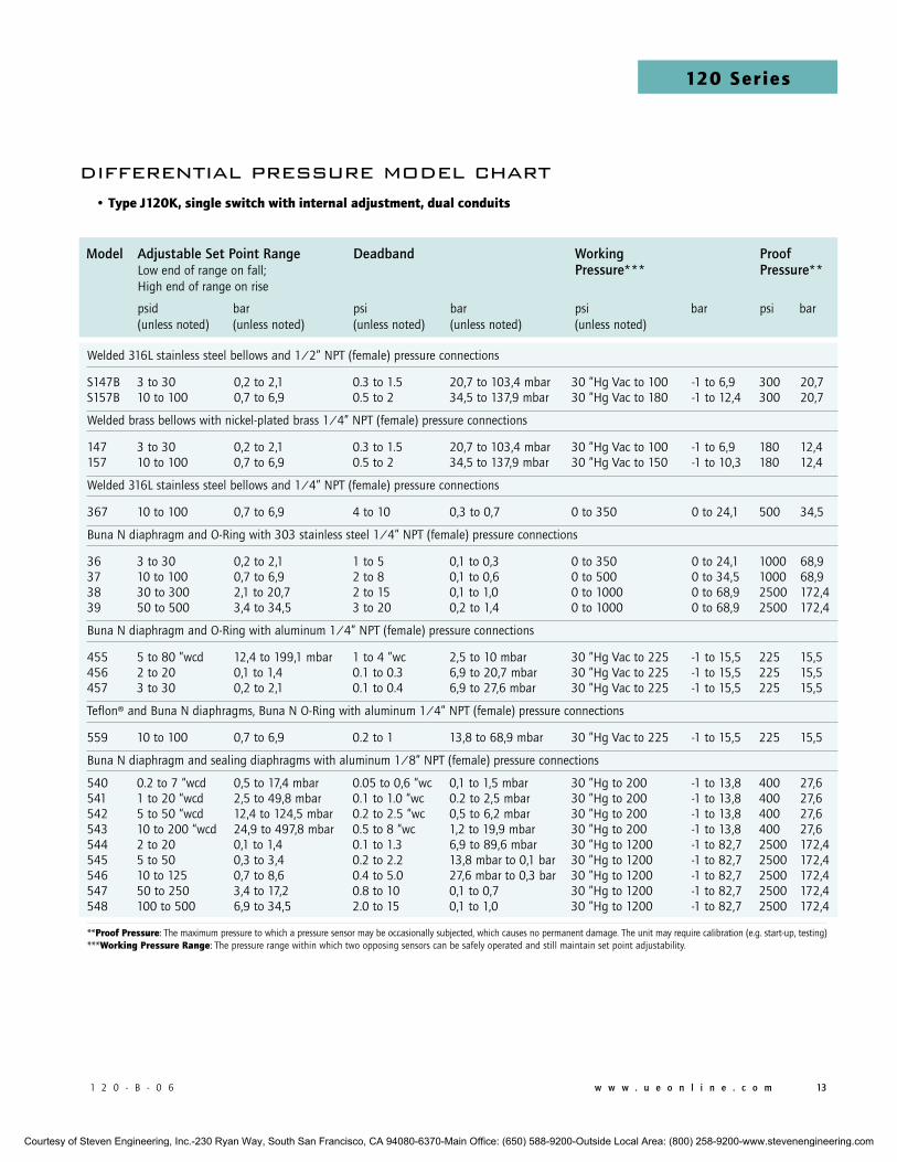
Welded 316L stainless steel bellows and 1/2” NPT (female) pressure connections
S147B 3 to 30 0,2 to 2,1 0.3 to 1.5 20,7 to 103,4 mbar 30 ”Hg Vac to 100 -1 to 6,9 300 20,7S157B 10 to 100 0,7 to 6,9 0.5 to 2 34,5 to 137,9 mbar 30 ”Hg Vac to 180 -1 to 12,4 300 20,7
Welded brass bellows with nickel-plated brass 1/4” NPT (female) pressure connections
147 3 to 30 0,2 to 2,1 0.3 to 1.5 20,7 to 103,4 mbar 30 ”Hg Vac to 100 -1 to 6,9 180 12,4157 10 to 100 0,7 to 6,9 0.5 to 2 34,5 to 137,9 mbar 30 ”Hg Vac to 150 -1 to 10,3 180 12,4
Welded 316L stainless steel bellows and 1/4” NPT (female) pressure connections
367 10 to 100 0,7 to 6,9 4 to 10 0,3 to 0,7 0 to 350 0 to 24,1 500 34,5
Buna N diaphragm and O-Ring with 303 stainless steel 1/4” NPT (female) pressure connections
36 3 to 30 0,2 to 2,1 1 to 5 0,1 to 0,3 0 to 350 0 to 24,1 1000 68,937 10 to 100 0,7 to 6,9 2 to 8 0,1 to 0,6 0 to 500 0 to 34,5 1000 68,938 30 to 300 2,1 to 20,7 2 to 15 0,1 to 1,0 0 to 1000 0 to 68,9 2500 172,439 50 to 500 3,4 to 34,5 3 to 20 0,2 to 1,4 0 to 1000 0 to 68,9 2500 172,4
Buna N diaphragm and O-Ring with aluminum 1/4” NPT (female) pressure connections
455 5 to 80 ”wcd 12,4 to 199,1 mbar 1 to 4 ”wc 2,5 to 10 mbar 30 ”Hg Vac to 225 -1 to 15,5 225 15,5456 2 to 20 0,1 to 1,4 0.1 to 0.3 6,9 to 20,7 mbar 30 ”Hg Vac to 225 -1 to 15,5 225 15,5457 3 to 30 0,2 to 2,1 0.1 to 0.4 6,9 to 27,6 mbar 30 ”Hg Vac to 225 -1 to 15,5 225 15,5
Teflon® and Buna N diaphragms, Buna N O-Ring with aluminum 1/4” NPT (female) pressure connections
559 10 to 100 0,7 to 6,9 0.2 to 1 13,8 to 68,9 mbar 30 ”Hg Vac to 225 -1 to 15,5 225 15,5
Buna N diaphragm and sealing diaphragms with aluminum 1/8” NPT (female) pressure connections
540 0.2 to 7 “wcd 0,5 to 17,4 mbar 0.05 to 0,6 “wc 0,1 to 1,5 mbar 30 ”Hg to 200 -1 to 13,8 400 27,6541 1 to 20 “wcd 2,5 to 49,8 mbar 0.1 to 1.0 “wc 0.2 to 2,5 mbar 30 ”Hg to 200 -1 to 13,8 400 27,6542 5 to 50 “wcd 12,4 to 124,5 mbar 0.2 to 2.5 “wc 0,5 to 6,2 mbar 30 ”Hg to 200 -1 to 13,8 400 27,6543 10 to 200 “wcd 24,9 to 497,8 mbar 0.5 to 8 “wc 1,2 to 19,9 mbar 30 ”Hg to 200 -1 to 13,8 400 27,6544 2 to 20 0,1 to 1,4 0.1 to 1.3 6,9 to 89,6 mbar 30 ”Hg to 1200 -1 to 82,7 2500 172,4545 5 to 50 0,3 to 3,4 0.2 to 2.2 13,8 mbar to 0,1 bar 30 ”Hg to 1200 -1 to 82,7 2500 172,4546 10 to 125 0,7 to 8,6 0.4 to 5.0 27,6 mbar to 0,3 bar 30 ”Hg to 1200 -1 to 82,7 2500 172,4547 50 to 250 3,4 to 17,2 0.8 to 10 0,1 to 0,7 30 ”Hg to 1200 -1 to 82,7 2500 172,4548 100 to 500 6,9 to 34,5 2.0 to 15 0,1 to 1,0 30 ”Hg to 1200 -1 to 82,7 2500 172,4
**proof pressure: The maximum pressure to which a pressure sensor may be occasionally subjected, which causes no permanent damage. The unit may require calibration (e.g. start-up, testing)***working pressure Range: The pressure range within which two opposing sensors can be safely operated and still maintain set point adjustability.
• Type J120k, single switch with internal adjustment, dual conduits
Courtesy of Steven Engineering, Inc.-230 Ryan Way, South San Francisco, CA 94080-6370-Main Office: (650) 588-9200-Outside Local Area: (800) 258-9200-www.stevenengineering.com
14 w w w . u e o n l i n e . c o m 1 2 0 - B - 0 6
120 Series1
20
Se
rie
s
Model Adjustable Set Point Range Deadband Working Proof Dial Low end of range on fall; Pressure*** Pressure** Divisions High end of range on rise
psid bar psi mbar psi bar psi bar psi (unless noted)
Welded 316L stainless steel bellows and 1/2” NPT (female) pressure connections
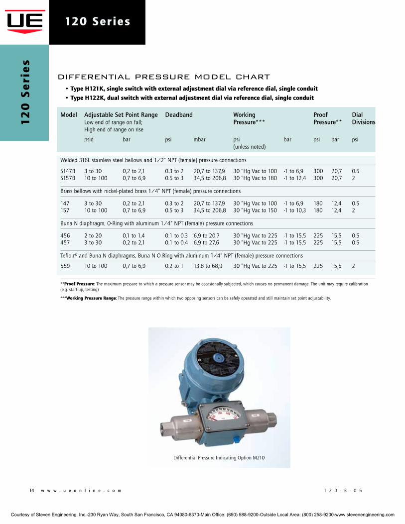
S147B 3 to 30 0,2 to 2,1 0.3 to 2 20,7 to 137,9 30 ”Hg Vac to 100 -1 to 6,9 300 20,7 0.5S157B 10 to 100 0,7 to 6,9 0.5 to 3 34,5 to 206,8 30 ”Hg Vac to 180 -1 to 12,4 300 20,7 2
Brass bellows with nickel-plated brass 1/4” NPT (female) pressure connections
147 3 to 30 0,2 to 2,1 0.3 to 2 20,7 to 137,9 30 ”Hg Vac to 100 -1 to 6,9 180 12,4 0.5157 10 to 100 0,7 to 6,9 0.5 to 3 34,5 to 206,8 30 ”Hg Vac to 150 -1 to 10,3 180 12,4 2
Buna N diaphragm, O-Ring with aluminum 1/4” NPT (female) pressure connections
456 2 to 20 0,1 to 1,4 0.1 to 0.3 6,9 to 20,7 30 ”Hg Vac to 225 -1 to 15,5 225 15,5 0.5457 3 to 30 0,2 to 2,1 0.1 to 0.4 6,9 to 27,6 30 ”Hg Vac to 225 -1 to 15,5 225 15,5 0.5
Teflon® and Buna N diaphragms, Buna N O-Ring with aluminum 1/4” NPT (female) pressure connections
559 10 to 100 0,7 to 6,9 0.2 to 1 13,8 to 68,9 30 ”Hg Vac to 225 -1 to 15,5 225 15,5 2
**proof pressure: The maximum pressure to which a pressure sensor may be occasionally subjected, which causes no permanent damage. The unit may require calibration (e.g. start-up, testing)
***working pressure Range: The pressure range within which two opposing sensors can be safely operated and still maintain set point adjustability.
• Type h121k, single switch with external adjustment dial via reference dial, single conduit
• Type h122k, dual switch with external adjustment dial via reference dial, single conduit
differential pressure model chart
Differential Pressure Indicating Option M210
Courtesy of Steven Engineering, Inc.-230 Ryan Way, South San Francisco, CA 94080-6370-Main Office: (650) 588-9200-Outside Local Area: (800) 258-9200-www.stevenengineering.com
1 2 0 - B - 0 6 w w w . u e o n l i n e . c o m 15
120 Series
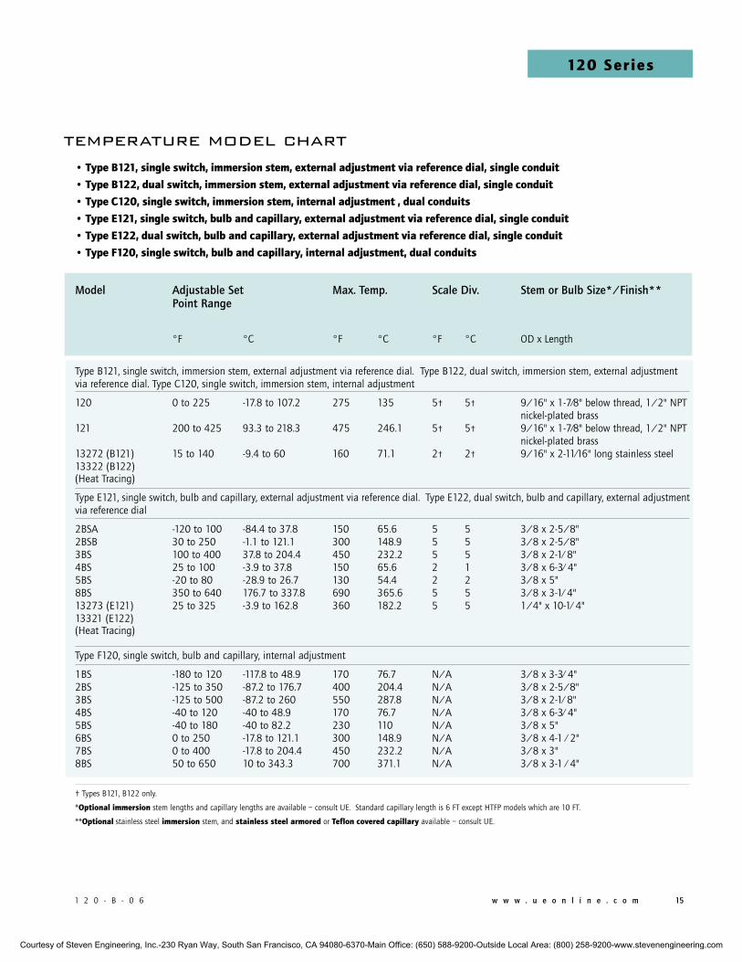
Model Adjustable Set Max. Temp. Scale Div. Stem or Bulb Size*/Finish** Point Range
°F °C °F °C °F °C OD x Length
Type B121, single switch, immersion stem, external adjustment via reference dial. Type B122, dual switch, immersion stem, external adjustment via reference dial. Type C120, single switch, immersion stem, internal adjustment
120 0 to 225 -17.8 to 107.2 275 135 5† 5† 9/16" x 1-7⁄8" below thread, 1/2" NPT nickel-plated brass 121 200 to 425 93.3 to 218.3 475 246.1 5† 5† 9/16" x 1-7⁄8" below thread, 1/2" NPT nickel-plated brass 13272 (B121) 15 to 140 -9.4 to 60 160 71.1 2† 2† 9/16" x 2-11⁄16" long stainless steel13322 (B122)(Heat Tracing)
Type E121, single switch, bulb and capillary, external adjustment via reference dial. Type E122, dual switch, bulb and capillary, external adjustment via reference dial
2BSA -120 to 100 -84.4 to 37.8 150 65.6 5 5 3/8 x 2-5/8" 2BSB 30 to 250 -1.1 to 121.1 300 148.9 5 5 3/8 x 2-5/8" 3BS 100 to 400 37.8 to 204.4 450 232.2 5 5 3/8 x 2-1⁄ 8" 4BS 25 to 100 -3.9 to 37.8 150 65.6 2 1 3/8 x 6-3⁄ 4" 5BS -20 to 80 -28.9 to 26.7 130 54.4 2 2 3/8 x 5" 8BS 350 to 640 176.7 to 337.8 690 365.6 5 5 3/8 x 3-1⁄ 4" 13273 (E121) 25 to 325 -3.9 to 162.8 360 182.2 5 5 1/4" x 10-1⁄ 4" 13321 (E122)(Heat Tracing)
Type F120, single switch, bulb and capillary, internal adjustment
1BS -180 to 120 -117.8 to 48.9 170 76.7 N/A 3/8 x 3-3⁄ 4" 2BS -125 to 350 -87.2 to 176.7 400 204.4 N/A 3/8 x 2-5/8"3BS -125 to 500 -87.2 to 260 550 287.8 N/A 3/8 x 2-1⁄ 8"4BS -40 to 120 -40 to 48.9 170 76.7 N/A 3/8 x 6-3⁄ 4"5BS -40 to 180 -40 to 82.2 230 110 N/A 3/8 x 5"6BS 0 to 250 -17.8 to 121.1 300 148.9 N/A 3/8 x 4-1 ⁄ 2"7BS 0 to 400 -17.8 to 204.4 450 232.2 N/A 3/8 x 3"8BS 50 to 650 10 to 343.3 700 371.1 N/A 3/8 x 3-1 ⁄ 4"
† Types B121, B122 only.
*optional immersion stem lengths and capillary lengths are available – consult UE. Standard capillary length is 6 FT except HTFP models which are 10 FT.
**optional stainless steel immersion stem, and stainless steel armored or Teflon covered capillary available – consult UE.
temperature model chart• Type b121, single switch, immersion stem, external adjustment via reference dial, single conduit
• Type b122, dual switch, immersion stem, external adjustment via reference dial, single conduit
• Type c120, single switch, immersion stem, internal adjustment , dual conduits
• Type E121, single switch, bulb and capillary, external adjustment via reference dial, single conduit
• Type E122, dual switch, bulb and capillary, external adjustment via reference dial, single conduit
• Type F120, single switch, bulb and capillary, internal adjustment, dual conduits
Courtesy of Steven Engineering, Inc.-230 Ryan Way, South San Francisco, CA 94080-6370-Main Office: (650) 588-9200-Outside Local Area: (800) 258-9200-www.stevenengineering.com
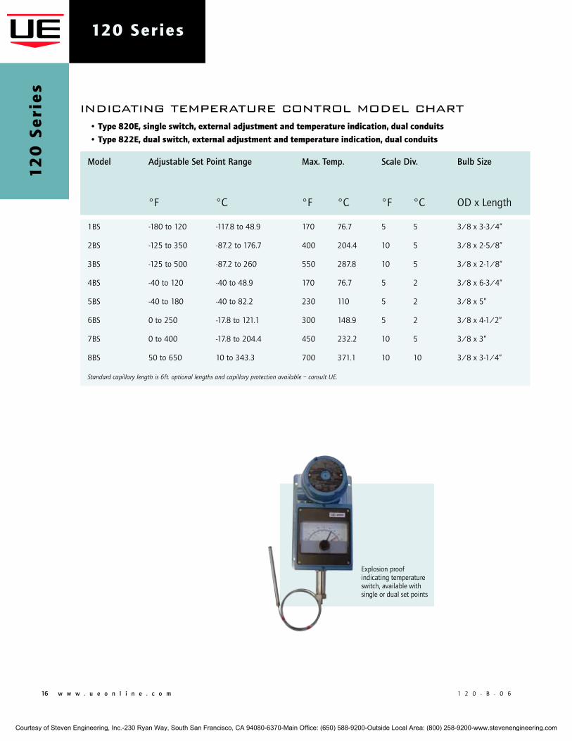
16 w w w . u e o n l i n e . c o m 1 2 0 - B - 0 6
120 Series1
20
Se
rie
s
indicating temperature control model chart
Explosion proof indicating temperature switch, available with single or dual set points
• Type 820E, single switch, external adjustment and temperature indication, dual conduits
• Type 822E, dual switch, external adjustment and temperature indication, dual conduits
Model Adjustable Set Point Range Max. Temp. Scale Div. Bulb Size
°F °C °F °C °F °C OD x Length
1BS -180 to 120 -117.8 to 48.9 170 76.7 5 5 3/8 x 3-3/4”
2BS -125 to 350 -87.2 to 176.7 400 204.4 10 5 3/8 x 2-5/8”
3BS -125 to 500 -87.2 to 260 550 287.8 10 5 3/8 x 2-1/8”
4BS -40 to 120 -40 to 48.9 170 76.7 5 2 3/8 x 6-3/4”
5BS -40 to 180 -40 to 82.2 230 110 5 2 3/8 x 5”
6BS 0 to 250 -17.8 to 121.1 300 148.9 5 2 3/8 x 4-1/2”
7BS 0 to 400 -17.8 to 204.4 450 232.2 10 5 3/8 x 3”
8BS 50 to 650 10 to 343.3 700 371.1 10 10 3/8 x 3-1/4”
Standard capillary length is 6ft. optional lengths and capillary protection available – consult UE.
Courtesy of Steven Engineering, Inc.-230 Ryan Way, South San Francisco, CA 94080-6370-Main Office: (650) 588-9200-Outside Local Area: (800) 258-9200-www.stevenengineering.com
1 2 0 - B - 0 6 w w w . u e o n l i n e . c o m 17
120 Series
TypE dEScRipTion
Pressure Type J120 - One SPDT; epoxy coated enclosure; internal adjustment with no reference scale, dual conduits
Type H121 - One SPDT; epoxy coated enclosure; external adjustment with reference dial, single conduit
Type H122 - Two SPDT; epoxy coated enclosure; external adjustment with reference dial, single conduit
Type H122P - Two SPDT; hermetically sealed switches; epoxy coated enclosure; external adjustment with reference dial, single conduit
Differential Pressure Type J120K - One SPDT; epoxy coated enclosure; internal adjustment with no reference scale, dual conduits
Type H121K - One SPDT; epoxy coated enclosure; external adjustment with reference dial, single conduit
Type H122K - Two SPDT; epoxy coated enclosure; external adjustment with reference dial, single conduit
Temperature Type B121 - Immersion stem; one SPDT; epoxy coated enclosure; external adjustment with reference dial, single conduit
Type B122 - Immersion stem; two SPDT; epoxy coated enclosure; external adjustment with reference dial, single conduit
Type C120 - Immersion stem; one SPDT; epoxy coated enclosure; internal adjustment with no reference scale, dual conduits
Type E121 - Bulb and capillary; one SPDT; epoxy coated enclosure; external adjustment with reference dial, single conduit
Type E122 - Bulb and capillary; two SPDT; epoxy coated enclosure; external adjustment with reference dial, single conduit
Type F120 - Bulb and capillary; one SPDT; epoxy coated enclosure; internal adjustment with no reference dial, dual conduits
Type 820E - Bulb and capillary; one SPDT; external adjustment and temperature indication, dual conduits
Type 822E - Bulb and capillary; two SPDT; external adjustment and temperature indication, dual conduits
SwiTch opTionS**
0140 Gold contacts, 1 amp 125 VAC resistive, NOT AVAILABLE TyPE H122P, 820E, & 822E
0500 Close deadband, 5 amp 125/250 VAC resistive. NOT AVAILABLE TyPE H122P AND MODELS 520-535
1010 DPDT switch, 10 amp 125/250 VAC resistive; deadband and minimum set point will increase. NOT AVAILABLE TEMPERATURE
VERSIONS; TyPES H122, H122P H122K; OR J120K MODELS 36-39, 367, AND 540-548; OR J120 MODELS 171-194, 483-494,
520-535, 560-567, 680
1070 10 amp 125 VDC or VAC resistive; deadband and minimum set point will increase. NOT AVAILABLE TyPES 820E, 822E,
H122P, H122K, B122, AND J120K MODELS 36-39; J120 MODELS 171-194, 483-494, 520-535, 560-567
1180 Hermetically sealed, SPDT, 11 amp 125/250 VAC resistive, must be specified with type H122P. NOT AVAILABLE TyPES B122,
E122, H122, H121K and H122K, 820 AND 822E; deadband and minimum set point will increase.
1190 Hermetically sealed, DPDT, 11 amp 125/250 VAC; products set on rising pressure or temperature due to inherent separation of
circuits on falling pressure or temperature; specify option 1195 if setting on fall is required; deadband and minimum set point will
increase. NOT AVAILABLE TyPES 820E, 822E, B122, E122, H122, H121K, H122K, H122P or models 523, 533
1195 Hermetically sealed, DPDT, 11 amp 125/250 VAC; products set on falling pressure or temperature due to inherent separation of
circuits on rising pressure or temperature; specify option 1190 if setting on rise is required; deadband and minimum set point will
increase. NOT AVAILABLE TyPES 820E, 822E, B122, E122, H122, H121K, H122K, H122P or models 523, 533
** All switches have limited DC capabilities. Consult factory for details.
how to orderbUilding A pART nUmbER
Select a Type Select a model Select an option
Refer to the “Type” section below.
Determine type number based on switch output, enclosure, adjustment and reference.
Fill in the type portion of your part number with the corresponding number.
Refer to the “Model Charts”
Determine model based on adjustable range, deadband and proof pressure.
Fill in the model portion of your part num-ber with the corresponding number.
Refer to the “Options” section
Determine option number based on switch output, optional materials or other product enhancements.
Fill in the option portion of your part number with the corresponding number.
Leave “option” portion blank if no options are needed. FOR MULTIPLE OPTIONS: Call United Electric Controls.
Courtesy of Steven Engineering, Inc.-230 Ryan Way, South San Francisco, CA 94080-6370-Main Office: (650) 588-9200-Outside Local Area: (800) 258-9200-www.stevenengineering.com
18 w w w . u e o n l i n e . c o m 1 2 0 - B - 0 6
120 Series1
20
Se
rie
s SwiTch opTionS** (conT.)
1519* Adjustable deadband, 15 amp 125/250/480 VAC resistive; adjustable wheel changes rise setting only; if adjust-
ment of fall setting is required use primary adjustment; deadband and minimum set point will increase. NOT AVAIL-
ABLE TyPES 820E, 822E, B121, B122, E121, E122, H121, H122, H121K, H122K, H122P or models 171-194, 483-
494, 520-535, 560-567, 612-616
1530 External manual reset, 15 amp 125/250/480 VAC resistive; latches on rise only. NOT AVAILABLE TyPES 820E,
822E, B122, E122, H122, H121K, H122K, H122P
1535 High ambient, 15 amp 125/250 VAC resistive; temperatures up to 250°F (120°C). NOT AVAILABLE TyPES 820E,
822E, H122P models 520-535
1537 Vapor sealed switch, 15 amp 125/250 VAC resistive. NOT AVAILABLE TyPES 820E, 822E, H122P or models
520-535
1539 Fungus resistant case, 15 amp 125/250 VAC resistive. NOT AVAILABLE TyPES 820E, 822E, H122P or models
520-535
2000 20 amp 125/250 VAC resistive. NOT AVAILABLE MODELS H122P, 520-535, 540-548
3000 30 amp 125/250/277 VAC resistive. NOT AVAILABLE TyPES 820E, 822E, B121, B122, E122, H121, H122, H121K,
H122K, H122P, J120K or models 171-194, 483-494, 520-535, 540-548, 560-567
SEnSoR opTionS
M504 316L stainless steel stem. AVAILABLE TEMPERATURE MODELS 120 AND 121 ONLy
M540 Viton® wetted parts with standard pressure connection. Deadbands and low end of range may increase. AVAILABLE
MODELS 36-39, 450-454, 540-548. Models 455-457 (Viton® sealing diaphragms and O-rings with Teflon® main
diaphragm). Models 612-616 (O-Ring only). AVAILABLE TyPE J120 MODELS 701-705 and TyPES H121 and H122
MODELS 701-703 with stainless steel pressure connection.
M913 1/4" NPT (female) stainless steel pressure connection. AVAILABLE ON MODELS S126B - S146B, S152B, S156B,
S164B, 188 AND 189 ONLy
M914 1/2" NPT (female) stainless steel pressure connection. AVAILABLE ON MODELS 356, 358, 361, 376, 612 AND 616
ONLy
6361-762 1/2" NPT MALE to G1/2 male stainless steel pressure fitting adaptor kit
6361-761 1/4" NPT male to G1/2 male stainless steel pressure fitting adaptor kit
opTionAl SEnSoR mATERiAl FoR "wc RAngES. AVAilAblE modElS 520-525
XC001 Aluminum pressure connection, Viton® diaphragm, Viton® O-Ring
XC002 Aluminum pressure connection, Kapton® diaphragm, Buna N O-Ring
XC003 Aluminum pressure connection, Kapton® diaphragm, Viton® O-Ring
XC004 316L Stainless steel pressure connection, 316L Stainless steel diaphragm, Viton® O-Ring
(Over range pressure is limited to 100 psi)
XC005 316L Stainless steel pressure connection, Viton® diaphragm, Viton® O-Ring
XC006 316L Stainless steel pressure connection, Kapton® diaphragm, Viton® O-Ring
XC007 316L Stainless steel pressure connection, Teflon® diaphragm, Viton® O-Ring
opTionAl SEnSoR mATERiAl FoR coRRoSiVE mEdiA. AVAilAblE modElS 183-189, 483-489
XD002 Hastelloy® C diaphragm (NACE MR-0175 compliant)
XD003 Monel® diaphragm (NACE MR-0175 compliant)
XP112 Hastelloy® C pressure connection (NACE MR-0175 compliant)
XP113 Monel® pressure connection (NACE MR-0175 compliant)
*please note: In order to accommodate free movement of adjustable wheel, left hand electrical conduit is permanently sealed. ** All switches have limited DC capabilities. Consult factory for details.
Courtesy of Steven Engineering, Inc.-230 Ryan Way, South San Francisco, CA 94080-6370-Main Office: (650) 588-9200-Outside Local Area: (800) 258-9200-www.stevenengineering.com
1 2 0 - B - 0 6 w w w . u e o n l i n e . c o m 19
120 Series
opTionAl SEnSoR mATERiAl FoR coRRoSiVE mEdiA (conT.)
XR211 Kalrez® O-Ring
XR212 Silicone O-Ring. NOT AVAILABLE MODELS 188-189, 488-489
XR213 Ethylene propylene O-Ring
XR214 Aflas® O-Ring
oThER opTionS
M201 Factory set one switch
M202 Factory set two switches. NOT AVAILABLE SINGLE SWITCH VERSIONS
M210 Differential pressure indication. AVAILABLE ON H121K, H122K, MODELS 147, 157, S147B, S157B ONLy
M277 Range indicated on nameplate in kPa or MPa. NOT AVAILABLE ON TEMPERATURE VERSIONS
M278 Range indicated on nameplate in Kg/cm2. NOT AVAILABLE ON TEMPERATURE VERSIONS
M320 Tamper resistant cover for indication portion of control, internal adjustment. AVAILABLE TyPES 820E AND 822E ONLy
M403 Flameproof compliance for Australia per IECEx standards NOT AVAILABLE ON 820E AND 822E
M404 Flameproof compliance for Ukraine per Gosnadzorohrantruda standards
M405 Intrinsic safety compliance for European Union per ATEX standards. NOT AVAILABLE TyPES 820E AND 822E
M406 Flameproof and intrinsic safety compliance for Russia per Gosgortechnadzor standards. Intrinsic safety NOT AVAILABLE
TyPES 820E & 822E
M408 Flameproof compliance for China per CQST standards
M440 Cover chain
M444 Paper ID tag
M446 Stainless steel ID tag & wire attachment
M450 Breather drain. NOT AVAILABLE WITH OPTIONS 1530, M210 OR WITH ATEX CERTIFICATION
M550 Oxygen service cleaning; alcohol cleaning to remove residue from the process connection. NOT AVAILABLE ON H122,
MODELS 704 AND 705
6361-704 Surface and pipe mounting hardware. (required for models 520-535, 540-548 when surface mounting)
AlSo AVAilAblE: 150# and 300# flanges (consult factory for part numbers)
noTE: Options available on models 13272, 13273, 13321, 13322, 15622, 15834-15839 and 15875 are M201, M202, M444, M446 and vari-
ous certification related documentation only.
Courtesy of Steven Engineering, Inc.-230 Ryan Way, South San Francisco, CA 94080-6370-Main Office: (650) 588-9200-Outside Local Area: (800) 258-9200-www.stevenengineering.com
20 w w w . u e o n l i n e . c o m 1 2 0 - B - 0 6
120 Series1
20
Se
rie
s
options for temperature models
Union connEcToRS Option Replacement Number Description BrassW027 SD6213-27 1⁄2” NPT w/ 3⁄4” bushingW045 SD6213-45 3⁄4” NPTW051 SD6213-51 1⁄2” NPT 304 Stainless Steel W028 SD6213-28 1⁄2” NPT w/ 3⁄4” bushingW046 SD6213-46 3⁄4” NPT W050 SD6213-50 1⁄2” NPT ThERmowEllS For all bulb & capillary switches, except Models 13273 and 13321 Brass W075 SD6225-75 3⁄4” NPT bushing adapter, 4” BT W191 SD6225-191 1⁄2” NPT, 4” BTW118 SD6225-118 3⁄4” NPT bushing adapter, 7” BTW192 SD6225-192 1⁄2” NPT, 7” BT 316 Stainless SteelW076 SD6225-76 3⁄4” NPT, 4.5” BT W193 SD6225-193 1⁄2” NPT, 4.5” BT W119 SD6225-119 3⁄4” NPT, 7.5” BT W177 SD6225-177 1⁄2” NPT, 7.5” BT For all immersion stem switches, except Models 13272 and 13322 W139 SD6225-139 3⁄4” NPT X 1-23/32” BT, BRASS W140 SD6225-140 3⁄4” NPT X 1-23/32” BT, 316 ST/ST
w000 immERSion STEm And ThERmowEllS Note: Option W000 is a special Immersion Stem construction that has no external thread. This option fits inside a special thermowell and is secured with a set-screw.
Option Description
W000 Immersion stem only, BRASSW097 Immersion stem and thermowell. Includes W000 stem and 1⁄2” NPT x 1-23⁄32" BT BRASS thermowellW099 Immersion stem and thermowell. Includes W000 stem and 1⁄2” NPT x 1-23⁄32" BT 316 ST/ST thermowell
opTionAl lEngThS Optional immersion stem lengths to 15" available in brass, with or without 316 ST/ST thermowell. Consult UE for additional information.
Optional capillary length to *50' available in copper or 304 ST/ST. Armor or Teflon® capillary protection available to lengths less than or equal to capillary length. Consult UE for additional information.
*Consult UE regarding repeatability and ambient effects on capillary lengths over 30'.
Courtesy of Steven Engineering, Inc.-230 Ryan Way, South San Francisco, CA 94080-6370-Main Office: (650) 588-9200-Outside Local Area: (800) 258-9200-www.stevenengineering.com
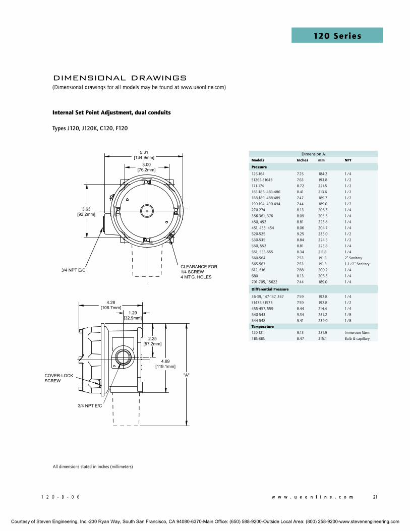
1 2 0 - B - 0 6 w w w . u e o n l i n e . c o m 21
120 Series
All dimensions stated in inches (millimeters)
Dimension Amodels inches mm npT
pressure
126-164 7.25 184.2 1/4
S126B-S164B 7.63 193.8 1/2
171-174 8.72 221.5 1/2
183-186, 483-486 8.41 213.6 1/2
188-189, 488-489 7.47 189.7 1/2
190-194, 490-494 7.44 189.0 1/2
270-274 8.13 206.5 1/4
356-361, 376 8.09 205.5 1/4
450, 452 8.81 223.8 1/4
451, 453, 454 8.06 204.7 1/4
520-525 9.25 235.0 1/2
530-535 8.84 224.5 1/2
550, 552 8.81 223.8 1/4
551, 553-555 8.34 211.8 1/4
560-564 7.53 191.3 2” Sanitary
565-567 7.53 191.3 1-1/2” Sanitary
612, 616 7.88 200.2 1/4
680 8.13 206.5 1/4
701-705, 15622 7.44 189.0 1/4
differential pressure
36-39, 147-157, 367 7.59 192.8 1/4
S147B-S157B 7.59 192.8 1/2
455-457, 559 8.44 214.4 1/4
540-543 9.34 237.2 1/8
544-548 9.41 239.0 1/8
Temperature
120-121 9.13 231.9 Immersion Stem
1BS-8BS 8.47 215.1 Bulb & capillary
dimensional drawings(Dimensional drawings for all models may be found at www.ueonline.com)
internal Set point Adjustment, dual conduits
Types J120, J120K, C120, F120
Courtesy of Steven Engineering, Inc.-230 Ryan Way, South San Francisco, CA 94080-6370-Main Office: (650) 588-9200-Outside Local Area: (800) 258-9200-www.stevenengineering.com
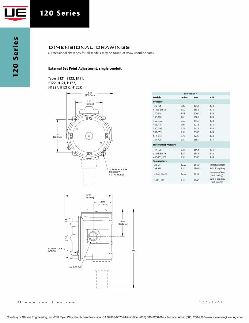
22 w w w . u e o n l i n e . c o m 1 2 0 - B - 0 6
120 Series1
20
Se
rie
s
dimensional drawings(Dimensional drawings for all models may be found at www.ueonline.com)
External Set point Adjustment, single conduit
Types B121, B122, E121, E122, H121, H122, H122P, H121K, H122K
Dimension A
models inches mm npT
pressure
126-164 8.09 205.5 1/4
S126B-S164B 8.50 215.9 1/2
270-274 7.88 200.2 1/4
358-376 7.81 198.4 1/4
450, 452 9.69 246.1 1/4
453, 454 8.94 227.1 1/4
550, 552 9.75 247.7 1/4
553-555 9.31 236.5 1/4
612, 614 8.75 222.3 1/4
701-705 8.31 211.1 1/4
differential pressure
147-157 8.44 214.4 1/4
S147B-S157B 8.44 214.4 1/2
456-457, 559 9.31 236.5 1/4
Temperature
120,121 10.00 254.0 Immersion Stem
2BS-8BS 9.31 236.5 Bulb & capillary
13272, 13322 10.00 254.0Immersion Stem(Heat tracing)
13273, 13321 9.31 236.5Bulb & capillary(Heat tracing)
Courtesy of Steven Engineering, Inc.-230 Ryan Way, South San Francisco, CA 94080-6370-Main Office: (650) 588-9200-Outside Local Area: (800) 258-9200-www.stevenengineering.com
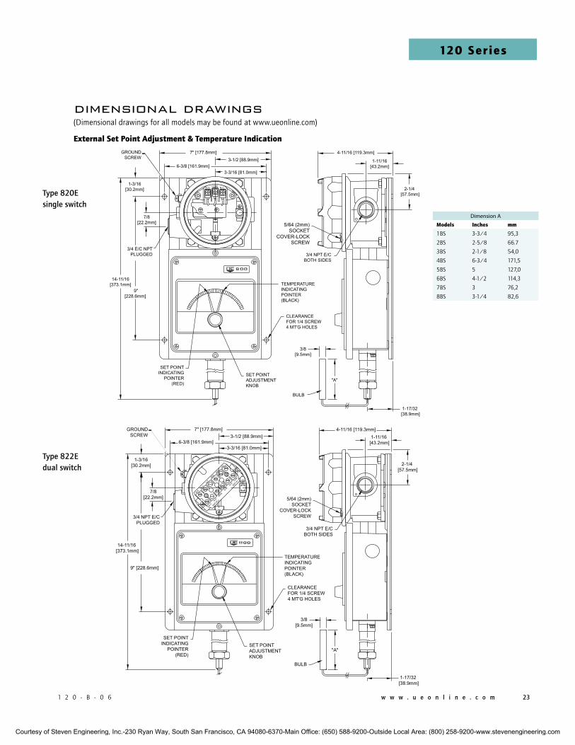
1 2 0 - B - 0 6 w w w . u e o n l i n e . c o m 23
120 Series
dimensional drawings(Dimensional drawings for all models may be found at www.ueonline.com)
External Set point Adjustment & Temperature indication
Type 820Esingle switch
Type 822Edual switch
Dimension A
models inches mm
1BS 3-3/4 95,3
2BS 2-5/8 66.7
3BS 2-1/8 54,0
4BS 6-3/4 171,5
5BS 5 127,0
6BS 4-1/2 114,3
7BS 3 76,2
8BS 3-1/4 82,6
Courtesy of Steven Engineering, Inc.-230 Ryan Way, South San Francisco, CA 94080-6370-Main Office: (650) 588-9200-Outside Local Area: (800) 258-9200-www.stevenengineering.com

24 w w w . u e o n l i n e . c o m 1 2 0 - B - 0 6
120 Series1
20
Se
rie
s
pressure Sensors (see drawings and charts on page 21 & 22 for complete dimensions)
dimensional drawings
SENSORS
Models 126-164
Models 183-186, 483-486 Models 188-194, 488-494 J120 Models 270-376, 680
Models S126B-S164B Models 171-174
Courtesy of Steven Engineering, Inc.-230 Ryan Way, South San Francisco, CA 94080-6370-Main Office: (650) 588-9200-Outside Local Area: (800) 258-9200-www.stevenengineering.com
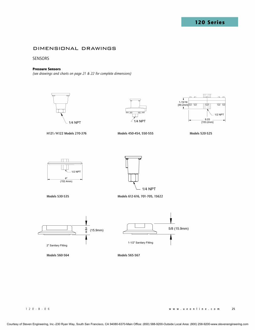
1 2 0 - B - 0 6 w w w . u e o n l i n e . c o m 25
120 Series
H121/H122 Models 270-376
Models 612-616, 701-705, 15622
Models 450-454, 550-555
Models 530-535
Models 520-525
Models 560-564 Models 565-567
pressure Sensors (see drawings and charts on page 21 & 22 for complete dimensions)
dimensional drawings
SENSORS
Courtesy of Steven Engineering, Inc.-230 Ryan Way, South San Francisco, CA 94080-6370-Main Office: (650) 588-9200-Outside Local Area: (800) 258-9200-www.stevenengineering.com
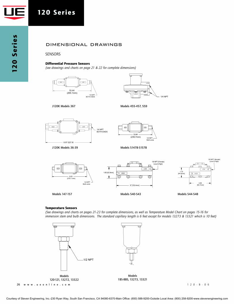
26 w w w . u e o n l i n e . c o m 1 2 0 - B - 0 6
120 Series1
20
Se
rie
s
differential pressure Sensors (see drawings and charts on page 21 & 22 for complete dimensions)
Models 455-457, 559
Models 544-548Models 540-543Models 147-157
J120K Models 36-39
J120K Models 367
Models S147B-S157B
dimensional drawings
SENSORS
Models 1BS-8BS, 13273, 13321
Models 120-121, 13272, 13322
Temperature Sensors (See drawings and charts on pages 21-23 for complete dimensions, as well as Temperature Model Chart on pages 15-16 for immersion stem and bulb dimensions. The standard capillary length is 6 feet except for models 13273 & 13321 which is 10 feet)
Courtesy of Steven Engineering, Inc.-230 Ryan Way, South San Francisco, CA 94080-6370-Main Office: (650) 588-9200-Outside Local Area: (800) 258-9200-www.stevenengineering.com
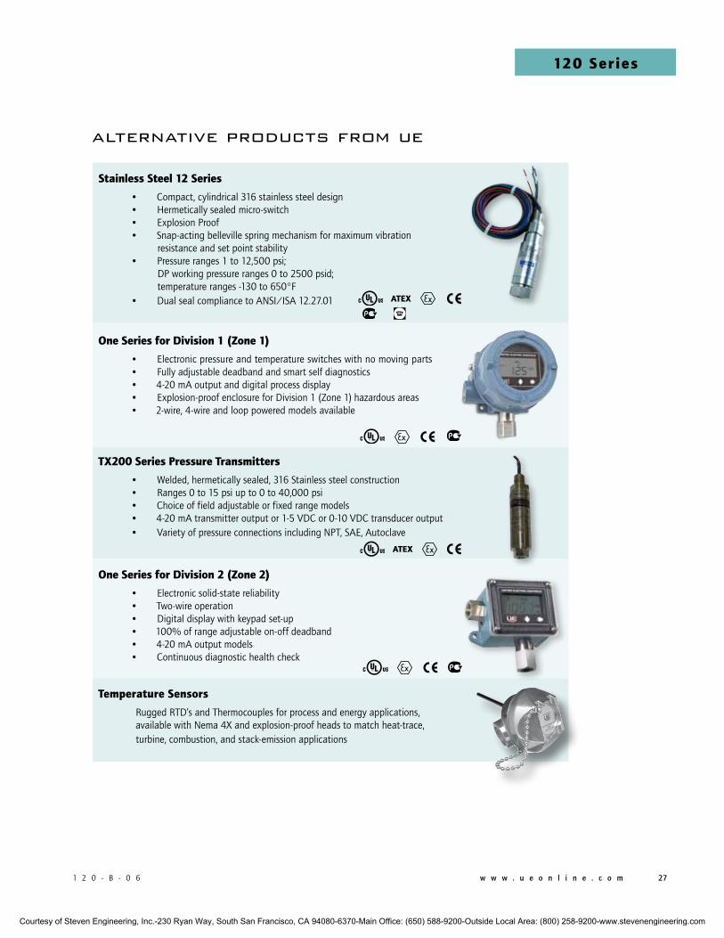
1 2 0 - B - 0 6 w w w . u e o n l i n e . c o m 27
120 Series
alternative products from ue
Stainless Steel 12 Series
• Compact, cylindrical 316 stainless steel design• Hermetically sealed micro-switch• Explosion Proof• Snap-acting belleville spring mechanism for maximum vibration resistance and set point stability
• Pressure ranges 1 to 12,500 psi; DP working pressure ranges 0 to 2500 psid; temperature ranges -130 to 650°F
• Dual seal compliance to ANSI/ISA 12.27.01
one Series for division 1 (Zone 1) • Electronic pressure and temperature switches with no moving parts • Fully adjustable deadband and smart self diagnostics• 4-20 mA output and digital process display• Explosion-proof enclosure for Division 1 (Zone 1) hazardous areas• 2-wire, 4-wire and loop powered models available
TX200 Series pressure Transmitters
• Welded, hermetically sealed, 316 Stainless steel construction• Ranges 0 to 15 psi up to 0 to 40,000 psi• Choice of field adjustable or fixed range models• 4-20 mA transmitter output or 1-5 VDC or 0-10 VDC transducer output • Variety of pressure connections including NPT, SAE, Autoclave
one Series for division 2 (Zone 2)
• Electronic solid-state reliability• Two-wire operation• Digital display with keypad set-up• 100% of range adjustable on-off deadband• 4-20 mA output models• Continuous diagnostic health check
Temperature Sensors
Rugged RTD’s and Thermocouples for process and energy applications, available with Nema 4X and explosion-proof heads to match heat-trace, turbine, combustion, and stack-emission applications
ATEX
ATEX
Courtesy of Steven Engineering, Inc.-230 Ryan Way, South San Francisco, CA 94080-6370-Main Office: (650) 588-9200-Outside Local Area: (800) 258-9200-www.stevenengineering.com
CP12093500
U.S. SAlES oFFicES
United Electric Controls 31 Old Stage Road Hampton Falls, NH 03844 Phone: 617-899-1132 email: [email protected]
United Electric Controls 28 N. Wise Ave. Freeport, IL 61032 Phone: 815-341-2588 email: [email protected]
United Electric Controls 1022 Vineyard Drive Conyers, GA 30013 Phone: 770-335-9802 email: [email protected]
United Electric Controls 5829 Grazing Court Mason, OH 45040 Phone: 513-535-5486 email: [email protected]
United Electric Controls 102 Salazar Court Clayton, CA 94517 Phone: 925-408-5997 email: [email protected]
United Electric Controls 27 Summit Terrace Sparta, NJ 07871 Phone: 973-271-2550 email: [email protected]
United Electric Controls 4306 Whickham Drive Fulshear, TX 77441 Phone: 832-457-6138 email: [email protected]
cAnAdA
EASTERN 68 Mosley Crescent Brampton, Ontario Canada L6y 5C8 Phone: 905-455-5131 FAX: 905-455-5131
WESTERN 148 Silver Ridge Close N.W. Calgary, Alberta Canada T3B 3T4 Phone: 403-247-3724 FAX: 403-247-3724
180 Dexter Avenue, P.O. Box 9143 Watertown, MA 02471-9143 USATelephone: 617 926-1000 Fax: 617 926-2568http://www.ueonline.com
REcommEndEd pRAcTicES And wARningS
United Electric Controls Company recommends careful consideration of the following factors when specifying and installing UE pressure and temperature units. Before installing a unit, the Installation and Maintenance instructions provided with unit must be read and understood.
• To avoid damaging unit, proof pressure and maximum temperature limits stated in literature and on nameplates must never be exceeded, even by surges in the system. Operation of the unit up to maximum pressure or temperature is acceptable on a limited basis (e.g., start-up, testing) but continuous operation must be restricted to the designated adjustable range. Excessive cycling at maximum pressure or temperature limits could reduce sensor life.
• A back-up unit is necessary for applications where damage to a primary unit could endanger life, limb or property. A high or low limit switch is necessary for applications where a dangerous runaway condition could result.
• The adjustable range must be selected so that incorrect, inadvertent or malicious setting at any range point cannot result in an unsafe system condition.
• Install unit where shock, vibration and ambient temperature fluctuations will not damage unit or affect operation. When applicable, orient unit so that moisture does not enter the enclosure via the electrical connection. When appropriate, this entry point should be sealed to prevent moisture entry.
• Unit must not be altered or modified after shipment. Consult UE if modification is necessary.
• Monitor operation to observe warning signs of possible damage to unit, such as drift in set point or faulty display. Check unit immediately.
• Preventative maintenance and periodic testing is necessary for critical applications where damage could endanger property or personnel.
• Electrical ratings stated in literature and on nameplate must not be exceeded. Overload on a switch can cause damage, even on the first cycle. Wire unit according to local and national electrical codes, using wire size recommended in installation sheet.
• Do not mount unit in ambient temp. exceeding published limits.
limiTEd wARRAnTySeller warrants that the product hereby purchased is, upon delivery, free from defects in material and workmanship and that any such product which is found to be defective in such workmanship or material will be repaired or replaced by Seller (Ex-works, Factory, Watertown, Massachusetts. INCOTERMS); provided, however, that this warranty applies only to equipment found to be so defective within a period of 24 months from the date of manufacture by the Seller. Seller shall not be obligated under this warranty for alleged defects which examination discloses are due to tampering, misuse, neglect, improper storage, and in any case where products are disassembled by anyone other than authorized Seller’s representatives. EXCEPT FOR THE LIMITED WARRANTy OF REPAIR AND REPLACEMENT STATED ABOVE, SELLER DISCLAIMS ALL WARRANTIES WHATSOEVER WITH RESPECT TO THE PRODUCT, INCLUDING ALL IMPLIED WARRANTIES OF MERCHANTABILITy OR FITNESS FOR ANy PARTICULAR PURPOSE.
limiTATion oF SEllER’S liAbiliTySELLER’S LIABILITy TO BUyER FOR ANy LOSS OR CLAIM, INCLUDING LIABILITy INCURRED IN CONNECTION WITH (I) BREACH OF ANy WARRANTy WHATSOEVER, EXPRESSED OR IMPLIED, (II) A BREACH OF CONTRACT, (III) A NEGLIGENT ACT OR ACTS (OR NEGLIGENT FAILURE TO ACT) COMMITTED By SELLER, OR (IV) AN ACT FOR WHICH STRICT LIABILITy WILL BE INPUTTED TO SELLER, IS LIMITED TO THE “LIMITED WARRANTy” OF REPAIR AND/OR REPLACEMENT AS SO STATED IN OUR WARRANTy OF PRODUCT. IN NO EVENT SHALL THE SELLER BE LIABLE FOR ANy SPECIAL, INDIRECT, CONSEQUENTIAL OR OTHER DAMAGES OF A LIKE GENERAL NATURE, INCLUDING, WITHOUT LIMI-TATION, LOSS OF PROFITS OR PRODUCTION, OR LOSS OR EXPENSES OF ANy NATURE INCURRED By THE BUyER OR ANy THIRD PARTy.
UE specifications subject to change without notice.
inTERnATionAl oFFicES
CHINA United Electric Controls, Shanghai Office Room 1011, 10th Flr, Huai Hai Zhonghua Building No. 885, Renmin Road, Luwan District Shanghai 200010, P.R. China Phone: +8621-6255 8059 email: [email protected]
United Electric Controls, Beijing Office Room 1006, Jainhao International Bldg. Block D, No. 116 Zizhuyuanlu, Haidian District Beijing, China 100089 Phone: +86-10-5893-0518 email: [email protected]
EASTERN EUROPE & SCANDINAVIA United Electric Controls 05-806 Komorow Kujawska 5, Poland Phone: +48 22 499 4804 email: [email protected]
GERMANy United Electric Controls An Der Zentlinde 21 D-64711 Erbach, Germany Phone: 496-062-7400 email: [email protected]
INDIA United Electric Controls House no. 7, Kamalkunj Society Nizampura, Baraoda (Gujarat), India Phone: +91 (-265) -2788654 email: [email protected]
ASIA-PACIFIC United Electric Controls, Far East No. 1-2-2, 2nd Floor Jalan 4/101C Cheras Business Centre Batu 5, Jalan Cheras 56100 Kuala Lumpur, Malaysia Phone: 603-9133-4122 email: [email protected]
MEXICO United Electric Controls Zacatecas # 206, Suite 20 Col Guadalupe CP 89120 Tampico, Tamaulipas Mexico Phone: 833-217-5201 email: [email protected]
RUSSIA United Electric Controls, Moscow Elninskaya str., 15-140 Moscow, 121552, Russia Phone: +7 (495) 792-88-06 email: [email protected]
Be sure to visit www.ueonline.com for the latest information.
Courtesy of Steven Engineering, Inc.-230 Ryan Way, South San Francisco, CA 94080-6370-Main Office: (650) 588-9200-Outside Local Area: (800) 258-9200-www.stevenengineering.com
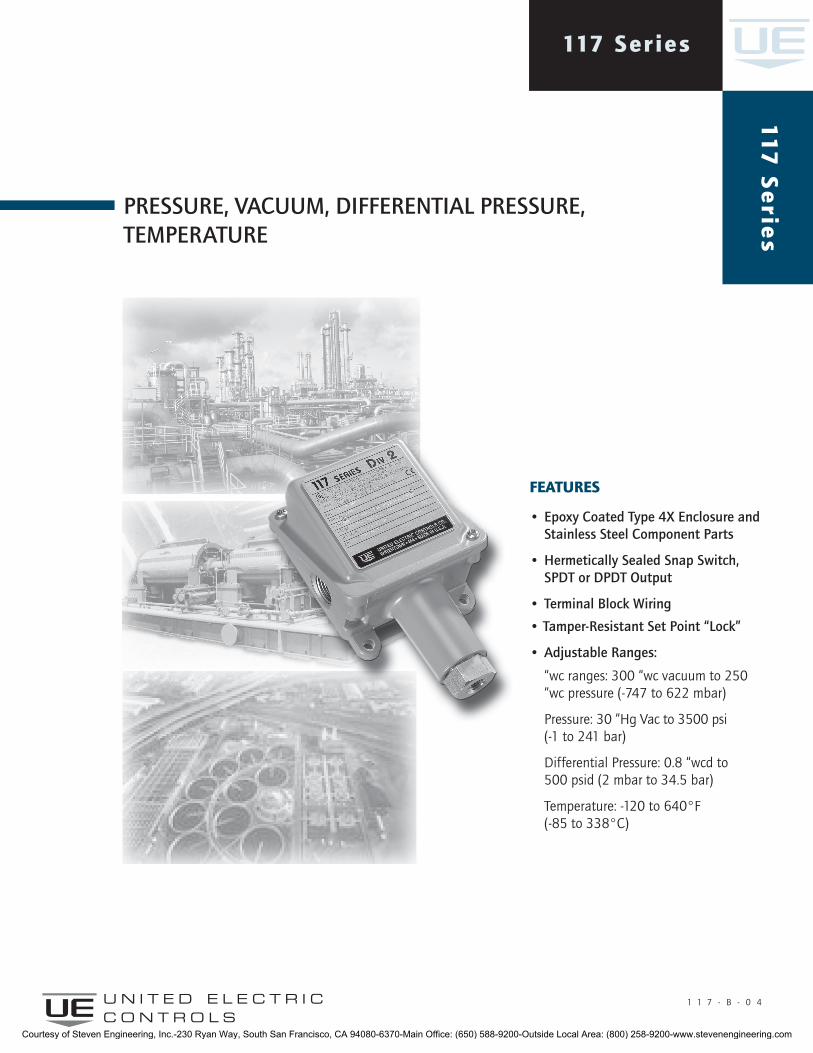
117 Series11
7 S
erie
s
U N I T E D E L E C T R I C C O N T R O L S
Pressure, Vacuum, Differential Pressure, temPerature
1 1 7 - B - 0 4
featureS
• epoxy coated type 4X enclosure and stainless steel component Parts
• Hermetically sealed snap switch, sPDt or DPDt Output
• terminal Block Wiring
• tamper-resistant set Point “lock”
• adjustable ranges:
“wc ranges: 300 “wc vacuum to 250 “wc pressure (-747 to 622 mbar)
Pressure: 30 “Hg Vac to 3500 psi (-1 to 241 bar)
Differential Pressure: 0.8 “wcd to 500 psid (2 mbar to 34.5 bar)
Temperature: -120 to 640°F (-85 to 338°C)
Courtesy of Steven Engineering, Inc.-230 Ryan Way, South San Francisco, CA 94080-6370-Main Office: (650) 588-9200-Outside Local Area: (800) 258-9200-www.stevenengineering.com
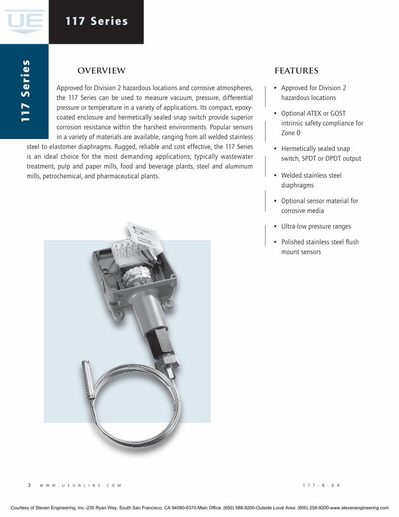
� w w w . u e o n l i n e . c o m 1 1 7 - B - 0 4
117 Series
Approved for Division 2 hazardous locations and corrosive atmospheres, the 117 Series can be used to measure vacuum, pressure, differential pressure or temperature in a variety of applications. Its compact, epoxy-coated enclosure and hermetically sealed snap switch provide superior corrosion resistance within the harshest environments. Popular sensors in a variety of materials are available, ranging from all welded stainless
steel to elastomer diaphragms. Rugged, reliable and cost effective, the 117 Series is an ideal choice for the most demanding applications; typically wastewater treatment, pulp and paper mills, food and beverage plants, steel and aluminum mills, petrochemical, and pharmaceutical plants.
overview features
• Approved for Division 2 hazardous locations
• Optional ATEX or GOST intrinsic safety compliance for Zone 0
• Hermetically sealed snap switch, SPDT or DPDT output
• Welded stainless steel diaphragms
• Optional sensor material for corrosive media
• Ultra-low pressure ranges
• Polished stainless steel flush mount sensors
117
Se
rie
s
Courtesy of Steven Engineering, Inc.-230 Ryan Way, South San Francisco, CA 94080-6370-Main Office: (650) 588-9200-Outside Local Area: (800) 258-9200-www.stevenengineering.com
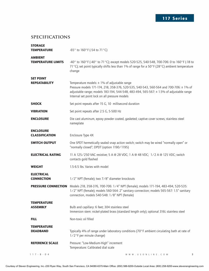
1 1 7 - B - 0 4 w w w . u e o n l i n e . c o m �
117 S e r i e s
specifications
Storage temperature -65° to 160°F (-54 to 71°C)
ambienttemperature limitS -40° to 160°F (-40° to 71°C); except models 520-525, 540-548, 700-706: 0 to 160°F (-18 to 71°C); set point typically shifts less than 1% of range for a 50°F (28°C) ambient temperature change
Set point repeatability Temperature models: ± 1% of adjustable range Pressure models 171-174, 218, 358-376, 520-535, 540-543, 560-564 and 700-706: ± 1% of adjustable range; models 183-194, 544-548, 483-494, 565-567: ± 1.5% of adjustable range Internal set point lock on all pressure models
Shock Set point repeats after 15 G, 10 millisecond duration
Vibration Set point repeats after 2.5 G, 5-500 Hz
encloSure Die cast aluminum, epoxy powder coated, gasketed; captive cover screws; stainless steel nameplate
encloSure claSSification Enclosure Type 4X
Switch output One SPDT hermetically sealed snap action switch; switch may be wired “normally open” or “normally closed”; DPDT (option 1190/1195)
electrical rating 11 A 125/250 VAC resistive; 5 A @ 28 VDC; 1 A @ 48 VDC; 1/2 A @ 125 VDC; switch contacts gold flashed
weight 1.5-6.5 lbs. Varies with model
electrical connection 1/2” NPT (female); two 7/8” diameter knockouts
preSSure connection Models 218, 358-376, 700-706: 1/4” NPT (female); models 171-194, 483-494, 520-535: 1/2” NPT (female); models 560-564: 2” sanitary connection; models 565-567: 1.5” sanitary connection, models 540-548: 1/8” NPT (female)
temperature aSSembly Bulb and capillary: 6 feet; 304 stainless steel Immersion stem: nickel-plated brass (standard length only); optional 316L stainless steel
fill Non-toxic oil filled
temperature deadband Typically 4% of range under laboratory conditions (70°F ambient circulating bath at rate of 1/2°F per minute change)
reference Scale Pressure: “Low-Medium-High” increment Temperature: Calibrated dial scale
Courtesy of Steven Engineering, Inc.-230 Ryan Way, South San Francisco, CA 94080-6370-Main Office: (650) 588-9200-Outside Local Area: (800) 258-9200-www.stevenengineering.com
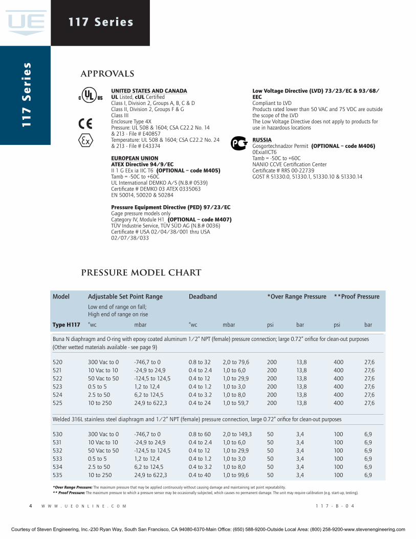
4 w w w . u e o n l i n e . c o m 1 1 7 - B - 0 4
117 Series11
7 S
eri
es
approvals
pressure model chart
model adjustable set Point range Deadband *Over range Pressure **Proof Pressure
Low end of range on fall; High end of range on rise
type h117 “wc mbar “wc mbar psi bar psi bar
Buna N diaphragm and O-ring with epoxy coated aluminum 1/2” NPT (female) pressure connection; large 0.72” orifice for clean-out purposes (Other wetted materials available - see page 9)
520 300 Vac to 0 -746,7 to 0 0.8 to 32 2,0 to 79,6 200 13,8 400 27,6 521 10 Vac to 10 -24,9 to 24,9 0.4 to 2.4 1,0 to 6,0 200 13,8 400 27,6 522 50 Vac to 50 -124,5 to 124,5 0.4 to 12 1,0 to 29,9 200 13,8 400 27,6 523 0.5 to 5 1,2 to 12,4 0.4 to 1.2 1,0 to 3,0 200 13,8 400 27,6 524 2.5 to 50 6,2 to 124,5 0.4 to 3.2 1,0 to 8,0 200 13,8 400 27,6 525 10 to 250 24,9 to 622,3 0.4 to 24 1,0 to 59,7 200 13,8 400 27,6
Welded 316L stainless steel diaphragm and 1/2” NPT (female) pressure connection, large 0.72” orifice for clean-out purposes
530 300 Vac to 0 -746,7 to 0 0.8 to 60 2,0 to 149,3 50 3,4 100 6,9 531 10 Vac to 10 -24,9 to 24,9 0.4 to 2.4 1,0 to 6,0 50 3,4 100 6,9 532 50 Vac to 50 -124,5 to 124,5 0.4 to 12 1,0 to 29,9 50 3,4 100 6,9 533 0.5 to 5 1,2 to 12,4 0.4 to 1.2 1,0 to 3,0 50 3,4 100 6,9 534 2.5 to 50 6,2 to 124,5 0.4 to 3.2 1,0 to 8,0 50 3,4 100 6,9 535 10 to 250 24,9 to 622,3 0.4 to 40 1,0 to 99,6 50 3,4 100 6,9
*Over Range Pressure: The maximum pressure that may be applied continuously without causing damage and maintaining set point repeatability. ** Proof Pressure: The maximum pressure to which a pressure sensor may be occasionally subjected, which causes no permanent damage. The unit may require calibration (e.g. start-up, testing).
united StateS and canadaul Listed, cul CertifiedClass I, Division 2, Groups A, B, C & DClass II, Division 2, Groups F & GClass IIIEnclosure Type 4XPressure: UL 508 & 1604; CSA C22.2 No. 14& 213 - File # E40857Temperature: UL 508 & 1604; CSA C22.2 No. 24& 213 - File # E43374
european unionateX directive 94/9/ecII 1 G EEx ia IIC T6 (optional – code m405)Tamb = -50C to +60CUL International DEMKO A/S (N.B.# 0539)Certificate # DEMKO 03 ATEX 0335063EN 50014, 50020 & 50284
pressure equipment directive (ped) 97/23/ecGage pressure models onlyCategory IV, Module H1 (optional – code m407)TÜV Industrie Service, TÜV SÜD AG (N.B.# 0036)Certificate # USA 02/04/38/001 thru USA 02/07/38/033
low Voltage directive (lVd) 73/23/ec & 93/68/eecCompliant to LVDProducts rated lower than 50 VAC and 75 VDC are outside the scope of the LVDThe Low Voltage Directive does not apply to products for use in hazardous locations
ruSSiaGosgortechnadzor Permit (optional – code m406)0ExiaIICT6Tamb = -50C to +60CNANIO CCVE Certification CenterCertificate # RRS 00-22739GOST R 51330.0, 51330.1, 51330.10 & 51330.14
Courtesy of Steven Engineering, Inc.-230 Ryan Way, South San Francisco, CA 94080-6370-Main Office: (650) 588-9200-Outside Local Area: (800) 258-9200-www.stevenengineering.com
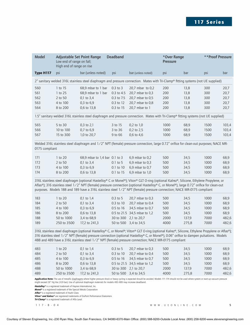
1 1 7 - B - 0 4 w w w . u e o n l i n e . c o m �
117 S e r i e s
model adjustable set Point range Deadband *Over range **Proof Pressure Low end of range on fall; Pressure High end of range on rise
type h117 psi bar (unless noted) psi bar (unless noted) psi bar psi bar
2” sanitary welded 316L stainless steel diaphragm and pressure connection. Mates with Tri-Clamp® fitting systems (not UE supplied)
560 1 to 15 68,9 mbar to 1 bar 0.3 to 3 20,7 mbar to 0,2 200 13,8 300 20,7 561 1 to 25 68,9 mbar to 1 bar 0.3 to 4.5 20,7 mbar to 0,3 200 13,8 300 20,7 562 2 to 50 0,1 to 3,4 0.3 to 7.5 20,7 mbar to 0,5 200 13,8 300 20,7 563 4 to 100 0,3 to 6,9 0.3 to 12 20,7 mbar to 0,8 200 13,8 300 20,7 564 8 to 200 0,6 to 13,8 0.3 to 15 20,7 mbar to 1 200 13,8 300 20,7
1.5” sanitary welded 316L stainless steel diaphragm and pressure connection. Mates with Tri-Clamp® fitting systems (not UE supplied)
565 5 to 30 0,3 to 2,1 3 to 15 0,2 to 1,0 1000 68,9 1500 103,4 566 10 to 100 0,7 to 6,9 3 to 36 0,2 to 2,5 1000 68,9 1500 103,4 567 15 to 300 1,0 to 20,7 9 to 66 0,6 to 4,6 1000 68,9 1500 103,4
Welded 316L stainless steel diaphragm and 1/2” NPT (female) pressure connection, large 0.72” orifice for clean-out purposes; NACE MR-0175 compliant
171 1 to 20 68,9 mbar to 1,4 bar 0.1 to 3 6,9 mbar to 0,2 500 34,5 1000 68,9 172 2 to 50 0,1 to 3,4 0.1 to 5 6,9 mbar to 0,3 500 34,5 1000 68,9 173 4 to 100 0,3 to 6,9 0.1 to 10 6,9 mbar to 0,7 500 34,5 1000 68,9 174 8 to 200 0,6 to 13,8 0.1 to 15 6,9 mbar to 1,0 500 34,5 1000 68,9
316L stainless steel diaphragm (optional Hastelloy® C or Monel®); Viton® GLT O-ring (optional Kalrez®, Silicone, Ethylene Propylene, or Aflas®); 316 stainless steel 1/2” NPT (female) pressure connection (optional Hastelloy® C, or Monel®), large 0.72” orifice for clean-out purposes. Models 188 and 189 have a 316L stainless steel 1/2” NPT (female) pressure connection; NACE MR-0175 compliant
183 1 to 20 0,1 to 1,4 0.3 to 5 20,7 mbar to 0,3 500 34,5 1000 68,9 184 2 to 50 0,1 to 3,4 0.3 to 10 20,7 mbar to 0,4 500 34,5 1000 68,9 185 4 to 100 0,3 to 6,9 0.5 to 16 34,5 mbar to 0,7 500 34,5 1000 68,9 186 8 to 200 0,6 to 13,8 0.5 to 21.5 34,5 mbar to 1,2 500 34,5 1000 68,9 188 50 to 1000 3,4 to 68,9 30 to 300 2,1 to 20,7 2000 137,9 7000 482,6 189 250 to 3500 17,2 to 241,3 50 to 500 3,4 to 34,5 4000 275,8 7000 482,6
316L stainless steel diaphragm (optional Hastelloy® C, or Monel®; Viton® GLT O-ring (optional Kalrez®, Silicone, Ethylene Propylene or Aflas®); 316 stainless steel 1/2” NPT (female) pressure connection (optional Hastelloy® C, or Monel®), 0.06” orifice to dampen pulsations. Models 488 and 489 have a 316L stainless steel 1/2” NPT (female) pressure connection; NACE MR-0175 compliant
483 1 to 20 0,1 to 1,4 0.3 to 5 20,7 mbar to 0,3 500 34,5 1000 68,9 484 2 to 50 0,1 to 3,4 0.3 to 10 20,7 mbar to 0,4 500 34,5 1000 68,9 485 4 to 100 0,3 to 6,9 0.5 to 16 34,5 mbar to 0,7 500 34,5 1000 68,9 486 8 to 200 0,6 to 13,8 0.5 to 21.5 34,5 mbar to 1,2 500 34,5 1000 68,9 488 50 to 1000 3,4 to 68,9 30 to 300 2,1 to 20,7 2000 137,9 7000 482,6 489 250 to 3500 17,2 to 241,3 50 to 500 3,4 to 34,5 4000 275,8 7000 482,6application note: The use of metallic diaphragms where higher pressure shock or heavy cycling is expected should be avoided. Models 171-174 should not be used where system or start-up vacuum pressure might exceed 26” Hg Vac (-0,9 bar). Use of optional diaphragm materials for models 483-489 may increase deadband.
Hastelloy® is a registered trademark of Haynes International, Inc.Monel® is a registered trademark of the Special Metals CorporationAflas® is a registered trademark of Asahi GlassViton® and Kalrez® are registered trademarks of DuPont Performance ElastomersTri-Clamp® is a registered trademark of Alfa Laval.
Courtesy of Steven Engineering, Inc.-230 Ryan Way, South San Francisco, CA 94080-6370-Main Office: (650) 588-9200-Outside Local Area: (800) 258-9200-www.stevenengineering.com
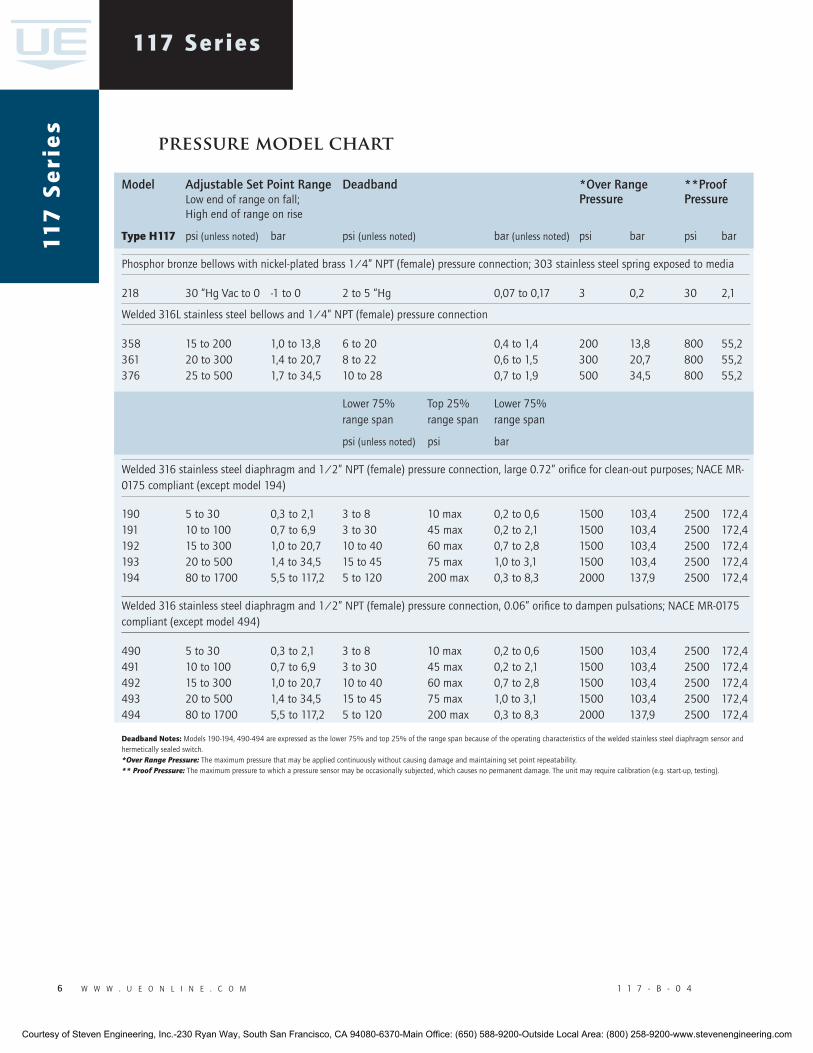
� w w w . u e o n l i n e . c o m 1 1 7 - B - 0 4
117 Series11
7 S
eri
es
model adjustable set Point range Deadband *Over range **Proof Low end of range on fall; Pressure Pressure High end of range on rise
type h117 psi (unless noted) bar psi (unless noted) bar (unless noted) psi bar psi bar
Phosphor bronze bellows with nickel-plated brass 1/4” NPT (female) pressure connection; 303 stainless steel spring exposed to media
218 30 “Hg Vac to 0 -1 to 0 2 to 5 “Hg 0,07 to 0,17 3 0,2 30 2,1
Welded 316L stainless steel bellows and 1/4” NPT (female) pressure connection
358 15 to 200 1,0 to 13,8 6 to 20 0,4 to 1,4 200 13,8 800 55,2 361 20 to 300 1,4 to 20,7 8 to 22 0,6 to 1,5 300 20,7 800 55,2 376 25 to 500 1,7 to 34,5 10 to 28 0,7 to 1,9 500 34,5 800 55,2
Lower 75% Top 25% Lower 75% range span range span range span
psi (unless noted) psi bar
Welded 316 stainless steel diaphragm and 1/2” NPT (female) pressure connection, large 0.72” orifice for clean-out purposes; NACE MR-0175 compliant (except model 194)
190 5 to 30 0,3 to 2,1 3 to 8 10 max 0,2 to 0,6 1500 103,4 2500 172,4 191 10 to 100 0,7 to 6,9 3 to 30 45 max 0,2 to 2,1 1500 103,4 2500 172,4 192 15 to 300 1,0 to 20,7 10 to 40 60 max 0,7 to 2,8 1500 103,4 2500 172,4 193 20 to 500 1,4 to 34,5 15 to 45 75 max 1,0 to 3,1 1500 103,4 2500 172,4 194 80 to 1700 5,5 to 117,2 5 to 120 200 max 0,3 to 8,3 2000 137,9 2500 172,4
Welded 316 stainless steel diaphragm and 1/2” NPT (female) pressure connection, 0.06” orifice to dampen pulsations; NACE MR-0175 compliant (except model 494)
490 5 to 30 0,3 to 2,1 3 to 8 10 max 0,2 to 0,6 1500 103,4 2500 172,4491 10 to 100 0,7 to 6,9 3 to 30 45 max 0,2 to 2,1 1500 103,4 2500 172,4492 15 to 300 1,0 to 20,7 10 to 40 60 max 0,7 to 2,8 1500 103,4 2500 172,4 493 20 to 500 1,4 to 34,5 15 to 45 75 max 1,0 to 3,1 1500 103,4 2500 172,4 494 80 to 1700 5,5 to 117,2 5 to 120 200 max 0,3 to 8,3 2000 137,9 2500 172,4
deadband notes: Models 190-194, 490-494 are expressed as the lower 75% and top 25% of the range span because of the operating characteristics of the welded stainless steel diaphragm sensor and hermetically sealed switch. *Over Range Pressure: The maximum pressure that may be applied continuously without causing damage and maintaining set point repeatability. ** Proof Pressure: The maximum pressure to which a pressure sensor may be occasionally subjected, which causes no permanent damage. The unit may require calibration (e.g. start-up, testing).
pressure model chart
Courtesy of Steven Engineering, Inc.-230 Ryan Way, South San Francisco, CA 94080-6370-Main Office: (650) 588-9200-Outside Local Area: (800) 258-9200-www.stevenengineering.com
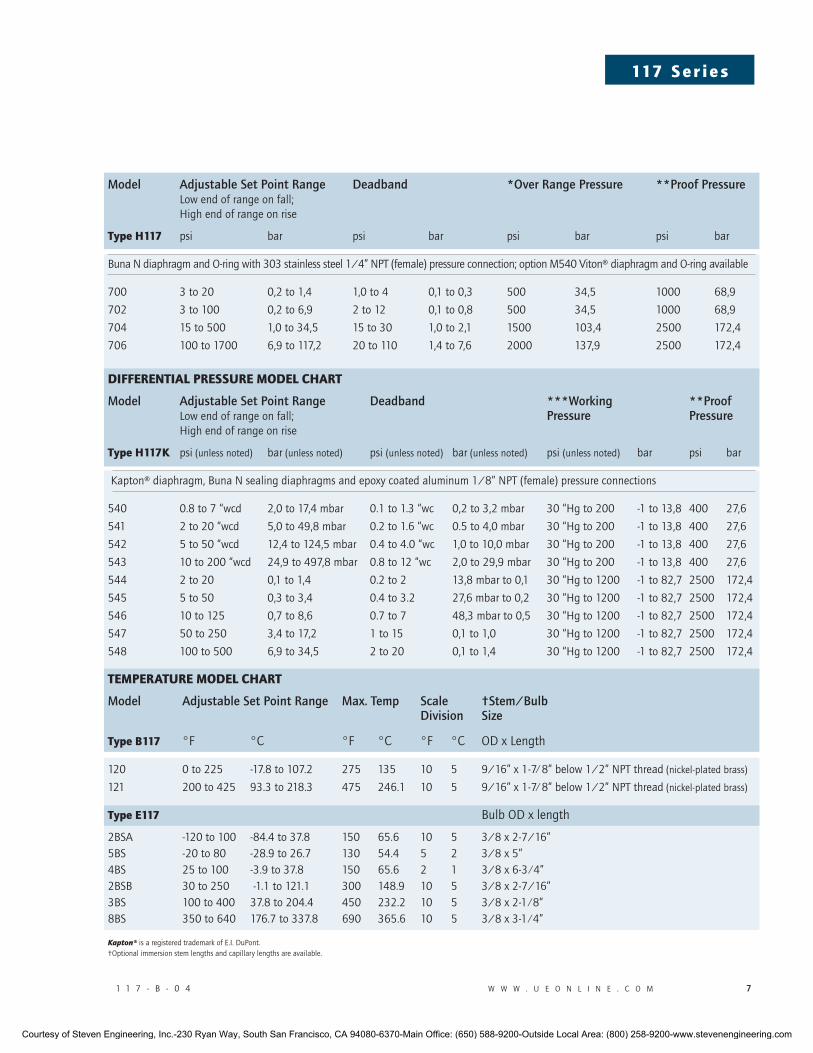
1 1 7 - B - 0 4 w w w . u e o n l i n e . c o m �
117 S e r i e s
model adjustable set Point range Deadband *Over range Pressure **Proof Pressure Low end of range on fall; High end of range on rise
type h117 psi bar psi bar psi bar psi bar
Buna N diaphragm and O-ring with 303 stainless steel 1/4” NPT (female) pressure connection; option M540 Viton® diaphragm and O-ring available
700 3 to 20 0,2 to 1,4 1,0 to 4 0,1 to 0,3 500 34,5 1000 68,9
702 3 to 100 0,2 to 6,9 2 to 12 0,1 to 0,8 500 34,5 1000 68,9
704 15 to 500 1,0 to 34,5 15 to 30 1,0 to 2,1 1500 103,4 2500 172,4
706 100 to 1700 6,9 to 117,2 20 to 110 1,4 to 7,6 2000 137,9 2500 172,4
differential preSSure model chart
model adjustable set Point range Deadband ***Working **Proof Low end of range on fall; Pressure Pressure High end of range on rise
type h117k psi (unless noted) bar (unless noted) psi (unless noted) bar (unless noted) psi (unless noted) bar psi bar
Kapton® diaphragm, Buna N sealing diaphragms and epoxy coated aluminum 1/8” NPT (female) pressure connections
540 0.8 to 7 “wcd 2,0 to 17,4 mbar 0.1 to 1.3 “wc 0,2 to 3,2 mbar 30 “Hg to 200 -1 to 13,8 400 27,6
541 2 to 20 “wcd 5,0 to 49,8 mbar 0.2 to 1.6 “wc 0.5 to 4,0 mbar 30 “Hg to 200 -1 to 13,8 400 27,6
542 5 to 50 “wcd 12,4 to 124,5 mbar 0.4 to 4.0 “wc 1,0 to 10,0 mbar 30 “Hg to 200 -1 to 13,8 400 27,6
543 10 to 200 “wcd 24,9 to 497,8 mbar 0.8 to 12 “wc 2,0 to 29,9 mbar 30 “Hg to 200 -1 to 13,8 400 27,6
544 2 to 20 0,1 to 1,4 0.2 to 2 13,8 mbar to 0,1 30 “Hg to 1200 -1 to 82,7 2500 172,4
545 5 to 50 0,3 to 3,4 0.4 to 3.2 27,6 mbar to 0,2 30 “Hg to 1200 -1 to 82,7 2500 172,4
546 10 to 125 0,7 to 8,6 0.7 to 7 48,3 mbar to 0,5 30 “Hg to 1200 -1 to 82,7 2500 172,4
547 50 to 250 3,4 to 17,2 1 to 15 0,1 to 1,0 30 “Hg to 1200 -1 to 82,7 2500 172,4
548 100 to 500 6,9 to 34,5 2 to 20 0,1 to 1,4 30 “Hg to 1200 -1 to 82,7 2500 172,4
temperature model chart
model adjustable set Point range max. temp scale †stem/Bulb Division size
type b117 °F °C °F °C °F °C OD x Length
120 0 to 225 -17.8 to 107.2 275 135 10 5 9/16” x 1-7⁄ 8” below 1/2” NPT thread (nickel-plated brass)
121 200 to 425 93.3 to 218.3 475 246.1 10 5 9/16” x 1-7⁄ 8” below 1/2” NPT thread (nickel-plated brass)
type e117 Bulb OD x length
2BSA -120 to 100 -84.4 to 37.8 150 65.6 10 5 3/8 x 2-7/16”5BS -20 to 80 -28.9 to 26.7 130 54.4 5 2 3/8 x 5”4BS 25 to 100 -3.9 to 37.8 150 65.6 2 1 3/8 x 6-3 ⁄ 4”2BSB 30 to 250 -1.1 to 121.1 300 148.9 10 5 3/8 x 2-7/16”3BS 100 to 400 37.8 to 204.4 450 232.2 10 5 3/8 x 2-1 ⁄ 8”8BS 350 to 640 176.7 to 337.8 690 365.6 10 5 3/8 x 3-1 ⁄ 4”
Kapton® is a registered trademark of E.I. DuPont.†Optional immersion stem lengths and capillary lengths are available.
Courtesy of Steven Engineering, Inc.-230 Ryan Way, South San Francisco, CA 94080-6370-Main Office: (650) 588-9200-Outside Local Area: (800) 258-9200-www.stevenengineering.com
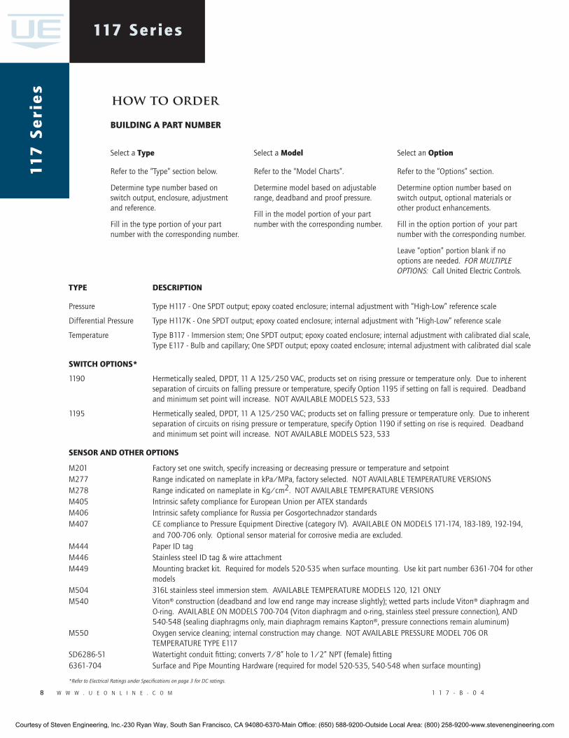
� w w w . u e o n l i n e . c o m 1 1 7 - B - 0 4
117 Series11
7 S
eri
es
type deScription
Pressure Type H117 - One SPDT output; epoxy coated enclosure; internal adjustment with “High-Low” reference scale
Differential Pressure Type H117K - One SPDT output; epoxy coated enclosure; internal adjustment with “High-Low” reference scale
Temperature Type B117 - Immersion stem; One SPDT output; epoxy coated enclosure; internal adjustment with calibrated dial scale, Type E117 - Bulb and capillary; One SPDT output; epoxy coated enclosure; internal adjustment with calibrated dial scale
Switch optionS*
1190 Hermetically sealed, DPDT, 11 A 125/250 VAC, products set on rising pressure or temperature only. Due to inherent separation of circuits on falling pressure or temperature, specify Option 1195 if setting on fall is required. Deadband and minimum set point will increase. NOT AVAILABLE MODELS 523, 533
1195 Hermetically sealed, DPDT, 11 A 125/250 VAC; products set on falling pressure or temperature only. Due to inherent separation of circuits on rising pressure or temperature, specify Option 1190 if setting on rise is required. Deadband and minimum set point will increase. NOT AVAILABLE MODELS 523, 533
SenSor and other optionS
M201 Factory set one switch, specify increasing or decreasing pressure or temperature and setpoint M277 Range indicated on nameplate in kPa/MPa, factory selected. NOT AVAILABLE TEMPERATURE VERSIONSM278 Range indicated on nameplate in Kg/cm2. NOT AVAILABLE TEMPERATURE VERSIONSM405 Intrinsic safety compliance for European Union per ATEX standardsM406 Intrinsic safety compliance for Russia per Gosgortechnadzor standardsM407 CE compliance to Pressure Equipment Directive (category IV). AVAILABLE ON MODELS 171-174, 183-189, 192-194, and 700-706 only. Optional sensor material for corrosive media are excluded.M444 Paper ID tagM446 Stainless steel ID tag & wire attachment M449 Mounting bracket kit. Required for models 520-535 when surface mounting. Use kit part number 6361-704 for other modelsM504 316L stainless steel immersion stem. AVAILABLE TEMPERATURE MODELS 120, 121 ONLYM540 Viton® construction (deadband and low end range may increase slightly); wetted parts include Viton® diaphragm and O-ring. AVAILABLE ON MODELS 700-704 (Viton diaphragm and o-ring, stainless steel pressure connection), AND 540-548 (sealing diaphragms only, main diaphragm remains Kapton®, pressure connections remain aluminum)M550 Oxygen service cleaning; internal construction may change. NOT AVAILABLE PRESSURE MODEL 706 OR TEMPERATURE TYPE E117SD6286-51 Watertight conduit fitting; converts 7/8” hole to 1/2” NPT (female) fitting6361-704 Surface and Pipe Mounting Hardware (required for model 520-535, 540-548 when surface mounting)
*Refer to Electrical Ratings under Specifications on page 3 for DC ratings.
how to order
building a part number
Select a type
Refer to the “Type” section below.
Determine type number based on switch output, enclosure, adjustment and reference.
Fill in the type portion of your part number with the corresponding number.
Select a model
Refer to the “Model Charts”.
Determine model based on adjustable range, deadband and proof pressure.
Fill in the model portion of your part number with the corresponding number.
Select an option
Refer to the “Options” section.
Determine option number based on switch output, optional materials or other product enhancements.
Fill in the option portion of your part number with the corresponding number.
Leave “option” portion blank if no options are needed. FoR multiplE optionS: Call United Electric Controls.
Courtesy of Steven Engineering, Inc.-230 Ryan Way, South San Francisco, CA 94080-6370-Main Office: (650) 588-9200-Outside Local Area: (800) 258-9200-www.stevenengineering.com
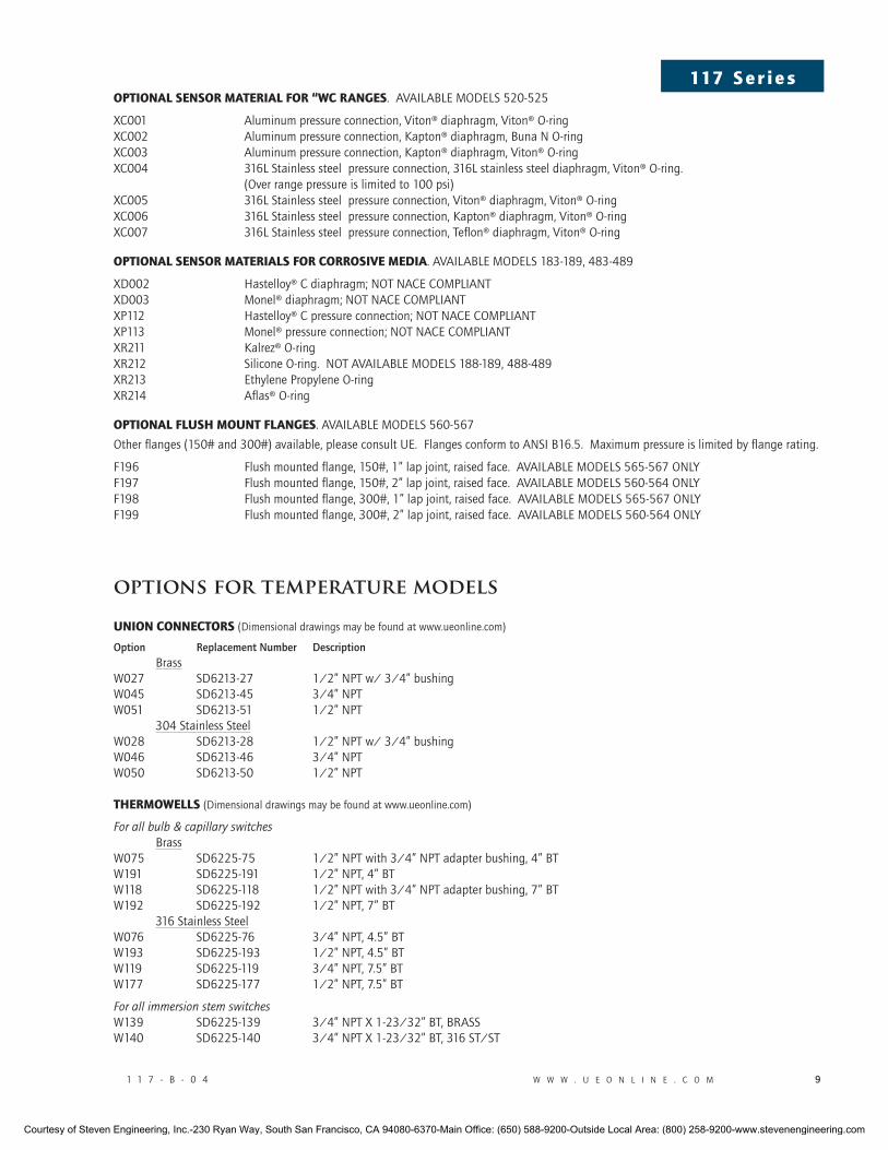
1 1 7 - B - 0 4 w w w . u e o n l i n e . c o m �
117 S e r i e soptional SenSor material for “wc rangeS. AVAILABLE MODELS 520-525
XC001 Aluminum pressure connection, Viton® diaphragm, Viton® O-ringXC002 Aluminum pressure connection, Kapton® diaphragm, Buna N O-ring XC003 Aluminum pressure connection, Kapton® diaphragm, Viton® O-ringXC004 316L Stainless steel pressure connection, 316L stainless steel diaphragm, Viton® O-ring. (Over range pressure is limited to 100 psi) XC005 316L Stainless steel pressure connection, Viton® diaphragm, Viton® O-ringXC006 316L Stainless steel pressure connection, Kapton® diaphragm, Viton® O-ringXC007 316L Stainless steel pressure connection, Teflon® diaphragm, Viton® O-ring
optional SenSor materialS for corroSiVe media. AVAILABLE MODELS 183-189, 483-489
XD002 Hastelloy® C diaphragm; NOT NACE COMPLIANTXD003 Monel® diaphragm; NOT NACE COMPLIANTXP112 Hastelloy® C pressure connection; NOT NACE COMPLIANTXP113 Monel® pressure connection; NOT NACE COMPLIANTXR211 Kalrez® O-ringXR212 Silicone O-ring. NOT AVAILABLE MODELS 188-189, 488-489 XR213 Ethylene Propylene O-ringXR214 Aflas® O-ring
optional fluSh mount flangeS. AVAILABLE MODELS 560-567
Other flanges (150# and 300#) available, please consult UE. Flanges conform to ANSI B16.5. Maximum pressure is limited by flange rating.
F196 Flush mounted flange, 150#, 1” lap joint, raised face. AVAILABLE MODELS 565-567 ONLYF197 Flush mounted flange, 150#, 2” lap joint, raised face. AVAILABLE MODELS 560-564 ONLYF198 Flush mounted flange, 300#, 1” lap joint, raised face. AVAILABLE MODELS 565-567 ONLY F199 Flush mounted flange, 300#, 2” lap joint, raised face. AVAILABLE MODELS 560-564 ONLY
options for temperature models
union connectorS (Dimensional drawings may be found at www.ueonline.com)
Option replacement number Description BrassW027 SD6213-27 1/2” NPT w/ 3/4” bushingW045 SD6213-45 3/4” NPTW051 SD6213-51 1/2” NPT 304 Stainless Steel W028 SD6213-28 1/2” NPT w/ 3/4” bushingW046 SD6213-46 3/4” NPT W050 SD6213-50 1/2” NPT thermowellS (Dimensional drawings may be found at www.ueonline.com)
For all bulb & capillary switches Brass W075 SD6225-75 1/2” NPT with 3/4” NPT adapter bushing, 4” BT W191 SD6225-191 1/2” NPT, 4” BTW118 SD6225-118 1/2” NPT with 3/4” NPT adapter bushing, 7” BTW192 SD6225-192 1/2” NPT, 7” BT 316 Stainless SteelW076 SD6225-76 3/4” NPT, 4.5” BT W193 SD6225-193 1/2” NPT, 4.5” BT W119 SD6225-119 3/4” NPT, 7.5” BT W177 SD6225-177 1/2” NPT, 7.5” BT
For all immersion stem switches W139 SD6225-139 3/4” NPT X 1-23/32” BT, BRASS W140 SD6225-140 3/4” NPT X 1-23/32” BT, 316 ST/ST
Courtesy of Steven Engineering, Inc.-230 Ryan Way, South San Francisco, CA 94080-6370-Main Office: (650) 588-9200-Outside Local Area: (800) 258-9200-www.stevenengineering.com
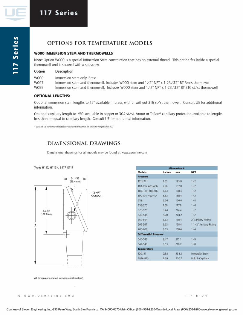
10 w w w . u e o n l i n e . c o m 1 1 7 - B - 0 4
117 Series11
7 S
eri
es
Dimension Amodels inches mm npt
pressure
171-174 7.63 193.8 1/2
183-186, 483-486 7.56 192.0 1/2
188, 189, 488-489 6.63 168.4 1/2
190-194, 490-494 6.63 168.4 1/2
218 6.56 166.6 1/4
358-376 7.00 177.8 1/4
520-525 8.44 214.4 1/2
530-535 8.00 203.2 1/2
560-564 6.63 168.4 2” Sanitary Fitting
565-567 6.63 168.4 1-1/2” Sanitary Fitting
700-706 6.63 168.4 1/4
differential pressure
540-543 8.47 215.1 1/8
544-548 8.53 216.7 1/8
temperature
120,121 9.38 238.3 Immersion Stem
2BSA-8BS 8.69 220.7 Bulb & Capillary
options for temperature models
w000 immerSion Stem and thermowellS
note: Option W000 is a special Immersion Stem construction that has no external thread. This option fits inside a special thermowell and is secured with a set-screw.
Option Description
W000 Immersion stem only, BrassW097 Immersion stem and thermowell. Includes W000 stem and 1/2” NPT x 1-23/32” BT Brass thermowellW099 Immersion stem and thermowell. Includes W000 stem and 1/2” NPT x 1-23/32” BT 316 st/st thermowell
optional lengthS:
Optional immersion stem lengths to 15” available in brass, with or without 316 st/st thermowell. Consult UE for additional information.
Optional capillary length to *50’ available in copper or 304 st/st. Armor or Teflon® capillary protection available to lengths less than or equal to capillary length. Consult UE for additional information.
* Consult uE regarding repeatability and ambient effects on capillary lengths over 30’.
dimensional drawingsDimensional drawings for all models may be found at www.ueonline.com
types H11�, H11�K, B11�, e11�
Courtesy of Steven Engineering, Inc.-230 Ryan Way, South San Francisco, CA 94080-6370-Main Office: (650) 588-9200-Outside Local Area: (800) 258-9200-www.stevenengineering.com
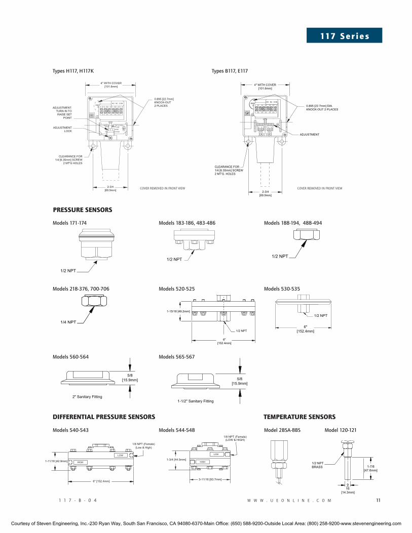
1 1 7 - B - 0 4 w w w . u e o n l i n e . c o m 11
117 S e r i e s
preSSure SenSorS
models �1�-���, �00-�0�
models 1��-1�4, 4��-4�4
models ��0-��� models ��0-���
differential preSSure SenSorS temperature SenSorS
models ���-���
models 1�1-1�4 models 1��-1��, 4��-4��
models ��0-��4
model �Bsa-�Bsmodels �40-�4� models �44-�4� model 1�0-1�1
types H11�, H11�K types B11�, e11�
COVER REMOVED IN FRONT VIEW COVER REMOVED IN FRONT VIEW
Courtesy of Steven Engineering, Inc.-230 Ryan Way, South San Francisco, CA 94080-6370-Main Office: (650) 588-9200-Outside Local Area: (800) 258-9200-www.stevenengineering.com
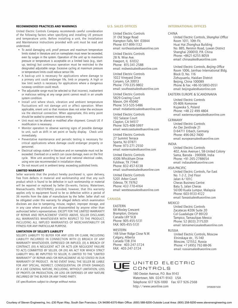
SP08081500
180 Dexter Avenue, P.O. Box 9143 Watertown, MA 02471-9143 USATelephone: 617 926-1000 Fax: 617 926-2568http://www.ueonline.com
U N I T E D E L E C T R I C C O N T R O L S
recommended practiceS and warningS
United Electric Controls Company recommends careful consideration of the following factors when specifying and installing UE pressure and temperature units. Before installing a unit, the Installation and Maintenance instructions provided with unit must be read and understood.
• To avoid damaging unit, proof pressure and maximum temperature limits stated in literature and on nameplates must never be exceeded, even by surges in the system. Operation of the unit up to maximum pressure or temperature is acceptable on a limited basis (e.g., start-up, testing) but continuous operation must be restricted to the designated adjustable range. Excessive cycling at maximum pressure or temperature limits could reduce sensor life.
• A back-up unit is necessary for applications where damage to a primary unit could endanger life, limb or property. A high or low limit switch is necessary for applications where a dangerous runaway condition could result.
• The adjustable range must be selected so that incorrect, inadvertent or malicious setting at any range point cannot result in an unsafe system condition.
• Install unit where shock, vibration and ambient temperature fluctuations will not damage unit or affect operation. When applicable, orient unit so that moisture does not enter the enclosure via the electrical connection. When appropriate, this entry point should be sealed to prevent moisture entry.
• Unit must not be altered or modified after shipment. Consult UE if modification is necessary.
• Monitor operation to observe warning signs of possible damage to unit, such as drift in set point or faulty display. Check unit immediately.
• Preventative maintenance and periodic testing is necessary for critical applications where damage could endanger property or personnel.
• Electrical ratings stated in literature and on nameplate must not be exceeded. Overload on a switch can cause damage, even on the first cycle. Wire unit according to local and national electrical codes, using wire size recommended in installation sheet.
• Do not mount unit in ambient temp. exceeding published limits.
limited warrantySeller warrants that the product hereby purchased is, upon delivery, free from defects in material and workmanship and that any such product which is found to be defective in such workmanship or material will be repaired or replaced by Seller (Ex-works, Factory, Watertown, Massachusetts. INCOTERMS); provided, however, that this warranty applies only to equipment found to be so defective within a period of 36 months from the date of manufacture by the Seller. Seller shall not be obligated under this warranty for alleged defects which examination discloses are due to tampering, misuse, neglect, improper storage, and in any case where products are disassembled by anyone other than authorized Seller’s representatives. EXCEPT FOR THE LIMITED WARRANTY OF REPAIR AND REPLACEMENT STATED ABOVE, SELLER DISCLAIMS ALL WARRANTIES WHATSOEVER WITH RESPECT TO THE PRODUCT, INCLUDING ALL IMPLIED WARRANTIES OF MERCHANTABILITY OR FITNESS FOR ANY PARTICULAR PURPOSE.
limitation of Seller’S liabilitySELLER’S LIABILITY TO BUYER FOR ANY LOSS OR CLAIM, INCLUDING LIABILITY INCURRED IN CONNECTION WITH (I) BREACH OF ANY WARRANTY WHATSOEVER, EXPRESSED OR IMPLIED, (II) A BREACH OF CONTRACT, (III) A NEGLIGENT ACT OR ACTS (OR NEGLIGENT FAILURE TO ACT) COMMITTED BY SELLER, OR (IV) AN ACT FOR WHICH STRICT LIABILITY WILL BE INPUTTED TO SELLER, IS LIMITED TO THE “LIMITED WARRANTY” OF REPAIR AND/OR REPLACEMENT AS SO STATED IN OUR WARRANTY OF PRODUCT. IN NO EVENT SHALL THE SELLER BE LIABLE FOR ANY SPECIAL, INDIRECT, CONSEqUENTIAL OR OTHER DAMAGES OF A LIKE GENERAL NATURE, INCLUDING, WITHOUT LIMITATION, LOSS OF PROFITS OR PRODUCTION, OR LOSS OR EXPENSES OF ANY NATURE INCURRED BY THE BUYER OR ANY THIRD PARTY.
uE specifications subject to change without notice.
international officeS
CHINA United Electric Controls, Shanghai office Room 1011, 10th Flr, Huai Hai Zhonghua Building No. 885, Renmin Road, Luwan District Shanghai 200010, P.R. China Phone: +8621-6255 8059 email: [email protected] United Electric Controls, Beijing office Room 1006, Jainhao International Bldg. Block D, No. 116 Zizhuyuanlu, Haidian District Beijing, China 100089 Phone & Fax: +86-10-5893-0551 email: [email protected]
EASTERN EUROPE & SCANDINAVIA
United Electric Controls 05-806 Komorow Kujawska 5, Poland Phone: +48 22 499 4804 email: [email protected]
GERMANY United Electric Controls An Der Zentlinde 21 D-64711 Erbach, Germany Phone: 496-062-7400 email: [email protected]
INDIA United Electric Controls 402, Aries Avenue-I, 58-United Colony Sama, Baroda - 390008, India Phone: +91-265-2788654 email: [email protected]
ASIA-PACIFIC United Electric Controls, Far East No. 1-2-2, 2nd Floor Jalan 4/101C Cheras Business Centre Batu 5, Jalan Cheras 56100 Kuala Lumpur, Malaysia Phone: 603-9133-4122 email: [email protected]
MEXICO United Electric Controls Zacatecas #206 Suite 20 Col Guadalupe CP 89120 Tampico, Tamaulipas Mexico Phone: 52 (833) 2175201 email: [email protected]
RUSSIA United Electric Controls, Moscow Elninskaya str., 15-140 Moscow, 121552, Russia Phone: +7 (495) 792-88-06 email: [email protected]
u.S. SaleS officeS
United Electric Controls 31 Old Stage Road Hampton Falls, NH 03844 Phone: 617-899-1132 email: [email protected]
United Electric Controls 28 N. Wise Ave. Freeport, IL 61032 Phone: 815-341-2588 email: [email protected]
United Electric Controls 1022 Vineyard Drive Conyers, GA 30013 Phone: 770-335-9802 email: [email protected]
United Electric Controls 5829 Grazing Court Mason, OH 45040 Phone: 513-535-5486 email: [email protected]
United Electric Controls 102 Salazar Court Clayton, CA 94517 Phone: 925-408-5997 email: [email protected]
United Electric Controls 27 Summit Terrace Sparta, NJ 07871 Phone: 973-271-2550 email: [email protected]
United Electric Controls 4306 Whickham Drive Fulshear, TX 77441 Phone: 832-457-6138 email: [email protected]
United Electric Controls 5201 Arbor Court Odessa, TX 79762 Phone: 432-770-4164 email: [email protected]
canada
EASTERN 68 Mosley Crescent Brampton, Ontario Canada L6Y 5C8 Phone: 905-455-5131 FAX: 905-455-5131
WESTERN 148 Silver Ridge Close N.W. Calgary, Alberta Canada T3B 3T4 Phone: 403-247-3724 FAX: 403-247-3724
Courtesy of Steven Engineering, Inc.-230 Ryan Way, South San Francisco, CA 94080-6370-Main Office: (650) 588-9200-Outside Local Area: (800) 258-9200-www.stevenengineering.com