Embed Size (px)
Citation preview

FLUSARC 36SF6 Gas-insulated switchboards
InstructionsInstallation - Commissioning
Secondary Distribution Switchgear

FLUSARC 36 Contents
iSDIOPM0130600-02 revision: 01
1 Schneider Electric at your service 1. . . . . . . . . . . . . . . . . . . .1.1 Particular instructions for operations and interventions 1. . . . . . . . . . . . . . . . . .1.2 Protection equipments 1. . . . . . . . . . . . . . . . . . . . . . . . . . . . . . . . . . . . . . . . . . . . .1.3 Symbols of information 1. . . . . . . . . . . . . . . . . . . . . . . . . . . . . . . . . . . . . . . . . . . . .1.4 Symbols and important safety informations 1. . . . . . . . . . . . . . . . . . . . . . . . . . . .1.5 Contacts 1. . . . . . . . . . . . . . . . . . . . . . . . . . . . . . . . . . . . . . . . . . . . . . . . . . . . . . . . .
2 With regards to this User Manual 2. . . . . . . . . . . . . . . . . . . .2.1 Reminder concerning normal service conditions (in accordance with
IEC62271- 1) 2. . . . . . . . . . . . . . . . . . . . . . . . . . . . . . . . . . . . . . . . . . . . . . . . . . . . .* Permissible ambient temperature 2. . . . . . . . . . . . . . . . . . . . . . . . . . . . . . . . . . .* Installation altitude 2. . . . . . . . . . . . . . . . . . . . . . . . . . . . . . . . . . . . . . . . . . . . . . .* Atmospheric pollution 2. . . . . . . . . . . . . . . . . . . . . . . . . . . . . . . . . . . . . . . . . . . .* Permissible atmospheric humidity level 2. . . . . . . . . . . . . . . . . . . . . . . . . . . . . .
2.2 Tools (not supplied) required for the operations described in this notice 2. . .2.3 Tightening torque values [Nm] for standard assemblies (nut + bolt) 2. . . . . .
3 Presentation of the Flusarc 36 3. . . . . . . . . . . . . . . . . . . . . . .3.1 Identification of the switchboard 3. . . . . . . . . . . . . . . . . . . . . . . . . . . . . . . . . . . . .3.2 Presentation of the Flusarc 36 3. . . . . . . . . . . . . . . . . . . . . . . . . . . . . . . . . . . . . . .3.3 Legend of mimic diagrams for manual controls 4. . . . . . . . . . . . . . . . . . . . . . . .
4 Storage - Packing 5. . . . . . . . . . . . . . . . . . . . . . . . . . . . . . . . . .4.1 Transport 5. . . . . . . . . . . . . . . . . . . . . . . . . . . . . . . . . . . . . . . . . . . . . . . . . . . . . . . .4.2 Flusarc 36 Unit packing 5. . . . . . . . . . . . . . . . . . . . . . . . . . . . . . . . . . . . . . . . . . . .4.3 Handling 5. . . . . . . . . . . . . . . . . . . . . . . . . . . . . . . . . . . . . . . . . . . . . . . . . . . . . . . . .4.4 Specific transportation requirements 6. . . . . . . . . . . . . . . . . . . . . . . . . . . . . . . . .4.5 Temporary storage – less than 6 months 6. . . . . . . . . . . . . . . . . . . . . . . . . . . . . .
5 Handling and Unpacking 7. . . . . . . . . . . . . . . . . . . . . . . . . . . .5.1 Reminder 7. . . . . . . . . . . . . . . . . . . . . . . . . . . . . . . . . . . . . . . . . . . . . . . . . . . . . . . .5.2 Unpacking and handling 7. . . . . . . . . . . . . . . . . . . . . . . . . . . . . . . . . . . . . . . . . . .
Valorizing packaging waste 7. . . . . . . . . . . . . . . . . . . . . . . . . . . . . . . . . . . . . . . . .5.3 Acceptance 7. . . . . . . . . . . . . . . . . . . . . . . . . . . . . . . . . . . . . . . . . . . . . . . . . . . . . .
6 Requirements for internal arc 8. . . . . . . . . . . . . . . . . . . . . . . .6.1 Cable cunicle volume > 10 m3 8. . . . . . . . . . . . . . . . . . . . . . . . . . . . . . . . . . . . . .6.2 Cable cunicle volume < 10 m3 8. . . . . . . . . . . . . . . . . . . . . . . . . . . . . . . . . . . . . .
7 Fixing to the floor for Flusarc 36 switchgear 9. . . . . . . . . .7.1 Fixing to the floor 9. . . . . . . . . . . . . . . . . . . . . . . . . . . . . . . . . . . . . . . . . . . . . . . . . .
8 Modular Unit installation 10. . . . . . . . . . . . . . . . . . . . . . . . . . . .8.1 Installation procedure 10. . . . . . . . . . . . . . . . . . . . . . . . . . . . . . . . . . . . . . . . . . . . . .8.2 Ground bar connection 11. . . . . . . . . . . . . . . . . . . . . . . . . . . . . . . . . . . . . . . . . . . .8.3 Assembly of the busbar 11. . . . . . . . . . . . . . . . . . . . . . . . . . . . . . . . . . . . . . . . . . . .
Supplies required for the assembly of the busbar 11. . . . . . . . . . . . . . . . . . . . . .Switchboard status 11. . . . . . . . . . . . . . . . . . . . . . . . . . . . . . . . . . . . . . . . . . . . . . . .Busbar assembly 12. . . . . . . . . . . . . . . . . . . . . . . . . . . . . . . . . . . . . . . . . . . . . . . . . .Installation Busbar System protection 15. . . . . . . . . . . . . . . . . . . . . . . . . . . . . . . . .
9 Earthing the Flusarc 36 Unit 16. . . . . . . . . . . . . . . . . . . . . . . . .9.1 Location of the connector terminal 16. . . . . . . . . . . . . . . . . . . . . . . . . . . . . . . . . . .9.2 Connecting the earthing cable 16. . . . . . . . . . . . . . . . . . . . . . . . . . . . . . . . . . . . . .
10 Connection of the HV cables 17. . . . . . . . . . . . . . . . . . . . . . . .10.1 Opening the cable compartment 17. . . . . . . . . . . . . . . . . . . . . . . . . . . . . . . . . . . . .10.2 Bushings [according to standard EN 50181] 17. . . . . . . . . . . . . . . . . . . . . . . . . .10.3 General connection precautions 17. . . . . . . . . . . . . . . . . . . . . . . . . . . . . . . . . . . . .10.4 Type C connection 18. . . . . . . . . . . . . . . . . . . . . . . . . . . . . . . . . . . . . . . . . . . . . . . .10.5 Passage of the cables 18. . . . . . . . . . . . . . . . . . . . . . . . . . . . . . . . . . . . . . . . . . . . . .10.6 Connection of the cables 19. . . . . . . . . . . . . . . . . . . . . . . . . . . . . . . . . . . . . . . . . . .
11 Metering panels installation 21. . . . . . . . . . . . . . . . . . . . . . . . .11.1 Metering Units 21. . . . . . . . . . . . . . . . . . . . . . . . . . . . . . . . . . . . . . . . . . . . . . . . . . . .11.2 Handling and Unpacking 21. . . . . . . . . . . . . . . . . . . . . . . . . . . . . . . . . . . . . . . . . . .11.3 Fixing to the floor 21. . . . . . . . . . . . . . . . . . . . . . . . . . . . . . . . . . . . . . . . . . . . . . . . . .11.4 Ground bar connection 21. . . . . . . . . . . . . . . . . . . . . . . . . . . . . . . . . . . . . . . . . . . .11.5 Connecting plugs on busbar 22. . . . . . . . . . . . . . . . . . . . . . . . . . . . . . . . . . . . . . . .

FLUSARC 36
ii SDIOPM0130600-02 revision: 01
11.6 Attaching the cables and connecting the earthing braids 22. . . . . . . . . . . . . . . .
12 Fitting the HV fuses 23. . . . . . . . . . . . . . . . . . . . . . . . . . . . . . . . .12.1 Dimensions (mm) of the fuses – in accordance with standards IEC60282- 1 and
IEC62271- 105 23. . . . . . . . . . . . . . . . . . . . . . . . . . . . . . . . . . . . . . . . . . . . . . . . . . .12.2 Selection table for fuses 23. . . . . . . . . . . . . . . . . . . . . . . . . . . . . . . . . . . . . . . . . . . .12.3 Fitting a fuse [earthing switch closed] 23. . . . . . . . . . . . . . . . . . . . . . . . . . . . . . . .
Processing fuse packaging 25. . . . . . . . . . . . . . . . . . . . . . . . . . . . . . . . . . . . . . . . .
13 Commissioning 26. . . . . . . . . . . . . . . . . . . . . . . . . . . . . . . . . . . . .13.1 Reminder 26. . . . . . . . . . . . . . . . . . . . . . . . . . . . . . . . . . . . . . . . . . . . . . . . . . . . . . . .13.2 Carry out an inventory of all tools and accessories on completion of the work . . . .
2613.3 Pre- commissioning information 26. . . . . . . . . . . . . . . . . . . . . . . . . . . . . . . . . . . . .13.4 Principle pre- commissioning checks 26. . . . . . . . . . . . . . . . . . . . . . . . . . . . . . . .13.5 Energizing the Flusarc 36 switchgears 26. . . . . . . . . . . . . . . . . . . . . . . . . . . . . . . .13.6 VPIS (Voltage Present Indicating System) 26. . . . . . . . . . . . . . . . . . . . . . . . . . . . .
Voltage Present Indications verifications with a standard unit 27. . . . . . . . . . . . .13.7 Energizing the switchboard 27. . . . . . . . . . . . . . . . . . . . . . . . . . . . . . . . . . . . . . . . .
14 Wiring diagrams for C Function 28. . . . . . . . . . . . . . . . . . . . . .14.1 Legend of wiring diagrams 28. . . . . . . . . . . . . . . . . . . . . . . . . . . . . . . . . . . . . . . . .14.2 Single diagram of the C Unit with motorization kit [See legend § 14.1] 28. . . . .14.3 Standard diagram for manual mechanism [See legend § 14.1] 29. . . . . . . . . . .14.4 Terminal (X1) [See legend § 14.1] 29. . . . . . . . . . . . . . . . . . . . . . . . . . . . . . . . . . . .14.5 Standard diagram for motorised mechanism (24VDC) [See legend § 14.1] 30.14.6 Standard diagram for motorised mechanism (48VDC) [See legend § 14.1] 31.14.7 Standard diagram for motorised mechanism (110VDC) [See legend § 14.1] 3214.8 Standard diagram for motorised mechanism (230VAC) [See legend § 14.1] 3314.9 Terminal box 34. . . . . . . . . . . . . . . . . . . . . . . . . . . . . . . . . . . . . . . . . . . . . . . . . . . . . .
15 Wiring diagrams for T1 Function 36. . . . . . . . . . . . . . . . . . . . .15.1 Legend of wiring diagrams 36. . . . . . . . . . . . . . . . . . . . . . . . . . . . . . . . . . . . . . . . .15.2 Single diagram for the T1 Unit [See legend § 15.1] 36. . . . . . . . . . . . . . . . . . . . .15.3 Single diagram for the T1 Unit with tripping coil [See legend § 15.1] 37. . . . . . .
16 Wiring diagrams for CB Function 38. . . . . . . . . . . . . . . . . . . .16.1 Legend of wiring diagrams 38. . . . . . . . . . . . . . . . . . . . . . . . . . . . . . . . . . . . . . . . .16.2 Single diagram of the CB Unit with self supplied relay [See legend § 16.1] 38.16.3 Standard diagram for CB unit auxiliary contacts [See legend § 16.1] 39. . . . . .16.4 Terminal box for CB Unit auxiliary contacts 40. . . . . . . . . . . . . . . . . . . . . . . . . . . .16.5 Terminal box for motorized CB Unit auxiliary contacts 40. . . . . . . . . . . . . . . . . . .16.6 Standard diagram for motorized CB unit [See legend § 16.1] 41. . . . . . . . . . . .16.7 Standard diagram for motorized CB unit auxiliary contacts [See legend § 16.1] . .
42
17 Notes 43. . . . . . . . . . . . . . . . . . . . . . . . . . . . . . . . . . . . . . . . . . . . . .

FLUSARC 36
SDIOPM0130600-02 revision: 01 1
© - Schneider Electric - 2012. SchneiderElectric, the Schneider Electric logo and theirfigurative forms are Schneider Electricregistered trademarks. The other brandnames mentioned within this document,whether they be copyright or not, belong totheir respective holders.Schneider Electric request the carefullyreading of the following instructions in orderto familiarize yourself with the product in thisdocument before trying to install, operation,put into service or conduct the maintenanceon it.
Our products are fully quality controlled andtested at the factory in accordance with thestandards and regulations currently in force.The correct functioning and lifespan of theproduct depend on respecting the installation,commissioning and exploitation instructionsfound in this manual. Not respecting theseinstructions is likely to invalidate anyguarantee.Local safety requirements which are inaccordance with these instructions,especially those regarding the safety ofproduct operators and other site workers,must be observed.
Schneider Electric declines any responsibilityfor the following points:- the non respect of the recommendations inthis manual which make reference to theinternational regulations in force.- the non respect of the instructions by thesuppliers of cables and connectionaccessories during installation and fittingoperations,- possible aggressive climatic conditions(humidity, pollution, etc.) acting in theimmediate environment of the materials thatare neither suitably adapted nor protected forthese effects.
1.1 Particular instructions for operations and interventions
This user manual does not list the locking-outprocedures that must be applied. Theinterventions described are carried out onde-energized equipment (in the course ofbeing installed) or locked out (nonoperational).
Whilst commissioning and operating theproduct all general safety instructions forelectrical applications (protective gloves,insulating stool, etc.) must be respected, thisin addition to the standard operatinginstructions.
All operations must be completed oncestarted.The durations (for completing the operationsmentioned) given in the maintenance tablesare purely an indication and depend onon-site conditions.
1.2 Protection equipments
Only qualified and accredited people canoperate on our products. They must beequipped with all the correct protectiveequipment required for the task beingperformed.
A qualified person is one who has the skillsand knowledge related to the construction,installation and operation of electricalequipment and has received safety training torecognize and avoid the hazards involved.
Except when it is imposed, the wearing of thegloves has been voluntarily limited in thismanual so as to have clear visuals of thehands and operations described.
1.3 Symbols of information
Code for a product recommendedand marketed by Schneider Electric ATTENTION10Tightening torque value
Example: 21 NmMark corresponding to a key21
Nm06
1.4 Symbols and important safety informations
The following special messages may appearthroughout this bulletin or on the equipment towarn of potential hazards or to call attentionto information that clarifies or simplifies aprocedure.
DANGERDANGER indicates an imminently hazardoussituation which, if not avoided, will result indeath or serious injury.
WARNINGWARNING indicates a potentially hazardoussituation which, if not avoided, can result indeath or serious injury.
CAUTIONCAUTION indicates a potentially hazardoussituation which, if not avoided, can result inminor or moderate injury.
NOTICENOTICE is used to address practices notrelated to physical injury. The safety alertsymbol shall not be used with this signalword.
1.5 Contacts
Group Schneider Electric service centers arethere for:
J Engineering and technical assistanceJ CommissioningJ TrainingJ Preventive and corrective maintenanceJ Spare partsJ Adaptation work
Schneider Electric Energy France
35 rue Joseph Monier - CS 30323
F-92506 Rueil-Malmaison Cedex
www.schneider-electric.com
1 Schneider Electric at your service

FLUSARC 36
2 SDIOPM0130600-02 revision: 01
2.1 Reminder concerning normal service conditions (in accordance with IEC62271-1)
* Permissible ambient temperature
The ambient air temperature should becomprised between - 15°C and + 40° C.
The mean measured value for a 24 hourperiod must not exceed 35°C.
* Installation altitude
HV equipment is defined in accordance withEuropean Standards and can be used up toan altitude of 2,000 m.
Beyond this, account must be taken of thedecrease in dielectric withstand.
For these specific cases, contact theSchneider Electric Sales Department.
* Atmospheric pollution
The ambient air must not contain any dustparticles, fumes or smoke, corrosive orflammable gases, vapours or salts.
* Permissible atmospheric humidity level
The average atmospheric relative humiditylevel measured over a 24-hour period mustnot exceed 95%.The average water vapour pressure over aperiod of 24 hours must not exceed 22 mbar.The average atmospheric relative humidityvalue measured over a period of one monthmust not exceed 90 %.The average water vapour pressure over aperiod of one month must not exceed18 mbar.
Condensation may appear in case of anysharp variation in temperature, due toexcessive ventilation, a high atmospherichumidity level or the presence of hot air. Thiscondensation can be avoided by anappropriate lay-out of the room or of thebuilding (suitably adapted ventilation, airdriers, heating etc.).
Whenever the humidity level is higher than95 %, we recommend that you takeappropriate corrective measures. For anyassistance or advice, contact the SchneiderElectric After-Sales department.
2.2 Tools (not supplied) required for the operations described in this notice
- Crowbar
- Scissors
- Open-ended spanners sizes 7, 13 and 17
- 2 x open-ended spanner - size 16
- Ratchet handle + extension with socket sizes 8, 10, 13 and 16 mm
- Torque wrench
2.3 Tightening torque values [Nm] for standard assemblies (nut + bolt)
Bolt
Steel on SteelSteel on CopperBrass Alluminium
Bolts in BrassSteel on plastic
Class8.8
Class6.8
Class6.8 / 8.8
M 4 2.5 ÷ 3 1.8 ÷ 2.3 1.8 ÷ 2.3 1.5 ÷ 1.9 1.25 ÷ 1.5
M 5 5 ÷ 6 3.7 ÷ 4.5 3.7 ÷ 4.5 2.5 ÷ 3 2.5 ÷ 3
M 6 8.5 ÷ 10 6.4 ÷ 7.7 6.4 ÷ 7.7 3.1 ÷ 3.8 4.2 ÷ 5.2
M 8 20.5 ÷ 25 15 ÷ 18 15 ÷ 18 12.7 ÷ 15.6 10.2 ÷ 12
M 10 40 ÷ 49 30 ÷ 35 30 ÷ 35 25 ÷ 30 20 ÷ 24
M 12 70 ÷ 84 51 ÷ 63 51 ÷ 63 43 ÷ 53 34 ÷ 42
2 With regards to this User Manual

FLUSARC 36
SDIOPM0130600-02 revision: 01 3
3.1 Identification of the switchboard
J 1. Data plate position
1
J The technical data ranges give theindividual characteristics of theswitchboard.
J Functions making up the switchboard.
C = Line function with switch-disconnectorT1 = Transformer protection fuseCB = Circuit-breaker function
3.2 Presentation of the Flusarc 36
0 Legend
- 1 Lifting ring
- 2 Technical data ratingplate
- 3 Fuse compartment
- 4 Voltage presenceindicator
- 5 Manometer
- 6 Cable compartment cover
- 7 Mimic diagram panel
- 8 Key lock
- 9 Earth connection point
- 10 Tank filled with SF6
1
2
3
4
6
8
7
9
10
5
3 Presentation of the Flusarc 36

FLUSARC 36
4 SDIOPM0130600-02 revision: 01
3.3 Legend of mimic diagrams for manual controls
0 Legend
- 1 Disconnector switch state indicator
- 2 Disconnector switch operating control
- 3 Line/earth controls mechanical interlock
- 4 Earthing switch operating control
- 5 Earthing switch state indicator
- 6 Fuse state indicator
- 7 Fuses compartment door handle
- 8 Fuses compartment door interlock
- 9 Data plate
- 10 Voltage indicator
- 11 Fault indicator
- 12 Circuit breaker closing button
- 13 Circuit breaker opening button
- 14 Circuit breaker closing spring control
- 15 Circuit breaker closing spring state indicator
- 16 Disconnector/circuit breaker controls mechanical interlock
- 17 Line side isolator operating control
- 18 Disconnector/earthing switch state indicator
- 19 Circuit breaker state indicator
- 20 Operation counter
9
3
1
2
48
5
3
10
11
9
1
2
4
5
36
7
13
20
12
19
16
14
15
18
4
17
9

FLUSARC 36
SDIOPM0130600-02 revision: 01 5
4.1 Transport
The motor vehicle used for the transport mustbe equipped with the loading platform realizedin an ant-slip material with a high frictioncoefficient.The switchgear must be positionedon the loading platform transversally back toback, by interposing materials fit forabsorbing the compressions and foreliminating any possible direct contact of thesurfaces of the different apparatus.
On the loading platform, purposedlongitudinal members must be disposed, inorder to space every switchgear and toprevent both its longitudinal and itstransversal shifting.
The different switchgear must be anchored tothe motor vehicle structure by means ofropes, in order not to cause deformations andto prevent their possible turnover on curvesor in case of a sudden braking.The motor vehicle used for the transport mustbe equipped with a covering sheet.
4.2 Flusarc 36 Unit packing
J For road and rail transport:- attached to the pallet using two plasticribbon strips,- covered by a protective plastic film.
Instructions forhandling andunpacking
J The packaging of a Flusarc 36 Unit forair and maritime transport:- under a heat-sealed cover with bags ofdesiccant,- packed in wooden crates.
J Status of the equipment on delivery:1. load-break switches, disconnectors
and circuit breakers on `open',2. Earthing switch on `earth closed'.
2
1 1
2
4.3 Handling
During the switchgear handling, it isrecommende not to stress the possiblecables connection bushings placed outside.
NOTICE J In order to lift the Flusarc 36 switchgearinside their packing, use a lift truckhaving an adequate lifting power withrespect to the apparatus weight, bytaking care to verify that the packingkeeps perfectly balanced during thelifting phase.
J Once the packings have been removed,in order to lift the Flusarc 36 switchgear,use the purposed eyebolts predisposedon their top, by using either a bridgecrane, a crane or a lift truck having asuitable lifting capacity with respect tothe apparatus weight.
>45
4 Storage - Packing

FLUSARC 36
6 SDIOPM0130600-02 revision: 01
4.4 Specific transportation requirements
Ensure the Flusarc 36 Unit cannot slide or tip.If necessary, nail or chock the transport palletin place on the truckbed.
Leave the Flusarc 36 Unit in its originalpacking until it arrives on-site ready forinstallation.
NOTICERespect the instructions given on the sheetattached to the front panel of the switchboard.
4.5 Temporary storage – less than 6 months
Please consult Schneider Electric for any derogationsto these criteria or for a storage more than 6 months
+ 50° C
- 25° C
If the installation of a unit is not carried out immediately after
delivery it may be stocked for up to 6 months, in the following
conditions:
. Store the unit in all of its original packaging.
. Repack for continued storage parts unpacked for inspection. Use
original packaging.
. The storage area must protect the unit against any eventual
degradation agents such as: water, water vapour, saline
atmosphere, pollution of all kinds, micro-organisms.

FLUSARC 36
SDIOPM0130600-02 revision: 01 7
5.1 Reminder
CAUTIONThe Flusarc switchgear must remain on itspallet, within its original packaging during anyeventual storage period and until it arrives atthe location of its installation.
5.2 Unpacking and handling
Proceed with unpacking the switchgear onlywhere they are to be installed on site.
Tools required:- Cutter for road and rail transport packaging- Crowbar for air and sea transport packaging- Wrench 13
Use suitable protective gloves for anyhandling operation.
J Remove the protective cover.J Remove the nuts M8 Din 6923
(wrench 13) from the wooden base:- Free the Unit- Place the Unit on the ground.
J In order to lift the Flusarc 36 Unit, use thepurposed eyebolts predisposed on their top, byusing either a bridge crane, a crane or a lift truckhaving a suitable lifting capacity with respect tothe apparatus weight.
1m
1m
Valorizing packaging waste
After unpacking, the materials remaining(cover, wooden floor panel, etc) should besorted and sent to the appropriate recyclingservices.
5.3 Acceptance
Ensure that the delivered material iscomplete. Carry out a visual inspection of thefunctional units and moving parts.Check the presence of the accessories withthe enclosed list.Check the characteristics shown on the nameand rating plates, in relation to their order.The standard pack includes the installation,user and maintenance manuals and theoperating handles.Other accessories may be includeddepending on the configuration of theswitchboard itself (fuses, fixings, panels,etc.).
NOTICEIn case of anomalies, make the necessaryreserves with the carrier.
5 Handling and Unpacking

FLUSARC 36
8 SDIOPM0130600-02 revision: 01
Flusarc 36 internal arc capability isAFL 20kA 1s, according to IEC 62271-200,for all modules and configurations except themeasuring panels.
To achieve this performance, the followinginstallation precautions must be respected.
6.1 Cable cunicle volume > 10 m3
The volume behind the switchgear in thecable cunicle must be at least of 10m3.
Sid
ev
iew
1 2
6.2 Cable cunicle volume < 10 m3
If the volume is less than 10m3, proper gridsmust be installed to let the hot gas escape.There must be present at least 2 grids40x40 cm with protection degrees IP2X.
It is mandatory to install the grids in a notaccessible area.
2
GridsGrids 40x40 cm
Sid
ev
iew
1
6 Requirements for internal arc

FLUSARC 36
SDIOPM0130600-02 revision: 01 9
NOTICEBefore install the switchgear be carefully thatthe bearing surface is perfectly horizontal andcorrectly leveled, with a planarity tolerancelower than 2 per thousand.
7.1 Fixing to the floor
Position and fix the Flusarc switchgear to aconcrete floor or supporting surface using5 x M10 bolts (Class 8.8) with flat washers(exterior diameter – 30 mm, thickness –3 mm).
Ensure the unit is no way deformed whenfixing to the floor. Chock it in place ifnecessary.
Use some expansion anchoring bolts incorrespondance with the holes on the base.
To
pv
iew
See Civil Engineering Guide
2 5FLUSARC 3640Nm
40Nm
40Nm
140Nm
340Nm 4
6 40Nm
Fixing by external plates
To
pv
iew
See Civil Engineering Guide
FLUSARC 36
With internal fixing
40Nm
3
40Nm
4
40Nm
M Unit
1
32
1
240Nm
4
40Nm
40Nm
7 Fixing to the floor for Flusarc 36switchgear

FLUSARC 36
10 SDIOPM0130600-02 revision: 01
8.1 Installation procedure
NOTICEFor all installations, we recommend the useof work gloves.
J 1. Join the units through two upperclamping bars, applying the suitablescrews.
1
J 2. Join the units with four M6 screws tobe applied on the relevant fasteningpoints of the side walls of the lowersupports.
2
2
J Fasten the four M6 screws (wrench 10).
J 3. Fixed the units to the ground byapplying four screws M12 in the relevantfastening points inside the lowersupports.
3
3
J Top view.
1
32
4
J Fasten the four screws M12 (wrench 18).
40Nm
8 Modular Unit installation

FLUSARC 36
SDIOPM0130600-02 revision: 01 11
8.2 Ground bar connection
J Each compartment is supplied with a barfor the connection between the groundunits.
J After having lossened the fastening nut,let the bar pass in the special slot.
J Fix it to both sides.J Fasten the nuts.
8.3 Assembly of the busbar
NOTICEThis information might not be updated.Refer also to Busbars manufacturesspecific information.
NOTICEDuring the intervention, the time during whichthe adapter cones are not covered by theirend plug must be reduced to a minimum.
If, for whatever reason, the installationoperation is interrupted for more than24 hours, the blanking plugs must be re-fitted.
Supplies required for the assembly of the busbar
The accessories boxes and the packagingaround the busbar itself must beremoved/opened with care.
CAUTIONDo not use a cutter if its blade might damagethe surface of the components.
J End connector. J Intermediate connector. J Linkage bar (See different lengths in
“Busbar assembly”).
Switchboard status
Before any interventions on the busbar, theswitchboard must be installed in its finallocation, coupled and fixed to the floor.
The busbar must be the last component fittedduring the assembly operation. WARNING
The switchboard must not be energisedbefore the busbar is fitted.

FLUSARC 36
12 SDIOPM0130600-02 revision: 01
Busbar assembly
NOTICEThis operation must be carried out in a dust,pollution and humidity-free area.
CAUTIONIf the centre to centre dimension of thebusbars is out of tolerance, dismantle againand proceed with a new assembly of thefunctions.
Brand NKT code Length (mm) Rated current (A)
NKT Busbar
26-451-78 580
1250
26-451-42 550
26-451-13 500
26-451-27 400
26-451-16 600
26-451-82 656
26-451-83 595
NKT Adapter26-129-53 Cross
125026-129-52 End
J Screw threaded bolt manually into the
bushing until stop.
J Then tighten to indicated torque.
10Nm
J The threaded bolt must project from the
bushing 79 + 2 mm (A).
J Clean and coat the bushing with
assembling paste.

FLUSARC 36
SDIOPM0130600-02 revision: 01 13
J Clean and coat the adapter with
assembling paste.
J Check the copper ends of the busbar for
oxidation and tarnish colors. If
necessary, clean with a lint free cleaning
fleece.
J Check the cleanness and integrity of the
silicone.
J Clean the busbar and coat with
assembling paste.
J Pose the busbars on two small blocks to
keep the greased sections from touching
anything.
J Clean and place contact shells together. J For end-adapter additionally use the
contact piece.
J Slide the greased busbar into the middle
of the adapter.
J The drills of the contact shells have to fit
with the threaded pin.
J Slide the busbar into the adapter casing.
The adapter must overlap the black
conductive layer of the busbar.

FLUSARC 36
14 SDIOPM0130600-02 revision: 01
J Slide the adapter onto the bushing. J Insert the tightening washer into the
adapter.
J Insert the nut into the adapter.
J Place the barrel extension wrench. J Screw threaded bolt to indicated torque.
50Nm
J Clean the insulating plug and coat with
assembling paste.
J Push insulating plug together with a
clean cable tie (to ventilate) into the
adapter.
J Screw lightly together (key size 19).
J Pull out cable tie.
J Unscrew insulating plug approx.
1.5 turns.
J Tighten insulating plug to indicated
torque.
30Nm

FLUSARC 36
SDIOPM0130600-02 revision: 01 15
J Fix covering cap to the adapter casing. J Connect earthing strands to every
adapter.
J Check correct fastening of the earthing
strands at the adapter.
J Busbar system.
Installation Busbar System protection
J Place the hood cover of the busbar
system.
J Screw the bolts. J Example of assembly protective box.

FLUSARC 36
16 SDIOPM0130600-02 revision: 01
9.1 Location of the connector terminal
The switchboard's general connectionpoint is on the left and right side.
Front view Side view
9.2 Connecting the earthing cable
Before executing the earthing, eliminate anypossible traces of oxidation from theconnections'contact surface.
CAUTIONJ Connect the earthing terminal to the
building's grounding network(screw M12x25).
J When the assembly is completed, applya Vaseline film on the joint.
72Nm
The grounding network connection cable andfixings are not supplied by SchneiderElectric.
NOTICE
9 Earthing the Flusarc 36 Unit
FLUSARC 36
SDIOPM0130600-02 revision: 01 17
CAUTIONBefore accessing to the apparatus inside,make sure that the vacuum circuit breakersare open and that the opening and closingsprings inside the CBs unit are discharged,that the switch disconnectors is open and thatthe earthing switch is positioned on “earth”.
NOTICEThe operations indicated in this paragraphmust be exclusively carried out by specialisttechnicians, in full observance of all the rulesin force about electrical safety.
NOTICEThe here following described procedurereports the installation of a single cable. Thesame procedure shall be executed for all theother cables.
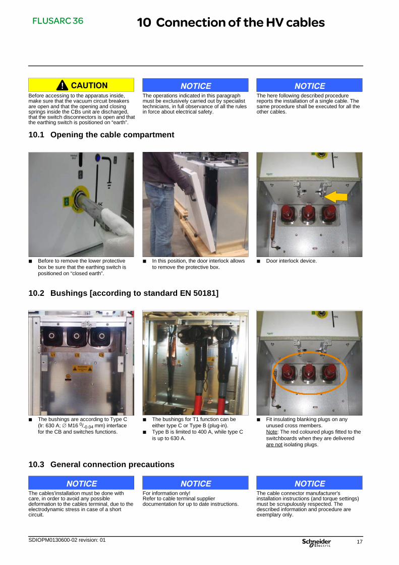
10.1 Opening the cable compartment
J Before to remove the lower protectivebox be sure that the earthing switch ispositioned on “closed earth”.
J In this position, the door interlock allowsto remove the protective box.
J Door interlock device.
10.2 Bushings [according to standard EN 50181]
J The bushings are according to Type C(lr: 630 A; M16 0/-0.04 mm) interfacefor the CB and switches functions.
J The bushings for T1 function can beeither type C or Type B (plug-in).
J Type B is limited to 400 A, while type Cis up to 630 A.
J Fit insulating blanking plugs on anyunused cross members.Note: The red coloured plugs fitted to theswitchboards when they are deliveredare not isolating plugs.
10.3 General connection precautions
NOTICEThe cables'installation must be done withcare, in order to avoid any possibledeformation to the cables terminal, due to theelectrodynamic stress in case of a shortcircuit.
NOTICEFor information only!Refer to cable terminal supplierdocumentation for up to date instructions.
NOTICEThe cable connector manufacturer'sinstallation instructions (and torque settings)must be scrupulously respected. Thedescribed information and procedure areexemplary only.
10 Connection of the HV cables

FLUSARC 36
18 SDIOPM0130600-02 revision: 01
10.4 Type C connection
NOTICEPlease refer to the connector manufacturer'sinstructions, especially regarding thetightening torque value.
Clean the separable connectors and crossmembers using a dry cloth.
Type C (630 A)
1 - Cross member - Male2 - Support plate3 - Screw contact
1
2 3
20 - 35 mmScrew thread depth
Single cable connector 630 A
Double cable connector 630 A
10.5 Passage of the cables
J Unscrew the fastening nuts of the baselocking the rubber conical fairleads.
J Remove both the nuts and the base. J Cut the rubber conical fairlead accordingto the cable diameter.

FLUSARC 36
SDIOPM0130600-02 revision: 01 19
J Insert the rubber conical fairlead on thecable and position it inside theswitchgear lower seat.
10.6 Connection of the cables
The insertion of the cable into the adapterterminal must be exclusively executed byqualified personnel, in order to avoid any riskof damaging the cable itself.
CAUTION J Clean and coat the bushing and theadapter with a uniform thin coat of silicongrease supplied in the delivery.
J Insert the cable into the adapter terminaland then position this last one on theswitchgear connexion bushing.
J Insert the cable into the clamp and lock itthere by tightening the screws.
J Grease the connecting pin with thesilicon grease supplied in the delivery ofthe connector.
J Insert the connecting pin into the adapterterminal and fully tighten it by using thepurposed spanner.
J Unscrew the screws of the fasteningclamp and open the clamp itself.
J Insert the cable into the clamp and lock itthere by tightening the screws.

FLUSARC 36
20 SDIOPM0130600-02 revision: 01
J Lubrificate the capacitive insulator withthe silicon grease supplied in thedelivery.
J Insert it into the adapter terminal andtighten the clamping screw.
J As an indicator, the maximumpermissible tightening torques are 40 Nmfor brass fasteners and 84 Nm for steelfasteners.N.B.: Check values also in connectormanufacturer instructions.
J After installing the capacitive insulatorconnect the screen of the wire.
J Connect to earth the cable shield throughthe bus bar predisposed in theswitchgear, by using for realizing thefastening a screw M8 with relevant nut,and flat and grover washers.
J Install the terminal cover on the terminaladapter.
J Position the base locking the rubberconical fairleads and fasten it by meansof the nuts.
J Install the protective box.

FLUSARC 36
SDIOPM0130600-02 revision: 01 21
11.1 Metering Units
M1 - Cable incoming and outgoing from bottom (CTs, VTs)M2 - Top left incoming, right bottom outgoing (CTs, VTs)M3 - Top right incoming, left bottom outgoing (CTs, VTs)M4 - Top right incoming, top left outgoing (CTs, VTs)M5 - Top right incoming (VTs)
There are 5 types of metering panels in Flusarc36 range. This chapter describes, as example,the installation of M3 and M5. The installationof other panels is identical.
NOTICE
Designation M1 M2 M3 M4 M5
Single line diagrams
11.2 Handling and Unpacking
Please refer to chapter 5.
11.3 Fixing to the floor
Please refer to chapter 6.
n.4 14
50 50
5050
B2
800
1100
11.4 Ground bar connection
Please refer to chapter 8.2.
11 Metering panels installation
FLUSARC 36
22 SDIOPM0130600-02 revision: 01
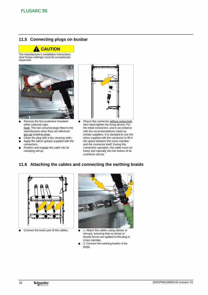
11.5 Connecting plugs on busbar
CAUTIONThe manufacturer's installation instructions(and torque settings) must be scrupulouslyrespected.
J Remove the first protective insulatedwhite coloured caps.Note: The red coloured plugs fitted to theswitchboards when they are deliveredare not isolating plugs.
J Clean the plug with a dry cleaning cloth.J Apply the silicon grease supplied with the
connectors.J Position and engage the cable into its
clamping stirrup.
J Plug in the connector without using toolsthen hand-tighten the fixing device. Forthe initial connection, and in accordancewith the recommendations made bycertain suppliers, it is standard to use thewires supplied with the connector to fill inthe space between the cross memberand the connector itself. During thisconnection operation, the cable must runfreely and naturally into the bottom of itsconnector stirrup.
11.6 Attaching the cables and connecting the earthing braids
J Connect the lower part of the cables. J 1. Attach the cables using clamps orstirrups, ensuring that no stress ortensile forces are applied to the plug-incross member.
J 2. Connect the earthing braids of theplugs.
12

FLUSARC 36
SDIOPM0130600-02 revision: 01 23
12.1 Dimensions (mm) of the fuses – in accordance with standards IEC60282-1 andIEC62271-105
33 33Ø 88 max.
striker pin
442
Ø 45
12.2 Selection table for fuses
NOTICEThe table below is for information only. Fusesize must be selected according to powertransformer indication and service conditions.
Rated voltage
(kV)
Power of the transformer (kVA)
100 125 160 200 250 315 400 500 630 800 1000 1250 1600 2000
Uk = 4% Uk = 5% Uk = 6%
Rated current of high voltage fuse link (A)
6 / 7.2 20 25 32 40 50 63 80 100 125 160 200 - - -
10 / 12 16 16 20 25 32 40 580 63 80 100100125 - - -
16 / 17.5 10 10 16 16 20 25 32 40 50 63 80 - - -
20 / 24 10 10 16 16 16 25 25 32 40 63 63 - - -
30 / 36 6,3 10 10 16 16 20 25 25 32 40 40 50 63 -
12.3 Fitting a fuse [earthing switch closed]
CAUTIONWhenever changing or fitting a fuse, close thecompartment immediately afterwards to avoidletting dust and humidity enter.
12 Fitting the HV fuses

FLUSARC 36
24 SDIOPM0130600-02 revision: 01
J Ensure that the function's earthing switchis closed.
J Act on the interlock of the door, byshifting it rightwards.
J After unlocking the fuse compartmentdoor handle by the key, rotate the handleitself counterclockwise.
J Fully open the fuses compartment door,in order to restore, if necessary, thecorrect position of the rod placed on thefuses compartment door.
J Apply the lever to the fuseholder coverand screw into the two holespredisposed on the cover the two finnedscrews.
J Turn the lever counterclockwise for afourth of a revolution.
J Extract the cover.
J Insert the fuse from the striker side onthe cover, by paying attention that thefuse base gets into the spring acting asan interlock.
J The figure shows the correct positioningof the cover interlock.
NOYES
Cover
InterlockInterlock
J From the fuse opposite side, insert thecentering disc.
DANGERDo not force interlocks to put in service theUnits without fuses inserted.

FLUSARC 36
SDIOPM0130600-02 revision: 01 25
For fuses having a limited length, mount onthe striker opposite side the extension, pushit up to the end of stroke and tighten theclamp.
NOTICE
Centering discClamp Striker
J Insert the cover with the fuse. J Turn the lever clockwise and lock thecover.
J Unscrew the wing screws and removethe lever from the cover.
J Close the fuse compartment door byrotating the handle clockwise andsuccessively locking it by the key.
Processing fuse packaging
NOTICEThe packaging is to be disposed of viaGeneral Industrial Waste recycling channels.
NOTICEIf a fuse blows, it is recommended to replaceall three.

FLUSARC 36
26 SDIOPM0130600-02 revision: 01
13.1 Reminder
Prior to dispatch, Flusarc 36 switchgears aremechanically and electrically tested.
Also check the leaktightness of the room, thecable troughs, ventilation, etc.
13.2 Carry out an inventory of all tools and accessories on completion of the work
Recover, verify and tidy away all assemblytools and objects not required in theswitchboard.
Store away, in their respective location, theoperating accessories for the switchboard.
Attach the Flusarc technical manual in avisible location within the room.
13.3 Pre-commissioning information
Respect the General Safety Instructionsbooklet for Electrical Applications and theparticular regulations for the networkconcerned with regard to locking-outprocedures.
Check and record the serial numbers andidentifying marks on equipment andswitchgear while they are accessible.
Refer to the drawings and diagrams suppliedwith the equipment. They describe thefunctionalities employed to carry out the levelof operation required.
13.4 Principle pre-commissioning checks
Visual inspections Date Remarks Signature
- Ensure there are no foreign bodies inside the switchboard- Check the external appearance (no signs of blows, scratches on the paintwork)
-- > carry out touch-up repairs if needed- Check the conformity with the Protection Index (leaktightness of the FunctionalUnits, various blanking panels, etc.)
- Ensure that the insulating blanking plugs are fitted on extendable switchboards
Tightening torque verifications Date Remarks Signature
- Inspection of mechanical tightening torques, (assemblies, electrical connections,earthing circuits, cables, etc.)
Operational verifications Date Remarks Signature
- Repeat a couple of operations to check the functioning of the system for the circuitbreaker and the earthing switch- Verify, after each operation, the status of the position indicator
13.5 Energizing the Flusarc 36 switchgears
CAUTIONBefore commissioning, the load-breakswitches, circuit breakers, disconnectors andearthing switch must all be `open'.
When the switchboard incoming feeders areenergise the voltage present indicatorsshould flash or come on (depending on theequipment).
13.6 VPIS (Voltage Present Indicating System)
The VPIS unit is an integrated voltagedetection system in accordance withIEC61958. Used to indicate that a voltage ispresent across the cables.
CAUTIONThis equipment cannot be used to check foran absence of voltage.
13 Commissioning

FLUSARC 36
SDIOPM0130600-02 revision: 01 27
Voltage Present Indications verifications with a standard unit
J Standard Voltage Presence Indicator(Elen).
J Phase concordance can be verified witha specific phase comparator.
J Check the comparator between 2 phasesof a voltage present indicator light: Thelamp should light up.
Check phase concordance
J Connect the now verified comparatorbetween the L3 phases on the twoswitchboard incoming feeder functions.
J Phases balanced:The lamp on the unit is extinguished.
J Phases out of sequence:The lamp on the unit is lit.
J Repeat operation for L1 and L2.
13.7 Energizing the switchboard
Close the breaking devices on the `Incomingfeeder' functions.Close the load-break switch on the`Transformer outgoing feeder' function.See the specific instructions given in theappropriate manual.

FLUSARC 36
28 SDIOPM0130600-02 revision: 01
NOTICEFor information only!Refer to specific order electrical diagram forcorrect and up to date wirings.
14.1 Legend of wiring diagrams
0 M Motor
0 89 .. Switch disconnector auxiliary contacts
0 89T.. Earthing switch contacts
0 PO Local opening luminous push button
0 PC Local closing luminous push button
0 RA Opening relay
0 RC Closing relay
0 KT Electronic timer excitation delayed
0 Y Antipumping relay
0 75.L Electrical interlock when handle is inserted in switchdisconnector manual mechanism
0 75.B Electrical interlock when handle is inserted inearthing switch manual mechanism
0 Diode 1N4007
0 Varistor zinc oxide
0 Terminal printed circuit board
0 Terminal -type Phoenix
14.2 Single diagram of the C Unit with motorization kit [See legend § 14.1]
The diagram indicates the following conditions:Switch disconnector and Earthing switch opened
Flair 21D Flair 21D
14 Wiring diagrams for C Function

FLUSARC 36
SDIOPM0130600-02 revision: 01 29
14.3 Standard diagram for manual mechanism [See legend § 14.1]
Terminal box
The diagram indicates the following conditions:Switch disconnector and Earthing switch opened
14.4 Terminal (X1) [See legend § 14.1]
Terminal box
The diagram indicates the following conditions:Switch disconnector and Earthing switch opened

FLUSARC 36
30 SDIOPM0130600-02 revision: 01
14.5 Standard diagram for motorised mechanism (24VDC) [See legend § 14.1]
Terminal box: See § 14.9
The diagram indicates the following conditions:Switch disconnector and Earthing switch opened
CONTROL CARD940006044

FLUSARC 36
SDIOPM0130600-02 revision: 01 31
14.6 Standard diagram for motorised mechanism (48VDC) [See legend § 14.1]
Terminal box: See § 14.9
The diagram indicates the following conditions:Switch disconnector and Earthing switch opened
CONTROL CARD940006025

FLUSARC 36
32 SDIOPM0130600-02 revision: 01
14.7 Standard diagram for motorised mechanism (110VDC) [See legend § 14.1]
Terminal box: See § 14.9
The diagram indicates the following conditions:Switch disconnector and Earthing switch opened
CONTROL CARD940006026

FLUSARC 36
SDIOPM0130600-02 revision: 01 33
14.8 Standard diagram for motorised mechanism (230VAC) [See legend § 14.1]
Terminal box: See § 14.9
The diagram indicates the following conditions:Switch disconnector and Earthing switch opened
CONTROL CARD940006045

FLUSARC 36
34 SDIOPM0130600-02 revision: 01
14.9 Terminal box
For 24VDC
+ F2
- F1
For 48VDC
+ F2
- F1

FLUSARC 36
SDIOPM0130600-02 revision: 01 35
For 110VDC
For 230VAC

FLUSARC 36
36 SDIOPM0130600-02 revision: 01
NOTICEFor information only!Refer to specific order electrical diagram forcorrect and up to date wirings.
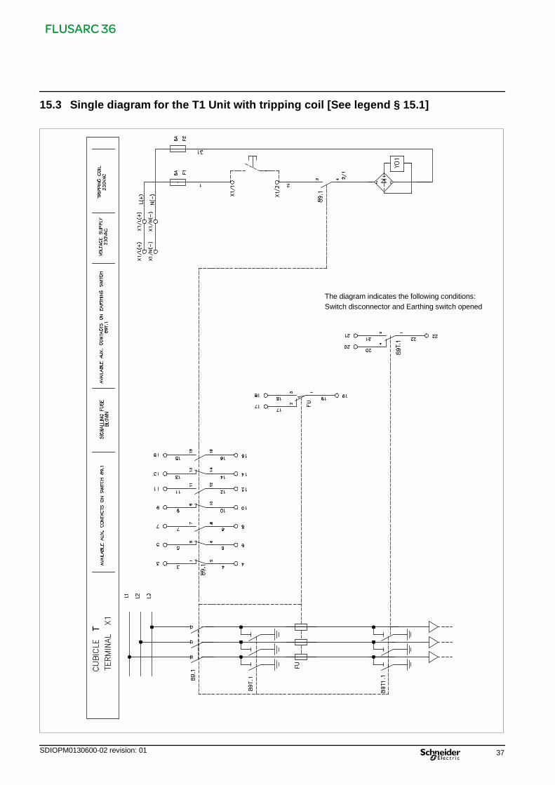
15.1 Legend of wiring diagrams
0 89.1 Switch disconnector auxiliary contacts
0 89T.1 Earthing switch contacts
0 FU Fuse blown contact
0 L1; L2 LV fuses
0 Y01 Tripping relay
15.2 Single diagram for the T1 Unit [See legend § 15.1]
The diagram indicates the following conditions:Switch disconnector and Earthing switch opened
15 Wiring diagrams for T1 Function
FLUSARC 36
SDIOPM0130600-02 revision: 01 37
15.3 Single diagram for the T1 Unit with tripping coil [See legend § 15.1]
The diagram indicates the following conditions:Switch disconnector and Earthing switch opened

FLUSARC 36
38 SDIOPM0130600-02 revision: 01
NOTICEFor information only!Refer to specific order electrical diagram forcorrect and up to date wirings.
16.1 Legend of wiring diagrams
0 M Motor
0 89 .. Switch disconnector auxiliary contacts
0 89T.. Earthing switch contacts
0 PO Local opening luminous push button
0 PC Local closing luminous push button
0 RA Opening relay
0 RC Closing relay
0 KT Electronic timer excitation delayed
0 Y Antipumping relay
0 75.L Electrical interlock when handle is inserted in switchdisconnector manual mechanism
0 75.B Electrical interlock when handle is inserted inearthing switch manual mechanism
0 Diode 1N4007
0 Varistor zinc oxide
0 Terminal printed circuit board
0 Terminal -type Phoenix
16.2 Single diagram of the CB Unit with self supplied relay [See legend § 16.1]
The diagram indicates the following conditions:Switch disconnector and Earthing switch opened
(*)
whe
nm
otor
ized(*
)
16 Wiring diagrams for CB Function

FLUSARC 36
SDIOPM0130600-02 revision: 01 39
16.3 Standard diagram for CB unit auxiliary contacts [See legend § 16.1]
The diagram indicates the following conditions:Switch disconnector and Earthing switch opened

FLUSARC 36
40 SDIOPM0130600-02 revision: 01
16.4 Terminal box for CB Unit auxiliary contacts
Terminal XCB Cubicle CB
16.5 Terminal box for motorized CB Unit auxiliary contacts
Terminal XCB Cubicle CB

FLUSARC 36
SDIOPM0130600-02 revision: 01 41
16.6 Standard diagram for motorized CB unit [See legend § 16.1]
The diagram indicates the following conditions:Switch disconnector and Earthing switch opened

FLUSARC 36
42 SDIOPM0130600-02 revision: 01
16.7 Standard diagram for motorized CB unit auxiliary contacts [See legend § 16.1]
The diagram indicates the following conditions:Switch disconnector and Earthing switch opened

FLUSARC 36
SDIOPM0130600-02 revision: 01 43
17 Notes
If you have any comments on the use of this document or on the use of the equipment and services that are described in it, please sendus your remarks, suggestions and wishes to:
Schneider Electric Energy Manufacturing Italia S.r.l.Strada Comunale della Braglia, 1226862 Guardamiglio (Lodi) ITALY

Schneider Electric Energy France
35, rue Joseph Monier
CS 30323
F - 92506 Rueil-Malmaison Cedex
RCS Nanterre 511 746 356
Capital social 6 909 620 €
www.schneider-electric.com
SDIOPM0130600-02 revision: 01
As standards, specifications and designs change from time to time, please ask for confirmationof the information given in this publication.
Design: Schneider Electric
Photos: Schneider Electric
11-2014
E20
14S
chne
ider
Ele
ctric
-A
llrig
hts
rese
rved