Embed Size (px)
Citation preview

INSTITUT ZA RUDARSTVO I METALURGIJU BOR KOMITET ZA PODZEMNU EKSPLOATACIJU MINERALNIH SIROVINA
RUDARSKI RADOVI je časopis baziran na bogatoj tradiciji stručnog i naučnog rada u oblasti rudarstva, podzemne i površinske eksploatacije, pripreme mineralnih sirovina, geologije, mineralogije, petrologije, geomehanike i povezanih srodnih oblasti. Izlazi dva puta godišnje od 2001. godine.
Glavni i odgovorni urednik Dr Milenko Ljubojev naučni savetnik,
dopisni član IAS Institut za rudarstvo i metalurgiju Bor E-mail: [email protected]. 030/454-110
Zamenik glavnog i odgovornog urednika Dr Mirko Ivković, viši naučni saradnik Komitet za podzemnu eksploataciju mineralnih sirovina Resavica E-mail: [email protected] Tel. 035/625-566
Urednik Vesna Marjanović, dipl.inž.
Prevodilac Nevenka Vukašinović, prof.
Tehnički urednik Suzana Cvetković, teh.
Priprema za štampu Ljiljana Mesarec, teh.
Štamparija: Grafomedtrade Bor
Tiraž: 100 primeraka
Internet adresa www.mininginstitutebor.com
Izdavanje časopisa finansijski podržavaju Ministarstvo za nauku i tehnološki razvoj Republike Srbije Institut za rudarstvo i metalurgiju Bor Komitet za podzemnu eksploataciju mineralnih sirovina Resavica
ISSN 1451-0162 Indeksiranje časopisa u SCIndeksu i u ISI. Sva prava zadržana.
Izdavač
Institut za rudarstvo i metalurgiju Bor 19210 Bor, Zeleni bulevar 35 E-mail: [email protected]. 030/454-254
Uređivački odbor Prof. dr Živorad Milićević
Tehnički fakultet Bor Akademik Prof. dr Mladen Stjepanović
Tehnički fakultet Bor Prof. dr Vladimir Bodarenko
Nacionalni rudarski univerzitet, Odeljenje za podzemno rudarstvo, Ukrajina
Prof. dr Miroslav Ignjatović Institut za rudarstvo i metalurgiju Bor
Prof. dr Milivoj Vulić Univerzitet u Ljubljani, Slovenija
Prof. dr Jerzy Kicki Državni institut za mineralne sirovine i energiju, Krakov, Poljska
Prof. dr Tajduš Antoni Stanislavov univerzitet za rudarstvo i metalurgiju, Krakov, Poljska
Prof. Dr Dušan Gagić Rudarsko geološki fakultet Beograd
Prof. dr Nebojša Vidanović Rudarsko geološki fakultet Beograd
Prof. dr Neđo Đurić Tehnički institut, Bjeljina, Republika Srpska, BiH
Prof. dr Vitomir Milić Tehnički fakultet Bor
Prof. dr Rodoljub Stanojlović Tehnički fakultet Bor
Prof. dr Mevludin Avdić RGGF-Univerzitet u Tuzli, BiH
Prof. dr Nenad Vušović Tehnički fakultet Bor
Dr Miroslav R. Ignjatović, viši naučni saradnik Privredna komora Srbije
Dr Mile Bugarin, viši naučni saradnik Institut za rudarstvo i metalurgiju Bor
Dr Dragan Zlatanović Ministarstvo rudarstva i energetike Srbije
Dr Miodrag Denić Ugalj projekt Beograd
Dr Duško Đukanović, naučni saradnik Institut za ispitivanje materijala Beograd
Dr Ružica Lekovski, naučni saradnik Institut za rudarstvo i metalurgiju Bor
Dr Jovo Miljanović JP za podzemnu eksploataciju Resavica
Mr Zlatko Dragosavljević JP za podzemnu eksploataciju Resavica
VODEĆI ČASOPIS NACIONALNOG ZNAČAJA M51 ZA 2010.

MINING AND METALLURGY INSTITUTE BOR COMMITTEE OF UNDERGROUND EXPLOITATION OF THE MINERAL DEPOSITS
MINING ENGINEERING is a journal based on the rich tradition of expert and scientific work from the field of mining, underground and open-pit mining, mineral processing, geology, mineralogy, petrology, geomechanics, as well as related fields of science. Since 2001, published twice a year. Editor-in-chief
Ph.D. Milenko Ljubojev, Principal Reasearch Fellow, Associate member of ESC Mining and Metallurgy Institute Bor E-mail: [email protected]: +38130/454-110
Co-Editor Ph.D. Mirko Ivković, Senior Research Associate Committee of Underground Exploitation of the Mineral Deposits Resavica E-mail: [email protected] Phone: +38135/625-566
Editor Vesna Marjanović, B.Eng.
English Translation Nevenka Vukašinović
Technical Editor Suzana Cvetković
Preprinting Ljiljana Mesarec
Printed in: Grafomedtrade Bor
Circulation: 100 copies
Web site www.mininginstitutebor.com
MINING ENGINEERING is financially supported by
The Ministry of Science and Technological Development of the Republic Serbia Mining and Metallurgy Institute Bor Committee of Underground Exploitation of the Mineral Deposits Resavica
ISSN 1451-0162 Journal indexing in SCIndex and ISI. All rights reserved.
Published by Mining and Metallurgy Institute Bor 19210 Bor, Zeleni bulevar 35 E-mail: [email protected]: +38130/454-254
Editorial Board Prof.Ph.D. Živorad Milićević
Technical Faculty Bor Academic Prof.Ph.D. Mladen Stjepanović
Technical Faculty Bor Prof.Ph.D. Vladimir Bodarenko
National Mining University, Department of Deposit Mining, Ukraine
Prof.Ph.D. Miroslav Ignjatović Mining and Metallurgy Institute Bor
Prof.Ph.D. Milivoj Vulić University of Ljubljana, Slovenia
Prof.Ph.D. Jerzy Kicki Gospodarkl Surowcami Mineralnymi i Energia, Krakow, Poland
Prof.Ph.D. Tajduš Antoni The Stanislaw University of Mining and Metallurgy, Krakow, Poland
Prof.Ph.D. Dušan Gagić Faculty of Mining and Geology Belgrade
Prof.Ph.D. Nebojša Vidanović Faculty of Mining and Geology Belgrade
Prof.Ph.D. Neđo Đurić Technical Institute, Bjeljina, Republic Srpska, B&H
Prof.Ph.D. Vitomir Milić Technical Faculty Bor
Prof.Ph.D. Rodoljub Stanojlović Technical Faculty Bor
Prof.Ph.D. Mevludin Avdić MGCF-University of Tuzla, B&H
Prof.Ph.D. Nenad Vušović Technical Faculty Bor
Ph.D. Miroslav R. Ignjatović, Senior Research Associate Chamber of Commerce and Industry Serbia
Ph.D. Mile Bugarin, Senior Research Associate Mining and Metallurgy Institute Bor
Ph.D. Dragan Zlatanović Ministry of Mining and Energy of Republic Serbia
Ph.D. Miodrag Denić Coal Project Belgrade
Ph.D. Duško Djukanović, Research Associate Institute for Testing Materials Belgrade
Ph.D. Ružica Lekovski, Research Associate Mining and Metallurgy Institute Bor
Ph.D. Jovo Miljanović PC for Underground Exploitation Resavica
M.Sc. Zlatko Dragosavljević PC for Underground Exploitation Resavica
LEADING NATIONAL JOURNAL CATEGORIZATION M51 FOR 2010.

SADR@AJ CONTENS
V. Marinković, M. Maksimović, M. Jovanović D. Kržanović IZRADA GEOMODELA LEŽIŠTA UGLJA (POTRLICA, CEMENTARA I DEO KALUŠIĆA) SA PRORAČUNOM REZERVI PROGRAMOM ZA MODELOVANJE LEŽIŠTA I PROJEKTOVANJE POVRŠINSKIH KOPOVA MINEX 5.2.3. ...........................................................................................................1
GEOMODEL DEVELOPMENT OF COAL DEPOSITS (POTRLICA, CEMENTARA AND A PART OF KALUSIC) WITH THE CALCULATION OF RESERVES USING THE PROGRAM OF DEPOSIT MODELLING AND DESIGN THE OPEN PITS MINEX 5.2.3. ............................9
M. Bugarin, G. Slavković, M. Maksimović VREDNOVANJE KORISNE SIROVINE ČOKA MARINA.............................................................................17
VALUATION OF RAW MINERAL FOR THE COKA MARIN DEPOSIT ....................................................23
D. Petrović, Z. Damnjanović, D. Djenadić, R. Pantović, V. Milić PRIMENA MODERNIH RAČUNARSKIH UREĐAJA I ALATA ZA SMANJENJE AKCIDENTNIH SITUACIJA U RUDARSKIM SISTEMIMA......................................................................................................29
USE OF MODERN COMPUTER EQUIPMENT AND TOOLS TO REDUCE THE OCCURRENCE OF ACCIDENTS IN THE MINING SISTEMS......................................................................35
Lj. Obradović, R. Rajković, D. Urošević, D. Milanović ODLAGANJE JALOVINE IZ SEPARACIJE KVARCA LEŽIŠTA ''KAONA'' KOD KUČEVA...................41
DEPOSITION OF TAILINGS FROM THE QUARTZ SEPARATION PLANT OF THE ''KAONA'' DEPOSIT NEAR KUČEVO .............................................................................................................47
S. Ćosić, H. Okanović MODELIRANJE NAPONSKO-DEFORMACIJSKOG STANJA NUMERIČKIM METODAMA KOD ŠIROKOČELNOG OTKOPAVANJA..............................................................................53
MODELING OF STRESS-DEFORMATION STATE USING THE NUMERICAL METHODS IN THE WIDE FACE MINING......................................................................................................73
Lj. Obradović, M. Bugarin, Z. Stevanović, M. Mikić, R. Lekovski PREGLED AKTUELNOG DOMAĆEG ZAKONODAVSTVA IZ OBLASTI UPRAVLJANJA I DEPONOVANJA OTPADA ..............................................................................................................................93
REVIEW OF CURRENT NATIONAL LEGISLATION IN THE FIELD OF WASTE MANAGEMENT AND DISPOSAL ....................................................................................................99
M. Ljubojev, D. Ignjatović, V. Ljubojev, L. Đurđevac Ignjatović, D. Rakić DEFORMABILNOST I NOSIVOST NASUTOG MATERIJALA U NEPOSREDNOJ BLIZINI OTVORA OKNA NA P. K. “ZAGRAĐE” – KOP – 2 .....................................................................107
DEFORMATION AND BEARING CAPACITY OF BURRIED MATERIAL NEAR THE SHAFT OPENING AT THE OPEN PIT MINE ”ZAGRADJE”-OPEN PIT 2 .......................................115
Lj. Obradović, M. Bugarin, Z. Stevanović, M. Ljubojev, Z. Milijić ODLAGANJE OPASNOG OTPADA NA DEPONIJE U SKLADU SA DIREKTIVOM EVROPSKE UNIJE O DEPONIJAMA BR. 1999/31/EU ................................................................................123
DISPOSAL OF HAZARDOUS WASTE ON THE LANDFILL IN ACCORDANCE WITH THE COUNCIL DIRECTIVE OF THE EUROPEAN UNION ON THE LANDFILL OF WASTE No. 1999/31/EC...................................................................................................................................133
R. Todorović, D. Urošević, Lj. Obradović, V. Gardić, Z. Stanojević Šimšić RECIKLAŽA OLOVNOG OTPADA ...............................................................................................................143
RECYCLING OF LEAD WASTE ....................................................................................................................149
R. Marković, Lj. Mladenović, M. Petrov, J. Stevanović UTICAJ MEHANO-HEMIJSKE AKTIVACIJE FLOTACIJSKE JALOVINE NA STEPEN IZDVAJANJA KORISNIH KOMPONENTI.........................................................155
EFFECT OF MECHANICAL-CHEMICAL ACTIVATION OF FLOTATION TAILINGS ON REMOVAL THE USEFUL COMPONENTS.................................................161
R. Marković, M. Bugarin, R. Jonović, Lj. Avramović, Z. Stevanović, Lj. Obradović, R. Stevanović IZDVAJANJE BAKRA KOMBINOVANIM TRETMANOM KOPOVSKE RASKRIVKE KISELIM RUDNIČKIM VODAMA SA LOKACIJE RUDNIKA "CEROVO" I DOBIJANJE SOLI BAKAR-SULFAT PENTAHIDRATA ...................................................................................................167
COPPER REMOVAL USING THE COMBINED TREATMENT OF OVERBURDEN BY THE ACID MINE WATER FROM THE ABANDONED COPPER MINE "CEROVO" AND OBTAINING THE COPPER-SULPHATE PENTAHYDRATE............................................................171

INSTITUT ZA RUDARSTVO I METALURGIJU BOR YU ISSN: 1451-0162 KOMITET ZA PODZEMNU EKSPLOATACIJU MINERALNIH SIROVINA UDK: 622
UDK: 553.94:681.51(045)=861
Vladan Marinković*, Miroslava Maksimović*, Milenko Jovanović*, Daniel Kržanović*
IZRADA GEOMODELA LEŽIŠTA UGLJA (POTRLICA, CEMENTARA I DEO KALUŠIĆA) SA PRORAČUNOM REZERVI
PROGRAMOM ZA MODELOVANJE LEŽIŠTA I PROJEKTOVANJE POVRŠINSKIH KOPOVA MINEX 5.2.3.
Izvod
U ovom radu je opisan način izrade 3D geološkog modela ležišta uglja Potrlica, Cementara i deo Kalušića Pljevaljskog ugljonosnog basena.
Ležište uglja Potrlica, Cementara i deo Kalušića je istraživano vertikalnim istražnim bušoti-nama sa površine terena, čime su utvrđeni geološka građa, oblik ležišta i moćnost ugljenih slo-jeva.
Za izradu geološkog modela izabran je programski paket Minex 5.2.3. koji je posebno diza-jniran za modelovanje slojevitih ležišta i projektovanje površinskih kopova.
Cilj izrade geološkog modela je bio dobijanje digitalnog 3D modela koji bi verno i precizno reprezentovao ležište u celini.
Prednost modela izrađenog na ovakav način se ogleda pre svega u mogućnosti sagledavanja prostorne pozicije ležišta, brzog proračuna geoloških rezervi, kao i dobijanje podataka o kvalita-tivnim karakteristikama uglja kako za celo ležište tako i za pojedine njegove delove.
Ovako izrađen digitalni 3D model predstavlja osnovu za projektovanje rudarskih radova. Ključne reči: 3D model, geološki model, sloj, proračun rezervi, Minex 5.2.3.
* Institut za rudarstvo i metalurgiju Bor, Srbija
UVOD
Pljevaljski ugljonosni basen se nalazi na krajnjem severu Crne Gore, neposredno uz grad Pljevlju sa njegove južne strane, u kotlini u kojoj se dolina reke Ćehotine u svom središnjem toku najviše širi. Ukupan neogeni kompleks u pljevaljskoj kotlini zauzima površinu od oko 18 km2, od čega Pljevaljski basen zahvata oko 12 km2.
Ležište “Potrlica” zahvata severne, severozapadne i istočne, centralne i južne
delove basena a lokalitet “Cementara” vezan je za to ležište sa severozapadne strane. Lokalitet “Kalušić” je vezan za lokalitet “Potrlicu” sa zapadne strane.
Pljevaljska kotlina, u morfološkom smislu, predstavlja paleokarstnu depresiju u srednjem toku rijeke Ćehotine sa proseč-nom nadmorskom visinom od 750 m. De-presija je ispunjena ugljonosnim miocen-skim sedimentima jezerskog tipa taloženja.
Broj 2,2010. RUDARSKI RADOVI
1

Obodni krečnjački tereni strmo se izdižu iznad kotline.
Tok izrade 3D geološkog modela
Obrada ležišta započeta je unosom po-dataka iz nekoliko datoteka (Excel) o is-tražnim bušotinama.
Datoteke sadrže za svaku bušotinu: ime bušotine, podatke o koti, koordinatama, podatke o litološkim članovima u ge-ološkim stubovima bušotina (koji su rele-vantni za procenu pozicije slojeva u izdvo-jenim geološkim sredinama), kao i podatke
o rezultatima hemijskih analiza pojedinač-nih i kompozitnih proba. U tabeli 1 su pri-kazani parametri kvaliteta koji su uzeti u obzir kao i imena i sufiksi pod koima su uneti u program.
Izvedeno je devet (9) istražnih bušot-ina, dubine 8,0 – 12,0 m, na kojima su provedeni opiti SPT-a, uzeti poremećeni i neporemećeni uzorci tla, registrovani nivoi podzemnih voda i ugrađeni piezometri za praćenje oscilacija tokom vremena. Pros-torni položaj istražnih bušotina je po pro-filima upravnim na riječni tok, slika 1.
Tabela 1. Osnovni podaci o parametrima kvaliteta Parametar kvaliteta Ime Grid sufix
Vlaga VLAGA WU Sumpor ispariv SUMPOR-P SP Sumor sagoriv SUMPOR-S SS
Sumpor ukupan SUMPOR-U SU Pepeo PEPEO P Koks KOKS KO
Ugljenik C-FIX CF Gornja toplotna moć GTE GTE Donja toplotna moć DTE DTE
Pre početka izrade 3D modela ležišta
uglja (Potrlica, Cementara i deo Kalušića), bilo je potrebno formirati bazu podataka na osnovu koje bi se pristupilo izradi modela. Do svih potrebnih podataka se došlo u procesu istražnog bušenja, kao i izvršenih laboratorijskih analiza (prostorni položaj svake bušotine definisan X, Y, Z koordina-tom, konačna dubina svake bušotine, li-tološki članovi određeni u procesu kartiranja jezgra bušotine i podaci o kvalitetu dobijeni laboratorijskim analizama).
Baza podataka se sastoji iz 4 osnovna faila:
• Collars cls. Fail – sadrži sve podatke o prostornom položaju bušotina;
• Quality cls. Fail – sadrži sve podatke vezane za kvalitet;
• Lithology cls. Fail – sadrži sve po-datke vezane za litologiju;
• Seam prn. Fail – sadrži podatke o položaju slojeva uglja i jalovih stena, u stubu svake od bušotina.
Za zapreminsku masu uglja usvojena je srednja vrednost, koja iznosi 1,36 t/m³ (podatak preuzet iz Elaborata o rudnim rezervama za ležišta Potrlica i Cementara).
Ležište uglja (Potrlica, Cementara i deo Kalušića) je predstavljeno slojevima nepra-vilnog oblika. Ležište je izgrađeno od četiri ugljena sloja između kojih senalaze slojevi i proslojci jalovih stena, tako da je zbog toga svaki od ovih slojeva i proslojaka, bilo uglja ili jalovine modelovan kao zaseban sloj (tabela 2.)
Broj 2,2010. RUDARSKI RADOVI
2

Takođe su uneti podaci o topografiji terena. Podaci o topografiji preuzeti su od Geodetske službe Rudnika uglja Pljevlja.
Digitalizacija je izvršena programskim paketom AutoCAD (slika 1).
Tabela 2. Osnovni podaci o slojevima Ime sloja Minex seam name
Površinski pokrivač PP Krovinski laporci (različiti varieteti) KRO1
Krovinski ugljeni sloj U1 Krovinski laporci (različiti varieteti) KRO2
Glavni ugljeni sloj U2a Međuslojna jalovina (gline) MJ
Glavni ugljeni sloj U2b Podinske gline (različiti varieteti) POD1
Prvi podinski ugljeni sloj U3 Podinske gline (različiti varieteti) POD2
Drugi podinski ugljeni sloj U4 Podinske gline (različiti varieteti) POD3 Paleoreljef (krečnjačka osnova) KR
Slika 1. 3D prikaz topografije (programskim paketom MINEX 5.2.3.).
Po unosu osnovnih podataka o bušoti-
nama i topografiji u 3D vrši se vizualni pregled odnosa bušotina i površine terena (slika 2.).
Broj 2,2010. RUDARSKI RADOVI
3

Slika 2. 3D prikaz odnosa topografije i bušotina
(programskim paketom MINEX 5.2.3.) U program su pored topografije unete i
konture ugljenih slojeva odnosno njihove geološke granice, u vidu poligonih linija
digitalizovanih programskim paketom AutoCAD (tabela 3.)
Tabela 3. Osnovni podaci o poligonim linijama u modelu GRUP MAP Objašnjenje TOPO MAPA Topografija
KROVINSKI CEMENTARA Kontura krovinskog ugljenog sloja na prostoru Cementare KROVINSKI KALUŠIĆ Kontura krovinskog ugljenog sloja na prostoru Kalušića
GLAVNI KOMPLET Objedinjene granice za ležišta Cementara, Potrlica i deo Kalušića
PRVI POD 1 Konture prvog podinskog ugljenog sloja PRVI POD 2 Konture prvog podinskog ugljenog sloja PRVI POD 3 Konture prvog podinskog ugljenog sloja
DRUGI POD DI Kontura drugog podinskog ugljenog sloja DRUGI POD DII Kontura drugog podinskog ugljenog sloja DRUGI POD DIII Kontura drugog podinskog ugljenog sloja
Potrebno je napomenuti da je glavni ugljeni sloj zbog prisustva jalovih proslo-jaka u sebi, modelovan metodom deobe sloja. Pri čemu je ovaj sloj podeljen na pod slojeve U2a i U2b.
Svi ostali slojevi su modelovani pri-menom opšteg metoda modelovanja.
U procesu interpolacije nedostajućih slojeva korišćeni su podaci iz minimalno 3 a maksimalno 4 susedne bušotine, dok je radius pretrage ograničen na 700 m.
Nakon kreiranja ovih slojeva, pristupilo se njihovoj međusobnoj prostornoj ko-relaciji i izradi 3D modela ležišta. Na tako
Broj 2,2010. RUDARSKI RADOVI
4

kreiranom modelu ležišta bilo je moguće proračunati geološke rezerve, kako za svaki sloj ponaosob, tako i za ležište u celosti.
Proračun rezervi programskim pake-tom MINEX 5.2.3., vrši se metodom trou-glova na osnovu poznatih formula.
Površina trouglova je:
2haPx
×=
a - osnovica trougla (m2), h - visina trougla (m). Srednja debljina sloja:
nllll n
sr)...( 21 +++
=
nlll ,.., 21 - debljina ugljenog sloja u istražnom radu (m).
Količina uglja unutar trougla:
dlPQ srx ××=
xP - površina trouglova (m2), lsr - srednja debljina ugljenog sloja u is-
tražnom radu (m), d - zapreminska masa uglja (t/m3).
Trouglovi potrebni za proračun rezervi, dobijaju se na osnovu gridova (mreža) predhodno modeliranih slojeva, pri čemu program svakoj ćeliji kvadratne mreže (sl. 3), dodeljuje dijagonalu tako da od ćelije kvadratnog oblika nastaju dva pravougla trougla (sl. 4).
Slika 3. Grid (mreža) predhodno modeliranog sloja
Slika 4. Grid (mreža) predhodno modeliranog sloja sa dijagonalama
Broj 2,2010. RUDARSKI RADOVI
5

Sve ostale podatke potrebne za pro-račun rezervi program preuzima iz pred-hodno kreiranih baza podataka.
Izgled slojeva u 3D modelovanih pro-gramskim paketom Minex 5.2.3. je prika-zan slikama 5 i 6.
Slika 5. 3D prikaz slojeva uglja sa topografijom programskim paketom MINEX 5.2.3
Legenda: (U1-prvi ugljeni sloj, U2a+U2b-glavni ugljeni sloj i U3-prvi podinski ugljeni sloj).
Slika 6. 3D prikaz slojeva uglja sa topografijom programskim paketom MINEX 5.2.3. (presek).
Legenda: (U2a+U2b-glavni ugljeni sloj, U3-prvi podinski ugljeni sloj i U4-drugi podinski ugljeni sloj).
Broj 2,2010. RUDARSKI RADOVI
6

Rezultati proračuna rezervi, prikazani su u tabeli 4, kao i na slici 7. (izvorni iz-
veštaj tabelarnog prikaza proračuna rezervi programskim paketom MINEX 5.2.3.).
Tabela 4: Rezultati proračuna rezervi uglja programskim paketom Minex 5.2.3.
Slika 7: Prikaz izvornog izveštaja proračuna geoloških rezervi programskim paketom MINEX 5.2.3
ZAKLJUČAK
Prednost modela izrađenog na ovakav način se ogleda pre svega u mogućnosti sagledavanja prostorne pozicije ležišta, brzog proračuna geoloških rezervi, kao i dobijanje podataka o kvalitativnim kara
kteristikama uglja kako za celo ležište tako i za pojedine njegove delove. Ovako izrađen digitalni 3D model predstavlja osnovu za projektovanje rudarskih radova.
ZAPREMINA JALOVINE
(m3)
MOĆNOST JALOVIH SLOJEVA
(m)
KOLIĆINA UGLJA
(t)
MOĆNOST UGLJENIH SLOJEVA
(m)
287.735.443,00 96,9 54.402.280,00 18,37
Broj 2,2010. RUDARSKI RADOVI
7

LITERATURA
[1] Gomilanović J., Damjanović B., i Damjanović M. 2009.: Elaborat o klasifikaciji, kategorizaciji i proračunu rezervi uglja u ležištu „Potrlica“, lokalitet „Cementara“, Crna Gora.
[2] Gomilanović J. i Damjanović B. 2005.: Elaborat o klasifikaciji, kategorizaciji i proračunu rezervi uglja u ležištu „Potrlica“, Crna Gora.
[3] Dopunski rudarski projekat PK „Potrlica“-Pljevlja od 1989 do 2000 god., Crna Gora.
[4] Nikolić P. i Dimitrijević D. 1990.: Ugalj Jugoslavije, Srbija.
[5] Bugarin M. 2006.: Geologija Ugljeva, Srbija.
[6] Stajević B. 2000.: Projektovanje leži-
šta mineralnih sirovina, Srbija. [7] Marinković V., Rajković R., Kržanović
D., Pačkovski G., Mitić D., 2D and 3D models, similarity and diferences, časopis Bakar br. 1, 2009 god., str. 1-9
[8] Bošković Z., Cebasek V., Mitrović V., Stanić S., Cement sheath integrity control during well life, Technics Technologies Education Management, Vol. 5, br.3 2010, 450-454
[9] Cebasek V., Bošković Z., Gojković N., Mitrović V., Tangential stress in the in the casing – cement stone – formation system, Technics Technologies Education Management, Vol. 5, br.3 2010, 495-501
Broj 2,2010. RUDARSKI RADOVI
8

MINING AND METALLURGY INSTITUTE BOR YU ISSN: 1451-0162 COMMITTEE OF UNDERGROUND EXPLOITATION OF THE MINERAL DEPOSITS UDK: 622
UDK: 553.94:681.51(045)=20
Vladan Marinković*, Miroslava Maksimović*, Milenko Jovanović*, Daniel Kržanović*
GEOMODEL DEVELOPMENT OF COAL DEPOSITS (POTRLICA, CEMENTARA AND A PART OF KALUSIC) WITH THE CALCULA-
TION OF RESERVES USING THE PROGRAM OF DEPOSIT MODEL-LING AND DESIGN THE OPEN PITS MINEX 5.2.3.
Abstract
This paper gives a development method of 3D geological model of the coal deposits Potrlica, Cementara and a part of Kalusic within the Pljevlja Coal Basin.
The coal deposits Potrlica, Cementara and a part of Kalusic were explored by the vertical prospecting drill holes from the terrain surface, what defined the geological structure, deposit form and thickness of coal layers.
The program package Minex 5.2.3 was chosen for development of geological model that is spe-cially designed for modeling of layered deposits and design of open pits.
The aim of development the geological model was obtaining the digital 3D model that would credibly and accurately represent the deposit as a whole.
The advantage of developed model by this way is primarily reflected in a possibility of recog-nizing the spatial position of deposits, fast calculation of geological reserves as well as obtaining the data on qualitative characteristics of coal both for the whole deposit and some parts of it.
Such developed 3D model presents the base for design the mining works. Key words: 3D model, geological model, layer, calculation of reserves, Minex 5.2.3.
* Mining and Metallurgy Institute Bor, Serbia
INTRODUCTION
The Pljevlja Coal Basin is located in the far north of Montenegro, near Pljevlja town on its southern side, in the ravine where the valley of the Cehotina River is the the most spreads in its middle course. Total Neogeni complex in the Pljevlja ravine covers an area of about 18 km2, out of which the Pljevlja Basin spreads at about 12 km2.
The Potrlica deposit overtakes the northern, northwestern and eastern, central and southern parts of the Basin, and the
Cementara locality is bound to this deposit on the northwest side. The Kalusic locality is bound to the Potrlica locality on the west side.
The Pljevlja ravine, in the morphologi-cal sense, presents the Paleokarst depres-sion in the middle course of the Cehotina River with an average altitude of 750 m. Depression is filled with carbonaceous Miocene sediments of lake-type sedimen-tation. Peripheral calcareous grounds are steeply raised above the ravine.
No 2, 2010. MINING ENGINEERING
9

The course of development the 3D geological model
Processing of deposits started by enter-ing the data from some files (Excel) on prospecting drillholes.
The files contain for each drillhole: drillhole name, data on level, coordinates, data on lithological members in geological columns of drillholes (which are relevant to
the evaluation of position the geological layers in isolated areas) as well as data on the results of chemical analyses of individ-ual and composite test. Table 1 shows the quality parameters taken into consideration as well as the names and suffixes under which they are included in the program.
Table 1. Basic data on quality parameters Quality parameters Name Grid suffix
Humidity HUMIDITY WU Sulfur evaporable SULFUR-P SP Sulfur combustible SULFUR-S SS
Sulfur total SULFUR-U SU Ash ASH P Coke COKE KO
Carbon C-FIX CF
Upper thermal power GTE GTE
Lower thermal power DTE DTE
Before doing the 3D model of coal de-posits (Potrlica, Cementara and a part of Kalusic), it was necessary to establish a data base from which would be the base for model development. The all necessary data were found in the process of pros-pecting drilling as well as performed labo-ratory analyses (spatial position of each drillhole defined by X, Y, Z coordinate, the final depth of each drillhole, lithologi-cal members determined in the mapping process of drillhole core and data on qual-ity obtained by laboratory analyses).
The database consists of 4 basic files: • Collars cls. File – contains all data
about the spatial position of drillholes; • Quality cls. File – contains all data
on quality;
• Lithology cls. File – contains all data on lithology;
• Seam prn. File - contains data on po-sition of coal layers and dead rocks in a pillar of each drillhole.
For mass volume of coal, the mean value of 1.36 t/m³ was adopted (data taken from the Project Study on ore reserves for the deposits Potrlica and Cementara).
The coal deposits (Potrlica, Cement and a part of Kalušić) is presented in lay-ers of irregular shape. Deposit is made of four coal layers between which are layers and interlayers of dead rocks, so that is why each of these layers and interlayers, either coal or overburden is modeled as a separate layer (Table 2).
No 2, 2010. MINING ENGINEERING
10

Table 2. Basic data on layers Layer name Minex seam name
Surface caprock PP Overlying marls (different varieties) KRO1
Overlaying coal layer U1 Overlying marls (different varieties) KRO2
Main coal layer U2a Interlayer waste (clay) MJ
Main coal layer U2b Underlying clays (different varieties) POD1
First underlying coal layer U3 Underlying clays (different varieties) POD2
Second underlying coal layer U4 Underlying clays (different varieties) POD3
Paleorelief (limestone base) KR Data on terrain topography were also
entered. Data on topography were taken from the Geodetic Services of the Coal
Mine Pljevlja. Digitization was carried out using the AutoCAD software package (Figure 1).
Figure 1. 3D review of topography (program package MINEX 5.2.3).
By entering basic data on drillholes
and topography in 3D, the visual examina tion is done of relation between drillhole and surface ground (Figure 2).
No 2, 2010. MINING ENGINEERING
11

Figure 2. 3D review of relation between topography and drillholes
(program package MINEX 5.2.3).
Beside topography, the contours of
coal layers and their geological boundaries were also entered into program in a
form of polygonal lines digitalized by the AutoCAD software package (Table 3).
Table 3. Basic data on polygonal lines in a model
GROUP MAP Explanation
TOPO MAP Topography
OVERLYING CEMENTARA Contours of overlaying coal layer on Cementara OVERLYING KALUSIC Contours of overlaying coal layer on part of Kalusic
MAIN COMPLETE Geological borders for coal deposits Cementara, Potrlica and part of Kalusic
FIRST UNDERLAYING 1 Contours of first underlying coal layer FIRST UNDERLAYING 2 Contours of first underplaying coal layer FIRST UNDERLAYING 3 Contours of first underlying coal layer
SECOND UNDERLAYING DI Contour of second underlying coal layer SECOND UNDERLAYING DII Contour of second underlying coal layer SECOND UNDERLAYING DIII Contour of second underlying coal layer
It should be noted that the main coal layer due to the presence of dead interlay-ers in itself, is modeled by the method of
layer division, where this layer is divided into the U2a and U2b and layers.
All other layers are modeled using the
No 2, 2010. MINING ENGINEERING
12

general method of modeling. In the process of interpolation of miss-
ing layers, the data were used in at least 3 characters and maximum of 4 adjacent drill holes, the radius of search is limited to 700 m.
After creating of these layers, their spatial correlation between them and cre-ating 3D model of deposit was carried out. On the created model of deposit, it was possible to calculate the geological re-serves, both for each layer separately, and for the entire deposit.
Calculation of reserves using the MINEX 5.2.3 software package is done using the triangles on the basis of known formulae.
Surface of triangles is:
2haPx
×=
a – triangle base (m2), h – triangle height (m).
Middle layer thickness:
nllll n
sr)...( 21 +++
=
nlll ,.., 21 - coal layer thickness in ex-ploratory work (m).
Coal quantity inside triangle:
dlPQ srx ××=
xP - surface of triangles (m2), lsr - coal layer thickness in exploratory
work (m), d - volume mass of coal(t/m3).
The required triangles for calculation of reserves are obtained based on the pre-viously modeled layers, in which program on each cell of square network (Figure 3), assign a diagonal such as two right-angled triangles (Figure 4) are formed from a square shaped cell.
Figure 3. Grid of pre-modeled layer
Figure 4. Grid of pre-modeled layer with diagonals.
No 2, 2010. MINING ENGINEERING
13

All other necessary data for calculation the reserves, the program takes from pre-created databases.
View of layers in 3D modeled using the software package Minex 5.2.3 is shown in Figures 5 and 6
Figure 5. 3D view of coal layers with topography using the
MINEX 5. 2 .3 software package Legend: (U1-first coal layer, U2a + U2b – main coal layer and U3-first underlaying coal layer).
Figure 6. 3D view of coal layers with topography using the
MINEX 5. 2. 3 software package. (Vertical section). Legend: (U2a + U2b- main coal layer, U3-first underlying coal layer and U4 - second underlying coal layer).
No 2, 2010. MINING ENGINEERING
14

The results of calculation the reserves are shown in Table 4, as in Figure 7 (origi-
nal report on calculation of reserves using the MINEX 5.2.3 software package).
Table 4. Results of calculation the reserves of coal using the Minex 5.2.3 software package.
Figure 7. View of original report on calculation the geological reserves using the software package MINEX 5. 2. 3.
CONCLUSION
The advantage of model produced in this way is primarily reflected in a possi-bility of viewing the spatial position of deposit, fast calculation of geological re-serves, as well as obtaining the data on
qualitative characteristics of coal to the whole deposit and some of its parts. Thus developed the digital 3D model is the base for designing the mining works.
WASTE VOLUME (m3)
THICKNESS OF WASTE LAYERS
(m)
COAL QUANTITY (t)
THICKNESS OF COAL LAYERS
(m)
287,735,443.00 96.9 54,402,280.00 18.37
No 2, 2010. MINING ENGINEERING
15

REFERENCES
[1] Gomilanović J., Damjanović B., and Damjanović M. 2009: Study on Classification, Categorization and Calculation of the Ore Reserves in the Deposit “Potrlica”, Locality “Cementara”, Montenegro (in Serbian)
[2] Gomilanović J. and Damjanović B. 2005: Study on Classification, Categorization and Calculation of the Ore Reserves in the Deposit “Potrlica”, Montenegro (in Serbian)
[3] Additional Mining Project of the Open Pit “Potrlica“-Pljevlja from 1989 to 2000, Montenegro (in Serbian)
[4] Nikolić P. and Dimitrijević D. 1990: Coal of Yugoslavia, Serbia (in Serbian)
[5] Bugarin M. 2006: Coal Geology, Serbia (in Serbian)
[6] Stajević B. 2000: Designing of
Mineral Deposits, Serbia (in Serbian) [7] Marinković V., Rajković R., Kržanović
D., Pačkovski G., Mitić D., 2D and 3D models, similarity and diferences, časopis Bakar br. 1, 2009 god., str. 1-9
[8] Bošković Z., Cebasek V., Mitrović V., Stanić S., Cement sheath integrity control during well life, Technics Technologies Education Management, Vol. 5, No.3 2010, 450-454
[9] Cebasek V., Bošković Z., Gojković N., Mitrović V., Tangential stress in the in the casing – cement stone – formation system, Technics Technologies Education Management, Vol. 5, No.3 2010, 495-501
No 2, 2010. MINING ENGINEERING
16

INSTITUT ZA RUDARSTVO I METALURGIJU BOR YU ISSN: 1451-0162 KOMITET ZA PODZEMNU EKSPLOATACIJU MINERALNIH SIROVINA UDK: 622
UDK: 622.3:330.1(045)=861
Mile Bugarin*, Gordana Slavković*, Miroslava Maksimović*
VREDNOVANJE KORISNE SIROVINE ČOKA MARINA
Izvod
Ovaj rad pokazuje određivanje vrednosti korisne sirovine ležišta Čoka Marin kao bitnog dela geološko-ekonomske ocene koja može biti:
1) Sa uzimanjem u obzir vremenskog faktora-dinamičko ocenjivanje, 2) Bez uzimanja u obzir vremenskog faktora –sintetički pokazatelji. Dakle, u ovom radu se pre svega utvrđuje vrednost korisne sirovine ležišta Čoka Marin na os-
novu varijante geološkog –rudarskog projektovanja i takva vrednost mineralne sirovine je jednom utvrđena za oba načina ekonomskog vrednovanja ležišta.
Ključne reči: vrednost, mineralna sirovina, prihod metala, ocena
* Institut za rudarstvo i metalurgiju
UVOD
Osnovna razlika između statičkog i di-namičkog pristupa je u tome što se kod statičkog pristupa izračunavaju sintetičkih pokazatelji tj. koriste se podaci koji se od-nose na prosečnu godinu poslovanja, dok se kod izračunavanja dinamičkih pokazatelja koriste podaci za više godina, pa i za celi vek, a koji se svode na godinu ocene (svođenje budućih efekata na današnji dan pomoću određene diskontne stope). Utvrđuje vrednost korisne sirovine ležišta Čoka Marin na osnovu varijante geološkog – rudarskog projektovanja je vrednost mineralne sirovine utveđena za oba načina ekonomskog vred-novanja ležišta.
1. Obračun vrednosti mineralne sirovine
Cena mineralne sirovine
Trenutni uslovi privređivanja u zemlji su veoma složeni i opterećeni su mnogobro-jnim problemima: tranzicija i svetska
ekonomska kriza.Na svetskom tržištu cena bakra je visoka od 7.400 USD po toni, 35.200 USD po kilogramu zlata i 547 USD po kilogramu srebra ( mart 2010.)
Perspektiva prerade, odnosno dobijanja bakra, zavisi od tržišnih uslova, odnosno ponude i potražnje. Na potražnju bakra a i zlata posebno deluju velike kupovine iz Azije (Kina i Indija). Svetska banka svo-jom najnovijom prognozom predviđa cene ovih metala od 2011- 2020god. i to:
• bakar 4.250 USD/t • zlato 25.000 USD/kg • srebro 400 USD/kg Troškovi metalurške prerade iznose : a) za bakar: - topljenje i rafinacija: ukupno 850
USD/t katode za početne dve godine, od treće godine (2013.god.) - 600 USD/t katode do kraja veka (nova topionica).
b) za zlato i srebro troškovi rafinacije po kg:
Broj 2,2010. RUDARSKI RADOVI
17

- zlato:1075 USD - srebro: 24 USD Metalurška iskorišenja iznose: - na bakru 93%(prve dve godine) i
97,5% od treće godine do kraja veka, - na zlatu 91%, - na srebru 85%
Vrednost proizvodnje obračunata je na bazi projektovanog kapaciteta proizvodnje i prognoziranih cena za bakar, zlato i srebro i varijante geološko rudarskih parametara. Obračun količina metala za vrednovanje-formiranje prihoda prikazan je u tabelama:
Tabela 1. Obračun količine katodnog bakra
Godina Cu u rud. flot.iskor. Cu t met. isk. Cu u t kg % koncentrat % za vrednovanje
1 309 98.0 303 93.0 281,51 2 309 98.0 303 93.0 281,51 3 309 98.0 303 97.5 295 4 309 98.0 303 97.5 295 5 309 98.0 303 97.5 295 6 309 98.0 303 97.5 295 7 309 98.0 303 97.5 295 8 309 98.0 303 97.5 295 9 309 98.0 303 97.5 295
10 309 98.0 303 97.5 295 3090 3030 2923
Tabela 2. Obračun količine zlata za vrednovanje
Godina Au u rud. flot.iskor. Au kg met. isk. Au u kg kg % koncentrat % za vrednovanje
1 90,4990 94.0 85 91 77,44 2 90,4990 94.0 85 91.0 77,44 3 90,4990 94.0 85 91.0 77,44 4 90,4990 94.0 85 91.0 77,44 5 90,4990 94.0 85 91.0 77,44 6 90,4990 94.0 85 91.0 77,44 7 90,4990 94.0 85 91.0 77,44 8 90,4990 94.0 85 91.0 77,44 9 90,4990 94.0 85 91.0 77,44
10 90,4990 94.0 85 91.0 77,44 904,9900 850 774,40
Broj 2,2010. RUDARSKI RADOVI
18

Tabela 3. Obračun količine srebra za vrednovanje Godina Ag u rud. flot.iskor. Ag kg met.isk. Ag u kg
kg % koncentrat % za vrednovanje 1 785 90.0 707 85.0 600,68 2 785 90.0 707 85.0 600,68 3 785 90.0 707 85.0 600,68 4 785 90.0 707 85.0 600,68 5 785 90.0 707 85.0 600,68 6 785 90.0 707 85.0 600,68 7 785 90.0 707 85.0 600,68 8 785 90.0 707 85.0 600,68 9 785 90.0 707 85.0 600,68
10 785 90.0 707 85.0 600,68 7.850 7070 6006,78
Tabela 4. Obračun vrednosti proizvodnje –prihoda po godinama
Količina cena prihod met.prerada neto prihod ** GODINA: 1 1 Cu 281.5132 4.2500 1,196.43 239.29 957.14 2 Au 77.4128 23.9250 1,852.10 0.00 1,852.10 3 Ag 600.6780 0.3760 225.85 0.00 225.85 ukupno 3,274.39 239.29 3,035.10 ** GODINA: 2 1 Cu 281.5132 4.2500 1,196.43 239.29 957.14 2 Au 77.4128 23.9250 1,852.10 0.00 1,852.10 3 Ag 600.6780 0.3760 225.85 0.00 225.85 ukupno 3,274.39 239.29 3,035.10 ** GODINA: 3 1 CU 295.1348 4.2500 1,254.32 177.08 1,077.24 2 Au 77.4128 23.9250 1,852.10 0.00 1,852.10 3 Ag 600.6780 0.3760 225.85 0.00 225.85 ukupno 3,332.28 177.08 3,155.20 ** GODINA: 4 1 CU 295.1348 4.2500 1,254.32 177.08 1,077.24 2 Au 77.4128 23.9250 1,852.10 0.00 1,852.10 3 Ag 600.6780 0.3760 225.85 0.00 225.85 ukupno 3,332.28 177.08 3,155.20 ** GODINA: 5 1 CU 295.1348 4.2500 1,254.32 177.08 1,077.24 2 Au 77.4128 23.9250 1,852.10 0.00 1,852.10 3 Ag 600.6780 0.3760 225.85 0.00 225.85 ukupno 3,332.28 177.08 3,155.20
Broj 2,2010. RUDARSKI RADOVI
19

** GODINA: 6 1 CU 295.1348 4.2500 1,254.32 177.08 1,077.24 2 Au 77.4128 23.9250 1,852.10 0.00 1,852.10 3 Ag 600.6780 0.3760 225.85 0.00 225.85 ukupno 3,332.28 177.08 3,155.20 ** GODINA: 7 1 Cu 295.1348 4.2500 1,254.32 177.08 1,077.24 2 Au 77.4128 23.9250 1,852.10 0.00 1,852.10 3 Ag 600.6780 0.3760 225.85 0.00 225.85 ukupno 3,332.28 177.08 3,155.20 ** GODINA: 8 1 Cu 295.1348 4.2500 1,254.32 177.08 1,077.24 2 Au 77.4128 23.9250 1,852.10 0.00 1,852.10 3 Ag 600.6780 0.3760 225.85 0.00 225.85 ukupno 3,332.28 177.08 3,155.20 ** GODINA: 9 1 Cu 295.1348 4.2500 1,254.32 177.08 1,077.24 2 Au 77.4128 23.9250 1,852.10 0.00 1,852.10 3 Ag 600.6780 0.3760 225.85 0.00 225.85 ukupno 3,332.28 177.08 3,155.20 ** GODINA: 10 1 Cu 295.1348 4.2500 1,254.32 177.08 1,077.24 2 Au 77.4128 23.9250 1,852.10 0.00 1,852.10 3 Ag 600.6780 0.3760 225.85 0.00 225.85 ukupno 3,332.28 177.08 3,155.20 UKUPNI PRIHOD 33,207.01 1,895.22 31,311.79
*Troškovi rafinacije za zlato i srebro obuhvaćeni su umanjenjem prodajnih cena za Au i Ag.
Grafik 1. Struktura prihoda po godinama
Broj 2,2010. RUDARSKI RADOVI
20
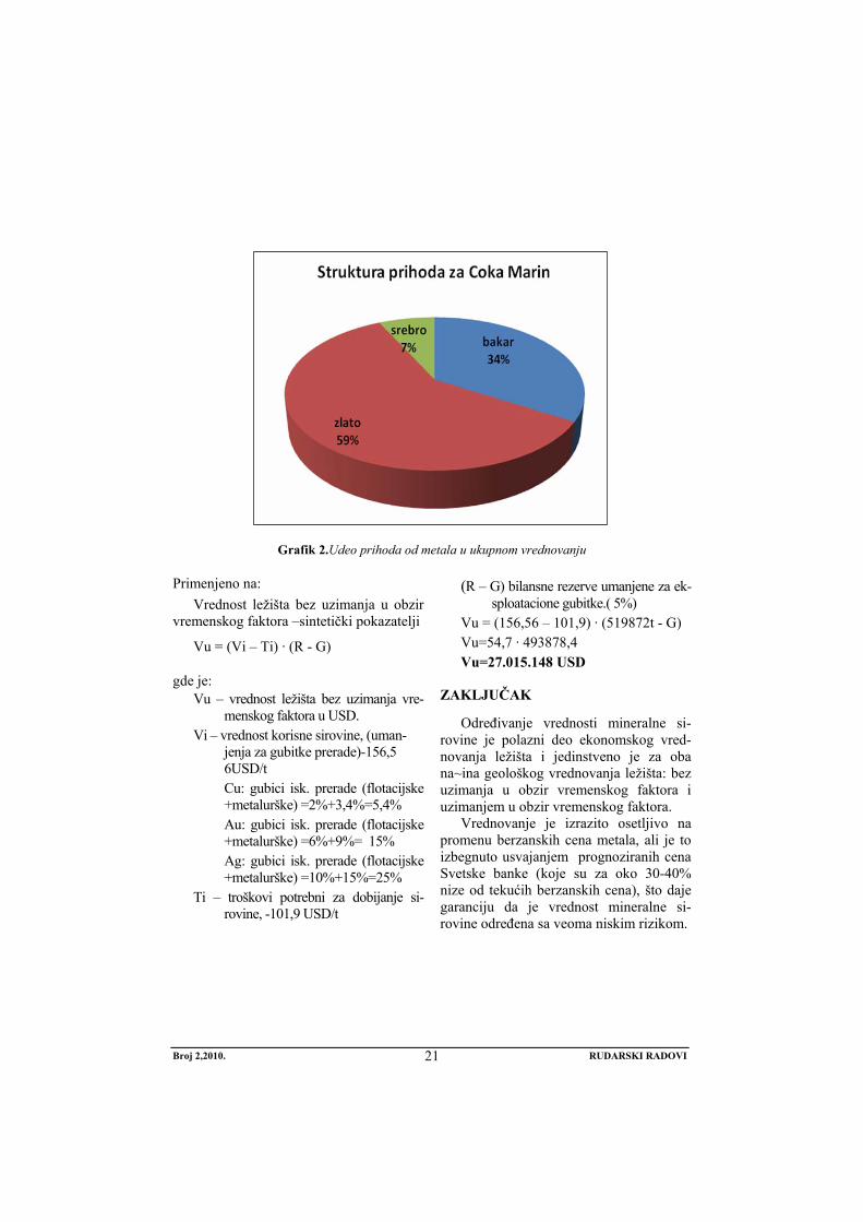
Grafik 2.Udeo prihoda od metala u ukupnom vrednovanju
Primenjeno na: Vrednost ležišta bez uzimanja u obzir
vremenskog faktora –sintetički pokazatelji
Vu = (Vi – Ti) · (R - G)
gde je: Vu – vrednost ležišta bez uzimanja vre-
menskog faktora u USD. Vi – vrednost korisne sirovine, (uman-
jenja za gubitke prerade)-156,5 6USD/t Cu: gubici isk. prerade (flotacijske +metalurške) =2%+3,4%=5,4% Au: gubici isk. prerade (flotacijske +metalurške) =6%+9%= 15% Ag: gubici isk. prerade (flotacijske +metalurške) =10%+15%=25%
Ti – troškovi potrebni za dobijanje si-rovine, -101,9 USD/t
(R – G) bilansne rezerve umanjene za ek-sploatacione gubitke.( 5%)
Vu = (156,56 – 101,9) · (519872t - G) Vu=54,7 · 493878,4 Vu=27.015.148 USD
ZAKLJUČAK
Određivanje vrednosti mineralne si-rovine je polazni deo ekonomskog vred-novanja ležišta i jedinstveno je za oba na~ina geološkog vrednovanja ležišta: bez uzimanja u obzir vremenskog faktora i uzimanjem u obzir vremenskog faktora.
Vrednovanje je izrazito osetljivo na promenu berzanskih cena metala, ali je to izbegnuto usvajanjem prognoziranih cena Svetske banke (koje su za oko 30-40% nize od tekućih berzanskih cena), što daje garanciju da je vrednost mineralne si-rovine određena sa veoma niskim rizikom.
Broj 2,2010. RUDARSKI RADOVI
21

LITERATURA:
[1] B. Cavender, Mineral Production Costs - Analyses and Management, SME, (1999).
[2] N. Dondur, Ekonomska analiza projekata, Mašinski fakultet, Beograd (2002).
[5] T. Kuronen: Capital Budgeting In A Capital-Intensive Industry, Helsinki University Of Technology, Mat-2.108 Independent research projects in applied mathematics, (2007).
[6] G. Slavković, „Prihod u finansijskoj analizi investicija u rudarstvu“, Inovacije i razvoj, br. 2, 2010. god. str. 25-32
[3] G.Mankju, Principi ekonomije, Ekonomski fakultet Beograd, (2005).
[4] M. Bugarin, G. Slavković "Tehnoeko-nomska ocena " Institut za bakar, Bor (2006).
Broj 2,2010. RUDARSKI RADOVI
22

MINING AND METALLURGY INSTITUTE BOR YU ISSN: 1451-0162 COMMITTEE OF UNDERGROUND EXPLOITATION OF THE MINERAL DEPOSITS UDK: 622
UDK: 622.3:330.1(045)=20
Mile Bugarin*, Gordana Slavkovic*, Miroslava Maksimovic*
VALUATION OF RAW MINERAL FOR THE COKA MARIN DEPOSIT
Abstract
This paper shows the determination of raw mineral for the Coka Marin deposit as an important part of geological-economical evaluation that could be:
1. with taking into account the time factor-the dynamic evaluation, 2. without taking into account the time factor-synthetic indicators. Therefore, in this paper, the raw mineral of the Coka Marin deposit is primarily de-
termined based on the variation of geological-mining design and such value of raw min-eral was once determined for both methods of economic valuation of deposit.
Key words: value, mineral, income of metals, evaluation
* Mining and Metallurgy Institute Bor
INTRODUCTION
The basic difference between the static and dynamic approach is that the static ap-proach calculates the synthetic indicators, i.e. the data relating to the average business year are used, while the data for several years and for the whole century are used in calculating the dynamic indicators and they are reduced to the year of evaluation (reduc-ing the future effects on today’s date using the certain discount rate). Determination the mineral value of the Coka Marin deposit, based on the variations of geological-mining design of the mineral value, was determined for both methods of economic evaluation of deposit.
1. Calculation of the mineral value Price of mineral raw
Current economic conditions in the country are very complex and burdened
with numerous problems: the transition and world economic crisis. On the world market, the price of copper is high of 7,400 USD per ton, gold is 35,200 USD per kilogram and silver 547 USD per kilo-gram (March 2010).
Perspective of copper treatment, that is copper production, depends on the market conditions or supply and demand. The demand for copper and gold are particu-larly under the influence of large pur-chases from Asia (China and India). The World Bank predicts, in its latest forecast, the prices of these metals from 2011-2020 as follows:
• copper 4.250 USD/t • gold 25.000 USD/kg • silver 400 USD/kg
Metallurgical treatment costs are: a) for copper
No 2,2010. MINING ENGINEERING
23

- smelting and refining: Total of 850 USD / t of cathode for the initial two years, and from the third year (2013) - 600 USD / t cathode by the end of the century (The New Smelter).
b) refining costs for gold and silver per kg are:
- gold: 1075 USD - silver: 24 USD
Metallurgical recoveries are:
- on gold 93% (the first two years) and 97.5% from the third year by the end of century,
- on gold 91%, - on silver 85% The value of production was calculated
based on the projected production capacity and the forecasted prices for copper, gold and silver, and geological variant of geo-logical-mining parameters. Calculation of the metal amount for evaluation - the in-come forming, is shown in tables:
Table 1. Calculation of cathode copper quantity for valuation year Cu in ore flot.used Cu t met.used Cu t
kg % concentrate % For valuation 1 309 98.0 303 93.0 281,51 2 309 98.0 303 93.0 281,51 3 309 98.0 303 97.5 295 4 309 98.0 303 97.5 295 5 309 98.0 303 97.5 295 6 309 98.0 303 97.5 295 7 309 98.0 303 97.5 295 8 309 98.0 303 97.5 295 9 309 98.0 303 97.5 295
10 309 98.0 303 97.5 295 3090 3030 2923
Table 2. Calculation of gold quantity for valuation year Au in ore flot.used Au kg met.used Au kg
kg % concentrate % For valuation 1 90,4990 94.0 85 91 77,44 2 90,4990 94.0 85 91.0 77,44 3 90,4990 94.0 85 91.0 77,44 4 90,4990 94.0 85 91.0 77,44 5 90,4990 94.0 85 91.0 77,44 6 90,4990 94.0 85 91.0 77,44 7 90,4990 94.0 85 91.0 77,44 8 90,4990 94.0 85 91.0 77,44 9 90,4990 94.0 85 91.0 77,44 10 90,4990 94.0 85 91.0 77,44 904,9900 850 774,40
No 2,2010. MINING ENGINEERING
24
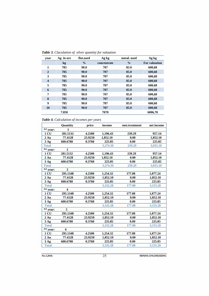
Table 3. Claculation of silver quantity for valuation year Ag in ore flot.used Ag kg metal. used Ag kg
kg % concentrate % For valuation 1 785 90.0 707 85.0 600,68 2 785 90.0 707 85.0 600,68 3 785 90.0 707 85.0 600,68 4 785 90.0 707 85.0 600,68 5 785 90.0 707 85.0 600,68 6 785 90.0 707 85.0 600,68 7 785 90.0 707 85.0 600,68 8 785 90.0 707 85.0 600,68 9 785 90.0 707 85.0 600,68
10 785 90.0 707 85.0 600,68 7.850 7070 6006,78
Table 4. Calculation of incomes per years Quantity price income met.treatment net income ** year: 1 1 CU 281.5132 4.2500 1,196.43 239.29 957.14 2 Au 77.4128 23.9250 1,852.10 0.00 1,852.10 3 Ag 600.6780 0.3760 225.85 0.00 225.85 Total 3,274.39 239.29 3,035.10 ** year: 2 1 CU 281.5132 4.2500 1,196.43 239.29 957.14 2 Au 77.4128 23.9250 1,852.10 0.00 1,852.10 3 Ag 600.6780 0.3760 225.85 0.00 225.85 Total 3,274.39 239.29 3,035.10 ** year: 3 1 CU 295.1348 4.2500 1,254.32 177.08 1,077.24 2 Au 77.4128 23.9250 1,852.10 0.00 1,852.10 3 Ag 600.6780 0.3760 225.85 0.00 225.85 Total 3,332.28 177.08 3,155.20 ** year: 4 1 CU 295.1348 4.2500 1,254.32 177.08 1,077.24 2 Au 77.4128 23.9250 1,852.10 0.00 1,852.10 3 Ag 600.6780 0.3760 225.85 0.00 225.85 Total 3,332.28 177.08 3,155.20 ** year: 5 1 CU 295.1348 4.2500 1,254.32 177.08 1,077.24 2 Au 77.4128 23.9250 1,852.10 0.00 1,852.10 3 Ag 600.6780 0.3760 225.85 0.00 225.85 Total 3,332.28 177.08 3,155.20 ** year: 6 1 CU 295.1348 4.2500 1,254.32 177.08 1,077.24 2 Au 77.4128 23.9250 1,852.10 0.00 1,852.10 3 Ag 600.6780 0.3760 225.85 0.00 225.85 Total 3,332.28 177.08 3,155.20
No 2,2010. MINING ENGINEERING
25

** year: 7 1 CU 295.1348 4.2500 1,254.32 177.08 1,077.24 2 Au 77.4128 23.9250 1,852.10 0.00 1,852.10 3 Ag 600.6780 0.3760 225.85 0.00 225.85 Total 3,332.28 177.08 3,155.20 ** year: 8 1 CU 295.1348 4.2500 1,254.32 177.08 1,077.24 2 Au 77.4128 23.9250 1,852.10 0.00 1,852.10 3 Ag 600.6780 0.3760 225.85 0.00 225.85 Total 3,332.28 177.08 3,155.20 ** year: 9 1 CU 295.1348 4.2500 1,254.32 177.08 1,077.24 2 Au 77.4128 23.9250 1,852.10 0.00 1,852.10 3 Ag 600.6780 0.3760 225.85 0.00 225.85 Total 3,332.28 177.08 3,155.20 ** year: 10 1 CU 295.1348 4.2500 1,254.32 177.08 1,077.24 2 Au 77.4128 23.9250 1,852.10 0.00 1,852.10 3 Ag 600.6780 0.3760 225.85 0.00 225.85 Total 3,332.28 177.08 3,155.20 Total income 33,207.01 1,895.22 31,311.79
*Costs of refining for gold and silver are included by reduction the seling prices for Au and Ag.
As the average annual capacity of mining was determined at 20.000 t, in the first variant, and the analyzing pe-riod is ten year, it follows that:
Value of production per ton of ore is: 156.56 USD.
The following graphs present graphically the results of this valuation as well as the largest share of income from gold (59%) in total income-valuation of raw mineral.
Graph 1. Structure of income per years
No 2,2010. MINING ENGINEERING
26

Figure 2. Share of metal incomes in total valuation
Applied on: Value of deposit without taking into
account the time factor - synthetic indica-tors
Vu = (Vi – Ti) · (R - G)
Where: Vu – Value of deposit without taking into
account the time factor in USD Vi – Value of useful raw mineral,(reduced
for treatment loss) – 156.56USD/t Cu: loss of processing (flotation + metallurgy) = 2% + 3.4% = 5.4% Au: loss of processing (flotation + metallurgy) = 6% + 9% = 15% Ag: loss of processing (flotation + metallurgy) =10% +15% = 25%
Ti – production costs of raw mineral -101.9 USD/t
R – G balance of reserves reduced for mining losses (5%)
Vu = (156.56 – 101.9) · (519872t - G) Vu=54.7 · 493878.4 Vu=27,015.148 USD
CONCLUSION
Determination the value of raw mineral is the initial part of economic valuation for deposit and that is unique for both models of geological valuation: without taking into account the time factor and with tak-ing into account the time factor.
Valuation is specially sensitive on changing the stock prices of metal, but that was avoid with accepting the World Bank forecast prices (which are about 30-40% lower than the current stock prices), what gives a warranty that the value of raw min-eral was determined raw with very low risk.
No 2,2010. MINING ENGINEERING
27
REFERENCES
[1] B. Cavender, Mineral Production Costs - Analyses and Management, SME, (1999).
[2] N. Dondur, Economical Analyses of Projects, Faculty of Mechanical Engineering, Belgrade (2002).
[3] G.Mankju, Principles of Economics, Faculty of Economics, Belgrade (2005).
[4] M. Bugarin, G. Slavković, "Techno-economical Evaluation", Copper Institute, Bor (2006).
[5] T. Kuronen: Capital Budgeting in a Capital-Intensive Industry, Helsinki University of Technology, Mat-2.108 Independent Research Projects in the Applied Mathematics, (2007).
[6] G. Slavković, „The income in financial analiysis of investments in mining“, Innovation and development, No. 2, 2010. g. pp. 25-32
No 2,2010. MINING ENGINEERING
28

INSTITUT ZA RUDARSTVO I METALURGIJU BOR YU ISSN: 1451-0162 KOMITET ZA PODZEMNU EKSPLOATACIJU MINERALNIH SIROVINA UDK: 622
UDK: 622:681.51(045)=861
Dejan Petrović*, Zvonko Damnjanović*, Dalibor Djenadić*, Radoje Pantović*, Vitomir Milić*
PRIMENA MODERNIH RAČUNARSKIH UREĐAJA I ALATA ZA SMANJENJE AKCIDENTNIH SITUACIJA U
RUDARSKIM SISTEMIMA
Izvod
Veliki rudarski sistemi zahtevaju obimno održavanje za koje je potrebno izdvojiti dosta velika novčana sredstva kojima se opterećuje poslovanje preduzeća. Ako se tome doda da većina sistema nije adekvatno održavana godinama, naša reč je zapuštenost, onda uvek postoji dilema kojim putem. U ovom radu dat je prikaz primene termovizije u industriji kao efikasnognačina praćenja stanja sistema. Termovizijskom analizom mogu se brzo i precino pronaći kritični delovi u sistemu koji mogu dovesti do otkaza istog. Kao primer uzet je rotorni bager SchRs 800. Analizom termograma konstrukcije bagera locirana su mesta na kojima su povećane temperature na konstrukciji rotornog bagera usled dinamičkih naprezanja tokom rada sistema. Kombinovanjem tehnika termovizijske analize sa merenjima napona koristeći merne trake, informacionih tehnologija i primenom FTA i FMECA metoda za identifikaciju, analizu tipova u efekata kritičnih otkaza sa analizom rizika moze dati veliki doprinos poboljšanju održavanja rudarskih sistema.
Ključne reči: termovizija, termovizijska kamera, analiza rizika, napon, rotorni bager
* Tehnički fakultet u Boru - e-mail: [email protected]
UVOD
Razvoj tehnologije u rudarsrvu doveo je do stvaranja složenih tehničkih sistema koji se teško mogu sagledati bez sistemskog pristupa, analitičkih i metodoloških načina. Tehnički sistemi u rudarstvu predstavljaju katakteristična stanja pojedinih tehnologija u kontekstu funkcionalnih karakteristika, od jednostavnih do najsloženijih radnih akti-vnosti. Osnovni procesi rudarstva u toku svog rada su destruktivnim uticajem različitih aktivnosti koje mogu značajno umanjiti njihov kvalitet.
O TERMOVIZIJI
Termovizija predstavlja snimanje tempe-rature tela. Poznato je da sva tela emituju određenu količinu toplote (čal i led). Pra-ćenje emitovanja ovog vida zračenja našlo je široku primenu u praćenju različitih pojava u raznim granama industrije. Merenja termovi-zijskom kamerom spadaju u grupu nedestru-ktivnih metoda ispitivanja i omogućuji konti-nualno, precizno i brzo određivanje raspo-dela temperatura sistema koji se analizira u realnim uslovima. Dakle, ona omogućava da se vrši bez kontaktno merenje tempera-
Broj 2,2010. RUDARSKI RADOVI
29
ture objekta. IC kamera je po konstrukciji slična digitalnoj video kameri. Određene IC kamer imaju ugrađen softver koji omogu-ćava korisniku da se fokusira na specifične oblasti OMS i izračuna temperaturu. Drugi sistemi koriste računar ili sistem podataka sa spacijalizovanim softverom koji omogu-ćava temperaturnu analizu.
Analizom dobijenih termovizijskoh in-formacija omogućava se višeznačna upo-redna komparacija termograma i ostalih izmerenih veličina, čime se omogućava sveobuhvatna analiza problema i preven-tivno delovanje.
Termalne kamere, koje se nekada nazi-vaju i infracrvene kamere, sposobne su da registruju minimalne razlike u temperaturi i da njih konvertuju u jasnu termalnu sliku na kojoj se mogu uočiti i najsitniji detalji. Za razliku od drugih tehnologija kao što su pojačivači osvetljena, kojima je potrebna barem mala količina svetlosti da bi dali
sliku, temalna tehnologija može da vidi u totalnom mraku. Njoj svetlost uopšte nije potrebna.
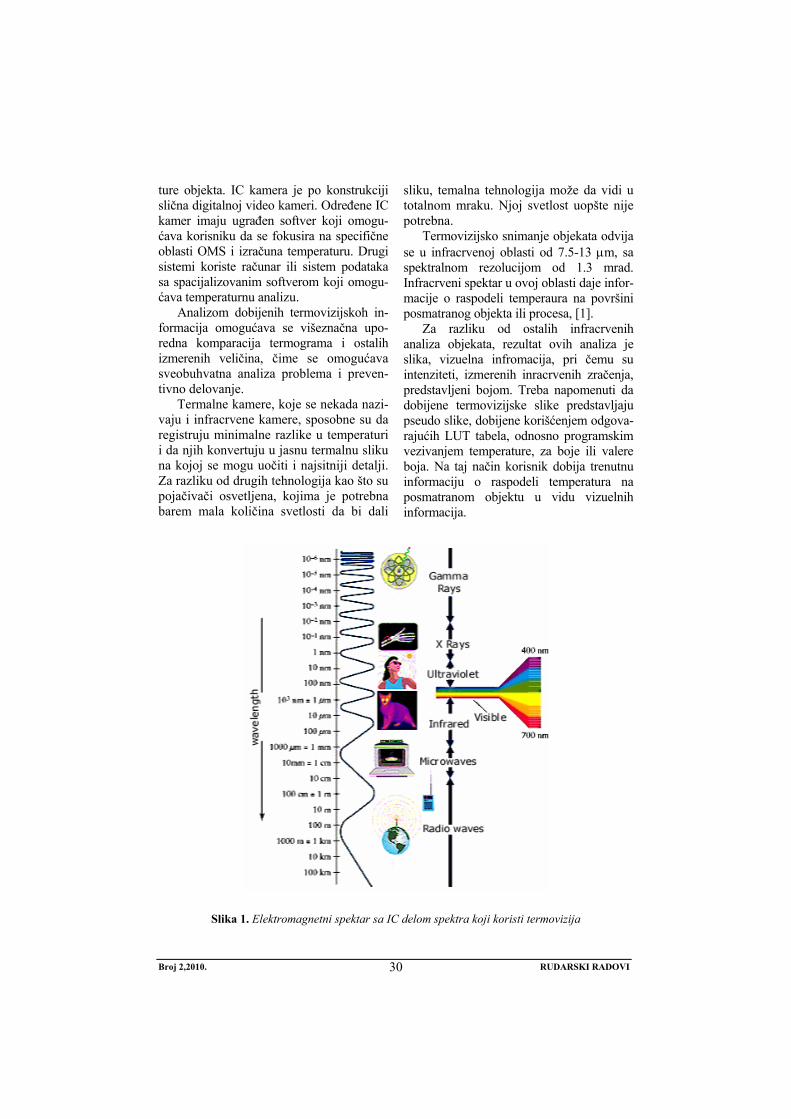
Termovizijsko snimanje objekata odvija se u infracrvenoj oblasti od 7.5-13 μm, sa spektralnom rezolucijom od 1.3 mrad. Infracrveni spektar u ovoj oblasti daje infor-macije o raspodeli temperaura na površini posmatranog objekta ili procesa, [1].
Za razliku od ostalih infracrvenih analiza objekata, rezultat ovih analiza je slika, vizuelna infromacija, pri čemu su intenziteti, izmerenih inracrvenih zračenja, predstavljeni bojom. Treba napomenuti da dobijene termovizijske slike predstavljaju pseudo slike, dobijene korišćenjem odgova-rajućih LUT tabela, odnosno programskim vezivanjem temperature, za boje ili valere boja. Na taj način korisnik dobija trenutnu informaciju o raspodeli temperatura na posmatranom objektu u vidu vizuelnih informacija.
Slika 1. Elektromagnetni spektar sa IC delom spektra koji koristi termovizija
Broj 2,2010. RUDARSKI RADOVI
30

Temovizija je našla vema veliku pri-menu u svim sverama društva: mašinskoj i elektro industriji, građevinarstvu, rudarstvu, procesnoj industriji, industriji prerade drveta, auto industriji, medicini, policiji, spasilaćkim i vatrogasnim službama...
TERMOVIZIJA U RUDARSTVU
Mogućnost primene termovizijskih kamera u rudarstvu je jako velika, iz prostog razloga što su procesi pri eksploataciji i preradi korisne mineralne sirovine jako složeni uz upotrebu kom-pleksne mehanizacije i opreme. Samim tim proizvodnja je praćena brojnim zastojima zbog kvarova na opremi i mehanizaciji. Upravo je to pravo mesto delovanja i primene tremovizije u rudarstvu, na praćenju i ranom otkrivanju kritičnih ele-menata sistema i preventivnom delovanju.
Praćenje temparaturnih promena termo-vizijskom kamerom na opremi i objektima, kao posledice pojave napona primenljivo je u gotovo svim fazama podzemne i površinske eksploatacije, kao što je:
- otkrivanje i praćenje promene napona na delovima bagera (streli, nosaču kašike i samoj kašici, uređaju za kre-tanje)
- kontrola temperature pojedinih delo-va elektromotora kod kamiona;
- praćenje temperature uređaja za ko-čenje na kamionima;
- merenje temperature elektromotora, spojnice, ležajeva, osovina i konstru-kcija pogonskih i povratnih stanica trakastih transportera;
- merenje i provera napona na kon-strukcijama pretovarnih mostova i odlagača trakastih transportera;
- merenje temperature ležajeva i elek-tromotora mlinova za mlevenje rude, pumpnih agregata, drobiličnih pos-trojenja, izvoznih mašina;
- određivanje debljine obloga u mlino-vima i napona u istim;
- određivanje mesta na šasijama jam-skih kamiona gde se javljaju najveći naponi;
- merenje temperature delova motora, uređaja za hlađenje i izduvnog sis-tema jamskih kamiona;
- analiza stanja pneumatika kamiona; - u trafostanicama za otkrivanje preop-
terećenih osigurača, elektro vodova, sklopki, uklopnika . . .
- Na sledećoj slici može se videti jedan od mnogih primera primene termovizijske kamere, za merenje temperature na radnom organu rotor-nog bagera.
Slika 2. Termovizijski snimak i standardna fotografija radnog organa rotornog bagera [3]
Broj 2,2010. RUDARSKI RADOVI
31

Takođe može se primeniti za : - otkrivanje i praćenje pukotina u bok-
ovima kopa; - otkrivanje pukotina na objektima koji
se nalaze u blizini kopa (postolja dro-biličnih postrojenja, radionice, pos-tolja trakastih transportera);
- otkrivanje delova rudnika u kojima se
- javljaju oksidacioni procesi kao pred-faze požara;
- prećenje oksidacionih procesa na de-ponijama korisne mineralne sirovine i detektovanje pojave požara na istim;
- praćenje stanja napona u sigurnosnim stubovima podzemnih prostorija i stubova u otkopnim komorama . . .
Slika 3. Termovizijski snimak i standardna fotografija bagera Komatsu PC 4000
Slika 4. Termovizijski snimak i standardna fotografija rudničkog transformatora
Broj 2,2010. RUDARSKI RADOVI
32

ANALIZA RIZIKA U RUDARSTVU
Moderni multivarijabilni pristup aspektu problema bezbednosti nameće uslove za velikim stepenom pouzdanosti i sigurnosti procesa u rudarstvu. Takvi zahtevi su opravdani činjenicom da postoji potreba za smanjenje rizika. Rudarska industrija je oblast od posebnog interesa gde se mogu primeniti naučna znanja u sferi rizika. Prethodni napori u odnosu na zahteve u procesu projektovanja sistema i potrebu za redizajniranje postojećih koji funkcionišu duže vreme. Bezbedno, sigurno funkcio-nisanje sistema je ugroženo. Takve se greške moraju u potpunosti izbegavati - eliminisati. Greška može da utiče na konačni ishod u većoj ili manjojmeri, na direktan ili
indirektan način, dok sistem za pozi-cioniranje smislu ograničenja rizika – mo-gućnost nastanka rizićnih događaja. Kao knačan ishod može izazavati upotrbu do-datnih finansijskih sredstava. Bezbedno, sigurno funkcionisanje sistema je ugroženo. Takve se greške moraju u potpunosti izbegavati - eliminisati.
Danas, za procenu rizika postoje više modernih metoda kao što su FTA (analza stabla grešaka) i FMECA ( modeli otkaza, efekti i analiza kritičnosti). Na njihovim osnovama razvijeno je mnoštvo alata i programa za analizu rizika (Design Safe, Asent, Item ToolKit, …)[5].
Slika 5. Neki od otkaza rudarske mehanizacije, [6]
Pogodnost održavanja je naročito prikladna za ocene izvršenih izmena ili poboljšanja određenog sistema održavanja ili tehničkog sistema koji se odražava, a znatno manje ako se upoređuju različiti sistemi. Na pogodnost održavanja utiče veći broj faktora kao što su: uslovi eksploatacije, kvalitet sistema održavanja, kvalitet logističke podrške, a najveći uticaj ima unugodnosti održavanja jeste da obezbedi maksimalnu gotovost sistema uz minimalne troškove održavanja i minimalne zastoje, odnosno minimalno vreme održavanja uz minimalnu logističku podršku. [7].
Funkcija pogodnosti održavanja se, po definiciji, izražava u obliku:
( ) ( )∫=1
0000
ti dttftP .................. (1)
gde su: to- vreme trajanja održavanja f(to)- funkcija gustine ovog
vremena, [7]. Tehnički sistemi i procesi u toku svog
radnog veka su pod dejstvom raznih destruktivnih uticaja koji mogu ozbiljno
Broj 2,2010. RUDARSKI RADOVI
33

smanjiti kvalitet njihovog rada. Šanse pojavljivanja i očekivane posledice doga-đaja u ciklusu smatraju se rizikom u sistemu analize tokom perioda uvođenja ili određenog procesa (kombinovanje učesta-losti i verovatnoće pojavljivanja, kao i rezultat određenog štetnog događaja), [8].
ZAKLJUČAK
Primena modrenih metoda FTA (analiza stabla greške) i FMECA (modeli otkaza, efekti i analiza kritičnosti) za iden-tifikaciju, analizu tipa, efekata kritičnih otkaza i analize rizika može dati veliki doprinos poboljšanju održavanja rudarskih sistema. Upotreba termovizije u industriji omogućava pračenje rada sistema u neo-metano funkcinisanje mašina i postrojenja, i veoma kratkom roku otkriva lokacije na kojima može doći do havarije. Upotrebom termovizije u industrijskom održavanju smanjuju se direktni troškovi održavanja, smanjiju se gubici usled zastoja i prekida proizvodnje i omogućava izradu efikasnog plana preventivnog održavanja
Kombinovanjem ova dva načina za praćenje i analizu i upotrebom modenih softverskih alata (programa Design Safe, Asent, Item ToolKit, …) može se smanjiti broj otkaza sistema i cena koštanja održavanja rudarskih sistema.
LITERATURA
[1] www.flirthermography.com/about[2] Biocanin R, Lojančić R., Martinović B.:
Bio-effects of ionizing radiation and protection, 10th International conference ”Research and Development in
Mechanical Industry” - RaDMI 2010, Donji Milanovac, 16-19. September 2010. p 726-733;
[3] Jovanić P. Damnjanović Z. and Petrović D.: Thermal analysis of SCHRS 800 continous excavator construction frame on open pit Drmno, 10th International conference ”Research and Development in Mechanical Industry” - RaDMI 2010, Donji Milanovac, 16-19. September 2010. p 600-609;
[4] Radosavljević S., Lilić N., Ćurčić S, Radosavljević M.: Risk assessment and managing technical systems in case of mining industry, Strojniški Vestnik – Journal of Mechanical Engineering 55 (2009) 2, p. 119-130;
[5] http://www.fmea-fmeca.com[6] Bošnjak S., Zrnić N., Gašić V.,
Petković Z.: Changeability as a basic working load characteristic of machinery for mechanization, 10th International conference ”Research and Development in Mechanical Industry” - RaDMI 2010, Donji Milanovac, 16-19. September 2010. p 58-67;
[7] Bogdanović B., Dašić P.: Evaluation of maintence the air-driven fans and work safety in the underground mine, Rudarski Radovi – Mines Engineering 1/2007 p 38-45;
[8] Dašić, P., Natsis, A., Petropoulos, G.: Models of reliability for cutting tools: Examples in manufacturing and agricultural engineering. Strojniški vestnik – Journal of Mechanical Engineering, vol. 54 no. 2 (2008), p. 122-130.
Broj 2,2010. RUDARSKI RADOVI
34

MINING AND METALLURGY INSTITUTE BOR YU ISSN: 1451-0162 COMMITTEE OF UNDERGROUND EXPLOITATION OF THE MINERAL DEPOSITS UDK: 622
UDK: 622:681.51(045)=20
Dejan Petrović*, Zvonko Damnjanović*, Dalibor Djenadić*, Radoje Pantović*, Vitomir Milić*
USE OF MODERN COMPUTER EQUIPMENT AND TOOLS TO REDUCE THE OCCURRENCE OF ACCIDENTS IN THE
MINING SISTEMS
Abstract
Large mining systems require extensive maintenance that needs to asset a lot of large financial assets that burden the business enterprises. If it is added to this that the most systems are not properly maintained for years, our word is disrepair, then there is always a doubt which way to go. This paper gives a description of thermography use in the industry as the efficient way of monitoring the system condition. Thermal imaging analysis can quickly and precisely find the critical parts in the system that can result into a failure of the same. The wheel excavator SchRs 800 was used as an example. By thermography analyzing, the areas with higher temperature on the wheel excavator construction can be located due to the dynamic tensions during the system operation. By combining the thermal imaging techniques with tension measurements using the measuring tape, ITC and use of FTA(Fault Tree Analysis) and FMECA (Failure Models, Effects and Criticality Analysis) modern methods for identification, the analysis of types in the effects of critical failures with the risk analysis can make a great contribution to the maintenance improve-ment of mining systems.
Key words: thermography, thermal camera, risk analysis, tension, wheel excavator
* Technical Faculty Bor, University of Belgrade, Bor, Serbia - e-mail: [email protected]
INTRODUCTION
Development of technology in mining has led to the creation of complex techni-cal systems that can hardly be seen with-out a systematic approach to the analytical and methodological terms. Technical sys-tems in mining represent distinctive condi-tions of some specific technologies in a context of functional features, from simple to the most complex work activities. The basic mining processes in their operation are subjected to the destructive impact of various activities that can significantly reduce their quality.
ABOUT THERMOGRAPHY
Thermography is recording of object heat. It is known that all objects emit a certain amount of heat (even ice). Moni-toring of heat emissions has found wide application in monitoring of different phe-nomena in various fields of industry. Measurements of thermal cameras belong to a group that testing without destroying materials and provide continuous, accurate and quick determination of distribution system temperature that is analyzed in real conditions. Therefore, it allows without contact temperature measuring. IR camera
No 2,2010. MINING ENGINEERING
35
is similar in the construction to a digital video camera. Certain infrared cameras have built-in software that allows user to focus on specific areas of OMS and calculate the temperature. Other systems use a computer or data system with specialized software that allows the temperature analysis.
Analyzing the obtained thermovision information gives a possibility if multi important parallel comparison of thermo-grams and other measured values allowing a comprehensive analysis of problems and preventive action.
Thermal cameras, sometimes referred to as the infrared cameras, are able to reg-ister minimum differences in temperature and convert them into a clear thermal im-age, which can spot the smallest details. Unlike other technologies that require a small amount of light to give an image,
thermal technology can see in total dark-ness. It does not need a light.
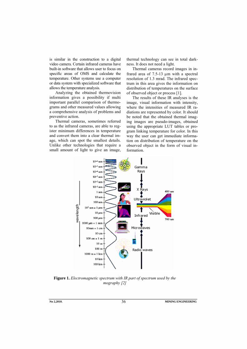
Thermal cameras record images in in-frared area of 7.5-13 μm with a spectral resolution of 1.3 mrad. The infrared spec-trum in this area gives the information on distribution of temperatures on the surface of observed object or process [1].
Тhe results of these IR analyses is the image, visual information with intensity, where the intensities of measured IR ra-diations are represented by color. It should be noted that the obtained thermal imag-ing images are pseudo-images, obtained using the appropriate LUT tables or pro-gram linking temperature for color. In this way the user can get immediate informa-tion on distribution of temperature on the observed object in the form of visual in-formation.
Figure 1. Electromagnetic spectrum with IR part of spectrum used by the mography [2]
No 2,2010. MINING ENGINEERING
36

Thermography has found a large use in all spheres of society: mechanical and electrical industry, construction, mining, processing industry, wood processing in-dustry, car industry, medicine, police, res-cue and fire services…
THERMOGRAPHY IN MINING
Possibility of use the thermo vision camera in mining industry is very large, for the simple reason that the processes of ore mining and processing are very complex with the use of complex machinery and equipment. Therefore the production is accompanied by numerous delays due to the failures on equipment and machinery. That is real place for action and implemen-tation the thermal cameras in mining on monitoring and early detection the critical elements of system and preventive action.
Monitoring of temperature changes by thermal camera on equipment and facili-ties, as the consequence of tension, is ap-plicable in nearly all phases of under-ground and surface mining, such as:
- detecting and monitoring the changes of tension on parts of excavators (ar-row, bucket carrier, bucket and driv-ing device);
- temperature control of some electric motor parts on trucks;
- temperature monitoring of braking device for braking on trucks;
- temperature measuring of electric motors, couplings, bearings, axles and construction of driving and re-current stations of belt conveyors;
- tension measuring and checking on constructions of reloading bridges and disposer of belt conveyors;
- temperature measuring of bearings and electrical motors of mills for ore grinding, pump aggregates, crushing plants, hoisting machines;
- determination of mill lining thick-ness and tension in the same;
- determination of spots on the under-ground truck boxes with the highest tensions;
- temperature measuring of engine parts, device for cooling and exhaust system of underground trucks;
- condition analysis of underground truck tires;
- in electrical substations for detection the overloaded fuses, electrical trans-formers, electrical cables, switchers…
Figure 2 presents one of many exam-ple of use the thermal camera for tempera-ture measuring on the working device of wheel excavator.
Figure 2. Thermal camera image and standard photo of wheel excavator [3]
No 2,2010. MINING ENGINEERING
37

Thermal camera can be also used for: - detection and monitoring cracks in
the sides of open mine; - detection of cracks in buildings that
are close to the open pit (crushing plant stands, workshops, stands of belt conveyors);
- detection of the mine parts where the
oxidative processes occur as direct indicator of mine fires;
- monitoring of oxidative processes on landfills of coal and detection of fire occurrences in the same;
- monitoring of tensions in the security pillars around underground chambers and pillars in rooms for excavation…
Figure 3. Thermal camera image and standard photo of Komatsu PC 4000 excavator
Figure 4. Thermal camera image and standard photo of mine transformer
RISK ANALYSIS IN MINING
Modern multi-aspect approach to the occupational safety problems imposes the requirements for high degree of reliability
and safety of the process in mining. Such requirements are justified by the fact that there is a need for risk reduction. Mining
No 2,2010. MINING ENGINEERING
38

industry is a field of particular interest con-cerning the use of scientific knowledge within the sphere of risk. Previous efforts in relation to the requirements in the process of system design and the need for redesign the existing ones that have worked a long time. A fault can affect the final outcome to greater or lesser extent, in a direct or indirect way, while the positioning system within the context of risk limits / possibility of occurrence the risky events. As the final outcome, it can cause the use of unplanned
financial resources. Safe and secure func-tion of the system is threatened. Such faults need to be completely avoided/eliminated, [4].
Today, many modern methods exist for risk analysis such as FTA (Fault Tree Analysis) and FMECA (Failure Models, Effect and Criticality Analysis). On theirs bases is developed many tools and pro-grams for risk analysis (Design Safe, Asent, Item ToolKit,..) [5].
Figure 5. Some failures of mining mechanization [6]
Maintainability is especially suitable for evaluation the completed changes or improvements to a certain system maintenance or technical system that reflects, and considerably less if different systems are compared. Number of factors has influence on the benefit of maintenance such as mining conditions, quality of maintenance system, quality of logistic support and the highest benefit of maintenance is maximum impact of the system with minimum maintenance costs and minimum downtime, that is minimum time of maintenance with minimum logistic support, [7].
Maintainability function, by definition, is expressed by the next formula:
( ) ( )∫=1
0000
ti dttftP ..................(1)
where: to- maintenance time f(to)- density function of this time
Technological systems and processes during their life cycle are under various destructive influences which can consid-erably reduce the quality of their opera-tion. The chances of unwanted events and anticipated consequences of the events in the cycle are considered to be a risk in the system analysis during the established length of time or a certain process (the combination of frequency and chances of appearing, as well as the result of certain adverse event) [8].
CONCLUSION
The use of FTA (Fault Tree Analysis) and FMECA (Failure Models, Effects and
No 2,2010. MINING ENGINEERING
39

Criticality Analysis) modern methods for identification, analysis of types, effects of critical failures and risk analysis can lead to a high benefit in maintenance the mining systems. The use of themography in indus-try allows the system monitoring without stoppage of operation the machinery and equipments, and in a very short period of time reveals locations in the system where damages may occur. Using thermography recording and monitoring in the industrial maintenance, the direct maintenance costs could be reduced, losses could be reduced due to delays and interruption of produc-tion, and allows development of effective preventive maintenance plan.
Combining these two ways for moni-toring and analysis and using modern computer tools (programs Design Safe, Asent, Item ToolKit …) number of delays and cost of maintaining mining systems could be reduced.
REFERENCES
[1] www.flirthermography.com/about[2] Biocanin R, Lojančić R., Martinović
B.: Bio-effects of Ionizing Radiation and Protection, 10th International Conference ”Research and Develo-pment in Mechanical Industry” - RaDMI 2010, Donji Milanovac, 16-19 September 2010, pgs. 726-733 (in Serbian)
[3] Jovanić P., Damnjanović Z., and Petrović D.: Thermal Analysis of SCHRS 800 Continuous Excavator Construction Frame at the OpenPit Drmno, 10th International Conference ”Research and Development in Mechanical Industry” - RaDMI 2010, Donji Milanovac, 16-19 September 2010, pgs. 600-609(in Serbian)
[4] Radosavljević S., Lilić N., Ćurčić S., Radosavljević M.: Risk Assessment and managing Technical Systems in a Case of Mining Industry, Strojniški Vestnik – Journal of Mechanical Engi-neering 55 (2009) 2, pgs. 119-130
[5] http://www.fmea-fmeca.com[6] Bošnjak S., Zrnić N., Gašić V.,
Petković Z.: Changeability as the Basic Working Load Characteristic of Machinery for Mechanization, 10th International Conference ”Research and Development in Mechanical Industry” - RaDMI 2010, Donji Milanovac, 16-19 September 2010, pgs. 58-67 (in Serbian);
[7] Bogdanović B., Dašić P.: Evaluation of Maintenance the Air-driven Fans and Work Safety in the Underground Mine, Mining Engineering 1/2007, pgs. 38-45(in Serbian)
[8] Dašić, P., Natsis, A., Petropoulos, G., Models of Reliability for Cutting Tools: Examples in Manufacturing and Agricultural Engineering, Strojniški Vestnik – Journal of Mechanical Engineering, Vol. 54, No. 2 (2008), pgs. 122-130
No 2,2010. MINING ENGINEERING
40

INSTITUT ZA RUDARSTVO I METALURGIJU BOR YU ISSN: 1451-0162 KOMITET ZA PODZEMNU EKSPLOATACIJU MINERALNIH SIROVINA UDK: 622
UDK: 622.7:552.685(045)=861
Ljubiša Obradović*, Radmilo Rajković*, Daniela Urošević*, Dragan Milanović*
ODLAGANJE JALOVINE IZ SEPARACIJE KVARCA LEŽIŠTA ''KAONA'' KOD KUČEVA
Izvod
Ležište kvarcnih minerala ''Kaona'' je dobilo ime po istoimenom zaseoku blizu koga se nalazi. Od Kučeva kao najbližeg grada ležište ''Kaona'' je udaljeno oko 6,5 km. Minerali kvarca u ležištu su u najvećoj meri zastupljeni srednje sitnim i sitnim frakcijama, najčešće zaprljanim limonitnim i glinenim prevlakama. Radi dobijanja kvalitetnih - tržišnih proizvoda, potrebno je rovni kvarcni pesak prethodno podvrgnuti procesu pranja i separacije. Proizvodi separacije kvarcnog peska su čist pesak i nečistoće koje predstavljaju definitivnu jalovinu, koju treba trajno deponovati na jalovištu. U radu su opisani osnovni tehnološki parametri budućeg separacijskog jalovišta.
Ključne reči: Ležište Kaona, kvarcni pesak, jalovište
* Institut za rudarstvo i metalurgiju Bor
UVOD
Ležište kvarcita ''Kaona'' se nalazi u is-točnoj Srbiji, zapadno od Kučeva na uda-ljenosti od oko 6,5 km. U administrativno teritorijalnom pogledu ležište pripada brani-čevskom okrugu i opštini Kučevo. U cilju definisanja geoloških rezervi rađena su u više navrata geološka istraživanja počevši od 1969 godine. Kompletna istraživanja su završena 2007 godine, tako da se na osnovu dobijenih rezultata može zaključiti da je moguće nakon čišćenja rovnog peska dobiti nekoliko kvalitetnih komercijalnih proizvoda.
Kako rovni pesak nakon površinske eksploatacije sadrži nečistoće koje se najčešće ogledaju u limonitnim i glinenim prevlakama (opnama) neophodno je nakon eksploatacije kvarcni pesak podvrgnuti postupcima pranja odnosno čišćenja.
Kvarcni pesak se nakon pranja, prosejava u komercijalne proizvode i skladira na privremenim depoima.
Za postupak pranja i čišćenja kvarcnog peska se koristi čista voda, koja se iz vodo-zahvata sa obližnjeg potoka pumpama transportuje do bazena iznad pogona sepa-racije. Osim vode za čišćenje kvarcnog peska ne koriste se druga hemijska sredstva. Posle faze čišćenja, s obzirom na konfi-guraciju terena, voda zajedno sa nečisto-ćama se gravitacijski transportuje kanalom do separacijskog jalovišta. Na jalovištu se vrši taloženje finih muljevitih čestica, nakon čega se čista tehnološka voda vraća ponovo u tehnološki proces separacije, čime se smanjuje upotreba sveže vode na najmanju moguću meru.
Broj 2,2010. RUDARSKI RADOVI
41

KONCEPCIJSKO REŠENJE IZGRADNJE SEPARACIJSKOG JALOVIŠTE
Ulazni tehnološki parametri
Prilikom projektovanja separacijskog jalovišta korišćeni su tehnološki parametri obrađeni u tehnološkom delu studije
izvodljivosti. Osnovni parametri su prika-ani u narednoj tabeli 1.
Tabela 1. Tehnološki parametri separacijske jalovine
R. br. PARAMETAR Oznaka J.M. Oznaka na teh. šemi 19
1 Maseni protok čvrste faze QČ t/h 1,3677 2 Maseni protok čvrste faze MČ % 3,96 3 Gustina čvrste faze ρČ t/m3 2,720 4 Zaprem protok čvrste faze VR m3/h 0,4939 5 Sadržaj čvrstog u pulpi Č ili p % 2,12 6 Razređenje pulpe R Del.j 46,17 7 Zaprem protok vode VV m3/h 63,1556 8 Zaprem protok pulpe VP m3/h 63,6495 9 Maseni protok pulpe QP t/h 64,514
10 Gustina pulpe ρP kg/m3 1,0136 11 Krupnoća jalovine d mm -0,106 + 0,0
Izbor lokacije jalovišta
Pre projektovanja ekipa projektanata IRM-a je obišla Kaonu kao i lokacije koje se eventualno mogu iskoristiti za izgra-dnju separacije i jalovišta.
Nekoliko lokacija je evidentirano kao moguće lokacije za smeštaj jalovine iz se-paracije. Analiziranjem sledećih tehničko-tehnoloških parametara uticajnih na izbor lokacije za jalovište, izabrana lokacija predstavlja optimalno rešenje:
• topografske karakteristike terena, • geološke, geotehničke i hidrološke
karakteristike terena, • odnos mogućeg i potrebnog kapaci-
teta jalovišta, • dužinu kao i mogućnost gravita-
cijskog transporta jalovine, • uslove i mogućnost korišćenja po-
vratne vode.
Izabrana lokacija se nalazi oko 220 m
jugozapadno od pogona separacije. Kako se separacija nalazi na koti K+280 mnv a završna kota jalovišta K+250 mnv gravi-tacijski transport jalovine iz sparacije je moguć tokom celog radnog veka jalovišta, što značajno umanjuje troškove transporta pulpe svodeći ih praktično na nulu.
Opis tehnologije izgradnje jalovišta
Separacijsko jalovište u Kaoni se izgra-đuje od zemlje - materijala iz pozajmišta, koje se bira unutar budućeg akumulacionog polja. Na taj se način efektivno povećava zapremina slobodnog akumulacionog pro-stora za zapreminu zemlje koja se ugrađuje u telo pregradne brane.
Brana se gradi sa sledećim geome-trijskim parametrima:
Broj 2,2010. RUDARSKI RADOVI
42

• nagib spoljašnje kosine 1:2, • nagib unutrašnje kosine 1:2, • širina krune brane na završnoj koti
K+250 mnv je 4 m, • širina brane u nožici u najširem delu
je 38 m,
• najveća visina brane je između kota K+240 mnv i K+250 mnv i iznosi 10 m,
• ukupna dužina brane na koti K+250 mnv iznosi 175 m,
Sl. 1. Detalj polaganja vodonepropusne folije na unutrašnju kosinu brane
Da bi se omogućila izgradnja brane prikazane geometrije sa koeficijentima sta-bilnosti koji su zakonom propisani potrebno je uraditi sledeće:
• unutrašnju kosinu brane treba obložiti vodonepropusnom folijom tipa HDPE debljine 2 mm,
• na spoljašnjoj kosini treba izgraditi drenažnu prizmu od kamenog agre-gata sa površinskog kopa, celom du-žinom spoljašnje nožice, ukupne dužine od oko 182 m,
• pored drenažne prizme treba izgraditi drenažni kanal koji će sakupljati dre-nažne vode i usmeravati ih u pravcu drenažnog sabirnika odakle će se vo-da prepumpavati nazad u akumula-ciono jezero,
• zemlju za izgradnju brane sabijati u slojevima od oko 40 cm valjkom, vibro-pločom ili sličnom mehaniza-cijom, do propisane zbijenosti koja se zahteva odgovarajućim standardom,
• nakon izgradnje brane spoljašnju ko-sinu kao i krunu brane treba odmah rekultivirati, sejanjem trave ili buseno-vanjem, radi sprečavanja dejstva ero-zije na branu.
Transport pulpe od separacije do jalovišta obavljaće se gravitacijski kanalom pravouga-onog poprečnog preseka 0,4x0,5 m. Kanal će biti iskopan u zemlji i obložen daskama debljine 2 cm. Ukupna dužina kanala će biti oko 200 m.
Broj 2,2010. RUDARSKI RADOVI
43

BILANS MASA, ZAPREMINA JALOVIŠTA I VEK EKSPLOATACIJE
Bilans masa
Separacijsko jalovište u Kaoni spada u jalovišta dolinskog tipa, pri čemu se akumulacioni prostor za deponovanje jalovine dobija izgradnjom jedne nizvodne pregradne brane. Maksimalna kota brane iznosi K+250 mnv, sa kotom osnovice na K+240 mnv i svojom maksimalnom visi-nom od 10 m. Kako je ukupna jalovina krupnoće 100% - 0,106 mm sastavljena od veoma finih i muljevitih čestica, ista se ne može upotrebiti za izgradnju brane, tako da se brana gradi od materijala iz pozajmišta. Radi povećanja ukupnog akumulacionog prostora jalovišta pozajmište se predviđa unutar akumulacionog prostora.
U narednoj tabeli 2 prikazan je bilans masa kao i slobodna zapremina jalovišta za predviđeni period eksploatacije od 10
godina, sa planiranom godišnjom dina-mikom eksploatacije od 150.000 t rovnog peska.
Kako maseni udeo jalovine u ukupnoj raspodeli masa čvrste faze iznosi 3,96% (prema tabeli 1) godišnje je na separa-cijsko jalovište potrebno deponovati oko 5.45,43 t jalovine.
Kako je zapreminska masa jalovine koja se deponuje oko 1,3 t/m3 to praktično znači da godišnje treba za deponovanje jalovine obezbediti akumulacioni prostor od približno 4.573,41 m3.
U narednoj tabeli 2 dat je bilans jalovine koju je potrebno deponovati na separacijsko jalovište za predviđeni period rada površinskog kopa, u skladu sa godišnjom dinamikom.
Tabela 2. Bilans masa jalovine za period od 10 godina
Godina Količina jalovine t /god
Količina jalovine kumulativno
t
Zapremina jalovine m3/god
Zapremina jalovine kumulativno
m3 1 5945,43 5945,43 4573,41 4573,41 2 5945,43 11890,86 4573,41 9146,82 3 5945,43 17836,29 4573,41 13720,23 4 5945,43 23781,72 4573,41 18293,64 5 5945,43 29727,15 4573,41 22867,05 6 5945,43 35672,58 4573,41 27440,46 7 5945,43 41618,01 4573,41 32013,87 8 5945,43 47563,44 4573,41 36587,28 9 5945,43 53508,87 4573,41 41160,69 10 5945,43 59454,30 4573,41 45734,10
Kako se iz prethodne tabele može videti
prema predviđenoj dinamici otkopavanja na površinskom kopu u Kaoni i preradi u separaciji, za 10 godina je potrebno deponovati ukupno 59,454,3 t jalovine, za šta je potrebno obezbediti akumulacioni prostor od oko 45.734,1 m3.
Zapremina i vek eksploatacije jalovišta
Prema predviđenoj dinamici proizvo-dnje rovnog peska na površinskom kopu i rada separacije za period od 10 godina potrebno je obezbediti prostor za trajno odlaganje za 45,734,1 m3 separacijske jalovine.
Broj 2,2010. RUDARSKI RADOVI
44

Da bi se to omogućilo potrebno je izgraditi jalovište sa minimalnom zapreminom akumulacionog prostora od oko 46.000 m3. Na ovu zapreminu treba dodati retenzioni prostor koji mora da postoji u slučaju velikih kiša (sa povratnim periodom od 1.000 godina) kako bi se zaštitila naselja koja se nalaze nizvodno od jalovišta, jer po važećem zakonodavstvu nije dozvoljeno nikakvo ispuštanje otpadnih voda i jalovine u okolni prostor, odnosno van kontura jalovišta.
Kako je u pitanju veoma fina jalovina neodgovarajućih fizičko-mehaničkih kara-kteristika za izgradnju brane jalovišta (100% - 0.106 mm) pregradna brana za formiranje akumulacionog prostora za deponovanje jalovine biće izgrađena od zemlje. Unutrašnja kosina brane biće obložena vodonepropusnom folijom. Nožica brane biće na koti K+240mnv, sa krunom brane na koti K+250 mnv, tako da će maksimalna visina brane iznositi oko 10 m. Akumulacioni prostor koji će služiti za odlaganje jalovine biće prostor visinski ograničen kotama K+240 mnv do K+ 249 mnv, pri čemu će preostala visina od 1 m do kote K+250 mnv služiti kao retenzioni prostor, naročito u poslednjim godinama eksploatacije kopa i separacijskog jalovišta, kada ukupna aktivna zapremina jalovišta bude smanjena.
Kako je početna kota izgradnje jalovišta K+240 mnv sa branom izgra-đenom do kote K+250 mnv ukupna zapremina jalovišta će biti:
VJ= VB + VB A
gde su: VJ - ukupna slobodna zapremina
jalovišta, m3
VB - zapremina brane do K+250 mnv, mB
3
VA - zapremina akumulacionog prostora do K+249 mnv, m3
Vj = 18 141,4 + 28 658,6 = 46 800 m3
Vj = 46 800 m3
Kako je za odlaganje godišnje količine jalovine iz separacije potreban prostor od 4573,41m3 to će vek eksploatacije jalo-višta za kotu zapunjavanja od K+249 mnv biti:
Te = VgVj
= 41,4573
46800 = 10,23 godine
odnosno gde je:
Vg - godišnja zapremina jalovine, m3
Te = 10 godina i 3 meseca
Jalovište pripremljeno i projektovano na prikazan način omogućuje sigurnu i stabilnu eksploataciju narednih 10 godina sa projektovanim godišnjim kapacitetom.
ZAKLJUČAK
Pri dizajniranju separacijskog jalovišta ležišta kvarcita ''Kaona'' vodilo se računa o svim važećim zakonskim normama kao i savremenim ekološkim metodama za projektovanje deponija i odlagališta. Bez obzira što se za pranje - čišćenje rovnog kvarcnog peska u separaciji koristi voda bez dodataka hemijskih sredstava separa-cijsko jalovište je projektovano sa vodone-propusnom folijom, čime se sprečava u potpunosti infiltriranje vode iz akulu-lacionog prostora jalovišta u okolni teren. Ekološki pristup se takođe ogleda i u maksimalnom korišćenju povratne tehnološke vode iz akumulacionog jezera jalovišta za rad pogona separacije, uz minimalan dotok sveže vode iz vodo-zahvata, čime se štite okolni vodeni resursi.
Kako ukupna zapremina jalovišta iznosi 46.800 m3 ukupni vek eksploatacije jalovišta sa projektovanim kapacitetom eskploatacije rovnog peska od 150.000 t godišnje, iznosi preko 10 godina.
Po završetku eksploatacije separa-cijskog jalovišta izvršiće se kompletna rekultivacija jalovišnog prostora, čime se stvaraju uslovi za njegovo vraćanje prvobitnoj nameni i potpunog uklapanja u okolni prostor.
Broj 2,2010. RUDARSKI RADOVI
45

LITERATURA
[1] Ljubiša Obradović: ''Studija izvodlji-vosti separacije kvarcnog peska iz ležišta ''Kaona '' Kučevo - deo odlaga-nja separacijske jalovine, Institut za rudarstvo i metalurgiju Bor, 2009.
[2] Dragan Milanović i sar. ''Separacija
kvarcnih mineralnih sirovina iz ležišta ''Kaona'' kod Kučeva, Rudarstvo 2010/Mining 2010 - I Međunarodni simpozijum, 24-26 maj Tara 2010, Zbornik radova.
Broj 2,2010. RUDARSKI RADOVI
46

MINING AND METALLURGY INSTITUTE BOR YU ISSN: 1451-0162 COMMITTEE OF UNDERGROUND EXPLOITATION OF THE MINERAL DEPOSITS UDK: 622
UDK: 622.7:552.685(045)=20
Ljubiša Obradović*, Radmilo Rajković*, Daniela Urošević*, Dragan Milanović*
DEPOSITION OF TAILINGS FROM THE QUARTZ SEPARATION PLANT OF THE ''KAONA'' DEPOSIT NEAR KUČEVO
Abstract
The ''Kaona'' deposit of quartz minerals was named according to the same small vil-lage near which it is located. The ''Kaona'' is located about 6.5 km from Kučevo as the nearest town. Quartz minerals in the deposit are mostly represented by small and me-dium-small fractions, usually dirty with limonite and clay coatings. In order to obtain the high quality – market products, the run-of-mine quartz sand is necessary to undergo the process of washing and separation. The separation products of quartz sand are clean sand and impurities as the final tailings, which should be permanently deposited on the tailing dump. This paper describes the basic technological parameters of future separa-tion tailing dump.
Key words: Kaona deposit, quartz sand, tailing dump
* Mining and Metallurgy Institute Bor
INTRODUCTION
The ''Kaona'' deposit of quartz minerals is located in eastern Serbia, on the west of Kučevo at a distance of about 6.5 km. In terms of administrative and territorial posi-tion the deposit belongs to the Braničevo district and Kučevo municipality. In order to define the geological reserves, the geo-logical explorations were made on several occasions starting in 1969. Complete ex-plorations were completed in 2007, so based on these results it can be concluded that it is possible, after cleaning the run-if-mine sand, to get a number of quality commercial products.
As the run-of-mine sand after the sur-
face mining operation contains impurities that are commonly seen in limonite and clay coatings (membranes), it is necessary, after mining operation, to subject the quartz sand to the washing or cleaning procedures. After washing the quartz sand is screened into commercial products and stored at the temporary depots.
The pure water is used for washing and cleaning procedure of quartz sand, which is the water from a nearby stream trans-ported by pumps to the pool above the separation plant. Other chemical agents
No 2,2010. MINING ENGINEERING
47

than water are not used for cleaning the quartz sand. After the cleaning stage, re-garding to the terrain configuration, the water with impurities is transported gravi-tationally by canal to the separation tailing dump. Deposition of fine slurry particles is done on the tailing dump, after which the pure technological water is returned back into the technological process of separa tion, thus reducing the use of fresh water to a minimum.
CONCEPTUAL SOLUTION FOR CONSTRUCTION THE SEPARATION TAILING DUMP
Input technological parameters
In designing the separation tailings, the technological parameters were used which were processed in the technological part of feasibility study. The basic parameters are shown in the following Table 1.
Table 1 Technological parameters of tailings separation
Ord. No. PARAMETER Mark Unit Marko on techn. scheme 19
1 Mass flow of the solid phase Qs t/h 1.3677
2 Mass flow of the solid phase Ms % 3.96
3 Density of the solid phase ρs t/m3 2.720
4 Volumetric flow of solid phase VR m3/h 0.4939
5 Solid content in the pulp S or p % 2.12
6 Dilution of the pulp R Parts of unit 46.17
7 Volume of the water flow VV m3/h 63.1556
8 Volume of the pulp flow VP m3/h 63.6495 9 Mass flow of the pulp QP t/h 64.514
10 Pulp density ρP kg/m3 1.0136 11 Size range of the tailings d mm -0.106 + 0.0
Selection of tailing dump location
Before the design, a team of designers from the Mining and Metallurgy Institute visited Kaona as well as the locations that may be used for construction the separa-tion and tailing dump.
Several locations were recorded as the possible locations for placement the tail-ings from separation. By analyzing the following technical and technological pa-rameters affecting the selection of location
for tailings, the selected location presents an optimum solution:
• Topographic characteristics of the terrain,
• geological, geotechnical and hydrological characteristics of the terrain,
• relationship of possible and required capacity of the tailing dump,
No 2,2010. MINING ENGINEERING
48

• length and possibility of gravitational transport of tailings,
• conditions and possibility of using the feedback water.
The selected site is located about 220 m southwest of the separation plant. As the separation plant is at elevation K+280 m altitude, and the final elevation of tail-ing dump K+250 m altitude, the gravity transport of tailings from the separation plant is possible throughout the lifetime of tailing dump, thereby reducing the trans-port costs of pulp by practically reduction to zero.
Description of construction technology for tailing dump
Separation tailing dump in Kaona is built of ground - material from borrow
pits, which is selected within the future accumulation field. By this way, the vol-ume of free accumulation space is effec-tively increased for ground volume that is built into the body of separating dam.
The dam is built with the following geometric parameters:
• fall of outer slope 1:2, • fall of inner slope 1:2, • width of dam crest at the final eleva-
tion K+250 m is 4 m, • dam width in the base of wider part
is 38 m, the highest dam height between ele-vations K
•+240 m and K+250 m and
• gth at elevation K+250 m is 175 m,
is 10 m, total dam len
Figure 1. Detail of laying the waterproof film on the inner slope of dam
No 2,2010. MINING ENGINEERING
49

To enable the construction of dam with
shown geometry with the stability coeffi-cients, required by the law, it is necessary to do the following:
• the inner slope of dam should be covered with a waterproof film, type HDPE, thickness 2 mm,
• a drainage prism of stone aggregate from the open pit should be built on the outer slope, in whole length of external pins, the total length of about 182 m,
• in addition to the drainage prism, a drainage channel should be built to collect drainage water and guide them in the direction of drainage hopper from where the water will be repumped back into the accumula-tion lake,
• compress the land for dam construc-tion in layers of about 40 cm using roller, vibrating plate or similar ma-chinery to the prescribed density, re-quired by the applicable standards, after dam construction, the outer slope and crown of dam should be immediately reclamated by grass seeding or sodding, to preven
•
t the ef-
tal length of channel will be about 200 m.
fects of erosion on the dam. Transport of pulp from separation to
the tailing dump will be carried out by the gravity channel with rectangular cross-section 0.4x0.5m. The channel will be dug in the ground and covered with planks of 2cm thickness. The to
MASS BALANCE, VOLUME OF TAILING DUMP AND SERVICE LIFE
Mass balance
Separation tailing dump in Kaona be-longs to the tailing dumps of a valley type, with an accumulation area for disposal of tailings received by building a down-stream partition dam. Maximum elevation of dam is K +250 m altitude, with the base elevation of K +240 m altitude and its maximum height of 10 m. As the total tailings, size range 100% - 0.106 mm, is composed of very fine and muddy parti-cles, the same cannot be used for dam construction, so the dam is constructed of materials from the borrow pit. To increase the total storage space of tailing dump, the borrow pit is predicted inside the storage space.
The following Table 2 shows the mass balance as well as free volume of tailing dump for predicted operation period of 10 years, with the planned annual dynamics of exploitation of 150000 tons run-of-mine sand.
As the mass proportion of tailings in the total mass distribution of solid phase is 3.96% (according to Table 1), about 5945.43 tons of tailings annually is re-quired for deposition on the separation tailing dump.
As the density mass of deposited tail-ings is about 1.3 t/m3, it means that the annual need for providing the tailings dis-posal area is about 4573.41 m3.
The following Table 2 gives a balance of tailings that needs to be deposited on the separation tailing dump for intended operation period of the open pit, according to the annual dynamics.
No 2,2010. MINING ENGINEERING
50

Table 2. Mass balance of tailings for a period of 10 years
Year Quantity of
tailings t /year
Cumulative quantity of tail-
ings t
Volume of tailings m3/year
Cumulative quan-tity of tailings
m3
1 5945.43 5945.43 4573.41 4573.41 2 5945.43 11890.86 4573.41 9146.82 3 5945.43 17836.29 4573.41 13720.23 4 5945.43 23781.72 4573.41 18293.64 5 5945.43 29727.15 4573.41 22867.05 6 5945.43 35672.58 4573.41 27440.46 7 5945.43 41618.01 4573.41 32013.87 8 5945.43 47563.44 4573.41 36587.28 9 5945.43 53508.87 4573.41 41160.69
10 5945.43 59454.30 4573.41 45734.10 As it can be seen from Table above ac-
cording to the anticipated schedule for open pit mining in Kaona and processing in separation, the total of 59,454.3 tons of tailings is required to be deposited for 10 years, to what is necessary to provide an accumulation area of about 45,734.1 m3.
Volume and service life of tailing dump
According to the planned schedule of raw sand production at the open pit and operation of work separation for a period of 10 years, it is necessary to provide a space for permanent disposal of 45,734.1 m3 separation tailings.
To make this possible, it is necessary to build a tailing dump with minimum volume of accumulation space of about 46,000 m3. The retention area should be added to this volume that must exist in the case of heavy rains (with the return period of 1000 years) to protect the settlements located downstream from the tailing dump, since the current legislation does not allowed any discharge of waste water and tailings into the environment or out-side the contours of tailing dump.
As it is quite fine tailings of inade-quate physical - mechanical characteristics for construction the tailings dam
(100% - 0.106 mm), a dividing dam for formation the accumulation space for tail-ings disposal will be built from the ground. Inner slope of dam will be lined with waterproof film. Foot dam will be at elevation of K +240 m altitude, with the dam crest at elevation +250 K m altitude, so maximum height of dam will be about 10 m. Accumulation space that will be used for disposal of tailings will be limited space in height with the elevations from K +240 to K + 249 m altitude, where the remaining height of 1 m to the elevation K+250 m altitude will serve as the reten-tion area, especially in the last years of open pit mining and separation tailing dump, when the total active volume of tailing dump would be reduced.
As the initial elevation of construction the tailing dump K +240 m altitude with the built dam up to the elevation K +250 m altitude, the total volume of tailings will be:
VJ = VB + VB A
where: VJ - total free volume of tailing dump, m3
VB – dam volume to K+250 m, mB
3
VA – volume of accumulation space up to K+249 m, m3
No 2,2010. MINING ENGINEERING
51
Vj = 18 141.4 + 28 658.6 = 46 800 m3
Vj = 46 800 m3
As the space of 4573.41 m3 is required for disposal of annual quantity of tailings, the service life of tailing dump for filling elevation K +249 m altitude will be:
Te = VgVj
= 41,4573
46800 = 10.23 years or
where: Vg – annual volume of tailings, m3
Te = 10 years and 3 months The prepared and designed tailing
dump by the shown way provides a secure and stable exploitation in the next 10 years, with designed annual capacity.
CONCLUSION
In designing the separation tailing dump of the ''Kaona'' deposit of quartz minerals, the all applicable legal standards and modern ecological methods for design of landfills and dumps were taken into account.
Regardless a fact that water without added chemicals is used for washing – cleaning of run-of-mine quartz, the sepa-ration tailing dump was designed with a waterproof film, what prevents the full infiltration of water from the accumulation
space of tailing dump into the surrounding terrain. The ecological approach is also reflected in maximum use of feedback process water from accumulation in lake of tailing dump for the separation plant operation, with minimum flow of fresh water from the water intake, thus protect-ing the surrounding water resources.
As the total tailing dump volume is 46,800 m3, the total service life of tailing dump with a design capacity of exploita-tion the run-of-mine sand of 150,000 tons per year, is over 10 years.
Upon completion the exploitation of separation tailing dump, a complete rec-lamation of tailing dump area will be done, thus creating the conditions for its return to its original purpose and complete integration with the surrounding area.
REFERENCES
[1] Lj. Obradović: ''Feasibility Study of Separation the Quartz Sand from the Deposit ''Kaona'' near Kučevo - Part of Deposition the Separation Tailings”, Mining and Metallurgy Institute Bor, 2009 (in Serbian)
[2] D. Milanović et all. ''Separation of Quartz Minerals from the Deposit ''Kaona'' near Kučevo”, Mining 2010 – Ist International Symposium, 24-26 May 2010, Tara, Proceedings (in Serbian)
No 2,2010. MINING ENGINEERING
52

INSTITUT ZA RUDARSTVO I METALURGIJU BOR YU ISSN: 1451-0162 KOMITET ZA PODZEMNU EKSPLOATACIJU MINERALNIH SIROVINA UDK: 622
UDK: 622.272:517.1(045)=861
Salko Ćosić*, Hasan Okanović**
MODELIRANJE NAPONSKO-DEFORMACIJSKOG STANJA NUMERIČKIM METODAMA KOD ŠIROKOČELNOG
OTKOPAVANJA
Izvod
U ovom radu se u kratkoj formi daje prikaz mogućnosti primjene numeričkih metoda u modeliranju naponsko-deformacionog stanja u stijenskom masivu za slučaj širokočelne eksploatacije ležišta mineralne sirovine. Opisane su osnovne metode sa navedenim prednostima i nedostacima. Navedeni su osnovni komercijalni programski paketi i dati primjeri primjene istih na problemu širokočelnog otkopavanja. Za MKE je opisan postupak razvoja 3D modela, diskretiziranje na konačne elemente uzevši u obzir nehomogenost i elasto-plastično ponašanje slojevitog materijala.
Ključne riječi: jamski pritisak, širokočelna metoda, modeliranje, naponsko-deformacijsko stanje, numeričke metode i metoda konačnih elemanata.
* Rudarski Institut Tuzla ** Univerzitet u Tuzli
1. UVOD
Izradom jamskih prostorija, a naročito otvaranjem otkopa, otvara se slobodna površina krovine koja počinje da se deformi-še, raslojava i puca i u toku vremena, ako nije na vrijeme osigurana podgradom zaru-šava. Ove deformacije i pritisci su posljedica preraspodjele naponskog stanja u masivu. Radi objašnjenja jamskog pritiska postoji niz teorija i hipoteza koje polaze od raznih pretpostavki, pa prema tome daju i različita tumačenja. Termin „jamski pritisak“ defi-nisan je preko sila koje se javljaju u stijenskim masama pod uticajem naruša-vanja prvobitne ravnoteže i preraspodjele naprezanja sa ciljem da se uspostavi nova
ravnoteža masiva. Ima više definicija jamskih pritisaka, neke od njih su bazirane na promjeni stanja, neke na stadiju razvoja faza deformacija stijena i formiranja zona deformacija u stijenskom masivu oko podzemne prostorije, a neke na karakteristi-kama podgrade. O kako složenom pro-blemu se radi najbolje govori da ne postoji opće prihvaćena teorija koja bi bila prihvatljiva za sve rudarsko geološke slučajeve. Poznavanje naponsko-deforma-cijskog stanja u masivu od velikog je značaja za sigurno projektovanje i određi-vanje dimenzija jamskih prostorija, izbor podgrade i upravljanja krovinom.
Broj 2,2010. RUDARSKI RADOVI
53

1.1. Uticajni faktori na pojavu i intenzitet jamskih pritisaka
Značajan uticaj na pojavu i manifestaciju jamskih pritisaka i deformacija pri podzemnoj eksploataciji imaju inženjersko-geološke, fizičko-mehaničke karakteristike masiva i tehnologija otkopavanja. Radna sredina može imati različite fizičko-mehaničke osobine, tako npr. krovina može biti od vrlo čvrstih stijena do vodonosnih pijesaka kao najnepovoljnijih materijala. Pored ovih postoji i niz drugi prirodnih faktora koji utiču na pojavu i intenzitet jamskih pritisaka kao što su anizotropija radne sredine, tektonske pukotine, klizne i kontaktne površine.
U osnovi možemo razlikovati tri slučaja: - nekompaktna ili plastična stijenska
masa je sredina gdje se podgrada mora blagovremeno ugrađivati da bi se obezbijedila potpuna ili djelimična stabilnost prostorije,
- srednje kompaktna stijenska masa je sredina gdje je obezbijeđena privre-mena stabilnost podzemne prostorije i,
- kompaktna stijenska masa je sredina u kojoj je podzemna prostorija sta-bilna. U ovakvim prostorijama podgrada nije potrebna.
Karakteristike masiva, za potrebe projekovanja jamskih prostorija, moraju biti u potpunosti definisane prethodnim istraži-vanjima pomoću raznih metoda: labo-ratorijskim ispitivanjima uzoraka, in-situ, geofizičkim ili nekim drugim prihvatljivim metodama. Ova ispitivanja moraju dati tačne i pouzdane rezultate što bitno utiče na izbor podgrade, dimenzionisanje prostorija i druge parametre potrebne za projektovanje. I pored svih istraživanja, zbog jako složenih rudarsko geoloških uslova, uvijek postoji opasnost od neželjenih pojava. Takav primjer je pojava „lažne“ krovine u „Staroj jami“ Zenica tektonski blok TB-1 (OP-1 i OP-2), gdje je
krovina bila čvrsta i kompaktna, međutim između osnovne i „lažne“ krovine (čija je debljina u prosjeku oko 0,7 m) nalazi se proslojak uglja debljine manje od 0,5 mm, koji je fizički odvajao osnovnu krovinu. „Lažna“ krovina se ponašala dobro i sigurno sve dok se ne otvori prostorija (komora) takvih dimenzija da ona postaje nestabilna i da se počinje urušavati, pri čemu se ugrožava sigurnost rada.
Pored geoloških i geomehaničkih kara-kteristika terena na pojavu i intenzitet jam-skih pritisaka značajan uticaj imaju i pri-mijenjeni tehnološki procesi otkopavanja. Projektanti u fazi projektovanja izborom odgovarajuće metode otkopavanja, raspore-dom i dimenzijama prostorija, dinamikom napredovanja i drugim rješenjima, mogu u znatnoj mjeri uticati na smanjenje uticaja jamskih pritisaka. Pri tome se mora tačno i na vrijeme ugraditi odgovarajuća podgrada da bi se uspostavio kontakt sa stijenskom masom.
Najviše korištena metoda otkopavanja slojeva uglja u podzemnoj eksploataciji je širokočelna metoda otkopavanja. Sa aspekta mehanike stijena postoji niz hipoteza za opis naponskog stanja i nastajanja jamskih pritisaka oko širokog čela.
1.2 Jamski pritisci
Razlike u interpretaciji jamskih pritisaka dolazi najviše zbog različitog metoda pristupa ovom problemu, a pri čemu se mogu izdvojiti dva osnovna pristupa:
- primjena teorije elastičnosti za rješa-vanje problema naprezanja i deforma-cija raznih tipova jamskih prostorija,
- snimanje i mjerenje deformacija. Ispitivanje jamskih pritisaka i mjerenje u
jamskim uslovima omogućuje direktno opažanje ponašanja navedenih pojava u funkciji napredovanja širokog čela. Pri ovim mjerenjima teškoće pričinjavaju ograničenosti
Broj 2,2010. RUDARSKI RADOVI
54

u posmatranom prostoru koji se svodi na opažanje deformacija u uskom pojasu krovine, bokova i podine, uslijed čega se registruju posljedice, a ne uzroci nastanka deformacija i preraspodjele napona u okolnim stijenama.
Da bi se u procesu otkopavanja moglo ovladati jamskim pritiscima potrebno je poduzeti niz tehničkih mjera i aktivnosti za zaštitu i održavanje jamskih prostorija. U ove mjere spadaju podgrađivanje, zarušavanje,
zasipanje i ostavljanje neotkopanih zaštitnih ploča i stubova. Zadatak svih pomenutih mjera je postizanje potrebne sigurnosti u procesu podzemne eksploatacije a nazivaju se upravljanje jamskim pritiskom. Upravljanje jamskim pritiskom ne može se posmatrati odvojeno od ponašanja krovine, koja u procesu podzemnog otkopavanja ima jednu od najznačajnih uloga, zbog čega se upravljanje jamskim pritiskom svodi na problem upravljanja krovinom.
b2 3
1 2
4
1
I II III IV V VI
Sl.1: Situacija otkopa i dijagram pritisaka na otkopu sa dinamikom kretanja otkopa
1. Neporemećeni masiv; 2. Zona zarušavanja; 3. Otkop; 4. Dijagram pritisaka; b2. širina otkopa;
I – Zona konstantnog pritiska; II – Zona oslonog pritiska u otkopu; III –Zona smanjenog pritiska u blizini čela otkopa; IV – Zona zdrobljenog uglja; V – Zona oslonog pritiska; VI – Zona
normalnog naprezanja u neporemećenom masiv
1.3 Ispitivanje i istraživanje karakter-istika stijenskih materijala
Najobimnija ispitivanja i istraživanja radne sredine vrše se pri izgradnji podzemnih objekata, a u svrhu definisanja
karakteristika prostora i sredine u kojem se gradi objekat. U tu svrhu neophodno je izvršiti prethodna i naknadna ispitivanja.
b3
1
2 4
b
1 2 4
1
3
Broj 2,2010. RUDARSKI RADOVI
55

Prethodnim ispitivanjima određuju se rudarsko-geološke osobine stijenskog mate-rijala u kojem se treba graditi objekat. Ova istraživanja treba da daju projektantima podloge na osnovu kojih mogu vršiti projektovanje podzemnih prostorija, čije karakteristike moraju obezbijediti funkcio-nalnost, sigurnost, ekonomičnost, trajnost i drugo što zahtijeva određeni objekat. Naknadnim istraživanjima se vrše ispitivanja i praćenja osobina radne sredine ili njene bliže okoline u fazi izrade i eksploatacije prostorija, pri čemu obim ispitivanja zavisi od vrste, namjene, trajnosti prostorije i drugih uticajnih faktora.
Istraživanje zakonitosti promjena napona i deformacija u stijenama predstavlja važnu djelatnost u izradi i eksploataciji podzemnih rudarskih prostorija. Ova istraživanja se mogu vršiti u laboratorijskim i u prirodnim uslo-vima. Laboratorijska ispitivanja odnosa na-pona i deformacija imaju niz faktora koji mogu znatno uticati na rezultate istraživanja. U ova istraživanja ubrajamo izradu prostornih modela od ekvivalentnih materijala. Na izradi ovih modela kod širokočelnih otkopavanja značajne rezultate je postigla grupa stručnjaka sa Rudarskog instituta u Tuzli, 70-tih godina prošlog vijeka. U novije vrijeme sve veću primjenu nalaze numeričke metode, korište-njem CAD-a inženjeri mogu lako da nume-rički modeliraju objekte. Računarskim mode-lima mogu se provjeriti stanja objekata izlo-ženih raznim uticajnim faktorima bez dodat-
nih finansijskih ulaganja ili izgradnje prosto-rnih modela za čiju izradu je potrebno više vremena.
Mjerenja u realnoj sredini i terenska mjerenje napona, deformacija i pritisaka ima veliki značaj za rješavanje teorijskih i praktičnih problema pri projektovanju i izradi podzemnih rudarskih prostorija. Terenska mjerenja se mogu vršiti na postojećim objektima u fazi eksploatacije prostorije ili na eksperimentalnim prostorijama i komorama. U jami „Sretno“ – Breza tako je izrađena jedna eksperimentalna komora sa ciljem da se odredi nosivost jalovog proslojka (breče). Da bi dobili što pouzdanije podatke pored mjerenja na terenu izvršen je analitički proračun parametara nosivosti proslojka kao i analiza metodom konačnih elemenata. Ovakve uporedne analize imaju veliki teoretski i praktični značaj. U izrađenoj komori dimenzija oko 6,0x2,5x2,3 m, na određenim rastojanjima ugrađeni su reperi za mjerenje deformacije prostorije. Deformacije su mjerene svakodnevno sve do trenutka loma krovine. Prednost ovog opita je u tome što su se mjerenja mogla vršiti do samog loma krovine (proslojka) dok se kod eksploatacionih prostorija, da bi se očuvala njena funkcionalnost i sigurnost, ispitivanja prekidaju prije očekivanog loma. Rezultati dobiveni „in situ“ mjerenjima, analitičkom i numeričkom metodom (MKE) su bili u granicama prihvatljivih odstupanja i imala su praktičnu vrijednost za dalje radove (slika 2).
Sl. 2. Raspodjela glavnih napona na ispitnoj komori
Broj 2,2010. RUDARSKI RADOVI
56

1.4. Mjerenje pritisaka na širokom čelu
Instrumenti za mjerenje napona, defor-macija i pritisaka mogu biti mehanički, hidraulički, optički i električni. Za mjerenja koja smo vršili u našim jamama korišteni su hidraulički uređaji za mjerenje reakcija mehanizovane hidrauličke podgrade (MHP), mjerenje reakcija stupaca, dinamometri za mjerenje pritisak i uređaji za mjerenje dužina. Ova mjerena se vrše na kontaktu podgrade i konture prostorije. Kod zahtjevnijih i složenijih objekata (temelji brana za hidro-centrale i sl.) ispitivanja se mogu vršiti u samom masivu ugradnjom hidrauličkih jastuka ili sondi u masiv.
Mjerenje reakcija MHP (npr. Raspotočje–Zenica, Mramor–Kreka) se vrši njemačkim uređajima Hydrostar (0-600 bar) koji se ugrađuju na hidraulički sistem sekcija širokog čela, pri čemu se kontinuirano prate reakcije podgrade. Rezultati mjerenja se automatski ispisuju na mjernu traku. Uređaji se postavljaju na tri sekcije, dva u blizini pristupnih prostorija i jedan u sredini širokog čela. Ova mjerenja traju 30 do 40 dana, zavisno od mogućnosti i potreba na terenu, nakon čega se uređaji skidaju sa sekcija a vrijednosti sa traka očitavaju i obrađuju.
Mjerenje reakcija na hidrauličkim stupcima širokog čela (npr. Omazići – Ba-novići) se vrše pomoću uređaja koji se spaja na ventil stupca pri čemu se direktno očitava pritisak u stupcu. Pri ovim mje-renjima vrši se izbor stupaca po dužini širokog čela ali se vodi računa o fazi rada na širokom čelu, što će kasnije analizi imati važan uticaj za analizu rezultata.
U toku ovih ispitivanja, u pristupnim
prostorijama širokog čela (transportnom i ventilacionom hodniku), postavljeni su dinamometri za mjerenje pritisaka na određenoj udaljenosti od širokog čela. Na dinamometrima se prate promjene pritisaka u funkciji napredovanja širokog čela. Za mjerenje deformacija pristupnih prostorija postavljaju se reperi na osnovu kojih pratimo približavanje (konvergencija) ili udaljavanje (divergencija) zidova pro-storije. Nakon svih izvršenih mjerenja na terenu prikupljeni podaci se obrađuju, pri čemu se mora voditi računa o fazama rada na širokom čelu a u funkciji vremena i izmjerenih veličina te eventualnih zastoja u radu širokog čela. Tako obrađeni podaci uzimaju se za analizu naponsko deforma-cijskog stanja.
Do sada su ove analize rađene po nekoj od mnogobrojni hipoteza postavljenih od strane teoretičara, stručnjaka u oblasti teorije elastičnosti (Kirsh, Kolosov, Mushelisvilli, Boussinesq, P. M. Cimbareviča, Grede, Labasova, K. V. Rupenejta i dr). Na osnovu dugogodišnjeg iskustva i proračuna u našim jamama najbolje je rezultate davala a i najčešće primjenjivana Hipoteza svoda.
Analitičke metode podrazumijevaju idealan, homogen, izotropan materijal za koji se pretpostavlja da je izložen naponima koji ne dovode do plastičnih deformacija te da je promjena oblika i zapremine zanemarivo mala. Osnovni skup jednačina koji opisuje naponsko-deformacijsko stanje masiva dat je na slici br. 3
Broj 2,2010. RUDARSKI RADOVI
57
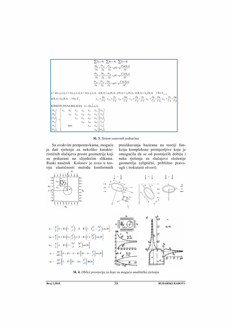
2xyx xz
2
Fx 0; Fy 0; Fz 0;
u(X, t) Xx y z t
= = =
∂τ∂σ ∂τ ∂+ + +ρ = ρ
∂ ∂ ∂ ∂
∑ ∑ ∑
2yx y yz
2
zyzx z
v(X, t) Yx y z t
Zx y z
∂τ ∂σ ∂τ ∂+ + +ρ = ρ
∂ ∂ ∂ ∂∂τ∂τ ∂σ ∂
+ + +ρ = ρ∂ ∂ ∂
2
2
0 0 0 u,v,w
0 xx yy zz xy
w(X, t)t
u u(x, y,z, t),v v(x,y,z, t),w w(x, y,z, t), u(X, t) u (X, t); v(X, t) v (X, t); w(X, t) w (X, t); Xu v w u v(X, t) (X, t) X , , ; x y z y xσ
∂
= = = = = = ∀ ∈Γ
∂ ∂ ∂ ∂ ∂σ = σ ∀ ∈Γ ε = ε = ε = ε = +
∂ ∂ ∂ ∂ ∂ xz yz
xx x11 12 13 14 15 16
yy 22 23 24 25 26
zz 33 34 35 36
yz 44 45 46
xz 55 56
xy 66
u w v w, , z x z y
KONSTITUTIVNA RELACIJA f( , , , t)c c c c c c
c c c c cc c c c
c c c
sym. c cc
•
∂ ∂ ∂ε = + ε = +
∂∂ ∂ ∂
σ = ε ε α
σ ε⎧ ⎫ ⎡ ⎤⎪ ⎪ ⎢ ⎥σ⎪ ⎪ ⎢ ⎥⎪ ⎪σ ⎢ ⎥⎪ ⎪ = ⎢ ⎥⎨ ⎬σ ⎢ ⎥⎪ ⎪
⎢ ⎥⎪ ⎪σ⎢ ⎥⎪ ⎪
σ ⎢ ⎥⎪ ⎪ ⎣ ⎦⎩ ⎭
x
yy
zz
yz
xz
xy
⎧ ⎫⎪ ⎪ε⎪ ⎪⎪ ⎪ε⎪ ⎪⎨ ⎬ε⎪ ⎪⎪ ⎪ε⎪ ⎪ε⎪ ⎪⎩ ⎭
∂
Sl. 3. Sistem osnovnih jednačina
Sa ovakvim pretpostavkama, moguće je dati rješenja za nekoliko karakte-rističnih slučajeva proste geometrije koji su prikazani na slijedećim slikama. Ruski naučnik Kolosov je uveo u teo-riju elastičnosti metodu konformnih
preslikavanja baziranu na teoriji fun-kcija kompleksne promjenljive koja je omogućila da se od postojećih dobiju i neka rješenja za slučajeve složenije geometrije (eliptični, približno pravo-ugli i trokutasti otvori).
Sl. 4. Oblici prostorija za koje su moguća analitička rješenja
Broj 2,2010. RUDARSKI RADOVI
58

2. NUMERIČKE METODE
Uslovi u kojima se izvodi proces široko-čelnog otkopavanja često se bitno razlikuju od onih navedenih kao pretpostavke za analitička rješenja naponsko-deformacione distribucije. Prije svega domena u kojoj se odvija proces uglavnom je izrazito neho-mogena, fragmentirana, slojevita i ispresije-cana rasjedima. Zatim materijali koji učest-vuju u procesu se ponašaju anizotropno,
neelastično a mnogi pokazuju i vremenski zavisne karakteristike tj. efekte viskopla-stičnosti ili puzanja. Geometrija radnog prostora je složena, deformacije nisu zane-marivo male a naponi se često iznad granica elastičnosti. Ovo čini da su analitičke me-tode imaju ograničenu primjen u oblasti širokočelnog otkopavanja.
Sl. 5. Širokočelna metoda, opšta dispozicija (a), slojevitost i rasjedi (b)
Kao alternativno rješenje za određi-vanje napona i deformacija nameće se mogućnost numeričke simulacije. Numer-ičkom analizom omogućeno je:
• Modeliranje široke klase geomehan-ičkih materijala, prije svega, stijenskih masiva, tla, betona, čeličnih elemenata, drveta i drugih materijala koji se po-javljuju u podzemnoj eksploataciji.
• Omogućeno je modeliranje vremenski zavisnih modela ponašanja (visko-plastičnost, puzanje)
• Mogućnost analiza za slučaj ge-ometrijske nelinearnosti (velika de-formacija), materijalne nelinearnosti (konstitutivna relacija) ili kontaktne nelinearnosti.
• Dinamičke analize koje obuhvataju seizmičke i efekte uslijed miniranja
Numeričke metode su sredstvo i alat kojim se savremena geomehanika inten-zivno koristi. Grubo govoreći, postoji pod-jela na kontinualne i diskontinualne me-tode. Ova podjela je napravljena na osnovu geomehaničkih karakteristika medija tj. stijenskog materijala u kome se odvija proces eksploatacije tj. u kome se metoda primjenjuje. Metode zasnovane na me-hanici kontinuuma (BEM, FEM i CDM) mogu se primjenjivati u problemima kod kojih materijal ima približno karakteristike kontinuuma ili je domena podijeljena u blokove poznatih dimenzija i oblika koji se ponašaju kao kontinualni, sl. 6, a i b.
Broj 2,2010. RUDARSKI RADOVI
59

Sl. 6. Osnovni modeli sredine u kojoj se izvodi podzemna eksploatacija [2]
Ukoliko je domena izrazito diskretna tj. fragmetirana primjenjuju se diskretne me-tode pod uslovom da je moguće odrediti oblike i položaje diskretnih elemenata. Ukoliko je materijal fragmentiran na tako sitne komade da su njihove dimenzije zanemarive u odnosu na geometrijske razmjere domene može se primijeniti me-toda pseudo-kontinuuma.
Proces numeričkog modeliranja meto-dama kontinuuma se izvodi u nekoliko koraka. Prvi korak podrazumijeva izradu 3D geometrijskog modela koji predstavlja domen u kome se odvija proces deforma-cije stijenskog masiva. Za njegovu reali-zaciju potrebno je precizno poznavati di-menzije svih prostorija te položaje, oblike i pravce prostiranja svih slojeva materi-jala. Drugi korak je pravilno modeliranja ponašanja svih materijala pod opterećen-jem. Osnovu za taj korak čini geomehan-ičko ispitivanje uzoraka litoloških čla-nova uzetih neposredno na terenu. Treći korak je nelinearna naponsko-deforma-ciona analiza koja se obavlja MKE, BEM ili CDM metodama. MKE metoda je trenutno dominantna za analizu nelin-earnih elasto-plastičnih problema. U poslednjem koraku, post-procesiranju rezultata, vrši se kritička analiza prikaza-nih rezultata distribucije napona i defor-macija te, po potrebi, korekcije modela. Bitne prednosti koje se ostvaruju prim-jenom navedene procedure ogledaju se u mogućnosti određivanja svih komponenti napona u uslovima složene geometrije i nehomogenosti materijala kao i moguć-
nost analiziranja raznih varijanti i para-metara eksploatacije s obzirom na no-sivost podgrade ili karakteristike opreme. S druge strane, tačnost i pouzdanost rezul-tata simulacije zavisi od tačnosti geo-metrije modela, tačnosti, kvaliteta i obima ispitivanja uzoraka materijala kao i složenosti analize izvedene pomoću nu-meričke simulacije. U cilju verifikacije i validacije i kalibrisanja modela, potrebno je u odgovarajućem broju tačaka imati i podatke o naponima dobijenim eksperi-mentalno.
2.1 Metod graničnih elemenata (Boundary element method - BEM)
U problemima kod kojih je odnos površine i zapremine domene vrlo mali (velike 3D domene) metoda konačnih elemenata nije posebno pogodna zbog vrlo velikog broja DOF. U tom slučaju BEM metoda je po-voljnija posebno ako je potrebno odrediti napone ili deformacije samo na određenim površinama domene koja može biti proiz-voljno velikih dimenzija i oblika. Generi-sanje modela je jednostavnije i brže a pot-rebna količina podataka je manja. Ovom metodom diskretizira se samo konturna linija domene (za 2D probleme) ili kon-turna površina (3D problemi). Time se di-menzionalnost problema smanjuje za 1 a time i broj DOF te je ova metoda efikasna za 3D probleme. Numerička procedura se sastoji u svođenju sistema diferencijalnih jednačina pomoću uticajnih koeficijenata i interpolacijskih funkcija na sistem linearnih
Broj 2,2010. RUDARSKI RADOVI
60

algebarskih jednačina koje opisuju pomake u čvornim tačkama elemenata na konturi. Ova metoda je efikasna za probleme gdje se materijal modelira kao linearan. Za složenije modele materijala obim računanja se drastično povećava. Takođe ako je pot-rebno odrediti napone u unutrašnjosti modela, potrebno je vršiti dopunske inter-polacije (smanjena tačnost) ili uzimati nove presjeke ili konture (povećanje obima raču-
nanja). Dio prednosti u odnosu na FEM se gubi i zbog toga što sistemske matrice nisu trakaste i simetrične kao što je to slučaj sa FEM. Zbog prethodno navedenog, ova metoda se koristi za elastične simulacije velikih 3D modela i kao pomoćna metoda za neke presjeke, u kombinaciji sa FEM-om. Od komercijalnih programa baziranih na ovoj metodi ističu se BEFE++ , BEMFF I BEMSAD.
Sl. 7. Diskretizacija metodom graničnih (rubnih) elemenata
2.2. Metod konačnih razlika (Finite difference method-FDM)
Metoda konačnih razlika je jedna od prvih numeričkih metoda koja se primjen-juje u oblasti geomehanike. Domena (radni prostor) se diskretizira mrežom čvornih ta-čaka u kojima se računaju čvorni pomaci kao primarna rješenja. Parcijalni izvodi u sistemu diferencijalnih jednačina koji opisuje proces deformacije domene se zam-jenjuju konačnim razlikama. Poznavajući granične uslove, formira se sistem algebar-skih jednačina koji se rješava pomoću lin-earnog solvera. Izvedene varijable se dobi-jaju u post-procesorskom postupku.
Osnovni algoritamski koraci FDM me-toda:
Generiše se diskretna mreža tačaka u domenu jednačine (2D ili 3D)
• U osnovnim jednačinama zamjen-juju se izvodi sa konačnim razlikama
• Sistem PDJ se pretvara u sistem al-gebarskih jednačina. Traži se numer-ičko rešenje u čvornim tačkama
• Za razliku od vremenski zavisnih prob-lema, rešenje se ne određuje napredo-vanjem korak po korak po vremenskoj osi, već se približno rešenje određuje u svim tačkama mreže simultano rje-šavanjem jednog sistema algebarskih jednačina.
Broj 2,2010. RUDARSKI RADOVI
61

( )1
21 1
22
12
1
2
2 2; ;
;
..
2
+ −
+
−
+ −
+
∂ − ∂ − += =
∂ Δ ∂
− + +=
Δ
Δ
−
Δ1442443 144424443
k k k k
j j j j m j j m
ki i i i i
u u u u u ui n
x yu uxx y
u u u u u u ux x x x
y
1,. ,
Sl. 8. Zamjena izvoda konačnim (centralnim) razlikama i diskretizacija domene
Metoda se može primijeniti za statičke i dinamičke probleme koji osim prostorne zahtijevaju i vremensku diskretizaciju sis-tema osnovnih jednačina. Dinamičke analize obuhvataju seizmičku kao i problematiku rudarskog miniranja i uglavnom koriste ek-splicitnu integracijsku shemu i koncept kon-centrisane mase čime se u numeričkom smislu povećava efikasnost algoritma.
Osnovni nedostatak ovog metoda je problem oko opisa domene nepravilnog oblika i nehomogenosti materijala što je čest slučaj kod modeliranja širokočelne metode otkopavanja. Ipak u problemima sa homogenom sredinom i jednostavnijom geometrijom, ova metoda daje rezultate koji se dobro poklapaju sa mjerenjima na terenu.
Sl. 9. Poređenje numeričkog (FLAC) i analitičkog rezultata za veličinu pomaka čvornih tačaka
Najpoznatiji komercijalni program po-godan za probleme modeliranja napona kod širokočelnog otkopavanja a baziran na
FDM je FLAC (za 2D) i FLAC3D za 3D modele razvijen od kompanije „Itasca Co“ u SAD (www.itasca.com).
Broj 2,2010. RUDARSKI RADOVI
62

Sl. 10. Primjer korisničkog interface-a programa FLAC 3D
Program ima vlastiti preprocesor kojim
se izgrađuje geometrija modela i automat-ski generiše 2D i 3D mreža čvornih tačaka. Solver je baziran na metodu FDM (statički i dinamički problemi, hidrologija tj. stru-janje podzemnih voda u poroznoj sredini, termalna opterećenja i dr.). Program ima kolekciju modela osnovnih geo materijala koji obuhvataju i opisuju elastično, plas-tično, visko-elasto-plastično, puzanje, modele porozne sredine i dr.
2. 3. MKE u analizi naponskih stanja kod širokočelnog otkopavanja
MKE je savremena numerička metoda za rješavanje PDJ. Suština metode je u aproksimaciji funkcije rješenja (u,v,w) diskretnim skupom funkcija (polinoma) i diskretizaciji domene konačnim skupom konačnih elemenata. Tri osnovna koncepta na kome se definiše savremena MK:
• Raleigh-Ritz ov varijacijski princip • Galerkin-ov princip težinskog rezidu-
ala • Princip minimuma kvadrata greške
(Laest square principle) U oblasti određivanja naponskih stanja
u geomehanici MKE se primjenjuje skoro
od samog nastanka. Prednosti u odnosu na druge numeričke metode:
• Složena geometrija, proizvoljni oblik domene
• Složeni granični uslovi (opterećenja i oslonci, konturne sile i pomaci)
• Složene (nelinearne) konstitutivne relacije
• Kombinovanje različitih elemenata i materijala
• Visoka tačnost na koju se može uti-cati
Budući da ova metoda spada u kontin-ualne metode, njezina primjena u prob-lemima određivanja naponskog stanja kod širokočelne metode otkopavanja je ogra-ničena na one slučajeve koji se mogu aprok-simirati kontinuumom, kao što je prethodno već navedeno. U slučajevima kontinualne ali slojevite sredine ispresijecane rasjedima moguće je, ako se poznaju geometrijske i materijalne karakteristike slojeva te ge-ometrija rasjeda napraviti realističan model koji može pratiti ponašanje masiva. Na sl.br.11 prikazani su osnovni tipovi i načini modeliranja rasjeda.
Uzimanje u obzir rasjeda podrazumijeva modeliranje elasto-plastičnog kontakta
Broj 2,2010. RUDARSKI RADOVI
63

između odgovarajućih slojeva. Time se analiza u numeričkom smislu znatno usložn-java ali savremeni softveri mogu rješavati probleme i sa takvim modelima. Kao i za ostale probleme, za naponsku analizu kod širokočelnog otkopavanja, MKE analiza se sastoji iz slijedećih koraka:
1. Izrada prostornog modela širokog čela sa svim bitnim geometrijskim detaljima uključujući podgrade
2. Određivanje slojeva sa različitim materijalima te eventualnih rasjeda ukoliko su položaji istih poznati (particija modela)
3. Izbor modela materijala i pridruži-
vanje materijala i graničnih uslova odgovarajućim dijelovima modela (particijama)
4. Definisanje kontakta za slučaj ras-jeda
5. Diskretizacija domene na konačne elemente odgovarajućeg tipa
6. Pokretanje solvera čime se for-miraju elementske i sistemske ma-trice i vektori i direktno ili indirek-tno rješava rezultujući sistem lin-earnih jednačina
7. Postprocesiranje rezultata, računanje sekundarnih varijabli
8. Kritička analiza i korekcija modela
Sl. 11. Osnovni tipovi rasjeda i načini geometrijskog modeliranja rasjeda
Svaka od ovih stavki zahtijeva dobro
poznavanje fizike problema, numeričkog postupka te softvera kojim se rješava prob-lem. U opštem slučaju najviše vremena se troši na prve četiri stavke i od istih najviše
zavisi tačnost rezultata. Stavke 5, 6, 7 se izvode u velikoj mjeri automatski od strane software-a dok je za poslednju 8 stavku potrebno praktično znanje i iskustvo u problematici naponske analize.
Broj 2,2010. RUDARSKI RADOVI
64

Sl. 12. Modeliranje geometrije podgrade i ležišta
Osnovni problemi i ograničenja s ko-jima se susrećemo kod primjene MKE u analizi širokog čela su:
• Nepoznavanje položaja i karakter-istika slojeva, nepoznavanje položaja rasjeda
• Problemi kontaktnih interakcija iz-među podgrade i stijenskog masiva
• Velika plastična deformacija koja dovodi do gubitka konvergencija
• Pojava pukotine u dijelu materijala automatski dovodi do prekida itera-tivnog postupka i obustave analize
Zbog velikih dimenzija domene (3D) te uzimanja u obzir malih detalja, automatski mesh generatori generišu mrežu elemenata koja često broji nekoliko stotina hiljada ili preko milion stepeni slobode. Ovako veliki problemi kod kojih se dopunski pojavljuju kontakti i plastične deformacije koje do-vode do velikog broja iteracija fizički su težak problem za „male“ PC računare jer zahtijevaju ogroman broj kalkulacija i ve-liku količinu radne memorije. Paralelno procesiranje na multiprocesorskim maši-nama predstavlja jedino rješenje ukoliko nije moguće uprostiti model.
Sl. 13. 3D diskretizacija i postprocesiranje rezultata analize širokog čela
Broj 2,2010. RUDARSKI RADOVI
65

Sl. 14. Postprocesiranje rezultata analize kod širokog čela, distribucija (a) i maksimalni verikalni
naponi ispred fronta čela (b)
2.3.1 Osnovne konstitutivne relacije (modeli materijala) za MKE analizu
Jedna od najvažnijih stavki u postupku analize svakako je i izbor odgovarajućeg modela tj. konstitutivne relacije za materijale s kojima se susrećemo u zoni čela. Savremeni MKE softveri imaju implementi-rane sve osnovne modele ponašanja geo materijala. Operator treba da izabere odgovarajući model te da za isti unese odgovarajuće parametre. To podrazumijeva eksperimentalno ispitivanje geo-mehaničkih karakteristika materijala u laboratoriji i na
terenu. Taj dio posla ima veliki uticaj (često najznačajniji) na validnost same analize.
Anizotropija: Većina stijenskih materi-jala (sedimentne i metamorfne stijene) poka-zuje anizotropno ponašanje. U nekim sluča-jevima materijali se ponašaju ortotropno (3 glavne ose anizotropije) ili imaju transverznu anizotropiju tj. izotropiju u ravni. U tom slu-čaju za numeričko modeliranje potrebno je poznavati pravce glavih osa i odgovarajući broj parametara materijala za svaku osu.
Sl. 15. Izotropnost, ravna anizotropija, ortotropnost
Savremeni softveri (Abaqus, Adina, An-sys, Flac…) imaju implementirane elas-
tične a u poslednjim verzijama i neke ine-lastične anizotropne modele materijala.
Broj 2,2010. RUDARSKI RADOVI
66

Sl.16. Osnovni modeli materijala implementirani u komercijalnom programu Abaqus
Plastičnost: Naponsko-deformaciona analiza se zbog nelinearnosti odvija u malim inkrementima porasta opterećenja (gravitaciono opterećenja) i isključivanja elemenata iz mreže tj. „umiranje ele-menata“ čime se simulira kopanje. Nakon svakog inkremena računaju se naponi u svim integracijskim tačkama a zatim se isti porede sa kriterijem plastičnosti, u zavisnosti od usvojenom modela materi-jala. Mogući su slijedeći slučajevi:
U slučaju da je otkrivena tačka u kojoj dolazi do plastičnog tečenja, u iterativnoj proceduri se naponi preraspoređuju dok se ne postigne naponska ravnoteža. Tada se prelazi na novi inkrement.
Osnovni modeli elasto-plastičnog po-našanja materijala materijala u zoni širo-kog čela su: MC (Mohr-Coulomb), MCSS, Drucker-Prager, Drucker-Prager-Cap, Cam-Clay. U zavisnosti od uslova na terenu, moguće je da korisnik implemen-tira vlastiti model pomoću opcije koris-ničkog materijala date u vodećim pro-gramima.
( )( )( )
ij
ij
ij
f σ , Y 0 Elastično ponašanje
f σ , Y 0 Na granici površine klizanja
f σ , Y 0 Plastificiranje,nedozvoljeno područje
<
=
>
Broj 2,2010. RUDARSKI RADOVI
67

( )1 2 3
1 3 1 3
1 3
sin 2 cos1 sin 1 sin 12 cos 2 cos
σ > σ > σ
= σ − σ + σ + σ φ − φ
+ φ − φσ − σ =
φ φ
φ
f c
c cc = kohezija
= ugao unutrašnjeg trenja
Sl. 17. MC i DP-Cap modeli plastičnosti
2.3.2 Model materijala za opis ponašanja ugljenog sloja
Dosadašnja iskustva iz prakse poka-zala su da se deformaciono ponašanje ugl-jenog sloja može najadekvatnije opisati pomoću MCSS materijala, napredne verzije klasičnog Mohr-Coulomb modela koja omogućava uzimanje u obzir slabl-jenje materijala nakon dostizanja odgova
rajućeg naponskog nivoa koji dovodi do plastične deformacije (Strain-Softening). Na slici su prikazani numerički simulirani triaksijalni testovi sa klasičnim MC i naprednim MCSS modelom za iste pa-rametre koji se dobro poklapa sa eksperi-mentalnim ispitivanjima na uzorcima.
Sl. 18. Model MCSS za modeliranje ponašanja ugljenog sloja
( )1 2 3
1 3 1 3
1 3
sin 2 cos1 sin 1 sin 12 cos 2 cos
σ > σ > σ
= σ −σ + σ +σ φ− φ
+ φ − φσ −σ =
φ φ
φ
f c
c cc = kohezija
= ugao unutrašnjeg trenja
Broj 2,2010. RUDARSKI RADOVI
68

3. DEM (Discrete Element Method)
Metoda diskretnih elemenata je numer-ička metoda koja se koristi za računanje napona i deformacija u sredinama koje se sastoje od velikog broja pojedinačnih čes-tica, komada ili zrna. Takav (granulisan) materijal se modelira kao skup krutih čes-
tica proizvoljnog oblika sa unaprijed de-finisanim kontaktnim interakcijama iz-među istih. Oblik i karakteristike partikula definiše sam korisnik u zavisnosti od vrste problema. Najčešće se koriste sfere, pra-vilni poligonalni ili elipsoidalni oblici.
Sl. 19. DEM metoda, diskretizacija (a) i kontaktni model (b)
Između partikula se mogu prenijeti
normalne i tangencijalne kontaktne sile, gravitaciona sila, potisak fluida, sila kohezije, hemijske veze i druge interakcije. Osnovni problem u numeričkom smislu je efikasna detekcija svih mogućih kontakta svih partikula koje učestvuju u modelu. Ovo zahtijeva velike računarske resurse. Diferencijalna jednačina koja definiše kre-tanje svakog diskretnog (distinktnog) ele-menta data je sa:
pri čemu su M, C i K sistemske matrice mase, prigušenja i krutosti respektivno a Fext vektor eksterne sile, rezultante na diskretni element.
Navedena matrična jednačina predstavlja sistem jednačina kojih ima koliko i stepeni slobode ukupno u domeni. Glavina vremena i računarskog resursa se ipak ne odnosu na rješavanje ovog sistema jednačina nego na otkrivanje i praćenje kontaktnih interakcija između svih elemenata. Uglavnom se disk-retni elementi smatraju krutim međutim ima i izvedbi kod kojih su pojedinačni elementi deformabilini. DEM je novija ali brzo raz-vijajuća metoda čija se primjena u oblasti mehanike stijena sve više povećava. Od komercijalnih kodova baziranih na ovoj metodi vrijedi pomenuti UDEC i 3DEC razvijenim od strane Itasca Co, istog proiz-vođača kao i Flac3D. Program 3DEC pose-bno je pogodan za dinamičke analize u prob-lemima miniranja u podzemnim rudnicima.
•• •
+ + = EXTM U CU KU F
Broj 2,2010. RUDARSKI RADOVI
69

Sl. 20. DEM – primjer 2D i 3D modela
4. HIBRIDNE METODE
Praksa je pokazala da se kombinovanjem nekih od prethodno navedenih metoda mogu iskoristiti prednosti i umanjiti nedostaci dru-gih metoda. Tako nastaju hibridne metode analize koje podrazumijevaju slijedeće kombinacije: FEM/BEM, DEM/FEM i DEM/BEM. Ovakav koncept često se koristi u naponskoj analizi širokočelne i klasične metode otkopavanja. Prva od njih (FEM/BEM) se najčešće koristi u slučaju velike domene kod koje postoje mjesta koja
predstavljaju singularitete (mali i nepravilni otvori ili pukotine). U tom slučaju se napon-sko polje dovoljno udaljeno od singulariteta (linearno elastično stanje) dobija BEM meto-dom dok se diskretizacija domene i analiza u kritičnom prostoru (nelinearna analiza) vrši pomoću MKE s tim da se na manji dio domene prenose već dobijeni BEM rezultati u formi graničnih uslova. Time je smanjeno vrijeme analize i olakšano modeliranje uz eventualno mali gubitak tačnosti.
\
Sl. 21. Hibridna BEM-FEM metoda
Broj 2,2010. RUDARSKI RADOVI
70

5. ZAKLJUČAK
Određivanje naponsko-deformacionog stanja u zoni rudarskih radova u podzemnoj eksploataciji je složen i odgovoran zadatak. Rješavanje istog zahtijeva poznavanje veličina svih komponenti napona stijen-skom masivu. Pod pretpostavkom da se podzemna eksploatacija vrši u idealno elas-tičnoj i homogenoj sredini, za prostorije proste geometrije moguće je analitički odrediti distribuciju napona. Na žalost, u praktičnim uslovima, analitičko određi-vanja naprezanja u stijenskom masivu je ograničenih mogućnosti, nepouzdano ili nemoguće. Eksperimentalno mjerenje naprezanja je slijedeća mogućnost. Ista se odlikuje pouzdanošću rezultata ali zahtijeva skupu opremu, specijalizovano osoblje i često ometa proces proizvodnje. Takođe u projektnoj fazi nije moguće imati mjerne podatke o podzemnim pritiscima jer pros-torije još ne postoje. Stoga se kao perspek-tivne nameću metode numeričke simu-lacije, samostalno ili u kombinaciji sa pre-thodno navedenim. Prikazane metode daju zadovoljavajuće rezultate uz pravilnu pripremu modela i interpretaciju rezultata. Od istih, posebno se ističe MKE, danas osnovna metoda analize u geomehaničkim problemima, u koje spada i naponsko-deformaciona analiza kod širokočelne me-tode otkopavanja. MKE omogućava dobi-janje pouzdane informacije o distribuciji napona ukoliko se sredina u kojoj se odvija proces može smatrati kontinuumom te ako su sve stavke od kojih se sastoji analiza izvedene pravilno. Ako je domena (radni prostor) fragmentiran ali u formi da se može procijeniti srednji oblik i veličina i raspored fragmenata ona se uz odgovara-juće uslove, DEM metodom mogu dobiti rezultati koji omogućavaju uvid i procjenu procesa deformisanja. Navedene metode su verificirane na brojnim primjerima i nji-hova široka primjena u svijetu uz rastući broj programa i teorijskih modela
najsigurniji su pokazatelj opravdanosti primjene istih u problemima podzemne eksploatacije.
6. LITERATURA:
[1] S. Helwany: Applied soil mechanics”, John Wiley & Sons Ltd, 2006
[2] A. Bobet: „Numerical Methods in geomechanics“, The Arabian Journal for Science and Engineering, Volume 35, Number 1B, 2010
[3] L. Jing and J. A. Hudson, “Numerical Methods in Rock Mechanics”, Interna-tional Journal of Rock Mechanics and Mining Sciences, 39(2002), pp. 409–427.
[4] L. Jing, “A Review of Techniques, Advances and Outstanding Issues in Numerical Modeling for Rock Mechanics, and Rock Engineering”, International Journal of Rock Mechanics and Mining Sciences, 40(2003), pp. 283–353.
[5] A. A. Borisov, „Proračuni podzemnog pritiska“ (prijevod) Tuzla, 1970
[6] B. H. G. Brady, “Boundary Element and Linked Methods for Underground Excavation”, in Analytical and Computational Methods in Engineering Rock Mechanics. Ed. E.T. Brown, London, England: Allen & Unwin, 1987, pp. 164–204.
[7] G. N. Pande, G. Beer, and J. R. Williams, Numerical Methods in Rock Mechanics. West Sussex, England: John Wiley & Sons, Ltd., 1990.
[8] M. Stević, „Mehanika tla i stijena“ Rudarsko-geološki fakultet Tuzla, 1991
[9] Memić M., Hadžić E., Karadžin Z., „Savremene teorije i rporačuni podzemnih pritisaka“ Rudarski institut u Tuzli, 2006
Broj 2,2010. RUDARSKI RADOVI
71

[10] S. L. Crouch and A. M. Starfield, Boundary Element Methods in Solid Mechanics. London, England: Allen and Unwin, (1983)
[11] J. P. Carter and B. Xiao: „A 2d coupled finite element and boundary Element scheme to simulate the elastic Behaviour of jointed rocks“ International journal for numerical and analytical methods in geomechanics, vol. 18, 49-71 (1994)
[12] P. A. Cundall and O. D. L. Strack, “A Discrete Numerical Model for Granular Assemblies”, Geotechnique, 29(1)(1979), pp. 47–65.
[13] R. Hart, P. A. Cundall, and J. Lemos, “Formulation of a Three-Dimensional Distinct Element Model – Part II. Mechanical Calculations for Motion and Interaction of a System Composed of Many Polyhedral Blocks”, International Journal of Rock Mechanics and Mining Sciences, 25(3) (1998)
[14] M. Ljubojev, R. Popović, M. Avdić, L. Đ. Ignjatović, V. Ljubojev, Defining the legality of gray sandstone rock strength testing in a complex state of stress, TTEM Journal of society for development of teaching and business processes in new net environment in B&H, vol. 5, No. 3 2010, pp. 437-443
[15] R. Popović, M. Ljubojev, D. Ignjatović, V. Ljubojev, L. Đ. Ignjatović, Geomechanical laboratory conditions of rock fracture, TTEM Journal of society for development of teaching and business processes in new net environment in B&H, vol. 5, No. 3 2010, pp. 544-547
[16] M. Ljubojev, M. Avdić, V. Ljubojev, D. Ignjatović, L. Đ. Ignjatović, Observation of chenges and measurment of subsidence on the collector under the open pit „Bogutovo selo“ in Ugljevik, Rudarski radovi, br. 1/2010, str. 25-31
Broj 2,2010. RUDARSKI RADOVI
72

MINING AND METALLURGY INSTITUTE BOR YU ISSN: 1451-0162 COMMITTEE OF UNDERGROUND EXPLOITATION OF THE MINERAL DEPOSITS UDK: 622
UDK:622.272:517.1(045)=20
Salko Ćosić*, Hasan Okanović**
MODELING OF STRESS-DEFORMATION STATE USING THE NUMERICAL METHODS IN THE WIDE FACE MINING
Abstract
This paper presents in the short form the possibilities of potential use the numerical methods in modeling the stress-deformation condition in rock massif for the case of wide face exploitation of mineral deposits. The basic methods are described with the advantages and disadvantages. The basic commercial software packages and examples of application on problems of wide face mining are given. For the MKE, the procedure for development of 3D model, discretization on finite elements taking into account the inhomogeneity of the elastic-plastic behavior of layered material.
Key words: pit pressure, wide face method, modeling, stress-deformation condition, numerical methods, finite elements method
* University of Tuzla ** Mining Institute Tuzla
1. INTRODUCTION
Development of mining workings and especially the opening of stopes, the free surface of roof is opened which begins to deform, separation and fracture and in the course of time, if it is not supported, breaks down.
These strains and pressures resulting from the redistribution of stress state of the massif. For an explanation of pit pressure there are many theories and hypotheses which start from different assumptions, and therefore give the different interpretations. The term “pit pressure” was defined by forces that occur in rock masses under the influence of distortion of the original bal-ance and redistribution of stresses in order
to establish a new equilibrium range. There are several definitions of underground pres-sures, some of them are based on changing conditions, some of the stages of the devel-opment phase of deformation of rocks and formation of deformation zones in rock massif around the underground chamber and some of the characteristics of support. On complexity the problem, the best proof is that there is no generally accepted theory to all mining and geological cases. Knowl-edge of the stress-strain state of the massif is of great importance for the safe design and determination the dimensions of parts of the mine, the choice of support and man-agement of roofing.
No 2,2010. MINING ENGINEERING
73

1.1. Influential factors on the occurrence and intensity of pitpressures
Significant impact on the occurrence and manifestation of pit pressures and deformations in the underground mining are geological, physical and mechanical characteristics of massif and mining tech-nology. The work environment can have different physical and mechanical charac-teristics, so, for example, the roof of can be very hard rock to the water-bearing sands as the worst material. Besides these, there are number of other natural factors that influence the occurrence and intensity of pit pressures such as anisotropy in the working environment, tectonic fractures, sliding and contact surfaces.
Basically, three cases can be distin-guished:
- Non-compact or plastic rock mass is the environment where the support has to be installed timely in order to provide full or partial stability of the room,
- Medium compact rock mass is the environment with provided tempo-rary stability of underground room, and
- Compact rock mass is the environ-ment with the stable underground room. The support is not required in these rooms.
Characteristics of massif, for the needs of design the mining workings, must be completely defined, by the previous studies using different methods: laboratory testing of samples, in-situ geophysical or other ac-ceptable methods. These tests must provide accurate and reliable results what signifi-cantly influences the choice of support, siz-ing of the rooms and other parameters needed for design. Despite all researches due to very complex mining and geological con-ditions, there is always a risk of side effects. Such example is the appearance of “false”
roof in the “Old Pit” Zenica tectonic block TB-1 (OP-1 and OP-2), where the roof was solid and compact, but between the basic “false” roof (with average thickness about 0.7 mm) there is a coal band of thickness less than 0.5 mm, which physically sepa-rated the basic roof. The “false” roof be-haved well and safe until the opening of the room of such sizes that it becomes unstable and begins to fall down with endangering the safety of operation.
Besides the geological and geotechni-cal characteristics of the terrain, the ap-plied technological processes of excava-tion have also a significant effect on the occurrence and intensity of pit pressures.
Designers at the design stage by selec-tion the appropriate mining method, lay-out and sizes of the rooms, dynamics of progress and other solutions, can signifi-cantly affect to the reduction of influence the pit pressures. The suitable support must be accurately and timely installed to establish a contact with the rock mass.
The wide face mining method is the most used method for mining the coal layers in the underground mining. From the point of rock mechanics, there are a number of hypotheses for description the stress state and emergence of pit pressures around the wide face.
1.2. Pit pressures
Differences in interpretation the pit pressures mainly come due to different methods of approaching to this issue, and where two basic approaches could be em-phasized:
- the use of elasticity theory to solve the problems of stress and deformation the various types of mining workings,
- recording and measurement of defor-mations.
No 2,2010. MINING ENGINEERING
74

Testing of pit pressures and measure-ment in the mining conditions allows direct observation the behavior of these phenom-ena in the function of advancing the wide face. In these measurements the difficulties cause limitations in the observed area that comes down to the observation of deforma-tion in the narrow strip of roof, sides and floor causing a registration of consequences, but not the causes of formation the deforma-tions and stress redistribution in the sur-rounding rocks.
In order manage the pit pressures in the excavation process, it is necessary to undertake a series of technical measures
and activities for protection and mainte-nance the mining workings. These meas-ures include supporting, caving, stowing and leaving the unexcavated protective plates and pillars. The task of these meas-ures is to achieve the required safety in the process of underground mining and they are called the control of pit pressure. Con-trol of pit pressure cannot be considered separately from behavior of roof, which in the process of underground mining has one of the most important role why the control of pit pressure is reduced to the problem of roof control.
b3
1
2 4
b2 3
1 2 4
1
b2 3
1 2
4
1
I II III IV V VI
Figure 1. Situation of excavation and diagram of pressures at the stope with the dynamics of stope movement
1. Undisturbed massif, 2. Caving zone, 3. Stope, 4. Pressure diagram, b2 stope width, I – Zone of constant pressure, II – Zone of abutment pressure in the stope,
III – Zone of reduced pressure near the stope face, IV – Zone of crushed coal, V – Zone of abutment pressure, VI – Zone of normal stress in the undisturbed massif.
No 2,2010. MINING ENGINEERING
75

1.3. Testing and study the characteristics of rock materials
The most extensive testing and re-search of work environment are made in the construction of underground facilities for the purpose of defining the characteris-tics of the space and environment in which the facility is built. For this purpose, it is necessary to carry out the previous and subsequent tests. Previous testing is used to determine the mining-geological char-acteristics of rock material where the fa-cility should be built. These researches should give the background to the design-ers based on which they will design the underground chambers, whose character-istics must provide the functionality, secu-rity, economy, durability and other re-quired things for the facility. By subse-quent researches, the investigations are carried out as well as monitoring the fea-tures of working environment or its im-mediate surroundings in the stage of de-velopment and exploitation of the rooms, while the scope of these tests depends on the type, purpose, duration of the rooms and other influential factors.
Research the law on stress and defor-mation changes in rocks is an important activity in development and exploitation the underground mining facilities. These researches can be done in the laboratory and natural conditions. Laboratory tests on the relationship of stress and deformation have a number of factors that might influ-ence on the testing results. These re-searches include development of spatial models of equivalent materials. A group of experts of the Mining Institute in Tuzla, in the 70 of the last century, have achieved the significant results in development of these models of wide face mining. In re-cent years, the numerical methods have found much more use and the engineers could easily numerically model the facili-ties using the CAD. Computer models can
check the state of facilities exposed to various influential factors with no addi-tional financial investments or construc-tion the spatial models which need more time for development.
Measurements in the real environment and field measurement of stresses, defor-mations and pressures is of great impor-tance for solving theoretical and practical problems in the design and construction the underground mining facilities. Field measurements can be made on existing facilities in the exploitation phase of the room or on the experimental facilities and chamber. In the pit, “Sretno“ – Breza - thus an experimental chamber was con-structed in order to determine the bearing capacity of barren band (breccia).
To obtain more reliable data in addition to field measurements, an analytical calcula-tion of parameters and load bands with finite element analysis were carried out. Such comparative analyses have great theoretical and practical importance. In the drawn chamber, size about 6.0 x 2.5 x 2.3 m, at certain distances, the benchmarks are em-bedded for measuring the deformations of the room. Deformations were measured on a daily basis until the moment of the roof frac-ture. The advantage of this experiment is that the measurements could be made to the fracture of roof (bands) while in the exploi-tation room, in order to preserve its func-tionality and security, the tests were inter-rupted before the expected fracture. The obtained results by “in situ” measurements, analytical and numerical methods (MKE) were within the acceptable limits of error and had practical value for further work (Figure 2).
Measurements in a real environment and field measurement of stresses, defor-mations and pressures is of great impor-tance for solving the theoretical and
No 2,2010. MINING ENGINEERING
76

practical problems in the design and manu-facture of underground mining facilities. Field measurements can be made on the existing facilities in the exploitation phase of the room or on the experimental facilities and chambers. In the pit, “Sretno” - Breza thus was created an experimental chamber in order to determine the bearing capacity of barren bands with (breccia). To obtain more reliable data in addition to the field meas-urements, an analytical calculation of the parameters and load bands with finite ele-ment analysis was carried out. Such com-parative analysis has great theoretical and practical importance. The drawn chamber
dimensions of 6.0 x 2.5 x 2.3 m, at certain distances are embedded benchmarks for measuring the deformation of the room. Strains were measured on a daily basis until the moment the roof of fracture. The advan-tage of this experiment is that the measure-ments could be made to the roof of the frac-ture (bands) while in space exploitation, in order to preserve its functionality and secu-rity, tests were interrupted before the ex-pected fracture. The obtained results by in situ measurements, analytical and numerical methods (MKE) were within the acceptable limits of error and had practical value for further work (Figure 2).
Figure 2. Distribution of main stresses on a test chamber
1.4. Pressure measurements on a wide face
Instruments for measuring the stresses, deformations and pressures can be mechani-cal, hydraulic, optical or electrical. For measurements that are carried out in the pits, hydraulic devices were used for measuring the response of mechanical hydraulic sup-port (MHP), measuring the reaction of col-umns, dynamometers for measuring the pressure and devices for measuring the length. These measurements are carried at the contact of support and contour of the room. In more demanding and more com-plex objects (foundations of dams for
hydroelectric power plants, etc...) tests can be carried out in the massif by installing the hydraulic cushions or probes into the massif.
Measuring of IHL response (e.g. Raspotočje-Zenica, Marble-Kreka) is per-formed using the German HydroStar de-vices (0-600 bar) that are installed on the hydraulic system section of a wide face, with continuously monitoring of support reaction. The results of measuring are automatically recorded on the measuring tape. Devices are placed into three sec-tions, two near the access rooms and one
No 2,2010. MINING ENGINEERING
77

in the middle of a wide face. These meas-urements take 30 to 40 days, depending on the opportunities and needs in the field, after what the devices are removed from sections and the values of tapes are read and processed.
Measuring of response on the hydraulic columns of wide face (e.g. Omazići - Banovići) are made using a device that is connected to the valve of column where the pressure is read directly in the column. In these measurements, the selection of col-umns is done in length of wide face but the phase of work on a wide face is taken into account, which would later have a signifi-cant impact to an analysis of the results.
During these tests, in the access facili-ties of a wide face (transport and ventila-tion gate), the dynamometers were in-stalled to measure the pressure at certain distance from the wide face. Dynamome-ters monitor the changes in pressure in the function of advancing the wide face. Measuring the deformation of access rooms is carried out by the benchmarks for monitoring the convergence or
divergence of the room walls. After all carried out measurements in the field, the collected data are processed, where the stages of work on a wide face must be taken into account and in a function of time and measured values and possible downtime in the operation of a wide face. Thus processed data are taken for analysis of stress and deformation state.
Until now, these analyses were carried out by one of many hypotheses set by the scholars, experts in the field theory of elas-ticity (Kirsh, Kolosov, Mushelisvilli, Bous-sinesq, P. M. Cimbarevič, Greda, Labasov, K. V. Rupeneit, etc.). Based on a long year experience and calculations in our pits, the arch hypothesis has given the best results and it was the most frequently used.
Analytical methods include an ideal, homogeneous, isotropic material, which is assumed to be subjected to stresses that do not cause plastic deformation and that the change in form and volume is negligible small. The basic set of equations describ-ing the stress-deformation state of mass is given in Figure.
2xyx xz
2
Fx 0; Fy 0; Fz 0;
u(X, t) Xx y z t
= = =
∂τ∂σ ∂τ ∂+ + +ρ = ρ
∂ ∂ ∂ ∂
∑ ∑ ∑
2yx y yz
2
zyzx z
v(X, t) Yx y z t
Zx y z
∂τ ∂σ ∂τ ∂+ + +ρ = ρ
∂ ∂ ∂ ∂∂τ∂τ ∂σ ∂
+ + +ρ = ρ∂ ∂ ∂
2
2
0 0 0 u,v,w
0 xx yy zz xy
w(X, t)t
u u(x, y,z, t),v v(x,y,z, t),w w(x, y,z, t), u(X, t) u (X, t); v(X, t) v (X, t); w(X, t) w (X, t); Xu v w u v(X, t) (X, t) X , , ; x y z y xσ
∂
= = = = = = ∀ ∈Γ
∂ ∂ ∂ ∂ ∂σ = σ ∀ ∈Γ ε = ε = ε = ε = +
∂ ∂ ∂ ∂ ∂ xz yz
xx x11 12 13 14 15 16
yy 22 23 24 25 26
zz 33 34 35 36
yz 44 45 46
xz 55 56
xy 66
u w v w, , z x z y
KONSTITUTIVNA RELACIJA f( , , , t)c c c c c c
c c c c cc c c c
c c c
sym. c cc
•
∂ ∂ ∂ε = + ε = +
∂∂ ∂ ∂
σ = ε ε α
σ ε⎧ ⎫ ⎡ ⎤⎪ ⎪ ⎢ ⎥σ⎪ ⎪ ⎢ ⎥⎪ ⎪σ ⎢ ⎥⎪ ⎪ = ⎢ ⎥⎨ ⎬σ ⎢ ⎥⎪ ⎪
⎢ ⎥⎪ ⎪σ⎢ ⎥⎪ ⎪
σ ⎢ ⎥⎪ ⎪ ⎣ ⎦⎩ ⎭
x
yy
zz
yz
xz
xy
⎧ ⎫⎪ ⎪ε⎪ ⎪⎪ ⎪ε⎪ ⎪⎨ ⎬ε⎪ ⎪⎪ ⎪ε⎪ ⎪ε⎪ ⎪⎩ ⎭
∂
Figure 3. System of basic equations
No 2,2010. MINING ENGINEERING
78

With these assumptions, it is possible to provide solutions for several typical cases of simple geometry shown in the following pictures. The Russian scientist Kolosov introduced the conformal map-ping method in the theory of elasticity,
based on the theory of functions the com-plex variable, which made possible to ob-tain from the existing and some solutions for the cases of complex geometry (ellip-tical, roughly rectangular and triangular openings).
Figure 4. Shapes of the rooms for which the analytical solutions are possible
2. NUMERICAL METHODS
Conditions of the wide face mining process are often significantly different from those mentioned as a prerequisite for the analytical solutions of stress-deformation distribution. First of all, the domains in which the process takes place is mostly highly unhomogeneous, frag-mented, layered and intersected with faults. Then, the materials involved in the
process behave anisotropic, inelastic and many of them have time-dependent char-acteristics, ie. the effects of viscoplasticity or creep. The geometry of the workspace is complex, deformations are not negligi-ble and the stresses are oftenover the lim-its of elasticity. It seems that the analytical methods have limited application in the field wide face mining.
No 2,2010. MINING ENGINEERING
79

Figure 5. Wide space method, general disposition (a), layers and faults (b)
As an alternative solution for deter-
mining the stress and deformations there is the possibility of numerical simulation. Numerical analysis has enabled:
• Modeling the large class of geotech-nical materials, primarily rock mas-sives, soil, concrete, steel elements, wood and other materials appearing in the underground mining,
• Modeling the time-dependent models of behavior (visco-plasticity, creep) is enabled,
• Possible analyzing in a case of geo-metric nonlinearities (large deforma-tions), the material nonlinearity (con-stitutive relation) or contact nonlin-earity.
• Dynamic analyses that include the seismic and effects due to the mining.
Numerical methods are means and tool that makes extensive use in modern ge-omechanics. Roughly speaking, there is a division on the continuous and discon-tinuous methods. This division was based on geo-mechanical characteristics of the media ie. rock material where the process of exploitation is developed, that is in which the method is applied. Methods based on the continuum mechanics (BEM, FEM and CDM) could be applied to the problems where the material has approxi-mate characteristics of continuum or the domain is divided into blocks of known sizes and shapes that act as a continuous, Figure 6a and b.
Figure 6. Basic models of medium where underground mining is developed [2]
If the domain is very discrete ie. Fragmented, the discrete methods are used
under a condition that it is possible to de-termine the shapes and positions of dis-
No 2,2010. MINING ENGINEERING
80

crete elements. If the material is frag-mented in such small pieces that their sizes are negligible compared to the geo-metric scale of domain, the pseudo-continuummethod can be applied. The process of numerical modeling using the continuum methods is done in several steps. The first step is a development of 3D geometric model that represents a do-main within which the process of rock mass deformation is developed. For its realization, it is necessary to know the precise sizes of all rooms and positions, shapes and strike direction of all material layers. The second step is correctly model-ing the behavior of all materials under load. The basis for this step includes the geomechanical testing of samples of lithologic members taken in the field. The third step is a nonlinear stress-deformation analysis that is carried out using the MKE, BEM or CDM methods. MKE method is currently dominant for the analysis of nonlinear elastic-plastic problems. In the last step, the post-processing of results, a critical analysis of present results of stress and deformation distribution is carried out and, if necessary, a model correction. The essential advantages, achieved by the use of given procedure, are the possibility of determining all components of stress in the conditions of complex of geometry and material inhomogeneity as well as the ability to analyze various options and pa-rameters of mining with respect to the carrying capacity of support or equipment characteristics. On the other hand, the accuracy and reliability of simulation re-sults depends on the accuracy of geome-try, accuracy, quality and range of testing the material samples as well as the com-plexity of analysis performed by means of numerical simulation. In order to verify, validate and calibrate the model, it is re-quired to have also the data on stresses,
obtained experimentally, in the appropri-ate number of points
2.1. Boundary element method - BEM
In problems where the ratio of surface to volume of domain is very small (large 3D domains) the finite element method is not particularly suitable due to very large number of DOF. In this case the BEM method is favorable especially if it is nec-essary to determine the stresses or defor-mations only in the certain areas of do-main which can be arbitrarily with large sizes and shapes. Model generating is simpler and faster and needs less amounts of data. This method discretizes only a contour line of domains (for 2D problems) or contour surface (3D problems).Thus, the problem dimensionality is reduced by 1 and thus the number of DOF, and this method is effective for 3D problems.
Numerical procedure consists in reduc-tion the system of differential equations in terms of influence coefficients and the in-terpolation of functions to the system of linear algebraic equations describing the shifts in nodal points of elements on a con-tour. This method is effective for problems where the material is modeled as a linear.
For more complex models of material, the volume of calculation is drastically increased. Also, if it is necessary to de-termine the stresses inside a model, it is necessary to perform the additional inter-polations (reduced accuracy) or take the new sections or contours (increasing the volume of calculation. Part of advantages over the FEM is lost and because the sys-tem matrices are not bandy and symmet-rical as it is the case with FEM. Due to the above given, this method is used for elas-tic simulations of large 3D models and as an auxiliary method for some sections, combined with the FEM. Of commercial program, based on this method, the BEFE + +, BEMFF and BEMSAD are stood out.
No 2,2010. MINING ENGINEERING
81

Figure 7. Discretization by the method of boundary elements
2.2. Finite difference method-FDM
Finite difference method is one of the first numerical methods used in the field of geomechanics. Domain (working area) is discretized by the network nodes where the nodal displacements are calculated as the primary solution. Partial derivatives in the system of differential equations, de-scribing the process of deformation do-mains, are replaced by the finite differ-ences. Knowing the boundary conditions, form a system of algebraic equations is formed that is solved using the linear solver. Derived variables are obtained in the post-processing procedure.
The basic algorithmic steps of FDM methods:
• A discrete network of points in the
domain of equation (2D or 3D) is generated,
• The statements are replaced by the finite differences in basic equations,
• PDJ system is converted to a system of algebraic equations. The numeri-cal solution of nodal points is re-quired,
• In contrast to the time-dependent problems, the solution is not deter-mined by the step by step progress by the timeline, but the approximate solution is determined simultaneosly in all points of network solving one system of algebraic equations.
( )1
21 1
22
12
1
2
2 2; ;
;
..
2
+ −
+
−
+ −
+
∂ − ∂ − += =
∂ Δ ∂
− + +=
Δ
Δ
−
Δ1442443 144424443
k k k k
j j j j m j j m
ki i i i i
u u u u u ui n
x yu uxx y
u u u u u u ux x x x
y
1,. ,
Figure 8. Replacement of statement by the finite (central) differences and domain discretization
The method could be used for static and dynamic problems that require also, except the spatial, the temporal discretiza-
tion of system of basic equations. Dy-namic analyses include seismic as well as problems of mining blasting and mainly
No 2,2010. MINING ENGINEERING
82

use an explicit integration scheme and concept of concentrated mass element what in numerical terms increase the effi-ciency of algorithm.
The main disadvantage of this method is the problem of description the domains of irregular shape and material inhomoge-
neity that is often the case in modeling the wide face mining method. However, in the problems with a homogeneous environ-ment and simpler geometry, this method produces results that correspond well with the field measurements.
Figure 9. Comparison of numerical (FLAC) and analytical results for the value of node shift
The best-known commercial software suitable for modeling the problems of stress in the wide face mining and based
on FDM is FLAC (2D) and FLAC3D for 3D models, developed by “Itasca Co.“ in the USA (www.itasca.com).
Figure 10. An example of the user interface program FLAC 3D
The program has its own preprocessor which builds the model geometry and automatically generates the 2D and 3D
network nodes. Solver is based on the FDM method (static and dynamic prob-lems, hydrology, ie. underground water
No 2,2010. MINING ENGINEERING
83

flow in porous media, thermal loads, etc...). The program has a collection of models of basic geo materials that include and de-scribe the elastic, plastic, visco-elastic-plastic, creep, models of porous media and others.
2.3. MKE in the analysis of stress states in the wide face mining
MKE is a modern numerical method for solving the PDJ. The essence of method is the approximation of solution functions (u,v,w) using a discrete set of functions (polynomials) and discretization the domain by the finite set of finite ele-ments. Three basic concepts in defining the modern MK are:
• The Raleigh-Ritz variational prin-ciple,
• The Galerkin principle of weight residual,
• Least square principle. In the area of determining the stress
states in geomehanici, MKE is applied from the beginning. The advantages over other numerical methods are:
• Complex geometry, random shape domain
• Complex boundary conditions (load and supports, contour forces and dis-placements)
• Complex (nonlinear) constitutive re-lations
• Combining the different elements and materials
• High accuracy, which may be af-fected
Since this method is one of the con-tinuous methods, its application to the problems of determining the stress state inthe wide gace mining method is limited
to those cases that can be approximated by a continuum, as previously stated. In the cases of continuous but layered environ-ment intersected by faults, it is possible, if the geometric and material characteristics of layers and the geometry of fault are known, to make a realistic model which can track the behavior of massif. Figure 11 shows the basic types and ways of fault modeling.
Taking into account the fault involves modeling of elastic-plastic contacts be-tween the corresponding layers. This analysis of the numerical terms is more complicated, but modern software can solve problems with such models. As for other problems, the stress analysis for wide face mining, FEM analysis consists of the following steps:
1. Development of physical model of a wide face with all relevant geo-metric detail of support including supports,
2. Determination of layers with differ-ent materials, and any faults if the positions are well-known (model partition),
3. Selection of material model and join-ing of materials and boundary condi-tions to the corresponding parts of model (volumes),
4. Defining a contact in case of fault, 5. Discretization of the domain on the
final elements of appropriate type, 6. Starting the solver what forms the
element and system matrices and vectors, and directly or indirectly solves the resulting system of linear equations,
7. Post-processing of the results, cal-culation of secondary variables,
8. Critical analysis and model correc-tion.
No 2,2010. MINING ENGINEERING
84

Figure 11. Basic fault types and methods of geometric fault modeling
Each of these items requires a good knowledge of physics problems, the nu-merical procedure and software that solves the problem. In general the most time is spent on the first four items, and the result accuracy the result accuracy depends on
most of them. Items 5, 6 and 7 are largely performed automatically by the software until for the last 8 item, the practical knowledge and experience in stress analy-sis problems is required.
Figure 12. Modeling the geometry of support and deposit
The main problems and limits encoun-tered in the MKE use in the analysis of wide face are:
• Lack of knowledge on the position and characteristics of layers, un-knowing the location of faults,
• Problems of contact interactions be-tween the support and rock massif,
• High plastic deformation which leads to the loss of convergence,
• The appearance of cracks in a part of material automatically leads to the
No 2,2010. MINING ENGINEERING
85

interruption of iterative procedure and suspension of analysis.
Because of the large-scale domain (3D) and taking into account small details, the automatic mesh generators generate a net-work of elements that is often several hun-dred thousand or one million degrees of freedom. Such great problems, where the
additional contacts and plastic deformations occur that lead to a large number of itera-tions, are physically difficult problem for “small” PCs because they require a huge number of calculations and a large amount of RAM. Parallel processing on multi-processor machines is the only solution if it is not possible to simplify the model.
Figure 13. 3D discretization and post processing the results of wide face analysis
Figure 14. Post processing analysis the results of analysis in a wide face, distribution (a) and maximum vertical stresses ahead of the face front (b)
2.3.1 Basic constitutive relations (material models) for MKE analysis
One of the most important items in the process of analysis is certainly a selection
of appropriate model, i.e. constitutive rela-tion for materials encountered in the face
No 2,2010. MINING ENGINEERING
86
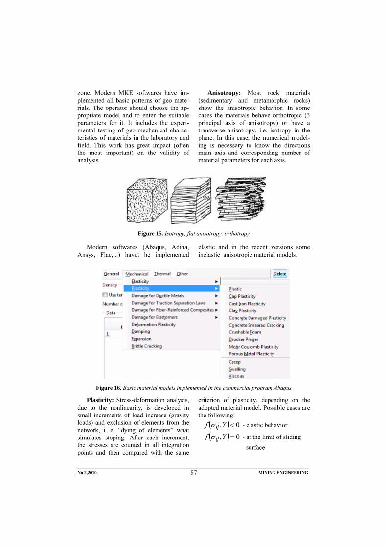
zone. Modern MKE softwares have im-plemented all basic patterns of geo mate-rials. The operator should choose the ap-propriate model and to enter the suitable parameters for it. It includes the experi-mental testing of geo-mechanical charac-teristics of materials in the laboratory and field. This work has great impact (often the most important) on the validity of analysis.
Anisotropy: Most rock materials (sedimentary and metamorphic rocks) show the anisotropic behavior. In some cases the materials behave orthotropic (3 principal axis of anisotropy) or have a transverse anisotropy, i.e. isotropy in the plane. In this case, the numerical model-ing is necessary to know the directions main axis and corresponding number of material parameters for each axis.
Figure 15. Isotropy, flat anisotropy, orthotropy
Modern softwares (Abaqus, Adina, Ansys, Flac,...) havet he implemented
elastic and in the recent versions some inelastic anisotropic material models.
Figure 16. Basic material models implemented in the commercial program Abaqus
Plasticity: Stress-deformation analysis, due to the nonlinearity, is developed in small increments of load increase (gravity loads) and exclusion of elements from the network, i. e. “dying of elements” what simulates stoping. After each increment, the stresses are counted in all integration points and then compared with the same
criterion of plasticity, depending on the adopted material model. Possible cases are the following:
( ) 0, <Yf ijσ - elastic behavior
( ) 0, =Yf ijσ - at the limit of sliding surface
No 2,2010. MINING ENGINEERING
87

( ) 0, >Yf ijσ - plastification, unauthorized area
If the item is discovered that leads to plastic flow, the stresses are reordered in the iterative procedure until the voltage balance is attained. Then it moves to a new increment.
The basic models of elastic-plastic ma-terial behavior in the zone of wide face are: MC (Mohr-Coulomb), MCSS, Drucker-Prager, Drucker – Prager - Cap, Cam - Clay. Depending on the conditions in the field, it is possible that user could imple-ment its own model using the user material option given in the leading program.
c = cohesion
( )1 2 3
1 3 1 3
1 3
sin 2 cos1 sin 1 sin 12 cos 2 cos
σ > σ > σ
= σ −σ + σ +σ φ− φ
+ φ − φσ −σ =
φ φ
f c
c ck h
φ = angle of internal friction
( )1 2 3
1 3 1 3
1 3
sin 2 cos1 sin 1 sin 12 cos 2 cos
σ > σ > σ
= σ −σ + σ +σ φ− φ
+ φ − φσ −σ =
φ φ
f c
c c
c = cohesion φ = angle of internal friction
Figure 17. MC and DP-Cap models of plasticity
2.3.2. Material models for description the behavior of coal seam
Previous experiences have shown that the deformation behavior of coal seam can be adequately described by the MCSS material, the advanced version of the clas-sical Mohr-Coulomb model that allows taking into account the weakening of ma-terial after reaching the appropriate stress
level that leads to the plastic deformation (Strain-Softening). Figure 18 shows the numerically simulated triaxial tests with conventional MC and advanced MCSS model for the same parameters that are coincided well with the experimental tests on samples.
No 2,2010. MINING ENGINEERING
88

Figure 18. Model MCSS for modeling the behavior of coal seam
3. DEM (DISCRETE ELEMENT METHOD)
Discrete element method is a numerical method used to calculate stresses and strains in media that consist of a large number of individual particles, pieces or grains. Such (granulated) material is mod-eled as a set of rigid particles of random
shape with pre-defined contact interactions between them. The shape and characteris-tics of particles are defined by the user himself depending on the types of prob-lems. Sphere, regular polygonal or ellipsoi-dal shapes are the most commonly used.
Figure 19. DEM method, discretization (a) and contact model (b
Normal and tangential contact force,
the force of gravity, thrust fluid, the force of cohesion, chemical bonding and other
interactions can be transferred between the particles. The main problem in numerical terms is the effective detection of all pos-
No 2,2010. MINING ENGINEERING
89

sible contacts of all particles participating in the model. This requires large comput-ing resources. Differential equation which defines the movement of each discrete (distinctive) element is given by
where M, C and K system matrices of mass, damping and stiffness respectively and Fext vector of external forces, the re-sultant on discrete element.
The above matrix equation is a system of equations which have as the total de-grees of freedom in the domain. Hub time and computer resources, however, not
compared to the solution of this system of equations, but the detection and monitor-ing of contact interaction between all ele-ments. Generally considered as discrete elements, however, has a solid perform-ance in which the individual elements are deformable. DEM is a newer but rapidly developing method with the growing up use in the field of rock mechanics. It is worth to mention UDEC and 3DEC com-mercial codes, developed by Itasca Co., based on this method, the same manu-facturer as the Flac3D. 3DEC program is particularly suitable for dynamic analysis of blasting problems in the underground mines.
•• •
+ + = EXTM U CU KU F
Figure 20. DEM – example of 2D and 3D models
4. HYBRID METHODS
Practice has shown that combining of some the above methods can take advan-tage and reduce disadvantages of other methods. The results of this are the hybrid methods of analysis that include the fol-lowing combinations: FEM/BEM, DEM/FEM and DEM/BEM. This concept is often used in the stress analysis of wide face and classical methods of mining. The first of these (FEM / BEM) is commonly used in the case of large domains in which there are places which are singularities
(small and irregular openings or cracks). In this case, the stress field far enough from the singularity (linear elastic state) is obtained by BEM method while the dis-cretization domain and analysis in the critical area (non-linear analysis) is done using MKE provided that already obtained BEM results, in the form of border condi-tions, are transferred to a smaller part of domain This reduces the analysis time and simplified modeling with possibly small loss of accuracy.
No 2,2010. MINING ENGINEERING
90

Figure 21. Hybrid BEM-FEM method
5. CONCLUSION
Determination of the stress-deformation state in the zone of mining activities in un-derground mining is a complex task. Ad-dressing the same size requires knowledge of all components of rock massif stress. As-suming that the underground mining is done in an ideal elastic and homogeneous envi-ronment, it is possible to analytically deter-mine the stress distribution for the rooms simple geometry. Unfortunately, in practical terms, the analytical determination of stresses in rock massif of the limited re-sources is unreliable or impossible. Experi-mental measurement of stress is the next option. The same is characterized by the results reliability, but requires expensive equipment, specialized personnel and often interferes the production process. Also, in the design stage it is not possible to have measurement data on groundwater pressures because the room does not yet exist. There-fore, as the perspective are imposed the nu-merical simulation methods, alone or in combination with the above. Presented
methods give satisfactory results with proper preparation and interpretation of model re-sults. Out of them, MKE is especially dis-tinctive, now the main method for analyzing in geomechanical problems, which include the stress-deformation analysis of the wide face mining method. MKE allows obtaining reliable information on stress distribution if the environment in which the developed process can be considered as a continuum, and if all items that make up the analysis are carried out properly. If the domain (work place) is fragmented but in a form that mean shape and size and arrangement of the frag-ments can be estimated, it with appropriate conditions, using DEM method can give the results that provide insight and evaluation of deformation process. The above methods were verified in numerous examples and their wide application in the world with a growing number of applications and theo-retical models are the surest indicators of the feasibility of use the same in the problems in underground mining.
No 2,2010. MINING ENGINEERING
91

6. REFERENCES
[1] S. Helwany: Applied Soil Mechanics”, John Wiley & Sons Ltd, 2006
[2] A. Bobet: „Numerical Methods in Geomechanics“, The Arabian Journal for Science and Engineering, Volume 35, Number 1B, 2010
[3] L. Jing and J. A. Hudson, “Numerical Methods in Rock Mechanics”, International Journal of Rock Mecha-nics and Mining Sciences, 39(2002), pp. 409–427
[4] L. Jing, “A Review of Techniques, Advances and Outstanding Issues in Numerical Modeling for Rock Mechanics, and Rock Engineering”, International Journal of Rock Mechanics and Mining Sciences, 40(2003), pp. 283–353
[5] A. A. Borisov, “Calculation of the Underground Pressure“, Tuzla, 1970 (in Serbian)
[6] B. H. G. Brady, “Boundary Element and Linked Methods for Underground Excavation”, in Analytical and Compu-tational Methods in Engineering Rock Mechanics. Ed. E.T. Brown, London, England: Allen & Unwin, 1987, pp. 164–204
[7] G. N. Pande, G. Beer, and J. R. Williams, Numerical Methods in Rock Mechanics. West Sussex, England: John Wiley & Sons, Ltd., 1990
[8] M. Stević, “Soil and Rock Mecha-nics“, Mining and Geology Faculty Tuzla, 1991 (in Serbian)
[9] Memić M., Hadžić E., Karadžin Z., “Modern Theories and Calculations of the Underground Pressures”, Mining Institute in Tuzla, 2006 (in Serbian)
[10] S. L. Crouch and A. M. Starfield, Boundary Element Methods in Solid Mechanics, London, England: Allen and Unwin, 1983
[11] J. P. CARTER AND B. XIAO: “A 2d
Coupled Finite Element and Boundary Element Scheme to Simulate the Elastic Behaviour of Jointed Rocks“, International Journal for Numerical and Analytical Methods in Geome-chanics, Vol. 18, 49-71 1994)
[12] P. A. Cundall and O. D. L. Strack, “A Discrete Numerical Model for Granu-lar Assemblies”, Geotechnique, 29(1), 1979, pp. 47–65
[13] R. Hart, P. A. Cundall, and J. Lemos, “Formulation of a Three-Dimensional Distinct Element Model-Part II. Mechanical Calculations for Motion and Interaction of a System Composed of Many Polyhedral Blocks”, Interna-tional Journal of Rock Mechanics and Mining Sciences, 25(3), 1998
[14] M. Ljubojev, R. Popović, M. Avdić, L. Đ. Ignjatović, V. Ljubojev, Defining the legality of gray sandstone rock strength testing in a complex state of stress, TTEM Journal of society for development of teaching and business processes in new net environment in B&H, vol. 5, No. 3 2010, pp. 437-443
[15] R. Popović, M. Ljubojev, D. Ignjatović, V. Ljubojev, L. Đ. Ignjatović, Geomechanical laboratory conditions of rock fracture, TTEM Journal of society for development of teaching and business processes in new net environment in B&H, vol. 5, No. 3 2010, pp. 544-547
[16] M. Ljubojev, M. Avdić, V. Ljubojev, D. Ignjatović, L. Đ. Ignjatović, Observation of chenges and measurment of subsidence on the collector under the open pit „Bogutovo selo“ in Ugljevik, Rudarski radovi, No. 1/2010, pp. 25-31
No 2,2010. MINING ENGINEERING
92

INSTITUT ZA RUDARSTVO I METALURGIJU BOR YU ISSN: 1451-0162 KOMITET ZA PODZEMNU EKSPLOATACIJU MINERALNIH SIROVINA UDK: 622
UDK: 340.134:628.4(045)=861
Ljubiša Obradović*, Mile Bugarin*, Zoran Stevanović*, Miomir Mikić*, Ružica Lekovski*
PREGLED AKTUELNOG DOMAĆEG ZAKONODAVSTVA IZ OBLASTI UPRAVLJANJA I DEPONOVANJA OTPADA
Izvod
Donošenjem Zakona o Upravljanju otpadom Republike Srbije 2009. godine (''Sl. glasnik RS'', broj 36/09), stvoreni su neophodni preduslovi za uvođenje reda u predmetnoj oblasti. U radu je dat pregled aktuelne, domaće zakonske regulative iz oblasti upravljanja otpadom, ambalažom i ambalažnim otpadom. Takođe su hronološki prikazane sve aktivnosti koje je Republika Srbija sprovela u cilju usklađivanja domaćeg zakonodavstva sa zakonodavstvom Evropske Unije iz domena zaštite životne sredine i upravljanja otpadom, počevši od 2000. godine koji se smatra teoretskim početkom pridruživanja EU (kada je RS uključena u proces Stabilizacije i pridruživanja), preko 2004. godine koji se smatra praktičnim početkom pridruživanja EU (kada je u Narodnoj skupštini usvojena Rezolucija o pridruživanju Evropskoj Uniji), pa sve do 2008. godine kada je Narodna Skupština ratifikovala Sporazum o stabilizaciji i pridruživanju Republike Srbije EU.
Ključne reči: deponija, otpad, zakonodavstvo, pridruživanje EU
* Institut za rudarstvo i metalurgiju Bor
UVOD
Usaglašavanje nacionalnog zakono-davstva sa pravnim tekovinama EU (acquis communautaire - je pravna tekovina EU koja sadrži pored osnivačkih ugovora i više od 20.000 propisa iz sekundarnog zakono-davstva i 4.000 sudskih presuda) je teoretski započeto 2000 godine, kada je Republika Srbija uključena u proces stabilizacije pridruživanja. Praktično je ovaj proces započet oktobra 2004. godine usvajanjem u Narodnoj skupštini Rezolucije o pridruživanju Evropskoj Uniji. Proces je dalje nastavljen septembra 2008. godine, kada je Republička Skupština ratifikovala Spora-zum o stabilizaciji i pridruživanju. U okto-bru 2008. godine Vlada RS je usvojila Nacionalni program za integraciju (NPI) Republike Srbije u Evropsku Uniju, kao
strateški dokument koji objedinjuje sva dokumenta i akcione planove neophodne za proces evropskih integracija i definiše obaveze svih aktera za period do kraja 2012. godine.
Proces evropskih integracija sastoji se od tri ključna elementa:
prenošenje zakonodavstva EU u nacionalno zakonodavstvo i njego-va efikasna primena;
uspostavljanje odgovarajućih admi-nistrativnih i institucionalnih kapa-citeta na svim nivoima u cilju pravilnog prenošenja i primene propisa EU;
obezbeđivanje finansijskih sredstava i ekonomskih instrumenata.
Broj 2,2010. RUDARSKI RADOVI
93

Harmonizacija propisa je obiman i ne-odložan proces za državu koja pretenduje na članstvo u EU. Oblast životne sredine osim što je najobimnija u stalnom je razvoju, pa se shodno potrebi pravnog regulisanja ove oblasti obim EU propisa konstantno povećeva, što zahteva stalno praćenje razvoja EU zakonodavstva radi usaglašavanja sa domaćim propisima. U NPI dokumentu, ova oblast je podeljena na sledeća poglavlja: horizontalno za-konodavstvo, kvalitet vazduha i kli-matske promene, upravljanje otpadom, zaštita i upravljanje vodama, zaštita prirode, hemikalije, kontrola industrijskog zagađenja i upravljanje rizikom, genetički modifikovani organizmi, zaštita od buke, šumarstvo i civilna zaštita. Iskustvo novih zemalja članica EU pokazuje da su najslo-ženiji delovi acquis-a neke od direktiva iz oblasti kvaliteta vazduha, voda, otpada i industrijskog zagađenja.
HRONOLOŠKI PREGLED DOSADAŠNJIH AKTIVNOSTI U VEZI SA UPRAVLJANJEM OTPADOM SA PRIKAZOM POSTOJEĆEG STANJA
U Republici Srbiji je do pre nekoliko godina, praktično jedini način upravljanja otpadom bio odlaganje na lokalne deponije, koje u najvećoj meri (izuzetak su samo nekoliko) ne zadovoljavaju ni osnovne higijenske i tehničko-tehničke uslove. Naci-onalna strategija upravljanja otpadom usvojena 2003. godine, predstavlja osnovu za racionalno i održivo upravljanje otpadom, i u njoj su implementirani osnovni principi EU u oblasti upravljanja otpadom. Tokom 2005. godine u Agenciji za zaštitu životne sredine implementiran je projekat ''Inovi-ranje katastra deponija u Republici Srbiji'', prema kome su u našoj zemlji locirane 164 deponije koje koriste opštinska javno komunalna preduzeća za odlaganje otpada. Tokom 2009. godine, Sektor za kontrolu i nadzor Ministarstva je izvršio inventar divljih deponija na teritoriji R. Srbije, prema kome je evidentirana ukupno 4.500 divljih
deponija. U najvećem broju divlje deponije se nalaze u seoskim sredinama, najčešće duž saobraćajnica u putnom pojasu (na kosinama i u nožici nasipa puteva gde je čišćenje veoma otežano), kao i na obalama vodo-tokova. U 2006. godini Agencija za zaštitu životne sredine je prikupljala i obrađivala podatke o količinama komunalnog otpada, kao i broj domaćinstva iz kojih se otpad organizovano sakuplja. Količine komu-nalnog otpada na godišnjem nivou su proračunate na osnovu merenja otpada u referentnim opštinama. Rezultati merenja ukazuju da gradsko stanovništvo prosečno dnevno generiše 1 kg komunalnog otpada po stanovniku na dan (u Beogradu je 1,2 kg/ stanovniku/dan), dok seosko stanovništvo prosečno generiše 0,7 kg otpada/stanovniku /dan, tako da prosečna količina komunalnog otpada po stanovniku u Republici Srbiji iznosi 0,87 kg/stanovniku/dan, odnosno 318 kg/godišnje. Procena je da se u R. Srbiji organizovano sakuplja oko 60% komu-nalnog otpada (u gradskim sredinama to negde prelazi i 80% dok u pojedinim seo-skim sredinama procenat organizovanog sakupljanja ide i ispod 20%).
Što se organizacije upravljanja opasnim otpadom u Republici Srbiji tiče, ona je na niskom nivou i zahteva integralan pristup u svim fazama - od trenutka nastajanja, preko sakupljanja, transporta, tretmana do odla-ganja. Postoje postrojenja za tretman poje-dinih vrsta posebnih tokova otpada kao što su korišćeni akumulatori, elektronski i električni otpad, otpadna ulja i otpadna vozila. Ne postoje postrojenja za trajno skladištenje opasnog otpada, a privremeno odlaganje se uglavnom vrši u krugu preduzeća u kom je otpad proizveden, i to vrlo često na neadekvatan način.
U okviru projekta ''Jačanje kapaciteta životne sredine 2003'' (CARDS program) izvršena je procena štete prouzrokovane nepropisnim upravljanjem otpadom u R. Srbiji koja na godišnjem nivou iznosi između 98 i 276 miliona €, što je ekviva-lentno 0,4 - 1,1% BDP-a. Isti projekat je obuhvatio i izradu Inventara otpada opera-
Broj 2,2010. RUDARSKI RADOVI
94

tera koji podležu izdavanju integrisane dozvole u Republici Srbiji. U toku prve polovine 2008. godine formirana je baza podataka opasnih materija na lokacijama operatera, sačinjena na osnovu prikupljenih podataka od 400 operatera koji obavljaju delatnost sa opasnim materijama. Ova baza je tokom prve polovine 2009. godine proširena na ukupno 600 operatera.
Prema podacima Ministarstva za zaštitu životne sredine u 2007. godini proizvedeno je oko 5.200.000 t opasnog otpada, a u 2008. godini 5.700.000 t. Od ove ukupne količine više od 5.000.000 t otpada na lebdeći pepeo iz termoelektrana. Značajne količine opasanog otpada proizvode i operateri koji ne podležu izdavanju integrisane dozvole, i te količine nisu obuhvaćene prikazanim ukupnim količinama za prethodne 2 godine.
Usvajanjem Zakona o upravljanju otpa-dom i Zakona o ambalažnom otpadu (''Sl. glasnik RS'', broj 36/09) obezbeđen je pravni okvir za uspostavljanje integralnog sistema upravljanja otpadom, odnosno ambalažom i ambalažnim otpadom. U narednom periodu treba očekivati završetak svih podzakonskih akata koji će u potpunosti urediti sistem upra-vljanja otpadom (razni pravilnici i uredbe).
Problem opasnog industrijskog otpada je u njegovom nepropisnom skladištenju koji nije u skladu sa zakonom, kao i nepostojanje sistemskog rešenja za taj problem. Delimično rešenje je izvoz opasnog otpada na trajno zbrinjavanje u drugim zemljama koji je zastupljen sa sve-ga 6%. Republička vlada je u decembru 2008. usvojila Zaključak o izgradnji postrojenja za fizičko-hemijski tretman opasnog otpada, a u junu 2009. Zaključak o privremenom skladištenju opasnog otpa-da nepoznatog vlasnika. Izdvajanje kom-ponenti koje se mogu reciklirati iz otpada je takođe uređeno zakonom. Razvojem reciklažne industrije u Srbiji uz podršku ministarstva stvaraju se uslovi za otva-ranje novih radnih mesta u novoj indu-strijskoj grani.
Spaljivanje otpada u Srbiji uz energe-tsku valorizaciju u ovom trenutku ne
postoji, jer ne postoje pogoni za insinera-ciju (spaljivanje) otpada. Deo otpada koje predstavljaju otpadne gume je počeo da se koristi kao energetski resurs/supstituenat u cementarama u Srbiji.
Poseban problem u Srbiji predstavlja takođe i medicinski otpad koji se godišnje generiše u količini od 48.000 t (bez pri-vatnog sektora i sektora veterinarske medicine), od čega oko 20% predstavlja infektivni otpad, koji se jedino kontro-lisanim spaljivanjem u autoklavima može adekvatno uništiti. Deo ovog otpada se zbrinjava na odgovarajući način spalji-vanjem u 78 autoklava širom Republike Srbije ali je ovaj broj još uvek nedovoljan.
Osnovni uzroci neadekvatnog upra-vljanja otpadom u Republici Srbiji su:
− loša infrastruktura za tretman i odla-ganje otpada; zajedničko odlagane ko-munalnog i opasnog otpada iz doma-ćinstava; nepostojanje organizovanog sistema sakupljanja, transporta i odla-ganja otpada, posebno u seoskim sredi-nama; nedovoljni i ograničeni kapa-citeti postrojenja za reciklažu otpada;
− nedostatak postrojenja za skladištenje, tretman i odlaganje opasnog otpada;
− nedovoljni kapaciteti za upravljanje nekim posebnim tokovima otpada (otpadne baterije i akumulatori, otpa-dna ulja, PCB, otpad i ambalaža pesticida, medicinski otpad, otpad iz klanica, elektronski i električni otpad, otpadne gume i vozila itd.);
− niske/neekonomske cene usluga saku-pljanja i odlaganja komunalnog otpada;
− nedovoljna efikasnost javnih komu-nalnih preduzeća; nedostatak finan-sijskih sredstava; nizak nivo svesti ja-vnosti u pogledu upravljanja otpadom;
− nepostojanje geoloških i hidrogeolo-ških podloga za mikrolokacije komu-nalnog i opasnog otpada; nedovoljno korišćenje geoekološkoh materijala u toku izgradnje deponija različitih tipova otpada i saniranje zagađenih površina.
Broj 2,2010. RUDARSKI RADOVI
95

Loše i neadekvatno upravljanje otpa-dom utiče na životnu sredinu kroz:
− zagađenje površinskih i podzemnih voda i zemljišta procednim vodama;
− zagađenje vazduha prouzrokovano nekontrolisanjem paljenjem otpada na smetlištima i u kontejnerima, posebno emisijom gasova polihlorovanih dibe-nzofurana i dioksina (PCDF/D);
− emisiju metana koja doprinosi stva-ranju efekta staklene bašte;
− degradaciju prostora nepropisnim odlaganjem otpada.
PRIORITETNI CILJEVI ZAŠTITE ŽIVOTNE SREDINE, OBLAST UPRAVLJANJA OTPADOM
Iz domena upravljanja otpadom defini-sani su sledeći prioritetni ciljevi zaštite životne sredine: kratkoročni 2010-2014, srednjoročni 2015-2019 i kontinuirani ciljevi 2010-2019.
U kratkoročne ciljeve 2010-2014. godine spadaju sledeći ciljevi:
− usklađeni nacionalni propisi iz oblasti upravljanja otpadom sa EU zakonima;
− razvijeni regionalni i lokalni planovi upravljanja otpadom;
− povećan broj stanovnika buhvaćen sistemom sakupljanja otpada na 75%;
− uspostavljen nacionalni kapacitet za tretman opasnog otpada;
− unapređen sistem upravljanja pose-bnim tokovima otpada (otpadnim gu-mama, otpadnim uljima, otpadnim vozilima, otpadnim baterijamai aku-mulatorima);
− povećati stope ponovnog iskori-šćenja i reciklaže ambalažnog otpada (staklo, papir/karton, metal, plastika i drvo) na 25% od njegove količine;
− izvršena detaljna geološka i hidro-geološka istraživanja za mikrolokacije komunalnog i opasnog otpada;
− razvijen informacioni sistem upra-vljanja otpadom;
− razvijen program upravljanja otpa-dom animalnog porekla.
U srednjoročne ciljeve 2015-2019. godine spadaju sledeći ciljevi:
− zbrinuti PCB otpad, otpad od napuštenih pesticida i ambalažni otpad od pesticida prema rešenjima iz operacionih planova;
− uvesti reciklažu pojedinih vrsta indu-strijskog otpada (jonska smola, mineralna vuna, pepeo itd.).
U kontinuirane ciljeve 2010-2019. godine spadaju sledeći ciljevi:
− uvođenje odvojenog sakupljanja i tretmana opasnog otpada iz domaći-nstva i industrije;
− izgradnja regionalnih centara za upravljanje otpadom u svakom re-gionu prema tehničkim i operativnim zahtevima Direktive o deponijama 1999/31/EZ i odgovarajućom zakon-skom regulativom;
− obezbediti kapacitete za spaljivanje organskog, industrijskog i medici-nskog otpada;
− podsticati korišćenje otpada kao alter-nativnog goriva u cementarama, žele-zarama i termoelektranama-toplana-ma, u skladu sa principom hijerarhije otpada;
− unapređenje efikasnosti uspostavlje-nih sistema za upravljanje posebnim tokovima otpada uz konstantno približavanje ciljevima koji su zadati EU zakonodavstvom;
− sanirati postojeća smetlišta i izvršiti remedijaciju istih, koja predstavljaju najveći rizik po životnu sredinu;
− jačanje profesionalnih i institucio-nalnih kapaciteta za upravljanje opa-snim otpadom;
− uspostaviti sistem upravljanja građe-vinskim otpadom koji sadrži azbest;
− povećanje količina kompostiranog zelenog otpada.
Broj 2,2010. RUDARSKI RADOVI
96

SPISAK DOMAĆIH PROPISA IZ DOMENA UPRAVLJANJA OTPADOM, AMBALAŽOM I AMBALAŽNIM OTPADOM
Kada je u pitanju upravljanje otpadom ono je direktno definisano sa: jednim Zakonom, tri Uredbe i sedam Pravilnika. U pitanju su sledeći propisi Republike Srbije:
− Zakon o upravljanju otpadom (''Sl. glasnik RS'' broj 36/09).
− Uredba o određivanju pojedinih vrsta opasnog otpada koje se mogu uvoziti kao sekundarne sirovine (''Sl. glasnik RS'', broj 60/09).
− Uredba o listama otpada za preko-granično kretanje, sadržini i izgledu dokumenta koji prate prekogranično kretanje otpada sa uputstvima za njihovo popunjavanje (''Sl. glasnik RS'', broj 60/09).
− Uredba o proizvodima koji posle upo-trebe postaju posebni tokovi otpada, obrascu dnevne evidencije i količini i vrsti proizvedenih i uvezenih proizvo-da i godišnjem izveštaju, načinu i roko-vima dostavljanja godišnjeg izveštaja, obveznicima plaćanja naknada, kriteri-jumima za obračun, visinu i način obračunavanja i plaćanja naknade (''Sl. glasnik RS'', broj 89/09).
− Pravilnik o kriterijumima za određi-vanje lokacije i uređenje deponija otpadnih materija ("Sl. glasnik RS", broj 54/92).
− Pravilnik o sadržini dokumentacije koja se podnosi uz zahtev za izda-vanje dozvole za uvoz, izvoz i tranzit otpada (''Sl. glasnik RS'', broj 60/09).
− Pravilnik o obrascu Dokumenta o kre-tanju opasnog otpada i uputstvu za nje-govo popunjavanje (''Sl. glasnik RS'', broj 72/09).
− Pravilnik o obrascu Dokumenta o kretanju otpada i uputstvu za njego-vo popunjavanje (''Sl. glasnik RS'', broj 72/09).
− Pravilnik o obrascu zahteva za izda-
vanje dozvole za skladištenje, tretman i odlaganje otpada (''Sl. glasnik RS'', broj 72/09).
− Pravilnik o sadržini i izgledu dozvole za skladištenje, tretman i odlaganje otpada (''Sl. glasnik RS'', broj 96/09).
− Pravilnik o načinu i postupku upra-vljanja otpadnim gumama (''Sl. gla-snik RS'', broj 104/09).
Kada je u pitanju ambalaža i ambalažni otpad ono je direktno definisano sa: jednim Zakonom, jednom Uredbom i osam Pravi-lnika. U pitanju su sledeći propisi Republike Srbije:
− Zakon o ambalaži i ambalažnom otpadu (''Sl. glasnik RS'', broj 36/09).
− Uredba o ambalaži i ambalažnom otpadu (''Sl. glasnik RS'', broj 36/09).
− Pravilnik o uslovima i načinu razvrsta-vanja, pakovanja i čuvanja sekundar-nih sirovina (''Sl. glasnik RS'', broj 55/01 i 72/09).
− Pravilnik o godišnjoj količini amba-lažnog otpada po vrstama za koje se obavezno obezbeđuje prostor za preuzimanje, sakupljanje, razvrsta-vanje i privremeno skladištenje (''Sl. glasnik RS'', broj 70/09).
− Pravilnik o kriterijumima za određi-vanje šta može biti ambalaža sa primerima za primenu kriterijuma i listi srpskih standarda koji se odnose na osnovne zahteve koje ambalaža mora da ispunjava (''Sl. glasnik RS'', broj 70/09).
− Pravilnik o vrsti ambalaže sa dugim vekom trajanja (''Sl. glasnik RS'', broj 70/09).
− Pravilnik o vrsti i godišnjoj količini ambalaže korišćene za upakovanu robu stavljenu u promet za koju proizvođač, uvoznik, paker/punilac i isporučilac nije dužan da obezbedi
Broj 2,2010. RUDARSKI RADOVI
97

upravljanje ambalažnim otpadom (''Sl. glasnik RS'', broj 70/09).
− Pravilnik o načinu numerisanja, skraćenicama i simbolima na kojima se zasniva sistem identifikacije i označavanja ambalažnih materijala (''Sl. glasnik RS'', broj 70/09).
− Pravilnik o graničnoj vrednosti uku-pnog nivoa koncentracije olova, kadmijuma, žive i šestovalentnog hroma u ambalaži i njenim kompo-nentama, izuzecima od primene i roku za primenu graničnih vrednosti (''Sl. glasnik RS'', broj 70/09).
− Pravilnik o sadržini i načinu vođenja registra izdatih dozvola za upra-vljanje ambalažnim otpadom (''Sl. glasnik RS'', broj 76/09).
Osim navedenih Zakona i podzakonskih akata koji se direktno odnose na upravljanje otpadom, ambalažom i ambalažnim otpa-dom postoje i drugi zakoni (sa pripadajućim podzakonskom aktima) koji u manjoj ili većoj meri imaju uticaja na navedenu oblast, i to su pre svega sledeći zakoni:
− Ustav Republike Srbije (''Sl. glasnik RS'', broj 98/06).
− Zakon o zaštiti životne sredine (''Sl. glasnik RS'', broj 135/04, 36/09, 72/09).
− Zakom o fondu za zaštitu životne sredine (''Sl. glasnik RS'', broj 72/09).
− Zakon o zaštiti prirode (''Sl. glasnik RS'', broj 36/09).
− Zakon o proceni uticaja na životnu sredinu (''Sl. glasnik RS'', broj 135/04i 36/09).
− Zakon o strateškoj proceni uticaja na ži-votnu sredinu (''Sl. gl. RS'', broj 135/04).
− Zakon o integrisanom sprečavanju i kontroli zagađivanja životne sredine (''Sl. glasnik RS'', broj 135/04).
− Zakon o hemikalijama (''Sl. glasnik RS'', 36/09).
− Zakon o zaštiti vazduha (''Sl. glasnik RS'', broj 36/09).
− Zakon o vodama (''Sl. glasnik RS'', 46/91, 53/93, 67/93, 48/94, 54/96, i 101/05).
− Zakon o poljoprivrednom zemljištu (''Sl. glasnik RS'', broj 62/06, 65/08, 41/09).
− Zakon o energetici (''Sl. glasnik RS'', broj 84/04).
− Zakon o rudarstvu (''Sl. glasnik RS'', broj 135/04).
− Zakon o planiranju i izgradnji (''Sl. glasnik RS'', broj 72/09), kao i drugi zakoni.
ZAKLJUČAK
U radu su na jednostavan i razumljiv način, hronološki prikazane sve dosadašnje aktivnosti koje su u Republici Srbiji sprove-dene, a tiču se u najvećoj meri upravljanju otpadom, kao i deponovanju različitih vrsta otpada na deponijama.
Takođe je dat i pregled svih propisa iz domena upravljanja otpadom, ambalažom i ambalažnim otpadom, uključujući kako za-kone tako i sva podzakonska akta (važeće uredbe i pravilnici). Ovo je veoma bitno jer se po prvi put na jednom mestu mogu sagle-dati svi propisi, što je naročito bitno kako za stručnjake iz navedenih oblasti tako i za buduće istraživače, studente, komunalne i druge organizacije koje se bave sakupljnjem i odlaganjem otpada, NVO i drugi zaintere-sovani subjekti i pojedinci.
LITERATURA
[1] Zakon o zaštiti životne sredine (''Sl. glasnik RS'', 135/04, 36/09).
[2] Zakon o Upravljanju otpadom (''Sl. glasnik RS'', broj 36/09).
[3] Zakon o ambalaži i ambalažnom otpadu (''Sl. glasnik RS'', broj 36/09).
[4] ''Jačanje kapaciteta životne sredine 2003'', CARDS program 2003.
[5] Nacionalna strategija upravljanja otpadom, usvojena 2003. godine.
[6] Nacionalna strategija održivog razvoja Republike Srbije, ratifikovana maja 2008.
[7] Nacionalni program zaštite životne sredine Republike Srbije za period 2010-2019.
Broj 2,2010. RUDARSKI RADOVI
98

MINING AND METALLURGY INSTITUTE BOR YU ISSN: 1451-0162 COMMITTEE OF UNDERGROUND EXPLOITATION OF THE MINERAL DEPOSITS UDK: 622
UDK: 340.134:628.4(045)=20
Ljubiša Obradović*, Mile Bugarin*, Zoran Stevanović*, Miomir Mikić*, Ružica Lekovski*
REVIEW OF CURRENT NATIONAL LEGISLATION IN THE FIELD OF WASTE MANAGEMENT AND DISPOSAL
Abstract
By passing the Law on Waste Management of the Republic of Serbia in 2009 (“Official Gazette RS”, No. 36/09), the necessary preconditions for the introduction of order in the subject area were created. This paper gives an overview of current, domestic legal regulations for the waste man-agement, packaging and packaging waste. The all conducted activities by the Republic of Serbia are also chronologically displayed in order to harmonize the domestic legislation with the Euro-pean Union in the field of environmental protection and waste management, starting in 2000 that is considered as the theoretical beginning of EU accession (when the RS is included in the Stabili-zation and Association process), through 2004 that is considered as the practical beginning of EU accession (when the National Assembly adopted the Resolution on European Union) all by 2008 when the National Assembly ratified the Stabilization and Association Agreement of the Republic of Serbia to the EU.
Key words: landfill, waste, legislation, association to the EU
* Mining and Metallurgy Institute Bor
INTRODUCTION
Harmonization of the national legisla-tion with the EU legislation regulates (ac-quis communautaire – is the legislation regulative which also includes, in addition to the founding treaties, more than 20,000 regulations from the secondary legislation and 4,000 court rulings) has theoretically started in 2000, when the Republic of Ser-bia is involved in the stabilization and association process.
Practically, this process began in Octo-
ber 2004 by adoption the Resolution on European Union in the National Assembly. Process is still continued in September 2008 when the Republican Parliament ratified the Stabilization and Association Agreement. In October 2008, the Government has adopted the National Program for Integration (NPI) of the Republic of Serbia into the European Union as the strategic document
No 2,2010. MINING ENGINEERING
99

that brings together the all documents and action plans necessary for the process of European integrations and defines the re-sponsibilities of all actors for the period until end of 2012.
The process of European integrations consists of three key elements:
transposition of EU legislation into national legislation and its effective implementation;
establishment of appropriate ad-ministrative and institutional ca-pacities at all levels in order of cor-rect transfer and application of EU regulations;
providing the financial resources and economic instruments.
Harmonization of the regulations is a comprehensive and immediate process for a country that aspires to the EU member-ship. The area of environment in addition to being the most voluminous it is also constantly in development, so that under appropriate legal regulation of this area, the volume of EU legislation is constantly increased, what requires constant monitor-ing of development the EU legislation regarding to a comply with the national regulations. In the NPI document, this area is divided into the following chapters: horizontal legislation, air quality and cli-mate changes, waste management, water protection and management, nature pro-tection, chemicals, industrial pollution control and risk management, genetically modified organisms, noise protection, forestry and civil protection. The experi-ence of new EU member states shows that the most complex parts of the acquis are
some of directives in the field of air qual-ity, water, waste and industrial pollution.
CHRONOLOGICAL REVIEW OF THE PREVIOUS ACTIVITIES RELATED TO THE WASTE MANAGEMENT WITH THE PRESENTATION OF EXISTING CONDITION
In the Republic of Serbia, a few years ago, practically the only way for waste management was disposal at the local landfills, which in most cases (exceptions are only a few) do not meet even the basic sanitary and technical-technical require-ments. National Waste Management Strat-egy, adopted in 2003, presents the basis for rational and sustainable waste man-agement, and it is implemented by the basic principles of EU in the field of waste management. In 2005, the project “Inno-vation of Cadastre of Landfills in the Re-public of Serbia” was implemented in the Agency for Environmental Protection un-der which 164 landfills, used by the mu-nicipal public utilities for waste disposal, are located in our country .In 2009, the Department for control and supervision of the Ministry has carried out an inventory of illegal landfills in the territory of the Republic of Serbia, in which the total of 4500 illegal dumps was recorded. In the majority of illegal landfills are located in rural areas, mostly along the roads in the road area (on the slopes and foot em-bankment where the road is very difficult to clean), and on the banks of waterways.
In 2006, the Agency for Environ-mental Protection has collected and proc-
No 2,2010. MINING ENGINEERING
100

essed information on the quantities of mu-nicipal waste, and the number of house-holds from which the waste is collected organized. The quantities of municipal waste per year are calculated based on the measurement of waste in relevant munici-palities. The measurement results indicate that the urban residents generate a daily average of 1 kg municipal waste per capita per day (in Belgrade 1.2 kg/capita/day), while the rural population generates an average of 0.7 kg waste per capita per day, so that the average amount of municipal waste per capita in the Republic of Serbia is 0.87 kg/capita/day or 318 kg per year. It is estimated that in the Republic of Serbia about 60% of municipal waste (in urban areas it goes somewhere and 80%, while in some rural areas the percentage of or-ganized collection goes below 20%) is from organized collection.
Regarding to the organization of haz-ardous waste management in Serbia, it is at low level and requires an integrated approach at all stages - from the moment of creation, through the collection, trans-port, treatment and disposal. There are plants for treatment the certain types of special waste streams such as used batter-ies, electronic and electrical waste, waste oil and waste vehicles. There are no facili-ties for permanent storage of hazardous waste, and a temporary storage is mainly done within the company in which the waste is generated, and very often by in-adequate manner.
Within the project “Strengthening the Capacity of the Environment in 2003" (CARDS Program), the evaluation of damage was made, caused by improper waste management in the Republic of Ser-bia, which annually amounts between 98 and 276 million €, what is equivalent 0.4 to 1.1% of GDP. The same project also
included making the Inventory of waste operators subjected to the issuing of inte-grated license in the Republic of Serbia. In the first half of 2008, the data base of haz-ardous substances at operator sites was made on the basis of collected data from 400 operators who perform activities in-volving dangerous substances. This data base was expanded to the total of 600 op-erators in the first half of 2009.
According to the data of the Ministry for Environmental Protection, around 5.2 million tons of hazardous waste was pro-duced in 2007 and 5.7 million tons in 2008. From this total amount, more than 5 million tons of waste is the fly ash from power plants. Significant quantities of hazardous waste are also produced by the operators that are not subjected to the is-suance of integrated license, and these amounts are not included in the total shown amounts for the last 2 years.
Adoption of the Law on Waste Man-agement and the Law on Packaging Waste (“Official Gazette RS”, No. 36/09) has provided the legal framework for estab-lishment the integrated waste management system, i.e. packaging and packaging waste. The next period we expect Comple-tion of all by-laws that will completely regulate the waste management system (various rules and regulations) will be expected in the next period.
The problem of hazardous industrial waste is in its improper storage that does not comply with the law as well as the lack of a systemic solution to this problem. Par-tial solution is in export of hazardous waste for permanent disposal in other countries, which accounts for only 6%. The Republic Government has adopted in December 2008 the Conclusion on construction the facilities for physical-chemical treatment of hazardous wastes, and in June 2009, the Conclusion on temporary storage of
No 2,2010. MINING ENGINEERING
101
hazardous waste of unknown owner. Sepa-ration of components that can be recycled from waste is also regulated by the law. Development of recycling industry in Ser-bia with the support of the ministry creates the conditions for opening the new job po-sitions in the new industry.
Burning of waste with the energy evaluation does not exist at this moment, because there are no facilities for waste incineration (burning). A part of waste, presented by the waste tires, has begun to be used as energy resource/substitutes in the cement factories in Serbia.
Medical waste is also a special prob-lem in Serbia that is generated annually in the amount of 48,000 t (without the pri-vate sector and the sector of veterinary medicine), out of which about 20% is the infectious waste, which can be properly destroyed by the controlled burning in autoclaves. Part of this waste is disposed properly by incineration in 78 autoclaves throughout the Republic of Serbia, but this number is still insufficient.
The main causes of inadequate waste management in Serbia are:
− poor infrastructure for waste treat-ment and disposal; the joint disposal of municipal and hazardous waste from households; the lack of organ-ized system for waste collecting, transport and disposal particularly in the rural areas; the insufficient and limited capacities of the plant for waste recycling;
− lack of facilities for storage, treat-ment and disposal of hazardous waste;
− insufficient capacities for manage of some special waste streams (waste batteries and accumulators, waste oils, PCB, waste and packaging of pesticides, medical waste, waste
from slaughterhouses, electronic and electrical waste, waste tires and ve-hicles, etc...);
− low/non-economic prices of services for collection and disposal of mu-nicipal waste;
− insufficient efficiency of the public utility services; the lack of financial resources; low level of public aware-ness regarding the waste manage-ment;
− lack of geological and hydro geo-logical basis for the micro location of municipal and hazardous waste; the insufficient use of geoecological ma-terials in the construction of various types of waste landfills and remedia-tion of contaminated areas.
Poor and inadequate waste manage-ment affects the environment through:
− pollution of surface and ground wa-ter and soil by the leachate water;
− air pollution caused by the out-of-control burning of waste in garbage dumps and containers, especially by the gas emissions of polychlorinated dibenzofurans and dioxins (PCDF/D);
− methane emission that contribute to the creation of greenhouse effect;
− degradation of space by the improper waste disposal.
PRIORITY OBJECTIVES OF THE ENVIRONMENT PROTECTION, WASTE MANAGEMENT AREA
In the field of waste management, the following priority objectives of environ-mental protection are defined: the short-term 2010-2014, medium-term 2015-2019. and continuous objectives from 2010 to 2019.
No 2,2010. MINING ENGINEERING
102

The short-term objectives 2010-2014 include the followings:
− harmonized national regulations in the field of waste management with the EU legislation;
− developed regional and local waste management plans;
− increased number of inhabitants cov-ered by the system of waste collec-tion to 75%;
− established national capacity for haz-ardous waste treatment;
− improved management system of specific waste streams (waste tires, waste oil, waste vehicles, waste bat-teries and accumulators);
− increase the rate of re-utilization and recycling of packaging waste (glass, paper/cardboard, metal, plastic and wood) to 25% of its quantity;
− realized detailed geological and hy-dro geological studies for micro lo-cations of municipal and hazardous waste;
− developed information system for waste management;
− developed program on waste man-agement of animal origin.
The medium-term objectives 2015-2019 include the followings:
− disposed PCB waste, waste from the abandoned pesticides and pesticide packaging waste according to the so-lutions in operational plans;
− introduce recycling of certain types of industrial waste (ion resin, mineral wool, ash, etc.).
The continuous objectives include the followings:
− introduction the separate collection and treatment of hazardous waste from homes and industry;
− construction the regional waste man-agement centers in each region based on technical and operational
requirements of the Directive 1999/31/EC on the landfills and ap-propriate legislation;
− provide facilities for incineration of organic, industrial and medical waste;
− encourage the use of waste as alterna-tive fuel in cement factories, steel mills and thermoelectric-power plants, in ac-cordance with the principle of waste hierarchy;
− improving the efficiency of estab-lished systems for management of specific waste streams with a con-stant approximation to the objectives set in EU legislation;
− rehabilitation the existing dumpsites and remediation the same ones, that pose the biggest risk to the environ-ment;
− strengthening the professional and institutional capacities for manage-ment of hazardous waste;
− establishment the management sys-tem of construction waste containing asbestos;
− increasing the amounts of composted green waste.
LIST OF NATIONAL REGULA-TIONS IN THE AREA OF MAN-AGEMENT THE WASTE, PACKAG-ING AND PACKAGING WASTE
When the waste management is in question, it is directly defined by: 1 Law, 3 Regulations and 7 Rulebooks. Those are the following regulations of the Republic of Serbia:
− Law on waste management (''Official Gazette RS'', No. 36/09).
− Regulation on determining the cer-tain types of hazardous waste that can be imported as secondary raw materials (''Official Gazette RS'', No. 60/09).
No 2,2010. MINING ENGINEERING
103

− Regulation on waste lists for trans-boundary movement, the content and format of document accompanying the trans-boundary movement of waste containing the instructions for their filling (''Official Gazette RS'', No. 60/09).
− Regulation on products that after use become more specific waste streams, the form of daily records and the quantity and types of manufactured and imported products and annual re-port, the methods and timeframe for submission of annual reports, taxpay-ers of the fees, criteria for calculation, the amount and method of calculation and payment of compensation (''Offi-cial Gazette RS'', No. 89/09).
− Rulebook on criteria for determining the location and arrangement of waste landfills (''Official Gazette RS'', No. 54/92).
− Rulebook on content of documents to be submitted with the application for issuing the permit for import, ex-port and transit of waste (''Official Gazette RS'', No. 60/09).
− Rulebook on the form of document of movement the hazardous waste and instructions for its filling (''Offi-cial Gazette RS'', No. 72/09).
− Rulebook on the form of application for issuing the permit for waste stor-age, treatment and disposal (''Official Gazette RS'', No. 72/09).
− Rulebook on content and appearance of permit for waste storage, treat-ment and disposal (''Official Gazette RS'', No. 96/09).
− Rulebook on the way and procedure for waste tire management (''Official Gazette RS'', No. 104/09).
When the packaging and waste pack-aging are in a question, that is directly defined by: 1 Law, 1 Regulation and 8 Rulebooks. Those are the following regu-lations of the Republic of Serbia:
− Law on Packaging and Packaging Waste (''Official Gazette RS'', No. 36/09).
− Regulation on Packaging and Pack-aging Waste (''Official Gazette RS'', No. 36/09).
− Rulebook on conditions and way of classification, packaging and storage of raw materials (''Official Gazette RS'', Nos. 55/01 and 72/09).
− Rulebook on the annual amount of packaging waste by categories with necessary providing the space for taking, collecting, sorting and tempo-rary storage (''Official Gazette RS'', No. 70/09).
− Rulebook on criteria for determining what may be the packaging with ex-amples for criteria usage and the list of Serbian standards relating to the basic requirements that packaging must meet (''Official Gazette RS'', No. 70/09).
− Rulebook on the type of packaging material with high durability (''Offi-cial Gazette RS'', No. 70/09).
− Rulebook on the type and annual amount of packaging used for pack-aged goods placed on the market for which the manufacturer, importer, packer/filler and supplier is not obliged to provide the management of packaging waste (''Official Ga-zette RS'', No. 70/09).
− Rulebook on numbering, abbrevia-tions and symbols on which the sys-tem of identification and marking of packaging materials is based (''Offi-cial Gazette RS'', No. 70/09).
No 2,2010. MINING ENGINEERING
104

− Rulebook on the limit value the total concentration levels of lead, cad-mium, mercury and hexavalent chromium in packaging and its com-ponents, exceptions to the use and the deadline for usage the limit val-ues (''Official Gazette RS'', No. 70/09).
− Rulebook on content and way of keeping the register of issued permits for management of packaging waste (''Official Gazette RS'', No. 76/09).
In addition to the above laws and by-law deeds that are directly related to waste management, packaging and packaging waste, there are also other laws (with as-sociated by-law deeds) that a greater or lesser extent have the influence on speci-fied area, and these are primarily the fol-lowing laws:
− Constitution of the Republic of Ser-bia (''Official Gazette RS'', No. 98/06).
− Law on Environmental Protection (''Official Gazette RS'', Nos. 135/04, 36/09, 72/09).
− Law on Fund for Environmental Pro-tection (''Official Gazette RS'', No. 72/09).
− Law on Nature Protection (''Official Gazette RS'', No. 36/09).
− Law on Impact Assessment on Envi-ronment (''Official Gazette RS'', Nos. 135/04 and 36/09).
− Law on Strategic Environmental Im-pact (''Official Gazette RS'', No. 135/04).
− Law on Integrated Prevention and Control of Environmental Pollution (''Official Gazette RS'', No. 135/04).
− Law on Chemicals (''Official Gazette RS'', No. 36/09).
− Law on Air Protection (''Official Ga-zette RS'', No. 36/09).
− Law on Water (''Official Gazette RS'', Nos. 46/91, 53/93, 67/93, 48/94, 54/96, and 101/05).
− Law on Agricultural Land (''Official Gazette RS'', Nos. 62/06, 65/08, 41/09).
− Energy Law (''Official Gazette RS'', No. 84/04).
− Mining Law (''Official Gazette RS'', No. 135/04).
− Law on Planning and Construction (''Official Gazette RS'', No. 72/09), and other laws.
CONCLUSION
This paper presents chronologically all current activities by a simple and under-standable way, realized in the Republic of Serbia with a concern in most cases to the waste management as well as dumping of various types of waste on landfills.
A review of all regulations in the field of waste management, packaging and packaging waste was also given including both the laws and by-law deeds (applica-ble statutes and regulations).
This is very important because for the first time all rules can be looked in one place, what is particularly important both for professionals in these areas and for future researchers, students, community and other organizations dealing with waste collecting and disposal, NGO and other interested entities and individuals.
No 2,2010. MINING ENGINEERING
105

REFERENCES
[1] Law on Environmental Protection (''Official Gazette RS'', Nos. 135/04, 36/09).
[2] Law on Waste Management (''Official Gazette RS'', No. 36/09).
[3] Law on Packaging and Packaging Waste (''Official Gazette RS'', No. 36/09).
[4] ''Strengthening of the Environment Capacity 2003'', CARDS Program 2003.
[5] National Waste Management Strategy, adopted in 2003.
[6] National Sustainable Development Strategy of the Republic of Serbia, ratified May 2008.
[7] National Environmental Strategy of the Republic of Serbia for the period 2010-2019.
No 2,2010. MINING ENGINEERING
106
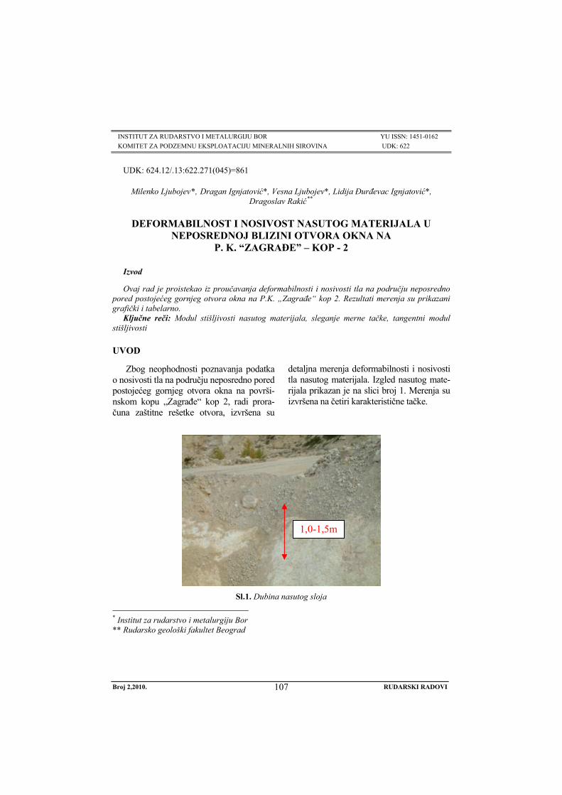
INSTITUT ZA RUDARSTVO I METALURGIJU BOR YU ISSN: 1451-0162 KOMITET ZA PODZEMNU EKSPLOATACIJU MINERALNIH SIROVINA UDK: 622
UDK: 624.12/.13:622.271(045)=861
Milenko Ljubojev*, Dragan Ignjatović*, Vesna Ljubojev*, Lidija Đurđevac Ignjatović*, Dragoslav Rakić**
DEFORMABILNOST I NOSIVOST NASUTOG MATERIJALA U NEPOSREDNOJ BLIZINI OTVORA OKNA NA
P. K. “ZAGRAĐE” – KOP - 2
Izvod
Ovaj rad je proistekao iz proučavanja deformabilnosti i nosivosti tla na području neposredno pored postojećeg gornjeg otvora okna na P.K. „Zagrađe“ kop 2. Rezultati merenja su prikazani grafički i tabelarno.
Ključne reči: Modul stišljivosti nasutog materijala, sleganje merne tačke, tangentni modul stišljivosti
* Institut za rudarstvo i metalurgiju Bor** Rudarsko geološki fakultet Beograd
UVOD
Zbog neophodnosti poznavanja podatka o nosivosti tla na području neposredno pored postojećeg gornjeg otvora okna na površi-nskom kopu „Zagrađe“ kop 2, radi prora-čuna zaštitne rešetke otvora, izvršena su
detaljna merenja deformabilnosti i nosivosti tla nasutog materijala. Izgled nasutog mate-rijala prikazan je na slici broj 1. Merenja su izvršena na četiri karakteristične tačke.
1,0-1,5m
Sl.1. Dubina nasutog sloja
Broj 2,2010. RUDARSKI RADOVI
107
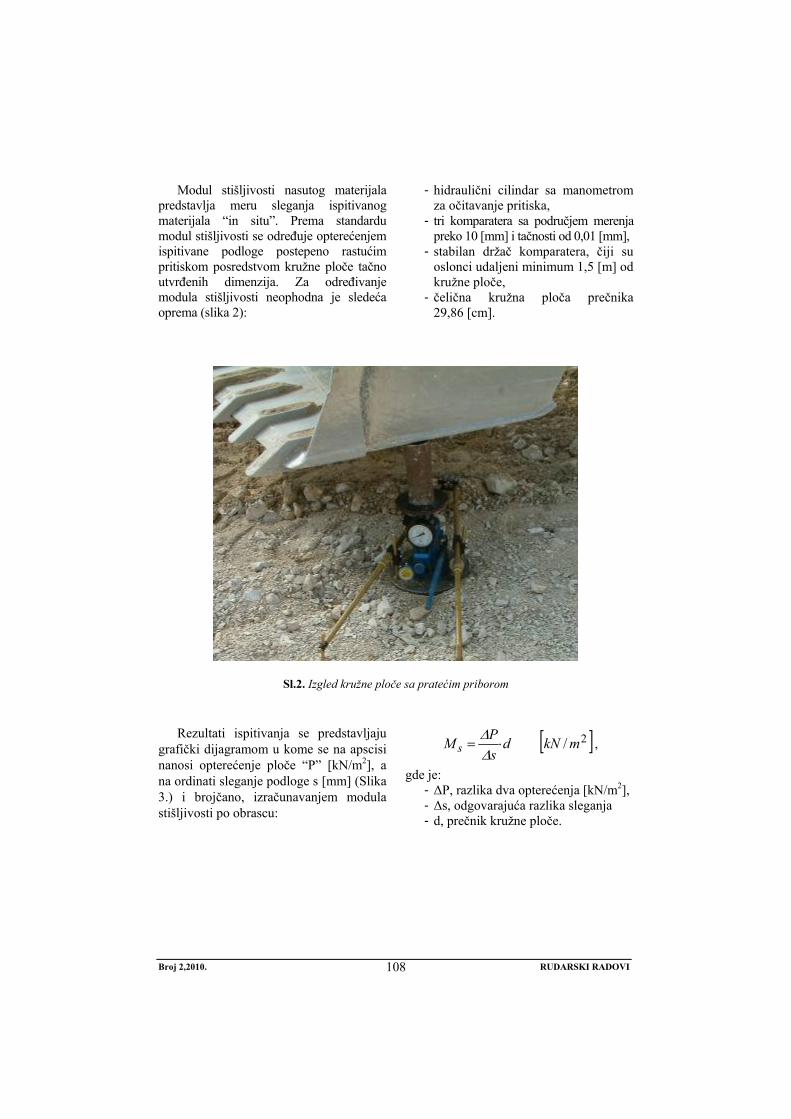
Modul stišljivosti nasutog materijala predstavlja meru sleganja ispitivanog materijala “in situ”. Prema standardu modul stišljivosti se određuje opterećenjem ispitivane podloge postepeno rastućim pritiskom posredstvom kružne ploče tačno utvrđenih dimenzija. Za određivanje modula stišljivosti neophodna je sledeća oprema (slika 2):
- hidraulični cilindar sa manometrom za očitavanje pritiska,
- tri komparatera sa područjem merenja preko 10 [mm] i tačnosti od 0,01 [mm],
- stabilan držač komparatera, čiji su oslonci udaljeni minimum 1,5 [m] od kružne ploče,
- čelična kružna ploča prečnika 29,86 [cm].
Sl.2. Izgled kružne ploče sa pratećim priborom
Rezultati ispitivanja se predstavljaju grafički dijagramom u kome se na apscisi nanosi opterećenje ploče “P” [kN/m2], a na ordinati sleganje podloge s [mm] (Slika 3.) i brojčano, izračunavanjem modula stišljivosti po obrascu:
[ ]2/ mkNdsPM s ⋅=ΔΔ
,
gde je: - ΔP, razlika dva opterećenja [kN/m2], - Δs, odgovarajuća razlika sleganja - d, prečnik kružne ploče.
Broj 2,2010. RUDARSKI RADOVI
108

2,5
2,0
1,5
1,0
0,5
3,0
3,5
4,0
0 50 100 150 200 250 300 350 400
Opterecenje
Sleg
anje
u [m
] 10
[kN/m ] 2
[kN/m ]2
3
2
1
IV
III
II
I
-3
.
Sl. 3. Granične linije sleganja
Na dijagramu slike. 3. granične linije sleganja dele dijagram na četiri zone:
- Zona I, ispod linije 1, pripada tlu ne-dovoljne nosivosti,
- Zona II, između linija 1 i 2, pripada tlu dovoljne nosivosti,
- Zona III, između linija 2 i 3, pripada donjem nosećem sloju dovoljne nosivosti,
- Zona IV, iznad linije 3, pripada gorn-jem nosećem sloju dovoljne nosivosti.
REZULTATI ISPITIVANJA PA-RAMETARA DEFORMABILNOSTI
Rezultati parametara deformabilnosti tačke 1.
Sl. 4. Kružna ploča na tački 1.
Broj 2,2010. RUDARSKI RADOVI
109
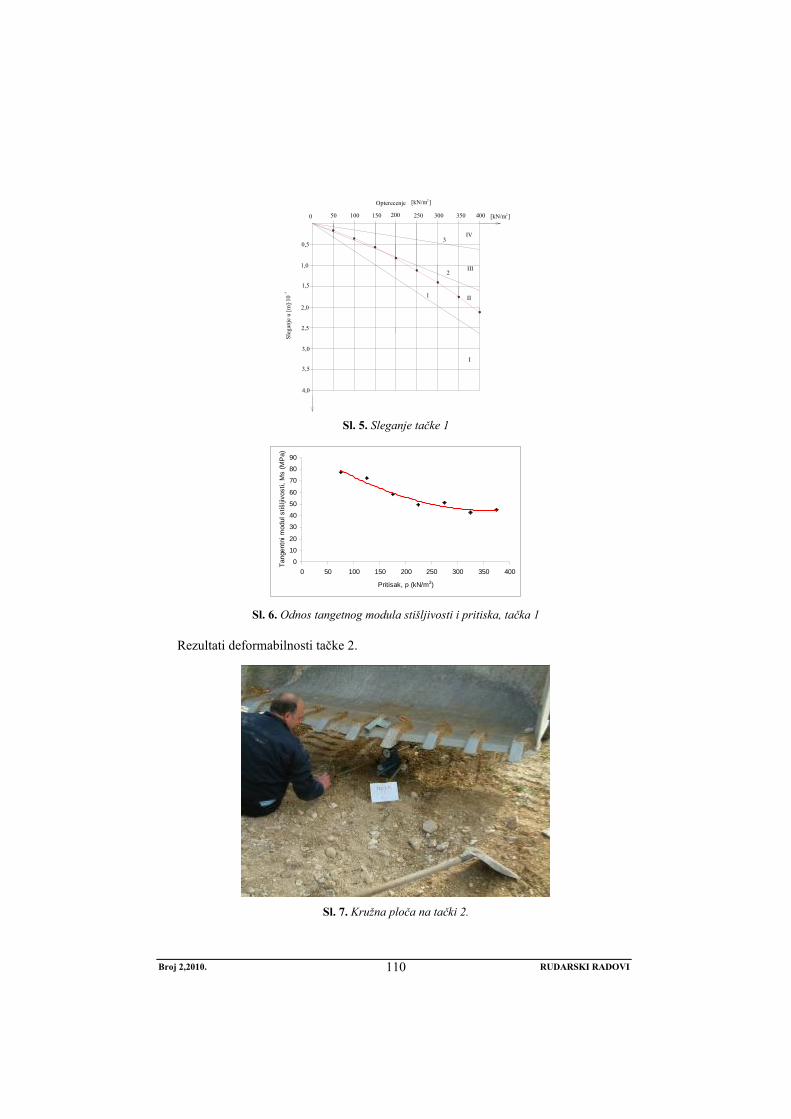
2,5
2,0
1,5
1,0
0,5
3,0
3,5
4,0
0 50 100 150 200 250 300 350 400
Opterecenje
Sleg
anje
u [m
] 10
[kN/m ] 2
[kN/m ] 2
3
2
1
IV
III
II
I
-3
.
Sl. 5. Sleganje tačke 1
0
10
20
30
40
50
60
70
80
90
0 50 100 150 200 250 300 350 400
Pritisak, p (kN/m2)
Tang
entn
i mod
ul s
tišlji
vost
i, M
s (M
Pa)
Sl. 6. Odnos tangetnog modula stišljivosti i pritiska, tačka 1
Rezultati deformabilnosti tačke 2.
Sl. 7. Kružna ploča na tački 2.
Broj 2,2010. RUDARSKI RADOVI
110
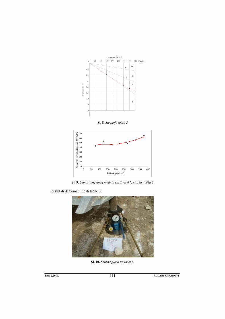
2,5
2,0
1,5
1,0
0,5
3,0
3,5
4,0
0 50 100 150 200 250 300 350 400
Opterecenje
Sleg
anje
u [m
] 10
[kN/m ] 2
[kN/m ] 2
3
2
1
IV
III
II
I
-3
.
Sl. 8. Sleganje tačke 2
0
10
20
30
40
50
60
70
0 50 100 150 200 250 300 350 400
Pritisak, p (kN/m2)
Tang
entn
i mod
ul s
tišlji
vost
i, M
s (M
Pa)
Sl. 9. Odnos tangetnog modula stisljivosti i pritiska, tačka 2
Rezultati deformabilnosti tačke 3.
Sl. 10. Kružna ploča na tački 3.
Broj 2,2010. RUDARSKI RADOVI
111

2,5
2,0
1,5
1,0
0,5
3,0
3,5
4,0
0 50 100 150 200 250 300 350 400
Opterecenje
Sleg
anje
u [m
] 10
[kN/m ] 2
[kN/m ]2
3
2
1
IV
III
II
I
-3
.
Sl. 11. Sleganje tačke 3
0
20
40
60
80
100
120
140
160
180
0 50 100 150 200 250 300 350 400
Pritisak, p (kN/m2)
Tang
entn
i mod
ul s
tišlji
vost
i, M
s (M
Pa)
Sl. 12. Odnos tangetnog modula stisljivosti i pritiska, tačka 3
Rezultati parametara deformabilnosti tačke 4.
Sl. 13. Kružna ploča na tački 4.
Broj 2,2010. RUDARSKI RADOVI
112

2,5
2,0
1,5
1,0
0,5
3,0
3,5
4,0
0 50 100 150 200 250 300 350 400
Opterecenje
Sleg
anje
u [m
] 10
[kN/m ] 2
[kN/m ] 2
3
2
1
IV
III
II
I
-3
.
Sl. 14. Sleganje tačke 4
0
50
100
150
200
250
300
350
0 50 100 150 200 250 300 350 400
Pritisak, p (kN/m2)
Tang
entn
i mod
ul s
tišlji
vost
i, M
s (M
Pa)
Sl. 15. Odnos tangetnog modula stisljivosti i pritiska, tačka 4
NOSIVOST NASUTOG MATERI-JALA
Suština projektovanja i analiza temelja zavisi od nosivosti materijala temeljnog dna. U ovom slučaju pod navedenim po-jmom nosivost materijala se podrazumeva čvrstoća materijala ispod temeljnog dna koja se suprotstavlja lomu usled smičućih napona.
Za temeljnu stopu u obliku trake, Ter-
zaghi-ev obrazac za izračunavanje granične nosivosti ima sledeći oblik:
γγγ NBNhNcq qcf ⋅⋅⋅+⋅⋅+⋅= 21 5,0
c = 0, - kohezija nasutog krečnjačkog materijala
Broj 2,2010. RUDARSKI RADOVI
113

Nc, Nq, Nγ, - faktori nosivosti i zavise od
ugla unutrašnjeg trenja Nq = 40; Nγ = 40 h = 0,35 i 0,5 [m] – dubina temeljenja γ1 = 16,68 [kN/m3] – zapreminska težina
nasutog materijala γ2 = 16,68 [kN/m3] – zapreminska teži-
na ispod temelj- nog dna
B = 0,5 [m] – širina temelja
Tabela 1.
Dubina temelja
[m]
Širina temelja
[m]
Granična nosivost temelj-nog materijala
[kN/m3]
0,35 0,35 350,28 0,50 0,35 450,36 0,50 0,50 500,40
ZAKLJUČAK
Izračunata granična nosivost je prika-zana u tabeli 1. i kreće se od 350,28 do 500,40 [kN/m3] u zavisnosti od dubine temeljenja i njihove širine.
Na osnovu dobijenih rezultata granične nosivosti temeljnog materijala, može se zaključiti da je potrebno izvršiti dodatno sabijanje terena, kako bi se ujednačila i povećala zbijenost.
LITERATURA
[1] Izveštaj o deformabilnosti i nosivosti nasutog materijala u neposrednoj blizini otvora okna na P.K. “Zagrađe” Kop-2, Bor, Oktobar 2008. Godine
[2] M. Ljubojev, M. Avdić, V. Ljubojev, D. Ignjatović, L. Đ. Ignjatović, Opažanje promena I merenje sleganja na kolektoru VZO P.K. “Bogutovo selo” u Ugljeviku, Rudarski radovi, 1/2010, str. 25-36
[3] M. Ljubojev, M. Avdić, D. Ignjatović, L. Đ. Ignjatović, Uticaj flotacijskog jalovišta polja 2 na stabilnost tunela Kriveljske reke, Rudarski radovi, 2/2009, str. 21-28
[4] M. Ljubojev, R. Popović, Osnove geomehanike, RTB Bor, Institut za bakar Bor, 2006.
[5] R. Popović, M. Ljubojev, Principi rešavanja problema u geomehanici, RTB Bor, Institut za bakar, Indok centar, 2007.
[6] M. Ljubojev, M. Avdić, M. Bugarin, R. Popović, i D. Ignjatović, Tunnel analysis in fault zones and the effects of stress distribution on the support, Journal of mining and metallurgy, section A, 1, 2009, str. 49-57
[7] M. Ljubojev, M. Ivković, J. Miljanović i L. Đurđevac. Ignjatović, Testing of geomechanical properties of coal series in order for support determination of the mechanized stope on the example of „stara jama“ mine in „Lubnica“, Journal of mining and metallurgy, section A, 1, 2009, str. 58-70
Broj 2,2010. RUDARSKI RADOVI
114

MINING AND METALLURGY INSTITUTE BOR YU ISSN: 1451-0162 COMMITTEE OF UNDERGROUND EXPLOITATION OF THE MINERAL DEPOSITS UDK: 622
UDK: 624.12/.13:622.271(045)=20
Milenko Ljubojev*, Dragan Ignjatović*, Vesna Ljubojev*, Lidija Đurđevac Ignjatović*, Dragoslav Rakić**
DEFORMATION AND BEARING CAPACITY OF BURRIED MATERIAL NEAR THE SHAFT OPENING AT THE OPEN PIT MINE
”ZAGRADJE”-OPEN PIT 2
Abstract
This paper is the result of study the deformation and bearing capacity of soil in the area near the existing upper opening of shaft at the the open pit mine “Zagradje” open pit 2. The results of measurement are presented graphically and in tables.
Key words: compressibility module, buried material, subsidence of measuring point, tangent module of compressibility
* Mining and Metallurgy Institute Bor ** University of Belgrade, Faculty of Mining and Geology, Serbia
INTRODUCTION
Due to the necessity of knowing the data on soil bearing capacity in the area near the existing upper opening of shaft at the the open pit mine „Zagradje” open pit 2, due to calculate the protective grid of openings,
detailed measurements of deformation and bearing capacity of the buried material were carried out. The view of buried material is shown in Figure 1. Measurements were car-ried out at four characteristic points.
1,0-1,5m
Figure 1. Depth of buried layer
No 2,2010. MINING ENGINEERING
115
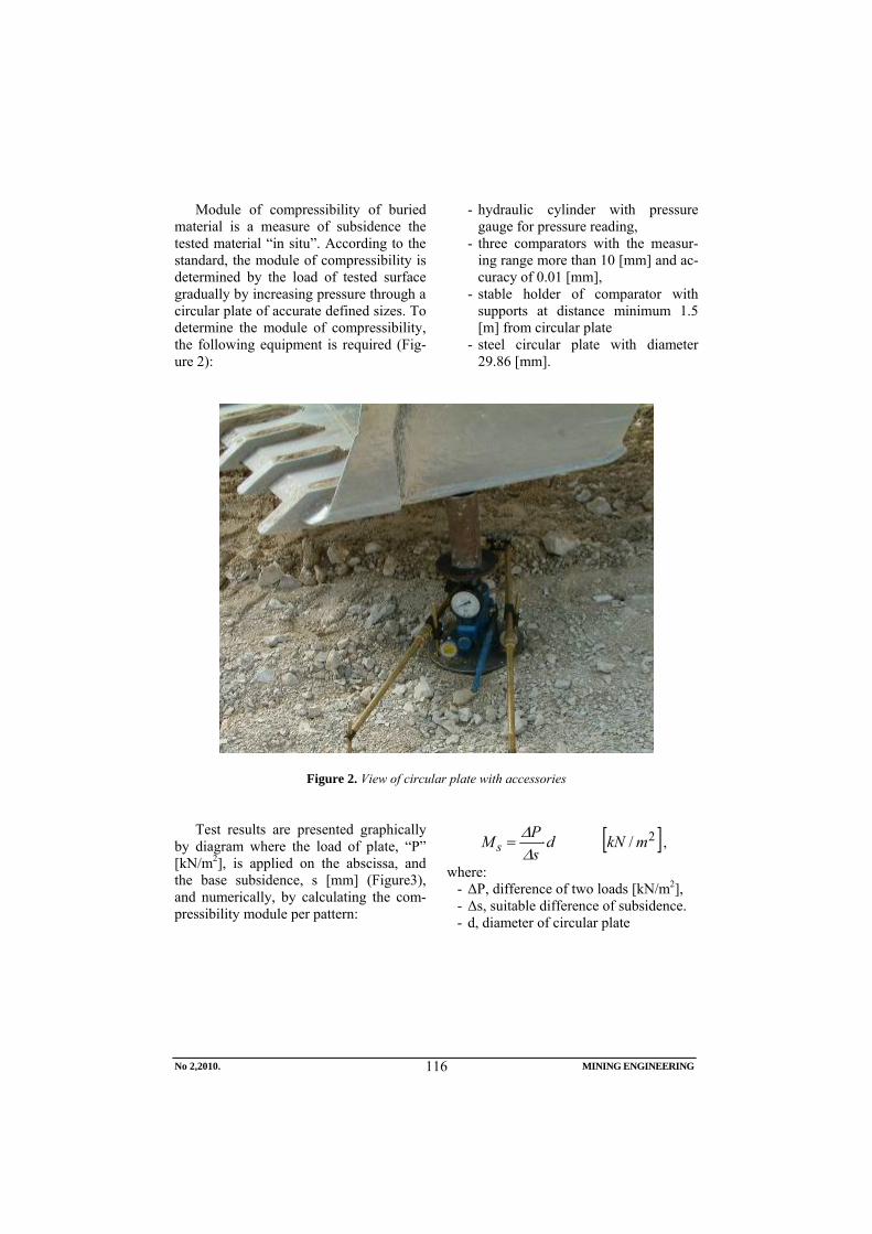
Module of compressibility of buried material is a measure of subsidence the tested material “in situ”. According to the standard, the module of compressibility is determined by the load of tested surface gradually by increasing pressure through a circular plate of accurate defined sizes. To determine the module of compressibility, the following equipment is required (Fig-ure 2):
- hydraulic cylinder with pressure gauge for pressure reading,
- three comparators with the measur-ing range more than 10 [mm] and ac-curacy of 0.01 [mm],
- stable holder of comparator with supports at distance minimum 1.5 [m] from circular plate
- steel circular plate with diameter 29.86 [mm].
Figure 2. View of circular plate with accessories
Test results are presented graphically
by diagram where the load of plate, “P” [kN/m2], is applied on the abscissa, and the base subsidence, s [mm] (Figure3), and numerically, by calculating the com-pressibility module per pattern:
[ ]2/ mkNdsPM s ⋅=ΔΔ
,
where: - ΔP, difference of two loads [kN/m2], - Δs, suitable difference of subsidence. - d, diameter of circular plate
No 2,2010. MINING ENGINEERING
116

2,5
2,0
1,5
1,0
0,5
3,0
3,5
4,0
0 50 100 150 200 250 300 350 400
Opterecenje
Sleg
anje
u [m
] 10
[kN/m ] 2
[kN/m ] 2
3
2
1
IV
III
II
I
-3
.
Figure 3. Boundary lines of subsidence
In diagram in Figure 3, the limit lines
of subsidence divide diagram into four zones:
- Zone I, below the line 1, belongs to the ground of insufficient bearing capacity,
- Zone II, between the lines 1 and 2, belongs to the ground of sufficient capacity,
- Zone III, between lines 2 and 3,
belongs to the lower carrying layer of sufficient capacity,
- Zone IV, above the line 3, belongs to the upper carrying layer of sufficient capacity.
TEST RESULTS OF DEFORMATION PARAMETERS
The results of deformation parameters of point 1:
Figure 4. Circular plate at point 1
No 2,2010. MINING ENGINEERING
117

2,5
2,0
1,5
1,0
0,5
3,0
3,5
4,0
0 50 100 150 200 250 300 350 400
Opterecenje
Sleg
anje
u [m
] 10
[kN/m ] 2
[kN/m ] 2
3
2
1
IV
III
II
I
-3
.
Figure 5. Subsidence of point 1
0
10
20
30
40
50
60
70
80
90
0 50 100 150 200 250 300 350 400
Pritisak, p (kN/m2)
Tang
entn
i mod
ul s
tišlji
vost
i, M
s (M
Pa)
Figure 6. Ratio of tangential module of compressibility and pressure, point 1
The results of deformation parameters of point 2:
Figure 7. Circular plate at point 2
No 2,2010. MINING ENGINEERING
118
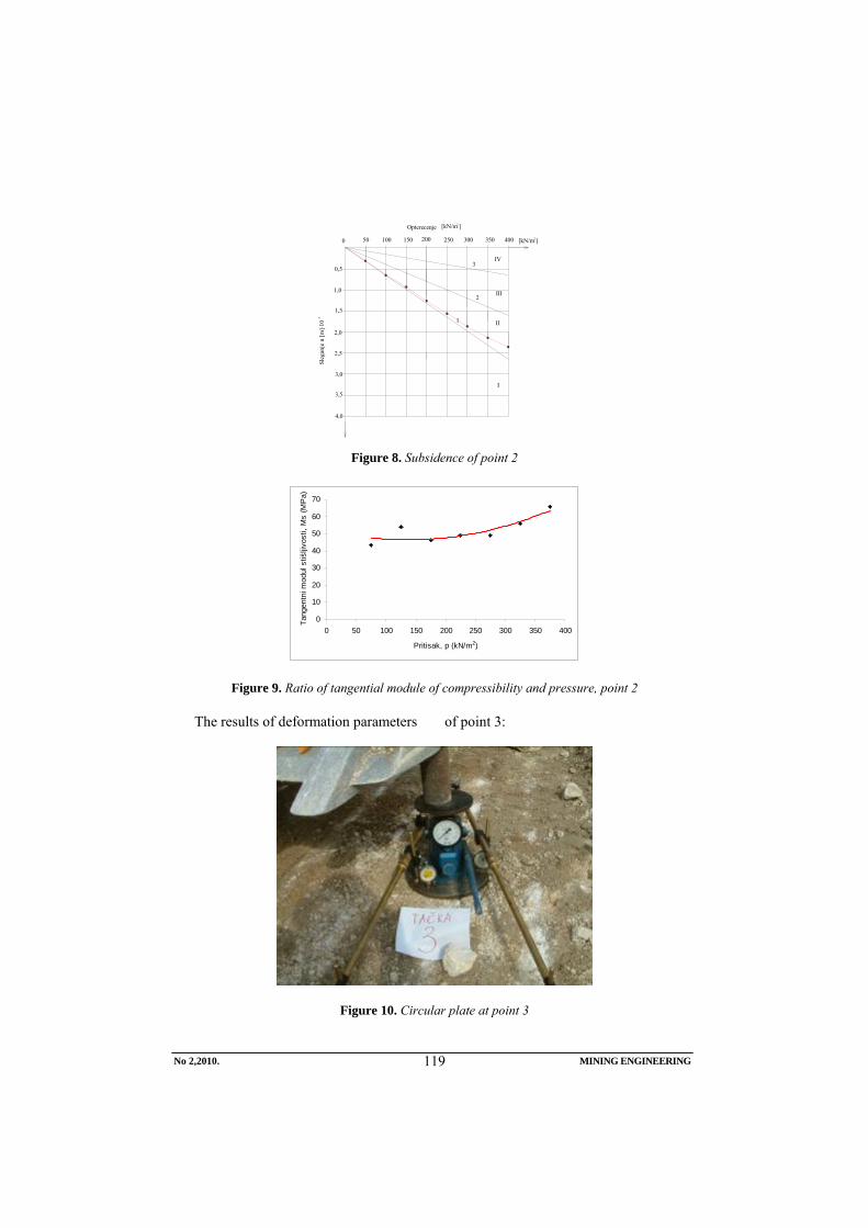
2,5
2,0
1,5
1,0
0,5
3,0
3,5
4,0
0 50 100 150 200 250 300 350 400
Opterecenje
Sleg
anje
u [m
] 10
[kN/m ] 2
[kN/m ] 2
3
2
1
IV
III
II
I
-3
.
Figure 8. Subsidence of point 2
0
10
20
30
40
50
60
70
0 50 100 150 200 250 300 350 400
Pritisak, p (kN/m2)
Tang
entn
i mod
ul s
tišlji
vost
i, M
s (M
Pa)
Figure 9. Ratio of tangential module of compressibility and pressure, point 2
The results of deformation parameters of point 3:
Figure 10. Circular plate at point 3
No 2,2010. MINING ENGINEERING
119
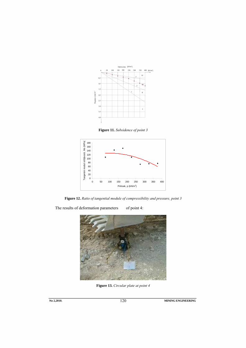
2,5
2,0
1,5
1,0
0,5
3,0
3,5
4,0
0 50 100 150 200 250 300 350 400
Opterecenje
Sleg
anje
u [m
] 10
[kN/m ] 2
[kN/m ] 2
3
2
1
IV
III
II
I
-3
.
Figure 11. Subsidence of point 3
0
20
40
60
80
100
120
140
160
180
0 50 100 150 200 250 300 350 400
Pritisak, p (kN/m2)
Tang
entn
i mod
ul s
tišlji
vost
i, M
s (M
Pa)
Figure 12. Ratio of tangential module of compressibility and pressure, point 3
The results of deformation parameters of point 4:
Figure 13. Circular plate at point 4
No 2,2010. MINING ENGINEERING
120

2,5
2,0
1,5
1,0
0,5
3,0
3,5
4,0
0 50 100 150 200 250 300 350 400
Opterecenje
Sleg
anje
u [m
] 10
[kN/m ] 2
[kN/m ] 2
3
2
1
IV
III
II
I
-3
.
Figure 14. Subsidence of 4
0
50
100
150
200
250
300
350
0 50 100 150 200 250 300 350 400
Pritisak, p (kN/m2)
Tang
entn
i mod
ul s
tišlji
vost
i, M
s (M
Pa)
Figure 15. Ratio of tangential module of compressibility and pressure, point 4
BEARING CAPACITY OF THE BURRIED MATERIAL
The essence of design and analysis of foundations depends on the material ca-pacity of foundation bottom. In this case, the said concept of material carrying ca-pacity means the material strength below foundation bottom in contrast to the frac-ture due to shear stresses.
For footing in the form of tape, the
Terzaghi form to calculate the limit bear-ing capacity is expressed as follows:
γγγ NBNhNcq qcf ⋅⋅⋅+⋅⋅+⋅= 21 5,0
c = 0 - cohesion of the buried limestone material
No 2,2010. MINING ENGINEERING
121

Nc, Nq, Nγ - load factors, depending on
the angle of internal friction Nq = 40; Nγ = 40 h = 0.35 and 0.5 [m] – depth of founda-
tion γ1 = 16.68 [kN/m3] – volumetric weight
of the buried ma-terial
γ2 = 16.68 [kN/m3] – bulk density below the foundation bottom
B = 0.5 [m] – width of foundation Table 1
Depth of foundation
[m]
Width of foundation
[m]
Limit bearing capacity of
foundation ma-terial [kN/m3]
0.35 0.35 350.28 0.50 0.35 450.36 0.50 0.50 500.40
CONCLUSION
The calculated limit bearing capacity is presented in Table 1 and ranges from 350.28 to 500.40 [kN/m3] depending on the depth of foundation and its width.
Based on the obtained results of limit bearing capacity of foundation material, it can be concluded that it is necessary to carry out further compaction of terrain in order to obtain the uniform and increase density.
REFERENCES
[1] Report on Deformation and Bearing Capacity of Buried Material near the Shaft Opening at the Open Pit Mine “Zagradje” Open Pit-2, Bor, October 2008 (in Serbian)
[2] M. Ljubojev, M. Avdić, V. Ljubojev, D. Ignjatović, L. Dj. Ignjatović, Obser-vation of Changes and Measurement of Subsidence on the collector VZO OP “Bogutovo selo” in Ugljevik, Mining Engineering, 1/2010, pp. 25-36
[3] M. Ljubojev, M. Avdić, D. Ignjatović, L. Dj. Ignjatović, The Effect of Flotation Tailing Dump of the Field 2 on stability of the Kriveljska River Tunnel, Mining Engineering, 2/2009, pp. 21-28
[4] M. Ljubojev, R. Popović, Fundamentals of the Soil Mechanics, RTB Bor, Copper Institute Bor, 2006 (in Serbian)
[5] R. Popović, M. Ljubojev, Principles of the Problem Solving in Geomechanics, RTB Bor, Copper Institute Bor, INDOC Center, 2007 (in Serbian)
[6] M. Ljubojev, M. Avdić, M. Bugarin, R. Popović, and D. Ignjatović, Tunnel analysis in fault zones and the effects of stress distribution on the support, Journal of mining and metallurgy, section A, 1, 2009, pp. 49-57
[7] M. Ljubojev, M. Iivkovićdić, J. Miljanović and L. Đurđevac. Ignjatović, Testing of geomechanical properties of coal series in order for support determination of the mechanized stope on the example of „stara jama“ mine in „Lubnica“, Journal of mining and metallurgy, section A, 1, 2009, pp. 58-70
No 2,2010. MINING ENGINEERING
122

INSTITUT ZA RUDARSTVO I METALURGIJU BOR YU ISSN: 1451-0162 KOMITET ZA PODZEMNU EKSPLOATACIJU MINERALNIH SIROVINA UDK: 622
UDK: 340.134:628.4(045)=861
Ljubiša Obradović*, Mile Bugarin*, Zoran Stevanović*, Milenko Ljubojev*, Zvonko Milijić**
ODLAGANJE OPASNOG OTPADA NA DEPONIJE U SKLADU SA DI-REKTIVOM EVROPSKE UNIJE O DEPONIJAMA br. 1999/31/EU
Izvod
Izbor lokacije i uređenje deponija otpadnog materijala se u Srbiji vrši prema važećem Pravilniku o kriterijumima za određivanje lokacije i uređenje deponija otpadnih materijala iz 1992. godine (''Sl. glasnik RS'', br. 54/92). Ovim Pravilnikom su sve deponije svrstane u isti ''koš'', odnosno za izbor i uređenje lokacija važe isti kriterijumi bez obzira da li se radi o deponiji kućnog odnosno komunalnog otpada, inertnog otpada u koji spadaju razni građevinski otpadi (otpadi nastali u toku rada i uređenje na gradilišima), kao i otpadi koji su po svojim karakteristikama svrstani u opasne otpade. Donošenjem Zakona o Upravljanju otpadom RS 2009. godine, stvoreni su preduslovi za projektovanje i izgradnju i drugih vrsta deponija, koje ovaj zakon prepoznaje i svrstava u tri kategorije, zavisno od karakteristika samog otpada, odnosno od njegovog štetnog uticaja na životnu sredinu. U radu je detaljno obrađena Direktiva o deponijama otpada br. 1999/31/EU, koja po preporuci Ministarstva za zaštitu životne sredine predstavlja osnovni dokument, na osnovu koga će se izraditi novi pravilnici o odlaganju svih vrsta otpada u Republici Srbiji.
Ključne reči: direktiva 1999/31/EU, deponija, opasan otpad, projektovanje
* Institut za rudarstvo i metalurgiju, Bor ** RTB Bor
UVOD
Usaglašavanje zakonodavstva Republike Srbije sa zakonodavstvom Evropske Unije iz domena zaštite životne sredine i upravljanja otpadom je teoretski započeto 2000. godine, kada je RS uključena u proces Stabilizacije i pridruživanja. Praktičnim početkom pridru-živanja EU uzima se oktobar 2004. godine, kada je u Narodnoj Skupštini usvojena Rezolucija o pridruživanju Evropskoj Uniji. Dalji proces pridruživanja EU je septembra 2008. godine dobio zakonsku potporu kada je Narodna Skupština ratifikovala Sporazum
o stabilizaciji i pridruživanju Republike Srbije EU. Na osnovu ovog Sporazuma Vlada RS je oktobra 2008. godine usvojila Nacionalni program za integraciju (NPI) Republike Srbije u Evropsku Uniju, kao strateški dokument koji objedinjuje sva dokumenta i akcione planove neophodne za proces evropskih integracija i definiše obaveze svih aktera za period do kraja 2012. godine.
Od 1992. godine do danasnjih dana izbor lokacije i uređenje deponija otpadnog materijala se u Srbiji vrši prema važećem
Broj 2,2010. RUDARSKI RADOVI
123
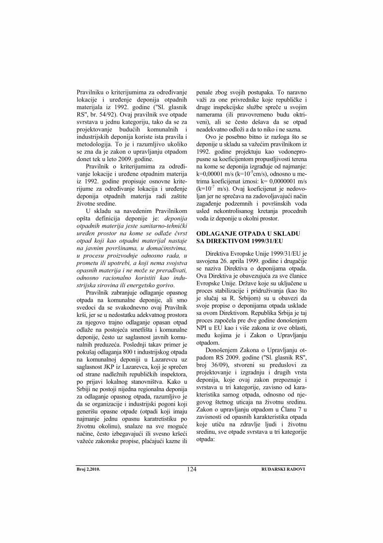
Pravilniku o kriterijumima za određivanje lokacije i uređenje deponija otpadnih materijala iz 1992. godine (''Sl. glasnik RS'', br. 54/92). Ovaj pravilnik sve otpade svrstava u jednu kategoriju, tako da se za projektovanje budućih komunalnih i industrijskih deponija koriste ista pravila i metodologija. To je i razumljivo ukoliko se zna da je zakon o upravljanju otpadom donet tek u leto 2009. godine.
Pravilnik o kriterijumima za određi-vanje lokacije i uređene otpadnim materija iz 1992. godine propisuje osnovne krite-rijume za određivanje lokacija i uređenje deponija otpadnih materija radi zaštite životne sredine.
U skladu sa navedenim Pravilnikom opšta definicija deponije je: deponija otpadnih materija jeste sanitarno-tehnički uređen prostor na kome se odlaže čvrst otpad koji kao otpadni materijal nastaje na javnim površinama, u domaćinstvima, u procesu proizvodnje odnosno rada, u prometu ili upotrebi, a koji nema svojstva opasnih materija i ne može se prerađivati, odnosno racionalno koristiti kao indu-strijska sirovina ili energetsko gorivo.
Pravilnik zabranjuje odlaganje opasnog otpada na komunalne deponije, ali smo svedoci da se svakodnevno ovaj Pravilnik krši, jer se u nedostatku adekvatnog prostora za njegovo trajno odlaganje opasan otpad odlaže na postojeća smetlišta i komunalne deponije, često uz saglasnost javnih komu-nalnih preduzeća. Poslednji takav primer je pokušaj odlaganja 800 t industrijskog otpada na komunalnoj deponiji u Lazarevcu uz saglasnost JKP iz Lazarevca, koji je sprečen od strane nadležnih republičkih inspektora, po prijavi lokalnog stanovništva. Kako u Srbiji ne postoji nijedna regionalna deponija za odlaganje opasnog otpada, razumljivo je da se organizacije i industrijski pogoni koji generišu opasne otpade (otpadi koji imaju najmanje jednu opasnu karatretistiku po životnu okolinu), snalaze na sve moguće načine, često izbegavajući ili svesno kršeći važeće zakonske propise, plaćajući kazne ili
penale zbog svojih postupaka. To naravno važi za one privrednike koje republičke i druge inspekcijske službe spreče u svojim namerama (ili pravovremeno budu oktri-veni), ali se često dešava da se otpad neadekvatno odloži a da to niko i ne sazna.
Ovo je posebno bitno iz razloga što se deponije u skladu sa važećim pravilnikom iz 1992. godine projektuju kao vodonepro-pusne sa koeficijentom propustljivosti terena na kome se deponija izgrađuje od najmanje: k=0,00001 m/s (k=10-5cm/s), odnosno u me-trima koeficijenat iznosi: k= 0,0000001 m/s (k=10-7 m/s). Ovaj koeficijenat je nedovo-ljan jer ne sprečava na zadovoljavajući način zagađenje podzemnih i površinskih voda usled nekontrolisanog kretanja procednih voda iz deponije u okolni prostor.
ODLAGANJE OTPADA U SKLADU SA DIREKTIVOM 1999/31/EU
Direktiva Evropske Unije 1999/31/EU je usvojena 26. aprila 1999. godine i drugačije se naziva Direktiva o deponijama otpada. Ova Direktiva je obavezujuća za sve članice Evropske Unije. Države koje su uključene u proces stabilizacije i pridruživanja (kao što je slučaj sa R. Srbijom) su u obavezi da svoje propise o deponijama otpada usklade sa ovom Direktivom. Republika Srbija je taj proces započela pre dve godine donošenjem NPI u EU kao i više zakona iz ove oblasti, među kojima je i Zakon o Upravljanju otpadom.
Donošenjem Zakona o Upravljanju ot-padom RS 2009. godine (''Sl. glasnik RS'', broj 36/09), stvoreni su preduslovi za projektovanje i izgradnju i drugih vrsta deponija, koje ovaj zakon prepoznaje i svrstava u tri kategorije, zavisno od kara-kteristika samog otpada, odnosno od nje-govog štetnog uticaja na životnu sredinu. Zakon o upravljanju otpadom u Članu 7 u zavisnosti od opasnih karakteristika otpada koje utiču na zdravlje ljudi i životnu sredinu, sve otpade svrstava u tri kategorije otpada:
Broj 2,2010. RUDARSKI RADOVI
124

1. opasan otpad jeste otpad koji po svom poreklu, sastavu ili kon-centraciji opasnih materija može prouzrokovati opasnost po životnu sredinu i zdravlje ljudi i ima najmanje jednu od opasnih karakteristika utvrđenih posebnim propisima.;
2. neopasan otpad jeste otpad koji nema karakteristike opasnog otpada;
3. inertni je onaj otpad koji nije podložan fizičko/hemijskim ili biološkim promenama.
Na osnovu Zakona o Upravljanju otpadom RS i Diretive 1999/31/EU u Ministarstvu za Životnu sredinu je započeta izrada novih Pravilnika o deponijama u skladu sa navedenim Zakonom i Direktivom. To praktično znači da će u budućnosti projektovanje i izgradnja svih vrsta deponija u RS biti na adekvatan način definisana i precizirana. Preporuka je resornog Ministarstva RS da se do završetka navedenih podzakonskih akata (pravilnika i uredbi), pri projektovanju novih deponija koristi Direktiva EU o deponijama otpada br. 1999/31/EU, uz konsultacije sa odgovarajućim službama u resornom Ministarstvu.
a) Kratak opis Direktive 1999/31/EU i pripadajućih aneksa
Direktiva Saveta EU o deponijama otpada br. 1999/31/EU je usvojena 26. aprila 1999. godine, a potpisana je od strane predsednika saveta J. Fischera. Direktiva je obavezujuća za sve članice EU. Direktiva sadrži ukupno 20 Člana u kojima je preciznije obuhvaćeno sledeće: opšti cilj, definicije, obim primene, klase deponija, otpad koji treba da bude prihvaćen u različite klase deponija, zahtev za dozvolu, uslovi dozvole, sadržaj dozvole, troškovi deponije otpada, procedure prihvatanja otpada, procedure kontrole i monitoringa u operativnoj fazi, procedure zatvaranja i
održavanja, postojeće deponije otpada, obaveza izveštavanja, odbor, procedura odbora, transpozicija, stupanje na snagu i adresati.
Osim izvornog dokumenta Direktiva obuhvata i tri pripadajuća Aneksa:
− Aneks I - Opšti zahtevi za sve klase deponija;
− Aneks II - Kriterijumi prihvatanja i procedure;
− Aneks III - Procedure kontrole i monitoringa u radu i fazama održavanja.
Članom 4 Direktive o deponijama otpa-da je precizirano da svaka deponija mora biti klasifikovana u jednu od sledećih klasa:
− Deponija za opasan otpad; − Deponija za neopasan otpad; − Deponija za inertni otpad.
b) Opšti zahtevi za sve klase deponija - Aneks I
Ovim Aneksom su bliže određeni sledeći parametri-pojmovi:
1. Lokacija - lokacija deponije mora uzeti u obzir pre svega uslove koji se odnose na: udaljenost deponije od stambenih i drugih urbanih objekata, vodotokova, poljoprivrednog zemlji-šta i dr.; postojanje podzemnih voda, primorskih voda ili zaštitnih pri-rodnih zona; geoloških i hidrogeo-loških uslova u području; rizika od poplava, klizišta, sleganja; zaštize prirode i kulturne baštine u području.
2. Kontrola vode i upravljanje pro-cednom vodom - mere koje se pre-duzimaju zavise od karakteristika deponija i metroroloških uslova i preduzimaju se u cilju: kontrole atmosferskih voda koje ulaze u telo deponije; sprečavanja ulaska površinskih i podzemnih voda u deponiju otpada; prikupljanja zaga-đene vode i procedne vode i nje-
Broj 2,2010. RUDARSKI RADOVI
125

nom tretiranju i prečišćavanju ako je to potrebno.
3. Zaštita zemljišta i voda - deponija mora da bude isprojektovana i izgrađena tako da ispunjava neo-phodne uslove za sprečavanje zaga-đenja zemljišta, podzemnih i površi-nskih voda i obezbedi efikasno sakupljanje procednih voda iz tela deponije. Zaštita voda i zemljišta se postiže kombinacijom geološke barijere i oblaganja dna nepropu-snom folijom tokom opera-tivne/aktivne faze i kombinacijom geološke barijere i oblaganja na vrhu tokom pasivne faze/posle zatvaranja. Geološka barijera je sastavljena od mineralnog sloja i određena je geološkim i hidro-geološkim uslovima ispod i u neposrednoj blizini lokacije depo-nije sa sledećim minimalnim koefi-
cijentima propustljivosti:
− deponija opasnog otpada:
K ≤ 1,0 x 10⁻⁹ m/s; debljina ≥ 5 m;
− deponija neopasnog otpada:
K ≤ 1,0 x 10⁻⁹ m/s: debljina ≥ 1,0;
− deponija inertnog otpada:
K ≤ 1,0 x 10⁻⁷ m/s: debljina ≥ 1,0.
Ukoliko geološka barijera ne zado-voljava napred definisane uslove može se veštački ojačati materijalima sa drugih lokacija, dajući jednaku zaštitu. Debljina sloja veštački uspostavljene geološke barijere ne sme biti manja od 0,5 m.
Pored gore opisane geološke barijere, neophodno je izgraditi i odgovarajući drenažni sloj na dnu deponije radi održavanja akumulacije procednih voda na minimumu, u skladu sa tabelom 1.
Tabela 1. Sakupljanje procednih voda i zaptivanje dna deponije
Kategorija deponije Neopasan otpad Opasan otpad Veštačka zaptivna obloga potrebno potrebno
Drenažni sloj ≥ 0,5 m potrebno potrebno
U narednoj tabeli 2 date su preporuke za izgradnju površinskog sloja za
zaptivanje deponije po završetku eksploa-tacionog perioda.
Tabela 2. Preporuke za zaptivanje površine deponije posle eksploatacije
Kategorija deponije Neopasan otpad Opasan otpad Drenažni sloj gasa potrebno nije potrebno
Veštačka zaptivna obloga nije potrebno potrebno Nepropustljiv mineralni sloj potrebno potrebno
Drenažni sloj > 0,5 m potrebno potrebno Površinski pokrivač zemljišta > 1 m potrebno potrebno
Broj 2,2010. RUDARSKI RADOVI
126

4. Kontrola gasa - sakupljanje, tret-man i korišćenje deponijskog gasa vrši se na način koji minimizira oštećenja ili pogoršanja životne sredine i rizik po ljudsko zdravlje. Deponijski gas se sakuplja iz svih de-ponija koje primaju biorazgradivor-ganski otpad koji mora da se tretira i koristi. Ukoliko je količina saku-pljenog gasa nedovoljna za isplativu proizvodnju enegrije on se spaljuje bez valorizacije.
5. Smetnje i opasnosti - preduzimaju se mere za smanjenje smetnji i opa-snosti kroz: emisije neprijatnih miri-sa i prašine, materijala raznetih vetrom, buke i saobraćaja, ptica, štetočina i insekata, formiranja aero-sola, požara. Deponija se mora opre-miti tako da nečistoće sa lokacije ne rasipava na javnim putevima i na okolno zemljište.
6. Stabilnost - Otpad na lokaciji se pos-tavlja tako da se obezbedi stabilnost mase otpada i pratećih objekata, posebno u pogledu klizanja.
7. Barijere - deponija treba da bude osi-gurana adekvatnom ogradom i kapi-jom radi sprečavanja slobodnog i ne-kontrolisanog pristupa deponiji. Van radnog vremena kapija treba da bude zaključana. Takođe sistem za kon-trolu i pristup svakom objektu treba da sadrži program mera za otkrivanje i sprečavanje ilegalnog deponovanja na objektu.
c) Kriterijumi prihvatanja otpada i procedure - Aneks II
Ovaj Aneks opisuje opšte principe za prihvatanje otpada na različite klase deponija. Buduća procedura klasifikacije otpada treba da bude zasnovana na tim principima. Ovaj Aneks se sastoji iz 5 poglavlja: Uvoda; Opštih principa; Opštih
postupaka za ispitivanje i prihvatanje otpada; Smernica za preliminarne procedure prihvatanja otpada; Uzorkovanja otpada.
d) Procedure za kontrolu i monitoring u radu i fazama održavanja - Aneks III
Cilj ovog Aneksa je da obezbedi minimum procedura za monitoring za proveru:
− da je otpad prihvaćen za odlaganje u skladu sa kriterijumima za datu kategoriju deponije;
− da su nastavljeni procesi u okviru rada deponije u skladu sa dokumentacijom;
− da sistemi zaštite životne sredine funkcionišu u potpunosti kao što je planirano;
− da su uslovi dozvole za deponije ispunjeni.
Aneks III se sastoji od ukupno 5 po-glavlja i to su: Uvod; Meteorološki podaci; Podaci o emisiji voda, Procedne vode i kon-trola gasa; Zaštita podzemnih voda; Topo-grafija lokacije - podaci o telu deponije.
OSNOVNI ELEMENTI DEPONIJE OPASNOG OTPADA SAGLASNO DIREKTIVI
Na slici 1 je prikazan detalj formiranja glinenog sloja na dnu deponije sa koefi-cijentom propustljivoti K ≥ 10-9 m/s. Kako podloga ne poseduje odgovarajući koefici-jenat dovozi se dodatan sloj gline koji se odgovarajućom mehanizacijom planira po dnu, sabija i ravna. Na slici 2 prikazan je de-talj poprečnog preseka slojeva dna i bočnih strana deponije, u skladu sa Direktivom 1999/31/EU, za deponije opasnog otpada. Slika 3 prikazuje detalj spajanja - lepljenja deponije koji se izvodi na ''toplo'' pomoću posebnog uređaja. nakon spajanja svi varovi se proveravaju najmanje dva puta. Širina preklapajućeg sloja iznosi najmanje 0,3 m.
Broj 2,2010. RUDARSKI RADOVI
127

Sl. 1. Planiranje, kompaktiranje i ravnanje dna deponije
Sl. 2. Poprečni presek dna/strana deponije sastavljen od različitih slojeva
Broj 2,2010. RUDARSKI RADOVI
128

Sl. 3. Detalj spajanja HDPE geomembrane
Na slici 4 prikazan je način na koji se
folija na krajevima oko deponije zateže. Zatezanje se izvodi pomoću zateznog rova dimenzija 0,5 x 0,5 m, u koji se postavlja
folija i isti se zatrpa zemljom po celoj dužini. Ovaj način omogućava ravnome-rno zatezanje folije oko deponije.
Sl. 4. Zatezanje geomembrane pomoću zateznog rova i zemlje
Broj 2,2010. RUDARSKI RADOVI
129

Sl. 5. Polaganje drenažnih cevi po dnu deponije
Kako se sa slike 5 može videti, po dnu deponije odmah na HDPE geomembranu (foliju) se postavljaju perforirane drenažne cevi, koje služe za sakupljanje i odvođenje procednih voda iz tela deponije (održava se nivo procednih voda na minimum). Preko drenažnih cevi se postavlja sloj
šljunka debljine najmanje 0,5 m. Detalj pokrivnog sloja koji se postavlja na deponiju po završetku njene eksploatacije prikazan je na sledećoj slici 6. Tipičan izgled ravničarske deponije nakon faze rekultivacije prikazan je na slici 7.
Sl. 6. Poprečni presek pokrivnog sloja deponije
Broj 2,2010. RUDARSKI RADOVI
130
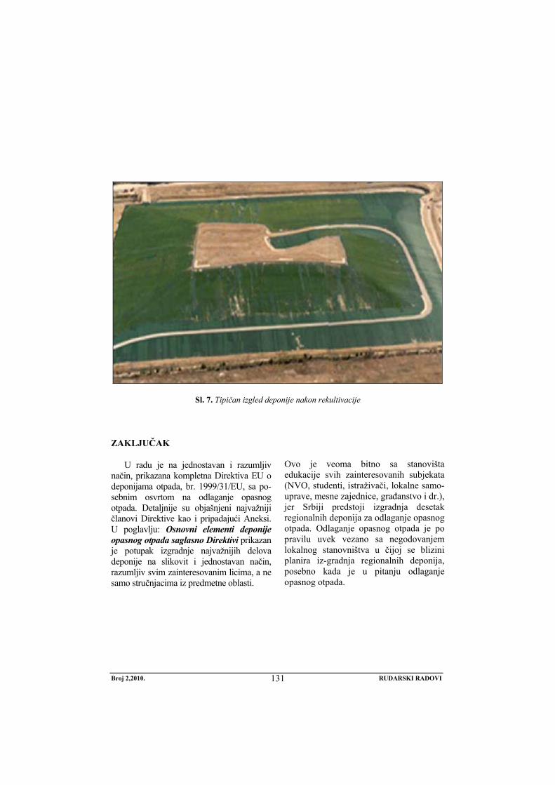
Sl. 7. Tipičan izgled deponije nakon rekultivacije
ZAKLJUČAK
U radu je na jednostavan i razumljiv način, prikazana kompletna Direktiva EU o deponijama otpada, br. 1999/31/EU, sa po-sebnim osvrtom na odlaganje opasnog otpada. Detaljnije su objašnjeni najvažniji članovi Direktive kao i pripadajući Aneksi. U poglavlju: Osnovni elementi deponije opasnog otpada saglasno Direktivi prikazan je potupak izgradnje najvažnijih delova deponije na slikovit i jednostavan način, razumljiv svim zainteresovanim licima, a ne samo stručnjacima iz predmetne oblasti.
Ovo je veoma bitno sa stanovišta edukacije svih zainteresovanih subjekata (NVO, studenti, istraživači, lokalne samo-uprave, mesne zajednice, građanstvo i dr.), jer Srbiji predstoji izgradnja desetak regionalnih deponija za odlaganje opasnog otpada. Odlaganje opasnog otpada je po pravilu uvek vezano sa negodovanjem lokalnog stanovništva u čijoj se blizini planira iz-gradnja regionalnih deponija, posebno kada je u pitanju odlaganje opasnog otpada.
Broj 2,2010. RUDARSKI RADOVI
131

LITERATURA
[1] Direktiva Evropske Unije o depo-nijama otpada, br. 1999/31/EU.
[2] Pravilnik o kriterijumima za određiva-nje lokacije i uređenje deponija otpa-dnih materija, ''Sl. glasnik RS'', br. 54/92.
[3] Zakon o Upravljanju otpadom (''Sl. glasnik RS'', broj 36/09).
[4] M. Ilić, S. Miletić - Osnovi upravlja-nja čvrstim otpadom, Knjiga, IMS, Beograd 1998. god.
[5] M. Ljubojev, R. Popović, M. Avdić, L. Đurđevac Ignjatović i V. Ljubojev,
Defining the legallity of gray sandstone rock strength testing in a complex state of stress, Technics Technologies Education Management, Vol. 5, br. 3 2010, str. 437-443
[6] R. Rajković, D. Kržanović, R. Lekovski, Stability analysis innner waste dump „Kutlovaca“ of the coal open pit mine „Potrlica“ – Pljevlja using the geostusio 2007 software, Časopis Rudarski radovi, br. 1, 2010, str. 75-80
Broj 2,2010. RUDARSKI RADOVI
132

MINING AND METALLURGY INSTITUTE BOR YU ISSN: 1451-0162 COMMITTEE OF UNDERGROUND EXPLOITATION OF THE MINERAL DEPOSITS UDK: 622
UDK: 340.134:628.4(045)=20
Ljubiša Obradović*, Mile Bugarin*, Zoran Stevanović*, Milenko Ljubojev*, Zvonko Milijić**
DISPOSAL OF HAZARDOUS WASTE ON THE LANDFILL IN ACCORDANCE WITH THE COUNCIL DIRECTIVE OF THE
EUROPEAN UNION ON THE LANDFILL OF WASTE No. 1999/31/EC
Abstract
The choice of location and arrangement of waste landfills in Serbia are carried out according to the current Regulation on criteria for determining the location and arrangement of waste land-fills from 1992 (“Official Gazette RS”, no. 54/92). By this Regulation, all landfills are classified in the same “basket”, that is the same criteria are valid for the selection and arrangement of sites regardless whether it is a dump of household or municipal waste, inert waste, which includes vari-ous construction waste (produced waste during operation and arrangement of sites) as well as the waste classified according to its characteristics into the hazardous waste. By passing the Law on Waste Management the Republic of Serbia in 2009, the prerequisites for design and construction the other types of landfills, which this law recognizes and classifies into three categories, depend-ing on the waste characteristics or its harmful impact on the environment. This paper gives in detail the Directive on the Landfill of Waste, No. 1999/31/EU that presents the main document by the recommendation of the Ministry of Environment document, based on which the new regula-tions for disposal of all types of waste in the Republic of Serbia will be created.
Key words: directive 1999/31/EC, landfill, hazardous waste, design
* Mining and Metallurgy Institute Bor ** RTB Bor
INTRODUCTION
Harmonization of the legislation of the Republic of Serbia with the European Un-ion in the field of environmental protec-tion and waste management is theoreti-cally initiated in 2000 when the Republic of Serbia is included in the Stabilization and Association Process. Practical begin-ning of accession to the EU is taken in
October 2004 when the National Assem-bly adopted the Resolution on European Union. Further accession process to the EU in September 2008 received the legal support when the National Assembly rati-fied the Stabilization and Association of the Republic of Serbia to the EU. Based on this Agreement, the Government of the
No 2,2010. MINING ENGINEERING
133

Republic of Serbia in October 2008 adopted the National Program for Integra-tion (NPI) of the Republic of Serbia into the European Union as the strategic document that brings together all docu-ments and action plans necessary for the European integration process and define the responsibilities of all actors for the period until the end of 2012.
From 1992 to the present day, a selec-tion of site and regulation of waste landfills in Serbia is carried out according to the current Rulebook on criteria for determin-ing the location and arrangement of waste landfills from 1992 (“Official Gazette RS”, No. 54/92). This Rulebook classifies all types of waste in one category, so that de-signing the future municipal and industrial landfills uses the same rules and method-ologies. It is understandable if it is known that the Law on Waste Management was adopted in the summer of 2009.
The Rulebook on criteria for determin-ing the location and arrangement the waste materials in 1992 lays down the basic criteria for determining the location and arrangement of waste landfills to pro-tect the environment.
In accordance with this Rulebook, the general definition of landfill is: a landfill of waste is the sanitary-technical land-scaped area where the solid waste is dis-posed that as the waste material occurs in public areas, in households, in the pro-duction process or work, in traffic or use, and which has no properties of hazardous substances and cannot be processed and rational use as an industrial raw material or energetic fuel.
The Rulebook prohibits the disposal of hazardous waste in the municipal landfills, but we are the witnesses of everyday vio-lation of this Rulebook due to the lack of adequate space for permanent disposal, the hazardous waste is disposed of at the existing municipal landfills and dumps, often with the approval of public utility-companies. The last example is an attempt
of disposal 800 tons of industrial waste in the municipal landfill in Lazarevac with the approval from the PUC Lazarevac, which is prevented by the Republican inspectors, upon notification of the local population. Since there is no regional landfill for haz-ardous waste in Serbia, it is understandable that organizations and industrial facilities that generate hazardous waste (waste with at least one dangerous characteristic for the environment), coping in every possible way, often avoiding or knowingly violating a valid legislation, paying fines or penalties for their actions. This is also applied to those entrepreneurs that Republic and other inspection services prevent in their inten-tions (or promptly being disclosed), but it often happens that the waste is inade-quately disposed and no one does not know.
This is particularly important because the landfill in accordance with the appli-cable Rulebook from 1992 is designed as a watertight with the coefficient of terrain permeability on which the landfill is built of at least: k= 0.00001 m/s (k=10-5cm/s), or in meters coefficient is: k= 0.0000001 m/s (k=10-7 m/s). This ratio is insufficient because it does not satisfactorily prevent pollution of groundwater and surface wa-ter due to the uncontrolled movement of leachate from the landfill into the sur-rounding space.
WASTE DISPOSAL IN ACCOR-DANCE WITH THE DIRECTIVE 1999/31/EC
Council Directive of the European Un-ion 1999/31/EC was adopted on 26 April 1999 and otherwise known as the Directive on the landfill of waste. This directive is binding on all members of the European Union. The involved states in the stabiliza-tion and association process (as is the case with the Republic of Serbia) are bound to comply their regulations on waste dis-posalwith this Directive.Republic of Serbia
No 2,2010. MINING ENGINEERING
134

has started this process two years ago by making the National program for EU inte-gration and more laws in this area, includ-ing the Law on Waste Management.
Passing the Law on Waste Manage-ment RS 2009 (“Official Gazette RS, No. 36/09), the prerequisites for design and construction and other types of landfills were formed, which this law recognizes and classifies into three categories, de-pending on the characteristics of waste, or its harmful effect on the environment. The Law on Waste Management in Article 7, depending on the characteristics of haz-ardous waste that affect the human health and environment, classifies all waste into three categories of waste:
1. hazardous waste is a waste that in its origin, composition or concentration of hazardous substances can cause danger to the environment and hu-man health and has at least one of the hazardous characteristics defined by the special regulations;
2. non-hazardous waste is a waste that has the characteristics of hazardous waste;
3. inert waste is a waste that is not sub-jected to the physical/chemical or biological changes.
According to the Law on Waste Man-agement of the Republic of Serbia and Directive 1999/31/EC, the Ministry of Environment has initiated a development of new Regulations on the landfills in ac-cordance with these Law and Directive. This practically means that in the future design and construction of all types of landfills in the Republic of Serbia will to be adequately defined and specified. Rec-ommendation of the relevant Ministry of the Republic of Serbia that to the comple-tion of these by-laws (rulebooks and regu-lations), the design of new landfills use
the EU Directive on the landfill of waste No. 1999/31/EU, in consultation with relevant departments in relevant Ministry.
a) A brief description of the Directive 1999/31/EC and associated annexes
Council Directive on the landfill of waste No. 1999/31/EC was adopted on 26th April 1999 and signed by the Council President J. Fischer. The directive is obliga-tory for all member states of EU. The Di-rective contains the total of 20 articles which more accurately included the follow-ing: Overall objective, Definitions, Scope, Classes of landfill, Waste and treatment not acceptable in landfills, Waste to be ac-cepted in the different classes of landfill, Application for a permit, Conditions of the permit, Content of the permit, Cost of the landfill of waste, Waste acceptance proce-dures, Control and monitoring procedures in the operational phase, Closure and after-care procedures, Existing landfill sites, Obligation to report, Committee, Commit-tee procedure, Committee, Entry into force and Addressees.
In addition to the original document, the Directive includes the following three Annexes:
− Annex I – General requirements for all classes of landfills
− Annex II – Waste acceptance criteria and procedures
− Annex III – Control and monitoring procedures in operation and after-care phases.
Article 4 on the landfill of waste is specifies that each landfill must be classi-fied into one of the following classes:
− Landfill for hazardous waste, − Landfill for non-hazardous waste, − Landfill for inert waste.
No 2,2010. MINING ENGINEERING
135

b) General requirements for all classes of landfill - Annex I
This Annex closer determines the fol-lowing parameters - terms:
1. Location - location of a landfill must take into consideration re-quirements relating to: the distance of landfill from the residential and other urban sites, waterways, water bodies, agricultural land and oth-ers; the existence of groundwater, coastal water or nature protection zones; the geological and hydro-geological conditions in the area; the risk of flooding, subsidence, landslides; the protection of the na-ture or cultural patrimony in the area.
2. Water control and leachate man-agement - measures shall be taken, with respect to the characteristics of the landfill and the meteorologi-cal conditions, in order to: control water from precipitations entering into the landfill body; prevent sur-face water and groundwater from entering into the landfilled waste; collect contaminated water and leachate and their treatment and purification, if it is necessary.
3. Protection of soil and water - A landfill must be designed and con-structed so as to meet the necessary conditions for preventing pollution of the soil, groundwater or surface water and ensuring efficient collec-tion of leachate from the landfill body. Protection of water and soil
is achieved by the combination of a geological barrier and a bottom liner with non-permeable film dur-ing the operational/active phase and by the combination of a geo-logical barrier and a top liner dur-ing the passive phase/post closure. Geological barrier consists of mineral layer and is determined by geological and hydrogeological conditions below and in the vicin-ity of a landfill site with the follow-ing minimum permeability coeffi-cients:
− landfill for hazardous waste: K ≤ 1.0 x 10⁻⁹ m/s; thickness ≥ 5 m;
− landfill for non-hazardous waste: K ≤ 1.0 x 10⁻⁹ m/s: thickness ≥ 1.0;
− landfill for inert waste: K ≤ 1.0 x 10⁻⁷ m/s: thickness ≥ 1.0.
Where the geological barrier does not naturally meet the above conditions it can be completed artificially and reinforced by materials from other locations giving equivalent protection. An artificially es-tablished geological barrier should be no less than 0.5 m thick.
In addition to the geological barrier described above a leachate collection and sealing system must be added in accor-dance with the following principles so as to ensure that leachate accumulation at the base of the landfill is kept to a minimum according to Table 1.
Table 1. Leachate collection and sealing of landfill bottom Landfill category Non hazardous waste Hazardous waste
Artificial sealing liner required required
Drainage layer ≥ 0.5 m required required
No 2,2010. MINING ENGINEERING
136

The following Table 2 gives the recommendations for construction the
surface sealing after exploitation period.
Table 2. Recommendation for surface sealing after exploitation period
Landfill category Non hazardous waste Hazardous waste
Gas drainage layer required not required
Artificial sealing liner not required required
Impermeable mineral layer required required
Drainage layer > 0.5 m required required
Top soil cover > 1 m required required
4. Gas control - The collection, treatment and use of landfill gas shall be carried on in a manner which minimizes damage to or de-terioration of the environment and risk to human health. Landfill gas shall be collected from all landfills receiving biodegradable waste that must be treated and used. If the quantity of collected gas cannot be used to produce energy, it must be flared without valorization
5. Nuisances and hazards - measures shall be taken to minimize nuisances and hazards arising from: emissions of odors and dust; wind-blown mate-rials; noise and traffic; birds, vermin and insects; formation and aerosols; fires. The landfill shall be equipped so that dirt originating from the site is not dispersed onto public roads and the surrounding land.
6. Stability - The emplacement of waste on the site shall take place in such a way as to ensure stability of the mass of waste and associated structures, particularly in respect of avoidance of slippages.
7. Barriers – the landfill shall be se-cured by the suitable fences and gates to prevent free and uncon-trolled access to the site. The gates shall be locked outside operating hours. The system of control and access to each facility should con-tain a program of measures to detect and discourage illegal dumping in the facility.
c) Waste acceptance criteria and proce-dures - Annex II This Annex describes the general princi-
ples for acceptance of waste at the various classes of landfills. The future waste classi-fication procedure should be based on these principles. This Annex consists of 5 chap-ters: Introduction, General principles, Gen-eral procedures for testing and acceptance of waste, Guidelines for preliminary waste acceptance procedures, Sampling of waste.
d) Control and monitoring procedure in operation and after-care phases - An-nex III The purpose of this Annex is to pro-
vide the minimum procedures for monitor-ing to be carried out to check:
No 2,2010. MINING ENGINEERING
137

− that waste has been accepted to dis-
posal in accordance with the criteria set for the category of landfill in ques-tion;
− that the processes within the landfill proceed as desired;
− that the environmental protection sys-tems are functioning fully as intended;
− that the permit conditions for the landfill are fulfilled.
Annex III consists of 5 chapters: Intro-duction, Meteorological data, Emission data on water, leachate and gas control, Protection of ground water, Topography of the site – data on the landfill body.
BASIC ELEMENTS OF THE HAZ-ARDOUS WASTE LANDFILL ACC
Figure 1 shows a detail of formation the clay layer on the bottom of landfill with the coefficient of permeability K ≥ 10-9 m/s. As the base does not have the appropriate coefficient, an extra layer of clay t is brought by the adequate mechani-zation and planned on the bottom, com-pressed and flattened. Figure 2 shows a detail of cross-sectional layers of the bot-tom and sides of the landfill, in accor-dance with the Directive 1999/31/EC for the hazardous waste landfill. Figure 3 shows a detail of connecting – sticking the landfill that is carried out on “hot“ using a special device. After connecting, all welds are checked at least twice. The width of overlapping layer is at least 0.3 m.
Figure 1. Planning, compacting and flattening the bottom of the landfill
No 2,2010. MINING ENGINEERING
138

Figure 2. Cross section of the bottom/side of the landfill made up of different layers
Figure 3. Detail of connecting the HDPE geomembrane
Figure 4 shows the way in which the foil at the ends around the landfill is tight-ened. Tightening is done by the tension trench, size 0.5 x 0.5 m, where the foil is
placed and the same is buried with earth throughout its length. This way enables the uniform film tension around the land-fill.
No 2,2010. MINING ENGINEERING
139

Figure 4. Geomembrane tension by tightening trench and earth
Figure 5. Laying of drainage pipes on the bottom of the landfill
As it can be seen from Figure 5, the
perforated drainage pipes, which are used for the collection and disposal of leachate from the landfill body (maintaining the level of leachate at minimum), are placed
along the bottom of the landfill immedi-ately on the HDPE geomembrane (foil). Alayer of gravel, thickness of at least 0.5 m, is placed over the drainage pipes. A detail of top layer, placed on the landfill
No 2,2010. MINING ENGINEERING
140

after its exploitation, is shown in the fol-lowing Figure 6. A typical view of plain
landfill after reclamation phase is shown in Figure 7.
Figure 6. Cross-section of top layer of the landfill
Figure 7. Typical view of the landfill after reclamation
CONCLUSION
A complete Directive on the landfill of waste, No.1999/31/EC is pre-sent in this paper by a simple and under-standable way, with a special reference to the disposal of hazardous waste. The most important articles of the Directive and
associated annexes are explained in detail. The Chapter The Basic Elements of the Hazardous Waste Landfill in accordance with the Directive presents the procedure of building the most important parts of the landfill by a scenic and simple way,
No 2,2010. MINING ENGINEERING
141

understandable to all interested parties, not only to the experts in the subject area. This is very important from the standpoint of education of all stakeholders (NGO, students, researchers, local governments, local communities, citizens, etc...) because the construction of a dozen of regional landfills for disposal of hazardous waste is going to be realized in Serbia. Disposal of hazardous waste is generally always con-nected to the displeasure of local popula-tion in the vicinity of planned construction of regional landfill, especially when it comes to disposal of hazardous waste.
REFERENCES
[1] European Union Directive on the Landfill of Waste, No. 1999/31/EC.
[2] Rulebook on the Criteria for Determining the Location and Arrangement of the Landfill of Waste Material, (“Official Gazette RS”, No. 54/92).
[3] Law on the waste management,
(“Official Gazette RS”, No. 36/09). [4] M. Ilić, S. Miletić – Basic on the
Hazardous Waste Management, Book, IMS, Belgrade1998.
[5] M. Ljubojev, R. Popović, M. Avdić, L. Đurđevac Ignjatović and V. Ljubojev, Defining the legallity of gray sandstone rock strength testing in a complex state of stress, Technics Technologies Education Management, Vol. 5, No. 3 2010, pp. 437-443
[6] R. Rajković, D. Kržanović, R. Lekovski, Stability analysis innner waste dump „Kutlovaca“ of the coal open pit mine „Potrlica“ – Pljevlja using the geostusio 2007 software, Journal engineering mining, No. 1, 2010, pp. 75-80
No 2,2010. MINING ENGINEERING
142

INSTITUT ZA RUDARSTVO I METALURGIJU BOR YU ISSN: 1451-0162 KOMITET ZA PODZEMNU EKSPLOATACIJU MINERALNIH SIROVINA UDK: 622
UDK: 658.567:546.815(045)=861
Radiša Todorović*, Daniela Urošević*, Ljubiša Obradović*, Vojka Gardić*, Zdenka Stanojević Šimšić*
RECIKLAŽA OLOVNOG OTPADA
Izvod
U radu je opisan postupak recikliranja otpadnih olovnih cevi, počev od pripreme šarže, topljenja, rafinacije i livenja, pa sve do izrade novih proizvoda od recikliranih olovnih cevi.
Strukturu olovnog otpada za recikliranje čine: vodovodne i kanalizacione cevi iz građevinarstva i industrijskih pogona, koje se povlače iz upotrebe zbog štetnog uticaja na životnu sredinu.
Postupak recikliranja podrazumeva: ručnu separaciju-odvajanje olovnih komponenti od ostalih prisutnih elemenata na bazi drugih metala i legura (mesingani ventili, čelični priključci i dr.), mehaničko odstranjivanje nataloženog kamenca, sečenje na manje komade radi lakšeg šaržiranja u peć za topljenje i rafinaciju.
Pre pripreme šarže za topljenje, izvršena je hemijska analiza po osnovu koje je izvršen dalji postupak klasifikacije otpada u prvu grupu na osnovu čistoće olova.
Topljenje, rafinacija i livenje je obavljeno u lončastoj indukcionoj peći, a dobijeni ingoti su iskorišćeni za izradu novih proizvoda (za potrebe kablovske industrije, ingoti dolegirani sa antimonom za proizvodnju pojedinih delova akumulatora...).
Ključne reči: olovni otpad, reciklaža, ingoti
*Institut za rudarstvo i metalurgiju,
UVOD
Amortizacioni otpadak nastaje kao nus proizvod već upotrebljenih i iskorišćenih osnovnih sredstava i predmeta široke potrošnje. Izvori amortizacionog otpada su rashodovana osnovna sredstva u industriji, transportu, građevinarstvu, seoskim gazdin-stvima, otpaci od generalnog i tekućeg remonta mašina, opreme i konstrukcija [2].
Vek upotrebe pojedinih delova i pred-meta prema međunarodnim podacima je:
- olovni akumulatori .............. 3-5 god., - olovna izolacija kablova...... 40 god., - olovne cevi .......................... 50 god., - lemovi ................................. 10 god., Udeo proizvodnog i amortizacionog
otpada kod olova i njegovih legura iznosi
19% proizvodnog otpada i 81% amorti-zacionog otpada.
Predmet ovog rada je postavljanje tehnološkog postupka recikliranja olovnog otpada (vodovodne i kanalizacione cevi) i dobijanje tehnički čistog olova koji se može koristiti za izradu novih proizvoda:
- blokovi-gredice za kablovsku industriju, - gredice za izradu legura u različitim
oblastima primene (lemovi, osigurači..), - lovačka sačma, - balans tegovi i plombe, - valjani proizvodi, - elementi za olovne akumulatore... Potrošnja energije za proizvodnju
tehnički čistog olova iz navedenog
Broj 2,2010. RUDARSKI RADOVI
143

olovnog otpada je manja za 50% u odnosu na energiju potrebnu za proizvodnju olova iz rude[1].
Posmatrano sa ekološkog aspekta, reciklaža olovnog otpada ne zahteva velika ulaganja u sistem za otprašivanje i ispuštanje gasova u atmosferu, ukoliko se poštuje propisana tehnološka procedura[4].
EKSPERIMENTALNI DEO
U toku rekonstrukcije vodovodne i kanalizacione mreže, u Institutu za rudarstvo i metalurgiju u Boru, izvršena je zamena celokupne vodovodne i kanalizacione instalacije. Tom prilikom izvedeni su eksperimenti na odbačenim olovnim cevima, sa ciljem izrade novih proizvoda od istih.
Selektiranje i priprema olovnih cevi
Selekcija otpadnih cevi je izvršena po osnovu dimenzija (prečnika) i namene.
Tanke cevi za dovod vode do određenih potrošača su odvajane posebno od kanalizacionih cevi. Cevi su pre topljenja odvajane od mesinganih kolendera i ventila od mesinga.
Kanalizacione cevi su prethodno očišćene od nataloženih otpadnih materijala i kamenca i isečene na optimalne dužine, radi lakšeg šaržiranja u lonce za topljenje (slika 1).
Na reprezentativnim uzorcima cevi urađena je hemijska analiza (tabela 1). Tabela 1 Hemijska analiza otpadnih
olovnih cevi Elementi Sadržaj (%)
Sn 0,006 Bi 0,03 Fe 0,001 Pb 99,40 Sb 0,49 Cd 0,002 Cu 0,025
Slika 1. Otpadne olovne cevi
Topljenje i livenje
Pripremljena šarža od otpadnih olovnih cevi topljena je u dva agregata i to u grafitnom loncu tipa AC-100 u indukcionoj
peći (slika 2 ) i grafitnom loncu uz pomoć autogenog topljenja (slika 3 ).
Broj 2,2010. RUDARSKI RADOVI
144

Slika 2. Grafitni lonac tip AC-100
Slika 3. Grafitni lonac sa autogenim topljenjem
Topljenje metalnog uloška se obavlja pod slojem drvenog uglja (ćumura). Ukoliko ima veću količinu rastresitog materijala, dobro je da se ubaci koks radi intenzivnije dezoksidacije rastopa, ali u tom slučaju može dići do kontaminacije rastopa metala sumporom iz koksa (što zavisi od prisutne količine sumpora u koksu) [3].
Temperatura topljenja otpadnog olova nije visoka, ali da bi nemetalni uključci isplivali na površinu potrebno je tempe-raturu podići do 500°C.
Pre livenja, rastop se ostavi da odstoji kraće vreme, da bi nemetalne primese i gasovi isplivali na površinu.
Livenje je obavljeno u grafitnim kokilama različitog oblika (slika 4 i 5 ).
Broj 2,2010. RUDARSKI RADOVI
145

Slike 4. i 5. Grafitne kokile
Na dobijenim odlivcima (ingotima),
izvršena je hemijska analiza (tabela 2). Tabela 2. Hemijska analiza odlivaka
(ingota) Elementi Sadržaj (%)
Sn 0,39 Sb 0,51 Bi 0,027 Cu 0,021 S 0,004
Ag 0,005 Pb 99,00
ANALIZA REZULTATA
Reciklaža je obavljena u poluindu-strijskoj laboratoriji, gde je izvršena ade-kvatna priprema otpadnih olovnih cevi. Na ovo ukazuje visok izvadak metala od 99 %.
Drugi bitan faktor koji je praćen u toku reciklaže je hemijski sastav ingota. Hemij-ska analiza je urađena na emisionom spe-ktrometru. Analizirani su uzorci otpadnih cevi pre topljenja i uzorci odlivenih ingota. Analizom dobijenih rezultata uočava se razlika u hemijskom sastavu kod ingota u
Broj 2,2010. RUDARSKI RADOVI
146

odnosu na cevi po osnovu prisutnih elemenata kalaja i srebra u ingotima usled prisutnih lemova kod cevi. razlika. Odlivci dobijeni pretapanjem otpadnih cevi koje su lemljene, imaju povećan sadržaj kalaja, jer je lemljenje obavljeno mekim lemom na bazi Sn-Pb.
I pored prisustva Sn i Sb u ingotima, to ne utiče bitno na ograničenje pri izradi novih proizvoda (cevi, limovi, kablovska industrija, izrada mekih lemova...) od recikliranih olovnih cevi.
PODRUČJE PRIMENE RECIK-LIRANOG OLOVNOG OTPADA
Na osnovu dobijenih rezultata hemijske analize recikliranog olovnog otpada,
moguća je primena za izradu proizvoda širokog spektra. Prvenstveno za izradu cevi, limova i u oplaštavanju kablova. Najveću primenu reciklirano olovo nalazi u proizvodnji akumulatorskih baterija.
Reciklirano olovo se može koristiti i u proizvodnji niskotopivih lemova i za izradu većeg broja Vudovih legura, sa tačkom topljenja od 68°C do 138°C [1].
U Institutu za rudarstvo i metalurgiju proizvodi se veći broj ovih legura namenjenih tržištu, u čiji sastav pored olova ulaze još i Bi, Sn, Cd. U ovim legurama se sadržaj olova kreće od 25% težinskih do 50% težinskih.
Dobijeni proizvodi od recikliranih olovnih cevi prikazani su na slikama 6 i 7.
Slika 6 Ingoti za dalju preradu
Slika 7. Finalni proizvodi od vudovih legura
Broj 2,2010. RUDARSKI RADOVI
147

ZAKLJUČAK
Ukoliko se olovni amortizacioni otpad u obliku vodovodnih i kanalizacionih cevi dobro očisti od prljavštine nataložene u toku eksploatacije, i dobro odstrane zalemljena mesta, može se dobiti visokokvalitetno olovo.
Reciklirano visokokvalitetno olovo ima široku primenu kako u proizvodnji legura (niskotemperaturni lemovi, vudove legure), tako i u drugim granama industrije.
Reciklažu ovakvog olovnog otpada prati niska cena prerade, manje zagađenje okoline i štednja u energentima, čime se postiže velika konkurentnost u odnosu na olovo proizvedeno iz rude.
Analizom hemijskog sastava sekun-darne sirovine i odlivaka posle
reciklaže, potvrđuje se visok kvalitet recikliranog olovnog otpada.
LITERATURA
[1] N. M. Goldin, D. F. Černega, D. F. Ivančuk, V. V. Čistjakov-Tehnologija litejnogo proizvodstva – Cvetnoe litie, Moskva "Mašinostroenie" 1989
[2] I. Ilić, Z. Gulišija, N. Radovanović, M. Sokić, V. Matković, J. Marinković-"Resursi i reciklaža sekundarnih siro-vina obojenih metala", Bor, 2002
[3] B. Kočovski - Metalurgija legura; obo-jenih metala, Bor 1996
[4] J. Krišto: Projekat - Prerada sekundarnih sirovina obojenih metala (II) deo, Beograda-Bor,1976
Broj 2,2010. RUDARSKI RADOVI
148

MINING AND METALLURGY INSTITUTE BOR YU ISSN: 1451-0162 COMMITTEE OF UNDERGROUND EXPLOITATION OF THE MINERAL DEPOSITS UDK: 622
UDK: 658.567:546.815(045)=20
Radiša Todorović*, Daniela Urošević*, Ljubiša Obradović*, Vojka Gardić*, Zdenka Stanojević Šimšić*
RECYCLING OF LEAD WASTE
Abstract
The process of recycling the lead waste pipes includes the following steps: batch preparation, refining, casting, development and production of new products from recycled lead. The structure of lead waste for recycling are: water and sewer pipes from construction and industrial plants that are no longer in use because of its harmful impact on human and environment. The process starts with manual separation, which presents the separation of component with lead content from other metals and alloys (brass valves, steel fittings, etc..), followed by the mechanical removal of depos-ited scale, and cutting pieces into smaller pieces for batching into the melting furnace and refining process.
Chemical analysis of lead waste is necessary to be carried out before the melting process, in order to determine the purity of lead and its classification into the appropriate groups. Process of smelting, refining and casting were performed in the induction furnace. The resulting ingots were used for development of new products in cable industry or alloyed with antimony for production of some parts of battery ...).
Key words: lead waste, recycling, ingot
*Mining and Metallurgy Institute Bor,
INTRODUCTION
The structure of lead waste for recy-cling are: water and sewer pipes from con-struction and industrial plants that are no longer in use because of its harmful im-pact on human and environment [2].
Lifetime of components made of lead or component that contain lead, according to the international data, are following [2]:
- lead batteries 3-5 years, - lead insulation cables 40 years, - lead pipes 50 years, - solders 10 years.
Waste generated in the production process as by-product make 19% of the total waste based on lead, while 81% is
waste generated after the life of lead-based products.
The aim of this paper is to define the parameters of technological process of recycling the lead waste (water and sew-age pipes) and production the technically pure lead that can be used in manufactur-ing the new products:
- blocks-stringers for cable industry, - beams for making the alloys in vari-
ous fields of use (solders, fuses...), - hunting pellets, - balance weights and fillings, - rolled products, - lead battery elements.
No 2, 2010. MINING ENGINEERING
149
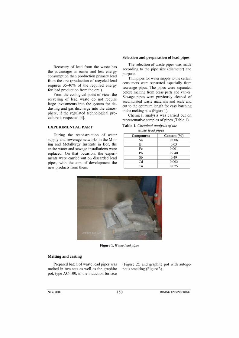
Recovery of lead from the waste has the advantages in easier and less energy consumption than production primary lead from the ore (production of recycled lead requires 35-40% of the required energy for lead production from the ore.).
From the ecological point of view, the recycling of lead waste do not require large investments into the system for de-dusting and gas discharge into the atmos-phere, if the regulated technological pro-cedure is respected [4].
EXPERIMENTAL PART
During the reconstruction of water supply and sewerage networks in the Min-ing and Metallurgy Institute in Bor, the entire water and sewage installations were replaced. On that occasion, the experi-ments were carried out on discarded lead pipes, with the aim of development the new products from them.
Selection and preparation of lead pipes
The selection of waste pipes was made according to the pipe size (diameter) and purpose.
Thin pipes for water supply to the certain consumers were separated especially from sewerage pipes. The pipes were separated before melting from brass parts and valves. Sewage pipes were previously cleaned of accumulated waste materials and scale and cut to the optimum length for easy batching in the melting pots (Figure 1).
Chemical analysis was carried out on representative samples of pipes (Table 1). Table 1. Chemical analysis of the
waste lead pipes Component Content (%)
Sn 0.006 Bi 0.03 Fe 0.001 Pb 99.40 Sb 0.49 Cd 0.002 Cu 0.025
Figure 1. Waste lead pipes
Melting and casting
Prepared batch of waste lead pipes was melted in two sets as well as the graphite pot, type AC-100, in the induction furnace
(Figure 2), and graphite pot with autoge-nous smelting (Figure 3).
No 2, 2010. MINING ENGINEERING
150

Figure 2. Graphite pot, type AC-100
Figure 3. Graphite pot with autogenous smelting
Melting of the metal insert is per-formed under a layer of charcoal. If it has a large quantity of loose material, it is good to charge the coke for intensive desoxidation of melt, but in this case the contamination of molten metal sulfur from coke could appear (what depends on pre-sent sulfur quantity in coke) [3].
Melting point of waste lead is not high,
but the presence of non-metallic inclu-sions requires higher melting temperature (about 500°C).
Before casting, the liquid phase is left to rest for a short time, in order of coming to the surface the non-metallic impurities and gases to the surface. Casting was done in the graphite moulds of various shapes (Figures 4 and 5).
No 2, 2010. MINING ENGINEERING
151

Figures 4. and 5. Graphite moulds
Chemical analysis was carried out on
the representative samples of ingots (Ta-ble 2). Table 2. Results of chemical analysis of
the ingots Component Content (%)
Sn 0.39 Sb 0.51 Bi 0.027 Cu 0.021 S 0.004
Ag 0.005 Pb 99.00
RESULTS AND DISCUSION
Recycling was carried out in the semi-industrial laboratory where the adequate preparation of waste lead pipes was done. This is indicated by high metal recovery of 99%.
Chemical composition of ingot is the second important parameter observed in the recycling process. Chemical analysis was carried out on the emission spec-trometer. The samples of waste pipes were analyzed before melting and samples of cast ingots.
Analyzing the obtained results indicate
No 2, 2010. MINING ENGINEERING
152

the difference in chemical composition of ingots regarding to the pipes, based on the present elements of tin and silver in the ingots, due to the present solders of the pipes. The ingots, obtained by the recy-cling of waste pipes with solders, have the increased tin content due to the soldering with soft solder, based on Sn-Sb.
Despite the presence of Sn and Sb in the ingots, it has no significant effect to the the limitation in development of new products (pipes, sheets, cable industry, manufacture of soft solders...) from the recycled lead pipes.
SCOPE OF USE THE RECYCLED LEAD WASTE
Based on the obtained results of chemical analysis of recycled lead waste,
the usage for manufacturing the products of a wide spectrum is possible - primary, manufacturing of pipes, sheets and cable plating. The largest use of recycled lead is manufacturing of batteries.
Also, the recycled lead could be used in production of low temperature solder, low melting temperature alloys with the melting point of 68°C to 138°C, the Wood alloys. [1].
Mining and Metallurgy Institute Bor produce a large number of alloys intended for the market, with content of Bi, Sn and Cd besides lead. In these alloys, the con-tent of lead is from 25% to 50% weight by weight.
The resulted products from recycled lead pipes are shown in Figures 6 and 7.
Figure 6. Ingots for further processing
No 2, 2010. MINING ENGINEERING
153

Figuren 7. Final products of the Wood's alloys
CONCLUSION
If the lead waste, in the form of water supply and sewerage pipes, is thoroughly cleaned of dirt, accumulated during opera-tion, and well removed the soldered places, the high-quality lead could be obtained.
The recycled high quality lead is widely used in the production of alloys (low-temperature solders, Wood alloys), and in other industries.
The recycling of such lead waste is fol-lowed by the low costs of processing, less environment pollution and energy savings, resulting in a major competition in respect to the lead produced from ore.
By analyzing the chemical composition of secondary raw materials and castings after recycling, the high quality of recy-cled lead waste is confirmed.
REFERENCES
[1] N. M. Goldin, D. F. Černega, D. F. Ivančuk, V. V. Čistjakov, Tehnologija litejnogo proizvodstva – Cvetnoe litie, Moskva "Mašinostroenie",1989
[2] I. Ilić, Z. Gulišija, N. Radovanović, M. Sokić, V. Matković, J. Marinković, Resources and Recycling the Secondary Raw Materials of Non-ferrous metals, Bor, 2002 (in Serbian)
[3] B. Kočovski, Metallurgy of Non-ferrous Metal Alloys, Bor, 1996 (in Serbian)
[4] J. Krišto, Project - Processing the Secondary Raw materials of Non-ferrous Metals, (II) Part, Belgrade -Bor,1976 (in Serbian)
No 2, 2010. MINING ENGINEERING
154

INSTITUT ZA RUDARSTVO I METALURGIJU BOR YU ISSN: 1451-0162 KOMITET ZA PODZEMNU EKSPLOATACIJU MINERALNIH SIROVINA UDK: 622
UDK: 622.79:66.061:622.778:669.332.3(045)=861
Radmila Marković*, Ljiljana Mladenović*, Milan Petrov**, Jasmina Stevanović***
UTICAJ MEHANO-HEMIJSKE AKTIVACIJE FLOTACIJSKE JALOVINE NA STEPEN IZDVAJANJA KORISNIH KOMPONENTI****
Izvod
Prikazani rezultati odnose se na ispitivanje uticaja mehano-hemijske aktivacije flo-tacijske jalovine na stepen izluženja bakra, gvožđa i sumpora u sumporno-hloridnom rastvoru uz dodatak H2O2 kao oksidansa. Uzorak borske flotacijske jalovine (BFJ) sa lokacije starog borskog flotacijskog jalovišta sadrži 23% pirita i 75,23% jalovine kao osnovne komponente, a aktiviran je suvim postupkom u vibro mlinu bez i sa dodatkom NaOH kao hemijskog reagensa, uzorci BFJ1 i BFJ2, respektivno. Suvom magnetnom separacijom u visokogradijentnom magnetnom separatoru "Sala", uzorci su razdvojeni na magnetičnu i nemagnetičnu frakciju, BFJ MF i BFJ NMF, respektivno.
Luženje različito tretiranih uzoraka pokazalo je da je najviši stepen izluženja bakra, 98,7 %, postignut kod uzorka BFJ2 MF dok je stepen izluženja Fe i S viši kod nemag-netičnih frakcija, i kreće se do 92,46 % kod uzorka BFJ1 NMF za Fe i 80,62 % za S iz uzorka BFJ2 NMF.
Ključne reči:, flotacijska jalovina, mehano-hemijska aktivacija, magnetna separacija, luženje, Cu, Fe, S
*Institut za rudarstvo i metalurgiju Bor - [email protected] **ITNMS, Bul. Franše d’Eperea 86 , 11000 Beograd, Srbija***IHTM-Centar za elektrohemiju, Karnegijeva 4, 11000 Beograd, Srbija****Ovaj rad je proistekao iz Projekta broj 19021 koji je finansiran sredstvima Ministarstva za
nauku i tehnološki razvoj Republike Srbije
UVOD
Mehanohemijska aktivacija u oblasti rudarsko-metalurške prerade sve više dobija na primatu na nivou industrijske proizvod-nje mineralnih sirovina(1). Efekti mehan-ičke aktivacije se odnose na preuređenje kristalne strukture mineralne sirovine
fizičkim procesima i dobijanju metala bez predhodnog oksidacionog prženja a samim tim i bez emisije štetnog gasa SO2 u atmos-feru. Takodje i hidrometalurški procesi sve više dobijaju na značaju zahvaljujući sve strožim ekološkim pravilima.
Broj 1,2010. RUDARSKI RADOVI
155

Tehnološka ispitivanja prerade me-hanohemijski aktiviranog pirita borske flotacijske jalovine imala su za cilj ispiti-vanje uticaja mehano-hemijske aktivacije na stepen izluženja bakra, gvožđa i sum-pora korišćenjem kombinovanog sum-porno-hloridnog rastvora uz dodatak H2O2 kao oksidansa.
Mehanohemijska aktivacija uzorka BFJ uradena je u laboratorijama ITNMS – Beograd. Efektivnost izluženja korisnih komponenti u velikoj meri zavisi od ste-pena otvaranja minerala i otvorenosti površina [2]. Brzina prelaza elemenata u rastvor u opštem slučaju zavisi od veličine površine čvrstih čestica, a za neke tipove ruda krupnoća pretstavlja osnovni faktor izlužljivosti [3].
EKSPERIMENTALNA ISTRAŽIVANJA
Fizičko-hemijska karakterizacija uzorka borske flotacijske jalovine (BFJ)
Hemijska karakterizacija uzorka borske flotacijske jalovine korišćene za proces luženja kombinovanim sumporno-hloridnim rastvorom uz dodatak H2O2 kao oksidansa, prikazana je u tabeli 1, a mineraloška analiza, u tabeli 2.
Tabela 1. Hemijska analiza BFJ Elemenat ili jedinjenje
Sadržaj %
Fe 4,82 S 6,20
Cu–oksidni 0,006 Al2O3 15,63 SiO2 61,60 MgO 0,014
Cu–ukupno 0,131 Fe3O4 0,359 SO4 2- /
Tabela 2. Mineraloška analiza uzorka BFJ
Minerali Kvalitativno, % Pirit 23
Halkopirit 0,124
Pirotin < 1 ppm
Rutil 0,98
Limonit 0,234
Jalovina 75,23
Rezultati sitovne analize koja je urađena standardnom metodom prose-javanja, na seriji sita tipa TYLER, prika-zani su u tabeli 3.
Tabela 3. Sitovna analiza uzorka BFJ Klasa krupnoće
mm Maseno učešće
% -0,600+0,425 2,40
-0,425+0,300 5,60
-0,300+0,212 10,00
-0,212+0,106 24,80
-0,106+0,075 9,60
-0,075+0,038 11,60
-0,038+0,020 7,20
-0,020 28,80
Za određivanje nasipne mase uzorka BFJ, koja iznosi 2930 kg m-3, korišćena je VMK (Validna metoda kuće – IRM Bor) - Određivanje zapreminske mase i nasipne mase uzoraka ( E.b.11:2007).
Postupak mehano-hemijskog tretmana (MC-H) uzorka BFJ vršen je u laboratori-jskom vibro mlinu Humbolt. Mlin ima radnu temperaturu oko 340 K kada radi u kontinuitetu. Mlin može da ostvari rad dispergovanja u visini 7,3 x10³ KJmol-1.
Broj 1,2010. RUDARSKI RADOVI
156

To je, prema literaturnim podacima (1), dovoljna energija da izazove cepanje pet nivoa d orbitala slobodnog jona feruma iz pirita u oktaedarskom ligandnom polju. Izvršena su dva opita MC-H tretiranja BFJ suvim postupkom. U prvom opitu izvršeno je optimalno aktiviranje BFJ bez dodataka reagenasa (BFJ1).
nog polja (MP) je izabrana da bude B = 0,6 T. Paramagnetični minerali kao što je pirit, pri srednjem iznosu intenziteta (MP), imaju izvestan mali maseni udeo (MF). Oba MC-H tretirana uzorka BFJ podvrgnuta su postupku magnetne koncen-tracije. Rezultat odvajanja pojedinih frak-cija prikazan je u tabeli 4. Dejstvu istog magnetnog polja B=0,6 T bio je izložen i uzorak BFJ koji nije MC-H aktiviran, i on je imao 90 g MF i 210 g NMF.
U drugom opitu je dodat NaOH u količini od 4%, (BFJ2).
Magnetna koncentracija vršena je na visokogradijentnom magnetnom separa-toru (HGMS) Sala u vodenoj sredini.
Tabela 4. Rezultati magnetne koncentracije MC-H tretirane BFJ
Ispitivanja lužljivosti Cu, Fe i S iz do-bijenih frakcija izvedena su na opremi laboratorijskog tipa korišćenjem 0.8 M H2SO4 uz dodatak 30 % H2O2 kao oksi-dansa i uz prisustvo hlornih jona koji su u rastvor dodavani u obliku NaCl pri čemu je inicijalna koncentracija NaCl odgova-rala 1M rastvoru.
Uzorak BFJ
MC-H tretman bez re-agensa
MC-H tretman sa
NaOH
Nemagnetična frakcija, g 206 50
Magnetična frakcija, g 94 250
Ukupno, g 300 300
Proces luženja odvijao se pri radnoj temperaturi rastvora od je 90±5oC, uz mešanje od 600 min-1, pri odnosu Č:T = 1:20, u trajanju od 8 h.
Za hemijsku karakterizaciju korišćene su sledeće hemijske metode: za određivanje sadržaja S - gasna volumetrija (spaljivanje) na opremi Marsova peć a za odrešivanje sadržaja Cu i Fe – atomska apsorpciona spektrofotometrija, na opremi Atomsko apsorpcioni Spektrofotometar PERKIN ELMER 403.
Za kompleks:
( )( )
−
⎥⎦
⎤⎢⎣
⎡
4
3....
...
3....
4
SOOHFeFeOHFe
SONa
vrednost magnetnog momenta je:
BS μμ ⋅+= )21(1 = 2,8 μB (5), REZULTATI I DISKUSIJA
Magnetni koncentrator (HGMS) daje dva proizvoda od kojih je jedan mag-netična frakcija (MF) a drugi nemag-netična frakcija (NMF). Indukcija magnet
a upravo je i odnos magnetičnih frakcija iz opita magnetne koncentracije, tabela 4, približno 2,8 (94 x 2,8 = 263,2)
Broj 1,2010. RUDARSKI RADOVI
157

Tabela 5. Hemijska karakterizacija frakcija dobijenih magnetnom separacijom Opis Oznaka uzorka
BFJ1 MF
BFJ1 NMF
BFJ2 MF
BFJ2 NMF
Fe, % 6,30 3,60 5,03 1,83 S, % 10,70 5,60 7,40 2,70 Cu–oxid, % 0,005 0,007 0,015 0,019 Al2O3, % 11,79 18,74 15,72 18,50 SiO2, % 64,74 62,46 64,10 63,08 MgO, % 0,026 0,021 0,11 0,026 Cu–ukupno, % 0,152 0,153 0,135 0,134 Fe3O4, % 0,445 / / / SO4 2-, % / / Rezultati hemijske karakterizacije frak-
cija dobijenih magnetnom separacijom prikazani su u Tabeli 5.
Rezultati postignutog izluženja Cu, Fe i S iz različitih uzoraka flotacijske jalovine, korišćenjem, u jednom slučaju sulfatnog rastvora bez dodatka NaCl a u drugom sa dodatkom NaCl, prikazani su na slikama 1, 2 i 3. Najviši stepen izluženja Cu postignut je kod uzorka BFJ2 MF u vrednosti od
98,75 %. Kod uzorka BFJ1 NMF karakter-istično je da je postignut najviši stepen izluženja Fe a kod istog uzorka je postignut i najviši stepen izluženja S i to za proces luženja u sulfatnom rastvoru. Rezulatti izluženja pojedinih elemenata pokazuju da izluženje Cu, Fe i S ima isti trend kod svih uzoraka osim kod uzorka BFJ2 MF kod kog je izluženje gvožđa manje u kombino-vanom sulfatno-hloridnom rastvoru.
Sl. 1. Izluženje Cu iz različitih uzoraka BFJ primenom različitih lužnih rastvora
Broj 1,2010. RUDARSKI RADOVI
158

Sl. 2. Izluženje Fe iz različitih uzoraka BFJ primenom različitih lužnih rastvora
Sl. 3. Izluženje S iz različitih uzoraka BFJ primenom različitih lužnih rastvora
Broj 1,2010. RUDARSKI RADOVI
159

ZAKLJUČAK
Na osnovu sprovedenih istraživanja vidi se da se uz pomoć MC-H tretmana i magnetne kocentracije može uticati na razvoj procesa koji bi omogućili odvajanje metaličnih od nemetaličnih minerala. Metalične mineralne sirovine imaju na-jmanje desetostruko veću vrednost u od-nosu na nemetalične pa stoga treba u tom kontekstu shvatiti tehno-ekonomsku funk-ciju razvoja iznetog postupka tretiranja BFJ. Dalji tretman metalične i nemeta-ične komponente dovodi do izvlačenja korisnih komponenti i stvaranja uslova za korišćenje modifikovane nemetalične komponnte.
LITERATURA
[1] M. Petrov i dr, Mechano-chemical trea-tment of of mineral waste, Rudarski Radovi, Br. 2, (2009) 77-84,
[2] Z. Y. u etc, Hydrometallurgy, 56 (2006) 189 – 202.
[3] A. R. Kamali etc., Mineral Processing of Non-ferrous Metals, vol. 49, No. 1, (2008), 138-143.
[4] R. Murphy, D. Strongin, Surface reactivity of pyrite and related sulfides, Surface Science Reports, Novembar (2008), 24-36
[5] M. Ilić, „Specijalna Mineralogija deo II“, ICS Beograd, 1978 Beograd
Broj 1,2010. RUDARSKI RADOVI
160

MINING AND METALLURGY INSTITUTE BOR YU ISSN: 1451-0162 COMMITTEE OF UNDERGROUND EXPLOITATION OF THE MINERAL DEPOSITS UDK: 622
UDK: 622.79:66.061:622.788:669.332.3(045)=20
Radmila Marković*, Ljiljana Mladenović*, Milan Petrov**, Jasmina Stevanović***
EFFECT OF MECHANICAL-CHEMICAL ACTIVATION OF FLOTATION TAILINGS ON REMOVAL THE
USEFUL COMPONENTS****
Abstract
The presented results refer to the investigation of effect the mechanical-chemical activation of flo-tation tailings on copper, iron and sulfur leaching degree in the sulfuric-chloride solution with the addition of H2O2 as oxidant. A sample of the Bor flotation tailings (BFT) from the old Bor flotation tailing dump consists of pyrite and tailings as the main components, and is activated in a dry process of the vibro mill with (BFT1) and without (BFT2) addition of NaOH as the chemical reagent. Using the dry magnetic separation in thed high-gradient magnetic separator Sala, the samples were sepa-rated into magnetic and non-magnetic fraction, BFT MF and BFT NMF, respectively.
Leaching of various treated samples showed that the highest level of copper leaching (98.7 wt %), was obtained for BFJ2 MF sample while the leaching degree of Fe and S was higher in non-magnetic fractions, up to 92.46 wt % in BFT1 NMF sample for Fe and 80.62 wt % for S in BFT2 NMF sample.
Key words: flotation tailings, mechanical-chemical activation, magnetic separation, leaching, Cu, Fe, S
* Mining and Metallurgy Institute Bor, Srbija - [email protected] **ITNMS, Bul. Franše d’Eperea 86 , 11000 Belgrade, Serbia***ICTM, Institute of Chemistry, Technology and Metallurgy, Belgrade, 11000 Belgrade, Serbia****This work is derived from the Project TR: 21008 which is financed by the Ministry of Science
and Technological Development of the Republic of Serbia.
INTRODUCTION
Mechanical-chemical activation be-comes and more significant in the field of mining and metallurgy processing and industrial production of minerals [1]. The effects of mechanical activation refer to
the rearrangement of mineral crystal struc-ture by physical processes and obtaining-metal without previous oxidation roasting and therefore without emission of harmful SO2 gas into the atmosphere.
No 2,2010. MINING ENGINEERING
161

Also, the hydrometallurgical processes [2,3] increasingly gain in importance due to more strict environmental regulations.
Technological investigations of treat-ment the mechanical-chemical activated pyrite from the Bor flotation tailings was aimed to the investigation the effect of mechanical-chemical activation on the leaching degree of copper, iron and sulfur using combined sulfur-chloride solution with addition of H2O2 as the oxidizdant. Mechanical-chemical activation of BFT samples was done in the ITNMS-Belgrade laboratories. The efficiency of useful com-ponents leaching processes largely de-pends on mineral and surfaces opening [4]. Solubility rate of elements generally de-pends on the size of solid particle surface and, for some ore types, the grain size represents the main dissolution factor.
EXPERIMENTS
Physical-chemical characterization of the Bor flotation tailings sample (BFT)
The results of chemical characterization the Bor flotation tailings sample, used for leaching process by the mixed sulfate-chloride solution with addition of H2O2 as the oxidant are presented in Table 1, and mineralogical analyse in Table 2.
Table 1. Chemical analyses of BFT
Elements Content wt %
Fe 4.82 S 6.20
Cu–oxide 0.006 Al2O3 15.63 SiO2 61.60 MgO 0.014
Cu–total 0.131 Fe3O4 0.359
Table 2. Mineralogical analyses of BFT Minerals Content wt %
Pyrite 23
Chalcopyrite 0.124
Pyrrhotine < 1 ppm
Rutile 0.98
Limonite 0.234
Tailings 75.23 The results of sieve analysis, carried
out by the standard sieve analysis, on stan-dard TYLER sieve, are shown in Table 3.
Table 3. Sieve analysis Particle size
mm Content wt
% -0.600+0.425 2.40
-0.425+0.300 5.60
-0.300+0.212 10.00
-0.212+0.106 24.80
-0.106+0.075 9.60
-0.075+0.038 11.60
-0.038+0.020 7.20
-0.020 28.80
A valid method of MMI Bor - Determi-nation of Volume Density and Apparent Density (E.b.11: 2007 was used for deter-mination the sample apparent density.
The mechanical-chemical treatment (MC-H) was achieved using the Humboldt Wedag vibrating mill. Mill has the work-ing temperature of about 340 K during the continual work and can achieve the disper-sion work at height 7.3 x10³ KJmol-1. This is according to the literature data [1] the enough energy to cause the splitting of five levels of d orbital of free ferrum ion from pyrite in the octahedral ligand field.
No 2,2010. MINING ENGINEERING
162

(MP) was chosen to be B = 0.6 T. Para-magnetic minerals, such as pyrite, in the average amount of intensity (MP) have some small mass share of magnetic frac-tion (MF).
Two experiments of M-CH treatment of BFT were carried out using dry proce-dure. In the first experiment, an optimal activation of BFT was carried out without addition of reagents (BFT1). In the second experiment, NaOH was added to the amount of 4 wt% (BFT2).
High gradient magnetic separator (HGMS) SALA was used for the magnetic concentration in aqueous medium.
Copper, iron and sulphur leaching in-vestigations from the obtained fractions were tested in laboratory equipment using 0.8 M H2SO4 and with addition of 30 % H2O2 as the oxidant. The chlorine ions in a form of NaCl salt, with the initial concentration of 1M, were also added into the leaching solution. The leaching process was carried out at the temperature of 90±5oC with 600 min-1 stirring, with the proportion of solid: liquid = 1:20, for 8 hours.
Both M-CH treated samples of BFT were subjected to the magnetic concentra-tion process. The result of separation of some fractions is shown in Table 4. A sample of BFT was subjected to the effect of same magnetic field B = 0.6 T that was not MC-H activated, and had 90g MF and 210g NMF.
Table 4. Results of magnetic concentration BFT treated by MC-H treatment
BFT sample
MC-H treatment
without chemi-cal reagents
MC-H treatment with
NaOH
NMF, g 206 50
MF, g 94 250
Total, g 300 300 The following chemical methods were
used for determination the sulphur concen-tration: the gas volumetry (incineration) in the Mars furnace and copper and iron de-termination: the atomic absorption spec-trophotometer PERKIN ELMER 403.
For complex:
( )( )
−
⎥⎦
⎤⎢⎣
⎡
4
3....
...
3....
4 .SO
OHFeFeOHFeSO
Na
Na the value of magnetic moment is
RESULTS AND DISCUSSION BS μμ ⋅+= )21(1 = 2.8 μB (5),
Magnetic concentrator (HGMS) gives two products, one of which is magnetic fraction (MF) and the other nonmagnetic fraction (NMF). Induction of magnetic field
and the relationship of magnetic fractions from the experiment of magnetic concen-tration, Table 4, is also approximately 2.8 (94 x 2.8 = 263.2).
No 2,2010. MINING ENGINEERING
163

Table 5. Chemical characterization of fraction obtained by magnetic separation Element Sample designation
BFJ1MF
wt % BFJ1 NMF
wt % BFJ2 MF
wt % BFJ2 NMF
wt % Fe 6.30 3.60 5.03 1.83 S 10.70 5.60 7.40 2.70 Cu–oxide 0.005 0.007 0.015 0.019 Al2O3 11.79 18.74 15.72 18.50 SiO2 64.74 62.46 64.10 63.08 MgO 0.026 0.021 0.11 0.026 Cu–total 0.152 0.153 0.135 0.134 Fe3O4 0.445 / / / Results of Cu, Fe and S leaching de-
gree from different BFT samples using sulphuric acid solution without NaCl addi-tion in one case, and sulphuric acid solu-tion with NaCl addition in another case, are presented in Figures 1-3. The highest Cu leaching degree 98.75 wt % was obtained using BFT2 MF sample
while the highest Fe and S leaching degree was obtained using BFJ1 NMF sample. The results of leaching the useful elements have shown that the possibility of Cu, Fe and S leaching have the same trend for all samples except for the BFJ2 MF sample where Fe leaching degree is lower in mixed sulphate-chloride solution.
Figure 1. Cu leaching degree from different BFT samples using various leaching solutions
No 2,2010. MINING ENGINEERING
164

Figure 2. Fe leaching degree from different BFT samples using various leaching solutions
Figure 3. S leaching degree from different BFT samples using various leaching solutions
CONCLUSION
Based on realized investigations, it is seen that using MC-H treatment and mag-netic concentration may affect a develop-ment process that would enable the sepa-ration of metallic from non-metallic phase from minerals. Metallic mineral resources have at least ten times higher value com-pared to non-metallic, and therefore it
should be understood in this context the techno-economic development function of given treatment procedure of BFT. Further treatment of metallic and non-metallic fraction leads to obtaining the useful com-ponents and creating the conditions for use the modified non-metallic component.
No 2,2010. MINING ENGINEERING
165

REFERENCES
[1] M. Petrov et all., Mechano-chemical Treatment of Mineral Waste, Mineral Processing, Vol. 2, (2009), pgs. 77-84 (in Serbian)
[2] Z. Y. Lu et all., Hydrometallurgy, 56 (2006), pgs. 189 – 202
[3] A. R. Kamali et all., Mineral Processing of Non-ferrous Metals, Vol. 49, No. 1, (2008),pgs. 138-143.
[4] R. Murphy, D. Strongin, Surface
Reactivity of Pyrite and Related Sulphides, Surface Science Reports, November (2008), pgs. 24-36
[5] M. Ilić, Special Mineralogy - Part II“, ICS Belgrade, 1978, Belgrade (in Serbian)
No 2,2010. MINING ENGINEERING
166

INSTITUT ZA RUDARSTVO I METALURGIJU BOR YU ISSN: 1451-0162 KOMITET ZA PODZEMNU EKSPLOATACIJU MINERALNIH SIROVINA UDK: 622
UDK: 622.271:66.061:661.856(045)=861
Radmila Marković*, Mile Bugarin*, Radojka Jonović*, Ljiljana Avramović*, Zoran Stevanović*, Ljubiša Obradović*, Radomir Stevanović**
IZDVAJANJE BAKRA KOMBINOVANIM TRETMANOM KOPOVSKE RASKRIVKE KISELIM RUDNIČKIM VODAMA SA LOKACIJE
RUDNIKA "CEROVO" I DOBIJANJE SOLI BAKAR-SULFAT PENTAHIDRATA***
Izvod
U radu su prikazani rezultati laboratoriskih istraživanja integralnog tretmana materijala sa lokacije zatvorenog rudnika "Cerovo" i to kopovske raskrivke sa sadržajem bakra od 0.21 mas. % koja je lužena rudničkim kiselim otpadnim vodama u kojima je sadržaj bakra 0.201 g dm-3a sve u cilju dobijanja kristala bakar-sulfata pentahidrata. Ispitivanjem procesa perkolacionog luženja pri različitim vrednostima pH (1.0, 1.5 i 2.0 ) zadovoljavajući rezultati su postignuti za pH vrednost 1.5 i to: koncentracija bakra 1.08 g dm-3 i koncentracija gvožđa 1.11 g dm-3. Ovaj rastvor je podvrgnut procesu solventne ekstrakcije korišćenjem ekstragensa LIX 984N. Rastvor dobijen nakon procesa solventne ekstrakcije i višestepene reekstrakcije imao je sledeće karakteristike: koncentracija bakra - 42.29 g dm-3, sumporna kiselina - 196.25 g dm-3 i gvožđe - 0.0017 g dm-3 i korišćen je za dobijanje kristala bakar-sulfata pentahirata. Hemijska karakterizacija dobijenih kristala pokazala je da je dobijena so čije hemijske karakteristike zadovoljavaju zahteve standarda za pesticide SRPS H.P1.058.
Ključne reči: kopovska raskrivka, rudničke kisele otpadne vode, bakar-sulfat pentahidrat
* Institut za rudarstvo i metalurgiju Bor - [email protected]** Institut “Vinča”, Beograd, Srbija*** Ovaj rad je proistekao iz Projekta broj 21008 koji je finansiran sredstvima Ministarstva za
nauku i tehnološki razvoj Republike Srbije
UVOD
Prisustvo velikih količina vanbilansnih delova ležišta na lokaciji zatvorenog rudnika "Cerovo" - RTB Bor kao i rudničkih voda, predstavlja permanentan izvor zagađenja kako okolnog područja tako i šireg slivnog područja.
Za vreme rada površinskog kopa
„Cerovo – Cementacija 1“ i postrojenja za preradu rude, rasturne vode iz pogona za usitnjavanje i provirne vode koje su se pojavljivale po obodu kopa i odložene raskrivke bile su akumilirane u takozvanoj „ekološkoj brani“ i korišćene kao povratne u procesu pripreme rude. Nakon prestanka
Broj 2,2010. RUDARSKI RADOVI
167

eksploatacije rude, više nije bilo potrebe za tehničkom vodom a u ekološkoj brani su se i dalje akumulirale vode čija je pH vrednost bila između 3 i 4, kao posledica luženja mineralnog sadržaja materijala usled dejstva atmosferilija. Na lokaciji zatvorenog rudnika bakra "Cerovo" nalazi se približno 25.000.000 tona raskrivke sa prosečnim sadržajem bakra od oko 0.2 mas. %. Usled dejstva atmosferskih pada-vina nastavlja se hemijski tretman ovog materijala, dolazi do formiranja zagađenih morfoloških potočića u kojima se koncentracija bakra kreće i do 1 g dm-3, a koji gravitiraju ka rekama Cerovo, Valja Mare i dalje Kriveljskoj reci. Na taj način dolazi do direktnog ugrožavanja lokalnog stanovništva u reonu slivnog područja reka Cerovo i Kriveljske, koje ove vode koristi za svakodnevnu upotrebu.
Danas se u svetu za preradu sulfidnih bakronosnih ruda koriste pirometalurški procesi koji su ekonomski isplativi za rude bogate bakrom [1,2] dok se hidrometalurški procesi koriste prvenstveno za oksidne i niskosadržajne rude [3,4].
Cilj ovog rada bio je da ispita mogućnost dobijanja bakar-sulfata pentahi-drata kombinacijom sledećih procesa: luženje bakra iz kopovske raskrivke rastvo-rom iz postojeće akumulacije – solventna ekstrakcija u cilju odvajanja bakra – krista-lizacija soli bakra iz rastvora obogaćenog bakrom. Rezultati su pokazali da je kombi-nacijom navedenih procesa moguće dobiti bakar-sulfat pentahidrat čije krakteristike odgovaraju standardu SRPS H.P1.058.
EKSPERIMENTALNA ISTRAŽIVANJA
Karakterizacija uzoraka raskrivke i rudničkih voda sa lokacije rudnika "Cerovo"
Hemijska karakterizacija uzorka raskrivke korišćenog za proces luženja rud-ničkim vodama akumuliranim u dnu površinskog kopa Cerovo, prikazana je u
tabeli 1, a karakterizacija uzorka rudničkih voda koji je korišćen kao rastvor za luženje, u tabeli 2. Tabela 1. Hemijska analiza uzorka
raskrivke Element Sadržaj, %
Cu-total 0.210 Cuox 0.136 Fe2+ 1.680 Fe3+ 3.870 Mg 1.530 Mn 0.027 Ca 2.020 Zn 0.009 Cd / SiO2 62.980 Al2O3 17.070 Ag (g/t) 0.500 Au (g/t) 0.020
Tabela 2. Hemijska analiza rudničkih voda
Element Sadržaj, g/dm3
Cu 0.201 Fe 0.095 Ni 0.0004 As / Zn 0.026 Mn 0.041 Ostale karakteristike rudničkih voda:
pH vrednost - 3.3, boja rastvora – crvena. Nakon homogenizacije, uzorak raskri-
vke mase 8.300 g nasut je u kolonu sledećih dimenzija: prečnik – 150 mm, visina – 900 mm, koja je korišćena za proces perkolacio-nog luženja. Rastvor za luženje ukupne zapremine 20 dm3, cirkulisao je kroz zat-voreni sistem koji se sastojao od sabirnog rezervoara, hemijske pumpe, dozer rezer-voara, sistema cevovoda za povezivanje ovih celina i ventila za regulaciju protoka od 0,300 dm3 h-1. Vrednost protoka definisana je na osnovu literaturnih podataka za protok rastvora kroz poroznu sredinu tokom luženja bakarnih ruda [5]. Urađene su dve serije eksperimenata u cilju utvrđivanja uticaja pH vrednosti (pH: 1; 1,5 i 2) i koncentracije
Broj 2,2010. RUDARSKI RADOVI
168

Fe3+ jona (1; 5 i 10 g dm-3). Svi eksperi-menti izvedeni su pri atmosferskim us-lovima u trajanju od 120 h uz recirkulaciju rastvora za luženje čija je pH vrednost na ulazu održavana konstantnom.
zaciji saglasno zahtevima standarda SRPS H.P1.058 od 1988. koji se primenjuje za pesticide.
REZULTATI I DISKUSIJA Rastvor dobijen nakon luženja korišćen
je za proces solventne ekstrakcije bakra i njegovog koncentrisanja u procesu reek-strakcije. Za proces je korišćen Mixer-settler, tip "Polux C", sa pratećom opremom koja obezbeđuje cirkulaciju i adekvatno mešanje različitih rastvora, čija je zapre-mina miksera 85 cm3 a razdvajača 175 cm3. Kao ekstragens korišćen je 5% rastvor LIX 984N u kerozinu a sam proces se sastojao od dva procesa ekstrakcije pri čemi je od-nos vodene i organske faze bio 1:1 i višeste-penog procesa reekstrakcije korišćenjem 2M H2SO4.
Rezultati serije eksperimenata tokom koje je ispitivan uticaj pH vrednosti na stepen izluženja bakra, pokazali su da sa porastom pH vrednosti u opsegu 1,0 – 2,0, nakon 120 sati luženja, dolazi do sman-jenja sadržaja bakra u rastvoru od 1,08 g dm-3 do 0,99 g dm-3 što odgovara stepenu izluženja bakra od 79 mass % odnosno 68 mass %, respektivno. Smanjenje stepena izluženja bakra može se objasniti smanjen-jem sadržaja prirodnog oksidansa, Fe3+
jona, usled formiranja hidroksida gvožđa pri pH-2. Rezultati za koncentraciju gvožđa u lužnom rastvoru potvrđuju da se sa smanjenjem kiselosti rastvora smanjuje i koncentracija izluženog gvožđa, tako je pri pH – 1.0 kon-centracija Fe - 2.28 g·dm-
3 a pri pH - 2.0 koncentracija Fe je 0.54 g dm-3. Visok sadržaj gvožđa u rastvoru predstavlja ograničavajući faktor za proces ekstrakcije tako da je za dalja istraživanja usvojeno da se za luženje koristi rastvor čija je pH vrednost 1,5 pri čemu su postig-nute sledeće koncentracije u izlaznom ras-tvoru: Cu – 1,08 g dm-3 i Fe – 1,11 g dm-3.
Rastvor dobijen nakon procesa reek-strakcije korišćen je za kristalizaciju bakar-sulfat pentahidrata. Rastvor zapremine 0.400 dm3 uparavan je uz neprekidno mešanje do vrednosti od oko 1/3 od polazne zapremine. Kristalizacija je ostvarivana naglim hlađe-njem uz neprekidno mešanje u cilju posti-zanja maksimalno mogućeg stepena izdva-janja kristala.
Dobijeni kristali bakar-sulfata penta-hidrata podvrgnuti su hemijskoj karakteri
Sl. 1. Uticaj različite koncentracije Fe3+ jona na izluženje Cu
Broj 2,2010. RUDARSKI RADOVI
169

Rezultati luženja bakra uz dodatak Fe3+ jona kao oksidansa (za koncentracije od (1; 5 i 10 g dm-3), prikazani na slici 1., pokazuju da je stepen izluženja bakra neznatno povećan – za oko 3 % dok je koncentracija gvožđa neodgovarajuća za dalji proces ekstrakcije bakra.
U procesu solventne ekstrakcije i višestepene reekstrakcije bakra iz organ
ske faze dobijen je rastvor sledećeg hemi-jskog sastava u pogledu sadržaja Cu, Fe i H2SO4:
• Cu: 42,29 g dm-3, • H2SO4: 196,25 g dm-3, • Fe: 0,0017 g dm-3 Ovaj rastvor je korišćen u procesu do-
bijanja kristala CuSO4 · 5H2O a hemijska karakterizacija je prikazana u Tabeli 3.
Tabela 3. Hemijska karakterizacija kristala CuSO4 · 5H2O
Element Standard: SRPS H.P1.058
CuSO4 · 5H2O kristali
%
Cu 24.94 (min 98 mass % CuSO4x5H2O) 25.36
Fe 0.05 0.008 Nerastvorno u H2O 0.2 0.002 Slobodna H2SO4 0.05 0.02 Higroskopna H2O 1 0.2
Rezultati iz tabele 3., pokazuju da su
hemijske karakteristike u skladu sa zahte-vima važećeg standarda.
ZAKLJUČAK
Rezultati ispitivanja integralnog tret-mana odložene kopovske raskrivke (luženje – solventna ekstrakcija - kristalizacija soli bakra) na lokaciji zatvorenog rudnika Cerovo kiselim rudničkim vodama akumu-liranim na istoj lokaciji, pokazuju da je moguće izdvojiti bakar u obliku soli bakar-sulfat pentahidtrata. Primenom navedenog procesa sprečilo bi se nekontrilisano oti-canje voda zagađenih štetnim i opasnim materijama sa lokacije zatvorenog rudnika Cerovo koje se preko lokalnih i regionalnih vodotokova Srbije ulivaju u Dunav. Takođe bi se postigao i ekonomski efekat prodajom dobijene soli koja po svojim hemijskim karakteristikama odgovara standardu za pesticide SRPS H.P1.058.
LITERATURA
[1] M. G. King, JOM Vol.59, No.2, (2007) 21.
[2] F. Habashi, Journal of Mining and Metallurgy, Section B. Metallurgy, 43(1)B (2007)
[3] Z. Stevanović i dr., Journal of Mining and Metallurgy 45 B (1) (2009) 45 – 57
[4] Lj. Obradović i dr., Rudarski radovi, br.1, (2009), 65-72.
[5] E. Cariaga i dr., Chemical Engineering Journal, 111(2-3) (2005), 151.
[6] Lj. Todorović, J. Petrović, Spectrofotometric determination of iron in copper electrolyte and products of electrolyte regeneration, časopis Bakar, br. 1, 2010 god., str. 41-48
[7] N. Mijatović, J. Petrović, Lj. Todorović, Comparative rezults of copper contents in samples of ore, slag and copper concentrate from flo-tation Veliki Krivelj, časopis Bakar, br. 1, 2010 god., str. 49-62
Broj 2,2010. RUDARSKI RADOVI
170

MINING AND METALLURGY INSTITUTE BOR YU ISSN: 1451-0162 COMMITTEE OF UNDERGROUND EXPLOITATION OF THE MINERAL DEPOSITS UDK: 622
UDK: 622.271:66.061:661.856(045)=20
Radmila Marković*, Mile Bugarin*, Radojka Jonović*, Ljiljana Avramović*, Zoran Stevanović*, Ljubiša Obradović*, Radomir Stevanović**
COPPER REMOVAL USING THE COMBINED TREATMENT OF OVERBURDEN BY THE ACID MINE WATER FROM THE
ABANDONED COPPER MINE "CEROVO" AND OBTAINING THE COPPER-SULPHATE PENTAHYDRATE***
Abstract
This paper presents the results of combined laboratory treatment the materials from location of the abandoned copper mine Cerovo as well as the overburden with copper content of 0.21 wt % , leached with the waste mine acid water with copper content of 0.201 g dm-3, aimed to the obtaining the copper-sulphate pentahydrate cristals. The investigation of percolation leaching process at different pH values (1.0, 1.5 i 2.0 ) has given the satisfactory results for pH value of 1.5 and: copper concentration of 1.08 g dm-3 and iron concentrationi of 1.11 g dm-3. This solution was used for the SX process using the extraction reagent LIX 984N. The characteristics of the solution, obtained during the extraction and multi-stage reextraction stage: copper concentration - 42.29 g dm-3, sulphuric acid concentration- 196.25 g dm-3 and iron concentration - 0.0017 g dm-3, and this solution was used for obtaining the copper-sulphate pentahydrate. The chemical charac-terization shown that the salt with chemical characteristics, according to the Standard for pesti-cides SRPS H.P1.058, was obtained using this combined treatment,
Key words: overburden, waste mine acid water, copper-sulphate pentahydrate
* Mining and Metallurgy Institute Bor - [email protected]** Institute “Vinca”, Belgrade, Serbia *** This work is derived from the Project TR: 21008 which is financed by the Ministry of Science
and Technological Development of the Republic of Serbia.
INTRODUCTION
The presence of large quantities of off-balance parts on the location of abandoned copper mine "Cerovo"-RTB Bor as well as the acid mine drainage (AMD) water, is a permanent source of pollution both the surrounding areas and wider catchment area. During the mining activities of the open pit “Cerovo – Cementacija 1“ and operation of the ore processing plant, the
waste technological water from the plant for grinding and leachates, appeared on the edge of the mine and overburden, were accumulated in the so-called "ecological dam"; and used as the feedback in the ore preparation process. After cessation of ore exploitation, there was no need for techni-cal water, but the solutions with pH values between 3 and 4, were still accumulated in
No 2,2010. MINING ENGINEERING
171

the "ecological barrier" as the result of leaching the mineral content of materials due to the atmospheric conditions.
Approximately 25 million tons of over-burden, dumped with the average copper content of about 0.2 wt %, is situated in the site of the closed copper mine "Cerovo".
Due to the atmospheric conditions, the chemical treatment of this material was continued; the polluted streams are formed with copper concentration of about 1 gdm-
3 and gravitate to the rivers Cerovo, Valja Mare and further to the Krivelj river.
Thus, the direct threat of local popula-tion appears in the catchment areas of the rivers Cerovo and Krivelj, who use this water for everyday use.
Today, in the world, the pyrometallur-gical processes are used for processing the sulphide copperbearing ores because they are economically profitable for high-grade copper ores [1,2] while the hydrometallur-gical processes are primarily used for ox-ide ore and low-grade copper ores[3,4].
The aim of this paper was investigation the possibility of copper-sulphate pentahy-drate production using the combination of following processes: the copper leaching from overburden using the waste solutions from the existing accumulation – SX proc-ess aimed to the copper concentration – copper salt crystallization from the preg-nant solution. The results were shown that copper-sulphate pentahydrate, according to the Serbian Standard SRPS H.P1.058, is possible to obtain using the combination of mentioned processes.
EXPERIMENTS
Characterization of the Cerovo over-burden and mine water samples from the "Cerovo" mine
Chemical characteristics of overburden sample, used for the leaching process by the use of AMD water, accumulated on the open pit bottom, are presented in Table 1, and the characteristics of AMD water sample, used as the leaching solution, in Table 2.
Table 1. Chemical analyses of overburden sample
Element Content, wt % Cu-total 0.210 Cuox 0.136 Fe2+ 1.680 Fe3+ 3.870 Mg 1.530 Mn 0.027 Ca 2.020 Zn 0.009 Cd / SiO2 62.980 Al2O3 17.070 Ag (g/t) 0.500 Au (g/t) 0.020
Table 2. Chemical analyses of AMD water sample
Element Concentration, g dm-3
Cu 0.201 Fe 0.095 Ni 0.0004 As / Zn 0.026 Mn 0.041
The other characteristics of AMD water sample are: pH value - 3.3, colour – red.
After homogenization, the overburden sample of 8300 g was poured into column of the following size: diameter – 150 mm, height – 900 mm, which was used for the percolation leaching process. Solution for the leaching (total volume 20 dm3) was circulated through the closed system, con-sisted of collecting tank, chemical pump, dozer tank, piping system for these units connection and a control valve for 0.300 dm3 h-1 flow rate. The flow rate value was defined according to the literature data for flow rate through porous materials during the copper ore leaching process [5]. Two different series of experiments were car-ried out to the aim of determining the in-fluence of pH values (pH: 1, 1.5 and 2) and initial concentration of Fe3+ ions (1, 5 and 10 g dm-3). All experiments were per-
No 2,2010. MINING ENGINEERING
172

formed in the atmospheric conditions for the period of 120 h, with recirculation of leaching solution with constant pH value at the inlet.
The obtained solution upon leaching was used for the process of copper solvent extraction and its concentration. Mixer-Settler, type "Polux C", was used for the process, with support equipment for pro-viding the circulation and suitable mixing of different solutions. The mixer volume was 85 cm3 and settler volume 175 cm3.
As the extraction reagent, 5% solution of LIX 984N in kerosene was used and the process consisted of two extraction processes and a multi-stage process of copper re-extraction using 2M H2SO4 (SX-process).
The loaded solution, obtained after the re-extraction process, was used for crystalli-zation the copper sulphate pentahydrate. Solution volume of 0.400 dm3 was evapo-rated with continuous stirring to the value of about 1/3 of initial volume. Crystallization was realized by the rapid cooling with con-tinuous stirring in order to achieve the maximum possible separation degree of crystals.
The resulted crystals of copper-sulphate pentahydrate were subjected to the chemical characterization according to the requirements of Serbian Standard
SRPS H.P1.058 1988, which is applied to pesticides.
RESULTS AND DISCUSSION
The results of series of experiments, where the effect of pH value on copper leaching degree was investigated, showed that with increased pH value in the range 1.0-2.0, after 120 hours of leaching, cop-per content in the solution decreased in the range from 1.08 g dm-3 to 0.99 g dm-3 what corresponds to the copper leaching degree in the range from 79 wt % to 68 wt %, respectively. Decreasing the copper leach-ing degree could be explained by lowering the content of natural oxidant, Fe3+ ions, due to the formation of iron hydroxide at pH-2. The results of iron concentration in the leaching solutions confirm that de-crease of leaching solution acidity causes decreasing of leached iron concentration; for example, at pH-1.0, the iron concentra-tion is 2.28 g dm-3 and, at pH-2.0, the iron concentration is 0.54 g dm-3. High content of iron in the solution presents the limit factor for extraction process; therefore the leaching solution with pH value of 1.5 is adopted for further investigations. The following concentrations were realized in the output solution: Cu – 1.08 g dm-3 and Fe – 1.11 g dm-3.
Figure1. The effect of various concentrations of Fe3+ ions on copper leaching degree
No 2,2010. MINING ENGINEERING
173

The results of copper leaching process with the addition of Fe3+ ions as the oxidiz-ing agents (concentrations of 1.0, 5.0 and 10 g dm-3), shown in Figure 1, have indicated that the copper leaching degree is slightly increased - about 3%, while the concentra-tion of iron was unsuitable for further proc-ess of copper extraction.
The obtained solution after the re-extraction process of Cu from the organic
phase has the following chemical compo-sition:
• Cu concentration: 42.29 g dm-3,
• H2SO4 concentration: 196.25 g dm-3,
• Fe concentration: 0.0017 g dm-3
This solution was used for the copper sulphate salt crystallization process and the chemical characterization is given in Table 3.
Table 3. Chemical characterization of CuSO4 · 5H2O Element Standard: SRPS H.P1.058 CuSO4 · 5H2O crystals
%
Cu 24.94 (min 98 wt % CuSO4x5H2O) 25.36
Fe 0.05 0.008 Insoluble in H2O 0.2 0.002 Free H2SO4 0.05 0.02 Hygroscopic H2O 1 0.2
The results from Table 3, show that the
chemical properties are in accordance with the requirements of valid Standard.
CONCLUSION
The results of combined treatment test-ing the overburden with AMD, accumu-lated in the abandoned copper mine "Cerovo", show that it is possible to ex-tract copper in the form of copper-sulphate pentahydtrate (leaching - solvent extraction-crystallization of copper salt). Applying this process, it could be pre-vented the leakage of water contaminated with harmful and dangerous materials from the site of the closed mines "Cerovo" that through local and regional rivers empty into the Danube river. Also, the economic effect could be achieved by selling the salt with chemical properties in accordance with the Standard for pesti-cides SRPS H.P1.058.
REFERENCES [1] M. G. King, JOM Vol. 59, No.2,
(2007) 21. [2] F. Habashi, Journal of Mining and
Metallurgy, Section B. Metallurgy, 43(1)B (2007)
[3] Z. Stevanović et all., Journal of Mining and Metallurgy 45 B (1) (2009), pgs. 45-57 (in Serbian)
[4] Lj. Obradović et all, Mining Engineering, No.1, (2009), pgs. 65-72 (in Serbian)
[5] E. Cariaga et all., Chemical Engineering Journal, 111(2-3) (2005), pg.151.
[6] Lj. Todorović, J. Petrović, Spectrofo-tometric determination of iron in co-pper electrolyte and products of elec-trolyte regeneration, Cooper Journal, No. 1, 2010 g., pp. 41-48
[7] N. Mijatović, J. Petrović, Lj. Todorović, Comparative rezults of copper contents in samples of ore, slag and copper con-centrate from flotation Veliki Krivelj, Cooper Journal, No.1, 2010g., pp.49-62
No 2,2010. MINING ENGINEERING
174

UPUTSTVO AUTORIMA
Časopis RUDARSKI RADOVI izlazi dva puta godišnje i objavljuje naučne, stručne i pregledne radove. Za
objavljivanje u časopisu prihvataju se isključivo originalni radovi koji nisu prethodno objavljivani i nisu istovremeno podneti za objavljivanje negde drugde. Radovi se anonimno recenziraju od strane recenzenta posle čega uredništvo donosi odluku o objavljivanju. Rad priložen za objavljivanje treba da bude pripremljen prema dole navedenom uputstvu da bi bio uključen u proceduru recenziranja. Neodgovarajuće pripremljeni rukopisi biće vraćeni autoru na doradu.
Obim i font. Rad treba da je napisan na papiru A4 formata (210x297 mm), margine (leva, desna, gornja i donja) sa po 25 mm, u Microsoft Wordu novije verzije, fontom Times New Roman, veličine 12, sa razmakom 1,5 reda, obostrano poravnat prema levoj i desnoj margini. Preporučuje se da celokupni rukopis ne bude manji od 5 strana i ne veći od 10 strana.
Naslov rada treba da je ispisan velikim slovima, bold, na srpskom i na engleskom jeziku. Ispod naslova rada pišu se imena autora i institucija u kojoj rade. Autor rada zadužen za korespodenciju sa uredništvom mora da navede svoju e-mail adresu za kontakt u fusnoti.
Izvod se nalazi na početku rada i treba biti dužine do 200 reči, da sadrži cilj rada, primenjene metode, glavne rezultate i zaključke. Veličina fonta je 10, italic.
Ključne reči se navode ispod izvoda. Treba da ih bude minimalno 3, a maksimalno 6. Veličina fonta je 10, italic.
Izvod i ključne reči treba da budu date i na engleski jezik. Osnovni tekst. Radove treba pisati jezgrovito, razumljivim stilom i logičkim redom koji, po pravilu, uključuje
uvodni deo s određenjem cilja ili problema rada, opis metodologije, prikaz dobijenih rezultata, kao i diskusiju rezultata sa zaključcima i implikacijama.
Glavni naslovi trebaju biti urađeni sa veličinom fonta 12, bold, sve velika slova i poravnati sa levom marginom. Podnaslovi se pišu sa veličinom fonta 12, bold, poravnato prema levoj margini, velikim i malim slovima. Slike i tabele. Svaka ilustracija i tabela moraju biti razumljive i bez čitanja teksta, odnosno, moraju imati redni
broj, naslov i legendu (objašnjenje oznaka, šifara, skraćenica i sl.). Tekst se navodi ispod slike, a iznad tabele. Redni brojevi slika i tabela se daju arapskim brojevima.
Reference u tekstu se navode u ugličastim zagradama, na pr. [1,3]. Reference se prilažu na kraju rada na sledeći način:
[1] B.A. Willis, Mineral Procesing Technology, Oxford, Perganom Press, 1979, str. 35. (za poglavlje u knjizi) [2] H. Ernst, Research Policy, 30 (2001) 143–157. (za članak u časopisu) [3] www: http://www.vanguard.edu/psychology/apa.pdf (za web dokument) Navođenje neobjavljenih radova nije poželjno, a ukoliko je neophodno treba navesti što potpunije podatke o
izvoru. Zahvalnost se daje po potrebi, na kraju rada, a treba da sadrži ime institucije koja je finansirala rezultate koji se
daju u radu, sa nazivom i brojem projekta; ili ukoliko rad potiče iz magistarske teze ili doktorske disertacije, treba dati naziv teze/disertacije, mesto, godinu i fakultet na kojem je odbranjena. Veličina fonta 10, italic.
Radovi se šalju prevashodno elektronskom poštom ili u drugom elektronskom obliku. Adresa uredništva je: Časopis RUDARSKI RADOVI
Institut za rudarstvo i metalurgiju Zeleni bulevar 35, 19210 Bor E-mail: [email protected] ; [email protected] Telefon: 030/435-164; 030/454-110
Svim autorima se zahvaljujemo na saradnji.

INSTRUCTIONS FOR THE AUTHORS
MINING ENGINEERING Journal is published twice a year and publishes the scientific, technical and
review paper works. Only original works, not previously published and not simultaneously submitted for publication elsewhere, are accepted for publication in the journal. The papers are anonymously reviewed by the reviewers after that the editors decided to publish. The submitted work for publication should be prepared according to the instructions below as to be included in the procedure of reviewing. Inadequate prepared manuscripts will be returned to the author for finishing.
Volume and Font size. The work needs to be written on A4 paper (210x297 mm), margins (left, right, upper and bottom) with each 25 mm, in the Microsoft Word later version, font Times New Roman, size 12, with 1.5 line spacing, justified to the left and right margins. It is recommended that the entire manuscript can not be less than 5 pages and not exceed 10 pages.
Title of Work should be written in capital letters, bold, in Serbian and English. Under the title, the names of authors and institutions where they work are written under the title. The author of work, responsible for correspondence with the editorial staff, must provide his/her e-mail address for contact in a footnote.
Abstract is at the beginning of work and should be up to 200 words, include the aim of the work, the applied methods, the main results and conclusions. The font size is 10, italic.
Key words are listed below abstract. They should be minimum 3 and maximum of 6. The font size is 10, italic. Abstract and Key words should be also given in English language. Basic text. The papers should be written concisely, in understandable style and logical order that, as a rule,
including the introductory section with a definition of the aim or problem, a description of the methodology, presentation of the results as well as a discussion of the results with conclusions and implications.
Main titles should be done with the font size 12, bold, all capital letters and aligned with the left margin. Subtitles are written with the font size 12, bold, aligned to the left margin, large and small letters. Figure and Tables. Each figure and table must be understandable without reading the text, i.e., must have a
serial number, title and legend (explanation of marks, codes, abbreviations, etc.). The text is stated below the figure and above the table. Serial numbers of figures and tables are given in Arabic numbers.
References in the text are referred to in angle brackets, exp. [1, 3]. References are enclosed at the end in the following way:
[1] Willis B. A., Mineral Procesing Technology, Oxford, Pergamon Press, 1979, pg. 35. (for the chapter in a book) [2] Ernst H., Research Policy, 30 (2001) 143–157. (for the article in a journal) [3] www: http://www.vanguard.edu/psychology/apa.pdf (for web document)
Specifying the unpublished works is not desirable and, if it is necessary, as much as possible data on the source should be listed.
Acknowledgement is given where appropriate, at the end of the work and should include the name of institution that funded the given results in the work, with the name and number of project, or if the work is derived from the master theses or doctoral dissertation, it should give the name of thesis / dissertation, place, year and faculty where it was defended. Font size is 10, italic.
The paper works are primarily sent by e-mail or in other electronic form. Editorial address : Journal MINING ENGINEERING
Mining and Metallurgy Institute Bor
E-mail:35 Zeleni bulevar, 19210
[email protected]; [email protected] Telephone: +381 (0) 30/435-164; +381 (0) 30/454-110 We are thankful for all authors on cooperation