Embed Size (px)
Citation preview

ZiLOG WorlTelepho
eZ80® Family of Microprocessors
ZiLOG TCP/IP Software Suite v1.3.4
Reference Manual RM000809-0306dwide Headquarters • 532 Race Street • San Jose, CA 95126ne: 408.558.8500 • Fax: 408.558.8300 • www.zilog.com

This publication is subject to replacement by a later edition. To determine whether a later edition exists, or to request copies of publications, contact:
ZiLOG Worldwide Headquarters532 Race StreetSan Jose, CA 95126Telephone: 408.558.8500Fax: 408.558.8300www.zilog.com
Document DisclaimerZiLOG is a registered trademark of ZiLOG Inc. in the United States and in other countries. All other products and/or service names mentioned herein may be trademarks of the companies with which they are associated.©2006 by ZiLOG, Inc. All rights reserved. Information in this publication concerning the devices, applications, or technology described is intended to suggest possible uses and may be superseded. ZiLOG, INC. DOES NOT ASSUME LIABILITY FOR OR PROVIDE A REPRESENTATION OF ACCURACY OF THE INFORMATION, DEVICES, OR TECHNOLOGY DESCRIBED IN THIS DOCUMENT. ZiLOG ALSO DOES NOT ASSUME LIABILITY FOR INTELLECTUAL PROPERTY INFRINGEMENT RELATED IN ANY MANNER TO USE OF INFORMATION, DEVICES, OR TECHNOLOGY DESCRIBED HEREIN OR OTHERWISE. Devices sold by ZiLOG, Inc. are covered by warranty and limitation of liability provisions appearing in the ZiLOG, Inc. Terms and Conditions of Sale. ZiLOG, Inc. makes no warranty of merchantability or fitness for any purpose Except with the express written approval of ZiLOG, use of information, devices, or technology as critical components of life support systems is not authorized. No licenses are conveyed, implicitly or otherwise, by this document under any intellectual property rights.
RM000809-0306

ZiLOG TCP/IP Software Suite v1.3.4Reference Manual
iii
Revision HistoryEach instance in the Revision History reflects a change to this document from its previous revision. For more details, refer to the corresponding pages or appropriate links given in the table below.
DateRevision
Level Section DescriptionPage No.
JUN 03 01 Original issue. All
DEC 03 02 Modified for ZTP v1.2 release. All
MAR 04 03 Modified for ZTP v1.3 release. All
APR 04 04 ZTP Device Driver APIs
init_dev device driver API renamed to initialize; headers changed.
360
MAY 04 05 How to Use SSL Modified SSL section for ZTP v1.3.1 release. 150
Kernel Macros Added kernel macros section. 342
AUG 04 06 ZTP Configuration Configuration section updated. 39
JAN 05 07 Formatted to current publication standards. All
ZTP API Reference Many new APIs added; minor updates. 217
MAR 05 08 Modified for ZTP v1.3.4 release; removed Preliminary designation from document.
All
MAR 06 09 Added the registered trademark symbol (®) for eZ80Acclaim! and eZ80.
All
RM000809-0306 Revision History

ZiLOG TCP/IP Software Suite v1.3.4eZ80® Family of Microprocessors
iv
Revision History RM000809-0306
ZiLOG TCP/IP Software Suite v1.3.4Reference Manual
v
Table of ContentsRevision History. . . . . . . . . . . . . . . . . . . . . . . . . . . . . . . . . . . . . . . . . . . . . . . . iii
List of Figures. . . . . . . . . . . . . . . . . . . . . . . . . . . . . . . . . . . . . . . . . . . . . . . . . .xv
List of Tables . . . . . . . . . . . . . . . . . . . . . . . . . . . . . . . . . . . . . . . . . . . . . . . . xvii
ZTP Manual Objectives . . . . . . . . . . . . . . . . . . . . . . . . . . . . . . . . . . . . . . . . . . .1About This Manual . . . . . . . . . . . . . . . . . . . . . . . . . . . . . . . . . . . . . . . . .1Intended Audience . . . . . . . . . . . . . . . . . . . . . . . . . . . . . . . . . . . . . . . . .1Organization . . . . . . . . . . . . . . . . . . . . . . . . . . . . . . . . . . . . . . . . . . . . . .1Related Software Releases . . . . . . . . . . . . . . . . . . . . . . . . . . . . . . . . . . .2Conventions . . . . . . . . . . . . . . . . . . . . . . . . . . . . . . . . . . . . . . . . . . . . . .2Safeguards . . . . . . . . . . . . . . . . . . . . . . . . . . . . . . . . . . . . . . . . . . . . . . .3Trademarks . . . . . . . . . . . . . . . . . . . . . . . . . . . . . . . . . . . . . . . . . . . . . . .3Online Information . . . . . . . . . . . . . . . . . . . . . . . . . . . . . . . . . . . . . . . . .3
ZTP Overview . . . . . . . . . . . . . . . . . . . . . . . . . . . . . . . . . . . . . . . . . . . . . . . . . .5System Features . . . . . . . . . . . . . . . . . . . . . . . . . . . . . . . . . . . . . . . . . . . . . .5
ZTP Software . . . . . . . . . . . . . . . . . . . . . . . . . . . . . . . . . . . . . . . . . . . . .6Getting Started with ZTP and ZDS II . . . . . . . . . . . . . . . . . . . . . . . . . . . . . .8
System Requirements . . . . . . . . . . . . . . . . . . . . . . . . . . . . . . . . . . . . . . .9Installing the Software . . . . . . . . . . . . . . . . . . . . . . . . . . . . . . . . . . . . . .9Connecting the Hardware . . . . . . . . . . . . . . . . . . . . . . . . . . . . . . . . . . . .9Running a Sample ZTP Application . . . . . . . . . . . . . . . . . . . . . . . . . . .10Creating a New ZTP Project . . . . . . . . . . . . . . . . . . . . . . . . . . . . . . . . .11Working with Flash-Based Projects . . . . . . . . . . . . . . . . . . . . . . . . . . .11
ZTP Resource Usage . . . . . . . . . . . . . . . . . . . . . . . . . . . . . . . . . . . . . . . . . .11Hardware Resources . . . . . . . . . . . . . . . . . . . . . . . . . . . . . . . . . . . . . . .11Optional Hardware Resources . . . . . . . . . . . . . . . . . . . . . . . . . . . . . . .13
ZTP OS Overview . . . . . . . . . . . . . . . . . . . . . . . . . . . . . . . . . . . . . . . . . . . .15Operating System Fundamentals . . . . . . . . . . . . . . . . . . . . . . . . . . . . .15Operating System Components . . . . . . . . . . . . . . . . . . . . . . . . . . . . . .17
RM000809-0306 Table of Contents

ZiLOG TCP/IP Software Suite v1.3.4eZ80® Family of Microprocessors
vi
Process State Transitions . . . . . . . . . . . . . . . . . . . . . . . . . . . . . . . . . . 24Real-Time Characteristics . . . . . . . . . . . . . . . . . . . . . . . . . . . . . . . . . . 25
Protocol Overview . . . . . . . . . . . . . . . . . . . . . . . . . . . . . . . . . . . . . . . . . . 27ZTP HTTP Server Overview . . . . . . . . . . . . . . . . . . . . . . . . . . . . . . . . . . . 35
Understanding Webserver Web Pages . . . . . . . . . . . . . . . . . . . . . . . . 35Understanding Webservers on Computer Systems . . . . . . . . . . . . . . . 36Understanding Webservers on Embedded Systems . . . . . . . . . . . . . . 36
ZTP Configuration . . . . . . . . . . . . . . . . . . . . . . . . . . . . . . . . . . . . . . . . . . . . . 39ZDS II Target Configuration . . . . . . . . . . . . . . . . . . . . . . . . . . . . . . . . . . . 39Hardware Configuration . . . . . . . . . . . . . . . . . . . . . . . . . . . . . . . . . . . . . . 40
eZ80_HW_Config.c . . . . . . . . . . . . . . . . . . . . . . . . . . . . . . . . . . . . . . 40F91_phy.c . . . . . . . . . . . . . . . . . . . . . . . . . . . . . . . . . . . . . . . . . . . . . . 45ipw_ez80.c . . . . . . . . . . . . . . . . . . . . . . . . . . . . . . . . . . . . . . . . . . . . . 45XINU System Timer and Interrupt Vector . . . . . . . . . . . . . . . . . . . . . 46Minimum Stack Size . . . . . . . . . . . . . . . . . . . . . . . . . . . . . . . . . . . . . . 47EMAC Driver Configuration . . . . . . . . . . . . . . . . . . . . . . . . . . . . . . . 47DHCP Usage . . . . . . . . . . . . . . . . . . . . . . . . . . . . . . . . . . . . . . . . . . . . 48UART Usage and Interrupt Vectors . . . . . . . . . . . . . . . . . . . . . . . . . . 49Command Prompt Strings . . . . . . . . . . . . . . . . . . . . . . . . . . . . . . . . . . 50Maximum Number of Ethernet Packets . . . . . . . . . . . . . . . . . . . . . . . 50net_conf.c . . . . . . . . . . . . . . . . . . . . . . . . . . . . . . . . . . . . . . . . . . . . . . 51modem.c . . . . . . . . . . . . . . . . . . . . . . . . . . . . . . . . . . . . . . . . . . . . . . . 52serial_conf.c . . . . . . . . . . . . . . . . . . . . . . . . . . . . . . . . . . . . . . . . . . . . 52
Operating System Configuration . . . . . . . . . . . . . . . . . . . . . . . . . . . . . . . . 54shell_conf.c . . . . . . . . . . . . . . . . . . . . . . . . . . . . . . . . . . . . . . . . . . . . . 54netcmds.c . . . . . . . . . . . . . . . . . . . . . . . . . . . . . . . . . . . . . . . . . . . . . . . 55sys_conf.c . . . . . . . . . . . . . . . . . . . . . . . . . . . . . . . . . . . . . . . . . . . . . . 56panic.c . . . . . . . . . . . . . . . . . . . . . . . . . . . . . . . . . . . . . . . . . . . . . . . . . 58null_proc.c . . . . . . . . . . . . . . . . . . . . . . . . . . . . . . . . . . . . . . . . . . . . . . 59
Network Configuration . . . . . . . . . . . . . . . . . . . . . . . . . . . . . . . . . . . . . . . 60bootinfo.c . . . . . . . . . . . . . . . . . . . . . . . . . . . . . . . . . . . . . . . . . . . . . . 60dgram_conf.c . . . . . . . . . . . . . . . . . . . . . . . . . . . . . . . . . . . . . . . . . . . . 61
Table of Contents RM000809-0306

ZiLOG TCP/IP Software Suite v1.3.4Reference Manual
vii
ip_conf.c . . . . . . . . . . . . . . . . . . . . . . . . . . . . . . . . . . . . . . . . . . . . . . . .61ppp_conf.c . . . . . . . . . . . . . . . . . . . . . . . . . . . . . . . . . . . . . . . . . . . . . .61snmib.c . . . . . . . . . . . . . . . . . . . . . . . . . . . . . . . . . . . . . . . . . . . . . . . . .69snmp_conf.c . . . . . . . . . . . . . . . . . . . . . . . . . . . . . . . . . . . . . . . . . . . . .70tcp_conf.c . . . . . . . . . . . . . . . . . . . . . . . . . . . . . . . . . . . . . . . . . . . . . . .72ssl_conf.c . . . . . . . . . . . . . . . . . . . . . . . . . . . . . . . . . . . . . . . . . . . . . . .72
Build Options . . . . . . . . . . . . . . . . . . . . . . . . . . . . . . . . . . . . . . . . . . . . . . .74Libraries . . . . . . . . . . . . . . . . . . . . . . . . . . . . . . . . . . . . . . . . . . . . . . . .74Preprocessor Definitions . . . . . . . . . . . . . . . . . . . . . . . . . . . . . . . . . . . .81Target Configuration . . . . . . . . . . . . . . . . . . . . . . . . . . . . . . . . . . . . . .82Linker Directives . . . . . . . . . . . . . . . . . . . . . . . . . . . . . . . . . . . . . . . . .83Porting ZTP Applications to a Custom Hardware Platform . . . . . . . . .83
ZTP Initialization . . . . . . . . . . . . . . . . . . . . . . . . . . . . . . . . . . . . . . . . . . . .86
Using ZTP . . . . . . . . . . . . . . . . . . . . . . . . . . . . . . . . . . . . . . . . . . . . . . . . . . . .89How to Use Interrupts . . . . . . . . . . . . . . . . . . . . . . . . . . . . . . . . . . . . . . . . .89
eZ80® Interrupt Overview . . . . . . . . . . . . . . . . . . . . . . . . . . . . . . . . . .89Using the ZTP Interrupt Model . . . . . . . . . . . . . . . . . . . . . . . . . . . . . .98
How to Use Ethernet . . . . . . . . . . . . . . . . . . . . . . . . . . . . . . . . . . . . . . . . .104How to Use DHCP . . . . . . . . . . . . . . . . . . . . . . . . . . . . . . . . . . . . . . . . . .105How to Use RARP . . . . . . . . . . . . . . . . . . . . . . . . . . . . . . . . . . . . . . . . . .106
How to Use ICMP . . . . . . . . . . . . . . . . . . . . . . . . . . . . . . . . . . . . . . .109How to Use IGMP . . . . . . . . . . . . . . . . . . . . . . . . . . . . . . . . . . . . . . . . . . .110How to Use TCP . . . . . . . . . . . . . . . . . . . . . . . . . . . . . . . . . . . . . . . . . . . .113
TCP Background . . . . . . . . . . . . . . . . . . . . . . . . . . . . . . . . . . . . . . . .113The ZTP TCP Interface . . . . . . . . . . . . . . . . . . . . . . . . . . . . . . . . . . .115
How to Use HTTP . . . . . . . . . . . . . . . . . . . . . . . . . . . . . . . . . . . . . . . . . . .124HTTP Application Protocols . . . . . . . . . . . . . . . . . . . . . . . . . . . . . . .124The http_init Function . . . . . . . . . . . . . . . . . . . . . . . . . . . . . . . . . . . .126CGI Functions . . . . . . . . . . . . . . . . . . . . . . . . . . . . . . . . . . . . . . . . . .136Building Web Pages . . . . . . . . . . . . . . . . . . . . . . . . . . . . . . . . . . . . . .140
How to Use TFTP . . . . . . . . . . . . . . . . . . . . . . . . . . . . . . . . . . . . . . . . . . .141How to Use SMTP . . . . . . . . . . . . . . . . . . . . . . . . . . . . . . . . . . . . . . . . . .142
RM000809-0306 Table of Contents

ZiLOG TCP/IP Software Suite v1.3.4eZ80® Family of Microprocessors
viii
How to Use Telnet . . . . . . . . . . . . . . . . . . . . . . . . . . . . . . . . . . . . . . . . . . 144How to Use DNS . . . . . . . . . . . . . . . . . . . . . . . . . . . . . . . . . . . . . . . . . . . 145How to Use IGMP . . . . . . . . . . . . . . . . . . . . . . . . . . . . . . . . . . . . . . . . . . 146How to Use TIMEP . . . . . . . . . . . . . . . . . . . . . . . . . . . . . . . . . . . . . . . . . 147
timed_738_init . . . . . . . . . . . . . . . . . . . . . . . . . . . . . . . . . . . . . . . . . 148How to Use PPP . . . . . . . . . . . . . . . . . . . . . . . . . . . . . . . . . . . . . . . . . . . 148How to Use SSL . . . . . . . . . . . . . . . . . . . . . . . . . . . . . . . . . . . . . . . . . . . 151
SSL Overview . . . . . . . . . . . . . . . . . . . . . . . . . . . . . . . . . . . . . . . . . . 152Initializing the SSL Server . . . . . . . . . . . . . . . . . . . . . . . . . . . . . . . . 158Creating x.509 Certificates . . . . . . . . . . . . . . . . . . . . . . . . . . . . . . . . 161The ZTP SSL2 Cipher Suite . . . . . . . . . . . . . . . . . . . . . . . . . . . . . . . 164Creating an SSL Connection . . . . . . . . . . . . . . . . . . . . . . . . . . . . . . . 165
How to Use the HTTPS Server . . . . . . . . . . . . . . . . . . . . . . . . . . . . . . . . 168How to Use the Serial Ports . . . . . . . . . . . . . . . . . . . . . . . . . . . . . . . . . . . 171How to Use the Shell . . . . . . . . . . . . . . . . . . . . . . . . . . . . . . . . . . . . . . . . 174How to Use SNMP . . . . . . . . . . . . . . . . . . . . . . . . . . . . . . . . . . . . . . . . . 176How to Create a Custom Ethernet Driver . . . . . . . . . . . . . . . . . . . . . . . . 203
ZTP Ethernet Driver Overview . . . . . . . . . . . . . . . . . . . . . . . . . . . . . 203The EMAC Driver Package . . . . . . . . . . . . . . . . . . . . . . . . . . . . . . . 204Implementing a New Ethernet Driver . . . . . . . . . . . . . . . . . . . . . . . . 206
ZTP API Reference. . . . . . . . . . . . . . . . . . . . . . . . . . . . . . . . . . . . . . . . . . . . 221Kernel APIs . . . . . . . . . . . . . . . . . . . . . . . . . . . . . . . . . . . . . . . . . . . . . . . 221
Process Manipulation Functions . . . . . . . . . . . . . . . . . . . . . . . . . . . . 222KE_TaskChangePrio . . . . . . . . . . . . . . . . . . . . . . . . . . . . . . . . . . 225KE_TaskCreate . . . . . . . . . . . . . . . . . . . . . . . . . . . . . . . . . . . . . . . 228KE_TaskGetCurPID . . . . . . . . . . . . . . . . . . . . . . . . . . . . . . . . . . . 231KE_TaskGetPID . . . . . . . . . . . . . . . . . . . . . . . . . . . . . . . . . . . . . . 233KE_TaskGetPrio . . . . . . . . . . . . . . . . . . . . . . . . . . . . . . . . . . . . . . 235KE_TaskDelete . . . . . . . . . . . . . . . . . . . . . . . . . . . . . . . . . . . . . . . 237KE_TaskResume . . . . . . . . . . . . . . . . . . . . . . . . . . . . . . . . . . . . . 240KE_TaskSleep . . . . . . . . . . . . . . . . . . . . . . . . . . . . . . . . . . . . . . . 242KE_TaskSleep10 . . . . . . . . . . . . . . . . . . . . . . . . . . . . . . . . . . . . . 244
Table of Contents RM000809-0306
ZiLOG TCP/IP Software Suite v1.3.4Reference Manual
ix
KE_TaskSleep100 . . . . . . . . . . . . . . . . . . . . . . . . . . . . . . . . . . . . .246KE_TaskSuspend . . . . . . . . . . . . . . . . . . . . . . . . . . . . . . . . . . . . . .248KE_TaskSuspendCur . . . . . . . . . . . . . . . . . . . . . . . . . . . . . . . . . . .251KE_TaskUnsleep . . . . . . . . . . . . . . . . . . . . . . . . . . . . . . . . . . . . . .253
Semaphore Functions . . . . . . . . . . . . . . . . . . . . . . . . . . . . . . . . . . . . .254KE_SemCount . . . . . . . . . . . . . . . . . . . . . . . . . . . . . . . . . . . . . . . .256KE_SemCreate . . . . . . . . . . . . . . . . . . . . . . . . . . . . . . . . . . . . . . . .258KE_SemDelete . . . . . . . . . . . . . . . . . . . . . . . . . . . . . . . . . . . . . . . .260KE_SemRelease . . . . . . . . . . . . . . . . . . . . . . . . . . . . . . . . . . . . . . .263KE_SemReset . . . . . . . . . . . . . . . . . . . . . . . . . . . . . . . . . . . . . . . .266KE_SemAcquire . . . . . . . . . . . . . . . . . . . . . . . . . . . . . . . . . . . . . .268
Mailbox Messaging Functions . . . . . . . . . . . . . . . . . . . . . . . . . . . . . .270KE_MBoxSend . . . . . . . . . . . . . . . . . . . . . . . . . . . . . . . . . . . . . . .271KE_MBoxReceive . . . . . . . . . . . . . . . . . . . . . . . . . . . . . . . . . . . . .273KE_MBoxRcvTime . . . . . . . . . . . . . . . . . . . . . . . . . . . . . . . . . . . .275KE_MBoxRecvClr . . . . . . . . . . . . . . . . . . . . . . . . . . . . . . . . . . . . .277
Memory Management Functions . . . . . . . . . . . . . . . . . . . . . . . . . . . .278KE_BpoolCreate . . . . . . . . . . . . . . . . . . . . . . . . . . . . . . . . . . . . . .282KE_BpoolDelete . . . . . . . . . . . . . . . . . . . . . . . . . . . . . . . . . . . . . .284KE_BpoolFreeBuf . . . . . . . . . . . . . . . . . . . . . . . . . . . . . . . . . . . . .286KE_BpoolGetBuf . . . . . . . . . . . . . . . . . . . . . . . . . . . . . . . . . . . . . .288getmem . . . . . . . . . . . . . . . . . . . . . . . . . . . . . . . . . . . . . . . . . . . . . .290freemem . . . . . . . . . . . . . . . . . . . . . . . . . . . . . . . . . . . . . . . . . . . . .292querymem . . . . . . . . . . . . . . . . . . . . . . . . . . . . . . . . . . . . . . . . . . . .294addmem . . . . . . . . . . . . . . . . . . . . . . . . . . . . . . . . . . . . . . . . . . . . .295
Message Port Functions . . . . . . . . . . . . . . . . . . . . . . . . . . . . . . . . . . .296KE_PortCount . . . . . . . . . . . . . . . . . . . . . . . . . . . . . . . . . . . . . . . .298KE_PortCreate . . . . . . . . . . . . . . . . . . . . . . . . . . . . . . . . . . . . . . . .300KE_PortDelete . . . . . . . . . . . . . . . . . . . . . . . . . . . . . . . . . . . . . . . .302KE_PortReceive . . . . . . . . . . . . . . . . . . . . . . . . . . . . . . . . . . . . . . .305KE_PortReset . . . . . . . . . . . . . . . . . . . . . . . . . . . . . . . . . . . . . . . . .308KE_PortSend . . . . . . . . . . . . . . . . . . . . . . . . . . . . . . . . . . . . . . . . .311
RM000809-0306 Table of Contents

ZiLOG TCP/IP Software Suite v1.3.4eZ80® Family of Microprocessors
x
KE_PortSendUnique . . . . . . . . . . . . . . . . . . . . . . . . . . . . . . . . . . . 315Miscellaneous OS Functions . . . . . . . . . . . . . . . . . . . . . . . . . . . . . . . 317
set_evec . . . . . . . . . . . . . . . . . . . . . . . . . . . . . . . . . . . . . . . . . . . . . 318kprintf . . . . . . . . . . . . . . . . . . . . . . . . . . . . . . . . . . . . . . . . . . . . . . 320panic . . . . . . . . . . . . . . . . . . . . . . . . . . . . . . . . . . . . . . . . . . . . . . . 324KE_DisablePreempt . . . . . . . . . . . . . . . . . . . . . . . . . . . . . . . . . . . 326KE_EnablePreempt . . . . . . . . . . . . . . . . . . . . . . . . . . . . . . . . . . . . 330KE_RestorePreempt . . . . . . . . . . . . . . . . . . . . . . . . . . . . . . . . . . . 332KE_IsrResched . . . . . . . . . . . . . . . . . . . . . . . . . . . . . . . . . . . . . . . 334KE_TaskGetTime . . . . . . . . . . . . . . . . . . . . . . . . . . . . . . . . . . . . . 339KE_TaskSetTime . . . . . . . . . . . . . . . . . . . . . . . . . . . . . . . . . . . . . 341KE_KernelInit . . . . . . . . . . . . . . . . . . . . . . . . . . . . . . . . . . . . . . . . 343
Kernel Macros . . . . . . . . . . . . . . . . . . . . . . . . . . . . . . . . . . . . . . . . . . 346KE_Reboot . . . . . . . . . . . . . . . . . . . . . . . . . . . . . . . . . . . . . . . . . . 347KE_EnableMI . . . . . . . . . . . . . . . . . . . . . . . . . . . . . . . . . . . . . . . . 348KE_DisableMI . . . . . . . . . . . . . . . . . . . . . . . . . . . . . . . . . . . . . . . 350KE_EnterISR . . . . . . . . . . . . . . . . . . . . . . . . . . . . . . . . . . . . . . . . 353KE_ExitISR . . . . . . . . . . . . . . . . . . . . . . . . . . . . . . . . . . . . . . . . . 357KE_CriticalBegin . . . . . . . . . . . . . . . . . . . . . . . . . . . . . . . . . . . . . 358KE_CriticalEnd . . . . . . . . . . . . . . . . . . . . . . . . . . . . . . . . . . . . . . . 361
ZTP Device Driver APIs . . . . . . . . . . . . . . . . . . . . . . . . . . . . . . . . . . . . . 364adddevice . . . . . . . . . . . . . . . . . . . . . . . . . . . . . . . . . . . . . . . . . . . 370KE_AddDevice . . . . . . . . . . . . . . . . . . . . . . . . . . . . . . . . . . . . . . . 371initialize . . . . . . . . . . . . . . . . . . . . . . . . . . . . . . . . . . . . . . . . . . . . 374open . . . . . . . . . . . . . . . . . . . . . . . . . . . . . . . . . . . . . . . . . . . . . . . . 376close . . . . . . . . . . . . . . . . . . . . . . . . . . . . . . . . . . . . . . . . . . . . . . . 379control . . . . . . . . . . . . . . . . . . . . . . . . . . . . . . . . . . . . . . . . . . . . . . 381read . . . . . . . . . . . . . . . . . . . . . . . . . . . . . . . . . . . . . . . . . . . . . . . . 384write . . . . . . . . . . . . . . . . . . . . . . . . . . . . . . . . . . . . . . . . . . . . . . . 387peek . . . . . . . . . . . . . . . . . . . . . . . . . . . . . . . . . . . . . . . . . . . . . . . . 391getc . . . . . . . . . . . . . . . . . . . . . . . . . . . . . . . . . . . . . . . . . . . . . . . . 394putc . . . . . . . . . . . . . . . . . . . . . . . . . . . . . . . . . . . . . . . . . . . . . . . . 395
Table of Contents RM000809-0306

ZiLOG TCP/IP Software Suite v1.3.4Reference Manual
xi
seek . . . . . . . . . . . . . . . . . . . . . . . . . . . . . . . . . . . . . . . . . . . . . . . . .396ZTP Networking APIs . . . . . . . . . . . . . . . . . . . . . . . . . . . . . . . . . . . . . . .398
UDP Functions . . . . . . . . . . . . . . . . . . . . . . . . . . . . . . . . . . . . . . . . . .398udp_init . . . . . . . . . . . . . . . . . . . . . . . . . . . . . . . . . . . . . . . . . . . . .401udp_add_cmds . . . . . . . . . . . . . . . . . . . . . . . . . . . . . . . . . . . . . . . .403open . . . . . . . . . . . . . . . . . . . . . . . . . . . . . . . . . . . . . . . . . . . . . . . .404control . . . . . . . . . . . . . . . . . . . . . . . . . . . . . . . . . . . . . . . . . . . . . .407read . . . . . . . . . . . . . . . . . . . . . . . . . . . . . . . . . . . . . . . . . . . . . . . . .411write . . . . . . . . . . . . . . . . . . . . . . . . . . . . . . . . . . . . . . . . . . . . . . . .414peek . . . . . . . . . . . . . . . . . . . . . . . . . . . . . . . . . . . . . . . . . . . . . . . .417close . . . . . . . . . . . . . . . . . . . . . . . . . . . . . . . . . . . . . . . . . . . . . . . .419
TCP Functions . . . . . . . . . . . . . . . . . . . . . . . . . . . . . . . . . . . . . . . . . .420tcp_init . . . . . . . . . . . . . . . . . . . . . . . . . . . . . . . . . . . . . . . . . . . . . .423tcp_add_cmds . . . . . . . . . . . . . . . . . . . . . . . . . . . . . . . . . . . . . . . . .426open . . . . . . . . . . . . . . . . . . . . . . . . . . . . . . . . . . . . . . . . . . . . . . . .427control . . . . . . . . . . . . . . . . . . . . . . . . . . . . . . . . . . . . . . . . . . . . . .431read . . . . . . . . . . . . . . . . . . . . . . . . . . . . . . . . . . . . . . . . . . . . . . . . .436write . . . . . . . . . . . . . . . . . . . . . . . . . . . . . . . . . . . . . . . . . . . . . . . .440peek . . . . . . . . . . . . . . . . . . . . . . . . . . . . . . . . . . . . . . . . . . . . . . . .443getc . . . . . . . . . . . . . . . . . . . . . . . . . . . . . . . . . . . . . . . . . . . . . . . . .445putc . . . . . . . . . . . . . . . . . . . . . . . . . . . . . . . . . . . . . . . . . . . . . . . . .446close . . . . . . . . . . . . . . . . . . . . . . . . . . . . . . . . . . . . . . . . . . . . . . . .447
ARP Functions . . . . . . . . . . . . . . . . . . . . . . . . . . . . . . . . . . . . . . . . . .449arp_init . . . . . . . . . . . . . . . . . . . . . . . . . . . . . . . . . . . . . . . . . . . . . .450arp_add_cmds . . . . . . . . . . . . . . . . . . . . . . . . . . . . . . . . . . . . . . . .453get_arp_mapping . . . . . . . . . . . . . . . . . . . . . . . . . . . . . . . . . . . . . .454
ICMP Functions . . . . . . . . . . . . . . . . . . . . . . . . . . . . . . . . . . . . . . . . .456icmp_init . . . . . . . . . . . . . . . . . . . . . . . . . . . . . . . . . . . . . . . . . . . .457icmp_add_cmds . . . . . . . . . . . . . . . . . . . . . . . . . . . . . . . . . . . . . . .459ping . . . . . . . . . . . . . . . . . . . . . . . . . . . . . . . . . . . . . . . . . . . . . . . . .460
IGMP Functions . . . . . . . . . . . . . . . . . . . . . . . . . . . . . . . . . . . . . . . . .461igmp_init . . . . . . . . . . . . . . . . . . . . . . . . . . . . . . . . . . . . . . . . . . . .463
RM000809-0306 Table of Contents

ZiLOG TCP/IP Software Suite v1.3.4eZ80® Family of Microprocessors
xii
hgjoin . . . . . . . . . . . . . . . . . . . . . . . . . . . . . . . . . . . . . . . . . . . . . . 465hgleave . . . . . . . . . . . . . . . . . . . . . . . . . . . . . . . . . . . . . . . . . . . . . 467igmp_add_cmds . . . . . . . . . . . . . . . . . . . . . . . . . . . . . . . . . . . . . . 469
Ethernet Functions . . . . . . . . . . . . . . . . . . . . . . . . . . . . . . . . . . . . . . 470emac_reset . . . . . . . . . . . . . . . . . . . . . . . . . . . . . . . . . . . . . . . . . . 471eth_init . . . . . . . . . . . . . . . . . . . . . . . . . . . . . . . . . . . . . . . . . . . . . 473Is_Ethernet_Connected . . . . . . . . . . . . . . . . . . . . . . . . . . . . . . . . . 476
PPP Functions . . . . . . . . . . . . . . . . . . . . . . . . . . . . . . . . . . . . . . . . . . 477ppp_init . . . . . . . . . . . . . . . . . . . . . . . . . . . . . . . . . . . . . . . . . . . . . 478ppp_stop . . . . . . . . . . . . . . . . . . . . . . . . . . . . . . . . . . . . . . . . . . . . 480ppp_resume . . . . . . . . . . . . . . . . . . . . . . . . . . . . . . . . . . . . . . . . . . 482get_ppp_state . . . . . . . . . . . . . . . . . . . . . . . . . . . . . . . . . . . . . . . . 484
Miscellaneous Network Functions . . . . . . . . . . . . . . . . . . . . . . . . . . 486netstart . . . . . . . . . . . . . . . . . . . . . . . . . . . . . . . . . . . . . . . . . . . . . . 488name2ip . . . . . . . . . . . . . . . . . . . . . . . . . . . . . . . . . . . . . . . . . . . . . 490ip2name . . . . . . . . . . . . . . . . . . . . . . . . . . . . . . . . . . . . . . . . . . . . . 492dot2ip . . . . . . . . . . . . . . . . . . . . . . . . . . . . . . . . . . . . . . . . . . . . . . 494ip2dot . . . . . . . . . . . . . . . . . . . . . . . . . . . . . . . . . . . . . . . . . . . . . . 496timed_738_init . . . . . . . . . . . . . . . . . . . . . . . . . . . . . . . . . . . . . . . 498timed_738_gettime . . . . . . . . . . . . . . . . . . . . . . . . . . . . . . . . . . . . 500
HTTP Functions . . . . . . . . . . . . . . . . . . . . . . . . . . . . . . . . . . . . . . . . 501http_init . . . . . . . . . . . . . . . . . . . . . . . . . . . . . . . . . . . . . . . . . . . . . 502
Advanced Topic: Creating Your Own Method Handler . . . . . . . . . . 510ZTP C Run-Time Library Functions . . . . . . . . . . . . . . . . . . . . . . . . . . . . 511
xc_ascdate . . . . . . . . . . . . . . . . . . . . . . . . . . . . . . . . . . . . . . . . . . . 512xc_fprintf . . . . . . . . . . . . . . . . . . . . . . . . . . . . . . . . . . . . . . . . . . . 513xc_sprintf . . . . . . . . . . . . . . . . . . . . . . . . . . . . . . . . . . . . . . . . . . . 514xc_strcasecmp . . . . . . . . . . . . . . . . . . . . . . . . . . . . . . . . . . . . . . . . 515xc_index . . . . . . . . . . . . . . . . . . . . . . . . . . . . . . . . . . . . . . . . . . . . 516
ZTP Shell Command Reference . . . . . . . . . . . . . . . . . . . . . . . . . . . . . . . . . . 517arp . . . . . . . . . . . . . . . . . . . . . . . . . . . . . . . . . . . . . . . . . . . . . . . . . 519bpool . . . . . . . . . . . . . . . . . . . . . . . . . . . . . . . . . . . . . . . . . . . . . . . 521
Table of Contents RM000809-0306

ZiLOG TCP/IP Software Suite v1.3.4Reference Manual
xiii
conf . . . . . . . . . . . . . . . . . . . . . . . . . . . . . . . . . . . . . . . . . . . . . . . . .523date . . . . . . . . . . . . . . . . . . . . . . . . . . . . . . . . . . . . . . . . . . . . . . . . .525devs . . . . . . . . . . . . . . . . . . . . . . . . . . . . . . . . . . . . . . . . . . . . . . . .526dg . . . . . . . . . . . . . . . . . . . . . . . . . . . . . . . . . . . . . . . . . . . . . . . . . .530echo . . . . . . . . . . . . . . . . . . . . . . . . . . . . . . . . . . . . . . . . . . . . . . . .531exit . . . . . . . . . . . . . . . . . . . . . . . . . . . . . . . . . . . . . . . . . . . . . . . . .532tftpdemo . . . . . . . . . . . . . . . . . . . . . . . . . . . . . . . . . . . . . . . . . . . . .533hang . . . . . . . . . . . . . . . . . . . . . . . . . . . . . . . . . . . . . . . . . . . . . . . .534help . . . . . . . . . . . . . . . . . . . . . . . . . . . . . . . . . . . . . . . . . . . . . . . . .535ifstat . . . . . . . . . . . . . . . . . . . . . . . . . . . . . . . . . . . . . . . . . . . . . . . .536igmp . . . . . . . . . . . . . . . . . . . . . . . . . . . . . . . . . . . . . . . . . . . . . . . .537kill . . . . . . . . . . . . . . . . . . . . . . . . . . . . . . . . . . . . . . . . . . . . . . . . .538mail . . . . . . . . . . . . . . . . . . . . . . . . . . . . . . . . . . . . . . . . . . . . . . . . .539mem . . . . . . . . . . . . . . . . . . . . . . . . . . . . . . . . . . . . . . . . . . . . . . . .540netstat . . . . . . . . . . . . . . . . . . . . . . . . . . . . . . . . . . . . . . . . . . . . . . .542ns . . . . . . . . . . . . . . . . . . . . . . . . . . . . . . . . . . . . . . . . . . . . . . . . . .544ping . . . . . . . . . . . . . . . . . . . . . . . . . . . . . . . . . . . . . . . . . . . . . . . . .545port . . . . . . . . . . . . . . . . . . . . . . . . . . . . . . . . . . . . . . . . . . . . . . . . .546pppmode . . . . . . . . . . . . . . . . . . . . . . . . . . . . . . . . . . . . . . . . . . . . .548pppopt . . . . . . . . . . . . . . . . . . . . . . . . . . . . . . . . . . . . . . . . . . . . . . .550pppresume . . . . . . . . . . . . . . . . . . . . . . . . . . . . . . . . . . . . . . . . . . .552pppstat . . . . . . . . . . . . . . . . . . . . . . . . . . . . . . . . . . . . . . . . . . . . . .553pppstop . . . . . . . . . . . . . . . . . . . . . . . . . . . . . . . . . . . . . . . . . . . . . .555ps . . . . . . . . . . . . . . . . . . . . . . . . . . . . . . . . . . . . . . . . . . . . . . . . . .556reboot . . . . . . . . . . . . . . . . . . . . . . . . . . . . . . . . . . . . . . . . . . . . . . .559route . . . . . . . . . . . . . . . . . . . . . . . . . . . . . . . . . . . . . . . . . . . . . . . .560routes . . . . . . . . . . . . . . . . . . . . . . . . . . . . . . . . . . . . . . . . . . . . . . .563sem . . . . . . . . . . . . . . . . . . . . . . . . . . . . . . . . . . . . . . . . . . . . . . . . .565sleep . . . . . . . . . . . . . . . . . . . . . . . . . . . . . . . . . . . . . . . . . . . . . . . .567time . . . . . . . . . . . . . . . . . . . . . . . . . . . . . . . . . . . . . . . . . . . . . . . . .568timerq . . . . . . . . . . . . . . . . . . . . . . . . . . . . . . . . . . . . . . . . . . . . . . .569udplisten . . . . . . . . . . . . . . . . . . . . . . . . . . . . . . . . . . . . . . . . . . . . .570
RM000809-0306 Table of Contents

ZiLOG TCP/IP Software Suite v1.3.4eZ80® Family of Microprocessors
xiv
udpping . . . . . . . . . . . . . . . . . . . . . . . . . . . . . . . . . . . . . . . . . . . . . 571
Table of Contents RM000809-0306

ZiLOG TCP/IP Software Suite v1.3.4Reference Manual
xv
List of FiguresFigure 1. ZTP Protocol Stack Software Block Diagram . . . . . . . . . . .7
Figure 2. XINU Process States . . . . . . . . . . . . . . . . . . . . . . . . . . . . . .25
Figure 3. Symmetric Cipher Encryption and Decryption . . . . . . . . .155
Figure 4. Asymmetric Cipher Encryption and Decryption . . . . . . .156
Figure 5. Internet Options Window . . . . . . . . . . . . . . . . . . . . . . . . .170
Figure 6. Security Alert Warning Message . . . . . . . . . . . . . . . . . . .171
RM000809-0306 List of Figures

ZiLOG TCP/IP Software Suite v1.3.4eZ80® Family of Microprocessors
xvi
List of Figures RM000809-0306

ZiLOG TCP/IP Software Suite v1.3.4Reference Manual
xvii
List of TablesTable 1. ZTP Protocol Layers . . . . . . . . . . . . . . . . . . . . . . . . . . . . . . .7Table 2. Modemchat Scripts . . . . . . . . . . . . . . . . . . . . . . . . . . . . . . .68Table 3. ZTP Libraries . . . . . . . . . . . . . . . . . . . . . . . . . . . . . . . . . . .75Table 4. ZTP HTTP Request Methods . . . . . . . . . . . . . . . . . . . . . .125Table 5. HTTP Reply Response Codes . . . . . . . . . . . . . . . . . . . . . .126Table 6. Web Page Filename Extensions . . . . . . . . . . . . . . . . . . . .141Table 7. Default IP Addresses by Protocol . . . . . . . . . . . . . . . . . . .150Table 8. SSL2 Cipher Algorithms . . . . . . . . . . . . . . . . . . . . . . . . . .165Table 9. ASN1-Supported Primitive Data Types . . . . . . . . . . . . . .180Table 10. ZTP API Groups . . . . . . . . . . . . . . . . . . . . . . . . . . . . . . . .221Table 11. ZTP OS Interfaces . . . . . . . . . . . . . . . . . . . . . . . . . . . . . . .222Table 12. Kernel APIs as a Function of State . . . . . . . . . . . . . . . . . .223Table 13. Process Manipulation Functions . . . . . . . . . . . . . . . . . . . .223Table 14. Semaphore Functions . . . . . . . . . . . . . . . . . . . . . . . . . . . .255Table 15. Mailbox Messaging Functions . . . . . . . . . . . . . . . . . . . . .270Table 16. Memory Manager Functions . . . . . . . . . . . . . . . . . . . . . . .281Table 17. Message Port Functions . . . . . . . . . . . . . . . . . . . . . . . . . .297Table 18. Utility Functions . . . . . . . . . . . . . . . . . . . . . . . . . . . . . . . .317Table 19. Kernel Macros . . . . . . . . . . . . . . . . . . . . . . . . . . . . . . . . . .346Table 20. ZTP Device Driver APIs . . . . . . . . . . . . . . . . . . . . . . . . . .368Table 21. Stack User Interfaces . . . . . . . . . . . . . . . . . . . . . . . . . . . .398Table 22. Datagram Services . . . . . . . . . . . . . . . . . . . . . . . . . . . . . .399Table 23. TCP Services . . . . . . . . . . . . . . . . . . . . . . . . . . . . . . . . . . .421Table 24. HTTP Method Requests . . . . . . . . . . . . . . . . . . . . . . . . . .501Table 25. HTTP API Functions . . . . . . . . . . . . . . . . . . . . . . . . . . . .507Table 26. Library Routines . . . . . . . . . . . . . . . . . . . . . . . . . . . . . . . .511
RM000809-0306 List of Tables

ZiLOG TCP/IP Software Suite v1.3.4eZ80® Family of Microprocessors
xviii
Table 27. Shell Commands . . . . . . . . . . . . . . . . . . . . . . . . . . . . . . . 517
List of Tables RM000809-0306
ZiLOG TCP/IP Software Suite v1.3.4Reference Manual
1
ZTP Manual ObjectivesThis reference manual describes the architecture and application pro-gramming interface (API) to the ZiLOG TCP/IP (ZTP) Software Suite, which features a set of TCP/IP software libraries and a version of the XINU operating system for ZiLOG’s eZ80Acclaim!® microprocessors/controllers. The ZTP libraries require minimal memory and transform the devices into efficient embedded webservers.
About This ManualZiLOG recommends that you read and understand everything in this man-ual before using this product to develop code. However, we recognize that there are different styles of learning. Therefore, this manual is designed to be used either as a procedural manual or a reference guide to important data.
Intended AudienceThis document is written for ZiLOG customers who are experienced at working with microprocessors and who understand networking funda-mentals.
OrganizationThis Reference Manual is divided into several sections, starting with an introduction section and concluding with reference material. Each section details a specific topic about the ZTP product.
ZTP OverviewPresents an overview of the ZTP operating system, network protocols, and system resources required for ZTP.
ZTP ConfigurationContains information describing the setup and configuration of ZTP.
RM000809-0306 About This Manual
ZiLOG TCP/IP Software Suite v1.3.4eZ80® Family of Microprocessors
2
Using ZTPExplains how to develop applications using the ZTP software suite and the XINU Operating System.
ZTP API ReferenceDescribes the ZTP programming interface to the kernel, networking mod-ule, and C run time library functions.
ZTP Shell Command Reference
Describes the shell interface for monitoring ZTP functions.
Related Software ReleasesRefer to the ZiLOG website for latest release of ZTP and updates to this manual.
ConventionsThe following assumptions and conventions are adopted to provide clarity and ease of use:
Courier TypefaceCommands, code lines and fragments, bits, equations, hexadecimal addresses, and various executable items are distinguished from general text by the use of the Courier typeface.
Hexadecimal ValuesHexadecimal values are designated by a lowercase h and appear in the Courier typeface.
• Example: STAT is set to F8h.
AsterisksAn asterisk preceding a parameter denotes the parameter as a pointer.
ZTP Manual Objectives RM000809-0306

ZiLOG TCP/IP Software Suite v1.3.4Reference Manual
3
Software Release VersionsSoftware release versions in the manual are represented as <version>, where <version> denotes the current release of the software available on www.zilog.com.
• Example: The demo_htm.c file is located in the following directory: ..\ZTP<version>\website.
SafeguardsIt is important that you understand the following safety terms, which are defined below.
Means a procedure or file can become corrupted if you do not follow di-rections.
Means a procedure can cause injury or death if you do not follow directions.
TrademarkseZ80® is a registered trademark of ZiLOG, Inc. eZ80Acclaim!® is a trademark of ZiLOG, Inc.
Online InformationRefer to the ZiLOG’s website for:
• Product information for eZ80Acclaim!® microprocessors and micro-controllers.
• Online copies of eZ80Acclaim!® documentation.
• Source license information.
Caution:
Warning:
RM000809-0306 Safeguards

ZiLOG TCP/IP Software Suite v1.3.4eZ80® Family of Microprocessors
4
ZTP Manual Objectives RM000809-0306
ZiLOG TCP/IP Software Suite v1.3.4Reference Manual
5
ZTP OverviewZiLOG TCP/IP (ZTP) Software Suite includes a preemptive, multitasking kernel that is based on the XINU operating system. It contains a set of libraries that implement an embedded TCP/IP stack. The ZTP application programming interface (API) allows programmers using any member of the eZ80® family of microprocessors/controllers to rapidly develop inter-net-ready applications with minimal effort. Because the API is common to all members of the eZ80® family, applications targeting one processor are easily ported to any other eZ80® device.
System Features• Compact, preemptive multitasking, multithreaded kernel with Inter-
process communications support (IPC) and soft real-time attributes.
• Complete TCP/IP stack and physical layer implementation.
• Compatible with all members of the eZ80® family.
• Implementation of the following standard network protocols:
• Interoperable with all RFC-compliant TCP/IP and Network Protocol implementations to provide seamless connectivity.
• HTML to C Compiler translation for easy website integration.
• An API layer for TCP/IP services.
• An Ethernet MAC driver for the CrystalScan 8900A, the RealTek 8019AS, and the eZ80F91 integrated EMACs.
HTTP TFTP SMTP Telnet IP PPP
DHCP DNS TIMEP SNMP TCP UDP
ICMP IGMP ARP RARP SSL
RM000809-0306 System Features

ZiLOG TCP/IP Software Suite v1.3.4eZ80® Family of Microprocessors
6
• A serial driver.
• A high-level API hides protocol details from the user to accelerate application development.
• Final stack size is link/time configurable and determined by the pro-tocols included in the build.
• Application demonstrations.
ZTP SoftwareZTP software can be visualized as two planes.
1. The first plane represents the XINU operating system (OS Plane).
2. The second plane represents the embedded TCP/IP protocol stack (Stack Plane).
Modules in the Stack Plane typically require the services of the OS Plane to ensure that they can coexist with other applications that compete for the processor. The OS Plane includes the Scheduler, the Memory Manager, and Interprocess Communications services. These OS components are described in the ZTP OS Overview.
The ZiLOG TCP/IP protocol stack architecture is shown in Figure 1. Also Figure 1 shows the locations where the user’s application can interface to ZTP (these blocks are shown in the color teal).
Table 1 shows the full name of the protocol layers. Many TCP/IP applica-tion protocols are designed using a client-server model. Therefore, Table 1 also indicates whether ZTP implements the Client or Server of each of the application protocols shown in Figure 1. Protocols that imple-ment the Transport, Network, and Datalink layers typically operate in peer-to-peer mode, requiring both a client component and a server com-ponent to allow interoperability. These protocols are designated as Peer in Table 1.
A brief introduction to the protocol layers is provided in the Protocol Overview section on page 27.
ZTP Overview RM000809-0306

ZiLOG TCP/IP Software Suite v1.3.4Reference Manual
7
Figure 1. ZTP Protocol Stack Software Block Diagram
Table 1. ZTP Protocol Layers
Protocol Full NameClient, Server, or Peer
ARP Address Resolution Protocol Peer
DHCP Dynamic Host Configuration Protocol Client
DNS Domain Name Server Client
HTTP Hyper Text Transfer Protocol Server
ICMP Internet Control Message Protocol Peer
IGMP Internet Group Management Protocol Peer
IP Internet Protocol Peer
PPP Point-to-Point Protocol Peer
RARP Reverse Address Resolution Protocol Peer
SMTP Simple Mail Transfer Protocol Client
Global Plane Operating System
Software Stack Plane
GPIO
User Application
UART0 UART1 EMAC
Serial Driver PPP Ethernet Driver
TCP
TELNET SMTP FTP HTTP
User App User App
User App TIMEP BOOTP
DHCP
DNS TFTP SNMP User App
UDP
PHYSICAL
DATALINK
NETWORK
TRANSPORT
APPLICATION
USER APPLICATION
ARP
IP
RARP
IGMP ICMP
SSL
HTTPS
RM000809-0306 ZTP Software

ZiLOG TCP/IP Software Suite v1.3.4eZ80® Family of Microprocessors
8
ZTP also provides the software to drive the hardware used for TCP/IP connections. This hardware comprises SERIAL1 (UART1) for PPP con-nections and the Ethernet Media Access Controller (EMAC) for Ethernet connections.
Getting Started with ZTP and ZDS IIThis section describes how to use the ZiLOG Developer Studio Integrated Development Environment (ZDS II IDE) with ZiLOG’s ZPAK II Debug Interface Tool when working with ZTP projects. The host PC runs the ZDS II IDE software, which is used to compile and debug software for the entire eZ80® family of processors. After the ZDS II IDE completes building your project, it uses the ZPAK II Debug Tool to send the data to the target eZ80® development module. During interactive debug sessions, the ZDS II IDE also uses ZPAK II to send commands to the target CPU to obtain status information.
Refer to the ZiLOG Developer Studio II–eZ80Acclaim!® User Manual (UM0144) for a complete description of the ZDS II IDE.
SNMP Simple Network Management Protocol Server
SSL Secure Socket Layer Protocol Server
TCP Transmission Control Protocol Peer
Telnet Telnet Server
TFTP Trivial File Transfer Protocol Client
TIMEP Time Protocol Client
UDP User Datagram Protocol Peer
Table 1. ZTP Protocol Layers (Continued)
Protocol Full NameClient, Server, or Peer
ZTP Overview RM000809-0306

ZiLOG TCP/IP Software Suite v1.3.4Reference Manual
9
System RequirementsDeveloping user software with ZTP and ZDS II requires an IBM-compat-ible PC running Windows 98 Second Edition, Windows 2000, Windows NT, or Windows XP. For host memory requirements and minimum pro-cessor speed, refer to the ZiLOG Developer Studio II–eZ80Acclaim!® User Manual (UM0144).
Installing the SoftwareBefore developing applications for ZTP with ZDS II, you must install both ZDS II and ZTP. ZDS II is included in each of the eZ80® develop-ment kits. ZTP and the most recent version of ZDS II are available for download at www.zilog.com/tools/software.asp.
Downloading either package requires a license key. License keys for ZDS II and ZTP object code are available within each eZ80® development kit.
Connecting the HardwareAfter both packages are installed, connect the host PC to the eZ80® development platform. The host communicates with the target using the ZPAK II Debug Interface Tool. Refer to the ZPAK II Debug Interface Tool Product User Guide (PUG0015) included with your eZ80® development kit for details.
To complete the example in the next section, it is necessary to attach an Ethernet cable to the eZ80® development platform as described in the User Manual contained in each eZ80® development kit. You must also connect a serial cable between the console port on the eZ80® develop-ment platform and a PC running a terminal application such as HyperTer-minal. This PC serves as a console for displaying the ZTP interface and for sending commands to the ZTP system. By default, ZTP configures the serial link used by the console as: 115200 bps, no parity, 8 data bits, 1 stop bit, and no flow control.
Note:
RM000809-0306 System Requirements

ZiLOG TCP/IP Software Suite v1.3.4eZ80® Family of Microprocessors
10
Running a Sample ZTP ApplicationAfter completing the software installation and connecting the hardware, you can immediately create a simple embedded webserver. Use the Demo project that is included in the ZTP installation by following the steps below.
1. Launch the ZDS II IDE.
2. From the File Menu, select Open Project. The Open Project dialog box is displayed. Navigate to the folder in which ZTP is installed.
3. In the Demo folder contained within the ZTP directory, open the zdsproj file that corresponds the development kit being used. For example, if you are using the eZ80F910200ZCO Development Kit, open the eZ80F910200ZCO_Demo.zdsproj project file.
4. Select the RAM configuration from the Active Configuration pull-down menu.
5. From the Build menu, select Rebuild All. Observe the Build Status window to ensure that the project builds without errors.
6. From the Build → Debug menu, select Go to cause the ZDS II IDE to begin downloading the project to the target eZ80® development mod-ule via the ZPAK II debug tool. After the download is completed, the project starts running on the target.
7. Observe the IP address displayed on the console as the project initial-izes. This address is a four-octet dotted-decimal number (for example, 192.168.1.1).
8. On a PC connected to the same LAN segment as the eZ80® develop-ment platform running the webserver demonstration, open a web browser and enter the IP address observed in the previous step as the URL. After entering the URL, the home page of the embedded web-site is displayed.
ZTP Overview RM000809-0306

ZiLOG TCP/IP Software Suite v1.3.4Reference Manual
11
Creating a New ZTP ProjectThe simplest way to create a new ZTP project is to copy one of the exist-ing sample projects into a new folder and modify it to suit your require-ments. Refer to the ZiLOG Developer Studio II User Manual for eZ80Acclaim!® Products (UM0144) for information about how to add and remove files from a project as well as a description of the advanced features of the tool.
For more information about configuring ZTP see the ZTP Configuration chapter on page 39.
Working with Flash-Based ProjectsWhen you create a Flash-based project, it is necessary to load the flash image into the target device. This can be done with the ZDS II Integrated Flash Loader. For information about using these tools, refer to the ZiLOG Developer Studio II–eZ80Acclaim!® User Manual (UM0144).
ZTP Resource UsageThis section describes the hardware resources used by ZTP when it is run-ning on any member of the eZ80® family of microprocessors. For a com-plete description of the hardware resources available on any particular eZ80® development platform, refer to the user manual included with your specific eZ80® development kit.
ZTP hardware resource consumption can be modified by altering the val-ues within the configuration files. For details, see the ZTP Configuration chapter on page 39.
Hardware ResourcesAll ZTP projects require the following resources regardless of the specific eZ80® development kit being used.
RM000809-0306 Creating a New ZTP Project
ZiLOG TCP/IP Software Suite v1.3.4eZ80® Family of Microprocessors
12
Programmable TimerBy default, ZTP uses Timer 0 as its internal system timer. This timer is used by the Scheduler to control preemptive task-switching between pro-cesses. If your application requires Timer 0 for its own purposes, you can move the ZTP system timer to a different hardware timer. For details, see the ZTP Configuration chapter on page 39.
RAM MemoryWhen you build an application using ZTP, the variables you manipulate in your application (as well as the variables in the ZTP libraries) all require some amount of static RAM. To determine the amount of static RAM required by your application, examine the MAP file generated by ZDS II when it links your project.
In addition to static RAM, ZTP consumes memory at run time as pro-cesses are created and as those processes request memory from the Mem-ory Manager. This memory is called dynamic RAM. It is very difficult to determine the dynamic RAM requirements of your project because the exact amount of dynamic RAM required by the system is dependent upon factors that are typically outside of your control. For example, the recep-tion of some frames from the Ethernet driver can cause a protocol module to allocate a buffer at run time to process this data, then create a new pro-cess to take additional action. Therefore, the dynamic memory require-ments of your project vary over time and depend upon system conditions.
When building ZTP projects with ZDS II, use the Project Settings menu option to define the range of physical addresses that contain RAM. From the Project Settings menu, navigate via the Linker tab to the Address Spaces panel. In the RAM text box, specify a hexadecimal address range. ZDS II will satisfy the compile-time RAM requirements from this range of memory when the project is built. When ZTP is running on the target, the ZTP Memory Manager will take control of all remaining bytes in the RAM memory range to appropriately satisfy the dynamic memory requirements. See the ZTP Memory Manager section on page 19 for more information.
ZTP Overview RM000809-0306

ZiLOG TCP/IP Software Suite v1.3.4Reference Manual
13
Even though it is difficult to accurately determine the amount of dynamic memory required by your application, you can limit the amount of RAM that ZTP is allowed to use when satisfying dynamic memory requests. To adjust this limitation, modify the ram_blocks array. See the description of the eZ80_HW_Config.c file on page 40 for more information.
ZTP can run poorly or cease operating if it runs out of dynamic memory. Therefore, ZiLOG recommends including all physically contiguous RAM memory in the RAM memory range of the ZDS II address space. The ZTP Memory Manager can also control noncontiguous RAM memory blocks that are outside the RAM memory range of the ZDS II address space. Control of these memory blocks is ceded to the ZTP Memory Man-ager by calling the addmem API.
Finally, some members of the eZ80® family, such as the eZ80F91 device, include internal SRAM. ZTP must use the EMAC shared RAM on the eZ80F91 device to process Ethernet traffic. The eZ80F91 general-purpose internal RAM, and the internal RAM on all other processors, can either be used by your application or given to the ZTP Memory Manager (by call-ing the addmem API).
Interrupt SystemBecause ZTP always requires the use of a programmable timer, it also requires the interrupt system to be active on the target eZ80® develop-ment module. ZTP relies on the ZDS II start-up module to initialize the interrupt system on each of the eZ80® development modules. However, if your final application involves a custom hardware design, it may be nec-essary to modify or even replace this code.
Optional Hardware ResourcesDepending on how you configure ZTP, the following resources are required:
• Flash Memory
Note:
RM000809-0306 Optional Hardware Resources

ZiLOG TCP/IP Software Suite v1.3.4eZ80® Family of Microprocessors
14
• Ethernet Controller
• Serial Port 0
• Serial Port 1
• GPIO Pins
• Watchdog Timer
Each of these resources is discussed below.
Flash MemoryFor any of the sample ZTP applications, when you change the active con-figuration to Flash, ZDS II targets at least part of the project for Flash memory. This Flash memory can either be internal or external. Refer to the ZiLOG Developer Studio II User Manual for eZ80Acclaim!® Products (UM0144) for information about configuring a project to use Flash mem-ory.
Ethernet ControllerBy default, all sample network-enabled ZTP projects include one of the Ethernet MAC libraries (CS8900A.lib, or F91_emac.lib). Depending on the physical hardware connection, one or more interrupt vectors and/or GPIO pins are required. Refer to the user manual included with the eZ80® development kit you are using to understand the resources that the Ether-net controller requires.
The drivers and sample projects included with ZTP are already config-ured to properly access all of the resources associated with the supported set of Ethernet controllers. If your final application requires a custom hardware layout, it may be possible to use the default drivers by modify-ing some of the ZTP configuration files. See the ZTP Configuration chap-ter on page 39 for more information.
Note:
ZTP Overview RM000809-0306

ZiLOG TCP/IP Software Suite v1.3.4Reference Manual
15
Serial Port 0By default, the sample projects included with ZTP use Serial Port 0 to implement the console. However, this can be modified, or even disabled.
Serial Port 1By default, the PPP layer in ZTP use Serial Port 1 to either connect to an external modem or connect via a serial cable directly to another PPP-enabled device. ZTP does not use Serial Port 1 in projects that do not use PPP.
GPIO PinsSome of the GPIO pins on the eZ80® family of processors are multi-plexed for alternate functions. For example, the pins on Port C can be used as normal GPIO pins. Alternatively, they can also be configured as alternate function pins and connected to UART1 on each eZ80® device.
GPIO configuration in ZTP is accomplished via the eZ80_HW_Config.c file (see the description on page 40). The sample projects included with ZTP include comments that describe how each pin is being used.
Watchdog TimerZTP does not use the Watchdog Timer.
ZTP OS OverviewThe section that follows discusses a number of features that are key to understanding how to work with ZiLOG TCP/IP Software Suite v1.3.4.
Operating System FundamentalsOperating systems typically use the term process to describe the machine-executable image of a program and the environment created by the OS in which that image executes. At a minimum, this environment consists of an address space and a set of OS-dependent control blocks. Some operat-ing systems use a virtual memory system that prevents an errant process
RM000809-0306 ZTP OS Overview

ZiLOG TCP/IP Software Suite v1.3.4eZ80® Family of Microprocessors
16
from corrupting the address space of other processes. In effect, these operating systems prevent processes from accessing resources that they do not own, such as memory. Therefore, if multiple processes share infor-mation, they must usually employ one of the operating systems’ interpro-cess communication mechanisms, such as shared memory blocks, message queues, or semaphores.
When a program is designed, the tasks that must be performed can be coded as sequential blocks of instructions or logically broken down into smaller tasks that the operating system can schedule independently. The advantage of the latter approach is that if one of the subtask blocks (for example, the operating system stops running the task until some event occurs), it is possible that other tasks within the process can continue to perform the work. In the former approach, if one of the sequential steps is blocked, the entire process temporarily stops running until the event occurs.
Depending on the operating system, the programmer can create a separate process for each of these tasks or create separate threads of execution within a single process to perform each task. Each thread runs on the same environment as the process that created it. Therefore, all threads within a process can access the same address space and communicate with each other in any manner the programmer chooses, including the use of the operating system’s IPC mechanisms. However, threads in different processes must use IPC mechanisms to communicate.
To keep the ZTP operating system compact, it combines the concept of threads and processes. In addition, the operating system only maintains one address space that directly maps to the system’s physical memory. Therefore, ZTP can be regarded as an operating system that only supports one process and allows multiple threads to be created within that single process. Conversely, it can be regarded as an operating system that sup-ports multiple processes, each of which can contain only a single thread.
Although the term thread is closest to general operating system concepts, this document predominantly uses the term process to describe the operat-
Note:
ZTP Overview RM000809-0306
ZiLOG TCP/IP Software Suite v1.3.4Reference Manual
17
ing system’s basic unit of scheduling even though each of these processes share the same address space and control blocks. In most cases, the terms process and thread are interchangeable in ZTP.
Operating System ComponentsThe following section offers a broad discussion of the integral parts of the ZTP operating system.
ZTP ProcessesIn ZTP, every process contains a private context area that contains its run-time stack and CPU register set. Because there is only one processor in the system, only one process can be actively running on the CPU at any given time. When the operating system stops running one process to resume another, it must save the current CPU state in the context area of the first process and restore the CPU state of the second process from its context area. This process is referred to as a context switch.
When a process is created, the creating process assigns a priority to the created process. This information is also maintained in the process’ con-text area. In addition, the operating system assigns and tracks the state of each process as it executes. When the process requests IPC services from the OS, its state can change, and it can even be preempted by the operat-ing system to run a higher-priority process. The combination of the pro-cess priority and its current state are the main factors the ZTP Scheduler uses to determine when a process is allowed to run on the CPU.
ZTP SchedulerThe ZTP Scheduler is responsible for determining when a process can access the CPU. Conceptually, the Scheduler places each process on one of the three lists:
1. Current list.
2. Ready list.
3. Blocked list.
RM000809-0306 Operating System Components

ZiLOG TCP/IP Software Suite v1.3.4eZ80® Family of Microprocessors
18
Because there is only one processor in the system, the Current list can only contain a single process identifier (PID). This process is the one that is currently active on the CPU. The Ready list contains the PIDs of all processes in the system that are ready to execute once they can access the CPU. Processes on the Blocked list are prevented from accessing the CPU because they are waiting for some event that allows them to transition to the Ready list.
The ZTP Scheduler does not actually maintain the three lists described above. They are only used here to help explain the operation of the ZTP Scheduler.
For example, if the currently-executing process requests access to a sema-phore (see the description of KE_SemAcquire process manipulation func-tion on page 264), and that semaphore is not in a signalled state, then the current process is moved to the Blocked list until the semaphore is sig-nalled by some other process. This situation causes the Scheduler to choose one of the processes on the Ready list to become the current pro-cess. When the semaphore that the first process is waiting on is eventually signalled, the operating system changes the state of the process to Ready and moves the process from the Blocked list to the Ready list.
The ZTP Scheduler maintains the Ready list in a prioritized order. That is, when a process is added to the Ready list, it is not appended to the end of the Ready list, instead it is inserted into the Ready list according to its pri-ority. Processes that possess a higher numerical priority value occur before processes with a lower numerical priority value on the Ready list. If a process being added to the Ready list contains a priority that is exactly equal to some other process(es) on the Ready list, it is inserted in the list after the final process of that priority.
When the current process is no longer able to continue executing, the Scheduler must decide which PID gains control of the processor. The algorithm the Scheduler uses to make this decision is very simple. The scheduler merely transitions the process at the front of the Ready list to the Current list. Through the methods the processes are added to the
Note:
ZTP Overview RM000809-0306

ZiLOG TCP/IP Software Suite v1.3.4Reference Manual
19
Ready list, processes with high numeric priority run on the CPU before processes with numerically lower priorities. Processes that contain the same priority execute in a round-robin order.
ZTP is a preemptive system. Therefore, each process is allotted a maxi-mum finite duration of time during which it is permitted to be the Current process. This duration is referred to as the system quantum or process time slice. By default, this value is set to 100 ms. (See the description of ipw_ez80.c file on page 45 for details about how this value can be changed). If a process does not call an IPC mechanism that causes it to block before its time slice expires, the operating system forcibly transi-tions that process to the Ready list after its time slice expires.
It is important to understand how the Scheduler operates, as it can impact application design. For example, consider a ZTP system in which a high-priority process never yields the CPU by calling an IPC mechanism that causes the process to block. Therefore, after the process’s time slice expires, the CPU moves the process to the Ready list. However, if this process maintains a priority greater than all other processes in the system, it is placed at the beginning of the Ready list. Therefore, when the Sched-uler chooses the next process to run, it is forced to select this same pro-cess. As a result, all other processes in the system are prevented from becoming the current process, resulting in a hung system.
See the Kernel APIs section on page 217 for information about functions used to manipulate process behavior and affect scheduling. These func-tions include: KE_TaskCreate, KE_TaskResume, KE_TaskSuspend, KE_TaskDelete, KE_TaskSleep, KE_TaskSleep10, KE_TaskSleep100, KE_TaskUnsleep, KE_TaskGetPID, KE_TaskGetPrio, KE_TaskChangePrio.
ZTP Memory ManagerThe Memory Manager in ZTP assumes control of all memory within the RAM address spaces of the ZDS II project settings not used for static memory (that is, containing application data). This memory region is referred to as the heap. The area of RAM memory that the ZTP Memory
RM000809-0306 Operating System Components

ZiLOG TCP/IP Software Suite v1.3.4eZ80® Family of Microprocessors
20
Manager uses for the heap is identified in the ZDS II-generated map file by the variables heapbot and heaptop. heapbot contains a value that is 1 byte higher than the most recent RAM address used for your project’s static memory. heaptop contains a value that corresponds to the most recent byte of memory in the RAM address space defined in the ZDS II project settings. For proper operation of the ZTP Memory Manager, it is mandatory that all RAM memory between heapbot and heaptop be physically contiguous. This statement should not infer that all memory between heapbot and heaptop must reside in the same physical mem-ory device; nor does it mean that discontinuities in the RAM address space cannot exist.
For example, suppose Chip Select 1 is controlling a block of RAM from 0x100000 to 0x17FFFF, Chip Select 2 controls another block of RAM in a different physical memory device from 0x200000 to 0x27FFFF, Chip Select 3 controls memory in a different RAM device from 0x280000 to 0x2FFFFF, and that your project requires 0xA00000 bytes of static RAM. In this instance, the ZDS II RAM address space is defined as 100000–17FFFF,200000–2FFFFF. Therefore, ZDS II assigns heapbot the value 0x220000 and heaptop the value 0x2FFFFF based on the static RAM requirements of this project. Because heaptop and heapbot are in physically contiguous blocks of memory, the ZTP Memory Man-ager will operate properly. In contrast, if your project only requires 0x050000 bytes of static RAM, then heapbot will contain a value of 0x150000. In this instance, heaptop and heapbot do not exist in phys-ically contiguous blocks of RAM, and the ZTP Memory Manager will not be able to allocate memory out of the gap between 0x180000 and 0x1FFFFF.
When there are discontinuities in the physical RAM memory map, ZTP can still manage this memory as part of the heap, but you must employ the addmem API to explicitly grant control of this memory to the ZTP Mem-ory Manager.
Continuing the previous example, suppose you redefine the ZDS II RAM address space from 0x200000 to 0x27FFFF and your project requires
ZTP Overview RM000809-0306
ZiLOG TCP/IP Software Suite v1.3.4Reference Manual
21
0x050000 bytes of static RAM. In this case, ZDS II will assign heapbot the value 0x025000 and heaptop the value 0x027FFFF. Next, to allow the ZTP Memory Manager access to the physical RAM controlled by Chip Select 1 (0x100000–17FFFF) and Chip Select 3 (0x280000–28FFFF), add the following calls to main.c immediately after calling KE_KernelInit:
addmem( (HANDLE)0x100000, 0x080000 );addmem( (HANDLE)0x280000, 0x080000 );
Your application can request memory at run time by calling the getmem function. When your application no longer requires dynamic memory, it should call freemem to return the allocated memory to the heap for use by other processes.
If the system runs out of dynamic memory in the heap, the ZTP system functions poorly, and can crash in some cases. Use the mem shell com-mand to determine the amount of dynamic memory remaining in the system.
Interprocess CommunicationThis section introduces each of the ZTP synchronization and interprocess communication mechanisms. These mechanisms allow processes to share information and synchronize their operation.
SemaphoreConceptually, a semaphore is an OS object containing a counter, and a queue of PIDs currently waiting on this semaphore. When a semaphore is created (see the description for the KE_SemCreate semaphore function on page 254), the caller sets the initial count value, and the queue of waiting processes is empty. Every time a process calls the KE_SemAcquire func-tion, the semaphore count is decremented by 1. If the resulting semaphore count is negative, then the calling process is placed on the Blocked list and the Scheduler resumes execution of another process. In effect, the
Caution:
RM000809-0306 Operating System Components
ZiLOG TCP/IP Software Suite v1.3.4eZ80® Family of Microprocessors
22
PID is added to the end of the queue of processes associated with this semaphore. Otherwise, if the resulting count after the wait call is positive, control is immediately returned to the caller.
Every time a process calls the KE_SemRelease semaphore function, the semaphore count increases by 1. If the resulting semaphore count is less than or equal to zero, the process at the beginning of the queue of pro-cesses waiting on the semaphore is transitioned to the Ready list. The Scheduler is then called to determine which process should be given con-trol of the CPU. If the signalled process maintains a priority strictly greater than that of the signalling process, it becomes the current process and a context switch is performed. Otherwise, the process that called KE_SemRelease continues executing as the current process.
It is also possible for a process to call signaln to increase the semaphore count by a value greater than 1. In effect, up to n processes that are wait-ing on the semaphore are transitioned to the ready state. If fewer than n processes are waiting on the semaphore, only those waiting processes are transitioned to the Ready list. After an the appropriate number of process are transitioned, the Scheduler is called to determine which process should be given control of the CPU.
See the Semaphore Functions section on page 250 for more information about using semaphores.
MailboxA portion of the private context area allocated to every process in ZTP is a mailbox. A mailbox is used to contain a message sent by another process. A process can only retrieve messages from its own mailbox—it cannot retrieve messages from mailboxes belonging to other processes. Addition-ally, a mailbox can contain only a single message.
In ZTP, a message is a scalar object. This object is an arbitrary 24-bit value. A message only pertains to the process that sends the message, and to the process that receives it. The message can be a counter, a pointer, a time stamp, or anything else appropriate to your application.
ZTP Overview RM000809-0306

ZiLOG TCP/IP Software Suite v1.3.4Reference Manual
23
To send a message to the mailbox of another process, call the KE_MBoxSend API. If the mailbox of the process to which you are send-ing the message already contains a message, the KE_MBoxSend function returns an error.
To retrieve a message from its private mailbox, a process calls the KE_MBoxReceive function. If the mailbox contains a message, control is immediately returned to the caller, along with the message. However, if the mailbox does not contain a message, the process is transitioned to the Blocked list until a message is sent by some other process.
See the Mailbox Messaging Functions section on page 266 for additional information.
Message PortA message port is similar to a mailbox in that it allows processes to exchange messages. However, there are several important differences.
A message port is not a private object. Any process in the system can place a message in the message port, and any other process can remove a message from the message port. Therefore, the producing and consuming processes must be familiar with the message port ID being used in the exchange. This port ID is returned when the message port is created (see the description for the KE_PortCreate message port function on page 296). In addition, the KE_PortCreate call defines the maximum number of messages that can be placed in the message port. That is, unlike a mail-box, a message port can contain an arbitrary number of messages. To send a message to a message port, the KE_PortSend API is called. To remove a message from the message port, the KE_PortReceive API must be called.
The operating system uses two semaphores to synchronize access to the message port. Conceptually, the message port can be viewed as a finite-length queue. Messages are added to the end of the queue and removed from the beginning of the queue. The end of the queue is protected by a producer semaphore. The initial value of this producer semaphore matches the size of the message port specified on the call to
RM000809-0306 Operating System Components
ZiLOG TCP/IP Software Suite v1.3.4eZ80® Family of Microprocessors
24
KE_PortCreate. The front of the queue is protected by a consumer semaphore, the initial value of which is zero (that is, the message port contains no messages).
Every time a process sends a message to the message port, it must first acquire the producer semaphore. (The OS acquires this semaphore auto-matically as part of the KE_PortSend API). If the resulting count of the producer semaphore is negative, then the message port is full and the new message cannot be added to the port. In this case, the calling process blocks on the producer semaphore. If the message port is not full, then the act of adding a new message to the port causes the consumer semaphore count to increase by 1.
Each time a process attempts to remove a message from the message port, it must first acquire the consumer semaphore. If the consumer semaphore count is less than or equal to zero, there are no messages in the message port and the caller blocks until a producing process sends a message to the message port. However, if the consumer semaphore count is positive, then control is immediately returned to the process that called KE_PortReceive, along with the message from the beginning of the port. Each time a message is removed from the message port, the OS automatically signals the producer semaphore to allow the first process that blocked on the producer semaphore to add its message to the message port.
See the Message Port Functions API reference on page 292 for more information about using message ports.
Process State TransitionsThe diagram in Figure 2 is helpful toward understanding the events that can cause a process to change states. The Ready and Current states are directly related to the Scheduler’s Ready and Current lists. The Blocked list is comprised of processes in all other states.
ZTP Overview RM000809-0306

ZiLOG TCP/IP Software Suite v1.3.4Reference Manual
25
Real-Time CharacteristicsTo a certain degree, real-time is a subjective term that is largely dependent upon your application. A system is said to be real-time if it is able to respond to events or produce results that satisfy the timing requirements of its environment. Not only must information be processed correctly, but there is also a critical element of time by which, at which, or during which the information must be available. The degree to which the system can
Figure 2. XINU Process States
Sleeping
Receiving
Waiting
Suspended
Reschedule
KE_TaskCreate
KE_TaskResume
KE_TaskSuspend KE_TaskSuspend
KE_MBoxSend KE_MBoxReceive
KE_TaskUnsleep KE_TaskSleep,˚˚˚KE_TaskSleep10,˚˚˚˚˚˚or KE_TaskSleep100
KE_SemRelease KE_SemAcquire
Reschedule
CurrentReady
RM000809-0306 Real-Time Characteristics

ZiLOG TCP/IP Software Suite v1.3.4eZ80® Family of Microprocessors
26
tolerate timing violations is used to classify a system as hard real time, as opposed to soft real time. In a hard real-time system, timing violations are simply not an option. In soft real-time systems, timing violations are inap-propriate, but can be tolerated.
To understand the distinction, consider a hypothetical example of a laser beam used to reshape the cornea of a human eye during corrective sur-gery. The beam must be precisely positioned, it must fire for an exact duration of time, and it must react to miniscule movements of the eye as they occur. The system controlling this beam exhibits hard real-time requirements. Activating the beam too early, too late, or for an incorrect duration can result in permanent damage to the patient’s eye, and is there-fore unacceptable.
Contrast the example above with a highway toll booth system that photo-graphs and analyzes the license plates of automobiles, as they pass a cer-tain position, to calculate a toll levied against the vehicle’s owner. The system is required to correctly identify license plates when vehicles are travelling at normal highway speeds at least one car length apart. Although it is undesirable for the system to violate its timing require-ments, the occasional loss of a toll presents a much more acceptable error than in the previous example.
With this understanding, ZTP is unsuitable in an environment where hard real-time response is required. ZTP exhibits many aspects of hard real-time systems such as: preemptive multitasking, prioritized tasks, a multi-threaded OS, low interrupt latency, fast context-switching times, and a deterministic thread-scheduling policy. However, there is no absolute guarantee that the system is always able to meet any statistically-observed timing.
The above does not imply that ZTP cannot be used in a real-time environ-ment. However, the application developer should consider the following items when deciding if ZTP meets the requirements of the application.
ZTP Overview RM000809-0306

ZiLOG TCP/IP Software Suite v1.3.4Reference Manual
27
1. All timing characterizations are dependent upon the hardware config-uration of the application (system clock speed, memory access time, bus mode configuration, etc.).
2. Some operating system functions require varying amounts of process-ing time depending on the state of the system. For example, memory allocation requests take longer as the heap becomes fragmented.
3. Although context-switching times are on the order of tens of micro-seconds (depending on hardware configuration), should multiple interrupts occur while the system is switching contexts (or even immediately after the context switch is performed but before any instruction in the new context is executed), the switching time can become unbound.
4. The best real-time response is likely to be achieved inside a high-pri-ority ISR at the cost of preventing other ISRs from executing. This situation can result in a loss of data.
5. The current version of ZTP targets an interrupt latency for any maskable interrupt of less than 25 µs while processing moderate lev-els of traffic on both the Ethernet and PPP interfaces (for RAM-based projects running on the eZ80F91 Development Platform at 50 MHz, one wait state). Therefore, the developer can expect an ISR to typi-cally start executing within 25 µs of an event occurring. However, ZiLOG does not guarantee that this latency is never exceeded. For example, ZTP interrupt handlers can execute long-running error recovery paths if certain device errors are detected.
See the Interrupt System section on page 13 for more information about interrupt latency.
Protocol OverviewTCP/IP is one of the most popular networking standards, and is used in a number of devices from mainframes to tiny embedded devices. Although the transmission control protocol (TCP) and internet protocol (IP) are the
RM000809-0306 Protocol Overview
ZiLOG TCP/IP Software Suite v1.3.4eZ80® Family of Microprocessors
28
two main protocols in a TCP/IP protocol stack, the complete suite can include many other protocols (such as UDP, SMTP, TFTP, SNMP, etc.). TCP/IP implementations vary widely in size, from stacks that occupy a few megabytes to the essential functionality packaged in a few tens of kilobytes.
ZTP includes a TCP/IP stack optimized for ZiLOG processors along with user interfaces where appropriate, as shown in Figure 1. ZTP provides developers a clean and straightforward mechanism for choosing the pro-tocol mix they require, and cuts down size requirements to only what is actually used. ZTP also provides for further size reduction by allowing the optimization of table sizes internal to some of the stack elements. ZTP supports networking over Ethernet connections and dial-up lines, and is designed to help the application developer quickly deploy ZiLOG prod-ucts in Internet-based systems using minimal code and data memory.
While this manual is not intended as a primer on TCP/IP protocols, this section briefly describes each of the TCP/IP stack elements. The Using ZTP chapter on page 89 describes how to use them. For more informa-tion, consult one of the many TCP/IP web tutorials or books that are pub-licly available.
HTTPThe HyperText Transfer Protocol is a standard protocol used for transfer-ring information between hosts over TCP/IP-based networks, the most common being the Internet.
HTTP is often referred to as the World Wide Web protocol because it manipulates interconnected information around the globe. Each piece of information is ultimately retrieved from an HTTP server operating on a host with access to the required piece(s) of information.
The ZTP HTTP server manages multiple connections simultaneously. HTTP is a client-server protocol. The remote HTTP client initiates a transfer by contacting the HTTP server. The most common HTTP client is a web browser, such as Microsoft Internet Explorer or Netscape Naviga-
ZTP Overview RM000809-0306

ZiLOG TCP/IP Software Suite v1.3.4Reference Manual
29
tor. The web browser, referred to as the web client, issues HTTP requests to access information from the webserver. The server must be operating before the browser initiates its request. Generally, most browsers are designed to make multiple simultaneous connections to retrieve the multi-ple pieces of information about a web page. If those pieces of information are on different servers than the browser communicates with multiple servers at the same time.
TFTPTrivial File Transfer Protocol is the less-complex version of FTP. Similar to FTP, the TFTP protocol allows clients to read or write files from/to the TFTP server. However, TFTP lacks the FTP command set and the ability to authenticate clients. TFTP is designed to work with datagram protocols (such as UDP) that do not offer reliable data delivery. Therefore, TFTP utilizes a time-out retransmit mechanism to ensure data transfer. All of these characteristics allow TFTP to require less resources than FTP.
SMTPSimple Mail Transfer Protocol specifies the details of electronic mail exchange between two hosts (computers). One of the hosts acts as the SMTP server and the other acts as the SMTP client. The SMTP client contacts the SMTP sever when it must send a mail message (arbitrary information) to a user on another host. SMTP uses TCP to make the exchange. The protocol consists of simple ASCII text commands, sent between the sending and receiving hosts, that determine the identification and readiness of each host. The validity the email address(es) involved in the exchange is usually verified before transferring the mail messages.
TelnetThe Telnet protocol allows a user to log in and access a host using a remote terminal. When the connection is established, the user can com-municate to the host using a console screen and keyboard as if the termi-nal is directly connected to the host. As a result, the Telnet client can access the set of shell commands available on the remote host. Telnet uses
RM000809-0306 Protocol Overview
ZiLOG TCP/IP Software Suite v1.3.4eZ80® Family of Microprocessors
30
TCP to connect to the host, and provides the mechanism to negotiate dif-ferent options, such as character set selection and half- or full-duplex operation.
BOOTPThe Bootstrap Protocol allows a host to determine its IP address during system startup. It is used by client machines that are either ROM-based or diskless. The format of its messages, both requests and replies, are the same. BOOTP uses the UDP transfer protocol for message transmission, the client hardware address for client identification, and the limited-broadcast IP address for the destination of the message. BOOTP requires that the network administrator maintain a configuration file that maps IP addresses to each host.
DHCPThe Dynamic Host Configuration Protocol is an extension of BOOTP. It offers everything that BOOTP offers, and in addition assigns IP addresses dynamically to each host without the maintenance of a configuration file by the network administrator. The network administrator supplies a set of IP addresses that can be used in the dynamic assignment. It also allows for some hosts to be given a specific static IP address, as is performed by BOOTP. In addition, DHCP allows other server addresses to be specified, such as name servers and gateways. DHCP works well in environments where the hosts are mobile, or in cases where there are a limited number of IP addresses that must be shared between multiple hosts that are not required to be constantly connected to the network.
DNSThe Domain Name Server system is a distributed database system across the Internet used to map human readable domain names into IP addresses. The client host requiring a translation of a domain name must know the IP address of at least one Domain Name Server. The DNS uses UDP to transfer Domain Name Server formatted messages. The client sends a DNS request to the known DNS server. If the DNS server cannot translate
ZTP Overview RM000809-0306
ZiLOG TCP/IP Software Suite v1.3.4Reference Manual
31
the domain name into an IP address, it becomes the client and makes a request to another DNS server. If a DNS server can translate the domain name, the resulting translation is sent back to the original host client. If, after a number of requests, the domain name cannot be translated, the cli-ent receives an error message.
TIMEPThe Time Protocol allows a client to obtain the date and time from a host TIMEP server. The motivation for this protocol arises from the fact that not all systems incorporate a date/time clock, and all are subject to occa-sional human or machine error. TIMEP uses UDP to access a network server. The use of time servers makes it possible to quickly confirm or correct a system’s time of day by conducting a brief poll of several inde-pendent sites on the network. If the server is unable to determine the time, it either refuses the connection or closes it without sending any data. Oth-erwise the server responds with a timestamp that represents the number of seconds since midnight, January 1, 1900 GMT. This baseline time origin serves until the year 2036.
SNMPThe Simple Network Management Protocol provides network managers the capability to manage entities on a TCP/IP network. For example, SNMP is used to restart routers or reconfigure routes. SNMP runs at the application level and operates on the Client-Server paradigm. Its com-mand structure follows a Fetch-Store model that controls simple data items for a particular operation. The SNMP Agent (or server) controls a database of objects. Each object contains a unique identifier. An SNMP management entity (or client) can retrieve objects from this database and/or modify the values of objects in the database. As a result, a higher level user interface can be developed that uses the SNMP protocol to query the status and control the operation of remote devices by manipulating objects in the database.
RM000809-0306 Protocol Overview

ZiLOG TCP/IP Software Suite v1.3.4eZ80® Family of Microprocessors
32
TCPThe Transmission Control Protocol provides reliable, flow-controlled, end-to-end, stream service between two machines using the IP mecha-nism for communication. TCP operates even if datagrams are delayed, duplicated, lost, delivered out of order, or delivered with corrupted or truncated data. The TCP layer uses port numbers to identify the many application protocols that can run over it.
SSL
The Secure Sockets Layer protocol adds security features such as authen-tication, privacy (encryption) and data integrity to basic TCP data trans-fer. ZTP includes an SSL (version 2.0) server that can be used with the TCP protocol. With ZTP, using SSL is as easy as using TCP—the same set of commands used to create a TCP connection and transfer data are used to create an SSL connection and transfer the encrypted data. ZTP also includes an HTTPS server that can be used to transfer encrypted web pages to a client browser.
UDPThe User Datagram Protocol provides connectionless communication between application programs. Using UDP, a program on one machine can send and receive datagrams to and from a program on another machine. Communication with UDP is quite simple. As with TCP, UDP uses port numbers to identify the many application protocols that can run over it. Unlike TCP, the UDP protocol does not offer reliable data deliv-ery, nor does it provide flow-control.
IPThe Internet Protocol is the central switching point in the protocol soft-ware. It sends and receives blocks of data called datagrams to and from the network interface as well as upper-layer protocols. The IP transmits datagrams from sources to destinations, where sources and destinations are hosts identified by fixed-length addresses. The selection of the path between these addresses is called routing. The Internet Protocol also
ZTP Overview RM000809-0306
ZiLOG TCP/IP Software Suite v1.3.4Reference Manual
33
divides long datagrams, if necessary, into manageable chunks for trans-mission through small packet networks. The ZTP IP module manages the fragmenting and reassembling of IP packets.
ICMPThe Internet Control Message Protocol is part of the IP layer. ICMP com-municates error messages and other conditions that require attention. ICMP is also used for ping applications to determine whether a remote host is active or not.
IGMPThe Internet Group Management Protocol is used by routers and hosts to communicate group membership information for multicasting. It uses IP datagrams to communicate this information. Multicasting allows the transmission of an IP datagram to a set of hosts that form a single multi-cast membership group. IP multicasting makes it possible for the mem-bers of the group to be in separate physical networks. Membership in an IP multicast group is dynamic. A host can join or leave the membership at any time, as well as being a member of more than one group.
ARPThe Address Resolution Protocol binds high-level, IP addresses to low-level, hardware MAC addresses. Address binding software forms a boundary between higher layers of protocol software, which use only IP addresses, and the lower layers of device driver software, which use only hardware addresses.
When sending a datagram, the network interface routine calls ARP to bind a high-level protocol address (IP address) to its corresponding hard-ware address. ARP returns the binding, which the network interface rou-tines use to encapsulate and transmit the packet. ARP maintains a table to keep track of the entries. ARP also manages ARP request packets that arrive from the network for resolution.
RM000809-0306 Protocol Overview

ZiLOG TCP/IP Software Suite v1.3.4eZ80® Family of Microprocessors
34
If ARP cannot resolve an IP address, it broadcasts an ARP request packet containing the IP address in question. The ARP module on the machine with the IP address in question replies with its hardware address, and updates the ARP cache on both machines. The size of the ARP cache is fixed, so new entries overwrite old entries after reaching the maximum number of table entries.
RARPThe Reverse Address Resolution Protocol provides a mechanism for a host to obtain an IP address at startup. The host obtains a RARP response with an IP address from a network server by sending the server a RARP request using the network broadcast address and its own physical address as identification. The server is required to maintain a map of hardware addresses to IP addresses.
PPPThe Point-to-Point Protocol is a full-duplex protocol that provides com-munication between two computers using a serial interface (synchronous or asynchronous). These computers are typically personal computers equipped with modems and connected via phone line to a server. With PPP, users with computers at home or in remote offices can connect to a site's network.
PPP is used by the internet protocol (IP) for framing on a serial connec-tion. Communications over a point-to-point link are established by send-ing link control protocol (LCP) packets to configure and test the data link. After the link is established, the peer can be authenticated. PPP also uses the network control protocol (NCP) to choose and configure one or more network layer protocols. When each of the chosen Network Layer proto-cols is configured, datagrams from each network layer protocol can be sent over the link.
While the link is up, PPP provides data error detection, while higher-layer protocols are responsible for error recovery. The link remains configured for communication until explicit LCP or NCP packets close down the
ZTP Overview RM000809-0306
ZiLOG TCP/IP Software Suite v1.3.4Reference Manual
35
link, or until an external event occurs (an inactivity timer expires or a net-work administrator intervenes).
ZTP HTTP Server OverviewBecause ZTP is designed to run on an embedded system, there are differ-ences with ZTP as compared to a webserver that runs on a mainframe computer system.
Understanding Webserver Web PagesTo understand how ZTP functions, one must first understand how web-servers operate on the PC architecture. When you browse the worldwide web, the web pages that are viewed typically fall under two categories:
• Static HTML pages
• Dynamic HTML pages
Static HTML pages are web pages that do not change. For example, a website can be devoted to a historical monument. Its pages can display photos of the monument and a description of the monument’s history. The pages are viewed in the same manner by everyone.
Conversely, dynamic HTML pages change their content based on user feedback or other external events. A prime example is a search engine. The web page viewed as the result of performing a search changes depending on the data entered into a form.
Online banking offers another example. Some banks allow each customer to log on via the web and view, among other things, the balance of a checking account. Not every customer carries the same balance, nor views the same page. These pages must be generated dynamically using input received from the user (name and password) and external sources (balance as reported by the bank’s computers).
RM000809-0306 ZTP HTTP Server Overview

ZiLOG TCP/IP Software Suite v1.3.4eZ80® Family of Microprocessors
36
Understanding Webservers on Computer SystemsA static HTML page is a collection of information that typically resides on the server’s file system. When a web browser requests a static web page, the HTTP server retrieves the requested information and sends it to the web browser. No changes occur, and the same information is sent to every user requesting that web page.
Dynamic web pages cannot be saved as files because their content changes. Dynamic content can be created by a variety of means, but the most common is the use of Computer Gateway Interface (CGI) scripts. CGI scripts are programs that, when executed, generate HTML on the fly based on information sent from the web browser and/or external sources.
Static web pages are easy to create because they do not change. Dynamic web pages are more difficult to create because the HTML page is gener-ated at run time.
Understanding Webservers on Embedded SystemsEmbedded systems typically do not contain a file system. They cannot save static web pages as separate files. ZTP saves a static page as a string of characters within a C program. When a user requests this static page, ZTP sends this character string back to the browser rather than read it from a file. The lack of a file system also means that embedded systems cannot save CGI scripts as separate programs.
Instead of saving CGI scripts as separate programs, ZTP uses C function calls, collectively called CGI functions. When a C function is called, it generates an HTML page that is sent to the browser. It is in this function call that a programmer writes the code to read a temperature sensor and generate a page that displays the temperature reading to the user. It is also in these function calls that a programmer writes code to read information sent by a form from a web browser. Based on the information in the form, the programmer can adjust a thermostat, turn on a motor, and so on.
ZTP Overview RM000809-0306

ZiLOG TCP/IP Software Suite v1.3.4Reference Manual
37
Static web pages and dynamic web pages operate similarly in ZTP soft-ware. For a static web page, the webserver reads a character string and sends it back to the user. For a dynamic web page, the webserver calls a CGI function, which produces the content of the web page. The events that occur within the function calls makes dynamic web pages more pow-erful (and complex).
RM000809-0306 Understanding Webservers on Embedded

ZiLOG TCP/IP Software Suite v1.3.4eZ80® Family of Microprocessors
38
ZTP Overview RM000809-0306
ZiLOG TCP/IP Software Suite v1.3.4Reference Manual
39
ZTP ConfigurationThis section describes the elements of ZTP that are user-configurable. When running any of the sample projects included with the ZTP install package, all options are preconfigured to work with each of ZiLOG’s eZ80® development kits. The information in this section is primarily intended for developers who must port the sample projects to custom hardware platforms or must tailor projects for a particular application.
There are several facets of ZTP configuration:
• ZDS II target configuration.
• Hardware configuration.
• OS configuration.
• Network configuration.
• Build options.
ZDS II Target ConfigurationZTP relies on ZDS II to configure and initialize the eZ80® device on the target platform. This initialization is primarily accomplished by entering values into the Setup window of the Debugger tab in the Project Settings menu option of the ZDS II IDE. The information entered into the ZDS II target configuration windows is then saved in a project-independent XML file that can be shared between multiple ZDS II project files. Additional information regarding RAM and ROM/Flash memory ranges is entered in the ZDS II Address Spaces category on the Linker tab in the Project Set-tings menu option. For complete details about ZDS II target configura-tion, refer to the ZiLOG Developer Studio II–eZ80Acclaim!® User Manual (UM0144).
RM000809-0306 ZDS II Target Configuration
ZiLOG TCP/IP Software Suite v1.3.4eZ80® Family of Microprocessors
40
Hardware ConfigurationThis section discusses files that are in the conf directory that can be optionally included in project files to modify the ZTP hardware configu-ration. The hardware configuration files include:
• eZ80_HW_Config.c
• F91_phy.c
• ipw_ez80.c
• net_conf.c
• modem.c
• serial_conf.c
eZ80_HW_Config.cAlthough ZDS II start-up code initializes most of the special function reg-isters on the target eZ80® device, not every registers is initialized. In addition, there are some ZTP-specific initialization values that must be preprogrammed into special function registers to ensure proper and/ or efficient operation of the system. For these reasons, there is a ZTP_HW_Init routines within the eZ80_HW_Config.c file that gets called during kernel initialization.
The eZ80_HW_Config.c file is organized according to the target eZ80® development kit. There are multiple #ifdef selections that contain con-figurations for a number of eZ80® development platform. Each #ifdef is of the form:
#ifdef _EZ80xxx
where _eZ80xxx identifies the ZiLOG part number of the target develop-ment kit. For example, when using the eZ80F910200ZCO Development Kit, the relevant #ifdef section in the eZ80_HW_Config.c file begins
ZTP Configuration RM000809-0306
ZiLOG TCP/IP Software Suite v1.3.4Reference Manual
41
with #ifdef _EZ80F910200ZCO. There is a corresponding ZDS II tar-get configuration file (XML format) that must be selected in the Debugger tab of ZDS II’s Project Settings menu option. In this example, the target configuration begins with EZ80F910200ZCO.
For each platform, the eZ80_HW_Config.c file specifies settings for:
• GPIO configuration.
• Ethernet MAC configuration.
The first item is configured within a routine called ZTP_HW_Init within the eZ80_HW_Config.c file. The final item is controlled by a pair of global variables.GPIO Configuration. By default, ZDS II will initialize all GPIO pins to Mode 2 (Input). However, for proper operation of ZTP specific peripher-als (such as the CS8900 Ethernet controller or the integrated UARTs), it is necessary for the ZTP_HW_Init routine to modify the GPIO configura-tion by writing values directly to the GPIO DR, DDR, ALT1, and ALT2 registers. Comments included in the eZ80_HW_Config.c file indicate the GPIO configuration used by ZTP. A portion of the GPIO configura-tion code from the ZTP_HW_Init routine follows, along with relevant comments./* * Port D * PD0 Console (Uart 0) TxD, Mode 7, Alternate Function * PD1 Console (Uart 0) RxD, Mode 7, Alternate Function * PD2 Console (Uart 0) RTS, Mode 7, Alternate Function * PD3 Console (Uart 0) CTS, Mode 7, Alternate Function * PD4 - available for user, Mode 2, Input * PD5 - available for user, Mode 2, Input * PD6 - available for user, Mode 2, Input * PD7 - available for user, Mode 2, Input */PD_DR = 0xF0;PD_DDR = 0xFF;PD_ALT1 = 0x00;
RM000809-0306 eZ80_HW_Config.c

ZiLOG TCP/IP Software Suite v1.3.4eZ80® Family of Microprocessors
42
PD_ALT2 = 0x0F;
ZTP configures the GPIO registers exactly one time during system initial-ization. After this initial programming, ZTP does not modify the GPIO settings until the next time the stack is initialized. Therefore, it is impor-tant to not accidentally disturb the GPIO configuration. In particular, be aware that reading a GPIO port’s data register does not return the most recent value written to the register. Instead, it returns the current sampling of the pins. It is not incorrect to write code such as:
PD_DR | = 04h;
so long as you do not assume that the read matches the most recent write to the data register. If you must access the most recent value written to a GPIO Data Register, store this value in a variable unless all of the GPIO pins were configured as outputs.
The GPIO Data Register of an eZ80Acclaim!® device is not a normal read/write register. If the user writes a value of 0xA5 to this register, then to ensure that the value the user reads back is 0xA5, all pins in the GPIO Data Register must be configured as outputs. In all other cases, the current input value of the pins is sampled, and this value is unlikely to be 0xA5.
Ethernet MAC Configuration. When ZTP initializes the Ethernet control-ler, it passes the driver a pointer (p_mac_addr) to the memory location containing the 48-bit MAC address to be used on the network. The actual 48-bit address is stored in an array called emac_addr. These variables are defined in the Z80_HW_Conf.ig.c file. For proper ZTP operation, p_mac_addr must reference a valid individual 48-bit MAC address (broadcast or multicast addresses must not be used). An example is shown below in which the Ethernet MAC address is set to 009023000F91.
const BYTE emac_addr[EP_ALEN] = {0x00, 0x90, 0x23, 0x00, 0x0F, 0x91};
Note:
ZTP Configuration RM000809-0306
ZiLOG TCP/IP Software Suite v1.3.4Reference Manual
43
BYTE * p_mac_addr = (BYTE *) emac_addr;
When using the ZDS II integrated Flash Loader’s serialization controls to incrementally change the EMAC address burned into successive targets, it is necessary to locate the address of emac_addr in the map file. The physical address should be supplied as the starting address to use during serialization and the number of bytes to serialize should be set to 6.
The portion of the eZ80_HW_Config.c file applicable to targets contain-ing an eZ80F91 device contains one additional Ethernet MAC configura-tion variable called F91_emac_config.
const F91_EMAC_CONF_S F91_emac_config = { 1568, // Size of Mac transmit buffer F91_10_HD, // Default to 10 Mbps Half Duplex BUF32 // Each EMAC_RAM packet buffer is
// 32 bytes}
The first value indicates how much of the 8 KB of eZ80F91 Ethernet shared RAM memory should be used for the transmit buffer. For proper ZTP operation, this value must always be greater than 1500 bytes, and must be an integer multiple of the third parameter, BUFxxx. The second value indicates the physical Ethernet link speed and duplex setting. Valid values that can be used are:
F91_10_HD 10 Mbps half-duplex link.F91_10_FD 10 Mbps full-duplex link.F91_100_HD 100 Mbps half-duplex link.
Note:
RM000809-0306 eZ80_HW_Config.c
ZiLOG TCP/IP Software Suite v1.3.4eZ80® Family of Microprocessors
44
Do not use the F91_AUTO setting unless the PHY chip used with the eZ80F91 device is configured to support auto-sensing the physical link.
The final parameter in the F91_emac_config structure indicates the size of internal packet buffers used by the eZ80F91 integrated Ethernet con-troller. Valid values that can be used for this parameter are:
ZTP projects that use the CS8900 Ethernet controller also call the emac_reset API from the ZTP_HW_Init routine in the eZ80_HW_Config.c file. This call is made to ensure that the external CS8900 Ethernet controller is in a known state when the system (re)ini-tializes, and to ensure that the CS8900 device will not generate interrupts until after the eth_init API is called. This assurance is necessary because the ZDS II start-up code has no knowledge of any nonintegrated peripherals present in the system. In projects that use the eZ80F91 inte-grated Ethernet controller, ZTP_HW_Init is not required to call the emac_reset API, because the ZDS II start-up code automatically resets this integrated peripheral.
If your target platform contains other external peripheral devices, it may be necessary to insert additional function calls into the ZTP_HW_Init
F91_100_FD 100 Mbps full-duplex link.F91_AUTO Perform autosensing to select the link speed and
duplex setting.
BUF32 Each packet buffer is 32 bytes longBUF64 Each packet buffer is 64 bytes longBUF128 Each packet buffer is 128 bytes longBUF128 Each packet buffer is 256 bytes long
F91_10_HD 10 Mbps half-duplex link.
Note:
Note:
ZTP Configuration RM000809-0306
ZiLOG TCP/IP Software Suite v1.3.4Reference Manual
45
routine to ensure that these external devices are also in a known state from which interrupts will not be generated during system (re)initialization.
F91_phy.cThe F91_phy.c file is included in the F91_emac.lib files to initialize the AMD PHY (AM79C874) used on the eZ80F915050MOD module (part of the eZ80F910200ZCO Development Kit). When using other PHY chips (such as the Micrel PHY, KS8721) used on the eZ80F915005MOD (part of the eZ80F910100KIT development kit), this file must be included in your project, and may require modification. When the EVB_F91_MINI preprocessor definition is defined in your ZDS II project in the C coding language, the F91_phy.c file will automatically initialize the Micrel KS8721 PHY. If your custom hardware platform uses a different PHY, it may be necessary to modify the PhyInit routine to properly configure the PHY for use with ZTP.
ipw_ez80.cThe ipw_ez80.c file specifies additional hardware configuration options and the settings for some stack components. The hardware configuration performed in the eZ80_HW_Config.c file is intended to configure the target hardware platform for basic operation by a ZDS II application such as ZTP. The configuration items in the ipw_ez80.c file are intended to provide ZTP-specific hardware and software configuration. This configu-ration file allows the configuration/selection of the following:
• XINU system timer and interrupt vector.
• Minimum stack size.
• Emac driver configuration.
• DHCP usage.
• UART usage and interrupt vectors.
• Command prompt strings.
RM000809-0306 F91_phy.c

ZiLOG TCP/IP Software Suite v1.3.4eZ80® Family of Microprocessors
46
• Maximum number of Ethernet packets.
To effect a change, modify the value of the controlling variable, and rebuild the entire project.
XINU System Timer and Interrupt VectorZTP requires one programmable reload timer to operate as its system timer. Timer selection is determined by the value of the xinu_prtc vari-able. By default, this variable is set to TMR0. Other values that can be used are (TMR1, TMR2, TMR3, TMR4, and TM5).
Not all members of the eZ80® family include the same number of hard-ware timers. If you change the XINU system timer, it is also necessary to change the value of the xinu_prtc_iv variable. This variable contains the value of the interrupt vector associated with the selected timer. The default value of this variable is IV_TMR0. Other values that can be used are IV_TMR1, IV_TMR2, IV_TMR3, IV_TMR4, and IV_TMR5.
ZTP configures the timer to generate an interrupt every 10 ms. This inter-val is used to drive all internal ZTP timings. As a result, ZTP is required to calculate an appropriate value to program into the timer reload registers based on the value of the master clock variable and the particular eZ80® device being used. The requirement is due to the differing timer prescaler constants of the different members of the eZ80® family.
The b_initial_prtc_divisor variable contains the numeric value of the timer’s smallest prescaler. For example, the smallest timer prescaler value of the eZ80190 device is 2, so the value of the b_initial_prtc_divisor variable for eZ80190 projects is 2. How-ever, on other devices such as the eZ80F91, the smallest prescaler is 4.
ZTP is a preemptive multitasking operating system. Therefore, after a maximum interval of time (called a quantum or time slice), the operating system preempts the currently-executing task to perform a context switch to another task. The maximum duration of the time slice is controlled by the xinu_quantum variable. This variable holds the count of the maxi-
Note:
ZTP Configuration RM000809-0306

ZiLOG TCP/IP Software Suite v1.3.4Reference Manual
47
mum number of system timer interrupts over which a process is allowed to run as the current process. The default value of this variable is 10, which means the default time slice is 10 * 10 ms = 100 ms. If the value of this variable is changed, keep in mind that a shorter time slice means that the operating system must perform context switches more often, resulting in more operating system overhead. Longer time slices can affect a pro-cess’ responsiveness to system events.
Minimum Stack SizeEach process in ZTP is allocated a private stack when the process is cre-ated. One of the parameters upon the creation of a process is the stack size for that process. If the stack size specified on the create call is smaller than the system-defined minimum stack size, then ZTP automatically uses the system-defined minimum stack size for that process. Otherwise, the requested size is used. The xinu_min_stack variable allows to set this minimum stack size. If the stack is too small, run-time failures occur. If the stack is too large, dynamic memory is wasted.
EMAC Driver ConfigurationSome members of the eZ80® family require external Ethernet controllers. The ZTP-supplied drivers for these controllers assume that the device is connected to the eZ80® device via the external I/O space. The p_emac_base variable contains the I/O base address of the external Ethernet controller. For the eZ80F91 development module, the integrated Ethernet controller is used, thereby making the value of the p_emac_base variable irrelevant. Additionally, for external Ethernet controllers, one of the GPIO pins is typically used as the interrupt request line for that device. Depending on the hardware design of your target application, it can be necessary to change the value of the xinu_eth_irq variable. This variable contains the interrupt vector number corresponding to the GPIO pin used to connect the external Ethernet controller’s interrupt request line. For example, the eZ80L92
RM000809-0306 Minimum Stack Size

ZiLOG TCP/IP Software Suite v1.3.4eZ80® Family of Microprocessors
48
development module uses PD4 as the interrupt request signal from the CS8900A device.
The CS8900A device can experience intermittent interrupt failures when operated in 8-bit mode. That is, under heavy network loads, the CS8900A device occasionally stops generating interrupts. As a result, all network activity can come to a halt. To prevent this situation from occurring, the ZTP stack includes a patch that counts how many CS8900A interrupts have occurred over a certain interval of time. If the patch determines that no CS8900 interrupts have occurred over this interval, it calls the CS8900A interrupt handler to query the interrupt status register on the CS8900A device. In effect, this instance simulates a CS8900A interrupt request. As a result of reading the interrupt status register, the device is again able to generate interrupts in 8-bit mode until the next failure occurs. This patch is contained in the CS8900 EMAC driver; the fre-quency at which the patch is executed is controlled by the value of the b_poll_emac variable. If this variable is set to FALSE (or 0), the patch code is never executed. If the value of b_poll_emac is nonzero, the patch is executed every b_poll_emac seconds. By default, the b_poll_emac variable is set to TRUE (or 1) in all configurations using the CS8900A device. As a result, the patch code executes every second.
The value of the b_poll_emac variable is ignored in ZTP configurations in which the CS8900A device is not used.
DHCP UsageWhen ZTP initializes the TCP/IP stack over the Ethernet interface, it can either use the static IP parameters contained in the Bootrecord struc-ture, or it can search for a DHCP server that dynamically assigns the ZTP TCP/IP stack its IP parameters. To enable DHCP, call the eth_init API using dhcp as an argument, that is, eth_init(dhcp);. To use static values specified in the Bootrecord structure, call the eth_init API using NULLPTR as an argument, that is, eth_init(NULLPTR);. See the description of eth_init API on page 469 for more information. The
Note:
Note:
ZTP Configuration RM000809-0306

ZiLOG TCP/IP Software Suite v1.3.4Reference Manual
49
number of attempts to obtain an IP address from a DHCP server is set by the bootp_tries variable (see the description of the net_conf.c file in the Network Configuration section on page 60).
When DHCP is used, the ZTP DHCP client sends DHCP handshake packets containing the text string ez80_name. Some DHCP servers use this name when displaying information in a user-friendly GUI to identify the device to which a particular IP address has been assigned.
UART Usage and Interrupt VectorsThe b_xinu_uses_uart0 and b_xinu_uses_uart1 parameters allow the user to specify whether ZTP should automatically open the respective serial device driver during system initialization. If either of these parame-ters is set to TRUE, ZTP opens the appropriate serial device driver; other-wise the drivers are not opened. Attempting to read or write data from/to a serial driver that is not open results in a SYSERR return code. Even if the xinu_uses_uart0 or xinu_uses_uart1 variable is set to FALSE, these drivers are still present in the system and initialized. As a result, it is possible to use them in your application for basic data transfer by using the open API on the appropriate driver.
By default, ZTP uses UART0 for the console. The console device is the device on which kprintf messages are displayed. Therefore, the value of the consoledev variable defaults to the address of the SERIAL0 vari-able (the device ID of the driver controlling UART0). To change the con-sole to another device (for example, SERIAL1) change the value of this variable to the address of the corresponding device ID. If you do not choose to use the console in your application, the consoledev variable should be set to the address of the NULLDEV device ID. In this case, you should also set the b_xinu_uses_uart0 variable to FALSE.
If consoledev is set to SERIAL0 but xinu_uses_uart0 is set to FALSE, then kprintf messages will not be sent to the device attached to SERIAL0. However, should your application later call the open API
RM000809-0306 UART Usage and Interrupt Vectors

ZiLOG TCP/IP Software Suite v1.3.4eZ80® Family of Microprocessors
50
using SERIAL0 as a parameter, kprintf messages will then be dis-played on the device connected to SERIAL0.
The only devices that ZiLOG recommends for the console are: SERIAL0, SERIAL1, or NULLDEV.
When ZTP is configured to use interrupts, it is necessary to instruct the stack as to which interrupt vectors are associated with each UART (because this information depends on which eZ80® device is being tar-geted). The variables used to identify the UART interrupt vectors are b_uart0_iv and b_uart1_iv. For example, on the eZ80190 device, UART interrupts are routed through the corresponding UZI device. Therefore, b_uart0_iv is set to IV_UZI0. By contrast, the eZ80F91 device includes separate interrupt vectors for the UARTS. Therefore, b_uart0_iv is set to IV_UART0. Refer to the appropriate eZ80® Prod-uct Specification for more information.
Command Prompt StringsThe ShellPrompt variable specifies the character string that precedes the % character that appears in the prompt displayed on the console shell. The default prompt used on the console is ZTP %, but it can be modified by changing the text referenced by the ShellPrompt variable.
The TelnetPrompt variable specifies the character string that precedes the % character that appears in the prompt displayed on the Telnet shell. The default Telnet prompt is ZTP %, but it can be modified by changing the text referenced by the TelnetPrompt variable.
Maximum Number of Ethernet PacketsThe TCP/IP protocols in ZTP manipulate data in Ethernet packets. These packets come from one of two system defined buffer pools: PktPool and BigPktPool. Packets from the PktPool buffer pool contain a maximum of 1533 bytes. When ZTP internal protocol headers are removed, these packets contain no more than 1500 data bytes, and can be sent in a single
Note:
ZTP Configuration RM000809-0306

ZiLOG TCP/IP Software Suite v1.3.4Reference Manual
51
Ethernet frame. However, the IP Layer can transfer datagrams that are composed of multiple Ethernet frames. The theoretical maximum IP data-gram size is 65,535 bytes. However, to conserve memory, the ZTP IP layer restricts the maximum IP datagram size to 4063 bytes, which results in a BigPktPool buffer size of 4096 bytes.
There are a finite number of buffers within each of these buffer pools. The maximum number of packets in PktPool is controlled by the value of the NumPkts variable. The maximum number of packets in BigPktPool is controlled by the value of the NumBigPkts variable.
Under heavy network load, packets may be received on the Ethernet inter-face faster than they can be processed. If this situation persists, a point can be reached wherein there are no free buffers available in either buffer pool. In this instance, ZTP displays a debug message on the console such as emac: No Rx buffer avail and incoming data is discarded. By increasing the number of packets in PktPool (or possibly BigPktPool), it is possible to reduce the frequency at which data is lost under heavy net-work load. However, keep in mind that as the number of buffers in the buffer pool is increased, additional dynamic memory will be required from the heap. Use the BPOOL shell command to see information regard-ing the number of buffers used from these buffer pools.
net_conf.cThe net_conf.c file contains the nif[n] table. The size of this table controls the maximum number of network interfaces. An entry is required in nif[n] for each network interface that is configured for the system. In addition to the network interfaces associated with hardware, such as Ethernet and PPP, one entry must exist for a local network interface that is used internally by ZTP. If insufficient entries are provided, some network interfaces fail to configure. Configure the value n to reflect the number of hardware interfaces plus one.
At the time of publication of this document, it is determined that the value of n should always be set to 3.
Note:
Note:
RM000809-0306 net_conf.c

ZiLOG TCP/IP Software Suite v1.3.4eZ80® Family of Microprocessors
52
The second configurable parameter in the net_conf.c file is the value of the bootp_retries variable. This variable specifies the number of times that BOOTP/DHCP attempts to solicit a response from a server containing IP parameters that the local node can use on the network. After making a request, the BOOTP/DHCP client waits for responses before reissuing the request. The listening period doubles each time the request is reissued. The first wait period is set to 2 seconds, the next is set to occur in 4 seconds, then 8 seconds, and so on. Therefore, if you set bootp_tries to a value of 4, the BOOTP/DHCP client waits up to 30 seconds for a response. After all bootp_tries have been exhausted and the final time-out period has elapsed, ZTP uses the IP parameters con-tained in the Bootrecord structure in the main.c file of the Demo projects.
modem.cThe modem.c file is, strictly speaking, not a configuration file. It contains executable code that is called to parse entries in the modemchat scripts. These scripts define the interaction between the PPP layer in ZTP and the device connected to Serial Port1. There is nothing in this file that the user can configure, nor should a user change its contents. However, an advanced programmer who plans to modify the interaction between the PPP software stack and the modem can rewrite the modem function in this file.
serial_conf.cEach member of the eZ80® family contains two UARTs that can operate at different baud rates and be configured for different word lengths. By default, ZTP uses UART0 for the console and UART1 for PPP connec-tions. The serial_conf.c file contains an array (list) of two serial-param structures. Each structure specifies the baud rate, number of data and stop bits, parity setting, and ZTP-specific flags for the corresponding UART.
ZTP Configuration RM000809-0306

ZiLOG TCP/IP Software Suite v1.3.4Reference Manual
53
The baud rate, data bits, and stop bits parameters are all numeric values. Parity should be set to PAREVEN, PARODD, or PARNONE to specify even parity, odd parity, or no parity, respectively. The list of ZTP-specific flags can be found in the serial.h file. To use these flags, perform a bitwise OR on one or more of the following values:SERSET_DTR_ON. This flag directs the serial driver to assert the DTR signal whenever the corresponding serial device (UART) is open.SERSET_RTSCTS. This flag directs ZTP to use RTS/CTS flow control over the serial link.SERSET_DTRDSR. This flag is currently not used by ZTP.SERSET_XONXOFF. This flag directs the ZTP serial driver to use soft-ware flow control (XON/XOFF) over the serial link. ZTP uses the charac-ter value 0x11 as XON and the character value 0x13 as XOFF. If your serial application requires the use of either of these XON/XOFF values, then do not use XON/XOFF flow control.SERSET_ONLCR. This flag is no longer supported by ZTP.1 This flag was used to direct the serial driver to convert an outgoing new-line char-acter (‘\n’) into a carriage return plus new-line sequence (‘\r\n’). This conversion is now automatically performed by the TTY and Console driv-ers whenever a ‘\n’ character is encountered in the message text sent through these devices.SERSET_SYNC. This flag is no longer supported by ZTP.SERSET_IGNHUP. When the serial driver detects the loss of a valid Car-rier Detect signal, it assumes that the remote end of the serial connection has disconnected the physical link. As a result, ZTP automatically closes the underlying serial device, effectively terminating all PPP or serial com-munications. Including this flag in the serparams structure causes ZTP to ignore the loss of a valid Carrier Detect signal.
1.The most recent ZTP release that used this flag was ZTP 1.3.3.
RM000809-0306 serial_conf.c
ZiLOG TCP/IP Software Suite v1.3.4eZ80® Family of Microprocessors
54
As an example, to configure a UART for 57600 bps, 8 data bits, 1 stop bit, no parity, and to specify the use of the SERSET_ONLCR and SERSET_IGNHUP flags, the corresponding entry in the serparams array is:
{57600, 8, 1, PARNONE, SERSET_ONLCR | SERSET_IGNHUP}
ZTP may not be able to keep up with incoming serial data if baud rates greater than 11520 bps are used.
Operating System ConfigurationThe following configuration files are used to tailor the configuration of the ZTP operating system.
shell_conf.cnetcmds.csys_conf.cpanic.c
These files are located in the conf directory, and are described below.
shell_conf.cThe shell_conf.c file contains the defaultcmds array, the entries to which define the default set of shell commands available on the console or through a Telnet session. Each element of the array is a cmd_ent struc-ture (defined in cmd.h) that identifies the following:
• An ASCII string of characters that the user enters on the console to invoke the command.
• A Boolean flag to indicate whether this command can be executed within the Shell process.
• The name of the routine that gets called to perform the command.
• A link to the next command.
Note:
ZTP Configuration RM000809-0306
ZiLOG TCP/IP Software Suite v1.3.4Reference Manual
55
If the cbuiltin field of a cmdent structure is set to TRUE, the kernel will execute the command as a direct function call from within the Shell process. As a result, the shell command processor will not be able to accept new commands until the current command finishes executing. If you create a new shell command that requires significant amounts of pro-cessing time, or a command that blocks waiting for an external event to occur, set the cbuiltin field to FALSE. This setting causes the ZTP command processor to create a separate process in which the shell com-mand executes. In turn, the command processor accepts and processes the new command while the previous command executes in the background.
Even if the cbuiltin field is set to TRUE, the user can force the shell command to operate as a background task by entering an ampersand (&) character after the command. For example, to execute the BPOOL com-mand in the background in a separate task, enter BPOOL & on the console.
When modifying entries in the defaultcmds array, always set the cnext field to either NULLPTR or NULL.
For example, if you wanted to add a new command to the shell that is exe-cuted when the user enters test on the console, and the shell function that implements this command is called shell_test_cmd, you can add the following line to the defaultcmds array.
{ "test", TRUE, (SHELL_CMD)shell_test_cmd, NULLPTR },
For an example of how to add new commands to the console at run time, see the main.c file in the Demo folder. For an explanation of the default commands available on the shell, see the ZTP Shell Command Reference section on page 513.
netcmds.cThe netcmds.c file contains the set of shell commands that are added to the system when the shell_add_commands(netcmds, nnetcmds);
RM000809-0306 netcmds.c

ZiLOG TCP/IP Software Suite v1.3.4eZ80® Family of Microprocessors
56
instruction is called. The contents of the information in this file reflect the same structure as items in the shell_conf.c file described above. By default, most network-related shell commands are not included in the netcmds array. These additional shell commands are typically added to the system by calling an API of the form xxx_add_cmds; where xxx indicates the network-protocol-related commands to add to the shell. For example, by default, the arp shell command is not included in the netc-mds array defined in netcmds.c. You can either modify the netcmds array to include this command, or dynamically call the arp_add_cmds API to add this command to the shell at run time.
sys_conf.cThe sys_conf.c file contains a number of variables critical to the oper-ation of ZTP. These variables are:
• NumBpools
• NumTasks
• NumSem
• NumPorts
• NumDev
If these variables are configured too small, ZTP does not function. Take care to tune these tables in small increments while testing in an environ-ment that closely simulates the expected target environment.
NumBpoolsThe NumBpools variable defines the maximum number of buffer pools that can exist in the system at the same time. ZTP uses several buffer pools to allocate system resources, such as Semaphores, Tasks, and Mes-sage Ports. User-application code can also use buffer pools for their own purposes, provided there are enough buffer pools in the system to satisfy the request. Use the BPOOL shell command to obtain information about all buffer pools in the system.
Note:
ZTP Configuration RM000809-0306
ZiLOG TCP/IP Software Suite v1.3.4Reference Manual
57
NumTasksDuring kernel initialization, ZTP creates a buffer pool called TaskTable. The maximum number of buffers in this pool is controlled by the value of the NumTasks variable. Each time ZTP, or user-application code, calls the KE_TaskCreate API, one entry from the TaskTable is used to hold the private context area for the new task. When there are no free entries in this buffer pool, no more processes can be created, and the KE_TaskCreate function will call the panic API. To modify the maxi-mum number of ZTP processes, change the value of NumTasks.
ZTP requires 10–20 entries, depending on the actual configuration. Therefore, NumTasks should be 20 plus the number of processes added by the user. The list of processes currently in the system can be obtained by using the ps shell command on the console. See the ZTP Shell Com-mand Reference section on page 513.
NumSemDuring kernel initialization, ZTP creates a buffer pool called SemTable. The maximum number of buffers in this pool is controlled by the value of the NumSem variable. Each time ZTP, or user-application code, calls the KE_SemCreate API, one entry from SemTable is used. When there are no free entries in this buffer pool, no more semaphores can be created, and the KE_SemCreate API will return NULLPTR. To modify the maxi-mum number of semaphores available in the system, change the value of NumSem.
Semaphores are used by many different parts of ZTP. Use caution when reducing the size of the NumSem variable. Use the sem shell command to display information about all semaphores that have been created out of the SemTable buffer pool.
NumPortsDuring kernel initialization, ZTP creates a buffer pool called MsgPort-Table. The maximum number of buffers in this pool is controlled by the value of the NumPorts variable. Each time ZTP, or user-application code,
Caution:
RM000809-0306 sys_conf.c
ZiLOG TCP/IP Software Suite v1.3.4eZ80® Family of Microprocessors
58
calls the KE_PortCreate API, one entry from MsgPortTable is used. When there are no free entries in this buffer pool, no more message ports can be created and the KE_PortCreate API returns NULLPTR. To mod-ify the maximum number of message ports available in the system, change the value of NumPorts.
Use the port shell command to display information about each message port that has been created by the KE_PortCreate API. Each TCP server in the system will require one message port that is used to implement the server’s listen queue.
NumDevDuring kernel initialization, ZTP creates a buffer pool called Device-Table. The maximum number of buffers in this pool is controlled by the value of the NumDev variable. Each time ZTP, or user-application code, calls the KE_AddDevice API, one entry from DeviceTable is used. When there are no free entries in this buffer pool, no more device drivers can be added to the system and the KE_AddDevice API will return NULLPTR. To modify the maximum number of device drivers available in the system, change the value of NumDev.
ZTP uses device drivers for almost all basic I/O operations. Examples include the serial device drivers for UART0 and UART1, the console, the NULL device, the Ethernet device driver, and all UDP and TCP devices in the system.
panic.cDuring operation, if ZTP encounters an error so severe as to compromise system integrity, it will call the panic API to pass a string that describes the error. The default implementation of the panic routine disables maskable interrupts, attempts to display the error message on the console, and then loops forever, effectively hanging the system.
Source code to the panic routine is provided in the conf directory to allow user-application code to modify the behavior of the system should a
ZTP Configuration RM000809-0306
ZiLOG TCP/IP Software Suite v1.3.4Reference Manual
59
catastrophic error occur. For example, in some cases it may be appropriate to restart the system (via KE_Reboot), then force the system to lock-up.
null_proc.cWhen ZTP is in operation, there can be multiple processes in the system competing for access to the processor. At any given point of time, only 1 task will actually be active, and all other tasks will either be blocked or ready to execute. When the current task blocks, the ZTP scheduler will choose the next-highest priority task ready to execute to become current. At some point this task could also be blocked. If this process were to con-tinue, a point would be reached in which the most recent task in the sys-tem that is not already blocked becomes blocked. Should this instance occur, the ZTP scheduler will not be able to find any task in the system ready to execute, and the system will simply stop.
To prevent this situation from occurring, ZTP requires that there always be at least one task in the system that is always ready to execute. This task is called the NULL process, and it is accorded the lowest priority in the ZTP system (priority 0). When the ps shell command is issued, the NULL process is displayed as prnull. The default implementation of the NULL task is:
while(1){}
Source code to the NULL process is supplied in the null_proc.c file. By modifying this routine and including it in your project, the NULL pro-cess can be used to perform slow running, low priority, background tasks. If you modify the NULL process, it is imperative that no blocking ZTP APIs be called (for example, waiting on a semaphore, calling the sus-pend API, etc.). Failure to comply with this restriction can cause the sys-tem to stop functioning.
RM000809-0306 null_proc.c
ZiLOG TCP/IP Software Suite v1.3.4eZ80® Family of Microprocessors
60
Network ConfigurationThe configuration files identified in this section are also located in the conf directory. Modify this set of configuration files to affect the behav-ior of the ZiLOG TCP/IP protocol stack.
bootinfo.cThe bootinfo.c file contains the boot record, which contains the default IP parameters that are used by ZTP if the stack is configured to either not use DHCP, or if IP parameters cannot be obtained from a DHCP server.
The following Bootrecord example shows network parameters and set-tings.
struct BootInfo Bootrecord = {"192.168.1.1", /* Default IP address */"192.168.1.4", /* Default Gateway */"192.168.1.5", /* Default Timer Server */"192.168.1.6", /* Default File Server */"","192.168.1.7", /* Default Name Server */"",0x00FFFFFF /* Default Subnet Mask */};
At the time of publication of this document, Bootrecord is included in the main.c file of all demo projects that use the ZTP TCP/IP stack. If your project also includes Bootrecord in the main.c file, it is not nec-essary to include the bootinfo.c file in your project.
dgram_conf.cThe dgram_conf.c file contains the variable udp_timeout, which is used to control the maximum amount of time that a UDP-based applica-
Note:
ZTP Configuration RM000809-0306
ZiLOG TCP/IP Software Suite v1.3.4Reference Manual
61
tion will wait for a packet when the UDP endpoint is operated in DG_TMODE (timed receive). The time interval is in units of 100 ms. The default value is 30, which corresponds to a 3-second time-out.
ip_conf.cThis file contains the RT_BPSIZE variable. The value of this variable determines the size of the routing table employed by ZTP. The routing table is allocated out of the system buffer pool called RouteTable.
An entry in the routing table must exist for each subnet that can be learned by this system. In addition, a certain number of entries are also required to contain the default route and routes associated with each network inter-face. Configure the value RT_BPSIZE to reflect the appropriate number of routes. The value of RT_BPSIZE is currently set to 25.
If the routing table is too small, portions of the network can become un-reachable from this system. Use caution when adjusting the size of the routing table. Use the routes or routes s shell command to see the number of entries currently in the routing table.
ppp_conf.cThe ppp_conf.c file contains variables that define the configurable aspects of the ZTP PPP layer, including the peerauthpairs array of usernames and passwords, the structure ppp containing PPP setup param-eters, and scripts of type modemchat.
The array of usernames and passwords is named peerauthpairs[] and is of the authpair structure. An example is shown in the code segment below.struct authpair peerauthpairs[] = {
{"ez80", "ppp"},{"zlgusr", "zlgpwd"}
Caution:
RM000809-0306 ip_conf.c

ZiLOG TCP/IP Software Suite v1.3.4eZ80® Family of Microprocessors
62
Each entry contains the username followed by the password of an autho-rized user. These additional usernames and passwords are used by the PPP server to authenticate outside clients requesting connections. Other authorized users can be added or changed by the user.
Changes to the PPP parameters can be made by changing the parameter in the ppp structure. PPP is of the pppconf structure type (as defined in pppconf.h), and is shown as follows:
struct pppconf ppp = {char *myaddress;char *myuser;char *mypassword;char *peeraddress;unsigned short auth;int MRU;unsigned long ACCM;int LCPTimer;int LCPMaxTimeouts;int LCPMaxTerminate;int LCPMaxConfigure;int offerSecondaryDNS;int offerPrimaryNBNS;int offerSecondaryNBNS;boolean debug;unsigned char ppp_mode;unsigned char use_peer_dns;unsigned char enable_routing;unsigned char ppp_is_default_route;unsigned char do_auto_reconnect;struct modemchat *chat;int nchat;};
These parameters are further described in the following pages:
ZTP Configuration RM000809-0306
ZiLOG TCP/IP Software Suite v1.3.4Reference Manual
63
char *myaddress. A string that contains the four-octet IP address is used for the local end of the connection. Use a NULL variable to indicate that the local IP is obtained by negotiation from the other end of the connec-tion.char *myuser. A string that represents a username that is used for authen-tication when ZTP is acting as a PPP client connecting to the remote sys-tem (dial-out).char *mypassword. A string that represents the ZTP client password used for authentication (dial-out).char *peeraddress. A string that contains the four-octet IP address that is used for the remote end of the connection. Use a NULL command to indi-cate that the remote IP is obtained by negotiation from the other end of the connection. If a value is specified, the connection is only established if the remote end negotiates the same address.unsigned short auth. A value that specifies the authentication protocol to use. A value of 0 means the peer is not authenticated. A value of PPP_PAP requires the remote to authenticate using the PAP protocol.int MRU. The Maximum Receive Unit specifies the largest packet size that can be received.unsigned long ACCM. The Asynchronous Control Character Map (ACCM) is a 32-bit value that specifies which control characters (those less than 20h) require transparency to be applied when the peer transmits them over the data link. Each bit represents a value equal to the position of the bit that is set. For example, if bit 0 in the ACCM is set to 1, then the peer is required to transmit the value 00h as the sequence 7Dh 20h.int LCPTimer. The Link Control Protocol Timer measures the wait time between configuration packets when no response is received. The default value is 3 seconds.int LCPMaxTimeouts. The maximum number of time-outs of duration LCP_Timer that PPP allows to either establish or terminate a connection. For example, PPP attempts to establish a connection in LCPMaxTime-outs x LCP_Timer seconds. Otherwise, it terminates.
RM000809-0306 ppp_conf.c

ZiLOG TCP/IP Software Suite v1.3.4eZ80® Family of Microprocessors
64
int LCPMaxTerminate. The number of times a termination request packet is sent and unanswered, after which the link is assumed to be dead.int LCPMaxConfigure. The number of times a configuration request packet is sent and either unanswered or rejected before the connection is terminated.int offerSecondaryDNS. A string that contains the four-octet IP address of the secondary DNS server provided to the peer.int offerPrimaryNBNS. A string that contains the four-octet IP address of the primary NBNS server provided to the peer.int offerSecondaryNBNS. A string that contains the four-octet IP address of the secondary NBNS server provided to the peer.boolean debug. A boolean expression that indicates whether debug mes-sages are to be displayed on the console.unsigned char ppp_mode. The current mode of operation of the PPP layer. Permissible values are: DCC_CLIENT, DCC_SERVER, DIALIP_CLIENT, or DIALUP_SERVER (see the definition of the PPP_MODE_E enumeration in the includes\pppconf.h file.unsigned char use_peer_dns. A flag to indicate if PPP should request the IP address of the Domain Name Server from the peer. If the use_perr_dns flag is set to a nonzero value, the PPP layer requests the IP address of the remote’s DNS server. If the peer supplies a DNS address, ZTP uses this address as the default name server for the duration of the PPP connection. If the PPP link is broken, ZTP reverts to using the DNS address it used before the PPP connection was established.unsigned char enable_routing. A flag to indicate if ZTP should allow rout-ing between its PPP and Ethernet interfaces. If enable_routing is set to a nonzero value, ZTP forwards packets received from PPP that are not destined for the local host via its Ethernet interface. Similarly, packets received from the Ethernet interface that are not destined for the local host are forwarded over the PPP interface.
ZTP Configuration RM000809-0306

ZiLOG TCP/IP Software Suite v1.3.4Reference Manual
65
When the enable_routing flag is set to TRUE, ZTP does not perform full Internet routing, nor does ZTP participate in any routing algorithms. ZTP merely forwards IP datagrams between the Ethernet and PPP inter-faces without modifying the contents of the packet.
unsigned char ppp_is_default_route. A flag to indicate whether the default gateway address should be changed to that of the peer device after the PPP connection is established. If this flag is set to a nonzero value, the default route is modified to use the peer as the gateway for the duration of the PPP connection. If the PPP connection terminates, the original gate-way address is restored.unsigned char do_auto_reconnect. A flag to indicate whether PPP should automatically attempt to reestablish the PPP connection after the link is disconnected. If this flag is set to 0, a PPP connection is not attempted until either the ppp_resume() API is called or until the pppresume shell command is executed. If this flag is set to a nonzero value, the PPP immediately begins executing the modemchat script specified in this structure after the PPP link is broken.struct modemchat * chat. A pointer to the modemchat structure that con-tains the script to be executed to establish a physical PPP connection. Depending on the current mode of operation of the PPP layer (see unsigned char ppp_mode on the previous page), this script could take an external modem off-hook and dial a preconfigured number, or it can wait for an incoming connection. Default scripts are provided in the conf\ppp_conf.c file.int nchat. The number of entries in the modemchat script referenced by the chat member of this structure.
Examples of the above PPP settings for both server and client appear in the code segments below. Additional examples of modifying these values can be found in the PPPDemo project included in the ZTP install.
Server PPP Settingsstruct pppconf ppp = {
Note:
RM000809-0306 ppp_conf.c

ZiLOG TCP/IP Software Suite v1.3.4eZ80® Family of Microprocessors
66
192.168.2.1, /* myaddress */NULL, /* myuser */NULL, /* mypassword */192.168.2.2, /* peeraddress */PPP_PAP, /* auth protocol, or 0 for none */1500, /* MTU/MRU */0xffffffff, /* ACCM */3, /* LCPTimer */10, /* LCPMaxTimeouts */2, /* LCPMaxTerminate */10, /* LCPMaxConfigure */NULL, /* offerSecondaryDNS */NULL, /* offerPrimaryNBNS */NULL, /* offerSecondaryNBNS */TRUE, /* debug */DIALUP_SERVER, /* default to DIALUP Server mode */0, /* 0 = use existing DNS server,
/* 1 = request DNS server address from /* peer to use while connected*/
1, /* 0 = PPP-Ethernet Routing disabled,/* 1 = PPP-Ethernet enabled */
0, /* 0 = use existing default route, /* 1 = change default route to PPP /* peer while connected */
1, /* 0 = Manual reconnect, 1 = Auto /* Reconnect */
modemchat, /* Default chat script for Dialup /* Server */
4 /* Number of entries in modemchat /* script for Dialup Server */
};
Client PPP Settingsstruct pppconf ppp = {NULL, /* myaddress */"zilog", /* myuser */"demo", /* mypassword */
ZTP Configuration RM000809-0306

ZiLOG TCP/IP Software Suite v1.3.4Reference Manual
67
NULL, /* peeraddress */0, /* auth protocol, or 0 for none */1500, /* MTU/MRU */0xffffffff, /* ACCM */3, /* LCPTimer */10, /* LCPMaxTimeouts */2, /* LCPMaxTerminate */10, /* LCPMaxConfigure */NULL, /* offerSecondaryDNS */NULL, /* offerPrimaryNBNS */NULL, /* offerSecondaryNBNS */TRUE, /* debug */DIALUP_CLIENT, /* default to DIALUP Client mode */1, /* 0 = use existing DNS server,
/* 1 = request DNS server address from /* peer to use while connected*/
0, /* 0 = PPP-Ethernet Routing disabled,/* 1 = PPP-Ethernet enabled */
1, /* 0 = use existing default route, /* 1 = change default route to PPP /* peer while connected */
0, /* 0 = Manual reconnect, 1 = Auto /* Reconnect */
dialchat, /* Default chat script for Dialup /* Client */
ndialchat /* Number of entries in modemchat /* script for Dialup Client */
};
Structures of the type modemchat contain chat scripts (character strings) that are used in exchanges between the modem and the PPP software to perform tasks such as answering an incoming call (PPP server) or dialing a specific phone number (PPP client). There are four default modemchat scripts in the ppp_conf.c file for use as a starting point in creating your projects. The default modemchat scripts are listed in Table 2.
RM000809-0306 ppp_conf.c

ZiLOG TCP/IP Software Suite v1.3.4eZ80® Family of Microprocessors
68
The structure of modemchat is shown in the code below.
struct modemchat {char *send;char *expect;unsigned short int timeout;
};
The modemchat parameters are defined as follows:send. A pointer to a string that is sent to the device; use NULL if no string should be sent. expect. A pointer to a string that is expected from the device; use NULL if no response is expected.timeout. The maximum number of seconds to wait for an expected string from the external device. After sending a string, the modem control soft-ware sets a timer and waits for the expected string. If the expected string arrives before the time-out period, the timer is stopped and the next modemchat in the script is executed. However, a time-out occurs before
Table 2. Modemchat Scripts
modemchat Used when ZTP acts as a PPP server to answer incoming calls from an external modem.
dialchat Used when ZTP acts as a PPP client to dial outgoing calls using an external modem.
dcchostchat Used when ZTP acts as a PPP server to use Direct Cable Connect (DCC, NULL modem) with a client PC running MS Windows.
dccclientchat Used when ZTP acts as a PPP client to use Direct Cable Connect (DCC, NULL modem) with a server PC running MS Windows.
ZTP Configuration RM000809-0306
ZiLOG TCP/IP Software Suite v1.3.4Reference Manual
69
the expected string is received, the PPP layer closes the serial port and abandons this connection attempt. If the time-out is specified as 0, the time-out period is set to an infinite value.
The final configurable parameter in the ppp_conf.c file is the ppp_connect_delay variable. This variable is only has meaning when hardware flow control is employed over the eZ80® UART used for PPP. Hardware flow control is enabled by specifying the SERSET_RTSCTS flag in the serparams array (see serial_conf.c). This variable repre-sents the amount of time (in seconds) that the ZTP PPP layer will wait before starting execution of the modemchat script after detecting that CTS has been activated. The default time-out is 2 seconds.
snmib.cThis file contains the Management Information Base (MIB) controlled by the SNMP Agent. The MIB is implemented as an array of mib_info structures (see mib.h in the includes directory). There is an entry in the mib[] array for each leaf object in the MIB. A leaf object contains no direct descendants. There are also entries in the mib[] for tables of objects. Each mib[] table entry contains the object identifier that uniquely identifies the object within the MIB, the data type of the object, a pointer to the value of the object, and a flag that indicates if the object can be modified by the SNMP Set primitive.
You can add this file to a project and modify the mib[] as appropriate for the application. For every table that is added to the mib[], a correspond-ing entry is added to the sn_table[] array located in the snmib.c file. This secondary table contains information required by the SNMP library to properly manipulate objects within a table. In particular, each entry in the sn_table[] array contains the address of a user-supplied routine to implement the SNMP functions Get and Set for all objects within the table. In addition, sn_table[] entries contain the address of a user-sup-plied function to find the Next object within the table that is accorded an arbitrary input object identifier. Finally, the sn_table[] entry describes the number of fields (that is, columns) within the table and the number of
RM000809-0306 snmib.c

ZiLOG TCP/IP Software Suite v1.3.4eZ80® Family of Microprocessors
70
subidentifiers comprising the table index. For more information about updating the SNMP mib[] and sn_table[] arrays, see the How to Use SNMP section on page 174.
snmp_conf.cThis file contains user-modifiable objects within the System Group of the MIB and general SNMP configuration values. Objects within the System group that can be tailored to your application include:SysObjectID. This object identifier uniquely identifies this product within your organization’s Enterprise code.SysDescr. This displayable text string describes your product.SysContact. This displayable string contains the email address of the con-tact person in your organization responsible for managing this device.SysName. This displayable string contains the assigned name for this device. Typically, this name is the fully qualified domain name of the device, such as blackbox238.company.com.SysLocation. This displayable string identifies the physical location of this device.SysServices. This 7-bit quantity identifies the set of service layers offered by your device.
In addition to these objects from the SNMP System group, the snmp_conf.c file contains the following variables that can be tailored for your application:u_short snmp_max_object_size. This variable represents the number of bytes of the largest SNMP object value that your application must pro-cess. For example, if you define an object within the mib that is a 2000-byte-long octet string, the value of snmp_max_object_size should be set to 2000. To ensure proper operation of the SNMP library routines, this value should always be at least as large as sizeof(struct oid).char snmp_trap_target[]. This string of characters identifies the name of the device to which all SNMP trap message are sent. The name can be
ZTP Configuration RM000809-0306
ZiLOG TCP/IP Software Suite v1.3.4Reference Manual
71
specified as a domain name or as an IP address. By default, SNMP Trap messages are sent to UDP port 162 on the target device. If you must mod-ify the destination port, append a colon (:) to the end of the device name and the port number that should be used. For example, to send Trap mes-sages to Port 12345 on device traptarget.mycompnay.com, specify the snmp_trap_target as: device.mycompany.com:12345.Bool Generate_Cold_Start_Traps, Bool Generate_Link_Up_Traps, Bool Generate_Link_Down_Traps, and Bool Generate_Enterprise_ Traps. These flags indicate whether the SNMP library should generate the corresponding Trap message type. By default, all of these flags are set to TRUE, meaning that the system generates the corresponding Trap mes-sage and sends it to the snmp_trap_target[] device. The system does not provide a mechanism to disable the generation of individual enter-prise-specific traps. Therefore, if the Generate_Enterprise_Traps flag is set to FALSE, the system does not forward any enterprise-specific Trap generated by your application.char snmp_community_name[]. This text string identifies the community name of this SNMP device. Every incoming SNMP request (Get, Get Next, and Set) contains a target SNMP community name for the opera-tion. The library compares the target community name to the value of snmp_community_name[] and only processes the request if the com-munity names match. Additionally, if authentication traps are enabled (either through modification of the MIB at compile time or by a remote SNMP management entity manipulating the MIB at run time), then an Authentication Trap is sent to the snmp_trap_target device.
tcp_conf.cThe TCP protocol provides automatic error recovery for lost data. This is accomplished through the use of acknowledgement packets and time-outs. If a positive acknowledgement is not received within the time-out period then the data is retransmitted and the time-out period is doubled. However, ZTP does not follow this strategy indefinitely. After the data has been retransmitted a maximum of max_tcp_resends times (and
RM000809-0306 tcp_conf.c
ZiLOG TCP/IP Software Suite v1.3.4eZ80® Family of Microprocessors
72
max_tcp_resends + 1 time-outs have occurred), the TCP layer will automatically close the connection.
The tcp_conf.c file also contains the default values of the TCP (per-connection) Transmit (TCPSBS) and Receive (TCPRBS) buffers. By adjusting these values, you can control how much dynamic memory is allocated to buffer TCP data when a new TCP connection is established. Be careful when adjusting these values. Using smaller values could result in decreased TCP throughput. Using larger values consumes more dynamic memory when multiple TCP connections are simultaneously transferring data.
The final parameter that can be adjusted is the default TCP Keep Alive time-out (KeepAliveTO). This value indicates the number of minutes the system will wait before generating a TCP Keep Alive message after the connection is determined to be idle. The default time-out is set to 0 to indicate that TCP Keep Alives will not be generated. For more informa-tion about the use of TCP Keep Alives, see the discussion of the control API in the How to Use TCP section on page 113.
ssl_conf.cThis file is used to control the session cache of the SSL server. There are three configurable parameters associated with the SSL server as shown below.
SSL_BYTESSL_MAX_SESSION_CACHE_ENTRIES = 16;SSL_DWORD SSL_CACHE_TIMEOUT = 30000;SSL_BYTE SSL_Debug_level = SSL_DEBUG_ERROR;
The SSL_MAX_SESSION_CACHE_ENTRIES variable is used to specify the maximum number of entries that the server session cache can contain. When this variable is set to 0, the SSL server does not cache information from previous sessions. As a result, every time a client requires to connect
ZTP Configuration RM000809-0306
ZiLOG TCP/IP Software Suite v1.3.4Reference Manual
73
with the ZTP SSL server, the server must execute a computationally-intensive algorithm to initiate the session.
When the session cache is used, the SSL client can request that the server resume a previously established session from the session cache. If the server is able to locate the required session in its cache, resuming the pre-vious session takes a fraction of the time required to start a new session.
The second configuration variable, SSL_CACHE_TIMEOUT, specifies the maximum amount of time (in 10 ms ticks) that an entry in the SSL server session cache remains valid. The default time-out is 5 minutes. Every time an SSL client resumes a session that was previously cached, the time-out is reset for another SSL_CACHE_TIMEOUT interval. After an entry in the server session cache times-out, it is necessary for the SSL server to execute the computationally intensive algorithm to establish a new session. The newly created session’s initial time-out is set to SSL_CACHE_TIMEOUT ticks.
The final configuration variable SSL_Debug_Level is used to control the amount of information the SSL protocol displays on the console dur-ing operation. Valid values for this variable are:
• SSL_DEBUG_NONE (produces the least amount of output).
• SSL_DEBUG_ERROR (default setting).• SSL_DEBUG_WARNING.
• SSL_DEBUG_INFO (produces the most amount of output).
Build OptionsThe final method of configuring the ZTP system is to modify the build configuration within the ZDS II IDE. This modification includes linking different libraries and modifying the project settings.
RM000809-0306 Build Options

ZiLOG TCP/IP Software Suite v1.3.4eZ80® Family of Microprocessors
74
LibrariesThe ZTP software is provided as a set of libraries. These ZTP libraries are organized by TCP/IP protocol, web page storage, hardware support, and operating system. The C Compiler in ZDS II supports ZTP software by providing additional libraries. Understanding how to leverage the code in these libraries allows the user to create projects that range in complexity from a stand-alone XINU kernel application to a full-featured TCP/IP-based network application.
When building a ZTP project with the ZDS II IDE, the list of libraries used during linking is specified in the Object/ library modules text box in the General category on the Linker tab in the Project Settings menu option. It is important to understand that the ZDS II linker does not include all code from all libraries while linking your project. For example, if a library included in the Object/ library modules list contains the three independent functions Func1, Func2, and Func3 but your project source code only calls Func2, then ZDS II will only include code for Func2 in the final target image. Therefore, the simplest way to configure ZTP projects is to simply include the same set of libraries that are included in the ZTP Demo projects and let the linker determine how much code, if any, is required from the default set of libraries.
For customers with limited amounts of memory in their system, the default ZTP configuration could be too large to fit within their target. If increasing the amount of physical memory on the target is not an option, then it will be necessary to remove/disable certain ZTP features and serv-ers. For example, if HTTP operation is not required, then the call to http_init can be removed from main. As a result, the linker will not include any functions from the HTTP.lib library, and HTTP server func-tionality will be disabled. Similarly, the Ethernet, ARP, ICMP, IGMP, UDP, TCP, Telnet, TimeD, PPP, SNMP, Shell, SSL, SMTP, and TFTP protocols can be removed from the project by simply not calling their respective ZTP functions: eth_init, arp_init, icmp_init, igmp_init, udp_init, tcp_init, telnet_init, timed_738_init,
ZTP Configuration RM000809-0306

ZiLOG TCP/IP Software Suite v1.3.4Reference Manual
75
ppp_init, snmp_init, shell_init, ssl_init, mail, tftp_put, and tftp_get.
It is not possible to remove the IP protocol from network-based ZTP projects. When a core protocol such as TCP is removed, any application protocol that uses TCP as a transport will not function and should not be included in the project. Therefore, if TCP is removed from the ZTP con-figuration, the HTPP, SMTP, Telnet, and SSL protocols will not function. Similarly, if UDP is removed, the DHCP, DNS, SNMP, TFTP, and TimeD protocols cannot be used.
Table 3 provides a complete list of ZTP libraries and indicates which can be removed.
Table 3. ZTP Libraries
Location Library Contents and Comments
..\libs arp.lib The ARP driver; this library must be included when an Ethernet driver is also included in the project. This library is initialized by calling arp_init. If arp_init is not called, the ARP library will not be included in your project and the Ethernet driver will not function.
..\libs dgram.lib The datagram driver, which provides the user interface to the UDP driver.
..\libs eZ80190.lib Platform-specific code for the eZ80190 device; there must be exactly one platform-specific library included in every ZTP project.
..\libs eZ80L92.lib Platform-specific code for the eZ80L92 device; there must be exactly one platform-specific library included in every ZTP project.
Note:
RM000809-0306 Libraries

ZiLOG TCP/IP Software Suite v1.3.4eZ80® Family of Microprocessors
76
..\libs eZ80F91.lib Platform-specific code for the eZ80F91 device; there must be exactly one platform-specific library included in every ZTP project.
..\libs eZ80F92.lib Platform-specific code for the eZ80F92 device; there must be exactly one platform-specific library included in every ZTP project.
..\libs eZ80F93.lib Platform-specific code for the eZ80F93 device; there must be exactly one platform-specific library included in every ZTP project.
..\libs CS8900A.lib External Ethernet driver for the CS8900A device
..\libs F91_emac.lib Internal Ethernet driver for the eZ80F91 device
..\libs RT8019AS.lib External Ethernet driver for the Realtek 8019 device
..\libs http.lib The HTTP protocol used by the webserver; only linked into project if http_init is called.
..\libs icmp.lib The ICMP driver; only linked into project if icmp_init is called.
..\libs igmp.lib The IGMP driver; only linked into project if igmp_init is called.
Table 3. ZTP Libraries (Continued)
Location Library Contents and Comments
ZTP Configuration RM000809-0306
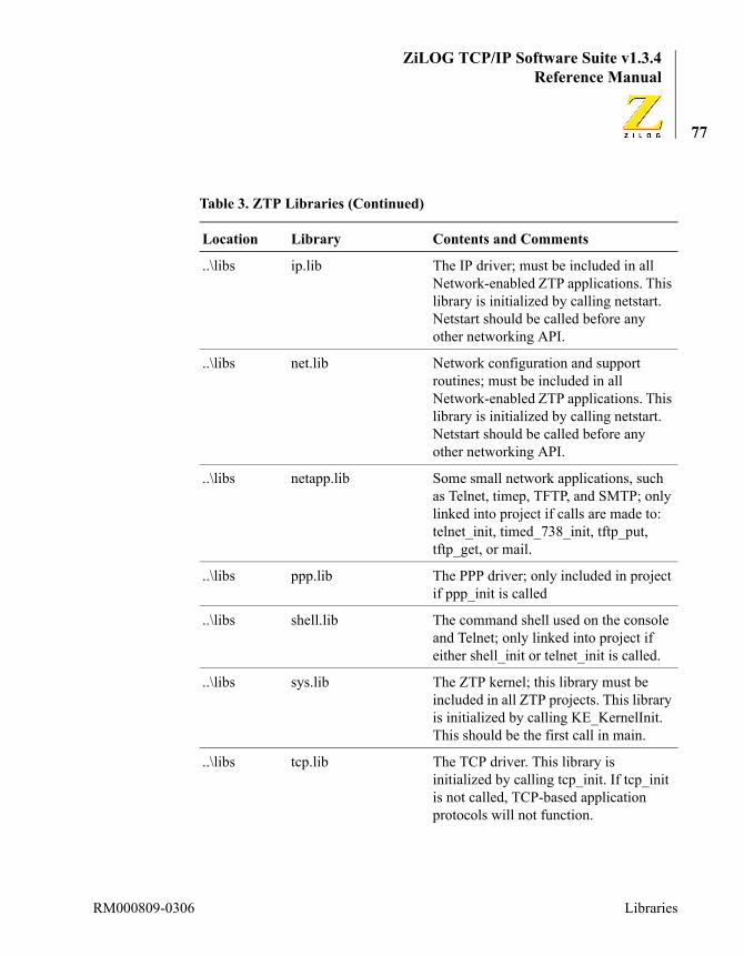
ZiLOG TCP/IP Software Suite v1.3.4Reference Manual
77
..\libs ip.lib The IP driver; must be included in all Network-enabled ZTP applications. This library is initialized by calling netstart. Netstart should be called before any other networking API.
..\libs net.lib Network configuration and support routines; must be included in all Network-enabled ZTP applications. This library is initialized by calling netstart. Netstart should be called before any other networking API.
..\libs netapp.lib Some small network applications, such as Telnet, timep, TFTP, and SMTP; only linked into project if calls are made to: telnet_init, timed_738_init, tftp_put, tftp_get, or mail.
..\libs ppp.lib The PPP driver; only included in project if ppp_init is called
..\libs shell.lib The command shell used on the console and Telnet; only linked into project if either shell_init or telnet_init is called.
..\libs sys.lib The ZTP kernel; this library must be included in all ZTP projects. This library is initialized by calling KE_KernelInit. This should be the first call in main.
..\libs tcp.lib The TCP driver. This library is initialized by calling tcp_init. If tcp_init is not called, TCP-based application protocols will not function.
Table 3. ZTP Libraries (Continued)
Location Library Contents and Comments
RM000809-0306 Libraries
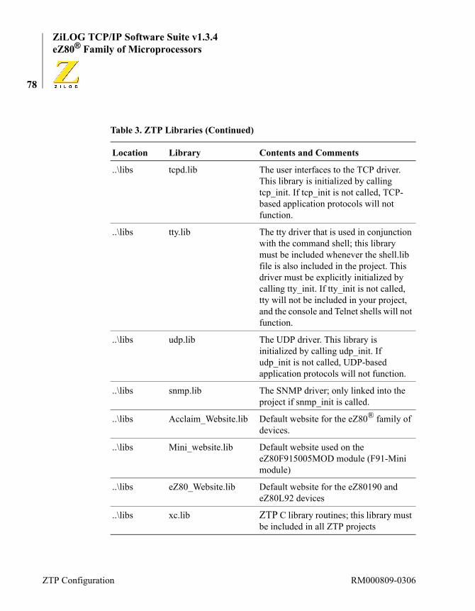
ZiLOG TCP/IP Software Suite v1.3.4eZ80® Family of Microprocessors
78
..\libs tcpd.lib The user interfaces to the TCP driver. This library is initialized by calling tcp_init. If tcp_init is not called, TCP-based application protocols will not function.
..\libs tty.lib The tty driver that is used in conjunction with the command shell; this library must be included whenever the shell.lib file is also included in the project. This driver must be explicitly initialized by calling tty_init. If tty_init is not called, tty will not be included in your project, and the console and Telnet shells will not function.
..\libs udp.lib The UDP driver. This library is initialized by calling udp_init. If udp_init is not called, UDP-based application protocols will not function.
..\libs snmp.lib The SNMP driver; only linked into the project if snmp_init is called.
..\libs Acclaim_Website.lib Default website for the eZ80® family of devices.
..\libs Mini_website.lib Default website used on the eZ80F915005MOD module (F91-Mini module)
..\libs eZ80_Website.lib Default website for the eZ80190 and eZ80L92 devices
..\libs xc.lib ZTP C library routines; this library must be included in all ZTP projects
Table 3. ZTP Libraries (Continued)
Location Library Contents and Comments
ZTP Configuration RM000809-0306
ZiLOG TCP/IP Software Suite v1.3.4Reference Manual
79
Example Project ConfigurationsKernel-Only Configuration. If your applications requires a small real time kernel but does not use any networking features, then the Kernel-Only configuration will provide the smallest possible memory footprint.
In this configuration, the required libraries are SYS.lib, XC.lib, and one of: eZ80F91.lib, eZ80F92.lib, eZ80F93.lib, eZ80L92.lib, or eZ80190.lib.
This configuration must call KE_KernelInit to initialize the ZTP ker-nel.Kernel + Shell Configuration. If your application requires an interactive command shell, the following libraries must be added to the Kernel-Only Configuration:
Shell.lib, TTY.lib
In addition to the initialization calls made in the kernel-only configura-tion, this configuration must also call tty_init and shell_init.Minimal Network Configuration. If your project does not use any UDP or TCP protocols, but only requires ICMP (that is, ping) support, the fol-lowing libraries must be added to the Kernel + Shell Configuration: IP.lib, NET.lib, and either F91_emac.lib or cs8900a.lib if the system uses the Ethernet interface. This configuration will not support the use of DNS or DHCP, nor any TCP/IP application protocol such as SNMP, TFTP, HTTP, or SMTP.
If PPP is used instead of Ethernet, then PPP can be used instead of either F91_emac.lib or CS8900a.lib. If both PPP and Ethernet are being used, include PPP.lib and either F91_emac.lib or CS8900a.lib.
If either of the Ethernet driver libraries (F91_emac.lib or CS8900A.LIB) is included in the project, ARP.lib must also be included. ARP.lib does not need to be included for PPP-only configura-tions.
Note:
RM000809-0306 Libraries
ZiLOG TCP/IP Software Suite v1.3.4eZ80® Family of Microprocessors
80
In addition to the initialization calls made in the kernel + shell configura-tion, this configuration must also call netstart, eth_init (if using Ethernet), arp_init (if using Ethernet), icmp_init, and ppp_init (if using PPP).UDP-Only Configuration. If your project requires the use of UDP-based protocols, such as DHCP, DNS, TFTP, or SNMP, but not -TCP-based pro-tocols, add the UDP.lib and DGRAM.lib libraries to the Minimal Net-work configuration.
In addition to the initialization calls made in the minimal network config-uration, this configuration must also include calls to udp_init.TCP-Only Configuration. If your project requires the use of TCP-based protocols, such as HTTP and SMTP, but not UDP-based protocols, add TCP.lib and TCPD.lib to the Minimal Network configuration. In addi-tion to the initialization calls made in the minimal network configuration, this configuration must also include calls to tcp_init.Full Network Configuration. If your project requires the use of both UDP and TCP based protocols, add DGRAM.lib, UDP.lib, TCP.lib, and TCPD.lib to the Minimal Network configuration. In addition to the ini-tialization calls made in the minimal network configuration, this configu-ration must include calls to udp_init and tcp_init.Expanded Configurations. Depending on which UDP and/or TCP proto-cols are called from your application, the following libraries may need to be added to the Full Network configuration: NETAPP.lib (for Telnet, SMTP, TFTP, and Timed738 support), HTTP.lib, and SNMP.lib. The daemons in the netapp.lib library are initialized by calling telnet_init, timed_738_init, http_init, and snmp_init.
When SNMP is included in your project, it references counters used in other network libraries. Therefore, it is typically required to include all ZTP networking libraries to allow the SNMP agent to build properly. However, this statement does not mean to imply that all code from these libraries will be included in your project. ZDS II will only include the variables required by SNMP.
Note:
ZTP Configuration RM000809-0306

ZiLOG TCP/IP Software Suite v1.3.4Reference Manual
81
To enable the ICMP protocol (for example, ping and processing IP error messages), ICMP.lib should be included.
To enable IP multicasting support, add IGMP.lib.
To use one of the ZiLOG-supplied websites, add one of: Acclaim_Website.lib, eZ80_Website.lib, or Mini_Website.lib.ZTP Default Configuration. By default, ZTP projects include all libraries from all configurations. However, not all of the code from these libraries is linked into your project unless specific initialization calls are made. If memory permits, ZiLOG recommends including all ZTP libraries in your projects and allowing the ZDS II linker to determine which components are required.
Preprocessor DefinitionsEach ZTP sample project includes a ZDS II preprocessor definition that is used to distinguish between different target hardware platforms. These preprocessor definitions correspond to one of the various ZiLOG eZ80® development platforms. For example, the eZ80F910200ZCO_Demo.zdsproj file is designed to run on the eZ80F910200ZCO Development Kit. Therefore this project includes the preprocessor definition: _EZ80F910200ZCO.
The eZ80_HW_Config.c file included with every ZTP project contains #ifdef blocks of code to conditionally compile hardware platform spe-cific code. For example, when using the eZ80F910200ZCO_Demo.zdsproj file, the _EZ80F910200ZCO pre-processor definition is created and only code from the eZ80_HW_Config.c file within the #ifdef _EZ80F910200ZCO and #endif directives will be included in the project.
When porting ZTP projects to a custom hardware platform, you can either modify the platform-specific code within the #ifdef blocks or copy one of the existing ZDSPROJ files, create a new preprocessor definition to identify your own target hardware platform, and then create a new
RM000809-0306 Preprocessor Definitions

ZiLOG TCP/IP Software Suite v1.3.4eZ80® Family of Microprocessors
82
#ifdef block of code in the eZ80_HW_Config.c file based on one of the existing blocks.
Target ConfigurationEach ZTP sample project features one or more ZDS II project configura-tions such as RAM or Flash. These configurations each offer a preselected target platform in the Debugger tab of the Project Settings menu option. For example, in the eZ80F910200ZCO_Demo.zdsproj file, when the RAM configuration is selected, the eZ80DevPlatform_F91_RAM target platform will be preselected.
If you click the Setup button in ZDS II’s Project Settings → Debugger tab, the eZ80® hardware-specific settings used for that target platform are dis-played and can be modified. Information from the platform-specific set-tings is stored in an XML file that corresponds to the specific target hardware platform and ZDS II target interface module used to communi-cate with that target. For example, when the eZ80DevPlatform_F91_RAM target platform is selected and the Ether-net (ZPAK II) interface is used to communicate with the target, the plat-form-specific settings are stored in a file called eZ80DevPlatform_F91_RAM-Ethernet.xml.
The ZDS II XML files used to configure a particular target platform are shared between all ZDS II projects that use that target platform. There-fore, if you make a change to the eZ80DevPlatform_F91_RAM-Ethernet.xml hardware settings while using the ZTP Demo project, those changes will automatically be transferred to any other ZDS II project that uses the eZ80DevPlatform_F91_RAM-Ethernet.xml tar-get platform.
At the time this document was published, all ZDS II target configuration (XML) files were required to be placed in the compiler’s ..\targets directory.
When porting ZTP projects to a custom hardware platform, you can either modify the settings in one of the ZDS II-provided XML files using the
Note:
ZTP Configuration RM000809-0306
ZiLOG TCP/IP Software Suite v1.3.4Reference Manual
83
Setup option on the Debugger tab of the Project Settings menu option, or create a new target XML configuration file. Refer to the ZiLOG Devel-oper Studio II–eZ80Acclaim!® User Manual (UM0144) for more infor-mation about how to create a new target configuration file.
Linker DirectivesZTP does not define any unique linker directives. The only directives used by ZTP are those created by ZDS II. For more information about the default ZDS II linker directives, refer to ZiLOG Developer Studio II–eZ80Acclaim!® User Manual (UM0144).
Porting ZTP Applications to a Custom Hardware PlatformPorting ZTP projects to a custom hardware platform is easy to accom-plish. The simplest option is to modify the ZTP project configuration that uses the same CPU type. For example, if your target platform uses the eZ80F92 processor, then the ZTP-supplied project file that is most suit-able as a starting point is eZ80F920200ZCO_Demo.zdsproj. Remem-ber that if you make changes to the eZ80DevPlatform_F92_RAM-Ethernet.xml configuration file, these changes will be reflected in all ZDS II projects that use the eZ80DevPlatform_F92_RAM-Ethernet target configuration in the Debugger tab of the Project Settings menu option.
A slightly more complicated option is to create a unique *.ZDSPROJ and *.XML file for your custom hardware platform. In the example that fol-lows, it is assumed that the target platform will use the eZ80F91 proces-sor, that the Demo project is being ported (RAM configuration), the ZPAK II emulator is used to communicate with the target over Ethernet, and that the eZ80F910200ZCO development platform is most similar to the target hardware platform. With this premise, the ZTP Demo project is ported as follows:
1. Create a copy of the eZ80DevPlatform_F91_RAM-Ethernet.xml file. Give this XML file a name that easily identifies your target hard-
RM000809-0306 Linker Directives

ZiLOG TCP/IP Software Suite v1.3.4eZ80® Family of Microprocessors
84
ware platform. In this example, the copied file has been named MyF91Product_RAM_ZTP–Ethernet.XML. If there are other con-figurations of interest, make copies of them as well. For example, if a Flash configuration is required, make a copy of the eZ80DevPlatform_F91_Flash-Ethernet.xml files and gener-ate a name of MyF91Product_Flash_ZTP–Ethernet.xml or sim-ilar.
At the time of publication, all XML files were required to be stored in the compiler’s ..\targets directory.
2. In the ZTP Demo folder, make a copy of the eZ80F910200ZCO_Demo.zdsproj project file and give it a descrip-tive name that identifies the target product. In this example, the cop-ied demo project is called MyF91Product_Demo.zdsproj.
3. Open the ZDS II project files just created (MyF91Product_Demo.zdsprog) and select the appropriate config-uration. In this example, the RAM configuration should be selected.
4. Under the Project Settings menu option, select the C tab and then the Preprocessor category. Change the _EZ80F910200ZCO preprocessor definition to one that uniquely identifies your hardware platform. In this example, MY_F91_PRODUCT is used.
5. Under the Project Settings menu option, select the Linker tab and then the Address Spaces category. Modify the memory ranges for RAM and ROM as applicable to your hardware platform.
In the RAM configuration, a portion of the RAM address space must be assigned to ROM or else the ZDS II linker will have nowhere to store your program code. There must be enough physical memory on your tar-get to contain all of the ZTP modules that have been configured. (See the Libraries section on page 74 section for information about removing ZTP components).
6. Under the Project Settings menu option, select the Debugger tab and then select the target configuration file that corresponds to your cus-
Note:
ZTP Configuration RM000809-0306

ZiLOG TCP/IP Software Suite v1.3.4Reference Manual
85
tom hardware platform. In this example, the MyF91Product_RAM_ZTP–Ethernet option is selected.
If the XML configuration file created in Step 1 does not appear in the window, save the current project, exit ZDS II, and make sure the XML file is contained in the proper directory.
At the time of publication, all target XML configuration files were required to be located in the compiler’s ..\targets directory.
7. Click the Setup button and modify the parameters as appropriate for your hardware platform. Typically, this modification involves the Chip Select, Bus Mode, system clock frequency, and stack location. For ZTP projects, set the SPL stack pointer to a value 1 byte higher than the highest physical RAM address. For example, if the RAM address range entered in Step 5 was 0xC00000 to 0xC7FFFF, then SPL should be set to C80000. For more information about configur-ing the target processor, refer to the ZiLOG Developer Studio II–eZ80Acclaim!® User Manual (UM0144).
8. In the eZ80_HW_Config.c file, copy the block of code from the #ifdef section from which the project was initially created. In this example, the new project file was created from the eZ80F910200ZCO_Demo.zdsproj project file. Therefore, the #ifdef _EZ80F910200ZCO block of code in the eZ80_HW_Config.c file should be copied into a new #ifdef MY_F91_PRODUCT block. The value to use in the #ifdef directive should match the preprocessor definition created in Step 4.
9. In the ZTP_HW_Init routine within the #ifdef MY_F91_PRODUCT block, modify the GPIO configuration as appropriate.
At the time of publication, ZDS II start-up code would only initialize GPIO pins to Mode 2. If future ZDS II releases initialize these regis-ters, it will not be necessary to reinitialize the registers in the ZTP_HW_Init routine.
RM000809-0306 Porting ZTP Applications to a Custom Hardware
ZiLOG TCP/IP Software Suite v1.3.4eZ80® Family of Microprocessors
86
Finally, adjust the Ethernet MAC settings if required for your applica-tion.
10. Rebuild the project and download it to the target.
ZTP InitializationZTP relies on the ZDS II start-up code to initialize the hardware and the software run-time environment. This initialization routine resets all peripheral devices integrated within the eZ80® device, configures chip selects and internal RAM and/or ROM, sets up the interrupt system, cop-ies all initialized data variables to RAM, and initializes the BSS segment. As with any other application, after ZDS II has finished initializing the system, it calls the main() application entry point.
The very first call that should be made from main is a call to:
KE_KernelInit();
Calling the KE_KernelInit function initializes the ZTP kernel and transforms the ZDS II run-time from a single threaded application into a real-time, preemptive multitasking system. Before calling any other KE_xxx function, you must call KE_KernelInit.
After the ZTP kernel has been initialized, if your application requires the use of TCP/IP networking protocols,
netstart();
must be called. The netstart function initializes the core TCP/IP lay-ers. This initialization must be performed prior to calling any other ZTP networking API.
After the core networking protocols have been initialized, you can selec-tively enable optional ZTP protocols such as HTTP, Telnet, or SNMP.
ZTP Configuration RM000809-0306

ZiLOG TCP/IP Software Suite v1.3.4Reference Manual
87
To alter the default ZTP configuration, a number of configuration files can be included in your project. These files are contained in the ..\conf directory and are described in the ZTP Configuration chapter on page 39.
RM000809-0306 ZTP Initialization

ZiLOG TCP/IP Software Suite v1.3.4eZ80® Family of Microprocessors
88
ZTP Configuration RM000809-0306

ZiLOG TCP/IP Software Suite v1.3.4Reference Manual
89
Using ZTPThis chapter describes how to use the various protocols and services available in the ZTP software suite.
How to Use InterruptsThis section provides a brief overview of eZ80® interrupt functionality and explains the ZTP interrupt model and relevant kernel calls. Addition-ally, this section describes how interrupts affect ZTP multitasking. The section concludes with sample code to illustrate the steps necessary to integrate an interrupt handler with the ZTP system. The material in this section is pertinent to the eZ80® family of devices and may not be rele-vant for other processor families.
eZ80® Interrupt OverviewWhile the CPU is executing code (referred to here as a foreground task), a peripheral device can encounter a situation that requires immediate atten-tion by the CPU. This situation could occur, for example, if a UART has received a few bytes of data, or if an external Ethernet controller has fin-ished sending a packet. Without interrupts, the device would have to patiently wait for the CPU to execute code to check the status of the device (referred to as polling), then take appropriate action. Depending on how frequently the CPU polls the status of the device, a significant amount of time can elapse between the time the peripheral required ser-vicing and the time the CPU services the device. As a result, a loss of data can occur, and is therefore undesirable.
However, if the device has a physical connection to one of the CPU’s interrupt pins (a GPIO pin configured for interrupt mode on the eZ80® family of devices), the device can activate one of the CPU’s interrupt request lines to demand service from the CPU (referred to as generating an interrupt). If the CPU is in a state where it can recognize the physical
RM000809-0306 How to Use Interrupts
ZiLOG TCP/IP Software Suite v1.3.4eZ80® Family of Microprocessors
90
interrupt signal, it will stop executing the foreground task and immedi-ately begin executing a special block of code called the Interrupt Service Routine (ISR), which is used to process the interrupt request from the peripheral device. The CPU is therefore interrupted.
In the eZ80® family of devices, there are two different types of interrupts: maskable interrupts and nonmaskable interrupts. Software executing on the eZ80® CPU can execute a disable interrupt (DI) instruction that pre-vents the CPU from responding to any (maskable) interrupt request. In this instance, interrupts are said to be disabled or masked. When the eZ80® assembly enable interrupt (EI) instruction is executed, the CPU can once again respond to maskable interrupts. In this instance, interrupts are said to be unmasked or enabled. While the eZ80® CPU is executing code within an ISR in response to one maskable interrupt source, maskable interrupts from all other sources will be ignored until the ISR software executes an EI instruction. Clearly, the software that is currently running on the CPU can affect the CPU’s ability to respond to maskable interrupts.
The second type of interrupt that can occur in the eZ80® family of devices is a nonmaskable interrupt (NMI). As the name implies, it is impossible to mask (that is, prevent the CPU from responding to) a nonmaskable inter-rupt. Because nonmaskable interrupts are unaffected by software running on the CPU, they cannot be controlled by the ZTP interrupt model. As a result, if your application uses an NMI, the associated ISR must not call any ZTP API. The reason for this restriction is because ZTP sometimes disables maskable interrupts for a short period of time (on the order of microseconds) to manipulate critical kernel resources. Should an NMI occur and the associated ISR call a ZTP API that modifies the same criti-cal kernel resource, system integrity could be compromised.
The remainder of the material in this section is only applicable to maskable interrupts.
Using ZTP RM000809-0306

ZiLOG TCP/IP Software Suite v1.3.4Reference Manual
91
Understanding Interrupt LatencyThe software currently executing on the eZ80® CPU can affect the CPU’s ability to respond to maskable interrupts. Included in this type of instance are the number of system clock cycles required to finish executing the current instruction, a determination as to whether the currently executing block of code has explicitly disabled maskable interrupts by issuing a DI assembly instruction, and a determination as to whether the currently exe-cuting block of code is running within an ISR (maskable interrupts are implicitly disabled by the eZ80® CPU when it responds to an interrupt). Even after the eZ80® CPU recognizes the occurrence of a physical inter-rupt, there is a finite amount of time required for the CPU to save its cur-rently-executing state and switch to the ISR code. On the eZ80® CPU, this time duration involves storing values to the stack and jumping through the interrupt vector table; refer to the eZ80® CPU User Manual (UM0077) for more information. These factors combine to determine the time lag between a peripheral device generating an interrupt and the eZ80® CPU executing the first instruction of the ISR responsible for ser-vicing that device. This time lag is referred to as interrupt latency.
In a system that must rapidly respond to external events, it is preferable to keep system interrupt latency to a minimum level. Simply defined, system interrupt latency is the longest interrupt latency period for all interrupts in the system. Suppose a system has two interrupt sources—one from Device A and the other from Device B. Further suppose that the ISR for Device A takes 20 µs to service the device and the ISR for Device B takes between 10 µs and 5,000 µs to service the device (the numbers in this example are arbitrary and not meant to reflect any actual processing time in a ZTP system). Finally, suppose that, on average, it takes 1 µs for the CPU to start executing code in an ISR after the interrupt is recognized. Then, when the CPU is able to immediately recognize the interrupt (that is, a DI is not in effect), the interrupt latency will be about 1 µs.
Consider what happens if Device B generates an interrupt a split second after the ISR for Device A begins to execute. In this instance, the latency of the interrupt for Device A will be approximately 1 µs, but the latency of
RM000809-0306 eZ80® Interrupt Overview

ZiLOG TCP/IP Software Suite v1.3.4eZ80® Family of Microprocessors
92
the interrupt for Device B will be approximately 21 µs. Worse yet, sup-pose Device A generates an interrupt request a split second after the ISR for Device B begins executing. In this instance, the latency for Device B will be 1 µs, but the interrupt latency for Device A could be as long as 5,001 µs. Because this interval is the longest interrupt period for all inter-rupts in the system, system interrupt latency will be just over 5 ms. As a result, a loss of data can occur on Device A.
In an effort to keep system interrupt latency as low as possible, ZTP inter-rupt handlers do not completely service an interrupt from within the ISR. Instead, the ISR performs just enough processing to disable the source of the interrupt, then schedules an Interrupt Task to perform the bulk of the interrupt processing. Because low-level ISR code typically executes in a few microseconds, system interrupt latency is much lower than the actual processing time performed in any of the interrupt tasks. Returning to the example above, suppose the ISR for Device B is split into two sections: the first section prevents Device B from generating any further interrupts and uses the kernel’s KE_IsrResched API to schedule the longer-run-ning Interrupt Task. If the first step could be completed in less than 20 µs (the time required to process an interrupt from Device A from within the ISR), then the system interrupt latency could be reduced to just 21 µs.
Besides keeping system interrupt latency to a minimum level, there are several other advantages to this approach, as described below.
Firstly, interrupt tasks can be interrupted. Recall that after an ISR begins executing on the eZ80® CPU, the CPU cannot respond to any other maskable interrupt until an EI instruction is executed. In the running example, if the interrupt for Device B is serviced completely from within the ISR, it can take up to 5 ms before the ISR for Device A is recognized. However, when interrupt tasks are employed, the CPU can interrupt the current Interrupt Task to service other interrupt requests.
Secondly, interrupts tasks are prioritized just like any other task in the ZTP system. As a result, the user can assign a priority to an Interrupt Task that is higher, or lower, than other tasks (or interrupt tasks) in the ZTP
Using ZTP RM000809-0306

ZiLOG TCP/IP Software Suite v1.3.4Reference Manual
93
system. Recall that when the ZTP scheduler switches tasks, it always runs the highest-priority task that is in the Ready state. In contrast, interrupt priorities on the eZ80® CPU are fixed. Therefore, if Device A and Device B generate simultaneous interrupt requests, the CPU will always execute the ISRs in a predetermined order based on their hardware priorities, and both ISRs will execute to completion before the foreground task can resume execution.
However, with interrupt tasks, the user can assign Interrupt Task A a higher priority than Interrupt Task B. Therefore, if both interrupts occur at exactly the same time, and even if the eZ80® CPU interrupt priority of Device B is higher than Device A, Interrupt Task A will execute before Interrupt Task B. In addition, if the user assigns the foreground task a pri-ority higher than both of the interrupt tasks, then the user can ensure that the foreground task will not be preempted for long periods of time. In effect, the processing of the interrupt is deferred without disabling maskable interrupts and increasing system interrupt latency.
Thirdly, interrupt tasks can be preempted just like any other task in the system. Returning to the example, if the Interrupt Task for Device B begins processing a long-running interrupt, not only can the system respond to the interrupt request from Device A (property 1), but the Inter-rupt Task for Device B can actually be preempted in mid-stream to ser-vice Device A if the Interrupt Task for Device A is assigned a higher priority than the Interrupt Task for Device B.
Fourthly, this strategy can reduce the processing overhead associated with handling multiple, near-simultaneous interrupt requests. In the ZTP inter-rupt model, interrupt generation is disabled on the requesting device after the interrupt task is scheduled for execution, and remains disabled while the interrupt task executes. Interrupt generation by the peripheral device is only enabled when the interrupt task is placed in a suspended state.
Fifthly, the use of interrupt tasks to minimize the amount of processing time steals from the foreground task. Recall that unless a task blocks or is preempted, it is allowed to execute until its time slice expires. When an
RM000809-0306 eZ80® Interrupt Overview
ZiLOG TCP/IP Software Suite v1.3.4eZ80® Family of Microprocessors
94
interrupt occurs, the CPU starts running an interrupt service routine in the context of the foreground task. If interrupt tasks are not used, then the interrupt must be completely serviced within the ISR, which effectively reduces the foreground task’s time slice. When using the ZTP interrupt model, the amount of time the ISR steals from the foreground task can be reduced to just a few microseconds.
The chief disadvantage to the ZTP interrupt model arises from the fact that interrupt tasks must compete for processor time with other ZTP tasks. This type of situation can actually increase interrupt response time. For example, if the Interrupt Task for Device B is preempted by the Interrupt Task for Device A, followed by a higher-priority Application Task C, the total time required to service the interrupt for Device B will be equal to the processing time taken by the Interrupt Task for Device A, Application Task C, and the system overhead associated with multiple context switches. It is up to the programmer to assign relative task priorities to ensure that more important tasks are assigned higher relative priorities. Typically, interrupt tasks are assigned priorities higher than foreground tasks, although this type of priority is not a requirement when working with ZTP.
ZiLOG highly recommends following the ZTP interrupt model when add-ing interrupts to ZTP if moderate to heavy processing is required. If you choose not to use this model, then your ISR must not call any ZTP API. In addition, system interrupt latency can increase depending upon the amount of processing performed in your ISR; this situation can result in a loss of data. However, for devices that require very little code to service the interrupt (such as simply reading a status register), completely servic-ing the device within the ISR can provide a better solution than employ-ing the ZTP interrupt model.
The ZTP Interrupt ModelThe ZTP interrupt model requires that an interrupt be divided into two components. The first component executes from within an assembly stub to disable the source of the interrupt and schedule the Interrupt Task for
Note:
Using ZTP RM000809-0306

ZiLOG TCP/IP Software Suite v1.3.4Reference Manual
95
execution. The second component is the interrupt task that performs the majority of the processing required to service the interrupt. After the interrupt task has finished servicing the device, it reenables interrupt gen-eration by the peripheral and self-suspends.
In this interrupt model, the interrupt task operates in polling mode to ser-vice the device, and hardware interrupts are used to control when the interrupt task is scheduled for execution. The relative priority of the inter-rupt task determines when the interrupt task actually runs.
The only ZTP API that should be called from within the assembly inter-rupt stub is KE_IsrResched if the interrupt stub determines that it is necessary to schedule the interrupt task for execution. If other ZTP APIs are called, system integrity can be compromised.
Interrupts, Critical Sections, and PreemptionConsider a system with 2 tasks of equal priority, Task A and Task B. Fur-ther, suppose these tasks both manipulate a shared resource such as the global data buffer of a linked list. Because ZTP is a preemptive multitask-ing system, it is possible that immediately after Task A begins manipulat-ing the shared resource, its time slice expires and Task B begins executing. If Task B also starts to modify the same shared resource, then Task A’s modifications could be compromised. Even worse, it is possible that Task A was preempted when the shared resource was in an indetermi-nate state. Therefore, when Task B access the shared resource, it will appear that the resource is corrupt and unusable.
To prevent this situation, the block(s) of code in Task A and Task B that manipulate the shared resource can be placed in a critical section(s). After a task enters a critical section, no other task in the system will be able to enter the same, or any other, critical section.
Conceptually, a critical section can be implemented using a global binary semaphore (a semaphore that has an initial semaphore count of 1). Note the distinction between the use of a binary semaphore and a critical sec-tion. If binary semaphore Sem1 is used to ensure mutually exclusive
Note:
RM000809-0306 eZ80® Interrupt Overview

ZiLOG TCP/IP Software Suite v1.3.4eZ80® Family of Microprocessors
96
access to some resource and binary semaphore Sem2 is used to ensure mutually exclusive access to some other resource, then when Task A acquires semaphore Sem1, Task B will still be able to acquire Sem2. How-ever, if both resources are protected by a critical section, then after Task A enters the critical section to manipulate the first resource, Task B will be prevented from entering its critical section and manipulating the other resource. In addition, the amount of code required to implement a sema-phore is typically much larger, and takes longer to execute, than the amount of code to implement a critical section. Therefore, for very sensi-tive objects that are manipulated frequently, such as kernel objects associ-ated with task scheduling, critical sections are preferable to using more complex synchronization methods such as semaphores.
The ZTP kernel provides two mechanisms to implement critical sections. The first method is to disable maskable interrupts (KE_CriticalBegin and KE_CriticalEnd). The second method only disables preemption (KE_DisablePreempt and KE_RestorePreempt).
When code bracketed by a call to KE_CriticalBegin and KE_CriticalEnd executes, the CPU will not be able to respond to any maskable interrupt. In this case, it is impossible for a context switch to occur, and there is no possibility that any other task in the system will be able to enter another critical section. However, if large amounts of code are placed within this critical section, system interrupt latency will begin to increase dramatically as well as adversely affect the system’s ability to respond to real-time events, and should be avoided. Therefore, the ZTP kernel frequently uses the second method of implementing critical sec-tions in which preemption is disabled. As explained below, this second method of implementing critical sections is vulnerable to rogue ISRs that attempt to circumvent the ZTP interrupt model.
When code bracketed by a call to KE_DisablePreempt and KE_RestorePreempt executes, the CPU can still respond to maskable interrupts, but the ZTP kernel will not preempt the currently-executing task until the earlier of:
Using ZTP RM000809-0306

ZiLOG TCP/IP Software Suite v1.3.4Reference Manual
97
• A call to KE_EnablePreempt (explicit call to reenable preemption).
• A call to a ZTP API that causes the current task to block (implicit call to reenable preemption).
Because maskable interrupts are enabled while preemption is disabled, it is possible that an ISR will interrupt code bracketed by KE_DisablePreempt and KE_RestorePreempt. Therefore, the only ZTP API that the ISR is permitted to call is KE_IsrResched, because the code that implements other APIs can attempt to manipulate a resource that the kernel was protecting by disabling preemption. If ZTP APIs other than KE_IsrResched are called, kernel objects could become corrupted and cause system failure. Therefore, if your ISR must call ZTP APIs, the ISR must schedule an interrupt task for execution by calling KE_IsrResched. The interrupt task can call any ZTP API without com-promising system integrity. If the ISR must manipulate a resource shared with a foreground task, the code in the foreground task must be placed in a critical section bracketed by calls to KE_CriticalBegin and KE_CriticalEnd.
Interrupts and Context SwitchingWhen a task disables maskable interrupts, either directly by calling KE_DisableMI, or indirectly by calling KE_CriticalBegin, the ZTP kernel will not be able to preempt the task. However, the task will not be prevented from voluntarily preempting itself (that is, yielding control of the CPU). For example, if the task calls the KE_Sleep API, the task will block and the kernel will perform a context switch to start executing a new task. Similarly, if the task releases a semaphore that a higher-priority task was blocked on, then the application is implicitly yielding control of the CPU and the kernel will context-switch to the higher-priority task.
There is a subtle difference between implementing critical sections with KE_CriticalBegin/KE_CriticalEnd and KE_DisablePreempt/KE_RestorePreempt. In the former case, a context switch will occur if the task explicitly calls a ZTP API that causes a task of equal or higher priority to transition to the Ready scheduling state, or if the task calls a
Note:
RM000809-0306 eZ80® Interrupt Overview

ZiLOG TCP/IP Software Suite v1.3.4eZ80® Family of Microprocessors
98
ZTP API that causes it to block. When KE_DisablePreempt is used, the kernel will only perform a task switch if the task calls a ZTP API that causes the task to block.
It is important to realize that part of a ZTP task’s context is the state of the interrupt system. If Task A includes disabled maskable interrupts and Task B does not, then when the kernel switches from Task A to Task B, maskable interrupts will be enabled. When the kernel switches back to Task A, maskable interrupts will be disabled. Therefore, if code within your critical section causes a context switch, ZTP will terminate the criti-cal section (although maskable interrupts will be disabled upon return from the context switch when KE_CriticalBegin is used to start the critical section).
Using the ZTP Interrupt ModelThis section describes the basic steps to be followed when integrating interrupt handlers with ZTP. These steps are:
1. Create an Interrupt Task.
2. Create an Interrupt Service Routine.
3. Add the interrupt task to ZTP.
4. Install the ISR.
5. Activate the interrupt.
Creating An Interrupt TaskThis routine should perform most of the processing required to service an interrupt, and can involve such tasks as reading data from a hardware buffer, sending the next block of data to a peripheral device, or using one of the ZTP interprocess communication mechanisms to alert another task that an event has occurred. Unlike the ISR, the interrupt task can call any ZTP API.
Using ZTP RM000809-0306

ZiLOG TCP/IP Software Suite v1.3.4Reference Manual
99
After this routine has finished servicing the interrupt, it should reenable interrupt generation by the peripheral device and then self-suspend. The next time the ISR fires, it will again schedule the interrupt task for execu-tion. Therefore, the interrupt task must not terminate if it reenables inter-rupt generation by the peripheral device. Typically, the interrupt task is implemented in a ZTP process within a do-forever loop. An example interrupt task follows below.
PROCESS MyInterruptTask( void ){
KE_DisableMI();while( 1 ){
KE_EnableMI();/* * Read status registers to
determine source * of interrupt. Process the
interrupt as * required calling any ZTP
API. * It may be necessary to do
this multiple * times to ensure all events
are processed. * e.g. * HW_Status =
ReadStatusReg(); * while( HW_Status & INT_MASK
) * { * // Service this
event * HW_Status =
ReadStatusReg(); * }
RM000809-0306 Using the ZTP Interrupt Model

ZiLOG TCP/IP Software Suite v1.3.4eZ80® Family of Microprocessors
100
*/
/* * Enable interrupt generation
on the * peripheral device. * Do this with Maskable
interrupts disabled. */KE_DisableMI();// <<<turn on device
interrupts here >>>
/* * Self-suspend. The next time
a HW interrupt * occurs, the ISR will
reschedule this * routine and we will go back
to the start * of the while loop. */KE_TaskSuspendCur();
}}
Create An Interrupt Service RoutineThe interrupt service routine should perform very little processing. Ide-ally, it should only prevent the interrupting peripheral from generating more interrupts, then schedule the interrupt task for execution.
.include ”kernel.inc”
.assume adl=1
.extern _InterruptTaskPID
.extern _KE_IsrResched
.def _My_ISR
Using ZTP RM000809-0306
ZiLOG TCP/IP Software Suite v1.3.4Reference Manual
101
_My_ISR:;*** KE_EnterISR is a macro that
saves all CPU;*** registers on the stack. KE_EnterISR
;*** Disable the source of the HW interrupt here.
;*** Schedule the Interrupt Taskld iy, (_InterruptTaskPID)call_KE_IsrResched
;*** KE_ExitISR is a macro that restores all CPU
;*** registers from the stack and then calls EI and
;*** reti.KE_ExitISR
This ISR only schedules the Interrupt Task for execution, and it does so by loading the IY register with the ZTP process ID (PID) of the Interrupt Task that services the interrupt, then calling KE_IsrResched. Immedi-ately after the comment Disable the source of the HW inter-rupt here, you can add code to prevent the peripheral device from generating additional interrupts.
After the Interrupt Task resumes execution, it will completely service the interrupting device. Just before suspending, the interrupt task will reen-able interrupt generation on the peripheral device. This interrupt model ensures that the only time the peripheral device will generate interrupts is when an interrupt task is not running. The interrupt task will keep running as long as the device requires servicing.
If you explicitly choose to save and restore all CPU registers to the stack instead of using the ZTP-supplied macros (KE_EnterISR and
RM000809-0306 Using the ZTP Interrupt Model

ZiLOG TCP/IP Software Suite v1.3.4eZ80® Family of Microprocessors
102
KE_ExitISR), you must restore the registers in the reverse order that they were saved, or else the CPU registers will become corrupted after the ISR exits. In addition, you should not use the EXX instruction to save the CPU registers to the alternate register set if you install more than one interrupt handler. To simplify the programming of the ISR, ZiLOG rec-ommends using the ZTP-supplied KE_EnterISR and KE_ExitISR mac-ros.
To ensure system integrity, the ISR is only permitted to call the KE_IsrResched API.
Add The Interrupt Task To ZTPAn interrupt task is added to ZTP using the KE_TaskCreate API similar to the way in which any other task in the ZTP system is created. However, there is one important distinction: you must not call the KE_TaskResume API to schedule the interrupt task after it has been created. Instead, just save the PID value returned from the KE_TaskCreate API in a global variable. The ISR will use the PID value to schedule the interrupt task for execution after an actual hardware interrupt occurs. In the sample code fragment that follows, a task is created. This task is assigned a priority of 25, named MyIntTask, and is given a private stack that is 1024 bytes long. The process ID (PID) value returned from the KE_TaskCreate API is saved in a global variable named InterruptTaskPID that the ISR uses to schedule the interrupt task for execution.
PID InterruptTaskPID; InterruptTaskPID = KE_TaskCreate((procptr)MyInterruptTask, 1024, 25, “MyIntTask”, 0 );
Install the ISRThe Interrupt Service Routine is added to the ZTP system using the set_evec API. set_evec includes two parameters that indicate the name of the routine to be called after the interrupt occurs and the interrupt
Using ZTP RM000809-0306
ZiLOG TCP/IP Software Suite v1.3.4Reference Manual
103
vector number of the corresponding interrupt. In the sample code that fol-lows, the My_ISR interrupt service routine is installed in the system using an interrupt vector for GPIO Port B, pin 5 (IV_PB5).
extern void My_ISR( void );set_evec(IV_PB5, My_ISR);
Activate the InterruptThe final step, when integrating interrupt handlers with ZTP, is to enable interrupt generation on the peripheral device. Typically, this step involves setting specific bits in one or more of the peripheral device’s control reg-isters. Additionally, if your design uses GPIO pins as interrupt request lines, you must configure the GPIO port registers appropriately.
If you modify the GPIO registers to configure one or more of the port pins as an interrupt request line, the interrupt could fire immediately. Therefore, you must integrate the interrupt with ZTP before placing the corresponding port pin into interrupt mode and allowing the peripheral device to generate interrupts.
In some cases, you can modify code in the ZTP_HW_Init routine (see the description of the eZ80_HW_Config.c file) to preconfigure the GPIO pins during system initialization instead of adding code to perform this task elsewhere. If you choose to configure GPIO pins for interrupt mode by modifying the ZTP_HW_Init code, it may be necessary to add instruc-tions to the ZTP_HW_Init routine to explicitly disable interrupts on the peripheral device. As an example, all ZiLOG eZ80® development plat-forms that do not use the eZ80F91 device use an external Ethernet con-troller that employs one of the GPIO pins as an interrupt request line. The default code in the ZTP_HW_Init routine configures the corresponding GPIO pin for interrupt mode. In addition, before modifying the GPIO configuration, there is a call to the emac_reset routine, which prevents the external Ethernet controller from asserting its interrupt request line. These steps are necessary to ensure that the Ethernet controller does not
Caution:
Note:
RM000809-0306 Using the ZTP Interrupt Model

ZiLOG TCP/IP Software Suite v1.3.4eZ80® Family of Microprocessors
104
generate an interrupt before the ZTP system start-up code has followed the steps above to install the interrupt task and corresponding ISR.
How to Use EthernetBy default, the network-based ZTP demo projects all include an Ethernet driver used to transfer packets over the Ethernet medium. Depending on the eZ80® development platform being used, the Ethernet driver will sup-port either the Cirrus CS8900A device or the Ethernet controller inte-grated with the eZ80F91 device. Ethernet communication will not be possible if an Ethernet driver is not included in your project or if the wrong Ethernet driver is included. For projects using the eZ80F91 device, the F91_emac.lib module must be included in the list of object/library modules listed in the Linker tab of the Project Settings menu option in ZDS II. For all other eZ80® development platforms, the CS8900A.lib module should be included.
Whichever Ethernet driver is included in your project, it is initialized by using the eth_init API. The function protocol for the eth_init API is:
SYSCALL eth_init(GET_IP_FUNC pGetIPFunc);
This function takes one parameter that indicates which ZTP internal func-tion should be used to specify the IP address used on the Ethernet inter-face. Possible choices include:
• NULLPTR
• dhcp
• rarp
When NULLPTR is specified, the Ethernet interface will use the IP address and subnet mask specified in the Bootrecord structure.
Using ZTP RM000809-0306

ZiLOG TCP/IP Software Suite v1.3.4Reference Manual
105
When dhcp is specified, the DHCP protocol will be used to obtain dynamic IP parameters from a DHCP server if one is present on your net-work.
When rarp is specified, the RARP protocol will be used to obtain an IP address to use from a RARP server if one is present on your network.
If either of the DHCP or RARP protocols fails to obtain IP parameters, then the default values from the boot record will be used as if NULLPTR was specified on the call to eth_init.
DHCP is the preferred method of obtaining IP parameters. Therefore, the ZTP demo project specifies dhcp when initializing the Ethernet driver, as shown below:
eth_init should be called after the call to netstart in main. After this call, the Ethernet driver is initialized, and your application is free to use the Ethernet interface.
How to Use DHCPThe ZTP TCP/IP protocol stack can be configured to use either statically-assigned IP parameters, or obtain these parameters dynamically from a DHCP server. The default IP parameters are contained in the Bootrecord structure (see the main.c file in the project folders). The use of DHCP is controlled by specifying the dhcp parameter when on the call to eth_init. When DHCP is used, the protocol attempts to update the default IP parameters specified in the bootrecord structure during system initialization. If a server cannot be found, then ZTP defaults to the values contained in the boot record. When DHCP is not used, ZTP uses the values in the boot record to determine its IP parameters.
When ZTP attempts to access a DHCP server, it starts a timer. If the timer times out, either it makes a repeat attempt or defaults to the static IP address. ZTP attempts to access the DHCP server a certain number of times specified by the parameter bootp_tries. bootp_tries is defined in the \conf\net_conf.c file. Each time-out causes the next
RM000809-0306 How to Use DHCP

ZiLOG TCP/IP Software Suite v1.3.4eZ80® Family of Microprocessors
106
time-out to be double the previous time-out. The BOOTP_RESEND macro in the bootp.h file contains the initial time-out in seconds. The number of retries should be set according to the expected network congestion.
How to Use RARPBefore DHCP servers were widely available, a simpler protocol, called RARP, was used to assign an IP address to a device during its initializa-tion. The RARP protocol requires that the network contain one or more RARP servers that listen for RARP request packets from devices that are booting up on the network. When the RARP server receives a RARP request, the server attempts to find the hardware address of the requesting device in a static table. If a match is found, the RARP server responds with a reply packet that indicates the IP address that the requesting device should use. However, the RARP protocol is not able to assign IP parame-ters such as a subnet mask, a default gateway, or a domain name server. Therefore, RARP is inferior to the DHCP protocol, which can assign these (and other) IP parameters to a requesting device. Additionally, very few modern networks contain RARP servers; therefore, this protocol is typically not useful.
For these reasons, ZiLOG strongly recommends not using the RARP pro-tocol with your application. Instead, use the DHCP protocol to obtain IP parameters, or simply assign the eZ80® device a suitable set of static IP parameters in the Bootrecord structure.
To use the RARP protocol, specify the RARP command on the call to eth_init. Using RARP will cause ZTP to generate a RARP request packet that is broadcast on the local network. ZTP will then wait for one second for a reply. If a reply is not received, another RARP request is gen-erated, and ZTP will double the waiting period to two seconds. Each time the RARP request is resent, the waiting time doubles. After four RARP requests have been sent and the associated time-outs have expired, the default IP address specified in the Bootrecord structure will be assigned to the Ethernet interface. If a response is received before the time-out
Using ZTP RM000809-0306
ZiLOG TCP/IP Software Suite v1.3.4Reference Manual
107
period expires, the Ethernet interface will be assigned the IP address con-tained in the RARP reply packet. RARP will not overwrite any values in the Bootrecord structure.
Even if the RARP server assigns an IP address, you must manually ensure that the subnet mask specified in the boot record is applicable to the IP address received. If an inappropriate subnet mask is used, network com-munication may not be possible.
How to Use ARP
The ARP module is used by the ZTP network layer when packets must be sent through the Ethernet interface. The network layer uses IP addresses to identify the source and destination of IP datagrams. However, Ethernet controllers do not use IP addresses to transfer data on the physical Ether-net medium. The ARP module maintains a dynamic table that maps IP addresses to Ethernet MAC addresses. Each time the IP layer must send a datagram through the Ethernet interface, the ARP module is used to deter-mine the appropriate Ethernet MAC address to which the packet will be sent. If the local ARP table does not contain an entry for the destination IP address, the ARP protocol is used to query devices in the local router domain and determine which device is using the target IP address. If a response is received, the local ARP table is updated with the mapping. The ARP module is also responsible for responding to queries from other devices trying to determine the IP to Ethernet MAC address mapping for the IP address used on the ZTP Ethernet interface.
To enable ARP, you must call the arp_init API only after calling the netstart API. The function prototype for arp_init is:
void arp_init(WORD ArpTableSize);
The arp_init function requires one parameter that indicates that maxi-mum number of entries in the local IP-to-Ethernet address mapping table. After the table is full, the ARP module will cyclically discard older entries to make room available for newer entries. Each entry in the table
Note:
RM000809-0306 How to Use RARP

ZiLOG TCP/IP Software Suite v1.3.4eZ80® Family of Microprocessors
108
has an associated Time To Live (TTL) counter that indicates the number of seconds until the entry expires and is automatically removed from the table. The default TTL value is 5 minutes.
After arp_init has been called, there is nothing more your application must do to use the services of ARP. The IP layer will automatically use the ARP module as required. For applications that do not use Ethernet (that is, PPP-only applications), there is no requirement to call the arp_init API, because PPP does not use any ARP services. If appropri-ate, these applications can remove the ARP.lib module from the list of modules linked to your project.
The ARP module includes a shell command called arp that can option-ally be added to the shell. This command will display information regard-ing active entries in the ARP mapping table. For more information about the ARP command, see the ZTP Shell Command Reference chapter on page 513.
To add the arp command to the shell, your application can call the arp_add_cmds API. The function prototype is:
void arp_add_cmds( void );
Alternatively, you can add the netcmds.c file to your project and uncomment the entry for the arp command. Entries in the netcmds array (defined in netcmds.c located in the \conf directory) are added to the ZTP shell when your application calls the shell_add_commands API, passing a reference to the netcmds array as an argument as well as the number of entries in the array.
shell_add_commands(netcmds, nnetcmds);
The ARP library contains an additional API that can be called from your application. This API will allow your application to determine the Ether-
Using ZTP RM000809-0306

ZiLOG TCP/IP Software Suite v1.3.4Reference Manual
109
net MAC address that corresponds to the specified IP address. The func-tion prototype is:
SYSCALL get_arp_mapping(IPaddr ipaddr, BYTE *pMapping, BOOL IncludeGW);
The first parameter specifies the IP address of interest. The second param-eter reference a buffer in which the 6-byte Ethernet MAC address corre-sponding to the IP address will be stored if the specified IP address can be located in the ARP mapping table. The final parameter specifies whether the gateway address should be returned for IP addresses in a different sub-net. This API will return SYSERR if mapping cannot be determined. Note that this API does not force the ARP module to generate an ARP Request packet.
How to Use ICMPThe Internet Control Message Protocol is used to transfer errors and/or messages between the IP layers of devices. For example, when a device attempts to send a UDP datagram to a remote host on a port that is not currently being used, the remote IP layer will respond with an ICMP error message that states: ICMP Destination Unreachable. The most well-known ICMP control message used on TCP/IP networks is the ping request/response message. ping messages are actually ICMP Echo Request and ICMP Echo Reply control messages. When a device tests to determine if there is a remote device using a specific IP address, the IP layer can generate an ICMP Echo Request message that is sent to the remote device. If the remote device receives the ICMP Echo Request message, it will respond with an ICMP Echo Reply message.
To enable the ICMP protocol, your application must call the icmp_init API. In addition, the ICMP.lib file must be included in the list of object/ library modules in the Linker tab of the Project Settings menu option in ZDS II. By default, all network-based ZTP demo projects initialize the ICMP module. The function prototype for icmp_init is:
RM000809-0306 How to Use ICMP

ZiLOG TCP/IP Software Suite v1.3.4eZ80® Family of Microprocessors
110
SYSCALL icmp_init(void);
This call should be made in main() after calling netstart.
The ICMP library includes the ping shell command, which can option-ally be added to the ZTP command shell. The ping command will gener-ate the specified number of ICMP Echo Request packets and display how many ICMP Echo Reply messages are received. For more information about the ping command, see the ZTP Shell Command Reference chap-ter on page 513.
To add the ping command to the shell, your application can call the icmp_add_cmds API. The function prototype is:
void icmp_add_cmds( void );
Alternatively, you can add the netcmds.c file to your project and uncomment the entry for the ping command. Entries in the netcmds array (defined in netcmds.c located in the \conf directory) are added to the ZTP shell when your application calls the shell_add_commands API to pass a reference to the netcmds array as an argument as well as the number of entries in the array.
shell_add_commands(netcmds, nnetcmds);
How to Use IGMPWhen a host sends an IP datagram, the destination IP address must be specified. Typically, this IP address is being used by a single remote device. If an Internet application requires that n devices all receive a copy of the same message, then the originating host could make n copies of the message and direct one copy to each of the n devices requiring receipt of the message. This procedure will work, but becomes cumbersome as the size of n increases; network performance is also adversely affected by congestion. Another problem arises from the possibility that some of the n
Using ZTP RM000809-0306
ZiLOG TCP/IP Software Suite v1.3.4Reference Manual
111
devices may or may not be active at the time of message delivery; in the case of dynamic IP addresses, the list of target devices may require peri-odic updating.
A simpler solution to the problem is to use IP multicasting. With IP multi-casting, a host joins specific multicast groups, and can send a message to multiple destinations. However, instead of sending multiple copies of the message, a host can send a single copy of the message with the destina-tion address set to the IP multicast (or group address) of interest. All devices that are members of the group will receive the same copy of the message.
Normally, IP routers only forward directed IP datagrams. However, multi-cast routers will also forward IP datagrams that contain an IP multicast address as the destination IP address. When such a router receives an IP multicast packet, it consults a local table to determine if there are any devices within the local router domain using the target group address. If there are such devices, the multicast router will forward the packet to the local network segment; otherwise, the multicast is discarded.
Only connectionless datagrams (that is, UDP packets) can be used with IP multicasting, because it is impossible for a connection-oriented protocol such as TCP to ensure that all members of the group receive the packet.
The Internet Group Management Protocol is used by IP multicast routers to manage participation in IP multicast groups. When a host uses a multi-cast address, it sends an IGMP membership report message. If a multicast router receives the message, it will update its local table of in-use IP mul-ticast addresses. Periodically, the multicast router sends membership query messages to determine if there are any devices in the local network using an IP multicast address. The queries can be generic, and will request that local devices respond with membership report messages for all IP multicast groups they are using, or for specific queries for particular mul-ticast addresses. The IGMP protocol includes mechanisms to limit the amount of membership reports generated when large numbers of devices are using multiple group addresses. If no devices indicate that a particular
Note:
RM000809-0306 How to Use IGMP

ZiLOG TCP/IP Software Suite v1.3.4eZ80® Family of Microprocessors
112
multicast address is being used, the router will stop forwarding multicast packets using that group address until a new membership report contain-ing that group address is received.
To enable the IGMP protocol, your application must call the igmp_init API. In addition the IGMP.lib file must be included in the list of object/library modules in the Linker tab of the Project Settings menu option in ZDS II. By default, all network-based ZTP demo projects initialize the IGMP module. The function prototype for igmp_init is:
void igmp_init(WORD IgmpTableSize);
This call should be made in main() after calling netstart. The igmp_init API requires a single parameter that specifies the maximum number of entries in the IGMP multicast table. There is one entry in this table for each IP multicast group address to which ZTP belongs. Entries can be added or removed from the table using either the igmp shell com-mand, or by programmatically calling the ZTP hgjoin and hgleave APIs.
The IGMP library’s igmp shell command can optionally be added to the ZTP command shell. This command allows you to interactively join or leave multicast groups via the command shell. It can also be used to dis-play information about entries in the IGMP multicast table. For more information about the igmp command, see the ZTP Shell Command Ref-erence chapter on page 513.
To add the igmp command to the shell, your application can call the igmp_add_cmds API. The function prototype is:
void igmp_add_cmds( void );
Alternatively, you can add the netcmds.c file to your project and uncomment the entry for the igmp command. Entries in the netcmds array (defined in netcmds.c located in the \conf directory) are added
Using ZTP RM000809-0306
ZiLOG TCP/IP Software Suite v1.3.4Reference Manual
113
to the ZTP shell when your application calls the shell_add_commands API to pass a reference to the netcmds array as an argument as well as the number of entries in the array.
shell_add_commands(netcmds, nnetcmds);
How to Use TCPThe Transmission Control Protocol (TCP) is a peer-to-peer protocol that offers reliable data transfer, flow control, multiplexing and connection-oriented services. ZTP includes several application protocols, such as the Simple Mail Transfer Protocol (SMTP) and Telnet that use the TCP trans-port to provide additional features to ZTP. You can also create your own TCP-based applications using the ZTP device driver interface.
TCP BackgroundThe material in this section explains a number of the high-level features of TCP to readers that are unfamiliar with the terms used to describe the TCP protocol.
A peer-to-peer protocol is a protocol in which all entities have the same level of capability and function. Therefore, it is possible for peers to com-municate directly without referencing another entity with additional fea-tures. In contrast, a client server-protocol is one in which different entities perform different functions depending on which side of the protocol is implemented/active. Typically, clients request functions from servers and cannot communicate directly with other clients.
Reliable data transfer requires that the TCP protocol be able to detect and automatically retransmit lost application data. The TCP protocol will con-tinue to resend lost data until it determines that the data was received by the peer, or until it determines that the connection has been terminated.
Flow control is a mechanism that ensures a fast transmitter does not over-whelm a slower receiver. During TCP data transfer, the receiver informs
RM000809-0306 How to Use TCP

ZiLOG TCP/IP Software Suite v1.3.4eZ80® Family of Microprocessors
114
the transmitter of the amount of buffer space available for data reception. The transmitter is not permitted to send more than this amount of data until the receiver indicates that more buffer space is available.
Each TCP-based application identifies itself to the TCP layer through the use of a value called a TCP port number. In turn, TCP uses port numbers to multiplex packets between different applications.
A connection-oriented protocol requires its endpoints to establish a logi-cal binding (connection) that excludes disconnected endpoints. For TCP/IP devices, this binding is an association between a local and a remote socket. A TCP socket specifies an IP address and a TCP port number. Connections are uniquely identified by a tuple {local socket, remote socket). After a connection has been established, all data transferred through the connection will be exclusively sourced by one of the connec-tion endpoints, and will be exclusively destined to the opposite endpoint. It is possible for one of the endpoints (sockets) to exist in simultaneous connections with multiple different endpoints; but there can be only one connection established between two specific endpoints.
To establish a TCP connection, one of the peers enters a passive state in which it waits for the other peer to actively send a connection request. Although not technically accurate, it is common to refer to the TCP peer in a passive connection establishment state as a TCP Server and the other peer that actively initiates the connection as the TCP Client.
After the peers have finished exchanging data, the TCP connection is sev-ered, or closed, to allow the connection endpoints to be used to establish new connections with other endpoints.
It is important to realize that both sides of the TCP connection must be closed before the TCP protocol will break the connection between the peers. For example, suppose TCP endpoints (sockets) A and B establish a connection. While in connection, Socket A can send data to Socket B and vice versa. When Socket A closes its side of the TCP connection, it is interpreted as a signal to Socket B that Socket A does not intend to send any more data to Socket B. However, Socket A’s termination of the con-
Using ZTP RM000809-0306

ZiLOG TCP/IP Software Suite v1.3.4Reference Manual
115
nection does not prevent Socket B from continuing to send data to Socket A, because the TCP connection is still partially established. After Socket B has no more data to send to Socket A, it too must close its side of the TCP connection. After both of these sockets are closed, the peer TCP lay-ers will sever the TCP connection.
The ZTP TCP InterfaceThe TCP layer in ZTP is accessed through the device driver interface. The device driver interface is conceptually quite simple. First call the open API to access a TCP device, optionally use the control API to configure the device, then use the write and read APIs to send and receive TCP data. After your application has finished transferring TCP data, call the close API.
tcp_initBefore your application can use the TCP device driver interface, this interface must be initialized by calling the tcp_init API, which should be called from main() after calling the netstart API. The function prototype for tcp_init is:
SYSCALL tcp_init(WORD NumTCP);
The tcp_init API takes a single parameter that indicates how many TCP device drivers should be added to the system. Each active TCP con-nection used to exchange data between peer TCP sockets requires one TCP device driver. Additionally, for every TCP socket that is passively waiting for a connection, one TCP device driver is required. Therefore, the value of NumTCP determines the maximum number of simultaneous TCP connections and passive TCP servers that can exist in the system at the same time.
The tcp_init API will also create a special device driver called the TCP master device. The Device ID (DID) of the TCP master device is stored in a system defined global variable called TCP. This value must be specified
RM000809-0306 The ZTP TCP Interface
ZiLOG TCP/IP Software Suite v1.3.4eZ80® Family of Microprocessors
116
on the open API when a new TCP connection is created. When using the DEVS shell command, the TCP master device is assigned the name TCP Master. Below the TCP Master device, the NumTCP slave device driv-ers will be created. Each of these drivers is called TCP but each will con-tain a unique dvminor code.
After a TCP connection is established, ZTP will allocate memory from the heap for the TCP layer to use for buffering TCP data. The size of this buffer is determined by the values of the TCP Send Buffer Size (TCPSBS) and TCP Receive Buffer Size (TCPRBS) variables located in the \conf\tcp_conf.c file.
Use extreme caution when modifying these variables. Adjusting them too high can cause the ZTP Memory Manager to run out of dynamic memory, and adjusting them too low can degrade TCP performance sig-nificantly. In addition, as more TCP device drivers are added to the sys-tem, additional memory is required to create TCP Control Blocks (TCBs used to track information about the connection). Finally, if too many TCP device drivers are created, the system can run out of entries in the system DeviceTable buffer pool. Should this situation occur, the size of the device driver table can be increased by increasing the NumDev variable in the \conf\sys_conf.c file (assuming there is enough dy-namic memory available in the system).
openAfter the TCP layer has been initialized, use the open API to initiate the TCP connection establishment procedure. The function prototype for the TCP open API is:
DID open( DIDTcpMaster, char * pRemoteSocket, char * LocalPort);
Where TcpMaster must be the Device ID of the TCP master device. This parameter should be set to the system-defined value TCP (see tcp_init).
Caution:
Using ZTP RM000809-0306
ZiLOG TCP/IP Software Suite v1.3.4Reference Manual
117
The remote socket parameter indicates whether the TCP protocol should use an active or passive connection establishment procedure.
TCP server applications are passive. They wait for a remote TCP client application to establish an active connection. Therefore, if you are creat-ing a TCP server application, set the pRemoteSocket parameter to the system-defined value ANYFPORT to tell the TCP master device to allocate one of the TCP slave devices from the device driver table and place it into LISTEN mode. When the TCP layer receives a connection request from any remote socket (combination of IP address and port number), the TCP layer will automatically accept the connection on behalf of the TCP Server device. The server device learns of these pending connections by using the TCPC_ACCEPT control function. If the TCP master device is unable to allocate a slave device from the driver table, NULLPTR is returned, otherwise the open API will return the Device ID of the TCP Server device that is passively listening for connections.
If you are creating a TCP client application, the pRemoteSocket param-eter should completely specify the foreign TCP socket (combination of IP address and port number) to instruct the TCP master device to allocate one of the TCP slave devices from the device driver table and begin an active connection attempt. For example, to attempt an active connection to the TCP application using port 100 on a device using IP address 192.168.1.77, the pRemoteSocket parameter would be specified as 192.168.1.77:100. If the connection attempt is successful, the open API will return the Device ID of the slave TCP Connection device that has been allocated to transfer TCP data. This device ID parameter is used on the TCP read and write APIs to exchange data with the remote TCP peer. If the connection cannot be established, NULLPTR is returned.
The final parameter on the open API is the local port number to be used by the TCP application. TCP server applications typically reside on well-known port numbers and will therefore use a specific value for this parameter. For example, the HTTP server used to send web pages to client browsers typically uses TCP port 80 and the Telnet server typically resides on TCP port 23. When creating a TCP client application, you
RM000809-0306 The ZTP TCP Interface

ZiLOG TCP/IP Software Suite v1.3.4eZ80® Family of Microprocessors
118
should not specify a specific port number. Instead, set the port parameter to the system-defined value ANYLPORT to instruct the TCP master device to assign your application an unallocated TCP port number.
ZTP will only allow one application to use a given TCP port. Therefore, if you create one TCP server application using port 2507, no other ZTP application will be permitted to use port 2507 until the first application closes the underlying TCP device. To request a specific TCP port number, specify a numeric argument as the third parameter on the TCP open call cast to a pointer to char (char *); for example:
TcpServerDev = open( TCP, ANYFPORT, (char*) 2507 );
It is important to realize that the ZTP TCP layer distinguishes between three types of TCP device drivers. These are the TCP Master device, the TCP Server devices, and the TCP Connection devices. There is only one TCP Master device in the system that is always used as the target of the TCP open API. If the open API is called with the remote socket parame-ter set to ANYFPORT, a TCP Server device is created; otherwise, a TCP Connection device is created. After the TCP layer accepts a connection from a remote TCP peer on behalf of a TCP Server device, a new TCP Connection device is dynamically allocated. Only TCP Connection devices can be used to transfer data using the TCP read and write APIs.
controlThe TCP control API is used to configure the associated TCP device driver, or obtain information about the device. The function prototype of the TCP control API is:
SYSCALL control(DID Dev, WORD Func, char *arg, char * arg2);
Where the Dev parameter indicates the TCP device that is the target of the control function, Func. The arg and arg2 parameters have different
Note:
Using ZTP RM000809-0306
ZiLOG TCP/IP Software Suite v1.3.4Reference Manual
119
meanings depending on the TCP control function being used. For control functions that have no specific parameters, the arg and arg2 parameters should be set to NULLPTR. If only one parameter is required, then arg2 should be specified as NULLPTR.
Some TCP control functions are only applicable to TCP Connection devices; other control functions are only applicable to TCP Server devices. Some control functions are applicable to TCP Server, Connec-tion, and Master devices.
Valid control functions that can be specified in the Func parameter include:TCPC_LISTENQ. Used on a Server device or the TCP Master device to set the size of the server’s listen queue (default value is 5). This queue is used to contain information about pending connections that the TCP layer has accepted on behalf of the server in LISTEN mode. The TCP Server learns of these connections by using the TCPC_ACCEPT control function.
When the TCPC_LISTENQ control function is used on the TCP Master device, it sets the default size for all TCP Server devices subsequently created using the open API. When this control function is called on a TCP Server device, it reconfigures the size of that particular server’s lis-ten queue. Any pending connections are automatically closed.
If the server device’s listen queue becomes full, or if the listen queue size is set to 0, the TCP layer will not be able to accept any new connections on behalf of the server until there is space available in the listen queue.
The code fragment below is used set the size of a TCP Server device’s list queue to 3:
control( TcpServerDevice, TCPC_LISTENQ, (char*)3, NULLPTR);
TCPC_ACCEPT. Used on a Server device to learn of TCP connections that have been accepted by the TCP layer on behalf of the listening server
RM000809-0306 The ZTP TCP Interface

ZiLOG TCP/IP Software Suite v1.3.4eZ80® Family of Microprocessors
120
device. Each time the TCPC_ACCEPT control function is called, the first entry on the server device’s listen queue is removed and the TCP connec-tion allocated for data transfer is returned through the arg pointer. If there are no entries in the server’s listen queue, the TCP layer will block the caller until a connection is received.
With ZTP, it is possible to have multiple simultaneous connections to your server application. To take advantage of this feature, your server application code should not use global variables. If global variables are used, they must be protected against concurrent access using kernel objects such as semaphores or critical sections. To actually create multiple instances of your server application, launch a separate task (KE_TaskCreate) to process each TCP connection obtained through the listen queue.
For example, the code fragment below calls the open API to request a TCP Server device from the TCP Master device. The Server device is automatically placed into LISTEN mode after it is created by the TCP Master device. To acquire the TCP Connection device ID associated with a connection that the TCP layer accepted on behalf of this server, the control API is called, and a separate task is created to process the data transferred over the connection in a routine called tcp_server_code. After the tcp_server_code task is created, the original task goes to the start of the while loop. If another TCP connection is available, a second concurrent instance of the tcp_server_code task will be created. This process will continue until the original task blocks on the TCPC_ACCEPT control call (that is, the listen queue is empty).
DID TcpServerDevice;DID TcpConnectionDevice;
TcpServerDevice = open( TCP, ANYFPORT, (char*)5000 );while( 1 ){ control(TcpServerDevice, TCPC_ACCEPT, (char*)&TcpConnectionDevice, NULLPTR);
Using ZTP RM000809-0306

ZiLOG TCP/IP Software Suite v1.3.4Reference Manual
121
if( TcpConnectionDevice ) { KE_TaskResume( KE_TaskCreate( (procptr)tcp_server_code, 1024, 15, "tcp srvr", 0) ); }}
If your application design allows a task in the system to close the TCP Server device upon which another task is currently blocked (via the TCPC_ACCEPT control API), then the control API could return SYSERR, and the value referenced by the arg pointer will not be modified.TCPC_STATUS. This control function can be used on any TCP device type. However, the information returned depends on the TCP device type. The status information is returned in the buffer referenced by the arg pointer. This pointer should reference a tcpstat structure. Refer to the tcpstat.h file in the \includes directory for information about the tcpstat fields relevant to the TCP Master, Server, and Connection devices.
As an example, the code fragment below obtains the remote TCP port number used by the peer TCP device by calling the TCPC_STATUS con-trol function on the TCP Connection device.
struct tcpstat Info;extern DID TcpConnectionDevice;control( TcpConnectionDevice, TCPC_STATUS, (char*)&Info, NULLPTR );kprintf( “Remote port number is %u\n”, Info.ts_fport );TCPC_SOPTTCPC_COPT
These control functions are used to set and clear specific flags that affect the operation of the specified TCP Connection device. The only valid flags are TCBF_DELACK and TCPBF_BUFFER.
RM000809-0306 The ZTP TCP Interface

ZiLOG TCP/IP Software Suite v1.3.4eZ80® Family of Microprocessors
122
The TCBF_DELACK flag instructs the TCP layer to wait up to 200 ms before sending a TCP acknowledgment packet to the peer to indicate that data has been received. By default, this flag is not sent, and ACKs will be generated as soon as possible.
The TCPBF_BUFFER flag is used to request the TCP layer to block the read API until an amount of data exactly equal to the buffer size passed on the read API has been received. When this flag is not set, the buffer size on the read API is interpreted to mean the maximum amount of data that can be read. Regardless of whether this flag is set, the read API will return whatever amount of data is currently available in the receive buffer after a TCP Push flag is received. By default, this flag is not set.TCPC_KEEP_ALIVE. This control function is used on TCP Connection devices to specify the number of minutes to wait before spontaneously generating a TCP Keep Alive frame after a TCP connection goes silent. The default value used for TCP Keep Alive generation is 0 minutes, which disables the feature.
Normally, when the TCP layer establishes a connection, the protocol is silent until one of the endpoints has data to send. If a TCP client applica-tion establishes a connection with a TCP server application but loses power before any data is exchanged, the server is required to maintain a TCP connection with the nonexistent client indefinitely. If the server application will eventually send data to the nonexistent client application, the TCP error recovery mechanism will detect that the client is no longer present, and automatically terminate the connection.
A ZTP Keep Alive contains one data byte that is outside the left edge of the peer’s current receive window. If the peer is still present, its TCP layer will automatically discard the data byte and eventually generate a TCP acknowledgement frame that indicates the proper receive window bound-aries. The retransmission algorithm in the local TCP layer will continue to resend the keep alive message until an acknowledgment is received, or until it is determined that the remote is not present. If a remote is not present, the TCP layer is caused to sever the connection and free the asso-ciated resources.
Using ZTP RM000809-0306

ZiLOG TCP/IP Software Suite v1.3.4Reference Manual
123
read and writeThe TCP read and write APIs are used to exchange data through the TCP Connection device. The function prototypes are:SYSCALL read( DID TcpConnectionDevice, char * Buffer, WORSD Len );SYSCALL write( DID TcpConnectionDevice, char * Buffer, WORSD Len );
The read API is used to retrieve a maximum of Len bytes of data from the receive buffer associated with this TCP connection. The data is placed into the application-level buffer specified by the Buffer parameter. If successful, the read API returns the number of bytes actually copied into the caller’s Buffer. When the remote TCP socket closes its side of the TCP connection, the read API will return SYSERR after the final byte of data sent by the remote has been transferred to the upper-layer applica-tion. This error return is a signal to the application that it should finish sending data to the remote socket and close the local side of the TCP con-nection.
The write API is used to send Len bytes of data contained in the speci-fied Buffer to the remote TCP socket using the specified TCP Connec-tion device. If the data cannot be delivered (for example, the Ethernet call is unplugged), the write API will return SYSERR, which is a signal to the calling application that the TCP connection has failed and should be closed. In all other cases, write returns OK.
closeAfter the ZTP application is finished sending data to the remote TCP socket, the close API must be called to release the TCP Connection device and release kernel resources. The function prototype of the close API is:
SYSCALL close(DID TCPDevice );
RM000809-0306 The ZTP TCP Interface

ZiLOG TCP/IP Software Suite v1.3.4eZ80® Family of Microprocessors
124
It is also valid to close a TCP Server device. If a TCP Server device is closed, the associated TCP device driver is released and can be subse-quently allocated by the TCP master device as either a TCP Connection or TCP Server device. Closing a TCP Server device will not have any affect on active TCP connections that the server has learned of through using the TCPC_ACCEPT control API. However, all pending connections remaining on the server’s listen queue will automatically be closed.
How to Use HTTPUsing the ZTP HTTP user interface primarily involves writing user appli-cation code that calls a ZTP HTTP initialization function. It also involves building user web pages into the webserver using ZDS II. To understand the use of this interface, a brief discussion of the HTTP application proto-col is in order.
HTTP Application ProtocolsLike most network protocols, HTTP uses the client-server model, in which an HTTP client opens a connection and sends a request message to an HTTP server. The server returns a response message usually contain-ing the resource that is requested. After delivering the response, the client or server closes the connection.
HTTP RequestWhen a web browser contacts a webserver, a TCP connection is estab-lished between the two hosts, as shown in the following sequence.
1. The webserver waits on the TCP socket, usually Port 80, for a con-nection request from the client.
2. The browser connects its own TCP socket to the server socket.
The connection, when established, is used for only one browser request. Multiple requests can be handled concurrently by ZTP. The number is limited by the tcbtab parameter in the tcp_conf.c file. When multiple
Using ZTP RM000809-0306

ZiLOG TCP/IP Software Suite v1.3.4Reference Manual
125
requests are made, ZTP creates a new process and connection to handle each request and also creates a separate internal parameter entry to keep the requests separate.
The request line includes a universal resource identifier that identifies the document of interest. The request line also identifies the operation (method) to be performed using the document. The webserver reply depends on the requested method. The methods supported by ZTP are POST, GET, HEAD, SUBSCRIBE, and UNSUBSCRIBE. Additional methods can be added. Table 4 describes the POST, GET, HEAD, SUB-SCRIBE, and UNSUBSCRIBE options used by ZTP.
HTTP ReplyThe webserver reply includes a status line followed by zero or more lines of text that provide additional information about the reply.
The requested document, if any, follows in the body of the reply. The webserver responds with a status code depending on the server’s ability to
Table 4. ZTP HTTP Request Methods
Method DescriptionPOST Sends information to the server.GET Retrieves information about an entity in addition to the
entity itself.HEAD Similar to GET, but only information about the entity is
obtained.SUBSCRIBE Requests notification when the indicated resource changes.
A user-supplied CGI function is required to control the generation of notifications.
UNSUBSCRIBE Removes subscription information from the server created by the Subscribe method. A user-supplied CGI function is required to control generation of notifications.
RM000809-0306 HTTP Application Protocols

ZiLOG TCP/IP Software Suite v1.3.4eZ80® Family of Microprocessors
126
fulfill the request. Table 5 identifies typical response codes, as defined in RFC 2616.
The http_init FunctionTo configure the a webserver to provide web pages to any web client (browser) connected to a network, the user calls http_init. The syntax of the http_init function is shown here.SYSCALL http_init (const Http_Method* http_defmethods, const struct header_rec * httpdefheaders, Webpage *website, WORD portnum);
The http_init function is called to initialize and run the webserver. When called, http_init sets the default webserver processes within the webserver and connects to the TCP/IP stack to allow communication over the web. After the setup of webserver processes is complete and the web-server is running, http_init either returns a SYSERR if the function fails, or returns the TCP port number if the function is successful.
A description of each parameter of the http_init function follows. See the main.c file in the ZTP sample projects for an example of how to use the http_init function.
Table 5. HTTP Reply Response Codes
Code Type Definition1xx: Informational Request received, continuing process.2xx: Success The action is successfully received,
understood, and accepted.3xx: Redirection Further action must be taken to
complete the request.4xx Client error The request contains bad syntax or
cannot be fulfilled.5xx: Server error The server failed to fulfill an
apparently valid request.
Using ZTP RM000809-0306

ZiLOG TCP/IP Software Suite v1.3.4Reference Manual
127
The http_defmethods ParameterThe first parameter of the http_init function is http_defmethods, which is externally defined as an array of http_method structures. The definition of the http_method structure is found in the http.h include file and is shown as follows:typedef struct http_method {
int key; char *name; void (*method)(Http_Request *);
} Http_Method;
Each element in the http_defmethods array maps one of the HTTP methods supported by ZTP (the key member of the http_method struc-ture) to the requested function that implements the method (the method member of the http_method structure). The name structure member is a human readable text string to identify the method. Collectively the ele-ments of the http_defmethods array identify the set of HTTP methods (commands) to which the webserver responds.
The current set of methods implemented by the ZTP HTTP server include the following:
• POST
• GET
• HEAD
• SUBSCRIBE
• UNSUBSCRIBE
These methods can be overridden, or extended, by replacing the http_defmethods array with a user-defined array of http_method structures.
RM000809-0306 The http_init Function

ZiLOG TCP/IP Software Suite v1.3.4eZ80® Family of Microprocessors
128
The default methods are shown as follows:
const Http_Method http_defmethods[] = {
{HTTP_GET,"GET",http_get}, {HTTP_HEAD,"HEAD",http_get}, {HTTP_POST,"POST",http_post}, {HTTP_SUBSCRIBE,"SUBSCRIBE",http_post}, {HTTP_UNSUBSCRIBE,"UNSUBSCRIBE",http_post}, {0, NULL, NULL },
};
For example, the user can replace the http_get function with a user function called http_myget by changing the HTTP_GET entry as fol-lows:HTTP_GET, “GET”, http_myget
http_myget must use a prototype similar to the prototype for http_get, as follows:
void HTTP_GET (struct http_request *request)
The ZTP http_post function can also be replaced by a user function in a similar way. Both of these functions use the pointer request, which is of the http_request structure type. Alternatively, the user can choose a custom method by adding an entry to http_defmethods. For example, the custom request NEW can be entered as follows:HTTP_NEW, “NEW”, http_new
The http_new function, as well as HTTP_NEW, must also be declared in the http.h file by the user.
The http_defheaders ParameterThe second parameter of the http_init function is http_defheaders. This parameter contains the default table of recog-
Using ZTP RM000809-0306
ZiLOG TCP/IP Software Suite v1.3.4Reference Manual
129
nized headers. It is externally defined by the webserver software. If the header from the client request is recognized from this list, it is passed to the HTTP method.
Similar to the http_defmethods parameter, the http_defheaders parameter can accept new entries. The http_defheaders parameter is a structure of type header_rec, defined as follows:struct header_rec {
char *name;WORD val;};
The defaults for http_defheaders are shown as follows:const struct header_rec httpdefheaders[] ={
{“Accept”, HTTP_HDR_ACCEPT },{“Cache-Control”, HTTP_HDR_CACHE_CONTROL },{“Callback”, HTTP_HDR_CALLBACK },{“Connection”, HTTP_HDR_CONNECTION },{“Content-Length”, HTTP_HDR_CONTENT_LENGTH },{“Content-Type”, HTTP_HDR_CONTENT_TYPE },{“Transfer-Encoding”, HTTP_HDR_TRANSFER_ENCODING },{“Date”, HTTP_HDR_DATE },{“Location”, HTTP_HDR_LOCATION },{“Host”, HTTP_HDR_HOST },{“Server”, HTTP_HDR_SERVER },{NULL, 0 },
} ;
The website ParameterThe third parameter of the http_init function is website, which must be defined by the user. This parameter defines the web pages to be included in the user’s website. Because web pages created by the web-server are accessed by the webserver software as embedded data elements and not from a mass storage device such as a disk drive, the web pages are built into the webserver code using ZiLOG developer studio (ZDS II).
RM000809-0306 The http_init Function

ZiLOG TCP/IP Software Suite v1.3.4eZ80® Family of Microprocessors
130
The website parameter is an array of web page structures, defined in http.h, which is listed below. There must be an element in this array for each web page in the website.struct webpage { BYTE type; /* Whether this is a static*/ /* (HTTP_PAGE_STATIC) */ /* or dynamic (HTTP_PAGE_DYNAMIC) */ /* page. */ char *path; /* The relative path to this page. */ char mimetype; /* The mime type to be returned in */ /* the MIMETYPE header. */ union {
/* Either a structure defining the */const struct staticpage spage; /* static page */int (*cgi)(void *); /* or a 'cgi' function */
} content; /* that generates this page */};
As the definition above shows, the webpage structure contains four fields: type, pointer to path, mimetype, and either a pointer to a page of type staticpage or a pointer to the CGI function.
The following provides an example of both static and dynamic web page entries for the website array. The last entry must always be a null entry.Webpage website[] = {/* 3 different ways of specifying the default web page */{HTTP_PAGE_DYNAMIC, “/”,“text/html”, (struct staticpage*)index_cgi },{HTTP_PAGE_DYNAMIC, “/default.htm”, “text/html”, (struct staticpage*)index_cgi },{HTTP_PAGE_DYNAMIC, “/index.htm”, “text/html”, (struct staticpage*)index_cgi },
/* Specifying a dynamic web page added by the user */
Using ZTP RM000809-0306
ZiLOG TCP/IP Software Suite v1.3.4Reference Manual
131
{HTTP_PAGE_DYNAMIC, “/cgi-bin/add”, “text/html”, (struct staticpage*)add_cgi },{HTTP_PAGE_STATIC, “/messagerA.class”, “application/octet-stream”,&messagerA_class },{HTTP_PAGE_STATIC, “/JavaClock.class”, “application/octet-stream”,&JavaClock_class },{HTTP_PAGE_STATIC, “/AnalogClock.class”, “application/octet-stream”,&AnalogClock_class },{HTTP_PAGE_STATIC, “/CustomParser.class”, “application/octet-stream”,&CustomParser_class },{HTTP_PAGE_STATIC, “/ParamParser.class”, “application/octet-stream”,&ParamParser_class },{HTTP_PAGE_STATIC, “/demo.htm”, “text/html”, &demo_htm },{HTTP_PAGE_STATIC, “/htmlpost.htm”, “text/html”, &htmlpost_htm },{HTTP_PAGE_STATIC, “/htmlget.htm”, “text/html”, &htmlget_htm },{HTTP_PAGE_STATIC, “/javaapplet.htm”, “text/html”, &javaapplet_htm },{HTTP_PAGE_STATIC, “/javascript.htm”, “text/html”, &javascript_htm },{HTTP_PAGE_STATIC, “/products.htm”, “text/html”, &products_htm },{HTTP_PAGE_STATIC, “/siteinfo.htm”, “text/html”, &siteinfo_htm },{HTTP_PAGE_STATIC, “/webcam.htm”, “text/html”, &webcam_htm },{HTTP_PAGE_STATIC, “/zoffices.htm”, “text/html”, &zoffices_htm },{HTTP_PAGE_STATIC, “/aqua_bar1.gif”, “image/gif”, &aqua_bar1_gif },
RM000809-0306 The http_init Function

ZiLOG TCP/IP Software Suite v1.3.4eZ80® Family of Microprocessors
132
{HTTP_PAGE_STATIC, “/ez80banner.jpg”, “image/jpg”, &ez80banner_jpg },{HTTP_PAGE_STATIC, “/ez80chip.jpg”, “image/jpg”, &ez80chip_jpg },{HTTP_PAGE_STATIC, “/ez80logo.gif”, “image/gif”, &ez80logo_gif },{HTTP_PAGE_STATIC, “/pioneer_banner.jpg”, “image/jpg”, &pioneer_banner_jpg},{HTTP_PAGE_STATIC, “/metro.gif”, “image/jpg”, &metro_gif },{HTTP_PAGE_STATIC, “/zilog.jpg”, “image/jpg”, &zilog_jpg },{HTTP_PAGE_DYNAMIC, “/cgi-bin/ml_reflector”,“text/plain”, (struct staticpage*){reflect_cgi}},{HTTP_PAGE_DYNAMIC, “/cgi-bin/ml_replacer”,“text/plain”, (struct staticpage*){replace_cgi}},{0, NULL, NULL, NULL }};
The type Parameter. The first parameter that defines a web page is the type parameter, which must be of type HTTP_PAGE_STATIC or HTTP_PAGE_DYNAMIC, indicating whether the page is a static web page or a dynamic web page.The path Parameter. The second parameter path is a pointer to a charac-ter string containing the relative path (including filename) to the web page. Because the file structure for web pages in ZTP is flat, the path parameter is simply used by ZTP as a character string to match the path (character string) from a browser URL to a pointer for a web page, CGI function, image, applet, etc. The pointer is the fourth parameter in the webpage structure.The mimetype Parameter. The third parameter, mimetype, is a pointer to a character string that defines the mime type of the web page. Examples of mime types managed by a webserver are:
Using ZTP RM000809-0306

ZiLOG TCP/IP Software Suite v1.3.4Reference Manual
133
• text/html
• application/octet-stream
• image/gif
• image/jpgThe Fourth Parameter. The fourth parameter is dependent upon the defini-tion of the first website parameter, type.Static web pages. If type is defined as a static web page (HTTP_PAGE_STATIC), then the fourth parameter must be a pointer to a staticpage structure. The staticpage structure is defined in http.h and shown below.struct staticpage { BYTE *contents; WORD size; };
When the web pages are built into the code using ZDS II, each web page is provided a reference to a parameter declared with a staticpage struc-ture. The name of this parameter is derived from the name of the web page file, as follows:
filename.htm → filename_htm
The user must therefore include these external declarations in application code using the filename_htm naming convention. See the Building Web Pages section on page 139 for more information.
For example, demo_htm is defined in the final line of the demo_htm.c file in the directory ..\ZTP<version>\website as follows:const struct staticpage demo_htm = {(BYTE *)demo_htm_data, sizeof(demo_htm_data)};
The filename_html form of the web page name must be used when editing or referencing the static page filename.htm. For example:
RM000809-0306 The http_init Function

ZiLOG TCP/IP Software Suite v1.3.4eZ80® Family of Microprocessors
134
// HTML pagesextern struct staticpage demo_htm;extern struct staticpage htmlpost_htm;extern struct staticpage htmlget_htm;extern struct staticpage javaapplet_htm;extern struct staticpage javascript_htm;extern struct staticpage products_htm;extern struct staticpage siteinfo_htm;
These parameter names correspond to the staticpage parameter names for static pages in the website array.
The static pages in the website array can be normal static web pages or static web pages containing links to applets. If there is a link to an applet, the website must also contain the applet functions. These applet functions are downloaded to the browser with the static page containing the applet link.
The applet functions in the example website array above contain the class extension in the path and filename, and are of the application/octet-stream mimetype.
The applet functions can be created by writing java classes in .java files. These .java files are built using a Java IDS, such as Sun’s JDK, to gen-erate .class files. The output .class files are then placed into the web-site directory before a ZDS II build. When beginning a ZDS II build, ZDS II transforms the .class files into .c files that are then built with the other source files to create a downloadable output file for the webserver. See the Building Web Pages section on page 139.Dynamic web pages. If the type parameter of the website parameter is defined as a dynamic web page (HTTP_PAGE_DYNAMIC), then the fourth parameter must be a pointer to a CGI function. The CGI function must adhere to the following structure:int function_name(struct http_request *request)
Note:
Using ZTP RM000809-0306

ZiLOG TCP/IP Software Suite v1.3.4Reference Manual
135
For example, the website array shows an entry in the dynamic web page definition with a reference to a function named add_cgi. In the website directory, this function is found in the add_cgi.c. file. When the request from the web browser on the client side asks for the /cgi-bin/add directory and this request is for a dynamic web page, the webserver invokes the add_cgi function.
ZTP provides functions to support the writing of CGI code. These func-tions generate responses back to the client browser and are described in the next section, CGI Functions.
The port ParameterThe final parameter for both static and dynamic web pages is port. The port number is used to differentiate applications, or instances of the same application, using the TCP/IP stack protocol. For HTTP applications, port 80 is used.
CGI FunctionsCGI functions are invoked when the HTTP application in ZTP matches the path parameter in the array of webpage structures to a pointer of a CGI function. The request pointer to the http_request structure is passed to each CGI function for this client request. The http_request structure contains the parameters from the client request. This structure is defined as follows (from http.h).typedef struct http_request {BYTE method;WORD reply;BYTE numheaders;BYTE numparams;BYTE numrespheaders;DID fd;SYSCALL (*getch)(file_t fd);SYSCALL (*write)(file_t fd, const void *buf,int size);Http_Hdr rqstheaders[HTTP_MAX_HEADERS];Http_Hdr respheaders[HTTP_MAX_HEADERS];
RM000809-0306 CGI Functions

ZiLOG TCP/IP Software Suite v1.3.4eZ80® Family of Microprocessors
136
Http_Params params[HTTP_MAX_PARAMS];const struct http_method *methods;const struct webpage *website;const struct header_rec*headers;char buffer[HTTP_REQUEST_BUF];char *bufstart; /* first free space */BYTE *extraheader;} Http_Request;
The http_request structure includes two other structures, http_hdr and http_params, as shown in the following code (from http.h).typedef struct http_hdr {BYTE key;char* value;} Http_Hdr;/*** A key/value pair of strings.* @name http_params* @type typedef struct http_params*/struct http_params {/** The key, typically an http header. */BYTE* key;/** The value associated with that key. */char* value;};
ZTP provides the following CGI functions for the user’s own purposes.• SYSCALL http_output_reply(Http_Request *request,
WORD reply);
• char *http_find_argument (Http_Request *request, BYTE *arg);
• int _http_write (Http_Request *request, char *buff, int count);
Using ZTP RM000809-0306
ZiLOG TCP/IP Software Suite v1.3.4Reference Manual
137
In each ZTP CGI function, the pointer to the request structure is used to keep the requests from different clients separate. The following discusses the use of these functions.
The http_output_reply function is used to return an acknowledge-ment to the browser that made the request. The function is structured as follows:SYSCALL http_output_reply(Http_Request *request, WORD reply);
This function returns the reply in the reply parameter to the browser that sent the request. reply contains the appropriate reply code. A list of reply codes is provided in httpd.h and is shown below.HTTP_200_OKHTTP_400_BAD_REQUESTHTTP_403_FORBIDDENHTTP_404_NOT_FOUNDHTTP_411_LENGTH_REQUIREDHTTP_412_PRECONDITION_FAILEDHTTP_414_REQUEST_URI_TOO_LONGHTTP_500_INTERNAL_ERRORHTTP_501_NOT_IMPLEMENTEDHTTP_503_SERVICE_UNAVAILABLE
The next two functions can be used in CGI functions to receive and send data to and from the corresponding browser. The http_find_argument function is used to extract parameters from the received data in the parsed browser request. _http_write is a macro used to return data to the browser that sent the request that invoked the CGI function. The structure of these functions is shown as follows:char *http_find_argument (Http_Request *request, BYTE *arg); int _http_write (Http_Request *request, char *buff, int count);
RM000809-0306 CGI Functions

ZiLOG TCP/IP Software Suite v1.3.4eZ80® Family of Microprocessors
138
In both functions, the request parameter is the pointer to the request structure containing the parsed request from the browser. In the http_find_argument function, the arg parameter is a character string that is used to identify the parameter to be extracted from the request structure. This function returns a character string containing the value of the extracted parameter.
In the _http_write macro, the buff parameter is a pointer to a buffer that stores the character string that is to be sent to the browser. The count parameter is the length of this character string. This macro is defined in httpd.h.
The next two functions can be used in CGI functions to dynamically add headers in response to a browser request. void http_add_header (Http_Request *request, WORD header, char *value)void http_output_headers (Http_Request *request)
The function http_add_header is used to add a header to the http_request structure request for a response. The header parame-ter is the header type to be added, and the value parameter is a character string containing the value of the header. The default set of header types recognized by ZTP are provided in httpd.h and are shown as follows:HTTP_HDR_ACCEPTHTTP_HDR_CACHE_CONTROLHTTP_HDR_CONNECTIONHTTP_HDR_CONTENT_LENGTHHTTP_HDR_CONTENT_TYPEHTTP_HDR_TRANSFER_ENCODINGHTTP_HDR_DATEHTTP_HDR_LOCATIONHTTP_HDR_HOSTHTTP_HDR_SERVER
The function http_output_headers is used to output the text repre-sentation of all of the httpdefheaders contained in the respheaders
Using ZTP RM000809-0306

ZiLOG TCP/IP Software Suite v1.3.4Reference Manual
139
array. The corresponding value of the respheader from the http_request structure is pointed to by request.
For example, if the CGI routine called the function add_header(request, HTTP_HDR_LOCATION, “Jupiter”); and then called output_headers(request), the following text is added to the HTTP response: Location: Jupiter\r\n.
Building Web PagesIn ZDS II, the Project Viewer contains directories of all source files, dependencies, and web files in the project. The web files are added to the Web Files directory. When one of the webserver demonstration project files, such as AcclaimDemo.pro, is opened, the Web Files directory can appear empty (as seen in the Project Viewer). If the Web Files directory is empty, it is because the most recent build removed the files from this directory after building its contents and placed them into a library file called Acclaim_Website.lib/eZ80_Website.lib. This library can be seen in the Source Files directory of the Project Viewer.
To include web page files in the project for the first time, or to change the set of web pages in the project, the current Acclaim_Website.lib/eZ80_Website.lib file must first be removed from the project. To remove the current Acclaim_Website.lib/eZ80_Website.lib file, follow the instructions below.
1. Select the file in the Project Viewer and then select Project → Remove From Project.
2. Add the web page files to the project by choosing Project → Add to Project → File… from the ZDS II menu bar.
3. When the Add Files into Project dialog box appears, navigate to the directory containing the web pages (in the demonstration exam-ple, it is the website directory). For Files of Type, choose Web File.
RM000809-0306 Building Web Pages

ZiLOG TCP/IP Software Suite v1.3.4eZ80® Family of Microprocessors
140
4. Select the web page file to add from the list, and click Add (or click Add All to add all of the .htm files in the directory). The selected file(s) in the Web Files directory are added to the Web Files directory in the Project Viewer.
All web page files in the website directory cannot be of the .htm filetype. All files linked to a web page, including java applets and CGI functions, are to be placed in the website directory. These filetypes are listed in Table 6.
After the project is built, the downloaded executable contains the appro-priate web pages. The files in the Web Files directory are removed and a new website.lib file appears in the Source Files directory. This library includes structures of the type staticpage for each web page. As previ-ously discussed, these structures are identified with a name that is derived from the name of each web file.
How to Use TFTPTo transfer files to and from another host using the Trivial File Transfer Protocol (TFTP), ZTP provides two TFTP functions: tftp_put and tftp_get. The function tftp_get is used to download a file from a TFTP server, and the function tftp_put is used to upload a file to a
Table 6. Web Page Filename Extensions
web pages .htm.html
cgi functions .capplet classes .classimage files .jpg
.gif
Note:
Using ZTP RM000809-0306

ZiLOG TCP/IP Software Suite v1.3.4Reference Manual
141
TFTP server. Each function establishes a separate UDP connection for the file transfer.
The prototype of the tftp_get function is:int tftp_get (char *Addr, char *filename, unsigned char *buf, int buflen)
where Addr is a pointer to a character string containing the name or IP address (in decimal/dotted notation) of the TFTP server, and filename is the name of the file to be downloaded (the format of the filename is server OS-dependent). The parameter buf is a pointer to a buffer to contain the contents of the file retrieved and buflen is the size of the buffer. The tftp_get function returns SYSERR on failure; otherwise it returns the number of bytes that are loaded into buf.
The prototype of the tftp_put function is:int tftp_put (char *Addr, char *filename, unsigned char *buf, int buflen)
where Addr is a pointer similar to tftp_get, and filename is the name of the file to be uploaded. The parameter buf is a pointer to a buffer that contains the contents of the file to be sent, and buflen is the size of the buffer.
The tftp_put function returns OK when successful, and SYSERR other-wise.
How to Use SMTPTo allow the user to send email messages using the Simple Mail Transfer Protocol, ZTP provides the mail function. The mail function sends an SMTP mail message to a specified SMTP server/port. The function estab-lishes a TCP connection for the mail transfer.
RM000809-0306 How to Use SMTP
ZiLOG TCP/IP Software Suite v1.3.4eZ80® Family of Microprocessors
142
The prototype of the mail function is:int mail (char *Addr, short port, char *subject, char *to, char *from, char *data, char **error, int errorlen)
where Addr is a pointer to a character string containing the name or IP address (in decimal/dotted notation) of the SMTP server and port is the SMTP port to use (normally 25). The parameter subject is a character string containing the Subject: text in the mail message. The parameters to and from are character strings containing the email addresses of the recipient and sender, respectively. The parameter data is also a character string containing the body of the email along with any additional headers. The data buffer should contain a mime-content type header. An example of this type of header is shown here:MIME-Version: 1.0\r\nContent-Type: TEXT/PLAIN; charset=US-ASCII\r\n\r\n
The parameter error is a pointer to a buffer-pointer in which ZTP can place a text string describing the reason why the mail function failed to send the message. The user is responsible for allocating and freeing this buffer. The parameter errorlen is the maximum size (in bytes) of the buffer referenced by the error parameter.
The function mail automatically prepends the Date:, Subject:, From:, and To: lines in the body of the message.
This function returns OK when successful, and SYSERR otherwise.
An example of the mail function is shown below:status = mail("SmtpServer.mycompany.com", // Destination SMTP server25, // Port number"re Thermostat Control", // Subject"[email protected]", // Recipient email address"[email protected]", // Sender's email address // email body
Using ZTP RM000809-0306
ZiLOG TCP/IP Software Suite v1.3.4Reference Manual
143
"MIME-Version: 1.0\r\nContent-Type: TEXT/PLAIN;" \ "charset=US-ASCII\r\n\r\n" \"My sensors indicate the temperature in Office 506" \"is 20 degrees above normal room temperature.",
&p_buffer, // Buffer to contain any // returned error msgs500 // length of Buffer);
The mail function works with either of the Ethernet or PPP network interfaces. It is important to note that an SMTP server is required and that either the domain name or IP address of the server must be specified. Email addresses with domain names or IP addresses can also be used for the sender’s and recipient’s email address.
How to Use TelnetZTP provides the capability for an outside client to access the command shell using the TELNET protocol. To activate the Telnet server, the user calls the following function:telnet_init( )
The telnet_init function creates a process that operates as a TELNET server. The telnet_init function first sets up a TCP port to wait for a connection from a TELNET client. When the TELNET client connects, the TELNET server creates a shell process to allow the SHELL applica-tion to communicate over the TCP connection. The SHELL application accepts—and operates on—any of the shell commands described in the ZTP Shell Command Reference chapter on page 513.
To access the ZTP TELNET server, a TELNET client on a host connected to the network is required. A TELNET client in Windows can be used by entering TELNET after the DOS prompt in a DOS window, followed by the IP address or domain name. Additionally, a web browser such as
RM000809-0306 How to Use Telnet
ZiLOG TCP/IP Software Suite v1.3.4eZ80® Family of Microprocessors
144
Netscape or Internet Explorer can be used by entering the following in the URL:Telnet:\\IP address or domain name
In each case, a TELNET window opens to allow shell commands to be entered.
How to Use DNSTo resolve a host name to an IP address using DNS, ZTP provides the fol-lowing function:IPaddr name2ip(char *name);
where name is a character string containing the host name or URL.
This function is defined in network.h. name2ip accesses DNS directly using a DNS-formatted message in a UDP datagram with the DNS IP address acquired from the boot record. When name2ip receives the IP address from DNS, it is returned to the user as an IPaddr variable. IPaddr is defined as an unsigned long in ippadr.h, which is located in the includes directory. If the name cannot be resolved, name2ip returns SYSERR. This error occurs in the following ways:
• The name server's IP address is unknown.
• The name server is down.
• The webserver is not attached to the network.
• The gateway goes down.
• The user enters the name incorrectly.
Therefore, if the user resolves www.zilog.com into its associated IP address (that is, 209.164.33.249). the following code is added to the user project:#include <network.h>Ipaddr zilog_ip_address;
Using ZTP RM000809-0306

ZiLOG TCP/IP Software Suite v1.3.4Reference Manual
145
zilog_ip_address = name2ip( "www.zilog.com" );
You must verify that the returned address is not SYSERR.
How to Use IGMPIGMP must first be configured into the TCP/IP stack by including the igmp.lib library in the project. If it is configured into the stack, IGMP is initialized at startup as part of the call to nulluser().
Two functions are available to the user that enable or disable specified group IP addresses at which the webserver responds. These functions are:int hgjoin(int ifnum, IPaddr ipa, unsigned char ttl) int hgleave(int ifnum, IPaddr ipa)
where ifnum is the interface index, which should always be set to NI_PRIMARY to allow the use of IP multicasting over the primary net-work interface (Ethernet).
The ipa parameter is the multicast IP address to be added or removed from the host. It is of type IPaddr. Use the function dot2ip to convert a character string containing an IP address in dotted-decimal form to an IP address as an IPaddr type. The function prototype for dot2ip is:IPaddr dot2ip(char *pdot)
where pdot is a pointer to a character string containing the IP address in dotted-decimal notation.
Each webserver host can provide as many multicast IP addresses as is specified in the size of the hgtable[] array in the igmp_conf.c file. To add more multicast IP addresses, call hgjoin for each multicast address. To remove multicast IP addresses, call hgleave with the IP address specified in ipa.
Only multicast addresses in the range 224.0.0.2 to 239.255.255.255 should be used. Broadcast IP addresses cannot be used.
RM000809-0306 How to Use IGMP

ZiLOG TCP/IP Software Suite v1.3.4eZ80® Family of Microprocessors
146
The parameter ttl is the time to live value, which is a routing parameter used to restrict the number of gateways/multicast routers through which the multicast packet can pass.
Multicasting with a webserver on the network is limited to the local net-work if a multicast router is not present on the local network.
When multicasting is set up between hosts on a network, the application using UDP on a webserver host with ZTP must check the received mes-sages from the UDP link to determine if the content is correct for a partic-ular IP address, because other groups can be using the same multicast address.
All IP multicast addresses are Class D IPv4 addresses (that is, the first four bits are 1110). In dotted-decimal notation, the range is 224.0.0.0 to 239.255.255.255. Address 224.0.0.1 is reserved for the IGMP protocol. Address 224.0.0.2 is reserved for the multicast routers group. In general, addresses in the range 224.0.0.0 to 224.0.0.255 are reserved for routing protocols. IP multicast addresses are only used as destination addresses.
All IP multicast addresses map into the lower half of the Ethernet address block 01 00 5E xx xx xx. Therefore, only the last 23 bits of the 32-bit IP multicast address is mapped to an Ethernet multicast address; for example, both address 224.0.10.10 and address 230.128.10.10 use the Ethernet multicast address 01 00 5E 00 0A 0A.
How to Use TIMEPFor the TIMEP protocol to operate in ZTP, the user is only required to ini-tialize it using the timed_738_init() function.
timed_738_initThe timed_738_init() function creates a process that operates as a TIMEP client, requesting the time from a TIMEP server every 10 min-utes. The default IP address for the TIMEP server is specified in the boot
Note:
Using ZTP RM000809-0306

ZiLOG TCP/IP Software Suite v1.3.4Reference Manual
147
record structure (see the main.c source file included with the ZTP sam-ple projects). When the time is received from the server, the time of day maintained by XINU is updated. The 738 in the function name is derived from the RFC that defines TIMEP—RFC 738.
The user can obtain the time of day from XINU at any time using the fol-lowing OS Service function (see the Kernel APIs section):SYSCALL gettime(DWORD * timeofday)
The timeofday parameter is a pointer to a 32-bit value that is set to the system time of day (see the description for TIMEP in the Protocol Over-view section on page 27). The value returned in the timeofday parame-ter is the number of seconds that have elapsed since January 1, 1970.
How to Use PPPPPP is designed primarily to provide a mechanism for connecting to a TCP/IP network via a serial line. In most instances, the physical line includes a modem. ZTP provides PPP as a second network interface with a separate IP Address. Both a PPP client and PPP server are provided.
To use ZTP PPP, the user must perform the following:
• Include the ppp.lib file in the project.
• Add a function call to the PPP initialization function.
• Configure the PPP configuration files.
• Perform a build.
The ppp.lib files contain the PPP element of the ZTP stack.
The PPP initialization function is ppp_init. In the PPPDemo project this function is called from the netconfig routine (see main.c in the \pppconf directory). The function prototype of the PPP initialization function is:void ppp_init (int serdev, struct pppconf *pppconf);
RM000809-0306 How to Use PPP

ZiLOG TCP/IP Software Suite v1.3.4eZ80® Family of Microprocessors
148
The serdev parameter is the device ID of the device that is used by PPP to establish a connection with a remote device. Typically, this parameter is specified as SERIAL1. For more information about the serial ports see the How to Use the Serial Ports section on page 169. The pppconf parameter is a pointer to a pppconf structure that is contained in the ppp_conf.c file. For more information regarding the pppconf struc-ture, see the discussion of the ppp_conf.c file on page 61.
The other configuration file that affects PPP is the serial_conf.c file. It contains the configurable parameters for the UARTs in an array of two structures named serparams. For PPP, the modem port (UART1) on the eZ80® development platform is used. The serial port is initialized with the serparms parameters during system initialization.
Special attention must be given to the settings in serparms. These set-tings allow for the configuration of some of the modem lines to a particu-lar state—for example, some modems require the DTR to be active. In such a case, SERSET_DTR_ON must be used. In other modems, if data car-rier detect (DCD) goes down while there should still be a connection, it must be ignored. In such a case, SERSET_IGNHUP is used. Otherwise, ZTP closes the serial port. The parameters in this file are described in more detail in the serial_conf.c file.
The following modems are tested and are fully operational with ZTP PPP.
• Diamond Supra Express, 56 K V.90.
• ELSA Microlink, 56K Internet.
• DLINK, 56 K.
• ZYXEL, 33.6 K.
• FASTTALK II, 19.6 K.
• USR Sportster, 14.4 K.
• USR Sportster, 28.8 K.
• USR 56 K Sportster Fax/Modem with X2 V.90.
Using ZTP RM000809-0306

ZiLOG TCP/IP Software Suite v1.3.4Reference Manual
149
• USR 56 K Fax/Modem V.92.
• Zoom 56 K V.92 Fax/Modem.
• Creative Modem Blaster V.92-Serial.
Other modems not on this list should also work with ZTP PPP. Those modems that contain the RC144 chipset from Rockwell also work; how-ever, the data compression and error correction settings for these units must be turned OFF while using the AT command string in modemchat, as shown:
ATEF10&K3&S1+H\r
This configuration, however, is not recommended because it leads to poor system performance.
An example of PPP usage is provided in the \PPPDemo directory of the ZTP software.
The default IP address for the webserver is different when using PPP than when using Ethernet, because they operate on different networks. These default addresses are shown in Table 7.
The IP address for the PPP protocol can be changed in the ppp_conf.c file.
More information about using modems with ZTP PPP is available in the eZ80® Connectivity: ZTP PPP Operation Application Note (AN0109).
Table 7. Default IP Addresses by Protocol
Protocol Default IP Address
Ethernet 192.168.1.1
Point-to-Point 192.168.2.1
Note:
RM000809-0306 How to Use PPP

ZiLOG TCP/IP Software Suite v1.3.4eZ80® Family of Microprocessors
150
How to Use SSLThe ZTP Secure Sockets Layer implements the server side of the SSL version 2.0 protocol. Applications use SSL to securely exchange data over a reliable transport such as TCP. The features of ZTP SSL2 are listed below:
• RSA Key Exchange (default 512-bit key length).
• RC4 (128-bit), DES (64-bit), and 3DES (192-bit) cipher algorithms.
• MD5 hash function.
• Independent SSL layer can be used by TCP server application.
• Supports an HTTPS server for secured transfer of web contents.
To enable the SSL protocol in ZTP, call the Initialize_SSL API from within the main function. In addition, the project must include the ssl.lib and crypto.lib libraries. After these steps have been per-formed, use the SSL server device driver API to transfer encrypted data in the same way the TCP Server device driver API is used to transfer nonen-crypted data. Additionally, you can call the https_init API to create an HTTPS server that uses SSL to transfer encrypted web pages. Before explaining these steps in detail, a brief overview of the SSL protocol and security concepts is presented.
SSL OverviewBefore SSL begins transferring encrypted application data, an SSL ses-sion is established between the SSL client and the SSL server. Session establishment is initiated by the SSL client.
During session establishment, the following tasks occur:
1. The client verifies the identity of the server. This verification is accomplished by analyzing a certificate that the server sends the cli-ent when a new session is established. The SSL protocol optionally allows the server to request a certificate from the client so the server
Using ZTP RM000809-0306
ZiLOG TCP/IP Software Suite v1.3.4Reference Manual
151
can verify the client’s identity. However, the SSL server in ZTP does not implement client authentication.
2. The client and server decide on a set of cryptographic algorithms to be used to exchange a secret key, encrypt/decrypt data (cipher) and ensure message integrity (via a one-way Hash function). The combi-nation of the Key Exchange algorithm, the Cipher algorithm, and the Hash algorithm is called a Cipher Suite.
3. The client generates a secret value called a Master Key that is used to derive additional keys used for encrypting/decrypting data exchanged between the client and server. This key is sent to the server using the selected Key Exchange algorithm and is encrypted using the server’s public key contained in the server’s certificate.
4. Because the Key Exchange algorithm is asymmetric, only the server that possesses the corresponding private key can decrypt the Master Key generated by the client.
5. The client and server independently generate the Read and Write keys from the Master Key and these keys are used to encrypt/decrypt data with the Cipher algorithm.
6. The client and server exchange test messages to ensure both sides are using the correct Read and Write keys. Such an exchange also establishes that the server is in possession of the private key corre-sponding to the public key in the server’s certificate and completes the authentication of the server.
When a session is successfully established, every byte of data exchanged between the client and server is packaged into an SSL data record. Each data record contains a field called the Message Authentication Code (MAC), which is computed using the Hash function defined for the par-ticular Cipher Suite used. The entire record is then encrypted and sent to the peer. The peer decrypts the inbound message, verifies the MAC code and, if found acceptable, it presents the data to the upper layer applica-tion. When all of the required information is exchanged between the cli-ent and server, the underlying TCP connection is severed.
RM000809-0306 SSL Overview

ZiLOG TCP/IP Software Suite v1.3.4eZ80® Family of Microprocessors
152
Security ConceptsThis section introduces some basic aspects of security as they relate to the SSL2 protocol. This information is not intended to be a security reference or to explain the SSL protocol.Identity. Identity is the set of attributes that uniquely distinguishes one particular entity from other similar entities. Before the SSL client can establish a session, it must be able to identify the SSL server with which it must communicate. The identity of the server is typically the host name (or IP address) and the underlying TCP port number.Authentication. Authentication is the process of validating an entity’s identity. In the SSL2 session establishment handshake, the SSL server sends the client an x.509 certificate that the client uses to verify the iden-tity of the server. One of the fields in the certificate is a digital signature created by a third party (or possibly the server itself) called the certificate issuer. By signing the certificate, the issuer vouches for the identity of the server and asserts that there is a binding between the subject of the certif-icate (the SSL server) and the public key contained in the certificate, implying that the real SSL server to which the certificate is issued is in possession of the corresponding private key. By the properties of asym-metric ciphers, if the server that presents a signed certificate is able to decrypt a message that was encrypted with the public key contained in the certificate, then the server indeed possesses the private key. Therefore, if the client trusts the certificate issuer then the client can be assured of the server’s identity and begin transferring sensitive information.
The trust relationship can be hierarchical in nature. A client can obtain a certificate from an unknown server that was signed by an issuer that the client does not know/trust. However, if the client obtains the issuer’s cer-tificate and that certificate is signed by a trusted issuer, than the client can implicitly trust the intermediate certificate issuer and therefore also trust the server’s certificate.
Cipher. A Cipher is an algorithm that transforms plain text into encrypted text; it also transforms encrypted text into plain text. In terms of security,
Note:
Using ZTP RM000809-0306
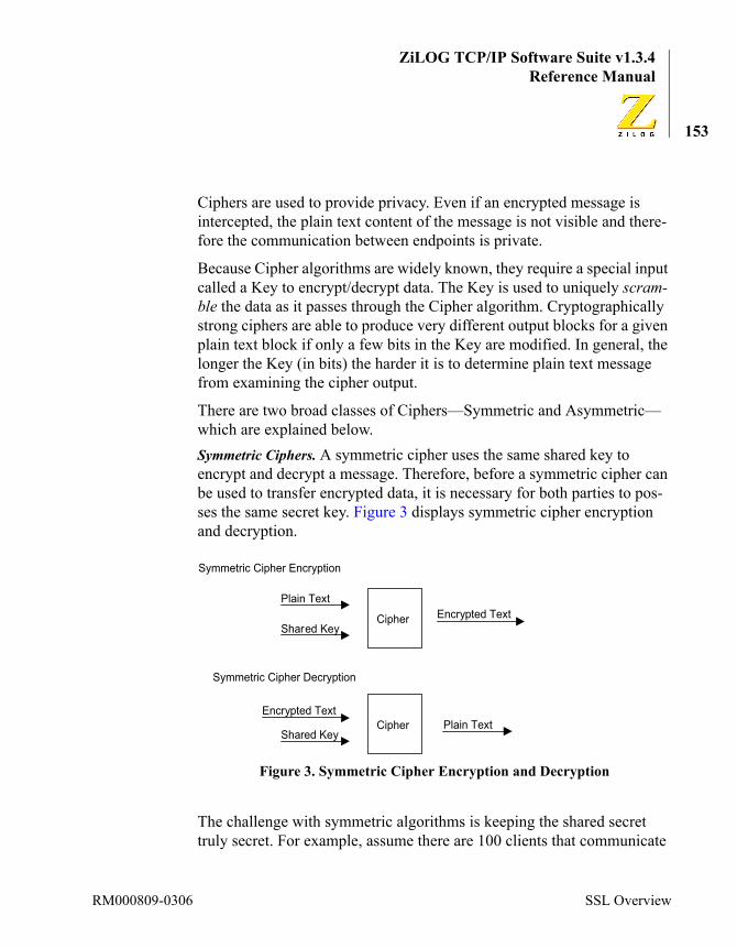
ZiLOG TCP/IP Software Suite v1.3.4Reference Manual
153
Ciphers are used to provide privacy. Even if an encrypted message is intercepted, the plain text content of the message is not visible and there-fore the communication between endpoints is private.
Because Cipher algorithms are widely known, they require a special input called a Key to encrypt/decrypt data. The Key is used to uniquely scram-ble the data as it passes through the Cipher algorithm. Cryptographically strong ciphers are able to produce very different output blocks for a given plain text block if only a few bits in the Key are modified. In general, the longer the Key (in bits) the harder it is to determine plain text message from examining the cipher output.
There are two broad classes of Ciphers—Symmetric and Asymmetric—which are explained below.Symmetric Ciphers. A symmetric cipher uses the same shared key to encrypt and decrypt a message. Therefore, before a symmetric cipher can be used to transfer encrypted data, it is necessary for both parties to pos-ses the same secret key. Figure 3 displays symmetric cipher encryption and decryption.
The challenge with symmetric algorithms is keeping the shared secret truly secret. For example, assume there are 100 clients that communicate
Figure 3. Symmetric Cipher Encryption and Decryption
Cipher
Plain Text
Shared Key
Encrypted Text
Cipher Plain TextShared Key
Encrypted Text
Symmetric Cipher Encryption
Symmetric Cipher Decryption
RM000809-0306 SSL Overview

ZiLOG TCP/IP Software Suite v1.3.4eZ80® Family of Microprocessors
154
with a particular server using a shared secret. If the secret is compromised by one of the clients then all 101 systems must be updated with a new shared secret.Asymmetric Ciphers. Asymmetric algorithms use different keys to encrypt and decrypt data. Asymmetric algorithms typically use a public and pri-vate key-pair. Therefore, unlike symmetric algorithms, it is not necessary to distribute a shared secret to all parties involved before encrypted data transfer can occur. Figure 4 displays asymmetric cipher encryption and decryption.
In the context of SSL, the server possesses a private key that is not distrib-uted or shared with any client. The corresponding public key is contained in the server’s x.509 certificate and freely distributed to prospective cli-ents when they initiate a new SSL session. Therefore, unlike symmetric ciphers, there is no risk associated with a public key being compromised by a client because the public key is not a secret.
The disadvantage of asymmetric ciphers is that they are usually much more computationally intensive than symmetric ciphers. As a result, asymmetric ciphers typically run much slower than symmetric algo-
Figure 4. Asymmetric Cipher Encryption and Decryption
Cipher
Plain Text
Public Key
Encrypted Text
Cipher Plain TextPrivate Key
Encrypted Text
Asymmetric Cipher Encryption
Asymmetric Cipher Decryption
Using ZTP RM000809-0306

ZiLOG TCP/IP Software Suite v1.3.4Reference Manual
155
rithms. The difference in performance can be a few orders of magnitude and it increases as the key strength is increased.
The SSL server uses an asymmetric cipher (Key Exchange algorithm) to exchange the Master Key and it uses a symmetric cipher to encrypt/decrypt the upper layer data blocks when an SSL session is established.
Stream Cipher. A stream cipher is a symmetric cipher that operates on an arbitrary-sized input message to produce an output message of the same length. The algorithm expands a cryptographic key into a key-stream whose length matches the length of the input text. The input text and key-stream are typically exclusively-ORed to produce the final cipher-text output message.Block Cipher. A block cipher is a symmetric cipher that breaks an input message into fixed-sized blocks. Padding may be required to ensure that the input text is an exact multiple of the block size. The block cipher algo-rithm uses a key to convert the plain text blocks into cipher text blocks on a block-by-block basis. Hash Function. A Hash function takes an arbitrary amount of input data and produces a fixed-sized hash or digest of the message. Cryptographic hash functions are one-way functions—it is impossible to determine the original message from the hash of that message. Hashes are commonly used in digital signatures and message authentication codes (MAC).Message Integrity. Prior to encrypting an SSL data record, the SSL proto-col computes a one-way hash on the data in the record as well as the state information pertinent to the SSL session (secret Read and Write keys + message sequence number). The output of the hash function is called a Message Authentication Code (MAC). If only the originator and intended recipient of the message know the correct state information used to com-pute the hash, then it is unlikely that an attacker modifies the message in transit without the recipient detecting an error on the MAC.x.509 Certificate. The SSL 2.0 protocol requires that the server has a cer-tificate that is passed to the client for authentication purposes. The x.509 standard specifies the format of the information in the certificate. The cer-
Note:
RM000809-0306 SSL Overview

ZiLOG TCP/IP Software Suite v1.3.4eZ80® Family of Microprocessors
156
tificate contains information such as the identity of the server to which the certificate was issued, a time period over which the certificate is valid, the server’s public key, the identity of the certificate issuer and a digital sig-nature of the certificate generated by the issuer. The signature is created using a hash of the certificate and encrypted using an asymmetric cipher with the issuer’s private key. If a client has the issuer’s public key (which can also be contained in the certificate), then the client is able to validate the signature and verify the identity of the server. When the server proves that it is in possession of the private key corresponding to the public key in the certificate, the client trusts the server and begins exchanging sensi-tive data.
The x.509 certificate is specified using a platform independent data mod-elling language called Abstract Syntax Notation (ASN.1). Encoding of data values in the actual certificate follows ASN.1 Distinguished Encod-ing Rules (DER format).
Optionally, the SSL 2.0 protocol allows the server to request a certificate from the client so that it can authenticate the client. However, few clients are likely to have valid certificates and the server typically does not request a certificate from the client. The SSL server in ZTP does not sup-port client authentication—it does not request a certificate from the client.
Initializing the SSL ServerBefore an application can use the SSL layer in ZTP it must call the Initialize_SSL routine by passing the server’s x.509 certificate and private key as arguments to the function. These parameters are used by the SSL protocol to establish SSL sessions where encrypted data transfer occurs. The function prototype of the Initialize_SSL function is given below:extern SSL_STATUS Initialize_SSL(SSL_DATA_BLOCK_S *pX509Data, SSL_DATA_BLOCK_S *pPrivateKey, BYTE EncodingMethod);
Using ZTP RM000809-0306
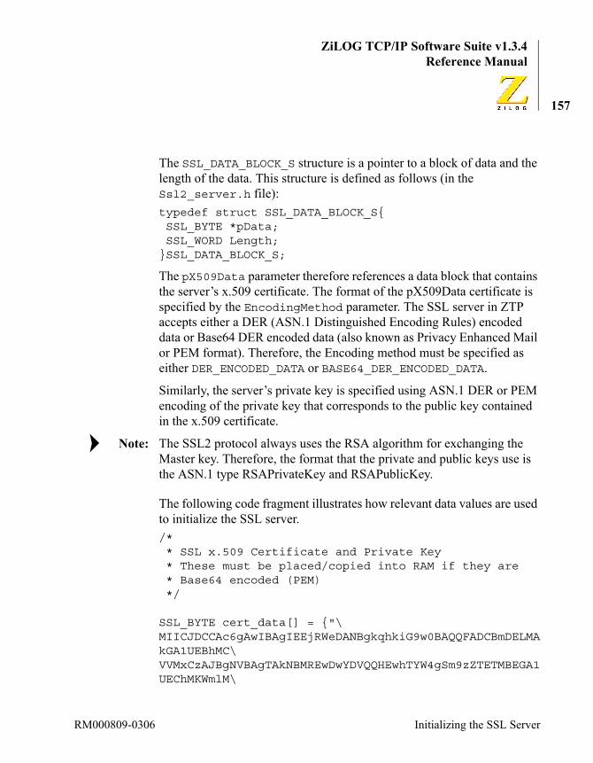
ZiLOG TCP/IP Software Suite v1.3.4Reference Manual
157
The SSL_DATA_BLOCK_S structure is a pointer to a block of data and the length of the data. This structure is defined as follows (in the Ssl2_server.h file):typedef struct SSL_DATA_BLOCK_S{ SSL_BYTE *pData; SSL_WORD Length;}SSL_DATA_BLOCK_S;
The pX509Data parameter therefore references a data block that contains the server’s x.509 certificate. The format of the pX509Data certificate is specified by the EncodingMethod parameter. The SSL server in ZTP accepts either a DER (ASN.1 Distinguished Encoding Rules) encoded data or Base64 DER encoded data (also known as Privacy Enhanced Mail or PEM format). Therefore, the Encoding method must be specified as either DER_ENCODED_DATA or BASE64_DER_ENCODED_DATA.
Similarly, the server’s private key is specified using ASN.1 DER or PEM encoding of the private key that corresponds to the public key contained in the x.509 certificate.
The SSL2 protocol always uses the RSA algorithm for exchanging the Master key. Therefore, the format that the private and public keys use is the ASN.1 type RSAPrivateKey and RSAPublicKey.
The following code fragment illustrates how relevant data values are used to initialize the SSL server./* * SSL x.509 Certificate and Private Key * These must be placed/copied into RAM if they are * Base64 encoded (PEM) */
SSL_BYTE cert_data[] = {"\MIICJDCCAc6gAwIBAgIEEjRWeDANBgkqhkiG9w0BAQQFADCBmDELMAkGA1UEBhMC\VVMxCzAJBgNVBAgTAkNBMREwDwYDVQQHEwhTYW4gSm9zZTETMBEGA1UEChMKWmlM\
Note:
RM000809-0306 Initializing the SSL Server

ZiLOG TCP/IP Software Suite v1.3.4eZ80® Family of Microprocessors
158
T0cgSW5jLjEWMBQGA1UECxMNTWljcm8gRGV2aWNlczEZMBcGA1UEAxQQZVo4MEFj\Y2xhaW0hKFRNKTEhMB8GCSqGSIb3DQEJARYSc29mdHdhcmVAemlsb2cuY29tMB4X\DTA0MDMxMjA5MDY0OVoXDTA0MDQxMTA5MDY0OVowgZgxCzAJBgNVBAYTAlVTMQsw\CQYDVQQIEwJDQTERMA8GA1UEBxMIU2FuIEpvc2UxEzARBgNVBAoTClppTE9HIElu\Yy4xFjAUBgNVBAsTDU1pY3JvIERldmljZXMxGTAXBgNVBAMUEGVaODBBY2NsYWlt\IShUTSkxITAfBgkqhkiG9w0BCQEWEnNvZnR3YXJlQHppbG9nLmNvbTBcMA0GCSqG\SIb3DQEBAQUAA0sAMEgCQQDJ2DkuW/mxlwo7+9mqqp5+hPIAT/LlVTCnB6lxpTID\jNCewVhFIYrfStV2IEp2FHAvqs30iAJlgyYYgJ+g2cKNAgMBAAEwDQYJKoZIhvcN\AQEEBQADQQAkA6aEBLSQcZP3qQ7BhUFa0HLy/vk3L/jHiEPvpKBW03i7hRlwzRnJ\2UQC1UJh+DtRGCzL78zi1mX092VPeaEo"};
SSL_BYTE key_data[] = {"\MIIBOwIBAAJBAMnYOS5b+bGXCjv72aqqnn6E8gBP8uVVMKcHqXGlMgOM0J7BWEUh\it9K1XYgSnYUcC+qzfSIAmWDJhiAn6DZwo0CAwEAAQJBALkuvm9xBOnQ2BvmWXJC\LT2IfXqZ3xBWk1d7KRNR60vi35r0g2clkAhGtB+NE7v+DMvRpw5hlXQpYRhq2MmX\/qUCIQD5Jn882at2bkVevW3R6wmB7dZIHfCApk5vuHd5BPD5YwIhAM9kyq7AyxZh\IO60khTo0p2XmUUBvYy3OCFVIdPKoA9PAiAcxGwmi393si3CTZ7zgO7dGKgINaTC\RfGChssMpxxnvwIgEBAqcqaUFEOpnVN3DQ+LYJFhWars131JZ6uEVzcWdpkCIQCa\mVxpaO3b/Jogavs3wD7+wq5mSB9w16yqJp5Zc3CV9Q=="};
SSL_DATA_BLOCK_S Certificate =
Using ZTP RM000809-0306

ZiLOG TCP/IP Software Suite v1.3.4Reference Manual
159
{cert_data,sizeof(cert_data)-1};SSL_DATA_BLOCK_S PrivateKey ={key_data,sizeof(key_data)-1};
Initialize_SSL( &Certificate, &PrivateKey, BASE64_DER_ENCODED_DATA );
Creating x.509 CertificatesZTP does not include utilities to generate x.509 certificates or RSA key pairs. Typically, a utility is used to generate a certificate request that is submitted (with the RSA Public Key) to a Certificate Authority (CA) for verification. If the CA is satisfied with the request and the requestor is able to validate the identity of the certificate’s subject then the CA signs the certificate with its private key and returns the signed certificate to the requestor.
While developing an SSL-based application, either use the sample certifi-cate and private key included in the SSLDemo project or create a new cer-tificate and private key. To create a new certificate, it is necessary to obtain a 3rd-party tool. The sample certificate included in the SSLDemo project was created using OpenSSL tool (from www.openssl.org). The sample certificate is self-signed, that is, the Certificate Issuer and Certifi-cate Subject are the same. The OpenSSL command issued to generate the RSA key-pair and X.509 certificate is shown below.OpenSSL>OpenSSL> req -newkey rsa:512 -x509 -config certreqacclaim.txt -nodes -out Test.crt -keyout TestKey.txt -set_serial 0x12345678
RM000809-0306 Creating x.509 Certificates
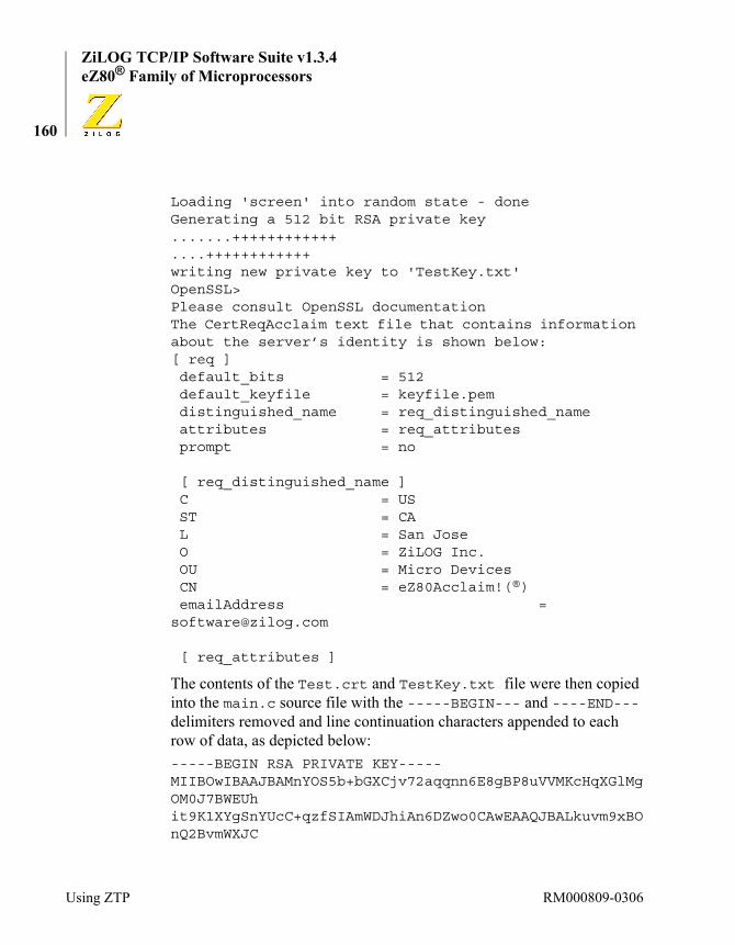
ZiLOG TCP/IP Software Suite v1.3.4eZ80® Family of Microprocessors
160
Loading 'screen' into random state - doneGenerating a 512 bit RSA private key.......++++++++++++....++++++++++++writing new private key to 'TestKey.txt'OpenSSL>Please consult OpenSSL documentation The CertReqAcclaim text file that contains information about the server’s identity is shown below:[ req ] default_bits = 512 default_keyfile = keyfile.pem distinguished_name = req_distinguished_name attributes = req_attributes prompt = no
[ req_distinguished_name ] C = US ST = CA L = San Jose O = ZiLOG Inc. OU = Micro Devices CN = eZ80Acclaim!(®) emailAddress = [email protected]
[ req_attributes ]
The contents of the Test.crt and TestKey.txt file were then copied into the main.c source file with the -----BEGIN--- and ----END--- delimiters removed and line continuation characters appended to each row of data, as depicted below:-----BEGIN RSA PRIVATE KEY-----MIIBOwIBAAJBAMnYOS5b+bGXCjv72aqqnn6E8gBP8uVVMKcHqXGlMgOM0J7BWEUhit9K1XYgSnYUcC+qzfSIAmWDJhiAn6DZwo0CAwEAAQJBALkuvm9xBOnQ2BvmWXJC
Using ZTP RM000809-0306
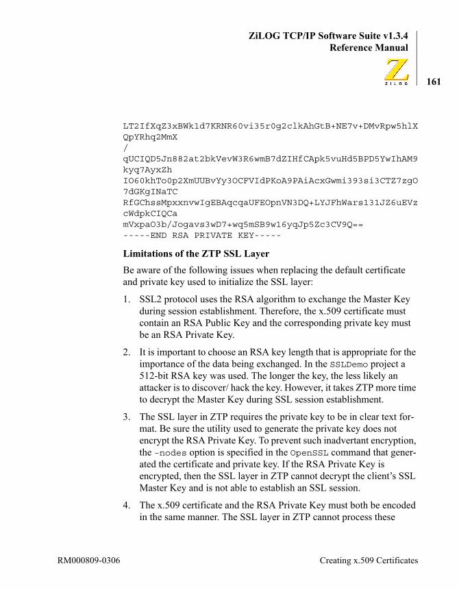
ZiLOG TCP/IP Software Suite v1.3.4Reference Manual
161
LT2IfXqZ3xBWk1d7KRNR60vi35r0g2clkAhGtB+NE7v+DMvRpw5hlXQpYRhq2MmX/qUCIQD5Jn882at2bkVevW3R6wmB7dZIHfCApk5vuHd5BPD5YwIhAM9kyq7AyxZhIO60khTo0p2XmUUBvYy3OCFVIdPKoA9PAiAcxGwmi393si3CTZ7zgO7dGKgINaTCRfGChssMpxxnvwIgEBAqcqaUFEOpnVN3DQ+LYJFhWars131JZ6uEVzcWdpkCIQCamVxpaO3b/Jogavs3wD7+wq5mSB9w16yqJp5Zc3CV9Q==-----END RSA PRIVATE KEY-----
Limitations of the ZTP SSL LayerBe aware of the following issues when replacing the default certificate and private key used to initialize the SSL layer:
1. SSL2 protocol uses the RSA algorithm to exchange the Master Key during session establishment. Therefore, the x.509 certificate must contain an RSA Public Key and the corresponding private key must be an RSA Private Key.
2. It is important to choose an RSA key length that is appropriate for the importance of the data being exchanged. In the SSLDemo project a 512-bit RSA key was used. The longer the key, the less likely an attacker is to discover/ hack the key. However, it takes ZTP more time to decrypt the Master Key during SSL session establishment.
3. The SSL layer in ZTP requires the private key to be in clear text for-mat. Be sure the utility used to generate the private key does not encrypt the RSA Private Key. To prevent such inadvertant encryption, the –nodes option is specified in the OpenSSL command that gener-ated the certificate and private key. If the RSA Private Key is encrypted, then the SSL layer in ZTP cannot decrypt the client’s SSL Master Key and is not able to establish an SSL session.
4. The x.509 certificate and the RSA Private Key must both be encoded in the same manner. The SSL layer in ZTP cannot process these
RM000809-0306 Creating x.509 Certificates

ZiLOG TCP/IP Software Suite v1.3.4eZ80® Family of Microprocessors
162
parameters if one is DER_ENCODED_DATA and the other is BASE64_DER_ENCODED_DATA.
5. If the SSL server’s RSA Private Key is in the PEM format (BASE64_DER_ENCODED_DATA) it must be stored in RAM because the algorithm that converts PEM format data into the DER format data (DER_ENCODED_DATA) performs the conversion on location in the RAM memory.
6. Because the RSA Private Key is stored in memory and must be trans-ferred to the CPU over the system data bus, some form of physical security is required to prevent an attacker from analyzing the system memory or snooping on the data bus and obtaining the private key.
7. A single SSL certificate is supported in the current ZTP SSL layer implementation.
ZTP SSL2 Cipher SuiteAn SSL Cipher Suite is composed of the following components:
• A Key Exchange algorithm used to send the Master Key to the SSL sever.
• A Cipher algorithm used for encrypting and decrypting data through the SSL layer.
• A Hash algorithm used to compute a Message Authentication Code that allows the receipient of an SSL data record to verify that the data sent by the peer was not altered in transit.
By using various combinations of algorithms for these components a large number of cipher suites can be supported. However, the SSL version 2 Specification limits the choice of Key Exchange algorithm and Hash function to RSA and MD5 respectively. Therefore, the SSL2 Cipher Suite is determined by the choice of Cipher algorithm (and corresponding sym-metric key size).
Using ZTP RM000809-0306
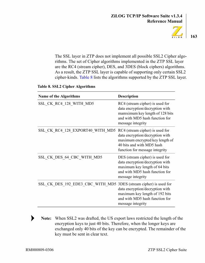
ZiLOG TCP/IP Software Suite v1.3.4Reference Manual
163
The SSL layer in ZTP does not implement all possible SSL2 Cipher algo-rithms. The set of Cipher algorithms implemented in the ZTP SSL layer are the RC4 (stream cipher), DES, and 3DES (block ciphers) algorithms. As a result, the ZTP SSL layer is capable of supporting only certain SSL2 cipher-kinds. Table 8 lists the algorithms supported by the ZTP SSL layer.
When SSL2 was drafted, the US export laws restricted the length of the encryption keys to just 40 bits. Therefore, when the longer keys are exchanged only 40 bits of the key can be encrypted. The remainder of the key must be sent in clear text.
Table 8. SSL2 Cipher Algorithms
Name of the Algorithms Description
SSL_CK_RC4_128_WITH_MD5 RC4 (stream cipher) is used for data encryption/decryption with mamximum key length of 128 bits and with MD5 hash function for message integrity
SSL_CK_RC4_128_EXPORT40_WITH_MD5 RC4 (stream cipher) is used for data encryption/decryption with maximum encrypted key length of 40 bits and with MD5 hash function for message integrity
SSL_CK_DES_64_CBC_WITH_MD5 DES (stream cipher) is used for data encryption/decryption with maximum key length of 64 bits and with MD5 hash function for message integrity
SSL_CK_DES_192_EDE3_CBC_WITH_MD5 3DES (stream cipher) is used for data encryption/decryption with maximum key length of 192 bits and with MD5 hash function for message integrity
Note:
RM000809-0306 ZTP SSL2 Cipher Suite

ZiLOG TCP/IP Software Suite v1.3.4eZ80® Family of Microprocessors
164
Creating an SSL ConnectionTransferring encrypted data using the ZTP SSL layer follows the seman-tics that transferring data using the ZTP TCP layer follows; the syntax however, is a little different. This section presents the steps that a ZTP TCP server-process uses to create a TCP connection and shows the modi-fication required to use the SSL layer.
For more information about the TCP device driver APIs, see section ZTP Device Driver APIs section on page 360.
Follow these steps to establish a TCP-SSL connection:
1. To open a TCP/SSL Server Device: A TCP server application in ZTP must first create a TCP Server Device ID over which the application waits for a connection. For example:DID ServerDev;ServerDev = open( TCP, ANYFPORT, (char *)0x1234 );
This command opens the TCP master device ID (TCP) and requests a server device to be created on TCP port 0x1234. To create an SSL server device, the open call is modified as follows:DID ServerDev;ServerDev = open( SSL, ANYFPORT, (char *)0x1234 );
This command opens the SSL master device ID (SSL) and requests a server device to be created over TCP port 0x1234.
2. To accept a TCP-SSL connection from a remote client: The Connec-tionDev command is used to tell the the TCP Server device to wait for an incoming TCP connection request and when a connection request arrives to Accept the TCP connection. The command is defined below.DID ConnectionDev;control( ServerDev, TCPC_ACCEPT, (char *)&ConnectionDev, 0 );
Using ZTP RM000809-0306
ZiLOG TCP/IP Software Suite v1.3.4Reference Manual
165
After the TCP connection handshake is completed, the TCP Server-Dev command sets the ConnectionDev variable to the TCP Con-nection device ID created to transfer TCP data between the server and client sockets.
To create an SSL connection the command ConnectionDev is issued when the ServerDev is returned on the open call to the SSL master device.
3. To transfer data over the TCP-SSL connection: To receive TCP data, the read command is used. For example, to receive 10 bytes of TCP data and place the data in a buffer called MyBuff, the following code fragment can be used:BYTE MyBuff[100];INT16 Status;Status = read(ConnectionDev, MyBuf, 10 );
This command can also be used to receive 10 bytes through the SSL layer.
Although the data sent between the client and server SSL layers is encrypted, the data passed between the ZTP SSL layer and user appli-cation is nonencrypted. Therefore, the code that retrieves data from the ZTP TCP layer can be used to retrieve decrypted data from the ZTP SSL layer.
To send TCP data, the write command is used. For example, to send 10 bytes of TCP data from a buffer called MyBuff, the following code fragment can be used:Status = write(ConnectionDev, MyBuf, 10 );
This command can also be used to send 10 bytes through the SSL layer.
4. To close the TCP/SSL connection: To close an underlying TCP con-nection, the close command is used with the device ID of the con-nection device (used during data transfer) passed as a parameter.
Note:
RM000809-0306 Creating an SSL Connection

ZiLOG TCP/IP Software Suite v1.3.4eZ80® Family of Microprocessors
166
close( ConnectionDev );
The close command can also be used to close the SSL session repre-sented by the SSL connection device ID.
When it is no longer necessary to maintain the TCP server in a run-ning condition, the application can close the TCP Server device by issuing the close command and using the TCP Server device ID.close( ServerDev );
Again, this close command can be used to close the SSL server device.
In summary, any ZTP TCP server application can be converted to use the SSL for secure data transfer simply by changing the Master device ID used on the open call from TCP to SSL. The syntax and semantics of all other TCP data transfer commands are identical for both TCP and SSL. It is beyond the scope of this manual to explain how a remote SSL client application can be developed.
The SSL layer in ZTP only supports SSL server applications.
How to Use the HTTPS ServerThe SSL.lib file contains an HTTPS server that can be used to serve encrypted webpages to client browsers. The server is initialized by calling the https_init API. This API takes the same number and type of parameters as the standard HTTP server API (see The http_init Function section on page 126 for details about this function).
For example, to initialize the standard HTTP server in ZTP, the following command is used:http_init(http_defmethods,httpdefheaders,website,80);
Note:
Using ZTP RM000809-0306

ZiLOG TCP/IP Software Suite v1.3.4Reference Manual
167
To initialize the HTTPS server the following command is used:https_init(http_defmethods,httpdefheaders,website,443);
It is possible to have both the secure and nonsecure web servers running at the same time; however, the two web servers must be on different ports. The port number typically used for nonsecure HTTP servers is port 80 and for secure HTTP servers (HTTP over SSL or HTTPS) the port num-ber typically used is port 443.
For more information about the HTTP (or HTTPS server), see the How to Use HTTP section on page 124.
Limitations of the ZTP HTTPS ServerBe aware of the following when using the ZTP HTTPS server.
1. It may be necessary to configure the client browser to support the SSL2 protocol. Consult the documentation for your browser for con-figuration assistance. Using Microsoft Internet Explorer as an exam-ple, navigate to Tools → Internet Options, select the Advanced tab and ensure that the SSL 2.0 protocol is selected. Figure 5 is a screen shot of the Internet Options dialog.
RM000809-0306 How to Use the HTTPS Server

ZiLOG TCP/IP Software Suite v1.3.4eZ80® Family of Microprocessors
168
2. When using the sample certificate with the HTTPS server in the SSLDemo project, be aware that client browsers such as Microsoft Internet Explorer can generate warning messages while processing the sample certificate (see Figure 6). The first warning typically encountered is because the certificate was self-signed and therefore a trusted Root Certificate Authority (CA) does not exist in the certifi-cate chain. The second warning is generated because the certificate’s subject (the distinguished name of identity of the SSL server) does
Figure 5. Internet Options Window
Using ZTP RM000809-0306
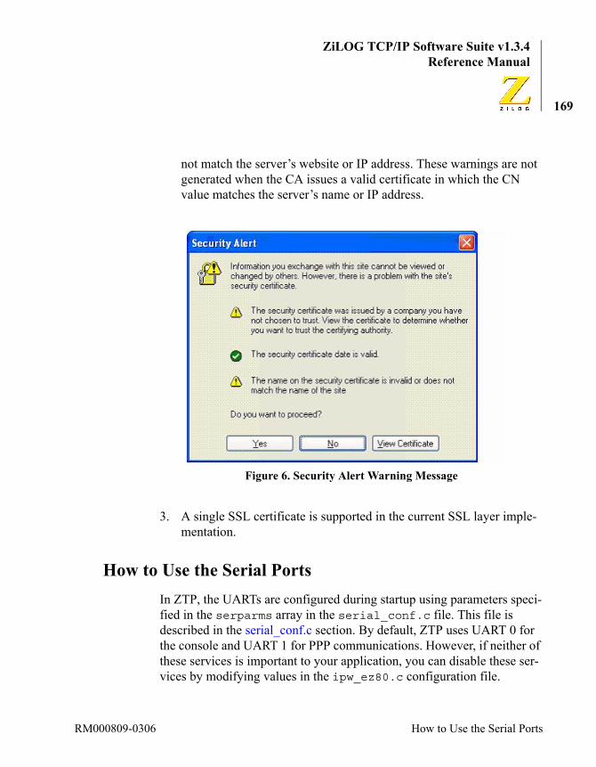
ZiLOG TCP/IP Software Suite v1.3.4Reference Manual
169
not match the server’s website or IP address. These warnings are not generated when the CA issues a valid certificate in which the CN value matches the server’s name or IP address.
3. A single SSL certificate is supported in the current SSL layer imple-mentation.
How to Use the Serial PortsIn ZTP, the UARTs are configured during startup using parameters speci-fied in the serparms array in the serial_conf.c file. This file is described in the serial_conf.c section. By default, ZTP uses UART 0 for the console and UART 1 for PPP communications. However, if neither of these services is important to your application, you can disable these ser-vices by modifying values in the ipw_ez80.c configuration file.
Figure 6. Security Alert Warning Message
RM000809-0306 How to Use the Serial Ports

ZiLOG TCP/IP Software Suite v1.3.4eZ80® Family of Microprocessors
170
For example, if you do not wish to use the console, set the b_xinu_uses_uart0 variable to FALSE and set the consoledev vari-able to NULLDEV. If you do not wish to use PPP, do not call ppp_init from within netconfig.
Use of the serial ports for other purposes can conflict with components of ZTP that use the serial ports. When multiple processes attempt to use the same device, detrimental results can occur. This is why it is impor-tant to prevent ZTP from accessing the UARTs if your application in-tends on using them for other purposes.
When the default services provided by ZTP are prevented from accessing the UARTs, your application is free to use these device for your own pur-posees. You can either write your own software routines to access the UART registers or use the ZTP device driver API to access the SERIAL0 (UART0) and SERIAL1 (UART1) devices. If you choose to write your own routines to access the UART registers, refer to the relevant product specification for a description of the UART registers.
The subset of the device driver API applicable to the serial ports is listed below. For a complete description of the ZTP device driver model, see the ZTP Device Driver APIs section on page 360.
int open (int descrp, char *name, char *arg)int read (int descrp, char *buff, int count)int write (int descrp, char *buff, int count)int close (int descrp)int getc (int descrp)int putc (int descrp, char ch)
Before transferring data through the UART, the corresponding ZTP device driver must be opened by calling the open device driver API. The first parameter in the open function specifies the device to be opened. For UART0, this parameter should be specified as SERIAL0. For UART1, this parameter should be specified as SERIAL1. The next two parameters,
Caution:
Using ZTP RM000809-0306
ZiLOG TCP/IP Software Suite v1.3.4Reference Manual
171
name and arg, are not used for serial ports SERIAL0 or SERIAL1. They should be set to 0.
When ZTP opens either SERIAL0 or SERIAL1, the underlying UART is initialized according to the values in the corresponding entry in the ser-parms array.
To read from a serial port, the read function is used. The first parameter, descrp, is the value returned from the open function for the serial port of interest. The second parameter, buff, is a pointer to a buffer where the received characters are placed. The count parameter specifies the num-ber of characters to read. If the call to read is successful, the number of characters placed into the buffer is returned. If the call to read fails, SYSERR is returned.
To read a single character at a time from the serial port, the getc function is used where the descrp parameter is the same as in the read function. The getc function returns the character if the operation is successful. Upon failure, a SYSERR is returned.
To write to a serial port, the write function is used. Similar to the read function, descrp is the value returned from the open function and the buff parameter is the pointer to the buffer containing the characters to be sent. The count parameter is the number of characters to send. The write function can block when the UART FIFO is full. The write func-tion returns either a SYSERR if there is a write failure or OK if the write function is successful.
To write a single character at a time to the serial port, the putc function is used. The descrp parameter is the same as in the write function. The character to be written using this function is provided in the ch parameter. If the operation is successful, a 1 is returned. Upon failure, a SYSERR is returned.
The close function closes the serial port related to the device descriptor descrp. Closing the port includes disabling the device interrupts and freeing up the UZI port (only applicable to the eZ80190 deice).
Note:
RM000809-0306 How to Use the Serial Ports

ZiLOG TCP/IP Software Suite v1.3.4eZ80® Family of Microprocessors
172
How to Use the ShellZTP provides a shell that allows the user to interact with the system using commands transferred via a remote terminal. The remote terminal can be a PC running a terminal program such as HyperTerminal via a serial con-nection, or to a TELNET terminal via an Ethernet connection. For more information about TELNET, see the How to Use Telnet section on page 143.
To include the shell in the ZTP stack, add the shell.lib file to the project and include the shell_init function in the code, as follows:int shell_init(int dev)
where dev is the device ID of the device over which the shell is to oper-ate. If shell_init fails to initialize, it returns a SYSERR. The following example code shows how to enable the shell over UART0 (that is, the console):open(SERIAL0, 0,0);if ((fd=open(TTY, (char *)SERIAL0,0)) == SYSERR) { kprintf(“Can't open tty for SERIAL0\n"); return SYSERR; }kprintf(“Starting up a shell on device %d\n", fd );shell_init(fd);
The set of commands available through the shell is configurable by modi-fying the defaultcmds array in the shell_conf.c file. The shell com-mands are described in the ZTP Shell Command Reference chapter on page 513. Shell commands can also be added at run time using the shell_add_commands function (from shell.h):void shell_add_commands(struct cmdent *cmds, int ncmds)
The shell_add_commands function contains two parameters; cmds and ncmds. cmds is a pointer to an array of cmdent structures containing information required to add the command. The cmdent structure is the same structure used to configure the set of shell commands in
Using ZTP RM000809-0306
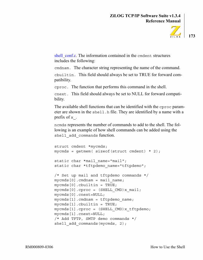
ZiLOG TCP/IP Software Suite v1.3.4Reference Manual
173
shell_conf.c. The information contained in the cmdent structures includes the following:cmdnam. The character string representing the name of the command.cbuiltin. This field should always be set to TRUE for forward com-patibility.cproc. The function that performs this command in the shell.cnext. This field should always be set to NULL for forward compati-bility.
The available shell functions that can be identified with the cproc param-eter are shown in the shell.h file. They are identified by a name with a prefix of x_.
ncmds represents the number of commands to add to the shell. The fol-lowing is an example of how shell commands can be added using the shell_add_commands function.
struct cmdent *mycmds;mycmds = getmem( sizeof(struct cmdent) * 2);
static char *mail_name="mail";static char *tftpdemo_name="tftpdemo";
/* Set up mail and tftpdemo commands */mycmds[0].cmdnam = mail_name;mycmds[0].cbuiltin = TRUE;mycmds[0].cproc = (SHELL_CMD)x_mail;mycmds[0].cnext=NULL;mycmds[1].cmdnam = tftpdemo_name;mycmds[1].cbuiltin = TRUE;mycmds[1].cproc = (SHELL_CMD)x_tftpdemo;mycmds[1].cnext=NULL;/* Add TFTP, SMTP demo commands */shell_add_commands(mycmds, 2);
RM000809-0306 How to Use the Shell

ZiLOG TCP/IP Software Suite v1.3.4eZ80® Family of Microprocessors
174
A prepackaged number of network commands can be added as a set, as shown here:/* Make the network-related shell commands available /* to all shells */shell_add_commands(netcmds, nnetcmds);
netcmds and nnetcmds are externals, as declared in shell.h.
How to Use SNMPTo enable the SNMP agent included in ZTP, call the snmp_init API from within your main routine. Additionally, it is necessary to include the SNMP.lib library in the list of library files linked with your project. These are the only steps required to activate the SNMP Agent that responds to SNMP requests for objects in the default MIB (see the snmib.c file in the \conf directory for a listing of objects in the standard MIB provided by ZTP).
The SNMP implementation in ZTP includes objects within the following MIB-II groups:
• System
• Interfaces
• Address Translation
• IP
• ICMP
• TCP
• UDP
• SNMP
If you choose to add objects to the MIB that are unique to your applica-tion, the material in this section provides sufficient background to guide you through the process.
Using ZTP RM000809-0306

ZiLOG TCP/IP Software Suite v1.3.4Reference Manual
175
Understanding SNMPThe Simple Network Management Protocol, SNMP, is a protocol for accessing a database of objects. In SNMP, this database is called a Man-agement Information Base (MIB). Each object in the MIB has a name, a type, and a value. The protocol can be used to read or write values in the MIB by using the Get, Get Next, or Set operations. Requests originate from the SNMP Management Entity (similar in concept to a client appli-cation) and are sent to the SNMP Agent (similar in concept to a server application) that manages the MIB of interest. After the SNMP Agent processes the request, it returns relevant information to the Management Entity. The Management Entity can obtain information about objects in the MIB using the Get or Get Next requests; or, it can modify the value of an object in the MIB using the Set request. Only objects specified as read/write can be modified using Set.
TCP/IP devices implementing SNMP are required to include a subset of the standard MIB-II objects that are applicable to each device in the local MIB (refer to the RFC 1213, Management Information Base for Network Management of TCP/IP-based Networks MIB-II). In addition, the SNMP Agent can allow the MIB to be augmented with user-defined objects. As a result, the Management Entity obtains information about the Agent device that is unique to that device’s application. For example, suppose the device in which the SNMP Agent is embedded includes a sensor capa-ble of measuring the temperature of the processor. The designer of the MIB extensions for this device could therefore add an object to the MIB, the value of which reflects the processor temperature. Of course, the Agent device must include logic to update this value at a reasonable inter-val. If a Management Entity queries the value of this object (using Get), it is able to remotely obtain the processor temperature of the Agent device. Similarly, the designer of the MIB extensions for this device could add a second object to the MIB to control the speed of a cooling fan. The value that the Management Entity assigns to this object (using Set) could be used by logic in the Agent device to program the speed (in revolutions per minute) of the cooling fan.
RM000809-0306 How to Use SNMP

ZiLOG TCP/IP Software Suite v1.3.4eZ80® Family of Microprocessors
176
In addition, the SNMP version 1 protocol includes a Trap primitive that allows an SNMP Agent to alert a Management Entity about specific events. The alert is in the form of an SNMP Trap message that can contain object information (name, type, and value). Continuing the example above, the SNMP Agent device could be programmed to generate a Trap message that is sent to a Management Entity if the processor temperature exceeded a predefined threshold. The Trap message could contain an object, the value of which reflects the temperature reading that triggered the Trap.
Object NamesObjects are named using object identifiers and arranged in the MIB hier-archically according to each object’s name. Every object identifier is a collection of subidentifiers separated by periods. In this way, the MIB can be thought of as a tree of nodes, where each node (subidentifier) can include several branches (child nodes) leading to lower objects. There-fore, a complete object identifier is simply the concatenated string of sub-identifiers leading from the unnamed Root node to the object of interest. In printed form, the object identifier can either be represented using text subidentifiers or numbers. In SNMP implementations, object identifiers are represented as a series of numbers according to the ASN.1 BER defi-nition of an object identifier.
For example, the object identifier corresponding to the TCP group in the MIB-II specification is iso.org.dod.internet.mgmt.mib.tcp, or 1.3.6.1.2.1.6, and the object identifier of the IP group is iso.org.dod.internet.mgmt.mib.ip, or 1.3.6.1.2.1.4. Within each of these groups, the MIB-II specification identifies several child objects.
In the ZTP implementation, object identifiers are described by the oid structure shown below.
Using ZTP RM000809-0306
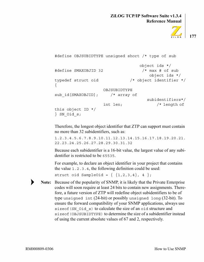
ZiLOG TCP/IP Software Suite v1.3.4Reference Manual
177
#define OBJSUBIDTYPE unsigned short /* type of sub
object ids */#define SMAXOBJID 32 /* max # of sub object ids */typedef struct oid /* object identifier */{
OBJSUBIDTYPE sub_id[SMAXOBJID]; /* array of subidentifiers*/
int len; /* length of this object ID */} SN_Oid_s;
Therefore, the longest object identifier that ZTP can support must contain no more than 32 subidentifiers, such as:1.2.3.4.5.6.7.8.9.10.11.12.13.14.15.16.17.18.19.20.21.22.23.24.25.26.27.28.29.30.31.32
Because each subidentifier is a 16-bit value, the largest value of any subi-dentifier is restricted to be 65535.
For example, to declare an object identifier in your project that contains the value 1.2.3.4, the following definition could be used:struct oid SampleOid = { {1,2,3,4}, 4 };
Because of the popularity of SNMP, it is likely that the Private Enterprise codes will soon require at least 24 bits to contain new assignments. There-fore, a future version of ZTP will redefine object subidentifiers to be of type unsigned int (24-bit) or possibly unsigned long (32-bit). To ensure the forward compatibility of your SNMP applications, always use sizeof(SN_Oid_s) to calculate the size of an oid structure and sizeof(OBJSUBIDTYPE) to determine the size of a subidentifier instead of using the current absolute values of 67 and 2, respectively.
Note:
RM000809-0306 How to Use SNMP

ZiLOG TCP/IP Software Suite v1.3.4eZ80® Family of Microprocessors
178
Object TypesObjects within the SNMP MIB are restricted to using a subset of the prim-itive data types defined within the ASN.1 standards, such as integers, octet strings, and object identifiers. In addition, objects can be defined using SNMP-specific data types such as IP address, counter, gauge, and timeticks—each of which are defined using ASN.1 primitive data types. SNMP also allows these primitive data types to be aggregated to create lists or tables using the ASN.1 constructor type sequence. By using a restricted set of data types, SNMP management tools from one vendor can interoperate with agents from a different vendor because they all speak the same language of ASN.1.
The ASN.1 primitive data types shown in Table 9 are supported in ZTP.
As an implementation limit, the maximum size of an integer and octet string is constrained by the value that the user assigns to the variable snmp_max_object_size in snmp_conf.c. The default value of this variable is 400. Therefore, the default maximum length for any integer or octet string manipulated by ZTP is 400 bytes. If such large objects are not required, the user can reduce the value of the snmp_max_object_size variable. Additionally, the maximum size of an SNMP data frame in the ZTP implementation is currently 4044 bytes. Because the SNMP frame must contain the object and headers, the SNMP library does not allow the
Table 9. ASN1-Supported Primitive Data Types
ASN.1 Data Type ZTP Data Type ExplanationInteger ASN1_INT An arbitrarily long signed number.Octet String ASN1_OCTSTR An arbitrarily long string of octets
(bytes).Object Identifier ASN1_OBJID An object Identifier used to name
objects within the MIB.Null ASN1_NULL An object that does not contain a
value is said to be of type NULL.
Note:
Using ZTP RM000809-0306

ZiLOG TCP/IP Software Suite v1.3.4Reference Manual
179
user to specify a value of snmp_max_object_size larger than SNMP_ABSOLUTE_MAX_OBJECT_SIZE (currently set to 3600) bytes long.
ZTP also supports the following SNMP-specific object types:DisplayString. SN_DISPLAY_STRING: a 255-byte octet string containing text characters meant to be readable by humans. ZTP allows the user to change the maximum length of display strings (see snmp_conf.c in the conf directory).IpAddress. ASN1_IPADDR: a 4-byte octet string used to contain an IP address.Counter. ASN1_COUNTER—a 32-bit monotonically-increasing unsigned integer that wraps from FFFFFFFFh to 00000000h.Gauge. ASN1_GAUGE: a 32-bit unsigned integer that latches when it reaches FFFFFFFFh.PhysAddress. SN_PHYS_ADDR: a 6-byte octet string that contains a 48-bit MAC address.TimeTicks. ASN1_TIMETICKS: a 32-bit unsigned integer that counts time in units of 10 ms since the beginning of a defined epoch.Additional Internal Objects. Finally, ZTP defines object types for its own internal use. All of these object types are transmitted as ASN.1 integers.SN_INT8. A signed 8-bit integer that can accept any value in the range –128 to +127.SN_INT16. A signed 16-bit integer that can accept any value in the range –32,768 to +32,767.SN_INT24. A signed 24-bit integer that can accept any value in the range –8,388,608 to 8,388,607.SN_INT32. A signed 32-bit integer that can accept any value in the range –2,147,483,648 to 2,147,483,647.SN_UINT8. An unsigned 8-bit integer that can accept any value in the range 0 to 255.
RM000809-0306 How to Use SNMP

ZiLOG TCP/IP Software Suite v1.3.4eZ80® Family of Microprocessors
180
SN_UINT16. An unsigned 16-bit integer that can accept any value in the range 0 to 65,535.SN_UINT24. An unsigned 24-bit integer that can accept any value in the range 0 to 16,777,215.SN_UINT32. An unsigned 32-bit integer that can accept any value in the range 0 to 4,294,967,295.
SNMP ObjectsEvery SNMP object contains a name, a type, and a value. Object names are specified as object identifiers of type SN_Oid_s (see the Object Names section on page 176; the set of permissible object types is described in the Object Types section on page 178. Finally, the user can assign and/or update an object value in the user’s SNMP application.
Before discussing object updates, the definition of an SNMP object in ZTP must be examined (see snmp.h in the includes folder).typedef struct sn_object_s{
SN_Oid_s Oid;u_char Type;SN_Value_s Value;
} SN_Object_s;Where an SN_Value_s structure is defined as:typedef union sn_value_s{
void * pData;struct oid * pOid; // Object IdentifierSN_Descr_s * pDescr; // Octet String, big
// Integer, Display String // (Octet String)
int8_t * pInt8;int16_t * pInt16;int24_t * pInt24;int32_t * pInt32;uint8_t * pUint8;uint16_t * pUint16;
Using ZTP RM000809-0306
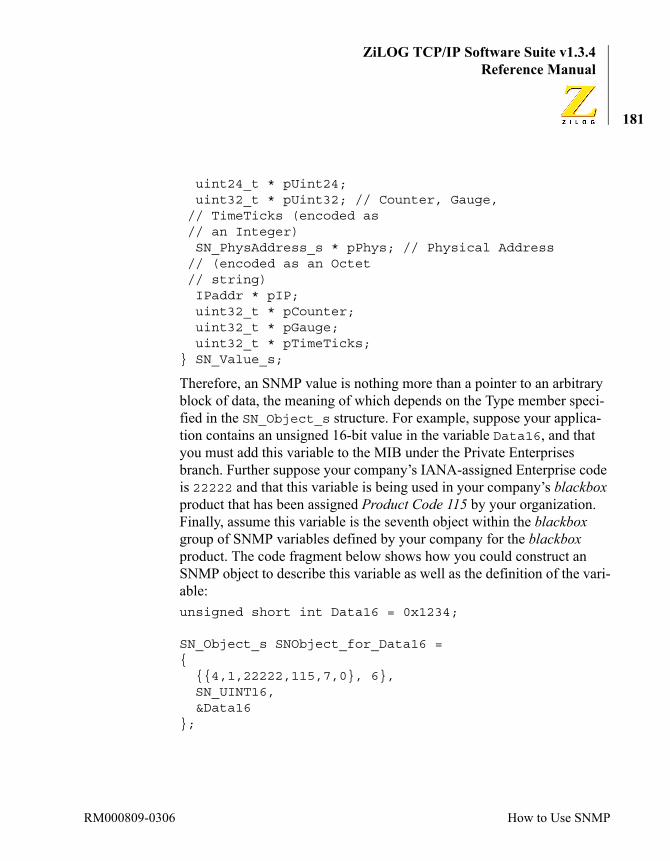
ZiLOG TCP/IP Software Suite v1.3.4Reference Manual
181
uint24_t * pUint24;uint32_t * pUint32; // Counter, Gauge,
// TimeTicks (encoded as // an Integer)
SN_PhysAddress_s * pPhys; // Physical Address // (encoded as an Octet // string)
IPaddr * pIP;uint32_t * pCounter;uint32_t * pGauge;uint32_t * pTimeTicks;
} SN_Value_s;
Therefore, an SNMP value is nothing more than a pointer to an arbitrary block of data, the meaning of which depends on the Type member speci-fied in the SN_Object_s structure. For example, suppose your applica-tion contains an unsigned 16-bit value in the variable Data16, and that you must add this variable to the MIB under the Private Enterprises branch. Further suppose your company’s IANA-assigned Enterprise code is 22222 and that this variable is being used in your company’s blackbox product that has been assigned Product Code 115 by your organization. Finally, assume this variable is the seventh object within the blackbox group of SNMP variables defined by your company for the blackbox product. The code fragment below shows how you could construct an SNMP object to describe this variable as well as the definition of the vari-able:unsigned short int Data16 = 0x1234;
SN_Object_s SNObject_for_Data16 = {
{{4,1,22222,115,7,0}, 6},SN_UINT16,&Data16
};
RM000809-0306 How to Use SNMP
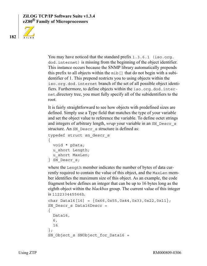
ZiLOG TCP/IP Software Suite v1.3.4eZ80® Family of Microprocessors
182
You may have noticed that the standard prefix 1.3.6.1 (iso.org. dod.internet) is missing from the beginning of the object identifier. This instance occurs because the SNMP library automatically prepends this prefix to all objects within the mib[] that do not begin with a subi-dentifier of 1. This prepend restricts you to using objects within the iso.org.dod.internet branch of the set of all possible object identi-fiers. Furthermore, to define objects within the iso.org.dod.inter-net.directory tree, you must fully specify all of the subidentifiers to the root.
It is fairly straightforward to see how objects with predefined sizes are defined. Simply use a Type field that matches the type of your variable and set the object value to reference the variable. To define octet strings and integers of arbitrary length, wrap your variable in an SN_Descr_s structure. An SN_Descr_s structure is defined as:typedef struct sn_descr_s{
void * pData;u_short Length;u_short MaxLen;
} SN_Descr_s;
where the Length member indicates the number of bytes of data cur-rently required to contain the value of this object, and the MaxLen mem-ber identifies the maximum size of this object. As an example, the code fragment below defines an integer that can be up to 16 bytes long as the eighth object within the blackbox group. The current value of this integer is 112233445566h.char Data16[16] = {0x66,0x55,0x44,0x33,0x22,0x11};SN_Descr_s Data16Descr = {
Data16,6,16
};SN_Object_s SNObject_for_Data16 =
Using ZTP RM000809-0306
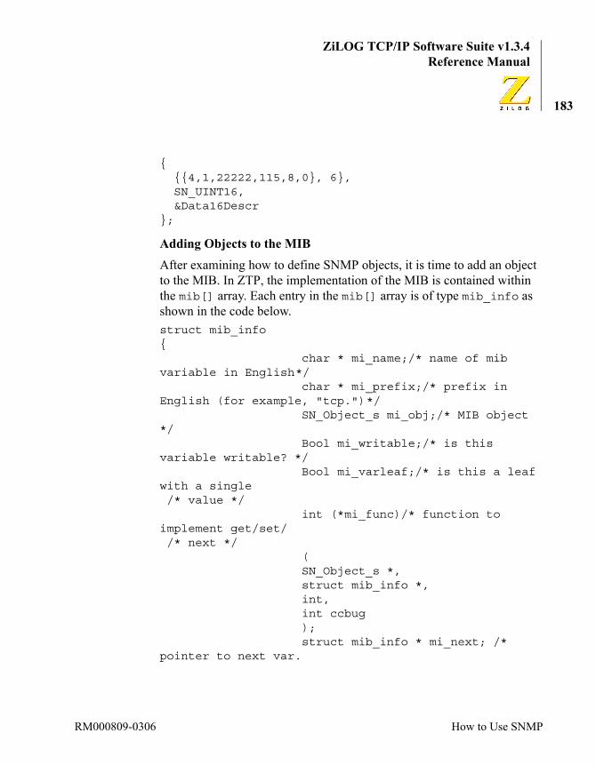
ZiLOG TCP/IP Software Suite v1.3.4Reference Manual
183
{{{4,1,22222,115,8,0}, 6},SN_UINT16,&Data16Descr
};
Adding Objects to the MIBAfter examining how to define SNMP objects, it is time to add an object to the MIB. In ZTP, the implementation of the MIB is contained within the mib[] array. Each entry in the mib[] array is of type mib_info as shown in the code below.struct mib_info {
char * mi_name;/* name of mib variable in English */
char * mi_prefix;/* prefix in English (for example, "tcp.") */
SN_Object_s mi_obj;/* MIB object */
Bool mi_writable;/* is this variable writable? */
Bool mi_varleaf;/* is this a leaf with a single /* value */
int (*mi_func)/* function to implement get/set/ /* next */
(SN_Object_s *,struct mib_info *,int,int ccbug);struct mib_info * mi_next; /*
pointer to next var.
RM000809-0306 How to Use SNMP
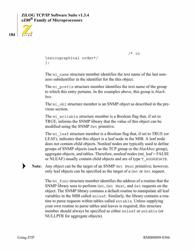
ZiLOG TCP/IP Software Suite v1.3.4eZ80® Family of Microprocessors
184
/* in lexicographical order*/};
The mi_name structure member identifies the text name of the last non-zero subidentifier in the identifier for the this object.
The mi_prefix structure member identifies the text name of the group to which this entry pertains. In the examples above, this group is black-box.
The mi_obj structure member is an SNMP object as described in the pre-vious section.
The mi_writable structure member is a Boolean flag that, if set to TRUE, informs the SNMP library that the value of this object can be modified using the SNMP Set primitive.
The mi_leaf structure member is a Boolean flag that, if set to TRUE (or LEAF), indicates that this object is a leaf node in the MIB. A leaf node does not contain child objects. Nonleaf nodes are typically used to define groups of SNMP objects (such as the TCP group or the blackbox group), aggregate objects, and tables. Therefore, nonleaf nodes (mi_leaf = FALSE or NLEAF) usually contain child objects and are of type T_AGGREGATE.
Any object can be the target of an SNMP Get Next primitive; however, only leaf objects can be specified as the target of a Get or Set request.
The mi_func structure member identifies the address of a routine that the SNMP library uses to perform Get, Get Next, and Set requests on the object. The SNMP library contains a default routine to manipulate all leaf variables in the MIB called snleaf. Similarly, the library contains a rou-tine to parse requests within tables called sntable. Unless supplying your own routine to parse tables and leaves is required, this structure member should always be specified as either snleaf or sntable (or NULLPTR for aggregate objects).
Note:
Using ZTP RM000809-0306

ZiLOG TCP/IP Software Suite v1.3.4Reference Manual
185
The mi_next structure member should always be specified as NULLPTR in the mib[] array. The system determines this value at run time and updates this field as required.
As an example of how to add entries to the MIB, consider the declaration of the System group in the mib[] array in the file conf\snmib.c.
// System Group { "system","", {{{2,1,1},3}, T_AGGREGATE, NULLPTR}, FALSE, NLEAF, NULLPTR, NULLPTR}, { "sysDescr", "system.", {{{2,1,1,1,0},5}, SN_DISPLAY_STR, SysDescr}, FALSE, LEAF, snleaf, NULLPTR}, { "sysObjectID", "system.", {{{2,1,1,2,0},5}, ASN1_OBJID, &SysObjectID}, FALSE, LEAF, snleaf, NULLPTR}, { "sysUpTime", "system.", {{{2,1,1,3,0},5}, ASN1_TIMETICKS, &SysUpTime}, FALSE, LEAF, snleaf, NULLPTR}, { "sysContact", "system.", {{{2,1,1,4,0},5}, SN_DISPLAY_STR, SysContact}, TRUE, LEAF, snleaf, NULLPTR}, { "sysName", "system.", {{{2,1,1,5,0},5}, SN_DISPLAY_STR, SysName}, TRUE, LEAF, snleaf, NULLPTR}, { "sysLocation", "system.", {{{2,1,1,6,0},5}, SN_DISPLAY_STR, SysLocation}, TRUE, LEAF, snleaf, NULLPTR}, { "sysServices", "system.", {{{2,1,1,7,0},5}, SN_INT32, &SysServices}, FALSE, LEAF, snleaf, NULLPTR},
The first element in the System group is an aggregate identifier for the group itself. Aggregate objects are not accessible using the SNMP primi-tives Get, Get Next, or Set. However, their use in the mib[] array is
RM000809-0306 How to Use SNMP

ZiLOG TCP/IP Software Suite v1.3.4eZ80® Family of Microprocessors
186
required to allow the library’s parsing routines to properly traverse the tree of objects in the MIB.
There are seven objects in the System group. Each of these objects is a leaf node (that is, mi_leaf = LEAF) and the mi_func structure member for these entries is snleaf. Because each leaf entry is a child of the Sys-tem aggregate object, the mi_prefix structure member names are all specified as system. Therefore, the text names and completely-specified corresponding object identifier of each of the entries in the system group are:
system.sysDescr 1.3.6.1.2.1.1.1.0system.sysObjectID 1.3.6.1.2.1.1.2.0system.sysUpTime 1.3.6.1.2.1.1.3.0system.sysContact 1.3.6.1.2.1.1.4.0system.sysName 1.3.6.1.2.1.1.5.0system.sysLocation 1.3.6.1.2.1.1.6.0system.sysServices 1.3.6.1.2.1.1.7.0
Observe that a zero is appended as the final subidentifier for all leaf objects. This zero is required in SNMP to uniquely identify the instance of the indicated object. Objects within tables are uniquely identified by an index that spans one or more subidentifiers in the object identifier (tables is discussed in the next section).
Finally, notice that the mi_writable structure member is set to TRUE for sysContact, sysName, and sysLocation. As a result, remote SNMP management entities are able to modify the values of these objects by using the SNMP Set primitive.
Using SNMP to Manipulate Leaf Objects in the MIBAfter adding leaf objects to the MIB, the ZTP SNMP Agent must manip-ulate these leaf objects by calling snmp_init() from within your main routine and linking the snmp.lib library to your project. The snleaf function implemented in the library automatically processes all Get, Get
Note:
Using ZTP RM000809-0306
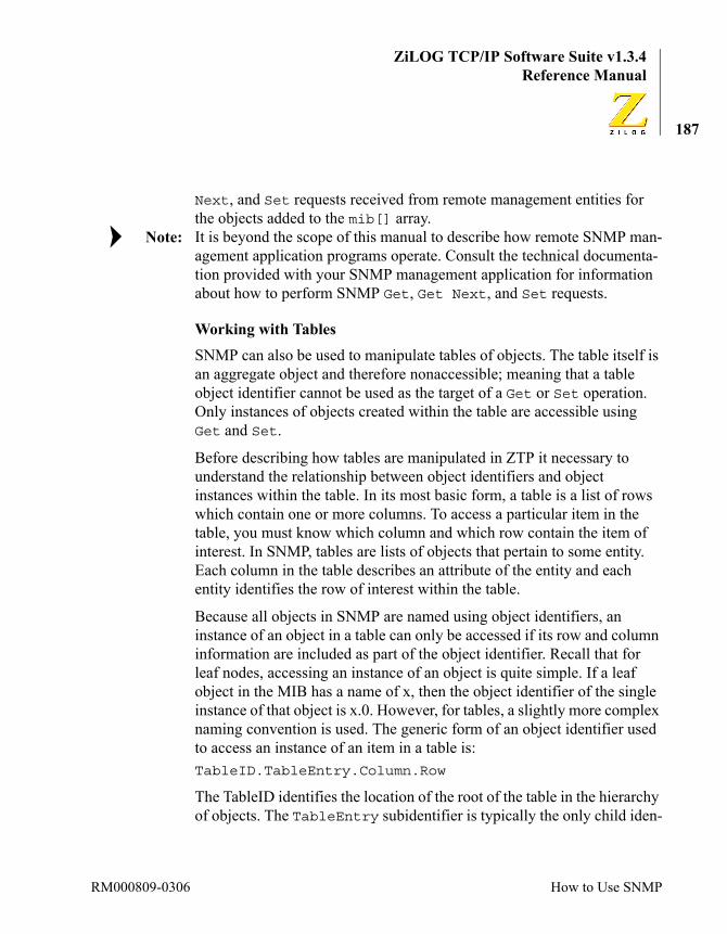
ZiLOG TCP/IP Software Suite v1.3.4Reference Manual
187
Next, and Set requests received from remote management entities for the objects added to the mib[] array. It is beyond the scope of this manual to describe how remote SNMP man-agement application programs operate. Consult the technical documenta-tion provided with your SNMP management application for information about how to perform SNMP Get, Get Next, and Set requests.
Working with TablesSNMP can also be used to manipulate tables of objects. The table itself is an aggregate object and therefore nonaccessible; meaning that a table object identifier cannot be used as the target of a Get or Set operation. Only instances of objects created within the table are accessible using Get and Set.
Before describing how tables are manipulated in ZTP it necessary to understand the relationship between object identifiers and object instances within the table. In its most basic form, a table is a list of rows which contain one or more columns. To access a particular item in the table, you must know which column and which row contain the item of interest. In SNMP, tables are lists of objects that pertain to some entity. Each column in the table describes an attribute of the entity and each entity identifies the row of interest within the table.
Because all objects in SNMP are named using object identifiers, an instance of an object in a table can only be accessed if its row and column information are included as part of the object identifier. Recall that for leaf nodes, accessing an instance of an object is quite simple. If a leaf object in the MIB has a name of x, then the object identifier of the single instance of that object is x.0. However, for tables, a slightly more complex naming convention is used. The generic form of an object identifier used to access an instance of an item in a table is:TableID.TableEntry.Column.Row
The TableID identifies the location of the root of the table in the hierarchy of objects. The TableEntry subidentifier is typically the only child iden-
Note:
RM000809-0306 How to Use SNMP

ZiLOG TCP/IP Software Suite v1.3.4eZ80® Family of Microprocessors
188
tifier of the TableID, that is, {TableID 1}, and must be included in the name of every instance of an object located within the table. The Column subidentifier indicates the attribute of interest within the TableEntry and the Row subidentifier is the instance of the object of interest.
Therefore, a simpler form of the object identifier for an instance of an object in the table is:y.Row
where y,{TableID.TableEntry.Column} is the name of the attribute of interest within the table. Note that y.Row is a leaf node in the table and is therefore a valid object identifier to use with the SNMP Get and Set primitives.
As an example, consider the ip.ipRouteTable defined in the standard MIB. The specification defines 13 attributes (columns) for each Route (row) that appears in the table. The object identifier that corresponds to the Next Hop (attribute 7) of any route in the table contains the common prefix 1.3.6.1.2.1.4.21.1.7 corresponding to {ip.ipRouteTa-ble.ipRouteEntry.ipRouteNextHop}. Therefore, the particular instance of the Next Hop attribute for the specific route 1.2.3.4 would be found by performing a Get request using an object identifier of 1.3.6.1.2.1.4.21.1.7.1.2.3.4.
How to Add a Table to the MIBNow that we understand how tables are organized in SNMP, let’s examine how tables are added to the mib[] array in ZTP. Consider the declaration of the IP Routing table (shown below) in the mib[] array in the conf\snmib.c source file:
{ "ipRoutingTable", "ip.", {{{2,1,4,21}, 4}, T_AGGREGATE, NULLPTR}, TRUE, NLEAF, NULLPTR, NULLPTR},{ "ipRouteEntry", "ip.ipRoutingTable.", {{{2,1,4,21,1}, 5}, T_TABLE, &sn_table[T_RTTABLE]}, TRUE, NLEAF, sntable, NULLPTR},
Using ZTP RM000809-0306
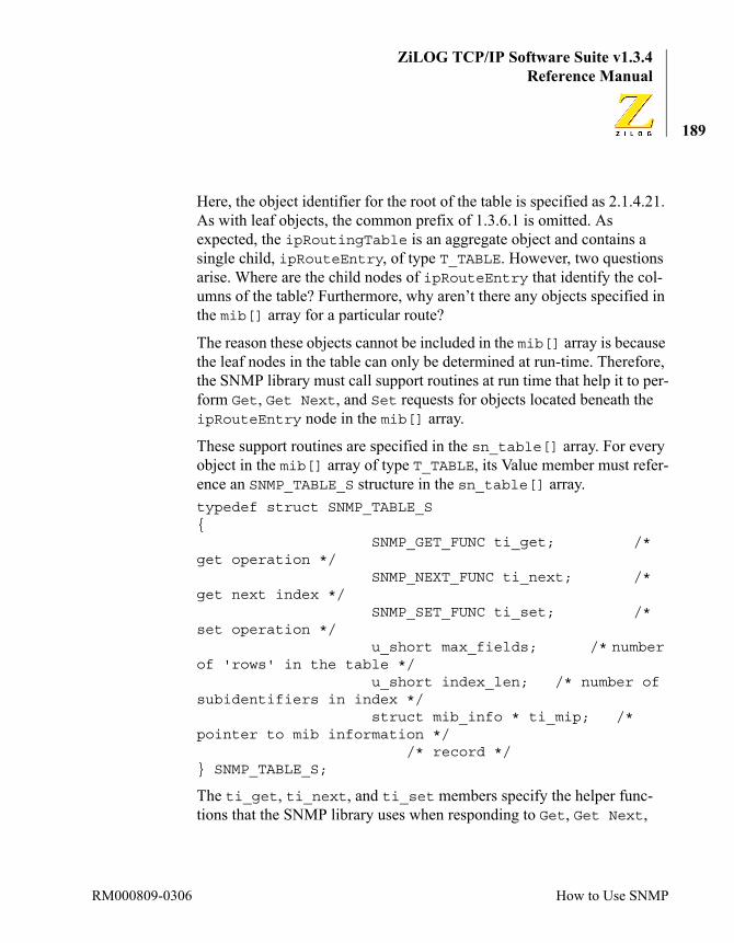
ZiLOG TCP/IP Software Suite v1.3.4Reference Manual
189
Here, the object identifier for the root of the table is specified as 2.1.4.21. As with leaf objects, the common prefix of 1.3.6.1 is omitted. As expected, the ipRoutingTable is an aggregate object and contains a single child, ipRouteEntry, of type T_TABLE. However, two questions arise. Where are the child nodes of ipRouteEntry that identify the col-umns of the table? Furthermore, why aren’t there any objects specified in the mib[] array for a particular route?
The reason these objects cannot be included in the mib[] array is because the leaf nodes in the table can only be determined at run-time. Therefore, the SNMP library must call support routines at run time that help it to per-form Get, Get Next, and Set requests for objects located beneath the ipRouteEntry node in the mib[] array.
These support routines are specified in the sn_table[] array. For every object in the mib[] array of type T_TABLE, its Value member must refer-ence an SNMP_TABLE_S structure in the sn_table[] array.typedef struct SNMP_TABLE_S{
SNMP_GET_FUNC ti_get; /* get operation */
SNMP_NEXT_FUNC ti_next; /* get next index */
SNMP_SET_FUNC ti_set; /* set operation */
u_short max_fields; /* number of 'rows' in the table */
u_short index_len; /* number of subidentifiers in index */
struct mib_info * ti_mip; /* pointer to mib information */
/* record */} SNMP_TABLE_S;
The ti_get, ti_next, and ti_set members specify the helper func-tions that the SNMP library uses when responding to Get, Get Next,
RM000809-0306 How to Use SNMP
ZiLOG TCP/IP Software Suite v1.3.4eZ80® Family of Microprocessors
190
and Set requests for objects within the table. If you add your own tables to the MIB, you must implement these support routines.
The max_fields member indicates the number of columns in the table. For example, the specification of the IP Routing table in the standard MIB identifies thirteen attributes (child nodes) to the ipRouteEntry. There-fore, the max_fields parameter for the IP Routing Table is specified as 13.
The index_len member defines the number of subidentifiers in the name of the TableEntry within the mib[] hierarchy. For example, the complete TableEntry name of the ipRouteEntry is 1.3.6.1.2.1.4.21.1. However, in the ZTP implementation, the com-mon root of 1.3.6.1 is not included for any entry in the mib[]. There-fore, the index_len of the ipRouteEntry in the ZTP implementation is 5, which corresponds to an identifier of 2.1.4.21.1.
The ti_mip member cross-links the sn_table[] entry to the corre-sponding TableEntry in the mib[] array, the object Value of which references this sn_table[] entry. The SNMP library automatically determines the value of this pointer and updates the ti_mip value during SNMP initialization.
To add a table to the mib[] array, you must also add an entry to the exist-ing sn_table[] array to describe your table to the SNMP library. The code fragment below adds a table to the mib[] array.{ "Table", "demo.", {{{4,1,12897,2,19},5}, T_AGGREGATE, NULLPTR}, FALSE, NLEAF, NULLPTR, NULLPTR},{ "TableEntry", "table.sample.", {{{4,1,12897,2,19,1},6}, T_TABLE, &sn_table[7]}, FALSE, NLEAF, sntable, NULLPTR}
The corresponding entry in the sn_table[] array is:{sdt_get, sdt_next, sdt_set, SNUMF_DTTAB, SDT_INDEX_LEN, NULLPTR}
Using ZTP RM000809-0306
ZiLOG TCP/IP Software Suite v1.3.4Reference Manual
191
This table contains SNUF_DTTAB fields (currently defined to be 3). The rows in the table are indexed by a single subidentifier so that the value of SDT_INDEX_LEN is defined to be 1.
Next, to examine the structure of the support routines, the SNMP library calls through function pointers ti_get, ti_next, and ti_set in the SNMP_TABLE_S structure. It can be helpful to reference the main.c file in the SNMPDemo project folder as you read the following sections.
The SNMP_GET_FUNC Support RoutineThe SNMP library calls the routine you specify in the ti_get field of the SNMP_TABLE_S when it requires the value of the named object in response to an SNMP Get request. A compatible function prototype for the SNMP_GET_FUNC function pointer is shown below.int Table_GET(SN_Object_s * p_Obj);
In the Table_GET function, the pObj parameter references an incomplete SNMP object. Recall that SNMP objects contain a name, type, and value. When processing an SNMP Get request, the library is only able to deter-mine the name (pObj → Oid) of the requested object. It is up to your Table_GET routine to either supply the type and value of the object or to return integer error codes such as SERR_NO_SUCH. How objects are stored within your table is an implementation decision.
The pObj → Oid parameter contains the object identifier that corre-sponds to the instance of the object that is the target of a Get request. The SNMP library has no means by which to determine if the requested object is actually within your table. The only preprocessing that the library per-forms on the requested object identifier is to remove the common mib[] root prefix of 1.3.6.1 and to ensure that the requested object identifier begins with the same subidentifiers as the TableEntry corresponding to the ti_mip pointer in your table’s sn_table[] array entry.
Therefore, the first task to be performed in the Table_GET routine is to ensure the requested object is in fact within your table. If the requested object cannot be located in the table, return the SERR_NO_SUCH error
RM000809-0306 How to Use SNMP
ZiLOG TCP/IP Software Suite v1.3.4eZ80® Family of Microprocessors
192
code to the SNMP library. Do not perform any further processing on the pObj parameter.
As a result of verifying that the object identifier is valid, the Table_GET routine should determine the row (table index) and column (field) of the applicable object. How you convert the row and column identifiers into a meaningful index you can use at run time to access the value of the requested object is an implementation-specific design issue.
After your Table_GET routine locates the applicable object, the next step is to update the pObj → Type and pObj → Value fields as appropriate. For more information about SNMP objects and data types in ZTP, see the SNMP Objects section on page 180.
As a simple example, if the Table_GET routine determines that the appli-cable object is a 32-bit ASN1 counter, set pObj → Type to ASN1_COUNTER and set the *pObj → Value → pCounter to the 32-bit unsigned value of the counter.
Your code must not modify the value of pObj → Value. You can only modify memory referenced by one of the members of the pObj → Value union.
Before calling your Table_GET handler, the SNMP library allocates a buffer of size snmp_max_object_size and set the pData and MaxLen member of the pObj → Value.pDescr. Therefore, if snmp_max_object_size is at least as large as the size of the largest object within your table, it is not necessary to verify the size of pObj → Value.pDescr → MaxLen. However, if snmp_max_object_size has not been initialized to an appropriate value, you should verify that the buffer allocated by the SNMP library (pObj → Value.pDescr → MaxLen) is large enough to contain the value of the requested object. This condition is only applicable to objects of type Integer and Octet String, which can have arbitrary lengths.
Note:
Using ZTP RM000809-0306
ZiLOG TCP/IP Software Suite v1.3.4Reference Manual
193
The SNMP_SET_FUNC Support RoutineThe SNMP library calls the routine specified in the ti_set field of the SNMP_TABLE_S when it requires you to update the value of the named object in response to an SNMP Set request. A compatible function proto-type for the SNMP_SET_FUNC function pointer is shown below.int Table_SET(SN_Object_s * p_Obj);
The pObj → Oid parameter contains the object identifier corresponding to the instance of the object that is the target of a Set request. The SNMP library cannot determine if the requested object is actually within your table. The only preprocessing that the library performs on the requested object identifier is to remove the common mib[] root prefix of 1.3.6.1 and to ensure that the requested object identifier begins with the same subidentifiers as the TableEntry corresponding to the ti_mip pointer in the in sn_table[] entry.
Therefore, the first task to be performed in the Table_SET routine is to ensure that the requested object is in fact within your table. If the requested object cannot be located in the table, return the SERR_NO_SUCH error code to the SNMP library. Do not perform any further processing on the pObj parameter.
As a result of verifying that the object identifier is valid, the Table_SET routine should have determined the row (table index) and column (field) of the applicable object. How you convert the row and column identifiers into a meaningful index you can use at run time to access the value of the requested object is an implementation-specific design issue.
After the Table_SET routine locates the applicable object, the next step is to verify that the pObj → Type field is compatible with the internal representation of the indicated object. Some SNMP object types are syn-tactically specified as one object type but encoded using a compatible ASN.1 primitive data type. For example, SNMP display strings (repre-sented in ZTP as type SN_DISPLAY_STR) are encoded as ASN.1 octet strings. Therefore, even though you can create an object of type SN_DISPLAY_STR, the SNMP library sets the pObj → Type parameters
RM000809-0306 How to Use SNMP

ZiLOG TCP/IP Software Suite v1.3.4eZ80® Family of Microprocessors
194
to ASN1_OCTSTR before calling your Table_SET routine. Consequently, your Table_SET routine should accept an Octet String as a valid data type for the SN_DISPLAY_STR object. However, if the remote SNMP management entity specified the object type as an ASN.1 Integer in the Set request, then your Table_SET routine should not accept the value of the object because an Integer data type is not compatible with either an Octet String or a Display String. In this case, your Table_SET routine should return SERR_BAD_VALUE to the SNMP library and perform no further processing.
After the Table_SET routine verifies that the applicable object exists within the table and that the pObj → Type field of the object is appropri-ate, the next step is to determine if the object size is valid. If you have defined the value of snmp_max_object_size appropriately, the SNMP library ensures that pObj → Value contains no more than snmp_max_object_size bytes of data. Otherwise, for object values that use an SN_Descr_s structure (arbitrary length Integers and Octet Strings), you should ensure that the size (pObj → Value.MaxLen) of the object value specified in the Set operation does not exceed the size of the local buffer you are using to contain the value of the target object. If the Value of the object specified in the Set operation exceeds the storage capacity of the local buffer, your Table_SET routine should return SERR_TOO_BIG and not perform any more processing of the pObj parameter.
It can also be appropriate to verify the correctness of the object value specified in the Set operation. For example, if you define an object within your table of type Integer and specify that the permissible range of values for that integer is between 10 and 20, then you can either allow the remote management entity to assign an invalid value to your object (such as +1729, or -15) or you can return SERR_BAD_VALUE to the SNMP library and perform no further processing on the pObj parameter.
If the Object Name, Type, and Value specified in the Set operation are all appropriate, then the final step to perform in the Table_SET routine is to copy the value of the pObj input parameter into the memory location
Using ZTP RM000809-0306

ZiLOG TCP/IP Software Suite v1.3.4Reference Manual
195
where you are storing the value of the target object. It is important to actu-ally copy the contents of the value into your local buffer and not to merely retain the value of the pointer that the library provides to the object data. The reason why this issue is important is because the object value sup-plied by the SNMP library is located in a dynamically allocated buffer that is released after your Table_SET routine returns control to the SNMP library.
For more information about objects, see the SNMP Objects section on page 180. As a simple example, if the Table_SET routine determines that the target object is a 32-bit ASN1 Counter, you would set the value of the counter to the value *pObj → Value → pCounter.
The SNMP_NEXT_FUNC Support RoutineThe SNMP library calls the routine specified in the ti_next field of the SNMP_TABLE_S when it requires you to determine the name of the object that immediately follows (in lexicographical order) the specified object identifier. A compatible function prototype for the SNMP_SET_FUNC function pointer is shown below.int Table_NEXT(OBJSUBIDTYPE * pSubID);
Currently, OBJSUBIDTYPE is defined to be an unsigned short (16-bit) integer; although this value could change in future versions of the stack.
The pSubID pointer references an array of subidentifiers that begins with the table index (that is, row) of interest. The Table_NEXT routine must modify this list of subidentifiers to match the index of the next row in the table. If there is no element in the table that follows the specified index, the Table_NEXT routine should return SERR_NO_SUCH and not modify the specified list of subidentifiers.
The key to implementing the Table_NEXT function is to understand what is meant by lexicographical order. Lexicographical order is sometimes referred to as dictionary order. In a dictionary, the definition of the word the appears before the definition of the word then, but after the definition
RM000809-0306 How to Use SNMP

ZiLOG TCP/IP Software Suite v1.3.4eZ80® Family of Microprocessors
196
of the word tap. Therefore, the lexicographical ordering of these words is tap the then.
To illustrate how the concept is applied to subidentifiers, suppose your table index is defined as an IP address. Further assume that your table contains three rows, wherein the index (that is, the IP address) of each row is:192.168.1.50192.168.1.200192.168.4.75
Therefore, it is easy to see that if the pSubID array contained the value 192.168.1.50, then the next index (in lexicographical order) that appears in your table is 192.168.1.200. Suppose that the pSubID array contained the values 192.168.1.60—there is no row in your table with this index. However, the next row in the table that follows in lexicograph-ical order is still 192.168.1.200 because the value 60 is between 50 and 200. Similarly, the next entry in the table after 192.168.2.1 is 192.168.4.75.
Determining lexicographical order is slightly more complicated if the pSubID contains more, or less, subidentifiers than what you expect as a valid index. For example, given an input subidentifier string of 192.168.2, the next index is 192.168.4.75. Similarly, the next index after 192.168.1.3.4.5.6.7.8.9. is also 192.168.4.75. Two other special cases to consider are the case where the pSubID input array refer-ences an item before the first object in your table (for example, for an input of 100.1, the next row in the table is 192.168.1.50) and the case where there is no element in the table that follows the input list of subi-dentifiers. For example, given an input of 192.168.4.75, there is ele-ment in the table that follows this subidentifier so that the Table_NEXT routine should return SERR_NO_SUCH.
The SNMP library automatically pads subidentifiers shorter than the index_len specified in the sn_table[] array entry for your table with a zero to simplify lexicographical processing. For sample code that you
Using ZTP RM000809-0306

ZiLOG TCP/IP Software Suite v1.3.4Reference Manual
197
can use as a starting point for writing the Table_NEXT routine, refer to the main.c file in the SNMPDemo project folder.
Updating SNMP ValuesThe SNMP library automatically updates the values of SNMP objects defined in the standard MIB. However, it is up to you to update the values of SNMP objects specific to your application, if appropriate. For exam-ple, if you define an SNMP object of type Counter to count some event unique to your application and add it to the mib[] array, the SNMP library Get and Set functions obtain and set the value of the object in response to requests from a remote SNMP management entity. But it is up to your application to increase the value of the counter when the trigger event occurs. Conversely, if you define an SNMP object of type Octet String to contain the serial number of your embedded device, it is likely that you do not require to update this value during run time.
Also, be aware that the SNMP library does not use critical sections (that is, does not disable interrupts) while manipulating objects within the mib[] array. If this issue causes problems for your application, then ZiLOG recommends that you perform updates to SNMP objects in a pro-cess that runs at a lower priority than the SNMP Agent (which currently executes at priority 20, see the KE_TaskChangePrio API on page 221 for information about how to change this value) and that your application only updates SNMP variables from within a critical section. The first measure ensures that the process in your application that updates SNMP variables can never preempt the SNMP Agent while it is manipulating an object within the mib[] array. The second measure ensures that the SNMP Agent (nor any other process in the system) is not able to preempt the process in your application that updates SNMP variables.
Finally, note that the mib[] array is contained in RAM. Any changes made to the mib[] array is lost when power is removed from the system.
RM000809-0306 How to Use SNMP
ZiLOG TCP/IP Software Suite v1.3.4eZ80® Family of Microprocessors
198
Trap GenerationThe SNMP library in ZTP is capable of generating the following SNMP v1 traps:
• Cold Start Trap.
• Link Up Trap.
• Link Down Trap.
• Authentication Failure Trap.
• Enterprise-Specific Trap.
If the Generate_Cold_Start_Traps flag is set to TRUE, a Cold Start Trap is generated when the system boots up regardless of whether the sys-tem is warm-booted (for example, executing the reboot command from the shell) or cold-booted (disconnecting and reconnecting the power sup-ply). This situation occurs because the mib[] is stored in RAM and any changes made to the MIB, which could affect the operation of this device, are lost when the system is reinitialized. Therefore, from an SNMP per-spective, every initialization is a Cold Start.
If the Generate_Link_Up_Traps flag is set to TRUE, the system gen-erates a Link Up Trap whenever a network interface is (re)activated. For example, during system initialization, the Ethernet interface becomes active and a Link up Trap is generated.
Conversely, if the Generate_Link_Down_Traps flag is set to TRUE, when a network interface changes state from active to inactive, a Link Down Trap is generated. For example, a Link Down trap is generated when the PPP link is disconnected.
If the SnmpEnableAuthenTraps variable is set to SNMP_AUTH_TRAPS_DISABLED, the system generates an Authentication Failure trap whenever a request (Get, Get Next, or Set) is received containing a community name that does not match the community name specified in the snmp_community_name[] string. The SnmpEnable-
Using ZTP RM000809-0306
ZiLOG TCP/IP Software Suite v1.3.4Reference Manual
199
AuthenTraps variable can be modified by your application or by a remote management entity.
If the Generate_Enterprise_Traps flag is set to TRUE, then an Enterprise-specific Trap is generated when your application calls the TrapGen API. The TrapGen function prototype is:SYSCALL TrapGen(
unsigned char Type,unsigned long Code,unsigned short NumObjects, SN_Object_s * pObjList
);
The Type parameter should always be specified as SN_TRAP_ENTERPRISE_SPECIFIC.
The Code parameter is a 32-bit value unique to your application that iden-tifies the particular trap message being generated.
The NumObjects parameter specifies the number of SN_Object_s structures that are to be included in the body of the Trap message. If your application-specific trap does not require any objects to be included in the trap message, set this parameter to 0.
The pObjList parameter is an array of NumObjects SN_Object_s structures that identify the SNMP objects to be included in the body of the trap message. If your application-specific trap does not require any objects to be included in the trap message, set this parameter to NULLPTR.
All traps are directed to the device identified by the snmp_trap_target variable in snmp_conf.c.
RM000809-0306 How to Use SNMP
ZiLOG TCP/IP Software Suite v1.3.4eZ80® Family of Microprocessors
200
How to Create a Custom Ethernet DriverZTP can support a single Ethernet interface that is used to transfer TCP/IP information. The libraries supplied with the ZTP install package include Ethernet drivers for the Cirrus CS8900A Crystal Lan Ethernet controller as well as the Ethernet controller integrated with ZiLOG’s eZ80F91 MCU. (The Realtek RT8019AS controller is no longer supported in the ZTP package.) Source code to these drivers is available as a separate install package that you can use to modify their functionality, or as start-ing points to help you develop a driver to support a different Ethernet con-troller.
This section describes the EMAC driver implementation in ZTP and introduces the EMAC driver package available for download from ZiLOG’s website. Reading this section is optional if you do not plan to modify the existing ZTP Ethernet drivers.
ZTP Ethernet Driver OverviewThe Ethernet drivers provided with ZTP follow the same driver model as presented in the ZTP Device Driver APIs section on page 360. When the devs shell command is executed, the Ethernet driver is the one named ETHER. When you use one of the existing ZTP demo projects, either the F91_emac.lib library or the CS8900A.lib library is linked into your project depending on whether you are using the eZ80F91 Module or one of the other eZ80® modules containing the Cirrus CS8900A device. Each of these libraries contains code that implements the ETHER device driver for ZTP.
The ETHER driver is implemented as two separate layers: the ZTP Inter-face layer and the controller-specific MAC sublayer. The top layer is common for all ZTP Ethernet device drivers. This layer contains code to implement the subset of the ZTP device driver API applicable to the Ethernet driver. The bottom layer must be tailored to the specific Ethernet controller that is integrated with your design. To simplify the task of cre-ating the ETHER device for different Ethernet controllers, the EMAC
Using ZTP RM000809-0306

ZiLOG TCP/IP Software Suite v1.3.4Reference Manual
201
driver package includes the emac.lib library which implements the common Interface layer of the ETHER device. Therefore, you are only required to implement the controller-specific sublayer to create a new Ethernet device driver.
The EMAC Driver PackageThe EMAC driver package creates an EMAC folder within the directory where ZTP is installed. The EMAC directory contains four subdirecto-ries:
• \CS8900A
• \F91_emac
• \RT8019as
• \Template
The first three of these subdirectories contain source code to the lower layer of the ETHER driver that implements the hardware-specific sublay-ers for the corresponding Ethernet controllers. The Template subdirectory, contains a skeleton of the routines that the common Interface layer expects to be implemented in the hardware-specific sublayer. These func-tions are described in the Implementing a New Ethernet Driver section on page 203.• emac_reset
• emac_enable_irq
• emac_disable_irq
• ETHINITFUNC
• TransmitPkt
• ReceivePkt
• ETHMADDFUNC
• ETHMDELFUNC
RM000809-0306 The EMAC Driver Package
ZiLOG TCP/IP Software Suite v1.3.4eZ80® Family of Microprocessors
202
To create a new Ethernet driver, perform the following the steps:
1. Add code to the Template.c source file to implement these func-tions. It can also be necessary to include an Interrupt Service Routine (ISR) if appropriate for your device.
2. Build the Template.lib library using ZDS II.
3. Copy the Template.lib file into the \libs subdirectory where ZTP is installed.
4. Modify one of the existing Demo projects (or one of your own ZTP projects) and remove either the CS8900A.lib or F91_emac.lib library from the list of Object/Library Modules displayed in the Linker tab of the Project → Settings dialog box. In its place, include the ..\libs\emac.lib and ..\libs\Template.lib libraries.
5. Modify the eZ80_HW_Config.c and/or ipw_ez80.c configuration files as appropriate. For example, when using the CS8900A library, an entry in the GPIO_config[] array in eZ80_HW_Config.c pre-configures one of the GPIO pins (usually PD4) for use as the Interrupt Request signal from the CS8900A device to the eZ80® CPU. Depending on the physical connection from the Ethernet controller to the eZ80® CPU, an entry can be required in the cs_config[] array and, if applicable, the cs_bus_mode[] array. These settings may not be appropriate for the device you are using and likely must be modi-fied. Similarly, ipw_ez80.c defines three configuration variables used by the CS8900A hardware-specific sublayer: p_emac_base, xinu_eth_irq, and b_poll_emac. These variables may not be required for the particular device you are using.
For more information about hardware resources required for the CS8900 or eZ80F91 drivers, consult the product documentation included with the eZ80® development kit you are using.
6. After the demo project is rebuilt, downloaded, and executed, ZTP starts using your new Ethernet driver.
Using ZTP RM000809-0306
ZiLOG TCP/IP Software Suite v1.3.4Reference Manual
203
Implementing a New Ethernet DriverThis section describes each of the routines that the common Interface layer expects to find in the hardware-specific sublayer of the ETHER device driver.
emac_resetThe emac_reset routine is the first routine in the hardware-specific sub-layer that the system calls during initialization. The purpose of this rou-tine is to place the Ethernet controller into a dormant state, and to ensure that the hardware controller does not generate any interrupts until after the ETHINITFUNC routine is called. In many cases, this objective can be accomplished by invoking a hardware reset function within the specific Ethernet controller you are using. If applicable, the controller could be disconnected from the link and placed in a low power mode.
This routine could require examination of the configuration values in ipw_ez80.c before attempting to reset the controller. For example, the CS8900A driver uses the p_emac_base variable to locate the first I/O address of the CS8900 register set before manipulating the controller. This issue allows the user to redefine the I/O starting address of the CS8900 driver without requiring a recompile of the CS8900A.library file. You are not obliged to use such a scheme in your driver.
This routine is called with interrupts disabled. After disabling interrupts, but prior to calling this routine, the system configures the GPIO pins according to the values defined in the GPIO_config[] array, possibly configuring one or more of these pins as interrupt request signals to the eZ80® CPU. Shortly after calling this routine, but prior to calling your ETHINITFUNC (where you can install your interrupt handler), the system enables interrupts. It is imperative, therefore, that the emac_reset rou-tine not return control to the system until the Ethernet controller is pre-vented from generating interrupts.
Note:
RM000809-0306 Implementing a New Ethernet Driver

ZiLOG TCP/IP Software Suite v1.3.4eZ80® Family of Microprocessors
204
Failure to observe the above convention can result in an unexpected in-terrupt. Should an unexpected interrupt occur, ZTP displays a message on the console alerting you to this condition, and then halts the system.
Because this routine is called before the system is fully initialized, you cannot call any ZTP API that results in a context switch such as a sema-phore function, message port functions, mailbox functions, or other pro-cess manipulation functions.
This routine can also be accessed by calling the device driver control API that specifies the Device ID of the ETHER driver and a control code of EPV_RESET. However, be aware that the default libraries supplied with ZTP cease to function properly as a result. If you must take advantage of this feature, it is necessary to modify the existing Ethernet drivers.emac_enable_irq. This function is called to enable interrupt generation from the specific Ethernet controller you are using. Consult the hardware resistor set for the controller for information about how this task is accomplished. If your Ethernet driver does not use interrupts, then this routine should reenable polling of the Ethernet controller. If neither inter-rupts nor polling is used this routine should return control without per-forming any processing.
This function is accessible by calling the device driver control API speci-fying the Device ID of the ETHER driver and a control code of EPV_IRQ_ENABLE.
The emac_enable_irq routine is not called by any module within ZTP. However, if your application must temporarily disable Ethernet interrupts, you can use the EPV_IRQ_DISABLE and/or EPV_IRQ_ENABLE control codes (or directly call the emac_disable_irq and emac_enable_irq routines). While Ethernet interrupts are disabled, data loss can occur. If the specific controller you are using loses track of interrupts while it is prevented from asserting its IRQ signal, then this feature should not be used.
Caution:
Using ZTP RM000809-0306

ZiLOG TCP/IP Software Suite v1.3.4Reference Manual
205
emac_disable_irq. This function is called to disable interrupt generation from the specific Ethernet controller you are using. Consult the hardware resistor set for the controller for information about how this task is accomplished. If your Ethernet driver does not use interrupts, then this routine should disable polling of the Ethernet controller until the emac_enable_irq function is called. If neither interrupts nor polling is used, this routine should return control without performing any process-ing.
This function is accessible by calling the device driver control API speci-fying the Device ID of the ETHER driver and a control code of EPV_IRQ_DISABLE.
This routine is not called by any module within ZTP. However, if your application must temporarily disable Ethernet interrupts, you can use the EPV_IRQ_DISABLE and/or EPV_IRQ_ENABLE control codes (or directly call the emac_disable_irq and emac_enable_irq routines). While Ethernet interrupts are disabled, data loss can occur. If the specific con-troller you are using loses track of interrupts while it is prevented from asserting its IRQ signal, then this feature should not be used.
ETHINITFUNCThe ETHINITFUNC routine is the second routine in the hardware-specific sublayer that the system calls during initialization. This function is called by the ETHER device driver’s dvinit handler. The purpose of this rou-tine is to prepare the hardware Ethernet controller and the software driver for immediate use by the system.
This routine should assume that the Ethernet controller’s register set is programmed such that an invalid value has been placed into every register in the controller. Therefore, this routine must reprogram each register that controls a function required by the driver. It can be possible to invoke a reset function within the Ethernet controller to reprogram some (or all) of the affected registers.
RM000809-0306 Implementing a New Ethernet Driver
ZiLOG TCP/IP Software Suite v1.3.4eZ80® Family of Microprocessors
206
The ETHINITFUNC routine is called with two parameters. The function prototype (taken from emac\Template\Template.c) is:int ETHINITFUNC(char *ieeeaddr, void *(*rxnotify)( void ));
The first parameter is a pointer to a six-byte (48-bit) MAC address that the driver should program the controller to use as the device’s unicast address. The value of this address is determined by the get_etheraddr routine in the conf\emac_conf.c source file. The second parameter is a callback function pointer to the common Interface layer’s receive packet routine. The driver should save the function pointer value and call the callback routine for each error-free Ethernet frame received from the net-work.
If applicable, the driver should call set_evec from within the ETHINIT-FUNC routine to claim the interrupt vector(s) dedicated to the Ethernet controller. This step should be performed prior to enabling the controller’s interrupt generation logic.
Failure to observe the above convention can result in an unexpected in-terrupt. Should an unexpected interrupt occur, ZTP displays a message on the console alerting you to this condition, and then halts the system.
It can be necessary for the driver to access configuration values in the ipw_ez80.c source file to properly initialize the Ethernet controller and/or software driver. For example, the CS8900 driver installs its interrupt service routine at the vector defined by xinu_eth_irq. Similarly, if the b_poll_emac variable is nonzero, the CS8900 software driver creates a ZTP process to periodically monitor the CS8900 interrupt status queue for hardware events.
The ETHINITFUNC routine should return a status code of OK to indicate that the hardware controller and software driver have been initialized suc-cessfully. However, the ETHER Interface layer currently ignores the sta-tus value returned from the ETHINITFUNC routine. Therefore, if an error
Caution:
Using ZTP RM000809-0306

ZiLOG TCP/IP Software Suite v1.3.4Reference Manual
207
occurs during initialization that prevents the driver from functioning, the driver should display an error message on the console and/or call the sys-tem’s panic API to halt the system.
TransmitPktThe TransmitPkt routine is called by the common Interface layer’s dvwrite handler to transmit a contiguous block of data through the Ethernet controller. The function prototype of the TransmitPkt routine is:int TransmitPkt(struct ep *pep);
The first parameter is a pointer to an Ethernet packet (ep) structure that contains the data to be transmitted. The ep structure is defined within the ether.h header file in the includes subdirectory. The current defini-tion of this structure is:struct ep { /* complete structure of Ethernet
/* packet*/IPaddrep_nexthop; /* niput()
uses this */unsigned shortep_ifn;/*
originating interface number */unsigned shortep_order; /* byte
order mask (for debugging)*/unsigned shortep_len;/* length of
the packet */structeh ep_eh; /* the Ethernet
header */unsigned charep_data[EP_DLEN]; /
* data in the packet */};
The only structure members of importance to the TransmitPkt routine are:ep_len. This member is the number of bytes of data in the Ethernet header (ep_eh) and the data (ep_data) fields.
RM000809-0306 Implementing a New Ethernet Driver

ZiLOG TCP/IP Software Suite v1.3.4eZ80® Family of Microprocessors
208
ep_eh. This member is the standard Ethernet header composed of Ethernet Destination address (6 bytes), Ethernet source address (6 bytes), and the Type field (2 bytes).ep_data. This buffer contains the body of the Ethernet frame.
The common interface layer expects the TransmitPkt routine to trans-mit ep_len bytes of data beginning with the ep_eh field over the Ether-net medium without modifying any of these bytes. It is the responsibility of the TransmitPkt routine to ensure that a valid 32-bit CRC is appended to the end of this frame (either by the controller or by software in the driver).
The Interface layer’s dvwrite handler always sets the ep_len field to at least 60 bytes to meet minimum Ethernet frame size requirements.
It is your choice as to how the TransmitPkt routine is implemented. Your software may elect to wait until the Ethernet controller is ready to transmit new data and then synchronously send the new frame, or it may append the new frame to a queue (either in software or in hardware) and transmit the data asynchronously when an event (for example, interrupt) signals that the controller is able to accept a new transmit request. Hybrid schemes are also possible. For optimal system performance, ZILOG rec-ommends the use of interrupts instead of polling.
If the controller encounters an error while transmitting the frame, it is your choice as to whether the driver should attempt to retransmit the same frame or discard the data. The TCP protocol automatically detects the lost data and retransmit it at a letter point in time. However, the UDP protocol cannot detect this error condition. The sample drivers included with ZTP do not attempt to retransmit a frame that the Ethernet controller is unable to transmit.
The common Interface layer expects the TransmitPkt routine to return an integer value to indicate the status of the transmit request. Possible val-ues that can be returned and their interpretation are shown below:
Note:
Using ZTP RM000809-0306
ZiLOG TCP/IP Software Suite v1.3.4Reference Manual
209
TX_DONE. This status code indicates that your controller-specific layer has either completely finished transmitting the frame or has completely buffered the frame within the controller’s hardware buffers. In either case, the frame is not required to be retained by ZTP, and the common Interface layer destroys the packet by calling freebuf with the pep pointer as an argument. If your driver returns TX_DONE, you must not refer to the mem-ory referenced by the pep pointer after returning from the TransmitPkt routine.TX_WAITING. This status code indicates to the common Interface layer that your driver is waiting for some event (typically a transmit complete interrupt) that must occur before the new Ethernet frame can be sent. As a result, your driver is implicitly maintaining ownership of the memory ref-erenced by the pep pointer. After the event occurs and the new frame is actually transmitted (or at least buffered within the controller), your driver must call freebuf using the pep pointer as an argument, for example, freebuf( (int*)pep ); This call must be performed to return the packet structure referenced by the pep pointer to the system for subsequent reuse. Failure to perform this task causes the system to run out of ep structures and, as a result, block all network communications. The call to freebuf can be made from the TransmitPkt routine or the Ethernet ISR.TX_FULLBUF, PKTTOOBIG. These status codes, or any other value not already listed, are all interpreted as errors by the common Interface layer. As such, the common Interface layer discards the Ethernet frame by call-ing freebuf on the passed Ethernet packet pointer (pep). TX_FULLBUF is returned if your controller-specific code is unable to either transmit or queue the new Ethernet packet. PKTTOOBIG is returned if the given Ether-net packet pointer (pep) is larger than the maximum-sized data frame supported by the particular controller being used.
ReceivePktFor every data frame your driver receives from the network (either as a result of polling or servicing an interrupt), a corresponding call must be made to the rxnotify callback routine in the common Interface layer.
RM000809-0306 Implementing a New Ethernet Driver

ZiLOG TCP/IP Software Suite v1.3.4eZ80® Family of Microprocessors
210
This function allocates an EMACFRAME structure that is used to contain the contents of the received data frame. If the rxnotify callback function is able to allocate an EMACFRAME structure, it calls your driver’s Receive-Pkt routine to copy the data into the structure. If your receive Receive-Pkt routine is not called by rxnotify, you can either queue the received frame and call the rxnotify function later or discard the frame. The sample drivers provided in the EMAC DDK discard frames received frames for which the ReceivePkt routine is not called by rxnotify.
The function prototype of the ReceivePkt routine is:void ReceivePkt( EMACFRAME * databuff );
The EMACFRAME structure is defined in includes\ether.h as:typedef struct Frm { unsigned short Flags; unsigned short Length; unsigned short DstAddr[3]; unsigned short SrcAddr[3]; unsigned short FrmType; // type or length unsigned short Payload[750];// max size is 1500 bytes} EMACFRAME;
The fields your driver must update are:Length. This field should reflect the number of bytes of data in the received frame. The Length field includes the number of bytes in the DstAddr, SrcAddr, FramType, and Payload fields. The frame’s CRC length should not be included in the Length field, nor should the CRC be included in the Payload.DstAddr. This field contains the 48-bit Ethernet Destination address of the frame. The common interface layer does not check the validity of this address. It assumes that the controller-specific layer either programmed the controller to filter inappropriate frames in hardware or performs this filtering in software. The stack assumes that all unicast frames directed to the address specified on the call to ETHINITFUNC, all broadcast frames, and all multicast frames specified as parameters to the ETHMADDFUNC
Using ZTP RM000809-0306
ZiLOG TCP/IP Software Suite v1.3.4Reference Manual
211
function are received by the controller-specific layer, and that frames with any other destination address are ignored by the controller-specific layer. Although this field is defined as an array of 16-bit values, the most signif-icant byte of the received address is necessarily placed into the lowest memory address occupied by this field followed by subsequent bytes of the destination address.SrcAddr. This field contains the 48-bit Ethernet address of the device that transmitted this frame. As with the DstAddr field, the most significant byte of the Ethernet source address should be placed into the lowest mem-ory location occupied by this field, followed by the remaining bytes in the source address.FrmType. This 16-bit field contains the 16-bit Ethernet Type field. The most significant byte of the Ethernet frame’s Type field should be placed into the lowest memory location occupied by the FrmType field and the least significant byte of the Ethernet type field should be placed into the highest memory location occupied by the FrmType field.Payload. This field is large enough to contain up 1500 bytes of data from the Ethernet frame. Data should be copied into the Payload field in the same order as it is transmitted in the Ethernet frame. That is, the most sig-nificant byte of the Ethernet data field should be placed in the lowest memory location occupied by the Payload fields, followed by subse-quent data bytes. When copying data into this field, do not include the Ethernet frame’s CRC in the Payload field.
Only valid Ethernet data frames should be copied into the EMACFRAME structure. While processing the received Ethernet frame within this rou-tine, if it is determined that the frame is invalid (for example, the frame contains a CRC error), simply set the Length field to 0 and return control to the rxnotify function.
Failure to follow the above convention could lead to the stack process-ing corrupt data that can disrupt network communications or possibly cause the stack to cease operation.
Caution:
RM000809-0306 Implementing a New Ethernet Driver

ZiLOG TCP/IP Software Suite v1.3.4eZ80® Family of Microprocessors
212
Receive Frame Processing in ZTPThe following list summarizes the order of events that occur during frame reception:
1. The controller-specific layer of the ETHER driver discovers that the controller has accepted a frame from the network for reception. This instance can happen as a result of a receive interrupt or as a result of the driver polling the status of the controller.
2. The controller-specific driver calls the common Interface layer’s rxnotify routine to allocate an EMACFRAME structure.
3. If an EMACFRAME structure is available, the common Interface layer calls the sublayer’s ReceivePkt routine to copy the Ethernet frame from hardware buffers into the EMACFRAME structure.
4. The common Interface layer places the EMACFRAME on a queue owned by the emac_read process.
The emac_read process is created by the common Interface layer to submit received frames to various layers within the ZTP protocol stack (for example, ARP or IP). If you enter the ps shell command on the console, you usually see the emac_read process in a suspended state because this process voluntarily suspends itself when it has pro-cessed all frames in its input queue (which is where nxnotify places frames after it calling ReceivePkt).
Therefore, the last step in frame reception is:
5. Resume the emac_read process so that it can process the new data.
The point at which the emac_read process is resumed during Receive frame processing is under the user’s control to allow the user to optimize system performance. However, if this task is not performed correctly, the result can be a degradation of system performance, possible preven-tion of further frame processing within ZTP, or a crash of the system.
Caution:
Using ZTP RM000809-0306
ZiLOG TCP/IP Software Suite v1.3.4Reference Manual
213
The process ID of the emac_read process is stored in the EMAC control block array. This array is declared in your controller-specific driver and contains only a single element, as noted in the code fragment below.struct etdev_comm emac[1];
The only member of the etdev_comm structure that your code should examine is the edc_rpid field, which is the process ID of the emac_read process. Therefore, when your driver is ready for the emac_read process to examine new frames on its input queue, you would call either resume or ready using emac[0].edc_rpid as a parameter.
ready is a ZTP internal function and is not intended to be called from application programs. It forcibly transitions a process to the Ready list and can cause synchronization problems with other processes if the pro-cess so transitioned was blocked in some other state besides Suspend. ZiLOG recommends that you use resume when implementing your own EMAC driver, even though the existing sample drivers provided in the EMAC DDK use ready.
You can resume the emac_read process after each call to rxnotify, or you can choose to defer resuming the emac_read process until multiple Ethernet frames are received. For example, if the Ethernet controller you are using indicates that three Ethernet frames are available for processing in a single interrupt, you can reduce system overhead (which increases overall system performance) by only calling resume at the end of the interrupt instead of after each call to rxnotify.
The sample drivers included with the EMAC DDK contain the following code fragment to decide when to active the emac_read process:if( b_rx_count )
{ // b_rx_count is incremented every time a // frame is successfully processed by // ReceivePkt
if( ped → edc_rpid != BADPID && lenq(ped → edc_inq)) { // If the Ethernet Receive Process has been
Note:
RM000809-0306 Implementing a New Ethernet Driver
ZiLOG TCP/IP Software Suite v1.3.4eZ80® Family of Microprocessors
214
// activated and there is at least 1 packet on // the input queue
if( currpid != ped → edc_rpid ) { // If the Ethernet Receive Process is not
// currently executing, make this process // 'Ready'.b_rx_count = 0;ready(ped → edc_rpid,RESCHYES);
} }}
By default, the emac_read process is the highest-priority process in the system. Therefore, as soon as your driver calls resume on this process, execution of the ISR is suspended until emac_read processes all frames on its input queue and again suspends itself. This instance can cause sig-nificant delays in processing Ethernet events. Therefore, the user can decide to allow the Ethernet ISR to be reentrant to capture new data while emac_read is processing currently-queued frames.
ETHMADDFUNCThe function prototype for the Ethernet Multicast Add function is :void ETHMADDFUNC( unsigned char * ether_addr );
This routine is called to inform the controller-specific sublayer that it should enable reception of the specified 48-bit multicast address (ether_addr). Multicast frame reception can be performed using soft-ware or hardware filters. Best performance is achieved when hardware fil-ters within the controller are used. Consult the documentation on your specific Ethernet controller for more information about how the multicast frame reception is handled.
This function is accessible by calling the device driver control API specifying the device ID of the ETHER driver and a control code of EPC_MADD. In addition, the addr parameter on the control call should point to the applicable 48-bit multicast address.
Using ZTP RM000809-0306

ZiLOG TCP/IP Software Suite v1.3.4Reference Manual
215
ETHMDELFUNCThe function prototype for the Ethernet Multicast Delete function is:void ETHMDELFUNC( unsigned char * ether_addr );
This routine is called to inform the controller-specific sublayer that it should disable reception of the specified 48-bit multicast address (ether_addr). Multicast frame reception can be performed using soft-ware or hardware filters. Best performance is achieved when hardware fil-ters within the controller are used. Consult the documentation on your specific Ethernet controller for more information about how the multicast frame reception is handled.
This function is accessible by calling the device driver control API speci-fying the device ID of the ETHER driver and a control code of EPC_MDEL. In addition, the addr parameter on the control call should point to the applicable 48-bit multicast address.
RM000809-0306 Implementing a New Ethernet Driver

ZiLOG TCP/IP Software Suite v1.3.4eZ80® Family of Microprocessors
216
Using ZTP RM000809-0306

ZiLOG TCP/IP Software Suite v1.3.4Reference Manual
217
ZTP API ReferenceZTP contains a rich set of API functions used to create, manage, and coor-dinate tasks, and interface with hardware devices. The API also includes functions to access the TCP/IP protocol stack. Functions within the API are organized within logical groups and alphabetized within each group. Table 10 provides a brief description of each of the API group.
Kernel APIsThis section describes the ZTP kernel API. Features of the API covered in this section are listed in Table 11.
Table 10. ZTP API Groups
Section Description
Kernel APIs Provides functions for process manipulation, device manipulation, messaging and semaphore management. Describes kernel macros that can be used both in C files and Assembly files.
ZTP Device Driver APIs Describes the ZTP device driver model.
ZTP Networking APIs Provide access to the HTTP, TCP, and UDP protocols.
ZTP C Run-Time Library Functions Common C run-time library functions.
RM000809-0306 Kernel APIs
ZiLOG TCP/IP Software Suite v1.3.4eZ80® Family of Microprocessors
218
Process Manipulation FunctionsZTP provides a set of operations for creating and managing processes. Processes exist in one of several states—such as Current, Ready, Sus-pended, Sleeping, Waiting, and Receiving—each with an associated pri-ority. The Scheduler tracks each process on one of three lists, depending on its state: the Current list, the Ready list, and the Blocked list.
The Current process is active on the CPU. At any given time, there is only one process in the Current state, and therefore only one entry in the Cur-rent list. All processes in the Ready state are sorted by priority on the Ready list. Only processes on the Ready list can become Current accord-ing to the ZTP scheduling algorithm. Processes not in the Current or Ready lists are conceptually maintained on the Blocked list. The Sched-uler does not allow these processes to become current until they are first transitioned to the Ready list. A process on the Blocked list can exist in one of several states, such as Suspended, Waiting, Sleeping, and Receiv-ing, as shown in Table 12.
Table 11. ZTP OS Interfaces
Function Description
Process manipulation functions Create, destroy, and manage processes.
Semaphore functions Interprocess synchronization.
Mailbox messaging functions Sending and receiving messages to/from one process to another.
Port messaging functions Using message queues.
Memory management functions Functions to manage fixed- and variable-sized memory blocks.
Miscellaneous functions ZTP utility functions.
ZTP API Reference RM000809-0306

ZiLOG TCP/IP Software Suite v1.3.4Reference Manual
219
Table 13 provides a brief description of each of the ZTP process manipu-lation functions.
Table 12. Kernel APIs as a Function of State
State Associated Kernel API*
Suspended KE_TaskCreate, KE_TaskSuspend, KE_TaskSuspendCur, KE_TaskResume
Waiting KE_MBoxSend, KE_MBoxReceive, KE_SemAcquire, KE_SemRelease, KE_PortSend, KE_PortReceive
Sleeping KE_TaskSleep, KE_TaskSleep10, KE_TaskSleep100, KE_TaskUnsleep
Receiving KE_MBoxReceive, KE_MBoxSend*Note: Click a link to jump to a description of each kernel API.
Table 13. Process Manipulation Functions
Kernel API Description
KE_TaskChangePrio Changes priority of a process.
KE_TaskCreate Creates a new process.
KE_TaskGetCurPID Retrieves process ID.
KE_TaskGetPID Obtain a process ID from a name.
KE_TaskGetPrio Retrieves process priority.
KE_TaskDelete Terminates a process.
KE_TaskResume Allows a process to run.
KE_TaskSleep Puts process to sleep.
KE_TaskSleep10 Puts process to sleep.
KE_TaskSleep100 Puts process to sleep.
RM000809-0306 Process Manipulation Functions

ZiLOG TCP/IP Software Suite v1.3.4eZ80® Family of Microprocessors
220
KE_TaskSuspend Suspends process.
KE_TaskSuspendCur Suspends current process.
KE_TaskUnsleep Aborts sleep operation.
Table 13. Process Manipulation Functions (Continued)
Kernel API Description
ZTP API Reference RM000809-0306
ZiLOG TCP/IP Software Suite v1.3.4Reference Manual
221
KE_TaskChangePrio
Synopsis#include <kernel.h>SYSCALL KE_TaskChangePrio(KE_TASK * pTask, BYTE NewPrio );
Librarysys.lib
Description
If the specified process ID, pTask is valid, the KE_TaskChangePrio function changes its scheduling priority to NewPrio.
Changing the priority of a process on the Ready list can cause the process to preempt the currently executing process if NewPrio is numerically greater than the scheduling priority of the calling process. Similarly, changing the priority of the currently executing process can result in pre-emption of the currently executing process if a process on the Ready list holds a scheduling priority numerically larger than NewPrio.
Arguments
Returned Value
If the parameters are valid, this function returns the scheduling priority of the specified process before it is changed to NewPrio. Otherwise, SYSERR is returned.
Sample UsageBOOL RunFlag = TRUE;
PROCESS SampleProcess(WORD Number);
pTask Process ID of the process whose priority is to be changed.
NewPrio The new priority to assign to the process.
RM000809-0306 Process Manipulation Functions

ZiLOG TCP/IP Software Suite v1.3.4eZ80® Family of Microprocessors
222
void SetupRoutine( void ){
PID Process1_PID;PID Process2_PID;
Process1_PID =
KE_TaskCreate((procptr)SampleProcess,1024,15,"Process One",1, 1);
KE_TaskResume( Process1_PID );
Process2_PID = KE_TaskCreate((procptr)SampleProcess,1024,10,"Process Two",1, 2);KE_TaskResume( Process2_PID );
// Yield the processor to allow these process to// run for awhile.
KE_TaskSleep(10);
/** Why isn’t process 2 ever running???!!!* Note that the scheduling priority of process1 >* process2 AND process 1 never yields the CPU.* Therefore, process1 prevents all process with* scheduling priorities < 15 from ever executing.* To fix this, we either must force process1 to* yield the CPU or we can reduce its scheduling* priority to allow it to run round-robin with* process2. */
KE_TaskChangePrio( Process1_PID, 10 );KE_TaskSleep(10);
RunFlag = FALSE;KE_TaskDelete( Process1_PID );
ZTP API Reference RM000809-0306

ZiLOG TCP/IP Software Suite v1.3.4Reference Manual
223
KE_TaskDelete( Process2_PID );}
/** This is the sample process created by the* SetupRoutine. Note that this routine is* multithreaded. Both process 1 and 2 execute this* same routine.*/
PROCESS SampleProcess(WORD Number){
while(RunFlag == TRUE){ kprintf( "Process %u\n", Number );}return(OK);
}
See Also
KE_TaskCreate KE_TaskResume
KE_TaskGetCurPID KE_TaskGetPrio
RM000809-0306 Process Manipulation Functions

ZiLOG TCP/IP Software Suite v1.3.4eZ80® Family of Microprocessors
224
KE_TaskCreate
Synopsis#include <kernel.h>KE_TASK * KE_TaskCreate( procptr procaddr, WORD ssize, BYTE priority, char *name, BYTE nargs, ... );
Librarysys.lib
Description
The KE_TaskCreate function creates a new process that begins execu-tion at the location procaddr. Typically, procaddr is a user-defined C function. The process is allocated a private stack that is the larger of (ssize, xinu_min_stack) bytes long. The process is assigned the indi-cated priority, which must be a value less than 32. The name of the pro-cess is an arbitrary user-defined ASCII string that can aid the programmer while debugging.
The process function procaddr can take a variable number of parame-ters (0 or more). nargs is the number of parameters required by pro-caddr. If nargs is 0, no other parameters must be passed on the create call. If nargs > 0, then the remaining nargs parameters on the create call is passed to the procaddr routine. If a process returns control from the procaddr routine, the operating system automatically kills the pro-cess
The created process remains in the Suspend state. It does not begin execu-tion until started by a resume command. Because all ZTP processes share a common address space, the created process is able to share global data with other processes.
The relative priority of the created process and the priority of all other processes in the system determine how often this process is scheduled for execution. See the ZTP Scheduler section on page 17 for more informa-tion. To determine the priorities of all processes in the system, see the
ZTP API Reference RM000809-0306
ZiLOG TCP/IP Software Suite v1.3.4Reference Manual
225
description of the ps console command on page 552. If the priority of the created process is numerically larger than that of other processes in the system, then this process is scheduled for execution before other pro-cesses of lower priority (assuming the processes are all in the Ready state). Processes at the same priority are scheduled in round-robin order.
The user is cautioned against passing the address of any dynamically allo-cated datum to a process, because such objects can be deallocated from the creator's run time stack, even though the created process retains a pointer.
Arguments
Returned Value
If successful, the newly-created process ID is returned. This value is suit-able for use on other process manipulation functions requiring a PID (pointer to a KE_TASK structure) parameter. If there is not enough mem-ory in the system to create the new process, or if the requested priority is invalid, this API forces a system halt.
Sample Usage#define GLOBAL_BUFFER_SIZE 1024PROCESS SampleProcess(char *pData, WORDLength);
procaddr Pointer to the function that the new process should execute.
ssize Size of the stack space that is allocated for this process.
priority The priority at which this process executes.
name The name to be assigned to the process.
nargs The number of arguments to pass to the new process (pro-caddr)
args The (possibly empty) list of arguments to pass to the new process (procaddr).
Note:
RM000809-0306 Process Manipulation Functions

ZiLOG TCP/IP Software Suite v1.3.4eZ80® Family of Microprocessors
226
void SetupRoutine( void ){
PID SamplePID;char * BufferPtr;
BufferPtr = getmem( GLOBAL_BUFFER_SIZE );SamplePID =
KE_TaskCreate((procptr)SampleProcess,1024,10,"Sample Process",2, BufferPtr, GLOBAL_BUFFER_SIZE );
if( SamplePID ){ KE_TaskResume( SamplePID );}
}
/* This is the sample process created by the* SetupRoutine*/
PROCESS SampleProcess(char * pData, WORDLength){
kprintf("The global buffer is %u bytes long and located at %p", Length, pData);
// Add code to process the global buffer// Free the allocated buffer
freemem( pData, Length );return(OK);}
See Also
KE_TaskResume KE_TaskDelete KE_TaskSuspend
KE_TaskChangePrio KE_TaskGetCurPID KE_TaskGetPrio
ZTP API Reference RM000809-0306

ZiLOG TCP/IP Software Suite v1.3.4Reference Manual
227
KE_TaskGetCurPID
Synopsis#include <kernel.h> PID KE_TaskGetCurPID( void );
Librarysys.lib
Description
The KE_TaskGetCurPID function returns the process ID of the currently executing process.
Arguments
None.
Returned Value
A reference to the current process ID.
Sample UsagePROCESS SampleProcess(void);void SetupRoutine( void ){
PID SamplePID;SamplePID =
KE_TaskCreate((procptr)SampleProcess,1024,10,"Sample Process",0);
KE_TaskResume( SamplePID );}/* This is the sample process created by theSetupRoutine*/
PROCESS SampleProcess(void){
PID MyProcessId;
RM000809-0306 Process Manipulation Functions

ZiLOG TCP/IP Software Suite v1.3.4eZ80® Family of Microprocessors
228
MyProcessId = KE_TaskGetCurPID();
/* MyProcessId contains the same value as /* SamplePID */
return(OK);}
See Also
KE_TaskCreate KE_TaskResume
KE_TaskDelete KE_TaskGetPrio
ZTP API Reference RM000809-0306

ZiLOG TCP/IP Software Suite v1.3.4Reference Manual
229
KE_TaskGetPID
Synopsis#include <kernel.h>PID KE_TaskGetPID( char * pName );
Librarysys.lib
Description
The KE_TaskGetPID function returns the process ID of the process with the specified name. If there is no process in the system with the specified name, NULLPTR is returned.
Arguments
Returned Value
A reference to the requested process ID. This value can de used on other process manipulation routines requiring a process ID (PID) value.
Sample Usagevoid SetupRoutine( void ){
PID SamplePID;
SamplePID = KE_TaskGetPID( “prnull” );kprintf( “Null Process PID is %p\n”, SamplePID );
}
pName Pointer to a string indicating the name of the task whose process ID is being requested.
RM000809-0306 Process Manipulation Functions

ZiLOG TCP/IP Software Suite v1.3.4eZ80® Family of Microprocessors
230
See Also
KE_TaskCreate KE_TaskResume
KE_TaskDelete KE_TaskGetPrio
ZTP API Reference RM000809-0306
ZiLOG TCP/IP Software Suite v1.3.4Reference Manual
231
KE_TaskGetPrio
Synopsis#include <kernel.h>SYSCALL KE_TaskGetPrio(KE_TASK * pTask );
Librarysys.lib
Description
The KE_TaskGetPrio function returns the scheduling priority of the specified process. For more information about how priorities affect pro-cess scheduling, see the ZTP Overview chapter on page 5.
Arguments
Returned Value
If the specified process ID is valid, then an integer value representing its scheduling priority is returned. For valid process IDs, the returned value will be in the range of 0 to MAX_TASK_PRIORITY – 1.
Sample UsagePROCESS SampleProcess(void);void SetupRoutine( void ){
PID SamplePID;SamplePID =KE_TaskCreate((procptr)SampleProcess,1024,10,"Sample
Process",0);KE_TaskResume( SamplePID );
}/* This is the sample process created by theSetupRoutine*/
pTask Process ID of the process whose priority is to be retrieved.
RM000809-0306 Process Manipulation Functions

ZiLOG TCP/IP Software Suite v1.3.4eZ80® Family of Microprocessors
232
PROCESS SampleProcess(void){
kprintf( “My task priority is %u\n”, KE_TaskGetPrio(KE_TaskGetCurPID()) );
PID MyPriority;MyPriority = KE_TaskGetPrio(KE_TaskGetCurPID() );
/* MyPriority contains the value 10 */
return(OK);}
See Also
KE_TaskCreate KE_TaskChangePrio KE_TaskGetCurPID
ZTP API Reference RM000809-0306

ZiLOG TCP/IP Software Suite v1.3.4Reference Manual
233
KE_TaskDelete
Synopsis#include <kernel.h>SYSCALL KE_TaskDelete(PID pid);
Librarysys.lib
Description
The KE_TaskDelete function is used to terminate the specified process regardless of that process’ current scheduling state. To maintain system stability, the application developer must ensure that the process being killed releases all of the resources that it acquired. For example, if you kill a process that acquired a semaphore on which other process are waiting without first releasing that semaphore, the waiting processes may never execute again. For this reason, care must be taken when killing a process that calls the kprintf API, because this API will internally acquire a semaphore used to control access to the underlying serial device.
Killing a process before it releases memory acquired from the Memory Manager results in a memory leak.
When a process is killed, its private stack is released to the Memory Man-ager. Therefore, any references to local variables that the process is shar-ing with other processes are no longer valid after the process is killed. In poorly designed applications, this event causes unpredictable system behavior and can result in a complete failure of the system.
If a process is waiting on a semaphore when it is killed, this function auto-matically increases the associated semaphore count by1.
If the NULL process, named prnull, is deleted, the system may cease to operate. Under normal circumstances, you should never kill the NULL process.
Note:
Note:
RM000809-0306 Process Manipulation Functions

ZiLOG TCP/IP Software Suite v1.3.4eZ80® Family of Microprocessors
234
The currently executing process can call the KE_TaskDelete API to ter-minate itself. Alternatively, when a process returns from the routine that is specified as the procedure start address during the KE_TaskCreate call, the operating system automatically terminates the process.
Arguments
Returned Value
If the specified process ID is valid and not equal to the currently execut-ing process, OK is returned. If the currently executing process terminates itself, the KE_TaskDelete API does not return. In all other cases, SYSERR is returned.
Sample UsagePROCESS SampleProcess(void);void SetupRoutine( void ){
PID SamplePID;SamplePID =KE_TaskCreate((procptr)SampleProcess,1024,10,"Sample
Process",0);KE_TaskResume( SamplePID );
// Allow the Sample process to run for 10 seconds.
KE_TaskSleep(10);KE_TaskDelete( SamplePID );
}
/* This is the sample process created by theSetupRoutine */
PROCESS SampleProcess(void){
pid Process ID of the process that should be terminated.
ZTP API Reference RM000809-0306

ZiLOG TCP/IP Software Suite v1.3.4Reference Manual
235
while(1){}
}
See Also
KE_TaskCreate KE_TaskResume
RM000809-0306 Process Manipulation Functions
ZiLOG TCP/IP Software Suite v1.3.4eZ80® Family of Microprocessors
236
KE_TaskResume
Synopsis#include <kernel.h>SYSCALL KE_TaskResume(KE_TASK *pTask);
Librarysys.lib
Description
The KE_TaskResume function is called to transition the indicated pro-cess from the Suspend state to the Ready state. Whenever a process is cre-ated, it is initially in the Suspend state until the precess is resumed. Thereafter, a process can enter the Suspend state as a result of calling the KE_TaskSuspend or KE_TaskSuspendCur APIs. After the indicated process is added to the Ready list, the Scheduler is called to select a new process for execution. Only processes in the Suspend state can be resumed.
Calling the KE_TaskResume API does not necessarily mean that the pro-cess immediately begins execution. The KE_TaskResume API does not transition a process from the Suspend state to the Current state. After a process is resumed, it is Ready for execution, and executes according to the ZTP scheduling rules.
Arguments
Returned Value
If this function call succeeds, the process priority is returned (a value greater than or equal to zero). SYSERR is returned if the process ID is invalid or the process is not in the Suspend state.
pTask Process ID of the process to transition to the Ready state.
ZTP API Reference RM000809-0306
ZiLOG TCP/IP Software Suite v1.3.4Reference Manual
237
Sample UsagePROCESS SampleProcess(void);void SetupRoutine( void ){
PID SamplePID;SamplePID = KE_TaskCreate((procptr)SampleProcess,1024,10,"Sample
Process",0);
/* The newly created process is not scheduled for* execution until resume is called to change the* state of the process to Ready.*/
KE_TaskResume( SamplePID );}
/* This is the sample process created by the* SetupRoutine*/
PROCESS SampleProcess(void){
PID MyProcessId;MyProcessId = KE_TaskGetCurPID();
/* MyProcessId contains the same value as /* SamplePID */
return(OK);}
See Also
KE_TaskCreate KE_TaskSuspend KE_TaskDelete
RM000809-0306 Process Manipulation Functions

ZiLOG TCP/IP Software Suite v1.3.4eZ80® Family of Microprocessors
238
KE_TaskSleep
Synopsis#include <kernel.h>SYSCALL KE_TaskSleep( WORD Ticks );
Librarysys.lib
Description
Calling the KE_TaskSleep function causes the currently executing pro-cess to stop executing for a specified number of seconds. During this interval, the Scheduler runs other processes on the Ready list; however, the calling process remains blocked until the delay period expires. After the delay period expires, the calling process is transitioned from the Blocked list back to the Ready list where it can compete for processor time with the other processes on the Ready list.
Calling this function with a sleep interval of zero seconds ends the cur-rently executing process’ time slice and thereby yields the CPU to other processes on the Ready list. However, if the currently executing process carries a priority greater than other all other processes on the Ready list, calling KE_TaskSleep(0) immediately returns control to the calling process.
Arguments
Returned Value
If the sleep interval is valid, the sleep function returns OK after the specified sleep period expires. Otherwise, SYSERR is returned.
Sample UsagePROCESS SampleProcess(void);
Ticks The number of seconds that the current process sleeps.
ZTP API Reference RM000809-0306

ZiLOG TCP/IP Software Suite v1.3.4Reference Manual
239
void SetupRoutine( void ){
PID SamplePID;SamplePID = KE_TaskCreate((procptr)SampleProcess,1024,15,"Sample
Process",0);KE_TaskResume( SamplePID );
}
/* This is the sample process created by theSetupRoutine*/
PROCESS SampleProcess(void){
while(1){
kprintf( "." );/** Wait 1 second before printing the next period*/
KE_TaskSleep(1);}return(OK);
}
See Also
KE_TaskSleep10 KE_TaskSleep100 KE_TaskSuspend
KE_TaskCreate KE_TaskResume KE_TaskDelete
RM000809-0306 Process Manipulation Functions
ZiLOG TCP/IP Software Suite v1.3.4eZ80® Family of Microprocessors
240
KE_TaskSleep10
Synopsis#include <kernel.h>SYSCALL KE_TaskSleep10( WORD Ticks );
Librarysys.lib
Description
The behavior of the KE_TaskSleep10 function is very similar to the sleep API. The only difference is that the duration of n in the KE_TaskSleep10 API is measured in units of 1/10th of a second (100 ms). Therefore, to put a process to sleep for 10 seconds, the user can either call KE_TaskSleep(10) or KE_TaskSleep10(100).
Arguments
Returned Value
If the sleep interval is valid, the KE_TaskSleep10 function returns OK after the specified sleep period expires. Otherwise, SYSERR is returned.
Sample UsagePROCESS SampleProcess(void);void SetupRoutine( void ){
PID SamplePID;
SamplePID = KE_TaskCreate((procptr)SampleProcess,1024,15,"Sample
Process",0);KE_TaskResume( SamplePID );
Ticks The amount of time, in 100 ms intervals, that the current process sleeps.
ZTP API Reference RM000809-0306

ZiLOG TCP/IP Software Suite v1.3.4Reference Manual
241
}
/* This is the sample process created by theSetupRoutine*/
PROCESS SampleProcess(void){
while(1){
kprintf( "." );
/** Wait 1 second before printing the next period*/
KE_TaskSleep10(10);}return(OK);
}
See Also
KE_TaskSleep KE_TaskSleep100 KE_TaskSuspend
KE_TaskCreate KE_TaskResume KE_TaskDelete
RM000809-0306 Process Manipulation Functions

ZiLOG TCP/IP Software Suite v1.3.4eZ80® Family of Microprocessors
242
KE_TaskSleep100
Synopsis#include <kernel.h>SYSCALL KE_TaskSleep100( WORD Ticks );
Librarysys.lib
Description
The behavior of the KE_TaskSleep100 function is very similar to the sleep API. The only difference is that the duration of n in the KE_TaskSleep100 API is measured in units of 1/100th of a second (10 ms). Therefore, to put a process to sleep for 10 seconds, the user can either call sleep(10) or sleep100(1000).
Arguments
Returned Value
If the sleep interval is valid, the KE_TaskSleep100 function returns OK after the specified sleep period expires. Otherwise, SYSERR is returned.
Sample UsagePROCESS SampleProcess(void);void SetupRoutine( void ){
PID SamplePID;SamplePID =
KE_TaskCreate((procptr)SampleProcess,1024,15,"Sample Process",0);
KE_TaskResume( SamplePID );
Ticks The amount of time, in 10 ms intervals, that the current pro-cess sleeps.
ZTP API Reference RM000809-0306
ZiLOG TCP/IP Software Suite v1.3.4Reference Manual
243
}
/* This is the sample process created by the* SetupRoutine*/
PROCESS SampleProcess(void){
while(1){
kprintf( "." );
/** Wait 1 second before printing the next period*/
KE_TaskSleep100(100);}return(OK);
}
See Also
KE_TaskSleep KE_TaskSleep10 KE_TaskSuspend
KE_TaskCreate KE_TaskResume KE_TaskDelete
RM000809-0306 Process Manipulation Functions

ZiLOG TCP/IP Software Suite v1.3.4eZ80® Family of Microprocessors
244
KE_TaskSuspend
Synopsis#include <kernel.h>SYSCALL KE_TaskSuspend( KE_TASK * pTask );
Librarysys.lib
Description
The KE_TaskSuspend function can be called to suspend the process with the specified process ID, pTask. The Suspended process does not resume execution until the KE_TaskResume API is called using the pro-cess ID of the Suspended process.
If the process ID parameter, pTask, used in the KE_TaskSuspend API matches the process ID of the currently executing process, then the cur-rent process is suspended. In this instance the scheduler will select the process with the highest priority on the Ready list to become the current process. This behavior can also be achieved by calling the KE_TaskSuspendCur API.
The only time a process can suspend another process is if the target pro-cess is on the Ready list waiting to become the currently executing pro-cess. Processes that are on the Scheduler’s Blocked list (for example, waiting for a semaphore or sleeping) cannot be suspended.
Arguments
Returned Value
When a process suspends a process in the Ready state, this function returns the priority of the Suspended process to the point at which it sus-pended. When a process suspends itself, the Suspend call does not return
pTask Process ID of the task that should be suspended.
ZTP API Reference RM000809-0306

ZiLOG TCP/IP Software Suite v1.3.4Reference Manual
245
control until after the process is resumed. In this case, Suspend returns the priority of the process at the point of resumption.
If the given process ID is invalid, or the process is not in either the Cur-rent or Ready states, SYSERR is returned.
Sample UsagePROCESS SampleProcess(void);void SetupRoutine( void ){
PID SamplePID;SamplePID =
KE_TaskCreate((procptr)SampleProcess,1024,20,"Sample Process",0);
KE_TaskResume( SamplePID );
/** Yield the CPU to let the created process run for* 10 seconds. Then suspend the Sample process for* 10 seconds after which the created process is* resumed.*/
KE_TaskSleep(10);KE_TaskSuspend(SamplePID);KE_TaskSleep(10);KE_TaskResume(SamplePID);
}
/* This is the sample process created by the* SetupRoutine*/
PROCESS SampleProcess(void){
while(1){
RM000809-0306 Process Manipulation Functions
ZiLOG TCP/IP Software Suite v1.3.4eZ80® Family of Microprocessors
246
kprintf( "." );}
return(OK);}
See Also
KE_TaskCreate KE_TaskResume
KE_TaskGetPrio KE_TaskChangePrio
ZTP API Reference RM000809-0306

ZiLOG TCP/IP Software Suite v1.3.4Reference Manual
247
KE_TaskSuspendCur
Synopsis#include <kernel.h>void KE_TaskSuspendCur( void );
Librarysys.lib
Description
The KE_TaskSuspendCur function can be called by the currently exe-cuting process to voluntarily suspend itself. Process execution does not resume until another process explicitly calls the KE_TaskResume API function using the process ID of the Suspended process.
Arguments
None.
Returned Value
None.
Sample Usagevoid SetupRoutine( void ){
kprintf( “Suspending this process...\n” );KE_TaskSuspendCur();
/* * To reach here some other process must call
KE_TaskResume using * the process ID of this task. */kprintf( “ until another task calls resume.\n” );
}
RM000809-0306 Process Manipulation Functions

ZiLOG TCP/IP Software Suite v1.3.4eZ80® Family of Microprocessors
248
See Also
KE_TaskCreate KE_TaskResume
KE_TaskGetPrio KE_TaskChangePrio
ZTP API Reference RM000809-0306

ZiLOG TCP/IP Software Suite v1.3.4Reference Manual
249
KE_TaskUnsleep
Synopsis#include <kernel.h>SYSCALL KE_TaskUnsleep( KE_TASK * pTask );
Librarysys.lib
Description
The KE_TaskUnsleep function allows one process to take another out of the Sleep state before the sleeping process’ time-out expires. The sleeping process is effectively moved from the Blocked list to the Ready list. Call-ing the KE_TaskUnsleep function does not immediately result in the execution of the specified process. The process must compete with all other processes on the Ready list according to the ZTP scheduling rules.
It is invalid to call the KE_TaskUnsleep API to specify a process that is not asleep.
Arguments
Returned Value
If the specified process is sleeping, OK is returned. In all other cases, SYSERR is returned.
Sample UsagePROCESS SampleProcess(void);void SetupRoutine( void ){
PID SamplePID;SamplePID =
pTask The process ID of the task to unsleep.
RM000809-0306 Process Manipulation Functions

ZiLOG TCP/IP Software Suite v1.3.4eZ80® Family of Microprocessors
250
KE_TaskCreate((procptr)SampleProcess,1024,15,"Sample Process",0);
KE_TaskResume( SamplePID );
/** The sample process sleeps for 2 minute* intervals. During one of these intervals,* unsleep can be called to end the time-out* period.*/
KE_TaskSleep(10);KE_TaskUnsleep(SamplePID);
}
/* This is the sample process created by the* SetupRoutine*/
PROCESS SampleProcess(void){
while(1){kprintf( "Tick\n" );
// Wait 2 minutes before printing the next message.KE_TaskSleep(120);}
return(OK);}
See Also
KE_TaskCreate KE_TaskResume KE_TaskSleep
KE_TaskSleep10 KE_TaskSleep100
ZTP API Reference RM000809-0306

ZiLOG TCP/IP Software Suite v1.3.4Reference Manual
251
Semaphore FunctionsA semaphore is an interprocess synchronization object. It can be used to protect a resource or resources shared between multiple processes, or as a technique that multiple processes can use to synchronize their execution. Conceptually, a semaphore can be thought of as a counter and a queue. The counter is referred to as the semaphore count. The queue is used to contain a list of processes waiting on the semaphore. Synchronization (protection) is accomplished by ensuring that before a process accesses the shared resources, it first acquires the semaphore (see the description of the KE_SemAcquire semaphore function on page 264). After the pro-cess completes its operation on the shared resource, it releases the sema-phore KE_SemRelease (described on page 259).
The classic definition of a semaphore requires the semaphore count to always be greater than or equal to zero. In this implementation, the sema-phore count is allowed to become negative (less than zero), which indi-cates the number of processes waiting (blocked) on the semaphore.
Table 14 provides a brief description of each of the ZTP semaphore func-tions.
Table 14. Semaphore Functions
Function Description
KE_SemCount Obtain semaphore count.
KE_SemCreate Creates and initializes a semaphore.
KE_SemDelete Delete a semaphore.
KE_SemRelease Signal (release) a semaphore.
KE_SemReset Reset a semaphore.
KE_SemAcquire Acquire a semaphore.
RM000809-0306 Semaphore Functions

ZiLOG TCP/IP Software Suite v1.3.4eZ80® Family of Microprocessors
252
KE_SemCount
Synopsis#include <kernel.h>SYSCALL KE_SemCount( KE_SEM *pSem );
Librarysys.lib
Description
The KE_SemCount function is called to retrieve the current value of the semaphore count of the specified semaphore. If the count is positive, then the semaphore is in a signalled state. As such, the next call to KE_SemAcquire succeeds without the calling process having to block. A value of 0 indicates that the semaphore is not in a signalled state. There-fore, the next process to call KE_SemAcquire on this semaphore blocks and is placed at the start of the list of processes waiting on this sema-phore. If the count is negative, the semaphore is not in a signalled state, and the absolute value of the semaphore count indicates the number of processes currently waiting on this semaphore. Should another process call KE_SemAcquire while the semaphore is count is negative, the pro-cess is added to the list of waiting processes.
Unless this function is called inside a critical section (see the description of disable and restore in the Miscellaneous OS Functions section on page 313), it is possible that the calling process can be preempted between obtaining the semaphore count and attempting to use it. Because the preempting process can cause the semaphore count to change, it is possible that the obtained value is out of date. Therefore, ZiLOG recom-mends using a critical section when calling this routine.
Arguments
pSem The semaphore ID.
ZTP API Reference RM000809-0306

ZiLOG TCP/IP Software Suite v1.3.4Reference Manual
253
Returned Value
If the specified semaphore ID is valid, the function returns an integer rep-resentation of the semaphore count. In all other cases, SYSERR is returned.
Sample Usagevoid SetupRoutine( void ){
INT16 count;SID SemaphoreID;SemaphoreID = KE_SemCreate(10);
/** Check the semaphore count. In this example it* is 10. Because no other processes have been* created to use the semaphore. Note the use of a* critical section when obtaining the semaphore* count.*/
KE_DisableMI();count = KE_SemCount( SemaphoreID );KE_EnableMI();kprintf( "The value of the semaphore is %x\n", count
);}
See Also
KE_SemCreate KE_SemDelete
KE_SemAcquire KE_SemRelease
RM000809-0306 Semaphore Functions

ZiLOG TCP/IP Software Suite v1.3.4eZ80® Family of Microprocessors
254
KE_SemCreate
Synopsis#include <kernel.h>KE_SEM * KE_SemCreate(INT16 Count);
Librarysys.lib
Description
The KE_SemCreate routine allocates an unused semaphore from the sys-tem’s pool of semaphores, initializes it, and returns it to the caller. The semaphore count is initialized to the value specified in the count param-eter. It is invalid to specify a negative value for the count parameter. The count parameter indicates the maximum number of times the KE_SemAcquire function can be called before the calling process blocks on the semaphore. The queue of processes waiting (blocked) on this semaphore is initially empty.
There are only a finite number of semaphores in the system. The size of the semaphore table is user configurable. NumSem (see the discussion of the sys_conf.c file on page 56) determines the maximum number of sema-phores that can be created by this function. To display the state of each semaphore in the system, use the SEM console command.
Arguments
Returned Value
If the count parameter is greater than or equal to zero and an unused semaphore from the system’s pool of semaphores still exists table, the KE_SemCreate function returns semaphore ID that is used as a parameter on all other semaphore function calls. In all other cases, NULLPTR is returned.
count Initial value of the semaphore count.
ZTP API Reference RM000809-0306
ZiLOG TCP/IP Software Suite v1.3.4Reference Manual
255
Sample Usagevoid SetupRoutine( void ){
SID SemaphoreID;SemaphoreID = KE_SemCreate(10);If( SemaphoreID != NULLPTR ){
kprintf( "Successfully allocated semaphore ID_%x\n", SemaphoreID );
}else{
kprintf( "Unable to allocate a semaphore\n" );}
}
See Also
KE_SemAcquire KE_SemRelease KE_SemDelete
RM000809-0306 Semaphore Functions
ZiLOG TCP/IP Software Suite v1.3.4eZ80® Family of Microprocessors
256
KE_SemDelete
Synopsis#include <kernel.h>void KE_SemDelete( KE_SEM * pSem );
Librarysys.lib
Description
The KE_SemDelete routine is called to return a semaphore to the sys-tem’s pool of semaphores for subsequent allocation by the KE_SemCreate API. All processes that are blocked on this semaphore are transitioned to the Ready list. After all waiting process are transi-tioned to the Ready list, the Scheduler is invoked. Invocation of the Scheduler can result in a preemption of the process that deletes the sema-phore if a process on the Ready list holds a priority greater than or equal to that of the process that calls this function. If no processes are blocked on the semaphore at the time of deletion, control immediately returns to the calling process.
Before deleting a semaphore, ensure that no processes are blocked on the semaphore (see KE_SemCount on page 252). Otherwise, multiple pro-cesses can possibly access a shared resource in an unsynchronized man-ner and possibly corrupt the resource, resulting in system instability. Processes that were previously blocked on a semaphore (see KE_SemAcquire) that is subsequently deleted will receive a SYSERR upon return from KE_SemAcquire.
Arguments
Returned Value
None.
pSem ID of the semaphore to be deleted.
ZTP API Reference RM000809-0306
ZiLOG TCP/IP Software Suite v1.3.4Reference Manual
257
Sample UsagePROCESS SampleProcess(SID SemaphoreID);void SetupRoutine( void )
{PID SamplePID;SID SemaphoreID;SemaphoreID = KE_SemCreate( 0 );SamplePID =
KE_TaskCreate((procptr)SampleProcess,1024,20,"Sample Process",1, SemaphoreID);KE_TaskResume( SamplePID );
/** The sample process is waiting on SemaphoreID.* Normally, signal() is used to unblock the* process. In this example the semaphore is* deleted, causing the waiting process to become* unblocked.*/
KE_SemDelete( SemaphoreID );}
/* This is the sample process created by theSetupRoutine*/
PROCESS SampleProcess(SID SemaphoreID){
INT16 Status;
kprintf("Waiting on semaphore %x\n",SemaphoreID );Status = KE_SemAcquire( SemaphoreID );if( Status == SYSERR ){
kprintf( “Semaphore deleted\n” );}
RM000809-0306 Semaphore Functions

ZiLOG TCP/IP Software Suite v1.3.4eZ80® Family of Microprocessors
258
else{
kprintf( "Semaphore signalled \n" );}return(OK);
}
See Also
KE_SemCreate KE_SemCount
KE_SemRelease KE_SemAcquire
ZTP API Reference RM000809-0306
ZiLOG TCP/IP Software Suite v1.3.4Reference Manual
259
KE_SemRelease
Synopsis#include <kernel.h>SYSCALL KE_SemRelease( KE_SEM *pSem );
Librarysys.lib
Description
The KE_SemRelease function is called to increase the semaphore count of the specified semaphore by one. If the resulting value of the semaphore count is less than or equal to zero, there is at least one process that is blocked on this semaphore. Consequently, the process at the front of the queue of blocked processes is transitioned to the Ready list. Additionally, the Scheduler is invoked to select a new current process. Therefore, if the process that is transitioned to the Ready list holds a priority greater than or equal to the priority of the process that called KE_SemRelease, then the calling process is preempted. Otherwise, control of the processor is immediately returned to the calling process. Additionally, preemption of the calling process does not occur if the queue of processes blocked on this semaphore is empty (that is, the value of the semaphore count prior to calling KE_SemRelease is greater than or equal to zero).
Processes blocked on a semaphore are released in the same order in which they blocked (FIFO). However, when these processes are transitioned to the Ready list, they are scheduled according to priority.
Arguments
pSem The semaphore ID to be signaled.
RM000809-0306 Semaphore Functions

ZiLOG TCP/IP Software Suite v1.3.4eZ80® Family of Microprocessors
260
Returned Value
If the specified semaphore ID is valid, this function returns OK. Other-wise, SYSERR is returned. The caller can be preempted as a result of call-ing this function.
Sample UsagePROCESS SampleProcess(SID SemaphoreID);int Value;void SetupRoutine( void ){
PID SamplePID1, SamplePID2;SID SemaphoreID;SemaphoreID = KE_SemCreate( 1 );SamplePID1 =
KE_TaskCreate((procptr)SampleProcess,1024,20,"Sample Process", 1, SemaphoreID);
SamplePID2 = KE_TaskCreate((procptr)SampleProcess,1024,20,"Sample Process", 1, SemaphoreID);
kprintf( "beginning test\n" );KE_TaskResume( SamplePID1 );KE_TaskResume( SamplePID2 );KE_TaskSleep(20);KE_TaskDelete(SamplePID1);KE_TaskDelete(SamplePID2);kprintf( "done\n" );
}
/* This is the sample process created by theSetupRoutine*/
PROCESS SampleProcess(SID SemaphoreID){
PID MyPID = KE_TaskGetCurPID();while( 1 )
ZTP API Reference RM000809-0306
ZiLOG TCP/IP Software Suite v1.3.4Reference Manual
261
{
/** The global Value is a shared resource between* process 1 and process 2. To synchronize access* to this resource, uncomment the wait and signal* calls below.*/
// KE_SemAcquire( SemaphoreID );Value = MyPID;if( Value != MyPID ){
kprintf("Value mismatch in Process %d", MyPID );}// KE_SemRelease( SemaphoreID );}
return(OK);}
See Also
KE_SemAcquire KE_SemCreate KE_SemDelete
RM000809-0306 Semaphore Functions
ZiLOG TCP/IP Software Suite v1.3.4eZ80® Family of Microprocessors
262
KE_SemReset
Synopsis#include <kernel.h>SYSCALL KE_SemReset( KE_SEM * pSem,INT16 NewCount );
Librarysys.lib
Description
The KE_SemReset routine transitions all process blocked on the speci-fied semaphore ID to the Ready list. The semaphore count is set equal to the value of the count parameter. Therefore, the calling process will be preempted if any process on the Ready list carries a scheduling priority greater than or equal to the priority of the calling process.
When a process that was previously blocked on a semaphore that gets reset becomes current, the call to KE_SemAcquire will return SYSERR. In contrast, when a semaphore is successfully acquired, KE_SemAcquire will return OK.
Exercise caution when using the KE_SemReset function. If processes unblocked as a result of the KE_SemReset call do not check the return code from the KE_SemAcquire function, then these processes will function as if they are granted access to the shared resource.
Arguments
Returned Value
If the semaphore ID is valid and specified count value is greater than or equal to zero, OK is returned. Otherwise, SYSERR is returned.
pSem ID of the semaphore to be reset.
count The new value of the semaphore count for the indicated semaphore.
Caution:
ZTP API Reference RM000809-0306
ZiLOG TCP/IP Software Suite v1.3.4Reference Manual
263
Sample UsagePROCESS SampleProcess(SID SemaphoreID);void SetupRoutine( void ){
SID SemaphoreID;PID SamplePID;SemaphoreID = KE_SemCreate( 2 );SamplePID =
KE_TaskCreate((procptr)SampleProcess,1024,20,"Sample Process",1, SemaphoreID);
KE_TaskResume( SamplePID );}
/* This is the sample process created by theSetupRoutine*/
PROCESS SampleProcess(SID SemaphoreID){
KE_SemAcquire( SemaphoreID );
KE_SemReset( SemaphoreID, 5 );return(OK);
}
See Also
KE_SemCreate KE_SemDelete KE_SemCount
RM000809-0306 Semaphore Functions

ZiLOG TCP/IP Software Suite v1.3.4eZ80® Family of Microprocessors
264
KE_SemAcquire
Synopsis#include <kernel.h>SYSCALL KE_SemAcquire(KE_SEM * pSem );
Librarysys.lib
Description
Calling the KE_SemAcquire function causes the semaphore count of the specified semaphore to decrement by 1. If the resulting value of the sema-phore count is negative, then the calling process is said to be blocked on the semaphore, and is placed at the end of the queue of processes waiting on the semaphore. If the resulting semaphore count is greater than or equal to zero, then the calling process returns immediately.
When the semaphore count is negative, its absolute value indicates the number of processes currently blocked on the semaphore. After a process blocks on a semaphore, it is not rescheduled for execution until some other process signals the semaphore or until the semaphore is reset or deleted.
The queue of processes blocked on the semaphore is maintained in FIFO order. Therefore, if a lower-priority process blocks on the semaphore before a higher-priority process, the lower-priority process is transitioned to the Ready list before the higher-priority process. The lower-priority process does not necessarily become current before the higher-priority process, because the Ready list is sorted by process priority.
Arguments
pSem ID of the semaphore to wait on (acquire).
ZTP API Reference RM000809-0306

ZiLOG TCP/IP Software Suite v1.3.4Reference Manual
265
Returned Value
If the specified semaphore ID is valid, the KE_SemAcquire function returns OK when the semaphore is acquired. Otherwise, SYSERR is returned.
If the semaphore is deleted (see KE_SemDelete) or reset (see KE_SemReset) while a process that calls KE_SemAcquire is blocked on the semaphore, this function will return SYSER.
Sample UsagePROCESS SampleProcess(SID SemaphoreID);void SetupRoutine( void ){
PID SamplePID;SID SemaphoreID;SemaphoreID = KE_SemCreate( 0 );SamplePID =
KE_TaskCreate((procptr)SampleProcess,1024,20,"Sample Process",1, SemaphoreID);
KE_TaskResume( SamplePID );
/** The sample process is waiting on SemaphoreID.* Signal it.*/
KE_SemRelease( SemaphoreID );}
/* This is the sample process created by theSetupRoutine*/
PROCESS SampleProcess(SID SemaphoreID){
kprintf("Waiting on sem %x\n",SemaphoreID );if( KE_SemAcquire( SemaphoreID ) == OK ){
Note:
RM000809-0306 Semaphore Functions
ZiLOG TCP/IP Software Suite v1.3.4eZ80® Family of Microprocessors
266
kprintf( "Semaphore acquired\n" );}else{
kprintf( “Unable to acquire semaphore\n” );}return(OK);
}
See Also
Mailbox Messaging FunctionsThis section describes the ZTP functions used to exchange messages via a mailbox. Every ZTP process contains a private mailbox to which any pro-cess can send a message. A process can only retrieve a message from its own mailbox. A mailbox can only contain one message. A message is an arbitrary 24-bit value that pertains only to the sender of the message and the intended recipient.
Table 15 provides a brief description of each of the ZTP mailbox messag-ing functions.
KE_SemRelease KE_SemCount KE_SemCreate
KE_SemDelete KE_SemReset
Table 15. Mailbox Messaging Functions
Function Description
KE_MBoxSend Send a message to a process’ mailbox.
KE_MBoxReceive Retrieve a message from the mailbox.
KE_MBoxRcvTime Retrieve a message from mailbox with a finite waiting time.
KE_MBoxRecvClr Retrieves a message from the mailbox without blocking.
ZTP API Reference RM000809-0306
ZiLOG TCP/IP Software Suite v1.3.4Reference Manual
267
KE_MBoxSend
Synopsis#include <kernel.h>SYSCALL KE_MBoxSend(KE_TASK *pTask, HANDLE Msg );
Librarysys.lib
Description
A process calls the KE_MBoxSend function to send the specified message to the mailbox belonging to the indicated process ID. If the target mailbox already contains a message (that is, the mailbox is full), the KE_MBoxSend function call fails.
If the message is successfully posted to the target mailbox and the owning process is currently blocked waiting for a message, the target process is transitioned to the Ready list. As a result, the calling function is pre-empted if the priority of the target process is numerically higher than the priority of the calling process. If the message is successfully posted to the target mailbox and the owning process is currently not blocked waiting for a message, control immediately returns to the calling process. In this case, the next time the target process calls the KE_MBoxReceive func-tion, it immediately is able to retrieve the new message without blocking.
Arguments
Returned Value
The KE_MBoxSend function returns OK if the message is successfully posted to the target mailbox. In all other cases, SYSERR is returned.
pTask Process ID of the mailbox owner.
msg Message datum to be sent.
RM000809-0306 Mailbox Messaging Functions

ZiLOG TCP/IP Software Suite v1.3.4eZ80® Family of Microprocessors
268
Sample UsagePROCESS SampleProcess(void);void SetupRoutine( void ){
PID SamplePID;SamplePID =KE_TaskCreate((procptr)SampleProcess,1024,20,"Sample
Process",0);KE_TaskResume( SamplePID );
/** The sample process is waiting for a message,* Wait 10 seconds, then send it a message.*/
KE_TaskSleep(10);KE_MBoxSend(SamplePID, (HANDLE)0x112233);
}
/* This is the sample process created by theSetupRoutine*/
PROCESS SampleProcess(void){
HANDLE Message;while(1){
kprintf( "Waiting for a message\n" );Message = KE_MBoxReceive();kprintf( "Message received: %p\n", Message );
}return(OK);
}
See Also
KE_MBoxReceive
ZTP API Reference RM000809-0306

ZiLOG TCP/IP Software Suite v1.3.4Reference Manual
269
KE_MBoxReceive
Synopsis#include <kernel.h>HANDLE KE_MBoxReceive( void );
Librarysys.lib
Description
A process calls the KE_MBoxReceive function to retrieve a message from its mailbox. If a message is unavailable, the calling process is transi-tioned to the Blocked list (in the Receiving state). The process does not transition to the Ready list (that is, is not eligible to become the current process) until another process sends it a message. Therefore, the KE_MBoxReceive function does not return control until a message is available in the mailbox. As a consequence, if a message is never sent to this process’ mailbox, the KE_MBoxReceive function never returns.
Arguments
None.
Returned Value
The KE_MBoxReceive function returns the message HANDLE that is posted to the mailbox when the KE_MBoxSend API is called. In ZTP, a handle is an arbitrary pointer (that is, of type void *) that only has mean-ing to the sender and the recipient of the message.
Sample UsagePROCESS SampleProcess(void);void SetupRoutine( void ){
PID SamplePID;SamplePID =
RM000809-0306 Mailbox Messaging Functions

ZiLOG TCP/IP Software Suite v1.3.4eZ80® Family of Microprocessors
270
KE_TaskCreate((procptr)SampleProcess,1024,20,"Sample Process",0);
KE_TaskResume( SamplePID );
/** The sample process is waiting for a message,* Wait 10 seconds* and then send it a message.*/
KE_TaskSleep(10);KE_MBoxSend(SamplePID, (HANDLE)0x112233);
}
/* This is the sample process created by theSetupRoutine*/
PROCESS SampleProcess(void){
HANDLE Message;while(1){kprintf( "Waiting for a message\n" );Message = KE_MBoxReceive();kprintf( "Message received: %p\n", Message );}return(OK);
}
See Also
KE_MBoxSend
ZTP API Reference RM000809-0306
ZiLOG TCP/IP Software Suite v1.3.4Reference Manual
271
KE_MBoxRcvTime
Synopsis#include <kernel.h>HANDLE KE_MBoxRcvTime( WORD MaxDelay );
Librarysys.lib
Description
The KE_MBoxRcvTime API will attempt to retrieve a message from the mailbox of the calling process. If a message is available, it is immediately returned to the caller. If a message is unavailable, the calling process is transitioned to the Blocked list (in the Sleeping state). If a message arrives before the specified MaxDelay interval expires, the calling process will be transitioned to the Ready list. When the calling process becomes cur-rent, it will obtain the sent message.
The MaxDelay is measured in units of 100 ms. If a message does not arrive before the MaxDelay time expires, the process will be transitioned to the Ready list. In this case, when the calling process becomes current, it will obtain the system predefined message (HANDLE) TIMEOUT.
It is not possible for the recipient of a TIMEOUT message to know if this value is the one that was posted to the mailbox by a call to KE_MBoxSend, or if this value was obtained because the time-out period expired. Therefore, you should avoid sending messages that contain the system-defined value of TIMEOUT (currently defined as –3 in kernel.h) if this API is used.
Arguments
MaxDelay Maximum number of 100 ms intervals to wait for a mes-sage if one is not immediately available.
Note:
RM000809-0306 Mailbox Messaging Functions

ZiLOG TCP/IP Software Suite v1.3.4eZ80® Family of Microprocessors
272
Returned Value
If a message is retrieved from the mailbox, this API returns the message HANDLE that is posted to the mailbox when the KE_MBoxSend API is called. In ZTP, a handle is an arbitrary pointer (that is, of type void *) that only has meaning to the sender and the recipient of the message.
If a message is not retrieved before the time-out period expires, the sys-tem-defined message (HANDLE) TIMEOUT is returned.
Sample Usagevoid SetupRoutine( void ){
BYTE * pBuf;
/* * In this example, the mailbox message is a pointer * to a fixed size buffer. * See if a message (buffer pointer) is currently * available. */pBuf = KE_MBoxRcvClr( );if( pBuf != (BYTE *) OK ){
kprintf( “Buffer pointer is %p\n”, pBuf );}
See Also
KE_MBoxSend KE_MBoxReceive
ZTP API Reference RM000809-0306

ZiLOG TCP/IP Software Suite v1.3.4Reference Manual
273
KE_MBoxRecvClr
Synopsis#include <kernel.h>HANDLE KE_MBoxRecvClr( void );
Librarysys.lib
Description
The KE_MBoxRecvClr API will attempt to retrieve a message from the mailbox of the calling process. If a message is available, it is immediately returned to the caller. If a message is unavailable, the system-predefined message (HANDLE) OK is returned. The caller is never blocked by call-ing this API. Therefore, a process typically uses this API to remove any stale messages from its mailbox.
It is not possible for the recipient of an OK message to know if this was the value posted to the mailbox by a call to KE_MBoxSend, or if this value was obtained because there was no message available. Therefore, you should avoid sending messages that have the system-defined value of OK (currently defined as 1 in kernel.h) if this API is used.
Arguments
None.
Returned Value
This API returns the message HANDLE that was posted to the mailbox when the KE_MBoxSend API was called. In ZTP, a handle is an arbitrary pointer (that is, of type void *) that only has meaning to the sender and the recipient of the message.
If a message is not available when this API is called, the system defined message (HANDLE) OK is returned.
Note:
RM000809-0306 Mailbox Messaging Functions
ZiLOG TCP/IP Software Suite v1.3.4eZ80® Family of Microprocessors
274
Sample Usagevoid SetupRoutine( void ){
BYTE * pBuf;
/* * In this example, the mailbox message is a pointer * to a fixed size buffer. * Before looking for a new message, empty the * mailbox. */KE_MBoxRecvClr();// This call doesn’t blockpBuf = KE_MBoxReceive( );// This call might blockkprintf( “Buffer pointer is %p\n”, pBuf );
See Also
KE_MBoxSend KE_MBoxReceive KE_MBoxRcvTime
ZTP API Reference RM000809-0306
ZiLOG TCP/IP Software Suite v1.3.4Reference Manual
275
Memory Management FunctionsThe ZTP Memory Manager assumes controls of all RAM memory, defined in the Address Spaces category in the Linker tab of ZDS II’s Project → Settings menu option, that is not required to satisfy the com-pile-time RAM requirements of your project. ZTP uses this memory to dynamically allocate blocks of memory to requesting processes at run time. This pool of memory is called the heap. ZTP applications use the getmem API to request a block of memory from the heap and use the freemem API to return the block of memory to the heap.
When building your project with ZDS II, the generated map file contains two linker symbols that indicate the location of the heap: _heapbot and _heaptop.
You must never blindly modify the contents of the heap when running a ZTP project. This could destroy memory blocks ZTP or another task in the system is using which can lead to system failure. If your application requires a temporary buffer, you must use the getmem or KE_BpoolGetBuf API to request memory for the buffer from the ZTP Memory Manager. The ZDS II C run-time library also includes routines to access the global heap (malloc and free); however, these routines must not be used with ZTP. At the time of this writing, the ZDS II memory-management func-tions were not thread-safe. In addition, system failure will occur if you use both the ZTP and ZDS II heap management functions.
When defining the RAM memory range on your target platform, you should avoid creating gaps in the RAM memory space, because the ZTP Memory Manager assumes the memory block bounded by _heapbot and _heaptop is contiguous. If there are regions in this address range not backed by physical RAM, then system failure is likely to occur when ZTP tries to allocate a block of memory from the gap.
Note:
RM000809-0306 Memory Management Functions

ZiLOG TCP/IP Software Suite v1.3.4eZ80® Family of Microprocessors
276
It does not matter if there are one or more discontinuities in the memory range from the start of physical RAM to _heapbot–1, because this mem-ory range is used to contain your project’s statically-defined variables. The ZDS II linker will not place any of these variables within gaps in the physical memory space.
Even if there are gaps in the physical RAM address space beyond what is required to contain your project’s statically-defined variables, ZTP can still manage the noncontiguous memory blocks in two steps, as described below.
1. If there are one or more discontinuities in the range of _heapbot to _heaptop, modify the ZDS II project settings and change the upper range of the RAM address space to end one byte below the first dis-continuity. For example, suppose the RAM address space was origi-nally defined in the project settings as: 0–00FFFFh, 030000–03FFFFh, 050000–05FFFFh. After the project is compiled, suppose that, by examining the ZDS II-generated map file, the variable _heapbot is assigned the value 0x03418B. _heaptop will have the value 05FFFFh, because this value is the last (final) byte of RAM. Clearly, there is a discontinuity in the heap from 040000 to 04FFFFh. To make the heap usable by the ZTP Memory Manager, remove the last address range from the address spaces defined for RAM in the ZDS II project settings: 0–00FFFFh, 030000–03FFFFh. When the project is rebuilt, _heapbot will still contain a value of 0x03418B, but _heaptop will now have the value 0x03FFFFF, thereby removing the discontinuity.
2. Make the noncontiguous memory block(s) hidden from ZDS II by Step 1 available to the ZTP Memory Manager by calling the addmem API for each noncontiguous block. to continue the example from Step 1: after hiding the 64 KB memory block at 050000h to 05FFFFh from ZDS II, it can be given to ZTP by calling addmem (0x050000, 0x010000).
Note:
ZTP API Reference RM000809-0306

ZiLOG TCP/IP Software Suite v1.3.4Reference Manual
277
The ZTP Memory Manager logically divides the heap into two sections. The upper section is used to dynamically allocate space for a process’ run-time stack when it is created with the KE_TaskCreate API. The bot-tom section is used to satisfy memory allocation requests from processes at run-time using the getmem API.
The ZTP Memory Manager can also control fixed-sized memory blocks through the use of Buffer Pools. A Buffer Pool contains 1 or more fixed-size blocks of memory. Although the buffers pool is allocated from the global heap, management of the individual buffers does not require heap manipulation. As a result, the kernel can allocate and release buffers within a buffer pool much faster than allocating and releasing memory blocks from the global heap using getmem and freemem.
Table 16 provides a brief description of the ZTP Memory Manager func-tions.
Table 16. Memory Manager Functions
KE_BpoolCreate Create a buffer pool.
KE_BpoolDelete Delete a buffer pool.
KE_BpoolFreeBuf Return a buffer to a buffer pool.
KE_BpoolGetBuf Obtain a buffer from a buffer pool.
addmem Increases the size of the heap
freemem Releases dynamically allocated memory.
getmem Allocates dynamic memory from the Memory Manager.
querymem Determines the largest block of contiguous memory available for allocation using getmem.
RM000809-0306 Memory Management Functions

ZiLOG TCP/IP Software Suite v1.3.4eZ80® Family of Microprocessors
278
KE_BpoolCreate
Synopsis#include <kernel.h>KE_BPOOL * KE_BpoolCreate(char * pName, WORD NumBuffers, WORD BufferSize);
Librarysys.lib
Description
The KE_BpoolCreate function allocates a buffer pool out of the system buffer pool table and initializes the buffer pool for subsequent use. The buffer pool will contain a number of buffers equal to the value of Num-Buffers. Each buffer is exactly BufferSize bytes long. Memory for the buffers within the buffer pool is automatically allocated from the sys-tem heap (see the description of the getmem function on page 286). The newly allocated buffer pool is called pName.
For more information about all buffer pools in the system, use the BPOOL console command. The size of the system buffer pool table is controlled by the NumBpools variable in \conf\sys_conf.c (see the discussion of the sys_conf.c file on page 56). After all entries in the buffer pool table have been allocated, calls to KE_BpoolCreate will fail.
Arguments
pName Name to be assigned to the allocated buffer pool.
NumBuffers Defines the number of buffers within the buffer pool being created.
BufferSize The size, in bytes, of each of the NumBuffers within the buffer pool being created.
ZTP API Reference RM000809-0306

ZiLOG TCP/IP Software Suite v1.3.4Reference Manual
279
Returned Value
If there is at least one free entry in the system buffer pool table and there is enough memory in the system to create NumBuffers of BufferSize bytes, this function will return a reference to the allocated buffer pool. This value is used on subsequent KE_Bpool_xxx functions to identify the buffer pool of interest. In all other cases, NULLPTR is returned.
Sample Usagevoid SetupRoutine( void ){
KE_BPOOL * MyBpool;
/* * Create a buffer pool called “Test Pool” * containing 10 buffers each 500 bytes long. */MyBpool = KE_BpoolCreate( “Test Pool”, 10, 500 );
}
See Also
KE_BpoolCreate KE_BpoolGetBuf KE_BpoolFreeBuf
RM000809-0306 Memory Management Functions
ZiLOG TCP/IP Software Suite v1.3.4eZ80® Family of Microprocessors
280
KE_BpoolDelete
Synopsis#include <kernel.h>SYSCALL KE_BpoolDelete( KE_BPOOL * pBpool );
Librarysys.lib
Description
The KE_BpoolDelete function returns the specified buffer pool to the system for subsequent reuse. Dynamic memory that was allocated when the buffer pool was created is released. It is invalid for an application to reference a buffer from a buffer pool that has been deleted. For this rea-son, the kernel will only a allow a buffer pool to be deleted after all buff-ers have been returned to the buffer pool via the KE_BpoolFreeBuf API.
Arguments
Returned Value
If the indicated buffer pool is valid and there are no outstanding buffers, the buffer pool is destroyed and this function returns OK. In all other cases, SYSERR is returned.
Sample Usagevoid SetupRoutine( void ){
KE_BPOOL *MyBpool;
/* * Create a buffer pool called “Test Pool”
containing *10 buffers each 500 bytes long.
pBpool Reference to the Buffer Pool being deleted.
ZTP API Reference RM000809-0306
ZiLOG TCP/IP Software Suite v1.3.4Reference Manual
281
*/MyBpool = KE_BpoolCreate( “Test Pool”, 10, 500 );
/* * No buffers are outstanding so the buffer pool can
be released. */KE_BpoolFreeBuf( MyBpool );
}
See Also
KE_BpoolCreate KE_BpoolGetBuf KE_BpoolFreeBuf
RM000809-0306 Memory Management Functions

ZiLOG TCP/IP Software Suite v1.3.4eZ80® Family of Microprocessors
282
KE_BpoolFreeBuf#include <kernel.h>void KE_BpoolFreeBuf( HANDLE pBuff );
Librarysys.lib
Description
This function returns the specified buffer to the buffer pool from which it was allocated (see KE_BpoolGetBuf). It is invalid for an application to reference a buffer after the buffer has been released by calling KE_BpoolFreeBuf.
Arguments
Returned Value
If the pBuff parameter was allocated from one of the system buffer pools, it is returned to the pool from which it was allocated. In all other cases, the passed pBuff parameter is invalid and the panic API is called to indicate that an unrecoverable memory failure has occurred.
Sample Usagevoid SetupRoutine( void ){
KE_BPOOL *MyBpool;BYTE * pBuf;
/* * Create a buffer pool called “Test Pool”
containing *10 buffers each 500 bytes long. */MyBpool = KE_BpoolCreate( “Test Pool”, 10, 500 );
pBuff Reference to the buffer being released.
ZTP API Reference RM000809-0306
ZiLOG TCP/IP Software Suite v1.3.4Reference Manual
283
// Obtain one of the buffers from the buffer pool..pBuf = KE_BpoolGetBuf( MyBpool );
// Return the buffer to the buffer pool..KE_BpoolFreeBuf( pBuf );
}
See Also
KE_BpoolCreate KE_BpoolGetBuf KE_BpoolDelete
RM000809-0306 Memory Management Functions
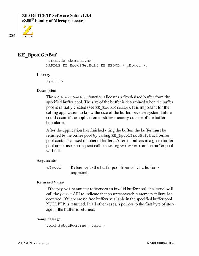
ZiLOG TCP/IP Software Suite v1.3.4eZ80® Family of Microprocessors
284
KE_BpoolGetBuf#include <kernel.h>HANDLE KE_BpoolGetBuf( KE_BPOOL * pBpool );
Librarysys.lib
Description
The KE_BpoolGetBuf function allocates a fixed-sized buffer from the specified buffer pool. The size of the buffer is determined when the buffer pool is initially created (see KE_BpoolCreate). It is important for the calling application to know the size of the buffer, because system failure could occur if the application modifies memory outside of the buffer boundaries.
After the application has finished using the buffer, the buffer must be returned to the buffer pool by calling KE_BpoolFreeBuf. Each buffer pool contains a fixed number of buffers. After all buffers in a given buffer pool are in use, subsequent calls to KE_BpoolGetBuf on the buffer pool will fail.
Arguments
Returned Value
If the pBpool parameter references an invalid buffer pool, the kernel will call the panic API to indicate that an unrecoverable memory failure has occurred. If there are no free buffers available in the specified buffer pool, NULLPTR is returned. In all other cases, a pointer to the first byte of stor-age in the buffer is returned.
Sample Usagevoid SetupRoutine( void )
pBpool Reference to the buffer pool from which a buffer is requested.
ZTP API Reference RM000809-0306

ZiLOG TCP/IP Software Suite v1.3.4Reference Manual
285
{KE_BPOOL * MyBpool;BYTE * pBuf;
/* * Create a buffer pool called “Test Pool” * containing 10 buffers each 500 bytes long. */MyBpool = KE_BpoolCreate( “Test Pool”, 10, 500 );
// Obain one of the buffers from the buffer pool..pBuf = KE_BpoolGetBuf( MyBpool );
if( pBuf == NULLPTR ){
kprintf( “Buffer pool is empty\n” );}else{
kprintf( “Obtained buffer %p\n”, pBuf );}
// Return the buffer to the buffer pool..KE_BpoolFreeBuf( pBuf );
}
See Also
KE_BpoolCreate KE_BpoolFreeBuf KE_BpoolDelete
RM000809-0306 Memory Management Functions
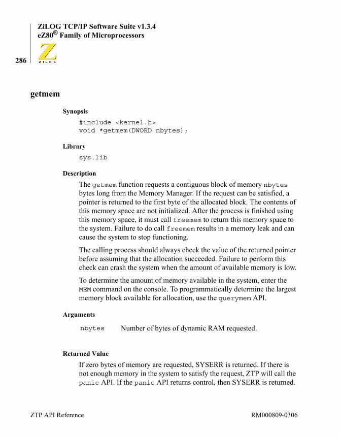
ZiLOG TCP/IP Software Suite v1.3.4eZ80® Family of Microprocessors
286
getmem
Synopsis#include <kernel.h>void *getmem(DWORD nbytes);
Librarysys.lib
Description
The getmem function requests a contiguous block of memory nbytes bytes long from the Memory Manager. If the request can be satisfied, a pointer is returned to the first byte of the allocated block. The contents of this memory space are not initialized. After the process is finished using this memory space, it must call freemem to return this memory space to the system. Failure to do call freemem results in a memory leak and can cause the system to stop functioning.
The calling process should always check the value of the returned pointer before assuming that the allocation succeeded. Failure to perform this check can crash the system when the amount of available memory is low.
To determine the amount of memory available in the system, enter the MEM command on the console. To programmatically determine the largest memory block available for allocation, use the querymem API.
Arguments
Returned Value
If zero bytes of memory are requested, SYSERR is returned. If there is not enough memory in the system to satisfy the request, ZTP will call the panic API. If the panic API returns control, then SYSERR is returned.
nbytes Number of bytes of dynamic RAM requested.
ZTP API Reference RM000809-0306

ZiLOG TCP/IP Software Suite v1.3.4Reference Manual
287
If the request is satisfied, ZTP returns a pointer to the first byte of the allo-cated memory block.
Sample Usagevoid SetupRoutine( void ){
BYTE * pData;
// Allocate 1000 bytes of memory
pData = getmem( 1000 );if( pData == (BYTE *) SYSERR ){
panic( "Memory request failed\n" );}else{
// Manipulate the memory block as required.pData[0] = 0x00;pData[999] = 0xFF;freemem( pData, 1000 );
}}
See Also
freemem
RM000809-0306 Memory Management Functions

ZiLOG TCP/IP Software Suite v1.3.4eZ80® Family of Microprocessors
288
freemem
Synopsis#include <kernel.h>SYSCALL freemem( void * pMem, DWORD size );
Librarysys.lib
Description
The freemem function returns a block of memory previously allocated by getmem to the Memory Manager. The size of the memory block must match the block size requested. Failure to perform this function results in memory corruption and/or a memory leak.
Arguments
Returned Value
If the parameters are valid, OK is returned. Otherwise, SYSERR is returned.
Sample Usagevoid SetupRoutine( void ){
BYTE *pData;// Allocate 1000 bytes of memorypData = getmem( 1000 );if( pData == (BYTE *) SYSERR ){
pMem Pointer to the first byte of a block of memory previously allocated by calling getmem.
size Number of bytes of memory in this block.
ZTP API Reference RM000809-0306

ZiLOG TCP/IP Software Suite v1.3.4Reference Manual
289
panic( "Memory request failed\n" );}else{
// Manipulate the memory block as requiredpData[0] = 0x00;pData[999] = 0xFF;if( freemem( pData, 1000 ) != OK ){ kprintf( "Problem releasing memory\n" );}
}}
See Also
getmem
RM000809-0306 Memory Management Functions

ZiLOG TCP/IP Software Suite v1.3.4eZ80® Family of Microprocessors
290
querymem
Synopsis#include <kernel.h>DWORD querymem( void );
Librarysys.lib
Description
The querymem function is used to determine the largest block of memory that can be allocated by a subsequent call to getmem.
Arguments
None.
Returned Value
The value returned by this function represents the size (in bytes) of the largest contiguous block of memory that can be allocated by calling get-mem.
Sample Usagevoid SetupRoutine( void ){
DWORD MaxSize;MaxSize = querymem();kprintf( "Largest memory block that can beallocated is %U bytes\n", MaxSize );
}
See Also
getmem
ZTP API Reference RM000809-0306

ZiLOG TCP/IP Software Suite v1.3.4Reference Manual
291
addmem
Synopsis#include <kernel.h>SYSCALL addmem(void * pMem, DWORD size);
Librarysys.lib
Description
The addmem function is used to release control of a contiguous block of memory to the ZTP Memory Manager. In effect, this transaction increases the size of the ZTP run-time heap.
When a ZTP project is compiled, ZDS II will define two variables that mark the boundaries of the run-time heap: _heapbot and _heaptop. For proper operation of ZTP, there must not be any discontinuities in this address range. However, if there are other unused blocks of memory that are noncontiguous with the _heapbot to _heaptop memory range, they can be added to the heap by using the addmem API.
Arguments
Returned Value
If the memory block is currently outside of the ZTP heap boundaries, it is added to the heap, and the ZTP heap boundaries are increased. In this case, OK is returned. In all other cases, SYSERR is returned.
pMem Pointer to the first byte of a block of contiguous memory memory block being given to the ZTP Memory Manager.
size Number of bytes of memory in this block.
RM000809-0306 Memory Management Functions

ZiLOG TCP/IP Software Suite v1.3.4eZ80® Family of Microprocessors
292
Sample Usagevoid SetupRoutine( void ){
/* * Add 64kb of memory to the ZTP heap starting * at 0x050000. This memory block must not * appear in the RAM address space of the ZDS II * project settings. */addmem( 0x050000, 0x010000 );
}
See Also
freemem, getmem
Message Port FunctionsA message port is a managed queue for passing scalar data between pro-cesses. The message port functions guarantee safe concurrent operations on the message port queue.
Message ports differ from the simpler mailbox functions in three ways. First, message ports are public resources. Only the mailbox owner can remove a message from a mailbox. In contrast, any process that carries the message port ID can remove a message from the port. Second, while a mailbox can only contain a single message, a message port can be made arbitrarily long. Third, message ports are protected by two semaphores. Therefore, if a process attempts to retrieve a message from an empty mes-sage port or post a message to a full message port, the calling process blocks on a semaphore. In the text that follows, posting of a message to the message port is protected by the producer semaphore and retrieval of a message from the message port is protected by the consumer semaphore.
As with mailbox messaging, a message port message is an arbitrary pointer (that is, of type void *) that pertains only to the processes that exchanges messages through the port.
ZTP API Reference RM000809-0306

ZiLOG TCP/IP Software Suite v1.3.4Reference Manual
293
There are only a finite number of message ports available in the ZTP sys-tem. The ZTP system internally requires the use of a message port for every TCP server device (such as the HTTP or TELNET servers, or other TCP servers created within user applications). In addition, the TCP multi-plexor requires the use of one message port. To see information about the number of message ports currently in use, use the port shell command.
To modify the number of message ports in the system, change the value of the NumPorts variable in the \conf\sys_conf.c file (see the discus-sion of the sys_conf.c file on page 56).
Table 17 provides a brief description of each of the ZTP message port functions. Table 17. Message Port Functions
KE_PortCount Counts messages queued to a port.
KE_PortCreate Creates a message port.
KE_PortDelete Deletes a message port.
KE_PortReceive Receives the next message from a port.
KE_PortReset Resets a port.
KE_PortSend Sends a message to a port.
KE_PortSendUnique Sends a message to a port, avoiding duplicate messages.
RM000809-0306 Message Port Functions

ZiLOG TCP/IP Software Suite v1.3.4eZ80® Family of Microprocessors
294
KE_PortCount
Synopsis#include <kernel.h>SYSCALL KE_PortCount( KE_MSG_PORT * pPort );
Librarysys.lib
Description
The KE_PortCount function returns the number of messages currently queued in the message port. If the port is full, the count also includes the number of messages waiting to be posted to the message port; that is, if the message port can contain ten messages, but five processes are blocked on the producer semaphore for this port, the count returned is fifteen.
Arguments
Returned Value
If the port ID is valid, the count of messages available through this port is returned. Otherwise, SYSERR is returned.
Sample Usagevoid SetupRoutine( void ){
MPID MessagePortID;INT16 Count;
/** Create a message port and place 2 messages on* the port.*/
pPort Message port ID.
ZTP API Reference RM000809-0306

ZiLOG TCP/IP Software Suite v1.3.4Reference Manual
295
MessagePortID = KE_PortCreate( 5 );if( MessagePortID == NULLPTR ){ kprintf( "Unable to pcreate message port.\n" );return;}KE_PortSend( MessagePortID, (HANDLE)0x112233 );KE_PortSend( MessagePortID, (HANDLE)0x664422 );// How many messages are available on the port?Count = KE_PortCount( MessagePortID );kprintf("%d messages have been posted to the message
port\n", Count);}
See Also
KE_PortCreate KE_PortSend
KE_PortReceive KE_PortDelete
RM000809-0306 Message Port Functions
ZiLOG TCP/IP Software Suite v1.3.4eZ80® Family of Microprocessors
296
KE_PortCreate
Synopsis#include <kernel.h>KE_MSG_PORT * KE_PortCreate( WORD NumMsgs );
Librarysys.lib
Description
The KE_PortCreate function allocates and initializes an unused mes-sage port from the system defined MsgPortTable buffer pool. The allo-cated port ID is used as a parameter on all other message port functions; therefore KE_PortCreate must be called prior to using any other message port function. The message port is configured to contain, at most, count messages. count must be an integer value greater than 0.
The KE_PortCreate API assumes that count will always be greater than zero. Message port operation is undefined if the port is created with the NumMsgs parameter set to 0; tis setting is likely to result in system failure.
The count parameter is used to initialize the producer semaphore. There-fore, if no process retrieves messages from the port, up to count mes-sages can be posted to the port before the process(es) sending messages to the port can block on the producer semaphore. Regardless of the size of the message port, the consumer semaphore is always initialized to zero to indicate that the port is initially empty. Every time a message is posted to a message port using the KE_PortSend API, the consumer count is incre-mented by 1. Every time a message is retrieved from a message port, the producer semaphore count is increased by 1.
Arguments
NumMsgs Specifies the maximum number of messages the port can contain.
Note:
ZTP API Reference RM000809-0306

ZiLOG TCP/IP Software Suite v1.3.4Reference Manual
297
Returned Value
If a message port can be allocated, a reference to the message port is returned. This value must be accessible to all processes requiring access to the message port. This datum can be exchanged using a global variable, a mailbox message, or as a parameter during process creation.
If a message port cannot be allocated NULLPTR is returned.
Sample Usagevoid SetupRoutine( void ){
MPID MessagePortID;
/** Create a message port and place a message on the* port.* This message port is able to contain a maximum* of 5 messages.*/
MessagePortID = KE_PortCreate( 5 );if( MessagePortID == NULLPTR ){
kprintf( "Unable to pcreate message port.\n" );return;
}KE_PortSend( MessagePortID, (HANDLE)0x112233 );
}
See Also
KE_PortDelete KE_PortSend KE_PortReceive
RM000809-0306 Message Port Functions
ZiLOG TCP/IP Software Suite v1.3.4eZ80® Family of Microprocessors
298
KE_PortDelete
Synopsis#include <kernel.h>SYSCALL KE_PortDelete(KE_MSG_PORT * pPort, SYSCALL (*Dispose)(HANDLE));
Librarysys.lib
Description
The KE_PortDelete function is called to return the indicated message port to the system for subsequent allocation using the KE_PortCreate function. System resources, such as the producer and consumer sema-phores associated with the message port, are also freed. As a result, any process blocked on these semaphores is transitioned to the Ready list. These processes receive SYSERR status codes in response to the message port API functions they called at the time they blocked, because this func-tion invalidates the port ID.
Example: if a process calls KE_PortSend on a full message port, the pro-cess blocks on the producer semaphore. If the message port is deleted (as a result of the KE_PortDelete API being called) before the waiting pro-cess can post its message, the KE_PortSend call returns with a status code of SYSERR because the message port ID used on the call is no longer valid. This situation applies even if the same message port is real-located for use (via KE_PortCreate) before the blocked process becomes current.
Because every message in the port pertains only to the sender and recipi-ent of the message, the message can represent a dynamically-allocated resource. Resources associated with these messages must be freed when the message port is deleted or else these resources can be lost. The dis-pose parameter allows the calling process to identify a callback routine that is executed for each message remaining on the message port at the
ZTP API Reference RM000809-0306

ZiLOG TCP/IP Software Suite v1.3.4Reference Manual
299
time KE_PortDelete is called. The function prototype for the dispose parameter is:SYSCALL dispose(HANDLE pMessage );
The pMessage parameter is the same as the datum that was originally posted to the message port via the KE_PortSend API. Even though the prototype specifies that the dispose parameter should return an integer value, the system currently does not use this value. For forward compati-bility, the dispose parameter should always return OK. The dispose callback is not executed for those messages that are pending on the pro-ducer semaphore. Resources associated with messages that cannot be posted to the message port should be freed by the process that attempted to post the message if that process receives a SYSERR status in response to the KE_PortSend or KE_PortSendUnique APIs. If there are no dynamic resources associated with the messages in this message port, the caller can specify NULLPTR as the dispose handler, in which case the system does not attempt to call the handler.
Arguments
Returned Value
If the specified port ID is valid, OK is returned. Otherwise, SYSERR is returned.
Sample UsageSYSCALL PortDispose(HANDLE pMessage ){
kprintf( "Freeing resources associated with message %p\n", pMessage );
return( OK );}
pPort Message port ID.
dispose Callback function pointer for returning resources.
RM000809-0306 Message Port Functions
ZiLOG TCP/IP Software Suite v1.3.4eZ80® Family of Microprocessors
300
void SetupRoutine( void ){
MPID MessagePortID;
/** Create a message port and place 2 messages on* the port.* This message port is able to contain a maximum* of 5 messages.*/
MessagePortID = KE_PortCreate( 5 );if( MessagePortID == NULLPTR ){
kprintf( "Unable to pcreate message port.\n" );return;
}KE_PortSend( MessagePortID, (HANDLE)0x112233 );KE_PortSend( MessagePortID, (HANDLE)0x445566 );
/** Normally, one can create a process to process* messages on the port. However in this example* we immediately delete it.*/
KE_PortDelete( MessagePortID, PortDispose );}
See Also
KE_PortReceive KE_PortSend KE_PortSendUnique
ZTP API Reference RM000809-0306

ZiLOG TCP/IP Software Suite v1.3.4Reference Manual
301
KE_PortReceive
Synopsis#include <kernel.h>HANDLE KE_PortReceive(KE_MSG_PORT * pPort );
Librarysys.lib
Description
A process calls the KE_PortReceive function to retrieve a message datum previously posted to the specified message port.
The system uses two semaphores to protect access to the message port. These semaphores are referred to as the producer and consumer sema-phores. The semaphore count of the consumer semaphore exactly matches the number of messages available for reception through the port. Each time a process calls KE_PortReceive to obtain the next message from the port, it must first acquire the consumer semaphore. Therefore, the calling process blocks on the consumer semaphore when the message port is empty.
If a message is available, the KE_PortReceive function returns an arbi-trary pointer (that is, of type void *) representing the message datum that was posted to the message port by a previous call to KE_PortSend or KE_PortSendUnique. As a result of obtaining a message from the message port, the producer semaphore is signalled, thereby allowing a process blocked on the producer semaphore to add a new message to the port.
Arguments
pPort Message port ID.
RM000809-0306 Message Port Functions

ZiLOG TCP/IP Software Suite v1.3.4eZ80® Family of Microprocessors
302
Returned Value
When successful, the KE_PortReceive function returns the message value as an arbitrary pointer. Upon failure, SYSERR is returned.
If a process sends a message of FFFFFFh (SYSERR) to a message port, then the returned value from the KE_PortReceive function is FFFFFFh (SYSERR). In this case, the receiving process cannot distinguish FFFFFFh from SYSERR. Therefore, ZiLOG recommends against send-ing a message with the value FFFFFFh. This situation does not occur when using mailboxes.
Sample UsagePROCESS SampleProcess(PID PortID);void SetupRoutine( void ){
PID SamplePID;MPID MessagePortID;
/** Create a message port and place a message on the* port.*/
MessagePortID = KE_PortCreate( 5 );if( MessagePortID == NULLPTR ){
kprintf( "Unable to pcreate message port.\n" );return;
}KE_PortSend( MessagePortID, (HANDLE)0x112233 );
/* Tell the Sample process which message port touse */
SamplePID =
Note:
ZTP API Reference RM000809-0306
ZiLOG TCP/IP Software Suite v1.3.4Reference Manual
303
KE_TaskCreate((procptr)SampleProcess,1024,20,"Sample Process",1, MessagePortID);
KE_TaskResume( SamplePID );
/** The sample process is waiting for a message,* Wait 10 seconds, then send it another message.*/
KE_TaskSleep(10);KE_MBoxSend(SamplePID, (HANDLE)0x664422);
}
/* This is the sample process created by the* SetupRoutine*/
PROCESS SampleProcess(PID PortID){
HANDLE Message;while(1){
kprintf( "Waiting for a message\n" );Message = KE_PortReceive(PortID);kprintf( "Message received: %p\n", Message );
}return(OK);
}
See Also
KE_PortSend KE_PortSendUnique KE_PortCreate
KE_PortDelete KE_PortCreate
RM000809-0306 Message Port Functions
ZiLOG TCP/IP Software Suite v1.3.4eZ80® Family of Microprocessors
304
KE_PortReset
Synopsis#include <kernel.h>SYSCALL KE_PortReset( KE_MSG_PORT * pPort, SYSCALL (*Dispose)(HANDLE));
Librarysys.lib
Description
The KE_PortReset function is called to flush the message port. All mes-sages within the port are discarded, processes blocked on either the pro-ducer or consumer semaphore are returned to the Ready state, and the message port is reinitialized.
The actions performed by KE_PortReset are nearly identical to those performed by KE_PortDelete. The only difference between these two functions is that KE_PortReset does not return the specified message port to the system for subsequent allocation.
For more information, see the KE_PortDelete API description on page 298.
Arguments
Returned Value
If the specified port ID is valid, OK is returned. Otherwise, SYSERR is returned.
pPort Message port ID.
Dispose Callback function pointer for returning resources.
ZTP API Reference RM000809-0306
ZiLOG TCP/IP Software Suite v1.3.4Reference Manual
305
Sample UsagePROCESS SampleProcess(MPID PortID);void SetupRoutine( void ){
PID SamplePID;MPID MessagePortID;
/** Create a message port and place a message on the* port.*/
MessagePortID = KE_PortCreate( 5 );if( MessagePortID == NULLPTR ){
kprintf( "Unable to pcreate message port.\n" );return;
}KE_PortSend ( MessagePortID, (HANDLE)0x112233 );KE_PortSend ( MessagePortID, (HANDLE)0x664422 );// Reset the message portKE_PortReset( MessagePortID, NULLPTR );
/* Tell the Sample process which message port touse*/
SamplePID =
KE_TaskCreate((procptr)SampleProcess,1024,20,"Sample Process",1, MessagePortID);
KE_TaskResume( SamplePID );
/** The sample process is waiting for a message,* and then send it another message. Wait 10* seconds because the message port is reset,* this is the only message the sample process can
RM000809-0306 Message Port Functions
ZiLOG TCP/IP Software Suite v1.3.4eZ80® Family of Microprocessors
306
* retry.*/
KE_TaskSleep(10);KE_MBoxSend(SamplePID, (HANDLE)0x333333);}
/* This is the sample process created by the* SetupRoutine*/
PROCESS SampleProcess(MPID PortID){
HANDLE Message;while(1){kprintf( "Waiting for a message\n" );Message = KE_PortReceive(PortID);kprintf( "Message received: %p\n", Message );}return(OK);
}
See Also
KE_PortDelete KE_PortCreate
KE_PortSend KE_PortReceive
ZTP API Reference RM000809-0306
ZiLOG TCP/IP Software Suite v1.3.4Reference Manual
307
KE_PortSend
Synopsis#include <kernel.h>SYSCALL KE_PortSend( KE_MSG_PORT * pPort, HANDLE Msg );
Librarysys.lib
Description
A process calls the KE_PortSend function to post the specified message to the specified message port. Messages are arbitrary pointers (that is, of type void *) that pertain only to the sender and the recipient of the mes-sage.
The system uses two semaphores to protect access to every message port. These semaphores are referred to as the producer and consumer sema-phores. The semaphore count of the producer semaphore matches the ini-tial size of the message port specified on the KE_PortCreate call. Each time a process calls KE_PortSend to post a message to the port, it must first acquire the producer semaphore. Therefore, the calling process blocks on the producer semaphore when the message port is full.
If a message can be posted to the indicated port, the consumer semaphore is signalled to allow a process blocked on the consumer semaphore to retrieve a message from the port. If the calling process blocks on the pro-ducer semaphore, it is transitioned back to the Ready list when another process retrieves a message from the port. Processes are returned to the Ready list in the same order in which they are transitioned to the Blocked list to wait for the producer semaphore.
If a process sends a message of FFFFFFh (SYSERR) to a message port, then the process that calls KE_PortReceive to obtain the message receives a returned value from the KE_PortReceive call of FFFFFFh (SYSERR). In this case, the receiving process cannot distinguish
Note:
RM000809-0306 Message Port Functions

ZiLOG TCP/IP Software Suite v1.3.4eZ80® Family of Microprocessors
308
FFFFFFh from SYSERR. Therefore, ZiLOG recommends against send-ing a message with the value FFFFFFh. This situation does not occur when using mailboxes.
If a message is successfully posted to a specified port, and a process with a scheduling priority numerically larger than the scheduling priority of the calling process is blocked on the consumer semaphore, then the Scheduler preempts the current process to resume execution of the higher-priority process.
Arguments
Returned Value
If a message is successfully posted to the indicated message port, OK is returned. If the pPort parameter is invalid, or if the message port is deleted (via KE_PortDelete) or reset (via KE_PortReset) before the process calling KE_PortSend is able to add its message to the port, this function returns SYSERR.
Sample UsagePROCESS SampleProcess(MPID PortID);void SetupRoutine( void ){
PID SamplePID;MPID MessagePortID;
/** Create a message port and place a message on the* port.*/
pPort Message port ID.
msg Message datum to send to the port.
ZTP API Reference RM000809-0306

ZiLOG TCP/IP Software Suite v1.3.4Reference Manual
309
MessagePortID = KE_PortCreate( 5 );if( MessagePortID == NULLPTR ){
kprintf( "Unable to pcreate message port.\n" );return;
}KE_PortSend( MessagePortID, (HANDLE)0x112233 );// Set our process priority to a value of 20KE_TaskChangePrio(KE_TaskGetPrio(), 20 );// Tell the Sample process which message port to use SamplePID =KE_TaskCreate((procptr)SampleProcess,1024,25,"Sample
Process",1, MessagePortID);KE_TaskResume( SamplePID );
/** Note that the priority of the process consuming* the port* messages is higher than our priority.* Therefore, every time* we send a message to the port we are preempted by* the sample process.*/
kprintf( "Sending another message\n" );KE_PortSend( MessagePortID, (HANDLE)0x222222 );kprintf( "Done\n" );kprintf( "Sending another message\n" );KE_PortSend( MessagePortID, (HANDLE)0x333333 );kprintf( "Done\n" );
/** Now set our priority of the sample process below* ours.*/
KE_TaskChangePrio( SamplePID, 19 );
RM000809-0306 Message Port Functions

ZiLOG TCP/IP Software Suite v1.3.4eZ80® Family of Microprocessors
310
kprintf( "Sending another message\n" );KE_PortSend( MessagePortID, (HANDLE)0x444444 );kprintf( "Done\n" );kprintf( "Sending another message\n" );KE_PortSend( MessagePortID, (HANDLE)0x555555 );kprintf( "Done\n" );KE_TaskSleep(10);}
/* This is the sample process created by theSetupRoutine*/
PROCESS SampleProcess(MPID PortID){
HANDLE Message;while(1){
kprintf( "Waiting for a message\n" );Message = KE_PortReceive(PortID);kprintf( "Message received: %p\n", Message );
}return(OK);
}
See Also
KE_PortSendUnique KE_PortReceive
KE_PortCreate KE_PortDelete
ZTP API Reference RM000809-0306

ZiLOG TCP/IP Software Suite v1.3.4Reference Manual
311
KE_PortSendUnique
Synopsis#include <kernel.h>SYSCALL KE_PortSendUnique(KE_MSG_PORT * pPort, HANDLE Msg );
Librarysys.lib
Description
The behavior of the KE_PortSendUnique function is almost identical to that of the KE_PortSend API. However, this type of send function is unique in that it prevents duplicate copies of the same message from being posted to the port. Therefore, the KE_PortSendUnique function returns OK without adding a second copy of the message to the indicated port if the port already contains the specified message. For more informa-tion, see the description of the KE_PortSend API on page 307.
If a process sends a message of FFFFFFh (SYSERR) to a message port, then the returned value from this function is FFFFFFh (SYSERR). In this case, the receiving process cannot distinguish FFFFFFh from SYSERR. Therefore, ZiLOG recommends against sending a message with the value FFFFFFh. This situation does not occur when using mail-boxes.
If a message is successfully posted to a specified port, and a process with a scheduling priority numerically larger than the scheduling priority of the calling process is blocked on the consumer semaphore, then the Scheduler preempts the current process to resume execution of the higher-priority process.
Note:
RM000809-0306 Message Port Functions

ZiLOG TCP/IP Software Suite v1.3.4eZ80® Family of Microprocessors
312
Arguments
Returned Value
If a message is successfully posted to an indicated message port (or the port already contains a copy of this message datum), OK is returned. If the pPort parameter is invalid, or if the message port is deleted (KE_PortDelete) or reset (via KE_PortReset) before the process calling KE_PortSend is able to add its message to the port, this function returns SYSERR.
Sample Usagevoid SetupRoutine( void ){
MPID MessagePortID;INT16 Count;
/** Create a message port and place messages on the* port.*/
MessagePortID = KE_PortCreate( 5 );if( MessagePortID == NULLPTR ){
kprintf( "Unable to pcreate message port.\n" );return;
}KE_PortSendUnique( MessagePortID, (HANDLE)0x112233
);KE_PortSendUnique( MessagePortID, (HANDLE)0x112233
);KE_PortSend( MessagePortID, (HANDLE)0x664422 );
pPort Message port ID.
msg Message datum to send to the port.
ZTP API Reference RM000809-0306

ZiLOG TCP/IP Software Suite v1.3.4Reference Manual
313
KE_PortSend( MessagePortID, (HANDLE)0x112233 );// How many messages are available on the port?Count = KE_PortCount( MessagePortID );kprintf("%d messages have been posted to themessage port\n", Count);
}
See Also
Miscellaneous OS FunctionsThis section describes the ZTP operating system utility functions. Table 18 provides a brief description of each of these functions.
KE_PortSendUnique KE_PortReceive
KE_PortCreate KE_PortDelete
Table 18. Utility Functions
set_evec Sets an Interrupt vector.
kprintf Displays a formatted message on the console.
panic Forces a system halt.
KE_DisablePreempt Prevents kernel from preempting the current task.
KE_EnablePreempt Enables the preemption.
KE_RestorePreempt Restores the preemptive state.
KE_IsrResched Resumes the execution of the interrupt task.
KE_KernelInit Initialize the ZTP kernel.
KE_TaskSetTime Sets the system time-of-day clock from a timestamp.
KE_TaskGetTime Obtain a timestamp representing the system’s current time of day.
RM000809-0306 Miscellaneous OS Functions

ZiLOG TCP/IP Software Suite v1.3.4eZ80® Family of Microprocessors
314
set_evec
Synopsis#include <kernel.h>void set_evec( WORD vector, void (*handler)(void) );
Library
One of: eZ80190.lib, eZ80L92.lib, eZ80F91.lib, eZ80F92.lib, or eZ80F93.lib.
Description
The set_evec routine sets the specified handler as a routine that is exe-cuted when an interrupt corresponding to its vector occurs. This routine places the handler’s starting address into the system’s interrupt vector table. For more information about eZ80® interrupt handling, refer to the appropriate eZ80® Product Specification for your target processor.
Before enabling interrupts on a peripheral device, call this function to replace the system’s default interrupt handler with your own ISR. For additional information about ZTP interrupt handling, see the How to Use Interrupts section on page 89.
Arguments
Returned Value
None.
Sample Usageextern void MyISR( void );
vector The interrupt vector for which a handler is being defined.
handler The starting address of the routine to execute when the ISR occurs.
ZTP API Reference RM000809-0306
ZiLOG TCP/IP Software Suite v1.3.4Reference Manual
315
void SetupRoutine( void ){
/* * Replace system default interrupt handler for * Timer 2 with MyISR. */KE_DisableMI();set_evec( IV_TMR2, MyISR );KE_EnableMI();
/* * It is now safe to program Timer 2 to generate * interrupts. See the appropriate eZ80 Product * Specification for details. */
}
See Also
set_evec KE_IsrResched
KE_ExitISR KE_EnterISR
RM000809-0306 Miscellaneous OS Functions

ZiLOG TCP/IP Software Suite v1.3.4eZ80® Family of Microprocessors
316
kprintf
Synopsis#include <kernel.h>SYSCALL kprintf(char * msg, ... );
Librarysys.lib
Description
The kprintf function displays the given message text on the console. The message text can contain plain text characters as well as an arbitrary number of conversion specifiers. A conversion specifier consists of a per-cent sign (%) followed by an optional format control flag, an optional padding character, an optional minimum field width, an optional maxi-mum field width, an optional type length modifier and a conversion char-acter to indicate the conversion to be performed. For each conversion specifier included in the message text, a corresponding argument must be included in the variable argument list.
The following format control flags may be used:
For conversions with numeric arguments (%b, %B, %d, %D, %o, %O, %p, %P, %u, %U, %x, %X), the output is normally padded on the left with blank spaces when right justification is used and the output is shorter than the minimum field width. If you wish the output to be padded with zeros, a padding character of 0 may precede the minimum field width specifier. When using left justification, padding appears after the value. This may cause confusion when displayed. For example, if you left justify the value 123 in a minimum field width of 5 characters, and specify the padding character to be 0, the value displayed is 12300. Only a 0 charac-
- Indicates that the conversion output is to be left justified. If this flag is omitted, the output is right justified.
ZTP API Reference RM000809-0306

ZiLOG TCP/IP Software Suite v1.3.4Reference Manual
317
ter may be specified as the padding character. If a padding character is not specified, a space character is used for padding.
The minimum field width specifier indicates the number of character positions this conversion should occupy in the output stream. By default, only the minimum number of characters required for the conversion is used. For example, the minimum number of characters required to display the value 00 is 1 (displayed as 0). However, by using a minimum field width specifier and padding, this value could be displayed as 00000. Nor-mally the minimum field width is specified as a positive number (for example, in the conversion specifier %5u, the minimum field width is 5). However, if you specify the minimum field width as an asterisk (*), then the minimum field width immediately precedes the argument value in the variable argument list.
When performing string conversions (%s), you can also specify a maxi-mum field width specifier by adding a period character (.) immediately after the minimum field width specifier, or you can add the % sign if the a minimum field width is not being used. This ensures that no more than the maximum field width characters from the string is included in the display. If the corresponding string argument is longer than the maximum field width specifier, its output is truncated when the maximum field width is reached.
Conversion with numeric arguments (%b, %d, %o, % u, %x) are always treated as 16-bit quantities. %D, %U, %X, %ld, %lu, or %lx are used to display 32-bit values. %p and %P are used to display 24-bit values. The displayed value is in hexadecimal form and is most appropriate for dis-playing the value of C pointers or memory addresses.
ZTP recognizes the following conversion specifiers:
RM000809-0306 Miscellaneous OS Functions

ZiLOG TCP/IP Software Suite v1.3.4eZ80® Family of Microprocessors
318
ZTP recognizes the following numeric conversion specifiers:
Arguments
c Displays the ASCII code equivalent to the corresponding 8-bit argument. For example, if the argument value is 112241h, the ASCII character A is displayed on the console corresponding to the 8-bit code 41h.
s Displays the character string pointed to by the corresponding argu-ment at the point the %s conversion specifier is encountered in the msg text passed to the kprintf function.
d/D The corresponding argument is displayed as a 16-bit signed integer (%d) or as a 32-bit signed integer (%D or %ld).
u/U The corresponding argument is displayed as a 16-bit unsigned inte-ger (%u) or as a 32-bit unsigned integer (%U or %lu).
o/O The corresponding argument is displayed in octal notation (base 8) as a 16-bit quantity (%o) or as a 32-bit quantity (%O or %lo) .
x/X The corresponding argument is displayed in hexadecimal notation (base 16) as a 16-bit quantity (%x), or as a 32-bit quantity (%X or %lx).
b/B The corresponding argument is displayed in binary notation (base 2) as a 16-bit quantity (%b) or as a 32-bit quantity (%B or %lb).
p The corresponding argument is displayed as a 24-bit pointer value.
msg Pointer to a NULL terminated string of characters to be displayed on the console, which may contain 0 or more conversion specifiers.
... Argument values to be used with the corresponding con-version specifiers in the msg text.
ZTP API Reference RM000809-0306

ZiLOG TCP/IP Software Suite v1.3.4Reference Manual
319
Returned Value
kprintf always returns OK.
Sample Usagevoid SetupRoutine( void ){
unsigned short int Value1 = 123;short int Value2 = -123;char TestStr[] = "Hello world.";
kprintf( "Value1 in decimal %d, binary %b, octal%o hexadecimal %x\n", Value1, Value1, Value1,Value1 );
kprintf( "Value1 padded with 0 in a 6 character field: *%06u*\n", Value1 );
kprintf( "Value1 left justified in a 6 characterfield: *%-6u*\n", Value1 );
kprintf( "Value2 as signed decimal %d, as unsigneddecimal %u, as hexadecimal %x\n", Value2, Value2,Value2 );
kprintf( "Test string is %s\n", TestStr );
kprintf( "Test string left justified *%-20s*\n",TestStr );
kprintf( "Test String right justified *%20s*\n",TestStr );
kprintf( "Test string in a maximum field of 5characters *%.5s*\n", TestStr );
}
RM000809-0306 Miscellaneous OS Functions

ZiLOG TCP/IP Software Suite v1.3.4eZ80® Family of Microprocessors
320
panic
Synopsis#include <kernel.h>void panic(char * msg,...);
Librarysys.lib
Description
The panic function displays the given message text on the console, dis-ables maskable interrupts and then loops endlessly; effectively halting the system. The message text can contain plain text characters and up to 3 conversion specifiers. A conversion specifier consists of a per cent sign (%) followed by an optional format control flag, an optional padding character, an optional minimum field width, an optional maximum field width, an optional type length modifier and a conversion character to indicate the conversion to be performed. For more information about the conversion specifiers supported by ZTP, see the description of kprintf on page 316.
The panic function is intended to be called when an error is detected that is so severe that the system can either not recover from the error or cannot continue to operate reliably.
Source code to the panic function can be found in the \conf\panic.c file. This file can be included in your project and modified as appropriate.
Arguments
msg Pointer to a NULL terminated string of characters to be displayed on the console including up to 3 conversion specifiers.
... Argument values to be used the conversion specifiers in the msg text.
ZTP API Reference RM000809-0306

ZiLOG TCP/IP Software Suite v1.3.4Reference Manual
321
Returned Value
None.
Sample Usagevoid SetupRoutine( void ){
BYTE * pData;DWORD Size;
Size = querymem();if( Size < 1000 ){ panic( "Only %U bytes of memory are left in the
system\n", Size );}
// Allocate 1000 bytes of memorypData = getmem( 1000 );
}
See Also
kprintf
RM000809-0306 Miscellaneous OS Functions
ZiLOG TCP/IP Software Suite v1.3.4eZ80® Family of Microprocessors
322
KE_DisablePreempt
Synopsis#include <task.h>BYTE KE_DisablePreempt(void);
Librarysys.lib
Description
ZTP is a preemptive kernel. Therefore, when the time slice of a task expires, the OS forcibly removes the currently executing task from the CPU and selects a new task for execution. Similarly, when the current executing task calls a ZTP API that causes a task of higher priority to become ready, the current task is removed from the CPU and a context switch occurs. These are both examples of preemption. Another way that a task can get preempted is, if an interrupt occurs and the ISR schedules an interrupt task whose priority is equal to a greater than the priority of the current task.
The KE_DisablePreempt API prevents the kernel from preempting the current task until the current task performs either one of the following:
• Calls a ZTP API that causes the task to block (e.g., KE_TaskSleep, KE_TaskSuspendCur or acquiring a semaphore that has not been signalled).
• Calls KE_RestorePreempt or KE_EnablePreempt API
Note that while preemption is disabled, maskable interrupts are still pro-cessed by the CPU. Therefore, by using the KE_DisablePreempt and KE_RestorePreempt calls a task can implement a critical section with-out increasing the system’s interrupt latency. In contrast, using KE_CriticalBegin/KE_CriticalEnd or KE_DisableMI/
ZTP API Reference RM000809-0306

ZiLOG TCP/IP Software Suite v1.3.4Reference Manual
323
KE_EnableMI leave the maskable interrupts disabled while the current task executes the code within the critical section.
If a maskable interrupt occurs while preemption is disabled, and the ISR uses the KE_IsrResched API to schedule the interrupt task for execu-tion, then the interrupt task will not be able to run until the current task reenables preemption through either of the methods mentioned above. Therefore, disabling preemption for long period of time should be avoided due to possible data loss.
The value returned from the KE_DisablePreempt API represents the preemption state of the task prior to calling the KE_DisablePreempt API. This value must be passed to the KE_RestorePreempt routine to restore the preemption state in effect when the task calls KE_DisablePreempt API. If the task does not nest KE_DisablePreempt calls, then it can call KE_EnablePreempt to end the critical section instead of calling KE_RestorePreempt.
Within a critical section implemented using the KE_DisablePreempt and KE_EnablePreempt or KE_RestorePreempt APIs, it is permissi-ble to call any kernel API. If the called API does not cause the calling pro-cess to block, the kernel will not preempt the current task while preemption is disabled. However, if the called API causes the calling task to block, the kernel will block the caller and context switch to another task.
As an example, if a task disables preemption and then calls the KE_SemRelease API, a task of possibly higher priority could be transi-tioned to the Ready list. If this task occurs with preemption enabled, the kernel transitions the currently executing task to the Ready list and con-text switches to the task of higher priority (that is, the current task is pre-empted). When preemption is disabled, the kernel will still transition the task of higher priority that was blocked on the semaphore to the Ready list, but the kernel will not preempt the caller. Contrast this to the case wherein a call is made to KE_SemAcquire while preemption is disabled. If the semaphore is not in a signalled state, the kernel must block the
RM000809-0306 Miscellaneous OS Functions

ZiLOG TCP/IP Software Suite v1.3.4eZ80® Family of Microprocessors
324
caller and context switch to some other task. If this block is not per-formed, the system will deadlock.
After returning from the kernel API that resulted in a context switch (that is, upon return from an API that caused the caller to block), the task is protected again from preemption until either of the conditions discussed above occur.
Arguments
None.
Returned Value
The value returned represents the task’s preemption state prior to calling this API. A non-zero value is returned if preemption was already disabled prior to calling KE_DisablePreempt. Otherwise, a zero is returned indi-cating that the current task can be preempted.
Sample UsageDWORD GlobalValue = 0x11223344;void SetupRoutine( void ){ BYTE PreemptState;
PreemptState = KE_DisablePreempt(); /*
* Preemption has now been disabled. The kernel will* not switch to another task until preemption is* either implicitly or explicitly reenabled.* While preemption is disabled, maskable interrupts * will still serviced by the CPU, but the interrupt * task will not execute until preemption has been* reenabled.* Keep the length of this block short.*/
if( GlobalValue == 0xFFFFFFFF ) {
ZTP API Reference RM000809-0306

ZiLOG TCP/IP Software Suite v1.3.4Reference Manual
325
GlobalValue = 0x11223344; }
KE_RestorePreempt( PreemptState );}
See Also
KE_EnablePreempt KE_RestorePreempt
RM000809-0306 Miscellaneous OS Functions
ZiLOG TCP/IP Software Suite v1.3.4eZ80® Family of Microprocessors
326
KE_EnablePreempt
Synopsis#include <task.h>void KE_EnablePreempt(void);
Librarysys.lib
Description
ZTP is a preemptive kernel. Therefore, when the time slice of a task expires, the OS will forcibly remove the currently executing task from the CPU and select a new task for execution. Similarly, when the currently executing task calls a ZTP API that causes a task of higher priority to become ready, the current task is removed from the CPU and a context switch occurs. These are both examples of preemption. Another way that a task can become preempted is if an interrupt occurs and the ISR sched-ules an interrupt task for which the priority is equal to or greater than the priority of the current task.
A task can use the KE_DisablePreempt API to prevent the kernel from preempting the current task. One way to reenable preemption is to call this API (see the description of KE_DisablePreempt on page 322 for more information).
If calls to KE_DisablePreempt are nested, a single call to KE_EnablePreempt reenables the preemption. Before returning from this function, the kernel checks to see if any higher priority tasks were scheduled for execution while preemption was disabled. If there are any such tasks, the calling task is preempted.
Arguments
None.
Note:
ZTP API Reference RM000809-0306
ZiLOG TCP/IP Software Suite v1.3.4Reference Manual
327
Returned Value
None.
Sample UsageDWORD GlobalValue = 0x11223344;void SetupRoutine( void ){ KE_DisablePreempt(); /*
* Preemption has now been disabled. The kernel will* not switch to another task until preemption is* either implicitly or explicitly reenabled.* While preemption is disabled, maskable interrupts * will still serviced by the CPU, but the interrupt * task will not execute until preemption has been* reenabled.* Keep the length of this block short.*/
if( GlobalValue == 0xFFFFFFFF ) {
GlobalValue = 0x11223344; }
KE_EnablePreempt();}
See Also
KE_DisablePreempt KE_RestorePreempt
RM000809-0306 Miscellaneous OS Functions

ZiLOG TCP/IP Software Suite v1.3.4eZ80® Family of Microprocessors
328
KE_RestorePreempt
Synopsis#include <task.h>void KE_RestorePreempt(BYTE PreemptState);
Librarysys.lib
Description
ZTP is a preemptive kernel. Therefore, when the time slice of the task expires, the OS forcibly removes the current executing task from the CPU and selects a new task for execution. Similarly, when the current execut-ing task calls a ZTP API that causes a task of higher priority to become ready, the current task is removed from the CPU and a context switch occurs. These are both examples of preemption. Another way that a task can get preempted is, if an interrupt occurs and the ISR schedules an interrupt task whose priority is equal to or greater than the priority of the current task.
A task can use the KE_DisablePreempt API to prevent the kernel from preempting the current task. After calling KE_DisablePreempt, a task may call the KE_EnablePreempt API to reenable preemption. However, in some cases where a task disables preemption and then calls another routine that also disables preemption (nested KE_DisablePreempt calls) the called routine should use KE_RestorePreempt to restore the preemption state that was in effect prior to the call to the inner routine. In this way, when control returns to the calling function, its preempt state is restored to the value it assumed was in effect when it called the inner rou-tine.
If the value passed to this routine indicates that preemption should be reenabled, then prior to returning control to the caller a check is per-formed to see if any equal or higher priority tasks are scheduled for exe-cution while preemption is disabled. Then the calling task is preempted.
ZTP API Reference RM000809-0306

ZiLOG TCP/IP Software Suite v1.3.4Reference Manual
329
Arguments
If this value is 0, then the API reenables preemption.
Returned Value
None.
Sample UsageDWORD GlobalValue = 0x11223344;void SetupRoutine( void ){ BYTE PreemptState;
PreemptState = KE_DisablePreempt(); /*
* Preemption has now been disabled. The kernel will* not switch to another task until preemption is* either implicitly or explicitly reenabled.* While preemption is disabled, maskable interrupts
are still serviced by the CPU, but the interrupt task are not executed until preemption is Reenabled.
* Keep the length of this block short.*/
if( GlobalValue == 0xFFFFFFFF ) {
GlobalValue = 0x11223344; }KE_RestorePreempt( PreemptState );}
See Also
KE_EnablePreempt KE_DisablePreempt
RM000809-0306 Miscellaneous OS Functions

ZiLOG TCP/IP Software Suite v1.3.4eZ80® Family of Microprocessors
330
KE_IsrResched
Synopsis#include <task.h>void KE_IsrResched(PID IsrTask);
This function is only available to assembly level ISR routines. Load the IY register with the Process ID (PID) value of the interrupt task to be resumed prior to calling this function. Only the value of the IX register will be preserved across the function call.
Librarysys.lib
Description
To maintain low system interrupt latency, it is recommended that interrupt service routines only disable the source of the hardware interrupt and allow a companion interrupt task to perform the majority of the process-ing required to service the interrupt. After disabling the source of the interrupt, an assembly ISR should call the KE_IsrResched API to resume execution of the interrupt task.
The assembly ISR and interrupt task must carefully coordinate when interrupts are enabled to ensure effective servicing of the interrupt. One strategy for doing this is to ensure that when the interrupt task is either executing or has been scheduled for execution (by calling the KE_IsrResched API) interrupt generation has been disabled on the device being serviced. This eliminates extra load on the CPU which would otherwise be required to service each individual interrupt. This requires the interrupt task to poll the interrupting device to determine the reason for the interrupt and perform whatever actions are required to ser-vice the interrupt. When the interrupt task determines that all interrupts have been processed, it should reenable interrupt generation on the device and then self-suspend. The next time the device generates an interrupt the assembly ISR will again disable interrupt generation on the device and
Note:
ZTP API Reference RM000809-0306
ZiLOG TCP/IP Software Suite v1.3.4Reference Manual
331
reschedule the interrupt task for execution on the CPU by calling KE_IsrResched.
KE_IsrResched only schedules the interrupt task for execution if it is in the Suspend state. Therefore, the interrupt task must call KE_TaskSuspendCur immediately after reenabling hardware interrupt generation.
The main advantage of using an interrupt task to service the interrupt instead of completely servicing the interrupt from within the low-level ISR is that other interrupts can also be serviced by the CPU while the interrupt task is executing (assuming of course that this interrupt task does not prevent the CPU from responding to maskable interrupts by calling KE_DisableMI or running for long periods of time within a critical sec-tion created by calling KE_CriticalBegin). As a result system inter-rupt latency will be low.
Another benefit of this strategy is it allows the programmer to assign pri-orities to interrupt tasks that do not need to correspond to the hardware priority associated with the interrupt vector used. As an example, consider a device that uses PB1 as its interrupt request line to the CPU. In addition, suppose on-chip TMR 1 is used as a low priority house-keeping timer. If both interrupts occur at the same time, the CPU will execute the ISR asso-ciated with TMR1 before executing the ISR of the device interrupting on PB1 because the hardware interrupt priority of TMR1 is higher than the hardware interrupt priority of PB1. However, if the function performed by the device on PB1 is more important than the function performed by the house-keeping timer, it would be desirable to service the PB1 interrupt before executing the house-keeping code. This is easily achieved when interrupt tasks are used by simply assigning the PB1 interrupt task a higher priority than the TMR1 interrupt task. Even if the interrupt task associated with TMR1 is executing, the PB1 interrupt will be recognized by the CPU and more importantly the ZTP kernel will preempt the TMR1 interrupt task to execute the more important task associated with the PB1 interrupt.
Note:
RM000809-0306 Miscellaneous OS Functions

ZiLOG TCP/IP Software Suite v1.3.4eZ80® Family of Microprocessors
332
The main disadvantage of this approach is that interrupt tasks must com-pete with each other and non-interrupt tasks for CPU time. Therefore, there can be significant delay between the time an interrupt task is sched-uled for execution and the time when the interrupt task actually resumes executing. As an example, if an interrupt task is assigned a priority of 5, but the currently executing task is assigned a priority of 10, the interrupt task is not eligible to become the current task until the task at priority 10 blocks. Since the default ZTP time-slice is 100ms, it could be 10s or even 100s of ms until the interrupt task becomes current. It could be even longer if tasks at priorities 6, 7, 8 and 9 were also Ready to become cur-rent when the interrupt task was scheduled. The choice of relative task priorities can either mitigate or exaggerate this problem.
For more information about ZTP interrupt processing, see the How to Use Interrupts section on page 89.
Arguments
Returned Value
None.
Sample UsageAssembly Level Stub.include ”kernel.inc”
.assume adl=1
.extern _InterruptTaskPID
.extern _KE_IsrResched
.def _My_ISR
_My_ISR:
IsrTask The process ID of the task to be resumed. This value should be loaded into the IY register prior to calling KE_IsrResched from an ISR written in assembly.
ZTP API Reference RM000809-0306

ZiLOG TCP/IP Software Suite v1.3.4Reference Manual
333
KE_EnterISR
; Disable the source of the hardware interrupt here
ld iy, (_InterruptTaskPID)call _KE_IsrResched
KE_ExitISR
C Interrupt Taskvoid C_handler( void ){ KE_DisableMI(); while( 1 ) {
KE_EnableMI(); /* * Read hardware status registers to determine
source of interrupt. * Process the interrupt as required calling any ZTP
API. */
KE_DisableMI();
// Reenable hardware interrupt generation hereKE_TaskSuspendCur();
}}
Creating the Interrupt TaskPID InterruptTaskPID;extern void My_ISR( void );
InterruptTaskPID = create((procptr)C_Handler, 1024, 20, “C Int Task”, 0 );
RM000809-0306 Miscellaneous OS Functions
ZiLOG TCP/IP Software Suite v1.3.4eZ80® Family of Microprocessors
334
To install the interrupt vector associated with the hardware device call set_evec. For example, to installMy_ISR to service interrupt vector 0x40, call:
set_evec(0x40, (void (*) (void))My_ISR);
See Also
ZTP Device Driver APIs KE_ExitISR KE_EnterISR
ZTP API Reference RM000809-0306

ZiLOG TCP/IP Software Suite v1.3.4Reference Manual
335
KE_TaskGetTime
Synopsis#include <kernel.h>DWORD KE_TaskGetTime( void );
Librarysys.lib
Description
ZTP maintains a software-based time-of-day clock that can be accessed through this API. Internally, the time-of-day clock is maintained as an unsigned 32-bit (DWORD) counter that counts the number of seconds elapsed since 00:00:00 (midnight) January 1, 1900. When this API is called, the current value of the counter is returned. To set the current time-of-day counter, use the KE_TaskSetTime API.
When the system is initialized, the time-of-day counter is initially set to 0 which corresponds to midnight January 1, 1900. You can manually set the current time-of-day counter by calling the KE_TaskSetTime API. Alter-natively, if you are using the ZTP TCP/IP layers the timed_738 client can be used to update the current time-of-day periodically (see timed_738_init) or the timed_738_gettime API may be called to obtain a time stamp suitable for use with the KE_TaskSetTime API.
You can use the xc_ascdate API to convert the time stamp obtained through this API into a string of characters that is easier to understand.
Arguments
None.
Returned Value
DWORD value representing the number of seconds elapsed since mid-night, January 1, 1900.
RM000809-0306 Miscellaneous OS Functions
ZiLOG TCP/IP Software Suite v1.3.4eZ80® Family of Microprocessors
336
Sample Usagevoid SetupRoutine( void ){
char * Buffer[80];DWORD TimeStamp;
TimeStamp = KE_TaskGetTime();xc_ascdate( TimeStamp, Buffer );kprintf( “Current time is: %s\n”, Buffer );
}
See Also
KE_TaskSetTime xc_ascdate
ZTP API Reference RM000809-0306
ZiLOG TCP/IP Software Suite v1.3.4Reference Manual
337
KE_TaskSetTime
Synopsis#include <kernel.h>DWORD KE_TaskSetTime( void );
Librarysys.lib
Description
ZTP maintains a software-based time-of-day clock that can be accessed through this API. Internally the time-of-day clock is maintained as an unsigned 32-bit (DWORD) counter that counts the number of seconds elapsed since 00:00:00 (midnight) January 1, 1900. When this API is called, the current value of the counter is updated. To obtain the current time-of-day counter, use the KE_TaskGetTime API.
When the system is initialized, the time-of-day counter is initially set to 0 which corresponds to midnight January 1, 1900. You can manually set the current time-of-day counter by calling this API. Alternatively, if you are using the ZTP TCP/IP layers the timed_738 client can be used to update the current time-of-day periodically (see timed_738_init) or the timed_738_gettime API may be called to obtain a timestamp suitable for use with this API.
You can use the xc_ascdate API to convert the time stamp obtained through this API into a string of characters that is easier to understand.
Arguments
None.
Returned Value
DWORD value representing the number of seconds elapsed since mid-night, January 1, 1900.
RM000809-0306 Miscellaneous OS Functions

ZiLOG TCP/IP Software Suite v1.3.4eZ80® Family of Microprocessors
338
Sample Usagevoid SetupRoutine( void ){
char * Buffer[80];DWORD TimeStamp;
// Set the current time of day to 0:0 January 1, 1980KE_TaskSetTime( 2524521600 );
TimeStamp = KE_TaskGetTime();xc_ascdate( TimeStamp, Buffer );kprintf( “Current time is: %s\n”, Buffer );
}
See Also
KE_TaskGetTime xc_ascdate
ZTP API Reference RM000809-0306

ZiLOG TCP/IP Software Suite v1.3.4Reference Manual
339
KE_KernelInit
Synopsis#include <kernel.h>SYSCALL KE_KernelInit( void );
Librarysys.lib
Description
ZTP relies on the ZDS II run time to initialize the target processor and call main(). If you wish to use the ZTP kernel, then the very first call in main must be to KE_KernelInit to initialize the XINU-based kernel used by ZTP. You must call KE_KernelInit before calling any other ZTP kernel or networking API, or system failure will occur.
The KE_KernelInit routine performs the following tasks:
• Calls ZTP_HW_Init to finish configuring the target hardware plat-form. The ZTP_HW_Init routine is located in the eZ80_HW_Config.c file included with all ZTP projects. This ZTP_HW_Init routine may need to be modified when porting ZTP to a customer platform.
• Initializes the ZTP Memory Manager.
• Creates a table of buffer pools. The size of this table is controlled by the value of the NumPools variable in the conf\sys_conf.c file (see the discussion of the sys_conf.c file on page 56).
• Creates the system Semaphore, Message Port, Task and Device Driver Tables. These tables are allocated out of the buffer pool table. The sizes of these tables are determined by the values of the NumSem, NumPorts, NumTasks, and NumDev variables in the \conf\sysconf.c file. Because these tables are mandatory for the kernel to operate, the size of NumPools must be at least 4. If your
RM000809-0306 Miscellaneous OS Functions
ZiLOG TCP/IP Software Suite v1.3.4eZ80® Family of Microprocessors
340
project uses the ZTP TCP/IP layers, an additional three buffer pools are required for network-related buffer pools.
• Converts the main routine into a process of priority 10. It will be allo-cated a run-time stack that is xinu_min_stack bytes long (see the \ez80_inc\ipw_ez80.c file).
• Creates the system Null Process. This process is assigned priority 0 and runs when all other tasks in the system are blocked. The source code to the Null process is available in the \conf\null_proc.c file.
• The system timer is initialized and started. The timer is used to main-tain ZTP system time as well as preempt the current process after its time slice expires.
• Creates the NULLDEV, SERIAL0, SERIAL1 and CONSOLE system device drivers. The serial 0 and serial 1 device drivers are automati-cally opened if the b_xinu_uses_uart0 and b_xinu_uses_uart1 variables are set to TRUE in the ipw_ez80.c file. If the serial port used by the shell has not been opened the shell will not be able to initialize. This has the same effect as not calling the shell_init API. Similarly, ZTP debug messages will not be displayed if the underlying serial device has not been opened.
If you do not want to use the shell in your application, do not call the shell_init or shell_add_commands APIs.
ZTP debug messages are displayed on the CONSOLE device. This device driver uses the services of an underlying device driver to actually display messages. The driver used is controlled by the value of the consoledev variable defined in the ipw_ez80.c file. By default, consoledev refer-ences SERIAL0, indicating that output should be sent through serial port 0. If this route is not appropriate, change the value of consoledev to either SERIAL1 or NULLDEV to prevent debug messages from being
Note:
ZTP API Reference RM000809-0306
ZiLOG TCP/IP Software Suite v1.3.4Reference Manual
341
sent to SERIAL0. Disabling the display of debug messages will not pre-vent the shell from operating.
If the call to KE_KernelInit does not return it usually indicates: an error in the target memory configuration, one or more of the system object tables is too small or that an external peripheral is generating unexpected interrupts. Depending on when the error occurs during system initializa-tion, a console message may be displayed or the kernel will call the panic API to abend. Source code to the panic API is available in the \conf\panic.c file.
Arguments
None.
Returned Value
If the kernel is successfully initialized, OK is returned. Otherwise, this kernel will either call the panic API and/or return a value of SYSERR.
Sample Usagevoid main(void ){
INT16 Status;
Status = KE_KernelInit();kprintf( "Kernel Init returns %x\n", Status );
}
RM000809-0306 Miscellaneous OS Functions
ZiLOG TCP/IP Software Suite v1.3.4eZ80® Family of Microprocessors
342
Kernel MacrosThis section describes the kernel macros used in the ZTP stack. Some of these macros are only available to C code; others are only available to assembly code and some are available to either or C or assembly code. The usage in different files are illustrated in examples. Table 19 provides a brief description of each of the Kernel Macros.
Table 19. Kernel Macros
KE_EnableMI Enables maskable interrupts processing on the eZ80® CPU.
KE_DisableMI Disables maskable interrupts processing on the eZ80® CPU.
KE_ExitISR Saves the CPU registers to the stack of the executing task.
KE_EnterISR Restores the CPU registers saved to the stack of the executing task.
KE_CriticalBegin Prevents CPU from processing maskable interrupts until the CriticalEnd is called.
KE_CriticalEnd Allows CPU to process maskable interrupts when it is called after CriticalBegin is called.
KE_Reboot Reboots the system.
ZTP API Reference RM000809-0306

ZiLOG TCP/IP Software Suite v1.3.4Reference Manual
343
KE_Reboot
Synopsis#include <kernel.h>KE_Reboot();
Description
The KE_Reboot macro reboots the system. It calls Rst8 to reboot the system.
Arguments
None.
Returned Value
None.
RM000809-0306 Kernel Macros
ZiLOG TCP/IP Software Suite v1.3.4eZ80® Family of Microprocessors
344
KE_EnableMI
Synopsis#include <kernel.h> .include "kernel.inc"void KE_EnableMI( void ); KE_EnableMI
Description
The KE_EnableMI macro enables maskable interrupt processing on the eZ80® CPU. The maskable interrupt state of one process does not affect the maskable interrupt state of any other process in the system. However, while maskable interrupts are disabled within a critical section, the oper-ating system is prevented from preempting the currently-existing process unless that process calls a system API that results in a context switch to another process.
Arguments
None.
Returned Value
None.
Sample Usage in C FilesDWORD GlobalValue = 0x11223344;void SetupRoutine( void ){
KE_DisableMI();/** Code that must execute with interrupts off goes* here. Keep the length of this block short and* avoid making function calls.*/
if( GlobalValue == 0xFFFFFFFF ) {
GlobalValue = 0x11223344; }
ZTP API Reference RM000809-0306

ZiLOG TCP/IP Software Suite v1.3.4Reference Manual
345
KE_EnableMI();}
Sample Usage in Assembly Files.include “kernel.inc”.extern _Variable.def _SampleFunc.assume ADL=1_SampleFunc:
KE_DisableMI ld hl, _Variableld iy, (hl)ld bc, 1add iy, bcld (hl), iyKE_EnableMIret
See Also
KE_DisableMI
RM000809-0306 Kernel Macros
ZiLOG TCP/IP Software Suite v1.3.4eZ80® Family of Microprocessors
346
KE_DisableMI
Synopsis#include <task.h> .include "kernel.inc"void KE_DisableMI(void); KE_DisableMI
Description
The KE_DisableMI macro prevents the eZ80® CPU from processing maskable interrupts until the KE_EnableMI macro is called. Together these functions can be used to implement a critical section. Critical sec-tions are used to implement atomic code blocks (that is code blocks that cannot be interrupted). Critical sections should be as short as possible so that system interrupt latency is not affected. The longer a task spends exe-cuting code in a critical section, the longer it takes for a maskable inter-rupt to be recognized by the CPU and the longer the system interrupt latency becomes.
Nonmaskable interrupts are not affected by the use of critical sections. That is, an NMI occurs regardless of whether the system is executing a foreground task, is already executing code within a maskable ISR, or is executing code in a critical section protected by the KE_DisableMI and KE_EnableMI macros. Therefore, if your project uses an NMI interrupt handler, that handler should not call any ZTP API that can affect the Scheduler. In essence, the NMI handler should only access the C run-time library functions.
Within a critical section implemented using the KE_DisableMI and KE_EnableMI macro, you should avoid calling kernel APIs that results in a context switch. This is because the CPU’s interrupt state is main-tained on a per-task basis. If your code calls a kernel API and a context switch occurs, the new task may have maskable interrupts enabled. As a result, the code block between these macros will not be atomic and unex-pected results can occur.
It is not possible to nest KE_DisableMI/KE_EnableMI calls. As an example, if a task calls the KE_DisableMI macro five times and then
Note:
ZTP API Reference RM000809-0306

ZiLOG TCP/IP Software Suite v1.3.4Reference Manual
347
makes a single call to KE_EnableMI, maskable interrupts are enabled again.
Arguments
None.
Returned Value
None.
Sample Usage in C FilesDWORD GlobalValue = 0x11223344;void SetupRoutine( void ){
KE_DisableMI();/** Code that must execute with interrupts off goes* here. Keep the length of this block short and* avoid making function calls.*/
if( GlobalValue == 0xFFFFFFFF ){
GlobalValue = 0x11223344;}KE_EnableMI();
}
Sample Usage in Assembly Files.include “kernel.inc”.extern _Variable.def _SampleFunc.assume ADL=1
_SampleFunc:KE_DisableMIld hl, _Variableld iy, (hl)
RM000809-0306 Kernel Macros
ZiLOG TCP/IP Software Suite v1.3.4eZ80® Family of Microprocessors
348
ld b c, 1 add iy, bc ld (hl), iy
KE_EnableMI ret
See Also
KE_EnableMI
ZTP API Reference RM000809-0306

ZiLOG TCP/IP Software Suite v1.3.4Reference Manual
349
KE_EnterISR
Synopsis.include “kernel.inc”KE_EnterISR
Description
KE_EnterISR should be called at the beginning of an (assembly) inter-rupt service routine. This macro will save all CPU registers to the stack of the currently executing task. After processing the hardware interrupt, the KE_ExitISR macro should be called to restore the processor registers. When coding an ISR for ZTP 1.3, it is necessary use an assembly-level stub. This stub should do as little processing as possible to maintain low interrupt latency. If extensive processing is required to service the inter-rupt, or if processing the interrupt requires switching tasks, an interrupt task must be used. It is not necessary to use an interrupt task if the ISR does not call any ZTP API.
When using an interrupt task in conjunction with an ISR, the ISR should perform the following tasks:
• Call KE_EnterISR
• Determine the cause of the interrupt. If the interrupt can be serviced without calling any ZTP API and servicing the interrupt can be per-formed quickly, service the interrupt and call KE_ExitISR.
• If an interrupt task is being used, disable the source of the hardware interrupt. This will prevent the assembly ISR from getting reentered while the system switches contexts to the interrupt task.
• Load the IY register with the Process ID of the interrupt task that per-forms extended interrupt processing.
• Call KE_IsrResched
• Call KE_ExitISR
RM000809-0306 Kernel Macros

ZiLOG TCP/IP Software Suite v1.3.4eZ80® Family of Microprocessors
350
KE_IsrResched can only be used to schedule a task in a Suspended state. Therefore, it is mandatory that when the source of the hardware interrupt is enabled, the interrupt task must be in a Suspended state.
Within the interrupt task, perform the following tasks in a tight loop:
• Examine the state of hardware status registers or software variables to determine the cause of the interrupt.
• Use ZTP system calls to process the interrupt as required.
• After all the hardware interrupt events have been processed, call KE_DisableMI to prevent the CPU from processing maskable inter-rupts.
• Reenable the source of the hardware interrupt.
• Call KE_TaskSuspendCur to suspend the current task.
• Call KE_EnableMI to reenable system interrupts; this step could also be performed at the start of the tight loop.
After calling KE_TaskSuspendCur, the interrupt task is in Suspended state and is not scheduled to run again until the assembly ISR calls KE_IsrResched. Note that hardware interrupts for the peripheral being serviced are only enabled while the interrupt task is in Suspended state. That is, the assembly ISR disabled hardware interrupt generation prior to calling KE_IsrResched and the interrupt task only reenables hardware interrupt generation prior to self-suspending. After the interrupt task returns from the KE_TaskSuspendCur call, maskable interrupts are still disabled. Therefore, it is necessary for the interrupt task to reenable maskable interrupts at an appropriate time.
An interrupt task is created in the same way as any other task in ZTP (see KE_TaskCreate on page 224). However, do not call resume after the interrupt task is created. Instead, save the PID value returned on the call to KE_TaskCreate and use this as a parameter on the call to KE_IsrResched to schedule the interrupt task for execution.
Note:
ZTP API Reference RM000809-0306

ZiLOG TCP/IP Software Suite v1.3.4Reference Manual
351
Arguments
None.
Returned Value
None.
Sample Usage
Code segments for creating an assembly-level stub for your ISR and for creating an interrupt task are provided below.
Assembly Level Stub.include ”kernel.inc”.assume adl=1.extern _InterruptTaskPID.extern _KE_IsrResched.def _My_ISR
_My_ISR:KE_EnterISR
; Disable the source of the hardware interrupt here
ld iy, (_InterruptTaskPID)call_KE_IsrResched
KE_ExitISRC Interrupt Taskvoid C_handler( void ){
KE_DisableMI();while( 1 ){
KE_EnableMI();
/* * Read hardware status registers to determine
RM000809-0306 Kernel Macros

ZiLOG TCP/IP Software Suite v1.3.4eZ80® Family of Microprocessors
352
* source of the interrupt. Process the interrupt * as required calling any ZTP API.*/
KE_DisableMI(); // Reenable hardware interrupt generation here KE_TaskSuspendCur();}
}
Creating the Interrupt TaskPID InterruptTaskPID;extern void My_ISR( void );
InterruptTaskPID = create((procptr)C_Handler,1024,20,“C Int Task”,0);/** To install the interrupt vector associated with * the hardware device call set_evec. For example, to * install My_ISR to service interrupt vector * 0x40,call:*/set_evec(0x40, My_ISR);
See Also
KE_ExitISR set_evec KE_IsrResched
KE_EnableMI KE_DisableMI
ZTP API Reference RM000809-0306

ZiLOG TCP/IP Software Suite v1.3.4Reference Manual
353
KE_ExitISR
Synopsis.include “kernel.inc”KE_ExitISR
Description
KE_ExitISR should be called at the end of an (assembly) interrupt ser-vice routine. This macro restores all the CPU registers that were previ-ously saved to the stack of the currently executing task when KE_EnterISR was called.
Arguments
None.
Returned Value
None.
Sample Usage
See the Sample Usage for KE_EnterISR on page 349.
See Also
KE_IsrResched set_evec
KE_EnableMI KE_DisableMI
RM000809-0306 Kernel Macros

ZiLOG TCP/IP Software Suite v1.3.4eZ80® Family of Microprocessors
354
KE_CriticalBegin
Synopsis#include <task.h> .include "kernel.inc"KE_CriticalBegin(); KE_CriticalBegin
Librarysys.lib
Description
The KE_CriticalBegin macro prevents the eZ80® CPU from process-ing maskable interrupts until the KE_CriticalEnd macro is called. Together these functions can be used to implement a critical section. Crit-ical sections are used to implement atomic code blocks (that is code blocks that cannot be interrupted). Critical sections should be as short as possible so that system interrupt latency is not affected. The longer a task spends executing code in a critical section, the longer it takes for a maskable interrupt to be recognized by the CPU, and the longer the sys-tem interrupt latency becomes.
Nonmaskable interrupts are not affected by the use of critical sections. That is, an NMI occurs regardless of whether the system is executing a foreground task, is already executing code within a maskable ISR, or is executing code in a critical section protected by the KE_DisableMI and KE_EnableMI macros. Therefore, if your project uses an NMI interrupt handler, that handler should not call any ZTP API that affects the Sched-uler. In essence, the NMI handler should only access the C run-time library functions.
Within a critical section implemented using the KE_CriticalBegin and KE_CriticalEnd macros you should avoid calling kernel APIs that could result in a context switch. This is because the CPU’s interrupt state is maintained on a per-task basis. If your code calls a kernel API and a con-text switch occurs, the new task may have maskable interrupts enabled.
ZTP API Reference RM000809-0306

ZiLOG TCP/IP Software Suite v1.3.4Reference Manual
355
As a result, the code block within the CriticalBegin or CriticalEnd macros are not atomic and unexpected results can occur.
The difference between the KE_CriticalBegin and KE_DisableMI macros is that the former saves the current CPU interrupt state to the caller’s task, so it can later be restored. This allows nesting of critical sec-tions implemented with KE_CriticalBegin and KE_CriticalEnd. For every call to KE_CriticalBegin, there should be a corresponding call to KE_CriticalEnd.
Arguments
None.
Returned Value
None.
Sample Usage in C FilesDWORD GlobalValue = 0x11223344;void SetupRoutine( void ){
KE_CriticalBegin();
/** Code that must execute with interrupts off goes* here. Keep the length of this block short and* avoid making function calls.*/if( GlobalValue == 0xFFFFFFFF ){
GlobalValue = 0x11223344;}KE_CriticalEnd();
}
Sample Usage in Assembly Files.include “kernel.inc”
RM000809-0306 Kernel Macros

ZiLOG TCP/IP Software Suite v1.3.4eZ80® Family of Microprocessors
356
.extern _ Variable
.assume ADL=1
.def _SampleFunc
_SampleFunc:KE_CriticalBegin
ld hl, _Variableld iy, (hl)ld c, 1add iy, bcld (hl), iy
KE_CriticalEndret
ZTP API Reference RM000809-0306

ZiLOG TCP/IP Software Suite v1.3.4Reference Manual
357
KE_CriticalEnd
Synopsis#include <task.h> .include "kernel.inc"void KE_CriticalEnd(void); KE_CriticalEnd
Librarysys.lib
Description
The KE_CriticalEnd macro allows the eZ80® CPU to process maskable interrupts when it is called after the KE_CriticalBegin macro is called. Together these functions can be used to implement a crit-ical section. Critical sections are used to implement atomic code blocks (code blocks that cannot be interrupted). Critical sections should be as short as possible so that system interrupt latency is not affected. The longer a task spends executing code in a critical section, the longer it takes for a maskable interrupt to be recognized by the CPU and the longer the system interrupt latency becomes.
Nonmaskable interrupts are not affected by the use of critical sections. That is, an NMI occurs regardless of whether the system is executing a foreground task, is already executing code within a maskable ISR, or is executing code in a critical section protected by the KE_DisableMI and KE_EnableMI macros. Therefore, if your project uses an NMI interrupt handler, that handler should not call any ZTP API that can affect the Scheduler. In essence, the NMI handler should only access the C run-time library functions.
Within a critical section implemented using the KE_CriticalBegin and KE_CriticalEnd macros you should avoid calling kernel APIs that may result in a context switch. This is because the CPU’s interrupt state is maintained on a per-task basis. If your code calls a kernel API and a con-text switch occurs, the new task may have maskable interrupts enabled.
RM000809-0306 Kernel Macros
ZiLOG TCP/IP Software Suite v1.3.4eZ80® Family of Microprocessors
358
As a result, the code block within the CriticalBegin/CriticalEnd macros are not atomic and unexpected results can occur.
The difference between the KE_CriticalEnd and KE_EnableMI mac-ros is that the former restores the CPU interrupt state from the stack of the calling task. If maskable interrupts are disabled when KE_CriticalBegin is called, they remain disabled after KE_CriticalEnd is called. This allows nesting of critical sections implemented with KE_CriticalBegin and KE_CriticalEnd. For every call to KE_CriticalBegin, there should be a corresponding call to KE_CriticalEnd.
Arguments
None.
Returned Value
None.
Sample Usage in C FilesDWORD GlobalValue = 0x11223344;void SetupRoutine( void ){
KE_CriticalBegin();
/** Code that must execute with interrupts off goes* here. Keep the length of this block short and* avoid making function calls.*/if( GlobalValue == 0xFFFFFFFF ){
GlobalValue = 0x11223344;}KE_CriticalEnd();
}
ZTP API Reference RM000809-0306

ZiLOG TCP/IP Software Suite v1.3.4Reference Manual
359
Sample Usage in Assembly Files.include “kernel.inc”.extern _ Variable.assume ADL=1.def _SampleFunc
_SampleFunc:KE_CriticalBegin
ld hl, _Variableld iy, (hl)ld c, 1add iy, bcld (hl), iy
KE_CriticalEndret
RM000809-0306 Kernel Macros

ZiLOG TCP/IP Software Suite v1.3.4eZ80® Family of Microprocessors
360
ZTP Device Driver APIsThis section describes the ZTP device driver model. Understanding the device driver model simplifies application coding, because many compo-nents of the system offer services via the device driver model. For exam-ple, the TCP, UDP, and Serial APIs are all accessed through the device driver API. Understanding how services are accessed on one device immediately leads to a basic understanding of how services are accessed on any other device. However, there are semantic differences between devices that should not be overlooked.
Typically, device drivers are used to abstract hardware manipulation details from other modules in the system. However, there is no require-ment that a device driver must directly control any hardware. For exam-ple, there are multiple TCP device drivers in the system, but none of these drivers directly manipulate any hardware resources.
A ZTP device driver is defined by the services it provides (or does not provide) based upon its KE_DEV structure (see the device.h file).
typedef struct devsw/* device table entry */{
BOOL InUse;char * dvname;DV_INIT_FUNCdvinit;DV_STOP_FUNCdvstop;DV_OPEN_FUNCdvopen;DV_CLOSE_FUNCdvclose;DV_READ_FUNCdvread;DV_WRITE_FUNCdvwrite;DV_PEEK_FUNCdvpeek;DV_SEEK_FUNCdvseek;DV_GETC_FUNCdvgetc;DV_PUTC_FUNCdvputc;DV_CNTL_FUNCdvcntl;WORDdvcsr;WORDdvivec;
ZTP API Reference RM000809-0306

ZiLOG TCP/IP Software Suite v1.3.4Reference Manual
361
WORD dvovec;DV_IINT_FUNCdviint;DV_OINT_FUNCdvoint;char* dvioblk;WORD dvminor;
} KE_DEV;
Type definitions for the set of services the driver can offer are also con-tained in the device.h file.
/* Device table declarations */typedef SYSCALL (*DV_INIT_FUNC)( struct devsw *);typedef SYSCALL (*DV_STOP_FUNC)( struct devsw *);typedef struct devsw * (*DV_OPEN_FUNC)( struct devsw *, char *, char *);typedef SYSCALL (*DV_CLOSE_FUNC)(struct devsw *);typedef SYSCALL (*DV_READ_FUNC)( struct devsw *, char *, WORD);typedef SYSCALL (*DV_WRITE_FUNC)(struct devsw *, char *, WORD);typedef SYSCALL (*DV_PEEK_FUNC)( struct devsw *);typedef SYSCALL (*DV_SEEK_FUNC)( struct devsw *, INT16);typedef SYSCALL (*DV_GETC_FUNC)( struct devsw *);typedef SYSCALL (*DV_PUTC_FUNC)( struct devsw *, char);typedef SYSCALL (*DV_CNTL_FUNC)( struct devsw *, WORD, char *, char *);typedef SYSCALL (*DV_IINT_FUNC)( struct devsw *, BYTE);typedef SYSCALL (*DV_OINT_FUNC)( struct devsw *);
After this KE_DEV structure is initialized, it is added to the system device table using the KE_AddDevice or adddevice API functions. After the device is added to the device table, it must be initialized using either the
RM000809-0306 ZTP Device Driver APIs

ZiLOG TCP/IP Software Suite v1.3.4eZ80® Family of Microprocessors
362
initialize system API or a private function known only to the driver developer. After the device is initialized, any module within the system can access the services the device driver provides by calling one of the system’s device driver APIs: open, close, control, read, write, peek, getc, putc, and seek. The driver writer is not obligated to pro-vide a service for all, or even any, of these APIs.
If a service is not being provided by the driver writer, the corresponding entry in the devsw structure should be set to either of the system default handlers: ioerr, ionull, or opennull, and cast to the appropriate ser-vice function to return either SYSERR, OK, or NULLPTR. For example, a device driver that does not offer a seek service can set the dvseek field in its KE_DEV structure to (DV_SEEK_FUNC) ioerr. Therefore, when a process calls the system function seek on that device, the system auto-matically returns SYSERR to the caller. Do not use NULLPTR to specify a service that is not being offered. As a result, the system is caused to start executing code at address 000000h when a process calls the correspond-ing driver API. The opennull default handler is used to return a NULLPTR to the caller of the open API if your device does not imple-ment DV_OPEN_FUNC.
The value returned by the adddevice or KE_AddDevice call is used as the first parameter on every operating system device driver API.
The dvname field is an arbitrary ASCII string of characters that is dis-played when the device driver table is displayed using the shell command devs.
The dvscr, dvivec, dvovec, dviint, dvoint, dvioblock, and dvminor fields can be used for whichever purpose the device driver writer chooses. Typical uses for these fields are described below.dvsr This field represents the device’s Control and Status Regis-
ter. A driver writer can store a status code from the most recent driver operation in this field or use it to control the driver’s mode of operation.
ZTP API Reference RM000809-0306

ZiLOG TCP/IP Software Suite v1.3.4Reference Manual
363
The following section describes each of the OS device driver APIs that can be used to access device driver services. Because the dviint and dvoint routines are implementation-specific services, they are not described.
dvivec This field can contain the system interrupt vector that the driver initialization routine uses as a set_evec parameter to configure the device’s input interrupt handler.
dvovec This field can contain the system interrupt vector that the driver initialization routine can use as a set_evec param-eter to configure the device’s output interrupt handler.
dviint This field can be used as a callback point from a lower-level driver when there is input data to be processed. As a result, one device driver is allowed to layer its services over another driver. Details about how drivers link to each other is a private implementation issue.
dvoint This field can be used as a callback point from a lower level driver to inform the upper level driver that it has finished sending the last block of data and is ready for more.
dvioblock This field is a pointer to a device-dependent I/O block. The driver writer can use this field to reference a block of memory that is currently being transferred. Alternatively, dvioblock can be used to contain a more detailed control block of information regarding the device this driver manipulates. Another possibility is that it can be used to point to an upper-layer driver’s devsw structure.
dvminor In cases where there are multiple instances of a certain device in the system, the dvminor field can be used to distinguish between the devices. For example, each eZ80® device contains two serial ports—Serial0 and Serial1. There is only one set of routines in ZTP to manipulate these hardware devices but there are two device drivers; each with a different dvminor field.
RM000809-0306 ZTP Device Driver APIs

ZiLOG TCP/IP Software Suite v1.3.4eZ80® Family of Microprocessors
364
When reading through this section, the description of each OS device driver API is presented in two perspectives. The first perspective is that of a process invoking one of the functions in Table 20. The second perspec-tive is that of the device driver writer, who must implement the driver rou-tine that gets invoked when one of the functions in Table 20 is called on their device.
All of the device drivers included with ZTP provide synchronous ser-vices. Control is not returned to the caller until the requested operation completes. This operation typically involves blocking the process making the request or immediately returning an error condition to indicate that the request cannot be serviced. However, the basic driver architecture is flex-ible enough to support user-defined drivers that can either choose to implement synchronous or asynchronous services. Generally speaking, synchronous drivers are easier to understand and work with, while asyn-chronous drivers allow a calling process to continue executing during a service request at the cost of added complexity.
Table 20 provides a brief description of each of the ZTP device driver APIs.
Where relevant, APIs described in this section assume a synchronous driver model.
Table 20. ZTP Device Driver APIs
adddevice Adds a KE_DEV structure to the device driver table.
KE_AddDevice Adds a KE_DEV structure to the device driver table.
initialize Initializes a device driver
stop Stops a device driver.
open Opens a device driver.
close Closes a device driver.
control Sends control information to the device driver.
read Obtains a block of data from the device driver.
ZTP API Reference RM000809-0306

ZiLOG TCP/IP Software Suite v1.3.4Reference Manual
365
write Sends a block of data to the device driver.
peek Determine if there is pending data to read.
getc Reads 1 byte of data from the device driver.
putc Writes 1 byte of data to the device driver.
seek Positions the device’s I/O pointer
Table 20. ZTP Device Driver APIs (Continued)
RM000809-0306 ZTP Device Driver APIs

ZiLOG TCP/IP Software Suite v1.3.4eZ80® Family of Microprocessors
366
adddevice
Synopsis#include <kernel.h>KE_DEV * adddevice(KE_DEV *newdev,WORD minor);KE_DEV * KE_AddDevice(KE_DEV * newdev);
Librarysys.lib
Description
This routine is called to add the specified KE_DEV structure that describes a new device driver to the system’s device driver table. The kernel copies information from the newdev structure into the system driver table and returns a reference to the device driver entry in the system table. The returned pointer is of type KE_DEV *, or equivalently, a DID. The device driver table is maintained in a system buffer pool named DeviceTable (see the bpool shell command on page 517). To see the list of active device drivers in the system, use the devs shell command.
The KE_AddDevice API is not presented in this manual in the same man-ner as other kernel APIs. However, there is little distinction between the KE_AddDevice API and the adddevice API but for the fact that the adddevice API essentially saves the programmer one line of code, as the following paragraphs demonstrate.
When using the adddevice API, the operating system automatically sets the minor code structure member of the device added to the system driver table to the value of the minor parameter to allow the caller to specify which instance of a device the underlying driver should control. For example, the TCP Master device driver creates multiple child devices, each with a different minor code.
Note:
ZTP API Reference RM000809-0306

ZiLOG TCP/IP Software Suite v1.3.4Reference Manual
367
KE_AddDeviceWhen using the KE_AddDevice API, the minor code of the device in the system driver table will be assigned the same minor code as the value set in the dvminor structure member of the newdev parameter.
It is not necessary for the caller’s KE_DEV structure to remain resident in memory after the adddevice or KE_AddDevice call. The operating sys-tem copies information from the caller’s KE_DEV structure into the system device driver table.
There is no function within the device driver that gets executed as a result of a process calling the adddevice or KE_AddDevice API.
Arguments
Returned Value
If there is a free entry in the system device driver table (see the devs con-sole command on page 522), the adddevice or KE_AddDevice function returns a reference to the driver that has been added to the system driver table. This value must be used on all subsequent driver calls for this device. If there are no free slots in the device table, NULLPTR is returned.
Sample UsageKE_DEV MyDriver = {
0, // InUse flag set by the OS."MyDriver",// Arbitrary name for this
// device driver.
newdev Pointer to a KE_DEV structure describing this the new device driver.
minor The minor code value to be placed in the dvminor field of the system’s KE_DEV structure (only applicable to the adddevice API).
RM000809-0306 ZTP Device Driver APIs

ZiLOG TCP/IP Software Suite v1.3.4eZ80® Family of Microprocessors
368
(DV_INIT_FUNC)DriverInit,(DV_STOP_FUNC)ioerr,(DV_OPEN_FUNC)DriverOpen,(DV_CLOSE_FUNC)DriverClose,(DV_READ_FUNC)DriverRead,(DV_WRITE_FUNC)DriverWrite,(DV_PEEK_FUNC)DriverPeek,(DV_SEEK_FUNC)ionull,//Return OK if seek is called(DV_GETC_FUNC)ioerr,// Return SYSERR if getc is
// called.(DV_PUTC_FUNC)ioerr,(DV_CNTL_FUNC)ioerr,0, // This device does not use
// the DVCSR0, // This driver does not use
// interrupts.0, // This driver does not use
// interrupts.(DV_IINT_FUNC)ioerr,(DV_OINT_FUNC)ioerr,NULLPTR, // This device does not
// require a dvioblock ptr.25 // Minor code
};
void SetupRoutine( void ){
DID MyDeviceID;
MyDeviceID = KE_AddDevice( &MyDriver );if( MyDeviceID == NULLPTR ){
kprintf( "Unable to add my device\n" );}else{
kprintf( "my device ID is %d\n", MyDeviceID );
ZTP API Reference RM000809-0306

ZiLOG TCP/IP Software Suite v1.3.4Reference Manual
369
}}
RM000809-0306 ZTP Device Driver APIs

ZiLOG TCP/IP Software Suite v1.3.4eZ80® Family of Microprocessors
370
initialize
Synopsis#include <kernel.h>SYSCALL initialize(DID DeviceID);
Librarysys.lib
Description
The initialize routine must be called before any of the other services of the device driver are accessed. Typically, the initialize routine is only called by the process that added the specified device driver to the system by calling KE_AddDevice.
In some cases, calling a device’s initialize routine multiple times can cause system instability or possibly even crash the system.
The DeviceID parameter is the value returned upon successful comple-tion of the KE_AddDevice call. When examining the device driver table (see the devs console command on page 522), DeviceID corresponds to the value displayed in the Device column in the device driver table.
When a process calls the initialize function, the dvinit routine in the underlying driver is called. The operating system passes the Devi-ceID parameter to the dvinit routine.
Within the dvinit routine, the device driver typically acquires whatever system resources are necessary and, if actual hardware is beginning manipulated, sets the hardware to a known initial state. If the device requires the use of interrupts, set_evec is called to add the interrupt han-dler(s) to the system’s interrupt vector table.
Arguments
DeviceID The device ID of the driver to be initialized.
Caution:
ZTP API Reference RM000809-0306

ZiLOG TCP/IP Software Suite v1.3.4Reference Manual
371
Returned Value
If the underlying device is initialized, OK is returned. Otherwise, SYSERR is returned.
Sample Usageextern struct devsw MyDriver;
void SetupRoutine( void ){
DID MyDeviceID;SYSCALL Status;
MyDeviceID = adddevice( &MyDriver, 0x1234);if( MyDeviceID == NULLPTR ){
kprintf( "Unable to add my device\n" );}else{
Status = initialize( MyDeviceID );if( Status == OK ){ kprintf( "Device initialization successful\n" );}
}}
RM000809-0306 ZTP Device Driver APIs

ZiLOG TCP/IP Software Suite v1.3.4eZ80® Family of Microprocessors
372
open
Synopsis#include <kernel.h>SYSCALL open(DID DeviceID, char *nam, char *mode);
Librarysys.lib
Description
After a driver is added to the system and initialized, it is ready for use by any process that knows the driver’s device ID. The open function is typi-cally the fist function a process requiring the services of the driver calls. The DeviceID parameter used on the open call is the value returned by the KE_AddDevice or adddevice function. When examining the device driver table (see the devs console command), the device ID is the value listed in the first column of the display.
ZTP includes a set of variables that contain the device IDs of the system-defined drivers. These variables are: NULLDEV, SERIAL0, SERIAL1, CONSOLE, TTY, UDP, and TCP. These variables are used when a DID (or KE_DEV *) parameter is required to access the corresponding system device. For example, to open the device driver corresponding to serial port 1, call open(SERIAL1, NULLPTR, NULLPTR).
When a process calls the open API, the dvopen routine in the underlying driver is called. The operating system passes the DeviceID argument as a parameter to the device driver’s dvopen routine. The nam and mode parameters are also passed to the dvopen routine, but are not interpreted by the operating system.
Within the dvopen routine, the device driver typically initializes software resources required to manage a device and, if applicable, reset the hard-ware to a known state. This action may involve clearing buffers, reinitial-izing queues, activating a slave device driver, or programming the hardware device to generate interrupts. The driver’s init and open func-
ZTP API Reference RM000809-0306

ZiLOG TCP/IP Software Suite v1.3.4Reference Manual
373
tions are related; however, they are meant to serve different purposes. The init routine performs tasks that must only be performed when the device is instantiated into the operating system. The open routine performs tasks required to ensure every process that accesses the device receives consis-tent behavior.
The returned value from the dvopen routine is a valid device ID that can be used as a parameter on other device driver API calls. The returned device ID may, or may not, be the same as the value of the DeviceID argument passed to the dvopen routine. If a different device ID is returned from the dvopen routine than what is passed into the routine, then the device ID that is used on the open call is referred to as a master (or parent) device. The device ID returned by a master device is the device ID of one of its slave (or child) devices.
Example: When opening a UDP socket, the UDP master device ID is used. The returned value from the UDP master device’s dvopen routine is a UDP slave device ID that is used to exchange UDP datagrams via the read or write functions. In contrast, the physical Serial device driver, SERIAL0, returns the same device ID that is passed into the open func-tion.
Arguments
Returned Value
If the parameters on the open call are valid and the underlying device is able to satisfy the request, the open routine returns a valid device ID that the calling process can use as a parameter to other device driver functions.
DeviceID The device ID of the driver to be opened.
nam A pointer to information, the meaning of which is deter-mined by the writer of the device driver.
mode A pointer to information, the meaning of which is deter-mined by the writer of the device driver.
RM000809-0306 ZTP Device Driver APIs

ZiLOG TCP/IP Software Suite v1.3.4eZ80® Family of Microprocessors
374
The returned device ID may or may not be the same as the value of the DeviceID argument used on this call.
If the open call fails, the value returned will be NULLPTR. It is invalid to call any device driver function using NULLPTR as the target device driver; system failure can result. Always ensure that the return code from the open call is not NULLPTR before proceeding to use the device.
Sample Usageextern DID MyDeviceID;
void SetupRoutine( void ){
DID SlaveDeviceID;SlaveDeviceID = open( MyDeviceID, NULLPTR, NULLPTR);
if( SlaveDeviceID != NULLPTR ){
kprintf( "Ready to transfer data\n" );}
}
Note:
ZTP API Reference RM000809-0306
ZiLOG TCP/IP Software Suite v1.3.4Reference Manual
375
close
Synopsis#include <kernel.h>SYSCALL close(DID DeviceID);
Librarysys.lib
Description
The close routine is called to close the driver with the specified device ID.
When a process calls the close function, the dvclose routine in the underlying driver is called. The operating system passes the DeviceID parameter to the dvclose routine.
Within the dvclose routine, the device driver typically releases all pro-cesses blocked on one of the driver’s services and frees any system resources acquired during the dvopen call. Drivers that manipulate hard-ware devices should ensure that the hardware device does not generate interrupts, and deactivate the device until it is next required.
Master devices such as TCP and UDP typically do not support a close function. Therefore, these devices return SYSERR if an attempt is made to close them. It is the device driver writer’s option to allow a Master device to close. If the master device is closed, it may be necessary to close each of it slave devices.
Arguments
Returned Value
If a specified device is closed, the close function returns OK. Otherwise, SYSERR is returned.
DeviceID The device ID of the driver to be closed.
RM000809-0306 ZTP Device Driver APIs

ZiLOG TCP/IP Software Suite v1.3.4eZ80® Family of Microprocessors
376
Sample Usageextern DID MyDeviceID;
void SetupRoutine( void ){
DID SlaveDeviceID;INT16 Status;SlaveDeviceID = open( MyDeviceID, NULLPTR, NULLPTR);if( SlaveDeviceID != NULLPTR ){
kprintf( "Ready to transfer data\n" );Status = close( SlaveDeviceID );if( Status == OK ){ kprintf( "Slave device closed\n" );}
}}
ZTP API Reference RM000809-0306
ZiLOG TCP/IP Software Suite v1.3.4Reference Manual
377
control
Synopsis#include <kernel.h>SYSCALL control(DID DeviceID, WORD func, char *addr,
char *addr2);
Librarysys.lib
Description
This routine is called to invoke a control function in the driver with the specified DeviceID. The func argument indicates which of the driver’s control functions should be executed and the addr and addr2 argu-ments are passed as parameters to that control function.
The list of possible control functions and associated parameters is device-specific and at the discretion of the device driver writer. Some control functions may only be appropriate when the driver is open; oth-ers can require the device to be closed. These details must also be speci-fied by the device driver writer.
If the device-specific documentation of a control function does not explic-itly state that any parameters are required, a value of NULLPTR must be passed in the addr and addr2 parameters. Similarly, if the documenta-tion only specifies that a single parameter is required, the value is passed through the addr parameter and a value of NULLPTR must be used for the addr2 parameter.
When a process calls the control function, the dvcntl routine in the underlying driver is called. The operating system passes the DeviceID parameter to the dvcntl routine along with the func, addr, and addr2 parameters.
Within the dvcntl routine, the device driver typically includes a switch statement to implement the control functions specified by func.
RM000809-0306 ZTP Device Driver APIs

ZiLOG TCP/IP Software Suite v1.3.4eZ80® Family of Microprocessors
378
Arguments
Returned Value
If the control function is not recognized, or the control-specific param-eters are invalid, SYSERR is returned. Otherwise, the device driver returns a value suitable to the control function requested.
Sample Usageextern DID MyDeviceID;
void SetupRoutine( void ){
INT16 Status;INT16 CurMode;/* * This driver supports GET_MODE and SET_MODE
* control functions. * Make sure the driver is operating in Mode 4 */CurMode = control( MyDeviceID, GET_MODE, NULLPTR,
NULLPTR );if( CurMode != 4 ){
Status = control( MyDeviceID, SET_MODE, char*)4, NULLPTR );if( STATUS == OK )
DeviceID The device ID of the driver providing the appropriate con-trol function.
func The control function to be executed.
addr A reference to control function specific data.
addr2 A second reference to control function specific data.
ZTP API Reference RM000809-0306
ZiLOG TCP/IP Software Suite v1.3.4Reference Manual
379
{ kprintf( "Driver is in mode 4\n" );}
}}
RM000809-0306 ZTP Device Driver APIs

ZiLOG TCP/IP Software Suite v1.3.4eZ80® Family of Microprocessors
380
read
Synopsis#include <kernel.h>SYSCALL read(DID DeviceID, char *buff, WORD count);
Librarysys.lib
Description
The read routine is called to read a block of data from a driver with a specified device ID. The driver will place up to a maximum of count bytes of data into the buffer referenced by the buff parameter
When a process calls the read function, the dvread routine in the under-lying driver is called. The operating system passes the DeviceID param-eter to the dvread routine along with the buff pointer and count parameters.
Within the dvread routine, the device driver typically checks to deter-mine whether it contains any buffered data previously obtained from the underlying device but not yet provided to a higher layer. If no data is buff-ered, the driver can also query the physical device to determine if any more data is available.
If more data is available than can be placed into the buffer referenced by buff, then the driver copies the first count bytes of data into the buffer referenced by buff.
If less than count bytes of data are available, the driver designer has at least two options. The driver can copy the amount of data currently avail-able (possibly none) and return control to the caller immediately, or it can invoke one of the operating system’s interprocess communication (IPC) mechanisms and block the caller until at least count bytes of data are available. Some drivers implement both schemes and provide a control function to switch between these two methods.
ZTP API Reference RM000809-0306

ZiLOG TCP/IP Software Suite v1.3.4Reference Manual
381
Regardless of which method is used, it is important to block a process waiting for data that has not yet arrived. A process that burns CPU cycles doing nothing but polling to determine whether data has arrived is wast-ing the most valuable resource in the system. Efficient multitasking can only be achieved if such a process is transitioned to the Blocked list as soon as possible to allow other processes with useful tasks to execute. For this reason, the ZTP-supplied device drivers typically block the calling process if no data is available when a driver’s dvread function is called.
Arguments
Returned Value
The read function returns a value greater than or equal to zero to indicate the number of bytes of data that are placed into the supplied buffer. If descrp is invalid or the driver is not in a state that permits access to data, SYSERR is returned.
Sample UsageBYTE keep_reading_data = TRUE;
PROCESS ReadRoutine( DID MyDeviceID ){
INT16 Status;char * pBuffer;
pBuffer = getmem( 1000 );if( pBuffer == (char*) SYSERR ){
kprintf( "Unable to allocate read buffer\n" );return(SYSERR);
DeviceID The device ID of the driver from which data is requested.
buff A reference to a buffer in which Read data is placed.
count The maximum amount of data that can be placed in the buffer.
RM000809-0306 ZTP Device Driver APIs
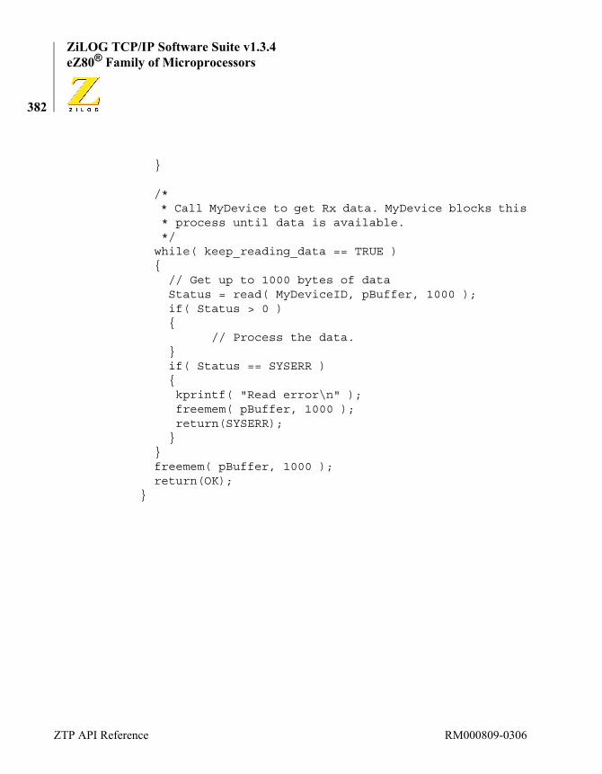
ZiLOG TCP/IP Software Suite v1.3.4eZ80® Family of Microprocessors
382
}
/* * Call MyDevice to get Rx data. MyDevice blocks this * process until data is available. */while( keep_reading_data == TRUE ){
// Get up to 1000 bytes of dataStatus = read( MyDeviceID, pBuffer, 1000 );if( Status > 0 ){
// Process the data.}if( Status == SYSERR ){ kprintf( "Read error\n" ); freemem( pBuffer, 1000 ); return(SYSERR);}
}freemem( pBuffer, 1000 );return(OK);
}
ZTP API Reference RM000809-0306

ZiLOG TCP/IP Software Suite v1.3.4Reference Manual
383
write
Synopsis#include <kernel.h>SYSCALL write(DID DeviceID, char *buff, WORD count);
Librarysys.lib
Description
The write routine is called to send a block of data through the driver with the specified DeviceID. The buffer passed to the driver via the buff parameter holds count bytes of data for the driver to process.
When a process calls the write function, the dvwrite routine in the underlying driver is called. The operating system passes the DeviceID parameter to the dvwrite routine along with the buff pointer and count parameters.
Within the dvwrite routine, the device driver typically checks to deter-mine whether the device is currently processing a block of data from a previous call. If the device is idle, the driver begins processing a new block of data. If the driver is currently processing another block of data, the driver designer has at least two options. The driver can immediately return control to the calling process to indicate that no data was processed because the device is busy. Alternatively, the driver can block the calling process until such time as it can process the new data. A variation of this instance occurs when a driver contains an internal staging buffer that does not include enough room to contain all of the data from the new request. The driver either copies part, or none, of the new data and immediately returns control to the caller. Alternatively, the driver blocks the caller until space is available.
Regardless of which method is used, it is important to block a process waiting to send data to the device. A process that burns CPU cycles doing nothing but polling to determine whether the driver is ready to process a
RM000809-0306 ZTP Device Driver APIs
ZiLOG TCP/IP Software Suite v1.3.4eZ80® Family of Microprocessors
384
new write request is wasting the most valuable resource in the system. Efficient multitasking can only be achieved if such a process is transi-tioned to the Blocked list as soon as possible to allow other processes with useful tasks to execute. For this reason, the ZTP-supplied device drivers typically block the calling process if the write request cannot be ser-viced immediately.
Arguments
Returned Value
If the write operation succeeds, OK is returned. If the operation fails (for example, the driver is not in a state that permits a write request to be ser-viced, or a hardware failure occurs), SYSERR is returned.
The device driver writer is free to return any value deemed appropriate from the dvwrite routine. In some cases, the driver writer may want to return the actual number of bytes written to the device if this is less than the amount of data requested to be written. The driver writer should avoid returning negative values if the function actually succeeded. Be aware that the number of bytes of data to be written is passed to this routine as a 16-bit unsigned quantity, whereas the return code is a signed 16-bit quan-tity. Therefore, when the write API is called to transfer large data blocks (bit 16 set), and the driver returns the actual number of bytes written, this value will appear negative to the caller. As an example, if the write API is called to transfer 65,535 bytes of data (FFFFh), and the write API suc-cessfully transfers all of the data, it is less ambiguous to return OK (value of 1) than it is to return FFFFh (SYSERR) to the caller.
DeviceID The device ID of the driver to which data is being sent.
buff A reference to a buffer containing data for the driver to process.
count The number of data bytes in the buffer for the driver to pro-cess.
Note:
ZTP API Reference RM000809-0306

ZiLOG TCP/IP Software Suite v1.3.4Reference Manual
385
In general, if the return code from the write call is positive, it should either return the value OK (currently defined as 0001h) or indicate the the actual number of bytes written (1 to 32,767). The return value should be interpreted as an error if it is negative. A zero return value should be inter-preted to mean that no data was written but no error occurred (that is, busy—try again later).
Sample Usagevoid WriteRoutine( DID MyDeviceID, char * pBuffer, WORD Length ){
SYSCALL Status;BYTE Done = FALSE;
while( !Done ){
Status = write( MyDeviceID, pBuffer, Length );if( Status < 0 ){ kprintf( "Error on write %d\n", Status ); Done = TRUE;}else{ if( Status == 0) { /* * Driver is not able to process the entire * buffer. * Wait 100ms before resubmitting remaining * data. */ sleep10( 1 ); } else {
RM000809-0306 ZTP Device Driver APIs

ZiLOG TCP/IP Software Suite v1.3.4eZ80® Family of Microprocessors
386
Done = TRUE; }}
}}
ZTP API Reference RM000809-0306
ZiLOG TCP/IP Software Suite v1.3.4Reference Manual
387
peek
Synopsis#include <kernel.h>SYSCALL peek(DID DeviceID);
Librarysys.lib
Description
The peek routine is called to determine if the driver with the specified device ID has any data waiting to be read using the read API. If the driver contains unread data it will return a positive quantity that indicates either the number of bytes, or packets, of data available to be read or OK, indicating at least one block (or packet) of data is available. This call can be used to prevent an application from blocking on a read call, that is, if the peek API is called and indicates that no data is available, the applica-tion can choose to defer the call to the read API, which would block in this instance.
When a process calls the peek function, the dvpeek routine in the under-lying driver is called. The operating system passes the DeviceID param-eter to the dvpeek as a parameter.
Within the dvpeek routine, the device driver typically checks to deter-mine whether it contains any buffered data previously obtained from the underlying device but not yet provided to a higher layer. If no data is buff-ered, the driver can also query the physical device to determine if any more data is available. The dvpeek routine then returns a value to the caller to indicate if any pending data is available for subsequent retrieval through the read API. Typically the dvpeek API does not block the caller.
Arguments
DeviceID The device ID of the driver being queried for data.
RM000809-0306 ZTP Device Driver APIs

ZiLOG TCP/IP Software Suite v1.3.4eZ80® Family of Microprocessors
388
Returned Value
A positive return value indicates that there is data available. In this instance, calling the read API will not block. a zero return value indi-cates that there is no data available. In this instance, if the read API is called, the calling process will block (unless data is received between the calls to peek and read). A negative return value indicates a problem with the device.
It is up to the driver writer to determine what value is appropriate to return to indicate pending data is available. In some cases, it is not possible to determine exactly how much data is available because doing so requires the data to be immediately retrieved from a physical device. In other cases, the driver may operate in packet-mode and instead of counting the number of bytes queued in all internal packets, the driver may simply return the number of packets queued or simply OK to indicate that one or more packets are available.
Sample Usagechar Buffer[ 1000 ];
PROCESS ReadRoutine( DID MyDeviceID ){
INT16 Status;
/* * See if there is any data available for reading. */Status = peek( MyDeviceID );if( Status == 0 ){
/* * No data available, do something else. */
}if( Status > 0 ){
ZTP API Reference RM000809-0306

ZiLOG TCP/IP Software Suite v1.3.4Reference Manual
389
/* * Read the available data. */ Status = read(MyDevice, Buffer, Status);
}return(OK);
}
RM000809-0306 ZTP Device Driver APIs

ZiLOG TCP/IP Software Suite v1.3.4eZ80® Family of Microprocessors
390
getc
Synopsis#include <kernel.h>SYSCALL getc(DID DeviceID);
Librarysys.lib
Description
The getc routine is used to read one byte of data from the driver with the specified DeviceID.
When a process calls the getc function, the dvgetc routine in the under-lying driver is called. The operating system passes the DeviceID param-eter to the dvgetc routine.
Within the dvgetc routine, the driver performs the same tasks as it would for a read request, wherein the length of the read buffer is only one byte. For more information, see the read device driver API on page 380. However, unlike the read routine, the getc function must not return a value of 0 to indicate that no data is read from the device. A returned value of 0 must only be used if it is the data value actually received from the underlying device.
Arguments
Returned Value
If the call succeeds, getc returns the 8-bit value read from the device. This value will always be returned as a positive value. For example, if FFh is read from the physical device, the driver will return 00FFh. If the function fails a negative value, such as SYSERR (FFFFh), will be returned.
DeviceID The device ID of the driver from which a single data byte is to be retrieved.
ZTP API Reference RM000809-0306
ZiLOG TCP/IP Software Suite v1.3.4Reference Manual
391
putc
Synopsis#include <kernel.h>SYSCALL putc(DID DeviceID, BYTE ch);
Librarysys.lib
Description
The putc routine is used to send the specified data byte (ch) to a driver with the specified DeviceID.
When a process calls the putc function, the dvputc routine in the under-lying driver is called. The operating system passes the DeviceID param-eter to the dvgetc routine along with the value of the ch parameter.
Within the dvputc routine, the driver performs the same tasks as it would for a write request, wherein the length of the write buffer is only one byte. For more information, see the write device driver API on page 383.
Arguments
Returned Value
The putc function returns a value of OK (1) to indicate that the data byte is successfully processed or SYSERR to indicate that the request did not complete.
DeviceID The device ID of the driver from which a single data byte is to be retrieved.
ch The 8-bit value to be processed by the driver.
RM000809-0306 ZTP Device Driver APIs

ZiLOG TCP/IP Software Suite v1.3.4eZ80® Family of Microprocessors
392
seek
Synopsis#include <kernel.h>SYSCALL seek(DID DeviceID, INT32 pos);
Librarysys.lib
Description
The seek routine is called to reposition the I/O pointer of a driver with a specified DeviceID. The pos parameter is either interpreted as an abso-lute offset or a relative offset at the discretion of the device driver designer.
When a process calls the seek function, the dvseek routine in the under-lying driver is called. The operating system passes the DeviceID param-eter to the dvseek routine along with the pos parameter.
Within the dvseek routine, the device driver typically checks to deter-mine whether the device is currently processing an I/O request from a pre-vious call. If the device is idle, the driver repositions the I/O pointer according to the value of the pos parameter.
The seek operation is only meaningful if the driver and/or underlying device support random access to the device data. A classic example is a file in which the I/O pointer is the position in the file (measured in bytes) at which a read or write operation occurs. A sequential-access device, such as a serial UART driver that cannot support the concept of an I/O pointer, should specify ioerr as the dvseek handler in its KE_DEV struc-ture.
ZTP API Reference RM000809-0306

ZiLOG TCP/IP Software Suite v1.3.4Reference Manual
393
Arguments
Returned Value
If the specified pos parameter is valid, the seek function returns an appropriate value for the operation as determined by the device driver designer. For some devices, this value will be the value OK; for other devices, the new position of the I/O pointer or a driver-specific error code is returned.
DeviceID The device ID of the driver to which data is being sent.
pos The relative or new absolute value to be applied to the device’s current I/O pointer.
RM000809-0306 ZTP Device Driver APIs

ZiLOG TCP/IP Software Suite v1.3.4eZ80® Family of Microprocessors
394
ZTP Networking APIsThis section describes the user interfaces to the ZTP stack interfaces. Table 21 provides a brief description of each of the ZTP stack elements.
UDP FunctionsUDP data transfer is accomplished using the datagram services imple-mented by the UDP master device driver and its slaves. A datagram is simply an arbitrary block of data created by a UDP application. The num-ber of UDP slave devices in the system is the same as the value passed to the udp_init API. For example, if udp_init(4); is called from within main(), then the system driver table will be populated with one master UDP device (named UDP) and four slave devices (named DGRAM).
Table 21. Stack User Interfaces
Section Description
UDP Functions Sending and receiving UDP datagrams.
TCP Functions Creating and using TCP connections (virtual circuits).
ARP Functions Public interface to the ARP module.
ICMP Functions Public interface to the ICMP module.
IGMP Functions Public interface to the IGMP module.
Ethernet Functions Public interface to the EMAC module.
PPP Functions Public interface to the PPP module.
Miscellaneous Network Functions
Public interface to the DNS and Timed738 modules.
HTTP Functions Creating and using a webserver.
ZTP API Reference RM000809-0306
ZiLOG TCP/IP Software Suite v1.3.4Reference Manual
395
Before calling any UDP driver function, you must call the udp_init API to initialize the UDP layer.
The UDP protocol exchanges datagrams between socket endpoints out-side of a connection. As such, each datagram is treated independently. Delivery of datagrams occurs on a best-effort basis, and applications must be aware that datagrams can get lost in the network, can be received in a different order from the order in which they are sent, and can even become duplicated while travelling through a network. These issues are not unique to ZTP; they are inherent in all datagram systems. The advan-tage of the datagram delivery system is that it requires very little protocol overhead. Therefore, UDP applications generally run faster than similar applications using TCP stream (connection-oriented) sockets.
This section presents the UDP device driver API that application pro-grams use to access ZTP datagram services. Table 22 lists the subset of ZTP device driver services implemented by the UDP drivers. Some of these functions are only applicable to the UDP master device, while oth-ers are only applicable to the slave device being used for the exchange of datagrams.
For more information about ZTP device drivers, see the ZTP Device Driver APIs section on page 360.
Table 22 provides a brief description of each of the ZTP datagram ser-vices.
Table 22. Datagram Services
udp_init n/a Initializes the UDP module.
udp_add_cmds n/a Adds optional UDP-based commands to the system command shell.
open Master Allocates a UDP Slave device for data transfer.
control Slave UDP-specific device control functions.
Note:
RM000809-0306 UDP Functions

ZiLOG TCP/IP Software Suite v1.3.4eZ80® Family of Microprocessors
396
read Slave Receives a UDP datagram.
write Slave Sends a UDP datagram.
peek Slave Returns number of datagrams waiting to be read.
close Slave Closes the UDP slave device.
Table 22. Datagram Services
ZTP API Reference RM000809-0306
ZiLOG TCP/IP Software Suite v1.3.4Reference Manual
397
udp_init
Synopsis#include <network.h>SYSCALL udp_init( WORD NumUDPDevices );
Libraryudp.libdgram.lib
Description
If your application requires direct access to the UDP layer (through the device driver interface) or indirectly through other application protocols that use UDP, then you must call udp_init before using any UDP-based service. udp_init should only be called after a call to netstart.
During initialization, the UDP layer will add the Master UDP device to the system device driver table. The device ID of the UDP master device is identified by the system defined global variable UDP. In addition, a num-ber of slave devices equal to the value of the NumUDPDevices parameter will also be added to the system driver table. To use a UDP device driver, you must first open the UDP master device, which will in turn allocate one of the free slave devices for use by your application.
Each UDP-based application in the system will require one UDP slave device. In addition, system services such as SNMP, TFTP, DHCP, and timed738 all use UDP for data transfer. Therefore, the value of the NumUDPDevices parameter should be set to the number of UDP-based applications that will be active at the same time.
Arguments
NumUDPDevices Determines the number of UDP slave devices that are added to the system.
Note:
RM000809-0306 UDP Functions

ZiLOG TCP/IP Software Suite v1.3.4eZ80® Family of Microprocessors
398
Returned Value
If the UDP layer successfully initializes, OK is returned. In all other cases SYSERR is returned.
Sample Usagevoid main( void ){
KE_KernelInit();netstart();udp_init( 8 );// Add 8 UDP slave devices to
// the system.}
ZTP API Reference RM000809-0306
ZiLOG TCP/IP Software Suite v1.3.4Reference Manual
399
udp_add_cmds
Synopsis#include <network.h>void udp_add_cmds( void );
Librarydgram.lib
Description
To use the services of the ZTP UDP layer, your application must call udp_init. In addition, there are three UDP-related shell commands that can optionally be added to the system. These are the dg, udplisten, and udpping commands. For more information about the use of these com-mands, see the ZTP Shell Command Reference chapter on page 513. If you are not using the shell, or do not wish to include these commands in your project, do not call udp_add_cmds.
Arguments
None.
Returned Value
None.
Sample Usagevoid main( void ){
KE_KernelInit();netstart();udp_init( 8 );// Add 8 UDP slave devices to
// the system.udp_add_cmd();// Add optional UDP shell
// commands.}
RM000809-0306 UDP Functions

ZiLOG TCP/IP Software Suite v1.3.4eZ80® Family of Microprocessors
400
open
Synopsis#include <network.h>SYSCALL open(DID DeviceID, char *remote_socket, char *local_port);
Libraryudp.libdgram.lib
Description
The UDP open routine is called to allocate a UDP slave device that an application can use to transfer UDP datagrams and establish local socket bindings. The open request is always directed towards the UDP master device. Therefore, the DeviceID parameter is always the system-defined variable UDP.
The local_port parameter is used to request a specific UDP port. This parameter allows the application to implement a service on a known port number.
For example, an application choosing to implement a Domain Name Server specifies a local_port value of 53 because DNS client applica-tions seek DNS services from applications that use UDP port 53. Port numbers are specified as 16-bit values that are cast to (char*).
The system grants the requestor the use of the specified local port as long as no other application previously requested the use of the same port. If the value of the local_port parameter is set to the system macro ANYLPORT, or explicitly set to 0, the system will dynamically assign the requestor an unused arbitrary port number. This port number is in the range 49152 to 65535.
Be aware that port numbers in the range 0 to 1023 are reserved for well-known TCP/IP services (for example, SNMP, DHCP, TFTP). Similarly,
Note:
ZTP API Reference RM000809-0306

ZiLOG TCP/IP Software Suite v1.3.4Reference Manual
401
port numbers 1024 through 49151 are registered with the IANA for spe-cific purposes. Only port numbers in the range 49152 to 65535 should be used for arbitrary purposes.
The remote_socket parameter specifies the default destination socket to be used for all outgoing datagrams. UDP servers typically sets this parameter to the system-predefined macro ANYFPORT because the server is likely to send data to multiple client devices that each use a different socket. UDP clients typically set this parameter to the socket address of the particular end point of interest.
If the remote_socket parameter is not set to ANYFPORT, it must be set to an ASCII string specifying the IP address and port number of interest.
Example: if the socket of interest is port 567 on a device that possesses IP address 1.2.3.4, then the remote socket is specified as 1.2.3.4:567. Instead of using an IP address, the device’s domain name can also be used (for example, SomeDevice.abc.com:567).
After the open call returns, the slave device ID returned by the UDP mas-ter device is immediately available to transfer UDP datagrams using the read and write APIs. The DG_CMODE and DG_NMODE control bits are set on the UDP slave device. For more information, see the UDP control function on page 403.
As a result of the open call, multiple local sockets are created and logi-cally bound to the requesting application. The number of local sockets created is equal to the current number of active physical interfaces in the system. Each socket uses the same local_port port number and an IP address unique to each active interface. As a result, every UDP applica-tion in ZTP is accessible via any physical interface.
As an example, if the Ethernet interface is using IP address 1.2.3.4, the PPP interface is using IP address 5.6.7.8, and you specify a local_port address of 2000 on the open call, then your UDP-based application will be accessible to remote Ethernet nodes via socket {1.2.3.4:2000} and will be accessible to the remote PPP device using socket {5.6.7.8:2000}.
RM000809-0306 UDP Functions

ZiLOG TCP/IP Software Suite v1.3.4eZ80® Family of Microprocessors
402
Arguments
Returned Value
If all parameters are valid and a UDP slave device is available, the open function returns the device ID of the allocated slave. In all other cases, NULLPTR is returned. NULLPTR is also returned if the remote socket is specified using a domain name and that name cannot be resolved to an IP address.
Sample UsageDID MyUDPDevID;/* * Request the use of a UDP slave device from the UDP * Master device. Specify a default remote socket so we * can later chose to use DATA-ONLY mode. Specify a * local port number of 4000. */MyUDPDevID = open(UDP, "192.168.1.238:115", (char *) 4000);if( MyUDPDevID == NULLPTR ){
kprintf("Unable to obtain UDP slave device\n");}
DeviceID The device ID of the UDP Master device. This value should always be specified as UDP.
remote_port An ASCII string containing the IP address of the foreign host (in dotted-decimal format), followed by a colon (:) and the decimal port number (Example: 127.0.0.1:7). Servers can also specify ANYFPORT.
local_port The unique integer port number to be assigned to the local port. If this parameter is set to ANYLPORT, the next available port number is automatically assigned.
ZTP API Reference RM000809-0306
ZiLOG TCP/IP Software Suite v1.3.4Reference Manual
403
control
Synopsis#include <network.h>SYSCALL control(DID DeviceID, WORD func, char *addr, char *addr2);
Libraryudp.libdgram.lib
Description
The UDP control routine is used to modify the behavior of a UDP slave device with a specified DeviceID. The behavior of the UDP master device cannot be modified. The addr2 parameter is not used by the UDP slave device and should always be specified as NULLPTR.
The value of the func argument specifies one of the following control functions:
The following mode bits can be specified for the slave device by logically ORing zero or more of the corresponding macros (see dgram.h) together and casting the result to (char *).DG_NMODE. This function sets the slave device to the NORMAL mode of operation. In NORMAL mode, your application sends and receives xgram structures (see dgram.h).
In NORMAL mode, the read operation explicitly sets the foreign IP address, foreign port, and local port fields in the xgram structure (see
DG_SETMODE This function is used to specify the mode bits of the UDP slave device. The value for the mode bits is taken from the addr argument.
DG_CLEAR This function discards all unread datagrams from the slave device’s internal packet queue.
RM000809-0306 UDP Functions

ZiLOG TCP/IP Software Suite v1.3.4eZ80® Family of Microprocessors
404
dgram.h). The data field in the xgram structure will contain the data sent by the remote UDP application.
A write request in NORMAL mode will always send the datagram to the remote_socket value specified on the open request, and ignores the value of the foreign IP address and foreign port fields set in the outgoing xgram structure. The only exception is if the remote_socket is speci-fied as ANYFPORT. In this instance, the foreign IP address and foreign port fields of the outgoing xgram structure will be used to deliver the data-gram. Therefore, a UDP client that explicitly specifies a remote_socket on its open call can only send data to that socket.DG_DMODE. This function sets the slave device to the DATA-ONLY mode of operation. In DATA-ONLY mode, the read operation only returns the data portion of the UDP datagram. In essence, the read rou-tine does not interpret the buffer pointer passed to the read routine as a pointer to an xgram structure; rather, it is regarded a a pointer to a buffer. Therefore, the remote socket that generated the data is unknown to the process obtaining the data. Similarly, when the write request is called, the buffer pointer is not interpreted as a pointer to an xgram structure as in NORMAL mode, but rather as a pointer to an opaque data buffer. Therefore, the destination socket in DATA-ONLY mode is always the remote_socket value specified on the open call. UDP client applica-tions that only need to communicate with one particular remote server (identified by the remote_socket parameter on the open call) can use DATA-ONLY mode to simplify data transfer. It is invalid to specify both DG_DMODE and DG_NMODE at the same time.DG_CMODE. This control bit specifies that the UDP slave device should always generate checksums on transmitted datagrams. If this option is set, checksums are generated. If this option is not set, the checksum field in the UDP packet header is set to 0000h. Regardless of whether this option is used, the checksum of inbound datagrams is always verified.DG_TMODE. This option directs the slave device to perform timed reads. If a remote device does not send any data to the local task waiting on the read, then the control never returns to the local task. However, when the
ZTP API Reference RM000809-0306

ZiLOG TCP/IP Software Suite v1.3.4Reference Manual
405
DG_TMODE option is used, the control is transferred to the process that sent the read request when:
• A 3-second time-out occurs ( this default time-out value can be changed by modifying the variable WORD udp_timeout in ipw_ez80.c file).
• When a datagram is received.
If the read operation times out, the return code from the read request is TIMEOUT.
When a UDP slave device is allocated using the open call, the mode is set to (DG_NMODE | DG_CMODE).
Arguments
Returned Value
If the control function and parameters are valid and the requested oper-ation can be performed, OK is returned. In all other cases, SYSERR is returned.
Sample Usage#include <network.h>extern DID MyUDPDevID;
INT16 Status;/* Set the UDP device to Data-Only Mode and disable * checksums on outbound datagrams.*/Status = control(MyUDPDevID,DG_SETMODE,(char *)(DG_DMODE), NULLPTR);if( Status == SYSERR )
DeviceID The device ID of the UDP slave being manipulated.
func The control function to be executed.
addr A reference to control function specific data.
addr2 A second reference to control function specific data.
RM000809-0306 UDP Functions

ZiLOG TCP/IP Software Suite v1.3.4eZ80® Family of Microprocessors
406
{ kprintf("Unable to change mode of UDP device\n"); close( MyUDPDevID );}
ZTP API Reference RM000809-0306

ZiLOG TCP/IP Software Suite v1.3.4Reference Manual
407
read
Synopsis#include <network.h>SYSCALL read(DID DeviceID, char *buff, WORD count);
Libraryudp.libdgram.lib
Description
The UDP read routine is called to retrieve a UDP datagram from the UDP slave device with the specified DeviceID.
In NORMAL mode (DG_NMODE), the buff pointer should reference an xgram structure (see dgram.h) and count should be specified as sizeof(struct xgram). In this case, the first byte of the received UDP data is available at buff xg_data[0]. In DATA-ONLY mode (DG_DMODE), the buff pointer references an arbitrary data buffer, the length of which is count bytes. In this case, the first byte of the UDP data is available at buffer[0].
The maximum length of the data portion of a UDP datagram that can be retrieved is U_MAXLEN bytes (currently defined as 4035). In NORMAL mode, if a received datagram (including headers) is bigger than count (the size of the xgram structure), then read discards the received data-gram and returns an error (SYSERR). In DATA-ONLY mode, if the data portion of the received datagram is bigger than count, only the first count bytes of the datagram are copied into the buffer referenced by buff.
If DG_TMODE is not in effect (see the UDP control API) and there are no datagrams queued in the UDP slave device at the time the read API is called, the read function blocks until a datagram is available. Because dat-agram delivery is packet-based, this function does not wait for exactly count bytes of data to arrive. Control is returned to the caller as soon as a
RM000809-0306 UDP Functions

ZiLOG TCP/IP Software Suite v1.3.4eZ80® Family of Microprocessors
408
datagram is available, regardless of the size of that datagram. When timed reads are in effect (DG_TMODE), the read request blocks for no more than udp_timeout ÷ 10 seconds for a datagram to be received. The value of udp_timeout is user-configurable by modifying the contents of the dgram_conf.c file.
Be aware that regardless of the value specified for remote_socket on the open call, the read function returns any datagram sent by any remote device to the local socket. Therefore, it can be necessary for a UDP appli-cation to verify that the device that generated the datagram is in fact the device considered to be the correct device by the application. This verifi-cation is accomplished by examining the xg_fip and xg_fport fields of the received xgram structure. Because these fields are unavailable in the DATA-ONLY mode of operation, the application designer is cautioned against assuming any relationship between successive received data-grams.
Because the read request can block indefinitely when timed reads are not used, application designers should consider using multiple processes within an application. One process can be created to retrieve datagrams and other processes created to perform the remaining application tasks.
Arguments
Returned Value
If the specified DeviceID is valid, the UDP read function returns the number of data bytes in the received datagram (headers are ignored). If timed reads are used and a datagram is not available within three seconds,
DeviceID The device ID of a UDP slave from which a datagram is to be retrieved.
buff A reference to an xgram structure or data buffer in which the datagram is placed.
count The size of the xgram structure or length of the data buffer.
ZTP API Reference RM000809-0306

ZiLOG TCP/IP Software Suite v1.3.4Reference Manual
409
this function returns TIMEOUT. In all other cases, this function returns SYSERR.
Sample Usage#include <network.h>extern DID MyUDPDevID;struct xgram Datagram;INT16 Status;
/* * Read a datagram from the UDP slave device. * It is assumed MyUDPDevID is operating in normal * mode. */Status = read(MyUDPDevID, (char *) &Datagram, sizeof(struct xgram));if( Status > 0 ){ kprintf("Received %d bytes of data at %p\n", Status, Datagram.xg_data );}
RM000809-0306 UDP Functions
ZiLOG TCP/IP Software Suite v1.3.4eZ80® Family of Microprocessors
410
write
Synopsis#include <network.h>SYSCALL write(DID DeviceID, char *buff, WORD count);
Libraryudp.libdgram.lib
Description
The UDP write routine is called to transmit a UDP datagram using the UDP slave device with the specified DeviceID.
In NORMAL mode (DG_NMODE), the buff pointer should reference an xgram structure (see dgram.h), and count specifies the size of the data block in the xg_data field to be transmitted. In DATA-ONLY mode (DG_DMODE), the buff pointer references an arbitrary data buffer contain-ing count bytes of data to be transmitted. In either case, the data is sent as a single datagram and the data block must be U_MAXLEN bytes (cur-rently defined as 4035) or less.
In the NORMAL mode of operation (see the description of DG_NMODE in the UDP control API), if the UDP slave device is created (see open on page 400) with a remote_socket parameter set to ANYFPORT, the target of the datagram is specified in the xg_fip and xg_fport fields of the dgram structure referenced by the buff pointer. Otherwise, the datagram is sent to the remote socket specified on the call to UDP open.
In DATA-ONLY mode, the datagram is always sent to the remote socket specified on the call to UDP open. If the remote_socket parameter is set to ANYFPORT, the datagram cannot be delivered.
The UDP layer transmits datagrams using a system resource called a packet buffer. These buffers are allocated from one of two system buffer pools. The first buffer pool is named PktPool and is used to transfer
ZTP API Reference RM000809-0306

ZiLOG TCP/IP Software Suite v1.3.4Reference Manual
411
UDP datagrams that can be placed in a single Ethernet frame. The second buffer pool is named BigPktPool and is used to send UDP datagrams that must be fragmented into multiple Ethernet frames (use the bpool shell command to display information about these buffer pools). The maximum number of packets in each of the system packet pools is determined by the value of the NumPkts and NumBigPkts variables defined in the ipw_ez80.c file.
The size of the UDP datagram determines which buffer pool the UDP layer uses to send application data. If the selected buffer pool is out of packets, the UDP datagram is not sent and SYSERR is returned. If a packet is available, the system copies information from the application buffer referenced by the buff parameter into the system packet allocated from one of the buffer pools. Therefore, the caller is not required to leave the buffer referenced by buff resident in memory.
Arguments
Returned Value
If the length of the data block is less than or equal to U_MAXLEN bytes (currently defined as 4035), and a valid target socket is specified, and a system packet buffer is available, this function returns OK. In all other cases, the function returns SYSERR.
Sample Usage#include <network.h>extern DID MyUDPDevID;struct xgram Datagram;INT16 Status;
DeviceID The device ID of a UDP slave to use for sending the data-gram.
buff A reference to an xgram structure or data buffer containing the data block to place in the outgoing datagram.
count The size of the data block referenced by the buff pointer.
RM000809-0306 UDP Functions

ZiLOG TCP/IP Software Suite v1.3.4eZ80® Family of Microprocessors
412
/* * Send a datagram through the UDP slave device. * It is assumed MyUDPDevID is operating in normal mode * and a valid target socket is specified on the open * call. */// Say hello to the remoteblkcopy( Datagram.xg_data, "Hello", 5 );Status = write(MyUDPDevID, (char *) &Datagram, 5);if( Status != OK ){ kprintf("Error on UDP write %x\n", Status );}
ZTP API Reference RM000809-0306

ZiLOG TCP/IP Software Suite v1.3.4Reference Manual
413
peek
Synopsis#include <network.h>SYSCALL peek(DID DeviceID);
Libraryudp.libdgram.lib
Description
The UDP peek routine is called to determine the amount of application-level UDP data that is available in the first datagram on the specified UDP slave device’s input queue. If all received UDP datagrams have been read by the application, then the peek API will return 0. In this instance, the next call to the read API is likely to block until another UDP datagram is received.
The peek API does not indicate the number of UDP datagrams waiting to be read, nor does it indicate the total amount of application-level data that is available in all queued datagrams. For example, if the UDP slave device with the specified DeviceID has accumulated two UDP data-grams from the network, the first datagram contains 20 bytes of applica-tion-level data, and the second contains 3000 bytes of application-level data, then the peek API will return a value of 20.
Arguments
Returned Value
If the UDP slave device with the specified DeviceID has accumulated at least one UDP datagram that has not yet been read by calling the UDP read API, the UDP peek function will return the number of bytes of application data contained in this datagram. In this instance, the return
DeviceID The device ID of the UDP slave device being queried.
RM000809-0306 UDP Functions

ZiLOG TCP/IP Software Suite v1.3.4eZ80® Family of Microprocessors
414
value will be greater than 0 and less than or equal to U_MAXLEN bytes (currently defined as 4035). If the specified UDP slave device does not contain any unread UDP datagrams, the peek API will return 0. In all other cases, SYSERR is returned.
Sample UsageDID MyUDPDevID;INT16 Size;
/** Determine how much data is currently available.*/Size = peek( MyUDPDevID );if( Size > 0 ){
kprintf( “%d bytes available to be read\n” );}
ZTP API Reference RM000809-0306

ZiLOG TCP/IP Software Suite v1.3.4Reference Manual
415
close
Synopsis#include <network.h>SYSCALL close(DID DeviceID);
Libraryudp.libdgram.lib
Description
The UDP close routine is called to release control of the UDP slave device with the specified DeviceID back to the UDP Master device for subsequent (re)allocation.
Any unread datagrams associated with this device are discarded. If a transmit operation is in progress at the time of the close request, the transmit operation may not complete successfully. Any process(es) that has blocked a read request is transitioned to the Ready list as a result of calling this close function.
If the UDP open function returns NULLPTR, indicating failure, do not call the close API with this specified as the DeviceID value.
Arguments
Returned Value
If a specified device is closed, the close function returns OK. Otherwise, SYSERR is returned.
Sample UsageDID MyUDPDevID;
/*
DeviceID The device ID of the UDP slave device to be closed.
RM000809-0306 UDP Functions

ZiLOG TCP/IP Software Suite v1.3.4eZ80® Family of Microprocessors
416
* Request the use of a UDP slave device from the UDP* Master device. Specify a default remote socket so we* can later chose to use DATA-ONLY mode. Specify a* local port number of 4000.*/
MyUDPDevID = open(UDP, "192.168.1.238:115", (char *)4000);
if( MyUDPDevID == NULLPTR ){ kprintf("Unable to obtain UDP slave device\n");}else{
close(MyUDPDevID);}
TCP FunctionsTCP data transfer is accomplished using the stream socket services imple-mented by the TCP master device driver and its slaves. Stream data trans-fer is connection-oriented, byte-oriented, reliable and employs flow control. Contrast TCP data transfer to datagram (UDP) data transfer, which is connectionless, block-oriented, unreliable, and does not employ flow control. The number of TCP slave devices in the system is the same as the value passed to the tcp_init API. For example, if tcp_init(4); is called from within main(), then the system driver table will be populated with one master TCP device (named TCP Mas-ter) and four slave devices (named TCP).
Before calling any TCP driver function, you must call the tcp_init API to initialize the TCP layer.
Before any data can be exchanged, the TCP protocol is used to create a connection between socket endpoints. Reliable data transfer requires the TCP protocol to automatically detect and retransmit any lost data to
Note:
ZTP API Reference RM000809-0306
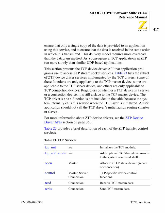
ZiLOG TCP/IP Software Suite v1.3.4Reference Manual
417
ensure that only a single copy of the data is provided to an application using this service, and to ensure that the data is received in the same order in which it is transmitted. This delivery model requires more overhead than the datagram method. As a consequence, TCP applications in ZTP run more slowly than similar UDP-based applications.
This section presents the TCP device driver API that application pro-grams use to access ZTP stream socket services. Table 23 lists the subset of ZTP device driver services implemented by the TCP drivers. Some of these functions are only applicable to the TCP master device, some are applicable to the TCP server device, and others are only applicable to TCP connection devices. Regardless of whether a TCP device is a server or a connection device, it is still a slave to the TCP master device. The TCP driver’s init function is not included in the table because the sys-tem internally calls this service when the TCP layer is initialized. A user application should not call the TCP driver’s initialization routine (master or slave).
For more information about ZTP device drivers, see the ZTP Device Driver APIs section on page 360.
Table 23 provides a brief description of each of the ZTP transfer control services.
Table 23. TCP Services
tcp_init n/a Initializes the TCP module.
tcp_add_cmds n/a Adds optional TCP-based commands to the system command shell.
open Master Allocate a TCP slave device (server or connection).
control Master, Server, Connection
TCP-specific device control functions.
read Connection Receive TCP stream data.
write Connection Send TCP stream data.
RM000809-0306 TCP Functions

ZiLOG TCP/IP Software Suite v1.3.4eZ80® Family of Microprocessors
418
peek Connection Returns the number of unread bytes of TCP data available.
putc Connection Send a single byte of TCP data.
close Server, Connection Close a TCP slave device (server or connection).
Table 23. TCP Services (Continued)
ZTP API Reference RM000809-0306
ZiLOG TCP/IP Software Suite v1.3.4Reference Manual
419
tcp_init
Synopsis#include <network.h>SYSCALL tcp_init( WORD NumTCPDevices );
Librarytcp.libtcpd.lib
Description
If your application requires direct access to the TCP layer (through the device driver interface) or indirect access through other application proto-cols that use TCP, then you must call tcp_init before using any TCP-based service. tcp_init should only be called after the call to net-start.
During initialization, the TCP layer will add the Master TCP device to the system device driver table. The device ID of the TCP master device is identified by the system defined global variable “TCP”. In addition, a number of slave devices equal to the value of the NumTCPDevices parameter will also be added to the system driver table. To use a TCP device driver, you must first open the TCP master device which will in turn allocate one of the free slave devices for use by your application.
Each TCP client application in the system will require one TCP slave device to establish a connection. Each TCP server application will require one TCP server device and can require multiple simultaneous TCP con-nection devices. In addition, system services like SMTP, HTTP, and Tel-net all use TCP for data transfer. Therefore, the value of the NumTCPDevices parameter should be set to the number of TCP-based connections and servers that will be active at the same time. This value can be difficult to determine. For example, if your project con-figuration uses the HTTP and Telnet servers, plus one custom TCP server
Note:
RM000809-0306 TCP Functions

ZiLOG TCP/IP Software Suite v1.3.4eZ80® Family of Microprocessors
420
you create, as well as the SMTP client, then at least four TCP slave devices (three servers and one connection) will be required. However, if it is anticipated that two remote Telnet clients and three remote (HTTP) browsers plus one remote custom client will typically all access your device simultaneously, then an additional five TCP slave devices will be required. Under conditions of peak load, this quantity may not be ade-quate; additional TCP slave devices could be required.
Each TCP connection device (but not a TCP server device; nor the TCP master device) allocates a block of memory to hold the per-connection TCP transmit and receive buffers. The size of these buffers is determined by the values of the TCPSBS (TCP Send Buffer Size) and TCPRBS (TCP Receive Buffer Size) variables in \conf\tcp_conf.c. Increasing the size of these buffers can improve performance at the price of requiring additional dynamic memory from the heap. In the previous example, it was assumed that up to 6 TCP connections could be in progress at the same time. Therefore, if the TCPSBS was set to 8 KB and the TCPRBS was set to 6 KB, then at least 84 KB of dynamic memory will be required from the heap to support all 6 simultaneous connections.
Arguments
Returned Value
If the TCP layer successfully initializes, OK is returned. In all other cases SYSERR is returned.
Sample Usagevoid main( void ){
KE_KernelInit();netstart();tcp_init( 8 );// Add 8 TCP slave devices to
NumTCPDevices Determines the number of TCP slave devices that are added to the system.
ZTP API Reference RM000809-0306

ZiLOG TCP/IP Software Suite v1.3.4Reference Manual
421
// the system.}
RM000809-0306 TCP Functions
ZiLOG TCP/IP Software Suite v1.3.4eZ80® Family of Microprocessors
422
tcp_add_cmds
Synopsis#include <network.h>void tcp_add_cmds( void );
Librarytcpd.lib
Description
To use the services of the ZTP TCP layer, your application must call tcp_init. In addition, there are two TCP-related shell commands that can optionally be added to the system. These are the netstat and tim-erq commands. For more information about the use of these commands, see the ZTP Shell Command Reference chapter on page 513. If you are not using the shell, or do not wish to include these optional commands in your project, do not call tcp_add_cmds.
Arguments
None.
Returned Value
None.
Sample Usagevoid main( void ){
KE_KernelInit();netstart();tcp_init( 8 );// Add 8 TCP slave devices to
// the system.tcp_add_cmd();// Add optional TCP shell
// commands.}
ZTP API Reference RM000809-0306

ZiLOG TCP/IP Software Suite v1.3.4Reference Manual
423
open
Synopsis#include <network.h>SYSCALL open(DID DeviceID, char * remote_socket, char * local_port);
Librarytcp.libtcpd.lib
Description
The TCP open routine is called to allocate either a TCP server device or a TCP connection device (both are slaves to the TCP master device) and bind these devices to the requesting process. The selection is implicitly made by the value used for the remote_socket parameter. This request is always directed toward the TCP master device. Therefore, the Devi-ceID parameter is always the system-defined TCP device ID, which is stored in the global variable TCP.
A TCP server device listens on a socket for a connection request from any remote device on the specified port. After a remote device initiates a con-nection, the TCP layer allocates a TCP connection device to allow data transfer between the local and remote socket endpoints. The TCP server application obtains the connection device ID by calling the TCPC_ACCEPT control function using the Server’s device ID. Both TCP server applications and TCP client applications require a TCP connection device to exchange data. A TCP server application additionally requires the use of a TCP server device ID to process connection requests initiated by a remote peer(s).
A TCP server device is allocated if the value of remote_socket is spec-ified as ANYFPORT. In this case, multiple local sockets are created (one over each active interface) and each socket begins passively listening for connection requests from any remote TCP client device. For information
RM000809-0306 TCP Functions
ZiLOG TCP/IP Software Suite v1.3.4eZ80® Family of Microprocessors
424
about how TCP server devices obtain a connection device to exchange data, see the TCP control function on page 427. As an example, if the Ethernet interface is using IP address 1.2.3.4, the PPP interface is using IP address 5.6.7.8, and you specify a remote_socket value of ANYFPORT and a local_port address of 2000 on the open call, then your TCP server application will be accessible to remote Ethernet nodes via socket {1.2.3.4:2000} and will be accessible to the remote PPP device using socket {5.6.7.8:2000}.
A TCP connection device is allocated if the remote_socket parameter is not set to ANYFPORT. In this case, remote_socket must be set to an ASCII string to specify the IP address and port number of a remote socket to which an active connection attempt is made. The TCP connection is attempted over the interface that is capable of reaching the appropriate remote_socket. As an example, if a TCP client application chooses to establish a TCP connection to a remote device using IP address 1.2.3.4 and is listening for connections on port 567, then the remote socket can be specified as 1.2.3.4:567. Instead of using an IP address, the device’s domain name can also be used (for example, SomeDe-vice.abc.com:567). The interface that can reach this foreign socket is then used to attempt the TCP connection.
The local_port parameter is used to request the use of a specific port number. This parameter allows applications to implement well-known services on a specific port.
Example: an application that implements an HTTP server specifies a local_port value of 80 because HTTP clients (such as web browsers) seek HTTP services from whatever application is using port 80. Port numbers are specified as a 16-bit value cast to (char*). The system grants the requestor the use of the specified local port as long as no other application previously requested the use of the same port. If the value of the local_port parameter is set to the system macro ANYLPORT or is explicitly set to 0, the system will dynamically assign the requestor an arbitrary port number. This port number will be in the range of 49152 to 65535.
ZTP API Reference RM000809-0306

ZiLOG TCP/IP Software Suite v1.3.4Reference Manual
425
Be aware that port numbers in the range 0 to 1023 are reserved for well-known TCP/IP services (for example SMTP, HTTP, and TELNET). Simi-larly, port numbers 1024 through 49151 are registered with the IANA for specific purposes. Only port numbers in the range 49152 to 65535 should be used for arbitrary purposes.
If you are implementing a TCP server application and therefore set the remote_socket parameter to ANYFPORT, it is invalid to specify a local_port of ANYLPORT; that is, a TCP server device must request a specific port.
After the open call returns, the slave device ID returned by the TCP mas-ter device is immediately available to use on other TCP driver functions. However, the only functions that are valid to call when using a TCP server device ID are the control and close functions. In addition to these, the read, write, peek, getc, and putc functions can also be used with a TCP connection device ID.
Arguments
Returned Value
If the open call succeeds, a TCP connection Device ID is returned. In all other cases, NULLPTR is returned. Possible reasons for the failure include:
DeviceID The device ID of the TCP Master device should always be specified as the ZTP system variable TCP.
remote_port An ASCII string containing the IP address of the foreign host (in dotted-decimal format), followed by a colon (:) and the decimal port number (Example: 127.0.0.1:7). Servers must specify ANYFPORT.
local_port The unique integer port number to be assigned to the local port. If this parameter is set to ANYLPORT, the next available port number is automatically assigned. Servers must not specify ANYLPORT.
Notes:
RM000809-0306 TCP Functions

ZiLOG TCP/IP Software Suite v1.3.4eZ80® Family of Microprocessors
426
• There are not enough TCP resources available to satisfy the request.
• For client open requests the specified remote host (IP address or domain name) cannot be found.
• For client open requests there is no service on the remote host listen-ing for connections on the specified port.
Sample Usage#include <network.h>
DID TCPSrvrDevID;DID TCPClntDevID;
/* * Request the use of 2 TCP slave devices from the TCP * Master device. The first is a Server device on port * 4000, the second is for a an client connection to * port 115 on device 192.168.1.238. */TCPSrvrDevID = open(TCP, ANYFPORT, (char *) 4000);TCPClntDevID = open(TCP, "192.168.1.238:115", ANYLPORT);
ZTP API Reference RM000809-0306

ZiLOG TCP/IP Software Suite v1.3.4Reference Manual
427
control
Synopsis#include <network.h>SYSCALL control(DID DeviceID, WORD func, char *addr, char *addr2);
Librarytcp.libtcpd.lib
Description
The TCP control routine is used to modify the behavior of the TCP device with the specified DeviceID.
The value of the func argument specifies one of the following control functions. In the descriptions that follow, if the control function indi-cates that no additional parameters are required, the addr and addr2 arguments should be specified as NULLPTR. If the control function indicates that only a single parameter is required, it is passed in the addr argument, and the addr2 argument should be specified as NULLPTR.TCPC_ACCEPT. This control function can only be used on a TCP server device ID. When a TCP server device is created by the TCP open call, the TCP layer will automatically accept connections on behalf of the server device and place information about the TCP connection device in the server’s listen queue. This control function allows the TCP server device to obtain the TCP connection device ID of the first connection in its listen queue. This has the effect of removing the connection device from the server’s listen queue. It directs the TCP layer to automatically accept a connection from any remote socket. When the TCPC_ACCEPT option is specified, the calling process is blocked if there is no TCP connection device waiting in server’s listen queue. Otherwise this control function returns immediately with the device id of the TCP connection device. A
RM000809-0306 TCP Functions

ZiLOG TCP/IP Software Suite v1.3.4eZ80® Family of Microprocessors
428
TCP connection device is used to exchange data with the remote TCP peer using the read, write, peek, getc, or putc primitives.
When calling the TCPC_ACCEPT function, the addr parameter must be set to the address of a DID that this function sets to the device ID of the first TCP connection device in the server’s listen queue. Before using the TCP connection device ID obtained through the addr parameter, the caller must verify that it is not a NULLPTR and that the control call returned a status of OK. If either of these conditions is not satisfied then the value of the connection device ID obtained through the arg parameter is invalid and cannot be used to transfer TCP data.TCPC_LISTENQ. This control function sets the size of the listen queue to the value specified in the addr parameter for a TCP server device. The listen queue contains information regarding TCP connections that the TCP layer has accepted on behalf of the TCP server device. When a TCP server device is created, the size of the server’s listen queue is inherited from the TCP master device. By default, the TCP master device uses a listen queue size of 5. However, this default listen queue size can be changed by using this control function on the TCP master device ID.TCPC_KEEP_ALIVE. This control function is used to manage the gener-ation of TCP Keep Alive frames for a specified TCP connection device. TCP Keep Alives can be used to detect an unusual condition wherein a remote TCP peer disappears on an idle TCP link. Typically, TCP server applications will respond to requests from remote TCP client applications until the client explicitly severs the TCP connection. However, if the cli-ent vanishes before closing the TCP connection, the TCP server is obli-gated to maintain the idle TCP connection indefinitely. This type of instance can unnecessarily consume server resources. When TCP Keep Alives are enabled, the server will generate a TCP keep alive frame after the TCP connection is idle for several minutes (called the keep alive idle time threshold). If the remote connection endpoint is still active, it will respond to the Keep Alive frame in a timely manner. If the remote con-nection endpoint is no longer in existence, then the TCP error-recovery
ZTP API Reference RM000809-0306

ZiLOG TCP/IP Software Suite v1.3.4Reference Manual
429
mechanism will cause the TCP connection to be severed, thereby freeing server resources.
The addr argument is used to specify the number of minutes the TCP connection must remain idle before a Keep Alive frame is generated (1 to 255 minutes). A value of 0 disables the generation of TCP Keep Alive frames. After a TCP connection is created, the initial value of the keep alive idle time threshold will be set to the value of the KeepAliveTO variable defined in the \conf\tcp_conf.c file. The default value of this variable is 0.
The TCP Keep Alive timer has a granularity of 1 minute. It is not intended to be a precise timer. After a TCP connection is initiated, or after this control function is called to modify the keep alive idle time threshold, the TCP layer will set a one-minute interval timer. Each time the interval timer expires, the TCP layer decrements a counter that counts down the number of minutes until the next keep alive frame should be generated. If TCP data is received or transmitted during the most recent one-minute interval, then instead of decrementing, the counter is reset to the keep alive idle time threshold. Therefore, the keep alive frame may not be transmitted for almost 60 seconds after the keep alive idle time threshold expires.
TCPC_STATUS. This control function is used to obtain status information (see tcpstat.h in the includes directory) regarding TCP server and connection devices. In this case, the addr parameter references a tcp-stat structure that is filled in as a result of this call. For TCP server devices, the T_uns member of the T_un union member of the tcpstat structure is filled in. For connection devices, the T_unc member of the T_un union member of the tcpstat structure is filled in. For the TCP master device, the T_unt member of the T_un union member of the tcp-stat structure is filled in. The type of information returned depends on whether the DeviceID parameter in the control call represents a TCP server device, a TCP connection device, or the TCP master device.
Note:
RM000809-0306 TCP Functions
ZiLOG TCP/IP Software Suite v1.3.4eZ80® Family of Microprocessors
430
TCPC_SOPT. These control functions are used to set or clear the TCP_COPT option cast to (char *) specified in the addr parameter. The only options that can be used with this control function are TCP_BUFFER and TCP_DELACK (for a discussion of their use, see the read function on page 432). These control functions are only meaningful on a TCP connec-tion device.
When a TCP connection device is created, both the TCP_BUFFER and TCP_DELACK options are disabled.TCPC_SENDURG. This control function is used to send urgent TCP data to a remote socket. The addr parameter is interpreted as a reference to a buffer containing the urgent TCP data to be transmitted, and the addr2 parameter is interpreted as the number of bytes of urgent data to be sent. Urgent data is sent before TCP data that is already queued for the remote socket.
Arguments
Returned Value
If the DeviceID, control function, and parameters are valid and the requested operation can be performed, OK is returned. In all other cases, SYSERR is returned.
Sample Usage#include <dgram.h>#include <tcb.h>
DID TCPSrvrDevID;DID TCPConnDevID, TCPSrvrDevID;
DeviceID The device ID of the TCP device being manipulated.
func The control function to be executed.
addr A reference to control function specific data.
addr2 A second reference to control function specific data.
ZTP API Reference RM000809-0306
ZiLOG TCP/IP Software Suite v1.3.4Reference Manual
431
struct tcpstat Info;char Buffer[20];
/* * Request a TCP server device, set its listenq depth * to 2, and wait for a connection from a remote * socket. After a connection is established, * determine the peer socket and set the Keep Alive * timeout to 5 minutes. */
TCPSrvrDevID = open(TCP, ANYFPORT, (char *) 4000);if( TCPSrvrDevID != NULLPTR ){
control( TCPSrvrDevID, TCPC_LISTENQ, (char*)2,0);control(TCPSrvrDevID, TCPC_ACCEPT,
(char*)&TCPConnDevID, NULLPTR);if( TCPConnDevID != NULLPTR )
{control( TCPConnDevID, TCPC_STATUS, (char *)&Info,
NULLPTR );kprintf( “Remote sockets is %s:%u\n”,ip2dot(Buffer, Info.ts_faddr), Info.ts_fport );control( TCPConnDevID, TCPC_KEEP_ALIVE, (char *)5,
NULLPTR );}
}
RM000809-0306 TCP Functions

ZiLOG TCP/IP Software Suite v1.3.4eZ80® Family of Microprocessors
432
read
Synopsis#include <network.h>SYSCALL read(DID DeviceID, char *buff, WORD count);
Librarytcp.libtcpd.lib
Description
The TCP read routine is called to retrieve data from the TCP connection device with the specified DeviceID. Up to count bytes of data are cop-ied into the caller’s buffer referenced by the buff parameter if the TCP connection device contains at least one byte of TCP data. If more than count bytes of data are available, the first count bytes are copied into the buffer referenced by buff and the remaining data is held by the TCP connection device until the next read request. If no data is available, the calling process is blocked until at least one byte of data is received. The largest data block that can be received on a single read call is constrained by the value of the TCPRBS variable declared in \conf\tcp_conf.c (currently 6144 bytes).
If the TCP_BUFFER option is set using the TCPC_SOPT control func-tion, then the read function operates in BUFFER mode instead of BYTE mode, as described above. In BUFFER mode, the read function blocks until there are exactly count bytes of TCP data available. After count bytes are available, the data is copied into the buffer referenced by buff. If more than count bytes are available, the surplus is contained within the TCP connection device. If a remote sends a TCP segment with the PUSH flag set, then the read function is unblocked and all TCP data cur-rently available (including the segment with the PUSH flag set) is copied into the caller’s buffer. This instance typically results in less than count bytes.
ZTP API Reference RM000809-0306

ZiLOG TCP/IP Software Suite v1.3.4Reference Manual
433
Normally, the TCP layer generates an ACK for each TCP data block received. However, if the remote sends very small amounts of data, hand-shaking can consume unnecessary network bandwidth. In this case, it can be advantageous to enable the TCP_DELACK option using the TCPC_SOPT control function. With this flag set, ACK generation is delayed by approx-imately 200 ms. The intent is for the delayed ACK to a single acknowl-edgement for multiple small data segments sent during the delay.
The TCP read function cannot be called on a TCP server or master device.
If the remote device sends urgent TCP data, the return code from the read function is TCPE_URGENTMODE. Upon receiving this status code, the caller should continue to make TCP read requests to extract the urgent data. After all urgent data is extracted, the next call to this API returns TCPE_NORMALMODE. The setting of TCP_BUFFER has no effect on urgent data.
Programmers should not assume any relationship between the size of a TCP data block sent by a remote and the size of the data block obtained from calling the read API. Remember that TCP is a stream-oriented pro-tocol. The local and remote TCP layers are free to combine multiple small TCP data blocks into larger ones or split larger data blocks into multiple smaller ones.
Example: if one end of the TCP connection sends 100 bytes of TCP data, the remote can receive these bytes as a single data block 100 bytes long. Alternatively, these bytes can be received as two data blocks that are each 50 bytes long, or as three data blocks in which the first is 60 bytes long, the second is 5 bytes long, and the third is 35 bytes long. It is even possi-ble that the 100-byte block can be combined with a subsequent block and therefore be received as the first 100 bytes within a larger block (for example, a 179-byte block).
Note:
RM000809-0306 TCP Functions

ZiLOG TCP/IP Software Suite v1.3.4eZ80® Family of Microprocessors
434
Arguments
Returned Value
If the specified DeviceID is valid, the TCP read function returns a posi-tive value indicating the number of data bytes placed into the caller’s buffer. If any of the arguments are invalid, or the underlying TCP connec-tion is closed, SYSERR is returned.
If read returns SYSERR, it typically indicates that remote socket has closed its side of the TCP connection. This event does not prevent the local TCP application from being able to send data to the remote device for as long as it chooses. Conversely, upon obtaining a SYSERR in response to a read request, if the caller does nothing, then the TCP con-nection will remain in a half-open state indefinitely. Therefore, after receiving a SYSERR on a read, and after all data has been sent, the local application must call TCP close to fully disconnect the TCP layers and release system resources associated with the connection.
Sample Usage/* cfd is a connected TCP device */char buffer[500];INT16 size;size = read(cfd, buffer , sizeof(buffer));
if(size < 0 ){ kprintf( "Error on read %x\n", size);} else
DeviceID The TCP connection device ID from which data is to be retrieved.
buff A reference to a data buffer in which the received TCP data is placed.
count The size of the data buffer.
Note:
ZTP API Reference RM000809-0306
ZiLOG TCP/IP Software Suite v1.3.4Reference Manual
435
{ kprintf("read %d bytes on TCP device %p\n",size,cfd);}
RM000809-0306 TCP Functions

ZiLOG TCP/IP Software Suite v1.3.4eZ80® Family of Microprocessors
436
write
Synopsis#include <network.h>SYSCALL write(DID DeviceID, char *buff, WORD count);
Librarytcp.libtcpd.lib
Description
The TCP write routine is called to transmit count bytes of TCP data referenced by the buff pointer using the specified TCP connection DeviceID. This write API cannot be called using either a TCP server device ID or the TCP master device ID.
Data to be sent over the TCP connection is internally buffered by the TCP connection device. Therefore, the calling process is free to modify the data referenced by the buff argument after this call returns. If there is not enough buffer space remaining in the TCP connection device to contain the requested data block, then the caller is blocked until buffer space is available. Each TCP connection device contains a buffer that is TCPSBS bytes long (defined in the \conf\tcp_conf.c file, currently 8 KB) for this purpose. However, it is not necessary that an application must restrict the size of its data blocks to 8 KB—the TCP layer blocks and releases the calling process as required to send arbitrarily large data blocks.
Programmers should not assume any relationship between the size of the TCP data block submitted to this write function and the size of the data block that the remote obtains by calling the TCP receive function. Remember that TCP is a stream-oriented protocol. The local and remote TCP layers are free to combine multiple small TCP data blocks into larger ones or split larger data blocks into multiple smaller ones.
Example: if one end of the TCP connection sends 100 bytes of TCP data, the remote can receive this data as a single data block 100 bytes long.
ZTP API Reference RM000809-0306

ZiLOG TCP/IP Software Suite v1.3.4Reference Manual
437
Alternatively, the data can be received as two data blocks 50 bytes long, or as three data blocks, in which the first is 60 bytes long, the second is 5 bytes long, and the third is 35 bytes long. It is even possible that the 100-byte block can be combined with a subsequent block and therefore received as the first 100 bytes within a larger block (for example, a 179-byte block).
Arguments
Returned Value
If the specified DeviceID is valid and all data has passed through the TCP device’s internal transmit buffer, the TCP write function returns OK. In all other cases, SYSERR is returned. If SYSERR is returned, it can indicate that the underlying TCP connection has been closed. The caller could choose to retry transmitting the data frame, but if SYSERR is continually returned, then the target TCP device should be closed to release system resources.
Sample Usage{
DID MyTCPDevID;INT16 Status;char Buffer[100];
// Establish a connection to remote serverMyTCPDev = open(TCP, “192.168.1.76:3000”, NULLPTR);if( MyTCPDev ){
// Send the Server a greeting messagewrite( MyTCPDev, “Hello”, 5 );
DeviceID The TCP connection device used for data transfer.
buff A reference to a data buffer containing the TCP data to transmit.
count The size of the data buffer.
RM000809-0306 TCP Functions

ZiLOG TCP/IP Software Suite v1.3.4eZ80® Family of Microprocessors
438
// Read the server’s responseread( MyTCPDev, Buffer, 100 );kprintf( “Server response is %s\n”, Buffer );close( MyTCPDev );
}}
ZTP API Reference RM000809-0306
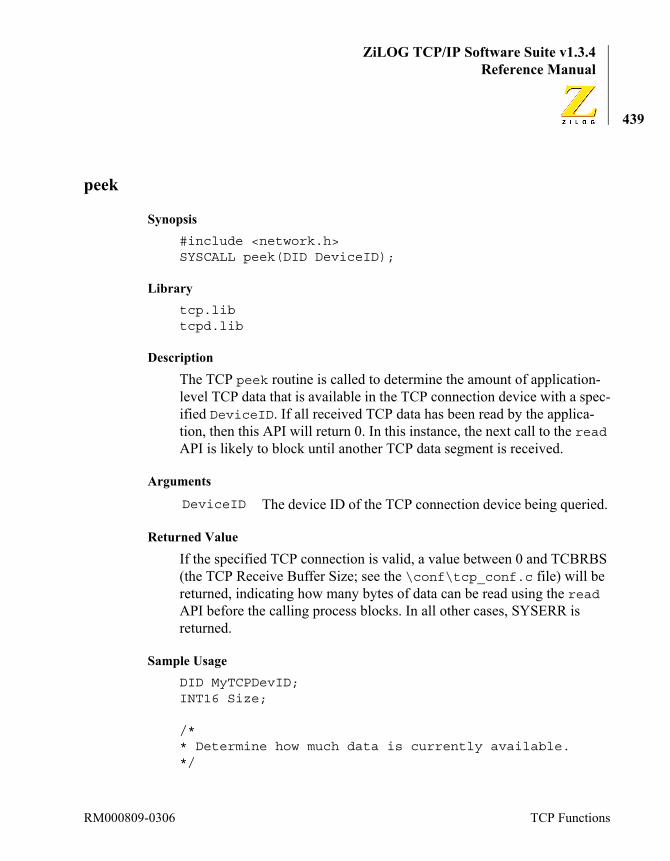
ZiLOG TCP/IP Software Suite v1.3.4Reference Manual
439
peek
Synopsis#include <network.h>SYSCALL peek(DID DeviceID);
Librarytcp.libtcpd.lib
Description
The TCP peek routine is called to determine the amount of application-level TCP data that is available in the TCP connection device with a spec-ified DeviceID. If all received TCP data has been read by the applica-tion, then this API will return 0. In this instance, the next call to the read API is likely to block until another TCP data segment is received.
Arguments
Returned Value
If the specified TCP connection is valid, a value between 0 and TCBRBS (the TCP Receive Buffer Size; see the \conf\tcp_conf.c file) will be returned, indicating how many bytes of data can be read using the read API before the calling process blocks. In all other cases, SYSERR is returned.
Sample UsageDID MyTCPDevID;INT16 Size;
/** Determine how much data is currently available.*/
DeviceID The device ID of the TCP connection device being queried.
RM000809-0306 TCP Functions
ZiLOG TCP/IP Software Suite v1.3.4eZ80® Family of Microprocessors
440
Size = peek( MyTCPDevID );if( Size > 0 ){
kprintf( “%d bytes available to be read\n” );}
ZTP API Reference RM000809-0306

ZiLOG TCP/IP Software Suite v1.3.4Reference Manual
441
getc
Synopsis#include <network.h>SYSCALL getc(DID DeviceID);
Librarytcp.libtcpd.lib
Description
The TCP getc routine is called to receive a single byte of data from the specified TCP connection DeviceID. This API cannot be called using either a TCP server device ID or the TCP master device ID.
Internally, the TCP connection device calls the TCP read API to specify a one-byte buffer into which a received TCP data byte is placed. For more information, see the TCP read API on page 432.
Arguments
Returned Value
If the specified DeviceID is valid and a single byte of TCP data is received, the getc function returns a positive value representing the received data byte. In all other cases, SYSERR is returned. If there is no data available in the TCP connection device at the time getc is called, the calling process is blocked until at least one byte of data is available.
DeviceID The TCP connection device from which a single data byte is to be received.
RM000809-0306 TCP Functions

ZiLOG TCP/IP Software Suite v1.3.4eZ80® Family of Microprocessors
442
putc
Synopsis#include <network.h>SYSCALL putc(DID DeviceID, char data);
Librarytcp.libtcpd.lib
Description
The TCP putc routine is called to transmit a single byte of data using the specified TCP connection DeviceID. This API cannot be called using either a TCP server device ID or the TCP master device ID.
Internally, the TCP connection device calls the TCP write API to spec-ify a one-byte buffer containing the data parameter. For more informa-tion, see the TCP write API on page 436.
Arguments
Returned Value
If the specified DeviceID is valid, the putc function returns a value of OK (currently defined as 1) to indicate successful transmission of the specified data byte. In all other cases, SYSERR is returned.
DeviceID The TCP connection device used for data transferdata The value of the single TCP data byte to be transmitted
using this TCP connection DeviceID.
ZTP API Reference RM000809-0306
ZiLOG TCP/IP Software Suite v1.3.4Reference Manual
443
close
Synopsis#include <network.h>SYSCALL close(DID DeviceID);
Librarytcp.libtcpd.lib
Description
The TCP close routine is called to close the TCP connection or server device with the specified DeviceID. This API cannot be called using the TCP master device ID.
Just because you call the close API, you must not assume that the TCP connection is actually severed, because the TCP connection must be explicitly closed by both endpoints before the TCP layers will completely sever the TCP connection and release any associated system resources.
When a TCP application calls the close API, it is only indicating to the remote peer that it has no more data to send. This action does not prevent the peer TCP application from continuing to send TCP data to the local socket. If your application does not remove this data from the TCP receive buffer (by calling the read API), TCP flow control could prevent the remote device from completing its data transfer operation. After the remote TCP peer has finished sending data, it too will call the close API. After your TCP application has read all of the data sent by the remote peer, the read API will return SYSERR.
After the TCP close API is called, subsequent calls to the write API using the same connection device will return SYSERR. In general, ZTP applications that interface with TCP should continue to call the read API until SYSERR is returned regardless of whether the remote or local appli-cation is the first to call the TCP close API. Additionally, every TCP
RM000809-0306 TCP Functions
ZiLOG TCP/IP Software Suite v1.3.4eZ80® Family of Microprocessors
444
connection device should be explicitly closed instead of assuming that the device may have been closed because of some other failure.
Closing a TCP server device does not affect the active TCP connections created by calling the TCPC_ACCEPT control API on the server. The only effect is that the server device cannot process new connection requests from remote sockets. However, one typically closes the TCP connection devices prior to closing the TCP server that created them.
After the close operation completes, the associated TCP slave devices are available for subsequent reallocation by the TCP master device.
Arguments
Returned Value
If the specified DeviceID is closed, OK is returned. Otherwise, SYSERR is returned.
Sample Usage{
DID MyTCPDevID;INT16 Status;char Buffer[100];
/* * Establish a connection to a remote server. * This application assumes the remote server will * send an arbitrary amount of data after receiving * a greeting message and then the server will close * its side of the connection. */MyTCPDev = open(TCP, “192.168.1.76:3000”, NULLPTR);if( MyTCPDev ){
// Send the Server a greeting message
DeviceID The TCP device ID to be closed.
ZTP API Reference RM000809-0306
ZiLOG TCP/IP Software Suite v1.3.4Reference Manual
445
write( MyTCPDev, “Hello”, 5 );
//Keep processing data from the peer.while(1){ Status = read( MyTCPDev, Buffer, 100 ); if( Status == SYSERR ) { close( MyTCPDev ); break; } // Process the data here}
}}
ARP FunctionsThis section describes the user interface to the ARP module. ARP is required when an Ethernet driver is included in your project. ARP man-ages the mapping of IP addresses to Ethernet addresses for devices within the same subnet.
Function Description
arp_init Initializes the ARP module.
arp_add_cmds Adds optional ARP-related commands to the shell.
get_arp_mapping Obtains an Ethernet address for a given IP address from the ARP table.
RM000809-0306 ARP Functions

ZiLOG TCP/IP Software Suite v1.3.4eZ80® Family of Microprocessors
446
arp_init
Synopsis#include <network.h>void arp_init( WORD ArpTableSize );
Libraryarp.lib
Description
If your application uses Ethernet to transfer network frames, you must include the ARP module in your project. The ARP module is initialized by calling the arp_init API. This function call should be made immedi-ately after the Ethernet interface, typically from within main(); see the eth_init API description on page 469.
During initialization, the ARP module allocates a table, from the global heap, that is used to manage the mapping of IP to Ethernet addresses. This table is referred to as the ARP mapping table. When the IP layer sends a datagram, the target recipient is identified by an IP address. If that IP address is within the same subnet as the ZTP system, then the ARP mod-ule is used to determine the Ethernet address to which an Ethernet frame containing the IP datagram will be sent. This information is stored in the ARP mapping table.
The size of the ARP mapping table is determined by the value of the ArpTableSize parameter. One entry is required in the table for each IP address that must be mapped to an Ethernet address. Therefore, the size of the table should be compatible with the number of devices your applica-tion will typically require to communicate with simultaneously. Remem-ber that your device must typically communicate with at least one gateway.
If the ARP table does not contain mapping for the target IP address, then the ARP protocol is used to query all devices within the local subnet to see which devices, if any, are using the target IP address. If the target IP
ZTP API Reference RM000809-0306

ZiLOG TCP/IP Software Suite v1.3.4Reference Manual
447
address is being used, the ARP protocol automatically updates the ARP mapping table. After an entry is created in the ARP table, it does not stay there indefinitely. In the ZTP implementation of ARP, mapping table entries decay in five minutes. This time-out is not user-configurable.
If the mapping table is full but does not contain mapping for a target IP address, the ZTP ARP module will discard entries in a cyclical manner. If the ARP mapping table is too small, thrashing can occur.
For example, suppose you call arp_init and specify a mapping table size of 2; but your application simultaneously communicates with three devices in the same subnet. Call these devices Device A, Device B, and Device C. Further assume that a frame must always be sent to Device A, then to Device B, then to Device C. In this instance, the target IP address will rarely be in the ARP mapping table. Therefore, instead of performing a simple table look-up, the ARP module must discard one of the other two entries, invoke the address resolution protocol, and update the mapping table. This exercise must be performed each time your application tries to send a frame.
To see the entries currently in the ARP mapping table, use the arp shell command.
Arguments
Returned Value
None.
Sample Usagevoid main( void ){
KE_KernelInit();netstart();eth_init( dhcp );arp_init( 5 ); // Mapping table will have 5 entries.
ArpTableSize Determines the size of the ARP mapping table.
RM000809-0306 ARP Functions

ZiLOG TCP/IP Software Suite v1.3.4eZ80® Family of Microprocessors
448
}
ZTP API Reference RM000809-0306

ZiLOG TCP/IP Software Suite v1.3.4Reference Manual
449
arp_add_cmds
Synopsis#include <network.h>void arp_add_cmds( void );
Libraryarp.lib
Description
To use the services of the ZTP ARP layer, your application must call arp_init. In addition, one ARP-related shell command, arp, can optionally be added to the system. For more information about the use of this command, see the ZTP Shell Command Reference chapter on page 513. If you are not using the shell, or do not wish to include this optional command in your project, do not call arp_add_cmds.
Arguments
None.
Returned Value
None.
Sample Usagevoid main( void ){
KE_KernelInit();netstart();eth_init( dhcp );arp_init( 5 ); // Mapping table will have 5 entries.arp_add_cmds(); // Include the arp shell command
}
RM000809-0306 ARP Functions
ZiLOG TCP/IP Software Suite v1.3.4eZ80® Family of Microprocessors
450
get_arp_mapping
Synopsis#include <network.h>SYSCALLget_arp_mapping(
IPaddr ipaddr,BYTE * pMapping,BOOL IncludeGW
)
Libraryarp.lib
Description
The get_arp_mapping API can be used to obtain the 6-byte Ethernet address of the device within the local network to which IP datagrams directed towards the specified IP address (ipaddr) will be sent. If the ARP table currently contains an entry for the specified IP address, the corresponding 6-byte Ethernet address will be copied into the buffer ref-erenced by the pMapping parameter. If mapping cannot be found in the ARP table, SYSERR is returned.
When an IP datagram is directed to a device within a different subnet, the datagram is delivered to a router (or gateway). The Ethernet address used by the router is typically not the same as the Ethernet address used by the device possessing the target IP address. Actually, one cannot assume that a device reachable through a gateway is even using Ethernet. For this rea-son, the get_arp_mapping API allows the caller to explicitly indicate if a gateway address should be returned for IP addresses in other subnets. If the IncludeGW flag is TRUE and the specified IP address is in another subnet, then instead of the Ethernet address of the target device being returned, the Ethernet address of the gateway is returned.
Note:
ZTP API Reference RM000809-0306

ZiLOG TCP/IP Software Suite v1.3.4Reference Manual
451
Arguments
Returned Value
If the ARP mapping table contains an entry for the specified IP address, the 6-byte Ethernet address is copied into the specified buffer and OK is returned.
OK will also be returned if the target IP address is in a different subnet, the ARP mapping table contains an entry for the gateway used to reach the target, and the IncludeGW flag is set to TRUE.
In all other cases, SYSERR is returned and nothing is copied into the specified buffer.
Sample Usagevoid main( void ){
BYTE Eth_Addr[6];IPaddr DestIP = dot2ip( “192.168.1.20” );
KE_KernelInit();netstart();eth_init( dhcp );icmp_init();// Send the Target a Ping request.// Wait up to 3 seconds for a responseif( Ping( DestIP, 100, 3) == TRUE )
IPaddr Target IP address for which an Ethernet mapping is being sought.
pMapping References a 6-byte buffer into which the Ethernet address used by the device possessing the specified IP address will be placed.
IncludeGW Set to TRUE if the Ethernet address of a gateway should be returned for target IP addresses in other subnets.
RM000809-0306 ARP Functions

ZiLOG TCP/IP Software Suite v1.3.4eZ80® Family of Microprocessors
452
{// Get the target’s Ethernet addressget_arp_mapping( DestIP, Eth_Addr, TRUE );
}}
ICMP FunctionsThis section describes the user interface to the ICMP module. ICMP is used to the IP layer to exchange control and error messages with other hosts. From a user perspective, one of the most important sets of control messages ICMP uses are the Echo and Echo Reply messages, commonly referred to as ping.
Function Description
icmp_init Initializes the ICMP module.
icmp_add_cmds Adds optional ICMP-related commands to the shell.
ping Send an Echo message to the specified host and waits for a reply.
ZTP API Reference RM000809-0306

ZiLOG TCP/IP Software Suite v1.3.4Reference Manual
453
icmp_init
Synopsis#include <network.h>SYSCALL icmp_init( void );
Libraryicmp.lib
Description
If your application requires the services of the ICMP protocol (e.g., ping, generation of Destination Unreachable messages, updating the routing table on redirects), you must include the ICMP module in your project. The ICMP module is initialized by calling the icmp_init API, which should be called after the call to netstart—typically from within main().
Although ZiLOG recommends including the ICMP module in your project for interoperability with other devices, you can choose to omit it by not calling the icmp_init API; this omission can help to conserve memory in systems with few resources.
Arguments
None.
Returned Value
This function always returns OK.
Sample Usagevoid main( void ){
KE_KernelInit();netstart();eth_init( dhcp );
RM000809-0306 ICMP Functions

ZiLOG TCP/IP Software Suite v1.3.4eZ80® Family of Microprocessors
454
icmp_init();}
ZTP API Reference RM000809-0306

ZiLOG TCP/IP Software Suite v1.3.4Reference Manual
455
icmp_add_cmds
Synopsis#include <network.h>void icmp_add_cmds( void );
Libraryicmp.lib
Description
To use the services of the ZTP ICMP layer, your application must call icmp_init. In addition, there is one ICMP-related shell command, ping, that can optionally be added to the system. For more information about the use of this command, see the ZTP Shell Command Reference chapter on page 513. If you are not using the shell, or do not wish to include this optional command in your project, do not call the icmp_add_cmds API.
Arguments
None.
Returned Value
None.
Sample Usagevoid main( void ){
KE_KernelInit();netstart();eth_init( dhcp );icmp_init();icmp_add_cmds(); // Include the ping shell command
}
RM000809-0306 ICMP Functions
ZiLOG TCP/IP Software Suite v1.3.4eZ80® Family of Microprocessors
456
ping
Synopsis#include <network.h>BOOL ping(IPaddr ipaddr, WORD Length, WORD TimeoutSeconds );
Libraryicmp.lib
Description
To use the services of the ZTP ICMP layer, your application must call icmp_init. After this call, an application can use the ping API to deter-mine if a remote device is using a specific IP address.
The ipaddr parameter specifies the IP address of the device to which an ICMP Echo Request (a.k.a. ping) packet will be sent. The ping packet will contain Length bytes of arbitrary data. The API will wait for up to TimeoutSeconds for a response from the target device. If a response is received before the time-out expires, TRUE will be returned.
Arguments
ipaddr The target of the ping (ICMP echo request) packet.
Length Specifies the number of bytes in the ICMP pay-load. The data will be arbitrary. At the time of pub-lication of this document, Length was constrained to be between 0 and 4035.
TimeoutSeconds Specifies the maximum number of seconds to wait for a ping response before aborting.
ZTP API Reference RM000809-0306
ZiLOG TCP/IP Software Suite v1.3.4Reference Manual
457
Returned Value
If the specified target responds to the echo request message within the time-out period, TRUE is returned. In all other cases, FALSE is returned.
Sample Usagevoid main( void ){
BYTE Eth_Addr[6];IPaddr DestIP = dot2ip( “192.168.1.21” );
KE_KernelInit();netstart();eth_init( dhcp );icmp_init();// Send the Target a Ping request.// Wait up to 3 seconds for a responseif( Ping( DestIP, 100, 3) == TRUE ){
kprintf( “Ping response was received\n” );}
}
IGMP FunctionsThis section describes the user interface to the IGMP module. IGMP is used to enable the exchange of IP multicast frames. Hosts normally com-municate with each other using directed datagrams. Therefore, if Host A must send a datagram to Host B, Host A will determine Host B’s unique IP address and send the data in a message directed to Host B. If Host A must send the same datagram to multiple devices, then IP Multicasting can be used to eliminate the need to send a unique datagram to each of the hosts. Instead, all devices join a particular multicast group using the IGMP protocol. Then, when Host A sends a message to all members of the group, the datagram is sent to the group address (IP multicast address) instead of an individual IP address.
RM000809-0306 IGMP Functions

ZiLOG TCP/IP Software Suite v1.3.4eZ80® Family of Microprocessors
458
Function Description
igmp_init Initializes the IGMP module.
igmp_add_cmds Adds optional IGMP-related commands to the shell.
hgjoin Used to request membership in a particular IP multicast group.
hgleave Used to terminate membership in a particular multicast group.
ZTP API Reference RM000809-0306

ZiLOG TCP/IP Software Suite v1.3.4Reference Manual
459
igmp_init
Synopsis#include <network.h>void igmp_init( WORD IgmpTableSize );
Libraryigmp.lib
Description
If your application requires IP Multicast support, you must include the IGMP module in your project. The IGMP module is initialized by calling the igmp_init API, which should be called after the call to net-start—typically from within main().
IP multicasting can be used to send UDP datagrams to multiple devices with a single call to the UDP write API. Instead of directing the UDP datagram to a specific IP address, the datagram is directed to an IP address in the range of 224.0.0.0 to 239.255.255.255 (that is, a Class D IP address). This address range is referred to as a group address. All devices that have joined a particular group are eligible to receive an IP multicast frame sent to the group address.
UDP does not guarantee the delivery of datagrams. Therefore, you must not assume that a multicast frame will be received by every, or any, mem-ber of the group. Also, be aware that some IP multicast address are reserved for special purposes. The IANA maintains a list of all reserved, assigned, and unassigned, IP multicast addresses. You should never use a reserved or assigned IP multicast address for your own private purposes.
Similarly, to enable reception of IP multicast datagrams through the UDP read API, ZTP applications are required to explicitly join a multicast group. To join a multicast group, use the hgjoin API. To leave the group, use the hgleave API. These APIs will either add or remove an IP multi-cast address from the IGMP host group table. The size of this table is
Note:
RM000809-0306 IGMP Functions

ZiLOG TCP/IP Software Suite v1.3.4eZ80® Family of Microprocessors
460
determined by the value of the IgmpTableSize parameter that is passed to the igmp_init routine. One entry is required per group address that your application employs.
Additionally, the IGMP module includes an optional shell command that can be used to interactively join or leave IP multicast groups and display the set of all group addresses currently being used (see the igmp shell command on page 533 and the igmp_add_cmds API on page 465).
If you are using both Ethernet and PPP and wish to use IGMP, then you must initialize the Ethernet interface via eth_init before initializing the PPP interface via ppp_init.
Arguments
Returned Value
None.
Sample Usagevoid main( void ){
KE_KernelInit();netstart();eth_init( dhcp );igmp_init( 5 );// IGMP table will have 5 entries.
}
IgmpTableSize Determines the maximum number of groups in which your device may be a member.
Note:
ZTP API Reference RM000809-0306

ZiLOG TCP/IP Software Suite v1.3.4Reference Manual
461
hgjoin
Synopsis#include <network.h>SYSCALL hgjoin(BYTE ifnum, IPaddr ipa, BYTE ttl);
Libraryigmp.lib
Description
To use the services of the ZTP IGMP layer, your application must call igmp_init. To enable reception of a particular group address, your application must call the hgjoin API to add an entry to the IGMP Host group table for the specified group address. As a result, the Ethernet driver will capture frames addressed to the specified group and allow them to be received by your application through the UDP read API.
To map an IP multicast address to an Ethernet address, the low-order 23 bits of the IP address are placed in the low-order 23 bits of the Ethernet frame. Because there are actually 28 significant bits of information in a Class D address, multiple IP multicast address will use the same Ethernet address. As a result, you should always check the xgram structure obtained through the UDP read API in NORMAL mode to ensure that the destination multicast address matches the group address used by your application.
When your application is finished using the IGMP group address, call the hgleave API to leave the group.
The ifnum parameter specifies the network interface through which the reception of IP Multicast frames is to be enabled. This parameter must always reference the Ethernet interface. Further, if you are using both Ethernet and PPP and choose to use IGMP, then you must initialize the Ethernet interface via eth_init before initializing the PPP interface via
Note:
RM000809-0306 IGMP Functions
ZiLOG TCP/IP Software Suite v1.3.4eZ80® Family of Microprocessors
462
ppp_init. If this requirement is followed, then the ifnum parameter should always be specified as the system-defined macro NI_PRIMARY.
Arguments
Returned Value
If a specified group address can be added to the host group table, OK is returned. In all other cases, SYSERR is returned.
Sample Usagevoid main( void ){
IPaddr GroupAddr = dot2ip( “224.0.253.8” );KE_KernelInit();netstart();eth_init( dhcp );igmp_init( 5 );// IGMP table will have 5 entries.igmp_add_cmds();// Include the IGMP shell command.if( hgjoin(NI_PRIMARY, GroupAddr, 5) == OK ){
kprintf( “Successfully joined the group\n” );}
}
ifnum The interface number through which reception of the specified IP multicast address is to be enabled. Always use NI_PRIMARY.
ipa Specifies the IP multicast address for which IGMP support is to be added.
ttl The Time To Live parameter is used on outbound IP datagrams sent to a specified IP address; it represents the maximum number of gateways through which a datagram may pass before it is discarded.
ZTP API Reference RM000809-0306

ZiLOG TCP/IP Software Suite v1.3.4Reference Manual
463
hgleave
Synopsis#include <network.h>SYSCALL hgleave(BYTE ifnum, IPaddr ipa);
Libraryigmp.lib
Description
To enable reception of IP Multicast frames, your application must call the hgjoin API. After your application is finished using the multicast (or group) address, use the hgleave API to disable reception of multicast frames destined to this group.
Internally, the IGMP layer maintains a table of all group addresses cur-rently being used by all applications in the system. This information is stored in the host group table (see the igmp_init API). This table is used to respond to queries from multicast routers that are intended to determine which host groups are in use within the subnet. The hgjoin API will add a specified IP multicast address to the host group table, and the hgleave API is used to remove the address from the table.
The value of the ifnum parameter must match the value used in the call to hgjoin for the target IP multicast address. This value should always be specified as NUI_PRIMARY.
Arguments
ifnum The interface number through which reception of a specified IP multicast address is to be disabled. Always use NI_PRIMARY.
ipa Specifies the IP multicast address for which IGMP support is to be removed.
RM000809-0306 IGMP Functions

ZiLOG TCP/IP Software Suite v1.3.4eZ80® Family of Microprocessors
464
Returned Value
If a specified group address is located in the host group table, it is removed and OK is returned. In all other cases, SYSERR is returned.
Sample Usagevoid main( void ){
IPaddr GroupAddr = dot2ip( “224.0.253.8” );KE_KernelInit();netstart();eth_init( dhcp );igmp_init( 5 );// IGMP table will have 5 entries.igmp_add_cmds();// Include the IGMP shell command.if( hgjoin(NI_PRIMARY, GroupAddr, 5) == OK ){
kprintf( “Successfully joined the group\n” );hgleave( NI_PRIMARY, GroupAddr );
}}
ZTP API Reference RM000809-0306

ZiLOG TCP/IP Software Suite v1.3.4Reference Manual
465
igmp_add_cmds
Synopsis#include <network.h>void igmp_add_cmds( void );
Libraryigmp.lib
Description
To use the services of the ZTP IGMP layer, your application must call igmp_init. In addition, there is one IGMP-related shell command, igmp, that can optionally be added to the system. For more information about the use of this command, see the ZTP Shell Command Reference chapter on page 513. If you are not using the shell, or do not wish to include this optional command in your project, do not call the igmp_add_cmds API.
Arguments
None.
Returned Value
None.
Sample Usagevoid main( void ){
KE_KernelInit();netstart();eth_init( dhcp );igmp_init();// IGMP table will have 5 entries.igmp_add_cmds();// Include the IGMP shell command.
}}
RM000809-0306 IGMP Functions
ZiLOG TCP/IP Software Suite v1.3.4eZ80® Family of Microprocessors
466
Ethernet FunctionsThis section describes the user interface to the Ethernet driver. The ZTP network layer exclusively uses services of the Ethernet driver to send and receive network data. User code must only initialize the Ethernet driver, and can query the driver to determine if a physical network connection is still present.
Function Description
eth_init Initializes the Ethernet driver.
Is_Ethernet_Connected Returns TRUE if there is a physical connection to the network.
emac_reset Resets the Ethernet controller.
ZTP API Reference RM000809-0306

ZiLOG TCP/IP Software Suite v1.3.4Reference Manual
467
emac_reset
Synopsis#include <ether.h>void emac_reset( void );
Library
F91_emac.lib or CS8900a.lib
Description
During system initialization, ZDS II start-up code resets all hardware peripherals on the eZ80® target device. The hardware resources that are reset are the Chip Select registers, internal Flash control registers, and the eZ80F91 integrated Ethernet controller. ZDS II not only initializes the integrated peripherals to a known initial state; it also ensures that these devices will not generate any interrupts. This aspect is important, because no ZTP interrupt handlers will be installed in the system until after the KE_KernelInit API is called.
The kernel will call the ZTP_HW_Init routine from within the KE_KernelInit routine to allow the user to perform any platform-spe-cific hardware initialization not performed by ZDS II. For platforms not using the eZ80F91 integrated Ethernet controller, the emac_reset rou-tine is typically the first API called from ZTP_HW_Config.
The emac_reset routine is called to place the Ethernet controller into a known initial state and to ensure that the device will not generate any interrupts until the eth_init API is called. ZTP projects that do not use an Ethernet controller are not required to call emac_reset. Similarly, ZTP projects that use the eZ80F91 integrated Ethernet controller are not required to call the emac_reset API, because ZDS II start-up code will place the eZ80F91 Ethernet controller into a known state.
Arguments
None.
RM000809-0306 Ethernet Functions

ZiLOG TCP/IP Software Suite v1.3.4eZ80® Family of Microprocessors
468
Returned Value
None.
Sample Usagevoid ZTP_HW_Init( void ){
emac_reset();
/* * Reset other external Peripheral devices here */
/* * If not using mode 2, modify GPIO registers here */
}
ZTP API Reference RM000809-0306

ZiLOG TCP/IP Software Suite v1.3.4Reference Manual
469
eth_init
Synopsis#include <network.h>SYSCALL eth_init( GET_IP_FUNC GetIPFunc );
Library
F91_emac.lib or CS8900a.lib
Description
If your application requires the use of Ethernet to transfer network data, then you must call the eth_init API before using other networking ser-vices. eth_init should be called from within main immediately after the call to netstart. The eth_init API will initialize the Ethernet driver included in your project (either the CS8900A driver or the F91_emac driver). In addition, this API will create the Ethernet interface used by the network driver to access the appropriate Ethernet driver.
Each network-enabled ZTP demo project includes an instantiation of a BootInfo structure named Bootrecord. Bootrecord contains the default set of static IP parameters that will be used to initialize the Ether-net interface. Bootrecord includes parameters such as the IP address to use on the Ethernet interface, the corresponding subnet mask, and the IP address of the default gateway.
eth_init requires one parameter that is a function pointer to a routine that attempts to obtain dynamic IP parameters. If the routine referenced by the GetIPFunc parameter is able to obtain dynamic IP parameters, some or all of the values assigned to the Ethernet interface from the Bootrecord structure will be updated. You can use one of the following three system-defined variables to specify the GetIPFunc argument.NULLPTR. Use this value to indicate that no dynamic update of the IP parameters should be performed. In this instance, the values in the Bootrecord structure will be assigned to the Ethernet interface without modification.
RM000809-0306 Ethernet Functions

ZiLOG TCP/IP Software Suite v1.3.4eZ80® Family of Microprocessors
470
dhcp. Use this value to specify that the DHCP protocol should be used to obtain IP parameters from a DHCP server. If a DHCP server supplies IP parameters, the values assigned by the server will be used to update the IP parameters assigned to the Ethernet interface. In addition, if any of the values assigned by the DHCP server differ from the values in the Bootrecord structure, the corresponding values in the Bootrecord structure will be updated. Specifying dhcp as the GetIPFunc argument results in the creation of a system task named dhcptimer that will peri-odically renew the leased IP parameters obtained from the DHCP server.
Note that the number of times the DHCP layer attempts to contact a DHCP server is controlled by the value of the bootp_tries variable defined in the \conf\net_conf.c file. For more information, see the DHCP Usage section on page 48 and the How to Use DHCP section on page 105.rarp. Use this value to specify that the RARP protocol should be used to obtain an IP address for the Ethernet interface being initialized. If a RARP server supplies an IP address, the IP address associated with this Ethernet interface is updated. No change will be made to the values stored in the Bootrecord structure.
Few networks will contain RARP servers. Those that do are not able to specify an appropriate subnet mask, default gateway, or name server for use with ZTP. If dynamic IP parameters are required for your application, ZiLOG recommends using DHCP instead of RARP. For more informa-tion about the RARP protocol, see the How to Use RARP section on page 106.
Arguments
GetIPFunc Function pointer to the routine used to obtain a dynamic IP parameter for the Ethernet interface. Valid options are: dhcp, NULLPTR, and rarp.
ZTP API Reference RM000809-0306
ZiLOG TCP/IP Software Suite v1.3.4Reference Manual
471
Returned Value
If the Ethernet interface is initialized, OK is returned. In all other cases SYSERR is returned.
Sample Usagevoid main( void ){
KE_KernelInit();netstart();eth_init( dhcp ); // Use DHCP to obtain IP params.
}
RM000809-0306 Ethernet Functions

ZiLOG TCP/IP Software Suite v1.3.4eZ80® Family of Microprocessors
472
Is_Ethernet_Connected
Synopsis#include <network.h>BOOL Is_Ethernet_Connected( void );
Library
F91_emac.lib or CS8900a.lib
Description
After the Ethernet interface has been initialized by calling the eth_init API, your application can call the Is_Ethernet_Connected API to determine if there is a valid physical connection to the Ethernet network. If a connection exists at the time this API is called, TRUE is returned. If there is no physical connection to the Ethernet network FALSE is returned.
Applications use the Is_Ethernet_Connected API to detect when the Ethernet cable has been disconnected. These applications can create a task that periodically wakes up and calls the Is_Ethernet_Connected API. If this API returns TRUE, the tasks sleeps for a certain number of sec-onds. If the polling task detects that the cable is unplugged, it can display an error message on the console or take whatever other action is deemed appropriate.
Arguments
None.
Returned Value
If there is a valid physical connection to the Ethernet network at the time this API is called, TRUE will be returned. In all other cases, FALSE is returned.
ZTP API Reference RM000809-0306

ZiLOG TCP/IP Software Suite v1.3.4Reference Manual
473
Sample Usagevoid main( void ){
KE_KernelInit();netstart();eth_init( dhcp ); // Use DHCP to obtain IP params.if( Is_Ethernet_Connected() == TRUE ){
kprintf( “Ethernet cable connected\n” );}
}
PPP FunctionsThis section describes the user interface to the Point-to-Point Protocol (PPP) layer. In ZTP, PPP is used to establish a physical connection over a serial channel that is then used to transfer IP datagrams. The ZTP PPP layer can be used to establish a connection using an external modem or by using a serial cable connected between devices. The ZTP PPP layer can either initiate the PPP connection (referred to as client mode), or passively wait for the remote to initiate the PPP connection (referred to as server mode).
Function Description
ppp_init Initializes the PPP module.
ppp_resume Used to (re)establish a PPP connection.
ppp_stop Used to disconnect PPP.
get_ppp_state Used to determine if PPP is connected.
RM000809-0306 PPP Functions
ZiLOG TCP/IP Software Suite v1.3.4eZ80® Family of Microprocessors
474
ppp_init
Synopsis#include <ppp.h>void ppp_init( DID dev, struct pppconf *pppconf );
Libraryppp.lib
Description
The ppp_init function initializes the PPP protocol layers. This API should be called from within main().
Arguments
Returned Value
None.
Sample Usagevoid main( void ){
KE_KernelInit();netstart();eth_init( dhcp ); // Use DHCP to obtain IP params.arp_init( 5 );
dev Device ID of the device driver over which PPP is layered. Typically this parameter is specified as SERIAL1.
pppconf Pointer to a pppconf structure that customizes the operation of PPP (see the discussion of the ppp_conf.c file on page 61). Typically, this parameter is specified as &ppp. See the How to Use PPP section on page 147 for additional information.
ZTP API Reference RM000809-0306

ZiLOG TCP/IP Software Suite v1.3.4Reference Manual
475
icmp_init();udp_init( 8 );tcp_init( 8 );
ppp_init( SERIAL1, &ppp );
// Establish a PPP connectionppp_resume();// Sleep 1 minute to allow PPP to connectsleep( 60 );
// Break the PPP connectionppp_stop();
}
RM000809-0306 PPP Functions
ZiLOG TCP/IP Software Suite v1.3.4eZ80® Family of Microprocessors
476
ppp_stop
Synopsis#include <ppp.h>void ppp_stop( void );
Libraryppp.lib
Description
The ppp_stop function can be called to break the PPP connection that has been established with a remote device. In cases where flags specified in the ppp structure (see the discussion of the ppp_conf.c file on page 61) instructed PPP to override IP parameter settings in effect before the PPP link was established, then the original settings are restored when the PPP layer is disconnected.
After calling ppp_stop, if the do_auto_reconnect member of the ppp structure is set to TRUE, the PPP layer automatically attempts to re-estab-lish a PPP connection after disconnecting from the remote. Therefore, if you desire the PPP layer to remain idle after calling ppp_stop, it is nec-essary to set the do_auto_reconnect member of the ppp structure to FALSE prior to calling ppp_stop. In this case, PPP does not attempt to establish another connection until you call the ppp_resume API (or enter the pppresume shell command).
Arguments
None.
Returned Value
None.
Sample Usage#include <ppp.h>
Note:
ZTP API Reference RM000809-0306
ZiLOG TCP/IP Software Suite v1.3.4Reference Manual
477
void SetupRoutine( void ){
DID SerDev;
/* * Disable PPP if it was running so we can use * the underlying UART for our own purpose. */ppp.do_auto_reconnect = FALSE;ppp_stop();
// Wait a few seconds for PPP to disconnectwhile( get_ppp_state() != PPP_DISCONNECTED ){
sleep(1);}
// Start using the underlying uartSerDev = open( SERIAL1, 0, 0 );write( SerDev, "Hello", 5 );
}
See Also
ppp_resume
RM000809-0306 PPP Functions

ZiLOG TCP/IP Software Suite v1.3.4eZ80® Family of Microprocessors
478
ppp_resume
Synopsis#include <ppp.h>void ppp_resume( void );
Libraryppp.lib
Description
The ppp_resume function is called to (re)establish a PPP connection after the link has been disconnected when the do_auto_reconnect member of the ppp structure is set to FALSE. If the do_auto_reconnect member of the ppp structure is set to TRUE, PPP will automatically attempt to re-establish the PPP connection once the connection breaks.
Arguments
None.
Returned Value
None.
Sample Usage#include <ppp.h>
void SetupRoutine( void ){
/* * Disable PPP if it was running. */ppp.do_auto_reconnect = FALSE;ppp_stop();
// Wait for the PPP layer to disconnect
ZTP API Reference RM000809-0306
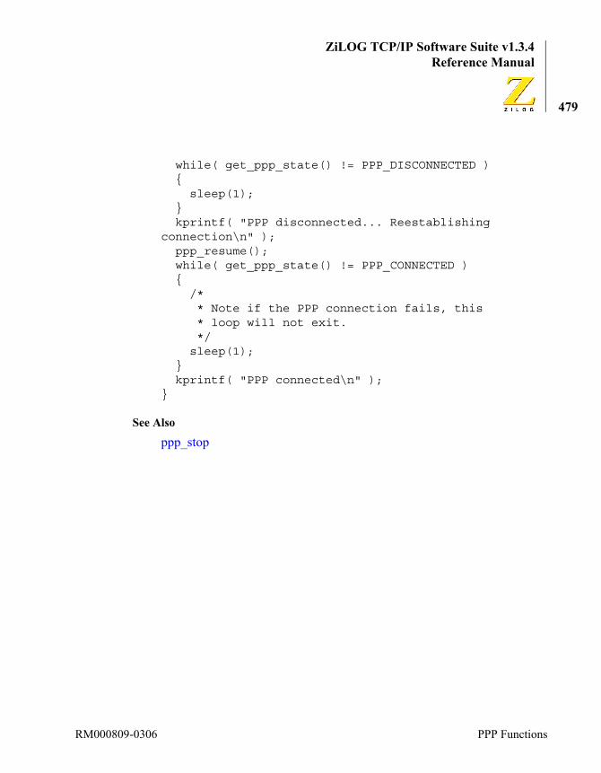
ZiLOG TCP/IP Software Suite v1.3.4Reference Manual
479
while( get_ppp_state() != PPP_DISCONNECTED ){
sleep(1);}kprintf( "PPP disconnected... Reestablishing
connection\n" );ppp_resume();while( get_ppp_state() != PPP_CONNECTED ){
/* * Note if the PPP connection fails, this * loop will not exit. */sleep(1);
}kprintf( "PPP connected\n" );
}
See Also
ppp_stop
RM000809-0306 PPP Functions
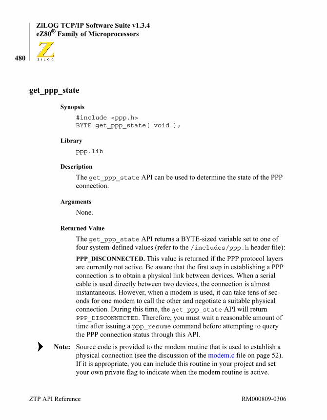
ZiLOG TCP/IP Software Suite v1.3.4eZ80® Family of Microprocessors
480
get_ppp_state
Synopsis#include <ppp.h>BYTE get_ppp_state( void );
Libraryppp.lib
Description
The get_ppp_state API can be used to determine the state of the PPP connection.
Arguments
None.
Returned Value
The get_ppp_state API returns a BYTE-sized variable set to one of four system-defined values (refer to the /includes/ppp.h header file):PPP_DISCONNECTED. This value is returned if the PPP protocol layers are currently not active. Be aware that the first step in establishing a PPP connection is to obtain a physical link between devices. When a serial cable is used directly between two devices, the connection is almost instantaneous. However, when a modem is used, it can take tens of sec-onds for one modem to call the other and negotiate a suitable physical connection. During this time, the get_ppp_state API will return PPP_DISCONNECTED. Therefore, you must wait a reasonable amount of time after issuing a ppp_resume command before attempting to query the PPP connection status through this API.
Source code is provided to the modem routine that is used to establish a physical connection (see the discussion of the modem.c file on page 52). If it is appropriate, you can include this routine in your project and set your own private flag to indicate when the modem routine is active.
Note:
ZTP API Reference RM000809-0306

ZiLOG TCP/IP Software Suite v1.3.4Reference Manual
481
PPP_CONNECTING. This value is returned when the PPP layers are actively negotiating the PPP connection. This process can take several seconds on slow links.PPP_CONNECTED. This value is returned after all of the PPP sublayers have completed negotiations and successfully established a PPP connec-tion. After PPP has been connected, other network protocols can be used over the PPP link.PPP_DISCONNECTING. After either end of the PPP connection decides to gracefully terminate the connection, the PPP protocol will tear down the link. While this tear-down is occurring, the get_ppp_state API will return PPP_DISCONNECTING. After the PPP link has been fully discon-nected, the get_ppp_state API will again return PPP_DISCONNECTED.
Sample Usage#include <ppp.h>
void ClientConnect( void ){
BYTE PPPState;WORD Count = 600;// Max wait time = 60 sec.
ppp_resume();
/* * Wait until PPP is connected before returning */PPPState = get_ppp_state();while( PPPState != PPP_CONNECTED ){
sleep100( 10 );PPPState = get_ppp_state();if( PPPState == PPP_DISCONNECTED ){ if( --Count == 0 ) {
RM000809-0306 PPP Functions
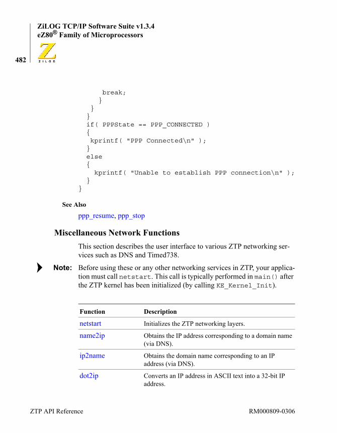
ZiLOG TCP/IP Software Suite v1.3.4eZ80® Family of Microprocessors
482
break; }
}}if( PPPState == PPP_CONNECTED ){ kprintf( "PPP Connected\n" );}else{
kprintf( "Unable to establish PPP connection\n" );}
}
See Also
ppp_resume, ppp_stop
Miscellaneous Network FunctionsThis section describes the user interface to various ZTP networking ser-vices such as DNS and Timed738.
Before using these or any other networking services in ZTP, your applica-tion must call netstart. This call is typically performed in main() after the ZTP kernel has been initialized (by calling KE_Kernel_Init).
Function Description
netstart Initializes the ZTP networking layers.
name2ip Obtains the IP address corresponding to a domain name (via DNS).
ip2name Obtains the domain name corresponding to an IP address (via DNS).
dot2ip Converts an IP address in ASCII text into a 32-bit IP address.
Note:
ZTP API Reference RM000809-0306

ZiLOG TCP/IP Software Suite v1.3.4Reference Manual
483
ip2dot Converts an IP address into dotted-decimal ASCII text.
timed_738_init Initializes the timed_738 daemon.
timed_738_gettime Obtains a time stamp from a Timed738 server.
RM000809-0306 Miscellaneous Network Functions
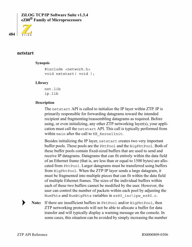
ZiLOG TCP/IP Software Suite v1.3.4eZ80® Family of Microprocessors
484
netstart
Synopsis#include <network.h>void netstart( void );
Librarynet.libip.lib
Description
The netstart API is called to initialize the IP layer within ZTP. IP is primarily responsible for forwarding datagrams toward the intended recipient and fragmenting/reassembling datagrams as required. Before using, or even initializing, any other ZTP networking layer(s), your appli-cation must call the netstart API. This call is typically performed from within main after the call to KE_KernelInit.
Besides initializing the IP layer, netstart creates two very important buffer pools. These pools are the PktPool and the BigPktPool. Both of these buffer pools contain fixed-sized buffers that are used to send and receive IP datagrams. Datagrams that can fit entirely within the data field of an Ethernet frame (that is, are less than or equal to 1500 bytes) are allo-cated from PktPool. Larger datagrams must be transferred using buffers from BigPktPool. When the ZTP IP layer sends a large datagram, it must be fragmented into multiple pieces that can fit within the data field of multiple Ethernet frames. The sizes of the individual buffers within each of these two buffers cannot be modified by the user. However, the user can control the number of packets within each pool by adjusting the NumPkts and NumBigPkts variables in ez80_inc\ipw_ez80.c.
If there are insufficient buffers in PktPool and/or BigPktPool, then ZTP networking protocols will not be able to allocate a buffer for data transfer and will typically display a warning message on the console. In some cases, this situation can be avoided by simply increasing the number
Note:
ZTP API Reference RM000809-0306
ZiLOG TCP/IP Software Suite v1.3.4Reference Manual
485
of buffers in each of these pools. Using too large a value for NumPkts and NumBigPkts can needlessly consume RAM. Use the BPOOL console command to obtain information about these buffer pools.
Arguments
None.
Returned Value
This function always returns OK.
Sample Usagevoid main( void ){
KE_KernelInit();// Initialize the ZTP kernelnetstart();// Initialize the ZTP network
// layers}
RM000809-0306 Miscellaneous Network Functions
ZiLOG TCP/IP Software Suite v1.3.4eZ80® Family of Microprocessors
486
name2ip
Synopsis#include <network.h>IPaddr name2ip( char * Name );
Librarynet.lib
Description
The name2ip API uses DNS to resolve a specified domain name into an IP address that can be used in other ZTP networking API calls.
Arguments
Returned Value
If the Name parameter is not a dotted-decimal text string, it is interpreted as a domain name. In this instance, a DNS query is generated and directed toward the network name server. If the name server is able to resolve the name into an IP address, the IP address is returned. If the name cannot be resolved, SYSERR is returned.
Sample Usage#include <network.h>
void SetupRoutine( void ){
IPaddr Dest;char Buffer[20];
Dest = name2ip( "www.zilog.com" );
Name The host name to be resolved. This string (including the terminal null) must be less than 64 bytes.
ZTP API Reference RM000809-0306

ZiLOG TCP/IP Software Suite v1.3.4Reference Manual
487
kprintf( "IP address is %s\n", ip2dot(Buffer, Dest) );}
See Also
ip2name
RM000809-0306 Miscellaneous Network Functions

ZiLOG TCP/IP Software Suite v1.3.4eZ80® Family of Microprocessors
488
ip2name
Synopsis#include <network.h>char * ip2name(IPaddr ip, char * Name);
Librarynet.lib
Description
The ip2name API uses DNS to obtain the domain name of a host with a specified IP address. If a domain name is obtained, it is copied into the buffer referenced by the Name parameter. It is the caller’s responsibility to ensure this buffer is large enough to contain the expected domain name.
If a domain name is not associated with the specified address, then this API will return a dotted-decimal ASCII representation of the IP address in the buffer referenced by the Name parameter.
Arguments
Returned Value
This API returns the value of the Name parameter.
Sample Usage#include <network.h>char Buffer[100];
void SetupRoutine( void ){
IPaddr Dest;
ip The IP address to be resolved.
Name References a buffer into which an ASCII representation of the name will be placed.
ZTP API Reference RM000809-0306
ZiLOG TCP/IP Software Suite v1.3.4Reference Manual
489
Dest = dot2ip( "66.238.115.245" );ip2name( Dest, Buffer );kprintf( “Name is %s\n”, Buffer );
}
See Also
name2ip
RM000809-0306 Miscellaneous Network Functions
ZiLOG TCP/IP Software Suite v1.3.4eZ80® Family of Microprocessors
490
dot2ip
Synopsis#include <network.h>IPaddr dot2ip( char * Name );
Librarynet.lib
Description
The dot2ip API converts the ASCII representation of a dotted-decimal IP address in to an IP address that can be used in other ZTP networking API calls.
Arguments
Returned Value
If the specified string contains a valid dotted-decimal representation of an IP address, this function returns the ZTP-internal representation of that IP address. If the input string is not a properly formatted IP address, the return value is undefined.
Sample Usage#include <network.h>
void SetupRoutine( void ){
IPaddr Dest;
Dest = dot2ip( "192.168.1.50" );kprintf( "IP address is %08X\n", Dest );
}
Name The ASCII representation of an IP address to be con-verted.
ZTP API Reference RM000809-0306
ZiLOG TCP/IP Software Suite v1.3.4Reference Manual
491
See Also
ip2dot
RM000809-0306 Miscellaneous Network Functions

ZiLOG TCP/IP Software Suite v1.3.4eZ80® Family of Microprocessors
492
ip2dot
Synopsis#include <network.h>char * ip2dot(char * Name, IPaddr ip);
Librarynet.lib
Description
The ip2dot API converts the ZTP representation of an IP address into an ASCII string of its dotted-decimal representation. The dotted-decimal representation is copied into the buffer referenced by the Name parameter. It is the caller’s responsibility to ensure this buffer is large enough to con-tain the dotted-decimal representation.
Arguments
Returned Value
This API returns the value of the Name parameter.
Sample Usage#include <network.h>char Buffer[100];
void SetupRoutine( void ){
IPaddr Dest;
Dest = dot2ip( "192.168.1.50" );
Name References a buffer into which an ASCII dotted-decimal representation of a specified IP address will be placed.
ip The IP address to be converted to dotted-decimal repre-sentation.
ZTP API Reference RM000809-0306

ZiLOG TCP/IP Software Suite v1.3.4Reference Manual
493
kprintf( "IP address is %08X\n", Dest );
ip2dot( Buffer, Dest );kprintf( "Dotted Decimal form is %s\n", Buffer );
}
See Also
dot2ip
RM000809-0306 Miscellaneous Network Functions

ZiLOG TCP/IP Software Suite v1.3.4eZ80® Family of Microprocessors
494
timed_738_init
Synopsis#include <netapp.h>void timed_738_init( void );
Librarynetapp.lib
Description
The timed_738_init API is used to initialize the Timed738 daemon (background task). The Timed738 daemon is used to periodically query a Timed738 time server for a time stamp that corresponds to the current date and time. If the daemon is able to obtain a time stamp, it will auto-matically update the ZTP time-of-day clock. The Timed738 daemon attempts to reset the ZTP system time every 10 minutes.
At the time of publication, ZTP maintained the current time-of-day clock in software instead of using a hardware based real time clock. Therefore the ZTP time-of-day clock will drift slightly depending on the level of interrupts present in the system.
The time stamp received from a Timed 738 time server is a 32-bit value that indicates the number of seconds that have elapsed since midnight (00:00:00) January 1, 1900 (GMT). ZTP uses this same reference point to maintain its internal time-of-day clock. The queried time server is stored in the Bootrecord structure.
It is not necessary to launch the Timed738 daemon to set or maintain the ZTP time-of-day clock. Applications can also call the KE_TaskSetTime API to programmatically set the ZTP time-of-day clock to an appropriate value. In addition, the timed_738_gettime API can be called to obtain a time stamp from a time server without altering the ZTP time-of-day clock.
Note:
Note:
ZTP API Reference RM000809-0306

ZiLOG TCP/IP Software Suite v1.3.4Reference Manual
495
To display the current ZTP time of day, use the time console command.
Arguments
None.
Returned Value
None.
Sample Usage#include <netapp.h>
void SetupRoutine( void ){
// Launch the Timed 738 clienttimed_738_init();
}
See Also
timed_738_gettime, KE_TaskSetTime
RM000809-0306 Miscellaneous Network Functions
ZiLOG TCP/IP Software Suite v1.3.4eZ80® Family of Microprocessors
496
timed_738_gettime
Synopsis#include <netapp.h>DWORD timed_738_gettime( void );
Librarynetapp.lib
Description
The timed_738_gettime API is used to obtain a 32-bit time stamp from the Time Server specified in the Bootrecord structure. If a time stamp cannot be obtained, then this API will return 0.
The time stamp received from a Timed 738 time server is a 32-bit value that indicates the number of seconds that have elapsed since midnight (00:00:00) January 1, 1900 (GMT). ZTP uses this same reference point to maintain its internal time-of-day clock. Therefore, the time stamp value obtained from this API can be used to update the ZTP time-of-day clock by calling KE_TaskSetTime.
To display the current ZTP time of day, use the time console command.
Arguments
None.
Returned Value
If a time stamp is obtained from the Timed738 time server specified in the Bootrecord structure, the value of the time stamp is returned. Other-wise, this API returns 0.
Sample Usage#include <netapp.h>
char * Buffer[80];
ZTP API Reference RM000809-0306

ZiLOG TCP/IP Software Suite v1.3.4Reference Manual
497
void SetupRoutine( void ){
DWORD Time;
Time = timed_738_gettime();xc_ascdate( Time, Buffer );kprintf( “Current time is: %s\n”, Buffer );
}
See Also
KE_TaskSetTime, xc_ascdate
HTTP FunctionsThe HTTP server provided with ZTP responds to the standard HTTP method requests listed in Table 24.
In addition to the http_init function, Table 25 on page 503 lists the set of support routines that a CGI routine can use while generating dynamic content.
Table 24. HTTP Method Requests
Function Description
Get Retrieve a resource and its associated information.
Post Request the server to accept the resource being sent.
Head Obtain information about the resource, but not the actual resource.
RM000809-0306 HTTP Functions
ZiLOG TCP/IP Software Suite v1.3.4eZ80® Family of Microprocessors
498
http_initSYSCALL http_init(const Http_Method *methods,const struct header_rec *headers, Webpage *website,WORD port);
Description
The http_init function initializes the HTTP server (also called a web-server) on a specified TCP port. The HTTP server will respond to HTTP requests for objects within the specified website from all active interfaces in the ZTP system (Ethernet and/or PPP).
To use the ZTP HTTP server, the user typically must create or modify a collection of web pages. The collection of such pages forms a website. In ZTP, a website is declared as an array of Webpage structures. A reference (pointer) to the first Webpage in the array is passed as the website argu-ment to the http_init function. Other arguments to the http_init function all have default values that should not be modified.
It is permissible to launch multiple webservers, but each must reside on a different TCP port number. Also, be aware that browsers (that is, HTTP client applications) typically seek resources from the HTTP server resid-ing on TCP port 80.
Argumentsmethods. This array contains a list of HTTP methods and the associated functions that the HTTP server calls when a client browser invokes a par-ticular method. This argument should always be specified as http_defmethods. The declaration of the ZTP defined http_defmethods array is shown below.
const Http_Method http_defmethods[] ={{ HTTP_GET, "GET", http_get },{ HTTP_HEAD, "HEAD", http_get },{ HTTP_POST, "POST", http_post },
ZTP API Reference RM000809-0306

ZiLOG TCP/IP Software Suite v1.3.4Reference Manual
499
{ 0, NULL, NULL },};
As an example, the HTTP server calls the http_get function whenever it encounters an HTTP_GET request. The default method handlers can be overridden by replacing these defaults with another declaration of this structure, or by creating your own array of Http_Method structures and passing a reference to it in the methods argument.
The default handlers provided with ZTP are sufficient to handle these HTTP methods. It is not necessary to override them. ZiLOG recommends that unless the user is very familiar with the HTTP protocol, the user should not override the default methods.
The same mechanism can be used to add other HTTP methods to the HTTP server. These methods can be optional HTTP 1.1 methods such as Put, Delete, or Trace, or custom methods such as My_Method.
Be aware that when implementing a nonstandard method, it is unlikely that a standard web browser can invoke a custom method. Describing the operation of the HTTP protocol is beyond the scope of this manual.
All method handlers follow the same function prototype, as defined in http.h. and shown below. The method handler simply parses the http_request and performs the appropriate action(s).void method_handler( Http_Request * )
headers. This array of header_rec structures constitutes the list of HTTP headers recognized by the webserver. This argument should always be specified as httpdefheaders. The declaration of the ZTP defined httpdefheaders array is shown below.
const struct header_rec httpdefheaders[] = {
{ "Accept",HTTP_HDR_ACCEPT },{ "Cache-Control",HTTP_HDR_CACHE_CONTROL },{ "Callback",HTTP_HDR_CALLBACK },
Note:
Note:
RM000809-0306 HTTP Functions
ZiLOG TCP/IP Software Suite v1.3.4eZ80® Family of Microprocessors
500
{ "Connection",HTTP_HDR_CONNECTION },{ "Content-Length",HTTP_HDR_CONTENT_LENGTH },{ "Content-Type",HTTP_HDR_CONTENT_TYPE },{ "Transfer-Encoding",HTTP_HDR_TRANSFER_ENCODING },{ "Date",HTTP_HDR_DATE },{ "Location",HTTP_HDR_LOCATION },{ "Host",HTTP_HDR_HOST },{ "Server",HTTP_HDR_SERVER },{ NULL,0 },
} ;
Before calling a method handler, the HTTP server parses incoming HTTP requests into an http_request structure, and passes this structure as a parameter to the handler. The http_request structure is found in http.h and is shown below.
typedef struct http_request {BYTEmethod;WORDreply;BYTEnumheaders;BYTEnumparams;BYTEnumrespheaders;DIDfd;const struct http_method * methods;const struct webpage* website;const struct header_rec * headers;char * bufstart; /* first free space */Http_Hdr rqstheaders[HTTP_MAX_HEADERS];Http_Hdr respheaders[HTTP_MAX_HEADERS];Http_Params params[HTTP_MAX_PARAMS];charbuffer[HTTP_REQUEST_BUF];
} Http_Request;
ZTP API Reference RM000809-0306

ZiLOG TCP/IP Software Suite v1.3.4Reference Manual
501
The HTTP server creates an entry in the rqstheaders field of the http_request structure for known headers from the headers struc-ture.website. The third parameter on the http_init call identifies the website for which the server processes requests. The website parameter can con-tain both static web pages and dynamic web pages. Each element of the website array corresponds to a single static or dynamic web page. Two sample web page declarations are shown below. The first is for a static page, the second is for a dynamic page:extern struct staticpage demo_htm;extern SYSCALL my_dynamic_cgi(struct http_request
*req);
The following code shows a sample website constructed from these pages:Webpage website[] = {
{HTTP_PAGE_STATIC, "/", "text/html",&my_static_page_htm },{HTTP_PAGE_DYNAMIC, "/dynamic.htm", "text/html", my_dynamic_cgi },{0, NULL, NULL, NULL }};
Static Web Pages. If the user’s website consists of only static web pages, the default HTTP library contains all of the necessary routines to process Get and Head requests without the programmer providing any additional code. The HTTP server calls its internal http_get method-handling function when a Get or Head request is received for any static webpage within the website array. The ZTP internal http_get method then returns the appropriate object in an HTTP response. However, if the user’s site contains dynamic web pages, code must be provided by the user to com-plete the processing of the HTTP request.
RM000809-0306 HTTP Functions

ZiLOG TCP/IP Software Suite v1.3.4eZ80® Family of Microprocessors
502
Dynamic Web Pages. When the ZTP HTTP server encounters a request for a dynamic page, it parses the incoming request into a http_request structure, then calls a helper function to complete the request. For an example, see the dynamic page entry in the website definition above.
When processing a Get request on the dynamic.htm page, the HTTP server’s http_get function calls the MY_DYNAMIC_CGI helper func-tion to generate the HTTP response for return to the client. A pointer to the http_request structure is passed to the helper function, my_dynamic_cgi.
To help process HTTP requests in CGI functions, ZTP provides a set of HTTP API functions, as shown in Table 25. CGI routines will typically look for a particular parameter value (http_find argument) or request header (http_find_header) associated with the request, perform any necessary actions, and then return a response to the requesting client. To form the response, the CGI routine calls the http_add_headers to con-struct the appropriate set of HTTP headers, calls http_output_reply to send the set of HTTP response headers and can then optionally call __http_write to send a message body in the response.
The Http_Request structure only holds the first HTTP_REQUEST_BUF bytes (currently defined as 1024) of the HTTP request. If longer requests are submitted, the CGI routine must read the remainder of the request message body directly from the underlying TCP device. This read is accomplished by using the TCP read API. The target TCP connection device is identified by the fd member of the Http_Request structure. The first byte of unprocessed data in the request is referenced by the buf-start pointer in the Http_Request structure.
Note:
ZTP API Reference RM000809-0306

ZiLOG TCP/IP Software Suite v1.3.4Reference Manual
503
void http_add_header (Http_Request *request, WORD header, char *value). This function adds the specified {header, value} pair to the list of response headers that is sent back to the HTTP request. This list is maintained in the Http_Request structure that is passed to the requested method or CGI routine. The text used in the HTTP response comes from the entry in the headers array that uses the same numeric header code.
For example, if the headers argument used on the call to http_init references an array of header_rec structures that contain the following entry: {“My HTTP Header”, 115}, then calling http_add_header( request, 115, “has this value” ); will cause HTTP to generate the following text in the headers section of the response sent to the cli-ent that issued the given HTTP request: My HTTP Header has this value<CRLF> (refer to the description of http_output_headers). It is necessary for the value string to remain resident in memory from the time this function is called until the time the http_output_headers API is called.
Table 25. HTTP API Functions
HTTP API Function Description
http_add_header Add a header to the list of response headers in a given HTTP_Response structure.
http_find_argument Find and return the value of the argument in the http_request structure.
http_find_header Returned Value the value of a request header corresponding to its key from the defheaders structure.
http_output_reply Generates an HTTP response with the specified error code followed by the response headers.
__http_write Directly output HTTP data over the TCP connection.
RM000809-0306 HTTP Functions

ZiLOG TCP/IP Software Suite v1.3.4eZ80® Family of Microprocessors
504
The httpd.h header file contains a set of macros that can be used to specify the desired header argument when the system defined httpdef-headers array is used as the headers argument in the http_init call.
The HTTP response sent to the client that issued the request can contain a maximum of HTTP_MAX_HEADERS (currently defined as 16). The char *http_find_argument (Http_Request *request, BYTE *key). When an HTTP request is received from a remote client, the HTTP server parses the request for parameters to be interpreted by the requested method (or CGI routine). Parameter strings have the general formatParm1 = Value1&Param2 = Value2...Paramn = Valuen
The text-string name of each parameter is separated from the text-string value of each parameter by the ‘=’ character. Multiple parameters are delineated by the ‘&’ character. Parameters are located immediately after the optional ‘?’ character in the URI or can be found within the request message body.
The params array in the Http_Request structure contains up to HTTP_MAX_PARAMS (currently defined as 16) Http_Params entries. Each of these entries contains a pointer to a parameter name and a pointer to the parameter value. If the HTTP request contains more than HTTP_MAX_PARAMS, the first HTTP_MAX_PARAMS–1 params will be completely parsed and the value of the last parameter will be concate-nated with the ampersand (&) character and all remaining parameter strings. After your CGI routine has processed the first block of HTTP parameters, you can set the numparams member of the Http_Request to 0 and call the http_parse_arguments API as follows:http_parse_arguments( Http_Request, NextParam );
where Http_Request is the reference to the Http_Request structure passed to your CGI routine and NextParam points to the character that follows the & character in the last parameter value from the preceding block of parameters.
ZTP API Reference RM000809-0306
ZiLOG TCP/IP Software Suite v1.3.4Reference Manual
505
The http_find_argument routine can be used obtain a reference to the parameter value with the specified parameter name. For example, suppose an HTML form was submitted using the POST method and the body of the request contains two variables, names Var1 and Var2. Suppose also that these variables are assigned the values 100 and 200, respectively. In this instance, the message body would contain the text Var1=100&Var2=200. Next, a CGI routine that would obtain a reference to the text representation of the value of the variable named Var1 could call:{
char * pValue;pValue = http_find_argument( Request, “Var1” );
}
char *http_find_header (Http_Request *rqst, BYTE key). The HTTP request submitted by the client can contain one or more HTTP headers of the form HeaderName:Value<CRLF>. For each header name that matches an entry in the headers array passed to the http_init call, an entry will be made in the rqstheaders array of the Http_Request structure passed to the CGI routine. Each entry contains a value corresponding to the header number from the headers array and a pointer to the header value that follows the colon (:) character. This routine searches through the list of rqstheaders in the http_request structure for a header with the specified key. If successful, a pointer to the value of the header is returned.SYSCALL http_output_reply (Http_request *request, WORD reply). This function transmits the HTTP status line and response headers contained in the associated HTTP request structure. The status line is constructed from the passed reply code. For example, a reply code of HTTP_200_OK results in the following status line being transmitted back to the request-ing client:
HTTP/1.1 200 OK<CRLF>
RM000809-0306 HTTP Functions

ZiLOG TCP/IP Software Suite v1.3.4eZ80® Family of Microprocessors
506
A list of response codes can be found in httpd.h.
The response headers returned to the client depend on the parameters that are passed on earlier http_add_header calls. After calling this func-tion, the CGI routine must still append the message body, if applicable, to the particular HTTP request.http_write(rqst,buf,size). This macro sends size bytes of raw HTTP data in the indicated buffer directly over the TCP connection to the requesting client. This function can be used to construct custom HTTP response messages.
If the user’s CGI routine must generate a message body, send the message body back to the requesting client using this function.portnum. The final parameter on the http_init function is the TCP port number. The HTTP server listens for incoming connections from client browsers via the TCP port. The default port used by HTTP servers is Port 80.
Advanced Topic: Creating Your Own Method HandlerWith ZTP software, the user is not required to write any code to create and serve static web pages. The supplied default HTTP library automati-cally performs all of the tasks required to serve static web pages. Even if the user’s site calls dynamic pages, the amount of code required to be written in a custom CGI helper function can be kept to a minimum by using the HTTP API function described in the previous section.
If the user decides to override a default method handler or add a custom method handler, a custom CGI routine must generate all headers as well as the message body. The difference between adding a CGI helper func-tion and adding a custom method handler is that the ZTP default method handlers generate a number of default headers in response to Get, Post, and Head commands. The list of response headers added by the default ZTP method handlers are: Date, Cache Control, Connection, Content Type, and if appropriate, Content Length.
ZTP API Reference RM000809-0306
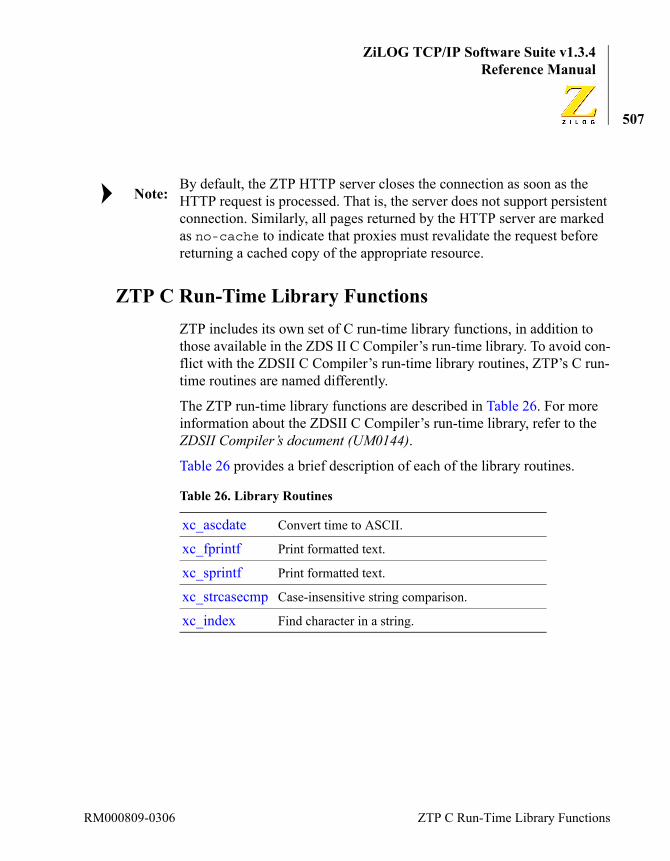
ZiLOG TCP/IP Software Suite v1.3.4Reference Manual
507
By default, the ZTP HTTP server closes the connection as soon as the HTTP request is processed. That is, the server does not support persistent connection. Similarly, all pages returned by the HTTP server are marked as no-cache to indicate that proxies must revalidate the request before returning a cached copy of the appropriate resource.
ZTP C Run-Time Library FunctionsZTP includes its own set of C run-time library functions, in addition to those available in the ZDS II C Compiler’s run-time library. To avoid con-flict with the ZDSII C Compiler’s run-time library routines, ZTP’s C run-time routines are named differently.
The ZTP run-time library functions are described in Table 26. For more information about the ZDSII C Compiler’s run-time library, refer to the ZDSII Compiler’s document (UM0144).
Table 26 provides a brief description of each of the library routines.
Table 26. Library Routines
xc_ascdate Convert time to ASCII.
xc_fprintf Print formatted text.
xc_sprintf Print formatted text.
xc_strcasecmp Case-insensitive string comparison.
xc_index Find character in a string.
Note:
RM000809-0306 ZTP C Run-Time Library Functions

ZiLOG TCP/IP Software Suite v1.3.4eZ80® Family of Microprocessors
508
xc_ascdate
Synopsis#include <kernel.h>
SYSCALL xc_ascdate (DWORD time, char *str)
Libraryxc.lib
DescriptionConvert time to ASCII. The xc_ascdate function takes its first argument as the number of seconds since midnight, January 1,1900, and produces an ASCII string for the date and time corresponding to that time. The ASCII string is copied into the second argument, which must point to a buffer large enough to contain it (twenty characters including the termi-nating NULL).
Arguments
Returned Value
This function always returns OK.
time Time in seconds since midnight January 1st, 1900.
str User-supplied buffer to contain output string.
ZTP API Reference RM000809-0306

ZiLOG TCP/IP Software Suite v1.3.4Reference Manual
509
xc_fprintf
Synopsis#include <kernel.h>
SYSCALL xc_fprintf (DID descriptor, char *format,...)
Libraryxc.lib
DescriptionPrint formatted text. The xc_fprintf function interprets its second argument as an ASCII format to use in printing its remaining argu-ments to a device identified by its integer first argument. The format con-tains simple text and special format codes that are identified by a preceding percent (%) character.
xc_fprintf uses the same conversion specifiers as kprintf. For more information, see kprintf on page 316.
Arguments
Returned Value
When successful, the xc_fprintf function returns OK.
See Also
descriptor The DeviceID of the driver used through which the out-put is sent.
format A string defining what to print.
… Arguments corresponding to the format codes, if any.
kprintf
RM000809-0306 ZTP C Run-Time Library Functions

ZiLOG TCP/IP Software Suite v1.3.4eZ80® Family of Microprocessors
510
xc_sprintf
Synopsis#include <kernel.h>
char * xc_sprintf (char *buffer, char *format,...)
Libraryxc.lib
DescriptionPrint formatted text. The xc_sprintf function prints formatted text into a specified buffer. Except for the output medium, it is identical to the xc_fprintf function. Consult the xc_fprintf description on page 509 for details.
Arguments
See the xc_fprintf function.
Returned Value
When successful, the xc_sprintf function returns OK.
ZTP API Reference RM000809-0306

ZiLOG TCP/IP Software Suite v1.3.4Reference Manual
511
xc_strcasecmp
Synopsis#include <kernel.h>
SYSCALL xc_strcasecmp (char *str1, char *str2)
Libraryxc.lib
DescriptionCase-insensitive string comparison. The xc_strcasecmp function performs a byte-by-byte comparison of two strings, in which it looks for the first character that differs other than by case. If the first char-acter in the first string that does not match is less than its corresponding character in the second string, or if the first string is shorter than the sec-ond string, a negative value is returned. If the character is larger than its corresponding character in the second string, or the second string is shorter than the first, a positive nonzero value returns. If the two strings are the same (except possibly in case), a zero is returned.
Arguments
Returned Value
The xc_strcasecmp function returns an integer that describes whether the first string is less than, equal to, or greater than the second string.
str1 The first of the two strings in the comparison.
str2 The second of the two strings in the comparison.
RM000809-0306 ZTP C Run-Time Library Functions

ZiLOG TCP/IP Software Suite v1.3.4eZ80® Family of Microprocessors
512
xc_index
Synopsis#include <stdlib.h>
char *xc_index (char *str, char c)
Libraryxc.lib
DescriptionFind a character in a string. The xc_index function searches a string for the first occurrence of the specified character, and returns a pointer to the character.
Arguments
Returned Value
If the character is found, a pointer to its location in the string is returned. If no match is found, a NULL pointer is returned..
str The string to be searched.
c The character to search for.
ZTP API Reference RM000809-0306

ZiLOG TCP/IP Software Suite v1.3.4Reference Manual
513
ZTP Shell Command ReferenceZTP includes a shell program that allows the user to interactively enter commands and query status information. The shell can be used via any device over which a TTY driver is layered. By default, the ZTP system configures Serial Port1 for use as a console to the shell. Similarly, the TELNET server layers a TTY device over the TCP connection created to service the TELNET session and allow another instance of the shell to run.
The user can modify the list of default commands that can be executed from within the shell. For details, see the description of the shell_conf.c file on page 54. Also, see descriptions of the shell_add_commands and shell_init functions in the How to Use the Shell section on page 172.
Table 27 provides a brief description of each of the shell commands.
Table 27. Shell Commands
arp Display the ARP table.
bpool Display buffer pool information.
conf Display configuration information.
date Print date.
devs Print device table.
dg Display datagram control table.
echo Echo arguments.
exit Exit shell.
tftpdemo Uses the TFTP API to retrieve a filename from the specified host.
hang Puts system into a tight loop (system hang) for test.
help Print help information.
RM000809-0306 ZTP C Run-Time Library Functions
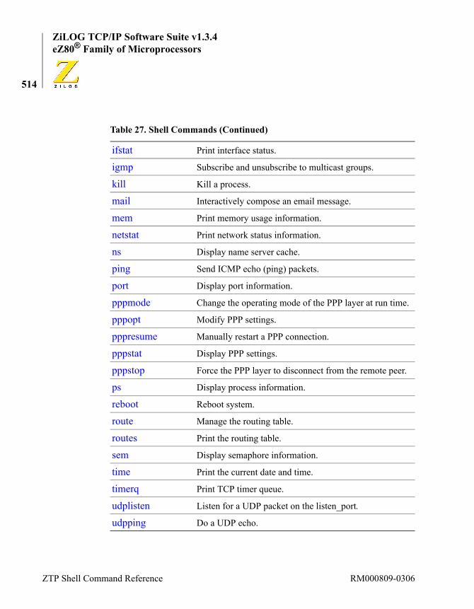
ZiLOG TCP/IP Software Suite v1.3.4eZ80® Family of Microprocessors
514
ifstat Print interface status.
igmp Subscribe and unsubscribe to multicast groups.
kill Kill a process.
mail Interactively compose an email message.
mem Print memory usage information.
netstat Print network status information.
ns Display name server cache.
ping Send ICMP echo (ping) packets.
port Display port information.
pppmode Change the operating mode of the PPP layer at run time.
pppopt Modify PPP settings.
pppresume Manually restart a PPP connection.
pppstat Display PPP settings.
pppstop Force the PPP layer to disconnect from the remote peer.
ps Display process information.
reboot Reboot system.
route Manage the routing table.
routes Print the routing table.
sem Display semaphore information.
time Print the current date and time.
timerq Print TCP timer queue.
udplisten Listen for a UDP packet on the listen_port.
udpping Do a UDP echo.
Table 27. Shell Commands (Continued)
ZTP Shell Command Reference RM000809-0306

ZiLOG TCP/IP Software Suite v1.3.4Reference Manual
515
arp
Syntaxarp [flush]
Description
The arp shell command prints the current contents of the Address Reso-lution Protocol table used to map Internet addresses to physical addresses. There is one row in the table for each of the IP ⇔ Physical Layer map-pings in effect.
The Interface column (Intf.) indicates the interface through which the tar-get IP address can be resolved. The default projects use interface 1 for Ethernet and Interface 2 for PPP. In ZTP, ARP entries are only meaningful for the Ethernet interfaces.
The IP address column indicates the network layer address that is being mapped to the physical layer address. For the ZTP stack, this address is always an IP address.
The physical layer address indicates the 48-bit physical address of the device using the IP address from the previous column.
The hardware column, signified by hardware, indicates the hardware address space in which the physical layer address is used. This space is always 1 for entries using the Ethernet interface.
The Proto column indicates the protocol address space being mapped to the indicated physical address. for ZTP this value is usually 0800h to indi-cate the IP protocol.
The State column indicates if this mapping is PENDING or if it is RESOLVED. The IP layer cannot forward datagrams until the mapping for the target address is resolved.
The Time To Live column indicates the number of seconds remaining until this entry decays out of the table. When an entry is first added to the
RM000809-0306 ZTP C Run-Time Library Functions

ZiLOG TCP/IP Software Suite v1.3.4eZ80® Family of Microprocessors
516
table, the TTL field is set to 600 (10 minutes). If the TTL field is marked Permanent, the associated entry does not expire out of the table.
Arguments
Sample Usage
flush An argument of flush causes the ARP table to be cleared; permanent entries are also cleared from the table.
ZTP % arp
Intf IP Address Physical Address HW Prot State Time To Live
---- ------------ ---------------- -- ---- -------- ---------
1 172.16.6.1 00:00:81:f3:2b:4b 1 0800 RESOLVED 593 s
1 172.16.6.77 00:06:5b:c9:7b:59 1 0800 RESOLVED 586 s
1 172.16.6.245 00:90:23:00:06:81 1 0800 RESOLVED 598 s
ZTP %
ZTP Shell Command Reference RM000809-0306

ZiLOG TCP/IP Software Suite v1.3.4Reference Manual
517
bpool
Syntaxbpool
Description
The bpool shell command displays information about each of the sys-tem’s buffer pools. Each line in the display corresponds to one of the sys-tems fixed buffer pools.
The count field indicated the number of buffers initially created within each pool. Each buffer is bsize bytes long.
The inuse field indicates the number of buffers within this pool that are currently in use by processes in the system. The max used field indicates the highest number of buffers from this pool that are in use simulta-neously.
Arguments
None.
Sample Usage
ZTP % bpool
SemTable (4ECC8): count=100 bsize=13 inuse=38 ( 38%) max 54 ( 54%)
MsgPortTable (4ECDD): count=20 bsize=25 inuse=6 ( 30%) max 6 ( 30%)
TaskTable (4ECF2): count=35 bsize=44 inuse=17 ( 48%) max 19 ( 54%)
DeviceTable (4ED07): count=50 bsize=51 inuse=28 ( 56%) max 28 ( 56%)
PktPool (4ED1C): count=32 bsize=1533 inuse=0 ( 0%) max 6 ( 18%)
BigPktPool (4ED31): count=8 bsize=4096 inuse=0 ( 0%) max 0 ( 0%)
RouteTable (4ED46): count=25 bsize=26 inuse=8 ( 32%) max 8 ( 32%)
RM000809-0306 ZTP C Run-Time Library Functions

ZiLOG TCP/IP Software Suite v1.3.4eZ80® Family of Microprocessors
518
4ED5B - unallocated
4ED70 - unallocated
4ED85 - unallocated
ZTP %
ZTP Shell Command Reference RM000809-0306

ZiLOG TCP/IP Software Suite v1.3.4Reference Manual
519
conf
Syntaxconf
Description
The conf shell command prints information about the configuration of the system. The IP address and domain name are displayed for every active interface the system is using. If the interface’s IP address is not rec-ognized by the default domain name server, then the same IP address is also reported as the domain name. This instance also applies to the values in brackets displayed under the Network information section.
The section that displays Table sizes reports the user-configured size of the process table, semaphore table, device table, buffer pool table, and message port table (see the discussion of the sys_conf.c file on page 56).
Under the Network information section, the IP addresses of the cur-rent RFC 738 Time server and Domain name server are listed. The system does not require nor use information regarding the Remote file server.
Default values for the IP address, time server, (remote file server), and domain server are taken from the boot record. If DHCP is enabled (see eth_init on page 469), values obtained from the DHCP server replace these values.
Arguments
None.
Sample UsageZTP % confIdentification ZTP version: v1.3.4Interface: eth1 IP address: 192.168.1.20
RM000809-0306 ZTP C Run-Time Library Functions

ZiLOG TCP/IP Software Suite v1.3.4eZ80® Family of Microprocessors
520
Domain name: 192.168.1.20
Table sizes Number of Tasks: 35 Number of Semaphores: 100 Number of Devices: 50 Number of Buffer Pools: 10 Number of Message Ports: 20
Network information Time server: 132.246.168.164 (time.nrc.ca) Remote file server: 192.168.1.6 (192.168.1.6) Domain name server: 209.53.4.130:53 (helium.bc.tac.net)ZTP %
See Also
ipw_ez80.c, devs, sys_conf.c, bootinfo.c
ZTP Shell Command Reference RM000809-0306
ZiLOG TCP/IP Software Suite v1.3.4Reference Manual
521
date
Syntaxdate
Description
The date shell command displays the current date and time. The date is always displayed in Greenwich Mean Time (GMT). By using the KE_TaskGetTime and KE_TaskSetTime APIs, programmers can adjust the system time for local time zones. However, even if this is done, the date displayed on the console will still be stamped GMT. If the RFC738 time client is initialized (see the timed_738_init section on page 146) and a compatible RFC 738 network time server is available (see the bootinfo.c structure discussion on page 60 and the conf shell command on page 519), the date is updated every 10 minutes. In all other cases, the system boots with an initial time stamp of midnight, Monday, January 1, 1900. The operation of the date command is identical to the operation of the time command.
Arguments
None.
Sample UsageZTP % dateMon, 01 Jan 1900 00:01:41 GMTZTP %
See Also
timed_738_init bootinfo.c
RM000809-0306 ZTP C Run-Time Library Functions

ZiLOG TCP/IP Software Suite v1.3.4eZ80® Family of Microprocessors
522
devs
Syntaxdevs
Description
The devs shell command prints device information in the DeviceTable buffer pool. The size of the device table is controlled by the value of the NumDev variable in the conf\sys_conf.c file (see the discussion of the sys_conf.c file on page 56). Each device implements a subset of the ZTP device driver API (see the ZTP Device Driver APIs chapter on page 360).
The Device column indicates the device ID that must be supplied on all OS device driver calls.
The Name field is the text string that is supplied in the KE_DEV structure, passed as a parameter to the KE_AddDevice call. For more information about these and other fields, see the ZTP Device Driver APIs chapter on page 360.
A number of the devices are marked as FREExx. These devices corre-spond to unused entries in the device table, in which the user can add a custom device (see the description of the adddevice API on page 366). In addition, there are multiple occurrences of the TTY, UDP, and TCP devices. The first occurrence of each of these devices is referred to as the Master device of that type. The remaining devices that share the same device name are created during system startup according to the values of the arguments used in the tty_init, udp_init, and tcp_init calls. The default sizes of these tables are 4, 8, and 8, respectively.
Arguments
None.
ZTP Shell Command Reference RM000809-0306

ZiLOG TCP/IP Software Suite v1.3.4Reference Manual
523
Sample Usage
ZTP % devs
Device Name Minor CSR iVec oVec Ctl Blk
------ ----------- ----- ---- ---- ---- -------
04FE5E NULLDEV 0000 0000 0000 0000 000000
04FE97 CONSOLE 0000 0000 0000 0000 000000
04FED0 SERIAL0 0000 0000 0070 0000 0062BF
04FF09 SERIAL1 0001 0000 0074 0000 0062E1
04FF42 TTY 0000 0000 0000 0000 000000
04FF7B TTY 0000 0000 0000 0000 00A3E0
04FFB4 TTY 0001 0000 0000 0000 000000
04FFED TTY 0002 0000 0000 0000 000000
050026 TTY 0003 0000 0000 0000 000000
05005F UDP 0000 0000 0000 0000 000000
050098 DGRAM 0000 0000 0000 0000 00A1E6
0500D1 DGRAM 0001 0000 0000 0000 00A204
05010A DGRAM 0002 0000 0000 0000 00A222
050143 DGRAM 0003 0000 0000 0000 00A240
05017C DGRAM 0004 0000 0000 0000 00A25E
0501B5 DGRAM 0005 0000 0000 0000 00A27C
0501EE DGRAM 0006 0000 0000 0000 00A29A
050227 DGRAM 0007 0000 0000 0000 00A2B8
050260 TCP Master 0000 0000 0000 0000 000000
050299 TCP 0000 0000 0000 0000 000000
0502D2 TCP 0001 0000 0000 0000 000000
RM000809-0306 ZTP C Run-Time Library Functions
ZiLOG TCP/IP Software Suite v1.3.4eZ80® Family of Microprocessors
524
05030B TCP 0002 0000 0000 0000 000000
050344 TCP 0003 0000 0000 0000 000000
05037D TCP 0004 0000 0000 0000 000000
0503B6 TCP 0005 0000 0000 0000 000000
0503EF TCP 0006 0000 0000 0000 000000
050428 TCP 0007 0000 0000 0000 000000
050461 ETHER 0000 0000 0000 0000 00A19E
FF7B92 FREE
FF7B92 FREE
FF7B92 FREE
FF7B92 FREE
FF7B92 FREE
FF7B92 FREE
FF7B92 FREE
FF7B92 FREE
FF7B92 FREE
FF7B92 FREE
FF7B92 FREE
FF7B92 FREE
FF7B92 FREE
FF7B92 FREE
FF7B92 FREE
FF7B92 FREE
FF7B92 FREE
FF7B92 FREE
ZTP Shell Command Reference RM000809-0306

ZiLOG TCP/IP Software Suite v1.3.4Reference Manual
525
See Also
dg, netstat
FF7B92 FREE
FF7B92 FREE
FF7B92 FREE
FF7B92 FREE
ZTP %
RM000809-0306 ZTP C Run-Time Library Functions

ZiLOG TCP/IP Software Suite v1.3.4eZ80® Family of Microprocessors
526
dg
Syntaxdg
Description
The dg shell command displays information for each active DGRAM device listed in the device table (see devs on page 522).
The Dev field corresponds to the device ID for a particular device. The fport (foreign port), and addr (foreign IP address) fields specify the remote socket used in the data exchange with this device. The local socket is composed of the IP address assigned to the interface through which the foreign device is accessed and the lport (local port) displayed by the dg command.
The mode field indicates the current mode of operation of the UDP device (see the UDP Functions section on page 394).
Arguments
None.
Sample UsageZTP % dgDev=050098: lport=161, fport=0, mode=011, queue=04A1FA addr=1401A8C0ZTP %
See Also
devs, UDP Functions
ZTP Shell Command Reference RM000809-0306

ZiLOG TCP/IP Software Suite v1.3.4Reference Manual
527
echo
Syntaxecho [text]
Description
The echo shell command is used to echo text entered after the echo com-mand to the standard output device associated with the shell processing the command. In simple terms, if the echo command is issued on the con-sole device, the input string is echoed to the console. If the echo com-mand is issued in a TELNET session, the input string is echoed to the TELNET session.
Arguments
Sample UsageZTP % echo ZiLOGZiLOGZTP %
text Test string to be echoed to the shell’s standard output device.
RM000809-0306 ZTP C Run-Time Library Functions

ZiLOG TCP/IP Software Suite v1.3.4eZ80® Family of Microprocessors
528
exit
Syntaxexit
Description
The exit shell command terminates the shell process. If this command is issued to the shell associated with a TELNET session, the TELNET ses-sion is effectively terminated. If this command is executed on the console, it is the last input or output operation that is processed by console. After the console shell is terminated the only way to restart it is to reboot the system.
Arguments
None.
Sample UsageZTP % exit
ZTP Shell Command Reference RM000809-0306

ZiLOG TCP/IP Software Suite v1.3.4Reference Manual
529
tftpdemo
Syntaxtftpdemo host filename newfile [bufsize]
Description
The tftpdemo shell command uses the TFTP API to retrieve a filename from a specified host. The host is the domain name or IP address of a TFTP server. After the file is retrieved, the file is returned to the TFTP server with a newfile name. The bufsize parameter is optional and directs the tftpdemo command to allocate a block of memory bufsize bytes long to contain the contents of the file. If the buffer cannot be allo-cated, the command does not attempt to retrieve or send any files. If the bufsize parameter is not specified, a default value of 4096 is used. If the bufsize parameter is not large enough to contain the file, only the first bufsize bytes of the file are retrieved from the server.
Arguments
Sample UsageZTP % tftpdemo 192.168.1.6 source.txt destination.txt 10000
Uploading to file desinaion.txtZTP %
host Name or IP address of the TFTP server.
filename Name of the file to be retrieved from the TFTP server.
newfile Name of the file to be created on the TFTP server.
bufsize An optional parameter. If provided, it specifies the number of bytes to get from the specified file on the TFTP server. The ZTP TFTP client echoes the same number.
RM000809-0306 ZTP C Run-Time Library Functions

ZiLOG TCP/IP Software Suite v1.3.4eZ80® Family of Microprocessors
530
hang
Syntaxhang
Description
The hang shell command intentionally hangs the system. As a result of executing this command, maskable interrupts are disabled and the proces-sor spins in a tight loop. To recover, it is necessary to reboot the system.
Arguments
None.
Sample UsageZTP % hang
ZTP Shell Command Reference RM000809-0306

ZiLOG TCP/IP Software Suite v1.3.4Reference Manual
531
help
Syntaxhelp
Description
The help shell command displays the set of commands that can be exe-cuted from the shell’s command prompt. Multiple instances of the shell can be active at the same time, but each instance shares the same com-mand set.
Arguments
None.
Sample Usage
ZTP % help
Commands are:
? arp bpool conf
date devs dg echo
exit hang help ifstat
igmp kill mail mem
netstat ns ping port
ps reboot route routes
sem sleep tftpdemo time
timerq udplisten udpping
ZTP %
RM000809-0306 ZTP C Run-Time Library Functions

ZiLOG TCP/IP Software Suite v1.3.4eZ80® Family of Microprocessors
532
ifstat
Syntaxifstat interface
Description
The ifstat shell command prints status information for a specified net-work interface. The number of network interfaces is defined in net_conf.c The default configuration uses three network interfaces: the Local interface (always interface 0), the Ethernet Interface (usually inter-face 1), and the PPP interface (usually interface 2). Each interface is capa-ble of sending and receiving data. Interface 1 is the Primary (preferred) interface.
Only an interface that is marked <UP> can be used to transfer data. Each physical interface marked <UP> includes an associated IP address, (sub)network mask, and Maximum Transmission Unit (MTU) value. Val-ues for the physical address (paddr) and broadcast address (bcast) are not meaningful for the PPP interface.
The addition of user-defined interfaces is currently not supported.
Arguments
Sample UsageZTP % ifstat 1eZ80 EMAC: state=1<UP>IP 172.16.6.207 NAME "eth1"MASK 255.255.255.0 BROADCAST 172.16.6.255MTU 1500 paddr 00:90:23:00:0F:91 bcast
FF:FF:FF:FF:FF:FFinq 0ZTP %
interface The number of the interface being queried.
Note:
ZTP Shell Command Reference RM000809-0306

ZiLOG TCP/IP Software Suite v1.3.4Reference Manual
533
igmp
Syntaxigmp [{join | leave} group]
Description
The igmp shell command adds or removes a specified IP multicast address from the list of addresses a host is using. This information can also be conveyed to the IGMP layer using the hgjoin and hgleave APIs. The IGMP protocol ensures that IP multicast routers in the same subnet as the host forward IP multicast frames for all group addresses any node that the router domain is using. Therefore, when group membership is no longer required, the IGMP hgleave API should be issued to avoid unnecessary multicasting.
Arguments
Sample UsageZTP % igmp join 224.0.0.5[B8A862]ZTP % igmp[B8A8A1]State Address Intf Ref TTL---------------------------------------IDLE 224.0.0.5 1 1 1ZTP %
[none] Displays the list of groups address currently being used on this device.
join | leave
If the string join is provided as the first argument, mem-bership is added. If the string leave is specified, group membership is terminated.
group The IP multicast address of the group.
RM000809-0306 ZTP C Run-Time Library Functions
ZiLOG TCP/IP Software Suite v1.3.4eZ80® Family of Microprocessors
534
kill
Syntaxkill process
Description
The kill shell command kills a specified process. This shell command performs the same function as the kill process manipulation API. Use the ps command to see the list of active processes and their associated process IDs (PID’s).
This command should only be used as a last resort to force a process to terminate. Well-designed processes are typically created to perform a par-ticular task and will self-terminate when the task is complete. Therefore, there should rarely be a need to forcibly terminate a task. A task that is killed will not have an opportunity to release any resource it has acquired; therefore, resources can be caused to become depleted or possibly even deadlock the system.
Arguments
Sample UsageZTP % kill B8A5AD
process The hexadecimal representation of the process ID to be killed.
Note:
ZTP Shell Command Reference RM000809-0306

ZiLOG TCP/IP Software Suite v1.3.4Reference Manual
535
Syntaxmail
Description
The mail shell command is used to interactively compose an email mes-sage that is sent to an SMTP server for delivery to a specified recipient. This shell command performs the same operation as the mail API.
Arguments
None.
Sample UsageZTP % mailPress <ESC> then <Enter> to exit earlyEnter the name or IP of the SMTP server: 172.16.6.132Enter the port number to connect to (normally 25): 25Enter the email Subject: test-ez80Enter the recipient's email address:[email protected] the sender's email address: [email protected] the body of the email (ESC/Enter to complete):Test message^[Please wait while the message is processedMail message is successfully sentZTP %
RM000809-0306 ZTP C Run-Time Library Functions

ZiLOG TCP/IP Software Suite v1.3.4eZ80® Family of Microprocessors
536
mem
Syntaxmem
Description
The mem shell command provides information about the use of the system heap. All requests for dynamic memory (see getmem on page 286) are allocated out of the heap. ZTP also allocates a process’ private stack from the heap. If the heap becomes depleted or extremely fragmented, dynamic memory allocations can fail. Should this situation occur, the system will call the panic function to forcibly halt the system.
The first line in the display shows the amount of memory that is available to the system Memory Manager for allocation requests at system initial-ization. The second line shows how much heap memory is currently available for allocation. This line is followed by the amount of dynamic memory currently allocated in RAM for process stack space, and then by the amount of dynamic RAM presently allocated to processes for general-purpose use.
The remainder of the display shows the Memory Manager’s list of free memory blocks. The length of the largest free block represents the largest memory allocation request that can be satisfied at the current time.
Arguments
None.
Sample UsageZTP % mem initially: 485192 bytes heap available presently: 411384 bytes heap available 12544 bytes allocated for task stacks 61264 bytes allocated for dynamic memory free list:
ZTP Shell Command Reference RM000809-0306

ZiLOG TCP/IP Software Suite v1.3.4Reference Manual
537
block at B98808, length 410872 block at BFFE00, length 512ZTP %
RM000809-0306 ZTP C Run-Time Library Functions

ZiLOG TCP/IP Software Suite v1.3.4eZ80® Family of Microprocessors
538
netstat
Syntaxnetstat
Description
The netstat shell command displays status information about UDP and TCP devices currently in use.
The fist column indicates whether the device is using the TCP or UDP protocol. For TCP devices, the RQ and SQ columns indicate the respective number of bytes of unprocessed application-layer data in the Receive and Send queues of that device. These fields do not pertain to UDP devices.
The L. Port column identifies the UDP or TCP port number that the application that opened the underlying device either requested or is assigned. Some application servers require the use of standard port num-bers. In the sample below, there is an HTTP server using TCP port 80, an idle TELNET server and an active TELNET session on TCP port 23, and an SNMP Agent (server) on UDP port 161.
The combination of Remote IP and R. Port identify the remote socket IP address and port with which the device is communicating. Idle server devices display a remote socket of 0.0.0.0:0. A TCP server device is never used to transfer application data; instead, a subordinate TCP device is used. As a result, there are two TCP devices in use on Port 23 in the sam-ple output. The first device is the TCP server on Port 23 waiting for new connection requests from remote clients. After such a request is received, the TCP server device spawns a TCP connection device to handle the flow of application data. As a result, a TCP service is allowed to be accessed by multiple remote devices simultaneously.
UDP server devices do not spawn a secondary device to handle connec-tions because UDP is a connectionless protocol.
The Dev field indicates the device ID of the node in the Device Table that is being used for the connection. This parameter is the same one that is
ZTP Shell Command Reference RM000809-0306
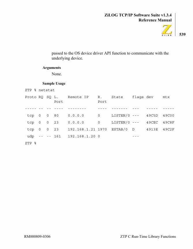
ZiLOG TCP/IP Software Suite v1.3.4Reference Manual
539
passed to the OS device driver API function to communicate with the underlying device.
Arguments
None.
Sample Usage
ZTP % netstat
Proto RQ SQ L. Port
Remote IP R. Port
State flags dev mtx
----- -- -- ---- -------- ---- ------- --- ----- -----
tcp 0 0 80 0.0.0.0 0 LISTEN/0 --- 49C5D 49C00
tcp 0 0 23 0.0.0.0 0 LISTEN/0 --- 49CEC 49C8F
tcp 0 0 23 192.168.1.21 1970 ESTAB/0 D 4913E 49C2F
udp -- -- 161 192.168.1.20 0 ---
ZTP %
RM000809-0306 ZTP C Run-Time Library Functions

ZiLOG TCP/IP Software Suite v1.3.4eZ80® Family of Microprocessors
540
ns
Syntaxns host_name
Description
The ns shell command takes one or more hostnames as arguments and uses DNS to resolve the name(s) to IP addresses.
Arguments
Sample UsageZTP % ns www.zilog.com"www.zilog.com": 209.164.33.249ZTP %
host_name An ASCII string containing the name of the host for which an IP address is requested.
ZTP Shell Command Reference RM000809-0306

ZiLOG TCP/IP Software Suite v1.3.4Reference Manual
541
ping
Syntaxping host [count [size [delay]]]
Description
The ping shell command sends ICMP echo request packets to a specified host and reports statistics upon successful replies.
Arguments
Sample UsageZTP % ping 172.16.6.1 3 500 2500 octets from 172.16.6.1: icmp_seq 0500 octets from 172.16.6.1: icmp_seq 1500 octets from 172.16.6.1: icmp_seq 2received 3/3 packets (0 % loss)ZTP %
host The IP address of the target system.
count An optional number of packets to send. If this parameter is not specified 10 packets are sent.
size If the count parameter is specified, then the size in bytes of each ping packet can also be specified. If this parameter is not specified each ping packet contains 56 bytes of data.
delay If the size parameter is specified, then the maximum time to wait for a reply (in seconds) between each ping request can also be specified.
RM000809-0306 ZTP C Run-Time Library Functions

ZiLOG TCP/IP Software Suite v1.3.4eZ80® Family of Microprocessors
542
port
Syntaxport
Description
The port shell command formats and prints information about all mes-sage ports currently in use. The number of message ports in the system is determined by the vale of NumPorts in \conf\sys_conf.c (see the discussion of the sys_conf.c file on page 56). The state of active ports is 3 (see ports.h in the includes directory). Each port uses two sema-phores to control access: the send (producer) semaphore and the receive (consumer) semaphore. The maxcnt value indicates the maxi-mum number of messages that a port can contain. seq is a sequence num-ber that indicates how many times this port has been created/deleted. The #msgs column identifies how many messages are currently available for reception.
Arguments
None.
Sample UsageZTP % port
port state ssem rsem maxcnt seq #msgs
---------- ------ ------- -------- ------ ----- -----
04F50E 3 04EF53 04EF66 32 0 0
04F52D 3 04EF8C 04EF9F 15 0 0
04F54C 3 04EFC5 04EFD8 5 1 0
04F56B 3 04EFEB 04EFFE 10 0 0
04F58A 3 04F024 04F037 5 1 0
ZTP Shell Command Reference RM000809-0306
ZiLOG TCP/IP Software Suite v1.3.4Reference Manual
543
04F5A9 3 04F04A 04F05D 10 0 0
ZTP %
RM000809-0306 ZTP C Run-Time Library Functions

ZiLOG TCP/IP Software Suite v1.3.4eZ80® Family of Microprocessors
544
pppmode
Syntaxpppmode [0 | 1 | 2 | 3] -OR-pppmode [dcc_client | dcc_server | dialup_client |
dialup_server]
Description
The pppmode shell command is used to change the operating mode of the PPP layer at run time. The source code that implements this command is included in the PPPDemo project folder.
If a new_mode parameter is not specified, this command displays the cur-rent operating mode of the PPP layer (one of DCC_Client, DCC_Server, Dialup_Client, or Dialup_Server). The current state of the PPP layer is also shown (one of Disconnected, Connecting, Con-nected or Disconnecting). If the new_mode parameter is specified, it must either be a number in the range 0–3 or one of the following text strings: DCC_Client, DCC_Server, Dialup_Client, or Dialup_Server. Input of a text string for new_mode is case-insensitive.
When the PPP operating mode is changed, the pppmode command first disconnects the current PPP connection (see the pppstop shell command on page 551 or the ppp_stop API on page 476), modifies the default PPP config structure (see the ppp_conf.c section on page 61) and calls pppresume (only if the do_auto_reconnect flag in the pppconf struc-ture is set to TRUE) to establish a PPP connection using the new mode of operation (see pppresume on page 548).
Arguments
If a new mode is specified, it must be one of 0 or dcc_client to make the PPP layer operate as a Direct Cable Connect client. In this mode of operation, the PPP layer uses a null-modem cable connected between the modem port on the eZ80® Development Platform and the serial port of a remote device acting as a DCC_Server.
ZTP Shell Command Reference RM000809-0306

ZiLOG TCP/IP Software Suite v1.3.4Reference Manual
545
1 or dcc_server to make the PPP layer operate as a Direct Cable Con-nect server. In this mode of operation, the PPP layer uses a null-modem cable connected between the modem port on the eZ80® Development Platform and the serial port of a remote device acting as a DCC_Client.
2 or dialup_client to make the PPP layer operate as a dial-up client. In this mode of operation, the PPP layer uses an external modem to con-nect to the PSTN to access a remote device acting as a dial-up server.
3 or dialup_server to make the PPP layer operate as a dial-up server. In this mode of operation, the PPP layer waits for an external modem con-nected to the PSTN to ring, indicating a remote dial-up client is attempt-ing to establish a connection.
Sample UsageZTP % pppmode[B8A91F]Current PPP Mode: Dialup_ServerCurrent PPP State: DisconnectedZTP %ZTP % pppmode dcc_server[B8A99D]Changing PPP Mode to DCC_ServerZTP %
RM000809-0306 ZTP C Run-Time Library Functions

ZiLOG TCP/IP Software Suite v1.3.4eZ80® Family of Microprocessors
546
pppopt
Syntaxpppopt {myaddr | perraddr | mypassword | mru | auth |
debug} value
Description
The pppopt shell command allows the user to modify the PPP settings. The PPP settings that can be modified using this command, and its per-missible values, are:
myaddr—can be set to an IP address or NULL.
peeraddr—can be set to an IP address or NULL.
mypassword—can be used to change the password that ZTP uses to authenticate itself to the remote peer.
mru—can be used to change the size of the largest data packet the PPP layer allows the peer to transmit over the link.
auth—can be set to PPP_PAP (requiring the peer to authenticate using PAP), or NULL (requiring the peer to not use any authentication proto-col).
debug—can be set to TRUE or FALSE, to turn on or off the logging of debug messages to the console.
If any of the settings for myaddr, peeraddr, or mru are modified, any existing PPP connection is terminated. (An attempt is made to automati-cally reestablish a connection if the do_auto_reconnect flag is set in the pppconf structure). In the sample output above, the PPP DEAD debug message appears as a result of changing myaddr.
Arguments
setting The PPP setting to be changed.
value The new value to be provided to the setting.
ZTP Shell Command Reference RM000809-0306
ZiLOG TCP/IP Software Suite v1.3.4Reference Manual
547
Sample UsageZTP % pppopt auth PPP_PAPpppopt: changing auth to PPP_PAPZTP % pppopt myaddr 192.168.2.3pppopt: changing myaddr to 192.168.2.3PPP DEADZTP %
RM000809-0306 ZTP C Run-Time Library Functions
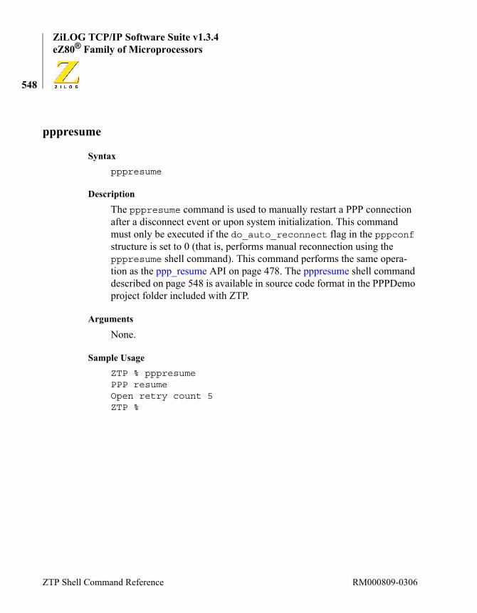
ZiLOG TCP/IP Software Suite v1.3.4eZ80® Family of Microprocessors
548
pppresume
Syntaxpppresume
Description
The pppresume command is used to manually restart a PPP connection after a disconnect event or upon system initialization. This command must only be executed if the do_auto_reconnect flag in the pppconf structure is set to 0 (that is, performs manual reconnection using the pppresume shell command). This command performs the same opera-tion as the ppp_resume API on page 478. The pppresume shell command described on page 548 is available in source code format in the PPPDemo project folder included with ZTP.
Arguments
None.
Sample UsageZTP % pppresumePPP resumeOpen retry count 5ZTP %
ZTP Shell Command Reference RM000809-0306

ZiLOG TCP/IP Software Suite v1.3.4Reference Manual
549
pppstat
Syntaxpppstat
Description
The pppstat shell command displays the following PPP settings (see the description of ppp_conf.c on page 61):
• myaddress
• myuser
• mypassword
• peeraddress
• auth
• MRU
• ACCM
• LCPTimer
• LCPMaxTimeouts
• LCPMaxConfigure
• offerSecondaryDNS
• offerPrimaryNBNS
• offerSecondaryNBNS
• debug
Arguments
None.
RM000809-0306 ZTP C Run-Time Library Functions

ZiLOG TCP/IP Software Suite v1.3.4eZ80® Family of Microprocessors
550
Sample UsageZTP % pppstatmyaddress = 192.168.2.3myuser = zilogmypassword = demopeeraddress = 192.168.2.2auth = 49187MRU = 1500ACCM = -1LCPTimer = 3LCPMaxTimeouts = 10LCPMaxConfigure = 10offerSecondaryDNS =offerPrimaryNBNS =offerSecondaryNBNS =debug = 1ZTP %
ZTP Shell Command Reference RM000809-0306

ZiLOG TCP/IP Software Suite v1.3.4Reference Manual
551
pppstop
Syntaxpppstop
Description
The pppstop shell command forces the PPP layer to disconnect from the remote peer. If the PPP layer is not connected when this command is issued, there is no effect. If the do_auto_reconnect flag is set to TRUE in the ppp structure (see ppp_conf.c on page 61), the PPP layer automatically attempts to reestablish the disconnected link. Therefore, if it is required that the PPP connection not be immediately reestablished after disconnecting, the do_auto_reconnect flag should be set to FALSE before calling the pppstop command described on page 551. This command performs the same function as the ppp_stop API described on page 476.
Arguments
None.
Sample UsageZTP % pppstopPPP StopSending LCP_Terminate_Request...ZTP % LCP_Terminate_AckPPP DEAD
RM000809-0306 ZTP C Run-Time Library Functions

ZiLOG TCP/IP Software Suite v1.3.4eZ80® Family of Microprocessors
552
ps
Syntaxps
Description
The ps shell command displays information about all processes in the system that are created but not yet killed.
The PID identifies each process and is used as an input parameter on the various process manipulation functions. The Name column displays the name provided to the process when it is created. The State field indi-cates the scheduling state of each process. All processes not marked as ready or curr are blocked on a given resource. The prio column indi-cates the scheduling priority assigned when the process is created.
The ps shell command displays four parameters pertaining to the process’ stack: the memory range occupied by the stack (range) the number of bytes of stack memory in use at the time the process was last preempted (last), the maximum number of bytes of stack memory ever consumed by this process (max), and the size, in bytes, of the stack (size).
The Stack Range column specifies the dynamic memory allocated for each processes stack. This parameter is specified when the process is cre-ated, but to be honored, it must be larger than the value of xinu_min_stack size (see ipw_ez80.c on page 45).
The sem column indicates what semaphore, if any, the process is currently waiting on. The message column is the value of an unread message in that process’ mailbox.
Arguments
None.
ZTP Shell Command Reference RM000809-0306
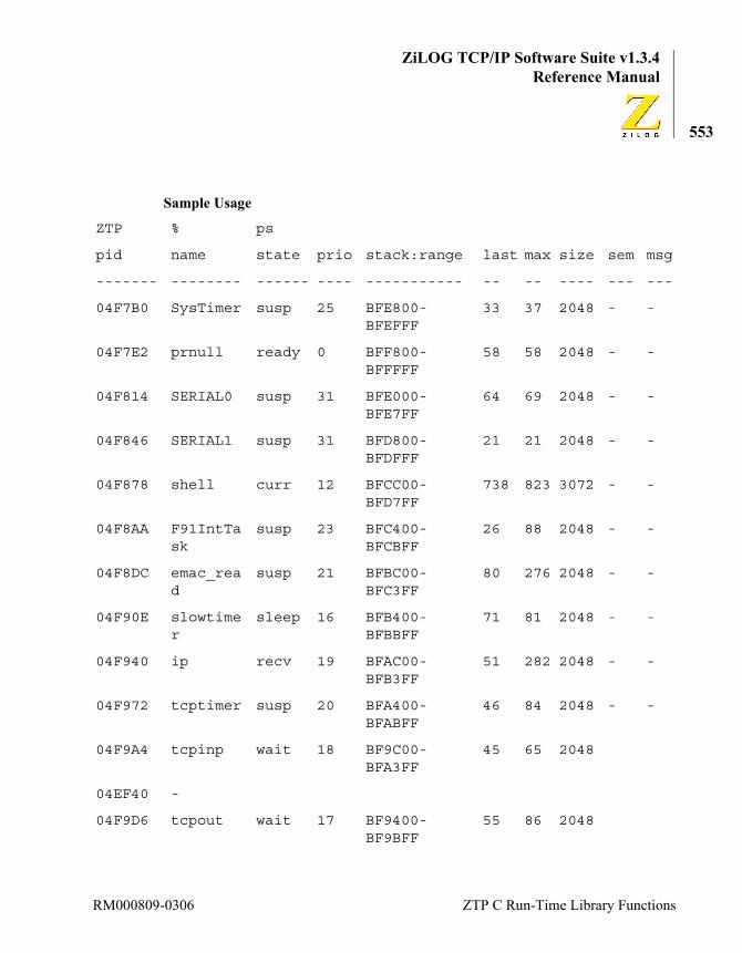
ZiLOG TCP/IP Software Suite v1.3.4Reference Manual
553
Sample Usage
ZTP % ps
pid name state prio stack:range last max size sem msg
------- -------- ------ ---- ----------- -- -- ---- --- ---
04F7B0 SysTimer susp 25 BFE800-BFEFFF
33 37 2048 - -
04F7E2 prnull ready 0 BFF800-BFFFFF
58 58 2048 - -
04F814 SERIAL0 susp 31 BFE000-BFE7FF
64 69 2048 - -
04F846 SERIAL1 susp 31 BFD800-BFDFFF
21 21 2048 - -
04F878 shell curr 12 BFCC00-BFD7FF
738 823 3072 - -
04F8AA F91IntTask
susp 23 BFC400-BFCBFF
26 88 2048 - -
04F8DC emac_read
susp 21 BFBC00-BFC3FF
80 276 2048 - -
04F90E slowtimer
sleep 16 BFB400-BFBBFF
71 81 2048 - -
04F940 ip recv 19 BFAC00-BFB3FF
51 282 2048 - -
04F972 tcptimer susp 20 BFA400-BFABFF
46 84 2048 - -
04F9A4 tcpinp wait 18 BF9C00-BFA3FF
45 65 2048
04EF40 -
04F9D6 tcpout wait 17 BF9400-BF9BFF
55 86 2048
RM000809-0306 ZTP C Run-Time Library Functions

ZiLOG TCP/IP Software Suite v1.3.4eZ80® Family of Microprocessors
554
04EF66 -
04FA08 igmp_update
wait 10 BF8C00-BF93FF
49 81 2048
04EF9F -
04FA3A httpd wait 20 BF8238-BF8BFF
104 110 2504
04EFFE -
04FA6C telnetd wait 15 BF7A38-BF8237
93 137 2048
04F05D -
04FA9E snmpd wait 20 BF7238-BF7A37
107 474 2048
04EE36 -
04FAD0 timed_738
sleep 15 BF6A38-BF7237
94 366 2048 -
ZTP %
ZTP Shell Command Reference RM000809-0306

ZiLOG TCP/IP Software Suite v1.3.4Reference Manual
555
reboot
Syntaxreboot
Description
The reboot shell command causes the operating system to begin its ini-tialization sequence. This command is not the same as the reboot com-mand used as a hardware reset. For details, refer to the appropriate eZ80® Product Specification for your target processor.
Arguments
None.
Sample UsageZTP % reboot
ZiLOG TCP/IP Software Suite v1.3.4Copyright (C) 2004, 2005 ZiLOG Inc.All Rights Reserved
Adding emac driver...Attempting to establish Ethernet connection10 Mbps Half-Duplex Link establishedAttempting to contact a DHCP serverDHCP ok.IP Address: 192.168.1.20IP Subnet: 192.168.1.0/255.255.255.0IP Gateway: 192.168.1.1
ZTP %
RM000809-0306 ZTP C Run-Time Library Functions
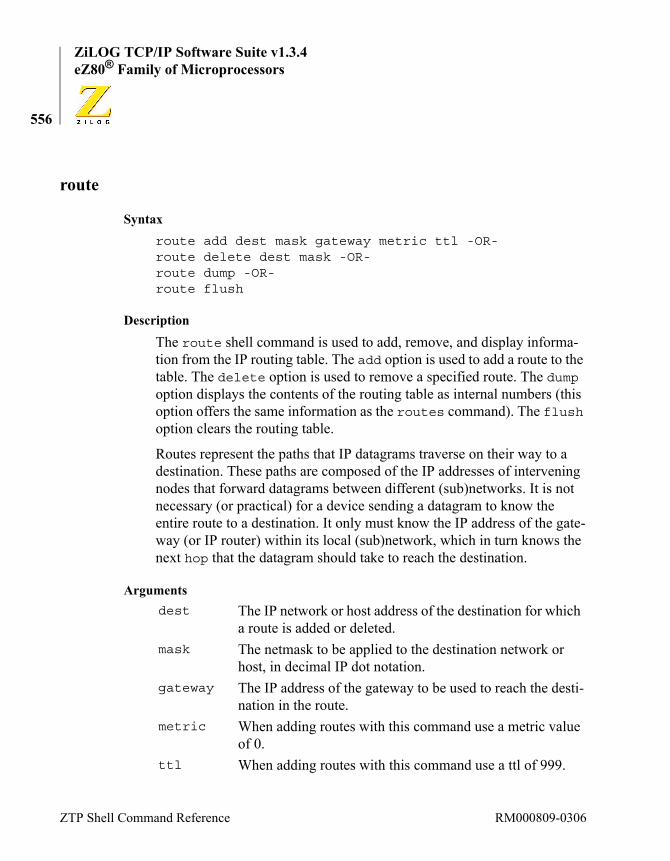
ZiLOG TCP/IP Software Suite v1.3.4eZ80® Family of Microprocessors
556
route
Syntaxroute add dest mask gateway metric ttl -OR-route delete dest mask -OR-route dump -OR-route flush
Description
The route shell command is used to add, remove, and display informa-tion from the IP routing table. The add option is used to add a route to the table. The delete option is used to remove a specified route. The dump option displays the contents of the routing table as internal numbers (this option offers the same information as the routes command). The flush option clears the routing table.
Routes represent the paths that IP datagrams traverse on their way to a destination. These paths are composed of the IP addresses of intervening nodes that forward datagrams between different (sub)networks. It is not necessary (or practical) for a device sending a datagram to know the entire route to a destination. It only must know the IP address of the gate-way (or IP router) within its local (sub)network, which in turn knows the next hop that the datagram should take to reach the destination.
Argumentsdest The IP network or host address of the destination for which
a route is added or deleted. mask The netmask to be applied to the destination network or
host, in decimal IP dot notation. gateway The IP address of the gateway to be used to reach the desti-
nation in the route.metric When adding routes with this command use a metric value
of 0.ttl When adding routes with this command use a ttl of 999.
ZTP Shell Command Reference RM000809-0306

ZiLOG TCP/IP Software Suite v1.3.4Reference Manual
557
Sample UsageZTP % route dumpnet mask gateway metric intf ttl refs useFFFFFFFF FFFFFFFF FFFFFFFF 0 0 255 1 00101A8C0 FFFFFFFF 0101A8C0 0 0 255 1 01401A8C0 FFFFFFFF 1401A8C0 0 0 255 1 7FF01A8C0 FFFFFFFF 1401A8C0 0 0 255 1 00001A8C0 FFFFFFFF 1401A8C0 0 0 255 1 0010000E0 FFFFFFFF 010000E0 0 0 255 1 00001A8C0 00FFFFFF 1401A8C0 0 1 255 1 0010000E0 000000F0 010000E0 0 1 255 1 000000000 00000000 0101A8C0 15 1 255 1 1ZTP %ZTP % route delete 192.168.1.0 255.255.255.255ZTP % route dumpnet mask gateway metric intf ttl refs useFFFFFFFF FFFFFFFF FFFFFFFF 0 0 255 1 00101A8C0 FFFFFFFF 0101A8C0 0 0 255 1 01401A8C0 FFFFFFFF 1401A8C0 0 0 255 1 7FF01A8C0 FFFFFFFF 1401A8C0 0 0 255 1 21010000E0 FFFFFFFF 010000E0 0 0 255 1 00001A8C0 00FFFFFF 1401A8C0 0 1 255 1 21010000E0 000000F0 010000E0 0 1 255 1 000000000 00000000 0101A8C0 15 1 255 1 1ZTP %ZTP % route add 192.168.1.0 255.255.255.255 192.168.1.20 0 255ZTP % route dumpnet mask gateway metric intf ttl refs useFFFFFFFF FFFFFFFF FFFFFFFF 0 0 255 1 10101A8C0 FFFFFFFF 0101A8C0 0 0 255 1 01401A8C0 FFFFFFFF 1401A8C0 0 0 255 1 8FF01A8C0 FFFFFFFF 1401A8C0 0 0 255 1 21010000E0 FFFFFFFF 010000E0 0 0 255 1 00001A8C0 FFFFFFFF 1401A8C0 0 0 255 1 00001A8C0 00FFFFFF 1401A8C0 0 1 255 1 21010000E0 000000F0 010000E0 0 1 255 1 0
RM000809-0306 ZTP C Run-Time Library Functions

ZiLOG TCP/IP Software Suite v1.3.4eZ80® Family of Microprocessors
558
00000000 00000000 0101A8C0 15 1 255 1 2ZTP %
ZTP % route flushZTP % route dumpnet mask gateway metric intf ttl refs useZTP %
ZTP Shell Command Reference RM000809-0306

ZiLOG TCP/IP Software Suite v1.3.4Reference Manual
559
routes
Syntaxroutes [any]
Description
The routes shell command prints the contents of the routing table to a standard output.
Arguments
Sample UsageZTP %ZTP % routesnet mask gateway metric intf ttl refcnt usecnt192.168.1.255 ffffffff 192.168.1.21 0 0 - 1 0192.168.1.0 ffffffff 192.168.1.21 0 0 - 1 0192.168.1.21 ffffffff 192.168.1.21 0 0 - 1 22255.255.255.255 ffffffff 255.255.255.255 0 0 - 1 0ALL-SYSTEMS.MCAS ffffffff ALL-SYSTEMS.MCAS 0 0 - 1 0192.168.1.0 ffffff00 192.168.1.21 0 1 - 1 19ALL-SYSTEMS.MCAS f0000000 ALL-SYSTEMS.MCAS 0 1 - 1 00.0.0.0 00000000 192.168.1.1 15 1 - 1 16ZTP %
ZTP % routes nnet mask gateway metric intf ttl refcnt usecnt192.168.1.255 ffffffff 192.168.1.21 0 0 - 1 1192.168.1.0 ffffffff 192.168.1.21 0 0 - 1 0192.168.1.21 ffffffff 192.168.1.21 0 0 - 1 46255.255.255.255 ffffffff 255.255.255.255 0 0 - 1 0224.0.0.1 ffffffff 224.0.0.1 0 0 - 1 0
any Any single parameter passed to this routine causes the rout-ing information to be displayed as IP addresses without DNS lookups being performed.
RM000809-0306 ZTP C Run-Time Library Functions
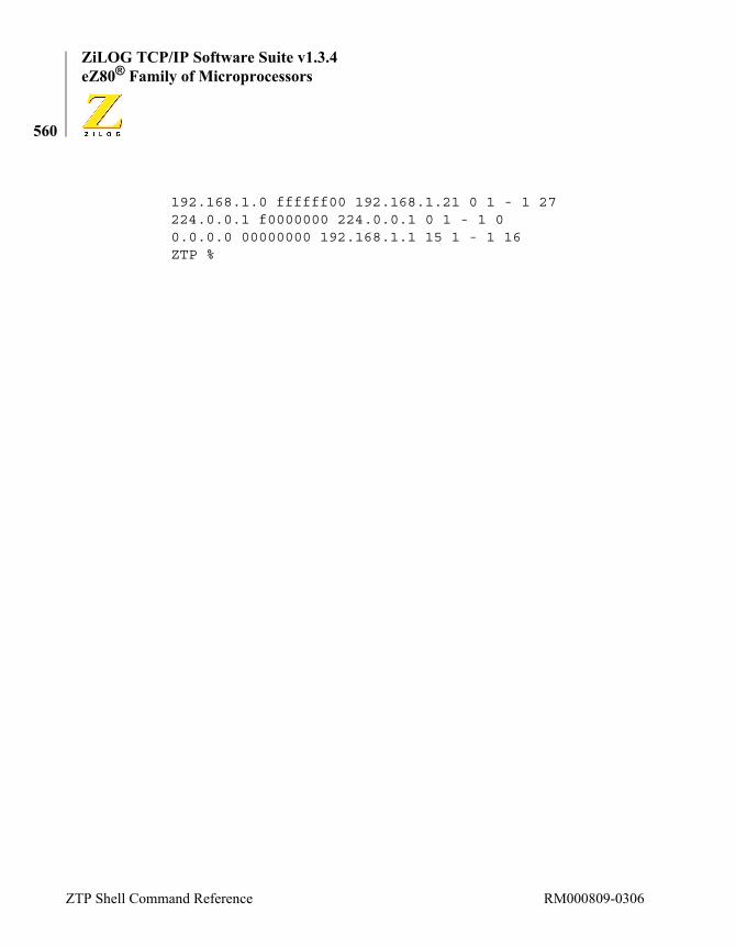
ZiLOG TCP/IP Software Suite v1.3.4eZ80® Family of Microprocessors
560
192.168.1.0 ffffff00 192.168.1.21 0 1 - 1 27224.0.0.1 f0000000 224.0.0.1 0 1 - 1 00.0.0.0 00000000 192.168.1.1 15 1 - 1 16ZTP %
ZTP Shell Command Reference RM000809-0306

ZiLOG TCP/IP Software Suite v1.3.4Reference Manual
561
sem
Syntaxsem
Description
The sem shell command displays information about all active semaphores (see KE_SemCreate on page 254) from the SemTable buffer pool. The number of semaphore available for simultaneous allocation is determined by the value of the NumSem variable in \conf\sys_conf.c (see the dis-cussion of the sys_conf.c file on page 56).
Each row in the display shows the semaphore ID, its current semaphore count, the last process that acquired (and possibly still holds) the sema-phore, and the process ID of the first process waiting (blocked) on the semaphore.
Arguments
None.
Sample UsageZTP % semsem count owner next------ ------ ------ ------04ED98 1 000000 00000004EDAB 1 000000 00000004EDBE 1 000000 00000004EDD1 1 000000 00000004EDE4 1 000000 00000004EDF7 256 000000 00000004EE0A 1 000000 00000004EE1D 1 000000 00000004EE30 -1 000000 04FA9E04EE43 0 000000 00000004EE56 0 000000 000000
RM000809-0306 ZTP C Run-Time Library Functions

ZiLOG TCP/IP Software Suite v1.3.4eZ80® Family of Microprocessors
562
04EE69 0 000000 00000004EE7C 0 000000 00000004EE8F 0 000000 00000004EEA2 0 000000 00000004EEB5 0 000000 00000004EEC8 1 000000 00000004EEDB 1 000000 00000004EEEE 1 000000 00000004EF01 1 000000 00000004EF14 1 000000 00000004EF27 1 000000 00000004EF3A -1 000000 04F9A404EF4D 32 000000 00000004EF60 -1 000000 04F9D604EF73 1 000000 00000004EF86 15 000000 00000004EF99 -1 000000 04FA0804EFAC 1 000000 00000004EFBF 5 000000 00000004EFD2 0 000000 00000004EFE5 10 000000 00000004EFF8 -1 000000 04FA3A04F00B 1 000000 00000004F01E 5 000000 00000004F031 0 000000 00000004F044 10 000000 00000004F057 -1 000000 04FA6CZTP %
ZTP Shell Command Reference RM000809-0306

ZiLOG TCP/IP Software Suite v1.3.4Reference Manual
563
sleep
Syntaxsleep seconds
Description
The sleep shell command places the shell process to sleep for a specified number of seconds. For more details, see the KE_TaskSleep API defini-tions starting on page 238.
Arguments
Sample UsageZTP % sleep 2ZTP %
seconds The duration of the sleep period in seconds.
RM000809-0306 ZTP C Run-Time Library Functions
ZiLOG TCP/IP Software Suite v1.3.4eZ80® Family of Microprocessors
564
time
Syntaxtime
Description
The time shell command prints the current date and time to a standard output. The operation of the time command is identical to the operation of the date command. For more information, see the description of the date command on page 521.
Arguments
None.
Sample UsageZTP % timeMon, 01 Jan 1900 00:05:20 GMTZTP %
ZTP Shell Command Reference RM000809-0306

ZiLOG TCP/IP Software Suite v1.3.4Reference Manual
565
timerq
Syntaxtimerq
Description
The timerq shell command displays information about events queued on the TCP event queue. Events can be queued from any of the TCP devices (see the devs command on page 522). For each entry in the queue, the timerq command displays:
Arguments
None.
Sample UsageZTP % timerqTime Left Set Time Port Event--------- -------- ---- -----220 3946 B8A106 000023300 4026 B8A106 00002B340 4066 B8A106 000013360 4086 B8A106 00003BZTP %
timeleft The number of 10 ms intervals remaining until an event time-out occurs.
time The system time stamp that indicates when an event is added to the TCP timer queue.
port The message port ID that is sent a message indicating the occurrence of a time-out.
msg The time-out message that is sent to the message port.
RM000809-0306 ZTP C Run-Time Library Functions
ZiLOG TCP/IP Software Suite v1.3.4eZ80® Family of Microprocessors
566
udplisten
Syntaxudplisten local_port remote_host remote_port
Description
The udplisten shell command listens for a UDP packet on the local_port. If a packet is received on this port before the time-out occurs (3 seconds), a status message is sent to port remote_port on host remote_host. The status message contains the number of data bytes in the UDP packet that are received. The length of the data portion of the status message is 16 bits (also known as a Word). After udplisten receives a packet and sends the status message or time-outs waiting for a packet, it exits.
Arguments
Sample UsageZTP % udplisten 5000 172.16.6.77 2114ZTP %
local_port The port on which to listen for a UDP packet.
remote_host The host to which a status message is sent.
remote_port The port to which a status message is sent.
ZTP Shell Command Reference RM000809-0306

ZiLOG TCP/IP Software Suite v1.3.4Reference Manual
567
udpping
Syntaxudpping host [count [size [delay]]]
Description
The udpping shell command performs a UDP echo to a specified host, and reports statistics upon successful replies. The maximum packet size that can be used for the echo operation is 1044 bytes. Each UDP echo packet is sent to Port 7 on the host device. If a UDP Echo server is cur-rently running on that device, it echoes the data it received. If a UDP echo server is not running on the target host, no response is received, and the command indicates 0 of n packets are received. In this example, n is the count of echo packets requested using the udpping command.
Arguments
Sample UsageZTP % udpping 172.16.6.77 2 100received 0/2 packets (100 % loss)ZTP %
host The IP address of the target system.
count The number of packets to send.
size The size of the packets to send (default 56 bytes).
delay The number of seconds to wait between packets.
RM000809-0306 ZTP C Run-Time Library Functions

ZiLOG TCP/IP Software Suite v1.3.4eZ80® Family of Microprocessors
568
ZTP Shell Command Reference RM000809-0306