Embed Size (px)
Citation preview
NIST NCSTAR1-4C
Federal Building and Fire Safety Investigation of the
World Trade Center Disaster
Fire Alarm Systems
Robert J. Keough
Raymond A. Grill
National Institute of Standards and Technology • Technology Administration • U.S. Deportment of Commerce

NIST NCSTAR1-4C
Federal Building and Fire Safety Investigation of the
World Trade Center Disaster
Fire Alarm Systems
Robert J. Keough
Raymond A. Grill
Rolf Jensen and Associates
September 2005
U.S. Department of CommerceCarlos M. Gutierrez, Secretary
Technology Administration
Michelle O'Neill, Acting Under Secretary for Technology
National Institute of Standards and TechnologyWilliam Jeffrey, Director
Disclaimer No. 1
Certain commercial entities, equipment, products, or materials are identified in this document in order to describe a
procedure or concept adequately or to trace the history of the procedures and practices used. Such identification is
not intended to imply recommendation, endorsement, or implication that the entities, products, materials, or
equipment are necessarily the best available for the purpose. Nor does such identification imply a finding of fault or
negligence by the National Institute of Standards and Technology.
Disclaimer No. 2
The policy of NIST is to use the International System of Units (metric units) in all publications. In this document,
however, units are presented in metric units or the inch-pound system, v\/hichever is prevalent in the discipline.
Disclaimer No. 3
Pursuant to section 7 of the National Construction Safety Team Act, the NIST Director has determined that certain
evidence received by NIST in the course of this Investigation is "voluntarily provided safety-related information" that is
"not directly related to the building failure being investigated" and that "disclosure of that information w/ould inhibit the
voluntary provision of that type of information" (15 USC 7306c).
In addition, a substantial portion of the evidence collected by NIST in the course of the Investigation has beenprovided to NIST under nondisclosure agreements.
Disclaimer No. 4
NIST takes no position as to whether the design or construction of a WTC building was compliant with any codesince, due to the destruction of the WTC buildings, NIST could not verify the actual (or as-built) construction, the
properties and condition of the materials used, or changes to the original construction made over the life of the
buildings. In addition, NIST could not verify the interpretations of codes used by applicable authorities in determining
compliance when implementing building codes. Where an Investigation report states whether a system wasdesigned or installed as required by a code provision, NIST has documentary or anecdotal evidence indicating
whether the requirement was met, or NIST has independently conducted tests or analyses indicating whether the
requirement was met.
Use in Legal Proceedings
No part of any report resulting from a NIST investigation into a structural failure or from an investigation under the
National Construction Safety Team Act may be used in any suit or action for damages arising out of any matter
mentioned in such report (15 USC 281a: as amended by P.L. 107-231).
National institute of Standards and Technoiogy National Construction Safety Team Act Report 1-4C
Natl. Inst. Stand. Techno!. Natl. Constr. Sfty. Tm. Act Rpt. 1-4C, 148 pages (September 2005)
CODEN: NSPUE2
U.S. GOVERNMENT PRINTING OFFICEWASHINGTON: 2005
For sale by the Superintendent of Documents, U.S. Government Printing Office
Internet: bookstore.gpo.gov — Phone: (202) 512-1800 — Fax: (202) 512-2250
Mail: Stop SSOP, Washington, DC 20402-0001
Abstract
This report was prepared to support the investigation of active fire protection systems as part of the
National Institute of Standards and Technology (NIST) World Trade Center (WTC) Investigation.
The purpose of this report is to document the design, installation, and modifications to the fire detection
and alann system for buildings 1, 2, and 7 of the WTC, including system performance during the
September 1 1, 2001, attack.
Keywords: Fire alarm systems, fire protection, smoke detection, voice communication. World Trade
Center.
NISTNCSTAR 1-4C. WTC Investigation iii

Abstract
This page intentionally left blank.
iv NISTNCSTAR 1-4C, WTC Investigation
Table of Contents
Abstract iii
List of Figures ix
List of Tables xi
List of Acronyms and Abbreviations xiii
Glossary xv
Preface xvii
Executive Summary xxvii
Chapter 1
Introduction 1
1.1 Purpose 1
1.2 History of Fire Alarm Systems 1
1 .3 WTC 1 , 2, and 7 Introduction 2
Chapter 2
Normal Operations and Fire Emergency Response 9
2. 1 Fire Command Station 9
2.2 WTC 1 and WTC 2 Operations Command Center 10
2.3 Fire Prevention and Fire Preparedness Procedures 10
2.3.1 Fire Drills 10
2.3.2 Training Exercises 10
2.3.3 Fire Prevention Inspections 10
2.4 Alarm Notification 1
1
2.5 Fire Safety Plan 11
2.6 Fire Department Response 12
2.6.1 Alarms 12
2.6.2 Communication 13
2.6.3 Support from Neighboring Fire Departments 13
Chapter 3
Original Fire Alarm System Prior to the 1993 Bombing and Modifications
Subsequent to 1993 15
3.1 Fire Alarm System 15
3.1.1 Description 16
NISTNCSTAR 1-4C, WTC Investigation v
Table of Contents
3.2 Smoke Detection and Alarm Systems 22
3.2. 1 Interior Return Air Smoke Alarm System 22
3.2.2 Elevator Lobby Smoke Alarm System..... 23
3.2.3 Ventilation Smoke Alarm System 23
3.2.4 Tenant Smoke Alarm Systems 27
3.3 Public Address System 27
3.3.1 Speaker System 27
3.4 Public Address Console 30
3.5 Sprinkler Waterflow Alann System 31
3.5.1 Component Descriptions 32
3.6 Standpipe Fireline Communication System 33
3.7 Comparison of the Pre- 1993 and Post- 1993 Fire Alarm Systems 35
3.7.1 General 35
3.7.2 Fire Command Station Pre- 1993 36
3.7.3 Fire Command Station Post- 1993 36
3.7.4 Base Building Fire Alarm System Pre- 1993 37
3.7.5 Base Building Fire Alarm System Post-1993 37
3.7.6 Detection, Monitoring, and Control Devices Pre- 1993 38
3.7.7 Detection Monitoring, and Control Devices Post-1993 39
3.7.8 Notification Appliance Devices Pre-1993 40
3.7.9 Notification Appliance Devices Post- 1993 40
3.7.10 Warden and Standpipe Fireline Communication Systern Pre-1993 40
3.7. 1 1 Warden and Standpipe Fireline Communications System Post- 1993 41
Chapter 4
Fire Alarm System Performance Requirements 43
4. 1 General Fire Alarm Requirements 44
4.2 Fire Command Station Fire Alarm System Functions 44
4.3 Fire Alarm System Functions 44
4.4 Fire Alarm System Installation Criteria 45
Chapters
Fire Alarm System Design, Equipment, Installation, and Performance Criteria 47
5.1 System Design and Installation Criteria for WTC 1 and WTC 2 48
5.1.1 System Arrangement 48
5. 1 .2 Design Criteria 49
vi NISTNCSTAR 1-4C, WTC Investigation
Table of Contents
5.1.3 Speaker Audibility and Intelligibility 49
5. 1 .4 Design Guidelines 50
5.1.5 Design Approach 51
5. 1 .6 Typical Fire Alarm Equipment and Device Locations 53
5.1.7 Typical Fire Alarm Cabinet Connections 53
5.1 .8 Typical Fire Alarm Installation Detail 56
5.1.9 Typical Fire Alarm Circuit Routing Criteria 58
5.1.10 Typical Fire Alarm Device Design Detail 58
5.1.11 Typical Fire Alarm Device Riser Detail 62
5.1.12 Installation Acceptance Testing and Commissioning Procedures 63
5.1.13 Quality and Performance Assurance Forms 64
5.1.14 Fire Command Station Performance Standard 66
5.1.15 Fire Command Station Equipment 66
5.1.16 Fire Command Station Design, Installation, and Operation 68
5.2 Base Building Fire Alarm Equipment Performance Standard 69
5.2. 1 Base Building Fire Alarm System Equipment 69
5.2.2 Base Building Fire Alarm System Design, Installation, and Operation 74
5.3 System Network Transmission Paths Performance Standards 74
5.3. 1 Detection, Monitoring, and Control Network Transmission Path Performance 75
5.3.2 Detection, Monitoring, and Control Network Transmission Path Design,
Installation, and Control 77
5.3.3 Typical Detection, Monitoring, and Control Devices 84
5.3.4 Typical Detection, Monitoring, and Control Device Design and Installation 84
5.3.5 Notification Appliance Circuit Network Transmission Path Performance 86
5.3.6 Notification Appliance Circuit Network Transmission Path Design, Installation, and
Control 87
5.3.7 Typical Speaker Notification Appliance Devices 90
5.3.8 Typical Strobe Notification Appliance Devices 91
5.3.9 Typical Strobe Circuits Equipment and Installation 92
5.3. 10 Floor Warden and Fireman Telephone Network Transmission Paths 92
5.3.11 Floor Warden and Fireman Telephone Network Transmission Path Design,
Installation, and Control 93
5.3.12 Typical Floor Warden and Fireman Telephone Devices 96
5.3.13 Floor Warden and Fireman Telephone Station System Design and Installation 96
5.4 Maintenance Performance Standard 97
5.5 System Design and Installation Criteria for WTC 7 97
NISTNCSTAR 1-4C, WTC Investigation vii
Table of Contents
5.5.1 System Arrangement 98
5.5.2 Design Approach 98
5.5.3 Typical Fire Alarm Equipment and Device Locations 99
5.5.4 Typical Fire Alarm Cabinet Connections 99
5.5.5 Typical Fire Alarm Installation Detail 99
5.5.6 Fire Alarm Device Design Detail 99
5.5.7 Fire Alarm Power Calculations 100
5.5.8 Quality and Perfonnance Assurance Forms 100
5.5.9 Installation Acceptance Testing and Commissioning Procedures 100
5.5.10 Inspection, Testing, and Maintenance 100
5.6 Comparison ofWTC 7 Fire Alarni System to WTC 1 and WTC 2 Fire Alarm System 100
Chapter 6
Estimates of Performance of the Fire Alarm System on September 11, 2001 103
6.1 Analysis Development 103
6.2 Observations 103
6.2.1 Summary of Results 106
Chapter?
References 109
vm NISTNCSTAR 1-4C, WTC Investigation
List of Figures
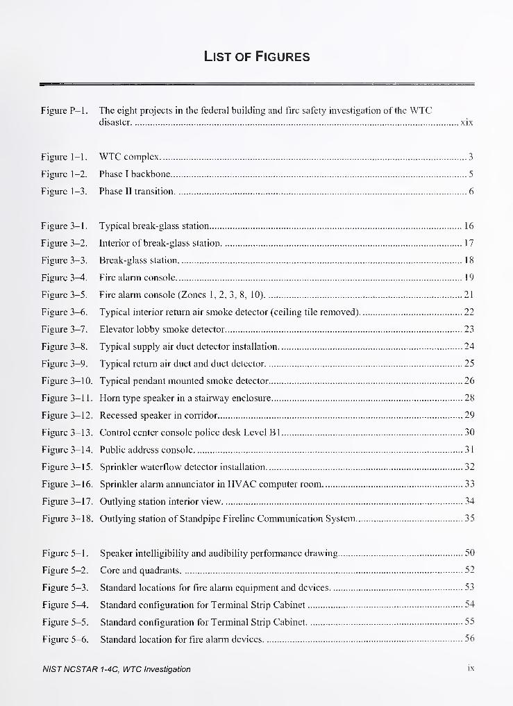
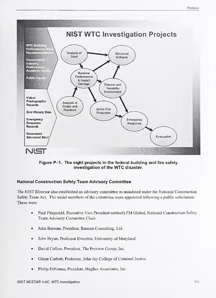
Figure P-1. The eight projects in the federal building and fire safety investigation of the WTCdisaster xix
Figure 1-1. WTC complex 3
Figure 1-2. Phase I backbone 5
Figure 1-3. Phase II transition 6
Figure 3-1. Typical break-glass station 16
Figure 3-2. Interior of break-glass station 1
7
Figure 3-3. Break-glass station 18
Figure 3^. Fire alarm console 19
Figure 3-5. Fire alarm console (Zones 1, 2, 3, 8, 10) 21
Figure 3-6. Typical interior return air smoke detector (ceiling tile removed) 22
Figure 3-7. Elevator lobby smoke detector 23
Figure 3-8. Typical supply air duct detector installation 24
Figure 3-9. Typical return air duct and duct detector 25
Figure 3-10. Typical pendant mounted smoke detector 26
Figure 3-11. Horn type speaker in a stairway enclosure 28
Figure 3-12. Recessed speaker in corridor 29
Figure 3-13. Control center console police desk Level Bl 30
Figure 3-14. Pubhc address console 3
1
Figure 3-15. Sprinkler waterflow detector installation 32
Figure 3-16. Sprinkler alarm annunciator in HVAC computer room 33
Figure 3-17. Outlying station interior view 34
Figure 3-1 8. Outlying station of Standpipe Fireline Communication System 35
Figure 5-1 . Speaker intelhgibihty and audibility performance drawing 50
Figure 5-2. Core and quadrants 52
Figure 5-3. Standard locations for fire alarm equipment and devices 53
Figure 5^. Standard configuration for Terminal Strip Cabinet 54
Figure 5-5. Standard configuration for Terminal Strip Cabinet 55
Figure 5-6. Standard location for fire alarm devices 56
NISTNCSTAR 1-4C, WTC Investigation ix
List of Figures
Figure 5-7. Standard locations for fire alarm duct smoke detectors 57
Figure 5-8. Standard routing for fire alarm circuit 58
Figure 5-9. Standard layout for fire alarm detection 59
Figure 5-10. Standard layout for fire alarm speakers 60
Figure 5-11. Standard layout for fire alarm strobes 61
Figure 5-12. Standard detail for fire alarm riser 62
Figure 5-13. New work acceptance best practices 63
Figure 5-14. Contractor tie-in and pre-test checklist 64
Figure 5-15. Contractor tie-in and pre-test checklist 65
Figure 5-16. WTC 1 fire command station 67
Figure 5-17. WTC 2 fire command station 68
Figure 5-18. Mechanical equipment room (MER) MXL-VR location 70
Figure 5-19. Fire alarm closet with PSR location 72
Figure 5-20. Fire alarm closet with PSR location , 73
Figure 5-2 1 . Single-line schematic ofMNET network configuration 78
Figure 5-22. Locations of typical MNET network equipment 79
Figure 5-23. Single-line schematic ofXNET network configuration 80
Figure 5-24. Locations ofXNET network equipment 81
Figure 5-25. Operation Control Center located on the Bl Level below WTC 2 with redundant fire
alarm system controls 82
Figure 5-26. Typical detection, monitoring, and control device layout 85
Figure 5-27. Single-line schematic of notification appliance network 88
Figure 5-28. Locations of audible notification apphance network equipment 89
Figure 5-29. Speaker circuit configurations 91
Figure 5-30. Strobe circuit configurations 92
Figure 5-3 1 . Single-line schematic of floor warden and firefighter telephones 94
Figure 5-32. Locations floor warden and firefighter telephone network equipment. ' 95
Figure 6-1. WTC 2 speaker and telephone circuit faults 105
Figure 6-2. WTC 7 central station alarm log 107
X NISTNCSTAR 1-4C, WTC Investigation

List of Tables
Table P-1. Federal building and fire safety investigation of the WTC disaster xviii
Table P-2. Public meetings and briefings of the WTC Investigation xxi
Table 5-1. Performance of Signaling Line Circuits (SLC) 76
Table 5-2. Notification Apphance Circuits (NAC) 86
NISTNCSTAR 1-4C, WTC Investigation xi

List of Tables
This page intentionally left blank.
xii NISTNCSTAR 1-4C, WTC Investigation
List of Acronyms and Abbreviations
MUl Uliyillo
ADAAG Americans with Disabilities Act Accessibility Guidelines for Building and Facilities
ANSI American National Standards Institute
ASTM ASTM International
ATC ALD Terminal Cabinets
BBFAS Base Building Fire Alarm System
BCNYC Building Code of the City ofNew York
BPS Building Performance Study
ESP Elevator Starter Panel
EVAC emergency voice alarm communication
FCS Fire Command Station
FDNY Fire Department of the City ofNew York
FEMA Federal Emergency Management Agency
HVAC heating, ventilating, and air conditioning
MER Mechanical Equipment Room
NCC Network Command Center
NFAC National Fire Alarm Code
NFPA National Fire Protection Association
NIST National Institute of Standards and Technology
NYC New York City
OCC Operation Control Center
PA Public Address System
PANYNJ Port Authority ofNew York and New Jersey
PSR Pyrotronics Remote Transponder
RMT Remote Monitoring Transponders
SEAoNY Structural Engineers Association ofNew York
TSC Terminal Strip Cabinet
use United States Code
WTC World Trade Center
NISTNCSTAR 1-4C, WTC Investigation xni
List ofAcronyms and Abbreviations
WTC 1 World Trade Center 1 (North Tower)
WTC 2 World Trade Center 2 (South Tower)
WTC 7 World Trade Center 7'
Abbreviations
°C degrees Celsius
°V degrees Fahrenheit
cfm cubic feet per minute
ft foot
h hour
in; inch
L liter
m meter
|im micrometer
min minute
s second
V voh
W watt
XIV NISTNCSTAR 1-4C, WTC Investigation
Glossary
Active fire protection - A means to help prevent the loss of life and property from fire by extinguishing,
suppressing or controlling a fire through functional systems. Sprinkler systems, fire alarm systems and
smoke control systems are examples of active fire protection.
Area of refuge - A floor area to which egress is made through a horizontal exit or supplemental vertical
exit.
Combustible - A material that will ignite and bum when subjected to fire or heat.
Damper - A device installed in HVAC ductwork used to prevent the spread of fire and/or smoke.
Dampers are provided to maintain a fire resistance rating of the assembly being penetrated.
Detector - An initiation device that automatically detects a change in state, such as presence of smoke,
high temperature or abnormal rate of temperature rise.
Fire alarm system - A system, automatic or manual, arranged to give a signal indicating a fire
emergency and initiate the appropriate response.
Fire resistance rating - The time in hours that materials or their assemblies will withstand fire exposure
as determined by a fire test.
Fireproofing - A method used to provide a fire resistance rating to a building component.
Firestopping - A solid or compact, tight closure to retard the spread of flames or hot gases within
concealed spaces.
Initiation device - A system component that originates a change in state signal in the fire alarm system.
An initiation device begins the life safety processes, such as evacuation, HVAC shut down, elevator
recall, etc.
Manual fire alarm box - A manually operated initiation device that originates a change in state signal in
the fire alarm system.
Means of egress - A continuous and unobstructed path of vertical and horizontal travel from any point in
a building to a public way. The means of egress consists of: the exit access, the exit and the exit
discharge.
Noncombustible - A material that does not ignite or bum when subjected to fire and heat.
Notification appliance - A fire alarm system component such as a bell, hom, speaker, or strobe that
provides audible, tactile, or visible outputs, or any combination thereof
NISTNCSTAR 1-4C, WTC Investigation XV
Glossary
Passive fire protection - A means to help prevent the loss of life and property from fire by increasing the
time to ignition or time to failure of a material. Providing fire separations and divisions, applying sprayed
fire-resistive material and enclosing structural members with noncombustible materials are examples of
passive fire protection.
Smoke and heat venting - A process used to move products of combustion to the outdoor air.
XVl NISTNCSTAR 1-4C, WTC Investigation
Preface
Genesis of This Investigation
Immediately following the terrorist attack on the World Trade Center (WTC) on September 1 1, 2001, the
Federal Emergency Management Agency (FEMA) and the American Society of Civil Engineers began
planning a building perfonnance study of the disaster. The week of October 7, as soon as the rescue and
search efforts ceased, the Building Performance Study Team went to the site and began its assessment.
This was to be a brief effort, as the study team consisted of experts who largely volunteered their time
away from their other professional commitments. The Building Performance Study Team issued its
report in May 2002, fulfilling its goal "to determine probable failure mechanisms and to identify areas of
future investigation that could lead to practical measures for improving the damage resistance of buildings
against such unforeseen events."
On August 21, 2002, with funding from the U.S. Congress through FEMA, the National Institute of
Standards and Technology (NIST) announced its building and fire safety investigation of the WTCdisaster. On October 1, 2002, the National Construction Safety Team Act (Public Law 107-231), was
signed into law. The NIST WTC Investigation was conducted under the authority of the National
Construction Safety Team Act.
The goals of the investigation of the WTC disaster were:
• To investigate the building construction, the materials used, and the technical conditions that
contributed to the outcome of the WTC disaster.
• To serve as the basis for:
- Improvements in the way buildings are designed, constructed, maintained, and used;
- Improved tools and guidance for industry and safety officials;
- Recommended revisions to current codes, standards, and practices; and
- Improved public safety.
The specific objectives were:
1. Determine why and how WTC 1 and WTC 2 collapsed following the initial impacts of the
aircraft and why and how WTC 7 collapsed;
2. Determine why the injuries and fatalities were so high or low depending on location,
including all technical aspects of fire protection, occupant behavior, evacuation, and
emergency response;
3. Determine what procedures and practices were used in the design, construction, operation,
and maintenance ofWTC 1,2, and 7; and
4. Identify, as specifically as possible, areas in current building and fire codes, standards, and
practices that warrant revision.
NISTNCSTAR 1-4C, WTC Investigation xvii
Preface
NIST is a nonregulatory agency of the U.S. Department of CoiTunerce's Technology Administration. The
purpose of NIST investigations is to improve the safety and structural integrity of buildings in the United
States, and the focus is on fact finding. NIST investigative teams are authorized to assess building
performance and emergency response and evacuation procedures in the wake of any building failure that
has resulted in substantial loss of life or that posed significant potential of substantial loss of life. NIST
does not have the statutory authority to make findings of fault nor negligence by individuals or
organizations. Further, no part of any report resulting from a NIST investigation into a building failure or
from an investigation under the National Constmction Safety Team Act may be used in any suit or action
for damages arising out of any matter mentioned in such report (15 USC 281a, as amended by Public
Law 107-231).
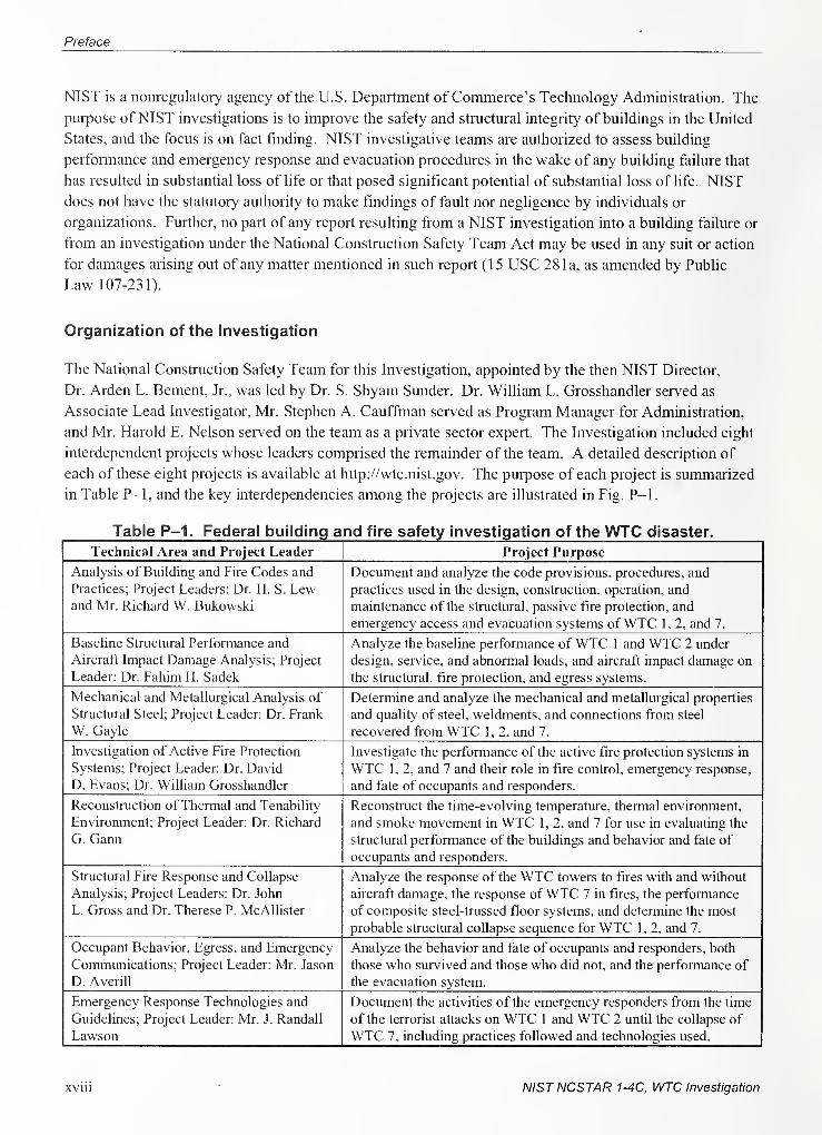
Organization of the Investigation
The National Construction Safety Team for this Investigation, appointed by the then NIST Director,
Dr. Arden L. Bement, Jr., was led by Dr. S. Shyam Sunder. Dr. William L. Grosshandler served as
Associate Lead Investigator, Mr. Stephen A. Cauffman served as Program Manager for Administration,
and Mr. Harold E. Nelson served on the team as a private sector expert. The Investigation included eight
interdependent projects whose leaders comprised the remainder of the team. A detailed description of
each of these eight projects is available at http://wtc.nist.gov. The purpose of each project is summarized
in Table P-1, and the key interdependencies among the projects are illustrated in Fig. P-1.
Table P-1. Federal building and fire safety investigation of the WTC disaster.
Technical Area and Project Leader Project Purpose
Analysis of Building and Fire Codes and
Practices; Project Leaders: Dr. H. S. Lewand Mr. Richard W. Bukowski
Document and analyze the code provisions, procedures, and
practices used in the design, construction, operation, and
maintenance of the structural, passive fire protection, and
emergency access and evacuation systems ofWTC 1, 2, and 7.
Baseline Structural Performance and
Aircraft Impact Damage Analysis; Project
Leader: Dr. Fahim H. Sadek
Analyze the baseline performance of WTC 1 and WTC 2 under
design, service, and abnormal loads, and aircraft impact damage on
the structural, fire protection, and egress systems.
Mechanical and Metallurgical Analysis of
Structural Steel; Project Leader: Dr. Frank
W. Gayle
Determine and analyze the mechanical and metallurgical properties
and quality of steel, weldments, and connections from steel
recovered from WTC 1, 2, and 7.
Investigation of Active Fire Protection
Systems; Project Leader: Dr. David
D. Evans; Dr. William Grosshandler
Investigate the perfonnance of the active fire protection systems in
WTC 1, 2, and 7 and their role in fire control, emergency response,
and fate of occupants and responders.
Reconstruction of Thermal and Tenability
Environment; Project Leader: Dr. Richard
G. Gann
Reconstruct the time-evolving temperature, thermal environment,
and smoke movement in WTC 1 , 2, and 7 for use in evaluating the
structural perfonnance of the buildings and behavior and fate of
occupants and responders.
Structural Fire Response and Collapse
Analysis; Project Leaders: Dr. John
L. Gross and Dr. Therese P. McAllister
Analyze the response of the WTC towers to fires with and without
aircraft damage, the response ofWTC 7 in fires, the performance
of composite steel-trussed floor systems, and determine the most
probable structural collapse sequence for WTC 1, 2, and 7.
Occupant Behavior, Egress, and Emergency
Communications; Project Leader: Mr. Jason
D. Averill
Analyze the behavior and fate of occupants and responders, both
those who survived and those who did not, and the performance of
the evacuation system.
Emergency Response Technologies and
Guidelines; Project Leader: Mr. J. Randall
Lawson
Document the activities of the emergency responders from the time
of the terrorist attacks on WTC 1 and WTC 2 until the collapse of
WTC 7, including practices followed and technologies used.
xviii NIST NCSTAR 1-4C, WTC Investigation
Preface
NIST WTC Investigation Projects
NisrFigure P-1. The eight projects in the federal building and fire safety
investigation of the WTC disaster.
National Construction Safety Team Advisory Committee
The NIST Director also established an advisory committee as mandated under the National Construction
Safety Team Act. The initial members of the committee were appointed following a public solicitation.
These were:
• Paul Fitzgerald, Executive Vice President (retired) FM Global, National Construction Safety
Team Advisory Committee Chair
• John Barsom, President, Barsom Consulting, Ltd.
• John Bryan, Professor Emeritus, University of Maryland
• David Collins, President, The Preview Group, Inc.
• Glenn Corbett, Professor, John Jay College of Criminal Justice
• Philip DiNenno, President, Hughes Associates, Inc.
NISTNCSTAR 1-4C, WTC Investigation XIX
Preface
• Robert Hanson, Professor Emeritus, University of Michigan
• Charles Thornton, Co-Chairman and Managing Principal, The Thomton-Tomasetti Group,
Inc.
• Kathleen Tiemey, Director, Natural Hazards Research and Applications Information Center,
University of Colorado at Boulder
• Fonnan Williams, Director, Center for Energy Research, University of California at San
Diego
This National Construction Safety Team Advisory Committee provided technical advice during the
Investigation and commentary on drafts of the Investigation reports prior to their public release. NIST
has benefited from the work of many people in the preparation of these reports, including the National
Construction Safety Team Advisory Conmiittee. The content of the reports and recommendations,
however, are solely the responsibility of NIST.
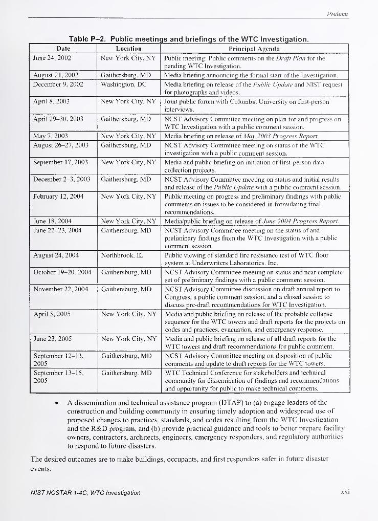
Public Outreach
During the course of this Investigation, NIST held public briefings and meetings (listed in Table P-2) to
solicit input from the public, present preliminaiy findings, and obtain comments on the direction and
progress of the Investigation from the public and the Advisoiy Committee.
NIST maintained a publicly accessible Web site during this Investigation at http://wtc.nist.gov. The site
contained extensive information on the background and progress of the Investigation.
NIST's WTC Public-Private Response Plan
The collapse of the WTC buildings has led to broad reexamination of how tall buildings are designed,
constructed, maintained, and used, especially with regard to major events such as fires, natural disasters,
and terrorist attacks. Reflecting the enlianced interest in effecting necessary change, NIST, with support
from Congress and the Administration, has put in place a program, the goal of which is to develop and
implement the standards, technology, and practices needed for cost-effective improvements to the safety
and security of buildings and building occupants, including evacuation, emergency response procedures,
and threat mitigation.
The strategy to meet this goal is a tliree-part NIST-led public-private response program that includes:
• A federal building and fire safety investigation to study the most probable factors that
contributed to post-aircraft impact collapse of the WTC towers and the 47-story WTC 7
building, and the associated evacuation and emergency response experience.
• A research and development (R&D) program to (a) facihtate the implementation of
recommendations resulting from the WTC Investigation, and (b) provide the technical basis
for cost-effective improvements to national building and fire codes, standards, and practices
that enhance the safety of buildings, their occupants, and emergency responders.
XX NISTNCSTAR 1-4C, WTC Investigation
Preface
Table P-2. Public meetings and briefings of the WTC Investigation.
Date Location Principal Af^cnda
June 24. 2002 New York City, NY Public meeting: Public comments on the Draft Plan for the
pending WTC Investigation.
August 21. 2002 Gaithersburg. MD Media briefing announcing the formal start of the Investigation.
December 9. 2002 Washington. DC Media briefing on release of the Public Update and N'lST request
for photographs and videos.
April 8. 2003 New York City, NY Joint public forum with Columbia University on firsl-per.son
interviews.
April 29-30, 2003 Gaithersburg, MD NCST Advisory Committee meeting on plan for and progress on
WTC Investigation with a public comment session.
May 7. 2003 New York City, NY Media briefing on release of May 2003 Progress Report.
August 26-27. 2003 Gaithersburg, MD NCST Advisory Committee meeting on status of the WTCinvestigation with a public comment session.
September 17,2003 New York City, NY Media and public briefing on initiation of first-person data
collection projects.
December 2-3, 2003 Gaithersburg, MD NCST Advisory Committee meeting on status and initial results
and release of the Public Update with a public comment session.
February 12, 2004 New York City, NY Public meeting on progress and preliminary findings with public
comments on issues to be considered in formulating final
recommendations.
June 18,2004 New York Cit>', NY Media/public briefing on release of June 2004 Progress Report.
June 22-23, 2004 Gaithersburg, MD NCST Advisory Committee meeting on the status of and
preliminary findings from the WTC Investigation with a public
comment session.
August 24, 2004 Northbrook, IL Public viewing of standard fire resistance test ofWTC floor
system at Underwriters Laboratories, Inc.
October 19-20. 2004 Gaithersburg, MD NCST Advisory Committee meeting on status and near complete
set of preliminary findings with a public comment session.
November 22. 2004 Gaithersburg. MD NCST Advisory Committee discussion on draft annual report to
Congress, a public comment session, and a closed session to
discuss pre-draft recommendations for WTC Investigation.
April 5, 2005 New York City, NY Media and public briefing on release of the probable collapse
sequence for the WTC towers and draft reports for the projects on
codes and practices, evacuation, and emergency response.
June 23,2005 New York City, NY Media and public briefing on release of all draft reports for the
WTC towers and draft recommendations for public comment.
September 12-13,
2005
Gaithersburg, MD NCST Advisory Committee meeting on disposition of public
comments and update to draft reports for the WTC towers.
September 13-15,
2005
Gaithersburg, MD WTC Technical Conference for stakeholders and technical
community for dissemination of findings and recommendations
and opportunity for public to make technical comments.
• A dissemination and technical assistance program (DTAP) to (a) engage leaders of the
construction and building community in ensuring timely adoption and widespread use of
proposed changes to practices, standards, and codes resulting from the WTC Investigation
and the R&D program, and (b) provide practical guidance and tools to better prepare facihty
owners, contractors, architects, engineers, emergency responders, and regulatory authorities
to respond to future disasters.
The desired outcomes are to make buildings, occupants, and first responders safer in future disaster
events.
NISTNCSTAR 1-4C, WTC Investigation xxi
Preface
National Construction Safety Team Reports on the WTC Investigation
A final report on the collapse of the WTC towers is being issued as NIST NCSTAR 1 . A companion
report on the collapse ofWTC 7 is being issued as NIST NCSTAR lA. The present report is one of a set
that provides more detailed documentation of the Investigation findings and the means by which these
technical results were achieved. As such, it is part of the archival record of this Investigation. The titles
of the full set of Investigation pubUcations are:
NIST (National Institute of Standards and Technology). 2005. Federal Building and Fire Safety
Investigation ofthe World Trade Center Disaster: Final Report on the Collapse of the World Trade
Center Towers. NIST NCSTAR 1. Gaithersburg, MD, September.
NIST (National Institute of Standards and Technology). 2006. Federal Building and Fire Safety
Investigation of the World Trade Center Disaster: Final Report on the Collapse of World Trade Center 7.
NIST NCSTAR 1 A. Gaithersburg, MD.
Lew, H. S., R. W. Bukowski, and N. J. Carino. 2005. Federal Building and Fire Safety Investigation of
the World Trade Center Disaster: Design, Construction, and Maintenance ofStructural and Life Safety
Systems. NIST NCSTAR 1-1. National Institute of Standards and Technology. Gaithersburg, MD,September.
Fanella, D. A., A. T. Derecho, and S. K. Ghosh. 2005. Federal Building and Fire Safety
Investigation ofthe World Trade Center Disaster: Design and Construction ofStructural Systems.
NIST NCSTAR 1-1 A. National Institute of Standards and Teclinology. Gaithersburg, MD,September.
Ghosh, S. K., and X. Liang. 2005. Federal Building and Fire Safety Investigation ofthe World
Trade Center Disaster: Comparison ofBuilding Code Structural Requirements. NIST
NCSTAR 1-lB. National Institute of Standards and Technology. Gaithersburg, MD, September.
Fanella, D. A., A. T. Derecho, and S. K. Ghosh. 2005. Federal Building and Fire Safety
Investigation ofthe World Trade Center Disaster: Maintenance and Modifications to Structural
Systems. NIST NCSTAR 1-lC. National Institute of Standards and Technology. Gaithersburg,
MD, September.
Grill, R. A., and D. A. Johnson. 2005. Federal Building and Fire Safety Investigation ofthe World
Trade Center Disaster: Fire Protection and Life Safety Provisions Applied to the Design and'
Construction of World Trade Center I, 2, and 7 and Post-Construction Provisions Applied after
Occupancy. NIST NCSTAR 1-lD. National Institute of Standards and Technology. Gaithersburg,
MD, September.
Razza, J. C, and R. A. Grill. 2005. Federal Building and Fire Safety Investigation ofthe World
Trade Center Disaster: Comparison of Codes, Standards, and Practices in Use at the Time ofthe
Design and Construction of World Trade Center I, 2, and 7. NIST NCSTAR 1-lE. National
Institute of Standards and Technology. Gaithersburg, MD, September.
Grill, R. A., D. A. Johnson, and D. A. Fanella. 2005. Federal Building and Fire Safety
Investigation ofthe World Trade Center Disaster: Comparison ofthe 1968 and Current (2003) New
xxn NIST NCSTAR 1-4C, WTC Investigation
Preface
York City Building Code Provisiom. NISTNCSTAR 1-lF. National Institute of Standards and
Technology. Gaithersburg, MD, September.
Grill, R. A., and D. A. Johnson. 2005. Federal Building and Fire Safety Investigation ofthe World
Trade Center Disaster: Amendments to the Fire Protection and Life Safety Provisions of the NewYork City Building Code by Local Laws Adopted While World Trade Center /, 2, and 7 Were in
Use. NIST NCSTAR 1-lG. National Institute of Standards and Technology. Gaithersburg, MD,September.
Grill, R. A., and D. A. Johnson. 2005. Federal Building and Fire Safety Investigation ofthe World
Trade Center Disaster: Post-Construction Modifications to Fire Protection and Life Safety Systems
of World Trade Center I and 2. NIST NCSTAR 1-lH. National Institute of Standards and
Technology. Gaithersburg, MD, September.
Grill, R. A., D. A. Johnson, and D. A. Fanella. 2005. Federal Building and Fire Safety Investigation
ofthe World Trade Center Disaster: Post-Construction Modifications to Fire Protection, Life
Safety, and Structural Systems of World Trade Center 7. NIST NCSTAR 1-1 1. National Institute of
Standards and Technology. Gaithersburg, MD, September.
Grill, R. A., and D. A. Johnson. 2005. Federal Building and Fire Safety Investigation ofthe World
Trade Center Disaster: Design, Installation, and Operation ofFuel System for Emergency Power in
World Trade Center 7. NIST NCSTAR 1-1 J. National Institute of Standards and Technology.
Gaithersburg, MD, September.
Sadek, F. 2005. Federal Building and Fire Safety Investigation ofthe World Trade Center Disaster:
Baseline Structural Performance and Aircraft Impact Damage Analysis of the World Trade Center
Towers. NIST NCSTAR 1-2. National Institute of Standards and Technology. Gaithersburg, MD,September.
Faschan, W. J., and R. B. Garlock. 2005. Federal Building and Fire Safety Investigation ofthe
World Trade Center Disaster: Reference Structural Models and Baseline Performance Analysis of
the World Trade Center Towers. NIST NCSTAR 1-2A. National Institute of Standards and
Technology. Gaithersburg, MD, September.
Kirkpatrick, S. W., R. T. Bocchieri, F. Sadek, R. A. MacNeill, S. Holmes, B. D. Peterson,
R. W. Cilke, C. Navarro. 2005. Federal Building and Fire Safety Investigation ofthe World Trade
Center Disaster: Analysis ofAircraft Impacts into the World Trade Center Towers, NIST
NCSTAR 1-2B. National Institute of Standards and Technology. Gaithersburg, MD, September.
Gayle, F. W., R. J. Fields, W. E. Luecke, S. W. Banovic, T. Foecke, C. N. McCowan, T. A. Siewert, and
J. D. McColskey. 2005. Federal Building and Fire Safety Investigation ofthe World Trade Center
Disaster: Mechanical and Metallurgical Analysis ofStructural Steel. NIST NCSTAR 1-3. National
Institute of Standards and Technology. Gaithersburg, MD, September.
Luecke, W. E., T. A. Siewert, and F. W. Gayle. 2005. Federal Building and Fire Safety
Investigation ofthe World Trade Center Disaster: Contemporaneous Structural Steel
Specifications. NIST Special Publication 1-3A. National Institute of Standards and Technology.
Gaithersburg, MD, September.
NISTNCSTAR 1-4C, WTC Investigation xxni
Preface
Banovic, S. W. 2005. Federal Building and Fire Safety Investigation ofthe World Trade Center
Disaster: Steel Inventoiy and Identification. NIST NCSTAR 1 -3B. National Institute of Standards
and Technology. Gaithersburg, MD, September.
Banovic, S. W., and T. Foecke. 2005. Federal Building and Fire Safety Investigation ofthe World
Trade Center Disaster: Damage and Failure Modes ofStructural Steel Components. NIST
NCSTAR 1-3C. National Institute of Standards and Technology. Gaithersburg, MD, September.
Luecke, W. E., J. D. McColskey, C. N. McCowan, S. W. Banovic, R. J. Fields, T. Foecke,
T. A. Siewert, and F. W. Gayle. 2005. Federal Building and Fire Safety Investigation ofthe World
Trade Center Disaster: Mechanical Properties ofStructural Steels. NIST NCSTAR 1-3D.
National Institute of Standards and Technology. Gaithersburg, MD, September.
Banovic, S. W., C. N. McCowan, and W. E. Luecke. 2005. Federal Building and Fire Safety
Investigation ofthe World Trade Center Disaster: Physical Properties ofStructural Steels. NIST
NCSTAR I-3E. National Institute of Standards and Technology. Gaithersburg, MD, September.
Evans, D. D., R. D. Peacock, E. D. Kuligowski, W. S. Dols, and W. L. Grosshandler. 2005. Federal
Building and Fire Safety Investigation ofthe World Trade Center Disaster: Active Fire Protection
Systems. NIST NCSTAR 1-4. National Instimte of Standards and Technology. Gaithersburg, MD,September.
Kuligowski, E. D., D. D. Evans, and R. D. Peacock. 2005. Federal Building and Fire Safety
Investigation ofthe World Trade Center Disaster: Post-Construction Fires Prior to September II,
2001. NIST NCSTAR 1-4A. National Institute of Standards and Technology. Gaithersburg, MD,September.
Hopkins, M., J. Schoenrock, and E. Budnick. 2005. Federal Building and Fire Safety Investigation
ofthe World Trade Center Disaster: Fire Suppression Systems. NIST NCSTAR 1-4B. National
Institute of Standards and Technology. Gaithersburg, MD, September.
Keough, R. J., and R. A. Grill. 2005. Federal Building and Fire Safety Investigation ofthe World
Trade Center Disaster: Fire Alarm Systems. NIST NCSTAR 1-4C. National Institute of Standards
and Technology. Gaithersburg, MD, September.
Ferreira, M. J., and S. M. Strege. 2005. Federal Building and Fire Safety Investigation ofthe
World Trade Center Disaster: Smoke Management Systems. NIST NCSTAR 1-4D. National
Institute of Standards and Technology. Gaithersburg, MD, September.
Gann, R. G., A. Hamins, K. B. McGrattan, G. W. Mulholland, H. E. Nelson, T. J. Ohlemiller,
W. M. Pitts, and K. R. Prasad. 2005. Federal Building and Fire Safet}' Investigation ofthe World Trade
Center Disaster: Reconstruction ofthe Fires in the World Trade Center Towers. NIST NCSTAR 1-5.
National Institute of Standards and Technology. Gaithersburg, MD, September.
Pitts, W. M., K. M. Butler, and V. Junker. 2005. Federal Building and Fire Safety Investigation of
the World Trade Center Disaster: Visual Evidence, Damage Estimates, and Timeline Analysis.
NIST NCSTAR 1-5A. National Institute of Standards and Technology. Gaithersburg, MD,September.
XXIV NIST NCSTAR 1-4C, WTC Investigation
Preface
Hamins, A., A. Maranghides, K. B. McGrattan, E. Johnsson, T. J. Ohlemiller, M. Donnelly,
J. Yang, G. Mulholland, K. R. Prasad, S. Kukuck, R. Anleitncr and T. McAllister. 2005. Federal
Building and Fire Safety Investigation of the World Trade Center Disaster: Experiments and
Modeling ofStructural Steel Elements Exposed to Fire. NIST NCSTAR 1-5B. National Institute of
Standards and Technology. Gaithersburg, MD, September.
Ohlemiller, T. J., G. W. Mulholland, A. Maranghides, J. J. Filliben, and R. G. Gann. 2005. Federal
Building and Fire Safety Investigation ofthe World Trade Center Disaster: Fire Tests ofSingle
Office Workstations. NIST NCSTAR 1-5C. National Institute of Standards and Technology.
Gaithersburg, MD, September.
Gann, R. G., M. A. Riley, J. M. Repp, A. S. Whittaker, A. M. Reinhom, and P. A. Hough. 2005.
Federal Building and Fire Safety Investigation ofthe World Trade Center Disaster: Reaction of
Ceiling Tile Systems to Shocks. NIST NCSTAR 1-5D. National Institute of Standards and
Technology. Gaithersburg, MD, September.
Hamins, A., A. Maranghides, K. B. McGrattan, T. J. Ohlemiller, and R. Anleitner. 2005. Federal
Building and Fire Safety Investigation ofthe World Trade Center Disaster: Experiments and
Modeling ofMultiple Workstations Burning in a Compartment. NIST NCSTAR 1-5E. National
Institute of Standards and Technology. Gaithersburg, MD, September.
McGrattan, K. B., C. Bouldin, and G. Fomey. 2005. Federal Building and Fire Safety
Investigation ofthe World Trade Center Disaster: Computer Simulation ofthe Fires in the World
Trade Center Towers. NIST NCSTAR 1-5F. National Institute of Standards and Technology.
Gaithersburg, MD, September.
Prasad, K. R., and H. R. Baum. 2005. Federal Building and Fire Safety Investigation ofthe World
Trade Center Disaster: Fire Structure Interface and Thermal Response ofthe World Trade Center
Towers. NIST NCSTAR 1-5G. National Institute of Standards and Teclinology. Gaithersburg,
MD, September.
Gross, J. L., and T. McAllister. 2005. Federal Building and Fire Safety Investigation ofthe World Trade
Center Disaster: Structural Fire Response and Probable Collapse Sequence of the World Trade Center
Towers. NIST NCSTAR 1-6. National Institute of Standards and Technology. Gaithersburg, MD,September.
Carino, N. J., M. A. Stames, J. L. Gross, J. C. Yang, S. Kukuck, K. R. Prasad, and R. W. Bukowski.
2005. Federal Building and Fire Safety Investigation of the World Trade Center Disaster: Passive
Fire Protection. NIST NCSTAR 1-6A. National Institute of Standards and Technology.
Gaithersburg, MD, September.
Gross, J., F. Hervey, M. Izydorek, J. Mammoser, and J. Treadway. 2005. Federal Building and
Fire Safety Investigation ofthe World Trade Center Disaster: Fire Resistance Tests ofFloor Truss
Systems. NIST NCSTAR 1-6B. National Institute of Standards and Technology. Gaithersburg,
MD, September.
Zarghamee, M. S., S. Bolourchi, D. W. Eggers, O. O. Erbay, F. W. Kan, Y. Kitane, A. A. Liepins,
M. Mudlock, W. I. Naguib, R. P. Ojdrovic, A. T. Sarawit, P. R Barrett, J. L. Gross, and
NIST NCSTAR 1-4C, WTC Investigation XX\'
Preface
T. P. McAllister. 2005. Federal Building and Fire Safety Investigation ofthe World Trade Center
Disaster: Component, Connection, and Subsystem Structural Analysis. NISTNCSTAR 1-6C.
National Institute of Standards and Technology. Gaithersburg, MD, September.
Zarghamee, M. S., Y. Kitane, O. O. Erbay, T. P. McAllister, and J. L. Gross. 2005. Federal
Building and Fire Safety Investigation ofthe World Trade Center Disaster: Global Structural
Analysis ofthe Response ofthe World Trade Center Towers to Impact Damage and Fire. NIST
NCSTAR 1-6D. National Institute of Standards and Technology. Gaithersburg, MD, September.
McAllister, T., R. W. Bukowski, R. G. Gann, J. L. Gross, K. B. McGrattan, H. E. Nelson, L. Phan,
W. M. Pitts, K. R. Prasad, F. Sadek. 2006. Federal Building and Fire Safety Investigation ofthe World
Trade Center Disaster: Structural Fire Response and Probable Collapse Sequence of World Trade
Center?. (Provisional). NIST NCSTAR 1-6E. National Institute of Standards and Technology.
Gaithersburg, MD. .
"
Gilsanz, R., V. Arbitrio, C. Anders, D. Chlebus, K. Ezzeldin, W. Guo, P. Moloney, A. Montalva,
J. Oh, K. Rubenacker. 2006. Federal Building and Fire Safety Investigation ofthe World Trade
Center Disaster: Structural Analysis ofthe Response of World Trade Center 7 to Debris Damage
and Fire. (Provisional). NIST NCSTAR 1-6F. National Institute of Standards and Technology.
Gaithersburg, MD.
Kim, W. 2006. Federal Building and Fire Safety Investigation ofthe World Trade Center
Disaster: Analysis ofSeptember 11, 2001, Seismogram Data. (Provisional). NIST NCSTAR 1-6G.
National Institute of Standards and Technology. Gaithersburg, MD.
Nelson, K. 2006. Federal Building and Fire Safety Investigation ofthe World Trade Center
Disaster: The Con Ed Substation in World Trade Center 7. (Provisional). NISTNCSTAR 1-6H.
National Institute of Standards and Technology. Gaithersburg, MD.
Averill, J. D., D. S. Mileti, R. D. Peacock, E. D. Kuligowski, N. Groner, G. Proulx, P. A. Reneke, and
H. E. Nelson. 2005. Federal Building and Fire Safety Investigation of the World Trade Center Disaster:
Occupant Behavior, Egress, and Emergency Communication. NIST NCSTAR 1-7. National Institute of
Standards and Technology. Gaithersburg, MD, September.
Fahy, R., and G. Proulx. 2005. Federal Building and Fire Safety Investigation ofthe World Trade
Center Disaster: Analysis ofPublished Accounts ofthe World Trade Center Evacuation. NIST
NCSTAR 1-7A. National Institute of Standards and Technology. Gaithersburg, MD, September.
Zmud, J. 2005. Federal Building and Fire Safety Investigation ofthe World Trade Center
Disaster: Technical Documentationfor Sun'cy Administration. NISTNCSTAR 1-7B. National
Institute of Standards and Technology. Gaithersburg, MD, September.
Lawson, J. R., and R. L. Vettori. 2005. Federal Building and Fire Safety Investigation ofthe World
Trade Center Disaster: The Emergency Response Operations. NIST NCSTAR 1-8. National Institute of
Standards and Technology. Gaithersburg, MD, September.
XXVI NISTNCSTAR 1-4C, WTC Investigation
Executive Summary
E.1 FIRE ALARM HISTORY AND APPLICATION
The application, performance, and use of fire alarms have changed over time through the development of
technology, and the public's expectation for fire safe buildings. The goal of the early systems was to
enhance property protection through early notification of first responders to initiate human intervention
that would limit property damage. Although life saving acts were performed by first responders, the
intent of the first fire alarm systems was to summon first responders to the fire, not to notify building
occupants of an impending fire emergency.
It wasn't until major studies published in 1962 by Mc Guire and Ruscoe and the Federal Fire Council
("Needed—Protection for People") that it was recognized that the majority of fire protection devices in
the market were devoted to property protection, not life safety enhancement. This realization has led to
the development of a more holistic approach to fire protection that includes the fire alarm as one of
numerous building systems involved in both occupant life safety and property protection.
The role played by a fire alarm system in the overall fire protection goals of a building is usually guided
by codes and standards adopted for the project, or enforced within the jurisdiction of the project. As an
interstate compact under the U.S. Constitution, the Port Authority was not subjected to any state or local
building codes. The Building Code of the City ofNew York (BCNYC) provides the criteria for the type,
location, and installation requirements for fire alarm protection within buildings in the City ofNew York.
The code has adopted sections, but not the full content of the National Fire Alarm Code and National
Electrical Code, as a Reference Standard (RS 17-3) for the installation of fire alarm systems. As in the
case of model building codes, the BCNYC has referenced specific editions of the supporting codes and
standards, such as the National Fire Alarm Code and National Electrical Code, which are not the most
current editions published. This is due to the fact that standards are constantly undergoing revision to
address new technologies and to incorporate issues identified during application of the standards. Also, a
code or standard that is in effect when a system is designed is usually applied to the system during its
existence, even if new codes or standards are developed or adopted by the authority having jurisdiction
during the time between when the project was approved and when it is completed. As such, the most
recent codes and standards are usually not applicable to a project due to the lag time between code or
standard development and its adoption by an authority having jurisdiction over any project.
E.2 WORLD TRADE CENTER (WTC) 1, 2, AND 7 FIRE ALARMINTRODUCTION
The successful function and operation of a fire alarm system is dependent on its design, equipment,
installation, maintenance, and on its use during an emergency. The majority of the documentation of the
fire alarm systems in WTC 1 and WTC 2 were kept on the 8 1 st floor ofWTC 1 , which ser\'ed as the fire
alarm contractor's office. This material was lost with the towers. Limited documentation maintained off-
site, along with information gained from personnel involved with the systems, allowed for the re-creation
of the system's design development, intended functions, and installation architecture. Actual
documentation and personal experiences relevant to the systems function and use during the events of
NISTNCSTAR 1-4C, WTC Investigation XXVll
Executive Summary
September 11, 2001 are sporadic in detail, with very limited documentation on the actual use or functional
interaction with the building occupants and other life safety systems.
The documentation and personal experiences relating to the WTC 7 system were limited, and only paint a
partial picture of its equipment and architecture. Maintenance documentation was available, showing that
the system was tested on a regular basis, but there was no documentation available on its design
development, installation, or use. The infonnation on the performance of the fire alarm system on
September 1 1, 2001 , is limited to a printout reporting of the systems alarm condition to an off-site
monitoring service.
E.3 NORMAL OPERATIONS AND FIRE EMERGENCY RESPONSE
The Port Authority ofNew York and New Jersey (PANYNJ or Port Authority) had a Fire Safety Plan for
WTC 1, 2, and 7 that provided direction for fire emergency response and was organized around a
hierarchy of staff associated with its implementation. At the top of this hierarchy was the WTC Fire
Safety Director. The Fire Safety Director oversaw fire emergency response until the arrival of The Fire
Department of the City ofNew York (FDNY or Fire Department), and was responsible for gathering all
necessary information for the Fire Department, which he/she relayed to the Chief upon his/her arrival. In
WTC 1 and WTC 2, subordinate to the Fire Safety Director was the Assistant Fire Safety Coordinator,
who was responsible for the availability and state of readiness of the Fire Brigade and the entire
Emergency Response Team (members of the WTC Division of the Port Authority Police, who receive
firefighting training and staff the WTC Fire Brigade). In WTC 7, the Fire Safety Director also performed
the functions of the Assistant Fire Safety Coordinator as identified above. WTC 7 also had a Fire Brigade
that the Fire Safety Director was responsible for organizing and training.
In addition to the WTC 1 and WTC 2 Assistant Fire Safety Coordinator, the towers had an Emergency
Response Team consisting of Deputy Fire Safety Directors, Lobby Deputy Fire Safety Directors, Floor
Wardens and Deputy Floor Wardens. Deputy Fire Safety Directors were responsible for performing the
duties of the Assistant Fire Safety Coordinator in his/her absence and staffing the Fire Command Station
for the purposes of executing the fire safety plan. At the end of the hierarchical chain for WTC 1, 2, and
7 were Floor Wardens and Deputy Floor Wardens, who were responsible for assessing conditions and
assisting in evacuation of floor occupants on their respective floors upon direction from the Fire Brigade
and/or Fire Command Station. Floor Wardens, Deputy Floor Wardens, and their alternates were
appointed tenants or employees of the WTC complex (SafirRosetti 2002; Kastner 1990; PANYNJ 2001).
Fire drills were conducted at WTC 1, 2, and 7 every six months under the direction of the Floor Warden
and Deputies of the Floor Warden. During the drills all employees, occupants, and visitors of the floor
where the drill was conducted were physically required to leave their office areas and evacuate to a
central hallway, near a stairwell. In addition, regular training exercises were conducted by the Port
Authority and the Fire Department, the designated lead authority responsible for coinmand of fire
incidents at the WTC complex. The exercises oriented new staff to the building, its equipment and the
appropriate emergency response procedures and served as a reminder to existing staff in the Port
Authority and New York City Fire Department.
Fire inspections were performed annually in each tenant space to limit the risk of life and property loss
from fire. A written report was prepared for all fire inspections and was maintained by the Fire Safety
XXVlll NISTNCSTAR 1-4C, WTC Investigation

Executive Summary
Office. Any deficiencies or violations were noted in the report and forwarded to the appropriate person in
the tenant space for correction.
Upon discovery of fire or smoke, the Fire Safety Plan called for occupants to activate the nearest building
manual fire alarm station, typically at the intersecting corridor, and to notify the WTC police via
telephone. The Police Desk dispatched the Fire Brigade and verified transmission of the alarm to the
New York City Fire Department. The Fire Safety Director could also initiate evacuation from the area or
the entire building. In this situation, the fire alarm emergency voice communication system was activated
on the floors to be evacuated. It is important to note that the transmission of the alarms to the building
occupants in WTC 1 and WTC 2 was not automatic and required the Fire Safety Director's initiation.
Tenant Fire Safety Procedures exercised during regular fire drills require that building occupants proceed
to the corridor areas to wait for verbal instructions provided over the fire alarm emergency voice
communication speakers.
E.4 ORIGINAL BUILDING FIRE ALARM SYSTEM
The WTC was designed in accordance with the New York City Building and Fire Prevention Codes of
1968, in effect at the time of the building's construction. The Port Authority ofNew York and NewJersey's objective was to adhere to or exceed local code requirements whenever practical.
In addition to legislated building codes, the Port Authority relied on nationally recognized fire safety
standards published by the American National Standards Institute (ANSI) and the National Fire
Protection Association (NFPA), as well as internal protocols established with fire officials in the city.
Two noteworthy protocols included the "Protocol for Periodic Joint Port Authority/Fire Department of
New York Inspections of Port Authority New York City Facilities" of 1988 and the "WTC/FDNY Joint
Protocol for Inspectional Activity at the World Trade Center Complex" of 1986. The Port Authority
maintained a working relationship with the New York City Fire Department through these protocols that
allowed the Fire Department access for inspections and evaluation of life safety and fire protection
systems at the complex. The Fire Department was provided with the authority to issue advisory reports
resuhing from their inspections, which the Port Authority could consider on a voluntary basis.
The fire alarm system originally installed within the WTC provided protection for the following facilities:
• WTC 1
• WTC 2
• WTC 4
• WTC 5
• Concourse Level
• Sub-Grade Level
NISTNCSTAR 1-4C, WTC Investigation XXIX
Executive Summary
The system integrated detectors and alarm devices from the various buildings, to be tied into a control
panel for that building or level. All control panels simultaneously annunciated alarms and troubles at the
Operations Control Center.
The system consisted of American Multiplex Remote Monitoring Transponders (RMT) on every third
floor, connected to the Digital Computer and Console in the Operations Control Center on the B-1
Sub-Grade Level. Transponders monitored Pyrotronics CR-7 Equipment connected to type DI-2, DI-3,
DI-4A, and DI-6 smoke detectors (non-addressable type), Pyrotronics System 3 panels, tenant proprietary
systems, waterflow switches, tamper switches, and control contacts.
Pryrotronics XL3 smoke detector systems, with addressable type detectors, were installed in the
mechanical equipment rooms of both WTC I and WTC 2 and connected via a CXL Communication
Device to a console in the Operations Control Center.
Manual Pull Stations were wired to an existing Executone system, which alarmed directly to the Fire
Department.
The Public Address Communication System with manually activated selection of floor was also located at
the Operations Control Center. Alarms from these systems were called in to the Fire Department,
manually, by the Port Authority Police on duty 24 hours a day at the Police Desk.
The American Multiplex Digital Computer and Console was a fire alarm and communication system
engineered and built specifically for the WTC. Although it was state-of-the-art at the time of
construction, fire protection technology had changed significantly in the decades since the original
installation. Perfonnance based codes and standards had consolidated the fire detection, monitoring,
control, and communication systems that were originally separate systems into single integrated systems.
The Port Authority did upgrade the mechanical equipment room (MER) fire alarni protection with the
installation of a microprocessor controlled, addressable Pyrotronics XL3 system in each MER, which was
monitored by a CXL Command Center monitored in the Operations Control Center. The XL3 fire alarm
system was the predecessor to the Siemens Pyrotronics MXL-V system that was installed after the
1993 bombing.
E.5 POST-1993 FIRE ALARM
The magnitude, size, and scope of the WTC fire alarm retrofit project rivaled any effort performed by the
fire protection industry. It was estimated that over 10,000 initiating devices (smoke detectors, maniaal
pull stations, waterflow indicators, etc.), with 30,000 notification appliances (speakers and strobes),
supported by over 700,000 ft of conduit and 5 million ft of wire were installed in the WTC as part of the
fire alarm system retrofit project (PANYNJ 1998). Project development documentation found and
analyzed was focused on the system's architecture and performance. No documentation was found that
indicated cost was a factor in obtaining the WTC's fire protection goals.
Before the original fire alarm system operation was fully restored after the 1993 bombing, the Port
Authority Engineering Department began to explore the WTC's fire detection and alarm system's goals
and how to incorporate these goals into a replacement system. Based upon its findings, the PAEngineering Department initiated a fire alarm retrofit project, which was developed from the following
objectives (PANYNJ 1998):
XXX NISTNCSTAR 1-4C, WTC Investigation
Executive Summary
1. Identify the type and extent of fire detection, communication, notification, and monitoring
capabilities required.
2. Select the fire alarm technology to support the size of the WTC complex (approximately
12,000,000 ft"^), with the capability to interface with the existing fire alarm systems. All the
equipment was required to be New York City approved, and was required to be readily
available for initial purchase and spare parts.
3. Determine the size, type, and number of equipment, devices, and hardware needed for the fire
alarm infrastructure. Identify location and space for the infrastructure.
4. Determine how to interface the new system with the existing fire alarm systems and their
components.
5. Develop standards, guidelines, and specifications for the design of the retrofit fire alarm
system.
6. Develop standards, guidelines, and specifications for the installation of the fire alarm system.
7. Institute maintenance procedures to ensure the availability and performance of the fire alarm
system.
Although documentation of the decision-making processes or directives defining the WTC fire alarm
protection goals were not located, the overall design development, installation, and maintenance of the
system indicates that it was the intention of the Port Authority to meet or exceed all local code and
American with Disabilities Act requirements as interpreted by the Chief Engineer of the WTC. If the Port
Authority believed that it was in the best interest of the WTC and its tenants to vary from the code
requirements due to operations and/or other features of the fire alarm system, the Port Authority would
obtain agreement or approval from the Fire Department and/or The New York City Department of
Buildings (Department of Buildings) as per the Memorandum of Understanding signed between the Port
Authority and the Department of Buildings (Semah 1996).
E.6 SEPTEMBER 1 1 , 2001 FIRE ALARM PERFORMANCE
The review of the WTC fire alarm system's performance September 1 1, 2001, indicated that the systems
did work, but not all functionality survived the impacts of the airplanes. The analysis of the fire alarm
system's performance has led to the following results:
• Remote monitoring of the WTC 7 fire alarm systems only provided a time and date of the
alarm condition (see Fig. 6-1). Large, addressable systems provide detailed information on
the type of alarm or fault condition, their location, and the date/time of the occurrence. The
analysis of the WTC fire alarm system would have benefited if the information commonly
processed within the protected property was also transmitted and stored off-site at the
location where the system was monitored.
• The WTC 1 and WTC 2 fire alarm systems required manual activation of the alarm signal to
notify building occupants. This signal was delayed by 12 min after the impact in WTC 1.
NISTNCSTAR 1-4C, WTC Investigation xxxi
Executive Summary
Fire alann systems have the capability and are usually configured to initiate an alarm signal
automatically upon alann initiation. Means are available to notify building occupants at risk
automatically by an alarm signal upon activation of the fire alann system.
• There is a disparity in performance requirements for the different types of circuits common to
a fire alarm system. As an example, a Class A Style 7 Signaling Line Circuit will continue to
perform if the circuit experiences a short. A Class A Style Z Notification Appliance Circuit
will not perform if it experiences a short. A Signaling Line Circuit may be required to turn
on loudspeakers connected to a Notification Appliance Circuit. If an event were to cause a
short on both circuits, then the Signaling Line Circuit would be able to turn on Notification
Appliance Circuits serving the loudspeakers, but the Notification Appliance Circuits
providing the voice message or alann tone to the speakers would not perform. Since the
primary intent is to broadcast from the loudspeakers through the Notification Appliance
Circuits, it would be appropriate for the Notification Appliance Circuits to have the same
performance requirements as the Signaling Line Circuits.
• The disparity in circuit perfonnance is also relevant to the floor warden and standpipe fireline
telephones. The fault tolerance performance standards for telephone communication circuits
are not as well defined as compared to other types of fire alarm circuits. This limits the
survivability characteristics of the telephone communication circuits in comparison to other
types of fire alarm circuits. Although manufacturers commonly provide some survivability
characteristics, there is not a standard requiring minimum circuit performance. As with the
Notification Appliance Circuits, a Signaling Line Circuit with robust survivability from
functional faults may be controlling the operation of a telephone circuit, which has minimal
survivability capabilities. If a fire alarm system objective is to provide enhanced
survivability characteristics through a Signaling Line Circuit that will control a required
function such as a telephone, then it would be appropriate for the survivability performance
characteristics of the circuits for the required function to match the performance of the circuit
supporting the function. -
• Although there is evidence that the floor warden telephones were used, the after action
interviews of the firefighters conducted by the National Institute of Standards and
Technology (NIST) did not find that there was any attempt to use the standpipe fireline
telephone system. This is not uncommon since the firefighters are trained to use their radios
as the prefened means of communication. The resources used to install a firefighter
telephone system would appear to be better served by installing radio repeaters to support
their radio communication instead of installing dedicated telephones.
• Although the fire alarm systems in WTC 1 and WTC 2 used multiple communication path
risers, the systems experienced performance degradation, especially in WTC 1 where all fire
alarm notification and communication functions appear to have been lost above the floors of
impact. The use of multiple risers does improve physical survivability in tall buildings, but
other measures may be necessary to address the extensive damage associated with a possible
explosion. Additional fire alarm system sui'vivability can be gained through the location of
the fire alarm equipment and a riser in a central building core area, and by protecting the area
with structural hardening and fire-resistive construction. Similar enhancements can be
XXXll NISTNCSTAR 1-4C, WTC Investigation

Executive Summary
achieved through the provision of additional fire alarm risers remotely located away from the
central core, supported by structural members, and provided with firc-resistive protection.
NISTNCSTAR 1-4C, WTC Investigation XXXlll

Executive Summary
This page intentionally left blank.
xxxiv NISTNCSTAR 1-4C, WTC Investigation
Chapter 1
Introduction
1.1 PURPOSE
The purpose of this report is to document the design, installation, and modifications to the fire detection
and alarm system for buildings 1, 2, and 7 of the World Trade Center (WTC), including system
performance during the September 11, 2001, attack.
1 .2 HISTORY OF FIRE ALARM SYSTEMS
The application, performance, and use of fire alarms have changed over time through the development of
technology, and the public's expectation for fire safe Duildings. The history of fire alarms began in 1847,
when the first municipal fire alarm system was installed in New York City. This first system consisted of
a dedicated telegraph system connecting City Hall to outlying fire stations. The central monitoring and
emergency force notification concept was improved upon in 1852, when Boston installed 40 fire alarm
signaling boxes throughout the city that provided a localized signal directly to first responders. This
technology was further enhanced through the installation of fire alarm telegraph stations within buildings
willing to pay for the ser\'ice. The goal of all of these systems was to enhance property protection
through early notification and to initiate human intervention that would limit property damage. Although
life saving acts were performed by first responders, the intent of the first fire alarm systems during this
time was to summon first responders to the fire, not to notify building occupants of an impending fire
emergency.
Technology development continued with the introduction of automatic heat detectors that were remotely
monitored. These devices were introduced in New York City as a function of a fire alarm system in the
1870s. This was the beginning of automatic fire department notification by a fire alarm system without
the need for human action. Again, the intent was to provide early fire department notification for
property protection, not building occupant notification. Fire detection technology improvements
continued with the introduction of smoke detection in the 1930s, which had limited success until the
1960s, when lower costs and simpler technology made the devices more attractive to the market place.
But, again, the primary use of both heat and smoke detectors was to enhance property protection.
It wasn't until major studies published in 1962 by Mc Guire and Ruscoe and the Federal Fire Council
("Needed—Protection for People") that it was recognized that the majority of fire protection devices in
the market were devoted to property protection, not life safety enhancement for people. This realization
has led to the development of a more holistic approach to fire protection that includes the fire alarm as
one of numerous building systems involved in occupant life safety and property protection.
The role played by a fire alarm system in the overall fire protection goals of a building is usually guided
by codes and standards adopted for the project, or enforced within the jurisdiction of the project. The
codes and standards adopted represent the minimum performance requirements for the fire alarm system,
along with all other components, structures, and systems that make up a "building." The first fire alarm
NISTNCSTAR 1-4C, WTC Investigation 1
Chapter 1
signaling standard, "General Rules for the Installation of Wiring, and Apparatus for Automatic Fire
Alarms, Hatch Closers, Sprinkler Alarms, and Other Automatic Alarm Systems and Their Auxiliaries"
was published in 1899 by the National Fire Protection Association (NFPA). This standard was the first of
numerous editions that preceded the "National Fire Alami Code" (NFPA 72), which is the baseline
standard universally used in the United States today for fire alarnis. The document provides the
performance requirements for fire alarni equipment and devices, but does not provide direction on where
a system or its devices are required. In addition to this performance standard for the fire alarm equipment
and devices, a separate code provides direction for the installation of the fire alarm's cable (wire) and
supporting hardware. The universal baseline code used in the United States for power cabling and
hardwire is the "National Electrical Code" (NFPA 70), which includes fire alarm requirements. The
National Electrical Code does not provide direction on what devices or equipment to install, only how to
install the supporting cable and hardware. The what, when, and where fire alarm system requirements for
a building are defined by the building code for the jurisdiction having authority over the protected
structure. The Building Code of the City ofNew York (BCNYC) provides the criteria for the type,
location, and installation requirements for fire alarm protection within buildings in the City ofNew York.
The code has adopted sections, but not the full content of the National Fire Alann Code and National
Electrical Code, as a Reference Standard (RS-3) for the installation of fire alann systems. As with all
model building codes, the BCNYC has referenced editions of the supporting codes and standards, such as
the National Fire Alarm Code and National Electrical Code, which are not the latest editions. Also, a
code or standard that is in effect when a system is designed is applied to the system during its existence,
even if new codes or standards are developed or adopted by the authority having jurisdiction during the
time between when the project was approved and when it is completed. As such, the most recent codes
and standards unless they contain retroactive provisions are usually not applicable to a project due to the
lag time between code or standard development and its adoption by an authority having jurisdiction over
any project.
As an interstate compact under the U.S. Constitution, the Port Authority was not subjected to any state or
local building codes. Still, the Port Authority of New York and New Jersey's (PANYNJ's or Port
Authority's) objective was to adhere to or exceed local code requirements whenever practical.
1.3 WTC 1,2, AND 7 INTRODUCTION
Figure 1-1 shows the buildings in the WTC complex. The availability and volume of documented history
outlining the development of the alarm systems for WTC 1 and WTC 2 was substantially greater than
what was available for WTC 7. The information available for WTC 7 was limited to system
specifications, basic installation criteria, design drawings, and maintenance records. As such, the
documentation and analysis of the WTC 7 fire alann system is based on the limited information available.
The history of the WTC 1 and WTC 2 fire alarm system is well documented considering the fact that the
central repository of the system's documentation was lost on September 11, 2001. The fire alann system
protecting the WTC towers was a direct result of February 26, 1993, when a bomb exploded in the B-2
underground parking level of the WTC virtually destroying all the WTC 1 and WTC 2 fire alarm
signaling and communication entering the Operations Control Center (OCC). That event effectively
made the fire alarm system at the time nonfunctional. Although electricians were able to restore, the
operability of the fire alarm, public address, and manual station systems within two weeks, the Port
Authority questioned the WTC's existing fire alarm system's capability to provide reliable life safety
2 NISTNCSTAR 1-4C, WTC Investigation
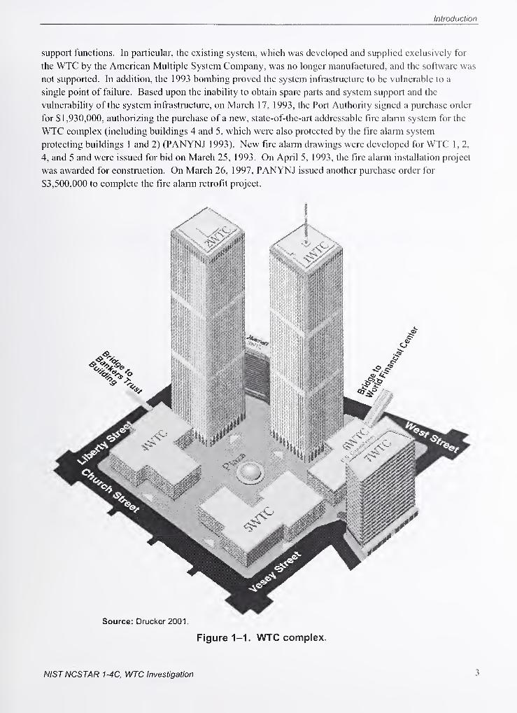
Introduction
support functions. In particular, the existing system, which was developed and supplied exclusively for
the WTC by the American Multiple System Company, was no longer manufactured, and the software was
not supported. In addition, the 1993 bombing proved the system infrastructure to be vulnerable to a
single point of failure. Based upon the inability to obtain spare parts and system support and the
vulnerability of the system infrastructure, on March 17, 1993, the Port Authority signed a purchase order
for SI,930,000, authorizing the purchase of a new, state-of-the-art addressable fire alarm system for the
WTC complex (including buildings 4 and 5, which were also protected by the fire alarm system
protecting buildings 1 and 2) (PANYNJ 1993). New fire alarm drawings were developed for WTC 1, 2,
4, and 5 and were issued for bid on March 25, 1993. On April 5, 1993, the fire alarm installation project
was awarded for construction. On March 26, 1997, PANYNJ issued another purchase order for
$3,500,000 to complete the fire alarm retrofit project.
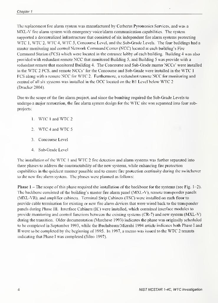
Chapter 1
The replacement fire alarm system was manufactured by Cerberus Pyrotronics Services, and was a
MXL-V fire alarm system with emergency voice/alarm communication capabilities. The system
supported a decentralized infi'astructure that consisted of six independent fire alarm systems protecting
WTC 1, WTC 2, WTC 4, WTC 5, Concourse Level, and the Sub-Grade Levels. The four buildings had a
master monitoring and control Network Command Center (NCC) located at each building's Fire
Command Station (FCS) which were located in the entrance lobby of each building. Building 4 was also
provided with redundant remote NCC that monitored Building 5, and Building 5 was provide with a
redundant remote that monitored Building 4. The Concourse and Sub-Grade master NCCs' were installed
in the WTC 2 FCS, and remote NCCs' for the Concourse and Sub-Grade were installed in the WTC 1
FCS along with a remote NCC for WTC 2. Furthermore, a redundant remote NCC for monitoring and
control of all six systems was installed in the OCC located on the B 1 Level below WTC 2
(Drucker 2004).
Due to the scope of the fire alarm project, and since the bombing required the Sub-Grade Levels to
undergo a major restoration, the fire alarm system design for the WTC site was separated into four sub-
projects:
1. WTC 1 and WTC 2
2. WTC 4 and WTC 5 T'"
'
3. Concourse Level .
4. Sub-Grade Level
The installation of the WTC 1 and WTC 2 fire detection and alarm systems was further separated into
three phases to address the constructability of the new systems, while enhancing fire protection
capabilities in the quickest manner possible and to ensure fire protection continuity during the switchover
to the new fire alarm system. The phases were planned as follows:
Phase 1 - The scope of this phase required the installation of the backbone for the systems (see Fig. 1-2).
The backbone consisted of the building's master fire alarm panel (MXL-V), remote transponder panels
(MXL-VR), and amplifier cabinets. Terminal Strip Cabinets (TSC) were installed on each floor to
provide cable termination for existing or new fire alarm devices that were wired back to the transponder
panels during Phase IIL Interface Cabinets (IC) were installed, which contained interface modules to
provide monitoring and control functions between the existing systems (CR-7) and new system (MXL-V)
during the transition. Older documentation (Marchese 1993) indicates the phase was originally scheduled
to be completed in September 1993, while the Buchsbaum/Mizrahi 1994 article indicates both Phase I and
II were to be completed by the beginning of 1995. In 1997, a memo was issued to the WTC 2 tenants
indicating that Phase I was completed (Sileo 1997).
4 NISTNCSTAR 1-4C, WTC Investigation
Introduction
FLOOR
EXISTINGREMOTEMULTIPLEXTERMINALS(RMT)
FLOOR
CR-7
CR-7
IC
CABINETSMXL-VR
EXISTINGAMERICANMULTIPLEXFIRE ALARM
(s) EXISTING SMOKE DETECTORS NEWMXL-V
Figure 1-2. Phase I backbone.
Phase II - Transition of the monitoring and control of existing fire alarm devices to the new system was
accomplished as Phase II (see Fig. 1-3). During this phase both the existing American Muhiplex system
and the MXL-V system were operating concurrently. Also, the new core area speakers, warden phones,
and pull stations were connected to the new fire alarm system. Older documentation (Marchese 1993)
indicates the phase was originally scheduled to be completed in October 1993, while the Buchbaum 1994
article indicates both Phase I and II were to be completed by the beginning of 1995. In 1997, a memowas issued to the WTC 2 tenants indicating that Phase II was completed (Sileo 1997).
NISTNCSTAR 1-4C, WTC Investigation 5
Chapter 1
FLOOR
MXL-VR
EXISTINGREMOTEMULTIPLEXTERMINALS
(RMT)
FLOOR
CR-7
CR-7
IC
CABINETSMXL-VR
EXISTINGAMERICANMULTIPLEXFIRE ALARM
(s) EXISTING SMOKE DETECTORS NEWMXL-V
Figure 1-3. Phase II transition.
6 NISTNCSTAR 1-4C, WTC Investigation
Introduction
Phase III - This phase required replacing all existing fire detection devices, and expanding the new
speaker and strobe capabilities into all tenant and mechanical spaces. All areas protected by the new fire
alarm system were designed to be in compliance with the New York Building Code - Class "E" system
requirements, and other applicable code criteria. The existing American Multiplex system was to be
disconnected and removed. This had not occurred by September 11, 2001
.
Although the original schedule for completion was not found, the Buchbaum 1994 article indicates this
phase was planned to be completed by the end of 1996. In 1997, a memo was issued to the WTC 2
tenants indicating that the Phase III portion of the fire alarm system that included the installation of
manual pull stations and warden telephones was completed (Sileo 1997). However, there are conflicting
reports as to the actual status of the fire alarm project. The most recent report on the status of completion
for the fire alarm retrofit indicated the following (PACO 2002):
1 . WTC 1 - 85 percent complete.
2. WTC 2-80 percent complete.
3. WTC 4 and 5 - 60 percent complete.
4. Concourse Level - 100 percent.
5. Sub-Grade Levels - 0 percent complete.
6. Sub-Grade Levels Backbone Modification - 0 percent complete.
7. Convert existing fire alarm protection in Mechanical Rooms to new system - 40 percent
complete.
8. Global Fiber Optic Loop interconnecting all six fire alarm systems - 0 percent complete.
It was estimated that 25 percent of the original American Multiplex system was still in use at the time of
the attack (PACO 2002). Documentation was not found providing a description of the extent and what
type (existing or new) of fire alarm protection was provided in each building on September 1 1, 2001.
NISTNCSTAR 1-4C, WTC Investigation 7

This page intentionally left blank.
NISTNCSTAR 1-4C, WTC Investigation
Chapter 2
Normal Operations and Fire Emergency Response
The Port Authority ofNew York and New Jersey (PANYNJ or Port Authority) had a Fire Safety Plan for
World Trade Center (WTC) 1, 2, and 7 that provided direction for fire emergency response and was
organized around a hierarchy of staff associated with its implementation. At the top of this hierarchy was
the WTC Fire Safety Director. The Fire Safety Director oversaw fire emergency response until the arrival
of the Fire Department of the City ofNew York (FDNY or Fire Department), and was responsible for
gathering all necessary information for the FDNY, which he/she relayed to the Chief upon his/her arrival.
In WTC 1 and WTC 2, subordinate to the Fire Safety Director was the Assistant Fire Safety Coordinator,
who was responsible for the availability and state of readiness of the Fire Brigade and the entire
Emergency Response Team (members of the WTC Division of the Port Authority Police, who receive
firefighting training and staff the WTC Fire Brigade). In WTC 7 the Fire Safety Director also performed
the functions of the Assistant Fire Safety Coordinator as identified above. WTC 7 also had a Fire Brigade
that the Fire Safety Director was responsible for organizing and training.
In addition to the WTC 1 and WTC 2 Assistant Fire Safety Coordinator, the towers had an Emergency
Response Team consisting of Deputy Fire Safety Directors, Lobby Deputy Fire Safety Directors, Floor
Wardens and Deputy Floor Wardens. Deputy Fire Safety Directors were responsible for performing the
duties of the Assistant Fire Safety Coordinator in his/her absence and staffing the Fire Command Station
(FCS) for the purpose of executing the fire safety plan. At the end of the hierarchical chain for WTC 1,
2, and 7 were Floor Wardens and Deputy Floor Wardens, who were responsible for assessing conditions
and assisting in evacuation of floor occupants on their respective floors upon direction from the Fire
Brigade and/or FCS. Floor Wardens, Deputy Floor Wardens, and their alternates were appointed tenants
or employees of the WTC complex (SafirRosetti 2002; Kastner 1990; PANYNJ 2001; PANYNJ).
2.1 fire command station
WTC 1, 2, and 7 FCS were located in the lobbies of each building. WTC 1 and WTC 2 had redundant
command centers. A back-up command center for WTC 1 was located at the Operations Control Center
(OCC) on the Bl sub-grade level ofWTC 2. The back up command center for WTC 2 was located in the
WTC I FCS and the OCC. The FCSs facilitated two-way communication between mechanical rooms,
elevator control rooms, and each floor through telephone, two-way fire alann box, fire standpipe
telephone, portable radios, public address systems, elevator intercom, and cellular telephones issued to
Floor Wardens. Additional information and equipment valuable to the Emergency Response Team was
also maintained at the FCSs. This information and equipment included copies of all appropriate building
information, a minimum of one set of master keys for the buildings, a list of floor wardens and their
contact infomiation, and a list of mobility-restricted individuals and other tenants requiring special
assistance in the event of evacuation (SafirRosetti 2002).
NISTNCSTAR 1-4C, WTC Investigation 9
Chapter 2
2.2 WTC 1 AND WTC 2 OPERATIONS COMMAND CENTER
The OCC for the WTC (located in level B-1 ofWTC 2) was where WTC Operations and Management
Staff evaluated the operation of the buildings' systems including elevators, intercoms, and
communications systems. During a fire incident, Operations Management staff assisted with evacuation
upon request. The staff of the mechanical section of Operations Management operated fire pumps and
manually activated smoke control upon request. They also secured sprinkler water shutoff valves upon
request of the Fire Safety Director or FDNY Chief Commanding Officer. The staff of the electrical
section of Operations Management reset smoke detector or fire alarm panels upon the request of the Fire
Safety Director or FDNY Chief Commanding Officer when the fire incident had been secured. The staff
of the electrical section also responded to electrical incidents and remotely secured related equipment
upon request.
The backup command center at the OCC provided redundancy to FDNY at any of the FCSs in WTC 1, 2,
4, and 5 to operate systems in any of the four buildings.'
2.3 FIRE PREVENTION AND FIRE PREPAREDNESS PROCEDURES
2.3.1 Fire Drills
Fire drills were conducted at WTC 1, 2, and 7 every six months under the direction of the Floor Warden
and Deputies of the Floor Warden. During the drills all employees, occupants, and visitors of the floor
where the drill was conducted were physically required to leave their office areas and evacuate to a
central hallway, near a stairwell. Building tenants and persons designated as Floor Wardens and Deputy
Floor Wardens were informed of the location, date, and time of the fire drill. Floor Wardens and Deputy
Floor Wardens were responsible for informing all employees on their floor of the date and time of the
drill.
2.3.2 Training Exercises
In addition, regular training exercises were conducted by the Port Authority and the Fire Department (the
designated lead authority responsible for command of fire incidents at the WTC complex). The exercises
oriented new staff and served as a reminder to existing staff in the Port Authority and Fire Department
with the building, its equipment, and the appropriate emergency response procedures. In 2001, twelve of
these training exercises were conducted before September 1 1th. Although the incidents of September 11,
200 1 , were beyond the expected scope of emergency response personnel, the emergency response plan
was implemented, and many of the emergency response staff involved possessed a high level of
familiarity with the building and its associated emergency procedures.
2„3.3 Fire Prevention Inspections
Fire inspections were performed annually in each tenant space to limit the risk of life and property loss
from fire. It was the intent that as a result of the inspections, the likehhood of a fire occurring was
minimized, or that if a fire occurred, the spread of the fire and its duration would be limited. Tenants
were advised to limit combustibles and avoid locating combustible materials in aisles, under desks, or
10 NISTNCSTAR 1-4C, WTC Investigation
Normal Operations and Fire Emergency Response
piled on top of office furniture. Smoking was not permitted in the buildings. Storage of materials was
not permitted within 18 in. of the ceiling and sprinkler heads.
A written report was prepared for all fire inspections and was maintained by the Fire Safety Office. Anydeficiencies or violations were noted in the report and forwarded to the appropriate person in the tenant
space for correction.
In addition to annual tenant space inspections, WTC staff conducted daily operational inspections. The
purpose of these inspections was to ensure that all necessary exits were maintained and available for
egress, all exit hardware was functional, and there were no obstructions to means of egress within the
WTC.
2.4 ALARM NOTIFICATION
Staff notification of a fire or smoke condition occurred when a smoke detector or sprinkler activation
transmitted an alarm to the PCS in the affected building. Staff notification also occurred through
activation of a manual pull station by a building occupant or a phone call reporting a fire or smoke
condition to the WTC Police Desk and/or PCS.
Occupant notification in WTC 1 and WTC 2 was initiated manually from the PCS by the Pire Safety
Director or his designees.
Occupant notification in WTC 7 was automatically provided in the event of fire alarm system activation.
2.5 FIRE SAFETY PLAN
Upon discovery of fire or smoke, the Pire Safety Plan called for occupants to activate the nearest building
manual fire alarm station, typically at the intersecting corridor, and to notify the WTC police via
telephone. The Police Desk would dispatch the Fire Brigade and transmit the alarm to the Pire
Department. The WTC Fire Safety Director was responsible for transmission of the fire alarm and
notification of the Fire Brigade, Floor Warden(s), and building occupants. If necessary, the Pire Safety
Director utilized the Security Staff to restrict building occupant access to the area(s) affected by the
incident. Staff at the Visitors' Desks were also notified to stop issuing visitors' passes to the area(s). The
managers of the Windows on the World restaurant and Top of the World Observation Deck were notified
of any facility emergency by the OCC Supervisor. The purpose of this notification was to reduce any
panic or anxiety that may be experienced by tenants, visitors, and other guests upon observing the
response of emergency personnel to the building/complex. Notification of an incident to building
occupants was performed through the Property Management staff, which coordinated with the Pire Safety
Director on issues directly affecting building tenants. During the emergency incident it was the
responsibility of the Property Management Staff to supply information to the building tenants as
appropriate.
The Pire Safety Director could also initiate evacuation from the area or the entire building. In this
situation, the fire alarm emergency voice communication system was activated on the floors to be
evacuated. Per Tenant Fire Safety Procedures exercised during regular fire drills, building occupants
proceed to the corridor areas to wait for verbal instructions provided over the fire alarm emergency voice
NISTNCSTAR 1-4C, WTC Investigation 11
Chapter 2
communication speakers. Occupants were instructed to evacuate the floor(s) using stairways to the
designated "safe" area, which was at least three levels below the fire floor. Occupants were not to use the
elevators. Occupants with special needs, requiring assistance in evacuating, were to be aided by the Floor
Warden(s).
The WTC Fire Brigade members would respond to the floor directly below the fire floor and proceed to
the fire floor utilizing stairways. Upon the initiation of evacuation procedures, Fire Brigade members
conducted searches of the floor and utilized firefighting appliances as necessary to control the fire as
much as possible until the arrival of the Fire Department, whereupon the Fire Brigade would transfer
firefighting operations to the Fire Department. While in control of firefighting operations, however, the
Fire Brigade was responsible for keeping the FCS and WTC Police Desk infomed of all operational
details.
Floor Wardens were to notify the FCS of any non-ambulatory or mobility restricted individuals requiring
special assistance during evacuation, utilizing the fire alarm Floor Warden Phone system. Tenants
requiring special assistance in evacuating the WTC would be assisted by members of the Fire Brigade
upon notification of fire or smoke in the buildings. Fire Brigade members were dispatched via staffed
freight elevators to the floor directly below the affected floor. Based on available information, the Fire
Brigade would take the freight elevator to the fire floor, or if conditions were severe and the use of the
freight elevators would expose these tenants to danger, tenants requiring special assistance were hand
carried down the staii-wells by members of the Fire Brigade to areas of refuge.
Occupants of the building located on the floor of fire incidence and above were evacuated to locations at
least three or more floors below the fire floor. It was the responsibility of Floor Wardens via the fire
alarm Floor Warden Phone system to inform the FCS (staffed by Deputy Fire Safety Directors) of the
evacuation actions taken and location of evacuees.
If stairways serving the fire floor or floors above the fire floor were not usable due to fire, smoke, or
overcrowding situations, the use of elevators could be considered for evacuation as long as the elevators
used did not serve the fire floor, and the elevators did not connect to other shafts opening onto the fire
floor. Only elevators staffed by fire fighters or other trained building personnel could be utilized for
evacuation.
2.6 FIRE DEPARTMENT RESPONSE
The primary objective of the Fire Department was to perfomi rescue operations of persons in the building.
This was achieved through ventilation of the building, entry into the building, and searches for persons
trapped in the building. Another important objective of the Fire Department was to control and
extinguish the fire. The Chief of the Fire Department was the highest-ranking unifonned firefighter and
was responsible for all operations when on the scene.
2.6.1 Alarms
Alarms were received by FDNY by several means. "Nine-one-one" telephone calls were made to report
fire. Activation of the fire alarm system within the buildings transmitted an alarm to the Fire Department.
Fire alarms were also received from street pull boxes.
12 NISTNCSTAR 1-4C, WTC Investigation
Normal Operations and Fire Emergency Response
Upon alarm notification. Fire Department units were immediately dispatched to the scene. The average
response time of the Fire Department in 2001 was less than 5 min.
2.6.2 Communication
Fire Department communications were achieved through VHF radios and hand-held radios. The VHFradios were used for dispatching units as well as communicating between apparatus (trucks, engines, etc.).
Hand held radios were used on site during tactical operations. Repeaters were installed in the WTCcomplex after the 1993 bombing to amplify radio signals and help alleviate these difficulties.
Communications between the Lobby Command Post and Fire Department units operating on upper floors
were achieved through the fire alarm's Standpipe Telephone System hard wire phones as well as hand
held radios. The fire alarni hard wire phones consisted of Floor Warden phones, which were in-house fire
alarm phones that connected the FCS in the lobby to each floor, and Standpipe Telephone phones, which
connected the FCS to the fire pump room and each Standpipe Phone outlet.
FDNY has established firefighting procedures for high-rise office buildings. The main objectives are to
locate, control, and extinguish the fire. The strategy in achieving these objectives includes determining
the specific fire floor, search of the fire floor and the floor directly above, and evacuation of any persons
found during the search. The building's elevators, ventilation system, communications systems, and fire
pumps are controlled and utilized. The ultimate goal is to control and extinguish the fire.
2.6.3 Support from Neighboring Fire Departments
FDNY maintained mutual agreements for two-way support with fire departments of neighboring
jurisdictions, including Nassau and Westchester Counties, Jersey City, and the cities of Mt. Vernon and
Yonkers. Historically, members ofFDNY have responded to alarms in other municipalities and vice
versa.
NISTNCSTAR 1-4C, WTC Investigation 13

Chapter 2
This page intentionally left blank.
14 NISTNCSTAR 1-4C, WTC Investigation
Chapter 3
Original Fire Alarm System Prior to the 1 993 Bombing andModifications Subsequent to 1993
The pre-1993 system outlined for the World Trade Center (WTC) encompassed the following facilities:
• WTC 1
• WTC 2
• WTC 4
• WTC 5
• Concourse Level
• Sub-Grade Level
The system integrated detectors and alarm devices from the various buildings, to be tied into a control
panel for that building or level. All control panels simultaneously amiunciated alarms and troubles at the
Operations Control Center (OCC).
The system consisted of American Multiplex Remote Monitoring Transponders (RMT), on every third
floor, connected to the Digital Computer and Console in the OCC on the B-1 Sub-Grade Level. The
Transponder monitored Pyrotronics CR-7 Equipment connected to type DI-2, DL3, DI-4A, and DI-6
smoke detectors (non-addressable type), Pyrotronics System 3 panels, tenant proprietary systems,
waterflow switches, tamper switches, and control contacts (PANYNJ 1986).
Pryrotronics XL3 smoke detector systems, with addressable type detectors, were installed in the
mechanical equipment rooms of both WTC 1 and WTC 2, and connected via a CXL Communication
Device to a console in the OCC.
Manual Pull Stations were wired to an existing Executone system which alarmed directly to the Fire
Department.
The Public Address Communication System with manually activated selection of floor was also located at
the OCC. Alarms from these systems were called in to the Fire Department, manually, by the Port
Authority Police on duty 24 h a day at the Police Desk.
3.1 fire alarm system
The Fire Alarm System in the WTC combined fire alarm signaling with an intercom, enabling fire safety
personnel to speak to the person turning in the alarm. Alanns could be initiated at break glass stations in
NISTNCSTAR 1-4C. WTC Investigation 15
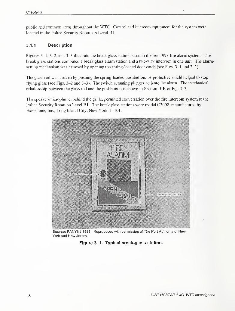
Chapter 3
public and common areas throughout the WTC. Control and intercom equipment for the system were
located in the Police Security Room, on Level B 1
.
3.1.1 Description
Figures 3-1, 3-2, and 3-3 illustrate the break glass stations used in the pre- 1993 fire alarm system. The
break glass stations combined a break glass alarm station and a two-way intercom in one unit. The alarni-
setting mechanism was exposed by opening the spring-loaded door catch (see Figs. 3-1 and 3-2).
The glass rod was broken by pushing the spring-loaded pushbutton. A protective shield helped to stop
flying glass (see Figs. 3-2 and 3-3). The switch actuating plunger activate the alarm. The mechanical
relationship between the glass rod and the pushbutton is shown in Section B-B of Fig. 3-3.
The speaker/microphone, behind the grille, permitted conversation over the fire intercom system to the
Police Security Room on Level Bl. The break glass stations were model C3002, manufactured by
Executone, Inc., Long Island City, New York 11101.
Source: PANYNJ 1986. Reproduced with permission of Tine Port Authority of NewYork and New Jersey.
Figure 3-1. Typical break-glass station.
16 NISTNCSTAR 1-4C, WTC Investigation
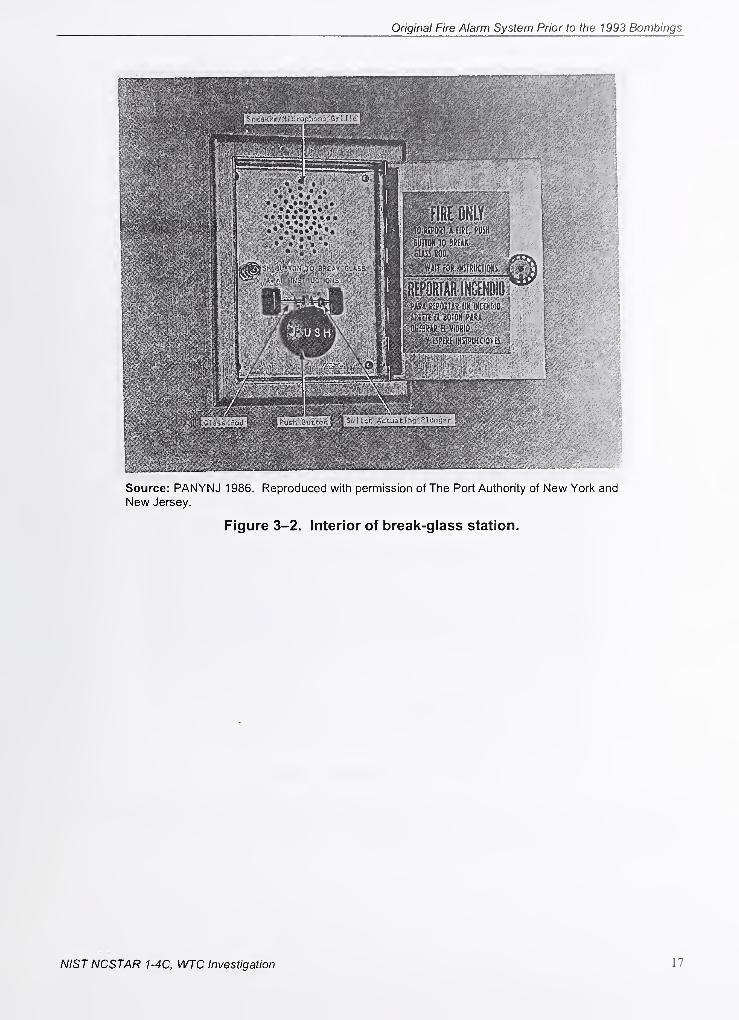
Original Fire Alarm System Prior to the 1993 Bombings
Source: PANYNJ 1986. Reproduced with permission of The Port Authority of New York and
New Jersey.
Figure 3-2. Interior of break-glass station.
NISTNCSTAR 1-4C, WTC Investigation 17
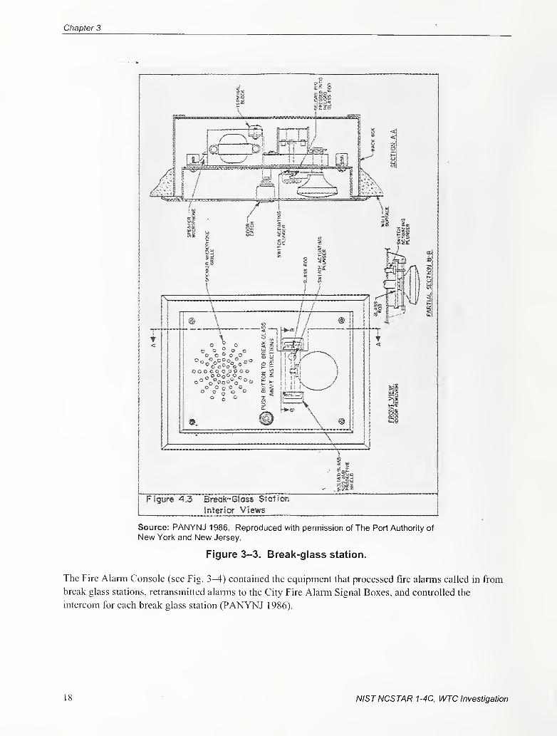
Chapter 3
Figure 4,3 Break-Glass Station
Interior Views
Source: PANYNJ 1986. Reproduced with permission of The Port Authority of
New York and New Jersey.
Figure 3-3. Break-glass station.
The Fire Alarm Console (see Fig. 3^) contained the equipment that processed fire alarms called in fi-om
break glass stations, retransmitted alarms to the City Fire Alarm Signal Boxes, and controlled the
intercom for each break glass station (PANYNJ 1986).
18 NISTNCSTAR 1-4C, WTC Investigation
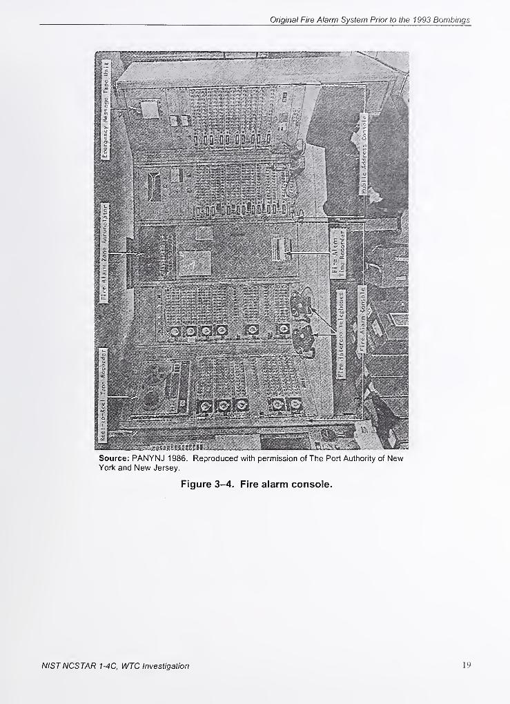
Original Fire Alarm System Prior to the 1993 Bombings
NISTNCSTAR 1-4C, WTC Investigation 19
Chapter 3
Each section of the Fire Alarm Console contained many Fire Alarm and Intercom Panels (see Figs. 3-4
and 3-5). Each fire alarm and intercom panel contained: illuminated intercom channel selector switches,
a fire call button, a city fire alarm cancel button, a station reset button, a zone test button, an adjustable
city alarm delay timer for calling in city fire alarnis, a fixed timer designed to delay broadcast of an
alerting signal to the fire zone until the console operator had 20 s to answer the call, and a buzzer
indicating that someone activated a break glass station.
Each panel represented a separate fire zone and actuated a separate New York City Fire Alarm Signal
Box by means of a remote electrical trip. Each intercom channel selector switch served an individual
break glass station and illuminated when that station initiated a fire alarm. The switch position
corresponded to the intercom channel (A or B) to be used.
The buzzer sounded when an alann was called in from a break glass station or an intercom channel
selector switch was actuated. The Fire Call button actuated the City Fire Alarm Signal Box for that zone
independent of calls from break glass stations. The City Fire Alarm Cancel button defeated the initiation
of a City fire alarm from a break glass station, provided that the adjustable City alarm delay timer had not
run out.
The Station Reset button stopped the internal 20-s timer from actuating an alerting signal directed to the
fire zone; no alerting signal was connected to that timer. The appropriate intercom channel selector
switch also had to be activated. The Zone Test button tested the supervisory circuits of the panel. The
Fire Alarm and Intercom Panels, model M423-36, were manufactured by Executone, Inc.
The Reel-to-Reel Tape Recorder (see Fig. 3-5) transcribed conversations made over the fire intercom
system. It was capable of recording, at 3 V4 in./s or 7 V2 in./s, intercom channels A and B simultaneously.
The recorder was manufactured by Sony for Executone and was Sony Model 666-D, Executone
Model M432.
20 NISTNCSTAR 1-4C, WTC Investigation
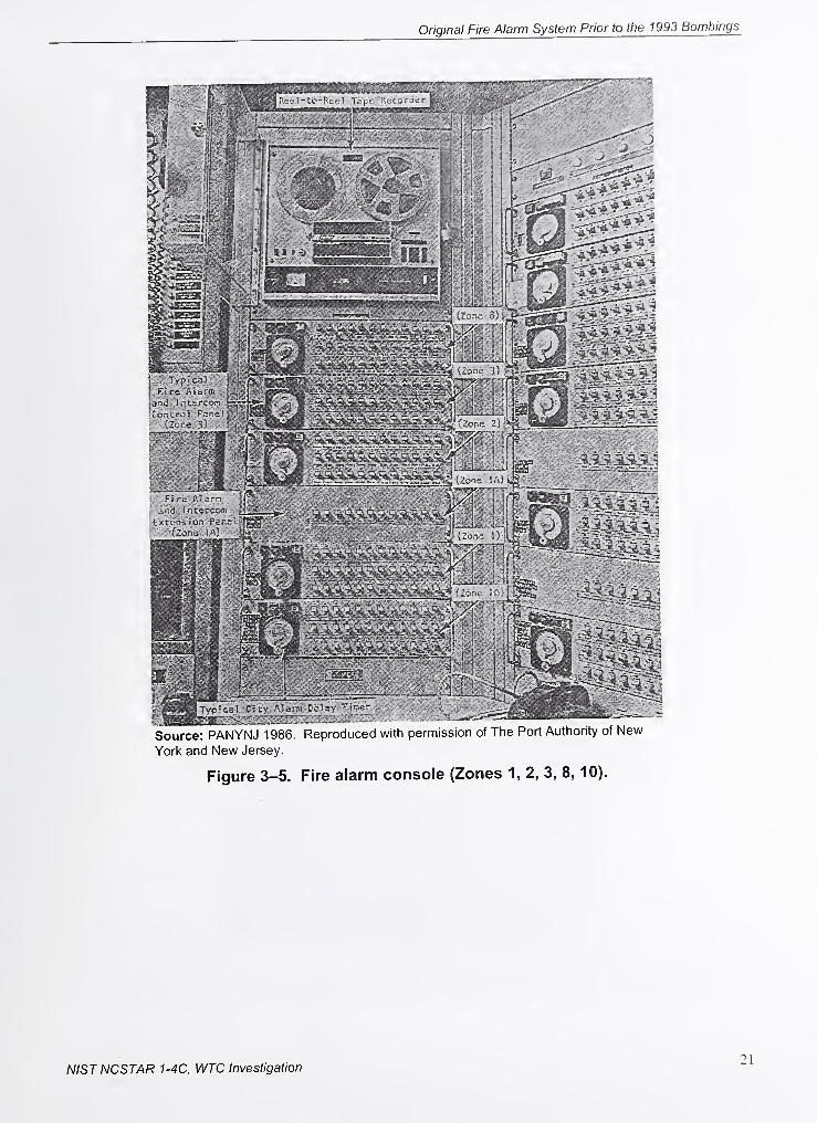
Original Fire Alarm System Prior to the 1993 Bombings
York and New Jersey.
Figure 3-5. Fire alarm console (Zones 1, 2, 3, 8, 10).
NISTNCSTAR 1-4C, WTC Investigation21
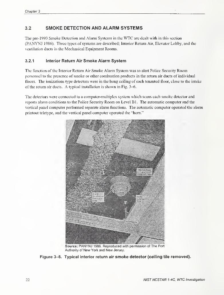
Chapter 3
3.2 SMOKE DETECTION AND ALARM SYSTEMS
The pre- 1993 Smoke Detection and Alanri Systems in the WTC are dealt with in this section
(PANYNJ 1986). Three types of systems are described; Interior Return Air, Elevator Lobby, and the
ventilation ducts in the Mechanical Equipment Rooms.
3.2.1 Interior Return Air Smoke Alarm System
The function of the Interior Return Air Smoke Alarm System was to alert Police Security Roompersonnel to the presence of smoke or other combustion products in the return air ducts of individual
floors. The ionizations type detectors were in the hung ceiling of each tenanted floor, close to the intake
of the return air ducts. A typical installation is shown in Fig. 3-6.
The detectors were connected to a computer-multiplex system which scans each smoke detector and
reports alarni conditions to the Police Security Room on Level B 1 . The automatic computer and the
vertical panel computer performed separate alann functions. The automatic computer operated the alarm
printout teletype, and the vertical panel computer operated the "horn."
Source: PANYNJ 1986. Reproduced with permission of The Port
Authority of New York and New Jersey.
Figure 3-6. Typical interior return air smoke detector (ceiling tile removed).
22 NISTNCSTAR 1-4C, WTC Investigation
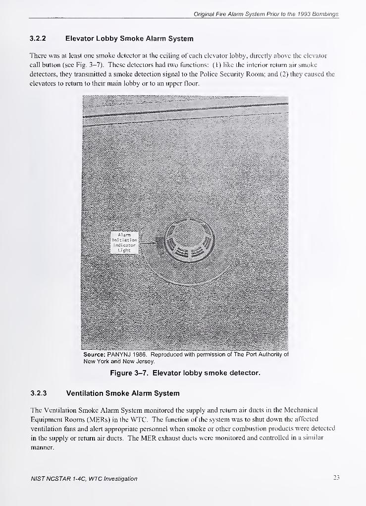
Original Fire Alarm System Prior to the 1993 Bombings
3.2.2 Elevator Lobby Smoke Alarm System
There was at least one smoke detector at the ceihng of each elevator lobby, directly above the elevator
call button (see Fig. 3-7). These detectors had two functions: (1) like the interior return air smoke
detectors, they transmitted a smoke detection signal to the Police Security Room; and (2) they caused the
elevators to return to their main lobby or to an upper floor.
Source: PANYNJ 1986. Reproduced with permission of The Port Authority of
New York and New Jersey.
Figure 3-7. Elevator lobby smoke detector.
3.2.3 Ventilation Smoke Alarm System
The Ventilation Smoke Alarm System monitored the supply and return air ducts in the Mechanical
Equipment Rooms (MERs) in the WTC. The function of the system was to shut down the affected
ventilation fans and alert appropriate personnel when smoke or other combustion products were detected
in the supply or return air ducts. The MER exhaust ducts were monitored and controlled in a similar
manner.
NISTNCSTAR 1-4C, WTC Investigation 23
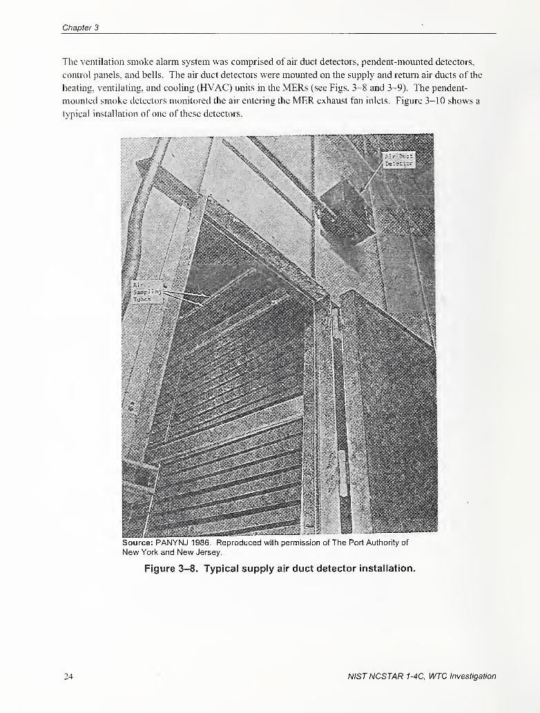
Chapter 3
The ventilation smoke alann system was comprised of air duct detectors, pendent-mounted detectors,
control panels, and bells. The air duct detectors were mounted on the supply and return air ducts of the
heating, ventilating, and cooling (HVAC) units in the MERs (see Figs. 3-8 and 3-9). The pendent-
mounted smoke detectors monitored the air entering the MER exhaust fan inlets. Figure 3-10 shows a
typical installation of one of these detectors.
Source: PANYNJ 1986. Reproduced with permission of The Port Authority of
New York and New Jersey.
Figure 3-8. Typical supply air duct detector installation.
24 NISTNCSTAR 1-4C, WTC Investigation
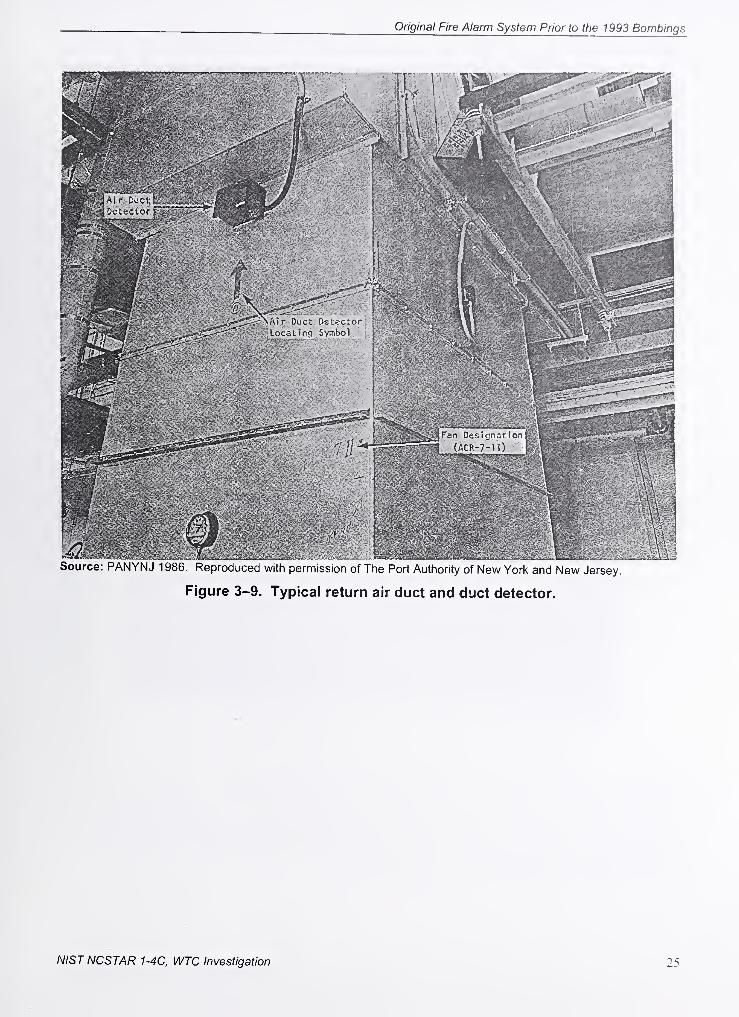
Original Fire Alarm System Prior to the 1993 Bombings
Source: PANYNJ 1986. Reproduced with permission of The Port Authority of New York and New Jersey.
Figure 3-9. Typical return air duct and duct detector.
NISTNCSTAR 1-4C, WTC Investigation 25
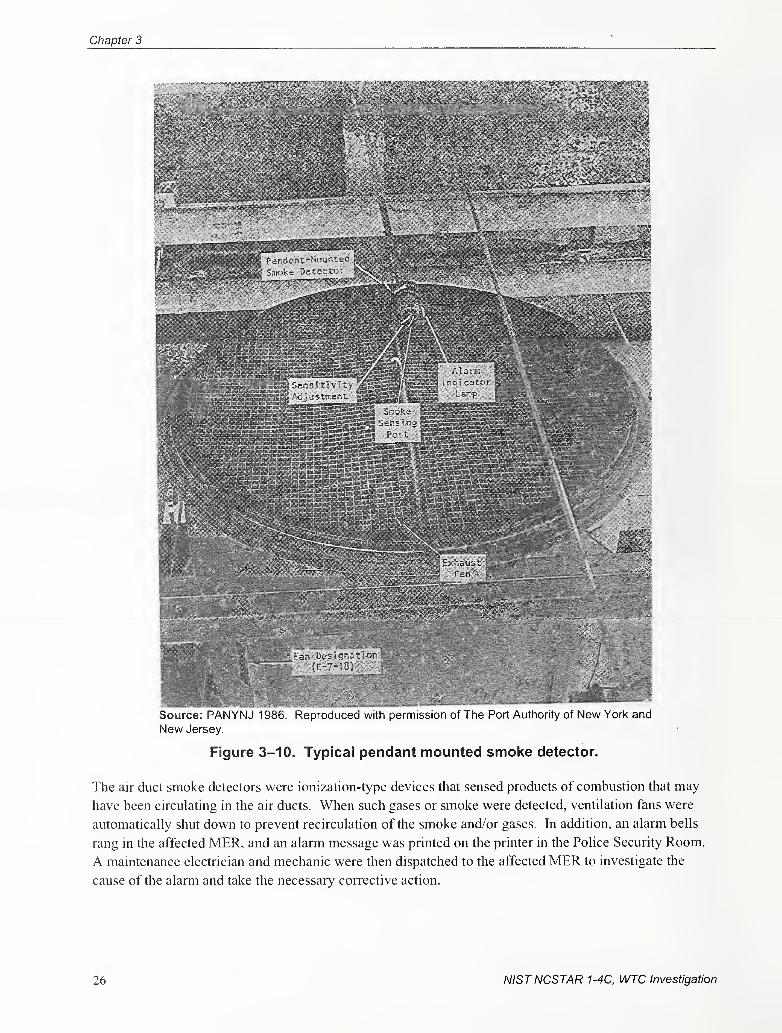
Chapter 3
Source: PANYNJ 1986. Reproduced with permission of The Port Authority of New York and
New Jersey.
Figure 3-10. Typical pendant mounted smoke detector.
The air duct smoke detectors were ionization-type devices that sensed products of combustion that may
have been circulating in the air ducts. When such gases or smoke were detected, ventilation fans were
automatically shut down to prevent recirculation of the smoke and/or gases, hi addition, an alarm bells
rang in the affected MER, and an alarm message was printed on the printer in the Police Security Room.
A maintenance electrician and mechanic were then dispatched to the affected MER to investigate the
cause of the alarm and take the necessary corrective action.
26 NISTNCSTAR 1-4C, WTC Investigation
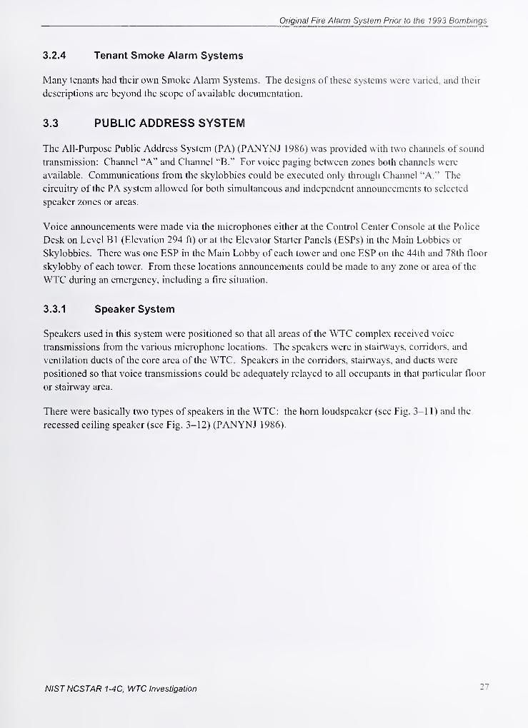
Original Fire Alarm System Prior to the 1993 Bombings
3.2.4 Tenant Smoke Alarm Systems
Many tenants had their own Smoke Alarm Systems. The designs of these systems were varied, and their
descriptions are beyond the scope of available documentation.
3.3 PUBLIC ADDRESS SYSTEM
The All-Purpose Public Address System (PA) (PANYNJ 1986) was provided with two channels of sound
transmission: Channel "A" and Channel "B." For voice paging between zones both channels were
available. Communications from the skylobbies could be executed only through Channel "A." The
circuitry of the PA system allowed for both simultaneous and independent announcements to selected
speaker zones or areas.
Voice announcements were made via the microphones either at the Control Center Console at the Police
Desk on Level Bl (Elevation 294 ft) or at the Elevator Starter Panels (ESPs) in the Main Lobbies or
Skylobbies. There was one ESP in the Main Lobby of each tower and one ESP on the 44th and 78th floor
skylobby of each tower. From these locations announcements could be made to any zone or area of the
WTC during an emergency, including a fire situation.
3.3.1 Speaker System
Speakers used in this system were positioned so that all areas of the WTC complex received voice
transmissions from the various microphone locations. The speakers were in stairways, corridors, and
ventilation ducts of the core area of the WTC. Speakers in the corridors, stairways, and ducts were
positioned so that voice transmissions could be adequately relayed to all occupants in that particular floor
or stairway area.
There were basically two types of speakers in the WTC: the horn loudspeaker (see Fig. 3-11) and the
recessed ceiling speaker (see Fig. 3-12) (PANYNJ 1986).
NISTNCSTAR 1-4C, WTC Investigation 27
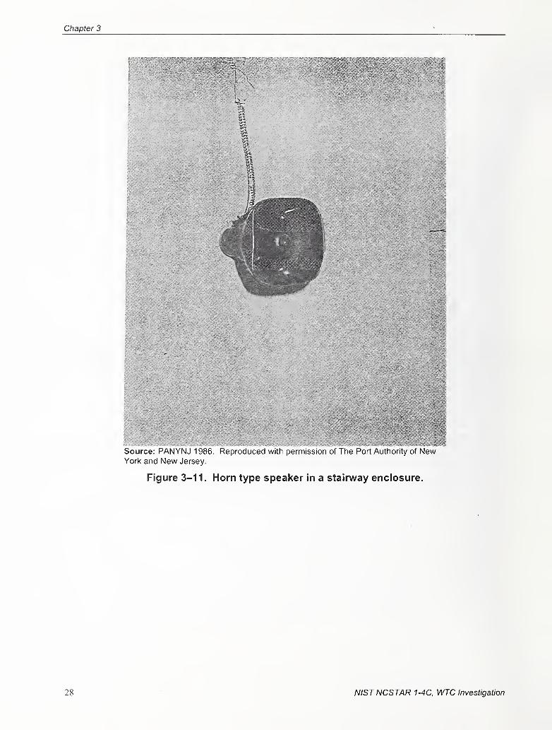
Chapter 3
Source: PANYNJ 1986. Reproduced with permission of The Port Authority of NewYork and New Jersey.
Figure 3-11. Horn type speaker in a stairway enclosure.
28 NISTNCSTAR 1-4C, WTC Investigation
Original Fire Alarm System Prior to the 1993 Bombings
NISTNCSTAR 1-4C, WTC Investigation 29
Chapter 3
3.4 PUBLIC ADDRESS CONSOLE
The Public Address Console was the right-hand portion of the Control Center Console that included the
Fire Alarm Console (see Fig. 3-13) (PANYNJ 1986). The Control Center Console was in the Police
Security Room on Level Bl. The Public Address Console was the heart of the All-Purpose PA System
and contained most of its controls and monitors (see Fig. 3-14).
Source: PANYNJ 1986. Reproduced with permission of The Port Authority of New Yorl< and New Jersey.
Figure 3-13. Control center console police desk Level B1.
30 NISTNCSTAR 1-4C, WTC Investigation
Original Fire Alarm System Prior to the 1993 Bombings
Source: PANYNJ 1986. Reproduced with permission of The Port Authority of NewYorl< and New Jersey.
Figure 3-14. Public address console.
3.5 SPRINKLER WATERFLOW ALARM SYSTEM
The Sprinkler Waterflow Alarm System in the Subgrades of the WTC is the subject of this subsection
(PANYNJ 1986). It contains descriptions of the major components of the system and their functions.
The function of the Sprinkler Waterflow Alarni System was to alert personnel in the Police Security
Room on Level B 1 that sprinkler water was flowing. The system included supervisory alarms that
monitored water level conditions in the fire reserve tanks and the condition of the pumps associated with
the Sprinkler System.
NISTNCSTAR 1-4C, WTC Investigation 31
Chapter 3
3.5.1 Component Descriptions
Sprinkler Waterflow Detectors
A sprinkler waterflow detector is an electromechanical device that initiates an electrical alarm when there
is a flow of water through a sprinkler pipe. A typical installation is shown in Fig. 3-15. The sprinkler
waterflow detector terminal cabinet shown in this figure connected the waterflow detector to the sprinkler
alarm annunciator in the old HVAC computer room on Level B4 (see Fig. 3-16).
The sprinkler waterflow detector was equipped with a vane that protruded into the sprinkler pipe. The
pressure of the water flowing through the pipe moved the vane, which in turn caused a microswitch to
close. This closing transmitted an alarm to the sprinkler alann annunciator panel in the old HVACcomputer room, and a flag dropped down, indicating the zone in which the water was flowing.
The sprinkler alarm annunciator panel that sent a signal to the multiplex computer in the Police Security
Room on Level B 1 , where the alarm was printed out on a teletype unit. A mechanical maintenance
person was then dispatched to the old HVAC computer room to detennine which flag on the annunciator
panel had dropped down. Then he or she reported the location of the flow to the Police Security Room.
Police and operations personnel then investigated the reason for the alarm.
Source: PANYNJ 1986. Reproduced with permission of The Port Authority of New Yorl< and NewJersey.
Figure 3-15. Sprinkler waterflow detector installation.
32 ' NISTNCSTAR 1-4C, WTC Investigation
Original Fire Alarm System Prior to the 1993 Bombings
•^1
Source: PANYNJ 1986. Reproduced with permission of The Port Authority of New Yorl< andNew Jersey.
Figure 3-16. Sprinkler alarm annunciator in HVAC computer room.
Sprinkler Alarm Annunciator Panel
The sprinkler alarm annunciator panel was in the old HVAC computer room on Level B4. The panel
contained sprinkler waterflow and supervisory alarms. The supervisory alarms indicated when and if the
conditions of certain equipment in the sprinkler system were abnormal. The conditions monitored were:
the level of water in the fire reserve tanks; and the operating status of the fire standpipe pumps, the
sprinkler fire pumps, the combination sprinkler/fire standpipe pumps, and the sprinkler jockey pump.
3.6 STANDPIPE FIRELINE COMMUNICATION SYSTEM
The Standpipe Fireline Communication System in the WTC is dealt with in this subsection
(PANYNJ 1986). Included are verbal descriptions of the system, photos of the equipment utilized, and
block diagrams of the entire system.
The Standpipe Fireline Communication System in the WTC was provided for firefighter use during
operation of the standpipe system. This system included two-way telephone communications.
The Standpipe Fireline Communication System was a selective-ringing, common-talking system that was
comprised of a Master, Submasters, and Outlying Stations, with a power supply, and an amplifier. The
NISTNCSTAR 1-4C, WTC Investigation 33
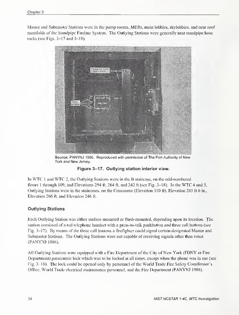
Chapter 3
Master and Submaster Stations were in the pump rooms, MERs, main lobbies, skylobbies, and near roof
manifolds of the Standpipe Fireline System. The Outlying Stations were generally near standpipe hose
racks (see Figs. 3-17 and 3-18).
Source: PANYNJ 1 986. Reproduced with permission of Tlie Port Autliority of NewYork and New Jersey.
Figure 3-17. Outlying station interior view.
In WTC 1 and WTC 2, the Outlying Stations were in the B staircase, on the odd-numbered
floors 1 through 109, and Elevations 294 ft, 264 ft, and 242 ft (see Fig. 3-18). In the WTC 4 and 5,
Outlying Stations were in the staircases, on the Concourse (Elevation 310 ft). Elevation 285 ft 6 in.,
Elevation 266 ft, and Elevation 246 ft.
Outlying Stations
Each Outlying Station was either surface-mounted or flush-mounted, depending upon its location. The
station consisted of a red telephone handset with a press-to-talk pushbutton and three call buttons (see
Fig. 3-17). By means of the three call buttons a firefighter could signal certain designated Master and
Submaster Stations. The Outlying Stations were not capable of receiving signals other than voice
(PANYNJ 1986).
All Outlying Stations were equipped with a Fire Department of the City ofNew York (FDNY or Fire
Department) paracentric lock which was to be locked at all times, except when the phone was in use (see
Fig. 3-18). The lock could be opened only by personnel of the World Trade Fire Safety Coordinator's
Office, World Trade electrical maintenance persomiel, and the Fire Department (PANYNJ 1986).
34 NISTNCSTAR 1-4C, WTC Investigation
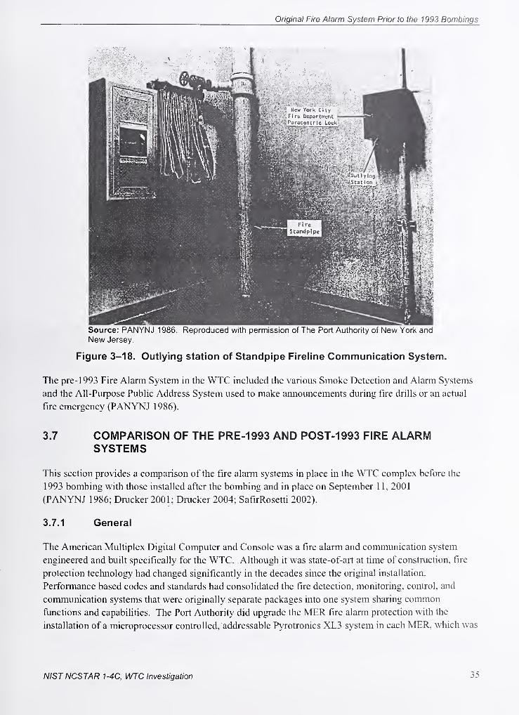
Original Fire Alarm System Prior to the 1993 Bombings
Source: PANYNJ 1986. Reproduced with permission of The Port Authority of New York and
New Jersey.
Figure 3-18. Outlying station of Standpipe Fireline Communication System.
The pre- 1993 Fire Alarm System in the WTC included the various Smoke Detection and Alarm Systems
and the All-Purpose Public Address System used to make announcements during fire drills or an actual
fire emergency (PANYNJ 1986).
3.7 COMPARISON OF THE PRE-1993 AND POST-1993 FIRE ALARMSYSTEMS
This section provides a comparison of the fire alann systems in place in the WTC complex before the
1993 bombing with those installed after the bombing and in place on September 1 1, 2001
(PANYNJ 1986; Drucker 2001; Drucker 2004; SafirRosetti 2002).
3.7.1 General
The American Multiplex Digital Computer and Console was a fire alarm and communication system
engineered and buih specifically for the WTC. Although it was state-of-art at time of construction, fire
protection technology had changed significantly in the decades since the original installation.
Performance based codes and standards had consolidated the fire detection, monitoring, control, and
communication systems that were originally separate packages into one system sharing common
functions and capabilities. The Port Authority did upgrade the MER fire alarm protection with the
installation of a microprocessor controlled, addressable Pyrotronics XL3 system in each MER, which was
NISTNCSTAR 1-4C, WTC Investigation 35
Chapter 3
monitored by a CXL Command Center monitor in the OCC. The XL3 fire alarm system was the
predecessor to the Siemens Pyrotronics MXL-V system installed post- 1993.
3.7.2 Fire Command Station Pre-1993
The original OCC on the B-1 Sub-Grade Level provided a single, central fire alarm monitoring and
control station for both the WTC 1 and WTC 2 towers. The fire alarm system consisted of multiple
components, from differing manufacturers, configured into a single-seat monitoring station for:
• Detection, monitoring, and control of fire alarm devices.
• Alarm and voice broadcast by floor.
• Floor intercom communication.
• Fire Department notification.
The original American Multiplex system was engineered and produced exclusively for the WTC towers.
The manual interface for monitoring and control of the fire alarm system consisted of visual indicators,
switches, audible notification appliances, alpha-numeric printouts, phones, and microphones.
The CXL Command Center monitor provided the status of the alarm and malfunction conditions for the
XLS fire alarm panels located in the mechanical equipment rooms.
3.7.3 Fire Command Station Post-1993
Each tower, WTC 1 and WTC 2, had its own Fire Command Station, which contained the building's fire
alarm system. Also, there were redundant fire alarm system monitoring and controls for each building's
system in the OCC. As another layer of redundancy, since the WTC 2 Fire Command Station was located
above the OCC, a second remote fire alarm system for WTC 2 was located in the WTC 1 Fire Command
Station.
The post- 1993 fire alarm system in the Fire Command Stations and OCC were manufactured, tested, and
produced as a single, integrated fire alarm system providing multiple, inter-relating functions. The
system was modular in design and could be modified or expanded as needed to provide:
• Detection, monitoring, and control of fire alami devices.
• Alarm and voice broadcast by floor.
• Floor intercom communication.
• Fire Department notification.
The system consisted of off-the-shelf technology that was produced by the manufacturer for large fire
alarm projects. The manual interface for monitoring and controlling the system consisted of a Network
Command Center monitor and computer keyboard, which provided alpha-numeric detail of the fire alarm
36 NISTNCSTAR 1-4C, WTC Investigation
Original Fire Alarm System Prior to the 1993 Bombings
Status and condition. Additional visual indicators, switches, phones, and microphone were available for
interfacing with the differing fire alarm functions.
The major differences between the pre-1993 fire alarm system monitoring and control capabilities found
at the main operator's monitoring station and the post- 1993 fire alarm system were the level of
infonnation provided about the status of the system and the ergonomic interface improvements offered by
the newer system. Since the newer system was a microprocessor based, addressable fire alarm system, it
was able to provide an alpha-numeric accounting of its status in both an alarm and abnormal functioning
condition. This was critical since any large system serving a facility with multiple tenants is going to
experience constant changes in configuration. These dynamic changes to the system require controls by
policy, procedure, and system. The system could provide immediate feedback on where changes to the
system were made through internal condition monitoring capabilities that provided an alpha-numeric
indication at the fire alarm monitoring stations. The system condition reports provide the general or
specific location of the induced faults that occurred during any system modification. These indications
allowed the system operator to remotely monitor if and when the system's status had returned to normal,
or if further actions were needed to return the system to normal.
The newer fire alarm system also offered a single-seat interface for all of its monitoring functions. The
Network Command Center monitor and keyboard offered the operator the ability to interrogate the status
of any alarm or fault condition and provided a historic log of past alarms or changes to the overall status
of the system. The control of the warden and Standpipe Fireline communications systems was
accomplished at the panels within the Fire Command Stafion, along with the control of the emergency
voice alarm communication (EVAC) capability. The newer system provided more infonnation and better
monitoring and control through fewer visual indicators, switches, phones, and microphones.
3.7.4 Base Building Fire Alarm System Pre-1993
In addition to the main Digital Computer and Console in the Operations Control Center located in B-1
Sub-Grade Level Operations Control Center, the pre-1993 fire alarm system consisted of American
Multiplex RMT located on every third floor. The RMT monitored Pyrotronics CR-7 Equipment, which
was connected to the non-addressable smoke detectors, tenant proprietary systems, and waterflow
switches through the remote sprinkler alarm annunciator located on the B4 level.
In addition, Pryrotronics XL3 smoke detector systems, with addressable type heads, were installed in the
mechanical equipment rooms of both WTC 1 and WTC 2, and connected via a CXL Communication
Device to a console in the OCC.
3.7.5 Base Building Fire Alarm System Post-1993
The post- 1993 Base Building Fire Alarm System consisted of a head-end MXL-V fire alarm panel
connected to five MXL-VR remote panels, and the remote MXL-VR panels monitored and controlled up
to eight PSR panels. The PSR panels monitored and controlled fire alarm circuits for typically three
floors.
The major differences between the old and new systems were the consohdation of all fire alarm
monitoring and controls into a single system and the survivability characteristics that were selected and
NISTNCSTAR 1-4C, WTC Investigation 37
Chapter 3
engineered into the newer system. The pre- 1993 fire alarm system consisted of components made by
different manufacturers consolidated into a single system out of necessity because all the functions and
capabilities required from the system was not available from a single manufacturer at the time. Although
documentation was not available to verify operator and maintenance personnel experiences with the
system, historically, separate systems and components that are consolidated into a uniquely configured
system can provide continual challenges for maintenance and modifications.
The improved survivability characteristic of the newer system resided in both the equipment and the
architecture of the system circuits. The distribution of the system's intelligence among the five remote
panels allowed each remote panel to act independently to follow its programmed sequence of operations
during a fire emergency. As an example, if the remote MXL-VR panel's communication was severed
from the head-end or other remote panels, it would switch to a communication degrade mode and initiate
audible and visual alarms throughout its protection area upon activation of an alarm device. This
capability was also taie for the PSR panels, which would switch to a degrade mode and initiate a visual
and audible alarm signal within its protection area if it lost communication with its remote MXL-VRwhen receiving an alarm indication from a monitored device. In addition to the degrade operation mode,
the PSR panels contained a back-up tone generator in case they lost the main audio signal circuit that was
controlled by the Head-end MXL-V panel. This allowed the PSR panels, which contained the audio
amplifiers and speaker circuits, to broadcast a general alarm signal when it received an alarm indication
from any connected panel or its own monitored devices. The signal would not contain a voice message
since all messages originated from the head-end MXL-V panel, but could provide a general alarm signal
for occupant notification.
Additional survivability was obtained from the newer system with the installation of Class A circuits
when available, which provided redundant paths for the transmission of signals and information for the
detection, monitoring, control, and EVAC communication. Class A circuits were not available for the
Warden and Standpipe Fireline systems. The redundant paths allowed the system to switch to an alternate
communication path if the cable or equipment was damaged. The extent of damage that could be
sustained while maintaining communication over the redundant paths was dependent on the type of
circuit. The Class A, Style 7 Signaling Line Circuit, used for detection, monitoring, and control, was able
to sustain communication while experiencing a wire-to-wire fault while the Class A, Style Z Notification
Appliance Circuit that provided the EVAC signal from the head-end panel was not able to sustain
communication with a wire-to-wire short. Although there was a disparity in circuit performance, the
circuits used provided the best survivability characteristics available for the cable used.
3.7.6 Detection, Monitoring, and Control Devices Pre-1993
Documentation shows that the original fire alarm system provided general detection, monitoring, and
control capabilities for the following:
• Return air smoke detectors located on each floor.
• Elevator lobby detectors that initiated elevator recall.
• Monitoring of the sprinkler water flow and tamper switches.
• Monitoring of tenant fire alarm system.
38 NISTNCSTAR 1-4C, WTC Investigation
Original Fire Alarm System Prior to the 1993 Bombings
• Monitoring of the air handling unit's smoke detectors in the mechanical equipment rooms.
The activated smoke detector would shut down the associated air handling unit.
• Manual break glass station would automatically activate an alarm on the floor of occurrence
if the system operator did not respond within 20 s.
The detection, monitoring, and control were performed by devices and equipment from different
manufacturers.
3.7.7 Detection Monitoring, and Control Devices Post-1993
The replacement fire alarm system provided detection, monitoring, and control capabilities for the
following:
• Return air smoke detectors located on each floor which would shut down its associated air
handling unit upon alarm.
• Smoke detector protection for the electrical, telephone, and fire alarm closets.
• Elevator lobby detectors that initiated elevator recall.
• Monitoring of the tenant fire alann panels.
• Monitoring of the sprinkler water flow and tamper switches.
• Monitoring of the air handling unit's smoke detectors in the mechanical equipment rooms.
The activated smoke detector would shut down the associated air handling unit. The
activation of a second detector within each air handling unit would activate the unit's
sprinkler deluge system.
• Manual stations located at every stairway entrance.
The main differences between the old and newer systems were the additional information and control
capability provided by the newer system and the inability of the newer system to provide automatic
occupant notification upon receipt of an alarm signal.
The newer system's detection, monitoring, and control capabilities were programmable and addressable.
The activation of any addressable device would provide the system operator with a detailed message for
identification. The device could also be programmed to control any associated addressable device that
had control functions. These capabilities provided for the automatic activation and control of life safety
function without human intervention.
The automatic control capability was not incorporated into the automatic notification of the occupants
upon device activation. The system had the capability to provide automatic notification based upon
programmed parameters, but this capability was not implemented.
NISTNCSTAR 1-4C, l/l/JC Investigation 39
Chapter 3
3.7.8 Notification Appliance Devices Pre-1993
Documentation shows that the original fire alarm system provided occupant notification through the
following:
• Speakers in the corridors.
• Speakers in the stairways. .
• Speakers in the core area of the ventilation ducts.
The PA was provided with two channels of sound transmission. Voice announcements were made via the
microphones either at the Control Center Console at the Police Desk on Level Bl or at the ESPs in the
Main Lobbies or Skylobbies. There was one ESP in the Main Lobby of each tower and one ESP on the
44th and 78th floor skylobbies of each tower. From these locations announcements could be made to any
floor of the WTC.
3.7.9 Notification Appliance Devices Post-1993
The newer fire alami system provided occupant notification through: -
• Speakers in all floor areas spaced to insure intelligibility and audibility.
• Strobes in all common areas that were area spaced and rated to ensure adequate illumination
for notification of the hearing impaired.
The major differences between the pre-and post- 1993 occupant notification capabilities were the
engineered spacing of the newer system to ensure performance, the inclusion of visual strobes on the new
system for the hearing impaired, and the ability of the newer system to broadcast voice commands from
selected telephones. -
The design of the newer system required that minimum audibility and intelligibility performance
requirements were met in the spacing and locations of the speakers. This effort was performed to ensure
that the alarm and voice announcements could be heard and understood throughout the building.
The newer system also provided visual strobe alarms that were spaced and located in the common use
areas. The location and spacing of the strobes was engineered to provide the illumination required to
notify persons with hearing impairments.
The newer fire alarm system also had the ability to allow the head-end system operator the ability to patch
selected telephones into the EVAC system for remote voice broadcasts.
3.7.10 Warden and Standpipe Fireline Communication System Pre-1993
Documentation shows that the original fire alarm system provided occupant and firefighter two-way
communication through an Executone intercom system for the occupants, and a Standpipe Fireline
40 NISTNCSTAR 1-4C, WTC Investigation
Original Fire Alarm System Prior to the 1993 Bombings
Communication System for firefighter use. The devices for the separate communication systems were as
follows:
• Occupant communication was provided with break glass stations located on every floor.
• Firefighter communication was provided with phone stations located near standpipc hose
racks on each floor, in the fire pump rooms, the MERs, the main lobbies, the skylobbies, and
near the roof standpipe manifolds.
The Executive intercom system was monitored and controlled at the OCC. The system was also
monitored by a reel-to-reel tape recorder that kept a history of all communications over the intercom
system.
The Standpipe Fireline Communication System was a selective-ringing, common-talking system that
comprised Master, Submaster, and Outlying Stations; a power supply; and an amplifier. The Master and
Submaster Stations were in the pump rooms, the MERs, the main lobbies, the skylobbies, and near the
roof manifolds of the standpipe system. The Outlying Stations were generally near standpipe hose racks.
3.7.11 Warden and Standpipe Fireline Communications System Post-1993
The newer fire alarm system provided warden and firefighter communications through:
• Floor Warden telephone stations located on each floor.
• Standpipie fireline communication stations located near standpipe hose racks on each floor, in
the fire pump rooms, the MERs, and near the roof standpipe manifolds.
The major differences between the pre-and post- 1993 arrangements were the use of a single
communication system for both the warden and the firefighter communication in the new system and the
ability of the newer system to broadcast voice messages over the speakers.
NISTNCSTAR 1-4C, WTC Investigation 41

Chapter 3
This page intentionally left blank.
42 NIST NCSTAR 1-4C, WTC Investigation
Chapter 4
Fire Alarm System Performance Requirements
As an interstate compact under the U.S. Constitution, the Port Authority was not subjected to any state or
local building codes. The World Trade Center (WTC) was designed in accordance with the New York
City Building and Fire Prevention Codes of 1968 in effect at the time of the building's construction. The
Port Authority ofNew York and New Jersey's (PANYNJ or Port Authority) objective was to adhere to or
exceed local code requirements.
In addition to the New York City building codes, the Port Authority relied on nationally recognized fire
safety standards published by the American National Standards Institute and the National Fire Protection
Association, as well as internal protocols established with fire officials in the city. Two noteworthy
protocols included the "Protocol for Periodic Joint Port Authority/ Fire Department ofNew York
Inspections of Port Authority New York City Facilities" of 1988 and the "WTC/ FDNY Joint Protocol for
Inspectional Activity at the World Trade Center Complex" of 1986. The Port Authority maintained a
positive working relationship with The Fire Department of the City ofNew York (FDNY or Fire
Department) through these protocols that allowed the Fire Department access for inspections and
evaluation of life safety and fire protection systems at the complex. The Fire Department was provided
with the authority to issue advisory reports resulting from their inspections, which the Port Authority
could consider on a voluntary basis (NIST NCSTAR 1-IH').
This spirit of cooperation was reciprocated with the New York City Department of Buildings and
formally acknowledged in a Memorandum of Understanding between the two parties after the explosion
at the towers on November 3, 1993. The most cuiTent edition of the New York City Building Code was
identified as the design basis for any construction after November 1993.
The applicable building codes document the requirements to achieve the minimum acceptable level of
safety for occupants. The building codes in effect are the primary source for determining what safety
features will be installed in a building. Many building codes include referenced standards that address
how various aspects of the building and systems are to be installed and constructed in order to provide the
intended levels of safety. Another regulatory element that comes into play is product safety standards.
Building codes and installation standards require the use of products that have been investigated to verily
that they perform as intended without causing a safety hazard. Product safety standards and listing
agencies, such as Underwriters Laboratories, Inc., provide vehicles for evaluating the performance of
products from a safety perspective. Verification and testing of products for public safety ensures that the
level of safety established by the building codes for the building design, and implemented per recognized
installation standards during the building's construction, will be accomplished through the products'
performance.
This reference is to one of the companion documents from this Investigation. A Hst of these documents appears in the Preface
to this report.
Chapter 4
4.1 GENERAL FIRE ALARM REQUIREMENTS
The fundamental purpose of a fire alarm system is to detect fires, notify occupants, and summonemergency responders. The applicable building and fire codes establish basic requirements for the types
of devices and functions required for a specific facility based on its use. The actual layout and interaction
with other building systems are established by the designers as part of the fire protection plan for a
facility. The goals and objectives of the fire alarm system are usually defined by a Fire Protection
Engineer as they relate to the fire protection needs of the facility.
The fire alann system within the WTC offered multiple functions to enhance the overall life safety
features within the buildings. The primary monitoring and control of the fire alarm system was
performed at the Fire Command Station (FCS) within each building. The life safety functions performed
by the FCSs were (PANYNJ 1999a; NIST NCSTAR I-IH):
• An audible alarm signal upon an alarm condition or system malfunction.
• Manual control of the emergency voice and alarm communication capability. Voice or alarm
notification could be selected by individual floor, group of floors, or throughout the building.
• A means to silence the audible alarm signals when the loud speakers were in use and for
activating the audible alarm system automatically when use of the loud speakers was
terminated. - .
• Manual acknowledgment of the alarm or system fault condition through an alpha/numeric
display and keyboard. -
• A two-way telephone system for the firefighters with the capability to make announcements
over the emergency voice and alarm communication system.
• A two-way telephone system for the floor warden stations, mechanical control center, and air-
handling control rooms.
• A means to manually transmit a fire alarm signal to the Fire Department.
• Means for testing the display, alarms, and connection to the Fire Department.
The detection and notification functions were performed throughout the building by the fire alarm system.
The life safety functions performed by the fire alann system were (PANYNJ 1999a; NIST
• Emergency voice and alarm speakers for audible notification and communication in all areas
within the building.
4.2 FIRE COMMAND STATION FIRE ALARM SYSTEM FUNCTIONS
4.3 FIRE ALARM SYSTEM FUNCTIONS
NCSTAR 1-lH):
44 NIST NCSTAR 1-4C, WTC Investigation
Original Fire Alarm System Prior to the 1993 Bombings
Strobes to provide visual alarm indications for the hearing impaired.
Two-way firefighter telephone communication system.
Two-way floor warden telephone communication system.
Two-way maintenance telephone communication located at the remote fire alarm panel
locations.
Automatic smoke detection that would provide an alarm signal at the FCS upon activation.
Monitor the fire sprinkler system for water flow or disabled perfonnance conditions that
would alarm at the FCS upon activation.
Manual stations for occupant activation that would alarm at the FCS upon activation.
Monitoring of independent fire alann systems installed by individual tenants that would
annunciate their alarm condition at the FCS.
Automatically notify the Fire Department upon fire alarm activation.
4.4 FIRE ALARM SYSTEM INSTALLATION CRITERIA
The overall performance of the fire alarm system is dependent on the installation of the equipment and
devices meeting prescribed standards, histallation standards originate from the manufacturer, design
criteria, and local requirements. A synopsis of the major equipment installation standards as they relate to
their performance included (PANYNJ 1999a; NIST NCSTAR 1-1 H):
Speakers located to ensure their operation would be heard clearly above ambient noise level.
The voice loudspeaker system was required to ensure 50 percent of the system would remain
operable throughout the building in the event 50 percent became inoperable.
Visual alarm devices were required in common use spaces.
Automatic smoke detectors were required in the mechanical rooms, electrical switch gear
rooms, electric and telephone closets.
Automatic smoke detectors installed at the return air ducts serving each floor were required to
shut down its corresponding air handling unit upon the detector's activation.
Automatic smoke detectors at each elevator landing for recalling elevators upon detector
activation.
At least one manual fire alarm station was required to be installed in each story in the path of
escape. No point on a floor could be more than two hundred feet from the nearest station.
Floor warden telephone stations were required to be located between required stairways.
NIST NCSTAR 1-4C, WTC Investigation 45
Firefighter telephones were required near the main standpipe in the stairway on each floor,
and within the sprinkler water tank and fire pump rooms.
FCS was required to be located in the lobby of the building.
The fire alann wire criteria required a minimum size and type that would not support flame.
Riser cable and its branches were not required to be installed in conduits or raceways if not
exposed to public view.
A terminal connection box for the wiring served a maximum of five floors above and five
floors below the terminal box.
NISTNCSTAR 1-4C, WTC Investigation
Chapter 5
Fire Alarm System Design, Equipment, Installation,
AND Performance Criteria
The magnitude, size, and scope of the World Trade Center (WTC) fire alarm retrofit project rivaled any
effort performed by the fire protection industry. It was estimated that over 10,000 initiating devices
(smoke detectors, manual pull stations, waterflow indicators, etc.), with 30,000 notification appliances
(speakers and strobes), supported by over 700,000 ft of conduit and 5 million ft of wire was installed in
the WTC as part of the fire alarm system retrofit project (Mizrahi). Project development documentation
found and analyzed was focused on the system's architecture and performance. No documentation was
found that indicated cost was a factor in obtaining the WTC's fire protection goals.
Before the original fire alarni system operation was fully restored after the 1 993 bombing, The Port
Authority ofNew York and New Jersey (PANYNJ or Port Authority) Engineering Department began to
explore the WTC's fire detection and alarm system's goals, and how to incorporate these requirements
into a replacement system. Based upon its findings, the Port Authority Engineering Department initiated
a fire alarm retrofit project, which was developed from the following objectives (PANYNJ 1998):
1. Identify the type and extent of fire detection, communication, notification, and monitoring
capabilities required.
2. Select the fire alarm technology to support the size of the WTC complex (approximately
12,000,000 ft"), with the capability to interface with the existing fire alarm systems. All the
equipment was required to be New York City (NYC) BSA/MEA approved, and was required
to be readily available for initial purchase and spare parts.
3. Determine the size, type, and number of equipment, devices, and hardware needed for the fire
alarm infrastructure. Identify location and space for the infrastructure.
4. Determine how to interface the new system with the existing fire alarm systems and their
components.
5. Develop standards, guidelines, and specifications for the design of the retrofit fire alarm
system.
6. Develop standards, guidelines, and specifications for the installation of the fire alarm system.
7. Institute maintenance procedures to ensure the availability and performance of the fire alarm
system.
Although documentation of the decision-making processes or directives defining the WTC fire alarm
protection goals were not located, the overall design development, installafion, and maintenance of the
system indicates that it was the intention of the Port Authority to meet or exceed all local code and
American with Disabilifies Act requirements as interpreted by the Chief Engineer of the WTC. If the Port
NISTNCSTAR 1-4C, WTC Investigation 47
Chapter 5
Authority believed that it was in the best interest of the WTC and its tenants to vary from the code
requirements due to operations and/or other features of the fire alarm system, the Port Authority would
obtain agreement or approval from the Fire Department and/or Department of Buildings as per the
Memorandum of Understanding signed between the Port Authority and the Department of Buildings
(Semah 1996).
5.1 SYSTEM DESIGN AND INSTALLATION CRITERIA FOR WTC 1 ANDWTC 2
The magnitude and size of the fire alarm system was reflective of the protected building's size and large
number of people that occupied the building on any given day. To control a project of this size, specific
design criteria were developed based upon the system's performance objectives and fire protection goals.
The design criteria designated type, models, location, and performance of the fire alarni control and
monitoring equipment, supporting hardware, and fire alarm devices. Procedures were also developed to
monitor and track the project's progress. The phased project approach and its criteria allowed the transfer
of the original system's fundamental monitoring, controls, and communication capabihties to be
transferred to the replacement system during the first phase of the project, and allowed new or revised fire
alarm devices to be put into service as soon as they were functional during succeeding phases.
The coordination of multiple projects involving the installation of the system and changes during tenant
fit outs required close coordination between the Port Authority, equipment supplier, architects, engineers,
and contractors. The equipment supplier, Siemens, provided the fire alarm equipment, system
engineering, technical support, and overall project management liaison. Project coordination meetings
were held on a weekly basis with the Port Authority Engineering, Risk Management, Operations, and
Contractor Representatives to coordinate all project activities. Additionally, daily conference calls were
made with the Port Authority Maintenance Supervisor to review the effect of all ongoing projects on the
overall operational status of the system. Tracking ongoing projects was documented through
(Drucker2001):
1. System inspection records and Fire Department logs.
2. System maintenance records.
3. Updates to core capital record for changes.
4. Design compliance review functions.
5. System reacceptance testing records.
5.1.1 System Arrangement
The baseline for defining the fire alarm system's performance was derived from the objective to meet
Local Law 76 as it related to existing high-rise office buildings over 100 ft tall. The Fire Alarm and
Communication System for a Class "E" building was required to contain the following components to
monitor and annunciate the status of its devices and initiate an appropriate response (PANYNJ 1999a;
NISTNCSTAR 1-lH):
48 NISTNCSTAR 1-4C, WTC Investigation
Fire Alarm System Design, Equip, Install & Perform Criteria
1. Fire Command Station (FCS) located in the lobby of the building on the entrance floor.
2. Manual Fire Alarm Stations provided in each story along the path of escape with additional
stations installed so that the maximum travel distance between stations would not exceed
200 ft.
3. Speakers located on all floors, stairways, and elevators" that can be operated in the FCS.
4. Visual Alarm Devices (strobes) are to be provided in spaces used by people having physical
disabilities. The Americans with Disabilities Act Accessibility Guidelines for Buildings and
Facilities (ADAAG) was used as the criteria for determining what areas require visual alarm,
devices.
5. Floor Warden Stations on each floor that provided two-way communication with the Fire
Command Station.
6. Standpipe Fire Line Telephone System with communication stations provided at FCS, each
floor near the standpipe riser, gravity tank rooms, and fire pump rooms.
7. Associated monitoring and controls:
a. Smoke and heat detection
b. Sprinkler monitoring
c. Status of air handling systems
5.1.2 Design Criteria
The fire alarm system was considered a single part of a comprehensive approach for the WTC's fire
protection needs. As such, quality controls were maintained through quality assurance analysis,
standards, and criteria for the design and installation of the replacement fire alarm replacement system.
This was an ongoing effort that introduced changes as studies or experiences identified areas requiring
improvement or new technology offered enhanced system performance (Drucker 1994; WTC Engineering
Dept 1994; Syska & Hennessy 1996; Drucker 1996; Semah 1996; Menno 1998; Drucker 1998;
Semah 1998; Barbella 1999; Boyle 1999; Bonacci 1999; Drucker 1999; Drucker 1999).
5.1.3 Speaker Audibility and Intelligibility
The Port Authority performed an in-depth analysis on speaker intelligibility and audibility for the WTC(see Fig. 5-1). The intent of the analysis was to develop a speaker location guideline that would ensure
an acceptable level of intelligibility (message clarity) and audibility (loud enough to be heard).
" Elevator speaker communication controlled by a separate elevator system.
NISTNCSTAR 1-4C, WTC Investigation 49
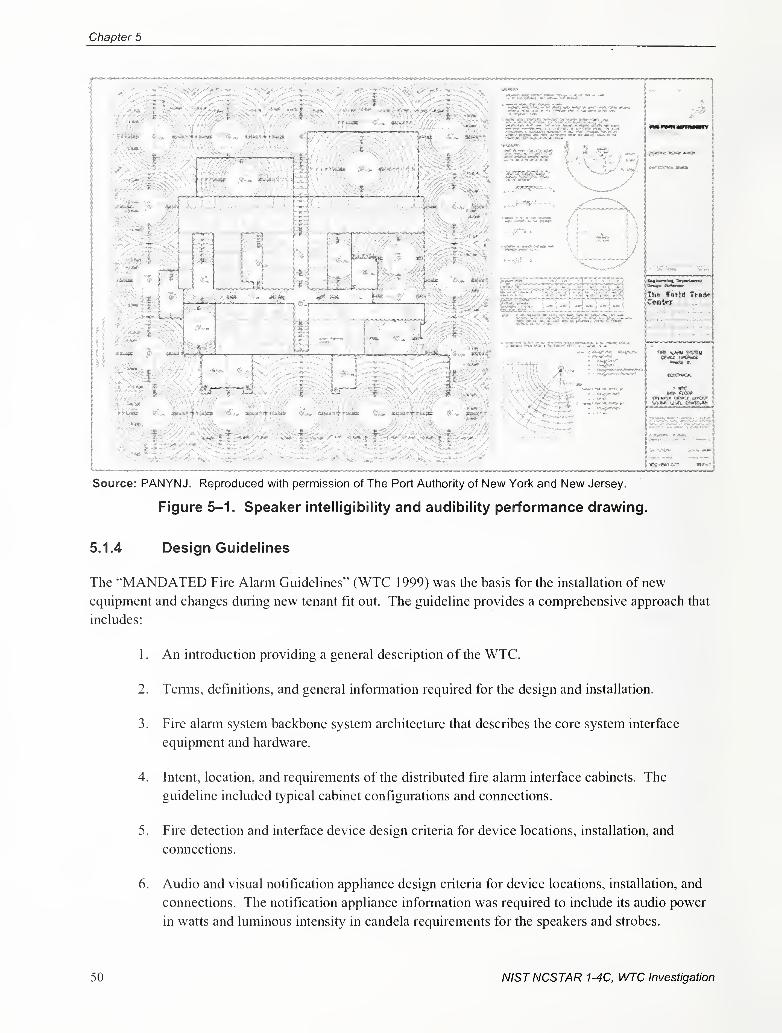
Chapter 5
il ;
!
ill 'I
5 \ :
Source: PANYNJ. Reproduced with permission of The Port Authority of New York and New Jersey.
Figure 5-1. Speaker intelligibility and audibility performance drawing.
5.1.4 Design Guidelines
The "MANDATED Fire Alarm Guidelines" (WTC 1999) was the basis for the installation ofnew
equipment and changes during new tenant fit out. The guideline provides a comprehensive approach that
includes:
1 . An introduction providing a general description of the WTC.
2. Temis, definitions, and general infonnation required for the design and installation.
3. Fire alarm system backbone system architecture that describes the core system interface
equipment and hardware.
4. Intent, location, and requirements of the distributed fire alarm interface cabinets. The
guidehne included typical cabinet configurations and connections.
5. Fire detection and interface device design criteria for device locations, installation, and
connections.
6. Audio and visual notification appliance design criteria for device locations, installation, and
connections. The notification appliance information was required to include its audio power
in watts and luminous intensity in candela requirements for the speakers and strobes.
50 NISTNCSTAR 1-4C, WTC Investigation
Fire Alarm System Design, Equip, Install & Perform Criteria
7. Fire alarm riser/one line diagram criteria requiring a diagrammatic fonnat for each mterface
cabinet, circuit, raceway, detection device type, and notification appliance type.
8. Circuit performance criteria with fomis for documenting test procedures, results, and
verification.
9. Contractor tie-in and pretest checklist to document that the design and installation procedures
have been followed.
10. Acceptance testing forms to document and assure the performance of the fire alarm
monitoring, detection, and notification devices.
11. Project summary that reviews the deliverables required for the fire alarm installation through
design, installation, acceptance, as-built documentation, and final project close out.
The standardized design concept was reinforced in the "Tenant Construction Review Manual" that
provided the technical criteria for all architectural and engineering consultants in connection with
construction work undertaken by the WTC tenants (Engineering Dept 1997).
5.1.5 Design Approach
A standardized approach for the design and installation of the tower fire alarm equipment and devices was
developed by subdividing a typical floor plate into a core and quadrants (see Fig. 5-2). The intent was to
set quality control standards with typical requirements and locations for common equipment, devices, and
circuits within an assigned area.
NISTNCSTAR 1-4C, WTC Investigation 51
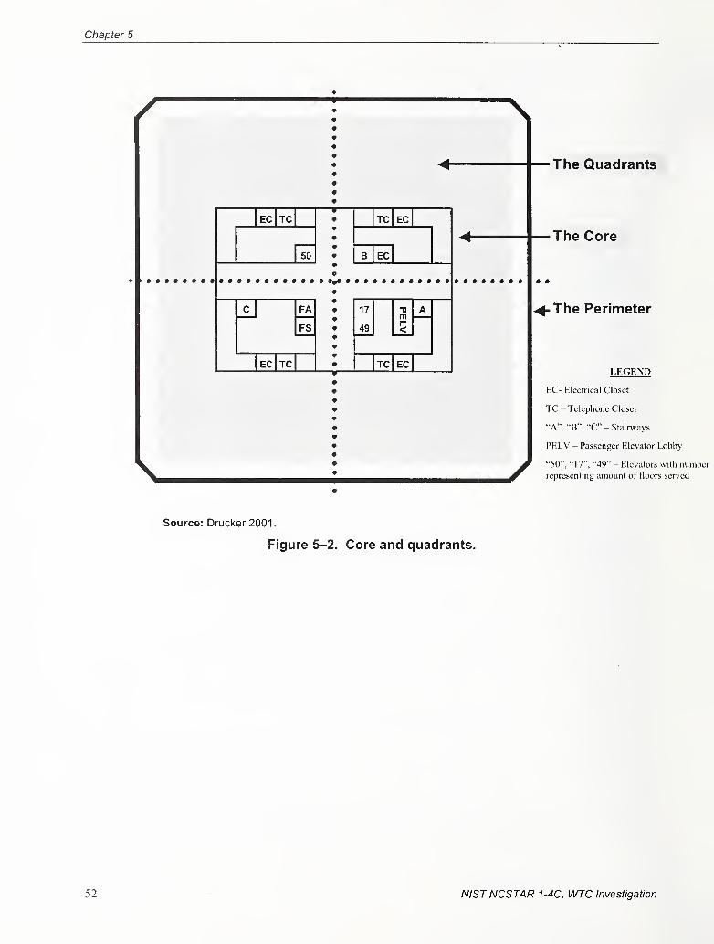
Chapter 5
The Quadrants
EC TC
50
TC EC
B EC
The Core
FA
FS
17
49
0m The Perimeter
EC TC TC EC
X
LEGEND
EC- Electrical Closet
TC - Telephone Closet
"A", "B", "C" - Stairways
PELV - Passenger Elevator Lobby
"50", "17", "49" - Elevators with number
representing amount of floors served
Source: Drucker 2001.
Figure 5-2. Core and quadrants.
52 NISTNCSTAR 1-4C, WTC Investigation
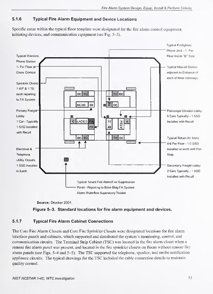
Fire Alarm System Design, Equip, Install & Perform Criteria
5.1.6 Typical Fire Alarm Equipment and Device Locations
Specific areas within the typical floor template were designated for the fire alarm control equipment,
initiating devices, and communication equipment (see Fig. 5-3).
Typical Wardens
Phone Station
1- Per Floor at~
Cross Corridor
Sprinkler Closet
1 WF & 1 TS
each reporting
to FA System
Primary Freight"
Lobby
1 Car - Typically
1 SSD Installed
with Recall
Electrical &
Telephone
Utility Closets
1 SSD Installed
in Each.
EC TC
MENS 50
C i-ADIES
FS
EC TC
TC EC
B EC
^ H -4-
TC EC
Typical Tenant Fire Alarm/Fire Suppression
• Panel - Reporting to Base BIdg FA System
Alamn-Waterflow-Supervisory-Trouble
Typical Firefighters
Phone Jack - 1 Per
Floor Inside "B" Stair
Typical Manual Station
adjacent to Entrance of
each of three stairways
Passenger Elevator Lobby
6 Cars Typically - 1 SSD
Installed with Recall
Typical Retum Air Inlets
4-8 Per Floor - 1/2 SSD
Installed at each with Fan
Stop.
Secondary Freight Lobby
2 Cars Typically - 1 SSD
Installed with Recall
Source: Drucker 2001
.
Figure 5-3. Standard locations for fire alarm equipment and devices.
5.1.7 Typical Fire Alarm Cabinet Connections
The Core Fire Alarm Closets and Core Fire Sprinkler Closets were designated locations for fire alarm
interface panels and cabinets, which supported and distributed the system's monitoring, control, and
communication circuits. The Terminal Strip Cabinet (TSC) was located in the fire alarm closet when a
remote fire alarm panel was present, and located in the fire sprinkler closets on floors without remote fire
alarm panels (see Figs. 5-4 and 5-5). The TSC supported the telephone, speaker, and strobe notification
appliance circuits. The typical drawings for the TSC included the cable connection details to maintain
quality control.
NISTNCSTAR 1-4C, WTC Investigation 53
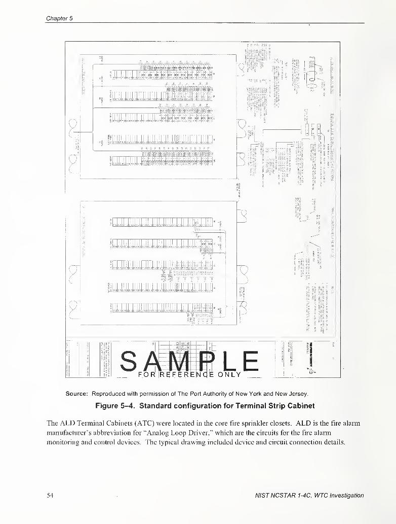
Chapter 5
Source: Reproduced with permission of The Port Authority of New York and New Jersey,
Figure 5-4. Standard configuration for Terminal Strip Cabinet
The ALD Tenninal Cabinets (ATC) were located in the core fire sprinkler closets. ALD is the fire alarm
manufacturer's abbreviation for "Analog Loop Driver," which are the circuits for the fire alarm
monitoring and control devices. The typical drawing included device and circuit cormection details.
54 NISTNCSTAR 1-4C, WTC Investigation
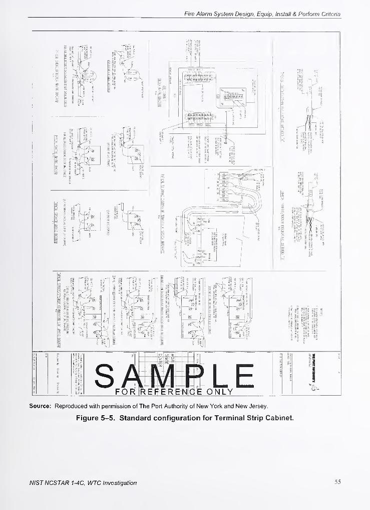
Fire Alarm System Design, Equip, Install & Perform Criteria
Source: Reproduced with permission of The Port Authority of New York and New Jersey.
Figure 5-5. Standard configuration for Terminal Strip Cabinet.
NISTNCSTAR 1-4C, WTC Investigation 55
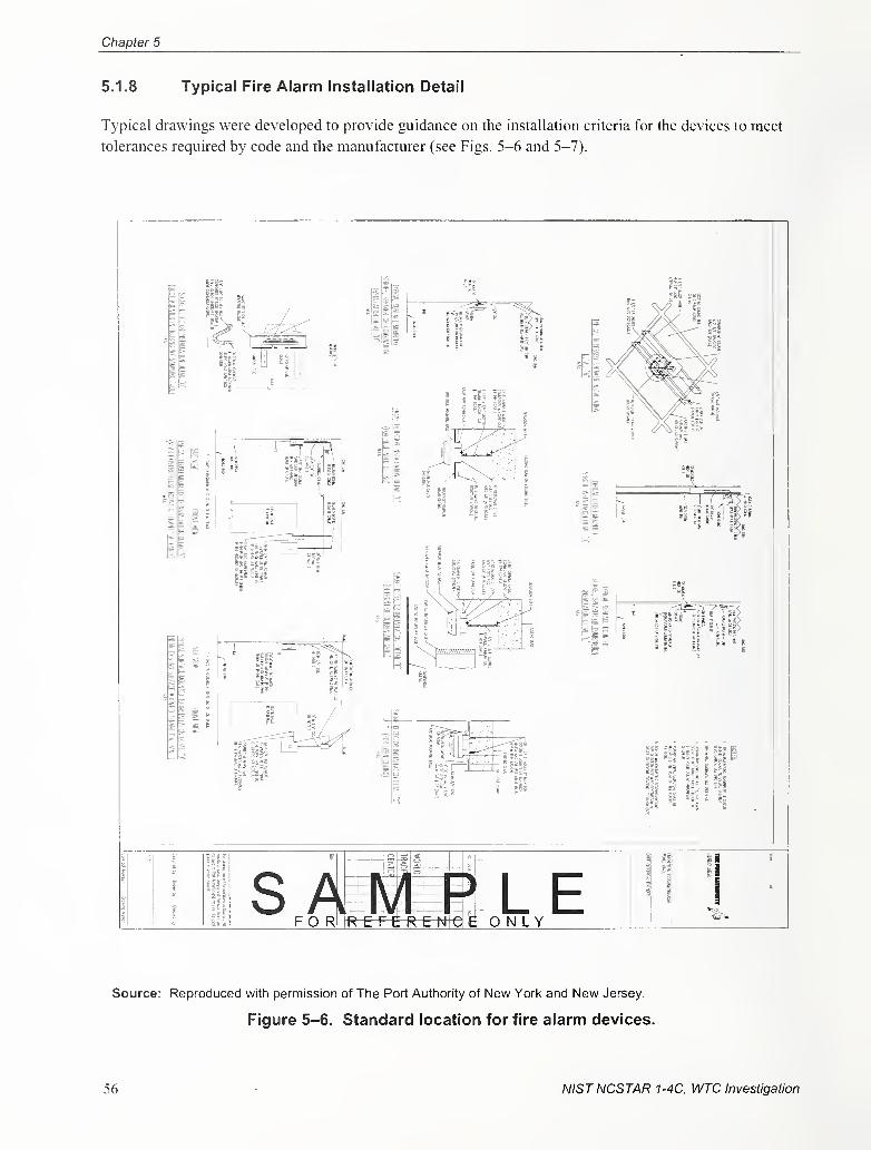
Chapter 5
5.1.8 Typical Fire Alarm Installation Detail
Typical drawings were developed to provide guidance on the installation criteria for the devices to meet
tolerances required by code and the manufacturer (see Figs. 5-6 and 5-7).
Source: Reproduced with permission of The Port Authority of New York and New Jersey.
Figure 5-6. Standard location for fire alarm devices.
56 NISTNCSTAR 1-4C, WTC Investigation
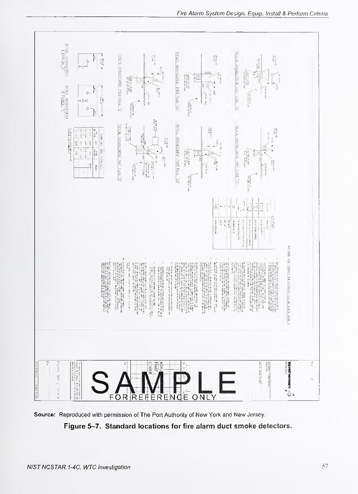
Fire Alarm System Design, Equip, Install & Perform Criteria
'711
i
r- >
BT
% c
|ia I/;n
S
1c
H]
1 m
il.fi
piil
SiiipiiSis! km
ii I-
||i sii gis P pilii
ill ^18 i*;*;*!;;;! ?§
lis mill mIs' «:s lisp
hpl -siil ii K i
Source: Reproduced with permission of The Port Authority of New Yorl< and New Jersey.
Figure 5-7. Standard locations for fire alarm duct smoke detectors.
NISTNCSTAR 1-4C, WTC Investigation 57
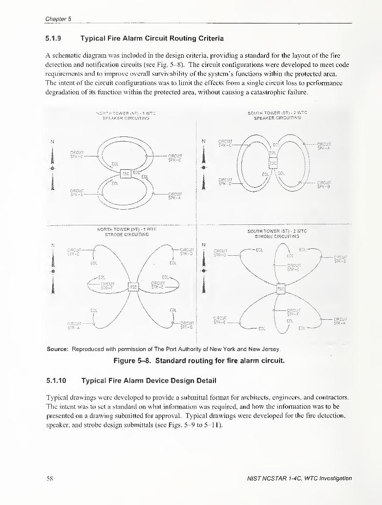
Chapter 5
5.1.9 Typical Fire Alarm Circuit Routing Criteria
A schematic diagram was included in the design criteria, providing a standard for the layout of the fire
detection and notification circuits (see Fig. 5-8). The circuit configurations were developed to meet code
requirements and to improve overall survivability of the system's functions within the protected area.
The intent of the circuit configurations was to limit the effects from a single circuit loss to performance
degradation of its function within the protected area, without causing a catastrophic failure.
iORTH TO'»VER iNT'! - 1 V/"
SPEAKER CIRCUiTiNG
CiRCUl!SPK-B
NORTH TOWER (NT) - 1 V/TC
STROBE CIRCUITING
CIRCUITSPK-A
SOUTH TOWER iST) - 2 VVTC
SPEAKER CIRCUiTiNG
i
SPK-A
IRCU!T
TR-8
SOUTH TOWER |ST) - 2 mcSTROBE C!RCU)T!NG
Source: Reproduced with permission of The Port Authority of New York and New Jersey.
Figure 5-8. Standard routing for fire alarm circuit.
5.1.10 Typical Fire Alarm Device Design Detail
Typical drawings were developed to provide a submittal fonnat for architects, engineers, and contractors.
The intent was to set a standard on what information was required, and how the infonnation was to be
presented on a drawing submitted for approval. Typical drawings were developed for the fire detection,
speaker, and strobe design submittals (see Figs. 5-9 to 5-11).
58 NISTNCSTAR 1-4C, WTC Investigation
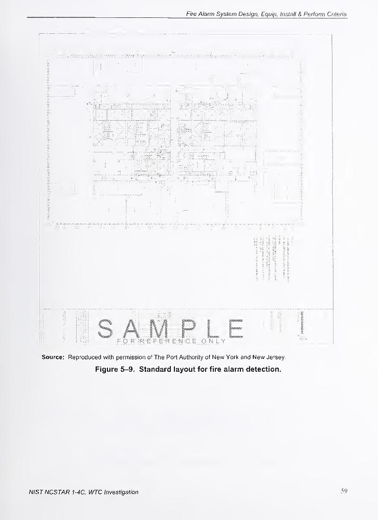
Fire Alarm System Design, Equip, Install & Perform Criteria
'1,
r ^<)
ifr
CD
as xssistsii is
1111'i ? P 5 tS I
t ^ i S ^ -
i : n M
FOR 'REFERENCE O N l Y
Source: Reproduced with permission of The Port Authority of New Yorl< and New Jersey.
Figure 5-9. Standard layout for fire alarm detection.
NIST NCSTAR 1-4C, WTC Investigation 59
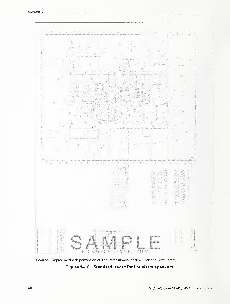
Chapter 5
J V
J!
J4
If
"7-
"O" - ^
-
"5:
A i ^
j...y
-^-^"!5-e--^r-^
i
L:i::^:^::«:s:i:.
Pi
11
iii „F o. RJSSEf:R:f:NS e, only
;
Source: Reproduced with permission of The Port Authority of New York and New Jersey
Figure 5-10. Standard layout for fire alarm speakers.
60 NISTNCSTAR 1-4C, WTC Investigation
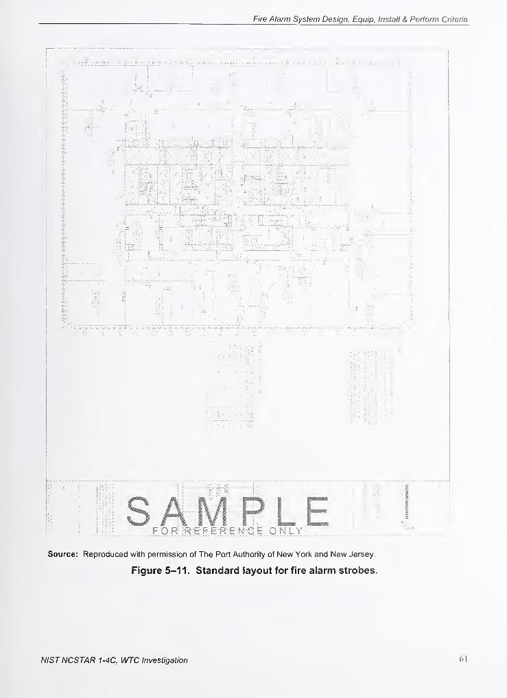
Fire Alarm System Design, Equip, Install & Perform Criteria
Source: Reproduced with permission of The Port Authority of New York and New Jersey.
Figure 5-11. Standard layout for fire alarm strobes.
NISTNCSTAR 1-4C, WTC Investigation 61
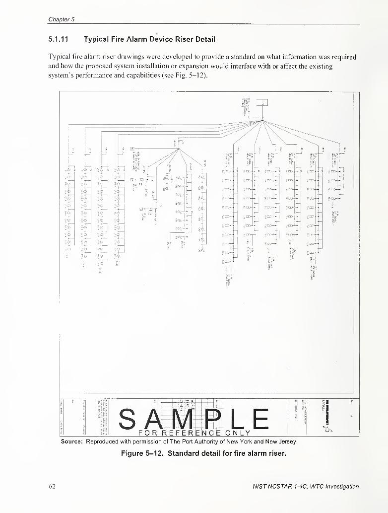
Chapter 5
5.1.11 Typical Fire Alarm Device Riser Detail
Typical fire alarm riser drawings were developed to provide a standard on what information was required
and how the proposed system installation or expansion would interface with or affect the existing
system's performance and capabilities (see Fig. 5-12).
Source: Reproduced with permission of The Port Authority of New Yorl< and New Jersey.
Figure 5-12. Standard detail for fire alarm riser.
62 NISTNCSTAR 1-4C, WTC Investigation
Fire Alarm System Design, Equip, Install & Perform Criteria
5.1.12 Installation Acceptance Testing and Commissioning Procedures
The installation of the approved fire alarm design required the contractor to perfomi specific quality
control procedures. Since any system modifications would affect both the building occupants and the
contractor's safety, specific testing and acceptance practices were developed to address these issues (see
Fig. 5-13).
CERBERUS PYROTRONtCS OPERATIONS BEST PRACTICES CO DrucKer
SPECIAL PROJECTS J WTC 19367.00 06'0-;96
Subject: Fire Aiarrr: System Acceptance Testing • Phase Hi 8BFAS Erigineenng Pfoiects - Part 1
WHAT; This cocumen! describes the AcceplanceTes) Procedures that are to be followed whenperforming this work on Smoke Detectors, Sub System TRI's, Speakers. Strobes, Pull Stations
Warden Phones, Standpipe & Maintenance Jacks
WHY: A standardized procedure insures that the required testing is performed efficently, effectively and in
accordance with project requirements It also insures that coordination activities and safety precautions are
followed
1) PA Manager to assign Acceptance Test dates and times based on successful connection
of and pretesting of fire aiarm equipment
2) Buiiding Fire Safety Director, Elevator Starters and Operators must t>e advised of the
Work Area, Time of and Scope of Work being Performed.
3) A SO Maintenance Log Worksheet shall be started for each EMR/MGR. The Worksheetmust be filled out completely^
4) (2) Sets of Ladders, Cleaning and Testing Agents. Meters,Hand Tools and Velocity Meter are required
5) Entry Into EfulR/MGR must be in the company of an elevator mechanic. Two Way Radio communications
with the accompanying Elevator Mechanic must be maintained at all times.
6) Prior to entry into, around or above Elevator Machinery the site shall be examined for personal hazards.
Where it is found that electrical equipment, motors, cables, or other UNPROTECTED hazards that could
cause injury or death are encountered the work in these areas shall be performed only after the
Elevator Mechanic has shutdown and locked out the equipme.nt
7) Only proper Ladders, Stairs or Access Ramps shall be utilized to reach equipment
Work shall not be performed using motors, etectncal panels, conduits, pipes, etc for support.
8) Encounters vjiVn Hazardous Substances, including but not limited to ACM shall
be reported immediately to the CPY Project Manager Work shall not proceed
in these areas.
9) Each Detector shall be maintained m accordance with the Contract Specifications
(Para. 2.) and RCNY-17-06, Actual Function Testing of Elevator Recall shall occur
10) The following procedure shall apply for each unit
a) Lead Tech Directs operation - makes appropriate notification calls.
b. ) One Tech works on Casing SD, One Tech works on Duct SO,
c. } Perform Detector Clear!ing and Examination Duct Detector Velocity (V) to be Checked.
d. ) Duct Detector sampling tubes are to be checked & cleaned via Access Doors if V Readings are Low.
d. ) Top Duct Smoke Detector - Verify Fan Shutdown - Reset -Restart Fan
e. ) Tnp Casing Smoke Detector - Verify Fan Shutdown - DO NOT RESETf. ) Tnp Duct Smoke Detector - Verify Deluge Sprinkler Operation - Reset - Restart Fan,
11) System Functions shall be documented, unexpected or failed operation shall be noted.
Detectors found water damaged, wet or othenf/ise contamined with other than normal
dusts and diit shall be reported. Duct Detector Velocity reading shall be recorded.
12} Sysiem{s) Shall be returned to Fully Operational Status and or the condition
found prior to the work. Verify with Mechanical Mechanic that Deluge Valve is Reset,
SUBJECT TO CHANGE PENDING CONTRACT AND OR PROCEDURAL REVISIONS
Source: PANYNJ 1999a. Reproduced with permission of Tine Port Authority of New York and NewJersey.
Figure 5-13. New work acceptance best practices.
NISTNCSTAR 1-4C, WTC Investigation 63
Chapter 5
5.1.13 Quality and Performance Assurance Forms
New fire alann work was required to be tested to ensure its compliance with adopted performance
criteria. Quality assurance forms were developed to provide testing accountability (see Figs. 5-14 and
5-15).
Tho Port Authority
Of NY & NJ
WTC BASE BUILDING FiRE ALARM SYSTEM
CONTRACTOR TIE-IN & PRE-TEST CHECKLIST
Eiectricaf Operations
anci Maintenance
This checklist is designee to assist the contractor, to reduce construction dsiays. accelerate tenant occupancy,
increase productivity and reduce delivered costs. The items listed are rec|uired to be complated prior to
the scheduling of the WTC Base Building Fire Alarm System Tie-in and Pre-Testing.
Please direct completed forms, scheduling and technical requests to Mr Ray Simonetti. at 212-435-5Q0S
»»> 24Jjou!\MvanceNotice Required .yi^S^j^
1 TENANT Name: (PRiNTj
? 8LDG Location: IV/TC 2 WTC 4VV7C 5WTC CONCOURSE SUBGRAOE (CiRCLE
)
3 BLOC Floor. ^
A COMTRACTOR Name: (PRINT)
5 Wire Test Results - Submitted, Corrected as Required and Approved.
6 SpeaKer/Strobe Wiring m TSC. ALD Wiring in ATC Ready for Tie-Sn.
7 Speakers set at selected power ieveis and installed.
(Power setting .in Watts, per Design}
S Strobes m.atch selected power levels and installed.
(Power setting ,in Cantiela. per Design)
9 Smoke Detectors programmed, labelled and installed.
10 TRI Interfaces programmed, labelled and installed.
1 1 Waterflow and Tamper Devices Installed and Operational.
12 Tenant SubSystem{s) Insfailed and Operational.
13 Fire Alarm Drav/ings - As installed including an Changes.
(2 Sets - Sutimittea in Advance to PA O&M Electhcsi Supsr/isor)
14 Architect, Enaineer. and General Contractor concur with Status.
I ] Completed
[ ] Completed
[ 3 Completed
( 3 Completed
( ] Completed
I I Completed
f 3 Completed
[ ] Completed
[ 3 Completed
[ 3 Completed
[ ] Not Applicable
{ } Not Applicable
[ 3 Not Applicable
[ ] Not Applicable
f 3 Not Applicable
[ 3 Not Applicable
[ 3 Not Applicable
I 3 ^ot Applicable
[ 3 Not Applicable
[ 3 Not jii^iplicable
IS 1 certify that the WTC Base Building Fire Alarm Work required for the referenced W completed forms to.
Tenant Project has been completed in its entirety compliant wUh the Plans and Mr Ray Stit^oneHl
Specifications submitted and Released, and ! am ready for the System Pretest WTC O&M - Electrics!
1-212-435-5717
16 Signed-
17 Dale:
Source: PANYNJ 1999a. Reproduced with permission of Tine Port Authority of New York and
New Jersey.
Figure 5-14. Contractor tie-in and pre-test checklist.
64 NISTNCSTAR 1-4C, WTC Investigation
Fire Alarm System Design, Equip, Install & Perform Criteria
a
i°
ta u.
ti
isosc. fcH- =>
a
22 £ a.
£ OS
K 2
2 •»
2 §
S —
!
S S
2
» 1 ISo
i ^ i
" = •££ o 2o 5 H
— tn> o
— o
c £.9 c
£ o
i g S J ^5 2 S 2 ®
5 — *
5 a •£E
2 o
£ ^ £ > o
O TO ^
_ « S ®
O XI -D O »-
S oo O
O<
" O „
~ o 5
XJ — ^m < §
= o cs- e g £Eu ^ 5 ^ ^x: JS c » = =*- j= i o a>
c E g ^ -o fo s ^ J; c c
? « 2 2 S »
£ o•S -E 2.
u » £re —. ^ ^j,
§ » « g
S o "5 = ^2 L i
*^ a- (C —
Source: PANYNJ 1999a. Reproduced with permission of Tine Port Authority of New Yorl< and New Jersey.
Figure 5-15. Contractor tie-in and pre-test checklist.
NISTNCSTAR 1-4C, WTC Investigation 65
Chapter 5
5.1.14 Fire Command Station Performance Standard
The FCS for Class E high-rise office buildings over 100 ft tall is required to be located in the lobby of the
building on the entrance floor and contains the following components to monitor and annunciate the
status of the fire alarm system and its devices (PANYNJ 1999a; PANYNJ 1999b; Drucker 2001
;
Drucker 2004):
1 . An audible alarm signal.
2. Emergency voice and alarm communication capability.
3. Means for silencing the audible alarm signals when the loud speakers are in use and for
activating the audible alarm system automatically when use of the loud speakers is
terminated.
4. A means to control the alarm sounding devices on any floor throughout the building.
5. A manually reset information display to indicate the floor where the alarm was activated.
6. Manual controls and display lamps to include on/off condition of air-handling systems.
7. A Standpipe Fire Line Telephone system for the firefighters with the capability to make
announcements over the emergency voice and alarm communication system.
8. A two-way communication system connected to a designated floor warden station on each
floor, the mechanical control center, elevators, air-handling control rooms, and elevator
machine rooms.
9. Means to manually transmit a fire alarm signal to the Fire Department via a central station of
a franchised operating company.
10. Means for testing the display, alarms, and connection to the central station.
5.1.15 Fire Command Station Equipment
After the 1993 bombing, the Port Authority built FCS for WTC 1 and WTC 2 based upon the Building
Code ofNew York code requirements as the baseline for design and performance (see Figs. 5-16 and
5-17). A master MXL-V and primary Network Command Center (NCC) for each building was installed
in the building's FCS as the fire alarm system's main monitoring and control center. The master MXL-Vconsisted of numerous panels, with each providing specific functions required to meet the FCSperformance criteria. The master fire alarm panels located in the FCS contained an alpha/numeric
annunciator with switches for acknowledging the system alarms and for controlling system functions.
These functions were also monitored, displayed, and controlled by the NCC located within the FCS.
Additional panels contained the microphone and controls for the emergency voice/alarm communication
(EVAC) system and controls for the firefighter and warden telephone communication systems.
66 NISTNCSTAR 1-4C, WTC Investigation
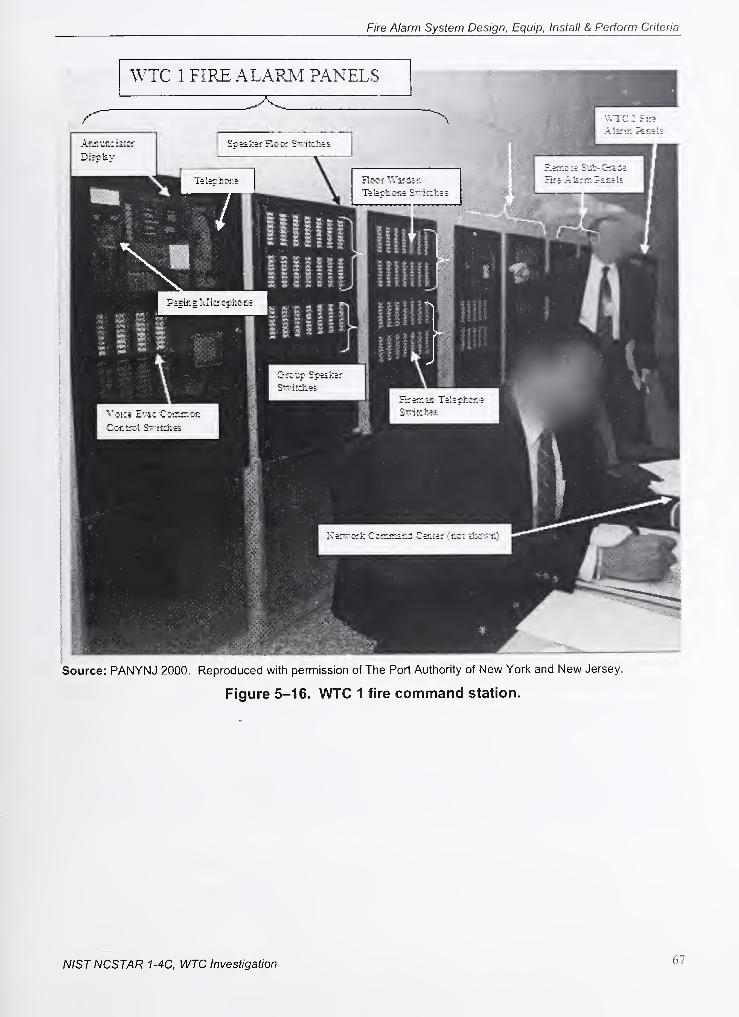
Fire Alarm System Design, Equip, Install & Perform Criteria
Source: PANYNJ 2000. Reproduced with permission of The Port Authority of New York and New Jersey.
Figure 5-16. WTC 1 fire command station.
NISTNCSTAR 1-4C, WTC Investigation 67
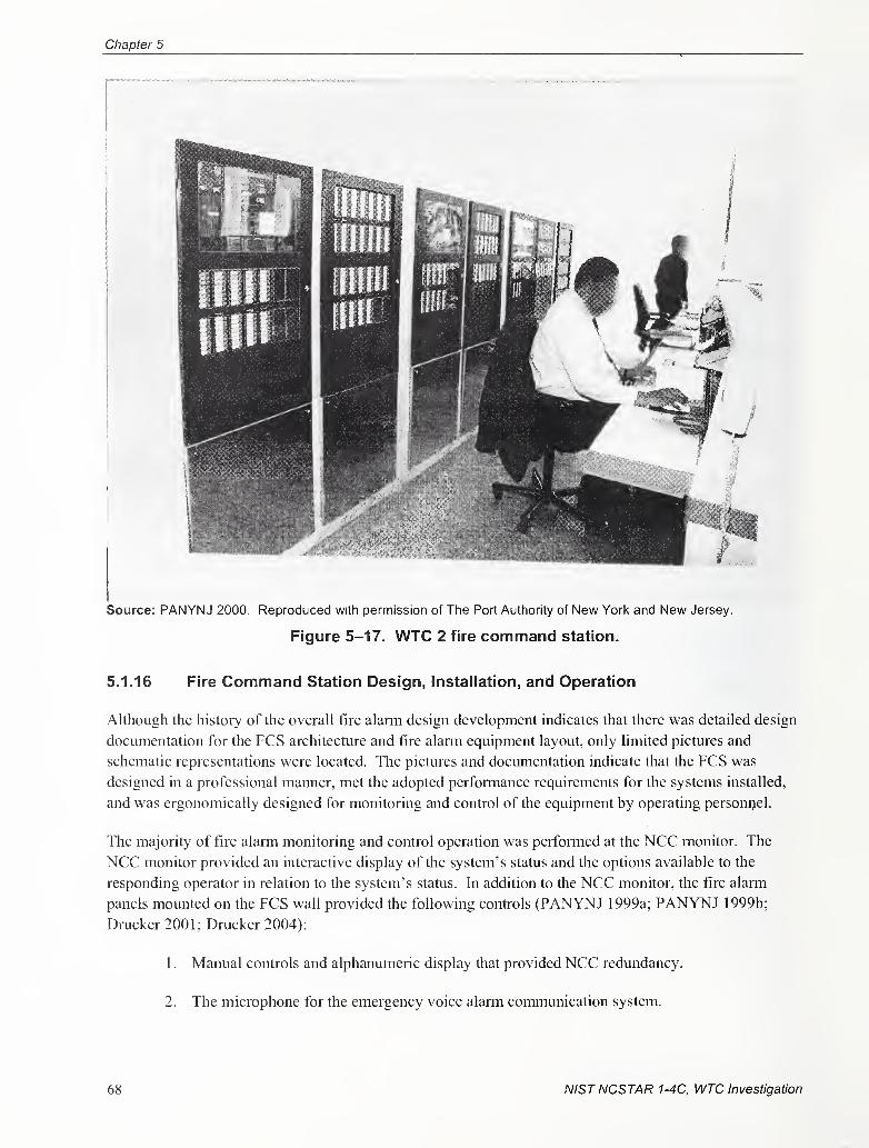
Chapter 5
Source: PANYNJ 2000. Reproduced with permission of The Port Authority of New York and New Jersey.
Figure 5-17. WTC 2 fire command station.
5.1.16 Fire Command Station Design, Installation, and Operation
Although the history of the overall fire alarm design development indicates that there was detailed design
documentation for the FCS architecture and fire alarm equipment layout, only limited pictures and
schematic representations were located. The pictures and documentation indicate that the FCS was
designed in a professional manner, met the adopted perfonnance requirements for the systems installed,
and was ergonomically designed for monitoring and control of the equipment by operating personnel.
The majority of fire alarm monitoring and control operation was performed at the NCC monitor. The
NCC monitor provided an interactive display of the system's status and the options available to the
responding operator in relation to the system's status. In addition to the NCC monitor, the fire alarm
panels mounted on the FCS wall provided the following controls (PANYNJ 1999a; PANYNJ 1999b;
Drucker 2001; Drucker 2004):
1. Manual controls and alphanumeric display that provided NCC redundancy.
2. The microphone for the emergency voice alarm communication system.
68 NISTNCSTAR 1-4C, WTC Investigation
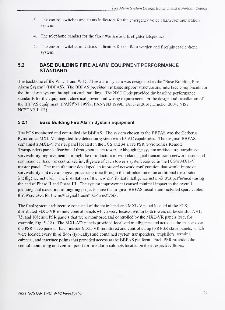
Fire Alarm System Design, Equip, Install & Perform Criteria
3 The control switches and status indicators for the emergency voice alarm communication
system.
4 The telephone handset for the floor warden and firefighter telephones.
5 The control switches and status indicators for the floor warden and firefighter telephone
system.
5.2 BASE BUILDING FIRE ALARM EQUIPMENT PERFORMANCESTANDARD
The backbone of the WTC 1 and WTC 2 fire alarm system was designated as the "Base Building Fire
Alarm System" (BBFAS). The BBFAS provided the basic support structure and interface components for
the fire alarm system throughout each building. The NYC Code provided the baseline performance
standards for the equipment, electrical power, and wiring requirements for the design and installation of
the BBFAS equipment (PANYNJ 1 999a; PANYNJ 1 999b; Drucker 200 1 ; Drucker 2004; NIST
NCSTAR 1-lH).
5.2.1 Base Building Fire Alarm System Equipment
The FCS monitored and controlled the BBFAS. The system chosen as the BBFAS was the Cerberus
Pyrotronics MXL-V integrated fire detection system with EVAC capabilities. The original BBFAScontained a MXL-V master panel located in the FCS and 34 slave PSR (Pyrotronics Remote
Transponder) panels distributed throughout each tower. Although the system architecture introduced
survivability improvements through the introduction of redundant signal transmission network risers and
command centers, the centralized intelligence of each tower's system resided in the FCS's MXL-Vmaster panel. The manufacturer developed an improved network configuration that would improve
survivability and overall signal processing time through the introduction of an additional distributed
intelligence network. The installation of the new distributed intelligence network was performed during
the end of Phase II and Phase III. The system improvement caused minimal impact to the overall
planning and execution of ongoing projects since the original BBFAS installation included spare cables
that were used for the new signal transmission network.
The final system architecture consisted of the main head-end MXL-V panel located at the FCS;
distributed MXL-VR remote control panels which were located within both towers on levels B6, 7, 41,
75, and 108; and PSR panels that were monitored and controlled by the MXL-VR panels (see, for
example. Fig. 5-18). The MXL-VR panels provided locahzed intelligence and acted as the master over
the PSR slave panels. Each master MXL-VR monitored and controlled up to 8 PSR slave panels, which
were located every third floor (typically) and contained system transponders, amplifiers, terminal
cabinets, and interface points that provided access to the BBFAS platform. Each PSR provided the
central monitoring and control point for fire alarm cabinets located on their respective floors.
NIST NCSTAR 1-4C, WTC Investigation 69
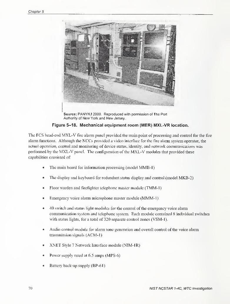
Chapter 5
Source: PANYNJ 2000. Reproduced with permission of The Port
Authority of New Yorl< and New Jersey.
Figure 5-18. Mechanical equipment room (MER) MXL-VR location.
The FCS head-end MXL-V fire alarm panel provided the main point of processing and control for the fire
alarm functions. Although the NCCs provided a video interface for the fire alarm system operator, the
actual operation, control and monitoring of device status, identity, and network communications was
perfonned by the MXL-V panel. The configuration of the MXL-V modules that provided these
capabilities consisted of:
• The main board for information processing (model MMB-1)
• The display and keyboard for redundant status display and control (model MKB-2)
• Floor warden and firefighter telephone master module (TMM-1
)
• Emergency voice alarm microphone master module (MMM-1)
• 40 switch and status light modules for the control of the emergency voice alarm
cominunication system and telephone system. Each module contained 8 individual switches
with status lights, for a total of 320 separate control zones (VSM-1).
• Audio control module for alarm tone generation and overall control of the voice alarm
transmission signals (ACM-1)
• XNET Style 7 Network Interface module (NIM-IR)
• Power supply rated at 6.5 amps (MPS-6)
• Battery back-up supply (BP-61)
70 NISTNCSTAR 1-4C, WTC Investigation
Fire Alarm System Design, Equip, Install & Perform Criteria
The MXL-VR remote panels distributed through the towers provided intelligence and gateways for signal
transmission and action between the MXL-V panels. They also provided a remote location to interrogate
the system status when performing system maintenance and repairs. The configuration of the MXL-VRmodules that provided these capabilities consisted of:
• The main board for information processing (model MMB-1)
• The display and keyboard for redundant status display and control (model MKB-2)
• XNET Style 7 Network Interface module (NIM- 1 R)
• Style 7 Communication Modules (NET-7)
• Power supply rated at 6.5 amps (MPS-6)
• Battery back-up supply (BP-61)
The PSR slave panels performed the main fire alarm device monitoring and control functions for each
building's fire alann system. To perfonn these fimctions, each PSR contained power supplies, battery
chargers, audio amplifiers, network transponder, initiating, notification, control, and communication
modules. The typical PSR panel configuration consisted of:
• Three 10 Amp Power Supplies (model PS-35)
- Power Supply #1 was for the strobes on the floor above the fire alarm closet.
- Power Supply #2 was for the strobes on the floor containing the fire alarm closet.
- Power Supply #3 was for the strobes on the floor below the fire alarm closet.
• Battery backup for 4 h standby followed by 15 min of alarm capability.
• Three 1 00 watt amplifiers (model EL-4 1 OD)
- Amplifier #1 was for Channel #1 - page/alert messaging.
- Amplifier #2 was for Channel #2 - EVAC messaging.
- Amplifier #3 was for backup - standby function.
• Backup tone generator (BTC-1)
• Four addressable initiating device loops - one loop for each floor with one spare (ALD-2)
• 16 audible speaker circuits - five circuits for each floor with one spare (ZC2-8B-70)
• 24 visual strobe circuits - six circuits for each floor with six spare (ZC1-8B-25)
• Fire Fighters and Warden Telephone Communication (ZCT-8B)
NISTNCSTAR 1-4C, WTC Investigation 71
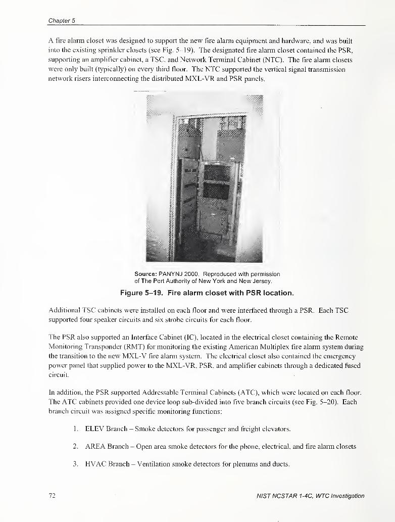
Chapter 5
A fire alarm closet was designed to support the new fire alarm equipment and hardware, and was built
into the existing sprinkler closets (see Fig. 5-19). The designated fire alann closet contained the PSR,
supporting an amplifier cabinet, a TSC, and Network Terminal Cabinet (NTC). The fire alarm closets
were only built (typically) on every third floor. The NTC supported the vertical signal transmission
network risers interconnecting the distributed MXL-VR and PSR panels.
Source: PANYNJ 2000. Reproduced with permission
of The Port Authority of New York and New Jersey.
Figure 5-19. Fire alarm closet with PSR location.
Additional TSC cabinets were installed on each floor and were interfaced through a PSR. Each TSCsupported four speaker circuits and six strobe circuits for each floor.
The PSR also supported an Interface Cabinet (IC), located in the electrical closet containing the Remote
Monitoring Transponder (RMT) for monitoring the existing American Multiplex fire alann system during
the transition to the new MXL-V fire alann system. The electrical closet also contained the emergency
power panel that supplied power to the MXL-VR, PSR, and amplifier cabinets through a dedicated fused
circuit.
In addition, the PSR supported Addressable Terminal Cabinets (ATC), which were located on each floor.
The ATC cabinets provided one device loop sub-divided into five branch circuits (see Fig. 5-20). Each
branch circuit was assigned specific monitoring functions:
1 . ELEV Branch - Smoke detectors for passenger and freight elevators.
2. AREA Branch - Open area smoke detectors for the phone, electrical, and fire alarm closets
3. HVAC Branch - Ventilation smoke detectors for plenums and ducts.
72 NISTNCSTAR 1-4C, WTC Investigation
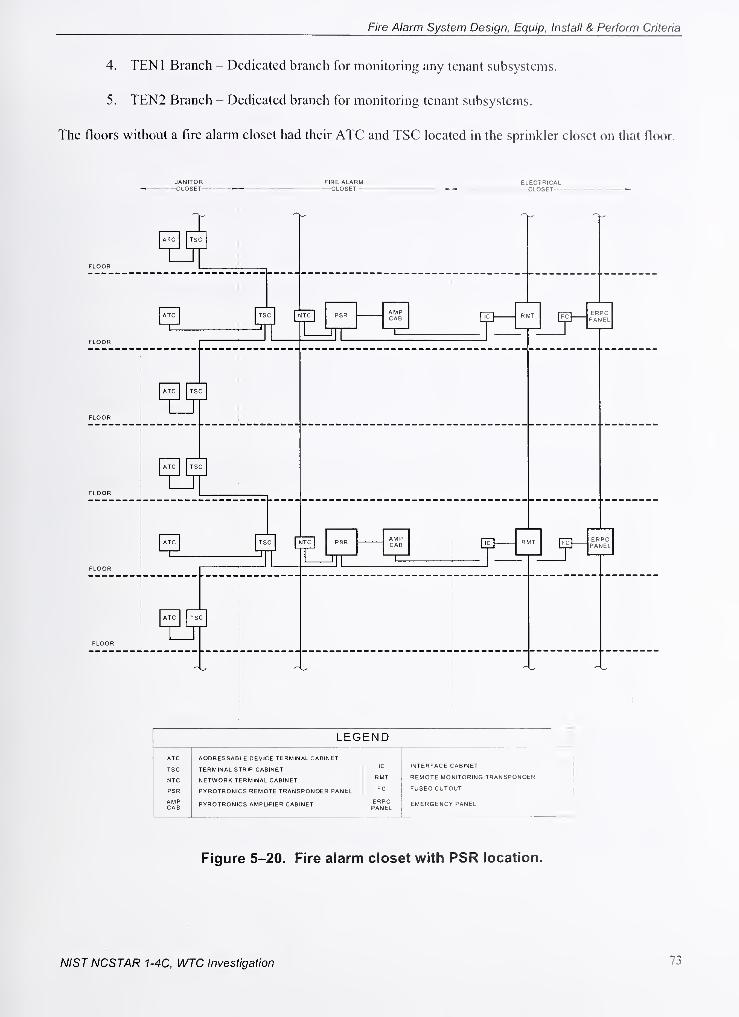
Fire Alarm System Design, Equip, Install & Perform Criteria
4. TENl Branch - Dedicated branch for monitoring any tenant subsystems.
5. TEN2 Branch - Dedicated branch for monitoring tenant subsystems.
The floors without a fire alarm closet had their ATC and TSC located in the sprinkler closet on that floor.
FLOOR
JA NITOFi FIRE ALARM ELECTRICAL
ATC
1
-OSET
1TSC
1
FLOOR
ATC
1
TS
1
^ L ITC1
PSR
Jll
AMPCAB
1
n R^n [fc]ERPAN
'CEL
FLOOR
ATC
1
TSC
1
FLOOR
ATC
1
TSC
FLOOR
ATC
1
TS
1
^ LITC
1
PSR
Jll
AMPCAB
1
n— R IT [fc]ERPAN
= CEL
FLOOR
ATC
1
TSC
LEGEND
ATC
TSC
NTC
PSR
AMPCAB
ADDRESSABLE DEVICE TERMINAL CABINET
TERMINAL STRIP CABINET
NETWORK TERMINAL CABINET
PYROTRONICS REMOTE TRANSPONDER PANEL
PYROTRONICS AMPLIFIER CABINET
IC
RMT
FC
ERPCPANEL
INTERFACE CABINET
REMOTE MONITORING TRANSPONDER
FUSED CUTOUT
EMERGENCY PANEL
Figure 5-20. Fire alarm closet with PSR location.
NISTNCSTAR 1-4C, WTC Investigation 73
Chapter 5
5.2.2 Base Building Fire Alarm System Design, Installation, and Operation
The Port Authority standardized the design and criteria, equipment configuration and layout, which was
critical to maintain quality controls. Equipment locations were also standardized, and dedicated fire
alarm closets were constructed to support the equipment. The overall design, equipment layout, and
installation of the BBFAS were consistent with applicable codes and standards.
The PCS NCCs provided the main point of control for the BBFAS equipment. The MXL-VR panels
located at floor levels B6, 7, 41, 75, and 108 provided a redundant point of monitoring and control of the
individual MXL-VR and its slave PSR panels. The FCSs provided the main point of monitoring for all
alanns and fault conditions, with the MXL-VR providing remote status query capability.
5.3 SYSTEM NETWORK TRANSMISSION PATHS PERFORMANCESTANDARDS
The WTC 1 and WTC 2 fire alarm systems consisted of numerous panels located throughout each tower.
The interconnection of the distributed panels within each tower was accomplished through multiple
vertical system network transmission paths commonly referred to as risers. The NYC Code provided the
baseline perfonnance for the risers. This baseline was very limited in scope, as are all model building
codes when regulating the performance and installation of risers.
A fire alarm riser may contain numerous transmission paths for multiple functions associated with the
system. The WTC 1 and WTC 2 system risers controlled functional capabilities that included;
1. Fire detection
2. Life safety system monitoring
3. Life safety system control
4. Occupant notification
5. Floor warden and firefighter telephone communication capability
6. System display and control of the fire alarm system
The type and performance of fire alarm transmission paths within a riser are not dictated by building
codes or standards. The type and performance of the communication paths are defined by the National
Fire Alarm Code (NFAC) (NFPA 72), and their capabilities verified through testing by nationally
recognized laboratories. The NFAC, which is developed by the National Fire Protection Association
(NFPA) through a consensus standards development process approved by the American National
Standards Institute, provides performance requirements for multiple types of transmission paths for
accomplishing the system's functions. The requirements establish different levels of performance. The
owner and system designer determine the expected level of performance.
74 NISTNCSTAR 1-4C, WTC Investigation
Fire Alarm System Design, Equip, Install & Perform Criteria
5.3.1 Detection, Monitoring, and Control Network Transmission Path Performance
The fire alantis systems for WTC 1 and WTC 2 were very large systems with distributed panels located
throughout each tower. Ahhough each panel performed specific functions, the monitoring and control of
the functions was perfonned as a single, holistic fire alarm system for the protected premises. The
sharing of intelligence, monitoring, and control between the panels within the protected premises were
accomplished through the system's network transmission paths. Tables within the NFAC define the
performance requirements for the transmission paths. The Signaling Line Circuit table relates to the
performance of the network transmission paths dealing with fire detection, life safety system monitoring
and control ftinctions.
These circuits support the fire detection, life safety system monitoring and control, occupant notification
fijnctions of the protected premises as a whole, and provide network interconnection to, monitor and
control the distributed panels within each tower.
The performance criteria within the tables provide multiple levels of circuit performance, with each
succeeding level proving increased survivability and endurance characteristics. All model building codes
reference the NFAC, but the survivability and endurance performance of the network transmission paths
as defined by the tables within the NFAC are not dictated by any model building code. It is the
responsibility of the system designer to detemiine and specify signaling cominunication path performance
requirements based upon the system architecture and performance goals. The Port Authority specified the
most stringent circuit class and technical style available for all circuits including the Signaling Line
Circuits (Class A, Style 7) and Notificafion Appliance Circuits (Class A, Style Z), which will be
discussed in detail later in the report. The intent for using the most stringent class of circuits was to
enhanced network survivability and endurance performance.
NISTNCSTAR 1-4C, WTC Investigation 75
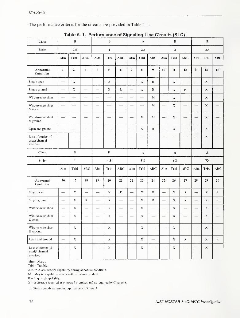
Chapter 5
The performance criteria for the circuits are provided in Table 5-1.
Table 5-1. Performance of Signaling Line Circuits (SLC).
Class B B A B B
Style 0.5 1 2U- 3 3.5
Aim Trbl ARC Aim Trbl ARC Aim Trbl ARC Aim Trbl ARC Aim Trbl ARC
AbnormalCondition
1 2 3 4 6 7 8 9 10 11 12 13 14 15
Single open X X X R X X
Single ground — X ~ — X R — X R — X R — X —
Wire-to-wire short M X X
Wire-to-wire short
& open
M X X
Wirc-to-wire short
& ground
X M X X
Open and ground X R X X
Loss of carrier (if
uscd)/channel
interface
X
Class n B A A A
Style 4 4.5 SOL 6a.
Aim Trbl ARC Aim Trbl ARC Aim Trbl ARC Aim Trbl ARC Alm Trbl ARC
AbnormalCondition
16 17 18 19 20 21 22 23 24 25 26 27 28 29 30
Single open X X R X R X R X R
Single ground X R X X R X R X R
Wire-to-wire short X X X X X R
Wirc-to-wirc short
& open
X X X X X
Wirc-to-wirc short
& ground
X X X X X
Open and ground X X X X R X R
Loss of carrier (if
used)/ channel
interface
X \ X X X
Aim = Alarm.
Trbl = Trouble.
ARC = Alarm receipt capability during abnormal condition.
M = May be capable of alarm with wire-to-wirc short.
R = Required capability.
X = Indication required at protected premises and as required by Chapter 8.
X= Style exceeds minimum requirements of Class A.
76 NISTNCSTAR 1-4C, WTC Investigation
Fire Alarm System Design, Equip, Install & Perform Criteria
5.3.2 Detection, Monitoring, and Control Network Transmission Path Design,Installation, and Control
The fire alarm system's detection, monitoring, and control network transmission paths consisted of
multiple limited area networks which consisted of 8 PSR slave panels connected to a MXL-VR master
panel (see Figs. 5-21 and 5-22). The transmission path between the panels in this typical arrangement
was referred to as the MNET by the manufacturer. The MXL-VR master panel monitored and controlled
the PSR slave panels and their fire alarm initiating and indicating appliances (PANYNJ 1999a;
PANYNJ 1999b; Drucker 2001; Drucker 2004).
In addition to the limited area networks, there was also a system network, which the manufacturer
referred to as the XNET (see Figs. 5-23 and 5-24). The XNET provided an interface for the multiple
MXL-VR master panels and the multiple NCC, which together operated as a single fire alarm system.
The distribution of the MXL-VR master panels within each tower allowed each MXL-VR to act
independently if isolated from the building XNET, or act in concert with the other MXL-VR panels when
the network communication was sustained. Both towers had a NCC in their FCS and an additional
Remote NCC, which was connected to their respective XNET, that was located in the OCC for
redundancy (see Fig. 5-25). The remote NCC's provided complete monitoring and control of all WTC 1
and WTC 2 fire alarm system functions. In addition to the remote NCC in the OCC, the WTC 2 fire
alarm system had a second remote NCC installed in WTC 1 . The additional remote WTC 2 NCC was
installed in WTC 1 to enhance the overall survivability of the WTC 2 fire alarm monitoring and control
funcfions. The Port Authority determined that since the WTC 2 FCS was located above, and in relative
close proximity to the OCC, an additional WTC 2 remote NCC was required in the WTC 1 FSC as an
extra level of safety in case a catastrophic event affected the capabilities of both WTC 2 FCS and OCCdue to their close proximity.
NIST NCSTAR 1-4C, WTC Investigation 11
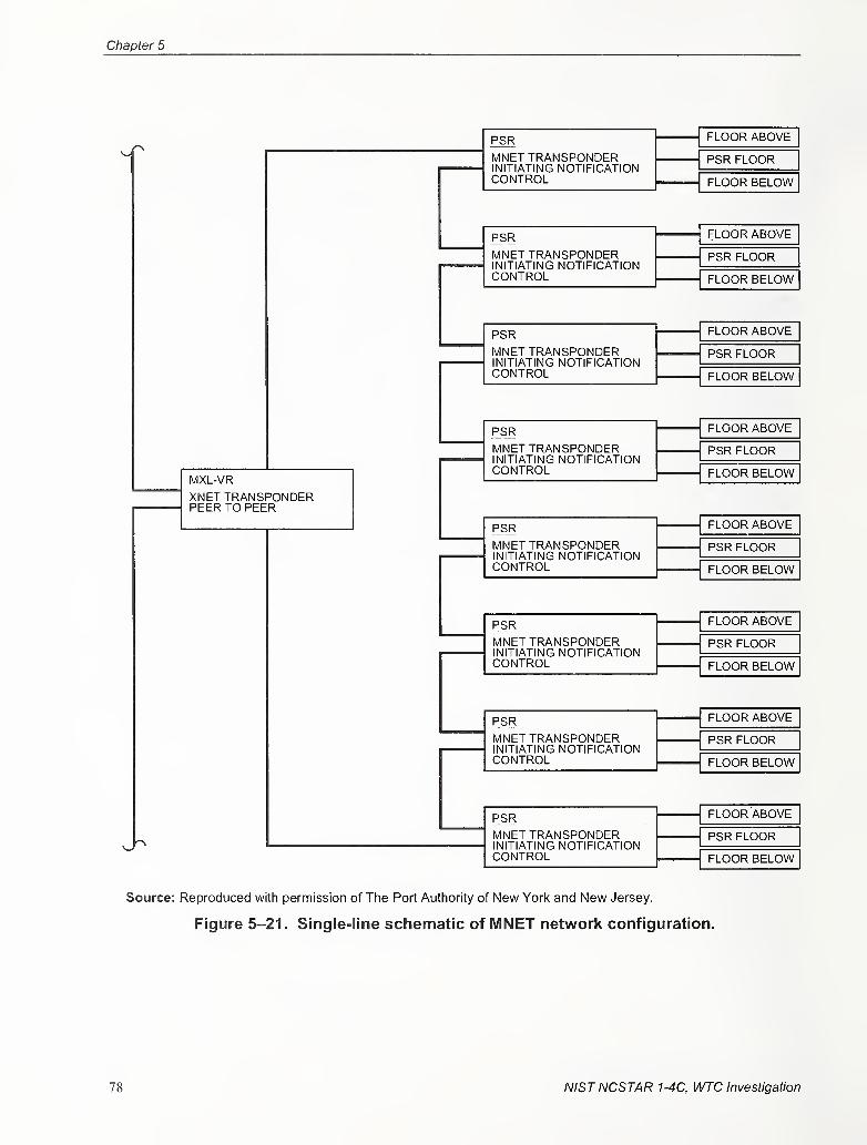
Chapter 5
MXL-yR
XNET TRANSPONDERPEER TO PEER
PSR
MNET TRANSPONDERINITIATING NOTIFICATIONCONTROL
PSR
MNET TRANSPONDERINITIATING NOTIFICATIONCONTROL
PSRMNET TRANSPONDERINITIATING NOTIFICATIONCONTROL
PSR
MNET TRANSPONDERINITIATING NOTIFICATIONCONTROL
PSR
MNET TRANSPONDERINITIATING NOTIFICATIONCONTROL
PSRMNET TRANSPONDERINITIATING NOTIFICATIONCONTROL
PSR
MNET TRANSPONDERINITIATING NOTIFICATIONCONTROL
PSRMNET TRANSPONDERINITIATING NOTIFICATIONCONTROL
FLOOR ABOVE
PSR FLOOR
FLOOR BELOW
FLOOR ABOVE
PSR FLOOR
FLOOR BELOW
FLOOR ABOVE
PSR FLOOR
FLOOR BELOW
FLOOR ABOVE
PSR FLOOR
FLOOR BELOW
FLOOR ABOVE
PSR FLOOR
FLOOR BELOW
FLOOR ABOVE
PSR FLOOR
FLOOR BELOW
FLOOR ABOVE
PSR FLOOR
FLOOR BELOW
FLOOR ABOVE
PSR FLOOR
FLOOR BELOW
Source: Reproduced with permission of Tlie Port Autlnority of New Yorl< and New Jersey.
Figure 5-21. Single-line schematic of MNET network configuration.
78 NISTNCSTAR 1-4C, WTC Investigation
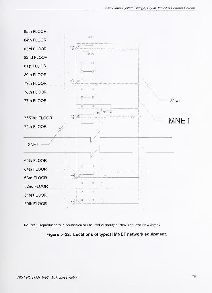
Fire Alarm System Design, Equip, Install & Perform Criteria
85th FLOOR
84th FLOOR
83rd FLOOR
82nd FLOOR
81st FLOOR
80th FLOOR
79th FLOOR
78th FLOOR
77th FLOOR
75/76th FLOOR
74th FLOOR
XNET
65th FLOOR
64th FLOOR
63rd FLOOR
62nd FLOOR
61st FLOOR
60th FLOOR
XNET
MNET
IE B
Source: Reproduced with permission of The Port Authority of New York and New Jersey.
Figure 5-22. Locations of typical MNET network equipment.
NISTNCSTAR 1-4C, WTC Investigation 79
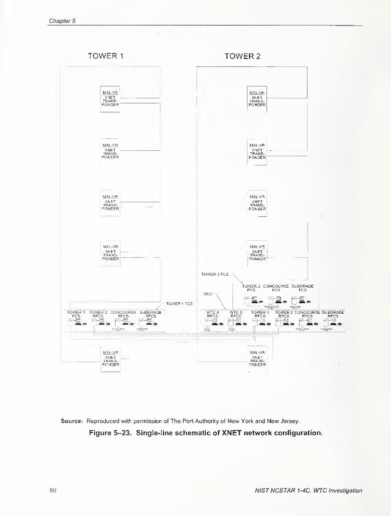
Chapter 5
TOWER 1 TOWER 2
MXL-VRXNETTRANS-PONDER
XNETTRANS-PONDER
XNET -
TRANS-PONDER"
MXL-VRXNETTRANS-PONDER
-TOWER 1 FCS
TOWER 2 FCS
XNETTRANS-PONDER
XNETTRANS-PONDER
MXl-yRXNETTRANS-PONDER
XNETTRANS-PONDER
TOWER 2 CONCOURSE SUBGF5ADEIPCS FCS FCS
TOWER 1 TOWER 2 CONCOURSE SUBGRADEFCS RFCS RFCS RFCS
Source: Reproduced with permission of The Port Authority of New York and New Jersey.
Figure 5-23. Single-line schematic of XNET network configuration.
80 NISTNCSTAR 1-4C, WTC Investigation
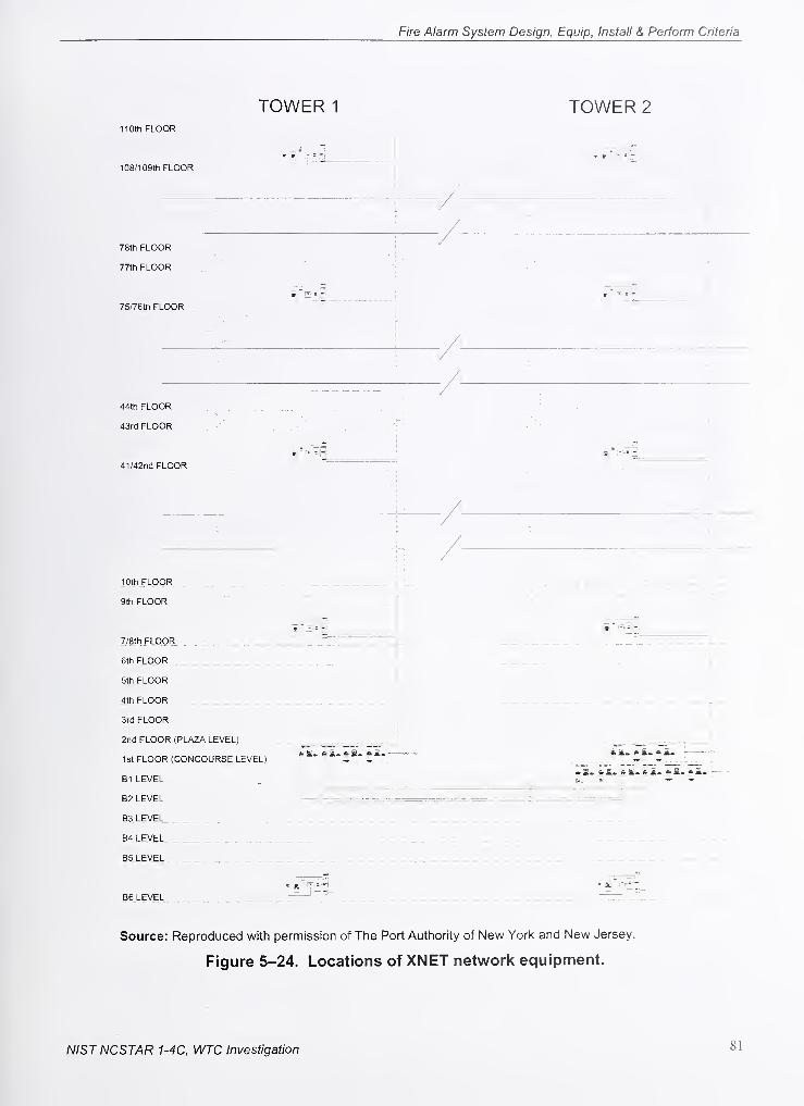
Fire Alarm System Design, Equip, Install & Perform Criteria
TOWER 1 TOWER 2
110th FLOOR
'"k
» '- s —
1 Uo/ 1 uy in ru'^i-'rs
78th FLOOR
77th FLOOR
1 /
'^
75/76th FLOOR
44th FLOOR
43rd FLOOR
41/42nd FLOOR
lOth FLOOFt
9th FLOOFt
7/8th FLOOR _ _ „
6th FLOOR;
5th FLOOR
4th FLOOR , _
3rd FLOOR
2nd FLOOR (PLAZA LEVEL)
1st FLOOR (CONCOURSE LEVEL)
B1 LEVEL
B2 LEVEL
B3 LEVEL[ . j.
B4 LEVEL _ ^ ;; \.
85 LEVEL '
-
, i-S.-
J
86 LEVEL
Source: Reproduced with permission of The Port Authority of New York and New Jersey.
Figure 5-24. Locations of XNET network equipment.
NISTNCSTAR 1-4C, WTC Investigation 81
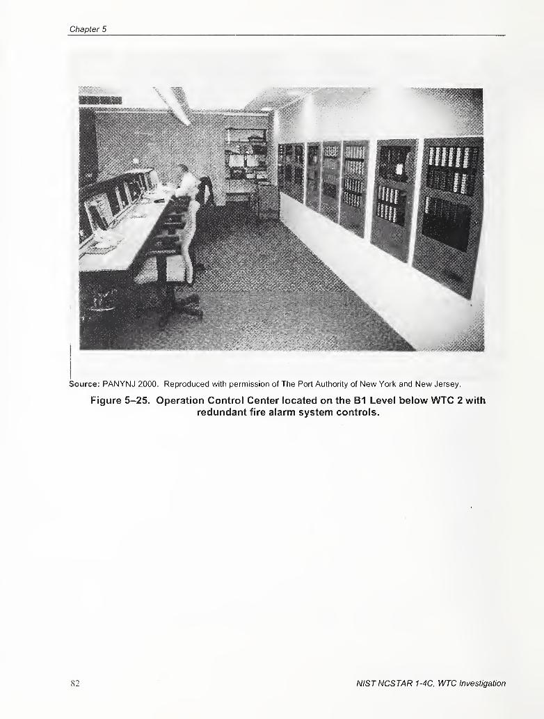
Chapter 5
Source: PANYNJ 2000. Reproduced with permission of The Port Authority of New York and New Jersey.
Figure 5-25. Operation Control Center located on the B1 Level below WTC 2 with
redundant fire alarm system controls.
82 NISTNCSTAR 1-4C, WTC Investigation
Fire Alarm System Design, Equip, Install & Perform Criteria
The NCC for each tower contained central monitoring and master control through the MXL-V for the
building's protected premises. The master MXL-V provided monitoring and control of the MXL-VRremote fire alann panels through a Style 7 XNET network (see Fig. 5-22). The PSR slave panels (along
with the MXL-VR panels) monitored and controlled fire alarm devices and communicated their status
through a Style 7 MNET back to their Master MXL-VR panel. The XNET provided a communication
path for the FCS and OCC to monitor the fire alann and life safety system supervisory signals and control
the interfaced life safety systems to the distributed MXL-VR panels and through the MXL-VR panels via
the MNET (see Fig. 5-23) to the PSR panels.
The controlled life safety systems included the speaker circuits that provided the EVAC messages ser\'ing
each floor and the stairways and also included controls for the switching of the warden and firefighter
telephone calls. The XNET provided a pathway for the main MXL-V (located at the FCS) to control the
distribution of the EVAC and telephone coirununication messages and calls, but did not transmit the
EVAC messages or telephone calls. The EVAC and telephone transmission path circuits were separate
and independent of the XNET and MNET transmission paths. The EVAC and telephone circuits
provided the actual voice messages and calls when in use, and the XNET and MNET directed the
distribution of the messages and calls. Figures 5-24 and 5-25 show the locations of XNET and MNETnetwork equipment in WTC 1 and WTC 2.
The XNET and MNET design and installation provided enhanced network integrity and reliability
through a loop wiring topology configuration that provided separate network communication path risers
(primary and secondary) installed in three different locations (fire alarm closet and stairways "A" and
"C"). Due to the excessive length of the network risers (each tower was approximately 1,350 ft high), the
network was designed with #14 AWG Teflon cables (twisted pair 600 V, 200 "C). The intent of the
Style 7 networks was to accommodate any type of single circuit fault, such as a cut wire, short between
wires, or grounding of a wire on any section of the network. Fiber optic cable was originally presented
for the network during meetings with The Fire Department of the City ofNew York (FDNY) Technology
Management, but was rejected by FDNY electrical supervisors as not compliant with the NYC Code
(CUMMISKEY 1993).
Fourteen pairs of cables were installed within the stairway "A" and "C" risers. The system only required
five cables per riser, but the Port Authority intentionally installed additional cables for fiature use. The
intent was to provide enough cables for the eventual replacement of the new fire alarm system. The
additional cables would allow the installation of a redundant system during the transition from the
existing system to a new system.
The system was designed to automatically compensate for faults on its XNET communication path by
allowing MXL-VR systems to remain in communication with each other as a subsystem if a catastrophic
failure were to separate a portion of the system from the head-end MXL-V panel at the FCS. The
separated portion of the system would dynamically retain all communication and control logic associated
with the remaining remote panels in communication with each other. Or, if a MXL-VR panel
experienced catastrophic network failure, the panel would act as a fully independent control unit
performing monitoring, notification, and control function assigned to the stand-alone control unit.
Design documents indicate that the Port Authority specified the most stringent performance criteria for
the fire alarm network communication paths and installed the network cable and hardware in a manner
that would enhance survivability and endurance from the risk of fire and physical damage. The XNET
NISTNCSTAR 1-4C, WTC Investigation 83
Chapter 5
and MNET riser consisted of Teflon sheathed cables rated at 200 °C and was installed in rigid conduit
between the distributed panels. In addition to these stringent criteria for cable and hardware survivability,
the separation of the risers provided physical protection of the network circuits from any localized fire or
physical damage. The intent of the design criteria was to provide enhanced survivability through: robust
circuit perfomiance, cable and hardware with enhanced protection characteristics, and the physical
separation of the risers. At the time of installation, this criteria exceeded all applicable code requirements
for survivability and endurance characteristics for fire alarm systems within high-rise buildings.
5.3.3 Typical Detection, Monitoring, and Control Devices
The Siemens Pyrotronics devices used for detection, monitoring, and control represented state-of-the-art
technology at the time of system design and installation. The devices included (PANYNJ 1999a):
• Addressable open area ionization smoke detectors (ILI- 1
)
• Addressable high-air velocity open area ionization smoke detectors (ILI-IA)
• Addressable duct ionization smoke detectors - high air velocity (ILI- IB)
• Addressable open area photoelectric smoke detectors (ILP-I)
• Addressable open area photoelectric smoke detectors with fixed heat detector (ILPT-1)
• Addressable open area rate compensated heat detectors (ID-60T-135)
• Addressable single input monitor modules (TRI-60)
• Addressable dual input monitor modules (TRI-60D)
• Addressable single input with relay control output modules (TRI-60R)
• Addressable single-action pull stations (MS-MI)
5.3.4 Typical Detection, Monitoring, and Control Device Design and Installation
As a minimum, the WTC mandated design guidelines (PANYNJ 1999a) required smoke detector
protection in each elevator lobby, electrical closet, telephone closet, fire alarm closet, and at each HVACair return (see Fig. 5-26). Also, manual stations were installed next to the three stairway access doors,
and sprinkler water flow and tamper switches were monitored for alarm and trouble conditions,
respectively. Additional fire alarm protection could be added by a tenant if their fire protection needs
exceeded the life safety goals set by the Port Authority. If a tenant installed a fire alarm subsystem, an
addressable monitor module (model TRI-60D) was required to monitor the subsystem for general alarm
and system malfunction (trouble) conditions by the BBFAS.
84 NISTNCSTAR 1-4C, WTC Investigation
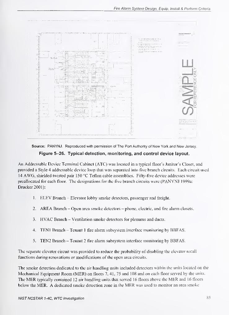
Fire Alarm System Design, Equip, Install & Perform Criteria
1
Source: PANYNJ. Reproduced with permission of The Port Authority of New York and New Jersey.
Figure 5-26. Typical detection, monitoring, and control device layout.
An Addressable Device Terminal Cabinet (ATC) was located in a typical floor's Janitor's Closet, and
provided a Style 4 addressable device loop that was separated into five branch circuits. Each circuit used
14 AWG, shielded twisted pair 150 °C Teflon cable assemblies. Fifty-five device addresses were
preallocated for each floor. The designations for the five branch circuits were (PANYNJ 1999a;
Drucker 2001):
1 . ELEV Branch - Elevator lobby smoke detectors, passenger and freight.
2. AREA Branch - Open area smoke detectors - phone, electric, and fire alarm closets.
3. HVAC Branch - Ventilation smoke detectors for plenums and ducts.
4. TENl Branch - Tenant 1 fire alarni subsystem interface monitoring by BBFAS.
5. TEN2 Branch - Tenant 2 fire alarm subsystem interface monitoring by BBFAS.
The separate elevator circuit was provided to reduce the probability of disabling the elevator recall
functions during renovations or modifications of the open area circuits.
The smoke detection dedicated to the air handling units included detectors within the units located on the
Mechanical Equipment Room (MER) on floors 7, 41, 75 and 108 and on each floor served by the units.
The MER typically contained 12 air handling units that served 16 floors above the MER and 16 floors
below the MER. A dedicated smoke detection zone in the MER was used to monitor an area smoke
NISTNCSTAR 1-4C, WTC Investigation 85
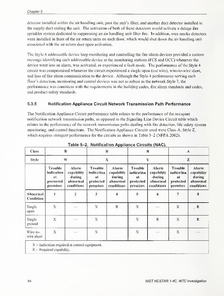
Chapter 5
detector installed within the air handling unit, past the unit's filter, and another duct detector installed in
the supply duct exiting the unit. The activation of both of these detectors would activate a deluge fire
sprinkler system dedicated to suppressing an air handling unit filter fire. In addition, area smoke detectors
were installed in front of the air return units on each floor, which would shut down the air handling unit
associated with the air return duct upon activation.
The Style 4 addressable device loop monitoring and controlling the fire alarm devices provided a custom
message identifying each addressable device at the monitoring stations (PCS and OCC) whenever the
device went into an alann, was activated, or experienced a fault mode. The performance of the Style 4
circuit was compromised whenever the circuit experienced a single open (cut wire), wire-to-wire short,
and loss of fire alarm communication to the device. Although the Style 4 performance serving each
floor's detection, monitoring and control devices was not as robust as the network Style 7, the
performance was consistent with the requirements in the building codes, flre alarm standards and codes,
and product safety standards.
5.3.5 Notification Appliance Circuit Network Transmission Path Performance
The Notification Appliance Circuit performance table relates to the performance of the occupant
notification network transmission paths, as opposed to the Signaling Line Device Circuit table which
relates to the performance of the network transmission paths dealing with fire detection, life safety system
monitoring, and control functions. The Notification Appliance Circuits used were Class A, Style Z,
which requires stringent perfonnance for the circuits as shown in Table 5-2 (NFPA 2002).
Table 5-2. Notification Appliance Circuits (NAC).
Class B B B A
Stjie X Y Z
Trouble
indication
at
protected
premises
Alarmcapability'
during
abnormal
conditions
Trouble
indication
at
protected
premises
Alarmcapability
during
abnormal
conditions
Trouble
indication
at
protected
premises
Alarmcapability
during
abnormal
conditions
Trouble
indication
at
protected
premises
Alarmcapability
during
abnormal
conditions
AbnormalCondition
1 2 3 4 5 6 7 8
Single
open
X X R X X R
Single
ground
X X X R X R
Wire-to-
wire short
X X X X
X = Indication required at control equipment.
R = Required capability.
86 NISTNCSTAR 1-4C, WTC Investigation
Fire Alarm System Design, Equip, Install & Perform Criteria
5.3.6 Notification Appliance Circuit Network Transmission Path Design, Installation,
and Control
The EVAC speakers and strobes were manually controllable and operable at the PCS or the OCC,depending on which station had operational rights to the system. The control equipment consisted of a
microphone and switches for turning on individual audio and visual notification zones, or the all-call
capability to broadcast on all speaker zones. The speaker and strobe zones were segregated by floor and
also grouped by elevator zones. The elevator speaker grouping provided a switch that would activate the
floors served by the low zone of elevators serving floors 9 through 40; a separate switch would activate
the floors served by the mid zone of elevators serving floors 44 through 74; and a third elevator group
switch would activate the floors served by the high zone of elevators serving floors 78 through 107. In
addition, the stairways were on a separate speaker zone, controlled by a switch (PANYNJ 1999a;
Drucker 2001; Drucker 2004).
The switches also allowed the voice message to include an alarm tone associated with evacuation or an
alert tone. Both tones would be a preamble to an advisory voice message when the microphone was
activated. In addition, there was a switch to use a floor warden or firefighter telephone as a remote
microphone to broadcast a voice message over selected or all zones. The status of all of these functions
was visually displayed via indicator lamps. The visual display, and a distinct audible tone, also provided
an indication if a specific zone or fianction was experiencing a technical fault that would affect its
performance.
The fire alarm system's audio notification network transmission paths consisted of two separate circuits
that provided two channels for emergency voice and alarm communication (see Figs. 5-27 and 5-28).
The separate channels allowed the operator to broadcast separate messages or tones simultaneously. The
intent was to be able to provide instructions for evacuation to the fire floor while simultaneously alerting
the occupants of adjacent floors to stand by for further instructions.
The fire alarm system's emergency voice communication messages were transmitted on a network path to
all the MXL-VR and PSR panels containing amplifiers and their associate speaker circuits (see
Fig. 5-27). The intent of the Style Z notification appliance circuit network design and installation was to
provide enhanced network integrity and reliability through a loop wiring topology configuration that
provided separate network communication path risers (primary and secondary) installed in two different
locations (fire alarm closet and stairway "C"). The network was designed with #14 AWG Teflon cables
(twisted pair 600 V, 200 °C). The perfomiance characteristics of the Style Z network allowed continued
service if the circuit experienced a single circuit fault, such as a cut wire, or grounding of a wire on any
section of the network. But, the network would not provide continued service if it were to experience a
wire-to-wire short.
As with the other communication network paths, the Port Authority specified stringent performance
criteria for the notification appliance circuit network communication paths (Class A, Style Z) and
installed the network cable and hardware in a manner that would enhance survivability and endurance
from the risk of fire and physical damage. The notification appliance riser consisted of two Teflon
sheathed cables rated at 200 °C, each containing a shielded twisted pair of wires. The cables were
installed in rigid conduit between the distributed amplifier panels (see Fig. 5-28). In addition to these
stringent criteria for cable and hardware survivability, the separation of the risers provided physical
protection of the network circuits from any localized fire or physical damage. The intent of the design
NISTNCSTAR 1-4C, WTC Investigation 87
Chapter 5
criteria was to provide enhanced survivability through: robust circuit performance, cable and hardware
with enhanced protection characteristics, and the physical separation of the risers. At the time of
installation, these criteria exceeded all applicable code required survivability and endurance
characteristics for fire alarm systems within high-rise buildings.
TOWER 1 TOWER 2
TYPICAL LOOP -INCLUDES EIGHTPSR AMPLIFIERPANELS
MXL-VR
PSR
AMP
PSR
AMP
PSR
AMP
I
PSR
AMP
MXL-VR
MXL-VR
-TOWER 1 PCS
TOWER 1
FCSTOWER 2 CONCOURSE SUBGRADERFCS RFCS RFCS
MXL-VR
MXL-VR
TYPICAL LOOP ^INCLUDES EIGHTPSR AMPLIFIERPANELS
PSR !
AMP
PSR:
AMPi
i
PSR1
AMP
PSR
AMPI
MXL-VR
TOWER 2 FCS
TOWER 2 CONCOURSE SUBGRADEFCS FCS FCS
TQWER 2 CONCOURSE SUBGRADERFCS RFCS RFCS
MXL-VR
JL ^Source: Reproduced with permission of The Port Authority of New York and New Jersey.
Figure 5-27. Single-line schematic of notification appliance network.
88 NISTNCSTAR 1-4C, WTC Investigation
Fire Alarm System Design, Equip, Install & Perform Criteria
110th FLOOR
85th FLOOR
84th FLOOR
83rd FLOOR
82nd FLOOR
81st FLOOR
80th FLOOR
79th FLOOR
78th FLOOR
77th FLOOR
75/76th FLOOR
74th FLOOR
XNET
65th FLOOR
64th FLOOR
63rd FLOOR
62nd FLOOR
61st FLOOR
60th FLOOR
4th FLOOR
3rd FLOOR
2nd FLOOR
1st FLOOR
B1 LEVEL
B2 LEVEL
B3 LEVEL_ _
84 LEVEL
85 LEVEL
86 LEVEL
XNET
MNET
AUDIOA/OICE
Source: Reproduced with permission of The Port Authority of New York and New Jersey.
Figure 5-28. Locations of audible notification appliance network equipment.
NIST NCSTAR 1-4C, WTC Investigation 89
Chapter 5
5.3.7 Typical Speaker Notification Appliance Devices
The Siemens Pyrotronics devices used for audio notification included (PANYNJ 1999a; PANYNJ 1999b;
Drucker2001):
• Ceiling mounted round speakers, 70 V (SPK-9070)
• Wall mounted square speakers, 70 V (SPK-7070)
. • Wall mounted speakers, 25/70 V (SPK- 1070)
• Wall mounted speakers, 70 V, with 24 V 1 5/75 cd strobe (SS70- 1 5/75)
The Port Authority performed an in-depth analysis on speaker intelligibility and audibility for the WTC(Drucker 2001). The intent of the analysis was to develop a speaker location guideline that would ensure
an acceptable level of intelligibility (message clarity) and audibility (loud enough to be heard.).
The audible alarni requirements were based upon the American with Disabilities Act and NFPArequirement for the alann signal to maintain a 15 dBA sound pressure level above the average ambient
sound level measured 5 ft above the floor in the occupied area (NFPA 2002). To establish the ambient
sound level, the Port Authority conducted an extensive sound level surv'cy to establish a baseline for
design. Testing results indicated that the average ambient sound level in office areas and in occupied
corridor areas was 55 dBA and 60 dBA, respectively. Based upon computations for sound loss and
reverberation (echo effect), a standard was established that the distance between speakers would not
exceed 40 ft.
A TSC was located in a typical floor's Sprinkler Closet or Fire Alarm Closet, and provided four Style Zspeaker circuits. The speaker circuits were designated SPK -A, B, C, D, and a single stairway circuit
designated SPK-E was provided for the three stairways, typically every four to five floors. Each circuit
used as a minimuml4 AWG, shielded twisted pair 150 °C Teflon cable assemblies. Each circuit was
rated for a maximum load of 25 W at 70.7 VRMS, with a maximum combined load of 25 W for all four
circuits. The three stairways each had a dedicated speaker circuit with a speaker installed every four to
five floors.
Enhanced sur\'ivability was incorporated through counter-rotating interleaved speaker circuits (see
Fig. 5-29). This approach required alternating speakers to be serviced by separate circuits. The intent
was to insure that a loss of a single circuit would not cause the complete loss of audible signals within the
area. This concept exceeded building code requirements.
90 NISTNCSTAR 1-4C, WTC Investigation
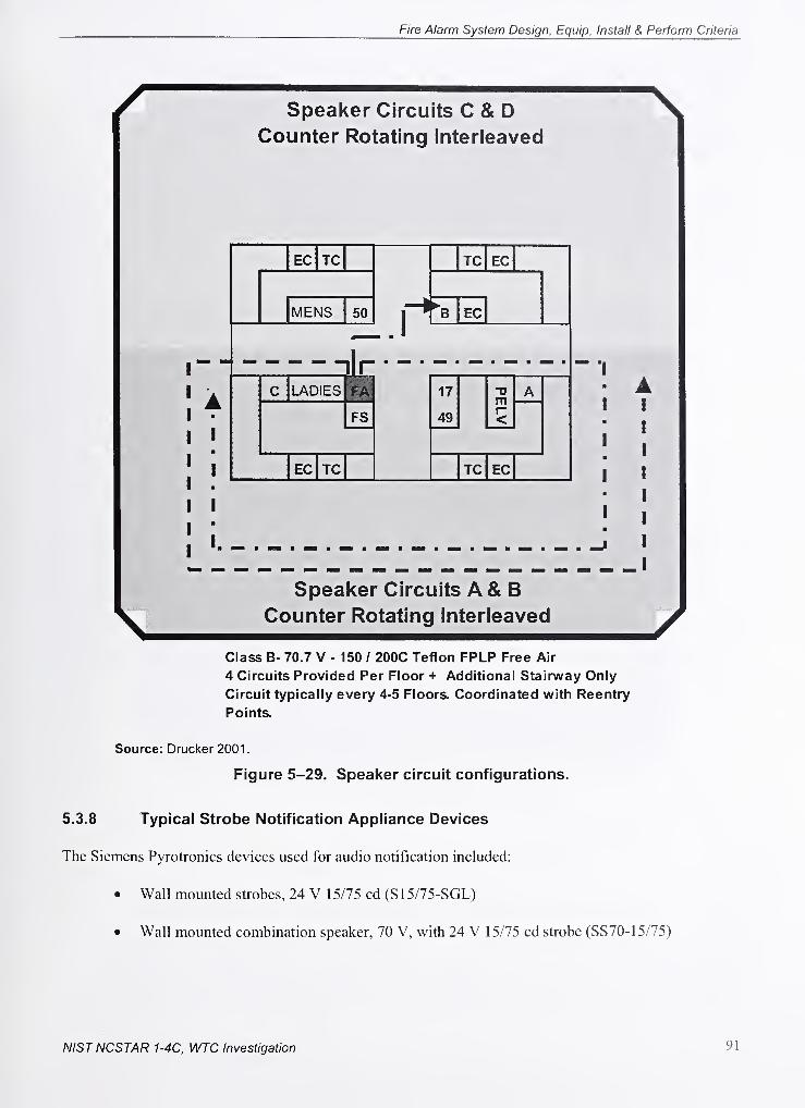
Fire Alarm System Design, Equip, Install & Perform Criteria
Speaker Circuits C & DCounter Rotating Interleaved
EC TC TC EC
MENS 50 EC
1
illmm
c LADIES FA 17PELV
A
FS 49
EC TC TC EC
Speaker Circuits A & BCounter Rotating Interleaved
Class B- 70.7 V - 150 / 200C Teflon FPLP Free Air
4 Circuits Provided Per Floor + Additional Stairway Only
Circuit typically every 4-5 Floors. Coordinated with Reentry
Points.
Source: Drucker 2001.
Figure 5-29. Speaker circuit configurations.
5.3.8 Typical Strobe Notification Appliance Devices
The Siemens Pyrotronics devices used for audio notification included:
• Wall mounted strobes, 24 V 15/75 cd (S15/75-SGL)
• Wall mounted combination speaker, 70 V, with 24 V 15/75 cd strobe (SS70- 15/75)
NISTNCSTAR 1-4C, WTC Investigation 91
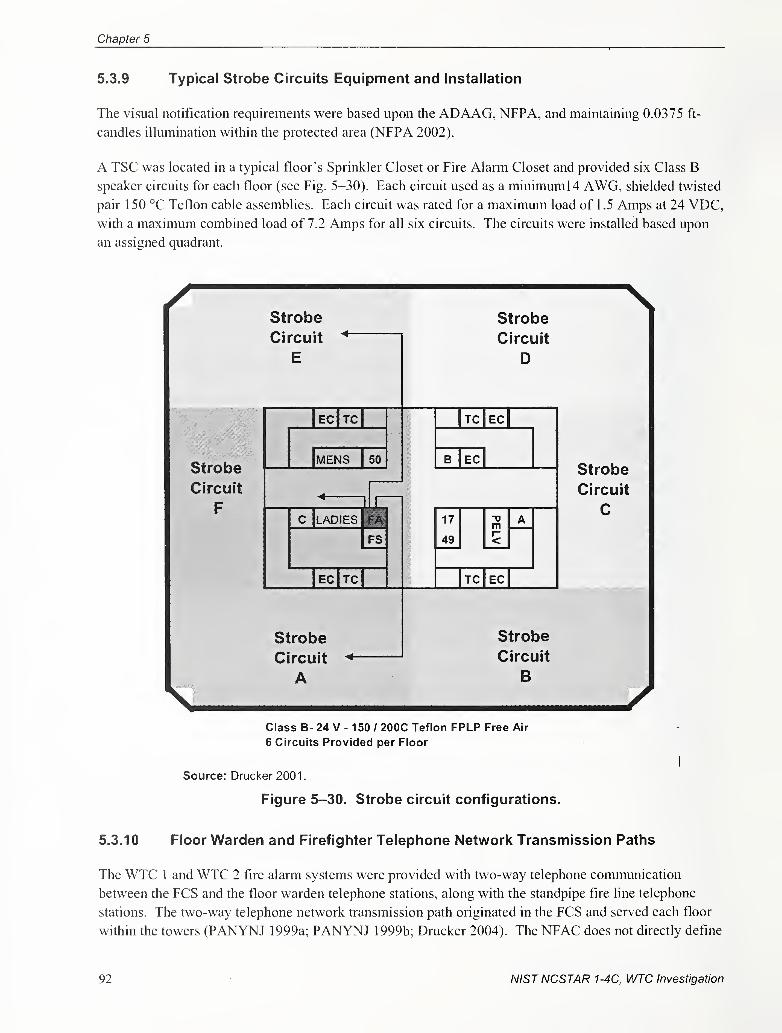
Chapter 5
5.3.9 Typical Strobe Circuits Equipment and installation
The visual notification requirements were based upon the ADAAG, NFPA, and maintaining 0.0375 ft-
candles illumination within the protected area (NFPA 2002).
A TSC was located in a typical floor's Sprinkler Closet or Fire Alarm Closet and provided six Class B
speaker circuits for each floor (see Fig. 5-30). Each circuit used as a minimuml4 AWG, shielded twisted
pair 150 °C Teflon cable assemblies. Each circuit was rated for a maximum load of 1 .5 Amps at 24 VDC,with a maximum combined load of 7.2 Amps for all six circuits. The circuits were installed based upon
an assigned quadrant.
Strobe
Circuit
F
Strobe
Circuit ^
E
ec|tc|
MENS 150
0 LADIES FA
FS
ecItcI
Strobe
Circuit
A
Strobe
Circuit
D
TC EC
B EC
17
49
-a
r-<
A
TO EC
Strobe
Circuit
C
Strobe
Circuit
B
Class B- 24 V - 150 / 200C Teflon FPLP Free Air
6 Circuits Provided per Floor
Source: Drucker 2001.
Figure 5-30. Strobe circuit configurations.
5.3.10 Floor Warden and Firefighter Telephone Network Transmission Paths
The WTC 1 and WTC 2 fire alarm systems were provided with two-way telephone communication
between the FCS and the floor warden telephone stations, along with the standpipe fire line telephone
stations. The two-way telephone network transmission path originated in the FCS and served each floor
within the towers (PANYNJ 1999a; PANYNJ 1999b; Drucker 2004). The NFAC does not directly define
92 NISTNCSTAR 1-4C, WTC Investigation
Fire Alarm System Design, Equip, Install & Perform Criteria
the two-way telephone circuit performance. The NFAC telephone performance requirements dcimc ilic
number of units that can simultaneously operate and the control parameters for their use. The ability of
the telephone network transmission circuit to indicate an abnormal condition was not dictated by the
NFAC. Neither the building codes nor the present ULI testing standards defines the performance of the
telephone circuit. This abnormal condition monitoring of a single wire-to-wire fault, single open circuit,
or single ground fault for telephone/intercom signaling circuits is scheduled to be a Underwriter
Laboratory Inc. testing standard requirement effective October 1, 2005. The two-way telephone
communication circuits serving WTC 1 and WTC 2 did have this circuit monitoring capability, which
provided a visible and audible indication whenever the circuit experienced an open, short, or ground.
This circuit monitoring capability exceeded codes and testing standards.
5.3.11 Floor Warden and Firefighter Telephone Network Transmission Path Design,
Installation, and Control
The fire alarni system's floor warden and firefighter telephone transmissions were carried on a single,
dedicated telephone network communication path to all the MXL-VR and PSR panels that served the
telephones within each tower (see Figs. 5-31 and 5-32). The telephone network consisted of a single pair
of #14 AWG Teflon cables (twisted pair 600 V, 200 °C). The single pair of wires did not have the
enhanced survivability characteristics associated with the Class A, Style 7 Signaling Line Circuit or
Class A, Style Z Notification Appliance Circuit. The Class B, Style Y circuit performance allowed a
single open (cut wire) or wire-to-wire short to disrupt service between the head-end MXL-V panel and
beyond where the wire fault occuired.
Although the circuit performance for the telephones was not as robust as the Signaling Line Circuits and
Notification Appliance Circuit Networks, the telephone circuit's performance contained survivability
capabilities that exceeded performance requirements for fire alarm systems. The applicable building
codes, fire alarm codes, and testing standards did not require the telephone circuits to have the
performance monitoring and survivability characteristics, inherent to the telephone circuits. The
manufacturer provided the enhanced performance characteristics and the Port Authority selected to utilize
the system for their floor warden and firefighter telephone communication needs.
NISTNCSTAR 1-4C, WTC Investigation 93
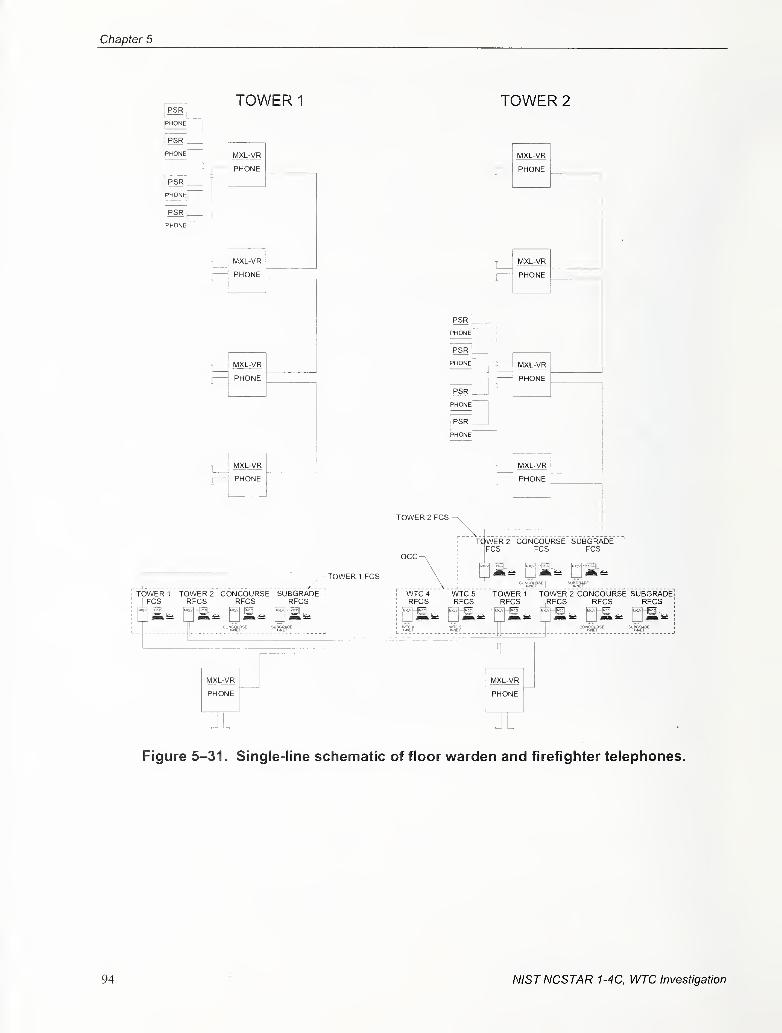
Chapter 5
PSR
phone"
PSR L
PHONEr
PSR _
phone"
PSR I
PHONEl
TOWER 1
MXL-VR
PHONE
MXL-VR
PHONE
PHONE
PHONE
TOWER 2
PHONE
PHONE
MXL-VR
MXL-VR
PHONE
TOWER 2 FCS
-TOWER 1 FCS
TCWER2 CONCOURSE SUBGRADEFCS FCS FCS
gs^ u^-^ ^M-^TOWER 1 TOWER 2 CONCOURSE SUBGRADE
FCS RFCS RFCS RFCS
MXLA/R
PHONE
WTC 4
RFCSWTC 5
RFCSTOWER 1 TOWER 2 CONCOURSE SUBGRADERFCS IRFCS RFCS RFCS
say ssf
MXL-VR
Figure 5-31 . Single-line schematic of floor warden and firefighter telephones.
94 NISTNCSTAR 1-4C, WTC Investigation
Fire Alarm System Design, Equip, Install & Perform Criteria
110th FLOOR
85th FLOOR
84th FLOOR
83rd FLOOR
82nd FLOOR
81st FLOOR
80th FLOOR
79th FLOOR
78th FLOOR
77th FLOOR
4th FLOOR
3rd FLOOR
2nd FLOOR
1st FLOOR
B1 LEVEL
B2 LEVEL
B3 LEVEL
B4 LEVEL
B5 LEVEL, .
B6 LEVEL
XNET
MNET
TELEPHONE
Figure 5-32. Locations floor warden and firefighter telephone network equipment.
NISTNCSTAR 1-4C, WTC Investigation 95
Chapter 5
5.3.12 Typical Floor Warden and Firefighter Telephone Devices
The Siemens Pyrotronics devices used for audio notification included:
• Flush wall mounted floor warden telephone station (FB-300)
• Surface wall mounted floor warden telephone station (FB-30 IS)
• Remote firefighters telephone station with armored cable (FT-301CL)
• Surface box for firefighter standpipe or maintenance jack (PUR17)
• Firefighters telephone jack (FJ-303)
• Portable firefighters telephone (PT-304)^
5.3.13 Floor Warden and Firefighter Telephone Station System Design andInstallation
The floor warden and firefighter telephone system consisted of the main telephone handset and controls
located at the FCS and OCC, remote firefighter telephone stations located within the stairways, and floor
wardens telephone stations located within the central cross-corridor on each floor. In addition to these
stations, a maintenance telephone station was provided at each of the MXL-VR panel locations for
maintenance personnel use (PANYNJ 1999a; PANYNJ 1999b; Drucker 2001; Drucker 2004).
The firefighter telephone station consisted of a connection point (jack) for a telephone handset. The
intent was to provide responding firefighters with a handset before they were dispatched to the fire
emergency. A call-in signal would be transmitted to the FCS whenever a handset was connected to the
jack located at the station. The signal would indicate which floor initiated the call. Permanent handsets
were not installed within the stairways. The jack connections were installed within metal boxes with
locks that could only be opened by a standard FDNY key.
The floor warden station consisted of a handset that would automatically initiate a call-in signal at the
FCS when the handset was removed from its cradle. The signal would indicate which floor had initiated
the call.
The maintenance telephone station consisted of a connection jack for a telephone handset. The MXL-VRmaintenance telephone station was connected to the same zone as the firefighter station. Separate zones
were not provided since the maintenance station would not be in use during a fire emergency. As with the
firefighter station, a call-in signal would be transmitted to the FCS whenever a handset was connected to
the jack at the station. The signal would indicate which floor initiated the call.
The head-end FCS telephone controls, with redundant controls at the OCC, consisted of a handset and
operator controls. The controls consisted of a push button switch and dual color light to indicate the
status of the telephone station. When a call was placed on a telephone zone, the light would flash, and an
audible tone would sound to indicate the telephone communication request. Once the operator selected
the call, the telephone circuit was patched into a "party line" mode where up to five telephone stations
could be on the line without loss of audio quality.
96 NISTNCSTAR 1-4C, WTC Investigation
Fire Alarm System Design, Equip, Install & Perform Criteria
5.4 MAINTENANCE PERFORMANCE STANDARD
Fire alarm system availability and perforaiance is dependant on four basic factors:
Equipment.
2 Design
3 Installation
4 Maintenance
Since the maintenance of the system affects of any system's life-cycle, its impact on the overall system
availability and perfonnance is a major consideration during the selection of equipment, design of the
system, and the installation of the equipment and devices. The documentation found suggests that
maintenance of the system was considered during system development and was carried out regularly after
the system was installed (PANYNJ 1984; PANYNJ 1986).
A team was contracted from Siemens Pyrotronics to perform fire alarm maintenance and repair functions
for the WTC. The maintenance procedures included scheduled testing of the fire alarm system's
detection, controls, communication, and notification capabilities. The testing was scheduled by area and
included all the fire alarm functions within the area. Before testing was performed, notices were posted
informing the occupants of the pending testing. Specific testing procedures were perfonned by specific
team members during the system test. The results of the testing were recorded for reference.
WTC 7 was built in 1985. It was located across Vesey Street from the main WTC complex. It was a steel
building which had forty-four floors. WTC 7 collapsed on September 11, 2001, roughly seven hours after
WTC 1 and WTC 2 collapsed.
The fire alarni system for WTC 7 appears to have been the original system installed when the building
was built (Syska 1984). Modifications were perfonned as needed to accommodate renovations and tenant
fit outs. Project development documentation found and analyzed has been limited to specifications, riser
diagrams, and a limited number of tenant fit out drawings that included fire alarm work. The design
criteria were based on the requirements set by the Basic Design Criteria revised November 5, 1984,
proposed by Syska & Hennessy, which reference the applicable local building codes at the time of
construction. The only performance criteria in the design criteria that exceeds the minimum requirement
was the statement requiring "All monitoring, communication and control for the fire alarm system shall
be on a separate muhiplex channel with its own processor" (S&K 1984). Based on the information
reviewed, the overall design and installation was consistent with the applicable code requirements.
Inspection, testing, and maintenance of the fire alarm system for WTC 7 was provided on a regular basis.
5.5 SYSTEM DESIGN AND INSTALLATION CRITERIA FOR WTC 7
NISTNCSTAR 1-4C, WTC Investigation 97
Chapter 5
5.5.1 System Arrangement
The baseline for defining the fire alann system's performance is derived from the specifications, which
referred to the applicable local building codes. The basic system was required to contain the following
components to monitor and annunciate the status of its devices and initiate an appropriate response
(Syska 1984):
1 . PCS located in the lobby of the building on the entrance floor.
2. Manual Fire Alarm Stations provided in each story along the path of escape with additional
stations installed so that the maximum travel distance between stations would not exceed
200 ft.
3. Speakers located on all floors, and stairways that could be operated in the PCS. The elevator
intercommunication system was provided separately.
4. Visual Alarm Devices (strobes) were provided in spaces used by people having physical
disabilities during more recent renovations. When the strobes were first introduced and what
areas contain strobes is unknown.
5. Floor Warden Stations on each floor that provided two-way communication with the FCS.
6. Standpipe Fire Line Telephone System with communication stations provided at FCS, each
floor near the standpipe riser, gravity tank rooms, and fire pump rooms.
7. Fire Sprinkler water flow alarm and malfunction monitoring.
8. Tenant fire alarm panels monitoring for alarm and system fault conditions.
9. Fan shutdown and restart system for smoke control.
10. Elevator recall upon its smoke detector activation.
1 1 . Fire stair door releases.
12. Smoke and heat detection
5.5.2 Design Approach
Documentation found consisted of modified riser as-built diagrams, and floor plans with fire alarm device
locations. Comprehensive as-built drawings for the system were not located.
The modified riser diagrams were conceptual in nature, and provided the installation contractor with the
number of devices installed on each floor, type of fire alarm equipment on each floor, and the number and
type of wire interconnecting the devices and equipment. The modified riser diagram had areas crossed
off, which was an indication that the area had undergone renovation. Additional renovation drawings
provided a section of the riser with its modifications. The final drawings consisted of the partially
98 NISTNCSTAR 1-4C, WTC Investigation
Fire Alarm System Design, Equip, Install & Perform Criteria
modified riser diagrams with areas crossed out, separate drawings containing a revised section ol the
riser, and floor plans with the locations of the devices on the designated floor.
It appears that the contractor was responsible for determining the final circuit configurations for the
devices and equipment based upon the drawings found.
5.5.3 Typical Fire Alarm Equipment and Device Locations
The documentation found provided limited infomiation on the specific location of the fire alarm control
equipment, initiating devices, and communication equipment (Syska 1984). The base fire alarm system
was a Firecom 8500 series fire alarm and voice communication system.
The Third Floor Lobby was found to be designated as the FCS. The FCS contained the Firecom 8500
Fire Command Center with printer and video monitor. On a typical floor, a system transponder/terminal
cabinet was provided for monitoring the manual pull stations located at each stair entrance and smoke
detectors in the electrical/telephone closets and elevator lobbies. Sprinkler water flow switch and valve
supervisory switch in each stairwell were also monitored by fire alarm transponder/terminal cabinets. In
addition, duct smoke detectors were installed in HVAC systems over 2,000 cfm and located at the main
supply duct and the return air duct and were monitored by the transponder/terminal cabinets. The fire
warden stations were installed separately on the north wall outside the elevator lobby.
5.5.4 Typical Fire Alarm Cabinet Connections
A mechanical room was located in the core area of each floor (Syska 1984). The south wall of the
mechanical room was the designated location for fire alarm transponder/tenninal cabinets, which
supported and distributed the system's monitoring, control, and communication circuits. The initiation
device circuits, speaker circuits, and the notification appliance circuits serving that floor were terminated
at the transponder/terminal cabinet at this location. Bulk amplification for the entire building was located
on the fifth floor and distributed through the transponder/terminal cabinets located on each floor.
Documentation was not located that provided a standard for the equipment or device connections.
5.5.5 Typical Fire Alarm Installation Detail
Drawings were not located that provided guidance on the installation of the devices to meet tolerances
required by code and the manufacture.
The riser diagrams indicate that the smoke detector, manual pull station, speaker and strobe circuits were
configured to be a Class B type (Syska 1984). The use of a Class B circuit was consistent with the
minimum requirements for performance, but did not have the higher level of surxavability capabilities
associated with a Class A circuit.
5.5.6 Fire Alarm Device Design Detail
Drawings were not located that provided design detail showing the number of wires required to run
between each device and between the device and equipment.
NISTNCSTAR 1-4C, WTC Investigation 99
Chapter 5
5.5.7 Fire Alarm Power Calculations
Fire alarni power calculations were not located that would document the capability of the fire alarm
equipment to power the number and type of devices connected to the equipment.
5.5.8 Quality and Performance Assurance Forms
Quality control documentation was not found for the installation.
5.5.9 Installation Acceptance Testing and Commissioning Procedures
Documentation was not found that documented the testing and commissioning procedures.
5.5.10 Inspection, Testing, and Maintenance
Inspection, testing and maintenance are mandated by the applicable building codes after a fire alarm
system is installed, and in commission.^ The building owner is responsible for inspection, testing, and
maintenance of the systems. This above work is permitted to be done by qualified and experienced
personnel.
It appears that the inspection, testing, and maintenance for WTC 7 was performed by an outside
contractor. The inspection, testing, and maintenance records were well-documented between 2000 and
2001.
5.6 COMPARISON OF WTC 7 FIRE ALARM SYSTEM TO WTC 1 AND WTC 2
FIRE ALARM SYSTEM
The fire alarm systems installed in WTC 1, 2, and 7 were consistent with the performance criteria as
adopted by the Port Authority, but there were significant differences in approach in meeting these
requirements. The development and implementation of the WTC 1 and WTC 2 alarm systems was
approached in a methodical way. The overall fire alarni goals were identified and systematic steps
developed and used for system design and installation. In comparison, documents available on the
WTC 7 fire alarm system indicate that the design development for the system did not follow the approach
used for WTC 1 and WTC 2. The WTC 7 fire alann design documents consisted of basic working
documents used by construction personnel for the equipment layout, which allowed the installation
contractor more leeway in determining what materials were used, where devices and equipment were
located, and how the system would ultimately perform. This approach does not indicate that the system
design or product was substandard, it only shows that the design, hardware, and equipment layout did not
follow the strict development requirements set forth by the Port Authority for WTC 1 and WTC 2. Nodocuments were found that would indicate that the WTC 7 fire alarm system were not consistent with the
performance standards required for the building.
The differences between the systems begin with the system goals. The WTC 1 and WTC 2 fire alarm
system criteria placed a strong emphasis on system survivability, which was not apparent in the WTC 7
Fire Service Incorporated, inspection and maintenance records for the WTC over the life of the building.
100 NISTNCSTAR 1-4C, WTC Investigation
Fire Alarm System Design, Equip, Install & Perform Criteria
system. The survivability enhancements present in the WTC 1 and WTC 2 systems that were not found
in the WTC 7 system included the distribution of the fire alarm intelligence, monitoring, and controls on
seven different levels. The WTC 7 fire alarm system did not use distributed intelligence. Also, the
WTC 1 and WTC 2 fire alarm systems required all fire alarm riser circuits to be installed in three separate
locations and within rigid conduit for additional physical protection. The WTC 7 fire alarm system
documents did not indicate that this was required for the WTC 7 system. The survival of the fire alarm
functions within WTC 1 and WTC 2 after impact can be directly attributed to these enhancements.
Another significant difference between the systems was the design development. Whereas the WTC 1
and WTC 2 systems had ''MANDATED Fire Alarm Guidelines" (WTC 1999) as the basis for the
installation of new equipment, there was no documentation available that indicated that the same controls
were developed for the WTC 7 system. The advantages gained from the use of adopted guidelines are
increased reliability and known performance through design and installation controls. This is especially
true for large systems that undergo frequent renovations, maintenance, and repairs.
The final major difference was the commissioning and acceptance controls. The WTC 1 and WTC 2 fire
alarm systems had comprehensive quality assurance procedures to maintain established perfonnance
levels for the fire alarm systems. The procedures included specific design, installation, and maintenance
requirements. An example of the controls was the verification of the voice loudspeaker system capability
to ensure fifty percent of the system remained operable on a floor if there was a loudspeaker circuit
failure. The WTC 1 and WTC 2 design criteria provided typical circuit diagrams, design documentation,
and quality assurance procedures to make sure this requirement was met. These strict quality controls
were implemented because it is extremely difficult without disabling the voice circuit to verify this
capability after the system is installed. The WTC 7 documentation does not indicate that this level of
quality assurance was performed. The maintenance of the records for these processes provided a baseline
for detennining performance levels at the time of acceptance in comparison to any future date. This
baseline is a major factor in maintaining system performance and availability.
The approach taken for the design, installation, and acceptance of the fire alarm system in WTC 7 was an
approach that is commonly taken for commercial high rise construction. The absence of design,
installation, and commissioning controls mentioned above does not indicate that common practices were
not used in the development and installation of the fire system. This comparison shows the differences
and enhanced measures that fire alarm system installation followed during its life-cycle to increase
performance and survivability.
NISTNCSTAR 1-4C, WTC Investigation 101

This page intentionally left blank.
NISTNCSTAR 1-4C, WTC Investigation
Chapter 6
Estimates of Performance of the Fire Alarm SystemON September 11, 2001
6.1 analysis development
Documenting the actual performance of the World Trade Center (WTC) 1 and WTC 2 fire alarm systems
was significantly hampered by the loss of all historic documentation stored within the buildings and the
loss of electronic files that were generated by the fire alarm system during the events of September 11,
2001. The analysis of the fire alarm's performance was limited to brief images of illuminated status
lamps on the fire alarm system's panels located in the WTC 1 Fire Command Station (FCS), which were
filmed by Goldfish Pictures during the event in 2001. Additional information was provided through
interviews by National Institute of Standards and Technology (NIST) which provided information from
interviews of individuals in the buildings, or in contact with people in the building during the event. The
former project manager for the fire alarm installation in WTC 1 and WTC 2 was instrumental in
clarifying system architecture nuances.
The performance of the WTC 7 fire alarm system was limited to the printout of the remote monitoring of
the fire alarm system's alarm and condition status. The printout indicates that the system registered an
alarm at 10:00 a.m."* No other information has been found on the performance of the system during the
event.
The review of the WTC 1 and WTC 2 fire alarm system performance indicated that the systems did work,
but not all fiinctions performed as intended. The factors that directly influenced the performance were
which building experienced the alarm condition, WTC 1 or WTC 2, and the location of the fire alarm
function in relation to the impact damage in the building.
As a baseline for understanding, the first plane impacted WTC 1 at 8:46 a.m., and floors 93 through 99
experienced extensive, immediate impact damage. The second plane impacted WTC 2 at 9:03 a.m., and
floors 77 through 85 experienced extensive, immediate impact damage. The following provides
observations of the fire alarm perfomiance based upon the interviews and film documentation.
WTC 1 Interviews - NIST interviews of survivors often included discussion of whether the occupant
heard or did not hear various alarm system functions during their evacuation (NIST NCSTAR 1-7"^). The
WTC 1 interviews provided the following observations on the fire alarm functions:
• There was no confirmation that audible fire alarms were broadcast above the floors of impact.
Letter from Richard Kleinman, President, AFA Protective Systems, dated July 16, 2003, based on a request by NIST.
^ This reference is to one of the companion documents from this Investigation. A list of these documents appears in the Preface
6.2 OBSERVATIONS
to this report.
NIST NCSTAR 1-4C, WTC Investigation 103
Chapter 6
• There was no confirmation that the emergency voice communication system functioned on any
floor within WTC 1 after the impact.
• Confimiation was provided that alarm tones (not voice messages) were heard on the floors below
impact.^ Fourteen percent of occupants in WTC 1 and 1 1 percent in WTC 2 reported hearing
alarm tones in the building (NIST NCSTAR 1-7).
• There was no confirmation that the floor warden or firefighter telephone system functioned after
impact.
WTC 1 Film Observations- The Goldfish Picture video provided brief images of the fire alarm visual
status indicators, along with a timeline to reference the observations. Although the images were limited,
the following provides a timeline of the observations:
• 8:59 a.m. - The WTC 1 Fire alarm panel general alarm visual indication and system fault
visual indications are illuminated. Speaker zones 84 and 89 also indicate that they are in a
fault condition. The majority of speaker zone lamps on the WTC 1 fire alarai panel are
illuminated solid red, which indicates that the speaker zones illuminated are in use. Floors 1
through 84 appear to have their zones illuminated, which indicates activated speakers. The
exact floors may not be correct because the analysis of the visual indicators was from the
personal memory of the fire alann project manager and was not in comparison with as-built
documentation (Drucker 2004). It is not known if a voice command, or an alarm tone was
broadcast over the activated speaker zones. It is not known if all speaker zones were
activated, but the interview transcripts indicate that no alarm tones or voice messages were
heard above the floors of impact.
• 9:06 a.m. - The alarm slow whoop tone was heard in the lobby.
• 9:58 a.m. - The visual indicators on the Concourse and Sub-Grade fire alarm panels indicate
that they are in alarm and their notification appliances have been silenced.
• 9:59 a.m. - WTC 2 collapsed, and all video of the fire alarm panels ceased.
WTC 2 911 Call Recordings - 911 calls from WTC 2 provided the following observations on the fire
alarm functions:
• Confirmation was provided that voice messages and alarm tones were broadcast before and
after the impact, and were heard above the impact floors.^
^ NIST Interview data set 2004 and New York City 91 1 Emergency Call Recording, 2001.
' New York City 91 1 Emergency Call Recordings, 2001
.
104 NIST NCSTAR 1-4C, WTC Investigation
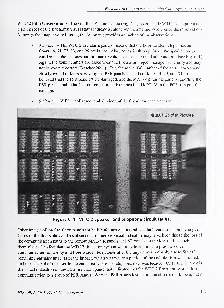
Estimates of Performance of the Fire Alarm System on 9/11/01
WTC 2 Film Observations- The Goldfish Pictures video (Fig. 6-1) taken inside WTC 1 also provided
brief images of the fire alami visual status indicators, along with a timeline to reference the observations.
Although the images were limited, the following provides a timeline of the observations:
• 9:58 a.m. - The WTC 2 fire alarm panels indicate that the floor warden telephones on
floors 64, 71, 73, 93, and 99 are in use. Also, zones 76 through 84 on the speaker zones,
warden telephone zones and fireman telephones zones are in a fault condition (see Fig. 6-1 ).
Again, the zone numbers are based upon the fire alarm project manager's memory and may
not be exactly correct (Drucker 2004). But, the sequential number of the zones correspond
closely with the floors served by the PSR panels located on floors 74, 79, and 83. It is
beheved that the PSR panels were damaged, and the MXL-VR remote panel supporting the
PSR panels maintained communication with the head-end MXL-V in the FCS to report the
damage.
• 9:59 a.m. - WTC 2 collapsed, and all video of the fire alarm panels ceased.
Figure 6-1. WTC 2 speaker and telephone circuit faults.
Other images of the fire alarm panels for both buildings did not indicate fault conditions on the impact
floors or the floors above. This absence of numerous visual indicators may have been due to the loss of
the communication paths to the remote MXL-VR panels, or PSR panels, or the loss of the panels
themselves. The fact that the WTC 2 fire alarm system was able to continue to provide voice
communication capability and floor warden telephones after the impact was probably due to Stair C
remaining partially intact after the impact, which was where a portion of the audible riser was located,
and the survival of the riser in the core area where the telephone riser was located. Of further interest is
the visual indication on the FCS fire alarm panel that indicated that the WTC 2 fire alarm system lost
communication to a group of PSR panels. Why the PSR panels lost communication is not known, but it
NISTNCSTAR 1-4C, WTC Investigation 105
Chapter 6
would be reasonable to expect physical damage to the circuits. If the MNET circuits were damaged
beyond use, survival of the audible circuits is difficult to explain. The audible circuit did survive since
some occupants did hear voice announcements. The perfonnance of other system functions and
components within the system were not verifiable without the recovery of records lost with the buildings.
6.2.1 Summary of Results
The analysis of the fire alarm systems performance has led to the following results:
• Remote monitoring of the WTC 7 fire alarni systems only provided a time and date of the
alarm condition (see Fig. 6-2)''.
• The WTC 1 and WTC 2 fire alarm system required manual activation of the alarm signal to
notify building occupants. This signal was delayed by 12 minutes after the impact in WTC 1.
• Although there is evidence that the floor warden telephones were used, the after action
interviews of the firefighters conducted by NIST did not find that there was any attempt to
use the firefighter telephone system. This is not uncommon since the firefighters are trained
to use their radios as the preferred means of communication.
• Although the fire alarni systems in WTC 1 and WTC 2 used multiple communication path
risers, the systems experienced performance degradation, especially in WTC 1 where all fire
alarm notification and communication functions appears to have been lost above the floors of
impact.
106 NISTNCSTAR 1-4C, WTC Investigation
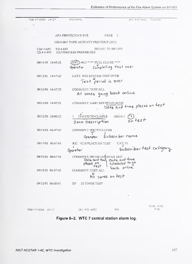
Estimates of Performance of the Fire Alarm System on 9/11/01
F£S-i?-«084 14:37 NIST-'KFkL jwi f.^i/isi
AFA PROTECTIVE SYS PAGE 1
HISTORY TAPE ACTIVITY PRINTOUT (221)
CS^? 4-653 TO 4-653 09/1 1/01 TO 09/1 1/01
CS # 4-653 SILVERSTSIN PROPERTIES
09/1 1/01 14:48:22 Q^XO ****'''l^^'^-
^^-^'^^ ****
09/n/Ol 14:47:22 LATE 3923 SYSTEM TEST OVER^ v!/
09/11/01 14:47:22 COMMENT: TEST:ALL
Aif zones JoiVi^ bacK onl;o£. .
09/11/01 14:47:21 COMMENT: LAST SET:Q91 ! 01 64742 I J-
09/11/01 10:00:52 1 lI'lO CO TO CLA<js £ AREA:1 Q)
09/11/01 06:47:43 COMMENT: RJC:WILLIAMS
09/11/01 06:47:43 RIC 4210 PLACE ON TEST CAT: 1
1
09/11/01 05:47:43 COMMENT: 091 10! 647(o91 101 1447 -
Oo4e and -hWA DaW. (X^vc) -nw\e
09/11/01 06:47:42 COMMENT: TEST:AU
09/11/01 06:05:01 R? 20 TIMER TEST
TOTAL P. Si
FEB-i7-2804 15:1.7 381 975 4352 38^. P-Bl
Figure 6-2. WTC 7 central station alarm log.
NISTNCSTAR 1-4C, WTC Investigation 107

Chapter 6
This page intentionally left blank.
v
108 NISTNCSTAR 1-4C, WTC Investigation
Chapter 7
References
Boyle, R. 1999. The Port Authority ofNew York and New Jersey, New York, NY, personal
communication to All Commissioners, WTC fire alann system tenant design requirements - adoption
of best industry practices. May 11.
Buchsbaum, J., and J. Mizrahi. 1994. Retrofitting the World Trade Center Fire Alarm System. The Port
Authority ofNew York and New Jersey. New York, NY, November.
DiChiara, R. 1993. The Port Authority ofNew York and New Jersey, New York, NY, personal
communication to T. Cancelliere, R. Cronin, C. Maikish, A. Reiss, and G. Rossi, Subgrade fire and
life safety enhancements - assignment of responsibilities. December 30.
Drucker, J. 2001. Presentation on the World Trade Center Fire Alarm System. Siemens Building
Technologies.
Drucker, J. 2001. Remembering the World Trade Center. October.
Drucker, J. 2004. Personal Communications.
Isner, M., and T. J. Klem. 1993. World Trade Center Explosion and Fire. National Fire Protection
Association. February 26.
Manning, W. The World Trade Center Bombing: Report and Analysis. Fire Engineering.
Marchese, P. 1993. The Port Authority ofNew York and New Jersey, New York, NY, personal
communication to E. Ramabhushanam, WTC - New WTC fire alarm system. July 2 1
.
McGuire, J.H., and B. E. Ruscoe. 1962. The Value ofa Fire Detector in the Home, National Research
Council of Canada, Fire Study No. 9 of the Division of Building Research, Ottawa, Canada.
Merritt & Harris, Inc. 2000. Property Condition Assessment of World Trade Center Portfolio.
Property #1. New York, NY, December 6.
Merritt & Harris, Inc. 2000. Property Condition Assessment of World Trade Center Portfolio.
Property #2. New York, NY, December 6.
Mizrahi, J. The World Trade Center Fire Alarm System Before & After. PANYNJ (The Port Authority of
New York and New Jersey).
Monti, R. M. 1979. Personal communication to G. F. Tozzoli, World Trade Department, WTC -
Towers A & B - fire safety program. February 5.
National Fire Protection Association (NFPA). 2002. NFPA 72, National Fire Alarm Code.
NISTNCSTAR 1-4C, WTC Investigation 109
Chapter 7
PACO Group, Inc. and Flack & Kurtz, Inc. 2002. Final Preliminary Report - General Description ofAll
Building Systems and the Capital Program. January 14.
PANYNJ (The Port Authority ofNew York and New Jersey). 2002. World Trade Center Fire Safety
Plan. New York, NY, November.
PANYNJ (The Port Authority ofNew York and New Jersey). 2000. The World Trade Center, New Fire
Alarm System Increase in Project Authorization. New York, NY. July 27.
PANYNJ (The Port Authority ofNew York and New Jersey). 1999a. World Trade Center, Base Building
Fire Alarm System. March 1.
PANYNJ (The Port Authority ofNew York and New Jersey). 1999b. World Trade Center - Code
Compliance Evaluation, New York, NY October 15.
PANYNJ (The Port Authority ofNew York and New Jersey). 1998. Design Guidelines, Specifications
and Standard Details Program. New York, NY, May 1 1.
PANYNJ (The Port Authority ofNew York and New Jersey). 1997. Tenant Construction Review Manual.
New York, NY, March.
PANYNJ (The Port Authority ofNew York and New Jersey). 1988. Fire Safety Plan for 7 World Trade
Center. April 18.
PANYNJ (The Port Authority ofNew York and New Jersey). 1986. World Trade Center Instruction
Manual No. 23, Operation and Maintenance ofFire Protection System. New York, NY, February.
PANYNJ (The Port Authority ofNew York and New Jersey). 1984. Fire Communications and Alarm
Systemfor Fire and Life Safety. October 22.
PANYNJ (The Port Authority ofNew York and New Jersey). 1984. Intercommunication System.
October 22.
PANYNJ (The Port Authority ofNew York and New Jersey). 1984. Power, Control and Alarm Wiring
Systems. October 22.
PANYNJ (The Port Authority ofNew York and New Jersey). 1979. Egress Facilities Serving the'WTC
Concourse A Re-Analysis, Considering Current Occupancy. December.
PANYNJ (The Port Authority ofNew York and New Jersey). 1971. Tenant Construction Review. NewYork, NY.
PANYNJ (The Port Authority ofNew York and New Jersey). New Fire Alarm System, Increase in
Project Authorization. July 27.
PANYNJ (The Port Authority ofNew York and New Jersey). Personal communication to R. Jensen,
Largo, FL, WTC Report Update Project - N10140.07. December 4.
110 NISTNCSTAR 1-4C. WTC Investigation
References
PANYNJ (The Port Authority ofNew York and New Jersey). System Narrative for Fire Alarm and
Communication Systemsfor the World Trade Center.
PANYNJ (The Port Authority ofNew York and New Jersey). Section 16910 - Fire Alarm Speaker,
Strobe andALD Loop, Field Testing of Wiring.
PANYNJ (The Port Authority ofNew York and New Jersey). Chapter 4 - Fire Alarm System.
PANYNJ (The Port Authority ofNew York and New Jersey). WTC - Changes to Evacuation Svstems
After 1993.
Reiss, A. 1993. World Trade Center, New York, NY, personal communication to J. McCormick, Rolf
Jensen & Associates, Inc., Springfield, NJ, Enclosing copy of specifications and system narrative for
the new Pyrotronics Fire Alarm System, WTC Tenant Guidelines dealing with firestopping, and WTCstandard detail drawings. August 3.
Rivera C, and R. Rinaldi. 1993. The City ofNew York Fire Department, Brooklyn, NY, personal
communication to D. Dinkins, Mayor, New York, NY, Fire and Building Codes and the Jurisdiction
and Compliance of Federal, State, State Authorities and Foreign Government Buildings report.
March 25.
Rohlfing, T. 1993. The City ofNew York Fire Department, Brooklyn, NY, personal communication to J.
Commiskey, World Trade Center - PA, New York, NY, Comments from our electrical unit. July 13.
Rolf Jensen & Associates, Inc. (RJA). 2003. World Trade Center Investigation - Task 2A - WTCTowers 1 & 2 Fire Protection Summary. October 22.
SafirRosetti Omnicom Group, Inc. 2002. Expert Report ofHoward Safir. August 1.
Sbarra, V. 1993. Gage-Babcock & Associates, Inc., New York, NY, personal communication to Keenan,
D., Hamond & Regine, Mineola, LI, New York, Port Authority ofNY & NJ Loss Control Report -
World Trade Center Complex. April 27.
Semah, C. 1996. The Port Authority ofNew York and New Jersey, New York, NY, personal
communication to A. Reiss, WTC F.A. system - system features and capabilities. October 1.
Sileo, M. 1987. World Trade Center, New York, NY, personal communication to All Two World Trade
Center Tenants on Floors 17 through 26, New York, NY, The World Trade Center fire alarm system.
August 18.
Syska & Hennessy. 1984. Basic Design Schematicfor 7 World Trade Center. November 5.
Visconti, R. 1993. The City ofNew York Department of Buildings, New York, NY, personal
communication to unknown distribution. Existing Approved Class E and Modified Class E fire alarm
systems: extension ofA and B speaker circuits in heu of speaker supervision in existing high-rise
office buildings. February 26.
NISTNCSTAR 1-4C, WTC Investigation 111
Chapter 7
Visconti, R. 1994. The City ofNew York Department of Buildings, New York, NY, personal
communication to M. Jachniewicz, Material and Equipment Acceptance Division, Fire alarm wiring.
October 3. ,, ,,
Visconti, R. 1995. The City ofNew York Department of Buildings, New York, NY, personal
communication to unknown distribution, "Grace Period" for the use of fluoropolymer "Teflon
Equivalent" cables previously accepted by the department. May 9.
Visconti, R. 1995. The City of New York Department of Buildings, New York, NY, personal
communication to unknown distribution, Using of fluoropolymer "Teflon" type cabling/wiring in fire
alarm systems. May 9.
World Trade Center Fire Prevention and Life Safety Unit. 2001. Emergency Procedures Manual 2001.
New York, NY.
World Trade Center Fire Prevention and Life Safety Unit. 2002. Tenant Fire Safety Guide. New York,
NY.
112 NISTNCSTAR 1-4C, WTC Investigation

I
!