Embed Size (px)
Citation preview
Service Manual
UltraShift PLUS Automated TransmissionsTRSM0940 EN-USMarch 2021
Linehaul Active Shifting (LAS)Vocational Active Shifting (VAS)Multipurpose Extreme Performance (MXP)Multipurpose High Performance (MHP)Vocational Construction Series (VCS)Vocational High Performance (VHP)Vocational Multipurpose Series (VMS)Vocational Extreme Performance (VXP)
1 © 2017 Eaton. All rights reserved 2020.02.20
| General Information TRSM0970
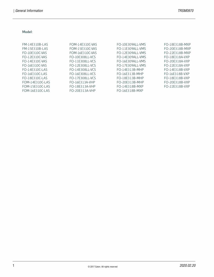
Model:
FM-14E310B-LAS
FM-15E310B-LAS
FO-10E310C-VAS
FO-12E310C-VAS
FO-14E310C-VAS
FO-16E310C-VAS
FO-14E310C-LAS
FO-16E310C-LAS
FO-18E310C-LAS
FOM-14E310C-LAS
FOM-15E310C-LAS
FOM-16E310C-LAS
FOM-14E310C-VAS
FOM-15E310C-VAS
FOM-16E310C-VAS
FO-10E308LL-VCS
FO-11E308LL-VCS
FO-12E308LL-VCS
FO-14E308LL-VCS
FO-16E308LL-VCS
FO-17E308LL-VCS
FO-16E313A-VHP
FO-18E313A-VHP
FO-20E313A-VHP
FO-10E309ALL-VMS
FO-11E309ALL-VMS
FO-12E309ALL-VMS
FO-14E309ALL-VMS
FO-16E309ALL-VMS
FO-17E309ALL-VMS
FO-14E313B-MHP
FO-16E313B-MHP
FO-18E313B-MHP
FO-20E313B-MHP
FO-14E318B-MXP
FO-16E318B-MXP
FO-18E318B-MXP
FO-20E318B-MXP
FO-22E318B-MXP
FO-18E318A-VXP
FO-20E318A-VXP
FO-22E318A-VXP
FO-14E318B-VXP
FO-16E318B-VXP
FO-18E318B-VXP
FO-20E318B-VXP
FO-22E318B-VXP
20
TRSM0940 Table of Contents |
Table of Contents
General InformationWarnings & Cautions . . . . . . . . . . . . . . . . . . . . . . . . . .1How to Use This Manual . . . . . . . . . . . . . . . . . . . . . . . .2Transmission Overview . . . . . . . . . . . . . . . . . . . . . . . . .3Serial Tag Information and Model Nomenclature . . . . .6Timing Procedures . . . . . . . . . . . . . . . . . . . . . . . . . . . .8Preventive Maintenance . . . . . . . . . . . . . . . . . . . . . . .10Assembly and Disassembly Precautions . . . . . . . . . . .11
Service ProceduresLAS/VAS Auxiliary Section Removal and Disassembly – In Chassis . . . . . . . . . . . . . . . . . . . . . .13LAS/VAS Auxiliary Section Removal and Disassembly . . . . . . . . . . . . . . . . . . . . . . . . . . . . . . . .17LAS/VAS Auxiliary Section Assembly and Installation . . . . . . . . . . . . . . . . . . . . . . . . . . . . . . . . .27Range Cylinder LAS/VAS Model Rebuild – In Chassis . . . . . . . . . . . . . . . . . . . . . . . . . . . . . . . . . .38VCS/VMS Auxiliary Section Removal and Disassembly – In Chassis . . . . . . . . . . . . . . . . . . . . . .44VCS/VMS Auxiliary Section Removal and Disassembly . . . . . . . . . . . . . . . . . . . . . . . . . . . . . . . .46VCS/VMS Auxiliary Section Assembly and Installation . . . . . . . . . . . . . . . . . . . . . . . . . . . . . . . . .57VCS/VMS Combination Cylinder Disassembly and Assembly . . . . . . . . . . . . . . . . . . . . . . . . . . . . . . .70VCS/VMS Combination Valve Removal and Installation . . . . . . . . . . . . . . . . . . . . . . . . . . . . . . . . .77MHP/MXP/VHP/VXP Auxiliary Section Removal and Disassembly . . . . . . . . . . . . . . . . . . . . . . . . . . . . . . . .79MHP/MXP/VHP/VXP Range Cylinder Disassembly and Assembly . . . . . . . . . . . . . . . . . . . . . . . . . . . . . . .92MHP/MXP/VHP/VXP Splitter Cylinder Disassembly and Assembly . . . . . . . . . . . . . . . . . . . . . . . . . . . . . . .98MHP/MXP/VHP/VXP Splitter Gear Bearing Disassembly and Assembly . . . . . . . . . . . . . . . . . . . .104MHP/MXP/VHP/VXP Auxiliary Section Assembly and Installation . . . . . . . . . . . . . . . . . . . . . . . . . . . . .108MHP/MXP/VHP/VXP Auxiliary Countershaft Installation . . . . . . . . . . . . . . . . . . . . . . . . . . . . . . . .112Range Synchronizer Disassembly and Assembly . . .124Input Shaft Removal and Installation . . . . . . . . . . . .128Clutch Housing Removal and Installation . . . . . . . . .132
Shift Bar Housing Removal and Installation . . . . . . .134Shift Bar Housing Disassembly and Assembly . . . . .137Main Case Disassembly and Lubrication Tube Removal . . . . . . . . . . . . . . . . . . . . . . . . . . . . . . . . . .143Oil Pump and Lube Tube Installation . . . . . . . . . . . . .152Main Case Main Shaft Disassembly with Low Force Gearing . . . . . . . . . . . . . . . . . . . . . . . . . . . . . . . . . . .167Main Case Main Shaft Assembly with Low Force Gearing . . . . . . . . . . . . . . . . . . . . . . . . . . . . . . . . . . .173Main Case Main Shaft without Low Force Gearing Disassembly . . . . . . . . . . . . . . . . . . . . . . . . . . . . . . .179Main Case Main Shaft Assembly . . . . . . . . . . . . . . . .184Reverse Switch Testing, Removal and Installation . .189Electronic Clutch Actuator (ECA) Removal and Installation . . . . . . . . . . . . . . . . . . . . . . . . . . . . . . . .192Low Capacity Inertia Brake (LCIB) Removal and Installation . . . . . . . . . . . . . . . . . . . . . . . . . . . . . . . .196Release Yoke and Cross-Shaft(s) Removal and Installation . . . . . . . . . . . . . . . . . . . . . . . . . . . . . . . .198Cobra Lever Removal and Installation . . . . . . . . . . . .203Eaton Push Button Shift Control Device (PBSC) Removal and Installation . . . . . . . . . . . . . . . . . . . . . .205Transmission Harness Removal and Installation . . . .207Transmission Electronic Control Unit (TECU) Removal and Installation . . . . . . . . . . . . . . . . . . . . . .209X-Y Shifter Removal and Installation . . . . . . . . . . . . .213Range Valve Removal and Installation . . . . . . . . . . .217Output Shaft Speed Sensor Removal and Installation . . . . . . . . . . . . . . . . . . . . . . . . . . . . . . . .220Input Shaft Speed Sensor Removal and Installation . . . . . . . . . . . . . . . . . . . . . . . . . . . . . . . .223Main Shaft Speed Sensor Removal and Installation . . . . . . . . . . . . . . . . . . . . . . . . . . . . . . . .226Electronic Clutch Actuator (ECA) Speed Sensor Removal and Installation . . . . . . . . . . . . . . . . . . . . . .229Rail Position Sensor Removal and Installation . . . . .232Gear Position Sensor Removal and Installation . . . . .235
21.03.17 © 2021 Eaton Cummins Automated Transmission Technologies. All rights reserved. i
| Table of Contents TRSM0940
AppendixTool Specifications . . . . . . . . . . . . . . . . . . . . . . . . . . 238Oil Leak Inspection Process . . . . . . . . . . . . . . . . . . . 242Inspection Procedure . . . . . . . . . . . . . . . . . . . . . . . . 243Power Flow . . . . . . . . . . . . . . . . . . . . . . . . . . . . . . . . 245Torque Specifications . . . . . . . . . . . . . . . . . . . . . . . . 249Lubrication Specifications . . . . . . . . . . . . . . . . . . . . . 253Clutch Greasing Guidelines . . . . . . . . . . . . . . . . . . . . 254Grade Sensor Calibration . . . . . . . . . . . . . . . . . . . . . 255
ii © 2021 Eaton Cummins Automated Transmission Technologies. All rights reserved. 2021.03.17
2021.03.17 © 2021 Eaton Cummins Automated Transmission Technologies. All rights reserved. 1
TRSM0940 General Information | Warnings & Cautions
Warnings & CautionsWarning: Follow specified procedures in indicated order to avoid personal injury.
Note: Additional relevant information not covered in service procedure.
Warning: Before starting a vehicle:
• Ensure adequate fuel level.
• Sit in driver’s seat.
• Place shift lever in Neutral.
• Set parking brake.
Warning: Before working on a vehicle or leaving cab with engine running:
• Ensure ignition is Off while hands are within the clutch housing area.
• Place shift lever in Neutral.
• Set parking brake.
• Block wheels.
Warning: When parking vehicle or leaving cab:
• Place shift lever in Neutral.
• Set parking brake.
Caution: Follow specified procedures in indicated order to avoid equipment malfunction or damage.
Caution: Do not release parking brake or attempt to select a gear until air pressure is at correct level.
Caution: To avoid damaging the transmission during tow-ing:
• Place shift lever in Neutral.
• Lift drive wheels off of the ground or disconnect the driveline.
Caution: Do not operate vehicle if alternator light is illumi-nated or if gauge indicates low voltage.
This symbol is used throughout this manual to call attention to procedures where carelessness or failure to follow spe-cific instructions may result in personal injury and/or com-ponent damage.
Always use genuine Eaton replacement parts.
!
!
!
!
!
!
!
!
!
2 © 2021 Eaton Cummins Automated Transmission Technologies. All rights reserved. 2021.03.17
How to Use This Manual | General Information TRSM0940
How to Use This ManualThis publication is divided into three sections: General Information, Service Repair Procedures and Appendix.
General InformationThis section contains basic chapters such as Transmission Overview, How to Use This Manual and Serial Tag and Model Nomenclature.
Service Repair ProceduresA Component Identification diagram is included at the beginning of each procedure for disassembly, assembly, removal and installation. Below the Component Identifica-tion diagram is a numerical listing for each part with the part name.
AppendixThis section contains information such as Operation, Lubri-cation Specifications, Inspection (in base box manuals), Power Flow (in base box manuals), Air System Operation and Troubleshooting (in base box manuals), General Trou-bleshooting (in base box manuals), Tool Specifications, Torque Specifications and Torque Overview.
The service procedures in this manual are for transmission mechanical components only. To find the information you need, simply locate the procedure in the Table of Contents, turn to the page specified and follow the procedure. If you are unsure of the name of a component, reference the Transmission Overview pages.
20
TRSM0940 General Information | Transmission Overview
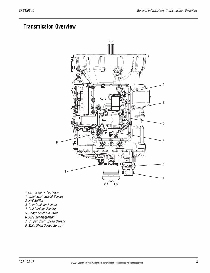
Transmission Overview
Transmission - Top View1. Input Shaft Speed Sensor2. X-Y Shifter3. Gear Position Sensor4. Rail Position Sensor5. Range Solenoid Valve6. Air Filter/Regulator7. Output Shaft Speed Sensor8. Main Shaft Speed Sensor
1
2
3
4
5
6
7
8
21.03.17 © 2021 Eaton Cummins Automated Transmission Technologies. All rights reserved. 3
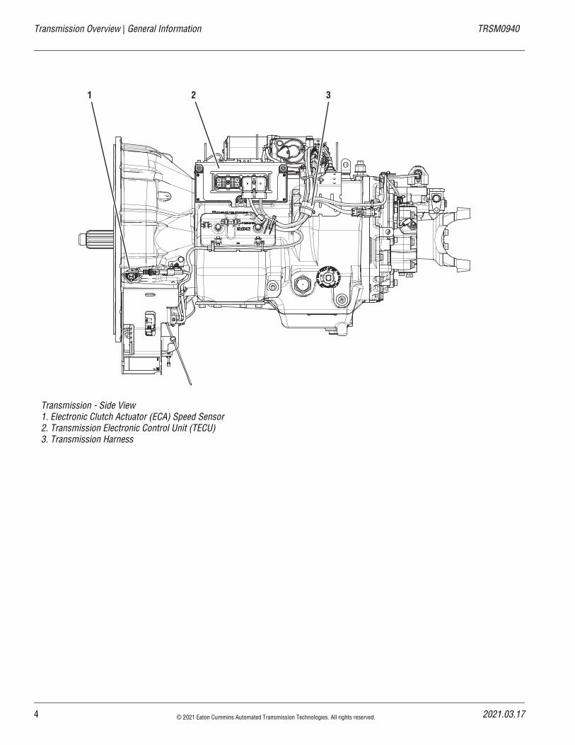
Transmission Overview | General Information TRSM0940
Transmission - Side View1. Electronic Clutch Actuator (ECA) Speed Sensor2. Transmission Electronic Control Unit (TECU)3. Transmission Harness
1 2 3
4 © 2021 Eaton Cummins Automated Transmission Technologies. All rights reserved. 2021.03.17
20
TRSM0940 General Information | Transmission Overview
Driver Instruction ManualComplete operation instructions can be found in the Driver Instruction Manual TRDR1110.
Transmission - Front View1. Release Yoke and Cross Shaft Assembly2. Electronic Clutch Actuator (ECA) 3. Low Capacity Inertia Brake (LCIB)
1
2
3
21.03.17 © 2021 Eaton Cummins Automated Transmission Technologies. All rights reserved. 5
Serial Tag Information and Model Nomenclature | General Information TRSM0940
Serial Tag Information and Model NomenclatureTransmission model designation and other transmission identification information are stamped on the serial tag. To identify the transmission model and serial number, locate the tag on the transmission and then locate the numbers as shown. The figure below shows the tag location for these transmissions.
When calling for service assistance or parts, have the model and serial numbers handy.
Important: Do not remove or destroy the transmission identification tag.
Model NumberThe model number gives basic information about the trans-mission and is explained below. Use this number when call-ing for service assistance or replacement parts.
Serial NumberThe serial number is the sequential identification number of the transmission. Before calling for service assistance, write the number down as it may be needed.
Bill of Material or Customer NumberThis number may be located below the model and serial numbers. It is a reference number used by Eaton.
!
Eaton® TransmissionsFuller® Transmissions
Model
Serial Assembled In
Eaton CorporationKalamazoo, MI USA
F A O 11 8 1O BRatio SetFuller
Advantage
O = OverdriveX = Direct
Multi torque
Forward Speeds
Design Level
Torque x 100
M
Prefix Definition
FM Fuller Multi-Torque
FO Fuller Overdrive
FOM Fuller Overdrive Multi-Torque
F Fuller
6 © 2021 Eaton Cummins Automated Transmission Technologies. All rights reserved. 2021.03.17
20
TRSM0940 General Information | Serial Tag Information and Model Nomenclature
Model Options
Torque RatingThe torque rating of the transmission specified in the model number is the input torque capacity in lb-ft. Various torque ratings are available. For more information, call 1-800-826-HELP (4357).
Shift Bar HousingThe Shift Bar Housing has a gear shifter opening located toward the rear of the transmission.
Upper CountershaftInternal lubrication pump driven off the PTO gear, and can be plumbed to an external oil cooler.
Power Take-Off (PTO) UsagePTOs can be mounted in two ways.
6- or 8-BoltThe 6- or 8-bolt openings are standard with the transmis-sion. The PTO is mounted to the opening and driven from the PTO gear on the front Counter Shaft.
Thru-ShaftThe Thru-Shaft PTO mounts on the rear of the transmis-sion. It requires a special auxiliary housing and main case Counter Shaft with internal splines.
Split-ShaftThe split-shaft PTO mounts between the transmission and the drive axle.
Standard Shift Bar Housing
21.03.17 © 2021 Eaton Cummins Automated Transmission Technologies. All rights reserved. 7
Timing Procedures | General Information TRSM0940
Timing ProceduresIt is essential that both Counter Shaft assemblies of the front and auxiliary sections are timed. This ensures proper tooth contact is made between Main Shaft gears seeking to center on the Main Shaft during torque transfer and mating Counter Shaft gears that distribute the load evenly. If not properly timed, serious damage to the transmission is likely to result from unequal tooth contact, causing the Main Shaft gears to climb out of equilibrium.
Timing is a simple procedure of marking the appropriate teeth of a gear set prior to installation and placing them in proper mesh while in the transmission. In the front section, it is necessary to time only the drive gear set. Depending on the model, only the low range, deep reduction or splitter gear set is timed in the auxiliary section.
Front Section
1. Clearly mark the tooth located directly over the drive gear keyway as shown prior to placing each Counter Shaft assembly into the case, This tooth is stamped with an “O” to aid identification.
2. Mark any two adjacent teeth on the Main Drive Gear.
3. Mark the two adjacent teeth located directly oppo-site the first set marked on the Main Drive Gear. There should be an equal number of unmarked gear teeth on each side between the marked sets.
4. After placing the Main Shaft assembly into the case, the Counter Shaft Bearings are installed to complete installation of the Counter Shaft assem-blies. This meshes marked Counter Shaft drive gear teeth with marked Main Drive Gear teeth.
When installing the bearings on the left Counter Shaft, mesh the Counter Shaft drive gear marked tooth with either set of Main Drive Gear two marked teeth.
Repeat the procedure when installing the bearings on the right Counter Shaft; make use of the remaining set of Main Drive Gear two marked teeth to time the assembly.
8 © 2021 Eaton Cummins Automated Transmission Technologies. All rights reserved. 2021.03.17
20
TRSM0940 General Information | Timing Procedures
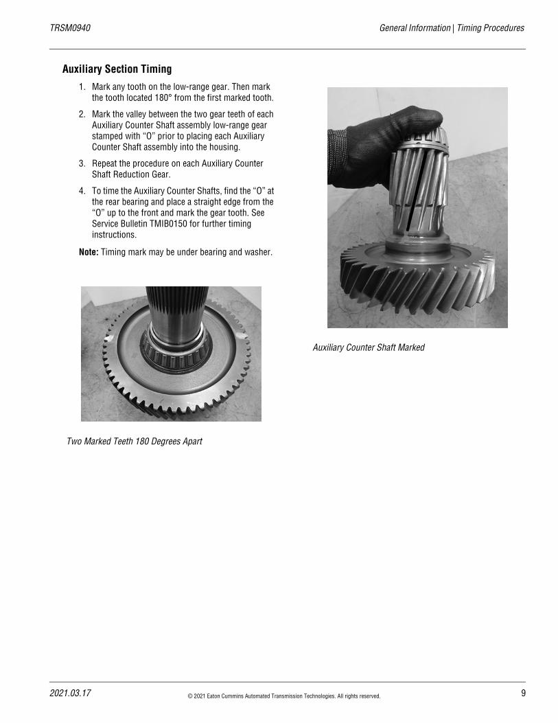
Auxiliary Section Timing
1. Mark any tooth on the low-range gear. Then mark the tooth located 180° from the first marked tooth.
2. Mark the valley between the two gear teeth of each Auxiliary Counter Shaft assembly low-range gear stamped with “O” prior to placing each Auxiliary Counter Shaft assembly into the housing.
3. Repeat the procedure on each Auxiliary Counter Shaft Reduction Gear.
4. To time the Auxiliary Counter Shafts, find the “O” at the rear bearing and place a straight edge from the “O” up to the front and mark the gear tooth. See Service Bulletin TMIB0150 for further timing instructions.
Note: Timing mark may be under bearing and washer.
Two Marked Teeth 180 Degrees Apart
Auxiliary Counter Shaft Marked
21.03.17 © 2021 Eaton Cummins Automated Transmission Technologies. All rights reserved. 9
10 © 2021 Eaton Cummins Automated Transmission Technologies. All rights reserved. 2021.03.17
Preventive Maintenance | General Information TRSM0940
Preventive MaintenanceSee Drivers Instructions TRDR1110 for daily maintenance checks.
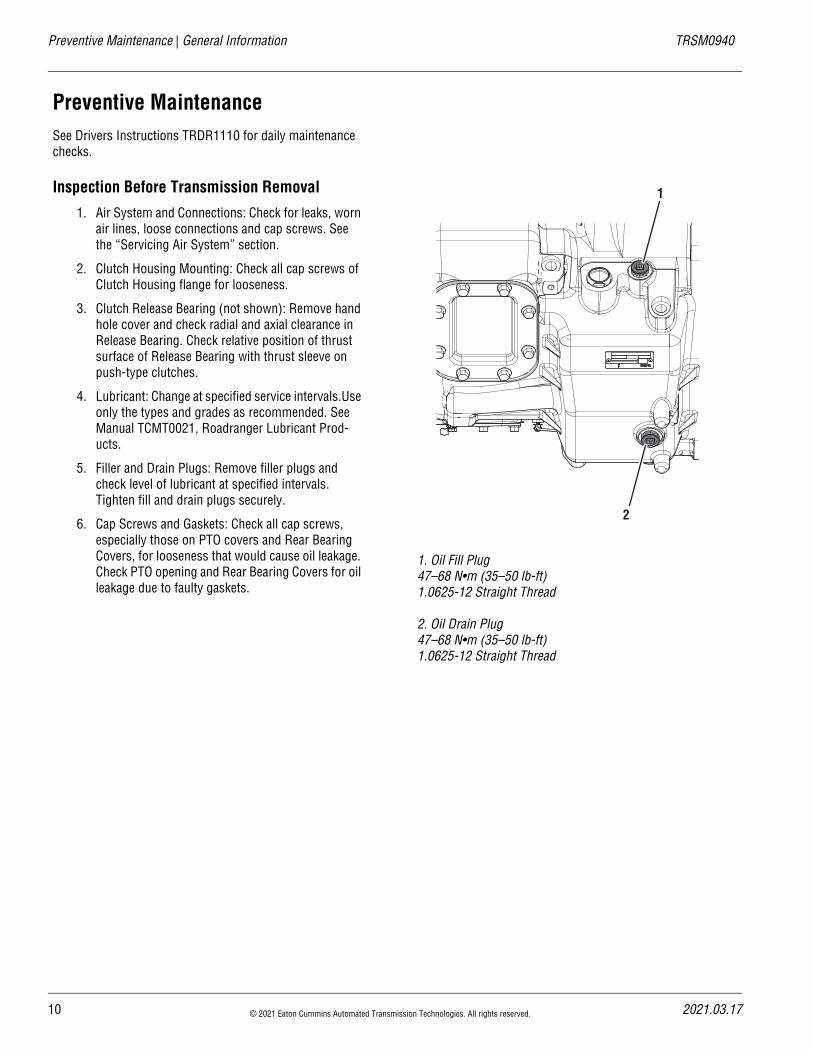
Inspection Before Transmission Removal
1. Air System and Connections: Check for leaks, worn air lines, loose connections and cap screws. See the “Servicing Air System” section.
2. Clutch Housing Mounting: Check all cap screws of Clutch Housing flange for looseness.
3. Clutch Release Bearing (not shown): Remove hand hole cover and check radial and axial clearance in Release Bearing. Check relative position of thrust surface of Release Bearing with thrust sleeve on push-type clutches.
4. Lubricant: Change at specified service intervals.Use only the types and grades as recommended. See Manual TCMT0021, Roadranger Lubricant Prod-ucts.
5. Filler and Drain Plugs: Remove filler plugs and check level of lubricant at specified intervals. Tighten fill and drain plugs securely.
6. Cap Screws and Gaskets: Check all cap screws, especially those on PTO covers and Rear Bearing Covers, for looseness that would cause oil leakage. Check PTO opening and Rear Bearing Covers for oil leakage due to faulty gaskets.
1. Oil Fill Plug47–68 N•m (35–50 lb-ft)1.0625-12 Straight Thread
2. Oil Drain Plug47–68 N•m (35–50 lb-ft)1.0625-12 Straight Thread
20
TRSM0940 General Information | Assembly and Disassembly Precautions
!
Assembly and Disassembly Precautions
Assembly Precautions
General InformationEnsure that case interiors and housings are clean. It is important that dirt and other foreign material are kept out of the transmission during assembly. Dirt is abrasive and can damage polished surfaces of bearings and washers. Use certain precautions, as listed below, during assembly.
BearingsUse a flange-end bearing driver for bearing installation. These special drivers apply equal force to both bearing races, preventing damage to balls/rollers and races while maintaining correct bearing alignment with bore and shaft. Avoid using a tubular or sleeve-type driver, whenever possi-ble, as force is applied to only one of the bearing races.
Cap ScrewsTo prevent oil leakage and loosening, use Eaton Fuller Seal-ant, Part Number 71205, on all cap screws.
GasketsUse new gaskets throughout the transmission as it is being rebuilt. Make sure all gaskets are installed. An omission of any gasket can result in oil leakage or misalignment of bear-ing covers.
Initial LubricationCoat all limit washers and shaft splines with lubricant during assembly to prevent scoring and galling of such parts.
O-RingsLubricate all O-rings with silicon lubricant.
Universal Joint Companion Flange or YokePull the companion flange or yoke tightly into place with the two Output Shaft bolts, using 84–92 lb-ft of torque. Ensure the speedometer drive gear or a replacement spacer of the same width has been installed. Failure to pull the compan-ion flange or yoke tightly into place can result in damage to the Main Shaft Rear Bearing.
Important: See the appropriate Illustrated Parts List (speci-fied by model series) to ensure that proper parts are used during assembly of the transmission.
Disassembly Precautions
General InformationIt is assumed in the detailed assembly instructions that the lubricant has been drained from the transmission, the nec-essary linkage and vehicle air lines disconnected and the transmission has been removed from vehicle chassis
Important: Follow each procedure closely in the detailed instructions. Be sure to make use of the text, illustrations and photographs provided.
AssembliesWhen disassembling the various assemblies, such as the Main Shaft, Counter Shafts and Shift Bar Housing, lay all parts on a clean bench in the same sequence as removed. This procedure will simplify assembly and reduce the possi-bility of losing parts.
BearingsCarefully wash and lubricate all usable bearings as removed and protectively wrap until ready for use. Remove bearings planned for reuse with pullers designed for this purpose.
CleanlinessProvide a clean place to work. It is important that no dirt or foreign material enters the unit during repairs. Dirt is abra-sive and can damage bearings. It is always good practice to clean the outside of the unit before starting the planned dis-assembly.
Input ShaftThe Input Shaft can be removed from the transmission without removing the Counter Shafts, Main Shaft or Main Drive Gear. Special procedures are required and provided in this manual.
Snap RingsRemove snap rings with pliers designed for this purpose. Snap rings removed in this manner can be reused, if they are not sprung or loose.
When Using Tools to Move PartsAlways use restraint when applying force to shafts, hous-ings, etc. Movement of some parts is restricted. Never apply force to driven parts after they stop solidly. The use of soft hammers, soft bars and mauls for all disassembly work is recommended.
!
21.03.17 © 2021 Eaton Cummins Automated Transmission Technologies. All rights reserved. 11
Assembly and Disassembly Precautions | General Information TRSM0940
12 © 2021 Eaton Cummins Automated Transmission Technologies. All rights reserved. 2021.03.17
20
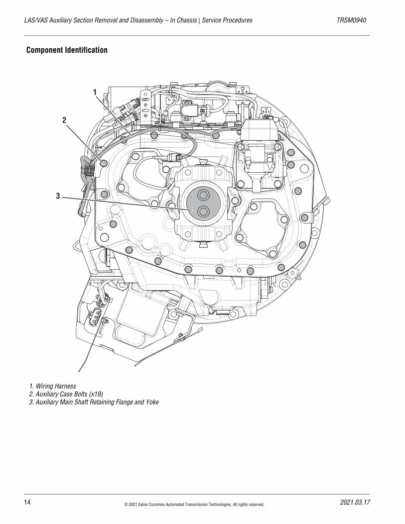
TRSM0940 Service Procedures | LAS/VAS Auxiliary Section Removal and Disassembly – In Chassis
LAS/VAS Auxiliary Section Removal and Disassembly – In ChassisSpecial InstructionsThe following procedure covers the removal and disassem-bly of the Auxiliary section with the transmission remaining in the chassis. If the transmission is removed from the truck refer to the “LAS/VAS Auxiliary Section Removal and Disassembly” on page 17.
Special ToolsNone
21.03.17 © 2021 Eaton Cummins Automated Transmission Technologies. All rights reserved. 13
LAS/VAS Auxiliary Section Removal and Disassembly – In Chassis | Service Procedures TRSM0940
Component Identification
1. Wiring Harness2. Auxiliary Case Bolts (x19)3. Auxiliary Main Shaft Retaining Flange and Yoke
2
3
1
14 © 2021 Eaton Cummins Automated Transmission Technologies. All rights reserved. 2021.03.17
20
TRSM0940 Service Procedures | LAS/VAS Auxiliary Section Removal and Disassembly – In Chassis
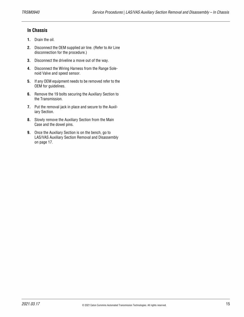
In Chassis
1. Drain the oil.
2. Disconnect the OEM supplied air line. (Refer to Air Line disconnection for the procedure.)
3. Disconnect the driveline a move out of the way.
4. Disconnect the Wiring Harness from the Range Sole-noid Valve and speed sensor.
5. If any OEM equipment needs to be removed refer to the OEM for guidelines.
6. Remove the 19 bolts securing the Auxiliary Section to the Transmission.
7. Put the removal jack in place and secure to the Auxil-iary Section.
8. Slowly remove the Auxiliary Section from the Main Case and the dowel pins.
9. Once the Auxiliary Section is on the bench, go to LAS/VAS Auxiliary Section Removal and Disassembly on page 17.
21.03.17 © 2021 Eaton Cummins Automated Transmission Technologies. All rights reserved. 15
LAS/VAS Auxiliary Section Removal and Disassembly – In Chassis | Service Procedures TRSM0940
16 © 2021 Eaton Cummins Automated Transmission Technologies. All rights reserved. 2021.03.17
20
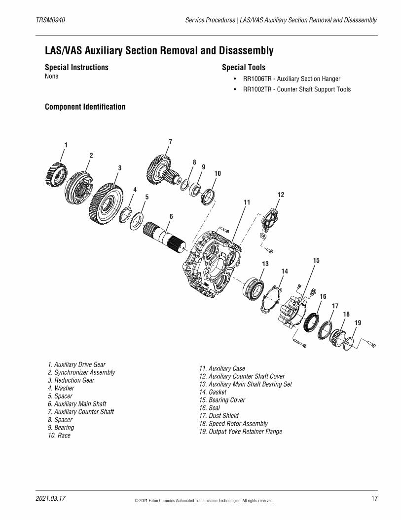
TRSM0940 Service Procedures | LAS/VAS Auxiliary Section Removal and Disassembly
LAS/VAS Auxiliary Section Removal and DisassemblySpecial InstructionsNone
Special Tools• RR1006TR - Auxiliary Section Hanger
• RR1002TR - Counter Shaft Support Tools
Component Identification
1. Auxiliary Drive Gear2. Synchronizer Assembly3. Reduction Gear4. Washer5. Spacer6. Auxiliary Main Shaft7. Auxiliary Counter Shaft8. Spacer9. Bearing10. Race
11. Auxiliary Case12. Auxiliary Counter Shaft Cover13. Auxiliary Main Shaft Bearing Set14. Gasket15. Bearing Cover16. Seal17. Dust Shield18. Speed Rotor Assembly19. Output Yoke Retainer Flange
4
1
2
3
5
6
7
89
10
12
1314
1617
1819
11
15
21.03.17 © 2021 Eaton Cummins Automated Transmission Technologies. All rights reserved. 17
LAS/VAS Auxiliary Section Removal and Disassembly | Service Procedures TRSM0940
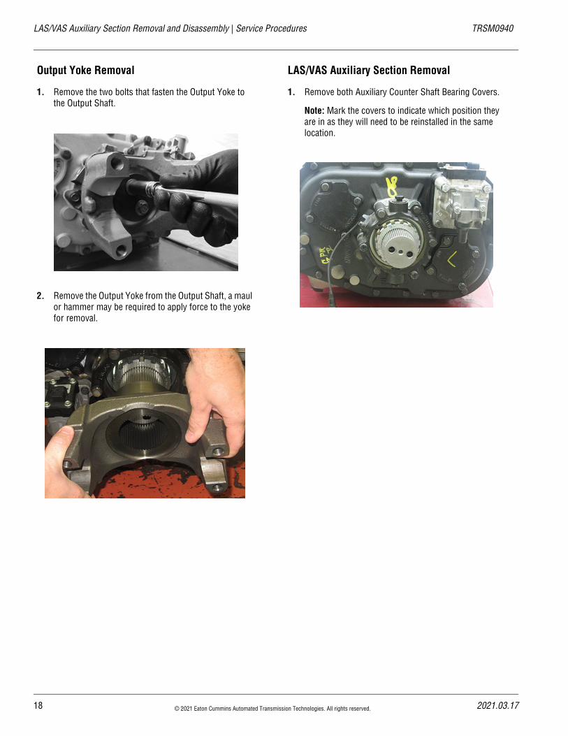
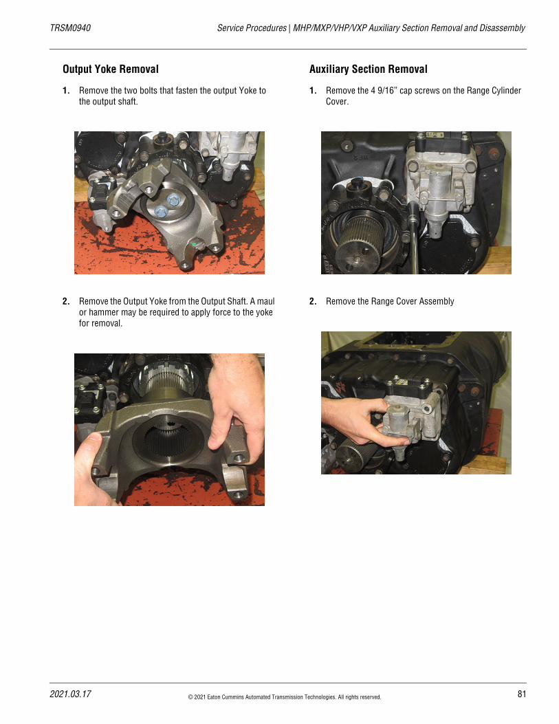
Output Yoke Removal
1. Remove the two bolts that fasten the Output Yoke to the Output Shaft.
2. Remove the Output Yoke from the Output Shaft, a maul or hammer may be required to apply force to the yoke for removal.
LAS/VAS Auxiliary Section Removal
1. Remove both Auxiliary Counter Shaft Bearing Covers.
Note: Mark the covers to indicate which position they are in as they will need to be reinstalled in the same location.
18 © 2021 Eaton Cummins Automated Transmission Technologies. All rights reserved. 2021.03.17
20
TRSM0940 Service Procedures | LAS/VAS Auxiliary Section Removal and Disassembly
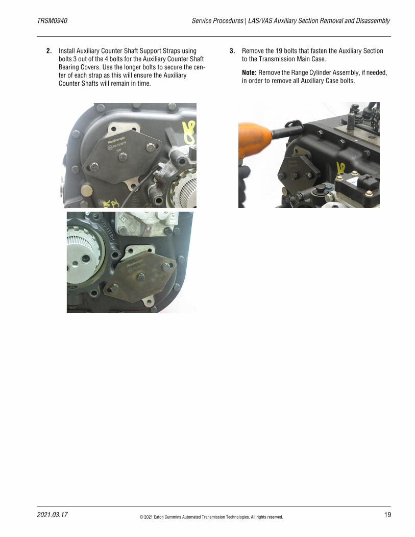
2. Install Auxiliary Counter Shaft Support Straps using bolts 3 out of the 4 bolts for the Auxiliary Counter Shaft Bearing Covers. Use the longer bolts to secure the cen-ter of each strap as this will ensure the Auxiliary Counter Shafts will remain in time.
3. Remove the 19 bolts that fasten the Auxiliary Section to the Transmission Main Case.
Note: Remove the Range Cylinder Assembly, if needed, in order to remove all Auxiliary Case bolts.
21.03.17 © 2021 Eaton Cummins Automated Transmission Technologies. All rights reserved. 19
LAS/VAS Auxiliary Section Removal and Disassembly | Service Procedures TRSM0940
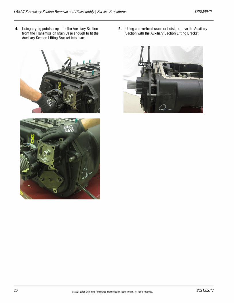
4. Using prying points, separate the Auxiliary Section from the Transmission Main Case enough to fit the Auxiliary Section Lifting Bracket into place.
5. Using an overhead crane or hoist, remove the Auxiliary Section with the Auxiliary Section Lifting Bracket.
20 © 2021 Eaton Cummins Automated Transmission Technologies. All rights reserved. 2021.03.17
20
TRSM0940 Service Procedures | LAS/VAS Auxiliary Section Removal and Disassembly
LAS/VAS Auxiliary Section Removal and Disas-sembly
1. Remove the six cap screws that fasten the Output Shaft Bearing Cover to the Auxiliary Section, remove the Out-put Shaft Bearing Cover.
2. Remove the cap screws that fasten the Range Cover to the Range Cylinder. Remove the Range Cover.
3. Remove the single cap screw that fasten the Range Piston to the Range Shift Yoke Bar.
4. Remove the Range Cylinder assembly.
Caution: Auxiliary Counter Shafts will fall out part way through this process.
!
21.03.17 © 2021 Eaton Cummins Automated Transmission Technologies. All rights reserved. 21
LAS/VAS Auxiliary Section Removal and Disassembly | Service Procedures TRSM0940
5. Place the Auxiliary Section on a bench with the gearing facing down; remove the Auxiliary Counter Shaft Sup-port Straps, using a hand maul drive the Output Shaft out of the case.
6. As the Auxiliary Main Shaft is driven out, remove the Synchronizer assembly and the Range Yoke.
7. Remove the bearing cup and outer spacer from the Auxiliary Case bore.
8. Using the front face of the low range gear as a base, press the Output Shaft through the gear and bearing. Remove the bearing and washer from the hub of the Auxiliary Reduction Gear.
Note: If reusing the bearing set, the tapered roller bear-ings are specific to each side of the race.
22 © 2021 Eaton Cummins Automated Transmission Technologies. All rights reserved. 2021.03.17
20
TRSM0940 Service Procedures | LAS/VAS Auxiliary Section Removal and Disassembly
9. Remove the splined spacer and stepped washer from the Auxiliary Reduction Gear.
Range Synchronizer Disassembly
1. Remove the Range Synchronizer from the Output Shaft.
21.03.17 © 2021 Eaton Cummins Automated Transmission Technologies. All rights reserved. 23
LAS/VAS Auxiliary Section Removal and Disassembly | Service Procedures TRSM0940
2. Place the Low Range Synchronizer on a bench with the larger ring facing down, (place a shop towel over the assembly to avoid losing any springs) pull the High Range Synchronizer from the Blocker Ring
3. Remove the Sliding Clutch from the pins of the Syn-chronizer Ring.
24 © 2021 Eaton Cummins Automated Transmission Technologies. All rights reserved. 2021.03.17
20
TRSM0940 Service Procedures | LAS/VAS Auxiliary Section Removal and Disassembly
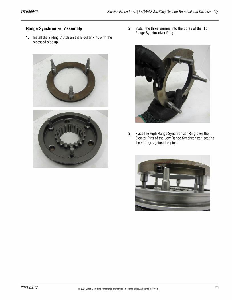
Range Synchronizer Assembly
1. Install the Sliding Clutch on the Blocker Pins with the recessed side up.
2. Install the three springs into the bores of the High Range Synchronizer Ring.
3. Place the High Range Synchronizer Ring over the Blocker Pins of the Low Range Synchronizer, seating the springs against the pins.
21.03.17 © 2021 Eaton Cummins Automated Transmission Technologies. All rights reserved. 25
LAS/VAS Auxiliary Section Removal and Disassembly | Service Procedures TRSM0940
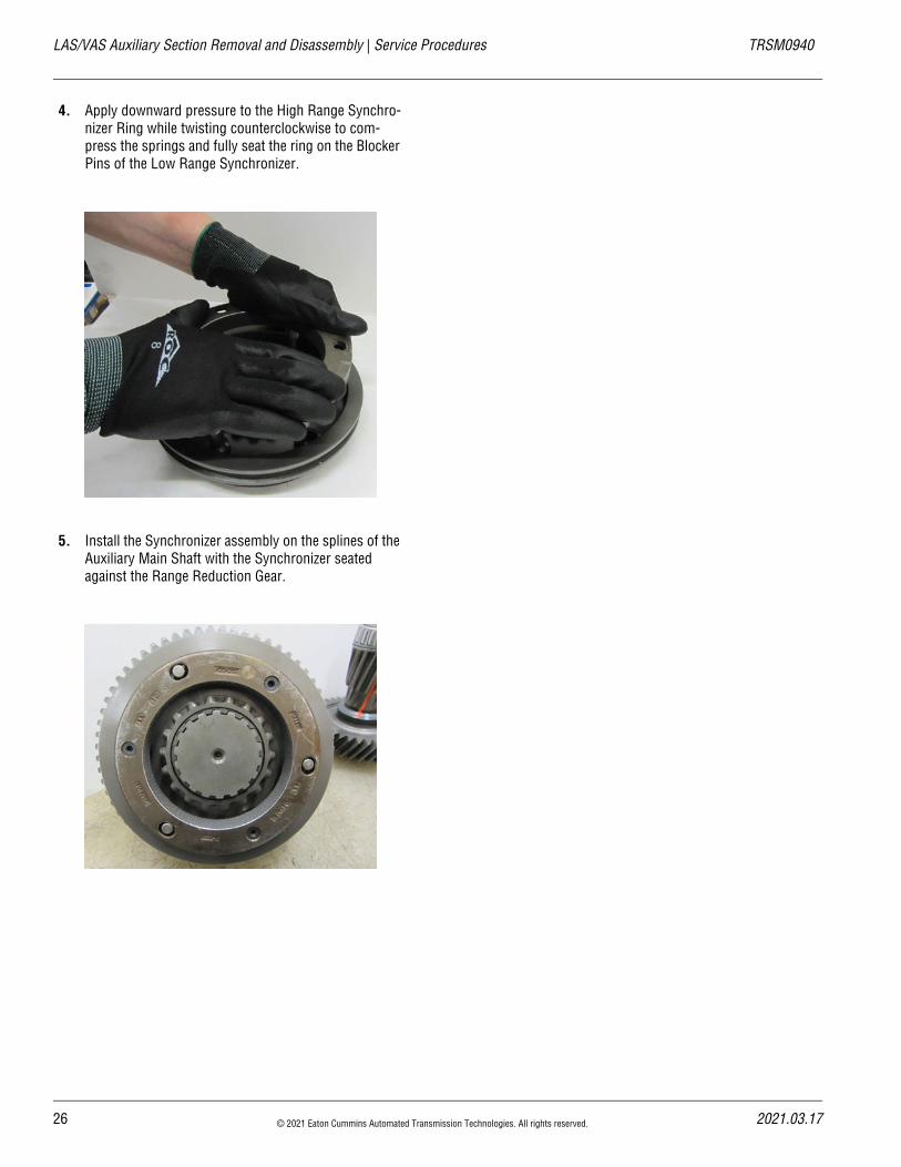
4. Apply downward pressure to the High Range Synchro-nizer Ring while twisting counterclockwise to com-press the springs and fully seat the ring on the Blocker Pins of the Low Range Synchronizer.
5. Install the Synchronizer assembly on the splines of the Auxiliary Main Shaft with the Synchronizer seated against the Range Reduction Gear.
26 © 2021 Eaton Cummins Automated Transmission Technologies. All rights reserved. 2021.03.17
20
TRSM0940 Service Procedures | LAS/VAS Auxiliary Section Assembly and Installation
LAS/VAS Auxiliary Section Assembly and InstallationSpecial InstructionsNone
Special ToolsPVC pipe (4-3/8" tall x 4" diameter)
Component Identification
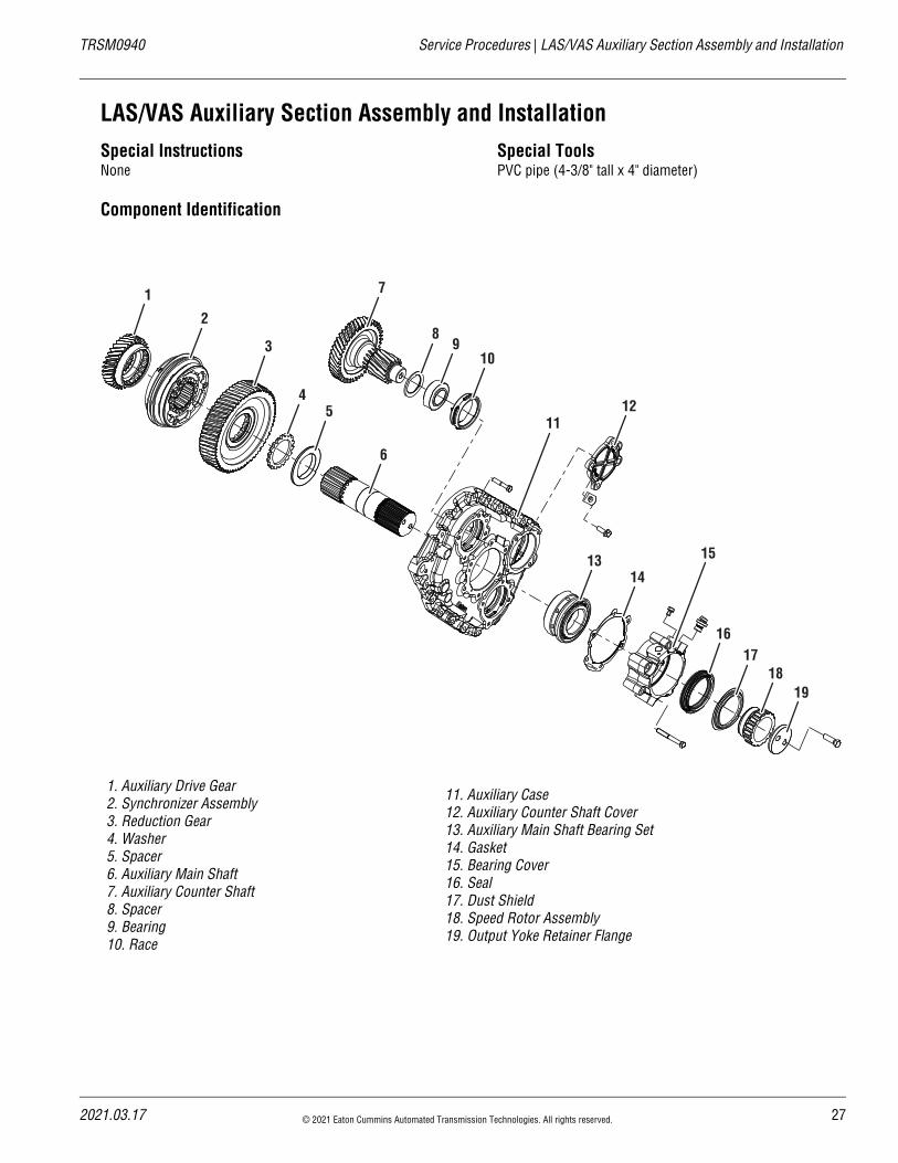
1. Auxiliary Drive Gear2. Synchronizer Assembly3. Reduction Gear4. Washer5. Spacer6. Auxiliary Main Shaft7. Auxiliary Counter Shaft8. Spacer9. Bearing10. Race
11. Auxiliary Case12. Auxiliary Counter Shaft Cover13. Auxiliary Main Shaft Bearing Set14. Gasket15. Bearing Cover16. Seal17. Dust Shield18. Speed Rotor Assembly19. Output Yoke Retainer Flange
4
1
2
3
5
6
7
89
10
12
1314
1617
1819
11
15
21.03.17 © 2021 Eaton Cummins Automated Transmission Technologies. All rights reserved. 27
LAS/VAS Auxiliary Section Assembly and Installation | Service Procedures TRSM0940
LAS/VAS Auxiliary Section Assembly
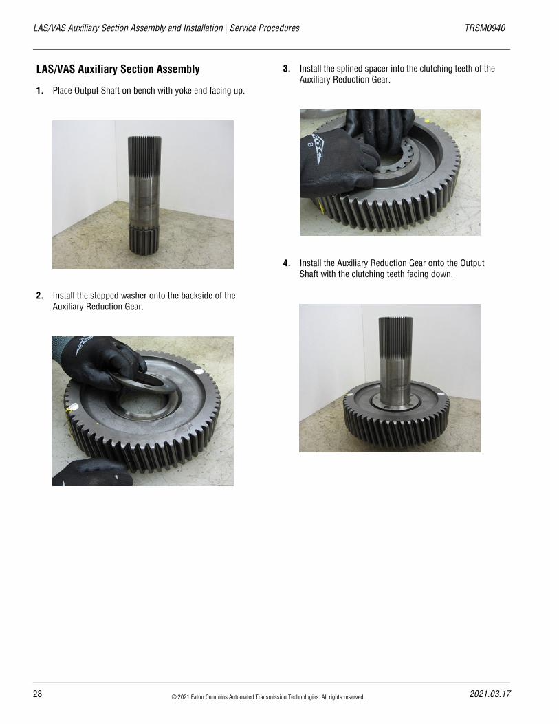
1. Place Output Shaft on bench with yoke end facing up.
2. Install the stepped washer onto the backside of the Auxiliary Reduction Gear.
3. Install the splined spacer into the clutching teeth of the Auxiliary Reduction Gear.
4. Install the Auxiliary Reduction Gear onto the Output Shaft with the clutching teeth facing down.
28 © 2021 Eaton Cummins Automated Transmission Technologies. All rights reserved. 2021.03.17
20
TRSM0940 Service Procedures | LAS/VAS Auxiliary Section Assembly and Installation
5. Mark any two teeth 180 degrees apart on the Range Reduction Gear using a highly visible dye.
6. Place the inner bearing (longer rollers) tapered side up over the Auxiliary Main Shaft.
7. Drive the bearing down to the Auxiliary Reduction Gear using the Output Shaft Bearing Driver.
8. Slide the bearing spacer down on top of the inner bear-ing.
21.03.17 © 2021 Eaton Cummins Automated Transmission Technologies. All rights reserved. 29
LAS/VAS Auxiliary Section Assembly and Installation | Service Procedures TRSM0940
LAS/VAS Auxiliary Counter Shaft Installation and Timing
Auxiliary Counter Shaft Installation and Timing
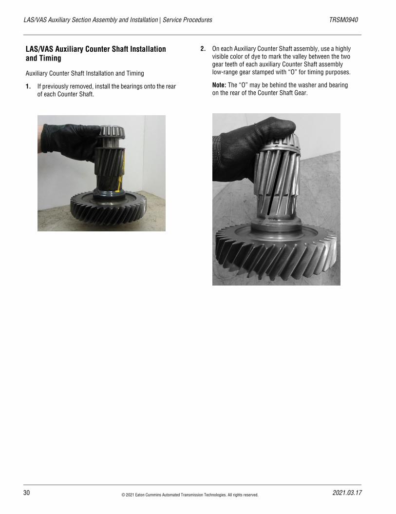
1. If previously removed, install the bearings onto the rear of each Counter Shaft.
2. On each Auxiliary Counter Shaft assembly, use a highly visible color of dye to mark the valley between the two gear teeth of each auxiliary Counter Shaft assembly low-range gear stamped with “O” for timing purposes.
Note: The “O” may be behind the washer and bearing on the rear of the Counter Shaft Gear.
30 © 2021 Eaton Cummins Automated Transmission Technologies. All rights reserved. 2021.03.17
20
TRSM0940 Service Procedures | LAS/VAS Auxiliary Section Assembly and Installation
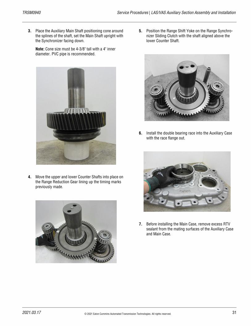
3. Place the Auxiliary Main Shaft positioning cone around the splines of the shaft, set the Main Shaft upright with the Synchronizer facing down.
Note: Cone size must be 4-3/8" tall with a 4" inner diameter. PVC pipe is recommended.
4. Move the upper and lower Counter Shafts into place on the Range Reduction Gear lining up the timing marks previously made.
5. Position the Range Shift Yoke on the Range Synchro-nizer Sliding Clutch with the shaft aligned above the lower Counter Shaft.
6. Install the double bearing race into the Auxiliary Case with the race flange out.
7. Before installing the Main Case, remove excess RTV sealant from the mating surfaces of the Auxiliary Case and Main Case.
21.03.17 © 2021 Eaton Cummins Automated Transmission Technologies. All rights reserved. 31
LAS/VAS Auxiliary Section Assembly and Installation | Service Procedures TRSM0940
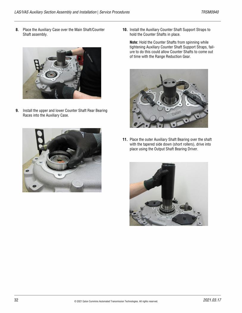
8. Place the Auxiliary Case over the Main Shaft/Counter Shaft assembly.
9. Install the upper and lower Counter Shaft Rear Bearing Races into the Auxiliary Case.
10. Install the Auxiliary Counter Shaft Support Straps to hold the Counter Shafts in place.
Note: Hold the Counter Shafts from spinning while tightening Auxiliary Counter Shaft Support Straps, fail-ure to do this could allow Counter Shafts to come out of time with the Range Reduction Gear.
11. Place the outer Auxiliary Shaft Bearing over the shaft with the tapered side down (short rollers), drive into place using the Output Shaft Bearing Driver.
32 © 2021 Eaton Cummins Automated Transmission Technologies. All rights reserved. 2021.03.17
20
TRSM0940 Service Procedures | LAS/VAS Auxiliary Section Assembly and Installation
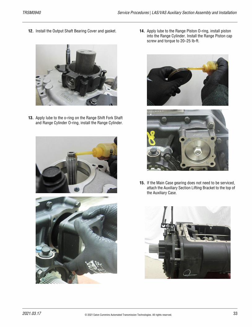
12. Install the Output Shaft Bearing Cover and gasket.
13. Apply lube to the o-ring on the Range Shift Fork Shaft and Range Cylinder O-ring, install the Range Cylinder.
14. Apply lube to the Range Piston O-ring, install piston into the Range Cylinder. Install the Range Piston cap screw and torque to 20–25 lb-ft.
15. If the Main Case gearing does not need to be serviced, attach the Auxiliary Section Lifting Bracket to the top of the Auxiliary Case.
21.03.17 © 2021 Eaton Cummins Automated Transmission Technologies. All rights reserved. 33
LAS/VAS Auxiliary Section Assembly and Installation | Service Procedures TRSM0940
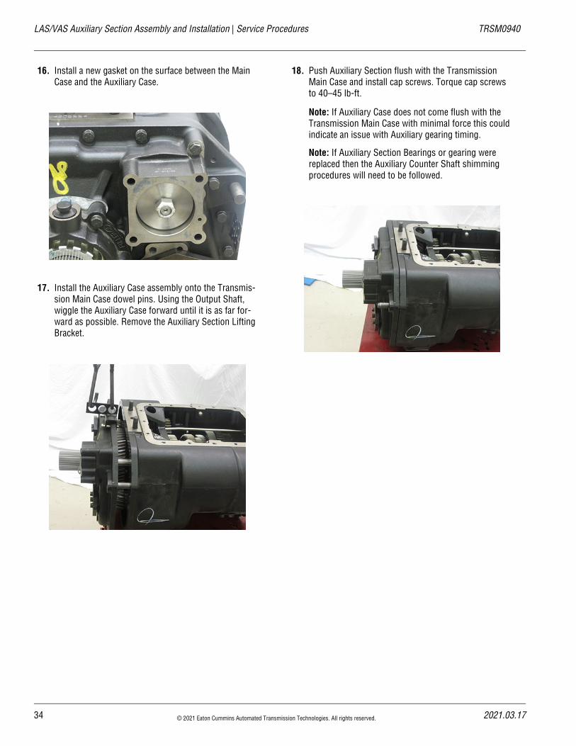
16. Install a new gasket on the surface between the Main Case and the Auxiliary Case.
17. Install the Auxiliary Case assembly onto the Transmis-sion Main Case dowel pins. Using the Output Shaft, wiggle the Auxiliary Case forward until it is as far for-ward as possible. Remove the Auxiliary Section Lifting Bracket.
18. Push Auxiliary Section flush with the Transmission Main Case and install cap screws. Torque cap screws to 40–45 lb-ft.
Note: If Auxiliary Case does not come flush with the Transmission Main Case with minimal force this could indicate an issue with Auxiliary gearing timing.
Note: If Auxiliary Section Bearings or gearing were replaced then the Auxiliary Counter Shaft shimming procedures will need to be followed.
34 © 2021 Eaton Cummins Automated Transmission Technologies. All rights reserved. 2021.03.17
20
TRSM0940 Service Procedures | LAS/VAS Auxiliary Section Assembly and Installation
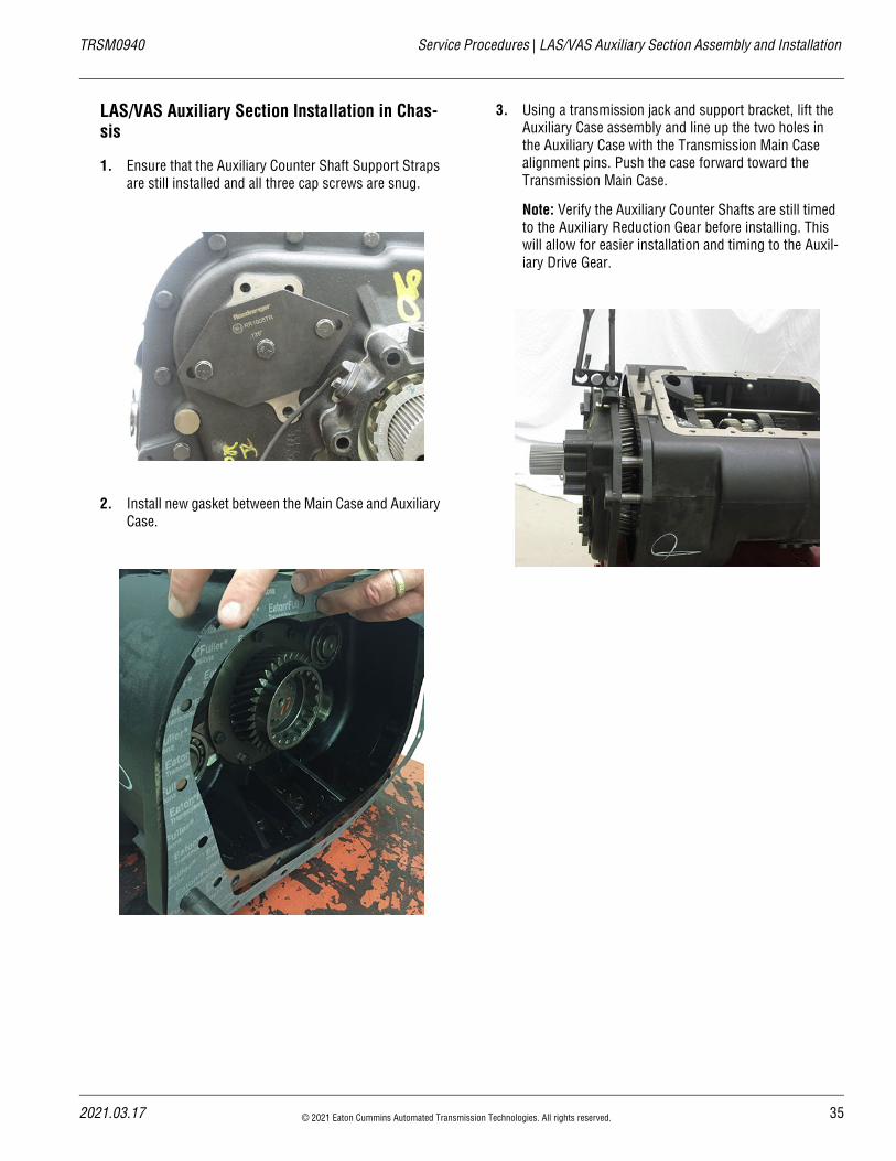
LAS/VAS Auxiliary Section Installation in Chas-sis
1. Ensure that the Auxiliary Counter Shaft Support Straps are still installed and all three cap screws are snug.
2. Install new gasket between the Main Case and Auxiliary Case.
3. Using a transmission jack and support bracket, lift the Auxiliary Case assembly and line up the two holes in the Auxiliary Case with the Transmission Main Case alignment pins. Push the case forward toward the Transmission Main Case.
Note: Verify the Auxiliary Counter Shafts are still timed to the Auxiliary Reduction Gear before installing. This will allow for easier installation and timing to the Auxil-iary Drive Gear.
21.03.17 © 2021 Eaton Cummins Automated Transmission Technologies. All rights reserved. 35
LAS/VAS Auxiliary Section Assembly and Installation | Service Procedures TRSM0940
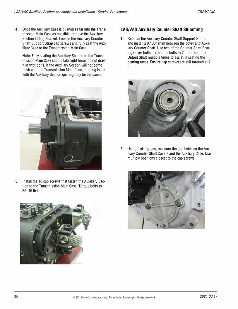
4. Once the Auxiliary Case is pushed as far into the Trans-mission Main Case as possible, remove the Auxiliary Section Lifting Bracket. Loosen the Auxiliary Counter Shaft Support Strap cap screws and fully seat the Aux-iliary Case to the Transmission Main Case.
Note: Fully seating the Auxiliary Section to the Trans-mission Main Case should take light force; do not draw it in with bolts. If the Auxiliary Section will not come flush with the Transmission Main Case, a timing issue with the Auxiliary Section gearing may be the cause.
5. Install the 16 cap screws that fasten the Auxiliary Sec-tion to the Transmission Main Case. Torque bolts to 35–45 lb-ft.
LAS/VAS Auxiliary Counter Shaft Shimming
1. Remove the Auxiliary Counter Shaft Support Straps and install a 0.100" shim between the cover and Auxil-iary Counter Shaft. Use two of the Counter Shaft Bear-ing Cover bolts and torque bolts to 7 lb-in. Spin the Output Shaft multiple times to assist in seating the bearing races. Ensure cap screws are still torqued at 7 lb-in.
2. Using feeler gages, measure the gap between the Aux-iliary Counter Shaft Covers and the Auxiliary Case. Use multiple positions closest to the cap screws.
36 © 2021 Eaton Cummins Automated Transmission Technologies. All rights reserved. 2021.03.17
20
TRSM0940 Service Procedures | LAS/VAS Auxiliary Section Assembly and Installation
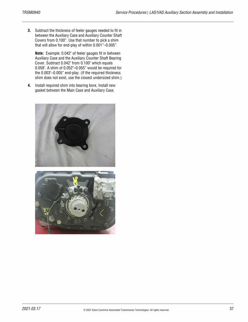
3. Subtract the thickness of feeler gauges needed to fit in between the Auxiliary Case and Auxiliary Counter Shaft Covers from 0.100”. Use that number to pick a shim that will allow for end-play of within 0.001”–0.005”.
Note: Example: 0.042" of feeler gauges fit in between Auxiliary Case and the Auxiliary Counter Shaft Bearing Cover. Subtract 0.042" from 0.100" which equals 0.058". A shim of 0.052"–0.055” would be required for the 0.003"–0.005” end-play. (If the required thickness shim does not exist, use the closest undersized shim.)
4. Install required shim into bearing bore, Install new gasket between the Main Case and Auxiliary Case.
21.03.17 © 2021 Eaton Cummins Automated Transmission Technologies. All rights reserved. 37
Range Cylinder LAS/VAS Model Rebuild – In Chassis | Service Procedures TRSM0940
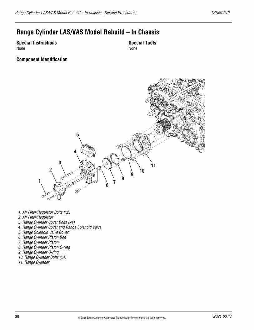
Range Cylinder LAS/VAS Model Rebuild – In ChassisSpecial InstructionsNone
Special ToolsNone
Component Identification
1. Air Filter/Regulator Bolts (x2)2. Air Filter/Regulator3. Range Cylinder Cover Bolts (x4)4. Range Cylinder Cover and Range Solenoid Valve5. Range Solenoid Valve Cover6. Range Cylinder Piston Bolt7. Range Cylinder Piston8. Range Cylinder Piston O-ring9. Range Cylinder O-ring10. Range Cylinder Bolts (x4)11. Range Cylinder
23
1
4
5
67
89
1011
38 © 2021 Eaton Cummins Automated Transmission Technologies. All rights reserved. 2021.03.17
20
TRSM0940 Service Procedures | Range Cylinder LAS/VAS Model Rebuild – In Chassis
Range Cylinder Disassembly
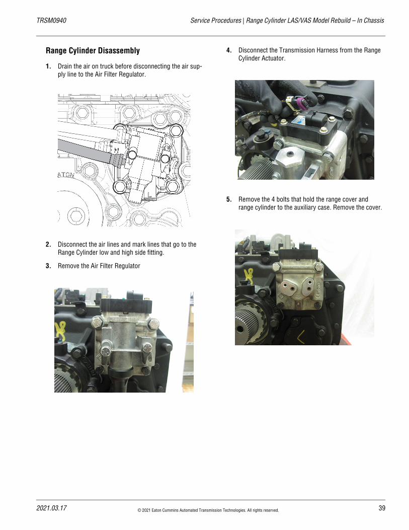
1. Drain the air on truck before disconnecting the air sup-ply line to the Air Filter Regulator.
2. Disconnect the air lines and mark lines that go to the Range Cylinder low and high side fitting.
3. Remove the Air Filter Regulator
4. Disconnect the Transmission Harness from the Range Cylinder Actuator.
5. Remove the 4 bolts that hold the range cover and range cylinder to the auxiliary case. Remove the cover.
21.03.17 © 2021 Eaton Cummins Automated Transmission Technologies. All rights reserved. 39
Range Cylinder LAS/VAS Model Rebuild – In Chassis | Service Procedures TRSM0940
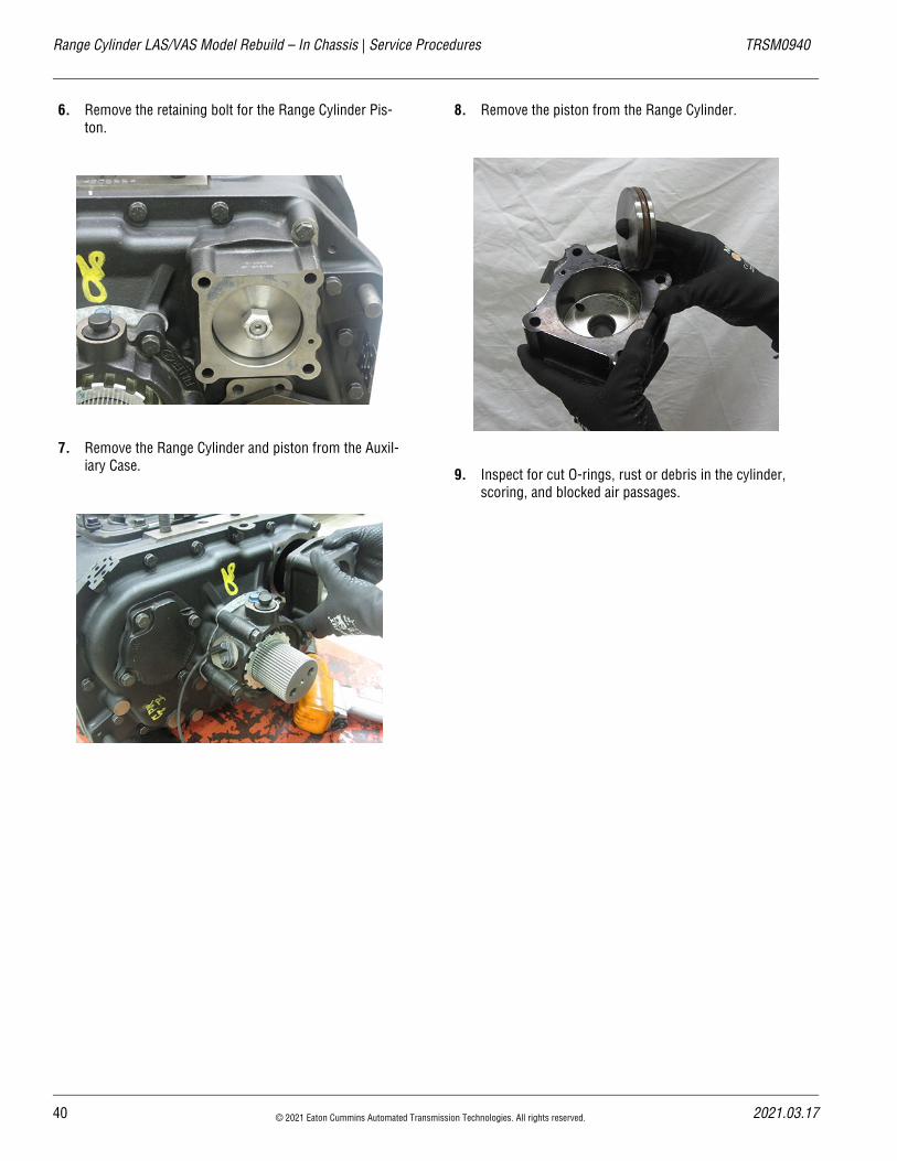
6. Remove the retaining bolt for the Range Cylinder Pis-ton.
7. Remove the Range Cylinder and piston from the Auxil-iary Case.
8. Remove the piston from the Range Cylinder.
9. Inspect for cut O-rings, rust or debris in the cylinder, scoring, and blocked air passages.
40 © 2021 Eaton Cummins Automated Transmission Technologies. All rights reserved. 2021.03.17
20
TRSM0940 Service Procedures | Range Cylinder LAS/VAS Model Rebuild – In Chassis
Range Cylinder Assembly
1. Install a new gasket on the Range Cylinder to seal against the Auxiliary Case. Clean off any remaining debris from the old gasket.
2. Install the Range Cylinder in the bore. Make sure the cylinder is positioned so that the concave corner is in the top right. This allows for proper access to the bolt that secures the Auxiliary Case to the Main Case.
21.03.17 © 2021 Eaton Cummins Automated Transmission Technologies. All rights reserved. 41
Range Cylinder LAS/VAS Model Rebuild – In Chassis | Service Procedures TRSM0940
3. Install a new O-ring on the Range Piston and Range Yoke Bar. Lube with silicone.
4. Install the Range Piston into the cylinder and onto the yoke bar.
5. Torque the bolt 35–45 lb-ft.
6. Install a new gasket between the Range Cylinder and the Range Cylinder Cover.
Note: Verify that the small air passage is located at the bottom to align properly with the cover.
7. Install the Range Cylinder Cover and 4 bolts. Torque bolts 30–35 lb-ft.
42 © 2021 Eaton Cummins Automated Transmission Technologies. All rights reserved. 2021.03.17
20
TRSM0940 Service Procedures | Range Cylinder LAS/VAS Model Rebuild – In Chassis
8. Reconnect the Transmission Harness to the Range Cyl-inder Actuator.
9. Install the Air Filter Regulator and torque bolts 8–12 lb-ft.
10. Install the air lines to the Range Cover as marked and connect the air supply lines to the Air Filter Regulator.
11. Verify all the work is done correctly. Air-up the truck and verify operation of the Transmission Range Sys-tem.
21.03.17 © 2021 Eaton Cummins Automated Transmission Technologies. All rights reserved. 43
VCS/VMS Auxiliary Section Removal and Disassembly – In Chassis | Service Procedures TRSM0940
VCS/VMS Auxiliary Section Removal and Disassembly – In ChassisSpecial InstructionsThe following procedure covers the removal and disassem-bly of the Auxiliary Section with the transmission remaining in the chassis.
If the transmission is removed from the truck refer to the “VCS/VMS Auxiliary Section Removal and Disassembly” on page 46.
Special Tools• RR1002TR – Counter Shaft Support Tools
• Support jack
Component Identification
44 © 2021 Eaton Cummins Automated Transmission Technologies. All rights reserved. 2021.03.17
20
TRSM0940 Service Procedures | VCS/VMS Auxiliary Section Removal and Disassembly – In Chassis
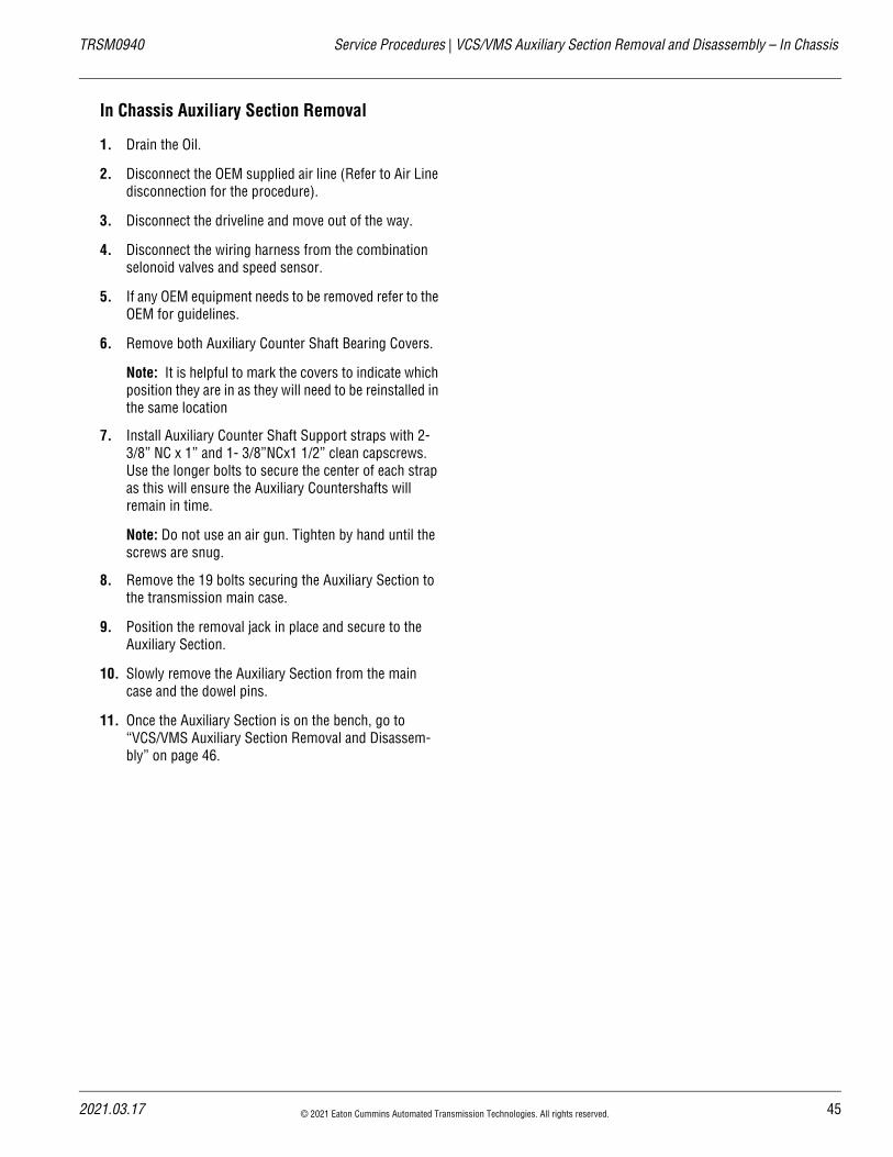
In Chassis Auxiliary Section Removal
1. Drain the Oil.
2. Disconnect the OEM supplied air line (Refer to Air Line disconnection for the procedure).
3. Disconnect the driveline and move out of the way.
4. Disconnect the wiring harness from the combination selonoid valves and speed sensor.
5. If any OEM equipment needs to be removed refer to the OEM for guidelines.
6. Remove both Auxiliary Counter Shaft Bearing Covers.
Note: It is helpful to mark the covers to indicate which position they are in as they will need to be reinstalled in the same location
7. Install Auxiliary Counter Shaft Support straps with 2- 3/8” NC x 1” and 1- 3/8”NCx1 1/2” clean capscrews. Use the longer bolts to secure the center of each strap as this will ensure the Auxiliary Countershafts will remain in time.
Note: Do not use an air gun. Tighten by hand until the screws are snug.
8. Remove the 19 bolts securing the Auxiliary Section to the transmission main case.
9. Position the removal jack in place and secure to the Auxiliary Section.
10. Slowly remove the Auxiliary Section from the main case and the dowel pins.
11. Once the Auxiliary Section is on the bench, go to “VCS/VMS Auxiliary Section Removal and Disassem-bly” on page 46.
21.03.17 © 2021 Eaton Cummins Automated Transmission Technologies. All rights reserved. 45
VCS/VMS Auxiliary Section Removal and Disassembly | Service Procedures TRSM0940
VCS/VMS Auxiliary Section Removal and DisassemblySpecial InstructionsNone
Special Tools• RR1006TR – Auxiliary Section Hanger
• RR1002TR – Counter Shaft Support Tools
• Soft bar
• Maul
• Press
• Hoist with lifting chain
• ACM Alignment Pins (P/N XXXX)
46 © 2021 Eaton Cummins Automated Transmission Technologies. All rights reserved. 2021.03.17
20
TRSM0940 Service Procedures | VCS/VMS Auxiliary Section Removal and Disassembly
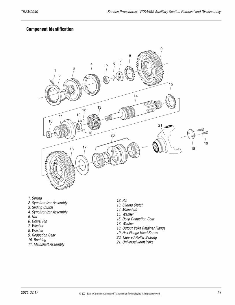
Component Identification
1. Spring2. Synchronizer Assembly3. Sliding Clutch4. Synchronizer Assembly5. Nut6. Dowel Pin7. Washer8. Washer9. Reduction Gear10. Bushing11. Mainshaft Assembly
12. Pin13. Sliding Clutch14. Mainshaft15. Washer16. Deep Reduction Gear17. Washer18. Output Yoke Retainer Flange19. Hex Flange Head Screw20. Tapered Roller Bearing21. Universal Joint Yoke
1
2
3
18
4 5 67
8
9
1011
1213
14
15
10
12
19
16 17
20
21
21.03.17 © 2021 Eaton Cummins Automated Transmission Technologies. All rights reserved. 47
VCS/VMS Auxiliary Section Removal and Disassembly | Service Procedures TRSM0940
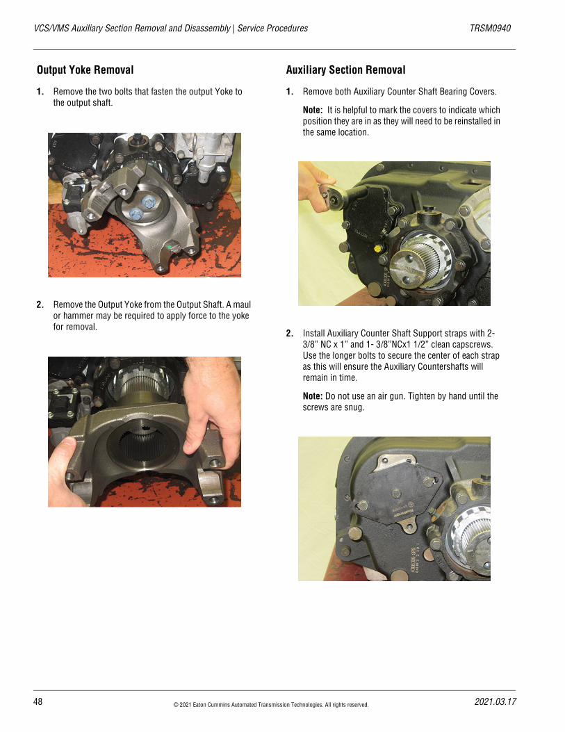
Output Yoke Removal
1. Remove the two bolts that fasten the output Yoke to the output shaft.
2. Remove the Output Yoke from the Output Shaft. A maul or hammer may be required to apply force to the yoke for removal.
Auxiliary Section Removal
1. Remove both Auxiliary Counter Shaft Bearing Covers.
Note: It is helpful to mark the covers to indicate which position they are in as they will need to be reinstalled in the same location.
2. Install Auxiliary Counter Shaft Support straps with 2- 3/8” NC x 1” and 1- 3/8”NCx1 1/2” clean capscrews. Use the longer bolts to secure the center of each strap as this will ensure the Auxiliary Countershafts will remain in time.
Note: Do not use an air gun. Tighten by hand until the screws are snug.
48 © 2021 Eaton Cummins Automated Transmission Technologies. All rights reserved. 2021.03.17
20
TRSM0940 Service Procedures | VCS/VMS Auxiliary Section Removal and Disassembly
3. Remove the 19 bolts that fasten the Auxiliary Section to the Transmission Main Case.
4. Using a pry bar to assist, separate the Auxiliary Section from the transmission main case enough to fit the aux-iliary section hanger (RR1006TR) into place.
Note: If unable to free Auxiliary section, use the two (2) longest bolts from the Auxiliary Case housing and insert them into the housing flange tapped holes. Tighten bolts evenly to move the Auxiliary Section away from the front box. Tighten until the gasket seal is broken.
5. Using an overhead crane or hoist, remove the Auxiliary Section with the auxiliary section hanger.
Note: The weight of the Auxiliary Section must be sup-ported during removal to avoid damage to internal transmission parts.
21.03.17 © 2021 Eaton Cummins Automated Transmission Technologies. All rights reserved. 49
VCS/VMS Auxiliary Section Removal and Disassembly | Service Procedures TRSM0940
Auxiliary Section Disassembly
1. Remove the 5 cap screws that fasten the Combination Cylinder Cover to the Auxiliary Main case. Remove the Range Cover.
2. Remove the 15/16” & 3/4” nuts that fasten the Range and Reduction Pistons to the Range and Reduction shift Yoke bars.
3. Remove the Combination Cylinder assembly.
Note: For Combination Disassembly and Assembly, see
4. Prepare the Auxiliary Section to remove the Auxiliary Counter Shafts. For ease of disassembly, mount the Auxiliary Section upright in a vise.
50 © 2021 Eaton Cummins Automated Transmission Technologies. All rights reserved. 2021.03.17
20
TRSM0940 Service Procedures | VCS/VMS Auxiliary Section Removal and Disassembly
5. Loosen the 1 1/2” nut retainer on the Output Shaft. Do not remove the nut.
Note: To prevent the counter shafts from turning, place a shop rag or equivalent between the splitter gear and one counter shaft.
6. Using a soft bar and maul, drive the Output Shaft for-ward far enough to partially unseat the bearing.
7. Support the Auxiliary Countershaft and remove the strap from the rear of the Auxiliary Case Housing
8. As the counter shaft straps are removed, the Counter Shaft can fall!
9. Repeat process to remove 2nd Auxiliary Counter Shaft.
10. Remove the Auxiliary Counter Shaft Bearing Races from their bores.
21.03.17 © 2021 Eaton Cummins Automated Transmission Technologies. All rights reserved. 51
VCS/VMS Auxiliary Section Removal and Disassembly | Service Procedures TRSM0940
11. If necessary, secure the Countershafts in a vise and remove both the front and rear bearings from the shafts with a bearing separator and jaw pullers.
12. Remove the 1 ½” nut retainer that was loosened in step 6.
13. Remove the washer and dowel pin from the Auxiliary Mainshaft
52 © 2021 Eaton Cummins Automated Transmission Technologies. All rights reserved. 2021.03.17
20
TRSM0940 Service Procedures | VCS/VMS Auxiliary Section Removal and Disassembly
14. Remove the Range Synchronizer Assembly with the Range Yoke from the Output Shaft.
Note: For disassembly and assembly of the Synchro-nizer, please refer to the “How to disassemble the Synchronizer Assembly” section.
15. Remove the Low Range Gear and Coupler Assembly.
16. Using a punch and hammer, drive the two coupler pins from the front of the coupler. Align the coupler splines with the washer splines and remove the range coupler from the Low Ranger Gear (Reduction Gear).
17. Remove the bushings from inside the coupler if neces-sary.
21.03.17 © 2021 Eaton Cummins Automated Transmission Technologies. All rights reserved. 53
VCS/VMS Auxiliary Section Removal and Disassembly | Service Procedures TRSM0940
18. Align the Splined Washer along the Coupler Shaft. Remove the Coupler from the Range Gear and Washer.
19. Remove the splined washer from inside the Low Range Gear (Reduction Gear)
20. Remove the sliding clutch and Deep Reduction Yoke Assembly.
21. Using a soft bar and maul, drive the Output Shaft for-ward and through the Rear Bearing Assembly.
54 © 2021 Eaton Cummins Automated Transmission Technologies. All rights reserved. 2021.03.17
20
TRSM0940 Service Procedures | VCS/VMS Auxiliary Section Removal and Disassembly
22. Remove the six cap screws that fasten the Output Shaft bearing cover tot eh Auxiliary Section.
23. Remove the Output Shaft bearing cover.
24. Inspect the Rear Bearing Cover oil seal for damage. Remove if damage is found.
25. Remove the rear portion of the tapered bearing which should be free sitting in the race in the case. Also remove the one piece race from it’s bore.
21.03.17 © 2021 Eaton Cummins Automated Transmission Technologies. All rights reserved. 55
VCS/VMS Auxiliary Section Removal and Disassembly | Service Procedures TRSM0940
Auxiliary Mainshaft Assembly Disassembly
1. Remove the bearing inner spacer from the Output Shaft
2. Using the Deep Reduction Gear front as a base, press the Output Shaft through the bearing and gear.
Note: If reusing the bearing set, the tapered roller bear-ings are specific to each side of the race.
3. Remove the spacer and stepped washer from the Deep Reduction Gear
56 © 2021 Eaton Cummins Automated Transmission Technologies. All rights reserved. 2021.03.17
20
TRSM0940 Service Procedures | VCS/VMS Auxiliary Section Assembly and Installation
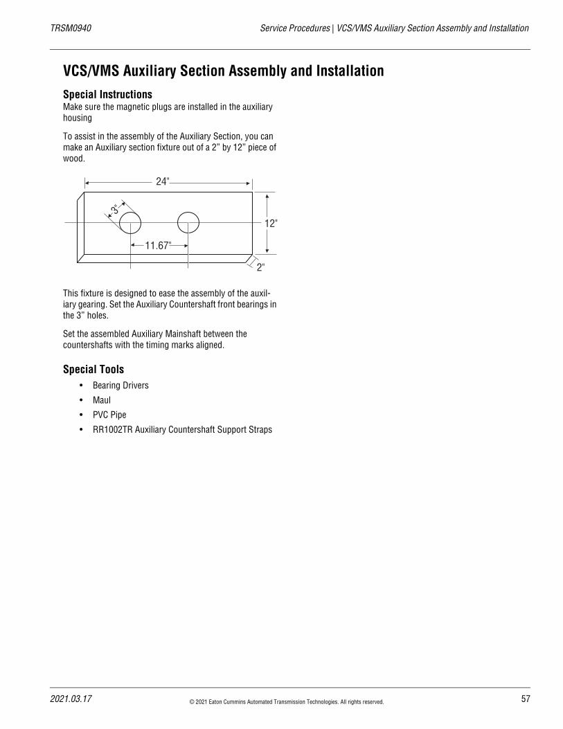
VCS/VMS Auxiliary Section Assembly and InstallationSpecial InstructionsMake sure the magnetic plugs are installed in the auxiliary housing
To assist in the assembly of the Auxiliary Section, you can make an Auxiliary section fixture out of a 2” by 12” piece of wood.
This fixture is designed to ease the assembly of the auxil-iary gearing. Set the Auxiliary Countershaft front bearings in the 3” holes.
Set the assembled Auxiliary Mainshaft between the countershafts with the timing marks aligned.
Special Tools• Bearing Drivers
• Maul
• PVC Pipe
• RR1002TR Auxiliary Countershaft Support Straps
24"
12"
2"
11.67"
3"
21.03.17 © 2021 Eaton Cummins Automated Transmission Technologies. All rights reserved. 57
VCS/VMS Auxiliary Section Assembly and Installation | Service Procedures TRSM0940
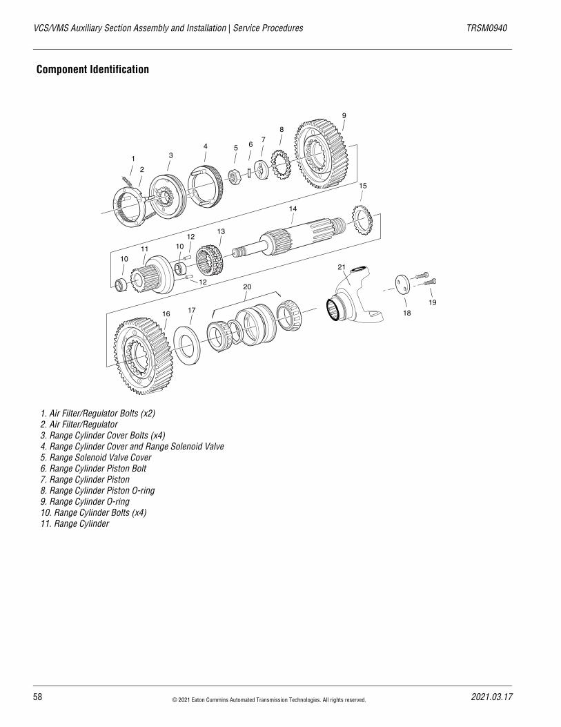
Component Identification
1. Air Filter/Regulator Bolts (x2)2. Air Filter/Regulator3. Range Cylinder Cover Bolts (x4)4. Range Cylinder Cover and Range Solenoid Valve5. Range Solenoid Valve Cover6. Range Cylinder Piston Bolt7. Range Cylinder Piston8. Range Cylinder Piston O-ring9. Range Cylinder O-ring10. Range Cylinder Bolts (x4)11. Range Cylinder
1
2
3
18
4 5 67
8
9
1011
1213
14
15
10
12
19
16 17
20
21
58 © 2021 Eaton Cummins Automated Transmission Technologies. All rights reserved. 2021.03.17
20
TRSM0940 Service Procedures | VCS/VMS Auxiliary Section Assembly and Installation
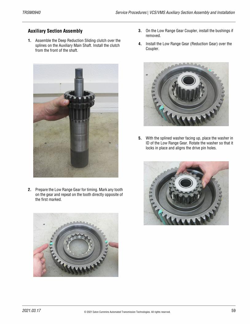
Auxiliary Section Assembly
1. Assemble the Deep Reduction Sliding clutch over the splines on the Auxiliary Main Shaft. Install the clutch from the front of the shaft.
2. Prepare the Low Range Gear for timing. Mark any tooth on the gear and repeat on the tooth directly opposite of the first marked.
3. On the Low Range Gear Coupler, install the bushings if removed.
4. Install the Low Range Gear (Reduction Gear) over the Coupler.
5. With the splined washer facing up, place the washer in ID of the Low Range Gear. Rotate the washer so that it locks in place and aligns the drive pin holes.
21.03.17 © 2021 Eaton Cummins Automated Transmission Technologies. All rights reserved. 59
VCS/VMS Auxiliary Section Assembly and Installation | Service Procedures TRSM0940
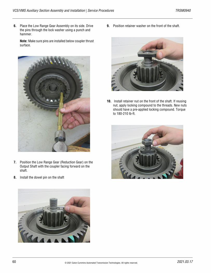
6. Place the Low Range Gear Assembly on its side. Drive the pins through the lock washer using a punch and hammer.
Note: Make sure pins are installed below coupler thrust surface.
7. Position the Low Range Gear (Reduction Gear) on the Output Shaft with the coupler facing forward on the shaft.
8. Install the dowel pin on the shaft
9. Position retainer washer on the front of the shaft.
10. Install retainer nut on the front of the shaft. If reusing nut, apply locking compound to the threads. New nuts should have a pre-applied locking compound. Torque to 180-210 lb-ft.
60 © 2021 Eaton Cummins Automated Transmission Technologies. All rights reserved. 2021.03.17
20
TRSM0940 Service Procedures | VCS/VMS Auxiliary Section Assembly and Installation
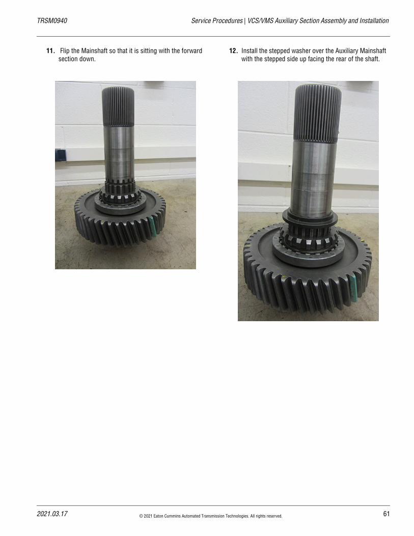
11. Flip the Mainshaft so that it is sitting with the forward section down.
12. Install the stepped washer over the Auxiliary Mainshaft with the stepped side up facing the rear of the shaft.
21.03.17 © 2021 Eaton Cummins Automated Transmission Technologies. All rights reserved. 61
VCS/VMS Auxiliary Section Assembly and Installation | Service Procedures TRSM0940
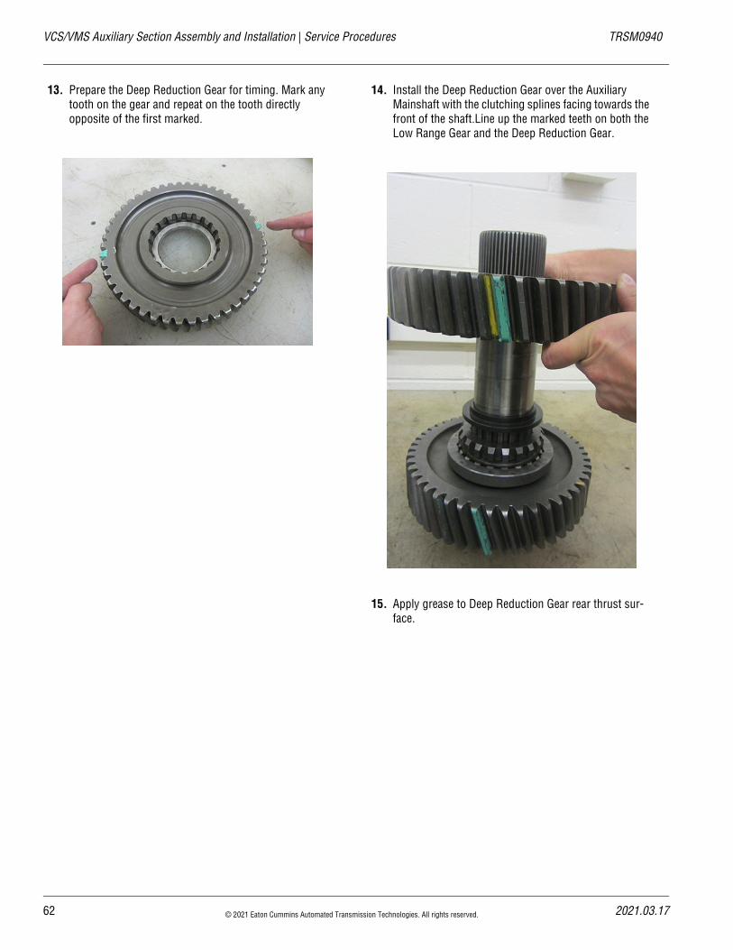
13. Prepare the Deep Reduction Gear for timing. Mark any tooth on the gear and repeat on the tooth directly opposite of the first marked.
14. Install the Deep Reduction Gear over the Auxiliary Mainshaft with the clutching splines facing towards the front of the shaft.Line up the marked teeth on both the Low Range Gear and the Deep Reduction Gear.
15. Apply grease to Deep Reduction Gear rear thrust sur-face.
62 © 2021 Eaton Cummins Automated Transmission Technologies. All rights reserved. 2021.03.17
20
TRSM0940 Service Procedures | VCS/VMS Auxiliary Section Assembly and Installation
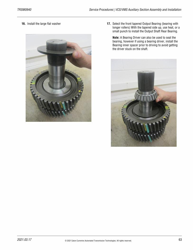
16. Install the large flat washer 17. Select the front tapered Output Bearing (bearing with longer rollers) With the tapered side up, use heat, or a small punch to install the Output Shaft Rear Bearing.
Note: A Bearing Driver can also be used to seat the bearing, however if using a bearing driver, install the Bearing inner spacer prior to driving to avoid getting the driver stuck on the shaft.
21.03.17 © 2021 Eaton Cummins Automated Transmission Technologies. All rights reserved. 63
VCS/VMS Auxiliary Section Assembly and Installation | Service Procedures TRSM0940
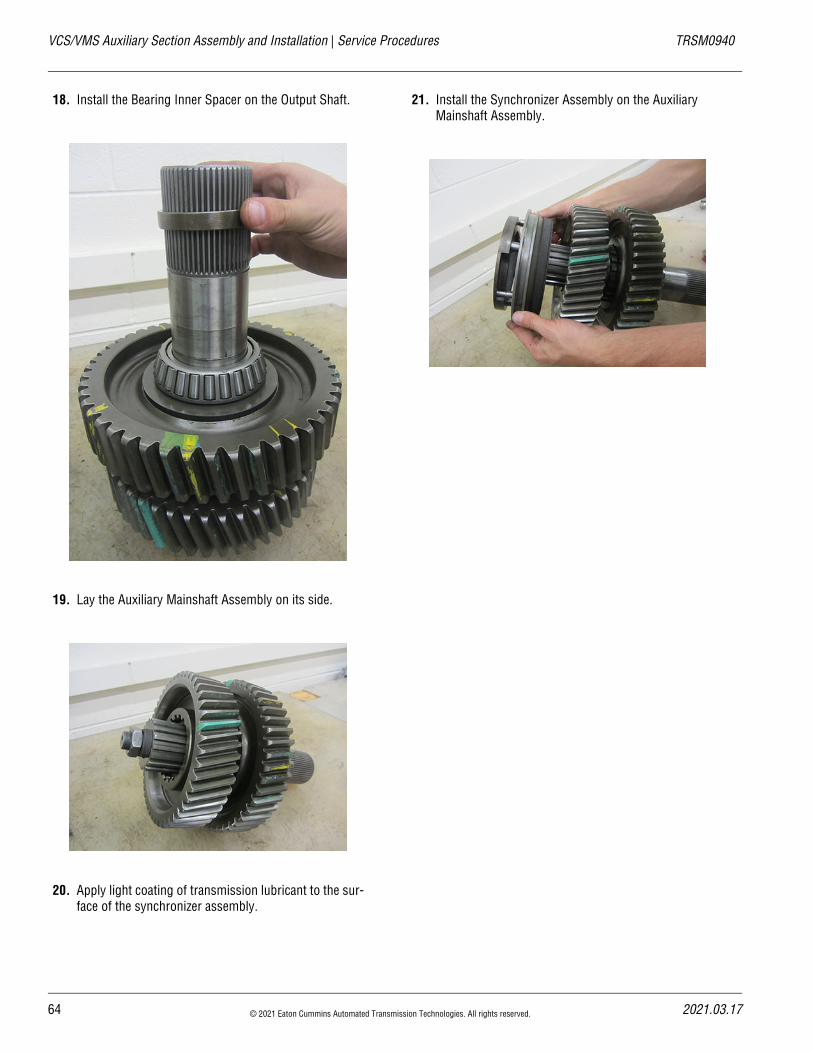
18. Install the Bearing Inner Spacer on the Output Shaft.
19. Lay the Auxiliary Mainshaft Assembly on its side.
20. Apply light coating of transmission lubricant to the sur-face of the synchronizer assembly.
21. Install the Synchronizer Assembly on the Auxiliary Mainshaft Assembly.
64 © 2021 Eaton Cummins Automated Transmission Technologies. All rights reserved. 2021.03.17
20
TRSM0940 Service Procedures | VCS/VMS Auxiliary Section Assembly and Installation
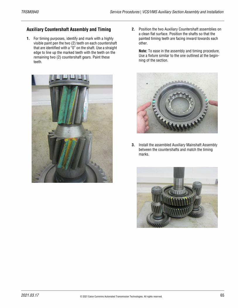
Auxiliary Countershaft Assembly and Timing
1. For timing purposes, identify and mark with a highly visible paint pen the two (2) teeth on each countershaft that are identified with a “0” on the shaft. Use a straight edge to line up the marked teeth with the teeth on the remaining two (2) countershaft gears. Paint these teeth.
2. Position the two Auxiliary Countershaft assemblies on a clean flat surface. Position the shafts so that the painted timing teeth are facing inward towards each other.
Note: To ease in the assembly and timing procedure. Use a fixture similar to the one outlined at the begin-ning of the section.
3. Install the assembled Auxiliary Mainshaft Assembly between the countershafts and match the timing marks.
21.03.17 © 2021 Eaton Cummins Automated Transmission Technologies. All rights reserved. 65
VCS/VMS Auxiliary Section Assembly and Installation | Service Procedures TRSM0940
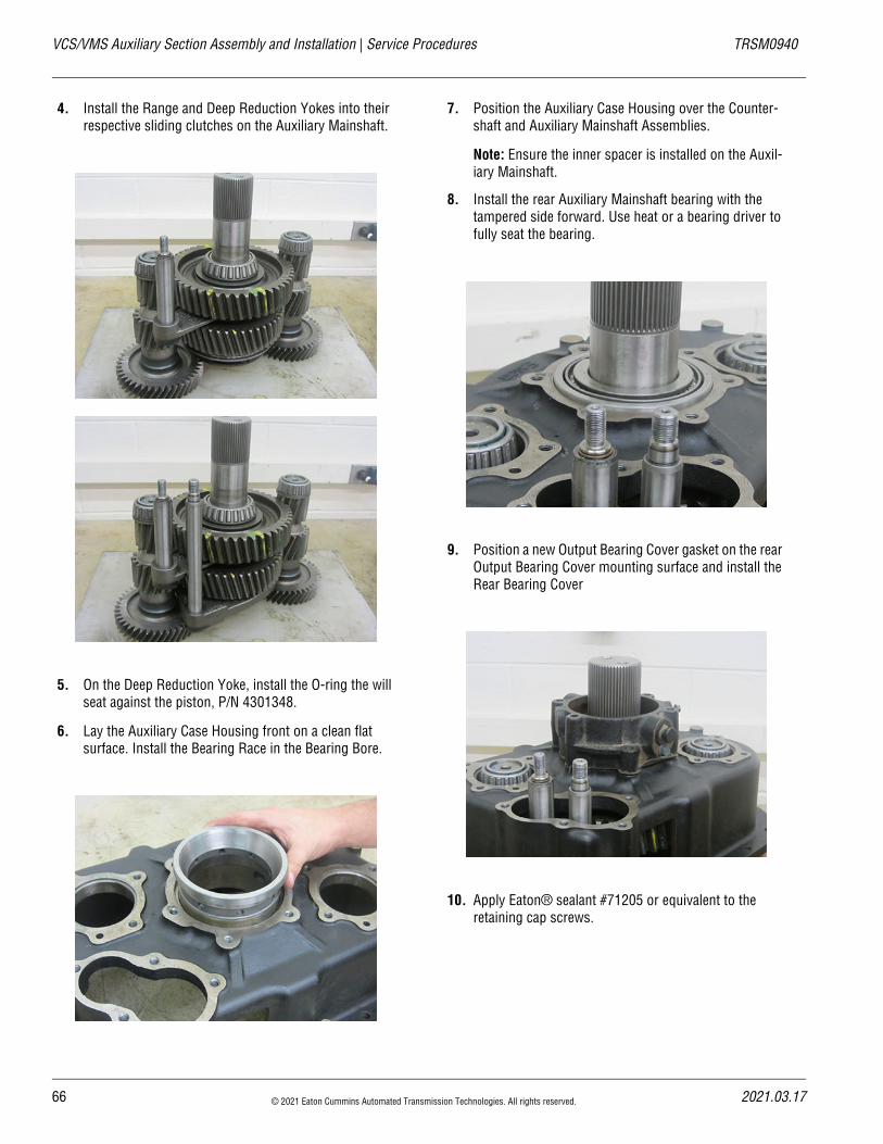
4. Install the Range and Deep Reduction Yokes into their respective sliding clutches on the Auxiliary Mainshaft.
5. On the Deep Reduction Yoke, install the O-ring the will seat against the piston, P/N 4301348.
6. Lay the Auxiliary Case Housing front on a clean flat surface. Install the Bearing Race in the Bearing Bore.
7. Position the Auxiliary Case Housing over the Counter-shaft and Auxiliary Mainshaft Assemblies.
Note: Ensure the inner spacer is installed on the Auxil-iary Mainshaft.
8. Install the rear Auxiliary Mainshaft bearing with the tampered side forward. Use heat or a bearing driver to fully seat the bearing.
9. Position a new Output Bearing Cover gasket on the rear Output Bearing Cover mounting surface and install the Rear Bearing Cover
10. Apply Eaton® sealant #71205 or equivalent to the retaining cap screws.
66 © 2021 Eaton Cummins Automated Transmission Technologies. All rights reserved. 2021.03.17
20
TRSM0940 Service Procedures | VCS/VMS Auxiliary Section Assembly and Installation
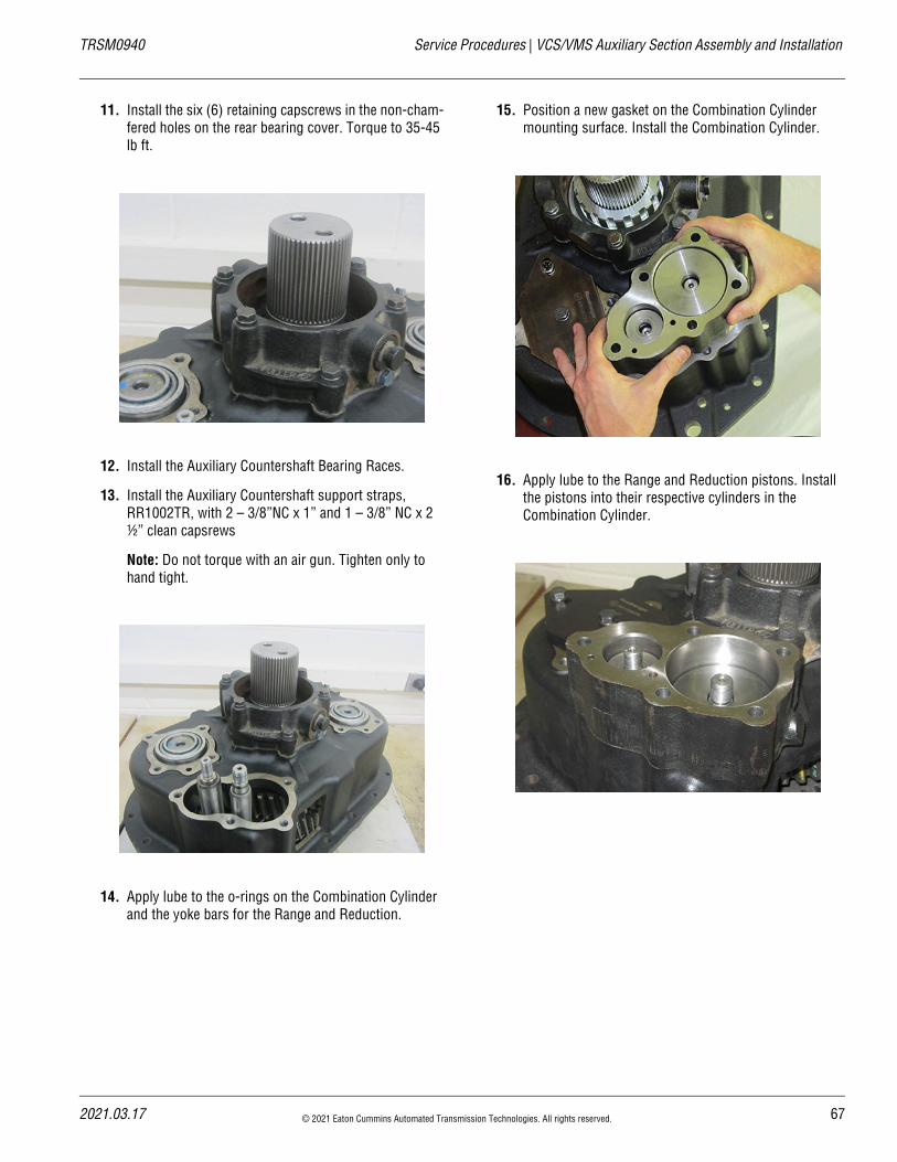
11. Install the six (6) retaining capscrews in the non-cham-fered holes on the rear bearing cover. Torque to 35-45 lb ft.
12. Install the Auxiliary Countershaft Bearing Races.
13. Install the Auxiliary Countershaft support straps, RR1002TR, with 2 – 3/8”NC x 1” and 1 – 3/8” NC x 2 ½” clean capsrews
Note: Do not torque with an air gun. Tighten only to hand tight.
14. Apply lube to the o-rings on the Combination Cylinder and the yoke bars for the Range and Reduction.
15. Position a new gasket on the Combination Cylinder mounting surface. Install the Combination Cylinder.
16. Apply lube to the Range and Reduction pistons. Install the pistons into their respective cylinders in the Combination Cylinder.
21.03.17 © 2021 Eaton Cummins Automated Transmission Technologies. All rights reserved. 67
VCS/VMS Auxiliary Section Assembly and Installation | Service Procedures TRSM0940
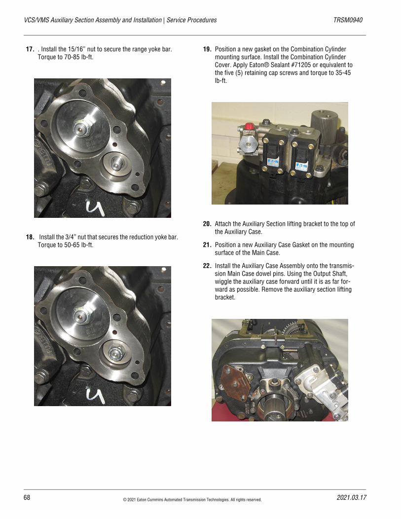
17. . Install the 15/16” nut to secure the range yoke bar. Torque to 70-85 lb-ft.
18. Install the 3/4” nut that secures the reduction yoke bar. Torque to 50-65 lb-ft.
19. Position a new gasket on the Combination Cylinder mounting surface. Install the Combination Cylinder Cover. Apply Eaton® Sealant #71205 or equivalent to the five (5) retaining cap screws and torque to 35-45 lb-ft.
20. Attach the Auxiliary Section lifting bracket to the top of the Auxiliary Case.
21. Position a new Auxiliary Case Gasket on the mounting surface of the Main Case.
22. Install the Auxiliary Case Assembly onto the transmis-sion Main Case dowel pins. Using the Output Shaft, wiggle the auxiliary case forward until it is as far for-ward as possible. Remove the auxiliary section lifting bracket.
68 © 2021 Eaton Cummins Automated Transmission Technologies. All rights reserved. 2021.03.17
20
TRSM0940 Service Procedures | VCS/VMS Auxiliary Section Assembly and Installation
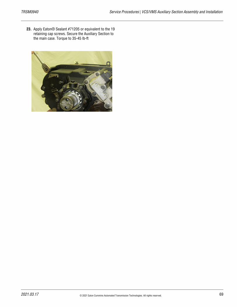
23. Apply Eaton® Sealant #71205 or equivalent to the 19 retaining cap screws. Secure the Auxiliary Section to the main case. Torque to 35-45 lb-ft
21.03.17 © 2021 Eaton Cummins Automated Transmission Technologies. All rights reserved. 69
VCS/VMS Combination Cylinder Disassembly and Assembly | Service Procedures TRSM0940
VCS/VMS Combination Cylinder Disassembly and AssemblySpecial InstructionsApply Eaton® Lubricant or equivalent to Shift Cylinder Assembly and insert valve O-Rings so a film covers the entire surface of each O-Ring.
The same Installation and Removal procedures can be fol-lowed for both the range and reduction valves of the Combi-nation Cylinder Assembly
The Range and Reduction Valves may be difficult to remove from the Transmission Housing because of the O-rings.
Special ToolsTypical Service Tool
70 © 2021 Eaton Cummins Automated Transmission Technologies. All rights reserved. 2021.03.17
20
TRSM0940 Service Procedures | VCS/VMS Combination Cylinder Disassembly and Assembly
Component Identification
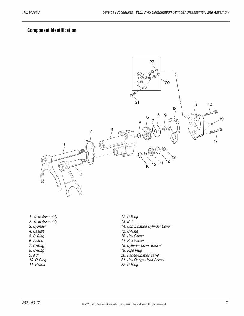
1. Yoke Assembly2. Yoke Assembly3. Cylinder4. Gasket5. O-Ring6. Piston7. O-Ring8. O-Ring9. Nut10. O-Ring11. Piston
12. O-Ring13. Nut14. Combination Cylinder Cover15. O-Ring16. Hex Screw17. Hex Screw18. Cylinder Cover Gasket19. Pipe Plug20. Range/Splitter Valve21. Hex Flange Head Screw22. O-Ring
1
2
34
56
798
14 16
10 15 11 1213
21
20
22
17
18
19
21.03.17 © 2021 Eaton Cummins Automated Transmission Technologies. All rights reserved. 71
VCS/VMS Combination Cylinder Disassembly and Assembly | Service Procedures TRSM0940
VCS/VMS Combination Cylinder Disassembly
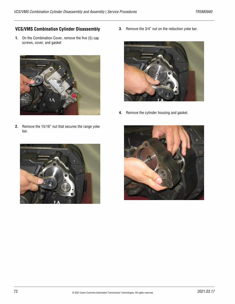
1. On the Combination Cover, remove the five (5) cap screws, cover, and gasket
2. Remove the 15/16” nut that secures the range yoke bar.
3. Remove the 3/4” nut on the reduction yoke bar.
4. Remove the cylinder housing and gasket.
72 © 2021 Eaton Cummins Automated Transmission Technologies. All rights reserved. 2021.03.17
20
TRSM0940 Service Procedures | VCS/VMS Combination Cylinder Disassembly and Assembly
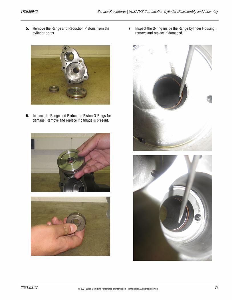
5. Remove the Range and Reduction Pistons from the cylinder bores
6. Inspect the Range and Reduction Piston O-Rings for damage. Remove and replace if damage is present.
7. Inspect the O-ring inside the Range Cylinder Housing, remove and replace if damaged.
21.03.17 © 2021 Eaton Cummins Automated Transmission Technologies. All rights reserved. 73
VCS/VMS Combination Cylinder Disassembly and Assembly | Service Procedures TRSM0940
Procedure – Combination Cylinder Assembly - VCS, VMS
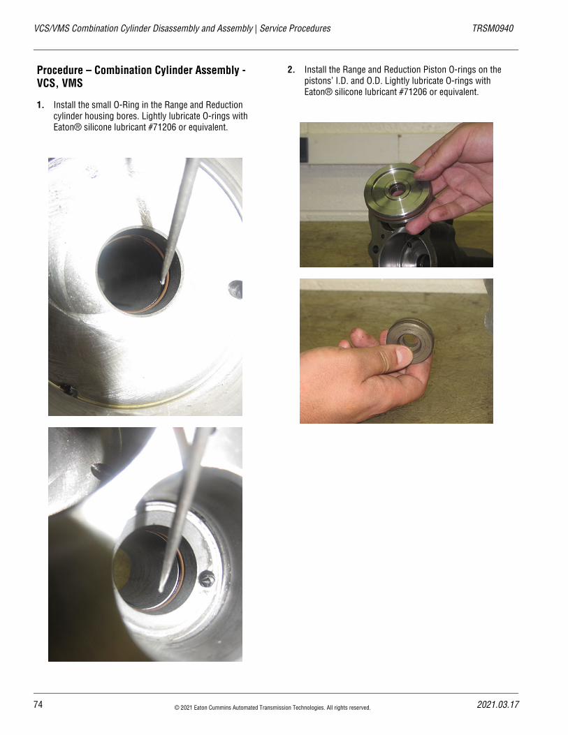
1. Install the small O-Ring in the Range and Reduction cylinder housing bores. Lightly lubricate O-rings with Eaton® silicone lubricant #71206 or equivalent.
2. Install the Range and Reduction Piston O-rings on the pistons’ I.D. and O.D. Lightly lubricate O-rings with Eaton® silicone lubricant #71206 or equivalent.
74 © 2021 Eaton Cummins Automated Transmission Technologies. All rights reserved. 2021.03.17
20
TRSM0940 Service Procedures | VCS/VMS Combination Cylinder Disassembly and Assembly
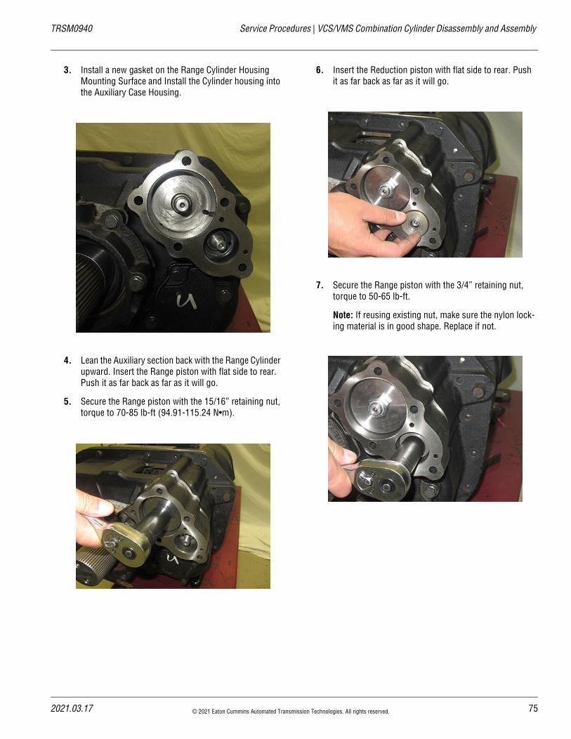
3. Install a new gasket on the Range Cylinder Housing Mounting Surface and Install the Cylinder housing into the Auxiliary Case Housing.
4. Lean the Auxiliary section back with the Range Cylinder upward. Insert the Range piston with flat side to rear. Push it as far back as far as it will go.
5. Secure the Range piston with the 15/16” retaining nut, torque to 70-85 lb-ft (94.91-115.24 N•m).
6. Insert the Reduction piston with flat side to rear. Push it as far back as far as it will go.
7. Secure the Range piston with the 3/4” retaining nut, torque to 50-65 lb-ft.
Note: If reusing existing nut, make sure the nylon lock-ing material is in good shape. Replace if not.
21.03.17 © 2021 Eaton Cummins Automated Transmission Technologies. All rights reserved. 75
VCS/VMS Combination Cylinder Disassembly and Assembly | Service Procedures TRSM0940
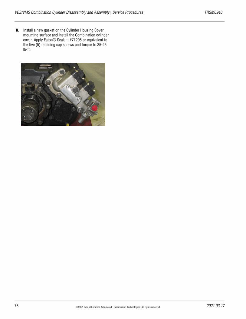
8. Install a new gasket on the Cylinder Housing Cover mounting surface and install the Combination cylinder cover. Apply Eaton® Sealant #71205 or equivalent to the five (5) retaining cap screws and torque to 35-45 lb-ft.
76 © 2021 Eaton Cummins Automated Transmission Technologies. All rights reserved. 2021.03.17
20
TRSM0940 Service Procedures | VCS/VMS Combination Valve Removal and Installation
VCS/VMS Combination Valve Removal and InstallationSpecial InstructionsNone
Special ToolsNone
Component Identification
None
21.03.17 © 2021 Eaton Cummins Automated Transmission Technologies. All rights reserved. 77
VCS/VMS Combination Valve Removal and Installation | Service Procedures TRSM0940
Combination Valve Removal
1. If equipped, remove the protective cover by pulling up on the release tab
2. Relieve system air pressure by draining air tanks on the vehicle. When air pressure has been relieved, dis-connect the transmission harness from the combina-tion valve.
3. Using a 5/16” Socket, remove the 4 mounting cap-screws from the combination valve.
4. Lift and remove the Combination valve from the hous-ing.
5. Do not use a hammer to loosen the Combination Valve or it could be damaged.
Combination Valve Installation
1. If equipped, remove the protective cover by pulling up on the release tab
Important: Follow each procedure closely in the detailed instructions. Be sure to make use of the text, illustrations and photographs provided.
2. Relieve system air pressure by draining air tanks on the vehicle. When air pressure has been relieved, dis-connect the transmission harness from the combina-tion valve.
3. Using a 5/16” Socket, remove the 4 mounting cap-screws from the combination valve.
4. Lift and remove the Combination valve from the hous-ing.
Caution: Do not use a hammer to loosen the Combina-tion Valve or it could be damaged.
!
!
78 © 2021 Eaton Cummins Automated Transmission Technologies. All rights reserved. 2021.03.17
20
TRSM0940 Service Procedures | MHP/MXP/VHP/VXP Auxiliary Section Removal and Disassembly
MHP/MXP/VHP/VXP Auxiliary Section Removal and DisassemblySpecial InstructionsNone
Special Tools• RR1006TR – Auxiliary Section Hanger
• RR1002TR – Counter Shaft Support Tools
• Soft bar
• Maul
• Press
• ACM Alignment Pins (P/N XXXX)
21.03.17 © 2021 Eaton Cummins Automated Transmission Technologies. All rights reserved. 79
MHP/MXP/VHP/VXP Auxiliary Section Removal and Disassembly | Service Procedures TRSM0940
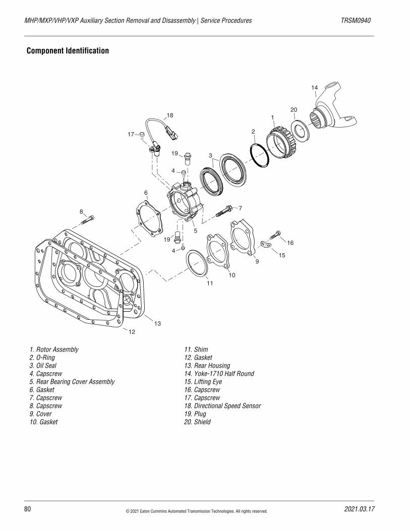
Component Identification
1. Rotor Assembly2. O-Ring3. Oil Seal4. Capscrew5. Rear Bearing Cover Assembly6. Gasket7. Capscrew8. Capscrew9. Cover10. Gasket
11. Shim12. Gasket13. Rear Housing14. Yoke-1710 Half Round15. Lifting Eye16. Capscrew17. Capscrew18. Directional Speed Sensor19. Plug20. Shield
4
6
3
7
5
2
1
9
8
1011
1213
14
15
16
17
18
19
20
4
19
80 © 2021 Eaton Cummins Automated Transmission Technologies. All rights reserved. 2021.03.17
20
TRSM0940 Service Procedures | MHP/MXP/VHP/VXP Auxiliary Section Removal and Disassembly
Output Yoke Removal
1. Remove the two bolts that fasten the output Yoke to the output shaft.
2. Remove the Output Yoke from the Output Shaft. A maul or hammer may be required to apply force to the yoke for removal.
Auxiliary Section Removal
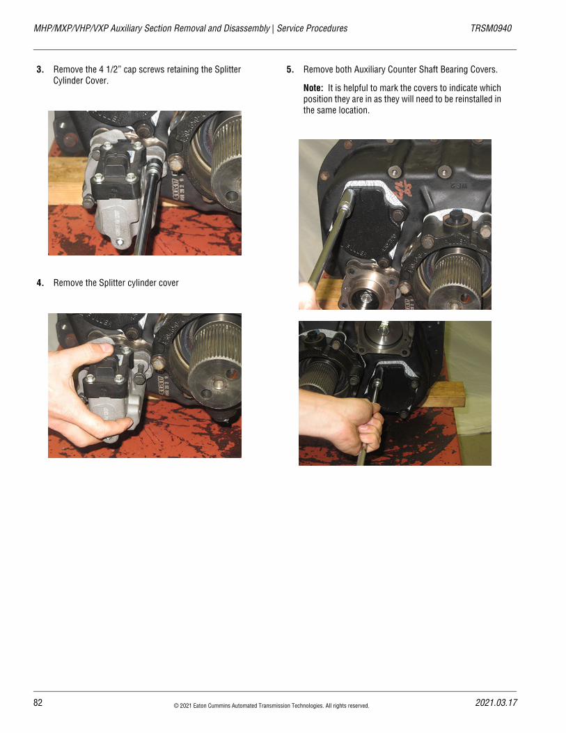
1. Remove the 4 9/16” cap screws on the Range Cylinder Cover.
2. Remove the Range Cover Assembly
21.03.17 © 2021 Eaton Cummins Automated Transmission Technologies. All rights reserved. 81
MHP/MXP/VHP/VXP Auxiliary Section Removal and Disassembly | Service Procedures TRSM0940
3. Remove the 4 1/2” cap screws retaining the Splitter Cylinder Cover.
4. Remove the Splitter cylinder cover
5. Remove both Auxiliary Counter Shaft Bearing Covers.
Note: It is helpful to mark the covers to indicate which position they are in as they will need to be reinstalled in the same location.
82 © 2021 Eaton Cummins Automated Transmission Technologies. All rights reserved. 2021.03.17
20
TRSM0940 Service Procedures | MHP/MXP/VHP/VXP Auxiliary Section Removal and Disassembly
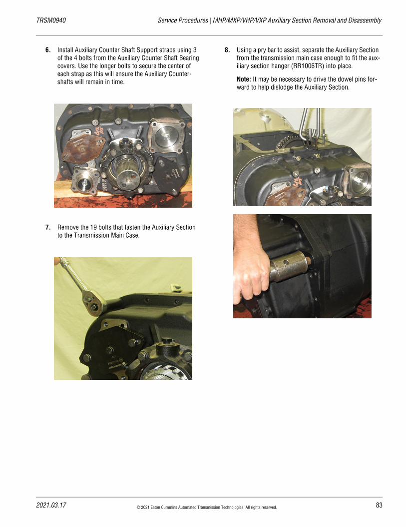
6. Install Auxiliary Counter Shaft Support straps using 3 of the 4 bolts from the Auxiliary Counter Shaft Bearing covers. Use the longer bolts to secure the center of each strap as this will ensure the Auxiliary Counter-shafts will remain in time.
7. Remove the 19 bolts that fasten the Auxiliary Section to the Transmission Main Case.
8. Using a pry bar to assist, separate the Auxiliary Section from the transmission main case enough to fit the aux-iliary section hanger (RR1006TR) into place.
Note: It may be necessary to drive the dowel pins for-ward to help dislodge the Auxiliary Section.
21.03.17 © 2021 Eaton Cummins Automated Transmission Technologies. All rights reserved. 83
MHP/MXP/VHP/VXP Auxiliary Section Removal and Disassembly | Service Procedures TRSM0940
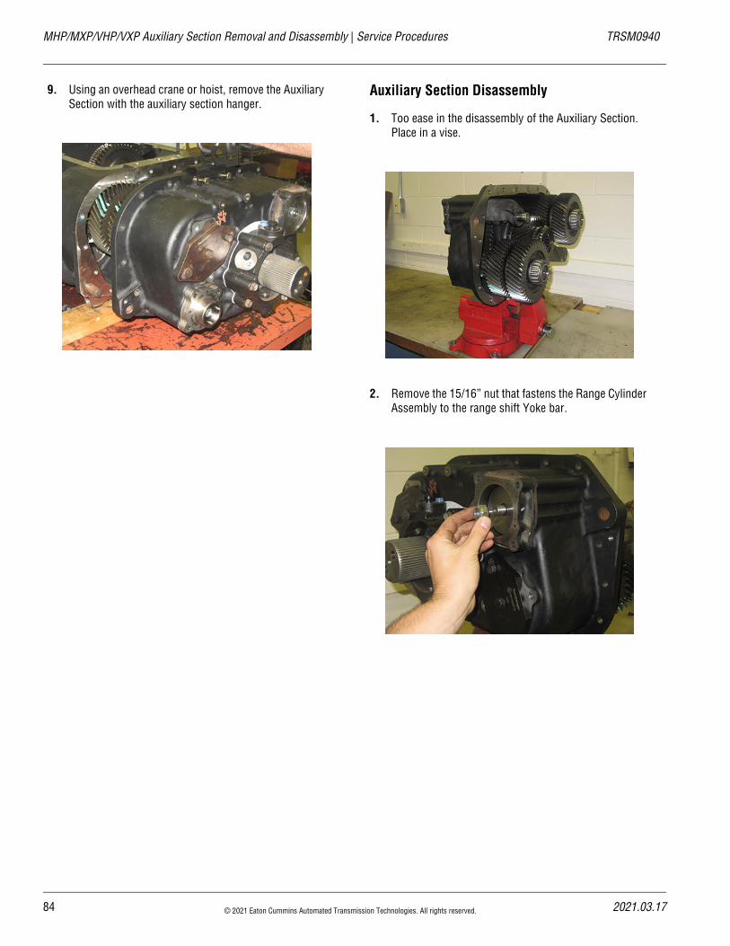
9. Using an overhead crane or hoist, remove the Auxiliary Section with the auxiliary section hanger.
Auxiliary Section Disassembly
1. Too ease in the disassembly of the Auxiliary Section. Place in a vise.
2. Remove the 15/16” nut that fastens the Range Cylinder Assembly to the range shift Yoke bar.
84 © 2021 Eaton Cummins Automated Transmission Technologies. All rights reserved. 2021.03.17
20
TRSM0940 Service Procedures | MHP/MXP/VHP/VXP Auxiliary Section Removal and Disassembly
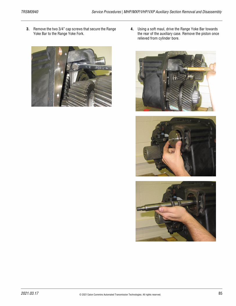
3. Remove the two 3/4” cap screws that secure the Range Yoke Bar to the Range Yoke Fork.
4. Using a soft maul, drive the Range Yoke Bar towards the rear of the auxiliary case. Remove the piston once relieved from cylinder bore.
21.03.17 © 2021 Eaton Cummins Automated Transmission Technologies. All rights reserved. 85
MHP/MXP/VHP/VXP Auxiliary Section Removal and Disassembly | Service Procedures TRSM0940
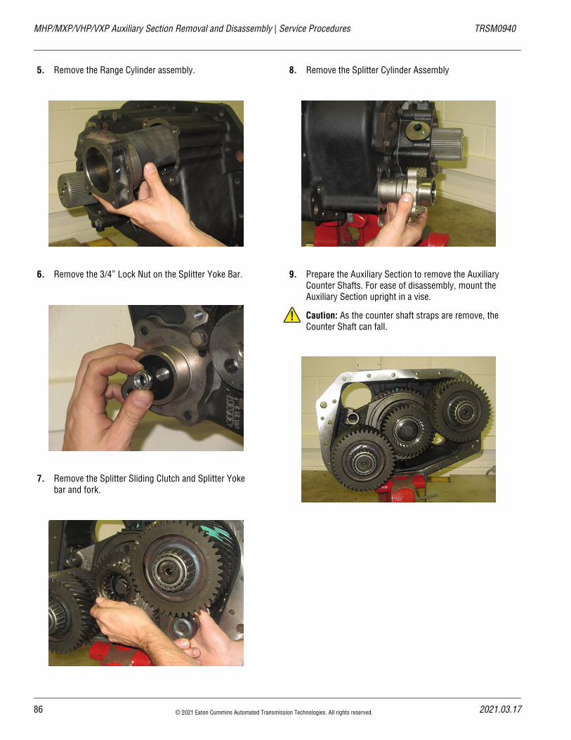
5. Remove the Range Cylinder assembly.
6. Remove the 3/4” Lock Nut on the Splitter Yoke Bar.
7. Remove the Splitter Sliding Clutch and Splitter Yoke bar and fork.
8. Remove the Splitter Cylinder Assembly
9. Prepare the Auxiliary Section to remove the Auxiliary Counter Shafts. For ease of disassembly, mount the Auxiliary Section upright in a vise.
Caution: As the counter shaft straps are remove, the Counter Shaft can fall.
!
86 © 2021 Eaton Cummins Automated Transmission Technologies. All rights reserved. 2021.03.17
20
TRSM0940 Service Procedures | MHP/MXP/VHP/VXP Auxiliary Section Removal and Disassembly
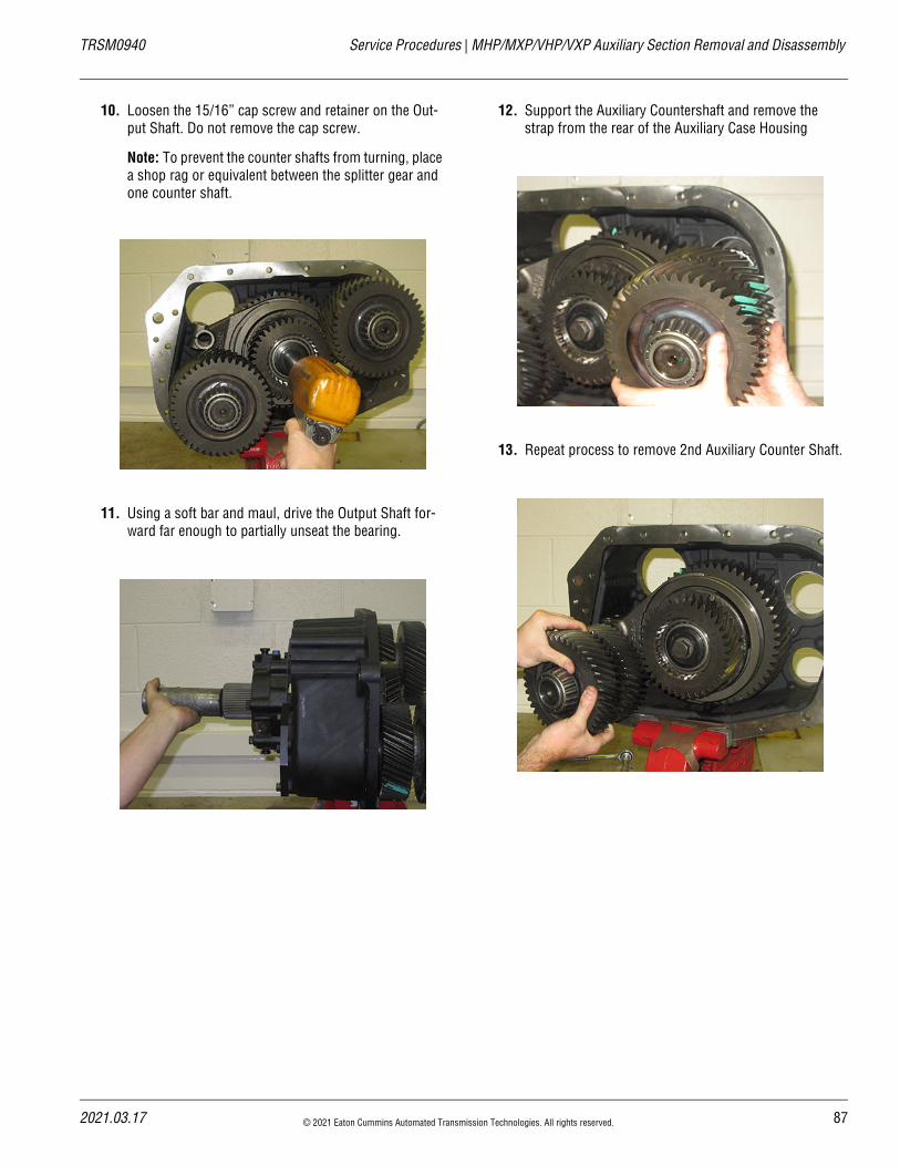
10. Loosen the 15/16” cap screw and retainer on the Out-put Shaft. Do not remove the cap screw.
Note: To prevent the counter shafts from turning, place a shop rag or equivalent between the splitter gear and one counter shaft.
11. Using a soft bar and maul, drive the Output Shaft for-ward far enough to partially unseat the bearing.
12. Support the Auxiliary Countershaft and remove the strap from the rear of the Auxiliary Case Housing
13. Repeat process to remove 2nd Auxiliary Counter Shaft.
21.03.17 © 2021 Eaton Cummins Automated Transmission Technologies. All rights reserved. 87
MHP/MXP/VHP/VXP Auxiliary Section Removal and Disassembly | Service Procedures TRSM0940
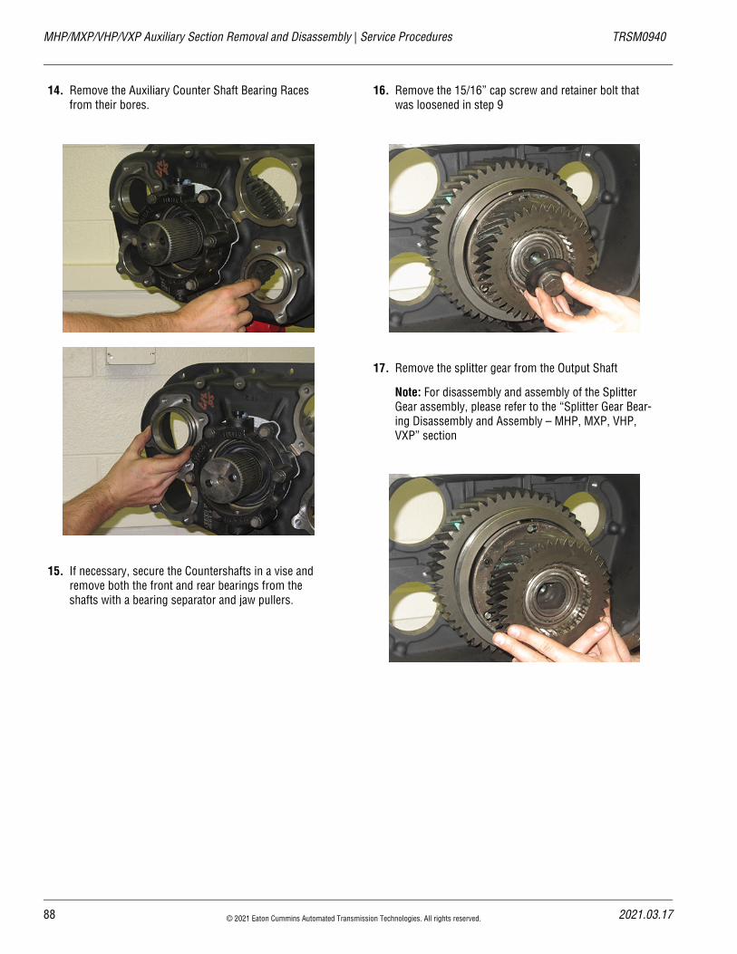
14. Remove the Auxiliary Counter Shaft Bearing Races from their bores.
15. If necessary, secure the Countershafts in a vise and remove both the front and rear bearings from the shafts with a bearing separator and jaw pullers.
16. Remove the 15/16” cap screw and retainer bolt that was loosened in step 9
17. Remove the splitter gear from the Output Shaft
Note: For disassembly and assembly of the Splitter Gear assembly, please refer to the “Splitter Gear Bear-ing Disassembly and Assembly – MHP, MXP, VHP, VXP” section
88 © 2021 Eaton Cummins Automated Transmission Technologies. All rights reserved. 2021.03.17
20
TRSM0940 Service Procedures | MHP/MXP/VHP/VXP Auxiliary Section Removal and Disassembly
18. Remove the Range Synchronizer Assembly from the Output Shaft
Note: For disassembly and assembly of the Syn-crhonizer, please refer to the “How to disassemble the Sychronizer Assembly” section.
19. Using a soft bar and maul, drive the Output Shaft for-ward and through the Rear Bearing Assembly.
20. Remove the six cap screws that fasten the Output Shaft bearing cover to the Auxiliary Section.
21. Remove the Output Shaft bearing cover.
22. Inspect the Rear Bearing Cover oil seal for damage. Remove if damage is found.
21.03.17 © 2021 Eaton Cummins Automated Transmission Technologies. All rights reserved. 89
MHP/MXP/VHP/VXP Auxiliary Section Removal and Disassembly | Service Procedures TRSM0940
23. Remove the rear portion of the tapered bearing which should be free sitting in the race in the case. Also remove the one piece race from it’s bore.
Auxiliary Mainshaft Disassembly
1. Remove the bearing inner spacer from the Output Shaft
2. Using the Auxiliary Mainshaft Assembly Gear front as a base, press the Output Shaft through the bearing and gear.
Note: If reusing the bearing set, the tapered roller bear-ings are specific to each side of the race.
90 © 2021 Eaton Cummins Automated Transmission Technologies. All rights reserved. 2021.03.17
20
TRSM0940 Service Procedures | MHP/MXP/VHP/VXP Auxiliary Section Removal and Disassembly
3. Remove the splined spacer and stepped washer from the Auxiliary Reduction Gear
21.03.17 © 2021 Eaton Cummins Automated Transmission Technologies. All rights reserved. 91
MHP/MXP/VHP/VXP Range Cylinder Disassembly and Assembly | Service Procedures TRSM0940
MHP/MXP/VHP/VXP Range Cylinder Disassembly and AssemblySpecial InstructionsOn 9-series UltraShift PLUS transmissions the Auxiliary section requires R&R prior to Range Cylinder removal. Damage to internal components will result if Auxiliary Sec-tion is not properly removed prior to Cylinder removal.
During installation, apply Eaton® Lubricant or equivalent to Shift Cylinder Assembly and insert valve O-Rings so a film covers the entire surface of each O-Ring.
Special ToolsTypical Service Tools
Component Identification
1. Hex Flange Head Screw2. O-Rings
1
2
92 © 2021 Eaton Cummins Automated Transmission Technologies. All rights reserved. 2021.03.17
20
TRSM0940 Service Procedures | MHP/MXP/VHP/VXP Range Cylinder Disassembly and Assembly
Range Cylinder Disassembly
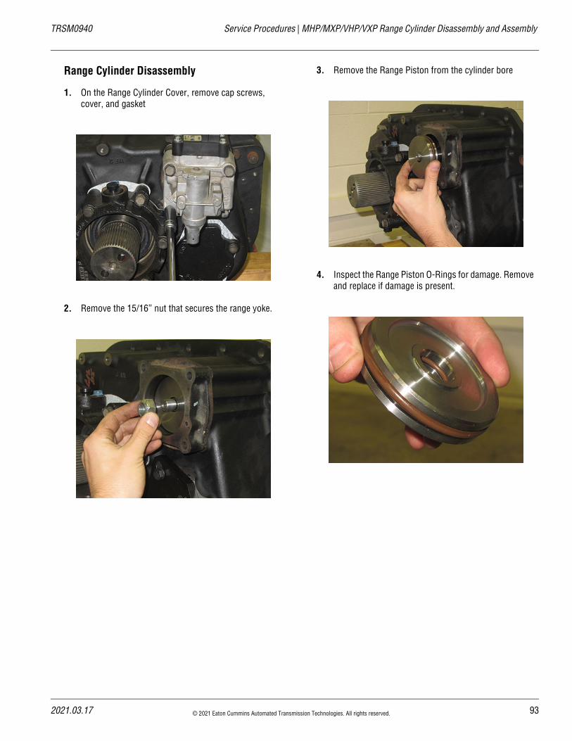
1. On the Range Cylinder Cover, remove cap screws, cover, and gasket
2. Remove the 15/16” nut that secures the range yoke.
3. Remove the Range Piston from the cylinder bore
4. Inspect the Range Piston O-Rings for damage. Remove and replace if damage is present.
21.03.17 © 2021 Eaton Cummins Automated Transmission Technologies. All rights reserved. 93
MHP/MXP/VHP/VXP Range Cylinder Disassembly and Assembly | Service Procedures TRSM0940
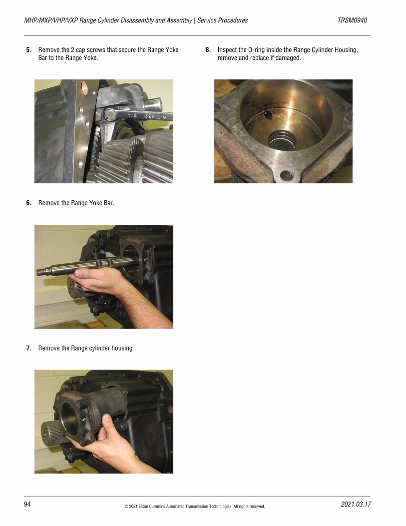
5. Remove the 2 cap screws that secure the Range Yoke Bar to the Range Yoke.
6. Remove the Range Yoke Bar.
7. Remove the Range cylinder housing
8. Inspect the O-ring inside the Range Cylinder Housing, remove and replace if damaged.
94 © 2021 Eaton Cummins Automated Transmission Technologies. All rights reserved. 2021.03.17
20
TRSM0940 Service Procedures | MHP/MXP/VHP/VXP Range Cylinder Disassembly and Assembly
Range Cylinder Assembly
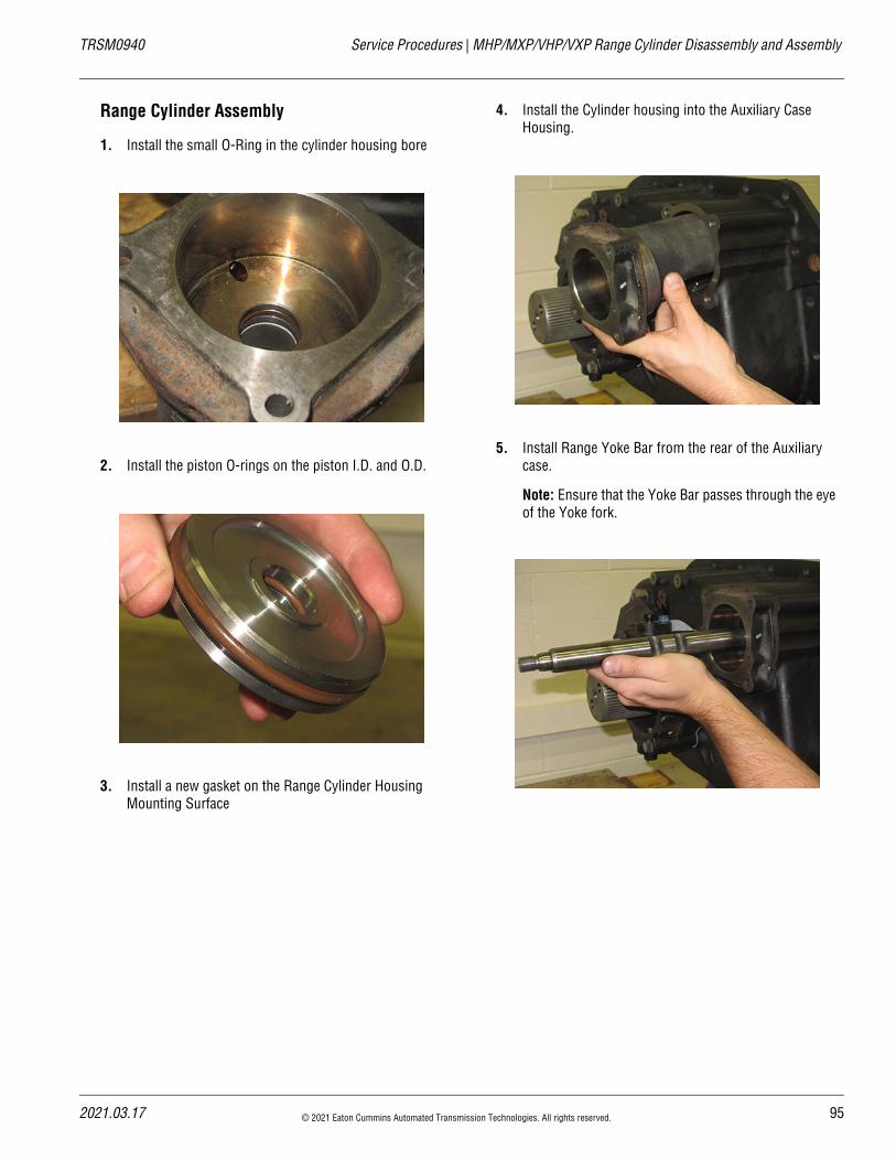
1. Install the small O-Ring in the cylinder housing bore
2. Install the piston O-rings on the piston I.D. and O.D.
3. Install a new gasket on the Range Cylinder Housing Mounting Surface
4. Install the Cylinder housing into the Auxiliary Case Housing.
5. Install Range Yoke Bar from the rear of the Auxiliary case.
Note: Ensure that the Yoke Bar passes through the eye of the Yoke fork.
21.03.17 © 2021 Eaton Cummins Automated Transmission Technologies. All rights reserved. 95
MHP/MXP/VHP/VXP Range Cylinder Disassembly and Assembly | Service Procedures TRSM0940
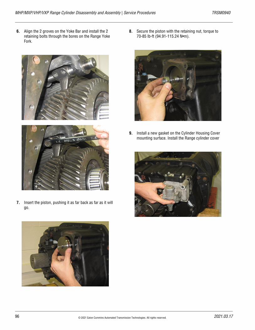
6. Align the 2 groves on the Yoke Bar and install the 2 retaining bolts through the bores on the Range Yoke Fork.
7. Insert the piston, pushing it as far back as far as it will go.
8. Secure the piston with the retaining nut, torque to 70-85 lb-ft (94.91-115.24 N•m).
9. Install a new gasket on the Cylinder Housing Cover mounting surface. Install the Range cylinder cover
96 © 2021 Eaton Cummins Automated Transmission Technologies. All rights reserved. 2021.03.17
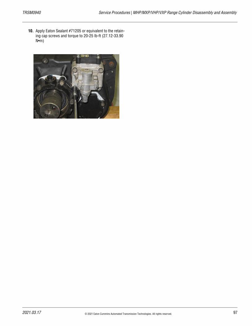
20
TRSM0940 Service Procedures | MHP/MXP/VHP/VXP Range Cylinder Disassembly and Assembly
10. Apply Eaton Sealant #71205 or equivalent to the retain-ing cap screws and torque to 20-25 lb-ft (27.12-33.90 N•m)
21.03.17 © 2021 Eaton Cummins Automated Transmission Technologies. All rights reserved. 97
MHP/MXP/VHP/VXP Splitter Cylinder Disassembly and Assembly | Service Procedures TRSM0940
MHP/MXP/VHP/VXP Splitter Cylinder Disassembly and AssemblySpecial InstructionsDuring removal on 9-series UltraShift PLUS transmissions the Auxiliary section requires R&R prior to Splitter Cylinder removal. Damage to internal components will result if Auxil-iary Section is not properly removed prior to Cylinder removal.
During removal if replacing only the O-Rings in the Splitter Cylinder, Auxiliary Section removal is not necessary
During installation apply Eaton® Lubricant or equivalent to Shift Cylinder Assembly and insert valve O-Rings so a film covers the entire surface of each O-Ring.
During installation apply Eaton® rust preventative #71213 or equivalent to all Shift Cylinder walls and Yoke Bars, cover the entire Yoke Bar surface that comes in contact with the Shift Cylinder O-Ring.
Special Tools• Typical Service Tools
• Vise with brass jaws or wood blocks
98 © 2021 Eaton Cummins Automated Transmission Technologies. All rights reserved. 2021.03.17
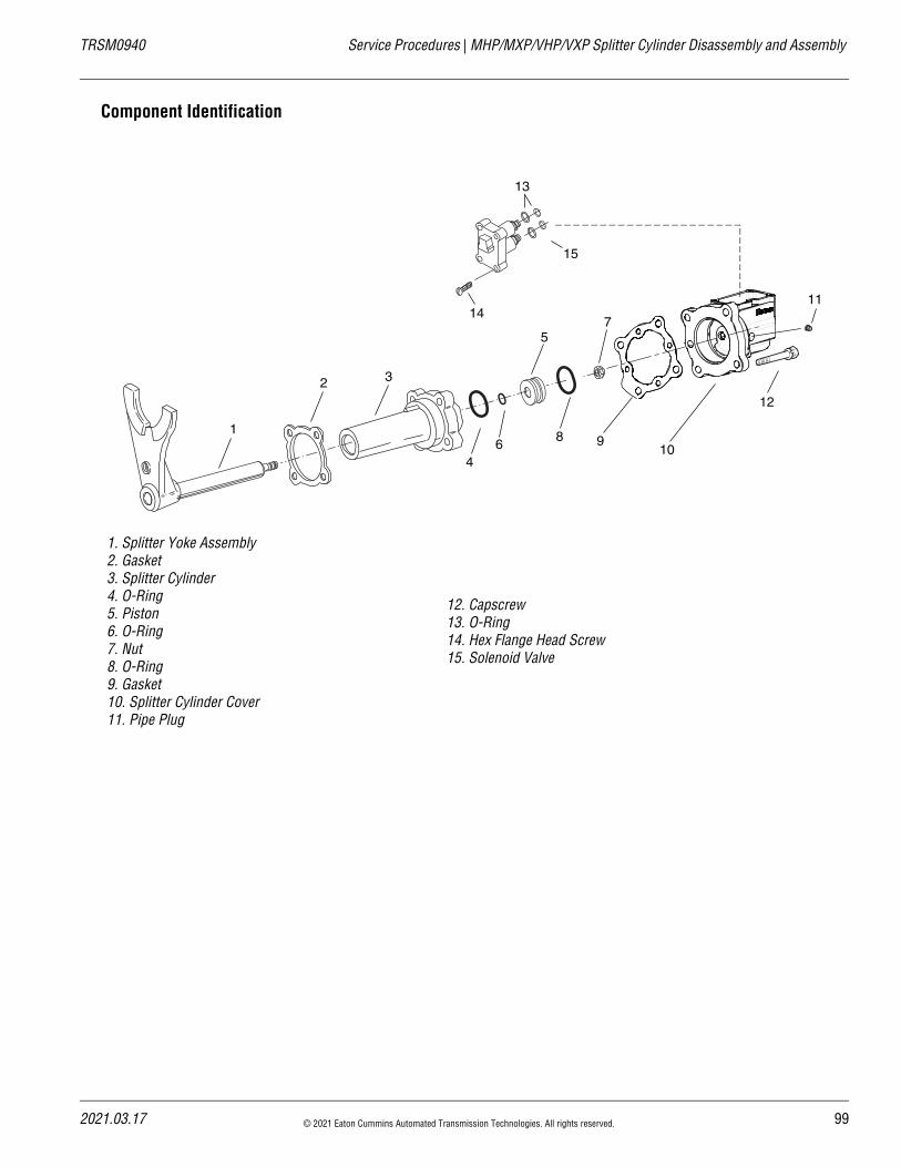
20
TRSM0940 Service Procedures | MHP/MXP/VHP/VXP Splitter Cylinder Disassembly and Assembly
Component Identification
1. Splitter Yoke Assembly2. Gasket3. Splitter Cylinder4. O-Ring5. Piston6. O-Ring7. Nut8. O-Ring9. Gasket10. Splitter Cylinder Cover11. Pipe Plug
12. Capscrew13. O-Ring14. Hex Flange Head Screw15. Solenoid Valve
1
11
122 3
4
5
6
7
8 910
13
14
15
21.03.17 © 2021 Eaton Cummins Automated Transmission Technologies. All rights reserved. 99
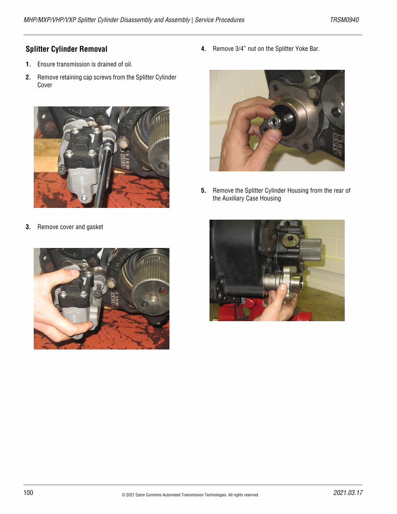
MHP/MXP/VHP/VXP Splitter Cylinder Disassembly and Assembly | Service Procedures TRSM0940
Splitter Cylinder Removal
1. Ensure transmission is drained of oil.
2. Remove retaining cap screws from the Splitter Cylinder Cover
3. Remove cover and gasket
4. Remove 3/4” nut on the Splitter Yoke Bar.
5. Remove the Splitter Cylinder Housing from the rear of the Auxiliary Case Housing
100 © 2021 Eaton Cummins Automated Transmission Technologies. All rights reserved. 2021.03.17
20
TRSM0940 Service Procedures | MHP/MXP/VHP/VXP Splitter Cylinder Disassembly and Assembly
6. Remove the Piston from the bore of the Splitter Cylin-der.
Note: If spool valve needs to be replaced, it must be done as an entire unit which is part of splitter cover
Splitter Cylinder Assembly
1. Install the Splitter Sliding Clutch on the Splitter Yoke Fork and engage into the Splitter Gear to maintain posi-tion.
2. Install small O-ring in the Cylinder Housing Bore if pre-viously removed.
3. On the Piston O.D., install the Piston O-ring if previ-ously removed.
21.03.17 © 2021 Eaton Cummins Automated Transmission Technologies. All rights reserved. 101
MHP/MXP/VHP/VXP Splitter Cylinder Disassembly and Assembly | Service Procedures TRSM0940
4. Position new gasket on the Cylinder Housing, and install the Splitter Cylinder
5. Install O-Ring on the end of the yoke bar inside of the Cylinder Housing
6. Install new O-rings on the ID and OD of the piston, then lubricate with silicone.
7. Install the piston into the Splitter Cylinder with the recessed side facing the rear of the transmission.
8. Secure piston with the 3/4 lock nut. Torque to 30-36 lb-ft (41-49N•m).
102 © 2021 Eaton Cummins Automated Transmission Technologies. All rights reserved. 2021.03.17
20
TRSM0940 Service Procedures | MHP/MXP/VHP/VXP Splitter Cylinder Disassembly and Assembly
9. Position new gasket on the Cylinder Housing Cover mounting surface and install the Splitter Cylinder Cover
Note: Ensure that the gasket air passage aligns with the housing air passage
10. Apply Eaton Sealant #71205 or equivalent to the retain-ing cap screws, and install on the cover. Torque to 20-25 lb-ft.
21.03.17 © 2021 Eaton Cummins Automated Transmission Technologies. All rights reserved. 103
MHP/MXP/VHP/VXP Splitter Gear Bearing Disassembly and Assembly | Service Procedures TRSM0940
MHP/MXP/VHP/VXP Splitter Gear Bearing Disassembly and AssemblySpecial InstructionsMake sure to use proper drivers for the bearing and sleeve.
Special Tools3.30” Diameter Bearing Driver
Component Identification
None
104 © 2021 Eaton Cummins Automated Transmission Technologies. All rights reserved. 2021.03.17
20
TRSM0940 Service Procedures | MHP/MXP/VHP/VXP Splitter Gear Bearing Disassembly and Assembly
Splitter Gear Bearing Disassembly
1. Remove the internal coiled snap ring.
2. Remove the Tapered Bearing Pack Assembly using bearing driver RR1012TR-4.
3. Separate the Bearing Pack Assembly.
21.03.17 © 2021 Eaton Cummins Automated Transmission Technologies. All rights reserved. 105
MHP/MXP/VHP/VXP Splitter Gear Bearing Disassembly and Assembly | Service Procedures TRSM0940
Splitter Gear Bearing Assembly
1. Install the Front Bearing Race
2. Install the bearing spacer
3. Install Bearing assembly
4. Install the Rear Bearing Race.
106 © 2021 Eaton Cummins Automated Transmission Technologies. All rights reserved. 2021.03.17
20
TRSM0940 Service Procedures | MHP/MXP/VHP/VXP Splitter Gear Bearing Disassembly and Assembly
5. Drive the bearing into place using the bearing driver, RR1012TR-4
6. Install the internal snap ring.
21.03.17 © 2021 Eaton Cummins Automated Transmission Technologies. All rights reserved. 107
MHP/MXP/VHP/VXP Auxiliary Section Assembly and Installation | Service Procedures TRSM0940
MHP/MXP/VHP/VXP Auxiliary Section Assembly and InstallationSpecial InstructionsNone
Special Tools• Bearing Drivers
• Maul
• PVC Pipe
• RR1002TR Auxiliary Countershaft Support Straps
Component Identification
1. Sliding Clutch2. Screw3. Retainer4. Splitter Gear5. Tapered Roller Bearing6. Bearing Sleeve7. Snap Ring8. Spring9. Synchronizer Assembly10. Sliding Clutch
11. Synchronizer Assembly12. Mainshaft13. Washer14. Reduction Gear15. Spacer16. Tapered Roller Bearing17. Output Yoke18. Hex Flange Screw19. Universal Joint Yoke
23
4
8
1
7
5 6
9
1011
12
13 14
15 16
1718
19
108 © 2021 Eaton Cummins Automated Transmission Technologies. All rights reserved. 2021.03.17
20
TRSM0940 Service Procedures | MHP/MXP/VHP/VXP Auxiliary Section Assembly and Installation
Auxiliary Mainshaft Assembly
1. Prepare the Reduction Gear for timing. Mark any one tooth on the gear and repeat on the tooth directly opposite of the first marked.
2. With the splined washer facing up, place the washer on the Output Shaft shoulder
3. Position the Reduction Gear on the Output Shaft with the clutching teeth facing down. Engage the washer splines to fully position the gear.
4. Position the Reduction Gear Rear Washer on the Out-put Shaft with the chamfer side up against the Reduc-tion Gear.
21.03.17 © 2021 Eaton Cummins Automated Transmission Technologies. All rights reserved. 109
MHP/MXP/VHP/VXP Auxiliary Section Assembly and Installation | Service Procedures TRSM0940
5. With the tapered side up, use heat, or a small punch to install the Output Shaft Rear Bearing.
Note: A Bearing Driver can also be used to seat the bearing, however if using a bearing driver, install the Bearing inner spacer prior to driving to avoid getting the driver stuck on the shaft.
6. Install the Bearing Inner Spacer on the Output Shaft. Set aside once installed.
Synchronizer Assembly and Splitter Gear Installation
1. Lay the Auxiliary Mainshaft Assembly on its side.
2. Install the Synchronizer Assembly on the Auxiliary Mainshaft Assembly.
Note: Apply light coating of transmission lubricant to the surface of the synchronizer assembly.
Note: For Synchronizer Assembly/Disassembly, see the section, Synchronizer Disassembly and Assembly in this manual.
3. Prepare the Splitter gear for timing. Mark any tooth splitter gear and repeat on the tooth directly opposite of the first marked.
110 © 2021 Eaton Cummins Automated Transmission Technologies. All rights reserved. 2021.03.17
20
TRSM0940 Service Procedures | MHP/MXP/VHP/VXP Auxiliary Section Assembly and Installation
4. Install the Splitter Gear on the Output Shaft
Note: For Splitter Gear Disassembly and Assembly, see the section: Splitter Gear Bearing Disassembly & Assembly, in this manual.
5. Install the Splitter Gear retainer and 15/16” cap screw. Torque to 190-210 lb-ft (257.61-284.72 N•m).
Note: Ensure proper torque is applied to the retainer bolt.
21.03.17 © 2021 Eaton Cummins Automated Transmission Technologies. All rights reserved. 111
MHP/MXP/VHP/VXP Auxiliary Countershaft Installation | Service Procedures TRSM0940
MHP/MXP/VHP/VXP Auxiliary Countershaft InstallationSpecial InstructionsTo assist in the Auxiliary Section Assembly, an Auxiliary Section fixture can be made out of a 2” x 12’ piece of wood.
This fixture is designed to ease the assembly of the Auxil-iary gearing. Set the Auxiliary Countershaft Front bearings in the 3” holes to maintain the gearing positions when com-bining with the Auxiliary Mainshaft Assembly.
Set the Assembled Auxiliary Mainshaft between the Countershafts with the timing marks on all 3 sets of gearing aligned.
Special Tools• RR1002TR Auxiliary Countershaft Support Straps
• Bearing drivers
• Maul
Component Identification
2"10.74"
3'
4.56"
1'
3"
None
112 © 2021 Eaton Cummins Automated Transmission Technologies. All rights reserved. 2021.03.17
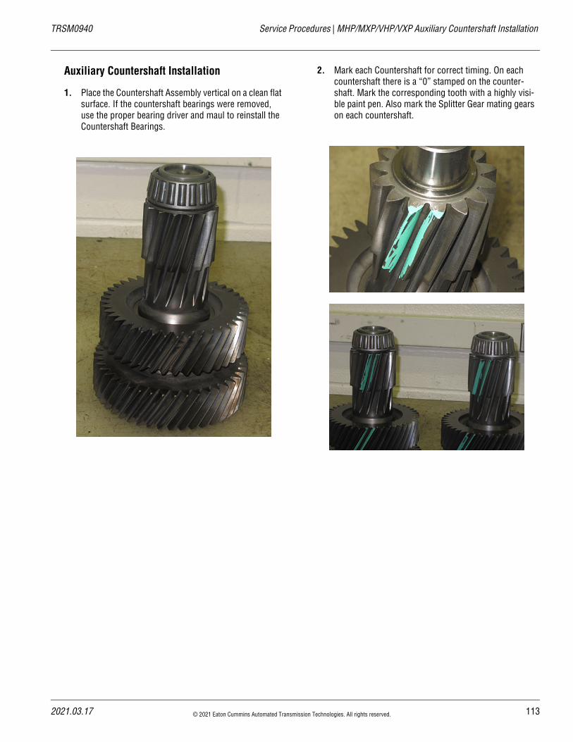
20
TRSM0940 Service Procedures | MHP/MXP/VHP/VXP Auxiliary Countershaft Installation
Auxiliary Countershaft Installation
1. Place the Countershaft Assembly vertical on a clean flat surface. If the countershaft bearings were removed, use the proper bearing driver and maul to reinstall the Countershaft Bearings.
2. Mark each Countershaft for correct timing. On each countershaft there is a “0” stamped on the counter-shaft. Mark the corresponding tooth with a highly visi-ble paint pen. Also mark the Splitter Gear mating gears on each countershaft.
21.03.17 © 2021 Eaton Cummins Automated Transmission Technologies. All rights reserved. 113
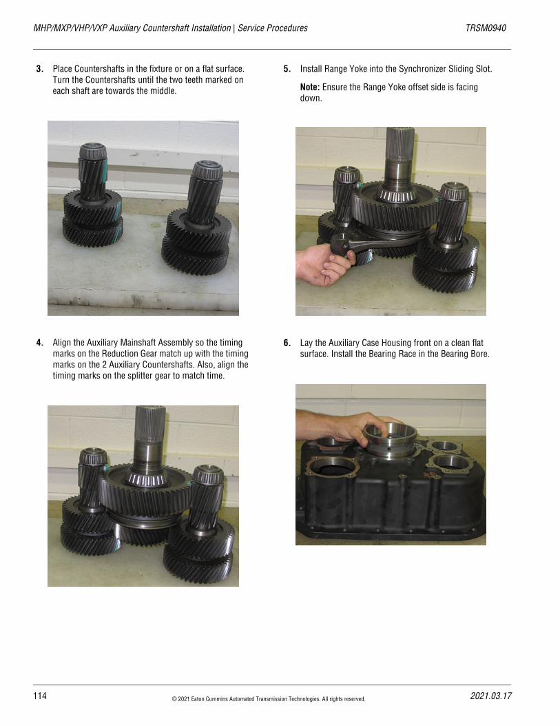
MHP/MXP/VHP/VXP Auxiliary Countershaft Installation | Service Procedures TRSM0940
3. Place Countershafts in the fixture or on a flat surface. Turn the Countershafts until the two teeth marked on each shaft are towards the middle.
4. Align the Auxiliary Mainshaft Assembly so the timing marks on the Reduction Gear match up with the timing marks on the 2 Auxiliary Countershafts. Also, align the timing marks on the splitter gear to match time.
5. Install Range Yoke into the Synchronizer Sliding Slot.
Note: Ensure the Range Yoke offset side is facing down.
6. Lay the Auxiliary Case Housing front on a clean flat surface. Install the Bearing Race in the Bearing Bore.
114 © 2021 Eaton Cummins Automated Transmission Technologies. All rights reserved. 2021.03.17
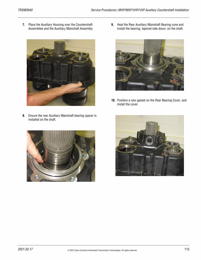
20
TRSM0940 Service Procedures | MHP/MXP/VHP/VXP Auxiliary Countershaft Installation
7. Place the Auxiliary Housing over the Countershaft Assemblies and the Auxiliary Mainshaft Assembly.
8. Ensure the rear Auxiliary Mainshaft bearing spacer is installed on the shaft.
9. Heat the Rear Auxiliary Mainshaft Bearing cone and install the bearing, tapered side down, on the shaft.
10. Position a new gasket on the Rear Bearing Cover, and install the cover.
21.03.17 © 2021 Eaton Cummins Automated Transmission Technologies. All rights reserved. 115
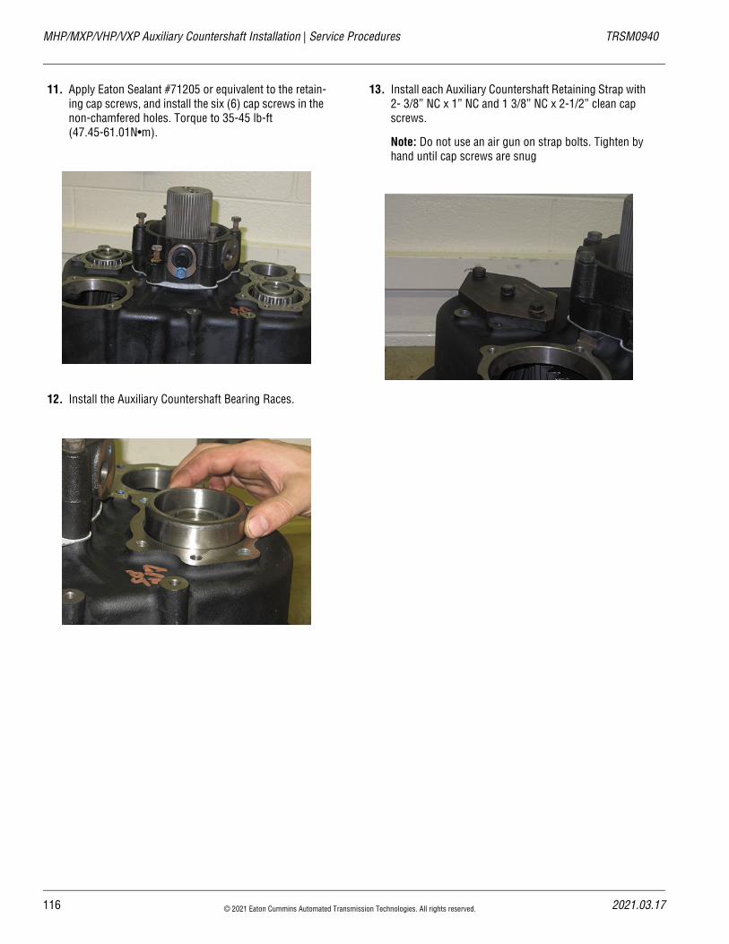
MHP/MXP/VHP/VXP Auxiliary Countershaft Installation | Service Procedures TRSM0940
11. Apply Eaton Sealant #71205 or equivalent to the retain-ing cap screws, and install the six (6) cap screws in the non-chamfered holes. Torque to 35-45 lb-ft (47.45-61.01N•m).
12. Install the Auxiliary Countershaft Bearing Races.
13. Install each Auxiliary Countershaft Retaining Strap with 2- 3/8” NC x 1” NC and 1 3/8” NC x 2-1/2” clean cap screws.
Note: Do not use an air gun on strap bolts. Tighten by hand until cap screws are snug
116 © 2021 Eaton Cummins Automated Transmission Technologies. All rights reserved. 2021.03.17
20
TRSM0940 Service Procedures | MHP/MXP/VHP/VXP Auxiliary Countershaft Installation
Range Cylinder and Piston Installation
1. To assist in the installation of the Range Cylinder, place the Auxiliary section in a vice.
2. Position a new gasket on the range Cylinder Mounting Surface of the Auxiliary Case.
3. Install the Range Cylinder through the Range Cylinder Bore on the Auxiliary Case housing. Position the Range Yoke Fork inside the open section of the cylinder.
4. Install Range Yoke Bar from the rear of the Auxiliary case.
Note: Ensure that the Yoke Bar passes through the eye of the Yoke fork.
5. Align the 2 groves on the Yoke Bar and install the 2 retaining bolts through the bores on the Range Yoke Fork.
6. Install new O-rings on the ID and OD of the piston, then lubricate with silicone.
21.03.17 © 2021 Eaton Cummins Automated Transmission Technologies. All rights reserved. 117
MHP/MXP/VHP/VXP Auxiliary Countershaft Installation | Service Procedures TRSM0940
7. Install Piston into the bore of the Range Cylinder Install with the flat side of the piston facing rearward.
8. Secure the piston with the retaining nut, torque to 70-85 lb-ft (94.91-115.24 N•m).
Splitter Cylinder Installation
1. With the Auxiliary Section still in the vice. Position the Splitter Sliding Clutch on the Splitter Yoke fork and bar. Engage into the Splitter Gear to maintain its position
2. Install small O-ring in the Cylinder Housing Bore if pre-viously removed
118 © 2021 Eaton Cummins Automated Transmission Technologies. All rights reserved. 2021.03.17
20
TRSM0940 Service Procedures | MHP/MXP/VHP/VXP Auxiliary Countershaft Installation
3. Position a new gasket between the Splitter Cylinder and the Auxiliary Case Housing bore. Install the Splitter Cylinder.
4. Install new O-rings on the ID and OD of the piston. Lubricate with silicone.
5. Install new O-ring on the end of the yoke bar inside of the cylinder housing.
6. Install the piston into the Splitter Cylinder with the recessed side facing the rear of the transmission.
7. Secure piston with the 3/4 lock nut. Torque to 30-36 lb-ft (41-49N•m).
21.03.17 © 2021 Eaton Cummins Automated Transmission Technologies. All rights reserved. 119
MHP/MXP/VHP/VXP Auxiliary Countershaft Installation | Service Procedures TRSM0940
Auxiliary Section Installation
1. Attach the Auxiliary Section lifting bracket to the top of the Auxiliary Case.
2. Position a new Auxiliary Case Gasket on the mounting surface of the Main Case.
3. Install the Auxiliary Case Assembly onto the transmis-sion Main Case dowel pins. Using the Output Shaft, wiggle the auxiliary case forward until it is as far for-ward as possible. Remove the auxiliary section lifting bracket.
120 © 2021 Eaton Cummins Automated Transmission Technologies. All rights reserved. 2021.03.17
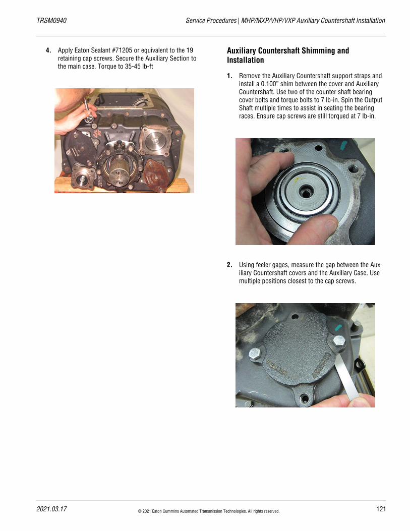
20
TRSM0940 Service Procedures | MHP/MXP/VHP/VXP Auxiliary Countershaft Installation
4. Apply Eaton Sealant #71205 or equivalent to the 19 retaining cap screws. Secure the Auxiliary Section to the main case. Torque to 35-45 lb-ft
Auxiliary Countershaft Shimming and Installation
1. Remove the Auxiliary Countershaft support straps and install a 0.100” shim between the cover and Auxiliary Countershaft. Use two of the counter shaft bearing cover bolts and torque bolts to 7 lb-in. Spin the Output Shaft multiple times to assist in seating the bearing races. Ensure cap screws are still torqued at 7 lb-in.
2. Using feeler gages, measure the gap between the Aux-iliary Countershaft covers and the Auxiliary Case. Use multiple positions closest to the cap screws.
21.03.17 © 2021 Eaton Cummins Automated Transmission Technologies. All rights reserved. 121
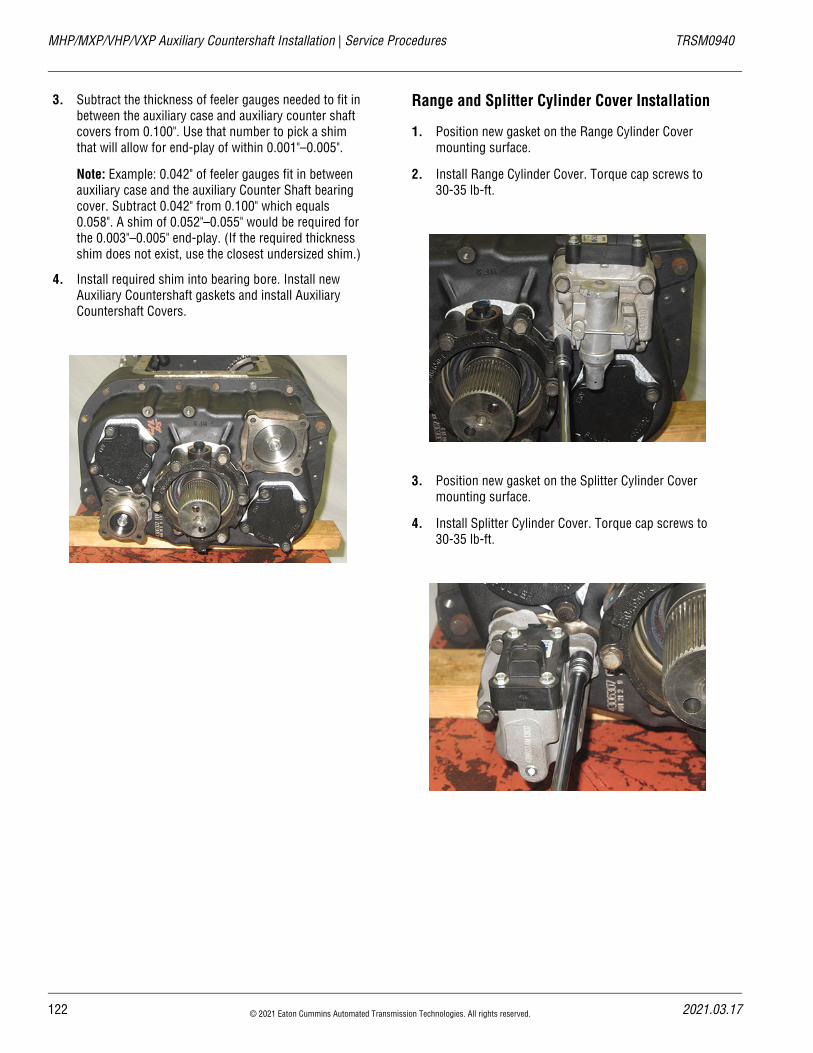
MHP/MXP/VHP/VXP Auxiliary Countershaft Installation | Service Procedures TRSM0940
3. Subtract the thickness of feeler gauges needed to fit in between the auxiliary case and auxiliary counter shaft covers from 0.100". Use that number to pick a shim that will allow for end-play of within 0.001"–0.005".
Note: Example: 0.042" of feeler gauges fit in between auxiliary case and the auxiliary Counter Shaft bearing cover. Subtract 0.042" from 0.100" which equals 0.058". A shim of 0.052"–0.055" would be required for the 0.003"–0.005" end-play. (If the required thickness shim does not exist, use the closest undersized shim.)
4. Install required shim into bearing bore. Install new Auxiliary Countershaft gaskets and install Auxiliary Countershaft Covers.
Range and Splitter Cylinder Cover Installation
1. Position new gasket on the Range Cylinder Cover mounting surface.
2. Install Range Cylinder Cover. Torque cap screws to 30-35 lb-ft.
3. Position new gasket on the Splitter Cylinder Cover mounting surface.
4. Install Splitter Cylinder Cover. Torque cap screws to 30-35 lb-ft.
122 © 2021 Eaton Cummins Automated Transmission Technologies. All rights reserved. 2021.03.17
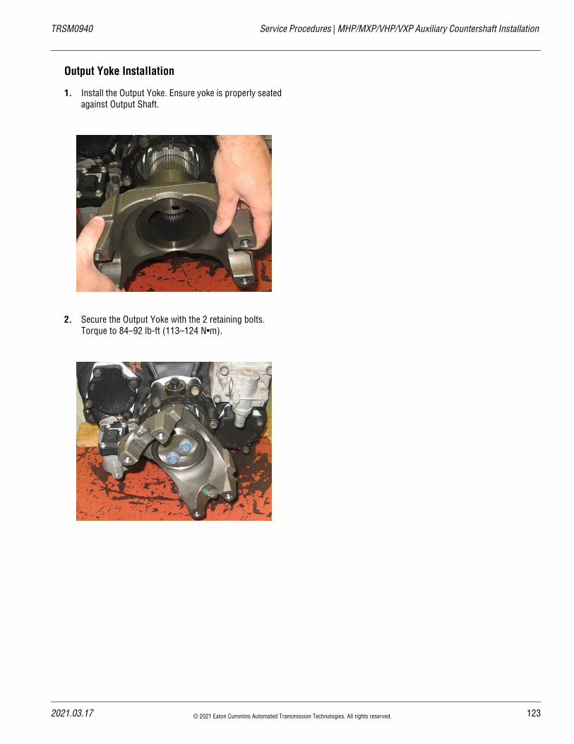
20
TRSM0940 Service Procedures | MHP/MXP/VHP/VXP Auxiliary Countershaft Installation
Output Yoke Installation
1. Install the Output Yoke. Ensure yoke is properly seated against Output Shaft.
2. Secure the Output Yoke with the 2 retaining bolts. Torque to 84–92 lb-ft (113–124 N•m).
21.03.17 © 2021 Eaton Cummins Automated Transmission Technologies. All rights reserved. 123
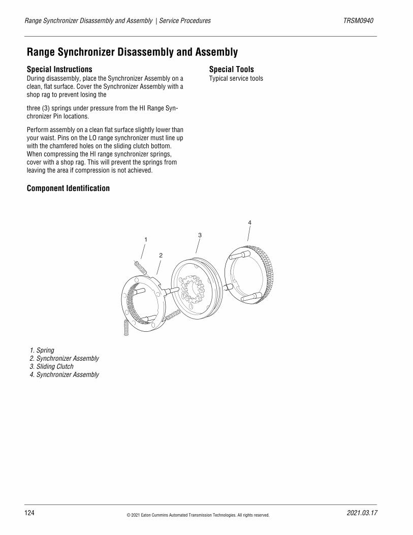
Range Synchronizer Disassembly and Assembly | Service Procedures TRSM0940
Range Synchronizer Disassembly and Assembly Special InstructionsDuring disassembly, place the Synchronizer Assembly on a clean, flat surface. Cover the Synchronizer Assembly with a shop rag to prevent losing the
three (3) springs under pressure from the HI Range Syn-chronizer Pin locations.
Perform assembly on a clean flat surface slightly lower than your waist. Pins on the LO range synchronizer must line up with the chamfered holes on the sliding clutch bottom. When compressing the HI range synchronizer springs, cover with a shop rag. This will prevent the springs from leaving the area if compression is not achieved.
Special ToolsTypical service tools
Component Identification
1. Spring2. Synchronizer Assembly3. Sliding Clutch4. Synchronizer Assembly
1
2
3
4
124 © 2021 Eaton Cummins Automated Transmission Technologies. All rights reserved. 2021.03.17
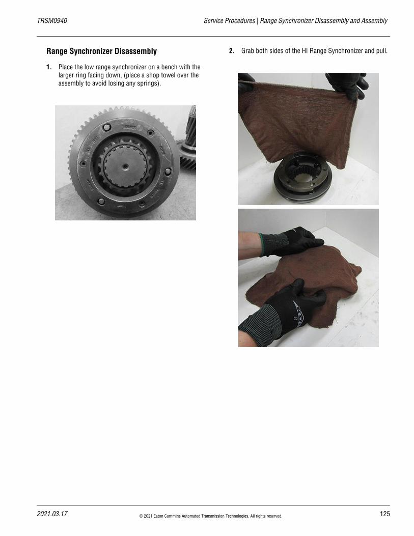
20
TRSM0940 Service Procedures | Range Synchronizer Disassembly and Assembly
Range Synchronizer Disassembly
1. Place the low range synchronizer on a bench with the larger ring facing down, (place a shop towel over the assembly to avoid losing any springs).
2. Grab both sides of the HI Range Synchronizer and pull.
21.03.17 © 2021 Eaton Cummins Automated Transmission Technologies. All rights reserved. 125
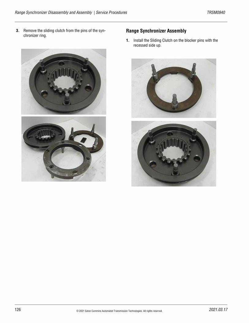
Range Synchronizer Disassembly and Assembly | Service Procedures TRSM0940
3. Remove the sliding clutch from the pins of the syn-chronizer ring.
Range Synchronizer Assembly
1. Install the Sliding Clutch on the blocker pins with the recessed side up.
126 © 2021 Eaton Cummins Automated Transmission Technologies. All rights reserved. 2021.03.17
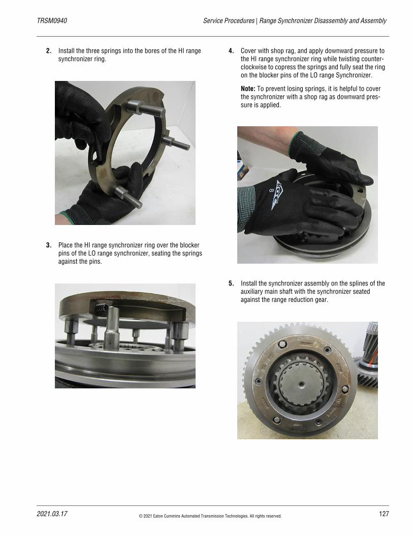
20
TRSM0940 Service Procedures | Range Synchronizer Disassembly and Assembly
2. Install the three springs into the bores of the HI range synchronizer ring.
3. Place the HI range synchronizer ring over the blocker pins of the LO range synchronizer, seating the springs against the pins.
4. Cover with shop rag, and apply downward pressure to the HI range synchronizer ring while twisting counter-clockwise to copress the springs and fully seat the ring on the blocker pins of the LO range Synchronizer.
Note: To prevent losing springs, it is helpful to cover the synchronizer with a shop rag as downward pres-sure is applied.
5. Install the synchronizer assembly on the splines of the auxiliary main shaft with the synchronizer seated against the range reduction gear.
21.03.17 © 2021 Eaton Cummins Automated Transmission Technologies. All rights reserved. 127
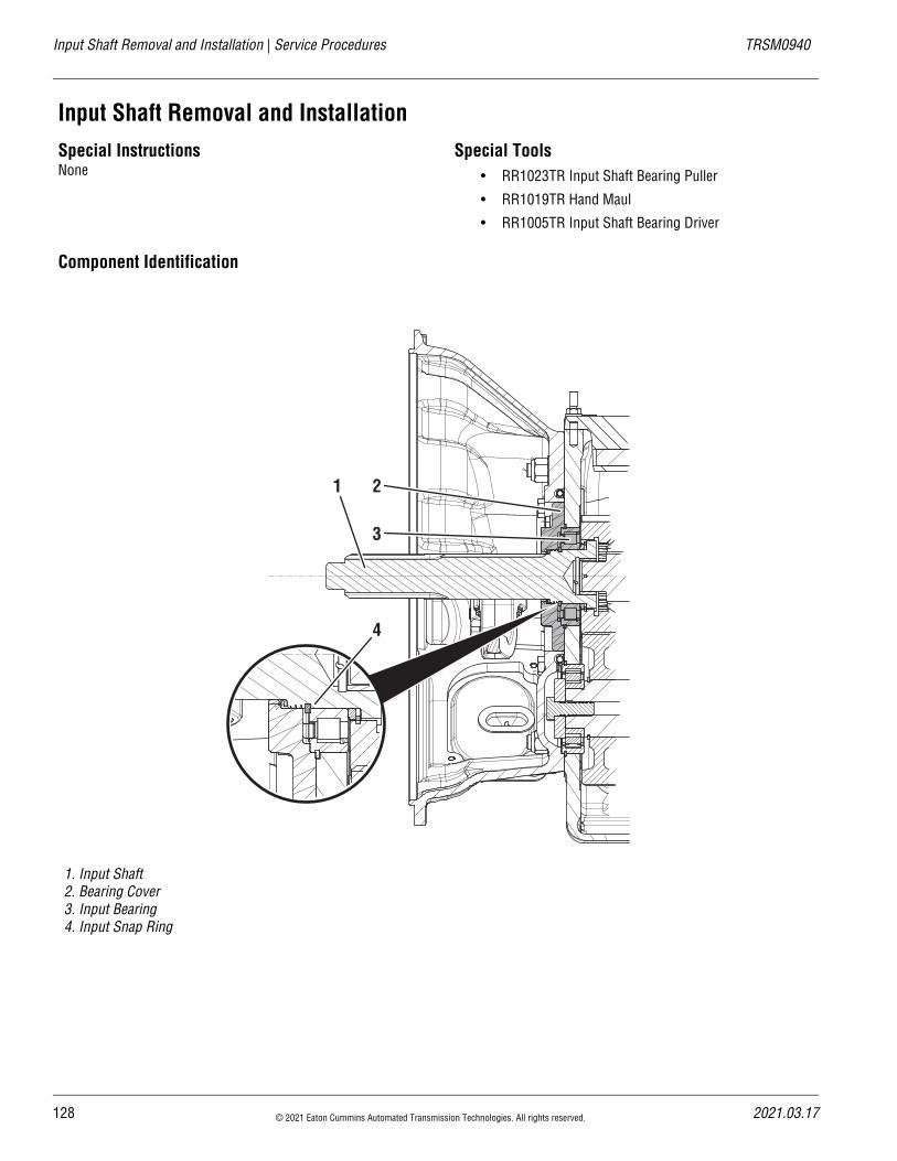
Input Shaft Removal and Installation | Service Procedures TRSM0940
Input Shaft Removal and InstallationSpecial InstructionsNone
Special Tools• RR1023TR Input Shaft Bearing Puller
• RR1019TR Hand Maul
• RR1005TR Input Shaft Bearing Driver
Component Identification
1. Input Shaft2. Bearing Cover3. Input Bearing4. Input Snap Ring
1 2
3
4
128 © 2021 Eaton Cummins Automated Transmission Technologies. All rights reserved. 2021.03.17
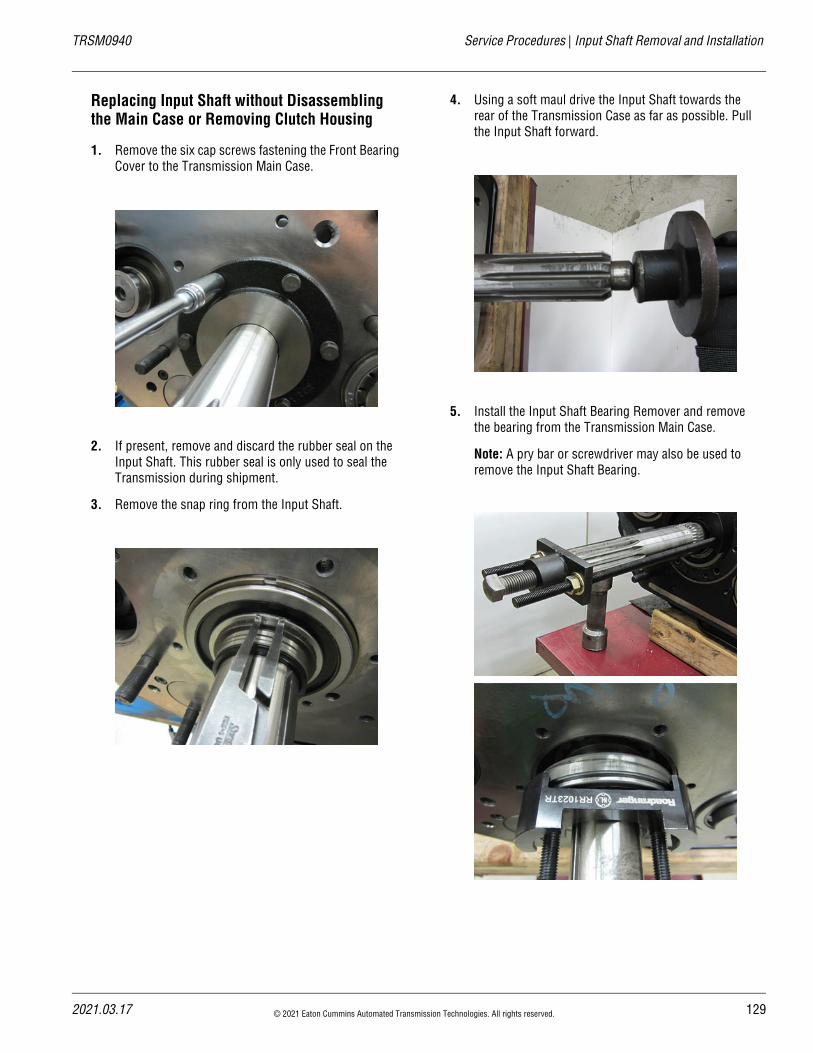
20
TRSM0940 Service Procedures | Input Shaft Removal and Installation
Replacing Input Shaft without Disassembling the Main Case or Removing Clutch Housing
1. Remove the six cap screws fastening the Front Bearing Cover to the Transmission Main Case.
2. If present, remove and discard the rubber seal on the Input Shaft. This rubber seal is only used to seal the Transmission during shipment.
3. Remove the snap ring from the Input Shaft.
4. Using a soft maul drive the Input Shaft towards the rear of the Transmission Case as far as possible. Pull the Input Shaft forward.
5. Install the Input Shaft Bearing Remover and remove the bearing from the Transmission Main Case.
Note: A pry bar or screwdriver may also be used to remove the Input Shaft Bearing.
21.03.17 © 2021 Eaton Cummins Automated Transmission Technologies. All rights reserved. 129
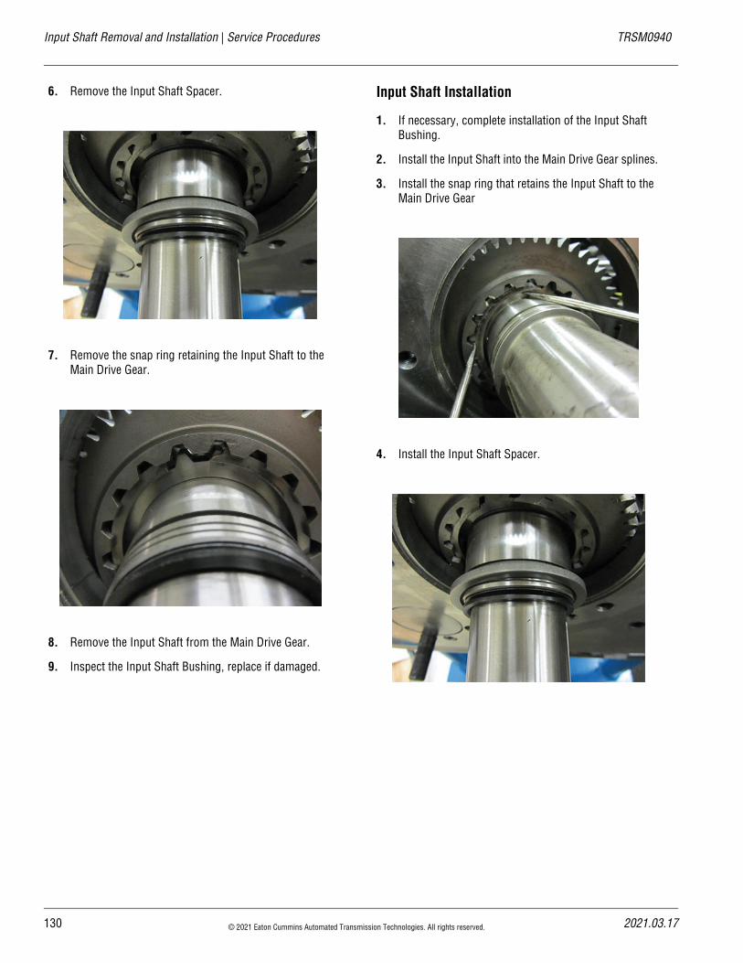
Input Shaft Removal and Installation | Service Procedures TRSM0940
6. Remove the Input Shaft Spacer.
7. Remove the snap ring retaining the Input Shaft to the Main Drive Gear.
8. Remove the Input Shaft from the Main Drive Gear.
9. Inspect the Input Shaft Bushing, replace if damaged.
Input Shaft Installation
1. If necessary, complete installation of the Input Shaft Bushing.
2. Install the Input Shaft into the Main Drive Gear splines.
3. Install the snap ring that retains the Input Shaft to the Main Drive Gear
4. Install the Input Shaft Spacer.
130 © 2021 Eaton Cummins Automated Transmission Technologies. All rights reserved. 2021.03.17
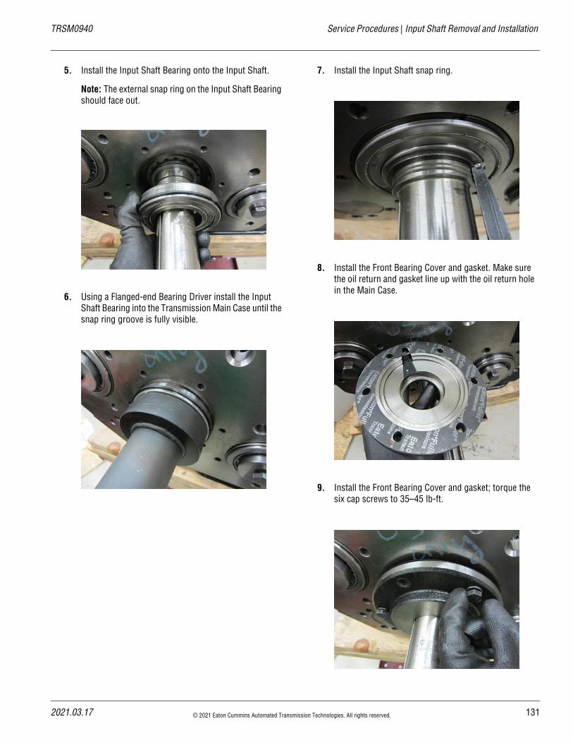
20
TRSM0940 Service Procedures | Input Shaft Removal and Installation
5. Install the Input Shaft Bearing onto the Input Shaft.
Note: The external snap ring on the Input Shaft Bearing should face out.
6. Using a Flanged-end Bearing Driver install the Input Shaft Bearing into the Transmission Main Case until the snap ring groove is fully visible.
7. Install the Input Shaft snap ring.
8. Install the Front Bearing Cover and gasket. Make sure the oil return and gasket line up with the oil return hole in the Main Case.
9. Install the Front Bearing Cover and gasket; torque the six cap screws to 35–45 lb-ft.
21.03.17 © 2021 Eaton Cummins Automated Transmission Technologies. All rights reserved. 131
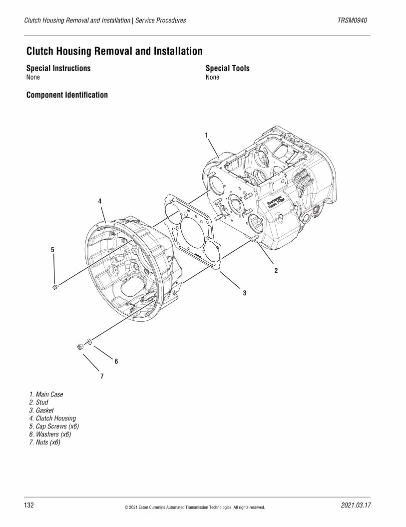
Clutch Housing Removal and Installation | Service Procedures TRSM0940
Clutch Housing Removal and InstallationSpecial InstructionsNone
Special ToolsNone
Component Identification
1. Main Case2. Stud3. Gasket4. Clutch Housing5. Cap Screws (x6)6. Washers (x6)7. Nuts (x6)
3
5
6
7
2
1
4
132 © 2021 Eaton Cummins Automated Transmission Technologies. All rights reserved. 2021.03.17
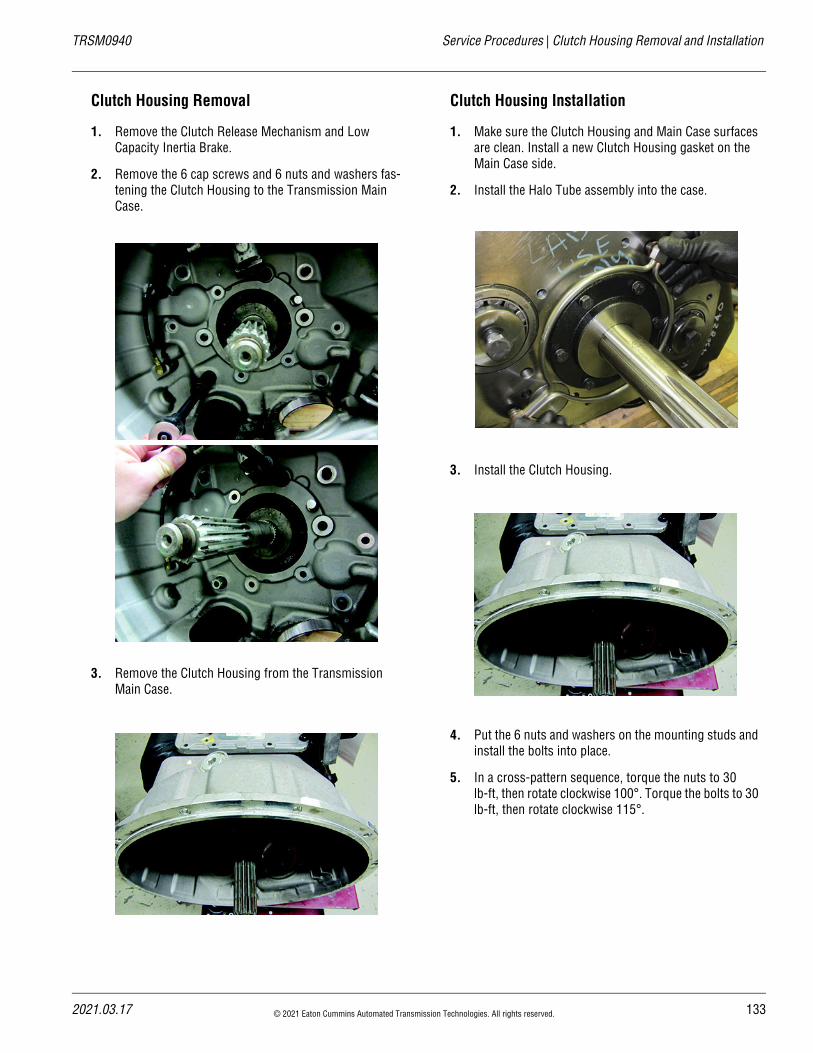
20
TRSM0940 Service Procedures | Clutch Housing Removal and Installation
Clutch Housing Removal
1. Remove the Clutch Release Mechanism and Low Capacity Inertia Brake.
2. Remove the 6 cap screws and 6 nuts and washers fas-tening the Clutch Housing to the Transmission Main Case.
3. Remove the Clutch Housing from the Transmission Main Case.
Clutch Housing Installation
1. Make sure the Clutch Housing and Main Case surfaces are clean. Install a new Clutch Housing gasket on the Main Case side.
2. Install the Halo Tube assembly into the case.
3. Install the Clutch Housing.
4. Put the 6 nuts and washers on the mounting studs and install the bolts into place.
5. In a cross-pattern sequence, torque the nuts to 30 lb-ft, then rotate clockwise 100°. Torque the bolts to 30 lb-ft, then rotate clockwise 115°.
21.03.17 © 2021 Eaton Cummins Automated Transmission Technologies. All rights reserved. 133
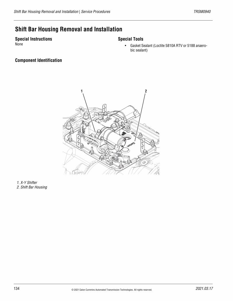
Shift Bar Housing Removal and Installation | Service Procedures TRSM0940
Shift Bar Housing Removal and InstallationSpecial InstructionsNone
Special Tools• Gasket Sealant (Loctite 5810A RTV or 5188 anaero-
bic sealant)
Component Identification
1. X-Y Shifter2. Shift Bar Housing
1 2
134 © 2021 Eaton Cummins Automated Transmission Technologies. All rights reserved. 2021.03.17
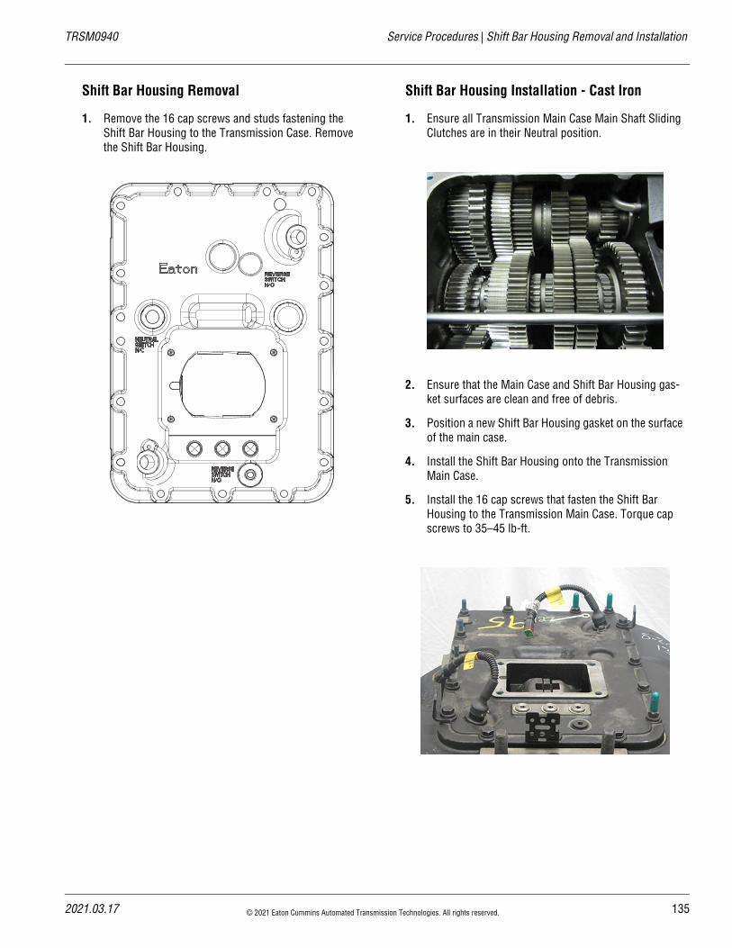
20
TRSM0940 Service Procedures | Shift Bar Housing Removal and Installation
Shift Bar Housing Removal
1. Remove the 16 cap screws and studs fastening the Shift Bar Housing to the Transmission Case. Remove the Shift Bar Housing.
Shift Bar Housing Installation - Cast Iron
1. Ensure all Transmission Main Case Main Shaft Sliding Clutches are in their Neutral position.
2. Ensure that the Main Case and Shift Bar Housing gas-ket surfaces are clean and free of debris.
3. Position a new Shift Bar Housing gasket on the surface of the main case.
4. Install the Shift Bar Housing onto the Transmission Main Case.
5. Install the 16 cap screws that fasten the Shift Bar Housing to the Transmission Main Case. Torque cap screws to 35–45 lb-ft.
21.03.17 © 2021 Eaton Cummins Automated Transmission Technologies. All rights reserved. 135
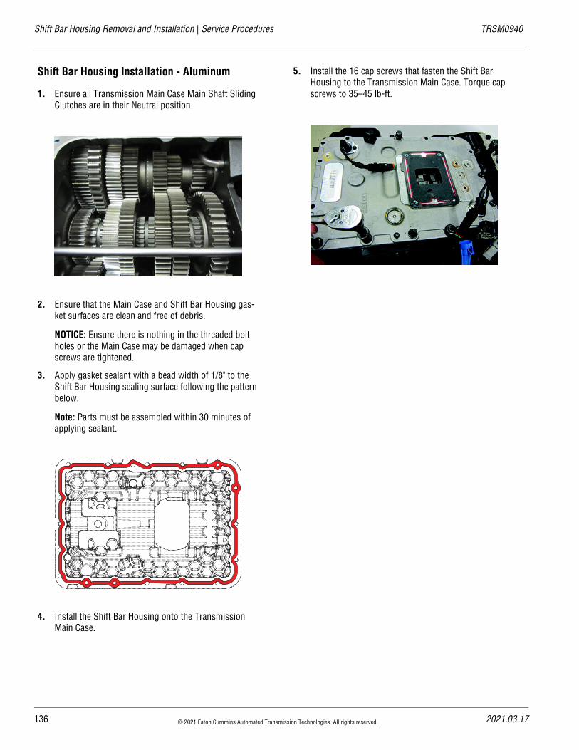
Shift Bar Housing Removal and Installation | Service Procedures TRSM0940
Shift Bar Housing Installation - Aluminum
1. Ensure all Transmission Main Case Main Shaft Sliding Clutches are in their Neutral position.
2. Ensure that the Main Case and Shift Bar Housing gas-ket surfaces are clean and free of debris.
NOTICE: Ensure there is nothing in the threaded bolt holes or the Main Case may be damaged when cap screws are tightened.
3. Apply gasket sealant with a bead width of 1/8" to the Shift Bar Housing sealing surface following the pattern below.
Note: Parts must be assembled within 30 minutes of applying sealant.
4. Install the Shift Bar Housing onto the Transmission Main Case.
5. Install the 16 cap screws that fasten the Shift Bar Housing to the Transmission Main Case. Torque cap screws to 35–45 lb-ft.
136 © 2021 Eaton Cummins Automated Transmission Technologies. All rights reserved. 2021.03.17
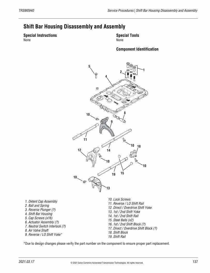
20
TRSM0940 Service Procedures | Shift Bar Housing Disassembly and Assembly
Shift Bar Housing Disassembly and AssemblySpecial InstructionsNone
Special ToolsNone
Component Identification
*Due to design changes please verify the part number on the component to ensure proper part replacement.
1. Detent Cap Assembly2. Ball and Spring3. Reverse Plunger (?)4. Shift Bar Housing5. Cap Screws (x16)6. Actuator Assembly (?)7. Neutral Switch Interlock (?)8. Air Valve Shaft9. Reverse / LO Shift Yoke*
10. Lock Screws11. Reverse / LO Shift Rail12. Direct / Overdrive Shift Yoke13. 1st / 2nd Shift Yoke14. 1st / 2nd Shift Rail 15. Steel Balls (x2)16. 1st / 2nd Shift Block (?)17. Direct / Overdrive Shift Block (?)18. Shift Block19. Shift Rail
124
5
8
9
11
14
15
18
19
13
1010
10
10
10
12
21.03.17 © 2021 Eaton Cummins Automated Transmission Technologies. All rights reserved. 137
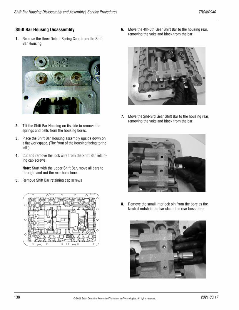
Shift Bar Housing Disassembly and Assembly | Service Procedures TRSM0940
Shift Bar Housing Disassembly
1. Remove the three Detent Spring Caps from the Shift Bar Housing.
2. Tilt the Shift Bar Housing on its side to remove the springs and balls from the housing bores.
3. Place the Shift Bar Housing assembly upside down on a flat workspace. (The front of the housing facing to the left.)
4. Cut and remove the lock wire from the Shift Bar retain-ing cap screws.
Note: Start with the upper Shift Bar, move all bars to the right and out the rear boss bore.
5. Remove Shift Bar retaining cap screws
6. Move the 4th-5th Gear Shift Bar to the housing rear, removing the yoke and block from the bar.
7. Move the 2nd-3rd Gear Shift Bar to the housing rear, removing the yoke and block from the bar.
8. Remove the small interlock pin from the bore as the Neutral notch in the bar clears the rear boss bore.
138 © 2021 Eaton Cummins Automated Transmission Technologies. All rights reserved. 2021.03.17
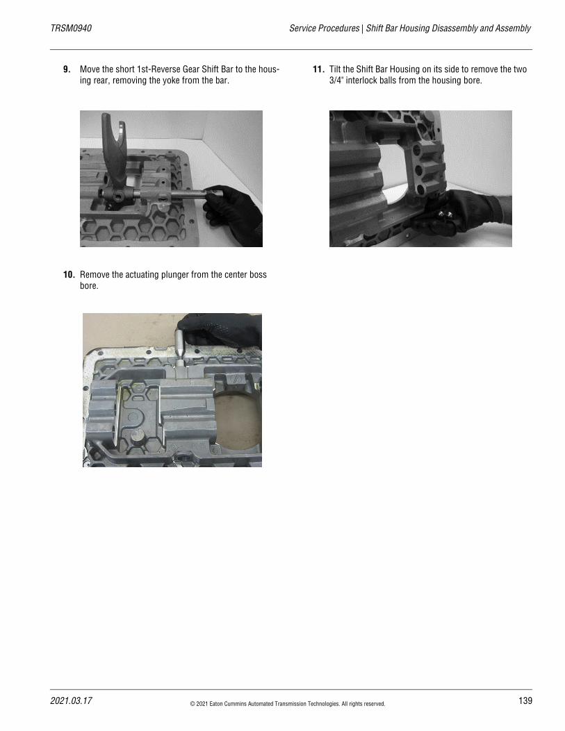
20
TRSM0940 Service Procedures | Shift Bar Housing Disassembly and Assembly
9. Move the short 1st-Reverse Gear Shift Bar to the hous-ing rear, removing the yoke from the bar.
10. Remove the actuating plunger from the center boss bore.
11. Tilt the Shift Bar Housing on its side to remove the two 3/4" interlock balls from the housing bore.
21.03.17 © 2021 Eaton Cummins Automated Transmission Technologies. All rights reserved. 139
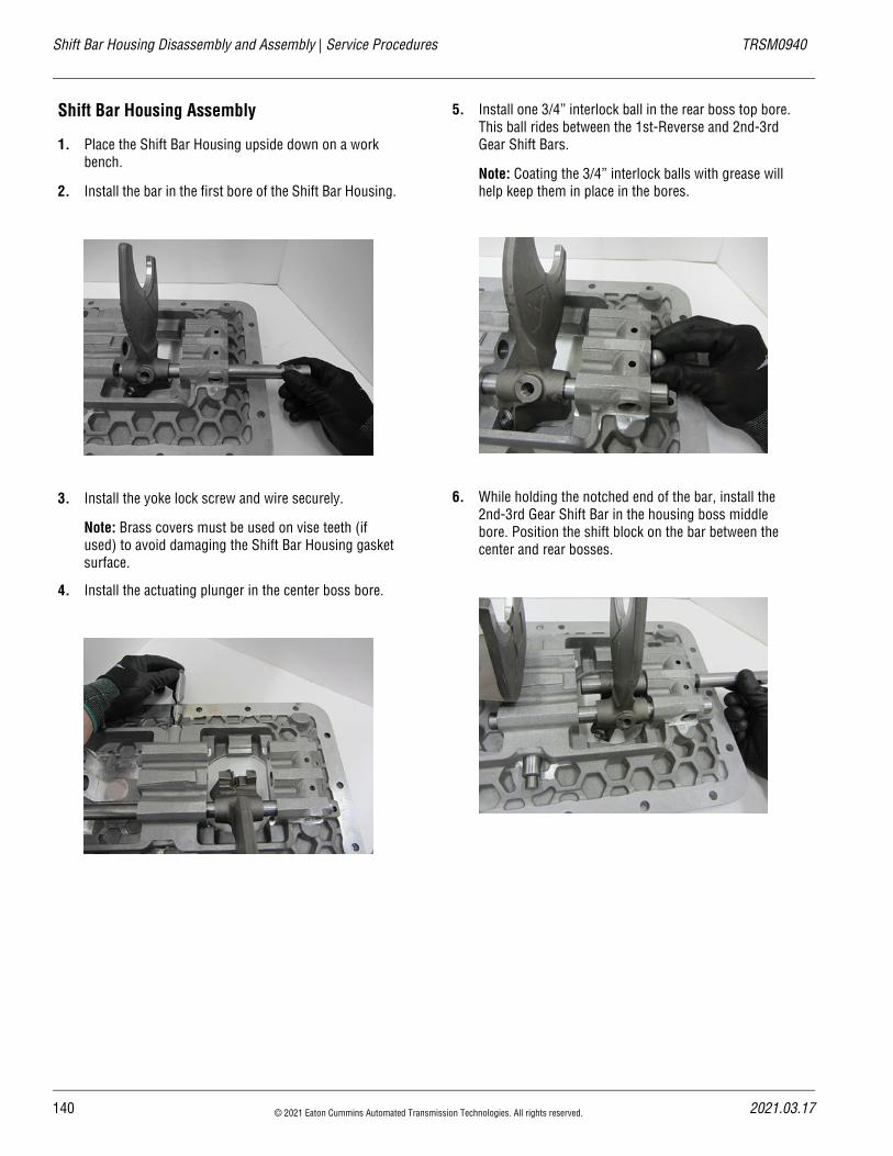
Shift Bar Housing Disassembly and Assembly | Service Procedures TRSM0940
Shift Bar Housing Assembly
1. Place the Shift Bar Housing upside down on a work bench.
2. Install the bar in the first bore of the Shift Bar Housing.
3. Install the yoke lock screw and wire securely.
Note: Brass covers must be used on vise teeth (if used) to avoid damaging the Shift Bar Housing gasket surface.
4. Install the actuating plunger in the center boss bore.
5. Install one 3/4” interlock ball in the rear boss top bore. This ball rides between the 1st-Reverse and 2nd-3rd Gear Shift Bars.
Note: Coating the 3/4” interlock balls with grease will help keep them in place in the bores.
6. While holding the notched end of the bar, install the 2nd-3rd Gear Shift Bar in the housing boss middle bore. Position the shift block on the bar between the center and rear bosses.
140 © 2021 Eaton Cummins Automated Transmission Technologies. All rights reserved. 2021.03.17
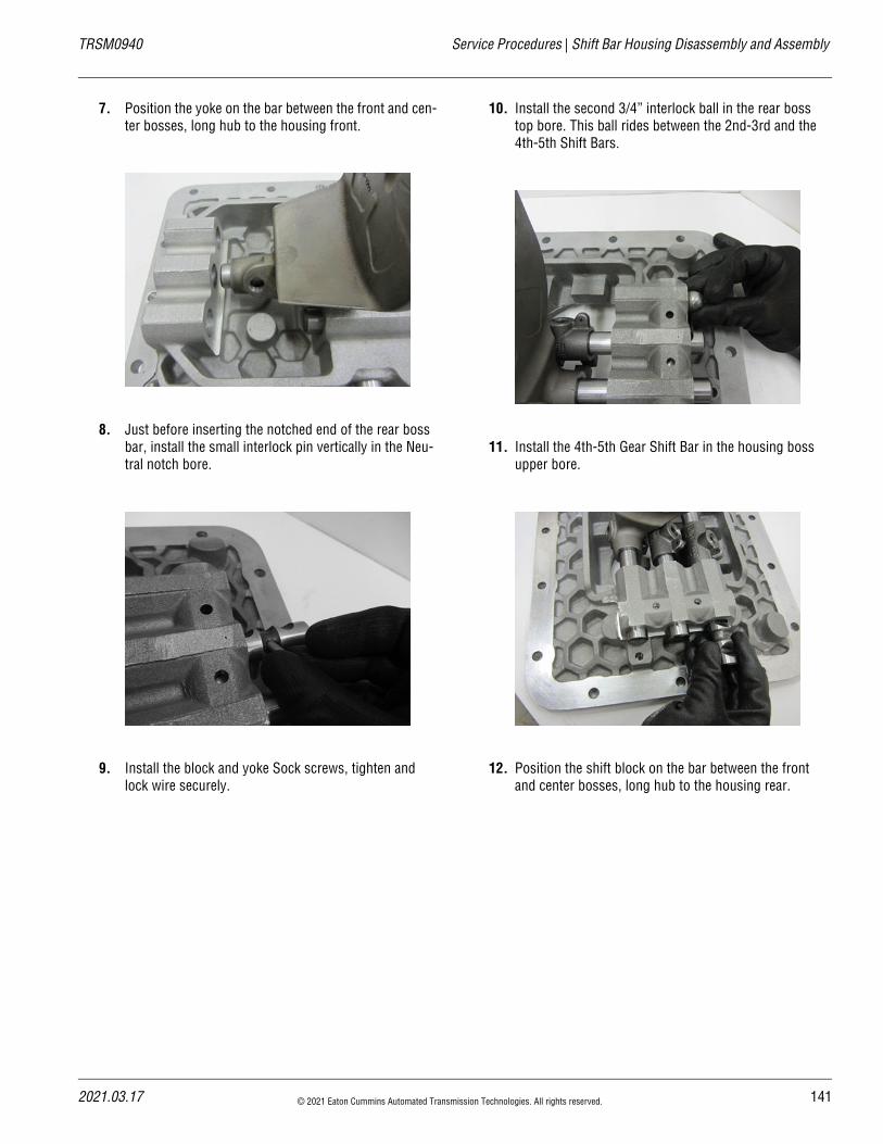
20
TRSM0940 Service Procedures | Shift Bar Housing Disassembly and Assembly
7. Position the yoke on the bar between the front and cen-ter bosses, long hub to the housing front.
8. Just before inserting the notched end of the rear boss bar, install the small interlock pin vertically in the Neu-tral notch bore.
9. Install the block and yoke Sock screws, tighten and lock wire securely.
10. Install the second 3/4” interlock ball in the rear boss top bore. This ball rides between the 2nd-3rd and the 4th-5th Shift Bars.
11. Install the 4th-5th Gear Shift Bar in the housing boss upper bore.
12. Position the shift block on the bar between the front and center bosses, long hub to the housing rear.
21.03.17 © 2021 Eaton Cummins Automated Transmission Technologies. All rights reserved. 141
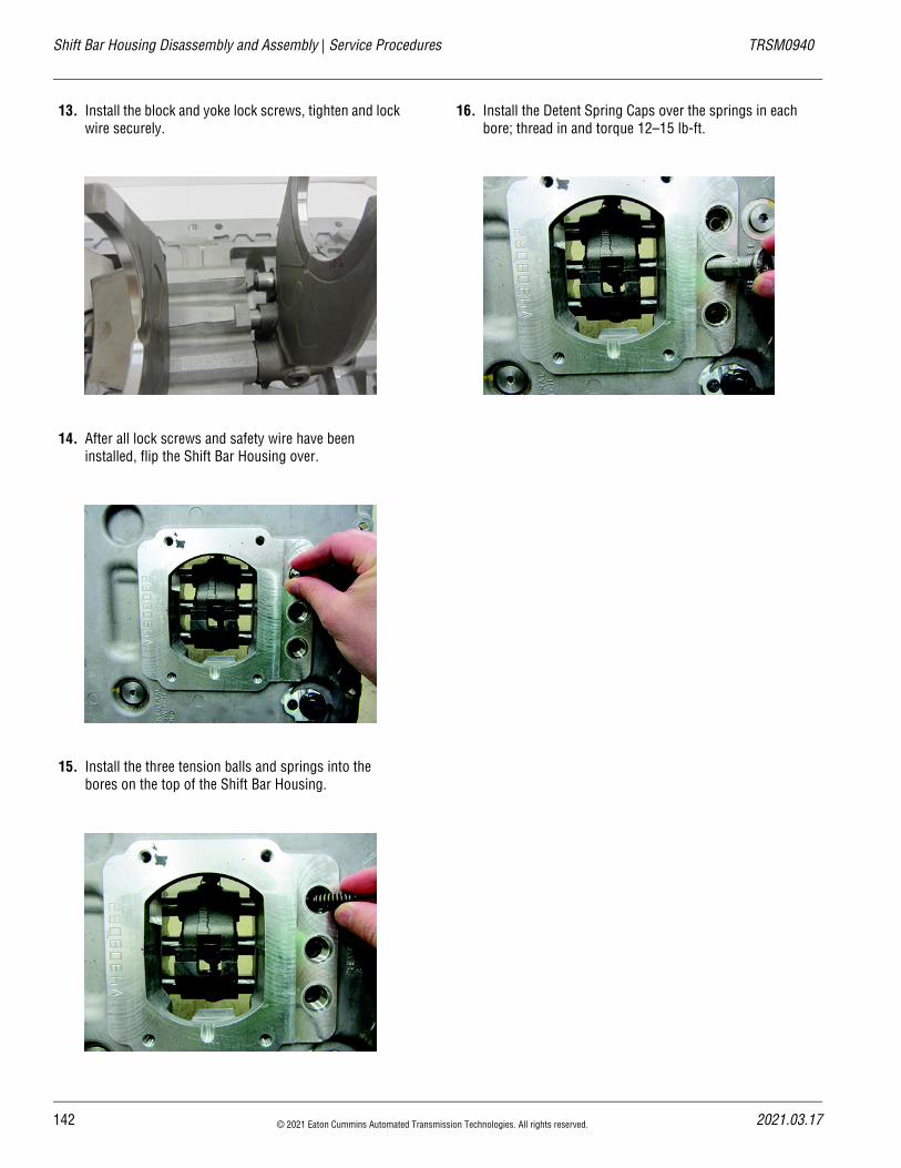
Shift Bar Housing Disassembly and Assembly | Service Procedures TRSM0940
13. Install the block and yoke lock screws, tighten and lock wire securely.
14. After all lock screws and safety wire have been installed, flip the Shift Bar Housing over.
15. Install the three tension balls and springs into the bores on the top of the Shift Bar Housing.
16. Install the Detent Spring Caps over the springs in each bore; thread in and torque 12–15 lb-ft.
142 © 2021 Eaton Cummins Automated Transmission Technologies. All rights reserved. 2021.03.17
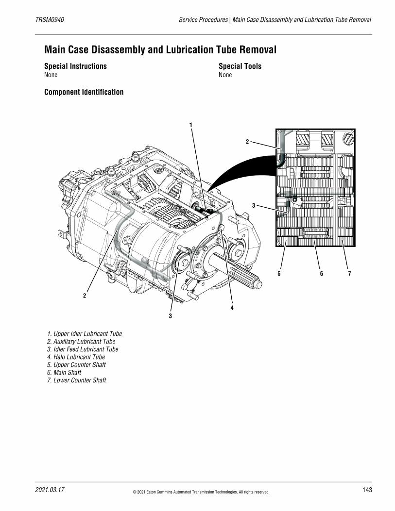
20
TRSM0940 Service Procedures | Main Case Disassembly and Lubrication Tube Removal
Main Case Disassembly and Lubrication Tube RemovalSpecial InstructionsNone
Special ToolsNone
Component Identification
1. Upper Idler Lubricant Tube2. Auxiliary Lubricant Tube3. Idler Feed Lubricant Tube4. Halo Lubricant Tube5. Upper Counter Shaft6. Main Shaft7. Lower Counter Shaft
21.03.17 © 2021 Eaton Cummins Automated Transmission Technologies. All rights reserved. 143
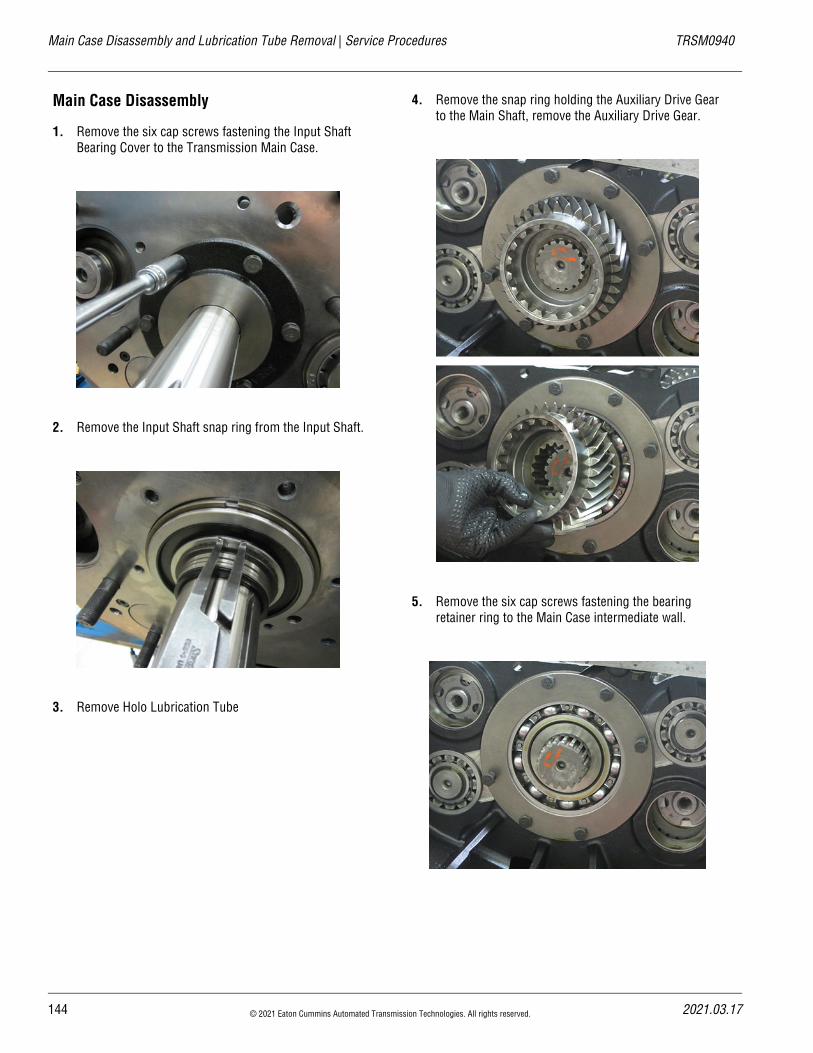
Main Case Disassembly and Lubrication Tube Removal | Service Procedures TRSM0940
Main Case Disassembly
1. Remove the six cap screws fastening the Input Shaft Bearing Cover to the Transmission Main Case.
2. Remove the Input Shaft snap ring from the Input Shaft.
3. Remove Holo Lubrication Tube
4. Remove the snap ring holding the Auxiliary Drive Gear to the Main Shaft, remove the Auxiliary Drive Gear.
5. Remove the six cap screws fastening the bearing retainer ring to the Main Case intermediate wall.
144 © 2021 Eaton Cummins Automated Transmission Technologies. All rights reserved. 2021.03.17
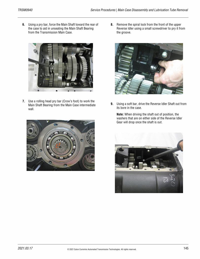
20
TRSM0940 Service Procedures | Main Case Disassembly and Lubrication Tube Removal
6. Using a pry bar, force the Main Shaft toward the rear of the case to aid in unseating the Main Shaft Bearing from the Transmission Main Case.
7. Use a rolling head pry bar (Crow’s foot) to work the Main Shaft Bearing from the Main Case intermediate wall.
8. Remove the spiral lock from the front of the upper Reverse Idler using a small screwdriver to pry it from the groove.
9. Using a soft bar, drive the Reverse Idler Shaft out from its bore in the case.
Note: When driving the shaft out of position, the washers that are on either side of the Reverse Idler Gear will drop once the shaft is out.
21.03.17 © 2021 Eaton Cummins Automated Transmission Technologies. All rights reserved. 145
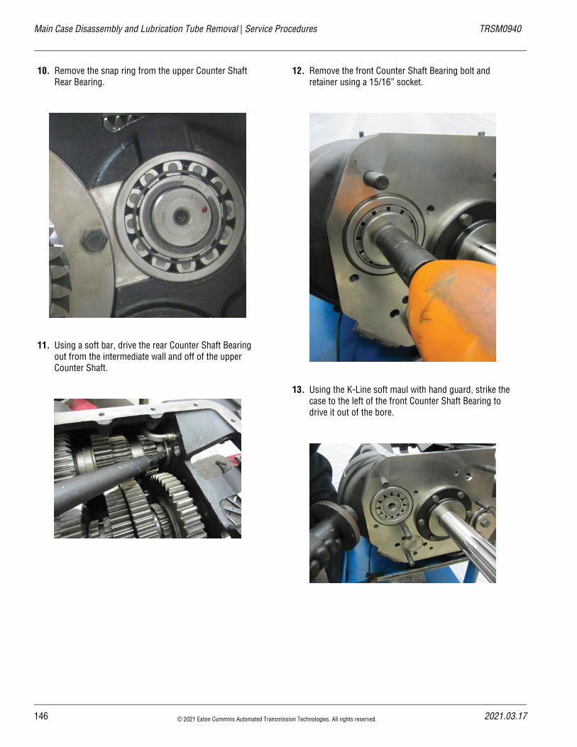
Main Case Disassembly and Lubrication Tube Removal | Service Procedures TRSM0940
10. Remove the snap ring from the upper Counter Shaft Rear Bearing.
11. Using a soft bar, drive the rear Counter Shaft Bearing out from the intermediate wall and off of the upper Counter Shaft.
12. Remove the front Counter Shaft Bearing bolt and retainer using a 15/16” socket.
13. Using the K-Line soft maul with hand guard, strike the case to the left of the front Counter Shaft Bearing to drive it out of the bore.
146 © 2021 Eaton Cummins Automated Transmission Technologies. All rights reserved. 2021.03.17
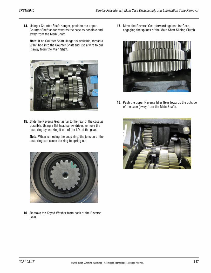
20
TRSM0940 Service Procedures | Main Case Disassembly and Lubrication Tube Removal
14. Using a Counter Shaft Hanger, position the upper Counter Shaft as far towards the case as possible and away from the Main Shaft.
Note: If no Counter Shaft Hanger is available, thread a 9/16” bolt into the Counter Shaft and use a wire to pull it away from the Main Shaft.
15. Slide the Reverse Gear as far to the rear of the case as possible. Using a flat head screw driver, remove the snap ring by working it out of the I.D. of the gear.
Note: When removing the snap ring, the tension of the snap ring can cause the ring to spring out.
16. Remove the Keyed Washer from back of the Reverse Gear
17. Move the Reverse Gear forward against 1st Gear, engaging the splines of the Main Shaft Sliding Clutch.
18. Push the upper Reverse Idler Gear towards the outside of the case (away from the Main Shaft).
21.03.17 © 2021 Eaton Cummins Automated Transmission Technologies. All rights reserved. 147
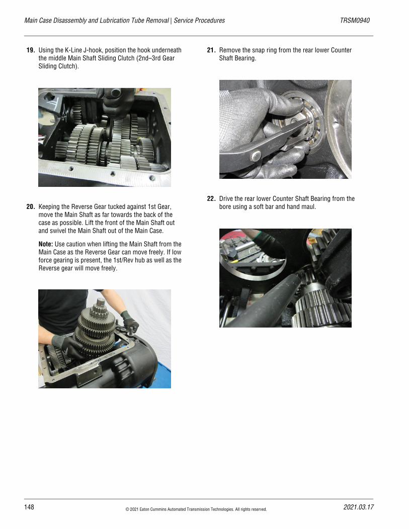
Main Case Disassembly and Lubrication Tube Removal | Service Procedures TRSM0940
19. Using the K-Line J-hook, position the hook underneath the middle Main Shaft Sliding Clutch (2nd–3rd Gear Sliding Clutch).
20. Keeping the Reverse Gear tucked against 1st Gear, move the Main Shaft as far towards the back of the case as possible. Lift the front of the Main Shaft out and swivel the Main Shaft out of the Main Case.
Note: Use caution when lifting the Main Shaft from the Main Case as the Reverse Gear can move freely. If low force gearing is present, the 1st/Rev hub as well as the Reverse gear will move freely.
21. Remove the snap ring from the rear lower Counter Shaft Bearing.
22. Drive the rear lower Counter Shaft Bearing from the bore using a soft bar and hand maul.
148 © 2021 Eaton Cummins Automated Transmission Technologies. All rights reserved. 2021.03.17
20
TRSM0940 Service Procedures | Main Case Disassembly and Lubrication Tube Removal
23. Using a 15/16” socket, remove the retaining bolt of the lower Counter Shaft Front Bearing.
24. Using a soft maul with hand guard, strike the case to the right of the front lower Counter Shaft Bearing to remove it from the bore.
Main Drive Gear and Input Shaft Removal
1. Using the K-Line tools Input Bearing Puller, remove the Input Shaft Bearing.
Note: Input Shaft may also be driven through the bear-ing using a soft hand maul.
2. With the upper Counter Shaft still pushed as far toward the case as possible, remove the Input Shaft, Main Drive Gear and spacer as an assembly.
21.03.17 © 2021 Eaton Cummins Automated Transmission Technologies. All rights reserved. 149
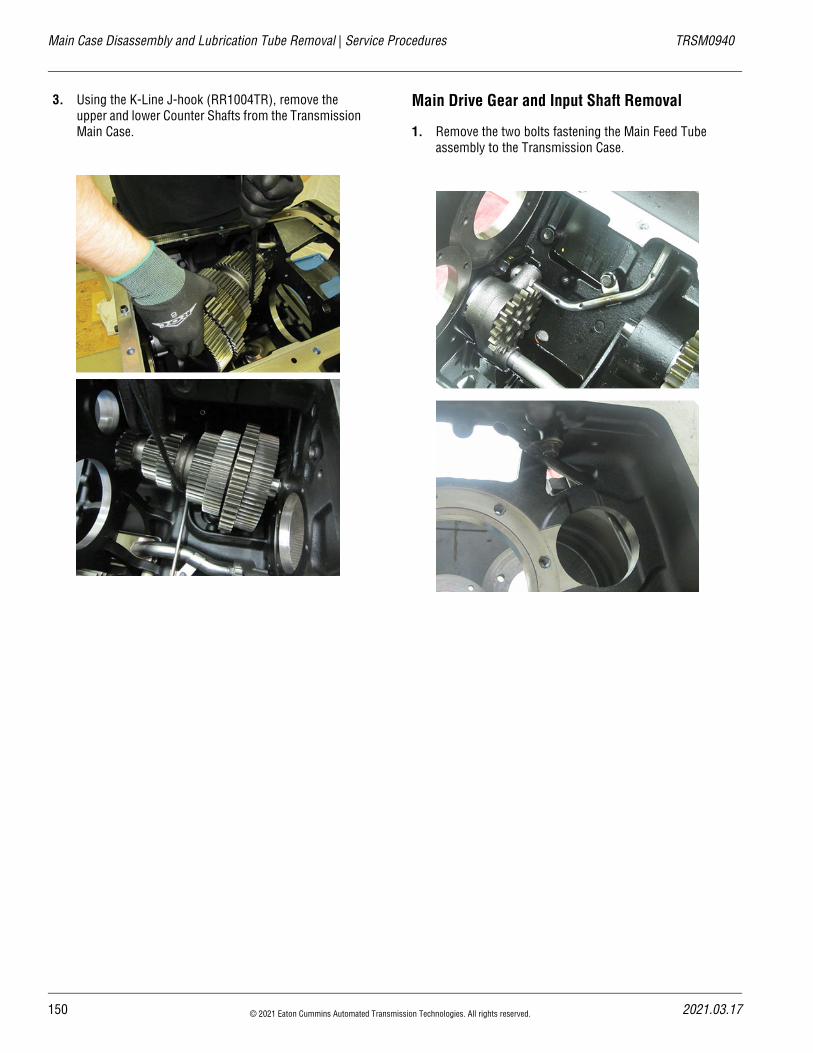
Main Case Disassembly and Lubrication Tube Removal | Service Procedures TRSM0940
3. Using the K-Line J-hook (RR1004TR), remove the upper and lower Counter Shafts from the Transmission Main Case.
Main Drive Gear and Input Shaft Removal
1. Remove the two bolts fastening the Main Feed Tube assembly to the Transmission Case.
150 © 2021 Eaton Cummins Automated Transmission Technologies. All rights reserved. 2021.03.17
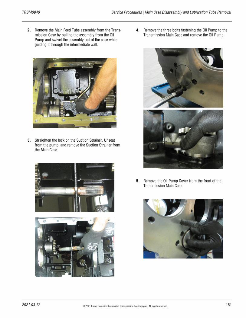
20
TRSM0940 Service Procedures | Main Case Disassembly and Lubrication Tube Removal
2. Remove the Main Feed Tube assembly from the Trans-mission Case by pulling the assembly from the Oil Pump and swivel the assembly out of the case while guiding it through the intermediate wall.
3. Straighten the lock on the Suction Strainer. Unseat from the pump, and remove the Suction Strainer from the Main Case.
4. Remove the three bolts fastening the Oil Pump to the Transmission Main Case and remove the Oil Pump.
5. Remove the Oil Pump Cover from the front of the Transmission Main Case.
21.03.17 © 2021 Eaton Cummins Automated Transmission Technologies. All rights reserved. 151
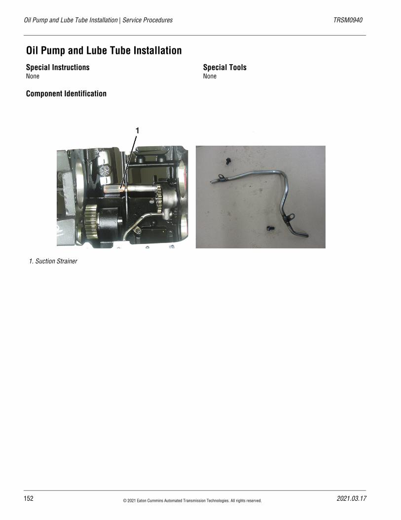
Oil Pump and Lube Tube Installation | Service Procedures TRSM0940
Oil Pump and Lube Tube InstallationSpecial InstructionsNone
Special ToolsNone
Component Identification
1. Suction Strainer
152 © 2021 Eaton Cummins Automated Transmission Technologies. All rights reserved. 2021.03.17
20
TRSM0940 Service Procedures | Oil Pump and Lube Tube Installation
Oil Pump Installation
1. Clean any debris from the Transmission Main Case before assembly.
2. Apply oil or assembly lube to the O-ring on the Oil Pump Cover. Install into the front of the Transmission Main Case.
3. Install the Oil Pump into the Transmission Main Case; torque bolts to 8–12 lb-ft.
Lubrication Tubes Installation
1. Install the Suction Strainer into the Transmission Main Case, push the tube into the Oil Pump until the tab is flush against the Oil Pump. After the Suction Strainer has been installed, secure the strainer by pushing down the tube lock.
2. Install the Main Feed Tube into the Transmission Main Case.
Note: The tube needs to be rotated through the Shift Bar Housing opening while going through the interme-diate wall, then rotated into place to line up with the Oil Pump.
21.03.17 © 2021 Eaton Cummins Automated Transmission Technologies. All rights reserved. 153
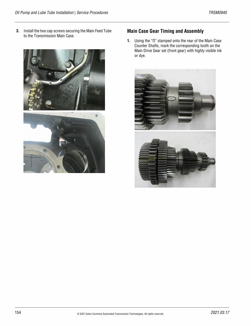
Oil Pump and Lube Tube Installation | Service Procedures TRSM0940
3. Install the two cap screws securing the Main Feed Tube to the Transmission Main Case.
Main Case Gear Timing and Assembly
1. Using the “O” stamped onto the rear of the Main Case Counter Shafts, mark the corresponding tooth on the Main Drive Gear set (front gear) with highly visible ink or dye.
154 © 2021 Eaton Cummins Automated Transmission Technologies. All rights reserved. 2021.03.17
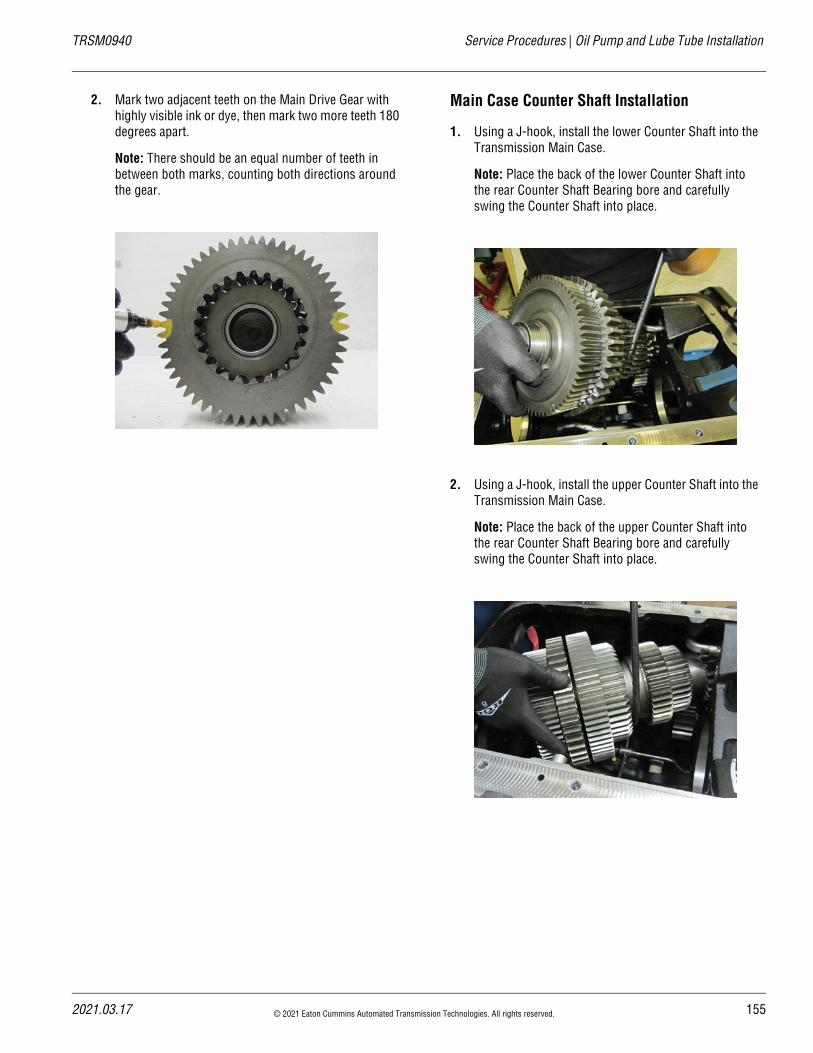
20
TRSM0940 Service Procedures | Oil Pump and Lube Tube Installation
2. Mark two adjacent teeth on the Main Drive Gear with highly visible ink or dye, then mark two more teeth 180 degrees apart.
Note: There should be an equal number of teeth in between both marks, counting both directions around the gear.
Main Case Counter Shaft Installation
1. Using a J-hook, install the lower Counter Shaft into the Transmission Main Case.
Note: Place the back of the lower Counter Shaft into the rear Counter Shaft Bearing bore and carefully swing the Counter Shaft into place.
2. Using a J-hook, install the upper Counter Shaft into the Transmission Main Case.
Note: Place the back of the upper Counter Shaft into the rear Counter Shaft Bearing bore and carefully swing the Counter Shaft into place.
21.03.17 © 2021 Eaton Cummins Automated Transmission Technologies. All rights reserved. 155
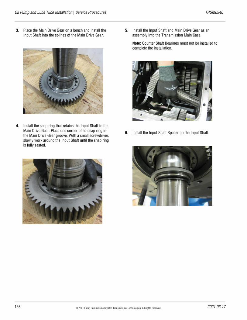
Oil Pump and Lube Tube Installation | Service Procedures TRSM0940
3. Place the Main Drive Gear on a bench and install the Input Shaft into the splines of the Main Drive Gear.
4. Install the snap ring that retains the Input Shaft to the Main Drive Gear. Place one corner of he snap ring in the Main Drive Gear groove. With a small screwdriver, slowly work around the Input Shaft until the snap ring is fully seated.
5. Install the Input Shaft and Main Drive Gear as an assembly into the Transmission Main Case.
Note: Counter Shaft Bearings must not be installed to complete the installation.
6. Install the Input Shaft Spacer on the Input Shaft.
156 © 2021 Eaton Cummins Automated Transmission Technologies. All rights reserved. 2021.03.17
20
TRSM0940 Service Procedures | Oil Pump and Lube Tube Installation
7. Place the Input Shaft Bearing over the Input Shaft. Using the Input Shaft Bearing Driver, press the bearing onto the Input Shaft and into the Transmission Main Case.
Note: Drive the bearing into the Transmission Main Case and wiggle the Input Shaft assembly back out. Continue driving the bearing onto the Input Shaft. Repeat this process until there is enough room to install the Input Shaft snap ring.
8. Install the Input Shaft snap ring.
9. Line up the marked tooth on the lower Counter Shaft with the two marked teeth on the Main Drive Gear.
10. Using the rear Counter Shaft Bearing Driver, RR1012TR-4, drive the rear bearing onto the lower Counter Shaft and into the intermediate wall of the Transmission Main Case until there is enough room to install the rear Counter Shaft Bearing snap ring.
21.03.17 © 2021 Eaton Cummins Automated Transmission Technologies. All rights reserved. 157
Oil Pump and Lube Tube Installation | Service Procedures TRSM0940
11. Install the rear lower Counter Shaft Bearing snap ring.
12. Using the bearing driver RR1012TR-2, install the front lower Counter Shaft Bearing onto the Counter Shaft and into the bore of the Transmission Main Case.
Note: Using an old race for the front Counter Shaft Bearings helps keep the rollers in place during installation.
13. Install the front lower Counter Shaft Bearing retaining washer and bolt and torque to 90–120 lb-ft.
158 © 2021 Eaton Cummins Automated Transmission Technologies. All rights reserved. 2021.03.17
20
TRSM0940 Service Procedures | Oil Pump and Lube Tube Installation
14. Place the upper Reverse Idler on top of the lower Counter Shaft; tuck it as close to the side of the case as possible.
Note: Ensure the gear is installed in the proper direc-tion. The gear should have “FRONT” scribed on the side facing the front of the transmission. If no mark-ings, the face of the gear with the machined indentation should go to the rear of the transmission.
15. Using a J-hook, install the Main Shaft assembly into the Transmission Main Case by placing the rear of the Main Shaft through the opening in the intermediate wall and lowering the front of the Main Shaft into place. Pull the Main Shaft forward and pilot the tip into the Input Shaft Bushing.
Note: Reverse Gear needs to be tucked into 1st Gear (over the 1st–Reverse Sliding Clutch) during installa-tion to ensure adequate room to position the Main Shaft.
Caution: The front sliding clutch (4th–5th) can slide off the Main Shaft during installation.
Caution: The reverse gear will move freely during installation. If low-force gearing is present, the hub will also move freely on the shaft.
16. Install the rear Main Shaft Bearing partially into the case to aid in supporting the Main Shaft assembly.
Note: Ensure the Reverse Gear remains tucked against 1st Gear.
!
!
21.03.17 © 2021 Eaton Cummins Automated Transmission Technologies. All rights reserved. 159
Oil Pump and Lube Tube Installation | Service Procedures TRSM0940
17. Line up the marked tooth on the upper Counter Shaft with the two marked teeth on the Main Drive Gear.
Note: Ensure the lower Counter Shaft is still in time with the Main Drive Gear before moving the upper Counter Shaft into place.
18. Using the rear Counter Shaft Bearing Driver, RR1012TR-4, drive the rear bearing onto the upper Counter Shaft and into the intermediate wall of the Transmission Main Case until there is enough room to install the rear Counter Shaft Bearing snap ring.
19. Install the rear upper Counter Shaft Bearing snap ring.
160 © 2021 Eaton Cummins Automated Transmission Technologies. All rights reserved. 2021.03.17
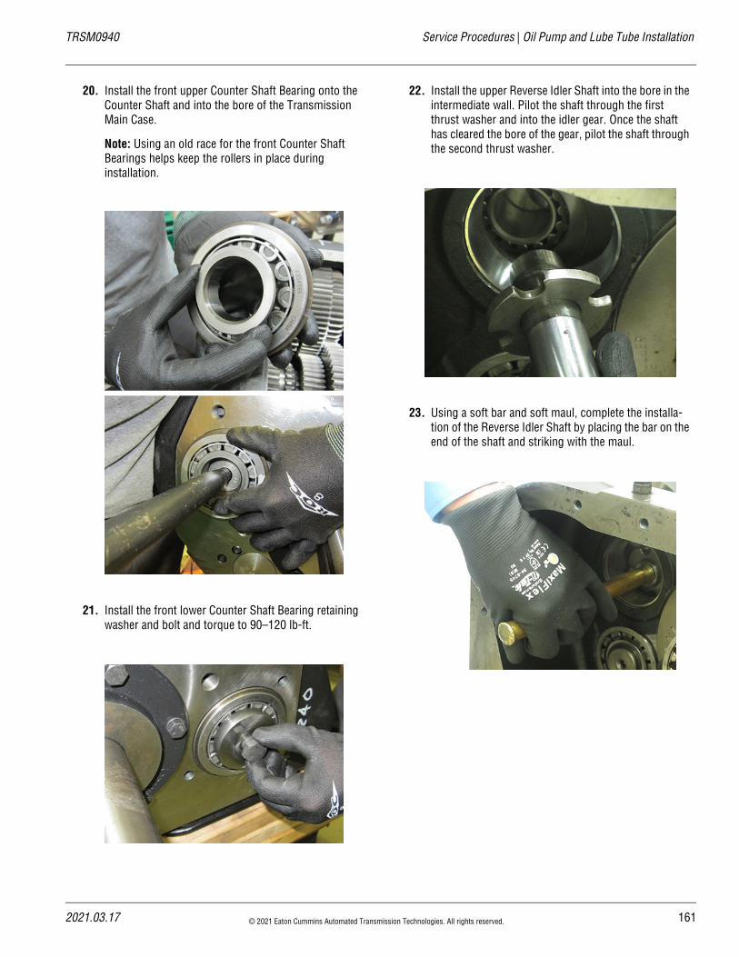
20
TRSM0940 Service Procedures | Oil Pump and Lube Tube Installation
20. Install the front upper Counter Shaft Bearing onto the Counter Shaft and into the bore of the Transmission Main Case.
Note: Using an old race for the front Counter Shaft Bearings helps keep the rollers in place during installation.
21. Install the front lower Counter Shaft Bearing retaining washer and bolt and torque to 90–120 lb-ft.
22. Install the upper Reverse Idler Shaft into the bore in the intermediate wall. Pilot the shaft through the first thrust washer and into the idler gear. Once the shaft has cleared the bore of the gear, pilot the shaft through the second thrust washer.
23. Using a soft bar and soft maul, complete the installa-tion of the Reverse Idler Shaft by placing the bar on the end of the shaft and striking with the maul.
21.03.17 © 2021 Eaton Cummins Automated Transmission Technologies. All rights reserved. 161
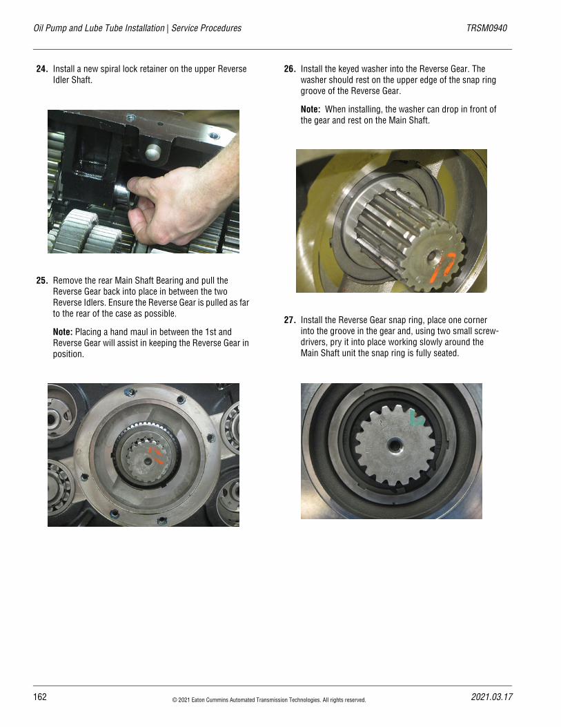
Oil Pump and Lube Tube Installation | Service Procedures TRSM0940
24. Install a new spiral lock retainer on the upper Reverse Idler Shaft.
25. Remove the rear Main Shaft Bearing and pull the Reverse Gear back into place in between the two Reverse Idlers. Ensure the Reverse Gear is pulled as far to the rear of the case as possible.
Note: Placing a hand maul in between the 1st and Reverse Gear will assist in keeping the Reverse Gear in position.
26. Install the keyed washer into the Reverse Gear. The washer should rest on the upper edge of the snap ring groove of the Reverse Gear.
Note: When installing, the washer can drop in front of the gear and rest on the Main Shaft.
27. Install the Reverse Gear snap ring, place one corner into the groove in the gear and, using two small screw-drivers, pry it into place working slowly around the Main Shaft unit the snap ring is fully seated.
162 © 2021 Eaton Cummins Automated Transmission Technologies. All rights reserved. 2021.03.17
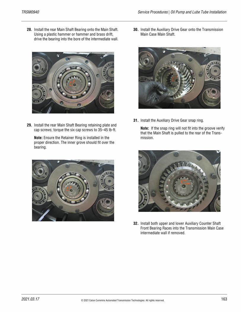
20
TRSM0940 Service Procedures | Oil Pump and Lube Tube Installation
28. Install the rear Main Shaft Bearing onto the Main Shaft. Using a plastic hammer or hammer and brass drift, drive the bearing into the bore of the intermediate wall.
29. Install the rear Main Shaft Bearing retaining plate and cap screws; torque the six cap screws to 35–45 lb-ft.
Note: Ensure the Retainer Ring is installed in the proper direction. The inner grove should fit over the bearing.
30. Install the Auxiliary Drive Gear onto the Transmission Main Case Main Shaft.
31. Install the Auxiliary Drive Gear snap ring.
Note: If the snap ring will not fit into the groove verify that the Main Shaft is pulled to the rear of the Trans-mission.
32. Install both upper and lower Auxiliary Counter Shaft Front Bearing Races into the Transmission Main Case intermediate wall if removed.
21.03.17 © 2021 Eaton Cummins Automated Transmission Technologies. All rights reserved. 163
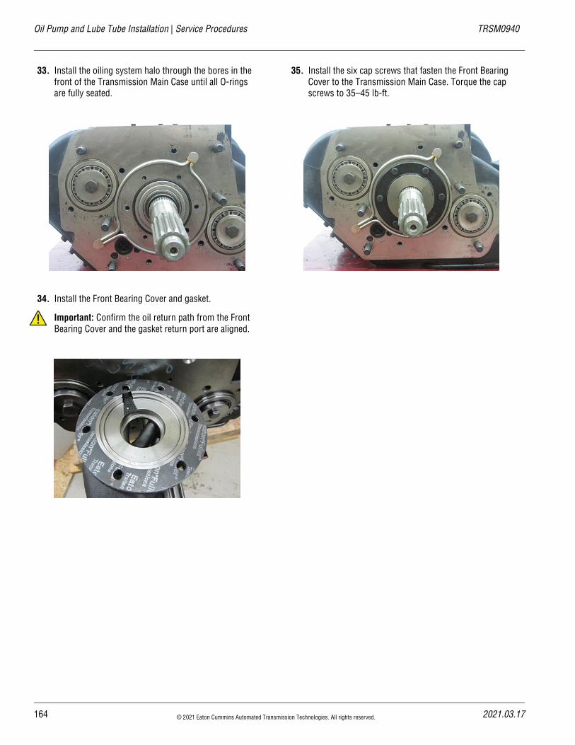
Oil Pump and Lube Tube Installation | Service Procedures TRSM0940
33. Install the oiling system halo through the bores in the front of the Transmission Main Case until all O-rings are fully seated.
34. Install the Front Bearing Cover and gasket.
Important: Confirm the oil return path from the Front Bearing Cover and the gasket return port are aligned.
35. Install the six cap screws that fasten the Front Bearing Cover to the Transmission Main Case. Torque the cap screws to 35–45 lb-ft.
!
164 © 2021 Eaton Cummins Automated Transmission Technologies. All rights reserved. 2021.03.17
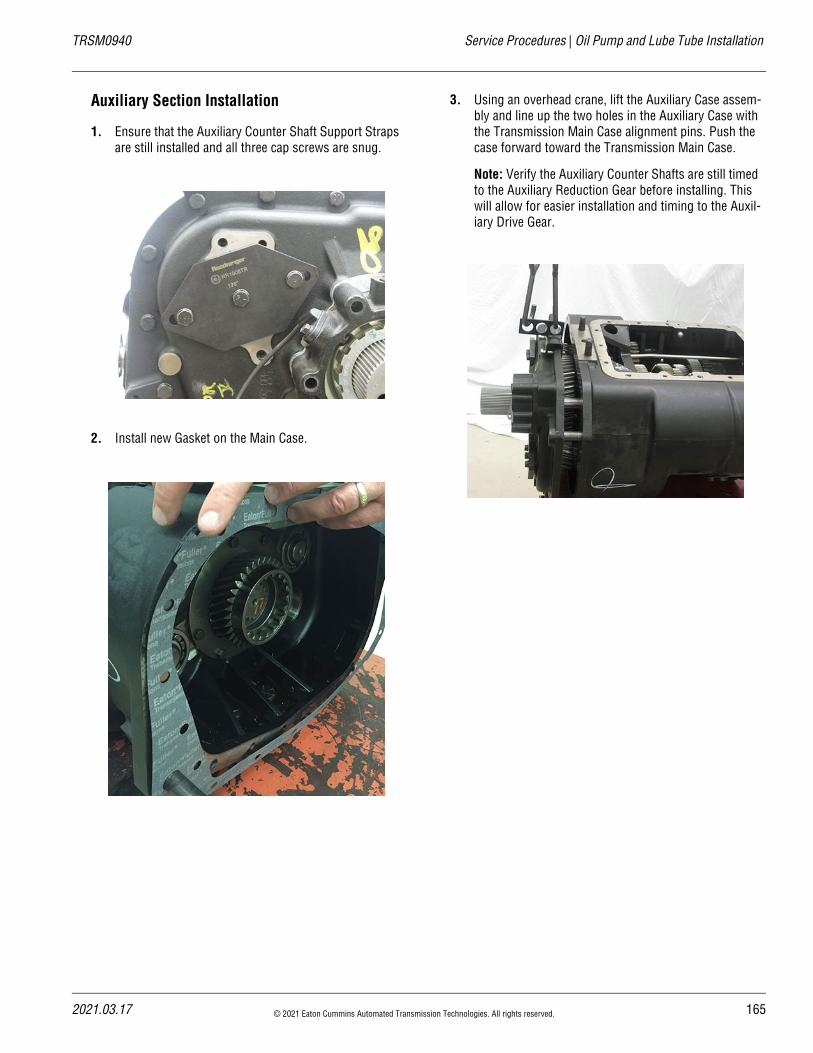
20
TRSM0940 Service Procedures | Oil Pump and Lube Tube Installation
Auxiliary Section Installation
1. Ensure that the Auxiliary Counter Shaft Support Straps are still installed and all three cap screws are snug.
2. Install new Gasket on the Main Case.
3. Using an overhead crane, lift the Auxiliary Case assem-bly and line up the two holes in the Auxiliary Case with the Transmission Main Case alignment pins. Push the case forward toward the Transmission Main Case.
Note: Verify the Auxiliary Counter Shafts are still timed to the Auxiliary Reduction Gear before installing. This will allow for easier installation and timing to the Auxil-iary Drive Gear.
21.03.17 © 2021 Eaton Cummins Automated Transmission Technologies. All rights reserved. 165
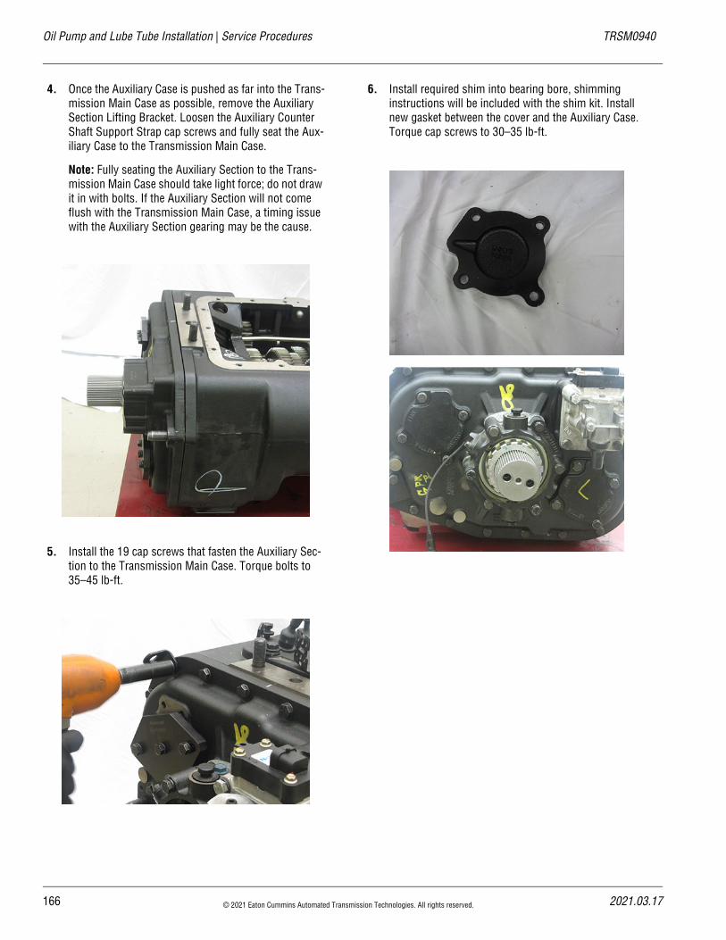
Oil Pump and Lube Tube Installation | Service Procedures TRSM0940
4. Once the Auxiliary Case is pushed as far into the Trans-mission Main Case as possible, remove the Auxiliary Section Lifting Bracket. Loosen the Auxiliary Counter Shaft Support Strap cap screws and fully seat the Aux-iliary Case to the Transmission Main Case.
Note: Fully seating the Auxiliary Section to the Trans-mission Main Case should take light force; do not draw it in with bolts. If the Auxiliary Section will not come flush with the Transmission Main Case, a timing issue with the Auxiliary Section gearing may be the cause.
5. Install the 19 cap screws that fasten the Auxiliary Sec-tion to the Transmission Main Case. Torque bolts to 35–45 lb-ft.
6. Install required shim into bearing bore, shimming instructions will be included with the shim kit. Install new gasket between the cover and the Auxiliary Case. Torque cap screws to 30–35 lb-ft.
166 © 2021 Eaton Cummins Automated Transmission Technologies. All rights reserved. 2021.03.17
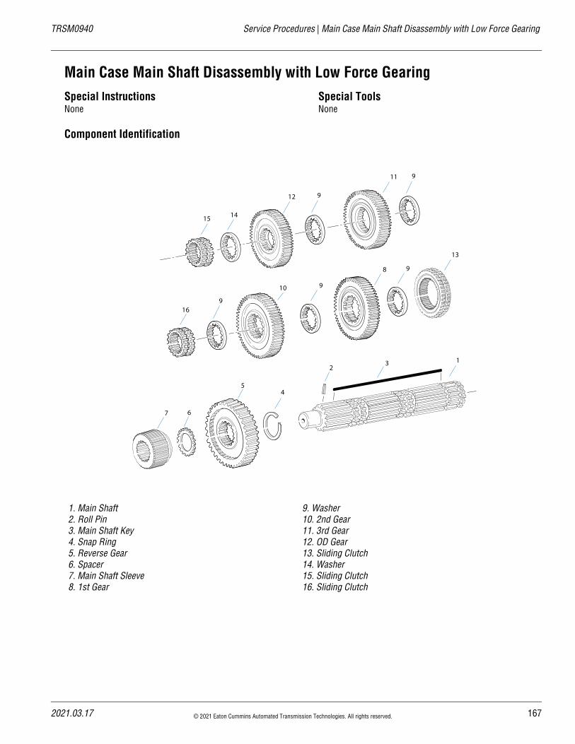
20
TRSM0940 Service Procedures | Main Case Main Shaft Disassembly with Low Force Gearing
Main Case Main Shaft Disassembly with Low Force GearingSpecial InstructionsNone
Special ToolsNone
Component Identification
1. Main Shaft2. Roll Pin3. Main Shaft Key4. Snap Ring5. Reverse Gear6. Spacer7. Main Shaft Sleeve8. 1st Gear
9. Washer10. 2nd Gear11. 3rd Gear12. OD Gear13. Sliding Clutch14. Washer15. Sliding Clutch16. Sliding Clutch
15 14
12 9
11
16
10
8
9
13
132
45
67
9
9
9
21.03.17 © 2021 Eaton Cummins Automated Transmission Technologies. All rights reserved. 167
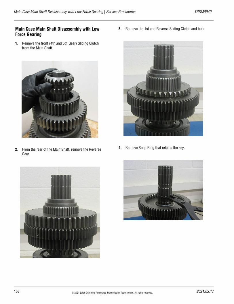
Main Case Main Shaft Disassembly with Low Force Gearing | Service Procedures TRSM0940
Main Case Main Shaft Disassembly with Low Force Gearing
1. Remove the front (4th and 5th Gear) Sliding Clutch from the Main Shaft
2. From the rear of the Main Shaft, remove the Reverse Gear.
3. Remove the 1st and Reverse Sliding Clutch and hub
4. Remove Snap Ring that retains the key.
168 © 2021 Eaton Cummins Automated Transmission Technologies. All rights reserved. 2021.03.17
20
TRSM0940 Service Procedures | Main Case Main Shaft Disassembly with Low Force Gearing
5. Remove the key from the Main Shaft keyway.
Note: When removing no-burn washers or spacers, note their location on the Main Shaft to facilitate reas-sembly. Keep each washer with the corresponding gear it was mated against.
6. Remove the 1st stepped no-burn washer from the Main Shaft.
Note: There are two types of washers used on the Main Shaft. The stepped washers (left) fit between gears and sliding clutches with the stepped edge facing the slid-ing clutch. The flat no-burn washers fit between gears.
21.03.17 © 2021 Eaton Cummins Automated Transmission Technologies. All rights reserved. 169
Main Case Main Shaft Disassembly with Low Force Gearing | Service Procedures TRSM0940
7. Remove the 1st Gear from the Main Shaft.
8. Remove the 2nd stepped no-burn washer from the Main Shaft.
9. Remove 2nd Gear from the Main Shaft.
10. Remove the 3rd stepped washer from the Main Shaft.
170 © 2021 Eaton Cummins Automated Transmission Technologies. All rights reserved. 2021.03.17
20
TRSM0940 Service Procedures | Main Case Main Shaft Disassembly with Low Force Gearing
11. Remove the 2nd–3rd Gear Sliding Clutch.
12. Remove the 4th no-burn washer and 3rd Gear.
13. Remove the 5th flat no-burn washer from the Main Shaft.
14. Remove 4th Gear (5th for direct drive) from the Main Shaft.
21.03.17 © 2021 Eaton Cummins Automated Transmission Technologies. All rights reserved. 171
Main Case Main Shaft Disassembly with Low Force Gearing | Service Procedures TRSM0940
15. Remove the last stepped no-burn washer from the Main Shaft.
Note: The last or furthest forward no-burn washer is smaller than the rest. This is specific for the front of the Main Shaft as the 4th–5th Gear Sliding Clutch is smaller than the 1st–Reverse and 2nd–3rd Gear Slid-ing Clutches.
172 © 2021 Eaton Cummins Automated Transmission Technologies. All rights reserved. 2021.03.17
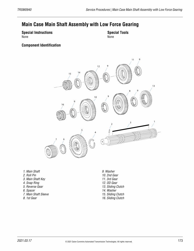
20
TRSM0940 Service Procedures | Main Case Main Shaft Assembly with Low Force Gearing
Main Case Main Shaft Assembly with Low Force GearingSpecial InstructionsNone
Special ToolsNone
Component Identification
1. Main Shaft2. Roll Pin3. Main Shaft Key4. Snap Ring5. Reverse Gear6. Spacer7. Main Shaft Sleeve8. 1st Gear
9. Washer10. 2nd Gear11. 3rd Gear12. OD Gear13. Sliding Clutch14. Washer15. Sliding Clutch16. Sliding Clutch
15 14
12 9
11
16
10
8
9
13
132
45
67
9
9
9
21.03.17 © 2021 Eaton Cummins Automated Transmission Technologies. All rights reserved. 173
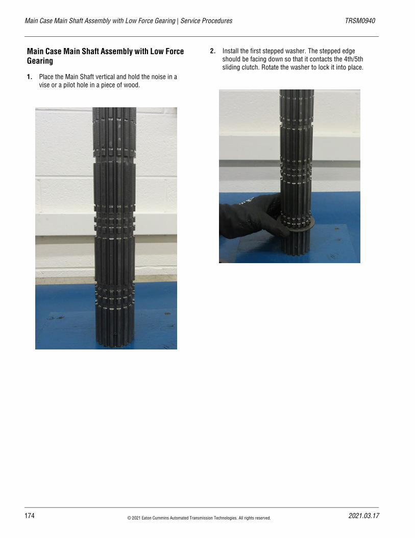
Main Case Main Shaft Assembly with Low Force Gearing | Service Procedures TRSM0940
Main Case Main Shaft Assembly with Low Force Gearing
1. Place the Main Shaft vertical and hold the noise in a vise or a pilot hole in a piece of wood.
2. Install the first stepped washer. The stepped edge should be facing down so that it contacts the 4th/5th sliding clutch. Rotate the washer to lock it into place.
174 © 2021 Eaton Cummins Automated Transmission Technologies. All rights reserved. 2021.03.17
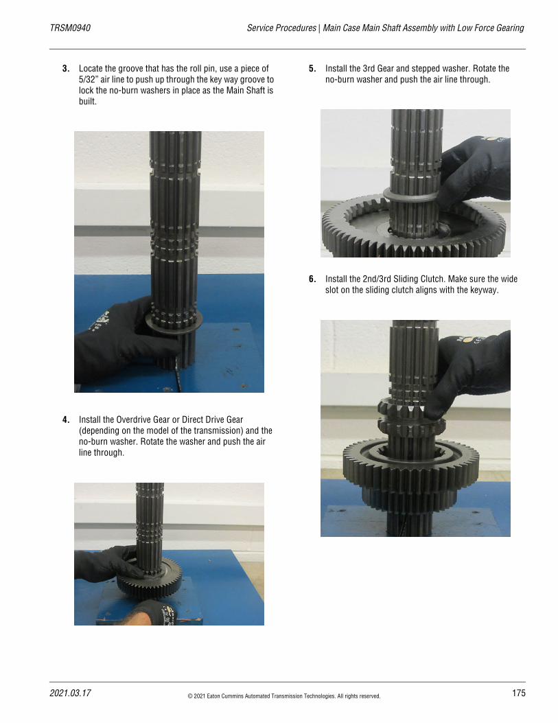
20
TRSM0940 Service Procedures | Main Case Main Shaft Assembly with Low Force Gearing
3. Locate the groove that has the roll pin, use a piece of 5/32” air line to push up through the key way groove to lock the no-burn washers in place as the Main Shaft is built.
4. Install the Overdrive Gear or Direct Drive Gear (depending on the model of the transmission) and the no-burn washer. Rotate the washer and push the air line through.
5. Install the 3rd Gear and stepped washer. Rotate the no-burn washer and push the air line through.
6. Install the 2nd/3rd Sliding Clutch. Make sure the wide slot on the sliding clutch aligns with the keyway.
21.03.17 © 2021 Eaton Cummins Automated Transmission Technologies. All rights reserved. 175
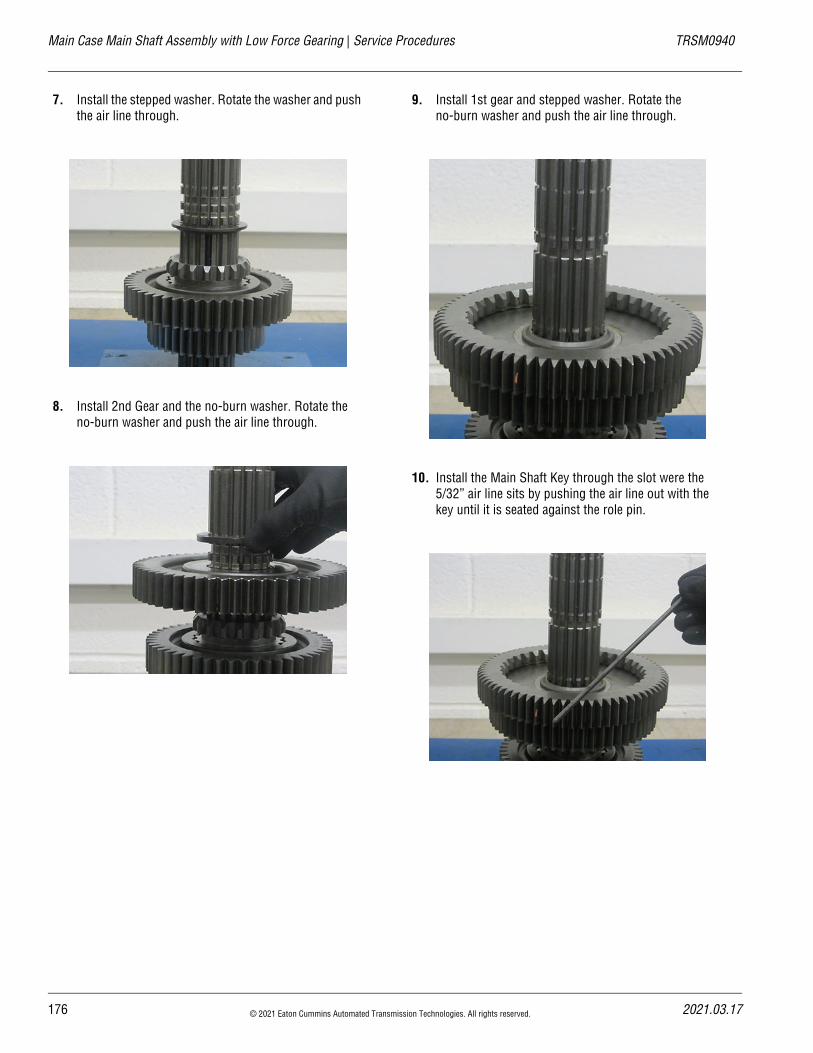
Main Case Main Shaft Assembly with Low Force Gearing | Service Procedures TRSM0940
7. Install the stepped washer. Rotate the washer and push the air line through.
8. Install 2nd Gear and the no-burn washer. Rotate the no-burn washer and push the air line through.
9. Install 1st gear and stepped washer. Rotate the no-burn washer and push the air line through.
10. Install the Main Shaft Key through the slot were the 5/32” air line sits by pushing the air line out with the key until it is seated against the role pin.
176 © 2021 Eaton Cummins Automated Transmission Technologies. All rights reserved. 2021.03.17
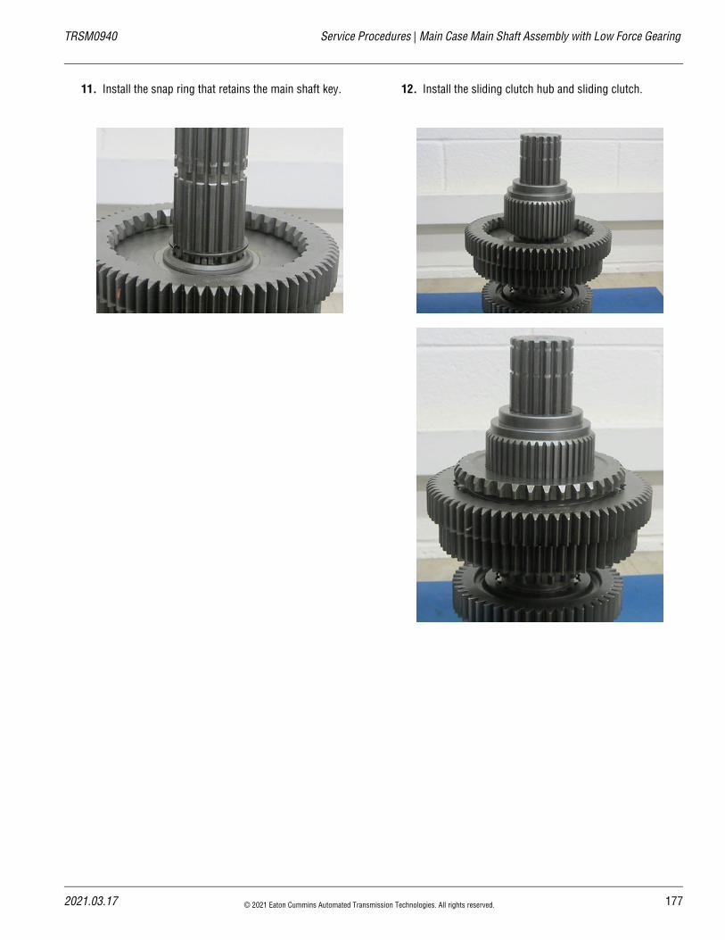
20
TRSM0940 Service Procedures | Main Case Main Shaft Assembly with Low Force Gearing
11. Install the snap ring that retains the main shaft key. 12. Install the sliding clutch hub and sliding clutch.
21.03.17 © 2021 Eaton Cummins Automated Transmission Technologies. All rights reserved. 177
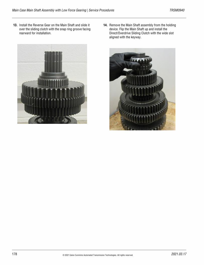
Main Case Main Shaft Assembly with Low Force Gearing | Service Procedures TRSM0940
13. Install the Reverse Gear on the Main Shaft and slide it over the sliding clutch with the snap ring groove facing rearward for installation.
14. Remove the Main Shaft assembly from the holding device. Flip the Main Shaft up and install the Direct/Overdrive Sliding Clutch with the wide slot aligned with the keyway.
178 © 2021 Eaton Cummins Automated Transmission Technologies. All rights reserved. 2021.03.17
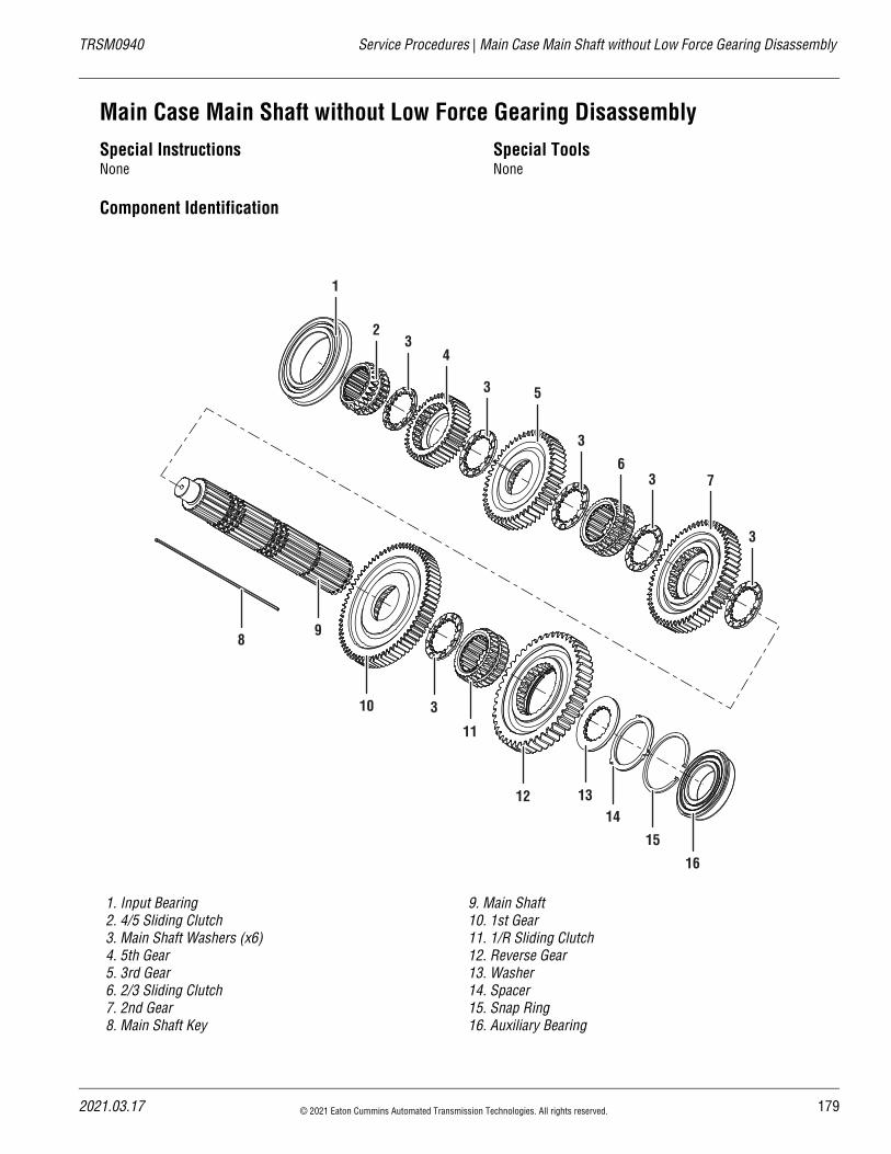
20
TRSM0940 Service Procedures | Main Case Main Shaft without Low Force Gearing Disassembly
Main Case Main Shaft without Low Force Gearing DisassemblySpecial InstructionsNone
Special ToolsNone
Component Identification
1. Input Bearing2. 4/5 Sliding Clutch3. Main Shaft Washers (x6)4. 5th Gear5. 3rd Gear6. 2/3 Sliding Clutch7. 2nd Gear8. Main Shaft Key
9. Main Shaft10. 1st Gear11. 1/R Sliding Clutch12. Reverse Gear13. Washer14. Spacer 15. Snap Ring16. Auxiliary Bearing
16
15
141312
10
98
3
7
53
43
2
1
3
3
6
11
3
21.03.17 © 2021 Eaton Cummins Automated Transmission Technologies. All rights reserved. 179
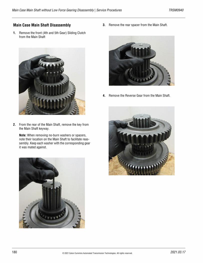
Main Case Main Shaft without Low Force Gearing Disassembly | Service Procedures TRSM0940
Main Case Main Shaft Disassembly
1. Remove the front (4th and 5th Gear) Sliding Clutch from the Main Shaft
2. From the rear of the Main Shaft, remove the key from the Main Shaft keyway.
Note: When removing no-burn washers or spacers, note their location on the Main Shaft to facilitate reas-sembly. Keep each washer with the corresponding gear it was mated against.
3. Remove the rear spacer from the Main Shaft.
4. Remove the Reverse Gear from the Main Shaft.
180 © 2021 Eaton Cummins Automated Transmission Technologies. All rights reserved. 2021.03.17
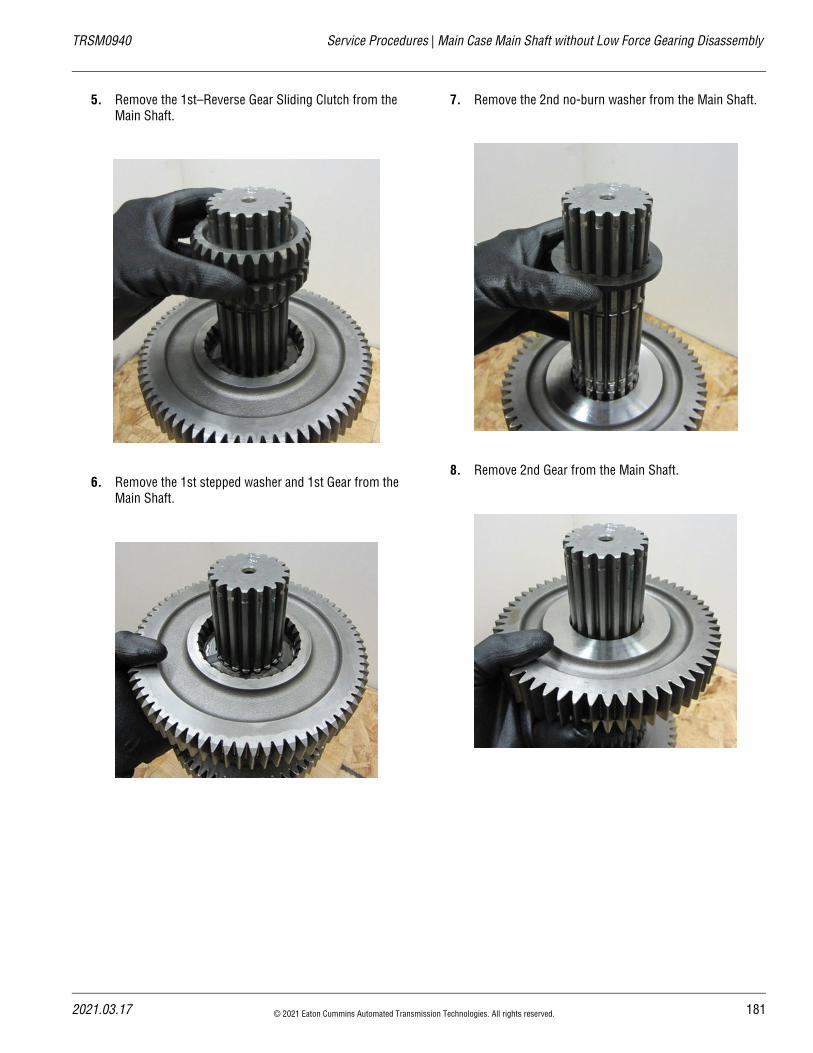
20
TRSM0940 Service Procedures | Main Case Main Shaft without Low Force Gearing Disassembly
5. Remove the 1st–Reverse Gear Sliding Clutch from the Main Shaft.
6. Remove the 1st stepped washer and 1st Gear from the Main Shaft.
7. Remove the 2nd no-burn washer from the Main Shaft.
8. Remove 2nd Gear from the Main Shaft.
21.03.17 © 2021 Eaton Cummins Automated Transmission Technologies. All rights reserved. 181
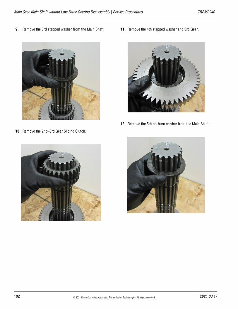
Main Case Main Shaft without Low Force Gearing Disassembly | Service Procedures TRSM0940
9. Remove the 3rd stepped washer from the Main Shaft.
10. Remove the 2nd–3rd Gear Sliding Clutch.
11. Remove the 4th stepped washer and 3rd Gear.
12. Remove the 5th no-burn washer from the Main Shaft.
182 © 2021 Eaton Cummins Automated Transmission Technologies. All rights reserved. 2021.03.17
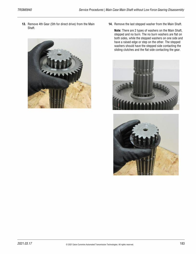
20
TRSM0940 Service Procedures | Main Case Main Shaft without Low Force Gearing Disassembly
13. Remove 4th Gear (5th for direct drive) from the Main Shaft.
14. Remove the last stepped washer from the Main Shaft.
Note: There are 2 types of washers on the Main Shaft, stepped and no burn. The no burn washers are flat on both sides, while the stepped washers on one side and have a raised edge or step on the other. The stepped washers should have the stepped side contacting the sliding clutches and the flat side contacting the gear.
21.03.17 © 2021 Eaton Cummins Automated Transmission Technologies. All rights reserved. 183
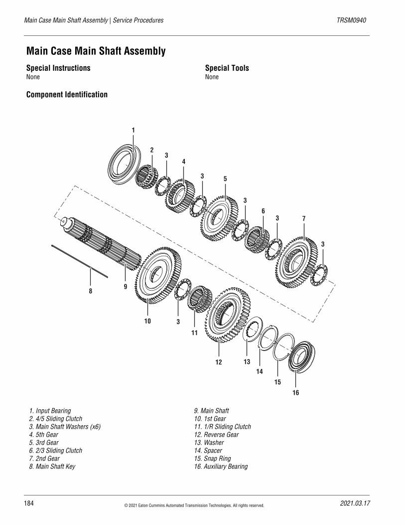
Main Case Main Shaft Assembly | Service Procedures TRSM0940
Main Case Main Shaft AssemblySpecial InstructionsNone
Special ToolsNone
Component Identification
1. Input Bearing2. 4/5 Sliding Clutch3. Main Shaft Washers (x6)4. 5th Gear5. 3rd Gear6. 2/3 Sliding Clutch7. 2nd Gear8. Main Shaft Key
9. Main Shaft10. 1st Gear11. 1/R Sliding Clutch12. Reverse Gear13. Washer14. Spacer 15. Snap Ring16. Auxiliary Bearing
16
15
141312
10
98
3
7
53
43
2
1
3
3
6
11
3
184 © 2021 Eaton Cummins Automated Transmission Technologies. All rights reserved. 2021.03.17
20
TRSM0940 Service Procedures | Main Case Main Shaft Assembly
Main Case Main Shaft Assembly
1. Place the Main Shaft vertical and hold the noise in a vise or a pilot hole in a piece of wood.
2. Install the first stepped washer with the stepped side facing down so it will contact the 4th/5th sliding clutch.
3. Use a piece of 5/32” air line to push up through the key way groove to lock the stepped and no-burn washers in place as the Main Shaft is built.
4. Install the Overdrive Gear or Direct Drive Gear (depending on the model of the transmission) and the no-burn washer. Rotate the washer and push the air line through.
5. Install the 3rd Gear and stepped washer. Rotate the stepped washer and push the air line through.
21.03.17 © 2021 Eaton Cummins Automated Transmission Technologies. All rights reserved. 185
Main Case Main Shaft Assembly | Service Procedures TRSM0940
6. Install the 2nd/3rd Sliding Clutch. Make sure the wide slot on the sliding clutch aligns with the keyway.
7. Install the stepped washer. Rotate the stepped washer and push the air line through.
8. Install 2nd Gear and the no-burn washer. Rotate the no-burn washer and push the air line through.
9. Install 1st Gear and the stepped washer. Rotate the stepped washer and push the air line through.
10. Install the 1st/Reverse Sliding Clutch. Align the wide slot on the sliding clutch with the keyway.
186 © 2021 Eaton Cummins Automated Transmission Technologies. All rights reserved. 2021.03.17
20
TRSM0940 Service Procedures | Main Case Main Shaft Assembly
11. Install the larger reverse washer. Rotate the washer and push the air line through.
12. Install the key and push the air line down through the Main Shaft until it contacts the roll pin.
13. Install the Reverse Gear on the Main Shaft and slide it over the sliding clutch with the snap ring groove facing rearward for installation.
21.03.17 © 2021 Eaton Cummins Automated Transmission Technologies. All rights reserved. 187
Main Case Main Shaft Assembly | Service Procedures TRSM0940
14. Remove the Main Shaft assembly from the holding device. Flip the Main Shaft up and install the Direct/Overdrive Sliding Clutch with the wide slot aligned with the keyway.
188 © 2021 Eaton Cummins Automated Transmission Technologies. All rights reserved. 2021.03.17
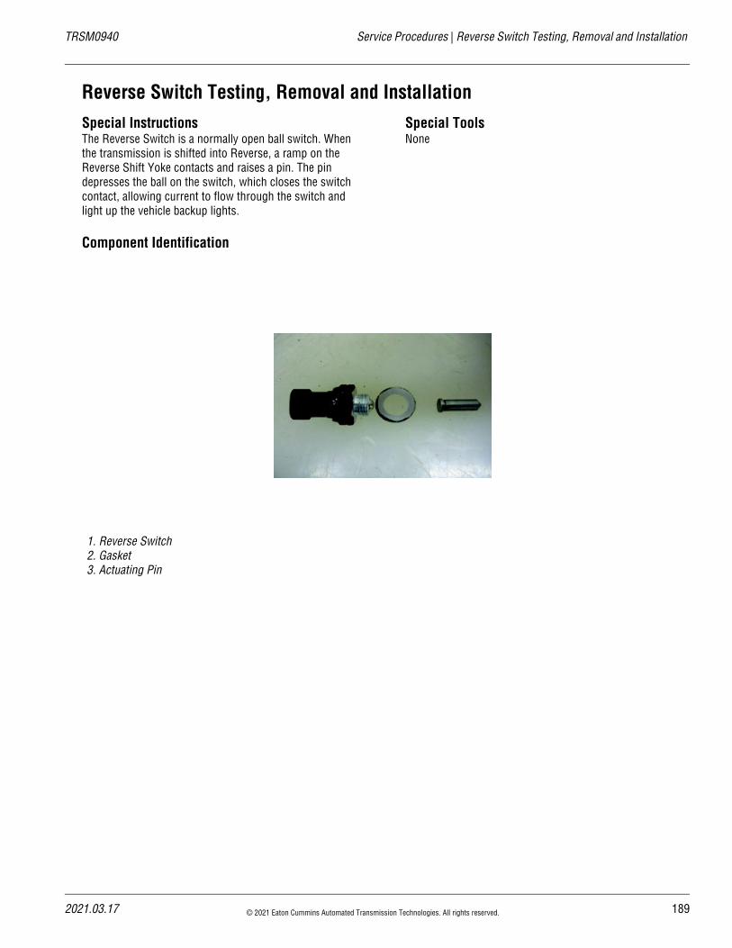
20
TRSM0940 Service Procedures | Reverse Switch Testing, Removal and Installation
Reverse Switch Testing, Removal and InstallationSpecial InstructionsThe Reverse Switch is a normally open ball switch. When the transmission is shifted into Reverse, a ramp on the Reverse Shift Yoke contacts and raises a pin. The pin depresses the ball on the switch, which closes the switch contact, allowing current to flow through the switch and light up the vehicle backup lights.
Special ToolsNone
Component Identification
1. Reverse Switch2. Gasket3. Actuating Pin
21.03.17 © 2021 Eaton Cummins Automated Transmission Technologies. All rights reserved. 189
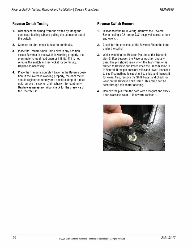
Reverse Switch Testing, Removal and Installation | Service Procedures TRSM0940
Reverse Switch Testing
1. Disconnect the wiring from the switch by lifting the connector locking tab and pulling the connector out of the switch.
2. Connect an ohm meter to test for continuity.
3. Place the Transmission Shift Lever in any position except Reverse. If the switch is working properly, the ohm meter should read open or infinity. If it is not, remove the switch and recheck it for continuity. Replace as necessary.
4. Place the Transmission Shift Lever in the Reverse posi-tion. If the switch is working properly, the ohm meter should register continuity or a small reading. If it does not, remove the switch and recheck it for continuity. Replace as necessary. Also, check for the presence of the Reverse Pin.
Reverse Switch Removal
1. Disconnect the OEM wiring. Remove the Reverse Switch using a 22 mm or 7/8” deep well socket or box end wrench.
2. Check for the presence of the Reverse Pin in the bore under the switch.
3. While watching the Reverse Pin, move the Transmis-sion Shifter between the Reverse position and any gear. The pin should raise when the Transmission is shifted to Reverse and lower when the Transmission is in Neutral. If the pin does not raise and lower, inspect it to see if something is causing it to stick, and inspect it for wear. Also, remove the Shift Tower and check for wear on the Reverse Yoke Ramp. This ramp can be seen through the shifter opening.
4. Remove the pin from the bore with a magnet and check it for excessive wear. If it is worn, replace it.
190 © 2021 Eaton Cummins Automated Transmission Technologies. All rights reserved. 2021.03.17
20
TRSM0940 Service Procedures | Reverse Switch Testing, Removal and Installation
Reverse Switch Installation
1. Insert the Reverse Pin in the Reverse Switch bore. (The Reverse Pin is longer than the Neutral Pin.)
2. Install the gasket on the switch.
3. Install the Reverse Switch. Torque to 15–20 lb-ft (20–27 N•m).
4. Connect the OEM wiring connector, making sure the locking tab engages properly.
21.03.17 © 2021 Eaton Cummins Automated Transmission Technologies. All rights reserved. 191
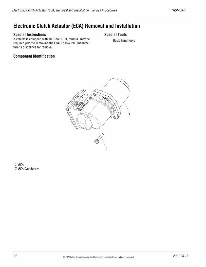
Electronic Clutch Actuator (ECA) Removal and Installation | Service Procedures TRSM0940
Electronic Clutch Actuator (ECA) Removal and InstallationSpecial InstructionsIf vehicle is equipped with an 8-bolt PTO, removal may be required prior to removing the ECA. Follow PTO manufac-turer’s guidelines for removal.
Special ToolsBasic hand tools
Component Identification
1. ECA 2. ECA Cap Screw
2
1
192 © 2021 Eaton Cummins Automated Transmission Technologies. All rights reserved. 2021.03.17
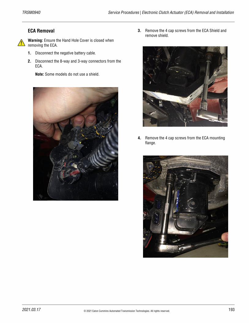
20
TRSM0940 Service Procedures | Electronic Clutch Actuator (ECA) Removal and Installation
!
ECA Removal
Warning: Ensure the Hand Hole Cover is closed when removing the ECA.
1. Disconnect the negative battery cable.
2. Disconnect the 8-way and 3-way connectors from the ECA.
Note: Some models do not use a shield.
3. Remove the 4 cap screws from the ECA Shield and remove shield.
4. Remove the 4 cap screws from the ECA mounting flange.
21.03.17 © 2021 Eaton Cummins Automated Transmission Technologies. All rights reserved. 193
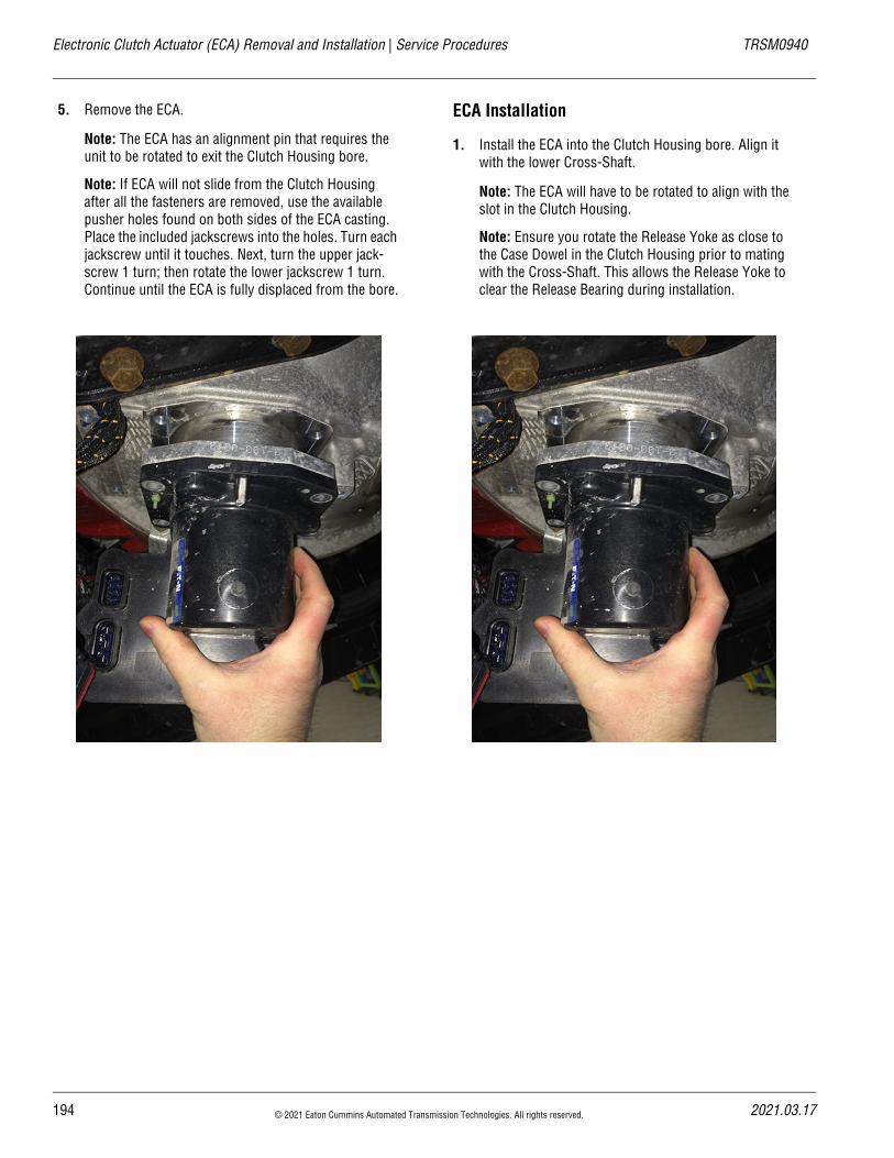
Electronic Clutch Actuator (ECA) Removal and Installation | Service Procedures TRSM0940
5. Remove the ECA.
Note: The ECA has an alignment pin that requires the unit to be rotated to exit the Clutch Housing bore.
Note: If ECA will not slide from the Clutch Housing after all the fasteners are removed, use the available pusher holes found on both sides of the ECA casting. Place the included jackscrews into the holes. Turn each jackscrew until it touches. Next, turn the upper jack-screw 1 turn; then rotate the lower jackscrew 1 turn. Continue until the ECA is fully displaced from the bore.
ECA Installation
1. Install the ECA into the Clutch Housing bore. Align it with the lower Cross-Shaft.
Note: The ECA will have to be rotated to align with the slot in the Clutch Housing.
Note: Ensure you rotate the Release Yoke as close to the Case Dowel in the Clutch Housing prior to mating with the Cross-Shaft. This allows the Release Yoke to clear the Release Bearing during installation.
194 © 2021 Eaton Cummins Automated Transmission Technologies. All rights reserved. 2021.03.17
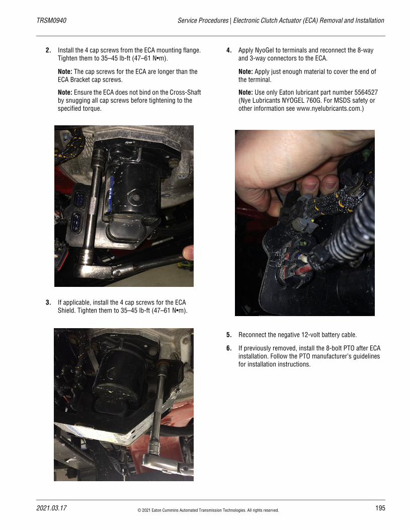
20
TRSM0940 Service Procedures | Electronic Clutch Actuator (ECA) Removal and Installation
2. Install the 4 cap screws from the ECA mounting flange. Tighten them to 35–45 lb-ft (47–61 N•m).
Note: The cap screws for the ECA are longer than the ECA Bracket cap screws.
Note: Ensure the ECA does not bind on the Cross-Shaft by snugging all cap screws before tightening to the specified torque.
3. If applicable, install the 4 cap screws for the ECA Shield. Tighten them to 35–45 lb-ft (47–61 N•m).
4. Apply NyoGel to terminals and reconnect the 8-way and 3-way connectors to the ECA.
Note: Apply just enough material to cover the end of the terminal.
Note: Use only Eaton lubricant part number 5564527 (Nye Lubricants NYOGEL 760G. For MSDS safety or other information see www.nyelubricants.com.)
5. Reconnect the negative 12-volt battery cable.
6. If previously removed, install the 8-bolt PTO after ECA installation. Follow the PTO manufacturer’s guidelines for installation instructions.
21.03.17 © 2021 Eaton Cummins Automated Transmission Technologies. All rights reserved. 195
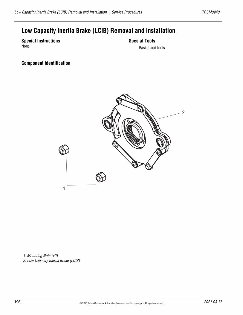
19
Low Capacity Inertia Brake (LCIB) Removal and Installation | Service Procedures TRSM0940
Low Capacity Inertia Brake (LCIB) Removal and InstallationSpecial InstructionsNone
Special ToolsBasic hand tools
Component Identification
1. Mounting Nuts (x2)2. Low Capacity Inertia Brake (LCIB)
1
2
6 © 2021 Eaton Cummins Automated Transmission Technologies. All rights reserved. 2021.03.17
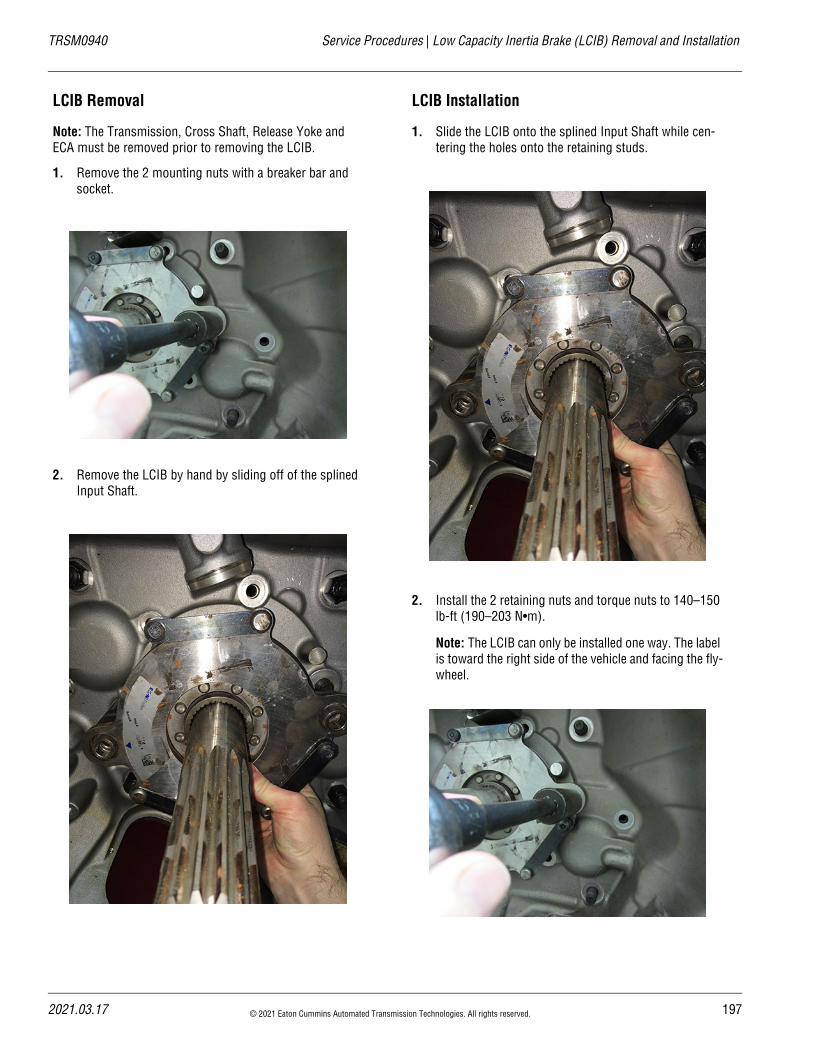
TRSM0940 Service Procedures | Low Capacity Inertia Brake (LCIB) Removal and Installation
LCIB Removal
Note: The Transmission, Cross Shaft, Release Yoke and ECA must be removed prior to removing the LCIB.
1. Remove the 2 mounting nuts with a breaker bar and socket.
2. Remove the LCIB by hand by sliding off of the splined Input Shaft.
LCIB Installation
1. Slide the LCIB onto the splined Input Shaft while cen-tering the holes onto the retaining studs.
2. Install the 2 retaining nuts and torque nuts to 140–150 lb-ft (190–203 N•m).
Note: The LCIB can only be installed one way. The label is toward the right side of the vehicle and facing the fly-wheel.
2021.03.17 © 2021 Eaton Cummins Automated Transmission Technologies. All rights reserved. 197
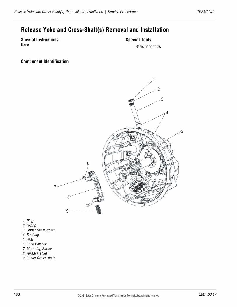
19
Release Yoke and Cross-Shaft(s) Removal and Installation | Service Procedures TRSM0940
Release Yoke and Cross-Shaft(s) Removal and InstallationSpecial InstructionsNone
Special ToolsBasic hand tools
Component Identification
1. Plug 2. O-ring 3. Upper Cross-shaft 4. Bushing 5. Seal 6. Lock Washer 7. Mounting Screw 8. Release Yoke 9. Lower Cross-shaft
1
2
3
4
5
6
7
8
9
8 © 2021 Eaton Cummins Automated Transmission Technologies. All rights reserved. 2021.03.17
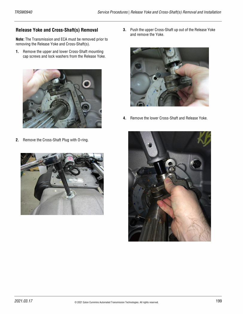
TRSM0940 Service Procedures | Release Yoke and Cross-Shaft(s) Removal and Installation
Release Yoke and Cross-Shaft(s) Removal
Note: The Transmission and ECA must be removed prior to removing the Release Yoke and Cross-Shaft(s).
1. Remove the upper and lower Cross-Shaft mounting cap screws and lock washers from the Release Yoke.
2. Remove the Cross-Shaft Plug with O-ring.
3. Push the upper Cross-Shaft up out of the Release Yoke and remove the Yoke.
4. Remove the lower Cross-Shaft and Release Yoke.
2021.03.17 © 2021 Eaton Cummins Automated Transmission Technologies. All rights reserved. 199
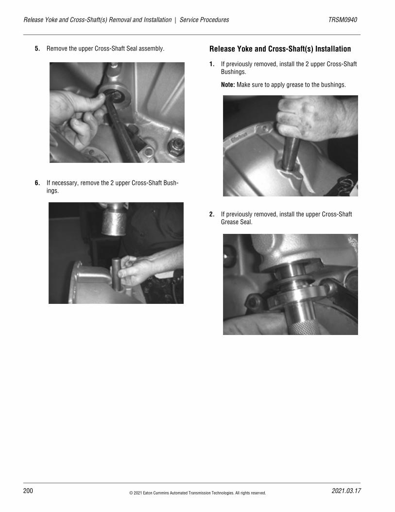
20
Release Yoke and Cross-Shaft(s) Removal and Installation | Service Procedures TRSM0940
5. Remove the upper Cross-Shaft Seal assembly.
6. If necessary, remove the 2 upper Cross-Shaft Bush-ings.
Release Yoke and Cross-Shaft(s) Installation
1. If previously removed, install the 2 upper Cross-Shaft Bushings.
Note: Make sure to apply grease to the bushings.
2. If previously removed, install the upper Cross-Shaft Grease Seal.
0 © 2021 Eaton Cummins Automated Transmission Technologies. All rights reserved. 2021.03.17
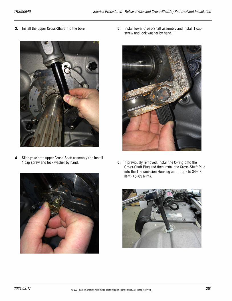
TRSM0940 Service Procedures | Release Yoke and Cross-Shaft(s) Removal and Installation
3. Install the upper Cross-Shaft into the bore.
4. Slide yoke onto upper Cross-Shaft assembly and install 1 cap screw and lock washer by hand.
5. Install lower Cross-Shaft assembly and install 1 cap screw and lock washer by hand.
6. If previously removed, install the O-ring onto the Cross-Shaft Plug and then install the Cross-Shaft Plug into the Transmission Housing and torque to 34–48 lb-ft (46–65 N•m).
2021.03.17 © 2021 Eaton Cummins Automated Transmission Technologies. All rights reserved. 201
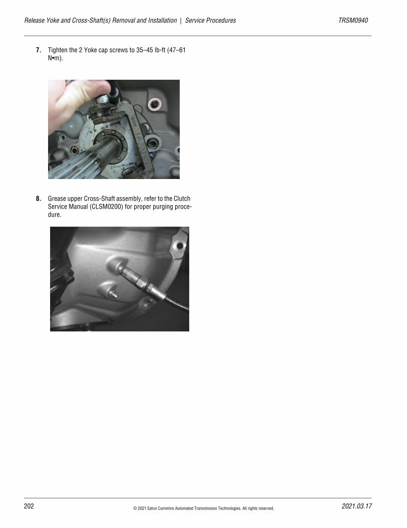
20
Release Yoke and Cross-Shaft(s) Removal and Installation | Service Procedures TRSM0940
7. Tighten the 2 Yoke cap screws to 35–45 lb-ft (47–61 N•m).
8. Grease upper Cross-Shaft assembly, refer to the Clutch Service Manual (CLSM0200) for proper purging proce-dure.
2 © 2021 Eaton Cummins Automated Transmission Technologies. All rights reserved. 2021.03.17
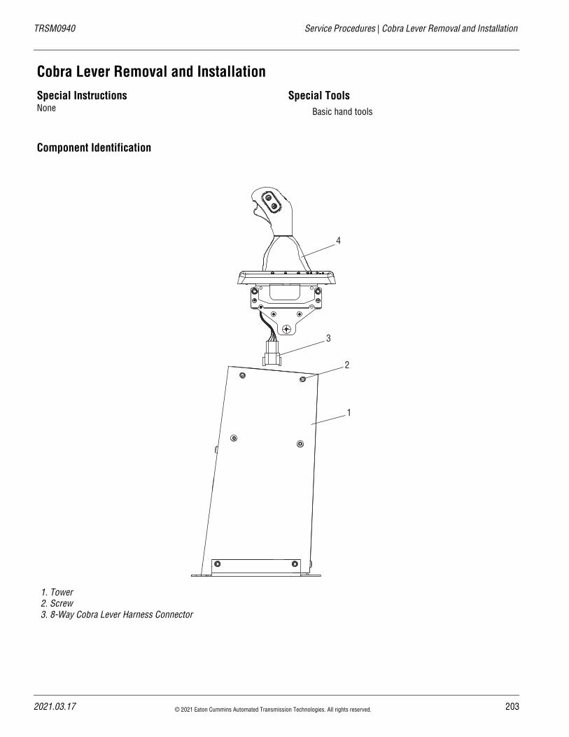
TRSM0940 Service Procedures | Cobra Lever Removal and Installation
Cobra Lever Removal and InstallationSpecial InstructionsNone
Special ToolsBasic hand tools
Component Identification
1. Tower2. Screw3. 8-Way Cobra Lever Harness Connector
1
2
3
4
2021.03.17 © 2021 Eaton Cummins Automated Transmission Technologies. All rights reserved. 203
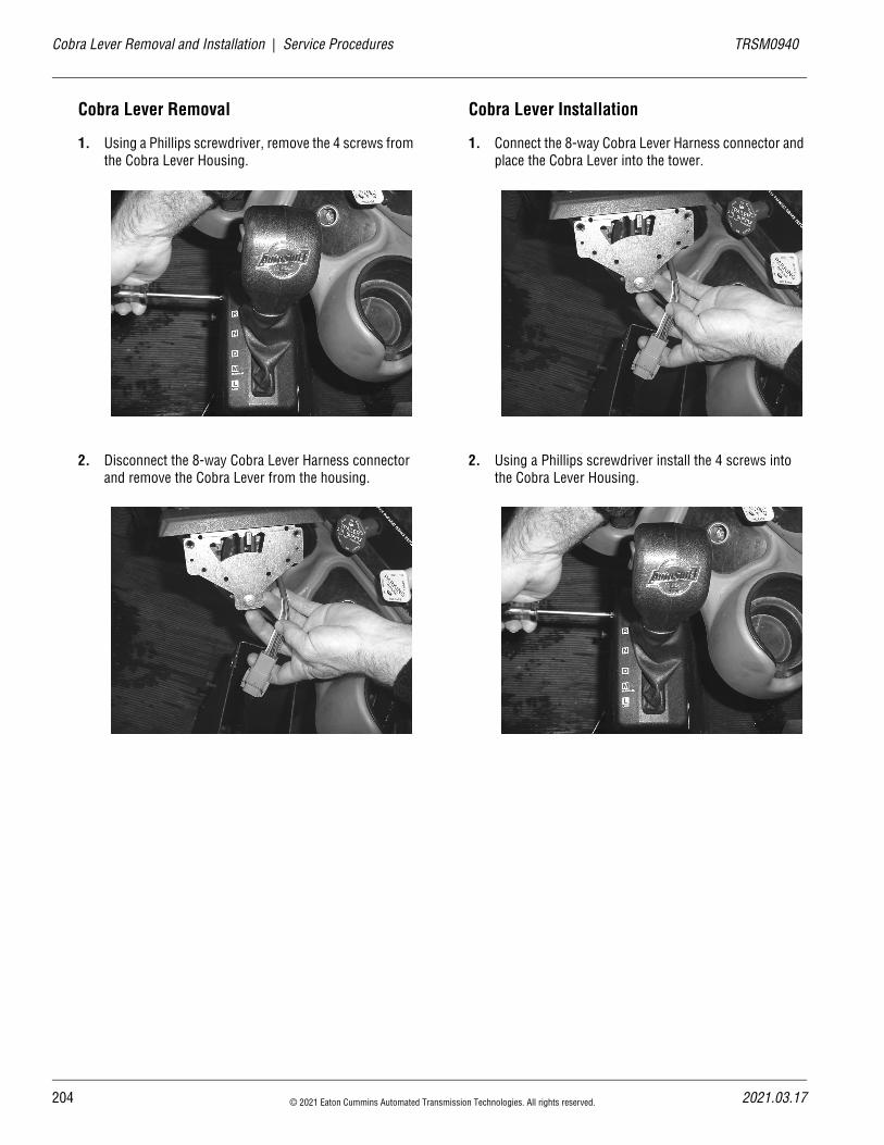
20
Cobra Lever Removal and Installation | Service Procedures TRSM0940
Cobra Lever Removal
1. Using a Phillips screwdriver, remove the 4 screws from the Cobra Lever Housing.
2. Disconnect the 8-way Cobra Lever Harness connector and remove the Cobra Lever from the housing.
Cobra Lever Installation
1. Connect the 8-way Cobra Lever Harness connector and place the Cobra Lever into the tower.
2. Using a Phillips screwdriver install the 4 screws into the Cobra Lever Housing.
4 © 2021 Eaton Cummins Automated Transmission Technologies. All rights reserved. 2021.03.17
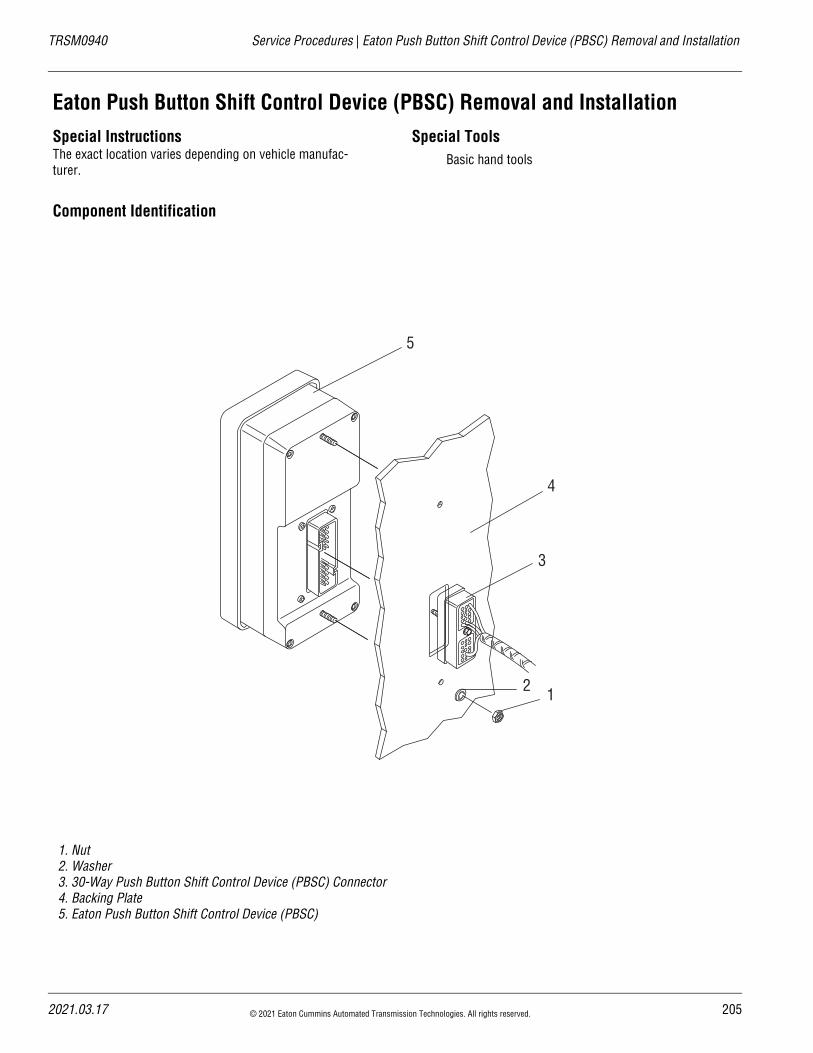
TRSM0940 Service Procedures | Eaton Push Button Shift Control Device (PBSC) Removal and Installation
Eaton Push Button Shift Control Device (PBSC) Removal and InstallationSpecial InstructionsThe exact location varies depending on vehicle manufac-turer.
Special ToolsBasic hand tools
Component Identification
1. Nut2. Washer3. 30-Way Push Button Shift Control Device (PBSC) Connector4. Backing Plate5. Eaton Push Button Shift Control Device (PBSC)
12
3
4
5
2021.03.17 © 2021 Eaton Cummins Automated Transmission Technologies. All rights reserved. 205
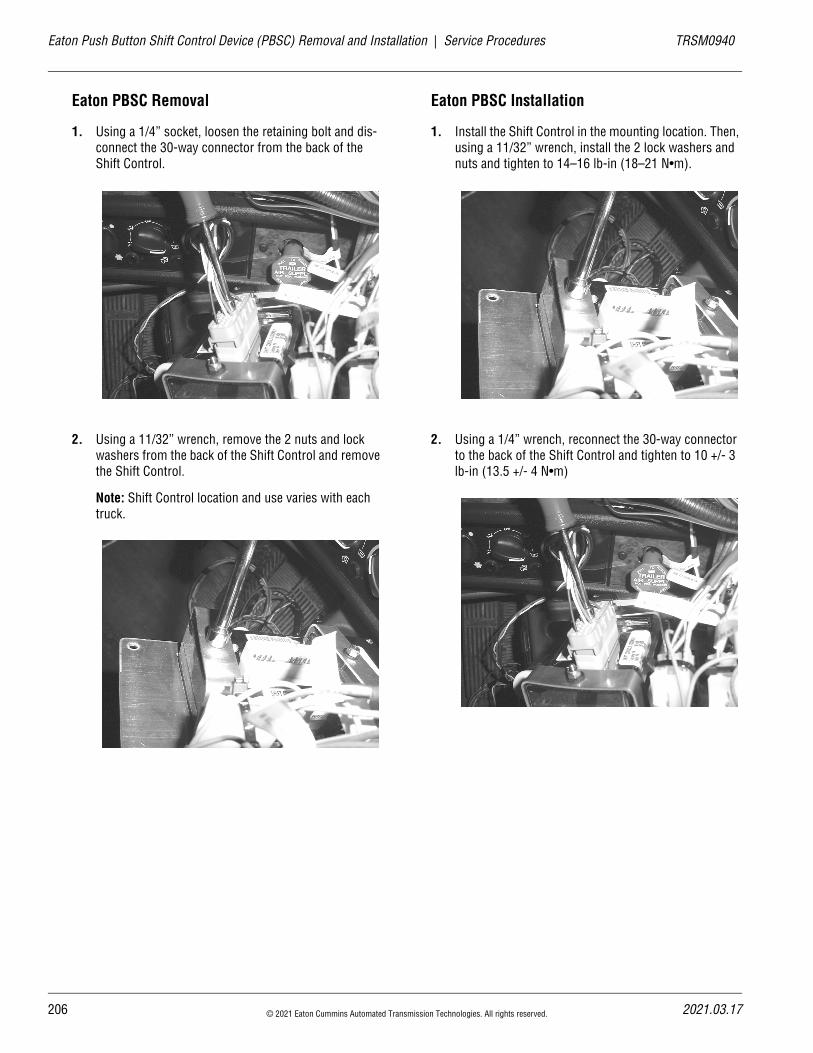
20
Eaton Push Button Shift Control Device (PBSC) Removal and Installation | Service Procedures TRSM0940
Eaton PBSC Removal
1. Using a 1/4” socket, loosen the retaining bolt and dis-connect the 30-way connector from the back of the Shift Control.
2. Using a 11/32” wrench, remove the 2 nuts and lock washers from the back of the Shift Control and remove the Shift Control.
Note: Shift Control location and use varies with each truck.
Eaton PBSC Installation
1. Install the Shift Control in the mounting location. Then, using a 11/32” wrench, install the 2 lock washers and nuts and tighten to 14–16 lb-in (18–21 N•m).
2. Using a 1/4” wrench, reconnect the 30-way connector to the back of the Shift Control and tighten to 10 +/- 3 lb-in (13.5 +/- 4 N•m)
6 © 2021 Eaton Cummins Automated Transmission Technologies. All rights reserved. 2021.03.17
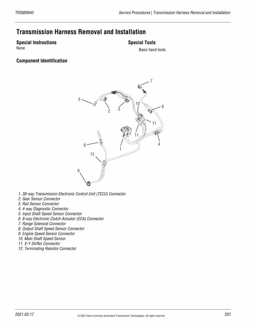
TRSM0940 Service Procedures | Transmission Harness Removal and Installation
Transmission Harness Removal and InstallationSpecial InstructionsNone
Special ToolsBasic hand tools
Component Identification
1. 38-way Transmission Electronic Control Unit (TECU) Connector 2. Gear Sensor Connector 3. Rail Sensor Connector 4. 4-way Diagnostic Connector 5. Input Shaft Speed Sensor Connector 6. 8-way Electronic Clutch Actuator (ECA) Connector 7. Range Solenoid Connector 8. Output Shaft Speed Sensor Connector 9. Engine Speed Sensor Connector 10. Main Shaft Speed Sensor 11. X-Y Shifter Connector 12. Terminating Resistor Connector
7
8
11
11
1
32
5
9
12
6
4
10
2021.03.17 © 2021 Eaton Cummins Automated Transmission Technologies. All rights reserved. 207
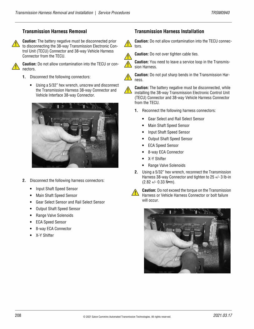
20
Transmission Harness Removal and Installation | Service Procedures TRSM0940
!
!
Transmission Harness Removal
Caution: The battery negative must be disconnected prior to disconnecting the 38-way Transmission Electronic Con-trol Unit (TECU) Connector and 38-way Vehicle Harness Connector from the TECU.
Caution: Do not allow contamination into the TECU or con-nectors.
1. Disconnect the following connectors:
• Using a 5/32” hex wrench, unscrew and disconnect the Transmission Harness 38-way Connector and Vehicle Interface 38-way Connector.
2. Disconnect the following harness connectors:
• Input Shaft Speed Sensor
• Main Shaft Speed Sensor
• Gear Select Sensor and Rail Select Sensor
• Output Shaft Speed Sensor
• Range Valve Solenoids
• ECA Speed Sensor
• 8-way ECA Connector
• X-Y Shifter
Transmission Harness Installation
Caution: Do not allow contamination into the TECU connec-tors.
Caution: Do not over tighten cable ties.
Caution: You need to leave a service loop in the Transmis-sion Harness.
Caution: Do not put sharp bends in the Transmission Har-ness.
Caution: The battery negative must be disconnected, while installing the 38-way Transmission Electronic Control Unit (TECU) Connector and 38-way Vehicle Harness Connector from the TECU.
1. Reconnect the following harness connectors:
• Gear Select and Rail Select Sensor
• Main Shaft Speed Sensor
• Input Shaft Speed Sensor
• Output Shaft Speed Sensor
• ECA Speed Sensor
• 8-way ECA Connector
• X-Y Shifter
• Range Valve Solenoids
2. Using a 5/32” hex wrench, reconnect the Transmission Harness 38-way Connector and tighten to 25 +/- 3 lb-in (2.82 +/- 0.33 N•m).
Caution: Do not exceed the torque on the Transmission Harness or Vehicle Harness Connector or bolt failure will occur.
!
!!
!
!
!
8 © 2021 Eaton Cummins Automated Transmission Technologies. All rights reserved. 2021.03.17
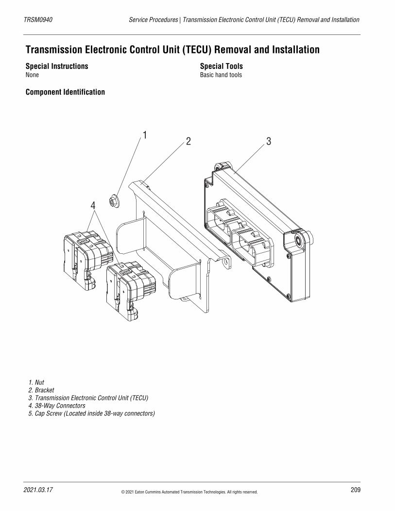
TRSM0940 Service Procedures | Transmission Electronic Control Unit (TECU) Removal and Installation
Transmission Electronic Control Unit (TECU) Removal and InstallationSpecial InstructionsNone
Special ToolsBasic hand tools
Component Identification
1. Nut2. Bracket3. Transmission Electronic Control Unit (TECU)4. 38-Way Connectors5. Cap Screw (Located inside 38-way connectors)
1 2 3
4
2021.03.17 © 2021 Eaton Cummins Automated Transmission Technologies. All rights reserved. 209
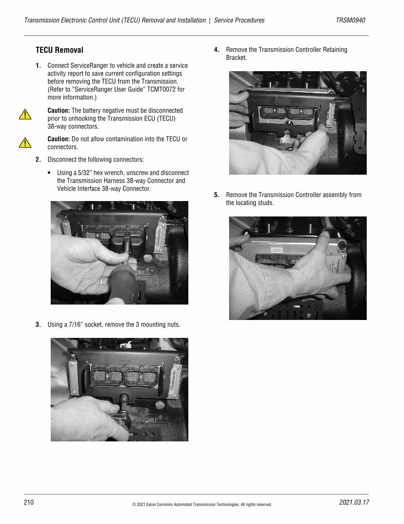
21
Transmission Electronic Control Unit (TECU) Removal and Installation | Service Procedures TRSM0940
!
!
TECU Removal
1. Connect ServiceRanger to vehicle and create a service activity report to save current configuration settings before removing the TECU from the Transmission. (Refer to “ServiceRanger User Guide” TCMT0072 for more information.)
Caution: The battery negative must be disconnected prior to unhooking the Transmission ECU (TECU) 38-way connectors.
Caution: Do not allow contamination into the TECU or connectors.
2. Disconnect the following connectors:
• Using a 5/32” hex wrench, unscrew and disconnect the Transmission Harness 38-way Connector and Vehicle Interface 38-way Connector.
3. Using a 7/16” socket, remove the 3 mounting nuts.
4. Remove the Transmission Controller Retaining Bracket.
5. Remove the Transmission Controller assembly from the locating studs.
0 © 2021 Eaton Cummins Automated Transmission Technologies. All rights reserved. 2021.03.17
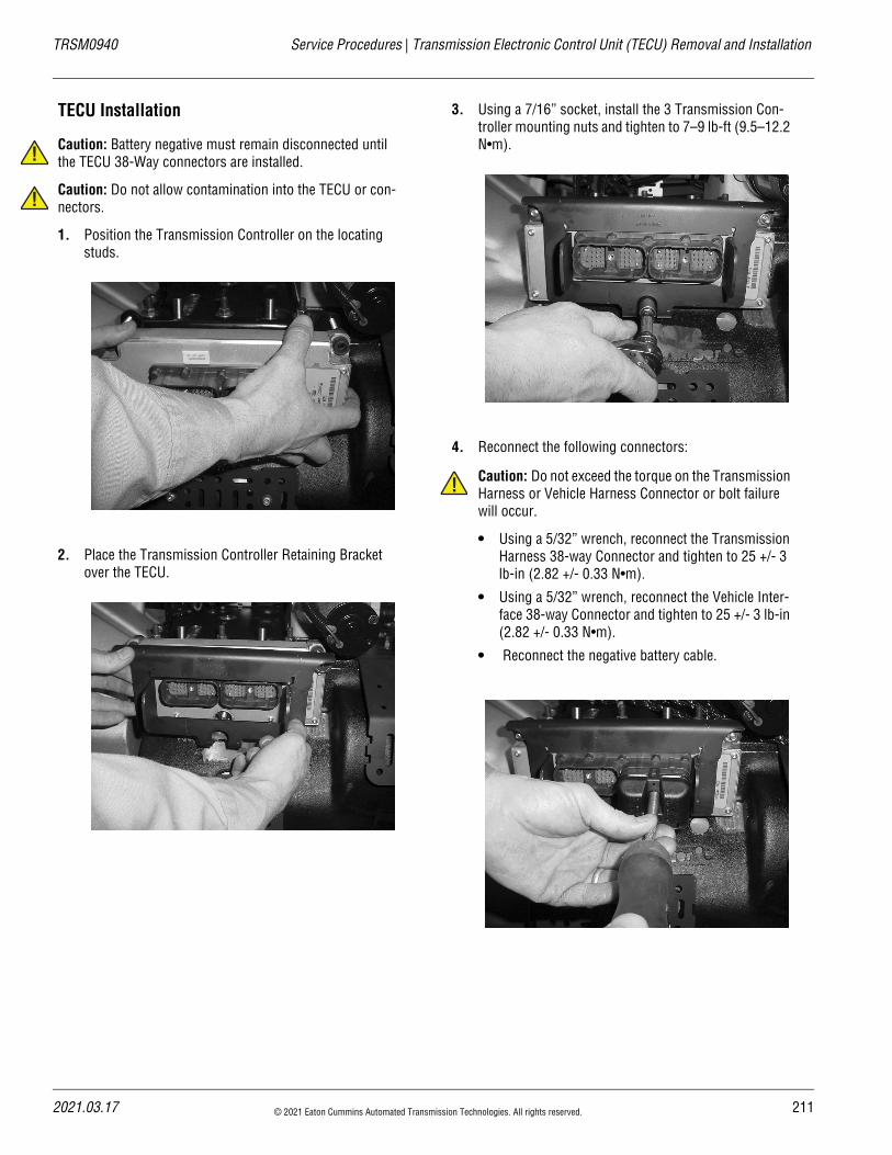
TRSM0940 Service Procedures | Transmission Electronic Control Unit (TECU) Removal and Installation
!
!
TECU Installation
Caution: Battery negative must remain disconnected until the TECU 38-Way connectors are installed.
Caution: Do not allow contamination into the TECU or con-nectors.
1. Position the Transmission Controller on the locating studs.
2. Place the Transmission Controller Retaining Bracket over the TECU.
3. Using a 7/16” socket, install the 3 Transmission Con-troller mounting nuts and tighten to 7–9 lb-ft (9.5–12.2 N•m).
4. Reconnect the following connectors:
Caution: Do not exceed the torque on the Transmission Harness or Vehicle Harness Connector or bolt failure will occur.
• Using a 5/32” wrench, reconnect the Transmission Harness 38-way Connector and tighten to 25 +/- 3 lb-in (2.82 +/- 0.33 N•m).
• Using a 5/32” wrench, reconnect the Vehicle Inter-face 38-way Connector and tighten to 25 +/- 3 lb-in (2.82 +/- 0.33 N•m).
• Reconnect the negative battery cable.
!
2021.03.17 © 2021 Eaton Cummins Automated Transmission Technologies. All rights reserved. 211
21
Transmission Electronic Control Unit (TECU) Removal and Installation | Service Procedures TRSM0940
!
5. Connect ServiceRanger to vehicle and compare recorded configuration settings (step 1 in removal pro-cess) to the replacement TECU. Update and save all configurations that are different. (Refer to “Ser-viceRanger User Guide” TCMT0072 for more informa-tion.)
6. To operate properly, the system must be calibrated as follows:
Important: The Grade Sensor and ECA must be cali-brated before the vehicle is placed in operation.
a. Turn ignition switch on. Allow Transmission to power up.
b. Turn ignition off. Wait 2 minutes.
ECA Calibration
1. Start the truck and let the system air up.
2. With ServiceRanger connected perform Clutch ECA Calibration in Service Routines Option.
Grade Sensor Calibration
1. Key on, engine off with truck on level ground.
2. With ServiceRanger connected perform Grade Sensor Calibration in Service Routines Option.
2 © 2021 Eaton Cummins Automated Transmission Technologies. All rights reserved. 2021.03.17
20
TRSM0940 Service Procedures | X-Y Shifter Removal and Installation
X-Y Shifter Removal and InstallationSpecial InstructionsNone
Special ToolsBasic hand tools
Component Identification
1. Cap Screw2. X-Y Shifter3. Gasket
1
2
3
21.03.17 © 2021 Eaton Cummins Automated Transmission Technologies. All rights reserved. 213
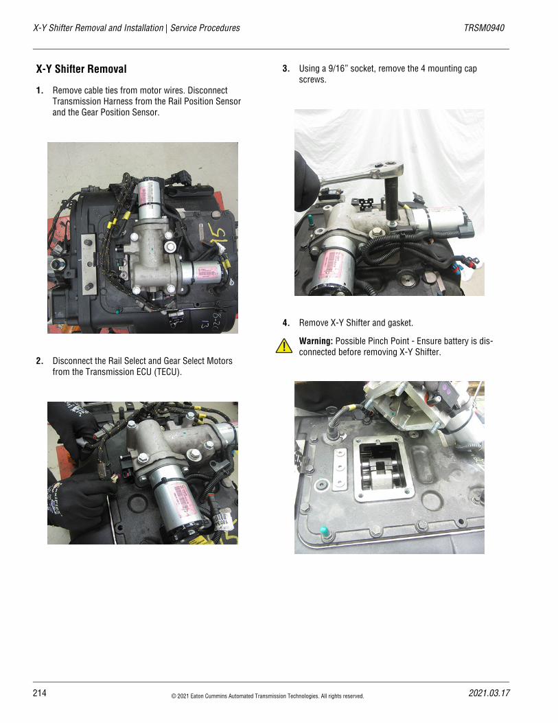
X-Y Shifter Removal and Installation | Service Procedures TRSM0940
X-Y Shifter Removal
1. Remove cable ties from motor wires. Disconnect Transmission Harness from the Rail Position Sensor and the Gear Position Sensor.
2. Disconnect the Rail Select and Gear Select Motors from the Transmission ECU (TECU).
3. Using a 9/16” socket, remove the 4 mounting cap screws.
4. Remove X-Y Shifter and gasket.
Warning: Possible Pinch Point - Ensure battery is dis-connected before removing X-Y Shifter.!
214 © 2021 Eaton Cummins Automated Transmission Technologies. All rights reserved. 2021.03.17
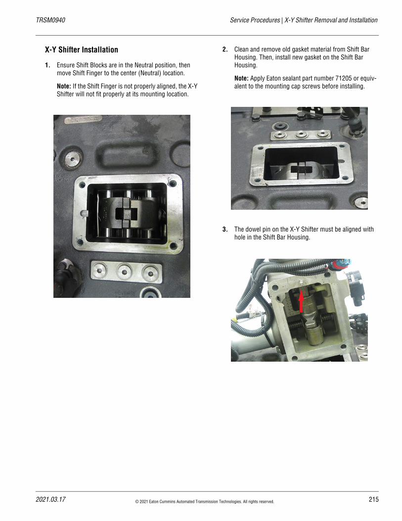
20
TRSM0940 Service Procedures | X-Y Shifter Removal and Installation
X-Y Shifter Installation
1. Ensure Shift Blocks are in the Neutral position, then move Shift Finger to the center (Neutral) location.
Note: If the Shift Finger is not properly aligned, the X-Y Shifter will not fit properly at its mounting location.
2. Clean and remove old gasket material from Shift Bar Housing. Then, install new gasket on the Shift Bar Housing.
Note: Apply Eaton sealant part number 71205 or equiv-alent to the mounting cap screws before installing.
3. The dowel pin on the X-Y Shifter must be aligned with hole in the Shift Bar Housing.
21.03.17 © 2021 Eaton Cummins Automated Transmission Technologies. All rights reserved. 215
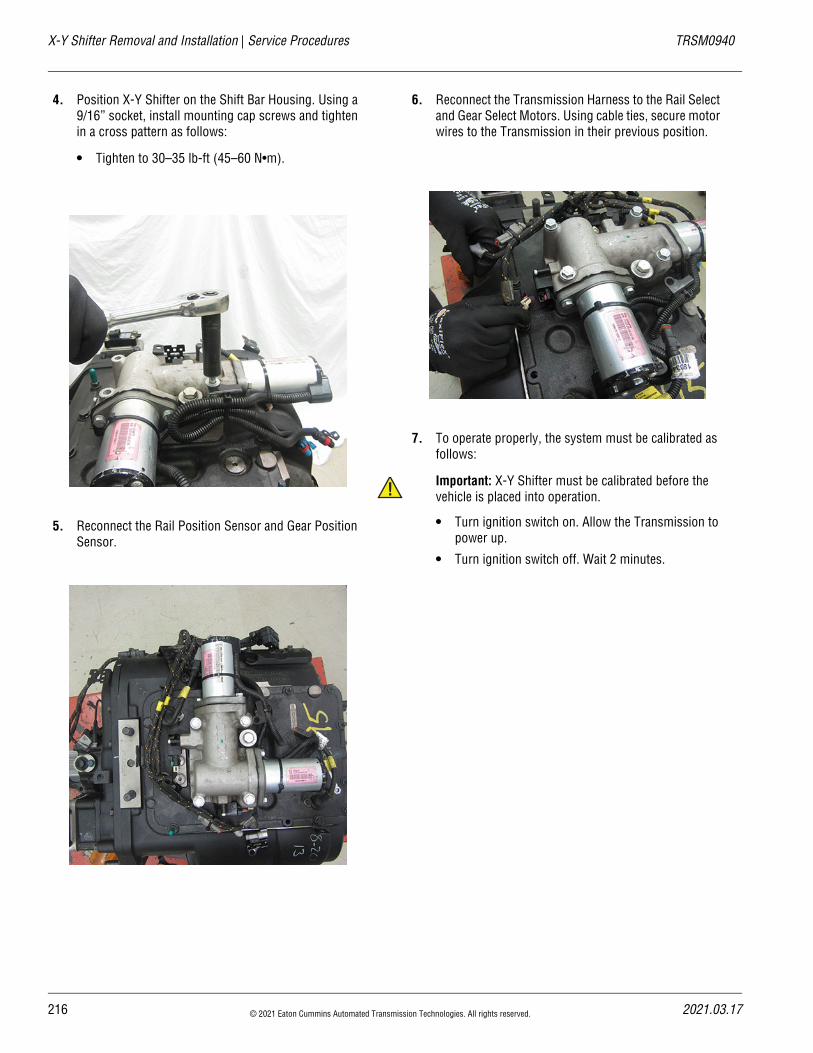
X-Y Shifter Removal and Installation | Service Procedures TRSM0940
4. Position X-Y Shifter on the Shift Bar Housing. Using a 9/16” socket, install mounting cap screws and tighten in a cross pattern as follows:
• Tighten to 30–35 lb-ft (45–60 N•m).
5. Reconnect the Rail Position Sensor and Gear Position Sensor.
6. Reconnect the Transmission Harness to the Rail Select and Gear Select Motors. Using cable ties, secure motor wires to the Transmission in their previous position.
7. To operate properly, the system must be calibrated as follows:
Important: X-Y Shifter must be calibrated before the vehicle is placed into operation.
• Turn ignition switch on. Allow the Transmission to power up.
• Turn ignition switch off. Wait 2 minutes.
!
216 © 2021 Eaton Cummins Automated Transmission Technologies. All rights reserved. 2021.03.17
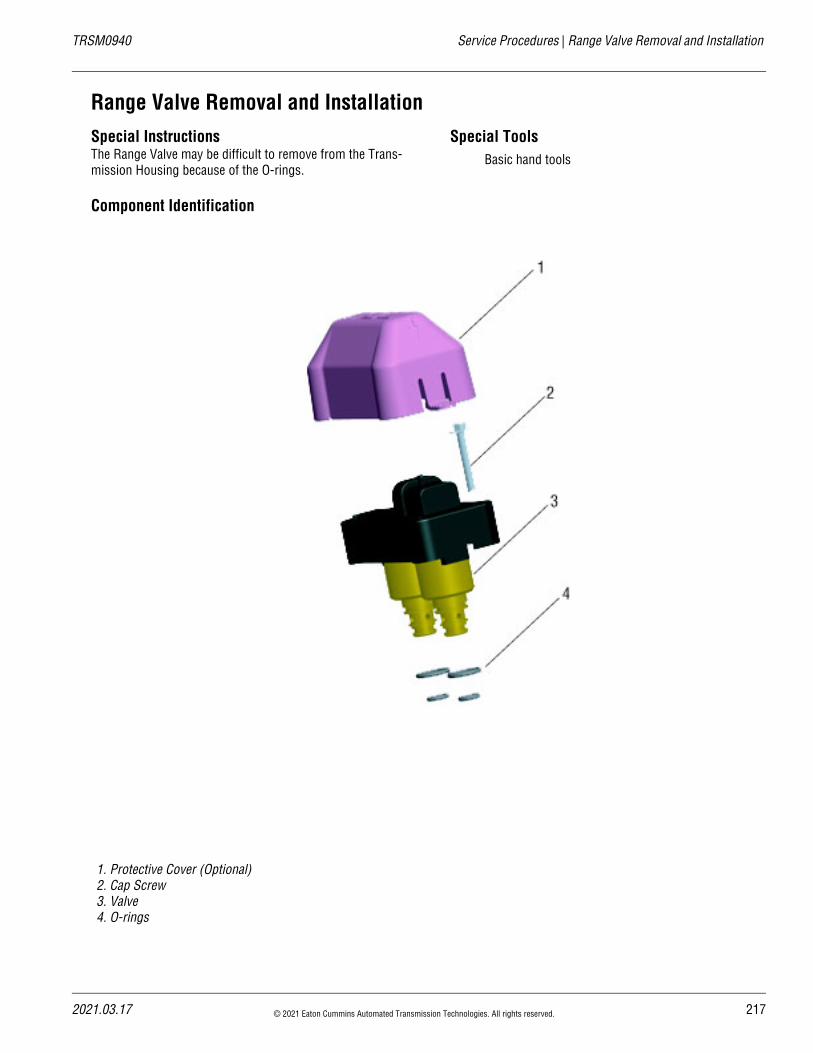
20
TRSM0940 Service Procedures | Range Valve Removal and Installation
Range Valve Removal and InstallationSpecial InstructionsThe Range Valve may be difficult to remove from the Trans-mission Housing because of the O-rings.
Special ToolsBasic hand tools
Component Identification
1. Protective Cover (Optional)2. Cap Screw3. Valve4. O-rings
21.03.17 © 2021 Eaton Cummins Automated Transmission Technologies. All rights reserved. 217
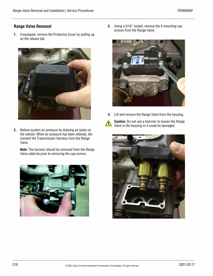
Range Valve Removal and Installation | Service Procedures TRSM0940
Range Valve Removal
1. If equipped, remove the Protective Cover by pulling up on the release tab.
2. Relieve system air pressure by draining air tanks on the vehicle. When air pressure has been relieved, dis-connect the Transmission Harness from the Range Valve.
Note: The harness should be removed from the Range Valve cable tie prior to removing the cap screws.
3. Using a 5/16” socket, remove the 4 mounting cap screws from the Range Valve.
4. Lift and remove the Range Valve from the housing.
Caution: Do not use a hammer to loosen the Range Valve in the housing or it could be damaged.!
218 © 2021 Eaton Cummins Automated Transmission Technologies. All rights reserved. 2021.03.17
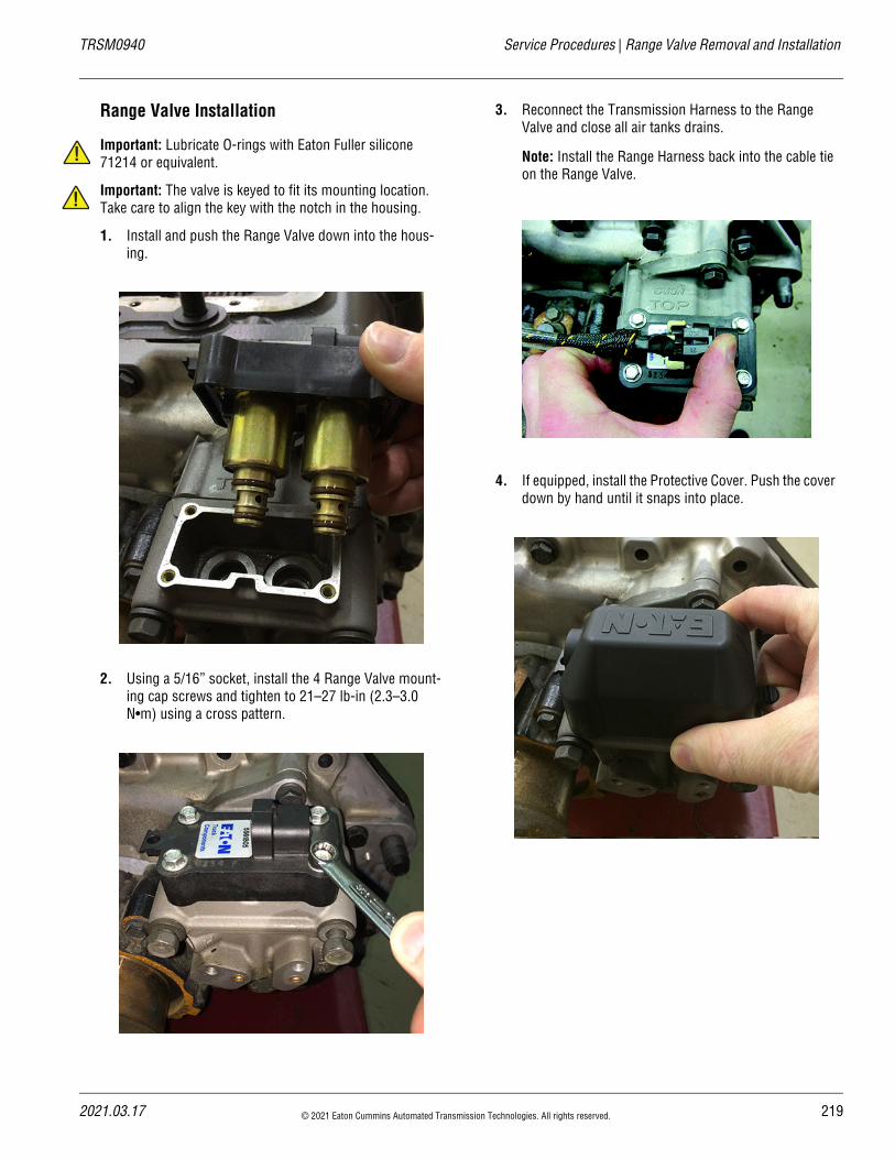
20
TRSM0940 Service Procedures | Range Valve Removal and Installation
!
!
Range Valve Installation
Important: Lubricate O-rings with Eaton Fuller silicone 71214 or equivalent.
Important: The valve is keyed to fit its mounting location. Take care to align the key with the notch in the housing.
1. Install and push the Range Valve down into the hous-ing.
2. Using a 5/16” socket, install the 4 Range Valve mount-ing cap screws and tighten to 21–27 lb-in (2.3–3.0 N•m) using a cross pattern.
3. Reconnect the Transmission Harness to the Range Valve and close all air tanks drains.
Note: Install the Range Harness back into the cable tie on the Range Valve.
4. If equipped, install the Protective Cover. Push the cover down by hand until it snaps into place.
21.03.17 © 2021 Eaton Cummins Automated Transmission Technologies. All rights reserved. 219
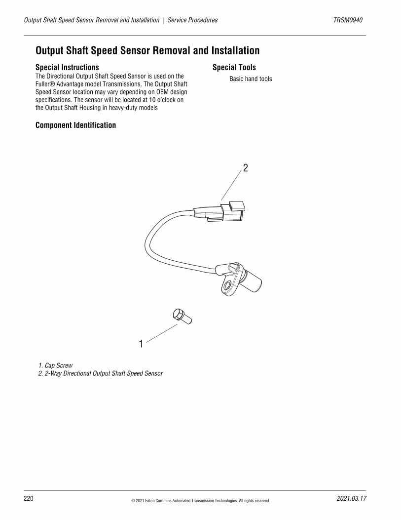
22
Output Shaft Speed Sensor Removal and Installation | Service Procedures TRSM0940
Output Shaft Speed Sensor Removal and InstallationSpecial InstructionsThe Directional Output Shaft Speed Sensor is used on the Fuller® Advantage model Transmissions. The Output Shaft Speed Sensor location may vary depending on OEM design specifications. The sensor will be located at 10 o’clock on the Output Shaft Housing in heavy-duty models
Special ToolsBasic hand tools
Component Identification
1. Cap Screw2. 2-Way Directional Output Shaft Speed Sensor
1
2
0 © 2021 Eaton Cummins Automated Transmission Technologies. All rights reserved. 2021.03.17
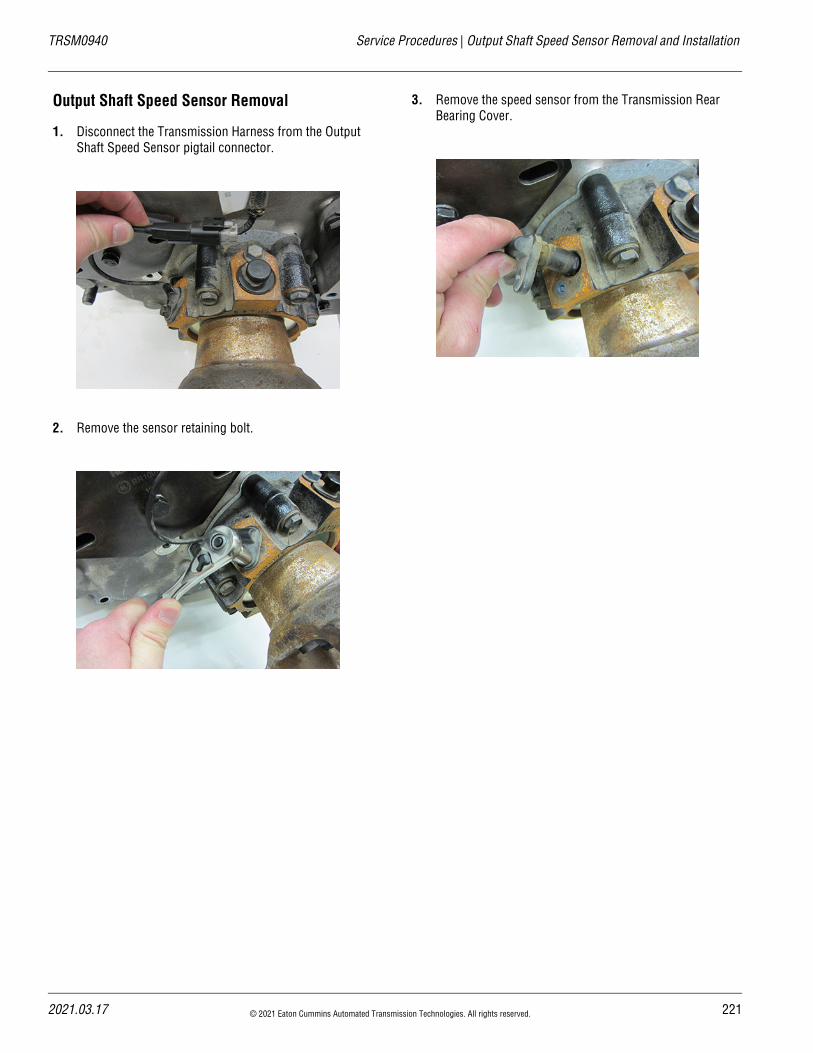
TRSM0940 Service Procedures | Output Shaft Speed Sensor Removal and Installation
Output Shaft Speed Sensor Removal
1. Disconnect the Transmission Harness from the Output Shaft Speed Sensor pigtail connector.
2. Remove the sensor retaining bolt.
3. Remove the speed sensor from the Transmission Rear Bearing Cover.
2021.03.17 © 2021 Eaton Cummins Automated Transmission Technologies. All rights reserved. 221
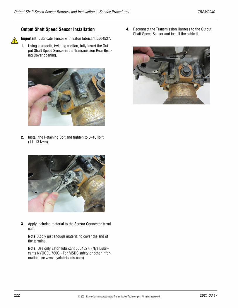
22
Output Shaft Speed Sensor Removal and Installation | Service Procedures TRSM0940
!
Output Shaft Speed Sensor Installation
Important: Lubricate sensor with Eaton lubricant 5564527.
1. Using a smooth, twisting motion, fully insert the Out-put Shaft Speed Sensor in the Transmission Rear Bear-ing Cover opening.
2. Install the Retaining Bolt and tighten to 8–10 lb-ft (11–13 N•m).
3. Apply included material to the Sensor Connector termi-nals.
Note: Apply just enough material to cover the end of the terminal.
Note: Use only Eaton lubricant 5564527. (Nye Lubri-cants NYOGEL 760G - For MSDS safety or other infor-mation see www.nyelubricants.com)
4. Reconnect the Transmission Harness to the Output Shaft Speed Sensor and install the cable tie.
2 © 2021 Eaton Cummins Automated Transmission Technologies. All rights reserved. 2021.03.17
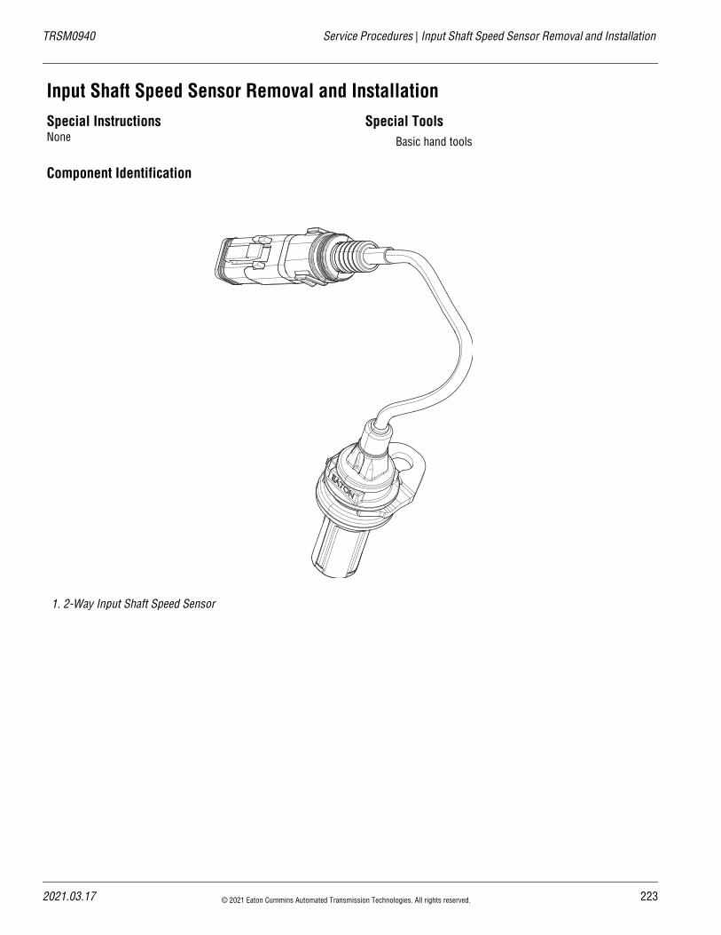
TRSM0940 Service Procedures | Input Shaft Speed Sensor Removal and Installation
Input Shaft Speed Sensor Removal and InstallationSpecial InstructionsNone
Special ToolsBasic hand tools
Component Identification
1. 2-Way Input Shaft Speed Sensor
2021.03.17 © 2021 Eaton Cummins Automated Transmission Technologies. All rights reserved. 223
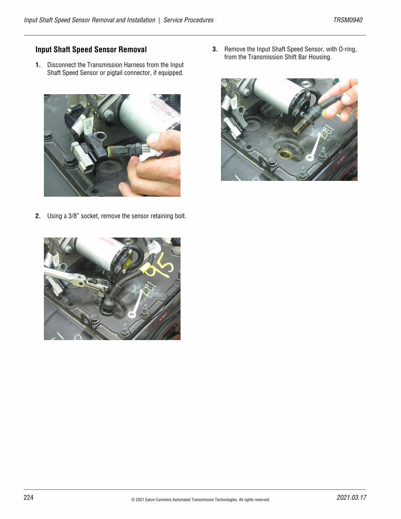
22
Input Shaft Speed Sensor Removal and Installation | Service Procedures TRSM0940
Input Shaft Speed Sensor Removal
1. Disconnect the Transmission Harness from the Input Shaft Speed Sensor or pigtail connector, if equipped.
2. Using a 3/8” socket, remove the sensor retaining bolt.
3. Remove the Input Shaft Speed Sensor, with O-ring, from the Transmission Shift Bar Housing.
4 © 2021 Eaton Cummins Automated Transmission Technologies. All rights reserved. 2021.03.17
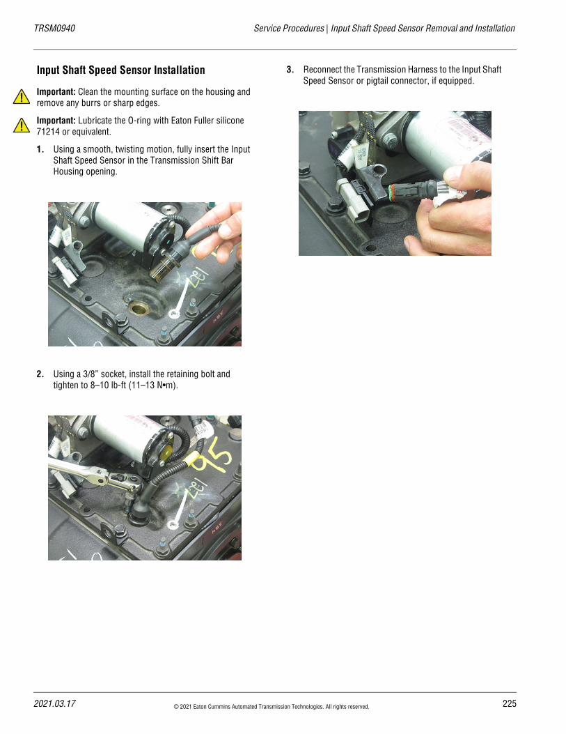
TRSM0940 Service Procedures | Input Shaft Speed Sensor Removal and Installation
!
!
Input Shaft Speed Sensor Installation
Important: Clean the mounting surface on the housing and remove any burrs or sharp edges.
Important: Lubricate the O-ring with Eaton Fuller silicone 71214 or equivalent.
1. Using a smooth, twisting motion, fully insert the Input Shaft Speed Sensor in the Transmission Shift Bar Housing opening.
2. Using a 3/8” socket, install the retaining bolt and tighten to 8–10 lb-ft (11–13 N•m).
3. Reconnect the Transmission Harness to the Input Shaft Speed Sensor or pigtail connector, if equipped.
2021.03.17 © 2021 Eaton Cummins Automated Transmission Technologies. All rights reserved. 225
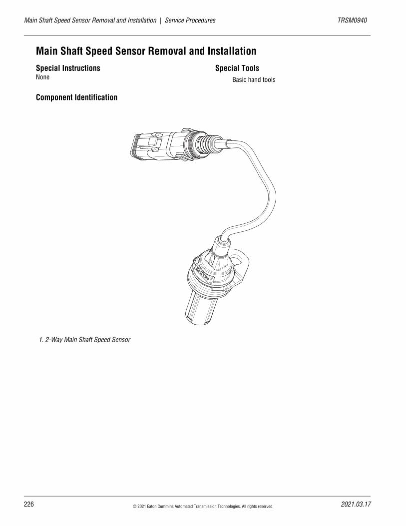
22
Main Shaft Speed Sensor Removal and Installation | Service Procedures TRSM0940
Main Shaft Speed Sensor Removal and InstallationSpecial InstructionsNone
Special ToolsBasic hand tools
Component Identification
1. 2-Way Main Shaft Speed Sensor
6 © 2021 Eaton Cummins Automated Transmission Technologies. All rights reserved. 2021.03.17
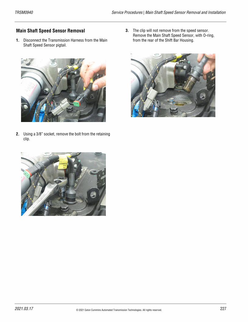
TRSM0940 Service Procedures | Main Shaft Speed Sensor Removal and Installation
Main Shaft Speed Sensor Removal
1. Disconnect the Transmission Harness from the Main Shaft Speed Sensor pigtail.
2. Using a 3/8” socket, remove the bolt from the retaining clip.
3. The clip will not remove from the speed sensor. Remove the Main Shaft Speed Sensor, with O-ring, from the rear of the Shift Bar Housing.
2021.03.17 © 2021 Eaton Cummins Automated Transmission Technologies. All rights reserved. 227
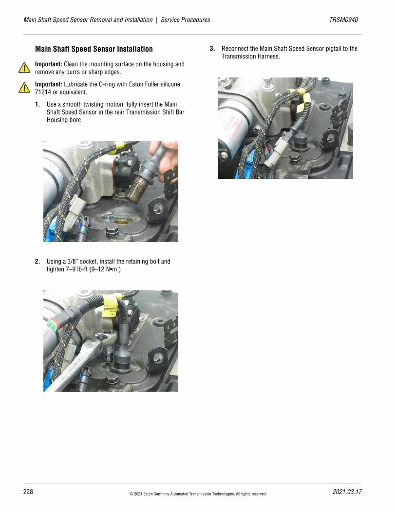
22
Main Shaft Speed Sensor Removal and Installation | Service Procedures TRSM0940
!
!
Main Shaft Speed Sensor Installation
Important: Clean the mounting surface on the housing and remove any burrs or sharp edges.
Important: Lubricate the O-ring with Eaton Fuller silicone 71214 or equivalent.
1. Use a smooth twisting motion; fully insert the Main Shaft Speed Sensor in the rear Transmission Shift Bar Housing bore
2. Using a 3/8” socket, install the retaining bolt and tighten 7–9 lb-ft (9–12 N•m.)
3. Reconnect the Main Shaft Speed Sensor pigtail to the Transmission Harness.
8 © 2021 Eaton Cummins Automated Transmission Technologies. All rights reserved. 2021.03.17
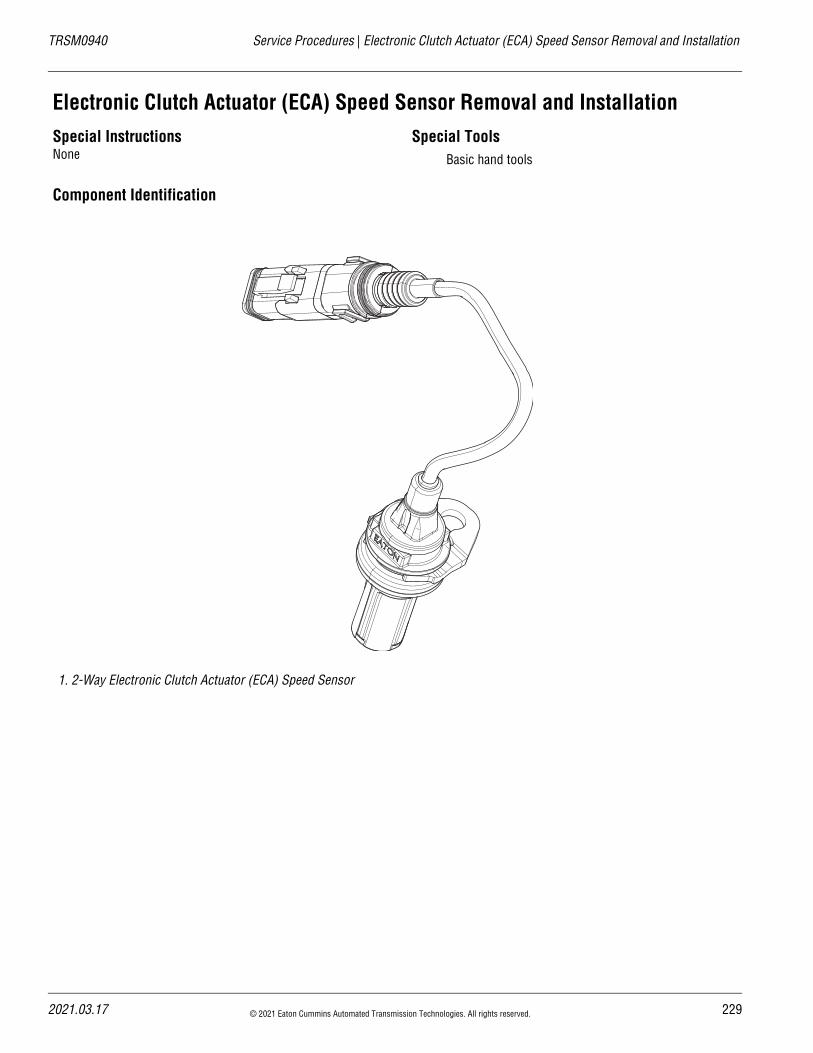
TRSM0940 Service Procedures | Electronic Clutch Actuator (ECA) Speed Sensor Removal and Installation
Electronic Clutch Actuator (ECA) Speed Sensor Removal and InstallationSpecial InstructionsNone
Special ToolsBasic hand tools
Component Identification
1. 2-Way Electronic Clutch Actuator (ECA) Speed Sensor
2021.03.17 © 2021 Eaton Cummins Automated Transmission Technologies. All rights reserved. 229
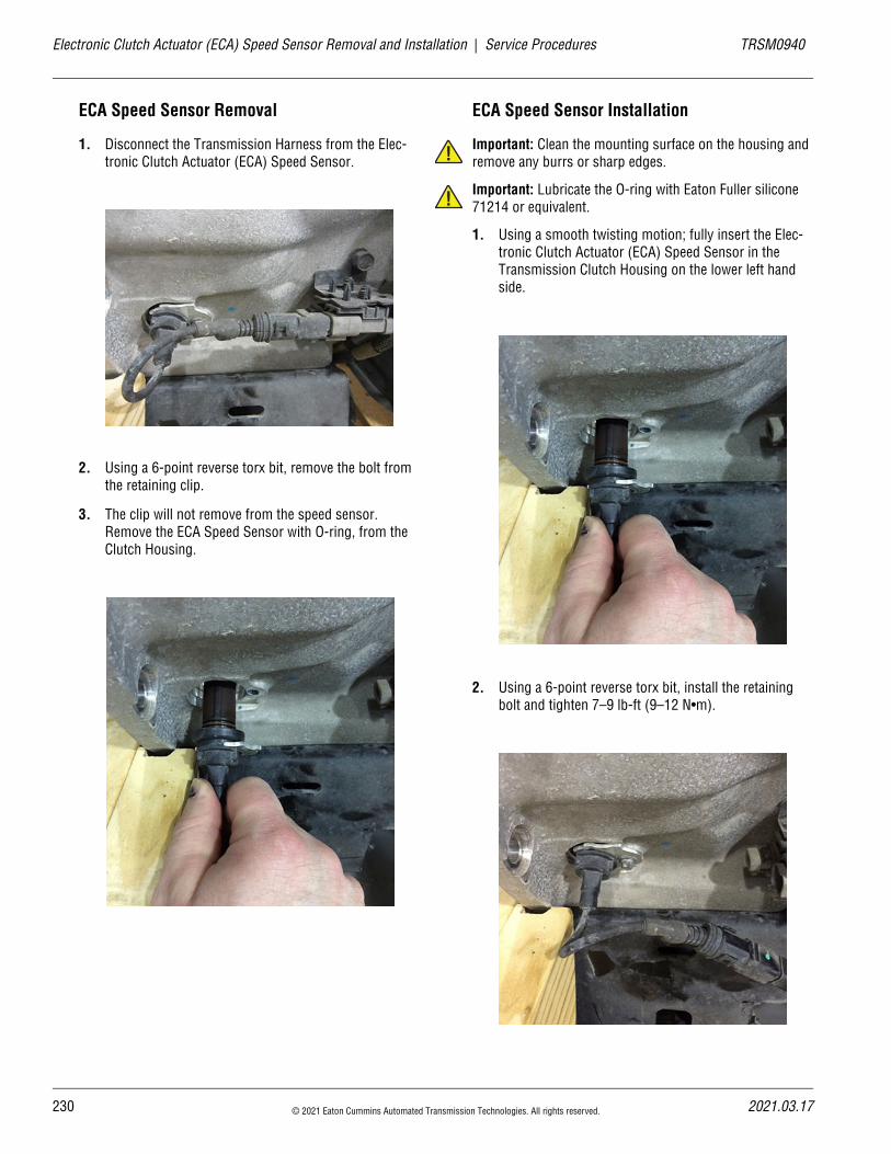
23
Electronic Clutch Actuator (ECA) Speed Sensor Removal and Installation | Service Procedures TRSM0940
ECA Speed Sensor Removal
1. Disconnect the Transmission Harness from the Elec-tronic Clutch Actuator (ECA) Speed Sensor.
2. Using a 6-point reverse torx bit, remove the bolt from the retaining clip.
3. The clip will not remove from the speed sensor. Remove the ECA Speed Sensor with O-ring, from the Clutch Housing.
ECA Speed Sensor Installation
Important: Clean the mounting surface on the housing and remove any burrs or sharp edges.
Important: Lubricate the O-ring with Eaton Fuller silicone 71214 or equivalent.
1. Using a smooth twisting motion; fully insert the Elec-tronic Clutch Actuator (ECA) Speed Sensor in the Transmission Clutch Housing on the lower left hand side.
2. Using a 6-point reverse torx bit, install the retaining bolt and tighten 7–9 lb-ft (9–12 N•m).
!
!
0 © 2021 Eaton Cummins Automated Transmission Technologies. All rights reserved. 2021.03.17

TRSM0940 Service Procedures | Electronic Clutch Actuator (ECA) Speed Sensor Removal and Installation
3. Reconnect the ECA Speed Sensor pigtail to the Trans-mission Harness.
2021.03.17 © 2021 Eaton Cummins Automated Transmission Technologies. All rights reserved. 231
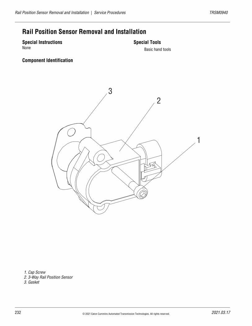
23
Rail Position Sensor Removal and Installation | Service Procedures TRSM0940
Rail Position Sensor Removal and InstallationSpecial InstructionsNone
Special ToolsBasic hand tools
Component Identification
1. Cap Screw2. 3-Way Rail Position Sensor3. Gasket
1
23
2 © 2021 Eaton Cummins Automated Transmission Technologies. All rights reserved. 2021.03.17
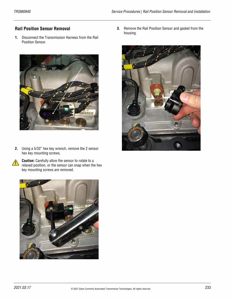
TRSM0940 Service Procedures | Rail Position Sensor Removal and Installation
Rail Position Sensor Removal
1. Disconnect the Transmission Harness from the Rail Position Sensor.
2. Using a 5/32” hex key wrench, remove the 2 sensor hex key mounting screws.
Caution: Carefully allow the sensor to rotate to a relaxed position, or the sensor can snap when the hex key mounting screws are removed.
3. Remove the Rail Position Sensor and gasket from the housing.
!
2021.03.17 © 2021 Eaton Cummins Automated Transmission Technologies. All rights reserved. 233
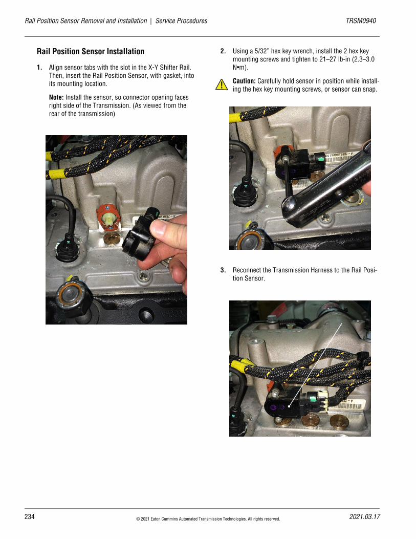
23
Rail Position Sensor Removal and Installation | Service Procedures TRSM0940
Rail Position Sensor Installation
1. Align sensor tabs with the slot in the X-Y Shifter Rail. Then, insert the Rail Position Sensor, with gasket, into its mounting location.
Note: Install the sensor, so connector opening faces right side of the Transmission. (As viewed from the rear of the transmission)
2. Using a 5/32” hex key wrench, install the 2 hex key mounting screws and tighten to 21–27 lb-in (2.3–3.0 N•m).
Caution: Carefully hold sensor in position while install-ing the hex key mounting screws, or sensor can snap.
3. Reconnect the Transmission Harness to the Rail Posi-tion Sensor.
!
4 © 2021 Eaton Cummins Automated Transmission Technologies. All rights reserved. 2021.03.17
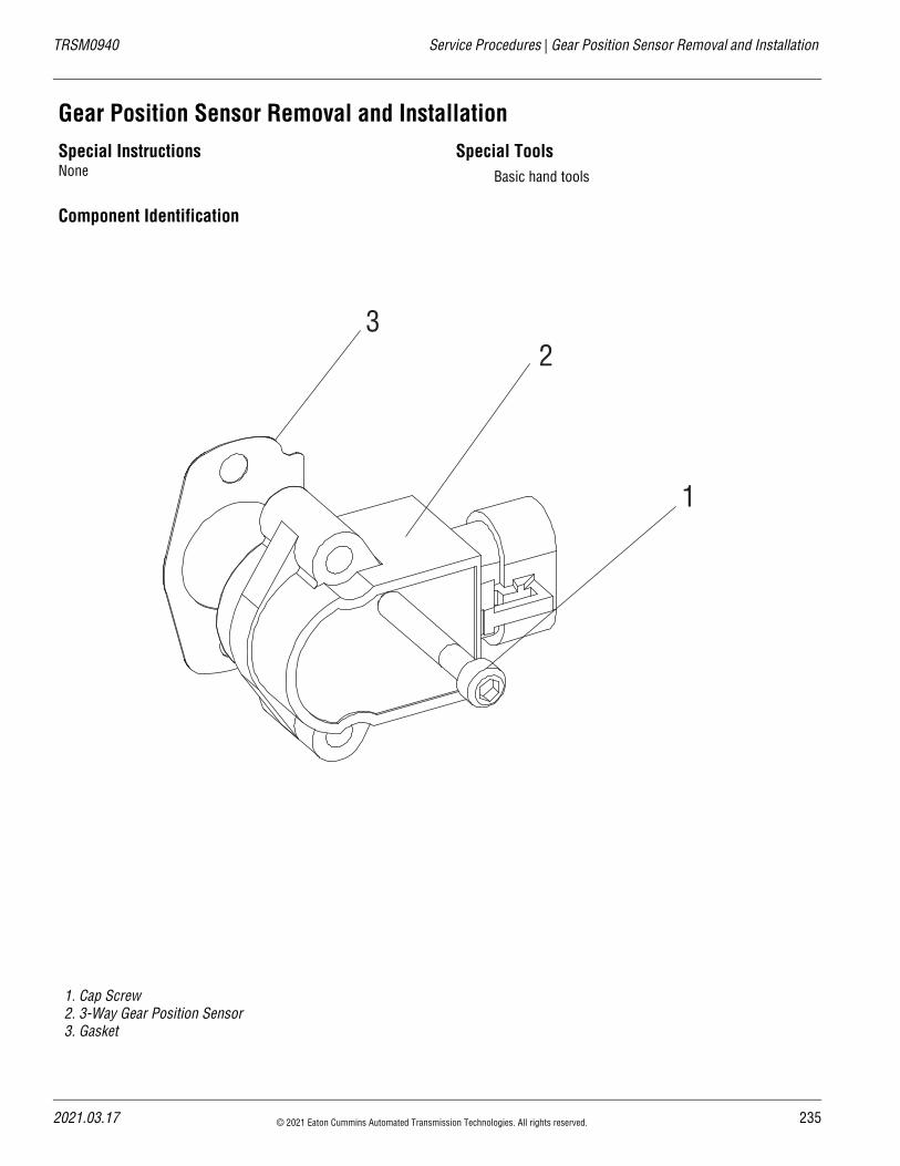
TRSM0940 Service Procedures | Gear Position Sensor Removal and Installation
Gear Position Sensor Removal and InstallationSpecial InstructionsNone
Special ToolsBasic hand tools
Component Identification
1. Cap Screw2. 3-Way Gear Position Sensor3. Gasket
1
23
2021.03.17 © 2021 Eaton Cummins Automated Transmission Technologies. All rights reserved. 235
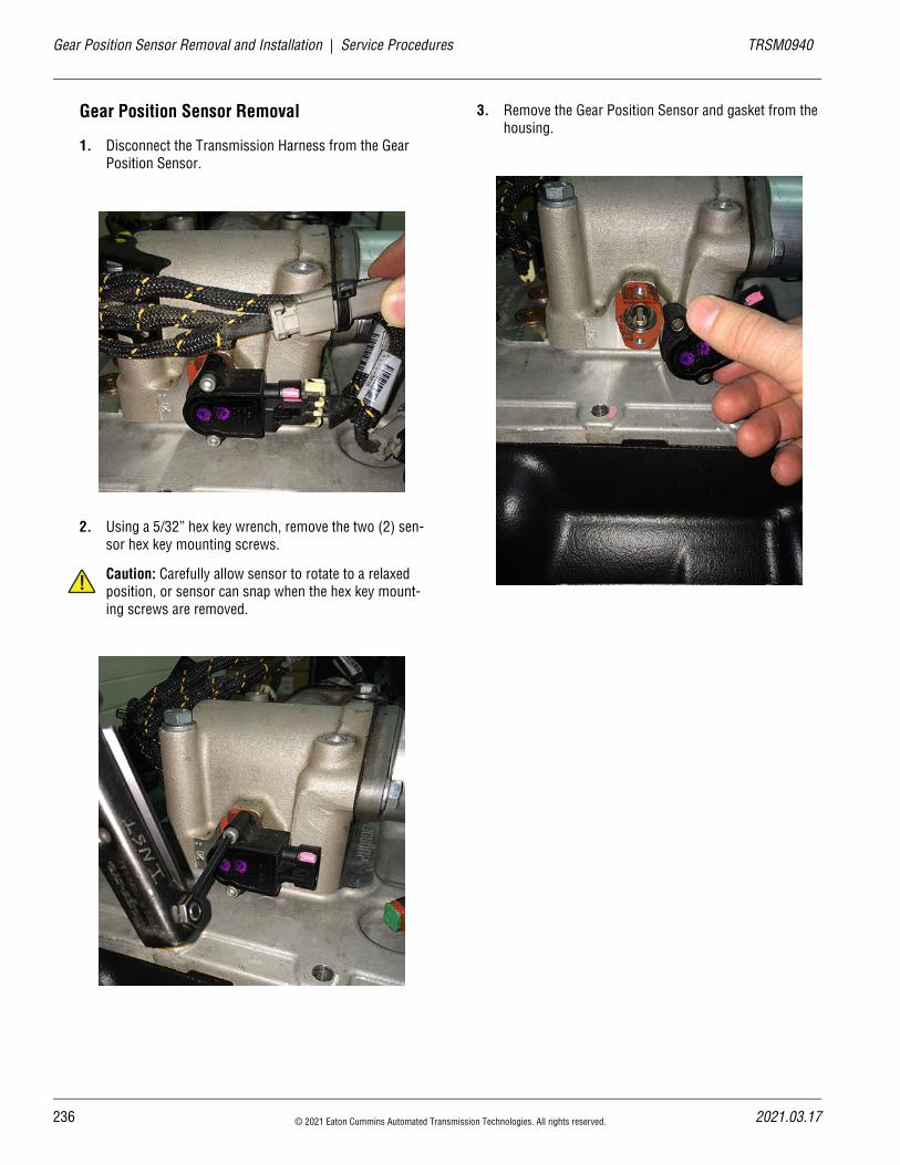
23
Gear Position Sensor Removal and Installation | Service Procedures TRSM0940
Gear Position Sensor Removal
1. Disconnect the Transmission Harness from the Gear Position Sensor.
2. Using a 5/32” hex key wrench, remove the two (2) sen-sor hex key mounting screws.
Caution: Carefully allow sensor to rotate to a relaxed position, or sensor can snap when the hex key mount-ing screws are removed.
3. Remove the Gear Position Sensor and gasket from the housing.
!
6 © 2021 Eaton Cummins Automated Transmission Technologies. All rights reserved. 2021.03.17
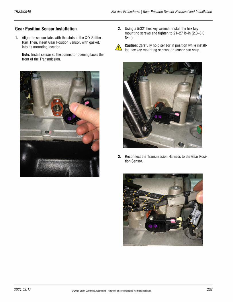
TRSM0940 Service Procedures | Gear Position Sensor Removal and Installation
Gear Position Sensor Installation
1. Align the sensor tabs with the slots in the X-Y Shifter Rail. Then, insert Gear Position Sensor, with gasket, into its mounting location.
Note: Install sensor so the connector opening faces the front of the Transmission.
2. Using a 5/32” hex key wrench, install the hex key mounting screws and tighten to 21–27 lb-in (2.3–3.0 N•m).
Caution: Carefully hold sensor in position while install-ing hex key mounting screws, or sensor can snap.
3. Reconnect the Transmission Harness to the Gear Posi-tion Sensor.
!
2021.03.17 © 2021 Eaton Cummins Automated Transmission Technologies. All rights reserved. 237
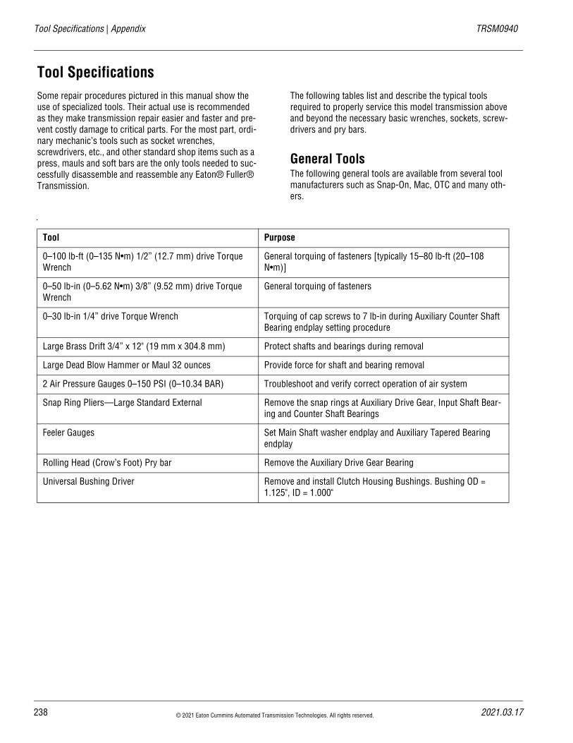
Tool Specifications | Appendix TRSM0940
Tool SpecificationsSome repair procedures pictured in this manual show the use of specialized tools. Their actual use is recommended as they make transmission repair easier and faster and pre-vent costly damage to critical parts. For the most part, ordi-nary mechanic’s tools such as socket wrenches, screwdrivers, etc., and other standard shop items such as a press, mauls and soft bars are the only tools needed to suc-cessfully disassemble and reassemble any Eaton® Fuller® Transmission.
The following tables list and describe the typical tools required to properly service this model transmission above and beyond the necessary basic wrenches, sockets, screw-drivers and pry bars.
General ToolsThe following general tools are available from several tool manufacturers such as Snap-On, Mac, OTC and many oth-ers.
Tool Purpose
0–100 lb-ft (0–135 N•m) 1/2” (12.7 mm) drive Torque Wrench
General torquing of fasteners [typically 15–80 lb-ft (20–108 N•m)]
0–50 lb-in (0–5.62 N•m) 3/8” (9.52 mm) drive Torque Wrench
General torquing of fasteners
0–30 lb-in 1/4” drive Torque Wrench Torquing of cap screws to 7 lb-in during Auxiliary Counter Shaft Bearing endplay setting procedure
Large Brass Drift 3/4” x 12" (19 mm x 304.8 mm) Protect shafts and bearings during removal
Large Dead Blow Hammer or Maul 32 ounces Provide force for shaft and bearing removal
2 Air Pressure Gauges 0–150 PSI (0–10.34 BAR) Troubleshoot and verify correct operation of air system
Snap Ring Pliers—Large Standard External Remove the snap rings at Auxiliary Drive Gear, Input Shaft Bear-ing and Counter Shaft Bearings
Feeler Gauges Set Main Shaft washer endplay and Auxiliary Tapered Bearing endplay
Rolling Head (Crow’s Foot) Pry bar Remove the Auxiliary Drive Gear Bearing
Universal Bushing Driver Remove and install Clutch Housing Bushings. Bushing OD = 1.125", ID = 1.000"
238 © 2021 Eaton Cummins Automated Transmission Technologies. All rights reserved. 2021.03.17
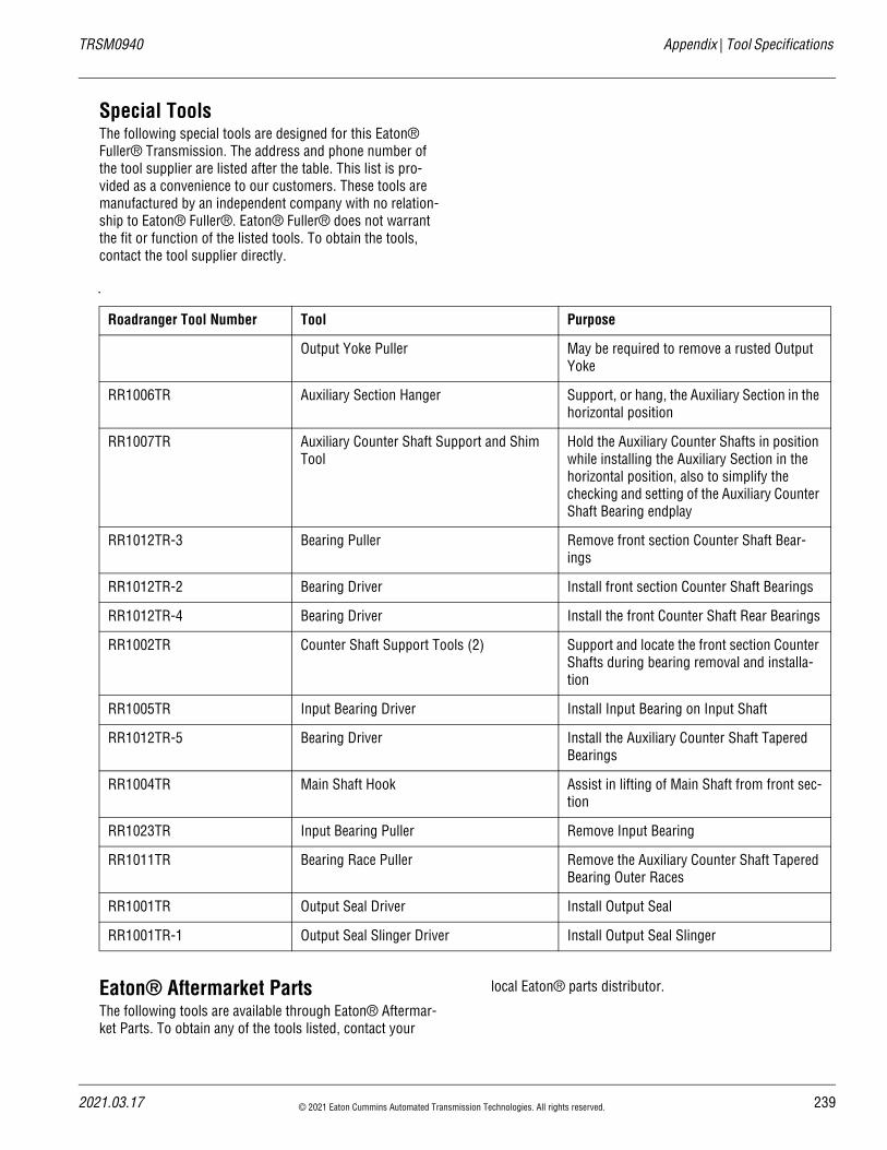
20
TRSM0940 Appendix | Tool Specifications
Special ToolsThe following special tools are designed for this Eaton® Fuller® Transmission. The address and phone number of the tool supplier are listed after the table. This list is pro-vided as a convenience to our customers. These tools are manufactured by an independent company with no relation-ship to Eaton® Fuller®. Eaton® Fuller® does not warrant the fit or function of the listed tools. To obtain the tools, contact the tool supplier directly.
Eaton® Aftermarket PartsThe following tools are available through Eaton® Aftermar-ket Parts. To obtain any of the tools listed, contact your
local Eaton® parts distributor.
Roadranger Tool Number Tool Purpose
Output Yoke Puller May be required to remove a rusted Output Yoke
RR1006TR Auxiliary Section Hanger Support, or hang, the Auxiliary Section in the horizontal position
RR1007TR Auxiliary Counter Shaft Support and Shim Tool
Hold the Auxiliary Counter Shafts in position while installing the Auxiliary Section in the horizontal position, also to simplify the checking and setting of the Auxiliary Counter Shaft Bearing endplay
RR1012TR-3 Bearing Puller Remove front section Counter Shaft Bear-ings
RR1012TR-2 Bearing Driver Install front section Counter Shaft Bearings
RR1012TR-4 Bearing Driver Install the front Counter Shaft Rear Bearings
RR1002TR Counter Shaft Support Tools (2) Support and locate the front section Counter Shafts during bearing removal and installa-tion
RR1005TR Input Bearing Driver Install Input Bearing on Input Shaft
RR1012TR-5 Bearing Driver Install the Auxiliary Counter Shaft Tapered Bearings
RR1004TR Main Shaft Hook Assist in lifting of Main Shaft from front sec-tion
RR1023TR Input Bearing Puller Remove Input Bearing
RR1011TR Bearing Race Puller Remove the Auxiliary Counter Shaft Tapered Bearing Outer Races
RR1001TR Output Seal Driver Install Output Seal
RR1001TR-1 Output Seal Slinger Driver Install Output Seal Slinger
21.03.17 © 2021 Eaton Cummins Automated Transmission Technologies. All rights reserved. 239
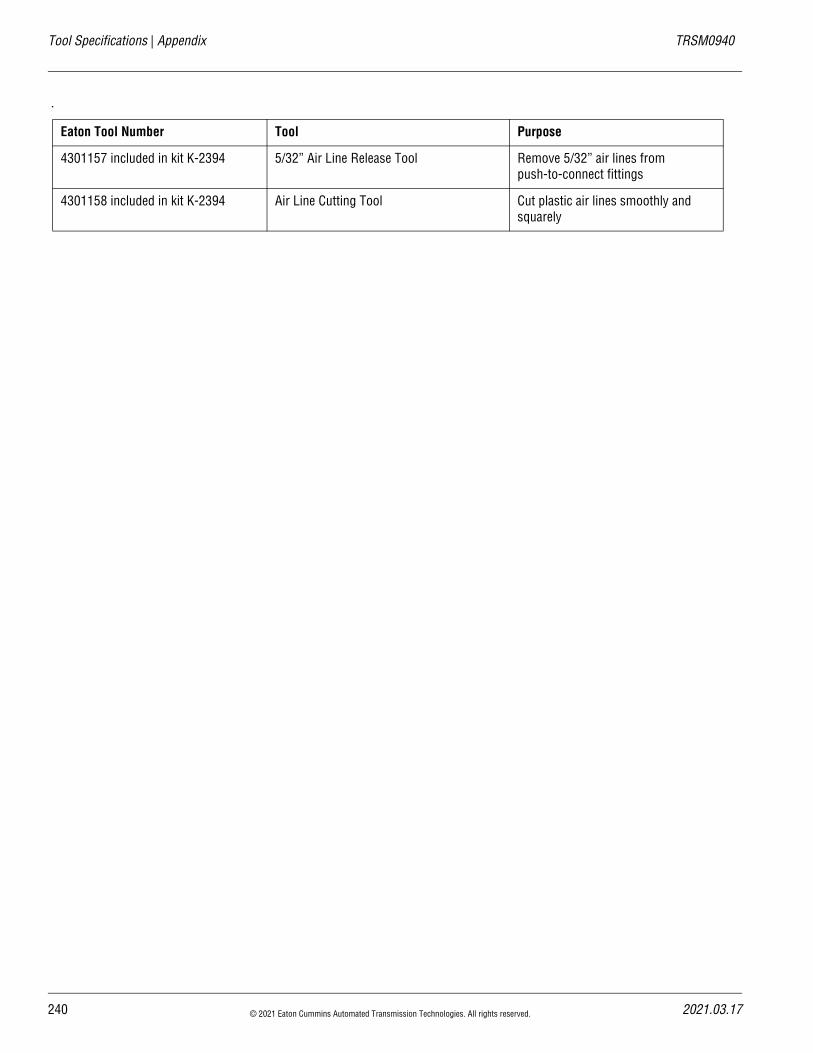
Tool Specifications | Appendix TRSM0940
Eaton Tool Number Tool Purpose
4301157 included in kit K-2394 5/32” Air Line Release Tool Remove 5/32” air lines from push-to-connect fittings
4301158 included in kit K-2394 Air Line Cutting Tool Cut plastic air lines smoothly and squarely
240 © 2021 Eaton Cummins Automated Transmission Technologies. All rights reserved. 2021.03.17
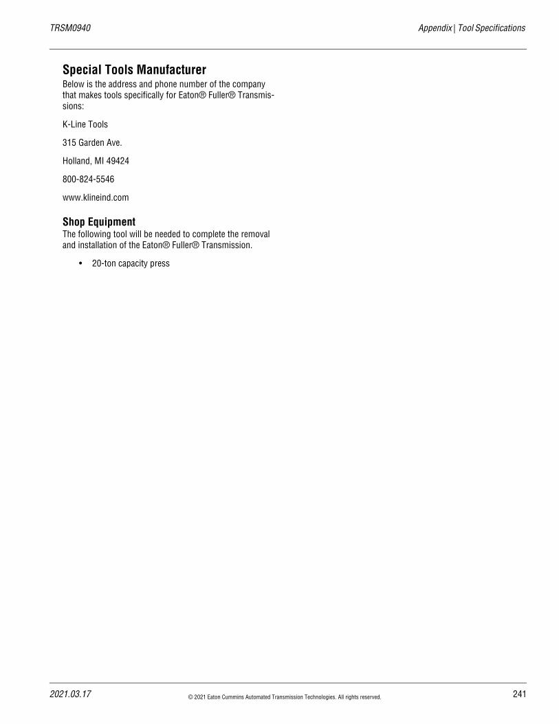
20
TRSM0940 Appendix | Tool Specifications
Special Tools ManufacturerBelow is the address and phone number of the company that makes tools specifically for Eaton® Fuller® Transmis-sions:
K-Line Tools
315 Garden Ave.
Holland, MI 49424
800-824-5546
www.klineind.com
Shop EquipmentThe following tool will be needed to complete the removal and installation of the Eaton® Fuller® Transmission.
• 20-ton capacity press
21.03.17 © 2021 Eaton Cummins Automated Transmission Technologies. All rights reserved. 241
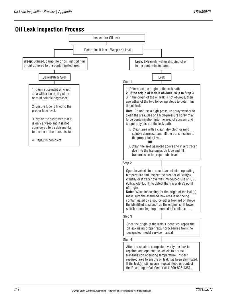
242 © 2021 Eaton Cummins Automated Transmission Technologies. All rights reserved. 2021.03.17
Oil Leak Inspection Process | Appendix TRSM0940
Oil Leak Inspection ProcessInspect for Oil Leak
Determine if it is a Weep or a Leak.
Weep: Stained, damp, no drips, light oil film or dirt adhered to the contaminated area.
Leak: Extremely wet or dripping of oil in the contaminated area.
Gasket/Rear Seal Leak
1. Clean suspected oil weeparea with a clean, dry clothor mild soluble degreaser.
2. Ensure lube is filled to theproper lube level.
3. Notify the customer that it is only a weep and it is notconsidered to be detrimentalto the life of the transmission.
4. Repair is complete.
1. Determine the origin of the leak path.2. If the origin of leak is obvious, skip to Step 3.3. If the origin of the oil leak is not obvious, then use either of the two following steps to determine the oil leak:Note: Do not use a high-pressure spray washer to clean the area. Use of a high-pressure spray mayforce contamination into the area of concern and temporarily disrupt the leak path.
i. Clean area with a clean, dry cloth or mild soluble degreaser and fill the transmission to the proper lube level. OR ii. Clean the area as noted above and insert tracer dye into the transmission lube and fill transmission to proper lube level.
Operate vehicle to normal transmission operating temperature and inspect the area for oil leak(s) visually or if tracer dye was introduced use an UVL (Ultraviolet Light) to detect the tracer dye’s point of origin.Note: When inspecting for the origin of the leak(s) make sure the assumed leak area is not being contaminated by a source either forward or above the identified area such as the engine, shift tower, shift bar housing, top mounted oil cooler, etc....
Once the origin of the leak is identified, repair the oil leak using proper repair procedures from the designated model service manual.
After the repair is completed, verify the leak is repaired and operate the vehicle to normaltransmission operating temperature. Inspect repaired area to ensure oil leak has been eliminated. If the leak(s) still occurs, repeat steps or contact the Roadranger Call Center at 1-800-826-4357.
Step 1
Step 2
Step 3
Step 4
20
TRSM0940 Appendix | Inspection Procedure
Inspection ProcedureBefore reassembling the transmission, check each part carefully for abnormal wear, excessive wear or damage to determine if the part is suitable for reuse. When replace-ment is necessary, use only genuine Eaton® Fuller® Trans-mission parts to assure continued performance and extended life from your unit.
Since the cost of a new part is generally a small fraction of the total cost of downtime and labor, avoid reusing a ques-tionable part. This could lead to additional repairs and expense soon after assembly. Consideration should also be given to the history of the unit, mileage, application, etc., when determining the reuse or replacement of any trans-mission part.
Bearings
• Wash all bearings in clean solvent. Check balls, rollers and raceways for pitting, discoloration and spalled areas.
• Replace bearings that are pitted, discolored, spalled or damaged during disassembly
• Lubricate bearings that are not pitted, discolored or spalled and check for axial and radial clearances.
• Replace bearings with excessive clearances.
• Check bearing fit. Bearing inner races should be tight to shaft; outer races slightly tight to slightly loose in case bore. If the bearing spins freely in the bore, the case should be replaced.
Bearing Covers
• Check covers for wear from thrust of adjacent bear-ing. Replace covers damaged from thrust of bear-ing outer race.
• Check cover bores for wear. Replace those worn or oversized.
Clutch Release Parts
• Replace yokes worn at cam surfaces and bearing carrier worn at contact pads.
• Check pedal shafts. Replace those worn at bushing surfaces.
Gears
• Check gear teeth for frosting and pitting. Frosting of gear teeth faces presents no threat of transmis-sion failure. Often in continued operation of the unit, frosted gears “heal” and do not progress to the pitting stage. In most cases, gears with light to moderate pitted teeth have considerable gear life remaining and can be reused, but gears in the advanced stage of pitting should be replaced.
• Check gears with clutching teeth abnormally worn, tapered or reduced in length from clashing during shifting. Replace gears found in any of these condi-tions.
• Check axial clearance of gears.
Gear Shift Lever Housing Assembly
• Check spring tension on Shift Lever. Replace ten-sion spring if lever moves too freely. If housing is disassembled, check the Gear Shift Lever bottom end and shift finger assembly for wear.
Gray Iron Parts
• Check all gray iron parts for cracks and breaks.
• Replace damaged parts.
Oil Return Threads and Seals
• Check oil return threads on the Input Shaft. If return action of threads has been destroyed, replace the Input Shaft.
• Check oil seal in Rear Bearing Cover. If sealing action of lip has been destroyed, replace seal.
O-Rings
• Check all O-rings for cracks or distortion. Replace if worn.
Reverse Idler Gear Assemblies
• Check for excessive wear from action of roller bear-ings.
Shift Bar Housing Assembly
• Check for wear on shift yokes and block at pads and lever slot. Replace excessively worn parts.
21.03.17 © 2021 Eaton Cummins Automated Transmission Technologies. All rights reserved. 243
Inspection Procedure | Appendix TRSM0940
• Check yokes for correct alignment. Replace sprung yokes.
• If housing has been disassembled, check shift shaft and all related parts for wear.
Sliding Clutches
• Check all shift yokes and yoke slots in sliding clutches for extreme wear or discoloration from heat.
• Check engaging teeth of sliding clutches for partial engagement pattern.
Splines
• Check splines on all shafts for abnormal wear. If sliding clutch gears, companion flange or clutch hub has wear marks in the spline sides, replace the specific shaft affected.
Synchronizer Assembly
• Check Synchronizer for burrs, uneven and exces-sive wear at contact surface, and metal particles.
• Check blocker pins for excessive wear or loose-ness.
• Check Synchronizer contact surfaces on the Syn-chronizer cups for wear.
Washers
• Check surfaces of all washers. Washers scored or reduced in thickness should be replaced.
244 © 2021 Eaton Cummins Automated Transmission Technologies. All rights reserved. 2021.03.17
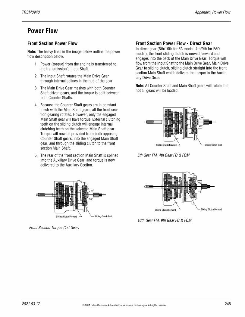
20
TRSM0940 Appendix | Power Flow
Power Flow
Front Section Power Flow
Note: The heavy lines in the image below outline the power flow description below.
1. Power (torque) from the engine is transferred to the transmission’s Input Shaft.
2. The Input Shaft rotates the Main Drive Gear through internal splines in the hub of the gear.
3. The Main Drive Gear meshes with both Counter Shaft driven gears, and the torque is split between both Counter Shafts.
4. Because the Counter Shaft gears are in constant mesh with the Main Shaft gears, all the front sec-tion gearing rotates. However, only the engaged Main Shaft gear will have torque. External clutching teeth on the sliding clutch will engage internal clutching teeth on the selected Main Shaft gear. Torque will now be provided from both opposing Counter Shaft gears, into the engaged Main Shaft gear, and through the sliding clutch to the front section Main Shaft.
5. The rear of the front section Main Shaft is splined into the Auxiliary Drive Gear, and torque is now delivered to the Auxiliary Section.
Front Section Power Flow - Direct GearIn direct gear (5th/10th for FA model, 4th/9th for FAO model), the front sliding clutch is moved forward and engages into the back of the Main Drive Gear. Torque will flow from the Input Shaft to the Main Drive Gear, Main Drive Gear to sliding clutch, sliding clutch straight into the front section Main Shaft which delivers the torque to the Auxil-iary Drive Gear.
Note: All Counter Shaft and Main Shaft gears will rotate, but not all gears will be loaded.
Front Section Torque (1st Gear)
5th Gear FM, 4th Gear FO & FOM
10th Gear FM, 9th Gear FO & FOM
21.03.17 © 2021 Eaton Cummins Automated Transmission Technologies. All rights reserved. 245
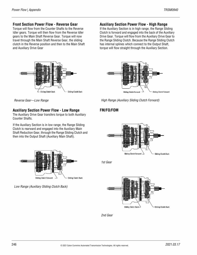
Power Flow | Appendix TRSM0940
Front Section Power Flow - Reverse GearTorque will flow from the Counter Shafts to the Reverse Idler gears. Torque will then flow from the Reverse Idler gears to the Main Shaft Reverse Gear. Torque will now travel through the Main Shaft Reverse Gear, the sliding clutch in the Reverse position and then to the Main Shaft and Auxiliary Drive Gear
Auxiliary Section Power Flow - Low RangeThe Auxiliary Drive Gear transfers torque to both Auxiliary Counter Shafts.
If the Auxiliary Section is in low range, the Range Sliding Clutch is rearward and engaged into the Auxiliary Main Shaft Reduction Gear, through the Range Sliding Clutch and then into the Output Shaft (Auxiliary Main Shaft).
Auxiliary Section Power Flow - High RangeIf the Auxiliary Section is in high range, the Range Sliding Clutch is forward and engaged into the back of the Auxiliary Drive Gear. Torque will flow from the Auxiliary Drive Gear to the Range Sliding Clutch. Because the Range Sliding Clutch has internal splines which connect to the Output Shaft, torque will flow straight through the Auxiliary Section.
FM/FO/FOM
Reverse Gear—Low Range
Low Range (Auxiliary Sliding Clutch Back)
High Range (Auxiliary Sliding Clutch Forward)
1st Gear
2nd Gear
246 © 2021 Eaton Cummins Automated Transmission Technologies. All rights reserved. 2021.03.17
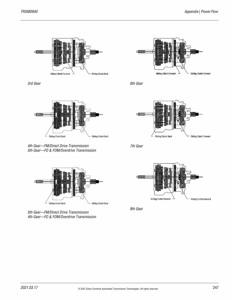
20
TRSM0940 Appendix | Power Flow
3rd Gear
4th Gear—FM/Direct Drive Transmission5th Gear—FO & FOM/Overdrive Transmission
5th Gear—FM/Direct Drive Transmission4th Gear—FO & FOM/Overdrive Transmission
6th Gear
7th Gear
8th Gear
21.03.17 © 2021 Eaton Cummins Automated Transmission Technologies. All rights reserved. 247
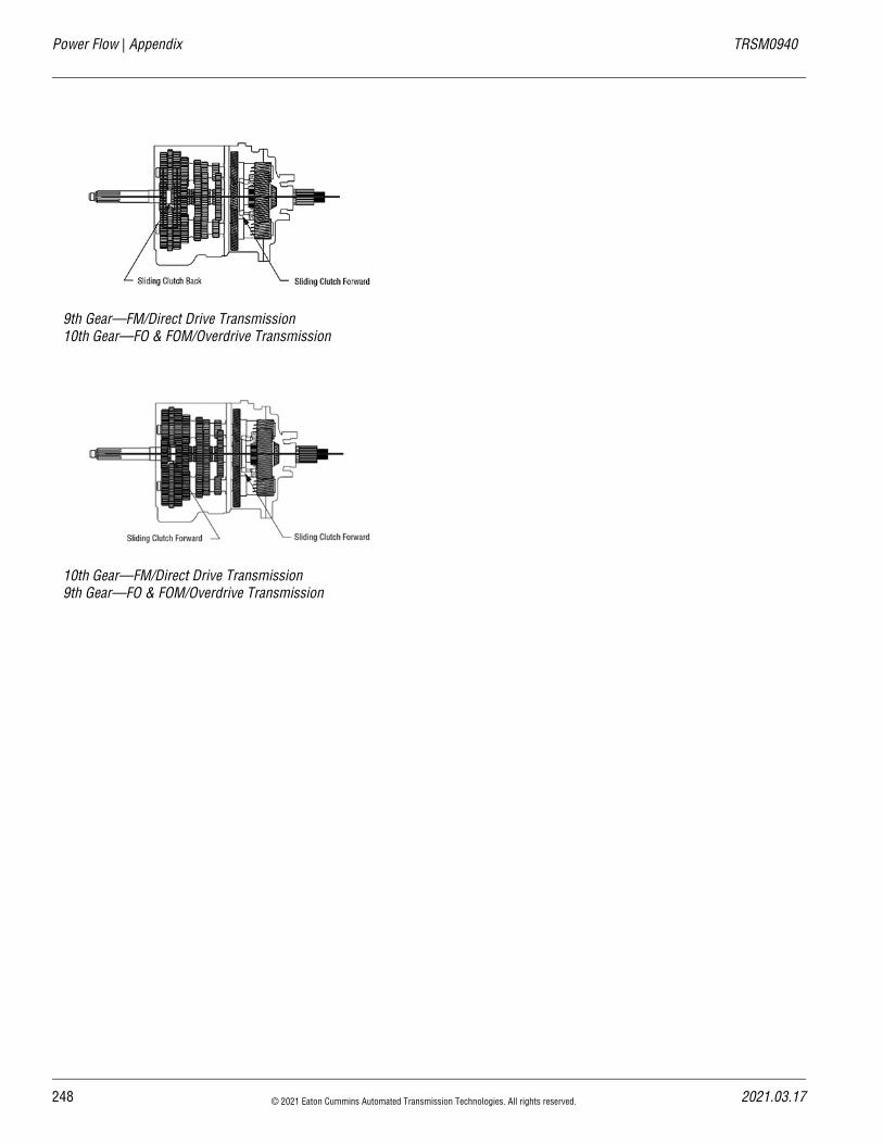
Power Flow | Appendix TRSM0940
9th Gear—FM/Direct Drive Transmission10th Gear—FO & FOM/Overdrive Transmission
10th Gear—FM/Direct Drive Transmission9th Gear—FO & FOM/Overdrive Transmission
248 © 2021 Eaton Cummins Automated Transmission Technologies. All rights reserved. 2021.03.17
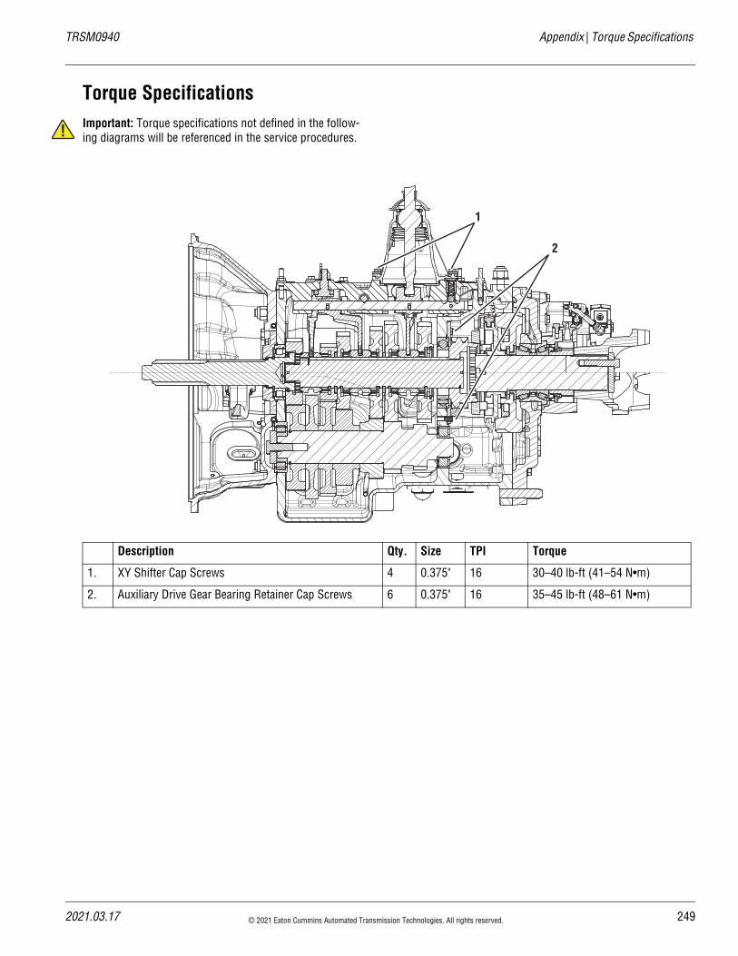
20
TRSM0940 Appendix | Torque Specifications
!
Torque SpecificationsImportant: Torque specifications not defined in the follow-ing diagrams will be referenced in the service procedures.
Description Qty. Size TPI Torque
1. XY Shifter Cap Screws 4 0.375" 16 30–40 lb-ft (41–54 N•m)
2. Auxiliary Drive Gear Bearing Retainer Cap Screws 6 0.375" 16 35–45 lb-ft (48–61 N•m)
2
1
21.03.17 © 2021 Eaton Cummins Automated Transmission Technologies. All rights reserved. 249
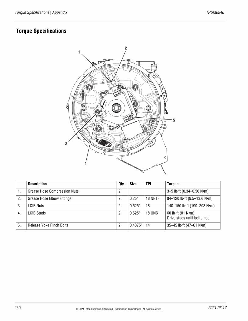
Torque Specifications | Appendix TRSM0940
Torque Specifications
Description Qty. Size TPI Torque
1. Grease Hose Compression Nuts 2 3–5 lb-ft (0.34–0.56 N•m)
2. Grease Hose Elbow Fittings 2 0.25" 18 NPTF 84–120 lb-ft (9.5–13.6 N•m)
3. LCIB Nuts 2 0.625" 18 140–150 lb-ft (190–203 N•m)
4. LCIB Studs 2 0.625" 18 UNC 60 lb-ft (81 N•m) Drive studs until bottomed
5. Release Yoke Pinch Bolts 2 0.4375" 14 35–45 lb-ft (47–61 N•m)
3
4
5
12
250 © 2021 Eaton Cummins Automated Transmission Technologies. All rights reserved. 2021.03.17
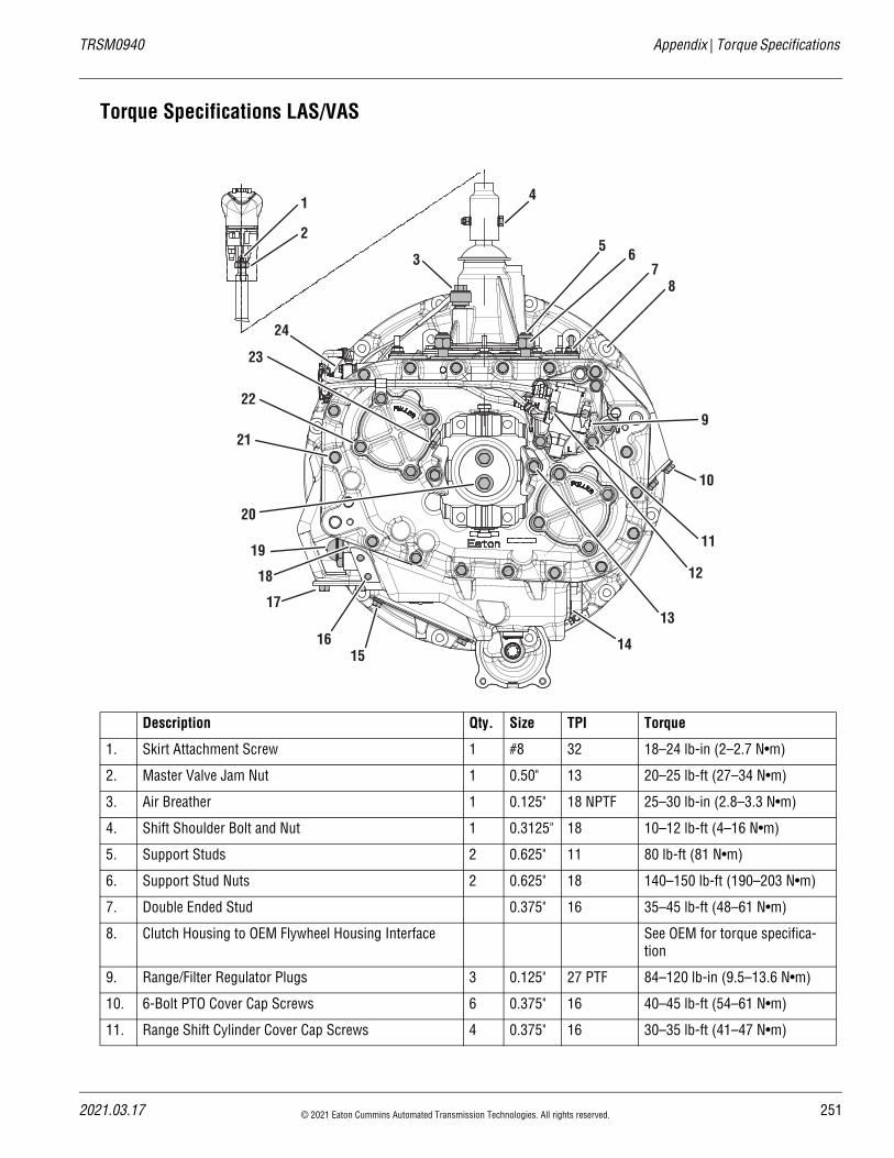
20
TRSM0940 Appendix | Torque Specifications
Torque Specifications LAS/VAS
Description Qty. Size TPI Torque
1. Skirt Attachment Screw 1 #8 32 18–24 lb-in (2–2.7 N•m)
2. Master Valve Jam Nut 1 0.50" 13 20–25 lb-ft (27–34 N•m)
3. Air Breather 1 0.125" 18 NPTF 25–30 lb-in (2.8–3.3 N•m)
4. Shift Shoulder Bolt and Nut 1 0.3125" 18 10–12 lb-ft (4–16 N•m)
5. Support Studs 2 0.625" 11 80 lb-ft (81 N•m)
6. Support Stud Nuts 2 0.625" 18 140–150 lb-ft (190–203 N•m)
7. Double Ended Stud 0.375" 16 35–45 lb-ft (48–61 N•m)
8. Clutch Housing to OEM Flywheel Housing Interface See OEM for torque specifica-tion
9. Range/Filter Regulator Plugs 3 0.125" 27 PTF 84–120 lb-in (9.5–13.6 N•m)
10. 6-Bolt PTO Cover Cap Screws 6 0.375" 16 40–45 lb-ft (54–61 N•m)
11. Range Shift Cylinder Cover Cap Screws 4 0.375" 16 30–35 lb-ft (41–47 N•m)
1 4
56
78
9
10
11
12
13
141615
19
17
18
20
21
22
23
24
3
2
21.03.17 © 2021 Eaton Cummins Automated Transmission Technologies. All rights reserved. 251
Torque Specifications | Appendix TRSM0940
12. Air Filter Regulator Cap Screws 2 0.25" 20 8–12 lb-ft (11–16 N•m)
13. Rear Bearing cover Cap Screws 6 0.375" 16 30–35 lb-ft (41–47 N•m)
14. Thermocouple Plug 1 0.50" 40–50 lb-ft (54–67 N•m)
15. Hand Hole Cover Cap Screws 4 0.321" 18 14–18 lb-ft (19–24 N•m)
16. Provision for PTO Bracket 2 0.375" 16 30–35 lb-ft (41–47 N•m)
17. 8-Bolt PTO Cover Cap Screws 8 0.4375" 14 50–65 lb-ft (68–88 N•m)
18. Oil Fill Plug 1 1.0625" 12 35–50 lb-ft (47–67 N•m)
19. Oil Level Sight Glass Plug 1 0.625" 12 60–70 lb-ft (82–95 N•m)
20. Output Yoke Retainer Bolts 2 M12 1.25 84–92 lb-ft (113–124 N•m)
21. Auxiliary Housing Cap Screws 19 0.375" 16 35–45 lb-ft (48–61 N•m)
22. Auxiliary Counter Shaft Rear Bearing Cover Cap Screws
8 0.375" 16 30–35 lb-ft (41–47 N•m)
23. Speed Sensor Retaining Bolt 1 0.25" 20 8–12 lb-ft (11–16 N•m)
Description Qty. Size TPI Torque
252 © 2021 Eaton Cummins Automated Transmission Technologies. All rights reserved. 2021.03.17
2021.03.17 © 2021 Eaton Cummins Automated Transmission Technologies. All rights reserved. 253
TRSM0940 Appendix | Lubrication Specifications
Lubrication Specifications Caution: Do not introduce additives and friction modifiers.
Caution: Never mix standard oils and synthetic transmis-sion oils in the same transmission. When switching between types of lubricants, all areas of each affected com-ponent must be thoroughly drained.
Caution: Do not mix lubricants of different grades.
Note: For a list of Eaton Approved Synthetic Lubricants, see TCMT0021 Roadranger Lubricant Products or call 1-800-826-HELP (4357).
Note: The use of lubricants not meeting these requirements will affect warranty coverage.
Note: For lubrication change and inspection intervals, see TCMT0021 Roadranger Lubricant Products.
Note: Please refer to CLSM0200 Eaton Heavy-Duty Clutches for clutch lubrication and service guidelines.
Buy From a Reputable DealerFor a complete list of approved and reputable dealers, write to:
Eaton, Worldwide Marketing Services
P.O. Box 4013
Kalamazoo, MI 49003
Transmission Operating AnglesIf the transmission operating angle is more than 12 degrees, or approximately a 21% grade, improper lubrica-tion will occur. The operating angle is the transmission mounting angle in the chassis plus the percent of upgrade (expressed in degrees).
For operating angles over 12 degrees, the transmission must be equipped with an oil pump or cooler kit to ensure proper lubrication.
Transmission filters should be changed during regular lubrication intervals. Inspection of the transmission filter should be conducted during preventative maintenance checks for damage or corrosion. Replace as necessary.
Operating Temperatures Transmissions must not be operated at temperatures that are consistently above 250°F (121°C). Operation at tem-peratures above this limit causes loaded gear tooth tem-peratures to exceed 350°F (177°C) which will ultimately destroy the heat treatment of the gears.
The following conditions, in any combination, can cause operating temperatures that exceed 250°F (120°C):
• Operating consistently at high loads/slow speeds
• High ambient temperatures
• Restricted air flow around the transmission
• Exhaust system too close to the transmission
• High horsepower operation
• Use of engine retarders
Maintenance and Lubricant Change IntervalsTransmission inspections and lubricant changes are out-lined below.
For a list of Eaton Roadranger-approved lubricants, see TCMT0020 Roadranger Lubricant Products.
!!
!
Interval Description
First 1,000 to 1,500 miles
Inspect oil levels. Check for leaks.
Every 2,500 miles
Inspect lubricant level. Perform Transmission Inspection.
Every 5 years or 500,000 miles, whichever occurs first
Change oil and filters.
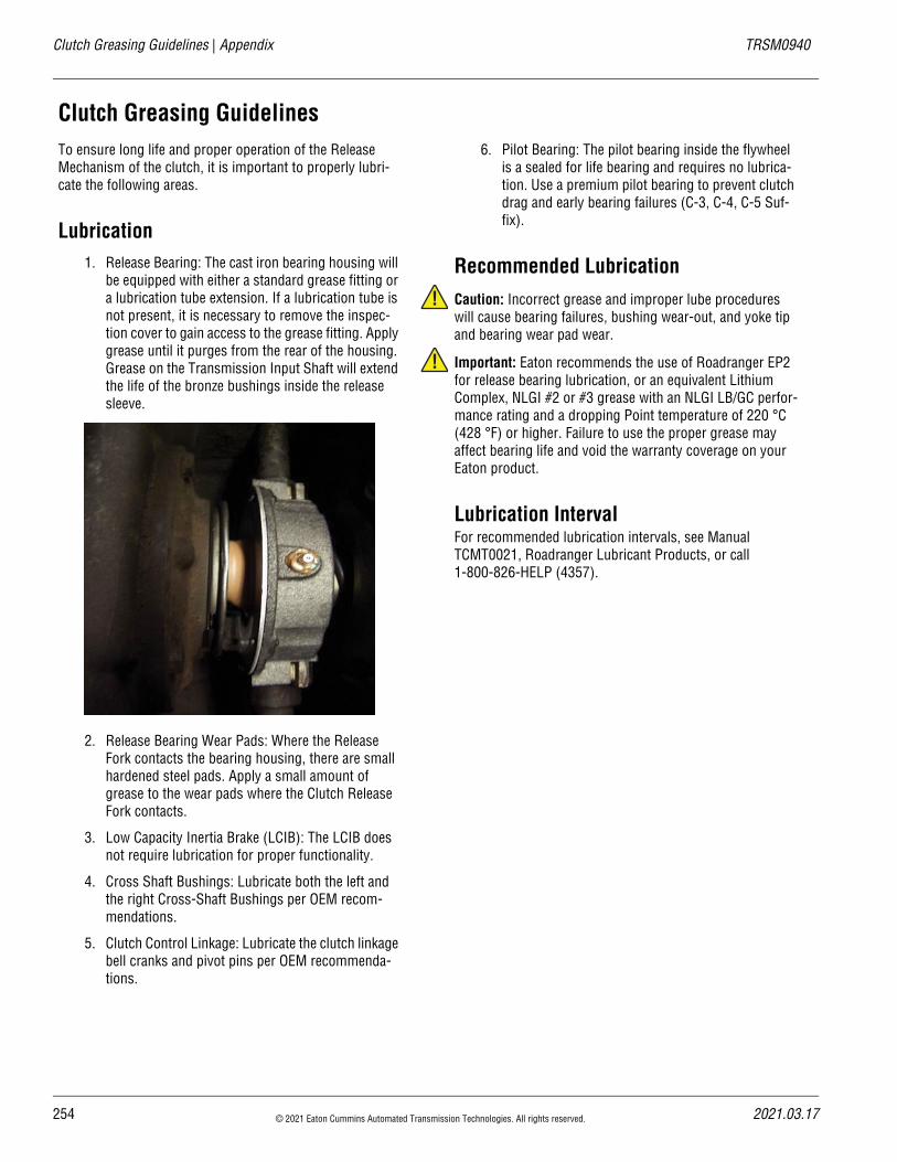
254 © 2021 Eaton Cummins Automated Transmission Technologies. All rights reserved. 2021.03.17
Clutch Greasing Guidelines | Appendix TRSM0940
Clutch Greasing GuidelinesTo ensure long life and proper operation of the Release Mechanism of the clutch, it is important to properly lubri-cate the following areas.
Lubrication1. Release Bearing: The cast iron bearing housing will
be equipped with either a standard grease fitting or a lubrication tube extension. If a lubrication tube is not present, it is necessary to remove the inspec-tion cover to gain access to the grease fitting. Apply grease until it purges from the rear of the housing. Grease on the Transmission Input Shaft will extend the life of the bronze bushings inside the release sleeve.
2. Release Bearing Wear Pads: Where the Release Fork contacts the bearing housing, there are small hardened steel pads. Apply a small amount of grease to the wear pads where the Clutch Release Fork contacts.
3. Low Capacity Inertia Brake (LCIB): The LCIB does not require lubrication for proper functionality.
4. Cross Shaft Bushings: Lubricate both the left and the right Cross-Shaft Bushings per OEM recom-mendations.
5. Clutch Control Linkage: Lubricate the clutch linkage bell cranks and pivot pins per OEM recommenda-tions.
6. Pilot Bearing: The pilot bearing inside the flywheel is a sealed for life bearing and requires no lubrica-tion. Use a premium pilot bearing to prevent clutch drag and early bearing failures (C-3, C-4, C-5 Suf-fix).
Recommended LubricationCaution: Incorrect grease and improper lube procedures will cause bearing failures, bushing wear-out, and yoke tip and bearing wear pad wear.
Important: Eaton recommends the use of Roadranger EP2 for release bearing lubrication, or an equivalent Lithium Complex, NLGI #2 or #3 grease with an NLGI LB/GC perfor-mance rating and a dropping Point temperature of 220 °C (428 °F) or higher. Failure to use the proper grease may affect bearing life and void the warranty coverage on your Eaton product.
Lubrication IntervalFor recommended lubrication intervals, see Manual TCMT0021, Roadranger Lubricant Products, or call 1-800-826-HELP (4357).
!
!
2021.03.17 © 2021 Eaton Cummins Automated Transmission Technologies. All rights reserved. 255
TRSM0940 Appendix | Grade Sensor Calibration
Grade Sensor CalibrationThe Transmission Electronic Control Unit (TECU) uses a Grade Sensor to calculate vehicle incline or grade. The grade position is used for the Hill Start Aid (HSA) feature and provides information to assist in vehicle launch and shifting. The Grade Sensor is internal to the TECU. Fault Code 68 FMI 13 indicates a Grade Sensor Calibration is required.
The Grade Sensor is calibrated via ServiceRanger or an Operator-Triggered Procedure.
Note: Verify the following prior to performing the Grade Sensor Calibration with ServiceRanger or the Operator Trig-gered Procedure:
1. Vehicle must be on level ground before initiating the grade sensor calibration.
2. Verify the suspension is fully aired.
3. Verify the suspension is set to proper height.
4. Ground surface must be within +/- 0.5% grade (0.28 degrees) from level.
5. Maximum allowable grade is +/- 0.5 degrees (0.87% grade) from level.
ServiceRanger Procedure1. Set vehicle parking brake and chock wheels.
Note: Verify vehicle is parked on level ground and the suspension is fully aired (if equipped) and set to proper ride height.
2. Key on with engine off.
3. Connect ServiceRanger.
4. Go To “Service Routines.”
5. Select "Start" Grade Sensor Calibration.
6. Follow on-screen prompts.
Operator-Triggered Procedure1. Set vehicle parking brake and chock wheels.
Note: Verify vehicle is parked on level ground and the suspension is fully aired (if equipped) and set to proper ride height.
2. Key on with engine off.
3. Select Low mode with the Transmission Driver Interface Device.
4. Select Upshift Requests until the Display indicates "6".
5. Depress and hold the Accelerator Pedal to the floor.
6. When the Display indicates a "Down Arrow", release the Accelerator Pedal.
7. When the Display indicates "0", select Neutral mode.
8. Key off and allow the TECU to perform a complete power down sequence.
Copyright Eaton Cummins Automated Transmission Technologies, 2021.Eaton Cummins Automated Transmission Technologies hereby grant their customers,vendors, or distributors permissionto freely copy, reproduce and/ordistribute this document in printedformat. It may be copied only inits entirety without any changes ormodifications. THIS INFORMATIONIS NOT INTENDED FOR SALE ORRESALE, AND THIS NOTICE MUSTREMAIN ON ALL COPIES.
Note: Features and specificationslisted in this document are subject tochange without notice and representthe maximum capabilities of thesoftware and products with all optionsinstalled. Although every attempt hasbeen made to ensure the accuracy ofinformation contained within, Eatonmakes no representation about thecompleteness, correctness or accuracyand assumes no responsibility forany errors or omissions. Features andfunctionality may vary depending onselected options.
For spec’ing or service assistance, call
1-800-826-HELP (4357) or visit
www.eaton.com/roadranger.
In Mexico, call 001-800-826-4357.
Roadranger: Eaton and trusted partners providing the best products and services in the industry, ensuring more time on the road.
Eaton Cummins Automated
Transmission Technologies
P.O. Box 4013Kalamazoo, MI 49003 USA800-826-HELP (4357)www.eaton.com/roadranger
Printed in USA


