Embed Size (px)
Citation preview

COOL-FIT ABS PlusCOOL-FIT PE Plus
Technical Information & Product Range 2017
GF Piping Systems

List of abbreviations
ANSI AmericanNationalStandard
ASTM AmericanSocietyforTestingand
Materials
BS BritishStandard
DIN DeutscheIndustrie-Normen
ISO InternationalStandardization
Organisation
ABS AcrylnitrilButadienStyrene
PVC-U PolyvinylChloride
PVC-C PolyvinylChloridechlorinated
PP Polypropylene,heatstabilised
PP-N Polypropylene,Random
copolymerunpigmented
PE Polyethylene
PVDF Polyvinylidenefluoride
EPDM EthylenePropyleneRubber
FPM FluorineRubber,e.g.Viton®
NBR NitrileRubber
IIR ButylRubber
CSM ChloreSulphonylPolythene,e.g.
Hypalon®
CR ChloropreneRubber,e.g.
Neoprene®
PROGEF GFofPP
PTFE Polytetrafluorethylene,e.g.Teflon®
UP-GF Unsaturatedpolyesterresin
glassfibrereinforced
St Steel
Ms Brass
Tg MalleableIron
d Pipeoutsidediameter
FM FusionMethod
DN Nominalbore
PN Nominalpressureat20°C,water
kg Weightinkilograms
g Weightingrams
SP Standardpack.Thefiguregiven
indicatesthequantityoffittings
containedinastandardpack
GP Grosspack.Thefiguregiven
indicatesthequantityoffittings
containedinagrosspack
G Pipethread,notpressuretight
inthethreadtoISO228/1
NPT Tapermalethreadpressuretightin
thethreadtoANSIB1.20.1
R Tapermalethread,pressuretight
inthethreadtoISO7/DIN2999/1
Rc Taperfemalethread,pressuretight
inthethreadtoISO7/1
Rp Parallelfemalethread,pressure
tightinthethreadtoISO7/DIN999/1
Tr Trapezoidthread
SC Sizeofhexagonbolts
s A/F
e Wallthickness
AL Numberofboltholes® Registeredtrade-mark

The best choicefor you
Georg Fischer focuses on three core businesses: GF Piping
Systems, GF Automotive and GF Machining Solutions. The
industrial corporation, founded in 1802, headquarters in
Switzerland and operates approximately 120 companies
with more than 14 500 employees in 32 countries. GF Piping
Systems is a leading supplier of plastic and metal piping
systems with global market presence. We offer correspond
ing pipes, fittings, valves, automation products and jointing
technology for the treatment of water and chemicals, as well
as for the safe distribution of liquids and gases.
Being a strong implementation partner, GF Piping Systems
supports its customers in every phase of the project. No
matter which processes and applications are planned in the
following market segments:• Automation• Building Technology• Chemical Process Industry• Energy• Food & Beverage / Cooling• Microelectronics• Marine• Water & Gas Utilities• Water Treatment
Our global presence ensures customer proximity worldwide.
Sales companies in 26 countries and representatives in an
other 80 countries provide customer service around the
clock. With 32 production sites in Europe, Asia and the USA
we are close to our customers and comply with local stan
dards. A modern logistics concept with local distribution
centers ensures highest product availability and short deliv
ery times. GF Piping Systems’ specialists are always close
by.
Our extensive product range represents a unique form of
product and competence bundling. With over 70 000 prod
ucts, allied with a broad range of services, we offer individu
al and comprehensive system solutions for a variety of in
dustrial applications. Having the profitability of the projects
of our customers in focus, we optimize processes and ap
plications that are integrated into the whole system. Continu
ally setting standards in the market, we directly provide our
customers with technological advantages. Due to our world
wide network customers benefit directly from our 50 years+
experience in plastics.
From start to finish, we support our customers as a compe
tent, reliable and experienced partner.
Georg Fischer
Corrosion and chemical resistant system solutions
Our market segments
Global presence
Complete solutions provider

IntroductionGF Piping Systems and your Refrigeration / Cooling application The origin of the artifi cial refrigeration process occurred not uncoincidentally at the same time as initial research into physics and thermodynamics. Linde, Carrier, Carre, Cullen and Harrison are prominent names in the history of refrigeration.
GF Piping Systems has been producing piping compo-nents since 1802, initially in malleable iron, nowadays with engineered system solutions for specifi c applica-tions. One example is the highpurity, top-grade plastic piping systems developed by GF Piping Systems for themanufacture of semi-conductors.
Refrigeration systems place high demands on the piping system, which has a direct impact on the reliability, effi ciency and life span of the plant.

GF Piping Systems in Cooling and Refrigeration PlantsIt is the expressed intention of GF Piping Systems to be part
of this world-wide initiative to optimise refrigeration and
cooling plants in terms of energy use and environmental im-
pact.
How effi ciently an entire refrigeration plant operates is de-
fi ned by the machinery’s COP (Coeffi cient of Performance),
the effi ciency of the secondary piping system and the heat-
transfer rate at the air cooler.
Thus, the secondary piping system plays a vital role in the
effi ciency of the plant as a whole.
COOL-FIT ABS Plus is a pre-insulated complete plastic pip-
ing system, designed specifi cally to optimise the effi ciency,
installation costs and life span of the secondary piping sys-
tem.
Secondary RefrigerationOne of the consequences of national and international regu-
lation to reduce and eliminate freons is an increase in the
use of so-called secondary refrigeration systems. Such sys-
tems reduce the amount of environmentally unfriendly pri-
mary charge (freon gas) in a plant by about 80 %.
Leaks in standard refrigeration systems can be as high as
35 % of the original charge per year. This is not only im-
mensely damaging to the environment, but also costs a great
deal to refi ll the systems.
Commonly used in larger industrial refrigeration installa-
tions where large charges of refrigerant gases can be a
health and safety issue, secondary refrigeration plants have
several advantages:
- higher safety
- lower refi ll costs
- higher temperature stability and control
- lower maintenance costs
- environmentally friendly
Secondary systems also allow removal of refrigerant gases
from the working or retail area into a separate machine
room. This means that natural refrigerant gases such as am-
monia or propane can be used to replace man-made
freons with no danger to the personnel or public. The result
is a 100 % sustainable plant with zero impact on the environ-
ment and with an improved effi ciency.
• no corrosion• zero maintenance• energy effi cient• reduced plant running costs• simple, reliable installation• dedicated system solutions• sustainable
Your benefi ts

The EnvironmentThe “Montreal Protocol” in 1987 set the fi rst internation-ally agreed timetable for the elimination of CFC gases. The Kyoto Protocol followed in 1997 with the intention of further accelerating the reduction of green-house gas emissions, including F-gases (fl uorinated refrigerant). The latest regulation in Europe is the EC Regulation No. 842 / 2006. The aim of which is to contain, prevent and thereby reduce emissions of fl uorinated greenhousegases, as outlined in the Kyoto Protocol.

4
Efficiency is the keyThe cold chain and environmental climate control are inte-
gral parts of modernday life. We simply expect fresh food
twelve months of the year and of course the fresher the bet-
ter. Climate control whether in hospitals or for medicines are
determining factors in the quality of our lives. The generation
of cold for a whole range of applications is part of day-to-day
life.
Refrigeration plants are major users of energy and play a
key role in environmental protection. In a supermarket, for
example, 70 % of the daily energy costs are attributed to the
cooling and refrigeration plant. Cold stores and food produc-
tion facilities with cooling performance energy requirements
of many megawatts are common. Any technology improve-
ments which improve the efficiency of refrigeration and
cooling plants have real ecological as well as economical
benefits.
COOL-FITSimplicity and efficiency were the driving forces behind one
of the most significant innovations introduced by +GF+ in re-
cent years: COOL-FIT, a plastic piping system for cooling and
refrigeration systems with a secondary cooling circuit.
• less energy in production• lower ozone depleting potential (ODP)• reduced energy consumption• far lower greenhouse gas emissions (TEWI)• lower global warming potential (GWP)
Ecological benefitsThe system‘s advantages in terms of energy consumption
and resource conservation as compared with traditional
metal piping extend to all aspects of its life cycle – from the
selection of materials and production to daily use in the
plant. For example, the elaborate melting and processing in-
volved in the production of copper releases significantly
more CO2 into the atmosphere than the production process
for ABS plastic. And we are talking about considerable mag-
nitudes. Take, for example, this sample calculation for a
500-metre- long piping system required for a Wal-Mart su-
permarket in the USA. The use of copper would have result-
ed in the release of 4 600 kilograms of CO2 at the material
production stage alone.
By using ABS, CO2 emissions are reduced to just 2 200 kilo-
grams. And what‘s more, the latter process produces fewer
toxic emissions than metal production.
COOL-FIT is used exclusively in “secondary refrigeration
systems”.
This type of installation allows the required volume of refrig-
erant to be reduced by 80 to 90 % compared to that used by
conventional systems. COOL-FIT therefore undercuts exist-
ing systems in terms of its TEWI (Total Equivalent Warming
Impact) value, which is based on energy and coolant require-
ments, by over 50 % – with welcome effects not just for the
environment, but also for reduced overall costs for the op-
erator.
0%
10%
20%
30%
40%
50%
60%
70%
80%
90%
100%
COOL-FITStainless Steel/PURCopper/PUR
Summer SmogAquatic toxicityHuman toxicityOzone layer depletion (ODP)
Global warming (GWP)
0%
10%
20%
30%40%
50%
60%
70%
80%
90%
100%
RefrigerantElectricity COOL-FITCopper 2Copper 1
0100020003000400050006000
0100020003000400050006000
0%
10%
20%
30%
40%
50%
60%
70%
80%
90%
100%
0%
10%
20%
30%
40%
50%
60%
70%
80%
90%
100%
Carbon Foot-Print (TEWI)
Environmental impacts
TEWI: Total Equivalent Warming ImpactODP: Ozone Depleting PotentialGWP: Global Warming Potential

Value added services
From planning support to implementation – our specialists are always close byAs a leading provider of piping systems in plastic and metal, we offer our customers not only reliable products, but also a large package of services. Our support ranges from a compre-hensive technical manual or the extensive CAD library to an international team of experts, who work closely together with local sales compa-nies. And when it comes to implementing a project, our customers additionally benefit from a wide range of training courses, either on site or in our modern training centres world-wide.
Generating a genuinely individual added value for our customers is our ultimate goal when implementing our tailor-made solutions. With our application knowledge and product exper-tise, we support our customers during the planning process, the sustainable realization of the projects and the provision of services. Our expertise in developing and producing piping systems, combined with our profound industry and market knowledge, based on longstanding experience, makes us a qualified and profes-sional partner for our customers.
Chemical resistanceOur specialist teams have decades of experience in the area
of chemical resistance. They can offer individual support and
advice in selecting the right material for the corresponding
system solution. On request, a team will examine and select
the appropriate material for special applications.
CAD libraryThe extensive CAD library is the most frequently used plan-
ning tool at GF Piping Systems. The database comprises over
30 000 drawings and technical data regarding pipes, fittings,
measurement and control technology as well as manual and
actuated valves. The big advantage of the CAD library is that
the data can be integrated directly in CAD models.
Technical supportTechnical support and material selection are key factors for
a successful installation. A team of specialists headquar-
tered in Switzerland is available to support the GF Piping
Systems sales companies around the world. For technical
advice or for general information, our customers are
supported individually by the specialist team in the corre-
sponding sales company.
Online and mobile calculation tools Our numerous, multilingual online calculation tools are very
useful for configuring and calculating. By means of pres-
sure / temperature diagrams, the pressure of liquid media
recommended for pipes and fittings at various temperatures
can be easily defined. FlowCalc App, the mobile application
of GF Piping Systems, is an on-site planning tool for pipe di-
ameter and flow velocity calculation to select the right di-
mension of piping systems when no expert is near by.
On-site trainingOur experts are available to support our customers locally
and conduct training in diverse fusion and jointing tech-
niques on location. The duration and structure of the training
depends on the project and the system being installed.
CustomizingThe customizing teams at GF Piping Systems work closely
together around the globe. The focus of these teams is to
manufacture custom parts for special systems. In addition, a
variety of special solutions can be produced in small series.
Standardized processes warrant the highest level of quality
for the individual solutions of our customers.

Your partner for customized special solutions
Training coursesGF Piping Systems off ers a wide range of training courses
that allow participants to gain confi dence in working with
our products and proven jointing technologies. The practical
training is clearly defi ned, structured and adapted to the
various levels of participants’ experience.
Technical manualFor our customers, we have documented the extensive
know-how of GF Piping Systems in planning and installing
plastic piping systems in our technical manual. This detailed
documentation is available in both printed and digital ver-
sion. The established reference book is helpful in planning
large and small projects.

10

11
Table of contents
Planning fundamentals 12
COOL-FIT ABS Plus 56
ABS metric - pipes, transition fittings, valves 76
COOL-FIT PE Plus 170
Index 186

12
System COOL-FIT Plus
1 General information ..................................................................................................................14
2 System specification .................................................................................................................15
2.1 COOL-FIT ABS Plus ...........................................................................................................15
2.2 COOL-FIT PE Plus .............................................................................................................16
3 Technical details of COOL-FIT ABS Plus .................................................................................18
3.1 COOL-FIT ABS Plus pipes .................................................................................................19
3.2 COOL-FIT ABS Plus fittings ................................................................................................19
3.3 COOL-FIT ABS Plus connecting elements..........................................................................20
3.4 COOL-FIT ABS Plus accessories .......................................................................................22
3.5 COOL-FIT ABS Plus tools ..................................................................................................24
4 Technical details of COOL-FIT PE Plus ...................................................................................25
4.1 COOL-FIT PE Plus pipes ....................................................................................................25
4.2 COOL-FIT PE Plus fittings ..................................................................................................25
4.3 COOL-FIT PE Plus connecting elements ............................................................................25
4.4 COOL-FIT PE Plus accessories ..........................................................................................26
4.5 COOL-FIT PE Plus tools .....................................................................................................26
5 COOL-FIT online calculation tool .............................................................................................27
6 Dimensioning, hydraulic calculation and installation .............................................................28
6.1 COOL-FIT ABS Plus pressure-temperature diagram ..........................................................28
6.2 COOL-FIT PE Plus pressure-temperature diagram .............................................................29
6.3 UV resistance and fire behavior ..........................................................................................31
6.4 Determining the change in length of COOL-FIT ABS Plus ..................................................33
6.5 Flexible sections for COOL-FIT ABS Plus ...........................................................................34
6.6 Determining the change in length of COOL-FIT PE Plus .....................................................36
6.7 Flexible sections for COOL-FIT PE Plus .............................................................................37
6.8 Pipe bracket spacing and support of pipelines ....................................................................38
6.9 COOL-FIT Plus fixed point ..................................................................................................39
6.10 COOL-FIT Plus underground installation ............................................................................40
7 Connection ................................................................................................................................41
7.1 Connection of COOL-FIT ABS Plus d25 to d225.................................................................41
7.2 Connection of COOL-FIT ABS Plus d250 to d315 ...............................................................47
7.3 Connection of COOL-FIT PE Plus ......................................................................................49
8 Internal pressure test ................................................................................................................53

13
9 Storage and handling ............................................................................................................... 54
9.1 Storage ..............................................................................................................................54
9.2 Handling of COOL-FIT ABS Plus nipple connections .........................................................54
9.3 Environment .......................................................................................................................54

14
System COOL-FIT Plus General information
1 General information
COOL-FIT Plus systems are completely pre-insulated plastic piping systems for secondary cooling circuits that are operated with water, sole, glycol solutions or slurry ice. Typical areas of application are industrial refrigeration systems with medium temperatures far below 0 °C and air-conditioning systems for media above 0 °C.
The COOL-FIT ABS Plus system is based on proven and cold-shock resistant ABS pipes and fittings for the media line, which is insulated by a high-quality PUR insulation, as well as a robust and UV-resistant outer jacket. The COOL-FIT PE Plus system consists of a tested PE media pipe and, similar to COOL-FIT ABS Plus, high-quality PUR insulation, as well as a robust and UV-resistant outer jacket. The smooth inner surface of the media piping system ensures very low pressure losses, the low thermal conductivity of the plastic and the insulation are a guarantee for low energy and operating costs during the service life of the pipe. Thanks to the 3-in-1 design, the installation times are very short.
The COOL-FIT Plus systems are used for the following applications, among other things:
Breweries, press houses
Fruit and vegetable processing, bakeries, fish and meat processing
Cold stores Process cooling water
System overview ABS COOL-FIT ABS Plus ecoFIT COOL-FIT PE
Piping system made of ABS plastic without additional external insulation
Piping system made of ABS plastic with rigid foam insulation and UV-resistant jacket
Piping system made of PE plastic without additional external insulation
Piping system made of PE plastic with rigid foam insulation and UV-resistant jacket
d20 – d315 mm d25 – d315 mm d16 – d1000 mm d250 – d415 mm
-50 °C to +60 °C -50 °C to +40 °C -50 °C to +60 °C -35 °C to +55 °C
Thermal conductivity ʎ = 0.17 W/mK
Thermal conductivity ʎ = ≤ 0.026
Thermal conductivity ʎ = 0.38 W/mK
Thermal conductivity ≤ 0.026 W/mK
For detailed information, see Planning Fundamentals, chapter 3, "System overview"
For detailed information, see the following chapters
For detailed information, see Planning Fundamentals, chapter 3, "System overview"
For detailed information, see the following chapters
Supplementary systems iFIT JRG Sanipex INSTAFLEX iKLIMA
Multi-layer composite pipes with snap-fit mechanical compression joints
Multi-layer composite pipes with mechanical, dead space-free compression joints
Piping system made of polybutene with electrofusion fittings
Floor heating and cooling system
Plus

15
System COOL-FIT Plus System specification
2 System specification
2.1 COOL-FIT ABS Plus
Specification
Material1) Media pipe ABS (acrylonitrile-butadiene-styrene)
Insulation PUR (polyurethane), closed-cell
Foamed with CO2 or cyclopentane
Outer jacket Pipe PE100 (polyethylene)
Fitting PUR (polyurethane) or PE100
Dimension d25 – d315 mm (metric)
Jointing technology Solvent cementing, patented inside nipple
Nominal pressure2) d25 – d225 mm 10 bar, SDR 17.6
d250 – d315 mm 6 bar, SDR 26
Insulation λ20 °C ≤ 0.026 W/mK
Density ≥ 55 kg/m³
Foam cell size Max. 0.5 mm
Thermal expansion coefficient α3)
Interior application 0.06 mm/mK
Exterior application 0.09 mm/mK
Temperature Medium -50 °C to +40 °C
Mechanical tensile strength
Axial shear strength2) ≥ 0.12 N/mm²
Tensile strength ≥ 0.2 N/mm²
Compressive strength ≥ 0.3 N/mm²
Color Outer jacket RAL 9004 (black)
Weight See chapter 3 "Technical details of COOL-FIT ABS Plus", page 7.
Oxygen diffusion < 0.1 g/m3 day
Environment Resistance • Weather-resistant • UV-resistant • Water- and vapor-tight
Global warming potential GWP
≤ 0.01
Ozone depletion potential ODP
0

16
System COOL-FIT Plus System specification
Specification
Standards and guidelines
EN ISO 15493 Plastics piping systems for industrial applications – ABS, UPVC and CPVC – Metric series for specifications for components and the piping system
ISO 727 Fittings made from UPVC, CPVC or ABS with plain sockets for pipes under pressure
ISO 7 Pipe threads
EN ISO 16135 EN ISO 16136 EN ISO 16137 EN ISO 16138
Industrial valves – Ball valves of thermoplastics materials Industrial valves – Butterfly valves of thermoplastics materials Industrial valves – Check valves of thermoplastics materials Industrial valves – Diaphragm valves of thermoplastics materials
EN ISO 16871 Plastics piping and ducting systems – Plastic pipes and fittings – Method for exposure to direct (natural) weathering
1) All three materials are firmly connected with each other 2) At 20 °C, medium: water 3) The values listed are guide values. The expansion coefficient depends on the temperature change of the medium and the environment and must be calculated based on the application.
2.2 COOL-FIT PE Plus
Specification
Material1) Media pipe PE-HD100 (polyethylene)
Insulation PUR (polyurethane), closed-cell
Foamed CO2 or cyclopentane
Outer jacket PE-HD 100 (polyethylene) (pipe and fitting)
Dimension d250 – d415 (metric)
Jointing technology Electrofusion (GF ELGEF)
Nominal pressure2) 10 bar, SDR 17.6
Insulation λ20 °C ≤ 0.026 W/mK
Density ≥ 55 kg/m³
Foam cell size Max. 0.5 mm
Temperature Medium -35 °C to +55 °C
Thermal expansion coefficient α3)
Interior application 0.14 mm/mK
Exterior application 0.18 mm/mK
Mechanical tensile strength
Axial shear strength2) ≥ 0.12 N/mm²
Tensile strength ≥ 0.2 N/mm²
Compressive strength ≥ 0.3 N/mm²
Color Outer jacket RAL 9004 (black)

17
System COOL-FIT Plus System specification
Specification
Weight See chapter 4 "Technical details of COOL-FIT PE Plus", page 14.
Oxygen diffusion < 0.1 g/m3 day
Environment Resistance • Weather-resistant • UV-resistant • Water- and vapor-tight
Global warming potential GWP
</= 0.01
Ozone depletion potential ODP
0
Standards EN ISO 15494 Plastics piping systems for industrial applications – PB, PE and PP – Metric series for specifications for components and the piping system
ISO 727 Fittings made from UPVC, CPVC or ABS with plain sockets for pipes under pressure
EN ISO 16136 EN ISO 16137
Industrial valves – Butterfly valves of thermoplastics materials Industrial valves – Check valves of thermoplastics materials
EN ISO 16871 Plastics piping and ducting systems – Plastic pipes and fittings – Method for exposure to direct (natural) weathering
1) All three materials are firmly connected with each other. 2) At 20 °C, medium: water 3) The values listed are guide values. The expansion coefficient depends on the temperature change of the medium and the environment and must be calculated based on the application.

18
System COOL-FIT Plus Technical details of COOL-FIT ABS Plus
3 Technical details of COOL-FIT ABS Plus
No. Name
1 COOL-FIT ABS Plus fitting pre-insulated
2 COOL-FIT ABS Plus double nipple d-d +10
3 COOL-FIT ABS Plus adaptor nipple d-di
4 COOL-FIT ABS Plus pipe pre-insulated
5 Pipe clamp
6 COOL-FIT ABS Plus double nipple di-di
7 COOL-FIT ABS pipe
8 PE end cap
9 Adapter union
10 COOL-FIT ABS valve
11 Flange connection
No. Name
1 Shrink tape

19
System COOL-FIT Plus Technical details of COOL-FIT ABS Plus
3.1 COOL-FIT ABS Plus pipes
COOL-FIT ABS Plus pipes are made of ABS raw material. The insulation made of PUR foam provides excellent insulation properties, protected by a UV and weather-resistant PE outer jacket.
All three materials are firmly connected with each other to ensure good insulation properties and a uniform coefficient of thermal expansion for the system.
d Nominal outside diameter ABS media pipe di Nominal inner diameter media pipe D Nominal outside diameter PE outer jacket e, e1 Nominal wall thickness 1) The dimensions d250 – d315 are designed as socket-spigot (with one open end) or as spigot-spigot version (with two open ends):
3.2 COOL-FIT ABS Plus fittings
The ABS fittings used in COOL-FIT ABS Plus are made of the same raw material as the pipes. The insulation made of PUR foam is protected by a PUR or PE outer jacket. This makes the fittings fully compatible with COOL-FIT ABS Plus pipes.
Media pipe ABS d x e (mm)
Media pipe ABS di (mm)
Outer jacket PE D x e1 (mm)
Open pipe ends (mm)
Weight (ABS, PUR, PE) (kg/m)
Volume (l/m)
Length (m)
Thermal conductivity coefficient (U) (W/m K)
25 x 2.3 20.4 90 x 3.0 - 1.3 0.36 5 0.13
32 x 1.9 28.2 90 x 3.0 - 1.5 0.61 5 0.16
40 x 2.4 35.2 110 x 3.0 - 1.9 0.95 5 0.17
50 x 3.0 44.0 110 x 3.0 - 2.1 1.49 5 0.21
63 x 3.8 55.4 125 x 3.0 - 2.7 2.34 5 0.25
75 x 4.5 66.0 140 x 3.0 - 3.5 3.36 5 0.27
90 x 5.4 79.2 160 x 3.0 - 4.4 4.80 5 0.29
110 x 6.6 96.8 180 x 3.0 - 5.5 7.21 5 0.34
140 x 8.3 123.4 225 x 3.4 - 8.5 11.69 5 0.35
160 x 9.5 141.0 250 x 3.6 - 10.5 15.22 5 0.37
200 x 12.3 175.4 280 x 3.9 - 13.5 24.50 5 0.50
225 x 13.9 197.2 315 x 4.1 - 18.5 30.05 5 0.50
250 x 9.6 230.8 355 x 5.6 1501) 14.9 41.84 5 0.49
280 x 10.7 258.6 400 x 4.8 1651) 18.7 52.50 5 0.48
315 x 12.1 290.8 450 x 5.2 1851) 23.7 66.42 5 0.48

20
System COOL-FIT Plus Technical details of COOL-FIT ABS Plus
3.3 COOL-FIT ABS Plus connecting elements 3.3.1 COOL-FIT ABS Plus nipple COOL-FIT ABS Plus components are connected with COOL-FIT ABS Plus nipples.
The following connecting nipples are available:
Each of these COOL-FIT ABS Plus connections creates a gap of 10 mm. The gap is used for visual inspection during the pressure test and is closed after a successful pressure test.
Connecting nipple
di-di
• For pipe-to-pipe connections • For pipe-to-installation fitting connections • For some pipe-T90° reduced connections
1 COOL-FIT ABS Plus pipe
2 COOL-FIT ABS Plus double nipple di-di
d-di
• For standard pipe-to-fitting connections 1 COOL-FIT ABS Plus pipe
2 COOL-FIT ABS Plus adaptor nipple d-di
3 COOL-FIT ABS Plus fitting
d-d
• For fitting-to-fitting connections
1 COOL-FIT ABS Plus fitting
2 COOL-FIT ABS Plus nipple d-d

21
System COOL-FIT Plus Technical details of COOL-FIT ABS Plus
The connecting material and the method are identical for every version of the connection. The same cement and the same tools are used for application.
3.3.2 Reducing a COOL-FIT ABS Plus fitting to a COOL-FIT ABS Plus pipe The d-type fittings feature standard ABS-d cement jointing. For this reason, the ABS short reduction can also be used for a reduction in diameter. For the next connection, the COOL-FIT ABS Plus nipple d-di for COOL-FIT ABS Plus pipes can be used.
No. Name
1 COOL-FIT ABS Plus T 90° equal, d75
2 ABS short reduction d75 – d50
3 COOL-FIT ABS Plus nipple d-di, d50 – di50
4 COOL FIT ABS Plus pipe DN110/d50
Connecting nipple
di –dred
For reducing the diameter of the media pipe. Using di-dred in combination with di-di results in an inspection gap with a width of 20 mm. The combination requires twice as much insulating profile.
1 COOL-FIT ABS Plus nipple di-dred
2 COOL-FIT ABS Plus pipe
3 ABS short reduction
4 COOL-FIT ABS Plus nipple d-di
5 COOL-FIT ABS Plus pipe

22
System COOL-FIT Plus Technical details of COOL-FIT ABS Plus
3.4 COOL-FIT ABS Plus accessories
COOL-FIT Plus insulating profile Insulating profile with a width of 13 mm and a thermal conductivity of 0.04 W/mK is used for insulating the inspection gap. The use of this insulation guarantees almost identical insulating properties for the gap as for the pipe.
COOL-FIT Plus sealing tape A roll of 40 mm wide butylene rubber-based sealing tape. For water- and vapor-tight sealing of inspection gaps in combination with shrink sleeves or shrink sockets. The sealing tape is affixed to the circumference of the pipe or fitting.
COOL-FIT Plus shrink sleeve, short Used to water and vapor seal the inspection gap in the outer jacket between pipe and pipe, pipe and fitting, and fitting and fitting connections. The standard design is 100 mm wide and is used to seal components with equal outside diameter. To ensure proper functionality of the system, the shrink sleeve must be used in conjunction with the insulating profile and the butylene-rubber sealing tape. The shrink sleeve is shrunk with an open soft flame or alternatively with a powerful hot-air gun. For a long-lasting high-quality seal, GF Piping Systems recommends the use of shrink sleeves.
COOL-FIT Plus shrink socket Used to water and vapor seal the inspection gap in the outer jacket. The design is 100 mm wide and can only seal components with equal outside diameter. To ensure proper functionality of the system, the shrink socket must be used in conjunction with the insulating profile and the butylene-rubber sealing tape. This version provides additional mechanical strength with regard to bending forces. It shrinks uniformly, resulting in a good visual appearance. This socket can be shrunk with an open, soft flame. For a long-lasting high-quality seal combined with high mechanical strength and good appearance, GF Piping Systems recommends the use of shrink sockets.
COOL-FIT Plus cold shrink tape Used to water and vapor seal the inspection gap in the outer jacket. Cold shrink tape is suitable only for interior applications. The cold shrink tape is applied without using heat. It is applied manually with slight pull and approx. 10 cm overlap. The design is 100 mm wide and can only seal components with equal outside diameter. To ensure proper functionality of the system cold shrink tape must be used in conjunction with the insulating profile.
COOL-FIT Plus shrink tape for underground applications This tape is specifically designed for underground applications. The integrated full-surface butylene rubber guarantees a water- and vapor-tight seal of the outer jacket at the inspection gaps.

23
System COOL-FIT Plus Technical details of COOL-FIT ABS Plus
COOL-FIT Plus shrink sleeve, long This sleeve is 200 mm long and can be used only to seal PE and PUR outer jackets at connections with different diameters. It may not be applied to non-insulated ABS pipes. The shrink sleeve is positioned in the center. Functionality is ensured only in combination with the insulating profile and the sealing tape. The sealing tape must be applied to both outer PE jackets. The delivery program shows the differences in dimensions that can be sealed.
COOL-FIT Plus shrink cap The shrink cap is to be used only to seal PE and PUR outer jackets at connections with different diameters. It may not be applied to non-insulated ABS pipes. The flame used to shrink the sleeve may damage the non-insulated ABS pipe. Ideal for use with T90° reducers. No separate sealing tape is required, the sealant is integrated into the cap. If the length of the cap is longer than the surface to be sealed, then the cap can be cut back up to the edge of the sealant. The delivery program shows the differences in dimensions that can be sealed.
End cap End caps are used to cap the pre-insulated system. They seal the PUR insulation and prevent moisture from entering.
Sealing PUR is achieved by using a suitable sealant.
No. Name
1 COOL-FIT ABS Plus nipple
2 Sealant
3 PE end cap
4 COOL-FIT ABS Plus pipe
Sealant The silicone-free sealant is used at the end of the pre-insulated system to seal the PUR insulation. It is used to cement the end caps.
Ball valve insulation GF Piping System offers customized insulation sets for ball valves type 546. The sets consist of UV-resistant PE foam with a shrink tape jacket and are available from d25 up to d110.

24
System COOL-FIT Plus Technical details of COOL-FIT ABS Plus
3.5 COOL-FIT ABS Plus tools
COOL-FIT ABS PLUS calibration tool It is necessary to calibrate the inside diameters of pipes with dimension d200 and d225. This tool calibrates the inside diameter of the pipe to an exact dimension to allow nipple cementing at the inside diameter. For further details, see chapter 7.1 "Connection of COOL-FIT ABS Plus d25 to d225", page 30.
Rotary peeler For COOL-FIT ABS Plus dimensions d250 to d315, a peeling tool must be used to completely remove residual insulation. For further details, see chapter 7.2 "Connection of COOL-FIT ABS Plus d250 to d315", page 36.
Tool for cemented joints The cementing material for cementing is identical with the tool for standard socket cementing.
For further details about the tool for cemented joints, see chapter 7.1.2 "Required tools and equipment", page 30.

25
System COOL-FIT Plus Technical details of COOL-FIT PE Plus
4 Technical details of COOL-FIT PE Plus
4.1 COOL-FIT PE Plus pipes
COOL-FIT PE Plus pipes are made of PE raw material. The insulation made of PUR foam provides excellent insulation properties, protecting pipes with a UV and weather-resistant PE outer jacket.
All three materials are firmly connected with each other to ensure good insulation properties and a uniform coefficient of thermal expansion for the system.
Media pipe PE d x e (mm)
Media pipe di (mm)
Outer jacket PE D x e1 (mm)
Open pipe ends (mm)
Weight PE/PUR/PE (kg/m)
Volume (l/m)
Standard length (m)
Thermal conductivity coefficient (u) (W/mK)
250 x 14.8 220.4 355 x 5.1 123 18.18 38.13 5.9 0.49
280 x 16.6 246.8 400 x 6.3 126 22.63 47.81 5.9 0.48
315 x 18.7 277.6 450 x 6.4 133 28.41 60.49 5.9 0.48
355 x 21.1 312.8 500 x 7.4 145 35.36 76.81 5.9 0.49
400 x 23.7 352.6 560 x 8.4 147 44.06 97.60 5.9 0.50
450 x 26.7 396.6 630 x 7.6 163 55.50 123.47 5.9 0.50
d Nominal outside diameter PE media pipe di Nominal inner diameter media pipe D Nominal outside diameter PE outer jacket e, e1 Nominal wall thickness
4.2 COOL-FIT PE Plus fittings
COOL-FIT PE Plus fittings are fully compatible with COOL-FIT PE Plus pipes. This applies to insulation properties and open spigots, as well as to jointing technology.
4.3 COOL-FIT PE Plus connecting elements COOL-FIT PE Plus pipes and fittings are delivered with a non-insulated spigot at each end. These open ends are used for connecting the individual products with a COOL-FIT PE Plus electrofusion socket.
COOL-FIT PE Plus electrofusion socket COOL-FIT PE Plus electrofusion sockets connect the pre-insulated products with each other. The electrofusion sockets are equipped with internal resistance wires to which electric current is applied during the fusion process. This process heats the inside of the fitting and the outside of the pipe to fusion temperature and melts it.

26
System COOL-FIT Plus Technical details of COOL-FIT PE Plus
4.4 COOL-FIT PE Plus accessories
COOL-FIT Plus sealing tape A roll of 40 mm wide butylene rubber-based sealing tape. For a water- and vapor-tight connection of inspection gaps with shrink sockets. The sealing tape is affixed to the circumference of the pipe or fitting.
COOL-FIT Plus shrink socket The shrink socket is used to water and vapor seal the inspection gap on the outer jacket and can seal only components with the same outside diameter. Functionality is ensured only in combination with the butylene-rubber sealing tape. This version provides additional mechanical strength with regard to bending forces. The socket shrinks uniformly, resulting in a good visual appearance. It can be shrunk with an open, soft flame.
COOL-FIT Plus shrink cap The shrink cap is to be used only to seal PE outer jackets at connections with different diameters. It may not be applied to non-insulated PE pipes. Ideal for use with T90° reducers. No separate sealing tape is required, the sealant is integrated into the cap. If the length of the cap is longer than the surface to be sealed, the cap can be cut back up to the edge of the sealant. The delivery program shows the differences in dimensions that can be sealed.
End cap End caps are used to cap the pre-insulated system. They seal the PUR insulation and prevent moisture from entering. Sealing PUR is achieved by using a suitable sealant.
Sealant The silicone-free sealant is used at the end of the pre-insulated system to seal the PUR insulation. It is used to cement the end caps.
4.5 COOL-FIT PE Plus tools
Electrofusion machines Electrofusion machines are required for connecting the COOL-FIT PE Plus components. The assortment includes monovalent and polyvalent fusion machines that are reliable and easy to operate.
Fusion adaptor Fusion adaptors serve as an extension of the fusion plugs of electrofusion machines. Compared to standard adaptors, the longer adaptor length matches the insulation of the COOL-FIT PE Plus electrofusion sockets.
Rotary peelers Rotary peelers are used to prepare the COOL-FIT PE Plus pipes for electrofusion. The chip-removing process in the fusion zone removes the existing oxide layer.
Peeler Dimension Code No.
RTC 315 d250 – d315 mm 799.150.423
RTC 710 d355 – d450 mm 799.300.757

27
System COOL-FIT Plus COOL-FIT online calculation tool
5 COOL-FIT online calculation tool
The cooling calculation tool by GF Piping Systems provides support for the dimensioning and sizing of cooling systems.
The online tool includes the following calculation functions: • Expansion, contraction • Flexible section design • Energy savings • Pipe exterior temperature • Pipe dimensioning • Pressure loss • Condensation point/insulation thickness • Pipe bracket spacing
The most common coolants are already stored in the calculation tool. It calculates all system components, such as pipes, fittings and valves. Its menu-based navigation is available in nine languages and allows for efficient and optimized dimensioning of a system.
The "Comparison" function allows for comparing a COOL-FIT system to a steel, stainless steel or copper system.
The online calculation tool for the support of dimensioning and calculation is available at www.gfps.com/tools

28
System COOL-FIT Plus Dimensioning, hydraulic calculation and installation
6 Dimensioning, hydraulic calculation and installation
The following section describes only the COOL-FIT-specific planning fundamentals. For generally applicable information and details, see Planning Fundamentals, chapter 9, "Design of metric piping systems".
6.1 COOL-FIT ABS Plus pressure-temperature diagram Pressure ratings for thermoplastic pipes are always quoted for water at +20 °C. Ensure that the working pressure is reduced at higher temperatures. The diagram shows the maximum permissible pressures at various temperatures up to the maximum allowable working temperature of +40 °C for COOL-FIT ABS Plus pipes and fittings. A safety factor of 1.8 has been included in all calculations with a minimum service life of 25 years.
6.1.1 Pressure/temperature limits for COOL-FIT ABS Plus pipes and fittings Medium: Water
P Permissible pressure (bar, psi) T Temperature (°C, °F)
6.1.2 Chemical resistance COOL-FIT ABS Plus is resistant to most diluted inorganic acids, bases and salts, and to most animal oils and fats. It is not resistant to organic solvents, pure alcohol, gasoline, acetic acid and vegetable oils. In addition, COOL-FIT ABS Plus is not suitable for primary refrigerants, such as ammonia, propane, R407 or R22.
For working temperatures below 0 °C, antifreeze has to be added to the water to prevent it from freezing. For some refrigerants, a reduction factor is required depending on the type and mixing ratio. By contrast to the pressure-temperature curve that applies only when the medium is water, the permissible operating pressure must be lowered.
Reduction factors Inorganic salt solutions F = 1 Organic salt solutions F = 1.25 Glycol solutions (max. 50 %) F = 1.7
The following formula is used for the calculation:
𝐏𝐃𝐅 =𝐏𝐰
𝐃𝐅
PDF Permissible pressure with reduction factor PW Permissible pressure for water as medium DF Reduction factor

29
System COOL-FIT Plus Dimensioning, hydraulic calculation and installation
6.1.3 Ice slurry Ice slurry is a mixture of ice particles, water and an antifreeze agent – usually alcohol, salt or glycol. GF Piping Systems has extensively tested ice slurry with COOL-FIT and can provide recommendations for pipeline layout and loss of pressure.
6.1.4 Glycol solutions COOL-FIT ABS Plus can be used with glycol solutions up to a maximum concentration of 50 %. The following antifreeze agents can be used with the COOL-FIT ABS Plus system in terms of chemical resistance: ANTIFROGEN L, N, TYFOCOR, DOWFROST.
Example – Glycol dissolved in water If the medium is a water-diluted glycol ≤ 50 %, the reduction factor for the pressure-temperature diagram = 1.7. Hence, at -10 °C and a minimum service life of 25 years, the permissible operating pressure is reduced as follows:
𝐏𝐃𝐅 =𝟏𝟏. 𝟖 𝐛𝐚𝐫
𝟏. 𝟕= 𝟔. 𝟗𝟒 𝐛𝐚𝐫
6.1.5 Pressure/temperature limits for COOL-FIT ABS Plus pipes and fittings Medium: Water-glycol mixture, 50 %
P Permissible pressure (bar, psi) T Temperature (°C, °F)
6.1.6 Organic salt solutions These media are usually potassium formate or potassium acetate: water-based solutions with low viscosities at low temperatures. Trade name examples: HYCOOL, TEMPER, TYFOXIT, ANTIFROGEN KF, FREEZIUM, ZITREC. ABS can be used with these types of media. The manufacturer’s instructions for the medium must be followed.
For more detailed information about resistance and reduction factors, see Planning Fundamentals, chapter 8, "Material selection – Chemical resistance".
6.2 COOL-FIT PE Plus pressure-temperature diagram Pressure ratings for thermoplastic pipes are always quoted for water at +20 °C. Ensure that the working pressure is reduced at higher temperatures.
The diagram shows the maximum permissible pressures at various temperatures up to the maximum allowable working temperature of +55 °C for COOL-FIT PE Plus pipes and fittings. The table is based on an ambient temperature of 20 °C. A safety factor of 1.4 has been included in all calculations with a minimum service life of 25 years.

30
System COOL-FIT Plus Dimensioning, hydraulic calculation and installation
6.2.1 Pressure-temperature limits for COOL-FIT PE Plus pipes and fittings Medium: Water
P Permissible pressure (bar, psi) T Temperature (°C, °F)
6.2.2 Chemical resistance with refrigerants For working temperatures below 0 °C, antifreeze has to be added to the water to prevent it from freezing.
For some refrigerants, a reduction factor is required depending on the type and mixing ratio. By contrast to the pressure-temperature curve that applies only when the medium is water, the permissible operating pressure must be lowered.
Reduction factors Inorganic salt solutions F = 1 Organic salt solutions F = 1 Glycol solutions (max. 50 %) F = 1.1
The following formula is used for the calculation:
𝐏𝐃𝐅 =𝐏𝐰
𝐃𝐅
PDF Permissible pressure with reduction factor PW Permissible pressure for water as medium DF Reduction factor
6.2.3 Ice slurry Ice slurry is a mixture of ice particles, water and an antifreeze agent – usually alcohol, salt or glycol.
6.2.4 Glycol solutions COOL-FIT PE Plus can be used with glycol solutions up to a maximum concentration of 50 %. The following antifreeze agents can be used with the COOL-FIT PE Plus system in terms of chemical resistance: ANTIFROGEN L, N, TYFOCOR, DOWFROST.
Example – Glycol dissolved in water If the medium is a water-diluted glycol ≤ 50 %, the reduction factor for the pressure-temperature diagram = 1.1. Hence, at -10 °C and a minimum service life of 25 years, the permissible operating pressure is reduced as follows:
𝐏𝐃𝐅 =𝟏𝟎 𝐛𝐚𝐫
𝟏. 𝟏= 𝟗 𝐛𝐚𝐫

31
System COOL-FIT Plus Dimensioning, hydraulic calculation and installation
6.2.5 Pressure-temperature limits for COOL-FIT PE Plus pipes and fittings Medium: water-glycol mixture, 50 %
P Permissible pressure (bar, psi) T Temperature (°C, °F)
6.2.6 Organic salt solutions These media are usually potassium formate or potassium acetate: water-based solutions with low viscosities at low temperatures. Trade name examples: HYCOOL, TEMPER, TYFOXIT, ANTIFROGEN KF, FREEZIUM, ZITREC. ABS can be used with these types of media. The manufacturer’s instructions for the medium must be followed.
For more detailed information about resistance and reduction factors, see Planning Fundamentals, chapter 8, "Material selection – Chemical resistance".
6.3 UV resistance and fire behavior 6.3.1 UV resistance The PE used by GF Piping Systems for the outer jacket of COOL-FIT ABS Plus and COOL-FIT PE Plus is UV resistant and, for this reason, safe for exterior installations.
6.3.2 ABS fire behavior According to UL94, ABS has an HB (Horizontal Burning) flammability coefficient for building material class B2 (normally inflammable, non-dripping) according to DIN 4102-1. When ABS burns, carbon dioxide, carbon monoxide and water are primarily formed. Tests have shown that the relative toxicity of the products to be burned is similar or even lower than that of natural products, such as wood, wool and cotton. ABS combustion gases are not corrosive. Soot and smoke develop during burning. Suitable firefighting agents are water, foam and carbon dioxide.
32
System COOL-FIT Plus Dimensioning, hydraulic calculation and installation
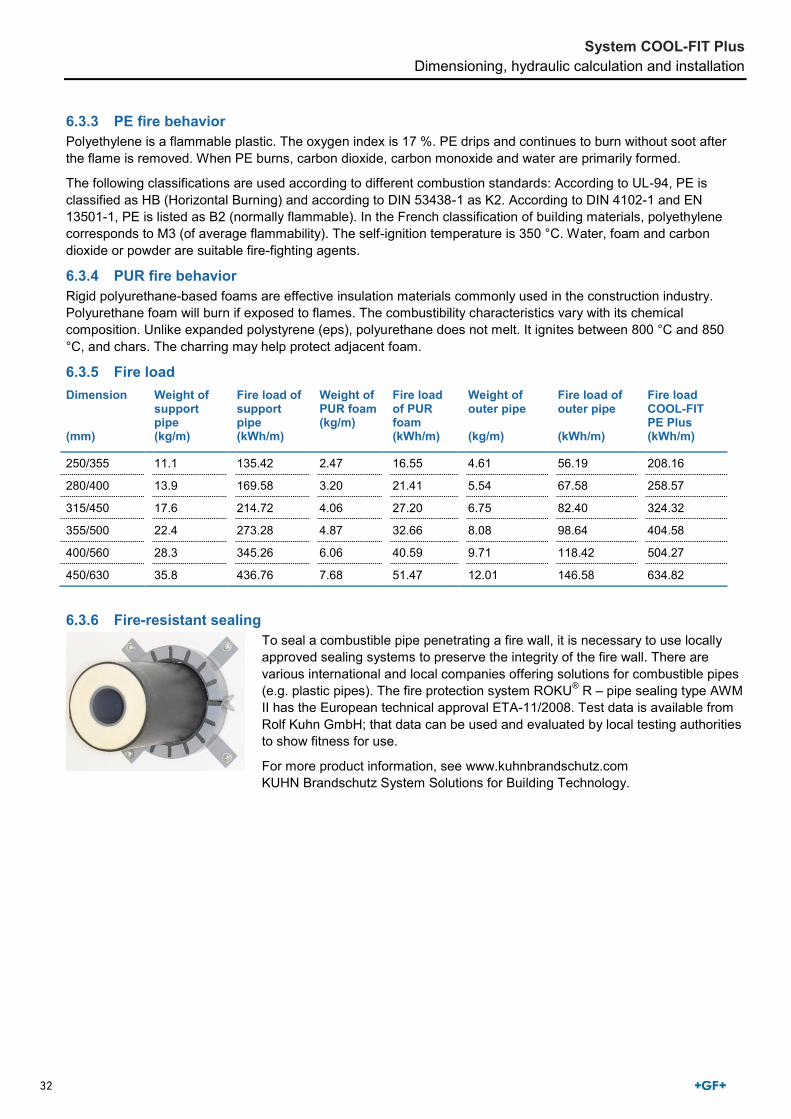
6.3.3 PE fire behavior Polyethylene is a flammable plastic. The oxygen index is 17 %. PE drips and continues to burn without soot after the flame is removed. When PE burns, carbon dioxide, carbon monoxide and water are primarily formed.
The following classifications are used according to different combustion standards: According to UL-94, PE is classified as HB (Horizontal Burning) and according to DIN 53438-1 as K2. According to DIN 4102-1 and EN 13501-1, PE is listed as B2 (normally flammable). In the French classification of building materials, polyethylene corresponds to M3 (of average flammability). The self-ignition temperature is 350 °C. Water, foam and carbon dioxide or powder are suitable fire-fighting agents.
6.3.4 PUR fire behavior Rigid polyurethane-based foams are effective insulation materials commonly used in the construction industry. Polyurethane foam will burn if exposed to flames. The combustibility characteristics vary with its chemical composition. Unlike expanded polystyrene (eps), polyurethane does not melt. It ignites between 800 °C and 850 °C, and chars. The charring may help protect adjacent foam.
6.3.5 Fire load Dimension (mm)
Weight of support pipe (kg/m)
Fire load of support pipe (kWh/m)
Weight of PUR foam (kg/m)
Fire load of PUR foam (kWh/m)
Weight of outer pipe (kg/m)
Fire load of outer pipe (kWh/m)
Fire load COOL-FIT PE Plus (kWh/m)
250/355 11.1 135.42 2.47 16.55 4.61 56.19 208.16
280/400 13.9 169.58 3.20 21.41 5.54 67.58 258.57
315/450 17.6 214.72 4.06 27.20 6.75 82.40 324.32
355/500 22.4 273.28 4.87 32.66 8.08 98.64 404.58
400/560 28.3 345.26 6.06 40.59 9.71 118.42 504.27
450/630 35.8 436.76 7.68 51.47 12.01 146.58 634.82
6.3.6 Fire-resistant sealing
To seal a combustible pipe penetrating a fire wall, it is necessary to use locally approved sealing systems to preserve the integrity of the fire wall. There are various international and local companies offering solutions for combustible pipes (e.g. plastic pipes). The fire protection system ROKU® R – pipe sealing type AWM II has the European technical approval ETA-11/2008. Test data is available from Rolf Kuhn GmbH; that data can be used and evaluated by local testing authorities to show fitness for use.
For more product information, see www.kuhnbrandschutz.com KUHN Brandschutz System Solutions for Building Technology.

33
System COOL-FIT Plus Dimensioning, hydraulic calculation and installation
6.4 Determining the change in length of COOL-FIT ABS Plus The change in length caused by temperature can be calculated using the following formula:
∆𝐋 = 𝐋 𝛂 ∆𝐓
∆L Temperature-related change in length (mm) L Length of the pipe section (m) α Linear coefficient of thermal expansion (mm/mK) ΔT Difference in temperature (K)
The following temperatures must be known to calculate the change in length ΔL of the COOL-FIT ABS Plus pipe: • Installation temperature • Minimum medium temperature • Maximum medium temperature • Minimum ambient temperature • Maximum ambient temperature
For general information about changes in length and flexible sections, see Planning Fundamentals, chapter 11, "Installation".
The following tables contain guide values. The online tool at www.cool-fit.georgfischer.com can be used to determine the exact change in length.
Change in length ΔL for exterior applications α = 0.09 mm/mK L = 25 m L = 50 m L = 100 m L = 150 m L = 200 m
ΔT (K) ΔL (mm) ΔL (mm) ΔL (mm) ΔL (mm) ΔL (mm)
5 11 23 45 68 90
10 23 45 90 135 180
15 34 68 135 203 270
20 45 90 180 270 360
25 56 113 225 338 450
30 68 135 270 405 540
35 79 158 315 473 630
40 90 180 360 540 720
45 101 203 405 608 810
50 113 225 450 675 900

34
System COOL-FIT Plus Dimensioning, hydraulic calculation and installation
ΔL Change in length for interior applications α = 0.06 mm/mK L = 25 m L = 50 m L = 100 m L = 150 m L = 200 m
ΔT (K) ΔL (mm) ΔL (mm) ΔL (mm) ΔL (mm) ΔL (mm)
5 8 15 30 45 60
10 15 30 60 90 120
15 23 45 90 135 180
20 30 60 120 180 240
25 38 75 150 225 300
30 45 90 180 270 360
35 53 105 210 315 420
40 60 120 240 360 480
45 68 135 270 405 540
50 75 150 300 450 600
6.5 Flexible sections for COOL-FIT ABS Plus The values for LF (mm) for a given ΔL (mm) and the corresponding pipe dimension are available in the following table:
Flexible sections LB
Dimension (mm)
ΔL 10 mm ΔL 20 mm ΔL 30 mm ΔL 40 mm ΔL 50 mm
LF (mm) LF (mm) LF (mm) LF (mm) LF (mm)
d25/D90 800 1,100 1,350 1,550 1,750
d32/D90 800 1,100 1,350 1,550 1,750
d40/D110 850 1,200 1,500 1,700 1,950
d50/D110 850 1,200 1,500 1,700 1,950
d63/D125 900 1,300 1,600 1,850 2,050
d75/D140 850 1,400 1,700 1,950 2,200
d90/D160 1,050 1,450 1,800 2,100 2,350
d110/D180 1,100 1,550 1,900 2,200 2,450
d140/D225 1,250 1,750 2,150 2,450 2,750
d160/D250 1,300 1,850 2,250 2,600 2,900
d200/D280 1,450 2,050 2,550 2,900 3,250
d222/D315 1,550 2,200 2,700 3,100 3,450
d250/D355 1,650 2,300 2,850 3,250 3,650
d280/D400 1,750 2,450 3,000 3,450 3,850
d315/D450 1,850 2,600 3,200 3,650 4,100

35
System COOL-FIT Plus Dimensioning, hydraulic calculation and installation
Dimension (mm)
ΔL 60 mm ΔL 70 mm ΔL 80 mm ΔL 90 mm
LF (mm) LF (mm) LF (mm) LF (mm)
d25/D90 1,900 2,050 2,200 2,340
d32/D90 1,900 2,050 2,050 2,340
d40/D110 2,100 2,300 2,300 2,450
d50/D110 2,100 2,300 2,300 2,450
d63/D125 2,250 2,450 2,450 2,600
d75/D140 2,400 2,500 2,500 2,752
d90/D160 2,550 2,750 2,750 2,950
d110D/180 2,700 2,900 2,900 3,100
d140/D225 3,000 3,250 3,250 3,500
d160/D250 3,200 3,450 3,450 3,700
d200/D280 3,600 3,850 3,850 4,150
d222/D315 3,800 4,100 4,100 4,400
d250/D355 4,000 4,300 4,300 4,600
d280/D400 4,250 4,600 4,600 4,900
d315/D450 4,500 4,850 4,850 5,200
Dimension (mm)
ΔL 100 mm ΔL 150 mm ΔL 200 mm ΔL 300 mm
LB (mm) LB (mm) LB (mm) LB (mm)
d25/D90 2,450 3,000 3,500 4,250
d32/D90 2,450 3,000 3,500 4,250
d40/D110 2,750 3,350 3,850 4,700
d50/D110 2,750 3,350 3,850 4,700
d63/D125 2,900 3,550 4,100 5,050
d75/D140 3,100 3,750 4,350 5,350
d90/D160 3,300 4,050 4,650 5,700
d110D180 3,500 4,250 4,950 6,050
d140/D225 3,900 4,800 5,500 6,750
d160/D250 4,150 5,050 5,850 7,150
d200/D280 4,600 5,650 6,550 8,000
d222/D315 4,900 6,000 6,950 8,500
d250/D355 5,150 6,350 7,300 8,950
d280/D400 5,450 670 7,750 9,500
d315/D450 5,800 7,100 8,200 10,050

36
System COOL-FIT Plus Dimensioning, hydraulic calculation and installation
6.6 Determining the change in length of COOL-FIT PE Plus The change in length caused by temperature can be calculated using the following formula:
∆𝐋 = 𝐋 𝛂 ∆𝐓
ΔL Temperature-related change in length (mm) L Length of the pipe section (m) α Linear coefficient of thermal expansion (mm/mK) ΔT Difference in temperature (K)
The following temperatures must be known to calculate the change in length ΔL (mm) of the COOL-FIT PE Plus pipe: • Installation temperature • Minimum medium temperature • Maximum medium temperature • Minimum ambient temperature • Maximum ambient temperature
For general information about changes in length and flexible sections, see Planning Fundamentals, chapter 11, "Installation".
The following tables contain guide values. The online tool at www.cool-fit.georgfischer.com can be used to determine the exact change in length.
Information for exterior applications α = 0.18 mm/mK L = 25 m L = 50 m L = 100 m L = 150 m L = 200 m
ΔT (K) ΔL (mm) ΔL (mm) ΔL (mm) ΔL (mm) ΔL (mm)
5 25 45 90 135 180
10 45 90 180 270 360
15 70 135 270 405 540
20 90 180 360 540 720
25 115 225 450 675 900
30 135 270 540 810 1,080
35 160 315 630 945 1,260
40 180 360 720 1,080 1,440
45 205 405 810 1,215 1,620
50 225 450 900 1,350 1,800

37
System COOL-FIT Plus Dimensioning, hydraulic calculation and installation
Information for interior applications α = 0.14 mm/mK L = 25 m L = 50 m L = 100 m L = 150 m L = 200 m
ΔT (K) ΔL (mm) ΔL (mm) ΔL (mm) ΔL (mm) ΔL (mm)
5 18 35 70 105 140
10 35 70 140 210 280
15 55 105 210 315 420
20 70 140 280 420 560
25 90 175 350 525 700
30 105 210 420 630 840
35 125 245 490 735 980
40 140 280 560 840 1,120
45 160 315 630 945 1,260
50 175 350 700 1,050 1,400
6.7 Flexible sections for COOL-FIT PE Plus The values for LF (mm) for a given ΔL (mm) and the corresponding pipe dimension are available in the following table:
Flexible sections LB
Dimension (mm)
ΔL 10 mm ΔL 20 mm ΔL 30 mm ΔL 40 mm ΔL 50 mm
LB (mm) LB (mm) LB (mm) LB (mm) LB (mm)
d250/D355 1,550 2,200 2,700 3,100 3,450
d280/D400 1,650 2,350 2,850 3,300 3,600
d315/D450 1,750 2,450 3,000 3,500 3,900
d355/D500 1,850 2,600 3,150 3,650 4,000
d400/D560 1,950 2,750 3,400 3,900 4,350
d450/D630 2,050 2,900 3,550 4,150 4,600

38
System COOL-FIT Plus Dimensioning, hydraulic calculation and installation
6.8 Pipe bracket spacing and support of pipelines 6.8.1 Overview Install COOL-FIT Plus pipelines using suitable pipe supports. In the process, the pipes must not be under too much stress. The pipe bracket spacing of COOL-FIT Plus pipes is always consistent independent of pressure and temperature.
For general information about pipe bracket spacing, see Planning Fundamentals, chapter 11, "Installation".
The pipe bracket spacing of COOL-FIT ABS Plus and COOL-FIT PE Plus is available in the following table for each dimension:
Pipe bracket spacing L for COOL-FIT ABS Plus d (mm)/ D (mm)
25/ 90
32/ 90
40/ 110
50/ 110
63/ 125
75/ 140
90/ 160
110/ 180
140/ 225
160/ 250
200/ 280
225/ 315
250/ 355
280/ 400
315/ 450
L (mm) 1,550 1,500 1,650 1,650 1,750 1,900 2,050 2,200 2,550 2,750 3,050 3,300 3,300 3,600 3,800
Pipe bracket spacing L for COOL-FIT PE Plus d (mm)/ D (mm)
250/ 355
280/ 400
315/ 450
355/ 500
400/ 560
450/ 630
L (mm) 3,300 3,500 3,700 3,900 4,100 4,300
Thanks to the excellent insulation properties of the COOL-FIT Plus pipes and the hard outer jacket, it is possible to use standard pipe brackets. Special insulation pipe brackets or refrigeration clamps are not required.
6.8.2 Arranging Loose Brackets What is a loose bracket? A loose bracket is a pipe bracket that allows axial movement of the pipe. This permits stress-free compensation of changes in length due to temperature changes or other changes in operating conditions.

39
System COOL-FIT Plus Dimensioning, hydraulic calculation and installation
When installed, the inner diameter of the bracket must be larger than the pipe outer diameter to allow for a change in pipe length at specified locations. The inner edges of the brackets must be constructed in such a way that the pipe surface cannot be damaged.
Another method is to use brackets with spacers in the screws which also avoids clamping the bracket on the pipe. The axial movement of the piping may not be hindered by fittings arranged next to the pipe bracket or other diameter changes. Sliding brackets and hanging brackets permit the pipe to move in several directions. Attaching a sliding block to the base of the pipe bracket permits free movement of the pipe along a flat supporting surface. Sliding or hanging brackets are needed in situations where the pipeline changes direction and free movement of the pipe must be allowed.
6.9 COOL-FIT Plus fixed point
Fixed points for COOL-FIT ABS Plus and COOL-FIT PE Plus are established with the special COOL-FIT Plus fixed points. The product consists of fusion bands and pipe brackets. Electrofusion bands as permanent joints transmit the forces that occur in the pipe to the fixed point. The supplied pipe brackets serve to build up the fusion pressure during installation of the fusion bands and provide stability during operation. For fusion, use an MSA 2.x, MSA 4.x or commercially available 220-V electrofusion unit. If you use an MSA electrofusion unit by GF Piping Systems, use the adaptor with code No. 799.350.339. Please take note of the maximum allowed forces in the table below.
Outside diameter (mm) D90 D110 D125 D140 D160 D180 D225 D250 D280 D315 D355
Maximum force F (kN) 1.5 2.0 3.5 5.5 9.0 10.0 10.0 10.0 10.0 10.0 10.0
COOL-FIT Plus fixed points must be calculated based on the application. Fixed point brackets and cross braces are not included in the scope of delivery.
Scope of delivery
No. Name
1 Electrofusion band
2 Pipe brackets for building up the fusion pressure

40
System COOL-FIT Plus Dimensioning, hydraulic calculation and installation
6.10 COOL-FIT Plus underground installation COOL-FIT Plus can be used underground. The corresponding national installation guidelines apply to building the pipe trenches and installing the pipes. In general, trenches should not be less than 1 meter deep, deeper if there is a risk of frost. The sand bed must be built in such a way that the pipe is evenly supported. The pipes must be laid in a sand bed and protected against sharp stones and debris. The sand must be well compacted.
The pipe zone has to be designed according to planning fundamentals and static calculations. The area between trench sole and side fill is referred to as bedding. A load-carrying bedding must be created by using soil replacement. For regular soil conditions, EN 1610 specifies a minimum thickness of a = 150 mm for the lower bedding. In addition to the minimum thickness, corresponding requirements are also imposed on the building materials that must be used for the bedding.
No building materials with components exceeding the following ranges may be used: • 22 mm for DN ≤ 200 • 40 mm for DN > 200
The upper bedding layer b is derived from static calculations. It is also important to ensure that no cavities are created below the pipe. The bedding dissipates all loads from the pipe securely and evenly into the ground. For this reason, the COOL-FIT Plus pipe has to rest solidly on the bedding across its entire length. The upper end of the pipe zone is defined according to EN 1610 as 150 mm above the pipe apex or 100 mm above the pipe connection. Ensure that the pipe is not damaged when the cover and main backfill are filled and compacted.
Closing the inspection gap requires the use of underground shrink tapes with integrated butylene rubber (738011 108). COOL-FIT Plus pipes have a higher degree of stiffness and a higher weight than non-insulated pipes. For this reason, the pipes should always be connected in the trench. Unnecessary stress on the COOL-FIT ABS Plus connecting elements is thus avoided. Under normal circumstances, it is not necessary to install expansion loops in the system.
A movement of the pipe before filling the pipe trench should be avoided. Please contact GF Piping Systems concerning recommendations for underground installations.

41
System COOL-FIT Plus Connection
7 Connection
General notes for performing ABS-Tangit cementing, see Planning Fundamentals, chapter 12, "Jointing technology".
7.1 Connection of COOL-FIT ABS Plus d25 to d225 7.1.1 Overview
The following instructions provide only an overview of permforming solvent cementing of COOL-FIT ABS Plus. For additional information about the detailed installation, see www.gfps.com
7.1.2 Required tools and equipment
No. Description Dimensions
1 Hand saw Commercially available
2 Deburring device Commercially available
3 Can lid –
4 Tangit cement ABS 0.65 kg can
5 Screwdriver or wooden spatula Commercially available
6 Round brush ø 4 mm Round brush ø 8 mm Flat brush 1″, 25 x 3 mm Flat brush 2″, 50 x 5 mm Flat brush 3″, 75 x 6 mm
Fitting 6 – 10 mm Fitting 12 – 32 mm Fitting 40 – 63 mm Fitting 75 – 225 mm Fitting 250 – 400 mm
7 Tangit UPVC, CPVC, ABS cleaner 1 liter can
8 Marking pen –
9 White, absorbent, lint-free paper Commercially available

42
System COOL-FIT Plus Connection
No. Description Dimensions
10 Folding rule Commercially available
11 Solvent-resistant safety gloves Commercially available
12 Protective glasses Commercially available
Propane gas and burner Commercially available
7.1.3 Cementing The jointing technique for COOL-FIT ABS Plus internal jointing follows the same tried and tested technique as that for standard COOL-FIT ABS using exactly the same tools and Tangit ABS cement.
Below is a detailed description of the special characteristics of COOL-FIT ABS solvent cement jointing. Please refer to the standard ABS solvent cementing jointing instructions for exact curing times, instructions for handling and procedure, and health and safety advice.
Push the required shrink sleeve onto the pipe before jointing. After closing the joints, this may no longer be possible.
Cementing COOL-FIT ABS Plus below d200 mm
1. Cutting the pipe to length Cut the pipe at a right angle with a saw.
2. Chamfering the pipe Chamfer the inside diameter of the pipe to ≈ 45° using a width according to the following table:
Pipe diameter d (mm)
Chamfer width d (mm)
25 – 50 1
63 – 90 2
≥ 110 3

43
System COOL-FIT Plus Connection
3. Cleaning pipe and nipple Clean the external surface of the nipple and the inside surface of the pipe with Tangit UPVC/CPVC/ABS cleaner and lint-free paper.
4. Marking the insertion depth In the inner diameter of the pipe, mark the cementing length by using a folding rule and marking pen.
Calculating the insertion depth:
𝐭 =𝐝
𝟐+ 𝟔
t Insertion depth (mm) d Pipe diameter (mm)
5. Applying the cement to pipe and fitting Apply a closed layer of ABS cement in axial direction onto the inside of the pipe.
Apply the cement using firm brush pressure so that it is worked into the pipe.
Apply ABS cement of approx. 1 mm thick onto the cementing surface of the nipple.
Insert the nipple into the pipe in axial direction and ensure that the pieces are not twisted or misaligned.

44
System COOL-FIT Plus Connection
Cementing COOL-FIT ABS Plus above d200 mm
1. Chamfering the pipe Chamfer the inside edge of the pipe according to the table in the section "Cementing COOL-FIT ABS Plus below d200 mm", step 2. anfasen.
2. Calibrating the pipe For diameters d200 and d225, the inside diameter of the pipe needs to be calibrated using the COOLFIT ABS Plus calibration tool.
Insert the tool into the pipe to the depth indicated on the thread. For short lengths of pipe, see instructions packed with the tool.
Fix the tool in the pipe with the clamping elements.
Screw in the cutting head, check the cutting knife and the two guide heads for correct seating.
Note that the tool calibrates the inner pipe diameter and therefore may remove different amounts of material as it cuts.
• Screw in the cutting head until the ring rests on the end of the pipe.
• Loosen the clamping elements and carefully remove the tool without damaging the pipe.

45
System COOL-FIT Plus Connection
3. Checking the pipe diameter Check the diameters of the calibrated pipe. The required inner diameters are listed in the COOL-FIT catalog and in the tool instructions.
4. Chamfering the pipe Chamfer the pipe again according to the table "Cementing COOL-FIT ABS Plus below d200 mm", step 2.
For further procedure, see section "Cementing COOL-FIT ABS Plus below d200 mm", step 3.
7.1.4 Waiting time and pressure test Following the recommended waiting time is important to avoid damage due to stress. Hence, it is absolutely necessary that the waiting times be followed.
The pressure test must be performed before insulating the cementing gap; otherwise, it is not possible to locate a potential leak. The pressure test is performed according to the same procedure as the one used with regular piping.
7.1.5 Insulating the gap
Push the required shrink sleeve onto the pipe before jointing.
1. Preparing the insulation If it is not possible to use the shrink sleeve or if the sleeve is damaged, cold or heat shrinking tapes can be used. It is also possible to use other insulating tapes instead of the shrink sleeve.
For information about service life and sealing properties of these tapes, contact the corresponding manufacturer.

46
System COOL-FIT Plus Connection
2. Wrapping the gap insulator tape Wrap Armaflex gap insulator tape into the gap. The gap must be evenly filled.
3. Affixing the sealing tape Affix the sealing tape centered and without gaps over the filled gap. Do not remove the protective film.
4. Positioning the shrink sleeve Position the shrink sleeve over the center of the gap. Fittings feature a positioning guide that facilitates aligning the shrink sleeve. Remove the protective film from the sealing tape and distribute the shrink sleeve (3-point location).
5. Shrinking the shrink sleeve Using a heat gun apply heat to the sleeve, taking care to keep the flame moving to keep the sleeve from melting. To avoid that the sleeve is distorted apply the heat to the center of the sleeve, not from the side.
A hot air blower can be used instead of a heat gun to shrink the sleeve. Due to the large amount of energy required to activate shrinking, GF Piping Systems recommends using a heat gun.

47
System COOL-FIT Plus Connection
7.2 Connection of COOL-FIT ABS Plus d250 to d315 The cementing process is identical to that of ABS in the dimensions d250 to d315, see Planning Fundamentals, chapter 12, section 2, "Tangit solvent cement jointing“. COOL-FIT ABS Plus pipes with dimensions d250 to d315 are delivered in lengths of 5 m as socket-spigot versions (with one open end) or as spigot-spigot versions (with two open ends).
If short pipe pieces are required for installation, the pipes must be shortened with a right-angle cut. To be able to cement the pipes, the insulation must first be removed professionally.
1. Marking the peeling length (X)
d (mm)
Xmin (mm)
250 151
280 166
315 186
The peeling length depends on the ABS pipe diameter. The following formula is used for the calculation:
𝐏𝐞𝐞𝐥𝐢𝐧𝐠 𝐥𝐞𝐧𝐠𝐡𝐭 =𝐝
𝟐+ 𝟔 𝐦𝐦
At least 20 mm are added for the inspection gap, as well as the tolerances for marking and peeling. GF Piping Systems recommends that the entire circumference be marked to allow for a precise cut.
2. Separating the PE protective sheath
During the entire cutting and peeling process the ABS pipe inside the sheath cannot be mechanically damaged under any circumstances!
Step 1 Cut into the protective sheath along the marking across the entire circumference using a hand saw. Then make a longitudinal cut (axial) up to the marking.
Step 2 Remove the protective sheath from the PUR insulation.

48
System COOL-FIT Plus Connection
3. Peeling off the PUR insulation
Step 1 Cut axially into the PE protective sheath with the saw at a sufficient distance to the ABS inner pipe.
Step 2 Remove the PE spacer in the peeling area. It is fixed with a metal wire and can easily be cut and removed.
Step 3 Remove remaining PUR with a blunt tool. Small residues may remain on the ABS surface.
4. Peeling the ABS pipe
Step 1 Clamp the peeler (RTC 315, code no. 799.150.423) onto the inner diameter and adjust the pre-tension of the cutting knife according to the supplied operating instructions. Peel the ABS pipe from the PUR insulation in the direction of the pipe end, removing an ABS peel of approx. 0.1 to 0.2 mm thickness.
After peeling, the surface is free of PUR.
Step 2 Chamfer the ABS pipe at an angle of 15° and a length of at least 6 to 8 mm. A chamfer device or a file can be used for this purpose.
The ABS pipe may be peeled only once!
Cementing the pipes and fittings is performed according to the cementing instructions for ABS systems, see Planning Fundamentals, chapter 12, "Jointing technology", section 2 "Tangit solvent cement jointing".

49
System COOL-FIT Plus Connection
7.3 Connection of COOL-FIT PE Plus
For general notes and information about electrofusion, see Planning Fundamentals, chapter 12, "Jointing technology", section 11 "Electrofusion jointing".
7.3.1 Processing notes The quality of the fusion is importantly determined by the careful execution of the preparatory work. The fusion area must be protected against harmful atmospheric influences, such as rain, snow or wind. Permissible temperature range for the processing is -10 °C to +45 °C. National guidelines must be observed. In case of direct exposure to the sun, shielding the fusion area can achieve a balanced temperature profile across the entire pipe circumference. Particular attention should be paid to positioning the automatic electrofusion control unit and the fusion area under the same climate conditions.
7.3.2 Performing the electrofusion Protecting the fusion area The fusion areas on the pipe and the fitting must be carefully protected against dirt, all greases, oils and lubricants. Only cleaning agents suitable for PE may be used.
No grease (e.g. hand creme, oily rags, silicone, etc.) may enter the fusion zone!
1. Preparing for fusion
Step 1 Perform a preliminary cleaning of the media pipe, deburr at a right angle using the pipe cutter, if necessary.
Step 2 Check the pipe outer diameter before and after peeling with a circumferential measuring tape.
Step 3 Check the open spigot length.
Overview of pipe outer diameter and open spigot length Dimension (mm)
Minimum permissible pipe outer diameter after peeling (mm)
Factory-set spigot length (mm)
d250 249.3 113 – 123
d280 279.3 116 – 126
d315 314.3 123 – 133
d355 354.3 135 – 145
d400 399.3 137 – 147
d450 449.3 153 – 163

50
System COOL-FIT Plus Connection
2. Cleaning
Step 1 Peel the media pipe with the rotary peeler. Observe min. peel removal of 0.2 mm.
Step 2 Clean peeled pipe section with PE cleaner and lint-free cloth and allow to air out.
Step 3 Clean fusion area of the electrofusion socket with PE cleaner and lint-free cloth and allow to air out.
3. Fusion process
Step 1 Slide on the electrofusion socket up to the insulation without touching the fusion area. Slide on the shrink sockets and fix the components stress-free1).
Step 2 Connect the fusion device with fusion adaptors and fuse according to the operating instructions of the fusion device. Check and monitor the fusion process1).
Step 3 After the fusion process, the socket is labeled with the following information. • Date • Fusion number • Cooling time
4. Sealing
Step 1 Affix the sealing tape centered over the gap and overlap it at the end. Press it on well and smooth out folds.
Step 2 Position the shrink socket centered.
Step 3 The flame or hot-air stream must strike the shrink socket as vertically as possible. Avoid applying unnecessary heat to the fittings.
1) The use of suitable fixing devices is recommended.

51
System COOL-FIT Plus Connection
Removing the insulation for COOL-FIT PE Plus pipes d250 to d450 COOL-FIT PE Plus pipes with large dimensions (d250 to d450) are delivered as spigot-spigot versions. If short pipe pieces are required for installation, the pipes must be shortened with a right-angle cut. To be able to fuse the pipes with COOL-FIT PE Plus electrofusion sockets, the insulation must first be removed professionally.
Marking the peeling length The peeling length depends on the COOL-FIT PE Plus pipe diameter (see table). GF Piping Systems recommends that the entire circumference be marked to allow for a precise cut.
Dimension (mm) d250/D355 d280/D400 d315/D450 d355/D500 d400/D560 d450/D630
Spigot length (mm)
126 123 133 145 147 163
5. Separating the PE protective sheath
The PE pipe on the inside must not be mechanically damaged in any way during the entire cutting and peeling process!
Step 1 Cut into the protective sheath along the marking across the entire circumference using a hand saw. Then make a longitudinal cut (axial) up to the marking.
Step 2 Remove the protective sheath from the PUR insulation.
6. Peeling off the PUR insulation
Step 1 Cut axially into the PE protective sheath with the saw at a sufficient distance to the ABS inner pipe.
Step 2 Remove the PE spacer in the peeling area. It is fixed with a metal wire and can easily be cut and removed.
Step 3 Remove the remaining PUR with a blunt tool. Small residues may remain on the PE surface.

52
System COOL-FIT Plus Connection
7. Peeling the PE pipe
Step 1 Clamp the peeler (RTC 710, code no. 799.330.757) onto the inner diameter and adjust the pre-tension of the cutting knife according to the supplied operating instructions. Peel the ABS pipe from the PUR insulation in the direction of the pipe end.
After peeling, the surface is free of PUR.
The PE pipe may be peeled only once!
7.3.3 Additional installation notes Foaming ABS with PUR at the construction site There are various types of PUR on the market using different types of activators to start the foaming process. All create an exothermic reaction, i.e. generate heat, usually reaching temperatures of about 120 °C, which can destroy thermoplastics. ABS has a softening point of +98 °C. This means that any temperatures above this have an adverse effect on ABS. Usually the on-site foaming takes place in an enclosed space which then causes external pressure on the components.
For these reasons, GF Piping Systems recommends that ABS fittings, pipes and valves are not insulated using PUR foaming on-site.
COOL-FIT Plus is foamed under controlled conditions to ensure that the quality of the ABS is not affected by the PUR foaming process.
Post-insulating ABS ABS is not chemically resistant to solvents. Solvents are used in the jointing process to soften and swell the material. This use of solvents takes place under controlled conditions while the pipe is inserted into the fitting. Any other contact of solvents with ABS should be avoided. Some insulation materials on the market use solvent-based cements to position the insulation.
According to the manufacturer's’ instructions, only the insulation itself should be cemented together. In the area of the cementing for sealing, apply self-adhesive tape first. Then perform the sealing on the adhesive tape.
Any surplus of cement that may come into direct contact with ABS, should be removed with a cloth. If the insulation was cemented directly onto the pipe, possible effects on the piping system must be clarified. Contact your authorized GF Piping Systems representative for additional information about this topic.

53
System COOL-FIT Plus Internal pressure test
8 Internal pressure test
For the internal pressure test and putting into operation, the same requirements apply to the COOL-FIT ABS Plus and COOL-FIT PE Plus systems as those for the non-insulated ABS and ecoFIT systems. For further details, see Planning Fundamentals, chapter 11 "Installation" in section 7 "Internal pressure and leak tightness test".

54
System COOL-FIT Plus Storage and handling
9 Storage and handling
9.1 Storage All plastic pipes, including pre-insulated plastic pipes, i.e. COOL-FIT ABS Plus, must be stacked on a flat surface free from sharp edges. During handling, care must be taken to avoid damage to the outside surface of the pipe, for instance no dragging along the ground. Avoid pipe overhangs during storage since this could cause the pipes to bend.
9.2 Handling of COOL-FIT ABS Plus nipple connections COOL-FIT ABS Plus pipes with nipple connection must always be kept straight during transport. Incorrect handling can cause the connection to break.
Correct handling Incorrect handling
9.3 Environment COOL-FIT Plus products are halogen-free. The materials used for COOL-FIT Plus (ABS, PE and PUR) are recyclable materials. GF Piping Systems aims to meet customer requirements regarding the environment. TEWI, ODP and GWP values and test reports are available for COOL-FIT ABS Plus pipes.
For additional information, visit www.coolfit.georgfischer.com

55

56
COOL-FIT ABS Plus

57
COOL-FIT ABS Plus Page
Pipes 58
Fittings 60
Accessories 69

58
Pipes
PF 2 33 372 001 COOL-FIT ABS Plus pipe PN10
Model:• Pre-insulated ABS metric• Insulation made from PUR• Outer jacket impact resistant. Color: black• Insulated length: 5m
d(mm)
D(mm)
PN(bar)
Code Weight(kg ⁄ m)
di(mm)
closestinch(inch)
RefrigerationSize(inch)
25 90 10 169 017 682 1.300 20.4 3∕4 7∕832 90 10 169 017 683 1.500 28.2 1 1 1∕840 110 10 169 017 684 1.900 35.2 1 1∕4 1 3∕850 110 10 169 017 685 2.100 44.0 1 1∕2 1 5∕863 125 10 169 017 686 2.700 55.4 2 2 1∕875 140 10 169 017 687 3.500 66.0 2 1∕2 2 5∕890 160 10 169 017 688 4.400 79.2 3 3 1∕8
110 180 10 169 017 689 5.500 96.8 4 4 1∕8140 225 10 169 017 691 8.500 123.4 5160 250 10 169 017 692 10.500 141.0 6 6200 280 10 169 017 693 13.500 175.4 8225 315 10 169 017 694 18.500 197.2 8
PF 2 33 372 001 COOL-FIT ABS Plus pipe PN6 - one socket end, one free end
Model:• Pre-insulated ABS metric• Insulation made from PUR• Outer jacket impact resistant. Color: black• Insulated length: 5m (as an option available in 10m)• Ready for connection with free pipe end and integrated socket
d(mm)
D(mm)
PN(bar)
Code Weight(kg ⁄ m)
x(mm)
L(mm)
e(mm)
di(mm)
Z1(mm)
closest inch(inch)
250 355 6 169 017 695 14.900 150 5000 9.6 230.8 130 10280 400 6 169 017 696 18.700 165 5000 10.7 258.6 145 10315 450 6 169 017 697 23.700 185 5000 12.1 290.8 165 12

59
PF 2 33 372 001 COOL-FIT ABS Plus pipe PN6 - two free ends
Model:• Pre-insulated ABS metric• Insulation made from PUR• Outer jacket impact resistant. Color: black• Insulated length: 5m (as an option available in 10m)• Ready for connection with two free pipe ends
d(mm)
D(mm)
PN(bar)
Code Weight(kg ⁄ m)
x(mm)
L(mm)
e(mm)
di(mm)
closest inch(inch)
250 355 6 169 017 698 14.900 150 5000 9.6 230.8 10280 400 6 169 017 699 18.700 165 5000 10.7 258.6 10315 450 6 169 017 700 23.700 185 5000 12.1 290.8 12

60
Fittings
PF 2 33 372 020 COOL-FIT ABS Plus Bend 90° PN10
Model:• Pre-insulated ABS metric• Insulation made from PUR• Outer jacket impact resistant. Color: black Connecting dimensions = Pipe outer diameter
d(mm)
D(mm)
PN(bar)
Code Weight(kg)
L(mm)
z(mm)
required Nipple closestinch(inch)
25 90 10 738 001 107 0.183 69 69 738901607 3∕432 90 10 738 001 108 0.220 86 86 738901608 140 110 10 738 001 109 0.363 109 109 738901609 1 1∕450 110 10 738 001 110 0.498 131 131 738901610 1 1∕263 125 10 738 001 111 0.759 164 164 738901611 275 140 10 738 001 112 1.159 194 194 738901612 2 1∕290 160 10 738 001 113 1.885 231 231 738901613 3
110 180 10 738 001 114 3.235 281 281 738901614 4140 225 10 738 001 116 6.909 356 356 738901616 5225 315 10 738 001 120 8.176 287 287 738901620 8
PF 2 33 372 020 COOL-FIT ABS Plus Elbow 90° PN10
Model:• Pre-insulated ABS metric• Insulation made from PUR• Outer jacket impact resistant.Color: black• Compact design Connecting dimensions = Pipe outer diameter
d(mm)
D(mm)
PN(bar)
Code Weight(kg)
L(mm)
z(mm)
required Nipple closestinch(inch)
160 250 10 738 101 117 2.600 166 166 738901617 6200 280 10 738 101 119 5.003 207 207 738901619 8

61
PF 2 33 372 020 COOL-FIT ABS Plus Bend 90° PN6
Model:• Pre-insulated ABS metric• Insulation made from PUR• Outer jacket impact resistant. Color: black• Compact design Connecting dimensions = Pipe outer diameter
d(mm)
D(mm)
PN(bar)
Code Weight(kg)
L(mm)
z1(mm)
z(mm)
closestinch(inch)
250 355 6 738 101 121 10.000 263 130 131 10280 400 6 738 001 122 18.000 357 145 210 10315 450 6 738 001 123 24.000 401 165 237 12
PF 2 33 372 020 COOL-FIT ABS Plus Elbow 45° PN10
Model:• Pre-insulated ABS metric• Insulation made from PUR• Outer jacket impact resistant.Color: black Connecting dimensions = Pipe outer diameter
d(mm)
D(mm)
PN(bar)
Code Weight(kg)
L(mm)
z(mm)
required Nipple closestinch(inch)
25 90 10 738 151 107 0.080 25 25 738901607 3∕432 90 10 738 151 108 0.103 30 30 738901608 140 110 10 738 151 109 0.166 36 36 738901609 1 1∕450 110 10 738 151 110 0.193 43 43 738901610 1 1∕263 125 10 738 151 111 0.300 52 52 738901611 275 140 10 738 151 112 0.443 61 61 738901612 2 1∕290 160 10 738 151 113 0.692 71 71 738901613 3
110 180 10 738 151 114 0.967 89 89 738901614 4140 225 10 738 151 116 1.967 108 108 738901616 5160 250 10 738 151 117 2.904 122 122 738901617 6200 280 10 738 151 119 3.687 149 149 738901619 8225 315 10 738 151 120 4.620 168 168 738901620 8

62
PF 2 33 372 020 COOL-FIT ABS Plus Elbow 45° PN6
Model:• Pre-insulated ABS metric• Insulation made from PUR• Outer jacket impact resistant. Color: black• Compact design Connecting dimensions = Pipe outer diameter
d(mm)
D(mm)
PN(bar)
Code Weight(kg)
L(mm)
z(mm)
closestinch(inch)
250 355 6 738 151 121 9.000 192 60 10280 400 6 738 151 122 13.000 213 66 10315 450 6 738 151 123 17.000 239 74 12
PF 2 33 372 020 COOL-FIT ABS Plus Tee 90° PN10
Model:• Pre-insulated ABS metric• Insulation made from PUR• Outer jacket impact resistant.Color: black
d(mm)
D(mm)
PN(bar)
Code Weight(kg)
L(mm)
z(mm)
required Nipple closestinch(inch)
25 90 10 738 201 007 0.287 80 80 738901607 3∕432 90 10 738 201 008 0.292 80 80 738901608 140 110 10 738 201 009 0.470 90 90 738901609 1 1∕450 110 10 738 201 010 0.517 90 90 738901610 1 1∕263 125 10 738 201 011 0.768 100 100 738901611 275 140 10 738 201 012 1.270 125 125 738901612 2 1∕290 160 10 738 201 013 1.600 140 140 738901613 3
110 180 10 738 201 114 2.309 122 122 738901614 4140 225 10 738 201 116 3.639 147 147 738901616 5160 250 10 738 201 117 5.106 167 167 738901617 6200 280 10 738 201 119 6.800 207 207 738901619 8225 315 10 738 201 120 10.200 233 233 738901620 8

63
PF 2 33 372 020 COOL-FIT ABS Plus Tee 90° PN6
Model:• Pre-insulated ABS metric• Insulation made from PUR• Outer jacket impact resistant. Color: black• Compact design Connecting dimensions = Pipe outer diameter
d(mm)
D(mm)
PN(bar)
Code Weight(kg)
L(mm)
z(mm)
closestinch(inch)
250 355 6 738 201 121 14.654 263 132 10280 400 6 738 201 122 21.000 298 152 10315 450 6 738 201 123 27.000 332 160 12

64
PF 2 33 372 020 COOL-FIT ABS Plus Tee 90° reduced PN10
Model:• Pre-insulated ABS metric• Insulation made from PUR• Outer jacket impact resistant.Color: black
d(mm)
d1(mm)
D(mm)
D1(mm)
Type PN(bar)
Code Weight(kg)
32 25 90 90 C 10 738 201 038 0.28240 25 110 90 C 10 738 201 051 0.43340 32 110 90 C 10 738 201 047 0.46050 25 110 90 C 10 738 201 092 0.47550 32 110 90 C 10 738 201 064 0.48963 25 125 90 C 10 738 201 093 0.66863 32 125 90 C 10 738 201 078 0.66863 50 125 110 C 10 738 201 070 0.80275 40 140 110 A 10 738 201 182 1.09190 32 160 90 C 10 738 201 043 1.49590 63 160 125 C 10 738 201 046 1.597
110 32 180 90 B 10 738 201 144 1.783110 50 180 110 B 10 738 201 136 1.841140 50 225 110 B 10 738 201 148 3.229140 75 225 140 B 10 738 201 149 3.342160 110 250 180 B 10 738 201 152 4.885200 110 280 180 C 10 738 201 153 7.799225 110 315 180 C 10 738 201 156 9.237225 160 315 250 C 10 738 201 157 9.968
d(mm)
d1(mm)
z(mm)
z1(mm)
required Nipple Closest inch(inch)
32 25 80 80 1x738901607; 2x738901608 1 ‐ 3∕440 25 90 90 1x738901607; 2x738901609 1 1∕4 ‐ 3∕440 32 90 90 1x738901608; 2x738901609 1 1∕4 ‐ 150 25 90 90 1x738901607; 2x738901610 1 1∕2 ‐ 3∕450 32 90 90 1x738901608; 2x738901610 1 1∕2 ‐ 163 25 100 100 1x738901607; 2x738901611 2 ‐ 3∕463 32 100 100 1x738901608; 2x738901611 2 ‐ 163 50 100 100 1x738901610; 2x738901611 2 ‐ 1 1∕475 40 115 110 1x738901109; 2x738901112 2 1∕2 ‐ 1 1∕490 32 140 140 1x738901608; 2x738901613 3 ‐ 190 63 140 140 1x738901611; 2x738901613 3 ‐ 2
110 32 117 130 1x738901108; 2x738901614 4 ‐ 1110 50 117 130 1x738901110; 2x738901614 4 ‐ 1 1∕2140 50 147 153 1x738901110; 2x738901616 5 ‐ 1 1∕2140 75 147 153 1x738901112; 2x738901616 5 ‐ 2 1∕2160 110 167 165 1x738901114; 2x738901617 6 ‐ 4200 110 213 193 1x738901614; 2x738901619 8 ‐ 4225 110 239 206 1x738901614; 2x738901620 8 ‐ 4225 160 239 206 1x738901617; 2x738901620 8 ‐ 6

65
PF 2 98 930 002 COOL-FIT ABS Plus Installation fitting type 310 PN10
Model:• Pre-insulated ABS metric• Threaded outlet 1 ¼" NPSM• Insulation made from PUR• Outer jacket impact resistant.Color: black Range of use:• Compatible Signet flow sensors: type 2551, 2537, 515, 8510, 2536, 8512• Compatible Signet pH/ORP sensors: type 2724, 2725, 2726, 2734, 2736, 2735 Attention:• sensor length depends on installation fitting Connecting dimensions = Pipe inner diameter
d(mm)
D(mm)
PN(bar)
Code Weight(kg)
25 90 10 738 310 107 0.37732 90 10 738 310 108 0.38040 110 10 738 310 109 0.49450 110 10 738 310 110 0.55063 125 10 738 310 111 0.70275 140 10 738 310 112 0.83990 160 10 738 310 113 0.964
110 180 10 738 310 114 1.256140 225 10 738 310 116 1.801160 250 10 738 310 117 2.385200 280 10 738 310 119 3.277225 315 10 738 310 120 5.154
d(mm)
D(mm)
H(mm)
L(mm)
z(mm)
Sensor Type required Nipple closestinch(inch)
Type
25 90 78 220 110 flow X0, pH XX 738901107 3∕4 A32 90 81 220 110 flow X0, pH XX 738901108 1 A40 110 85 220 110 flow X0, pH XX 738901109 1 A50 110 89 220 110 flow X0, pH XX 738901110 1 1∕2 A63 125 95 220 110 flow X0, pH XX 738901111 2 A75 140 161 220 110 flow X1 738901112 2 1∕2 B90 160 171 220 110 flow X1 738901113 3 B
110 180 181 220 110 flow X1 738901114 4 B140 225 193 220 110 flow X1 738901116 5 B160 250 202 220 110 flow X1 738901117 6 B200 280 211 250 125 flow X1 738901119 8 B225 315 225 280 140 flow X1 738901120 8 B

66
COOL-FIT ABS Plus Installation fitting type 313 PN10
Model:• Pre-insulated ABS metric• Insulation made from PUR• Outer jacket impact resistant.Color: black• With 1/2 " Rp threaded branch for sensors (i.e. pressure) Range of use:• compatible signet pressure sensors: type 2450-1 /-2 /-5
d(mm)
D(mm)
PN(bar)
Code PF Weight(kg)
25 90 10 738 313 007 2 33 372 020 0.33032 90 10 738 313 008 2 33 372 020 0.40040 110 10 738 313 009 2 33 372 020 0.50050 110 10 738 313 010 2 33 372 020 0.57063 125 10 738 313 011 2 33 372 020 0.89075 140 10 738 313 012 2 33 372 020 0.76790 160 10 738 313 013 2 33 372 020 0.961
110 180 10 738 313 114 2 98 930 002 1.178140 225 10 738 313 116 2 98 930 002 1.731160 250 10 738 313 117 2 98 930 002 2.228200 280 10 738 313 119 2 98 930 002 3.609225 315 10 738 313 120 2 98 930 002 4.645
d(mm)
D(mm)
Rp(inch)
H(mm)
L(mm)
z(mm)
required Nipple closestinch(inch)
Type
25 90 1∕2 112 160 80 2x738901607 3∕4 A32 90 1∕2 112 180 90 2x738901608 1 A40 110 1∕2 112 180 90 2x738901609 1 1∕4 A50 110 1∕2 112 180 90 2x738901610 1 1∕2 A63 125 1∕2 100 200 100 2x738901611 2 A75 140 1∕2 147 250 125 2x738901612 2 1∕2 A90 160 1∕2 162 280 140 2x738901613 3 A
110 180 1∕2 119 220 110 2x738901114 4 B140 225 1∕2 134 220 110 2x738901116 5 B160 250 1∕2 145 220 110 2x738901117 6 B200 280 1∕2 165 250 125 2x738901119 8 B225 315 1∕2 178 280 140 2x738901120 8 B
PF 2 33 372 020 COOL-FIT ABS Plus Barrel nipple di-di PN10
Model:• Material: ABS metric• To connect pipe inner diameters di
d(mm)
PN(bar)
Code Weight(kg)
di(mm)
L(mm)
z(mm)
closestinch(inch)
25 10 738 901 107 0.009 20 52 10 3∕432 10 738 901 108 0.014 28 58 10 140 10 738 901 109 0.021 35 66 10 1 1∕450 10 738 901 110 0.035 44 76 10 1 1∕263 10 738 901 111 0.059 55 90 10 275 10 738 901 112 0.087 65 102 10 2 1∕290 10 738 901 113 0.127 79 104 10 3
110 10 738 901 114 0.204 96 122 10 4140 10 738 901 116 0.416 123 150 10 5160 10 738 901 117 0.582 141 166 10 6200 10 738 901 119 1.019 176 202 10 8225 10 738 901 120 1.392 198 224 10 8

67
PF 2 33 372 020 COOL-FIT ABS Plus Adaptor nipple d-di PN10
Model:• Material: ABS metric• To connect d to pipe inner diameter di * Can also be used as a reducer di 160 to di 140
d(mm)
PN(bar)
Code Weight(kg)
di(mm)
L(mm)
z(mm)
closestinch(inch)
25 10 738 901 607 0.008 20 50 10 3∕432 10 738 901 608 0.017 28 56 10 140 10 738 901 609 0.026 35 64 10 1 1∕450 10 738 901 610 0.044 44 74 10 1 1∕263 10 738 901 611 0.082 55 88 10 275 10 738 901 612 0.127 65 100 10 2 1∕290 10 738 901 613 0.179 79 108 10 3
110 10 738 901 614 0.319 96 127 10 4* 140 10 738 901 616 0.505 123 156 10 5
160 10 738 901 617 0.765 141 174 10 6200 10 738 901 619 1.855 176 212 10 8225 10 738 901 620 1.921 198 236 10 8
PF 2 33 372 020 COOL-FIT ABS Plus Barrel nipple d-d PN10
Model:• Material: ABS metric• For a quick jointing of COOL-FIT fittings for d - connecting dimensions • For the shortest possible distance between COOL-FIT fittings• Overall length L = 2 x socket length + 10 mm inspection gap
d(mm)
PN(bar)
Code Weight(kg)
d1(mm)
L(mm)
closestinch(inch)
25 16 738 901 907 0.010 10 48 3∕432 10 738 901 908 0.011 10 54 140 10 738 901 909 0.021 10 62 1 1∕450 10 738 901 910 0.036 10 72 1 1∕263 10 738 901 911 0.072 10 86 275 10 738 901 912 0.115 10 98 2 1∕290 10 738 901 913 0.190 10 112 3
110 10 738 901 914 0.310 10 132 4140 10 738 901 916 0.727 10 162 5160 10 738 901 917 0.946 10 182 6200 10 738 901 919 1.790 10 222 8225 10 738 901 920 2.525 10 248 8250 6 738 901 921 2.525 10 272 10280 6 738 901 922 2.525 10 302 10315 6 738 901 923 2.525 10 332 12

68
PF 2 33 372 020 COOL-FIT ABS Plus Reducing nipple di-dred PN10
Model:• Material: ABS metric• To connect pipe inner diameter di to reduced dred
d(mm)
d1(mm)
PN(bar)
Code Weight(kg)
di(mm)
L(mm)
z(mm)
closestinch(inch)
32 25 10 738 911 341 0.006 28 34 10 140 32 10 738 911 346 0.009 35 38 10 1 1∕450 40 10 738 911 352 0.014 44 43 10 1 1∕263 50 10 738 911 358 0.024 55 50 10 275 63 10 738 911 364 0.022 65 56 10 2 1∕290 75 10 738 911 370 0.032 79 57 10 3
110 90 10 738 911 376 0.068 96 66 10 4140 110 10 738 911 385 0.218 123 80 10 5200 160 10 738 911 392 0.424 176 106 10 8

69
Accessories
PF 2 33 372 999 Insulation set
Model:• To insulate inspection gaps of 10mm width with the same outer diameter• For inspection gaps of 20 mm width two insulation sets are required• Scope of delivery: - Gap filler: 13 x 13 mm- Sealing tape: 40 mm width, butylene rubber-based
D(mm)
d(mm)
Code Weight(kg)
90 25 ‐ 32 738 011 313 0.032110 40 ‐ 50 738 011 314 0.045125 63 738 011 315 0.047140 75 738 011 316 0.053160 90 738 011 317 0.064180 110 738 011 318 0.067225 140 738 011 320 0.085250 160 738 011 321 0.082280 200 738 011 322 0.098315 225 738 011 323 0.128
PF 2 33 372 030 Gap filler
• 13 x 13mm, 2.5 m on a roll• To insulate inspection gap at jointsPrice listed per 2,5m roll
D(mm)
d-d(mm)
Code Weight(kg)
90 ‐ 450 25 ‐ 315 738 011 150 0.020
PF 2 33 372 999 Sealing tape
Model:• For a water- and steam-tight sealing of inspection gaps in combination with shrink sleeves/ -
sockets• Sealing tape: 40mm width, buthylene rubber-based• 30 m on a roll
D(mm)
d-d(mm)
Code Weight(kg)
Closest inch(inch)
90 ‐ 450 25 ‐ 315 738 011 152 2.134 3∕4 ‐ 12

70
PF 2 33 372 999 Shrink sleeve short PE
Model:• For a water- and steam-tight sealing in combination with buthylene rubber-based sealing tape • For connections of the same pipe outer diameter• Length: 100 mm • For a water- and steam-tight sealing in combination with buthylene rubber-based sealing tape• Length = 100 mm• For connections of the same pipe outer diameter
D(mm)
d(mm)
Code Weight(kg)
90 25 ‐ 32 738 011 113 0.035110 40 ‐ 50 738 011 114 0.052125 63 738 011 115 0.076140 75 738 011 116 0.073160 90 738 011 117 0.088180 110 738 011 118 0.087225 140 738 011 120 0.121250 160 738 011 121 0.130280 200 738 011 122 0.134315 225 738 011 123 0.130
Shrink socket PE
Model:• For a water- and steam-tight sealing in combination with buthylene rubber-based sealing tape • Length: 100 mm• "Heavy duty" version for high end applications• For connections of the same pipe outer diameter
D(mm)
d(mm)
Code PF Weight(kg)
L(mm)
90 25 ‐ 32 738 011 013 2 33 372 999 0.100 100110 40 ‐ 50 738 011 014 2 33 372 999 0.113 100125 63 738 011 015 2 33 372 999 0.133 100140 75 738 011 016 2 33 372 999 0.146 100160 90 738 011 017 2 33 372 999 0.165 100180 110 738 011 018 2 33 372 999 0.222 100225 140 738 011 020 2 33 372 999 0.280 100250 160 738 011 021 2 33 372 999 0.352 100280 200 738 011 022 2 33 372 999 0.371 100315 225 738 011 023 2 33 372 999 0.444 100355 250 738 011 024 2 33 372 999 0.900 100400 280 738 011 025 2 33 372 999 1.100 100450 315 738 011 026 2 33 372 999 1.900 100500 355 738 011 027 2 B3 A60 001 1.000 100560 400 738 011 028 2 B3 A60 001 1.000 100630 450 738 011 029 2 B3 A60 001 1.000 100

71
PF 2 33 372 999 Shrink sleeve long PE black
Model:• To provide a water tight seal in combination with sealing tape• For straight connections only• D-D1 connections can be realized with the sleeves listed in the table below• Length: 200 mm
D(mm)
Code Weight(kg)
L(mm)
Closest inch(inch)
110 ‐ 160 738 011 167 0.288 200 4 ‐ 6180 ‐ 225 738 011 170 0.098 200 7 ‐ 8250 ‐ 315 738 011 173 0.680 200 10 ‐ 12
PF 2 33 372 030 Shrink cap PE black
Model:• To seal dimension reductions on PE• Can also be used for T 90° reducers• No sealing tape required (In cap included)• Attention: Do not shrink onto ABS
D(mm)
D1(mm)
Code Weight(kg)
L(mm)
L1(mm)
Closest inch(inch)
225 ‐ 160 140 ‐ 90 733 960 135 0.177 137 61 8 ‐ 6315 ‐ 225 250 ‐ 125 733 960 140 0.315 143 43 12 ‐ 8

72
PF 2 33 372 999 Cold shrink tape PE black
Model:• For indoor use only• Width (L) available in 100mm• 15 m on a roll• Shrinks without heat application
D(mm)
d-d(mm)
Code Weight(kg)
Closest inch(inch)
90 ‐ 450 25 ‐ 315 738 011 107 1.723 3∕4 ‐ 8
PF 2 33 372 030 Hot shrink tape PE black
Model:• For watertight sealing of outer pipe in underground installations• Mastic backed• 30 m on a roll• Shrink with a burner or hot air gun• Order sealing patches separately (738 011 109)
D(mm)
d-d(mm)
Code Weight(kg)
L(mm)
Closest inch(inch)
90 - 630 25 - 450 738 011 108 3.000 150 3∕4 - 18
PF 2 33 372 030 Sealing patch
Model:• For sealing of hot-shrink-tape in underground installations• Mastic backed• 1 patch needed per seal
D(mm)
d-d(mm)
Code Weight(kg)
L(mm)
Closest inch(inch)
90 - 630 25 - 450 738 011 109 0.100 150 3∕4 - 18

73
PF 2 33 372 030 COOL-FIT ABS Plus Cap PE black
Model:• To seal the end of a COOL-FIT Plus pipe
d(mm)
D(mm)
D1(mm)
Code Weight(kg)
L(mm)
closestinch(inch)
25 90 24 733 960 171 0.026 35 3∕432 90 32 733 960 172 0.014 35 140 110 39 733 960 173 0.036 35 1 1∕450 110 48 733 960 174 0.024 35 1 1∕263 125 59 733 960 175 0.045 35 275 140 70 733 960 176 0.029 35 2 1∕290 160 83 733 960 177 0.031 35 3
110 180 100 733 960 178 0.055 35 4140 225 127 733 960 180 0.081 35 5160 250 144 733 960 181 0.066 35 6200 280 187 733 960 183 0.146 35 8225 315 210 733 960 184 0.125 35 8250 355 265 733 960 185 0.155 35 10280 400 300 733 960 186 0.185 35 10315 450 335 733 960 187 0.225 35 12
PF 2 33 372 999 Sealant
Model:• For sealing and glueing caps• Cartridge à 290 ml
Code Weight(kg)
290 ml 738 011 103 0.473

74
PF 2 33 372 999 Valve insulation
Model:• Insulation made from PE• Outer jacket UV resistant• For ball valve type 546 * handle extension for ball valve recommended, d75/90 161.490.920, d110 161.490.921
d(mm)
DN(mm)
Code Weight(kg)
D(mm)
D1(mm)
L(mm)
closestinch(inch)
25 20 738 990 138 0.100 89 87 108 3∕432 25 738 990 139 0.100 96 94 121 140 32 738 990 140 0.100 110 110 143 1 1∕450 40 738 990 141 0.100 122 120 156 1 1∕263 50 738 990 142 0.100 150 147 181 2
* 75 65 738 990 143 0.100 190 185 235 2 1∕2* 90 80 738 990 144 0.100 226 221 255 3* 110 100 738 990 145 1.100 268 262 300 4
PF 2 33 372 040 COOL-FIT ABS Plus fixed point
Model:• The product consists of two components namely a welding band an a pipe bracket.• Electro-fusion welded band as permanent connection to transmit the forces that occur in the
pipe to the fixed point.• The delivered pipe brackets are needed to deliver welding pressure during installtion and give
stability during operation.• For welding, use an MSA2.x, MSA4.x, MSA 250, 300, 350, 400 or commercially available 220 V
fusion machines.• If you use an MSA fusion machine from GF Piping Systems, use the 799 350 339 adapter or the
790 156 032 y-cable set.• Please take note of the maximum allowed forces for this version in the table below.• Fixed point brackets and cross braces have to be calculated and obtained by the installer.
They are not included in the fixed point set from GF. D
(mm)d
(mm)Code Weight
(kg)L
(mm)H
(mm)max. Force
(kN)Closest inch
(inch)
90 25 ‐ 32 738 912 013 0.895 150 60 1.5 3∕4 ‐ 1110 40 ‐ 50 738 912 014 0.904 170 60 2.0 1 1∕4 ‐ 1 1∕2125 63 738 912 015 1.103 180 60 3.5 2140 75 738 912 016 1.188 215 60 5.5 2 1∕2160 90 738 912 017 1.177 220 60 9.0 3180 110 738 912 018 1.530 255 60 10.0 4225 140 738 912 020 1.813 310 60 10.0 5250 160 738 912 021 1.957 335 60 10.0 6280 200 738 912 022 2.001 365 60 10.0 8315 225 738 912 023 2.388 400 60 10.0 8355 250 738 912 024 2.388 420 60 10.0 10

75
PF 2 33 372 999 Adaptor
• MSA electrofusion adaptor for COOL-Fit Fixed point Code Weight
(kg)
799 350 339 0.021
PF 3 10 588 900 COOL-FIT Y cables kit
• The COOL-fit Y cables are used to speed up the installation of the Fixed Points Electro-FusionTapes. The Y cables allow the welding in parallel of 2 E-Tapes, halving the total duration of thefusion process.
• Compatible with all MSA Units Type Code Weight
(kg)
4 leads cable with 2mm plugs in output 790 156 032 0.385
PF 2 33 372 050 COOL-FIT ABS Plus pipe calibration tool
Model:• To calibrate pipe inner diameters of COOL-FIT pipes d200/D280, d225/D315 • including transportation case
d-d(mm)
Code Weight(kg)
Closest inch(inch)
200 ‐ 225 790 205 001 18.905 5 ‐ 8

76
ABS metric - pipes, transition fittings, valves

77
ABS metric - pipes, transition fittings, valves Page
Pipes & transition fittings 79
Solvent cements & tools 97
Ball valves type 543 99
Ball valves type 546 101
Valve ends for ball valves type 543 and 546 103
Butterfly valves type 567 104
Butterfly valves type 578 107
Diaphragm valves 110
Angle seat check valves 112
Strainers 113
Cone check valves 114
Ball valves electric type 127 119
Ball valves electric type 167 122
Ball valves electric type 179 126
Ball valves pneumatic type 230 128
Ball valves pneumatic type 285 140
Butterfly valves electric type 145 144

78
ABS metric - pipes, transition fittings, valves Page
Butterfly valves electric type 146 147
Butterfly valves pneumatic type 240 148
Butterfly valves pneumatic type 243 151
Diaphragm valves pneumatic 154
Process control valves 169

79
Pipes & transition fittings
PF 2 33 472 001 Pipe ABS metricNominal pressure PN16 (at 20°C)
Model:• Colour: RAL 7001, gravel grey• Pipe length: 5m, with plain ends• Minimum order quantity: 1 length
d(mm)
PN(bar)
Code Weight(kg ⁄ m)
e(mm)
di(mm)
Copper size(inch)
closestinch(inch)
16 16 169 017 080 0.095 1.8 12.4 1∕2 3∕820 16 169 017 081 0.148 2.3 15.4 5∕8 1∕225 16 169 017 082 0.191 2.3 20.4 7∕8 3∕4
PF 2 33 472 001 Pipe ABS metricNominal pressure PN10 (at 20°C)
Model:• Colour: RAL 7001, gravel grey• Pipe length: 5m, with plain ends• Minimum order quantity: 1 length
d(mm)
PN(bar)
d(inch)
Code Weight(kg ⁄ m)
e(mm)
di(mm)
closestinch(inch)
Copper size(inch)
32 10 169 017 083 0.213 1.9 28.2 1 1 1∕840 10 169 017 084 0.336 2.4 35.2 1 1∕4 1 3∕850 10 169 017 085 0.516 3.0 44.0 1 1∕2 1 5∕863 10 169 017 086 0.819 3.8 55.4 2 2 1∕875 10 2 1∕2 169 017 087 1.154 4.5 66.0 2 1∕2 2 5∕890 10 169 017 088 1.905 5.4 79.2 3 3 1∕8
110 10 169 017 089 2.745 6.6 96.8 4 4 1∕8140 10 5 169 017 091 4.083 8.3 123.4 5160 10 169 017 092 5.200 9.5 141.0 6 6200 10 169 017 093 8.307 12.3 175.4 8225 10 169 017 094 10.522 13.9 197.2 9
PF 2 33 472 001 Pipe ABS metricNominal pressure PN6 (at 20°C)
Model:• Colour: RAL 7001, gravel grey• Pipe length: 5m, with plain ends• Minimum order quantity: 1 length
d(mm)
PN(bar)
Code Weight(kg ⁄ m)
di(mm)
e(mm)
closestinch(inch)
250 6 169 017 095 8.299 230.8 9.6 10280 6 169 017 096 10.346 258.6 10.7 11315 6 169 017 097 13.173 290.8 12.1 12

80
Reducing bush ABS metric
Model:• With solvent cement spigot and socket metric
d(mm)
d1(mm)
PN(bar)
Code PF Weight(kg)
z(mm)
L(mm)
* 25 20 16 729 900 337 2 33 197 006 0.005 3 19* 32 20 10 729 900 342 2 33 197 006 0.011 6 22* 32 25 10 729 900 341 2 33 197 006 0.008 4 22
40 20 10 729 900 348 2 33 197 006 0.016 10 2640 25 10 729 900 347 2 33 197 006 0.016 7 26
* 40 32 10 729 900 346 2 33 197 006 0.012 4 2650 20 10 729 900 355 2 33 197 006 0.026 15 3150 25 10 729 900 354 2 33 197 006 0.011 12 3150 32 10 729 900 353 2 33 197 006 0.035 9 31
* 50 40 10 729 900 352 2 33 197 006 0.022 5 3163 32 10 729 900 360 2 33 197 006 0.060 16 3863 40 10 729 900 359 2 33 197 006 0.051 12 38
* 63 50 10 729 900 358 2 33 197 006 0.043 7 3675 50 10 729 900 365 2 33 197 006 0.082 13 44
* 75 63 10 729 900 364 2 33 197 006 0.061 7 4490 50 10 729 900 372 2 33 197 006 0.143 20 5190 63 10 729 900 371 2 33 197 006 0.129 14 51
* 90 75 10 729 900 370 2 33 197 006 0.100 7 51110 63 10 729 900 378 2 33 197 006 0.231 24 61
* 110 90 10 729 900 376 2 33 197 006 0.196 10 61* 125 110 10 700 244 660 2 33 197 006 0.356 8 69* 140 110 10 729 900 385 2 33 197 007 0.459 15 76
160 110 10 729 900 390 2 33 197 006 0.662 25 86* 160 140 10 729 900 388 2 33 197 007 0.410 10 86
200 160 10 729 900 392 2 33 197 006 0.820 20 106225 160 10 729 900 396 2 33 197 006 1.651 33 119
* 225 200 10 729 900 181 2 33 197 006 1.018 13 119* 250 225 6 729 900 303 2 33 197 006 1.294 12 131* 280 250 6 729 900 306 2 33 197 006 2.500 15 146
315 280 6 729 900 312 2 33 197 006 2.852 17 164
PF 2 33 197 012 Hose connector ABS metric
Model:• With solvent cement spigot metric and parallel hose connection
d(mm)
PN(bar)
Code Weight(kg)
closestinch(inch)
D(mm)
L(mm)
20 10 729 960 406 0.012 1∕2 20 7325 10 729 960 407 0.015 3∕4 25 7932 10 729 960 408 0.027 1 30 8940 10 729 960 409 0.026 1 1∕4 40 10032 10 729 960 508 0.027 1 32 89

81
PF 2 33 198 001 Adaptor fitting ABS/brass Rp
Model:• Adaptor fitting equally suitable as socket and spigot• Brass with parallel female thread Rp• Gasket: O-ring EPDM
d(mm)
D(mm)
Rp(inch)
PN(bar)
Code Weight(kg)
D1(mm)
L(mm)
z1(mm)
z2(mm)
S(mm)
20 25 1∕2 10 729 950 106 0.098 40 55 17 17 2525 32 3∕4 10 729 950 107 0.166 50 65 19 19 3032 40 1 10 729 950 108 0.257 59 77 22 23 36
PF 2 33 198 001 Adaptor fitting ABS/brass Rp
Model:• Brass with parallel female thread Rp• Gasket: O-ring EPDM
d(mm)
Rp(inch)
PN(bar)
Code Weight(kg)
L(mm)
z1(mm)
z2(mm)
S(mm)
40 1∕2 10 729 950 131 0.263 48.2 17.0 12.4 2550 1∕2 10 729 950 132 0.348 54.2 17.0 12.5 2550 3∕4 10 729 950 133 0.356 54.9 18.5 13.0 3063 1∕2 10 729 950 134 0.432 66.2 17.0 7.1 2563 3∕4 10 729 950 135 0.449 66.9 18.5 13.0 3063 1 10 729 950 136 0.462 70.7 21.5 18.9 36
PF 2 33 198 001 Adaptor fitting ABS/brass R
Model:• Adaptor fitting equally suitable as socket and spigot• Brass with taper male thread R• Gasket: O-ring EPDM
d(mm)
D(mm)
R(inch)
PN(bar)
Code Weight(kg)
L(mm)
z1(mm)
z2(mm)
S(mm)
D1(mm)
20 25 1∕2 10 729 950 606 0.124 70 17 17 25 4025 32 3∕4 10 729 950 607 0.221 83 19 19 30 5032 40 1 10 729 950 608 0.336 96 22 23 36 59

82
PF 2 33 198 001 Adaptor fitting ABS/brass R
Model:• Brass with taper male thread R• Gasket: O-ring EPDM
d(mm)
R(inch)
PN(bar)
Code Weight(kg)
L(mm)
z1(mm)
z2(mm)
S(mm)
40 1∕2 10 729 950 631 0.336 63.2 17.0 12.4 2550 1∕2 10 729 950 632 0.404 69.2 17.0 12.5 2550 3∕4 10 729 950 633 0.416 72.9 19.0 13.0 3063 1∕2 10 729 950 634 0.492 81.2 17.0 7.1 2563 3∕4 10 729 950 635 0.501 84.9 19.0 13.0 3063 1 10 729 950 636 0.513 89.7 22.0 18.9 36
PF 2 33 198 001 Adaptor fitting ABS/stainless steel Rp
Model:• Adaptor fitting equally suitable as socket and spigot• Stainless steel WN 1.4404 (316L) with parallel female thread Rp• Gasket: O-ring EPDM
d(mm)
D(mm)
Rp(inch)
PN(bar)
Code Weight(kg)
D1(mm)
L(mm)
z1(mm)
z2(mm)
S(mm)
20 25 1∕2 10 729 940 106 0.094 40 55 17 17 2525 32 3∕4 10 729 940 107 0.164 50 65 19 19 3032 40 1 10 729 940 108 0.251 59 77 22 23 36
PF 2 33 198 001 Adaptor fitting ABS/stainless steel Rp
Model:• Stainless steel WN 1.4404 (316L) with parallel female thread Rp• Gasket: O-ring EPDM
d(mm)
Rp(inch)
PN(bar)
Code Weight(kg)
L(mm)
z1(mm)
z2(mm)
S(mm)
40 1∕2 10 729 940 131 0.356 48.2 17.0 12.4 2550 1∕2 10 729 940 132 0.443 54.2 17.0 12.5 2550 3∕4 10 729 940 133 0.458 54.9 18.5 13.0 3063 1∕2 10 729 940 134 0.721 66.2 17.0 7.1 2563 3∕4 10 729 940 135 0.732 66.9 18.5 13.0 3063 1 10 729 940 136 0.746 70.7 21.5 18.9 36

83
PF 2 33 198 001 Adaptor fitting ABS/stainless steel R
Model:• Adaptor fitting equally suitable as socket and spigot• Stainless steel with taper male thread R• Gasket: O-ring EPDM
d(mm)
D(mm)
R(inch)
PN(bar)
Code Weight(kg)
D1(mm)
L(mm)
z1(mm)
z2(mm)
S(mm)
20 25 1∕2 10 729 940 606 0.119 40 70 17 17 2525 32 3∕4 10 729 940 607 0.209 50 83 19 19 3032 40 1 10 729 940 608 0.319 59 96 22 23 36
PF 2 33 198 001 Adaptor fitting ABS/stainless steel R
Model:• Stainless steel WN 1.4404 (316L) with taper male thread R• Gasket: O-ring EPDM
d(mm)
R(inch)
PN(bar)
Code Weight(kg)
L(mm)
z1(mm)
z2(mm)
S(mm)
40 1∕2 10 729 940 631 0.476 63.2 17.0 12.4 2550 1∕2 10 729 940 632 0.535 69.2 17.0 12.5 2550 3∕4 10 729 940 633 0.539 72.9 19.0 13.0 3063 1∕2 10 729 940 634 0.861 81.2 17.0 7.1 2563 3∕4 10 729 940 635 0.869 84.9 19.0 13.0 3063 1 10 729 940 636 0.878 89.7 22.0 18.9 36
PF 2 33 198 001 Adaptor fitting ABS/stainless steel F NPT
• With solvent cement spigot/socket metric and female thread NPT
• Gasket: O-ring EPDM
• For transition from ABS to stainless steel
d(mm)
D(mm)
NPT(inch)
PSI(bar)
Code Weight(lb)
lbs z1(inch)
z2(inch)
L(inch)
S(mm)
20 25 1∕2 150 729 942 106 0.207 0 1 1 2 2525 32 3∕4 150 729 942 107 0.362 0 1 1 3 3032 40 1 150 729 942 108 0.553 1 1 1 3 36

84
PF 2 33 198 001 Adaptor fitting ABS/stainless steel M NPT
• With solvent cement spigot/socket metric and male thread NPT
• Gasket: O-ring EPDM
• For transition from ABS to stainless steel
d(mm)
D(mm)
NPT(inch)
PSI(bar)
Code Weight(lb)
z2(inch)
lbs z1(inch)
L(inch)
S(mm)
20 25 1∕2 150 729 942 606 0.262 1 0 1 3 2525 32 3∕4 150 729 942 607 0.461 1 1 1 3 3032 40 1 150 729 942 608 0.703 1 1 1 4 36
PF 2 33 198 008 Union ABS metric
Model:• Union End: Solvent cement socket metric• Union bush: Solvent cement socket metric• Gasket: O-ring EPDM code no. 748 410 006-016
d(mm)
d(inch)
PN(bar)
Code Weight(kg)
L1(mm)
D(mm)
L2(mm)
z1(mm)
z2(mm)
closestinch(inch)
G/Tr(inch)
20 10 729 510 106 0.035 21 43 26 4 10 1∕2 125 10 729 510 107 0.044 24 53 29 5 10 3∕4 1 1/432 10 729 510 108 0.064 27 60 33 5 10 1 1 1/240 10 729 510 109 0.130 31 74 39 3 12 1 1∕4 250 10 729 510 110 0.154 33 83 46 3 14 1 1∕2 2 1/463 10 729 510 111 0.258 40 103 58 3 18 2 2 3/475 2 1∕2 10 729 510 112 0.469 47 135 62 3 18 2 1∕2 Tr 108x590 10 729 510 313 0.701 56 158 69 5 18 3 Tr 128x5
110 10 729 510 114 1.069 66 158 72 5 11 4 Tr 154x5
PF 2 33 198 021 Adaptor union ABS/stainless steel metric Rp
Model:• Union Nut: ABS• Union Bush: Solvent cement socket ABS metric• Union End: Stainless Steel WN 1.4404 (316L), parallel female thread Rp• Gasket: O-ring EPDM code no. 748 410 006-011
d(mm)
Rp(inch)
PN(bar)
EPDMCode
Weight(kg)
z1(mm)
z2(mm)
D(mm)
L(mm)
L1(mm)
L2(mm)
G(inch)
s(mm)
20 1∕2 10 729 540 206 0.096 11 10 43 50 24 26 1 2425 3∕4 10 729 540 207 0.154 11 10 51 55 26 29 1 1/4 2932 1 10 729 540 208 0.212 12 10 58 61 29 33 1 1/2 3640 1 1∕4 10 729 540 209 0.356 14 12 74 71 33 39 2 4550 1 1∕2 10 729 540 210 0.443 15 14 83 79 34 46 2 1/4 5463 2 10 729 540 211 0.721 15 18 100 95 39 58 2 3/4 63

85
PF 2 33 198 021 Adaptor union ABS/stainless steel metric R
Model:• Union Nut: ABS• Union Bush: Solvent cement socket ABS metric• Union End: Stainless Steel WN 1.4404 (316L), taper male thread R• Gasket: O-ring EPDM code no. 748 410 006-011
d(mm)
R(inch)
PN(bar)
EPDMCode
Weight(kg)
z(mm)
D(mm)
L(mm)
L1(mm)
L2(mm)
G(inch)
s(mm)
20 1∕2 10 729 540 706 0.106 44 43 60 34 26 1 2425 3∕4 10 729 540 707 0.174 46 51 65 36 29 11/4 3232 1 10 729 540 708 0.262 50 58 72 40 33 11/2 3740 1 1∕4 10 729 540 709 0.476 58 74 84 46 39 2 4850 1 1∕2 10 729 540 710 0.535 62 83 93 48 46 21/4 5463 2 10 729 540 711 0.861 73 100 111 55 58 23/4 69
PF 2 33 198 021 Adaptor union ABS/stainless steel metricWelding end
Model:• Union End: Stainless Steel WN 1.4404 (316L) with welding end• Union Bush: Solvent cement socket ABS metric• Union Nut: Stainless Steel WN 1.4404 (316L)• Gasket: O-ring EPDM code no. 748 410 006-011
d1(mm)
d(mm)
PN(bar)
EPDMCode
Weight(kg)
z(mm)
L(mm)
L1(mm)
L2(mm)
e(mm)
G(inch)
s(mm)
21 20 10 729 545 506 0.176 32 48 22 26 2.0 1 4127 25 10 729 545 507 0.204 33 52 23 29 2.0 1 1/4 4634 32 10 729 545 508 0.313 36 58 26 33 2.0 1 1/2 5542 40 10 729 545 509 0.493 38 64 26 39 2.0 2 6848 50 10 729 545 510 0.566 42 73 28 46 2.0 2 1/4 7460 63 10 729 545 511 0.902 50 88 32 58 2.6 2 3/4 88
PF 2 33 198 005 Adaptor union ABS/copper for soldering metric
Model:• Union End: Copper• Union Bush: Solvent cement socket ABS metric• Union Nut: brass• Gasket: O-ring EPDM code no. 748 410 006-011
PN(bar)
d1(mm)
d(mm)
Code Weight(kg)
L1(mm)
L2(mm)
z1(mm)
z2(mm)
G(inch)
s(mm)
10 22 20 720 510 106 0.140 26 19 9 3 1 4010 28 25 720 510 107 0.269 29 28 9 6 1 1/4 5010 35 32 720 510 108 0.198 33 27 10 5 1 1/2 5210 42 40 720 510 109 0.350 39 35 12 6 2 6610 54 50 720 510 110 0.438 46 46 14 3 2 1/4 72

86
PF 2 33 198 015 Adaptor union ABS/brass metric Rp
Model:• Union Nut: ABS• Union Bush: Solvent cement socket ABS metric• Union End: Brass with parallel female thread Rp• Gasket: O-ring EPDM code no. 748 410 006-011
PN(bar)
Rp(inch)
d(mm)
Code Weight(kg)
z1(mm)
s(mm)
L2(mm)
L(mm)
G(inch)
z2(mm)
D(mm)
L1(mm)
10 1∕2 20 729 550 506 0.084 7 25 26 48 1 10 43 2210 3∕4 25 729 550 507 0.134 9 30 29 54 1 1/4 11 51 2510 1 32 729 550 508 0.179 8 36 33 60 1 1/2 11 58 2710 1 1∕4 40 729 550 509 0.327 10 48 39 70 2 13 72 3110 1 1∕2 50 729 550 510 0.452 14 55 46 81 2 1/4 21 83 3510 2 63 729 550 511 0.674 14 65 58 98 2 3/4 21 100 40
PF 2 33 198 016 Adaptor union ABS/brass metric R
Model:• Union Nut: ABS• Union Bush: Solvent cement socket ABS metric• Union End: Brass with taper male thread R• Gasket: O-ring EPDM code no. 748 410 006-011
d(mm)
R(inch)
PN(bar)
Code Weight(kg)
D(mm)
L(mm)
L1(mm)
L2(mm)
z(mm)
G(inch)
s(mm)
20 1∕2 10 729 550 906 0.123 43 63 37 26 47 1 2525 1∕2 10 729 550 957 0.185 51 66 37 29 48 1 1/4 3025 3∕4 10 729 550 907 0.175 51 71 42 29 52 1 1/4 3025 1 10 729 550 967 0.293 51 75 46 29 57 1 1/4 3032 1∕2 10 729 550 958 0.283 58 70 37 33 48 1 1/2 3632 3∕4 10 729 550 968 0.283 58 75 42 33 53 1 1/2 3632 1 10 729 550 908 0.374 58 79 46 33 57 1 1/2 3640 1 1∕4 10 729 550 909 0.503 72 91 52 39 65 2 4650 1 1∕2 10 729 550 910 0.640 83 102 56 46 71 2 1/4 5563 2 10 729 550 911 1.019 100 125 67 58 87 2 3/4 65
PF 2 33 172 002 Adapter Union, Stainless Steel FNPT thread, ABS
• Union End: stainless steel (304L) female NPT tread
• Union Bush: solvent cement socket ABS metric
• Union Nut: ABS
• Gasket: O-ring EPDM
NPT(inch)
PSI(bar)
d(mm)
Code Weight(lb)
z2(inch)
s(inch)
L(inch)
L1(inch)
D(inch)
z1(inch)
G(inch)
L2(inch)
3∕4 150 25 729 541 007 0.340 0 1 1∕4 2 1 2 0 1 1∕4 11 150 32 729 541 008 0.397 0 1 1∕2 2 1 2 0 1 1∕2 1
1 1∕4 150 40 150 541 009 0.2871 1∕2 150 50 150 541 010 0.002
2 150 63 150 541 011 1.521

87
PF 2 33 198 999 Union end ABS metric
Model:• Solvent cement socket metric• For union 729 510 106-114, 729 510 156-164
PN(bar)
d(mm)
Code Weight(kg)
closestinch(inch)
z(mm)
L(mm)
D(mm)
D1(mm)
10 20 729 800 106 0.007 1∕2 4 21 30 2810 25 729 800 107 0.012 3∕4 5 24 39 3610 32 729 800 108 0.016 1 5 27 44 4110 40 729 800 109 0.042 1 1∕4 3 31 57 5310 50 729 800 110 0.045 1 1∕2 3 34 63 5910 63 729 800 111 0.084 2 3 41 78 7410 75 729 800 162 0.109 2 1∕2 3 47 101 9110 90 729 800 163 0.178 3 5 56 121 10810 110 729 800 164 0.295 4 5 66 146 131
PF 2 33 198 999 Union bush ABS metric
Model:• Solvent cement socket metric• For union 729 510 106-114• Jointing face: with O-ring groove
d(mm)
PN(bar)
Code Weight(kg)
closestinch(inch)
z(mm)
D(mm)
L(mm)
G/Tr(inch)
20 10 729 840 106 0.011 1∕2 10 28 26 125 10 729 840 107 0.016 3∕4 10 33 29 1 1/432 10 729 840 108 0.027 1 10 41 33 1 1/240 10 729 840 109 0.046 1 1∕4 12 50 39 250 10 729 840 110 0.058 1 1∕2 14 62 46 2 1/463 10 729 840 111 0.110 2 18 77 58 2 3/475 10 729 840 112 0.160 2 1∕2 18 93 62 Tr108x590 10 729 840 123 0.274 3 18 110 69 Tr128x5
110 10 729 840 114 0.330 4 11 133 72 Tr154x6
Union nut ABS
Model:• For union 723 510 105-114
d(mm)
PN(bar)
Code PF Weight(kg)
L(mm)
G/Tr(inch)
D(mm)
closestinch(inch)
16 10 729 890 405 2 33 172 999 0.009 21 3/4 3∕820 10 729 890 406 2 33 172 999 0.048 23 1 28 1∕225 10 729 890 407 2 33 172 999 0.046 25 1 1/4 36 3∕432 10 729 890 408 2 33 172 999 0.025 27 1 1/2 42 140 10 729 890 409 2 33 172 999 0.060 30 2 53 1 1∕450 10 729 890 410 2 33 172 999 0.100 34 2 1/4 59 1 1∕263 10 729 890 411 2 33 172 999 0.147 38 2 3/4 74 275 10 729 690 012 2 33 198 999 0.192 40 Tr108x5 92 2 1∕290 10 729 690 013 2 33 198 999 0.269 43 Tr128x5 110 3
110 10 729 690 014 2 33 198 999 0.416 48 Tr154x6 133 4

88
PF 2 30 153 999 Union end stainless steel Rp
Model:• Material: stainless steel 1.4404 (316L)• Parallel female thread Rp
Rp(inch)
PN(bar)
Code Weight(kg)
z(mm)
D(mm)
D1(mm)
L(mm)
s(mm)
3∕8 16 724 600 655 0.030 9 24 22 19 191∕2 16 724 600 656 0.060 11 30 28 24 243∕4 16 724 600 657 0.092 11 39 36 26 291 16 724 600 658 0.137 12 45 42 29 36
1 1∕4 16 724 600 659 0.226 14 57 53 33 451 1∕2 16 724 600 660 0.314 15 63 59 34 54
2 16 724 600 661 0.438 15 78 74 39 63
PF 2 30 153 999 Union end stainless steel R
Model:• Material: stainless steel 1.4404 (316L)• Taper male thread R
R(inch)
PN(bar)
Code Weight(kg)
D(mm)
D1(mm)
L(mm)
s(mm)
3∕8 16 724 600 705 0.052 24 22 30 191∕2 16 724 600 706 0.083 30 28 34 243∕4 16 724 600 707 0.125 39 36 36 321 16 724 600 708 0.189 45 42 40 37
1 1∕4 16 724 600 709 0.356 57 53 46 481 1∕2 16 724 600 710 0.407 63 59 48 54
2 16 724 600 711 0.668 78 74 55 69
PF 2 30 153 999 Union end stainless steelWelding end
Model:• Material: stainless steel 1.4404 (316L)
d1(mm)
d(mm)
PN(bar)
Code Weight(kg)
D(mm)
D1(mm)
L(mm)
e(mm)
17 16 16 724 605 505 0.029 24 22 18 1.621 20 16 724 605 506 0.046 30 28 22 2.026 25 16 724 605 507 0.080 39 36 23 2.033 32 16 724 605 508 0.112 45 42 26 2.042 40 16 724 605 509 0.188 57 53 26 2.048 50 16 724 605 510 0.222 63 59 28 2.060 63 16 724 605 511 0.361 78 74 32 2.6

89
PF 2 30 153 999 Union end brass Rp
Model:• Union End: Brass with parallel female thread Rp
Rp(inch)
d(mm)
Code Weight(kg)
L(mm)
s(mm)
D(mm)
D1(mm)
z(mm)
1∕2 20 720 600 236 0.059 22 25 30 28 53∕4 25 720 600 237 0.100 25 30 39 36 61 32 720 600 238 0.128 27 36 45 42 6
1 1∕4 40 720 600 239 0.211 31 46 56 53 71 1∕2 50 720 600 240 0.324 35 55 62 59 7
2 63 720 600 241 0.510 40 65 78 74 82 1∕2 75 720 600 242 0.893 47 85 100 92 10
3 90 720 600 243 1.395 52 95 121 110 11
PF 2 30 153 999 Union end brass R
Model:• Union End: Brass with taper male thread R
d(mm)
R(inch)
Code Weight(kg)
z(mm)
D1(mm)
D(mm)
s(mm)
L(mm)
20 1∕2 720 600 246 0.092 22 28 30 25 3725 3∕4 720 600 247 0.151 25 36 39 30 4225 1∕2 720 600 257 0.142 27 36 39 30 4232 1 720 600 248 0.216 28 42 45 36 4632 1∕2 720 600 258 0.113 31 42 45 36 4632 3∕4 720 600 268 0.206 30 42 45 36 4640 1 1∕4 720 600 249 0.408 32 53 56 46 5250 1 1∕2 720 600 250 0.538 36 59 62 55 5663 2 720 600 251 0.859 42 74 78 65 6775 2 1∕2 720 600 252 1.446 49 92 100 85 7790 3 720 600 253 2.063 54 110 121 95 86

90
O-Ring gasket
Model:• For unions and adaptor unions• Hardness approx. 65° Shore• EPDM minimum temperature -40°C• FPM minimum temperature -15°C• * for unions PVC-U, PVC-C and ABS: 21 51 01, 21 51 11, 21 53 03, 21 53 08, 21 55 04, 21 55 13,
21 55 18, 23 51 01 and 29 51 01 only d
(mm)DN
(mm)EPDMCode
PF Weight(kg)
FPMCode
PF Weight(kg)
10 ‐ 12 8 748 410 004 2 30 162 006 0.002 749 410 004 2 30 162 008 0.02016 10 748 410 005 2 30 162 006 0.004 749 410 005 2 30 162 008 0.00220 15 748 410 006 2 30 162 006 0.002 749 410 006 2 30 162 008 0.00225 20 748 410 007 2 30 162 006 0.002 749 410 007 2 30 162 008 0.00232 25 748 410 008 2 30 162 006 0.003 749 410 008 2 30 162 008 0.002
d(mm)
DN(mm)
D(mm)
D1(mm)
D2(mm)
closestinch(inch)
10 ‐ 12 8 18 12 2.62 1∕416 10 21 16 2.62 3∕820 15 27 20 3.53 1∕225 20 35 28 3.53 3∕432 25 40 33 3.53 1
PF 2 34 539 999 Adapter ring for ball valve type 546
d(mm)
DN(mm)
Code Weight(kg)
20 15 167 481 182 0.00325 20 167 481 183 0.00332 25 167 481 184 0.00440 32 167 481 185 0.00850 40 167 481 186 0.01463 50 167 481 187 0.026

91
PF 2 33 198 019 Flange adaptor ABS metric
Model:• Counter part: same flange adaptor• Gasket: profile flange gasket EPDM code no. 748 440 706-723, FPM code no. 749 440 706-723• Gasket: flat gasket EPDM code no. 748 400 306-323• Joining faces flat/serrated • >d225 - maximum operating temperature: +40°C Note:* bevel on pipe may be needed if used with butterfly valve type 037/038/039
d(mm)
d(inch)
DN(mm)
PN(bar)
Code Weight(kg)
D(mm)
D1(mm)
L(mm)
L1(mm)
z(mm)
closestinch(inch)
20 15 10 729 790 106 0.007 27 34 21 6 3 1∕225 20 10 729 790 107 0.015 33 41 24 7 3 3∕432 25 10 729 790 108 0.020 41 50 27 7 3 140 32 10 729 790 109 0.028 50 61 30 8 3 1 1∕450 40 10 729 790 110 0.038 61 73 34 8 3 1 1∕263 50 10 729 790 111 0.068 76 90 41 9 3 275 2 1∕2 65 10 729 790 112 0.116 91 106 47 10 3 2 1∕290 80 10 729 790 113 0.185 108 125 56 11 5 3
110 100 10 729 790 114 0.305 131 150 66 12 5 4140 5 125 10 729 790 116 0.535 165 188 81 14 5 5
* 160 150 10 729 790 117 0.821 188 213 91 16 5 6* 200 200 10 729 790 119 1.123 224 250 112 24 6 8
225 200 10 729 790 120 1.330 248 274 125 25 6 8250 250 6 729 790 121 1.699 274 303 140 23 9 9280 250 6 729 790 122 2.183 307 329 151 23 5 10315 300 6 729 790 123 3.321 346 379 172 27 8 12
PF 2 34 238 030 Backing flange PP-V metricFor socket systems metric and BS
Model:• Connecting dimension: ISO 7005, EN 1092, BS 4504, DIN 2501• Bolt circle PN 10• Full-plastic flange PP-GF (30 % glass-fibre reinforced) 1) Suitable for socket- and butt fusion systems2) Not for BS3) Combined version, metric - ANSIAL: number of holes
d(mm)
DN(mm)
PN(bar)
Code Weight(kg)
D(mm)
D1(mm)
D2(mm)
D3(mm)
H(mm)
AL SC
1 20 15 16 727 700 406 0.093 95 65 28 14 16 4 M121 25 20 16 727 700 407 0.120 105 75 34 14 17 4 M121 32 25 16 727 700 408 0.151 115 85 42 14 18 4 M121 40 32 16 727 700 409 0.244 140 100 51 18 20 4 M161 50 40 16 727 700 410 0.297 150 110 62 18 22 4 M161 63 50 16 727 700 411 0.362 165 125 78 18 24 4 M161 75 65 16 727 700 412 0.487 185 145 92 18 26 4 M16
90 80 16 727 700 413 0.550 200 160 110 18 27 8 M162 110 100 16 727 700 414 0.640 220 180 133 18 28 8 M16
140 125 16 727 700 416 0.781 250 210 167 18 30 8 M162 160 150 16 727 700 417 1.050 285 240 190 22 32 8 M203 200 200 16 727 700 419 1.629 340 295 226 22 34 8 M203 225 200 16 727 700 420 1.400 340 295 250 22 34 8 M20
250 250 16 727 700 421 2.229 395 350 277 22 38 12 M20280 250 16 727 700 422 1.651 395 350 310 22 38 12 M20315 300 16 727 700 423 2.461 445 400 348 22 42 12 M20

92
PF 2 34 238 020 Backing flange PP-Steel metricFor socket systems metric and BS
Model:• Bolt circle PN 10• PP-GF (30% glass-fibre reinforced) with steel ring• UV-resistant. Applicable for outside applications• Connecting dimension: ISO 7005, EN 1092, BS 4504, DIN 2501 AL: number of holes1) Suitable for socket -and butt fusion systems2) Not for BS3) Connecting dimension: ISO 2536. bolt circle acc. DN125. suitable for flange adaptor d125/DN1004) Connecting dimension: ISO 2536. bolt circle acc. DN225. suitable for flange adaptor d250/DN2505) Combined version, bolt circle metric - ANSI
d(mm)
DN(mm)
PN(bar)
Code Weight(kg)
D1(mm)
D3(mm)
D2(mm)
D(mm)
H(mm)
AL SC
1 20 15 16 727 700 206 0.216 65 14 28 95 12 4 M121 25 20 16 727 700 207 0.279 75 14 34 105 12 4 M121 32 25 16 727 700 208 0.429 85 14 42 115 16 4 M121 40 32 16 727 700 209 0.621 100 18 51 140 16 4 M161 50 40 16 727 700 210 0.722 110 18 62 150 20 4 M161 63 50 16 727 700 211 1.084 125 18 78 165 20 4 M161 75 65 16 727 700 212 1.349 145 18 92 185 20 4 M16
90 80 16 727 700 213 1.369 160 18 110 200 20 8 M162 110 100 16 727 700 214 1.522 180 18 133 220 20 8 M163 125 125 16 727 700 815 2.475 210 18 150 250 26 8 M16
140 125 16 727 700 816 2.033 210 18 167 250 26 8 M162/5 160 150 16 727 700 817 3.167 241 22 190 285 26 8 M205 200 200 16 727 700 819 6.143 297 22 226 340 29 8 M205 225 200 16 727 700 820 4.448 297 22 250 340 29 8 M20
250 250 16 727 700 821 7.179 350 22 277 395 32 12 M204 250 225 16 727 700 031 8.340 325 22 277 395 32 8 M20
280 250 16 727 700 822 5.547 350 22 310 395 32 12 M20315 300 16 727 700 823 6.980 400 22 348 445 36 12 M20

93
Profile Flange Gasket, metricEPDM / FPM
Model:• For all metric GF Flange Adaptors• Hardness: 70° Shore EPDM, 75° Shore FPM• EPDM: approved acc. to DVGW W 270, KTW recommendation• Centering on the inner diameter of the screw crown• material steel insert: carbon steel• Rubber-steel body combined with rubber profile cord ring di FA are the suitable inner diameters of flanges adaptors
d(mm)
PN(bar)
DN(mm)
EPDMCode
PF FPMCode
PF Weight(kg)
20 16 15 748 440 706 2 30 162 037 749 440 706 2 30 162 038 0.01325 16 20 748 440 707 2 30 162 037 749 440 707 2 30 162 038 0.01432 16 25 748 440 708 2 30 162 037 749 440 708 2 30 162 038 0.01940 16 32 748 440 709 2 30 162 037 749 440 709 2 30 162 038 0.02650 16 40 748 440 710 2 30 162 037 749 440 710 2 30 162 038 0.03963 16 50 748 440 711 2 30 162 037 749 440 711 2 30 162 038 0.05075 16 65 748 440 712 2 30 162 037 749 440 712 2 30 162 038 0.08290 16 80 748 440 713 2 30 162 037 749 440 713 2 30 162 038 0.083
110 16 100 748 440 714 2 30 162 037 749 440 714 2 30 162 038 0.127125 16 100 748 440 715 2 30 162 037 749 440 715 2 30 162 038 0.105140 16 125 748 440 716 2 30 162 037 749 440 716 2 30 162 038 0.173
160 ‐ 180 16 150 748 440 717 2 30 162 037 749 440 717 2 30 162 038 0.207200 16 200 748 440 719 2 30 162 037 749 440 719 2 30 162 038 0.263225 16 200 748 440 720 2 30 162 037 749 440 720 2 30 162 038 0.255250 16 250 748 440 721 2 30 162 037 749 440 721 2 30 162 038 0.462280 16 250 748 440 722 2 30 162 037 749 440 722 2 30 162 038 0.323315 16 300 748 440 723 2 30 162 037 749 440 723 2 30 162 038 0.549
d(mm)
PN(bar)
D(mm)
D1(mm)
di FA(mm)
H(mm)
H1(mm)
20 16 51 20 10 ‐ 20 4 325 16 61 22 12 ‐ 22 4 332 16 71 28 18 ‐ 28 4 340 16 82 40 30 ‐ 40 4 350 16 92 46 36 ‐ 46 4 363 16 107 58 48 ‐ 58 5 475 16 127 69 59 ‐ 69 5 490 16 142 84 73 ‐ 84 5 4
110 16 162 104 94 ‐ 104 6 5125 16 162 123 113 ‐ 123 6 5140 16 192 137 127 ‐ 137 6 5
160 ‐ 180 16 218 160 150 ‐ 160 8 6200 16 273 203 192 ‐ 203 8 6225 16 273 220 207 ‐ 220 8 6250 16 328 252 238 ‐ 252 8 6280 16 328 274 264 ‐ 274 8 6315 16 378 306 296 ‐ 306 8 6

94
PF 2 30 162 003 Flat gasketEPDM
Model:• For all metric GF Flange Adaptors• Hardness approx. 65° Shore• Integrated fixation aids from d110 • Centering on the inner diameter of the screw crown di FA are the suitable inner diameters of flanges adaptors
d(mm)
DN(mm)
PN(bar)
Type EPDMCode
Weight(kg)
D(mm)
D1(mm)
D2(mm)
D3(mm)
H(mm)
di FA(mm)
20 15 10 A 748 400 306 0.012 51 20 2 10 ‐ 3025 20 10 A 748 400 307 0.004 61 25 2 15 ‐ 3532 25 10 A 748 400 308 0.008 71 32 2 22 ‐ 4240 32 10 A 748 400 309 0.013 82 40 3 30 ‐ 5050 40 10 A 748 400 310 0.016 92 50 3 40 ‐ 6063 50 10 A 748 400 311 0.018 107 63 3 53 ‐ 7375 65 10 A 748 400 312 0.029 127 71 3 61 ‐ 8190 80 10 A 748 400 313 0.035 142 84 3 74 ‐ 94
110 100 10 B 748 400 314 0.051 162 104 180 18 4 94 ‐ 114125 100 10 B 748 400 315 0.044 162 119 180 18 4 109 ‐ 129140 125 10 B 748 400 316 0.068 192 134 210 18 4 124 ‐ 144
160 ‐ 180 150 10 B 748 400 317 0.090 218 155 241 22 4 145 ‐ 165200 200 6 C 748 400 319 0.210 273 195 295 22 5 185 ‐ 205225 200 6 C 748 400 320 0.140 273 216 295 22 5 206 ‐ 226250 250 6 C 748 400 321 0.210 328 250 350 22 5 240 ‐ 260280 250 6 C 748 400 322 0.151 328 273 350 22 5 263 ‐ 283315 300 6 C 748 400 323 0.237 378 305 400 22 5 295 ‐ 315

95
PF 2 30 162 023 KLIP-IT pipe clip type 061 PP metric
Model:• Material: clip and safety clip PP black, UV resistant• d16 - d63: height designed for ball valve type 546 and 543• Minimum order quantity: standard packagings SP
d(mm)
d(inch)
Code Weight(kg)
* 10 167 061 003 0.003* 12 167 061 004 0.003* 16 167 061 035 0.007* 20 167 061 036 0.007* 25 167 061 037 0.009* 32 167 061 038 0.012
40 167 061 039 0.02750 167 061 040 0.03163 167 061 041 0.05275 2 1∕2 167 061 012 0.05790 3 167 061 013 0.092
110 4 167 061 014 0.117125 167 061 015 0.180140 5 167 061 016 0.224160 167 061 017 0.242
d(mm)
D(mm)
D1(mm)
H(mm)
H1(mm)
H2(mm)
H3(mm)
L1(mm)
L2(mm)
SC closestinch(inch)
* 10 5 8 20 10 6 12 11 14 M4 1∕8* 12 5 8 21 10 6 12 11 14 M5 1∕4* 16 6 11 27 10 6 16 14 17 M5 3∕8* 20 6 11 27 10 6 16 17 19 M5 1∕2* 25 6 11 30 10 6 16 19 22 M5 3∕4* 32 6 11 36 10 6 16 24 27 M5 1
40 7 14 44 10 7 22 34 34 M6 1 1∕450 7 14 51 10 7 22 37 37 M6 1 1∕263 9 17 64 10 10 25 45 45 M8 275 9 17 58 10 10 25 52 52 M8 2 1∕290 9 17 65 10 10 28 65 65 M8 3
110 9 17 75 10 10 28 79 79 M8 4125 9 17 90 10 10 32 88 88 M8140 9 17 110 10 10 32 98 98 M8 5160 9 17 108 10 10 32 109 109 M8 6

96
PF 2 30 162 023 KLIP-IT spacer type 061 PP
Model:• For pipe clips type 061/061H, PP black, UV resistant• Minimum order quantity: standard packaging SP
d(mm)
Inch(inch)
Code Weight(kg)
D(mm)
L1(mm)
L2(mm)
H(mm)
H1(mm)
H2(mm)
SC
10 ‐ 12 1∕8 ‐ 1∕4 167 061 153 0.003 5 11 14 20 10 12 M416 3∕8 167 061 155 0.005 6 14 17 20 10 16 M520 1∕2 167 061 156 0.005 6 17 19 20 10 16 M525 3∕4 167 061 157 0.007 6 19 22 20 10 16 M532 1 167 061 158 0.006 6 24 27 20 10 16 M540 1 1∕4 167 061 159 0.015 7 34 34 20 10 22 M650 1 1∕2 167 061 160 0.017 7 37 37 20 10 22 M663 2 167 061 161 0.020 9 45 45 20 10 25 M875 2 1∕2 167 061 162 0.027 9 52 52 20 10 25 M890 3 167 061 163 0.039 9 65 65 20 10 28 M8
110 4 167 061 164 0.048 9 79 79 20 10 28 M8125 4 1∕2 167 061 165 0.059 9 88 88 20 10 32 M8140 5 167 061 166 0.065 9 98 98 20 10 32 M8160 6 167 061 167 0.071 9 109 109 20 10 32 M8
PF 2 30 162 023 Pipe clip type 060 PP metric
Model:• Material: clip and safety clip PP black, UV resistant• Minimum order quantity: standard packaging SP or gross packaging GP• Accidental opening of the safety clip is not possible• Clip and safety clip are not assembled in the packaging.• Pipes with flanges can be installed directly
d(mm)
Code Weight(kg)
D(mm)
L(mm)
L1(mm)
H(mm)
H1(mm)
H2(mm)
SC closestinch(inch)
90 167 060 038 0.144 9 89 71 105 15 33 M 8 3110 167 060 039 0.158 9 94 80 115 15 33 M 8 4125 167 060 040 0.249 11 116 91 130 20 35 M10140 167 060 041 0.260 11 121 98 130 20 35 M10 5160 167 060 042 0.296 11 131 107 148 20 35 M10 6180 167 060 043 0.327 11 143 115 163 20 35 M10 7200 167 060 019 0.539 13 152 120 175 25 39 M12 8225 167 060 020 0.178 13 165 132 175 25 39 M12 8250 167 060 021 0.657 13 183 143 200 25 39 M12 9280 167 060 022 0.212 13 198 156 200 25 39 M12 10315 167 060 023 0.805 13 219 172 225 25 39 M12 12355 167 060 024 1.251 17 275 209 258 30 50 M16 14400 167 060 025 1.031 17 300 228 288 30 50 M16 16

97
Solvent cements & tools
PF 2 28 473 005 Tangit ABS solvent cement
Description Code Weight(kg)
Tin: 0.65 kg (net) 799 298 022 0.750
PF 2 28 473 002 Tangit PVC-U/PVC-C/ABS cleaner
Model:• For PVC-U, PVC-C, ABS• 1 litre tin
Code Weight(kg)
799 298 010 0.900
PF 2 28 473 009 Cap for cement
• Cap prevents the evaporation of the solvent whilst using the Tangit cement Code Weight
(kg)
799 298 028 0.030

98
PF 2 30 217 004 Round brush
d-d(mm)
Code Weight(kg)
Closest inch(inch)
6 ‐ 10 4 mm (for Fittings 6-10mm) 799 299 001 0.004 1∕812 ‐ 32 8 mm (for Fittings 12-32mm) 799 299 002 0.006 1∕4 ‐ 1
PF 2 30 217 005 Flat brush
d-d(mm)
Code Weight(kg)
Closest inch(inch)
40 ‐ 63 25x3 mm (for Fittings 40-63mm) 799 299 003 0.015 1 1∕4 ‐ 275 ‐ 225 50x5 mm (for Fittings 75-225mm) 799 299 004 0.035 2 1∕2 ‐ 8
250 ‐ 400 75x6 mm (for Fittings 250-400mm) 799 299 005 0.053 9 ‐ 16

99
Ball valves type 543
PF 2 33 728 901 3-Way ball valve type 543 ABSVertical/L-portWith lockable handleWith solvent cement sockets metric
Model:• Vertical inlet solvent cement spigot metric • Easy installation and removal using union on third outlet• Ball seals PTFE• Electric actuator available separately• Angle of operation 360° without turn limiter• Multifunctional lever red with ratched setting 45°, lockable• Delivery status B-C opened, see flow scheme Mode of action:• For interconnection of two inputs
d(mm)
DN(mm)
PN(bar)
kv-value(Δp=1 bar)
(l ⁄ min)
EPDMCode
Weight(kg)
16 10 10 49 169 543 821 0.19820 15 10 77 169 543 822 0.20225 20 10 146 169 543 823 0.28932 25 10 260 169 543 824 0.43340 32 10 437 169 543 825 0.73450 40 10 667 169 543 826 1.07963 50 10 1293 169 543 827 2.088
d(mm)
D(mm)
H(mm)
H1(mm)
L(mm)
L1(mm)
L2(mm)
L3(mm)
L4(mm)
z(mm)
closestinch(inch)
16 50 79 62 92 87 56 42 45 64 3∕820 50 79 62 95 87 56 42 45 64 1∕225 58 88 72 111 108 66 50 58 74 3∕432 68 94 77 123 108 71 50 58 79 140 84 113 87 146 140 85 66 74 95 1 1∕450 97 119 97 157 140 89 66 74 95 1 1∕263 124 141 112 183 165 101 78 87 107 2

100
PF 2 33 728 801 3-Way ball valve type 543 ABSHorizontal/T-portWith lockable handleWith solvent cement sockets metric
Model:• For easy installation and removal (valve end and union nut are compatible with type 546)• Ball seals PTFE• Pneumatic or electric actuator available separately• Angle of operation 360° without turn limiter• Turn limiter 90° enclosed, in different positions usable as a clip-on ring• Integrated stainless steel mounting inserts• Multifunctional lever red with ratched setting 45°, lockable• Delivery status A-B-C opened, see flow scheme
d(mm)
DN(mm)
PN(bar)
kv-value(Δp=1 bar)
(l ⁄ min)
EPDMCode
Weight(kg)
16 10 10 140 169 543 811 0.19720 15 10 200 169 543 812 0.20225 20 10 470 169 543 813 0.28132 25 10 793 169 543 814 0.42840 32 10 1290 169 543 815 0.72550 40 10 1910 169 543 816 1.06363 50 10 3100 169 543 817 2.054
d(mm)
D(mm)
H(mm)
H1(mm)
H2(mm)
L(mm)
L1(mm)
L2(mm)
L3(mm)
L4(mm)
L5(mm)
L6(mm)
M z(mm)
z1(mm)
closestinch(inch)
16 50 79 28 8 109 87 73 36 25 42 45 6 81 40 3∕820 50 79 28 8 112 87 73 36 25 42 45 6 81 40 1∕225 58 88 32 8 131 108 86 43 25 50 58 6 94 47 3∕432 68 94 36 8 151 108 99 50 25 50 58 6 107 54 140 84 113 45 9 181 141 120 60 45 66 75 8 130 65 1 1∕450 97 119 51 9 205 141 137 69 45 66 75 8 143 72 1 1∕263 124 141 65 9 261 165 179 89 45 78 87 8 185 92 2

101
Ball valves type 546
Ball valve type 546 ABSWith solvent cement sockets metric
Model:• For easy installation and removal• Ball seals PTFE• Without mounting inserts• z-dimension, valve end and union nut are not compatible with type 346 (DN10/15-50) resp.
type 370 (DN65-100) Option:• Individual configuration of the valve (see diagram)• Multifunctional module with integrated limit switches• Pneumatic or electric actuators from +GF+
d(mm)
DN(mm)
PN(bar)
kv-value(Δp=1 bar)
(l ⁄ min)
EPDMCode
PF Weight(kg)
16 10 10 71 169 546 001 2 33 542 801 0.11220 15 10 185 169 546 002 2 33 542 801 0.11925 20 10 350 169 546 003 2 33 542 801 0.18432 25 10 700 169 546 004 2 33 542 801 0.26540 32 10 1000 169 546 005 2 33 542 801 0.47050 40 10 1600 169 546 006 2 33 542 801 0.64763 50 10 3100 169 546 007 2 33 542 801 1.19075 65 10 5000 169 546 008 2 33 542 604 2.93690 80 10 7000 169 546 009 2 33 542 601 4.973
110 100 10 11000 169 546 010 2 33 542 601 6.930
d(mm)
D(mm)
H(mm)
H1(mm)
L(mm)
L1(mm)
L2(mm)
L4(mm)
L5(mm)
L6(mm)
z(mm)
closestinch(inch)
16 50 57 27 92 77 56 25 32 45 64 3∕820 50 57 27 95 77 56 25 32 45 64 1∕225 58 67 30 110 97 65 25 39 58 72 3∕432 68 73 36 123 97 71 25 39 58 79 140 84 90 44 146 128 85 45 54 74 94 1 1∕450 97 97 51 157 128 89 45 54 74 95 1 1∕263 124 116 64 183 152 101 45 66 87 107 275 166 149 85 233 270 136 70 64 206 144 2 1∕290 200 161 105 254 270 141 70 64 206 151 3
110 238 178 123 301 320 164 120 64 256 174 4

102
Ball valve type 546 ABSWith lockable handleWith solvent cement sockets metric
Model:• For easy installation and removal• Ball seals PTFE• Integrated stainless steel mounting inserts• z-dimension, valve end and union nut are not compatible with type 346 (DN10/15-50) resp.
type 370 (DN65-100)• Lockable hand lever with ratchet settings Option:• Individual configuration of the valve (see diagram)• Multifunctional module with integrated limit switches• Pneumatic or electric actuators from +GF+
d(mm)
DN(mm)
PN(bar)
kv-value(Δp=1 bar)
(l ⁄ min)
EPDMCode
PF Weight(kg)
16 10 10 71 169 546 081 2 33 542 801 0.12120 15 10 185 169 546 082 2 33 542 801 0.12325 20 10 350 169 546 083 2 33 542 801 0.19332 25 10 700 169 546 084 2 33 542 801 0.27340 32 10 1000 169 546 085 2 33 542 801 0.48050 40 10 1600 169 546 086 2 33 542 801 0.66563 50 10 3100 169 546 087 2 33 542 801 1.20575 65 10 5000 169 546 088 2 33 542 604 4.20090 80 10 7000 169 546 089 2 33 542 601 6.100
110 100 10 11000 169 546 090 2 33 542 601 9.400
d(mm)
D(mm)
H(mm)
H1(mm)
H2(mm)
L(mm)
L1(mm)
L2(mm)
L4(mm)
L5(mm)
L6(mm)
M z(mm)
closestinch(inch)
16 50 79 27 12 92 87 56 25 42 45 M6 64 3∕820 50 79 27 12 95 87 56 25 42 45 M6 64 1∕225 58 88 30 12 110 108 65 25 50 58 M6 72 3∕432 68 94 36 12 123 108 71 25 50 58 M6 79 140 84 113 44 15 146 140 85 45 66 75 M8 94 1 1∕450 97 119 51 15 157 140 89 45 66 75 M8 95 1 1∕263 124 141 64 15 183 165 101 45 78 87 M8 107 275 166 224 85 15 233 270 136 70 64 206 M8 144 2 1∕290 200 235 105 15 254 270 141 70 64 206 M8 151 3
110 238 245 123 22 301 320 164 120 64 256 M12 174 4

103
Valve ends for ball valves type 543 and 546
PF 2 33 542 999 Valve end 546 and 543 ABS (G23)With threaded socket Rp reinforced
Model:• Connection to plastic or metal threads• Reinforcing ring stainless (A2)• Do not use thread sealing pastes that are harmful to ABS
Rp(inch)
PN(bar)
Code Weight(kg)
D(mm)
D1(mm)
L(mm)
L1(mm)
z(mm)
3∕8 16 169 480 925 0.008 38 24 20 4 71∕2 16 169 480 926 0.010 38 28 22 4 63∕4 16 169 480 927 0.014 44 34 25 5 71 16 169 480 928 0.023 53 42 28 5 7
1 1∕4 16 169 480 929 0.035 65 52 30 5 71 1∕2 16 169 480 930 0.077 77 63 32 6 9
2 16 169 480 931 0.130 99 78 38 7 10
PF 2 33 542 999 Valve end 546 and 543 brassWith threaded spigot R
Model:• Connection to metal threads Size(inch)
Code Weight(kg)
D(mm)
D1(mm)
D2(mm)
L1(mm)
L(mm)
z(mm)
s(mm)
1∕2 161 486 640 0.144 38 32 13 4 36 23 303∕4 161 486 641 0.201 44 38 16 5 36 22 361 161 486 642 0.326 53 45 20 5 41 24 41
PF 2 33 542 999 Valve end 546 and 543 brassWith threaded socket Rp
Model:• Connection to metal threads Size(inch)
Code Weight(kg)
D(mm)
D1(mm)
D2(mm)
L(mm)
L1(mm)
s(mm)
z(mm)
1∕2 161 486 651 0.091 38 32 15 20 4 30 53∕4 161 486 652 0.149 44 38 20 25 5 36 81 161 486 653 0.224 53 45 25 29 5 41 10

104
Butterfly valves type 567
PF 2 33 564 001 Butterfly valve type 567 ABSHand lever with ratchet settings
Model:• Overall length according to EN 558, ISO 5752• Connecting dimension: ISO 7005 PN 10, EN 1092 PN 10, DIN 2501 PN 10, ANSI/ASME B 16.5
Class 150, BS 1560: 1989, BS 4504, JIS B 2220 d
(mm)DN
(mm)PN
(bar)kv-value
(Δp=1 bar)(l ⁄ min)
EPDMCode
Weight(kg)
63 50 10 1470 169 567 002 1.18775 65 10 2200 169 567 003 1.28290 80 10 3000 169 567 004 1.420
110 100 10 6500 169 567 005 2.020140 125 10 11500 169 567 006 2.536160 150 10 16600 169 567 007 3.337225 200 10 39600 169 567 008 5.808280 250 10 55200 169 567 009 14.328315 300 10 80000 169 567 010 18.899
d(mm)
d2(mm)
D(mm)
D1min.(mm)
D1max.
(mm)
H(mm)
H1(mm)
H2(mm)
H3(mm)
L(mm)
L1(mm)
L2(mm)
Q1(mm)
Q2(mm)
closestinch(inch)
63 104 19 120.0 125.0 265 77 134 54 45 106 205 40 275 115 19 139.7 145.0 277 83 140 54 46 106 205 54 35 2 1∕290 131 19 150.0 160.0 289 89 146 54 49 106 205 67 50 3
110 161 19 175.0 190.5 326 104 167 55 56 106 255 88 74 4140 187 23 210.0 215.9 353 117 181 55 64 106 255 113 97 5160 215 24 241.3 241.3 374 130 189 55 72 106 255 139 123 6225 267 23 290.0 295.0 435 158 210 67 73 140 408 178 169 8280 329 25 353.0 362.0 554 205 264 85 113 149 408 210 207 10315 379 25 400.0 432.0 598 228 285 85 113 149 408 256 253 12

105
Butterfly valve type 567 ABSReduction gear with handwheel
Model:• Overall length according to EN 558, ISO 5752• Connecting dimension: ISO 7005 PN 10, EN 1092 PN 10, DIN 2501 PN 10, ANSI/ASME B 16.5
Class 150, BS 1560: 1989, BS 4504, JIS B 2220 d
(mm)DN
(mm)PN
(bar)kv-value
(Δp=1 bar)(l ⁄ min)
EPDMCode
PF Weight(kg)
63 50 10 1470 169 567 022 2 33 564 003 3.07875 65 10 2200 169 567 023 2 33 564 003 3.20190 80 10 3000 169 567 024 2 33 564 003 3.259
110 100 10 6500 169 567 025 2 33 564 003 3.493140 125 10 11500 169 567 026 2 33 564 003 4.526160 150 10 16600 169 567 027 2 33 564 003 5.118225 200 10 39600 169 567 028 2 33 564 003 6.389280 250 10 51000 169 567 029 2 33 564 001 12.998315 300 10 73000 169 567 030 2 33 564 001 19.139
d(mm)
d2(mm)
D(mm)
D1min.(mm)
D1max.
(mm)
D3(mm)
H(mm)
H1(mm)
H2(mm)
H3(mm)
L(mm)
L1(mm)
L2(mm)
L3(mm)
Q1(mm)
63 104 19 120 125 160 273 77 134 62 45 78 112 179 4075 115 19 140 145 150 285 83 140 62 46 78 112 179 5490 131 19 150 160 150 297 89 146 62 49 78 112 179 67
110 160 19 175 191 150 333 104 167 62 56 78 112 179 88140 187 23 210 216 150 360 117 181 62 64 78 112 179 113160 215 24 241 241 160 381 130 189 62 72 78 112 179 139225 267 23 290 295 160 430 158 210 62 73 78 112 179 178280 329 25 353 362 200 538 205 264 69 113 97 130 198 210315 379 25 400 432 200 582 228 285 69 113 97 130 198 256
d(mm)
Q2(mm)
closestinch(inch)
63 275 35 2 1∕290 50 3
110 74 4140 97 5160 123 6225 169 8280 207 10315 253 12

106
PF 2 33 564 998 Butterfly valve type 567 ABSBare shaft
Model:• Overall length according to EN 558, ISO 5752• Connecting dimension: ISO 7005 PN 10, EN 1092 PN 10, DIN 2501 PN 10, ANSI/ASME B 16.5
Class 150, BS 1560: 1989, BS 4504, JIS B 2220• Interface F07 according to DIN/ISO 5211
d(mm)
DN(mm)
PN(bar)
kv-value(Δp=1 bar)
(l ⁄ min)
EPDMCode
Weight(kg)
63 50 10 1470 169 567 802 0.76375 65 10 2200 169 567 803 0.85990 80 10 3000 169 567 804 0.999
110 100 10 6500 169 567 805 1.535140 125 10 11500 169 567 806 2.018160 150 10 16600 169 567 807 2.858225 200 10 39600 169 567 808 4.129280 250 10 51000 169 567 809 11.600315 300 10 73000 169 567 810 16.000
d(mm)
d2(mm)
D(mm)
D1min.(mm)
D1max.
(mm)
D3(mm)
D4(mm)
H(mm)
H1(mm)
H2(mm)
H3(mm)
H4(mm)
H5(mm)
L(mm)
Q1(mm)
63 104 19 120 125 70 90 238 77 134 27 23 11 45 4075 115 19 140 145 70 90 250 83 140 27 23 11 46 5490 131 19 150 160 70 90 262 89 146 27 23 11 49 67
110 161 19 175 191 70 90 287 104 167 16 23 14 56 88140 187 23 210 216 70 90 314 117 181 16 23 14 64 113160 215 24 241 241 70 90 338 130 189 19 23 17 72 139225 267 23 290 295 70 90 387 158 210 19 23 17 73 178280 329 25 353 362 102 125 509 205 264 40 23 22 113 210315 379 25 400 432 102 125 553 228 285 40 23 22 113 256
d(mm)
Q2(mm)
closestinch(inch)
63 275 35 2 1∕290 50 3
110 74 4140 97 5160 123 6225 169 8280 207 10315 253 12

107
Butterfly valves type 578
PF 2 33 A82 001 Lugstyle butterfly valve type 578 ABSBare shaft
Model:• Housing material: PP-GF30 with SS316 lug-inserts• Overall length according to EN 558, ISO 5752 (DN50 - 200 line 25, DN250 - 300 line 10)• Connecting dimension: ISO 7005 PN10, EN 1092 PN10, DIN 2501 PN10• Interface F07 according to DIN/ISO 5211 Option:• Optional accessory: Valve-Integrated position feedback with limit switches (limit switches have
to be ordered separately) d
(mm)DN
(mm)PN
(bar)kv-value
(Δp=1 bar)(l ⁄ min)
EPDMCode
Weight(kg)
63 50 10 1470 169 578 802 1.29975 65 10 2200 169 578 803 1.45690 80 10 3000 169 578 804 1.701
110 100 10 6500 169 578 805 2.606140 125 10 11500 169 578 806 4.120160 150 10 16600 169 578 807 5.881225 200 10 39600 169 578 808 7.125280 250 10 55200 169 578 809 17.880315 300 10 80000 169 578 810 24.416
d(mm)
d2(mm)
D D1(mm)
D3(mm)
D4(mm)
H(mm)
H1(mm)
H2(mm)
H3(mm)
H4(mm)
H5(mm)
L(mm)
L3(mm)
Q1(mm)
Q2(mm)
63 160 M16 125 70 90 238 77 134 27 23 11 45 165 4075 180 M16 145 70 90 250 83 140 27 23 11 46 182 54 3590 195 M16 160 70 90 262 89 146 27 23 11 49 210 67 50
110 226 M16 180 70 90 289 106 167 16 23 14 56 240 88 74140 258 M16 210 70 90 318 121 181 16 23 14 64 272 113 97160 284 M20 240 70 90 341 133 189 19 23 17 72 300 139 123225 341 M20 295 70 90 388 159 210 19 23 17 73 360 178 169280 412 M20 350 200 125 555 205 264 86 23 22 113 440 210 207315 482 M20 400 200 125 605 234 285 86 23 22 113 510 256 253
d(mm)
closestinch(inch)
63 275 2 1∕290 3
110 4140 5160 6225 8280 10315 12

108
PF 2 33 A82 001 Lugstyle butterfly valve type 578 ABSHand lever with ratchet settings
Model:• Housing material: PP-GF30 with SS316 lug-inserts• Overall length according to EN 558, ISO 5752 (DN50 - 200 line 25, DN250 - 300 line 10)• Connecting dimension: ISO 7005 PN10, EN 1092 PN10, DIN 2501 PN10 Option:• Optional accessory: Valve-Integrated position feedback with limit switches (limit switches have
to be ordered separately) d
(mm)DN
(mm)closest
inch(inch)
PN(bar)
kv-value(Δp=1 bar)
(l ⁄ min)
EPDMCode
Weight(kg)
63 50 2 10 1470 169 578 002 1.80075 65 2 1∕2 10 2200 169 578 003 1.89590 80 3 10 3000 169 578 004 2.251
110 100 4 10 6500 169 578 005 3.146140 125 5 10 11500 169 578 006 4.660160 150 6 10 16600 169 578 007 6.430225 200 8 10 39600 169 578 008 8.625280 250 10 10 55200 169 578 009 19.528315 300 12 10 80000 169 578 010 26.106
d(mm)
d2(mm)
D D1(mm)
H(mm)
H1(mm)
H2(mm)
H3(mm)
L(mm)
L1(mm)
L2(mm)
L3(mm)
Q1(mm)
Q2(mm)
63 160 M16 125 265 77 134 54 45 106 205 165 4075 180 M16 145 277 83 140 54 46 106 205 182 54 3590 195 M16 160 289 89 146 54 49 106 205 210 67 50
110 226 M16 180 328 106 167 55 56 106 255 240 88 74140 258 M16 210 357 121 181 55 64 106 255 272 113 97160 284 M20 240 377 133 189 55 72 106 255 300 139 123225 341 M20 295 436 159 210 67 73 140 408 360 178 169280 412 M20 350 538 205 264 69 113 97 130 198 210 207315 482 M20 400 588 234 285 69 113 97 130 198 256 253

109
PF 2 33 A82 001 Lugstyle butterfly valve type 578 ABSReduction gear with handwheel
Model:• Housing material: PP-GF30 with SS316 lug-inserts• Overall length according to EN 558, ISO 5752 (DN50 - 200 line 25, DN250 - 300 line 10)• Connecting dimension: ISO 7005 PN10, EN 1092 PN10, DIN 2501 PN10 Option:• Optional accessory: Valve-Integrated position feedback with limit switches (limit switches have
to be ordered separately) d
(mm)DN
(mm)closest
inch(inch)
PN(bar)
kv-value(Δp=1 bar)
(l ⁄ min)
EPDMCode
Weight(kg)
63 50 2 10 1470 169 578 022 3.46775 65 2 1∕2 10 2200 169 578 023 3.61090 80 3 10 3000 169 578 024 3.929
110 100 4 10 6500 169 578 025 4.834140 125 5 10 11500 169 578 026 6.348160 150 6 10 16600 169 578 027 8.109225 200 8 10 39600 169 578 028 9.353280 250 10 10 55200 169 578 029 19.528315 300 12 10 80000 169 578 030 26.106
d(mm)
d2(mm)
D D1(mm)
D3(mm)
H(mm)
H1(mm)
H2(mm)
H3(mm)
L(mm)
L1(mm)
L2(mm)
L3(mm)
L4(mm)
Q1(mm)
Q2(mm)
63 160 M16 125 160 273 77 134 62 45 78 112 179 155 16575 180 M16 145 150 285 83 140 62 46 78 112 179 155 182 3590 195 M16 160 150 297 89 146 62 49 78 112 179 155 210 50
110 226 M16 180 150 335 106 167 62 56 78 112 179 155 240 74140 258 M16 210 150 364 121 181 62 64 78 112 179 155 272 97160 284 M20 240 160 384 133 189 62 72 78 112 179 155 300 123225 341 M20 295 150 419 159 210 50 73 110 120 360 155 178 169280 412 M20 350 200 536 205 264 67 113 100 131 440 170 210 207315 482 M20 400 200 586 234 285 67 113 100 131 510 170 256 253

110
Diaphragm valves
PF 2 33 778 020 Diaphragm valve type 514 ABSWith solvent cement sockets metric
Model:• Double flow rate compared to predecessor• One housing nut replaces four screws• Handwheel with built-in locking mechanism• For easy installation and removal• Short overall length Option:• Individual configuration of the valve (see diagram)• Self adjusting multifunctional module with integrated limit switches
d(mm)
DN(mm)
PN(bar)
kv-value(Δp=1 bar)
(l ⁄ min)
EPDMCode
Weight(kg)
PTFE/EPDMCode
Weight(kg)
20 15 10 125 169 514 012 0.355 169 514 032 0.36525 20 10 271 169 514 013 0.365 169 514 033 0.47932 25 10 481 169 514 014 1.061 169 514 034 1.08140 32 10 759 169 514 015 1.338 169 514 035 1.35750 40 10 1263 169 514 016 1.408 169 514 036 2.37463 50 10 1728 169 514 017 3.083 169 514 037 3.111
d(mm)
D(mm)
D2(mm)
D3(mm)
H(mm)
H1(mm)
H2(mm)
L(mm)
L2(mm)
M z(mm)
Lift =Hx
(mm)
closestinch(inch)
20 65 65 43 73 14 12 128 25 M6 96 7 1∕225 80 65 51 81 18 12 152 25 M6 114 10 3∕432 88 87 58 107 22 12 166 25 M6 122 13 140 101 87 72 115 26 15 192 45 M8 140 15 1 1∕450 117 135 83 148 32 15 222 45 M8 160 19 1 1∕263 144 135 100 166 39 15 266 45 M8 190 25 2

111
PF 2 33 778 010 Diaphragm valve type 515 ABSWith solvent cement spigots metric
Model:• Double flow rate compared to predecessor• One housing nut replaces four screws• Handwheel with built-in locking mechanism• Overall length EN 558 Option:• Individual configuration of the valve (see diagram)• Self adjusting multifunctional module with integrated limit switches
d(mm)
DN(mm)
PN(bar)
kv-value(Δp=1 bar)
(l ⁄ min)
EPDMCode
Weight(kg)
PTFE/EPDMCode
Weight(kg)
20 15 10 125 169 515 012 0.308 169 515 032 0.31825 20 10 271 169 515 013 0.400 169 515 033 0.41232 25 10 481 169 515 014 0.509 169 515 034 0.99240 32 10 759 169 515 015 1.143 169 515 035 1.16450 40 10 1263 169 515 016 2.112 169 515 036 2.14163 50 10 1728 169 515 017 1.805 169 515 037 2.726
d(mm)
D(mm)
D2(mm)
H(mm)
H1(mm)
H2(mm)
L(mm)
L2(mm)
M Lift =Hx
(mm)
closestinch(inch)
20 65 65 73 14 12 124 25 M6 7 1∕225 80 65 81 18 12 144 25 M6 10 3∕432 88 87 107 22 12 154 25 M6 13 140 101 87 115 26 15 174 45 M8 15 1 1∕450 117 135 148 32 15 194 45 M8 19 1 1∕263 144 135 166 39 15 224 45 M8 25 2

112
Angle seat check valves
PF 2 33 199 005 Angle seat check valve type 303 ABSWith solvent cement spigots metric
Model:• For horizontal or vertical installation• Leakproof from: EPDM 2m, FPM 3m water column• Specific gravity of piston approx. 2 kg/dm³• Overall length EN 558
d(mm)
DN(mm)
PN(bar)
kv-value(Δp=1 bar)
(l ⁄ min)
EPDMCode
Weight(kg)
D(mm)
H(mm)
L(mm)
L1(mm)
L2(mm)
closestinch(inch)
20 15 10 95 169 303 006 0.092 43 65 124 130 28 1∕225 20 10 180 169 303 007 0.133 47 75 144 150 37 3∕432 25 10 327 169 303 008 0.219 56 90 154 160 37 140 32 10 484 169 303 009 0.348 64 102 174 180 44 1 1∕450 40 10 725 169 303 010 0.615 82 123 194 200 48 1 1∕263 50 10 1130 169 303 011 1.059 95 144 224 230 60 2

113
Strainers
PF 2 33 199 005 Line strainer type 305 ABSWith solvent cement spigots metric
Model:• Protects valves, pumps, etc. from becoming soiled• Easy dismantling for cleaning the screens• Overall length EN 558• Cylindrical screen must be ordered separately• Screen in stainless steel operable temperature range up -40°C to +60°C • Screen in PVC-U operable temperature range up 0°C to +60°C
d(mm)
DN(mm)
PN(bar)
EPDMCode
Weight(kg)
D(mm)
H(mm)
L(mm)
L1(mm)
L2(mm)
closestinch(inch)
20 15 10 169 305 302 0.081 48 65 124 130 28 1∕225 20 10 169 305 303 0.120 54 76 144 150 37 3∕432 25 10 169 305 304 0.180 62 90 154 160 37 140 32 10 169 305 305 0.284 71 104 174 180 44 1 1∕450 40 10 169 305 306 0.484 88 124 194 200 48 1 1∕263 50 10 169 305 307 0.780 103 148 224 230 60 2

114
Cone check valves
PF 2 33 988 211 Check valve type 561 ABSWith threaded sockets Rp
Model:• Sealing at a minimum water column of 2 m• Designed for easy installation and removal• Vibration free even at high flow velocity• Flow-optimized return cone, double guided• For vertical installation• Compact installation length, same as ball valve type 546• Z-length, end connectors and union nuts not compatible with type 360
Rp(inch)
DN(mm)
PN(bar)
kv-value(Δp=1 bar)
(l ⁄ min)
EPDMCode
Weight(kg)
D(mm)
L(mm)
L2(mm)
z(mm)
3∕8 10 10 190 169 561 021 0.090 50 95 56 691∕2 15 10 180 169 561 022 0.100 50 100 56 673∕4 20 10 380 169 561 023 0.200 58 114 65 781 25 10 460 169 561 024 0.220 68 127 71 85
1 1∕4 32 10 850 169 561 025 0.380 84 146 85 1001 1∕2 40 10 1080 169 561 026 0.580 97 152 89 106
2 50 10 1670 169 561 027 1.040 124 177 101 121
PF 2 33 988 211 Check valve type 561 ABSWith solvent cement sockets metric
Model:• Sealing at a minimum water column of 2 m• Designed for easy installation and removal• Vibration free even at high flow velocity• Flow-optimized return cone, double guided• For vertical installation• Compact installation length, same as ball valve type 546• Z-length, end connectors and union nuts not compatible with type 360• New DN65-DN100
d(mm)
DN(mm)
PN(bar)
kv-value(Δp=1 bar)
(l ⁄ min)
EPDMCode
Weight(kg)
D(mm)
L(mm)
L2(mm)
z(mm)
closestinch(inch)
16 10 10 190 169 561 001 0.090 50 92 56 64 3∕820 15 10 180 169 561 002 0.090 50 95 56 64 1∕225 20 10 380 169 561 003 0.190 58 110 65 72 3∕432 25 10 460 169 561 004 0.220 68 123 71 79 140 32 10 850 169 561 005 0.380 84 146 85 94 1 1∕450 40 10 1080 169 561 006 0.560 97 157 89 95 1 1∕263 50 10 1670 169 561 007 0.990 124 183 101 107 275 65 10 2950 169 561 008 2.420 166 233 136 144 2 1∕290 80 10 3600 169 561 009 3.870 200 254 141 151 3
110 100 10 4150 169 561 010 6.240 238 301 164 174 4

115
PF 2 33 988 111 Check valve type 562 ABSWith threaded sockets Rp
Model:• For horizontal or vertical installation• Sealing at a minimum water column of 1 m• Spring loaded, spring made of stainless steel (1.4310)• Spring available in other materials, see spare parts• Designed for easy installation and removal• Vibration free even at high flow velocity• Flow-optimized return cone, double guided• Compact installation length, same as ball valve type 546• Z-length, end connectors and union nuts not compatible with type 360
Rp(inch)
DN(mm)
PN(bar)
kv-value(Δp=1 bar)
(l ⁄ min)
EPDMCode
Weight(kg)
D(mm)
L(mm)
L2(mm)
z(mm)
3∕8 10 10 190 169 562 021 0.090 50 95 56 691∕2 15 10 180 169 562 022 0.100 50 100 56 673∕4 20 10 380 169 562 023 0.200 58 114 65 781 25 10 460 169 562 024 0.220 68 127 71 85
1 1∕4 32 10 850 169 562 025 0.380 84 146 85 1001 1∕2 40 10 1080 169 562 026 0.580 97 152 89 106
2 50 10 1670 169 562 027 1.040 124 177 101 121
PF 2 33 988 111 Check valve type 562 ABSWith solvent cement sockets metric
Model:• For horizontal or vertical installation• Sealing at a minimum water column of 1 m• Spring loaded, spring made of stainless steel (1.4310)• Spring available in other materials, see spare parts• Designed for easy installation and removal• Vibration free even at high flow velocity• Flow-optimized return cone, double guided• Compact installation length, same as ball valve type 546• Z-length, end connectors and union nuts not compatible with type 360• New DN65-DN100
d(mm)
DN(mm)
PN(bar)
kv-value(Δp=1 bar)
(l ⁄ min)
EPDMCode
Weight(kg)
D(mm)
L(mm)
L2(mm)
z(mm)
closestinch(inch)
16 10 10 190 169 562 001 0.090 50 92 56 64 3∕820 15 10 180 169 562 002 0.090 50 95 56 64 1∕225 20 10 380 169 562 003 0.190 58 110 65 72 3∕432 25 10 460 169 562 004 0.220 68 123 71 79 140 32 10 850 169 562 005 0.380 84 146 85 94 1 1∕450 40 10 1080 169 562 006 0.560 97 157 89 95 1 1∕263 50 10 1670 169 562 007 0.990 124 183 101 107 275 65 10 2950 169 562 008 2.420 166 233 136 144 2 1∕290 80 10 3600 169 562 009 3.870 200 254 141 151 3
110 100 10 4150 169 562 010 6.240 238 301 164 174 4

116
Protected wide range
power supply
Accessories slot
LED light tube
Motor
Display for
error code
Shaft for integrated
emergency manual override
Integrated heater
with dial
Teach buttons for
adjustment
Terminals
Connections for
further plugs
Digital position
detection
Small & LightElectric actuators type EA15-250

117
Features & benefi ts
Clear displayIn addition to the standard display, there is colour LED feed-
back. This enables easy and fast detection of the operating
status at a glance – whether in low light conditions or from a
distance. The di� erent colours show the respective position
of the actuator. The integrated relays allow feedback from up
to three di� erent actuating positions.
Easy set-upDigital 360° position detection is used to clearly identify the
actuating position. Ex factory, the actuator is adjusted to 0°
and 90°. Readjustment by the user is possible at any time on
site via four buttons. The buttons are easy to operate without
any additional tools.
Intelligent feedbackThe 7-segment error display ensures the highest level of
security in case of a problem. Through various error codes,
the cause of a problem can be clearly identifi ed. A time and
labour-intensive search is no longer necessary. Whether it’s
undervoltage, a position error or use of the emergency
manual override – the display facilitates the identifi cation of
disruptions. The ‘ready-to-operate’ signal gives feedback on
the process control system. The signal will drop in case of
failure.
The new series of electric actuators from GF Piping Systems provides the highest reliability and ease of use. With smart additional functions, these actuators are ahead of their time.
Smart functions for easy operation

118
Technical details
EA15, EA25, EA45, EA120, EA250Nominal voltage AC: 100 – 230 V, 50/60 Hz
AC/DC: 24 V, 50/60 Hz
Nominal voltage tolerance ± 15%
Protection class IP 65 according to EN 60529
Pollution degree 2 according to EN 61010-1
Overload protection Current/time dependent, resetting
Overvoltage category II
Ambient temperature -10 ° to +50 °C
Allowable humidity Max. 90 % relative humidity, non condensing
Housing material PP-GF for very good chemical resistance
EA15 EA25 EA45 EA120 EA250Nominal power AC: 30 VA at
100–230 VAC: 35 VA at100–230 V
AC: 55 VA at100–230 V
AC: 50 VA at100–230 V
AC: 60 VA at100–230 V
AC/DC: 35 VA at 24 V
AC/DC: 40 VAat 24 V
AC/DC: 60 VAat 24 V
AC/DC: 55 VAat 24 V
AC/DC: 65 VAat 24 V
Nominal power 0.3A at 100V 0.35A at 100V 0.55A at 100V 0.5A at 100V 0.55A at 100V
0.13A at 230V 0.15A at 230V 0.24A at 230V 0.22A at 230V 0.26A at 230V
1.5A at 24V 1.7A at 24V 2.5A at 24V 2.3A at 24V 2.7A at 24V
Nominal torque Mdn (peak) 10 (20) Nm 10 (25) Nm 20 (45) Nm 60 (120) Nm 100 (250) Nm
Duty cycle 40% @ 25°C/15min 100% 50% 50% 35%
Cycle time s/90° at Mdn. 5 s 5 s 6 s 15 s 20 s
Flange fi tting F05 F05 F05 F07 F07
Tested cycles (at 20 °C and Mdn) 150 000 250 000 100 000 100 000 75 000
Weight 1.85 kg 2,1 kg 2,2 kg 3,6 kg 5,0 kg
Actuating angle Max. 355°, set to 90°

119
Ball valves electric type 127
PF 3 39 695 033 Ball valve type 127 ABS 100-230VWith manual emergency overrideWith solvent cement sockets metric
Model:• Built on with electric actuator EA15• Voltage 100-230V, 50-60Hz• Factory set control range 90°<)• Heating element, position feedback (Open/Close)• Integrated stainless steel mounting inserts Option:• Other valve and actuator configurations available• Optional accessories: Fail-safe return unit
d(mm)
DN(mm)
PN(bar)
kv-value(Δp=1 bar)
(l ⁄ min)
EPDMCode
Weight(kg)
16 10 10 70 199 127 082 2.07220 15 10 185 199 127 083 2.07225 20 10 350 199 127 084 2.18932 25 10 700 199 127 085 2.26140 32 10 1000 199 127 086 2.46550 40 10 1600 199 127 087 2.64863 50 10 3100 199 127 088 3.222
d(mm)
D(mm)
H(mm)
H1(mm)
H2(mm)
H3(mm)
H5(mm)
L(mm)
L1(mm)
L2(mm)
L4(mm)
L5(mm)
L6(mm)
L7(mm)
L8(mm)
z(mm)
16 50 200 27 64 64 137 92 161 56 25 77 83 122 33 6420 50 200 27 64 64 137 95 161 56 25 77 83 122 33 6425 58 209 30 73 64 137 110 161 65 25 77 83 122 33 7232 68 209 36 73 64 137 123 161 71 25 77 83 122 33 7940 84 220 44 84 64 137 146 161 85 45 77 83 122 33 9450 97 220 51 84 64 137 157 161 89 45 77 83 122 33 9563 124 243 64 106 64 137 183 161 101 45 77 83 122 33 107
d(mm)
closestinch(inch)
16 3∕820 1∕225 3∕432 140 1 1∕450 1 1∕263 2

120
PF 3 39 695 033 Ball valve type 127 ABS 24VWith manual emergency overrideWith solvent cement sockets metric
Model:• Built on with electric actuator EA15• Voltage 24V AC/DC• Factory set control range 90°<)• Heating element, position feedback (Open/Close)• Integrated stainless steel mounting inserts Option:• Other valve and actuator configurations available• Optional accessories: Fail-safe return unit
d(mm)
DN(mm)
PN(bar)
kv-value(Δp=1 bar)
(l ⁄ min)
EPDMCode
Weight(kg)
16 10 10 70 199 127 092 2.07220 15 10 185 199 127 093 2.09725 20 10 350 199 127 094 2.18932 25 10 700 199 127 095 2.25340 32 10 1000 199 127 096 2.59250 40 10 1600 199 127 097 2.91463 50 10 3100 199 127 098 3.209
d(mm)
D(mm)
H(mm)
H1(mm)
H2(mm)
H3(mm)
H5(mm)
L(mm)
L1(mm)
L2(mm)
L4(mm)
L5(mm)
L6(mm)
L7(mm)
L8(mm)
z(mm)
16 50 200 27 64 64 137 92 161 56 25 77 83 122 33 6420 50 200 27 64 64 137 95 161 56 25 77 83 122 33 6425 58 209 30 73 64 137 110 161 65 25 77 83 122 33 7232 68 209 36 73 64 137 123 161 71 25 77 83 122 33 7940 84 220 44 84 64 137 146 161 85 45 77 83 122 33 9450 97 220 51 84 64 137 157 161 89 45 77 83 122 33 9563 124 243 64 106 64 137 183 161 101 45 77 83 122 33 107
d(mm)
closestinch(inch)
16 3∕820 1∕225 3∕432 140 1 1∕450 1 1∕263 2

121
PF 3 39 695 033 Ball valve type 127 ABS 24VWith manual emergency overrideWith threaded sockets Rp
Model:• Built on with electric actuator EA15• Voltage 24V AC/DC• Factory set control range 90°<)• Heating element, position feedback (Open/Close)• Integrated stainless steel mounting inserts Option:• Other valve and actuator configurations available• Optional accessories: Fail-safe return unit
Rp(inch)
DN(mm)
PN(bar)
kv-value(Δp=1 bar)
(l ⁄ min)
EPDMCode
Weight(kg)
3∕8 10 10 70 199 127 692 2.1001∕2 15 10 185 199 127 693 2.1003∕4 20 10 350 199 127 694 2.2001 25 10 700 199 127 695 2.300
1 1∕4 32 10 1000 199 127 696 2.6001 1∕2 40 10 1600 199 127 697 3.000
2 50 10 3100 199 127 698 3.800
Rp(inch)
D(mm)
H(mm)
H1(mm)
H2(mm)
H3(mm)
H5(mm)
L(mm)
L1(mm)
L2(mm)
L4(mm)
L5(mm)
L6(mm)
L7(mm)
L8(mm)
z(mm)
3∕8 50 200 27 64 64 137 92 161 56 25 77 83 122 33 641∕2 50 200 27 64 64 137 95 161 56 25 77 83 122 33 643∕4 58 209 30 73 64 137 110 161 65 25 77 83 122 33 721 68 209 36 73 64 137 123 161 71 25 77 83 122 33 79
1 1∕4 84 220 44 84 64 137 146 161 85 45 77 83 122 33 941 1∕2 97 220 51 84 64 137 157 161 89 45 77 83 122 33 95
2 124 243 64 106 64 137 183 161 101 45 77 83 122 33 107

122
Ball valves electric type 167
PF 3 39 980 033 3-Way ball valve type 167 ABSHorizontal/L-port 100-230VWith manual emergency overrideWith solvent cement sockets metric
Model:• Voltage 100-230V, 50-60Hz• Factory set control range 90°<)• Basic position A-C opened, activated position B-C opened, see flow scheme• Other positions possible by adjusting the limit switches• Heating element, position feedback (Open/Close/ Middle)• Integrated stainless steel mounting inserts Option:• Optional accessories: Fail-safe return unit, Monitoring board, Position controller, Profibus DP
board d
(mm)DN
(mm)PN
(bar)kv-value
(Δp=1 bar)(l ⁄ min)
EA EPDMCode
Weight(kg)
16 10 10 50 EA25 199 167 162 2.06520 15 10 75 EA25 199 167 163 2.06925 20 10 150 EA25 199 167 164 2.17132 25 10 280 EA25 199 167 165 2.31640 32 10 480 EA25 199 167 166 2.64950 40 10 620 EA25 199 167 167 3.38463 50 10 1230 EA25 199 167 168 5.324
d(mm)
D(mm)
H(mm)
H1(mm)
H2(mm)
H3(mm)
H5(mm)
H6(mm)
L(mm)
L1(mm)
L2(mm)
L3(mm)
L4(mm)
L5(mm)
L6(mm)
L7(mm)
16 50 231 28 64 94 167 8 109 180 73 36 25 97 83 12220 50 231 28 64 94 167 8 112 180 73 36 25 97 83 12225 58 240 32 73 94 167 8 131 180 86 43 25 97 83 12232 68 240 36 73 94 167 8 151 180 99 50 25 97 83 12240 84 251 45 84 94 167 9 181 180 120 60 45 97 83 12250 97 251 51 84 94 167 9 205 180 137 69 45 97 83 12263 124 273 65 106 94 167 9 261 180 179 89 45 97 83 122
d(mm)
L8(mm)
M z(mm)
z1(mm)
closestinch(inch)
16 33 6 81 40 3∕820 33 6 81 40 1∕225 33 6 94 47 3∕432 33 6 107 54 140 33 8 130 65 1 1∕450 33 8 143 72 1 1∕263 33 8 185 92 2

123
PF 3 39 980 033 3-Way ball valve type 167 ABSHorizontal/T-port 100-230VWith manual emergency overrideWith solvent cement sockets metric
Model:• Voltage 100-230V, 50-60Hz• Factory set control range 90°<)• Basic position A-B-C opened, activated position B-C opened, see flow scheme• Other positions possible by adjusting the limit switches• Heating element, position feedback (Open/Close/ Middle)• Integrated stainless steel mounting inserts Option:• Optional accessories: Fail-safe return unit, Monitoring board, Position controller, Profibus DP
board d
(mm)DN
(mm)PN
(bar)kv-value
(Δp=1 bar)(l ⁄ min)
EA EPDMCode
Weight(kg)
16 10 10 140 EA25 199 167 172 2.06420 15 10 200 EA25 199 167 173 2.06825 20 10 470 EA25 199 167 174 2.16932 25 10 793 EA25 199 167 175 2.73240 32 10 1290 EA25 199 167 176 2.64050 40 10 1910 EA25 199 167 177 3.37763 50 10 3100 EA25 199 167 178 5.135
d(mm)
D(mm)
H(mm)
H1(mm)
H2(mm)
H3(mm)
H5(mm)
H6(mm)
L(mm)
L1(mm)
L2(mm)
L3(mm)
L4(mm)
L5(mm)
L6(mm)
L7(mm)
16 50 231 28 64 94 167 8 109 180 73 36 25 97 83 12220 50 231 28 64 94 167 8 112 180 73 36 25 97 83 12225 58 240 32 73 94 167 8 131 180 86 43 25 97 83 12232 68 240 36 73 94 167 8 151 180 99 50 25 97 83 12240 84 251 45 84 94 167 9 181 180 120 60 45 97 83 12250 97 251 51 84 94 167 9 205 180 137 69 45 97 83 12263 124 273 65 106 94 167 9 261 180 179 89 45 97 83 122
d(mm)
L8(mm)
M z(mm)
z1(mm)
closestinch(inch)
16 33 6 81 40 3∕820 33 6 81 40 1∕225 33 6 94 47 3∕432 33 6 107 54 140 33 8 130 65 1 1∕450 33 8 143 72 1 1∕263 33 8 185 92 2

124
PF 3 39 980 033 3-Way ball valve type 167 ABSHorizontal/L-port 24VWith manual emergency overrideWith solvent cement sockets metric
Model:• Voltage 24V AC/DC• Factory set control range 90°<)• Basic position A-C opened, activated position B-C opened, see flow scheme• Other positions possible by adjusting the limit switches• Heating element, position feedback (Open/Close/ Middle)• Integrated stainless steel mounting inserts Option:• Optional accessories: Fail-safe return unit, Monitoring board, Position controller, Profibus DP
board d
(mm)DN
(mm)PN
(bar)kv-value
(Δp=1 bar)(l ⁄ min)
EA EPDMCode
Weight(kg)
16 10 10 50 EA25 199 167 342 2.06520 15 10 75 EA25 199 167 343 2.06925 20 10 150 EA25 199 167 344 2.17132 25 10 280 EA25 199 167 345 2.70440 32 10 480 EA25 199 167 346 3.68150 40 10 620 EA25 199 167 347 3.37063 50 10 1230 EA25 199 167 348 4.042
d(mm)
D(mm)
H(mm)
H1(mm)
H2(mm)
H3(mm)
H5(mm)
H6(mm)
L(mm)
L1(mm)
L2(mm)
L3(mm)
L4(mm)
L5(mm)
L6(mm)
L7(mm)
16 50 231 28 64 94 167 8 109 180 73 36 25 97 83 12220 50 231 28 64 94 167 8 112 180 73 36 25 97 83 12225 58 240 32 73 94 167 8 131 180 86 43 25 97 83 12232 68 240 36 73 94 167 8 151 180 99 50 25 97 83 12240 84 251 45 84 94 167 9 181 180 120 60 45 97 83 12250 97 251 51 84 94 167 9 205 180 137 69 45 97 83 12263 124 273 65 106 94 167 9 261 180 179 89 45 97 83 122
d(mm)
L8(mm)
M z(mm)
z1(mm)
closestinch(inch)
16 33 6 81 40 3∕820 33 6 81 40 1∕225 33 6 94 47 3∕432 33 6 107 54 140 33 8 130 65 1 1∕450 33 8 143 72 1 1∕263 33 8 185 92 2

125
PF 3 39 980 033 3-Way ball valve type 167 ABSHorizontal/T-port 24VWith manual emergency overrideWith solvent cement sockets metric
Model:• Voltage 24V AC/DC• Factory set control range 90°<)• Basic position A-C opened, activated position B-C opened, see flow scheme• Other positions possible by adjusting the limit switches• Heating element, position feedback (Open/Close/ Middle)• Integrated stainless steel mounting inserts Option:• Optional accessories: Fail-safe return unit, Monitoring board, Position controller, Profibus DP
board d
(mm)DN
(mm)PN
(bar)kv-value
(Δp=1 bar)(l ⁄ min)
EA EPDMCode
Weight(kg)
16 10 10 50 EA25 199 167 352 2.06420 15 10 75 EA25 199 167 353 2.06825 20 10 150 EA25 199 167 354 2.16932 25 10 280 EA25 199 167 355 2.31140 32 10 480 EA25 199 167 356 2.64050 40 10 620 EA25 199 167 357 2.97763 50 10 1230 EA25 199 167 358 4.008
d(mm)
D(mm)
H(mm)
H1(mm)
H2(mm)
H3(mm)
H5(mm)
H6(mm)
L(mm)
L1(mm)
L2(mm)
L3(mm)
L4(mm)
L5(mm)
L6(mm)
L7(mm)
16 50 231 28 64 94 167 8 109 180 73 36 25 97 83 12220 50 231 28 64 94 167 8 112 180 73 36 25 97 83 12225 58 240 32 73 94 167 8 131 180 86 43 25 97 83 12232 68 240 36 73 94 167 8 151 180 99 50 25 97 83 12240 84 251 45 84 94 167 9 181 180 120 60 45 97 83 12250 97 251 51 84 94 167 9 205 180 137 69 45 97 83 12263 124 273 65 106 94 167 9 261 180 179 89 45 97 83 122
d(mm)
L8(mm)
M z(mm)
z1(mm)
closestinch(inch)
16 33 6 81 40 3∕820 33 6 81 40 1∕225 33 6 94 47 3∕432 33 6 107 54 140 33 8 130 65 1 1∕450 33 8 143 72 1 1∕263 33 8 185 92 2

126
Ball valves electric type 179
Ball valve type 179 ABS 100-230VWith manual emergency overrideWith solvent cement sockets metric
Model:• Voltage 100-230V, 50-60Hz• Factory set control range 90°<)• Heating element, position feedback (Open/Close/ Middle)• Integrated stainless steel mounting inserts Option:• Other valve and actuator configurations available• Optional accessories: Fail-safe return unit, Monitoring board, Position controller, Profibus DP
board d
(mm)DN
(mm)PN
(bar)kv-value
(Δp=1 bar)(l ⁄ min)
EA EPDMCode
PF Weight(kg)
16 10 10 70 EA25 199 179 702 3 39 696 033 2.10020 15 10 185 EA25 199 179 703 3 39 696 033 2.10025 20 10 350 EA25 199 179 704 3 39 696 033 2.20032 25 10 700 EA25 199 179 705 3 39 696 033 2.30040 32 10 1000 EA25 199 179 706 3 39 696 033 2.60050 40 10 1600 EA25 199 179 707 3 39 696 033 3.00063 50 10 3100 EA25 199 179 708 3 39 696 033 3.55575 65 10 5000 EA45 199 179 709 3 39 695 633 6.30090 80 10 7000 EA120 199 179 710 3 39 695 633 8.200
110 100 10 11000 EA120 199 179 711 3 39 695 633 11.500
d(mm)
D(mm)
H(mm)
H1(mm)
H2(mm)
H3(mm)
H5(mm)
L(mm)
L1(mm)
L2(mm)
L4(mm)
L5(mm)
L7(mm)
z(mm)
closestinch(inch)
16 50 231 27 64 94 167 92 180 56 25 97 122 64 3∕820 50 231 27 64 94 167 95 180 56 25 97 122 64 1∕225 58 240 30 73 94 167 110 180 65 25 97 122 72 3∕432 68 240 36 73 94 167 123 180 71 25 97 122 79 140 84 251 44 84 94 167 146 180 85 45 97 122 94 1 1∕450 97 251 51 84 94 167 157 180 89 45 97 122 95 1 1∕263 124 273 64 106 94 167 183 180 101 45 97 122 107 275 166 346 85 156 94 190 233 180 136 70 98 122 144 2 1∕290 200 358 105 168 94 190 254 180 141 70 98 122 151 3
110 238 365 123 175 94 190 301 180 164 120 98 122 174 4

127
Ball valve type 179 ABS 24VWith manual emergency overrideWith solvent cement sockets metric
Model:• Voltage 24V AC/DC• Factory set control range 90°<)• Heating element, position feedback (Open/Close/ Middle)• Integrated stainless steel mounting inserts Option:• Other valve and actuator configurations available• Optional accessories: Fail-safe return unit, Monitoring board, Position controller, Profibus DP
board d
(mm)DN
(mm)PN
(bar)kv-value
(Δp=1 bar)(l ⁄ min)
EA EPDMCode
PF Weight(kg)
16 10 10 70 EA25 199 179 742 3 39 696 033 2.10020 15 10 185 EA25 199 179 743 3 39 696 033 2.10025 20 10 350 EA25 199 179 744 3 39 696 033 2.20032 25 10 700 EA25 199 179 745 3 39 696 033 2.30040 32 10 1000 EA25 199 179 746 3 39 696 033 2.60050 40 10 1600 EA25 199 179 747 3 39 696 033 3.00063 50 10 3100 EA25 199 179 748 3 39 696 033 3.53575 65 10 5000 EA45 199 179 749 3 39 695 633 6.30090 80 10 7000 EA120 199 179 750 3 39 695 633 8.200
110 100 10 11000 EA120 199 179 751 3 39 695 633 11.500
d(mm)
D(mm)
H(mm)
H1(mm)
H2(mm)
H3(mm)
H5(mm)
L(mm)
L1(mm)
L2(mm)
L4(mm)
L5(mm)
L7(mm)
z(mm)
closestinch(inch)
16 50 231 27 64 94 167 92 180 56 25 97 122 64 3∕820 50 231 27 64 94 167 95 180 56 25 97 122 64 1∕225 58 240 30 73 94 167 110 180 65 25 97 122 72 3∕432 68 240 36 73 94 167 123 180 71 25 97 122 79 140 84 251 44 84 94 167 146 180 85 45 97 122 94 1 1∕450 97 251 51 84 94 167 157 180 89 45 97 122 95 1 1∕263 124 273 64 106 94 167 183 180 101 45 97 122 107 275 166 346 85 156 94 190 233 180 136 70 98 122 144 2 1∕290 200 358 105 168 94 190 254 180 141 70 98 122 151 3
110 238 365 123 175 94 190 301 180 164 120 98 122 174 4

128
Ball valves pneumatic type 230
PF 3 39 696 033 Ball valve type 230 ABS FC (Fail safe to close)With manual overrideWith solvent cement sockets metric
Model:• Built on with pneumatic actuator PA11 (DN10/15-25), PA21 (DN32-50)• Control time 90°<) 1-2s• For easy installation and removal• Integrated stainless steel mounting inserts Option:• Individual configuration of the valve (see diagram)
d(mm)
DN(mm)
PN(bar)
kv-value(Δp=1 bar)
(l ⁄ min)
EPDMCode
Weight(kg)
16 10 10 70 199 230 702 1.45920 15 10 185 199 230 703 1.45925 20 10 350 199 230 704 1.57632 25 10 700 199 230 705 1.39440 32 10 1000 199 230 706 2.75150 40 10 1600 199 230 707 3.07363 50 10 3100 199 230 708 3.054
d(mm)
D(mm)
H(mm)
H1(mm)
H2(mm)
H3(mm)
H4(mm)
H5(mm)
L(mm)
L1(mm)
L2(mm)
L4(mm)
L5(mm)
L6(mm)
L7(mm)
z(mm)
16 50 230 27 62 168 40 77 92 194 56 25 261 76 48 6420 50 230 27 62 168 40 77 95 194 56 25 261 76 48 6425 58 239 30 71 168 40 77 110 194 65 25 261 76 48 7232 68 239 36 71 168 40 77 123 194 71 25 261 76 48 7940 84 271 44 84 187 51 99 146 224 85 45 305 95 59 9450 97 271 51 84 187 51 99 157 224 89 45 305 95 59 9563 124 293 64 106 187 51 99 183 224 101 45 305 95 59 107
d(mm)
closestinch(inch)
16 3∕820 1∕225 3∕432 140 1 1∕450 1 1∕263 2

129
PF 3 39 696 033 Ball valve type 230 ABS FC (Fail safe to close)With manual overrideWith threaded sockets Rp
Model:• Built on with pneumatic actuator PA11 (DN10/15-25), PA21 (DN32-50)• Control time 90°<) 1-2s• For easy installation and removal• Integrated stainless steel mounting inserts Option:• Individual configuration of the valve (see diagram)
Rp(inch)
DN(mm)
PN(bar)
kv-value(Δp=1 bar)
(l ⁄ min)
EPDMCode
Weight(kg)
3∕8 10 10 70 199 230 722 1.4591∕2 15 10 185 199 230 723 1.4593∕4 20 10 350 199 230 724 1.5761 25 10 700 199 230 725 1.700
1 1∕4 32 10 1000 199 230 726 2.7511 1∕2 40 10 1600 199 230 727 3.073
2 50 10 3100 199 230 728 3.931
Rp(inch)
D(mm)
H(mm)
H1(mm)
H2(mm)
H3(mm)
H4(mm)
H5(mm)
L(mm)
L1(mm)
L2(mm)
L4(mm)
L5(mm)
L6(mm)
L7(mm)
z(mm)
3∕8 50 159 27 62 168 40 77 92 194 56 25 261 76 48 641∕2 50 159 27 62 168 40 77 95 194 56 25 261 76 48 643∕4 58 168 30 71 168 40 77 110 194 65 25 261 76 48 721 68 168 36 71 168 40 77 123 194 71 25 261 76 48 79
1 1∕4 84 202 44 84 187 51 99 146 224 85 45 305 95 59 941 1∕2 97 202 51 84 187 51 99 157 224 89 45 305 95 59 95
2 124 225 64 106 187 51 99 183 224 101 45 305 95 59 107

130
PF 3 39 696 033 Ball valve type 230 ABS FO (Fail safe to open)With manual overrideWith solvent cement sockets metric
Model:• Built on with pneumatic actuator PA11 (DN10/15-25), PA21 (DN32-50)• Control time 90°<) 1-2s• For easy installation and removal• Integrated stainless steel mounting inserts Option:• Individual configuration of the valve (see diagram)
d(mm)
DN(mm)
PN(bar)
kv-value(Δp=1 bar)
(l ⁄ min)
EPDMCode
Weight(kg)
16 10 10 70 199 230 742 1.45920 15 10 185 199 230 743 1.45925 20 10 350 199 230 744 1.57632 25 10 700 199 230 745 1.70040 32 10 1000 199 230 746 2.75150 40 10 1600 199 230 747 3.07363 50 10 3100 199 230 748 3.931
d(mm)
D(mm)
H(mm)
H1(mm)
H2(mm)
H3(mm)
H4(mm)
H5(mm)
L(mm)
L1(mm)
L2(mm)
L4(mm)
L5(mm)
L6(mm)
L7(mm)
z(mm)
16 50 230 27 62 168 40 77 92 194 56 25 261 76 48 6420 50 230 27 62 168 40 77 95 194 56 25 261 76 48 6425 58 239 30 71 168 40 77 110 194 65 25 261 76 48 7232 68 239 36 71 168 40 77 123 194 71 25 261 76 48 7940 84 271 44 84 187 51 99 146 224 85 45 305 95 59 9450 97 271 51 84 187 51 99 157 224 89 45 305 95 59 9563 124 293 64 106 187 51 99 183 224 101 45 305 95 59 107
d(mm)
closestinch(inch)
16 3∕820 1∕225 3∕432 140 1 1∕450 1 1∕263 2

131
PF 3 39 696 033 Ball valve type 230 ABS FO (Fail safe to open)With manual overrideWith threaded sockets Rp
Model:• Built on with pneumatic actuator PA11 (DN10/15-25), PA21 (DN32-50)• Control time 90°<) 1-2s• For easy installation and removal• Integrated stainless steel mounting inserts Option:• Individual configuration of the valve (see diagram)
Rp(inch)
DN(mm)
PN(bar)
kv-value(Δp=1 bar)
(l ⁄ min)
EPDMCode
Weight(kg)
3∕8 10 10 70 199 230 762 1.4591∕2 15 10 185 199 230 763 1.4593∕4 20 10 350 199 230 764 1.5761 25 10 700 199 230 765 1.700
1 1∕4 32 10 1000 199 230 766 2.7511 1∕2 40 10 1600 199 230 767 3.073
2 50 10 3100 199 230 768 3.931
Rp(inch)
D(mm)
H(mm)
H1(mm)
H2(mm)
H3(mm)
H4(mm)
H5(mm)
L(mm)
L1(mm)
L2(mm)
L4(mm)
L5(mm)
L6(mm)
L7(mm)
z(mm)
3∕8 50 159 27 62 168 40 77 92 194 56 25 261 76 48 641∕2 50 159 27 62 168 40 77 95 194 56 25 261 76 48 643∕4 58 168 30 71 168 40 77 110 194 65 25 261 76 48 721 68 168 36 71 168 40 77 123 194 71 25 261 76 48 79
1 1∕4 84 202 44 84 187 51 99 146 224 85 45 305 95 59 941 1∕2 97 202 51 84 187 51 99 157 224 89 45 305 95 59 95
2 124 225 64 106 187 51 99 183 224 101 45 305 95 59 107

132
PF 3 39 696 033 Ball valve type 230 ABS DA (Double acting)With manual overrideWith solvent cement sockets metric
Model:• Built on with pneumatic actuator PA11 (DN10/15-25), PA21 (DN32-50)• For easy installation and removal• Integrated stainless steel mounting inserts• Control time 90°<) 1-2s Option:• Individual configuration of the valve (see diagram)
d(mm)
DN(mm)
PN(bar)
kv-value(Δp=1 bar)
(l ⁄ min)
EPDMCode
Weight(kg)
16 10 10 70 199 230 782 1.45920 15 10 185 199 230 783 1.45925 20 10 350 199 230 784 1.57632 25 10 700 199 230 785 1.70040 32 10 1000 199 230 786 2.75150 40 10 1600 199 230 787 3.07363 50 10 3100 199 230 788 3.931
d(mm)
D(mm)
H(mm)
H1(mm)
H2(mm)
H3(mm)
H4(mm)
H5(mm)
L(mm)
L1(mm)
L2(mm)
L4(mm)
L5(mm)
L6(mm)
L7(mm)
z(mm)
16 50 230 27 62 168 40 77 92 194 56 25 261 76 48 6420 50 230 27 62 168 40 77 95 194 56 25 261 76 48 6425 58 239 30 71 168 40 77 110 194 65 25 261 76 48 7232 68 239 36 71 168 40 77 123 194 71 25 261 76 48 7940 84 271 44 84 187 51 99 146 224 85 45 305 95 59 9450 97 271 51 84 187 51 99 157 224 89 45 305 95 59 9563 124 293 64 106 187 51 99 183 224 101 45 305 95 59 107
d(mm)
closestinch(inch)
16 3∕820 1∕225 3∕432 140 1 1∕450 1 1∕263 2

133
PF 3 39 696 033 Ball valve type 230 ABS DA (Double acting)With manual overrideWith threaded sockets Rp
Model:• Built on with pneumatic actuator PA11 (DN10/15-25), PA21 (DN32-50)• Control time 90°<) 1-2s• For easy installation and removal• Integrated stainless steel mounting inserts Option:• Individual configuration of the valve (see diagram)
Rp(inch)
DN(mm)
PN(bar)
kv-value(Δp=1 bar)
(l ⁄ min)
EPDMCode
Weight(kg)
3∕8 10 10 70 199 230 802 1.4591∕2 15 10 185 199 230 803 1.4593∕4 20 10 350 199 230 804 1.5761 25 10 700 199 230 805 1.700
1 1∕4 32 10 1000 199 230 806 2.7511 1∕2 40 10 1600 199 230 807 3.073
2 50 10 3100 199 230 808 3.931
Rp(inch)
D(mm)
H(mm)
H1(mm)
H2(mm)
H3(mm)
H4(mm)
H5(mm)
L(mm)
L1(mm)
L2(mm)
L4(mm)
L5(mm)
L6(mm)
L7(mm)
z(mm)
3∕8 50 159 27 62 168 40 77 92 194 56 25 261 76 48 641∕2 50 159 27 62 168 40 77 95 194 56 25 261 76 48 643∕4 58 168 30 71 168 40 77 110 194 65 25 261 76 48 721 68 168 36 71 168 40 77 123 194 71 25 261 76 48 79
1 1∕4 84 202 44 84 187 51 99 146 224 85 45 305 95 59 941 1∕2 97 202 51 84 187 51 99 157 224 89 45 305 95 59 95
2 124 225 64 106 187 51 99 183 224 101 45 305 95 59 107

134
Ball valve type 230 ABS FC (Fail safe to close)Without manual overrideWith solvent cement sockets metric
Model:• Control time 90°<) 1-2s• Assignment of actuators: PA11 (DN10/15-25), PA21 (DN32-50), PA30 (DN65), PA40 (DN80), PA40
(DN100)• For easy installation and removal• Integrated stainless steel mounting inserts Option:• Individual configuration of the valve (see diagram)
d(mm)
DN(mm)
PN(bar)
kv-value(Δp=1 bar)
(l ⁄ min)
EPDMCode
PF Weight(kg)
16 10 10 70 199 230 822 3 39 696 033 1.45920 15 10 185 199 230 823 3 39 696 033 1.45925 20 10 350 199 230 824 3 39 696 033 1.57632 25 10 700 199 230 825 3 39 696 033 1.70040 32 10 1000 199 230 826 3 39 696 033 2.75150 40 10 1600 199 230 827 3 39 696 033 3.07363 50 10 3100 199 230 828 3 39 696 033 3.93175 65 10 5000 199 230 829 3 39 696 633 6.70090 80 10 7000 199 230 830 3 39 696 633 8.600
110 100 10 11000 199 230 831 3 39 696 633 12.900
d(mm)
D(mm)
H(mm)
H1(mm)
H2(mm)
H5(mm)
L(mm)
L1(mm)
L2(mm)
L4(mm)
L5(mm)
L6(mm)
L7(mm)
z(mm)
closestinch(inch)
16 50 159 27 62 77 92 194 56 25 261 76 48 64 3∕820 50 159 27 62 77 95 194 56 25 261 76 48 64 1∕225 58 168 30 71 77 110 194 65 25 261 76 48 72 3∕432 68 168 36 71 77 123 194 71 25 261 76 48 79 140 84 202 44 84 99 146 224 85 45 305 95 59 94 1 1∕450 97 202 51 84 99 157 224 89 45 305 95 59 95 1 1∕263 124 225 64 106 99 183 224 101 45 305 95 59 107 275 166 262 85 156 70 233 136 70 276 65 144 2 1∕290 200 281 105 168 78 254 141 70 341 72 151 3
110 238 292 123 175 86 301 164 120 369 80 174 4

135
PF 3 39 696 033 Ball valve type 230 ABS FC (Fail safe to close)Without manual overrideWith threaded sockets Rp
Model:• Built on with pneumatic actuator PA11 (DN10/15-25), PA21 (DN32-50)• Control time 90°<) 1-2s• For easy installation and removal• Integrated stainless steel mounting inserts Option:• Individual configuration of the valve (see diagram)
Rp(inch)
DN(mm)
PN(bar)
kv-value(Δp=1 bar)
(l ⁄ min)
EPDMCode
Weight(kg)
3∕8 10 10 70 199 230 842 1.2001∕2 15 10 185 199 230 843 1.2003∕4 20 10 350 199 230 844 1.3001 25 10 700 199 230 845 1.400
1 1∕4 32 10 1000 199 230 846 2.5001 1∕2 40 10 1600 199 230 847 2.800
2 50 10 3100 199 230 848 3.700
Rp(inch)
D(mm)
H(mm)
H1(mm)
H2(mm)
H4(mm)
H5(mm)
L(mm)
L1(mm)
L2(mm)
L4(mm)
L5(mm)
L6(mm)
L7(mm)
z(mm)
3∕8 50 159 27 62 40 77 92 194 56 25 261 76 48 641∕2 50 159 27 62 40 77 95 194 56 25 261 76 48 643∕4 58 168 30 71 40 77 110 194 65 25 261 76 48 721 68 168 36 71 40 77 123 194 71 25 261 76 48 79
1 1∕4 84 202 44 84 51 99 146 224 85 45 305 95 59 941 1∕2 97 202 51 84 51 99 157 224 89 45 305 95 59 95
2 124 225 64 106 51 99 183 224 101 45 305 95 59 107

136
Ball valve type 230 ABS FO (Fail safe to open)Without manual overrideWith solvent cement sockets metric
Model:• Control time 90°<) 1-2s• Assignment of actuators: PA11 (DN10/15-25), PA21 (DN32-50), PA30 (DN65), PA40 (DN80), PA40
(DN100)• For easy installation and removal• Integrated stainless steel mounting inserts Option:• Individual configuration of the valve (see diagram)
d(mm)
DN(mm)
PN(bar)
kv-value(Δp=1 bar)
(l ⁄ min)
EPDMCode
PF Weight(kg)
16 10 10 70 199 230 862 3 39 696 033 1.45920 15 10 185 199 230 863 3 39 696 033 1.45925 20 10 350 199 230 864 3 39 696 033 1.57632 25 10 700 199 230 865 3 39 696 033 1.70040 32 10 1000 199 230 866 3 39 696 033 2.75150 40 10 1600 199 230 867 3 39 696 033 3.07363 50 10 3100 199 230 868 3 39 696 033 3.93175 65 10 5000 199 230 869 3 39 696 633 6.70090 80 10 7000 199 230 870 3 39 696 633 8.600
110 100 10 11000 199 230 871 3 39 696 633 12.900
d(mm)
D(mm)
H(mm)
H1(mm)
H2(mm)
H5(mm)
L(mm)
L1(mm)
L2(mm)
L4(mm)
L5(mm)
L6(mm)
L7(mm)
z(mm)
closestinch(inch)
16 50 159 27 62 77 92 194 56 25 261 76 48 64 3∕820 50 159 27 62 77 95 194 56 25 261 76 48 64 1∕225 58 168 30 71 77 110 194 65 25 261 76 48 72 3∕432 68 168 36 71 77 123 194 71 25 261 76 48 79 140 84 202 44 84 99 146 224 85 45 305 95 59 94 1 1∕450 97 202 51 84 99 157 224 89 45 305 95 59 95 1 1∕263 124 225 64 106 99 183 224 101 45 305 95 59 107 275 166 262 85 156 70 233 136 70 276 65 144 2 1∕290 200 281 105 168 78 254 141 70 341 72 151 3
110 238 292 123 175 86 301 164 120 369 80 174 4

137
PF 3 39 696 033 Ball valve type 230 ABS FO (Fail safe to open)Without manual overrideWith threaded sockets Rp
Model:• Built on with pneumatic actuator PA11 (DN10/15-25), PA21 (DN32-50)• Control time 90°<) 1-2s• For easy installation and removal• Integrated stainless steel mounting inserts Option:• Individual configuration of the valve (see diagram)
Rp(inch)
DN(mm)
PN(bar)
kv-value(Δp=1 bar)
(l ⁄ min)
EPDMCode
Weight(kg)
3∕8 10 10 70 199 230 882 1.2001∕2 15 10 185 199 230 883 1.2003∕4 20 10 350 199 230 884 1.3001 25 10 700 199 230 885 1.400
1 1∕4 32 10 1000 199 230 886 2.5001 1∕2 40 10 1600 199 230 887 2.800
2 50 10 3100 199 230 888 3.700
Rp(inch)
D(mm)
H(mm)
H1(mm)
H2(mm)
H4(mm)
H5(mm)
L(mm)
L1(mm)
L2(mm)
L4(mm)
L5(mm)
L6(mm)
L7(mm)
z(mm)
3∕8 50 159 27 62 40 77 92 194 56 25 261 76 48 641∕2 50 159 27 62 40 77 95 194 56 25 261 76 48 643∕4 58 168 30 71 40 77 110 194 65 25 261 76 48 721 68 168 36 71 40 77 123 194 71 25 261 76 48 79
1 1∕4 84 202 44 84 51 99 146 224 85 45 305 95 59 941 1∕2 97 202 51 84 51 99 157 224 89 45 305 95 59 95
2 124 225 64 106 51 99 183 224 101 45 305 95 59 107

138
Ball valve type 230 ABS DA (Double acting)Without manual overrideWith solvent cement sockets metric
Model:• Control time 90°<) 1-2s• Assignment of actuators: PA11 (DN10/15-25), PA21 (DN32-50), PA35 (DN65), PA40 (DN80), PA45
(DN100)• For easy installation and removal• Integrated stainless steel mounting inserts Option:• Individual configuration of the valve (see diagram)
d(mm)
DN(mm)
PN(bar)
kv-value(Δp=1 bar)
(l ⁄ min)
EPDMCode
PF Weight(kg)
16 10 10 70 199 230 902 3 39 696 033 1.45920 15 10 185 199 230 903 3 39 696 033 1.45925 20 10 350 199 230 904 3 39 696 033 1.57632 25 10 700 199 230 905 3 39 696 033 1.70040 32 10 1000 199 230 906 3 39 696 033 2.75150 40 10 1600 199 230 907 3 39 696 033 3.07363 50 10 3100 199 230 908 3 39 696 033 3.93175 65 10 5000 199 230 909 3 39 696 633 5.60090 80 10 7000 199 230 910 3 39 696 633 7.900
110 100 10 11000 199 230 911 3 39 696 633 11.200
d(mm)
D(mm)
H(mm)
H1(mm)
H2(mm)
H5(mm)
L(mm)
L1(mm)
L2(mm)
L4(mm)
L5(mm)
L6(mm)
L7(mm)
z(mm)
closestinch(inch)
16 50 159 27 62 77 92 194 56 25 261 76 48 64 3∕820 50 159 27 62 77 95 194 56 25 261 76 48 64 1∕225 58 168 30 71 77 110 194 65 25 261 76 48 72 3∕432 68 168 36 71 77 123 194 71 25 261 76 48 79 140 84 202 44 84 99 146 224 85 45 305 95 59 94 1 1∕450 97 202 51 84 99 157 224 89 45 305 95 59 95 1 1∕263 124 225 64 106 99 183 224 101 45 305 95 59 107 275 166 257 85 156 66 233 144 136 70 60 144 2 1∕290 200 274 105 168 70 254 152 141 70 65 151 3
110 238 273 123 175 78 301 169 164 120 72 174 4

139
PF 3 39 696 033 Ball valve type 230 ABS DA (Double acting)Without manual overrideWith threaded sockets Rp
Model:• Built on with pneumatic actuator PA11 (DN10/15-25), PA21 (DN32-50)• Control time 90°<) 1-2s• For easy installation and removal• Integrated stainless steel mounting inserts Option:• Individual configuration of the valve (see diagram)
Rp(inch)
DN(mm)
PN(bar)
kv-value(Δp=1 bar)
(l ⁄ min)
EPDMCode
Weight(kg)
3∕8 10 10 70 199 230 922 1.2001∕2 15 10 185 199 230 923 1.2003∕4 20 10 350 199 230 924 1.3001 25 10 700 199 230 925 1.400
1 1∕4 32 10 1000 199 230 926 2.5001 1∕2 40 10 1600 199 230 927 2.800
2 50 10 3100 199 230 928 3.700
Rp(inch)
D(mm)
H(mm)
H1(mm)
H2(mm)
H4(mm)
H5(mm)
L(mm)
L1(mm)
L2(mm)
L4(mm)
L5(mm)
L6(mm)
L7(mm)
z(mm)
3∕8 50 159 27 62 40 77 92 194 56 25 261 76 48 641∕2 50 159 27 62 40 77 95 194 56 25 261 76 48 643∕4 58 168 30 71 40 77 110 194 65 25 261 76 48 721 68 168 36 71 40 77 123 194 71 25 261 76 48 79
1 1∕4 84 202 44 84 51 99 146 224 85 45 305 95 59 941 1∕2 97 202 51 84 51 99 157 224 89 45 305 95 59 95
2 124 225 64 106 51 99 183 224 101 45 305 95 59 107

140
Ball valves pneumatic type 285
PF 3 39 981 033 3-Way ball valve type 285 ABSHorizontal/L-portWithout manual overrideWith solvent cement sockets metric
Model:• Built on with pneumatic actuator PA11 (DN10/15-25), PA21 (DN32-50)• Actuator fails safe to the closed position FC• Basic position B-C opened, activated position A-C opened, see flow scheme• Control time 90°<) 1-3 s• For easy installation and removal• Integrated stainless steel mounting inserts
d(mm)
DN(mm)
PN(bar)
kv-value(Δp=1 bar)
(l ⁄ min)
EPDMCode
Weight(kg)
16 10 10 50 199 285 162 1.05820 15 10 75 199 285 163 1.06225 20 10 150 199 285 164 1.16432 25 10 280 199 285 165 1.30940 32 10 480 199 285 166 2.31850 40 10 620 199 285 167 2.66263 50 10 1230 199 285 168 3.689
d(mm)
D(mm)
H(mm)
H1(mm)
H2(mm)
H3(mm)
H4(mm)
H5(mm)
H6(mm)
L(mm)
L1(mm)
L2(mm)
L3(mm)
L4(mm)
L5(mm)
L6(mm)
16 50 159 28 62 97 40 77 8 109 194 73 36 25 261 7620 50 159 28 62 97 40 77 8 112 194 73 36 25 261 7625 58 168 32 71 97 40 77 8 131 194 86 43 25 261 7632 68 168 36 71 97 40 77 8 151 194 99 50 25 261 7640 84 203 45 84 119 51 99 9 181 224 120 60 45 305 9550 97 203 51 84 119 51 99 9 205 224 137 69 45 305 9563 124 225 65 106 119 51 99 9 261 224 179 89 45 305 95
d(mm)
L7(mm)
M z(mm)
z1(mm)
closestinch(inch)
16 48 6 81 40 3∕820 48 6 81 40 1∕225 48 6 94 47 3∕432 48 6 107 54 140 59 8 130 65 1 1∕450 59 8 143 72 1 1∕263 59 8 185 92 2

141
PF 3 39 981 033 3-Way ball valve type 285 ABSHorizontal/L-port DA (Double acting)Without manual overrideWith solvent cement sockets metric
Model:• Built on with pneumatic actuator PA11 (DN10/15-25), PA21 (DN32-50)• Basic position A-C opened, activated position B-C opened, see flow scheme• Control time 90°<) 1-3 s• For easy installation and removal• Integrated stainless steel mounting inserts
d(mm)
DN(mm)
PN(bar)
kv-value(Δp=1 bar)
(l ⁄ min)
EPDMCode
Weight(kg)
16 10 10 50 199 285 342 0.86720 15 10 75 199 285 343 0.87225 20 10 150 199 285 344 0.97432 25 10 280 199 285 345 1.11940 32 10 480 199 285 346 1.89450 40 10 620 199 285 347 2.23863 50 10 1230 199 285 348 3.287
d(mm)
D(mm)
H(mm)
H1(mm)
H2(mm)
H3(mm)
H4(mm)
H5(mm)
H6(mm)
L(mm)
L1(mm)
L2(mm)
L3(mm)
L4(mm)
L5(mm)
L6(mm)
16 50 159 28 62 97 40 77 8 109 194 73 36 25 261 7620 50 159 28 62 97 40 77 8 112 194 73 36 25 261 7625 58 168 32 71 97 40 77 8 131 194 86 43 25 261 7632 68 168 36 71 97 40 77 8 151 194 99 50 25 261 7640 84 203 45 84 119 51 99 9 181 224 120 60 45 305 9550 97 203 51 84 119 51 99 9 205 224 137 69 45 305 9563 124 225 65 106 119 51 99 9 261 224 179 89 45 305 95
d(mm)
L7(mm)
M z(mm)
z1(mm)
closestinch(inch)
16 48 6 81 40 3∕820 48 6 81 40 1∕225 48 6 94 47 3∕432 48 6 107 54 140 59 8 130 65 1 1∕450 59 8 143 72 1 1∕263 59 8 185 92 2

142
PF 3 39 981 033 3-Way ball valve type 285 ABSHorizontal/T-portWithout manual overrideWith solvent cement sockets metric
Model:• Built on with pneumatic actuator PA11 (DN10/15-25), PA21 (DN32-50)• Actuator fails safe to the closed position FC• Basic position B-C opened, activated position A-B-C opened, see flow scheme• Control time 90°<) 1-3 s• For easy installation and removal• Integrated stainless steel mounting inserts
d(mm)
DN(mm)
PN(bar)
kv-value(Δp=1 bar)
(l ⁄ min)
EPDMCode
Weight(kg)
16 10 10 140 199 285 172 1.05720 15 10 200 199 285 173 1.06125 20 10 470 199 285 174 1.16232 25 10 793 199 285 175 1.30440 32 10 1290 199 285 176 2.30950 40 10 1910 199 285 177 2.64663 50 10 3100 199 285 178 3.677
d(mm)
D(mm)
H(mm)
H1(mm)
H2(mm)
H3(mm)
H4(mm)
H5(mm)
H6(mm)
L(mm)
L1(mm)
L2(mm)
L3(mm)
L4(mm)
L5(mm)
L6(mm)
16 50 159 28 62 97 40 77 8 109 194 73 36 25 261 7620 50 159 28 62 97 40 77 8 112 194 73 36 25 261 7625 58 168 32 71 97 40 77 8 131 194 86 43 25 261 7632 68 168 36 71 97 40 77 8 151 194 99 50 25 261 7640 84 203 45 84 119 51 99 9 181 224 120 60 45 305 9550 97 203 51 84 119 51 99 9 205 224 137 69 45 305 9563 124 225 65 106 119 51 99 9 261 224 179 89 45 305 95
d(mm)
L7(mm)
M z(mm)
z1(mm)
closestinch(inch)
16 48 6 81 40 3∕820 48 6 81 40 1∕225 48 6 94 47 3∕432 48 6 107 54 140 59 8 130 65 1 1∕450 59 8 143 72 1 1∕263 59 8 185 92 2

143
PF 3 39 981 033 3-Way ball valve type 285 ABSHorizontal/T-port DA (Double acting)Without manual overrideWith solvent cement sockets metric
Model:• Built on with pneumatic actuator PA11 (DN10/15-25), PA21 (DN32-50)• Basic position A-B-C opened, activated position B-C opened, see flow scheme• Control time 90°<) 1-3 s• For easy installation and removal• Integrated stainless steel mounting inserts
d(mm)
DN(mm)
PN(bar)
kv-value(Δp=1 bar)
(l ⁄ min)
EPDMCode
Weight(kg)
16 10 10 140 199 285 352 0.86620 15 10 200 199 285 353 0.87125 20 10 470 199 285 354 0.97232 25 10 793 199 285 355 1.06040 32 10 1290 199 285 356 1.78350 40 10 1910 199 285 357 2.22263 50 10 3100 199 285 358 3.253
d(mm)
D(mm)
H(mm)
H1(mm)
H2(mm)
H3(mm)
H4(mm)
H5(mm)
H6(mm)
L(mm)
L1(mm)
L2(mm)
L3(mm)
L4(mm)
L5(mm)
L6(mm)
16 50 159 28 62 97 40 77 8 109 194 73 36 25 261 7620 50 159 28 62 97 40 77 8 112 194 73 36 25 261 7625 58 168 32 71 97 40 77 8 131 194 86 43 25 261 7632 68 168 36 71 97 40 77 8 151 194 99 50 25 261 7640 84 203 45 84 119 51 99 9 181 224 120 60 45 305 9550 97 203 51 84 119 51 99 9 205 224 137 69 45 305 9563 124 225 65 106 119 51 99 9 261 224 179 89 45 305 95
d(mm)
L7(mm)
M z(mm)
z1(mm)
closestinch(inch)
16 48 6 81 40 3∕820 48 6 81 40 1∕225 48 6 94 47 3∕432 48 6 107 54 140 59 8 130 65 1 1∕450 59 8 143 72 1 1∕263 59 8 185 92 2

144
Butterfly valves electric type 145
Butterfly valve type 145 ABS 100-230VWith manual override
Model:• Voltage 100-230V, 50-60Hz• Factory set control range 90°<)• Heating element, position feedback (Open/Close/ Middle)• Overall length according to EN 558, ISO 5752 (DN50-200 line 25, DN250-300 line 16)• Connecting dimension: ISO 7005 PN 10, EN 1092 PN 10, DIN 2501 PN 10, ANSI/ASME B 16.5
Class 150, BS 1560: 1989, BS 4504, JIS B 2220 Option:• Other valve and actuator configurations available• Optional accessories: Fail-safe return unit, Monitoring board, Position controller, Profibus DP
board d
(mm)DN
(mm)PN
(bar)kv-value
(Δp=1 bar)(l ⁄ min)
EPDMCode
PF Weight(kg)
63 50 10 1470 199 145 482 3 39 643 135 5.67875 65 10 2200 199 145 483 3 39 643 135 5.78190 80 10 3000 199 145 484 3 39 643 135 5.859
110 100 10 6500 199 145 485 3 39 643 135 6.395140 125 10 11500 199 145 486 3 39 643 135 5.389160 150 10 16600 199 145 487 3 39 643 135 7.718225 200 10 39600 199 145 488 3 39 643 135 13.529280 250 6 55200 199 145 489 3 39 643 131 14.334315 300 4 80000 199 145 490 3 39 643 131 19.546
d(mm)
Actuatorunit type
d2(mm)
D(mm)
D1min.(mm)
D1max.
(mm)
H(mm)
H1(mm)
H2(mm)
H3(mm)
H4(mm)
L(mm)
L1(mm)
L2(mm)
L3(mm)
63 EA-45 104 19 120 125 475 77 134 188 75 45 122 180 25075 EA-45 115 19 140 145 488 83 140 188 75 46 122 180 25090 EA-120 131 19 150 160 488 89 146 188 60 49 122 180 250
110 EA-120 161 19 175 191 520 104 167 188 60 56 122 180 250140 EA-120 187 23 210 216 547 117 181 188 60 64 122 180 250160 EA-120 215 24 241 241 568 130 189 188 60 72 122 180 250225 EA-250 267 23 290 295 635 158 210 208 60 73 122 180 250280 EA-250 329 25 353 362 677 205 264 208 0 113 122 180 440315 EA-250 379 25 400 432 721 228 285 208 0 113 122 180 510
d(mm)
Q1(mm)
Q2(mm)
closestinch(inch)
63 40 275 54 35 2 1∕290 67 50 3
110 88 74 4140 113 97 5160 139 123 6225 178 169 8280 210 207 10315 256 253 12

145
PF 3 39 643 135 Butterfly valve type 145 ABS 24VWith manual override
Model:• Voltage 24V AC/DC• Factory set control range 90°<)• Heating element, position feedback (Open/Close/ Middle)• Overall length according to EN 558, ISO 5752 (DN50-200 line 25, DN250-300 line 16)• Connecting dimension: ISO 7005 PN 10, EN 1092 PN 10, DIN 2501 PN 10, ANSI/ASME B 16.5
Class 150, BS 1560: 1989, BS 4504, JIS B 2220 Option:• Other valve and actuator configurations available• Optional accessories: Fail-safe return unit, Monitoring board, Position controller, Profibus DP
board d
(mm)DN
(mm)PN
(bar)kv-value
(Δp=1 bar)(l ⁄ min)
EPDMCode
Weight(kg)
63 50 10 1470 199 145 522 4.16175 65 10 2200 199 145 523 4.25790 80 10 3000 199 145 524 5.859
110 100 10 6500 199 145 525 6.395140 125 10 11500 199 145 526 5.389160 150 10 16600 199 145 527 9.910225 200 10 39600 199 145 528 13.529
d(mm)
Actuatorunit type
d2(mm)
D(mm)
D1min.(mm)
D1max.
(mm)
H(mm)
H1(mm)
H2(mm)
H3(mm)
H4(mm)
L(mm)
L1(mm)
L2(mm)
L3(mm)
63 EA-45 104 19 120 125 475 77 134 188 75 45 122 180 25075 EA-45 115 19 140 145 488 83 140 188 75 46 122 180 25090 EA-120 131 19 150 160 488 89 146 188 60 49 122 180 250
110 EA-120 161 19 175 191 520 104 167 188 60 56 122 180 250140 EA-120 187 23 210 216 547 117 181 188 60 64 122 180 250160 EA-120 215 24 241 241 568 130 189 188 60 72 122 180 250225 EA-250 267 23 290 295 635 158 210 208 60 73 122 180 250
d(mm)
Q1(mm)
Q2(mm)
closestinch(inch)
63 40 275 54 35 2 1∕290 67 50 3
110 88 74 4140 113 97 5160 139 123 6225 178 169 8

146
PF 3 39 643 135 Butterfly valve type 145 ABS 24VWithout manual override
Model:• Voltage 24V AC/DC• Factory set control range 90°<)• Heating element, position feedback (Open/Close/ Middle)• Overall length according to EN 558, ISO 5752 (DN50-200 line 25, DN250-300 line 16)• Connecting dimension: ISO 7005 PN 10, EN 1092 PN 10, DIN 2501 PN 10, ANSI/ASME B 16.5
Class 150, BS 1560: 1989, BS 4504, JIS B 2220 Option:• Other valve and actuator configurations available• Optional accessories: Fail-safe return unit, Monitoring board, Position controller, Profibus DP
board d
(mm)DN
(mm)PN
(bar)kv-value
(Δp=1 bar)(l ⁄ min)
EPDMCode
Weight(kg)
63 50 10 1470 199 145 542 4.17875 65 10 2200 199 145 543 3.21790 80 10 3000 199 145 544 4.359
110 100 10 6500 199 145 545 4.895140 125 10 11500 199 145 546 4.376160 150 10 16600 199 145 547 6.218225 200 10 39600 199 145 548 12.029280 250 6 55200 199 145 549 14.334315 300 6 55200 199 145 550 19.546
d(mm)
Actuatorunit type
d2(mm)
D(mm)
D1min.(mm)
D1max.
(mm)
H(mm)
H1(mm)
H2(mm)
H3(mm)
L(mm)
L1(mm)
L2(mm)
Q1(mm)
Q2(mm)
63 EA-45 104 19 120 125 415 77 134 188 45 122 180 4075 EA-45 115 19 140 145 428 83 140 188 46 122 180 54 3590 EA-120 131 19 150 160 428 89 146 188 49 122 180 67 50
110 EA-120 161 19 175 191 460 104 167 188 56 122 180 88 74140 EA-120 187 23 210 216 487 117 181 188 64 122 180 113 97160 EA-120 215 24 241 241 508 130 189 188 72 122 180 139 123225 EA-250 267 23 290 295 575 158 210 208 73 122 180 178 169280 EA-250 329 25 353 362 677 205 264 208 113 122 180 210 207315 EA-250 329 25 353 362 677 205 264 208 113 122 180 210 207
d(mm)
closestinch(inch)
63 275 2 1∕290 3
110 4140 5160 6225 8280 10315 12

147
Butterfly valves electric type 146
Lugstyle butterfly valve type 146 ABS 100-230VWithout manual override
Model:• Voltage 100-230V, 50-60Hz• Factory set control range 90°<)• Heating element, position feedback (Open/Close/ Middle)• Overall length according to EN 558, ISO 5752 (DN50-200 line 25, DN250-300 line 16)• Connecting dimension: ISO 7005 PN10, EN 1092 PN10, DIN 2501 PN10 Option:• Other valve and actuator configurations available• Optional accessories: Fail-safe return unit, Monitoring board, Position controller, Profibus DP
board d
(mm)DN
(mm)closest
inch(inch)
PN(bar)
kv-value(Δp=1 bar)
(l ⁄ min)
EPDMCode
PF Weight(kg)
63 50 2 10 1470 199 146 502 3 39 A85 121 4.29975 65 2 1∕2 10 2200 199 146 503 3 39 A85 121 4.45690 80 3 10 3000 199 146 504 3 39 A85 121 4.701
110 100 4 10 6500 199 146 505 3 39 A85 121 5.606140 125 5 10 11500 199 146 506 3 39 A85 121 7.120160 150 6 10 16600 199 146 507 3 39 A85 121 8.881225 200 8 10 39600 199 146 508 3 39 A85 121 13.625280 250 10 6 55200 199 146 509 3 39 A85 101 24.385315 300 12 4 80000 199 146 510 3 39 A85 101 30.916
d(mm)
Actuatorunit type
d2(mm)
D D1(mm)
H(mm)
H1(mm)
H2(mm)
H3(mm)
L(mm)
L1(mm)
L2(mm)
L3(mm)
Q1(mm)
Q2(mm)
63 EA-45 160 M16 125 399 77 134 188 45 122 180 165 4075 EA-45 180 M16 145 411 83 140 188 46 122 180 182 54 3590 EA-120 195 M16 160 423 89 146 188 49 122 180 210 67 50
110 EA-120 226 M16 180 461 106 167 188 56 122 180 240 88 74140 EA-120 258 M16 210 490 121 181 188 64 122 180 272 113 97160 EA-120 284 M20 240 510 133 189 188 72 122 180 300 139 123225 EA-250 341 M20 295 577 159 210 208 73 122 180 360 178 169280 EA-250 412 M20 350 677 205 264 208 113 122 180 440 210 207315 EA-250 482 M20 400 727 234 285 208 113 122 180 510 256 253

148
Butterfly valves pneumatic type 240
Butterfly valve type 240 ABSFC (Fail safe to close)Without manual override
Model:• Control range 90°<)• Overall length according to EN 558, ISO 5752• Connecting dimension: ISO 7005 PN 10, EN 1092 PN 10, DIN 2501 PN 10, ANSI/ASME B 16.5
Class 150, BS 1560: 1989, BS 4504, JIS B 2220 d
(mm)DN
(mm)PN
(bar)kv-value
(Δp=1 bar)(l ⁄ min)
EPDMCode
PF Weight(kg)
63 50 10 1470 199 240 402 3 39 644 035 3.37175 65 10 2200 199 240 403 3 39 644 035 3.10090 80 10 3000 199 240 404 3 39 644 035 3.399
110 100 10 6500 199 240 405 3 39 644 035 5.133140 125 10 11500 199 240 406 3 39 644 035 6.826160 150 10 16600 199 240 407 3 39 644 035 9.779225 200 10 39600 199 240 408 3 39 644 035 13.529280 250 10 55200 199 240 409 3 39 644 031 28.200315 300 10 80000 199 240 410 3 39 644 031 36.200
d(mm)
Actuator unittype
d2(mm)
D(mm)
D1min.(mm)
D1max.
(mm)
H(mm)
H1(mm)
H2(mm)
H3(mm)
H4(mm)
H5(mm)
L(mm)
L1(mm)
63 PA-30 FC 104 19 120 125 327 77 134 117 70 15 45 27675 PA-30 FC 115 19 140 145 340 83 140 117 70 15 46 27690 PA-35 FC 131 19 150 160 361 89 146 126 78 15 49 326
110 PA-40 FC 161 19 175 191 400 104 167 129 86 0 56 370140 PA-45 FC 187 23 210 216 436 117 181 139 96 0 64 411160 PA-50 FC 215 24 241 241 468 130 189 149 106 0 72 423225 PA-55 FC 267 23 290 295 529 158 210 161 118 0 73 452280 PA-65 FC 329 25 353 362 808 205 264 191 148 0 113 648315 PA-70 FC 379 25 400 432 866 228 285 196 157 0 113 663
d(mm)
L2(mm)
Q1(mm)
Q2(mm)
closestinch(inch)
63 65 40 275 65 54 35 2 1∕290 72 67 50 3
110 80 88 74 4140 90 113 97 5160 100 139 123 6225 112 178 169 8280 137 210 207 10315 145 256 253 12

149
PF 3 39 644 035 Butterfly valve type 240 ABSFO (Fail safe to open)Without manual override
Model:• Control range 90°<)• Overall length according to EN 558, ISO 5752• Connecting dimension: ISO 7005 PN 10, EN 1092 PN 10, DIN 2501 PN 10, ANSI/ASME B 16.5
Class 150, BS 1560: 1989, BS 4504, JIS B 2220 d
(mm)DN
(mm)PN
(bar)kv-value
(Δp=1 bar)(l ⁄ min)
EPDMCode
Weight(kg)
63 50 10 1470 199 240 422 3.37175 65 10 2200 199 240 423 3.46790 80 10 3000 199 240 424 3.399
110 100 10 6500 199 240 425 5.133140 125 10 11500 199 240 426 6.826160 150 10 16600 199 240 427 9.779225 200 10 39600 199 240 428 13.529
d(mm)
Actuator unittype
d2(mm)
D(mm)
D1min.(mm)
D1max.
(mm)
H(mm)
H1(mm)
H2(mm)
H3(mm)
H4(mm)
H5(mm)
L(mm)
L1(mm)
63 PA-30 FO 104 19 120 125 327 77 134 117 70 15 45 27675 PA-30 FO 115 19 140 145 340 83 140 117 70 15 46 27690 PA-35 FO 131 19 150 160 361 89 146 126 78 15 49 326
110 PA-40 FO 161 19 175 191 400 104 167 129 86 56 370140 PA-45 FO 187 23 210 216 436 117 181 139 96 64 411160 PA-50 FO 215 24 241 241 468 130 189 149 106 72 423225 PA-55 FO 267 23 290 295 529 158 210 161 118 73 452
d(mm)
L2(mm)
Q1(mm)
Q2(mm)
closestinch(inch)
63 65 40 275 65 54 35 2 1∕290 72 67 50 3
110 80 88 74 4140 90 113 97 5160 100 139 123 6225 112 178 169 8

150
PF 3 39 644 035 Butterfly valve type 240 ABSDA (Double acting)Without manual override
Model:• Control range 90°<)• Overall length according to EN 558, ISO 5752• Connecting dimension: ISO 7005 PN 10, EN 1092 PN 10, DIN 2501 PN 10, ANSI/ASME B 16.5
Class 150, BS 1560: 1989, BS 4504, JIS B 2220 d
(mm)DN
(mm)PN
(bar)kv-value
(Δp=1 bar)(l ⁄ min)
EPDMCode
Weight(kg)
63 50 10 1470 199 240 442 2.22175 65 10 2200 199 240 443 2.31790 80 10 3000 199 240 444 2.730
110 100 10 6500 199 240 445 3.385140 125 10 11500 199 240 446 4.076160 150 10 16600 199 240 447 6.258225 200 10 39600 199 240 448 7.529
d(mm)
Actuator unittype
d2(mm)
D(mm)
D1min.(mm)
D1max.
(mm)
H(mm)
H1(mm)
H2(mm)
H3(mm)
H4(mm)
H5(mm)
L(mm)
L1(mm)
63 PA-35 DA 104 19 120 125 317 77 134 107 60 15 45 17775 PA-35 DA 115 19 140 145 330 83 140 107 60 15 46 17790 PA-40 DA 131 19 150 160 348 89 146 113 66 15 49 190
110 PA-45 DA 161 19 175 191 372 104 167 102 71 56 235140 PA-45 DA 187 23 210 216 408 117 181 111 78 64 235160 PA-55 DA 215 24 241 241 448 130 189 129 86 72 279225 PA-55 DA 267 23 290 295 507 158 210 139 96 73 279
d(mm)
L2(mm)
Q1(mm)
Q2(mm)
closestinch(inch)
63 55 40 275 55 54 35 2 1∕290 60 67 50 3
110 65 88 74 4140 72 113 97 5160 80 139 123 6225 90 178 169 8

151
Butterfly valves pneumatic type 243
Lugstyle butterfly valve type 243 ABSFC (Fail safe to close)Without manual override
Model:• Housing material: PP-GF30 with SS316 lug-inserts• Control range 90°<)• Overall length according to EN 558, ISO 5752 (DN50 - 200 line 25, DN250 - 300 line 10)• Connecting dimension: ISO 7005 PN10, EN 1092 PN10, DIN 2501 PN10 Option:• Optional accessory: Valve-Integrated position feedback with limit switches (limit switches have
to be ordered separately) d
(mm)DN
(mm)closest
inch(inch)
PN(bar)
kv-value(Δp=1 bar)
(l ⁄ min)
EPDMCode
PF Weight(kg)
63 50 2 10 1470 199 243 402 3 39 A86 021 3.49975 65 2 1∕2 10 2200 199 243 403 3 39 A86 021 3.65690 80 3 10 3000 199 243 404 3 39 A86 021 4.692
110 100 4 10 6500 199 243 405 3 39 A86 021 6.406140 125 5 10 11500 199 243 406 3 39 A86 021 9.222160 150 6 10 16600 199 243 407 3 39 A86 021 12.902225 200 8 10 39600 199 243 408 3 39 A86 021 16.691280 250 10 10 55200 199 243 409 3 39 A86 001 33.880315 300 12 10 80000 199 243 410 3 39 A86 001 43.985
d(mm)
Actuator unittype
d2(mm)
D D1(mm)
H(mm)
H1(mm)
H2(mm)
H3(mm)
H4(mm)
H5(mm)
L(mm)
L1(mm)
L2(mm)
L3(mm)
63 PA-30 FC 160 M16 125 328 77 134 117 70 15 45 276 65 16575 PA-30 FC 180 M16 145 340 83 140 117 70 15 46 276 65 18290 PA-35 FC 195 M16 160 361 89 146 126 78 15 49 326 72 210
110 PA-40 FC 226 M16 180 402 106 167 129 86 0 56 370 80 240140 PA-45 FC 258 M16 210 441 121 181 139 96 0 64 411 90 272160 PA-50 FC 284 M20 240 471 133 189 149 106 0 72 423 100 300225 PA-55 FC 341 M20 295 530 159 210 161 118 0 73 452 112 360280 PA-65 FC 412 M20 350 660 205 164 191 148 0 113 648 137 440315 PA-70 FC 482 M20 400 715 234 285 196 157 0 113 663 145 510
d(mm)
Q1(mm)
Q2(mm)
63 4075 54 3590 67 50
110 88 74140 113 97160 139 123225 178 169280 210 207315 256 253

152
Lugstyle butterfly valve type 243 ABSFO (Fail safe to open)Without manual override
Model:• Housing material: PP-GF30 with SS316 lug-inserts• Control range 90°<)• Overall length according to EN 558, ISO 5752 (DN50 - 200 line 25, DN250 - 300 line 10)• Connecting dimension: ISO 7005 PN10, EN 1092 PN10, DIN 2501 PN10 Option:• Optional accessory: Valve-Integrated position feedback with limit switches (limit switches have
to be ordered separately) d
(mm)DN
(mm)closest
inch(inch)
PN(bar)
kv-value(Δp=1 bar)
(l ⁄ min)
EPDMCode
PF Weight(kg)
63 50 2 10 1470 199 243 422 3 39 A86 021 3.49975 65 2 1∕2 10 2200 199 243 423 3 39 A86 021 3.65690 80 3 10 3000 199 243 424 3 39 A86 021 4.692
110 100 4 10 6500 199 243 425 3 39 A86 021 6.406140 125 5 10 11500 199 243 426 3 39 A86 021 9.222160 150 6 10 16600 199 243 427 3 39 A86 021 12.902225 200 8 10 39600 199 243 428 3 39 A86 021 16.691280 250 10 10 55200 199 243 429 3 39 A86 001 33.880315 300 12 10 80000 199 243 430 3 39 A86 001 43.985
d(mm)
Actuator unittype
d2(mm)
D D1(mm)
H(mm)
H1(mm)
H2(mm)
H3(mm)
H4(mm)
H5(mm)
L(mm)
L1(mm)
L2(mm)
L3(mm)
63 PA-30 FO 160 M16 125 328 77 134 117 70 15 45 276 65 16575 PA-30 FO 180 M16 145 340 83 140 117 70 15 46 276 65 18290 PA-35 FO 195 M16 160 361 89 146 126 78 15 49 326 72 210
110 PA-40 FO 226 M16 180 402 106 167 129 86 0 56 370 80 240140 PA-45 FO 258 M16 210 441 121 181 139 96 0 64 411 90 272160 PA-50 FO 284 M20 240 471 133 189 149 106 0 72 423 100 300225 PA-55 FO 341 M20 295 530 159 210 161 118 0 73 452 112 360280 PA-70 FO 412 M20 350 660 205 264 191 148 0 113 648 137 440315 PA-70 FO 482 M20 400 715 234 285 196 157 0 113 663 145 510
d(mm)
Q1(mm)
Q2(mm)
63 4075 54 3590 67 50
110 88 74140 113 97160 139 123225 178 169280 210 207315 256 253

153
Lugstyle butterfly valve type 243 ABSDA (Double acting)Without manual override
Model:• Housing material: PP-GF30 with SS316 lug-inserts• Control range 90°<)• Overall length according to EN 558, ISO 5752 (DN50 - 200 line 25, DN250 - 300 line 10)• Connecting dimension: ISO 7005 PN10, EN 1092 PN10, DIN 2501 PN10 Option:• Optional accessory: Valve-Integrated position feedback with limit switches (limit switches have
to be ordered separately) d
(mm)DN
(mm)closest
inch(inch)
PN(bar)
kv-value(Δp=1 bar)
(l ⁄ min)
EPDMCode
PF Weight(kg)
63 50 2 10 1470 199 243 442 3 39 A86 021 3.49975 65 2 1∕2 10 2200 199 243 443 3 39 A86 021 3.65690 80 3 10 3000 199 243 444 3 39 A86 021 4.692
110 100 4 10 6500 199 243 445 3 39 A86 021 6.406140 125 5 10 11500 199 243 446 3 39 A86 021 9.222160 150 6 10 16600 199 243 447 3 39 A86 021 12.902225 200 8 10 39600 199 243 448 3 39 A86 021 16.691280 250 10 10 55200 199 243 449 3 39 A86 001 33.880315 300 12 10 80000 199 243 450 3 39 A86 001 43.985
d(mm)
Actuator unittype
d2(mm)
D D1(mm)
H(mm)
H1(mm)
H2(mm)
H3(mm)
H4(mm)
H5(mm)
L(mm)
L1(mm)
L2(mm)
L3(mm)
63 PA-35 DA 160 M16 125 318 77 134 107 60 15 45 177 55 16575 PA-35 DA 180 M16 145 330 83 140 107 60 15 46 177 55 18290 PA-40 DA 195 M16 160 348 89 146 113 66 15 49 190 60 210
110 PA-45 DA 226 M16 180 375 106 167 102 71 0 56 235 65 240140 PA-45 DA 258 M16 210 413 121 181 111 78 0 64 235 72 272160 PA-55 DA 284 M20 240 451 133 189 129 86 0 72 279 80 300225 PA-55 DA 341 M20 295 508 159 210 139 96 0 73 279 90 360280 PA-65 DA 412 M20 350 630 205 264 161 118 0 113 350 112 440315 PA-70 DA 482 M20 400 692 234 285 173 130 0 113 381 124 510
d(mm)
Q1(mm)
Q2(mm)
63 4075 54 3590 67 50
110 88 74140 113 97160 139 123225 178 169280 210 207315 256 253

154
Diaphragm valves pneumatic
PF 3 39 772 220 Diaphragm valve DIASTAR Six ABSFC (Fail safe to close)Unions with solvent cement sockets metric
Model:• Double flow rate compared to predecessor• One housing nut replaces four screws• Rotating air connection at 90° intervals• For easy installation and removal• Short overall length Option:• Individual configuration of the valve (see diagram)
d(mm)
DN(mm)
PN(bar)
kv-value(Δp=1 bar)
(l ⁄ min)
EPDMCode
Weight(kg)
20 15 6 125 169 614 012 0.52325 20 6 271 169 614 013 0.98632 25 6 481 169 614 014 1.17540 32 6 759 169 614 015 1.97750 40 6 960 169 614 016 2.49563 50 6 1181 169 614 017 3.460
d(mm)
D(mm)
D1_G(inch)
H(mm)
H1(mm)
H2(mm)
H3(mm)
H7(mm)
L(mm)
L2(mm)
M z(mm)
Lift =Hx
(mm)
closestinch(inch)
20 68 1∕8 101 14 12 60 43 128 25 M6 96 7 1∕225 96 1∕8 132 18 12 73 57 152 25 M6 114 10 3∕432 96 1∕8 143 22 12 84 57 166 25 M6 122 13 140 120 1∕8 173 26 15 99 69 192 45 M8 140 14 1 1∕450 120 1∕8 193 32 15 119 69 222 45 M8 160 16 1 1∕263 120 1∕8 205 39 15 132 69 266 45 M8 190 16 2

155
PF 3 39 772 210 Diaphragm valve DIASTAR Six ABSFC (Fail safe to close)With solvent cement spigots metric
Model:• Double flow rate compared to predecessor• One housing nut replaces four screws• Rotating air connection at 90° intervals• Overall length EN 558 Option:• Individual configuration of the valve (see diagram)
d(mm)
DN(mm)
PN(bar)
kv-value(Δp=1 bar)
(l ⁄ min)
EPDMCode
Weight(kg)
20 15 6 125 169 615 012 0.47725 20 6 271 169 615 013 0.92032 25 6 481 169 615 014 1.08640 32 6 759 169 615 015 1.78250 40 6 960 169 615 016 2.26263 50 6 1181 169 615 017 3.075
d(mm)
D(mm)
D1_G(inch)
H(mm)
H1(mm)
H2(mm)
H3(mm)
H7(mm)
L(mm)
L2(mm)
M Lift =Hx
(mm)
closestinch(inch)
20 68 1∕8 101 14 12 60 43 124 25 M6 7 1∕225 96 1∕8 132 18 12 73 57 144 25 M6 10 3∕432 96 1∕8 143 22 12 84 57 154 25 M6 13 140 120 1∕8 173 26 15 99 69 174 45 M8 14 1 1∕450 120 1∕8 193 32 15 119 69 194 45 M8 16 1 1∕263 120 1∕8 205 39 15 132 69 224 45 M8 16 2

156
PF 3 39 772 230 Diaphragm valve DIASTAR Six ABSFC (Fail safe to close)With backing flanges PP-V metric/BS
Model:• Double flow rate compared to predecessor• One housing nut replaces four screws• Rotating air connection at 90° intervals• Flat sealing faces• Overall length EN 558• Connecting dimension: ISO 7005 PN 10, EN 1092 PN 10, DIN 2501 PN 10, BS 4504 PN 10 Option:• Individual configuration of the valve (see diagram)
d(mm)
DN(mm)
PN(bar)
kv-value(Δp=1 bar)
(l ⁄ min)
EPDMCode
Weight(kg)
20 15 6 125 169 617 112 0.65225 20 6 271 169 617 113 1.14432 25 6 481 169 617 114 1.40640 32 6 759 169 617 115 2.28050 40 6 960 169 617 116 2.79863 50 6 1181 169 617 117 3.983
d(mm)
D(mm)
D1_G(inch)
D3(mm)
D4(mm)
D5(mm)
H(mm)
H1(mm)
H2(mm)
H3(mm)
H7(mm)
L(mm)
L2(mm)
M Lift =Hx
(mm)
20 68 1∕8 95 65 14 101 14 12 60 43 130 25 M6 725 96 1∕8 105 75 14 132 18 12 73 57 150 25 M6 1032 96 1∕8 115 85 14 143 22 12 84 57 160 25 M6 1340 120 1∕8 140 100 18 173 26 15 99 69 180 45 M8 1450 120 1∕8 150 110 18 193 32 15 119 69 200 45 M8 1663 120 1∕8 165 125 18 205 39 15 132 69 230 45 M8 16
d(mm)
closestinch(inch)
20 1∕225 3∕432 140 1 1∕450 1 1∕263 2

157
PF 3 39 772 220 Diaphragm valve DIASTAR Ten ABSFC (Fail safe to close)Unions with solvent cement sockets metric
Model:• Double flow rate compared to predecessor• One housing nut replaces four screws• Rotating air connection at 90° intervals• For easy installation and removal• Short overall length Option:• Individual configuration of the valve (see diagram)• Comprehensive range of accessories available Working Pressure: one side
d(mm)
DN(mm)
PN*(bar)
kv-value(Δp=1 bar)
(l ⁄ min)
EPDMCode
Weight(kg)
20 15 10 125 169 624 012 0.54925 20 10 271 169 624 013 1.06132 25 10 481 169 624 014 1.24740 32 10 759 169 624 015 2.12750 40 10 1263 169 624 016 3.63363 50 10 1728 169 624 017 4.381
d(mm)
D(mm)
D1_G(inch)
H(mm)
H1(mm)
H2(mm)
H3(mm)
H4(mm)
H5(mm)
H7(mm)
L(mm)
L2(mm)
M z(mm)
Lift =Hx
(mm)
20 68 1∕8 101 14 12 60 24 16 43 128 25 M6 96 725 96 1∕8 132 18 12 73 25 16 57 152 25 M6 114 1032 96 1∕8 143 22 12 84 25 16 57 166 25 M6 122 1340 120 1∕8 173 26 15 99 26 26 69 192 45 M8 140 1550 150 1∕4 214 32 15 119 36 26 88 222 45 M8 160 1963 150 1∕4 226 39 15 132 36 26 88 266 45 M8 190 23
d(mm)
closestinch(inch)
20 1∕225 3∕432 140 1 1∕450 1 1∕263 2

158
PF 3 39 772 210 Diaphragm valve DIASTAR Ten ABSFC (Fail safe to close)With solvent cement spigots metric
Model:• Double flow rate compared to predecessor• One housing nut replaces four screws• Rotating air connection at 90° intervals• Overall length EN 558 Option:• Individual configuration of the valve (see diagram)• Comprehensive range of accessories available Working Pressure: one side
d(mm)
DN(mm)
PN*(bar)
kv-value(Δp=1 bar)
(l ⁄ min)
EPDMCode
Weight(kg)
20 15 10 125 169 625 012 0.50325 20 10 271 169 625 013 0.99532 25 10 481 169 625 014 1.15840 32 10 759 169 625 015 1.93250 40 10 1263 169 625 016 3.52063 50 10 1728 169 625 017 3.996
d(mm)
D(mm)
D1_G(inch)
H(mm)
H1(mm)
H2(mm)
H3(mm)
H4(mm)
H5(mm)
H7(mm)
L(mm)
L2(mm)
M Lift =Hx
(mm)
closestinch(inch)
20 68 1∕8 101 14 12 60 24 16 43 124 25 M6 7 1∕225 96 1∕8 132 18 12 73 25 16 57 144 25 M6 10 3∕432 96 1∕8 143 22 12 84 25 16 57 154 25 M6 13 140 120 1∕8 173 26 15 99 26 26 69 174 45 M8 15 1 1∕450 150 1∕4 214 32 15 119 36 26 88 194 45 M8 19 1 1∕263 150 1∕4 226 39 15 132 36 26 88 224 45 M8 23 2

159
PF 3 39 772 230 Diaphragm valve DIASTAR Ten ABSFC (Fail safe to close)With backing flanges PP-V metric/BS
Model:• Double flow rate compared to predecessor• One housing nut replaces four screws• Rotating air connection at 90° intervals• Flat sealing faces• Overall length EN 558• Connecting dimension: ISO 7005 PN 10, EN 1092 PN 10, DIN 2501 PN 10, BS 4504 PN 10 Option:• Individual configuration of the valve (see diagram)• Comprehensive range of accessories available Working Pressure: one side
d(mm)
DN(mm)
PN*(bar)
kv-value(Δp=1 bar)
(l ⁄ min)
EPDMCode
Weight(kg)
20 15 10 125 169 627 112 0.67825 20 10 271 169 627 113 1.21932 25 10 481 169 627 114 1.47840 32 10 759 169 627 115 2.43050 40 10 1263 169 627 116 3.93663 50 10 1728 169 627 117 4.904
d(mm)
D(mm)
D1_G(inch)
D3(mm)
D4(mm)
D5(mm)
H(mm)
H1(mm)
H2(mm)
H3(mm)
H4(mm)
H5(mm)
H7(mm)
L(mm)
L2(mm)
M
20 68 1∕8 95 65 14 101 14 12 60 24 16 43 130 25 M625 96 1∕8 105 75 14 132 18 12 73 25 16 57 150 25 M632 96 1∕8 115 85 14 143 22 12 84 25 16 57 160 25 M640 120 1∕8 140 100 18 173 26 15 99 26 26 69 180 45 M850 150 1∕4 150 110 18 193 32 15 119 36 26 88 200 45 M863 150 1∕4 165 125 18 205 39 15 132 36 26 88 230 45 M8
d(mm)
Lift =Hx
(mm)
closestinch(inch)
20 7 1∕225 10 3∕432 13 140 15 1 1∕450 19 1 1∕263 23 2

160
PF 3 39 772 220 Diaphragm valve DIASTAR Ten ABSFO (Fail safe to open)Unions with solvent cement sockets metric
Model:• Double flow rate compared to predecessor• One housing nut replaces four screws• Rotating air connection at 90° intervals• For easy installation and removal• Short overall length Option:• Individual configuration of the valve (see diagram)• Comprehensive range of accessories available * PN: PTFEWorking Pressure: one side
d(mm)
DN(mm)
PN*(bar)
kv-value(Δp=1 bar)
(l ⁄ min)
EPDMCode
Weight(kg)
20 15 10/10* 125 169 644 012 0.49925 20 10/10* 271 169 644 013 0.88732 25 10/10* 481 169 644 014 1.06740 32 10/10* 759 169 644 015 1.76750 40 10/10* 1263 169 644 016 3.54363 50 10/10* 1728 169 644 017 4.291
d(mm)
D(mm)
D1_G(inch)
H(mm)
H1(mm)
H2(mm)
H3(mm)
H4(mm)
H5(mm)
H7(mm)
L(mm)
L2(mm)
M z(mm)
Lift =Hx
(mm)
20 68 1∕8 101 14 12 60 24 16 43 128 25 M6 96 725 96 1∕8 132 18 12 73 25 16 57 152 25 M6 114 1032 96 1∕8 143 22 12 84 25 16 57 166 25 M6 122 1340 120 1∕8 173 26 15 99 26 26 69 192 45 M8 140 1550 150 1∕4 214 32 15 119 36 26 88 222 45 M8 160 1963 150 1∕4 226 39 15 132 36 26 88 266 45 M8 190 23
d(mm)
closestinch(inch)
20 1∕225 3∕432 140 1 1∕450 1 1∕263 2

161
PF 3 39 772 210 Diaphragm valve DIASTAR Ten ABSFO (Fail safe to open)With solvent cement spigots metric
Model:• Double flow rate compared to predecessor• One housing nut replaces four screws• Rotating air connection at 90° intervals• Overall length EN 558 Option:• Individual configuration of the valve (see diagram)• Comprehensive range of accessories available * PN: PTFEWorking Pressure: one side
d(mm)
DN(mm)
PN*(bar)
kv-value(Δp=1 bar)
(l ⁄ min)
EPDMCode
Weight(kg)
20 15 10/10* 125 169 645 012 0.45325 20 10/10* 271 169 645 013 0.82132 25 10/10* 481 169 645 014 0.97840 32 10/10* 759 169 645 015 1.57250 40 10/10* 1263 169 645 016 3.31063 50 10/10* 1728 169 645 017 3.906
d(mm)
D(mm)
D1_G(inch)
H(mm)
H1(mm)
H2(mm)
H3(mm)
H4(mm)
H5(mm)
H7(mm)
L(mm)
L2(mm)
M Lift =Hx
(mm)
closestinch(inch)
20 68 1∕8 101 14 12 60 24 16 43 124 25 M6 7 1∕225 96 1∕8 132 18 12 73 25 16 57 144 25 M6 10 3∕432 96 1∕8 143 22 12 84 25 16 57 154 25 M6 13 140 120 1∕8 173 26 15 99 26 26 69 174 45 M8 15 1 1∕450 150 1∕4 214 32 15 119 36 26 88 194 45 M8 19 1 1∕263 150 1∕4 226 39 15 132 36 26 88 224 45 M8 23 2

162
PF 3 39 772 230 Diaphragm valve DIASTAR Ten ABSFO (Fail safe to open)With backing flanges PP-V metric/BS
Model:• Double flow rate compared to predecessor• One housing nut replaces four screws• Rotating air connection at 90° intervals• Flat sealing faces• Overall length EN 558• Connecting dimension: ISO 7005 PN 10, EN 1092 PN 10, DIN 2501 PN 10, BS 4504 PN 10 Option:• Individual configuration of the valve (see diagram)• Comprehensive range of accessories available * PN: PTFEWorking Pressure: one side
d(mm)
DN(mm)
PN*(bar)
kv-value(Δp=1 bar)
(l ⁄ min)
EPDMCode
Weight(kg)
20 15 10/10* 125 169 647 112 0.62825 20 10/10* 271 169 647 113 1.04532 25 10/10* 481 169 647 114 1.29840 32 10/10* 759 169 647 115 2.07050 40 10/10* 1263 169 647 116 3.84663 50 10/10* 1728 169 647 117 4.814
d(mm)
D(mm)
D1_G(inch)
D3(mm)
D4(mm)
D5(mm)
H(mm)
H1(mm)
H2(mm)
H3(mm)
H4(mm)
H5(mm)
H7(mm)
L(mm)
L2(mm)
M
20 68 1∕8 95 65 14 101 14 12 60 24 16 43 130 25 M625 96 1∕8 105 75 14 132 18 12 73 25 16 57 150 25 M632 96 1∕8 115 85 14 143 22 12 84 25 16 57 160 25 M640 120 1∕8 140 100 18 173 26 15 99 26 26 69 180 45 M850 150 1∕4 150 110 18 214 32 15 119 36 26 88 200 45 M863 150 1∕4 165 125 18 226 39 15 132 36 26 88 230 45 M8
d(mm)
Lift =Hx
(mm)
closestinch(inch)
20 7 1∕225 10 3∕432 13 140 15 1 1∕450 19 1 1∕263 23 2

163
PF 3 39 772 220 Diaphragm valve DIASTAR Ten ABSDA (Double acting)Unions with solvent cement sockets metric
Model:• Double flow rate compared to predecessor• One housing nut replaces four screws• Rotating air connection at 90° intervals• For easy installation and removal• Short overall length Option:• Individual configuration of the valve (see diagram)• Comprehensive range of accessories available * PN: PTFEWorking Pressure: one side
d(mm)
DN(mm)
PN*(bar)
kv-value(Δp=1 bar)
(l ⁄ min)
EPDMCode
Weight(kg)
20 15 10/10* 125 169 654 012 0.48325 20 10/10* 271 169 654 013 0.85132 25 10/10* 481 169 654 014 1.03740 32 10/10* 759 169 654 015 1.70750 40 10/10* 1263 169 654 016 2.79363 50 10/10* 1728 169 654 017 3.541
d(mm)
D(mm)
D1_G(inch)
H(mm)
H1(mm)
H2(mm)
H3(mm)
H4(mm)
H5(mm)
H7(mm)
L(mm)
L2(mm)
M z(mm)
Lift =Hx
(mm)
20 68 1∕8 101 14 12 60 24 16 43 128 25 M6 96 725 96 1∕8 132 18 12 73 25 16 57 152 25 M6 114 1032 96 1∕8 143 22 12 84 25 16 57 166 25 M6 122 1340 120 1∕8 173 26 15 99 26 26 69 192 45 M8 140 1550 150 1∕4 214 32 15 119 36 26 88 222 45 M8 160 1963 150 1∕4 226 39 15 132 36 26 88 266 45 M8 190 23
d(mm)
closestinch(inch)
20 1∕225 3∕432 140 1 1∕450 1 1∕263 2

164
PF 3 39 772 210 Diaphragm valve DIASTAR Ten ABSDA (Double acting)With solvent cement spigots metric
Model:• Double flow rate compared to predecessor• One housing nut replaces four screws• Rotating air connection at 90° intervals• Overall length EN 558 Option:• Individual configuration of the valve (see diagram)• Comprehensive range of accessories available * PN: PTFEWorking Pressure: one side
d(mm)
DN(mm)
PN*(bar)
kv-value(Δp=1 bar)
(l ⁄ min)
EPDMCode
Weight(kg)
20 15 10/10* 125 169 655 012 0.43725 20 10/10* 271 169 655 013 0.78532 25 10/10* 481 169 655 014 0.94840 32 10/10* 759 169 655 015 1.51250 40 10/10* 1263 169 655 016 2.56063 50 10/10* 1728 169 655 017 3.156
d(mm)
D(mm)
D1_G(inch)
H(mm)
H1(mm)
H2(mm)
H3(mm)
H4(mm)
H5(mm)
H7(mm)
L(mm)
L2(mm)
M Lift =Hx
(mm)
closestinch(inch)
20 68 1∕8 101 14 12 60 24 16 43 124 25 M6 7 1∕225 96 1∕8 132 18 12 73 25 16 57 144 25 M6 10 3∕432 96 1∕8 143 22 12 84 25 16 57 154 25 M6 13 140 120 1∕8 173 26 15 99 26 26 69 174 45 M8 15 1 1∕450 150 1∕4 214 32 15 119 36 26 88 194 45 M8 19 1 1∕263 150 1∕4 226 39 15 132 36 26 88 224 45 M8 23 2

165
PF 3 39 772 230 Diaphragm valve DIASTAR Ten ABSDA (Double acting)With backing flanges PP-V metric/BS
Model:• Double flow rate compared to predecessor• One housing nut replaces four screws• Rotating air connection at 90° intervals• Flat sealing faces• Overall length EN 558• Connecting dimension: ISO 7005 PN 10, EN 1092 PN 10, DIN 2501 PN 10, BS 4504 PN 10 Option:• Individual configuration of the valve (see diagram)• Comprehensive range of accessories available * PN: PTFEWorking Pressure: one side
d(mm)
DN(mm)
PN*(bar)
kv-value(Δp=1 bar)
(l ⁄ min)
EPDMCode
Weight(kg)
20 15 10/10* 125 169 657 112 0.61225 20 10/10* 271 169 657 113 1.00932 25 10/10* 481 169 657 114 1.26840 32 10/10* 759 169 657 115 2.01050 40 10/10* 1263 169 657 116 3.09663 50 10/10* 1728 169 657 117 4.064
d(mm)
D(mm)
D1_G(inch)
D3(mm)
D4(mm)
D5(mm)
H(mm)
H1(mm)
H2(mm)
H3(mm)
H4(mm)
H5(mm)
H7(mm)
L(mm)
L2(mm)
M
20 68 1∕8 95 65 14 101 14 12 60 24 16 43 130 25 M625 96 1∕8 105 75 14 132 18 12 73 25 16 57 150 25 M632 96 1∕8 115 85 14 143 22 12 84 25 16 57 160 25 M640 120 1∕8 140 100 18 173 26 15 99 26 26 69 180 45 M850 150 1∕4 150 110 18 214 32 15 119 36 26 88 200 45 M863 150 1∕4 165 125 18 226 39 15 132 36 26 88 230 45 M8
d(mm)
Lift =Hx
(mm)
closestinch(inch)
20 7 1∕225 10 3∕432 13 140 15 1 1∕450 19 1 1∕263 23 2

166
PF 3 39 772 220 Diaphragm valve DIASTAR TenPlus ABSFC (Fail safe to close)Unions with solvent cement sockets metric
Model:• Double flow rate compared to predecessor• One housing nut replaces four screws• Rotating air connection at 90° intervals• For easy installation and removal• Short overall length Option:• Individual configuration of the valve (see diagram)• Comprehensive range of accessories available * PN: PTFEWorking Pressure: both sides
d(mm)
DN(mm)
PN*(bar)
kv-value(Δp=1 bar)
(l ⁄ min)
EPDMCode
Weight(kg)
20 15 10/10* 125 169 684 012 0.94925 20 10/10* 271 169 684 013 1.06132 25 10/10* 481 169 684 014 1.84140 32 10/10* 759 169 684 015 3.19750 40 10/10* 1263 169 684 016 5.04163 50 10/10* 1728 169 684 017 5.788
d(mm)
D(mm)
D1_G(inch)
H(mm)
H1(mm)
H2(mm)
H3(mm)
H4(mm)
H5(mm)
H7(mm)
L(mm)
L2(mm)
M z(mm)
Lift =Hx
(mm)
20 96 1∕8 127 14 12 68 25 16 57 128 25 M6 96 725 96 1∕8 132 18 12 73 25 16 57 152 25 M6 114 1032 120 1∕8 167 22 12 93 26 26 69 166 25 M6 122 1340 150 1∕4 196 26 15 101 36 26 88 192 45 M8 140 1550 180 1∕4 239 32 15 124 37 26 103 222 45 M8 160 1963 180 1∕4 251 39 15 137 37 26 103 266 45 M8 190 23
d(mm)
closestinch(inch)
20 1∕225 3∕432 140 1 1∕450 1 1∕263 2

167
PF 3 39 772 210 Diaphragm valve DIASTAR TenPlus ABSFC (Fail safe to close)With solvent cement spigots metric
Model:• Double flow rate compared to predecessor• One housing nut replaces four screws• Rotating air connection at 90° intervals• Overall length EN 558 Option:• Individual configuration of the valve (see diagram)• Comprehensive range of accessories available * PN: PTFEWorking Pressure: both sides
d(mm)
DN(mm)
PN*(bar)
kv-value(Δp=1 bar)
(l ⁄ min)
EPDMCode
Weight(kg)
20 15 10/10* 125 169 685 012 0.90225 20 10/10* 271 169 685 013 0.99432 25 10/10* 481 169 685 014 1.75240 32 10/10* 759 169 685 015 3.00250 40 10/10* 1263 169 685 016 4.80863 50 10/10* 1728 169 685 017 5.403
d(mm)
D(mm)
D1_G(inch)
H(mm)
H1(mm)
H2(mm)
H3(mm)
H4(mm)
H5(mm)
H7(mm)
L(mm)
L2(mm)
M Lift =Hx
(mm)
closestinch(inch)
20 96 1∕8 127 14 12 68 25 16 57 124 25 M6 7 1∕225 96 1∕8 132 18 12 73 25 16 57 144 25 M6 10 3∕432 120 1∕8 167 22 12 93 26 26 69 154 25 M6 13 140 150 1∕4 196 26 15 101 36 26 88 174 45 M8 15 1 1∕450 180 1∕4 239 32 15 124 37 26 103 194 45 M8 19 1 1∕263 180 1∕4 251 39 15 137 37 26 103 224 45 M8 23 2

168
PF 3 39 772 230 Diaphragm valve DIASTAR TenPlus ABSFC (Fail safe to close)With backing flanges PP-V metric/BS
Model:• Double flow rate compared to predecessor• One housing nut replaces four screws• Rotating air connection at 90° intervals• Flat sealing faces• Overall length EN 558• Connecting dimension: ISO 7005 PN 10, EN 1092 PN 10, DIN 2501 PN 10, BS 4504 PN 10 Option:• Individual configuration of the valve (see diagram)• Comprehensive range of accessories available * PN: PTFEWorking Pressure: both sides
d(mm)
DN(mm)
PN*(bar)
kv-value(Δp=1 bar)
(l ⁄ min)
EPDMCode
Weight(kg)
20 15 10/10* 125 169 687 112 1.07925 20 10/10* 271 169 687 113 1.21932 25 10/10* 481 169 687 114 2.07240 32 10/10* 759 169 687 115 3.50050 40 10/10* 1263 169 687 116 5.34463 50 10/10* 1728 169 687 117 6.311
d(mm)
D(mm)
D1_G(inch)
D3(mm)
D4(mm)
D5(mm)
H(mm)
H1(mm)
H2(mm)
H3(mm)
H4(mm)
H5(mm)
H7(mm)
L(mm)
L2(mm)
M
20 96 1∕8 95 65 14 127 14 12 68 25 16 57 130 25 M625 96 1∕8 105 75 14 132 18 12 73 25 16 57 150 25 M632 120 1∕8 115 85 14 167 22 12 93 26 26 69 160 25 M640 150 1∕4 140 100 18 196 26 15 101 36 26 88 180 45 M850 180 1∕4 150 110 18 239 32 15 124 37 26 103 200 45 M863 180 1∕4 165 125 18 251 39 15 137 37 26 103 230 45 M8
d(mm)
Lift =Hx
(mm)
closestinch(inch)
20 7 1∕225 10 3∕432 13 140 15 1 1∕450 19 1 1∕263 23 2

169
Process control valves
PF 2 33 988 311 Ventilating and bleed valveType 591 ABSWith solvent cement sockets metric
Model:• With protection cap up to DN50 made of PP-GF, DN65-100 made of POM• Floater made of PP-H• Designed for easy installation and removal• Compact installation length
d(mm)
DN(mm)
PN(bar)
EPDMCode
D(mm)
L(mm)
t(mm)
closestinch(inch)
16 10 10 169 591 001 50 126 14 3∕820 15 10 169 591 002 50 127 16 1∕225 20 10 169 591 003 58 142 18 3∕432 25 10 169 591 004 68 155 22 140 32 10 169 591 005 84 177 26 1 1∕450 40 10 169 591 006 97 195 31 1 1∕263 50 10 169 591 007 124 227 38 275 65 10 169 591 008 166 256 45 2 1∕290 80 10 169 591 009 200 275 52 3
110 100 10 169 591 010 238 318 64 4
PF 2 33 988 411 Ventilating valve type 595 ABSWith solvent cement sockets metric
Model:• With protection cap up to DN50 made of PP-GF, DN65-100 made of POM• Spring HALAR coated• Spring available in other materials, see spare parts• Designed for easy installation and removal• Compact installation length
d(mm)
DN(mm)
PN(bar)
EPDMCode
D(mm)
L(mm)
t(mm)
closestinch(inch)
16 10 10 169 595 001 50 126 14 3∕820 15 10 169 595 002 50 127 16 1∕225 20 10 169 595 003 58 142 18 3∕432 25 10 169 595 004 68 155 22 140 32 10 169 595 005 84 177 26 1 1∕450 40 10 169 595 006 97 195 31 1 1∕263 50 10 169 595 007 124 227 38 275 65 10 169 595 008 166 256 45 2 1∕290 80 10 169 595 009 200 275 52 3
110 100 10 169 595 010 238 318 64 4

170
COOL-FIT PE Plus

171
COOL-FIT PE Plus Page
Pipes 172
Fittings 173
Accessories 176

172
Pipes
PF 2 B3 A58 001 COOL-FIT PE Plus pipe PN10
Model:• Pre-insulated PE100 SDR 17 metric• Outer jacket impact resistant. Color: black• Insulation made from PUR• Length: 5.9m (optional: 10m)
d(mm)
D(mm)
PN(bar)
Code Weight(kg ⁄ m)
di(mm)
x(mm)
closest inch(inch)
250 355 10 738 173 021 18.180 221.6 123 10280 400 10 738 173 022 22.640 248.2 126 10315 450 10 738 173 023 28.510 279.2 133 12355 500 10 738 173 024 35.350 314.8 145 14400 560 10 738 173 125 44.070 354.6 147 16450 630 10 738 173 126 55.490 400.0 163 18

173
Fittings
PF 2 B3 A59 001 COOL-FIT PE Plus Coupler
Model:• Pre-insulated PE100 SDR 17 metric• Outer jacket impact resistant. Color: black• Insulation made from PUR
d(mm)
D(mm)
PN(bar)
Code Weight(kg)
L(mm)
closest inch(inch)
250 355 10 738 911 821 4.616 247 10280 400 10 738 911 822 1.000 252 10315 450 10 738 911 823 13.800 267 12355 500 10 738 911 824 1.000 290 14400 560 10 738 911 875 1.000 294 16450 630 10 738 911 876 1.000 326 18
PF 2 B3 A59 001 COOL-FIT PE Plus Bend 90° PN10
Model:• Pre-insulated PE100 SDR 17 metric• Outer jacket impact resistant. Color: black• Insulation made from PUR
d(mm)
D(mm)
PN(bar)
Code L(mm)
x(mm)
closest inch(inch)
250 355 10 738 003 121 375 123 10280 400 10 738 003 122 430 126 10315 450 10 738 003 123 470 133 12355 500 10 738 003 124 900 145 14400 560 10 738 003 175 980 147 16450 630 10 738 003 176 1070 163 18

174
PF 2 B3 A59 001 COOL-FIT PE Plus Bend 45° PN10
Model:• Pre-insulated PE100 SDR 17 metric• Outer jacket impact resistant. Color: black• Insulation made from PUR
d(mm)
D(mm)
PN(bar)
Code L(mm)
x(mm)
closest inch(inch)
250 355 10 738 053 121 440 123 10280 400 10 738 053 122 460 126 10315 450 10 738 053 123 535 133 12355 500 10 738 053 124 620 145 14400 560 10 738 053 175 650 147 16450 630 10 738 053 176 680 163 18
PF 2 B3 A59 001 COOL-FIT PE Plus T 90° PN10
Model:• Pre-insulated PE100 SDR 17 metric• Outer jacket impact resistant. Color: black• Insulation made from PUR
d(mm)
D(mm)
PN(bar)
Code L1(mm)
L2(mm)
x(mm)
closest inch(inch)
250 355 10 738 203 121 1000 500 123 10280 400 10 738 203 122 1000 500 126 10315 450 10 738 203 123 1000 500 133 12355 500 10 738 203 124 1300 700 145 14400 560 10 738 203 175 1300 700 147 16450 630 10 738 203 176 1400 750 163 18

175
PF 2 B3 A59 001 COOL-FIT PE Plus Reducer
Model:• Pre-insulated PE100 SDR 17 metric• Outer jacket impact resistant. Color: black• Insulation made from PUR
d(mm)
d1(mm)
D(mm)
PN Code Weight(kg)
L(mm)
L1(mm)
z(mm)
250 225 355 PN 10 738 903 802 2.800 123 110 332280 225 400 PN 10 738 903 899 4.700 126 110 335315 225 450 PN 10 738 903 807 7.100 133 110 365280 250 400 PN 10 738 903 803 5.100 126 123 340315 250 450 PN 10 738 903 805 7.400 133 123 365315 280 450 PN 10 738 903 806 6.800 133 126 365355 250 500 PN 10 738 903 808 8.200 145 123 390355 280 500 PN 10 738 903 809 7.700 145 126 390355 315 500 PN 10 738 903 810 8.300 145 133 390400 280 560 PN 10 738 903 871 9.100 147 126 415400 315 560 PN 10 738 903 872 11.400 147 133 415400 355 560 PN 10 738 903 873 11.000 147 145 420450 280 630 PN 10 738 903 874 13.200 163 126 389450 315 630 PN 10 738 903 875 13.600 163 133 390450 355 630 PN 10 738 903 876 13.700 163 145 393450 400 630 PN 10 738 903 877 14.800 163 147 395

176
Accessories
Shrink socket PE
Model:• For a water- and steam-tight sealing in combination with buthylene rubber-based sealing tape • Length: 100 mm• "Heavy duty" version for high end applications• For connections of the same pipe outer diameter
D(mm)
d(mm)
Code PF Weight(kg)
L(mm)
355 250 738 011 024 2 33 372 999 0.900 100400 280 738 011 025 2 33 372 999 1.100 100450 315 738 011 026 2 33 372 999 1.900 100500 355 738 011 027 2 B3 A60 001 1.000 100560 400 738 011 028 2 B3 A60 001 1.000 100630 450 738 011 029 2 B3 A60 001 1.000 100
PF 2 33 372 999 Sealing tape
Model:• For a water- and steam-tight sealing of inspection gaps in combination with shrink sleeves/ -
sockets• Sealing tape: 40mm width, buthylene rubber-based• 30 m on a roll
D(mm)
d-d(mm)
Code Weight(kg)
Closest inch(inch)
90 ‐ 450 25 ‐ 315 738 011 152 2.134 3∕4 ‐ 12
PF 2 33 372 999 Cold shrink tape PE black
Model:• For indoor use only• Width (L) available in 100mm• 15 m on a roll• Shrinks without heat application
D(mm)
d-d(mm)
Code Weight(kg)
Closest inch(inch)
90 ‐ 450 25 ‐ 315 738 011 107 1.723 3∕4 ‐ 8

177
PF 2 33 372 030 Hot shrink tape PE black
Model:• For watertight sealing of outer pipe in underground installations• Mastic backed• 30 m on a roll• Shrink with a burner or hot air gun• Order sealing patches separately (738 011 109)
D(mm)
d-d(mm)
Code Weight(kg)
L(mm)
Closest inch(inch)
90 - 630 25 - 450 738 011 108 3.000 150 3∕4 - 18
PF 2 33 372 030 Sealing patch
Model:• For sealing of hot-shrink-tape in underground installations• Mastic backed• 1 patch needed per seal
D(mm)
d-d(mm)
Code Weight(kg)
L(mm)
Closest inch(inch)
90 - 630 25 - 450 738 011 109 0.100 150 3∕4 - 18
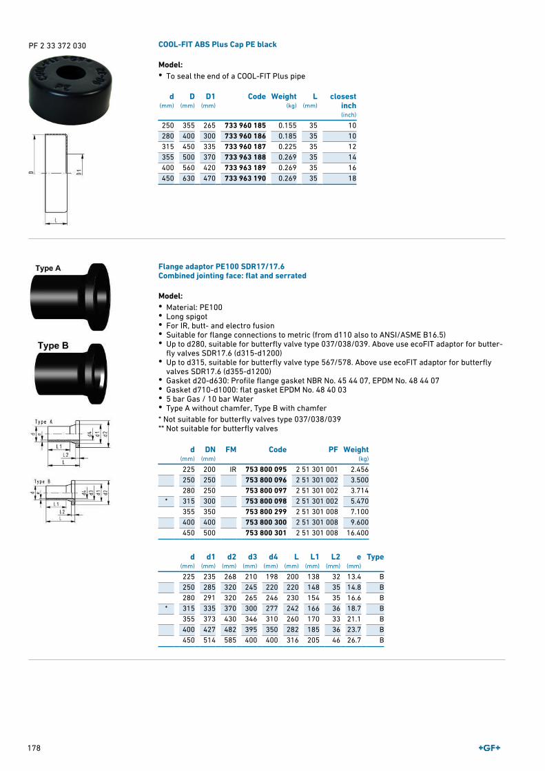
178
PF 2 33 372 030 COOL-FIT ABS Plus Cap PE black
Model:• To seal the end of a COOL-FIT Plus pipe
d(mm)
D(mm)
D1(mm)
Code Weight(kg)
L(mm)
closestinch(inch)
250 355 265 733 960 185 0.155 35 10280 400 300 733 960 186 0.185 35 10315 450 335 733 960 187 0.225 35 12355 500 370 733 963 188 0.269 35 14400 560 420 733 963 189 0.269 35 16450 630 470 733 963 190 0.269 35 18
Flange adaptor PE100 SDR17/17.6Combined jointing face: flat and serrated
Model:• Material: PE100• Long spigot• For IR, butt- and electro fusion• Suitable for flange connections to metric (from d110 also to ANSI/ASME B16.5)• Up to d280, suitable for butterfly valve type 037/038/039. Above use ecoFIT adaptor for butter-
fly valves SDR17.6 (d315-d1200)• Up to d315, suitable for butterfly valve type 567/578. Above use ecoFIT adaptor for butterfly
valves SDR17.6 (d355-d1200)• Gasket d20-d630: Profile flange gasket NBR No. 45 44 07, EPDM No. 48 44 07• Gasket d710-d1000: flat gasket EPDM No. 48 40 03• 5 bar Gas / 10 bar Water• Type A without chamfer, Type B with chamfer * Not suitable for butterfly valves type 037/038/039** Not suitable for butterfly valves
d(mm)
DN(mm)
FM Code PF Weight(kg)
225 200 IR 753 800 095 2 51 301 001 2.456250 250 753 800 096 2 51 301 002 3.500280 250 753 800 097 2 51 301 002 3.714
* 315 300 753 800 098 2 51 301 002 5.470355 350 753 800 299 2 51 301 008 7.100400 400 753 800 300 2 51 301 008 9.600450 500 753 800 301 2 51 301 008 16.400
d(mm)
d1(mm)
d2(mm)
d3(mm)
d4(mm)
L(mm)
L1(mm)
L2(mm)
e(mm)
Type
225 235 268 210 198 200 138 32 13.4 B250 285 320 245 220 220 148 35 14.8 B280 291 320 265 246 230 154 35 16.6 B
* 315 335 370 300 277 242 166 36 18.7 B355 373 430 346 310 260 170 33 21.1 B400 427 482 395 350 282 185 36 23.7 B450 514 585 400 400 316 205 46 26.7 B

179
Backing flange PP-V metricFor butt fusion systems metric
Model:• Full-plastic flange PP-GF (30 % glass-fibre reinforced)• Connecting dimension: ISO 7005, EN 1092, BS 4504, DIN 2501• Bolt circle PN 10 AL: number of holes1) Suitable for socket- and butt fusion systems2) Combined version, metric-ANSI
d(mm)
DN(mm)
PN(bar)
Code PF Weight(kg)
250 250 16 727 700 521 2 34 238 031 2.052280 250 16 727 700 522 2 34 238 031 1.700315 300 16 727 700 523 2 34 238 031 2.400355 350 10 727 700 524 2 34 238 031 4.440400 400 10 727 700 525 2 34 238 031 5.624
d(mm)
D(mm)
D1(mm)
D2(mm)
D3(mm)
H(mm)
AL SC
250 395 350 288 22 38 12 M20280 395 350 294 22 38 12 M20315 445 400 338 22 42 12 M20355 515 460 376 22 46 16 M20400 574 515 430 26 50 16 M24
Backing flange PP-Steel metricFor butt fusion systems metric
Model:• Material: PP (30% glass-fibre reinforced) with steel ring• Connecting dimension: ISO 7005, EN 1092, BS 4504, DIN 2501• Bolt circle PN 10 AL: number of holes1) Suitable for socket -and butt fusion systems2) Combined version, bolt circle metric - ANSI
d(mm)
DN(mm)
PN(bar)
Code PF Weight(kg)
250 250 16 727 700 721 2 34 238 022 6.632280 250 16 727 700 722 2 34 238 022 6.573315 300 16 727 700 723 2 34 238 022 7.903355 350 16 727 700 724 2 34 238 022 14.587400 400 16 727 700 725 2 34 238 022 20.034
d(mm)
D(mm)
D1(mm)
D2(mm)
D3(mm)
H(mm)
AL SC
250 395 350 288 22 32 12 M20280 395 350 294 22 32 12 M20315 445 400 338 22 36 12 M20355 515 460 376 23 42 16 M20400 574 515 430 26 42 16 M24

180
Profiled backing flange PP-Steel metricFor butt fusion systems metric
Model:• PP with glass-fibre reinforcement and GGG 50 insert• Connecting dimensions: ISO 7005, EN 1092, DIN 2501• Bolt circle PN 10 Note:flat side = bolt side profiled side = flange adaptor side AL: number of holes* Galvanized steel S235-JR, suitable for underground laying
d(mm)
DN(mm)
PN(bar)
Code PF Weight(kg)
* 450 450 10 724 705 026 2 55 337 001 38.000450 500 10 724 700 426 2 55 337 003 25.600
d(mm)
DN(mm)
D(mm)
D1(mm)
D2(mm)
D3(mm)
H(mm)
AL SC
* 450 450 615 565 470 26 36 20 M24450 500 685 620 517 26 56 20 M24
Backing flange PP-V Inch ANSIFor butt fusion systems metric
Model:• Full-plastic flange PP-GF (30 % glass-fibre reinforced)• Connecting dimension: ANSI/ASME B 16.5 class 150, ASTM D 4024, BS 1560, BS EN 1759• Bolt circle class 150• Special flange adapter ANSI for d25 - d50 and d90 required AL: number of holes1) Suitable for socket- and butt fusion systems2) Combined version, metric-ANSI
Size(inch)
d(mm)
DN(mm)
PN(bar)
Code PF Weight(kg)
10 250 250 16 727 701 521 2 34 238 033 2.24110 280 250 16 727 701 522 2 34 238 033 2.17312 315 300 16 727 701 523 2 34 238 033 3.627
Size(inch)
D(mm)
D1(mm)
D2(mm)
D3(mm)
H(mm)
AL SC
10 406 362 288 26 38 12 M2010 406 362 294 26 38 12 M2012 483 432 338 26 42 12 M20

181
Profile Flange Gasket, metricEPDM / FPM
Model:• For all metric GF Flange Adaptors• Hardness: 70° Shore EPDM, 75° Shore FPM• EPDM: approved acc. to DVGW W 270, KTW recommendation• Centering on the inner diameter of the screw crown• material steel insert: carbon steel• Rubber-steel body combined with rubber profile cord ring di FA are the suitable inner diameters of flanges adaptors
d(mm)
PN(bar)
DN(mm)
EPDMCode
PF FPMCode
PF Weight(kg)
250 16 250 748 440 721 2 30 162 037 749 440 721 2 30 162 038 0.462280 16 250 748 440 722 2 30 162 037 749 440 722 2 30 162 038 0.323315 16 300 748 440 723 2 30 162 037 749 440 723 2 30 162 038 0.549355 16 350 748 440 724 2 30 162 037 749 440 724 2 30 162 038 0.870400 16 400 748 440 725 2 30 162 037 749 440 725 2 30 162 038 1.088450 16 500 748 440 726 2 30 162 037 749 440 726 2 30 162 038 0.718
d(mm)
PN(bar)
D(mm)
D1(mm)
di FA(mm)
H(mm)
H1(mm)
250 16 328 252 238 ‐ 252 8 6280 16 328 274 264 ‐ 274 8 6315 16 378 306 296 ‐ 306 8 6355 16 438 355 340 ‐ 355 10 7400 16 489 400 385 ‐ 400 10 7450 16 594 403 393 ‐ 403 10 7
PF 2 30 162 003 Flat gasketEPDM
Model:• For all metric GF Flange Adaptors• Hardness approx. 65° Shore• Integrated fixation aids from d110 • Centering on the inner diameter of the screw crown di FA are the suitable inner diameters of flanges adaptors
d(mm)
DN(mm)
PN(bar)
Type EPDMCode
Weight(kg)
D(mm)
D1(mm)
D2(mm)
D3(mm)
H(mm)
di FA(mm)
250 250 6 C 748 400 321 0.210 328 250 350 22 5 240 ‐ 260280 250 6 C 748 400 322 0.151 328 273 350 22 5 263 ‐ 283315 300 6 C 748 400 323 0.237 378 305 400 22 5 295 ‐ 315

182
PF 2 34 238 038 Blanking flange set PECombined jointing face flat and serrated metric
Model:• d63 - d315: backing flange PP-V with end blank PE• d355 - d630: backing flange PP/Steel with end blank PE• Connecting dimensions: ISO 7005, EN 1092, DIN 2501• Bolt circle PN 10 AL: number of holesL: length of the End Blank
d(mm)
DN(mm)
PN(bar)
Code Weight(kg)
D(mm)
D1(mm)
D2(mm)
D3(mm)
D4(mm)
L(mm)
L1(mm)
H(mm)
AL SC
250 250 16 753 700 621 6.051 285 350 395 22 320 55 35 38 12 M20280 250 16 753 700 622 6.305 291 350 395 22 320 60 35 38 12 M20315 300 16 753 700 623 8.894 335 400 445 22 370 65 35 42 12 M20355 350 16 753 700 624 23.198 373 460 515 22 430 70 40 40 16 M20400 400 16 753 700 625 30.766 427 515 574 26 482 75 46 40 16 M24450 500 10 753 700 626 44.271 510 620 684 26 585 80 60 49 20 M24
Metal - butterfly valve type 039GReduction gear with handwheel
Model:• Body GGG40 (A 395 M:88, EN-JS 1020 EN1563) Rilsan coating• Seat material: EPDM, FPM and others on request• Full bore shaft, square shape• Installation length: EN 558 row 20• Mounting between ISO, ANSI, BS or JIS Flanges• Interface according to DIN/ISO 5211
d(mm)
Size(inch)
DN(mm)
PN(bar)
kv-value(Δp=1 bar)
(l ⁄ min)
Disc: ductileiron/Rilsan®
coatedEPDMCode
PF Weight(kg)
280 10 250 16 78333 199 039 033 3 39 226 002 31.600315 12 300 16 115000 199 039 034 3 39 226 002 40.000
d(mm)
Disc:stainless
steel EPDMCode
PF Weight(kg)
Disc: Alu-bronze
EPDMCode
PF Weight(kg)
280 199 039 233 3 39 226 026 19.000 199 039 433 3 39 226 026 19.000315 199 039 234 3 39 226 026 37.000 199 039 434 3 39 226 026 23.000
d(mm)
D3(mm)
D4(mm)
D5(mm)
H(mm)
H1(mm)
H2(mm)
H3(mm)
L1(mm)
L2(mm)
L3(mm)
L4(mm)
Cv val-ue (Δp=1
psi)(l ⁄ min)
280 331 333 250 542 200 275 67 106 184 52 142 20693315 380 353 250 609 227 315 67 106 184 52 142 30380

183
PF 3 39 226 002 Metal - butterfly valve type 039GReduction gear with handwheel metric DN350-1200
Model:• Housing: Ductile Iron ASTM A 395, Epoxy coated• Seatliner available in EPDM, FPM on request• Disc available in Aluminium Bronze on request• Up to DN 500: Overall length according to EN558, line 20, ISO 5752• Connecting dimension: EN 1092 PN10• Also available: ANSI, electric-, pneumatic actuated
d(mm)
DN(mm)
PN(bar)
kv-value(Δp=1 bar)
(l ⁄ min)
Disc: DuctileIron: EPOXY
coatedEPDMCode
Disc:stainless
steel EPDMCode
Disc: DuctileIron: EPOXYcoated FPM
Code
Disc:stainless
steel FPMCode
Weight(kg)
355 350 10 143360 198 039 000 198 039 010 198 039 040 198 039 050 53.700400 400 10 186700 198 039 001 198 039 011 198 039 041 198 039 051 81.200450 450 10 258390 198 039 002 198 039 012 198 039 042 198 039 052 110.500
d(mm)
D(mm)
D1(mm)
D2(mm)
D3(mm)
H1(mm)
H2(mm)
H3(mm)
L(mm)
L1(mm)
L2(mm)
L3(mm)
M(mm)
Q1(mm)
N(mm)
355 21 460 442 125 291 307 55 78 75 180 282 20 332 16400 25 515 193 140 325 342 65 102 88 226 270 24 382 16450 25 565 544 140 357 387 65 113 88 258 326 24 432 20

184
PF 2 33 372 050 Peeling tool COOL-FIT RTC-315
The peeling tool COOL-FIT RTC-315 is suitable for peeling of pre-insulated ABS pipes of the COOLFIT system.Scope of delivery: 1 Scraper arm, 1 Self-centering chuck base, 1 Aluminium transport case, 1screwdriver, 1 deburing knife.
d-d(mm)
Code Weight(kg)
Description
75 ‐ 315 799 150 423 9.616 max. working-range 185 mm
PF 2 51 305 001 Peeling tool RTC-710
The peeling tool RTC-710 is suitable for preparing pipe ends in big dimensions (d 355-710 mm).The tool ensures a constant peeling quality on the complete peeling surface of max. 530 mmlength and is suitable for PE 80 and PE 100 pipes. Scope of delivery: 1 Scraper arm, 1 Self-centering chuck base, 2 Aluminium transport cases, 1screwdriver, 1 spare blade, 1 deburing knife, 1 accessories bag.
d-d(mm)
Code Weight(kg)
Description
355 ‐ 710 799 300 757 31.400 max. working-range 530 mm
PF 3 10 588 500 Long adapters
• Adapters for Electrofusion units with 4 mm connectors.• Longer version, suitable for all COOL-FIT PE dimensions.
Type Code Weight(kg)
Description
4,0 mm 790 128 035 0.058 Angle adapters pair, black

185
PF 3 10 588 200 MSA 2.1Automatic Electrofusion Unit with protocols retrieval
The MSA 2.1 automatic electro fusion unit combines light weight and high efficiency, thanks to itsinverter technology and furthermore provides fusion documentation in PDF. The unit is extremelyfast and simple, with three basic operations required to operator: connect, scan, start the fusion.It is robust, safe and ergonomic.All is meant to simplify the job: the barcode scanner, for long distance reading, the cooling sys-tem to joint in series, the icon system, to keep the interaction between user and machine intuitive.The entire welding process is controlled and regulated with energy output compensation depend-ing on ambient temperature and the indication of cooling time.The unit has 1000 protocols permanently stored in the internal memory. The user can copy thefusion reports in an USB stick to print them out in PDF format.Scope of delivery includes: transport box, 1 pair of angle adapter clips 4.0 mm, 1 pair of angleadapter clips 4.7 mm, operating instructions, START/STOP badge and USB memory stick. The mi-ni Welding Book is available as option.Technical Data:• Operating temperature: -20°C to +50°C• Fusion data input mode: bar code, manual• Mains voltage: 230V (190V - 265V)• Mains frequency: 50-60 Hz• Welding technique: Voltage controlled• Fusion voltage: 8-42 V (48 V)• Fusion current: 90 A (max)• Suggested power generators: 3.5 kVA• Internal memory capacity: 1000 protocols• Fittings range: d20-1200 mm• Protocols format: PDF and binary (compatible with mini Welding Book)• USB Port: Type A• Protection factor: Class 1 / IP 65• Mains cable: 4 m• Fusion cable: 4 m • Weight: ca. 11.9 kg• Display: Graphical LCD, adjustable contrast• Languages support: all
Type Code Weight(kg)
Barcode scanner, transport case, mini Welding Book 790 156 003 13.000Barcode scanner, transport case, mini Welding Book, Swissplug 790 156 006 13.000
Barcode scanner, transport case, mini Welding Book, 8m weld-ing cables 790 156 010 21.000

Index
186
Code Page
150 541 009 86150 541 010 86150 541 011 86161 486 640 103161 486 641 103161 486 642 103161 486 651 103161 486 652 103161 486 653 103167 060 019 96167 060 020 96167 060 021 96167 060 022 96167 060 023 96167 060 024 96167 060 025 96167 060 038 96167 060 039 96167 060 040 96167 060 041 96167 060 042 96167 060 043 96167 061 003 95167 061 004 95167 061 012 95167 061 013 95167 061 014 95167 061 015 95167 061 016 95167 061 017 95167 061 035 95167 061 036 95167 061 037 95167 061 038 95167 061 039 95167 061 040 95167 061 041 95167 061 153 96167 061 155 96167 061 156 96167 061 157 96167 061 158 96167 061 159 96167 061 160 96167 061 161 96167 061 162 96167 061 163 96167 061 164 96167 061 165 96167 061 166 96167 061 167 96167 481 182 90167 481 183 90167 481 184 90167 481 185 90167 481 186 90167 481 187 90169 017 080 79169 017 081 79169 017 082 79169 017 083 79169 017 084 79
Code Page
169 017 085 79169 017 086 79169 017 087 79169 017 088 79169 017 089 79169 017 091 79169 017 092 79169 017 093 79169 017 094 79169 017 095 79169 017 096 79169 017 097 79169 017 682 58169 017 683 58169 017 684 58169 017 685 58169 017 686 58169 017 687 58169 017 688 58169 017 689 58169 017 691 58169 017 692 58169 017 693 58169 017 694 58169 017 695 58169 017 696 58169 017 697 58169 017 698 59169 017 699 59169 017 700 59169 303 006 112169 303 007 112169 303 008 112169 303 009 112169 303 010 112169 303 011 112169 305 302 113169 305 303 113169 305 304 113169 305 305 113169 305 306 113169 305 307 113169 480 925 103169 480 926 103169 480 927 103169 480 928 103169 480 929 103169 480 930 103169 480 931 103169 514 012 110169 514 013 110169 514 014 110169 514 015 110169 514 016 110169 514 017 110169 514 032 110169 514 033 110169 514 034 110169 514 035 110169 514 036 110169 514 037 110169 515 012 111
Code Page
169 515 013 111169 515 014 111169 515 015 111169 515 016 111169 515 017 111169 515 032 111169 515 033 111169 515 034 111169 515 035 111169 515 036 111169 515 037 111169 543 811 100169 543 812 100169 543 813 100169 543 814 100169 543 815 100169 543 816 100169 543 817 100169 543 821 99169 543 822 99169 543 823 99169 543 824 99169 543 825 99169 543 826 99169 543 827 99169 546 001 101169 546 002 101169 546 003 101169 546 004 101169 546 005 101169 546 006 101169 546 007 101169 546 008 101169 546 009 101169 546 010 101169 546 081 102169 546 082 102169 546 083 102169 546 084 102169 546 085 102169 546 086 102169 546 087 102169 546 088 102169 546 089 102169 546 090 102169 561 001 114169 561 002 114169 561 003 114169 561 004 114169 561 005 114169 561 006 114169 561 007 114169 561 008 114169 561 009 114169 561 010 114169 561 021 114169 561 022 114169 561 023 114169 561 024 114169 561 025 114169 561 026 114169 561 027 114
Code Page
169 562 001 115169 562 002 115169 562 003 115169 562 004 115169 562 005 115169 562 006 115169 562 007 115169 562 008 115169 562 009 115169 562 010 115169 562 021 115169 562 022 115169 562 023 115169 562 024 115169 562 025 115169 562 026 115169 562 027 115169 567 002 104169 567 003 104169 567 004 104169 567 005 104169 567 006 104169 567 007 104169 567 008 104169 567 009 104169 567 010 104169 567 022 105169 567 023 105169 567 024 105169 567 025 105169 567 026 105169 567 027 105169 567 028 105169 567 029 105169 567 030 105169 567 802 106169 567 803 106169 567 804 106169 567 805 106169 567 806 106169 567 807 106169 567 808 106169 567 809 106169 567 810 106169 578 002 108169 578 003 108169 578 004 108169 578 005 108169 578 006 108169 578 007 108169 578 008 108169 578 009 108169 578 010 108169 578 022 109169 578 023 109169 578 024 109169 578 025 109169 578 026 109169 578 027 109169 578 028 109169 578 029 109169 578 030 109

Index
187
Code Page
169 578 802 107169 578 803 107169 578 804 107169 578 805 107169 578 806 107169 578 807 107169 578 808 107169 578 809 107169 578 810 107169 591 001 169169 591 002 169169 591 003 169169 591 004 169169 591 005 169169 591 006 169169 591 007 169169 591 008 169169 591 009 169169 591 010 169169 595 001 169169 595 002 169169 595 003 169169 595 004 169169 595 005 169169 595 006 169169 595 007 169169 595 008 169169 595 009 169169 595 010 169169 614 012 154169 614 013 154169 614 014 154169 614 015 154169 614 016 154169 614 017 154169 615 012 155169 615 013 155169 615 014 155169 615 015 155169 615 016 155169 615 017 155169 617 112 156169 617 113 156169 617 114 156169 617 115 156169 617 116 156169 617 117 156169 624 012 157169 624 013 157169 624 014 157169 624 015 157169 624 016 157169 624 017 157169 625 012 158169 625 013 158169 625 014 158169 625 015 158169 625 016 158169 625 017 158169 627 112 159169 627 113 159169 627 114 159
Code Page
169 627 115 159169 627 116 159169 627 117 159169 644 012 160169 644 013 160169 644 014 160169 644 015 160169 644 016 160169 644 017 160169 645 012 161169 645 013 161169 645 014 161169 645 015 161169 645 016 161169 645 017 161169 647 112 162169 647 113 162169 647 114 162169 647 115 162169 647 116 162169 647 117 162169 654 012 163169 654 013 163169 654 014 163169 654 015 163169 654 016 163169 654 017 163169 655 012 164169 655 013 164169 655 014 164169 655 015 164169 655 016 164169 655 017 164169 657 112 165169 657 113 165169 657 114 165169 657 115 165169 657 116 165169 657 117 165169 684 012 166169 684 013 166169 684 014 166169 684 015 166169 684 016 166169 684 017 166169 685 012 167169 685 013 167169 685 014 167169 685 015 167169 685 016 167169 685 017 167169 687 112 168169 687 113 168169 687 114 168169 687 115 168169 687 116 168169 687 117 168198 039 000 183198 039 001 183198 039 002 183198 039 010 183198 039 011 183
Code Page
198 039 012 183198 039 040 183198 039 041 183198 039 042 183198 039 050 183198 039 051 183198 039 052 183199 039 033 182199 039 034 182199 039 233 182199 039 234 182199 039 433 182199 039 434 182199 127 082 119199 127 083 119199 127 084 119199 127 085 119199 127 086 119199 127 087 119199 127 088 119199 127 092 120199 127 093 120199 127 094 120199 127 095 120199 127 096 120199 127 097 120199 127 098 120199 127 692 121199 127 693 121199 127 694 121199 127 695 121199 127 696 121199 127 697 121199 127 698 121199 145 482 144199 145 483 144199 145 484 144199 145 485 144199 145 486 144199 145 487 144199 145 488 144199 145 489 144199 145 490 144199 145 522 145199 145 523 145199 145 524 145199 145 525 145199 145 526 145199 145 527 145199 145 528 145199 145 542 146199 145 543 146199 145 544 146199 145 545 146199 145 546 146199 145 547 146199 145 548 146199 145 549 146199 145 550 146199 146 502 147199 146 503 147199 146 504 147
Code Page
199 146 505 147199 146 506 147199 146 507 147199 146 508 147199 146 509 147199 146 510 147199 167 162 122199 167 163 122199 167 164 122199 167 165 122199 167 166 122199 167 167 122199 167 168 122199 167 172 123199 167 173 123199 167 174 123199 167 175 123199 167 176 123199 167 177 123199 167 178 123199 167 342 124199 167 343 124199 167 344 124199 167 345 124199 167 346 124199 167 347 124199 167 348 124199 167 352 125199 167 353 125199 167 354 125199 167 355 125199 167 356 125199 167 357 125199 167 358 125199 179 702 126199 179 703 126199 179 704 126199 179 705 126199 179 706 126199 179 707 126199 179 708 126199 179 709 126199 179 710 126199 179 711 126199 179 742 127199 179 743 127199 179 744 127199 179 745 127199 179 746 127199 179 747 127199 179 748 127199 179 749 127199 179 750 127199 179 751 127199 230 702 128199 230 703 128199 230 704 128199 230 705 128199 230 706 128199 230 707 128199 230 708 128199 230 722 129

Index
188
Code Page
199 230 723 129199 230 724 129199 230 725 129199 230 726 129199 230 727 129199 230 728 129199 230 742 130199 230 743 130199 230 744 130199 230 745 130199 230 746 130199 230 747 130199 230 748 130199 230 762 131199 230 763 131199 230 764 131199 230 765 131199 230 766 131199 230 767 131199 230 768 131199 230 782 132199 230 783 132199 230 784 132199 230 785 132199 230 786 132199 230 787 132199 230 788 132199 230 802 133199 230 803 133199 230 804 133199 230 805 133199 230 806 133199 230 807 133199 230 808 133199 230 822 134199 230 823 134199 230 824 134199 230 825 134199 230 826 134199 230 827 134199 230 828 134199 230 829 134199 230 830 134199 230 831 134199 230 842 135199 230 843 135199 230 844 135199 230 845 135199 230 846 135199 230 847 135199 230 848 135199 230 862 136199 230 863 136199 230 864 136199 230 865 136199 230 866 136199 230 867 136199 230 868 136199 230 869 136199 230 870 136199 230 871 136199 230 882 137
Code Page
199 230 883 137199 230 884 137199 230 885 137199 230 886 137199 230 887 137199 230 888 137199 230 902 138199 230 903 138199 230 904 138199 230 905 138199 230 906 138199 230 907 138199 230 908 138199 230 909 138199 230 910 138199 230 911 138199 230 922 139199 230 923 139199 230 924 139199 230 925 139199 230 926 139199 230 927 139199 230 928 139199 240 402 148199 240 403 148199 240 404 148199 240 405 148199 240 406 148199 240 407 148199 240 408 148199 240 409 148199 240 410 148199 240 422 149199 240 423 149199 240 424 149199 240 425 149199 240 426 149199 240 427 149199 240 428 149199 240 442 150199 240 443 150199 240 444 150199 240 445 150199 240 446 150199 240 447 150199 240 448 150199 243 402 151199 243 403 151199 243 404 151199 243 405 151199 243 406 151199 243 407 151199 243 408 151199 243 409 151199 243 410 151199 243 422 152199 243 423 152199 243 424 152199 243 425 152199 243 426 152199 243 427 152199 243 428 152
Code Page
199 243 429 152199 243 430 152199 243 442 153199 243 443 153199 243 444 153199 243 445 153199 243 446 153199 243 447 153199 243 448 153199 243 449 153199 243 450 153199 285 162 140199 285 163 140199 285 164 140199 285 165 140199 285 166 140199 285 167 140199 285 168 140199 285 172 142199 285 173 142199 285 174 142199 285 175 142199 285 176 142199 285 177 142199 285 178 142199 285 342 141199 285 343 141199 285 344 141199 285 345 141199 285 346 141199 285 347 141199 285 348 141199 285 352 143199 285 353 143199 285 354 143199 285 355 143199 285 356 143199 285 357 143199 285 358 143700 244 660 80720 510 106 85720 510 107 85720 510 108 85720 510 109 85720 510 110 85720 600 236 89720 600 237 89720 600 238 89720 600 239 89720 600 240 89720 600 241 89720 600 242 89720 600 243 89720 600 246 89720 600 247 89720 600 248 89720 600 249 89720 600 250 89720 600 251 89720 600 252 89720 600 253 89720 600 257 89
Code Page
720 600 258 89720 600 268 89724 600 655 88724 600 656 88724 600 657 88724 600 658 88724 600 659 88724 600 660 88724 600 661 88724 600 705 88724 600 706 88724 600 707 88724 600 708 88724 600 709 88724 600 710 88724 600 711 88724 605 505 88724 605 506 88724 605 507 88724 605 508 88724 605 509 88724 605 510 88724 605 511 88724 700 426 180724 705 026 180727 700 031 92727 700 206 92727 700 207 92727 700 208 92727 700 209 92727 700 210 92727 700 211 92727 700 212 92727 700 213 92727 700 214 92727 700 406 91727 700 407 91727 700 408 91727 700 409 91727 700 410 91727 700 411 91727 700 412 91727 700 413 91727 700 414 91727 700 416 91727 700 417 91727 700 419 91727 700 420 91727 700 421 91727 700 422 91727 700 423 91727 700 521 179727 700 522 179727 700 523 179727 700 524 179727 700 525 179727 700 721 179727 700 722 179727 700 723 179727 700 724 179727 700 725 179727 700 815 92

Index
189
Code Page
727 700 816 92727 700 817 92727 700 819 92727 700 820 92727 700 821 92727 700 822 92727 700 823 92727 701 521 180727 701 522 180727 701 523 180729 510 106 84729 510 107 84729 510 108 84729 510 109 84729 510 110 84729 510 111 84729 510 112 84729 510 114 84729 510 313 84729 540 206 84729 540 207 84729 540 208 84729 540 209 84729 540 210 84729 540 211 84729 540 706 85729 540 707 85729 540 708 85729 540 709 85729 540 710 85729 540 711 85729 541 007 86729 541 008 86729 545 506 85729 545 507 85729 545 508 85729 545 509 85729 545 510 85729 545 511 85729 550 506 86729 550 507 86729 550 508 86729 550 509 86729 550 510 86729 550 511 86729 550 906 86729 550 907 86729 550 908 86729 550 909 86729 550 910 86729 550 911 86729 550 957 86729 550 958 86729 550 967 86729 550 968 86729 690 012 87729 690 013 87729 690 014 87729 790 106 91729 790 107 91729 790 108 91729 790 109 91
Code Page
729 790 110 91729 790 111 91729 790 112 91729 790 113 91729 790 114 91729 790 116 91729 790 117 91729 790 119 91729 790 120 91729 790 121 91729 790 122 91729 790 123 91729 800 106 87729 800 107 87729 800 108 87729 800 109 87729 800 110 87729 800 111 87729 800 162 87729 800 163 87729 800 164 87729 840 106 87729 840 107 87729 840 108 87729 840 109 87729 840 110 87729 840 111 87729 840 112 87729 840 114 87729 840 123 87729 890 405 87729 890 406 87729 890 407 87729 890 408 87729 890 409 87729 890 410 87729 890 411 87729 900 181 80729 900 303 80729 900 306 80729 900 312 80729 900 337 80729 900 341 80729 900 342 80729 900 346 80729 900 347 80729 900 348 80729 900 352 80729 900 353 80729 900 354 80729 900 355 80729 900 358 80729 900 359 80729 900 360 80729 900 364 80729 900 365 80729 900 370 80729 900 371 80729 900 372 80729 900 376 80729 900 378 80729 900 385 80
Code Page
729 900 388 80729 900 390 80729 900 392 80729 900 396 80729 940 106 82729 940 107 82729 940 108 82729 940 131 82729 940 132 82729 940 133 82729 940 134 82729 940 135 82729 940 136 82729 940 606 83729 940 607 83729 940 608 83729 940 631 83729 940 632 83729 940 633 83729 940 634 83729 940 635 83729 940 636 83729 942 106 83729 942 107 83729 942 108 83729 942 606 84729 942 607 84729 942 608 84729 950 106 81729 950 107 81729 950 108 81729 950 131 81729 950 132 81729 950 133 81729 950 134 81729 950 135 81729 950 136 81729 950 606 81729 950 607 81729 950 608 81729 950 631 82729 950 632 82729 950 633 82729 950 634 82729 950 635 82729 950 636 82729 960 406 80729 960 407 80729 960 408 80729 960 409 80729 960 508 80733 960 135 71733 960 140 71733 960 171 73733 960 172 73733 960 173 73733 960 174 73733 960 175 73733 960 176 73733 960 177 73733 960 178 73733 960 180 73
Code Page
733 960 181 73733 960 183 73733 960 184 73733 960 185 73, 178733 960 186 73, 178733 960 187 73, 178733 963 188 178733 963 189 178733 963 190 178738 001 107 60738 001 108 60738 001 109 60738 001 110 60738 001 111 60738 001 112 60738 001 113 60738 001 114 60738 001 116 60738 001 120 60738 001 122 61738 001 123 61738 003 121 173738 003 122 173738 003 123 173738 003 124 173738 003 175 173738 003 176 173738 011 013 70738 011 014 70738 011 015 70738 011 016 70738 011 017 70738 011 018 70738 011 020 70738 011 021 70738 011 022 70738 011 023 70738 011 024 70, 176738 011 025 70, 176738 011 026 70, 176738 011 027 70, 176738 011 028 70, 176738 011 029 70, 176738 011 103 73738 011 107 72, 176738 011 108 72, 177738 011 109 72, 177738 011 113 70738 011 114 70738 011 115 70738 011 116 70738 011 117 70738 011 118 70738 011 120 70738 011 121 70738 011 122 70738 011 123 70738 011 150 69738 011 152 69, 176738 011 167 71738 011 170 71738 011 173 71

Index
190
Code Page
738 011 313 69738 011 314 69738 011 315 69738 011 316 69738 011 317 69738 011 318 69738 011 320 69738 011 321 69738 011 322 69738 011 323 69738 053 121 174738 053 122 174738 053 123 174738 053 124 174738 053 175 174738 053 176 174738 101 117 60738 101 119 60738 101 121 61738 151 107 61738 151 108 61738 151 109 61738 151 110 61738 151 111 61738 151 112 61738 151 113 61738 151 114 61738 151 116 61738 151 117 61738 151 119 61738 151 120 61738 151 121 62738 151 122 62738 151 123 62738 173 021 172738 173 022 172738 173 023 172738 173 024 172738 173 125 172738 173 126 172738 201 007 62738 201 008 62738 201 009 62738 201 010 62738 201 011 62738 201 012 62738 201 013 62738 201 038 64738 201 043 64738 201 046 64738 201 047 64738 201 051 64738 201 064 64738 201 070 64738 201 078 64738 201 092 64738 201 093 64738 201 114 62738 201 116 62738 201 117 62738 201 119 62738 201 120 62
Code Page
738 201 121 63738 201 122 63738 201 123 63738 201 136 64738 201 144 64738 201 148 64738 201 149 64738 201 152 64738 201 153 64738 201 156 64738 201 157 64738 201 182 64738 203 121 174738 203 122 174738 203 123 174738 203 124 174738 203 175 174738 203 176 174738 310 107 65738 310 108 65738 310 109 65738 310 110 65738 310 111 65738 310 112 65738 310 113 65738 310 114 65738 310 116 65738 310 117 65738 310 119 65738 310 120 65738 313 007 66738 313 008 66738 313 009 66738 313 010 66738 313 011 66738 313 012 66738 313 013 66738 313 114 66738 313 116 66738 313 117 66738 313 119 66738 313 120 66738 901 107 66738 901 108 66738 901 109 66738 901 110 66738 901 111 66738 901 112 66738 901 113 66738 901 114 66738 901 116 66738 901 117 66738 901 119 66738 901 120 66738 901 607 67738 901 608 67738 901 609 67738 901 610 67738 901 611 67738 901 612 67738 901 613 67738 901 614 67
Code Page
738 901 616 67738 901 617 67738 901 619 67738 901 620 67738 901 907 67738 901 908 67738 901 909 67738 901 910 67738 901 911 67738 901 912 67738 901 913 67738 901 914 67738 901 916 67738 901 917 67738 901 919 67738 901 920 67738 901 921 67738 901 922 67738 901 923 67738 903 802 175738 903 803 175738 903 805 175738 903 806 175738 903 807 175738 903 808 175738 903 809 175738 903 810 175738 903 871 175738 903 872 175738 903 873 175738 903 874 175738 903 875 175738 903 876 175738 903 877 175738 903 899 175738 911 341 68738 911 346 68738 911 352 68738 911 358 68738 911 364 68738 911 370 68738 911 376 68738 911 385 68738 911 392 68738 911 821 173738 911 822 173738 911 823 173738 911 824 173738 911 875 173738 911 876 173738 912 013 74738 912 014 74738 912 015 74738 912 016 74738 912 017 74738 912 018 74738 912 020 74738 912 021 74738 912 022 74738 912 023 74738 912 024 74738 990 138 74
Code Page
738 990 139 74738 990 140 74738 990 141 74738 990 142 74738 990 143 74738 990 144 74738 990 145 74748 400 306 94748 400 307 94748 400 308 94748 400 309 94748 400 310 94748 400 311 94748 400 312 94748 400 313 94748 400 314 94748 400 315 94748 400 316 94748 400 317 94748 400 319 94748 400 320 94748 400 321 94, 181748 400 322 94, 181748 400 323 94, 181748 410 004 90748 410 005 90748 410 006 90748 410 007 90748 410 008 90748 440 706 93748 440 707 93748 440 708 93748 440 709 93748 440 710 93748 440 711 93748 440 712 93748 440 713 93748 440 714 93748 440 715 93748 440 716 93748 440 717 93748 440 719 93748 440 720 93748 440 721 93, 181748 440 722 93, 181748 440 723 93, 181748 440 724 181748 440 725 181748 440 726 181749 410 004 90749 410 005 90749 410 006 90749 410 007 90749 410 008 90749 440 706 93749 440 707 93749 440 708 93749 440 709 93749 440 710 93749 440 711 93749 440 712 93749 440 713 93

Index
191
Code Page
749 440 714 93749 440 715 93749 440 716 93749 440 717 93749 440 719 93749 440 720 93749 440 721 93, 181749 440 722 93, 181749 440 723 93, 181749 440 724 181749 440 725 181749 440 726 181753 700 621 182753 700 622 182753 700 623 182753 700 624 182753 700 625 182753 700 626 182753 800 095 178753 800 096 178753 800 097 178753 800 098 178753 800 299 178753 800 300 178753 800 301 178790 128 035 184790 156 003 185790 156 006 185790 156 010 185790 156 032 75790 205 001 75799 150 423 184799 298 010 97799 298 022 97799 298 028 97799 299 001 98799 299 002 98799 299 003 98799 299 004 98799 299 005 98799 300 757 184799 350 339 75

192
Notes:

193
Notes:

194

195
General Condition of Supply of Georg Fischer Piping Systems Limited, Schaffhausen
1 General1.1 These General Conditions shall apply to all Products supplied by Georg Fischer Piping Systems
Limited («Georg Fischer») to the Purchaser. They shall also apply to all future business even when no express reference is made to them.1.2 Any deviating or supplementary conditions especially Purchaser’s general conditions of purchase
and verbal agreements shall only be applicable if accepted in writing by Georg Fischer.1.3 The written form shall be deemed to be fulfilled by all forms of transmission, evidenced in the form
of text, such as telefax, e-mail, etc.
2 Tenders Tenders shall only be binding if they contain a specifically stated period for acceptance.
3 Scope of Delivery3.1 Georg Fischer’s product range is subject to change.3.2 The confirmation of order shall govern the scope and execution of the contract.
4 Data and Documents4.1 Technical documents such as drawings, descriptions, illustrations and data on dimensions, performance and weight as well as the reference to standards are for information purposes only.
They are not warranted characteristics and are subject to change.4.2 All technical documents shall remain the exclusive property of Georg Fischer and may only be
used for the agreed purposes or as Georg Fischer may consent.
5 Confidentiality, Protection of Personal Data5.1 Each party shall keep in strict confidence all commercial or technical information relating to the
business of the other party, of which it has gained knowledge in the course of its dealing with the other party. Such information shall neither be disclosed to third parties nor used for other
purposes than those for which the information has been supplied.5.2 In the context of the contractual relation with the Purchaser personal data may be processed. The
Purchaser agrees to the disclosure of said data to third parties such as foreign subcontractors and suppliers etc .
6 Local Laws and Regulations, Export Controls6.1 The Purchaser shall bring to the attention of Georg Fischer all local laws and regulations at the
place of destination which bear connection with the execution of the contract and the adherence to relevant safety regulations and approval procedures.
6.2 In case of re-exports, Purchaser shall be responsible for compliance with pertinent export control regulations.
7 Price7.1 Unless agreed otherwise, the prices shall be deemed quoted net ex works (according to Incoterms
2010 of the ICC, or latest version) including standard packing. All supplementary costs such as the cost of carriage, insurance, export-, transit- and import- licences etc. shall be borne by the Purchaser. The Purchaser shall also bear the costs of all taxes, fees, duties etc. connected with the contract.
7.2 If the costs of packing, carriage, insurance, fees and other supplementary costs are included in the tender price or contract price or are referred to specifically in the tender or confirmation of order, Georg Fischer reserve the right to revise their prices accordingly should any change occur in the relevant tariffs.
8 Terms of Payment8.1 The Purchaser shall make payment in the manner agreed by the parties without any deductions
such as discounts, costs, taxes or dues.8.2 The Purchaser may only withhold or off-set payments due against counter claims which are either
expressly acknowledged by Georg Fischer or finally awarded to the Purchaser. In particular, payment shall still be made when unessential items are still outstanding provided
that the Products already delivered are not rendered unusable as a result.
9 Retention of Title9.1 The Products shall remain the property of Georg Fischer until the Purchaser shall have settled all
claims, present and future, which Georg Fischer may have against him.9.2 Should the Purchaser resell Products to which title is reserved, in the ordinary course of business, he shall hereby be deemed to have tacitly assigned to Georg Fischer the proceeds
deriving from their sale together with all collateral rights, securities and reservations of title until all claims held by Georg Fischer shall have been settled. Until revoked by Georg Fischer, this
assignment shall not preclude Purchaser‘s right to collect the assigned receivables.9.3 To the extent the value of the Products to which title is reserved together with collateral securities
exceeds Georg Fischer’s claims against the Purchaser by more than 20%, Georg Fischer shall re-assign the above proceeds to Purchaser at his request.
10 Delivery10.1 The term of delivery shall commence as soon as the contract has been entered into, all official
formalities such as import and payment permits have been obtained and all essential technical is-sues have been settled. The term of delivery shall be deemed duly observed when, upon its expiry, the Products are ready for despatch.
10.2 Delivery is subject to the following conditions, i.e. the term of delivery shall be reasonably exten-ded:
a) if Georg Fischer are not supplied in time with the information necessary for the execution of the contract or if subsequent changes causing delays are made by the Purchaser.
b) if Georg Fischer are prevented from performing the contract by force majeure. Force majeure shall equally be deemed to be any unforeseeable event beyond Georg Fischer’s control which renders Georg Fischer’s performance commercially unpractical or impossible, such as delayed or defective supplies from sub contractors labour disputes, governmental orders or regulati- ons, shortages in materials or energy, serious disturbances in Georg Fischer’s works, such as the total or partial destruction of plant and equipment or the breakdown of essential facili- ties, serious disruptions in transport facilities, e.g. impassable roads. Should the effect of force majeure exceed a period of six (6) months, either party may cancel the
contract forthwith. Georg Fischer shall not be liable for any damage or loss of any kind whatsoever resulting the refrom, any suspension or cancellation being without prejudice to Georg Fischer’s right to recover all sums due in respect of consignments delivered and costs incurred to date. c) if the Purchaser is in delay with the fulfilment of his obligations under the contract, in particular,
if he does not adhere to the agreed conditions of payment or if he has failed to timely provide the agreed securities.10.3 If for reasons attributable to Georg Fischer the agreed term of delivery or a reasonable extension
thereof is exceeded, Georg Fischer shall not be deemed in default until the Purchaser has granted to Georg Fischer in writing a reasonable extension thereof of not less than one (1) month which equally is not met.
The Purchaser shall then be entitled to the remedies provided at law, it being however understood that, subject to limitations of Art. 16, damage claims shall be limited to max. 10% of the price of the delayed delivery.
10.4 Part shipments shall be allowed and Georg Fischer shall be entitled to invoice for such partial deliveries.
10.5 If the Purchaser fails to take delivery within a reasonable time of Products notified as ready for despatch, Georg Fischer shall be entitled to store the Products at the Purchaser’s expense and risk and to invoice them as delivered. If Purchaser fails to effect payment, Georg Fischer shall be entitled to dispose of the Products.
10.6 Should Purchaser cancel an order without justification and should Georg Fischer not insist on the performance of the contract, Georg Fischer shall be entitled to a penalty amounting to 10% of the contract price, Georg Fischer‘s right to prove and claim higher damages remaining reserved.
Purchaser shall be entitled to prove, that Georg Fischer has suffered no or a considerably lower damage than the penalty forfeited.
11 Packing If the Products are provided with additional packing over and above the standard packing, such
packing shall be charged additionally.
12 Passing of Risk12.1 The risk in the Products shall pass to the Purchaser as soon as they have left Georg Fischer’s
works (EX WORKS, Incoterms 2010 ICC, or latest version), even if delivery is made carriage-paid, under similar clauses or including installation or when carriage is organized and managed by Georg Fischer.
12.2 If delivery is delayed for reasons beyond Georg Fischer’s control, the risk shall pass to the Purchaser when he is notified that the Products are ready for despatch.
13 Carriage and Insurance13.1 Unless agreed otherwise, the Purchaser shall bear the cost of carriage.13.2 The Purchaser shall be responsible for transport insurance against damage of whatever kind. Even when such insurance is arranged by Georg Fischer it shall be deemed taken out by the order
of and for the account of the Purchaser and at his risk.13.3 Special requests regarding carriage and insurance shall be communicated to Georg Fischer in
due time. Otherwise carriage shall be arranged by Georg Fischer at their discretion, but without responsibility, by the quickest and cheapest method possible.
In case of carriage-paid delivery transport arrangements shall be made by Georg Fischer. If the Purchaser specifies particular requirements, any extra costs involved shall be borne by him.
13.4 In the event of damage or loss of the Products during carriage the Purchaser shall mark the delivery documents accordingly and immediately have the damage ascertained by the carrier.
Not readily ascertainable damages sustained during carriage shall be notified to the carrier within six (6) days after receipt of the Products.
14 Inspection, Notification of Defects and Damages14.1 The Products will be subject to normal inspection by Georg Fischer during manufacture. Additional tests required by the Purchaser shall be agreed upon in writing and shall be charged to
the Purchaser.14.2 It shall be a condition of Georg Fischer’s obligation under the warranties stated hereinafter that
Georg Fischer be notified in writing by the Purchaser of any purported defect immediately upon discovery. Notice concerning weight, numbers or apparent defects is to be given latest within
30 days from receipt of the Products, notice of other defects immediately latest within seven (7) working days after discovery, in any event within the agreed warranty period.
14.3 Purchaser shall not dispose of allegedly defective Products until all warranty and/or damage claims are finally settled. At its request, defective Products are to be placed at Georg Fischer‘s disposal.
14.4 At its request, Georg Fischer shall be given the opportunity to inspect the defect and/or damage, prior to commencement of remedial work, either itself or by third party experts.
15 Warranty15.1 At the written request of the Purchaser, Georg Fischer undertakes to repair or replace at its
discretion, as quickly as possible and free of charge, all Products supplied which demonstrably suffer from faulty design, materials or workmanship, from faulty operating or installation
instructions or which become defective or unusable due to faulty advice. In order to protect employees from toxic or radioactive substances which may have been transported through defective parts returned to Georg Fischer‘s sales organisation, said parts
must be accompanied by a Material Safety Disclosure Form. The form may be obtained from Georg Fischer‘s local sales company or via www.piping.georgfischer.com. Replaced parts shall become property of Georg Fischer, unless Georg Fischer waives such claim.15.2 For Products which are manufactured to specifications, drawings or patterns supplied by the
Purchaser, Georg Fischer’s warranty shall be restricted to proper materials and workmanship.15.3 The Purchaser shall be entitled to rescind the contract or to demand a reduction of the contract
price if - the repair or replacement of the defective Product is impossible - the defective Product is not repaired or replaced within a reasonable period - Georg Fischer refuses the repair or replacement or if for reasons attributable to Georg Fischer
the repair or replacement is delayed.15.4 For Products or essential components manufactured by a third party and supplied by Georg Fischer under this contract, Georg Fischer’s warranty is limited to the warranty provided by said third party.15.5 This warranty shall not apply to damage resulting from normal wear and tear, improper storage
and maintenance, failure to observe the operating instructions, overstressing or overloading, unsuitable operating media, unsuitable construction work or unsuitable building ground, improper repairs or alterations by the Purchaser or third parties, the use of other than original spare parts and other reasons beyond Georg Fischer’s control.
15.6 No action or claim may be brought by the Purchaser on account of any alleged breach of warranty or any other obligation of Georg Fischer after the expiration of twelve (12) months from receipt of the Products by the end user or at the latest within eighteen (18) months of the Products being despatched by Georg Fischer.
15.7 In case of Products for use in domestic installations or in utilities - Georg Fischer will assume the costs of dismantling the defective Product and restoring the
damaged object up to CHF 1‘000‘000 per occurrence. - warranty or damage claims - contrary to Section 15.6 – are time-barred five (5) years from the
date of installation or seven (7) years from the production date, whichever is earlier.
16 Limitation of Liability The rights and remedies of the customer shall be exclusively governed by these General
Conditions of Supply and shall be in lieu of any remedies at law. All further claims for damages, reduction of the purchase price, termination of or rescission of the contract are excluded.
In no case whatsoever shall the customer be entitled to claim damages other than compensation for costs of remedying defects in the supplies. This in particular refers, but shall not be limited, to loss of production, loss of use, loss of orders, loss of profit, third party recovery claims and other direct or indirect or consequential damages.
This limitation of liability equally applies to the extent Georg Fischer is liable for acts or omissions of its employees or third parties engaged for the performance of its obligations. It does not apply in case unlawful intent or gross negligence on the part of Georg Fischer’s management and in case of Georg Fischer’s statutory liability, in particular under applicable product liability laws.
17 Severability Should any term or clause of these General Conditions in whole or in part be found to be unenforceable or void, all other provisions shall remain in full force and effect and the unenforceable or void provision shall be replaced by a valid provision, which comes closest to the original intention of the unenforceable or invalid provision.
18 Place of Performance and Jurisdiction18.1 Place of performance for the Products shall be the Georg Fischer works from which the Products
are despatched.18.2 The contract shall be governed by Swiss law without regard to conflict of law provisions that would
require the application of another law. 18.3 Any civil action based upon any alleged breach of this contract shall be filed and prosecuted
exclusively in the courts of Schaffhausen, Switzerland. Georg Fischer however reserves the right to file actions in any court having jurisdiction over
controversies arising out of or in connection with the present contract.
03/2011

GF Piping Systems
Worldwide at homeOur sales companies and representatives ensure local customer support in over 100 countries
The technical data are not binding. They neither constitute expressly warranted characteristics nor guaranteed properties nor a guaranteed durability. They are subject to modification. Our General Terms of Sale apply.
www.gfps.com
Argentina / Southern South AmericaGeorg Fischer Central Plastics Sudamérica S.R.L.Buenos Aires, ArgentinaPhone +54 11 4512 02 [email protected]/ar
AustraliaGeorge Fischer Pty LtdRiverwood NSW 2210 AustraliaPhone +61 (0) 2 9502 8000 [email protected]/au
AustriaGeorg Fischer Rohrleitungssysteme GmbH3130 HerzogenburgPhone +43 (0) 2782 856 [email protected]/at
Belgium / LuxembourgGeorg Fischer NV/SA1600 Sint-Pieters-Leeuw / BelgiumPhone +32 (0) 2 556 40 20Fax +32 (0) 2 524 34 [email protected]/be
BrazilGeorg Fischer Sist. de Tub. Ltda.04571-020 São Paulo/SPPhone +55 (0) 11 5525 [email protected]/br
CanadaGeorg Fischer Piping Systems LtdMississauga, ON L5T 2B2Phone +1 (905) 670 8005Fax +1 (905) 670 [email protected]/ca
ChinaGeorg Fischer Piping Systems Ltd Shanghai 201319Phone +86 21 3899 3899 [email protected]/cn
Denmark / IcelandGeorg Fischer A/S2630 TaastrupPhone +45 (0) 70 22 19 [email protected]/dk
FinlandGeorg Fischer AB01510 VANTAAPhone +358 (0) 9 586 58 25 Fax +358 (0) 9 586 58 [email protected]/fi
FranceGeorg Fischer SAS95932 Roissy Charles de Gaulle CedexPhone +33 (0) 1 41 84 68 [email protected]/fr
GermanyGeorg Fischer GmbH73095 Albershausen Phone +49 (0) 7161 302 [email protected]/de
IndiaGeorg Fischer Piping Systems Pvt. Ltd400 083 MumbaiPhone +91 22 4007 2000 Fax +91 22 4007 2020
www.gfps.com/in
IndonesiaPT Georg Fischer Indonesia Karawang 41371, Jawa BaratPhone +62 267 432 044Fax +62 267 431 [email protected]/id
ItalyGeorg Fischer S.p.A.20063 Cernusco S/N (MI)Phone +39 02 921 [email protected]/it
JapanGeorg Fischer Ltd530-0003 Osaka Phone +81 (0) 6 6341 [email protected]/jp
KoreaGeorg Fischer Korea Co. LtdUnit 2501, U-Tower120 HeungdeokJungang-ro (Yeongdeok-dong) Giheung-gu, Yongin-si, Gyeonggi-do Phone +82 31 8017 1450Fax +82 31 217 [email protected]/kr
MalaysiaGeorge Fischer (M) Sdn. Bhd.40460 Shah Alam, Selangor Darul EhsanPhone +60 (0) 3 5122 5585Fax +60 (0) 3 5122 [email protected]/my
Mexico / Northern Latin AmericaGeorg Fischer S.A. de C.V.Apodaca, Nuevo LeonCP66636 MexicoPhone +52 (81) 1340 8586Fax +52 (81) 1522 [email protected]/mx
Middle EastGeorg Fischer Piping Systems (Switzerland) LtdDubai, United Arab EmiratesPhone +971 4 289 49 [email protected]/int
NetherlandsGeorg Fischer N.V.8161 PA EpePhone +31 (0) 578 678 222 [email protected]/nl
NorwayGeorg Fischer AS1351 Rud Phone +47 67 18 29 [email protected]/no
PhilippinesGeorg Fischer Pte Ltd
Phone +632 571 2365 Fax +632 571 [email protected]/sg
PolandGeorg Fischer Sp. z o.o.05-090 Sekocin Nowy Phone +48 (0) 22 31 31 0 50 [email protected]/pl
RomaniaGeorg Fischer Piping Systems (Switzerland) Ltd020257 Bucharest - Sector 2Phone +40 (0) 21 230 53 [email protected]/int
RussiaGeorg Fischer Piping Systems (Switzerland) LtdMoscow 125040Phone +7 495 748 11 [email protected]/ru
SingaporeGeorge Fischer Pte Ltd11 Tampines Street 92, #04-01/07528 872 SingaporePhone +65 6747 0611Fax +65 6747 [email protected]/sg
Spain / PortugalGeorg Fischer S.A.28046 MadridPhone +34 (0) 91 781 98 [email protected]/es
SwedenGeorg Fischer AB117 43 StockholmPhone +46 (0) 8 506 775 [email protected]/se
SwitzerlandGeorg Fischer Rohrleitungssysteme (Schweiz) AG
Phone +41 (0) 52 631 [email protected]/ch
TaiwanGeorg Fischer Co. LtdSan Chung Dist., New Taipei CityPhone +886 2 8512 2822Fax +886 2 8512 2823www.gfps.com/tw
United Kingdom / IrelandGeorge Fischer Sales LimitedCoventry, CV2 2STPhone +44 (0) 2476 535 [email protected]/uk
USA / CaribbeanGeorg Fischer LLC9271 Jeronimo Road92618 Irvine, CAPhone +1 714 731 8800 Fax +1 714 731 [email protected]/us
International Georg Fischer Piping Systems (Switzerland) Ltd
Phone +41 (0) 52 631 3003Fax +41 (0) 52 631 [email protected]/int
GFDO_8918_4a (01.18)© Georg Fischer Piping Systems LtdCH-8201 Schaffhausen/Switzerland, 2018
700.671.669


