Embed Size (px)
Citation preview
SBB80TARev. 01/17
Model : NCC199CDV (GQ-C3259WZ-FF US)
CONDENSING TANKLESS GAS WATER HEATER
Owner’s Guide
NORITZ America Corporation
-Donotstoreorusegasolineorotherflammablevaporsandliquidsinthevicinityofthisoranyotherappliance.
- WHAT TO DO IF YOU SMELL GAS•Donottrytolightanyappliance.•Donottouchanyelectricalswitch;donotuseanyphoneinyourbuilding.•Immediatelycallyourgassupplierfromaneighbor’sphone.Followthegassupplier’sinstructions.
•Ifyoucannotreachyourgassupplier,callthefiredepartment.
-Installationandservicemustbeperformedbyaqualifiedinstaller,serviceagencyorthegassupplier.
If the information in this manual is not followed exactly, a fire or explosion may result causing property damage, personal injury, or death.WARNING
FOR USE IN COMMERCIAL OR MANUFACTURED HOME APPLICATIONS.
*SBB80TA*
Thank you for purchasing this Noritz Tankless Gas Water Heater. Before using, please:Read this manual completely for operation instructions.Completely fill out the warranty registration card (included separately) and mail the detachable portion to Noritz America Corporation.Keep this manual (and the remainder of the warranty registration card) where it can be found whenever necessary.Installation must conform with local codes, or in the absence of local codes, the National Fuel Gas Code, ANSI Z223.1/NFPA 54 - latest edition and/or the Natural Gas and Propane Installation Code CSA B149.1 - latest edition.When applicable, installation must conform with the Manufactured Home Construction and Safety Standard, Title 24 CFR, Part 3280 or the Canadian Standard CAN/CSA-Z240 MH Mobile Homes, Series M86.Noritz America reserves the right to discontinue, or change at any time, the designs and/or specifications of its products without notice.
CERTIFIEDR
Low NOx Approvedby SCAQMD
14 ng/J or 20 ppm(Natural Gas Only)
2
Prohibited Don’t touch.
Don’t disassemble the equipment.
Don’t touch with a wet hand.
No flame.
High Temperature.
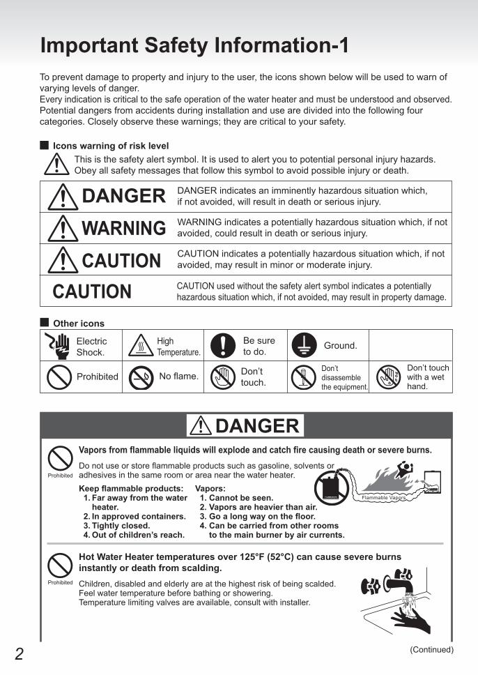
To prevent damage to property and injury to the user, the icons shown below will be used to warn of varying levels of danger.Every indication is critical to the safe operation of the water heater and must be understood and observed.Potential dangers from accidents during installation and use are divided into the following four categories. Closely observe these warnings; they are critical to your safety.
Other icons
DANGERWARNINGCAUTION
DANGER indicates an imminently hazardous situation which, if not avoided, will result in death or serious injury.
WARNING indicates a potentially hazardous situation which, if not avoided, could result in death or serious injury.
CAUTION indicates a potentially hazardous situation which, if not avoided, may result in minor or moderate injury.
CAUTION used without the safety alert symbol indicates a potentially hazardous situation which, if not avoided, may result in property damage.CAUTION
Be sure to do. Ground.Electric
Shock.
DANGER
Iconswarningofrisklevel
ImportantSafetyInformation-1
This is the safety alert symbol. It is used to alert you to potential personal injury hazards.Obey all safety messages that follow this symbol to avoid possible injury or death.
Vaporsfromflammableliquidswillexplodeandcatchfirecausingdeathorsevereburns.Do not use or store flammable products such as gasoline, solvents or adhesives in the same room or area near the water heater.Prohibited
Keepflammableproducts:1.Farawayfromthewater heater.2.Inapprovedcontainers.3.Tightlyclosed.4.Outofchildren’sreach.
Vapors:1.Cannotbeseen.2.Vaporsareheavierthanair.3.Goalongwayonthefloor.4.Canbecarriedfromotherroomstothemainburnerbyaircurrents.
HotWaterHeatertemperaturesover125°F(52°C)cancausesevereburnsinstantlyordeathfromscalding.Children, disabled and elderly are at the highest risk of being scalded. Feel water temperature before bathing or showering. Temperature limiting valves are available, consult with installer.
Prohibited
(Continued)
3
No flame.
(Continued)
WARNING
Be sure to do.
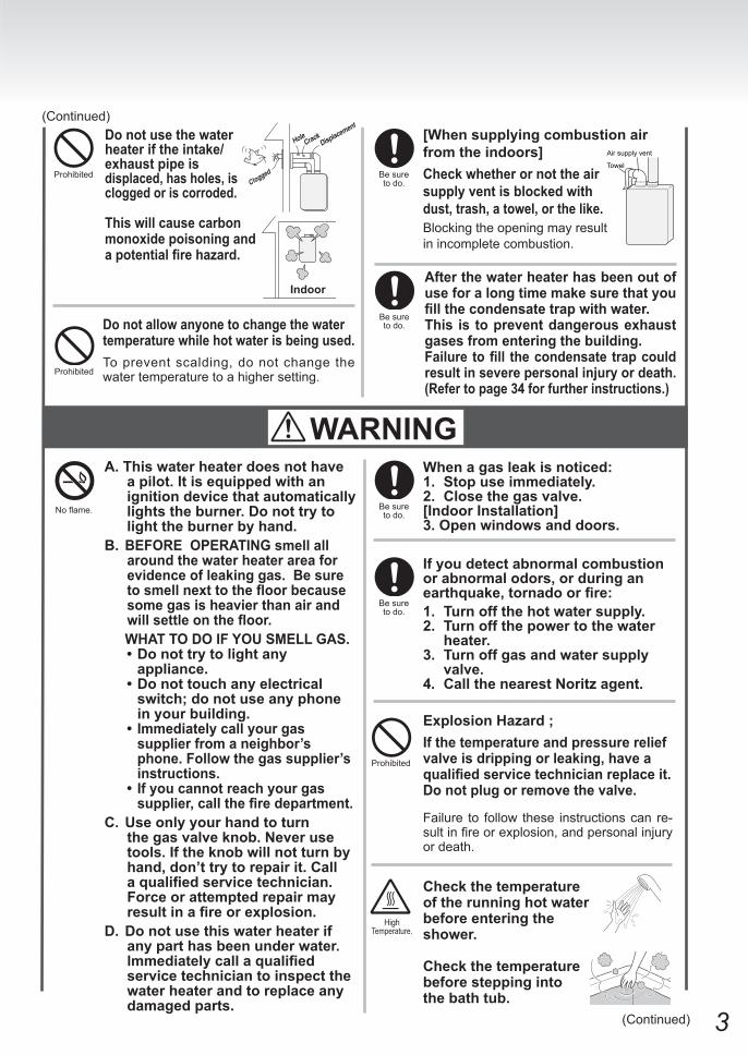
Whenagasleakisnoticed:1. Stopuseimmediately.2. Closethegasvalve.[Indoor Installation]3.Openwindowsanddoors.
Ifyoudetectabnormalcombustionorabnormalodors,orduringanearthquake,tornadoorfire:1. Turnoffthehotwatersupply.2. Turnoffthepowertothewater
heater.3. Turnoffgasandwatersupply
valve.4. CallthenearestNoritzagent.
Be sure to do.
Donotallowanyonetochangethewatertemperaturewhilehotwaterisbeingused.To prevent scalding, do not change the water temperature to a higher setting.Prohibited
A.Thiswaterheaterdoesnothaveapilot.Itisequippedwithanignitiondevicethatautomaticallylightstheburner.Donottrytolighttheburnerbyhand.
B.BEFORE OPERATING smell all aroundthewaterheaterareaforevidenceofleakinggas.Besuretosmellnexttothefloorbecausesomegasisheavierthanairandwillsettleonthefloor.
WHATTODOIFYOUSMELLGAS.•Donottrytolightany
appliance.•Donottouchanyelectrical
switch;donotuseanyphoneinyourbuilding.
• Immediatelycallyourgassupplierfromaneighbor’sphone.Followthegassupplier’sinstructions.
• Ifyoucannotreachyourgassupplier,callthefiredepartment.
C.Useonlyyourhandtoturnthegasvalveknob.Neverusetools.Iftheknobwillnotturnbyhand,don’ttrytorepairit.Callaqualifiedservicetechnician.Forceorattemptedrepairmayresultinafireorexplosion.
D.Donotusethiswaterheaterifanyparthasbeenunderwater.lmmediatelycallaqualifiedservicetechniciantoinspectthewaterheaterandtoreplaceanydamagedparts.
(Continued)
Prohibited
Checkthetemperatureoftherunninghotwaterbeforeenteringtheshower.
Checkthetemperaturebeforesteppingintothebathtub.
High Temperature.
ExplosionHazard;Ifthetemperatureandpressurereliefvalveisdrippingorleaking,haveaqualifiedservicetechnicianreplaceit.Donotplugorremovethevalve.
Failure to follow these instructions can re-sult in fire or explosion, and personal injury or death.
Prohibited
Do not use the water heateriftheintake/exhaustpipeis displaced,hasholes,iscloggedoriscorroded.
Thiswillcausecarbonmonoxidepoisoningandapotentialfirehazard.
Afterthewaterheaterhasbeenoutofuseforalongtimemakesurethatyoufillthecondensatetrapwithwater.This is topreventdangerousexhaustgasesfromenteringthebuilding.Failuretofill thecondensatetrapcouldresultinseverepersonalinjuryordeath.(Refertopage34forfurtherinstructions.)
Be sure to do.
Be sure to do.
[Whensupplyingcombustionairfromtheindoors]Checkwhetherornottheairsupplyventisblockedwith dust,trash,atowel,orthelike.Blocking the opening may result in incomplete combustion.
Towel
Air supply vent
Indoor
4
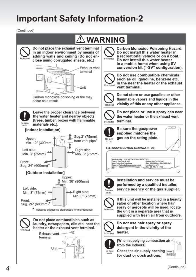
Donotplacetheexhaustventterminalinanindoorenvironmentbymeansofadding walls and ceiling (Do not en-closeusingcorrugatedsheets,etc.)
Carbon monoxide poisoning or fire may occur as a result.
ImportantSafetyInformation-2(Continued)
Ifthisunitwillbeinstalledinabeautysalon or other location where hair sprayoraerosolswillbeused,locatethe unit in a separate area that is suppliedwithfreshairfromoutdoors.
Prohibited
Besurethegas/powersupplied matches the gasontheratingplate.
e.g.)NCC199CDV(GQ-C3259WZ-FFUS)
Installationandservicemustbeperformedbyaqualifiedinstaller,serviceagencyorthegassupplier.
Be sure to do.
Be sure to do.
(Continued)
Prohibited
Do not store or use gasoline or other flammablevaporsandliquidsinthevicinityofthisoranyotherappliance.Prohibited
Donotplaceoruseaspraycannear thewaterheaterortheexhaustventterminal.
Donotusehairsprayorspraydetergentinthevicinityoftheheater.Prohibited
Prohibited
Leavetheproperclearancebetweenthewaterheaterandnearbyobjects(trees,timber,boxeswithflammablematerialsetc.).Be sure
to do.
* Indicates suggested clearances for maintenance.
Donotplacecombustiblessuchaslaundry,newspapers,oilsetc.neartheheaterortheexhaustventterminal.
Prohibited
Donotusecombustiblechemicalssuchasoil,gasoline,benzeneetc.intheneartheheaterortheexhaustventterminal.Prohibited
CarbonMonoxidePoisoningHazard.Do not install this water heater in arecreationalvehicleoronaboat.Do not install this water heater inamobilehomewhenusingSVconversionkit(“-SV”configuration).
Prohibited
WARNING
Left side: Min. 3" (75mm)
Left side: Min. 3" (75mm)
Right side:Min. 3" (75mm)
Right side:Min. 3" (75mm)
Front: Sug. 24" (600mm)*
Sug.3" (75mm) from vent pipe*Upper:
Min. 12" (300mm)
Exhaust vent terminal
Exhaust vent terminal
Unit
[Indoor Installation]
[Outdoor Installation]
Unit
Front: Sug. 24" (600mm)*
Be sure to do.
[Whensupplyingcombustionairfromtheindoors]Checktheairsupplyopening fordustorobstructions.
Cloggedair supplyopening!!
Made in Japan(Fabriqué au JAPON)
Upper: Min. 36" (900mm)
5
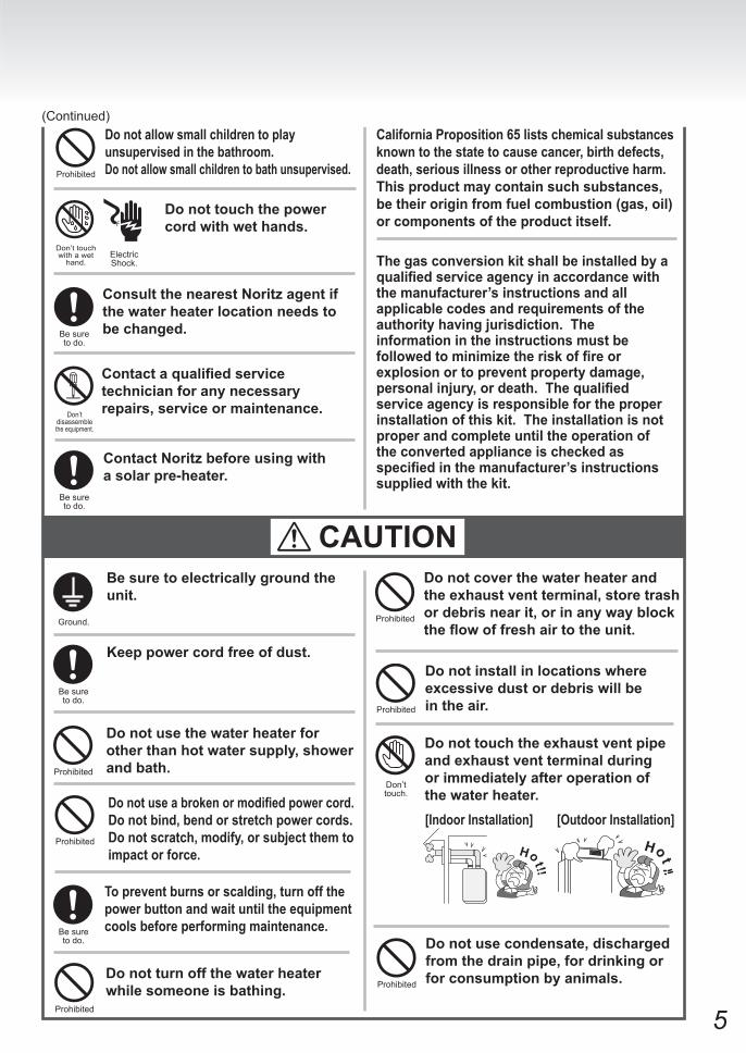
(Continued)Donotallowsmallchildrentoplayunsupervisedinthebathroom.Donotallowsmallchildrentobathunsupervised.
Do not touch the power cordwithwethands.
Electric Shock.
Don’t touch with a wet
hand.
Prohibited
ContactNoritzbeforeusingwithasolarpre-heater.
Contactaqualifiedservicetechnicianforanynecessaryrepairs,serviceormaintenance.
ConsultthenearestNoritzagentifthe water heater location needs to bechanged.
Don’t disassemble the equipment.
Be sure to do.
Be sure to do.
CaliforniaProposition65listschemicalsubstancesknowntothestatetocausecancer,birthdefects,death,seriousillnessorotherreproductiveharm.Thisproductmaycontainsuchsubstances,betheiroriginfromfuelcombustion(gas,oil)orcomponentsoftheproductitself.
CAUTIONBesuretoelectricallygroundtheunit.
Keeppowercordfreeofdust.
Ground.
Be sure to do.
Donotusethewaterheaterforotherthanhotwatersupply,showerandbath.Prohibited
Prohibited
Donotcoverthewaterheaterandtheexhaustventterminal,storetrashordebrisnearit,orinanywayblocktheflowoffreshairtotheunit.
Donotturnoffthewaterheaterwhilesomeoneisbathing.
Prohibited
Donotuseabrokenormodifiedpowercord.Donotbind,bendorstretchpowercords.Donotscratch,modify,orsubjectthemtoimpactorforce.
Donottouchtheexhaustventpipeandexhaustventterminalduringorimmediatelyafteroperationofthewaterheater.
Do not install in locations where excessivedustordebriswillbeintheair.
Prohibited
Don’t touch.
Prohibited
Be sure to do.
Topreventburnsorscalding,turnoffthepowerbuttonandwaituntiltheequipmentcoolsbeforeperformingmaintenance.
Thegasconversionkitshallbeinstalledbyaqualifiedserviceagencyinaccordancewiththemanufacturer’sinstructionsandallapplicablecodesandrequirementsoftheauthorityhavingjurisdiction.Theinformationintheinstructionsmustbefollowedtominimizetheriskoffireorexplosionortopreventpropertydamage,personalinjury,ordeath.Thequalifiedserviceagencyisresponsiblefortheproperinstallationofthiskit.Theinstallationisnotproperandcompleteuntiltheoperationoftheconvertedapplianceischeckedasspecifiedinthemanufacturer’sinstructionssuppliedwiththekit.
Donotusecondensate,dischargedfromthedrainpipe,fordrinkingorforconsumptionbyanimals.Prohibited
[Indoor Installation] [Outdoor Installation]
6
ImportantSafetyInformation-3
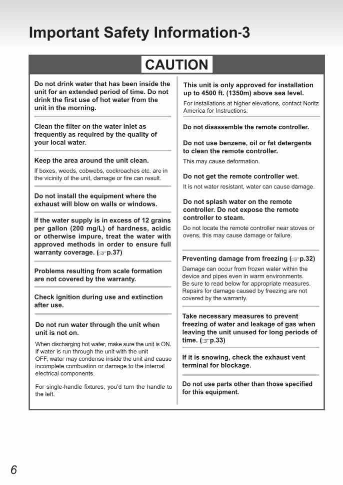
CAUTIONDonotdrinkwaterthathasbeeninsidetheunitforanextendedperiodoftime.Donotdrinkthefirstuseofhotwaterfromtheunitinthemorning.
Cleanthefilteronthewaterinletasfrequentlyasrequiredbythequalityofyourlocalwater.
Keeptheareaaroundtheunitclean.If boxes, weeds, cobwebs, cockroaches etc. are in the vicinity of the unit, damage or fire can result.
Donotinstalltheequipmentwheretheexhaustwillblowonwallsorwindows.
Problemsresultingfromscaleformationarenotcoveredbythewarranty.
Thisunitisonlyapprovedforinstallationupto4500ft.(1350m)abovesealevel.For installations at higher elevations, contact Noritz America for Instructions.
Checkignitionduringuseandextinctionafteruse.
Ifthewatersupplyisinexcessof12grainspergallon (200mg/L)ofhardness, acidicorotherwise impure, treat thewaterwithapprovedmethods inorder toensure fullwarrantycoverage.( p.37)
Preventingdamagefromfreezing( p.32)Damage can occur from frozen water within the device and pipes even in warm environments. Be sure to read below for appropriate measures.Repairs for damage caused by freezing are not covered by the warranty.
Takenecessarymeasurestopreventfreezingofwaterandleakageofgaswhenleavingtheunitunusedforlongperiodsoftime.( p.33)
Donotusepartsotherthanthosespecifiedforthisequipment.
Ifitissnowing,checktheexhaustventterminalforblockage.
Donotdisassembletheremotecontroller.
Donotusebenzene,oilorfatdetergentstocleantheremotecontroller.This may cause deformation.
Donotgettheremotecontrollerwet.It is not water resistant, water can cause damage.
Do not splash water on the remote controller.Donotexposetheremotecontrollertosteam.Do not locate the remote controller near stoves or ovens, this may cause damage or failure.
Do not run water through the unit when unitisnoton.When discharging hot water, make sure the unit is ON.If water is run through the unit with the unitOFF, water may condense inside the unit and causeincomplete combustion or damage to the internalelectrical components.
For single-handle fixtures, you’d turn the handle to the left.
7
ImportantSafetyInformation....................................................................... 2
Contents......................................................................................................... 7
RC-9018MOperationOverview.................................................................... 8
General Parts
Unit............................................................................................................ 10
Remote Controller.................................................................................... 12
SystemCheck............................................................................................... 14
Initial Operation............................................................................................ 16
ForAllSystems
ClockAdjustment...................................................................................... 17
Using the Water Heater............................................................................. 18
Setting Hot Water Temperature................................................................ 19
AutomaticWaterHeater“ON”or“OFF”Operation............................... 20
LockingtheRemoteController................................................................ 22
CustomizableSettings<Miscsettings>.................................................. 23
ForSystem[Rcrc]
EnablingAutomaticRecirculationOperation......................................... 26
ManuallyStartingRecirculationOperation............................................ 27
SettingtheRecirculationSystemOperationTimer............................... 28
SingleWaterHeaterOnly
Flow Meter Alarm...................................................................................... 30
PreventingDamagefromFreezing............................................................. 32
Regular Maintenance................................................................................... 35
Troubleshooting........................................................................................... 38
Follow-upService........................................................................................ 43
Specifications............................................................................................... 46
DefaultSettings............................................................................................ 47
Contents
8
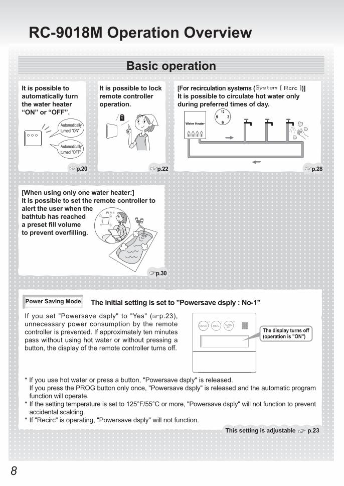
RC-9018MOperationOverview
PowerSavingMode
If you set "Powersave dsply" to "Yes" ( p.23), unnecessary power consumption by the remote controller is prevented. If approximately ten minutes pass without using hot water or without pressing a button, the display of the remote controller turns off.
Thissettingisadjustable p.23
[Whenusingonlyonewaterheater:]Itispossibletosettheremotecontrollertoalert the user when the bathtubhasreachedapresetfillvolumetopreventoverfilling.
p.30
Itispossibletolockremote controller operation.
p.22
Itispossibletoautomaticallyturnthe water heater “ON”or“OFF”.
[Forrecirculationsystems( )]Itispossibletocirculatehotwateronlyduringpreferredtimesofday.
p.20 p.28
Automatically turned "ON"
Automatically turned "OFF"
Pi Pi !!
12
6Water Heater
9 3
Basic operation
Theinitialsettingissetto"Powersavedsply:No-1"
* If you use hot water or press a button, "Powersave dsply" is released. If you press the PROG button only once, "Powersave dsply" is released and the automatic program
function will operate.* If the setting temperature is set to 125°F/55°C or more, "Powersave dsply" will not function to prevent
accidental scalding.* If "Recirc" is operating, "Powersave dsply" will not function.
Thedisplayturnsoff(operation is "ON")
9
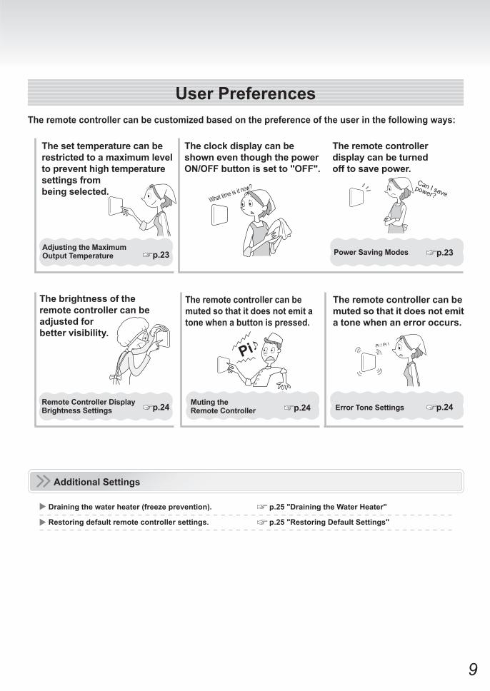
Theremotecontrollercanbecustomizedbasedonthepreferenceoftheuserinthefollowingways:
The remote controller displaycanbeturnedofftosavepower.
TheclockdisplaycanbeshowneventhoughthepowerON/OFFbuttonissetto"OFF".
What time is it now?Can I save
power?
Thebrightnessoftheremotecontrollercanbeadjustedforbettervisibility.
Additional Settings
p.25"DrainingtheWaterHeater"Drainingthewaterheater(freezeprevention).
p.25"RestoringDefaultSettings"Restoringdefaultremotecontrollersettings.
Thesettemperaturecanberestrictedtoamaximumleveltopreventhightemperaturesettingsfrombeingselected.
p.23
Theremotecontrollercanbemuted so that it does not emit a tonewhenabuttonispressed.
Pi Pi ! Pi !
UserPreferences
AdjustingtheMaximumOutput Temperature
RemoteControllerDisplayBrightness Settings p.24
Theremotecontrollercanbemuted so that it does not emit atonewhenanerroroccurs.
PowerSavingModes p.23
Error Tone Settings p.24Muting the Remote Controller p.24
10
Indoor InstallationOutdoor Installation
Outdoor Vent Cap
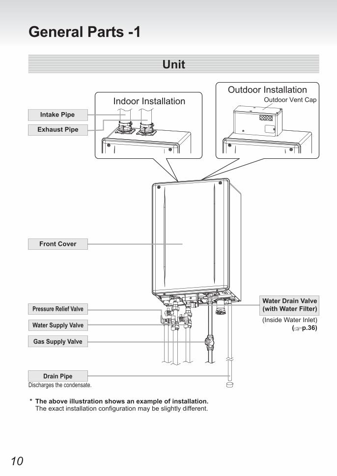
* Theaboveillustrationshowsanexampleofinstallation. The exact installation configuration may be slightly different.
FrontCover
(Inside Water Inlet) ( p.36)
PressureReliefValve
General Parts -1
IntakePipe
ExhaustPipe
GasSupplyValve
Drain PipeDischarges the condensate.
Unit
WaterDrainValve(with Water Filter)
WaterSupplyValve
11
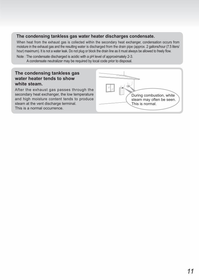
Thecondensingtanklessgaswaterheaterdischargescondensate.When heat from the exhaust gas is collected within the secondary heat exchanger, condensation occurs from moisture in the exhaust gas and the resulting water is discharged from the drain pipe (approx. 2 gallons/hour (7.5 liters/hour) maximum). It is not a water leak. Do not plug or block the drain line as it must always be allowed to freely flow.Note : The condensate discharged is acidic with a pH level of approximately 2-3. A condensate neutralizer may be required by local code prior to disposal.
Thecondensingtanklessgaswater heater tends to show whitesteam.After the exhaust gas passes through the secondary heat exchanger, the low temperature and high moisture content tends to produce steam at the vent discharge terminal.This is a normal occurrence.
During combustion, white steam may often be seen. This is normal.

12
Remote Controller (RC-9018M)The remote controller will emit a tone when a button is pressed.
Activates the automatic water heater power “ON” or “OFF” setting as determined by the user selected schedule. ( p.21)
For turning the water heater on/off.
( Next page)
Locks remote controller operation. ( p.22)
Check the status of the system or the number of installed units ( p.14)
Returns to the previous screen while making system settings or checking status.
Confirms changes made by the user.
For setting the hot water temperature ( p.19),the flow meter alarm, and other settings.
Remote ControllerPart Number
* Use to change system settings or to return to the home screen.
* If you press the menu button and press the temperature setting buttons,
is sometimes displayed, however, do not use this mode as it meant for instal lat ion or service personnel only.
Stops the tone that is emitted when an error occurs. ( p.42)
Covershownintheopenposition.
ProgButton/Indicator(Red)
PowerON/OFFButton/Indicator(Green)
Menu Button
BackButton
AlarmOffButton/Indicator(Red)
Speaker
DisplayScreen
Status Button
LockButton
Enter Button
Hot Water Temperature Setting Buttons
The part number is printed on the surface of the cover.
General Parts -2
13
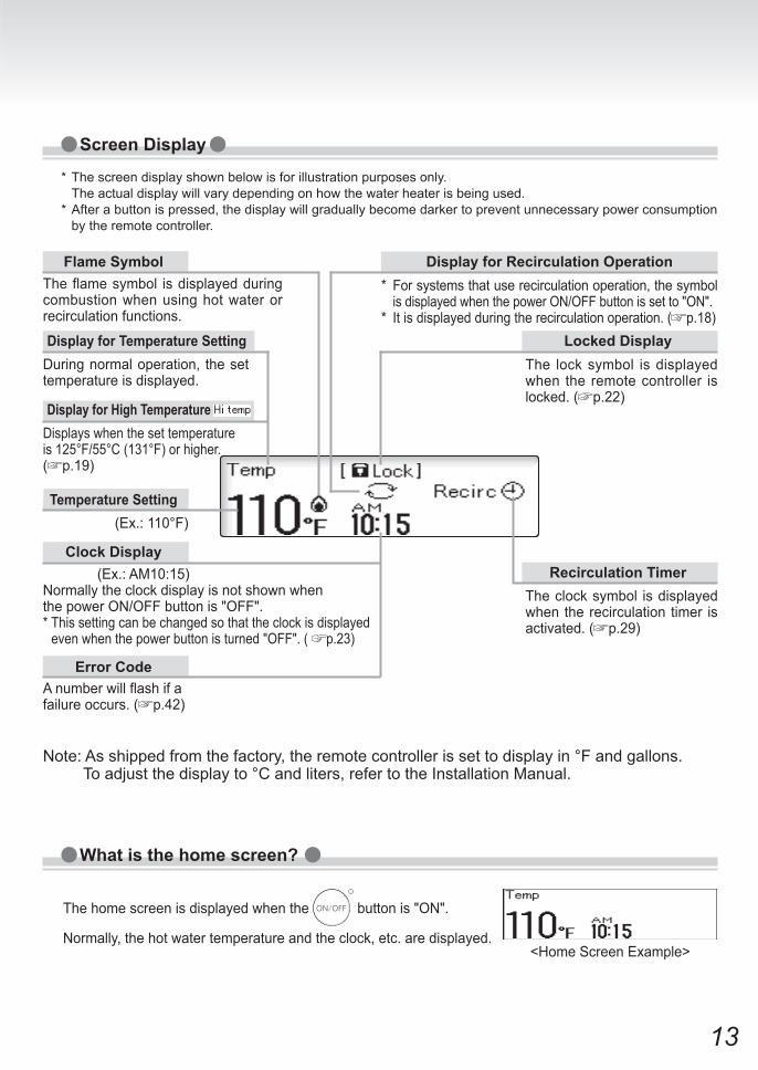
(Ex.: AM10:15)Normally the clock display is not shown whenthe power ON/OFF button is "OFF".* This setting can be changed so that the clock is displayed even when the power button is turned "OFF". ( p.23)
* The screen display shown below is for illustration purposes only. The actual display will vary depending on how the water heater is being used.* After a button is pressed, the display will gradually become darker to prevent unnecessary power consumption
by the remote controller.
(Ex.: 110°F)
The flame symbol is displayed during combustion when using hot water or recirculation functions.
A number will flash if a failure occurs. ( p.42)
<Home Screen Example>
ScreenDisplay
What is the home screen?
The home screen is displayed when the button is "ON".
Normally, the hot water temperature and the clock, etc. are displayed.
FlameSymbol
During normal operation, the set temperature is displayed.
DisplayforRecirculationOperation
DisplayforHighTemperature
Temperature Setting
ClockDisplay
Error Code
* For systems that use recirculation operation, the symbol is displayed when the power ON/OFF button is set to "ON".
* It is displayed during the recirculation operation. ( p.18)DisplayforTemperatureSetting
The lock symbol is displayed when the remote controller is locked. ( p.22)
LockedDisplay
The clock symbol is displayed when the recirculation timer is activated. ( p.29)
Recirculation Timer
Displays when the set temperatureis 125°F/55°C (131°F) or higher. ( p.19)
Note: As shipped from the factory, the remote controller is set to display in °F and gallons. To adjust the display to °C and liters, refer to the Installation Manual.
14
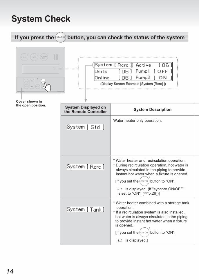
SystemDisplayedonthe Remote Controller SystemDescription
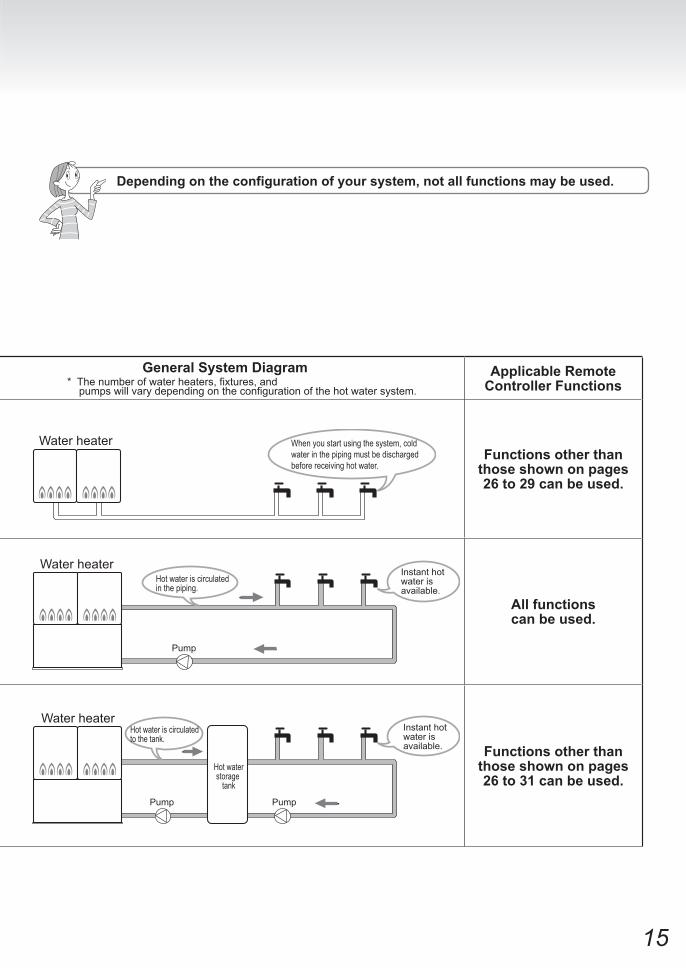
GeneralSystemDiagram * The number of water heaters, fixtures, and pumps will vary depending on the configuration of the hot water system.
ApplicableRemoteController Functions
Water heater only operation.
Functions other than those shown on pages 26to29canbeused.
* Water heater and recirculation operation.* During recirculation operation, hot water is
always circulated in the piping to provide instant hot water when a fixture is opened.
[If you set the button to "ON",
is displayed. (If "synchro ON/OFF" is set to "ON". ( p.26))]
Allfunctionscanbeused.
* Water heater combined with a storage tank operation.* If a recirculation system is also installed, hot water is always circulated in the piping to provide instant hot water when a fixture is opened.
[If you set the button to "ON",
is displayed.]
Functions other than those shown on pages 26to31canbeused.
Covershownintheopenposition.
(Display Screen Example [System [Rcrc] ])
Ifyoupressthe button,youcancheckthestatusofthesystem
SystemCheck
15
SystemDisplayedonthe Remote Controller SystemDescription
GeneralSystemDiagram * The number of water heaters, fixtures, and pumps will vary depending on the configuration of the hot water system.
ApplicableRemoteController Functions
Water heater only operation.
Functions other than those shown on pages 26to29canbeused.
* Water heater and recirculation operation.* During recirculation operation, hot water is
always circulated in the piping to provide instant hot water when a fixture is opened.
[If you set the button to "ON",
is displayed. (If "synchro ON/OFF" is set to "ON". ( p.26))]
Allfunctionscanbeused.
* Water heater combined with a storage tank operation.* If a recirculation system is also installed, hot water is always circulated in the piping to provide instant hot water when a fixture is opened.
[If you set the button to "ON",
is displayed.]
Functions other than those shown on pages 26to31canbeused.
Dependingontheconfigurationofyoursystem,notallfunctionsmaybeused.
When you start using the system, cold water in the piping must be discharged before receiving hot water.
Water heater
Water heaterInstant hot water is available.
Hot water is circulated in the piping.
Pump
Hot waterstorage
tank
Instant hot water is available.
Water heater
PumpPump
Hot water is circulated to the tank.
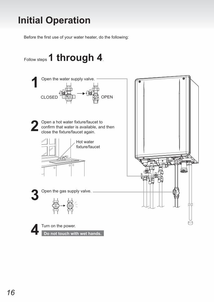
16
Initial OperationBefore the first use of your water heater, do the following:
Follow steps 1 through 4.
1 Open the water supply valve.
Open a hot water fixture/faucet to confirm that water is available, and then close the fixture/faucet again.
3 Open the gas supply valve.
Hot water fixture/faucet
2
Turn on the power.
CLOSED
4
OPEN
Donottouchwithwethands.

17
For All Systems ClockAdjustment
* This adjustment can be made regardless of whether the
button is ON/OFF.12
(Ex: AM10:15)
Covershownintheopenposition.
3 1)
2)
The screen returns to the previous screen.
Press the buttoninsidethecover.
Press the button.
1) Use the buttonsto
resettheclock.
2) Press the button
tocompletetheclocksetting.
* The time changes in 1-minute increments with each press of the but ton, and then in 10-minute increments if the button is kept pressed down.
* If the display is left untouched for approximately 20 seconds without
pressing the button, the setting will be completed. When
the button is turned ON,
the home screen will be restored.
* In the event of a power outage or after disconnecting power to the water heater, when power is restored, the clock on the display screen will show " - : - - " and the clock will need to be reset.
* Normally, when the button is turned OFF, the clock display disappears, but it is possible to display
the clock when the button is turned OFF by changing a setting. ( p.23)
Operation ScreenDisplay Description
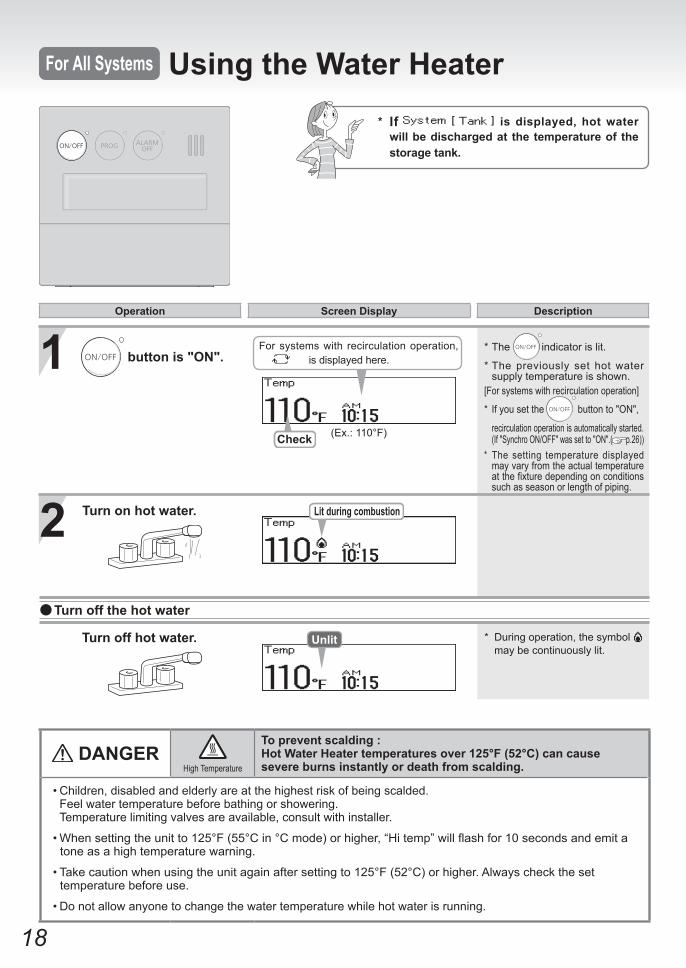
18
* The indicator is lit.
* The previously set hot water supply temperature is shown.
[For systems with recirculation operation]
* If you set the button to "ON",
recirculation operation is automatically started. (If "Synchro ON/OFF" was set to "ON".( p.26))* The setting temperature displayed
may vary from the actual temperature at the fixture depending on conditions such as season or length of piping.
* During operation, the symbol may be continuously lit.
1
2 Turnonhotwater. Lit during combustion
Check (Ex.: 110°F)
Turnoffhotwater. Unlit
DANGERHigh Temperature
Topreventscalding:HotWaterHeatertemperaturesover125°F(52°C)cancausesevereburnsinstantlyordeathfromscalding.
For All Systems Using the Water Heater* If isdisplayed,hotwaterwillbedischargedatthetemperatureofthestoragetank.
For systems with recirculation operation, is displayed here. buttonis"ON".
Turnoffthehotwater
Operation ScreenDisplay Description
• Children, disabled and elderly are at the highest risk of being scalded. Feel water temperature before bathing or showering. Temperature limiting valves are available, consult with installer.
• When setting the unit to 125°F (55°C in °C mode) or higher, “Hi temp” will flash for 10 seconds and emit a tone as a high temperature warning.
• Take caution when using the unit again after setting to 125°F (52°C) or higher. Always check the set temperature before use.
• Do not allow anyone to change the water temperature while hot water is running.
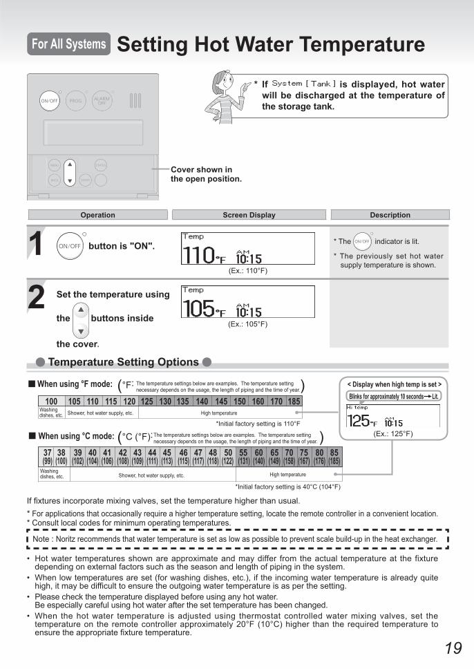
19
Temperature Setting Options
<Displaywhenhightempisset>Blinksforapproximately10secondsLit.
(Ex.: 125°F)
(°F: )The temperature settings below are examples. The temperature setting necessary depends on the usage, the length of piping and the time of year.
*Initial factory setting is 110°F
(°C (°F): )The temperature settings below are examples. The temperature setting necessary depends on the usage, the length of piping and the time of year.
*Initial factory setting is 40°C (104°F)
When using °F mode:
When using °C mode:
Shower, hot water supply, etc.Washing dishes, etc. High temperature
37 38 39 40 41 42 43 44 45 46 47 48 50 55 60 65 70 75 80 85 (99) (100) (102) (104) (106) (108) (109) (111) (113) (115) (117) (118) (122) (131) (140) (149) (158) (167) (176) (185)
100 105 110 115 120 125 130 135 140 145 150 160 170 185Shower, hot water supply, etc.Washing
dishes, etc. High temperature
* The indicator is lit.
* The previously set hot water supply temperature is shown.
1 buttonis"ON".
2 Set the temperature using
the buttonsinside
thecover.
(Ex.: 110°F)
(Ex.: 105°F)
Covershownintheopenposition.
* If isdisplayed,hotwaterwillbedischargedat thetemperatureofthestoragetank.
For All Systems Setting Hot Water Temperature
Operation ScreenDisplay Description
• Hot water temperatures shown are approximate and may differ from the actual temperature at the fixture depending on external factors such as the season and length of piping in the system.
• When low temperatures are set (for washing dishes, etc.), if the incoming water temperature is already quite high, it may be difficult to ensure the outgoing water temperature is as per the setting.
• Please check the temperature displayed before using any hot water. Be especially careful using hot water after the set temperature has been changed.• When the hot water temperature is adjusted using thermostat controlled water mixing valves, set the
temperature on the remote controller approximately 20°F (10°C) higher than the required temperature to ensure the appropriate fixture temperature.
If fixtures incorporate mixing valves, set the temperature higher than usual. * For applications that occasionally require a higher temperature setting, locate the remote controller in a convenient location.* Consult local codes for minimum operating temperatures.
Note : Noritz recommends that water temperature is set as low as possible to prevent scale build-up in the heat exchanger.
20
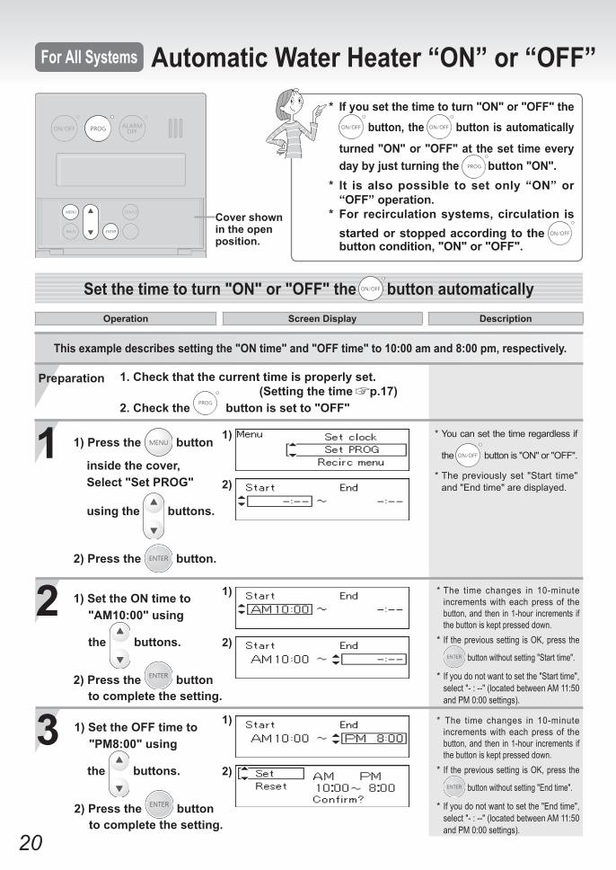
1. Check that the current time is properly set. (Setting the time p.17)2. Check the button is set to "OFF"
Cover shown in the open position.
This example describes setting the "ON time" and "OFF time" to 10:00 am and 8:00 pm, respectively.
1 * You can set the time regardless if
the button is "ON" or "OFF".
* The previously set "Start time" and "End time" are displayed.
2
3
1) Set the ON time to "AM10:00" using
the buttons.
2) Press the button to complete the setting.
1)
2)
1)
2)
1)
2)
Set the time to turn "ON" or "OFF" the button automaticallyOperation Screen Display Description
For All Systems Automatic Water Heater “ON” or “OFF” Operation* If you set the time to turn "ON" or "OFF" the
button, the button is automatically
turned "ON" or "OFF" at the set time every day by just turning the button "ON".
* It is also possible to set only “ON” or “OFF” operation.
* For recirculation systems, circulation is started or stopped according to the button condition, "ON" or "OFF".
* The time changes in 10-minute increments with each press of the button, and then in 1-hour increments if the button is kept pressed down.
* If the previous setting is OK, press the
button without setting "Start time".
* If you do not want to set the "Start time", select "- : --" (located between AM 11:50 and PM 0:00 settings).
* The time changes in 10-minute increments with each press of the button, and then in 1-hour increments if the button is kept pressed down.
* If the previous setting is OK, press the
button without setting "End time".
* If you do not want to set the "End time", select "- : --" (located between AM 11:50 and PM 0:00 settings).
1) Press the button
inside the cover, Select "Set PROG"
using the buttons.
2) Press the button.
Preparation
1) Set the OFF time to "PM8:00" using
the buttons.
2) Press the button to complete the setting.
21
For All Systems Automatic Water Heater “ON” or “OFF” Operation
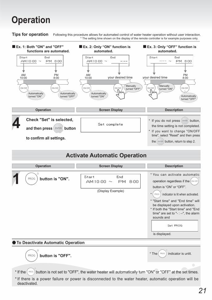
Activate Automatic Operation
4 * If you do not press button, the time setting is not completed.
* If you want to change "ON/OFF time", select "Reset" and then press
the button, return to step 2.
Operation Screen Display Description
(Display Example)
1 button is "ON".
* The indicator is unlit. button is "OFF".
To Deactivate Automatic Operation
Operation Screen Display Description
* If the button is not set to "OFF", the water heater will automatically turn "ON" or "OFF" at the set times.
* If there is a power failure or power is disconnected to the water heater, automatic operation will be deactivated.
AM10:00
PM8:00
PM8:00
AM10:00 your desired time your desired time
Tips for operation Following this procedure allows for automated control of water heater operation without user interaction.* The setting time shown on the display of the remote controller is for example purposes only.
Ex. 1: Both "ON" and "OFF" functions are automated.
Ex. 2: Only “ON” function is automated.
Ex. 3: Only “OFF” function is automated.
Automatically turned "ON"
Automatically turned "ON" Automatically
turned "OFF"
Automatically turned "OFF"
Manually turned "OFF"
Manually turned "ON"
Check "Set" is selected,
and then press button
to confirm all settings.
* You can activate automatic
operation regardless if the
button is “ON” or “OFF”.
* indicator is lit when activated.
* "Start time" and "End time" will be displayed upon activation.
* If both the "Start time" and "End time" are set to "- : --", the alarm sounds and
is displayed.
22
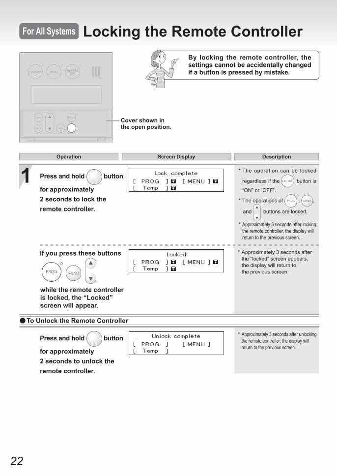
* Approximately 3 seconds after the "locked" screen appears, the display will return to
the previous screen.
1
For All Systems Locking the Remote ControllerBy locking the remote controller, the settings cannot be accidentally changed if a button is pressed by mistake.
Press and hold button
for approximately 2 seconds to lock theremote controller.
* The operation can be locked
regardless if the button is
“ON” or “OFF”.
* The operations of , ,
and buttons are locked.
* Approximately 3 seconds after locking the remote controller, the display will return to the previous screen.
If you press these buttons
* Approximately 3 seconds after unlocking the remote controller, the display will return to the previous screen.
To Unlock the Remote Controller
Press and hold button
for approximately 2 seconds to unlock theremote controller.
Cover shown in the open position.
Operation Screen Display Description
while the remote controller is locked, the “Locked” screen will appear.
23
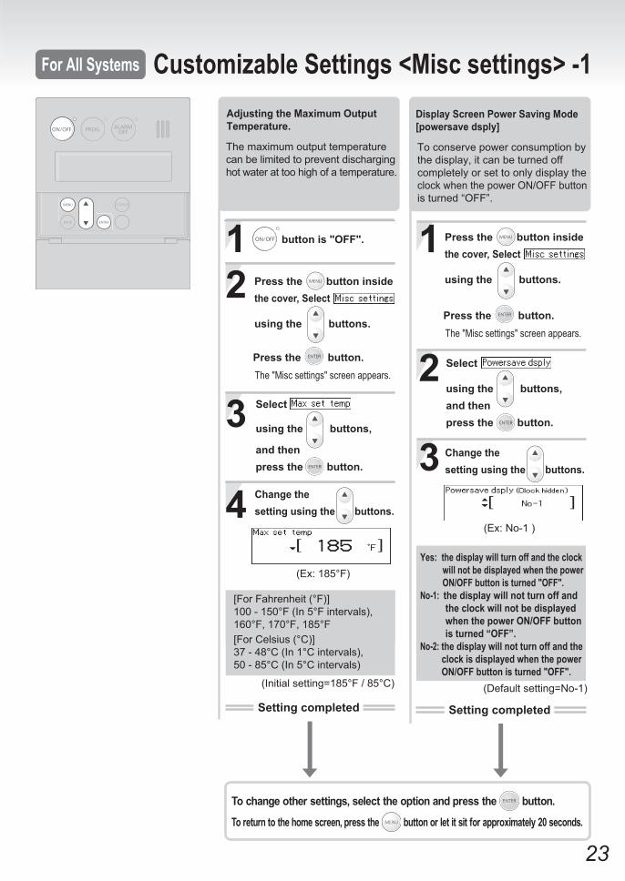
Adjusting the Maximum Output Temperature.
Setting completed
The maximum temperature setting differs by product, refer to P11.
12
3
4(Ex: 185°F)
The maximum output temperature can be limited to prevent discharging hot water at too high of a temperature.
button is "OFF".
Press the button inside the cover, Select
using the buttons.
Press the button.
Select
using the buttons,
and thenpress the button.
Change the setting using the buttons.
The "Misc settings" screen appears.
[For Fahrenheit (°F)]100 - 150°F (In 5°F intervals),160°F, 170°F, 185°F[For Celsius (°C)]37 - 48°C (In 1°C intervals),50 - 85°C (In 5°C intervals)
(Initial setting=185°F / 85°C)
3
1
2
(Default setting=No-1)
(Ex: No-1 )
Press the button inside the cover, Select
using the buttons.
Press the button.The "Misc settings" screen appears.
Select
using the buttons, and thenpress the button.
Change the setting using the buttons.
Display Screen Power Saving Mode [powersave dsply]
Yes: the display will turn off and the clock will not be displayed when the power ON/OFF button is turned "OFF".No-1: the display will not turn off and the clock will not be displayed when the power ON/OFF button is turned “OFF”.No-2: the display will not turn off and the clock is displayed when the power ON/OFF button is turned "OFF".
To conserve power consumption by the display, it can be turned off completely or set to only display the clock when the power ON/OFF buttonis turned “OFF”.
Setting completed
To change other settings, select the option and press the button.
To return to the home screen, press the button or let it sit for approximately 20 seconds.
Customizable Settings <Misc settings> -1For All Systems
24
3
1
2
Yes / No
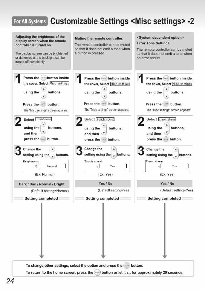
Muting the remote controller.
The remote controller can be muted so that it does not emit a tone when a button is pressed.
Press the button inside the cover, Select
using the buttons.
Press the button.The "Misc settings" screen appears.
Select
using the buttons, and thenpress the button.
Change the setting using the buttons.
(Ex: Yes)
(Default setting=Yes)
Setting completed
3
1
2
Dark / Dim / Normal / Bright
Adjusting the brightness of the display screen when the remote controller is turned on.
The display screen can be brightened or darkened or the backlight can be turned off completely.
(Default setting=Normal)
Change the setting using the buttons.
Select
using the buttons, and thenpress the button.
Press the button inside the cover, Select
using the buttons.
Press the button.The "Misc settings" screen appears.
(Ex: Normal)
Setting completed
3
1
2
Error Tone Settings.<System dependent option>
The remote controller can be muted so that it does not emit a tone when an error occurs.
Press the button inside the cover, Select
using the buttons.
Press the button.The "Misc settings" screen appears.
Select
using the buttons, and thenpress the button.
Change the setting using the buttons.
Yes / No
(Ex: Yes)
(Default setting=Yes)
Setting completed
To change other settings, select the option and press the button.
To return to the home screen, press the button or let it sit for approximately 20 seconds.
Customizable Settings <Misc settings> -2For All Systems
25
4
2
3
1
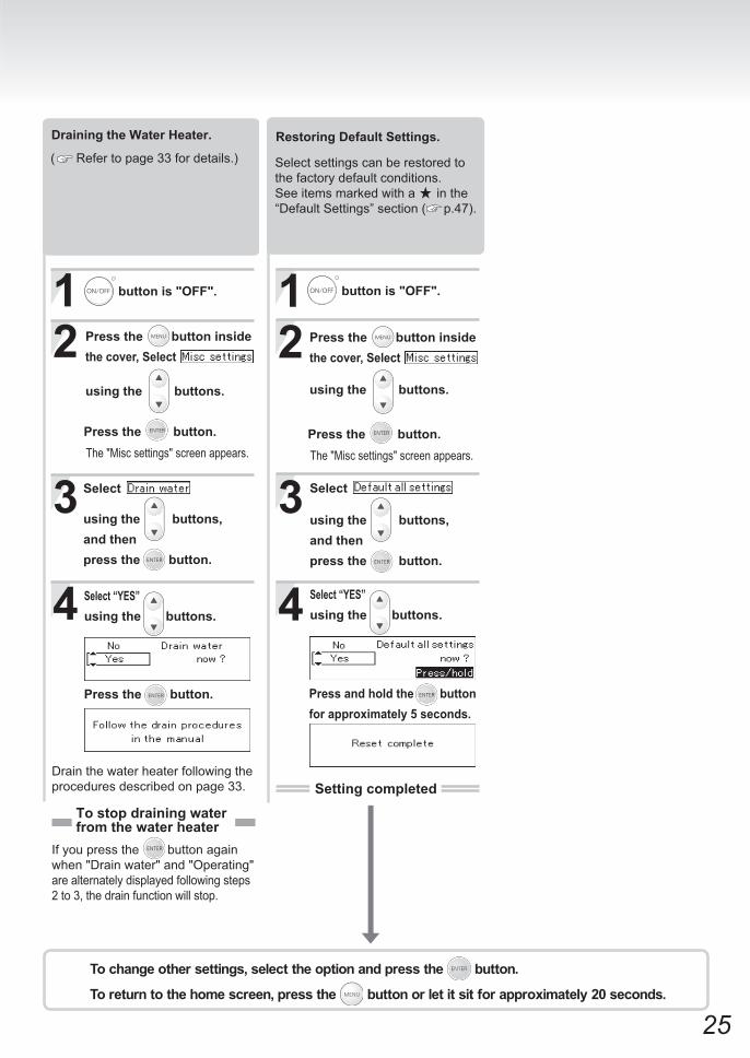
Draining the Water Heater.
( Refer to page 33 for details.)
Drain the water heater following the procedures described on page 33.
Press the button inside the cover, Select
using the buttons.
Select “YES” using the buttons.
Press the button.The "Misc settings" screen appears.
button is "OFF".
Select
using the buttons, and thenpress the button.
Press the button.
To stop draining waterfrom the water heater
If you press the button again when "Drain water" and "Operating" are alternately displayed following steps 2 to 3, the drain function will stop.
4
2
3
1
Restoring Default Settings.
Select settings can be restored to the factory default conditions. See items marked with a in the “Default Settings” section ( p.47).
button is "OFF".
Press the button inside the cover, Select
using the buttons.
Press the button.The "Misc settings" screen appears.
Select
using the buttons, and thenpress the button.
Select “YES” using the buttons.
Press and hold the button for approximately 5 seconds.
Setting completed
To change other settings, select the option and press the button.
To return to the home screen, press the button or let it sit for approximately 20 seconds.
26
12)
1)
1)
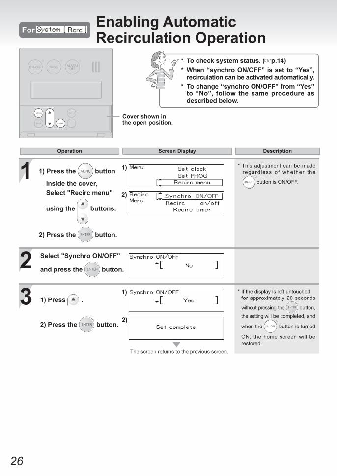
23
* This adjustment can be made regardless of whether the
button is ON/OFF.
2)
The screen returns to the previous screen.
* If the display is left untouched for approximately 20 seconds
without pressing the button, the setting will be completed, and
when the button is turned
ON, the home screen will be restored.
* To check system status. ( p.14)* When “synchro ON/OFF” is set to “Yes”,
recirculation can be activated automatically.* To change “synchro ON/OFF” from “Yes”
to “No”, follow the same procedure as described below.
Enabling Automatic Recirculation OperationFor
Select "Synchro ON/OFF"
and press the button.
1) Press .
2) Press the button.
Cover shown in the open position.
1) Press the button
inside the cover, Select "Recirc menu"
using the buttons.
2) Press the button.
Operation Screen Display Description
27
The screen returns to the previous screen.
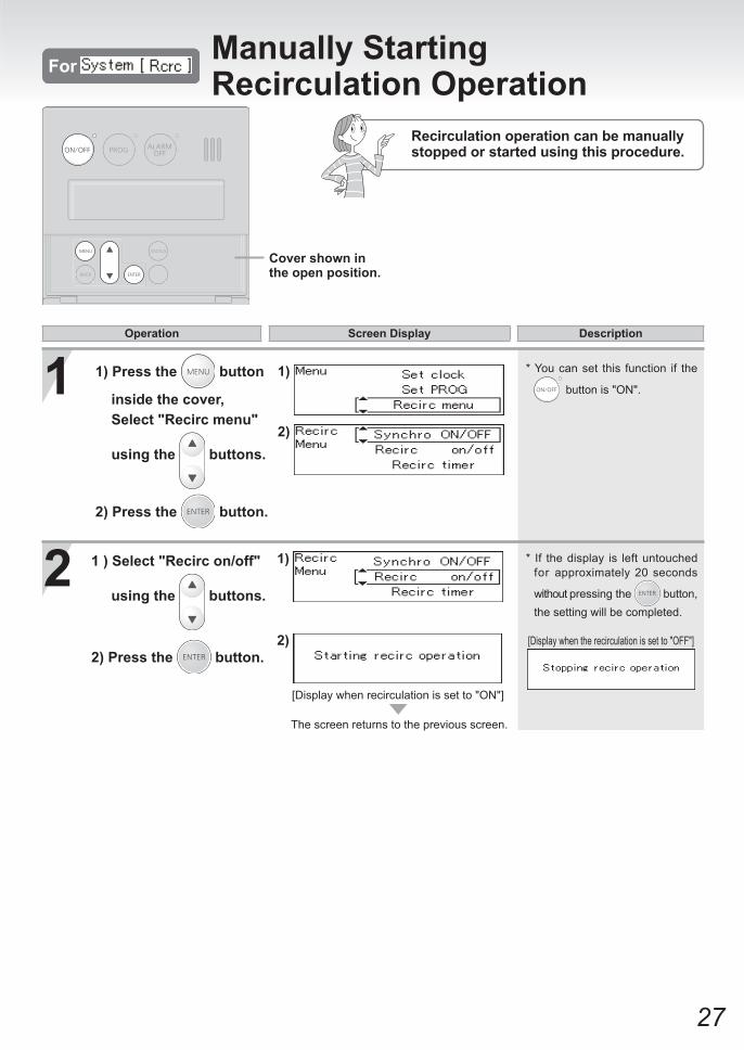
Recirculation operation can be manually stopped or started using this procedure.
1
2 * If the display is left untouched for approximately 20 seconds
without pressing the button, the setting will be completed.
1)
2) [Display when the recirculation is set to "OFF"]
1 ) Select "Recirc on/off"
using the buttons.
2) Press the button.
[Display when recirculation is set to "ON"]
Cover shown in the open position.
2)
1)1) Press the button
inside the cover, Select "Recirc menu"
using the buttons.
2) Press the button.
Operation Screen Display Description
Manually Starting Recirculation OperationFor
* You can set this function if the
button is "ON".
28
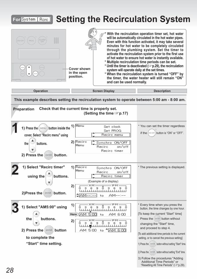
This example describes setting the recirculation system to operate between 5:00 am - 8:00 am.
1
2
3Here
1)
2)
1)
2)
(Example of a display)
1)
2)
* With the recirculation operation timer set, hot water will be automatically circulated in the hot water pipes.
Even with this function activated, it may take several minutes for hot water to be completely circulated through the plumbing system. Set the timer to activate the recirculation system prior to the first use of hot water to ensure hot water is instantly available.
* Multiple recirculation time periods can be set.* Until the timer is deactivated ( p.29), the recirculation
system will operate daily at the set times.* When the recirculation system is turned “OFF” by
the timer, the water heater will still remain “ON” and can be used normally.
For Setting the Recirculation System Operation Timer
* The previous setting is displayed.
* Every time when you press the button, the time changes by one hour.
[To keep the current “Start” time] Press the button without
changing the "Start" time, and proceed to step 4.
[To add additional time periods to the current setting, or to cancel the previous setting]
1) Press the button without setting "Start" time.
2) Press the button without setting "End" time.
3) Follow the procedures "Adding Additional Time Periods” or “Resetting All Time Periods” ( p.29).
Cover shown in the open position.
Check that the current time is properly set. (Setting the time p.17)
Preparation
* You can set the timer regardless
if the button is “ON” or “OFF”.
1) Select "Recirc timer"
using the buttons.
2)Press the button.
1) Press the button inside the
cover, Select "Recirc menu" using
the buttons.
2) Press the button.
1) Select "AM5:00" using
the buttons.
2) Press the button
to complete the “Start” time setting.
Operation Screen Display Description
29
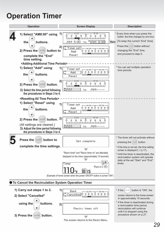
For Setting the Recirculation System Operation Timer
5 Press the button to
complete the time settings.
4Here
1)
2)
Lit
"Recirc timer" and "Recirc timer on" are altenately displayed on the menu (approximately 10 seconds)
(Example of home screen when the power ON/OFF button is turned "ON")
1)
2)
* You can set multiple operation time periods.
1)
2)
1)
2)
The screen returns to the Recirc Menu.
<Adding Additional Time Periods>
<Resetting All Time Periods>
Operation Screen Display Description
* If the button is "ON", the
screen returns to the home screen in approximately 10 seconds.* If the timer is deactivated during
a recirculation time period, recirculation will continue until it is stopped using the procedure shown on p.27.
1) Carry out steps 1 to 2.
2) Select "Cancelled"
using the buttons.
3) Press the button.
To Cancel the Recirculation System Operation Timer
* The timer will not activate without
pressing the button.
* If the time is not set, the time setting screen is displayed ( p.17).
* Until the timer is deactivated, the recirculation system will operate daily at the set “Start” and “End” times.
(All settings are cleared.)3) Adjust the time period following the procedures in Steps 3 to 4.
1) Select "Add" using
the buttons.
2) Press the button.3) Select the time period following the procedures in Steps 3 to 4.
* Every time when you press the button, the time changes by one hour.
[To keep the current “End” time]
Press the button without
changing the "End" time, and proceed to step 5.
1) Select "AM8:00" using
the buttons.
2) Press the button to complete the “End”
time setting.
1) Select "Reset" using
the buttons.
2) Press the button.

30
* Open the lid closest to the spout to allow for filling.Close the lid.
Confirm that thestopper is closed.
(Example of bathtub filled with hot water.)
1 * The indicator is lit.
2(Ex: Home screen)Check
1)
2)
(Ex: Alarm off)
3 1)
2)(Ex: 45 gal)
10 15 20 25 30 35 40 45 50 55 60 70 80 90 100 Alarm off(gal)
40 60 80 100 120 140 160 180 200 220 240 260 300 340 380 Alarm off(L)
Single Water Heater Only Flow Meter Alarm
* The current setting temperature is displayed.
* The current hot water filling volume is displayed.
Adjust the Flow Meter Alarm volume setting1) Change the volume with to your desired hot water volume.
2) Press the button.
* The set hot water volume will be stored in memory.* The screen returns to the home screen.
button is "ON".
1) Press the button inside the
cover, Select "Flow meter" using
the buttons.
2) Press the button.
* If the display is left untouched for approximately 20 seconds
without pressing the button, the setting will be completed and the home screen will be restored.
Preparation
Fill Volume Options
(Default setting = Alarm off)
Operation Screen Display Description
If the flow meter alarm is being used to indicate when a tub is full:
• If any hot water is being used besides what is going into the tub, the alarm will sound before the tub is full.
• If there was water in the tub before the fill began, or if the water is not shut off manually when the alarm sounds, the tub may overflow.
• If there was water in the tub before the fill began, the temperature in the tub after it is full may be different from the temperature setting.

31
Single Water Heater Only Flow Meter Alarm
4 Turn on hot water.
5 When the bathtub fills with the preset volume of water, an alarm will sound alerting you to shut off the water.
I will go to
turn off.
Pi Pi !
The highesttemperature
Lit during combustion
Hot Water Filling Temperature Options
* Why doesn't the flow meter alarm sound even if the bathtub is filled with water? ( p.40)
* The alarm will continue to sound
even if the button is pressed.
* Although the temperature can be set to 125°F / 50°C or higher, do not set the temperature to 125°F / 50°C or higher as it can cause severe burns instantly or death from scalding.* The hot water filling temperature is same as the setting temperature.* The setting temperature displayed may vary from the actual temperature at the fixture depending on conditions such as season or length of piping.
Turn off the hot water when the alarm sounds to prevent overfilling.
If the hot water temperature has been set so that it does not require mixing, set the mixing valve to its highest setting.The hot water in the bathtub may becomelukewarm if it is mixed with cold water at the fixture.
Operation Screen Display Description
* Initial factory setting: 110°F or 40°C (104°F)
The temperatures settings below are only examples. The temperature setting necessary will depend on the usage, the length of piping and the time of year.(°C (°F) : )
Warmer HotWarm
37 38 39 40 41 42 43 44 45 46 47 48 (99) (100) (102) (104) (106) (108) (109) (111) (113) (115) (117) (118)
100 105 110 115 120Warmer HotWarm
The temperatures settings below are only examples. The temperature setting necessary will depend on the usage, the length of piping and the time of year.(°F : )
32
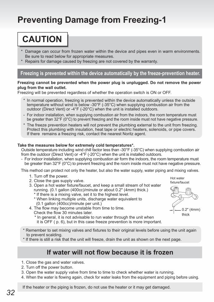
* Damage can occur from frozen water within the device and pipes even in warm environments. Be sure to read below for appropriate measures.
* Repairs for damage caused by freezing are not covered by the warranty.
Freezing cannot be prevented when the power plug is unplugged. Do not remove the power plug from the wall outlet.Freezing will be prevented regardless of whether the operation switch is ON or OFF.
Take the measures below for extremely cold temperatures*. Outside temperature including wind chill factor less than -30°F (-35°C) when supplying combustion air from the outdoor (Direct Vent) or -4°F (-20°C) when the unit is installed outdoors.- For indoor installation, when supplying combustion air form the indoors, the room temperature must
be greater than 32°F (0°C) to prevent freezing and the room inside must not have negative pressure.
This method can protect not only the heater, but also the water supply, water piping and mixing valves.1. Turn off the power.2. Close the gas supply valve.3.Openahotwaterfixture/faucet,andkeepasmallstreamofhotwater running. (0.1 gallon (400cc)/minute or about 0.2" (4mm) thick.) * If there is a mixing valve, set it to the highest level.
* When linking multiple units, discharge water equivalent to (0.1 gallon (400cc)/minute per unit.)
4.Theflowmaybecomeunstablefromtimetotime.Checktheflow30minuteslater.
* In general, it is not advisable to run water through the unit when it is OFF ( p. 6), but in this case freeze prevention is more important.
*Remembertosetmixingvalvesandfixturestotheiroriginallevelsbeforeusingtheunitagain to prevent scalding.* If there is still a risk that the unit will freeze, drain the unit as shown on the next page.
Preventing Damage from Freezing-1
Freezing is prevented within the device automatically by the freeze-prevention heater.
If water will not flow because it is frozen1. Close the gas and water valves.2. Turn off the power button.3. Open the water supply valve from time to time to check whether water is running.4. Whenthewaterisflowingagain,checkforwaterleaksfromtheequipmentandpipingbeforeusing.
If the heater or the piping is frozen, do not use the heater or it may get damaged.
CAUTION
* In normal operation, freezing is prevented within the device automatically unless the outside temperature without wind is below -30°F (-35°C) when supplying combustion air from the outdoor (Direct Vent) or -4°F (-20°C) when the unit is installed outdoors.
- For indoor installation, when supplying combustion air from the indoors, the room temperature must be greater than 32°F (0°C) to prevent freezing and the room inside must not have negative pressure.
* The freeze prevention heaters will not prevent the plumbing external to the unit from freezing. Protect this plumbing with insulation, heat tape or electric heaters, solenoids, or pipe covers. If there remains a freezing risk, contact the nearest Noritz agent.
0.2" (4mm) thick
Hot water fixture/faucet

33
Lid - Condensate ContainerDo not take the lid off.Drain Plugs
Each drain plug mignt not be visible if insulation is installed around the piping.
If the water heater will not be used for a long period of time, drain the water.Drain the water as follows:
To avoid burns, wait until the equipment cools down before draining the water. The appliance will remain hot after it is turned off.High Temperature
CAUTION
4 Open all drain plugs and drain the water out of the unit.
1
Fully open all hot water fixtures/faucets.
Drainage Using the Remote Controller
2 (1) Turn the power on/off button “On”.
(2) Turn and leave open thehotwaterfixtures/ faucets for more than 2 minutes and close.
* If multiple units are being used, drain two minutes for each unit.
* An 11 Error Code may appear on the remote controller.
This is not a malfunction of the unit. Do not turn Power ON/OFF Button OFF.
Manual Draining
Close the water supply valve and disconnect the electrical power supplied to the unit.
34
5 When the water is completely drained, replace alldrainplugsandclosethehotwaterfixtures/faucets.
5 Open all drain plugs and drain the water out of the unit.
6
Close the gas valve. 1
Close the water supply valve.2
When the water is completely drained, replace all drain plugs and close the hotwaterfixtures/faucets.
Do not touch with wet hands.
Drain water into a bucket to prevent water damage.
(1) button is “OFF”.
(2) Press the button inside the cover,
Select using the buttons.
Press the button.
The "Misc settings" screen appears.
(3) Select using the buttons,
and then press button.
(4) Select "YES" using the buttons,
Press button.
6 Close the gas valve and disconnect the electrical power supplied to the unit.Do not touch with wet hands.
Fully open all hot water fixtures/faucets.3 Hot water
fixture/faucet
Hot water fixture/faucet
Hot water fixture/faucet
To prevent damage from freezing, the water heater must be plugged into power at all times. If power is unplugged, drain the water completely from the water heater. Then use an air compressor to remove all water from inside the unit's water piping. It is recommended that Isolation Valves are installed on the water heater, otherwise the water connections will need to be removed to drain the unit completely. Freeze damage due to not draining properly will not be covered under warranty.
34
Preventing Damage from Freezing-2
Turning the Unit Back On1. Check that all drain plugs are inserted.2.Checkthatallhotwaterfixtures/faucets are closed.3. Follow the procedure on p.16 “Initial operation”, steps 1 through 4.4. Make sure that the area around the appliance is well ventilated; open a window or a door if necessary.
Then, operate the unit and verify that condensate is coming out of the drain pipe. (During normal use of the water heater, condensate will begin to discharge from the drain pipe within 15
minutes of use. However, depending on the season and/or installation site conditions, it may take longer.)
*Ifwaterdoesnotappearattheendofthedrainline,aqualifiedservicetechnicianmustcleanthecondensate line.
Afterthewaterheaterhasbeenoutofuseforalongtimemakesurethatyoufillthe condensate trap with water.This is to prevent dangerous exhaust gases from entering the building.Failuretofillthecondensatetrapcouldresultinseverepersonalinjuryordeath.(By performing step 4 as described above, the condensate trap will automatically fillitselfwithwater.)
Be sure to do.
DANGER
35
Air Supply Vent
Periodic Maintenance
Wipe the outside surface with a wet cloth, then dry the surface. Use a neutral detergent to clean any stains.If an external condensate neutralizer is installed, periodic replacement of the neutralizing agent will be required. Refer to the instructions supplied with the neutralizer for suggested replacement intervals.
• Do not use benzene, oil or fatty detergents to clean the remote controller; deformation may occur.• The remote controller is not water resistant. Keep it dry.
Regular Maintenance-1
Periodic Inspection
Unit
Remote ControllerWipe the surface with a wet cloth.
Be sure to do.
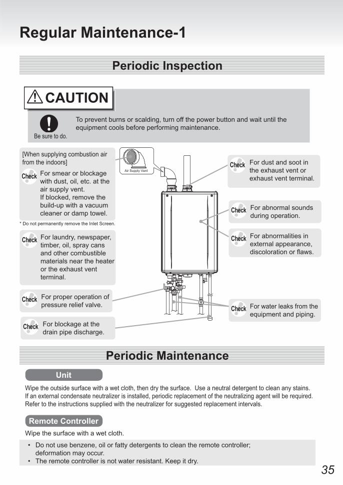
To prevent burns or scalding, turn off the power button and wait until the equipment cools before performing maintenance.
CAUTION
Check
For abnormal sounds during operation.
For abnormalities in external appearance, discolorationorflaws.
For water leaks from the equipment and piping.
For dust and soot in the exhaust vent or exhaust vent terminal.
Check
Check
Check
Check
For blockage at the drain pipe discharge.
Check
Check
[When supplying combustion air from the indoors]
For proper operation of pressure relief valve.
Check
For smear or blockage with dust, oil, etc. at the air supply vent.If blocked, remove the build-up with a vacuum cleaner or damp towel.
* Do not permanently remove the Inlet Screen.
For laundry, newspaper, timber, oil, spray cans and other combustible materials near the heater or the exhaust vent terminal.
36
Periodic Maintenance
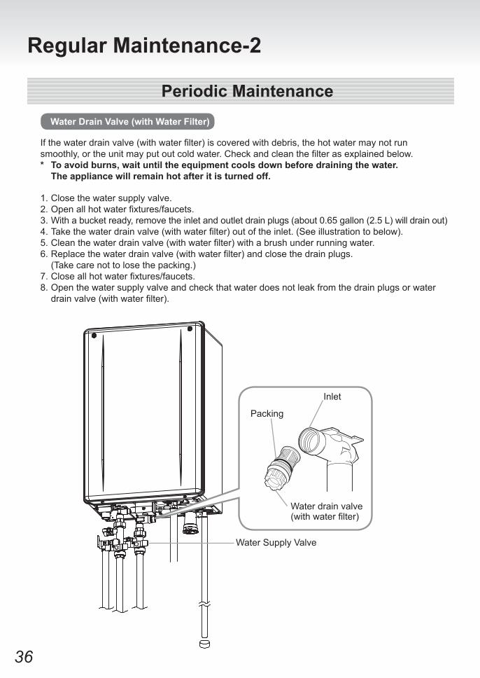
Ifthewaterdrainvalve(withwaterfilter)iscoveredwithdebris,thehotwatermaynotrunsmoothly,ortheunitmayputoutcoldwater.Checkandcleanthefilterasexplainedbelow.* To avoid burns, wait until the equipment cools down before draining the water.
The appliance will remain hot after it is turned off.
Water Drain Valve (with Water Filter)
1. Close the water supply valve.2.Openallhotwaterfixtures/faucets.3. With a bucket ready, remove the inlet and outlet drain plugs (about 0.65 gallon (2.5 L) will drain out)4.Takethewaterdrainvalve(withwaterfilter)outoftheinlet.(Seeillustrationtobelow).5.Cleanthewaterdrainvalve(withwaterfilter)withabrushunderrunningwater.6.Replacethewaterdrainvalve(withwaterfilter)andclosethedrainplugs. (Take care not to lose the packing.)7.Closeallhotwaterfixtures/faucets.8. Open the water supply valve and check that water does not leak from the drain plugs or water drainvalve(withwaterfilter).
Water Supply Valve
Inlet
Packing
Water drain valve (withwaterfilter)
Regular Maintenance-2
37
Cold Water Service Valve
Hot Water Service Valve
Pressure Relief Valve
Water Inlet
Water Outlet
Drain
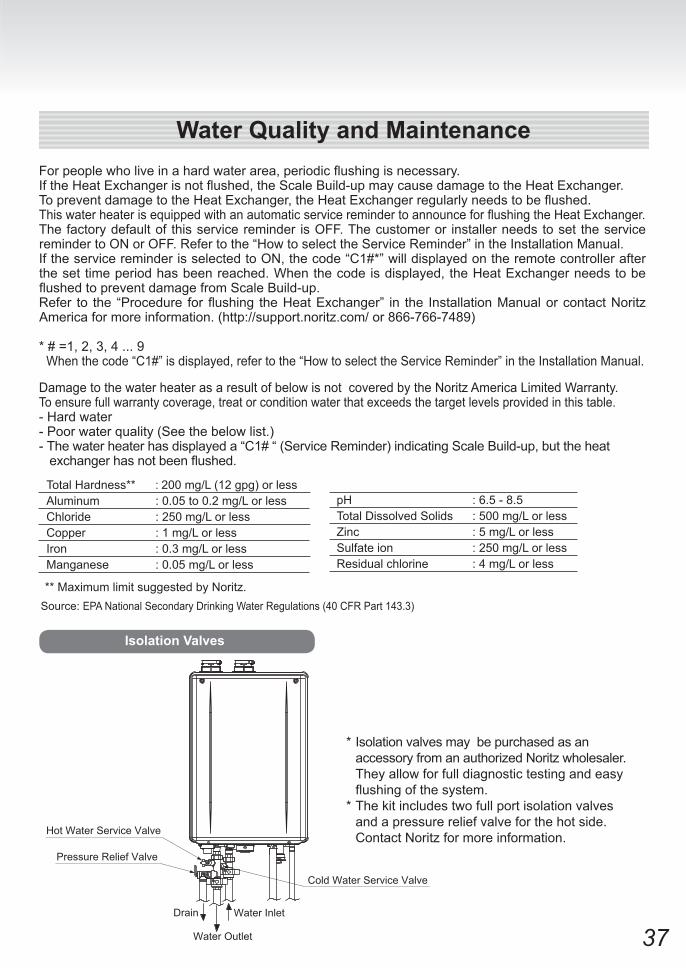
* Isolation valves may be purchased as an accessory from an authorized Noritz wholesaler.
They allow for full diagnostic testing and easy flushingofthesystem.
* The kit includes two full port isolation valves and a pressure relief valve for the hot side.
Contact Noritz for more information.
Isolation Valves
Forpeoplewholiveinahardwaterarea,periodicflushingisnecessary.IftheHeatExchangerisnotflushed,theScaleBuild-upmaycausedamagetotheHeatExchanger.TopreventdamagetotheHeatExchanger,theHeatExchangerregularlyneedstobeflushed.ThiswaterheaterisequippedwithanautomaticserviceremindertoannounceforflushingtheHeatExchanger.The factory default of this service reminder is OFF. The customer or installer needs to set the service reminder to ON or OFF. Refer to the “How to select the Service Reminder” in the Installation Manual.If the service reminder is selected to ON, the code “C1#*” will displayed on the remote controller after the set time period has been reached. When the code is displayed, the Heat Exchanger needs to be flushedtopreventdamagefromScaleBuild-up.Refer to the “Procedure forflushing theHeatExchanger” in the InstallationManualorcontactNoritzAmerica for more information. (http://support.noritz.com/ or 866-766-7489)
* # =1, 2, 3, 4 ... 9 When the code “C1#” is displayed, refer to the “How to select the Service Reminder” in the Installation Manual.
Total Hardness** : 200 mg/L (12 gpg) or lessAluminum : 0.05 to 0.2 mg/L or lessChloride : 250 mg/L or lessCopper : 1 mg/L or lessIron : 0.3 mg/L or lessManganese : 0.05 mg/L or less
** Maximum limit suggested by Noritz.
pH : 6.5 - 8.5Total Dissolved Solids : 500 mg/L or lessZinc : 5 mg/L or lessSulfate ion : 250 mg/L or less Residual chlorine : 4 mg/L or less
Damage to the water heater as a result of below is not covered by the Noritz America Limited Warranty.To ensure full warranty coverage, treat or condition water that exceeds the target levels provided in this table.- Hard water- Poor water quality (See the below list.)- The water heater has displayed a “C1# “ (Service Reminder) indicating Scale Build-up, but the heatexchangerhasnotbeenflushed.
Source: EPA National Secondary Drinking Water Regulations (40 CFR Part 143.3)
Water Quality and Maintenance
38
Troubleshooting-1
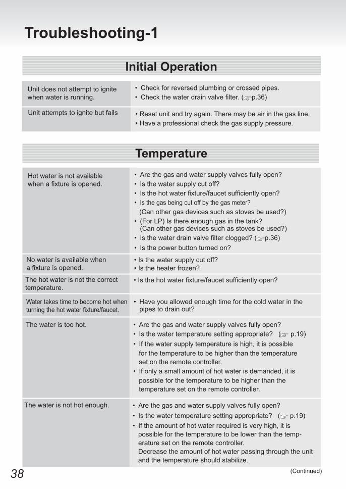
Initial OperationUnit does not attempt to ignite when water is running.
• Check for reversed plumbing or crossed pipes.• Checkthewaterdrainvalvefilter.( p.36)
Unit attempts to ignite but fails
TemperatureHot water is not availablewhenafixtureisopened.
• Are the gas and water supply valves fully open?• Is the water supply cut off?• Isthehotwaterfixture/faucetsufficientlyopen?• Is the gas being cut off by the gas meter? (Can other gas devices such as stoves be used?) • (For LP) Is there enough gas in the tank?
(Can other gas devices such as stoves be used?)• Isthewaterdrainvalvefilterclogged?( p.36)• Is the power button turned on?
• Are the gas and water supply valves fully open?• Is the water temperature setting appropriate? ( p.19)• If the water supply temperature is high, it is possible for the temperature to be higher than the temperature set on the remote controller.• If only a small amount of hot water is demanded, it is possible for the temperature to be higher than the temperature set on the remote controller.
The water is too hot.
• Have you allowed enough time for the cold water in the pipes to drain out?
Water takes time to become hot when turningthehotwaterfixture/faucet.
No water is available whenafixtureisopened.
• Is the water supply cut off?• Is the heater frozen?
The hot water is not the correcttemperature.
•Isthehotwaterfixture/faucetsufficientlyopen?
• Reset unit and try again. There may be air in the gas line.• Have a professional check the gas supply pressure.
(Continued)
• Are the gas and water supply valves fully open?• Is the water temperature setting appropriate? ( p.19)• If the amount of hot water required is very high, it is possible for the temperature to be lower than the temp- erature set on the remote controller. Decrease the amount of hot water passing through the unit and the temperature should stabilize.
The water is not hot enough.
39
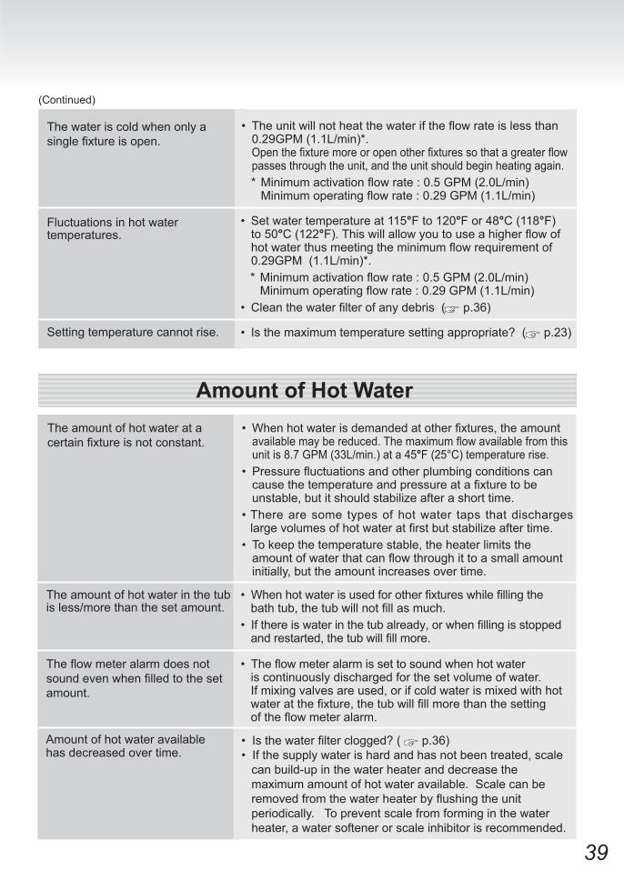
The water is cold when only a singlefixtureisopen.
• Theunitwillnotheatthewateriftheflowrateislessthan0.29GPM (1.1L/min)*.
Openthefixturemoreoropenotherfixturessothatagreaterflowpasses through the unit, and the unit should begin heating again.
*Minimumactivationflowrate:0.5GPM(2.0L/min) Minimumoperatingflowrate:0.29GPM(1.1L/min)
Amount of Hot WaterThe amount of hot water at a certainfixtureisnotconstant.
• Whenhotwaterisdemandedatotherfixtures,theamountavailablemaybereduced.Themaximumflowavailablefromthisunit is 8.7 GPM (33L/min.) at a 45°F (25°C) temperature rise.
• Pressurefluctuationsandotherplumbingconditionscancausethetemperatureandpressureatafixturetobeunstable, but it should stabilize after a short time.
• There are some types of hot water taps that discharges largevolumesofhotwateratfirstbutstabilizeaftertime.
• To keep the temperature stable, the heater limits the amountofwaterthatcanflowthroughittoasmallamountinitially, but the amount increases over time.
The amount of hot water in the tubis less/more than the set amount.
• Whenhotwaterisusedforotherfixtureswhilefillingthebathtub,thetubwillnotfillasmuch.• Ifthereiswaterinthetubalready,orwhenfillingisstoppedandrestarted,thetubwillfillmore.
Theflowmeteralarmdoesnotsoundevenwhenfilledtothesetamount.
• Theflowmeteralarmissettosoundwhenhotwater is continuously discharged for the set volume of water. If mixing valves are used, or if cold water is mixed with hotwateratthefixture,thetubwillfillmorethanthesettingoftheflowmeteralarm.
Amount of hot water availablehas decreased over time.
Fluctuations in hot water temperatures.
• Set water temperature at 115°F to 120°F or 48°C (118°F) to 50°C (122°F).Thiswillallowyoutouseahigherflowofhotwaterthusmeetingtheminimumflowrequirementof0.29GPM (1.1L/min)*.
*Minimumactivationflowrate:0.5GPM(2.0L/min) Minimumoperatingflowrate:0.29GPM(1.1L/min)• Cleanthewaterfilterofanydebris ( p.36)
(Continued)
Setting temperature cannot rise. • Is the maximum temperature setting appropriate? ( p.23)
•Isthewaterfilterclogged?( p.36) • If the supply water is hard and has not been treated, scale can build-up in the water heater and decrease the maximum amount of hot water available. Scale can be removedfromthewaterheaterbyflushingtheunit periodically. To prevent scale from forming in the water heater, a water softener or scale inhibitor is recommended.
40
Troubleshooting-2
Remote Controller
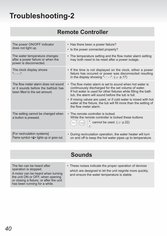
The clock display shows "- : - -".
• If the time is not displayed on the clock, either a power failure has occured or power was disconnected resulting in the display showing "- : - -". ( p.17)
The fan can be heard after operation is stopped.A motor can be heard when turningthe unit ON or OFF, when openingorclosingafixture,oraftertheunithas been running for a while.
• These noises indicate the proper operation of devices which are designed to let the unit reignite more quickly, and ensure the water temperature is stable.
Sounds
The flow meter alarm does not sound or it sounds before the bathtub has been filled to the set amount.
• The flow meter alarm is set to sound when hot water is continuously discharged for the set volume of water.
If hot water is used for other fixtures while filling the bath tub, the alarm will sound before the tub is full.
• If mixing valves are used, or if cold water is mixed with hot water at the fixture, the tub will fill more than the setting of the flow meter alarm.
The setting cannot be changed when a button is pressed.
• The remote controller is locked. While the remote controller is locked these buttons cannot be used. ( p.22)
[For recirculation systems]Flame symbol < > lights up or goes out.
• During recirculation operation, the water heater will turn on and off to keep the hot water pipes up to temperature.
The water temperature changes after a power failure or when the power is disconnected.
The power ON/OFF indicator does not light up.
• Has there been a power failure?• Is the power connected properly?
• Thetemperaturesettingandtheflowmeteralarmsettingmay both need to be reset after a power outage.
41
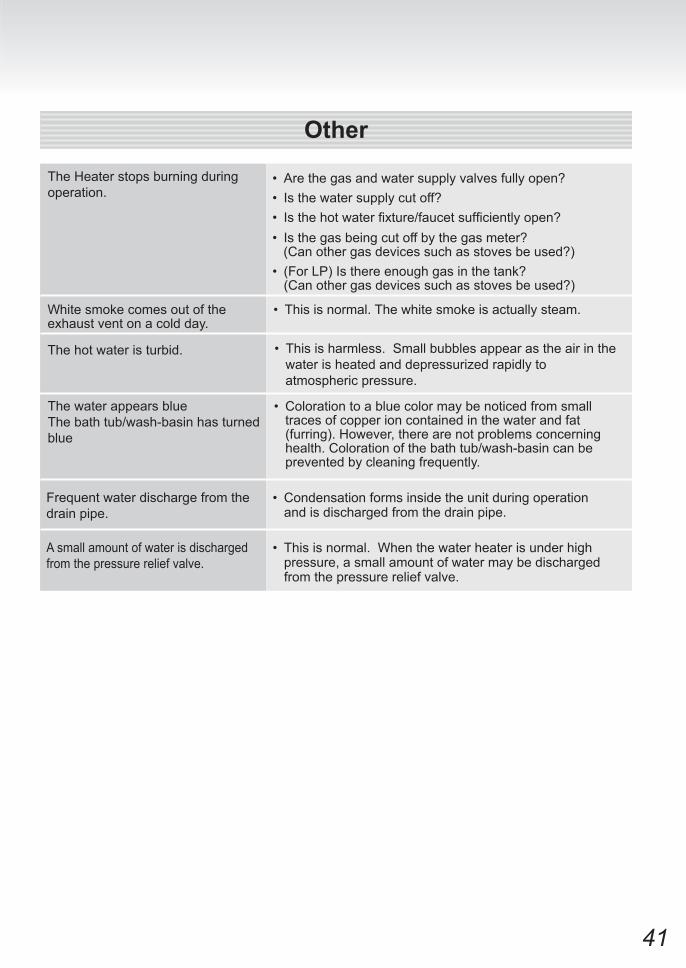
The water appears blueThe bath tub/wash-basin has turned blue
• Coloration to a blue color may be noticed from small traces of copper ion contained in the water and fat (furring). However, there are not problems concerning health. Coloration of the bath tub/wash-basin can be prevented by cleaning frequently.
Frequent water discharge from the drain pipe.
• Condensation forms inside the unit during operation and is discharged from the drain pipe.
The Heater stops burning during operation.
• Are the gas and water supply valves fully open?• Is the water supply cut off?• Is the hot water fixture/faucetsufficientlyopen?• Is the gas being cut off by the gas meter? (Can other gas devices such as stoves be used?)• (For LP) Is there enough gas in the tank?
(Can other gas devices such as stoves be used?)
• This is normal. The white smoke is actually steam.White smoke comes out of the exhaust vent on a cold day.
The hot water is turbid. • This is harmless. Small bubbles appear as the air in the water is heated and depressurized rapidly to atmospheric pressure.
Other
A small amount of water is discharged from the pressure relief valve.
• This is normal. When the water heater is under high pressure, a small amount of water may be discharged from the pressure relief valve.

42
Troubleshooting-3
Contact Noritz America if:• Any other error code appears.• An error code is indicated again after the above actions were followed.• There are any other questions.
Error Code Cause Action Ignition error Check whether the gas valve is open. Press the power button to turn
theunitoff,openahotwaterfixture/faucet,andturntheunitbackon.Iftheflashingnumberdoesn'treturntheproblemissolved.
Check air supply vent for blockage or obstruction. ( p.35) [When supplying combustion air from the indoors]The air supply vent may be clogged.
Check exhaust vent for blockage or obstruction.
Have a professional check the gas supply pressure.
Check condensate drain line is clogged or frozen.If the display continues, contact nearest Noritz agent.
Exhaust vent may be clogged.
Abnormal combustion,low gas supply pressur.
Condensate drain line maybe clogged.
When a failure occurs, information relating to the error blinks on the display.The error alarm may also continuously sound.
Checking for Error Conditions
The display may indicate the type of failure that has occured depending on the system configuration.
Error Code Display Screen
To Stop the Error Alarm
Press the button (the indicator will turn off).
This unit is equipped with an automatic service reminder. Excessive scale build-up may cause premature failure of the heat exchanger. Excessive dust or lint build-up in the fan and air intake may affect efficiencyandcombustionperformance.Contact Noritz America for additional information about recommended maintenance procedures (866-766-7489).
Service Reminder(Warning Indication)
11
90
C1## = 1-9
43
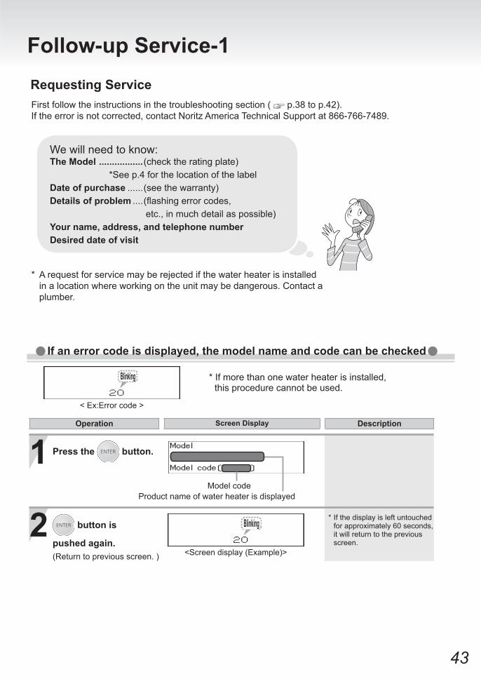
Requesting ServiceFirst follow the instructions in the troubleshooting section ( p.38 to p.42). If the error is not corrected, contact Noritz America Technical Support at 866-766-7489.
* A request for service may be rejected if the water heater is installed in a location where working on the unit may be dangerous. Contact a plumber.
We will need to know:The Model .................(check the rating plate) *See p.4 for the location of the labelDate of purchase ......(see the warranty)Details of problem ....(flashingerrorcodes, etc., in much detail as possible)Your name, address, and telephone numberDesired date of visit
1
2Model code
Product name of water heater is displayed
< Ex:Error code >
<Screen display (Example)>
Operation Screen Display Description
If an error code is displayed, the model name and code can be checked
* If more than one water heater is installed, this procedure cannot be used.
Press the button.
button is
pushed again.(Return to previous screen. )
* If the display is left untouched for approximately 60 seconds, it will return to the previous screen.
Follow-up Service-1
44
A warranty registration card is included separately.Besurethattheinstallername,dateofpurchaseandothernecessaryitemsarefilledin.Read the content carefully, and keep the warranty card in a safe place.
For repairs after the warranty period, there will be a charge on any service, and service will only be performed if the unit is deemed repairable.
Period of Time for Stocking Repair Parts
Warranty
Noritz will stock repair and maintenance parts for this unit for the time period from the date of the original installation as follows: twelve (12) years for the heat exchanger and ten (10) years for remaining parts.
Reinstallation
Ifyouwanttoreinstalltheapplianceatadifferentlocation,confirmthatthegasandpowersupply indicated on the rating plate are available at the new location. If you are not sure, consult the local utility company.
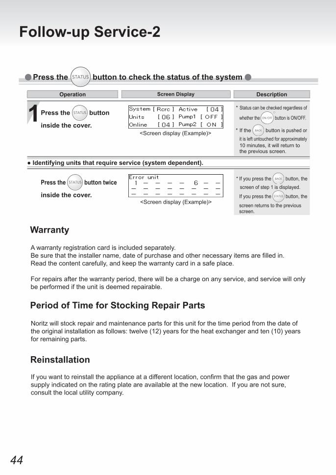
1Press the button
inside the cover.<Screen display (Example)>
<Screen display (Example)>
● Identifying units that require service (system dependent).
Operation Screen Display Description
Press the button to check the status of the system
* If you press the button, the screen of step 1 is displayed.
If you press the button, the
screen returns to the previous screen.
* If the button is pushed or it is left untouched for approximately
10 minutes, it will return to the previous screen.
* Status can be checked regardless of
whether the button is ON/OFF.
Press the button twice
inside the cover.
Follow-up Service-2
45
Gas ConversionIf you move to a region that uses a different type of gas or if the local gas supply is converted, replacement of the gas manifold and adjustment of the appliance will be necessary. ThisworkmustbeperformedbyeitherNoritzoraqualifiedserviceagencyandwillbechargedforevenduringthewarrantyperiod.Thequalifiedinstallerwillalsoberesponsibleforpurchasingthegas conversion kit directly from the manufacturer. For more information, contact Noritz America Technical Support at 866-766-7489.
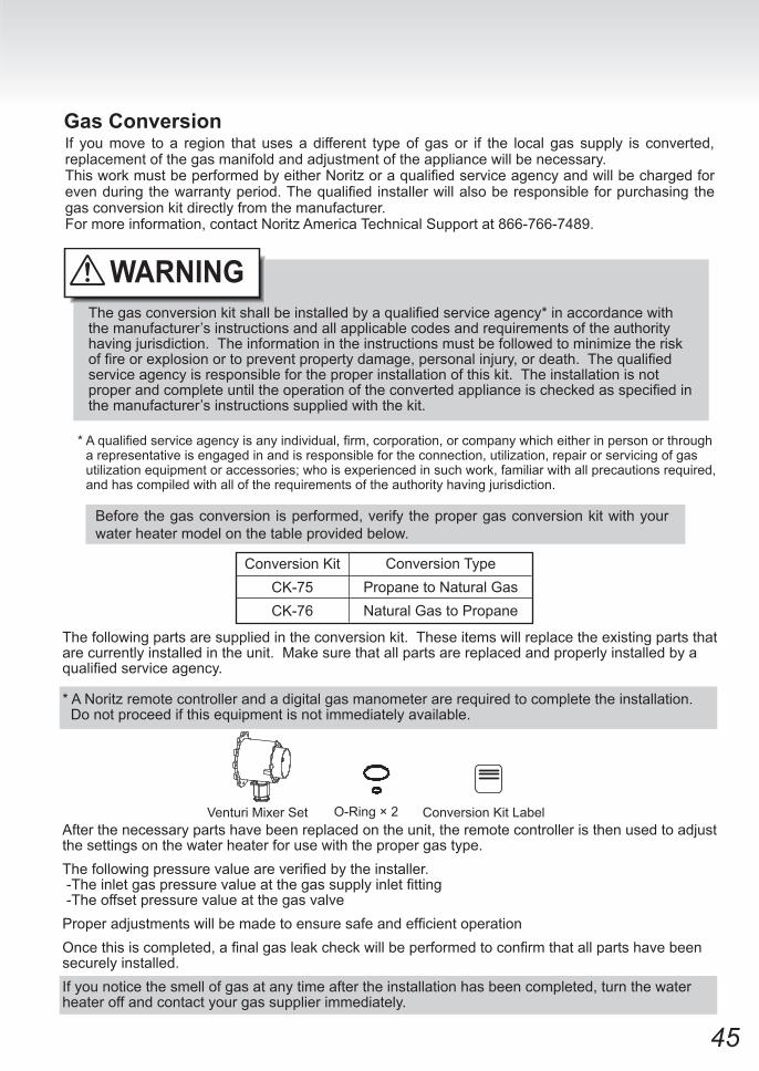
The following parts are supplied in the conversion kit. These items will replace the existing parts that are currently installed in the unit. Make sure that all parts are replaced and properly installed by a qualifiedserviceagency.
* A Noritz remote controller and a digital gas manometer are required to complete the installation. Do not proceed if this equipment is not immediately available.
*Aqualifiedserviceagencyisanyindividual,firm,corporation,orcompanywhicheitherinpersonorthrougha representative is engaged in and is responsible for the connection, utilization, repair or servicing of gas utilization equipment or accessories; who is experienced in such work, familiar with all precautions required, and has compiled with all of the requirements of the authority having jurisdiction.
Thegasconversionkitshallbeinstalledbyaqualifiedserviceagency*inaccordancewiththe manufacturer’s instructions and all applicable codes and requirements of the authority having jurisdiction. The information in the instructions must be followed to minimize the risk offireorexplosionortopreventpropertydamage,personalinjury,ordeath.Thequalifiedservice agency is responsible for the proper installation of this kit. The installation is not properandcompleteuntiltheoperationoftheconvertedapplianceischeckedasspecifiedinthe manufacturer’s instructions supplied with the kit.
Before the gas conversion is performed, verify the proper gas conversion kit with your water heater model on the table provided below.
After the necessary parts have been replaced on the unit, the remote controller is then used to adjust the settings on the water heater for use with the proper gas type.Thefollowingpressurevalueareverifiedbytheinstaller.-Theinletgaspressurevalueatthegassupplyinletfitting -The offset pressure value at the gas valveProperadjustmentswillbemadetoensuresafeandefficientoperationOncethisiscompleted,afinalgasleakcheckwillbeperformedtoconfirmthatallpartshavebeensecurely installed. If you notice the smell of gas at any time after the installation has been completed, turn the water heater off and contact your gas supplier immediately.
Conversion KitCK-75CK-76
Venturi Mixer Set O-Ring × 2 Conversion Kit Label
WARNING
Conversion TypePropane to Natural GasNatural Gas to Propane
46
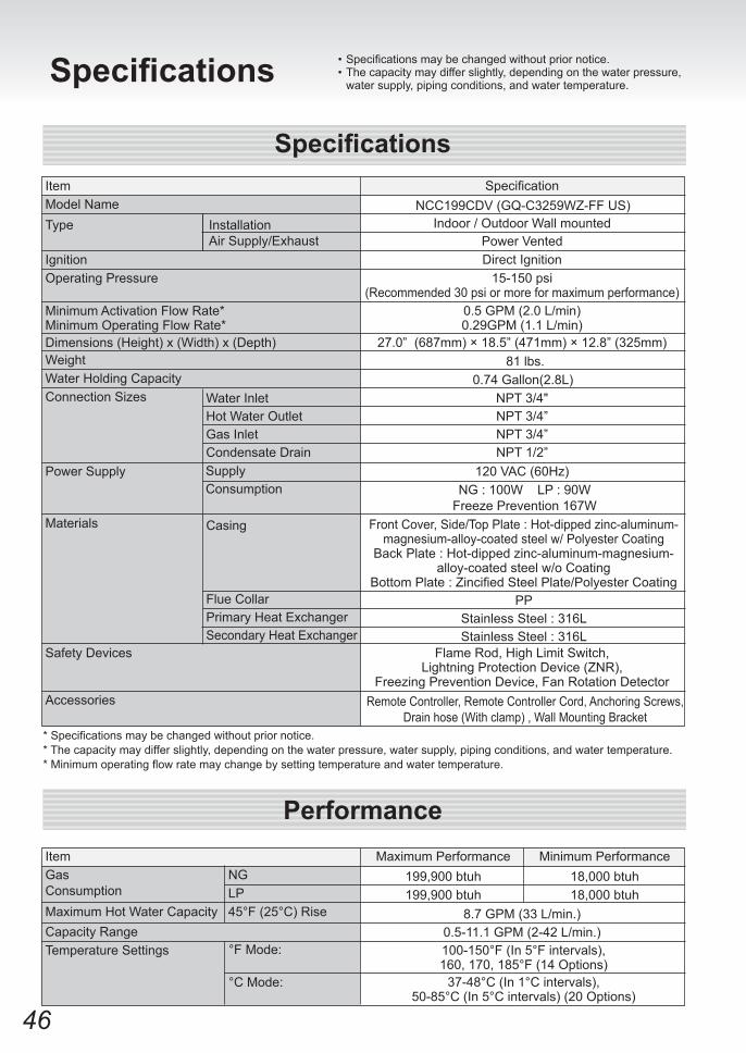
Specifications •Specificationsmaybechangedwithoutpriornotice.• The capacity may differ slightly, depending on the water pressure,
water supply, piping conditions, and water temperature.
Specification
Indoor / Outdoor Wall mounted
Direct Ignition15-150 psi
(Recommended 30 psi or more for maximum performance)0.5 GPM (2.0 L/min)0.29GPM (1.1 L/min)
27.0” (687mm) × 18.5” (471mm) × 12.8” (325mm)81 lbs.
0.74 Gallon(2.8L)NPT 3/4"NPT 3/4”NPT 3/4”NPT 1/2”
120 VAC (60Hz)NG : 100W LP : 90W
Freeze Prevention 167WFront Cover, Side/Top Plate : Hot-dipped zinc-aluminum-
magnesium-alloy-coated steel w/ Polyester CoatingBack Plate : Hot-dipped zinc-aluminum-magnesium-
alloy-coated steel w/o CoatingBottomPlate:ZincifiedSteelPlate/PolyesterCoating
PPStainless Steel : 316LStainless Steel : 316L
Flame Rod, High Limit Switch, Lightning Protection Device (ZNR),
Freezing Prevention Device, Fan Rotation DetectorRemote Controller, Remote Controller Cord, Anchoring Screws,
Drain hose (With clamp) , Wall Mounting Bracket
Specifications
Performance
ItemModel NameType
IgnitionOperating Pressure
Minimum Activation Flow Rate*Minimum Operating Flow Rate*Dimensions (Height) x (Width) x (Depth)WeightWater Holding Capacity
Accessories
*Specificationsmaybechangedwithoutpriornotice.* The capacity may differ slightly, depending on the water pressure, water supply, piping conditions, and water temperature.*Minimumoperatingflowratemaychangebysettingtemperatureandwatertemperature.
InstallationAir Supply/Exhaust
Connection Sizes
Power Supply
Materials
Water InletHot Water OutletGas InletCondensate Drain
Safety Devices
ItemGasConsumptionMaximum Hot Water CapacityCapacity RangeTemperature Settings
NGLP45°F (25°C) Rise
Maximum Performance199,900 btuh199,900 btuh
Minimum Performance18,000 btuh18,000 btuh
8.7 GPM (33 L/min.)0.5-11.1 GPM (2-42 L/min.)100-150°F (In 5°F intervals),160, 170, 185°F (14 Options)
Casing
Flue CollarPrimary Heat ExchangerSecondary Heat Exchanger
SupplyConsumption
°F Mode:
°C Mode: 37-48°C (In 1°C intervals), 50-85°C (In 5°C intervals) (20 Options)
Power Vented
NCC199CDV (GQ-C3259WZ-FF US)
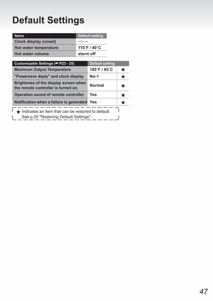
47
Default Settings
Customizable Settings ( P23 - 25) Default settingMaximum Output Temperature 185˚F / 85˚C"Powersave dsply" and clock display No-1Brightness of the display screen when the remote controller is turned on. Normal
Operation sound of remote controller Yes
Notification when a failure is generated Yes
Items Default settingClock display (unset)Hot water temperature 110˚F / 40˚CHot water volume alarm off
Indicates an item that can be restored to default. See p.25 "Restoring Default Settings".


