Embed Size (px)
Citation preview
FILE NO. A10-1510
SERVICE MANUALAIR-CONDITIONER (MULTI TYPE)
OUTDOOR UNIT
Model name:
This service manual provides relevant explanations about new outdoor unit. Please refer to the following service manuals for each indoor units.
MCY-MHP0404HS(J)-E/0504HS(J)-E/0604HS(J)-EMCY-MHP0404HS-TR/0504HS-TR/0604HS-TRMCY-MHP0404HS(J)/0504HS(J)/0604HS(J)MCY-MHP0404HS-ID/0504HS-ID/0604HS-IDMCY-MHP0404HS-A/0504HS-A/0604HS-A
Service Manual No.<4-way Cassette Type> (MMU-AP****H) A08-004(MMU-AP***4HP*) (Made in Thailand model) SVM-13011
<2-way Cassette Type> (MMU-AP****WH*) A10-007
<Concealed Duct Standard Type> (MMD-AP***6BHP*) (Made in Thailand model) SVM-14069
<Slim Duct Type> (MMD-AP024, A0274SPH*) A12-005
<Concealed Duct High Static Pressure Type> (MMD-AP***6HP*) (Made in Thailand model) SVM-15032
<High-wall Type> (MMK-AP***4MH*) (Made in Thailand model) SVM-09059(MMK-AP***3H*) (Made in Thailand model) A10-034
<Console Type> (MML-AP****NH*) (Made in Thailand model) SVM-11036
<Ceiling Type> (MMC-AP***7HP*) (Made in Thailand model) SVM-13085
<Floor Standing Type> (MMF-AP***6H*) A10-1420
<Other indoor units> (MM*-AP*****H*) A10-033
A10-1510.indb 1A10-1510.indb 1 2016/04/08 17:20:032016/04/08 17:20:03
1
ContentsPrecautions for safety. . . . . . . . . . . . . . . . . . . . . . . . . . . . . . . . . . . . . . . . . . . . . . . . . . 7
1 Product summary . . . . . . . . . . . . . . . . . . . . . . . . . . . . . . . . . . . . . . . . . . . . . . . . . . . . 151-1. Outdoor unit . . . . . . . . . . . . . . . . . . . . . . . . . . . . . . . . . . . . . . . . . . . . . . . . . . . . . . . . . . . . . . . . . 15
1-2. Connectable indoor units . . . . . . . . . . . . . . . . . . . . . . . . . . . . . . . . . . . . . . . . . . . . . . . . . . . . . . . 15
1-3. Branching joints and headers . . . . . . . . . . . . . . . . . . . . . . . . . . . . . . . . . . . . . . . . . . . . . . . . . . . 16
1-4. PMV kit . . . . . . . . . . . . . . . . . . . . . . . . . . . . . . . . . . . . . . . . . . . . . . . . . . . . . . . . . . . . . . . . . . . . 16
2 Construction views . . . . . . . . . . . . . . . . . . . . . . . . . . . . . . . . . . . . . . . . . . . . . . . . . . . 17
3 Wiring diagram. . . . . . . . . . . . . . . . . . . . . . . . . . . . . . . . . . . . . . . . . . . . . . . . . . . . . . . 18
4 Parts rating. . . . . . . . . . . . . . . . . . . . . . . . . . . . . . . . . . . . . . . . . . . . . . . . . . . . . . . . . . 204-1. Outdoor unit . . . . . . . . . . . . . . . . . . . . . . . . . . . . . . . . . . . . . . . . . . . . . . . . . . . . . . . . . . . . . . . . . 20
4-2. Outdoor inverter. . . . . . . . . . . . . . . . . . . . . . . . . . . . . . . . . . . . . . . . . . . . . . . . . . . . . . . . . . . . . . 20
4-4. Parts layout in outdoor unit . . . . . . . . . . . . . . . . . . . . . . . . . . . . . . . . . . . . . . . . . . . . . . . . . . . . . 21
4-5. Parts layout in inverter assembly. . . . . . . . . . . . . . . . . . . . . . . . . . . . . . . . . . . . . . . . . . . . . . . . . 22
4-6. Outdoor (inverter) print circuit board . . . . . . . . . . . . . . . . . . . . . . . . . . . . . . . . . . . . . . . . . . . . . . 24
4-6-1. Interface P.C. board (MCC-1639) . . . . . . . . . . . . . . . . . . . . . . . . . . . . . . . . . . . . . . . . . 24
4-6-2. Inverter P.C. board for compressor (MCC-1647) A3-IPDU . . . . . . . . . . . . . . . . . . . . . . 25
4-6-3. Fan motor IPDU (MCC-1597) for upper fan and lower fan . .. . . . . . . . . . . . . . . . . . . . . 26
4-6-4. Noise filter (MCC-1551) . . . . . . . . . . . . . . . . . . . . . . . . . . . . . . . . . . . . . . . . . . . . . . . . 27
4-5-1. Except "MCY-MHP****HS-A" Model . . . . . . . . . . . . . . . . . . . . . . . . . . . . . . . . . . . . 224-5-2. For “MCY-MHP****HS-A” Model . . . . . . . . . . . . . . . . . . . . . . . . . . . . . . . . . . . . . 23
4-3. Other parts for Australia DRED (Demand response enabling device) . . . . . . . . . . . . . . 20 . . . . . .
5 Refrigerant piping systematic drawing . . . . . . . . . . . . . . . . . . . . . . . . . . . . . . . . . . . 28
6 Control outline . . . . . . . . . . . . . . . . . . . . . . . . . . . . . . . . . . . . . . . . . . . . . . . . . . . . . . . 30
7 Applied control for outdoor unit . . . . . . . . . . . . . . . . . . . . . . . . . . . . . . . . . . . . . . . . 36
7-2. Priority operation mode setting . . . . . . . . . . . . . . . . . . . . . . . . . . . . . . . . . . . . . . . . . . . . . . . . . . . 36
7-3. Applied control of outdoor unit . . . . . . . . . . . . . . . . . . . . . . . . . . . . . . . . . . . . . . . . . . . . . . . . . . . 38
7-3-1. Optional P.C. board of outdoor unit installation . . . . . . . . . . . . . . . . . . . . . . . . . . . . . . . 38
7-3-2. Power peak-cut control (standard) . . . . . . . . . . . . . . . . . . . . . . . . . . . . . . . . . . . . . . . . . 40
7-3-3. Power peak-cut control (extended) . . . . . . . . . . . . . . . . . . . . . . . . . . . . . . . . . . . . . . . 41
7-3-4. Snowfall fan control . . . . . . . . . . . . . . . . . . . . . . . . . . . . . . . . . . . . . . . . . . . . . . . . . . . . 42
7-3-5. External master ON / OFF control . . . . . . . . . . . . . . . . . . . . . . . . . . . . . . . . . . . . . . . . . 42
7-3-6. Night operation (sound reduction) control . . . . . . . . . . . . . . . . . . . . . . . . . . . . . . . . . . . 43
7-3-7. Operation mode selection control. . . . . . . . . . . . . . . . . . . . . . . . . . . . . . . . . . . . . . . . . . 44
7-3-8. Error / Operation output . . . . . . . . . . . . . . . . . . . . . . . . . . . . . . . . . . . . . . . . . . . . . . . . . 45
. .. .
7-1. Outdoor fan high static pressure shift . . . . . . . . . . . . . . . . . . . . . . . . . . . . . . . . . . . . . . . . . . . . . . 36
7-4. Demand response for Australia . . . . . . . . . . . . . . . . . . . . . . . . . . . . . . . . . . . . . . . . . . . . . . . . . . 46
. . .
1
A10-1510.indb 1A10-1510.indb 1 2016/04/08 17:20:122016/04/08 17:20:12
2
8-4. Address setup . . . . . . . . . . . . . . . . . . . . . . . . . . . . . . . . . . . . . . . . . . . . . . . . . . . . . . . . . . . . . . . 548-4-1. Precautions . . . . . . . . . . . . . . . . . . . . . . . . . . . . . . . . . . . . . . . . . . . . . . . . . . . . . . . . . . 548-4-2. Address setup and check procedure . . . . . . . . . . . . . . . . . . . . . . . . . . . . . . . . . . . . . . . 54
8-4-3. Address setup procedure . . . . . . . . . . . . . . . . . . . . . . . . . . . . . . . . . . . . . . . . . . . . . . . . 558-4-4. Check after address setup when central control system is connected. . . . . . . . . . . . . . 69
8-5. Troubleshooting in test operation . . . . . . . . . . . . . . . . . . . . . . . . . . . . . . . . . . . . . . . . . . . . . . . . 708-5-1. A check code is displayed on the remote controller . . . . . . . . . . . . . . . . . . . . . . . . . . . . 708-5-2. Operation from the indoor remote controller is not accepted, and a check code is
displayed on the 7-segment display of the interface P.C. board of the outdoor unit . . . . 718-5-3. There is no display of a check code on the 7-segment display on the interface P.C.
board of the outdoor unit, although there is indoor unit that is not accepting operation from the indoor remote controller. . . . . . . . . . . . . . . . . . . . . . . . . . . . . . . . . . . . . . . . . . 71
8-5-4. In checking the number of connected outdoor units and connected indoor units after address setup, a lower number of connected units is displayed. (There are outdoor / indoor units that do not operate in a test operation.). . . .. . . . . . . . . . . . . . . . 72
8-6. Test operation check . . . . . . . . . . . . . . . . . . . . . . . . . . . . . . . . . . . . . . . . . . . . . . . . . . . . . . . . . . 738-6-1. Fan check. . . . . . . . . . . . . . . . . . . . . . . . . . . . . . . . . . . . . . . . . . . . . . . . . . . . . . . . . . . . 73
8-6-2. Cooling / Heating test operation check. . . . . . . . . . . . . . . . . . . . . . . . . . . . . . . . . . . . . . 748-7. Service support function . . . . . . . . . . . . . . . . . . . . . . . . . . . . . . . . . . . . . . . . . . . . . . . . . . . . . . . 78
8-7-1. Check function for connecting of refrigerant and control lines . . . . . . . . . . . . . . . . . . . . 78
8-7-2. Function to start / stop (ON / OFF) indoor unit from outdoor unit . . . . . . . . . . . . . . . . . . 808-7-3. Checkcode clearing function . . . . . . . . . . . . . . . . . . . . . . . . . . . . . . . . . . . . . . . . . . . . . . 858-7-4. Remote controller distinction function . . . . . . . . . . . . . . . . . . . . . . . . . . . . . . . . . . . . . . 87
8-7-5. Pulse motor valve (PMV) forced open / close function in indoor unit . . . . . . . . . . . . . . . 888-7-6. Pulse motor valve (PMV) forced fixing function in outdoor unit . . . . . . . . . . . . . . . . . . . 88
8-7-7. Solenoid valve forced open / close function in outdoor unit . . . . . . . . . . . . . . . . . . . . . . 898-7-8. Fan operation check in outdoor unit . . . . . . . . . . . . . . . . . . . . . . . . . . . . . . . . . . . . . . . . 908-7-9. Manual adjustment function of outside temperature (TO) sensor . . . . . . . . . . . . . . . . . 91
8-7-10. Refrigerant leakage detection . . . . . . . . . . . . . . . . . . . . . . . . . . . . . . . . . . 92
9 Troubleshooting . . . . . . . . . . . . . . . . . . . . . . . . . . . . . . . . . . . . . . . . . . . . . . . . . . . . . 959-1. Overview . . . . . . . . . . . . . . . . . . . . . . . . . . . . . . . . . . . . . . . . . . . . . . . . . . . . . . . . . . . . . . . . . . . 95
8-7-11. Service support function list . . . . . . . . . . . . . . . . . . . . . . . . . . . . . . . . . . 938-7-12. Monitor function of remote controller switch. . . . . . . . . . . . . . . . . . . . . . . . . . . . . . . . . . 94
.............. ................
8-3. Check at main power-on . . . . . . . . . . . . . . . . . . . . . . . . . . . . . . . . . . . . . . . . . . . . . . . . . . . . . . . 53
8-2. Check items before test operation (before powering-on). . . . . . . . . . . . . . . . . . . . . . . . . . . . . . . 49
8 Test operation . . . . . . . . . . . . . . . . . . . . . . . . . . . . . . . . . . . . . . . . . . . . . . . . . . . . . . . 8-1. Procedure and summary of test operation . . . . . . . . . . . . . . . . . . . . . . . . . . . . . . . . . . . . . . . . . 48
8 Test operation . . . . . . . . . . . . . . . . . . . . . . . . . . . . . . . . . . . . . . . . . . . . . . . . . . . . . . . 48
9-1-1. Before Troubleshooting . . . . . . . . . . . . . . . . . . . . . . . . . . . . . . . . . . . . . . . . . . . . . . . . . 969-1-2. Troubleshooting Procedure for DRED models . . . . . . . . . . . . . . . . . . . . . . . . . . . . . . . . 96
9-2. Troubleshooting method . . . . . . . . . . . . . . . . . . . . . . . . . . . . . . . . . . . . . . . . . . . . . . . . . . . . . . . 989-3. Troubleshooting based on information displayed on remote controller 103
9-4. Check codes displayed on remote controller and outdoor unit (7-segment display on I/F board) and locations to be checked . . . . . . . . . . . . . . . . . . . . . . . . . . . . . . . . . . . . . . . . . . . . . 107
9-5. Diagnosis procedure for each check code . . . . . . . . . . . . . . . . . . . . . . . . . . . . . . . . . . . . . . . . 119
9-6. 7-segment display function . . . . . . . . . . . . . . . . . . . . . . . . . . . . . . . . . . . . . . . . . . . . . . . . . . . . 142
. . . . . . . . . . . . . . . . . . .
2
A10-1510.indb 2A10-1510.indb 2 2016/04/08 17:20:132016/04/08 17:20:13

3
11 P.C. board exchange procedures. . . . . . . . . . . . . . . . . . . . . . . . . . . . . . . . . . . . . . . 16911-1. Interface P.C. board replacement procedure (MCC-1639) . . . . . . . . . . . . . . . . . . . 169
11-2. Comp-IPDU P.C. board replacement procedure (MCC-1647) . . . . . . . . . . . . . . . . 171
11-3. Fan IPDU P.C. board replacement procedure (MCC-1597) . . . . . . . . . . . . . . . . . 173
11-4. Noise filter P.C. board replacement procedure (MCC-1551) . . . . . . . . . . . . . . . . . 176
12 Exploded diagram / parts list . . . . . . . . . . . . . . . . . . . . . . . . . . . . . . . . . . . . . . . . . . 178
. . . . . . . . . .
. . . . . . . . . .
. . . . . . . . .
. . . . . . . . .
10 Outdoor unit parts replacement methods. . . . . . . . . . . . . . . . . . . . . . . . . . . . . . . . 152
9-7. Sensor characteristics . . . . . . . . . . . . . . . . . . . . . . . . . . . . . . . . . . . . . . . . . . . . . . . . . . . . . . . . 147
9-8. Pressure sensor output check . . . . . . . . . . . . . . . . . . . . . . . . . . . . . . . . . . . . . . . . . . . . . . . . . . 150
3
A10-1510.indb 3A10-1510.indb 3 2016/04/08 17:20:132016/04/08 17:20:13
– 5 –
Original instruction
Please read carefully through these instructions that contain important information which complies with the“Machinery Directive” (Directive 2006/42/EC), and ensure that you understand them.Some of the details provided in these instructions differ from the service manual, and the instructions providedhere take precedence.
Generic Denomination: Air Conditioner
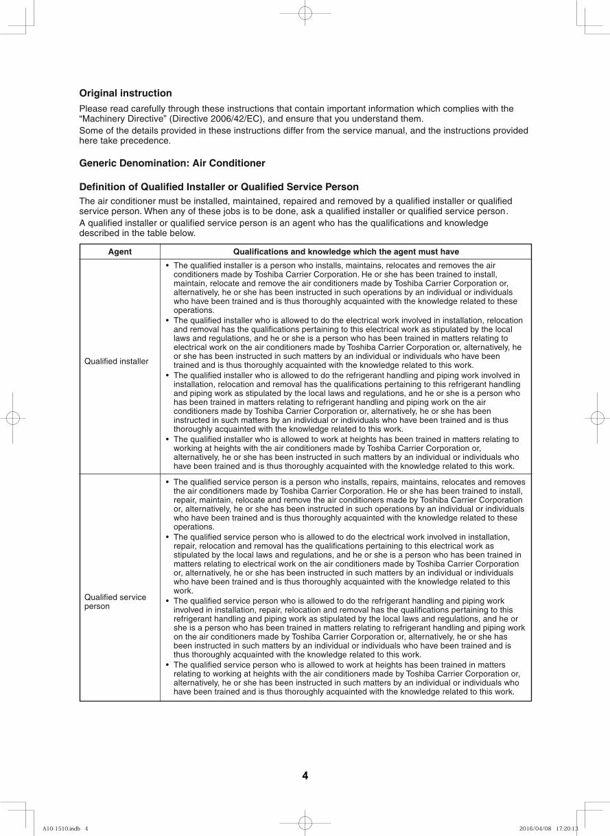
Definition of Qualified Installer or Qualified Service PersonThe air conditioner must be installed, maintained, repaired and removed by a qualified installer or qualifiedservice person. When any of these jobs is to be done, ask a qualified installer or qualified service person .A qualified installer or qualified service person is an agent who has the qualifications and knowledgedescribed in the table below.
The qualified service person is a person who installs, repairs, maintains, relocates and removesthe air conditioners made by Toshiba Carrier Corporation. He or she has been trained to install,repair, maintain, relocate and remove the air conditioners made by Toshiba Carrier Corporationor, alternatively, he or she has been instructed in such operations by an individual or individualswho have been trained and is thus thoroughly acquainted with the knowledge related to theseoperations.The qualified service person who is allowed to do the electrical work involved in installation,repair, relocation and removal has the qualifications pertaining to this electrical work asstipulated by the local laws and regulations, and he or she is a person who has been trained inmatters relating to electrical work on the air conditioners made by Toshiba Carrier Corporationor, alternatively, he or she has been instructed in such matters by an individual or individualswho have been trained and is thus thoroughly acquainted with the knowledge related to thiswork.The qualified service person who is allowed to do the refrigerant handling and piping workinvolved in installation, repair, relocation and removal has the qualifications pertaining to thisrefrigerant handling and piping work as stipulated by the local laws and regulations, and he orshe is a person who has been trained in matters relating to refrigerant handling and piping workon the air conditioners made by Toshiba Carrier Corporation or, alternatively, he or she hasbeen instructed in such matters by an individual or individuals who have been trained and isthus thoroughly acquainted with the knowledge related to this work.The qualified service person who is allowed to work at heights has been trained in mattersrelating to working at heights with the air conditioners made by Toshiba Carrier Corporation or,alternatively, he or she has been instructed in such matters by an individual or individuals whohave been trained and is thus thoroughly acquainted with the knowledge related to this work.
The qualified installer is a person who installs, maintains, relocates and removes the airconditioners made by Toshiba Carrier Corporation. He or she has been trained to install,maintain, relocate and remove the air conditioners made by Toshiba Carrier Corporation or,alternatively, he or she has been instructed in such operations by an individual or individualswho have been trained and is thus thoroughly acquainted with the knowledge related to theseoperations.The qualified installer who is allowed to do the electrical work involved in installation, relocationand removal has the qualifications pertaining to this electrical work as stipulated by the locallaws and regulations, and he or she is a person who has been trained in matters relating toelectrical work on the air conditioners made by Toshiba Carrier Corporation or, alternatively, heor she has been instructed in such matters by an individual or individuals who have beentrained and is thus thoroughly acquainted with the knowledge related to this work.The qualified installer who is allowed to do the refrigerant handling and piping work involved ininstallation, relocation and removal has the qualifications pertaining to this refrigerant handlingand piping work as stipulated by the local laws and regulations, and he or she is a person whohas been trained in matters relating to refrigerant handling and piping work on the airconditioners made by Toshiba Carrier Corporation or, alternatively, he or she has beeninstructed in such matters by an individual or individuals who have been trained and is thusthoroughly acquainted with the knowledge related to this work.The qualified installer who is allowed to work at heights has been trained in matters relating toworking at heights with the air conditioners made by Toshiba Carrier Corporation or,alternatively, he or she has been instructed in such matters by an individual or individuals whohave been trained and is thus thoroughly acquainted with the knowledge related to this work.
Qualified installer
Qualified serviceperson
Agent Qualifications and knowledge which the agent must have
4
A10-1510.indb 4A10-1510.indb 4 2016/04/08 17:20:132016/04/08 17:20:13
4
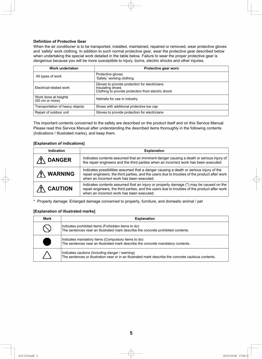
Definition of Protective Gear When the air conditioner is to be transported, installed, maintained, repaired or removed, wear protective gloves and ‘safety’ work clothing. In addition to such normal protective gear, wear the protective gear described below when undertaking the special work detailed in the table below. Failure to wear the proper protective gear is dangerous because you will be more susceptible to injury, burns, electric shocks and other injuries.
The important contents concerned to the safety are described on the product itself and on this Service Manual.Please read this Service Manual after understanding the described items thoroughly in the following contents(Indications / Illustrated marks), and keep them.
[Explanation of indications]
* Property damage: Enlarged damage concerned to property, furniture, and domestic animal / pet
[Explanation of illustrated marks]
nrow raeg evitcetorPnekatrednu kroW
All types of work Protective gloves ‘Safety’ working clothing
Electrical-related workGloves to provide protection for electriciansInsulating shoes Clothing to provide protection from electric shock
Work done at heights(50 cm or more) Helmets for use in industry
Transportation of heavy objects Shoes with additional protective toe cap
Repair of outdoor unit Gloves to provide protection for electricians
noitanalpxEnoitacidnI
DANGER Indicates contents assumed that an imminent danger causing a death or serious injury of the repair engineers and the third parties when an incorrect work has been executed.
WARNINGIndicates possibilities assumed that a danger causing a death or serious injury of the repair engineers, the third parties, and the users due to troubles of the product after work when an incorrect work has been executed.
CAUTIONIndicates contents assumed that an injury or property damage (*) may be caused on the repair engineers, the third parties, and the users due to troubles of the product after work when an incorrect work has been executed.
noitanalpxEkraM
Indicates prohibited items (Forbidden items to do)The sentences near an illustrated mark describe the concrete prohibited contents.
Indicates mandatory items (Compulsory items to do)The sentences near an illustrated mark describe the concrete mandatory contents.
Indicates cautions (Including danger / warning)The sentences or illustration near or in an illustrated mark describe the concrete cautious contents.
5
A10-1510.indb 5A10-1510.indb 5 2016/04/08 17:20:132016/04/08 17:20:13
5
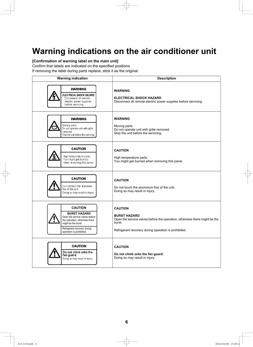
Warning indications on the air conditioner unit[Confirmation of warning label on the main unit]Confirm that labels are indicated on the specified positionsIf removing the label during parts replace, stick it as the original.
noitpircseDnoitacidni gninraW
WARNING
ELECTRICAL SHOCK HAZARDDisconnect all remote electric power supplies before servicing.
WARNING
Moving parts. Do not operate unit with grille removed. Stop the unit before the servicing.
CAUTION
High temperature parts. You might get burned when removing this panel.
CAUTION
Do not touch the aluminium fins of the unit. Doing so may result in injury.
CAUTION
BURST HAZARDOpen the service valves before the operation, otherwise there might be the burst.
Refrigerant recovery during operation is prohibited.
CAUTION
Do not climb onto the fan guard.Doing so may result in injury.
CAUTION
BURST HAZARDOpen the service valves before the operation, otherwise there might be the burst.
Refrigerant recovery during operation is prohibited.
6
A10-1510.indb 6A10-1510.indb 6 2016/04/08 17:20:132016/04/08 17:20:13
6
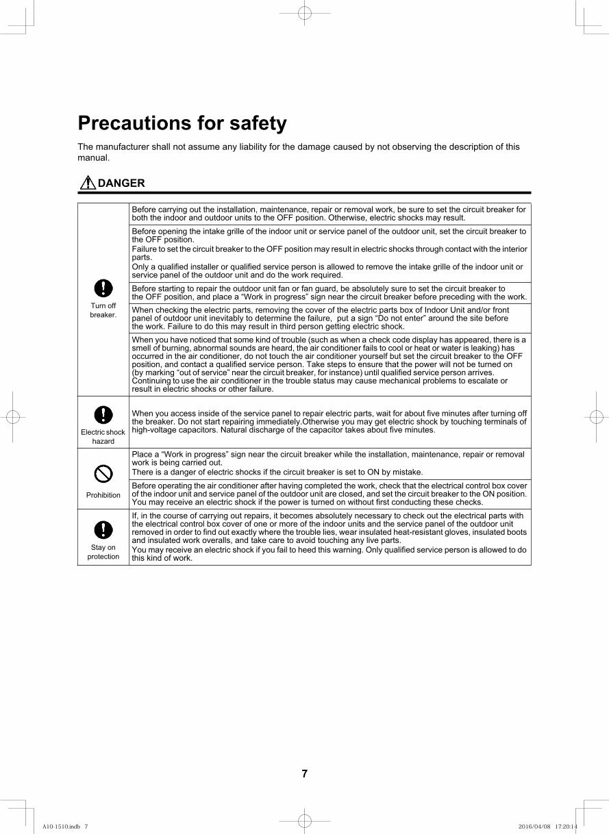
Precautions for safetyThe manufacturer shall not assume any liability for the damage caused by not observing the description of this manual.
DANGER
Before carrying out the installation, maintenance, repair or removal work, be sure to set the circuit breaker for both the indoor and outdoor units to the OFF position. Otherwise, electric shocks may result.Before opening the intake grille of the indoor unit or service panel of the outdoor unit, set the circuit breaker to the OFF position.Failure to set the circuit breaker to the OFF position may result in electric shocks through contact with the interior parts.Only a qualified installer or qualified service person is allowed to remove the intake grille of the indoor unit or service panel of the outdoor unit and do the work required.Before starting to repair the outdoor unit fan or fan guard, be absolutely sure to set the circuit breaker to the OFF position, and place a “Work in progress” sign near the circuit breaker before preceding with the work.When checking the electric parts, removing the cover of the electric parts box of Indoor Unit and/or front panel of outdoor unit inevitably to determine the failure, put a sign “Do not enter” around the site before the work. Failure to do this may result in third person getting electric shock.When you have noticed that some kind of trouble (such as when a check code display has appeared, there is a smell of burning, abnormal sounds are heard, the air conditioner fails to cool or heat or water is leaking) has occurred in the air conditioner, do not touch the air conditioner yourself but set the circuit breaker to the OFF position, and contact a qualified service person. Take steps to ensure that the power will not be turned on (by marking “out of service” near the circuit breaker, for instance) until qualified service person arrives. Continuing to use the air conditioner in the trouble status may cause mechanical problems to escalate or result in electric shocks or other failure.
Electric shock hazard
When you access inside of the service panel to repair electric parts, wait for about five minutes after turning off the breaker. Do not start repairing immediately.Otherwise you may get electric shock by touching terminals of high-voltage capacitors. Natural discharge of the capacitor takes about five minutes.
Prohibition
Place a “Work in progress” sign near the circuit breaker while the installation, maintenance, repair or removal work is being carried out.There is a danger of electric shocks if the circuit breaker is set to ON by mistake.Before operating the air conditioner after having completed the work, check that the electrical control box cover of the indoor unit and service panel of the outdoor unit are closed, and set the circuit breaker to the ON position. You may receive an electric shock if the power is turned on without first conducting these checks.
Stay on protection
If, in the course of carrying out repairs, it becomes absolutely necessary to check out the electrical parts with the electrical control box cover of one or more of the indoor units and the service panel of the outdoor unit removed in order to find out exactly where the trouble lies, wear insulated heat-resistant gloves, insulated boots and insulated work overalls, and take care to avoid touching any live parts.You may receive an electric shock if you fail to heed this warning. Only qualified service person is allowed to do this kind of work.
Turn off breaker.
7
A10-1510.indb 7A10-1510.indb 7 2016/04/08 17:20:142016/04/08 17:20:14
7
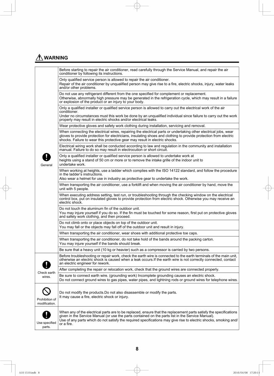
WARNING
Before starting to repair the air conditioner, read carefully through the Service Manual, and repair the air conditioner by following its instructions.
Only qualified service person is allowed to repair the air conditioner.Repair of the air conditioner by unqualified person may give rise to a fire, electric shocks, injury, water leaks and/or other problems.
Do not use any refrigerant different from the one specified for complement or replacement.Otherwise, abnormally high pressure may be generated in the refrigeration cycle, which may result in a failure or explosion of the product or an injury to your body.
Only a qualified installer or qualified service person is allowed to carry out the electrical work of the air conditioner.Under no circumstances must this work be done by an unqualified individual since failure to carry out the work properly may result in electric shocks and/or electrical leaks.
Wear protective gloves and safety work clothing during installation, servicing and removal.When connecting the electrical wires, repairing the electrical parts or undertaking other electrical jobs, wear gloves to provide protection for electricians, insulating shoes and clothing to provide protection from electric shocks. Failure to wear this protective gear may result in electric shocks.Electrical wiring work shall be conducted according to law and regulation in the community and installation manual. Failure to do so may result in electrocution or short circuit.
Only a qualified installer or qualified service person is allowed to undertake work atheights using a stand of 50 cm or more or to remove the intake grille of the indoor unit toundertake work.
When working at heights, use a ladder which complies with the ISO 14122 standard, and follow the procedure in the ladder’s instructions.Also wear a helmet for use in industry as protective gear to undertake the work.
When transporting the air conditioner, use a forklift and when moving the air conditioner by hand, move the unit with 5 people.
When executing address setting, test run, or troubleshooting through the checking window on the electrical control box, put on insulated gloves to provide protection from electric shock. Otherwise you may receive an electric shock.
Do not touch the aluminum fin of the outdoor unit.You may injure yourself if you do so. If the fin must be touched for some reason, first put on protective gloves and safety work clothing, and then proceed.
Do not climb onto or place objects on top of the outdoor unit.You may fall or the objects may fall off of the outdoor unit and result in injury.
When transporting the air conditioner, wear shoes with additional protective toe caps.
When transporting the air conditioner, do not take hold of the bands around the packing carton.You may injure yourself if the bands should break.
Be sure that a heavy unit (10 kg or heavier) such as a compressor is carried by two persons.
Check earth wires.
Before troubleshooting or repair work, check the earth wire is connected to the earth terminals of the main unit, otherwise an electric shock is caused when a leak occurs.If the earth wire is not correctly connected, contact an electric engineer for rework.
After completing the repair or relocation work, check that the ground wires are connected properly.
Be sure to connect earth wire. (grounding work) Incomplete grounding causes an electric shock.Do not connect ground wires to gas pipes, water pipes, and lightning rods or ground wires for telephone wires.
Prohibition of modification.
Do not modify the products.Do not also disassemble or modify the parts.It may cause a fire, electric shock or injury.
Use specified parts.
When any of the electrical parts are to be replaced, ensure that the replacement parts satisfy the specifications given in the Service Manual (or use the parts contained on the parts list in the Service Manual).Use of any parts which do not satisfy the required specifications may give rise to electric shocks, smoking and/or a fire.
General
8
A10-1510.indb 8A10-1510.indb 8 2016/04/08 17:20:142016/04/08 17:20:14
8
Do not bring a child close to
theequipment.
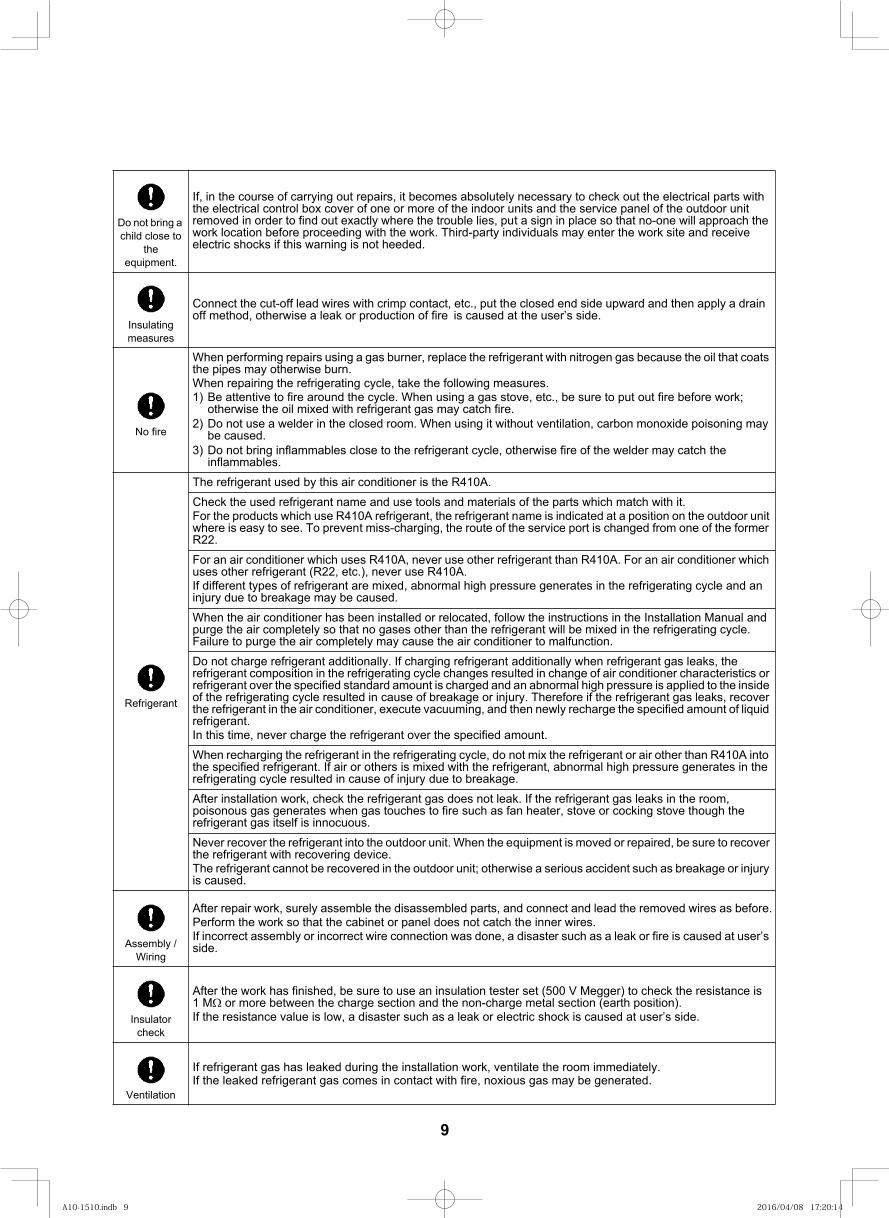
If, in the course of carrying out repairs, it becomes absolutely necessary to check out the electrical parts with the electrical control box cover of one or more of the indoor units and the service panel of the outdoor unit removed in order to find out exactly where the trouble lies, put a sign in place so that no-one will approach the work location before proceeding with the work. Third-party individuals may enter the work site and receive electric shocks if this warning is not heeded.
Insulating measures
Connect the cut-off lead wires with crimp contact, etc., put the closed end side upward and then apply a drain off method, otherwise a leak or production of fire is caused at the user’s side.
No fire
When performing repairs using a gas burner, replace the refrigerant with nitrogen gas because the oil that coats the pipes may otherwise burn.When repairing the refrigerating cycle, take the following measures.1) Be attentive to fire around the cycle. When using a gas stove, etc., be sure to put out fire before work;
otherwise the oil mixed with refrigerant gas may catch fire.2) Do not use a welder in the closed room. When using it without ventilation, carbon monoxide poisoning may
be caused.3) Do not bring inflammables close to the refrigerant cycle, otherwise fire of the welder may catch the
inflammables.
Refrigerant
The refrigerant used by this air conditioner is the R410A.Check the used refrigerant name and use tools and materials of the parts which match with it.For the products which use R410A refrigerant, the refrigerant name is indicated at a position on the outdoor unit where is easy to see. To prevent miss-charging, the route of the service port is changed from one of the former R22.For an air conditioner which uses R410A, never use other refrigerant than R410A. For an air conditioner which uses other refrigerant (R22, etc.), never use R410A.If different types of refrigerant are mixed, abnormal high pressure generates in the refrigerating cycle and an injury due to breakage may be caused.When the air conditioner has been installed or relocated, follow the instructions in the Installation Manual and purge the air completely so that no gases other than the refrigerant will be mixed in the refrigerating cycle. Failure to purge the air completely may cause the air conditioner to malfunction.Do not charge refrigerant additionally. If charging refrigerant additionally when refrigerant gas leaks, the refrigerant composition in the refrigerating cycle changes resulted in change of air conditioner characteristics or refrigerant over the specified standard amount is charged and an abnormal high pressure is applied to the inside of the refrigerating cycle resulted in cause of breakage or injury. Therefore if the refrigerant gas leaks, recover the refrigerant in the air conditioner, execute vacuuming, and then newly recharge the specified amount of liquid refrigerant.In this time, never charge the refrigerant over the specified amount.When recharging the refrigerant in the refrigerating cycle, do not mix the refrigerant or air other than R410A into the specified refrigerant. If air or others is mixed with the refrigerant, abnormal high pressure generates in the refrigerating cycle resulted in cause of injury due to breakage.After installation work, check the refrigerant gas does not leak. If the refrigerant gas leaks in the room, poisonous gas generates when gas touches to fire such as fan heater, stove or cocking stove though the refrigerant gas itself is innocuous.Never recover the refrigerant into the outdoor unit. When the equipment is moved or repaired, be sure to recover the refrigerant with recovering device.The refrigerant cannot be recovered in the outdoor unit; otherwise a serious accident such as breakage or injury is caused.
Assembly / Wiring
After repair work, surely assemble the disassembled parts, and connect and lead the removed wires as before.Perform the work so that the cabinet or panel does not catch the inner wires.If incorrect assembly or incorrect wire connection was done, a disaster such as a leak or fire is caused at user’s side.
Insulator check
After the work has finished, be sure to use an insulation tester set (500 V Megger) to check the resistance is 1 M or more between the charge section and the non-charge metal section (earth position).If the resistance value is low, a disaster such as a leak or electric shock is caused at user’s side.
Ventilation
If refrigerant gas has leaked during the installation work, ventilate the room immediately.If the leaked refrigerant gas comes in contact with fire, noxious gas may be generated.
9
A10-1510.indb 9A10-1510.indb 9 2016/04/08 17:20:142016/04/08 17:20:14
9
Compulsion
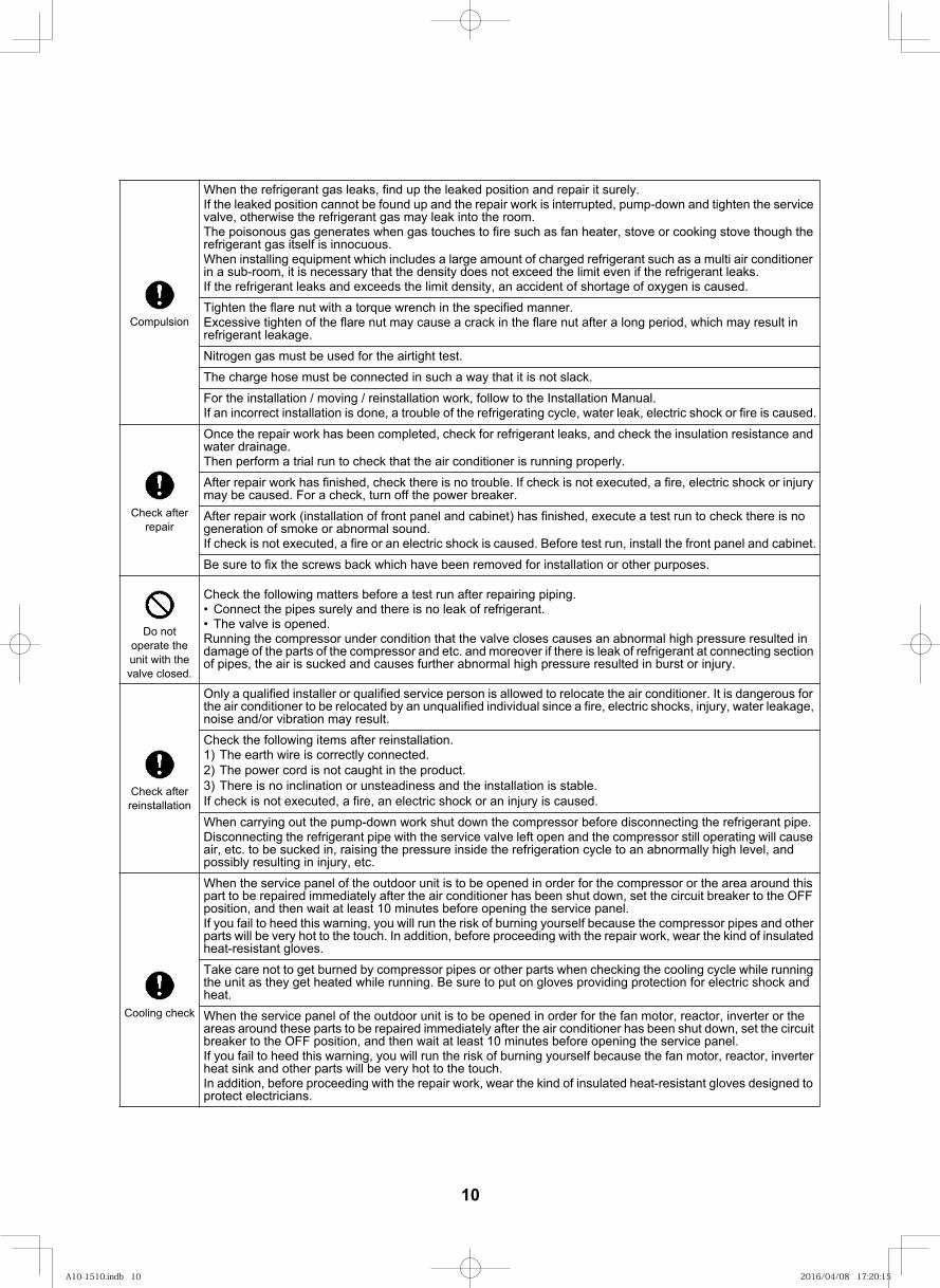
When the refrigerant gas leaks, find up the leaked position and repair it surely.If the leaked position cannot be found up and the repair work is interrupted, pump-down and tighten the service valve, otherwise the refrigerant gas may leak into the room.The poisonous gas generates when gas touches to fire such as fan heater, stove or cooking stove though the refrigerant gas itself is innocuous.When installing equipment which includes a large amount of charged refrigerant such as a multi air conditioner in a sub-room, it is necessary that the density does not exceed the limit even if the refrigerant leaks.If the refrigerant leaks and exceeds the limit density, an accident of shortage of oxygen is caused.
Tighten the flare nut with a torque wrench in the specified manner.Excessive tighten of the flare nut may cause a crack in the flare nut after a long period, which may result in refrigerant leakage.
Nitrogen gas must be used for the airtight test.
The charge hose must be connected in such a way that it is not slack.
For the installation / moving / reinstallation work, follow to the Installation Manual.If an incorrect installation is done, a trouble of the refrigerating cycle, water leak, electric shock or fire is caused.
Check after repair
Once the repair work has been completed, check for refrigerant leaks, and check the insulation resistance and water drainage.Then perform a trial run to check that the air conditioner is running properly.
After repair work has finished, check there is no trouble. If check is not executed, a fire, electric shock or injury may be caused. For a check, turn off the power breaker.
After repair work (installation of front panel and cabinet) has finished, execute a test run to check there is no generation of smoke or abnormal sound.If check is not executed, a fire or an electric shock is caused. Before test run, install the front panel and cabinet.
Be sure to fix the screws back which have been removed for installation or other purposes.
Do not operate the unit with the valve closed.
Check the following matters before a test run after repairing piping.Connect the pipes surely and there is no leak of refrigerant.The valve is opened.
Running the compressor under condition that the valve closes causes an abnormal high pressure resulted in damage of the parts of the compressor and etc. and moreover if there is leak of refrigerant at connecting section of pipes, the air is sucked and causes further abnormal high pressure resulted in burst or injury.
Check after reinstallation
Only a qualified installer or qualified service person is allowed to relocate the air conditioner. It is dangerous for the air conditioner to be relocated by an unqualified individual since a fire, electric shocks, injury, water leakage, noise and/or vibration may result.
Check the following items after reinstallation.1) The earth wire is correctly connected.2) The power cord is not caught in the product.3) There is no inclination or unsteadiness and the installation is stable.If check is not executed, a fire, an electric shock or an injury is caused.
When carrying out the pump-down work shut down the compressor before disconnecting the refrigerant pipe.Disconnecting the refrigerant pipe with the service valve left open and the compressor still operating will cause air, etc. to be sucked in, raising the pressure inside the refrigeration cycle to an abnormally high level, and possibly resulting in injury, etc.
Cooling check
When the service panel of the outdoor unit is to be opened in order for the compressor or the area around this part to be repaired immediately after the air conditioner has been shut down, set the circuit breaker to the OFF position, and then wait at least 10 minutes before opening the service panel.If you fail to heed this warning, you will run the risk of burning yourself because the compressor pipes and other parts will be very hot to the touch. In addition, before proceeding with the repair work, wear the kind of insulated heat-resistant gloves.
Take care not to get burned by compressor pipes or other parts when checking the cooling cycle while running the unit as they get heated while running. Be sure to put on gloves providing protection for electric shock and heat.
When the service panel of the outdoor unit is to be opened in order for the fan motor, reactor, inverter or the areas around these parts to be repaired immediately after the air conditioner has been shut down, set the circuit breaker to the OFF position, and then wait at least 10 minutes before opening the service panel.If you fail to heed this warning, you will run the risk of burning yourself because the fan motor, reactor, inverter heat sink and other parts will be very hot to the touch.In addition, before proceeding with the repair work, wear the kind of insulated heat-resistant gloves designed to protect electricians.
10
A10-1510.indb 10A10-1510.indb 10 2016/04/08 17:20:152016/04/08 17:20:15
10
Explanations given to userIf you have discovered that the fan grille is damaged, do not approach the outdoor unit but set the circuit breaker to the OFF position, and contact a qualified service person to have the repairs done.Do not set the circuit breaker to the ON position until the repairs are completed.
RelocationOnly a qualified installer or qualified service person is allowed to relocate the air conditioner.It is dangerous for the air conditioner to be relocated by an unqualified individual since a fire, electric shocks, injury, water leakage, noise and/or vibration may result.When carrying out the pump-down work shut down the compressor before disconnecting the refrigerant pipe.Disconnecting the refrigerant pipe with the service valve left open and the compressor still operating will cause air, etc. to be sucked in, raising the pressure inside the refrigeration cycle to an abnormally high level, and possibly resulting in injury, etc.
Installation
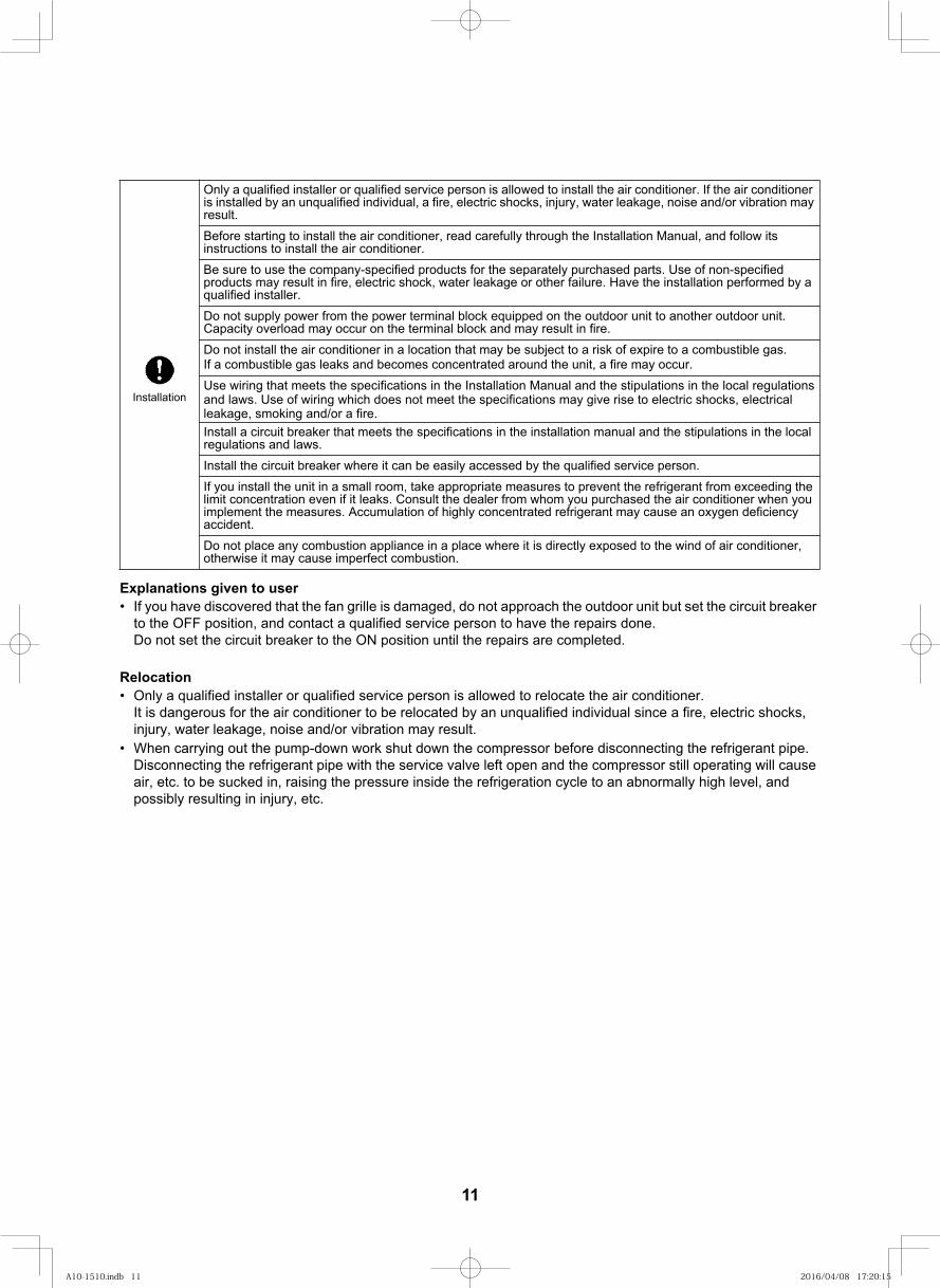
Only a qualified installer or qualified service person is allowed to install the air conditioner. If the air conditioner is installed by an unqualified individual, a fire, electric shocks, injury, water leakage, noise and/or vibration may result.
Before starting to install the air conditioner, read carefully through the Installation Manual, and follow its instructions to install the air conditioner.
Be sure to use the company-specified products for the separately purchased parts. Use of non-specified products may result in fire, electric shock, water leakage or other failure. Have the installation performed by a qualified installer.
Do not supply power from the power terminal block equipped on the outdoor unit to another outdoor unit. Capacity overload may occur on the terminal block and may result in fire.
Do not install the air conditioner in a location that may be subject to a risk of expire to a combustible gas.If a combustible gas leaks and becomes concentrated around the unit, a fire may occur.
Use wiring that meets the specifications in the Installation Manual and the stipulations in the local regulations and laws. Use of wiring which does not meet the specifications may give rise to electric shocks, electrical leakage, smoking and/or a fire.Install a circuit breaker that meets the specifications in the installation manual and the stipulations in the local regulations and laws.
Install the circuit breaker where it can be easily accessed by the qualified service person.
If you install the unit in a small room, take appropriate measures to prevent the refrigerant from exceeding the limit concentration even if it leaks. Consult the dealer from whom you purchased the air conditioner when you implement the measures. Accumulation of highly concentrated refrigerant may cause an oxygen deficiency accident.
Do not place any combustion appliance in a place where it is directly exposed to the wind of air conditioner, otherwise it may cause imperfect combustion.
11
A10-1510.indb 11A10-1510.indb 11 2016/04/08 17:20:152016/04/08 17:20:15
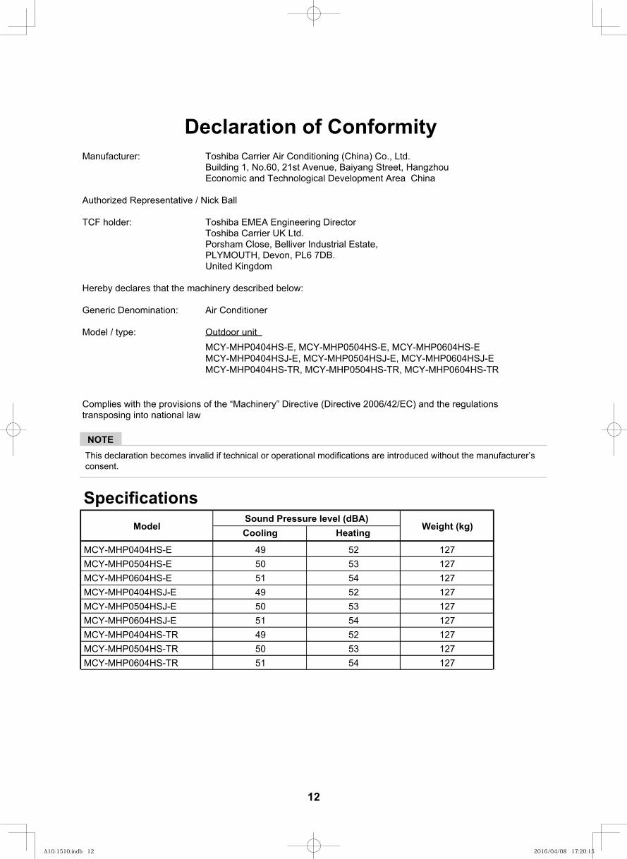
Declaration of ConformityManufacturer: Toshiba Carrier Air Conditioning (China) Co., Ltd.
Building 1, No.60, 21st Avenue, Baiyang Street, Hangzhou Economic and Technological Development Area China
Authorized Representative / Nick Ball
TCF holder: Toshiba EMEA Engineering DirectorToshiba Carrier UK Ltd.Porsham Close, Belliver Industrial Estate,PLYMOUTH, Devon, PL6 7DB.United Kingdom
Hereby declares that the machinery described below:
Generic Denomination: Air Conditioner
Model / type: Outdoor unit
Complies with the provisions of the “Machinery” Directive (Directive 2006/42/EC) and the regulationstransposing into national law
NOTEThis declaration becomes invalid if technical or operational modifications are introduced without the manufacturer’s consent.
11
Specifications
Cooling Heating
495051495051495051
525354525354525354
127127127127127127127127127
ModelSound Pressure level (dBA)
Weight (kg)
MCY-MHP0404HS-E, MCY-MHP0504HS-E, MCY-MHP0604HS-E MCY-MHP0404HSJ-E, MCY-MHP0504HSJ-E, MCY-MHP0604HSJ-E MCY-MHP0404HS-TR, MCY-MHP0504HS-TR, MCY-MHP0604HS-TR
MCY-MHP0404HS-EMCY-MHP0504HS-EMCY-MHP0604HS-EMCY-MHP0404HSJ-EMCY-MHP0504HSJ-EMCY-MHP0604HSJ-EMCY-MHP0404HS-TRMCY-MHP0504HS-TRMCY-MHP0604HS-TR
12
A10-1510.indb 12A10-1510.indb 12 2016/04/08 17:20:152016/04/08 17:20:15
11
New refrigerant (R410A)This air conditioner adopts a new HFC type refrigerant (R410A) which does not deplete the ozone layer.
1. Safety caution concerned to new refrigerantThe pressure of R410A is high 1.6 times of that of the former refrigerant (R22). Accompanied with change of refrigerant, the refrigerating oil has been also changed. Therefore, be sure that water, dust, the former refrigerant or the former refrigerating oil is not mixed into the refrigerating cycle of the air conditioner with new refrigerant during installation work or service work. If an incorrect work or incorrect service is performed, there is a possibility to cause a serious accident. Use the tools and materials exclusive to R410A to purpose a safe work.
2. Cautions on installation / service(1) Do not mix the other refrigerant or refrigerating oil.
For the tools exclusive to R410A, shapes of all the joints including the service port differ from those of the former refrigerant in order to prevent mixture of them.
(2) As the use pressure of the new refrigerant is high, use material thickness of the pipe and tools which are specified for R410A.
(3) In the installation time, use clean pipe materials and work with great attention so that water and others do not mix in because pipes are affected by impurities such as water, oxide scales, oil, etc. Use the clean pipes.Be sure to brazing with flowing nitrogen gas. (Never use gas other than nitrogen gas.)
(4) For the earth protection, use a vacuum pump for air purge.(5) R410A refrigerant is azeotropic mixture type refrigerant. Therefore use liquid type to charge the refrigerant.
(If using gas for charging, composition of the refrigerant changes and then characteristics of the air conditioner change.)
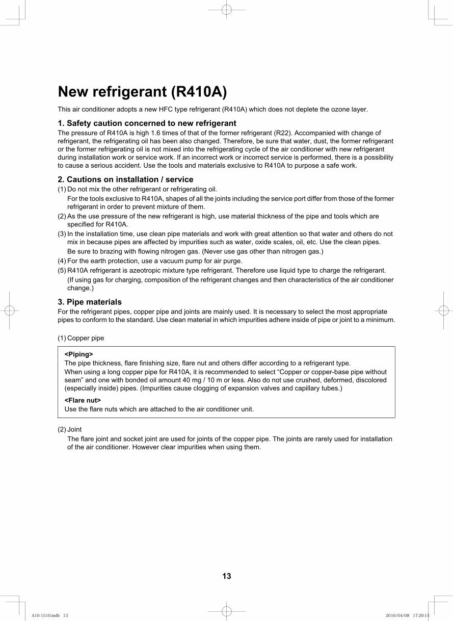
3. Pipe materialsFor the refrigerant pipes, copper pipe and joints are mainly used. It is necessary to select the most appropriate pipes to conform to the standard. Use clean material in which impurities adhere inside of pipe or joint to a minimum.
(1) Copper pipe
(2) JointThe flare joint and socket joint are used for joints of the copper pipe. The joints are rarely used for installation of the air conditioner. However clear impurities when using them.
<Piping>The pipe thickness, flare finishing size, flare nut and others differ according to a refrigerant type.When using a long copper pipe for R410A, it is recommended to select “Copper or copper-base pipe without seam” and one with bonded oil amount 40 mg / 10 m or less. Also do not use crushed, deformed, discolored (especially inside) pipes. (Impurities cause clogging of expansion valves and capillary tubes.)
<Flare nut>Use the flare nuts which are attached to the air conditioner unit.
13
A10-1510.indb 13A10-1510.indb 13 2016/04/08 17:20:152016/04/08 17:20:15
12
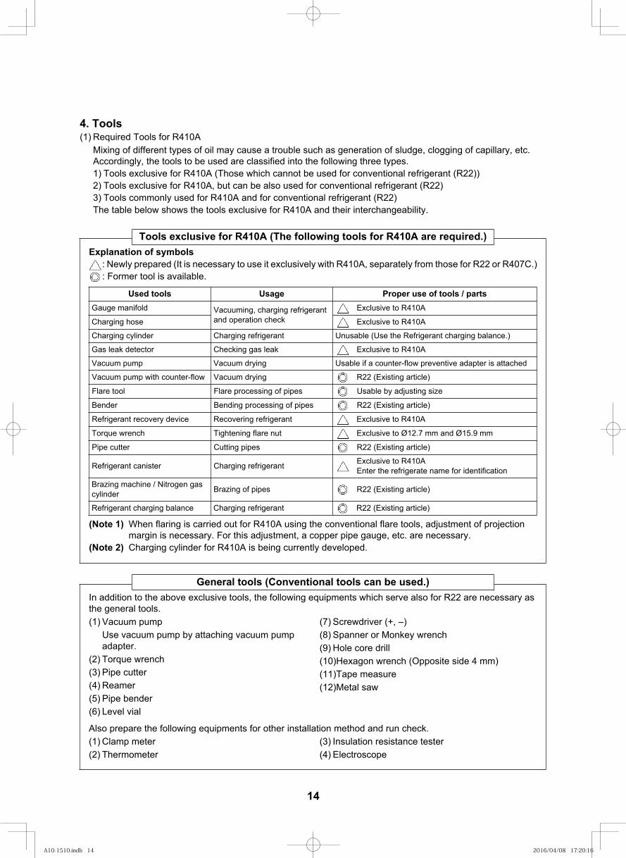
4. Tools(1) Required Tools for R410A
Mixing of different types of oil may cause a trouble such as generation of sludge, clogging of capillary, etc. Accordingly, the tools to be used are classified into the following three types.1) Tools exclusive for R410A (Those which cannot be used for conventional refrigerant (R22))2) Tools exclusive for R410A, but can be also used for conventional refrigerant (R22)3) Tools commonly used for R410A and for conventional refrigerant (R22)The table below shows the tools exclusive for R410A and their interchangeability.
Tools exclusive for R410A (The following tools for R410A are required.)Explanation of symbols
: Newly prepared (It is necessary to use it exclusively with R410A, separately from those for R22 or R407C.): Former tool is available.
(Note 1) When flaring is carried out for R410A using the conventional flare tools, adjustment of projection margin is necessary. For this adjustment, a copper pipe gauge, etc. are necessary.
(Note 2) Charging cylinder for R410A is being currently developed.
strap / sloot fo esu reporPegasUsloot desUGauge manifold Vacuuming, charging refrigerant
and operation checkExclusive to R410A
A014R ot evisulcxEesoh gnigrahC
Charging cylinder Charging refrigerant Unusable (Use the Refrigerant charging balance.)
Gas leak detector Checking gas leak Exclusive to R410A
Vacuum pump Vacuum drying Usable if a counter-flow preventive adapter is attached
)elcitra gnitsixE( 22Rgniyrd muucaVwolf-retnuoc htiw pmup muucaV
ezis gnitsujda yb elbasUsepip fo gnissecorp eralFloot eralF
)elcitra gnitsixE( 22Rsepip fo gnissecorp gnidneBredneB
Refrigerant recovery device Recovering refrigerant Exclusive to R410A
Torque wrench Tightening flare nut Exclusive to Ø12.7 mm and Ø15.9 mm
)elcitra gnitsixE( 22Rsepip gnittuCrettuc epiP
Refrigerant canister Charging refrigerant Exclusive to R410AEnter the refrigerate name for identification
Brazing machine / Nitrogen gas cylinder )elcitra gnitsixE( 22R Brazing of pipes
Refrigerant charging balance Charging refrigerant R22 (Existing article)
General tools (Conventional tools can be used.)In addition to the above exclusive tools, the following equipments which serve also for R22 are necessary as the general tools.(1) Vacuum pump
Use vacuum pump by attaching vacuum pump adapter.
(2) Torque wrench(3) Pipe cutter(4) Reamer(5) Pipe bender(6) Level vial
(7) Screwdriver (+, –)(8) Spanner or Monkey wrench(9) Hole core drill(10)Hexagon wrench (Opposite side 4 mm)(11)Tape measure(12)Metal saw
Also prepare the following equipments for other installation method and run check.(1) Clamp meter(2) Thermometer
(3) Insulation resistance tester(4) Electroscope
14
A10-1510.indb 14A10-1510.indb 14 2016/04/08 17:20:162016/04/08 17:20:16
Air to Air Heat Exchanger with DX Coil Unit
13
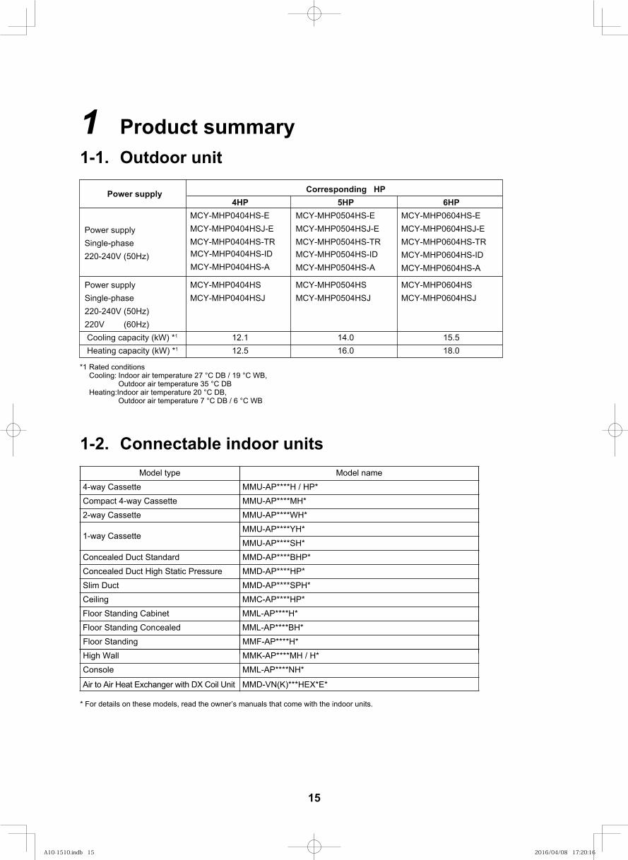
1 Product summary1-1. Outdoor unit
*1 Rated conditionsCooling: Indoor air temperature 27 °C DB / 19 °C WB,
Outdoor air temperature 35 °C DBHeating:Indoor air temperature 20 °C DB,
Outdoor air temperature 7 °C DB / 6 °C WB
1-2. Connectable indoor unitseman ledoMepyt ledoM
MMU-AP****H / HP*4-way Cassette
Compact 4-way Cassette MMU-AP****MH*
MMU-AP****WH*
MMU-AP****YH*
2-way Cassette
MMU-AP****SH*
Concealed Duct Standard MMD-AP****BHP*
Concealed Duct High Static Pressure MMD-AP****HP*
MMD-AP****SPH*Slim Duct
MMD-VN(K)***HEX*E*
1-way Cassette
* For details on these models, read the owner’s manuals that come with the indoor units.
Power supply
Power supply Single-phase220-240V (50Hz) 220V (60Hz) Cooling capacity (kW) *1
Heating capacity (kW) *1
4HPMCY-MHP0404HS-EMCY-MHP0404HSJ-EMCY-MHP0404HS-TRMCY-MHP0404HS-IDMCY-MHP0404HS-A
MCY-MHP0404HSMCY-MHP0404HSJ
12.1 12.5
Corresponding HP5HP
MCY-MHP0504HS-EMCY-MHP0504HSJ-EMCY-MHP0504HS-TRMCY-MHP0504HS-IDMCY-MHP0504HS-A
MCY-MHP0504HSMCY-MHP0504HSJ
14.0 16.0
6HPMCY-MHP0604HS-EMCY-MHP0604HSJ-EMCY-MHP0604HS-TRMCY-MHP0604HS-IDMCY-MHP0604HS-A
MCY-MHP0604HSMCY-MHP0604HSJ
15.5 18.0
MMC-AP****HP*Ceiling
Floor Standing Cabinet MML-AP****H*
MML-AP****BH*Floor Standing Concealed
MMF-AP****H*Floor Standing
High Wall MMK-AP****MH / H*
MML-AP****NH*Console
Power supply Single-phase220-240V (50Hz)
15
A10-1510.indb 15A10-1510.indb 15 2016/04/08 17:20:162016/04/08 17:20:16
14
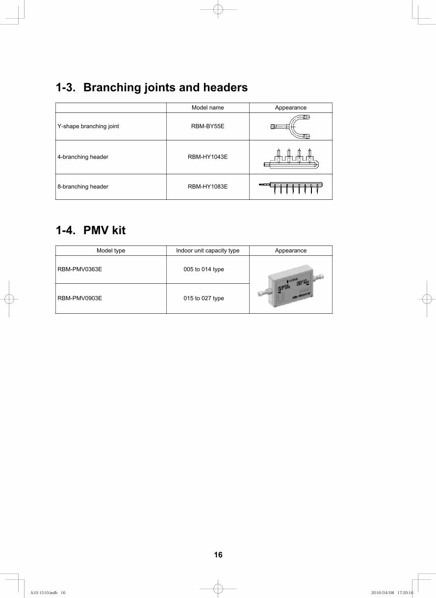
1-3. Branching joints and headers
1-4. PMV kit
Model name Appearance
E3401YH-MBR redaeh gnihcnarb-4
E3801YH-MBR redaeh gnihcnarb-8
Model type Indoor unit capacity type Appearance
005 to 014 typeE3630VMP-MBR
015 to 027 typeE3090VMP-MBR
RBM-BY55Etnioj gnihcnarb epahs-Y
16
A10-1510.indb 16A10-1510.indb 16 2016/04/08 17:20:162016/04/08 17:20:16
15
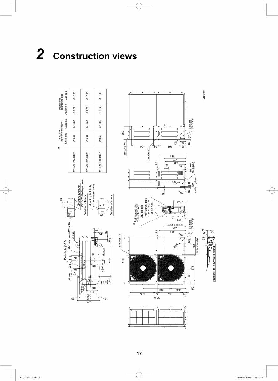
2 Construction views
(15
×20
long
hol
e)
Det
aile
s of
A le
gs
Mou
ntin
g bo
lt ho
le
Dia
met
er o
fpi
pe c
onne
ctin
g po
rt
MC
Y-M
HP0
404H
S*
Det
aile
s of
B le
gs(
15×2
0 U
-sha
pe h
ole)
Mou
ntin
g bo
lt ho
le
*Li
quid
sid
e
9.52
Gas
sid
e
conn
ectin
g pi
pe
Liqu
id s
ide
Gas
sid
e
Dia
met
er o
f
B le
gs
A le
gs
5050
25
15
4512
5
990
660
165
Dra
in h
ole
(25
)
150
37
57
535 53 535 71
339
50326588
574
Ref
riger
ant p
ipe
(Gas
sid
e)co
nnec
ting
port
(Liq
uid
side
)co
nnec
ting
port
Ref
riger
ant p
ipe
*
30
29445476
Knoc
kout
for d
ownw
ard
pipi
ng
54
port
Air o
utle
t
port
Air i
nlet
Air i
nlet
p
ort
235
110 30
85
245
44225 23
155
45
6-D
rain
hol
e (
20×8
8)
58
4901235
130
159
R65
9.52
9.52
15.8
8
15.8
8
19.0
59.
52
9.52
9.52
19.0
5
15.8
8
15.8
8
100
159
R50
305
134
120
R60
1616
16
390
Slit
hole
for p
ipin
g38
0(C
ente
r of g
ravi
ty)
(Center of gravity)490
(Cen
ter o
f gra
vity
)19
0
155
7035° 30
°
for p
ipin
gSl
it ho
leSl
it ho
lefo
r pip
ing
Embo
ss ×
8
Embo
ss ×
4
108464124464
269
14
581
25
581
25
Han
dle
×3
MC
Y-M
HP0
504H
S*
MC
Y-M
HP0
604H
S*
90(U
nit:m
m)
270.5
70
17
A10-1510.indb 17A10-1510.indb 17 2016/04/08 17:20:162016/04/08 17:20:16
16
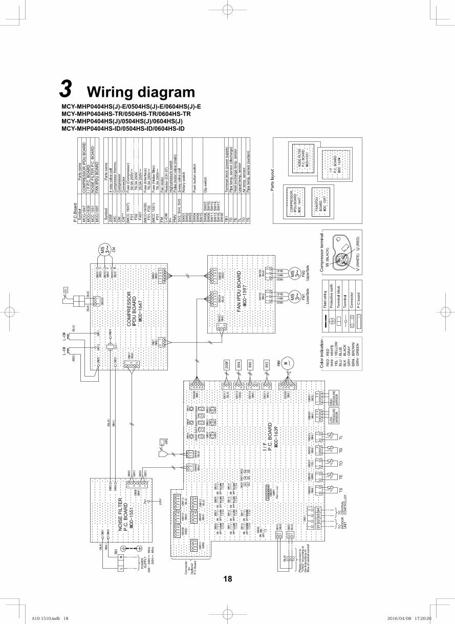
3 Wiring diagramMCY-MHP0404HS(J)-E/0504HS(J)-E/0604HS(J)-E MCY-MHP0404HS-TR/0504HS-TR/0604HS-TR MCY-MHP0404HS(J)/0504HS(J)/0604HS(J) MCY-MHP0404HS-ID/0504HS-ID/0604HS-ID
CO
MPR
ESSO
R IP
DU
BO
ARD
I / F
P.C
. BO
ARD
NO
ISE
FILT
ER P
.C. B
OAR
DFA
N IP
DU
BO
ARD
18
A10-1510.indb 18A10-1510.indb 18 2016/04/08 17:20:202016/04/08 17:20:20
16
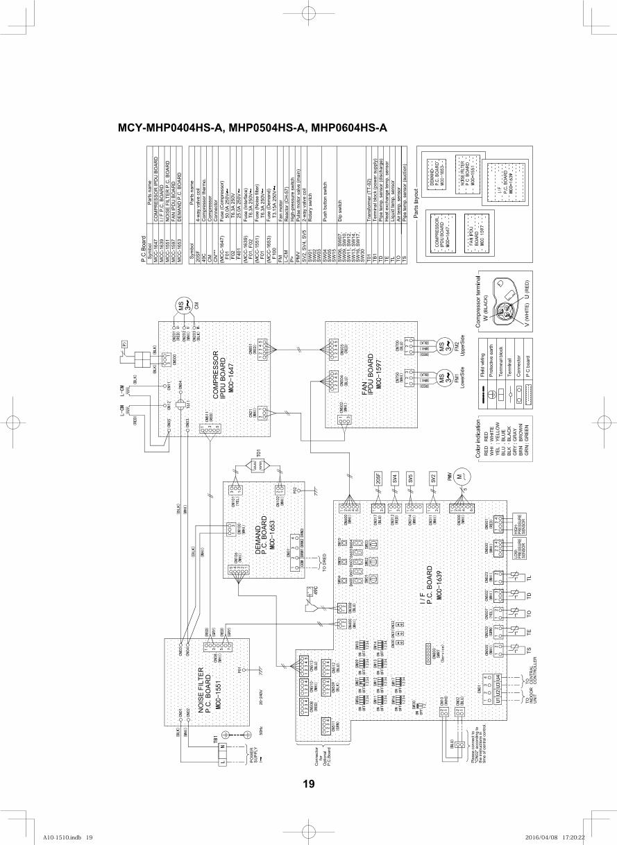
MCY-MHP0404HS-A, MHP0504HS-A, MHP0604HS-A
DEMA
NDP.
C. B
OARD
1653
Con
nect
or
Pus
h bu
tton
switc
h
Rot
ary
switc
h
Pul
se m
otor
val
ve (m
ain)
Com
pres
sor
Dip
sw
itch
4-w
ay v
alve
coi
lC
ompr
esso
r the
rmo.
SW
01
SW
06, S
W07
,
49C
CN
***
SW
04
SV2
, SV
4, S
V5
CM
20S
F
Fan
mot
or
Pip
e te
mp.
sen
sor (
disc
harg
e)TD TO
Hea
t exc
hang
e te
mp.
sen
sor
TE
Air
tem
p. s
enso
rTL
Liqu
id te
mp.
sen
sor
Rea
ctor
(CH
-57)
Fuse
(Com
pres
sor)
Fuse
(Int
erfa
ce)
Fuse
(Noi
se fi
lter)
TSP
ipe
tem
p. s
enso
r (su
ctio
n)
CO
MPR
ESSO
R IP
DU
BO
ARD
NO
ISE
FILT
ER P
.C. B
OA
RD
Sym
bol
MC
C-1
647
MC
C-1
551
MC
C-1
597
MC
C-1
639
Parts
nam
e
I / F
P.C
. BO
AR
D
FAN
IPD
U B
OA
RD
P.C
.Boa
rd
Sym
bol
Parts
nam
e
2-w
ay v
alve
coi
l
SW
03S
W02
SW
05S
W15
SW
09, S
W10
,S
W11
, SW
12,
SW
13, S
W14
,S
W16
, SW
17,
SW
30
Term
inal
blo
ck (p
ower
sup
ply)
TB1
(MC
C-1
647)
F01
F02
F401
F01,
F02
(MC
C-1
639)
(MC
C-1
551)
F01
FM L-C
MP
>P
MV
T6.3
A 25
0V
T6.3
A 25
0V
25.0
A 25
0VT6
.3A
250V
50.0
A 25
0V
Hig
h-pr
essu
re s
witc
h
Tran
sfor
mer
(TT-
02)
T01
MC
C-1
653
DE
MA
ND
P.C
. BO
ARD
Fuse
(Dem
and)
(MC
C-1
653)
F100
T3.1
5A 2
50V
3 FM2
MS
MS
CM
MS
FM1
3
PO
WER
Uppe
rSid
e
SU
PPL
Y
Lowe
rSid
e
IPD
U B
OAR
D
IPD
U B
OAR
DC
OM
PRES
SOR
TS
t°
t°
TE
t° TOTD
t°
t° TL
M
P.C
. BO
ARD
NO
ISE
FILT
ER
P.C
.Boa
rdO
ptio
nal
for
Con
nect
or
LOW
-PR
ESSU
RESE
NSO
R
HIG
H-PR
ESSU
RESE
NSO
R
IND
OO
RU
NIT
TOC
ENTR
ALC
ON
TRO
LLER
TO
P.C
. BO
ARD
I / F
Plea
se c
onne
ct to
the
inst
ruct
ions
in"C
N02
" acc
ordi
ng to
time
of c
entra
l con
trol.
FAN
P.C
. BO
ARD
TO D
RED
DEM
AND
3
19
A10-1510.indb 19A10-1510.indb 19 2016/04/08 17:20:222016/04/08 17:20:22
17
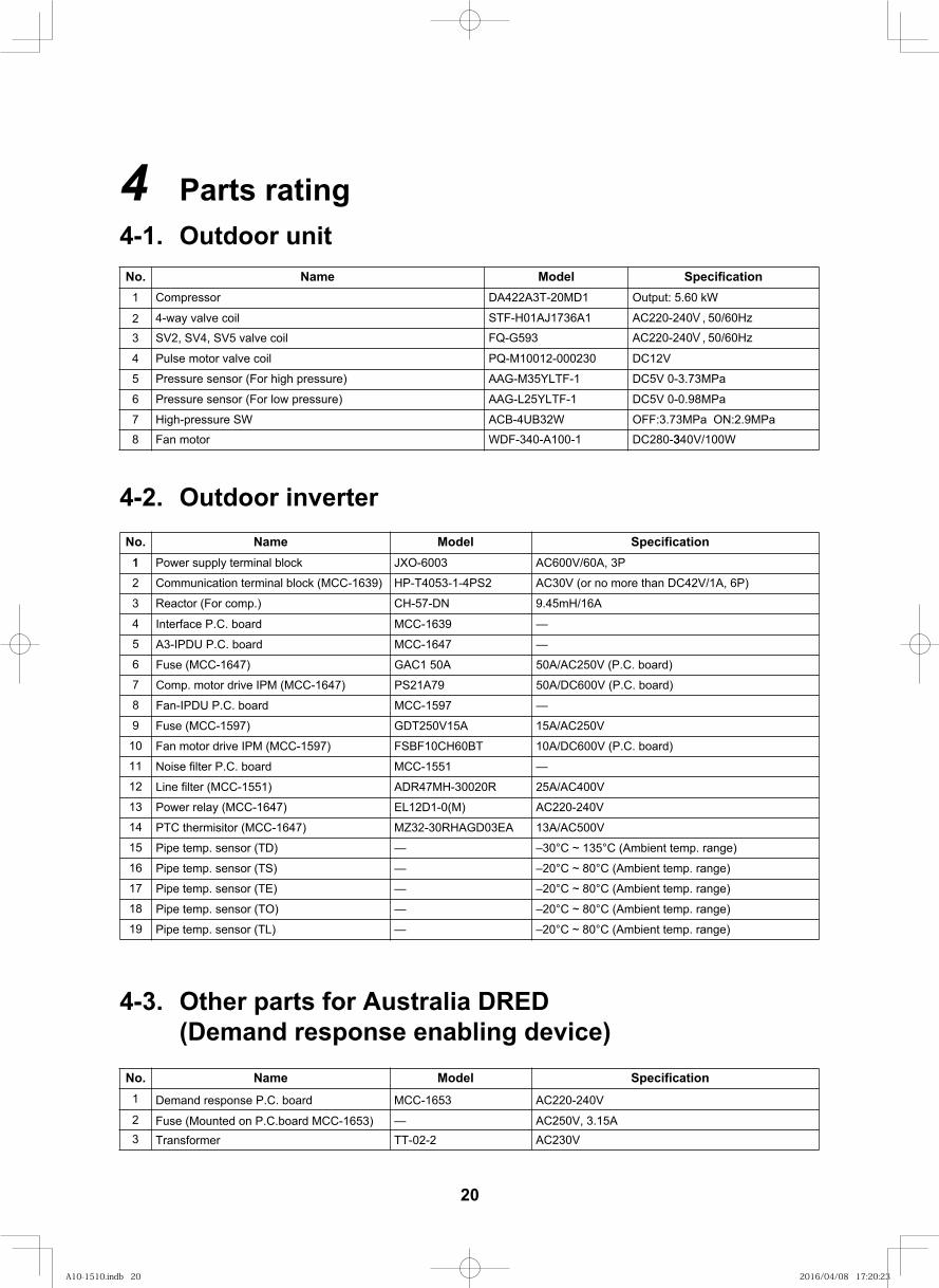
4 Parts rating4-1. Outdoor unit
4-2. Outdoor inverter
noitacificepS.oNrosserpmoC1
2 4-way valve coil3 SV2, SV4, SV5 valve coil
lioc evlav rotom esluP4
5 Pressure sensor (For high pressure)
6 Pressure sensor (For low pressure)
rotom naF8
Output: 5.60 kW
AC220-240V, 50/60Hz
DC5V 0-0.98MPa
DC280-340V/100W3
DC5V 0-3.73MPa
DC12V
AC220-240V, 50/60Hz
DA422A3T-20MD1
STF-H01AJ1736A1FQ-G593
AAG-M35YLTF-1
AAG-L25YLTF-1
WDF-340-A100-1
PQ-M10012-000230
emaN ledoM
High-pressure SW7 OFF:3.73MPa ON:2.9MPaACB-4UB32W
4-3. Other parts for Australia DRED (Demand response enabling device)
noitacificepS.oNDemand response P.C. board1
2 Fuse (Mounted on P.C.board MCC-1653)3 Transformer
AC220-240V
AC250V, 3.15AAC230V
MCC-1653
—TT-02-2
emaN ledoM
noitacificepSledoM.oN1 AC600V/60A, 3PJXO-6003Power supply terminal block1
2 AC30V (or no more than DC42V/1A, 6P)HP-T4053-1-4PS2Communication terminal block (MCC-1639)
9.45mH/16A3 CH-57-DNReactor (For comp.)
10
11
12
13
14
15
16
17
18
19
4
5
6
7
8
9
emaN
–20°C ~ 80°C (Ambient temp. range)—Pipe temp. sensor (TL)
15A/AC250VGDT250V15AFuse (MCC-1597)
10A/DC600V (P.C. board)FSBF10CH60BTFan motor drive IPM (MCC-1597)
—MCC-1551Noise filter P.C. board
25A/AC400VADR47MH-30020RLine filter (MCC-1551)
AC220-240VEL12D1-0(M)Power relay (MCC-1647)
13A/AC500VMZ32-30RHAGD03EAPTC thermisitor (MCC-1647)
–30°C ~ 135°C (Ambient temp. range)—Pipe temp. sensor (TD)
–20°C ~ 80°C (Ambient temp. range)—Pipe temp. sensor (TS)
–20°C ~ 80°C (Ambient temp. range)—Pipe temp. sensor (TE)
–20°C ~ 80°C (Ambient temp. range)—Pipe temp. sensor (TO)
—MCC-1639Interface P.C. board
—MCC-1647A3-IPDU P.C. board
50A/AC250V (P.C. board)GAC1 50AFuse (MCC-1647)
50A/DC600V (P.C. board)PS21A79Comp. motor drive IPM (MCC-1647)
—MCC-1597Fan-IPDU P.C. board
20
A10-1510.indb 20A10-1510.indb 20 2016/04/08 17:20:232016/04/08 17:20:23
18
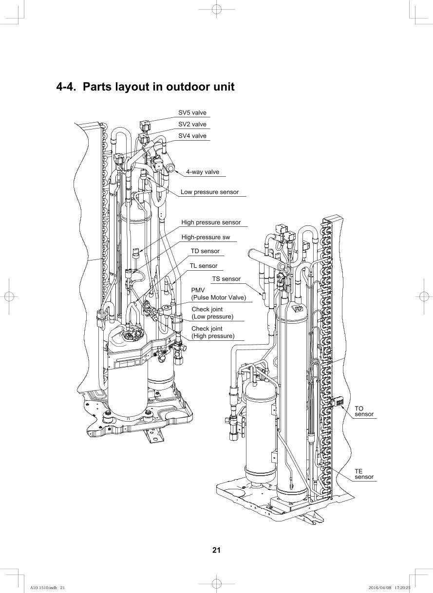
4-4. Parts layout in outdoor unit
SV4 valve
SV2 valve
SV5 valve
4-way valve
Low pressure sensor
TS sensor
High pressure sensor
High-pressure sw
(High pressure)Check joint
(Low pressure)Check joint
TD sensor
TL sensor
(Pulse Motor Valve)PMV
sensor
sensorTO
TE
21
A10-1510.indb 21A10-1510.indb 21 2016/04/08 17:20:252016/04/08 17:20:25
19
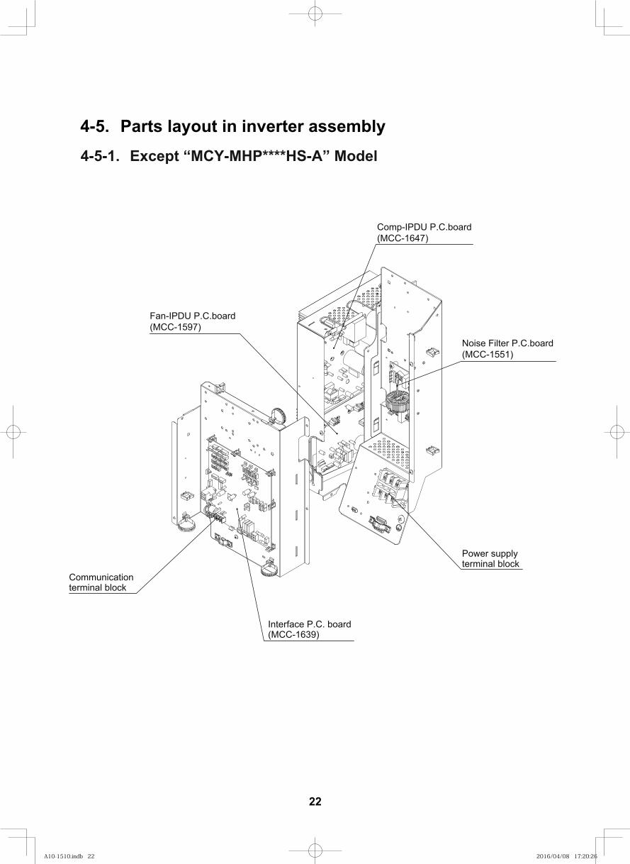
4-5. Parts layout in inverter assembly 4-5-1. Except “MCY-MHP****HS-A” Model
Fan-IPDU P.C.board(MCC-1597)
Communicationterminal block
Interface P.C. board(MCC-1639)
Power supplyterminal block
Noise Filter P.C.board (MCC-1551)
Comp-IPDU P.C.board (MCC-1647)
22
A10-1510.indb 22A10-1510.indb 22 2016/04/08 17:20:262016/04/08 17:20:26
19
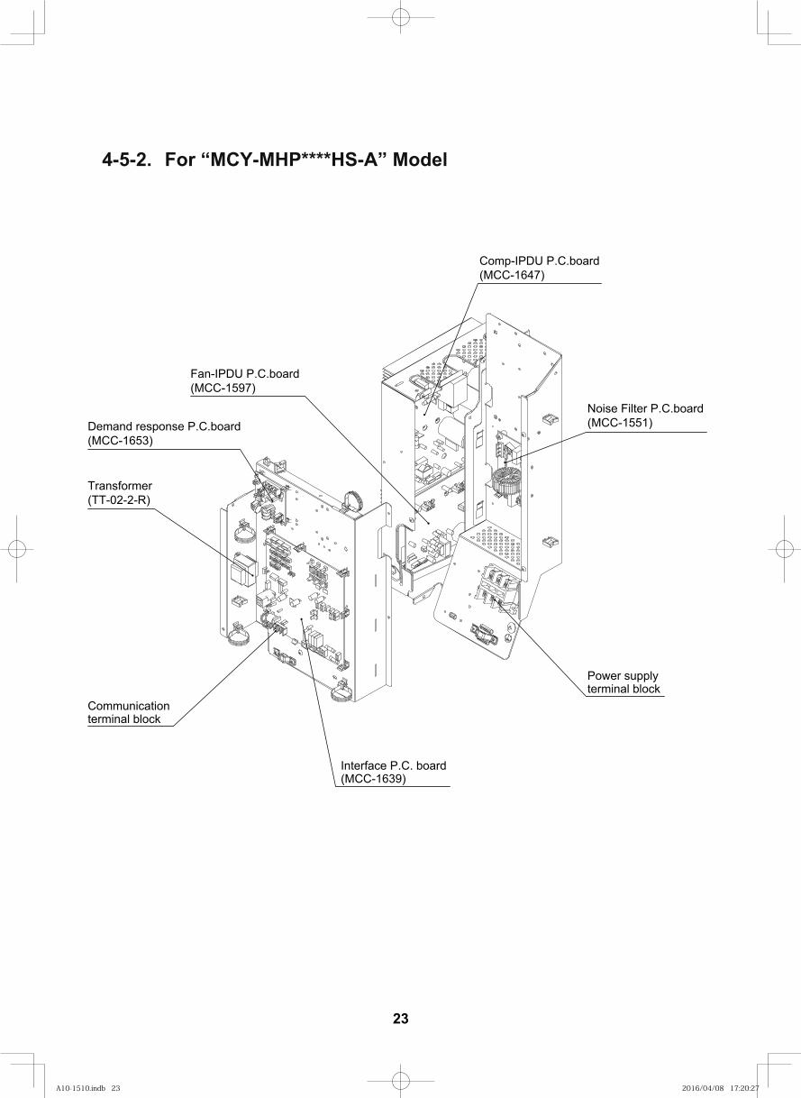
4-5-2. For “MCY-MHP****HS-A” Model
Fan-IPDU P.C.board(MCC-1597)
Communicationterminal block
Interface P.C. board(MCC-1639)
Power supplyterminal block
Noise Filter P.C.board (MCC-1551)
Comp-IPDU P.C.board (MCC-1647)
Demand response P.C.board(MCC-1653)
Transformer(TT-02-2-R)
23
A10-1510.indb 23A10-1510.indb 23 2016/04/08 17:20:272016/04/08 17:20:27
20
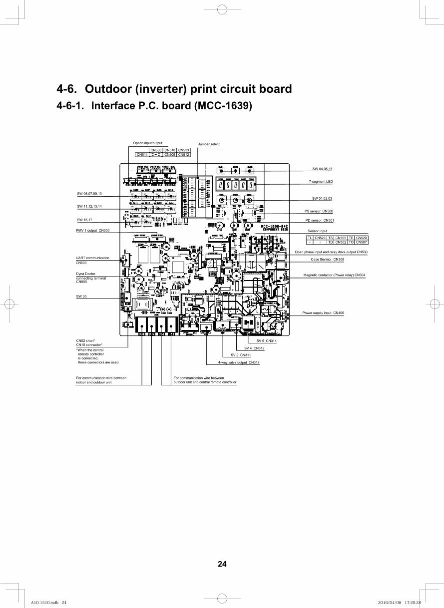
4-6. Outdoor (inverter) print circuit board4-6-1. Interface P.C. board (MCC-1639)
CN508 CN510 CN513CN511 CN509 CN512
TL CN523 TS CN505 TE CN520- - TD CN502 TO CN507
SW 04,05,15
7-segment LED
Jumper selectOption input/output
SW 06,07,09,10
SW 11,12,13,14
SW 16,17
SW 01,02,03
Sensor input
PS sensor CN500
PD sensor CN501
PMV 1 output CN300
UART communicationCN600
Dyna Doctorconnecting terminalCN800
SW 30
For communication wire betweenoutdoor unit and central remote controller
SV 5 CN314
SV 4 CN312
SV 2 CN311
4-way valve output CN317
Power supply input CN400
Case thermo. CN308
For communication wire betweenindoor and outdoor unit
CN02 short*CN10 connector**When the central remote controller is connected, these connectors are used.
Magnetic contactor (Power relay) CN304
Open phase input and relay drive output CN530
24
A10-1510.indb 24A10-1510.indb 24 2016/04/08 17:20:282016/04/08 17:20:28
21
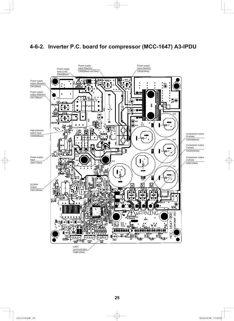
4-6-2. Inverter P.C. board for compressor (MCC-1647) A3-IPDU
CN03(White)
Compressor outputW-phase
CN202(White)
Compressor outputV-phase
CN203(Black)
CN201(Red)
Compressor outputU-phase
UARTcommunicationCN851(Red)
Power supplyInput (Neutral)
CN05(Black and Red)
Power supplyInput (Reactor)
CN12(Red)
Power supplyoutput (Reactor)
CN11(Black)
Power supplyoutput (Reactor)
CN500(Black)
High-pressureswitch input
CN511(Red)
Power supplyInput
DC280VOutputCN21(White)
CN04(Black)
Power supplyInput (Live)
25
A10-1510.indb 25A10-1510.indb 25 2016/04/08 17:20:292016/04/08 17:20:29
22
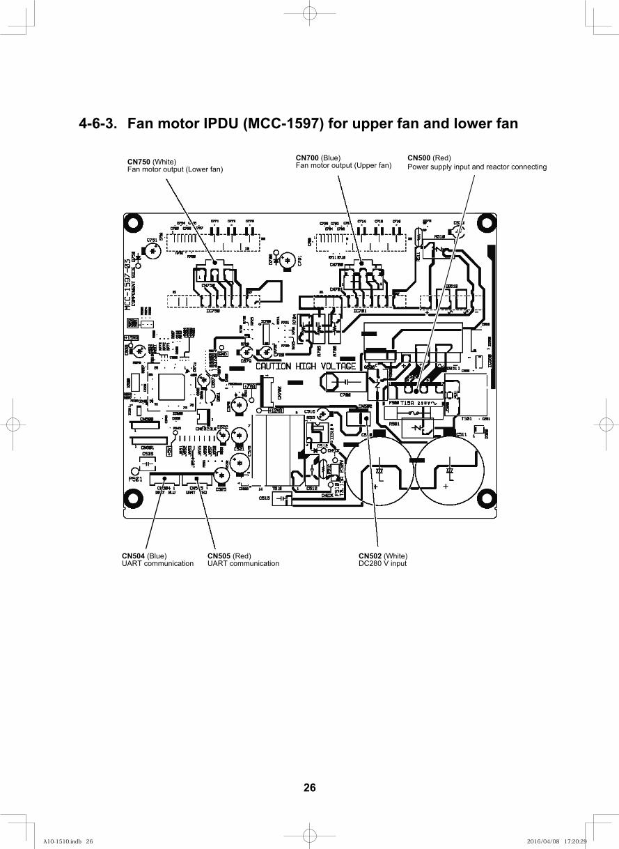
4-6-3. Fan motor IPDU (MCC-1597) for upper fan and lower fan
CN750 (White)Fan motor output (Lower fan)
CN700 (Blue)Fan motor output (Upper fan)
CN505 (Red)UART communication
CN504 (Blue)UART communication
CN502 (White)DC280 V input
CN500 (Red)Power supply input and reactor connecting
26
A10-1510.indb 26A10-1510.indb 26 2016/04/08 17:20:292016/04/08 17:20:29
23
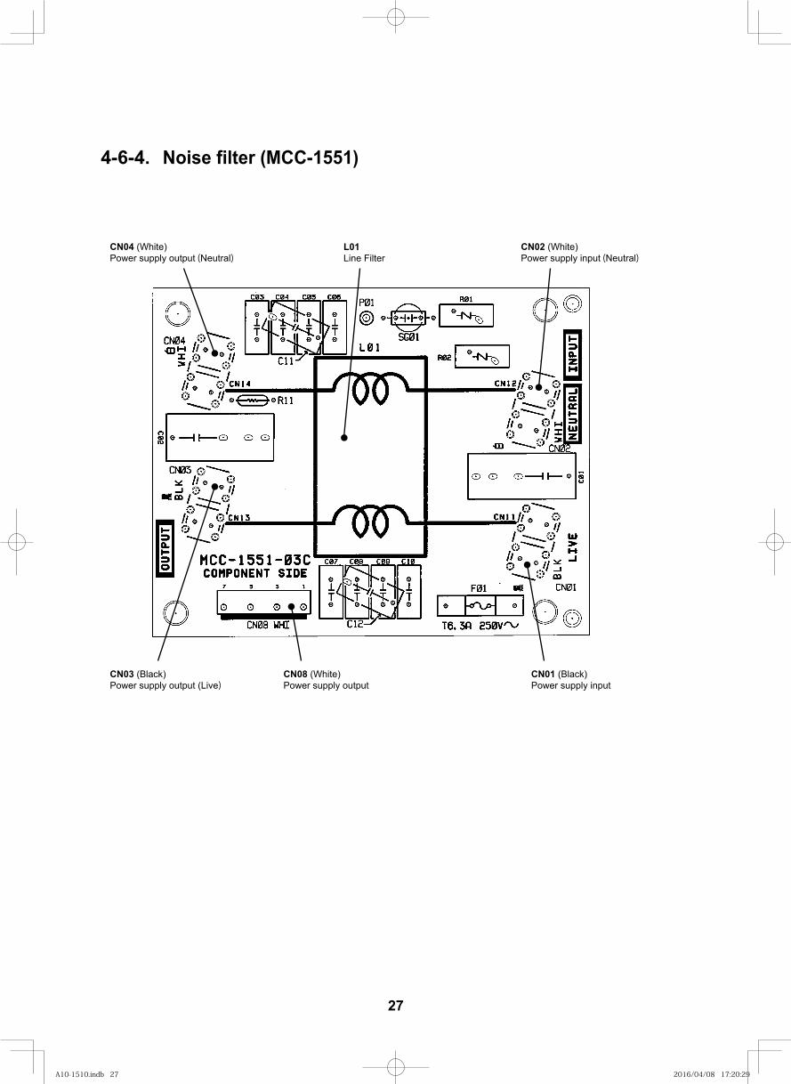
4-6-4. Noise filter (MCC-1551)
L01Line Filter
CN02 (White)Power supply input (Neutral)
CN04 (White)Power supply output (Neutral)
CN03 (Black)Power supply output (Live)
CN08 (White)Power supply output
CN01 (Black)Power supply input
27
A10-1510.indb 27A10-1510.indb 27 2016/04/08 17:20:292016/04/08 17:20:29
24
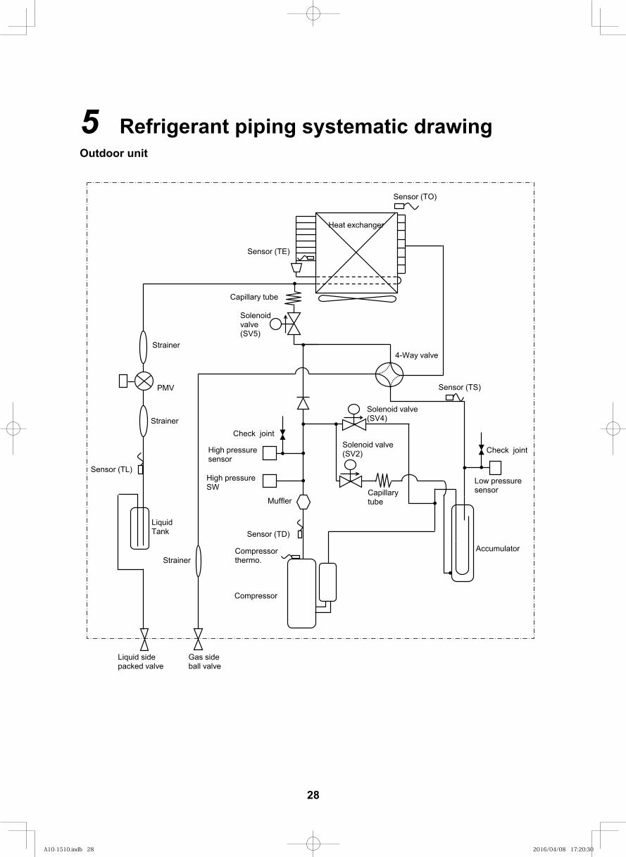
5 Refrigerant piping systematic drawingOutdoor unit
Sensor (TO)
Heat exchanger
Sensor (TE)
Compressor thermo.
Solenoid valve(SV5)
Strainer
PMV
Strainer
Sensor (TL)
Liquid sidepacked valve
Gas sideball valve
Compressor
Strainer
Sensor (TD)
4-Way valve
Sensor (TS)
Solenoid valve(SV4)
Solenoid valve(SV2)
Capillarytube
Check joint
Muffler
High pressuresensor
Check joint
Low pressuresensor
Accumulator
High pressureSW
Capillary tube
LiquidTank
28
A10-1510.indb 28A10-1510.indb 28 2016/04/08 17:20:302016/04/08 17:20:30
25
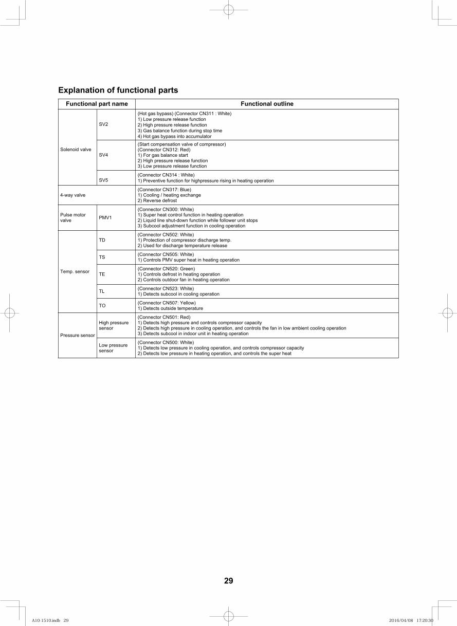
Explanation of functional partsFunctional part na eniltuo lanoitcnuFem
Solenoid valve(Start compensation valve of compressor)(Connector CN312: Red)1) For gas balance start2) High pressure release function3) Low pressure release function
4-way valve(Connector CN317: Blue)1) Cooling / heating exchange2) Reverse defrost
Pulse motor valve PMV1
(Connector CN300: White)1) Super heat control function in heating operation2) Liquid line shut-down function while follower unit stops3) Subcool adjustment function in cooling operation
Temp. sensor
TD(Connector CN502: White)1) Protection of compressor discharge temp.2) Used for discharge temperature release
TS (Connector CN505: White)1) Controls PMV super heat in heating operation
TE(Connector CN520: Green)1) Controls defrost in heating operation2) Controls outdoor fan in heating operation
TL (Connector CN523: White)1) Detects subcool in cooling operation
TO (Connector CN507: Yellow)1) Detects outside temperature
Pressure sensor
High pressure sensor
(Connector CN501: Red)1) Detects high pressure and controls compressor capacity2) Detects high pressure in cooling operation, and controls the fan in low ambient cooling operation 3) Detects subcool in indoor unit in heating operation
Low pressure sensor
(Connector CN500: White)1) Detects low pressure in cooling operation, and controls compressor capacity2) Detects low pressure in heating operation, and controls the super heat
SV4
SV5
SV2
(Hot gas bypass) (Connector CN311 : White)1) Low pressure release function2) High pressure release function3) Gas balance function during stop time4) Hot gas bypass into accumulator
(Connector CN314 : White)1) Preventive function for highpressure rising in heating operation
29
A10-1510.indb 29A10-1510.indb 29 2016/04/08 17:20:302016/04/08 17:20:30
26
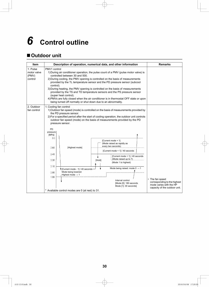
6 Control outline
Outdoor unitItem Description of operation, numerical data, and other information Remarks
1. Pulse motor valve (PMV) control
PMV1 control 1)During air conditioner operation, the pulse count of a PMV (pulse motor valve) is
controlled between 30 and 500.2)During cooling, the PMV opening is controlled on the basis of measurements
provided by the TL temperature sensor and the PD pressure sensor (subcool control).
3)During heating, the PMV opening is controlled on the basis of measurements provided by the TS and TD temperature sensors and the PS pressure sensor (super heat control).
4)PMVs are fully closed when the air conditioner is in thermostat OFF state or upon being turned off normally or shut down due to an abnormality.
2. Outdoor fan control
1. Cooling fan control1)Outdoor fan speed (mode) is controlled on the basis of measurements provided by
the PD pressure sensor.2)For a specified period after the start of cooling operation, the outdoor unit controls
outdoor fan speed (mode) on the basis of measurements provided by the PD pressure sensor.
* Available control modes are 0 (at rest) to 31.
The fan speed corresponding to the highest mode varies with the HP capacity of the outdoor unit.
[Highest mode]
[Current mode + 1](Mode raised as rapidly as every two seconds)
[Current mode + 1] / 40 seconds
[Current mode + 1] / 40 seconds(Mode raised up to 7)(Mode 1 to highest)
[Hold]
Mode being raised: mode 0 1[Current mode - 1] / 40 secondsMode being lowered:Highest mode 1
Interval control[Mode [0]: 180 secondsMode [1]: 30 seconds]
PDpressure
[MPa]
30
A10-1510.indb 30A10-1510.indb 30 2016/04/08 17:20:302016/04/08 17:20:30
27
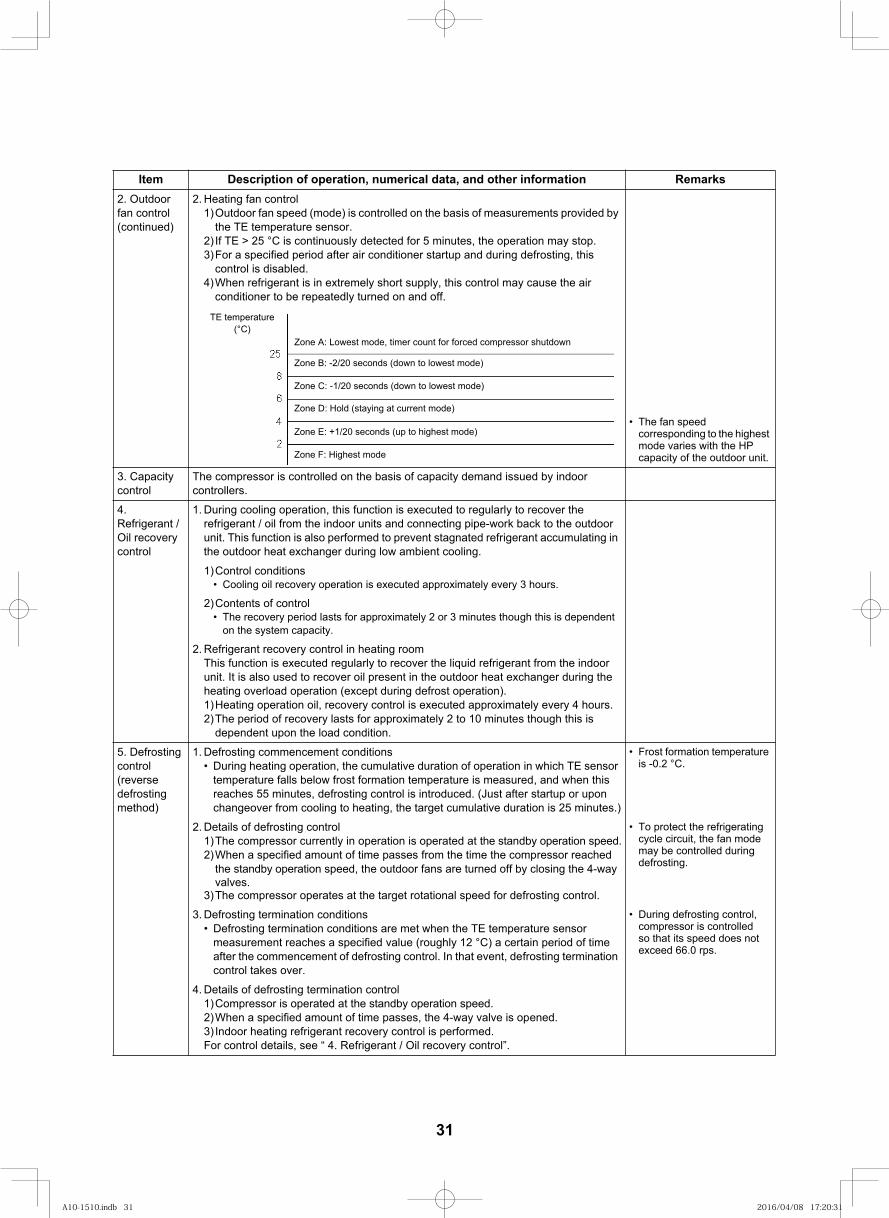
2. Outdoor fan control(continued)
2. Heating fan control1)Outdoor fan speed (mode) is controlled on the basis of measurements provided by
the TE temperature sensor.2) If TE > 25 °C is continuously detected for 5 minutes, the operation may stop.3)For a specified period after air conditioner startup and during defrosting, this
control is disabled.4)When refrigerant is in extremely short supply, this control may cause the air
conditioner to be repeatedly turned on and off.
The fan speed corresponding to the highest mode varies with the HP capacity of the outdoor unit.
3. Capacity control
The compressor is controlled on the basis of capacity demand issued by indoor controllers.
4. Refrigerant / Oil recovery control
1. During cooling operation, this function is executed to regularly to recover the refrigerant / oil from the indoor units and connecting pipe-work back to the outdoor unit. This function is also performed to prevent stagnated refrigerant accumulating in the outdoor heat exchanger during low ambient cooling.
1)Control conditionsCooling oil recovery operation is executed approximately every 3 hours.
2)Contents of controlThe recovery period lasts for approximately 2 or 3 minutes though this is dependent on the system capacity.
2. Refrigerant recovery control in heating roomThis function is executed regularly to recover the liquid refrigerant from the indoor unit. It is also used to recover oil present in the outdoor heat exchanger during the heating overload operation (except during defrost operation).1)Heating operation oil, recovery control is executed approximately every 4 hours.2)The period of recovery lasts for approximately 2 to 10 minutes though this is
dependent upon the load condition.
5. Defrosting control (reversedefrosting method)
1. Defrosting commencement conditionsDuring heating operation, the cumulative duration of operation in which TE sensor temperature falls below frost formation temperature is measured, and when this reaches 55 minutes, defrosting control is introduced. (Just after startup or upon changeover from cooling to heating, the target cumulative duration is 25 minutes.)
Frost formation temperature is -0.2 °C.
2. Details of defrosting control1)The compressor currently in operation is operated at the standby operation speed.2)When a specified amount of time passes from the time the compressor reached
the standby operation speed, the outdoor fans are turned off by closing the 4-way valves.
3)The compressor operates at the target rotational speed for defrosting control.
To protect the refrigerating cycle circuit, the fan mode may be controlled during defrosting.
3. Defrosting termination conditionsDefrosting termination conditions are met when the TE temperature sensor measurement reaches a specified value (roughly 12 °C) a certain period of time after the commencement of defrosting control. In that event, defrosting termination control takes over.
During defrosting control, compressor is controlled so that its speed does not exceed 66.0 rps.
4. Details of defrosting termination control1)Compressor is operated at the standby operation speed.2)When a specified amount of time passes, the 4-way valve is opened. 3) Indoor heating refrigerant recovery control is performed.For control details, see “ 4. Refrigerant / Oil recovery control”.
Item Description of operation, numerical data, and other information Remarks
Zone A: Lowest mode, timer count for forced compressor shutdown
Zone B: -2/20 seconds (down to lowest mode)
Zone C: -1/20 seconds (down to lowest mode)
Zone D: Hold (staying at current mode)
Zone E: +1/20 seconds (up to highest mode)
Zone F: Highest mode
TE temperature(°C)
31
A10-1510.indb 31A10-1510.indb 31 2016/04/08 17:20:312016/04/08 17:20:31
28
6. Releasevalve control
Item Description of operation, numerical data, and other information Remarks1. SV2 gas balance control
This control function is aimed at achieving gas balance by opening SV2 while compressor is turned off so as to reduce its startup load the next time it is turned on.1) Control conditions
The compressor has been turned off.2) Control details
The control point is changed according to P (PD pressure - PS pressure) registered just before the compressor was turned off.
When P 1.3MPa, SV2 is opened. When this results in P 1.1MPa, SV2 is closed.
When P 1.3MPa, SV2 is closed.2. SV2 high pressure release control
This control function is aimed at mitigating pressure rise while a compressor is in operation at low speeds.1) Control conditions
Heating operation is in progress (except periods of defrosting control). A speed of the compressor is in operation at low speeds of up to 77 rps.
2) Control details When PD pressure becomes 3.4 MPa, SV2 is opened. When PD pressure becomes 2.8 MPa, SV2 is closed.
3) Termination conditions Shutdown, thermostat OFF, defrosting operation, or cooling operation. The speed of the compressor rises to 82 rps or more.
3. SV2 low pressure release controlThis control function is aimed at preventing a rapid fall in pressure during transient operation.The control is always provided except during periods of stoppage or thermostat OFF.1) Control details (heating)
When PS pressure becomes 0.1 MPa, SV2 is opened. When PS pressure becomes 0.2 MPa, SV2 is closed.
4. SV4 low pressure release controlThis control function is aimed at providing low pressure protection.1) Control details (heating)
When PS pressure becomes 0.1 MPa, SV4 is opened; when PS pressure becomes 0.2MPa, SV4 is closed.
2)When PS pressure and PD pressure become 0.14 MPa and 1.8 MPa, respectively, SV4 is opened; when PS pressure and PD pressure become 0.24 MPa and 2.2 MPa, respectively, SV4 is closed.
5. SV5 high pressure release controlThis control function is aimed at mitigating pressure rise.1) Control details (heating)
When PD pressure and compressor speed become 3.4 MPa and 38 rps, respectively, SV5 is
compressor speed 42 rps, SV5 is closed.
2) Control details (cooling)
opened; when PD pressure becomes 2.7 MPa, or
Control details (cooling)
When PS pressure becomes 0.25 MPa, SV2 is opened. When PS pressure becomes 0.30 MPa, SV2 is closed.
32
A10-1510.indb 32A10-1510.indb 32 2016/04/08 17:20:312016/04/08 17:20:31
28
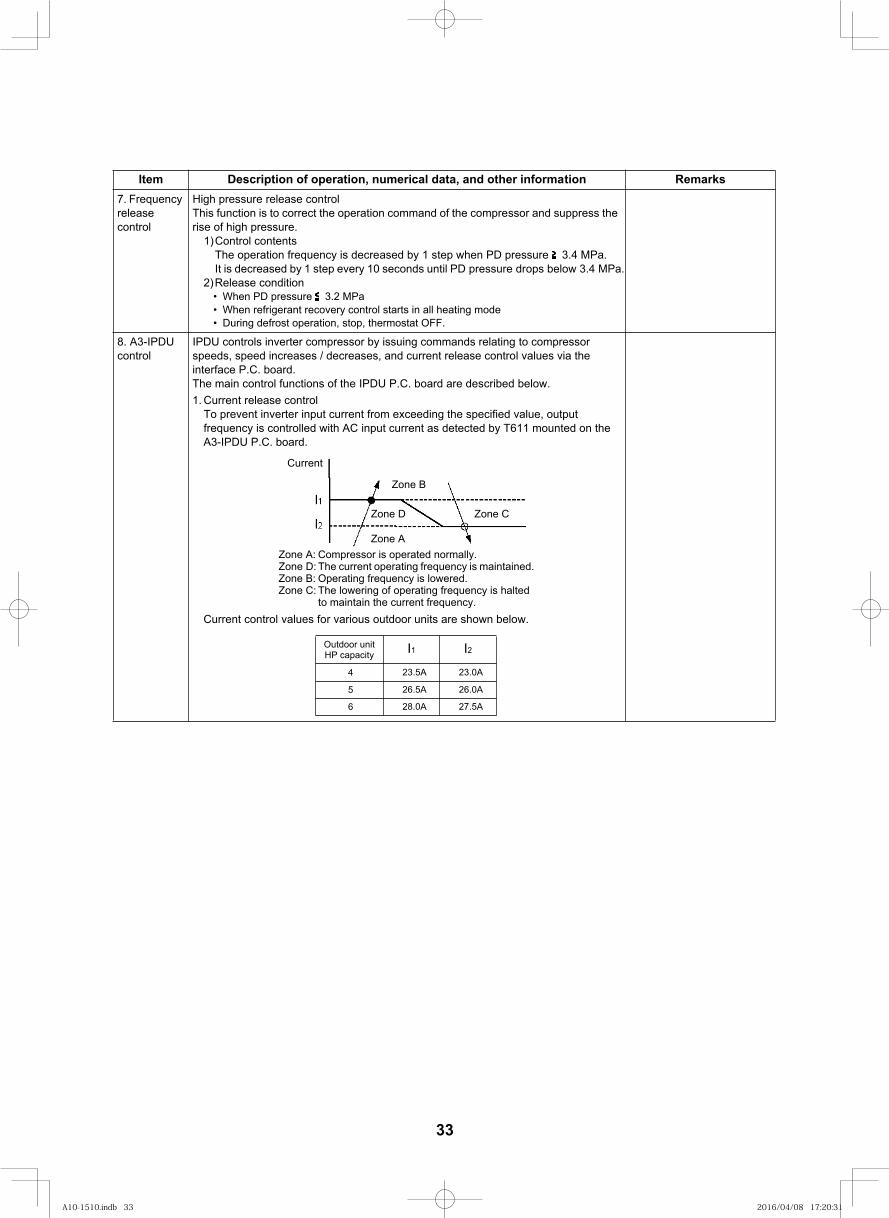
7. Frequency release control
High pressure release controlThis function is to correct the operation command of the compressor and suppress the rise of high pressure.
1)Control contentsThe operation frequency is decreased by 1 step when PD pressure 3.4 MPa. It is decreased by 1 step every 10 seconds until PD pressure drops below 3.4 MPa.
2)Release conditionWhen PD pressure 3.2 MPaWhen refrigerant recovery control starts in all heating modeDuring defrost operation, stop, thermostat OFF.
8. A3-IPDU control
IPDU controls inverter compressor by issuing commands relating to compressor speeds, speed increases / decreases, and current release control values via the interface P.C. board.The main control functions of the IPDU P.C. board are described below.1. Current release control
To prevent inverter input current from exceeding the specified value, output frequency is controlled with AC input current as detected by T611 mounted on the A3-IPDU P.C. board.
Current control values for various outdoor units are shown below.
Item Description of operation, numerical data, and other information Remarks
Zone A: Compressor is operated normally.Zone D: The current operating frequency is maintained.Zone B: Operating frequency is lowered.Zone C: The lowering of operating frequency is halted
to maintain the current frequency.
Current
Zone B
Zone D Zone C
Zone A
I1 I2Outdoor unit HP capacity
23.5A 23.0A
26.5A 26.0A
4
5
28.0A 27.5A6
33
A10-1510.indb 33A10-1510.indb 33 2016/04/08 17:20:312016/04/08 17:20:31
29
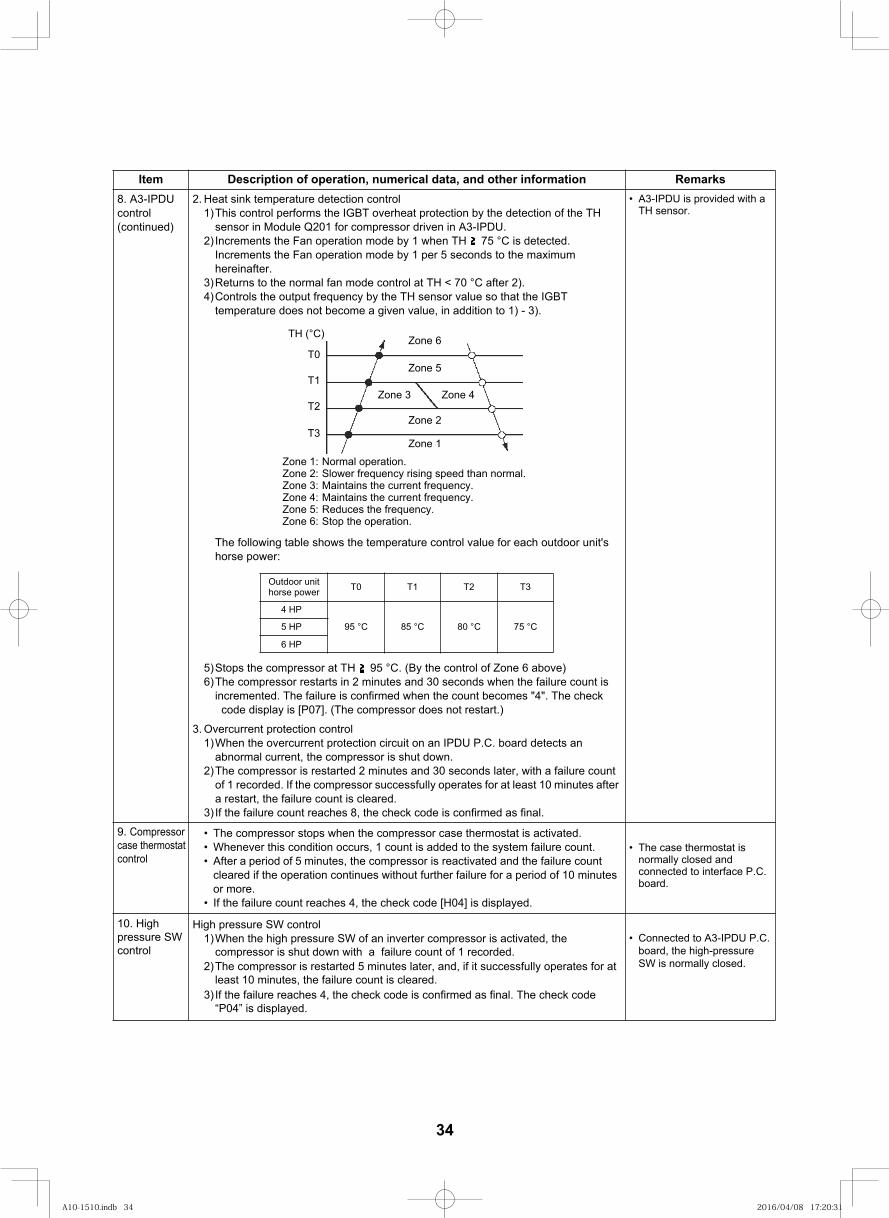
8. A3-IPDU control(continued)
2. Heat sink temperature detection control1)This control performs the IGBT overheat protection by the detection of the TH
sensor in Module Q201 for compressor driven in A3-IPDU.2) Increments the Fan operation mode by 1 when TH 75 °C is detected.
Increments the Fan operation mode by 1 per 5 seconds to the maximum hereinafter.
3)Returns to the normal fan mode control at TH < 70 °C after 2).4)Controls the output frequency by the TH sensor value so that the IGBT
temperature does not become a given value, in addition to 1) - 3).
The following table shows the temperature control value for each outdoor unit's horse power:
5)Stops the compressor at TH 95 °C. (By the control of Zone 6 above)6)The compressor restarts in 2 minutes and 30 seconds when the failure count is
incremented. The failure is confirmed when the count becomes "4". The check code display is [P07]. (The compressor does not restart.)
A3-IPDU is provided with a TH sensor.
3. Overcurrent protection control1)When the overcurrent protection circuit on an IPDU P.C. board detects an
abnormal current, the compressor is shut down.2)The compressor is restarted 2 minutes and 30 seconds later, with a failure count
of 1 recorded. If the compressor successfully operates for at least 10 minutes after a restart, the failure count is cleared.
3) If the failure count reaches 8, the check code is confirmed as final.
The compressor stops when the compressor case thermostat is activated.Whenever this condition occurs, 1 count is added to the system failure count. After a period of 5 minutes, the compressor is reactivated and the failure count
cleared if the operation continues without further failure for a period of 10 minutes or more.
If the failure count reaches 4, the check code [H04] is displayed.
The case thermostat is normally closed and connected to interface P.C. board.
Connected to A3-IPDU P.C. board, the high-pressure SW is normally closed.
Item Description of operation, numerical data, and other information Remarks
Zone 1: Normal operation.Zone 2: Slower frequency rising speed than normal.Zone 3: Maintains the current frequency.Zone 4: Maintains the current frequency.Zone 5: Reduces the frequency.Zone 6: Stop the operation.
TH (°C)
Zone 1
T0
T1
T2
T3Zone 2
Zone 3 Zone 4
Zone 5
Zone 6
Outdoor unit horse power T0 T1 T2 T3
4 HP
95 °C 85 °C 80 °C 75 °C5 HP
6 HP
9. Compressor case thermostat control
10. High pressure SW control
High pressure SW control1)When the high pressure SW of an inverter compressor is activated, the
compressor is shut down with a failure count of 1 recorded.2)The compressor is restarted 5 minutes later, and, if it successfully operates for at
least 10 minutes, the failure count is cleared. 3) If the failure reaches 4, the check code is confirmed as final. The check code
“P04” is displayed.
34
A10-1510.indb 34A10-1510.indb 34 2016/04/08 17:20:312016/04/08 17:20:31
30
<Other points to note>1 Cooling operation under low outside temperature conditions
1) If pressure falls to extremely low levels, indoor units may be shut down via freeze prevention control based on the indoor TC sensor.
2) If pressure falls to extremely low levels, frequency may be reduced via cooling capacity control.3) When the discharge temperature sensor reading falls below 60 °C, the frequency may be increased above
the level called for by the command received from the indoor unit.
2 PMV (Pulse Motor Valve)1) When the power is turned on, PMVs generate a tapping sound as they are initialized. If this sound is not
heard, there is a possibility of faulty PMV operation. However, in a noisy environment, it may simply be drowned out by ambient noise.
2) Do not separate the actuator (head section) from any PMV during operation. It may result in an inaccurate opening.
3) When transporting (relocating) the set, do not, under any circumstances, keep the actuator separated. It may damage the valve by causing it to close and exposing it to pressure from sealed liquid.
4) When reattaching the actuator after its removal, push it in firmly until a click sound is heard. Then, turn the power off and back on again.
35
A10-1510.indb 35A10-1510.indb 35 2016/04/08 17:20:322016/04/08 17:20:32
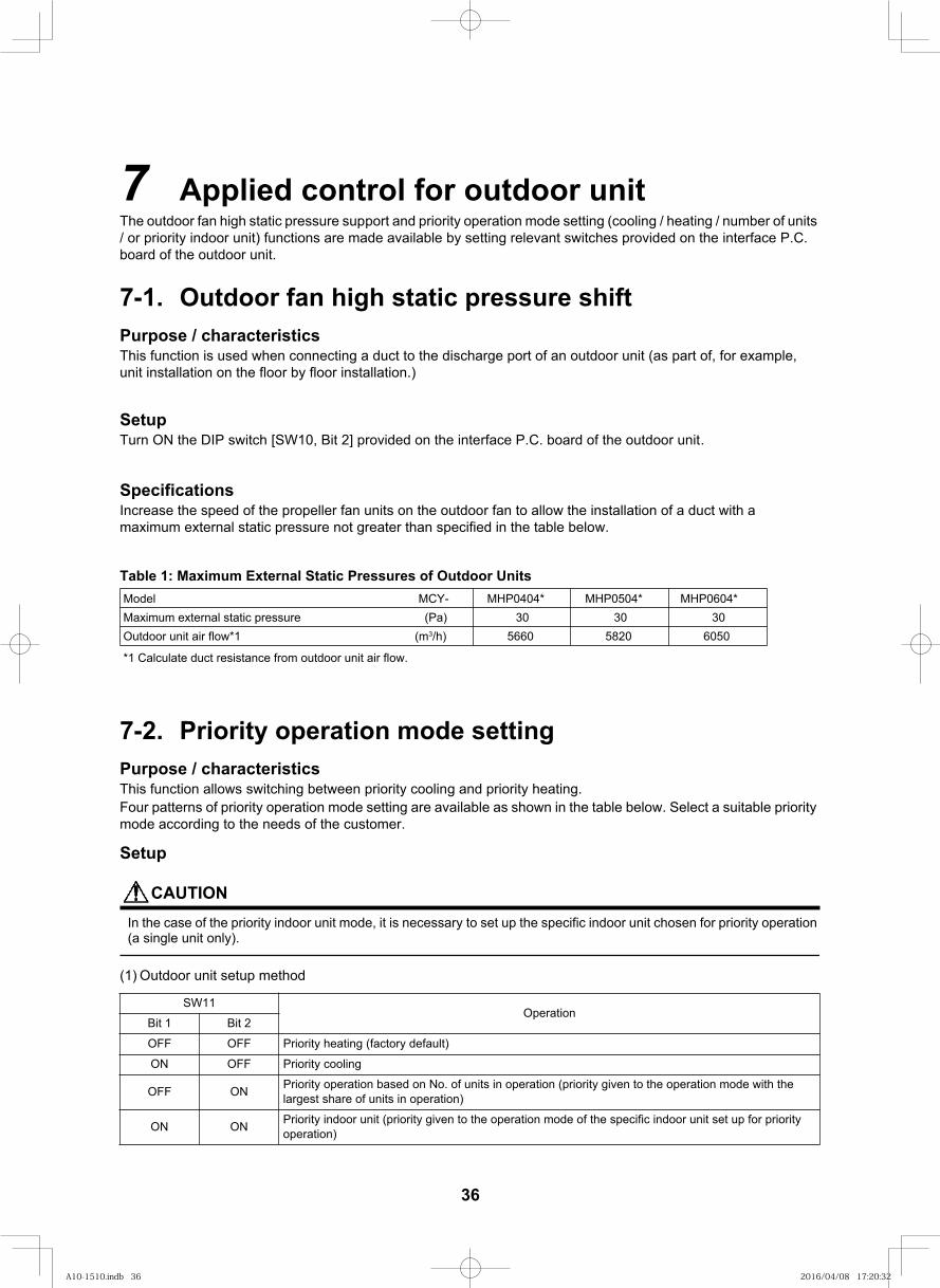
52
The outdoor fan high static pressure support and priority operation mode setting (cooling / heating / number of units / or priority indoor unit) functions are made available by setting relevant switches provided on the interface P.C. board of the outdoor unit.
Purpose / characteristicsThis function allows switching between priority cooling and priority heating.Four patterns of priority operation mode setting are available as shown in the table below. Select a suitable priority mode according to the needs of the customer.
Setup
CAUTIONIn the case of the priority indoor unit mode, it is necessary to set up the specific indoor unit chosen for priority operation (a single unit only).
(1) Outdoor unit setup method
SW11Operation
Bit 1 Bit 2
OFF OFF Priority heating (factory default)
ON OFF Priority cooling
OFF ON Priority operation based on No. of units in operation (priority given to the operation mode with the largest share of units in operation)
ON ON Priority indoor unit (priority given to the operation mode of the specific indoor unit set up for priority operation)
7 Applied control for outdoor unit
7-2. Priority operation mode setting
Purpose / characteristicsThis function is used when connecting a duct to the discharge port of an outdoor unit (as part of, for example, unit installation on the floor by floor installation.)
Table 1: Maximum External Static Pressures of Outdoor Units
7-1. Outdoor fan high static pressure shift
SetupTurn ON the DIP switch [SW10, Bit 2] provided on the interface P.C. board of the outdoor unit.
SpecificationsIncrease the speed of the propeller fan units on the outdoor fan to allow the installation of a duct with a maximum external static pressure not greater than specified in the table below.
Model MCY- MHP0404* MHP0504* MHP0604*Maximum external static pressure (Pa) 30 30 30Outdoor unit air flow*1 (m3/h) 5660 5820 6050
*1 Calculate duct resistance from outdoor unit air flow.
36
A10-1510.indb 36A10-1510.indb 36 2016/04/08 17:20:322016/04/08 17:20:32
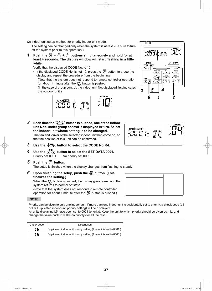
53
(2) Indoor unit setup method for priority indoor unit modeThe setting can be changed only when the system is at rest. (Be sure to turn off the system prior to this operation.)
1 Push the + + buttons simultaneously and hold for at least 4 seconds. The display window will start flashing in a little while.Verify that the displayed CODE No. is 10.
If the displayed CODE No. is not 10, press the button to erase the display and repeat the procedure from the beginning.(Note that the system does not respond to remote controller operation for about 1 minute after the button is pushed.)(In the case of group control, the indoor unit No. displayed first indicates the outdoor unit.)
2 Each time the button is pushed, one of the indoor unit Nos. under group control is displayed in turn. Select the indoor unit whose setting is to be changed.The fan and louver of the selected indoor unit then come on, so that the position of this unit can be confirmed.
3 Use the button to select the CODE No. 04.
4 Use the button to select the SET DATA 0001.Priority set 0001 No priority set 0000
5 Push the button.The setup is finished when the display changes from flashing to steady.
6 Upon finishing the setup, push the button. (This finalizes the setting.)When the button is pushed, the display goes blank, and the system returns to normal off state.(Note that the system does not respond to remote controller operation for about 1 minute after the button is pushed.)
NOTEPriority can be given to only one indoor unit. If more than one indoor unit is accidentally set to priority, a check code (L5 or L6: Duplicated indoor unit priority setting) will be displayed.All units displaying L5 have been set to 0001 (priority). Keep the unit to which priority should be given as it is, and change the value back to 0000 (no priority) for all the rest.
noitpircseD Check code
Duplicated indoor unit priority setting (The unit is set to 0001.)
Duplicated indoor unit priority setting (The unit is set to 0000.)
37
A10-1510.indb 37A10-1510.indb 37 2016/04/08 17:20:322016/04/08 17:20:32
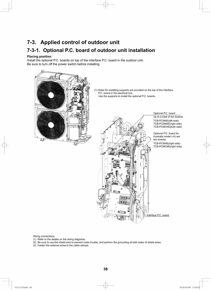
7-3. Applied control of outdoor unit7-3-1. Optional P.C. board of outdoor unit installationPlacing positionInstall the optional P.C. boards on top of the interface P.C. board in the outdoor unit.Be sure to turn off the power switch before installing.
(1) Holes for installing supports are provided on the top of the interface P.C. board in the electrical box. Use the supports to install the optional P.C. boards.
Optional P.C. boardUp to a total of two boardsTCB-PCIN4E(left side)TCB-PCDM4E(right side)TCB-PCMO4E(both side)
Optional P.C. board forAustralia model (-A) aretwo boards.TCB-PCIN4E(right side)TCB-PCMO4E(right side)
Wiring connections(1) Refer to the details on the wiring diagrams.(2) Be sure to use the shield wire to prevent noise trouble, and perform the grounding at both sides of shield wires.(3) Fasten the external wires to the cable clamps.
Interface P.C. board
38
A10-1510.indb 38A10-1510.indb 38 2016/04/08 17:20:322016/04/08 17:20:32
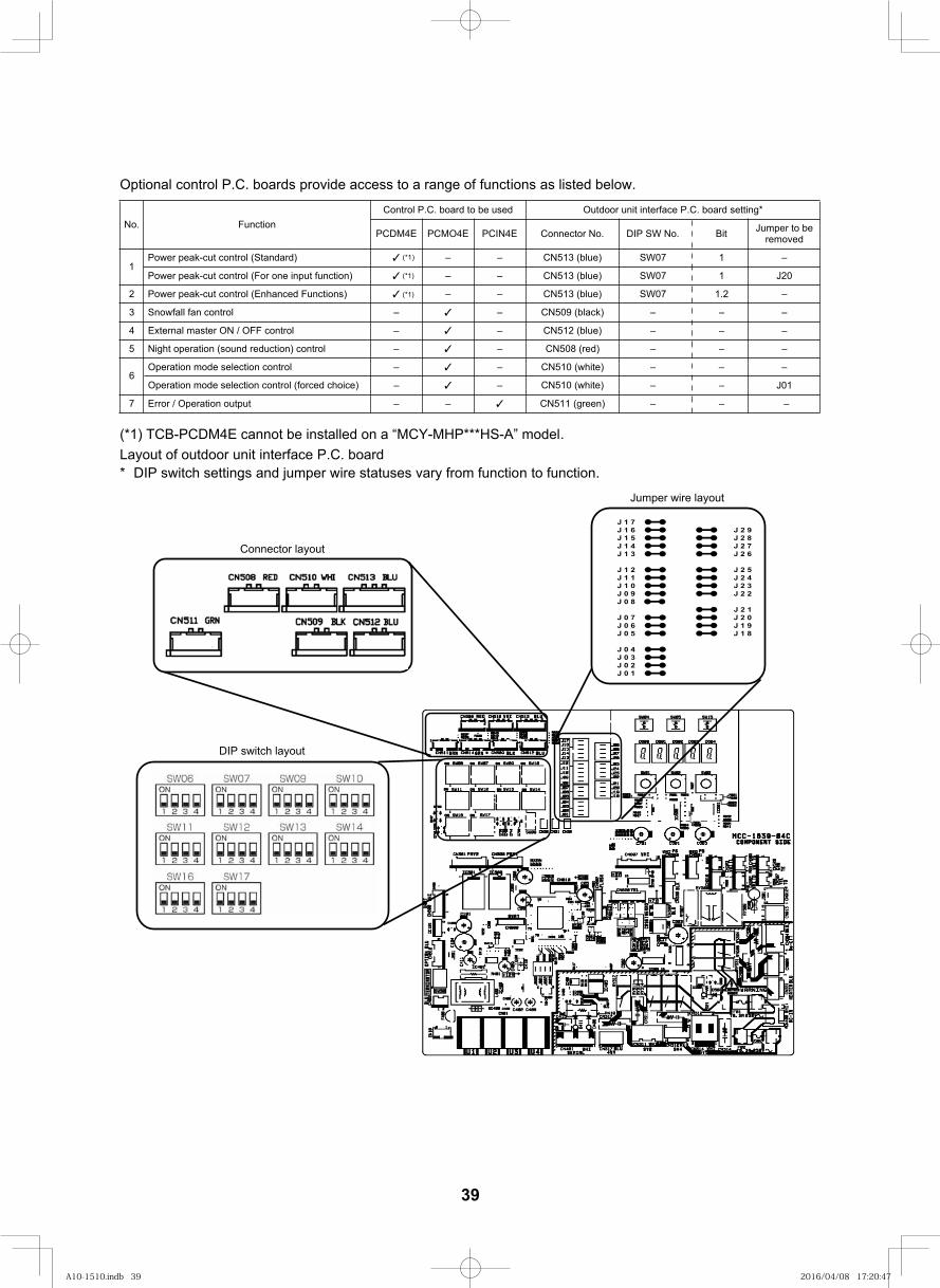
55
Optional control P.C. boards provide access to a range of functions as listed below.
Layout of outdoor unit interface P.C. board* DIP switch settings and jumper wire statuses vary from function to function.
noitcnuF.oNControl P.C. board to be used Outdoor unit interface P.C. board setting*
PCDM4E PCMO4E PCIN4E Connector No. DIP SW No. Bit Jumper to be removed
1Power peak-cut control (Standard) – – CN513 (blue) SW07 1 –
Power peak-cut control (For one input function) – – CN513 (blue) SW07 1
2 Power peak-cut control (Enhanced Functions) – – CN513 (blue) SW07 1.2 –
–lortnoc naf llafwonS3 – CN509 (black) – – –
–lortnoc FFO / NO retsam lanretxE4 – CN512 (blue) – – –
5 Night operation (sound reduction) control – – CN508 (red) – – –
–lortnoc noitceles edom noitarepO6
CN510 (white) – –
–tuptuo noitarepO / rorrE7 CN511 (green) –
– – –
–
–
J20
Operation mode selection control (forced choice) CN510 (white)
– –
–
J01
J 1 7J 1 6 J 2 9J 1 5 J 2 8J 1 4 J 2 7J 1 3 J 2 6
J 1 2 J 2 5J 1 1 J 2 4J 1 0 J 2 3J 0 9 J 2 2J 0 8
J 2 1J 0 7 J 2 0J 0 6 J 1 9J 0 5 J 1 8
J 0 4J 0 3J 0 2J 0 1
Connector layout
Jumper wire layout
DIP switch layout
(*1) TCB-PCDM4E cannot be installed on a “MCY-MHP***HS-A” model.
(*1)
–
(*1)
(*1)
39
A10-1510.indb 39A10-1510.indb 39 2016/04/08 17:20:472016/04/08 17:20:47
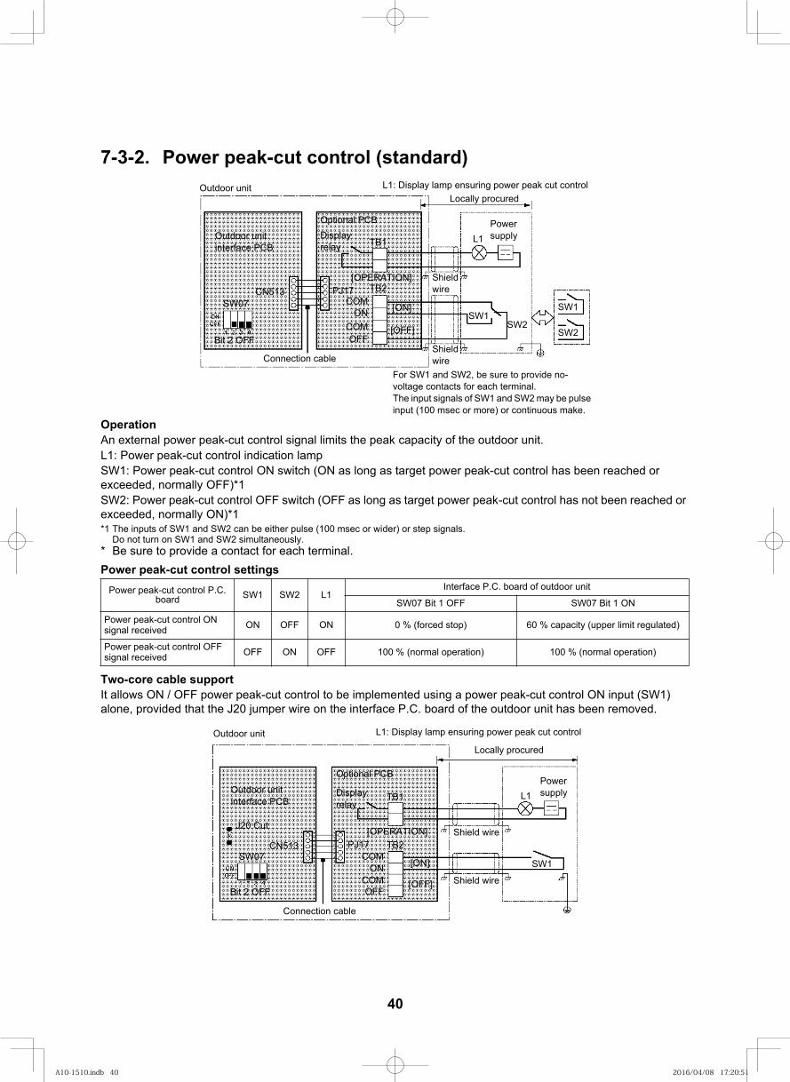
56
7-3-2. Power peak-cut control (standard)
OperationAn external power peak-cut control signal limits the peak capacity of the outdoor unit.L1: Power peak-cut control indication lampSW1: Power peak-cut control ON switch (ON as long as target power peak-cut control has been reached or exceeded, normally OFF)*1SW2: Power peak-cut control OFF switch (OFF as long as target power peak-cut control has not been reached or exceeded, normally ON)*1*1 The inputs of SW1 and SW2 can be either pulse (100 msec or wider) or step signals.
Do not turn on SW1 and SW2 simultaneously.* Be sure to provide a contact for each terminal.Power peak-cut control settings
Two-core cable supportIt allows ON / OFF power peak-cut control to be implemented using a power peak-cut control ON input (SW1) alone, provided that the J20 jumper wire on the interface P.C. board of the outdoor unit has been removed.
Power peak-cut control P.C. board SW1 SW2 L1
Interface P.C. board of outdoor unit
NO 1 tiB 70WSFFO 1 tiB 70WS
Power peak-cut control ON signal received ON OFF ON 0 % (forced stop) 60 % capacity (upper limit regulated)
Power peak-cut control OFF signal received OFF ON OFF 100 % (normal operation) 100 % (normal operation)
Outdoor unit L1: Display lamp ensuring power peak cut controlLocally procured
Outdoor unit interface PCB
CN513SW07
Bit 2 OFF
Connection cable
Optional PCBDisplay relay TB1
TB2PJ17COM
ON
OFFCOM
[ON]
[OFF]
[OPERATION] Shieldwire
PowersupplyL1
SW1SW2
SW1
SW2
Shieldwire
For SW1 and SW2, be sure to provide no-voltage contacts for each terminal.The input signals of SW1 and SW2 may be pulse input (100 msec or more) or continuous make.
Outdoor unit L1: Display lamp ensuring power peak cut control
Locally procured
Outdoor unit interface PCB
CN513SW07
Bit 2 OFF
Connection cable
Optional PCB
Display relay
TB1
TB2PJ17COM
ON
OFFCOM
[ON]
[OFF]
[OPERATION] Shield wire
PowersupplyL1
SW1
Shield wire
J20 Cut
40
A10-1510.indb 40A10-1510.indb 40 2016/04/08 17:20:512016/04/08 17:20:51
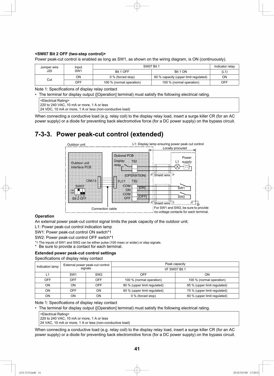
57
<SW07 Bit 2 OFF (two-step control)>Power peak-cut control is enabled as long as SW1, as shown on the wiring diagram, is ON (continuously).
Note 1: Specifications of display relay contactThe terminal for display output ([Operation] terminal) must satisfy the following electrical rating.
When connecting a conductive load (e.g. relay coil) to the display relay load, insert a surge killer CR (for an AC power supply) or a diode for preventing back electromotive force (for a DC power supply) on the bypass circuit.
7-3-3. Power peak-cut control (extended)
OperationAn external power peak-cut control signal limits the peak capacity of the outdoor unit.L1: Power peak-cut control indication lampSW1: Power peak-cut control ON switch*1SW2: Power peak-cut control OFF switch*1*1 The inputs of SW1 and SW2 can be either pulse (100 msec or wider) or step signals.* Be sure to provide a contact for each terminal.Extended power peak-cut control settingsSpecifications of display relay contact
Note 1: Specifications of display relay contactThe terminal for display output ([Operation] terminal) must satisfy the following electrical rating.
When connecting a conductive load (e.g. relay coil) to the display relay load, insert a surge killer CR (for an AC power supply) or a diode for preventing back electromotive force (for a DC power supply) on the bypass circuit.
Jumper wireJ20
InputSW1
yaler rotacidnI1 tiB 70WS)1L(NO 1 tiBFFO 1 tiB
Cut0 % (forced stop) 60 % capacity (upper limit regulated)
100 % (normal operation) 100 % (normal operation)
<Electrical Rating>220 to 240 VAC, 10 mA or more, 1 A or less24 VDC, 10 mA or more, 1 A or less (non-conductive load)
Indication lamp External power peak-cut control signals
Peak capacityI/F SW07 Bit 1
NOFFO2WS1WS1LOFF OFF OFF 100 % (normal operation) 100 % (normal operation)ON ON OFF 80 % (upper limit regulated) 85 % (upper limit regulated)ON OFF ON 60 % (upper limit regulated) 75 % (upper limit regulated)ON ON ON 0 % (forced stop) 60 % (upper limit regulated)
<Electrical Rating>220 to 240 VAC, 10 mA or more, 1 A or less24 VAC, 10 mA or more, 1 A or less (non-conductive load)
Outdoor unit L1: Display lamp ensuring power peak cut controlLocally procured
Outdoor unit interface PCB
CN513SW07
Bit 2 OFF
Connection cable
Optional PCBDisplay relay
TB1
TB2PJ17COM
ON
OFFCOM
[ON]
[OFF]
[OPERATION] Shield wire
PowersupplyL1
SW1
Shield wire
SW2
For SW1 and SW2, be sure to provide no-voltage contacts for each terminal.
ONOFFON
OFF
41
A10-1510.indb 41A10-1510.indb 41 2016/04/08 17:20:512016/04/08 17:20:51
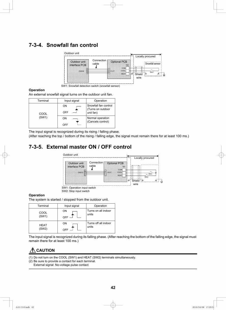
58
7-3-4. Snowfall fan control
OperationAn external snowfall signal turns on the outdoor unit fan.
The input signal is recognized during its rising / falling phase.(After reaching the top / bottom of the rising / falling edge, the signal must remain there for at least 100 ms.)
7-3-5. External master ON / OFF control
OperationThe system is started / stopped from the outdoor unit.
The input signal is recognized during its falling phase. (After reaching the bottom of the falling edge, the signal must remain there for at least 100 ms.)
CAUTION(1) Do not turn on the COOL (SW1) and HEAT (SW2) terminals simultaneously.(2) Be sure to provide a contact for each terminal.
External signal: No-voltage pulse contact
Terminal Input signal Operation
COOL(SW1)
Snowfall fan control(Turns on outdoor unit fan)
Normal operation(Cancels control)
Terminal Input signal Operation
COOL(SW1)
Turns on all indoor units
HEAT(SW2)
Turns off all indoor units
Outdoor unit
COM
Outdoor unit interface PCB
Optional PCBConnectioncable
Locally procured
Snowfall sensor
Shieldwire
71JP905NC
TB1
COOL
HEATSW1
SW1: Snowfall detection switch (snowfall sensor)
ON
OFF
ON
OFF
Outdoor unit
COM
Outdoor unit interface PCB
Optional PCBConnectioncable
Locally procured
Shieldwire
71JP215NC
TB1
COOL
HEATSW1
SW1: Operation input switchSW2: Stop input switch
SW2
ON
OFF
ON
OFF
42
A10-1510.indb 42A10-1510.indb 42 2016/04/08 17:20:512016/04/08 17:20:51

59
7-3-6. Night operation (sound reduction) control
OperationThis function decreases noise at night or other times as necessary.
The input signal is recognized during its rising / falling phase.(After reaching the top / bottom of the rising / falling edge, the signal must remain there for at least 100 ms.)
The system's capacity is reduced during low-noise operation.The table below provides a rough guide to this capacity reduction.
* Position of noise measuring device: 1 m from the front face of the set and 1.5 m above ground (in anechoic
Terminal Input signal Operation
COOL(SW1)
Night time control
Normal operation
Outdoor unit(base unit)
Relative to maximum capacity
Cooling Heating
Model 0404 approx. 90 % approx. 95 %
Model 0504 approx. 80 % approx. 80 %
Outdoor unit
COM
Outdoor unit interface PCB
Optional PCBConnectioncable
Locally procured
Shieldwire
7 1 J P8 0 5 N C
TB1
COOL
HEATSW1
SW1: Night time signal switch
ON
OFF
ON
OFF
Model 0604 approx. 80 % approx. 75 %
Cooling Heating
46
46
47
48
48
49
During low-noise mode* dB(A) Capacity
chambers)
43
A10-1510.indb 43A10-1510.indb 43 2016/04/08 17:20:512016/04/08 17:20:51
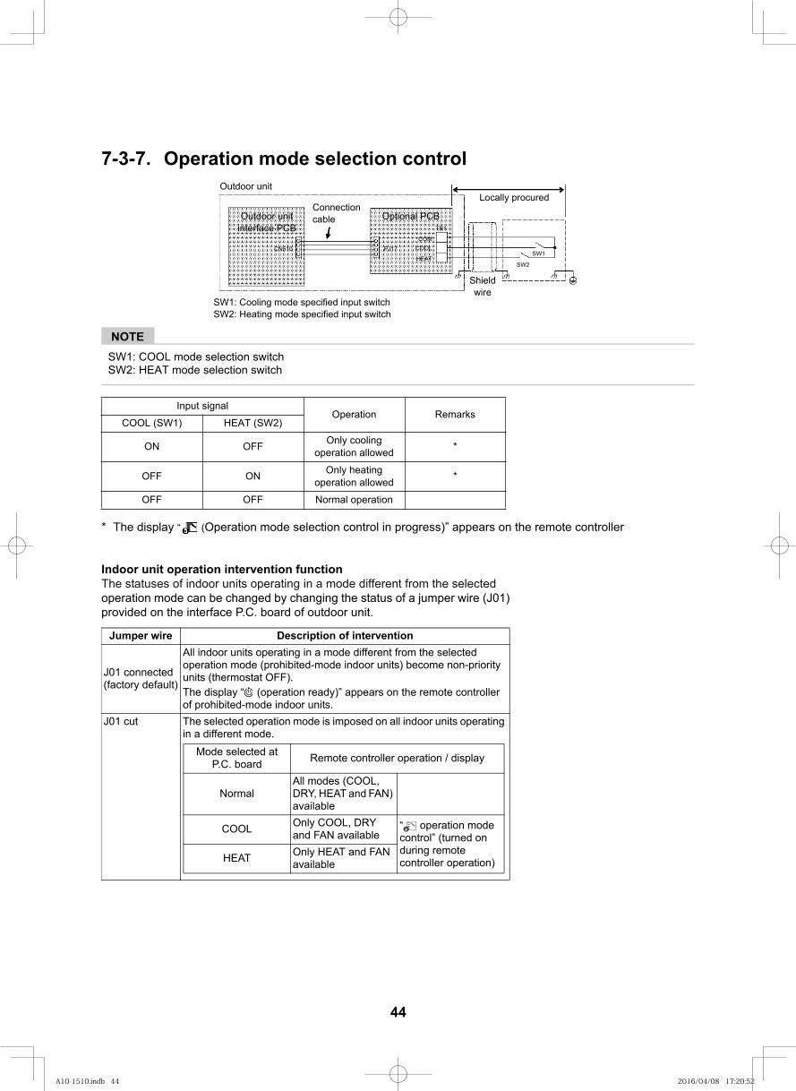
60
7-3-7. Operation mode selection control
NOTESW1: COOL mode selection switchSW2: HEAT mode selection switch
* The display “ (Operation mode selection control in progress)” appears on the remote controller
Input signalOperation Remarks
COOL (SW1) HEAT (SW2)
ON OFF Only cooling operation allowed *
OFF ON Only heating operation allowed *
OFF OFF Normal operation
Outdoor unit
COM
Outdoor unit interface PCB
Optional PCBConnection cable
Locally procured
Shield wire
71JP015NC
TB1
COOL
HEATSW1
SW1: Cooling mode specified input switchSW2: Heating mode specified input switch
SW2
Indoor unit operation intervention functionThe statuses of indoor units operating in a mode different from the selected operation mode can be changed by changing the status of a jumper wire (J01) provided on the interface P.C. board of outdoor unit.
Jumper wire Description of intervention
J01 connected (factory default)
All indoor units operating in a mode different from the selected operation mode (prohibited-mode indoor units) become non-priority units (thermostat OFF).The display “ (operation ready)” appears on the remote controller of prohibited-mode indoor units.
J01 cut The selected operation mode is imposed on all indoor units operating in a different mode.
Mode selected at P.C. board Remote controller operation / display
NormalAll modes (COOL, DRY, HEAT and FAN) available
COOL Only COOL, DRY and FAN available
“ operation mode control” (turned on during remote controller operation)HEAT Only HEAT and FAN
available
44
A10-1510.indb 44A10-1510.indb 44 2016/04/08 17:20:522016/04/08 17:20:52
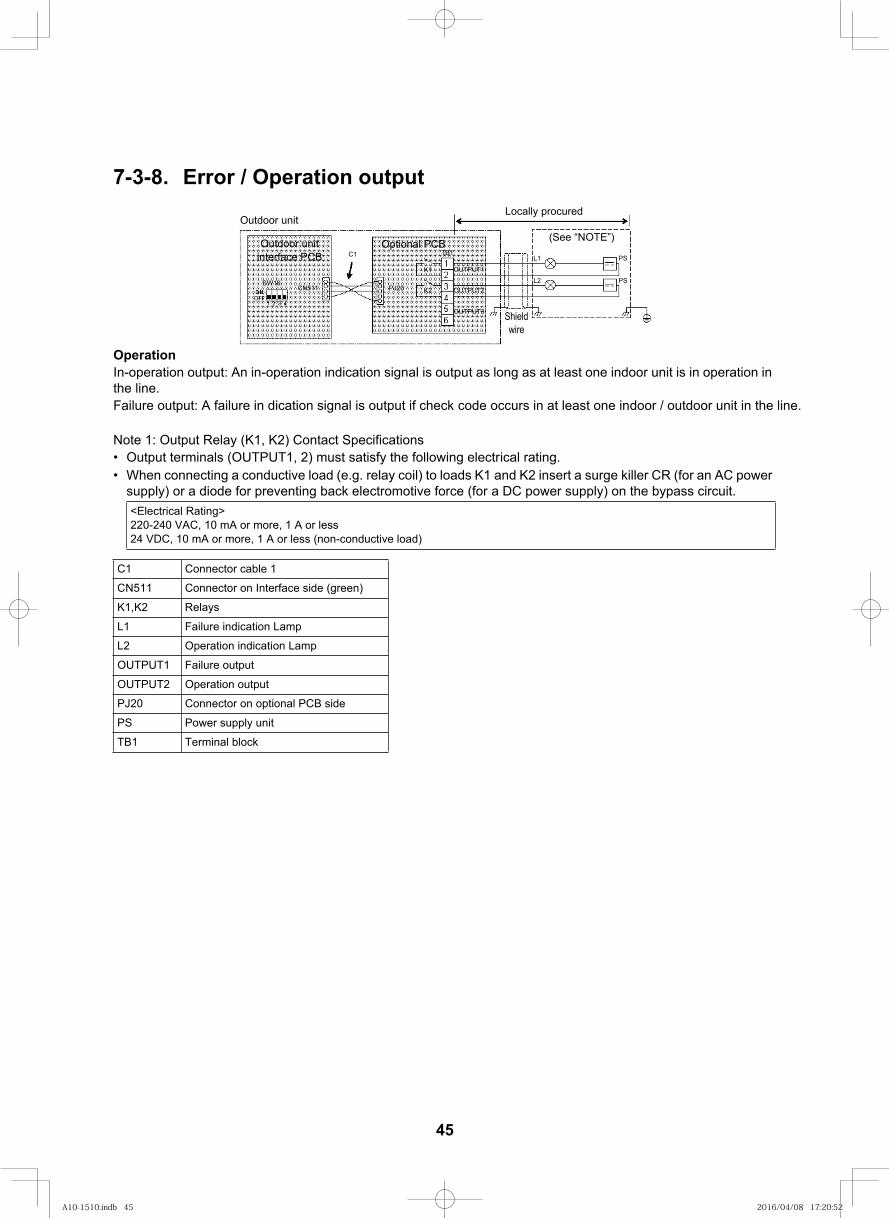
61
7-3-8. Error / Operation output
OperationIn-operation output: An in-operation indication signal is output as long as at least one indoor unit is in operation in the line.Failure output: A failure in dication signal is output if check code occurs in at least one indoor / outdoor unit in the line.
Note 1: Output Relay (K1, K2) Contact SpecificationsOutput terminals (OUTPUT1, 2) must satisfy the following electrical rating.When connecting a conductive load (e.g. relay coil) to loads K1 and K2 insert a surge killer CR (for an AC power supply) or a diode for preventing back electromotive force (for a DC power supply) on the bypass circuit.<Electrical Rating>220-240 VAC, 10 mA or more, 1 A or less24 VDC, 10 mA or more, 1 A or less (non-conductive load)
C1 Connector cable 1
CN511 Connector on Interface side (green)
K1,K2 Relays
L1 Failure indication Lamp
L2 Operation indication Lamp
OUTPUT1 Failure output
OUTPUT2 Operation output
PJ20 Connector on optional PCB side
PS Power supply unit
TB1 Terminal block
Outdoor unit
Outdoor unit interface PCB
Optional PCBC1
Locally procured
Shield wire
02JP115NC
TB1
SW16
K1
K2
L1
L2
PS
PS
(See “NOTE”)
OUTPUT3
OUTPUT1
OUTPUT2
45
A10-1510.indb 45A10-1510.indb 45 2016/04/08 17:20:522016/04/08 17:20:52
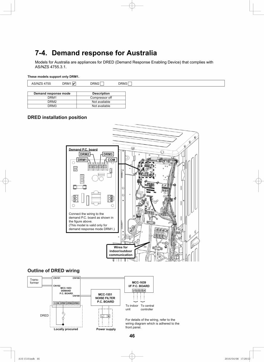
54
7-4. Demand response for AustraliaModels for Australia are appliances for DRED (Demand Response Enabling Device) that complies with AS/NZS 4755.3.1.
These models support only DRM1.
AS/NZS 4755 DRM1 DRM2 DRM3
Demand response mode DescriptionDRM1 Compressor offDRM2 Not availableDRM3 Not available
DRED installation position
Demand P.C. board
DRM1DRM2 DRM3
COM
Connect the wiring to the demand P.C. board as shown in
(This model is valid only for demand response mode DRM1.)
Wires for indoor/outdoor communication
Outline of DRED wiringCN101 CN106
CN102
CN100
COM DRM1 DRM2 DRM3
L
Trans-former
DRED
Locally procured Power supply
MCC-1653 DEMAND
P.C. BOARD MCC-1551 NOISE FILTER
P.C. BOARD
U1
To central controller
To indoor unit
N
U2 U3 U4
MCC-1639I/F P.C. BOARD
{ {
For details of the wiring, refer to the wiring diagram which is adhered to the front panel.
46
A10-1510.indb 46A10-1510.indb 46 2016/04/08 17:20:522016/04/08 17:20:52
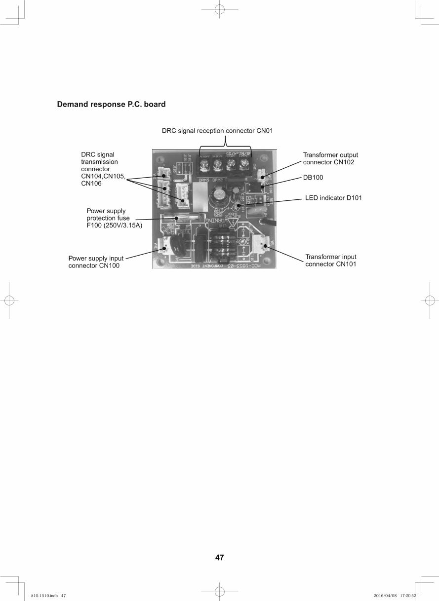
Demand response P.C. board
DRC signal transmission connectorCN104,CN105,CN106
DRC signal reception connector CN01
Transformer inputconnector CN101
Power supply protection fuseF100 (250V/3.15A)
Power supply input connector CN100
Transformer outputconnector CN102
DB100
LED indicator D101
47
A10-1510.indb 47A10-1510.indb 47 2016/04/08 17:20:522016/04/08 17:20:52
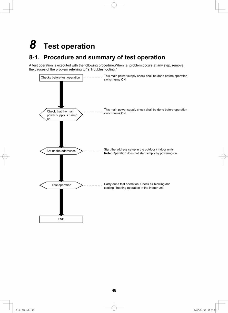
62
8 Test operation8-1. Procedure and summary of test operationA test operation is executed with the following procedure.When a problem occurs at any step, remove the causes of the problem referring to “9 Troubleshooting.”
Checks before test operation
Check that the main power supply is turned on.
Set up the addresses.
Test operation
END
This main power supply check shall be done before operation switch turns ON
This main power supply check shall be done before operation switch turns ON
Start the address setup in the outdoor / indoor units.Note: Operation does not start simply by powering-on.
Carry out a test operation. Check air blowing and cooling / heating operation in the indoor unit.
48
A10-1510.indb 48A10-1510.indb 48 2016/04/08 17:20:522016/04/08 17:20:52
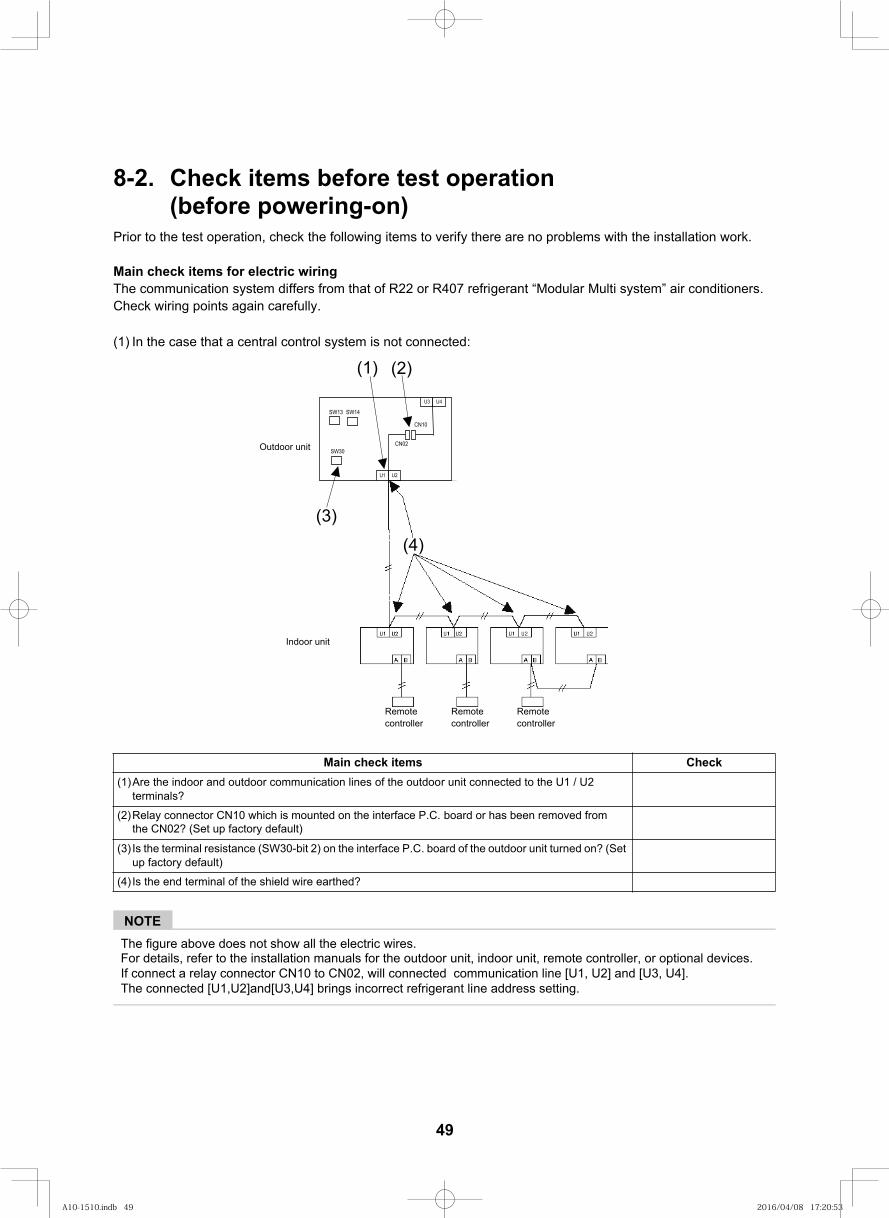
63
8-2. Check items before test operation (before powering-on)
Prior to the test operation, check the following items to verify there are no problems with the installation work.
Main check items for electric wiringThe communication system differs from that of R22 or R407 refrigerant “Modular Multi system” air conditioners.Check wiring points again carefully.
(1) In the case that a central control system is not connected:
NOTEThe figure above does not show all the electric wires.For details, refer to the installation manuals for the outdoor unit, indoor unit, remote controller, or optional devices.If connect a relay connector CN10 to CN02, will connected communication line [U1, U2] and [U3, U4]. The connected [U1,U2]and[U3,U4] brings incorrect refrigerant line address setting.
kcehCsmeti kcehc niaM(1)Are the indoor and outdoor communication lines of the outdoor unit connected to the U1 / U2
terminals?
(2)Relay connector CN10 which is mounted on the interface P.C. board or has been removed from the CN02? (Set up factory default)
(3) Is the terminal resistance (SW30-bit 2) on the interface P.C. board of the outdoor unit turned on? (Set up factory default)
(4) Is the end terminal of the shield wire earthed?
Indoor unit
Remote controller
Remotecontroller
Remotecontroller
(4)
U1 U2
U3 U4
CN02
SW13 SW14
SW30
CN10
(1) (2)
(3)
Outdoor unit
49
A10-1510.indb 49A10-1510.indb 49 2016/04/08 17:20:532016/04/08 17:20:53
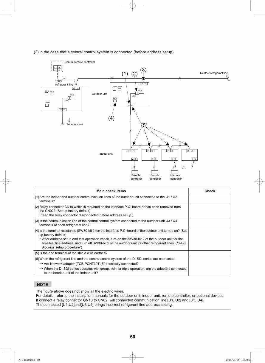
64
(2) In the case that a central control system is connected (before address setup)
NOTEThe figure above does not show all the electric wires.
kcehCsmeti kcehc niaM(1)Are the indoor and outdoor communication lines of the outdoor unit connected to the U1 / U2
terminals?
(2)Relay connector CN10 which is mounted on the interface P.C. board or has been removed from
(Keep the relay connector disconnected before address setup.)
(3) Is the communication line of the central control system connected to the outdoor unit U3 / U4 terminals of each refrigerant line?
(4) Is the terminal resistance (SW30-bit 2) on the interface P.C. board of the outdoor unit turned on? (Set up factory default)* After address setup and test operation check, turn on the SW30-bit 2 of the outdoor unit for the
smallest line address, and turn off SW30-bit 2 of the outdoor unit for other refrigerant lines. (“8-4-3. Address setup procedure”)
(5) Is the end terminal of the shield wire earthed?
(6)When the refrigerant line and the central control system of the DI-SDI series are connected:Are Network adapter (TCB-PCNT30TLE2) correctly connected?When the DI-SDI series operates with group, twin, or triple operation, are the adapters connected to the header unit of the indoor unit?
Central remote controller
(5)
Other refrigerant line
Outdoor unit
Indoor unit
Remotecontroller
Remote controller
Remote controller
the CN02? (Set up factory default)
For details, refer to the installation manuals for the outdoor unit, indoor unit, remote controller, or optional devices.If connect a relay connector CN10 to CN02, will connected communication line [U1, U2] and [U3, U4].The connected [U1,U2]and[U3,U4] brings incorrect refrigerant line address setting.
U1 U2
U3 U4
CN02
SW13 SW14
SW30
CN10
(1) (2)
(4)
(3)To other refrigerant line
U1 U2
U3 U4
CN02
SW13 SW14
SW30
CN10
To indoor unit
50
A10-1510.indb 50A10-1510.indb 50 2016/04/08 17:20:532016/04/08 17:20:53
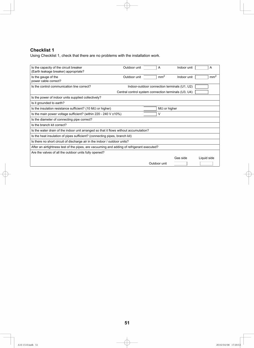
65
Checklist 1Using Checklist 1, check that there are no problems with the installation work.
Is the capacity of the circuit breaker (Earth leakage breaker) appropriate?
Outdoor unit A Indoor unit A
Is the gauge of the power cable correct?
Outdoor unit mm2 Indoor unit mm2
)2U ,1U( slanimret noitcennoc roodtuo-roodnI?tcerroc enil noitacinummoc lortnoc eht sI
Central control system connection terminals (U3, U4)
Is the power of indoor units supplied collectively?
Is it grounded to earth?
Is the insulation resistance sufficient? (10 M M )rehgih ro or higher
V in 220 - 240 V ±10%)htiw( ?tneiciffus egatlov rewop niam eht sI
Is the diameter of connecting pipe correct?
Is the branch kit correct?
Is the water drain of the indoor unit arranged so that it flows without accumulation?
Is the heat insulation of pipes sufficient? (connecting pipes, branch kit)
Is there no short circuit of discharge air in the indoor / outdoor units?
After an airtightness test of the pipes, are vacuuming and adding of refrigerant executed?
Are the valves of all the outdoor units fully opened?
Gas side Liquid side
Outdoor unit
51
A10-1510.indb 51A10-1510.indb 51 2016/04/08 17:20:532016/04/08 17:20:53
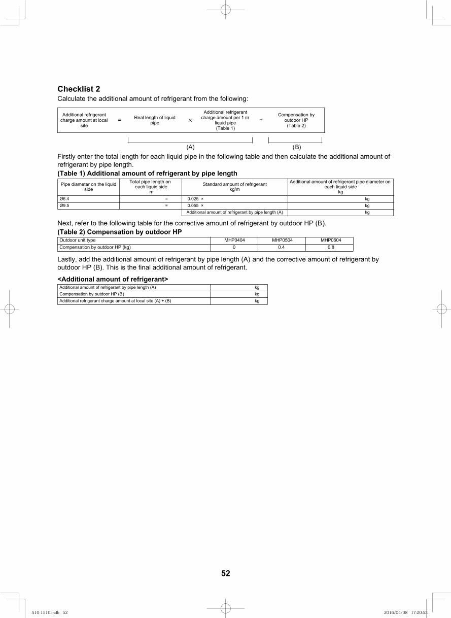
66
Checklist 2Calculate the additional amount of refrigerant from the following:
Firstly enter the total length for each liquid pipe in the following table and then calculate the additional amount of refrigerant by pipe length.(Table 1) Additional amount of refrigerant by pipe length
Additional refrigerant charge amount at local
site= Real length of liquid
pipe
Additional refrigerant charge amount per 1 m
liquid pipe (Table 1)
(A)
Additional amount of refrigerant pipe diameter on each liquid side
kg = × 520.04.6Ø kg
kg = × 550.05.9Ø kg
Total pipe length oneach liquid side
m
Additional amount of refrigerant by pipe length (A)
Standard amount of refrigerantkg/m
Pipe diameter on the liquidside
+Compensation by
outdoor HP (Table 2)
)B(
Next, refer to the following table for the corrective amount of refrigerant by outdoor HP (B).(Table 2) Compensation by outdoor HP
Lastly, add the additional amount of refrigerant by pipe length (A) and the corrective amount of refrigerant by outdoor HP (B). This is the final additional amount of refrigerant.
<Additional amount of refrigerant>
P0504HM P0404HMepyt tinu roodtuO0.40 )gk( PH roodtuo yb noitasnepmoC
gk )A( htgnel epip yb tnaregirfer fo tnuoma lanoitiddA
P0604HM0.8
gk )B( PH roodtuo yb noitasnepmoCAdditional refrigerant charge amount at local site (A) + (B) kg
52
A10-1510.indb 52A10-1510.indb 52 2016/04/08 17:20:532016/04/08 17:20:53
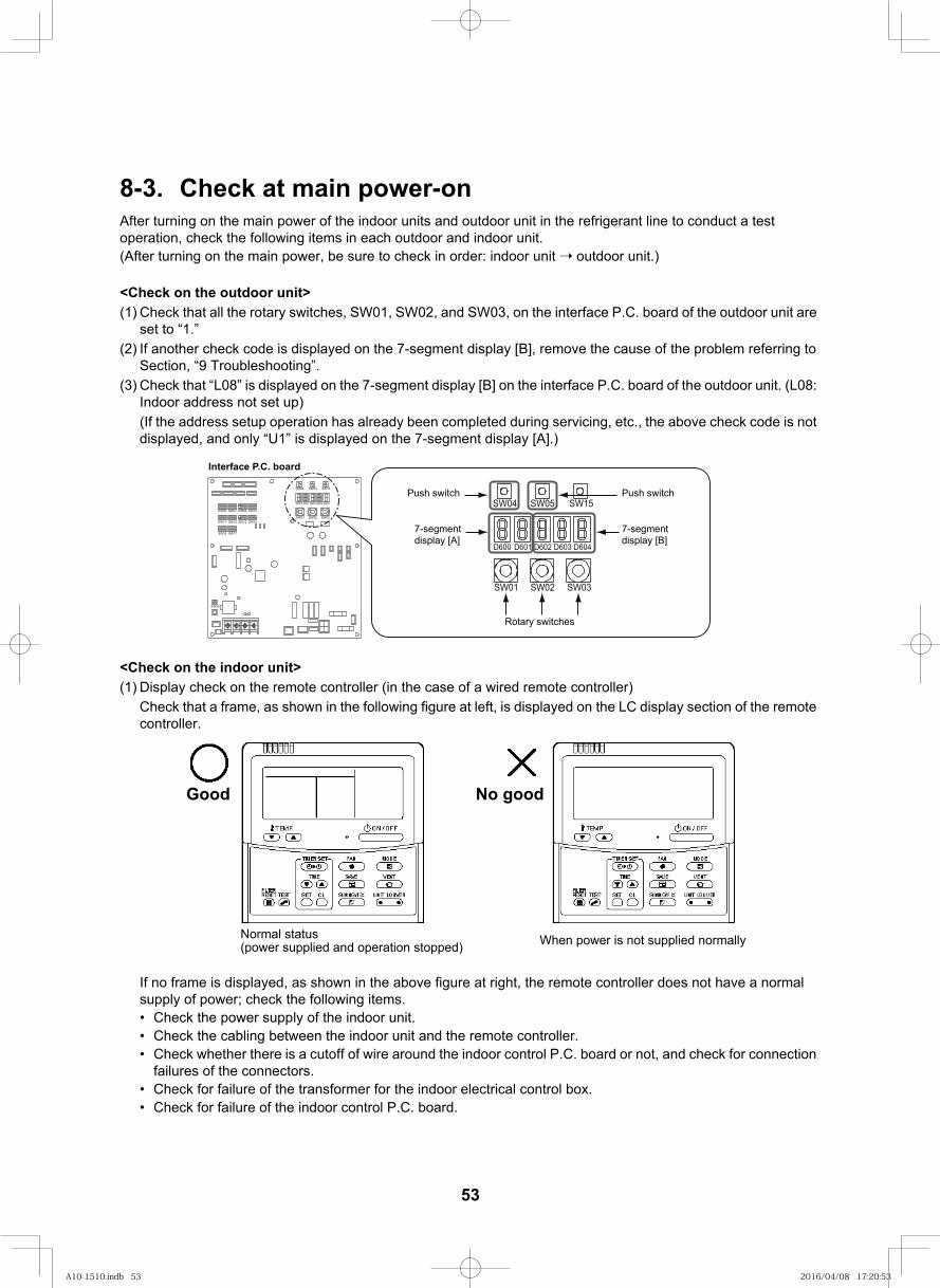
67
8-3. Check at main power-onAfter turning on the main power of the indoor units and outdoor unit in the refrigerant line to conduct a test operation, check the following items in each outdoor and indoor unit.(After turning on the main power, be sure to check in order: indoor unit outdoor unit.)
<Check on the outdoor unit>(1) Check that all the rotary switches, SW01, SW02, and SW03, on the interface P.C. board of the outdoor unit are
set to “1.”(2) If another check code is displayed on the 7-segment display [B], remove the cause of the problem referring to
Section, “9 Troubleshooting”.(3) Check that “L08” is displayed on the 7-segment display [B] on the interface P.C. board of the outdoor unit. (L08:
Indoor address not set up)(If the address setup operation has already been completed during servicing, etc., the above check code is not displayed, and only “U1” is displayed on the 7-segment display [A].)
<Check on the indoor unit>(1) Display check on the remote controller (in the case of a wired remote controller)
Check that a frame, as shown in the following figure at left, is displayed on the LC display section of the remote controller.
If no frame is displayed, as shown in the above figure at right, the remote controller does not have a normal supply of power; check the following items.• Check the power supply of the indoor unit.• Check the cabling between the indoor unit and the remote controller.• Check whether there is a cutoff of wire around the indoor control P.C. board or not, and check for connection
failures of the connectors.• Check for failure of the transformer for the indoor electrical control box.• Check for failure of the indoor control P.C. board.
Normal status (power supplied and operation stopped) When power is not supplied normally
doog oNdooG
SW09SW07
SW11
SW06 SW10
SW12 SW13
SW16
SW14
SW17
D600 D601 D602 D603 D604
SW04 SW05 SW15
SW01 SW02 SW03
SW30
D600 D601 D602 D603 D604
SW04 SW05 SW15
SW01 SW02 SW03
Interface P.C. board
Push switch
7-segment display [A]
Push switch
7-segment display [B]
Rotary switches
53
A10-1510.indb 53A10-1510.indb 53 2016/04/08 17:20:532016/04/08 17:20:53
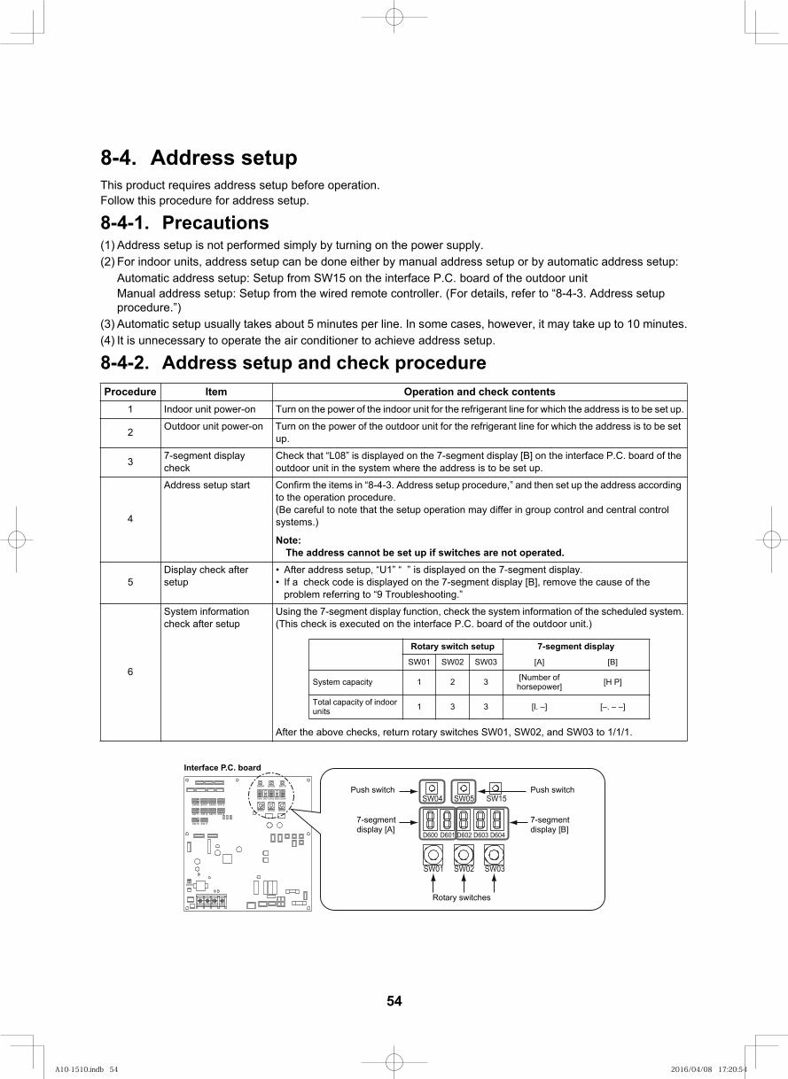
68
8-4. Address setupThis product requires address setup before operation.Follow this procedure for address setup.
8-4-1. Precautions(1) Address setup is not performed simply by turning on the power supply.(2) For indoor units, address setup can be done either by manual address setup or by automatic address setup:
Automatic address setup: Setup from SW15 on the interface P.C. board of the outdoor unitManual address setup: Setup from the wired remote controller. (For details, refer to “8-4-3. Address setup procedure.”)
(3) Automatic setup usually takes about 5 minutes per line. In some cases, however, it may take up to 10 minutes.(4) It is unnecessary to operate the air conditioner to achieve address setup.
8-4-2. Address setup and check procedurestnetnoc kcehc dna noitarepOmetIerudecorP
1 Indoor unit power-on Turn on the power of the indoor unit for the refrigerant line for which the address is to be set up.
2 Outdoor unit power-on Turn on the power of the outdoor unit for the refrigerant line for which the address is to be set up.
3 7-segment display check
Check that “L08” is displayed on the 7-segment display [B] on the interface P.C. board of the outdoor unit in the system where the address is to be set up.
4
Address setup start Confirm the items in “8-4-3. Address setup procedure,” and then set up the address according to the operation procedure.(Be careful to note that the setup operation may differ in group control and central control systems.)
Note: The address cannot be set up if switches are not operated.
5Display check after setup
After address setup, “U1” “ ” is displayed on the 7-segment display.If a check code is displayed on the 7-segment display [B], remove the cause of the problem referring to “9 Troubleshooting.”
6
System information check after setup
Using the 7-segment display function, check the system information of the scheduled system.(This check is executed on the interface P.C. board of the outdoor unit.)
After the above checks, return rotary switches SW01, SW02, and SW03 to 1/1/1.
Rotary switch setup 7-segment displaySW01 SW02 SW03 [A] [B]
System capacity 1 2 3 [Number of horsepower] [H P]
Total capacity of indoor units 1 3 3 [–. – –][l. –]
SW09SW07
SW11
SW06 SW10
SW12 SW13
SW16
SW14
SW17
D600 D601 D602 D603 D604
SW04 SW05 SW15
SW01 SW02 SW03
SW30
D600 D601 D602 D603 D604
SW04 SW05 SW15
SW01 SW02 SW03
Interface P.C. board
Push switch
7-segment display [A]
Push switch
7-segment display [B]
Rotary switches
54
A10-1510.indb 54A10-1510.indb 54 2016/04/08 17:20:542016/04/08 17:20:54
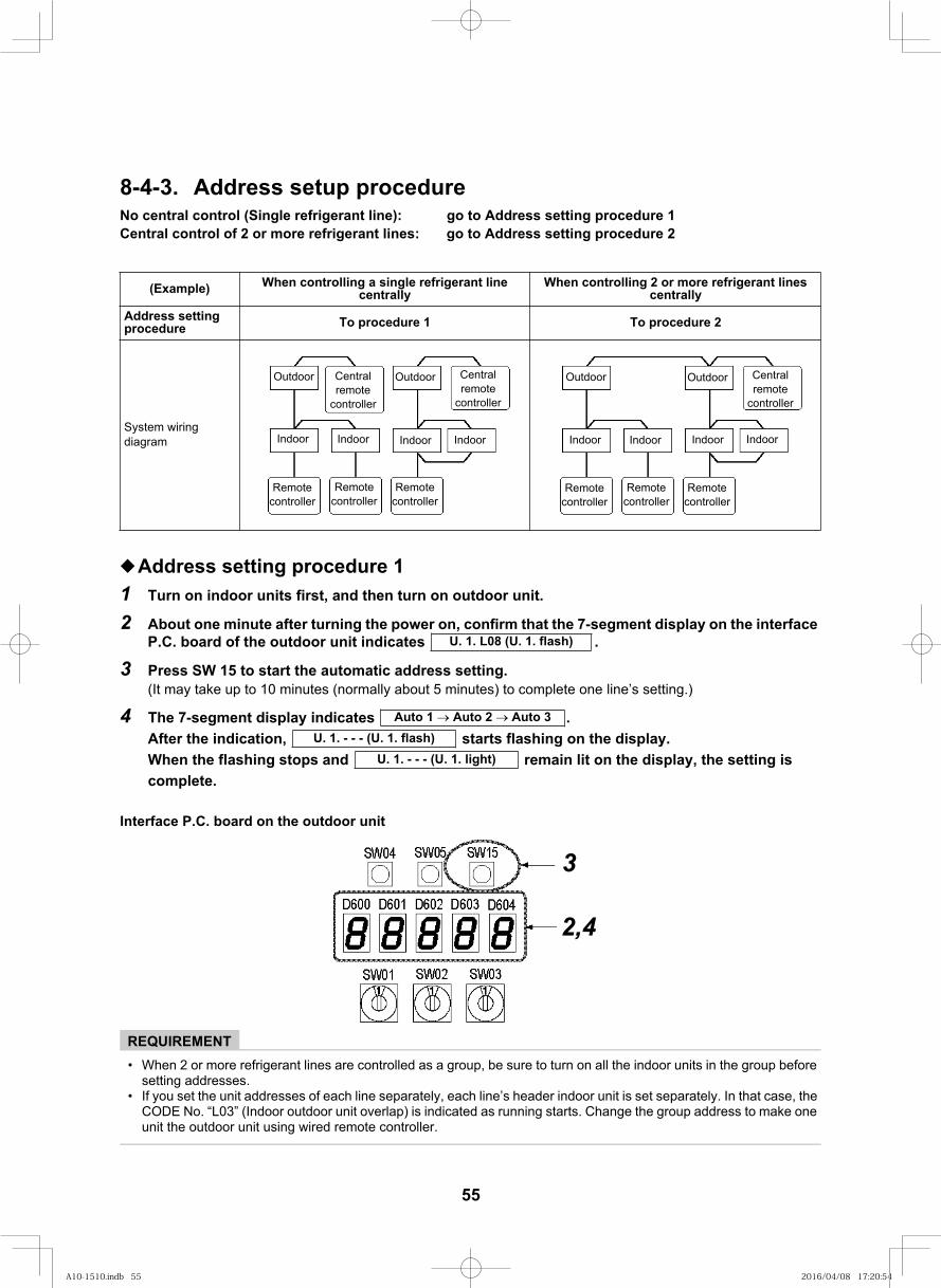
69
8-4-3. Address setup procedure
Address setting procedure 11 Turn on indoor units first, and then turn on outdoor unit.
2 About one minute after turning the power on, confirm that the 7-segment display on the interface . setacidni tinu roodtuo eht fo draob .C.P
3 Press SW 15 to start the automatic address setting.(It may take up to 10 minutes (normally about 5 minutes) to complete one line’s setting.)
4 . setacidni yalpsid tnemges-7 ehT .yalpsid eht no gnihsalf strats ,noitacidni eht retfA
si gnittes eht ,yalpsid eht no til niamer dna spots gnihsalf eht nehWcomplete.
Interface P.C. board on the outdoor unit
REQUIREMENT• When 2 or more refrigerant lines are controlled as a group, be sure to turn on all the indoor units in the group before
setting addresses.• If you set the unit addresses of each line separately, each line’s header indoor unit is set separately. In that case, the
CODE No. “L03” (Indoor outdoor unit overlap) is indicated as running starts. Change the group address to make one unit the outdoor unit using wired remote controller.
ddA ot og (Single refrigerant line):lortnoc lartnec oN ress setting procedure 1Central control of 2 or more refrigerant lines: go to Address setting procedure 2
(Example) When controlling a single refrigerant line centrally
When controlling 2 or more refrigerant lines centrally
Address setting procedure 2 erudecorp oT1 erudecorp oT
System wiring diagram
Outdoor
Indoor Indoor Indoor Indoor
OutdoorCentral remote
controller
Central remote
controller
Remote controller
Remote controller
Remote controller
Outdoor
Indoor Indoor Indoor Indoor
Outdoor Central remote
controller
Remote controller
Remotecontroller
Remotecontroller
U. 1. L08 (U. 1. flash)
Auto 1 Auto 2 Auto 3U. 1. - - - (U. 1. flash)
U. 1. - - - (U. 1. light)
3
2,4
55
A10-1510.indb 55A10-1510.indb 55 2016/04/08 17:20:542016/04/08 17:20:54
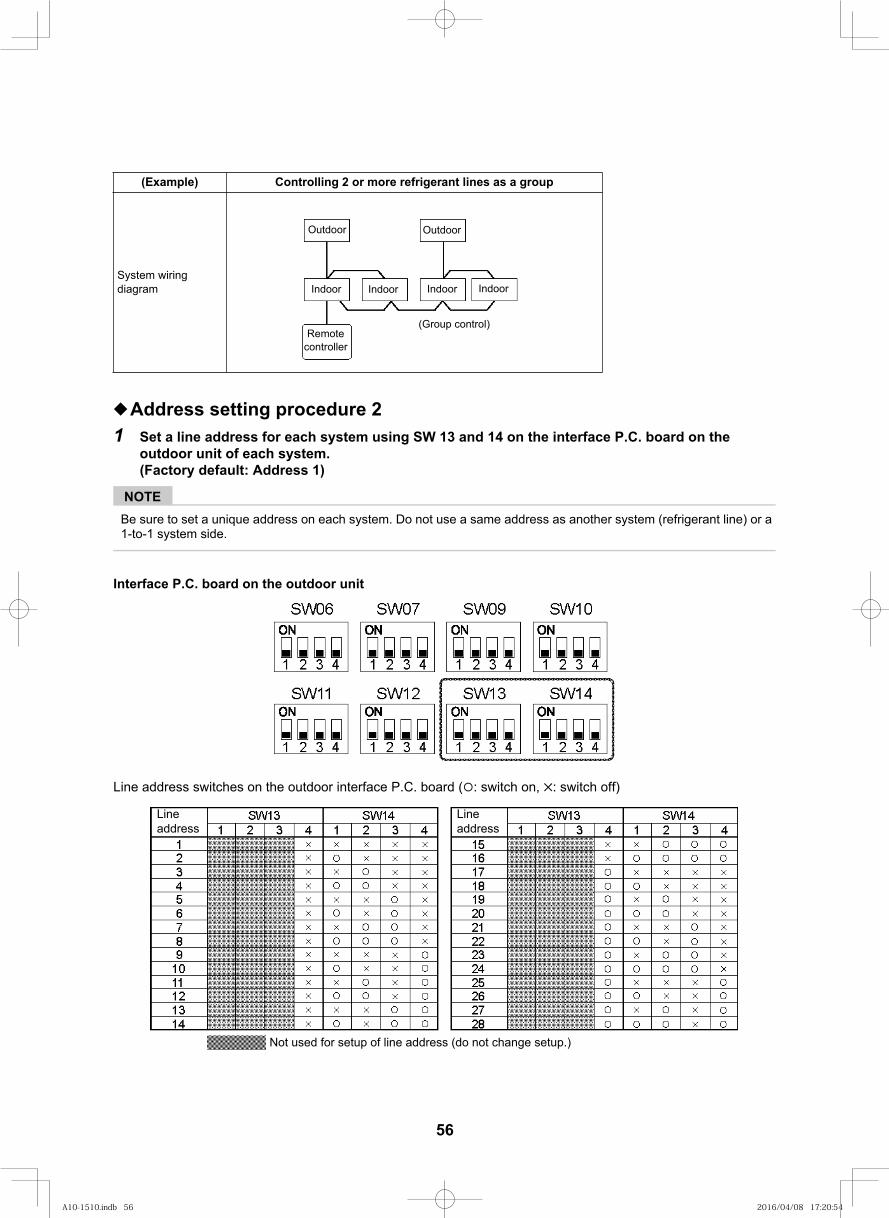
70
Address setting procedure 21 Set a line address for each system using SW 13 and 14 on the interface P.C. board on the
outdoor unit of each system.(Factory default: Address 1)
NOTEBe sure to set a unique address on each system. Do not use a same address as another system (refrigerant line) or a 1-to-1 system side.
Interface P.C. board on the outdoor unit
Line address switches on the outdoor interface P.C. board ( : switch on, : switch off)
(Example) Controlling 2 or more refrigerant lines as a group
System wiring diagram
Outdoor
Indoor Indoor Indoor Indoor
Outdoor
Remote controller
(Group control)
Line address
Not used for setup of line address (do not change setup.)
Line address
56
A10-1510.indb 56A10-1510.indb 56 2016/04/08 17:20:542016/04/08 17:20:54
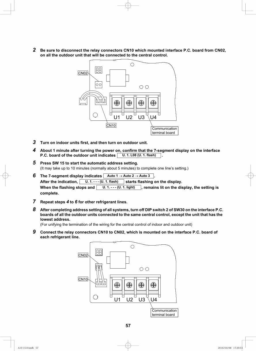
71
2 Be sure to disconnect the relay connectors CN10 which mounted interface P.C. board from CN02, on all the outdoor unit that will be connected to the central control.
3 Turn on indoor units first, and then turn on outdoor unit.
4 About 1 minute after turning the power on, confirm that the 7-segment display on the interface . setacidni tinu roodtuo eht fo draob .C.P
5 Press SW 15 to start the automatic address setting.(It may take up to 10 minutes (normally about 5 minutes) to complete one line’s setting.)
6 . setacidni yalpsid tnemges-7 ehT.yalpsid eht no gnihsalf strats ,noitacidni eht retfA
til sniamer , dna spots gnihsalf eht nehW on the display, the setting is complete.
7 Repeat steps 4 to 6 for other refrigerant lines.
8 After completing address setting of all systems, turn off DIP switch 2 of SW30 on the interface P.C. boards of all the outdoor units connected to the same central control, except the unit that has the lowest address.(For unifying the termination of the wiring for the central control of indoor and outdoor unit)
9 Connect the relay connectors CN10 to CN02, which is mounted on the interface P.C. board of each refrigerant line.
U. 1. L08 (U. 1. flash)
Auto 1 Auto 2 Auto 3U. 1. - - - (U. 1. flash)
U. 1. - - - (U. 1. light)
U1 U2 U3 U4
CN02
CN10Communication terminal board
CN02
CN10
U1 U2 U3 U4
Communication terminal board
57
A10-1510.indb 57A10-1510.indb 57 2016/04/08 17:20:542016/04/08 17:20:54
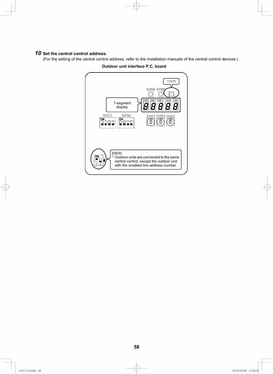
72
10 Set the central control address.(For the setting of the central control address, refer to the installation manuals of the central control devices.)
7-segment display
Outdoor unit interface P.C. board
SW30* Outdoor units are connected to the same
central control, except the outdoor unit with the smallest line address number.
58
A10-1510.indb 58A10-1510.indb 58 2016/04/08 17:20:552016/04/08 17:20:55
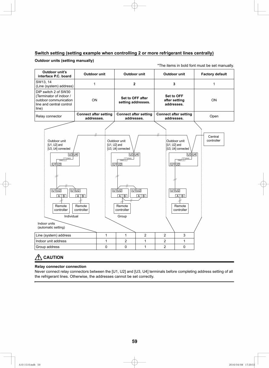
73
Switch setting (setting example when controlling 2 or more refrigerant lines centrally)Outdoor units (setting manually)
*The items in bold font must be set manually.
CAUTION
Relay connector connectionNever connect relay connectors between the [U1, U2] and [U3, U4] terminals before completing address setting of all the refrigerant lines. Otherwise, the addresses cannot be set correctly.
Outdoor unit’s interface P.C. board Outdoor unit Outdoor unit Outdoor unit Factory default
SW13, 14(Line (system) address) 1 32 1
DIP switch 2 of SW30 (Terminator of indoor / outdoor communication line and central control line)
ON Set to OFF after setting addresses.
Set to OFFafter setting addresses.
ON
Relay connector Connect after setting addresses.
Connect after setting addresses.
Connect after setting addresses. Open
Line (system) address 1 1 2 2 312121sserdda tinu roodnI02100sserdda puorG
2U1U
BA
2U1U2U1U
BABAA
2U1U2U1U
BAB
U4U3
U2U1CN02
CN10
U4U3
U2U1CN02
CN10
U4U3
U2U1CN02
CN10
Central controller
Remote controller
Remote controller
Remote controller
Remote controller
GroupIndividual
Indoor units (automatic setting)
Outdoor unit[U1, U2] and [U3, U4] connected
Outdoor unit[U1, U2] and [U3, U4] connected
Outdoor unit[U1, U2] and [U3, U4] connected
59
A10-1510.indb 59A10-1510.indb 59 2016/04/08 17:20:552016/04/08 17:20:55
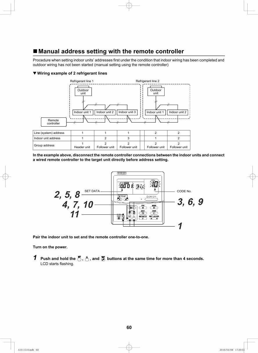
74
Manual address setting with the remote controllerProcedure when setting indoor units’ addresses first under the condition that indoor wiring has been completed and outdoor wiring has not been started (manual setting using the remote controller)
Wiring example of 2 refrigerant lines
In the example above, disconnect the remote controller connections between the indoor units and connect a wired remote controller to the target unit directly before address setting.
Pair the indoor unit to set and the remote controller one-to-one.
Turn on the power.
1 Push and hold the , , and buttons at the same time for more than 4 seconds.LCD starts flashing.
Line (system) address 1 1 1 2 2
Indoor unit address 1 2 3 1 2
Group address 1Header unit
2Follower unit
2Follower unit
2Follower unit
2Follower unit
Outdoorunit
Outdoorunit
Remote controller
Indoor unit 1 Indoor unit 2 Indoor unit 3 Indoor unit 1 Indoor unit 2
Refrigerant line 1 Refrigerant line 2
SET DATA CODE No.
60
A10-1510.indb 60A10-1510.indb 60 2016/04/08 17:20:552016/04/08 17:20:55

75
<Line (system) address>
2 Push the TEMP. / buttons repeatedly to set the CODE No. to .
3 Push the TIME / buttons repeatedly to set a line address.(Match the address with the address on the interface P.C. board of the outdoor unit in the same refrigerant line.)
4 Push button.(It is OK if the display turns on.)
<Indoor unit address>
5 Push the TEMP. / buttons repeatedly to set the CODE No. to .
6 Push the TIME / buttons repeatedly to set an indoor unit address.
7 Push the button.(It is OK if the display turns on.)
<Group address>
8 Push the TEMP. / buttons repeatedly to set the CODE No. to .
9 Push the TIME / buttons repeatedly to set a group address. If the indoor unit is individual, set the address to ; header unit, ; follower unit, .
10 Push the button.(It is OK if the display turns on.)
11 Push the button.The address setting is complete.( flashes. You can control the unit after has disappeared.)
NOTE1. Do not use address numbers 29 or 30 when setting line addresses using the remote controller.
These 2 address numbers cannot be used on outdoor units and the CODE No. [E04] (Indoor / outdoor communication failure) will appear if they are mistakenly used.
2. If you set addresses to indoor units in 2 or more refrigerate lines manually using the remote controller and will control them centrally, set the outdoor unit of each line as below.
Set a line address for the outdoor unit of each line with SW13 and 14 of their interface P.C. boards. Turn off DIP switch 2 of SW30 on the interface P.C. boards of all the outdoor units connected to the same central control, except the unit that has the lowest address. (For unifying the termination of the wiring for the central control of indoor and outdoor units)Connect the relay connectors between the [U1, U2] and [U3, U4] terminals on the outdoor unit of each refrigerate line.After finishing all the settings above, set the address of the central control devices. (For the setting of the central control address, refer to the installation manuals of the central control devices.)
Individual : 0000Header unit : 0001 In case of group
controlFollower unit : 0002
61
A10-1510.indb 61A10-1510.indb 61 2016/04/08 17:20:552016/04/08 17:20:55
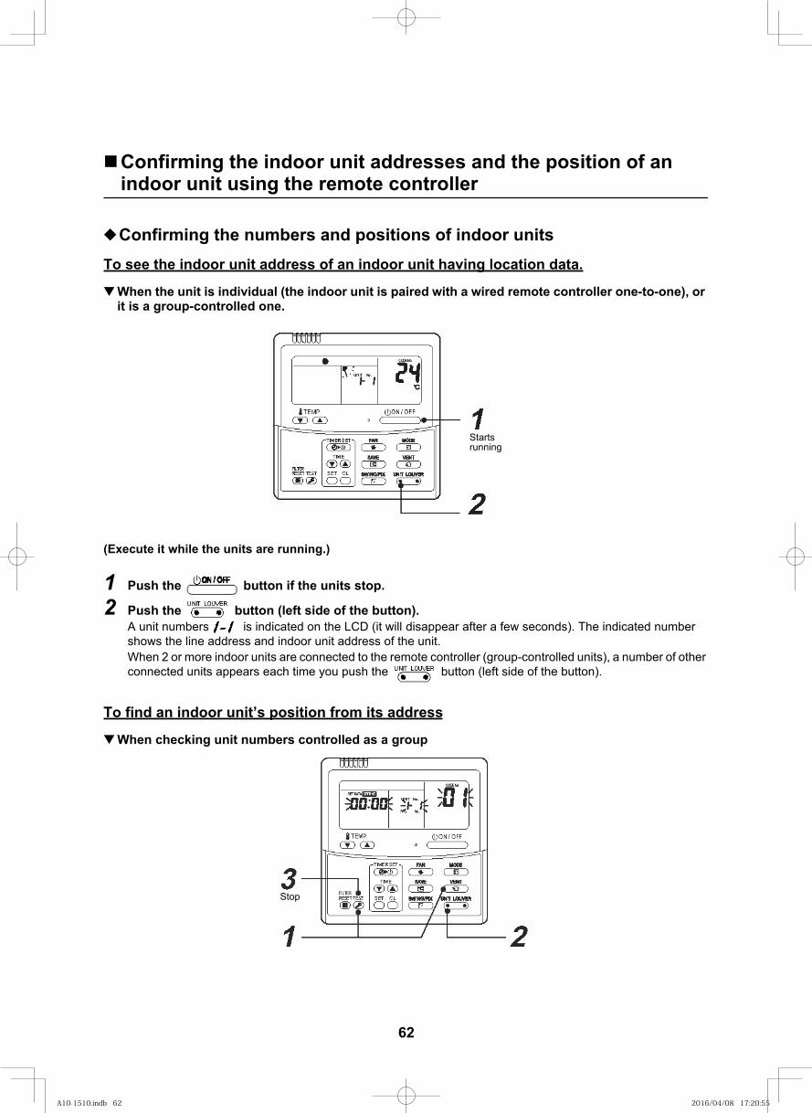
76
Confirming the indoor unit addresses and the position of an indoor unit using the remote controller
Confirming the numbers and positions of indoor unitsTo see the indoor unit address of an indoor unit having location data.
When the unit is individual (the indoor unit is paired with a wired remote controller one-to-one), or it is a group-controlled one.
(Execute it while the units are running.)
1 Push the button if the units stop.
2 Push the button (left side of the button).A unit numbers is indicated on the LCD (it will disappear after a few seconds). The indicated number shows the line address and indoor unit address of the unit. When 2 or more indoor units are connected to the remote controller (group-controlled units), a number of other connected units appears each time you push the button (left side of the button).
To find an indoor unit’s position from its address
When checking unit numbers controlled as a group
Starts running
Stop
62
A10-1510.indb 62A10-1510.indb 62 2016/04/08 17:20:552016/04/08 17:20:55
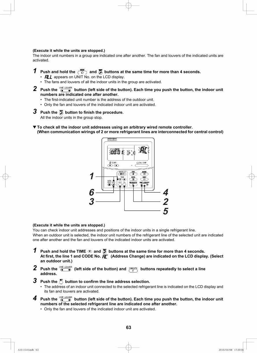
77
(Execute it while the units are stopped.)The indoor unit numbers in a group are indicated one after another. The fan and louvers of the indicated units are activated.
1 Push and hold the and buttons at the same time for more than 4 seconds.• appears on UNIT No. on the LCD display.• The fans and louvers of all the indoor units in the group are activated.
2 Push the button (left side of the button). Each time you push the button, the indoor unit numbers are indicated one after another.• The first-indicated unit number is the address of the outdoor unit.• Only the fan and louvers of the indicated indoor unit are activated.
3 Push the button to finish the procedure.All the indoor units in the group stop.
To check all the indoor unit addresses using an arbitrary wired remote controller.(When communication wirings of 2 or more refrigerant lines are interconnected for central control)
(Execute it while the units are stopped.)You can check indoor unit addresses and positions of the indoor units in a single refrigerant line.When an outdoor unit is selected, the indoor unit numbers of the refrigerant line of the selected unit are indicated one after another and the fan and louvers of the indicated indoor units are activated.
1 Push and hold the TIME and buttons at the same time for more than 4 seconds.At first, the line 1 and CODE No. (Address Change) are indicated on the LCD display. (Select an outdoor unit.)
2 Push the (left side of the button) and buttons repeatedly to select a line address.
3 Push the button to confirm the line address selection. • The address of an indoor unit connected to the selected refrigerant line is indicated on the LCD display and
its fan and louvers are activated.
4 Push the button (left side of the button). Each time you push the button, the indoor unit numbers of the selected refrigerant line are indicated one after another.• Only the fan and louvers of the indicated indoor unit are activated.
63
A10-1510.indb 63A10-1510.indb 63 2016/04/08 17:20:562016/04/08 17:20:56
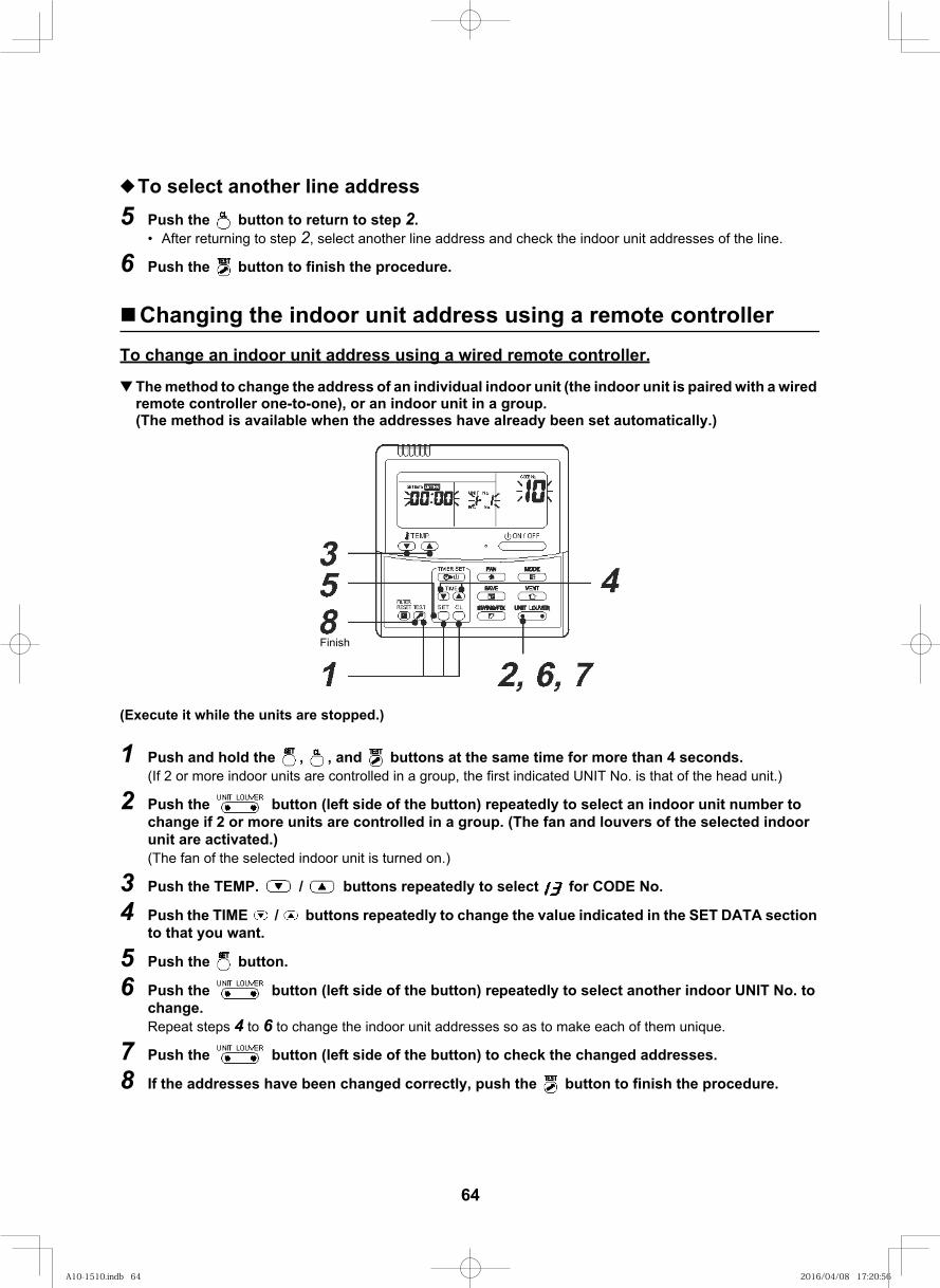
78
To select another line address5 Push the button to return to step 2.
• After returning to step 2, select another line address and check the indoor unit addresses of the line.
6 Push the button to finish the procedure.
Changing the indoor unit address using a remote controllerTo change an indoor unit address using a wired remote controller.
The method to change the address of an individual indoor unit (the indoor unit is paired with a wired remote controller one-to-one), or an indoor unit in a group.(The method is available when the addresses have already been set automatically.)
(Execute it while the units are stopped.)
1 Push and hold the , , and buttons at the same time for more than 4 seconds.(If 2 or more indoor units are controlled in a group, the first indicated UNIT No. is that of the head unit.)
2 Push the button (left side of the button) repeatedly to select an indoor unit number to change if 2 or more units are controlled in a group. (The fan and louvers of the selected indoor unit are activated.)(The fan of the selected indoor unit is turned on.)
3 Push the TEMP. / buttons repeatedly to select for CODE No..
4 Push the TIME / buttons repeatedly to change the value indicated in the SET DATA section to that you want.
5 Push the button.
6 Push the button (left side of the button) repeatedly to select another indoor UNIT No. to change.Repeat steps 4 to 6 to change the indoor unit addresses so as to make each of them unique.
7 Push the button (left side of the button) to check the changed addresses.
8 If the addresses have been changed correctly, push the button to finish the procedure.
Finish
64
A10-1510.indb 64A10-1510.indb 64 2016/04/08 17:20:562016/04/08 17:20:56
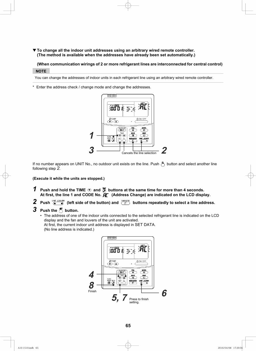
79
To change all the indoor unit addresses using an arbitrary wired remote controller.(The method is available when the addresses have already been set automatically.)
(When communication wirings of 2 or more refrigerant lines are interconnected for central control)
NOTEYou can change the addresses of indoor units in each refrigerant line using an arbitrary wired remote controller.
* Enter the address check / change mode and change the addresses.
If no number appears on UNIT No., no outdoor unit exists on the line. Push button and select another line following step 2.
(Execute it while the units are stopped.)
1 Push and hold the TIME and buttons at the same time for more than 4 seconds.At first, the line 1 and CODE No. (Address Change) are indicated on the LCD display.
2 Push (left side of the button) and buttons repeatedly to select a line address.
3 Push the button.• The address of one of the indoor units connected to the selected refrigerant line is indicated on the LCD
display and the fan and louvers of the unit are activated.At first, the current indoor unit address is displayed in SET DATA.(No line address is indicated.)
Cancels the line selection
Press to finish setting.
Finish
65
A10-1510.indb 65A10-1510.indb 65 2016/04/08 17:20:562016/04/08 17:20:56
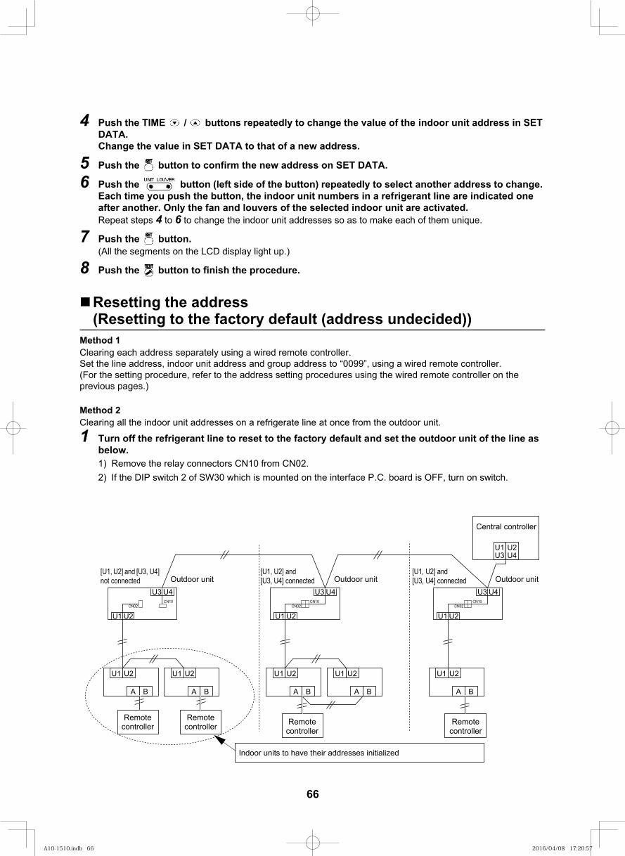
80
4 Push the TIME / buttons repeatedly to change the value of the indoor unit address in SET DATA.Change the value in SET DATA to that of a new address.
5 Push the button to confirm the new address on SET DATA.
6 Push the button (left side of the button) repeatedly to select another address to change. Each time you push the button, the indoor unit numbers in a refrigerant line are indicated one after another. Only the fan and louvers of the selected indoor unit are activated. Repeat steps 4 to 6 to change the indoor unit addresses so as to make each of them unique.
7 Push the button.(All the segments on the LCD display light up.)
8 Push the button to finish the procedure.
Resetting the address(Resetting to the factory default (address undecided))
Method 1Clearing each address separately using a wired remote controller.Set the line address, indoor unit address and group address to “0099”, using a wired remote controller. (For the setting procedure, refer to the address setting procedures using the wired remote controller on the previous pages.)
Method 2Clearing all the indoor unit addresses on a refrigerate line at once from the outdoor unit.
1 Turn off the refrigerant line to reset to the factory default and set the outdoor unit of the line as below.1) Remove the relay connectors CN10 from CN02.
If the DIP switch 2 of SW30 which is mounted on the interface P.C. board is OFF, turn on switch.2)
U1 U2
A B
U1 U2
A B
U1 U2
A B
U1 U2
A B
U1U3
U2U4
U1 U2
A B
U4U3
U2U1CN02
CN10
U4U3
U2U1CN02
CN10
U4U3
U2U1CN02
CN10
Remote controller
Central controller
Remote controller Remote
controllerRemote
controller
Indoor units to have their addresses initialized
Outdoor unit[U1, U2] and [U3, U4] connected
[U1, U2] and [U3, U4] connected
[U1, U2] and [U3, U4] not connected Outdoor unitOutdoor unit
66
A10-1510.indb 66A10-1510.indb 66 2016/04/08 17:20:572016/04/08 17:20:57
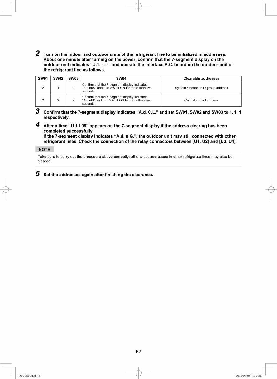
81
2 Turn on the indoor and outdoor units of the refrigerant line to be initialized in addresses. About one minute after turning on the power, confirm that the 7-segment display on the outdoor unit indicates “U.1. - - -” and operate the interface P.C. board on the outdoor unit of the refrigerant line as follows.
3 Confirm that the 7-segment display indicates “A.d. C.L.” and set SW01, SW02 and SW03 to 1, 1, 1 respectively.
4 After a time “U.1.L08” appears on the 7-segment display if the address clearing has been completed successfully.If the 7-segment display indicates “A.d. n.G.”, the outdoor unit may still connected with other refrigerant lines. Check the connection of the relay connectors between [U1, U2] and [U3, U4].
NOTETake care to carry out the procedure above correctly; otherwise, addresses in other refrigerate lines may also be cleared.
5 Set the addresses again after finishing the clearance.
sesserdda elbaraelC40WS30WS20WS10WS
2 1 2Confirm that the 7-segment display indicates “A.d.buS” and turn SW04 ON for more than five seconds.
System / indoor unit / group address
2 2 2Confirm that the 7-segment display indicates “A.d.nEt” and turn SW04 ON for more than five seconds.
Central control address
67
A10-1510.indb 67A10-1510.indb 67 2016/04/08 17:20:572016/04/08 17:20:57
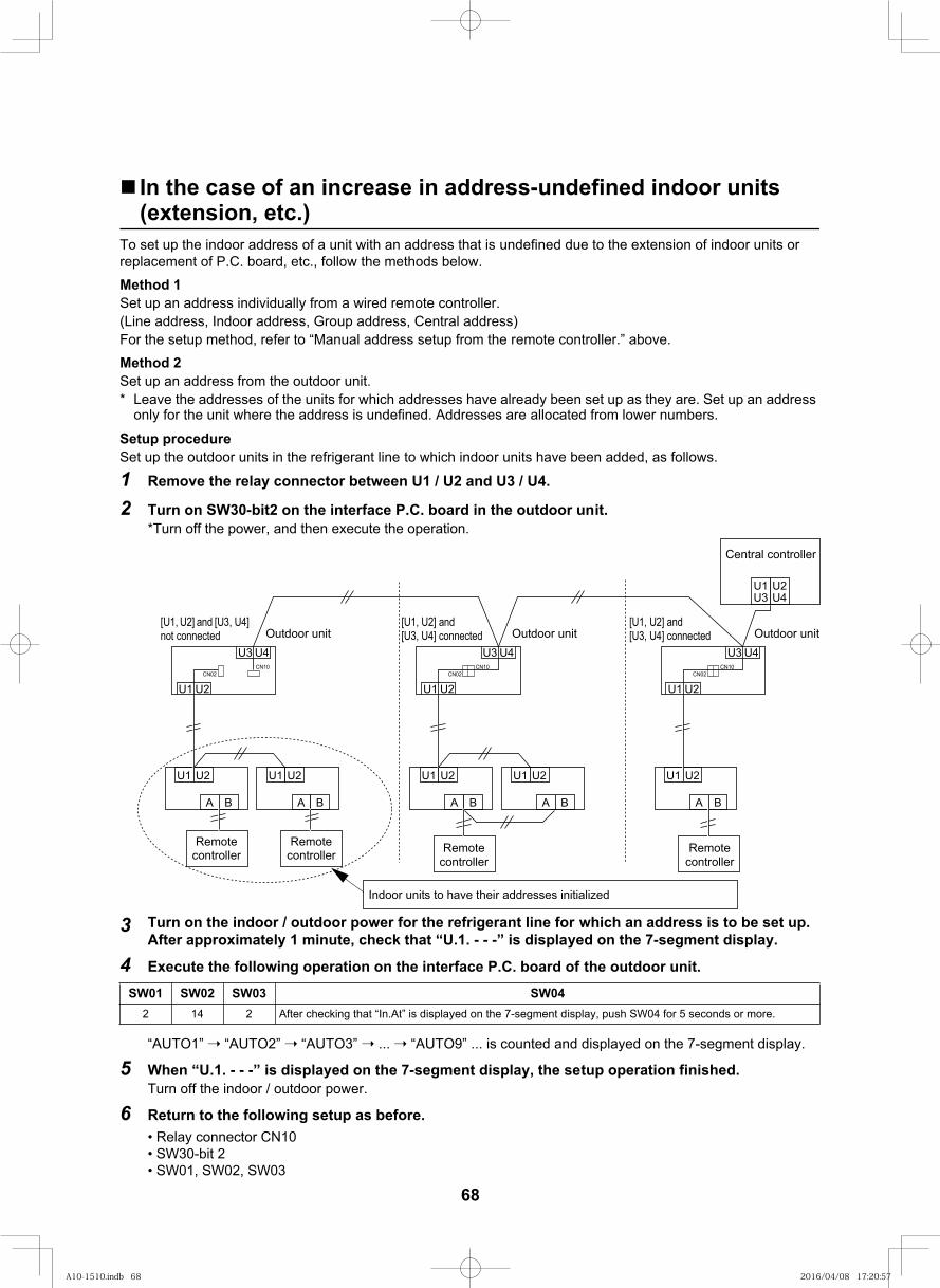
82
In the case of an increase in address-undefined indoor units (extension, etc.)
To set up the indoor address of a unit with an address that is undefined due to the extension of indoor units or replacement of P.C. board, etc., follow the methods below.Method 1Set up an address individually from a wired remote controller.(Line address, Indoor address, Group address, Central address)For the setup method, refer to “Manual address setup from the remote controller.” above.Method 2Set up an address from the outdoor unit.* Leave the addresses of the units for which addresses have already been set up as they are. Set up an address
only for the unit where the address is undefined. Addresses are allocated from lower numbers.
Setup procedureSet up the outdoor units in the refrigerant line to which indoor units have been added, as follows.
1 Remove the relay connector between U1 / U2 and U3 / U4.
2
3 Turn on the indoor / outdoor power for the refrigerant line for which an address is to be set up. After approximately 1 minute, check that “U.1. - - -” is displayed on the 7-segment display.
4 Execute the following operation on the interface P.C. board of the outdoor unit.
“AUTO1” “AUTO2” “AUTO3” ... “AUTO9” ... is counted and displayed on the 7-segment display.
5 When “U.1. - - -” is displayed on the 7-segment display, the setup operation finished.Turn off the indoor / outdoor power.
6 Return to the following setup as before.
40WS30WS20WS10WS2 14 2 After checking that “In.At” is displayed on the 7-segment display, push SW04 for 5 seconds or more.
U1 U2
A B
U1 U2
A B
U1 U2
A B
U1 U2
A B
U1U3
U2U4
U1 U2
A B
U4U3
U2U1CN02
CN10
U4U3
U2U1CN02
CN10
U4U3
U2U1CN02
CN10
Remote controller
Central controller
Remote controller Remote
controllerRemote
controller
Indoor units to have their addresses initialized
Outdoor unit[U1, U2] and [U3, U4] connected
[U1, U2] and [U3, U4] connected
[U1, U2] and [U3, U4] not connected Outdoor unitOutdoor unit
Turn on SW30-bit2 on the interface P.C. board in the outdoor unit.*Turn off the power, and then execute the operation.
68
A10-1510.indb 68A10-1510.indb 68 2016/04/08 17:20:572016/04/08 17:20:57
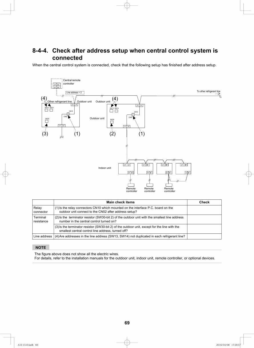
83
8-4-4. Check after address setup when central control system is connected
When the central control system is connected, check that the following setup has finished after address setup.
NOTEThe figure above does not show all the electric wires.For details, refer to the installation manuals for the outdoor unit, indoor unit, remote controller, or optional devices.
kcehCsmeti kcehc niaMRelayconnector
(1) Is the relay connectors CN10 which mounted on the interface P.C. board on the
Terminal resistance
(2) Is the terminator resistor (SW30-bit 2) of the outdoor unit with the smallest line address number in the central control turned on?
(3) Is the terminator resistor (SW30-bit 2) of the outdoor unit, except for the line with the smallest central control line address, turned off?
Line address (4)Are addresses in the line address (SW13, SW14) not duplicated in each refrigerant line?
Central remote controller
(4)
Indoor unit
To other refrigerant line
Remotecontroller
Remote controller
Remote controller
Outdoor unit
1 = sserdda eniL2 = sserdda eniL
outdoor unit connect to the CN02 after address setup?
U1 U2
U3 U4
CN02
SW13 SW14
SW30
CN10
U1 U2
U3 U4
CN02
SW13 SW14
SW30
CN10
(3)
(4)
(1) (2) (1)
(4)
Outdoor unit
Outdoor unitOther refrigerant line Outdoor unit
69
A10-1510.indb 69A10-1510.indb 69 2016/04/08 17:20:572016/04/08 17:20:57
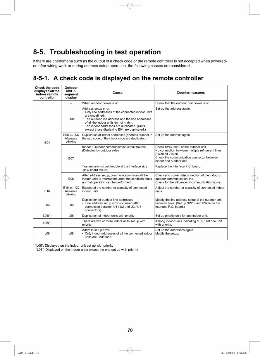
84
8-5. Troubleshooting in test operationIf there are phenomena such as the output of a check code or the remote controller is not accepted when powered-on after wiring work or during address setup operation, the following causes are considered.
8-5-1. A check code is displayed on the remote controller
* “L05”: Displayed on the indoor unit set up with priority“L06”: Displayed on the indoor units except the one set up with priority
Check the code displayed on the indoor remote
controller
Outdoor unit 7-
segment display
serusaemretnuoCesuaC
E04
no si rewop tinu roodtuo eht taht kcehCffo si rewop roodtuo nehW–
L08
Address setup errorOnly line addresses of the connected indoor units are undefined.The outdoor line address and the line addresses of all the indoor units do not match.The indoor addresses are duplicated. (Units except those displaying E04 are duplicated.)
Set up the address again.
E08 -XXAlternate blinking
Duplication of indoor addresses (address number in the sub code of the check code are duplicated).
Set up the address again.
E07
Indoor / Outdoor communication circuit trouble. (Detected by outdoor side)
Check SW30 bit 2 of the outdoor unit.No connection between multiple refrigerant lines: SW30 bit 2 is on.Check the communication connector between indoor and outdoor unit.
Transmission circuit trouble at the interface side (P.C.board failure)
Replace the interface P.C. board.
E06After address setup, communication from all the indoor units is interrupted under the condition that a normal operation can be performed.
Check and correct disconnection of the indoor / outdoor communication line.Check for the influence of communication noise.
E16E16 -XXAlternate blinking
Exceeded the number or capacity of connected indoor units
Adjust the number or capacity of connected indoor units.
L04 L04Duplication of outdoor line addresses
Line address setup error (occurred after connection between U1 / U2 and U3 / U4 connectors)
Modify the line address setup of the outdoor unit between lines. (Set up SW13 and SW14 on the interface P.C. board.)
L05(*) L06 Duplication of indoor units with priority Set up priority only for one indoor unit.
L06(*) There are two or more indoor units set up with priority.
Among indoor units indicating “L05,” set one unit with priority.
L08 L08Address setup error
Only indoor addresses of all the connected indoor units are undefined.
Set up the addresses again.Modify the setup.
70
A10-1510.indb 70A10-1510.indb 70 2016/04/08 17:20:582016/04/08 17:20:58
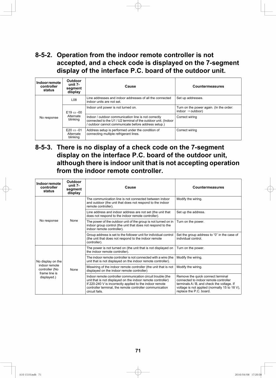
85
8-5-2. Operation from the indoor remote controller is not accepted, and a check code is displayed on the 7-segment display of the interface P.C. board of the outdoor unit.
8-5-3. There is no display of a check code on the 7-segment display on the interface P.C. board of the outdoor unit, although there is indoor unit that is not accepting operation from the indoor remote controller.
Indoor remote controller
status
Outdoor unit 7-
segment display
serusaemretnuoCesuaC
No response
L08 Line addresses and indoor addresses of all the connected indoor units are not set.
Set up addresses.
E19 -00Alternate blinking
:redro eht nI( .niaga rewop eht no nruT.no denrut ton si rewop tinu roodnIindoor outdoor)
Indoor / outdoor communication line is not correctly connected to the U1 / U2 terminal of the outdoor unit. (Indoor / outdoor cannot communicate before address setup.)
Correct wiring
E20 -01Alternate blinking
Address setup is performed under the condition of connecting multiple refrigerant lines.
Correct wiring
Indoor remote controller
status
Outdoor unit 7-
segment display
serusaemretnuoCesuaC
No response None
The communication line is not connected between indoor and outdoor (the unit that does not respond to the indoor remote controller).
Modify the wiring.
Line address and indoor address are not set (the unit that does not respond to the indoor remote controller).
Set up the address.
The power of the outdoor unit of the group is not turned on in indoor group control (the unit that does not respond to the indoor remote controller).
Turn on the power.
Group address is set to the follower unit for individual control (the unit that does not respond to the indoor remote controller).
Set the group address to “0” in the case of individual control.
No display on theindoor remotecontroller (No frame line is displayed.)
None
The power is not turned on (the unit that is not displayed on the indoor remote controller).
Turn on the power.
The indoor remote controller is not connected with a wire (the unit that is not displayed on the indoor remote controller).
Modify the wiring.
Miswiring of the indoor remote controller (the unit that is not displayed on the indoor remote controller)
Modify the wiring.
Indoor remote controller communication circuit trouble (the unit that is not displayed on the indoor remote controller)If 220-240 V is incorrectly applied to the indoor remote controller terminal, the remote controller communication circuit fails.
Remove the quick connect terminal connected to indoor remote controller terminals A / B, and check the voltage. If voltage is not applied (normally 15 to 18 V), replace the P.C. board.
71
A10-1510.indb 71A10-1510.indb 71 2016/04/08 17:20:582016/04/08 17:20:58
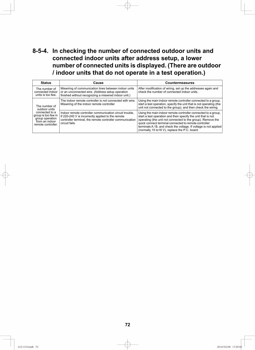
86
8-5-4. In checking the number of connected outdoor units and connected indoor units after address setup, a lower number of connected units is displayed. (There are outdoor / indoor units that do not operate in a test operation.)
serusaemretnuoCesuaCsutatSThe number of
connected indoor units is too few.
Miswiring of communication lines between indoor units or an unconnected wire. (Address setup operation finished without recognizing a miswired indoor unit.)
After modification of wiring, set up the addresses again and check the number of connected indoor units.
The number of outdoor units
connected to a group is too few in
group operation from an indoor
remote controller.
The indoor remote controller is not connected with wire.Miswiring of the indoor remote controller
Using the main indoor remote controller connected to a group, start a test operation, specify the unit that is not operating (the unit not connected to the group), and then check the wiring.
Indoor remote controller communication circuit trouble.If 220-240 V is incorrectly applied to the remote controller terminal, the remote controller communication circuit fails.
Using the main indoor remote controller connected to a group, start a test operation and then specify the unit that is not operating (the unit not connected to the group). Remove the quick connect terminal connected to remote controller terminals A / B, and check the voltage. If voltage is not applied (normally 15 to18 V), replace the P.C. board.
72
A10-1510.indb 72A10-1510.indb 72 2016/04/08 17:20:582016/04/08 17:20:58
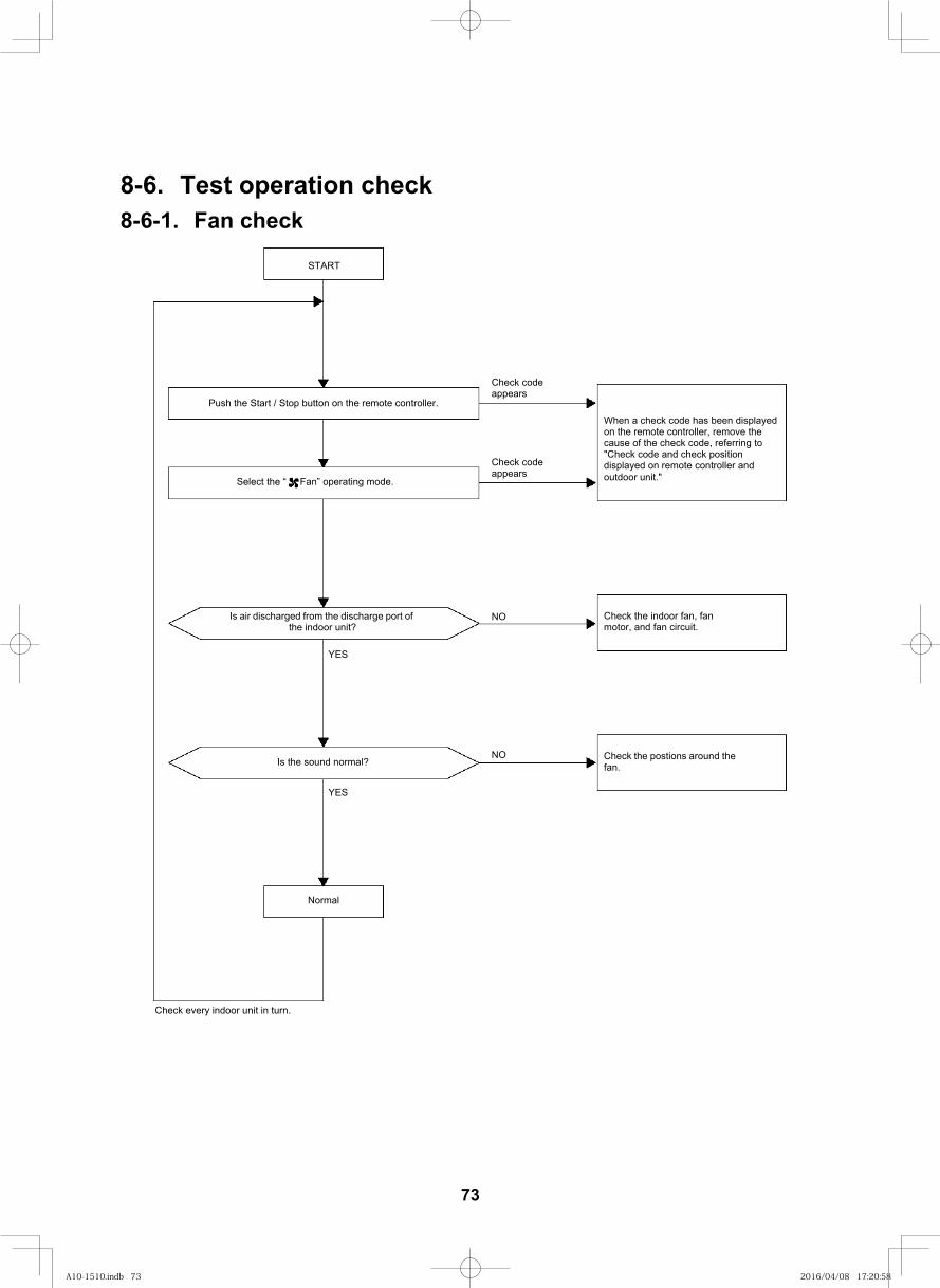
87
8-6. Test operation check8-6-1. Fan check
START
Push the Start / Stop button on the remote controller.
Check codeappears
Check codeappears
NO
NO
When a check code has been displayed on the remote controller, remove the cause of the check code, referring to "Check code and check position displayed on remote controller and outdoor unit."Select the “ Fan” operating mode.
Is air discharged from the discharge port of the indoor unit?
Check the indoor fan, fan motor, and fan circuit.
Is the sound normal? Check the postions around the fan.
YES
YES
Normal
Check every indoor unit in turn.
73
A10-1510.indb 73A10-1510.indb 73 2016/04/08 17:20:582016/04/08 17:20:58
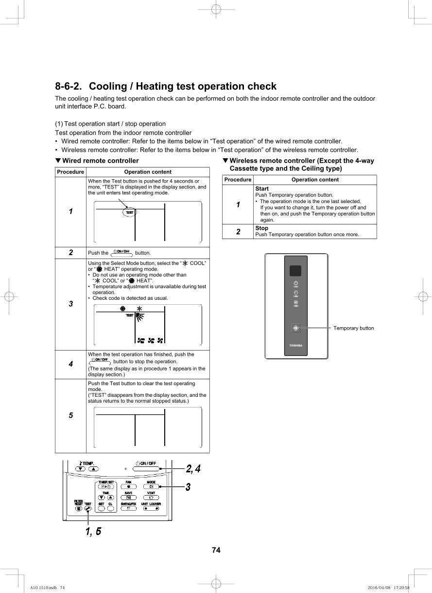
88
8-6-2. Cooling / Heating test operation checkThe cooling / heating test operation check can be performed on both the indoor remote controller and the outdoor unit interface P.C. board.
(1) Test operation start / stop operationTest operation from the indoor remote controller
Wired remote controller: Refer to the items below in “Test operation” of the wired remote controller.Wireless remote controller: Refer to the items below in “Test operation” of the wireless remote controller.Wired remote controller Wireless remote controller (Except the 4-way
Procedure Operation content
1
When the Test button is pushed for 4 seconds or more, “TEST” is displayed in the display section, and the unit enters test operating mode.
2 Push the button.
3
Using the Select Mode button, select the “ COOL” or “ HEAT” operating mode.
Do not use an operating mode other than “ COOL” or “ HEAT”.Temperature adjustment is unavailable during test operation.Check code is detected as usual.
4When the test operation has finished, push the
button to stop the operation.(The same display as in procedure 1 appears in the display section.)
5
Push the Test button to clear the test operating mode.(“TEST” disappears from the display section, and the status returns to the normal stopped status.)
Procedure Operation content
1
StartPush Temporary operation button.
2
The operation mode is the one last selected. If you want to change it, turn the power off and then on, and push the Temporary operation button again.StopPush Temporary operation button once more.
Temporary button
Cassette type and the Ceiling type)
74
A10-1510.indb 74A10-1510.indb 74 2016/04/08 17:20:582016/04/08 17:20:58
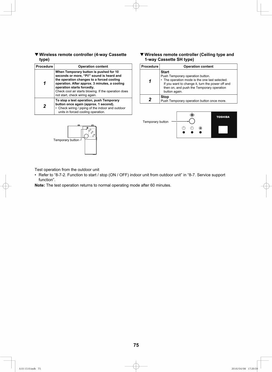
89
Test operation from the outdoor unit• Refer to “8-7-2. Function to start / stop (ON / OFF) indoor unit from outdoor unit” in “8-7. Service support
function”.Note: The test operation returns to normal operating mode after 60 minutes.
Wireless remote controller (4-way Cassettetype)
Wireless remote controller (Ceiling type and
Procedure Operation content
1
2
Procedure Operation content
1
2
When Temporary button is pushed for 10seconds or more, “Pi!” sound is heard andthe operation changes to a forced coolingoperation. After approx. 3 minutes, a coolingoperation starts forcedly.Check cool air starts blowing. If the operation doesnot start, check wiring again.To stop a test operation, push Temporarybutton once again (approx. 1 second).• Check wiring / piping of the indoor and outdoor
units in forced cooling operation.
StartPush Temporary operation button.• The operation mode is the one last selected.
If you want to change it, turn the power off and then on, and push the Temporary operation button again.
StopPush Temporary operation button once more.
1-way Cassette SH type)
Temporary button
Temporary button
75
A10-1510.indb 75A10-1510.indb 75 2016/04/08 17:20:592016/04/08 17:20:59
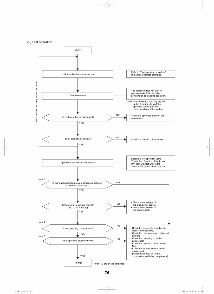
90
(2) Test operation
START
NO
YES
Test operation for one indoor unit
Operation starts
Is cold air or hot air discharged?
Is air circulation sufficient?
YES
Operate all the indoor units at once.
Is there adequate temperature difference between suction and discharge?
Note 1
Note 2
YES
Is the operating voltage correct? (220 - 240 V ±10 %)
NO
NO
NO
NO
NO
Is the operating current normal?
Note 3
Is the operating pressure normal?
YES
YES
YES
Normal Notes 1-3 are on the next page.
Refer to "Test operation procedure" of the indoor remote controller.
The operation does not start for approximately 3 minutes after powering-on or stopping operation.
Note: After powering-on, it may require up to 10 minutes to start the operation due to the initial communications of the system.
Check the operating status of the compressor.
Check the direction of the louver.
Execute a test operation using "Start / Stop Function of the Indoor Unit from Outdoor Unit" in the "Service Support Function" section.
• Check power voltage of the main power supply.
• Check the cable size of the power supply.
• Check the temperature load of the indoor / outdoor units.
• Check the pipe length and refrigerant amount.
• Check the operating Hz of the compressor.
• Check the operation of the outdoor fans.
• Check for abnormal sound in the outdoor unit.(Abnormal sound, etc. of the compressor and other components)
Test
ope
ratio
n fo
r eve
ry in
door
uni
t in
turn
76
A10-1510.indb 76A10-1510.indb 76 2016/04/08 17:20:592016/04/08 17:20:59
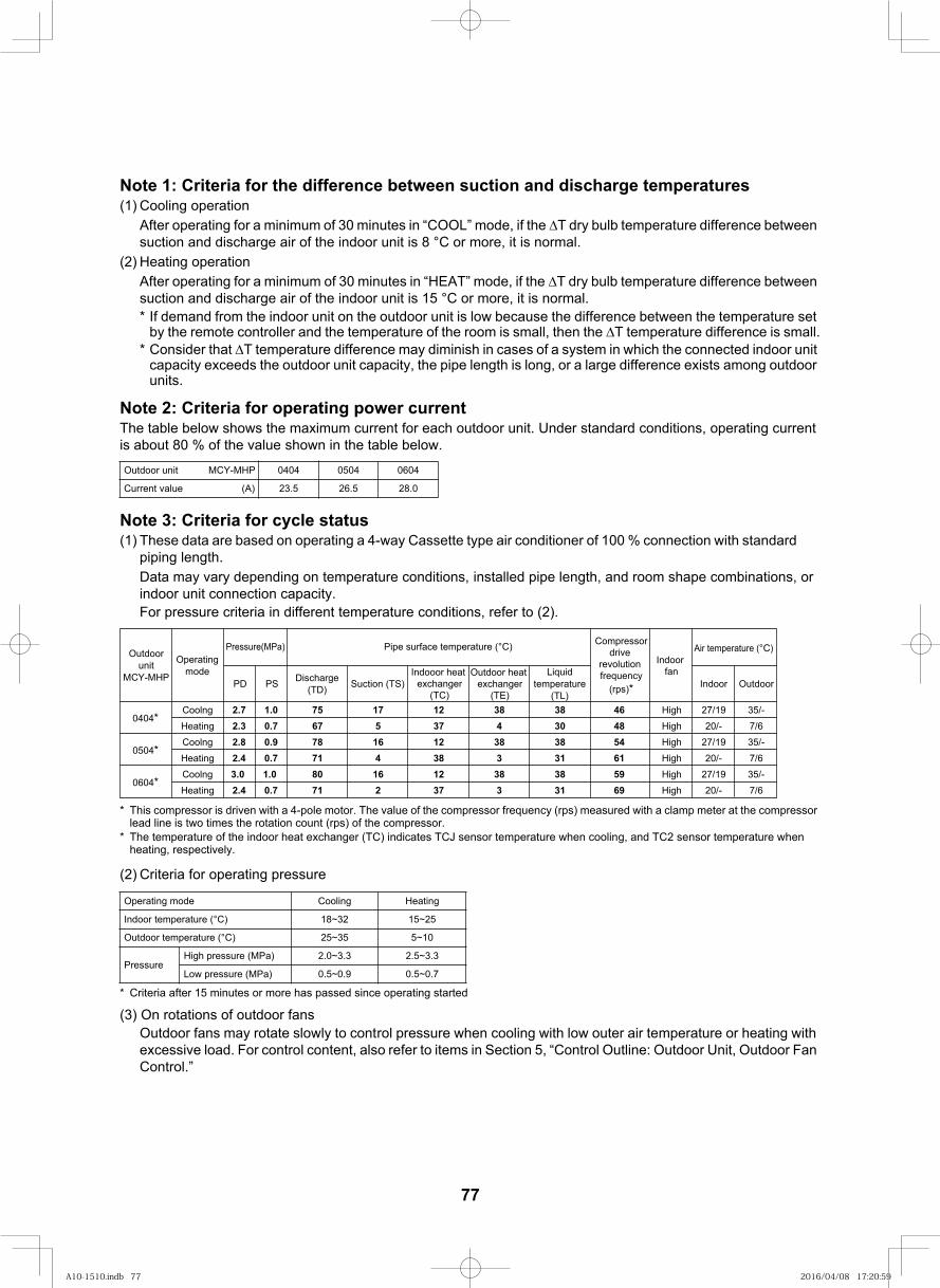
91
Note 1: Criteria for the difference between suction and discharge temperatures(1) Cooling operation
After operating for a minimum of 30 minutes in “COOL” mode, if the T dry bulb temperature difference between suction and discharge air of the indoor unit is 8 °C or more, it is normal.
(2) Heating operationAfter operating for a minimum of 30 minutes in “HEAT” mode, if the T dry bulb temperature difference between suction and discharge air of the indoor unit is 15 °C or more, it is normal.* If demand from the indoor unit on the outdoor unit is low because the difference between the temperature set
by the remote controller and the temperature of the room is small, then the T temperature difference is small.* Consider that T temperature difference may diminish in cases of a system in which the connected indoor unit
capacity exceeds the outdoor unit capacity, the pipe length is long, or a large difference exists among outdoor units.
Note 2: Criteria for operating power currentThe table below shows the maximum current for each outdoor unit. Under standard conditions, operating current is about 80 % of the value shown in the table below.
Note 3: Criteria for cycle status(1) These data are based on operating a 4-way
piping length.Data may vary depending on temperature conditions, installed pipe length, and room shape combinations, or indoor unit connection capacity.For pressure criteria in different temperature conditions, refer to (2).
* This compressor is driven with a 4-pole motor. The value of the compressor frequency (rps) measured with a clamp meter at the compressor lead line is two times the rotation count (rps) of the compressor.
* The temperature of the indoor heat exchanger (TC) indicates TCJ sensor temperature when cooling, and TC2 sensor temperature whenheating, respectively.
(2) Criteria for operating pressure
* Criteria after 15 minutes or more has passed since operating started
(3) On rotations of outdoor fansOutdoor fans may rotate slowly to control pressure when cooling with low outer air temperature or heating with excessive load. For control content, also refer to items in Section 5, “Control Outline: Outdoor Unit, Outdoor Fan Control.”
Outdoor unit MCY-MHP
Current value (A)
gnitaeHgnilooCedom gnitarepO
Indoor temperature (°C) 18~32 15~25
Outdoor temperature (°C) 25~35 5~10
PressureHigh pressure (MPa) 2.0~3.3 2.5~3.3
Low pressure (MPa) 0.5~0.9 0.5~0.7
Cassette type air conditioner of 100 % connection with standard
0404
23.5
0504
26.5
0604
28.0
PD PS Suction (TS)Discharge(TD)
Indooor heat exchanger
(TC)
Outdoor heat exchanger
(TE)
Liquidtemperature
(TL)Indoor Outdoor
Coolng 2.7 1.0 75 17 12 38 38 46 High 27/19 35/-
Heating 2.3 0.7 67 5 37 4 30 48 High 20/- 7/6
Coolng 2.8 0.9 78 16 12 38 38 54 High 27/19 35/-
Heating 2.4 0.7 71 4 38 3 31 61 High 20/- 7/6
Coolng 3.0 1.0 80 16 12 38 38 59 High 27/19 35/-
Heating 2.4 0.7 71 2 37 3 31 69 High 20/- 7/6
Air temperature (°C)
0404*
0504*
0604*
Outdoorunit
MCY-MHP
Operatingmode
Pressure(MPa) Pipe surface temperature (°C) Compressordrive
revolution frequency
(rps)*
Indoor fan
77
A10-1510.indb 77A10-1510.indb 77 2016/04/08 17:20:592016/04/08 17:20:59
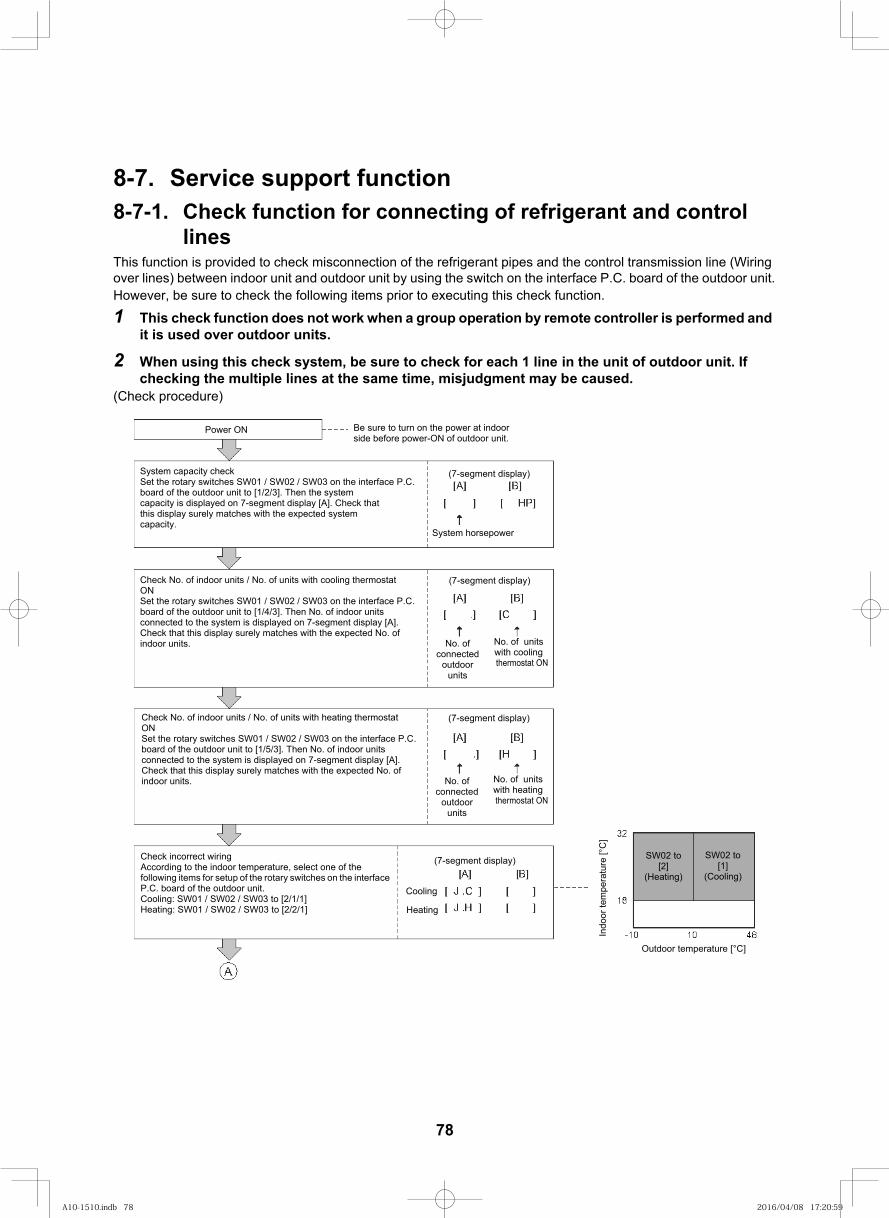
92
8-7. Service support function8-7-1. Check function for connecting of refrigerant and control
linesThis function is provided to check misconnection of the refrigerant pipes and the control transmission line (Wiring over lines) between indoor unit and outdoor unit by using the switch on the interface P.C. board of the outdoor unit.However, be sure to check the following items prior to executing this check function.
1 This check function does not work when a group operation by remote controller is performed and it is used over outdoor units.
2 When using this check system, be sure to check for each 1 line in the unit of outdoor unit. If checking the multiple lines at the same time, misjudgment may be caused.
(Check procedure)
Power ON Be sure to turn on the power at indoor side before power-ON of outdoor unit.
System capacity check Set the rotary switches SW01 / SW02 / SW03 on the interface P.C. board of the outdoor unit to [1/2/3]. Then the system capacity is displayed on 7-segment display [A]. Check that this display surely matches with the expected system capacity.
(7-segment display)
System horsepower
(7-segment display)
No. of connected
outdoor units
No. of units with cooling thermostat ON
(7-segment display)
No. of connected
outdoor units
No. of units with heating thermostat ON
(7-segment display)
Cooling
Heating
Check No. of indoor units / No. of units with cooling thermostatONSet the rotary switches SW01 / SW02 / SW03 on the interface P.C. board of the outdoor unit to [1/4/3]. Then No. of indoor units connected to the system is displayed on 7-segment display [A]. Check that this display surely matches with the expected No. of indoor units.
Check No. of indoor units / No. of units with heating thermostatONSet the rotary switches SW01 / SW02 / SW03 on the interface P.C. board of the outdoor unit to [1/5/3]. Then No. of indoor units connected to the system is displayed on 7-segment display [A]. Check that this display surely matches with the expected No. of indoor units.
Check incorrect wiringAccording to the indoor temperature, select one of the following items for setup of the rotary switches on the interface P.C. board of the outdoor unit. Cooling: SW01 / SW02 / SW03 to [2/1/1] Heating: SW01 / SW02 / SW03 to [2/2/1]
Indo
or te
mpe
ratu
re [°
C]
SW02 to[2]
(Heating)
SW02 to[1]
(Cooling)
Outdoor temperature [°C]
78
A10-1510.indb 78A10-1510.indb 78 2016/04/08 17:20:592016/04/08 17:20:59
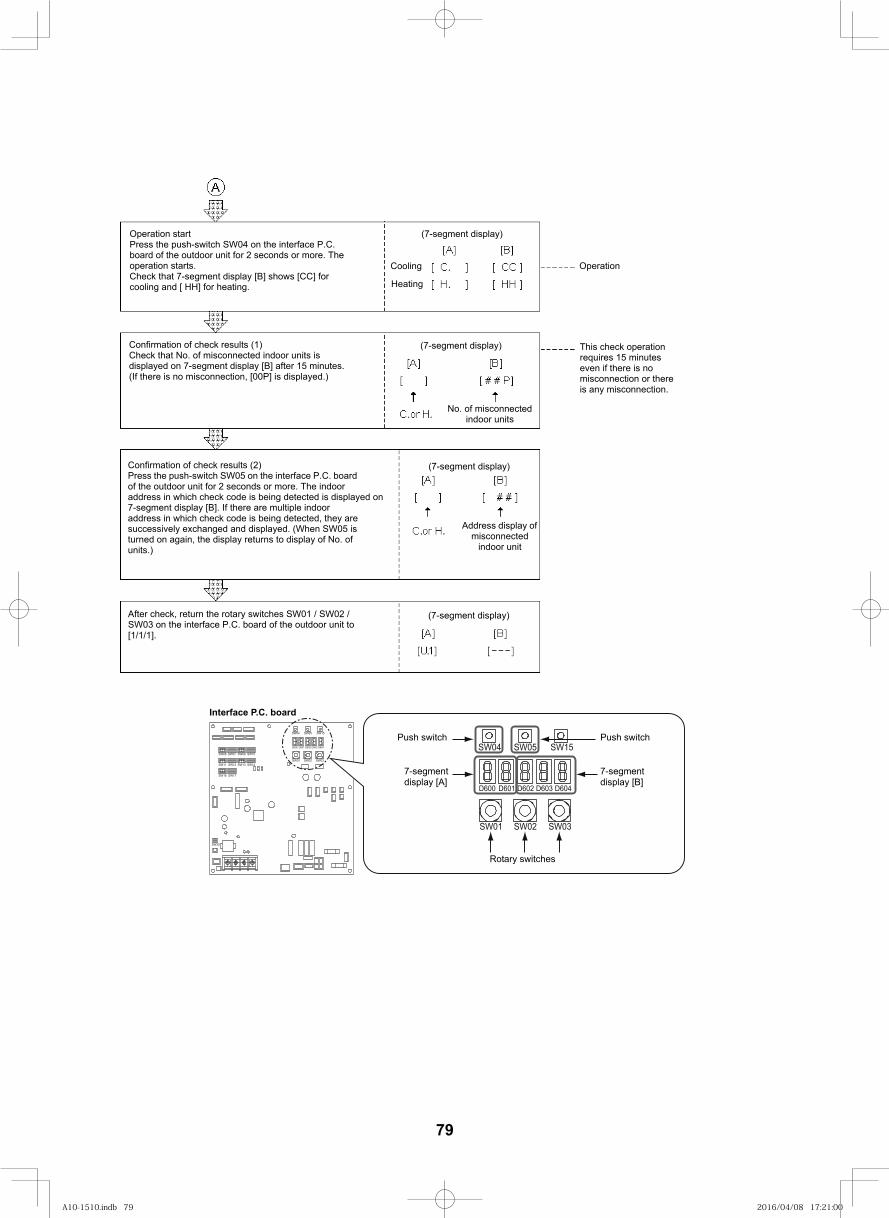
93
(7-segment display)
Cooling
Heating
Operation
This check operation requires 15 minutes even if there is no misconnection or there is any misconnection.
Operation startPress the push-switch SW04 on the interface P.C. board of the outdoor unit for 2 seconds or more. The operation starts. Check that 7-segment display [B] shows [CC] for cooling and [ HH] for heating.
Confirmation of check results (1)Check that No. of misconnected indoor units is displayed on 7-segment display [B] after 15 minutes. (If there is no misconnection, [00P] is displayed.)
(7-segment display)
No. of misconnected indoor units
Confirmation of check results (2)Press the push-switch SW05 on the interface P.C. board of the outdoor unit for 2 seconds or more. The indoor address in which check code is being detected is displayed on 7-segment display [B]. If there are multiple indoor address in which check code is being detected, they are successively exchanged and displayed. (When SW05 is turned on again, the display returns to display of No. of units.)
(7-segment display)
Address display of misconnected
indoor unit
After check, return the rotary switches SW01 / SW02 / SW03 on the interface P.C. board of the outdoor unit to [1/1/1].
(7-segment display)
.
.
. .
. .
. – – –
SW09SW07
SW11
SW06 SW10
SW12 SW13
SW16
SW14
SW17
D600 D601 D602 D603 D604
SW04 SW05 SW15
SW01 SW02 SW03
SW30
D600 D601 D602 D603 D604
SW04 SW05 SW15
SW01 SW02 SW03
Interface P.C. board
Push switch
7-segment display [A]
Push switch
7-segment display [B]
Rotary switches
79
A10-1510.indb 79A10-1510.indb 79 2016/04/08 17:21:002016/04/08 17:21:00
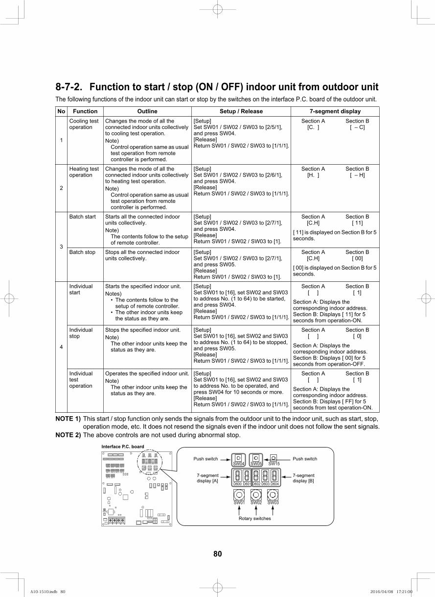
94
8-7-2. Function to start / stop (ON / OFF) indoor unit from outdoor unitThe following functions of the indoor unit can start or stop by the switches on the interface P.C. board of the outdoor unit.
NOTE 1) This start / stop function only sends the signals from the outdoor unit to the indoor unit, such as start, stop, operation mode, etc. It does not resend the signals even if the indoor unit does not follow the sent signals.
NOTE 2) The above controls are not used during abnormal stop.
yalpsid tnemges-7esaeleR / puteSeniltuOnoitcnuFoN
1
Cooling test operation
Changes the mode of all the connected indoor units collectively to cooling test operation.Note)
Control operation same as usual test operation from remote controller is performed.
[Setup]Set SW01 / SW02 / SW03 to [2/5/1], and press SW04.[Release]Return SW01 / SW02 / SW03 to [1/1/1].
Section A[C. ]
Section B[ – C]
2
Heating test operation
Changes the mode of all the connected indoor units collectively to heating test operation.Note)
Control operation same as usual test operation from remote controller is performed.
[Setup]Set SW01 / SW02 / SW03 to [2/6/1], and press SW04.[Release]Return SW01 / SW02 / SW03 to [1/1/1].
Section A[H. ]
Section B[ – H]
3
Batch start Starts all the connected indoor units collectively.Note)
The contents follow to the setup of remote controller.
[Setup]Set SW01 / SW02 / SW03 to [2/7/1], and press SW04.[Release]Return SW01 / SW02 / SW03 to [1].
Section A[C.H]
Section B[ 11]
[ 11] is displayed on Section B for 5 seconds.
Batch stop Stops all the connected indoor units collectively.
[Setup]Set SW01 / SW02 / SW03 to [2/7/1], and press SW05.[Release]Return SW01 / SW02 / SW03 to [1].
Section A[C.H]
Section B[ 00]
[ 00] is displayed on Section B for 5 seconds.
4
Individual start
Starts the specified indoor unit.Notes)
• The contents follow to the setup of remote controller.
• The other indoor units keep the status as they are.
[Setup]Set SW01 to [16], set SW02 and SW03 to address No. (1 to 64) to be started, and press SW04.[Release]Return SW01 / SW02 / SW03 to [1/1/1].
Section A[ ]
Section B[ 1]
Section A: Displays the corresponding indoor address.Section B: Displays [ 11] for 5 seconds from operation-ON.
Individual stop
Stops the specified indoor unit.Note)
The other indoor units keep the status as they are.
[Setup]Set SW01 to [16], set SW02 and SW03 to address No. (1 to 64) to be stopped, and press SW05.[Release]Return SW01 / SW02 / SW03 to [1/1/1].
Section A[ ]
Section B[ 0]
Section A: Displays the corresponding indoor address.Section B: Displays [ 00] for 5 seconds from operation-OFF.
Individual test operation
Operates the specified indoor unit.Note)
The other indoor units keep the status as they are.
[Setup]Set SW01 to [16], set SW02 and SW03 to address No. to be operated, and press SW04 for 10 seconds or more.[Release]Return SW01 / SW02 / SW03 to [1/1/1].
Section A[ ]
Section B[ 1]
Section A: Displays the corresponding indoor address.Section B: Displays [ FF] for 5 seconds from test operation-ON.
SW09SW07
SW11
SW06 SW10
SW12 SW13
SW16
SW14
SW17
D600 D601 D602 D603 D604
SW04 SW05 SW15
SW01 SW02 SW03
SW30
D600 D601 D602 D603 D604
SW04 SW05 SW15
SW01 SW02 SW03
Interface P.C. board
Push switch
7-segment display [A]
Push switch
7-segment display [B]
Rotary switches
80
A10-1510.indb 80A10-1510.indb 80 2016/04/08 17:21:002016/04/08 17:21:00
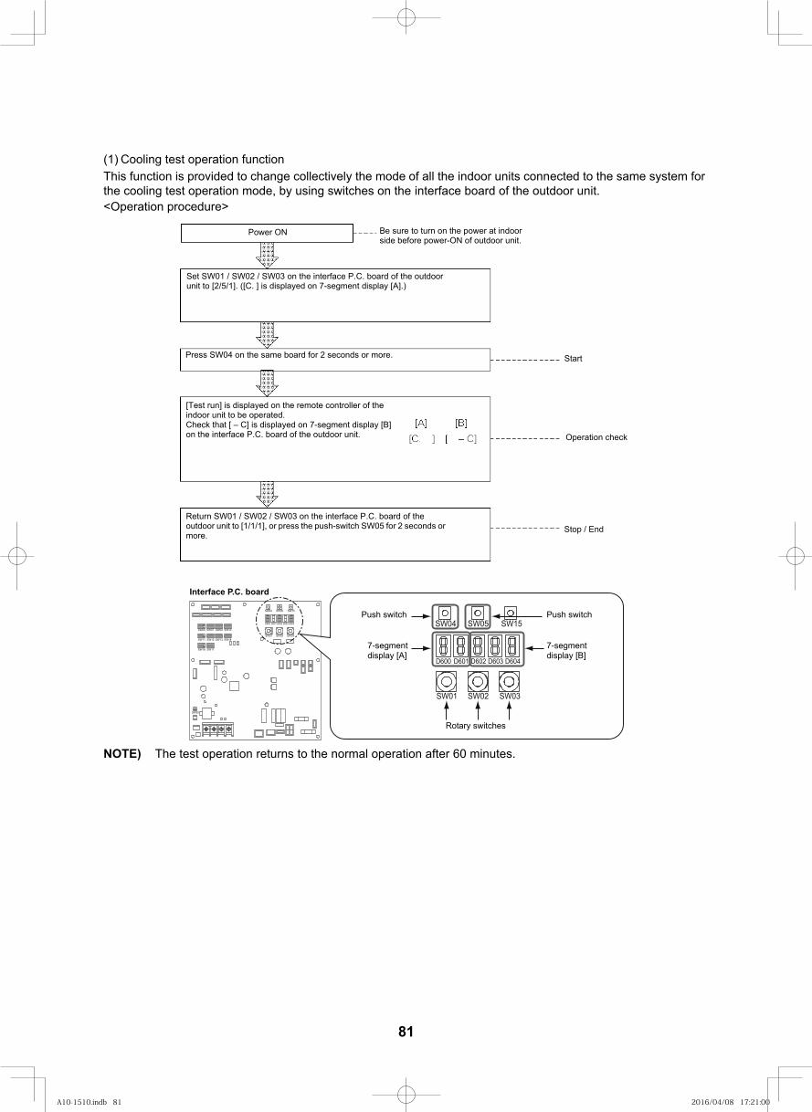
95
(1) Cooling test operation functionThis function is provided to change collectively the mode of all the indoor units connected to the same system for the cooling test operation mode, by using switches on the interface board of the outdoor unit.<Operation procedure>
Power ON Be sure to turn on the power at indoor side before power-ON of outdoor unit.
Set SW01 / SW02 / SW03 on the interface P.C. board of the outdoor unit to [2/5/1]. ([C. ] is displayed on 7-segment display [A].)
Press SW04 on the same board for 2 seconds or more.
[Test run] is displayed on the remote controller of the indoor unit to be operated.Check that [ – C] is displayed on 7-segment display [B] on the interface P.C. board of the outdoor unit.
Return SW01 / SW02 / SW03 on the interface P.C. board of the outdoor unit to [1/1/1], or press the push-switch SW05 for 2 seconds or more.
Start
Operation check
Stop / End
NOTE) The test operation returns to the normal operation after 60 minutes.
SW09SW07
SW11
SW06 SW10
SW12 SW13
SW16
SW14
SW17
D600 D601 D602 D603 D604
SW04 SW05 SW15
SW01 SW02 SW03
SW30
D600 D601 D602 D603 D604
SW04 SW05 SW15
SW01 SW02 SW03
Interface P.C. board
Push switch
7-segment display [A]
Push switch
7-segment display [B]
Rotary switches
81
A10-1510.indb 81A10-1510.indb 81 2016/04/08 17:21:002016/04/08 17:21:00
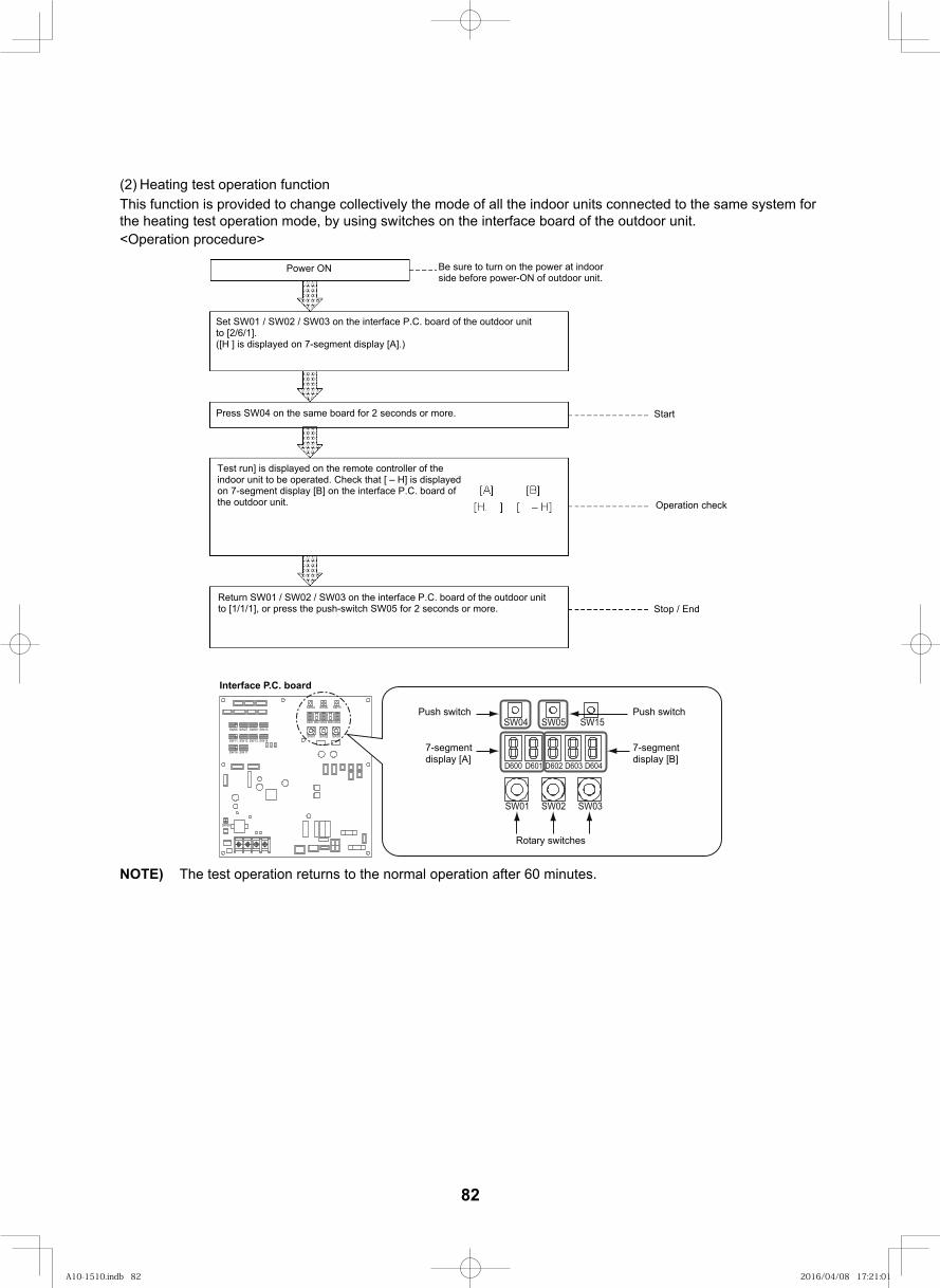
96
(2) Heating test operation functionThis function is provided to change collectively the mode of all the indoor units connected to the same system for the heating test operation mode, by using switches on the interface board of the outdoor unit.<Operation procedure>
Power ON Be sure to turn on the power at indoor side before power-ON of outdoor unit.
Set SW01 / SW02 / SW03 on the interface P.C. board of the outdoor unit to [2/6/1].([H ] is displayed on 7-segment display [A].)
Press SW04 on the same board for 2 seconds or more.
Test run] is displayed on the remote controller of the indoor unit to be operated. Check that [ – H] is displayed on 7-segment display [B] on the interface P.C. board of the outdoor unit.
Start
Operation check
Stop / EndReturn SW01 / SW02 / SW03 on the interface P.C. board of the outdoor unit to [1/1/1], or press the push-switch SW05 for 2 seconds or more.
NOTE) The test operation returns to the normal operation after 60 minutes.
SW09SW07
SW11
SW06 SW10
SW12 SW13
SW16
SW14
SW17
D600 D601 D602 D603 D604
SW04 SW05 SW15
SW01 SW02 SW03
SW30
D600 D601 D602 D603 D604
SW04 SW05 SW15
SW01 SW02 SW03
Interface P.C. board
Push switch
7-segment display [A]
Push switch
7-segment display [B]
Rotary switches
82
A10-1510.indb 82A10-1510.indb 82 2016/04/08 17:21:012016/04/08 17:21:01
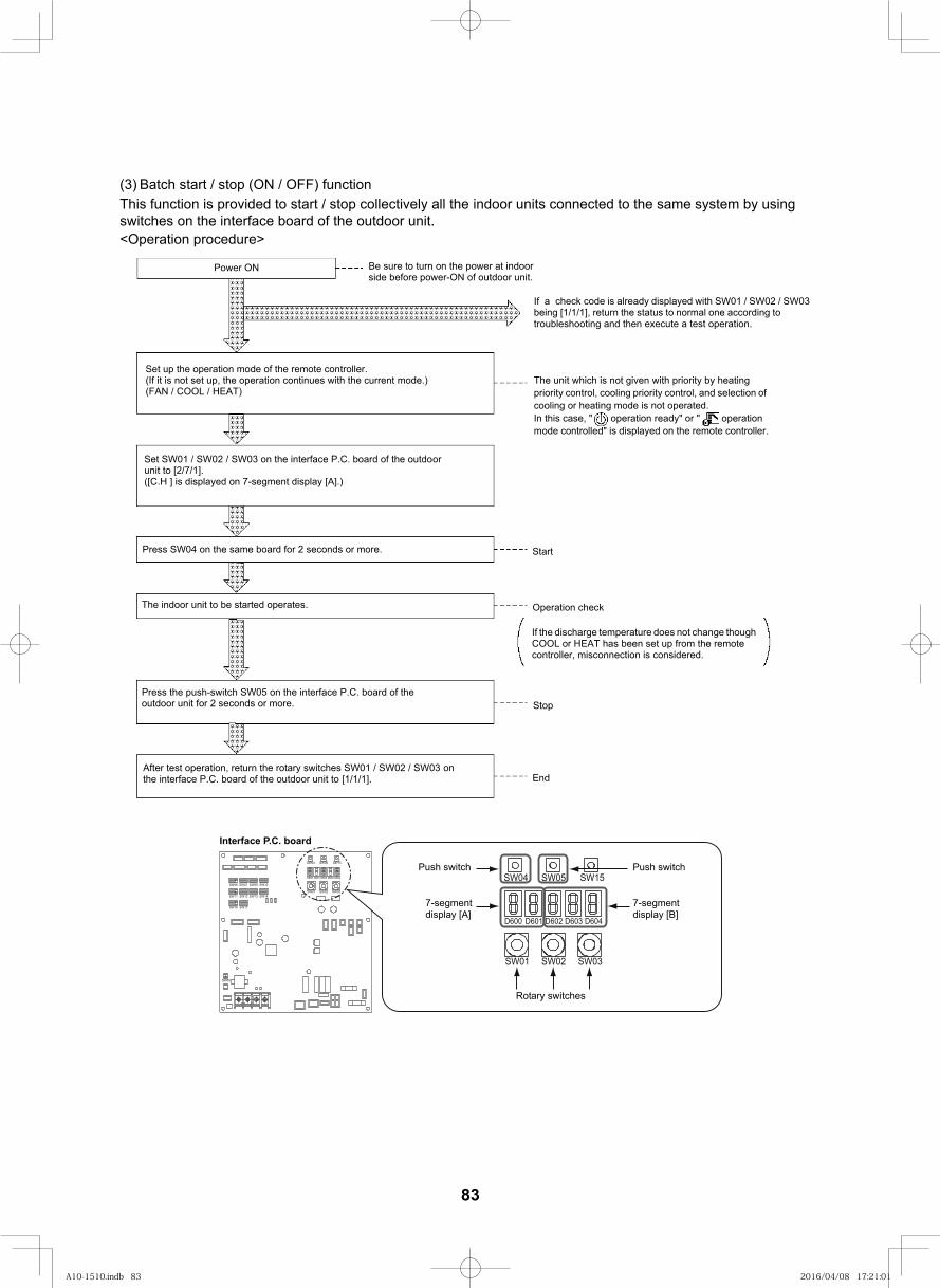
97
(3) Batch start / stop (ON / OFF) functionThis function is provided to start / stop collectively all the indoor units connected to the same system by using switches on the interface board of the outdoor unit.<Operation procedure>
Power ON Be sure to turn on the power at indoor side before power-ON of outdoor unit.
Set up the operation mode of the remote controller.(If it is not set up, the operation continues with the current mode.) (FAN / COOL / HEAT)
Set SW01 / SW02 / SW03 on the interface P.C. board of the outdoor unit to [2/7/1].([C.H ] is displayed on 7-segment display [A].)
Press SW04 on the same board for 2 seconds or more.
The indoor unit to be started operates.
Press the push-switch SW05 on the interface P.C. board of the outdoor unit for 2 seconds or more.
After test operation, return the rotary switches SW01 / SW02 / SW03 on the interface P.C. board of the outdoor unit to [1/1/1].
Start
Stop
End
If a check code is already displayed with SW01 / SW02 / SW03 being [1/1/1], return the status to normal one according to troubleshooting and then execute a test operation.
The unit which is not given with priority by heating priority control, cooling priority control, and selection of cooling or heating mode is not operated. In this case, " operation ready" or " operation mode controlled" is displayed on the remote controller.
Operation check
If the discharge temperature does not change though COOL or HEAT has been set up from the remote controller, misconnection is considered.
SW09SW07
SW11
SW06 SW10
SW12 SW13
SW16
SW14
SW17
D600 D601 D602 D603 D604
SW04 SW05 SW15
SW01 SW02 SW03
SW30
D600 D601 D602 D603 D604
SW04 SW05 SW15
SW01 SW02 SW03
Interface P.C. board
Push switch
7-segment display [A]
Push switch
7-segment display [B]
Rotary switches
83
A10-1510.indb 83A10-1510.indb 83 2016/04/08 17:21:012016/04/08 17:21:01
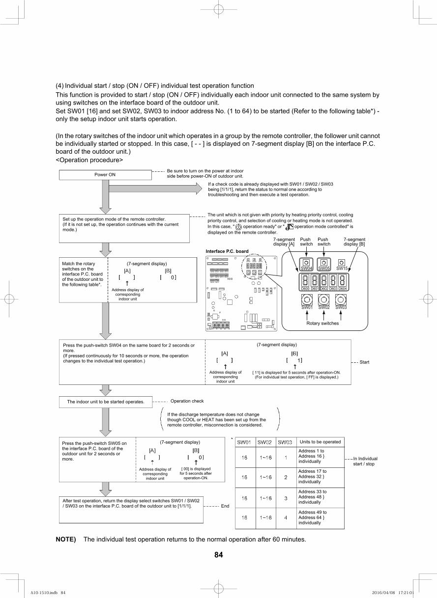
98
(4) Individual start / stop (ON / OFF) individual test operation functionThis function is provided to start / stop (ON / OFF) individually each indoor unit connected to the same system by using switches on the interface board of the outdoor unit.Set SW01 [16] and set SW02, SW03 to indoor address No. (1 to 64) to be started (Refer to the following table*) - only the setup indoor unit starts operation.
(In the rotary switches of the indoor unit which operates in a group by the remote controller, the follower unit cannot be individually started or stopped. In this case, [ - - ] is displayed on 7-segment display [B] on the interface P.C. board of the outdoor unit.)<Operation procedure>
NOTE) The individual test operation returns to the normal operation after 60 minutes.
Power ONBe sure to turn on the power at indoor side before power-ON of outdoor unit.
The unit which is not given with priority by heating priority control, cooling priority control, and selection of cooling or heating mode is not operated. In this case, " operation ready" or " operation mode controlled" is displayed on the remote controller.
If a check code is already displayed with SW01 / SW02 / SW03 being [1/1/1], return the status to normal one according to troubleshooting and then execute a test operation.
Set up the operation mode of the remote controller.(If it is not set up, the operation continues with the current mode.)
Match the rotary switches on the interface P.C. board of the outdoor unit to the following table*.
(7-segment display)
Address display of corresponding
indoor unit
Press the push-switch SW04 on the same board for 2 seconds or more.(If pressed continuously for 10 seconds or more, the operation changes to the individual test operation.)
(7-segment display)
Address display of corresponding
indoor unit
[ 11] is displayed for 5 seconds after operation-ON.(For individual test operation, [ FF] is displayed.)
The indoor unit to be started operates. Operation check
If the discharge temperature does not changethough COOL or HEAT has been set up from theremote controller, misconnection is considered.
Press the push-switch SW05 on the interface P.C. board of the outdoor unit for 2 seconds or more.
(7-segment display)
Address display of corresponding
indoor unit
[ 00] is displayed for 5 seconds after
operation-ON.
After test operation, return the display select switches SW01 / SW02 / SW03 on the interface P.C. board of the outdoor unit to [1/1/1]. End
Units to be operated
Address 1 to Address 16 } individually
Address 17 to Address 32 } individually
Address 33 to Address 48 } individually
Address 49 to Address 64 } individually
In Individual start / stop
7-segment display [A] 7-segment display [B]
<Rotary switches>
Start
SW09SW07
SW11
SW06 SW10
SW12 SW13
SW16
SW14
SW17
D600 D601 D602 D603 D604
SW04 SW05 SW15
SW01 SW02 SW03
SW30
D600 D601 D602 D603 D604
SW04 SW05 SW15
SW01 SW02 SW03
Interface P.C. board
7-segment display [A]
Push switch
Push switch
7-segment display [B]
Rotary switches
0
1
0
84
A10-1510.indb 84A10-1510.indb 84 2016/04/08 17:21:012016/04/08 17:21:01
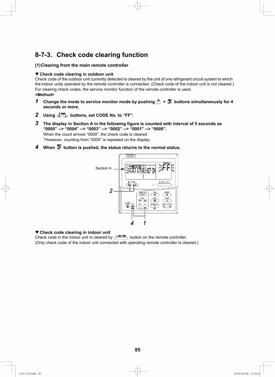
99
8-7-3. Check code clearing function(1)Clearing from the main remote controller
Check code clearing in outdoor unitCheck code of the outdoor unit currently detected is cleared by the unit of one refrigerant circuit system to which the indoor units operated by the remote controller is connected. (Check code of the indoor unit is not cleared.)For clearing check codes, the service monitor function of the remote controller is used.<Method>1 Change the mode to service monitor mode by pushing + buttons simultaneously for 4
seconds or more.
2 Using buttons, set CODE No. to “FF”.
3 The display in Section A in the following figure is counted with interval of 5 seconds as “0005” --> “0004” --> “0003” --> “0002” --> “0001” --> “0000”.When the count arrives “0000”, the check code is cleared. *However, counting from “0005” is repeated on the display.
4 When button is pushed, the status returns to the normal status.
Check code clearing in indoor unitCheck code in the indoor unit is cleared by button on the remote controller.(Only check code of the indoor unit connected with operating remote controller is cleared.)
Section A
85
A10-1510.indb 85A10-1510.indb 85 2016/04/08 17:21:012016/04/08 17:21:01
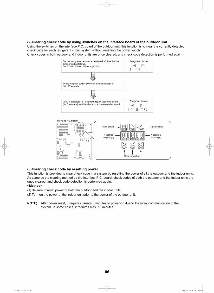
100
(2)Clearing check code by using switches on the interface board of the outdoor unitUsing the switches on the interface P.C. board of the outdoor unit, this function is to clear the currently detected check code for each refrigerant circuit system without resetting the power supply.Check codes in both outdoor and indoor units are once cleared, and check code detection is performed again.
Set the rotary switches on the interface P.C. board of the outdoor unit as follows. Set SW01 / SW02 / SW03 to [2/16/1]
7-segment display
Press the push-switch SW04 on the same board for 5 to 10 seconds.
[ C L] is displayed in 7-segment display [B] on the board (for 5 seconds), and the check code is completely cleared.
7-segment display
.
. .
(3)Clearing check code by resetting powerThis function is provided to clear check code in a system by resetting the power of all the outdoor and the indoor units.As same as the clearing method by the interface P.C. board, check codes of both the outdoor and the indoor units are once cleared, and check code detection is performed again.<Method>(1) Be sure to reset power of both the outdoor and the indoor units.(2) Turn on the power of the indoor unit prior to the power of the outdoor unit.
NOTE) After power reset, it requires usually 3 minutes to power-on due to the initial communication of the system. In some cases, it requires max. 10 minutes.
SW09SW07
SW11
SW06 SW10
SW12 SW13
SW16
SW14
SW17
D600 D601 D602 D603 D604
SW04 SW05 SW15
SW01 SW02 SW03
SW30
D600 D601 D602 D603 D604
SW04 SW05 SW15
SW01 SW02 SW03
Interface P.C. board
Push switch
7-segment display [A]
Push switch
7-segment display [B]
Rotary switches
86
A10-1510.indb 86A10-1510.indb 86 2016/04/08 17:21:022016/04/08 17:21:02
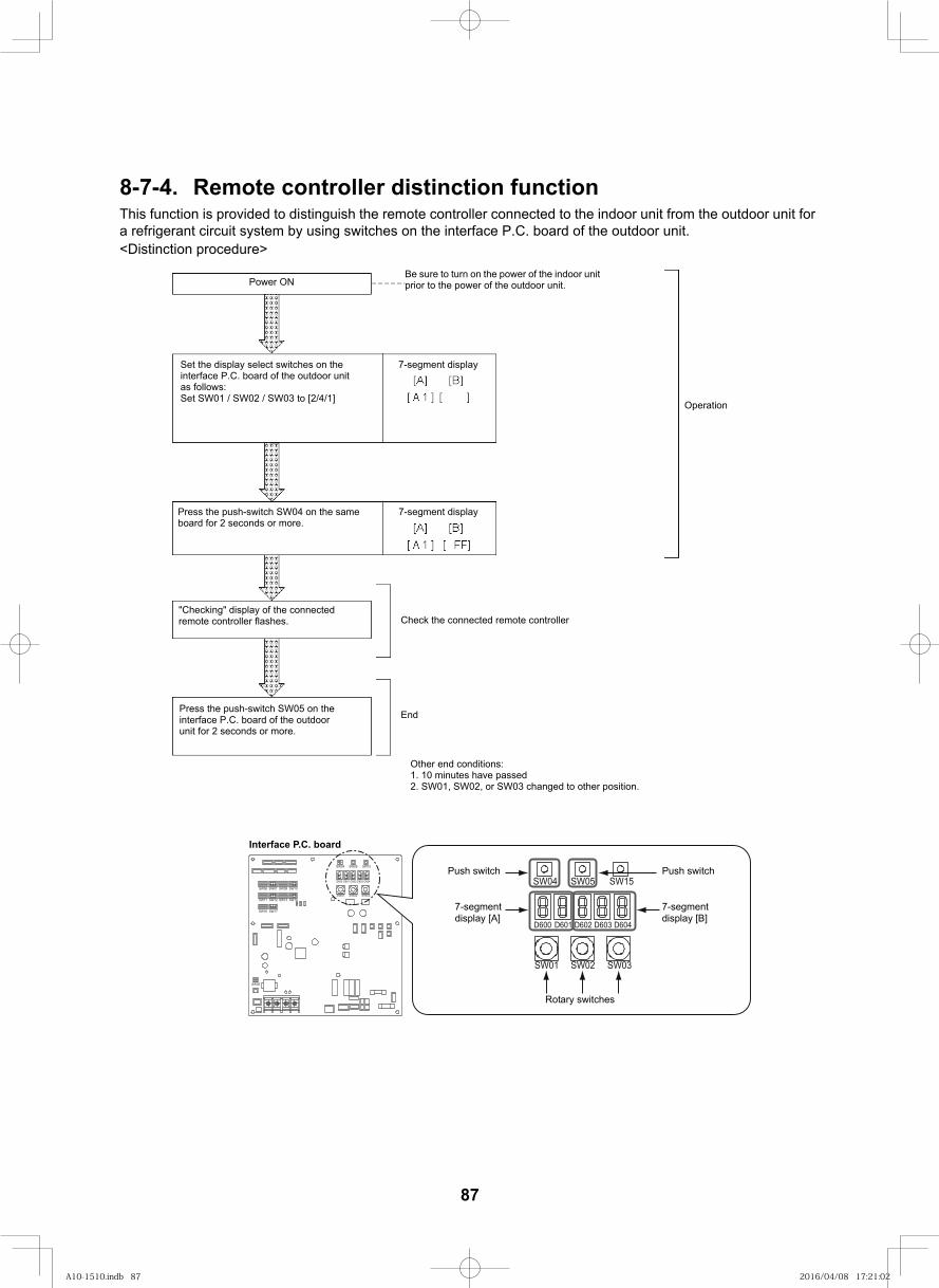
101
8-7-4. Remote controller distinction functionThis function is provided to distinguish the remote controller connected to the indoor unit from the outdoor unit for a refrigerant circuit system by using switches on the interface P.C. board of the outdoor unit.<Distinction procedure>
Power ONBe sure to turn on the power of the indoor unit prior to the power of the outdoor unit.
7-segment displaySet the display select switches on the interface P.C. board of the outdoor unit as follows:Set SW01 / SW02 / SW03 to [2/4/1]
Press the push-switch SW04 on the same board for 2 seconds or more.
7-segment display
"Checking" display of the connected remote controller flashes.
Press the push-switch SW05 on the interface P.C. board of the outdoor unit for 2 seconds or more.
Operation
Check the connected remote controller
End
Other end conditions:1. 10 minutes have passed2. SW01, SW02, or SW03 changed to other position.
SW09SW07
SW11
SW06 SW10
SW12 SW13
SW16
SW14
SW17
D600 D601 D602 D603 D604
SW04 SW05 SW15
SW01 SW02 SW03
SW30
D600 D601 D602 D603 D604
SW04 SW05 SW15
SW01 SW02 SW03
Interface P.C. board
Push switch
7-segment display [A]
Push switch
7-segment display [B]
Rotary switches
87
A10-1510.indb 87A10-1510.indb 87 2016/04/08 17:21:022016/04/08 17:21:02
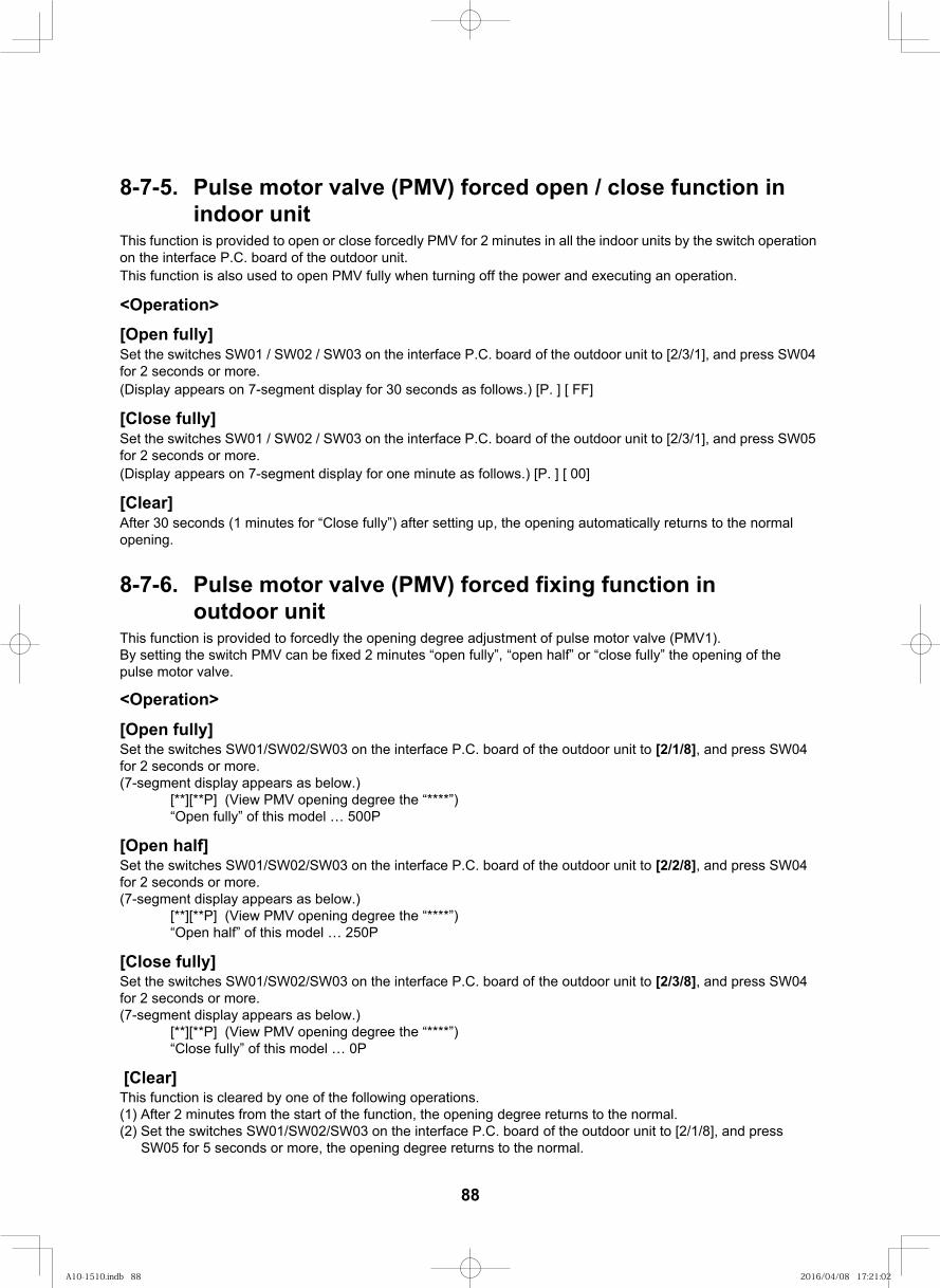
102
8-7-5. Pulse motor valve (PMV) forced open / close function in indoor unit
This function is provided to open or close forcedly PMV for 2 minutes in all the indoor units by the switch operation on the interface P.C. board of the outdoor unit.This function is also used to open PMV fully when turning off the power and executing an operation.
<Operation>[Open fully]Set the switches SW01 / SW02 / SW03 on the interface P.C. board of the outdoor unit to [2/3/1], and press SW04 for 2 seconds or more.(Display appears on 7-segment display for 30 seconds as follows.) [P. ] [ FF]
[Close fully]Set the switches SW01 / SW02 / SW03 on the interface P.C. board of the outdoor unit to [2/3/1], and press SW05 for 2 seconds or more.(Display appears on 7-segment display for one minute as follows.) [P. ] [ 00]
[Clear]After 30 seconds (1 minutes for “Close fully”) after setting up, the opening automatically returns to the normal opening.
8-7-6. Pulse motor valve (PMV) forced fixing function inoutdoor unit
This function is provided to forcedly the opening degree adjustment of pulse motor valve (PMV1).By setting the switch PMV can be fixed 2 minutes “open fully”, “open half” or “close fully” the opening of the pulse motor valve.
<Operation>[Open fully]Set the switches SW01/SW02/SW03 on the interface P.C. board of the outdoor unit to [2/1/8], and press SW04 for 2 seconds or more.(7-segment display appears as below.) [**][**P] (View PMV opening degree the “****”) “Open fully” of this model … 500P
[Open half]Set the switches SW01/SW02/SW03 on the interface P.C. board of the outdoor unit to [2/2/8], and press SW04 for 2 seconds or more.(7-segment display appears as below.) [**][**P] (View PMV opening degree the “****”) “Open half” of this model … 250P
[Close fully]Set the switches SW01/SW02/SW03 on the interface P.C. board of the outdoor unit to [2/3/8], and press SW04 for 2 seconds or more.(7-segment display appears as below.) [**][**P] (View PMV opening degree the “****”) “Close fully” of this model … 0P
[Clear]This function is cleared by one of the following operations.(1) After 2 minutes from the start of the function, the opening degree returns to the normal.(2) Set the switches SW01/SW02/SW03 on the interface P.C. board of the outdoor unit to [2/1/8], and press
SW05 for 5 seconds or more, the opening degree returns to the normal.
88
A10-1510.indb 88A10-1510.indb 88 2016/04/08 17:21:022016/04/08 17:21:02
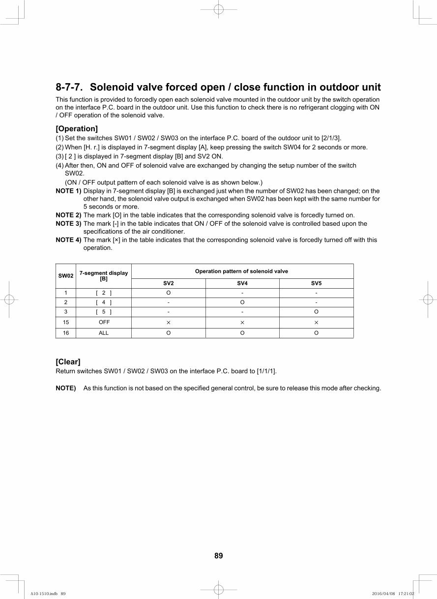
103
8-7-7. Solenoid valve forced open / close function in outdoor unitThis function is provided to forcedly open each solenoid valve mounted in the outdoor unit by the switch operation on the interface P.C. board in the outdoor unit. Use this function to check there is no refrigerant clogging with ON / OFF operation of the solenoid valve.
[Operation](1) Set the switches SW01 / SW02 / SW03 on the interface P.C. board of the outdoor unit to [2/1/3].(2) When [H. r.] is displayed in 7-segment display [A], keep pressing the switch SW04 for 2 seconds or more.(3) [ 2 ] is displayed in 7-segment display [B] and SV2 ON.(4) After then, ON and OFF of solenoid valve are exchanged by changing the setup number of the switch
SW02.(ON / OFF output pattern of each solenoid valve is as shown below.)
NOTE 1) Display in 7-segment display [B] is exchanged just when the number of SW02 has been changed; on the other hand, the solenoid valve output is exchanged when SW02 has been kept with the same number for 5 seconds or more.
NOTE 2) The mark [O] in the table indicates that the corresponding solenoid valve is forcedly turned on.NOTE 3) The mark [-] in the table indicates that ON / OFF of the solenoid valve is controlled based upon the
specifications of the air conditioner.NOTE 4) The mark [×] in the table indicates that the corresponding solenoid valve is forcedly turned off with this
operation.
[Clear]Return switches SW01 / SW02 / SW03 on the interface P.C. board to [1/1/1].
NOTE) As this function is not based on the specified general control, be sure to release this mode after checking.
SW02 7-segment display [B]
SV5-] 2 [1
-] 4 [2
3 [ 5 ] O
15
OALL61
Operation pattern of solenoid valve
SV2
-
-
O
SV4-
-
O
O
OFF
O
89
A10-1510.indb 89A10-1510.indb 89 2016/04/08 17:21:022016/04/08 17:21:02
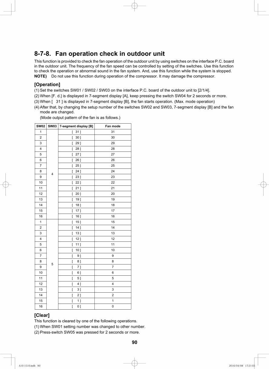
104
8-7-8. Fan operation check in outdoor unitThis function is provided to check the fan operation of the outdoor unit by using switches on the interface P.C. board in the outdoor unit. The frequency of the fan speed can be controlled by setting of the switches. Use this function to check the operation or abnormal sound in the fan system. And, use this function while the system is stopped.NOTE) Do not use this function during operation of the compressor. It may damage the compressor.
[Operation](1) Set the switches SW01 / SW02 / SW03 on the interface P.C. board of the outdoor unit to [2/1/4].(2) When [F. d.] is displayed in 7-segment display [A], keep pressing the switch SW04 for 2 seconds or more.(3) When [ 31 ] is displayed in 7-segment display [B], the fan starts operation. (Max. mode operation)(4) After that, by changing the setup number of the switches SW02 and SW03, 7-segment display [B] and the fan
mode are changed.(Mode output pattern of the fan is as follows.)
[Clear]This function is cleared by one of the following operations.(1) When SW01 setting number was changed to other number.(2) Press-switch SW05 was pressed for 2 seconds or more.
SW02 SW03 7-segment display [B] Fan mode
1
4
[ 31 ] 31
2 [ 30 ] 30
3 [ 29 ] 29
4 [ 28 ] 28
5 [ 27 ] 27
6 [ 26 ] 26
7 [ 25 ] 25
8 [ 24 ] 24
9 [ 23 ] 23
10 [ 22 ] 22
11 [ 21 ] 21
12 [ 20 ] 20
13 [ 19 ] 19
14 [ 18 ] 18
15 [ 17 ] 17
16 [ 16 ] 16
1
5
[ 15 ] 15
2 [ 14 ] 14
3 [ 13 ] 13
4 [ 12 ] 12
5 [ 11 ] 11
6 [ 10 ] 10
7 [ 9 ] 9
8 [ 8 ] 8
9 [ 7 ] 7
10 [ 6 ] 6
11 [ 5 ] 5
12 [ 4 ] 4
13 [ 3 ] 3
14 [ 2 ] 2
15 [ 1 ] 1
16 [ 0 ] 0
90
A10-1510.indb 90A10-1510.indb 90 2016/04/08 17:21:032016/04/08 17:21:03
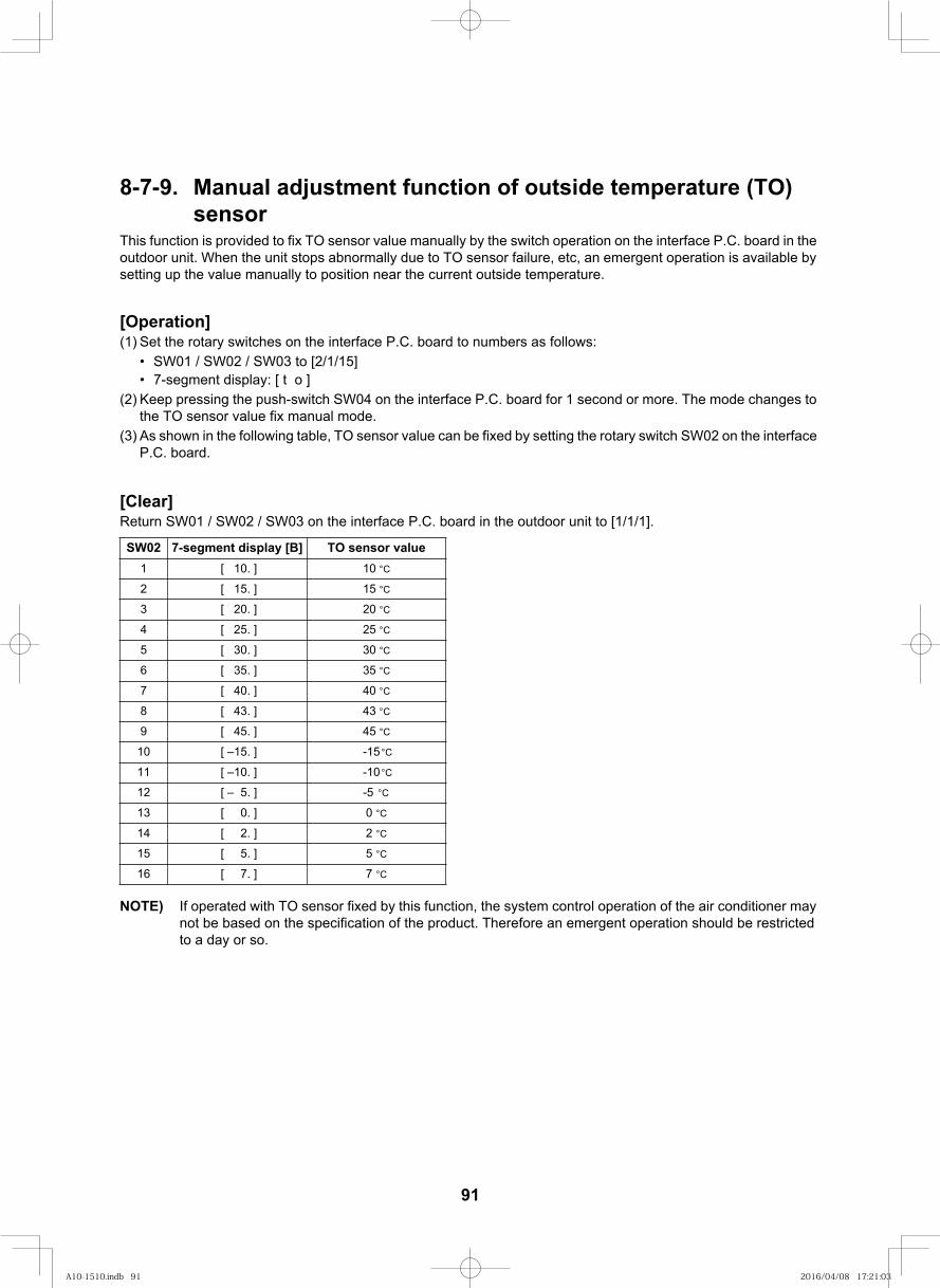
105
8-7-9. Manual adjustment function of outside temperature (TO) sensor
This function is provided to fix TO sensor value manually by the switch operation on the interface P.C. board in the outdoor unit. When the unit stops abnormally due to TO sensor failure, etc, an emergent operation is available by setting up the value manually to position near the current outside temperature.
[Operation](1) Set the rotary switches on the interface P.C. board to numbers as follows:
• SW01 / SW02 / SW03 to [2/1/15]• 7-segment display: [ t o ]
(2) Keep pressing the push-switch SW04 on the interface P.C. board for 1 second or more. The mode changes to the TO sensor value fix manual mode.
(3) As shown in the following table, TO sensor value can be fixed by setting the rotary switch SW02 on the interface P.C. board.
[Clear]Return SW01 / SW02 / SW03 on the interface P.C. board in the outdoor unit to [1/1/1].
NOTE) If operated with TO sensor fixed by this function, the system control operation of the air conditioner may not be based on the specification of the product. Therefore an emergent operation should be restricted to a day or so.
SW02 7-segment display [B] TO sensor value1 [ 10. ] 10 °C
2 [ 15. ] 15 °C
3 [ 20. ] 20 °C
4 [ 25. ] 25 °C
5 [ 30. ] 30 °C
6 [ 35. ] 35 °C
7 [ 40. ] 40 °C
8 [ 43. ] 43 °C
9 [ 45. ] 45 °C
10 [ –15. ] -15 °C
11 [ –10. ] -10 °C
12 [ – 5. ] -5 °C
13 [ 0. ] 0 °C
14 [ 2. ] 2 °C
15 [ 5. ] 5 °C
16 [ 7. ] 7 °C
91
A10-1510.indb 91A10-1510.indb 91 2016/04/08 17:21:032016/04/08 17:21:03
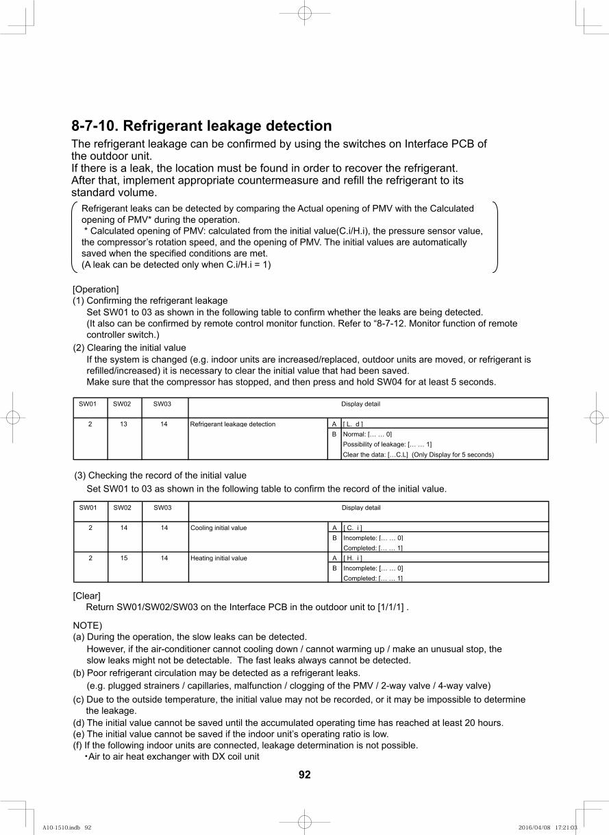
8-7-10. Refrigerant leakage detectionThe refrigerant leakage can be confirmed by using the switches on Interface PCB of the outdoor unit. If there is a leak, the location must be found in order to recover the refrigerant. After that, implement appropriate countermeasure and refill the refrigerant to its standard volume.
Refrigerant leaks can be detected by comparing the Actual opening of PMV with the Calculated opening of PMV* during the operation. * Calculated opening of PMV: calculated from the initial value(C.i/H.i), the pressure sensor value, the compressor’s rotation speed, and the opening of PMV. The initial values are automatically saved when the specified conditions are met. (A leak can be detected only when C.i/H.i = 1)
[Operation](1) Confirming the refrigerant leakage
SW01 SW02 SW03 Display detail
2 13 14 Refrigerant leakage detection A [ L. d ]B Normal: [… … 0]
Possibility of leakage: [… … 1]Clear the data: […C.L] (Only Display for 5 seconds)
SW01 SW02 SW03 Display detail
2 14 14 Cooling initial value A [ C. i ]B Incomplete: [… … 0]
Completed: [… … 1]2 15 14 Heating initial value A [ H. i ]
B Incomplete: [… … 0]Completed: [… … 1]
[Clear] Return SW01/SW02/SW03 on the Interface PCB in the outdoor unit to [1/1/1] .
Set SW01 to 03 as shown in the following table to confirm whether the leaks are being detected.(It also can be confirmed by remote control monitor function. Refer to “8-7-12. Monitor function of remote controller switch.)
(2) Clearing the initial valueIf the system is changed (e.g. indoor units are increased/replaced, outdoor units are moved, or refrigerant is refilled/increased) it is necessary to clear the initial value that had been saved. Make sure that the compressor has stopped, and then press and hold SW04 for at least 5 seconds.
(3) Checking the record of the initial valueSet SW01 to 03 as shown in the following table to confirm the record of the initial value.
However, if the air-conditioner cannot cooling down / cannot warming up / make an unusual stop, the slow leaks might not be detectable. The fast leaks always cannot be detected.
(e.g. plugged strainers / capillaries, malfunction / clogging of the PMV / 2-way valve / 4-way valve)
NOTE)(a) During the operation, the slow leaks can be detected.
(b) Poor refrigerant circulation may be detected as a refrigerant leaks.
(c) Due to the outside temperature, the initial value may not be recorded, or it may be impossible to determine the leakage.(d) The initial value cannot be saved until the accumulated operating time has reached at least 20 hours.(e) The initial value cannot be saved if the indoor unit’s operating ratio is low.(f) If the following indoor units are connected, leakage determination is not possible. ・Air to air heat exchanger with DX coil unit
92
A10-1510.indb 92A10-1510.indb 92 2016/04/08 17:21:032016/04/08 17:21:03
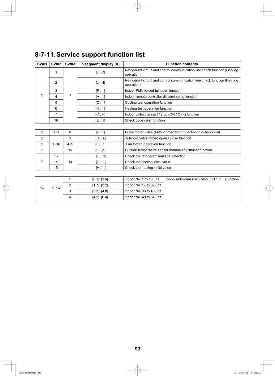
106
SW01 SW02 SW03 7-segment di stnetnoc noitcnuF]A[ yalps
2
1
1
[J . C] Refrigerant circuit and control communication line check function (Cooling operation)
]H . J[2 Refrigerant circuit and control communication line check function (Heating operation)
noitcnuf nepo lluf decrof VMP roodnI] . P[3
noitcnuf gnitanimircsid rellortnoc etomer roodnI]1 A[4
noitcnuf noitarepo tset gnilooC] . C[5
noitcnuf noitarepo tset gnitaeH] . H[6
noitcnuf )FFO / NO( pots / trats evitcelloc roodnI]H . C[7
E[61 . r] Check code clear function
1~16
3 [H . r.] Solenoid valve forced open / close function
2 4~5 [F . d.] Fan forced operation function
2 15 [t o] Outside temperature sensor manual adjustment function
16 1~16
1 [0 1]~[1 6] Indoor No. 1 to 16 unit Indoor individual start / stop (ON / OFF) function
2 [1 7]~[3 2] Indoor No. 17 to 32 unit
3 [3 3]~[4 8] Indoor No. 33 to 48 unit
4 [4 9]~[6 4] Indoor No. 49 to 64 unit
2
1~3 8 Pulse motor valve (PMV) forced fixing function in outdoor unit2 ] . P[ 1
8-7-11.Service support function list
2131415
14]d . L[]i . C[]i . H[
Check the refrigerant leakage detectionCheck the cooling initial valueCheck the heating initial value
93
A10-1510.indb 93A10-1510.indb 93 2016/04/08 17:21:032016/04/08 17:21:03
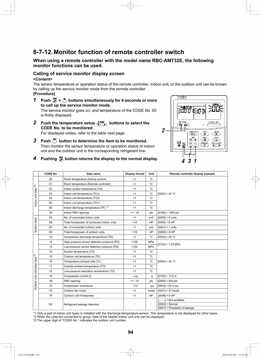
107
8-7-12.Monitor function of remote controller switchWhen using a remote controller with the model name RBC-AMT32E, the following monitor functions can be used.Calling of service monitor display screen<Content>The sensor temperature or operation status of the remote controller, indoor unit, or the outdoor unit can be known by calling up the service monitor mode from the remote controller.[Procedure]1 Push + buttons simultaneously for 4 seconds or more
to call up the service monitor mode. The service monitor goes on, and temperature of the CODE No. 00 is firstly displayed.
2 Push the temperature setup buttons to select the CODE No. to be monitored. For displayed codes, refer to the table next page.
3 Push button to determine the item to be monitored. Then monitor the sensor temperature or operation status of indoor unit and the outdoor unit in the corresponding refrigerant line.
4 Pushing button returns the display to the normal display.
*1 Only a part of indoor unit types is installed with the discharge temperature sensor. This temperature is not displayed for other types.*2 When the units are connected to group, data of the header indoor unit only can be displayed.*3 The upper digit of “CODE No.” indicates the outdoor unit number.
tinUtamrof yalpsiDeman ataD.oN EDOC Remote controller display example
Indo
or u
nit d
ata
*2
00 Room temperature (During control) ×1 °C
[0024] = 24 °C
01 Room temperature (Remote controller) ×1 °C
C°1×)AT( erutarepmet noitcus roodnI20
C°1×)JCT( erutarepmet lioc roodnI30C°1×)2CT( erutarepmet lioc roodnI40
C°1×)1CT( erutarepmet lioc roodnI50
06 Indoor discharge temperature (TF) *1 ×1 °C
slp 0051 = ]0510[slp01 / 1×gninepo VMP roodnI80
Sys
tem
dat
a stinu 6 = ]6000[tinu1×stinu roodni detcennoc fo .oNA0
0B Total horsepower of connected indoor units ×10 HP [0060] = 6 HP
stinu 1 = ]1000[tinu1×outdoor units detcennoc fo .oNC0
PH01×stinu roodtuo fo rewopesroh latoTD0
Out
door
uni
t ind
ivid
ual d
ata
*3
10 Compressor discharge temperature (TD) ×1 °C [0024] = 24 °C
12 High-pressure sensor detection pressure (PD) ×100 MPa[0123] = 1.23 MPa
13 Low-pressure sensor detection pressure (PS) ×100 MPa
C°1×)ST( erutarepmet noitcuS41
[0024] = 24 °C
C°1×)ET( erutarepmet lioc roodtuO51
C°1×)LT( edis diuqil ta erutarepmeT61
C°1×)OT( erutarepmet tneibma edistuO71
18 Low-pressure saturation temperature (TU) ×1 °C
A 5.01 = ]5010[)I( tnerruc rosserpmoC91
slp 005 = ]0500[slp01 / 1×V openingMPB1
0933] = 93.3 rps[revolutions rosserpmoCD1
edom 72 = ]7200[edom1×edom naf roodtuOE1
PH1×rewopesroh tinu roodtuOF1
E0 Refrigerant leakage detection - -[- - - -] = Not available[0000] = Normal[0001] = Possibility of leakage
rps
A01×
01×
[0060] = 6 HP
[0006] = 6 HP
94
A10-1510.indb 94A10-1510.indb 94 2016/04/08 17:21:032016/04/08 17:21:03
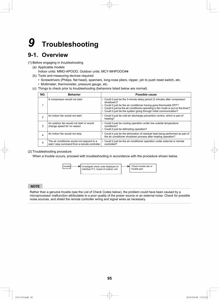
108
9 Troubleshooting9-1. Overview(1) Before engaging in troubleshooting
(a) Applicable modelsIndoor units: MMO-APOOO, Outdoor units: MCY-MHPOOO4
(b) Tools and measuring devices requiredScrewdrivers (Philips, flat head), spanners, long-nose pliers, nipper, pin to push reset switch, etc.Multimeter, thermometer, pressure gauge, etc.
(c) Things to check prior to troubleshooting (behaviors listed below are normal)
(2) Troubleshooting procedureWhen a trouble occurs, proceed with troubleshooting in accordance with the procedure shown below.
NOTERather than a genuine trouble (see the List of Check Codes below), the problem could have been caused by a microprocessor malfunction attributable to a poor quality of the power source or an external noise. Check for possible noise sources, and shield the remote controller wiring and signal wires as necessary.
esuac elbissoProivaheB.ON
1
A compressor would not start Could it just be the 3-minute delay period (3 minutes after compressor shutdown)?Could it just be the air conditioner having gone thermostat OFF?Could it just be the air conditioner operating in fan mode or put on the timer?Could it just be the system going through initial communication?
2 An indoor fan would not start Could it just be cold air discharge prevention control, which is part of heating?
3An outdoor fan would not start or would change speed for no reason
Could it just be cooling operation under low outside temperature conditions?Could it just be defrosting operation?
4 An indoor fan would not stop Could it just be the elimination of residual heat being performed as part of the air conditioner shutdown process after heating operation?
5 The air conditioner would not respond to a start / stop command from a remote controller
Could it just be the air conditioner operation under external or remote controllerl?
trouble Investigate check code displayed on interface P.C. board of outdoor unit
Check trouble site or trouble part
95
A10-1510.indb 95A10-1510.indb 95 2016/04/08 17:21:032016/04/08 17:21:03
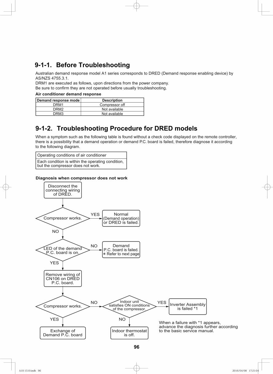
Australian demand response model A1 series corresponds to DRED (Demand response enabling device) byAS/NZS 4755.3.1.DRM1 are executed as follows, upon directions from the power company.Be sure to confirm they are not operated before usually troubleshooting.Air conditioner demand response
9-1-2. Troubleshooting Procedure for DRED modelsWhen a symptom such as the following table is found without a check code displayed on the remote controller,there is a possibility that a demand operation or demand P.C. board is failed, therefore diagnose it according to the following diagram.
Demand response mode DescriptionDRM1 Compressor off
elbaliava toN2MRDDRM3 Not available
Each condition is within the operating condition,but the compressor does not work.
Operating conditions of air conditioner
Diagnosis when compressor does not work
Disconnect theconnecting wiring
of DRED.
Remove wiring ofCN106 on DRED
P.C. board.
Normal(Demand operation)or DRED is failed.
Inverter Assemblyis failed *1
Compressor works.
NO
YES
YES
YES
DemandP.C. board is failed. Refer to next page
NO
NOCompressor works.
Indoor thermostatis off.
Exchange ofDemand P.C. board
NO
Indoor unitsatisfies ON conditions
of the compressor.
LED of the demandP.C. board is on.
YES
When a failure with *1 appears,advance the diagnosis further accordingto the basic service manual.
9-1-1. Before Troubleshooting
96
A10-1510.indb 96A10-1510.indb 96 2016/04/08 17:21:042016/04/08 17:21:04
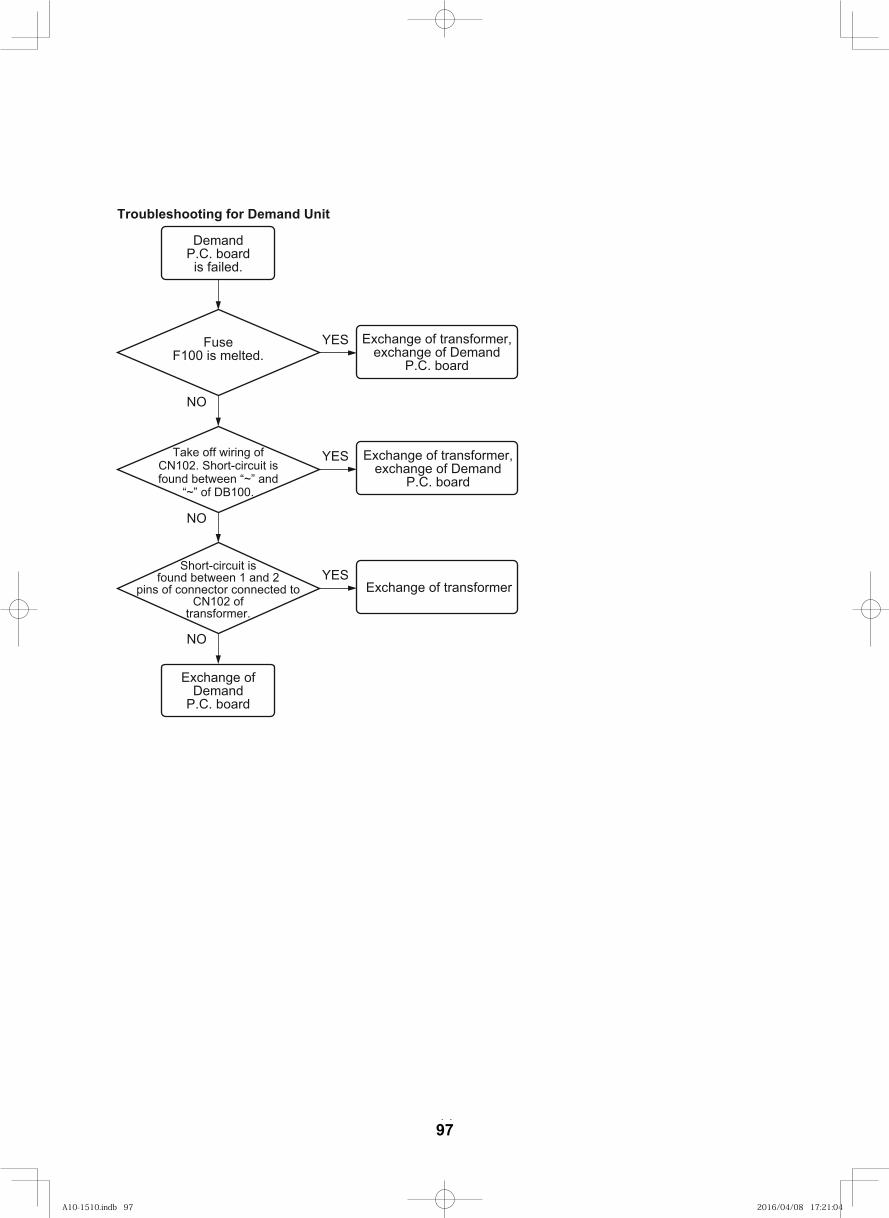
– 14 –
Troubleshooting for Demand Unit
DemandP.C. boardis failed.
Exchange of transformer,exchange of Demand
P.C. board
Exchange ofDemand
P.C. board
FuseF100 is melted.
NO
NO
YES
Exchange of transformer,exchange of Demand
P.C. board
YES
Exchange of transformerYES
Short-circuit isfound between 1 and 2
pins of connector connected toCN102 of
transformer.
Take off wiring ofCN102. Short-circuit isfound between “~” and
“~” of DB100.
NO
97
A10-1510.indb 97A10-1510.indb 97 2016/04/08 17:21:042016/04/08 17:21:04
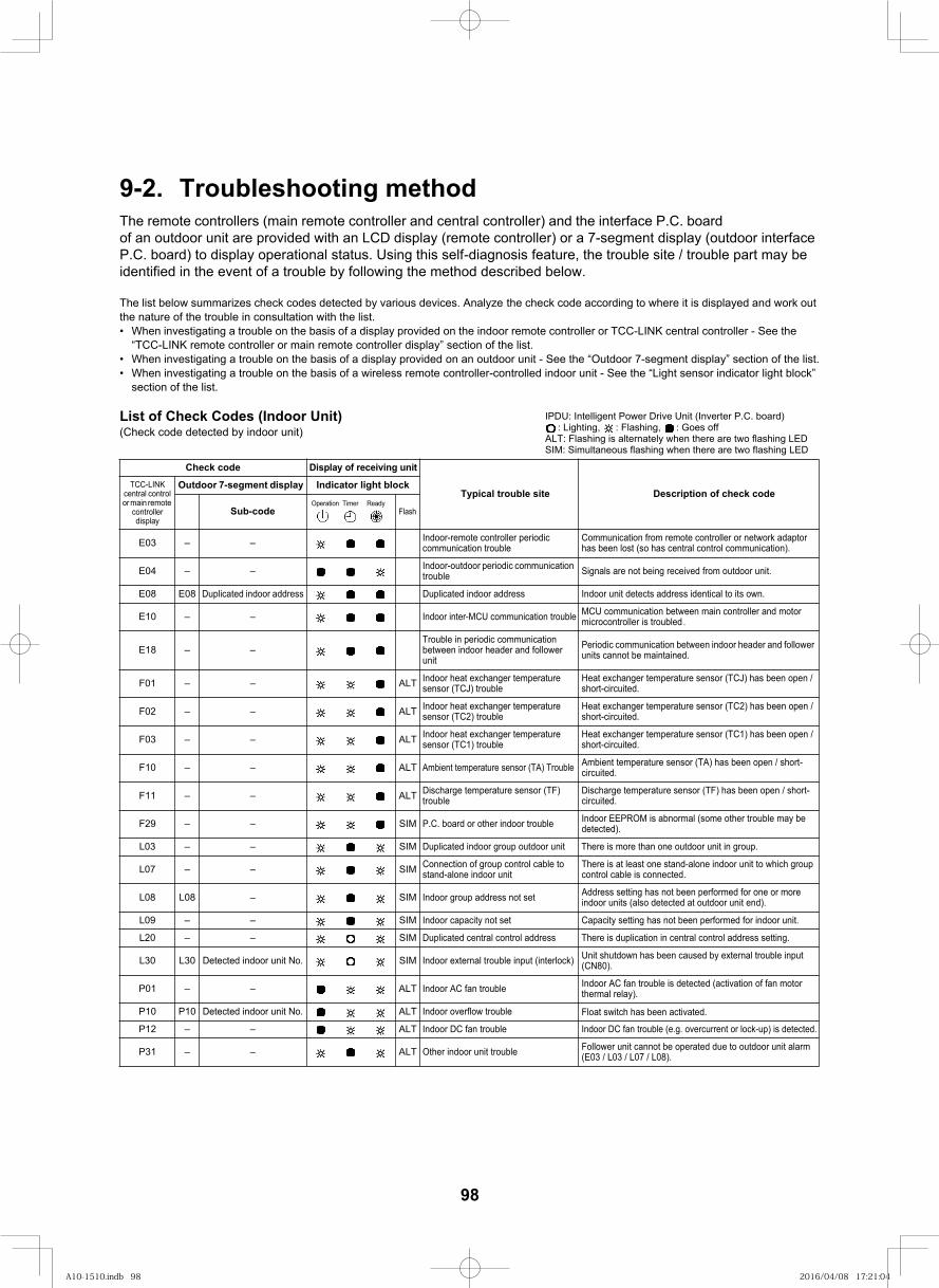
109
9-2. Troubleshooting methodThe remote controllers (main remote controller and central controller) and the interface P.C. board of an outdoor unit are provided with an LCD display (remote controller) or a 7-segment display (outdoor interface P.C. board) to display operational status. Using this self-diagnosis feature, the trouble site / trouble part may be identified in the event of a trouble by following the method described below.
The list below summarizes check codes detected by various devices. Analyze the check code according to where it is displayed and work out the nature of the trouble in consultation with the list.
When investigating a trouble on the basis of a display provided on the indoor remote controller or TCC-LINK central controller - See the “TCC-LINK remote controller or main remote controller display” section of the list.When investigating a trouble on the basis of a display provided on an outdoor unit - See the “Outdoor 7-segment display” section of the list.When investigating a trouble on the basis of a wireless remote controller-controlled indoor unit - See the “Light sensor indicator light block” section of the list.
List of Check Codes (Indoor Unit)(Check code detected by indoor unit)
Check code Display of receiving unit
check code fo noitpircseD trouble siteTypicalTCC-LINK
central control or main remote
controller display
Outdoor 7-segment display Indicator light block
Sub-code Flash
E03 – – Indoor-remote controller periodic communication trouble
Communication from remote controller or network adaptor has been lost (so has central control communication).
E04 – – Indoor-outdoor periodic communication trouble Signals are not being received from outdoor unit.
E08 E08 .nwo sti ot lacitnedi sserdda stceted tinu roodnIsserdda roodni detacilpuDsserdda roodni detacilpuD
E10 – – Indoor inter-MCU communication trouble MCU communication between main controller and motor microcontroller is troubled.
E18 – –Trouble in periodic communication between indoor header and follower unit
Periodic communication between indoor header and follower units cannot be maintained.
TLA––10F Indoor heat exchanger temperature sensor (TCJ) trouble
Heat exchanger temperature sensor (TCJ) has been open / short-circuited.
TLA––20F Indoor heat exchanger temperature sensor (TC2) trouble
Heat exchanger temperature sensor (TC2) has been open / short-circuited.
TLA––30F Indoor heat exchanger temperature sensor (TC1) trouble
Heat exchanger temperature sensor (TC1) has been open / short-circuited.
TLA––01F Ambient temperature sensor (TA) Trouble Ambient temperature sensor (TA) has been open / short-circuited.
TLA––11F Discharge temperature sensor (TF) trouble
Discharge temperature sensor (TF) has been open / short-circuited.
MIS––92F P.C. board or other indoor trouble Indoor EEPROM is abnormal (some other trouble may be detected).
MIS––30L Duplicated indoor group outdoor unit There is more than one outdoor unit in group.
MIS––70L Connection of group control cable to stand-alone indoor unit
There is at least one stand-alone indoor unit to which group control cable is connected.
MIS–80L80L Indoor group address not set Address setting has not been performed for one or more indoor units (also detected at outdoor unit end).
MIS––90L Indoor capacity not set Capacity setting has not been performed for indoor unit.
MIS––02L Duplicated central control address There is duplication in central control address setting.
L30 L30 Detected indoor unit No. SIM Indoor external trouble input (interlock) Unit shutdown has been caused by external trouble input (CN80).
TLA––10P Indoor AC fan trouble Indoor AC fan trouble is detected (activation of fan motor thermal relay).
P10 P10 Detected indoor unit No. ALT Indoor overflow trouble
TLA––21P Indoor DC fan trouble
TLA––13P Other indoor unit trouble Follower unit cannot be operated due to outdoor unit alarm (E03 / L03 / L07 / L08).
IPDU: Intelligent Power Drive Unit (Inverter P.C. board): Lighting, : Flashing, : Goes off
ALT: Flashing is alternately when there are two flashing LEDSIM: Simultaneous flashing when there are two flashing LED
Operation Timer Ready
Float switch has been activated.
Indoor DC fan trouble (e.g. overcurrent or lock-up) is detected.
98
A10-1510.indb 98A10-1510.indb 98 2016/04/08 17:21:042016/04/08 17:21:04
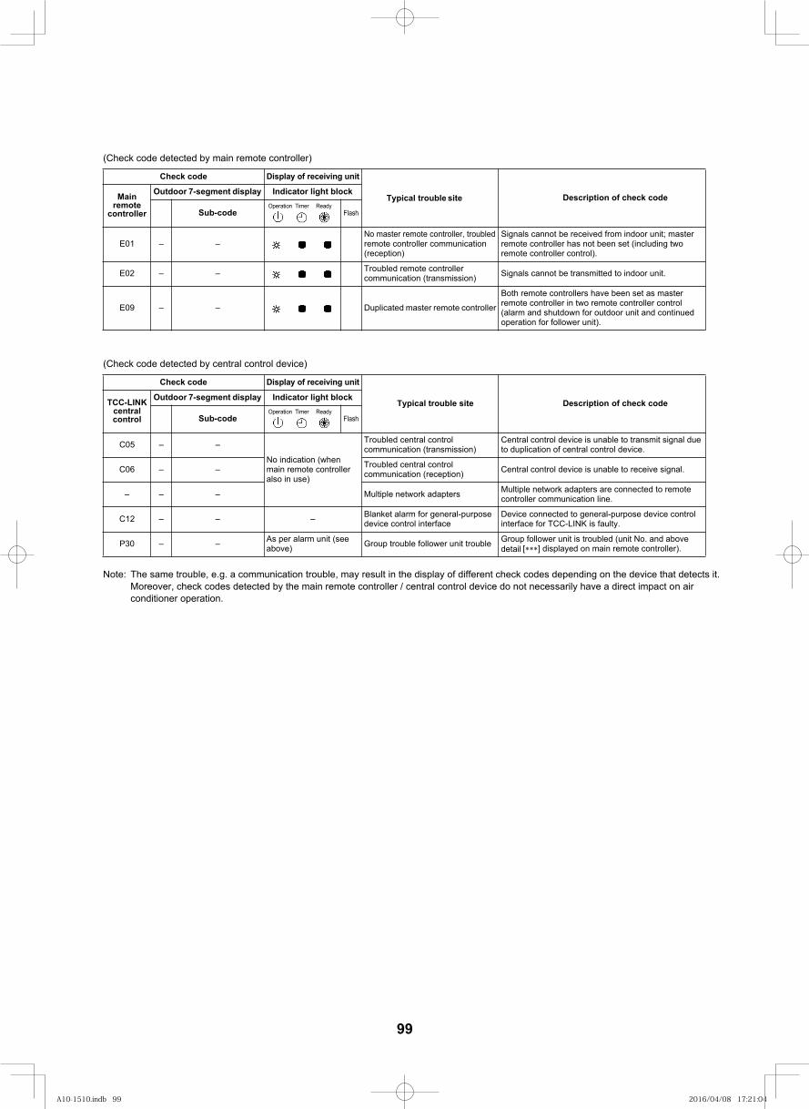
110
(Check code detected by main remote controller)
(Check code detected by central control device)
Note: The same trouble, e.g. a communication trouble, may result in the display of different check codes depending on the device that detects it. Moreover, check codes detected by the main remote controller / central control device do not necessarily have a direct impact on air conditioner operation.
Check code Display of receiving unit
check code fo noitpircseDsite trouble TypicalMain remote
controller
Outdoor 7-segment display Indicator light block
Sub-code Flash
E01 – –No master remote controller, troubled remote controller communication (reception)
Signals cannot be received from indoor unit; master remote controller has not been set (including two remote controller control).
E02 – – Troubled remote controller communication (transmission) Signals cannot be transmitted to indoor unit.
rellortnoc etomer retsam detacilpuD––90E
Both remote controllers have been set as master remote controller in two remote controller control (alarm and shutdown for outdoor unit and continued operation for follower unit).
Check code Display of receiving unit
check code of Description Typical trouble siteTCC-LINK central control
Outdoor 7-segment display Indicator light block
Sub-code Flash
C05 – –
No indication (when main remote controller also in use)
Troubled central control communication (transmission)
Central control device is unable to transmit signal due to duplication of central control device.
C06 – – Troubled central control communication (reception) Central control device is unable to receive signal.
sretpada krowten elpitluM––– Multiple network adapters are connected to remote controller communication line.
–––21C Blanket alarm for general-purpose device control interface
Device connected to general-purpose device control interface for TCC-LINK is faulty.
P30 – – As per alarm unit (see above) Group trouble follower unit trouble Group follower unit is troubled (unit No. and above
detail [ ] displayed on main remote controller).
Operation Timer Ready
Operation Timer Ready
99
A10-1510.indb 99A10-1510.indb 99 2016/04/08 17:21:042016/04/08 17:21:04
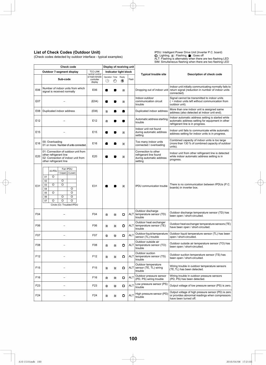
List of Check Codes (Outdoor Unit)(Check codes detected by outdoor interface - typical examples)
Check code Display of receiving unit
Typical trouble site Description of check codeOutdoor 7-segment display TCC-LINK
central control or main remote
controller display
Indicator light block
Sub-code Flash
E06 Number of indoor units from which signal is received normally tinu roodni fo tuo gnipporD60E
Indoor unit initially communicating normally fails to return signal (reduction in number of indoor units connected).
E07 – (E04)Indoor-outdoor communication circuit trouble
Signal cannot be transmitted to indoor units ( indoor units left without communication from outdoor unit).
E08 Duplicated indoor address (E08) Duplicated indoor address More than one indoor unit is assigned same address (also detected at indoor unit end).
E12 – E12 Automatic address starting trouble
Indoor automatic address setting is started while automatic address setting for equipment in other refrigerant line is in progress.
E15 – E15Indoor unit not found during automatic address setting
Indoor unit fails to communicate while automatic address setting for indoor units is in progress.
E16 00: Overloading01 or more: Number of units connected. E16 Too many indoor units
connected / overloading
Combined capacity of indoor units is too large (more than 130 % of combined capacity of outdoor units).
E20
01: Connection of outdoor unit from other refrigerant line02: Connection of indoor unit from other refrigerant line
E20
Connection to other refrigerant line found during automatic address setting
Indoor unit from other refrigerant line is detected while indoor automatic address setting is in progress.
TLA40F–40FOutdoor discharge temperature sensor (TD) trouble
Outdoor discharge temperature sensor (TD) has been open / short-circuited.
TLA60F–60FOutdoor heat exchanger temperature sensor (TE) trouble
Outdoor heat exchanger temperature sensors (TE) have been open / short-circuited.
TLA70F–70F Outdoor liquid temperature sensor (TL) trouble
Outdoor liquid temperature sensor (TL) has been open / short-circuited.
TLA80F–80FOutdoor outside air temperature sensor (TO) trouble
Outdoor outside air temperature sensor (TO) has been open / short-circuited.
TLA21F–21FOutdoor suction temperature sensor (TS) trouble
Outdoor suction temperature sensor (TS) has been open / short-circuited.
TLA51F–51FOutdoor temperature sensor (TE, TL) wiring trouble
Wiring trouble in outdoor temperature sensors TL) has been detected.
TLA61F–61F Outdoor pressure sensor (PD, PS) wiring trouble
Wiring trouble in outdoor pressure sensors (PD, PS) has been detected.
TLA32F–32F Low pressure sensor (PS)trouble Output voltage of low pressure sensor (PS) is zero.
TLA42F–42F High pressure sensor (PD)trouble
Output voltage of high pressure sensor (PD) is zero or provides abnormal readings when compressors have been turned off.
IPDU: Intelligent Power Drive Unit (Inverter P.C. board): Lighting, : Flashing, : Goes off
ALT: Flashing is alternately when there are two flashing LEDSIM: Simultaneous flashing when there are two flashing LED
Operation Timer Ready
A3-IPDUFan IPDU
0102
03
0405
06
07Circle (O): Troubled IPDUO
O
O
O
OO
OO
1 (Upper) 2 (Lower)
OOOO
111
IPDU communication trouble13E13E There is no communication between IPDUs (P.C. boards) in inverter box.
(TE,
100
A10-1510.indb 100A10-1510.indb 100 2016/04/08 17:21:052016/04/08 17:21:05
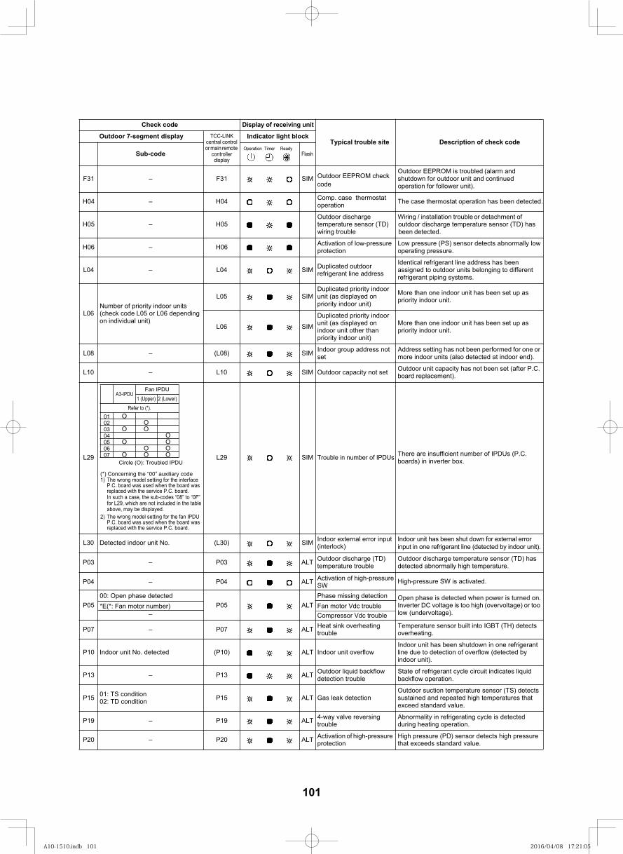
112
H06 – H06 Activation of low-pressure protection
Low pressure (PS) sensor detects abnormally lowoperating pressure.
MIS40L–40L Duplicated outdoor refrigerant line address
Identical refrigerant line address has been assigned to outdoor units belonging to different refrigerant piping systems.
L06Number of priority indoor units(check code L05 or L06 depending on individual unit)
MIS50LDuplicated priority indoor unit (as displayed on priority indoor unit)
More than one indoor unit has been set up as priority indoor unit.
MIS60L
Duplicated priority indoor unit (as displayed on indoor unit other than priority indoor unit)
More than one indoor unit has been set up as priority indoor unit.
MIS)80L(–80L Indoor group address not set
Address setting has not been performed for one or more indoor units (also detected at indoor end).
tes ton yticapac roodtuOMIS01L–01L Outdoor unit capacity has not been set (after P.C. board replacement).
MIS)03L(.oN tinu roodni detceteD03L Indoor external error input (interlock)
Indoor unit has been shut down for external error input in one refrigerant line (detected by indoor unit).
TLA30P–30P Outdoor discharge (TD) temperature trouble
Outdoor discharge temperature sensor (TD) has detected abnormally high temperature.
P0500: Open phase detected
TLA50PPhase missing detection Open phase is detected when power is turned on.
Inverter DC voltage is too high (overvoltage) or too low (undervoltage).–
Fan motor Vdc troubleCompressor Vdc trouble
TLA70P–70P Heat sink overheating trouble
Temperature sensor built into IGBT (TH) detects overheating.
wolfrevo tinu roodnITLA)01P(detceted .oN tinu roodnI01PIndoor unit has been shutdown in one refrigerant line due to detection of overflow (detected by indoor unit).
TLA31P–31P Outdoor liquid backflow detection trouble
State of refrigerant cycle circuit indicates liquid backflow operation.
P15 01: TS condition02: TD condition noitceted kael saGTLA51P
Outdoor suction temperature sensor (TS) detects sustained and repeated high temperatures that exceed standard value.
TLA91P–91P 4-way valve reversing trouble
Abnormality in refrigerating cycle is detected during heating operation.
TLA02P–02P Activation of high-pressure protection
High pressure (PD) sensor detects high pressure that exceeds standard value.
Check code Display of receiving unit
Typical trouble site Description of check codeOutdoor 7-segment display TCC-LINK
central control or main remote
controller display
Indicator light block
Sub-code Flash
*E(*: Fan motor number)
Operation Timer Ready
A3-IPDUFan IPDU
01020304050607
Circle (O): Troubled IPDUO
O
O
O
OO
OO
1 (Upper) 2 (Lower)
OOOO
check MORPEE roodtuOMIS13F–13FOutdoor EEPROM is troubled (alarm and shutdown for outdoor unit and continued
follower unit).
H04 – H04 Comp. case thermostat operation The case thermostat operation has been detected.
H05 – H05Outdoor discharge temperature sensor (TD) wiring trouble
Wiring / installation trouble or detachment of discharge temperature sensor (TD) has
detected.
Trouble in number of IPDUs MIS92L92L There are insufficient number of IPDUs (P.C. boards) in inverter box.
Refer to (*).
(*) Concerning the “00” auxiliary code1) The wrong model setting for the interface P.C. board was used when the board was
replaced with the service P.C. board.
2) The wrong model setting for the fan IPDU P.C. board was used when the board was replaced with the service P.C. board.
TLA40P–40P High-pressure SW is activated.Activation of high-pressureSW
In such a case, the sub-codes “08” to “0F” for L29, which are not included in the table above, may be displayed.
foroperation
outdoor been
code
101
A10-1510.indb 101A10-1510.indb 101 2016/04/08 17:21:052016/04/08 17:21:05
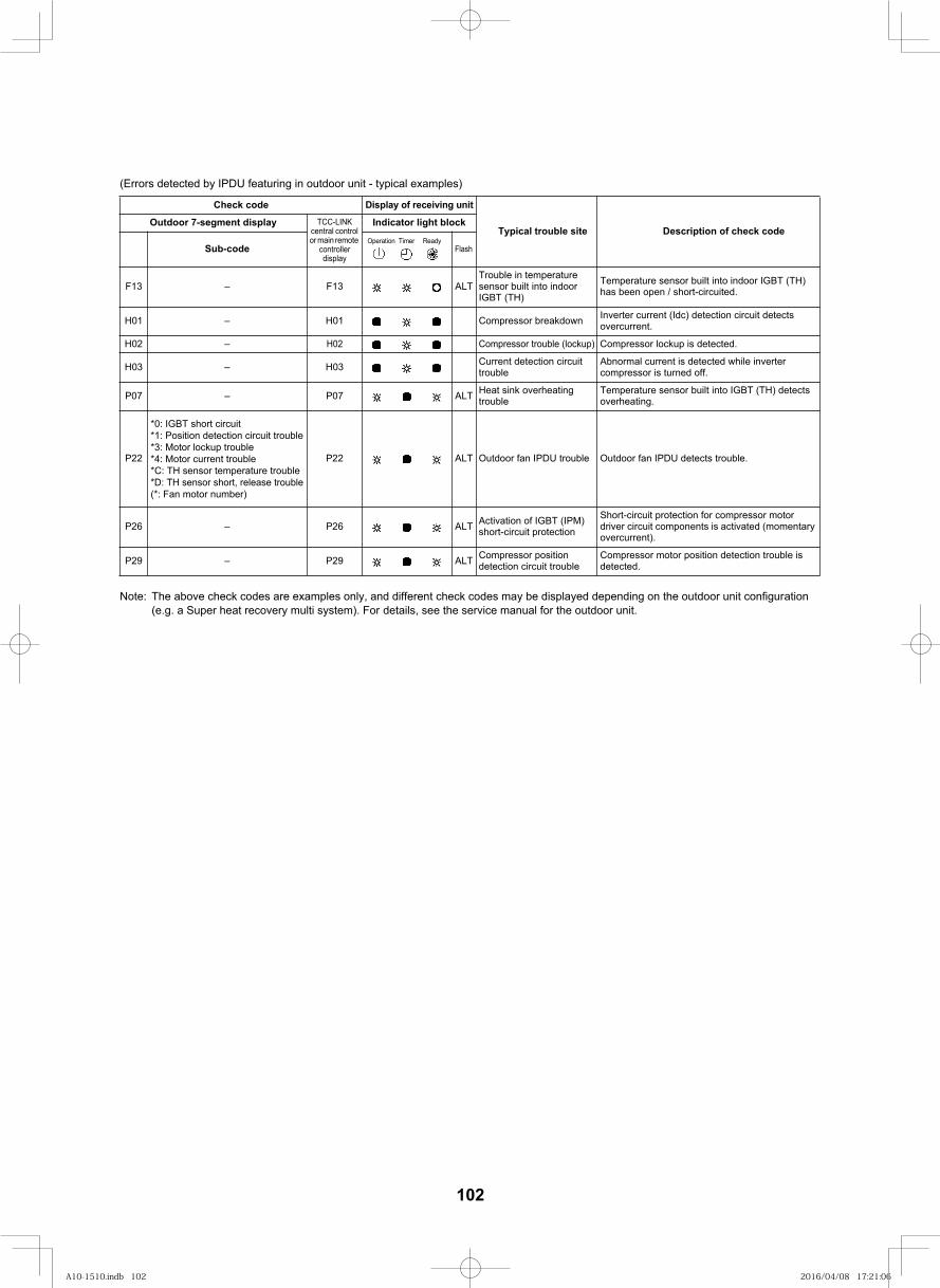
113
(Errors detected by IPDU featuring in outdoor unit - typical examples)
Note: The above check codes are examples only, and different check codes may be displayed depending on the outdoor unit configuration(e.g. a Super heat recovery multi system). For details, see the service manual for the outdoor unit.
Check code Display of receiving unit
Typical trouble site Description of check codeOutdoor 7-segment display TCC-LINK
central control or main remote
controller display
Indicator light block
Sub-code Flash
TLA31F–31FTrouble in temperaturesensor built into indoor IGBT (TH)
Temperature sensor built into indoor IGBT (TH) has been open / short-circuited.
nwodkaerb rosserpmoC10H–10H Inverter current (Idc) detection circuit detects overcurrent.
H02 – H02 Compressor trouble (lockup) Compressor lockup is detected.
H03 – H03 Current detection circuit trouble
Abnormal current is detected while inverter compressor is turned off.
TLA70P–70P Heat sink overheating trouble
Temperature sensor built into IGBT (TH) detects overheating.
P22
*0: IGBT short circuit*1: Position detection circuit trouble*3: Motor lockup trouble*4: Motor current trouble*C: TH sensor temperature trouble*D: TH sensor short, release trouble(*: Fan motor number)
trouble. stceted UDPI naf roodtuOtrouble UDPI naf roodtuOTLA22P
TLA62P–62P Activation of IGBT (IPM) short-circuit protection
Short-circuit protection for compressor motor driver circuit components is activated (momentary overcurrent).
TLA92P–92P Compressor position detection circuit trouble
Compressor motor position detection trouble is detected.
Operation Timer Ready
102
A10-1510.indb 102A10-1510.indb 102 2016/04/08 17:21:062016/04/08 17:21:06
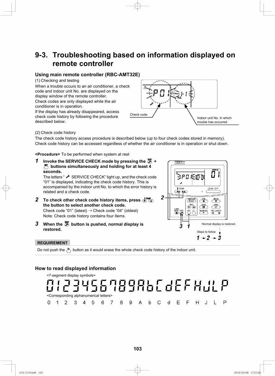
114
9-3. Troubleshooting based on information displayed on remote controller
Using main remote controller (RBC-AMT32E)(1) Checking and testingWhen a trouble occurs to an air conditioner, a check code and indoor unit No. are displayed on the display window of the remote controller.Check codes are only displayed while the air conditioner is in operation.If the display has already disappeared, access check code history by following the procedure described below.
(2) Check code historyThe check code history access procedure is described below (up to four check codes stored in memory). Check code history can be accessed regardless of whether the air conditioner is in operation or shut down.
<Procedure> To be performed when system at rest
1 Invoke the SERVICE CHECK mode by pressing the + buttons simultaneously and holding for at least 4
seconds.The letters “ SERVICE CHECK” light up, and the check code “01” is displayed, indicating the check code history. This is accompanied by the indoor unit No. to which the error history is related and a check code.
2 To check other check code history items, press the button to select another check code.Check code “01” (latest) Check code “04” (oldest)Note: Check code history contains four items.
3 When the button is pushed, normal display is restored.
REQUIREMENTDo not push the button as it would erase the whole check code history of the indoor unit.
How to read displayed information
Check codeIndoor unit No. in which trouble has occurred
Normal display is restored.
Steps to follow
<7-segment display symbols>
<Corresponding alphanumerical letters>
103
A10-1510.indb 103A10-1510.indb 103 2016/04/08 17:21:062016/04/08 17:21:06
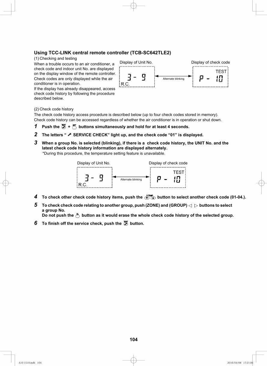
115
Using TCC-LINK central remote controller (TCB-SC642TLE2)(1) Checking and testingWhen a trouble occurs to an air conditioner, a check code and indoor unit No. are displayed on the display window of the remote controller.Check codes are only displayed while the air conditioner is in operation.If the display has already disappeared, access check code history by following the procedure described below.
(2) Check code historyThe check code history access procedure is described below (up to four check codes stored in memory). Check code history can be accessed regardless of whether the air conditioner is in operation or shut down.
1 Push the + buttons simultaneously and hold for at least 4 seconds.
2 The letters “ SERVICE CHECK” light up, and the check code “01” is displayed.
3 When a group No. is selected (blinking), if there is a check code history, the UNIT No. and the latest check code history information are displayed alternately.*During this procedure, the temperature setting feature is unavailable.
4 To check other check code history items, push the button to select another check code (01-04.).
5 To check check code relating to another group, push (ZONE) and (GROUP) buttons to select a group No.Do not push the button as it would erase the whole check code history of the selected group.
6 To finish off the service check, push the button.
Display of Unit No. Display of check code
Alternate blinking
Display of Unit No. Display of check code
Alternate blinking
104
A10-1510.indb 104A10-1510.indb 104 2016/04/08 17:21:062016/04/08 17:21:06
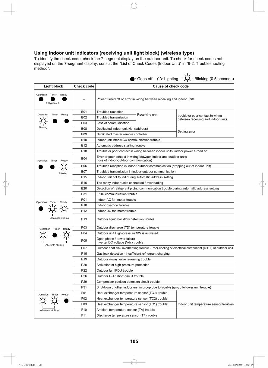
116
Using indoor unit indicators (receiving unit light block) (wireless type)To identify the check code, check the 7-segment display on the outdoor unit. To check for check codes not displayed on the 7-segment display, consult the “List of Check Codes (Indoor Unit)” in “9-2. Troubleshooting method”.
: Goes off : Lighting : Blinking (0.5 seconds)
check code fo esuaCedoc kcehCkcolb thgiL
– Power turned off or error in wiring between receiving and indoor units
E01 Troubled receptionReceiving unit trouble or poor contact in wiring
between receiving and indoor unitsE02 Troubled transmission
E03 Loss of communication
E08 Duplicated indoor unit No. (address)Setting error
E09 Duplicated master remote controller
E10 Indoor unit inter-MCU communication trouble
E12 Automatic address starting trouble
E18 Trouble or poor contact in wiring between indoor units, indoor power turned off
E04 Error or poor contact in wiring between indoor and outdoor units(loss of indoor-outdoor communication)
E06 Troubled reception in indoor-outdoor communication (dropping out of indoor unit)
E07 Troubled transmission in indoor-outdoor communication
E15 Indoor unit not found during automatic address setting
E16 Too many indoor units connected / overloading
E20 Detection of refrigerant piping communication trouble during automatic address setting
E31 IPDU communication trouble
P01 Indoor AC fan motor trouble
P10 Indoor overflow trouble
P12 Indoor DC fan motor trouble
P13 Outdoor liquid backflow detection trouble
P03 Outdoor discharge (TD) temperature trouble
P05 Open phase / power failureInverter DC voltage (Vdc) trouble
P07 Outdoor heat sink overheating trouble - Poor cooling of electrical component (IGBT) of outdoor unit
P15 Gas leak detection - insufficient refrigerant charging
P19 Outdoor 4-way valve reversing trouble
P20 Activation of high-pressure protection
P22 Outdoor fan IPDU trouble
P26 Outdoor G-Tr short-circuit trouble
P29 Compressor position detection circuit trouble
P31 Shutdown of other indoor unit in group due to trouble (group follower unit trouble)
F01 Heat exchanger temperature sensor (TCJ) trouble
Indoor unit temperature sensor troubles
F02 Heat exchanger temperature sensor (TC2) trouble
F03 Heat exchanger temperature sensor (TC1) trouble
F10 Ambient temperature sensor (TA) trouble
F11 Discharge temperature sensor (TF) trouble
Operation Timer Ready
All lights out
Operation Timer Ready
Blinking
Operation Timer Ready
Blinking
Operation Timer Ready
Alternate blinking
Operation Timer Ready
Alternate blinking
Operation Timer Ready
Alternate blinking
P04 Outdoor unit High-pressure SW is activated.
105
A10-1510.indb 105A10-1510.indb 105 2016/04/08 17:21:072016/04/08 17:21:07
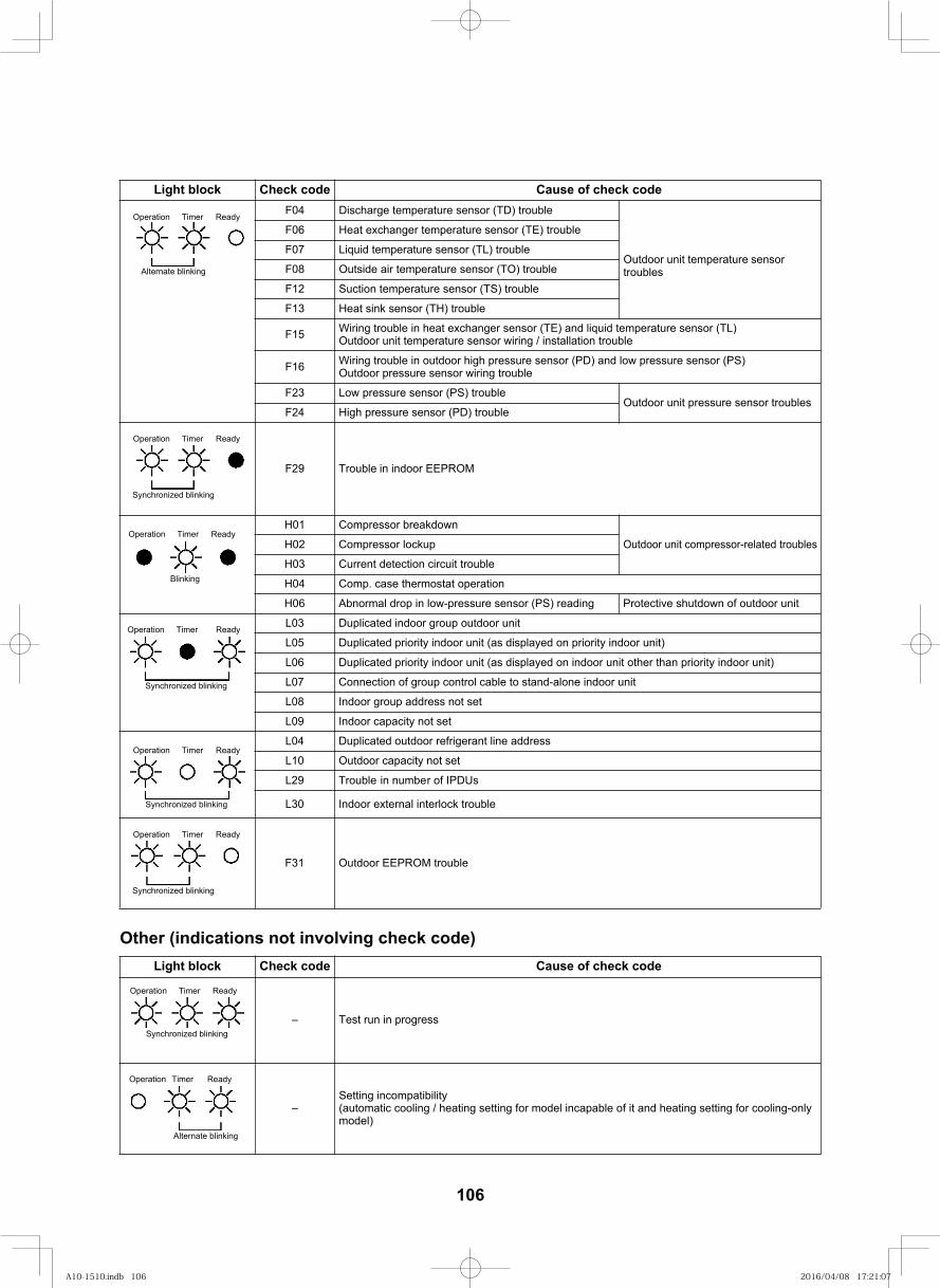
117
Other (indications not involving check code)
F04 Discharge temperature sensor (TD) trouble
Outdoor unit temperature sensor troubles
F06 Heat exchanger temperature sensor (TE) trouble
F07 Liquid temperature sensor (TL) trouble
F08 Outside air temperature sensor (TO) trouble
F12 Suction temperature sensor (TS) trouble
F13 Heat sink sensor (TH) trouble
F15 Wiring trouble in heat exchanger sensor (TE) and liquid temperature sensor (TL) Outdoor unit temperature sensor wiring / installation trouble
F16 Wiring trouble in outdoor high pressure sensor (PD) and low pressure sensor (PS)Outdoor pressure sensor wiring trouble
F23 Low pressure sensor (PS) troubleOutdoor unit pressure sensor troubles
F24 High pressure sensor (PD) trouble
F29 Trouble in indoor EEPROM
H01 Compressor breakdown
Outdoor unit compressor-related troublesH02 Compressor lockup
H03 Current detection circuit trouble
H04 Comp. case thermostat operation
H06 Abnormal drop in low-pressure sensor (PS) reading Protective shutdown of outdoor unit
L03 Duplicated indoor group outdoor unit
L05 Duplicated priority indoor unit (as displayed on priority indoor unit)
L06 Duplicated priority indoor unit (as displayed on indoor unit other than priority indoor unit)
L07 Connection of group control cable to stand-alone indoor unit
L08 Indoor group address not set
L09 Indoor capacity not set
L04 Duplicated outdoor refrigerant line address
L10 Outdoor capacity not set
L29 Trouble in number of IPDUs
L30 Indoor external interlock trouble
F31 Outdoor EEPROM trouble
check code fo esuaCedoc kcehCkcolb thgiL
– Test run in progress
–Setting incompatibility(automatic cooling / heating setting for model incapable of it and heating setting for cooling-only model)
check code fo esuaCedoc kcehCkcolb thgiL
Operation Timer Ready
Alternate blinking
Operation Timer Ready
Synchronized blinking
Operation Timer Ready
Blinking
Operation Timer Ready
Synchronized blinking
Operation Timer Ready
Synchronized blinking
Operation Timer Ready
Synchronized blinking
Operation Timer Ready
Synchronized blinking
Operation Timer Ready
Alternate blinking
106
A10-1510.indb 106A10-1510.indb 106 2016/04/08 17:21:072016/04/08 17:21:07
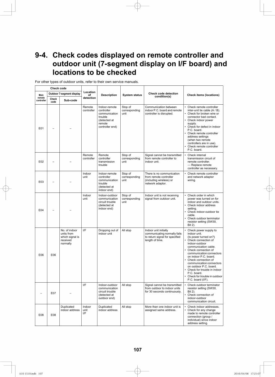
118
9-4. Check codes displayed on remote controller and outdoor unit (7-segment display on I/F board) and locations to be checked
For other types of outdoor units, refer to their own service manuals.
Locationof
detectionDescription System status Check code detection
condition(s) Check items (locations)Main remote
controller
Outdoor 7-segment display
Checkcode Sub-code
E01 – –
Remotecontroller
Indoor-remote controller communication trouble(detected at remote controller end)
Stop of corresponding unit
Communication between indoor P.C. board and remote controller is disrupted.
Check remote controller inter-unit tie cable (A / B).Check for broken wire or connector bad contact.Check indoor power supply.Check for defect in indoor P.C. board.Check remote controller address settings(when two remote controllers are in use).Check remote controller P.C. board.
E02 – –
Remotecontroller
Remote controller transmission trouble
Stop of corresponding unit
Signal cannot be transmitted from remote controller to indoor unit.
Check internal transmission circuit of remote controller.--- Replace remote controller as necessary.
E03 – –
Indoor unit
Indoor-remote controller communication trouble(detected at indoor end)
Stop of corresponding unit
There is no communication from remote controller (including wireless) or network adaptor.
Check remote controller and network adaptor wiring.
E04 – –
Indoor unit
Indoor-outdoor communication circuit trouble(detected at indoor end)
Stop of corresponding unit
Indoor unit is not receiving signal from outdoor unit.
Check order in which power was turned on for indoor and outdoor units.Check indoor address setting.Check indoor-outdoor tie cable.Check outdoor terminator resistor setting (SW30, Bit 2).
E06 E06
No. of indoor units from which signal is receivednormally
I/F Dropping out of indoor unit
All stop Indoor unit initially communicating normally fails to return signal for specified length of time.
Check power supply to indoor unit.(Is power turned on?)Check connection of indoor-outdoor communication cable.Check connection of communication connectors on indoor P.C. board.Check connection of communication connectors on outdoor P.C. board.Check for trouble in indoor P.C. board.Check for trouble in outdoor P.C. board (I/F).
– E07 –
I/F Indoor-outdoor communication circuit trouble(detected at outdoor end)
All stop Signal cannot be transmitted from outdoor to indoor units for 30 seconds continuously.
Check outdoor terminator resistor setting (SW30, Bit 2).Check connection of indoor-outdoor communication circuit.
E08 E08
Duplicated indoor address
Indoor unitI/F
Duplicated indoor address
All stop More than one indoor unit is assigned same address.
Check indoor addresses.Check for any change made to remote controller connection (group / individual) since indoor address setting.
Check code
107
A10-1510.indb 107A10-1510.indb 107 2016/04/08 17:21:072016/04/08 17:21:07
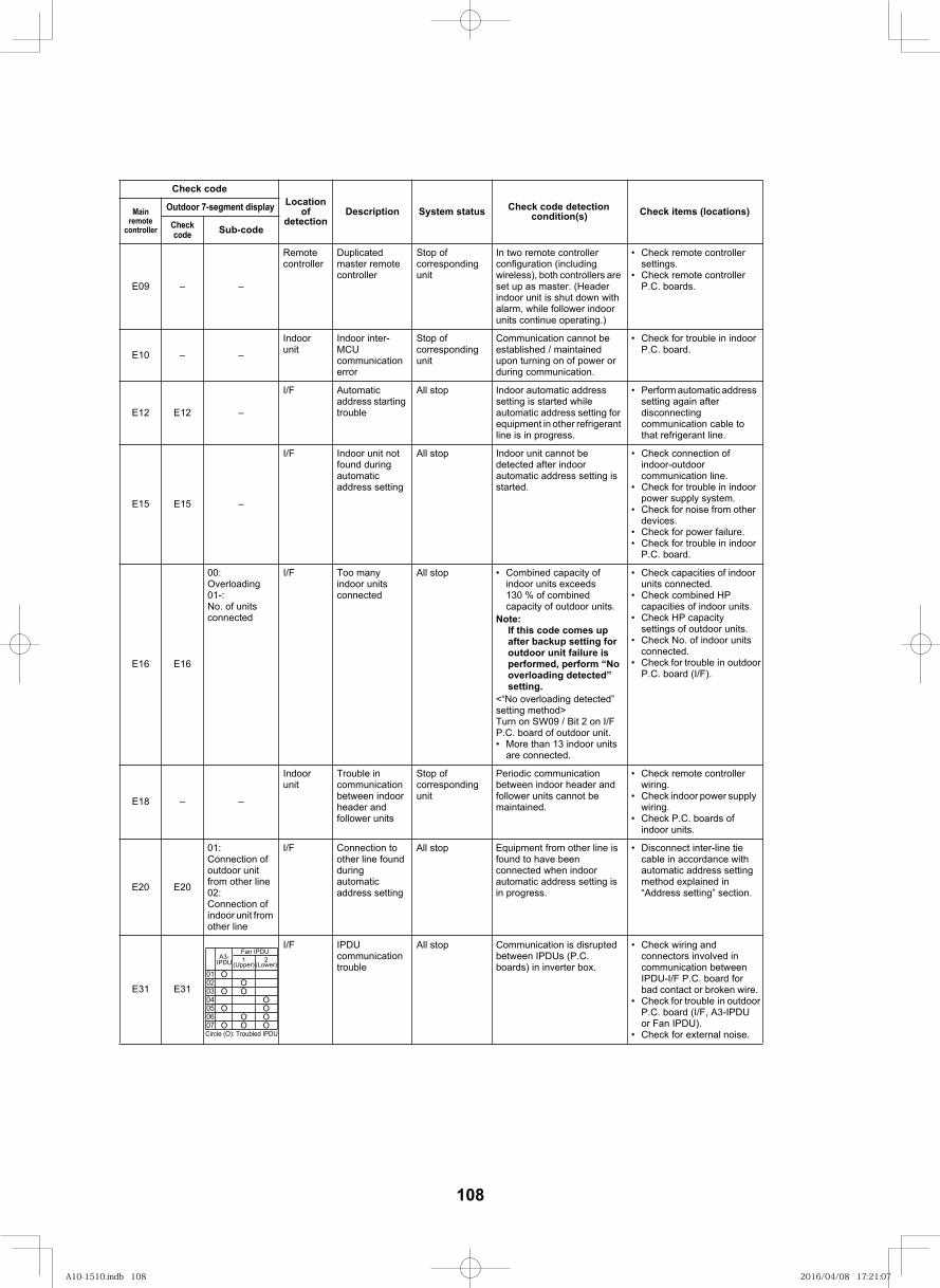
119
E09 – –
Remotecontroller
Duplicated master remote controller
Stop of corresponding unit
In two remote controller configuration (including wireless), both controllers are set up as master. (Header indoor unit is shut down with alarm, while follower indoor units continue operating.)
Check remote controller settings.Check remote controller P.C. boards.
E10 – –
Indoor unit
Indoor inter-MCUcommunication error
Stop of corresponding unit
Communication cannot be established / maintained upon turning on of power or during communication.
Check for trouble in indoorP.C. board.
E12 E12 –
I/F Automatic address starting trouble
All stop Indoor automatic address setting is started while automatic address setting for equipment in other refrigerant line is in progress.
Perform automatic address setting again after disconnecting communication cable to that refrigerant line.
E15 E15 –
I/F Indoor unit not found during automatic address setting
All stop Indoor unit cannot be detected after indoor automatic address setting is started.
Check connection of indoor-outdoor communication line.Check for trouble in indoor
power supply system.Check for noise from other devices.Check for power failure.Check for trouble in indoor P.C. board.
E16 E16
00: Overloading01-: No. of units connected
I/F Too many indoor units connected
All stop Combined capacity of indoor units exceeds 130 % of combined capacity of outdoor units.
Note: If this code comes up after backup setting for outdoor unit failure is performed, perform “No overloading detected” setting.
<“No overloading detected” setting method> Turn on SW09 / Bit 2 on I/F P.C. board of outdoor unit.
More than 13 indoor units are connected.
Check capacities of indoor units connected.Check combined HP capacities of indoor units.Check HP capacity settings of outdoor units.Check No. of indoor units connected.Check for trouble in outdoor
P.C. board (I/F).
E18 – –
Indoor unit
Trouble in communication between indoor header and follower units
Stop of corresponding unit
Periodic communication between indoor header and follower units cannot be maintained.
Check remote controller wiring.Check indoor power supply wiring.Check P.C. boards of indoor units.
E20 E20
01: Connection of outdoor unit from other line02: Connection of indoor unit from other line
I/F Connection to other line found during automatic address setting
All stop Equipment from other line is found to have been connected when indoor automatic address setting is in progress.
Disconnect inter-line tie cable in accordance with automatic address setting method explained in “Address setting” section.
13E13E
I/F IPDU communication trouble
All stop Communication is disrupted between IPDUs (P.C. boards) in inverter box.
Check wiring and connectors involved in communication between IPDU-I/F P.C. board for bad contact or broken wire.Check for trouble in outdoor P.C. board (I/F, A3-IPDU or Fan IPDU).Check for external noise.
Locationof
detectionDescription System status Check code detection
condition(s) Check items (locations)Main remote
controller
Outdoor 7-segment display
Checkcode Sub-code
O
Fan IPDU
02 O03 O O04 O05 O O06 O O07 O O O
Check code
01
1(Upper)
2(Lower)
A3-IPDU
Circle (O): Troubled IPDU
108
A10-1510.indb 108A10-1510.indb 108 2016/04/08 17:21:072016/04/08 17:21:07
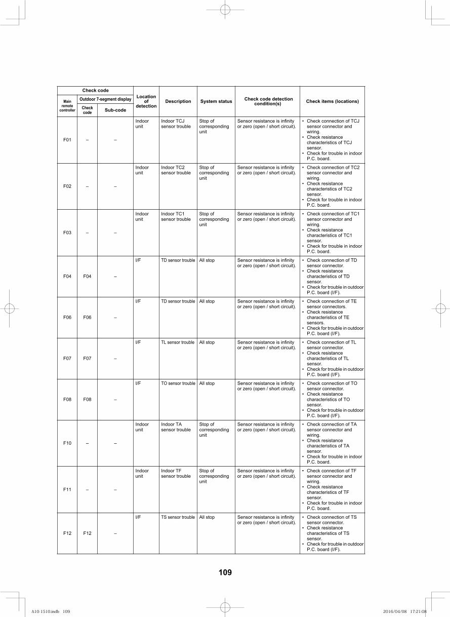
120
F01 – –
Indoor unit
Indoor TCJ sensor trouble
Stop of corresponding unit
Sensor resistance is infinity or zero (open / short circuit).
Check connection of TCJ sensor connector and wiring.Check resistance characteristics of TCJ sensor.Check for trouble in indoor P.C. board.
F02 – –
Indoor unit
Indoor TC2 sensor trouble
Stop of corresponding unit
Sensor resistance is infinity or zero (open / short circuit).
Check connection of TC2 sensor connector and wiring.Check resistance characteristics of TC2 sensor.Check for trouble in indoor P.C. board.
F03 – –
Indoor unit
Indoor TC1 sensor trouble
Stop of corresponding unit
Sensor resistance is infinity or zero (open / short circuit).
Check connection of TC1 sensor connector and wiring.Check resistance characteristics of TC1 sensor.Check for trouble in indoor P.C. board.
F04 F04 –
I/F TD sensor trouble or zero (open / short circuit).
Check connection of TD sensor connector.Check resistance characteristics of TD sensor.Check for trouble in outdoor P.C. board (I/F).
F06 F06 –
or zero (open / short circuit). Check connection of TE sensor connectors.Check resistance characteristics of TE sensors.Check for trouble in outdoor P.C. board (I/F).
F07 F07 –
or zero (open / short circuit). Check connection of TL sensor connector.Check resistance characteristics of TL sensor.Check for trouble in outdoor P.C. board (I/F).
F08 F08 –
or zero (open / short circuit). Check connection of TO sensor connector.Check resistance characteristics of TO sensor.Check for trouble in outdoor P.C. board (I/F).
F10 – –
Indoor unit
Indoor TA sensor trouble
Stop of corresponding unit
Sensor resistance is infinity or zero (open / short circuit).
Check connection of TA sensor connector and wiring.Check resistance characteristics of TA sensor.Check for trouble in indoor P.C. board.
F11 – –
Indoor unit
Indoor TF sensor trouble
Stop of corresponding unit
Sensor resistance is infinity or zero (open / short circuit).
Check connection of TF sensor connector and wiring.Check resistance characteristics of TF sensor.Check for trouble in indoor P.C. board.
F12 F12 –
or zero (open / short circuit). Check connection of TS sensor connector.Check resistance characteristics of TS sensor.Check for trouble in outdoor P.C. board (I/F).
Locationof
detectionDescription System status Check code detection
condition(s) Check items (locations)Main remote
controller
Outdoor 7-segment display
Checkcode Sub-code
Check code
All stop Sensor resistance is infinity
I/F TD sensor trouble All stop Sensor resistance is infinity
I/F TL sensor trouble All stop Sensor resistance is infinity
I/F TO sensor trouble All stop Sensor resistance is infinity
I/F TS sensor trouble All stop Sensor resistance is infinity
109
A10-1510.indb 109A10-1510.indb 109 2016/04/08 17:21:082016/04/08 17:21:08
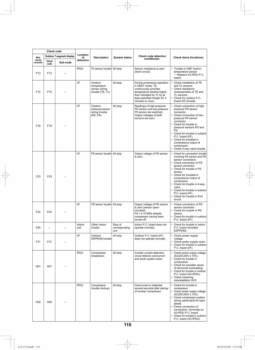
121
F13 F13 –
IPDU TH sensor trouble All stop Sensor resistance is zero (short circuit).
Trouble in IGBT built-in temperature sensor
Replace A3-IPDU P.C. board.
F15 F15 –
I/F Outdoor temperature sensor wiring trouble (TE, TL)
All stop During compressor operation in HEAT mode, TE continuously provides temperature reading higher than indicated by TL by at least specified margin for 3 minutes or more.
Check installation of TE and TL sensors.Check resistance characteristics of TE and TL sensors.Check for outdoor P.C. board (I/F) trouble.
F16 F16 –
I/F Outdoor pressure sensor wiring trouble
All stop Readings of high-pressure PD sensor and low-pressurePS sensor are switched.Output voltages of both sensors are zero.
Check connection of high-pressure PD sensor connector.Check connection of low-pressure PS sensor connector.Check for trouble in pressure sensors PD andPS.Check for trouble in outdoor P.C. board (I/F).Check for troubled in compressive output of compressor.
F23 F23 –
I/F PS sensor trouble All stop Output voltage of PS sensor is zero.
Check for connection trouble involving PS sensor and PDsensor connectors.Check connection of PS sensor connector.Check for trouble in PS sensor.Check for troubled in compressive output of compressor.Check for trouble in 4-way valve.Check for trouble in outdoorP.C. board (I/F).Check for trouble in SV4 circuit.
F24 F24 –
I/F PD sensor trouble All stop Output voltage of PD sensoris zero (sensor open-circuited). Pd > 4.15 MPa despite compressor having been turned off.
Check connection of PD sensor connector.Check for trouble in PD sensor.Check for trouble in outdoor P.C. board (I/F).
F29 – –Indoor unit
Other indoor trouble
Stop of corresponding unit
Indoor P.C. board does not operate normally.
Check for trouble in indoorP.C. board (troubledEEPROM)
F31 F31 –
I/F Outdoor EEPROM trouble
All stop Outdoor P.C. board (I/F) does not operate normally.
Check power supply voltage.Check power supply noise.Check for trouble in outdoorP.C. board (I/F).
IPDU Compressor breakdown
All stop Inverter current detection circuit detects overcurrent and shuts system down.
Check power supply voltage. (AC220-240V ± 10%).Check for trouble in compressor.Check for possible cause of abnormal overloading.Check for trouble in outdoorP.C. board (A3-IPDU).
H02 H02 –
IPDU Compressor trouble (lockup)
All stop Overcurrent is detected several seconds after startup of inverter compressor.
Check for trouble in compressor.Check power supply voltage.(AC220-240V ± 10%).Check compressor system wiring, particularly for open phase.Check connection of connectors / terminals on A3-IPDU P.C. board.Check for trouble in outdoorP.C. board (A3-IPDU).
Locationof
detectionDescription System status Check code detection
condition(s) Check items (locations)Main remote
controller
Outdoor 7-segment display
Checkcode Sub-code
Check code
Check 4-way valve trouble.
Check miswiring, misinstallation SV5.
H01 H01 –
(PD, PS)
110
A10-1510.indb 110A10-1510.indb 110 2016/04/08 17:21:082016/04/08 17:21:08
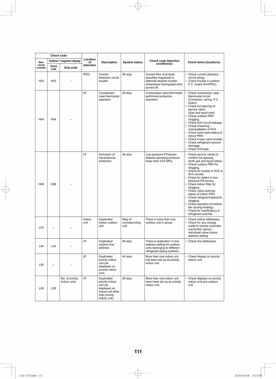
122
H03 H03 –
IPDU Current detection circuit trouble
All stop Current flow of at least specified magnitude is detected despite inverter compressor having been shut turned off.
Check current detection circuit wiring.Check trouble in outdoor P.C. board (A3-IPDU).
H04 H04 –
I/F Compressor case thermostat operation
All stop Compressor case thermostat performed protective operation.
Check compressor case thermostat circuit.(Connector, wiring, P.C. board)Check full opening of service valve. (Gas and liquid side)Check outdoor PMV clogging.Check SV4 circuit leakage.Check miswiring / misinstallation of SV4.Check valve open status of indoor PMV.Check 4-way valve trouble.Check refrigerant amount shortage.
H06 H06 –
I/F Activation of low-pressure protection
All stop Low-pressure PS sensor detects operating pressure lower than 0.02 MPa.
Check service valves to confirm full opening(both gas and liquid sides).Check outdoor PMV forclogging.Check for trouble in SV2 or SV4 circuits.Check for defect in low-pressure PS sensor.Check indoor filter for clogging.Check valve opening status of indoor PMV.Check refrigerant piping for clogging.Check operation of outdoor fan (during heating).Check for insufficiency in refrigerant quantity.
L03 – –
Indoor unit
Duplicated indoor outdoor unit
Stop of corresponding unit
There is more than one outdoor unit in group.
Check indoor addresses.Check for any change made to remote controller connection (group / individual) since indoor address setting.
L04 L04 –
I/F Duplicated outdoor line address
All stop There is duplication in line address setting for outdoor units belonging to different refrigerant piping systems.
Check line addresses.
L05 – –
I/F Duplicated priority indoor unit (as displayed on priority indoor unit)
All stop More than one indoor unit has been set up as priority indoor unit.
Check display on priority indoor unit.
L06 L06
No. of priority indoor units
I/F Duplicated priority indoor unit (as displayed on indoor unit other than priority indoor unit)
All stop More than one indoor unit have been set up as priority indoor unit.
Check displays on priority indoor unit and outdoor unit.
Locationof
detectionDescription System status Check code detection
condition(s) Check items (locations)Main remote
controller
Outdoor 7-segment display
Checkcode Sub-code
Check code
Check SV5 leak.
111
A10-1510.indb 111A10-1510.indb 111 2016/04/08 17:21:082016/04/08 17:21:08
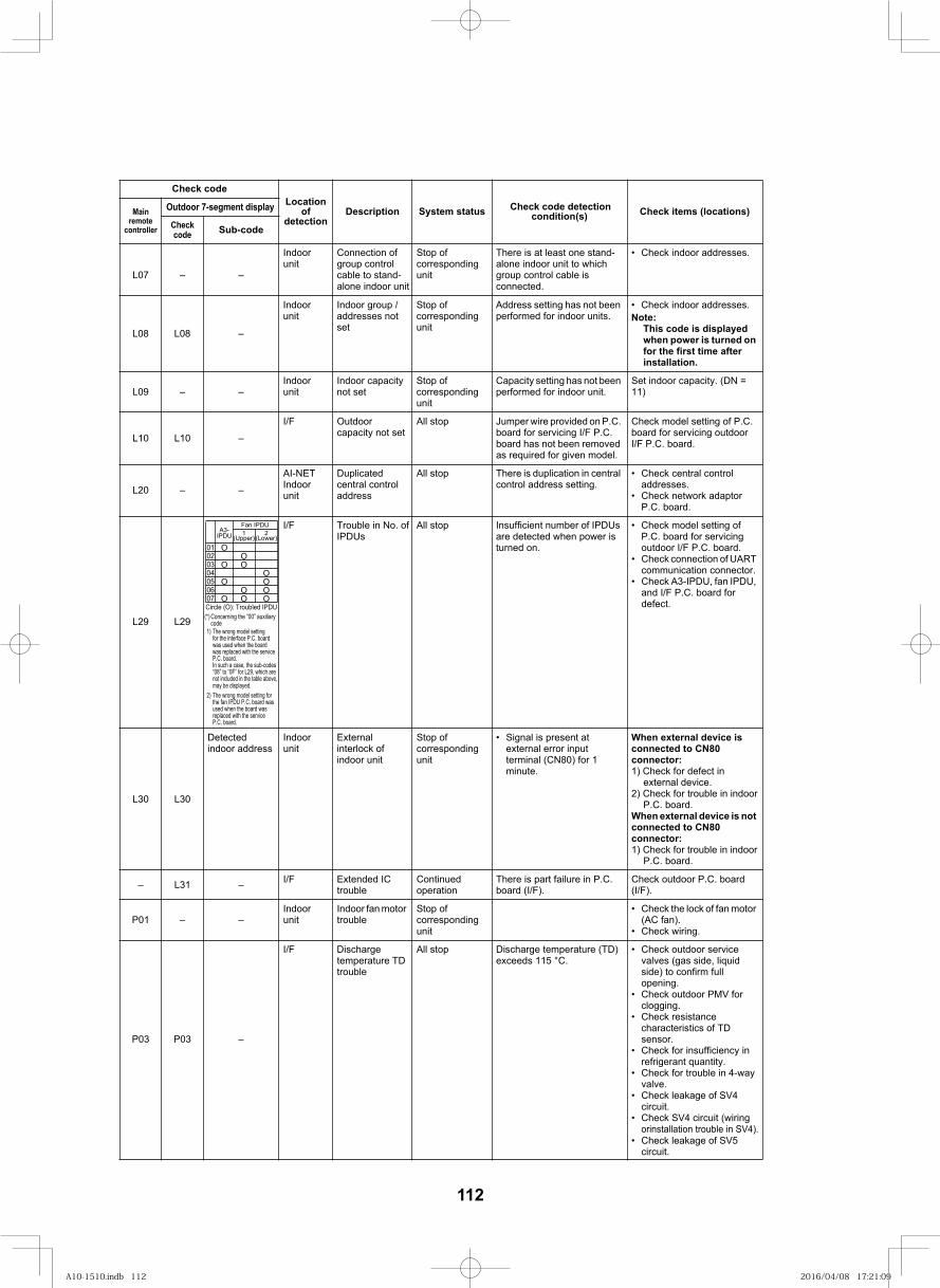
123
L07 – –
Indoor unit
Connection of group control cable to stand-alone indoor unit
Stop of corresponding unit
There is at least one stand-alone indoor unit to which group control cable is connected.
Check indoor addresses.
L08 L08 –
Indoor unit
Indoor group / addresses not set
Stop of corresponding unit
Address setting has not been performed for indoor units.
Check indoor addresses.Note:
This code is displayed when power is turned on for the first time after installation.
L09 – –Indoor unit
Indoor capacity not set
Stop of corresponding unit
Capacity setting has not been performed for indoor unit.
Set indoor capacity. (DN = 11)
L10 L10 –
I/F Outdoor capacity not set
All stop Jumper wire provided on P.C. board for servicing I/F P.C. board has not been removed as required for given model.
Check model setting of P.C. board for servicing outdoor I/F P.C. board.
L20 – –
AI-NETIndoor unit
Duplicated central control address
All stop There is duplication in central control address setting.
Check central control addresses.Check network adaptor P.C. board.
92L92L
I/F Trouble in No. of IPDUs
All stop Insufficient number of IPDUs are detected when power is turned on.
Check model setting of P.C. board for servicing outdoor I/F P.C. board.Check connection of UART communication connector.Check A3-IPDU, fan IPDU, and I/F P.C. board for defect.
L30 L30
Detected indoor address
Indoor unit
External interlock of indoor unit
Stop of corresponding unit
Signal is present at external error input terminal (CN80) for 1 minute.
When external device is connected to CN80 connector:1) Check for defect in
external device.2) Check for trouble in indoor
P.C. board.When external device is not connected to CN80 connector:1) Check for trouble in indoor
P.C. board.
– L31 – I/F Extended IC trouble
Continued operation
There is part failure in P.C. board (I/F).
Check outdoor P.C. board (I/F).
P01 – –Indoor unit
Indoor fan motor trouble
Stop of corresponding unit
Check the lock of fan motor (AC fan).Check wiring.
P03 P03 –
I/F Discharge temperature TD trouble
All stop Discharge temperature (TD) exceeds 115 °C.
Check outdoor service valves (gas side, liquid side) to confirm full opening.Check outdoor PMV forclogging.Check resistance characteristics of TD sensor.Check for insufficiency in refrigerant quantity.Check for trouble in 4-wayvalve.Check leakage of SV4circuit.Check SV4 circuit (wiring orinstallation trouble in SV4).
Locationof
detectionDescription System status Check code detection
condition(s) Check items (locations)Main remote
controller
Outdoor 7-segment display
Checkcode Sub-code
(*) Concerning the “00” auxiliary code1) The wrong model setting for the interface P.C. board was used when the board was replaced with the service P.C. board.
may be displayed.
In such a case, the sub-codes “08” to “0F” for L29, which are not included in the table above,
2) The wrong model setting for the fan IPDU P.C. board was used when the board was replaced with the service P.C. board.
Check code
O
Fan IPDU
02 O03 O O04 O05 O O06 O O07 O O O
01
1(Upper)
2(Lower)
A3-IPDU
Circle (O): Troubled IPDU
Check leakage of SV5 circuit.
112
A10-1510.indb 112A10-1510.indb 112 2016/04/08 17:21:092016/04/08 17:21:09
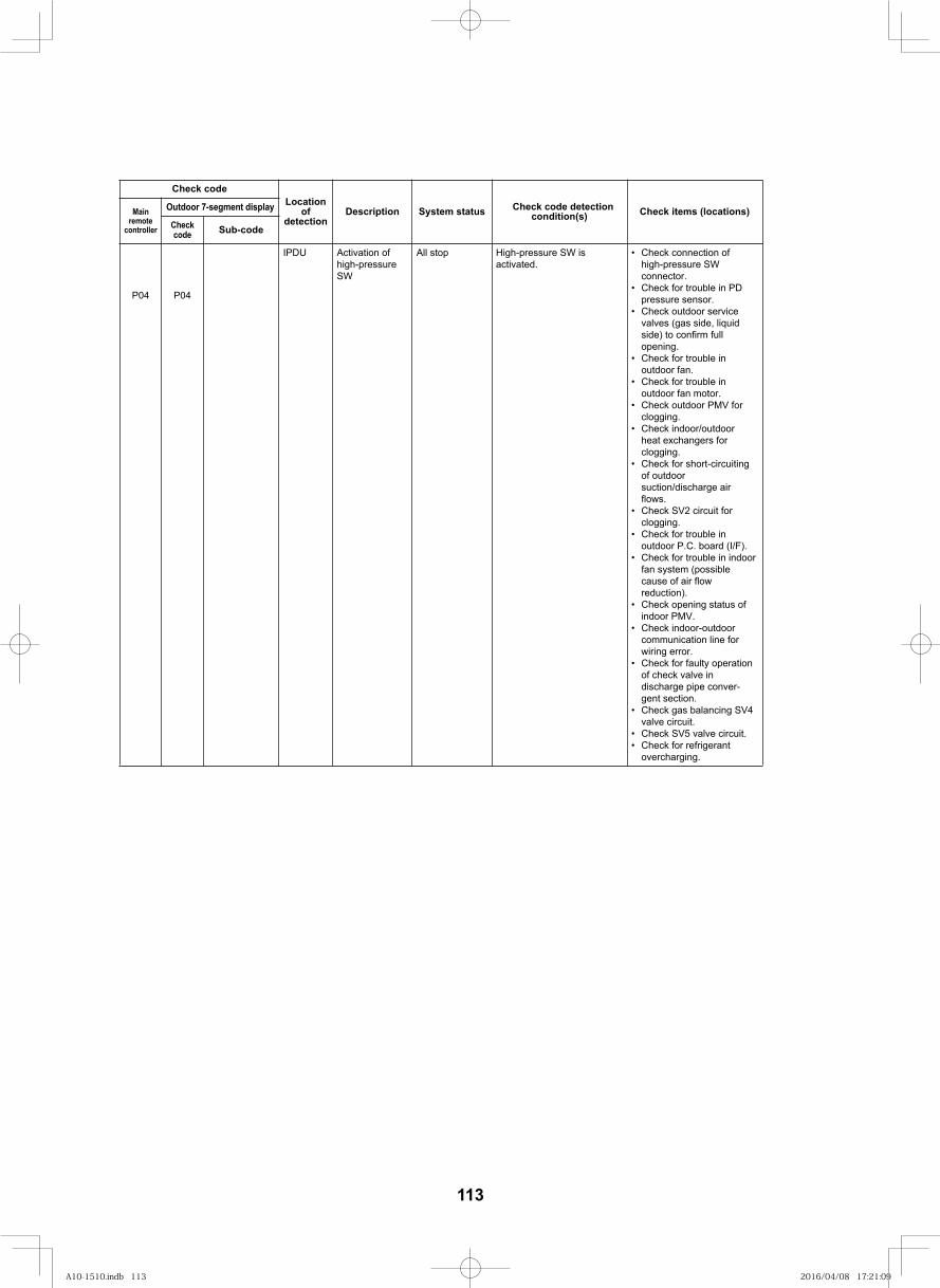
124
Locationof
detectionDescription System status Check code detection
condition(s) Check items (locations)Main remote
controller
Outdoor 7-segment display
Checkcode Sub-code
Check code
Check connection of high-pressure SW connector.
Check for trouble in PD pressure sensor.
Check outdoor service valves (gas side, liquid side) to confirm full opening.
Check for trouble in outdoor fan.
Check for trouble in outdoor fan motor.Check outdoor PMV for clogging.
Check indoor/outdoor heat exchangers for clogging.
Check for short-circuiting of outdoor suction/discharge air flows.
Check SV2 circuit for clogging.
Check for trouble in outdoor P.C. board (I/F).
Check for trouble in indoor fan system (possible cause of air flow reduction).
Check opening status of indoor PMV.
Check indoor-outdoor communication line for wiring error.
Check for faulty operation of check valve in discharge pipe conver-gent section.
Check gas balancing SV4 valve circuit.
Check SV5 valve circuit. Check for refrigerant
overcharging.
High-pressure SW is activated.
All stopActivation of high-pressure SW
IPDU
P04 P04
113
A10-1510.indb 113A10-1510.indb 113 2016/04/08 17:21:092016/04/08 17:21:09
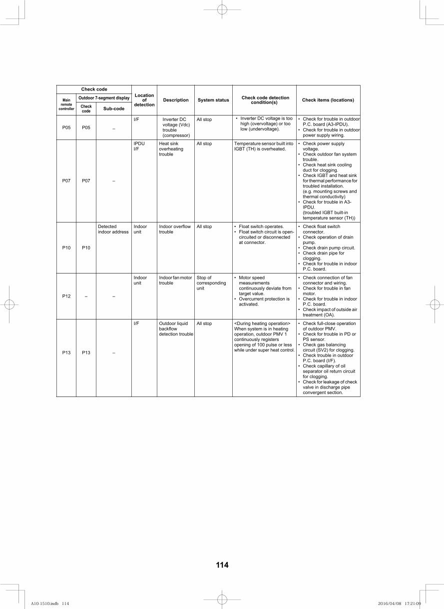
124
I/F
P07 P07 –
IPDUI/F
Heat sink overheating trouble
All stop Temperature sensor built into IGBT (TH) is overheated.
Check power supply voltage.Check outdoor fan system trouble.Check heat sink cooling duct for clogging.Check IGBT and heat sink for thermal performance for troubled installation.(e.g. mounting screws and thermal conductivity)Check for trouble in A3-IPDU.(troubled IGBT built-in temperature sensor (TH))
P10 P10
Detected indoor address
Indoor unit
Indoor overflow trouble
All stop Float switch operates.Float switch circuit is open-circuited or disconnected at connector.
Check float switch connector.Check operation of drain pump.Check drain pump circuit.Check drain pipe for clogging.Check for trouble in indoor P.C. board.
P12 – –
Indoor unit
Indoor fan motor trouble
Stop of corresponding unit
Motor speed measurements continuously deviate from target value.Overcurrent protection is activated.
Check connection of fan connector and wiring.Check for trouble in fan motor.Check for trouble in indoor P.C. board.Check impact of outside air treatment (OA).
P13 P13 –
I/F Outdoor liquid backflow detection trouble
All stop Check full-close operation of outdoor PMV.Check for trouble in PD or PS sensor.
Check trouble in outdoor P.C. board (I/F).Check capillary of oil separator oil return circuit for clogging.Check for leakage of check valve in discharge pipe convergent section.
Locationof
detectionDescription System status Check code detection
condition(s) Check items (locations)Main remote
controller
Outdoor 7-segment display
Checkcode Sub-code
Check gas balancing circuit (SV2) for clogging.
Check code
–
<During heating operation>When system is in heating operation, outdoor PMV 1 continuously registers opening of 100 pulse or less while under super heat control.
P05 P05
All stopInverter DC voltage (Vdc) trouble(compressor)
Inverter DC voltage is too high (overvoltage) or too low (undervoltage).
Check for trouble in outdoor P.C. board (A3-IPDU).Check for trouble in outdoor power supply wiring.
114
A10-1510.indb 114A10-1510.indb 114 2016/04/08 17:21:092016/04/08 17:21:09
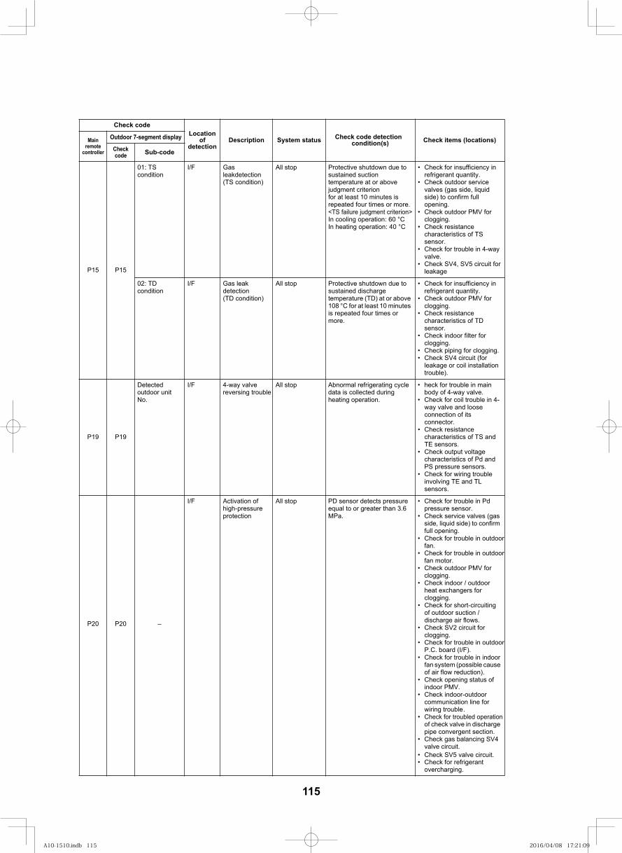
125
P15 P15
01: TS condition
I/F Gas leakdetection(TS condition)
All stop Protective shutdown due to sustained suction temperature at or above judgment criterionfor at least 10 minutes is repeated four times or more.<TS failure judgment criterion>In cooling operation: 60 °CIn heating operation: 40 °C
Check for insufficiency in refrigerant quantity.Check outdoor service valves (gas side, liquid side) to confirm full opening.Check outdoor PMV forclogging.Check resistance characteristics of TS sensor.Check for trouble in 4-wayvalve.Check SV4, SV5 circuit for leakage
02: TD condition
I/F Gas leak detection(TD condition)
All stop Protective shutdown due to sustained discharge temperature (TD) at or above 108 °C for at least 10 minutes is repeated four times or more.
Check for insufficiency in refrigerant quantity.Check outdoor PMV forclogging.Check resistance characteristics of TD sensor.Check indoor filter for clogging.Check piping for clogging.Check SV4 circuit (for leakage or coil installation trouble).
P19 P19
Detected outdoor unit No.
I/F 4-way valve reversing trouble
All stop Abnormal refrigerating cycle data is collected during heating operation.
heck for trouble in main body of 4-way valve.Check for coil trouble in 4-way valve and loose connection of its connector.Check resistance characteristics of TS and TE sensors.Check output voltage characteristics of Pd and PS pressure sensors.Check for wiring trouble involving TE and TL sensors.
P20 P20 –
I/F Activation of high-pressure protection
All stop PD sensor detects pressure equal to or greater than 3.6 MPa.
Check for trouble in Pd pressure sensor.Check service valves (gas side, liquid side) to confirm full opening.Check for trouble in outdoorfan.Check for trouble in outdoorfan motor.Check outdoor PMV forclogging.Check indoor / outdoor heat exchangers for clogging.
Check for trouble in outdoorP.C. board (I/F).Check for trouble in indoor fan system (possible cause of air flow reduction).Check opening status of indoor PMV.Check indoor-outdoor communication line for wiring trouble.Check for troubled operation of check valve in discharge pipe convergent section.
Check for refrigerant overcharging.
Locationof
detectionDescription System status Check code detection
condition(s) Check items (locations)Main remote
controller
Outdoor 7-segment display
Checkcode Sub-code
Check SV5 valve circuit.
Check gas balancing SV4 valve circuit.
Check for short-circuiting of outdoor suction / discharge air flows.Check SV2 circuit forclogging.
Check code
115
A10-1510.indb 115A10-1510.indb 115 2016/04/08 17:21:092016/04/08 17:21:09
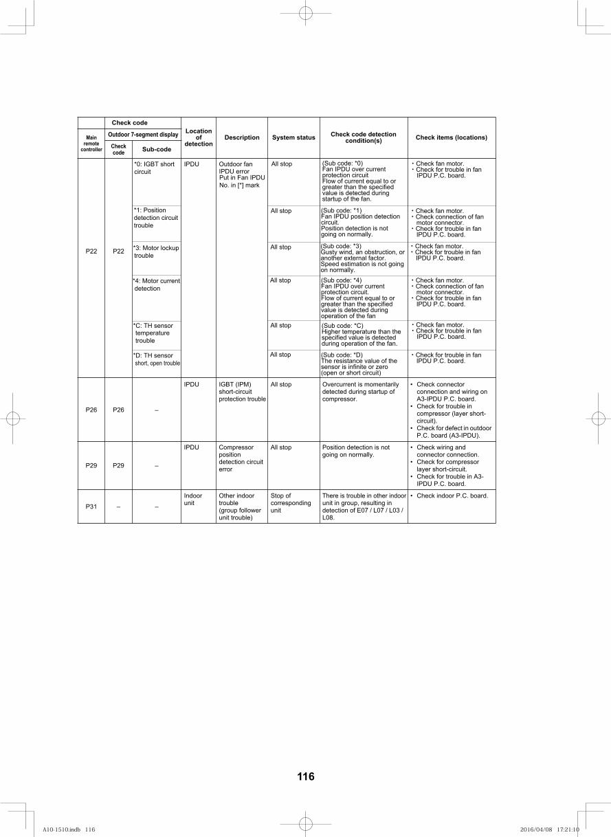
126
P22 P22
IPDU Outdoor fan IPDU error
P26 P26 –
IPDU IGBT (IPM) short-circuit protection trouble
All stop Overcurrent is momentarily detected during startup of compressor.
Check connector connection and wiring on A3-IPDU P.C. board.Check for trouble in compressor (layer short-circuit).Check for defect in outdoor P.C. board (A3-IPDU).
P29 P29 –
IPDU Compressor position detection circuit error
All stop Position detection is not going on normally.
Check wiring and connector connection.Check for compressor layer short-circuit.Check for trouble in A3-IPDU P.C. board.
P31 – –
Indoor unit
Other indoor trouble(group follower unit trouble)
Stop of corresponding unit
There is trouble in other indoor unit in group, resulting in detection of E07 / L07 / L03 / L08.
Check indoor P.C. board.
Locationof
detectionDescription System status Check code detection
condition(s) Check items (locations)Main remote
controller
Outdoor 7-segment display
Checkcode Sub-code
Put in Fan IPDU No. in [*] mark
All stop
All stop
All stop
All stop
All stop
All stop
*0: IGBT short circuit
*1: Position detection circuit trouble
*3: Motor lockup trouble
*4: Motor current detection
*C: TH sensor temperature trouble
*D: TH sensor short, open trouble
(Sub code: *0)Fan IPDU over current protection circuitFlow of current equal to or greater than the specified value is detected during startup of the fan.
(Sub code: *1)Fan IPDU position detection circuit.Position detection is not going on normally.
(Sub code: *3)Gusty wind, an obstruction, or another external factor.Speed estimation is not going on normally.(Sub code: *4)Fan IPDU over current protection circuit.Flow of current equal to or greater than the specified value is detected during operation of the fan(Sub code: *C)Higher temperature than the specified value is detected during operation of the fan.
(Sub code: *D)The resistance value of the sensor is infinite or zero (open or short circuit)
・Check fan motor.・Check for trouble in fan IPDU P.C. board.
・Check fan motor.・Check connection of fan motor connector.・Check for trouble in fan IPDU P.C. board.
・Check fan motor.・Check for trouble in fan IPDU P.C. board.
・Check fan motor.・Check connection of fan motor connector.・Check for trouble in fan IPDU P.C. board.
・Check fan motor.・Check for trouble in fan IPDU P.C. board.
・Check for trouble in fan IPDU P.C. board.
Check code
116
A10-1510.indb 116A10-1510.indb 116 2016/04/08 17:21:102016/04/08 17:21:10
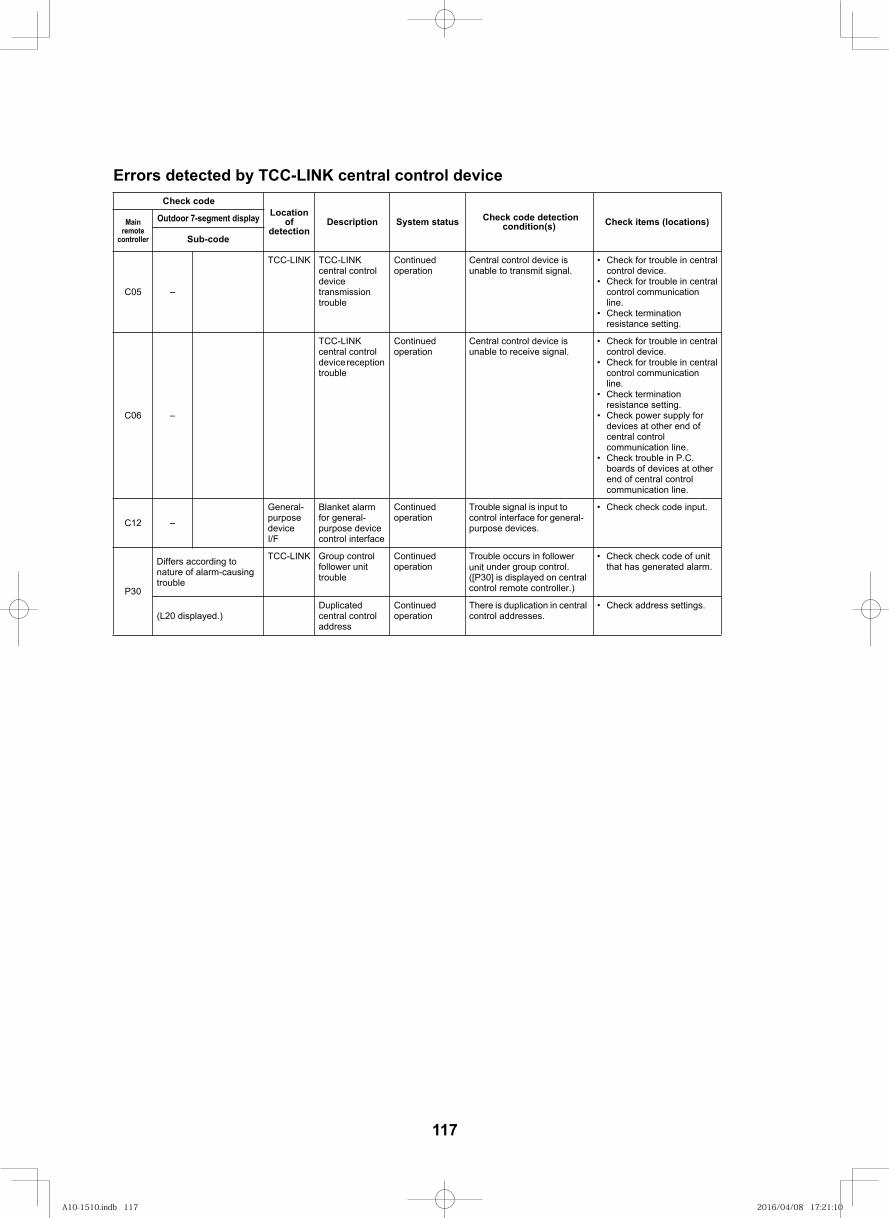
127
Errors detected by TCC-LINK central control device
Locationof
detectionDescription System status Check code detection
condition(s) Check items (locations)Main remote
controller
Outdoor 7-segment display
Sub-code
–50C
TCC-LINK TCC-LINK central control device transmission trouble
Continued operation
Central control device is unable to transmit signal.
Check for trouble in central control device.Check for trouble in central control communication line.Check termination resistance setting.
–60C
TCC-LINKcentral control device reception trouble
Continued operation
Central control device is unable to receive signal.
Check for trouble in central control device.Check for trouble in central control communication line.Check termination resistance setting.Check power supply for devices at other end of central control communication line.Check trouble in P.C. boards of devices at other end of central control communication line.
–21C
General-purpose deviceI/F
Blanket alarm for general-purpose device control interface
Continued operation
Trouble signal is input to control interface for general-purpose devices.
Check check code input.
P30
Differs according to nature of alarm-causing trouble
TCC-LINK Group control follower unit trouble
Continued operation
Trouble occurs in follower unit under group control.([P30] is displayed on central control remote controller.)
Check check code of unit that has generated alarm.
(L20 displayed.)Duplicated central control address
Continued operation
There is duplication in central control addresses.
Check address settings.
Check code
117
A10-1510.indb 117A10-1510.indb 117 2016/04/08 17:21:102016/04/08 17:21:10
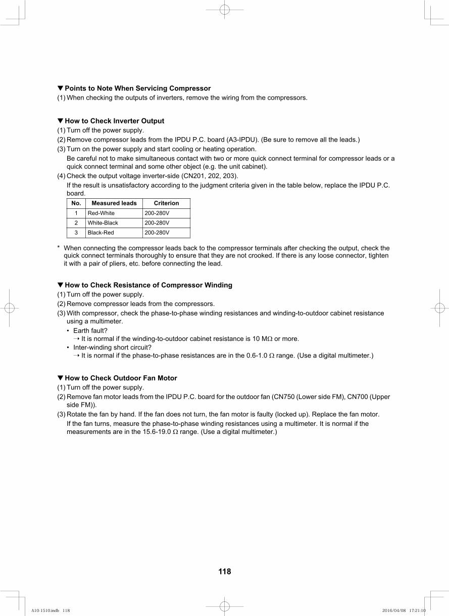
128
Points to Note When Servicing Compressor(1) When checking the outputs of inverters, remove the wiring from the compressors.
How to Check Inverter Output(1) Turn off the power supply.(2) Remove compressor leads from the IPDU P.C. board (A3-IPDU). (Be sure to remove all the leads.)(3) Turn on the power supply and start cooling or heating operation.
Be careful not to make simultaneous contact with two or more quick connect terminal for compressor leads or a quick connect terminal and some other object (e.g. the unit cabinet).
(4) Check the output voltage inverter-side (CN201, 202, 203).If the result is unsatisfactory according to the judgment criteria given in the table below, replace the IPDU P.C. board.
* When connecting the compressor leads back to the compressor terminals after checking the output, check the quick connect terminals thoroughly to ensure that they are not crooked. If there is any loose connector, tighten it with a pair of pliers, etc. before connecting the lead.
How to Check Resistance of Compressor Winding(1) Turn off the power supply.(2) Remove compressor leads from the compressors.(3) With compressor, check the phase-to-phase winding resistances and winding-to-outdoor cabinet resistance
using a multimeter.Earth fault?
It is normal if the winding-to-outdoor cabinet resistance is 10 M or more.Inter-winding short circuit?
It is normal if the phase-to-phase resistances are in the 0.6-1.0 range. (Use a digital multimeter.)
How to Check Outdoor Fan Motor(1) Turn off the power supply.(2) Remove fan motor leads from the IPDU P.C. board for the outdoor fan (CN750 (Lower side FM), CN700 (Upper
side FM)).(3) Rotate the fan by hand. If the fan does not turn, the fan motor is faulty (locked up). Replace the fan motor.
If the fan turns, measure the phase-to-phase winding resistances using a multimeter. It is normal if the measurements are in the 15.6-19.0 range. (Use a digital multimeter.)
No. Measured leads Criterion1 Red-White 200-280V
2 White-Black 200-280V
3 Black-Red 200-280V
118
A10-1510.indb 118A10-1510.indb 118 2016/04/08 17:21:102016/04/08 17:21:10
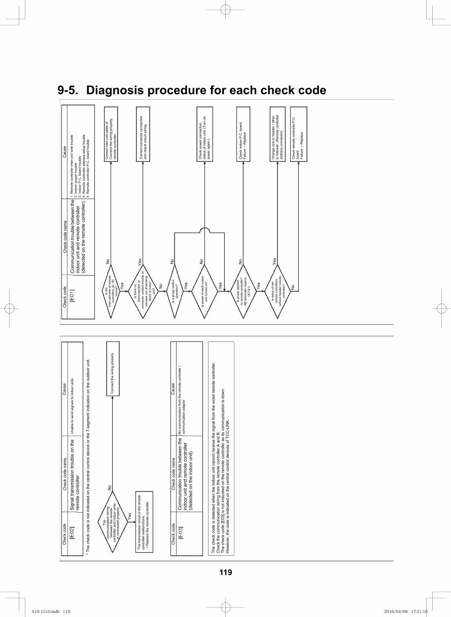
129
9-5. Diagnosis procedure for each check code
Che
ck c
ode
Che
ck c
ode
nam
eC
ause
Sign
al tr
ansm
issi
on tr
oubl
e on
the
rem
ote
cont
rolle
rU
nabl
e to
sen
d si
gnal
s to
indo
or u
nits
* The
che
ck c
ode
is n
ot in
dica
ted
on th
e ce
ntra
l con
trol d
evic
e or
the
7-se
gmen
t ind
icat
ion
on th
e ou
tdoo
r uni
t.
The
com
mun
icat
ion
wiri
ng
betw
een
the
rem
ote
cont
rolle
r and
indo
or u
nits
is
con
nect
ed p
rope
rly.
Con
nect
the
wiri
ng p
rope
rly.
The
trans
mis
sion
circ
uit i
n th
e re
mot
e co
ntro
ller m
alfu
nctio
ns.
Rep
lace
the
rem
ote
cont
rolle
r.
No
Yes
Che
ck c
ode
Che
ck c
ode
nam
eC
ause
Com
mun
icat
ion
troub
le b
etw
een
the
indo
or u
nit a
nd re
mot
e co
ntro
ller
(det
ecte
d on
the
indo
or u
nit)
No
com
mun
icat
ion
from
the
rem
ote
cont
rolle
r /
com
mun
icat
ion
adap
ter
The
chec
k co
de is
det
ecte
d w
hen
the
indo
or u
nit c
anno
t rec
eive
the
sign
al fr
om th
e w
ired
rem
ote
cont
rolle
r.C
heck
the
com
mun
icat
ion
wiri
ng fr
om th
e re
mot
e co
ntro
ller A
and
B.
The
chec
k co
de [E
03] i
s no
t ind
icat
ed o
n th
e re
mot
e co
ntro
ller a
s its
com
mun
icat
ion
is d
own.
How
ever
, the
cod
e is
indi
cate
d on
the
cent
ral c
ontro
l dev
ices
of T
CC
-LIN
K.
Che
ck c
ode
Che
ck c
ode
nam
eC
ause
Is th
e in
ter-u
nit w
ire o
f rem
ote
cont
rolle
rs (A
/ B)
no
rmal
?
No
Yes
Cor
rect
inte
r-uni
t cab
le o
f C
onne
ct th
e w
iring
pro
perly
. re
mot
e co
ntro
ller.
Cor
rect
con
nect
or c
onne
ctio
n an
d ch
eck
circ
uit w
iring
.
Is th
ere
no
disc
onne
ctio
n or
co
nnec
tor c
onta
ct tr
oubl
e on
ha
rnes
s ou
t of t
erm
inal
bl
ock
of in
door
un
it?
Yes
No
No
Yes
No
Yes
No
Yes
Yes
No
Is a
gro
up c
ontro
l op
erat
ion?
Is p
ower
of e
ach
indo
or
unit
turn
ed o
n?
Is p
ower
app
lied
to re
mot
e co
ntro
ller?
AB
term
inal
s: A
ppro
x.
DC
18 V
Is s
etup
of t
wo
rem
ote
cont
rolle
rs
with
out h
eade
r rem
ote
cont
rolle
r?
Che
ck p
ower
con
nect
ion
stat
us o
f ind
oor u
nit.
(Tur
n on
po
wer
aga
in.)
Che
ck in
door
P.C
. boa
rd.
Failu
re
Rep
lace
Cha
nge
one
to h
eade
r / o
ther
to
follo
wer
. (R
emot
e co
ntro
ller
addr
ess
conn
ecto
r)
Che
ck re
mot
e co
ntro
ller P
.C.
boar
d.
Failu
re
Rep
lace
Com
mun
icat
ion
troub
le b
etw
een
the
in
door
uni
t and
rem
ote
cont
rolle
r (d
etec
ted
on th
e re
mot
e co
ntro
ller)
1. R
emot
e co
ntro
ller i
nter
-uni
t wire
trou
ble
2. In
door
pow
er tr
oubl
e3.
Indo
or P
.C. b
oard
trou
ble
4. R
emot
e co
ntro
ller a
ddre
ss s
etup
trou
ble
5. R
emot
e co
ntro
ller P
.C. b
oard
trou
ble
119
A10-1510.indb 119A10-1510.indb 119 2016/04/08 17:21:102016/04/08 17:21:10
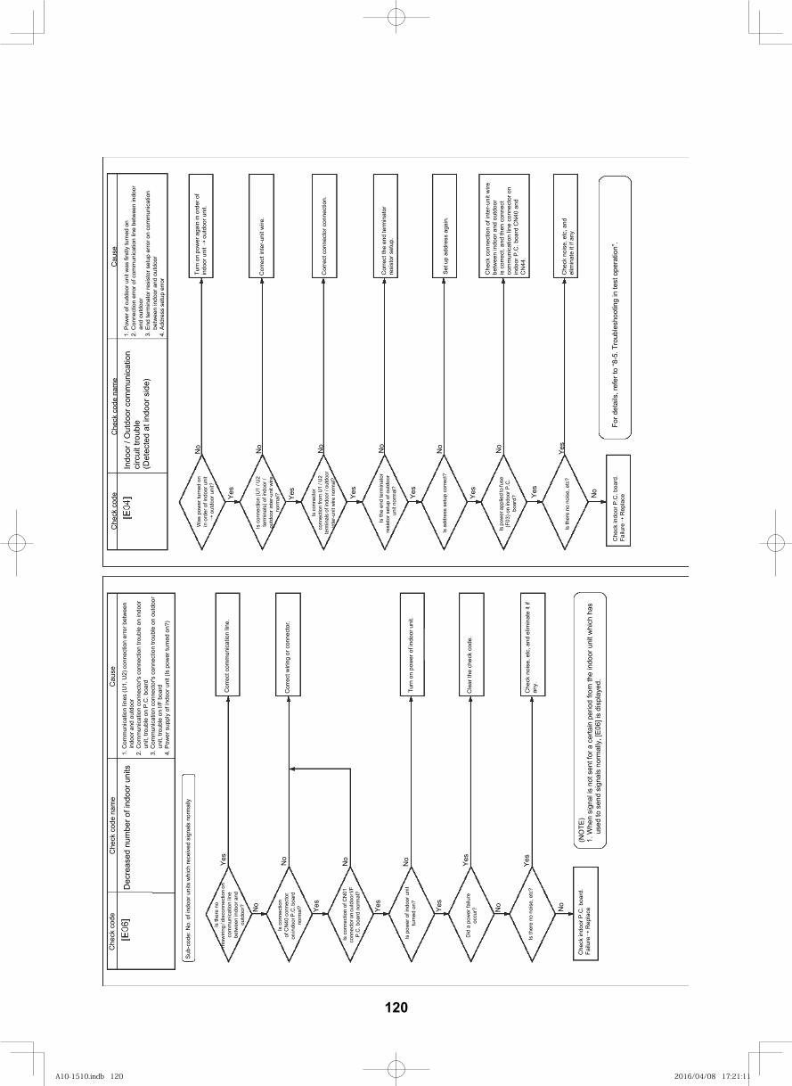
130
For d
etai
ls, r
efer
to “8
-5. T
roub
lesh
ootin
g in
test
ope
ratio
n”.
Che
ck c
ode
Che
ck c
ode
nam
eC
ause
Is th
ere
no
mis
wiri
ng / d
isco
nnec
tion
on
com
mun
icat
ion
line
betw
een
indo
or a
nd
outd
oor?
Yes
Sub-
code
: No.
of i
ndoo
r uni
ts w
hich
rece
ived
sig
nals
nor
mal
ly
Dec
reas
ed n
umbe
r of i
ndoo
r uni
ts1.
Com
mun
icat
ion
lines
(U1,
U2)
con
nect
ion
erro
r bet
wee
n in
door
and
out
door
2. C
omm
unic
atio
n co
nnec
tor's
con
nect
ion
troub
le o
n in
door
un
it, tr
oubl
e on
P.C
. boa
rd3.
Com
mun
icat
ion
conn
ecto
r's c
onne
ctio
n tro
uble
on
outd
oor
unit,
trou
ble
on I/
F bo
ard
4. P
ower
sup
ply
of in
door
uni
t (Is
pow
er tu
rned
on?
)
No
Is c
onne
ctio
n of
CN
40 c
onne
ctor
on
indo
or P
.C. b
oard
no
rmal
?
No
Yes
No
Is c
onne
ctio
n of
CN
01
conn
ecto
r on
outd
oor I
/F
P.C
. boa
rd n
orm
al?
Yes
Is p
ower
of i
ndoo
r uni
t tu
rned
on?
No
Yes
Yes
Did
a p
ower
failu
re
occu
r? No
Is th
ere
no n
oise
, etc
?Ye
s
No
Che
ck in
door
P.C
. boa
rd.
Failu
re R
epla
ce
Cor
rect
com
mun
icat
ion
line.
Cor
rect
wiri
ng o
r con
nect
or.
Turn
on
pow
er o
f ind
oor u
nit.
Cle
ar th
e ch
eck
code
.
Che
ck n
oise
, etc
, and
elim
inat
e it
if an
y.
(NO
TE)
1. W
hen
sign
al is
not
sen
t for
a c
erta
in p
erio
d fro
m th
e in
door
uni
t whi
ch h
as
used
to s
end
sign
als
norm
ally
, [E0
6] is
dis
play
ed.
No
Was
pow
er tu
rned
on
in o
rder
of i
ndoo
r uni
t o
utdo
or u
nit?
Che
ck c
ode
Che
ck c
ode
nam
e
Indo
or /
Out
door
com
mun
icat
ion
circ
uit t
roub
le (D
etec
ted
at in
door
sid
e)
Cau
se1.
Pow
er o
f out
door
uni
t was
firs
tly tu
rned
on
2. C
onne
ctio
n er
ror o
f com
mun
icat
ion
line
betw
een
indo
or
and
outd
oor
3. E
nd te
rmin
ator
resi
stor
set
up e
rror o
n co
mm
unic
atio
n be
twee
n in
door
and
out
door
4. A
ddre
ss s
etup
erro
r
Yes
Is c
onne
ctio
n (U
1 / U
2 te
rmin
als)
of i
ndoo
r /
outd
oor i
nter
-uni
t wire
no
rmal
?
No
Yes
No
Is c
onne
ctor
co
nnec
tion
from
U1
/ U2
term
inal
s of
indo
or /
outd
oor
inte
r-uni
t wire
nor
mal
?
Yes
No
Is th
e en
d te
rmin
ator
re
sist
or s
etup
of o
utdo
or
unit
norm
al?
Yes
No
Is a
ddre
ss s
etup
cor
rect
?
Yes
No
Is p
ower
app
lied
to fu
se
(F03
) on
indo
or P
.C.
boar
d? Yes
Yes
Is th
ere
no n
oise
, etc
?
Che
ck in
door
P.C
. boa
rd.
Failu
re R
epla
ce
Cor
rect
con
nect
or c
onne
ctio
n.
Turn
on
pow
er a
gain
in o
rder
of
indo
or u
nit
out
door
uni
t.
Cor
rect
inte
r-uni
t wire
.
Che
ck n
oise
, etc
, and
el
imin
ate
it if
any
Cor
rect
the
end
term
inat
orre
sist
or s
etup
.
Set u
p ad
dres
s ag
ain.
Che
ck c
onne
ctio
n of
inte
r-un
it w
ire
betw
een
indo
or a
nd o
utdo
oris
cor
rect
, and
then
con
nect
co
mm
unic
atio
n lin
e co
nnec
tor o
n in
door
P.C
. boa
rd C
N40
and
C
N44
.
No
120
A10-1510.indb 120A10-1510.indb 120 2016/04/08 17:21:112016/04/08 17:21:11
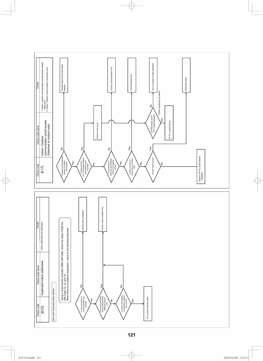
131
No
Is w
ire c
onne
ctio
n to
co
mm
unic
atio
n lin
e no
rmal
?
Che
ck c
ode
Che
ck c
ode
nam
e
Dup
licat
ed in
door
add
ress
esC
ause
Indo
or a
ddre
sses
are
dup
licat
ed
Sub-
code
: Dup
licat
ed in
door
add
ress
Usi
ng a
wire
d re
mot
e co
ntro
ller (
RBC
-AM
T32E
), ch
eck
the
setu
p C
OD
E N
o.
(DN
cod
e) 1
2, 1
3, a
nd 1
4.W
hen
ther
e is
no
addr
ess
dupl
icat
ion,
che
ck to
the
follo
win
g flo
wch
art.
Is n
ot co
mm
unic
atio
n lin
e co
nnec
ted
to th
e di
ffere
nt o
utdo
or
unit?
Yes
Yes
No
No
Yes
Is in
door
uni
t qua
ntity
conn
ecte
d to
out
door
unit
corre
ct?
Set u
p in
door
add
ress
aga
in.
Cor
rect
wire
con
nect
ion.
Cor
rect
com
mun
icat
ion
line.
No
Is s
etup
of e
nd te
rmin
ator
resi
stor
of o
utdo
or
unit
norm
al?
Cor
rect
com
mun
icat
ion
line.
Che
ck c
ode
Che
ck c
ode
nam
eC
ause
Indo
or /
Out
door
co
mm
unic
atio
n ci
rcui
t tro
uble
(Det
ecte
d at
out
door
sid
e)
1. In
door
/ ou
tdoo
r com
mun
icat
ion
end
term
inat
or re
sist
or
setu
p er
ror
2. In
door
/ ou
tdoo
r com
mun
icat
ion
conn
ectio
n er
ror
Yes
Is in
ter-u
nit w
ire
(U1,
U2)
bet
wee
n in
door
an
d ou
tdoo
r sho
rt-ci
rcui
ted?
Yes
No
No
Yes
Yes
Yes
No
No
Is c
onne
ctio
n of
in
ter-u
nit w
ire b
etw
een
indo
or a
nd o
utdo
or
corre
ct?
Is th
ere
no e
rror o
n po
wer
wire
to o
utdo
or
unit?
Is th
ere
nois
e so
urce
?
Out
door
I/F
P.C
. boa
rd fa
ilure
R
epla
ce
Cor
rect
sho
rt-ci
rcui
t
Is F
400
(fuse
) on
I/F
P.C
. boa
rd o
pene
d?
I/F P
.C. b
oard
failu
reYes
No
* Che
ck c
ondu
ctio
n by
test
er.C
orre
ct s
etup
of e
nd te
rmin
ator
resi
stor
.
Cor
rect
pow
er w
ire.
Turn
on
pow
er to
sta
rt op
erat
ion.
Elim
inat
e no
ise.
121
A10-1510.indb 121A10-1510.indb 121 2016/04/08 17:21:112016/04/08 17:21:11
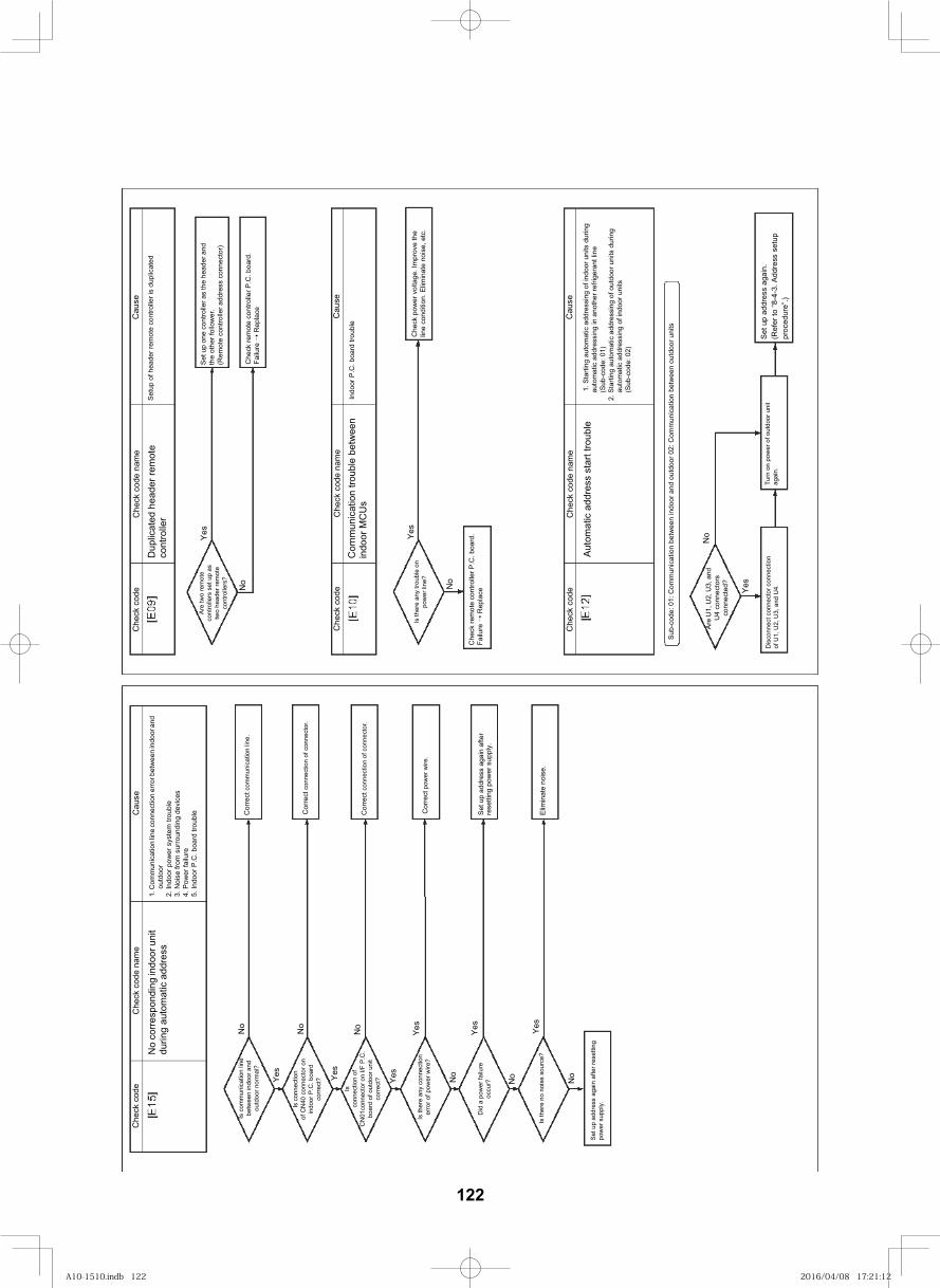
132
Set
up
addr
ess
agai
n.(R
efer
to “8
-4-3
. Add
ress
set
up
proc
edur
e”.)
No
corre
spon
ding
indo
or u
nit
durin
g au
tom
atic
add
ress
1. C
omm
unic
atio
n lin
e co
nnec
tion
erro
r bet
wee
n in
door
and
ou
tdoo
r2.
Indo
or p
ower
sys
tem
3.
Noi
se fr
om s
urro
undi
ng d
evic
es4.
Pow
er fa
ilure
5. In
door
P.C
. boa
rd
Cor
rect
com
mun
icat
ion
line.
Cor
rect
con
nect
ion
of c
onne
ctor
.
Cor
rect
con
nect
ion
of c
onne
ctor
.
Cor
rect
pow
er w
ire.
Set
up
addr
ess
agai
n af
ter
rese
tting
pow
er s
uppl
y.
Elim
inat
e no
ise.
No
Are
two
rem
ote
cont
rolle
rs s
et u
p as
tw
o he
ader
rem
ote
cont
rolle
rs?
Che
ck c
ode
Che
ck c
ode
nam
eC
ause
Dup
licat
ed
rem
ote
cont
rolle
rSe
tup
of h
eade
r rem
ote
cont
rolle
r is
dupl
icat
ed
Yes
Set
up
one
cont
rolle
r as
the
head
er a
nd
the
othe
r fol
low
er.
(Rem
ote
cont
rolle
r add
ress
con
nect
or)
Che
ck re
mot
e co
ntro
ller P
.C. b
oard
. Fa
ilure
➝ R
epla
ce
Che
ck c
ode
Che
ck c
ode
nam
eC
ause
Com
mun
icat
ion
bet
wee
n in
door
MC
Us
Indo
or P
.C. b
oard
Is th
ere
any
troub
le o
n po
wer
line
?
No
Yes
Che
ck re
mot
e co
ntro
ller P
.C. b
oard
. Fa
ilure
➝ R
epla
ce
Che
ck p
ower
vol
tage
. Im
prov
e th
e lin
e co
nditi
on. E
limin
ate
nois
e, e
tc.
Che
ck c
ode
Che
ck c
ode
nam
eC
ause
Aut
omat
ic a
ddre
ss s
tart
1. S
tarti
ng a
utom
atic
add
ress
ing
of in
door
uni
ts d
urin
g au
tom
atic
add
ress
ing
in a
noth
er re
frige
rant
line
(Sub
-cod
e: 0
1)2.
Sta
rting
aut
omat
ic a
ddre
ssin
g of
out
door
uni
ts d
urin
g au
tom
atic
add
ress
ing
of in
door
uni
ts(S
ub-c
ode:
02)
Sub-
code
: 01:
Com
mun
icat
ion
betw
een
indo
or a
nd o
utdo
or 0
2: C
omm
unic
atio
n be
twee
n ou
tdoo
r uni
ts
Are
U1,
U2,
U3,
and
U
4 co
nnec
tors
co
nnec
ted?
No
Yes
Dis
conn
ect c
onne
ctor
con
nect
ion
of U
1, U
2, U
3, a
nd U
4.Tu
rn o
n po
wer
of o
utdo
or u
nit
agai
n.
No
Is c
omm
unic
atio
n lin
e be
twee
n in
door
and
ou
tdoo
r nor
mal
?
Che
ck c
ode
Che
ck c
ode
nam
eC
ause
Yes
Is c
onne
ctio
n of
CN
40 c
onne
ctor
on
indo
or P
.C. b
oard
co
rrec
t? Yes
Isco
nnec
tion
of
CN
01co
nnec
tor o
n I/F
P.C
. bo
ard
of o
utdo
or u
nit
corr
ect?
No
Yes
Yes No
No No
Yes Ye
s
Is th
ere
any
conn
ectio
n er
ror o
f pow
er w
ire?
Did
a p
ower
failu
re
occu
r?
Is th
ere
no n
oise
sou
rce?
Set
up
addr
ess
agai
n af
ter r
eset
ting
pow
er s
uppl
y.
No
122
A10-1510.indb 122A10-1510.indb 122 2016/04/08 17:21:122016/04/08 17:21:12
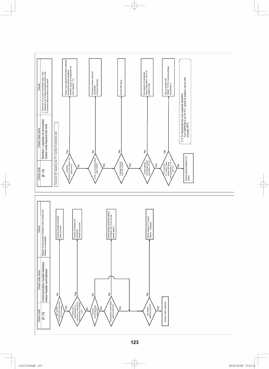
133
Che
ck c
ode
Che
ck c
ode
nam
eC
ause
Com
mun
icat
ion
troub
le b
etw
een
indo
or h
eade
r and
follo
wer
Reg
ular
com
mun
icat
ion
betw
een
indo
or h
eade
r and
fo
llow
er is
una
vaila
ble
No
Yes
Are
rem
ote
cont
rolle
r int
er-u
nit w
ires
(A /
B) n
orm
al?
Is th
ere
any
disc
onne
ctio
n of
co
nnec
tor o
r wiri
ng fr
om
term
inal
blo
ck o
f ind
oor
unit?
Yes
No
No No
Yes
Yes
Is g
roup
co
ntro
l ope
ratio
n ex
ecut
ed?
Are
pow
ers
of a
ll in
door
un
its tu
rned
on?
Cor
rect
indo
or a
ddre
ss.
Cor
rect
rem
ote
cont
rolle
r in
ter-u
nit w
ire.
Cor
rect
con
nect
ion
of
conn
ecto
r.C
heck
circ
uit w
ire.
Che
ck p
ower
conn
ectio
n st
atus
of
indo
or u
nit.
(Tur
n on
the
pow
er a
gain
.)
Num
ber /
cap
acity
of c
onne
cted
in
door
uni
ts b
eyon
d th
e lim
it
Che
ck c
ode
esuaC
eman edoc kceh
C1.
The
re a
re 1
3 or
mor
e co
nnec
ted
indo
or u
nits
2. C
apac
ity o
ver o
f tot
al c
onne
cted
indo
or u
nits
3. In
corre
ct s
etup
of i
ndoo
r uni
ts' p
ower
Sub-
code
: 00:
Cap
acity
ove
r, 01
-: nu
mbe
r of c
onne
cted
uni
ts
No
Yes
No
Is b
acku
p op
erat
ion
of o
ur o
utdo
or u
nit
bein
g se
t up
Is N
o. o
f con
nect
ed in
door
un
its c
orre
ct?
Is s
etup
of i
ndoo
r un
its’ H
P co
rrect
?
Is to
tal c
apac
ityof
con
nect
ed in
door
units
with
in 1
30 %
?
For a
ser
vice
P.C
. boa
rd, c
heck
outd
oor H
P se
tup.
(Set
up
jum
per 9
, 10,
11,
and
12.)
Che
ck o
utdo
or in
terfa
ce P
.C.
boar
d.
Yes
No
Yes
No
Yes
OK
NG
Indo
or o
ver-c
apac
ity h
as b
een
dete
cted
durin
g th
e ba
ckup
ope
ratio
n.Pe
rform
set
up o
f no
dete
ctio
n fo
r ov
er c
apac
ity. (
*1)
Exce
ssiv
e in
door
uni
ts a
re
conn
ecte
d.C
orre
ct m
isw
iring
.
Cor
rect
HP
setu
p.
Set c
apac
ity o
f con
nect
ed
indo
or u
nits
with
in 1
30 %
of
outd
oor u
nits
.
Set u
p ou
tdoo
r HP.
(Ref
er “1
1 P.
C. b
oard
exc
hang
e pr
oced
ures
”.)
(*1)
To
deac
tivat
e th
e ov
er-c
apac
ity d
etec
tion
Turn
SW
09 B
it 2
on I/
F P.
C. b
oard
of o
utdo
or u
nit t
o O
N.
(Usu
ally
OFF
)
Are
indo
or
addr
ess
corre
ct?
Yes
Che
ck in
door
P.C
. boa
rd.
Failu
re
Rep
lace
No
123
A10-1510.indb 123A10-1510.indb 123 2016/04/08 17:21:122016/04/08 17:21:12
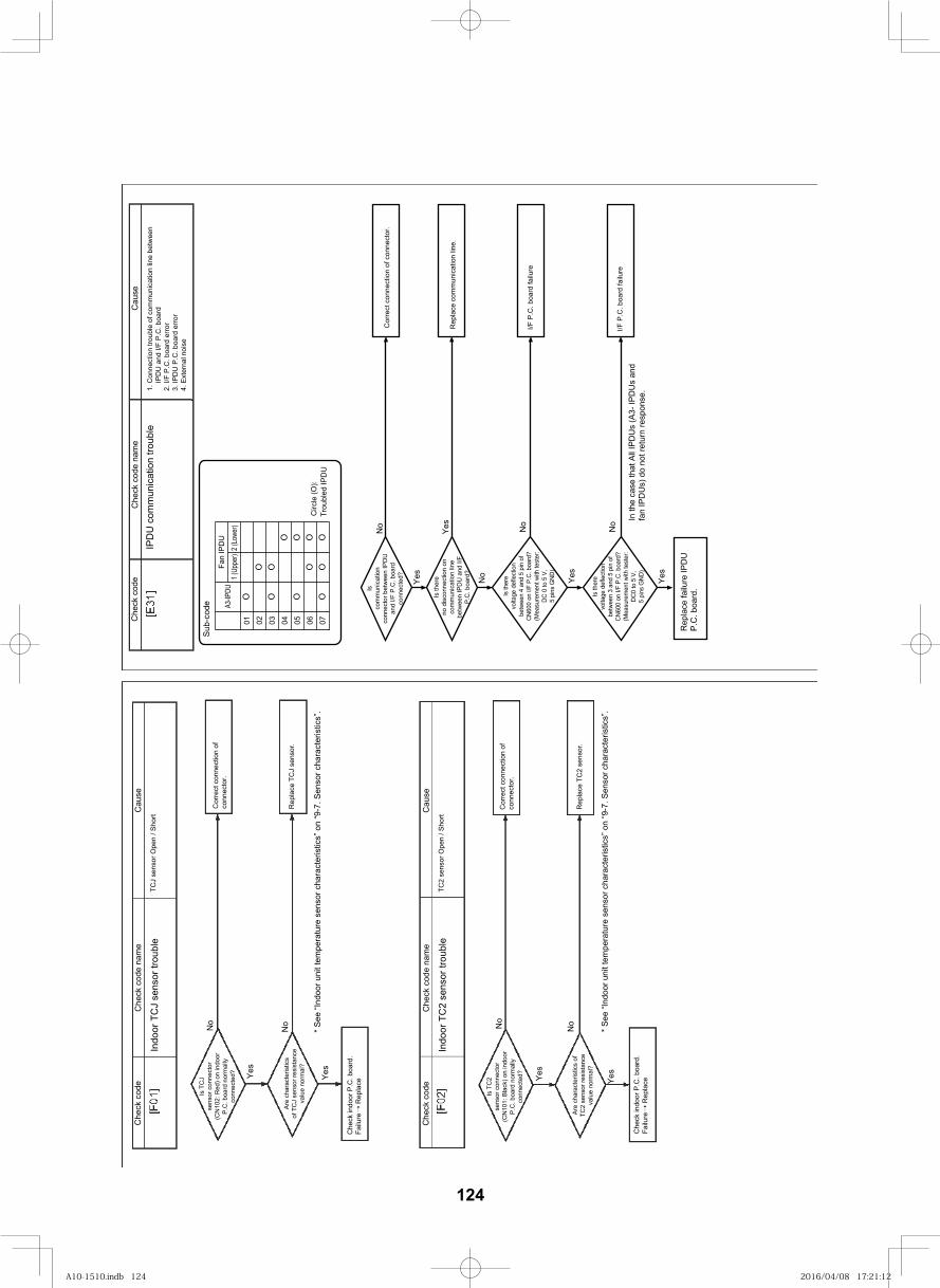
134
Che
ck c
ode
esuaC
eman edoc kceh
C
IPD
U c
omm
unic
atio
n tro
uble
1. C
onne
ctio
n tro
uble
of c
omm
unic
atio
n lin
e be
twee
n IP
DU
and
I/F
P.C
. boa
rd2.
I/F
P.C
. boa
rd e
rror
3. IP
DU
P.C
. boa
rd e
rror
4. E
xter
nal n
oise
Isco
mm
unic
atio
nco
nnec
tor b
etw
een
IPD
Uan
d I/F
P.C
. boa
rdco
nnec
ted?
No
Yes
Yes
No
No
Yes
No
Yes
Is th
ere
no d
isco
nnec
tion
onco
mm
unic
atio
n lin
ebe
twee
n IP
DU
and
I/F
P.C
. boa
rd?
Is th
ere
volta
ge d
efle
ctio
nbe
twee
n 4
and
5 pi
n of
CN60
0 on
I/F
P.C.
boa
rd?
(Mea
sure
men
t with
test
er:
DC 0
to 5
V,
5 pi
ns G
ND)
Is th
ere
volta
ge d
efle
ctio
nbe
twee
n 3
and
5 pi
n of
CN60
0 on
I/F
P.C.
boa
rd?
(Mea
sure
men
t with
test
er:
DC0
to 5
V,
5 pi
ns G
ND)
Rep
lace
failu
re IP
DU
P.C
. boa
rd.
In th
e ca
se th
at A
ll IP
DU
s (A
3- IP
DU
s an
d fa
n IP
DU
s) d
o no
t ret
urn
resp
onse
.
Cor
rect
con
nect
ion
of c
onne
ctor
.
Rep
lace
com
mun
icat
ion
line.
I/F P
.C. b
oard
failu
re
I/F P
.C. b
oard
failu
re
Sub-
code
* See
“Ind
oor u
nit t
empe
ratu
re s
enso
r cha
ract
eris
tics”
on
“9-7
. Sen
sor c
hara
cter
istic
s”.
* See
“Ind
oor u
nit t
empe
ratu
re s
enso
r cha
ract
eris
tics”
on
“9-7
. Sen
sor c
hara
cter
istic
s”.
Che
ck c
ode
esuaC
eman edoc kceh
C
Indo
or T
CJ
sens
or tr
oubl
e
No
Yes
TCJ
sens
or O
pen
/ Sho
rt
Is T
CJ
sens
or c
onne
ctor
(CN
102:
Red
) on
indo
orP.
C. b
oard
nor
mal
lyco
nnec
ted?
No
Yes
Are
char
acte
ristic
sof
TC
J se
nsor
resi
stan
ceva
lue
norm
al?
Che
ck in
door
P.C
. boa
rd.
Failu
re R
epla
ce
Cor
rect
con
nect
ion
of
conn
ecto
r.
Rep
lace
TC
J se
nsor
.
Che
ck c
ode
esuaC
eman edoc kceh
C
Indo
or T
C2
sens
or tr
oubl
eTC
2 se
nsor
Ope
n / S
hort
Is T
C2
sens
or c
onne
ctor
(CN
101:
Bla
ck) o
n in
door
P.C
. boa
rd n
orm
ally
conn
ecte
d?
No
Yes
No
Yes
Are
char
acte
ristic
s of
TC2
sens
or re
sist
ance
valu
e no
rmal
?
Che
ck in
door
P.C
. boa
rd.
Failu
re R
epla
ce
Cor
rect
con
nect
ion
of
conn
ecto
r.
Rep
lace
TC
2 se
nsor
.
A3-IP
DUFa
n IP
DU
01 02 03 04 05 06 07C
ircle
(O):
Trou
bled
IPD
UOOOO
OOOO
1 (Up
per)
2 (Lo
wer)
OOOO
124
A10-1510.indb 124A10-1510.indb 124 2016/04/08 17:21:122016/04/08 17:21:12
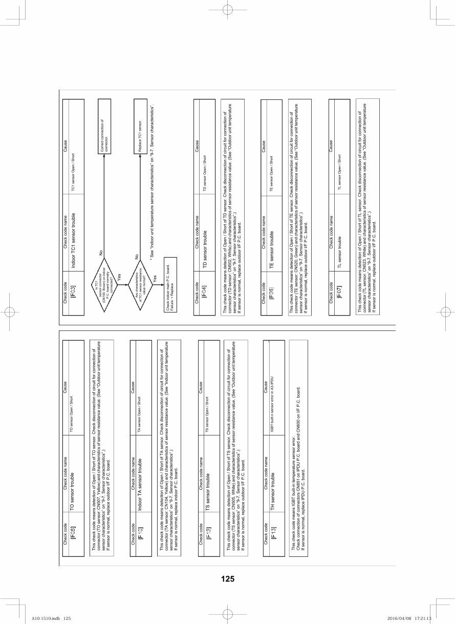
135
* See
“Ind
oor u
nit t
empe
ratu
re s
enso
r cha
ract
eris
tics”
on
“9-7
. Sen
sor c
hara
cter
istic
s”.
This
che
ck c
ode
mea
ns d
etec
tion
of O
pen
/ Sho
rt of
TD
sen
sor.
Che
ck d
isco
nnec
tion
of c
ircui
t for
con
nect
ion
of
conn
ecto
r (TD
sen
sor:
CN
502,
Whi
te) a
nd c
hara
cter
istic
s of
sen
sor r
esis
tanc
e va
lue.
(See
“Out
door
uni
t tem
pera
ture
se
nsor
cha
ract
eris
tics”
on
“9-7
. Sen
sor c
hara
cter
istic
s”.)
If se
nsor
is n
orm
al, r
epla
ce o
utdo
or I/
F P.
C. b
oard
.
This
che
ck c
ode
mea
ns d
etec
tion
of O
pen
/ Sho
rt of
TE
sens
or. C
heck
dis
conn
ectio
n of
circ
uit f
or c
onne
ctio
n of
co
nnec
tor (
TE s
enso
r: C
N52
0, G
reen
) and
cha
ract
eris
tics
of s
enso
r res
ista
nce
valu
e. (S
ee “O
utdo
or u
nit t
empe
ratu
re
sens
or c
hara
cter
istic
s” o
n “9
-7. S
enso
r cha
ract
eris
tics”
.)If
sens
or is
nor
mal
, rep
lace
out
door
I/F
P.C
. boa
rd.
Che
ck c
ode
esuaC
eman edoc kceh
C
Is T
C1
sens
or c
onne
ctor
(CN
100:
Bro
wn)
on
indo
orP.
C. b
oard
nor
mal
lyco
nnec
ted?
No
Indo
or T
C1
sens
or tr
oubl
eTC
1 se
nsor
Ope
n / S
hort
Yes
No
Yes
Are
char
acte
ristic
sof
TC
1 se
nsor
resi
stan
ceva
lue
norm
al?
Che
ck in
door
mai
n P.
C. b
oard
. Fa
ilure
Rep
lace
Cor
rect
con
nect
ion
of
conn
ecto
r.
Rep
lace
TC
1 se
nsor
.
Che
ck c
ode
esuaC
eman edoc kceh
C
TD s
enso
r tro
uble
TD s
enso
r Ope
n / S
hort
Che
ck c
ode
esuaC
eman edoc kceh
C
TE s
enso
r tro
uble
TE s
enso
r Ope
n / S
hort
This
che
ck c
ode
mea
ns d
etec
tion
of O
pen
/ Sho
rt of
TL
sens
or. C
heck
dis
conn
ectio
n of
circ
uit f
or c
onne
ctio
n of
co
nnec
tor (
TL s
enso
r: C
N52
3, W
hite
) and
cha
ract
eris
tics
of s
enso
r res
ista
nce
valu
e. (S
ee “O
utdo
or u
nit t
empe
ratu
re
sens
or c
hara
cter
istic
s” o
n “9
-7. S
enso
r cha
ract
eris
tics”
.)If
sens
or is
nor
mal
, rep
lace
out
door
I/F
P.C
. boa
rd.
This
che
ck c
ode
mea
ns d
etec
tion
of O
pen
/ Sho
rt of
TO
sen
sor.
Che
ck d
isco
nnec
tion
of c
ircui
t for
con
nect
ion
of
conn
ecto
r (TO
sen
sor:
CN
507,
Yel
low
) and
cha
ract
eris
tics
of s
enso
r res
ista
nce
valu
e. (S
ee “O
utdo
or u
nit t
empe
ratu
re
sens
or c
hara
cter
istic
s” o
n “9
-7. S
enso
r cha
ract
eris
tics”
.)If
sens
or is
nor
mal
, rep
lace
out
door
I/F
P.C
. boa
rd.
This
che
ck c
ode
mea
ns d
etec
tion
of O
pen
/ Sho
rt of
TA
sens
or. C
heck
dis
conn
ectio
n of
circ
uit f
or c
onne
ctio
n of
co
nnec
tor (
TA s
enso
r: C
N10
4, Y
ello
w) a
nd c
hara
cter
istic
s of
sen
sor r
esis
tanc
e va
lue.
(See
“Ind
oor u
nit t
empe
ratu
re
sens
or c
hara
cter
istic
s” o
n “9
-7. S
enso
r cha
ract
eris
tics”
.)If
sens
or is
nor
mal
, rep
lace
indo
or P
.C. b
oard
.
This
che
ck c
ode
mea
ns d
etec
tion
of O
pen
/ Sho
rt of
TS
sens
or. C
heck
dis
conn
ectio
n of
circ
uit f
or c
onne
ctio
n of
co
nnec
tor (
TS s
enso
r: C
N50
5, W
hite
) and
cha
ract
eris
tics
of s
enso
r res
ista
nce
valu
e. (S
ee “O
utdo
or u
nit t
empe
ratu
re
sens
or c
hara
cter
istic
s” o
n “9
-7. S
enso
r cha
ract
eris
tics”
.)If
sens
or is
nor
mal
, rep
lace
out
door
I/F
P.C
. boa
rd.
Cau
seC
heck
cod
e na
me
Che
ck c
ode
TL s
enso
r tro
uble
TL s
enso
r Ope
n / S
hort
Cau
seC
heck
cod
e na
me
Che
ck c
ode
TO s
enso
r tro
uble
TO s
enso
r Ope
n / S
hort
Cau
seC
heck
cod
e na
me
Che
ck c
ode
Indo
or T
A se
nsor
trou
ble
TA s
enso
r Ope
n / S
hort
Cau
seC
heck
cod
e na
me
Che
ck c
ode
TS s
enso
r tro
uble
TS s
enso
r Ope
n / S
hort
Cau
seC
heck
cod
e na
me
Che
ck c
ode
TH s
enso
r tro
uble
IGBT
bui
lt-n
sens
or e
rror i
n A3
-IPD
U
This
che
ck c
ode
mea
ns IG
BT b
uilt-
in te
mpe
ratu
re s
enso
r erro
r.C
heck
con
nect
ion
of c
onne
ctor
s C
N85
1 on
IPD
U P
.C. b
oard
and
CN
600
on I/
F P.
C. b
oard
.If
sens
or is
nor
mal
, rep
lace
IPD
U P
.C. b
oard
.
125
A10-1510.indb 125A10-1510.indb 125 2016/04/08 17:21:132016/04/08 17:21:13
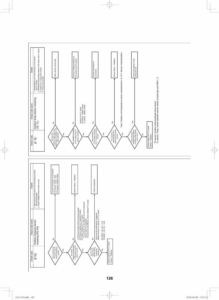
136
Cau
seC
heck
cod
e na
me
Che
ck c
ode
Out
door
tem
p se
nsor
mis
wiri
ng
(TE
, TL)
1. M
isin
stal
latio
n an
d m
isco
nnec
tion
of T
E se
nsor
an
d TL
sen
sor
2 . R
esis
tanc
e ch
arac
teris
tics
failu
re o
f TE
sens
or a
nd T
L se
nsor
3. O
utdo
or P
.C. b
oard
(I/F
) tro
uble
Cau
seC
heck
cod
e na
me
Che
ck c
ode
Out
door
pre
ssur
e se
nsor
mis
wiri
ng (P
D, P
S)
1. H
igh-
pres
sure
PD
sen
sor a
nd lo
w p
ress
ure
sens
orP
S a
re e
xcha
nged
2. O
utpu
t vol
tage
of e
ach
sens
or is
zer
o
Are
con
nect
ion
ofP
D s
enso
r and
Ps
sens
or c
onne
ctor
sco
rrec
t?
No
Yes
Are
out
put
volta
ge c
hara
cter
istic
sof
PD
sen
sor a
nd P
Sse
nsor
nor
mal
?
No
Yes
Are
PD
/ P
Sou
tput
val
ues
PD
>PS
dur
ing
com
pres
sor
oper
atio
n?
No
Yes
Che
ck o
utdo
or I/
F P
.C. b
oard
.Fa
ilure
Rep
lace
Che
ck c
ompr
esso
r
Sen
sor f
ailu
re R
epla
ce
Cor
rect
con
nect
ion
of c
onne
ctor
s.P
D s
enso
r: C
N50
1, R
edP
S s
enso
r: C
N50
0, W
hite
(1) P
ress
ure
(Che
ck jo
int)
by p
ress
ure
gaug
e(2
) Pre
ssur
e di
spla
y on
7-s
egm
ent d
ispl
ay(3
) Out
put v
olta
ge o
f I/F
P.C
. boa
rdIf
(1) a
nd (2
), (3
) are
diff
eren
t, an
erro
r of p
ress
ure
sens
or it
self
is c
onsi
dere
d.If
(2) a
nd (3
) are
diff
eren
t, ch
eck
inte
rface
P.C
. boa
rd.
Valu
e ca
n be
con
firm
ed b
y 7-
segm
ent
disp
lay
func
tion
on o
utdo
or I/
F P.
C. b
oard
.
PD
SW
01 /
02 /
03 =
1/1
/2P
S S
W01
/ 02
/ 03
= 1
/2/2
Are
inst
alle
d po
sitio
nsof
TE
sen
sor a
nd T
Lse
nsor
cor
rect
?
Are
conn
ectio
nof
TE
sen
sor c
onne
ctor
and
TL s
enso
r con
nect
orno
rmal
?
Cor
rect
inst
alle
d po
sitio
ns o
fTE
sen
sor a
nd T
L se
nsor
.
Cor
rect
con
nect
ion
ofco
nnec
tors
.
No
Yes
Out
door
I/F
P.C
. boa
rdTE
sen
sor :
CN
520,
Gre
enTL
sen
sor :
CN
523,
Whi
te
No
Yes
Are
ser
vice
valv
es o
f gas
pip
e an
dliq
uid
pipe
of o
utdo
or u
nit
fully
ope
ned?
No
Yes
Ope
n se
rvic
e va
lves
fully
.
4. 4
-way
val
ve tr
oubl
e
Che
ck o
utdo
or I/
F P
.C. b
oard
.Fa
ilure
Rep
lace
TE s
enso
r: O
utdo
or h
eat e
xcha
nger
tem
p se
nsor
TL
sen
sor:
Tem
p. s
enso
r bet
wee
n se
rvic
e va
lves
of l
iqui
d pi
pe a
nd P
MV
1 / 2
* Se
e “O
utdo
or u
nit t
empe
ratu
re s
enso
r cha
ract
eris
tics”
on
“9-7
. Sen
sor c
hara
cter
istic
s”.
Are
resi
stan
cech
arac
teris
tics
of T
Lse
nsor
and
TE
sen
sor
norm
al?
No
Yes
Sen
sor f
ailu
re R
epla
ce
Yes
No
Che
ck a
nd re
plac
e 4-
way
va
lve
and
coil.
Doe
s di
scha
rge
refri
gera
nt g
as b
ypas
sto
suc
tion
side
thro
ugh
4-w
ay v
alve
?
126
A10-1510.indb 126A10-1510.indb 126 2016/04/08 17:21:132016/04/08 17:21:13
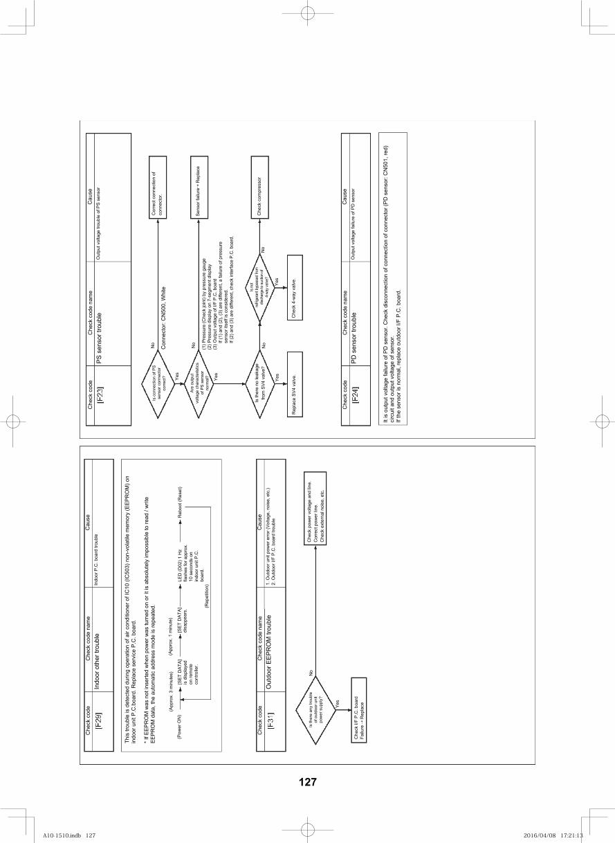
137
Cau
seC
heck
cod
e na
me
Che
ck c
ode
PS s
enso
r tro
uble
O
utpu
t vol
tage
trou
ble
of P
S se
nsor
(1) P
ress
ure
(Che
ck jo
int)
by p
ress
ure
gaug
e(2
) Pre
ssur
e di
spla
y on
7-s
egm
ent d
ispl
ay(3
) Out
put v
olta
ge o
f I/F
P.C
. boa
rdIf
(1) a
nd (2
), (3
) are
diff
eren
t, a
failu
re o
f pre
ssur
ese
nsor
itse
lf is
con
side
red.
If (2
) and
(3) a
re d
iffer
ent,
chec
k in
terfa
ce P
.C. b
oard
.
Is c
onne
ctio
n of
PS
sens
or c
onne
ctor
corre
ct?
No
Yes
Are
outp
utvo
ltage
cha
ract
eris
tics
of P
S se
nsor
no
rmal
?
No
Yes
Is th
ere
no le
akag
efro
m S
V4 v
alve
?N
o
Yes
Rep
lace
SV4
val
ve.
Che
ck 4
-way
val
ve.
Yes
No
Cor
rect
con
nect
ion
ofco
nnec
tor.
Che
ck c
ompr
esso
r
Sens
or fa
ilure
Rep
lace
Cau
seC
heck
cod
e na
me
Che
ck c
ode
PD s
enso
r tro
uble
Out
put v
olta
ge fa
ilure
of P
D s
enso
r
It is
out
put v
olta
ge fa
ilure
of P
D s
enso
r. C
heck
dis
conn
ectio
n of
con
nect
ion
of c
onne
ctor
(PD
sen
sor:
CN
501,
red)
circ
uit a
nd o
utpu
t vol
tage
of s
enso
r.If
the
sens
or is
nor
mal
, rep
lace
out
door
I/F
P.C
. boa
rd.
Con
nect
or: C
N50
0, W
hite Is
not
refri
gera
nt b
ypas
sed
from
disch
arge
to su
ction
of
4-wa
y valv
e?
Cau
seC
heck
cod
e na
me
Che
ck c
ode
Indo
or o
ther
trou
ble
Indo
or P
.C. b
oard
trou
ble
Che
ck p
ower
vol
tage
and
line
.C
orre
ct p
ower
line
.C
heck
ext
erna
l noi
se, e
tc.
No
Yes
Is th
ere
any
troub
leof
out
door
uni
tpo
wer
sup
ply?
This
trou
ble
is d
etec
ted
durin
g op
erat
ion
of a
ir co
nditi
oner
of I
C10
(IC
503)
non
-vol
atile
mem
ory
(EEP
RO
M) o
nin
door
uni
t P.C
.boa
rd. R
epla
ce s
ervi
ce P
.C. b
oard
.
* If E
EPR
OM
was
not
inse
rted
whe
n po
wer
was
turn
ed o
n or
it is
abs
olut
ely
impo
ssib
le to
read
/ w
rite
EEPR
OM
dat
a, th
e au
tom
atic
add
ress
mod
e is
repe
ated
.
[SET
DAT
A]is
dis
play
edon
rem
ote
cont
rolle
r.
[SET
DAT
A]di
sapp
ears
.LE
D (D
02) 1
Hz
flash
es fo
r app
rox.
10 s
econ
ds o
n in
door
uni
t P.C
. bo
ard.
Reb
oot (
Res
et)
(Rep
etiti
on)
Cau
seC
heck
cod
e na
me
Che
ck c
ode
Out
door
EEP
RO
M tr
oubl
e1.
Out
door
uni
t pow
er e
rror (
Volta
ge, n
oise
, etc
.)2.
Out
door
I/F
P.C
. boa
rd tr
oubl
e
(Pow
er O
N)
(App
rox.
3 m
inut
es)
(App
rox.
1 m
inut
e)
Che
ck I/
F P.
C. b
oard
Failu
re R
epla
ce
127
A10-1510.indb 127A10-1510.indb 127 2016/04/08 17:21:132016/04/08 17:21:13
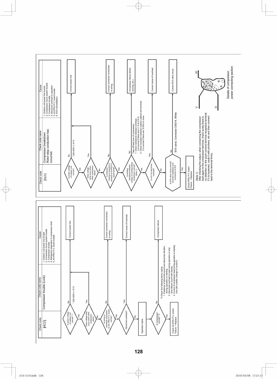
138
Cau
seC
heck
cod
e na
me
Che
ck c
ode
Com
pres
sor b
reak
dow
nR
otor
-sto
p co
nduc
tion
has
occu
rred.
1. O
utdo
or u
nit p
ower
line
trou
ble
2. C
ompr
esso
r circ
uit s
yste
m tr
oubl
e3.
Com
pres
sor t
roub
le4.
Abn
orm
al o
verlo
ad in
ope
ratio
n5.
A3-
IPD
U P
.C. b
oard
trou
ble
Is p
ower
vol
tage
of o
utdo
or u
nit
norm
al?
No
Yes
Yes
No
No
Yes
No
Yes
No
Yes
Che
ck IP
DU
P.C
. boa
rd
Doe
s vo
ltage
drop
occ
ur w
hen
othe
r com
pres
sor
star
ts?
Is co
nnec
tion
of w
iring
or co
nnec
tion
ofco
nnec
tor o
n A3
-IPDU
P.C
.bo
ard
norm
al?
Is w
indi
ngre
sist
ance
bet
wee
nph
ases
of c
orre
spon
ding
com
pres
sor n
orm
al?
(Not
e 1)
Is n
ot it
an
abno
rmal
over
load
?
(Not
e 1)
Afte
r che
ckin
g th
e ou
tput
, whe
n co
nnec
ting
the
com
pres
sor
lead
aga
in to
the
com
pres
sor t
erm
inal
, che
ck s
urel
y th
ere
is
no d
isto
rtion
on
the
quic
k co
nnec
t ter
min
al re
cept
acle
term
inal
.If
it is
loos
ened
, cau
lk it
with
pin
cher
s, e
tc a
nd th
en c
onne
ct
lead
to th
e te
rmin
al fi
rmly
.
Det
ails
of c
ompr
esso
rpo
wer
con
nect
ing
sect
ion
Cor
rect
con
nect
or c
onne
ctio
nor
wiri
ng.
Com
pres
sor f
ailu
re (M
otor
bu
rnin
g, e
tc.)
Cor
rect
cau
se o
f ove
rload
.
Cor
rect
pow
er li
ne.
Take
off
lead
wire
of c
ompr
esso
r.1.
Che
ck re
sist
ance
bet
wee
n w
indi
ngs:
It is
nor
mal
if th
ere
are
0.1
to 0
.4
.2.
Che
ck in
sula
tion
betw
een
outd
oor c
abin
et a
nd te
rmin
al:
It is
nor
mal
if th
ere
are
10 M
or m
ore.
Cau
seC
heck
cod
e na
me
Che
ck c
ode
Com
pres
sor t
roub
le (L
ock)
1. O
utdo
or u
nit p
ower
line
trou
ble
2. C
ompr
esso
r circ
uit s
yste
m tr
oubl
e3.
Com
pres
sor t
roub
le4.
Ref
riger
ant s
tagn
atio
n in
com
pres
sor s
hell
5. A
3-IP
DU
P.C
. boa
rd tr
oubl
e
Is p
ower
vol
tage
of o
utdo
or u
nit
norm
al?
*1
No
Yes
Ope
ratio
n st
arts
.
Cor
rect
pow
er li
ne.
Is w
iring
or
conn
ecto
r con
nect
ion
on A
3- IP
DU
P.C
. boa
rdno
rmal
?
No
Yes
Yes
No
Doe
s vo
ltage
dro
poc
cur w
hen
othe
rco
mpr
esso
rst
arts
?
Yes
No
Abno
rmal
ove
rload
?
Che
ck A
3-IP
DU
P.C
. boa
rd.
Is c
ompr
esso
rno
rmal
? *3
Yes
No
Com
pres
sor f
ailu
re
Cor
rect
cau
se o
f ove
rload
.
Cor
rect
con
nect
or c
onne
ctio
nor
wiri
ng.
*3 C
heck
the
follo
win
g ite
ms
mai
nly.
1. E
xist
ence
of a
bnor
mal
sou
nd a
nd a
bnor
mal
vib
ratio
n du
ring
oper
atio
n or
sta
rting
2. A
bnor
mal
ove
rhea
t of c
ase
durin
g op
erat
ion
or s
top
time
(Nev
er to
uch
with
han
ds)
3. C
urre
nt o
f com
pres
sor l
ead
durin
g op
erat
ion
or s
tarti
ng
time
(No
sudd
en c
hang
e of
cur
rent
?)
* 220
-240
V ±
10 %
* 220
-240
V ±
10 %
Failu
re R
epla
ce
Failu
re
Rep
lace
6. S
V5 m
isin
stal
latio
n.
No
Yes
Cor
rect
SV5
val
ve c
ircui
t.SV
5 va
lve:
Con
nect
or C
N31
4, W
hite
Is S
V5 v
alve
circ
uit n
orm
al?
Inco
rrect
inst
alla
tion
and
conn
ectio
n of
SV5
128
A10-1510.indb 128A10-1510.indb 128 2016/04/08 17:21:142016/04/08 17:21:14
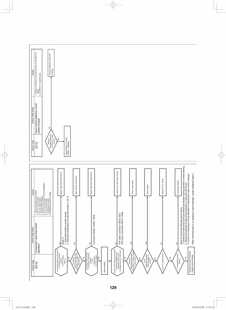
139
Cau
seC
heck
cod
e na
me
Che
ck c
ode
Inpu
t cur
rent
det
ectiv
e ci
rcui
t sy
stem
trou
ble
boar
d
Wiri
ng o
r co
nnec
tor c
onne
ctio
n on
IPD
U P
.C. b
oard
no
rmal
?
No
Yes
Cor
rect
con
nect
or c
onne
ctio
nor
wiri
ng.
Cau
seC
heck
cod
e na
me
Che
ck c
ode
Com
pres
sor c
ase
oper
atio
n
Che
ck IP
DU
P.C
. boa
rd
1. C
onne
ctor
con
nect
ion
2. W
iring
3. I/
F P.
C. b
oard
(N
ote
1)
No
Yes
Star
t ope
ratio
n.
(Not
e 1)
Are
serv
ice
valv
es o
f gas
pip
e an
d liq
uid
pipe
of o
utdo
or u
nit
fully
ope
ned?
No
Yes
Ope
n se
rvic
e va
lves
fully
.
Are
outd
oor P
MV
norm
al?
1. C
onne
ctor
con
nect
ion
2. W
iring
3. C
oil
4. V
alve
bod
y5.
I/F
P.C
. boa
rd
No
Yes
Con
nect
or C
N30
0, C
N30
1, W
hite
No
Yes
Cor
rect
SV4
, SV5
val
ve c
ircui
ts.
SV4
valv
e: C
onne
ctor
CN
312,
Blu
e
Doe
s no
t re
frige
rant
byp
ass
from
di
scha
rge
to s
uctio
n th
roug
h 4-
way
val
ve?
Yes
No
Che
ck 4
-way
val
ve.
Is n
ot
refri
gera
nt b
ypas
sed
from
dis
char
ge to
su
ctio
n?
Yes
Che
ck p
ipin
g.
Is c
ompr
esso
r nor
mal
? (N
ote
2)N
o
Yes
(Not
e 2)
Che
ck th
e fo
llow
ing
item
s m
ainl
y.1.
Exi
sten
ce o
f abn
orm
al s
ound
and
abn
orm
al v
ibra
tion
durin
g op
erat
ion
or w
hen
star
ting
2. A
bnor
mal
ove
rhea
t of c
ase
durin
g op
erat
ion
or s
top
(Do
not t
ouch
)3.
Cur
rent
of c
ompr
esso
r dur
ing
oper
atio
n or
sta
rting
(No
rapi
d cu
rrent
cha
nge)
Ref
riger
ant a
mou
nt s
horta
ge,
clog
ging
, pip
e br
eaka
ge(A
fter c
heck
ing
ther
e is
no
slog
ging
or p
ipe
brea
kage
, cha
rge
refri
gera
nt a
gain
.)
No
Is I/
F P.
C. b
oard
nor
mal
?N
oC
heck
I/F
P.C
. boa
rd.
Yes
Are
SV4,
SV5
Val
ve c
ircui
ts n
orm
al?
conn
ectio
n of
SV4
, SV5
2. L
eaka
ge fr
om S
V4, S
V5 c
ircui
t
1.In
corre
ct in
stal
latio
n an
d
SV5
valv
e: C
onne
ctor
CN
314,
Whi
te
1. W
iring
or c
onne
ctor
con
nect
ion
troub
le o
n A3
-IPD
U P
.C.
2. A
3-IP
DU
P.C
. boa
rd tr
oubl
e
Failu
re
Rep
lace
ther
mos
tat
Is c
ase
ther
mos
tat c
ircui
t nor
mal
?
1. C
ase
ther
mos
tat c
ircui
t tro
uble
2. I/
F P.
C. b
oard
trou
ble
3. S
ervi
ce v
alve
clo
sed
4. O
utdo
or P
MV
clog
ging
5. S
V4, S
V5 v
alve
leak
, Coi
l mis
inst
alla
tion
6. 4
-way
val
ve tr
oubl
e7.
Com
pres
sor t
roub
le8.
Ref
riger
ant a
mou
nt s
horta
ge Rep
air c
ase
ther
mos
tat c
ircui
t.
1. C
ase
ther
mos
tat i
s us
ually
clo
sed.
2. O
pera
tion
tem
pera
ture
of c
ase
ther
mos
tat i
s 12
0 °C
. Rep
air c
ase
ther
mos
tat c
ircui
t.
Com
pres
sor f
ailu
re
129
A10-1510.indb 129A10-1510.indb 129 2016/04/08 17:21:142016/04/08 17:21:14
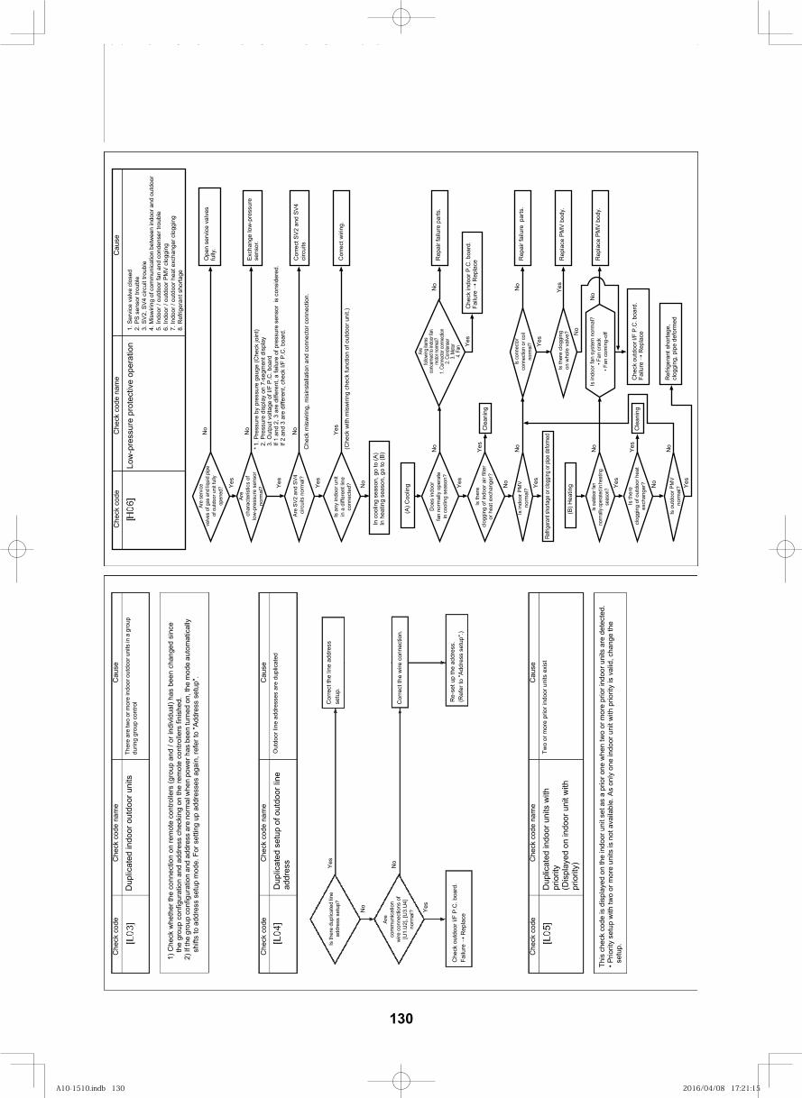
140
esuaC
eman edoc kceh
Cedoc kceh
C
Dup
licat
ed in
door
out
door
uni
tsTh
ere
are
two
or m
ore
indo
or o
utdo
or u
nits
in a
gro
up
durin
g gr
oup
cont
rol
1) C
heck
whe
ther
the
conn
ectio
n on
rem
ote
cont
rolle
rs (g
roup
and
/ or
indi
vidu
al) h
as b
een
chan
ged
sinc
e th
e gr
oup
conf
igur
atio
n an
d ad
dres
s ch
ecki
ng o
n th
e re
mot
e co
ntro
llers
fini
shed
.2)
If th
e gr
oup
conf
igur
atio
n an
d ad
dres
s ar
e no
rmal
whe
n po
wer
has
bee
n tu
rned
on,
the
mod
e au
tom
atic
ally
sh
ifts
to a
ddre
ss s
etup
mod
e. F
or s
ettin
g up
add
ress
es a
gain
, ref
er to
"Add
ress
set
up".
esuaC
eman edoc kceh
Cedoc kceh
C
Dup
licat
ed s
etup
of o
utdo
or li
ne
addr
ess
Out
door
line
add
ress
es a
re d
uplic
ated
Cor
rect
the
wire
con
nect
ion.
Yes
Yes
No
No
Cor
rect
the
line
addr
ess
setu
p.
Re-
set u
p th
e ad
dres
s.(R
efer
to "A
ddre
ss s
etup
".)
Is th
ere
dupl
icat
ed li
ne
addr
ess
setu
p?
Are
com
mun
icat
ion
wire
con
nect
ions
of
[U1.
U2]
, [U
3.U
4]no
rmal
?
Che
ck o
utdo
or I/
F P.
C. b
oard
. Fa
ilure
R
epla
ce
esuaC
eman edoc kceh
Cedoc kceh
C
Dup
licat
ed in
door
uni
ts w
ith
prio
rity
(Dis
play
ed o
n in
door
uni
t with
pr
iorit
y)
Two
or m
ore
prio
r ind
oor u
nits
exi
st
This
che
ck c
ode
is d
ispl
ayed
on
the
indo
or u
nit s
et a
s a
prio
r one
whe
n tw
o or
mor
e pr
ior i
ndoo
r uni
ts a
re d
etec
ted.
Prio
rity
setu
p w
ith tw
o or
mor
e un
its is
not
ava
ilabl
e. A
s on
ly o
ne in
door
uni
t with
prio
rity
is v
alid
, cha
nge
the
setu
p.
Low
-pre
ssur
e pr
otec
tive
oper
atio
n1.
Ser
vice
val
ve c
lose
d2.
PS
sens
or tr
oubl
e3.
SV2
, SV4
circ
uit t
roub
le4.
Mis
wiri
ng o
f com
mun
icat
ion
betw
een
indo
or a
nd o
utdo
or5.
Indo
or /
outd
oor f
an a
nd c
onde
nser
trou
ble
6. In
door
/ ou
tdoo
r PM
V cl
oggi
ng7.
Indo
or /
outd
oor h
eat e
xcha
nger
clo
ggin
g8.
Ref
riger
ant s
horta
ge
esuaC
eman edoc kceh
Cedoc kceh
C
Are
serv
ice
valve
s of
gas
and
liqui
d pi
pe
of o
utdo
or u
nit f
ully
open
ed?
Are
char
acte
ristic
s of
lo
w-p
ress
ure
sens
or
norm
al?
Are
SV2
and
SV4
ci
rcui
ts n
orm
al?
Is a
ny in
door
uni
tin
a d
iffer
ent l
ine
conn
ecte
d?
In c
oolin
g se
ason
, go
to (A
)In
hea
ting
seas
on, g
o to
(B)
*1. P
ress
ure
by p
ress
ure
gaug
e (C
heck
join
t)2.
Pre
ssur
e di
spla
y on
7-s
egm
ent d
ispl
ay3.
Out
put v
olta
ge o
f I/F
P.C
. boa
rdIf
1 an
d 2,
3 a
re d
iffer
ent,
a fa
ilure
of p
ress
ure
sens
or i
s co
nsid
ered
.If
2 an
d 3
are
diffe
rent
, che
ck I/
F P.
C. b
oard
.
Che
ck m
isw
iring
, mis
inst
alla
tion
and
conn
ecto
r con
nect
ion.
(Che
ck w
ith m
isw
iring
che
ck fu
nctio
n of
out
door
uni
t.)
No
No
No
Yes
Ope
n se
rvic
e va
lves
fu
lly.
Exch
ange
low
-pr e
ssur
ese
nsor
.
Cor
rect
SV2
and
SV4
ci
rcui
ts
Cor
rect
wiri
ng.
No
Yes
Yes
Yes
Rep
air f
ailu
re p
arts
.
Rep
air f
ailu
re p
arts
.
Rep
lace
PM
V bo
dy.
Rep
lace
PM
V bo
dy.
(A) C
oolin
g
Doe
s in
door
fan
norm
ally
ope
rate
in c
oolin
g se
ason
?
Is th
ere
clog
ging
of i
ndoo
r air
filte
ror
hea
t exc
hang
er?
Is in
door
PM
V no
rmal
?
Refrig
eran
t sho
rtage
or cl
oggin
g or p
ipe de
forme
d
Are
follow
ing ite
msco
ncern
ed to
indo
or fa
nmo
tor no
rmal?
1. Co
nnec
tor co
nnec
tion
2. Co
nden
ser
3. Mo
tor4.
Fan
Yes
No
No
Is c
onne
ctor
conn
ectio
n or
coi
l no
rmal
?
Is th
ere
clog
ging
on w
hole
val
ve?
Is in
door
fan
syst
em n
orm
al?
Fan
cra
ck F
an c
omin
g-of
f
Che
ck o
utdo
or I/
F P.
C. b
oard
.Fa
ilure
R
epla
ce
No
No
Yes
Yes N
o
No
Ref
riger
ant s
horta
ge,
clog
ging
, pip
e de
form
ed
Cle
anin
g
Cle
anin
g
(B) H
eatin
g
Che
ck in
door
P.C
. boa
rd.
Failu
re
Rep
lace
Is ou
tdoo
r fan
norm
ally o
pera
ted i
n hea
ting
seas
on?
Is th
ere
clog
ging
of o
utdo
or h
eat
exch
ange
r?
Is o
utdo
or P
MV
norm
al?
Yes
No
No
Yes
No
Yes
Yes
Yes
No
Yes
130
A10-1510.indb 130A10-1510.indb 130 2016/04/08 17:21:152016/04/08 17:21:15
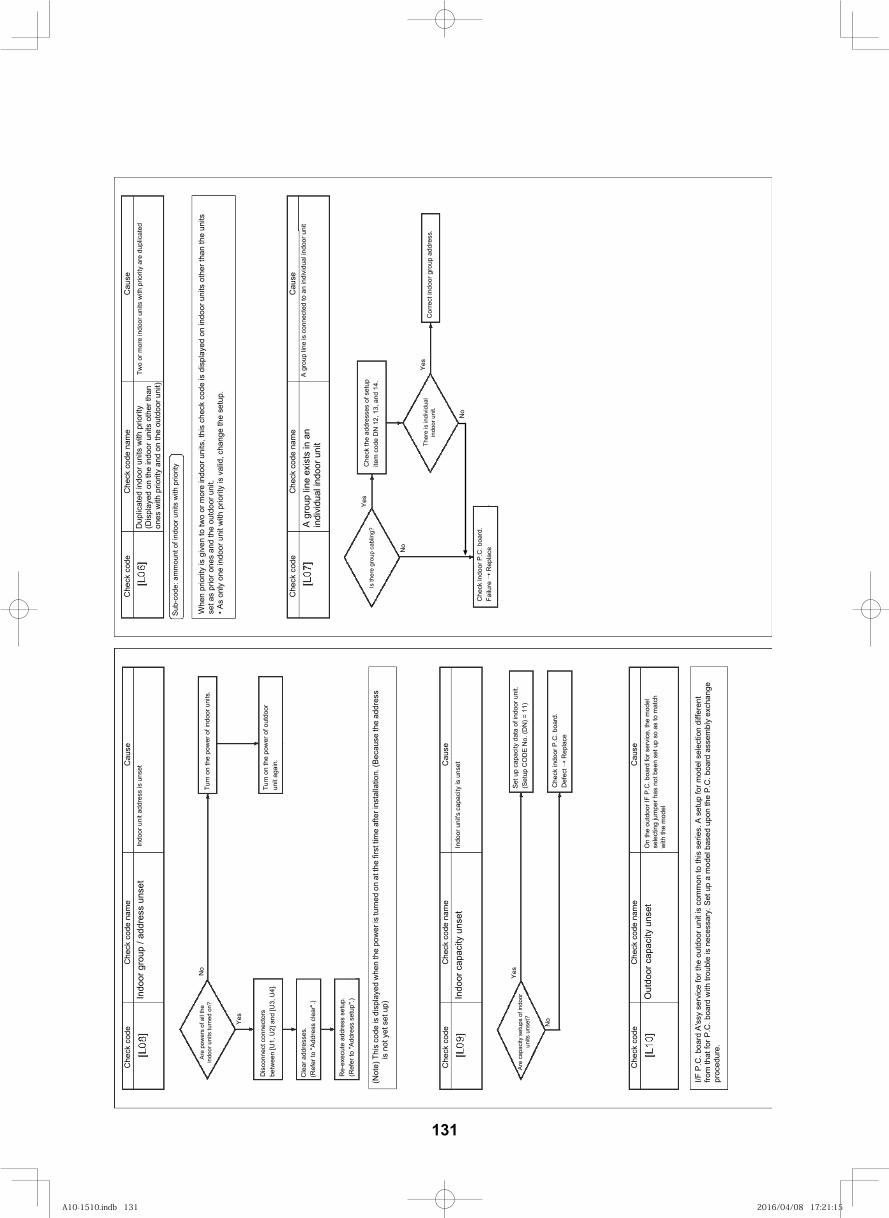
141
esuaC
eman edoc kceh
Cedoc kceh
C
esuaC
eman edoc kceh
Cedoc kceh
C
Dup
licat
ed in
door
uni
ts w
ith p
riorit
y(D
ispl
ayed
on
the
indo
or u
nits
oth
er th
an
ones
with
prio
rity
and
on th
e ou
tdoo
r uni
t)
Two
or m
ore
indo
or u
nits
with
prio
rity
are
dupl
icat
ed
Sub-
code
: am
mou
nt o
f ind
oor u
nits
with
prio
rity
Whe
n pr
iorit
y is
giv
en to
two
or m
ore
indo
or u
nits
, thi
s ch
eck
code
is d
ispl
ayed
on
indo
or u
nits
oth
er th
an th
e un
its
set a
s pr
ior o
nes
and
the
outd
oor u
nit.
As
only
one
indo
or u
nit w
ith p
riorit
y is
val
id, c
hang
e th
e se
tup.
A gr
oup
line
exis
ts in
an
indi
vidu
al in
door
uni
tA
grou
p lin
e is
con
nect
ed to
an
indi
vidu
al in
door
uni
t
Yes
Yes
No
No
Che
ck in
door
P.C
. boa
rd.
Failu
re
Rep
lace
Is th
ere
grou
p ca
blin
g?C
heck
the
addr
esse
s of
set
up
item
cod
e D
N 1
2, 1
3, a
nd 1
4.
Ther
e is
indi
vidu
al
indo
or u
nit.
Cor
rect
indo
or g
roup
add
ress
.
esuaC
eman edoc kceh
Cedoc kceh
C
esuaC
eman edoc kceh
Cedoc kceh
C
Indo
or g
roup
/ ad
dres
s un
set
Indo
or u
nit a
ddre
ss is
uns
et
No
Yes
Are
pow
ers
of a
ll th
ein
door
uni
ts tu
rned
on?
Dis
conn
ect c
onne
ctor
sbe
twee
n [U
1, U
2] a
nd [U
3, U
4].
Cle
ar a
ddre
sses
.(R
efer
to "A
ddre
ss c
lear
".)
Re-
exec
ute
addr
ess
setu
p.(R
efer
to "A
ddre
ss s
etup
".)
(Not
e) T
his
code
is d
ispl
ayed
whe
n th
e po
wer
is tu
rned
on
at th
e fir
st ti
me
afte
r ins
talla
tion.
(Bec
ause
the
addr
ess
is n
ot y
et s
et u
p)
Turn
on
the
pow
er o
f ind
oor u
nits
.
Turn
on
the
pow
er o
f out
door
un
it ag
ain.
Indo
or c
apac
ity u
nset
Indo
or u
nit's
cap
acity
is u
nset
Are
capa
city
set
ups
of in
door
un
its u
nset
?
No
Yes
Set u
p ca
paci
ty d
ata
of in
door
uni
t.(S
etup
CO
DE
No.
(DN
) = 1
1)
Che
ck in
door
P.C
. boa
rd.
Def
ect
Rep
lace
esuaC
eman edoc kceh
Cedoc kceh
C
Out
door
cap
acity
uns
etO
n th
e ou
tdoo
r IF
P.C
. boa
rd fo
r ser
vice
, the
mod
el
sele
ctin
g ju
mpe
r has
not
bee
n se
t up
so a
s to
mat
ch
with
the
mod
el
I/F P
.C. b
oard
A's
sy s
ervi
ce fo
r the
out
door
uni
t is
com
mon
to th
is s
erie
s. A
set
up fo
r mod
el s
elec
tion
diffe
rent
fro
m th
at fo
r P.C
. boa
rd w
ith tr
oubl
e is
nec
essa
ry. S
et u
p a
mod
el b
ased
upo
n th
e P.
C. b
oard
ass
embl
y ex
chan
ge
proc
edur
e.
131
A10-1510.indb 131A10-1510.indb 131 2016/04/08 17:21:152016/04/08 17:21:15
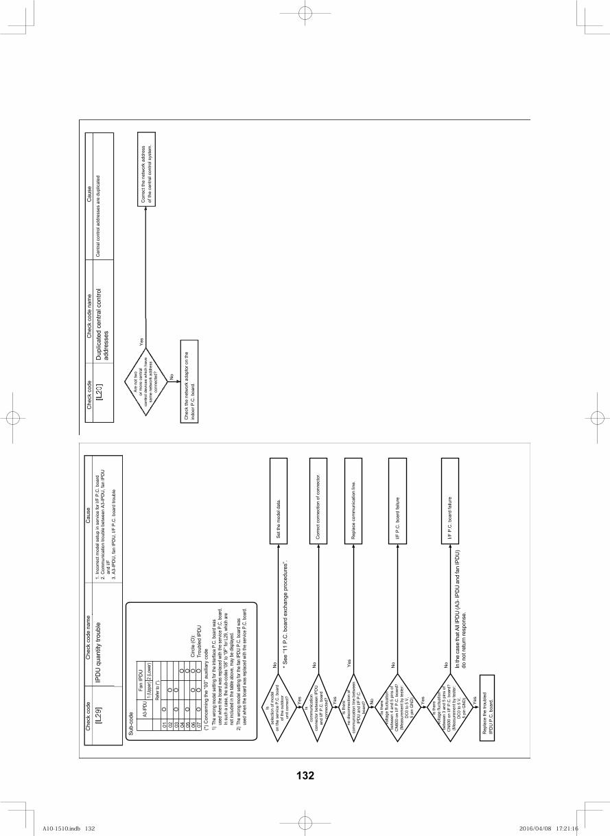
142
Dup
licat
ed c
entra
l con
trol
addr
esse
sC
entra
l con
trol a
ddre
sses
are
dup
licat
ed
Yes
No
Are
not
two
or m
ore
cent
ral
cont
rol d
evic
es w
hich
hav
esa
me
netw
ork
addr
ess
conn
ecte
d?
Che
ck th
e ne
twor
k ad
apto
r on
the
indo
or P
.C. b
oard
.
Cor
rect
the
netw
ork
addr
ess
of th
e ce
ntra
l con
trol s
yste
m.
IPD
U q
uant
ity tr
oubl
e1.
Inco
rrect
mod
el s
etup
in s
ervi
ce fo
r I/F
P.C
. boa
rd2.
Com
mun
icat
ion
troub
le b
etw
een
A3-IP
DU
, fan
IPD
U
and
I/F3.
A3-
IPD
U, f
an IP
DU
, I/F
P.C
. boa
rd tr
oubl
e
Is
sele
ctio
n of
mod
el
on th
e se
rvic
e P
.C. b
oard
of
the
outd
oor
unit
corr
ect?
Isco
mm
unic
atio
nco
nnec
tor b
etw
een
IPD
Uan
d I/F
P.C
. boa
rdco
nnec
ted?
Is th
ere
no d
isco
nnec
tion
ofco
mm
unic
atio
n lin
e be
twee
nIP
DU
and
I/F
P.C
.bo
ard?
IIs th
ere
volta
ge fl
uctu
atio
nbe
twee
n 4
and
5 pi
ns o
fC
N60
0 on
I/F
P.C
. boa
rd?
(Mea
sure
men
t by
test
er:
DC
0 to
5 V
,5
pin
GN
D)
Is th
ere
volta
ge fl
uctu
atio
nbe
twee
n 3
and
5 pi
ns o
fC
N60
0 on
I/F
P.C
. boa
rd?
(Mea
sure
men
t by
test
er:
DC
0 to
5 V
,5
pin
GN
D)
Rep
lace
the
troub
led
IPD
U P
.C. b
oard
.
No
Cor
rect
con
nect
ion
of c
onne
ctor
.
I/F P
.C. b
oard
failu
re
Rep
lace
com
mun
icat
ion
line.
I/F P
.C. b
oard
failu
re
Set t
he m
odel
dat
a.
No
No
NoYes
Yes
Yes
No
Yes
Yes
In th
e ca
se th
at A
ll IPD
U (A
3- IP
DU
and
fan
IPD
U)
do n
ot re
turn
resp
onse
.
Sub
-cod
e A3-IP
DUFa
n IP
DU
01 02 03 04 05 06 07C
ircle
(O):
Trou
bled
IPD
UOOOO
OOOO
1 (U
pper
)2
(Low
er)
OOOO
* S
ee “1
1 P
.C. b
oard
exc
hang
e pr
oced
ures
”.
Refe
r to
(*).
(*) C
once
rnin
g th
e “0
0” a
uxili
ary
code
1) T
he w
rong
mod
el se
tting
for t
he in
terfa
ce P
.C. b
oard
was
us
ed w
hen
the
boar
d wa
s rep
laced
with
the
serv
ice P
.C. b
oard
.
2) T
he w
rong
mod
el se
tting
for t
he fa
n IP
DU P
.C. b
oard
was
used
whe
n th
e bo
ard
was r
eplac
ed w
ith th
e se
rvice
P.C
. boa
rd.
In su
ch a
case
, the
sub-
code
s “08
” to
“0F”
for L
29, w
hich
are
not in
clude
d in
the
table
abo
ve, m
ay b
e dis
playe
d.
esuaC
eman edoc kceh
Cedoc kceh
Cesua
Ce
man edoc kcehC
edoc kcehC
132
A10-1510.indb 132A10-1510.indb 132 2016/04/08 17:21:162016/04/08 17:21:16
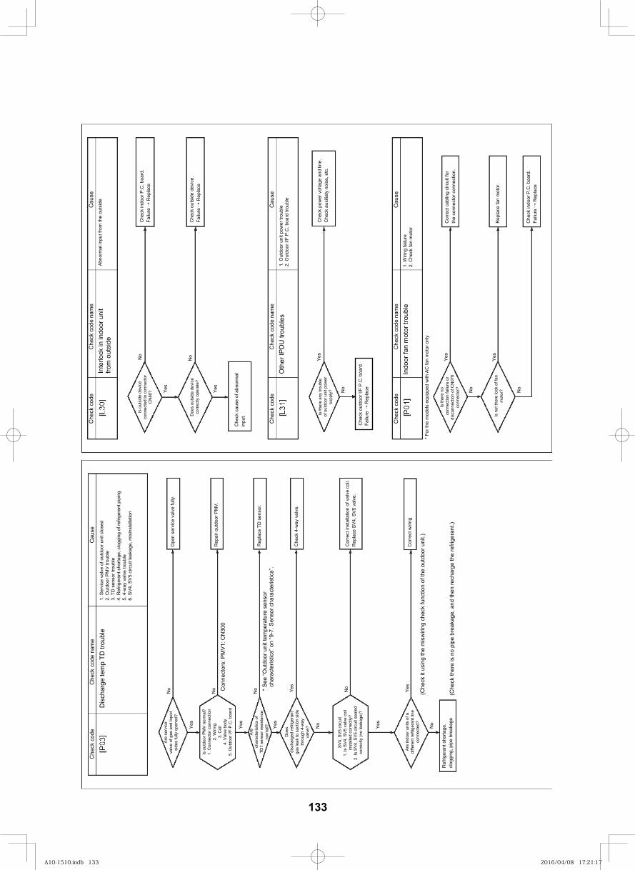
143
esuaC
eman edoc kceh
Cedoc kceh
C
esuaC
eman edoc kceh
Cedoc kceh
C
esuaC
eman edoc kceh
Cedoc kceh
C
Inte
rlock
in in
door
uni
t fro
m o
utsi
deAb
norm
al in
put f
rom
the
outs
ide
No
No
Yes
Yes
Is o
utsi
de d
evic
eco
nnec
ted
to c
onne
ctor
CN
80?
Doe
s ou
tsid
e de
vice
co
rrect
ly o
pera
te?
Che
ck c
ause
of a
bnor
mal
in
put.
Che
ck o
utsi
de d
evic
e.
Failu
re
Rep
lace
Che
ck in
door
P.C
. boa
rd.
Failu
re
Rep
lace
Oth
er IP
DU
trou
bles
1. O
utdo
or u
nit p
ower
trou
ble
2. O
utdo
or I/
F P.
C. b
oard
trou
ble
Che
ck p
ower
vol
tage
and
line
.C
heck
aux
iliaty
noi
se, e
tc.
Yes
No
Is th
ere
any
troub
leof
out
door
uni
t pow
ersu
pply
?
Indo
or fa
n m
otor
trou
ble
1. W
iring
failu
re2.
Che
ck fa
n m
otor
Yes
Yes
Cor
rect
cab
ling
circ
uit f
orth
e co
nnec
tor c
onne
ctio
n.
Rep
lace
fan
mot
or.
Che
ck in
door
P.C
. boa
rd.
Failu
re
Rep
lace
Is th
ere
noco
nnec
tion
failu
re o
rdi
scon
nect
ion
of C
N07
6co
nnec
tor?
Is n
ot th
ere
lock
of f
an
mot
or?No
No
* For
the
mod
els
equi
pped
with
AC
fan
mot
or o
nly
* See
“Out
door
uni
t tem
pera
ture
sen
sor
char
acte
ristic
s” o
n “9
-7. S
enso
r cha
ract
eris
tics”
.
esuaC
eman edoc kceh
Cedoc kceh
C
Dis
char
ge te
mp
TD tr
oubl
e1.
Ser
vice
val
ve o
f out
door
uni
t clo
sed
2. O
utdo
or P
MV
troub
le3.
TD
sen
sor t
roub
le4.
Ref
riger
ant s
horta
ge, c
logg
ing
of re
frige
rant
pip
ing
5. 4
-way
val
ve tr
oubl
e6.
SV4
, SV5
circ
uit l
eaka
ge, m
isin
stal
latio
n
Are
serv
ice
valv
e of
gas
and
liqu
idsi
des
fully
ope
ned?
Is o
utdo
or P
MV
norm
al?
1. C
onne
ctor
con
nect
ion
2. W
iring
3. C
oil
4. V
alve
bod
y5.
Out
door
I/F
P.C
. boa
rd
Are
char
acte
ristic
s of
TD1
sens
or re
sist
ance
norm
al?
Doe
sdi
scha
rged
refri
gera
ntga
s le
ak to
suc
tion
side
thro
ugh
4-w
ayva
lve?
No
No
No
Yes
Yes
Yes
No
Yes
Con
nect
ors:
PM
V1: C
N30
0
Ope
n se
rvic
e va
lve
fully
.
Rep
air o
utdo
or P
MV.
Rep
lace
TD
sen
sor.
Che
ck 4
-way
val
ve.
Cor
rect
inst
alla
tion
of v
alve
coi
l.R
epla
ce S
V4, S
V5 v
alve
.
Cor
rect
wiri
ngAr
e in
door
uni
ts o
f adi
ffere
nt re
frige
rant
line
conn
ecte
d? No
Ref
riger
ant s
horta
ge,
clog
ging
, pip
e br
eaka
ge(C
heck
ther
e is
no
pipe
bre
akag
e, a
nd th
en re
char
ge th
e re
frige
rant
.)
(Che
ck it
usi
ng th
e m
isw
iring
che
ck fu
nctio
n of
the
outd
oor u
nit.)
No
Yes
Yes
Che
ck o
utdo
or I/
F P.
C. b
oard
.Fa
ilure
R
epla
ce
SV4,
SV5
circ
uit
inst
alle
d co
rrect
ly?
corre
ctly
(no
leak
age)
?
1. Is
SV4
, SV5
val
ve c
oil
2. Is
SV4
, SV5
circ
uit s
eale
d
133
A10-1510.indb 133A10-1510.indb 133 2016/04/08 17:21:172016/04/08 17:21:17
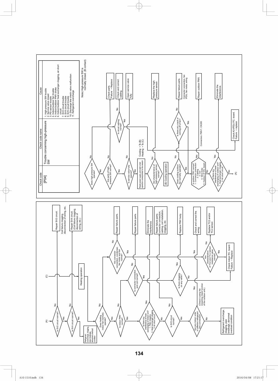
143
(A)Ye
s
Yes
Yes Ye
s
No
No
No
No
No
Yes
Yes
Yes
No
Yes
No
No
No
Che
ck c
ode
nam
eC
ause
Che
ck c
ode
Trou
ble
conc
erni
ng h
igh-
pres
sure
SW
1. H
igh-
pres
sure
SW
trou
ble
2. S
ervi
ce v
alve
clo
sed
3. P
D s
enso
r tro
uble
4. In
door
/out
door
fan
troub
le5.
Indo
or/o
utdo
or P
MV
chok
e6.
Indo
or/o
utdo
or h
eat e
xcha
nger
clo
ggin
g, a
ir sh
ort
circ
uit
7. S
V2 c
ircui
t tro
uble
8. S
V4 c
ircui
t tro
uble
9. S
V5 c
ircui
t tro
uble
10. D
isch
arge
line
che
ck v
alve
mal
func
tion
11. R
efrig
eran
t ove
rcha
rge
Not
e) H
igh-
pres
sure
SW
is
norm
ally
clo
sed.
(B c
onta
ct)
Doe
s hi
gh-p
ress
ure
SW
oper
ate?
Are
parts
of h
igh-
pres
sure
SW
nor
mal
?
Is s
ervi
ce v
alve
fully
op
ened
?
Are
char
acte
ristic
s of
hi
gh-p
ress
ure
sens
or
norm
al?
Doe
s co
olin
g ou
tdoo
r fa
n no
rmal
ly o
pera
te?
Is th
ere
any
inte
rfere
nce
of h
eat-
exch
angi
ng o
f out
door
uni
t?1.
Hea
t exc
hang
er c
logg
ing
2. A
ir sh
ort c
ircui
t
Is th
ere
any
crac
k or
co
min
g-of
f of f
an?
Con
nect
or c
onne
ctio
n, fa
n IP
DU
, fan
mot
or, w
iring
Con
nect
ors:
PM
V1: C
N30
0
Is c
ircui
t cab
ling
norm
al?
Che
ck p
arts
.Fa
ilure
Rep
lace
Che
ck a
nd c
orre
ct
cabl
ing.
Ope
n se
rvic
e va
lve
fully
.
Rep
lace
the
high
-pr
essu
re s
enso
r.
Rep
air f
ailu
re p
arts
.
Rep
air o
utdo
or P
MV.
Elim
inat
e th
e in
terfe
renc
e.
Che
ck A
3-IP
DU
P.C
. boa
rd.
Failu
re re
plac
e
(B) C
oolin
g op
erat
ion
Coo
ling
To (B
)H
eatin
g To
(C)
Rese
t pow
er su
pply,
and s
tart a
test
oper
ation
corre
spon
ded t
o the
seas
on.
Is o
utdo
or P
MV
norm
al?
1. C
onne
ctor
con
nect
ion
2. C
ablin
g3.
Coi
l4.
Val
ve b
ody
5. O
utdo
or I/
F P.
C. b
oard
Yes
Yes
Yes
No
No
Yes
No
Yes
No
No
No
No
No
Yes
No
Yes
Yes
Yes
Yes
Yes
Yes
No
No
(C)
(A)
Is S
V2 c
ircui
t nor
mal
?
Is S
V4 c
ircui
t nor
mal
?
Doe
s he
atin
g in
door
fan
norm
ally
op
erat
e?
Are
conn
ecto
r co
nnec
tion,
con
dens
er,
fan
mot
or a
nd fa
n no
rmal
?
Is c
onne
ctor
con
nect
ion
and
coil
norm
al?
Is th
ere
clog
ging
on
any
val
ve?
Are
char
acte
ristic
sof
TC
2 an
d TC
J se
nsor
re
sist
ance
val
ue
norm
al?
Is in
door
PM
V no
rmal
?
Is S
V5 c
ircui
t no
rmal
?
(Che
ck it
usi
ng th
e m
isw
iring
che
ck fu
nctio
n of
the
outd
oor u
nit.)
Are
any
indo
or u
nits
of
diff
eren
t ref
riger
ant
line
conn
ecte
d?
Is th
ere
any
inte
rfere
nce
of h
eat-
exch
angi
ng o
f ind
oor u
nit?
1. F
ilter c
logg
ing
2. H
eat e
xcha
nger
clo
ggin
g3.
Air
shor
t circ
uit
Rep
air S
V2 c
ircui
t.
Rep
air S
V4 c
ircui
t.(C
oil f
ailu
re c
logg
ing,
di
scon
nect
ion
of
wiri
ng, e
tc.)
Rep
air f
ailu
re p
arts
.
Rep
air f
ailu
re p
arts
.
Elim
inat
e th
e in
terfe
renc
e.
Rep
lace
PM
V bo
dy.
Che
ck a
nd c
orre
ct th
e w
iring
.
Rep
lace
TC
2 an
d/or
TC
J se
nsor
.
Rep
air f
ailu
re p
arts
; co
nnec
tor c
onne
ctio
n,
cabl
ing,
coi
l ins
talla
tion,
cl
oggi
ng, e
tc
Ref
riger
ant o
verc
harg
e,
clog
ging
, pip
e br
eaka
ge, a
bnor
mal
ov
erlo
ad c
ondi
tion
Che
ck in
door
P.C
. boa
rd.
Failu
re R
epla
ce
Hea
ting
oper
atio
n
Refrig
eran
tov
erch
arge
, clog
ging,
pipe b
reak
age,
abno
rmal
over
load
cond
ition
Coi
l fai
lure
clo
ggin
g,
disc
onne
ctio
n of
wiri
ng, e
tc.
[P04
]
134
A10-1510.indb 134A10-1510.indb 134 2016/04/08 17:21:172016/04/08 17:21:17
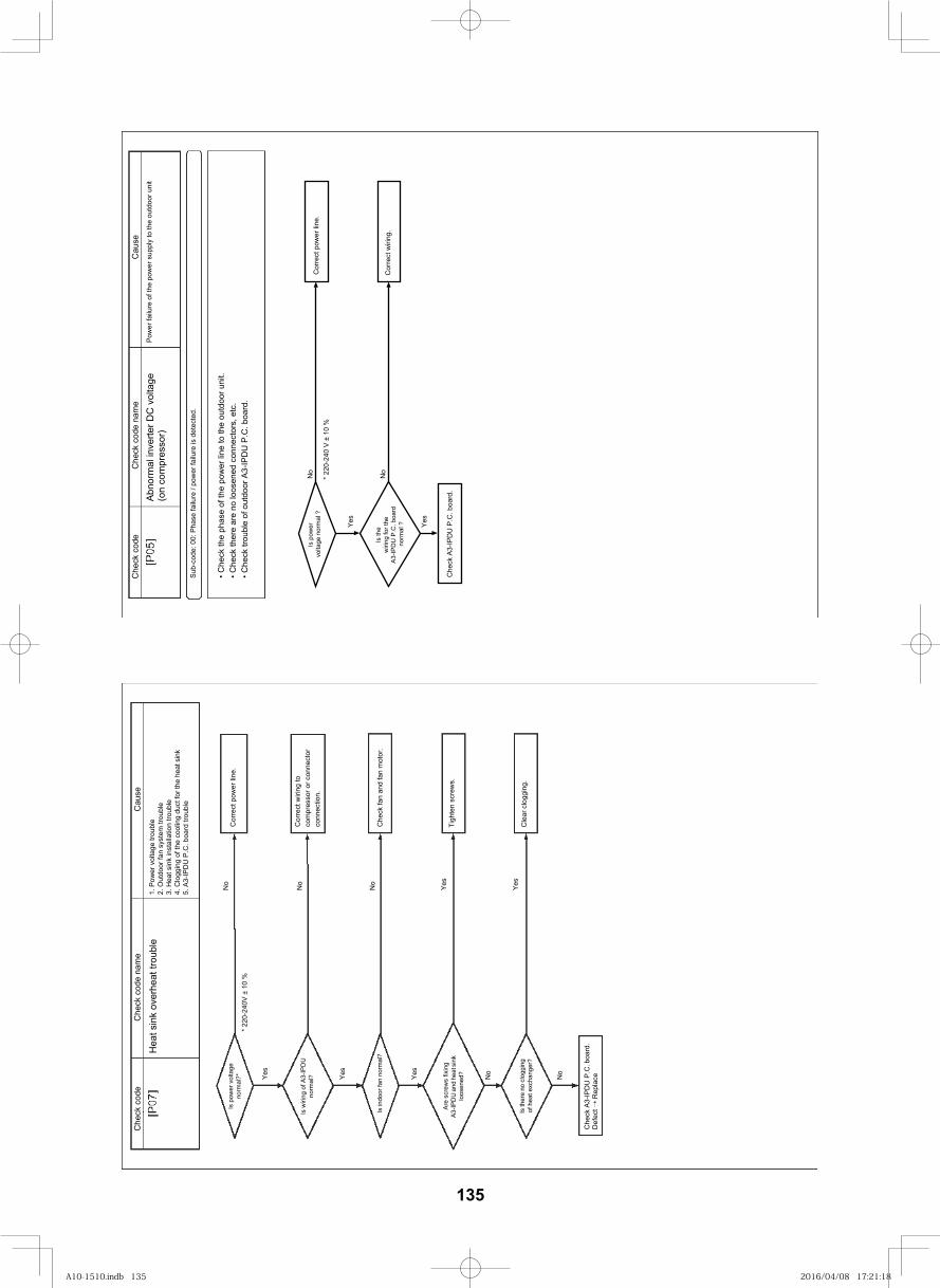
144
esuaC
eman edoc kceh
Cedoc kceh
C
Hea
t sin
k ov
erhe
at tr
oubl
e1.
Pow
er v
olta
ge tr
oubl
e2.
Out
door
fan
syst
em tr
oubl
e3.
Hea
t sin
k in
stal
latio
n tro
uble
4. C
logg
ing
of th
e co
olin
g du
ct fo
r the
hea
t sin
k5.
A3-
IPD
U P
.C. b
oard
trou
ble
Is w
iring
of A
3-IP
DU
no
rmal
?
Is p
ower
vol
tage
no
rmal
?*
Is in
door
fan
norm
al?
Yes
Yes
No
No
No
Yes
Cor
rect
pow
er li
ne.
Cor
rect
wiri
ng to
co
mpr
esso
r or c
onne
ctor
co
nnec
tion.
Che
ck fa
n an
d fa
n m
otor
.
Yes
Tigh
ten
scre
ws.
Cle
ar c
logg
ing.
Are
scre
ws
fixin
g A3
-IPD
U a
nd h
eat s
ink
loos
ened
?
Is th
ere
no c
logg
ing
of h
eat e
xcha
nger
?
Yes
No
No
Che
ck A
3-IP
DU
P.C
. boa
rd.
* 220
-240
V ±
10 %
Def
ect
Rep
lace
esuaC
eman edoc kceh
Cedoc kceh
C
Abno
rmal
inve
rter D
C v
olta
ge
(on
com
pres
sor)
Pow
er fa
ilure
of t
he p
ower
sup
ply
to th
e ou
tdoo
r uni
t
Sub-
code
: 00:
Pha
se fa
ilure
/ po
wer
failu
re is
det
ecte
d.
Che
ck th
e ph
ase
of th
e po
wer
line
to th
e ou
tdoo
r uni
t. C
heck
ther
e ar
e no
loos
ened
con
nect
ors,
etc
. C
heck
trou
ble
of o
utdo
or A
3-IP
DU
P.C
. boa
rd.
Is p
ower
vo
ltage
nor
mal
?C
orre
ct p
ower
line
.
Cor
rect
wiri
ng.
Yes
Yes
Che
ck A
3-IP
DU
P.C
. boa
rd.
No
No
* 220
-240
V ±
10
%
Is th
e w
iring
for t
he
A3-IP
DU
P.C
. boa
rd
norm
al ?
135
A10-1510.indb 135A10-1510.indb 135 2016/04/08 17:21:182016/04/08 17:21:18
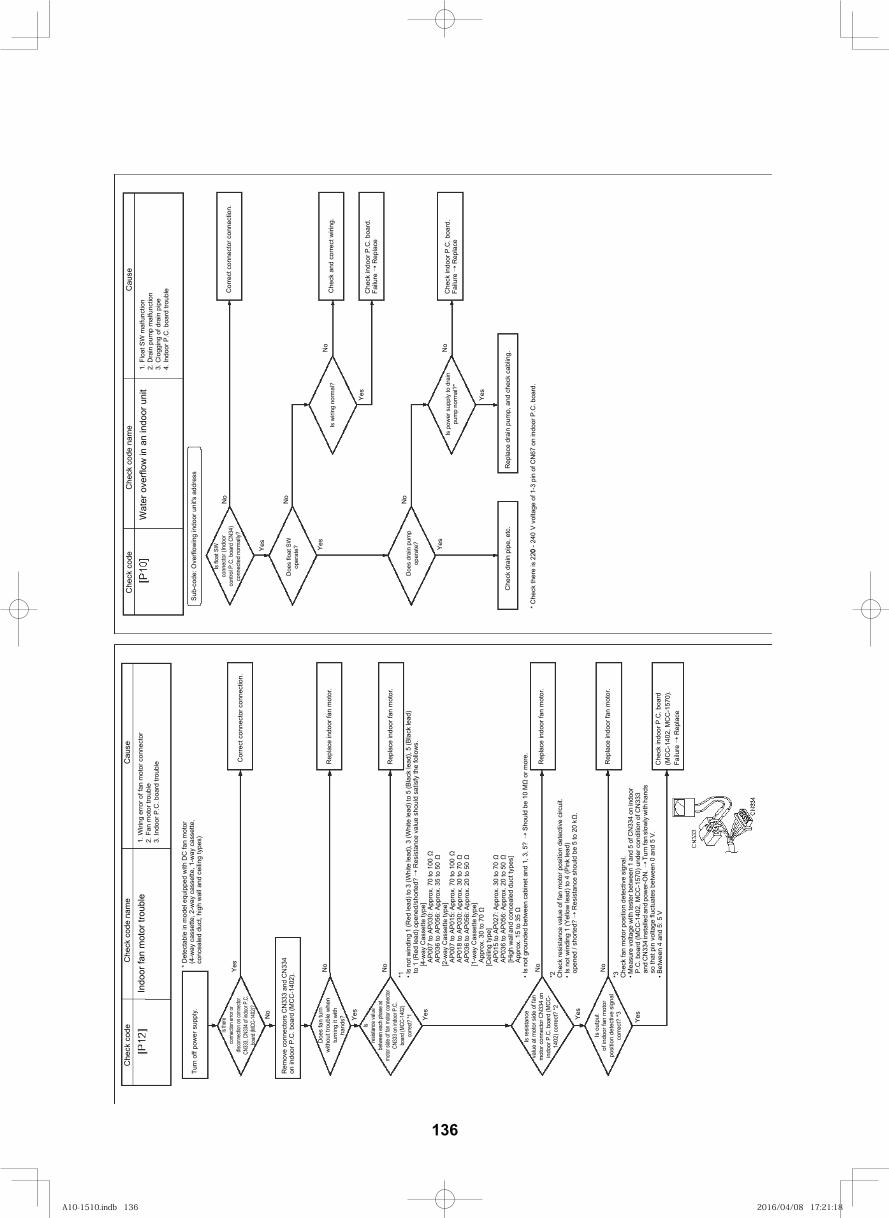
145
esuaC
eman edoc kceh
Cedoc kceh
C
Indo
or fa
n m
otor
trou
ble
1. W
iring
erro
r of f
an m
otor
con
nect
or2.
Fan
mot
or tr
oubl
e3.
Indo
or P
.C. b
oard
trou
ble
* D
etec
tabl
e in
mod
el e
quip
ped
with
DC
fan
mot
or(4
-way
cas
sette
, 2-w
ay c
asse
tte, 1
-way
cas
sette
, co
ncea
led
duct
, hig
h w
all
an
d ce
iling
type
s)Tu
rn o
ff po
wer
sup
ply.
Yes
No
No
No
Yes
Is the
reco
nnec
tion e
rror o
rdis
conn
ectio
n on c
onne
ctor
CN33
3, CN
334 o
f indo
or P
.C.
boar
d (MC
C-14
02)?
Rem
ove
conn
ecto
rs C
N33
3 an
d C
N33
4on
indo
or P
.C. b
oard
(MC
C-1
402)
.
Doe
s fa
n tu
rnw
ithou
t tro
uble
whe
ntu
rnin
g it
with
hand
s?
Isre
sista
nce
value
betw
een
each
pha
se at
mot
or si
de o
f fan
mot
or co
nnec
tor
CN33
3 on i
ndoo
r P.C
.bo
ard (
MCC
-140
2)co
rrect?
*1 Yes
No
No
Is re
sist
ance
valu
e at
mot
or s
ide
of fa
nm
otor
con
nect
or C
N33
4 on
indo
or P
.C. b
oard
(MC
C-
1402
) cor
rect
? *2
Is o
utpu
tof
indo
or fa
n m
otor
posi
tion
dete
ctiv
e si
gnal
corre
ct?
*3Yes
*1 Is n
ot w
indi
ng 1
(Red
lead
) to
3 (W
hite
lead
), 3
(Whi
te le
ad) t
o 5
(Bla
ck le
ad),
5 (B
lack
lead
) to
1 (R
ed le
ad) o
pene
d/sh
orte
d?
Res
ista
nce
valu
e sh
ould
sat
isfy
the
follo
ws.
[4-w
ay C
asse
tte ty
pe]
AP0
07 to
AP0
30: A
ppro
x. 7
0 to
100
A
P036
to A
P056
: App
rox.
35
to 5
0 [2
-way
Cas
sette
type
]A
P007
to A
P015
: App
rox.
70
to 1
00
AP0
18 to
AP0
30: A
ppro
x. 3
0 to
70
AP0
36 to
AP0
56: A
ppro
x. 2
0 to
50
[1-w
ay C
asse
tte ty
pe]
App
rox.
30
to 7
0 [C
eilin
g ty
pe]
AP0
15 to
AP0
27: A
ppro
x. 3
0 to
70
AP0
36 to
AP0
56: A
ppro
x. 2
0 to
50
[Hig
h w
all a
nd c
once
aled
duc
t typ
es]
App
rox.
15
to 3
5 Is
not
gro
unde
d be
twee
n ca
bine
t and
1, 3
, 5?
Sho
uld
be 1
0 M
or m
ore.
*2 Che
ck re
sist
ance
val
ue o
f fan
mot
or p
ositi
on d
etec
tive
circ
uit.
Is n
ot w
indi
ng 1
(Yel
low
lead
) to
4 (P
ink
lead
)op
ened
/ sh
orte
d?
Res
ista
nce
shou
ld b
e 5
to 2
0 k
.
*3 Che
ck fa
n m
otor
pos
ition
det
ectiv
e si
gnal
. M
easu
re v
olta
ge w
ith te
ster
bet
wee
n 1
and
5 of
CN
334
on in
door
P.
C. b
oard
(MC
C-1
402,
MC
C-1
570)
und
er c
ondi
tion
of C
N33
3 an
d C
N33
4 in
stal
led
and
pow
er-O
N.
Tur
n fa
n sl
owly
with
han
ds
so th
at p
in v
olta
ge fl
uctu
ates
bet
wee
n 0
and
5 V
. B
etw
een
4 an
d 5:
5 V
Rep
lace
indo
or fa
n m
otor
.
Rep
lace
indo
or fa
n m
otor
.
Cor
rect
con
nect
or c
onne
ctio
n.
Rep
lace
indo
or fa
n m
otor
.
Rep
lace
indo
or fa
n m
otor
.
Che
ck in
door
P.C
. boa
rd
(MC
C-1
402,
MC
C-1
570)
.Fa
ilure
R
epla
ce
Yes
esuaC
eman edoc kceh
Cedoc kceh
C
Wat
er o
verfl
ow in
an
indo
or u
nit
1. F
loat
SW
mal
func
tion
2. D
rain
pum
p m
alfu
nctio
n3.
Clo
ggin
g of
dra
in p
ipe
4. In
door
P.C
. boa
rd tr
oubl
e
Sub
-cod
e: O
verfl
owin
g in
door
uni
t's a
ddre
ss
Yes Ye
s
Yes
No
Che
ck d
rain
pip
e, e
tc.
* Che
ck th
ere
is 2
20 -
240
0V
vol
tage
of 1
-3 p
in o
f CN
67 o
n in
door
P.C
. boa
rd.
Doe
s dr
ain
pum
p op
erat
e?
Doe
s flo
at S
W
oper
ate?
Is fl
oat S
Wco
nnec
tor (
Indo
orco
ntro
l P.C
. boa
rd C
N34)
co
nnec
ted
norm
ally?
No
No
Rep
lace
dra
in p
ump,
and
che
ck c
ablin
g.
Is p
ower
sup
ply
to d
rain
pu
mp
norm
al?*
Is w
iring
nor
mal
?
Cor
rect
con
nect
or c
onne
ctio
n.
Che
ck a
nd c
orre
ct w
iring
.
Che
ck in
door
P.C
. boa
rd.
Failu
re
Rep
lace
Che
ck in
door
P.C
. boa
rd.
Failu
re
Rep
lace
No
Yes
Yes
No
136
A10-1510.indb 136A10-1510.indb 136 2016/04/08 17:21:182016/04/08 17:21:18
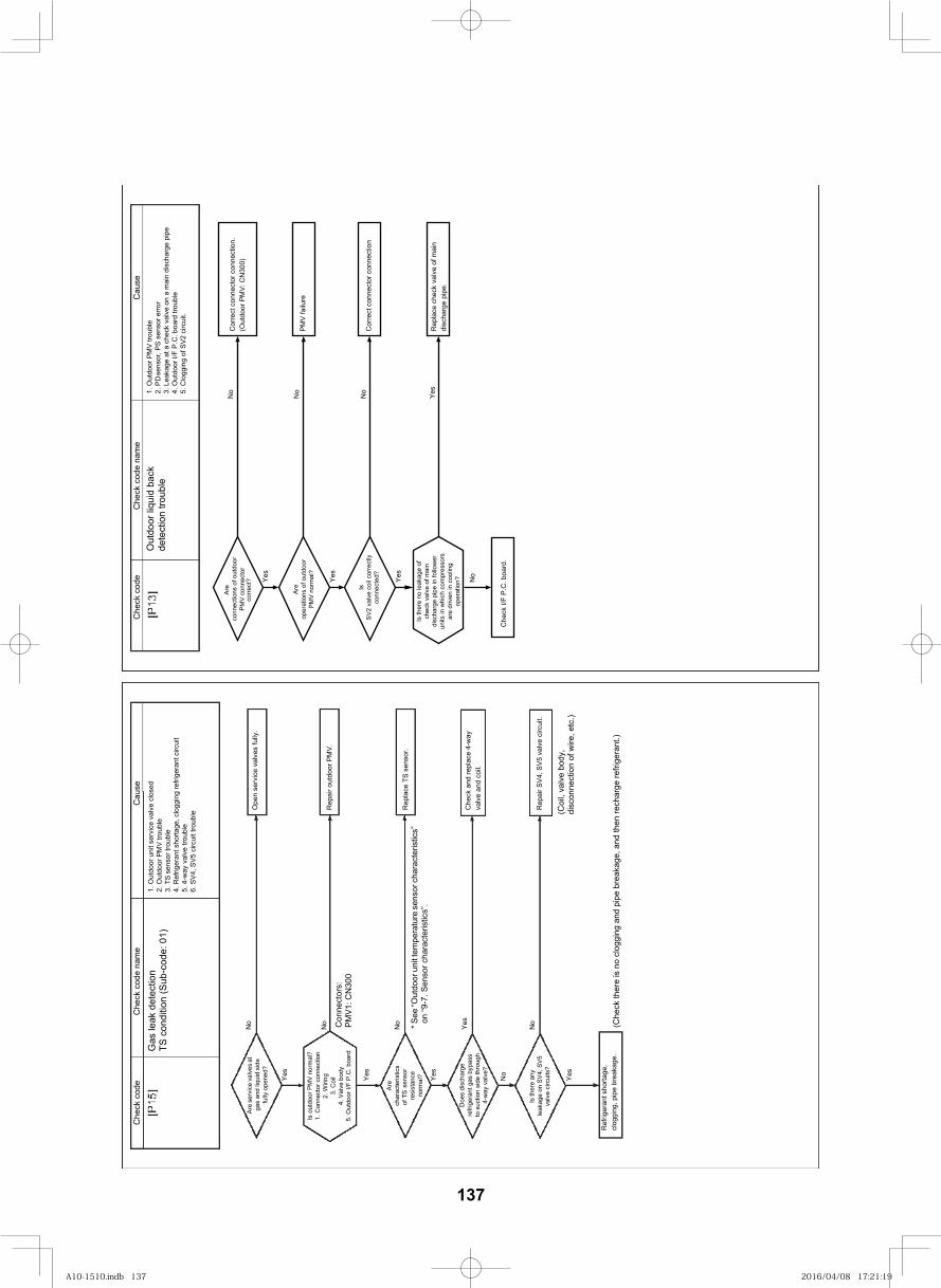
146
* See
“Out
door
uni
t tem
pera
ture
sen
sor c
hara
cter
istic
s”
on “9
-7. S
enso
r cha
ract
eris
tics”
.
esuaC
eman edoc kceh
Cedoc kceh
C
Gas
leak
det
ectio
nTS
con
ditio
n (S
ub-c
ode:
01)
1. O
utdo
or u
nit s
ervi
ce v
alve
clo
sed
2. O
utdo
or P
MV
trou
ble
3. T
S se
nsor
trou
ble
4. R
efrig
eran
t sho
rtage
, clo
ggin
g re
frige
rant
circ
uit
5. 4
-way
val
ve tr
oubl
e6.
SV
4, S
V5
circ
uit t
roub
le
Yes
Yes
Yes
No
Yes
No
No
No
No
YesCon
nect
ors:
PM
V1: C
N30
0
Ope
n se
rvic
e va
lves
fully
.
Rep
air o
utdo
or P
MV.
Are
ser
vice
val
ves
at
gas
and
liqui
d si
de
fully
ope
ned?
Is o
utdo
or P
MV
nor
mal
?1.
Con
nect
or c
onne
ctio
n2.
Wiri
ng3.
Coi
l4.
Val
ve b
ody
5. O
utdo
or I/
F P
.C. b
oard
Are
char
acte
ristic
sof
TS
sens
orre
sist
ance
norm
al?
Doe
s di
scha
rge
refri
gera
nt g
as b
ypas
sto
suc
tion
side
thro
ugh
4-w
ay v
alve
?
leak
age
on S
V4,
SV
5
Ref
riger
ant s
horta
ge,
clog
ging
, pip
e br
eaka
ge.
Rep
lace
TS
sens
or.
Che
ck a
nd re
plac
e 4-
way
va
lve
and
coil.
Rep
air S
V4,
SV
5 va
lve
circ
uit.
(Che
ck th
ere
is n
o cl
oggi
ng a
nd p
ipe
brea
kage
, and
then
rech
arge
refri
gera
nt.)
(Coi
l, va
lve
body
, di
scon
nect
ion
of w
ire, e
tc.)
esuaC
eman edoc kceh
Cedoc kceh
CO
utdo
or li
quid
bac
k de
tect
ion
troub
le1.
Out
door
PM
V tr
oubl
e2.
PD
sens
or, P
S se
nsor
erro
r3.
Lea
kage
at a
che
ck v
alve
on
a m
ain
disc
harg
e pi
pe4.
Out
door
I/F
P.C
. boa
rd tr
oubl
e5.
Clo
ggin
g of
SV
2 ci
rcui
t.
Are
conn
ectio
ns o
f out
door
corr
ect?
No
No
Yes
Cor
rect
con
nect
or c
onne
ctio
n.(O
utdo
or P
MV
: CN
300)
PM
V fa
ilure
Are
oper
atio
ns o
f out
door
No
Yes
Yes
Yes
No
Is th
ere
no le
akag
e of
chec
k va
lve
of m
ain
disc
harg
e pi
pe in
follo
wer
units
in w
hich
com
pres
sors
are
driv
en in
coo
ling
oper
atio
n?
Che
ck I/
F P
.C. b
oard
.
Rep
lace
che
ck v
alve
of m
ain
disc
harg
e pi
pe.
IsS
V2
valv
e co
il co
rrec
tlyco
nnec
ted?
Cor
rect
con
nect
or c
onne
ctio
n
Is th
ere
any
valv
e ci
rcui
ts?
PM
V c
onne
ctor
PM
V n
orm
al?
137
A10-1510.indb 137A10-1510.indb 137 2016/04/08 17:21:192016/04/08 17:21:19
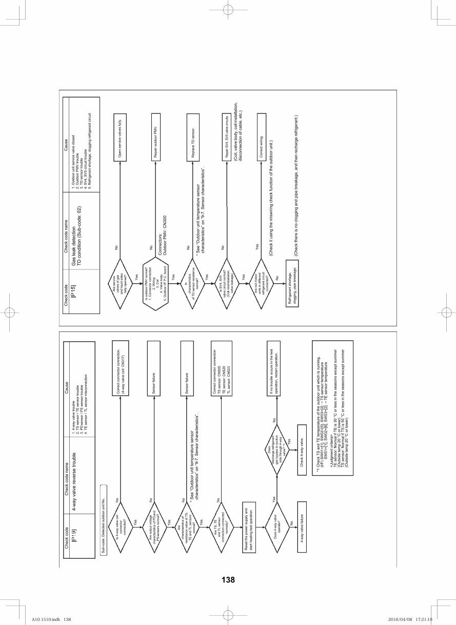
147
* See
“Out
door
uni
t tem
pera
ture
sen
sor
char
acte
ristic
s” o
n “9
-7. S
enso
r cha
ract
eris
tics”
.
esuaC
eman edoc kceh
Cedoc kceh
C
4-w
ay v
alve
reve
rse
troub
le1.
4-w
ay v
alve
trou
ble
2. T
S s
enso
r / T
E se
nsor
trou
ble
3. P
D se
nsor
/ P
S s
enso
r tro
uble
4. T
E se
nsor
/ TL
sen
sor m
isco
nnec
tion
Sub-
code
: Det
ecte
d ou
tdoo
r uni
t No. No
No
No
No
Yes
Yes
Yes
Yes
Is 4
-way
val
ve c
oil
conn
ecto
r co
nnec
ted?
Are
out
put v
olta
gech
arac
teris
tics
of P
D an
dP
S se
nsor
s no
rmal
?
Are
char
acte
ristic
s of
resi
stan
ce v
alue
of T
S,TE
and
TL
sens
ors
norm
al?
Are
TS
, TE
and
TL s
enso
rco
nnec
tors
con
nect
edno
rmal
ly?
Res
et th
e po
wer
sup
ply
and
star
t hea
ting
test
ope
ratio
n.
Doe
s 4-
way
val
ve
oper
ate?
4-w
ay v
alve
failu
re
No
Doe
sdi
scha
rge
refri
gera
ntga
s by
pass
to s
uctio
nsi
de th
roug
h 4-
way
valv
e? *
1
Che
ck 4
-way
val
ve.
*1 C
heck
TS
and
TE
tem
pera
ture
of t
he o
utdo
or u
nit w
hich
is ru
nnin
g.(I/
F) S
W01
=[1]
, SW
02=[
5], S
W03
=[2]
T
S s
enso
r tem
pera
ture
SW
01=[
1], S
W02
=[6]
, SW
03=[
2]
TE
sen
sor t
empe
ratu
re<J
udgm
ent c
riter
ia>
TE s
enso
r: N
orm
al if
TE
is 3
0 °C
or l
ess
in th
e se
ason
s ex
cept
sum
mer
(O
utsi
de te
mp
20 °
C o
r low
er)
TS s
enso
r: N
orm
al if
TS
is 5
0 °C
or l
ess
in th
e se
ason
s ex
cept
sum
mer
(O
utsi
de te
mp
20 °
C o
r low
er)
Cor
rect
con
nect
or c
onne
ctio
n.(4
-way
val
ve c
oil:
CN
317)
Sen
sor f
ailu
re
Sen
sor f
ailu
re
Cor
rect
con
nect
or c
onne
ctio
nTS
sen
sor:
CN
505
TE s
enso
r: C
N52
0TL
sen
sor:
CN
523
If no
trou
ble
occu
rs in
the
test
oper
atio
n, re
star
t ope
ratio
n.N
o
Yes
* See
“Out
door
uni
t tem
pera
ture
sen
sor
char
acte
ristic
s” o
n “9
-7. S
enso
r cha
ract
eris
tics”
.
esuaC
eman edoc kceh
Cedoc kceh
C
Gas
leak
det
ectio
nTD
con
ditio
n (S
ub-c
ode:
02)
1. O
utdo
or u
nit s
ervi
ce v
alve
clo
sed
2. O
utdo
or P
MV
trou
ble
3. T
D s
enso
r tro
uble
4. S
V4,
SV
5 ci
rcui
t tro
uble
5. R
efrig
eran
t sho
rtage
, clo
ggin
g re
frige
rant
circ
uit
No
No
No
No
Yes
(Che
ck it
usi
ng th
e m
isw
iring
che
ck fu
nctio
n of
the
outd
oor u
nit.)
Con
nect
ors:
O
utdo
or P
MV
: CN
300
Ope
n se
rvic
e va
lves
fully
.
Rep
air o
utdo
or P
MV.
Rep
lace
TD
sen
sor.
(Coi
l, va
lve
body
, coi
l inst
alla
tion,
di
scon
nect
ion
of c
able
, etc
.)
Cor
rect
wiri
ng.
Are
ser
vice
valv
es o
f gas
and
liqui
d si
des
fully
ope
ned? Ye
s
Yes
Yes
Yes
No
Is o
utdo
or P
MV
nor
mal
?1.
Con
nect
or c
onne
ctio
n2.
Wiri
ng3.
Coi
l4.
Val
ve b
ody
5. O
utdo
or I/
F P
.C. b
oard
Isch
arac
teris
tics
of T
D s
enso
r res
ista
nce
norm
al?
(Coi
l mis
inst
alla
tion,
valv
e le
akag
e)
Are
not
indo
orun
its in
diff
eren
tre
frige
rant
circ
uit
conn
ecte
d?
Ref
riger
ant s
horta
ge,
clog
ging
, pip
e br
eaka
ge.
(Che
ck th
ere
is n
o cl
oggi
ng a
nd p
ipe
brea
kage
, and
then
rech
arge
refri
gera
nt.)
Repa
ir SV
4, S
V5 v
alve
circ
uits
.
Is S
V4,
SV
5va
lve
circ
uit n
orm
al?
138
A10-1510.indb 138A10-1510.indb 138 2016/04/08 17:21:192016/04/08 17:21:19
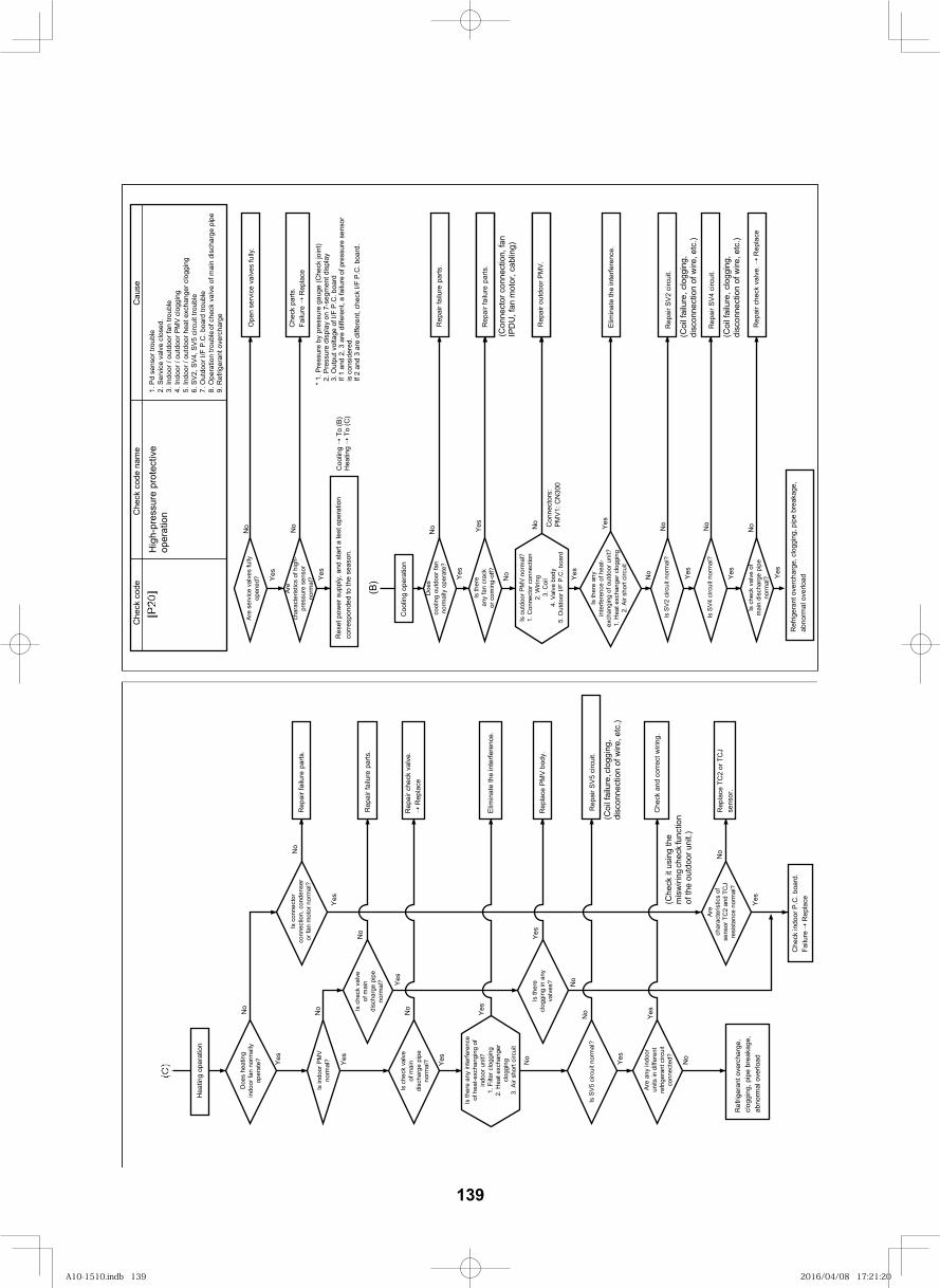
148
Hea
ting
oper
atio
n
Doe
s he
atin
gin
door
fan
norm
ally
oper
ate?
Is in
door
PM
Vno
rmal
?
Is c
heck
val
veof
mai
ndi
scha
rge
pipe
norm
al?
Is th
ere
any
inte
rfere
nce
of h
eat-e
xcha
ngin
g of
indo
or u
nit?
1. F
ilter
clo
ggin
g2.
Hea
t exc
hang
ercl
oggi
ng3.
Air
shor
t circ
uit
Are
any
indo
orun
its in
diff
eren
tre
frige
rant
circ
uit
conn
ecte
d?
Ref
riger
ant o
verc
harg
e,cl
oggi
ng, p
ipe
brea
kage
,ab
norm
al o
verlo
ad
Is c
heck
val
veof
mai
ndi
scha
rge
pipe
norm
al?
Is th
ere
clog
ging
in a
nyva
lves
?
Is c
onne
ctor
conn
ectio
n, c
onde
nser
or fa
n m
otor
nor
mal
?
Are
char
acte
ristic
s of
sens
or T
C2
and
TCJ
resi
stan
ce n
orm
al?
Che
ck in
door
P.C
. boa
rd.
Failu
re R
epla
ce
Rep
air f
ailu
re pa
rts.
Rep
air c
heck
val
ve.
Rep
lace
Elim
inat
e th
e in
terfe
renc
e.
Rep
lace
PM
V b
ody.
Che
ck a
nd c
orre
ct w
iring
.
Rep
lace
TC
2 or
TC
J se
nsor
.
Rep
air f
ailu
re pa
rts.
(Che
ck it
usi
ng th
e m
isw
iring
chec
k fun
ctio
n of
the
outd
oor u
nit.)
No
Yes
Yes
Yes No
No
Yes
Is S
V5
circ
uit n
orm
al?
Yes
NoYes
No
No
No
Yes
Yes
No
Yes
No
Yes
No
Rep
air S
V5
circ
uit.
(Coi
l fai
lure
,clo
ggin
g, di
scon
nect
ion
of w
ire, e
tc.)
Are
ser
vice
val
ves
fully
op
ened
?
Are
char
acte
ristic
s of
hig
h-pr
essu
re s
enso
rno
rmal
?
Res
et p
ower
sup
ply,
and
sta
rt a
test
ope
ratio
n co
rres
pond
ed to
the
seas
on.
Coo
ling
oper
atio
n
Doe
sco
olin
g ou
tdoo
r fan
norm
ally
ope
rate
?
Is th
ere
any
fan
crac
kor
com
ing-
off?
Is o
utdo
or P
MV
nor
mal
?1.
Con
nect
or c
onne
ctio
n2.
Wiri
ng3.
Coi
l4.
Val
ve b
ody
5. O
utdo
or I/
F P
.C. b
oard
Is th
ere
any
inte
rfere
nce
of h
eat-
exch
angi
ng o
f out
door
uni
t?1.
Hea
t exc
hang
er c
logg
ing
2. A
ir sh
ort c
ircui
t
Is S
V4 c
ircui
t nor
mal
?
Is c
heck
val
ve o
fm
ain
disc
harg
e pi
peno
rmal
?
Ref
riger
ant o
verc
harg
e, c
logg
ing,
pip
e br
eaka
ge,
abno
rmal
ove
rloadY
es Yes Ye
s
Yes
Yes
Yes
Yes
No No
No Yes No
No
No
No
Coo
ling
To
(B)
Hea
ting
To
(C)
* 1. P
ress
ure
by p
ress
ure
gaug
e (C
heck
join
t)2.
Pre
ssur
e di
spla
y on
7-s
egm
ent d
ispl
ay3.
Out
put v
olta
ge o
f I/F
P.C
. boa
rdIf
1 an
d 2,
3 a
re d
iffer
ent,
a fa
ilure
of
pre
ssur
e se
nsor
is c
onsi
dere
d.If
2 an
d 3
are
diffe
rent
, che
ck I/
F P
.C. b
oard
.
Ope
n se
rvic
e va
lves
fully
.
Che
ck p
arts
.Fa
ilure
R
epla
ce
Rep
air f
ailu
re p
arts
.
Rep
air f
ailu
re p
arts
.
Rep
air o
utdo
or P
MV
.
(Con
nect
or c
onne
ctio
n, fa
n IP
DU
, fan
mot
or, c
ablin
g)
Elim
inat
e th
e in
terfe
renc
e.
Rep
air S
V4
circ
uit.
Rep
air c
heck
val
ve.
Rep
lace
(Coi
l fai
lure
, cl
oggi
ng,
disc
onne
ctio
n of
wire
, etc
.)
Is S
V2 c
ircui
t nor
mal
?
Yes
No
Rep
air S
V2
circ
uit.
(Coi
l fai
lure
, cl
oggi
ng,
disc
onne
ctio
n of
wire
, etc
.)
Con
nect
ors:
P
MV
1: C
N30
0
No
(B)
7. O
utdo
or I/
F P.
C. b
oard
trou
ble
8. O
pera
tion
troub
le of
chec
k va
lve
of m
ain
disc
harg
e pi
pe9.
Ref
riger
ant o
verc
harg
e
esuaC
1. P
d se
nsor
trou
ble
2. S
ervi
ce v
alve
clo
sed.
3. In
door
/ ou
tdoo
r fan
trou
ble
4. In
door
/ ou
tdoo
r PM
V c
logg
ing
5. In
door
/ ou
tdoo
r hea
t exc
hang
er c
logg
ing
6. S
V2,
SV
4, S
V5
circ
uit t
roub
le
eman edoc kceh
Cedoc kceh
C
Hig
h-pr
essu
re p
rote
ctiv
e op
erat
ion
139
A10-1510.indb 139A10-1510.indb 139 2016/04/08 17:21:202016/04/08 17:21:20
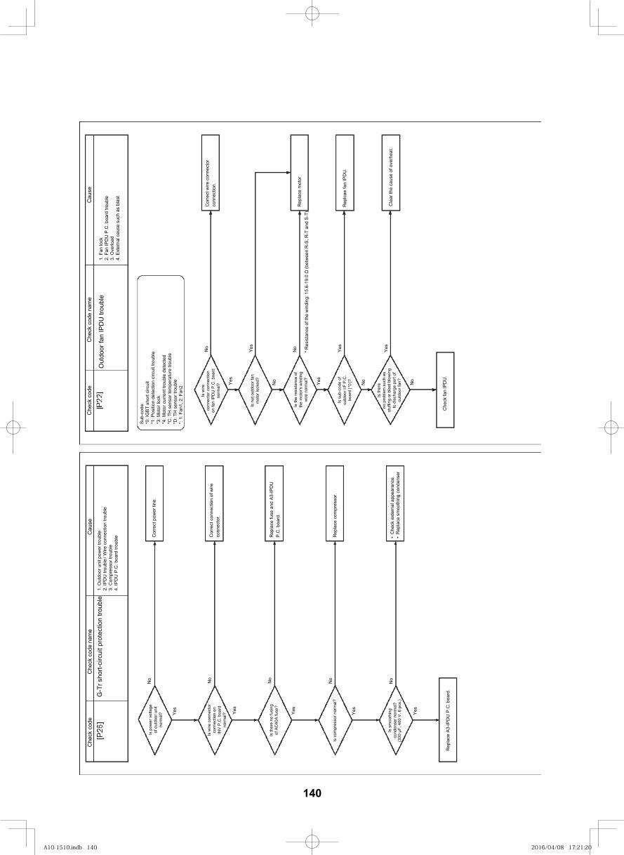
149
G-T
r sho
rt-ci
rcui
t pro
tect
ion
troub
le1.
Out
door
uni
t pow
er tr
oubl
e2.
IPD
U tr
oubl
e/
Wire
conn
ectio
n tro
uble
3. C
ompr
esso
r tro
uble
4. IP
DU
P.C
. boa
rd tr
oubl
e
Is p
ower
vol
tage
of o
utdo
or u
nit
norm
al?
Is w
ire c
onne
ctor
conn
ectio
n on
INV
P.C
. boa
rdno
rmal
?
Is th
ere
no fu
sing
of A
C40
A fu
se?
Is c
ompr
esso
r nor
mal
?
Rep
lace
A3-
IPD
U P
.C. b
oard
.
No
Yes
Yes
Yes
Yes
Cor
rect
pow
er li
ne.
Cor
rect
con
nect
ion
of w
ire
conn
ecto
r.
Rep
lace
fuse
and
A3-
IPD
U
P.C
. boa
rd.
Rep
lace
com
pres
sor.
Is s
moo
thin
gco
nden
ser n
orm
al?
(330
F,
400
V, 6
pcs
.)
Che
ck e
xter
nal a
ppea
ranc
e.R
epla
ce s
moo
thin
g co
nden
ser
Yes
No
No
No
No
esuaC
eman edoc kceh
Cedoc kceh
C
Is w
ireco
nnec
tor c
onne
ctio
non
fan
IPD
U P
.C. b
oard
norm
al?
Is n
ot o
utdo
or fa
nm
otor
lock
ed?
Is th
e re
sist
ance
of
the
mot
or's
win
ding
wire
nor
mal
?
Is s
ub-c
ode
ofou
tdoo
r I/F
P.C
.bo
ard
[ *0
]?
Is th
ere
no p
robl
em s
uch
asst
uffin
g or
bla
st b
low
ing
to d
isch
arge
por
t of
outd
oor f
an?
Che
ck fa
n IP
DU
.
Yes
No
Yes
No
No
No
Yes
No
Yes
Yes
Cor
rect
wire
con
nect
or
conn
ectio
n.
Rep
lace
mot
or
Rep
lcae
fan
IPD
U.
Cle
ar th
e ca
use
of o
verh
eat.
esuaC
eman edoc kceh
Cedoc kceh
C
Out
door
fan
IPD
U tr
oubl
e1.
Fan
lock
2. F
an IP
DU
P.C
. boa
rd tr
oubl
e3.
Ove
rload
4. E
xter
nal c
ause
suc
h as
bla
st
Sub
-cod
e:*0
: IG
BT
shor
t circ
uit
*1: P
ositi
on d
etec
tion
circ
uit t
roub
le*3
: Mot
or lo
ck*4
: Mot
or c
urre
nt tr
oubl
e de
tect
ed*C
: TH
sen
sor t
empe
ratu
re tr
oubl
e*D
: TH
sen
sor t
roub
le*:
1: F
an1,
2: F
an2
* Res
ista
nce
of th
e w
indi
ng: 1
5.6-
19.0
(b
etw
een
R-S
, R-T
and
S-T
)
140
A10-1510.indb 140A10-1510.indb 140 2016/04/08 17:21:202016/04/08 17:21:20
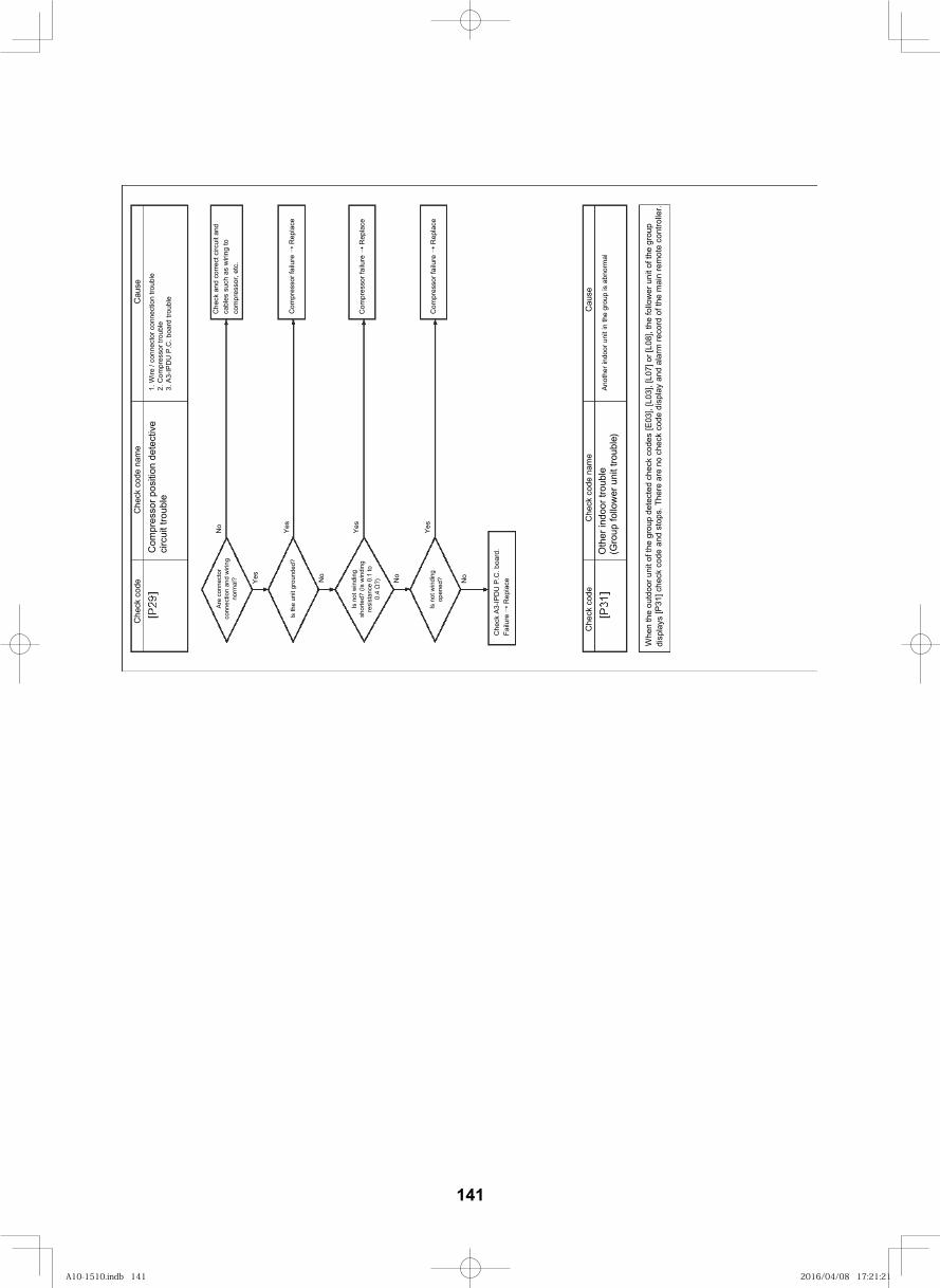
149
esuaC
eman edoc kceh
Cedoc kceh
C
Com
pres
sor p
ositi
on d
etec
tive
circ
uit t
roub
le1.
Wire
/ co
nnec
tor c
onne
ctio
n tro
uble
2. C
ompr
esso
r tro
uble
3. A
3-IP
DU
P.C
. boa
rd tr
oubl
e
Are
con
nect
orco
nnec
tion
and
wiri
ngno
rmal
?
Is th
e un
it gr
ound
ed?
Is n
ot w
indi
ngsh
orte
d? (I
s w
indi
ngre
sist
ance
0.1
to0.
4 ?)
Is n
ot w
indi
ngop
ened
?
Che
ck A
3-IP
DU
P.C
. boa
rd.
Failu
re
Rep
lace
No
No
No
No
Yes
Yes
Yes
Yes
Che
ck a
nd c
orre
ct c
ircui
t and
ca
bles
suc
h as
wiri
ng to
co
mpr
esso
r, et
c.
Com
pres
sor f
ailu
re R
epla
ce
Com
pres
sor f
ailu
re R
epla
ce
Com
pres
sor f
ailu
re R
epla
ce
Oth
er in
door
trou
ble
(Gro
up fo
llow
er u
nit t
roub
le)
Anot
her i
ndoo
r uni
t in
the
grou
p is
abn
orm
al
Whe
n th
e ou
tdoo
r uni
t of t
he g
roup
det
ecte
d ch
eck
code
s[E
03],
[L03
], [L
07] o
r [L0
8], t
he fo
llow
er u
nit o
f the
gro
up d
ispl
ays
[P31
] che
ck c
ode
an
d st
ops.
The
re a
re n
o ch
eck
code
dis
play
and
ala
rm re
cord
of t
he m
ain
rem
ote
cont
rolle
r.
esuaC
eman edoc kceh
Cedoc kceh
C
141
A10-1510.indb 141A10-1510.indb 141 2016/04/08 17:21:212016/04/08 17:21:21
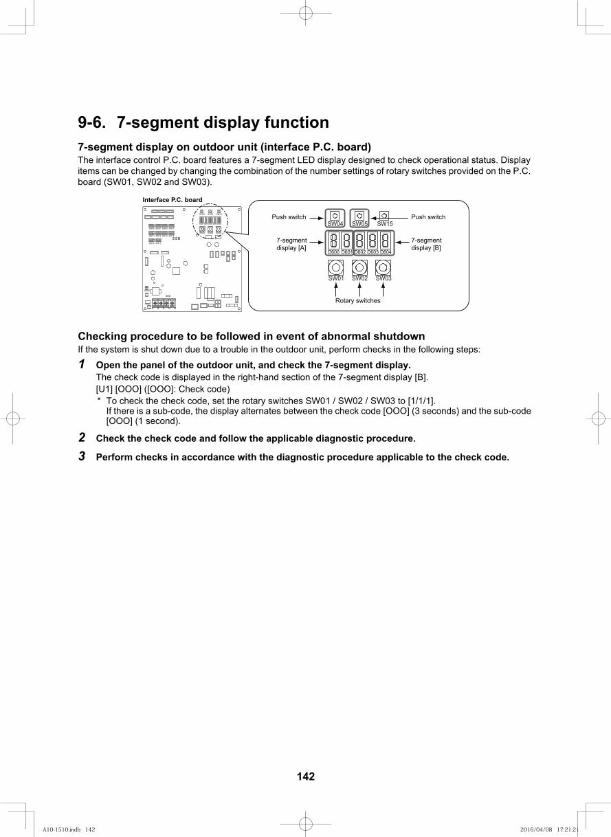
151
9-6. 7-segment display function7-segment display on outdoor unit (interface P.C. board)The interface control P.C. board features a 7-segment LED display designed to check operational status. Display items can be changed by changing the combination of the number settings of rotary switches provided on the P.C. board (SW01, SW02 and SW03).
Checking procedure to be followed in event of abnormal shutdownIf the system is shut down due to a trouble in the outdoor unit, perform checks in the following steps:
1 Open the panel of the outdoor unit, and check the 7-segment display.The check code is displayed in the right-hand section of the 7-segment display [B].[U1] [OOO] ([OOO]: Check code)* To check the check code, set the rotary switches SW01 / SW02 / SW03 to [1/1/1].
If there is a sub-code, the display alternates between the check code [OOO] (3 seconds) and the sub-code [OOO] (1 second).
2 Check the check code and follow the applicable diagnostic procedure.
3 Perform checks in accordance with the diagnostic procedure applicable to the check code.
SW09SW07
SW11
SW06 SW10
SW12 SW13
SW16
SW14
SW17
D600 D601 D602 D603 D604
SW04 SW05 SW15
SW01 SW02 SW03
SW30
D600 D601 D602 D603 D604
SW04 SW05 SW15
SW01 SW02 SW03
Interface P.C. board
Push switch
7-segment display [A]
Push switch
7-segment display [B]
Rotary switches
142
A10-1510.indb 142A10-1510.indb 142 2016/04/08 17:21:212016/04/08 17:21:21
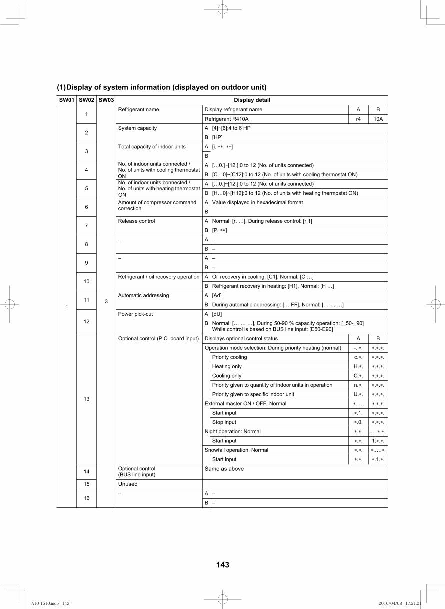
152
(1)Display of system information (displayed on outdoor unit)liated yalpsiD30WS20WS10WS
1
3
Refrigerant name
2System capacity A [4]~[6]:4 to 6 HP
B
Display refrigerant name
Refrigerant R410A
[HP]
3Total capacity of indoor units A [i. . ]
B
4No. of indoor units connected / No. of units with cooling thermostat ON
A […0.]~[12.]:0 to 12 (No. of units connected)
B [C…0]~[C12]:0 to 12 (No. of units with cooling thermostat ON)
5No. of indoor units connected / No. of units with heating thermostat ON
A […0.]~[12.]:0 to 12 (No. of units connected)
B [H…0]~[H12]:0 to 12 (No. of units with heating thermostat ON)
6Amount of compressor command correction
A Value displayed in hexadecimal format
B
7Release control A Normal: [r. …], During release control: [r.1]
B [P. ]
8–A–
B –
9–A–
B –
10Refrigerant / oil recovery operation A Oil recovery in cooling: [C1], Normal: [C …]
B Refrigerant recovery in heating: [H1], Normal: [H …]
11Automatic addressing A [Ad]
B During automatic addressing: [… FF], Normal: [… … …]
12Power pick-cut A [dU]
B Normal: [… … …], During 50-90 % capacity operation: [_50-_90]While control is based on BUS line input: [E50-E90]
13
BAsutats lortnoc lanoitpo syalpsiD)tupni draob .C.P( lortnoc lanoitpO
Operation mode selection: During priority heating (normal) -. . . . .
.cgnilooc ytiroirP . . . .
.Hylno gnitaeH . . . .
.Cylno gnilooC . . . .
Priority given to quantity of indoor units in operation n. . . . .
.Utinu roodni cificeps ot nevig ytiroirP . . . .
External master ON / OFF: Normal .…. . . .
Start input .1. . . .
Stop input .0. . . .
Night operation: Normal . . …. . .
Start input . . 1. . .
Snowfall operation: Normal . . .…. .
Start input . . .1. .
14 Optional control (BUS line input)
Same as above
15 Unused
16–A–
B –
r4 10A
A B
1
143
A10-1510.indb 143A10-1510.indb 143 2016/04/08 17:21:212016/04/08 17:21:21
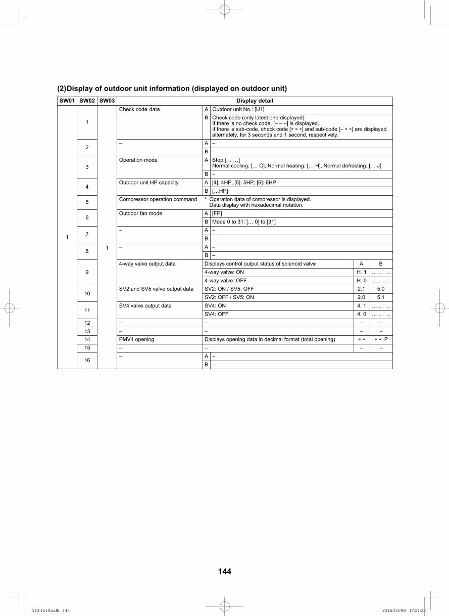
153
(2)Display of outdoor unit information (displayed on outdoor unit)liated yalpsiD30WS20WS10WS
1
]1U[ :.oN tinu roodtuOAatad Check codeB Check code (only latest one displayed)
If there is no check code, [– – –] is displayed.If there is sub-code, check code [ ] and sub-code [– ] are displayed alternately, for 3 seconds and 1 second, respectively.
2–A–
B –
3Operation mode A Stop [… …]
Normal cooling: [… C], Normal heating: [… H], Normal defrosting: [… J]B –
4Outdoor unit HP capacity A [4]: 4HP, [5]: 5HP, [6]: 6HP
B […HP]
5 Compressor operation command * Operation data of compressor is displayed.Data display with hexadecimal notation.
6Outdoor fan mode A [FP]
B Mode 0 to 31: [… 0] to [31]
7–A–
B –
8–A–
B –
94-way valve output data Displays control output status of solenoid valve A B
… … …1 .HNO :evlav yaw-4… … …0 .HFFO :evlav yaw-4
105.02.15.12.0SV2: OFF / SV5: ON
11… … …1 .4… … …0 .4FFO :4VS
12 ––––
13 ––––14 PMV1 opening Displays opening data in decimal format (total opening) . P
––––51
16–A–
B –
atad tuptuo evlav 4VS
SV2 and SV5 valve output data SV2: ON / SV5: OFF
NO :4VS
1
1
144
A10-1510.indb 144A10-1510.indb 144 2016/04/08 17:21:222016/04/08 17:21:22
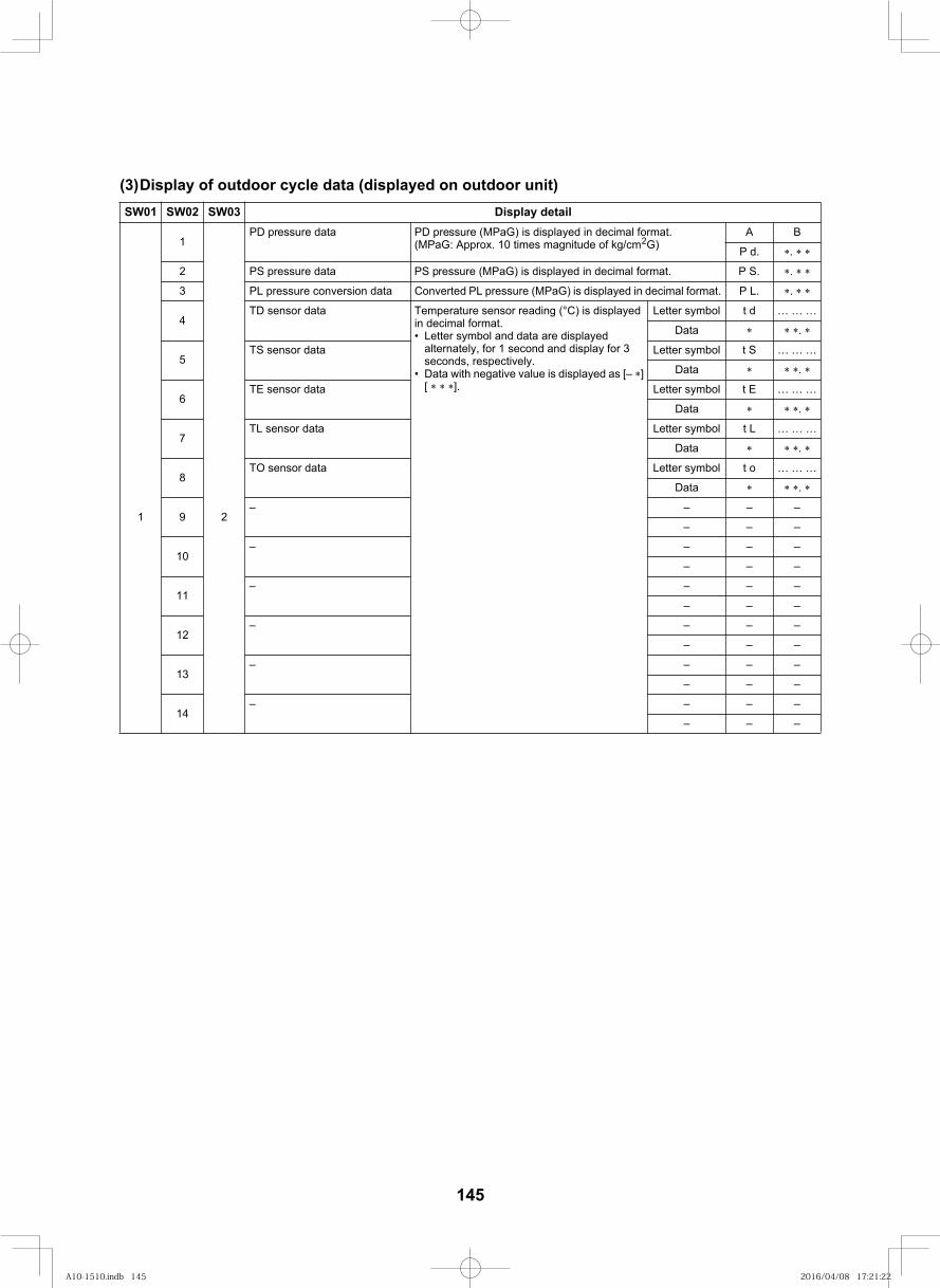
154
(3)Display of outdoor cycle data (displayed on outdoor unit)liated yalpsiD30WS20WS10WS
1
1
2
PD pressure data PD pressure (MPaG) is displayed in decimal format.(MPaG: Approx. 10 times magnitude of kg/cm2G)
A B
P d. .
2 PS pressure data PS pressure (MPaG) is displayed in decimal format. P S. .
3 PL pressure conversion data Converted PL pressure (MPaG) is displayed in decimal format. P L. .
4TD sensor data Temperature sensor reading (°C) is displayed
in decimal format.Letter symbol and data are displayed alternately, for 1 second and display for 3 seconds, respectively.Data with negative value is displayed as [– ][ ].
Letter symbol t d … … …
Data .
5… … …S tlobmys retteLatad rosnes ST
Data .
6… … …E tlobmys retteLatad rosnes ET
Data .
7… … …L tlobmys retteLatad rosnes LT
Data .
8… … …o tlobmys retteLatad rosnes OT
Data .
9– – – –
– – –
10– – – –
– – –
11– – – –
– – –
12– – – –
– – –
13– – – –
– – –
14– – – –
– – –
145
A10-1510.indb 145A10-1510.indb 145 2016/04/08 17:21:222016/04/08 17:21:22
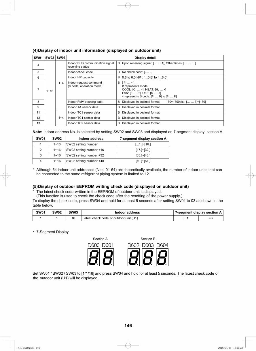
155
(4)Display of indoor unit information (displayed on outdoor unit)
Note: Indoor address No. is selected by setting SW02 and SW03 and displayed on 7-segment display, section A.
* Although 64 indoor unit addresses (Nos. 01-64) are theoretically available, the number of indoor units that can be connected to the same refrigerant piping system is limited to 12.
(5)Display of outdoor EEPROM writing check code (displayed on outdoor unit)* The latest check code written in the EEPROM of outdoor unit is displayed.
(This function is used to check the check code after the resetting of the power supply.)To display the check code , press SW04 and hold for at least 5 seconds after setting SW01 to 03 as shown in the table below.
7-Segment Display
Set SW01 / SW02 / SW03 to [1/1/16] and press SW04 and hold for at least 5 seconds. The latest check code of the
outdoor unit (U1) will be displayed.
liated yalpsiD30WS20WS10WS
4
1~16
1~4
Indoor BUS communication signal receiving status
B Upon receiving signal: [… … 1], Other times: [… … …]
5 Indoor check code B No check code: [– – –]
6 Indoor HP capacity B 0.6 to 6.0 HP : […0.6] to […6.0]
7
Indoor request command(S code, operation mode)
B [ #. … ]# represents mode: COOL: [C. … ], HEAT: [H. … ]FAN: [F. … ], OFF: [S. … ] represents S code: [#. … 0] to [#. … F]
8 Indoor PMV opening data B D 30~1500pls : [… … 3]~[150]isplayed in decimal format
9 Indoor TA sensor data B Displayed in decimal format
11
1~4
Indoor TCJ sensor data B Displayed in decimal format
12 Indoor TC1 sensor data B Displayed in decimal format
13 Indoor TC2 sensor data B Displayed in decimal format
SW03 SW02 Indoor address 7-segment display section Arebmun gnittes 20WS61~11
61+ rebmun gnittes 20WS61~12
23+ rebmun gnittes 20WS61~13
84+ rebmun gnittes 20WS61~14
sserdda roodnI30WS20WS10WS 7-segment display section A.1 .E)1U( tinu roodtuo fo check code tsetaL6111
Section A Section B
[33.]~[48.]
[49.]~[64.]
[...1.]~[16.]
[17.]~[32.]
146
A10-1510.indb 146A10-1510.indb 146 2016/04/08 17:21:222016/04/08 17:21:22
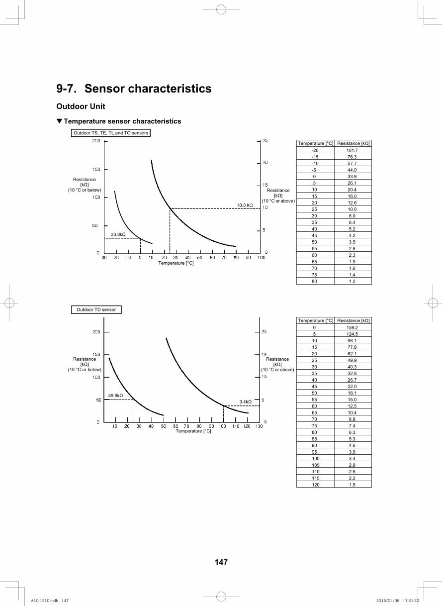
156
9-7. Sensor characteristicsOutdoor Unit
Temperature sensor characteristicsOutdoor TS, TE, TL and TO sensors
Resistance[k ]
(10 °C or below) Resistance[k ]
(10 °C or above)
Outdoor TD sensor
Temperature [°C]
Resistance[k ]
(10 °C or below)
Resistance[k ]
(10 °C or above)
Temperature [°C]
Temperature [°C] Resistance [k ]-20 101.7-15 76.3-10 57.7-5 44.0
33.826.120.4
15 16.020 12.625 10.030 8.035 6.440 5.245 4.250 3.555 2.860 2.365 1.970 1.675 1.480 1.2
Temperature [°C] Resistance [k ]159.2124.5
10 98.115 77.820 62.125 49.930 35 40 26.745 22.050 18.155 15.060 12.565 10.470 8.875 7.480 6.385 5.390 4.695 3.9100 3.4105 2.9110 2.5115 2.2120 1.9
0 5 10
0 5
40.332.8
33.8k
49.9k3.4k
147
A10-1510.indb 147A10-1510.indb 147 2016/04/08 17:21:222016/04/08 17:21:22
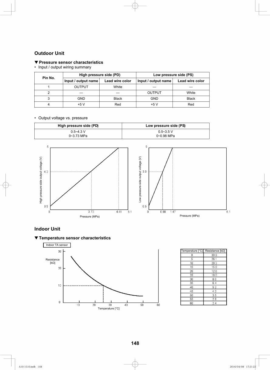
157
Outdoor Unit
Pressure sensor characteristicsInput / output wiring summary
Output voltage vs. pressure
Indoor Unit
Temperature sensor characteristics
Pin No.High pressure side (PD) Low pressure side (PS)
Input / output name Lead wire color Input / output name Lead wire color1 OUTPUT White — —
2 — — OUTPUT White
3 GND Black GND Black
4 +5 V Red +5 V Red
)SP( edis erusserp woL)DP( edis erusserp hgiH0.5~4.3 V
0~3.73 MPa0.5~3.5 V
0~0.98 MPa
Hig
h pr
essu
re-s
ide
outp
ut v
olta
ge (V
)
Low
pre
ssur
e-si
de o
utpu
t vol
tage
(V)
Pressure (MPa)Pressure (MPa)
Indoor TA sensor
Resistance[k ]
Temperature [°C]
Temperature [°C] Resistance [k ]
148
A10-1510.indb 148A10-1510.indb 148 2016/04/08 17:21:222016/04/08 17:21:22
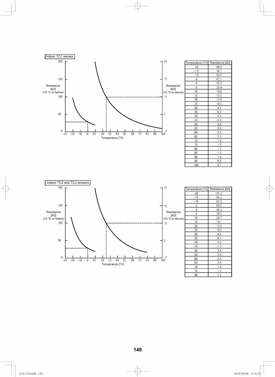
158
Temperature [°C] Resistance [k ]
Resistance[k ]
(10 °C or below)
Resistance[k ]
(10 °C or above)
Temperature [°C]
Indoor TC1 sensor
Resistance[k ]
(10 °C or below)
Resistance[k ]
(10 °C or above)
Temperature [°C]
Indoor TC2 and TCJ sensors
Temperature [°C] Resistance [k ]
149
A10-1510.indb 149A10-1510.indb 149 2016/04/08 17:21:232016/04/08 17:21:23
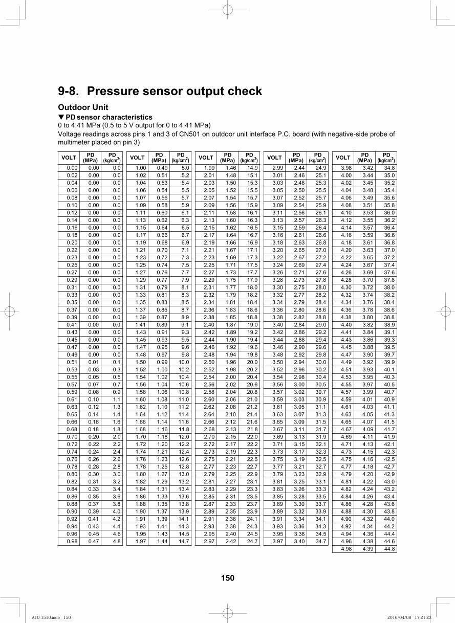
159
9-8. Pressure sensor output checkOutdoor Unit
PD sensor characteristics0 to 4.41 MPa (0.5 to 5 V output for 0 to 4.41 MPa)Voltage readings across pins 1 and 3 of CN501 on outdoor unit interface P.C. board (with negative-side probe of multimeter placed on pin 3)
VOLT PD(MPa)
PD(kg/cm2) VOLT PD
(MPa)PD
(kg/cm2) VOLT PD(MPa)
PD(kg/cm2) VOLT PD
(MPa)PD
(kg/cm2) VOLT PD(MPa)
PD(kg/cm2)
0.00 0.00 0.0 1.00 0.49 5.0 1.99 1.46 14.9 2.99 2.44 24.9 3.98 3.42 34.80.02 0.00 0.0 1.02 0.51 5.2 2.01 1.48 15.1 3.01 2.46 25.1 4.00 3.44 35.00.04 0.00 0.0 1.04 0.53 5.4 2.03 1.50 15.3 3.03 2.48 25.3 4.02 3.45 35.20.06 0.00 0.0 1.06 0.54 5.5 2.05 1.52 15.5 3.05 2.50 25.5 4.04 3.48 35.40.08 0.00 0.0 1.07 0.56 5.7 2.07 1.54 15.7 3.07 2.52 25.7 4.06 3.49 35.60.10 0.00 0.0 1.09 0.58 5.9 2.09 1.56 15.9 3.09 2.54 25.9 4.08 3.51 35.80.12 0.00 0.0 1.11 0.60 6.1 2.11 1.58 16.1 3.11 2.56 26.1 4.10 3.53 36.00.14 0.00 0.0 1.13 0.62 6.3 2.13 1.60 16.3 3.13 2.57 26.3 4.12 3.55 36.20.16 0.00 0.0 1.15 0.64 6.5 2.15 1.62 16.5 3.15 2.59 26.4 4.14 3.57 36.40.18 0.00 0.0 1.17 0.66 6.7 2.17 1.64 16.7 3.16 2.61 26.6 4.16 3.59 36.60.20 0.00 0.0 1.19 0.68 6.9 2.19 1.66 16.9 3.18 2.63 26.8 4.18 3.61 36.80.22 0.00 0.0 1.21 0.70 7.1 2.21 1.67 17.1 3.20 2.65 27.0 4.20 3.63 37.00.23 0.00 0.0 1.23 0.72 7.3 2.23 1.69 17.3 3.22 2.67 27.2 4.22 3.65 37.20.25 0.00 0.0 1.25 0.74 7.5 2.25 1.71 17.5 3.24 2.69 27.4 4.24 3.67 37.40.27 0.00 0.0 1.27 0.76 7.7 2.27 1.73 17.7 3.26 2.71 27.6 4.26 3.69 37.60.29 0.00 0.0 1.29 0.77 7.9 2.29 1.75 17.9 3.28 2.73 27.8 4.28 3.70 37.80.31 0.00 0.0 1.31 0.79 8.1 2.31 1.77 18.0 3.30 2.75 28.0 4.30 3.72 38.00.33 0.00 0.0 1.33 0.81 8.3 2.32 1.79 18.2 3.32 2.77 28.2 4.32 3.74 38.20.35 0.00 0.0 1.35 0.83 8.5 2.34 1.81 18.4 3.34 2.79 28.4 4.34 3.76 38.40.37 0.00 0.0 1.37 0.85 8.7 2.36 1.83 18.6 3.36 2.80 28.6 4.36 3.78 38.60.39 0.00 0.0 1.39 0.87 8.9 2.38 1.85 18.8 3.38 2.82 28.8 4.38 3.80 38.80.41 0.00 0.0 1.41 0.89 9.1 2.40 1.87 19.0 3.40 2.84 29.0 4.40 3.82 38.90.43 0.00 0.0 1.43 0.91 9.3 2.42 1.89 19.2 3.42 2.86 29.2 4.41 3.84 39.10.45 0.00 0.0 1.45 0.93 9.5 2.44 1.90 19.4 3.44 2.88 29.4 4.43 3.86 39.30.47 0.00 0.0 1.47 0.95 9.6 2.46 1.92 19.6 3.46 2.90 29.6 4.45 3.88 39.50.49 0.00 0.0 1.48 0.97 9.8 2.48 1.94 19.8 3.48 2.92 29.8 4.47 3.90 39.70.51 0.01 0.1 1.50 0.99 10.0 2.50 1.96 20.0 3.50 2.94 30.0 4.49 3.92 39.90.53 0.03 0.3 1.52 1.00 10.2 2.52 1.98 20.2 3.52 2.96 30.2 4.51 3.93 40.10.55 0.05 0.5 1.54 1.02 10.4 2.54 2.00 20.4 3.54 2.98 30.4 4.53 3.95 40.30.57 0.07 0.7 1.56 1.04 10.6 2.56 2.02 20.6 3.56 3.00 30.5 4.55 3.97 40.50.59 0.08 0.9 1.58 1.06 10.8 2.58 2.04 20.8 3.57 3.02 30.7 4.57 3.99 40.70.61 0.10 1.1 1.60 1.08 11.0 2.60 2.06 21.0 3.59 3.03 30.9 4.59 4.01 40.90.63 0.12 1.3 1.62 1.10 11.2 2.62 2.08 21.2 3.61 3.05 31.1 4.61 4.03 41.10.65 0.14 1.4 1.64 1.12 11.4 2.64 2.10 21.4 3.63 3.07 31.3 4.63 4.05 41.30.66 0.16 1.6 1.66 1.14 11.6 2.66 2.12 21.6 3.65 3.09 31.5 4.65 4.07 41.50.68 0.18 1.8 1.68 1.16 11.8 2.68 2.13 21.8 3.67 3.11 31.7 4.67 4.09 41.70.70 0.20 2.0 1.70 1.18 12.0 2.70 2.15 22.0 3.69 3.13 31.9 4.69 4.11 41.90.72 0.22 2.2 1.72 1.20 12.2 2.72 2.17 22.2 3.71 3.15 32.1 4.71 4.13 42.10.74 0.24 2.4 1.74 1.21 12.4 2.73 2.19 22.3 3.73 3.17 32.3 4.73 4.15 42.30.76 0.26 2.6 1.76 1.23 12.6 2.75 2.21 22.5 3.75 3.19 32.5 4.75 4.16 42.50.78 0.28 2.8 1.78 1.25 12.8 2.77 2.23 22.7 3.77 3.21 32.7 4.77 4.18 42.70.80 0.30 3.0 1.80 1.27 13.0 2.79 2.25 22.9 3.79 3.23 32.9 4.79 4.20 42.90.82 0.31 3.2 1.82 1.29 13.2 2.81 2.27 23.1 3.81 3.25 33.1 4.81 4.22 43.00.84 0.33 3.4 1.84 1.31 13.4 2.83 2.29 23.3 3.83 3.26 33.3 4.82 4.24 43.20.86 0.35 3.6 1.86 1.33 13.6 2.85 2.31 23.5 3.85 3.28 33.5 4.84 4.26 43.40.88 0.37 3.8 1.88 1.35 13.8 2.87 2.33 23.7 3.89 3.30 33.7 4.86 4.28 43.60.90 0.39 4.0 1.90 1.37 13.9 2.89 2.35 23.9 3.89 3.32 33.9 4.88 4.30 43.80.92 0.41 4.2 1.91 1.39 14.1 2.91 2.36 24.1 3.91 3.34 34.1 4.90 4.32 44.00.94 0.43 4.4 1.93 1.41 14.3 2.93 2.38 24.3 3.93 3.36 34.3 4.92 4.34 44.20.96 0.45 4.6 1.95 1.43 14.5 2.95 2.40 24.5 3.95 3.38 34.5 4.94 4.36 44.40.98 0.47 4.8 1.97 1.44 14.7 2.97 2.42 24.7 3.97 3.40 34.7 4.96 4.38 44.6
4.98 4.39 44.8
150
A10-1510.indb 150A10-1510.indb 150 2016/04/08 17:21:232016/04/08 17:21:23
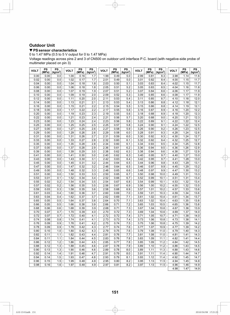
160
Outdoor UnitPS sensor characteristics
0 to 1.47 MPa (0.5 to 5 V output for 0 to 1.47 MPa)Voltage readings across pins 2 and 3 of CN500 on outdoor unit interface P.C. board (with negative-side probe of multimeter placed on pin 3)
VOLT PS(MPa)
PS(kg/cm2) VOLT PS
(MPa)PS
(kg/cm2) VOLT PS(MPa)
PS(kg/cm2) VOLT PS
(MPa)PS
(kg/cm2) VOLT PS(MPa)
PS(kg/cm2)
0.00 0.00 0.0 1.00 0.16 1.7 1.99 0.49 5.0 2.99 0.81 8.3 3.98 1.14 11.60.02 0.00 0.0 1.02 0.17 1.7 2.01 0.49 5.0 3.01 0.82 8.4 4.00 1.15 11.70.04 0.00 0.0 1.04 0.18 1.8 2.03 0.50 5.1 3.03 0.83 8.4 4.02 1.15 11.70.06 0.00 0.0 1.06 0.18 1.8 2.05 0.51 5.2 3.05 0.83 8.5 4.04 1.16 11.80.08 0.00 0.0 1.07 0.19 1.9 2.07 0.51 5.2 3.07 0.84 8.6 4.06 1.17 11.90.10 0.00 0.0 1.09 0.19 2.0 2.09 0.52 5.3 3.09 0.85 8.6 4.08 1.17 11.90.12 0.00 0.0 1.11 0.20 2.0 2.11 0.53 5.4 3.11 0.85 8.7 4.10 1.18 12.00.14 0.00 0.0 1.13 0.21 2.1 2.13 0.53 5.4 3.13 0.86 8.8 4.12 1.18 12.10.16 0.00 0.0 1.15 0.21 2.2 2.15 0.54 5.5 3.15 0.86 8.8 4.14 1.19 12.10.18 0.00 0.0 1.17 0.22 2.2 2.17 0.55 5.6 3.16 0.87 8.9 4.16 1.20 12.20.20 0.00 0.0 1.19 0.23 2.3 2.19 0.55 5.6 3.18 0.88 8.9 4.18 1.20 12.30.22 0.00 0.0 1.21 0.23 2.4 2.21 0.56 5.7 3.20 0.88 9.0 4.20 1.21 12.30.23 0.00 0.0 1.23 0.24 2.4 2.23 0.56 5.8 3.22 0.89 9.1 4.22 1.22 12.40.25 0.00 0.0 1.25 0.25 2.5 2.25 0.57 5.8 3.24 0.90 9.1 4.24 1.22 12.50.27 0.00 0.0 1.27 0.25 2.6 2.27 0.58 5.9 3.26 0.90 9.2 4.26 1.23 12.50.29 0.00 0.0 1.29 0.26 2.6 2.29 0.58 6.0 3.28 0.91 9.3 4.28 1.24 12.60.31 0.00 0.0 1.31 0.26 2.7 2.31 0.59 6.0 3.30 0.92 9.3 4.30 1.24 12.70.33 0.00 0.0 1.33 0.27 2.8 2.32 0.60 6.1 3.32 0.92 9.4 4.32 1.25 12.70.35 0.00 0.0 1.35 0.28 2.8 2.34 0.60 6.1 3.34 0.93 9.5 4.34 1.25 12.80.37 0.00 0.0 1.37 0.28 2.9 2.36 0.61 6.2 3.36 0.94 9.5 4.36 1.26 12.90.39 0.00 0.0 1.39 0.29 3.0 2.38 0.62 6.3 3.38 0.94 9.6 4.38 1.27 12.90.41 0.00 0.0 1.41 0.30 3.0 2.40 0.62 6.3 3.40 0.95 9.7 4.40 1.27 13.00.43 0.00 0.0 1.43 0.30 3.1 2.42 0.63 6.4 3.42 0.95 9.7 4.41 1.28 13.00.45 0.00 0.0 1.45 0.31 3.2 2.44 0.64 6.5 3.44 0.96 9.8 4.43 1.29 13.10.47 0.00 0.0 1.47 0.32 3.2 2.46 0.64 6.5 3.46 0.97 9.9 4.45 1.29 13.20.49 0.00 0.0 1.48 0.32 3.3 2.48 0.65 6.6 3.48 0.97 9.9 4.47 1.30 13.20.51 0.00 0.0 1.50 0.33 3.3 2.50 0.65 6.7 3.50 0.98 10.0 4.49 1.31 13.30.53 0.01 0.1 1.52 0.34 3.4 2.52 0.66 6.7 3.52 0.99 10.1 4.51 1.31 13.40.55 0.02 0.2 1.54 0.34 3.5 2.54 0.67 6.8 3.54 0.99 10.1 4.53 1.32 13.40.57 0.02 0.2 1.56 0.35 3.5 2.56 0.67 6.9 3.56 1.00 10.2 4.55 1.32 13.50.59 0.03 0.3 1.58 0.35 3.6 2.58 0.68 6.9 3.57 1.01 10.2 4.57 1.33 13.60.61 0.03 0.4 1.60 0.36 3.7 2.60 0.69 7.0 3.59 1.01 10.3 4.59 1.34 13.60.63 0.04 0.4 1.62 0.37 3.7 2.62 0.69 7.1 3.61 1.02 10.4 4.61 1.34 13.70.65 0.05 0.5 1.64 0.37 3.8 2.64 0.70 7.1 3.63 1.02 10.4 4.63 1.35 13.80.66 0.05 0.5 1.66 0.38 3.9 2.66 0.71 7.2 3.65 1.03 10.5 4.65 1.36 13.80.68 0.06 0.6 1.68 0.39 3.9 2.68 0.71 7.3 3.67 1.04 10.6 4.67 1.36 13.90.70 0.07 0.7 1.70 0.39 4.0 2.70 0.72 7.3 3.69 1.04 10.6 4.69 1.37 14.00.72 0.07 0.7 1.72 0.40 4.1 2.72 0.72 7.4 3.71 1.05 10.7 4.71 1.38 14.00.74 0.08 0.8 1.74 0.41 4.1 2.73 0.73 7.4 3.73 1.06 10.8 4.73 1.38 14.10.76 0.09 0.9 1.76 0.41 4.2 2.75 0.74 7.5 3.75 1.06 10.8 4.75 1.39 14.20.78 0.09 0.9 1.78 0.42 4.3 2.77 0.74 7.6 3.77 1.07 10.9 4.77 1.39 14.20.80 0.10 1.0 1.80 0.42 4.3 2.79 0.75 7.6 3.79 1.08 11.0 4.79 1.40 14.30.82 0.11 1.1 1.82 0.43 4.4 2.81 0.76 7.7 3.81 1.08 11.0 4.81 1.41 14.30.84 0.11 1.1 1.84 0.44 4.5 2.83 0.76 7.8 3.83 1.09 11.1 4.82 1.41 14.40.86 0.12 1.2 1.86 0.44 4.5 2.85 0.77 7.8 3.85 1.09 11.2 4.84 1.42 14.50.88 0.12 1.3 1.88 0.45 4.6 2.87 0.78 7.9 3.89 1.10 11.2 4.86 1.43 14.50.90 0.13 1.3 1.90 0.46 4.6 2.89 0.78 8.0 3.89 1.11 11.3 4.88 1.43 14.60.92 0.14 1.4 1.91 0.46 4.7 2.91 0.79 8.0 3.91 1.11 11.4 4.90 1.44 14.70.94 0.14 1.5 1.93 0.47 4.8 2.93 0.79 8.1 3.93 1.12 11.4 4.92 1.45 14.70.96 0.15 1.5 1.95 0.48 4.8 2.95 0.80 8.2 3.95 1.13 11.5 4.94 1.45 14.80.98 0.16 1.6 1.97 0.48 4.9 2.97 0.81 8.2 3.97 1.13 11.5 4.96 1.46 14.9
4.98 1.47 14.9
151
A10-1510.indb 151A10-1510.indb 151 2016/04/08 17:21:232016/04/08 17:21:23
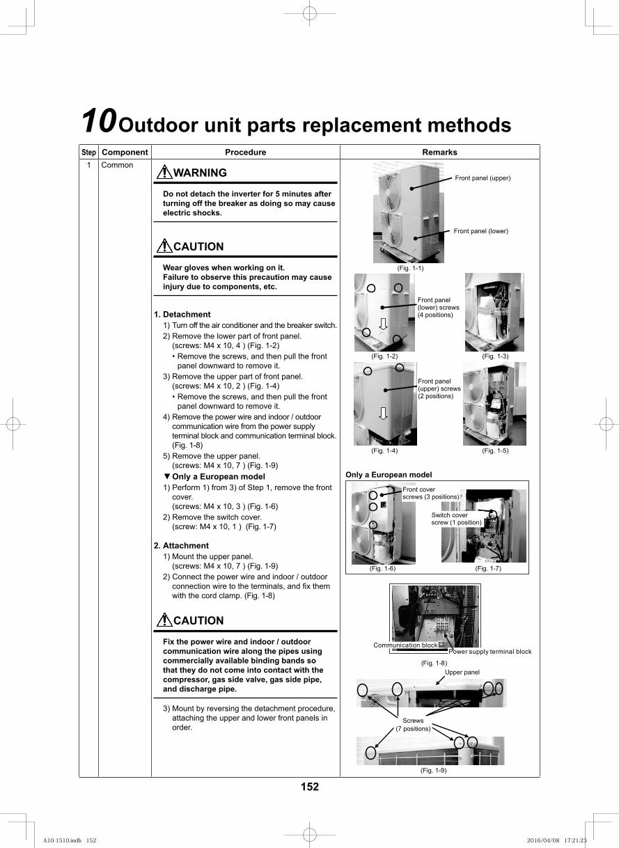
161
10Outdoor unit parts replacement methods
152
Step Component Procedure Remarks1 Common
WARNING
Do not detach the inverter for 5 minutes after turning off the breaker as doing so may cause electric shocks.
CAUTION
Wear gloves when working on it.Failure to observe this precaution may cause injury due to components, etc.
1. Detachment1) Turn off the air conditioner and the breaker switch.2) Remove the lower part of front panel.
(screws: M4 x 10, 4 ) (Fig. 1-2)• Remove the screws, and then pull the front
panel downward to remove it.3) Remove the upper part of front panel.
(screws: M4 x 10, 2 ) (Fig. 1-4)• Remove the screws, and then pull the front
panel downward to remove it.4) Remove the power wire and indoor / outdoor
communication wire from the power supply terminal block and communication terminal block. (Fig. 1-8)
5) Remove the upper panel. (screws: M4 x 10, 7 ) (Fig. 1-9)
Front panel (lower)
Front panel (upper)
Front panel(lower) screws(4 positions)
Front panel(upper) screws(2 positions)
(Fig. 1-1)
(Fig. 1-2) (Fig. 1-3)
(Fig. 1-4) (Fig. 1-5)
▼ Only a European model1) Perform 1) from 3) of Step 1, remove the front
cover. (screws: M4 x 10, 3 ) (Fig. 1-6)
2) Remove the switch cover. (screw: M4 x 10, 1 ) (Fig. 1-7)
2. Attachment1) Mount the upper panel.
(screws: M4 x 10, 7 ) (Fig. 1-9)2) Connect the power wire and indoor / outdoor
connection wire to the terminals, and fi x them with the cord clamp. (Fig. 1-8)
CAUTION
Fix the power wire and indoor / outdoor communication wire along the pipes using commercially available binding bands so that they do not come into contact with the compressor, gas side valve, gas side pipe, and discharge pipe.
3) Mount by reversing the detachment procedure, attaching the upper and lower front panels in order.
Only a European model
Upper panel
Screws(7 positions)
Front coverscrews (3 positions)
(Fig. 1-6) (Fig. 1-7)
(Fig. 1-9)
Switch coverscrew (1 position)
(Fig. 1-8)
Power supply terminal blockCommunication block
A10-1510.indb 152A10-1510.indb 152 2016/04/08 17:21:232016/04/08 17:21:23
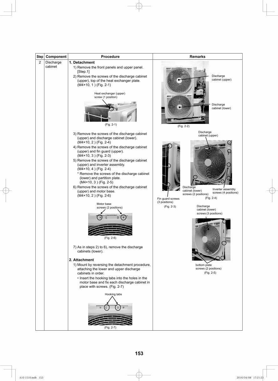
153
Step Component Procedure Remarks2 Discharge
cabinet1. Detachment
1) Remove the front panels and upper panel. [Step.1]
2) Remove the screws of the discharge cabinet (upper), top of the heat exchanger plate. (M4×10, 1 ) (Fig. 2-1)
Heat exchanger (upper)screw (1 position)
(Fig. 2-1)
3) Remove the screws of the discharge cabinet (upper) and discharge cabinet (lower). (M4×10, 2 ) (Fig. 2-4)
4) Remove the screws of the discharge cabinet (upper) and fi n guard (upper). (M4×10, 3 ) (Fig. 2-3)
5) Remove the screws of the discharge cabinet (upper) and inverter assembly. (M4×10, 4 ) (Fig. 2-4)* Remove the screws of the discharge cabinet
(lower) and partition plate.(M4×10, 3 ) (Fig. 2-5)
6) Remove the screws of the discharge cabinet (upper) and motor base. (M4×10, 2 ) (Fig. 2-6)
Motor basescrews (2 positions)
(Fig. 2-6)
7) As in steps 2) to 6), remove the discharge cabinets (lower).
2. Attachment1) Mount by reversing the detachment procedure,
attaching the lower and upper discharge cabinets in order.• Insert the hooking tabs into the holes in the
motor base and fix each discharge cabinet in place with screws. (Fig. 2-7)
Hooking tabs
(Fig. 2-7)
Dischargecabinet (lower)screws (3 positions)
bottom platescrews (2 positions)
Fin guard screws(3 positions)
Inverter assemblyDischargecabinet (lower)screws (2 positions) screws (4 positions)
Dischargecabinet (upper)
Dischargecabinet (upper)
Dischargecabinet (lower)
(Fig. 2-2)
(Fig. 2-3)
(Fig. 2-4)
(Fig. 2-5)
A10-1510.indb 153A10-1510.indb 153 2016/04/08 17:21:232016/04/08 17:21:23
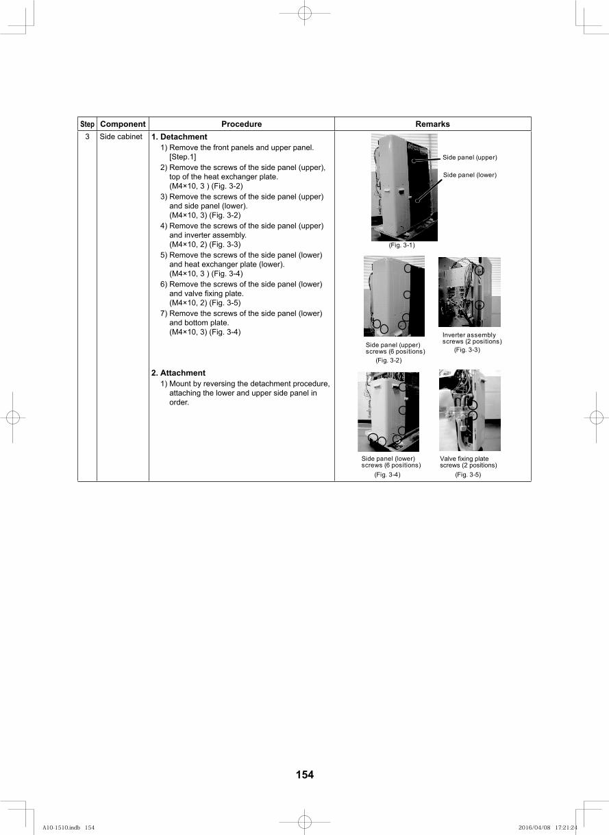
154
Step Component Procedure Remarks3 Side cabinet 1. Detachment
1) Remove the front panels and upper panel. [Step.1]
2) Remove the screws of the side panel (upper), top of the heat exchanger plate. (M4×10, 3 ) (Fig. 3-2)
3) Remove the screws of the side panel (upper) and side panel (lower). (M4×10, 3) (Fig. 3-2)
4) Remove the screws of the side panel (upper) and inverter assembly. (M4×10, 2) (Fig. 3-3)
5) Remove the screws of the side panel (lower) and heat exchanger plate (lower). (M4×10, 3 ) (Fig. 3-4)
6) Remove the screws of the side panel (lower) and valve fi xing plate. (M4×10, 2) (Fig. 3-5)
7) Remove the screws of the side panel (lower) and bottom plate. (M4×10, 3) (Fig. 3-4)
(Fig. 3-1)
Side panel (lower)
Side panel (upper)
(Fig. 3-2)
Side panel (upper)screws (6 positions)
Inverter assemblyscrews (2 positions)
(Fig. 3-3)
2. Attachment1) Mount by reversing the detachment procedure,
attaching the lower and upper side panel in order.
Valve fixing platescrews (2 positions)
(Fig. 3-4) (Fig. 3-5)
Side panel (lower)screws (6 positions)
A10-1510.indb 154A10-1510.indb 154 2016/04/08 17:21:242016/04/08 17:21:24
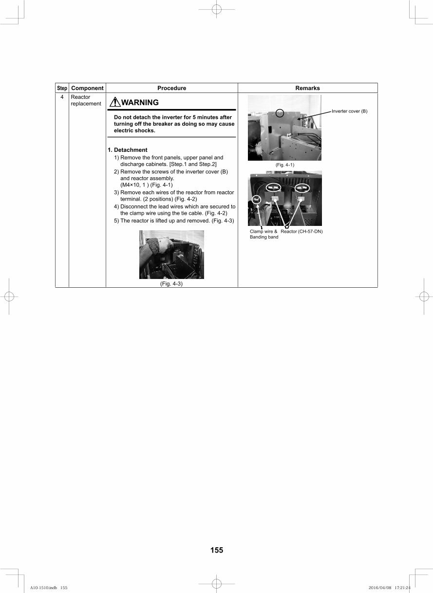
155
Step Component Procedure Remarks4 Reactor
replacement WARNING
Do not detach the inverter for 5 minutes after turning off the breaker as doing so may cause electric shocks.
1. Detachment1) Remove the front panels, upper panel and
discharge cabinets. [Step.1 and Step.2]2) Remove the screws of the inverter cover (B)
and reactor assembly.(M4×10, 1 ) (Fig. 4-1)
3) Remove each wires of the reactor from reactor terminal. (2 positions) (Fig. 4-2)
4) Disconnect the lead wires which are secured to the clamp wire using the tie cable. (Fig. 4-2)
5) The reactor is lifted up and removed. (Fig. 4-3)
(Fig. 4-3)
Inverter cover (B)
(Fig. 4-1)
Clamp wire & Banding band
Reactor (CH-57-DN)
A10-1510.indb 155A10-1510.indb 155 2016/04/08 17:21:242016/04/08 17:21:24
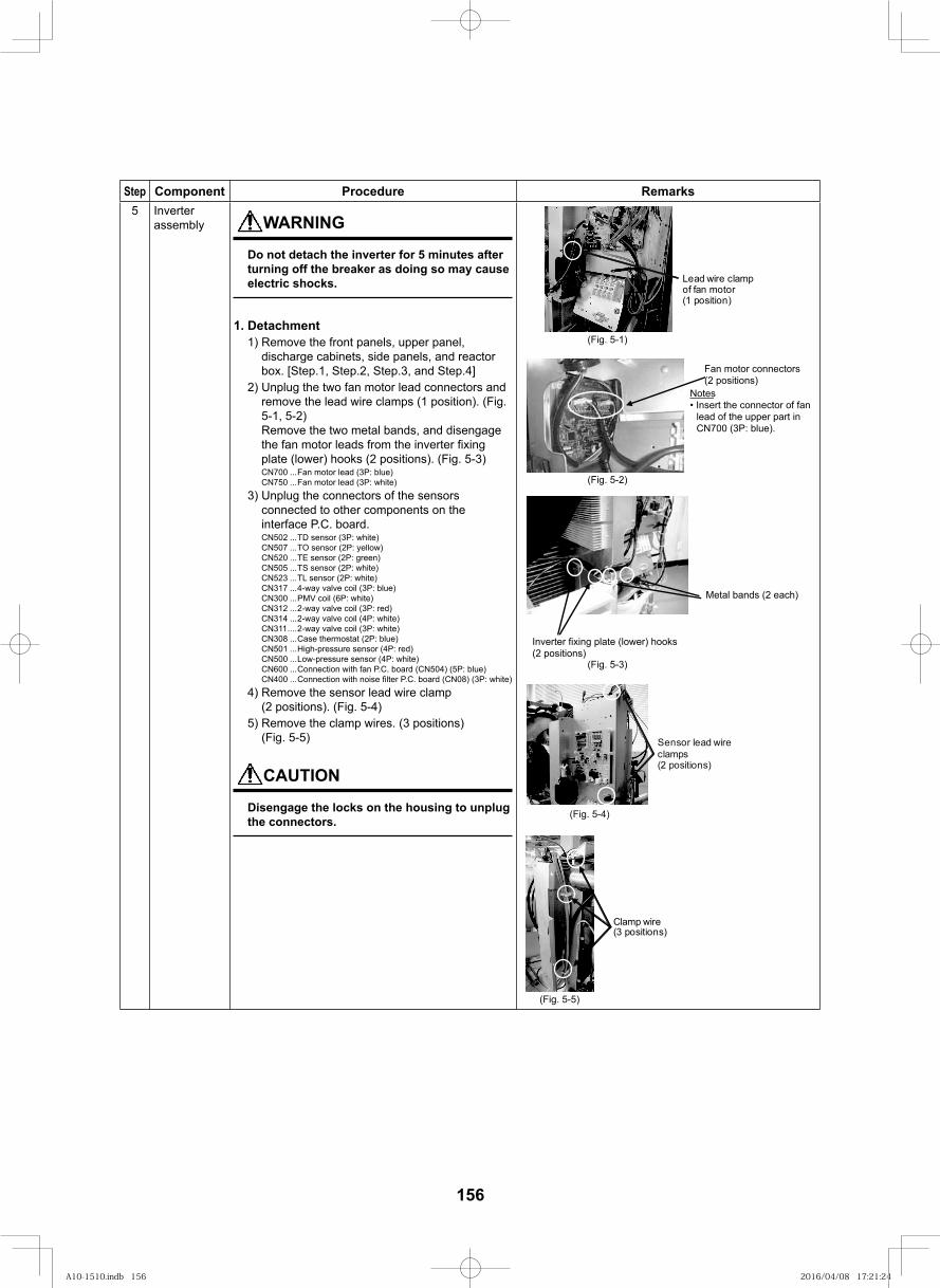
156
Step Component Procedure Remarks5 Inverter
assembly WARNING
Do not detach the inverter for 5 minutes after turning off the breaker as doing so may cause electric shocks.
1. Detachment1) Remove the front panels, upper panel,
discharge cabinets, side panels, and reactor box. [Step.1, Step.2, Step.3, and Step.4]
2) Unplug the two fan motor lead connectors and remove the lead wire clamps (1 position). (Fig. 5-1, 5-2)Remove the two metal bands, and disengage the fan motor leads from the inverter fi xing plate (lower) hooks (2 positions). (Fig. 5-3)CN700 ...Fan motor lead (3P: blue)CN750 ...Fan motor lead (3P: white)
3) Unplug the connectors of the sensors connected to other components on the interface P.C. board.CN502 ...TD sensor (3P: white)CN507 ...TO sensor (2P: yellow)CN520 ...TE sensor (2P: green)CN505 ...TS sensor (2P: white)CN523 ...TL sensor (2P: white)CN317 ...4-way valve coil (3P: blue)CN300 ...PMV coil (6P: white)CN312 ...2-way valve coil (3P: red)CN314 ...2-way valve coil (4P: white)CN311 ....2-way valve coil (3P: white)CN308 ...Case thermostat (2P: blue)CN501 ...High-pressure sensor (4P: red)CN500 ...Low-pressure sensor (4P: white)CN600 ...Connection with fan P.C. board (CN504) (5P: blue)CN400 ...Connection with noise fi lter P.C. board (CN08) (3P: white)
4) Remove the sensor lead wire clamp (2 positions). (Fig. 5-4)
5) Remove the clamp wires. (3 positions) (Fig. 5-5)
CAUTION
Disengage the locks on the housing to unplug the connectors.
(Fig. 5-1)
(Fig. 5-2)
Metal bands (2 each)
Inverter fixing plate (lower) hooks(2 positions)
Fan motor connectors(2 positions)
Notes
lead of the upper part inCN700 (3P: blue).
Lead wire clampof fan motor(1 position)
(Fig. 5-3)
(Fig. 5-4)
Sensor lead wireclamps(2 positions)
Clamp wire(3 positions)
(Fig. 5-5)
A10-1510.indb 156A10-1510.indb 156 2016/04/08 17:21:242016/04/08 17:21:24
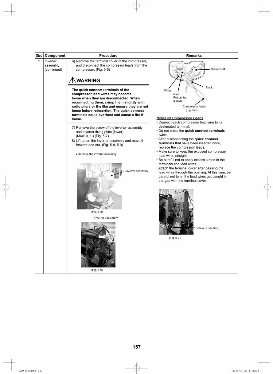
157
Step Component Procedure Remarks5 Inverter
assembly (continued)
6) Remove the terminal cover of the compressor, and disconnect the compressor leads from the compressor. (Fig. 5-6)
WARNING
The quick connect terminals of the compressor lead wires may become loose when they are disconnected. When reconnecting them, crimp them slightly with radio pliers or the like and ensure they are not loose before reinsertion. The quick connect terminals could overheat and cause a fi re if loose.
7) Remove the screw of the inverter assembly and inverter fi xing plate (lower).(M4×10, 1 ) (Fig. 5-7)
8) Lift up on the inverter assembly and move it forward and out. (Fig. 5-8, 5-9)
(Fig. 5-9)
Inverter assembly
Inverter assembly
Remove the inverter assembly.
(Fig. 5-8)
Thermostat
Compressor leads
Black
RedPut on thesleeve.
White
Notes on Compressor Leads
designated terminal.quick connect terminals
quick connect terminals that have been inserted once, replace the compressor leads.
Thermostat
Compressor leads
Black
RedPut on thesleeve.
White
(Fig. 5-6)
Scre (1 position)
(Fig. 5-7)
A10-1510.indb 157A10-1510.indb 157 2016/04/08 17:21:242016/04/08 17:21:24
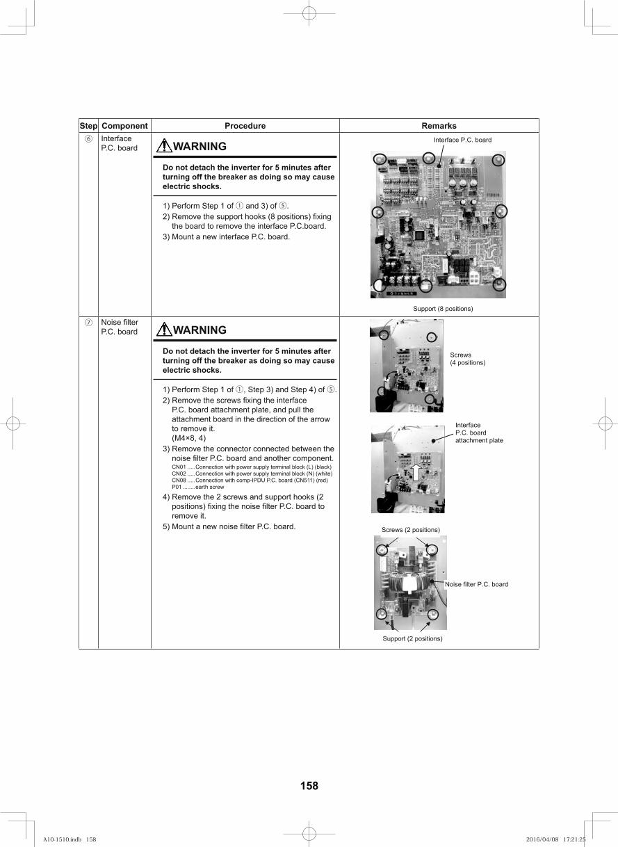
158
Step Component Procedure Remarks⑥ Interface
P.C. board WARNING
Do not detach the inverter for 5 minutes after turning off the breaker as doing so may cause electric shocks.
1) Perform Step 1 of ① and 3) of ⑤.2)
the board to remove the interface P.C.board.3) Mount a new interface P.C. board.
Support (8 positions)
Interface P.C. board
⑦P.C. board WARNING
Do not detach the inverter for 5 minutes after turning off the breaker as doing so may cause electric shocks.
1) Perform Step 1 of ①, Step 3) and Step 4) of ⑤.2)
P.C. board attachment plate, and pull the attachment board in the direction of the arrow to remove it. (M4×8, 4)
3) Remove the connector connected between the
CN01 .....Connection with power supply terminal block (L) (black)CN02 .....Connection with power supply terminal block (N) (white)CN08 .....Connection with comp-IPDU P.C. board (CN511) (red)P01 ........earth screw
4) Remove the 2 screws and support hooks (2
remove it.5)
Screws(4 positions)
InterfaceP.C. boardattachment plate
Noise filter P.C. board
Support (2 positions)
Screws (2 positions)
A10-1510.indb 158A10-1510.indb 158 2016/04/08 17:21:252016/04/08 17:21:25
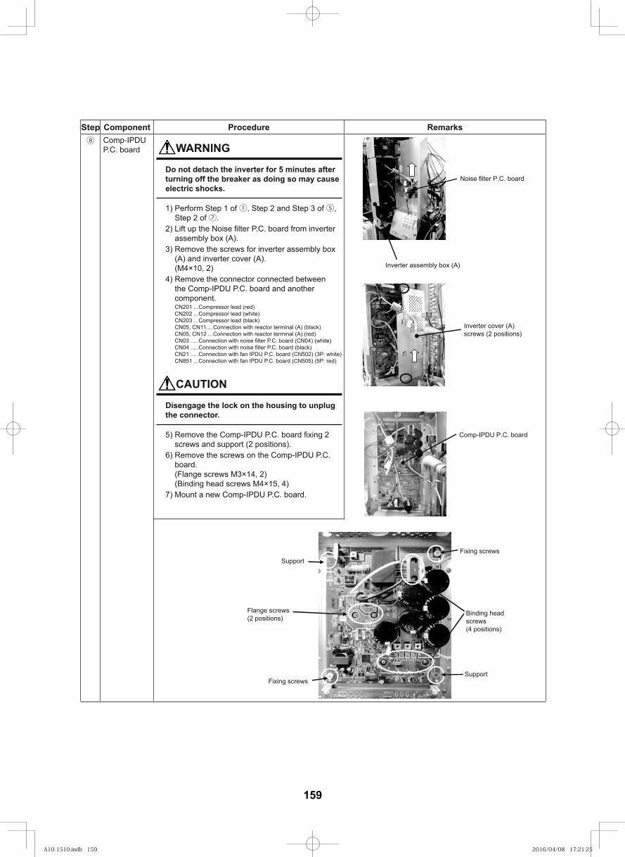
159
Step Component Procedure Remarks⑧ Comp-IPDU
P.C. board WARNING
Do not detach the inverter for 5 minutes after turning off the breaker as doing so may cause electric shocks.
1) Perform Step 1 of ①, Step 2 and Step 3 of ⑤, Step 2 of ⑦.
2) assembly box (A).
3) Remove the screws for inverter assembly box (A) and inverter cover (A). (M4×10, 2)
4) Remove the connector connected between the Comp-IPDU P.C. board and another component.CN201 ...Compressor lead (red)CN202 ...Compressor lead (white)CN203 ...Compressor lead (black)CN05, CN11.... Connection with reactor terminal (A) (black)CN05, CN12 ... Connection with reactor terminal (A) (red)CN03 .....CN04 .....CN21 .....Connection with fan IPDU P.C. board (CN502) (3P: white)CN851 ...Connection with fan IPDU P.C. board (CN505) (5P: red)
CAUTION
Disengage the lock on the housing to unplug the connector.
5) screws and support (2 positions).
6) Remove the screws on the Comp-IPDU P.C. board. (Flange screws M3×14, 2) (Binding head screws M4×15, 4)
7) Mount a new Comp-IPDU P.C. board.
Comp-IPDU P.C. board
Inverter cover (A)screws (2 positions)
Inverter assembly box (A)
Noise filter P.C. board
Binding headscrews(4 positions)
Flange screws(2 positions)
Fixing screws
Fixing screwsSupport
Support
A10-1510.indb 159A10-1510.indb 159 2016/04/08 17:21:252016/04/08 17:21:25
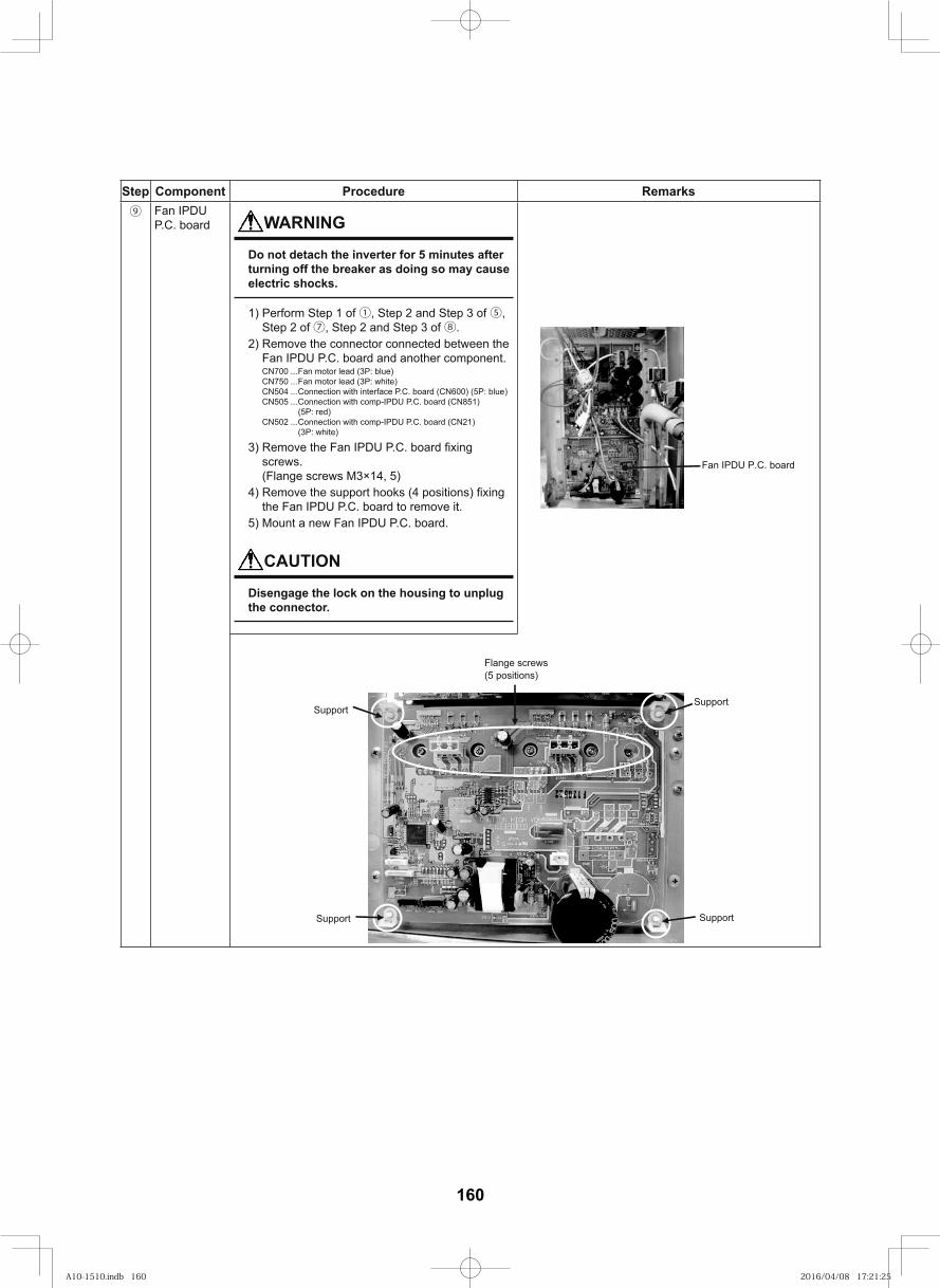
160
Step Component Procedure Remarks⑨ Fan IPDU
P.C. board WARNING
Do not detach the inverter for 5 minutes after turning off the breaker as doing so may cause electric shocks.
1) Perform Step 1 of ①, Step 2 and Step 3 of ⑤, Step 2 of ⑦, Step 2 and Step 3 of ⑧.
2) Remove the connector connected between the Fan IPDU P.C. board and another component.CN700 ...Fan motor lead (3P: blue)CN750 ...Fan motor lead (3P: white)CN504 ...Connection with interface P.C. board (CN600) (5P: blue)CN505 ...Connection with comp-IPDU P.C. board (CN851)
(5P: red)CN502 ...Connection with comp-IPDU P.C. board (CN21)
(3P: white)
3) screws. (Flange screws M3×14, 5)
4) the Fan IPDU P.C. board to remove it.
5) Mount a new Fan IPDU P.C. board.
CAUTION
Disengage the lock on the housing to unplug the connector.
Fan IPDU P.C. board
Flange screws(5 positions)
Support
SupportSupport
Support
A10-1510.indb 160A10-1510.indb 160 2016/04/08 17:21:252016/04/08 17:21:25
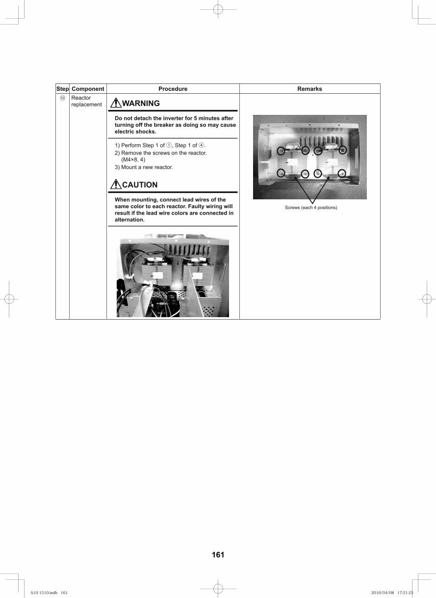
161
Step Component Procedure Remarks⑩ Reactor
replacement WARNING
Do not detach the inverter for 5 minutes after turning off the breaker as doing so may cause electric shocks.
1) Perform Step 1 of ①, Step 1 of ④.2) Remove the screws on the reactor.
(M4×8, 4)3) Mount a new reactor.
CAUTION
When mounting, connect lead wires of the same color to each reactor. Faulty wiring will result if the lead wire colors are connected in alternation.
Screws (each 4 positions)
A10-1510.indb 161A10-1510.indb 161 2016/04/08 17:21:252016/04/08 17:21:25
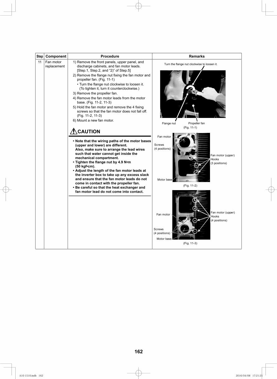
162
Step Component Procedure Remarks11 Fan motor
replacement1) Remove the front panels, upper panel, and
discharge cabinets, and fan motor leads. [Step.1, Step.2, and “2)” of Step.5]
2) Remove the fl ange nut fi xing the fan motor and propeller fan. (Fig. 11-1)• Turn the flange nut clockwise to loosen it.
(To tighten it, turn it counterclockwise.)3) Remove the propeller fan.4) Remove the fan motor leads from the motor
base. (Fig. 11-2, 11-3)5) Hold the fan motor and remove the 4 fi xing
screws so that the fan motor does not fall off. (Fig. 11-2, 11-3)
6) Mount a new fan motor.
CAUTION
• Note that the wiring paths of the motor bases (upper and lower) are different. Also, make sure to arrange the lead wires such that water cannot get inside the mechanical compartment.
• Tighten the fl ange nut by 4.9 N•m (50 kgf•cm).
• Adjust the length of the fan motor leads at the inverter box to take up any excess slack and ensure that the fan motor leads do not come in contact with the propeller fan.
• Be careful so that the heat exchanger and fan motor lead do not come into contact.
Flange nut(Fig. 11-1)
Turn the flange nut clockwise to loosen it.
Propeller fan
Fan motor (upper)Hooks(4 positions)
Screws(4 positions)
(Fig. 11-3)Motor base
Fan motor
Fan motor (upper)Hooks(3 positions)
(Fig. 11-2)
Screws(4 positions)
Motor base
Fan motor
A10-1510.indb 162A10-1510.indb 162 2016/04/08 17:21:252016/04/08 17:21:25
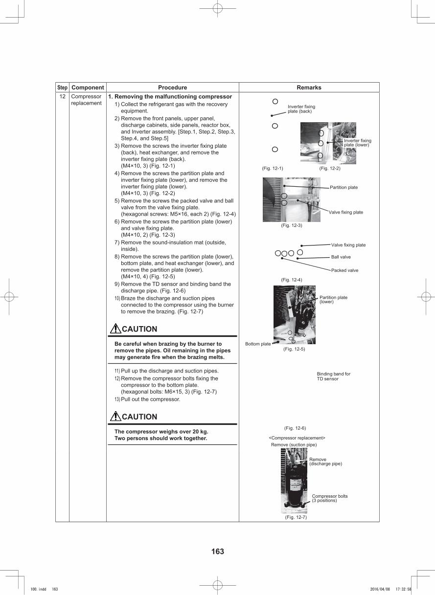
163
Step Component Procedure Remarks12 Compressor
replacement1. Removing the malfunctioning compressor
1) Collect the refrigerant gas with the recovery equipment.
2) Remove the front panels, upper panel, discharge cabinets, side panels, reactor box, and Inverter assembly. [Step.1, Step.2, Step.3, Step.4, and Step.5]
3) Remove the screws the inverter fixing plate (back), heat exchanger, and remove the inverter fixing plate (back). (M4×10, 3) (Fig. 12-1)
4) Remove the screws the partition plate and inverter fixing plate (lower), and remove the inverter fixing plate (lower). (M4×10, 3) (Fig. 12-2)
5) Remove the screws the packed valve and ball valve from the valve fixing plate. (hexagonal screws: M5×16, each 2) (Fig. 12-4)
6) Remove the screws the partition plate (lower) and valve fixing plate. (M4×10, 2) (Fig. 12-3)
7) Remove the sound-insulation mat (outside, inside).
8) Remove the screws the partition plate (lower), bottom plate, and heat exchanger (lower), and remove the partition plate (lower). (M4×10, 4) (Fig. 12-5)
9) Remove the TD sensor and binding band the discharge pipe. (Fig. 12-6)
10) Braze the discharge and suction pipes connected to the compressor using the burner to remove the brazing. (Fig. 12-7)
CAUTION
Be careful when brazing by the burner to remove the pipes. Oil remaining in the pipes may generate fire when the brazing melts.
11) Pull up the discharge and suction pipes.12) Remove the compressor bolts fixing the
compressor to the bottom plate. (hexagonal bolts: M6×15, 3) (Fig. 12-7)
13) Pull out the compressor.
CAUTION
The compressor weighs over 20 kg.Two persons should work together. <Compressor replacement>
Remove (suction pipe)
Compressor bolts(3 positions)
Valve fixing plate
Partition plate
Inverter fixingplate (back)
(Fig. 12-1) (Fig. 12-2)
(Fig. 12-3)
(Fig. 12-4)
Packed valve
Valve fixing plate
Ball valve
Partition plate(lower)
Bottom plate(Fig. 12-5)
(Fig. 12-7)
Inverter fixingplate (lower)
Remove(discharge pipe)
(Fig. 12-6)
Binding band forTD sensor
100.indd 163 2016/04/08 17:32:58
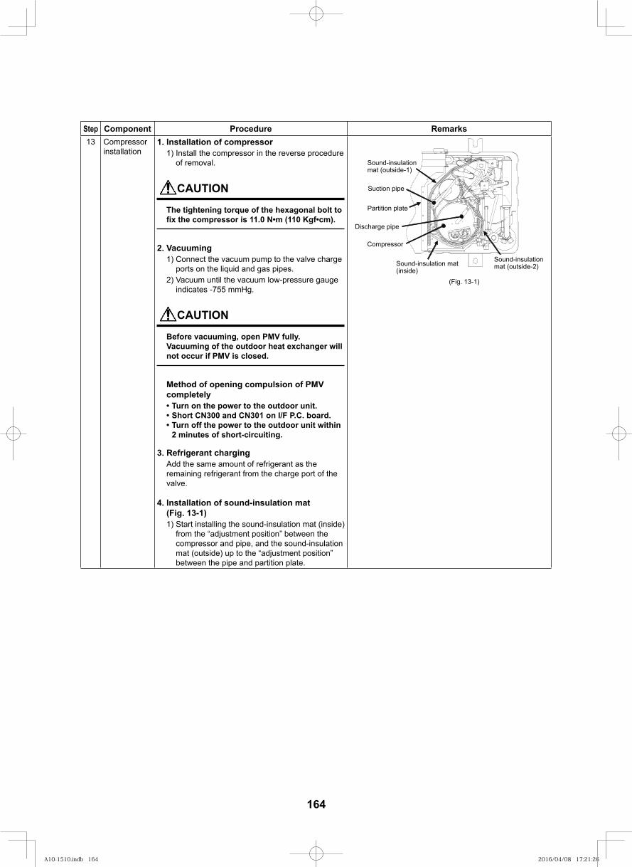
164
Step Component Procedure Remarks13 Compressor
installation1. Installation of compressor
1) Install the compressor in the reverse procedure of removal.
CAUTION
The tightening torque of the hexagonal bolt to fi x the compressor is 11.0 N•m (110 Kgf•cm).
2. Vacuuming1) Connect the vacuum pump to the valve charge
ports on the liquid and gas pipes.2) Vacuum until the vacuum low-pressure gauge
indicates -755 mmHg.
CAUTION
Before vacuuming, open PMV fully.Vacuuming of the outdoor heat exchanger will not occur if PMV is closed.
Method of opening compulsion of PMV completely• Turn on the power to the outdoor unit.• Short CN300 and CN301 on I/F P.C. board.• Turn off the power to the outdoor unit within
2 minutes of short-circuiting.
3. Refrigerant chargingAdd the same amount of refrigerant as the remaining refrigerant from the charge port of the valve.
4. Installation of sound-insulation mat (Fig. 13-1)1) Start installing the sound-insulation mat (inside)
from the “adjustment position” between the compressor and pipe, and the sound-insulation mat (outside) up to the “adjustment position” between the pipe and partition plate.
(Fig. 13-1)
Sound-insulation mat(inside)
Partition plate
Suction pipe
Sound-insulationmat (outside-1)
Discharge pipe
Compressor
Sound-insulationmat (outside-2)
A10-1510.indb 164A10-1510.indb 164 2016/04/08 17:21:262016/04/08 17:21:26
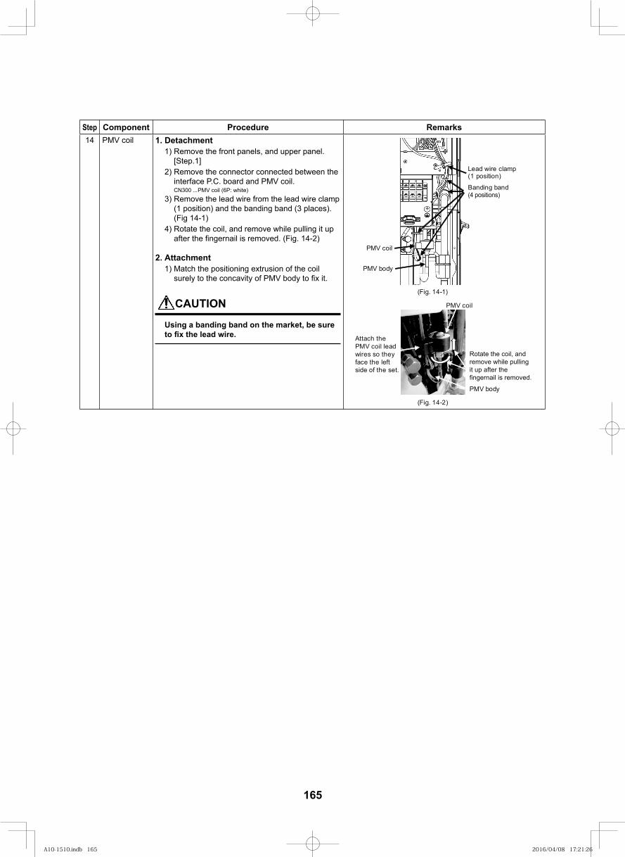
165
Step Component Procedure Remarks14 PMV coil 1. Detachment
1) Remove the front panels, and upper panel. [Step.1]
2) Remove the connector connected between the interface P.C. board and PMV coil.CN300 ...PMV coil (6P: white)
3) Remove the lead wire from the lead wire clamp (1 position) and the banding band (3 places). (Fig 14-1)
4) Rotate the coil, and remove while pulling it up after the fi ngernail is removed. (Fig. 14-2)
2. Attachment1) Match the positioning extrusion of the coil
surely to the concavity of PMV body to fi x it.
CAUTION
Using a banding band on the market, be sure to fi x the lead wire.
PMV body
Banding band (4 positions)
PMV coil
Lead wire clamp(1 position)
(Fig. 14-2)
PMV coil
PMV body
(Fig. 14-1)
Rotate the coil, and remove while pulling it up after the fingernail is removed.
Attach the PMV coil lead wires so they face the left side of the set.
A10-1510.indb 165A10-1510.indb 165 2016/04/08 17:21:262016/04/08 17:21:26
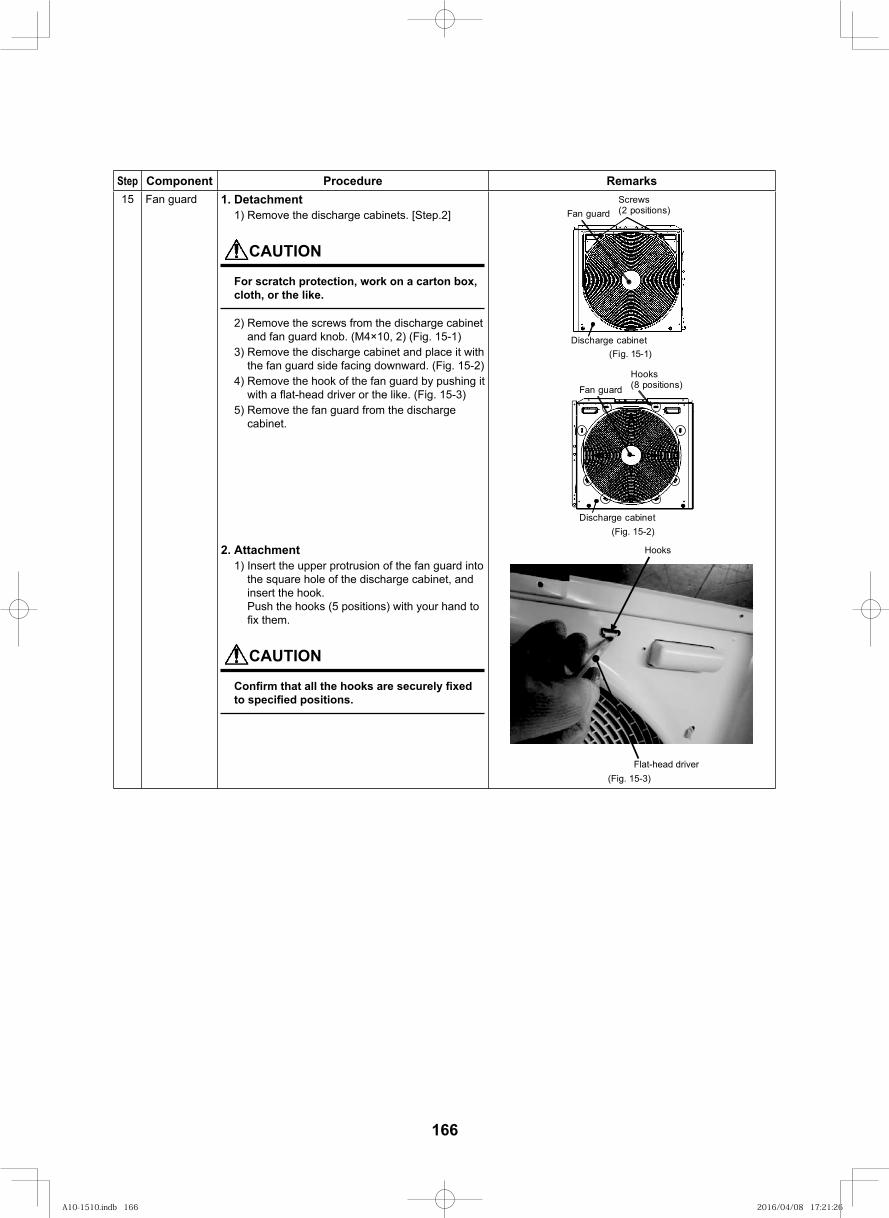
166
Step Component Procedure Remarks15 Fan guard 1. Detachment
1) Remove the discharge cabinets. [Step.2]
CAUTION
For scratch protection, work on a carton box, cloth, or the like.
2) Remove the screws from the discharge cabinet and fan guard knob. (M4×10, 2) (Fig. 15-1)
3) Remove the discharge cabinet and place it with the fan guard side facing downward. (Fig. 15-2)
4) Remove the hook of the fan guard by pushing it with a fl at-head driver or the like. (Fig. 15-3)
5) Remove the fan guard from the discharge cabinet.
(Fig. 15-1)
Fan guard
Discharge cabinet
Screws(2 positions)
(Fig. 15-2)
Fan guard
Discharge cabinet
Hooks(8 positions)
2. Attachment1) Insert the upper protrusion of the fan guard into
the square hole of the discharge cabinet, and insert the hook. Push the hooks (5 positions) with your hand to fi x them.
CAUTION
Confi rm that all the hooks are securely fi xed to specifi ed positions.
Hooks
Flat-head driver(Fig. 15-3)
A10-1510.indb 166A10-1510.indb 166 2016/04/08 17:21:262016/04/08 17:21:26
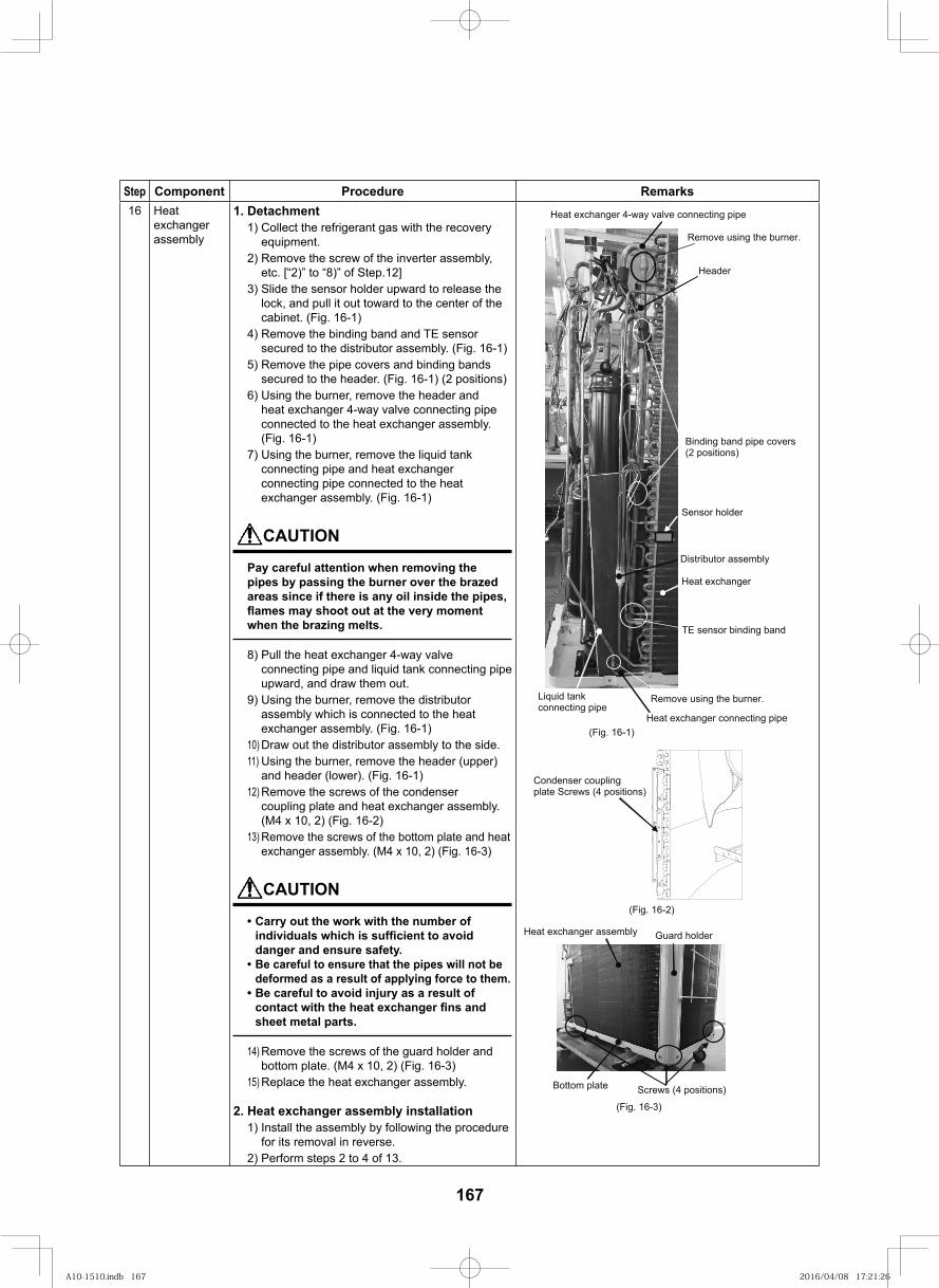
167
Step Component Procedure Remarks16 Heat
exchanger assembly
1. Detachment1) Collect the refrigerant gas with the recovery
equipment.2) Remove the screw of the inverter assembly,
etc. [“2)” to “8)” of Step.12]3) Slide the sensor holder upward to release the
lock, and pull it out toward to the center of the cabinet. (Fig. 16-1)
4) Remove the binding band and TE sensor secured to the distributor assembly. (Fig. 16-1)
5) Remove the pipe covers and binding bands secured to the header. (Fig. 16-1) (2 positions)
6) Using the burner, remove the header and heat exchanger 4-way valve connecting pipe connected to the heat exchanger assembly. (Fig. 16-1)
7) Using the burner, remove the liquid tank connecting pipe and heat exchanger connecting pipe connected to the heat exchanger assembly. (Fig. 16-1)
CAUTION
Pay careful attention when removing the pipes by passing the burner over the brazed areas since if there is any oil inside the pipes, fl ames may shoot out at the very moment when the brazing melts.
8) Pull the heat exchanger 4-way valve connecting pipe and liquid tank connecting pipe upward, and draw them out.
9) Using the burner, remove the distributor assembly which is connected to the heat exchanger assembly. (Fig. 16-1)
10) Draw out the distributor assembly to the side.11) Using the burner, remove the header (upper)
and header (lower). (Fig. 16-1)12) Remove the screws of the condenser
coupling plate and heat exchanger assembly. (M4 x 10, 2) (Fig. 16-2)
13) Remove the screws of the bottom plate and heat exchanger assembly. (M4 x 10, 2) (Fig. 16-3)
CAUTION
• Carry out the work with the number of individuals which is suffi cient to avoid danger and ensure safety.
• Be careful to ensure that the pipes will not be deformed as a result of applying force to them.
• Be careful to avoid injury as a result of contact with the heat exchanger fi ns and sheet metal parts.
14) Remove the screws of the guard holder and bottom plate. (M4 x 10, 2) (Fig. 16-3)
15) Replace the heat exchanger assembly.
2. Heat exchanger assembly installation1) Install the assembly by following the procedure
for its removal in reverse.2) Perform steps 2 to 4 of 13.
Heat exchanger assembly Guard holder
Screws (4 positions)Bottom plate
(Fig. 16-3)
Binding band pipe covers (2 positions)
TE sensor binding band
Heat exchanger
Sensor holder
(Fig. 16-1)
Remove using the burner.
Heat exchanger 4-way valve connecting pipe
Liquid tank connecting pipe
Heat exchanger connecting pipe
Distributor assembly
Remove using the burner.
Header
(Fig. 16-2)
Condenser coupling plate Screws (4 positions)
A10-1510.indb 167A10-1510.indb 167 2016/04/08 17:21:262016/04/08 17:21:26
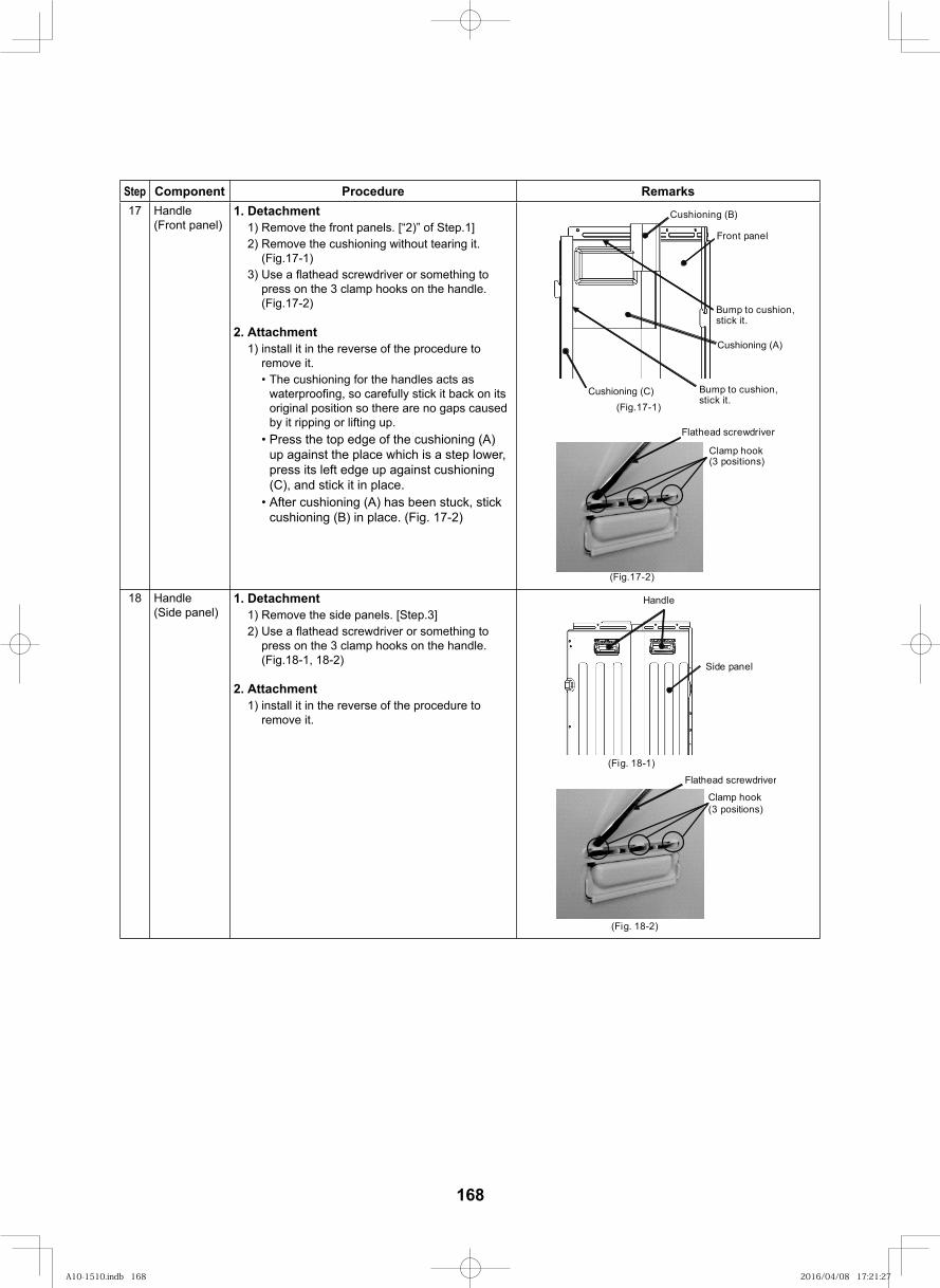
168
Step Component Procedure Remarks17 Handle
(Front panel)1. Detachment
1) Remove the front panels. [“2)” of Step.1]2) Remove the cushioning without tearing it.
(Fig.17-1)3) Use a fl athead screwdriver or something to
press on the 3 clamp hooks on the handle. (Fig.17-2)
2. Attachment1) install it in the reverse of the procedure to
remove it.• The cushioning for the handles acts as
waterproofing, so carefully stick it back on its original position so there are no gaps caused by it ripping or lifting up.
• Press the top edge of the cushioning (A) up against the place which is a step lower, press its left edge up against cushioning (C), and stick it in place.
• After cushioning (A) has been stuck, stick cushioning (B) in place. (Fig. 17-2)
(Fig.17-2)
Clamp hook(3 positions)
Flathead screwdriver
(Fig.17-1)
Cushioning (B)
Front panel
Cushioning (A)
Cushioning (C)
Bump to cushion,stick it.
Bump to cushion,stick it.
18 Handle (Side panel)
1. Detachment1) Remove the side panels. [Step.3]2) Use a fl athead screwdriver or something to
press on the 3 clamp hooks on the handle. (Fig.18-1, 18-2)
2. Attachment1) install it in the reverse of the procedure to
remove it.
Handle
(Fig. 18-1)
(Fig. 18-2)
Clamp hook(3 positions)
Flathead screwdriver
Side panel
A10-1510.indb 168A10-1510.indb 168 2016/04/08 17:21:272016/04/08 17:21:27
11P.C. board exchange procedures11-1.Interface P.C. board replacement procedure
(MCC-1639: 43H69011)This same service P.C. board is installed in different models at the shipment stage. If the P.C. board assembly is to be replaced, check what appears on the inspection display (7-segment display), enter this on the replacement record table, and then follow the replacement steps below to ensure that the assembly is replaced correctly for the model concerned.Please return to us P.C.board with the replacement record table attached,After P.C.board replaced.
1. Applicable models
2. Shipped parts listPlease make sure that before you do the work, the following parts are shipped all.
No Parts name Quantity1 P.C.board Replacement Procedure Manual (English and Chinese each 1page A4 paper double side print.) 12 Service P.C.board MCC-1639 (Interface P.C.board) in Antistatic air cap 1
3. Replacement steps(1) Turn off the power of the outdoor control unit. (Turn off the power of the outdoor unit.)(2) Immediately after turning off the power of the outdoor unit, the electrolytic capacitors inside the unit will still
have a high voltage, and there is a risk of electric shocks. Therefore, wait at least 5 minutes after turning off the power before starting the replacement procedure.
(3) Disconnect all the connectors which are connected to the interface P.C. board. (Since the connectors may be damaged if they are pulled out by grasping their lead wires, be sure to take hold of the connectors themselves when disconnecting them.)
(4) To remove the malfunctioning interface P.C. board, remove the eight card edge spacers ①
MCY-MHP0404HS-E MCY-MHP0504HS-E MCY-MHP0604HS-EMCY-MHP0404HSJ-E MCY-MHP0504HSJ-E MCY-MHP0604HSJ-EMCY-MHP0404HS-TR MCY-MHP0504HS-TR MCY-MHP0604HS-TRMCY-MHP0404HS MCY-MHP0504HS MCY-MHP0604HSMCY-MHP0404HSJ MCY-MHP0504HSJ MCY-MHP0604HSJMCY-MHP0404HS-ID MCY-MHP0504HS-ID MCY-MHP0604HS-IDMCY-MHP0404HS-A MCY-MHP0504HS-A MCY-MHP0604HS-A
169
A10-1510.indb 169A10-1510.indb 169 2016/04/08 17:21:272016/04/08 17:21:27
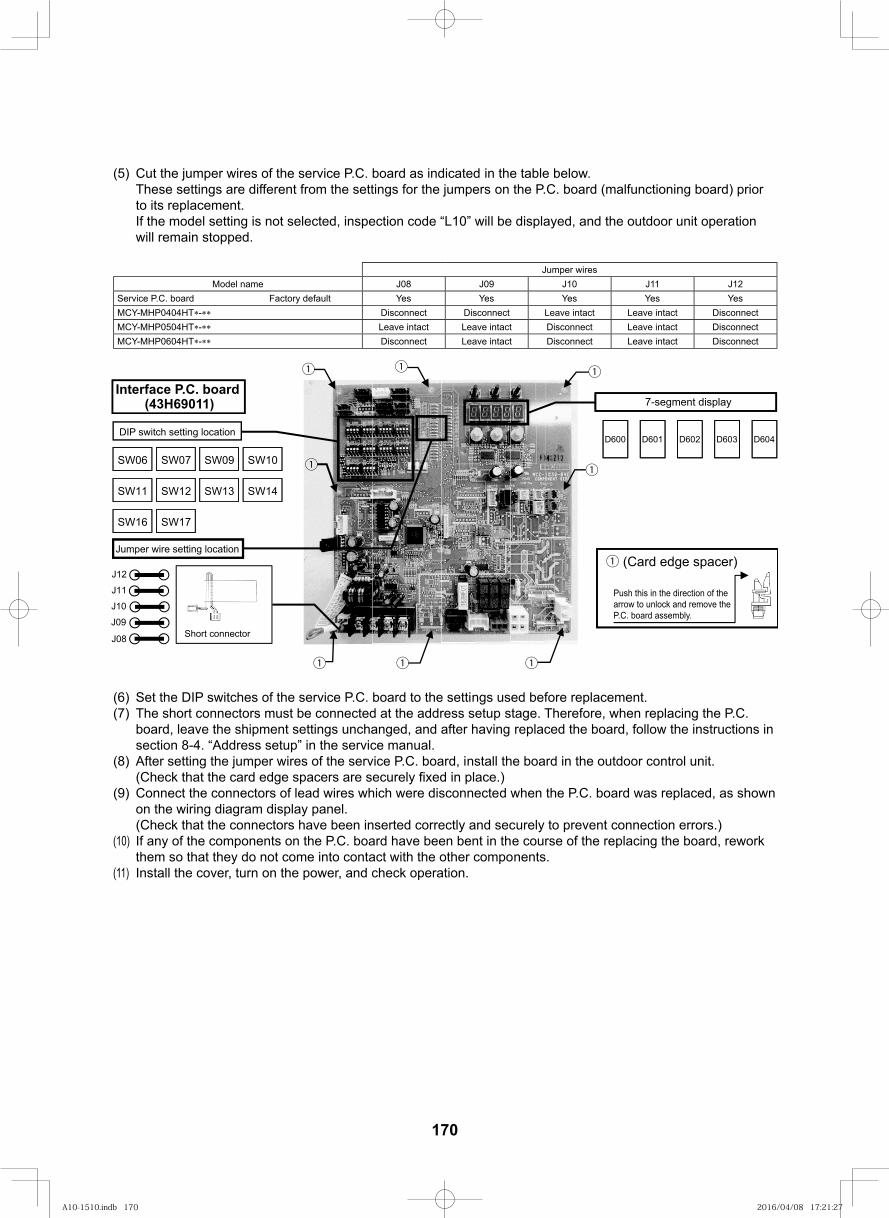
170
(5) Cut the jumper wires of the service P.C. board as indicated in the table below. These settings are different from the settings for the jumpers on the P.C. board (malfunctioning board) prior to its replacement. If the model setting is not selected, inspection code “L10” will be displayed, and the outdoor unit operation will remain stopped.
Jumper wiresModel name J08 J09 J10 J11 J12
Service P.C. board Factory default Yes Yes Yes Yes YesMCY-MHP0404HT - Disconnect Disconnect Leave intact Leave intact DisconnectMCY-MHP0504HT - Leave intact Leave intact Disconnect Leave intact DisconnectMCY-MHP0604HT - Disconnect Leave intact Disconnect Leave intact Disconnect
D600 D601 D602 D603 D604DIP switch setting location
Jumper wire setting location
SW06 SW07
SW11 SW12
SW17
SW13 SW14
SW16
SW10SW09
Interface P.C. board (43H69011) 7-segment display
① (Card edge spacer)
Push this in the direction of the arrow to unlock and remove the P.C. board assembly.
J08
J09
J10
J11
J12
Short connector
①
①
①①①
① ①
①
(6) Set the DIP switches of the service P.C. board to the settings used before replacement.(7) The short connectors must be connected at the address setup stage. Therefore, when replacing the P.C.
board, leave the shipment settings unchanged, and after having replaced the board, follow the instructions in section 8-4. “Address setup” in the service manual.
(8) After setting the jumper wires of the service P.C. board, install the board in the outdoor control unit.
(9) Connect the connectors of lead wires which were disconnected when the P.C. board was replaced, as shown on the wiring diagram display panel. (Check that the connectors have been inserted correctly and securely to prevent connection errors.)
(10) If any of the components on the P.C. board have been bent in the course of the replacing the board, rework them so that they do not come into contact with the other components.
(11) Install the cover, turn on the power, and check operation.
A10-1510.indb 170A10-1510.indb 170 2016/04/08 17:21:272016/04/08 17:21:27
11-2.Comp-IPDU P.C. board replacement procedure(MCC-1647: 43H69013)
1. Applicable models
2. Shipped parts listPlease make sure that before you do the work, the following parts are shipped all.
No Parts name Quantity1 P.C.board Replacement Procedure Manual (English and Chinese each 1page A4 paper double side print.) 12 Service P.C.board MCC-1647 (Comp-IPDU P.C.board) in Antistatic air cap 13 Card Spacer (No.①) in Plastic bag 2
3. Replacement steps(1) Turn off the power of the outdoor control unit. (Turn off the power of the outdoor unit.)(2) Immediately after turning off the power of the outdoor unit, the electrolytic capacitors inside the unit will still
have a high voltage, and there is a risk of electric shocks. Therefore, wait at least 5 minutes after turning off the power before starting the replacement procedure.
(3) Disconnect all the screws ④,screw ⑤ and screws ⑥ and connectors which are connected to the malfunctioning comp-IPDU P.C. board. (Since the connectors may be damaged if they are pulled out by grasping their lead wires, be sure to take hold of the connectors themselves when disconnecting them.)
(4) To remove the malfunctioning comp-IPDU P.C. board, remove the 2 card spacers ① and 2 single-touch spacers ② (Take care when removing the comp-IPDU P.C. board not to damage the 2 card spacers ①. If a card spacer ① has been damaged, be sure to use a card spacer ① packed with the board, and replace the damaged card spacer by following the steps in the service manual. Failure to replace it may cause the comp-IPDU P.C.
board to malfunction.)
(5) The screws and single-touch spacers ② which were removed will be used again when the service P.C. board is installed so keep them in a safe place to ensure that they will not be lost or misplaced.
(6) When replacing the board, install the removed single-touch spacers ② on the service P.C. board, and evenly apply silicone heat sink compound to the heat-sink surfaces of the IPM and devices on the service P.C. board. Then install the board in the outdoor control unit. Failure to apply the silicone heat sink compound may cause the service P.C. board to malfunction. (Tightening torque for screws ③ (M4x14) used to secure single-touch spacers ②: 1.2 ±0.1
(7) When replacing the board, use the removed screws ④ (M4x8) , screws ⑤ (M4x15) and screws ⑥ (M3x20) to connect the disconnected lead wires following the wiring diagram display panel. (Check that the wires have been inserted correctly and securely to prevent connection errors.)
(8) If screws ④, screws ⑤ and screws ⑥ are not tightened the contact between the terminals will deteriorate, possibly causing malfunctioning so pay attention when tightening the screws. However, under no circumstances must power-driven screwdrivers or air screwdrivers be used when installing the replacement P.C. board. Using such a device may damage the components. (Tightening torque: screw④,⑤ 1.2 ±0.1 screw ⑥ 0.55
(9) If any of the components on the P.C. board have been bent in the course of the replacing the board, rework them so that they do not come into contact with the other components.
(10) Install the cover, turn on the power, and check operation.
MCY-MHP0404HS-E MCY-MHP0504HS-E MCY-MHP0604HS-EMCY-MHP0404HSJ-E MCY-MHP0504HSJ-E MCY-MHP0604HSJ-EMCY-MHP0404HS-TR MCY-MHP0504HS-TR MCY-MHP0604HS-TRMCY-MHP0404HS MCY-MHP0504HS MCY-MHP0604HSMCY-MHP0404HSJ MCY-MHP0504HSJ MCY-MHP0604HSJMCY-MHP0404HS-ID MCY-MHP0504HS-ID MCY-MHP0604HS-IDMCY-MHP0404HS-A MCY-MHP0504HS-A MCY-MHP0604HS-A
171
A10-1510.indb 171A10-1510.indb 171 2016/04/08 17:21:272016/04/08 17:21:27
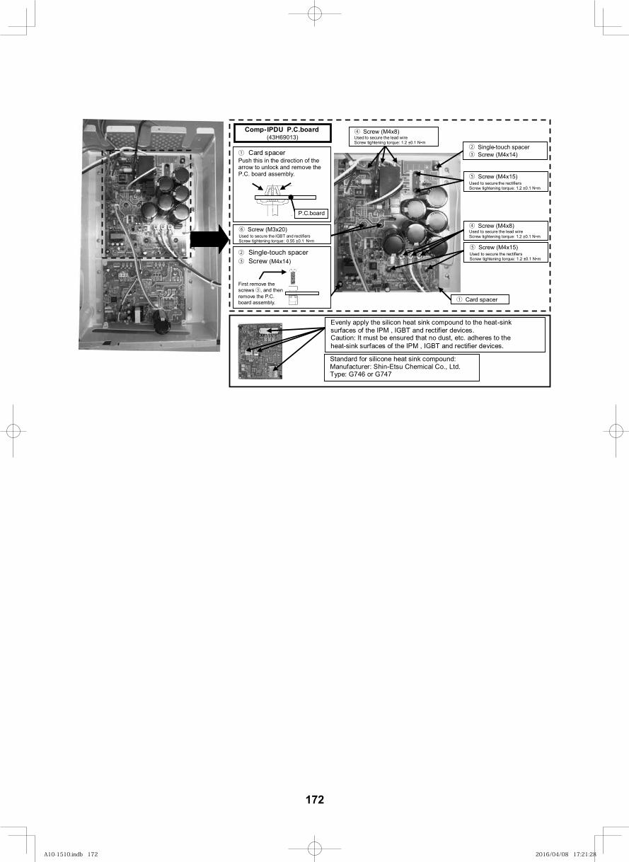
172
Standard for silicone heat sink compound: Manufacturer: Shin-Etsu Chemical Co., Ltd. Type: G746 or G747
④ Screw (M4x8) Used to secure the lead wire Screw tightening torque: 1.2 ±0.1 N m
⑤ Screw (M4x15) Used to secure the rectifiers Screw tightening torque: 1.2 ±0.1 N m
④ Screw (M4x8) Used to secure the lead wire Screw tightening torque: 1.2 ±0.1 N m
⑤ Screw (M4x15) Used to secure the rectifiers Screw tightening torque: 1.2 ±0.1 N m
① Card spacer
② Single-touch spacer ③ Screw (M4x14) ① Card spacer
Push this in the direction of the arrow to unlock and remove the P.C. board assembly.
② Single-touch spacer ③ Screw (M4x14) First remove the screws ③, and then remove the P.C. board assembly.
Evenly apply the silicon heat sink compound to the heat-sink surfaces of the IPM , IGBT and rectifier devices. Caution: It must be ensured that no dust, etc. adheres to the heat-sink surfaces of the IPM , IGBT and rectifier devices.
Comp-IPDU P.C.board (43H69013)
P.C.board
⑥ Screw (M3x20) Used to secure the IGBT and rectifiers Screw tightening torque: 0.55 ±0.1 N m
A10-1510.indb 172A10-1510.indb 172 2016/04/08 17:21:282016/04/08 17:21:28
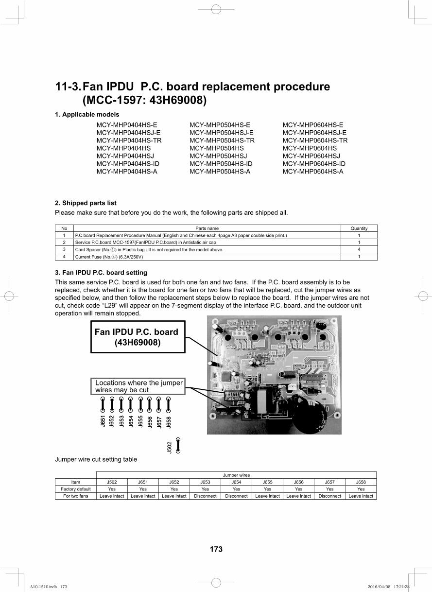
11-3.Fan IPDU P.C. board replacement procedure(MCC-1597: 43H69008)
1. Applicable models
2. Shipped parts listPlease make sure that before you do the work, the following parts are shipped all.
No Parts name Quantity1 P.C.board Replacement Procedure Manual (English and Chinese each 4page A3 paper double side print.) 12 Service P.C.board MCC-1597(FanIPDU P.C.board) in Antistatic air cap 13 Card Spacer (No.①) in Plastic bag : It is not required for the model above. 44 Current Fuse (No.④) (6.3A/250V) 1
3. Fan IPDU P.C. board settingThis same service P.C. board is used for both one fan and two fans. If the P.C. board assembly is to be replaced, check whether it is the board for one fan or two fans that will be replaced, cut the jumper wires as
below, and then follow the replacement steps below to replace the board. If the jumper wires are not cut, check code “L29” will appear on the 7-segment display of the interface P.C. board, and the outdoor unitoperation will remain stopped.
J651
J652
J653
J654
J655
J656
J657
J658
J502
J651
J652
J653
J654
J655
J656
J657
J658
Locations where the jumper wires may be cut
Fan IPDU P.C. board (43H69008)
Jumper wire cut setting table
Jumper wiresItem J502 J651 J652 J653 J654 J655 J656 J657 J658
Factory default Yes Yes Yes Yes Yes Yes Yes Yes YesFor two fans Leave intact Leave intact Leave intact Disconnect Disconnect Leave intact Leave intact Disconnect Leave intact
MCY-MHP0404HS-E MCY-MHP0504HS-E MCY-MHP0604HS-EMCY-MHP0404HSJ-E MCY-MHP0504HSJ-E MCY-MHP0604HSJ-EMCY-MHP0404HS-TR MCY-MHP0504HS-TR MCY-MHP0604HS-TRMCY-MHP0404HS MCY-MHP0504HS MCY-MHP0604HSMCY-MHP0404HSJ MCY-MHP0504HSJ MCY-MHP0604HSJMCY-MHP0404HS-ID MCY-MHP0504HS-ID MCY-MHP0604HS-IDMCY-MHP0404HS-A MCY-MHP0504HS-A MCY-MHP0604HS-A
173
A10-1510.indb 173A10-1510.indb 173 2016/04/08 17:21:282016/04/08 17:21:28
174
4. Replacement steps(1) Turn off the power of the outdoor control unit. (Turn off the power of the outdoor unit.)(2) Immediately after turning off the power of the outdoor unit, the electrolytic capacitors inside the unit will still
have a high voltage, and there is a risk of electric shocks. Therefore, wait at least 5 minutes after turning off the power before starting the replacement procedure.
(3) Disconnect all the screws ② and connectors which are connected to the malfunctioning fan IPDU P.C. board. (Since the connectors may be damaged if they are pulled out by grasping their lead wires, be sure to take hold of the connectors themselves when disconnecting them.)
(4) To remove the malfunctioning fan IPDU P.C. board, remove the four card spacers ③(When removing the fan IPDU P.C. board, take care not to damage any of the four card spacers ③. If a card spacer ③ has been damaged, be sure to use a card spacer ③ packed with the board, and replace the damaged card spacer by following the steps in the service manual. Failure to replace it may cause the fan IPDU P.C. board to malfunction.)
(5) The removed screws ② will be used again when the service P.C. board is installed so keep them in a safe place to ensure that they will not be lost or misplaced.
(6) When replacing the board, evenly apply silicone heat sink compound to the heat-sink surfaces of the IPM
apply the silicone heat sink compound may cause the service P.C. board to malfunction.(7) When replacing the board, use the removed screws ② (M3x20) to connect the disconnected lead wires
following the wiring diagram display panel. (Check that the wires have been inserted correctly and securely to prevent connection errors.)
(8) If screws ②will deteriorate, possibly causing malfunctioning so pay attention when tightening the screws. However, under no circumstances must power-driven screwdrivers or air screwdrivers be used when installing the replacement P.C. board. Using such a device may damage the components. (Screw tightening
(9) If any of the components on the P.C. board have been bent in the course of the replacing the board, rework them so that they do not come into contact with the other components.
(10) Install the cover, turn on the power, and check operation.
A10-1510.indb 174A10-1510.indb 174 2016/04/08 17:21:282016/04/08 17:21:28
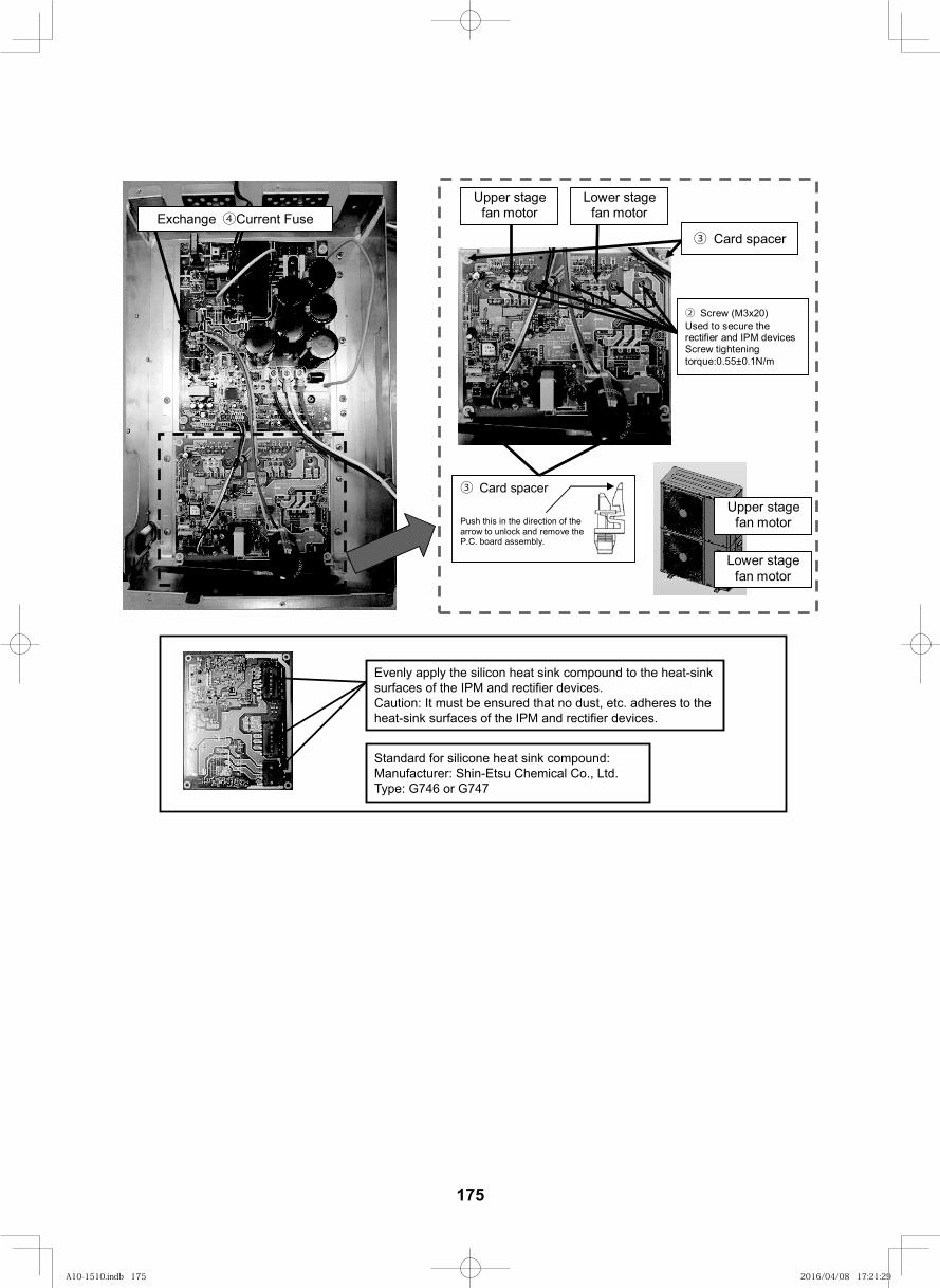
175
Upper stage fan motor
Lower stage fan motor
Upper stage fan motor
Lower stage fan motor
③ Card spacer
② Screw (M3x20) Used to secure the rectifier and IPM devices Screw tightening torque:0.55±0.1N/m
③ Card spacer Push this in the direction of the arrow to unlock and remove the P.C. board assembly.
Exchange ④Current Fuse
Standard for silicone heat sink compound:Manufacturer: Shin-Etsu Chemical Co., Ltd.Type: G746 or G747
Evenly apply the silicon heat sink compound to the heat-sink surfaces of the IPM and rectifier devices.Caution: It must be ensured that no dust, etc. adheres to the heat-sink surfaces of the IPM and rectifier devices.
A10-1510.indb 175A10-1510.indb 175 2016/04/08 17:21:292016/04/08 17:21:29
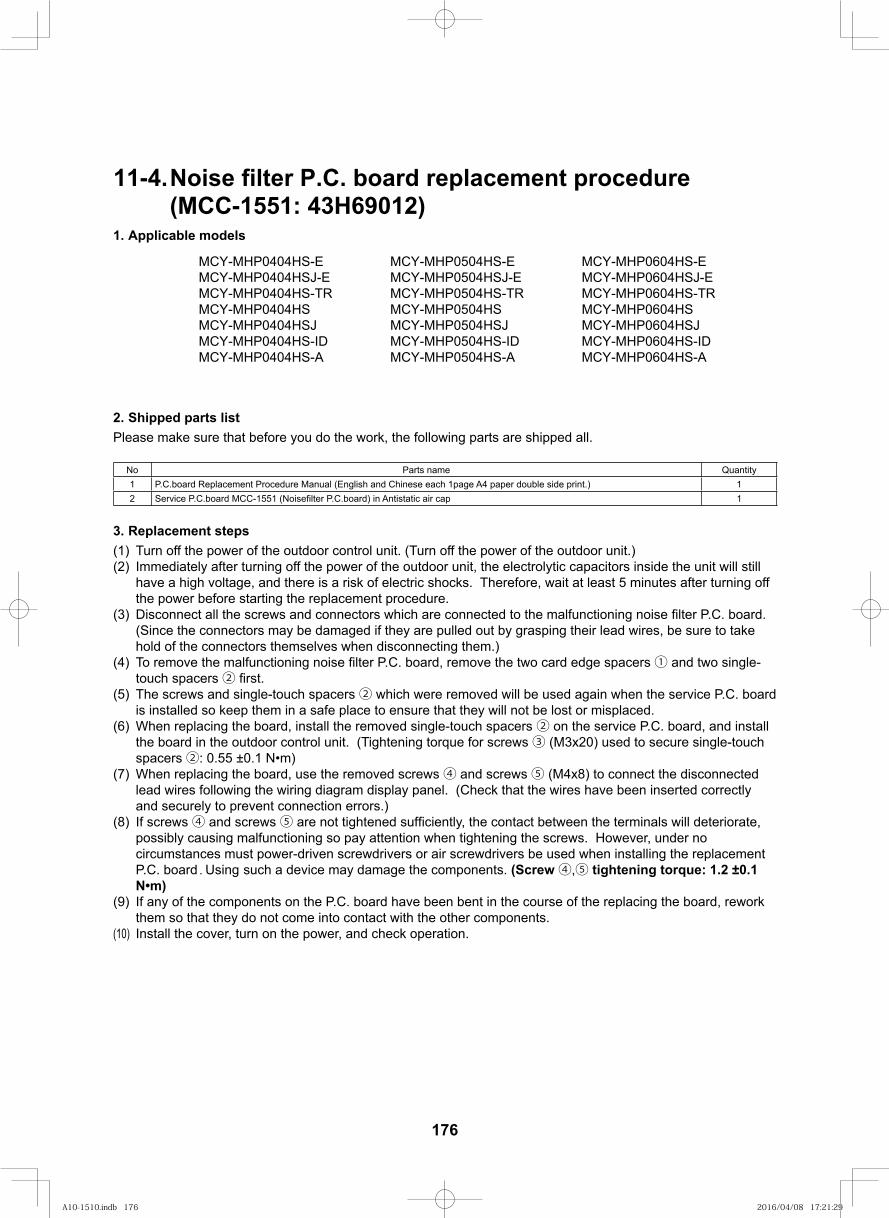
11-4.Noise filter P.C. board replacement procedure(MCC-1551: 43H69012)
1. Applicable models
2. Shipped parts listPlease make sure that before you do the work, the following parts are shipped all.
No Parts name Quantity1 P.C.board Replacement Procedure Manual (English and Chinese each 1page A4 paper double side print.) 12 Service P.C.board MCC-1551 P.C.board) in Antistatic air cap 1
3. Replacement steps(1) Turn off the power of the outdoor control unit. (Turn off the power of the outdoor unit.)(2) Immediately after turning off the power of the outdoor unit, the electrolytic capacitors inside the unit will still
have a high voltage, and there is a risk of electric shocks. Therefore, wait at least 5 minutes after turning off the power before starting the replacement procedure.
(3) Disconnect all the screws and connectors which are connected to the malfunctioning noise P.C. board. (Since the connectors may be damaged if they are pulled out by grasping their lead wires, be sure to take hold of the connectors themselves when disconnecting them.)
(4) To remove the malfunctioning noise P.C. board, remove the two card edge spacers ① and two single-touch spacers ②
(5) The screws and single-touch spacers ② which were removed will be used again when the service P.C. board is installed so keep them in a safe place to ensure that they will not be lost or misplaced.
(6) When replacing the board, install the removed single-touch spacers ② on the service P.C. board, and install the board in the outdoor control unit. (Tightening torque for screws ③ (M3x20) used to secure single-touch spacers ②: 0.55 ±0.1
(7) When replacing the board, use the removed screws ④ and screws ⑤ (M4x8) to connect the disconnected lead wires following the wiring diagram display panel. (Check that the wires have been inserted correctly and securely to prevent connection errors.)
(8) If screws ④ and screws ⑤ are not tightened the contact between the terminals will deteriorate, possibly causing malfunctioning so pay attention when tightening the screws. However, under no circumstances must power-driven screwdrivers or air screwdrivers be used when installing the replacement P.C. board. Using such a device may damage the components. (Screw ④,⑤ tightening torque: 1.2 ±0.1
(9) If any of the components on the P.C. board have been bent in the course of the replacing the board, rework them so that they do not come into contact with the other components.
(10) Install the cover, turn on the power, and check operation.
MCY-MHP0404HS-E MCY-MHP0504HS-E MCY-MHP0604HS-EMCY-MHP0404HSJ-E MCY-MHP0504HSJ-E MCY-MHP0604HSJ-EMCY-MHP0404HS-TR MCY-MHP0504HS-TR MCY-MHP0604HS-TRMCY-MHP0404HS MCY-MHP0504HS MCY-MHP0604HSMCY-MHP0404HSJ MCY-MHP0504HSJ MCY-MHP0604HSJMCY-MHP0404HS-ID MCY-MHP0504HS-ID MCY-MHP0604HS-IDMCY-MHP0404HS-A MCY-MHP0504HS-A MCY-MHP0604HS-A
176
A10-1510.indb 176A10-1510.indb 176 2016/04/08 17:21:292016/04/08 17:21:29
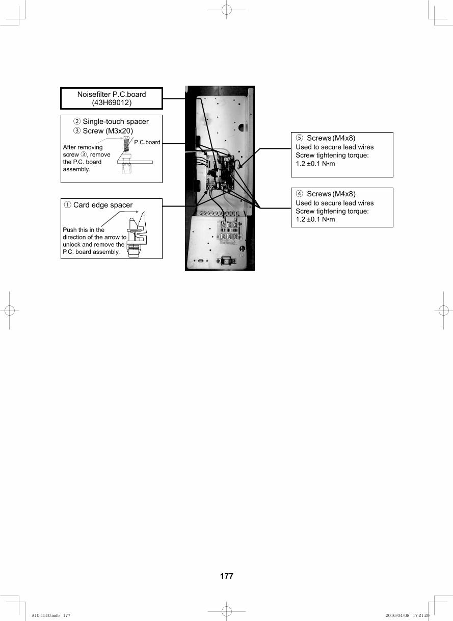
177
⑤ Screws (M4x8) Used to secure lead wires Screw tightening torque: 1.2 ±0.1
Noisefilter P.C.board (43H69012)
④ Screws (M4x8) Used to secure lead wires Screw tightening torque: 1.2 ±0.1
PCBPCBP.C.board
② Single-touch spacer
screw ③the P.C. board
y.
③ Screw (M3x20)
① Card edge spacer
Push this in the direction of the arrow to
P y.
A10-1510.indb 177A10-1510.indb 177 2016/04/08 17:21:292016/04/08 17:21:29
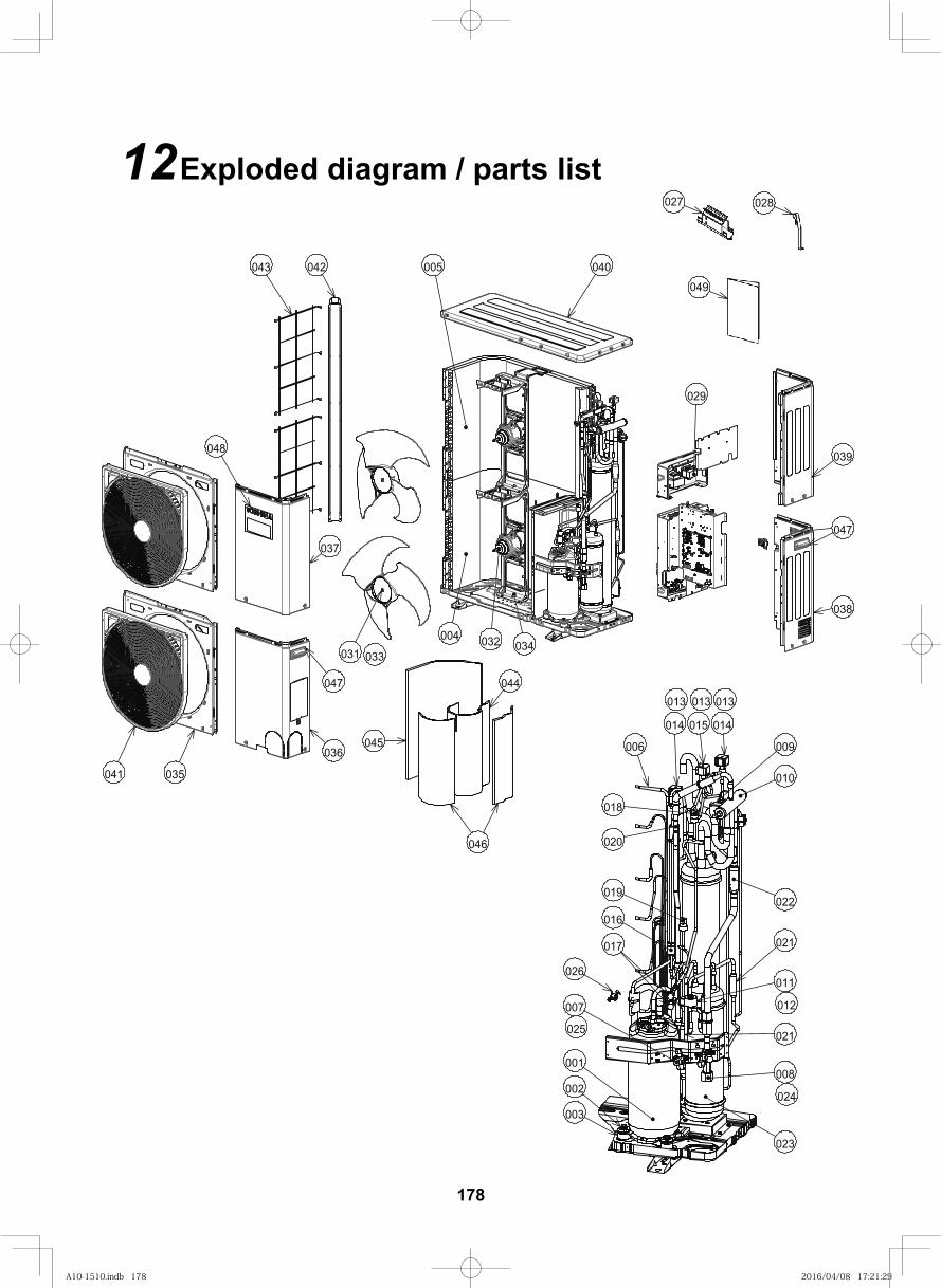
179
12Exploded diagram / parts list
038
043
036
039
031
040005
004
048
041 035
047
032 034
042
029
047
044
046
045
037
001
014015014
006
002
003
007
010
016
023
008
022
009
011
021
026
021
020
019
018
017
013
025
012
024
013013
033
027 028
049
178
A10-1510.indb 178A10-1510.indb 178 2016/04/08 17:21:292016/04/08 17:21:29
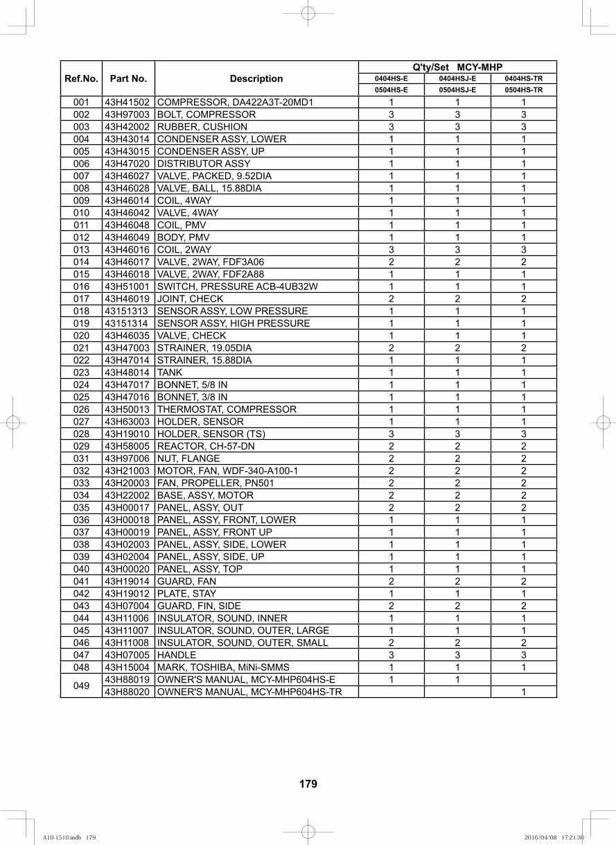
179
Ref.No. Part No. DescriptionQ'ty/Set MCY-MHP
0404HS-E 0404HSJ-E 0404HS-TR0504HS-E 0504HSJ-E 0504HS-TR
001 43H41502 COMPRESSOR, DA422A3T-20MD1 1 1 1002 43H97003 BOLT, COMPRESSOR 3 3 3003 43H42002 RUBBER, CUSHION 3 3 3004 43H43014 CONDENSER ASSY, LOWER 1 1 1005 43H43015 CONDENSER ASSY, UP 1 1 1006 43H47020 DISTRIBUTOR ASSY 1 1 1007 43H46027 VALVE, PACKED, 9.52DIA 1 1 1008 43H46028 VALVE, BALL, 15.88DIA 1 1 1009 43H46014 COIL, 4WAY 1 1 1010 43H46042 VALVE, 4WAY 1 1 1011 43H46048 COIL, PMV 1 1 1012 43H46049 BODY, PMV 1 1 1013 43H46016 COIL, 2WAY 3 3 3014 43H46017 VALVE, 2WAY, FDF3A06 2 2 2015 43H46018 VALVE, 2WAY, FDF2A88 1 1 1016 43H51001 SWITCH, PRESSURE ACB-4UB32W 1 1 1017 43H46019 JOINT, CHECK 2 2 2018 43151313 SENSOR ASSY, LOW PRESSURE 1 1 1019 43151314 SENSOR ASSY, HIGH PRESSURE 1 1 1020 43H46035 VALVE, CHECK 1 1 1021 43H47003 STRAINER, 19.05DIA 2 2 2022 43H47014 STRAINER, 15.88DIA 1 1 1023 43H48014 TANK 1 1 1024 43H47017 BONNET, 5/8 IN 1 1 1025 43H47016 BONNET, 3/8 IN 1 1 1026 43H50013 THERMOSTAT, COMPRESSOR 1 1 1027 43H63003 HOLDER, SENSOR 1 1 1028 43H19010 HOLDER, SENSOR (TS) 3 3 3029 43H58005 REACTOR, CH-57-DN 2 2 2031 43H97006 NUT, FLANGE 2 2 2032 43H21003 MOTOR, FAN, WDF-340-A100-1 2 2 2033 43H20003 FAN, PROPELLER, PN501 2 2 2034 43H22002 BASE, ASSY, MOTOR 2 2 2035 43H00017 PANEL, ASSY, OUT 2 2 2036 43H00018 PANEL, ASSY, FRONT, LOWER 1 1 1037 43H00019 PANEL, ASSY, FRONT UP 1 1 1038 43H02003 PANEL, ASSY, SIDE, LOWER 1 1 1039 43H02004 PANEL, ASSY, SIDE, UP 1 1 1040 43H00020 PANEL, ASSY, TOP 1 1 1041 43H19014 GUARD, FAN 2 2 2042 43H19012 PLATE, STAY 1 1 1043 43H07004 GUARD, FIN, SIDE 2 2 2044 43H11006 INSULATOR, SOUND, INNER 1 1 1045 43H11007 INSULATOR, SOUND, OUTER, LARGE 1 1 1046 43H11008 INSULATOR, SOUND, OUTER, SMALL 2 2 2047 43H07005 HANDLE 3 3 3048 43H15004 MARK, TOSHIBA, MiNi-SMMS 1 1 1
049 43H88019 OWNER'S MANUAL, MCY-MHP604HS-E 1 143H88020 OWNER'S MANUAL, MCY-MHP604HS-TR 1
A10-1510.indb 179A10-1510.indb 179 2016/04/08 17:21:302016/04/08 17:21:30
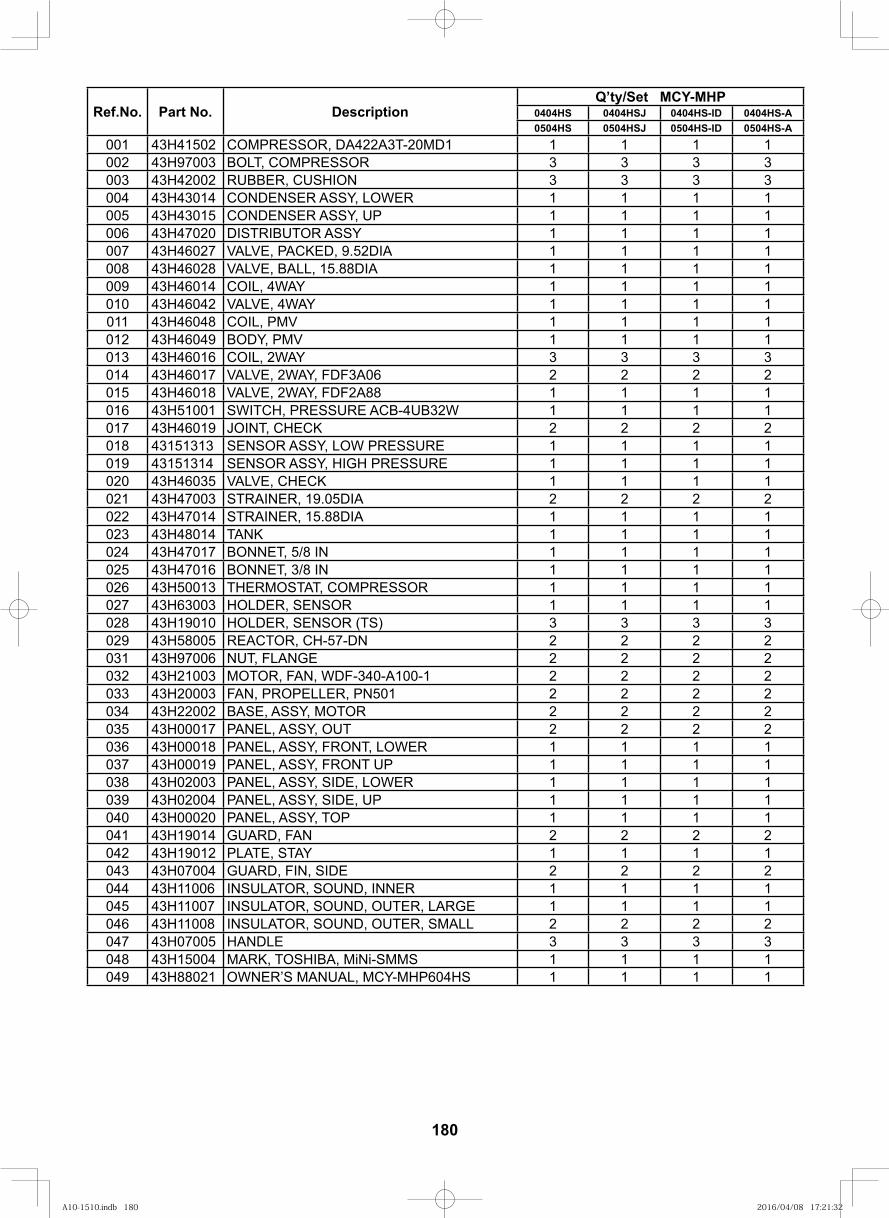
180
Ref.No. Part No. DescriptionQ’ty/Set MCY-MHP
0404HS 0404HSJ 0404HS-ID 0404HS-A0504HS 0504HSJ 0504HS-ID 0504HS-A
001 43H41502 COMPRESSOR, DA422A3T-20MD1 1 1 1 1002 43H97003 BOLT, COMPRESSOR 3 3 3 3003 43H42002 RUBBER, CUSHION 3 3 3 3004 43H43014 CONDENSER ASSY, LOWER 1 1 1 1005 43H43015 CONDENSER ASSY, UP 1 1 1 1006 43H47020 DISTRIBUTOR ASSY 1 1 1 1007 43H46027 VALVE, PACKED, 9.52DIA 1 1 1 1008 43H46028 VALVE, BALL, 15.88DIA 1 1 1 1009 43H46014 COIL, 4WAY 1 1 1 1010 43H46042 VALVE, 4WAY 1 1 1 1011 43H46048 COIL, PMV 1 1 1 1012 43H46049 BODY, PMV 1 1 1 1013 43H46016 COIL, 2WAY 3 3 3 3014 43H46017 VALVE, 2WAY, FDF3A06 2 2 2 2015 43H46018 VALVE, 2WAY, FDF2A88 1 1 1 1016 43H51001 SWITCH, PRESSURE ACB-4UB32W 1 1 1 1017 43H46019 JOINT, CHECK 2 2 2 2018 43151313 SENSOR ASSY, LOW PRESSURE 1 1 1 1019 43151314 SENSOR ASSY, HIGH PRESSURE 1 1 1 1020 43H46035 VALVE, CHECK 1 1 1 1021 43H47003 STRAINER, 19.05DIA 2 2 2 2022 43H47014 STRAINER, 15.88DIA 1 1 1 1023 43H48014 TANK 1 1 1 1024 43H47017 BONNET, 5/8 IN 1 1 1 1025 43H47016 BONNET, 3/8 IN 1 1 1 1026 43H50013 THERMOSTAT, COMPRESSOR 1 1 1 1027 43H63003 HOLDER, SENSOR 1 1 1 1028 43H19010 HOLDER, SENSOR (TS) 3 3 3 3029 43H58005 REACTOR, CH-57-DN 2 2 2 2031 43H97006 NUT, FLANGE 2 2 2 2032 43H21003 MOTOR, FAN, WDF-340-A100-1 2 2 2 2033 43H20003 FAN, PROPELLER, PN501 2 2 2 2034 43H22002 BASE, ASSY, MOTOR 2 2 2 2035 43H00017 PANEL, ASSY, OUT 2 2 2 2036 43H00018 PANEL, ASSY, FRONT, LOWER 1 1 1 1037 43H00019 PANEL, ASSY, FRONT UP 1 1 1 1038 43H02003 PANEL, ASSY, SIDE, LOWER 1 1 1 1039 43H02004 PANEL, ASSY, SIDE, UP 1 1 1 1040 43H00020 PANEL, ASSY, TOP 1 1 1 1041 43H19014 GUARD, FAN 2 2 2 2042 43H19012 PLATE, STAY 1 1 1 1043 43H07004 GUARD, FIN, SIDE 2 2 2 2044 43H11006 INSULATOR, SOUND, INNER 1 1 1 1045 43H11007 INSULATOR, SOUND, OUTER, LARGE 1 1 1 1046 43H11008 INSULATOR, SOUND, OUTER, SMALL 2 2 2 2047 43H07005 HANDLE 3 3 3 3048 43H15004 MARK, TOSHIBA, MiNi-SMMS 1 1 1 1049 43H88021 OWNER’S MANUAL, MCY-MHP604HS 1 1 1 1
A10-1510.indb 180A10-1510.indb 180 2016/04/08 17:21:322016/04/08 17:21:32
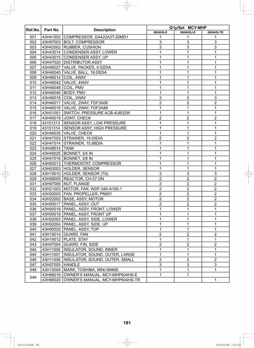
181
Ref.No. Part No. Description Q’ty/Set MCY-MHP0604HS-E 0604HSJ-E 0604HS-TR
001 43H41502 COMPRESSOR, DA422A3T-20MD1 1 1 1002 43H97003 BOLT, COMPRESSOR 3 3 3003 43H42002 RUBBER, CUSHION 3 3 3004 43H43014 CONDENSER ASSY, LOWER 1 1 1005 43H43015 CONDENSER ASSY, UP 1 1 1006 43H47020 DISTRIBUTOR ASSY 1 1 1007 43H46027 VALVE, PACKED, 9.52DIA 1 1 1008 43H46040 VALVE, BALL, 19.05DIA 1 1 1009 43H46014 COIL, 4WAY 1 1 1010 43H46042 VALVE, 4WAY 1 1 1011 43H46048 COIL, PMV 1 1 1012 43H46049 BODY, PMV 1 1 1013 43H46016 COIL, 2WAY 3 3 3014 43H46017 VALVE, 2WAY, FDF3A06 2 2 2015 43H46018 VALVE, 2WAY, FDF2A88 1 1 1016 43H51001 SWITCH, PRESSURE ACB-4UB32W 1 1 1017 43H46019 JOINT, CHECK 2 2 2018 43151313 SENSOR ASSY, LOW PRESSURE 1 1 1019 43151314 SENSOR ASSY, HIGH PRESSURE 1 1 1020 43H46035 VALVE, CHECK 1 1 1021 43H47003 STRAINER, 19.05DIA 2 2 2022 43H47014 STRAINER, 15.88DIA 1 1 1023 43H48014 TANK 1 1 1024 43H49025 BONNET, 3/4 IN 1 1 1025 43H47016 BONNET, 3/8 IN 1 1 1026 43H50013 THERMOSTAT, COMPRESSOR 1 1 1027 43H63003 HOLDER, SENSOR 1 1 1028 43H19010 HOLDER, SENSOR (TS) 3 3 3029 43H58005 REACTOR, CH-57-DN 2 2 2031 43H97006 NUT, FLANGE 2 2 2032 43H21003 MOTOR, FAN, WDF-340-A100-1 2 2 2033 43H20003 FAN, PROPELLER, PN501 2 2 2034 43H22002 BASE, ASSY, MOTOR 2 2 2035 43H00017 PANEL, ASSY, OUT 2 2 2036 43H00018 PANEL, ASSY, FRONT, LOWER 1 1 1037 43H00019 PANEL, ASSY, FRONT UP 1 1 1038 43H02003 PANEL, ASSY, SIDE, LOWER 1 1 1039 43H02004 PANEL, ASSY, SIDE, UP 1 1 1040 43H00020 PANEL, ASSY, TOP 1 1 1041 43H19014 GUARD, FAN 2 2 2042 43H19012 PLATE, STAY 1 1 1043 43H07004 GUARD, FIN, SIDE 2 2 2044 43H11006 INSULATOR, SOUND, INNER 1 1 1045 43H11007 INSULATOR, SOUND, OUTER, LARGE 1 1 1046 43H11008 INSULATOR, SOUND, OUTER, SMALL 2 2 2047 43H07005 HANDLE 3 3 3048 43H15004 MARK, TOSHIBA, MiNi-SMMS 1 1 1
049 43H88019 OWNER’S MANUAL, MCY-MHP604HS-E 1 143H88020 OWNER’S MANUAL, MCY-MHP604HS-TR 1
A10-1510.indb 181A10-1510.indb 181 2016/04/08 17:21:322016/04/08 17:21:32
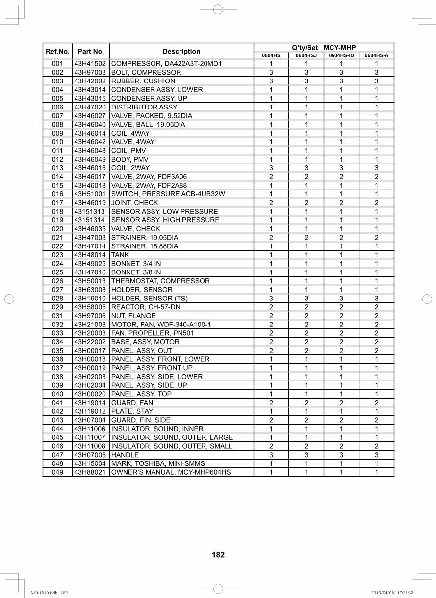
182
Ref.No. Part No. Description Q’ty/Set MCY-MHP0604HS 0604HSJ 0604HS-ID 0604HS-A
001 43H41502 COMPRESSOR, DA422A3T-20MD1 1 1 1 1002 43H97003 BOLT, COMPRESSOR 3 3 3 3003 43H42002 RUBBER, CUSHION 3 3 3 3004 43H43014 CONDENSER ASSY, LOWER 1 1 1 1005 43H43015 CONDENSER ASSY, UP 1 1 1 1006 43H47020 DISTRIBUTOR ASSY 1 1 1 1007 43H46027 VALVE, PACKED, 9.52DIA 1 1 1 1008 43H46040 VALVE, BALL, 19.05DIA 1 1 1 1009 43H46014 COIL, 4WAY 1 1 1 1010 43H46042 VALVE, 4WAY 1 1 1 1011 43H46048 COIL, PMV 1 1 1 1012 43H46049 BODY, PMV 1 1 1 1013 43H46016 COIL, 2WAY 3 3 3 3014 43H46017 VALVE, 2WAY, FDF3A06 2 2 2 2015 43H46018 VALVE, 2WAY, FDF2A88 1 1 1 1016 43H51001 SWITCH, PRESSURE ACB-4UB32W 1 1 1 1017 43H46019 JOINT, CHECK 2 2 2 2018 43151313 SENSOR ASSY, LOW PRESSURE 1 1 1 1019 43151314 SENSOR ASSY, HIGH PRESSURE 1 1 1 1020 43H46035 VALVE, CHECK 1 1 1 1021 43H47003 STRAINER, 19.05DIA 2 2 2 2022 43H47014 STRAINER, 15.88DIA 1 1 1 1023 43H48014 TANK 1 1 1 1024 43H49025 BONNET, 3/4 IN 1 1 1 1025 43H47016 BONNET, 3/8 IN 1 1 1 1026 43H50013 THERMOSTAT, COMPRESSOR 1 1 1 1027 43H63003 HOLDER, SENSOR 1 1 1 1028 43H19010 HOLDER, SENSOR (TS) 3 3 3 3029 43H58005 REACTOR, CH-57-DN 2 2 2 2031 43H97006 NUT, FLANGE 2 2 2 2032 43H21003 MOTOR, FAN, WDF-340-A100-1 2 2 2 2033 43H20003 FAN, PROPELLER, PN501 2 2 2 2034 43H22002 BASE, ASSY, MOTOR 2 2 2 2035 43H00017 PANEL, ASSY, OUT 2 2 2 2036 43H00018 PANEL, ASSY, FRONT, LOWER 1 1 1 1037 43H00019 PANEL, ASSY, FRONT UP 1 1 1 1038 43H02003 PANEL, ASSY, SIDE, LOWER 1 1 1 1039 43H02004 PANEL, ASSY, SIDE, UP 1 1 1 1040 43H00020 PANEL, ASSY, TOP 1 1 1 1041 43H19014 GUARD, FAN 2 2 2 2042 43H19012 PLATE, STAY 1 1 1 1043 43H07004 GUARD, FIN, SIDE 2 2 2 2044 43H11006 INSULATOR, SOUND, INNER 1 1 1 1045 43H11007 INSULATOR, SOUND, OUTER, LARGE 1 1 1 1046 43H11008 INSULATOR, SOUND, OUTER, SMALL 2 2 2 2047 43H07005 HANDLE 3 3 3 3048 43H15004 MARK, TOSHIBA, MiNi-SMMS 1 1 1 1049 43H88021 OWNER’S MANUAL, MCY-MHP604HS 1 1 1 1
A10-1510.indb 182A10-1510.indb 182 2016/04/08 17:21:322016/04/08 17:21:32
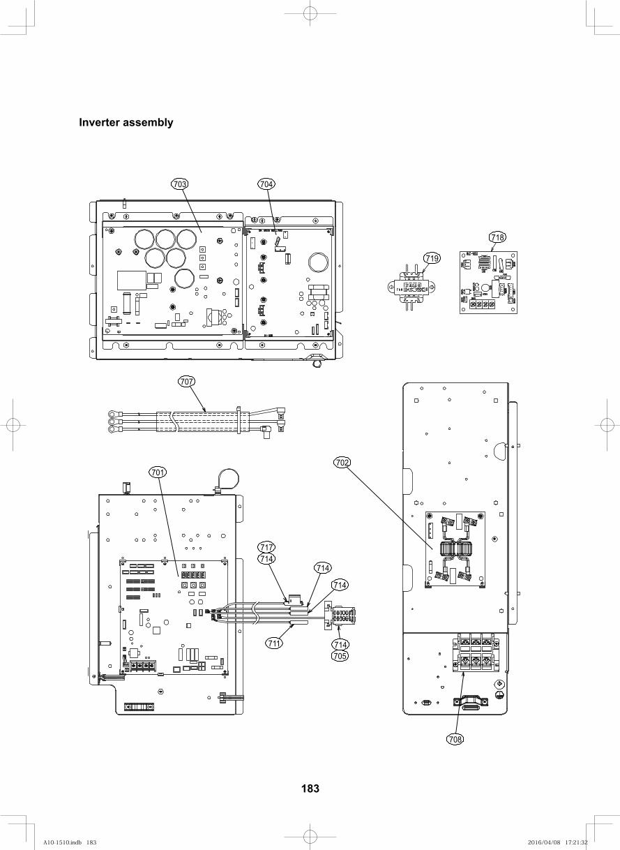
Inverter assembly
703 704
707
701
717714
705711
708
702
714
714
714
718
719
183
A10-1510.indb 183A10-1510.indb 183 2016/04/08 17:21:322016/04/08 17:21:32
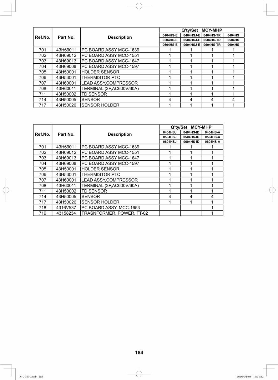
184
Ref.No. Part No. DescriptionQ’ty/Set MCY-MHP
0404HS-E 0404HSJ-E 0404HS-TR 0404HS0504HS-E 0504HSJ-E 0504HS-TR 0504HS0604HS-E 0604HSJ-E 0604HS-TR 0604HS
701 43H69011 PC BOARD ASSY MCC-1639 1 1 1 1702 43H69012 PC BOARD ASSY MCC-1551 1 1 1 1703 43H69013 PC BOARD ASSY MCC-1647 1 1 1 1704 43H69008 PC BOARD ASSY MCC-1597 1 1 1 1705 43H50001 HOLDER SENSOR 1 1 1 1706 43H53001 THERMISTOR PTC 1 1 1 1707 43H60001 LEAD ASSY,COMPRESSOR 1 1 1 1708 43H60011 TERMINAL (3P,AC600V/60A) 1 1 1 1711 43H50002 TD SENSOR 1 1 1 1714 43H50005 SENSOR 4 4 4 4717 43H50026 SENSOR HOLDER 1 1 1 1
Ref.No. Part No. DescriptionQ’ty/Set MCY-MHP
0404HSJ 0404HS-ID 0404HS-A0504HSJ 0504HS-ID 0504HS-A0604HSJ 0604HS-ID 0604HS-A
701 43H69011 PC BOARD ASSY MCC-1639 1 1 1702 43H69012 PC BOARD ASSY MCC-1551 1 1 1703 43H69013 PC BOARD ASSY MCC-1647 1 1 1704 43H69008 PC BOARD ASSY MCC-1597 1 1 1705 43H50001 HOLDER SENSOR 1 1 1706 43H53001 THERMISTOR PTC 1 1 1707 43H60001 LEAD ASSY,COMPRESSOR 1 1 1708 43H60011 TERMINAL (3P,AC600V/60A) 1 1 1711 43H50002 TD SENSOR 1 1 1714 43H50005 SENSOR 4 4 4717 43H50026 SENSOR HOLDER 1 1 1718 4316V537 PC BOARD ASSY, MCC-1653 1719 43158234 TRASNFORMER, POWER, TT-02 1
A10-1510.indb 184A10-1510.indb 184 2016/04/08 17:21:332016/04/08 17:21:33
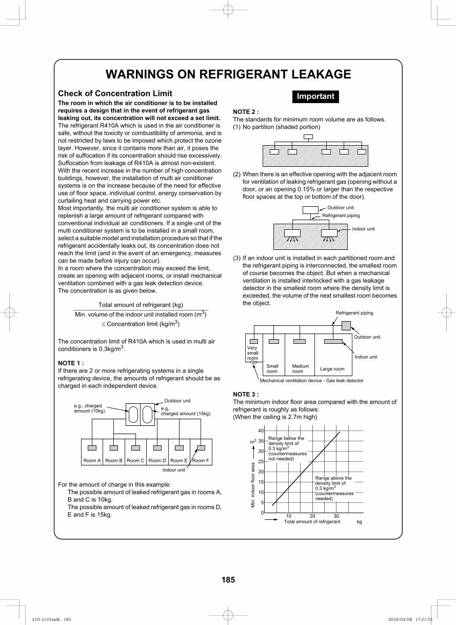
185
FILE NO. SVM-13011
WARNINGS ON REFRIGERANT LEAKAGECheck of Concentration LimitThe room in which the air conditioner is to be installed requires a design that in the event of refrigerant gas leaking out, its concentration will not exceed a set limit.The refrigerant R410A which is used in the air conditioner is safe, without the toxicity or combustibility of ammonia, and is not restricted by laws to be imposed which protect the ozone layer. However, since it contains more than air, it poses the risk of suffocation if its concentration should rise excessively. Suffocation from leakage of R410A is almost non-existent. With the recent increase in the number of high concentration buildings, however, the installation of multi air conditioner systems is on the increase because of the need for effective use of floor space, individual control, energy conservation by curtailing heat and carrying power etc.Most importantly, the multi air conditioner system is able to replenish a large amount of refrigerant compared with conventional individual air conditioners. If a single unit of the multi conditioner system is to be installed in a small room, select a suitable model and installation procedure so that if the refrigerant accidentally leaks out, its concentration does not reach the limit (and in the event of an emergency, measures can be made before injury can occur).In a room where the concentration may exceed the limit, create an opening with adjacent rooms, or install mechanical ventilation combined with a gas leak detection device.The concentration is as given below.
The concentration limit of R410A which is used in multi air conditioners is 0.3kg/m3.
NOTE 1 :If there are 2 or more refrigerating systems in a single refrigerating device, the amounts of refrigerant should be as charged in each independent device.
For the amount of charge in this example:The possible amount of leaked refrigerant gas in rooms A, B and C is 10kg.The possible amount of leaked refrigerant gas in rooms D, E and F is 15kg.
NOTE 2 :The standards for minimum room volume are as follows.(1) No partition (shaded portion)
(2) When there is an effective opening with the adjacent room for ventilation of leaking refrigerant gas (opening without a door, or an opening 0.15% or larger than the respective floor spaces at the top or bottom of the door).
(3) If an indoor unit is installed in each partitioned room and the refrigerant piping is interconnected, the smallest room of course becomes the object. But when a mechanical ventilation is installed interlocked with a gas leakage detector in the smallest room where the density limit is exceeded, the volume of the next smallest room becomes the object.
NOTE 3 :The minimum indoor floor area compared with the amount of refrigerant is roughly as follows:(When the ceiling is 2.7m high)
Total amount of refrigerant (kg)Min. volume of the indoor unit installed room (m3)
≤ Concentration limit (kg/m3)
e.g., charged amount (10kg)
Outdoor unite.g.,charged amount (15kg)
Indoor unit
Room A Room B Room C Room D Room E Room F
Important
Outdoor unitRefrigerant piping
Indoor unit
Refrigerant piping
Outdoor unit
Indoor unit
Mechanical ventilation device - Gas leak detector
Very small room
Smallroom
Medium room Large room
0
5
10
10 20 30
15
20
25
30
35
40
m2
Min
. ind
oor f
loor
are
a
Total amount of refrigerant kg
Range above the density limit of 0.3 kg/m3
(countermeasures needed)
Range below the density limit of 0.3 kg/m3
(countermeasures not needed)
A10-1510.indb 185A10-1510.indb 185 2016/04/08 17:21:332016/04/08 17:21:33

TOSHIBA CARRIER CORPORATION
23-17, TAKANAWAN,3 CHOME,MINATOKU TOKYO, 108-0075, JAPAN
Copyright © 1999 to 2012 TOSHIBA CARRIER CORPORATION, ALL Rights Reserved.
Revision record
First issue
Revision 1 Page 179 to184
Oct. 2011
Mar . 2012Change 12.Exploded diagram / Parts list
A10-1510.indb 186A10-1510.indb 186 2016/04/08 17:21:332016/04/08 17:21:33


