Embed Size (px)
Citation preview
Transmissions and Driveline
6.1 Introduction
The most powerhl engine in the world is of little use unless the power from the engine can be safely and effectively transmitted to the ground. This, then, is the primary function of the transmission and driveline. In addition to being able to transmit the torque and power from the engine, the transmission and driveline also must allow the vehicle to operate over a wide range of speeds-from a standstill to the maximum speed of the vehicle. This implies that the system must inherently have some method of disconnecting the engine from the remainder of the driveline to allow the vehicle to remain stationary. Furthermore, the transmission also must be designed to satisfy the conflicting requirements of quick acceleration, high speed, and adequate fuel economy.
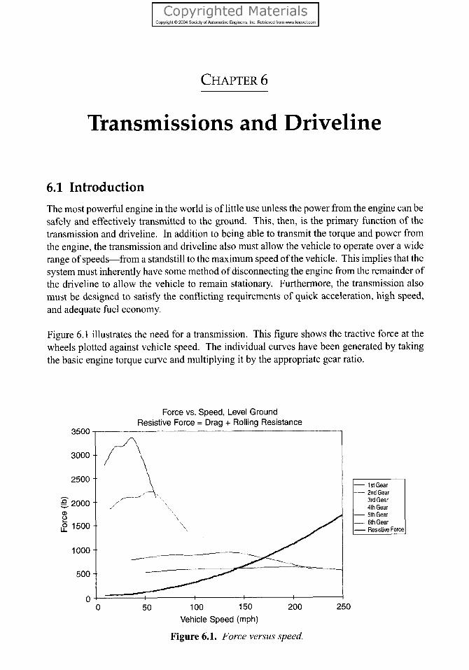
Figure 6.1 illustrates the need for a transmission. This figure shows the tractive force at the wheels plotted against vehicle speed. The individual curves have been generated by taking the basic engine torque curve and multiplying it by the appropriate gear ratio.
Force vs. Speed, Level Ground Resistive Force = Drag + Rolling Resistance
- 2ndGear 3rd Gear 4th Gear
- 5th Gear - 6th Gear
0 50 100 150 200 250
Vehicle Speed (mph)
Figure 6.1. Force versus speed.
236 1 Automotive Engineering Fundamentals
As shown in Fig. 6.1, a high torque multiplication is desired to accelerate the vehicle from a standstill. However, if first gear were all that were available, the maximum speed of the vehicle would be limited to 62 mph by the engine red-line. Although this might be an accept- able top speed for some, the penalty in fuel economy would be excessive. Figure 6.1 also plots the resistive force acting on the car, which is the sum of the aerodynamic drag and rolling resistance. As shown in Fig. 6.1, the car is capable of exceeding 62 mph by a large margin, but only by having more gear ratios available. At the other extreme, if the car had only sixth gear, any attempt to accelerate the car from a standstill inevitably would stall the engine or, at best, result in extreme clutch wear.
This chapter takes a logical progression from the engine flywheel to the drive axles. The first section deals with manual transmission systems and covers friction clutches, gear theory, and manual transmission operation and analysis. The next section discusses automatic transmis- sion systems, including hydrodynamic torque converters, planetary gear analysis, general transmission operation, and gear ratio analysis. The chapter includes a brief discussion of continuously variable transmissions (CVTs). The power flow then is traced through the driveline and the differential to the drive axles. Although the case can be made for includ- ing tires and wheels in the driveline, for the purposes of this work, they will be treated as part of the vehicle control system. Thus, tires will receive mention under steering, vehicle dynamics, and braking, with a full discussion of tire nomenclature and design in Chapter 9. Chapter 6 concludes with a case study of a modem, five-speed, electronically controlled automatic transaxle.
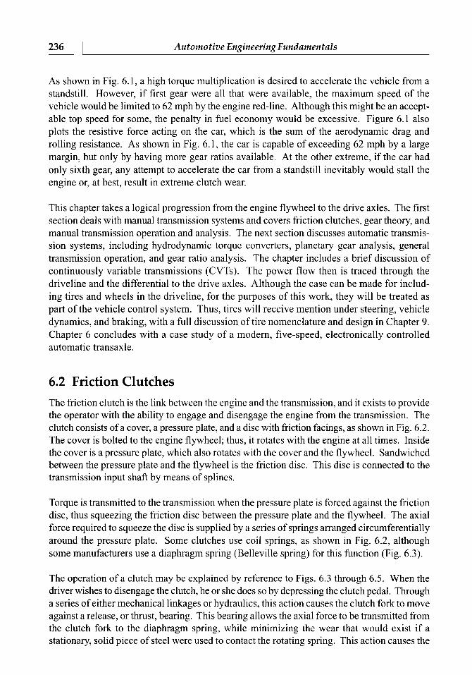
6.2 Friction Clutches The friction clutch is the link between the engine and the transmission, and it exists to provide the operator with the ability to engage and disengage the engine from the transmission. The clutch consists of a cover, a pressure plate, and a disc with friction facings, as shown in Fig. 6.2. The cover is bolted to the engine flywheel; thus, it rotates with the engine at all times. Inside the cover is a pressure plate, which also rotates with the cover and the flywheel. Sandwiched between the pressure plate and the flywheel is the friction disc. This disc is connected to the transmission input shaft by means of splines.
Torque is transmitted to the transmission when the pressure plate is forced against the friction disc, thus squeezing the friction disc between the pressure plate and the flywheel. The axial force required to squeeze the disc is supplied by a series of springs arranged circumferentially around the pressure plate. Some clutches use coil springs, as shown in Fig. 6.2, although some manufacturers use a diaphragm spring (Belleville spring) for this function (Fig. 6.3).
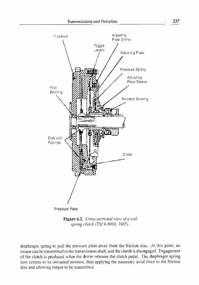
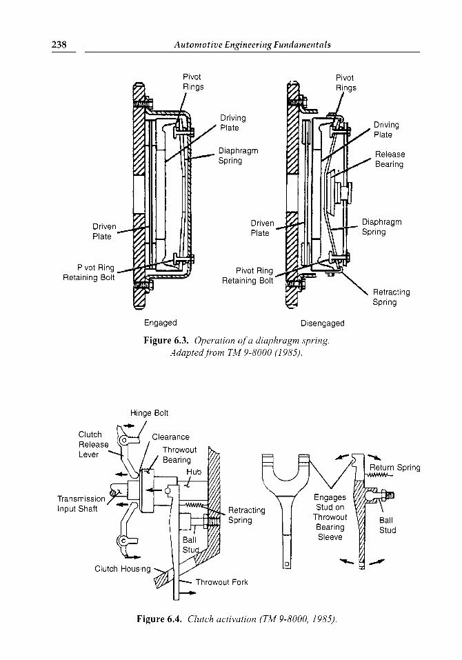
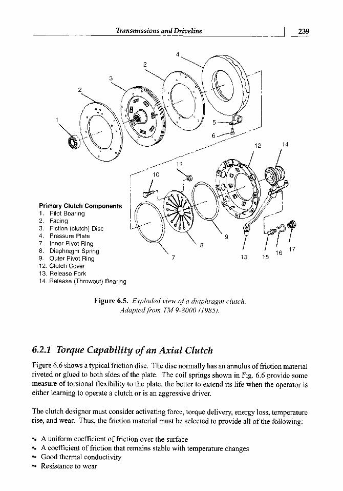
The operation of a clutch may be explained by reference to Figs. 6.3 through 6.5. When the driver wishes to disengage the clutch, he or she does so by depressing the clutch pedal. Through a series of either mechanical linkages or hydraulics, this action causes the clutch fork to move against a release, or thrust, bearing. This bearing allows the axial force to be transmitted from the clutch fork to the diaphragm spring, while minimizing the wear that would exist if a stationary, solid piece of steel were used to contact the rotating spring. This action causes the
Flywheel
Transmissions and Driveline
Adjusting Plate Shims
237
Toggle Levers
Adjusting Plate
Plate Sleeve
Disk with Facings
Pressure Plate
Figure 6.2. Cross-sectional view of a coil spring clutch (TM 9-8000, 1983).
diaphragm spring to pull the pressure plate away from the friction disc. At this point, no torque can be transmitted to the transmission shaft, and the clutch is disengaged. Engagement of the clutch is produced when the driver releases the clutch pedal. The diaphragm spring now returns to its unloaded position, thus applying the necessary axial force to the friction disc and allowing torque to be transmitted
Pivot
238
Pivot
Driving Plate
Diaphragm Spring
Driven Plate
Pivot Ring Retaining Bolt
Automotive Engineering Fundamentals
Engaged Disengaged
Figure 6.3. Operation of a diaphragm spring. Adapted from TM 9-8000 (1 985).
Hinge Bolt
Spring
Throwout Fork
Figure 6.4. Clutch activation (TM 9-8000, 1985).
1
Primary Clutch Components 1 . Pilot Bearing 2. Facing 3. Fiction (clutch) Disc 4. Pressure Plate 7. Inner Pivot Ring 8. Diaphragm Spring 9. Outer Pivot Rinq 7
Transmissions and Driveline
- 12. Clutch Cover 13. Release Fork 14. Release (Throwout) Bearing
239
Figure 6.5. Exploded view of'a diaphragm clutch Adapted,fiom TM 9-8000 (1 985).
6.2.1 Torque Capability of an Axial Clutch
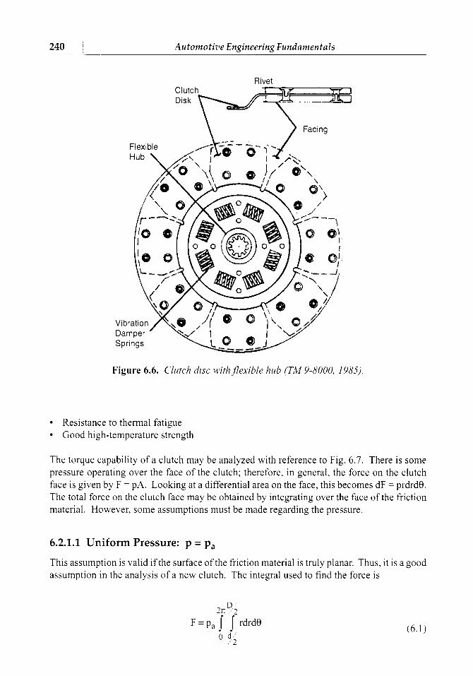
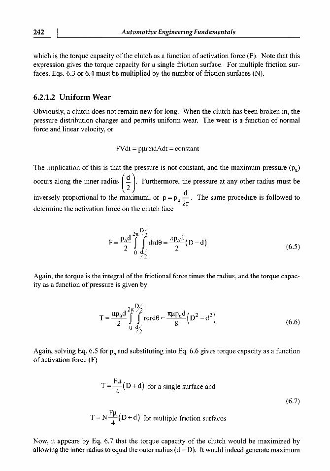
Figure 6.6 shows a typical friction disc. The disc normally has an annulus of friction material riveted or glued to both sides of the plate. The coil springs shown in Fig. 6.6 provide some measure of torsional flexibility to the plate, the better to extend its life when the operator is either learning to operate a clutch or is an aggressive driver.
The clutch designer must consider activating force, torque delivery, energy loss, temperature rise, and wear. Thus, the friction material must be selected to provide all of the following:
A uniform coefficient of friction over the surface A coefficient of friction that remains stable with temperature changes Good thermal conductivity Resistance to wear
Rivet Clutch Disk
240
Figure 6.6. Clutch disc ~i th f lex ib le hub (TM 9-8000, 1985).
Automotive Engineering Fundamentals
Resistance to thermal fatigue Good high-temperature strength
The torque capability of a clutch may be analyzed with reference to Fig. 6.7. There is some pressure operating over the face of the clutch; therefore, in general, the force on the clutch face is given by F = PA. Looking at a differential area on the face, this becomes dF = prdrd0. The total force on the clutch face may be obtained by integrating over the face of the friction material. However, some assumptions must be made regarding the pressure.
6.2.1.1 Uniform Pressure: p = pa
This assumption is valid if the surface of the friction material is truly planar. Thus, it is a good assumption in the analysis of a new clutch. The integral used to find the force is
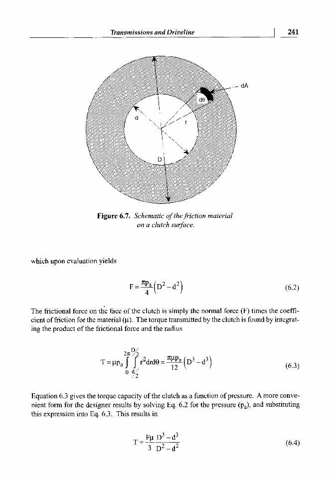
Figure 6.7. Schematic of the friction material on a clutch surface.
Transmissions and Driveline
which upon evaluation yields
241
The frictional force on the face of the clutch is simply the normal force (F) times the coeffi- cient of friction for the material (p). The torque transmitted by the clutch is found by integrat- ing the product of the frictional force and the radius
Equation 6.3 gives the torque capacity of the clutch as a function of pressure. Amore conve- nient form for the designer results by solving Eq. 6.2 for the pressure (pJ, and substituting this expression into Eq. 6.3. This results in
242 I Automotive Engineering Fundamentals
which is the torque capacity of the clutch as a function of activation force (F). Note that this expression gives the torque capacity for a single friction surface. For multiple friction sur- faces, Eqs. 6.3 or 6.4 must be multiplied by the number of friction surfaces (N).
6.2.1.2 Uniform Wear
Obviously, a clutch does not remain new for long. When the clutch has been broken in, the pressure distribution changes and permits uniform wear. The wear is a function of normal force and linear velocity, or
FVdt = pprwdAdt = constant
The implication of this is that the pressure is not constant, and the maximum pressure (pa)
occurs along the inner radius . Furthermore, the pressure at any other radius must be rl
inversely proportional to the maximum, or p = pa . The same procedure is followed to 9, L 1
determine the activation force on the clutch face
Again, the torque is the integral of the frictional force times the radius, and the torque capac- ity as a function of pressure is given by
Again, solving Eq. 6.5 for pa and substituting into Eq. 6.6 gives torque capacity as a function of activation force (F)
F P T = -(D + d) for a single surface and 4
F P T = N - (D + d) for multiple friction surfaces 4
Now, it appears by Eq. 6.7 that the torque capacity of the clutch would be maximized by allowing the inner radius to equal the outer radius (d = D). It would indeed generate maximum
torque because this gives the largest radius for the clutch. However, to do this would require infinite pressure to achieve any torque transfer. The proper way to maximize torque capacity is to take the appropriate partial differential of Eq. 6.6 (see problem 6.3 at the end of this chapter).
Transmissions and Driveline
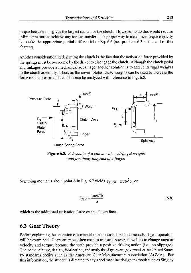
Another consideration in designing the clutch is the fact that the activation force provided by the springs must be overcome by the driver to disengage the clutch. Although the clutch pedal and linkages provide a mechanical advantage, another solution is to add centrifugal weights to the clutch assembly. Then, as the cover rotates, these weights can be used to increase the force on the pressure plate. This can be analyzed with reference to Fig. 6.8.
243
Pressure Plate
Clutch Plate Force
rnro*
Weight
Clutch Cover
I
Spin Axis Clutch Spring Force
Figure 6.8. Schematic of a clutch with centrifugal weights and free-body diagram of afinger.
2 Summing moments about point A in Fig. 6.7 yields Fpma = rnro b , or
which is the additional activation force on the clutch face.
6.3 Gear Theory Before explaining the operation of a manual transmission, the fundamentals of gear operation will be examined. Gears are most often used to transmit power, as well as to change angular velocity and torque, because the teeth provide a positive driving action (i.e., no slippage). The nomenclature, design, fabrication, and analysis of gears are governed in the United States by standards bodies such as the American Gear Manufacturers Association (AGMA). For this information, the student is directed to any good machine design textbook such as Shigley
and Mischke (2001). This book is concerned with the application of gears and their use in automobiles.
244
Almost every type of gear can be found in an automobile. The most common varieties are discussed next.
Automotive Engineering Fundamentals
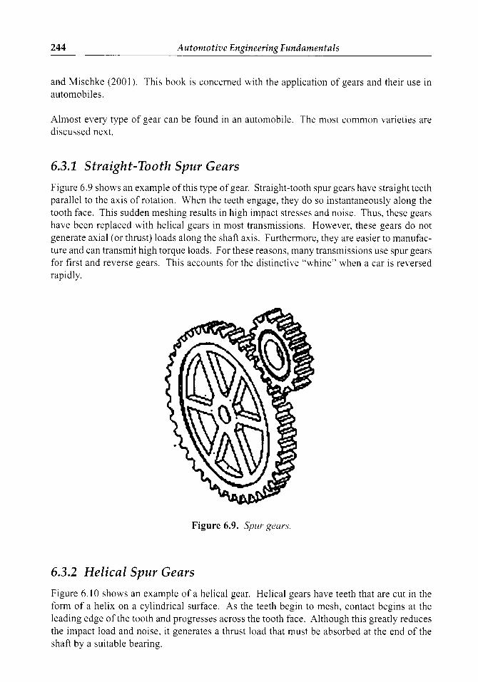
6.3.1 Straight-Tooth Spur Gears
Figure 6.9 shows an example of this type of gear. Straight-tooth spur gears have straight teeth parallel to the axis of rotation. When the teeth engage, they do so instantaneously along the tooth face. This sudden meshing results in high impact stresses and noise. Thus, these gears have been replaced with helical gears in most transmissions. However, these gears do not generate axial (or thrust) loads along the shaft axis. Furthermore, they are easier to manufac- ture and can transmit high torque loads. For these reasons, many transmissions use spur gears for first and reverse gears. This accounts for the distinctive "whine" when a car is reversed rapidly.
Figure 6.9. Spur gears.
6.3.2 Helical Spur Gears
Figure 6.10 shows an example of a helical gear. Helical gears have teeth that are cut in the form of a helix on a cylindrical surface. As the teeth begin to mesh, contact begins at the leading edge of the tooth and progresses across the tooth face. Although this greatly reduces the impact load and noise, it generates a thrust load that must be absorbed at the end of the shaft by a suitable bearing.
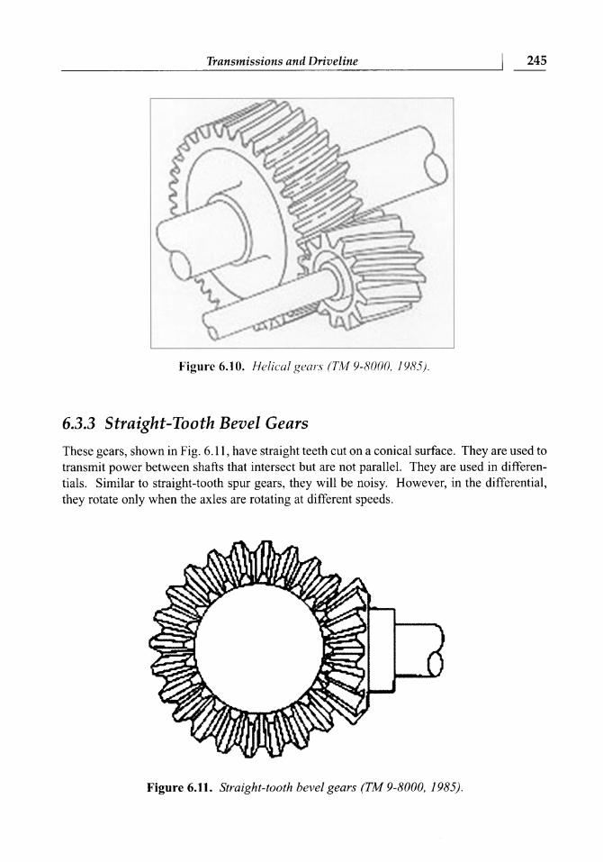
Figure 6.1 0. Helical gears (TM 9-8000, lY8S).
6.3.3 Straight-Tooth Bevel Gears
Transmissions and Driveline
These gears, shown in Fig. 6.11, have straight teeth cut on a conical surface. They are used to transmit power between shafts that intersect but are not parallel. They are used in differen- tials. Similar to straight-tooth spur gears, they will be noisy. However, in the differential, they rotate only when the axles are rotating at different speeds.
245
Figure 6.11. Straight-tooth bevel gears (TA4 9-8000, 198.5).
6.3.4 Spiral Bevel Gears
These gears have teeth cut in the shape of a helix on a conical surface. They can be used for final drives to connect intersecting shafts (Fig. 6.12).
Figure 6.12. Spiral bevel gears (TM 9-8000, 1985).
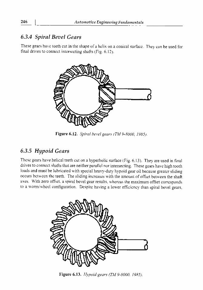
6.3.5 Hypoid Gears
These gears have helical teeth cut on a hyperbolic surface (Fig. 6.13). They are used in final drives to connect shafts that are neither parallel nor intersecting. These gears have high tooth loads and must be lubricated with special heavy-duty hypoid gear oil because greater sliding occurs between the teeth. The sliding increases with the amount of offset between the shaft axes. With zero offset, a spiral bevel gear results, whereas the maximum offset corresponds to a worrdwheel configuration. Despite having a lower efficiency than spiral bevel gears,
Figure 6.13. Hypoid gears (TM 9-8000, 198.5).
hypoid gears allow the driveshaft to be lowered, thereby requiring a smaller "transmission tunnel" in the body.
Transmissions and Driveline
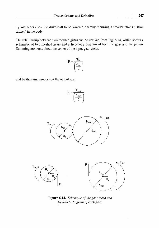
The relationship between two meshed gears can be derived from Fig. 6.14, which shows a schematic of two meshed gears and a free-body diagram of both the gear and the pinion. Summing moments about the center of the input gear yields
247
and by the same process on the output gear
Ti(
C din
Figure 6.14. Schematic of the gear mesh and free-body diagram of each gear.
248 ( Automotive Engineering Fundamentals
Because the tangential force at the mesh must be equal and opposite at the point of meshing,
Furthermore, for any gear, the pitch diameter is proportional to the number of teeth (N), and an analysis of angular velocity also shows that the speeds of the gears are inversely related to the diameter. Combining this leads to what is commonly known as the gear law
The negative sign in Eq. 6.9 accounts for the reversal of rotation in a single mesh. Equation 6.9 also assumes no friction loss in the mesh. In reality, there is a slight loss on the order of 1 to 2%.
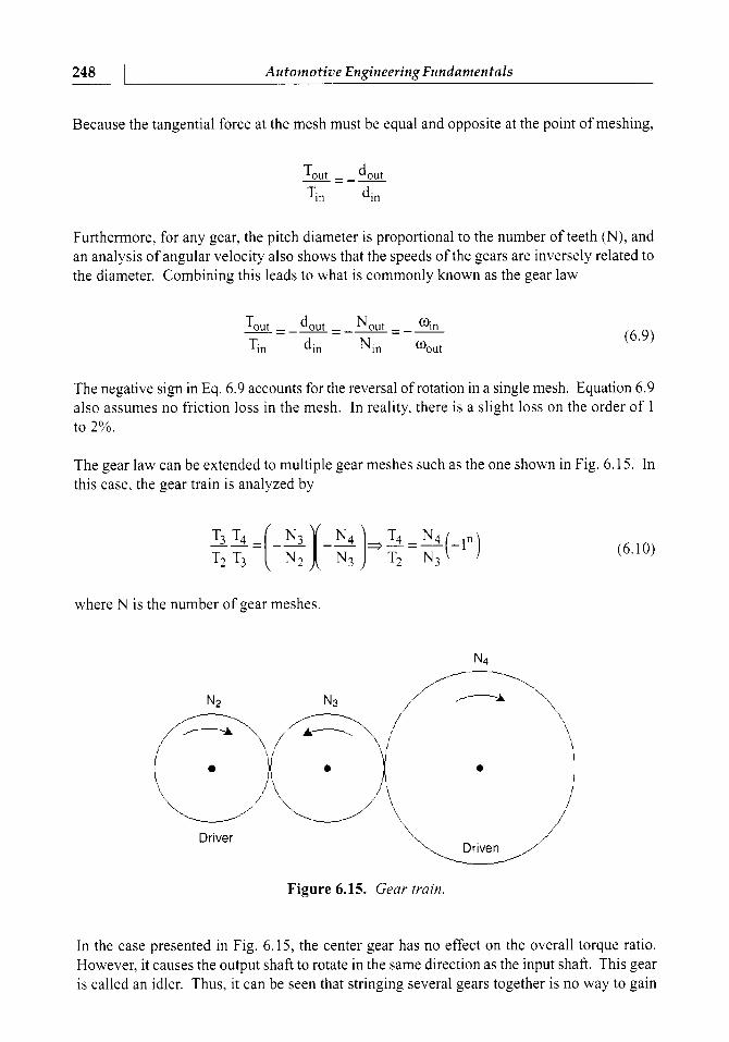
The gear law can be extended to multiple gear meshes such as the one shown in Fig. 6.15. In this case, the gear train is analyzed by
where N is the number of gear meshes.
N4
Driver
Figure 6.15. Gear train.
In the case presented in Fig. 6.15, the center gear has no effect on the overall torque ratio. However, it causes the output shaft to rotate in the same direction as the input shaft. This gear is called an idler. Thus, it can be seen that stringing several gears together is no way to gain
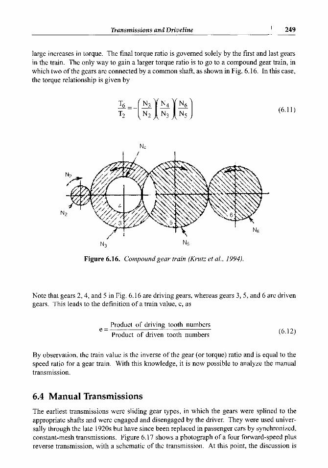
large increases in torque. The final torque ratio is governed solely by the first and last gears in the train. The only way to gain a larger torque ratio is to go to a compound gear train, in which two of the gears are connected by a common shaft, as shown in Fig. 6.16. In this case,
Transmissions and Driveline
the torque relationship is given by
249
C
N3 N5
Figure 6.16. Compound gear train (Krutz et al., 1994).
Note that gears 2,4, and 5 in Fig. 6.16 are driving gears, whereas gears 3,5, and 6 are driven gears. This leads to the definition of a train value, e, as
Product of driving tooth numbers e =
Product of driven tooth numbers
By observation, the train value is the inverse of the gear (or torque) ratio and is equal to the speed ratio for a gear train. With this knowledge, it is now possible to analyze the manual transmission.
6.4 Manual Transmissions The earliest transmissions were sliding gear types, in which the gears were splined to the appropriate shafts and were engaged and disengaged by the driver. They were used univer- sally through the late 1920s but have since been replaced in passenger cars by synchronized, constant-mesh transmissions. Figure 6.17 shows a photograph of a four fonvard-speed plus reverse transmission, with a schematic of the transmission. At this point, the discussion is
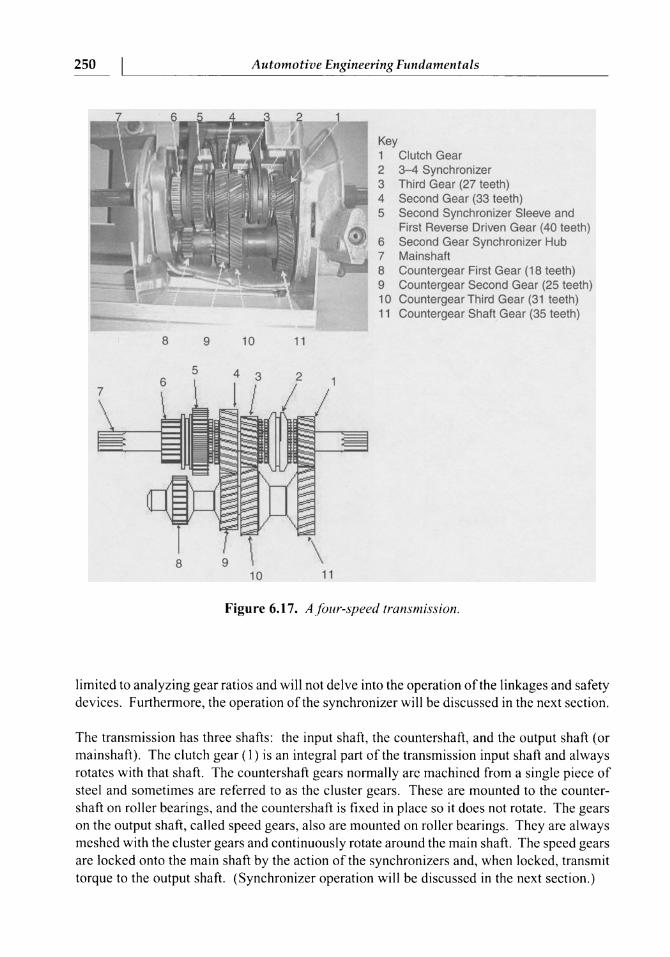
Clutch Gear 3-4 Synchronizer Third Gear (27 teeth) Second Gear (33 teeth) Second Synchronizer Sleeve and First Reverse Driven Gear (40 teeth) Second Gear Synchronizer Hub Mainshaft Countergear First Gear (1 8 teeth) Countergear Second Gear (25 teeth) Countergear Third Gear (31 teeth) Countergear Shaft Gear (35 teeth)
250
Figure 6.17. A four-speed transmission.
Automotive Engineering Fundamentals
limited to analyzing gear ratios and will not delve into the operation of the linkages and safety devices. Furthermore, the operation of the synchronizer will be discussed in the next section.
The transmission has three shafts: the input shaft, the countershaft, and the output shaft (or mainshaft). The clutch gear (1) is an integral part of the transmission input shaft and always rotates with that shaft. The countershaft gears normally are machined from a single piece of steel and sometimes are referred to as the cluster gears. These are mounted to the counter- shaft on roller bearings, and the countershaft is fixed in place so it does not rotate. The gears on the output shaft, called speed gears, also are mounted on roller bearings. They are always meshed with the cluster gears and continuously rotate around the main shaft. The speed gears are locked onto the main shaft by the action of the synchronizers and, when locked, transmit torque to the output shaft. (Synchronizer operation will be discussed in the next section.)
6.4.1 Transmission Power Flows
Transmissions and Driveline
Now it is possible to outline the flow of power through the transmission shown in Fig. 6.17, as well as to calculate the gear ratio for each gear.
251
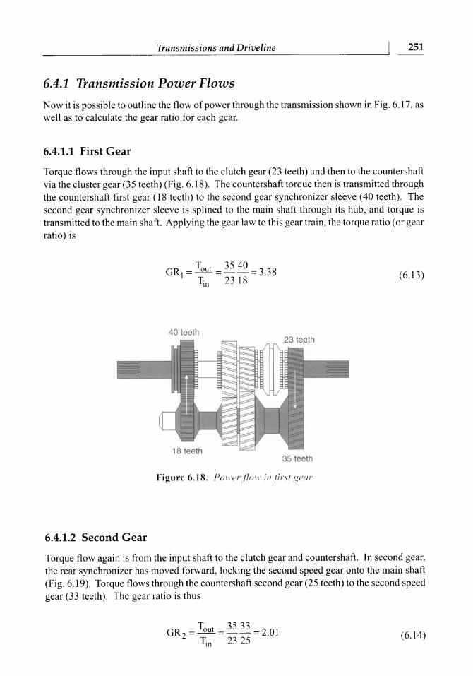
6.4.1.1 First Gear
Torque flows through the input shaft to the clutch gear (23 teeth) and then to the countershaft via the cluster gear (35 teeth) (Fig. 6.18). The countershaft torque then is transmitted through the countershaft first gear (18 teeth) to the second gear synchronizer sleeve (40 teeth). The second gear synchronizer sleeve is splined to the main shaft through its hub, and torque is transmitted to the main shaft. Applying the gear law to this gear train, the torque ratio (or gear ratio) is
Tout - 35 40 GR, =----=3.38 Ti, 2318
40 teeth
35 teeth
Figure 6.18. Ponw.,flor~~ i t~ , f ir .~t gear
6.4.1.2 Second Gear
Torque flow again is from the input shaft to the clutch gear and countershaft. In second gear, the rear synchronizer has moved forward, locking the second speed gear onto the main shaft (Fig. 6.19). Torque flows through the countershaft second gear (25 teeth) to the second speed gear (33 teeth). The gear ratio is thus
252 1 Automotive Engineering Fundamentals
Figure 6.19. Power,flow in second gear.
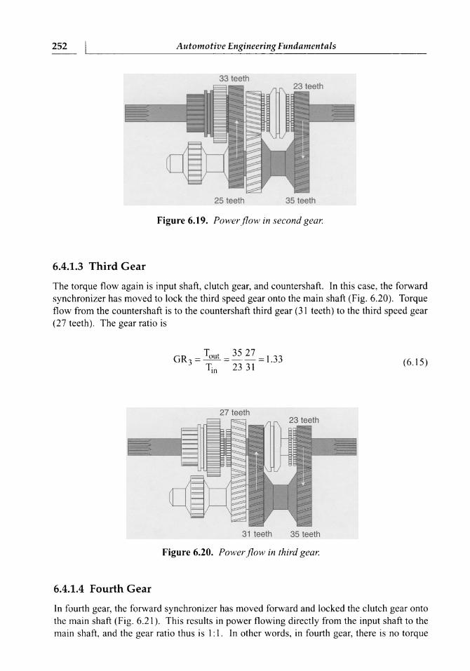
6.4.1.3 Third Gear
The torque flow again is input shaft, clutch gear, and countershaft. In this case, the forward synchronizer has moved to lock the third speed gear onto the main shaft (Fig. 6.20). Torque flow from the countershaft is to the countershaft third gear (3 1 teeth) to the third speed gear (27 teeth). The gear ratio is
27 teeth
31 teeth 35 teeth
Figure 6.20. Powerflow in third gear.
6.4.1.4 Fourth Gear
In fourth gear, the forward synchronizer has moved forward and locked the clutch gear onto the main shaft (Fig. 6.2 1). This results in power flowing directly from the input shaft to the main shaft, and the gear ratio thus is 1: 1. In other words, in fourth gear, there is no torque


