Embed Size (px)
Citation preview

Table of Contents 3- i
3
Section 3
CONTENTS
Driveline / Axle
Precautions .................................................3-1Precautions............................................................. 3-1
Precautions for Driveline / Axle ............................. 3-1
Drive Shaft / Axle ..................................... 3A-1Front .........................................................................3A-1
General Description .............................................3A-1Front Drive Shaft Construction............................3A-1
Diagnostic Information and Procedures............3A-1Front Drive Shaft Symptom Diagnosis ................3A-1
Repair Instructions ..............................................3A-2Front Drive Shaft Boot and Joint Check..............3A-2Front Drive Shaft Components ...........................3A-2Front Drive Shaft Assembly Removal and
Installation.........................................................3A-3Front Drive Shaft Disassembly and
Assembly ..........................................................3A-3Specifications.......................................................3A-6
Tightening Torque Specifications........................3A-6Special Tools and Equipment .............................3A-6
Recommended Service Material .........................3A-6Special Tool ........................................................3A-6
Rear ..........................................................................3A-7General Description .............................................3A-7
Rear Drive Shaft Construction ............................3A-7Repair Instructions ..............................................3A-7
Rear Drive Shaft Components ............................3A-7Rear Drive Shaft Assembly Removal and
Installation.........................................................3A-8Rear Drive Shaft Disassembly and
Assembly ..........................................................3A-8Specifications.......................................................3A-9
Tightening Torque Specifications........................3A-9Special Tools and Equipment .............................3A-9
Recommended Service Material .........................3A-9Special Tool ........................................................3A-9
Differential................................................ 3B-1Front .........................................................................3B-1
General Description .............................................3B-1Front Differential Construction ............................3B-1
Diagnostic Information and Procedures............3B-1Front Differential Symptom Diagnosis.................3B-1
Repair Instructions ..............................................3B-2Front Differential Oil Change ..............................3B-2Front Differential Unit Components.....................3B-3
Front Differential Dismounting and Remounting.......................................................3B-3
Front Differential Components ............................3B-4Front Differential Assembly Disassembly
and Reassembly ...............................................3B-5Front Differential Inspection ..............................3B-17
Specifications.....................................................3B-18Tightening Torque Specifications......................3B-18
Special Tools and Equipment ...........................3B-18Recommended Service Material .......................3B-18Special Tool ......................................................3B-18
Rear ........................................................................3B-21General Description ...........................................3B-21
Rear Differential Construction ...........................3B-21Diagnostic Information and Procedures..........3B-21
Rear Differential Symptom Diagnosis ...............3B-21Repair Instructions ............................................3B-21
Rear Differential Oil Change .............................3B-21Rear Differential Unit Components ...................3B-21Rear Differential Dismounting and
Remounting.....................................................3B-22Rear Differential Components...........................3B-23Rear Differential Assembly Disassembly
and Reassembly .............................................3B-24Rear Differential Inspection...............................3B-36
Specifications.....................................................3B-36Tightening Torque Specifications......................3B-36
Special Tools and Equipment ...........................3B-37Recommended Service Material .......................3B-37Special Tool ......................................................3B-37
Transfer .................................................... 3C-1Motor-Shift Type (Transfer with Shift
Actuator) ................................................................3C-1Precautions...........................................................3C-1
Transfer Warning ................................................3C-1Precautions in Diagnosing Trouble .....................3C-1
General Description .............................................3C-1Transfer Description............................................3C-1Transfer Shift Control System Components........3C-24WD Control System Description........................3C-3Function of 4WD Control System
Component........................................................3C-54WD Control System Operation..........................3C-54WD Control System Wiring Circuit Diagram....3C-11Terminal Arrangement of 4WD Control
Module ............................................................3C-12
www.CarGarage.ir
www.CarGarage.ir
www.CarGarage.ir

3-ii Table of Contents
Input / Output Signal Table of 4WD Control Module ............................................................3C-12
On-Board Diagnostic System Description.........3C-12CAN Communication System Description.........3C-13
Diagnostic Information and Procedures..........3C-144WD Control System Check .............................3C-14Transfer Position Indicator Operation Check ....3C-174WD Control System Operation Inspection ......3C-17Visual Inspection ...............................................3C-18DTC Check........................................................3C-19DTC Clearance .................................................3C-20DTC Table.........................................................3C-20Fail-Safe Table..................................................3C-21Scan Tool Data .................................................3C-22Scan Tool Data Definitions................................3C-224WD Control Symptom Diagnosis.....................3C-23Transfer Position Indicator Does Not Come
ON at Ignition Switch ON but Engine Stops....3C-24Transfer Position Indicator Remains ON
Steady at Ignition Switch ON ..........................3C-26DTC C1213: Transfer Switch Circuit Open .......3C-27DTC C1214: Transfer Switch Circuit Short .......3C-28DTC C1223 / C1235: Transfer Shift
Actuator Motor Position Switch 1 Circuit Open / Transfer Shift Actuator Motor Position Switch 2 Circuit Open .....................................3C-30
DTC C1224 / C1236: Transfer Shift Actuator Motor Position Switch 1 Circuit Short / Transfer Shift Actuator Motor Position Switch 2 Circuit Short......................................3C-32
DTC C1227: 4L/N Switch Circuit Open.............3C-34DTC C1228: 4L/N Switch Circuit Short .............3C-35DTC C1230: Transfer Actuator Circuit
Malfunction......................................................3C-37DTC C1237: Center Differential Lock Switch
Circuit Open ....................................................3C-38DTC C1238: Center Differential Lock Switch
Circuit Short ....................................................3C-40DTC C1240: 4WD Control Module Power
Supply Circuit Malfunction ..............................3C-41DTC C1243: Internal Circuit Malfunction of
4WD Control Module.......................................3C-42DTC C1246: Clutch Pedal Position (CPP)
Switch Circuit Short.........................................3C-43DTC U1073: Control Module Communication
Buss Off ..........................................................3C-44DTC U1100: Lost Communication with ECM....3C-46DTC U1101: Lost Communication with TCM ....3C-48DTC U1121: Lost Communication with ABS
Hydraulic Unit / Control Module ......................3C-50Inspection of 4WD Control Module and Its
Circuits ............................................................3C-51Repair Instructions ............................................3C-54
Transfer Oil Level Check...................................3C-54Transfer Oil Change..........................................3C-54Transfer Oil Seal Removal and Installation.......3C-55Transfer Switch Removal and Installation.........3C-55Transfer Switch Inspection................................3C-564WD Control Module Removal and
Installation.......................................................3C-56
Transfer Assembly Dismounting and Remounting.....................................................3C-57
Transfer Assembly Components.......................3C-58Transfer Assembly Disassembly and
Reassembly ....................................................3C-59Transfer Assembly Inspection...........................3C-67Input Gear Assembly, Counter Gear
Assembly, Front Output Shaft Assembly and Rear Output Shaft Assembly Components....................................................3C-69
Input Gear Assembly Disassembly and Reassembly ....................................................3C-70
Counter Gear Assembly Disassembly and Reassembly .............................................3C-71
Front Output Shaft Assembly Disassembly and Reassembly .............................................3C-71
Rear Output Shaft Assembly Disassembly and Reassembly .............................................3C-72
Specifications.....................................................3C-73Tightening Torque Specifications......................3C-73
Special Tools and Equipment ...........................3C-73Recommended Service Material .......................3C-73Special Tool ......................................................3C-74
Non-Shift Type (Transfer without Shift Actuator) ..............................................................3C-75Precautions.........................................................3C-75
Transfer Warning ..............................................3C-75General Description ...........................................3C-75
Transfer Construction........................................3C-75Diagnostic Information and Procedures..........3C-76
Transfer Symptom Diagnosis............................3C-76Repair Instructions ............................................3C-77
Transfer Oil Change..........................................3C-77Transfer Oil Level Check...................................3C-77Transfer Oil Seal Removal and Installation.......3C-77Transfer Assembly Dismounting and
Remounting.....................................................3C-77Transfer Assembly Components.......................3C-78Transfer Assembly Disassembly and
Reassembly ....................................................3C-80Input Gear Assembly Disassembly and
Reassembly ....................................................3C-86Front Output Shaft Assembly Disassembly
and Reassembly .............................................3C-86Rear Output Shaft Assembly Disassembly
and Reassembly .............................................3C-86Specifications.....................................................3C-87
Tightening Torque Specifications......................3C-87Special Tools and Equipment ...........................3C-87
Recommended Service Material .......................3C-87Special Tool ......................................................3C-87
Propeller Shafts ....................................... 3D-1Precautions...........................................................3D-1
Propeller Shaft Caution .......................................3D-1General Description .............................................3D-1
Propeller Shaft Construction ...............................3D-1Diagnostic Information and Procedures............3D-2
Propeller Shaft Symptom Diagnosis ...................3D-2
www.CarGarage.ir
www.CarGarage.ir
www.CarGarage.ir

Table of Contents 3-iii
Repair Instructions ..............................................3D-2Propeller Shaft Joint Check ................................3D-2Propeller Shaft Removal and Installation............3D-2Propeller Shaft Disassembly and Assembly .......3D-3Propeller Shaft Inspection...................................3D-5
Specifications.......................................................3D-5
Tightening Torque Specifications........................3D-5Special Tools and Equipment .............................3D-6
Recommended Service Material .........................3D-6Special Tool ........................................................3D-6
www.CarGarage.ir
www.CarGarage.ir
www.CarGarage.ir
3-1 Precautions:
Precautions PrecautionsPrecautions for Driveline / Axle
S5JB0A3000001Differential Gear Oil NoteRefer to “Differential Gear Oil Note: in Section 00”.
Fastener CautionRefer to “Fastener Caution: in Section 00”.
Precautions for TransferRefer to “Precautions in Diagnosing Trouble: Motor-Shift Type (Transfer with Shift Actuator) in Section 3C”.
www.CarGarage.ir
www.CarGarage.ir
www.CarGarage.ir
Drive Shaft / Axle: Front 3A-1
Drive Shaft / Axle
Front
General DescriptionFront Drive Shaft Construction
S5JB0A3111001A constant velocity tripod joint is used on the differential side of both the right and left drive shaft assemblies. And, a constant velocity ball joint is used on the wheel side of both the right and left drive shaft assemblies. The drive shaft can slide through the tripod joint in the extension / contraction direction.
Diagnostic Information and ProceduresFront Drive Shaft Symptom Diagnosis
S5JB0A3114001
Condition Possible cause Correction / Reference ItemAbnormal noise: When starting
Loose wheel nut(s) Tighten wheel nut(s) referring to “Wheel Removal and Installation: in Section 2D”.
Loose drive shaft flange bolt(s) Tighten drive shaft flange bolt(s) referring to “Front Drive Shaft Assembly Removal and Installation: Front”.
Broken or damaged wheel bearing Replace referring to “Front Wheel Hub, Disc, Nut and Bearing Check: in Section 2B”.
Abnormal noise: When making turns
Grease leakage from boot Replace boot and apply grease referring to “Front Drive Shaft Disassembly and Assembly: Front”.
Worn or broken drive shaft joint Replace drive shaft joint referring to “Front Drive Shaft Disassembly and Assembly: Front”.
Abnormal noise: When running
Broken drive shaft joint Replace drive shaft joint referring to “Front Drive Shaft Disassembly and Assembly: Front”.
Poorly lubricated or worn joint Lubricate or replace joint referring to “Front Drive Shaft Disassembly and Assembly: Front”.
Loose drive shaft flange bolt(s) Tighten drive shaft flange bolt(s) referring to “Front Drive Shaft Assembly Removal and Installation: Front”.
Vibration Worn drive shaft joint Replace drive shaft joint referring to “Front Drive Shaft Disassembly and Assembly: Front”.
Deformed drive shaft Replace referring to “Front Drive Shaft Disassembly and Assembly: Front”.
www.CarGarage.ir
www.CarGarage.ir
www.CarGarage.ir
3A-2 Drive Shaft / Axle: Front
Repair InstructionsFront Drive Shaft Boot and Joint Check
S5JB0A3116001
• Check boot for tear. If even a small tear is found, replace with new one.
• Check drive shaft joint for wear, breakage, and any other damage. Replace if any abnormality is found.
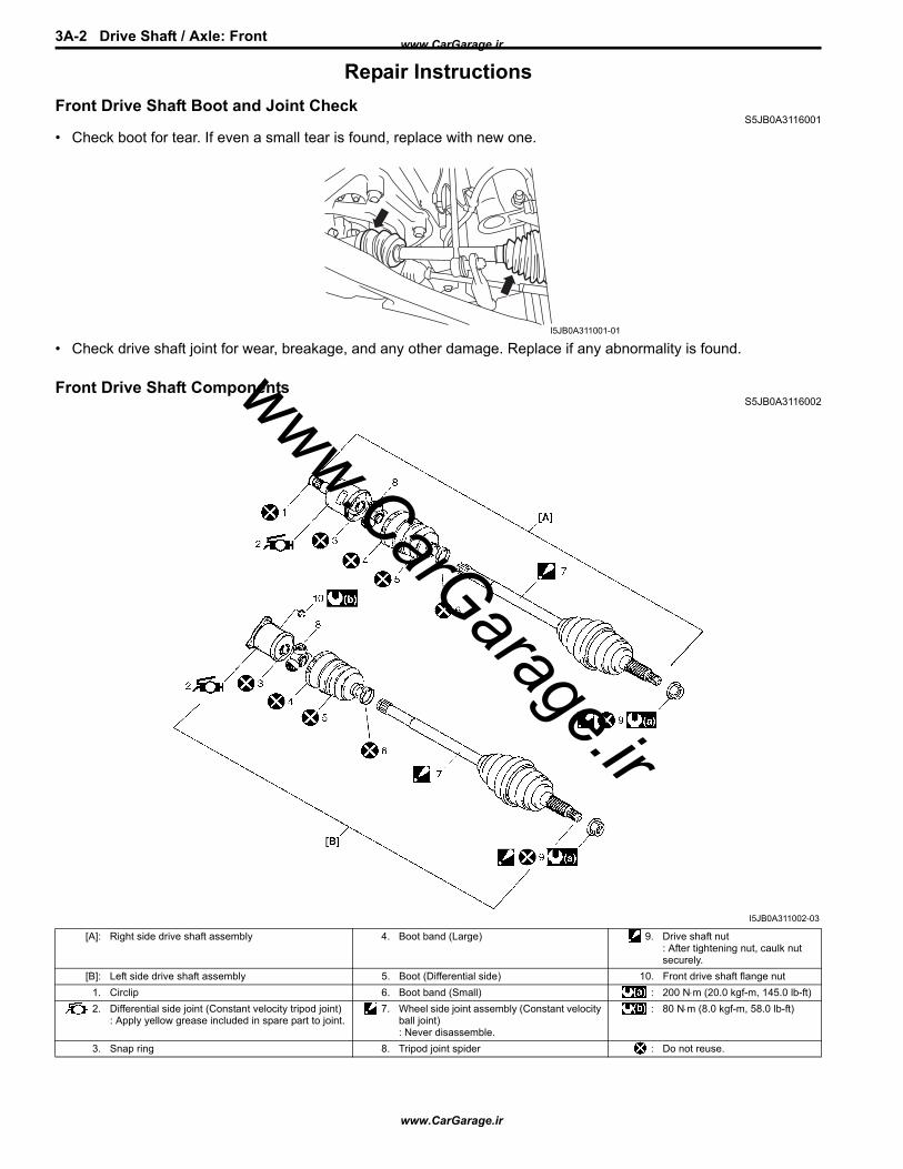
Front Drive Shaft ComponentsS5JB0A3116002
I5JB0A311001-01
I5JB0A311002-03
[A]: Right side drive shaft assembly 4. Boot band (Large) 9. Drive shaft nut: After tightening nut, caulk nut securely.
[B]: Left side drive shaft assembly 5. Boot (Differential side) 10. Front drive shaft flange nut1. Circlip 6. Boot band (Small) : 200 N⋅m (20.0 kgf-m, 145.0 lb-ft)2. Differential side joint (Constant velocity tripod joint)
: Apply yellow grease included in spare part to joint.7. Wheel side joint assembly (Constant velocity
ball joint): Never disassemble.
: 80 N⋅m (8.0 kgf-m, 58.0 lb-ft)
3. Snap ring 8. Tripod joint spider : Do not reuse.
www.CarGarage.ir
www.CarGarage.ir
www.CarGarage.ir

Drive Shaft / Axle: Front 3A-3
Front Drive Shaft Assembly Removal and Installation
S5JB0A3116003
Removal1) Undo caulking (1) and remove drive shaft nut (2).
2) Hoist vehicle and remove wheel.3) Drain front differential oil.4) Disconnect tie-rod end from steering knuckle
referring to “Steering Knuckle Removal and Installation: in Section 2B”.
5) Remove stabilizer joint from stabilizer bar.6) Remove brake hose mounting bolt.7) Remove suspension control arm referring to
“Suspension Control Arm Removal and Installation: in Section 2B”.
8) Remove front drive shaft flange nuts (1).
9) Remove drive shaft assembly from front differential.
CAUTION!
To prevent breakage of boots (wheel side and differential side), do not contact them with other parts when removing drive shaft assembly.
Installation
CAUTION!
• Be careful not to damage oil seals and boots when installing drive shaft.
• Do not hit joint boot with hammer.Inserting joint only by hands is allowed.
• Make sure that differential side joint is inserted fully and its snap ring is seated as it was.
Install drive shaft assembly by reversing removal procedure and noting the following points.• Tighten each bolts and nuts to the specified torque
referring to “Front Drive Shaft Components: Front” and “Front Suspension Construction: in Section 2B”.
Front Drive Shaft Disassembly and AssemblyS5JB0A3116004
Disassembly
CAUTION!
• Disassembly of wheel side joint assembly is not allowed. If any noise or damage exists in it, replace it as assembly.
• Do not disassemble tripod joint spider. If any malcondition is found in it, replace it as differential side joint assembly.
1) Draw hooks (2) of boot big band together and remove differential side boot big band (1).
I5JB0A311003-01
1I5JB0A311004-01
I5JB0A311005-01
www.CarGarage.ir
www.CarGarage.ir
www.CarGarage.ir

3A-4 Drive Shaft / Axle: Front
2) Wipe off grease from shaft and take off snap ring (1) using snap ring plier (2).
3) Remove tripod joint spider (1) using 3 arms puller (2).
CAUTION!
To prevent any problem caused by washing solution, do not wash tripod joint except its housing. Degreasing of tripod joint with cloth is allowed.
4) Remove differential side boot small band, and then pull out differential side boot from shaft.
AssemblyJudging from abnormality noted before disassembly and what is found through visual check of component parts after disassembly, prepare replacing parts and proceed to reassembly.Make sure that tripod joint housing is washed thoroughly and air dried.Replace boot with new one.
CAUTION!
• Do not wash boots in degreaser such as gasoline or kerosene. etc. Washing in degreaser causes deterioration of boot.
• To ensure full performance of joint as designed, apply grease of specified volume and color to joint.
1) Wash disassembled parts (except boots). After washing, dry parts completely by blowing air.
2) Clean boots with cloth.3) Set new differential side small band and new
differential side boot (1) on shaft temporarily, and then apply grease to tripod joint (2). Use specified grease in tube included in spare parts.
4) Install tripod joint spider (3) on shaft using special tool with hammer, directing its chamfered spline toward wheel side, and then fasten it with new snap ring (4) using snap ring plier (5).
Special tool(A): 09913–80113
I5JB0A311008-01
I3RH0A311004-01
I5JB0A311009-01
www.CarGarage.ir
www.CarGarage.ir
www.CarGarage.ir

Drive Shaft / Axle: Front 3A-5
5) Apply grease (including in spare parts) to inside of tripod joint housing (1), joint it with tripod joint.
Grease color“A”: Yellow
Amount“A”: 127 – 137 g (4.5 – 4.8 oz) (right side)“A”: 170 – 180 g (6.0 – 6.3 oz) (left side)
6) Fit boot to grooves of shaft and housing.7) Insert screw driver into boot and allow air to enter
boot so that air pressure in boot becomes the same as atmospheric pressure.
CAUTION!
• Bend each boot band against forward rotation.
• Do not squeeze or distort boot when fastening it with bands. Distorted boot caused by squeezing air may reduce its durability.
8) Place differential side boot new big band (3) and new small band (4) onto boot putting band outer end (1) against forward rotation (2) as shown in figure.
9) Fasten differential side boot big band.• For differential side boot big band
Fasten band (1) by drawing hooks (2) with special tool and engage hooks (3) in slot and window (4).
Special tool(A): 09943–57010
• For differential side boot small bandFasten band (5) securely using special tool.
NOTEFasten boot small band securely until complete contact “a” is obtained.
Special tool(A): 09943–57010
I4RS0B310003-01
I5JB0A311006-01
(A)
1 4
2 3
(A)
5
“a”
I5JB0A311007-02
www.CarGarage.ir
www.CarGarage.ir
www.CarGarage.ir
3A-6 Drive Shaft / Axle: Front
SpecificationsTightening Torque Specifications
S5JB0A3117001NOTEThe specified tightening torque is also described in the following.“Front Drive Shaft Components: Front”
Reference:For the tightening torque of fastener not specified in this section, refer to “Fastener Information: in Section 0A”.
Special Tools and EquipmentRecommended Service Material
S5JB0A3118001NOTERequired service material is also described in the following.“Front Drive Shaft Components: Front”
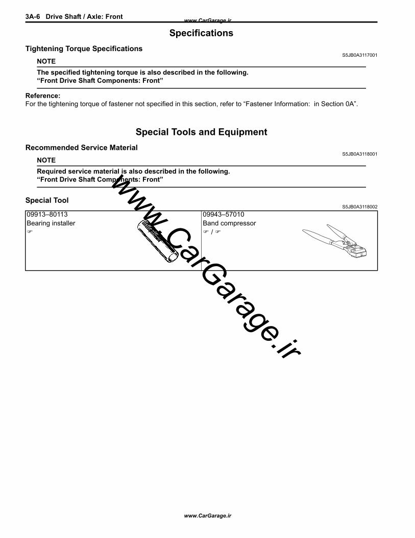
Special ToolS5JB0A3118002
09913–80113 09943–57010Bearing installer Band compressor
/
www.CarGarage.ir
www.CarGarage.ir
www.CarGarage.ir

Drive Shaft / Axle: Rear 3A-7
Rear
General DescriptionRear Drive Shaft Construction
S5JB0A3121002Refer to “Front Drive Shaft Construction: Front”.
Repair InstructionsRear Drive Shaft Components
S5JB0A3126007
I5JB0A312001-02
1. Differential side joint (Constant velocity tripod joint): Apply yellow grease included in spare part to joint.
5. Boot band (Small) 9. Rear drive shaft flange nut
2. Snap ring 6. Wheel side joint (Constant velocity ball joint): Never disassemble.
: 200 N⋅m (20.0 kgf-m, 145.0 lb-ft)
3. Boot band (Large) 7. Tripod joint spider : 80 N⋅m (8.0 kgf-m, 58.0 lb-ft)4. Boot (Differential side) 8. Drive shaft nut
: After tightening nut, caulk nut securely.: Do not reuse.
www.CarGarage.ir
www.CarGarage.ir
www.CarGarage.ir
3A-8 Drive Shaft / Axle: Rear
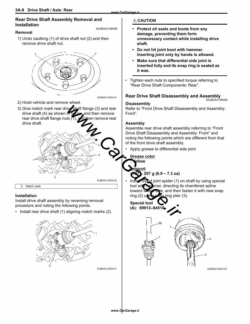
Rear Drive Shaft Assembly Removal and Installation
S5JB0A3126008Removal1) Undo caulking (1) of drive shaft nut (2) and then
remove drive shaft nut.
2) Hoist vehicle and remove wheel.3) Give match mark rear drive shaft flange (3) and rear
drive shaft (4) as shown in figure, and then remove rear drive shaft flange nuts (1), and then remove rear drive shaft.
InstallationInstall drive shaft assembly by reversing removal procedure and noting the following points.• Install rear drive shaft (1) aligning match marks (2).
CAUTION!
• Protect oil seals and boots from any damage, preventing them form unnecessary contact while installing drive shaft.
• Do not hit joint boot with hammer.Inserting joint only by hands is allowed.
• Make sure that differential side joint is inserted fully and its snap ring is seated as it was.
• Tighten each nuts to specified torque referring to “Rear Drive Shaft Components: Rear”.
Rear Drive Shaft Disassembly and AssemblyS5JB0A3126009
DisassemblyRefer to “Front Drive Shaft Disassembly and Assembly: Front”.
AssemblyAssemble rear drive shaft assembly referring to “Front Drive Shaft Disassembly and Assembly: Front” and noting the following points which are different from that of the front drive shaft assembly.• Apply grease to differential side joint.
Grease color: Yellow
Amount: 197 – 207 g (6.9 – 7.3 oz)
• Install tripod joint spider (1) on shaft by using special tool with hammer, directing its chamfered spline toward wheel side, and then fasten it with new snap ring (2) using snap ring plier (3).
Special tool(A): 09913–84510
2. Match mark
I5JB0A311003-01
1
3
2
4
I5JB0A312002-02
2
1
I5JB0A312003-01 I5JB0A312004-03
www.CarGarage.ir
www.CarGarage.ir
www.CarGarage.ir
Drive Shaft / Axle: Rear 3A-9
SpecificationsTightening Torque Specifications
S5JB0A3127001NOTEThe specified tightening torque is also described in the following.“Rear Drive Shaft Components: Rear”
Reference:For the tightening torque of fastener not specified in this section, refer to “Fastener Information: in Section 0A”.
Special Tools and EquipmentRecommended Service Material
S5JB0A3128001NOTERequired service material is also described in the following.“Rear Drive Shaft Components: Rear”
Special ToolS5JB0A3128002
09913–84510Bearing installer
www.CarGarage.ir
www.CarGarage.ir
www.CarGarage.ir

3B-1 Differential: Front
Differential
Front
General DescriptionFront Differential Construction
S5JB0A3211001The differential assembly uses a hypoid bevel pinion and gear.The differential assembly is decisive in that the drive power is concentrated there. Therefore, use of genuine parts and specified torque is compulsory. Further, because of sliding tooth meshing with high pressure between bevel pinion and gear, it is mandatory to lubricate them by hypoid gear oil.
Diagnostic Information and ProceduresFront Differential Symptom Diagnosis
S5JB0A3214001
Condition Possible cause Correction / Reference ItemGear noise Deteriorated or water mixed lubricant Repair and replenish referring to “Front
Differential Oil Change: Front”.Inadequate or insufficient lubricant Repair and replenish referring to “Front
Differential Oil Change: Front”.Maladjusted backlash between drive bevel pinion and gear
Adjust as prescribed referring to “Front Differential Assembly Disassembly and Reassembly: Front”.
Improper tooth contact in the mesh between drive bevel pinion and gear
Adjust or replace referring to “Front Differential Assembly Disassembly and Reassembly: Front”.
Loose drive bevel gear securing bolts Replace or retighten referring to “Front Differential Assembly Disassembly and Reassembly: Front”.
Damaged differential gear(s) or differential pinion(s)
Replace referring to “Front Differential Inspection: Front”.
Bearing noise (Constant noise) Deteriorated or water mixed lubricant
Repair and replenish referring to “Front Differential Oil Change: Front”.
(Constant noise) Inadequate or insufficient lubricant
Repair and replenish referring to “Front Differential Oil Change: Front”.
(Noise while coasting) Damaged bearing(s) of drive bevel pinion
Replace referring to “Front Differential Inspection: Front”.
(Noise while turning) Damaged differential side bearing(s) or axle bearing(s)
Replace referring to “Front Differential Inspection: Front”.
Oil leakage Clogged breather plug Clean.Worn or damaged oil seal Replace.Excessive oil Adjust oil level referring to “Front Differential
Oil Change: Front”.Loose differential carrier bolts Replace or retighten.
www.CarGarage.ir
www.CarGarage.ir
www.CarGarage.ir

Differential: Front 3B-2
Repair InstructionsFront Differential Oil Change
S5JB0A3216012
1) Before changing or inspecting oil, be sure to stop engine and lift vehicle horizontally.
2) With vehicle lifted up, check leakage.If leakage exists, correct it.
NOTEWhenever vehicle is hoisted for any other service work than oil change, also be sure to check for oil leakage.
3) Remove oil filler plug (2).4) Remove drain plug (1), and drain old oil.5) Apply sealant to thread of drain plug (1), and tighten
it to specified torque.
“A”: Sealant 99000–31260 (SUZUKI Bond No.1217G)
Tightening torqueDifferential oil drain plug (a): 23 N·m (2.3 kgf-m, 17.0 lb-ft)
6) Pour new specified oil until oil level reaches bottom of oil filler plug hole (3) as shown in figure.
NOTE
• Hypoid gear oil must be used for differential.
• It is highly recommended to use API GL-5 80W-90 gear oil.
Differential oil specification: API GL-5 (For SAE classification, refer to viscosity chart [A] in figure.)
Differential oil capacity (Reference): 0.9 – 1.1 liters (1.9/1.6 – 2.3/1.9 US/Imp. pt.)
7) Apply sealant to thread of level / filler plug, and then tighten it to specified torque.
“A”: Sealant 99000–31260 (SUZUKI Bond No.1217G)
Tightening torqueDifferential oil level / filler plug (b): 23 N·m (2.3 kgf-m, 17.0 lb-ft)
I5JB0A321004-02
www.CarGarage.ir
www.CarGarage.ir
www.CarGarage.ir
3B-3 Differential: Front
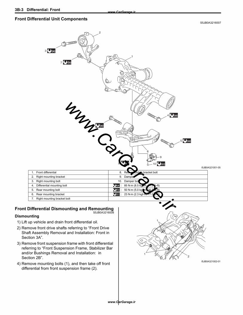
Front Differential Unit ComponentsS5JB0A3216007
Front Differential Dismounting and RemountingS5JB0A3216008
Dismounting1) Lift up vehicle and drain front differential oil.2) Remove front drive shafts referring to “Front Drive
Shaft Assembly Removal and Installation: Front in Section 3A”.
3) Remove front suspension frame with front differential referring to “Front Suspension Frame, Stabilizer Bar and/or Bushings Removal and Installation: in Section 2B”.
4) Remove mounting bolts (1), and then take off front differential from front suspension frame (2).
2
1
3
7
(a)
5 (a)
(b)
8
6
(b)
4 (a)
5 (a)
10 (c)
9
I5JB0A321001-05
1. Front differential 8. Rear mounting bracket bolt2. Right mounting bracket 9. Damper3. Right mounting bolt 10. Damper bolt4. Differential mounting bolt : 85 N⋅m (8.5 kgf-m, 61.5 lb-ft)5. Rear mounting bolt : 50 N⋅m (5.0 kgf-m, 36.5 lb-ft)6. Rear mounting bracket : 23 N⋅m (2.3 kgf-m, 17.0 lb-ft)7. Right mounting bracket bolt
1
12
I5JB0A321002-01
www.CarGarage.ir
www.CarGarage.ir
www.CarGarage.ir

Differential: Front 3B-4
RemountingReverse dismounting procedure for remounting noting the following.• Tighten each bolts and nuts referring to “Front Differential Unit Components: Front”, “Front Drive Shaft Components:
Front in Section 3A” and “Front Suspension Frame, Stabilizer Bar and/or Bushings Components: in Section 2B”.• Fill front differential oil referring to “Front Differential Oil Change: Front”.
Front Differential ComponentsS5JB0A3216001
(a)18
(a)18
(b)24
19
9
21
15
14
16
17
14
10
11
11
17
16
5
262
4
13 23
12
10
(c)22
3
6
7
1
A
8
(a)25
15
20
20
I5JB0A321003-08
1. Universal joint flange 17. Pinion washer2. Hypoid gear set 18. Retainer bolt3. Bevel pinion spacer 19. Differential side right retainer
: Apply sealant 99000-31260 to mating surface of right retainer, carrier and rear cover.
4. Shim 20. Shim5. Rear bearing 21. Front drive shaft retainer
: Apply sealant 99000-31260 to mating surface of drive shaft retainer, carrier and rear cover.
6. Front bearing 22. Bevel gear bolt: Apply thread lock cement 99000-32110 to thread part of bolt.
7. Oil seal: Apply grease 99000-25010 to oil seal lip.
23. Rear cover
8. Flange nut: After tightening nut so as rotation torque of bevel pinion shaft to be in specified value, caulk nut securely.
24. Rear cover bolt No.1 bolt
www.CarGarage.ir
www.CarGarage.ir
www.CarGarage.ir
3B-5 Differential: Front
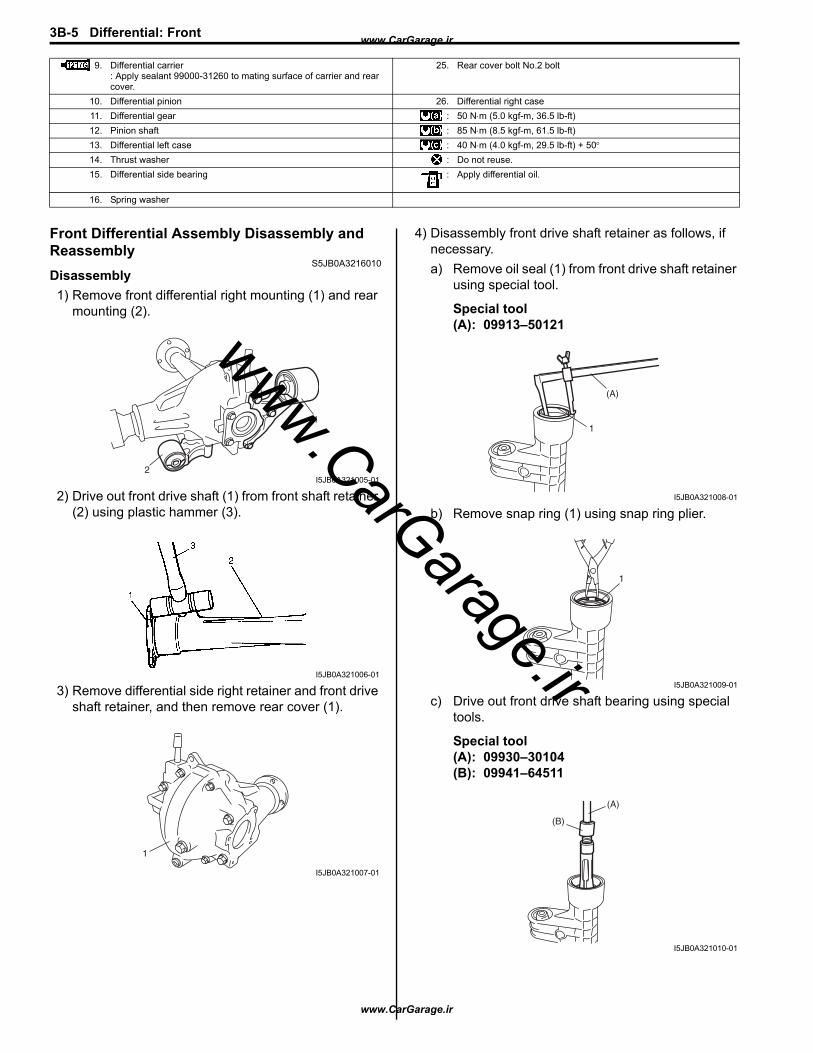
Front Differential Assembly Disassembly and Reassembly
S5JB0A3216010Disassembly1) Remove front differential right mounting (1) and rear
mounting (2).
2) Drive out front drive shaft (1) from front shaft retainer (2) using plastic hammer (3).
3) Remove differential side right retainer and front drive shaft retainer, and then remove rear cover (1).
4) Disassembly front drive shaft retainer as follows, if necessary.a) Remove oil seal (1) from front drive shaft retainer
using special tool.
Special tool(A): 09913–50121
b) Remove snap ring (1) using snap ring plier.
c) Drive out front drive shaft bearing using special tools.
Special tool(A): 09930–30104(B): 09941–64511
9. Differential carrier: Apply sealant 99000-31260 to mating surface of carrier and rear cover.
25. Rear cover bolt No.2 bolt
10. Differential pinion 26. Differential right case11. Differential gear : 50 N⋅m (5.0 kgf-m, 36.5 lb-ft)12. Pinion shaft : 85 N⋅m (8.5 kgf-m, 61.5 lb-ft)13. Differential left case : 40 N⋅m (4.0 kgf-m, 29.5 lb-ft) + 50°14. Thrust washer : Do not reuse.15. Differential side bearing : Apply differential oil.
16. Spring washer
1
2I5JB0A321005-01
I5JB0A321006-01
1
I5JB0A321007-01
1
(A)
I5JB0A321008-01
1
I5JB0A321009-01
(B)
(A)
I5JB0A321010-01
www.CarGarage.ir
www.CarGarage.ir
www.CarGarage.ir
Differential: Front 3B-6
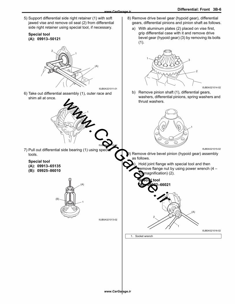
5) Support differential side right retainer (1) with soft jawed vise and remove oil seal (2) from differential side right retainer using special tool, if necessary.
Special tool(A): 09913–50121
6) Take out differential assembly (1), outer race and shim all at once.
7) Pull out differential side bearing (1) using special tools.
Special tool(A): 09913–65135(B): 09925–86010
8) Remove drive bevel gear (hypoid gear), differential gears, differential pinions and pinion shaft as follows.a) With aluminum plates (2) placed on vise first,
grip differential case with it and remove drive bevel gear (hypoid gear) (3) by removing its bolts (1).
b) Remove pinion shaft (1), differential gears, washers, differential pinions, spring washers and thrust washers.
9) Remove drive bevel pinion (hypoid gear) assembly as follows.a) Hold joint flange with special tool and then
remove flange nut by using power wrench (4 – 10 magnification) (2).
Special tool(A): 09922–66021
1
(A)
2
I5JB0A321011-01
1
I5JB0A321012-02
1(B)
(A)
I5JB0A321013-02
1. Socket wrench
3
2
1
I5JB0A321014-02
1
I5JB0A321015-02
(A)
2
1
I5JB0A321016-02
www.CarGarage.ir
www.CarGarage.ir
www.CarGarage.ir

3B-7 Differential: Front
b) Make mating marks (1) on drive bevel pinion and companion flange.
CAUTION!
Do not make mating mark on the coupling surface of the flange.
c) Remove flange (2) from drive bevel pinion. Use special tool if it is hard to remove.
Special tool(A): 09913–65135(B): 09925–88210
d) Remove drive bevel pinion (1) with rear bearing, shim and spacer from carrier.If it is hard to remove, screw an used nut (2) into drive bevel pinion and hammer (3) on that nut with a plastic hammer but never directly on drive bevel pinion.
e) Remove drive bevel pinion rear bearing (2) by using bearing puller (3) and hydraulic press.
CAUTION!
To avoid rear bearing from being damaged, support it at flat side of bearing puller.
10) Remove oil seal (1) using special tool.
Special tool(A): 09913–50121
11) Using a hammer and brass bar (1), drive out front bearing outer race (2).
2
(B)
(A)
21
I5JB0A321017-02
3
21
I5JB0A321018-01
1. Drive bevel pinion
I1JA01322006-01
(A)
1
I5JB0A321019-01
I5JB0A321020-01
www.CarGarage.ir
www.CarGarage.ir
www.CarGarage.ir
Differential: Front 3B-8
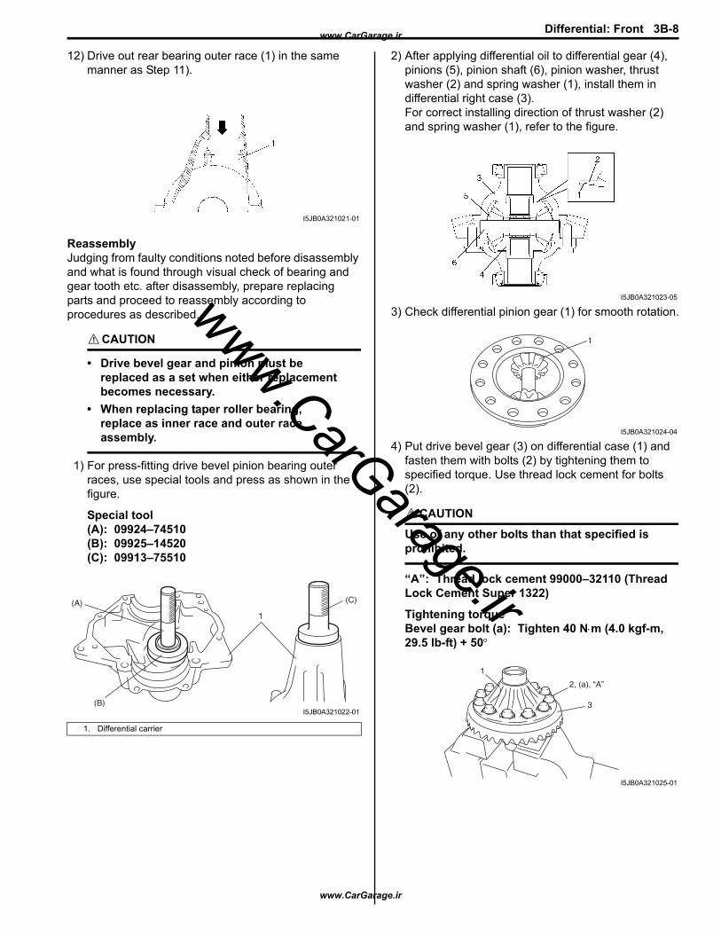
12) Drive out rear bearing outer race (1) in the same manner as Step 11).
ReassemblyJudging from faulty conditions noted before disassembly and what is found through visual check of bearing and gear tooth etc. after disassembly, prepare replacing parts and proceed to reassembly according to procedures as described.
CAUTION!
• Drive bevel gear and pinion must be replaced as a set when either replacement becomes necessary.
• When replacing taper roller bearing, replace as inner race and outer race assembly.
1) For press-fitting drive bevel pinion bearing outer races, use special tools and press as shown in the figure.
Special tool(A): 09924–74510(B): 09925–14520(C): 09913–75510
2) After applying differential oil to differential gear (4), pinions (5), pinion shaft (6), pinion washer, thrust washer (2) and spring washer (1), install them in differential right case (3).For correct installing direction of thrust washer (2) and spring washer (1), refer to the figure.
3) Check differential pinion gear (1) for smooth rotation.
4) Put drive bevel gear (3) on differential case (1) and fasten them with bolts (2) by tightening them to specified torque. Use thread lock cement for bolts (2).
CAUTION!
Use of any other bolts than that specified is prohibited.
“A”: Thread lock cement 99000–32110 (Thread Lock Cement Super 1322)
Tightening torqueBevel gear bolt (a): Tighten 40 N⋅m (4.0 kgf-m, 29.5 lb-ft) + 50°
1. Differential carrier
I5JB0A321021-01
(B)
(A)
1
(C)
I5JB0A321022-01
I5JB0A321023-05
1
I5JB0A321024-04
2, (a), “A”
3
1
I5JB0A321025-01
www.CarGarage.ir
www.CarGarage.ir
www.CarGarage.ir
3B-9 Differential: Front
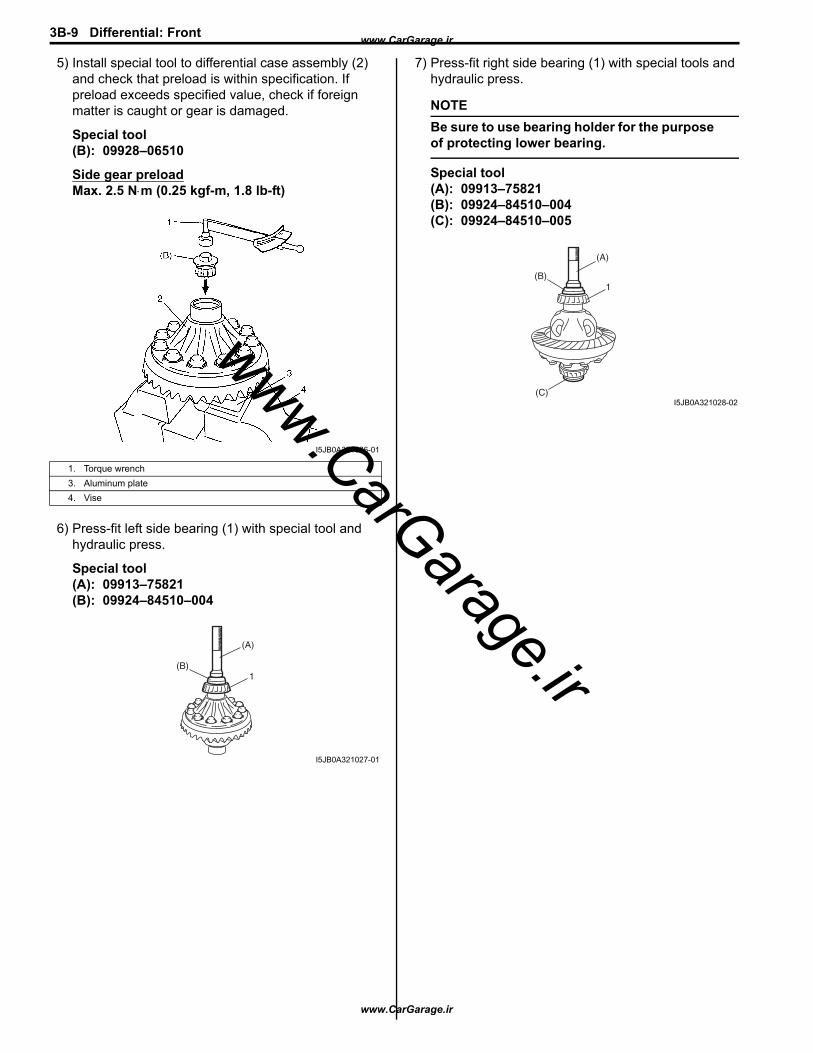
5) Install special tool to differential case assembly (2) and check that preload is within specification. If preload exceeds specified value, check if foreign matter is caught or gear is damaged.
Special tool(B): 09928–06510
Side gear preloadMax. 2.5 N⋅m (0.25 kgf-m, 1.8 lb-ft)
6) Press-fit left side bearing (1) with special tool and hydraulic press.
Special tool(A): 09913–75821(B): 09924–84510–004
7) Press-fit right side bearing (1) with special tools and hydraulic press.
NOTEBe sure to use bearing holder for the purpose of protecting lower bearing.
Special tool(A): 09913–75821(B): 09924–84510–004(C): 09924–84510–005
1. Torque wrench3. Aluminum plate4. Vise
I5JB0A321026-01
(B)
(A)
1
I5JB0A321027-01
(B)
(A)
1
(C)I5JB0A321028-02
www.CarGarage.ir
www.CarGarage.ir
www.CarGarage.ir
Differential: Front 3B-10
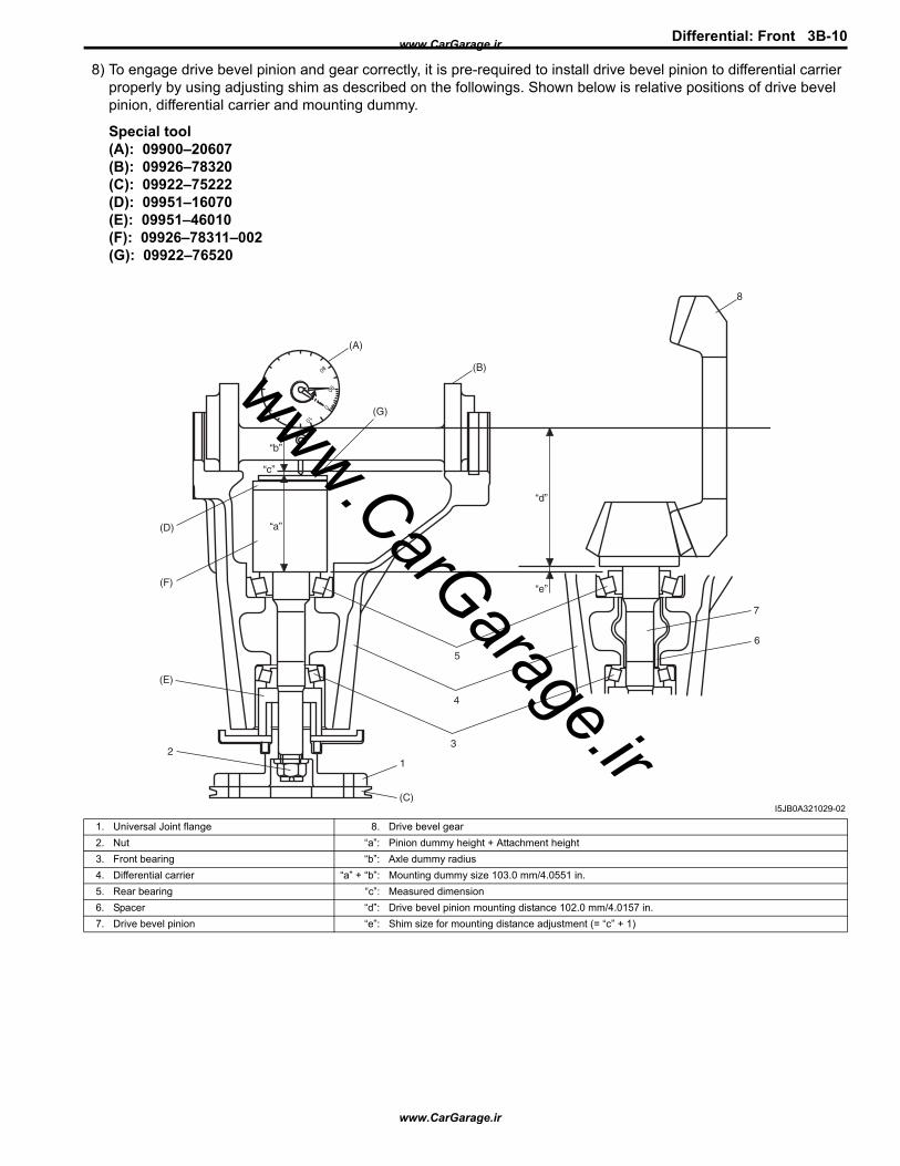
8) To engage drive bevel pinion and gear correctly, it is pre-required to install drive bevel pinion to differential carrier properly by using adjusting shim as described on the followings. Shown below is relative positions of drive bevel pinion, differential carrier and mounting dummy.
Special tool(A): 09900–20607(B): 09926–78320(C): 09922–75222(D): 09951–16070(E): 09951–46010(F): 09926–78311–002(G): 09922–76520
(A)
(B)
(D)
(F)
(E)
2
(G)
“a”
“b”
“d”
“e”
“c”
(C)
1
5
4
3
8
7
6
I5JB0A321029-02
1. Universal Joint flange 8. Drive bevel gear2. Nut “a”: Pinion dummy height + Attachment height3. Front bearing “b”: Axle dummy radius4. Differential carrier “a” + “b”: Mounting dummy size 103.0 mm/4.0551 in.5. Rear bearing “c”: Measured dimension6. Spacer “d”: Drive bevel pinion mounting distance 102.0 mm/4.0157 in.7. Drive bevel pinion “e”: Shim size for mounting distance adjustment (= “c” + 1)
www.CarGarage.ir
www.CarGarage.ir
www.CarGarage.ir
3B-11 Differential: Front
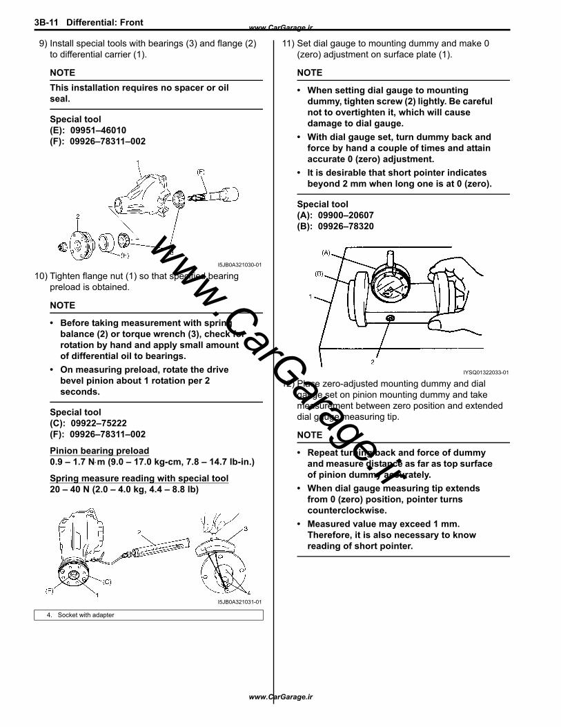
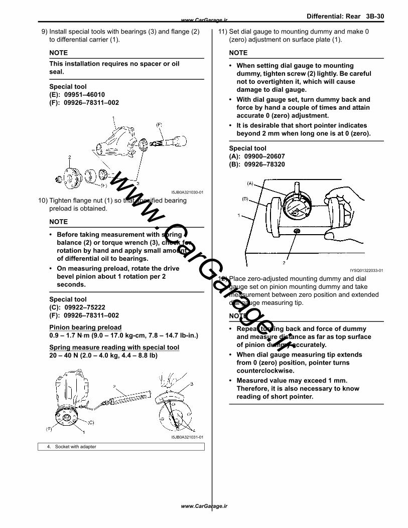
9) Install special tools with bearings (3) and flange (2) to differential carrier (1).
NOTEThis installation requires no spacer or oil seal.
Special tool(E): 09951–46010(F): 09926–78311–002
10) Tighten flange nut (1) so that specified bearing preload is obtained.
NOTE
• Before taking measurement with spring balance (2) or torque wrench (3), check for rotation by hand and apply small amount of differential oil to bearings.
• On measuring preload, rotate the drive bevel pinion about 1 rotation per 2 seconds.
Special tool(C): 09922–75222(F): 09926–78311–002
Pinion bearing preload0.9 – 1.7 N⋅m (9.0 – 17.0 kg-cm, 7.8 – 14.7 lb-in.)
Spring measure reading with special tool20 – 40 N (2.0 – 4.0 kg, 4.4 – 8.8 lb)
11) Set dial gauge to mounting dummy and make 0 (zero) adjustment on surface plate (1).
NOTE
• When setting dial gauge to mounting dummy, tighten screw (2) lightly. Be careful not to overtighten it, which will cause damage to dial gauge.
• With dial gauge set, turn dummy back and force by hand a couple of times and attain accurate 0 (zero) adjustment.
• It is desirable that short pointer indicates beyond 2 mm when long one is at 0 (zero).
Special tool(A): 09900–20607(B): 09926–78320
12) Place zero-adjusted mounting dummy and dial gauge set on pinion mounting dummy and take measurement between zero position and extended dial gauge measuring tip.
NOTE
• Repeat turning back and force of dummy and measure distance as far as top surface of pinion dummy accurately.
• When dial gauge measuring tip extends from 0 (zero) position, pointer turns counterclockwise.
• Measured value may exceed 1 mm. Therefore, it is also necessary to know reading of short pointer.
4. Socket with adapter
I5JB0A321030-01
I5JB0A321031-01
IYSQ01322033-01
www.CarGarage.ir
www.CarGarage.ir
www.CarGarage.ir

Differential: Front 3B-12
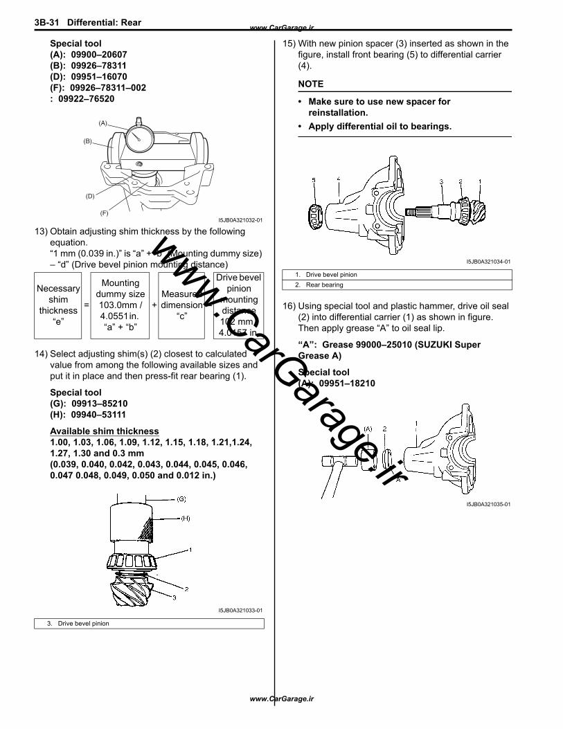
Special tool(A): 09900–20607(B): 09926–78311(D): 09951–16070(F): 09926–78311–002: 09922–76520
13) Obtain adjusting shim thickness by the following equation.“1 mm (0.039 in.)” is “a” + “b” (Mounting dummy size) – “d” (Drive bevel pinion mounting distance)
14) Select adjusting shim(s) (2) closest to calculated value from among the following available sizes and put it in place and then press-fit rear bearing (1).
Special tool(G): 09913–85210(H): 09940–53111
Available shim thickness1.00, 1.03, 1.06, 1.09, 1.12, 1.15, 1.18, 1.21,1.24, 1.27, 1.30 and 0.3 mm (0.039, 0.040, 0.042, 0.043, 0.044, 0.045, 0.046, 0.047 0.048, 0.049, 0.050 and 0.012 in.)
15) With new pinion spacer (3) inserted as shown in the figure, install front bearing (5) to differential carrier (4).
NOTE
• Make sure to use new spacer for reinstallation.
• Apply differential oil to bearings.
16) Using special tool and plastic hammer, drive oil seal (2) into differential carrier (1) as shown in figure. Then apply grease “A” to oil seal lip.
“A”: Grease 99000–25010 (SUZUKI Super Grease A)
Special tool(A): 09951–18210
Necessary shim thickness
“e”= 1 mm (0.039 in.) +
Dial gauge measured value “c”
3. Drive bevel pinion
(F)
(D)
(B)
(A)
I5JB0A321032-01
I5JB0A321033-01
1. Drive bevel pinion2. Rear bearing
I5JB0A321034-01
I5JB0A321035-01
www.CarGarage.ir
www.CarGarage.ir
www.CarGarage.ir

3B-13 Differential: Front
17) While tightening flange nut gradually with special tool and power wrench (4 – 10 magnification) (1), set preload of pinion to specification.
NOTE
• Before taking measurement with spring balance (3) or torque wrench (4), check for smooth rotation by hand.
• On measuring preload, rotate the drive bevel pinion about 1 rotation per 2 seconds.
• Be sure to tighten gradually and carefully till specified starting torque is obtained. Turning back overtightened flange nuts should be avoided.
Pinion bearing preload0.9 – 1.7 N⋅m (9.0 – 17.0 kg-cm, 7.8 – 14.7 lb-in.)
Spring measure reading with special tool20 – 40 N (2.0 – 4.0 kg, 4.4 – 8.8 lb)
Special tool(A): 09922–75222(B): 09922–66021
18) Select differential side bearing shim as follows.a) Measure dimension “a” and “b” using vernier
caliper.
b) Calculate dimension “a” – “b”, and select shims from among following available size so that total of thickness of right side and left side shims may reach the calculated value.
NOTESelect shims so that thickness of right side shims and left side shims become almost even.
Available shim thicknessRight side: 1.75, 1.85, 1.95, 2.00, 2.05, 2.15 and 2.25 mm (0.069, 0.073, 0.077, 0.079, 0.081, 0.085 and 0.089 in.)Left side: 2.75, 2.85, 2.95, 3.00, 3.05, 3.15 and 3.25 mm (0.108, 0.112, 0.116, 0.118, 0.120, 0.124 and 0.128 in.)
2. Socket wrench
I5JB0A321036-02
I5JB0A321037-04
www.CarGarage.ir
www.CarGarage.ir
www.CarGarage.ir
Differential: Front 3B-14
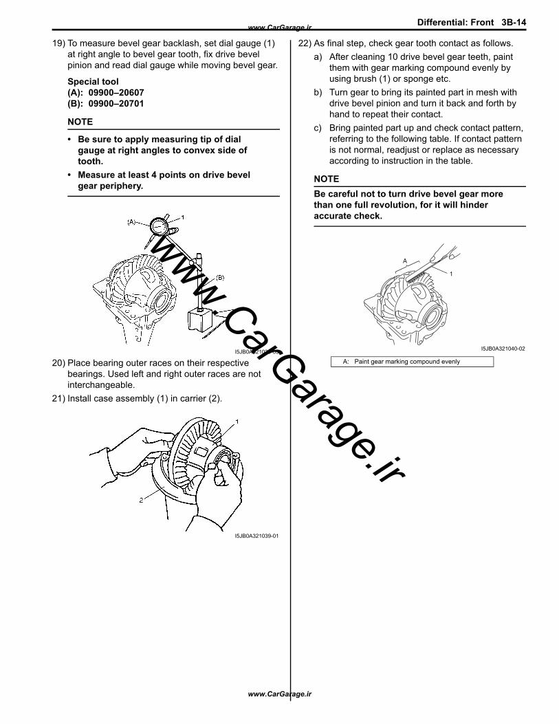
19) To measure bevel gear backlash, set dial gauge (1) at right angle to bevel gear tooth, fix drive bevel pinion and read dial gauge while moving bevel gear.
Special tool(A): 09900–20607(B): 09900–20701
NOTE
• Be sure to apply measuring tip of dial gauge at right angles to convex side of tooth.
• Measure at least 4 points on drive bevel gear periphery.
20) Place bearing outer races on their respective bearings. Used left and right outer races are not interchangeable.
21) Install case assembly (1) in carrier (2).
22) As final step, check gear tooth contact as follows.a) After cleaning 10 drive bevel gear teeth, paint
them with gear marking compound evenly by using brush (1) or sponge etc.
b) Turn gear to bring its painted part in mesh with drive bevel pinion and turn it back and forth by hand to repeat their contact.
c) Bring painted part up and check contact pattern, referring to the following table. If contact pattern is not normal, readjust or replace as necessary according to instruction in the table.
NOTEBe careful not to turn drive bevel gear more than one full revolution, for it will hinder accurate check.
I5JB0A321038-03
I5JB0A321039-01
A: Paint gear marking compound evenly
1
A
I5JB0A321040-02
www.CarGarage.ir
www.CarGarage.ir
www.CarGarage.ir

3B-15 Differential: Front
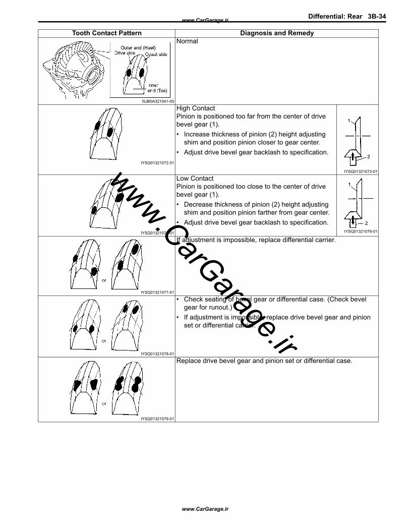
Tooth Contact Pattern Diagnosis and RemedyNormal
High ContactPinion is positioned too far from the center of drive bevel gear (1).• Increase thickness of pinion (2) height adjusting
shim and position pinion closer to gear center.• Adjust drive bevel gear backlash to specification.
Low ContactPinion is positioned too close to the center of drive bevel gear (1).• Decrease thickness of pinion (2) height adjusting
shim and position pinion farther from gear center.• Adjust drive bevel gear backlash to specification.
If adjustment is impossible, replace differential carrier.
• Check seating of bevel gear or differential case. (Check bevel gear for runout.)
• If adjustment is impossible, replace drive bevel gear and pinion set or differential carrier.
Replace drive bevel gear and pinion set or differential case.
I5JB0A321041-05
IYSQ01321072-01
IYSQ01321073-01
IYSQ01321074-01 IYSQ01321076-01
IYSQ01321077-01
IYSQ01321078-01
IYSQ01321079-01
www.CarGarage.ir
www.CarGarage.ir
www.CarGarage.ir

Differential: Front 3B-16
23) Upon completion of gear tooth contact check in Step 22), caulk flange nut (2) with caulking tool (1) and hammer.
24) Install rear cover (1) to differential carrier (2).
Tightening torqueRear cover bolt No.1 (a): 50 N·m (5.0 kgf-m, 36.5 lb-ft)Rear cover bolt No.2 (b): 85 N·m (8.5 kgf-m, 61.5 lb-ft)
25) Assembly front drive shaft retainer as follows.a) Install front drive shaft bearing (1) using special
tool, and then install snap ring.
Special tool(A): 09913–75520
b) Apply grease to oil seal lip, and then install oil seal (1) using special tools as shown in figure.
Distance between retainer surface and oil seal“a”: 4.7 – 5.2 mm (0.185 – 0.205 in.)
“A”: Grease 99000–25010 (SUZUKI Super Grease A)
Special tool(A): 09924–74510(B): 09951–16090
26) Apply grease to oil seal lip, and then install oil seal into differential side right retainer (1) as shown in figure.
Distance between retainer surface and oil seal“a”: 0.65 – 1.65 mm (0.026 – 0.065 in.)
“A”: Grease 99000–25010 (SUZUKI Super Grease A)
Special tool(A): 09913–75520
I1JA01322021-01
1
(a)
2
(b)I5JB0A321042-01
(A)
1
I5JB0A321043-01
I5JB0A321044-01
I5JB0A321045-01
www.CarGarage.ir
www.CarGarage.ir
www.CarGarage.ir
3B-17 Differential: Front
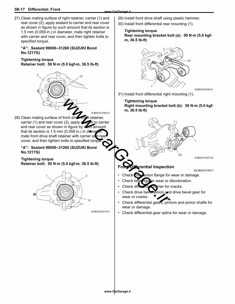
27) Clean mating surface of right retainer, carrier (1) and rear cover (2), apply sealant to carrier and rear cover as shown in figure by such amount that its section is 1.5 mm (0.059 in.) in diameter, mate right retainer with carrier and rear cover, and then tighten bolts to specified torque.
“A”: Sealant 99000–31260 (SUZUKI Bond No.1217G)
Tightening torqueRetainer bolt: 50 N·m (5.0 kgf-m, 36.5 lb-ft)
28) Clean mating surface of front drive shaft retainer, carrier (1) and rear cover (2), apply sealant to carrier and rear cover as shown in figure by such amount that its section is 1.5 mm (0.059 in.) in diameter, mate front drive shaft retainer with carrier and rear cover, and then tighten bolts to specified torque.
“A”: Sealant 99000–31260 (SUZUKI Bond No.1217G)
Tightening torqueRetainer bolt: 50 N·m (5.0 kgf-m, 36.5 lb-ft)
29) Install front drive shaft using plastic hammer.30) Install front differential rear mounting (1).
Tightening torqueRear mounting bracket bolt (a): 50 N·m (5.0 kgf-m, 36.5 lb-ft)
31) Install front differential right mounting (1).
Tightening torqueRight mounting bracket bolt (b): 50 N·m (5.0 kgf-m, 36.5 lb-ft)
Front Differential InspectionS5JB0A3216011
• Check companion flange for wear or damage.• Check bearings for wear or discoloration.• Check differential carrier for cracks.• Check drive bevel pinion and drive bevel gear for
wear or cracks.• Check differential gears, pinions and pinion shafts for
wear or damage.• Check differential gear spline for wear or damage.
1
“A”2
I5JB0A321048-01
“A”
21
I5JB0A322014-01
(a)
1I5JB0A321046-01
1
(b)I5JB0A321047-02
www.CarGarage.ir
www.CarGarage.ir
www.CarGarage.ir

Differential: Front 3B-18
SpecificationsTightening Torque Specifications
S5JB0A3217001
NOTEThe specified tightening torque is also described in the following.“Front Differential Unit Components: Front”“Front Differential Components: Front”
Reference:For the tightening torque of fastener not specified in this section, refer to “Fastener Information: in Section 0A”.
Special Tools and EquipmentRecommended Service Material
S5JB0A3218001
NOTERequired service material is also described in the following.“Front Differential Components: Front”
Special ToolS5JB0A3218002
Fastening part Tightening torque NoteN⋅m kgf-m lb-ftDifferential oil drain plug 23 2.3 17.0Differential oil level / filler plug 23 2.3 17.0Bevel gear bolt Tighten 40 N⋅m (4.0 kgf-m, 29.5 lb-ft) +
50° Rear cover bolt No.1 50 5.0 36.5Rear cover bolt No.2 85 8.5 61.5Retainer bolt 50 5.0 36.5 / Rear mounting bracket bolt 50 5.0 36.5Right mounting bracket bolt 50 5.0 36.5
Material SUZUKI recommended product or Specification NoteGrease SUZUKI Super Grease A P/No.: 99000–25010 / / Sealant SUZUKI Bond No.1217G P/No.: 99000–31260 / / / Thread lock cement Thread Lock Cement Super 1322 P/No.: 99000–32110
09900–20607 09900–20701Dial gauge Magnetic stand
/ / /
09913–50121 09913–65135Oil seal remover Bearing puller
/ / /
www.CarGarage.ir
www.CarGarage.ir
www.CarGarage.ir
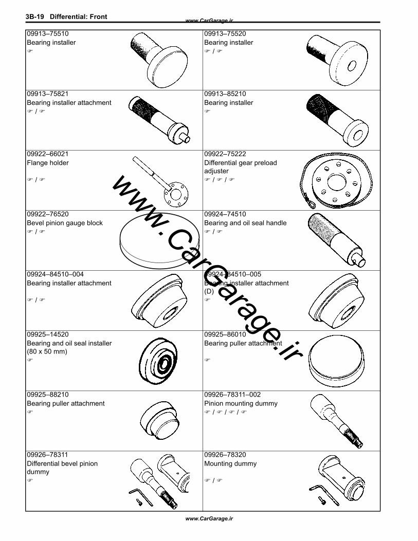
3B-19 Differential: Front
09913–75510 09913–75520Bearing installer Bearing installer
/
09913–75821 09913–85210Bearing installer attachment Bearing installer
/
09922–66021 09922–75222Flange holder Differential gear preload
adjuster / / /
09922–76520 09924–74510Bevel pinion gauge block Bearing and oil seal handle
/ /
09924–84510–004 09924–84510–005Bearing installer attachment Bearing installer attachment
(D) /
09925–14520 09925–86010Bearing and oil seal installer (80 x 50 mm)
Bearing puller attachment
09925–88210 09926–78311–002Bearing puller attachment Pinion mounting dummy
/ / /
09926–78311 09926–78320Differential bevel pinion dummy
Mounting dummy
/
www.CarGarage.ir
www.CarGarage.ir
www.CarGarage.ir
Differential: Front 3B-20
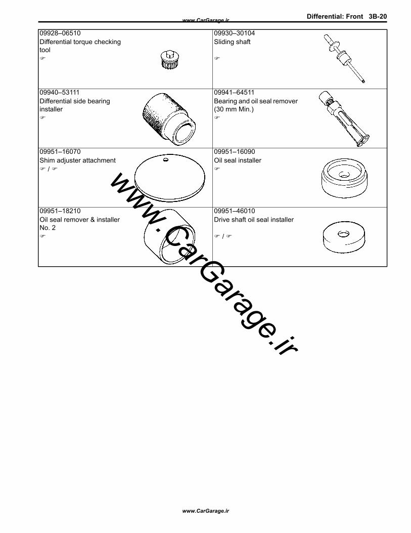
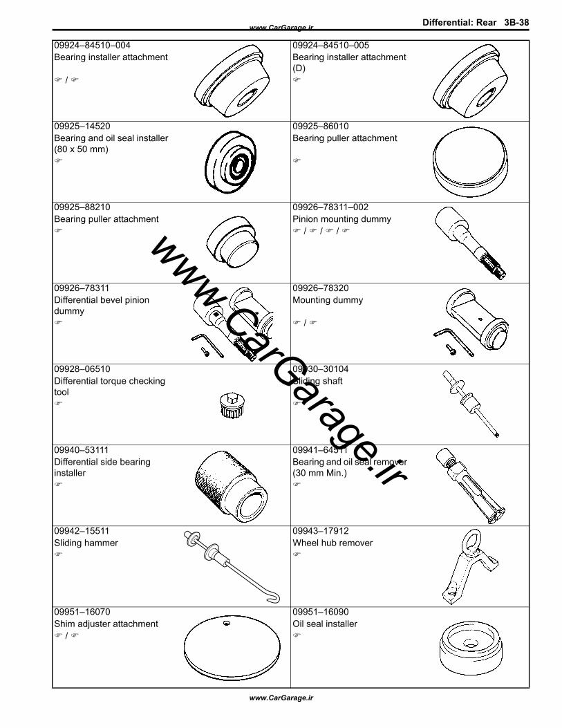
09928–06510 09930–30104Differential torque checking tool
Sliding shaft
09940–53111 09941–64511Differential side bearing installer
Bearing and oil seal remover (30 mm Min.)
09951–16070 09951–16090Shim adjuster attachment Oil seal installer
/
09951–18210 09951–46010Oil seal remover & installer No. 2
Drive shaft oil seal installer
/
www.CarGarage.ir
www.CarGarage.ir
www.CarGarage.ir

3B-21 Differential: Rear
Rear
General DescriptionRear Differential Construction
S5JB0A3221001Refer to “Front Differential Construction: Front”.
Diagnostic Information and ProceduresRear Differential Symptom Diagnosis
S5JB0A3224001Refer to “Front Differential Symptom Diagnosis: Front”.
Repair InstructionsRear Differential Oil Change
S5JB0A3226010Refer to “Front Differential Oil Change: Front”.The point which is different from the front differential is described.
Differential oil capacity (Reference): 0.8 – 0.9 liters (1.7/1.4 – 1.9/1.6 US/Imp. pt.)
Rear Differential Unit ComponentsS5JB0A3226011
(a)4
(a)3
(b)5
1
2
I5JB0A322002-03
1. Rear differential 4. Front mounting bracket bolt2. Front mounting bracket : 120 N⋅m (12.0 kgf-m, 87.0 lb-ft)3. Rear mounting bolt : 50 N⋅m (5.0 kgf-m, 36.5 lb-ft)
www.CarGarage.ir
www.CarGarage.ir
www.CarGarage.ir
Differential: Rear 3B-22
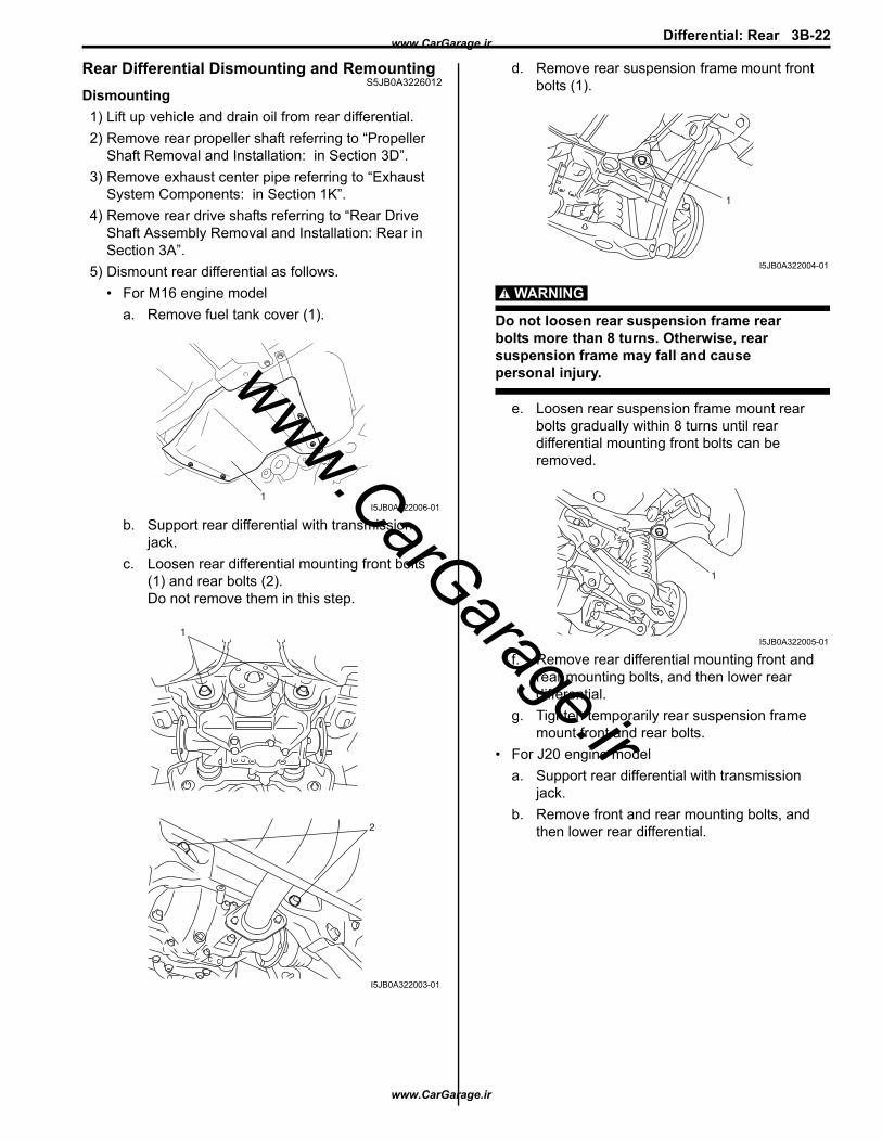
Rear Differential Dismounting and RemountingS5JB0A3226012
Dismounting1) Lift up vehicle and drain oil from rear differential.2) Remove rear propeller shaft referring to “Propeller
Shaft Removal and Installation: in Section 3D”.3) Remove exhaust center pipe referring to “Exhaust
System Components: in Section 1K”.4) Remove rear drive shafts referring to “Rear Drive
Shaft Assembly Removal and Installation: Rear in Section 3A”.
5) Dismount rear differential as follows.• For M16 engine model
a. Remove fuel tank cover (1).
b. Support rear differential with transmission jack.
c. Loosen rear differential mounting front bolts (1) and rear bolts (2).Do not remove them in this step.
d. Remove rear suspension frame mount front bolts (1).
WARNING!
Do not loosen rear suspension frame rear bolts more than 8 turns. Otherwise, rear suspension frame may fall and cause personal injury.
e. Loosen rear suspension frame mount rear bolts gradually within 8 turns until rear differential mounting front bolts can be removed.
f. Remove rear differential mounting front and rear mounting bolts, and then lower rear differential.
g. Tighten temporarily rear suspension frame mount front and rear bolts.
• For J20 engine modela. Support rear differential with transmission
jack.b. Remove front and rear mounting bolts, and
then lower rear differential.
1I5JB0A322006-01
1
2
I5JB0A322003-01
1
I5JB0A322004-01
1
I5JB0A322005-01
www.CarGarage.ir
www.CarGarage.ir
www.CarGarage.ir

3B-23 Differential: Rear
RemountingReverse dismounting procedure for remounting noting the following.• Tighten rear differential mounting front and rear bolts
to specified torque.
Tightening torqueRear differential front mounting bolt: 120 N·m (12.0 kgf-m, 87.0 lb-ft)Rear differential rear mounting bolt: 120 N·m (12.0 kgf-m, 87.0 lb-ft)
• Tighten rear suspension frame front and rear bolts to specified torque referring to “Rear Suspension Construction: in Section 2C”.
• Fill rear differential oil referring to “Rear Differential Oil Change: Rear”.
Rear Differential ComponentsS5JB0A3226001
2
10
10
12
(a)18
(a)18
(b)24
19
9
21
11
5
28
1323
20
12
(c)22
3
4
6
7 A
8 1
(a)25
26
12
11
27
17
16
14
14
16
1715
20
15
I5JB0A322001-09
1. Universal joint flange 18. Retainer bolt2. Hypoid gear set 19. Rear drive right retainer
: Apply sealant 99000-31260 to mating surface of right retainer, carrier and rear cover.
3. Bevel pinion spacer 20. Shim4. Shim 21. Rear drive left retainer
: Apply sealant 99000-31260 to mating surface of left retainer, carrier and rear cover.
5. Rear bearing 22. Bevel gear bolt: Apply thread lock cement 99000-32110 to thread part of bolt.
6. Front bearing 23. Rear cover 7. Oil seal
: Apply grease 99000-25010 to oil seal lip.24. Rear cover bolt No.1 bolt
www.CarGarage.ir
www.CarGarage.ir
www.CarGarage.ir
Differential: Rear 3B-24
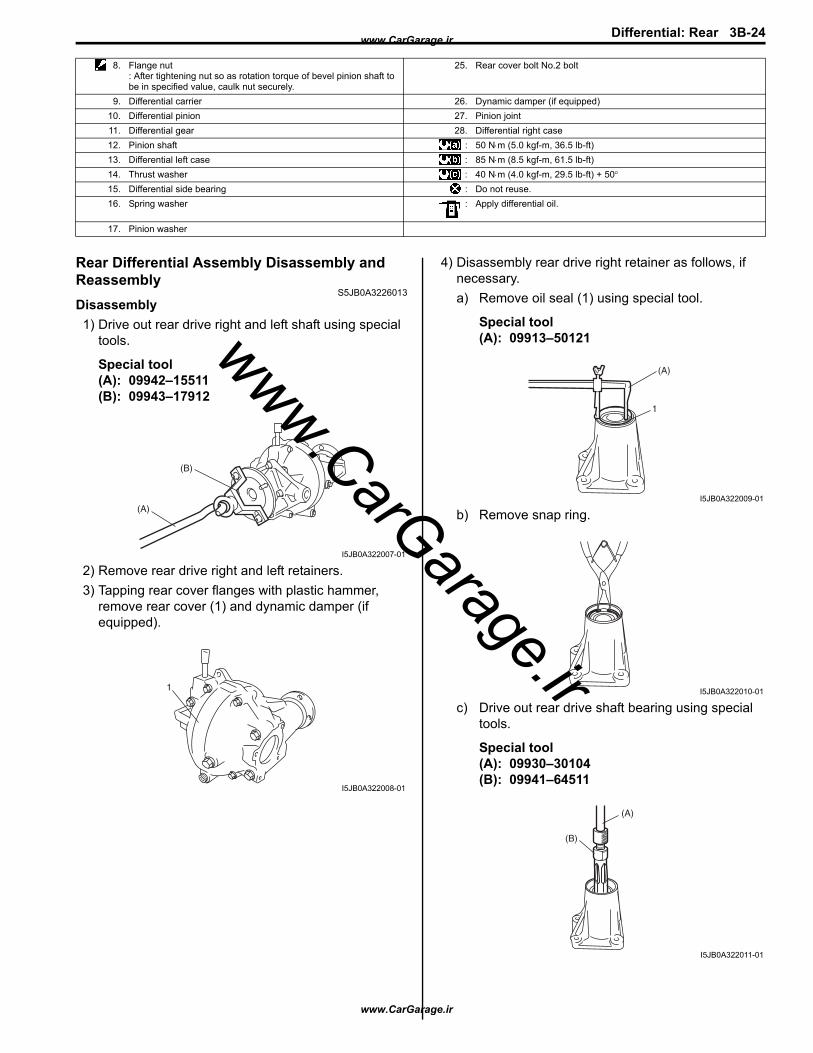
Rear Differential Assembly Disassembly and Reassembly
S5JB0A3226013Disassembly1) Drive out rear drive right and left shaft using special
tools.
Special tool(A): 09942–15511 (B): 09943–17912
2) Remove rear drive right and left retainers.3) Tapping rear cover flanges with plastic hammer,
remove rear cover (1) and dynamic damper (if equipped).
4) Disassembly rear drive right retainer as follows, if necessary.a) Remove oil seal (1) using special tool.
Special tool(A): 09913–50121
b) Remove snap ring.
c) Drive out rear drive shaft bearing using special tools.
Special tool(A): 09930–30104 (B): 09941–64511
8. Flange nut: After tightening nut so as rotation torque of bevel pinion shaft to be in specified value, caulk nut securely.
25. Rear cover bolt No.2 bolt
9. Differential carrier 26. Dynamic damper (if equipped)10. Differential pinion 27. Pinion joint11. Differential gear 28. Differential right case12. Pinion shaft : 50 N⋅m (5.0 kgf-m, 36.5 lb-ft)13. Differential left case : 85 N⋅m (8.5 kgf-m, 61.5 lb-ft)14. Thrust washer : 40 N⋅m (4.0 kgf-m, 29.5 lb-ft) + 50°15. Differential side bearing : Do not reuse.16. Spring washer : Apply differential oil.
17. Pinion washer
(A)
(B)
I5JB0A322007-01
1
I5JB0A322008-01
(A)
1
I5JB0A322009-01
I5JB0A322010-01
(A)
(B)
I5JB0A322011-01
www.CarGarage.ir
www.CarGarage.ir
www.CarGarage.ir
3B-25 Differential: Rear
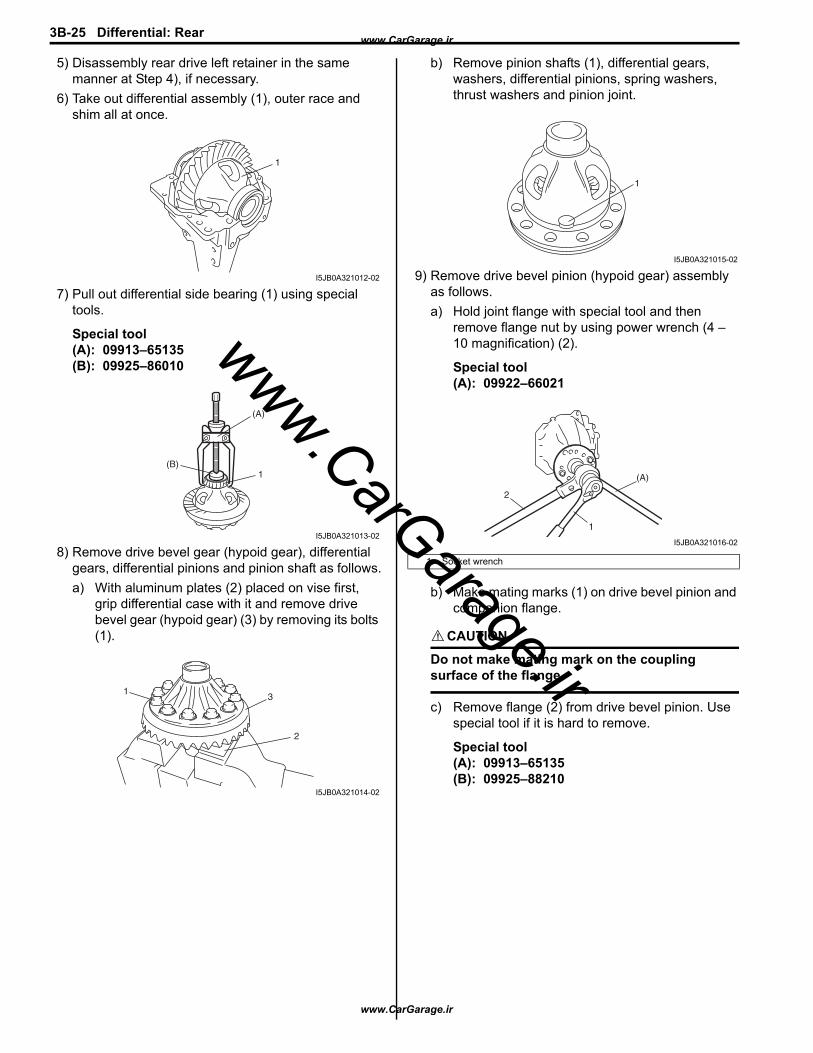
5) Disassembly rear drive left retainer in the same manner at Step 4), if necessary.
6) Take out differential assembly (1), outer race and shim all at once.
7) Pull out differential side bearing (1) using special tools.
Special tool(A): 09913–65135(B): 09925–86010
8) Remove drive bevel gear (hypoid gear), differential gears, differential pinions and pinion shaft as follows.a) With aluminum plates (2) placed on vise first,
grip differential case with it and remove drive bevel gear (hypoid gear) (3) by removing its bolts (1).
b) Remove pinion shafts (1), differential gears, washers, differential pinions, spring washers, thrust washers and pinion joint.
9) Remove drive bevel pinion (hypoid gear) assembly as follows.a) Hold joint flange with special tool and then
remove flange nut by using power wrench (4 – 10 magnification) (2).
Special tool(A): 09922–66021
b) Make mating marks (1) on drive bevel pinion and companion flange.
CAUTION!
Do not make mating mark on the coupling surface of the flange.
c) Remove flange (2) from drive bevel pinion. Use special tool if it is hard to remove.
Special tool(A): 09913–65135(B): 09925–88210
1
I5JB0A321012-02
1(B)
(A)
I5JB0A321013-02
3
2
1
I5JB0A321014-02
1. Socket wrench
1
I5JB0A321015-02
(A)
2
1
I5JB0A321016-02
www.CarGarage.ir
www.CarGarage.ir
www.CarGarage.ir
Differential: Rear 3B-26
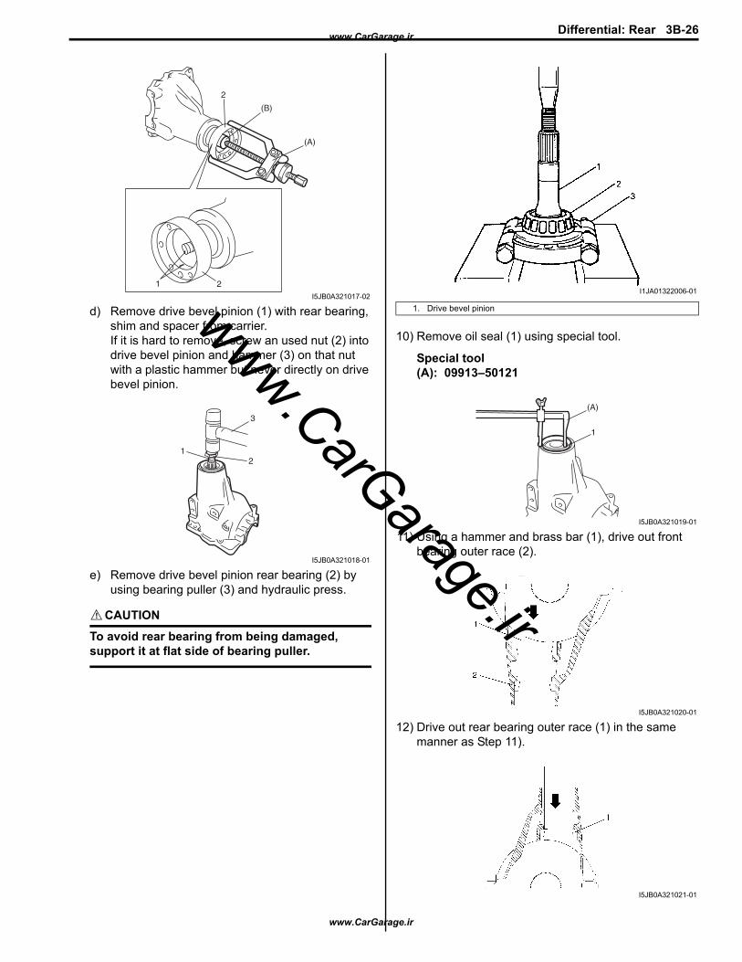
d) Remove drive bevel pinion (1) with rear bearing, shim and spacer from carrier.If it is hard to remove, screw an used nut (2) into drive bevel pinion and hammer (3) on that nut with a plastic hammer but never directly on drive bevel pinion.
e) Remove drive bevel pinion rear bearing (2) by using bearing puller (3) and hydraulic press.
CAUTION!
To avoid rear bearing from being damaged, support it at flat side of bearing puller.
10) Remove oil seal (1) using special tool.
Special tool(A): 09913–50121
11) Using a hammer and brass bar (1), drive out front bearing outer race (2).
12) Drive out rear bearing outer race (1) in the same manner as Step 11).
2
(B)
(A)
21
I5JB0A321017-02
3
21
I5JB0A321018-01
1. Drive bevel pinion
I1JA01322006-01
(A)
1
I5JB0A321019-01
I5JB0A321020-01
I5JB0A321021-01
www.CarGarage.ir
www.CarGarage.ir
www.CarGarage.ir
3B-27 Differential: Rear
ReassemblyJudging from faulty conditions noted before disassembly and what is found through visual check of bearing and gear tooth etc. after disassembly, prepare replacing parts and proceed to reassembly according to procedures as described.
CAUTION!
• Drive bevel gear and pinion must be replaced as a set when either replacement becomes necessary.
• When replacing taper roller bearing, replace as inner race and outer race assembly.
1) For press-fitting drive bevel pinion bearing outer races, use special tools and press as shown in the figure.
Special tool(A): 09924–74510(B): 09925–14520(C): 09913–75510
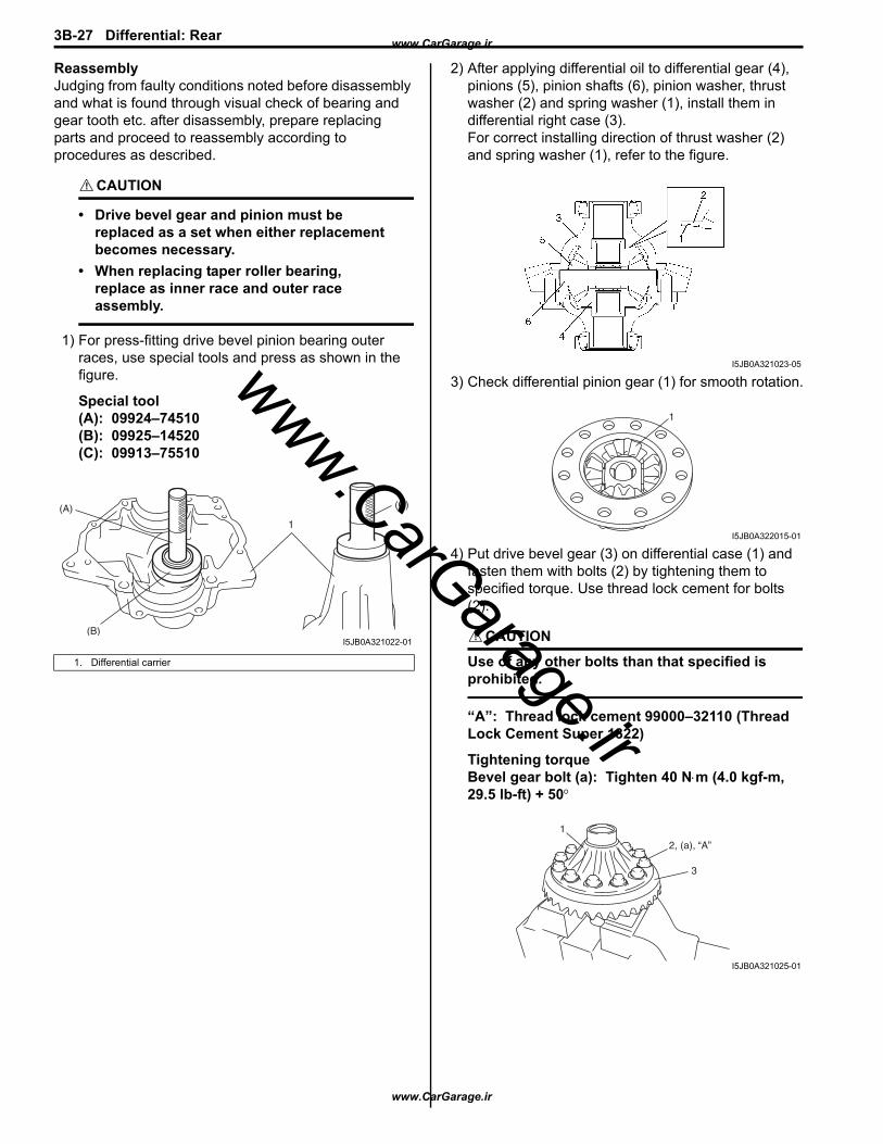
2) After applying differential oil to differential gear (4), pinions (5), pinion shafts (6), pinion washer, thrust washer (2) and spring washer (1), install them in differential right case (3).For correct installing direction of thrust washer (2) and spring washer (1), refer to the figure.
3) Check differential pinion gear (1) for smooth rotation.
4) Put drive bevel gear (3) on differential case (1) and fasten them with bolts (2) by tightening them to specified torque. Use thread lock cement for bolts (2).
CAUTION!
Use of any other bolts than that specified is prohibited.
“A”: Thread lock cement 99000–32110 (Thread Lock Cement Super 1322)
Tightening torqueBevel gear bolt (a): Tighten 40 N⋅m (4.0 kgf-m, 29.5 lb-ft) + 50°
1. Differential carrier
(B)
(A)
1
(C)
I5JB0A321022-01
I5JB0A321023-05
1
I5JB0A322015-01
2, (a), “A”
3
1
I5JB0A321025-01
www.CarGarage.ir
www.CarGarage.ir
www.CarGarage.ir
Differential: Rear 3B-28
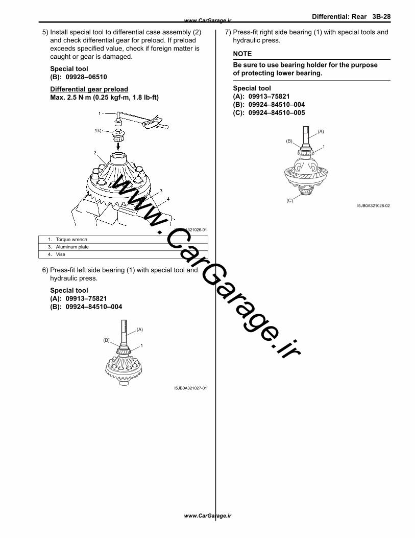
5) Install special tool to differential case assembly (2) and check differential gear for preload. If preload exceeds specified value, check if foreign matter is caught or gear is damaged.
Special tool(B): 09928–06510
Differential gear preloadMax. 2.5 N⋅m (0.25 kgf-m, 1.8 lb-ft)
6) Press-fit left side bearing (1) with special tool and hydraulic press.
Special tool(A): 09913–75821(B): 09924–84510–004
7) Press-fit right side bearing (1) with special tools and hydraulic press.
NOTEBe sure to use bearing holder for the purpose of protecting lower bearing.
Special tool(A): 09913–75821(B): 09924–84510–004(C): 09924–84510–005
1. Torque wrench3. Aluminum plate4. Vise
I5JB0A321026-01
(B)
(A)
1
I5JB0A321027-01
(B)
(A)
1
(C)I5JB0A321028-02
www.CarGarage.ir
www.CarGarage.ir
www.CarGarage.ir
3B-29 Differential: Rear
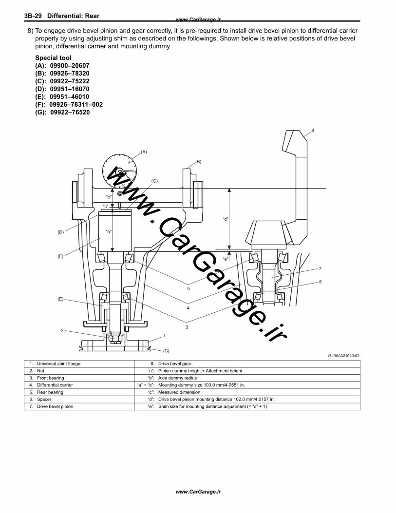
8) To engage drive bevel pinion and gear correctly, it is pre-required to install drive bevel pinion to differential carrier properly by using adjusting shim as described on the followings. Shown below is relative positions of drive bevel pinion, differential carrier and mounting dummy.
Special tool(A): 09900–20607(B): 09926–78320(C): 09922–75222(D): 09951–16070(E): 09951–46010(F): 09926–78311–002(G): 09922–76520
(A)
(B)
(D)
(F)
(E)
2
(G)
“a”
“b”
“d”
“e”
“c”
(C)
1
5
4
3
8
7
6
I5JB0A321029-02
1. Universal Joint flange 8. Drive bevel gear2. Nut “a”: Pinion dummy height + Attachment height3. Front bearing “b”: Axle dummy radius4. Differential carrier “a” + “b”: Mounting dummy size 103.0 mm/4.0551 in.5. Rear bearing “c”: Measured dimension6. Spacer “d”: Drive bevel pinion mounting distance 102.0 mm/4.0157 in.7. Drive bevel pinion “e”: Shim size for mounting distance adjustment (= “c” + 1)
www.CarGarage.ir
www.CarGarage.ir
www.CarGarage.ir
Differential: Rear 3B-30
9) Install special tools with bearings (3) and flange (2) to differential carrier (1).
NOTEThis installation requires no spacer or oil seal.
Special tool(E): 09951–46010(F): 09926–78311–002
10) Tighten flange nut (1) so that specified bearing preload is obtained.
NOTE
• Before taking measurement with spring balance (2) or torque wrench (3), check for rotation by hand and apply small amount of differential oil to bearings.
• On measuring preload, rotate the drive bevel pinion about 1 rotation per 2 seconds.
Special tool(C): 09922–75222(F): 09926–78311–002
Pinion bearing preload0.9 – 1.7 N⋅m (9.0 – 17.0 kg-cm, 7.8 – 14.7 lb-in.)
Spring measure reading with special tool20 – 40 N (2.0 – 4.0 kg, 4.4 – 8.8 lb)
11) Set dial gauge to mounting dummy and make 0 (zero) adjustment on surface plate (1).
NOTE
• When setting dial gauge to mounting dummy, tighten screw (2) lightly. Be careful not to overtighten it, which will cause damage to dial gauge.
• With dial gauge set, turn dummy back and force by hand a couple of times and attain accurate 0 (zero) adjustment.
• It is desirable that short pointer indicates beyond 2 mm when long one is at 0 (zero).
Special tool(A): 09900–20607(B): 09926–78320
12) Place zero-adjusted mounting dummy and dial gauge set on pinion mounting dummy and take measurement between zero position and extended dial gauge measuring tip.
NOTE
• Repeat turning back and force of dummy and measure distance as far as top surface of pinion dummy accurately.
• When dial gauge measuring tip extends from 0 (zero) position, pointer turns counterclockwise.
• Measured value may exceed 1 mm. Therefore, it is also necessary to know reading of short pointer.
4. Socket with adapter
I5JB0A321030-01
I5JB0A321031-01
IYSQ01322033-01
www.CarGarage.ir
www.CarGarage.ir
www.CarGarage.ir
3B-31 Differential: Rear
Special tool(A): 09900–20607(B): 09926–78311(D): 09951–16070(F): 09926–78311–002: 09922–76520
13) Obtain adjusting shim thickness by the following equation.“1 mm (0.039 in.)” is “a” + “b” (Mounting dummy size) – “d” (Drive bevel pinion mounting distance)
14) Select adjusting shim(s) (2) closest to calculated value from among the following available sizes and put it in place and then press-fit rear bearing (1).
Special tool(G): 09913–85210(H): 09940–53111
Available shim thickness1.00, 1.03, 1.06, 1.09, 1.12, 1.15, 1.18, 1.21,1.24, 1.27, 1.30 and 0.3 mm (0.039, 0.040, 0.042, 0.043, 0.044, 0.045, 0.046, 0.047 0.048, 0.049, 0.050 and 0.012 in.)
15) With new pinion spacer (3) inserted as shown in the figure, install front bearing (5) to differential carrier (4).
NOTE
• Make sure to use new spacer for reinstallation.
• Apply differential oil to bearings.
16) Using special tool and plastic hammer, drive oil seal (2) into differential carrier (1) as shown in figure. Then apply grease “A” to oil seal lip.
“A”: Grease 99000–25010 (SUZUKI Super Grease A)
Special tool(A): 09951–18210
Necessary shim
thickness “e”
=
Mounting dummy size 103.0mm /4.0551 in. “a” + “b”
+Measured dimension
“c”–
Drive bevel pinion
mounting distance 102 mm / 4.0157 in.
3. Drive bevel pinion
(F)
(D)
(B)
(A)
I5JB0A321032-01
I5JB0A321033-01
1. Drive bevel pinion2. Rear bearing
I5JB0A321034-01
I5JB0A321035-01
www.CarGarage.ir
www.CarGarage.ir
www.CarGarage.ir

Differential: Rear 3B-32
17) While tightening flange nut gradually with special tool and power wrench (4 – 10 magnification) (1), set preload of pinion to specification.
NOTE
• Before taking measurement with spring balance (3) or torque wrench (4), check for smooth rotation by hand.
• On measuring preload, rotate the drive bevel pinion about 1 rotation per 2 seconds.
• Be sure to tighten gradually and carefully till specified starting torque is obtained. Turning back overtightened flange nuts should be avoided.
Pinion bearing preload0.9 – 1.7 N⋅m (9.0 – 17.0 kg-cm, 7.8 – 14.7 lb-in.)
Spring measure reading with special tool20 – 40 N (2.0 – 4.0 kg, 4.4 – 8.8 lb)
Special tool(A): 09922–75222(B): 09922–66021
18) Select differential side bearing shim as follows.a) Measure dimension “a” and “b” using vernier
caliper.
b) Calculate dimension “a” – “b”, and select shims from among following available size so that total of thickness of right side and left side shims may reach the calculated value.
NOTESelect shims so that thickness of right side shims and left side shims become almost even.
Available shim thicknessRight side: 1.75, 1.85, 1.95, 2.00, 2.05, 2.15 and 2.25 mm (0.069, 0.073, 0.077, 0.079, 0.081, 0.085 and 0.089 in.)Left side: 2.75, 2.85, 2.95, 3.00, 3.05, 3.15 and 3.25 mm (0.108, 0.112, 0.116, 0.118, 0.120, 0.124 and 0.128 in.)
2. Socket wrench
I5JB0A321036-02
I5JB0A321037-04
www.CarGarage.ir
www.CarGarage.ir
www.CarGarage.ir

3B-33 Differential: Rear
19) To measure bevel gear backlash, set dial gauge (1) at right angle to bevel gear tooth, fix drive bevel pinion and read dial gauge while moving bevel gear.
Special tool(A): 09900–20607(B): 09900–20701
NOTE
• Be sure to apply measuring tip of dial gauge at right angles to convex side of tooth.
• Measure at least 4 points on drive bevel gear periphery.
20) Place bearing outer races on their respective bearings. Used left and right outer races are not interchangeable.
21) Install case assembly (1) in carrier (2).
22) As final step, check gear tooth contact as follows.a) After cleaning 10 drive bevel gear teeth, paint
them with gear marking compound evenly by using brush (1) or sponge etc.
b) Turn gear to bring its painted part in mesh with drive bevel pinion and turn it back and forth by hand to repeat their contact.
c) Bring painted part up and check contact pattern, referring to the following table. If contact pattern is not normal, readjust or replace as necessary according to instruction in the table.
NOTEBe careful not to turn drive bevel gear more than one full revolution, for it will hinder accurate check.
I5JB0A321038-03
I5JB0A321039-01
A: Paint gear marking compound evenly
1
A
I5JB0A321040-02
www.CarGarage.ir
www.CarGarage.ir
www.CarGarage.ir
Differential: Rear 3B-34
Tooth Contact Pattern Diagnosis and RemedyNormal
High ContactPinion is positioned too far from the center of drive bevel gear (1).• Increase thickness of pinion (2) height adjusting
shim and position pinion closer to gear center.• Adjust drive bevel gear backlash to specification.
Low ContactPinion is positioned too close to the center of drive bevel gear (1).• Decrease thickness of pinion (2) height adjusting
shim and position pinion farther from gear center.• Adjust drive bevel gear backlash to specification.
If adjustment is impossible, replace differential carrier.
• Check seating of bevel gear or differential case. (Check bevel gear for runout.)
• If adjustment is impossible, replace drive bevel gear and pinion set or differential carrier.
Replace drive bevel gear and pinion set or differential case.
I5JB0A321041-05
IYSQ01321072-01
IYSQ01321073-01
IYSQ01321074-01 IYSQ01321076-01
IYSQ01321077-01
IYSQ01321078-01
IYSQ01321079-01
www.CarGarage.ir
www.CarGarage.ir
www.CarGarage.ir

3B-35 Differential: Rear
23) Upon completion of gear tooth contact check in Step 22), caulk flange nut (2) with caulking tool (1) and hammer.
24) Install rear cover (1) to differential carrier (2).
Tightening torqueRear cover bolt No.1 (a): 50 N·m (5.0 kgf-m, 36.5 lb-ft)Rear cover bolt No.2 (b): 85 N·m (8.5 kgf-m, 61.5 lb-ft)
25) Assembly rear drive right retainer as follows.a) Install rear drive shaft bearing (1) using special
tool and press (2).
Special tool(A): 09913–75520
b) Install snap ring.
c) Install oil seal using special tools as shown in figure.
Distance between retainer surface and oil seal“a”: 2.5 – 3.0 mm (0.10 – 0.12 in.)
Special tool(A): 09924–74510 (B): 09951–16090
I1JA01322021-01
1
(a)
2
(b)I5JB0A321042-01
2
(A)
1
I5JB0A322012-01
I5JB0A322010-01
I5JB0A322013-02
www.CarGarage.ir
www.CarGarage.ir
www.CarGarage.ir
Differential: Rear 3B-36
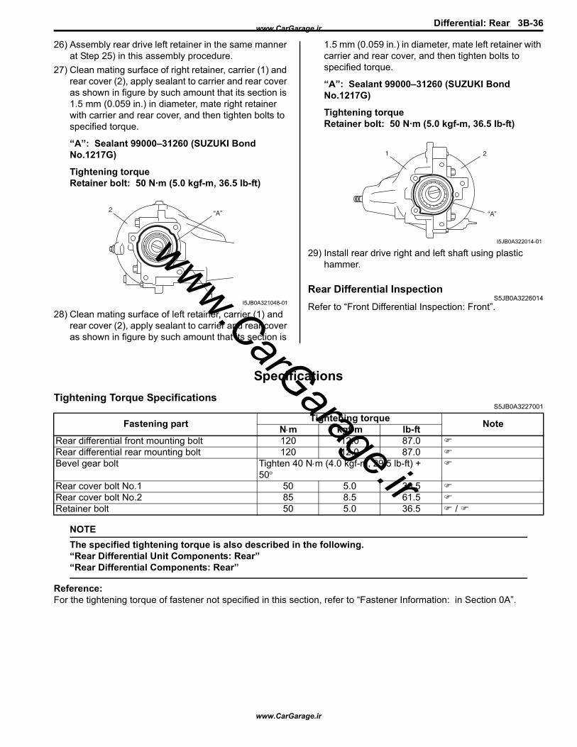
26) Assembly rear drive left retainer in the same manner at Step 25) in this assembly procedure.
27) Clean mating surface of right retainer, carrier (1) and rear cover (2), apply sealant to carrier and rear cover as shown in figure by such amount that its section is 1.5 mm (0.059 in.) in diameter, mate right retainer with carrier and rear cover, and then tighten bolts to specified torque.
“A”: Sealant 99000–31260 (SUZUKI Bond No.1217G)
Tightening torqueRetainer bolt: 50 N·m (5.0 kgf-m, 36.5 lb-ft)
28) Clean mating surface of left retainer, carrier (1) and rear cover (2), apply sealant to carrier and rear cover as shown in figure by such amount that its section is
1.5 mm (0.059 in.) in diameter, mate left retainer with carrier and rear cover, and then tighten bolts to specified torque.
“A”: Sealant 99000–31260 (SUZUKI Bond No.1217G)
Tightening torqueRetainer bolt: 50 N·m (5.0 kgf-m, 36.5 lb-ft)
29) Install rear drive right and left shaft using plastic hammer.
Rear Differential InspectionS5JB0A3226014
Refer to “Front Differential Inspection: Front”.
SpecificationsTightening Torque Specifications
S5JB0A3227001
NOTEThe specified tightening torque is also described in the following.“Rear Differential Unit Components: Rear”“Rear Differential Components: Rear”
Reference:For the tightening torque of fastener not specified in this section, refer to “Fastener Information: in Section 0A”.
1
“A”2
I5JB0A321048-01
“A”
21
I5JB0A322014-01
Fastening part Tightening torque NoteN⋅m kgf-m lb-ftRear differential front mounting bolt 120 12.0 87.0Rear differential rear mounting bolt 120 12.0 87.0Bevel gear bolt Tighten 40 N⋅m (4.0 kgf-m, 29.5 lb-ft) +
50° Rear cover bolt No.1 50 5.0 36.5Rear cover bolt No.2 85 8.5 61.5Retainer bolt 50 5.0 36.5 /
www.CarGarage.ir
www.CarGarage.ir
www.CarGarage.ir

3B-37 Differential: Rear
Special Tools and EquipmentRecommended Service Material
S5JB0A3228001
NOTERequired service material is also described in the following.“Rear Differential Components: Rear”
Special ToolS5JB0A3228002
Material SUZUKI recommended product or Specification NoteGrease SUZUKI Super Grease A P/No.: 99000–25010Sealant SUZUKI Bond No.1217G P/No.: 99000–31260 / Thread lock cement Thread Lock Cement Super 1322 P/No.: 99000–32110
09900–20607 09900–20701Dial gauge Magnetic stand
/ / /
09913–50121 09913–65135Oil seal remover Bearing puller
/ /
09913–75510 09913–75520Bearing installer Bearing installer
09913–75821 09913–85210Bearing installer attachment Bearing installer
/
09922–66021 09922–75222Flange holder Differential gear preload
adjuster / / /
09922–76520 09924–74510Bevel pinion gauge block Bearing and oil seal handle
/ /
www.CarGarage.ir
www.CarGarage.ir
www.CarGarage.ir
Differential: Rear 3B-38
09924–84510–004 09924–84510–005Bearing installer attachment Bearing installer attachment
(D) /
09925–14520 09925–86010Bearing and oil seal installer (80 x 50 mm)
Bearing puller attachment
09925–88210 09926–78311–002Bearing puller attachment Pinion mounting dummy
/ / /
09926–78311 09926–78320Differential bevel pinion dummy
Mounting dummy
/
09928–06510 09930–30104Differential torque checking tool
Sliding shaft
09940–53111 09941–64511Differential side bearing installer
Bearing and oil seal remover (30 mm Min.)
09942–15511 09943–17912Sliding hammer Wheel hub remover
09951–16070 09951–16090Shim adjuster attachment Oil seal installer
/
www.CarGarage.ir
www.CarGarage.ir
www.CarGarage.ir
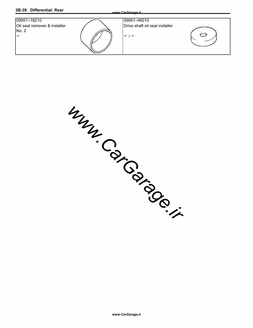
3B-39 Differential: Rear
09951–18210 09951–46010Oil seal remover & installer No. 2
Drive shaft oil seal installer
/
www.CarGarage.ir
www.CarGarage.ir
www.CarGarage.ir

Transfer: Motor-Shift Type (Transfer with Shift Actuator) 3C-1
Transfer
Motor-Shift Type (Transfer with Shift Actuator)
PrecautionsTransfer Warning
S5JB0A3310002
WARNING!
This transfer has a center differential.When testing with 2-wheel chassis dynamometer or speedometer tester (which tester roller is driven by vehicle wheels), be sure to make the vehicle as rear wheel drive or as front wheel drive temporarily as follows.Otherwise, front wheels drive rear wheels or vise-versa and personal injury may result.
1) Remove front propeller shaft or rear propeller shaft referring to “Propeller Shaft Removal and Installation: in Section 3D”.
2) Install special tool (cap) to flange yoke cover hole (front or rear) of transfer (1) and fix it to transfer or hook with string to prevent oil leakage from transfer.
Special tool(A): 09928–36510
3) Pour specified oil into transfer up to lever plug hole if front propeller shaft is removed.
4) Shift transfer to 4H-lock position as follows.
• M16 engine model:Remove lever bolt (1) on transfer, push down lever to 4H-lock position (2) and fix lever with bolt.
• J20 engine model:Shift transfer to 4H-lock position by turning transfer switch.
Precautions in Diagnosing TroubleS5JB0A3310001
• Do not disconnect the following parts before confirming diagnostic information (DTC, etc.) stored in 4WD control module memory. These actions will erase memorized information in 4WD control module memory.– Disconnection of coupler from 4WD control module– Disconnection of battery cable from battery– Disconnection of ground wire harness of 4WD
control module– Disconnect main fuse from fuse box
• Diagnostic information stored in 4WD control module memory can be cleared as well as checked by using SUZUKI scan tool. Before using scan tool, read its Operator’s (Instruction) Manual carefully to have good understanding as to what functions are available and how to use it.
• Be sure to read “Precautions for Electrical Circuit Service:” before inspection and observe what is written there.
General DescriptionTransfer Description
S5JB0A3311010The aluminum transfer case directly connected to the back of the transmission contains input gear, counter gear, rear output shaft, front output shaft, center differential, drive chain and their accompanying gears, hubs, sleeves, fork, etc.The center differential is installed in the transfer. With the torque induction type LSD used in the center differential, the effect of LSD works when a rotation difference between front and rear wheels is occurring.
(A)1
I5JB0A331107-03
2
1
I5JB0A331108-01
www.CarGarage.ir
www.CarGarage.ir
www.CarGarage.ir
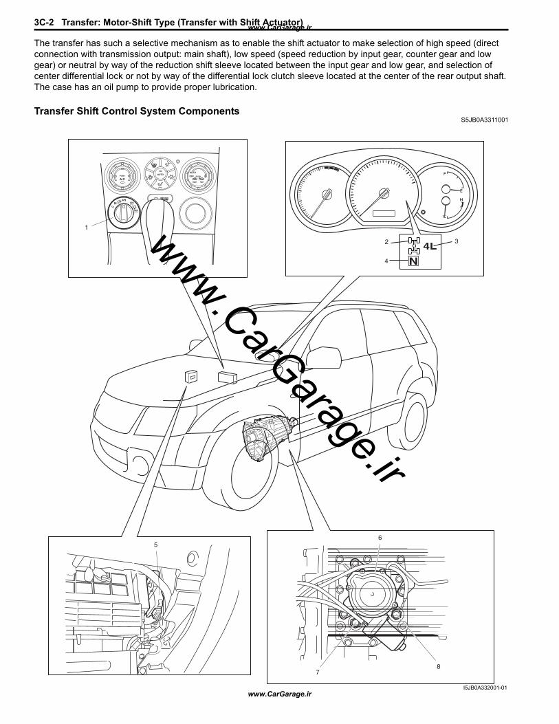
3C-2 Transfer: Motor-Shift Type (Transfer with Shift Actuator)
The transfer has such a selective mechanism as to enable the shift actuator to make selection of high speed (direct connection with transmission output: main shaft), low speed (speed reduction by input gear, counter gear and low gear) or neutral by way of the reduction shift sleeve located between the input gear and low gear, and selection of center differential lock or not by way of the differential lock clutch sleeve located at the center of the rear output shaft.The case has an oil pump to provide proper lubrication.
Transfer Shift Control System ComponentsS5JB0A3311001
6
7
5
1
8
2 3
4
I5JB0A332001-01
www.CarGarage.ir
www.CarGarage.ir
www.CarGarage.ir
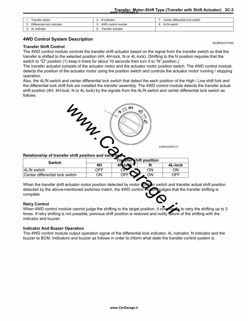
Transfer: Motor-Shift Type (Transfer with Shift Actuator) 3C-3
4WD Control System DescriptionS5JB0A3311002
Transfer Shift ControlThe 4WD control module controls the transfer shift actuator based on the signal from the transfer switch so that the transfer is shifted to the selected position (4H, 4H-lock, N or 4L-lock). (Shifting to the N position requires that the switch to “ ” position (1) keep it there for about 10 seconds then turn it to “N” position.)The transfer actuator consists of the actuator motor and the actuator motor position switch. The 4WD control module detects the position of the actuator motor using the position switch and controls the actuator motor running / stopping operation.Also, the 4L/N switch and center differential lock switch that detect the each position of the High / Low shift fork and the differential lock shift fork are installed the transfer assembly. The 4WD control module detects the transfer actual shift position (4H, 4H-lock, N or 4L-lock) by the signals from the 4L/N switch and center differential lock switch as follows.
Relationship of transfer shift position and switches
When the transfer shift actuator motor position detected by motor position switch and transfer actual shift position detected by the above-mentioned switches match, the 4WD control module judges that the transfer shifting is complete.
Retry ControlWhen 4WD control module cannot judge the shifting to the target position, it commands to retry the shifting up to 3 times. If retry shifting is not possible, previous shift position is restored and notify failure of the shifting with the indicator and buzzer.
Indicator And Buzzer OperationThe 4WD control module output operation signal of the differential lock indicator, 4L indicator, N indicator and the buzzer to BCM. Indicators and buzzer as follows in order to inform what state the transfer control system is.
1. Transfer switch 4. N indicator 7. Center differential lock switch2. Differential lock indicator 5. 4WD control module 8. 4L/N switch3. 4L indicator 6. Transfer actuator
Switch Transfer shift position4H 4H-lock N 4L-lock
4L/N switch OFF OFF ON ONCenter differential lock switch ON OFF ON OFF
1
I5JB0A332002-01
www.CarGarage.ir
www.CarGarage.ir
www.CarGarage.ir
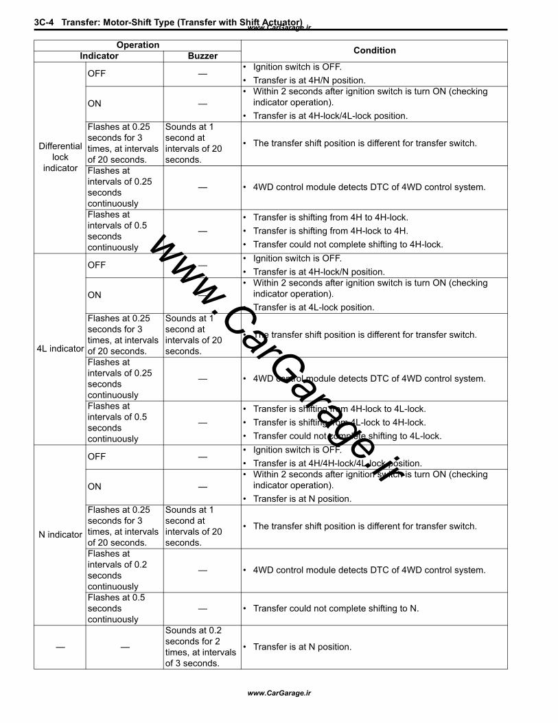
3C-4 Transfer: Motor-Shift Type (Transfer with Shift Actuator)
Operation ConditionIndicator Buzzer
Differential lock
indicator
OFF —• Ignition switch is OFF.• Transfer is at 4H/N position.
ON —• Within 2 seconds after ignition switch is turn ON (checking
indicator operation).• Transfer is at 4H-lock/4L-lock position.
Flashes at 0.25 seconds for 3 times, at intervals of 20 seconds.
Sounds at 1 second at intervals of 20 seconds.
• The transfer shift position is different for transfer switch.
Flashes at intervals of 0.25 seconds continuously
— • 4WD control module detects DTC of 4WD control system.
Flashes at intervals of 0.5 seconds continuously
—• Transfer is shifting from 4H to 4H-lock.• Transfer is shifting from 4H-lock to 4H.• Transfer could not complete shifting to 4H-lock.
4L indicator
OFF —• Ignition switch is OFF.• Transfer is at 4H-lock/N position.
ON —• Within 2 seconds after ignition switch is turn ON (checking
indicator operation).• Transfer is at 4L-lock position.
Flashes at 0.25 seconds for 3 times, at intervals of 20 seconds.
Sounds at 1 second at intervals of 20 seconds.
• The transfer shift position is different for transfer switch.
Flashes at intervals of 0.25 seconds continuously
— • 4WD control module detects DTC of 4WD control system.
Flashes at intervals of 0.5 seconds continuously
—• Transfer is shifting from 4H-lock to 4L-lock.• Transfer is shifting from 4L-lock to 4H-lock.• Transfer could not complete shifting to 4L-lock.
N indicator
OFF —• Ignition switch is OFF.• Transfer is at 4H/4H-lock/4L-lock position.
ON —• Within 2 seconds after ignition switch is turn ON (checking
indicator operation).• Transfer is at N position.
Flashes at 0.25 seconds for 3 times, at intervals of 20 seconds.
Sounds at 1 second at intervals of 20 seconds.
• The transfer shift position is different for transfer switch.
Flashes at intervals of 0.2 seconds continuously
— • 4WD control module detects DTC of 4WD control system.
Flashes at 0.5 seconds continuously
— • Transfer could not complete shifting to N.
— —
Sounds at 0.2 seconds for 2 times, at intervals of 3 seconds.
• Transfer is at N position.
www.CarGarage.ir
www.CarGarage.ir
www.CarGarage.ir
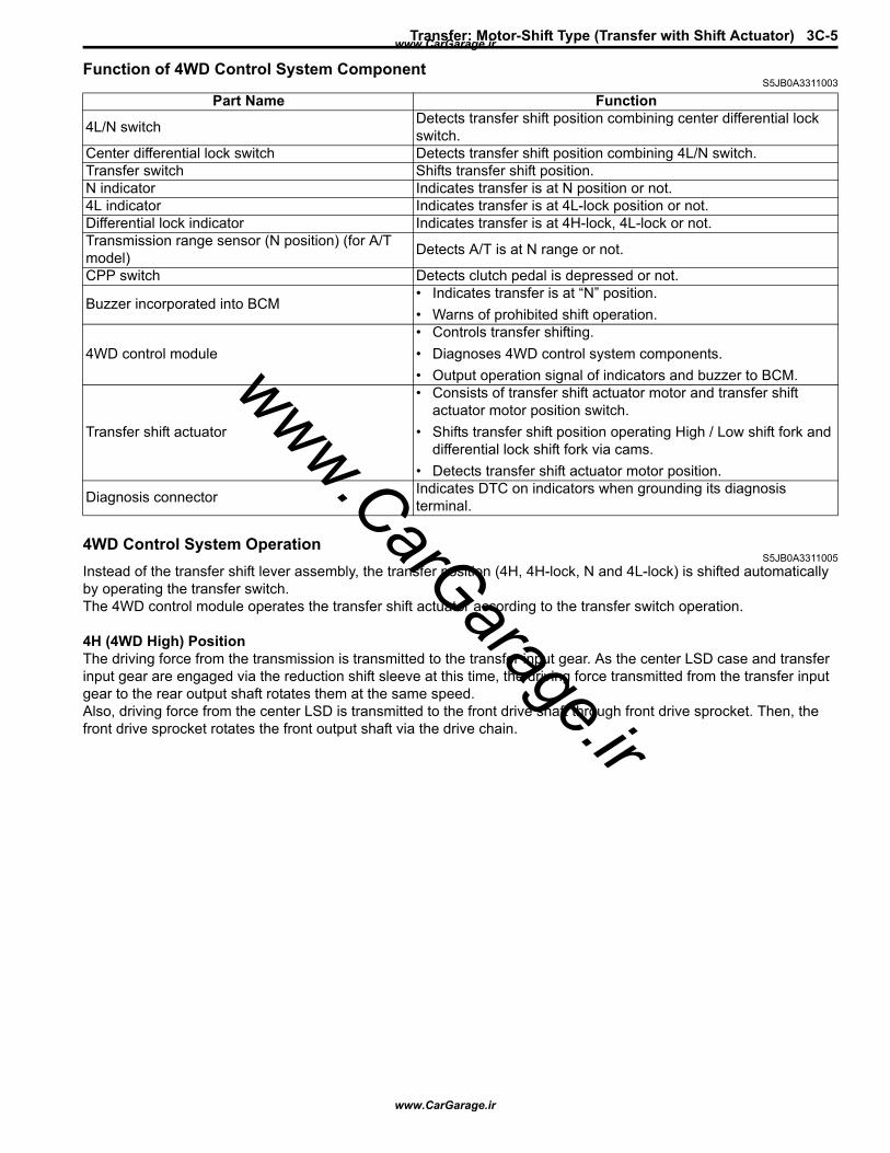
Transfer: Motor-Shift Type (Transfer with Shift Actuator) 3C-5
Function of 4WD Control System ComponentS5JB0A3311003
4WD Control System OperationS5JB0A3311005
Instead of the transfer shift lever assembly, the transfer position (4H, 4H-lock, N and 4L-lock) is shifted automatically by operating the transfer switch.The 4WD control module operates the transfer shift actuator according to the transfer switch operation.
4H (4WD High) PositionThe driving force from the transmission is transmitted to the transfer input gear. As the center LSD case and transfer input gear are engaged via the reduction shift sleeve at this time, the driving force transmitted from the transfer input gear to the rear output shaft rotates them at the same speed.Also, driving force from the center LSD is transmitted to the front drive shaft through front drive sprocket. Then, the front drive sprocket rotates the front output shaft via the drive chain.
Part Name Function
4L/N switch Detects transfer shift position combining center differential lock switch.
Center differential lock switch Detects transfer shift position combining 4L/N switch.Transfer switch Shifts transfer shift position.N indicator Indicates transfer is at N position or not.4L indicator Indicates transfer is at 4L-lock position or not.Differential lock indicator Indicates transfer is at 4H-lock, 4L-lock or not.Transmission range sensor (N position) (for A/T model) Detects A/T is at N range or not.
CPP switch Detects clutch pedal is depressed or not.
Buzzer incorporated into BCM• Indicates transfer is at “N” position.• Warns of prohibited shift operation.
4WD control module• Controls transfer shifting.• Diagnoses 4WD control system components.• Output operation signal of indicators and buzzer to BCM.
Transfer shift actuator
• Consists of transfer shift actuator motor and transfer shift actuator motor position switch.
• Shifts transfer shift position operating High / Low shift fork and differential lock shift fork via cams.
• Detects transfer shift actuator motor position.
Diagnosis connector Indicates DTC on indicators when grounding its diagnosis terminal.
www.CarGarage.ir
www.CarGarage.ir
www.CarGarage.ir
3C-6 Transfer: Motor-Shift Type (Transfer with Shift Actuator)
4H-lock (4WD High Center Differential Lock) PositionWhen 4H-lock position is selected from 4H position by turning the transfer switch, the transfer shift control actuator motor runs and shift cam rotates in the arrow direction “A”. The shift cam shifts the differential lock shift fork in the arrow direction “B”, and the differential lock clutch sleeve also moves in the arrow direction “B”.
[A] [B]1 2
5
4
43
5
98
6 7
11
12 13
14
15
10
I5JB0A332003-02
[A]: Transfer position indicator 5. Shift cam 11. Front drive shaft[B]: Transfer switch 6. High / Low shift fork 12. Front drive sprocket
1. 4L/N switch 7. Differential lock shift fork 13. Rear output shaft2. Center differential lock switch 8. Input gear 14. Drive chain3. Transfer actuator 9. Reduction shift sleeve 15. Front output shaft4. Shift fork pin 10. Center LSD case
www.CarGarage.ir
www.CarGarage.ir
www.CarGarage.ir
Transfer: Motor-Shift Type (Transfer with Shift Actuator) 3C-7
The driving force from the transmission is transmitted from the transfer input gear to the rear output shaft, as in the case of 4H position. Also, as the front drive shaft and front drive sprocket bush are engaged via differential lock clutch sleeve, the driving force from the input gear is locked and transmitted to the rear output shaft.
B
[A] [B]1 2
43
5
7
10
6
8 9
11
12
13
14
A
4
5
I5JB0A332004-03
[A]: Transfer position indicator 5. Shift cam 11. Rear output shaft[B]: Transfer switch 6. Differential lock shift fork 12. Front drive shaft
1. 4L/N switch 7. Input gear 13. Drive chain2. Center differential lock switch 8. Differential lock clutch sleeve 14. Front output shaft3. Transfer actuator 9. Front drive sprocket bush4. Shift fork pin 10. Front drive sprocket
www.CarGarage.ir
www.CarGarage.ir
www.CarGarage.ir

3C-8 Transfer: Motor-Shift Type (Transfer with Shift Actuator)
N (Neutral) PositionWhen N position is selected from 4H position by turning the transfer switch, the transfer shift control actuator motor runs and shift cam rotates in the arrow direction “A”. The shift cam shifts the High / Low shift fork in the arrow direction “B”, and the reduction shift sleeve moves in the arrow direction “B”. Also, the shift cam shifts the differential lock shift fork in the arrow direction “C”, and the differential lock clutch sleeve also moves in the arrow direction “C”.The driving force from the transmission is transmitted to the transfer input gear. However, as the reduction shift sleeve is not engaged with the transfer input gear and low gear, the driving force is not transmitted to the rear output shaft and front output shaft.
A
CB
[A] [B]1 2
5
4
43
5
9
8
6 7
11
12
13
10
I5JB0A332005-01
www.CarGarage.ir
www.CarGarage.ir
www.CarGarage.ir
Transfer: Motor-Shift Type (Transfer with Shift Actuator) 3C-9
4L-lock (4WD Low Center Differential Lock) PositionWhen 4L-lock position is selected from 4H-lock position by turning the transfer switch, the transfer shift control actuator motor runs and shift cam rotates in the arrow direction “A”. The shift cam shifts the High/Low shift fork in the arrow direction “B”, and the reduction shift sleeve moves in the arrow direction “B”. Also, the shift cam shifts the differential lock shift fork in the arrow direction “C”, and the differential lock clutch sleeve also moves in the arrow direction “C”.The driving force from the transmission is transmitted from the transfer low gear, through the transfer input gear and transfer counter gear with the speed reduced. At this time, as the center LSD case and transfer low gear are engaged via reduction shift sleeve, the driving force is transmitted to the rear output shaft.The driving force of the rear output shaft makes the front output shaft rotate via the differential lock clutch sleeve as in the case of 4H-lock position.
[A]: Transfer position indicator 4. Shift fork pin 9. Reduction shift sleeve[B]: Transfer switch 5. Shift cam 10. Differential lock clutch sleeve
1. 4L/N switch 6. High / Low shift fork 11. Rear output shaft2. Center differential lock switch 7. Differential lock shift fork 12. Drive chain3. Transfer actuator 8. Input gear 13. Front output shaft
www.CarGarage.ir
www.CarGarage.ir
www.CarGarage.ir
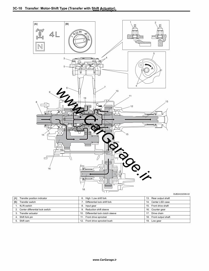
3C-10 Transfer: Motor-Shift Type (Transfer with Shift Actuator)
A
B C
[A] [B]1 2
5
4
43
5
9
8
6 7
11
10
12
13
17
15
18
16
14
19
I5JB0A332006-02
[A]: Transfer position indicator 6. High / Low shift fork 13. Rear output shaft[B]: Transfer switch 7. Differential lock shift fork 14. Center LSD case
1. 4L/N switch 8. Input gear 15. Front drive shaft2. Center differential lock switch 9. Reduction shift sleeve 16. Counter gear3. Transfer actuator 10. Differential lock clutch sleeve 17. Drive chain4. Shift fork pin 11. Front drive sprocket 18. Front output shaft5. Shift cam 12. Front drive sprocket bush 19. Low gear
www.CarGarage.ir
www.CarGarage.ir
www.CarGarage.ir
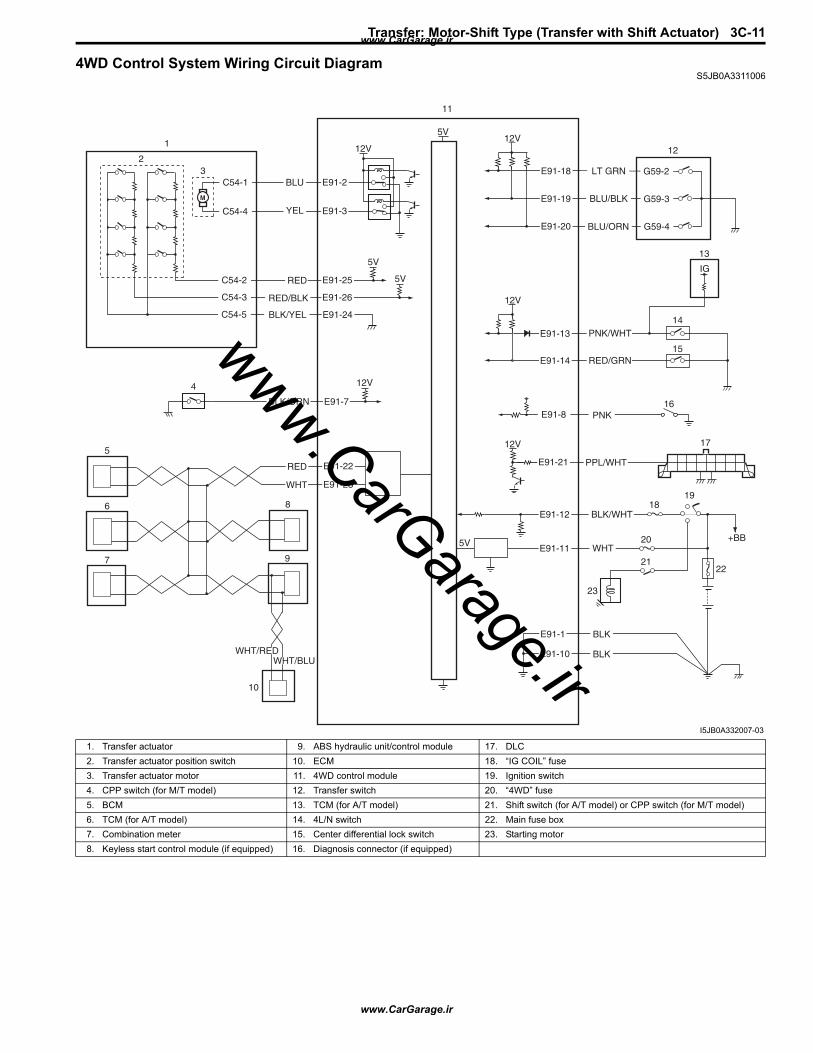
Transfer: Motor-Shift Type (Transfer with Shift Actuator) 3C-11
4WD Control System Wiring Circuit DiagramS5JB0A3311006
5V
5V
IG
5V
12V
E91-2
5V
12V
12V
+BB
YEL
RED/BLK
BLU
M
E91-3
E91-25
E91-26
RED
E91-24BLK/YEL
E91-7BLK/ORN
E91-21 PPL/WHTE91-22
E91-23
RED
WHT
E91-18
E91-19
E91-20
E91-13
E91-14
E91-12
E91-11
E91-10
E91-1
BLK
BLK
WHT
BLK/WHT
RED/GRN
PNK/WHT
BLU/ORN
BLU/BLK
LT GRN
12V
12V
G59-2
G59-3
G59-4
C54-1
C54-4
C54-2
C54-3
C54-5
WHT/REDWHT/BLU
1
23
4
5
6
7
8
9
10
12
11
13
14
15
17
1819
20
21
23
22
16E91-8 PNK
I5JB0A332007-03
1. Transfer actuator 9. ABS hydraulic unit/control module 17. DLC2. Transfer actuator position switch 10. ECM 18. “IG COIL” fuse3. Transfer actuator motor 11. 4WD control module 19. Ignition switch4. CPP switch (for M/T model) 12. Transfer switch 20. “4WD” fuse5. BCM 13. TCM (for A/T model) 21. Shift switch (for A/T model) or CPP switch (for M/T model)6. TCM (for A/T model) 14. 4L/N switch 22. Main fuse box7. Combination meter 15. Center differential lock switch 23. Starting motor8. Keyless start control module (if equipped) 16. Diagnosis connector (if equipped)
www.CarGarage.ir
www.CarGarage.ir
www.CarGarage.ir
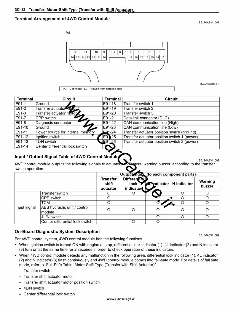
3C-12 Transfer: Motor-Shift Type (Transfer with Shift Actuator)
Terminal Arrangement of 4WD Control ModuleS5JB0A3311007
Input / Output Signal Table of 4WD Control ModuleS5JB0A3311008
4WD control module outputs the following signals to actuators, indicators, warning buzzer, according to the transfer switch operation.
On-Board Diagnostic System DescriptionS5JB0A3311009
For 4WD control system, 4WD control module has the following functions.• When ignition switch is turned ON with engine at stop, differential lock indicator (1), 4L indicator (2) and N indicator
(3) turn on at the same time for 2 seconds in order to check operation of these indicators.• When 4WD control module detects any malfunction in the following area, differential lock indicator (1), 4L indicator
(2) and N indicator (3) flash continuously and 4WD control module comes into fail-safe mode. For details of fail safe mode, refer to “Fail-Safe Table: Motor-Shift Type (Transfer with Shift Actuator)”.– Transfer switch– Transfer shift actuator motor– Transfer shift actuator motor position switch– 4L/N switch– Center differential lock switch
123456789101112
1314151617181920212223242526
[A]
I4JA01332038-01
[A]: Connector “E91” viewed from harness side
Terminal Circuit Terminal CircuitE91-1 Ground E91-18 Transfer switch 1E91-2 Transfer actuator motor 1 E91-19 Transfer switch 2E91-3 Transfer actuator motor 2 E91-20 Transfer switch 3E91-7 CPP switch E91-21 Data link connector (DLC)E91-8 Diagnosis connector E91-22 CAN communication line (High)E91-10 Ground E91-23 CAN communication line (Low)E91-11 Power source for internal memory E91-24 Transfer actuator position switch (ground)E91-12 Ignition switch E91-25 Transfer actuator position switch 1 (power)E91-13 4L/N switch E91-26 Transfer actuator position switch 2 (power)E91-14 Center differential lock switch
Output signal (to each component parts)Transfer
shift actuator
Differential lock
indicator4L indicator N indicator Warning
buzzer
Input signal
Transfer switchCPP switchTCMABS hydraulic unit / control module4L/N switchCenter differential lock switch
www.CarGarage.ir
www.CarGarage.ir
www.CarGarage.ir

Transfer: Motor-Shift Type (Transfer with Shift Actuator) 3C-13
• DTC can be checked by either one of the following ways.– DTC can be checked by using SUZUKI scan tool (4) connected to DLC (5).– If equipped with diagnosis connector, DTC can be displayed on digital display odometer by shorting diagnosis
connector (6).• When 4WD control module detects any malfunction, 4WD control module will shift automatically transfer to either N
or former position which is in before shifting process began.
DLC (Data Link Connector)Refer to “Data Link Connector (DLC)” under “On-Board Diagnostic System Description: in Section 1A”.
CAN Communication System DescriptionS5JB0A3311011
Refer to “CAN Communication System Description: in Section 1A”.
4WD Control Module Transmission Data
1 2
3
4
5
6
I5JB0A332008-01
BCM Combination Meter
Transmit DATA
4WD
Buzzer on requesLock indication status
Neutral Indication Status
Low indication status
4WD diagnostic trouble codes
control
module
I5JB0A332010-01
www.CarGarage.ir
www.CarGarage.ir
www.CarGarage.ir
3C-14 Transfer: Motor-Shift Type (Transfer with Shift Actuator)
4WD Control Module Reception Data
Diagnostic Information and Procedures4WD Control System Check
S5JB0A3314001Refer to the following items for the details of each step.
ECM TCM
DATAReceive
Engine speed
Vehicle speed
Brake pedal switch active
4WD
control
module
Transmission gearselector position
Wheel speed pulse (front right) Wheel speed pulse (front left)
Wheel speed pulse (rear right)
Wheel speed pulse (rear left) Antilock brake system active
ABS hydraulic unit / control module
I5JB0A332009-01
Step Action Yes No1 Customer complaint analysis
1) Perform customer complaint analysis.
Was customer complaint analysis performed?
Go to Step 2. Perform customer complaint analysis.
2 DTC / freeze frame data check, record and clearance1) Check for DTC.
Is there any DTC(s)?
Print DTC or write them down and clear them by referring to “DTC Clearance: Motor-Shift Type (Transfer with Shift Actuator)”. Go to Step 3.
Go to Step 4.
3 Visual inspection1) Perform visual inspection.
Is there any faulty condition?
Repair or replace malfunction part. Go to Step 11.
Go to Step 5.
4 Visual inspection1) Perform visual inspection.
Is there any faulty condition?
Repair or replace malfunction part. Go to Step 11.
Go to Step 8.
5 Trouble symptom confirmation1) Shift transfer to “4H”, “4H-lock”, “4L-lock” and “N”
positions referring to “4WD Control System Operation Inspection: Motor-Shift Type (Transfer with Shift Actuator)”.
2) Confirm trouble symptom.
Is trouble symptom identified?
Go to Step 6. Go to Step 7.
6 Rechecking and record of DTC / freeze frame data1) Recheck for DTC referring to “DTC Check: Motor-Shift
Type (Transfer with Shift Actuator)”.
Is there any DTC(s)?
Go to Step 9. Go to Step 8.
www.CarGarage.ir
www.CarGarage.ir
www.CarGarage.ir
Transfer: Motor-Shift Type (Transfer with Shift Actuator) 3C-15
Detail of 4WD Control System Check
Step 1: Customer complaint analysisRecord details of the problem (failure, complaint) and how it occurred as described by the customer.For this purpose, use of such a questionnaire form as shown in the following will facilitate collecting information to the point required for proper analysis and diagnosis.
7 Rechecking and record of DTC / freeze frame data1) Recheck for DTC referring to “DTC Check: Motor-Shift
Type (Transfer with Shift Actuator)”.
Is there any DTC(s)?
Go to Step 9. Go to Step 10.
8 4WD control symptom diagnosis1) Check and repair according to “4WD Control Symptom
Diagnosis: Motor-Shift Type (Transfer with Shift Actuator)”.
Are check and repair complete?
Go to Step 11. Check and repair malfunction part(s). Go to Step 11.
9 Troubleshooting for DTC1) Check and repair according to applicable DTC flow.
Are check and repair complete?
Go to Step 11. Check and repair malfunction part(s). Go to Step 11.
10 Check for intermittent problems1) Check for intermittent problems.
Is there any faulty condition?
Repair or replace malfunction part(s). Go to Step 11.
Go to Step 11.
11 Final confirmation test1) Clear DTC if any.2) Perform final confirmation test.
Is there any problem symptom, DTC or abnormal condition?
Go to Step 6. End.
Step Action Yes No
www.CarGarage.ir
www.CarGarage.ir
www.CarGarage.ir
3C-16 Transfer: Motor-Shift Type (Transfer with Shift Actuator)
Customer questionnaire (Example)
NOTEThe form is a standard sample. It should be modified according to conditions characteristic of each market.
Step 2. DTC / freeze frame data check, record and clearanceFirst, referring to “DTC Check: Motor-Shift Type (Transfer with Shift Actuator)”, check DTC and pending DTC. If DTC exists, print or write down DTC and freeze frame data and then clear malfunction DTC(s) by referring to “DTC Clearance: Motor-Shift Type (Transfer with Shift Actuator)”. Malfunction DTC indicates malfunction in the system but it is not possible to know from it whether the malfunction is occurring now or it occurred in the past and normal condition has been restored. In order to know that, check symptom in question according to Step 5 and then recheck DTC according to Step 6.
Diagnosing a trouble based on the DTC in this step only or failure to clear the DTC in this step may result in an faulty diagnosis, trouble diagnosis of a normal circuit or difficulty in troubleshooting which is otherwise unnecessary.
Step 3 and 4. Visual inspectionAs a preliminary step, be sure to perform visual check of the items that support proper function of the 4WD control system referring to “Visual Inspection: Motor-Shift Type (Transfer with Shift Actuator)”.
Customer’s name: Model: VIN:
Problem Symptoms
Frequency of Occurrence
Conditions for Occurrence of Ploblem
Environmental Condition
Diagnostic Trouble Code
Date of Reg:
Transfer position indicator abnormal: fails to turn on / fails to turn off / flashesAbnormal noise while vehicle running: from transfer, from actuator, otherNo shifted to “4H” positionNo shifted to “4H-lock” positionNo shifted to “4L-lock” positionNo shifted to “N” position
When starting: at initial start only / at every start / otherVehicle speed: while accelerating / while decelerating / at stop / while turning / while running at constant speed / otherRoad surface condition: Paved road / rough road / snow-covered road / other
Wheather: fine / cloudy / rain / snow / otherTemperature: ( )
First check: Normal code / malfunction code ( )Second check after test drive: Normal code / malfunction code ( )
Continuous / Intermittent ( times a day, a month) / other
Date of problem: Mileage:Date of issue:
I5JB0A332011-02
www.CarGarage.ir
www.CarGarage.ir
www.CarGarage.ir

Transfer: Motor-Shift Type (Transfer with Shift Actuator) 3C-17
Step 5. Trouble symptom confirmationCheck trouble symptoms based on information obtained in “Step 1: Customer complaint analysis: Motor-Shift Type (Transfer with Shift Actuator)” and “Step 2. DTC / freeze frame data check, record and clearance: Motor-Shift Type (Transfer with Shift Actuator)”.Also, reconfirm DTC according to “DTC Confirmation Procedure” described in each DTC flow.
Step 6 and 7. Rechecking and record of DTC and freeze frame dataRefer to “DTC Check: Motor-Shift Type (Transfer with Shift Actuator)” for checking procedure.
Step 8. 4WD control symptom diagnosisCheck the parts of the system suspected as a possible cause referring to “4WD Control Symptom Diagnosis: Motor-Shift Type (Transfer with Shift Actuator)”.
Step 9. Troubleshooting for DTCBased on the DTC indicated in Step 6 / 7 and referring to “applicable DTC flow”, locate the cause of the trouble, namely in a sensor, switch, wire harness, connector, actuator, 4WD control module or other part and repair or replace faulty parts.
Step 10. Check for intermittent problemCheck parts where an intermittent trouble is easy to occur (e.g. wire harness, connector, etc.), referring to “Intermittent and Poor Connection Inspection: in Section 00” and related circuit of DTC recorded in Step 2.
Step 11. Final confirmation testConfirm that the problem symptom has gone and the vehicle is free from any abnormal conditions. If what has been repaired is related to the malfunction DTC, clear the DTC once and check to ensure that no malfunction DTC is indicated.
Transfer Position Indicator Operation CheckS5JB0A3314003
1) Turn ignition switch to OFF position.2) Check that transfer position indicators turn on for
about 2 seconds and then turns off.If any faulty condition is found, proceed to “Transfer Position Indicator Does Not Come ON at Ignition Switch ON but Engine Stops: Motor-Shift Type (Transfer with Shift Actuator)” or “Transfer Position Indicator Remains ON Steady at Ignition Switch ON: Motor-Shift Type (Transfer with Shift Actuator)”.
4WD Control System Operation InspectionS5JB0A3314038
NOTE
• If it is difficult to shift between “4H” and “4H-lock” while vehicle is moving, stop vehicle and operate Transfer switch.
• When ABS operates while shifting from “4H” to “4H-lock” (“4H-lock” to “4H”), it becomes to disagreement of transfer switch and transfer position. End of the ABS operation, and then transfer shifting from “4H” to “4H-lock” (“4H-lock” to “4H”).
• Transfer position indicator blinks during shifting process.
• Transfer position indicator blinks and warning buzzer sounds during “N” position at intervals of 3 seconds.
• When shifting to “N” or “4L-lock” does not shifts, try the following procedure.– For M/T model, shift transmission to N
(Neutral) position, turn ignition switch to ON position, depress clutch pedal and brake pedal while engine is running, and then try shifting again.
– For A/T model, turn ignition switch to ON position, move vehicles lowly back or forth a few feet, depress brake pedal, and then try shifting again.
1) Inspect shift operation from 4H to 4H-lock as follows.a) Start engine.b) Position front wheels straight ahead.c) Confirm that vehicle is under following
conditions.• Transfer shift position is 4H.• Vehicle speed is less than 100 km/h (60 mph).
d) Turn transfer switch to “4H-lock” position.e) Check that differential lock indicator blinks, and
then comes ON steady.2) Inspect shift operation from 4H-lock to 4L-lock as
follows.a) Stop vehicle completely with engine running.b) Position front wheels straight ahead.c) Confirm that vehicle is under following
conditions.• Transfer shift position is 4H-lock.• Transmission shift lever is at “N” position. (for
A/T model)• Clutch pedal is depressed fully. (for M/T
model)• Brake pedal is depressed.
d) Push and turn transfer switch to “4L-lock” position.
www.CarGarage.ir
www.CarGarage.ir
www.CarGarage.ir
3C-18 Transfer: Motor-Shift Type (Transfer with Shift Actuator)
e) Check that 4L indicator blink, and then differential lock indicator and 4L indicator comes ON steady.
3) Inspect shift operation from 4L-lock to 4H-lock as follows.a) Stop vehicle completely with engine running.b) Position front wheels straight ahead.c) Confirm that vehicle is under following
conditions.• Transfer shift position is 4L-lock.• Transmission shift lever is at “N” position. (for
A/T model)• Clutch pedal is depressed fully. (for M/T
model)• Brake pedal is depressed.
d) Push and turn transfer switch to “4H-lock” position.
e) Check that 4L indicator blink, and then differential lock indicator comes ON steady and 4L indicator not come ON.
4) Inspect shift operation from 4H-lock to 4H as follows.a) Start engine.b) Position front wheels straight ahead.c) Confirm that vehicle is under following
conditions.• Transfer shift position is 4H-lock.• Vehicle speed is less than 100 km/h (60 mph).
d) Turn transfer switch to “4H” position.
e) Check that differential lock indicator blinks, and then not comes ON.
5) Inspect shift operation from 4H to N as follows.a) Stop vehicle completely with engine running.b) Position front wheels straight ahead.c) Confirm that vehicle is under following
conditions.• Transfer shift position is 4H.• Transmission shift lever is at “N” position. (for
A/T model)• Clutch pedal is depressed fully. (for M/T
model)• Brake pedal is depressed.
d) Turn transfer switch to “ ” position (1), keep it there for about 10 seconds, and then turn it to “N” position after N indicator blinks.
e) Check that N indicator blinks and warning buzzer sounds, and then N indicator comes ON steady.
Visual InspectionS5JB0A3314005
Check the following parts and systems visually.
1
I5JB0A332002-01
Inspection Item Referring• Front differential oil ---- level, leakage “Front Differential Oil Change: Front in Section 3B”• Rear differential oil ---- level, leakage “Rear Differential Oil Change: Rear in Section 3B”• Transfer gear oil ---- level, leakage “Transfer Oil Change: Motor-Shift Type (Transfer with
Shift Actuator)”• Manual transmission oil ---- level, leakage “Manual Transmission Oil Change: in Section 5B”• A/T fluid ---- level, leakage “A/T Fluid Level Check: in Section 5A”• Transfer mounting(s) ---- wear and looseness• Fuses ---- burning• Battery ---- fluid level, corrosion of terminal “Battery Inspection: in Section 1J”• Connectors of electric wire harness ---- disconnection,
friction“Intermittent and Poor Connection Inspection: in Section 00”
• Other parts that can be checked visually
www.CarGarage.ir
www.CarGarage.ir
www.CarGarage.ir
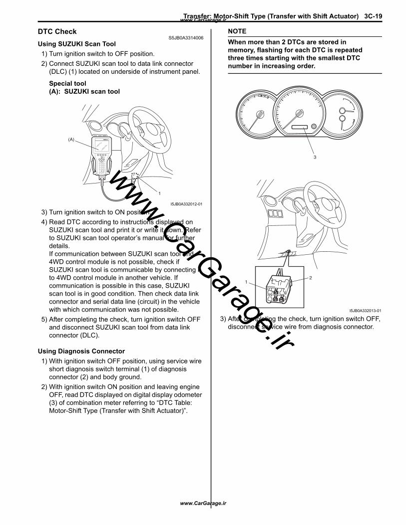
Transfer: Motor-Shift Type (Transfer with Shift Actuator) 3C-19
DTC CheckS5JB0A3314006
Using SUZUKI Scan Tool1) Turn ignition switch to OFF position.2) Connect SUZUKI scan tool to data link connector
(DLC) (1) located on underside of instrument panel.
Special tool(A): SUZUKI scan tool
3) Turn ignition switch to ON position.4) Read DTC according to instructions displayed on
SUZUKI scan tool and print it or write it down. Refer to SUZUKI scan tool operator’s manual for further details.If communication between SUZUKI scan tool and 4WD control module is not possible, check if SUZUKI scan tool is communicable by connecting it to 4WD control module in another vehicle. If communication is possible in this case, SUZUKI scan tool is in good condition. Then check data link connector and serial data line (circuit) in the vehicle with which communication was not possible.
5) After completing the check, turn ignition switch OFF and disconnect SUZUKI scan tool from data link connector (DLC).
Using Diagnosis Connector1) With ignition switch OFF position, using service wire
short diagnosis switch terminal (1) of diagnosis connector (2) and body ground.
2) With ignition switch ON position and leaving engine OFF, read DTC displayed on digital display odometer (3) of combination meter referring to “DTC Table: Motor-Shift Type (Transfer with Shift Actuator)”.
NOTEWhen more than 2 DTCs are stored in memory, flashing for each DTC is repeated three times starting with the smallest DTC number in increasing order.
3) After completing the check, turn ignition switch OFF, disconnect service wire from diagnosis connector.
(A)
1
I5JB0A332012-01
12
3
I5JB0A332013-01
www.CarGarage.ir
www.CarGarage.ir
www.CarGarage.ir
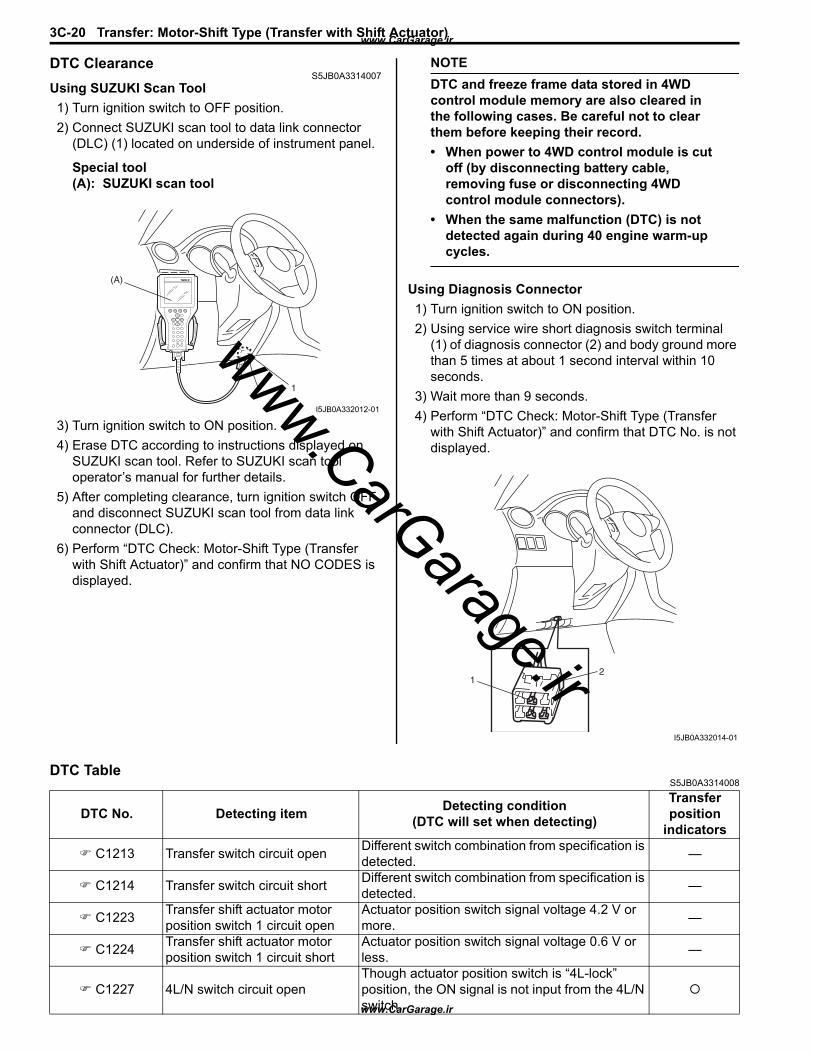
3C-20 Transfer: Motor-Shift Type (Transfer with Shift Actuator)
DTC ClearanceS5JB0A3314007
Using SUZUKI Scan Tool1) Turn ignition switch to OFF position.2) Connect SUZUKI scan tool to data link connector
(DLC) (1) located on underside of instrument panel.
Special tool(A): SUZUKI scan tool
3) Turn ignition switch to ON position.4) Erase DTC according to instructions displayed on
SUZUKI scan tool. Refer to SUZUKI scan tool operator’s manual for further details.
5) After completing clearance, turn ignition switch OFF and disconnect SUZUKI scan tool from data link connector (DLC).
6) Perform “DTC Check: Motor-Shift Type (Transfer with Shift Actuator)” and confirm that NO CODES is displayed.
NOTEDTC and freeze frame data stored in 4WD control module memory are also cleared in the following cases. Be careful not to clear them before keeping their record.• When power to 4WD control module is cut
off (by disconnecting battery cable, removing fuse or disconnecting 4WD control module connectors).
• When the same malfunction (DTC) is not detected again during 40 engine warm-up cycles.
Using Diagnosis Connector1) Turn ignition switch to ON position.2) Using service wire short diagnosis switch terminal
(1) of diagnosis connector (2) and body ground more than 5 times at about 1 second interval within 10 seconds.
3) Wait more than 9 seconds.4) Perform “DTC Check: Motor-Shift Type (Transfer
with Shift Actuator)” and confirm that DTC No. is not displayed.
DTC TableS5JB0A3314008
(A)
1
I5JB0A332012-01
12
I5JB0A332014-01
DTC No. Detecting item Detecting condition(DTC will set when detecting)
Transfer position
indicators
C1213 Transfer switch circuit open Different switch combination from specification is detected. —
C1214 Transfer switch circuit short Different switch combination from specification is detected. —
C1223 Transfer shift actuator motor position switch 1 circuit open
Actuator position switch signal voltage 4.2 V or more. —
C1224 Transfer shift actuator motor position switch 1 circuit short
Actuator position switch signal voltage 0.6 V or less. —
C1227 4L/N switch circuit openThough actuator position switch is “4L-lock” position, the ON signal is not input from the 4L/N switch.
www.CarGarage.ir
www.CarGarage.ir
www.CarGarage.ir
Transfer: Motor-Shift Type (Transfer with Shift Actuator) 3C-21
NOTE“O” in transfer position indicator column of the above table means indicator lights up when DTC is detected.
Fail-Safe TableS5JB0A3314010
This function is provided by the safe mechanism that assures safe drive ability even when the actuator, switch, sensor or its circuit fails. The following table shows the fail safe function for each fail condition of sensor, actuator, switch, 4WD control module or its circuit.
C1228 4L/N switch circuit shortThough actuator position switch is “4L-lock” position, the OFF signal is not input from the 4L/N switch.
C1230 Transfer actuator circuit malfunction
Transfer switch is changed of position, and then actuator position switch is not changed for more than 3 seconds.
—
C1235 Transfer shift actuator motor position switch 2 circuit open
Actuator position switch signal voltage 4.2 V or more. —
C1236 Transfer shift actuator motor position switch 2 circuit short
Actuator position switch signal voltage 0.6 V or less. —
C1237 Center differential lock switch circuit open
Though actuator position switch is “4H” position, the ON signal is not input from the center differential lock switch.
C1238 Center differential lock switch circuit short
Though actuator position switch is “4L-lock” position, the OFF signal is not input from the center differential lock switch.
C1240 4WD control module power supply circuit malfunction
Battery voltage is lower than lower limit voltage for 4WD control module diagnosis. —
C1243 Internal circuit malfunction of 4WD control module EEPROM error —
C1246 Clutch pedal position (CPP) switch circuit short
CPP switch signal is input when vehicle speed is 30 km/h (19 mph). —
U1073 Control module communication bus off
Transmitting and receiving error of 4WD control module for specified time continuously.
U1100 Lost communication with ECM Receiving error of 4WD control module from ECM for specified time continuously.
U1101 Lost communication with TCM Receiving error of 4WD control module from TCM for specified time continuously.
U1121 Lost communication with ABS control module
Receiving error of 4WD control module from ABS control module for specified time continuously.
DTC No. Detecting item Detecting condition(DTC will set when detecting)
Transfer position
indicators
DTC No. Trouble Area Fail-Safe Operation C1223 Transfer actuator switch 1 circuit open 4WD control module stops outputting of control
signal to transfer actuator (When shifting, stop it stops outputting after shifting is completed).
C1224 Transfer actuator switch 1 circuit short C1235 Transfer actuator switch 2 circuit open C1236 Transfer actuator switch 2 circuit short C1230 Transfer actuator circuit malfunction
4WD control module stops outputting of control signal to transfer actuator. C1240 4WD control module power supply circuit
malfunction C1246 Clutch switch circuit short
www.CarGarage.ir
www.CarGarage.ir
www.CarGarage.ir
3C-22 Transfer: Motor-Shift Type (Transfer with Shift Actuator)
Scan Tool DataS5JB0A3314009
Scan Tool Data DefinitionsS5JB0A3314011
Vehicle Speed (KM/H, MPH): This parameter indicates vehicle speed calculated by 4WD control module.
Engine Speed (RPM): This parameter indicates engine revolution calculated by 4WD control module.
Actuator Pos Sen (Transfer shift actuator motor position switch) (4H / 4H-lock / 4L-lock / N / 4H-lock-4H / 4H-N / N-4L-lock): This parameter indicates transfer shift actuator motor position switch status detected by 4WD control module.
Actuator motor Pos (Transfer shift actuator motor position) (4H / 4H-lock / 4L-lock / N): This parameter indicates transfer shift actuator motor position detected by 4WD control module using transfer shift actuator motor position.
Battery voltage (V): This parameter indicates battery voltage detected by 4WD control module.
4L / N switch (ON / OFF): This parameter indicates 4L / N switch status detected by 4WD control module.
Center diff lock Sw (ON / OFF): This parameter indicates center differential lock switch status detected by 4WD control module.
N range signal (AT) (ON / OFF): This parameter indicates A/T shift position (“N” range or not) detected by 4WD control module.
CPP switch (Clutch pedal position switch) (MT) (ON / OFF): This parameter indicates clutch pedal position switch status detected by 4WD control module using CPP switch.
Mode switch 1 (Transfer switch) (ON / OFF): ON: Transfer switch to N position.OFF: Transfer switch to other than N position.
Scan Tool Data Vehicle Condition Normal Condition / Reference Value
Vehicle speed At vehicle stop 0 km/h, 0 mphEngine speed At engine idle speed Engine idle speed is display
Actuator Pos Sen
Transfer shifted to 4H position 4HTransfer being shifted between 4H-lock and 4H position 4H-lock – 4HTransfer shifted to 4H-lock position 4H-lockTransfer being shifted between 4H and N position 4H – NTransfer shifted to 4L-lock position 4L-lockTransfer being shifted between N and 4L-lock position N – 4L-lockTransfer shifted to N position N
Actuator motor Pos
Transfer shifted to 4H position 4HTransfer shifted to 4H-lock position 4H-lockTransfer shifted to 4L-lock position 4L-lockTransfer shifted to N position N
Battery voltage Ignition switch ON and engine stop 10 – 14 V
4L/N switch Transfer shifted to 4L-lock or N position ONTransfer shifted to 4H or 4H-lock position OFF
Center diff lock SW Transfer shifted to 4H or N position ONTransfer shifted to 4H-lock or 4L-lock position OFF
N range signal (AT) A/T shifted to “N” range ONA/T shifted to other than “N” range OFF
CPP switch (MT) Clutch pedal depressed OFFClutch pedal released ON
Mode switch 1 Transfer switch selected to N position ONTransfer switch selected to 4H, 4H-lock or 4L-lock position OFF
Mode switch 2 Transfer switch selected to 4H, 4H-lock or N position ONTransfer switch selected to 4L-lock position OFF
Mode switch 3 Transfer switch selected to 4H-lock or 4L-lock position ONTransfer switch selected to 4H or N position OFF
Warning buzzer
Buzzer not being sound OFFTransfer shifted to N Position N PosTransfer shifted to disagreement of transfer switch and transfer position Error
ABS active ABS operating ONABS not operating OFF
www.CarGarage.ir
www.CarGarage.ir
www.CarGarage.ir
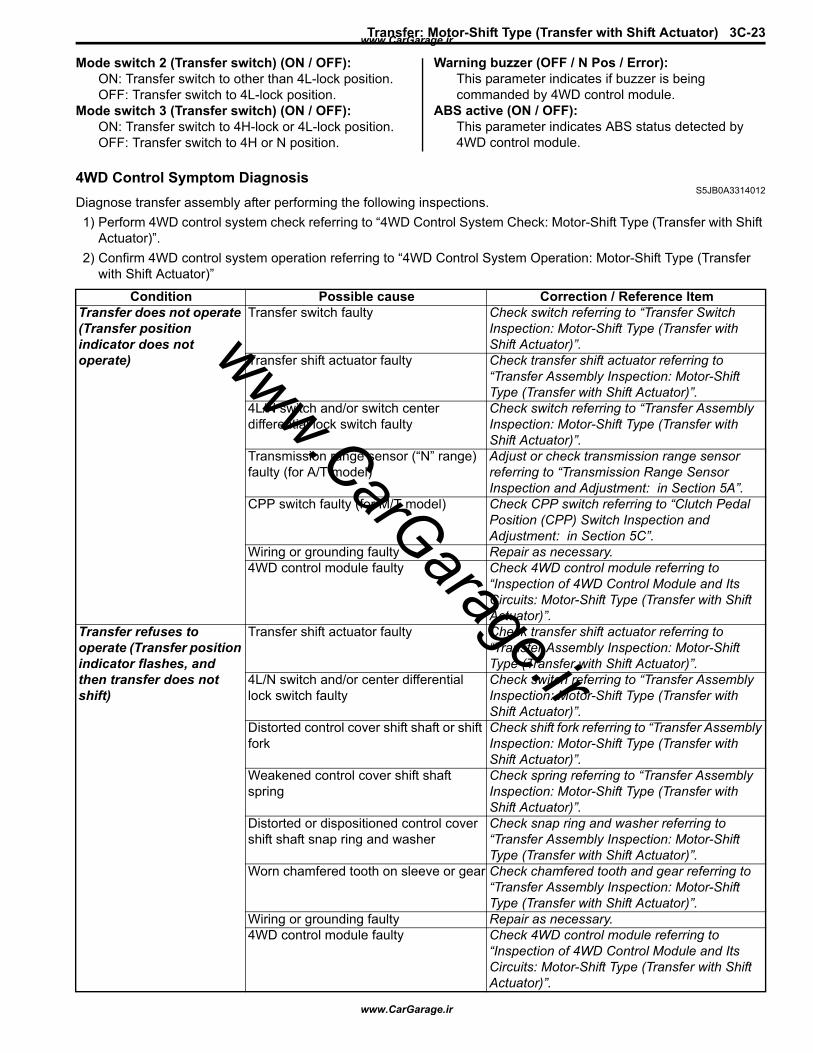
Transfer: Motor-Shift Type (Transfer with Shift Actuator) 3C-23
Mode switch 2 (Transfer switch) (ON / OFF): ON: Transfer switch to other than 4L-lock position.OFF: Transfer switch to 4L-lock position.
Mode switch 3 (Transfer switch) (ON / OFF): ON: Transfer switch to 4H-lock or 4L-lock position.OFF: Transfer switch to 4H or N position.
Warning buzzer (OFF / N Pos / Error): This parameter indicates if buzzer is being commanded by 4WD control module.
ABS active (ON / OFF): This parameter indicates ABS status detected by 4WD control module.
4WD Control Symptom DiagnosisS5JB0A3314012
Diagnose transfer assembly after performing the following inspections.1) Perform 4WD control system check referring to “4WD Control System Check: Motor-Shift Type (Transfer with Shift
Actuator)”.2) Confirm 4WD control system operation referring to “4WD Control System Operation: Motor-Shift Type (Transfer
with Shift Actuator)”
Condition Possible cause Correction / Reference ItemTransfer does not operate (Transfer position indicator does not operate)
Transfer switch faulty Check switch referring to “Transfer Switch Inspection: Motor-Shift Type (Transfer with Shift Actuator)”.
Transfer shift actuator faulty Check transfer shift actuator referring to “Transfer Assembly Inspection: Motor-Shift Type (Transfer with Shift Actuator)”.
4L/N switch and/or switch center differential lock switch faulty
Check switch referring to “Transfer Assembly Inspection: Motor-Shift Type (Transfer with Shift Actuator)”.
Transmission range sensor (“N” range) faulty (for A/T model)
Adjust or check transmission range sensor referring to “Transmission Range Sensor Inspection and Adjustment: in Section 5A”.
CPP switch faulty (for M/T model) Check CPP switch referring to “Clutch Pedal Position (CPP) Switch Inspection and Adjustment: in Section 5C”.
Wiring or grounding faulty Repair as necessary.4WD control module faulty Check 4WD control module referring to
“Inspection of 4WD Control Module and Its Circuits: Motor-Shift Type (Transfer with Shift Actuator)”.
Transfer refuses to operate (Transfer position indicator flashes, and then transfer does not shift)
Transfer shift actuator faulty Check transfer shift actuator referring to “Transfer Assembly Inspection: Motor-Shift Type (Transfer with Shift Actuator)”.
4L/N switch and/or center differential lock switch faulty
Check switch referring to “Transfer Assembly Inspection: Motor-Shift Type (Transfer with Shift Actuator)”.
Distorted control cover shift shaft or shift fork
Check shift fork referring to “Transfer Assembly Inspection: Motor-Shift Type (Transfer with Shift Actuator)”.
Weakened control cover shift shaft spring
Check spring referring to “Transfer Assembly Inspection: Motor-Shift Type (Transfer with Shift Actuator)”.
Distorted or dispositioned control cover shift shaft snap ring and washer
Check snap ring and washer referring to “Transfer Assembly Inspection: Motor-Shift Type (Transfer with Shift Actuator)”.
Worn chamfered tooth on sleeve or gear Check chamfered tooth and gear referring to “Transfer Assembly Inspection: Motor-Shift Type (Transfer with Shift Actuator)”.
Wiring or grounding faulty Repair as necessary.4WD control module faulty Check 4WD control module referring to
“Inspection of 4WD Control Module and Its Circuits: Motor-Shift Type (Transfer with Shift Actuator)”.
www.CarGarage.ir
www.CarGarage.ir
www.CarGarage.ir

3C-24 Transfer: Motor-Shift Type (Transfer with Shift Actuator)
Transfer Position Indicator Does Not Come ON at Ignition Switch ON but Engine StopsS5JB0A3314039
Wiring Diagram
Gear slipping out of mesh Worn control cover shift shaft Check control cover shift shaft referring to “Transfer Assembly Inspection: Motor-Shift Type (Transfer with Shift Actuator)”.
Worn shift fork or sleeve Check shift fork or sleeve referring to “Transfer Assembly Inspection: Motor-Shift Type (Transfer with Shift Actuator)”.
Weak or damaged control cover shift shaft spring
Check spring referring to “Transfer Assembly Inspection: Motor-Shift Type (Transfer with Shift Actuator)”.
Worn bearings on input gear or counter gear
Check bearing referring to “Transfer Assembly Inspection: Motor-Shift Type (Transfer with Shift Actuator)”.
Worn chamfered tooth on sleeve or gear Check sleeve and gear referring to “Transfer Assembly Inspection: Motor-Shift Type (Transfer with Shift Actuator)”.
Missing or disengagement of circlip(s) Check circlip(s) referring to “Transfer Assembly Inspection: Motor-Shift Type (Transfer with Shift Actuator)”.
Noise Damaged or worn bearing(s) Refer to “Transfer Assembly Inspection: Motor-Shift Type (Transfer with Shift Actuator)”.
Damaged or worn gear(s) Refer to “Transfer Assembly Inspection: Motor-Shift Type (Transfer with Shift Actuator)”.
Damaged or worn chamfered tooth on sleeve or gear
Refer to “Transfer Assembly Inspection: Motor-Shift Type (Transfer with Shift Actuator)”.
Condition Possible cause Correction / Reference Item
E91-22E91-23
REDWHT
REDWHT
G28-10G28-8
1
2
G28-13PPL/RED
BLK
WHT/GRN
BLK/YEL
8
G28-15
467
5
3
123456789101117 16151413122221201918
[B]
123456789101112
1314151617181920212223242526
[A]
I5JB0A332015-03
www.CarGarage.ir
www.CarGarage.ir
www.CarGarage.ir
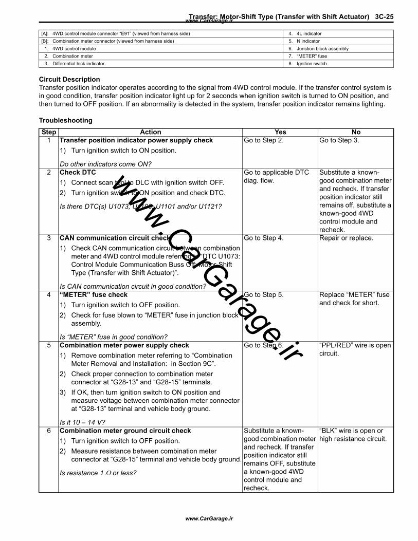
Transfer: Motor-Shift Type (Transfer with Shift Actuator) 3C-25
Circuit DescriptionTransfer position indicator operates according to the signal from 4WD control module. If the transfer control system is in good condition, transfer position indicator light up for 2 seconds when ignition switch is turned to ON position, and then turned to OFF position. If an abnormality is detected in the system, transfer position indicator remains lighting.
Troubleshooting
[A]: 4WD control module connector “E91” (viewed from harness side) 4. 4L indicator[B]: Combination meter connector (viewed from harness side) 5. N indicator
1. 4WD control module 6. Junction block assembly2. Combination meter 7. “METER” fuse3. Differential lock indicator 8. Ignition switch
Step Action Yes No1 Transfer position indicator power supply check
1) Turn ignition switch to ON position.
Do other indicators come ON?
Go to Step 2. Go to Step 3.
2 Check DTC1) Connect scan tool to DLC with ignition switch OFF.2) Turn ignition switch to ON position and check DTC.
Is there DTC(s) U1073, U1100, U1101 and/or U1121?
Go to applicable DTC diag. flow.
Substitute a known-good combination meter and recheck. If transfer position indicator still remains off, substitute a known-good 4WD control module and recheck.
3 CAN communication circuit check1) Check CAN communication circuit between combination
meter and 4WD control module referring to “DTC U1073: Control Module Communication Buss Off: Motor-Shift Type (Transfer with Shift Actuator)”.
Is CAN communication circuit in good condition?
Go to Step 4. Repair or replace.
4 “METER” fuse check1) Turn ignition switch to OFF position.2) Check for fuse blown to “METER” fuse in junction block
assembly.
Is “METER” fuse in good condition?
Go to Step 5. Replace “METER” fuse and check for short.
5 Combination meter power supply check1) Remove combination meter referring to “Combination
Meter Removal and Installation: in Section 9C”.2) Check proper connection to combination meter
connector at “G28-13” and “G28-15” terminals.3) If OK, then turn ignition switch to ON position and
measure voltage between combination meter connector at “G28-13” terminal and vehicle body ground.
Is it 10 – 14 V?
Go to Step 6. “PPL/RED” wire is open circuit.
6 Combination meter ground circuit check1) Turn ignition switch to OFF position.2) Measure resistance between combination meter
connector at “G28-15” terminal and vehicle body ground.
Is resistance 1 Ω or less?
Substitute a known-good combination meter and recheck. If transfer position indicator still remains OFF, substitute a known-good 4WD control module and recheck.
“BLK” wire is open or high resistance circuit.
www.CarGarage.ir
www.CarGarage.ir
www.CarGarage.ir
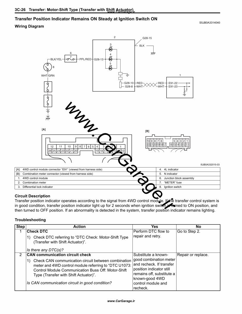
3C-26 Transfer: Motor-Shift Type (Transfer with Shift Actuator)
Transfer Position Indicator Remains ON Steady at Ignition Switch ONS5JB0A3314040
Wiring Diagram
Circuit DescriptionTransfer position indicator operates according to the signal from 4WD control module. If the transfer control system is in good condition, transfer position indicator light up for 2 seconds when ignition switch is turned to ON position, and then turned to OFF position. If an abnormality is detected in the system, transfer position indicator remains lighting.
Troubleshooting
E91-22E91-23
REDWHT
REDWHT
G28-10G28-8
1
2
G28-13PPL/RED
BLK
WHT/GRN
BLK/YEL
8
G28-15
467
5
3
123456789101117 16151413122221201918
[B]
123456789101112
1314151617181920212223242526
[A]
I5JB0A332015-03
[A]: 4WD control module connector “E91” (viewed from harness side) 4. 4L indicator[B]: Combination meter connector (viewed from harness side) 5. N indicator
1. 4WD control module 6. Junction block assembly2. Combination meter 7. “METER” fuse3. Differential lock indicator 8. Ignition switch
Step Action Yes No1 Check DTC
1) Check DTC referring to “DTC Check: Motor-Shift Type (Transfer with Shift Actuator)”.
Is there any DTC(s)?
Perform DTC flow to repair and retry.
Go to Step 2.
2 CAN communication circuit check1) Check CAN communication circuit between combination
meter and 4WD control module referring to “DTC U1073: Control Module Communication Buss Off: Motor-Shift Type (Transfer with Shift Actuator)”.
Is CAN communication circuit in good condition?
Substitute a known-good combination meter and recheck. If transfer position indicator still remains off, substitute a known-good 4WD control module and recheck.
Repair or replace.
www.CarGarage.ir
www.CarGarage.ir
www.CarGarage.ir
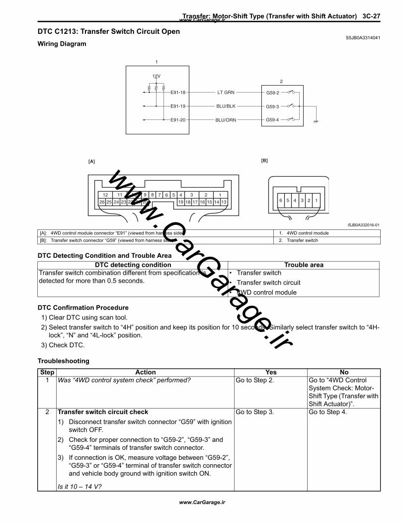
Transfer: Motor-Shift Type (Transfer with Shift Actuator) 3C-27
DTC C1213: Transfer Switch Circuit OpenS5JB0A3314041
Wiring Diagram
DTC Detecting Condition and Trouble Area
DTC Confirmation Procedure1) Clear DTC using scan tool.2) Select transfer switch to “4H” position and keep its position for 10 seconds. Similarly select transfer switch to “4H-
lock”, “N” and “4L-lock” position.3) Check DTC.
Troubleshooting
E91-18
E91-19
E91-20 BLU/ORN
BLU/BLK
LT GRN
1
212V
G59-4
G59-3
G59-2
123456789101112
1314151617181920212223242526
[A]
123456
[B]
I5JB0A332016-01
[A]: 4WD control module connector “E91” (viewed from harness side) 1. 4WD control module[B]: Transfer switch connector “G59” (viewed from harness side) 2. Transfer switch
DTC detecting condition Trouble areaTransfer switch combination different from specification is detected for more than 0.5 seconds.
• Transfer switch• Transfer switch circuit• 4WD control module
Step Action Yes No1 Was “4WD control system check” performed? Go to Step 2. Go to “4WD Control
System Check: Motor-Shift Type (Transfer with Shift Actuator)”.
2 Transfer switch circuit check1) Disconnect transfer switch connector “G59” with ignition
switch OFF.2) Check for proper connection to “G59-2”, “G59-3” and
“G59-4” terminals of transfer switch connector.3) If connection is OK, measure voltage between “G59-2”,
“G59-3” or “G59-4” terminal of transfer switch connector and vehicle body ground with ignition switch ON.
Is it 10 – 14 V?
Go to Step 3. Go to Step 4.
www.CarGarage.ir
www.CarGarage.ir
www.CarGarage.ir
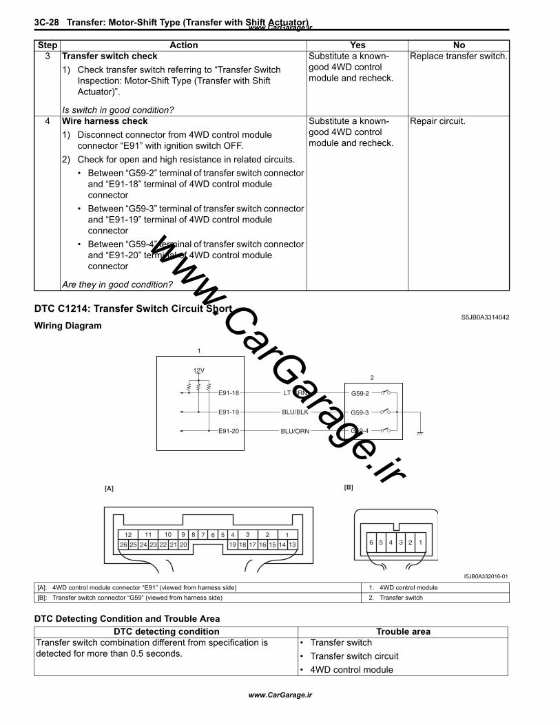
3C-28 Transfer: Motor-Shift Type (Transfer with Shift Actuator)
DTC C1214: Transfer Switch Circuit ShortS5JB0A3314042
Wiring Diagram
DTC Detecting Condition and Trouble Area
3 Transfer switch check1) Check transfer switch referring to “Transfer Switch
Inspection: Motor-Shift Type (Transfer with Shift Actuator)”.
Is switch in good condition?
Substitute a known-good 4WD control module and recheck.
Replace transfer switch.
4 Wire harness check1) Disconnect connector from 4WD control module
connector “E91” with ignition switch OFF.2) Check for open and high resistance in related circuits.
• Between “G59-2” terminal of transfer switch connector and “E91-18” terminal of 4WD control module connector
• Between “G59-3” terminal of transfer switch connector and “E91-19” terminal of 4WD control module connector
• Between “G59-4” terminal of transfer switch connector and “E91-20” terminal of 4WD control module connector
Are they in good condition?
Substitute a known-good 4WD control module and recheck.
Repair circuit.
Step Action Yes No
E91-18
E91-19
E91-20 BLU/ORN
BLU/BLK
LT GRN
1
212V
G59-4
G59-3
G59-2
123456789101112
1314151617181920212223242526
[A]
123456
[B]
I5JB0A332016-01
[A]: 4WD control module connector “E91” (viewed from harness side) 1. 4WD control module[B]: Transfer switch connector “G59” (viewed from harness side) 2. Transfer switch
DTC detecting condition Trouble areaTransfer switch combination different from specification is detected for more than 0.5 seconds.
• Transfer switch• Transfer switch circuit• 4WD control module
www.CarGarage.ir
www.CarGarage.ir
www.CarGarage.ir
Transfer: Motor-Shift Type (Transfer with Shift Actuator) 3C-29
DTC Confirmation Procedure1) Clear DTC using scan tool.2) Select transfer switch to “4H” position and keep its position for 10 seconds. Similarly select transfer switch to “4H-
lock”, “N” and “4L-lock” position.3) Check DTC.
TroubleshootingStep Action Yes No
1 Was “4WD control system check” performed? Go to Step 2. Go to “4WD Control System Check: Motor-Shift Type (Transfer with Shift Actuator)”.
2 Transfer switch circuit check1) Disconnect transfer switch connector “G59” with ignition
switch OFF.2) Check for proper connection to “G59-2”, “G59-3” and
“G59-4” terminals of transfer switch connector.3) If connection is OK, measure voltage between “G59-2”,
“G59-3” or “G59-4” terminal of transfer switch connector and vehicle body ground with ignition switch ON.
Is it 10 – 14 V?
Go to Step 3. Go to Step 4.
3 Transfer switch check1) Check transfer switch referring to “Transfer Switch
Inspection: Motor-Shift Type (Transfer with Shift Actuator)”.
Is switch in good condition?
Substitute a known-good 4WD control module and recheck.
Replace transfer switch.
4 Wire harness check1) Disconnect connector from 4WD control module
connector “E91” with ignition switch OFF.2) Check for shorted to ground in related circuits.
• Between “G59-2” terminal of transfer switch connector and “E91-18” terminal of 4WD control module connector
• Between “G59-3” terminal of transfer switch connector and “E91-19” terminal of 4WD control module connector
• Between “G59-4” terminal of transfer switch connector and “E91-20” terminal of 4WD control module connector
Are they in good condition?
Substitute a known-good 4WD control module and recheck.
Repair circuit.
www.CarGarage.ir
www.CarGarage.ir
www.CarGarage.ir

3C-30 Transfer: Motor-Shift Type (Transfer with Shift Actuator)
DTC C1223 / C1235: Transfer Shift Actuator Motor Position Switch 1 Circuit Open / Transfer Shift Actuator Motor Position Switch 2 Circuit Open
S5JB0A3314043Wiring Diagram
DTC Detecting Condition and Trouble Area
DTC Confirmation Procedure1) Clear DTC using scan tool.2) Select transfer switch to “4H” position and keep its position for 10 seconds. Similarly select transfer switch to “4H-
lock”, “N” and “4L-lock” position.3) Check DTC.
5V
12V
E91-2
5V
YEL
RED/BLK
BLU
M
E91-3
E91-25
E91-26
RED
E91-24BLK/YEL
1
23
C54-1
C54-4
C54-2
C54-3
C54-5
4
123456789101112
1314151617181920212223242526
[A]
123
456
[B]
I5JB0A332017-01
[A]: 4WD control module connector “E91” (viewed from harness side) 2. Transfer shift actuator motor position switch[B]: Transfer shift actuator connector “C54” (engine harness side) (viewed from harness side) 3. Transfer shift actuator motor
1. Transfer shift actuator 4. 4WD control module
DTC detecting condition Trouble areaTransfer shift actuator motor position switch signal voltage 4.2 V or more.
• Transfer shift actuator motor position switch• Transfer shift actuator motor position switch
circuit• 4WD control module
www.CarGarage.ir
www.CarGarage.ir
www.CarGarage.ir
Transfer: Motor-Shift Type (Transfer with Shift Actuator) 3C-31
TroubleshootingStep Action Yes No
1 Was “4WD control system check” performed? Go to Step 2. Go to “4WD Control System Check: Motor-Shift Type (Transfer with Shift Actuator)”.
2 Transfer shift actuator motor position switch circuit check1) Disconnect transfer shift actuator connector “C54” with
ignition switch OFF.2) Check for proper connection to “C54-2”, “C54-3” and
“C54-5” terminals of transfer shift actuator connector.3) If connection is OK, measure voltage between “G54-2”,
“G54-3” or “G54-5” terminal of transfer switch connector and vehicle body ground with ignition switch ON.
Is it approx. 5 V?
Go to Step 3. Go to Step 4.
3 Transfer shift actuator position switch check1) Check transfer shift actuator position switch referring to
“Transfer Assembly Inspection: Motor-Shift Type (Transfer with Shift Actuator)”.
Is actuator in good condition?
Substitute a known-good 4WD control module and recheck.
Faulty actuator position switch. Replace transfer shift actuator.
4 Wire harness check1) Disconnect connector from 4WD control module
connector “E91” with ignition switch OFF.2) Check for open and high resistance in related circuits.
• Between “C54-2” terminal of transfer shift actuator connector and “E91-25” terminal of 4WD control module connector
• Between “C54-3” terminal of transfer shift actuator connector and “E91-26” terminal of 4WD control module connector
• Between “C54-5” terminal of transfer shift actuator connector and “E91-24” terminal of 4WD control module connector
Are they it in good condition?
Substitute a known-good 4WD control module and recheck.
Repair circuit.
www.CarGarage.ir
www.CarGarage.ir
www.CarGarage.ir
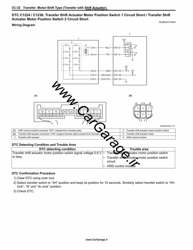
3C-32 Transfer: Motor-Shift Type (Transfer with Shift Actuator)
DTC C1224 / C1236: Transfer Shift Actuator Motor Position Switch 1 Circuit Short / Transfer Shift Actuator Motor Position Switch 2 Circuit Short
S5JB0A3314044Wiring Diagram
DTC Detecting Condition and Trouble Area
DTC Confirmation Procedure1) Clear DTC using scan tool.2) Select transfer switch to “4H” position and keep its position for 10 seconds. Similarly select transfer switch to “4H-
lock”, “N” and “4L-lock” position.3) Check DTC.
5V
12V
E91-2
5V
YEL
RED/BLK
BLU
M
E91-3
E91-25
E91-26
RED
E91-24BLK/YEL
1
23
C54-1
C54-4
C54-2
C54-3
C54-5
4
123456789101112
1314151617181920212223242526
[A]
123
456
[B]
I5JB0A332017-01
[A]: 4WD control module connector “E91” (viewed from harness side) 2. Transfer shift actuator motor position switch[B]: Transfer shift actuator connector “C54” (engine harness side) (viewed from harness side) 3. Transfer shift actuator motor
1. Transfer shift actuator 4. 4WD control module
DTC detecting condition Trouble areaTransfer shift actuator motor position switch signal voltage 0.6 V or less.
• Transfer shift actuator motor position switch• Transfer shift actuator motor position switch
circuit• 4WD control module
www.CarGarage.ir
www.CarGarage.ir
www.CarGarage.ir

Transfer: Motor-Shift Type (Transfer with Shift Actuator) 3C-33
TroubleshootingStep Action Yes No
1 Was “4WD control system check” performed? Go to Step 2. Go to “4WD Control System Check: Motor-Shift Type (Transfer with Shift Actuator)”.
2 Transfer shift actuator motor position switch circuit check1) Disconnect transfer shift actuator connector “C54” with
ignition switch OFF.2) Check for proper connection to “C54-2”, “C54-3” and
“C54-5” terminals of transfer shift actuator connector.3) If connection is OK, measure voltage between “G54-2”,
“G54-3” or “G54-5” terminal of transfer switch connector and vehicle body ground with ignition switch ON.
Is it approx. 5 V?
Go to Step 3. Go to Step 4.
3 Transfer shift actuator position switch check1) Check transfer shift actuator position switch referring to
“Transfer Assembly Inspection: Motor-Shift Type (Transfer with Shift Actuator)”.
Is actuator in good condition?
Substitute a known-good 4WD control module and recheck.
Faulty actuator position switch. Replace transfer shift actuator.
4 Wire harness check1) Disconnect connector from 4WD control module
connector “E91” with ignition switch OFF.2) Check for shorted to ground in related circuits.
• Between “C54-2” terminal of transfer shift actuator connector and “E91-25” terminal of 4WD control module connector
• Between “C54-3” terminal of transfer shift actuator connector and “E91-26” terminal of 4WD control module connector
• Between “C54-5” terminal of transfer shift actuator connector and “E91-24” terminal of 4WD control module connector
Are they in good condition?
Substitute a known-good 4WD control module and recheck.
Repair circuit.
www.CarGarage.ir
www.CarGarage.ir
www.CarGarage.ir
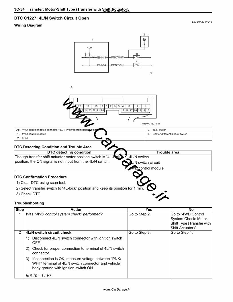
3C-34 Transfer: Motor-Shift Type (Transfer with Shift Actuator)
DTC C1227: 4L/N Switch Circuit OpenS5JB0A3314045
Wiring Diagram
DTC Detecting Condition and Trouble Area
DTC Confirmation Procedure1) Clear DTC using scan tool.2) Select transfer switch to “4L-lock” position and keep its position for 1 min.3) Check DTC.
Troubleshooting
IG
E91-13
E91-14 RED/GRN
PNK/WHT
2
3
4
12V
1
123456789101112
1314151617181920212223242526
[A]
I5JB0A332018-01
[A]: 4WD control module connector “E91” (viewed from harness side) 3. 4L/N switch1. 4WD control module 4. Center differential lock switch2. TCM
DTC detecting condition Trouble areaThough transfer shift actuator motor position switch is “4L-lock” position, the ON signal is not input from the 4L/N switch.
• 4L/N switch• 4L/N switch circuit• 4WD control module
Step Action Yes No1 Was “4WD control system check” performed? Go to Step 2. Go to “4WD Control
System Check: Motor-Shift Type (Transfer with Shift Actuator)”.
2 4L/N switch circuit check1) Disconnect 4L/N switch connector with ignition switch
OFF.2) Check for proper connection to terminal of 4L/N switch
connector.3) If connection is OK, measure voltage between “PNK/
WHT” terminal of 4L/N switch connector and vehicle body ground with ignition switch ON.
Is it 10 – 14 V?
Go to Step 3. Go to Step 4.
www.CarGarage.ir
www.CarGarage.ir
www.CarGarage.ir
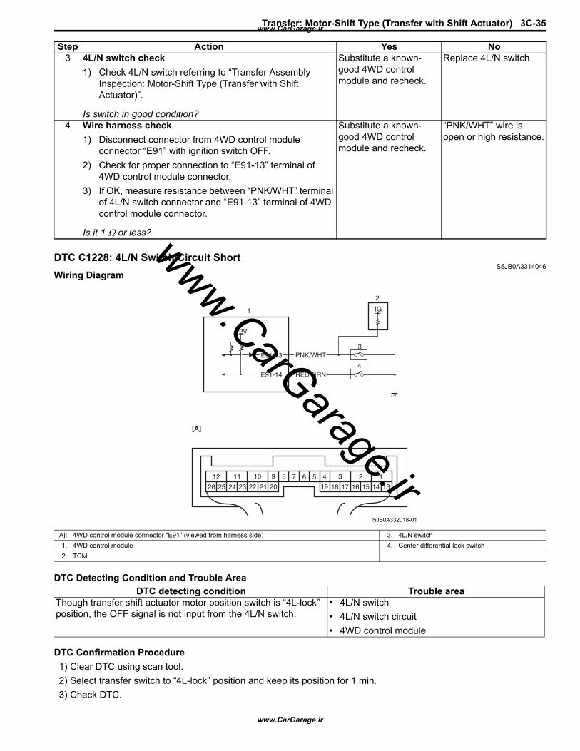
Transfer: Motor-Shift Type (Transfer with Shift Actuator) 3C-35
DTC C1228: 4L/N Switch Circuit ShortS5JB0A3314046
Wiring Diagram
DTC Detecting Condition and Trouble Area
DTC Confirmation Procedure1) Clear DTC using scan tool.2) Select transfer switch to “4L-lock” position and keep its position for 1 min.3) Check DTC.
3 4L/N switch check1) Check 4L/N switch referring to “Transfer Assembly
Inspection: Motor-Shift Type (Transfer with Shift Actuator)”.
Is switch in good condition?
Substitute a known-good 4WD control module and recheck.
Replace 4L/N switch.
4 Wire harness check1) Disconnect connector from 4WD control module
connector “E91” with ignition switch OFF.2) Check for proper connection to “E91-13” terminal of
4WD control module connector.3) If OK, measure resistance between “PNK/WHT” terminal
of 4L/N switch connector and “E91-13” terminal of 4WD control module connector.
Is it 1 Ω or less?
Substitute a known-good 4WD control module and recheck.
“PNK/WHT” wire is open or high resistance.
Step Action Yes No
IG
E91-13
E91-14 RED/GRN
PNK/WHT
2
3
4
12V
1
123456789101112
1314151617181920212223242526
[A]
I5JB0A332018-01
[A]: 4WD control module connector “E91” (viewed from harness side) 3. 4L/N switch1. 4WD control module 4. Center differential lock switch2. TCM
DTC detecting condition Trouble areaThough transfer shift actuator motor position switch is “4L-lock” position, the OFF signal is not input from the 4L/N switch.
• 4L/N switch• 4L/N switch circuit• 4WD control module
www.CarGarage.ir
www.CarGarage.ir
www.CarGarage.ir
3C-36 Transfer: Motor-Shift Type (Transfer with Shift Actuator)
TroubleshootingStep Action Yes No
1 Was “4WD control system check” performed? Go to Step 2. Go to “4WD Control System Check: Motor-Shift Type (Transfer with Shift Actuator)”.
2 4L/N switch circuit check1) Disconnect 4L/N switch connector with ignition switch
OFF.2) Check for proper connection to terminal of 4L/N switch
connector.3) If connection is OK, measure voltage between “PNK/
WHT” terminal of 4L/N switch connector and vehicle body ground with ignition switch ON.
Is it 10 – 14 V?
Go to Step 3. Go to Step 4.
3 4L/N switch check1) Check 4L/N switch referring to “Transfer Assembly
Inspection: Motor-Shift Type (Transfer with Shift Actuator)”.
Is switch in good condition?
Substitute a known-good 4WD control module and recheck.
Replace 4L/N switch.
4 Wire harness check1) Disconnect connector from 4WD control module
connector “E91” with ignition switch OFF.2) Check for proper connection to “E91-13” terminal of
4WD control module connector.3) If OK, measure resistance between “PNK/WHT” terminal
of 4L/N switch connector and “E91-13” terminal of 4WD control module connector.
Is it 1 MΩ or more?
Substitute a known-good 4WD control module and recheck.
“PNK/WHT” wire is shorted to ground circuit.
www.CarGarage.ir
www.CarGarage.ir
www.CarGarage.ir
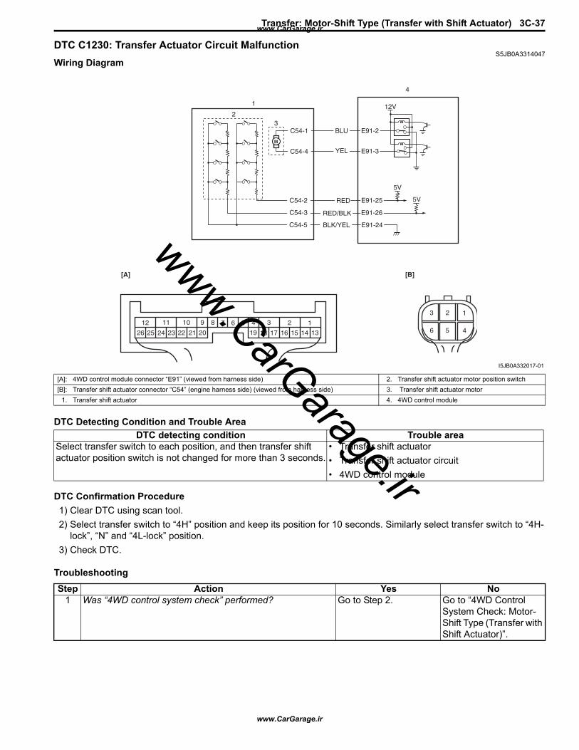
Transfer: Motor-Shift Type (Transfer with Shift Actuator) 3C-37
DTC C1230: Transfer Actuator Circuit MalfunctionS5JB0A3314047
Wiring Diagram
DTC Detecting Condition and Trouble Area
DTC Confirmation Procedure1) Clear DTC using scan tool.2) Select transfer switch to “4H” position and keep its position for 10 seconds. Similarly select transfer switch to “4H-
lock”, “N” and “4L-lock” position.3) Check DTC.
Troubleshooting
5V
12V
E91-2
5V
YEL
RED/BLK
BLU
M
E91-3
E91-25
E91-26
RED
E91-24BLK/YEL
1
23
C54-1
C54-4
C54-2
C54-3
C54-5
4
123456789101112
1314151617181920212223242526
[A]
123
456
[B]
I5JB0A332017-01
[A]: 4WD control module connector “E91” (viewed from harness side) 2. Transfer shift actuator motor position switch[B]: Transfer shift actuator connector “C54” (engine harness side) (viewed from harness side) 3. Transfer shift actuator motor
1. Transfer shift actuator 4. 4WD control module
DTC detecting condition Trouble areaSelect transfer switch to each position, and then transfer shift actuator position switch is not changed for more than 3 seconds.
• Transfer shift actuator• Transfer shift actuator circuit• 4WD control module
Step Action Yes No1 Was “4WD control system check” performed? Go to Step 2. Go to “4WD Control
System Check: Motor-Shift Type (Transfer with Shift Actuator)”.
www.CarGarage.ir
www.CarGarage.ir
www.CarGarage.ir

3C-38 Transfer: Motor-Shift Type (Transfer with Shift Actuator)
DTC C1237: Center Differential Lock Switch Circuit OpenS5JB0A3314048
Wiring Diagram
2 Transfer shift actuator circuit check1) Disconnect transfer shift actuator connector “C54” with
ignition switch OFF.2) Check for proper connection to “C54-1” and “C54-4”
terminals of transfer shift actuator connector.3) If connection is OK, measure voltage between “C54-1”
or “C54-4” terminal of transfer shift actuator connector and vehicle body ground.
Is it 10 – 14 V?
Go to Step 3. Go to Step 4.
3 Transfer shift actuator check1) Check transfer shift actuator referring to “Transfer
Assembly Inspection: Motor-Shift Type (Transfer with Shift Actuator)”.
Is actuator in good condition?
Substitute a known-good 4WD control module and recheck.
Replace transfer shift actuator.
4 Wire harness check1) Disconnect connector from 4WD control module
connector “E91” with ignition switch OFF.2) Check for open and high resistance or shorted to ground
in related circuits.• Between “C54-1” terminal of transfer shift actuator
connector and “E91-22” terminal of 4WD control module connector
• Between “C54-4” terminal of transfer shift actuator connector and “E91-3” terminal of 4WD control module connector
Are they in good condition?
Substitute a known-good 4WD control module and recheck.
Repair circuit.
Step Action Yes No
IG
E91-13
E91-14 RED/GRN
PNK/WHT
2
3
4
12V
1
123456789101112
1314151617181920212223242526
[A]
I5JB0A332018-01
[A]: 4WD control module connector “E91” (viewed from harness side) 3. 4L/N switch1. 4WD control module 4. Center differential lock switch2. TCM
www.CarGarage.ir
www.CarGarage.ir
www.CarGarage.ir
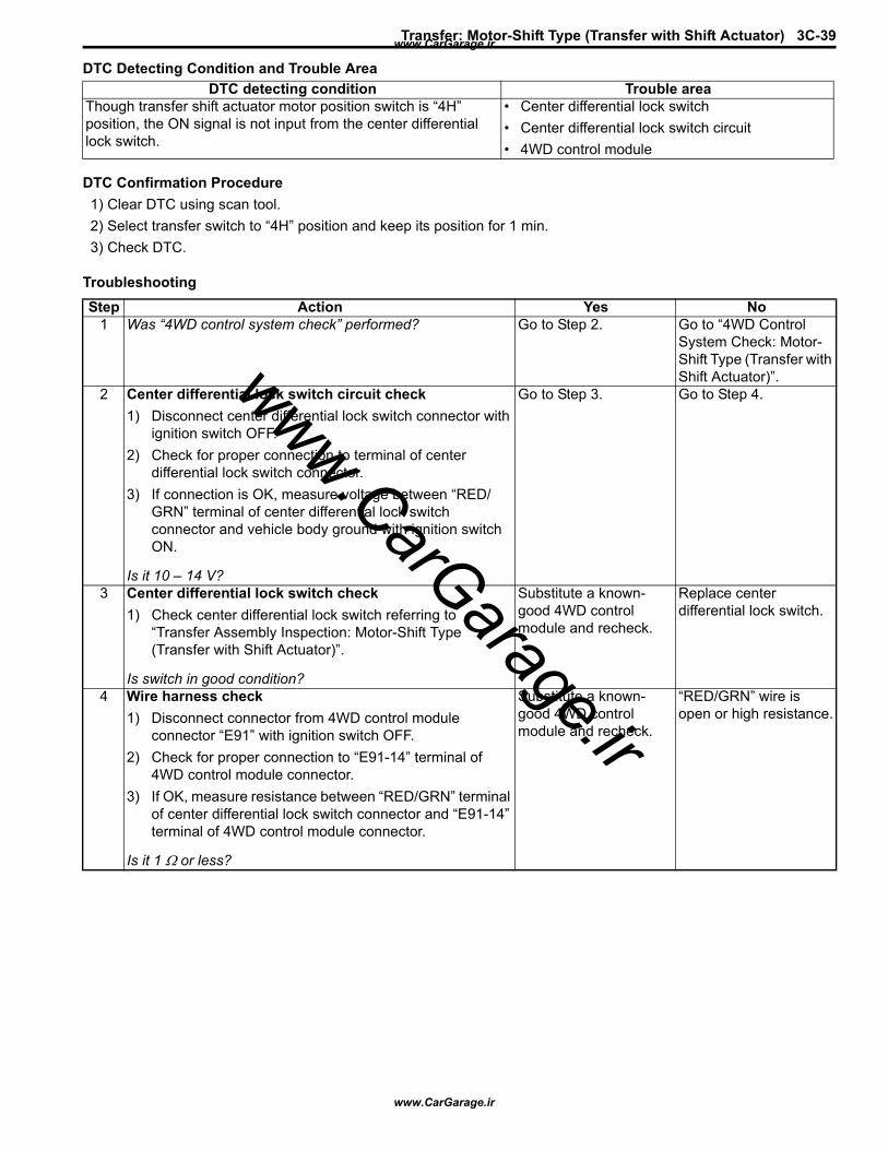
Transfer: Motor-Shift Type (Transfer with Shift Actuator) 3C-39
DTC Detecting Condition and Trouble Area
DTC Confirmation Procedure1) Clear DTC using scan tool.2) Select transfer switch to “4H” position and keep its position for 1 min.3) Check DTC.
Troubleshooting
DTC detecting condition Trouble areaThough transfer shift actuator motor position switch is “4H” position, the ON signal is not input from the center differential lock switch.
• Center differential lock switch• Center differential lock switch circuit• 4WD control module
Step Action Yes No1 Was “4WD control system check” performed? Go to Step 2. Go to “4WD Control
System Check: Motor-Shift Type (Transfer with Shift Actuator)”.
2 Center differential lock switch circuit check1) Disconnect center differential lock switch connector with
ignition switch OFF.2) Check for proper connection to terminal of center
differential lock switch connector.3) If connection is OK, measure voltage between “RED/
GRN” terminal of center differential lock switch connector and vehicle body ground with ignition switch ON.
Is it 10 – 14 V?
Go to Step 3. Go to Step 4.
3 Center differential lock switch check1) Check center differential lock switch referring to
“Transfer Assembly Inspection: Motor-Shift Type (Transfer with Shift Actuator)”.
Is switch in good condition?
Substitute a known-good 4WD control module and recheck.
Replace center differential lock switch.
4 Wire harness check1) Disconnect connector from 4WD control module
connector “E91” with ignition switch OFF.2) Check for proper connection to “E91-14” terminal of
4WD control module connector.3) If OK, measure resistance between “RED/GRN” terminal
of center differential lock switch connector and “E91-14” terminal of 4WD control module connector.
Is it 1 Ω or less?
Substitute a known-good 4WD control module and recheck.
“RED/GRN” wire is open or high resistance.
www.CarGarage.ir
www.CarGarage.ir
www.CarGarage.ir
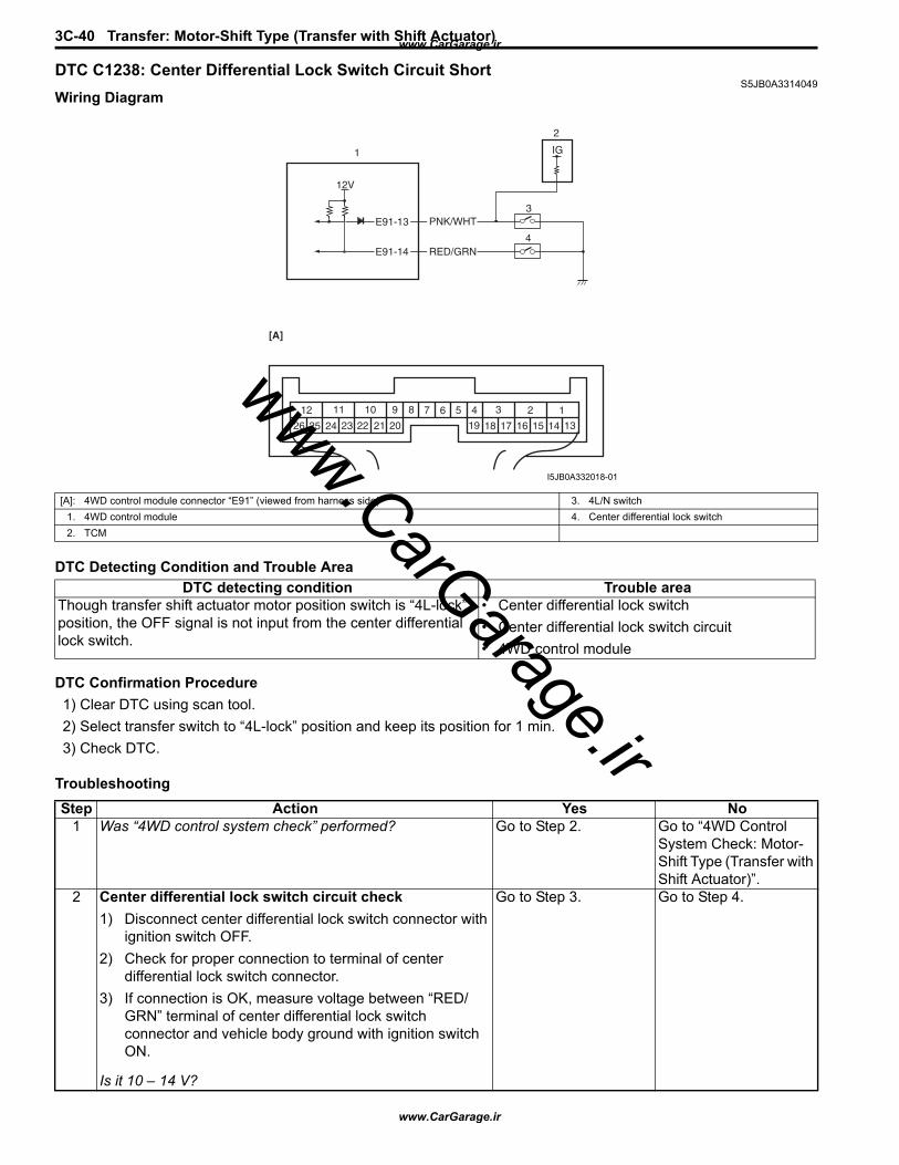
3C-40 Transfer: Motor-Shift Type (Transfer with Shift Actuator)
DTC C1238: Center Differential Lock Switch Circuit ShortS5JB0A3314049
Wiring Diagram
DTC Detecting Condition and Trouble Area
DTC Confirmation Procedure1) Clear DTC using scan tool.2) Select transfer switch to “4L-lock” position and keep its position for 1 min.3) Check DTC.
Troubleshooting
IG
E91-13
E91-14 RED/GRN
PNK/WHT
2
3
4
12V
1
123456789101112
1314151617181920212223242526
[A]
I5JB0A332018-01
[A]: 4WD control module connector “E91” (viewed from harness side) 3. 4L/N switch1. 4WD control module 4. Center differential lock switch2. TCM
DTC detecting condition Trouble areaThough transfer shift actuator motor position switch is “4L-lock” position, the OFF signal is not input from the center differential lock switch.
• Center differential lock switch• Center differential lock switch circuit• 4WD control module
Step Action Yes No1 Was “4WD control system check” performed? Go to Step 2. Go to “4WD Control
System Check: Motor-Shift Type (Transfer with Shift Actuator)”.
2 Center differential lock switch circuit check1) Disconnect center differential lock switch connector with
ignition switch OFF.2) Check for proper connection to terminal of center
differential lock switch connector.3) If connection is OK, measure voltage between “RED/
GRN” terminal of center differential lock switch connector and vehicle body ground with ignition switch ON.
Is it 10 – 14 V?
Go to Step 3. Go to Step 4.
www.CarGarage.ir
www.CarGarage.ir
www.CarGarage.ir
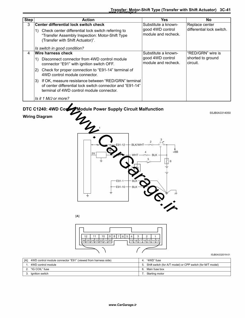
Transfer: Motor-Shift Type (Transfer with Shift Actuator) 3C-41
DTC C1240: 4WD Control Module Power Supply Circuit MalfunctionS5JB0A3314050
Wiring Diagram
3 Center differential lock switch check1) Check center differential lock switch referring to
“Transfer Assembly Inspection: Motor-Shift Type (Transfer with Shift Actuator)”.
Is switch in good condition?
Substitute a known-good 4WD control module and recheck.
Replace center differential lock switch.
4 Wire harness check1) Disconnect connector from 4WD control module
connector “E91” with ignition switch OFF.2) Check for proper connection to “E91-14” terminal of
4WD control module connector.3) If OK, measure resistance between “RED/GRN” terminal
of center differential lock switch connector and “E91-14” terminal of 4WD control module connector.
Is it 1 MΩ or more?
Substitute a known-good 4WD control module and recheck.
“RED/GRN” wire is shorted to ground circuit.
Step Action Yes No
5V +BB
E91-12
E91-11
E91-10
E91-1
BLK
BLK
WHT
BLK/WHT2
4
6
3
5
7
1
123456789101112
1314151617181920212223242526
[A]
BLK
I5JB0A332019-01
[A]: 4WD control module connector “E91” (viewed from harness side) 4. “4WD” fuse1. 4WD control module 5. Shift switch (for A/T model) or CPP switch (for M/T model)2. “IG COIL” fuse 6. Main fuse box3. Ignition switch 7. Starting motor
www.CarGarage.ir
www.CarGarage.ir
www.CarGarage.ir
3C-42 Transfer: Motor-Shift Type (Transfer with Shift Actuator)
DTC Detecting Condition and Trouble Area
DTC Confirmation Procedure1) Clear DTC using scan tool.2) Start engine and drive vehicle at 30 km/h (19 mph) or more vehicle speed at least for 1 min.3) Stop vehicle and check DTC.
Troubleshooting
DTC C1243: Internal Circuit Malfunction of 4WD Control ModuleS5JB0A3314056
DTC Detecting Condition and Trouble Area
DTC Confirmation Procedure1) Clear DTC using scan tool.2) Turn ignition switch to ON position for 60 seconds.3) Check DTC.
TroubleshootingSubstitute a known-good 4WD control module and recheck.
DTC detecting condition Trouble area4WD control module power supply voltage is out of specification while vehicle is running at 20 km/h (12 mph) or more.
• 4WD control module power supply circuit
Step Action Yes No1 Was “4WD control system check” performed? Go to Step 2. Go to “4WD Control
System Check: Motor-Shift Type (Transfer with Shift Actuator)”.
2 4WD control module power circuit check1) Disconnect 4WD control module connector with ignition
switch OFF.2) Check for proper connection to “E91” terminal of 4WD
control module connector.3) If connection is OK, measure voltage between “E91-11”
terminal of 4WD control module connector and vehicle body ground with ignition switch ON.
Is it 10 – 14 V?
Poor “E91-11” connection or intermittent trouble. Check for intermittent referring to “Intermittent and Poor Connection Inspection: in Section 00”. If wire and connections are OK, substitute a known-good 4WD control module and recheck.
“4WD” fuse blown, “WHT” or “BLK” wire is circuit open or circuit short.
DTC detecting condition Trouble areaEEPROM Error • 4WD control module
www.CarGarage.ir
www.CarGarage.ir
www.CarGarage.ir
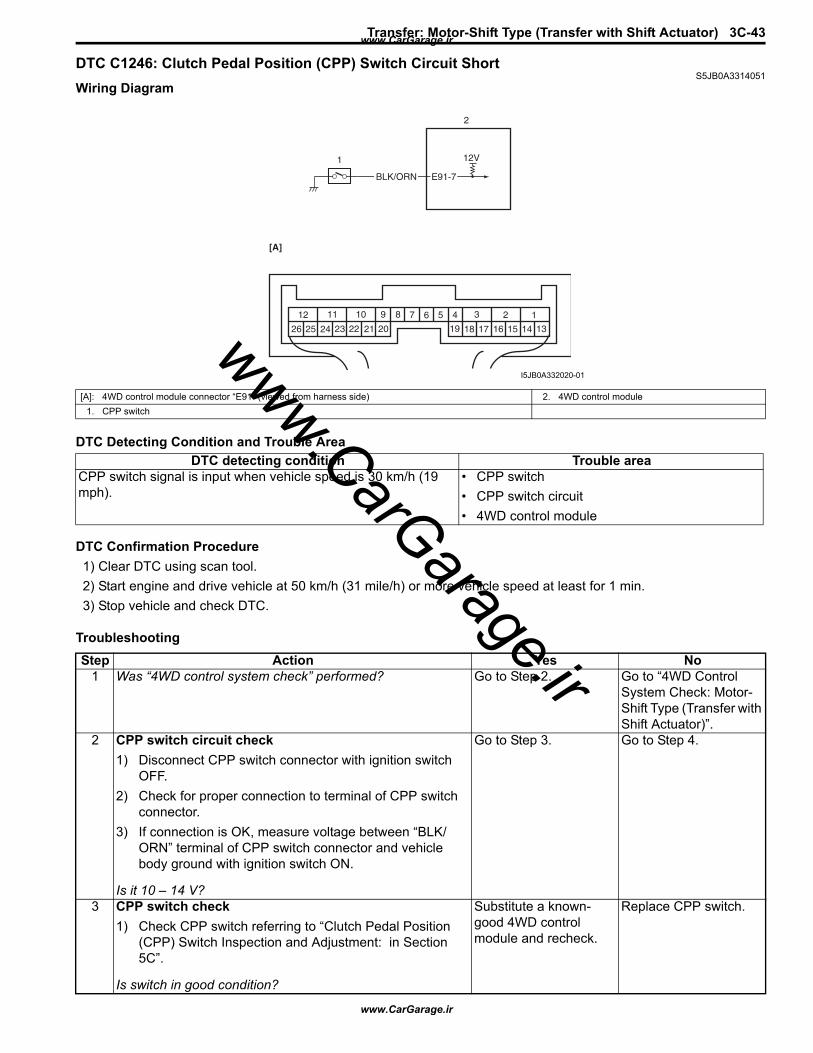
Transfer: Motor-Shift Type (Transfer with Shift Actuator) 3C-43
DTC C1246: Clutch Pedal Position (CPP) Switch Circuit ShortS5JB0A3314051
Wiring Diagram
DTC Detecting Condition and Trouble Area
DTC Confirmation Procedure1) Clear DTC using scan tool.2) Start engine and drive vehicle at 50 km/h (31 mile/h) or more vehicle speed at least for 1 min.3) Stop vehicle and check DTC.
Troubleshooting
12V
E91-7BLK/ORN
1
2
123456789101112
1314151617181920212223242526
[A]
I5JB0A332020-01
[A]: 4WD control module connector “E91” (viewed from harness side) 2. 4WD control module1. CPP switch
DTC detecting condition Trouble areaCPP switch signal is input when vehicle speed is 30 km/h (19 mph).
• CPP switch• CPP switch circuit• 4WD control module
Step Action Yes No1 Was “4WD control system check” performed? Go to Step 2. Go to “4WD Control
System Check: Motor-Shift Type (Transfer with Shift Actuator)”.
2 CPP switch circuit check1) Disconnect CPP switch connector with ignition switch
OFF.2) Check for proper connection to terminal of CPP switch
connector.3) If connection is OK, measure voltage between “BLK/
ORN” terminal of CPP switch connector and vehicle body ground with ignition switch ON.
Is it 10 – 14 V?
Go to Step 3. Go to Step 4.
3 CPP switch check1) Check CPP switch referring to “Clutch Pedal Position
(CPP) Switch Inspection and Adjustment: in Section 5C”.
Is switch in good condition?
Substitute a known-good 4WD control module and recheck.
Replace CPP switch.
www.CarGarage.ir
www.CarGarage.ir
www.CarGarage.ir
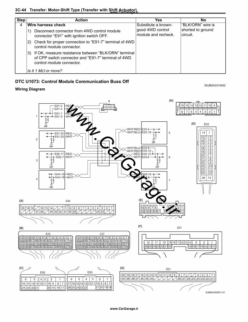
3C-44 Transfer: Motor-Shift Type (Transfer with Shift Actuator)
DTC U1073: Control Module Communication Buss OffS5JB0A3314052
Wiring Diagram
4 Wire harness check1) Disconnect connector from 4WD control module
connector “E91” with ignition switch OFF.2) Check for proper connection to “E91-7” terminal of 4WD
control module connector.3) If OK, measure resistance between “BLK/ORN” terminal
of CPP switch connector and “E91-7” terminal of 4WD control module connector.
Is it 1 MΩ or more?
Substitute a known-good 4WD control module and recheck.
“BLK/ORN” wire is shorted to ground circuit.
Step Action Yes No
WHTRED
WHTRED
G44-18G44-19
G44[A]
[B]
[C] [G]
123456789101114151636 34 33 32 31 30 29 24 2337
181920
G28-8G28-10
WHT/BLU
WHT/BLU
WHT/RED
WHT/RED E23-4E23-19
WHTRED E03-12
E03-10
E03-6
E03-8
WHTREDE92-17
E92-7
WHTREDE91-22
E91-23
WHTREDG31-1
G31-3
6 5
16 15 14 13 12 11
4 3
24 23 2122
10 9 8 7
2 1
1920 18 17
E92
17 1626 25
15 14
6 5 34 2
13 1223 2224
11 10 921 20 19
8 718
1
E93
2 1E23 C37
341819
56710111720
4746495051
2122
52
16259
241429
5557 54535960 58
2262728
1530
56 4832 31343536374042 39384445 43 41 33
1121323834
18195671011
1720
4746495051
2122
52
16259
241429
5557 54535960 58
2627281530
56 4832 31343536374042 39384445 43 41 33
1213238
123456789101117 16151413122221201918
G28[E]
G31
1234789101114151636 3435 24 23 212228 27 25263739 3840
18 17 13 121920
[D] E03
1516171819202122232425
23456789
101112
1
13
14
26
1234567891011121314151617181920212223242526
[F] E91
WHTREDG31-2
G31-4
[H]
8 7 6 5 4 3 2 1
910111213141516
1
2
3
4
8
5
6
7
I5JB0A332021-01
www.CarGarage.ir
www.CarGarage.ir
www.CarGarage.ir
Transfer: Motor-Shift Type (Transfer with Shift Actuator) 3C-45
DTC Detecting Condition and Trouble Area
DTC Confirmation Procedure1) Clear DTC using scan tool.2) Start engine and run it for 1 min. or more.3) Stop vehicle and check DTC.
Troubleshooting
[A]: Keyless start control module connector (if equipped) (viewed from harness side) 1. BCM[B]: ECM connector (viewed from harness side) 2. 4WD control module[C]: TCM connector (for A/T model) (viewed from harness side) 3. TCM (for A/T model)[D]: ABS hydraulic unit/control module connector (viewed from terminal side) 4. Keyless start control module (if equipped)[E]: Combination meter connector (viewed from harness side) 5. ECM[F]: 4WD control module connector (viewed from harness side) 6. ABS hydraulic unit / control module[G]: BCM connector (viewed from harness side) 7. Combination meter[H]: DLC (viewed from harness side) 8. DLC
DTC detecting condition Trouble areaTransmission error of communication data for 4WD control module is detected more than 7 times at more than specified error counts continuously.
• CAN communication circuit• ECM• BCM• 4WD control module• TCM• Combination meter• Keyless start control module (if equipped)• ABS hydraulic unit / control module
Step Action Yes No1 Was “4WD control system check” performed? Go to Step 2. Go to “4WD Control
System Check: Motor-Shift Type (Transfer with Shift Actuator)”.
2 Control module connector check1) Check connection of connectors of all control modules
communicating by means of CAN.2) Recheck DTC in TCM.
Is DTC U1073 detected?
Go to Step 3. Intermittent trouble. Check for intermittent referring to “Intermittent and Poor Connection Inspection: in Section 00”.
3 CAN communication circuit check1) Turn ignition switch to OFF position.2) Disconnect connectors of all control modules
communicating by means of CAN.3) Check CAN communication circuit between control
modules for open, short and high resistance.
Is each CAN communication circuit in good condition?
Go to Step 4. Repair circuit.
www.CarGarage.ir
www.CarGarage.ir
www.CarGarage.ir
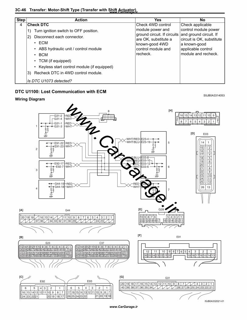
3C-46 Transfer: Motor-Shift Type (Transfer with Shift Actuator)
DTC U1100: Lost Communication with ECMS5JB0A3314053
Wiring Diagram
4 Check DTC1) Turn ignition switch to OFF position.2) Disconnect each connector.
• ECM• ABS hydraulic unit / control module• BCM• TCM (if equipped)• Keyless start control module (if equipped)
3) Recheck DTC in 4WD control module.
Is DTC U1073 detected?
Check 4WD control module power and ground circuit. If circuits are OK, substitute a known-good 4WD control module and recheck.
Check applicable control module power and ground circuit. If circuit is OK, substitute a known-good applicable control module and recheck.
Step Action Yes No
WHTRED
WHTRED
G44-18G44-19
G44[A]
[B]
[C] [G]
123456789101114151636 34 33 32 31 30 29 24 2337
181920
G28-8G28-10
WHT/BLU
WHT/BLU
WHT/RED
WHT/RED E23-4E23-19
WHTRED E03-12
E03-10
E03-6
E03-8
WHTREDE92-17
E92-7
WHTREDE91-22
E91-23
WHTREDG31-1
G31-3
6 5
16 15 14 13 12 11
4 3
24 23 2122
10 9 8 7
2 1
1920 18 17
E92
17 1626 25
15 14
6 5 34 2
13 1223 2224
11 10 921 20 19
8 718
1
E93
2 1E23 C37
341819
56710111720
4746495051
2122
52
16259
241429
5557 54535960 58
2262728
1530
56 4832 31343536374042 39384445 43 41 33
1121323834
18195671011
1720
4746495051
2122
52
16259
241429
5557 54535960 58
2627281530
56 4832 31343536374042 39384445 43 41 33
1213238
123456789101117 16151413122221201918
G28[E]
G31
1234789101114151636 3435 24 23 212228 27 25263739 3840
18 17 13 121920
[D] E03
1516171819202122232425
23456789
101112
1
13
14
26
1234567891011121314151617181920212223242526
[F] E91
WHTREDG31-2
G31-4
[H]
8 7 6 5 4 3 2 1
910111213141516
1
2
3
4
8
5
6
7
I5JB0A332021-01
www.CarGarage.ir
www.CarGarage.ir
www.CarGarage.ir
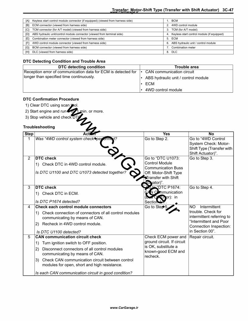
Transfer: Motor-Shift Type (Transfer with Shift Actuator) 3C-47
DTC Detecting Condition and Trouble Area
DTC Confirmation Procedure1) Clear DTC using scan tool.2) Start engine and run it for 1 min. or more.3) Stop vehicle and check DTC.
Troubleshooting
[A]: Keyless start control module connector (if equipped) (viewed from harness side) 1. BCM[B]: ECM connector (viewed from harness side) 2. 4WD control module[C]: TCM connector (for A/T model) (viewed from harness side) 3. TCM (for A/T model)[D]: ABS hydraulic unit/control module connector (viewed from terminal side) 4. Keyless start control module (if equipped)[E]: Combination meter connector (viewed from harness side) 5. ECM[F]: 4WD control module connector (viewed from harness side) 6. ABS hydraulic unit / control module[G]: BCM connector (viewed from harness side) 7. Combination meter[H]: DLC (viewed from harness side) 8. DLC
DTC detecting condition Trouble areaReception error of communication data for ECM is detected for longer than specified time continuously.
• CAN communication circuit• ABS hydraulic unit / control module• ECM• 4WD control module
Step Action Yes No1 Was “4WD control system check” performed? Go to Step 2. Go to “4WD Control
System Check: Motor-Shift Type (Transfer with Shift Actuator)”.
2 DTC check1) Check DTC in 4WD control module.
Is DTC U1100 and DTC U1073 detected together?
Go to “DTC U1073: Control Module Communication Buss Off: Motor-Shift Type (Transfer with Shift Actuator)”.
Go to Step 3.
3 DTC check1) Check DTC in ECM.
Is DTC P1674 detected?
Go to “DTC P1674: CAN Communication (Bus Off Error): in Section 1A”.
Go to Step 4.
4 Check each control module connectors1) Check connection of connectors of all control modules
communicating by means of CAN.2) Recheck in 4WD control module.
Is DTC U1100 detected?
Go to Step 5. NO Intermittent trouble. Check for intermittent referring to “Intermittent and Poor Connection Inspection: in Section 00”.
5 CAN communication circuit check1) Turn ignition switch to OFF position.2) Disconnect connectors of all control modules
communicating by means of CAN.3) Check CAN communication circuit between control
modules for open, short and high resistance.
Is each CAN communication circuit in good condition?
Check ECM power and ground circuit. If circuit is OK, substitute a known-good ECM and recheck.
Repair circuit.
www.CarGarage.ir
www.CarGarage.ir
www.CarGarage.ir
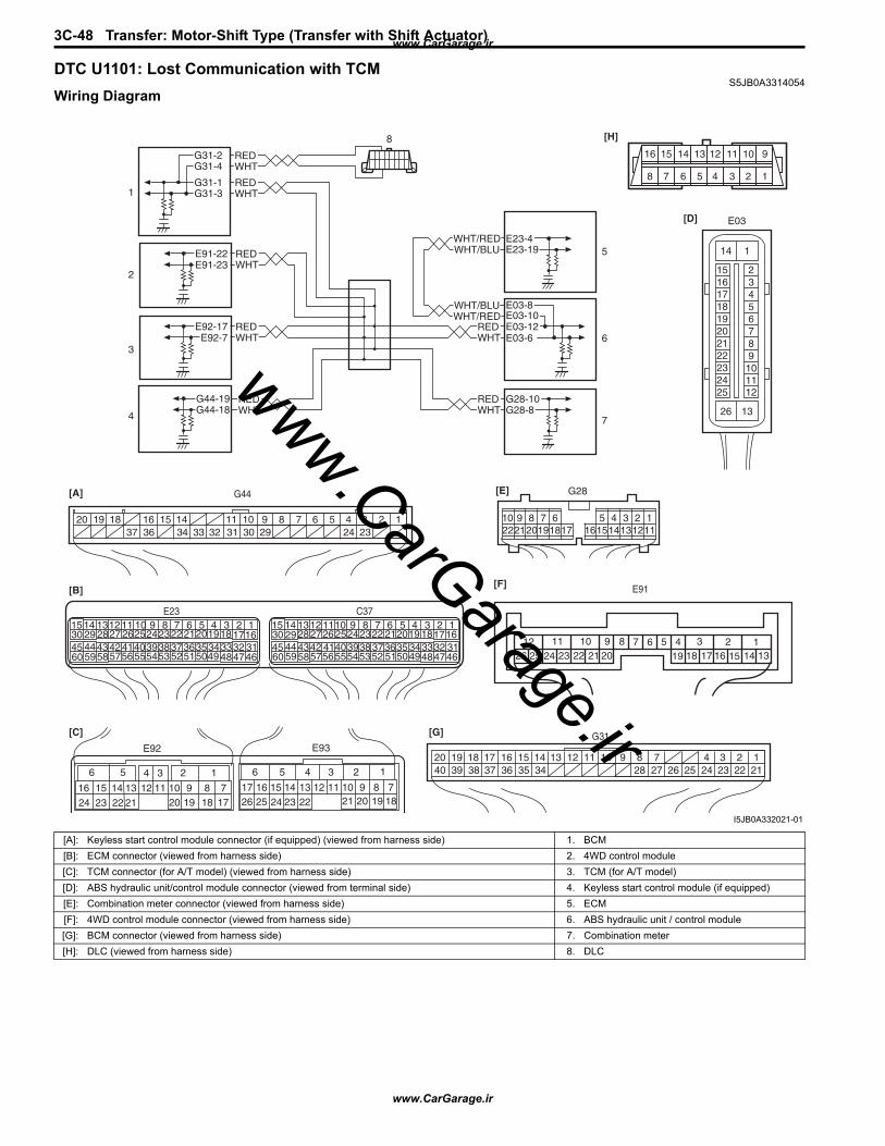
3C-48 Transfer: Motor-Shift Type (Transfer with Shift Actuator)
DTC U1101: Lost Communication with TCMS5JB0A3314054
Wiring Diagram
WHTRED
WHTRED
G44-18G44-19
G44[A]
[B]
[C] [G]
123456789101114151636 34 33 32 31 30 29 24 2337
181920
G28-8G28-10
WHT/BLU
WHT/BLU
WHT/RED
WHT/RED E23-4E23-19
WHTRED E03-12
E03-10
E03-6
E03-8
WHTREDE92-17
E92-7
WHTREDE91-22
E91-23
WHTREDG31-1
G31-3
6 5
16 15 14 13 12 11
4 3
24 23 2122
10 9 8 7
2 1
1920 18 17
E92
17 1626 25
15 14
6 5 34 2
13 1223 2224
11 10 921 20 19
8 718
1
E93
2 1E23 C37
341819
56710111720
4746495051
2122
52
16259
241429
5557 54535960 58
2262728
1530
56 4832 31343536374042 39384445 43 41 33
1121323834
18195671011
1720
4746495051
2122
52
16259
241429
5557 54535960 58
2627281530
56 4832 31343536374042 39384445 43 41 33
1213238
123456789101117 16151413122221201918
G28[E]
G31
1234789101114151636 3435 24 23 212228 27 25263739 3840
18 17 13 121920
[D] E03
1516171819202122232425
23456789
101112
1
13
14
26
1234567891011121314151617181920212223242526
[F] E91
WHTREDG31-2
G31-4
[H]
8 7 6 5 4 3 2 1
910111213141516
1
2
3
4
8
5
6
7
I5JB0A332021-01
[A]: Keyless start control module connector (if equipped) (viewed from harness side) 1. BCM[B]: ECM connector (viewed from harness side) 2. 4WD control module[C]: TCM connector (for A/T model) (viewed from harness side) 3. TCM (for A/T model)[D]: ABS hydraulic unit/control module connector (viewed from terminal side) 4. Keyless start control module (if equipped)[E]: Combination meter connector (viewed from harness side) 5. ECM[F]: 4WD control module connector (viewed from harness side) 6. ABS hydraulic unit / control module[G]: BCM connector (viewed from harness side) 7. Combination meter[H]: DLC (viewed from harness side) 8. DLC
www.CarGarage.ir
www.CarGarage.ir
www.CarGarage.ir
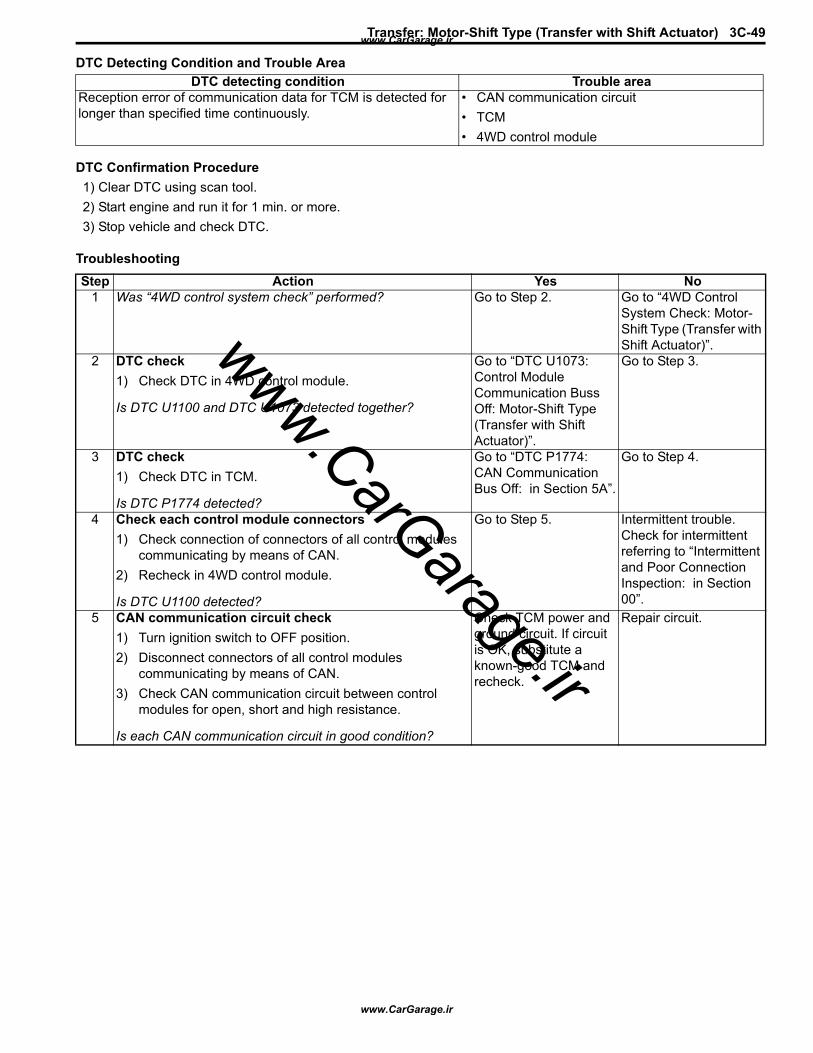
Transfer: Motor-Shift Type (Transfer with Shift Actuator) 3C-49
DTC Detecting Condition and Trouble Area
DTC Confirmation Procedure1) Clear DTC using scan tool.2) Start engine and run it for 1 min. or more.3) Stop vehicle and check DTC.
Troubleshooting
DTC detecting condition Trouble areaReception error of communication data for TCM is detected for longer than specified time continuously.
• CAN communication circuit• TCM• 4WD control module
Step Action Yes No1 Was “4WD control system check” performed? Go to Step 2. Go to “4WD Control
System Check: Motor-Shift Type (Transfer with Shift Actuator)”.
2 DTC check1) Check DTC in 4WD control module.
Is DTC U1100 and DTC U1073 detected together?
Go to “DTC U1073: Control Module Communication Buss Off: Motor-Shift Type (Transfer with Shift Actuator)”.
Go to Step 3.
3 DTC check1) Check DTC in TCM.
Is DTC P1774 detected?
Go to “DTC P1774: CAN Communication Bus Off: in Section 5A”.
Go to Step 4.
4 Check each control module connectors1) Check connection of connectors of all control modules
communicating by means of CAN.2) Recheck in 4WD control module.
Is DTC U1100 detected?
Go to Step 5. Intermittent trouble. Check for intermittent referring to “Intermittent and Poor Connection Inspection: in Section 00”.
5 CAN communication circuit check1) Turn ignition switch to OFF position.2) Disconnect connectors of all control modules
communicating by means of CAN.3) Check CAN communication circuit between control
modules for open, short and high resistance.
Is each CAN communication circuit in good condition?
Check TCM power and ground circuit. If circuit is OK, substitute a known-good TCM and recheck.
Repair circuit.
www.CarGarage.ir
www.CarGarage.ir
www.CarGarage.ir
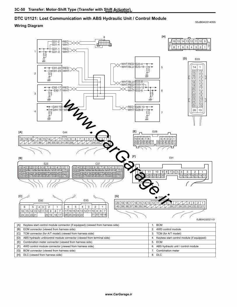
3C-50 Transfer: Motor-Shift Type (Transfer with Shift Actuator)
DTC U1121: Lost Communication with ABS Hydraulic Unit / Control ModuleS5JB0A3314055
Wiring Diagram
WHTRED
WHTRED
G44-18G44-19
G44[A]
[B]
[C] [G]
123456789101114151636 34 33 32 31 30 29 24 2337
181920
G28-8G28-10
WHT/BLU
WHT/BLU
WHT/RED
WHT/RED E23-4E23-19
WHTRED E03-12
E03-10
E03-6
E03-8
WHTREDE92-17
E92-7
WHTREDE91-22
E91-23
WHTREDG31-1
G31-3
6 5
16 15 14 13 12 11
4 3
24 23 2122
10 9 8 7
2 1
1920 18 17
E92
17 1626 25
15 14
6 5 34 2
13 1223 2224
11 10 921 20 19
8 718
1
E93
2 1E23 C37
341819
56710111720
4746495051
2122
52
16259
241429
5557 54535960 58
2262728
1530
56 4832 31343536374042 39384445 43 41 33
1121323834
18195671011
1720
4746495051
2122
52
16259
241429
5557 54535960 58
2627281530
56 4832 31343536374042 39384445 43 41 33
1213238
123456789101117 16151413122221201918
G28[E]
G31
1234789101114151636 3435 24 23 212228 27 25263739 3840
18 17 13 121920
[D] E03
1516171819202122232425
23456789
101112
1
13
14
26
1234567891011121314151617181920212223242526
[F] E91
WHTREDG31-2
G31-4
[H]
8 7 6 5 4 3 2 1
910111213141516
1
2
3
4
8
5
6
7
I5JB0A332021-01
[A]: Keyless start control module connector (if equipped) (viewed from harness side) 1. BCM[B]: ECM connector (viewed from harness side) 2. 4WD control module[C]: TCM connector (for A/T model) (viewed from harness side) 3. TCM (for A/T model)[D]: ABS hydraulic unit/control module connector (viewed from terminal side) 4. Keyless start control module (if equipped)[E]: Combination meter connector (viewed from harness side) 5. ECM[F]: 4WD control module connector (viewed from harness side) 6. ABS hydraulic unit / control module[G]: BCM connector (viewed from harness side) 7. Combination meter[H]: DLC (viewed from harness side) 8. DLC
www.CarGarage.ir
www.CarGarage.ir
www.CarGarage.ir

Transfer: Motor-Shift Type (Transfer with Shift Actuator) 3C-51
DTC Detecting Condition and Trouble Area
DTC Confirmation Procedure1) Clear DTC using scan tool.2) Start engine and run it for 1 min. or more.3) Stop vehicle and check DTC.
Troubleshooting
Inspection of 4WD Control Module and Its CircuitsS5JB0A3314037
4WD control module and its circuits can be checked at coupler connected to 4WD control module by measuring voltage, pulse signal.
CAUTION!
4WD control module cannot be checked by itself. It is strictly prohibited to connect voltmeter or ohmmeter to 4WD control module with couplers disconnected from it.
DTC detecting condition Trouble areaReception error of communication data for ABS hydraulic unit / control module is detected for longer than specified time continuously.
• CAN communication circuit• ABS hydraulic unit / control module• 4WD control module
Step Action Yes No1 Was “4WD control system check” performed? Go to Step 2. Go to “4WD Control
System Check: Motor-Shift Type (Transfer with Shift Actuator)”.
2 DTC check1) Check DTC in 4WD control module.
Is DTC U1100 and DTC U1073 detected together?
Go to “DTC U1073: Control Module Communication Buss Off: Motor-Shift Type (Transfer with Shift Actuator)”.
Go to Step 3.
3 DTC check1) Check DTC in ABS hydraulic unit / control module.
Is DTC PU1073 detected?
Go to “DTC U1073: Control Module Communication Bus Off: in Section 4E”.
Go to Step 4.
4 Check each control module connectors1) Check connection of connectors of all control modules
communicating by means of CAN.2) Recheck in 4WD control module.
Is DTC U1100 detected?
Go to Step 5. Intermittent trouble. Check for intermittent referring to “Intermittent and Poor Connection Inspection: in Section 00”.
5 CAN communication circuit check1) Turn ignition switch to OFF position.2) Disconnect connectors of all control modules
communicating by means of CAN.3) Check CAN communication circuit between control
modules for open, short and high resistance.
Is each CAN communication circuit in good condition?
Check ABS hydraulic unit / control module power and ground circuit. If circuit is OK, substitute a known-good ABS hydraulic unit / control module and recheck.
Repair circuit.
www.CarGarage.ir
www.CarGarage.ir
www.CarGarage.ir
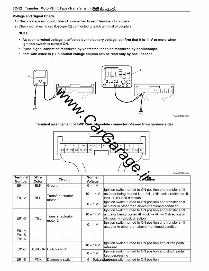
3C-52 Transfer: Motor-Shift Type (Transfer with Shift Actuator)
Voltage and Signal Check1) Check voltage using voltmeter (1) connected to each terminal of couplers.2) Check signal using oscilloscope (2) connected to each terminal of couplers.
NOTE
• As each terminal voltage is affected by the battery voltage, confirm that it is 11 V or more when ignition switch is turned ON.
• Pulse signal cannot be measured by voltmeter. It can be measured by oscilloscope.• Item with asterisk (*) in normal voltage column can be read only by oscilloscope.
Terminal arrangement of 4WD control module connector (Viewed from harness side)
1
2
I4JA01332053-01
123456789101112
1314151617181920212223242526
I4JA01332054-01
Terminal Number
Wire Color Circuit Normal
Voltage Condition
E91-1 BLK Ground 0 – 1 V —
E91-2 BLU Transfer actuator motor 1
10 – 14 VIgnition switch turned to ON position and transfer shift actuator being rotated N → 4H → 4H-lock direction or 4L-lock → 4H-lock direction
0 – 1 V Ignition switch turned to ON position and transfer shift actuator in other than above-mentioned condition
E91-3 YEL Transfer actuator motor 2
10 – 14 VIgnition switch turned to ON position and transfer shift actuator being rotated 4H-lock → 4H → N direction or 4H-lock → 4L-lock direction
0 – 1 V Ignition switch turned to ON position and transfer shift actuator in other than above-mentioned condition
E91-4 — — — —E91-5 — — — —E91-6 — — — —
E91-7 BLK/ORN Clutch switch10 – 14 V Ignition switch turned to ON position and clutch pedal
released
0 – 1 V Ignition switch turned to ON position and clutch pedal kept depressing
E91-8 PNK Diagnosis switch 4 – 5 V Ignition switch turned to ON position
www.CarGarage.ir
www.CarGarage.ir
www.CarGarage.ir

Transfer: Motor-Shift Type (Transfer with Shift Actuator) 3C-53
E91-9 — — — —E91-10 BLK Ground 0 – 1 V —
E91-11 WHT Power source for internal memory 10 – 14 V —
E91-12 BLK/WHT Ignition switch 10 – 14 V Ignition switch turned to ON position
E91-13 BLK/WHT 4L/N switch10 – 14 V Ignition switch turned to ON position and transfer shifted
to 4H or 4H-lock position
0 – 1 V Ignition switch turned to ON position and transfer shifted to 4L-lock or N position
E91-14 RED/GRN Center differential lock switch
10 – 14 V Ignition switch turned to ON position and transfer shifted to 4H-lock or 4L-lock position
0 – 1 V Ignition switch turned to ON position and transfer shifted to N or 4H position
E91-15 — — — —E91-16 — — — —E91-17 — — — —
E91-18 LT GRN Transfer switch 110 – 14 V Ignition switch turned to ON position and transfer switch
at 4H, N or 4L-lock position
0 – 1 V Ignition switch turned to ON position and transfer switch at N position
E91-19 BLU/BLK Transfer switch 210 – 14 V Ignition switch turned to ON position and transfer switch
at 4L-lock position
0 – 1 V Ignition switch turned to ON position and transfer switch at 4H, 4H-lock or N position
E91-20 BLU/ORN Transfer switch 310 – 14 V Ignition switch turned to ON position and transfer switch
at 4H or N position
0 – 1 V Ignition switch turned to ON position and transfer switch at 4H-lock or 4L-lock position
E91-21 PPL/WHT Data link connector (DLC) 10 – 14 V Ignition switch turned to ON position
E91-22 RED CAN communication line (High) *2.5 – 3.5 V Ignition switch turned to ON position
E91-23 WHT CAN communication line (Low) *1.5 – 2.5 V Ignition switch turned to ON position
E91-24 BLK/YELTransfer actuator position switch (ground)
0 – 1 V —
E91-25 REDTransfer actuator position switch 1 (power)
Approx. 4 V Ignition switch turned to ON position and transfer shifted to 4H-lock position
Approx. 2 V Ignition switch turned to ON position and transfer shifted to 4H position
Approx. 1 V Ignition switch turned to ON position and transfer shifted to 4L-lock or N position
Approx. 0 V Ignition switch turned to OFF position
E91-26 RED/BLKTransfer actuator position switch 2 (power)
Approx. 4 V Ignition switch turned to ON position and transfer shifted to 4L-lock position
Approx. 2 V Ignition switch turned to ON position and transfer shifted to N position
Approx. 1 V Ignition switch turned to ON position and transfer shifted to 4H or 4H-lock position
Approx. 0 V Ignition switch turned to OFF position
Terminal Number
Wire Color Circuit Normal
Voltage Condition
www.CarGarage.ir
www.CarGarage.ir
www.CarGarage.ir
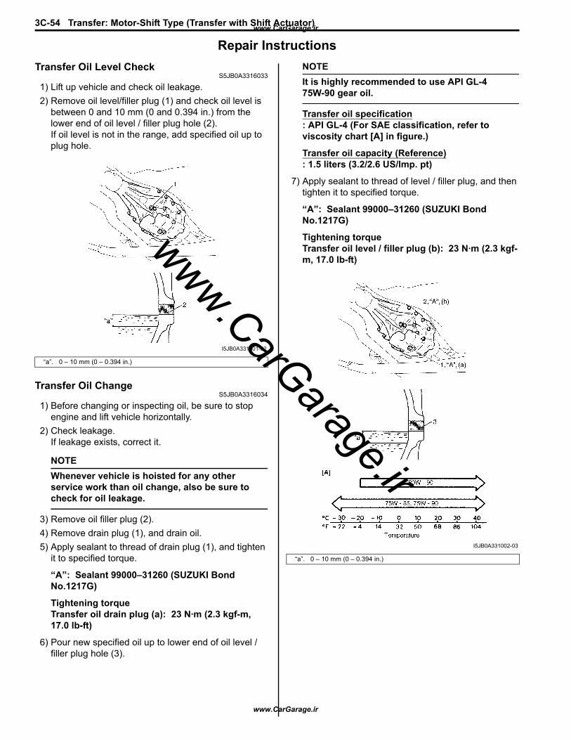
3C-54 Transfer: Motor-Shift Type (Transfer with Shift Actuator)
Repair InstructionsTransfer Oil Level Check
S5JB0A3316033
1) Lift up vehicle and check oil leakage.2) Remove oil level/filler plug (1) and check oil level is
between 0 and 10 mm (0 and 0.394 in.) from the lower end of oil level / filler plug hole (2).If oil level is not in the range, add specified oil up to plug hole.
Transfer Oil ChangeS5JB0A3316034
1) Before changing or inspecting oil, be sure to stop engine and lift vehicle horizontally.
2) Check leakage.If leakage exists, correct it.
NOTEWhenever vehicle is hoisted for any other service work than oil change, also be sure to check for oil leakage.
3) Remove oil filler plug (2).4) Remove drain plug (1), and drain oil.5) Apply sealant to thread of drain plug (1), and tighten
it to specified torque.
“A”: Sealant 99000–31260 (SUZUKI Bond No.1217G)
Tightening torqueTransfer oil drain plug (a): 23 N·m (2.3 kgf-m, 17.0 lb-ft)
6) Pour new specified oil up to lower end of oil level / filler plug hole (3).
NOTEIt is highly recommended to use API GL-4 75W-90 gear oil.
Transfer oil specification: API GL-4 (For SAE classification, refer to viscosity chart [A] in figure.)
Transfer oil capacity (Reference): 1.5 liters (3.2/2.6 US/lmp. pt)
7) Apply sealant to thread of level / filler plug, and then tighten it to specified torque.
“A”: Sealant 99000–31260 (SUZUKI Bond No.1217G)
Tightening torqueTransfer oil level / filler plug (b): 23 N·m (2.3 kgf-m, 17.0 lb-ft)
“a”. 0 – 10 mm (0 – 0.394 in.)
I5JB0A331001-02
“a”. 0 – 10 mm (0 – 0.394 in.)
I5JB0A331002-03
www.CarGarage.ir
www.CarGarage.ir
www.CarGarage.ir
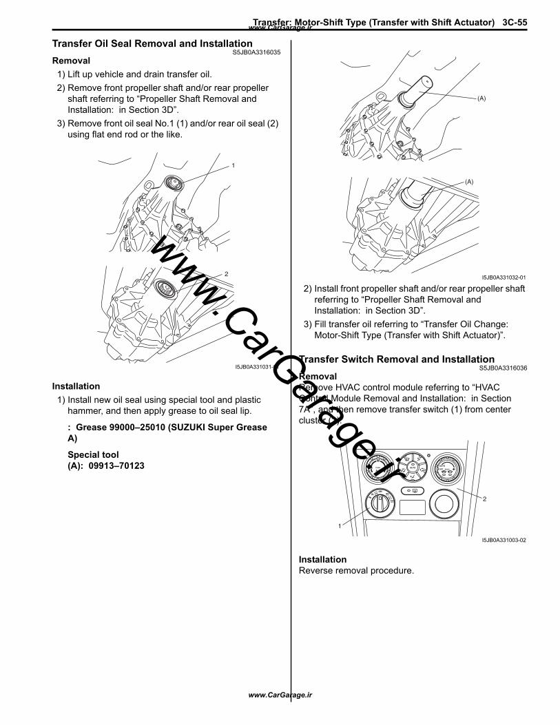
Transfer: Motor-Shift Type (Transfer with Shift Actuator) 3C-55
Transfer Oil Seal Removal and InstallationS5JB0A3316035
Removal1) Lift up vehicle and drain transfer oil.2) Remove front propeller shaft and/or rear propeller
shaft referring to “Propeller Shaft Removal and Installation: in Section 3D”.
3) Remove front oil seal No.1 (1) and/or rear oil seal (2) using flat end rod or the like.
Installation1) Install new oil seal using special tool and plastic
hammer, and then apply grease to oil seal lip.
: Grease 99000–25010 (SUZUKI Super Grease A)
Special tool(A): 09913–70123
2) Install front propeller shaft and/or rear propeller shaft referring to “Propeller Shaft Removal and Installation: in Section 3D”.
3) Fill transfer oil referring to “Transfer Oil Change: Motor-Shift Type (Transfer with Shift Actuator)”.
Transfer Switch Removal and InstallationS5JB0A3316036
RemovalRemove HVAC control module referring to “HVAC Control Module Removal and Installation: in Section 7A”, and then remove transfer switch (1) from center cluster (2).
InstallationReverse removal procedure.
2
1
I5JB0A331031-01
(A)
(A)
I5JB0A331032-01
1
2
I5JB0A331003-02
www.CarGarage.ir
www.CarGarage.ir
www.CarGarage.ir

3C-56 Transfer: Motor-Shift Type (Transfer with Shift Actuator)
Transfer Switch InspectionS5JB0A3316039
Check continuity between following terminals when transfer switch (1) operated at each position.
4WD Control Module Removal and InstallationS5JB0A3316038
Removal1) Disconnect negative (–) cable from battery.2) If the vehicle is equipped with air bag system,
disable air bag system. Refer to “Disabling Air Bag System: in Section 8B”.
3) Disconnect connectors from 4WD control module (1).
4) Remove 4WD control module with TCM by removing its nuts, and then separate 4WD control module and TCM.
InstallationReverse removal procedure for installation noting the following.• Connect 4WD control module connectors securely.• If the vehicle is equipped with air bag system, be sure
to enable air bag system after 4WD control module is back in place.Refer to “Enabling Air Bag System: in Section 8B”.
Switch position Terminal (2) 1 – 2
N (3) 1 – 2 – 34H (4) 1 – 3
4H-lock (5) 1 – 3 – 44L-lock (6) 1 – 4
[A]: Transfer switch connector (harness side view)
[A]
6 5 4 3 2 1
6
5
43
2
1
I5JB0A331004-04
1I5JB0A331005-01
www.CarGarage.ir
www.CarGarage.ir
www.CarGarage.ir
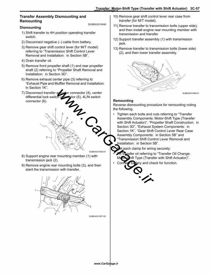
Transfer: Motor-Shift Type (Transfer with Shift Actuator) 3C-57
Transfer Assembly Dismounting and Remounting
S5JB0A3316040Dismounting1) Shift transfer to 4H position operating transfer
switch.2) Disconnect negative (–) cable from battery.3) Remove gear shift control lever (for M/T model)
referring to “Transmission Shift Control Lever Removal and Installation: in Section 5B”.
4) Drain transfer oil.5) Remove front propeller shaft (1) and rear propeller
shaft (2) referring to “Propeller Shaft Removal and Installation: in Section 3D”.
6) Remove exhaust center pipe (3) referring to “Exhaust Pipe and Muffler Removal and Installation: in Section 1K”.
7) Disconnect transfer actuator connector (4), center differential lock switch connector (5), 4L/N switch connector (6).
8) Support engine rear mounting member (1) with transmission jack (2).
9) Remove engine rear mounting bolts (3), and then slant the transmission with transfer.
10) Remove gear shift control lever rear case from transfer (for M/T model).
11) Remove transfer to transmission bolts (upper side), and then install engine rear mounting member with transmission and transfer.
12) Support transfer assembly (1) with transmission jack.
13) Remove transfer to transmission bolts (lower side) (2), and then lower transfer assembly.
RemountingReverse dismounting procedure for remounting noting the following.• Tighten each bolts and nuts referring to “Transfer
Assembly Components: Motor-Shift Type (Transfer with Shift Actuator)”, “Propeller Shaft Construction: in Section 3D”, “Exhaust System Components: in Section 1K”, “Gear Shift Control Lever Rear Case Assembly Components: in Section 5B” and “Transmission Shift Control Lever Removal and Installation: in Section 5B”.
• Set each clamp for wiring securely.• Fill transfer oil referring to “Transfer Oil Change:
Motor-Shift Type (Transfer with Shift Actuator)”.• Connect battery and check for function.
1
4
3
6
5
2
I5JB0A331006-01
1
2
3
I5JB0A331007-02
12
I5JB0A331008-01
www.CarGarage.ir
www.CarGarage.ir
www.CarGarage.ir
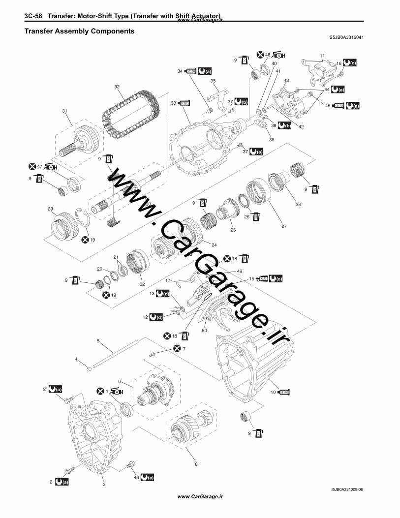
3C-58 Transfer: Motor-Shift Type (Transfer with Shift Actuator)
Transfer Assembly ComponentsS5JB0A3316041
11
16
44
45
42
43
41
409
(c)
(a)
39
38
(b)
37 (a)
37
35
(a)
(a)1217G
10 1217G
33
32
30
31
1217G
34 1217G
48 A
OIL
9
28
27
OIL
9
OIL
OIL
9
OIL
9
OIL
19
29
19
47 A
26
25
24
23
22
4
5
7
6
21
20
OIL
9O
IL
2 (a)
2 3
8
(a)46 (a)
1 A
9
OIL
12 (d)
13
17
(d)
15 (a)1322
49
5018
OIL18
14
(b)
I5JB0A331009-06
www.CarGarage.ir
www.CarGarage.ir
www.CarGarage.ir
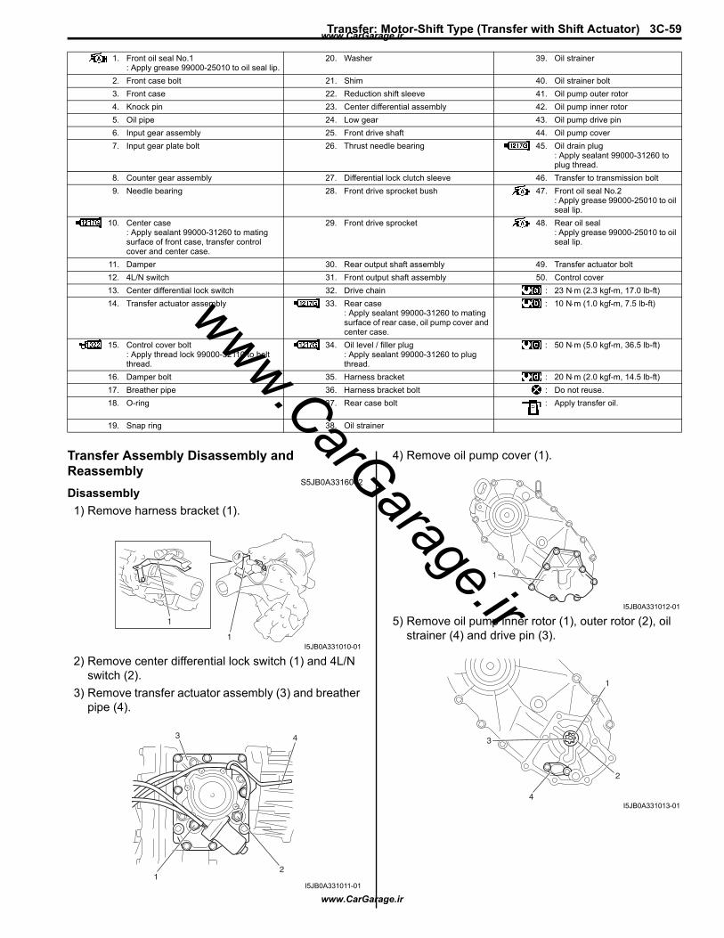
Transfer: Motor-Shift Type (Transfer with Shift Actuator) 3C-59
Transfer Assembly Disassembly and Reassembly
S5JB0A3316042Disassembly1) Remove harness bracket (1).
2) Remove center differential lock switch (1) and 4L/N switch (2).
3) Remove transfer actuator assembly (3) and breather pipe (4).
4) Remove oil pump cover (1).
5) Remove oil pump inner rotor (1), outer rotor (2), oil strainer (4) and drive pin (3).
1. Front oil seal No.1: Apply grease 99000-25010 to oil seal lip.
20. Washer 39. Oil strainer
2. Front case bolt 21. Shim 40. Oil strainer bolt3. Front case 22. Reduction shift sleeve 41. Oil pump outer rotor4. Knock pin 23. Center differential assembly 42. Oil pump inner rotor5. Oil pipe 24. Low gear 43. Oil pump drive pin6. Input gear assembly 25. Front drive shaft 44. Oil pump cover7. Input gear plate bolt 26. Thrust needle bearing 45. Oil drain plug
: Apply sealant 99000-31260 to plug thread.
8. Counter gear assembly 27. Differential lock clutch sleeve 46. Transfer to transmission bolt9. Needle bearing 28. Front drive sprocket bush 47. Front oil seal No.2
: Apply grease 99000-25010 to oil seal lip.
10. Center case: Apply sealant 99000-31260 to mating surface of front case, transfer control cover and center case.
29. Front drive sprocket 48. Rear oil seal: Apply grease 99000-25010 to oil seal lip.
11. Damper 30. Rear output shaft assembly 49. Transfer actuator bolt12. 4L/N switch 31. Front output shaft assembly 50. Control cover13. Center differential lock switch 32. Drive chain : 23 N⋅m (2.3 kgf-m, 17.0 lb-ft)14. Transfer actuator assembly 33. Rear case
: Apply sealant 99000-31260 to mating surface of rear case, oil pump cover and center case.
: 10 N⋅m (1.0 kgf-m, 7.5 lb-ft)
15. Control cover bolt: Apply thread lock 99000-32110 to bolt thread.
34. Oil level / filler plug: Apply sealant 99000-31260 to plug thread.
: 50 N⋅m (5.0 kgf-m, 36.5 lb-ft)
16. Damper bolt 35. Harness bracket : 20 N⋅m (2.0 kgf-m, 14.5 lb-ft)17. Breather pipe 36. Harness bracket bolt : Do not reuse.18. O-ring 37. Rear case bolt : Apply transfer oil.
19. Snap ring 38. Oil strainer
1
1I5JB0A331010-01
21
3 4
I5JB0A331011-01
1
I5JB0A331012-01
1
2
4
3
I5JB0A331013-01
www.CarGarage.ir
www.CarGarage.ir
www.CarGarage.ir
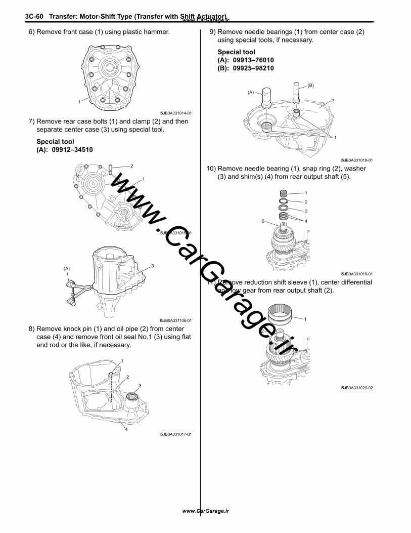
3C-60 Transfer: Motor-Shift Type (Transfer with Shift Actuator)
6) Remove front case (1) using plastic hammer.
7) Remove rear case bolts (1) and clamp (2) and then separate center case (3) using special tool.
Special tool(A): 09912–34510
8) Remove knock pin (1) and oil pipe (2) from center case (4) and remove front oil seal No.1 (3) using flat end rod or the like, if necessary.
9) Remove needle bearings (1) from center case (2) using special tools, if necessary.
Special tool(A): 09913–76010(B): 09925–98210
10) Remove needle bearing (1), snap ring (2), washer (3) and shim(s) (4) from rear output shaft (5).
11) Remove reduction shift sleeve (1), center differential and low gear from rear output shaft (2).
1
I5JB0A331014-01
1
2
I5JB0A331015-01
3(A)
I5JB0A331106-01
1
2
3
4I5JB0A331017-01
(A)
(B)
1
2
I5JB0A331018-01
1
2
3
45
I5JB0A331019-01
1
2
I5JB0A331020-02
www.CarGarage.ir
www.CarGarage.ir
www.CarGarage.ir

Transfer: Motor-Shift Type (Transfer with Shift Actuator) 3C-61
12) Remove needle bearings (1), front drive shaft (2) and thrust needle bearing (4) from rear output shaft (3).
13) Remove differential lock clutch sleeve (1) from rear output shaft (2).
14) Remove front drive sprocket bush (1) from rear output shaft (2).
15) Take out front drive sprocket (1), front output shaft assembly (2), drive chain (3) and needle bearing (4) from rear case (5) all at once.
16) Remove snap ring (1), and then remove rear output shaft assembly (2) from rear case (3).
17) Remove rear oil seal (1) from rear case (2) using flat end rod or the like, if necessary.
18) Remove needle bearing (1) from rear case (2) using special tool, if necessary.
Special tool(A): 09913–76010
19) Remove input gear plate bolts (1) from front case (2).
1
1
2
3
4
I5JB0A331021-01
1
2
I5JB0A331022-01
1
2
I5JB0A331023-01
1
2
3
5
4I5JB0A331024-01
1
23
I5JB0A331025-01
1
2
I5JB0A331026-01
(A)
1
2
I5JB0A331027-01
1
2I5JB0A331028-02
www.CarGarage.ir
www.CarGarage.ir
www.CarGarage.ir

3C-62 Transfer: Motor-Shift Type (Transfer with Shift Actuator)
20) Remove input gear assembly (1) and counter gear assembly (2) from front case (3) using plastic hammer.
21) Remove front oil seal No.2 (1) from front case (2) using flat end rod or the like, if necessary.
Reassembly1) Install new front oil seal No.2 to front case (1) using
special tool, and then apply grease to oil seal lip.
: Grease 99000–25010 (SUZUKI Super Grease A)
Special tool(A): 09913–85210
2) Install counter gear assembly (1) to front case (2), and then install input gear assembly (3).
NOTEInstall input gear plate (4) so as not to hit counter gear assembly.
3) Tighten new input gear plate bolts (1) to specified torque.
Tightening torqueInput gear plate bolt (a): 23 N·m (2.3 kgf-m, 17.0 lb-ft)
31
3
1
2
I5JB0A331029-01
1
2
I5JB0A331030-01
(A)
1
I5JB0A331033-01
2
31
1
2
43
I5JB0A331034-02
1, (a)
I5JB0A331035-03
www.CarGarage.ir
www.CarGarage.ir
www.CarGarage.ir

Transfer: Motor-Shift Type (Transfer with Shift Actuator) 3C-63
4) Install needle bearing (1) to rear case (2) using special tool as shown in figure.
Distance between case and needle bearing “a”: 0 – 0.5 mm (0 – 0.008 in.)
Special tool(A): 09913–76010
5) Install new rear oil seal (1) to rear case (2) using special tool as shown in figure, and then apply grease to oil seal lip.
“A”: Grease 99000–25010 (SUZUKI Super Grease A)
Distance between case and oil seal “a”: 3.5 – 4.5 mm (0.138 – 0.177 in.)
Special tool(A): 09913–70123
6) Install rear output shaft assembly (1) to rear case (2), and then install snap ring (3).
7) Install front drive sprocket (1), front output shaft assembly (2), drive chain (3) and needle bearing (4) into rear case (5).
8) Install front drive sprocket bush (1) into front drive sprocket (2).
9) Install differential lock clutch sleeve (1) to rear output shaft (2) as shown in figure.
10) Install thrust needle bearing (4), front drive shaft (1) and needle bearings (2) to rear output shaft (3).
(A)
1
2
“a”
I5JB0A331036-02
“a”(A)
1, “A”
2
1
2
I5JB0A331037-04
1
2
3
I5JB0A331038-01
1
2
3
5
4I5JB0A331024-01
1
2
I5JB0A331039-01
1
2
I5JB0A331040-01
1
1
2
3
4
I5JB0A331041-02
www.CarGarage.ir
www.CarGarage.ir
www.CarGarage.ir
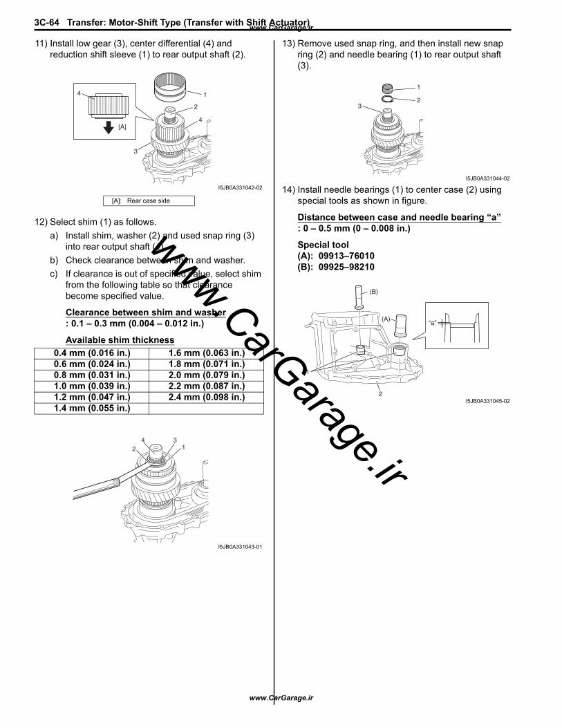
3C-64 Transfer: Motor-Shift Type (Transfer with Shift Actuator)
11) Install low gear (3), center differential (4) and reduction shift sleeve (1) to rear output shaft (2).
12) Select shim (1) as follows.a) Install shim, washer (2) and used snap ring (3)
into rear output shaft (4).b) Check clearance between shim and washer.c) If clearance is out of specified value, select shim
from the following table so that clearance become specified value.
Clearance between shim and washer: 0.1 – 0.3 mm (0.004 – 0.012 in.)
Available shim thickness
13) Remove used snap ring, and then install new snap ring (2) and needle bearing (1) to rear output shaft (3).
14) Install needle bearings (1) to center case (2) using special tools as shown in figure.
Distance between case and needle bearing “a”: 0 – 0.5 mm (0 – 0.008 in.)
Special tool(A): 09913–76010(B): 09925–98210
[A]: Rear case side
0.4 mm (0.016 in.) 1.6 mm (0.063 in.)0.6 mm (0.024 in.) 1.8 mm (0.071 in.)0.8 mm (0.031 in.) 2.0 mm (0.079 in.)1.0 mm (0.039 in.) 2.2 mm (0.087 in.)1.2 mm (0.047 in.) 2.4 mm (0.098 in.)1.4 mm (0.055 in.)
1
2
4
[A]4
3
I5JB0A331042-02
13
24
I5JB0A331043-01
1
23
I5JB0A331044-02
1
2
(B)
(A)“a”
I5JB0A331045-02
www.CarGarage.ir
www.CarGarage.ir
www.CarGarage.ir
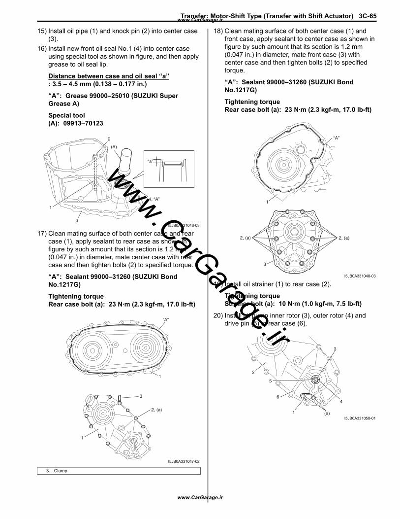
Transfer: Motor-Shift Type (Transfer with Shift Actuator) 3C-65
15) Install oil pipe (1) and knock pin (2) into center case (3).
16) Install new front oil seal No.1 (4) into center case using special tool as shown in figure, and then apply grease to oil seal lip.
Distance between case and oil seal “a”: 3.5 – 4.5 mm (0.138 – 0.177 in.)
“A”: Grease 99000–25010 (SUZUKI Super Grease A)
Special tool(A): 09913–70123
17) Clean mating surface of both center case and rear case (1), apply sealant to rear case as shown in figure by such amount that its section is 1.2 mm (0.047 in.) in diameter, mate center case with rear case and then tighten bolts (2) to specified torque.
“A”: Sealant 99000–31260 (SUZUKI Bond No.1217G)
Tightening torqueRear case bolt (a): 23 N·m (2.3 kgf-m, 17.0 lb-ft)
18) Clean mating surface of both center case (1) and front case, apply sealant to center case as shown in figure by such amount that its section is 1.2 mm (0.047 in.) in diameter, mate front case (3) with center case and then tighten bolts (2) to specified torque.
“A”: Sealant 99000–31260 (SUZUKI Bond No.1217G)
Tightening torqueRear case bolt (a): 23 N·m (2.3 kgf-m, 17.0 lb-ft)
19) Install oil strainer (1) to rear case (2).
Tightening torqueStrainer bolt (a): 10 N·m (1.0 kgf-m, 7.5 lb-ft)
20) Install oil pump inner rotor (3), outer rotor (4) and drive pin (5) to rear case (6).
3. Clamp
2
1
3
(A)
4, “A”
“a”
I5JB0A331046-03
“A”
1
3
1
2, (a)
I5JB0A331047-02
“A”
1
2, (a) 2, (a)
3
I5JB0A331048-03
2
5
6
1 (a)
4
3
I5JB0A331050-01
www.CarGarage.ir
www.CarGarage.ir
www.CarGarage.ir
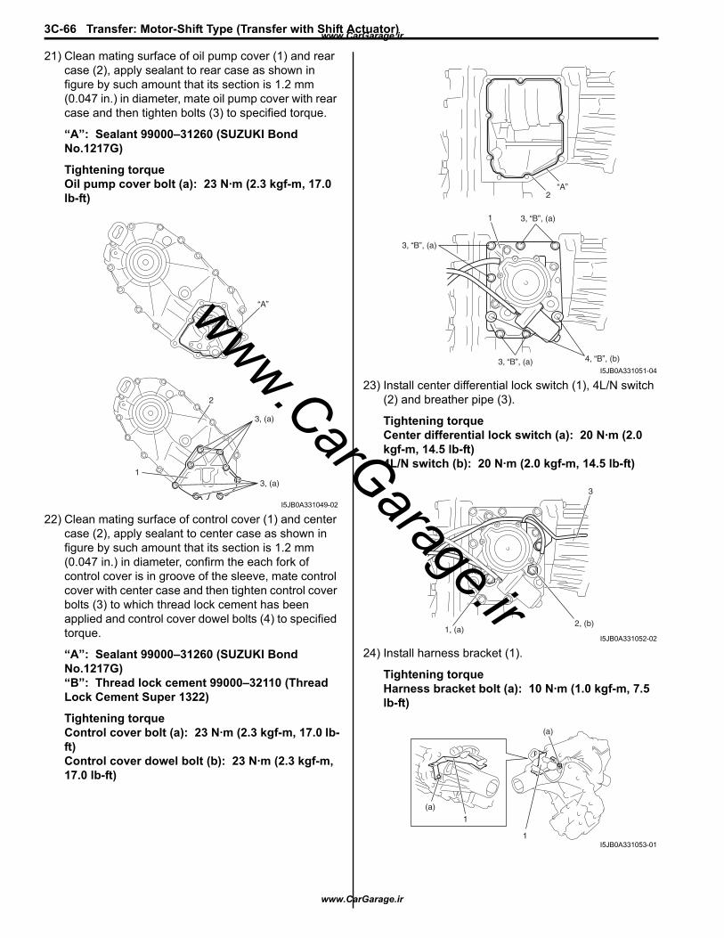
3C-66 Transfer: Motor-Shift Type (Transfer with Shift Actuator)
21) Clean mating surface of oil pump cover (1) and rear case (2), apply sealant to rear case as shown in figure by such amount that its section is 1.2 mm (0.047 in.) in diameter, mate oil pump cover with rear case and then tighten bolts (3) to specified torque.
“A”: Sealant 99000–31260 (SUZUKI Bond No.1217G)
Tightening torqueOil pump cover bolt (a): 23 N·m (2.3 kgf-m, 17.0 lb-ft)
22) Clean mating surface of control cover (1) and center case (2), apply sealant to center case as shown in figure by such amount that its section is 1.2 mm (0.047 in.) in diameter, confirm the each fork of control cover is in groove of the sleeve, mate control cover with center case and then tighten control cover bolts (3) to which thread lock cement has been applied and control cover dowel bolts (4) to specified torque.
“A”: Sealant 99000–31260 (SUZUKI Bond No.1217G)“B”: Thread lock cement 99000–32110 (Thread Lock Cement Super 1322)
Tightening torqueControl cover bolt (a): 23 N·m (2.3 kgf-m, 17.0 lb-ft)Control cover dowel bolt (b): 23 N·m (2.3 kgf-m, 17.0 lb-ft)
23) Install center differential lock switch (1), 4L/N switch (2) and breather pipe (3).
Tightening torqueCenter differential lock switch (a): 20 N·m (2.0 kgf-m, 14.5 lb-ft)4L/N switch (b): 20 N·m (2.0 kgf-m, 14.5 lb-ft)
24) Install harness bracket (1).
Tightening torqueHarness bracket bolt (a): 10 N·m (1.0 kgf-m, 7.5 lb-ft)
“A”
3, (a)
3, (a)1
2
I5JB0A331049-02
“A”2
1 3, “B”, (a)
3, “B”, (a)
3, “B”, (a) 4, “B”, (b)I5JB0A331051-04
3
2, (b)1, (a)
I5JB0A331052-02
(a)
(a)
1
1I5JB0A331053-01
www.CarGarage.ir
www.CarGarage.ir
www.CarGarage.ir
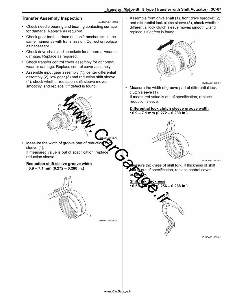
Transfer: Motor-Shift Type (Transfer with Shift Actuator) 3C-67
Transfer Assembly InspectionS5JB0A3316043
• Check needle bearing and bearing contacting surface for damage. Replace as required.
• Check gear tooth surface and shift mechanism in the same manner as with transmission. Correct or replace as necessary.
• Check drive chain and sprockets for abnormal wear or damage. Replace as required.
• Check transfer control cover assembly for abnormal wear or damage. Replace control cover assembly.
• Assemble input gear assembly (1), center differential assembly (2), low gear (3) and reduction shift sleeve (4), check whether reduction shift sleeve moves smoothly, and replace it if defect is found.
• Measure the width of groove part of reduction shift sleeve (1).If measured value is out of specification, replace reduction sleeve.
Reduction shift sleeve groove width: 6.9 – 7.1 mm (0.272 – 0.280 in.)
• Assemble front drive shaft (1), front drive sprocket (2) and differential lock clutch sleeve (3), check whether differential lock clutch sleeve moves smoothly, and replace it if defect is found.
• Measure the width of groove part of differential lock clutch sleeve (1).If measured value is out of specification, replace reduction sleeve.
Differential lock clutch sleeve groove width: 6.9 – 7.1 mm (0.272 – 0.280 in.)
• Measure thickness of shift fork. If thickness of shift fork is out of specification, replace control cover assembly.
Shift fork thickness: 6.5 – 6.8 mm (0.256 – 0.268 in.)
3
4
21
I5JB0A331054-01
1
I5JB0A331055-01
2
3
1I5JB0A331056-01
1
I5JB0A331057-01
I5JB0A331082-01
www.CarGarage.ir
www.CarGarage.ir
www.CarGarage.ir
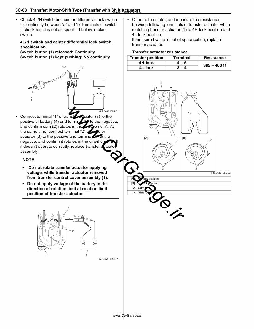
3C-68 Transfer: Motor-Shift Type (Transfer with Shift Actuator)
• Check 4L/N switch and center differential lock switch for continuity between “a” and “b” terminals of switch. If check result is not as specified below, replace switch.
4L/N switch and center differential lock switch specificationSwitch button (1) released: ContinuitySwitch button (1) kept pushing: No continuity
• Connect terminal “1” of transfer actuator (3) to the positive of battery (4) and terminal “2” to the negative, and confirm cam (2) rotates in the direction of A. At the same time, connect terminal “2” of transfer actuator (3) to the positive and terminal “1” to the negative, and confirm it rotates in the direction of B. If it doesn’t operate correctly, replace transfer actuator assembly.
NOTE
• Do not rotate transfer actuator applying voltage, while transfer actuator removed from transfer control cover assembly (1).
• Do not apply voltage of the battery in the direction of rotation limit at rotation limit position of transfer actuator.
• Operate the motor, and measure the resistance between following terminals of transfer actuator when matching transfer actuator (1) to 4H-lock position and 4L-lock position.If measured value is out of specification, replace transfer actuator.
Transfer actuator resistance
1
“a” “b”
I5JB0A331058-01
1
2
1354 2
43
AB
I5JB0A331059-01
Transfer position Terminal Resistance4H-lock 4 – 5 385 – 400 Ω4L-lock 3 – 4
[A]: 4H-lock position[B]: 4L-lock position
2. Cam3. Shift fork pin
[A] [B]
3 3
22
1
2
12
354
I5JB0A331060-02
www.CarGarage.ir
www.CarGarage.ir
www.CarGarage.ir
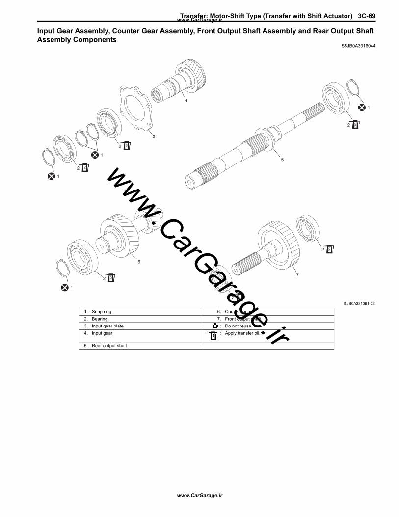
Transfer: Motor-Shift Type (Transfer with Shift Actuator) 3C-69
Input Gear Assembly, Counter Gear Assembly, Front Output Shaft Assembly and Rear Output Shaft Assembly Components
S5JB0A3316044
4
3
2
5
6
7O
IL
2
OIL
2
OIL
2
OIL
2
OIL
1
1
1
1
2
OIL
I5JB0A331061-02
1. Snap ring 6. Counter gear2. Bearing 7. Front output shaft3. Input gear plate : Do not reuse.4. Input gear : Apply transfer oil.
5. Rear output shaft
www.CarGarage.ir
www.CarGarage.ir
www.CarGarage.ir
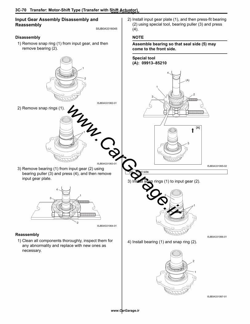
3C-70 Transfer: Motor-Shift Type (Transfer with Shift Actuator)
Input Gear Assembly Disassembly and Reassembly
S5JB0A3316045
Disassembly1) Remove snap ring (1) from input gear, and then
remove bearing (2).
2) Remove snap rings (1).
3) Remove bearing (1) from input gear (2) using bearing puller (3) and press (4), and then remove input gear plate.
Reassembly1) Clean all components thoroughly, inspect them for
any abnormality and replace with new ones as necessary.
2) Install input gear plate (1), and then press-fit bearing (2) using special tool, bearing puller (3) and press (4).
NOTEAssemble bearing so that seal side (5) may come to the front side.
Special tool(A): 09913–85210
3) Install snap rings (1) to input gear (2).
4) Install bearing (1) and snap ring (2).
1
2
I5JB0A331062-01
1
I5JB0A331063-01
1
2
3
4
I5JB0A331064-01
[A]: Front side
(A)
23
1
4
5
[A]
I5JB0A331065-02
1
2
I5JB0A331066-01
2
1
I5JB0A331067-01
www.CarGarage.ir
www.CarGarage.ir
www.CarGarage.ir
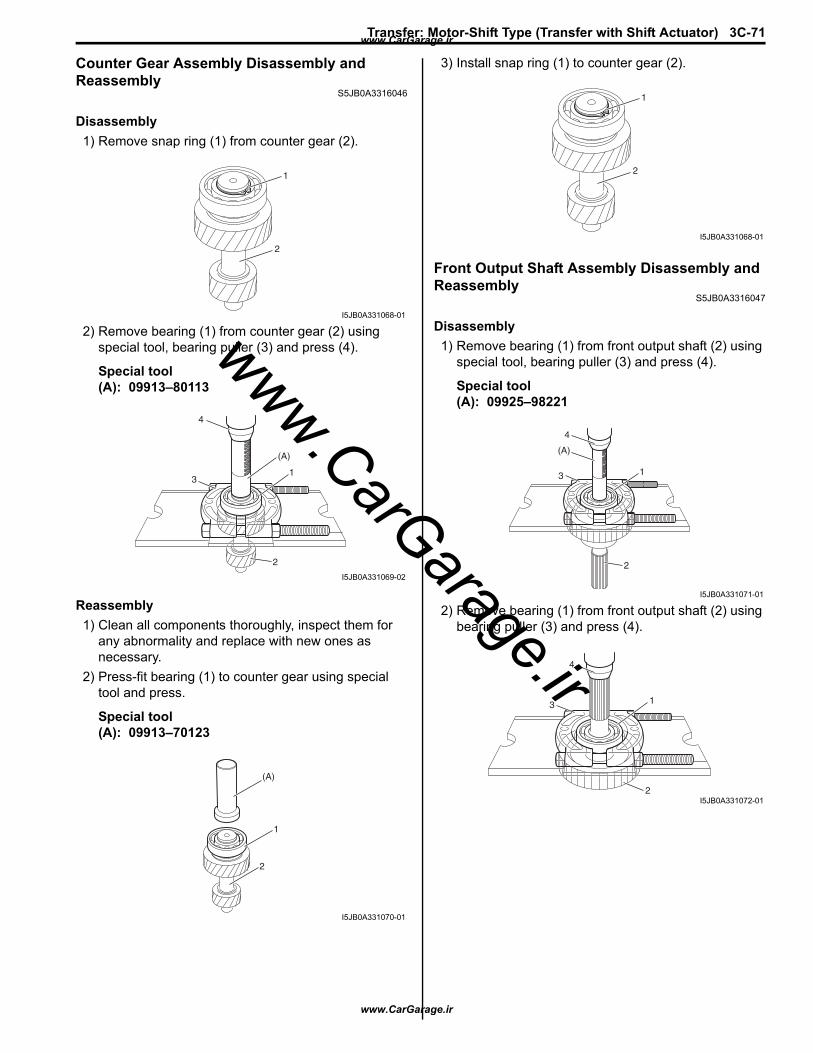
Transfer: Motor-Shift Type (Transfer with Shift Actuator) 3C-71
Counter Gear Assembly Disassembly and Reassembly
S5JB0A3316046
Disassembly1) Remove snap ring (1) from counter gear (2).
2) Remove bearing (1) from counter gear (2) using special tool, bearing puller (3) and press (4).
Special tool(A): 09913–80113
Reassembly1) Clean all components thoroughly, inspect them for
any abnormality and replace with new ones as necessary.
2) Press-fit bearing (1) to counter gear using special tool and press.
Special tool(A): 09913–70123
3) Install snap ring (1) to counter gear (2).
Front Output Shaft Assembly Disassembly and Reassembly
S5JB0A3316047
Disassembly1) Remove bearing (1) from front output shaft (2) using
special tool, bearing puller (3) and press (4).
Special tool(A): 09925–98221
2) Remove bearing (1) from front output shaft (2) using bearing puller (3) and press (4).
1
2
I5JB0A331068-01
2
1
(A)
3
4
I5JB0A331069-02
(A)
1
2
I5JB0A331070-01
1
2
I5JB0A331068-01
1
2
(A)
4
3
I5JB0A331071-01
1
2
3
4
I5JB0A331072-01
www.CarGarage.ir
www.CarGarage.ir
www.CarGarage.ir

3C-72 Transfer: Motor-Shift Type (Transfer with Shift Actuator)
Reassembly1) Clean all components thoroughly, inspect them for
any abnormality and replace with new ones as necessary.
2) Press-fit bearing (1) to front output shaft using special tool and press.
Special tool(A): 09913–84510
3) Press-fit bearing (1) to front output shaft using special tool and press.
Special tool(A): 09913–76010
Rear Output Shaft Assembly Disassembly and Reassembly
S5JB0A3316048
Disassembly1) Remove snap ring (1) from rear output shaft (2).
2) Remove bearing (1) from rear output shaft (2) using bearing puller (3) and press (4).
Reassembly1) Clean all components thoroughly, inspect them for
any abnormality and replace with new ones as necessary.
2) To ensure lubrication of rear output shaft (1), air blow oil holes (2) and make sure that they are free from any obstruction.
1
2
(A)
I5JB0A331073-01
(A)
1
2
I5JB0A331074-01
21
I5JB0A331075-01
13
4
2
I5JB0A331076-01
1
2
I5JB0A331077-01
www.CarGarage.ir
www.CarGarage.ir
www.CarGarage.ir
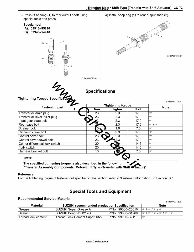
Transfer: Motor-Shift Type (Transfer with Shift Actuator) 3C-73
3) Press-fit bearing (1) to rear output shaft using special tools and press.
Special tool(A): 09913–85210 (B): 09940–54910
4) Install snap ring (1) to rear output shaft (2).
SpecificationsTightening Torque Specifications
S5JB0A3317001
NOTEThe specified tightening torque is also described in the following.“Transfer Assembly Components: Motor-Shift Type (Transfer with Shift Actuator)”
Reference:For the tightening torque of fastener not specified in this section, refer to “Fastener Information: in Section 0A”.
Special Tools and EquipmentRecommended Service Material
S5JB0A3318001
1
2
(B)
(A)
I5JB0A331078-01
21
I5JB0A331075-01
Fastening part Tightening torque NoteN⋅m kgf-m lb-ftTransfer oil drain plug 23 2.3 17.0Transfer oil level / filler plug 23 2.3 17.0Input gear plate bolt 23 2.3 17.0Rear case bolt 23 2.3 17.0 / Strainer bolt 10 1.0 7.5Oil pump cover bolt 23 2.3 17.0Control cover bolt 23 2.3 17.0Control cover dowel bolt 23 2.3 17.0Center differential lock switch 20 2.0 14.54L/N switch 20 2.0 14.5Harness bracket bolt 10 1.0 7.5
Material SUZUKI recommended product or Specification NoteGrease SUZUKI Super Grease A P/No.: 99000–25010 / / / Sealant SUZUKI Bond No.1217G P/No.: 99000–31260 / / / / / Thread lock cement Thread Lock Cement Super 1322 P/No.: 99000–32110
www.CarGarage.ir
www.CarGarage.ir
www.CarGarage.ir
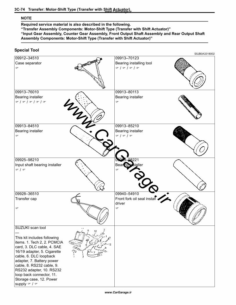
3C-74 Transfer: Motor-Shift Type (Transfer with Shift Actuator)
NOTERequired service material is also described in the following.“Transfer Assembly Components: Motor-Shift Type (Transfer with Shift Actuator)”“Input Gear Assembly, Counter Gear Assembly, Front Output Shaft Assembly and Rear Output Shaft Assembly Components: Motor-Shift Type (Transfer with Shift Actuator)”
Special ToolS5JB0A3318002
09912–34510 09913–70123Case separator Bearing installing tool
/ / /
09913–76010 09913–80113Bearing installer Bearing installer
/ / / /
09913–84510 09913–85210Bearing installer Bearing installer
/ /
09925–98210 09925–98221Input shaft bearing installer Bearing installer
/
09928–36510 09940–54910Transfer cap Front fork oil seal install
driver
SUZUKI scan tool—This kit includes following items. 1. Tech 2, 2. PCMCIA card, 3. DLC cable, 4. SAE 16/19 adapter, 5. Cigarette cable, 6. DLC loopback adapter, 7. Battery power cable, 8. RS232 cable, 9. RS232 adapter, 10. RS232 loop back connector, 11. Storage case, 12. Power supply /
www.CarGarage.ir
www.CarGarage.ir
www.CarGarage.ir
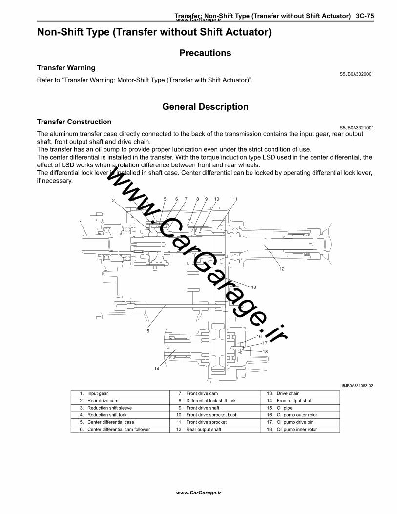
Transfer: Non-Shift Type (Transfer without Shift Actuator) 3C-75
Non-Shift Type (Transfer without Shift Actuator)
PrecautionsTransfer Warning
S5JB0A3320001Refer to “Transfer Warning: Motor-Shift Type (Transfer with Shift Actuator)”.
General DescriptionTransfer Construction
S5JB0A3321001The aluminum transfer case directly connected to the back of the transmission contains the input gear, rear output shaft, front output shaft and drive chain.The transfer has an oil pump to provide proper lubrication even under the strict condition of use.The center differential is installed in the transfer. With the torque induction type LSD used in the center differential, the effect of LSD works when a rotation difference between front and rear wheels.The differential lock lever is installed in shaft case. Center differential can be locked by operating differential lock lever, if necessary.
1
2 3 4 5 6 7 8 9 10 11
12
13
15
14
1617
18
I5JB0A331083-02
1. Input gear 7. Front drive cam 13. Drive chain2. Rear drive cam 8. Differential lock shift fork 14. Front output shaft3. Reduction shift sleeve 9. Front drive shaft 15. Oil pipe4. Reduction shift fork 10. Front drive sprocket bush 16. Oil pomp outer rotor5. Center differential case 11. Front drive sprocket 17. Oil pump drive pin6. Center differential cam follower 12. Rear output shaft 18. Oil pump inner rotor
www.CarGarage.ir
www.CarGarage.ir
www.CarGarage.ir
3C-76 Transfer: Non-Shift Type (Transfer without Shift Actuator)
Diagnostic Information and ProceduresTransfer Symptom Diagnosis
S5JB0A3324001Before attempting to repair the transfer or related components for any reason other than mechanical failure, the condition and possible causes should be identified.When any of these conditions occur, the following inspections should be made before disassembling the transfer.• Check transfer for oil level and oil deterioration.
Refer to “Transfer Oil Change: Non-Shift Type (Transfer without Shift Actuator)”.After performing the above inspections, refer to the following diagnosis table.
Condition Possible cause Correction / Reference ItemGear slipping out of mesh Worn control cover shift shaft Replace referring to “Transfer Assembly
Inspection: Motor-Shift Type (Transfer with Shift Actuator)”.
Worn shift fork or sleeve Replace referring to “Transfer Assembly Inspection: Motor-Shift Type (Transfer with Shift Actuator)”.
Weak or damaged control cover shift shaft spring
Replace referring to “Transfer Assembly Inspection: Motor-Shift Type (Transfer with Shift Actuator)”.
Worn bearings on input gear or counter gear
Replace referring to “Transfer Assembly Inspection: Motor-Shift Type (Transfer with Shift Actuator)”.
Worn chamfered tooth on sleeve or gear Replace sleeve and gear referring to “Transfer Assembly Inspection: Motor-Shift Type (Transfer with Shift Actuator)”.
Missing or disengagement of circlip(s) Repair or replace referring to “Transfer Assembly Inspection: Motor-Shift Type (Transfer with Shift Actuator)”.
Noise Inadequate or insufficient transfer oil Replenish referring to “Transfer Oil Change: Non-Shift Type (Transfer without Shift Actuator)”.
Damaged or worn bearing(s) Replace referring to “Transfer Assembly Inspection: Motor-Shift Type (Transfer with Shift Actuator)”.
Damaged or worn gear(s) Replace referring to “Transfer Assembly Inspection: Motor-Shift Type (Transfer with Shift Actuator)”.
Damaged or worn chamfered tooth on sleeve or gear
Replace referring to “Transfer Assembly Inspection: Motor-Shift Type (Transfer with Shift Actuator)”.
www.CarGarage.ir
www.CarGarage.ir
www.CarGarage.ir
Transfer: Non-Shift Type (Transfer without Shift Actuator) 3C-77
Repair InstructionsTransfer Oil Change
S5JB0A3326002Refer to “Transfer Oil Change: Motor-Shift Type (Transfer with Shift Actuator)”.
Transfer Oil Level CheckS5JB0A3326003
Refer to “Transfer Oil Level Check: Motor-Shift Type (Transfer with Shift Actuator)”.
Transfer Oil Seal Removal and InstallationS5JB0A3326004
Refer to “Transfer Oil Seal Removal and Installation: Motor-Shift Type (Transfer with Shift Actuator)”.
Transfer Assembly Dismounting and RemountingS5JB0A3326005
Refer to “Transfer Assembly Dismounting and Remounting: Motor-Shift Type (Transfer with Shift Actuator)”.
www.CarGarage.ir
www.CarGarage.ir
www.CarGarage.ir
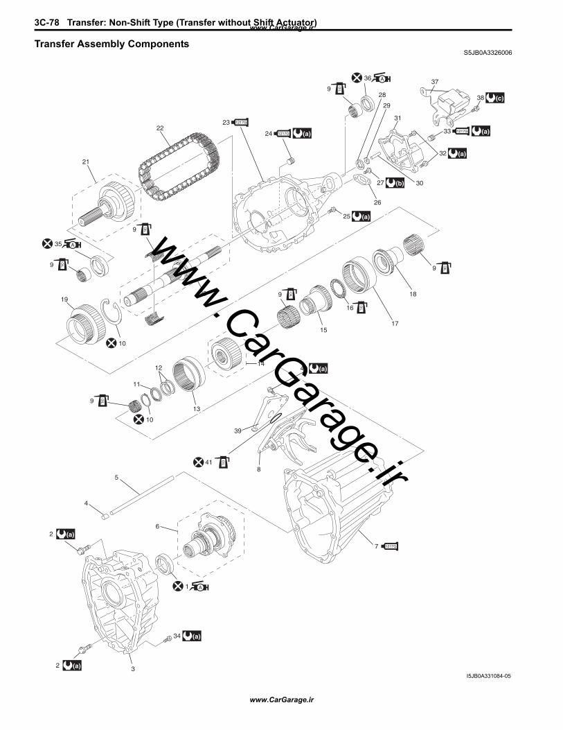
3C-78 Transfer: Non-Shift Type (Transfer without Shift Actuator)
Transfer Assembly ComponentsS5JB0A3326006
3736
938 (c)
32 (a)
25
20
(a)
(a)
40 (a)
27 (b)
(a)
A
OIL
28
29
31
33 1217G
30
26
10
10
19
9
OIL
9
OIL
23 1217G
24 1217G22
21
35 A
9
OIL
9
OIL
16
OIL
18
1715
14
13
12
11
9
OIL
5
4
62 (a)
2 (a)
34 (a)
3
7
8
39
1217G
1 A
OIL41
I5JB0A331084-05
www.CarGarage.ir
www.CarGarage.ir
www.CarGarage.ir

Transfer: Non-Shift Type (Transfer without Shift Actuator) 3C-79
1. Front oil seal No.1: Apply grease 99000-25010 to oil seal lip.
17. Differential lock clutch sleeve 33. Oil drain plug: Apply sealant 99000-31260 to plug thread.
2. Front case bolt 18. Front drive sprocket bush 34. Transfer to transmission bolt3. Front case 19. Front drive sprocket 35. Front oil seal No.2
: Apply grease 99000-25010 to oil seal lip.
4. Knock pin 20. Rear output shaft assembly 36. Rear oil seal: Apply grease 99000-25010 to oil seal lip.
5. Oil pipe 21. Front output shaft assembly 37. Damper6. Input gear assembly 22. Drive chain 38. Damper bolt7. Center case
: Apply sealant 99000-31260 to mating surface of front case, differential lock shift lever case and center case.
23. Rear case: Apply sealant 99000-31260 to mating surface of transfer rear case, oil pump cover and transfer center case.
39. Shift case
8. Differential lock shift lever case 24. Oil level / filler plug: Apply sealant 99000-31260 to plug thread.
40. Shift lever case bolt
9. Needle bearing 25. Rear case bolt 41. O-ring10. Snap ring 26. Oil strainer : 23 N⋅m (2.3 kgf-m, 17.0 lb-ft)11. Washer 27. Oil strainer bolt : 10 N⋅m (1.0 kgf-m, 7.5 lb-ft)12. Shim 28. Oil pump outer rotor : 50 N⋅m (5.0 kgf-m, 36.5 lb-ft)13. Reduction shift sleeve 29. Oil pump inner rotor : Do not reuse.14. Center differential assembly 30. Oil pump drive pin : Apply transfer oil.
15. Front drive shaft 31. Oil pump cover16. Thrust bearing 32. Oil pump cover bolt
www.CarGarage.ir
www.CarGarage.ir
www.CarGarage.ir
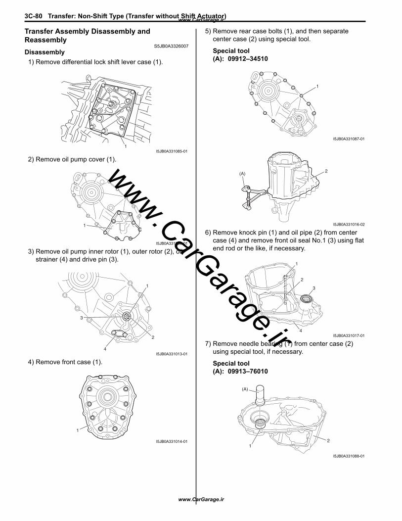
3C-80 Transfer: Non-Shift Type (Transfer without Shift Actuator)
Transfer Assembly Disassembly and Reassembly
S5JB0A3326007Disassembly1) Remove differential lock shift lever case (1).
2) Remove oil pump cover (1).
3) Remove oil pump inner rotor (1), outer rotor (2), oil strainer (4) and drive pin (3).
4) Remove front case (1).
5) Remove rear case bolts (1), and then separate center case (2) using special tool.
Special tool(A): 09912–34510
6) Remove knock pin (1) and oil pipe (2) from center case (4) and remove front oil seal No.1 (3) using flat end rod or the like, if necessary.
7) Remove needle bearing (1) from center case (2) using special tool, if necessary.
Special tool(A): 09913–76010
1I5JB0A331085-01
1
I5JB0A331086-01
1
2
4
3
I5JB0A331013-01
1
I5JB0A331014-01
1
I5JB0A331087-01
2(A)
I5JB0A331016-02
1
2
3
4I5JB0A331017-01
(A)
12
I5JB0A331088-01
www.CarGarage.ir
www.CarGarage.ir
www.CarGarage.ir

Transfer: Non-Shift Type (Transfer without Shift Actuator) 3C-81
8) Remove needle bearing (1), snap ring (2), washer (3) and shim(s) (4) from rear output shaft (5).
9) Remove reduction shift sleeve (1) and center differential (3) from rear output shaft (2).
10) Remove needle bearings (1), front drive shaft (2) and thrust needle bearing (4) from rear output shaft (3).
11) Remove differential lock clutch sleeve (1) from rear output shaft (2).
12) Remove front drive sprocket bush (1) from rear output shaft (2).
13) Take out front drive sprocket (1), front output shaft assembly (2), drive chain (3) and needle bearing (4) from rear case (5) all at once.
14) Remove snap ring (1), and then rear output shaft assembly (2) from rear case (3).
15) Remove rear oil seal (1) from rear case (2) using flat end rod or the like, if necessary.
1
2
3
45
I5JB0A331089-01
1
32
I5JB0A331090-02
1
1
2
3
4
I5JB0A331041-02
1
2
I5JB0A331022-01
1
2
I5JB0A331023-01
1
2
3
5
4I5JB0A331024-01
1
23
I5JB0A331025-01
1
2
I5JB0A331026-01
www.CarGarage.ir
www.CarGarage.ir
www.CarGarage.ir
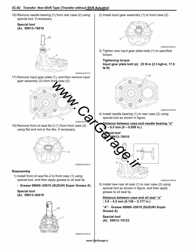
3C-82 Transfer: Non-Shift Type (Transfer without Shift Actuator)
16) Remove needle bearing (1) from rear case (2) using special tool, if necessary.
Special tool(A): 09913–76010
17) Remove input gear plate (1), and then remove input gear assembly (3) from front case (2).
18) Remove front oil seal No.2 (1) from front case (2) using flat end rod or the like, if necessary.
Reassembly1) Install front oil seal No.2 to front case (1) using
special tool, and then apply grease to oil seal lip.
: Grease 99000–25010 (SUZUKI Super Grease A)
Special tool(A): 09913–85210
2) Install input gear assembly (1) to front case (2).
3) Tighten new input gear plate bolts (1) to specified torque.
Tightening torqueInput gear plate bolt (a): 23 N·m (2.3 kgf-m, 17.0 lb-ft)
4) Install needle bearing (1) to rear case (2) using special tool as shown in figure.
Distance between case and needle bearing “a”: 0 – 0.5 mm (0 – 0.008 in.)
Special tool(A): 09913–76010
5) Install new rear oil seal (1) to rear case (2) using special tool as shown in figure, and then apply grease to oil seal lip.
Distance between case and oil seal “a”: 3.5 – 4.5 mm (0.138 – 0.177 in.)
“A”: Grease 99000–25010 (SUZUKI Super Grease A)
Special tool(A): 09913–70123
(A)
1
2
I5JB0A331027-01
1
23I5JB0A331091-01
1
2
I5JB0A331030-01
(A)
1
I5JB0A331033-01
1
2
I5JB0A331092-01
1, (a)
I5JB0A331093-03
(A)
1
2
“a”
I5JB0A331036-02
www.CarGarage.ir
www.CarGarage.ir
www.CarGarage.ir
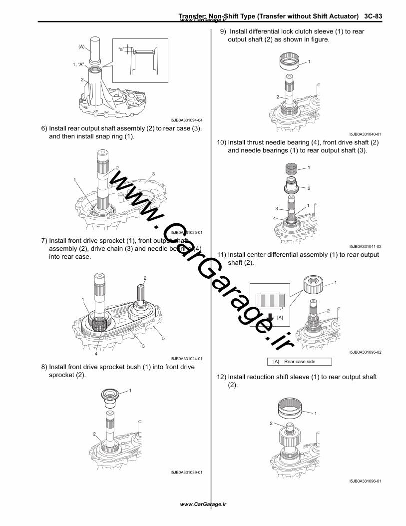
Transfer: Non-Shift Type (Transfer without Shift Actuator) 3C-83
6) Install rear output shaft assembly (2) to rear case (3), and then install snap ring (1).
7) Install front drive sprocket (1), front output shaft assembly (2), drive chain (3) and needle bearing (4) into rear case.
8) Install front drive sprocket bush (1) into front drive sprocket (2).
9) Install differential lock clutch sleeve (1) to rear output shaft (2) as shown in figure.
10) Install thrust needle bearing (4), front drive shaft (2) and needle bearings (1) to rear output shaft (3).
11) Install center differential assembly (1) to rear output shaft (2).
12) Install reduction shift sleeve (1) to rear output shaft (2).
(A)
1, “A”
2
“a”
I5JB0A331094-04
1
23
I5JB0A331025-01
1
2
3
5
4I5JB0A331024-01
1
2
I5JB0A331039-01
[A]: Rear case side
1
2
I5JB0A331040-01
1
1
2
3
4
I5JB0A331041-02
1
2[A]
I5JB0A331095-02
1
2
I5JB0A331096-01
www.CarGarage.ir
www.CarGarage.ir
www.CarGarage.ir
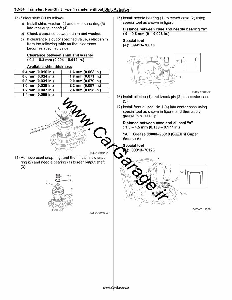
3C-84 Transfer: Non-Shift Type (Transfer without Shift Actuator)
13) Select shim (1) as follows.a) Install shim, washer (2) and used snap ring (3)
into rear output shaft (4).b) Check clearance between shim and washer.c) If clearance is out of specified value, select shim
from the following table so that clearance becomes specified value.
Clearance between shim and washer: 0.1 – 0.3 mm (0.004 – 0.012 in.)
Available shim thickness
14) Remove used snap ring, and then install new snap ring (2) and needle bearing (1) to rear output shaft (3).
15) Install needle bearing (1) to center case (2) using special tool as shown in figure.
Distance between case and needle bearing “a”: 0 – 0.5 mm (0 – 0.008 in.)
Special tool(A): 09913–76010
16) Install oil pipe (1) and knock pin (2) into center case (3).
17) Install front oil seal No.1 (4) into center case using special tool as shown in figure, and then apply grease to oil seal lip.
Distance between case and oil seal “a”: 3.5 – 4.5 mm (0.138 – 0.177 in.)
“A”: Grease 99000–25010 (SUZUKI Super Grease A)
Special tool(A): 09913–70123
0.4 mm (0.016 in.) 1.6 mm (0.063 in.)0.6 mm (0.024 in.) 1.8 mm (0.071 in.)0.8 mm (0.031 in.) 2.0 mm (0.079 in.)1.0 mm (0.039 in.) 2.2 mm (0.087 in.)1.2 mm (0.047 in.) 2.4 mm (0.098 in.)1.4 mm (0.055 in.)
134
2
I5JB0A331097-01
1
23
I5JB0A331098-02
1
(A)
2
“a”
I5JB0A331099-02
2
1
3
(A)
4, “A”
“a”
I5JB0A331100-03
www.CarGarage.ir
www.CarGarage.ir
www.CarGarage.ir

Transfer: Non-Shift Type (Transfer without Shift Actuator) 3C-85
18) Clean mating surface of both center case and rear case (1), apply sealant to rear case as shown in figure by such amount that its section is 1.2 mm (0.047 in.) in diameter, mate center case with rear case and then tighten bolts (2) to specified torque.
“A”: Sealant 99000–31260 (SUZUKI Bond No.1217G)
Tightening torqueRear case bolt (a): 23 N·m (2.3 kgf-m, 17.0 lb-ft)
19) Clean mating surface of both center case (1) and front case, apply sealant to center case as shown in figure by such amount that its section is 1.2 mm (0.047 in.) in diameter, mate front case (3) with center case and then tighten bolts (2) to specified torque.
“A”: Sealant 99000–31260 (SUZUKI Bond No.1217G)
Tightening torqueRear case bolt (a): 23 N·m (2.3 kgf-m, 17.0 lb-ft)
20) Install oil strainer (1) to rear case (2).
Tightening torqueStrainer bolt (a): 10 N·m (1.0 kgf-m, 7.5 lb-ft)
21) Install oil pump inner rotor (3), outer rotor (4) and drive pin (5) to rear case.
“A”
1
1
2, (a)
I5JB0A331101-02
“A”
1
2, (a) 2, (a)
3
I5JB0A331102-02
2
5
1 (a)
4
3
I5JB0A331103-01
www.CarGarage.ir
www.CarGarage.ir
www.CarGarage.ir
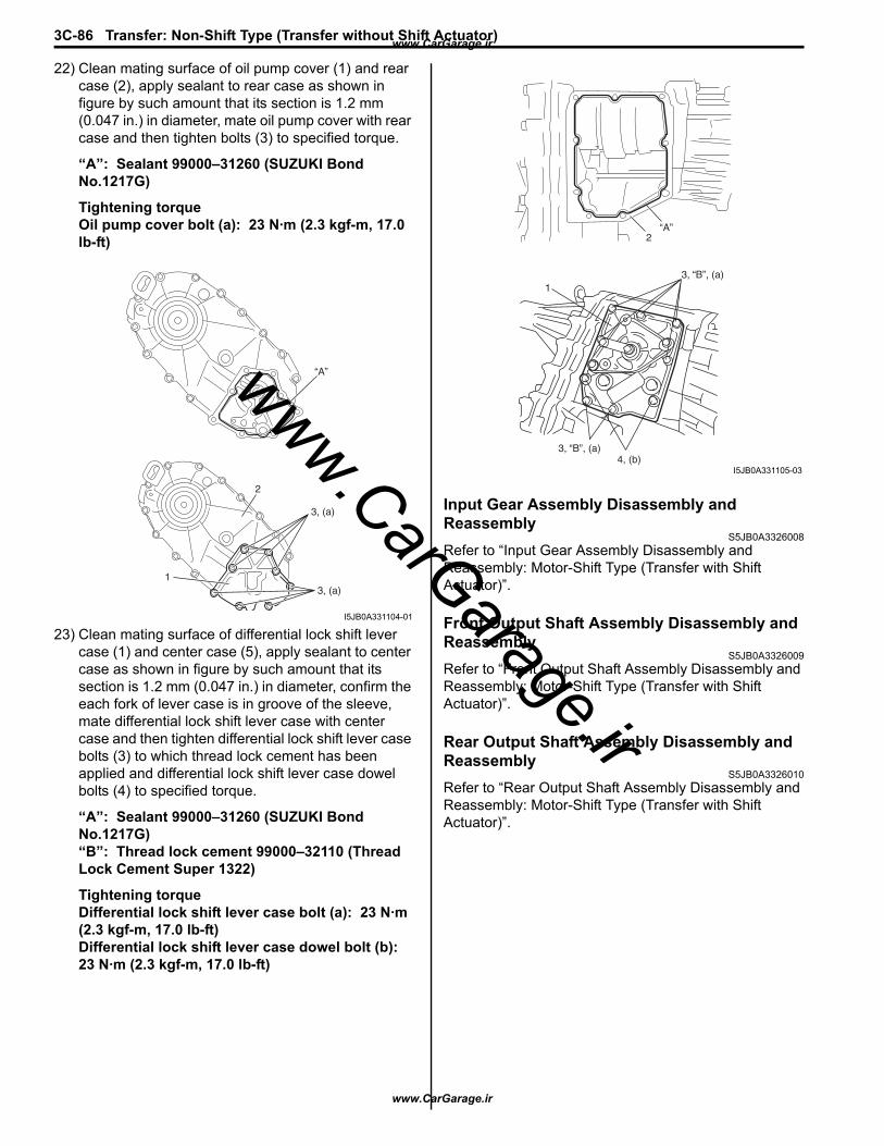
3C-86 Transfer: Non-Shift Type (Transfer without Shift Actuator)
22) Clean mating surface of oil pump cover (1) and rear case (2), apply sealant to rear case as shown in figure by such amount that its section is 1.2 mm (0.047 in.) in diameter, mate oil pump cover with rear case and then tighten bolts (3) to specified torque.
“A”: Sealant 99000–31260 (SUZUKI Bond No.1217G)
Tightening torqueOil pump cover bolt (a): 23 N·m (2.3 kgf-m, 17.0 lb-ft)
23) Clean mating surface of differential lock shift lever case (1) and center case (5), apply sealant to center case as shown in figure by such amount that its section is 1.2 mm (0.047 in.) in diameter, confirm the each fork of lever case is in groove of the sleeve, mate differential lock shift lever case with center case and then tighten differential lock shift lever case bolts (3) to which thread lock cement has been applied and differential lock shift lever case dowel bolts (4) to specified torque.
“A”: Sealant 99000–31260 (SUZUKI Bond No.1217G)“B”: Thread lock cement 99000–32110 (Thread Lock Cement Super 1322)
Tightening torqueDifferential lock shift lever case bolt (a): 23 N·m (2.3 kgf-m, 17.0 lb-ft)Differential lock shift lever case dowel bolt (b): 23 N·m (2.3 kgf-m, 17.0 lb-ft)
Input Gear Assembly Disassembly and Reassembly
S5JB0A3326008Refer to “Input Gear Assembly Disassembly and Reassembly: Motor-Shift Type (Transfer with Shift Actuator)”.
Front Output Shaft Assembly Disassembly and Reassembly
S5JB0A3326009Refer to “Front Output Shaft Assembly Disassembly and Reassembly: Motor-Shift Type (Transfer with Shift Actuator)”.
Rear Output Shaft Assembly Disassembly and Reassembly
S5JB0A3326010Refer to “Rear Output Shaft Assembly Disassembly and Reassembly: Motor-Shift Type (Transfer with Shift Actuator)”.
“A”
3, (a)
3, (a)1
2
I5JB0A331104-01
“A”2
13, “B”, (a)
3, “B”, (a)4, (b)
I5JB0A331105-03
www.CarGarage.ir
www.CarGarage.ir
www.CarGarage.ir

Transfer: Non-Shift Type (Transfer without Shift Actuator) 3C-87
SpecificationsTightening Torque Specifications
S5JB0A3327001
NOTEThe specified tightening torque is also described in the following.“Transfer Assembly Components: Non-Shift Type (Transfer without Shift Actuator)”
Reference:For the tightening torque of fastener not specified in this section, refer to “Fastener Information: in Section 0A”.
Special Tools and EquipmentRecommended Service Material
S5JB0A3328001
NOTERequired service material is also described in the following.“Transfer Assembly Components: Non-Shift Type (Transfer without Shift Actuator)”
Special ToolS5JB0A3328002
Fastening part Tightening torque NoteN⋅m kgf-m lb-ftInput gear plate bolt 23 2.3 17.0Rear case bolt 23 2.3 17.0 / Strainer bolt 10 1.0 7.5Oil pump cover bolt 23 2.3 17.0Differential lock shift lever case bolt 23 2.3 17.0Differential lock shift lever case dowel bolt 23 2.3 17.0
Material SUZUKI recommended product or Specification NoteGrease SUZUKI Super Grease A P/No.: 99000–25010 / / Sealant SUZUKI Bond No.1217G P/No.: 99000–31260 / / / Thread lock cement Thread Lock Cement Super 1322 P/No.: 99000–32110
09912–34510 09913–70123Case separator Bearing installing tool
/
09913–76010 09913–85210Bearing installer Bearing installer
/ / /
www.CarGarage.ir
www.CarGarage.ir
www.CarGarage.ir
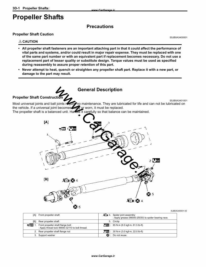
3D-1 Propeller Shafts:
Propeller Shafts PrecautionsPropeller Shaft Caution
S5JB0A3400001
CAUTION!
• All propeller shaft fasteners are an important attaching part in that it could affect the performance of vital parts and systems, and/or could result in major repair expense. They must be replaced with one of the same part number or with an equivalent part if replacement becomes necessary. Do not use a replacement part of lesser quality or substitute design. Torque values must be used as specified during reassembly to assure proper retention of this part.
• Never attempt to heat, quench or straighten any propeller shaft part. Replace it with a new part, or damage to the part may result.
General DescriptionPropeller Shaft Construction
S5JB0A3401001Most universal joints and ball joints require no maintenance. They are lubricated for life and can not be lubricated on the vehicle. If a universal joint becomes noisy or worn, it must be replaced.The propeller shaft is a balanced unit. Handle it carefully so that balance can be maintained.
I5JB0A340001-02
[A]: Front propeller shaft 4. Spider joint assembly: Apply grease (99000-25030) to spider bearing race.
[B]: Rear propeller shaft 5. Circlip1. Front propeller shaft flange bolt
: Apply thread lock 99000-32110 to bolt thread.: 85 N⋅m (8.5 kgf-m, 61.5 lb-ft)
2. Rear propeller shaft flange nut : 30 N⋅m (3.0 kgf-m, 22.0 lb-ft)3. Support washer : Do not reuse.
www.CarGarage.ir
www.CarGarage.ir
www.CarGarage.ir

Propeller Shafts: 3D-2
Diagnostic Information and ProceduresPropeller Shaft Symptom Diagnosis
S5JB0A3404001
Repair InstructionsPropeller Shaft Joint Check
S5JB0A3406001If universal joints and ball joints are suspected of producing chattering or rattling noise, inspect them for wear. For universal joint, check to see if cross spider rattles in yokes or if splines are worn down and replace defective propeller shaft assembly with new one.Noise coming from universal joint and ball joint can be easily distinguished from other noises because rhythm of chattering or rattling is in step with cruising speed. Noise is pronounced particularly on standing start or in coasting condition (when braking effect of engine is showing in the drive line).
Propeller Shaft Removal and InstallationS5JB0A3406002
Removal1) Hoist vehicle.2) Give match marks (1) on joint flange and propeller
shaft as shown in the figure.
3) Remove propeller shaft.
InstallationReverse removal procedure to install propeller shaft noting the following points.• Clean and inspect sliding portion of propeller shaft
end (where oil seal contacts) before installation and if even small dent or scratch exists, correct end clean it again.Then apply grease inside splines of propeller shaft.
“B”: Grease 99000–25010 (SUZUKI Super Grease A)
Condition Possible cause Correction / Reference ItemAbnormal noise Loose propeller shaft flange bolt and nut Tighten propeller shaft flange bolt and nut.
Spider bearing worn out or stuck Replace.Wear spider Replace propeller shaft.
Vibration Deformed propeller shaft Replace.
I5JB0A340003-01[A]: Front propeller shaft[B]: Rear propeller shaft
I5JB0A340002-02
IYSQ01521009-01
www.CarGarage.ir
www.CarGarage.ir
www.CarGarage.ir

3D-3 Propeller Shafts:
• Install propeller shaft aligning match marks. Otherwise, vibration may occur during driving.
• Use the following specification to torque universal joint flange nuts and bolts. For front propeller shaft flange bolt (front differential side), apply thread lock cement to thread part of bolts if reused.
“A”: Thread lock cement 99000–32110 (Thread Lock Cement Super 1322)
Tightening torqueFront propeller shaft flange bolt (a): 30 N·m (3.0 kgf-m, 22.0 lb-ft)Rear propeller shaft flange nut (b): 85 N·m (8.5 kgf-m, 61.5 lb-ft)
Propeller Shaft Disassembly and AssemblyS5JB0A3406005
CAUTION!
Never disassemble each joint.Performing this prohibited service will affect its original performance.
Disassembly1) Give match marks (1) on flange yoke and shaft as
shown in the figure.
2) Using snap ring plier (1), remove 2 circlips.
3) Using special tool, push spider bearing race out 3 – 4 mm (0.12 – 0.16 in.) from shaft yoke race.
NOTEBefore pushing it out, apply penetrate lubricant between bearing race (1) and yoke race (2).
Special tool(A): 09926-48010
Spider bearing race installing position (length “a”)“a”: 3 – 4 mm (0.12 – 0.16 in.)
[A]: Front propeller shaft[B]: Rear propeller shaft
I5JB0A340004-01
I5JB0A340007-01
I5JB0A340005-02
www.CarGarage.ir
www.CarGarage.ir
www.CarGarage.ir

Propeller Shafts: 3D-4
4) Tapping yoke with a hammer, completely remove bearing race.
5) Take out bearing race on the other side in the same way as in Step 3) and 4).
6) Push out bearing race on flange yoke side as described in Step 2) and 3), and then, holding bearing race in a vise (1), tap flange yoke and take out race. (Refer to the figure.)Remove bearing race on the opposite side in the same way.
NOTE
• Take care not to lose rollers in spider bearing race when removing it.
• Fit removed bearings temporarily in spider so that they can be reinstalled in their original positions.
Assembly
NOTEMake sure that rollers inside spider bearing race are all in place.
CAUTION!
In assembly, be sure to use new circlips, spider (1) and bearings (2). Reuse of circlips, spider (1) and bearings (2) once assembled is prohibited.
I5JB0A340006-01
IYSQ01340007-01
IYSQ01340008-01
IYSQ01340010-01
www.CarGarage.ir
www.CarGarage.ir
www.CarGarage.ir
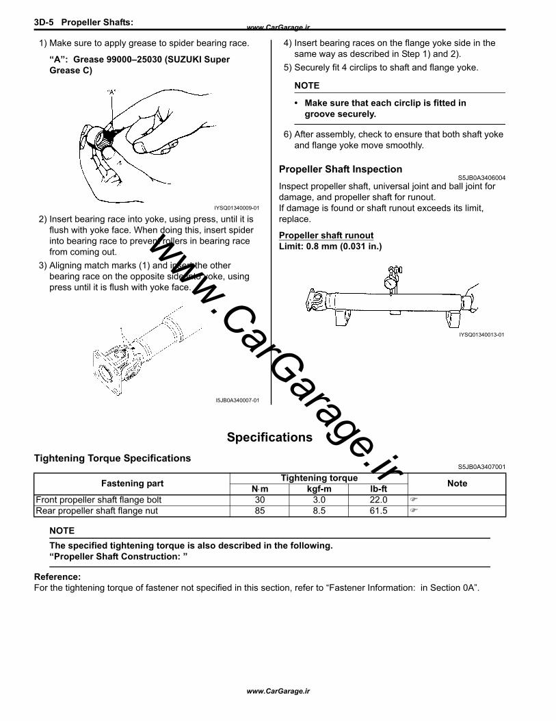
3D-5 Propeller Shafts:
1) Make sure to apply grease to spider bearing race.
“A”: Grease 99000–25030 (SUZUKI Super Grease C)
2) Insert bearing race into yoke, using press, until it is flush with yoke face. When doing this, insert spider into bearing race to prevent rollers in bearing race from coming out.
3) Aligning match marks (1) and insert the other bearing race on the opposite side into yoke, using press until it is flush with yoke face.
4) Insert bearing races on the flange yoke side in the same way as described in Step 1) and 2).
5) Securely fit 4 circlips to shaft and flange yoke.
NOTE
• Make sure that each circlip is fitted in groove securely.
6) After assembly, check to ensure that both shaft yoke and flange yoke move smoothly.
Propeller Shaft InspectionS5JB0A3406004
Inspect propeller shaft, universal joint and ball joint for damage, and propeller shaft for runout.If damage is found or shaft runout exceeds its limit, replace.
Propeller shaft runoutLimit: 0.8 mm (0.031 in.)
SpecificationsTightening Torque Specifications
S5JB0A3407001
NOTEThe specified tightening torque is also described in the following.“Propeller Shaft Construction: ”
Reference:For the tightening torque of fastener not specified in this section, refer to “Fastener Information: in Section 0A”.
IYSQ01340009-01
I5JB0A340007-01
IYSQ01340013-01
Fastening part Tightening torque NoteN⋅m kgf-m lb-ftFront propeller shaft flange bolt 30 3.0 22.0Rear propeller shaft flange nut 85 8.5 61.5
www.CarGarage.ir
www.CarGarage.ir
www.CarGarage.ir
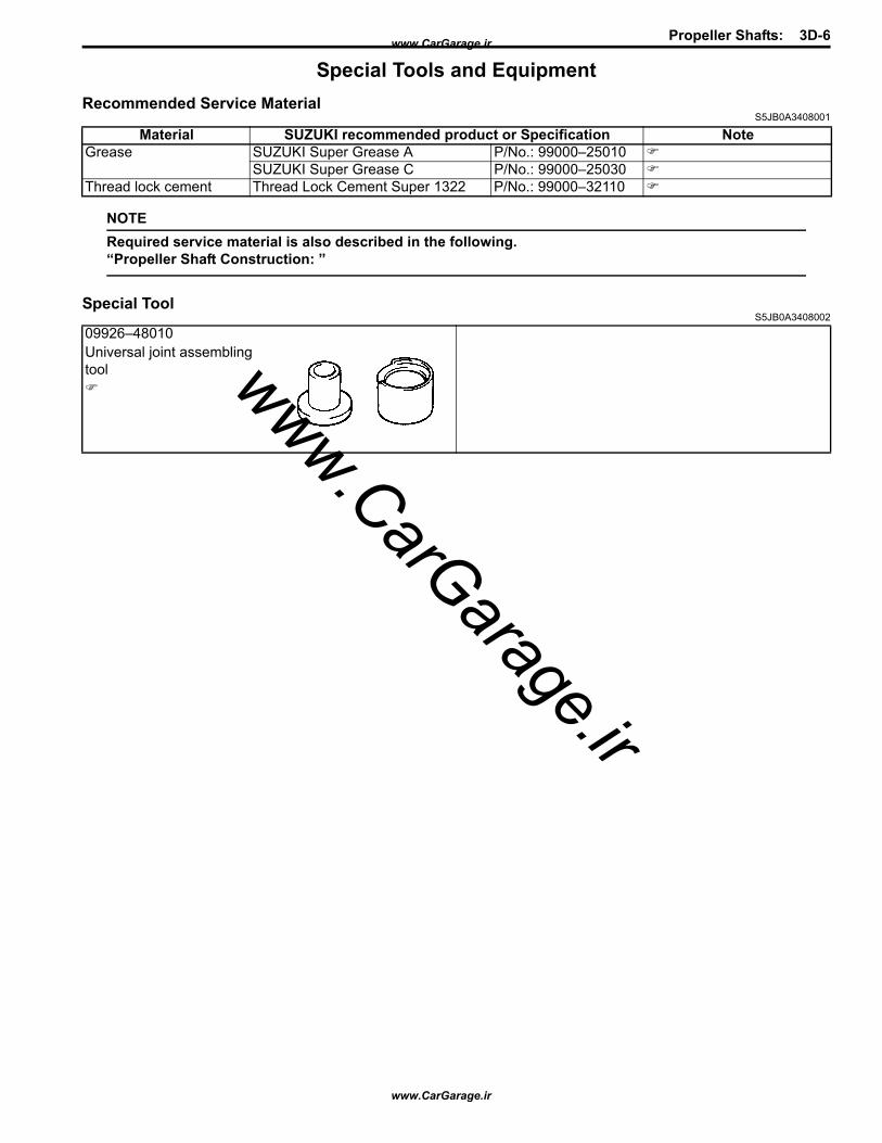
Propeller Shafts: 3D-6
Special Tools and EquipmentRecommended Service Material
S5JB0A3408001
NOTERequired service material is also described in the following.“Propeller Shaft Construction: ”
Special ToolS5JB0A3408002
Material SUZUKI recommended product or Specification NoteGrease SUZUKI Super Grease A P/No.: 99000–25010
SUZUKI Super Grease C P/No.: 99000–25030Thread lock cement Thread Lock Cement Super 1322 P/No.: 99000–32110
09926–48010Universal joint assembling tool
www.CarGarage.ir
www.CarGarage.ir
www.CarGarage.ir

3D-7 Propeller Shafts: www.CarGarage.ir
www.CarGarage.ir
www.CarGarage.ir


