Embed Size (px)
Citation preview
Readers are advised to check that this Certificate has not been withdrawn or superseded by a later issue by contacting
NSAI Agrément, NSAI, Santry, Dublin 9 or online at http://www.nsai.ie/modules/certificates/uploads/pdf/IAB150382.pdf
NSAI Agrément (Irish Agrément Board) is designated by Government to issue European Technical Approvals.
NSAI Agrément Certificates establish proof that the certified products are ‘proper materials’ suitable for their intended use under Irish site conditions, and in accordance with the Building Regulations 1997 to 2014.
Twinwall Road Drainage System Le système de drainage
Entwässerungssystem
IRISH AGRÉMENT BOARD CERTIFICATE NO. 15/0382 Condron Concrete Ltd. Arden Road, Tullamore, Co. Offaly. T: 05793 49000 F: 05793 41565 E: [email protected] W: www.condronconcrete.com
41 Rq2 CI/SfB
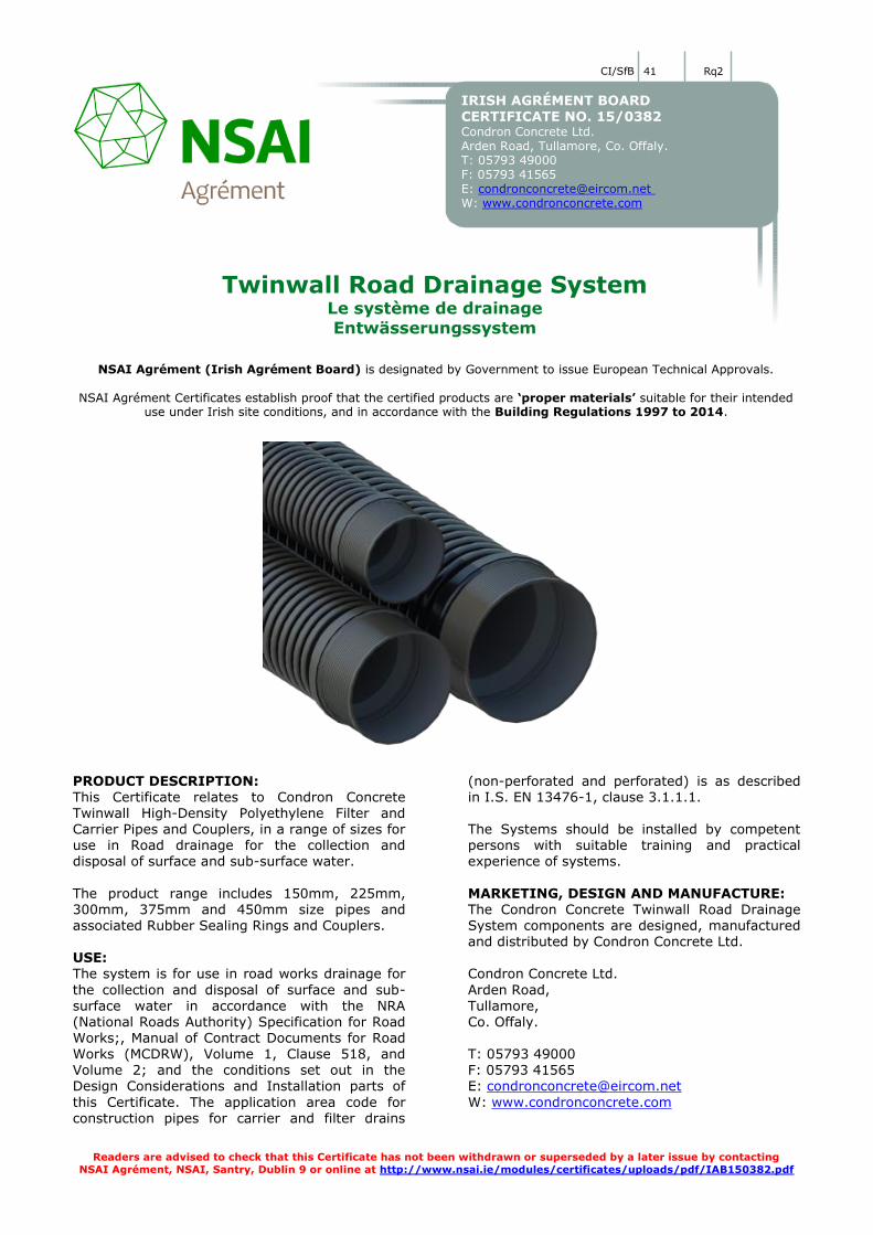
PRODUCT DESCRIPTION: This Certificate relates to Condron Concrete Twinwall High-Density Polyethylene Filter and Carrier Pipes and Couplers, in a range of sizes for use in Road drainage for the collection and disposal of surface and sub-surface water.
The product range includes 150mm, 225mm, 300mm, 375mm and 450mm size pipes and associated Rubber Sealing Rings and Couplers.
USE: The system is for use in road works drainage for
the collection and disposal of surface and sub-surface water in accordance with the NRA (National Roads Authority) Specification for Road Works;, Manual of Contract Documents for Road Works (MCDRW), Volume 1, Clause 518, and Volume 2; and the conditions set out in the Design Considerations and Installation parts of
this Certificate. The application area code for construction pipes for carrier and filter drains
(non-perforated and perforated) is as described in I.S. EN 13476-1, clause 3.1.1.1. The Systems should be installed by competent persons with suitable training and practical experience of systems.
MARKETING, DESIGN AND MANUFACTURE: The Condron Concrete Twinwall Road Drainage System components are designed, manufactured and distributed by Condron Concrete Ltd.
Condron Concrete Ltd.
Arden Road, Tullamore, Co. Offaly. T: 05793 49000 F: 05793 41565 E: [email protected]
W: www.condronconcrete.com
Certificate No. 15/0382 / Condron Concrete Road Drainage System
1.1 ASSESSMENT In the opinion of NSAI Agrément, the Condron Twinwall Road Drainage Systems, if used in accordance with this Certificate, can meet the requirements of the Building Regulations 1997 to
2014, as indicated in Section 1.2 of this Agrément Certificate. 1.2 BUILDING REGULATIONS 1997 to
2014
REQUIREMENTS:
Part C – Site Preparation & Resistance to Ground Moisture C4 - Resistance to weather and ground moisture The Condron Twinwall Road Drainage Systems,
as certified in this Certificate, meet the requirements for resistance to weather and ground moisture. Part D – Materials and Workmanship D1 – Materials & Workmanship The Condron Twinwall Road Drainage Systems,
as certified in this Certificate, meet the requirements for workmanship.
D3 – Proper Materials The Condron Twinwall Road Drainage Systems, as certified in this Certificate, are comprised of ‘proper materials’ fit for their intended use (see
Part 4 of this Certificate). Part H – Drainage and Waste Water Disposal H1 – Drainage Systems The Condron Twinwall Road Drainage Systems, once appropriately designed and installed in
accordance with this Certificate, will meet the requirements of Part H1 2010. Part J – Heat Producing Appliances J3 Protection of building The Condron Twinwall Road Drainage Systems,
as certified in this Certificate, meet the
requirements regarding building protection. Part L – Conservation of Fuel and Energy L1 Conservation of fuel and energy The Condron Twinwall Road Drainage Systems, as certified in this Certificate, meet the requirements for conservation of fuel and energy.
Certificate No. 15/0382 / Condron Concrete Road Drainage System
2.1 PRODUCT DESCRIPTION This Certificate relates to Condron Concrete Works Twinwall High-Density Polyethylene Filter and Carrier Pipes and Couplers, in a range of sizes for use in Road drainage for the collection and disposal of surface and sub-surface water.
2.1.1 Condron Twinwall Road Drainage
System Condron Twinwall Road Drainage 150mm, 225mm, 300mm, 375mm and 450mm diameter Filter and Carrier Pipes and Couplers are manufactured from recycled high-density
polyethylene polymer. Pipes consist of a double wall, which have a smooth interior and ribbed exterior with a smooth bore Integral Socket. Couplers consist of a single wall, with smooth interior and exterior surfaces. Soil-tight and watertight joints are made by fitting a Rubber
Sealing ring over the Pipe spigot end and then assembling it into the Integrated Pipe Socket or Coupler. The 150mm, 225mm, 300mm and 375mm diameter ranges incorporate an integrated spigot and socket while the 450mm diameter pipe use couplers only.
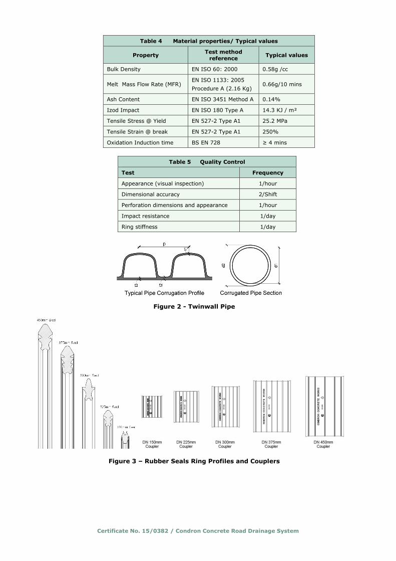
Rubber Sealing Rings are manufactured to EN681-1.
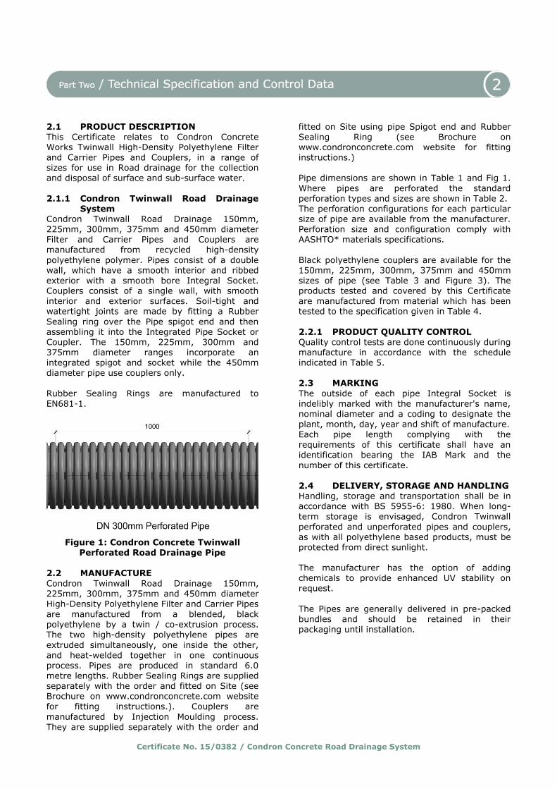
Figure 1: Condron Concrete Twinwall
Perforated Road Drainage Pipe 2.2 MANUFACTURE
Condron Twinwall Road Drainage 150mm, 225mm, 300mm, 375mm and 450mm diameter High-Density Polyethylene Filter and Carrier Pipes
are manufactured from a blended, black polyethylene by a twin / co-extrusion process. The two high-density polyethylene pipes are
extruded simultaneously, one inside the other, and heat-welded together in one continuous process. Pipes are produced in standard 6.0 metre lengths. Rubber Sealing Rings are supplied separately with the order and fitted on Site (see Brochure on www.condronconcrete.com website for fitting instructions.). Couplers are
manufactured by Injection Moulding process. They are supplied separately with the order and
fitted on Site using pipe Spigot end and Rubber Sealing Ring (see Brochure on www.condronconcrete.com website for fitting instructions.) Pipe dimensions are shown in Table 1 and Fig 1.
Where pipes are perforated the standard perforation types and sizes are shown in Table 2. The perforation configurations for each particular size of pipe are available from the manufacturer. Perforation size and configuration comply with AASHTO* materials specifications.
Black polyethylene couplers are available for the 150mm, 225mm, 300mm, 375mm and 450mm sizes of pipe (see Table 3 and Figure 3). The products tested and covered by this Certificate are manufactured from material which has been tested to the specification given in Table 4.
2.2.1 PRODUCT QUALITY CONTROL Quality control tests are done continuously during manufacture in accordance with the schedule indicated in Table 5. 2.3 MARKING
The outside of each pipe Integral Socket is indelibly marked with the manufacturer's name, nominal diameter and a coding to designate the plant, month, day, year and shift of manufacture.
Each pipe length complying with the requirements of this certificate shall have an identification bearing the IAB Mark and the
number of this certificate. 2.4 DELIVERY, STORAGE AND HANDLING Handling, storage and transportation shall be in accordance with BS 5955-6: 1980. When long-term storage is envisaged, Condron Twinwall
perforated and unperforated pipes and couplers, as with all polyethylene based products, must be protected from direct sunlight.
The manufacturer has the option of adding chemicals to provide enhanced UV stability on request.
The Pipes are generally delivered in pre-packed bundles and should be retained in their packaging until installation.
Certificate No. 15/0382 / Condron Concrete Road Drainage System
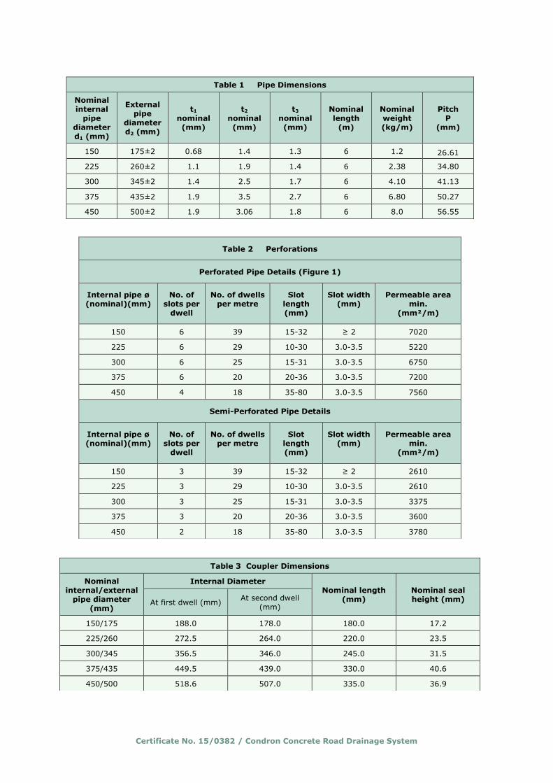
Table 1 Pipe Dimensions
Nominal internal
pipe diameter d1 (mm)
External pipe
diameter d2 (mm)
t1 nominal (mm)
t2 nominal (mm)
t3 nominal (mm)
Nominal length
(m)
Nominal weight (kg/m)
Pitch P
(mm)
150 175±2 0.68 1.4 1.3 6 1.2 26.61
225 260±2 1.1 1.9 1.4 6 2.38 34.80
300 345±2 1.4 2.5 1.7 6 4.10 41.13
375 435±2 1.9 3.5 2.7 6 6.80 50.27
450 500±2 1.9 3.06 1.8 6 8.0 56.55
Table 2 Perforations
Perforated Pipe Details (Figure 1)
Internal pipe ø (nominal)(mm)
No. of slots per
dwell
No. of dwells per metre
Slot length (mm)
Slot width (mm)
Permeable area min.
(mm²/m)
150 6 39 15-32 ≥ 2 7020
225 6 29 10-30 3.0-3.5 5220
300 6 25 15-31 3.0-3.5 6750
375 6 20 20-36 3.0-3.5 7200
450 4 18 35-80 3.0-3.5 7560
Semi-Perforated Pipe Details
Internal pipe ø (nominal)(mm)
No. of slots per
dwell
No. of dwells per metre
Slot length (mm)
Slot width (mm)
Permeable area min.
(mm²/m)
150 3 39 15-32 ≥ 2 2610
225 3 29 10-30 3.0-3.5 2610
300 3 25 15-31 3.0-3.5 3375
375 3 20 20-36 3.0-3.5 3600
450 2 18 35-80 3.0-3.5 3780
Table 3 Coupler Dimensions
Nominal internal/external
pipe diameter (mm)
Internal Diameter Nominal length
(mm) Nominal seal height (mm) At first dwell (mm)
At second dwell (mm)
150/175 188.0 178.0 180.0 17.2
225/260 272.5 264.0 220.0 23.5
300/345 356.5 346.0 245.0 31.5
375/435 449.5 439.0 330.0 40.6
450/500 518.6 507.0 335.0 36.9
Certificate No. 15/0382 / Condron Concrete Road Drainage System
Table 4 Material properties/ Typical values
Property Test method
reference Typical values
Bulk Density EN ISO 60: 2000 0.58g /cc
Melt Mass Flow Rate (MFR) EN ISO 1133: 2005
Procedure A (2.16 Kg) 0.66g/10 mins
Ash Content EN ISO 3451 Method A 0.14%
Izod Impact EN ISO 180 Type A 14.3 KJ / m²
Tensile Stress @ Yield EN 527-2 Type A1 25.2 MPa
Tensile Strain @ break EN 527-2 Type A1 250%
Oxidation Induction time BS EN 728 ≥ 4 mins
Table 5 Quality Control
Test Frequency
Appearance (visual inspection) 1/hour
Dimensional accuracy 2/Shift
Perforation dimensions and appearance 1/hour
Impact resistance 1/day
Ring stiffness 1/day
Figure 2 - Twinwall Pipe
Figure 3 – Rubber Seals Ring Profiles and Couplers

Certificate No. 15/0382 / Condron Concrete Road Drainage System
2.5 INSTALLATION
2.5.1 General
The pipes are installed using traditional drain-laying methods in accordance with NRA specifications and in accordance with the MCDRW, Volume 1, Clauses 503, 505, 518.7 and 518.8. Due to the lightweight nature of the pipe material, handling and jointing are easily performed. Pipes are available with a fixed socket
or a connection collar. Before laying the pipes and fittings must be checked for damage that may have occurred in transit or storage prior to installation. Damaged pipes or fittings must not be installed. The laying should be commenced at the lower end or outfall
end of the pipeline run and the pipes are preferably laid so that the sockets face to the top
of the pipeline run. When two pipelines are laid side by side appropriate separation should be allowed to permit the appropriate compaction of the material between the two pipe runs.
Sealing rings are enclosed separately in order to avoid damages. 2.5.2 Connecting pipes Prior to inserting the Rubber Sealing Ring, determine the “Pipe Insertion Depth” by
assembling the pipe Spigot end fully into the Socket or Coupler. Using chalk, mark the position on the Rib of the pipe that lines up exactly with the entrance point of the Socket or Coupler. Prior to connecting two sections of pipe or pipe
and coupler, ensure that all pipe ends, Rubber
Sealing Ring and Lubricant are clean and grit free. Assemble the Rubber Sealing Ring into the first corrugated valley of the pipe Spigot end – ensuring that the text marked “TOP” on the Rubber Sealing Ring is orientated towards the top of the pipe. Apply an approved lubricant using a
clean paintbrush around the outside perimeter of the Rubber Sealing Ring and around the inside circumference of the adjoining Socket or Coupler. Connect the Condron Concrete Twinwall Road Drainage pipe with constant axial force up to the previously marked insertion depth, without
overloading the pipe components. The Condron Concrete Twinwall Road Drainage pipes must be laid in accordance with design specifications
regarding the level and grade limits prescribed by the planning requirements and the NRA Manual of Contract Documents for Road Works.
2.5.3 Trench design Appropriate and optimal trench design shall necessitate a full assessment of the geotechnical aspects which prevail on site. Some design factors which should be considered when selecting an optimal trench design solutions will
comprise of trench wall stability, trench width,
trench depth, soil types and proximity to
obstructions or existing services.
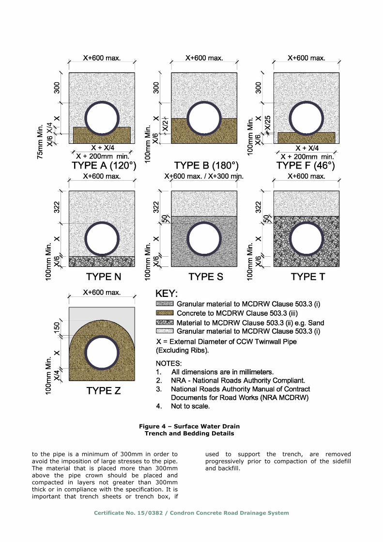
2.5.4 Bedding requirements Installation of the Condron Concrete Twinwall Road Drainage system can typically be carried out in accordance with the NRA Manual of Contract Documents for Road Works (see Figure 4 and 5). Granular pipe bed and surround
material, consisting of natural and/or recycled coarse aggregate or recycled concrete aggregate, should have specification as per Table 6 (in accordance with clause 503.3 of the MCDRW). 2.5.5 Trench Preparation Trenches should not be excavated too far in
advance of pipe installation and should be supported by trench boxes where required by
Health and Safety requirements. Trenches should be as narrow as practicable, generally the pipe diameter + 300 and 600mm.
Where multiple pipes are installed in a trench sufficient spacing should be allowed between them to ensure that there are no voids and the material can be fully compacted. Local soft spots in the trench base should be excavated and filled with a suitable compacted granular material.
The bedding material is laid below the Condron Concrete Twinwall Road Drainage pipe to provide uniform support and to permit small adjustment of the pipe’s line and level. All bedding material is to be compliant with the engineers’ specification. No temporary supports (blocks of bricks, stones,
wood, metal or other similar objects) should ever
be used to prop the pipe during the installation process as it can damage the pipe integrity and cause pipe deformation. 2.5.6 Sidefill placement After a section of the pipe has been installed and
successfully tested, the sidefill, the most important structural component of the fill, should be placed. The material should be placed evenly on both sides of the pipe, and compacted in accordance with the specification. Single-sized coarse granular materials, such as stone or gravel, may achieve the necessary density
without compaction. Compaction of these materials is recommended where trench walls are relatively soft and weak. For well-graded granular
soils compaction will be necessary. It is important that compacting equipment does not come into contact with the pipe at any stage of compaction. The sidefill material should normally
extend a minimum 100mm above the pipe crown. 2.5.5 Backfill placement The backfill material that lies within 300mm of the pipe crown should be free from particles
stones exceeding 40mm diameter. Heavy compaction should not be applied until the cover
Certificate No. 15/0382 / Condron Concrete Road Drainage System
to the pipe is a minimum of 300mm in order to
avoid the imposition of large stresses to the pipe. The material that is placed more than 300mm above the pipe crown should be placed and compacted in layers not greater than 300mm thick or in compliance with the specification. It is important that trench sheets or trench box, if
used to support the trench, are removed
progressively prior to compaction of the sidefill and backfill.
Figure 4 – Surface Water Drain Trench and Bedding Details

Certificate No. 15/0382 / Condron Concrete Road Drainage System
Table 6
Nominal pipe diameter
mm
Aggregate size
Graded Single
150
225
300
375
450
2/14 or 4/20 4/10, 6/14 or 10/20
Aggregate sizes as per NRA Specification for Road Works - Series 500
“Drainage and Service Ducts” (March 2015) - ref: Table 5/3 “Coarse Aggregate for pipe bedding, haunching and surrounding material”
Figure 5 – Filter Drains
Trench and Bedding Details
Certificate No. 15/0382 / Condron Concrete Road Drainage System
3.1 GENERAL Condron Concrete Twinwall Road Drainage 150mm, 225mm, 300mm, 375mm and 450mm
diameter High-Density Polyethylene Filter and Carrier Pipes and Couplers comply with the requirements of the NRA Specification for Roadworks; the requirements of the UK Roads
Agency (HA) Manual of Contract Documents for Road Works (MCHW), Volume 1, Clause 518.5 for
pipe, Clause 518.6 for couplings and Clause 518.7 for the system, and is suitable for use in road-works for the collection and disposal of surface and sub-surface water. 3.2 PERFORMANCE OF JOINTS Joints with the pipeline remain watertight under
conditions of pipeline movement in excess of those expected to occur in normal good drainage practice. Joints on filter pipes made from pipe and couplings without the rubber seals are not partially watertight as defined in the NRA Manual
of Contract Documents for Road Works and in
MCHW, Volume 1, Clause 504.3. Correctly made, the joints constructed from pipe and couplings with rubber seals remain watertight when subjected to deflection and
distortion, and comply with the NRA Manual of Contract Documents for Road Works, and the MCHW, Volume 1, Clauses 504.3 and 518.7. The performance of joints will not be adversely affected by thermal expansion or contraction when correctly made.
3.3 FLOW CHARACTERISTICS The pipes will have normal flow characteristics associated with thermoplastics pipes.
Full-bore velocities are available from the Tables for the Hydraulic Design of Pipes, Sewers and Channels, Volume 2, 8th Edition, by H R
Wallingford and D I H Barr. Appropriate values are based on the Colebrook-White equation. An
appropriate value of roughness coefficient should be selected when designing the drainage system. For new pipes, a value of 0.006 is applicable, but for designs a value of 0.6 is generally used. 3.4 EXAMPLE OF HYDRAULIC DESIGN
CALCULATION
The Colebrook-White equation provides the most accurate results to assist in gravity sewer design. Hydraulic flow charts published in “Tables for hydraulic design of pipes, sewers and channels” 7th edition are most commonly used to simplify the Colebrook-White equation. Once a pipe roughness coefficient (ks) is determined, the
corresponding flow chart details four variables,
i.e. pipe internal diameter; water velocity; hydraulic gradient; and discharge. Once two variables are known, the remaining two variables can be determined.
CCW Twinwall pipes have a smooth inner wall giving excellent hydraulic performance. Sewers for adaption 6th edition stipulates a minimum (ks) roughness coefficient of 0.6mm for surface water sewer design and a minimum velocity of 1.0 m/sec pipe full flow.
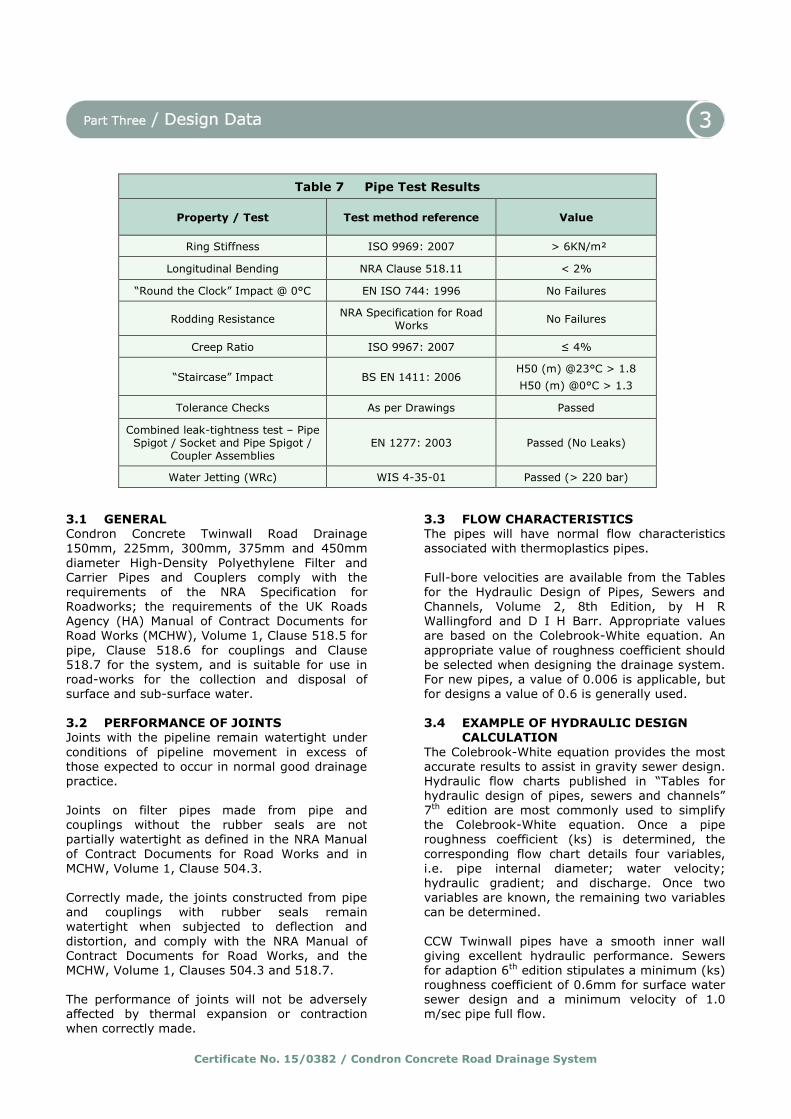
Table 7 Pipe Test Results
Property / Test Test method reference Value
Ring Stiffness ISO 9969: 2007 > 6KN/m²
Longitudinal Bending NRA Clause 518.11 < 2%
“Round the Clock” Impact @ 0°C EN ISO 744: 1996 No Failures
Rodding Resistance NRA Specification for Road
Works No Failures
Creep Ratio ISO 9967: 2007 ≤ 4%
“Staircase” Impact BS EN 1411: 2006 H50 (m) @23°C > 1.8
H50 (m) @0°C > 1.3
Tolerance Checks As per Drawings Passed
Combined leak-tightness test – Pipe Spigot / Socket and Pipe Spigot /
Coupler Assemblies EN 1277: 2003 Passed (No Leaks)
Water Jetting (WRc) WIS 4-35-01 Passed (> 220 bar)
Certificate No. 15/0382 / Condron Concrete Road Drainage System
The Colebrook – White equation is considered
most accurate for commercial pipes as effective roughness is applied. For full flowing pipes, the velocity (V) and discharge (Q) of liquid flowing in a pipe can be calculated using the following equations:-
Velocity
𝑉 = −2√(2𝑔𝐷𝑖) log10 [𝑘𝑠
3.71𝐷+
2.51𝑣
𝐷√2𝑔𝐷𝑖]………………(1)
Where V = Velocity (m/s) g = Gravitational acceleration (9.81 m/s2) D = Pipe internal diameter (m)
i = Hydraulic gradient = ∆𝐻
𝐿
L = Length of pipe (m) ΔH = Height differential (m)
ks = Pipe wall roughness factor (m) v = Kinematic viscosity of fluid at 15°C
(1.146x10⁻⁶ m²/s) Note for partially full pipes, the velocity of flow is given in equation 2 by replacing D with 4Rh
where Rh is the hydraulic radius.
𝑉 = −2√(8𝑔Rℎ𝑖) log10 [𝑘𝑠
14.8Rℎ+
1.255𝑣
Rℎ√32𝑔Rℎ𝑖]……… (2)
Where Rh = Hydraulic Radius (flow cross-sectional area
divided by the wetted perimeter (m2/m)). Discharge
𝑄 = 𝑉𝑅ℎ…………………………………………… . . … (3)
Where Q = Discharge (m3/s) V = Velocity (m/s)
Rh = Hydraulic Radius (m) = 𝐷
4 m
D = Pipe internal diameter (m)
Note the hydraulic radius Rh for a full flowing pipe is the cross-sectional area (𝜋𝑟2) divided by the
wetted perimeter (2𝜋𝑟) i.e. 𝐷
4 m.
Table 8 Hydraulic Design
For Twinwall High-Density Polyethylene pipe
Wall roughness factor (ks) 0.6 x10⁻³ m
Minimum velocity of full flow (V) 1.0 m/sec
Simple Design Example
Design of surface water sewer
Length of pipe = 12m Fall to outlet = 0.15m Hence gradient = 1:80 Design discharge = 0.1 m³/sec where
Pipe wall roughness factor Ks = 0.6 mm Minimum velocity of full flow = 1.0 m/sec
Step 1: Determine pipe size when flowing full? Using the Colebrook White chart with a design
discharge of 0.1 m³/sec and a gradient of 1:80 establishes that the next available pipe size is a 300mm diameter pipe. (red line in figure 6) Step 2: Check minimum velocity at full flow. Velocity of 300mm ø pipe @ gradient 1:80 =
1.7 m/sec (red dashed line in figure 6) 1.7 m/sec > 1.0 m/sec, therefore satisfactory

Certificate No. 15/0382 / Condron Concrete Road Drainage System
Figure 6 - Colebrook – White Flow Chart, ks = 0.6mm

Certificate No. 15/0382 / Condron Concrete Road Drainage System
4.1 GENERAL The following is a summary of the technical
investigations carried out on the Condron Concrete Works Twinwall Road Drainage System. 4.1.1 STRENGTH An assessment of the pipes ability to resist soil loads including traffic loads both during and after
installation was carried out. Both ring stiffness and creep ratio were assessed. The ring stiffness of a pipe is the mechanical
characteristic of a pipe, which is a measure of the resistance to ring deflection under an external force as determined in accordance with EN ISO
9969. The ring stiffness for all three pipe diameters were in excess of 6 kN/m2 (see table 7) and this equates to a ring stiffness class of SN6 as described in I.S. EN 13476-1:2007. The creep ratio of ≤ 4 (see table 7) was achieved for all three pipe diameters. This meets the
minimum requirements for polypropylene pipes as outlined in table 5/9 “Requirements for structural wall pipes" of the NRA MCDRW volume 1 “Specifications for Highway Works” document. 4.1.2 LONGITUDINAL BENDING
The NRA MCDRW volume 1 “Specifications for
Highway Works” document requires pipes with nominal diameters ≤ 350mm to have a Longitudinal Bending value of less than 5% when tested and for there to be no local permanent deformation caused during the test. This property is used to reduce the possibility of problems or
damage occurring during handling. The Condron Concrete Works Twinwall Road Drainage System surpassed the NRA documents requirements and achieved a Longitudinal Bending value of less than 2%. 4.1.3 IMPACT RESISTANCE
The pipes have adequate resistance to impact loads to which they may be subjected during installation and in service.
4.1.4 WATER INFILTRATION The slot area for the pipes exceeds the minimum
requirement of 1000 mm2 per metre length. 4.2 MAINTENANCE • The slots are designed to restrict the ingress
of silt into the drains. • Access to the system for cleaning should be
provided by conventional methods.
• The system can be rodded using flexible drain rods. In common with other standard plastic drainage systems, toothed root cutters and
rods with metal ferrules, as used with some mechanical clearing systems, could damage
the pipes and couplings and should not be used.
• Tests indicate that the pipes have adequate resistance to cleansing using pressure jetting equipment (see section 4.4). It is recommended that low-pressure, high-volume
systems are utilised. 4.3 DURABILITY In the opinion of NSAI Agrément, when installed
in accordance with this Certificate and the manufacturer’s instructions, the material from which the pipes and couplings are manufactured
will not significantly deteriorate and the anticipated life of the system will be in excess of 50 years. 4.4 TESTS AND ASSESSMENTS Tests were carried out on the pipe in accordance with the NRA specification for road works to
determine: • ring stiffness to EN ISO 9969: 2007 • creep ratio to EN ISO 9967: 2007 • longitudinal bending in accordance with the
NRA specification for road works sub-Clause 518.11
• rodding resistance in accordance with the NRA
specification for road works • impact resistance at -2°C and 23°C to BS EN
1411: 1996 with a d25 striker and 25 mm diameter conical head
• impact resistance to EN744 at 0°C with a type d90 striker
• water jetting WRc method. Tests were carried out on the system to establish: • leaktightness of joint to EN 1277: 2003,
Method 4, Conditions B, C and D • insertion force (ease of jointing).
Tests were carried out to establish the dimensional accuracy of the pipe, coupling and ring seal.
Pipe test results are shown in Table 7
4.5 CHEMICAL RESISTANCE The piping systems are resistant to corrosion by water with a wide range of pH values such as domestic wastewater, rainwater, surface water and ground water.
4.6 UV STABILITY When long-term storage is envisaged, Condron Twinwall perforated and unperforated pipes and
Certificate No. 15/0382 / Condron Concrete Road Drainage System
couplers, as with all polyethylene based products,
must be protected from direct sunlight.
The manufacturer has the option of adding chemicals to provide enhanced UV stability on request. In general, polyethylene based products which contain sufficient UV stabiliser have been shown to retain 98% of their original properties when exposed to 30 months of laboratory based
UV exposure. 4.7 OTHER INVESTIGATIONS • An examination was made of data in relation
to the effect of the production tolerances on the performance of the products.
• An evaluation of existing data was made to
assess material properties, chemical resistance and durability.
• Calculations were carried out to determine slot area.
• The manufacturing process was examined, including the methods adopted for quality
control, and details were obtained of the quality and composition of the materials used.
• An assessment of the suitability of the 100% recycled raw material was carried in the form of an Oxidation Induction Time (OIT) test. This test is performed to assess to thermal stability of the raw materials during the
extrusion process. Results of the OIT test are given in table 4 of this certificate and are deemed to surpass minimum industry requirements for this parameter.

Certificate No. 15/0382 / Condron Concrete Road Drainage System
5.1 National Standards Authority of Ireland ("NSAI") following consultation with NSAI
Agrément has assessed the performance and method of installation of the product/process and the quality of the materials used in its manufacture and certifies the product/process to be fit for the use for which it is certified provided that it is manufactured, installed, used and maintained in accordance with the descriptions
and specifications set out in this Certificate and in accordance with the manufacturer's instructions and usual trade practice. This Certificate shall
remain valid for five years from date of issue so long as: (a) the specification of the product is unchanged.
(b) the Building Regulations 1997 to 2012 and
any other regulation or standard applicable to the product/process, its use or installation remains unchanged.
(c) the product continues to be assessed for the quality of its manufacture and marking by NSAI.
(d) no new information becomes available which
in the opinion of the NSAI, would preclude the granting of the Certificate.
(e) the product or process continues to be
manufactured, installed, used and maintained in accordance with the description, specifications and safety recommendations set out in this certificate.
(f) the registration and/or surveillance fees due to IAB are paid.
5.2 The NSAI Agrément mark and certification number may only be used on or in relation to product/processes in respect of which
a valid Certificate exists. If the Certificate becomes invalid the Certificate holder must not use the NSAI Agrément mark and certification number and must remove them from the
products already marked. 5.3 In granting Certification, the NSAI makes
no representation as to; (a) the absence or presence of patent rights
subsisting in the product/process; or
(b) the legal right of the Certificate holder to market, install or maintain the
product/process; or (c) whether individual products have been
manufactured or installed by the Certificate holder in accordance with the descriptions and specifications set out in this Certificate.
5.4 This Certificate does not comprise installation instructions and does not replace the manufacturer's directions or any professional or
trade advice relating to use and installation which may be appropriate. 5.5 Any recommendations contained in this
Certificate relating to the safe use of the certified product/process are preconditions to the validity of the Certificate. However the NSAI does not certify that the manufacture or installation of the certified product or process in accordance with the descriptions and specifications set out in this
Certificate will satisfy the requirements of the Safety, Health and Welfare at Work Act 2005, or of any other current or future common law duty of care owed by the manufacturer or by the Certificate holder. 5.6 The NSAI is not responsible to any person
or body for loss or damage including personal injury arising as a direct or indirect result of the use of this product or process. 5.7 Where reference is made in this Certificate to any Act of the Oireachtas, Regulation made thereunder, Statutory
Instrument, Code of Practice, National Standards, manufacturer's instructions, or similar publication, it shall be construed as reference to such publication in the form in which it is in force at the date of this Certification.
Certificate No. 15/0382 / Condron Concrete Road Drainage System
This Certificate No. 15/0382 is accordingly granted by the NSAI to Condron Concrete Ltd. on behalf of NSAI Agrément.
Date of Issue: April 2015 Signed
Seán Balfe Director of NSAI Agrément Readers may check that the status of this Certificate has not changed by contacting NSAI
Agrément , NSAI, 1 Swift Square, Northwood, Santry, Dublin 9, Ireland. Telephone: (01) 807 3800. Fax: (01) 807 3842. www.nsai.ie
Revision: May 2016 150mm and 450mm diameter pipe sizes added.