Embed Size (px)
Citation preview

PDHonline Course M256 (12 PDH)
Siphonic Roof Drainage
2012
Instructor: John M. Rattenbury, PE, CIPE, LEEDap
PDH Online | PDH Center5272 Meadow Estates Drive
Fairfax, VA 22030-6658Phone & Fax: 703-988-0088
www.PDHonline.orgwww.PDHcenter.com
An Approved Continuing Education Provider
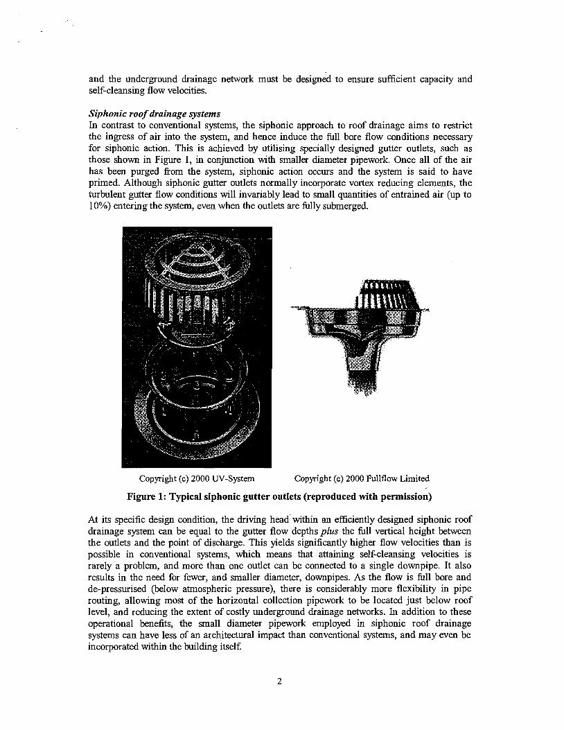
Investigation into the Performance Characteristics of Multi-Outlet Siphonic Roof Drainage Systems
G.B. wrightq, J.A. ~waffield* and S. Arthur** * Drainage and Water Supply Research Group, Department of Building Engineering and Surveying, Heriot-Watt University, Edinburgh, EH14 4AS, Scotland
** ([email protected], j [email protected]). Sustainable Water Management Research Group, Department of Civil and Offshore Engineering, Heriot-Watt University, Edinburgh, EH14 4AS, Scotland ([email protected]).
Abstract
Siphonic roof drainage systems have been in existence for approximately 30 years, and are becoming an increasingly common elemeiit of urban drainage iilfiastructure. In that time, the construction sector in most developed countries have been gradually persuaded of the benefits that these systems offer when compared to conventional roof drainage technologies. However, current design practice is based on steady-state theory and, arguably, simplistic assumptions. In response to perceived deficiencies in current design practice, a siphonic roof drainage research programme was initiated at Heriot-Watt University in 1996. This has led to a better understanding of the performance characteristics of siphonic systems, with particular reference to the priming of such systems (the purging of air fiom the system). This has resulted in the development of a numerical model capable of accurately simulating the priming phase of single outlet siphonic roof drainage systems. However, the majority of installed systems incorporate more than one roof outlet, and the interaction between such outlets is not well understood. It was therefore recognised that firther research was required to extend the applicability of the existing numerical model to multi-outlet applications.
The work reported herein details an ongoing UK governrhent funded research programme to investigate the performance characteristics of multi-outlet siphonic roof drainage systems. The experimental aims, apparatus and procedures are described, and results are illustrated. In addition, "real" data obtained fiom three installed siphonic roof drainage systems are discussed. Conclusions are drawn regarding the performance characteristics of multi-outlet siphonic roof drainage systems, and plans for future work are outlined.
Keywords
Siphonic roof drainage; multi-outlet; design.
Introduction
Conventional roof drainage systems Conventional roof drainage systems generally consist of a network of collection gutters connected (via open outlets) to vertical downpipes. The system components are sized to ensure annular flow through the downpipes (with a continuous central air path), and system pressures therefore remain close to atmospheric (BSI, 2000). Consequently, the driving head for flow within conventional roof drainage systems is limited to the gutter flow depths, which results in relatively low flow velocities within the system. This necessitates many, relatively large diameter, downpipes (typically 150mm) each of which must be connected into a suitable underground drainage network. Furthermore, the dimensionslgradients of the gutters
and the underground drainage network must be designed to ensure sufficient capacity and self-cleansing flow velocities.
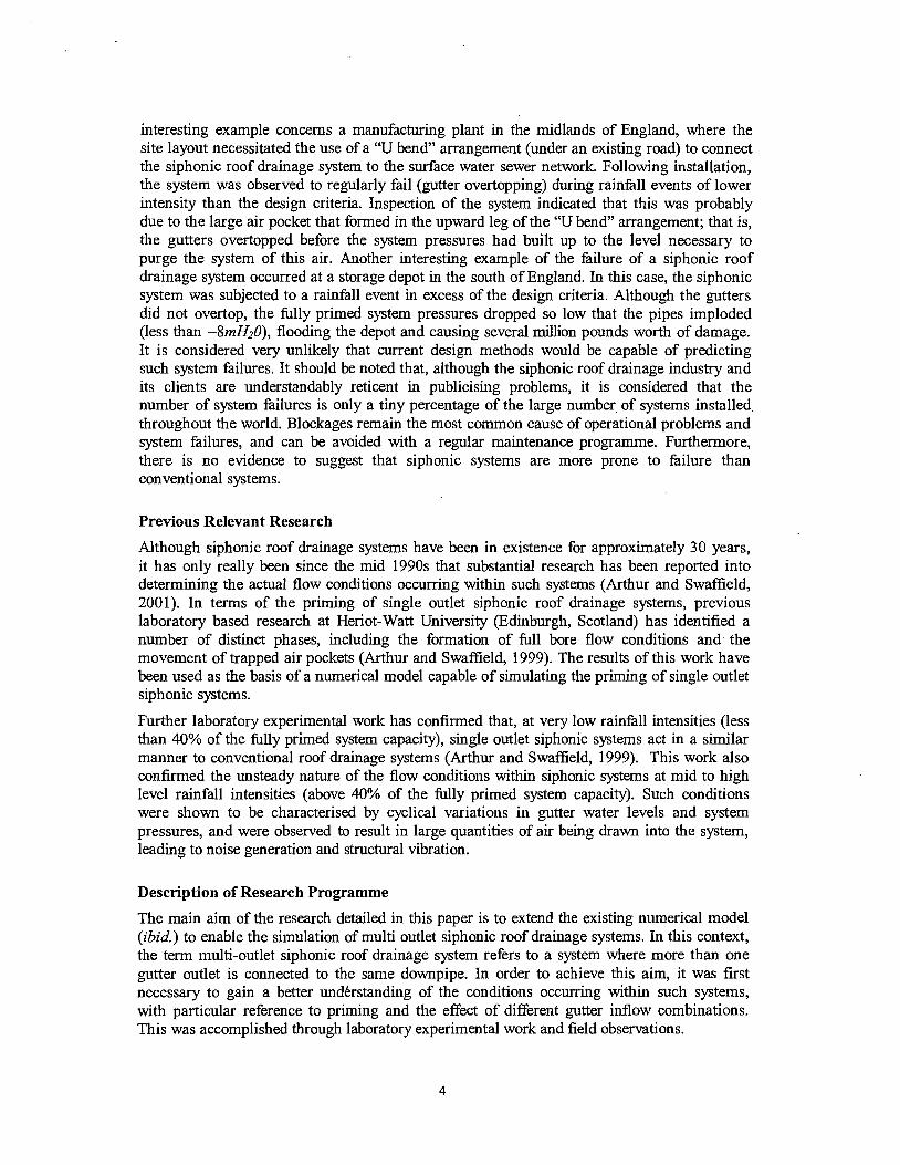
Siphonic roof drainage systems In contrast to conventional systems, the siphonic approach to roof drainage aims to restrict the ingress of air into the system, and hence induce the full bore flow conditions necessary for siphonic action. This is achieved by utilising specially designed gutter outlets, such as those shown in Figure 1, in conjunction with smaller diameter pipework. Once all of the air has been purged ftom the system, siphonic action occurs and the system is said to have primed. Although siphonic gutter outlets normally incorporate vortex reducing elements, the turbulent gutter flow conditions will invariably lead to small quantities of entrained air (up to 10%) entering the system, even when the outlets are fully submerged.
Copyright (c) 2000 W-System Copyright (c) 2000 Fullflow Limited
Figure 1: Typical siphonic gutter outlets (reproduced with permission)
At its specific design condition, the driving head' within an efficiently designed siphonic roof drainage system can be equal to the gutter flow depths plus the full vertical height between the outlets and the point of discharge. This yields significantly higher flow velocities than is possible in conventional systems, which means that attaining self-cleansing velocities is rarely a problem, and more than one outlet can be connected to a single downpipe. It also results in the need for fewer, and smaller diameter, downpipes. As the flow is full bore and de-pressurised (below atmospheric pressure), there is considerably more flexibility in pipe routing, allowing most of the horizontal collection pipework to be located just below roof level, and reducing the extent of costly underground drainage networks. In addition to these operational benefits, the small diameter pipework employed in siphonic roof drainage systems can have less of an architectural impact than conventional systems, and may even be incorporated within the building itself

A~iphonic,-o.o~dra~ag~~yste~~y~~g~~~p_e_r~~~~e~~~6:i.e_g~y~&~t~~desigtl.~~~~nditi-(rtf~mder ~ ~ ~ ~ ~ f i @ ~ a ~ ~ f ~ ~ ~ i t e r i ~ u s e ~ f o ~ & s i g n ~ p ~ p s ~ Q ~ g ~ ~ ~ ~ ~ & ~ ~ ~ ~ ~ a ~ ~ ~ e ~ Q . ~ ~ a & i s , ~ ~ y ~ 0 ~ ~ ~ n f ~ 1 : 1 ~ ~ ~ t ~ ~ ~ a ~ h e s ~ m y a p ~ ~ i ~ m ~ s ~ t e m ~ ~ 0 n ~ e q ~ e n f l ~ ~ i p h 0 ~ ~ ~ & ~ w~1,fl~~Lwf~~~~b~aP@Ft?j~;;deSi-wCDn~t&~~I~a~ih~i8~m~e~p~s&$a.axra~fa1t A.L...----
e & e ~ e ~ e d s ~ t h e ~ d . e s i - ~ T i ~ ~ e ~ W o ~ E ~ ~ p ~ . ~ ~ ~ ~ c ^ B ~ ~ ~ ~ ~ T r i n ~ E b ~ e ~ e ~ & ~ s , e ~ ~ h , , e ~ ~ ~ ~ . this may necessitate the installation of a secondary convenKal or siphonic system to drain any excess rainfall. The more likely scenario is that a system will be exposed to a rainfill event below the design criteria. When this occurs, the flow conditions will differ fiom those in a filly primed system, their exact nature depending on the specific characteristics of the rainfall event. Similar conditions can occur if the flow distribution between gutter outlets is not as per design, possibly as a result of poorly installed roof surfaceslgutters or wind driven rainfall. Another disadvantage of siphonic roof drainage systems is that the restrictive outlets and small diameter pipework are relatively easily blocked by detritus in the flow (e.g. leaves). If a regular maintenance program is not adhered to, this can lead to operational problems and system failure (Bowler and Arthur, 1999).
Current State of Siphonic Roof Drainage Technology
Since their development in Scandinavia in the late 1960s, siphonic roof drainage systems have gradually become accepted by the construction sector in most developed countries. Their high capacities and low architectural impact have made them particularly popular for large, prestigious developments such as airports and major sporting stadia, e.g. Chep Lap Kok Airport (Hong Kong) and The Olympic Stadium (Sydney, Australia). Howe~~qi_pphoni~ r o s f ~ & ~ ~ g ~ ~ ~ ~ ~ ~ ~ ~ ~ y ~ , ~ . e _ a r , d ~ 1 ~ e P ~ ~ e ~ T : ~ t ; a t t ~ ~ f ~ ~ ~ ~ ~ ~ O r & O ~ ~ ~
c 0 ~ ~ ~ ~ ~ : 5 : ~ ~ t & ~ ~ ~ f _ e ~ ~ S t a t e s . It is considered that the lack of acceptance of such technology in the United States may be due to a lack of understanding of the underlying principles of siphonic systems and problems involved in changing the necessary national, state and local regulatory codes. Interestingly, there is no specific European standard for siphonic roof drainage systems.
Current design practice assumes that, for the specified design criteria, a siphonic system fills and primes rapidly with 100% water. This assumption allows siphonic roof drainage systems to be designed utilising steady state hydraulic theory. The steady flow energy equation is normally employed (May and Escarameia, 1996), with the elevation difference between the outlets and the point of discharge being equated to the head losses in the system. Although this design approach neglects the small quantities of entrained air that always enter a siphonic roof drainage system, it has been reported to yield operational characteristics similar to those observed in laboratory test rigs at the fully primed state (May and Escarameia, 1996; Arthur and Swaffield, 2001). However, steady state design methods are not applicable when a siphonic system is exposed to a rainfall event below the design criteria, when the flow may contain substantial quantities of air, or an event with time varying rainfall intensity. As such events are the norm, it is clear that current design methods may not be suitable for determining the day-to-day performance characteristics of siphonic roof drainage systems. This is a major disadvantage, as it is during these events that the majority of operational problems (noise, vibration and failure) tend to occur.
In addition to the type of everyday operational problems outlined above, a number of more serious problems are known to have occurred with siphonic roof drainage systems. An
interesting example concerns a manufacturing plant in the midlands of England, where the site layout necessitated the use of a "U bend" arrangement (under an existing road) to connect the siphonic roof drainage system to the surface water sewer network. Following installation, the system was observed to regularly fail (gutter overtopping) during rainfiill events of lower intensity than the design criteria. Inspection of the system indicated that this was probably due to the large air pocket that formed in the upward leg of the "U bend" arrangement; that is, the gutters overtopped before the system pressures had built up to the level necessary to purge the system of this air. Another interesting example of the failure of a siphonic roof drainage system occurred at a storage depot in the south of England. In this case, the siphonic system was subjected to a rainfall event in excess of the design criteria. Although the gutters did not overtop, the fully primed system pressures dropped so low that the pipes imploded (less than -8mH20), flooding the depot and causing several million pounds worth of damage. It is considered very unlikely that current design methods would be capable of predicting such system failures. It should be noted that, although the siphonic roof drainage industry and its clients are understandably reticent in publicising problems, it is considered that the number of system failures is only a tiny percentage of the large number. of systems installed throughout the world. Blockages remain the most common cause of operational problems and system failures, and can be avoided with a regular maintenance programme. Furthermore, there is no evidence to suggest that siphonic systems are more prone to failure than conventional systems.
Previous Relevant Research
Although siphonic roof drainage systems have been in existence for approximately 30 years, it has only really been since the mid 1990s that substantial research has been reported into determining the actual flow conditions occurring within such systems (Arthur and Swaffield, 2001). In terms of the priming of single outlet siphonic roof drainage systems, previous laboratory based research at Heriot-Watt University (Edinburgh, Scotland) has identified a number of distinct phases, including the formation of full bore flow conditions and. the movement of trapped air pockets (Arthur and Swaffield, 1999). The results of this work have been used as the basis of a numerical model capable of simulating the priming of single outlet siphonic systems.
Further laboratory experimental work has confirmed that, at very low rainfall intensities (less than 40% of the fully primed system capacity), single outlet siphonic systems act in a similar manner to conventional roof drainage systems (Arthur and Swaffield, 1999). This work also confirmed the unsteady nature of the flow conditions within siphonic systems at mid to high level rainfall intensities (above 40% of the fully primed system capacity). Such conditions were shown to be characterised by cyclical variations in gutter water levels and system pressures, and were observed to result in large quantities of air being drawn into the system, leading to noise generation and structural vibration.
Description of Research Programme
The main aim of the research detailed in this paper is to extend the existing numerical model (ibid.) to enable the simulation of multi outlet siphonic roof drainage systems. In this context, the term multi-outlet siphonic roof drainage system refers to a system where more than one gutter outlet is connected to the same downpipe. In order to achieve this aim, it was first necessary to gain a better undkrstanding of the conditions occurring within such systems, with particular reference to priming and the effect of different gutter inflow combinations. This was accomplished through laboratory experimental work and field observations.
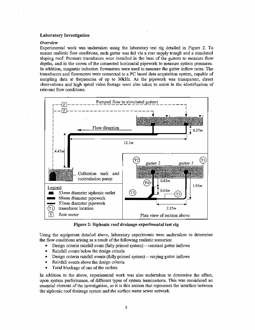
Laboratory Investigation
Overview Experimental work was undertaken using the laboratory test rig detailed in Figure 2. To ensure realistic flow conditions, each gutter was fed via a rear supply trough and a simulated sloping roof. Pressure transducers were installed in the base of the gutters to measure flow depths, and in the crown of the connected horizontal pipework to measure system pressures. In addition, magnetic induction flowmeters were used to measure the gutter inflow rates. The transducers and flowmeters were connected to a PC based data acquisition system, capable of sampling data at frequencies of up to 30kHz. As the pipework was transparent, direct observations and high speed video footage were also taken to assist in the identification of relevant flow conditions.
-------
- 53mm diameter siphonic outlet 69mm diameter pipework
Figure 2: Siphonic roof drainage experimental test rig
Using the equipment detailed above, laboratory experiments were undertaken to determine the flow conditions arising as a result of the following realistic scenarios:
Design criteria rainfall event ( I l ly primed system) - constant gutter inflows Rainfall events below the design criteria Design criteria rainfall events (fblly primed system) - varying gutter inflows Rainfall events above the design criteria Total blockage of one of the outlets
In addition to the above, experimental work was also undertaken to determine the effect, upon system performance, of different types of system terminations. This was considered an essential element of the investigation, as it is this section that represents the interface between the siphonic roof drainage system and the surfacewater sewer network.
With reference to Figure 2 and the experimental data detailed herein, branch I refers to the pipework connecting gutter I to the branch junction, branch 2 refers to the pipework connecting gutter 2 to the branch junction and common pipe refers to the pipework downstream of the branch junction. It should also be noted that, unless otherwise stated, the gutter inflow rates were constant throughout the testing periods, i.e. the simulated rainfall events were assumed to "instantaneously" reach a constant intensity.
Design criteria rainfall event Cfullyprimed system) - constant gutter inflows Priming of the laboratory siphonic test rig was observed to occur when the inflow to gutter I was set to 5.851/s and the inflow to gutter 2 was set to 7.781/s. As the two gutters were located at the same elevation above the point of discharge, the difference in inflows required for siphonic conditions was due solely to the different branch configurations. This is highlighted by inspection of Figure 2, which indicates that the head losses associated with the branch 2 configuration would be significantly less than those associated with the branch I configuration. The priming proced~re of the siphonic test rig was gefierally observed to occur as follows: 1. Initial gutter inflow: At the start of the simulated rainfall event, the gutter water levels and
the system inflows were relatively low, leading to free surface flow (subcritical) within the horizontal pipework and annular flow within the vertical pipework
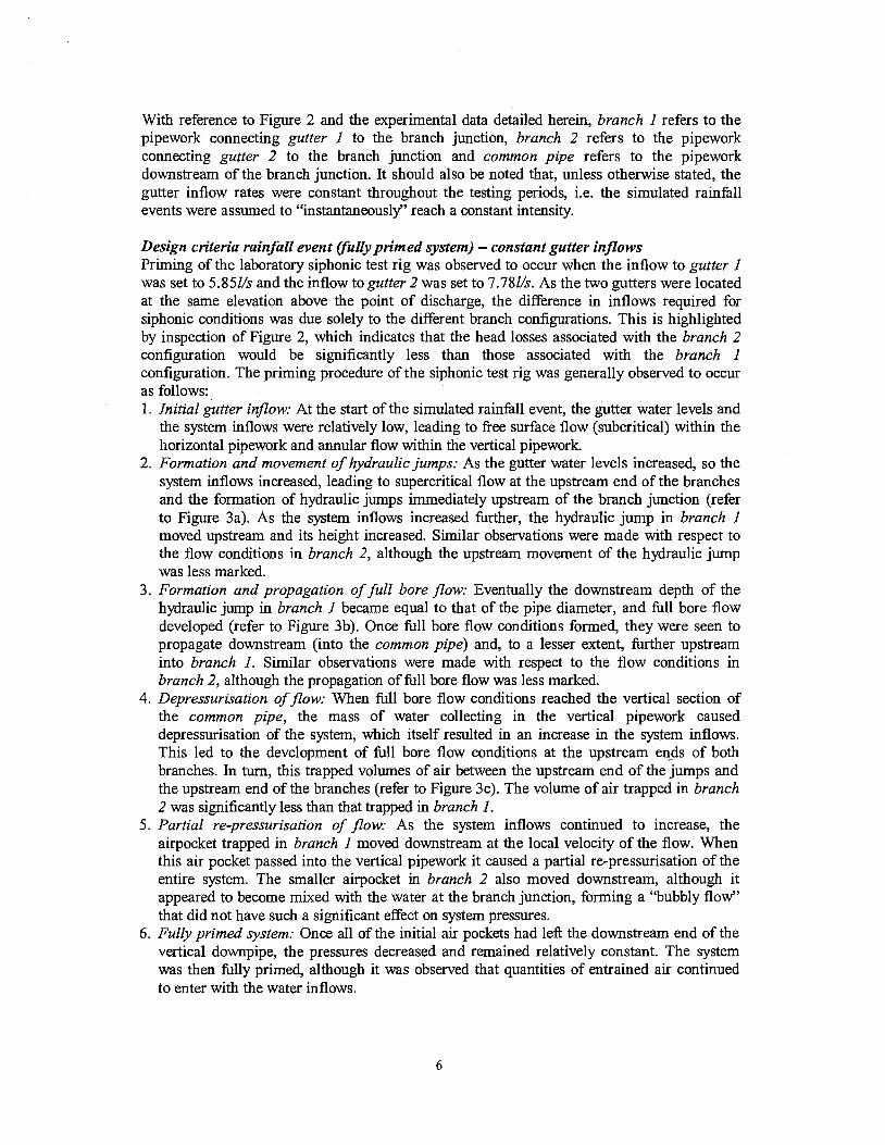
2. Formation and movement of hydraulic jumps: As the gutter water levels increased, so the system inflows increased, leading to supercritical flow at the upstream end of the branches and the formation of hydraulic jumps immediately upstream of the branch junction (refer to Figure 3a). As the system inflows increased further, the hydraulic jump in branch I moved upstream and its height increased. Similar observations were made with respect to the flow conditions in branch 2, although the upstream movement of the hydraulic jump was less marked.
3. Formation and propagation of full bore flow: Eventually the downstream depth of the hydraulic jump in branch I became equal to that of the pipe diameter, and fill bore flow developed (refer to Figure 3b). Once full bore flow conditions formed, they were seen to propagate downstream (into the common pipe) and, to a lesser extent, further upstream into branch I. Similar observations were made with respect to the flow conditions in branch 2, although the propagation of full bore flow was less marked.
4. Depressurisation of flow: When full bore flow conditions reached the vertical section of the common pipe, the mass of water collecting in the vertical pipework caused depressurisation of the system, which itself resulted in an increase in the system inflows. This led to the development of 111 bore flow conditions at the upstream ends of both branches. In turn, this trapped volumes of air between the upstream end of the jumps and the upstream end of the branches (refer to Figure 3c). The volume of air trapped in branch 2 was significantly less than that trapped in branch I .
5. Partial re-pressurisation of flow: As the system inflows continued to increase, the airpocket trapped in branch I moved downstream at the local velocity of the flow. When this air pocket passed into the vertical pipework it caused a partial re-pressurisation of the entire system. The smaller airpocket in branch 2 also moved downstream, although it appeared to become mixed with the water at the branch junction, forming a "bubbly flow" that did not have such a significant effect on system pressures.
6. Fully primed system: Once all of the initial air pockets had left the downstream end of the vertical downpipe, the pressures decreased and remained relatively constant. The system was then fully primed, although it was observed that quantities of entrained air continued to enter with the water inflows.
Figure 3: Priming process of the siphonic roof drainage experimental test rig
a. Formation of hydraulic from jumps gutter 2
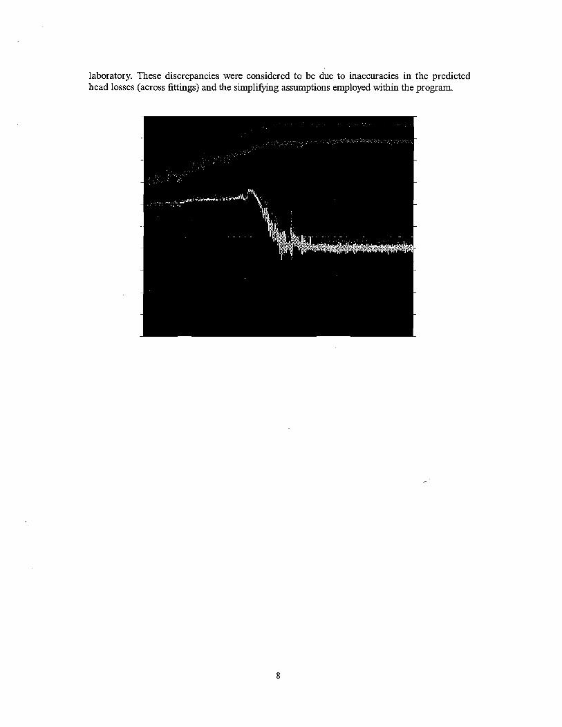
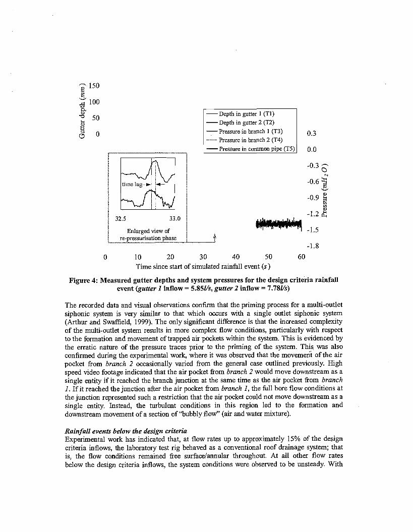
The gutter depths and system pressures recorded during the priming of the siphonic test rig are shown in Figure 4. The time lag between pressure peaks clearly illustrates that the re- pressurisation wave was generated at the downstream end of the common-pipe, and propagated upstream. The 0.04 second time lag shown between transducers 3 and 5, which were 2.3m apart, yields a wave propagation velocity of 57.5ds. Noting that the laboratory pipework was not restrained against radial or longitudinal movement (expansion joints), an iterative solution of the appropriate wave speed equation (Wylie and Streeter, 1993) yields an air content of 5.4% for a wave propagation velocity of 57.5ds. Although this can only be considered to be an approximation of the actual air content within the flow, it is of a similar magnitude to that previously estimated for single outlet systems (Arthur and Swaffield, 1999).
b. Formation and propagation from of full bore flow gutter 2
c. Formation of trapped air from pockets gutter 2
V
Using a design program based on the steady flow energy equation, it was predicted that siphonic conditions would occur at the measured gutter inflow rates if the internal roughness of the pipework was 0.028mm. Although such a roughness value is considered to be reasonable for the type of pipework employed in the laboratory test rig, the system pressures predicted by the design program were up to 39% lower than those actually measured in the
9 8 m E 5' 09
Et m
w 3 D.
ti' 2 8
Flow direction F
laboratory. These discrepancies were considered to be due to inaccuracies in the predicted head losses (across fittings) and the simplifying assumptions employed within the program.
-Depth in gutter 1 (TI) - Depth in gutter 2 (T2)
-Pressure in branch 1 (T3) Pressure in branch 2 (T4)
- Pressure in common pipe (T5) 1
Time since start of simulated rainfall event (s)
/ Enlarged view of re-pressurisation phase
Figure 4: Measured gutter depths and system pressures for the design criteria rainfall event (gutter 1 inflow = 5.851/s, gutter 2 inflow = 7.781/s)
a
The recorded data and visual observations confirm that the priming process for a multi-outlet siphonic system is very similar to that which occurs with a single outlet siphonic system (Arthur and Swaffield, 1999). The only significant difference is that the increased complexity of the multi-outlet system results in more complex flow conditions, particularly with respect to the formation and movement of trapped air pockets within the system. This is evidenced by the erratic nature of the pressure traces prior to the priming of the system. This. was also confirmed during the experimental work, where it was observed that the moveme* of the air pocket from branch 2 occasionally varied from the general case outlined previously. High speed video footage indicated that the air pocket fiom branch 2 would move downstream as a single entity if it reached the branch junction at the same time as the air pocket fiom branch 1. If it reached the junction after the air pocket fiom branch I , the full bore flow conditions at the junction represented such a restriction that the air pocket could not move downstream as a single entity. Instead, the turbulent conditions in this region led to the formation and downstream movement of a section of ''bubbly flow" (air and water mixture).
Rainfall events below the design criteria Experimental work has indicated that, at flow rates up to approximately 15% of the design criteria inflows, the laboratory test rig behaved as a conventional roof drainage system; that is, the flow conditions remained fiee surface/annular throughout. At all other flow rates below the design criteria inflows, the system conditions were observed to be unsteady. With
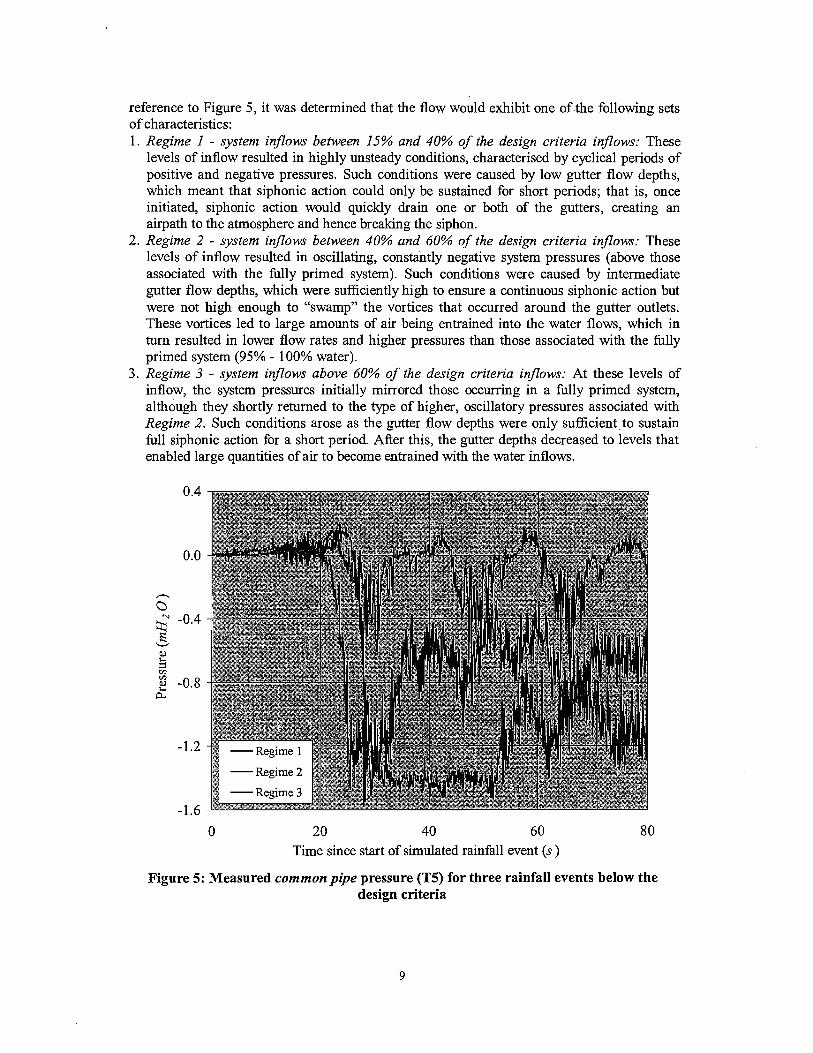
reference to Figure 5, it was determined that the flow would exhibit one of.the following sets of characteristics: 1. Regime 1 - system inflows between 15% and 40% of the design criteria inflows: These
levels of inflow resulted in highly unsteady conditions, characterised by cyclical periods of positive and negative pressures. Such conditions were caused by low gutter flow depths, which meant that siphonic action could only be sustained for short periods; that is, once initiated, siphonic action would quickly drain one or both of the gutters, creating an airpath to the atmosphere and hence breaking the siphon.
2. Regime 2 - system inflows between 40% and 60% of the design criteria inflows: These levels of inflow resulted in oscillating, constantly negative system pressures (above those associated with the fully primed system). Such conditions were caused by intermediate gutter flow depths, which were sufficiently high to ensure a continuous siphonic action but were not high enough to "swamp" the vortices that occurred around the gutter outlets. These vortices led to large amounts of air being entrained into the water flows, which in turn resulted in lower flow rates and higher pressures than those associated with the fully primed system (95% - 100% water).
3. Regime 3 - system inflows above 60% of the design criteria inflows: At these levels of inflow, the system pressures initially mirrored those occurring in a fully primed system, although they shortly returned to the type of higher, oscillatory pressures associated with Regime 2. Such conditions arose as the gutter flow depths were only sufficient to sustain 111 siphonic action for a short period. After this, the gutter depths decreased to levels that enabled large quantities of air to become entrained with the water inflows.
0 20 40 60 8 0 Time since start of simulated rainfall event (s )
Figure 5: Measured common pipe pressure (T5) for three rainfall events below the design criteria
In general it was determined that, with the inflow to one of the gutters set to a constant rate, increasing the inflow into the remaining gutter resulted in steadier and lower system pressures. This was as expected, as an increase in total system inflow leads to a decrease in the volume of air being drawn into the system. It was also apparent that, for the same total system inflow, overtopping became less likely as the ratio of the gutter inflows (Q gutter 1 : Q 2) approached that of the fully primed system (7.78:5.85 = 1.33: 1). This was again as expected, a more even gutter flow distribution increasing the probability of siphonic events, and hence increasing the average flow velocities within the system.
The disparity between the transition from free surfacelannular to unsteadylsiphonic conditions in the multi-outlet system (15% of design criteria inflows) and the single outlet system mentioned previously (40% of design criteria inflows) is considered to be due to the smaller pipe diameters employed and the flow distorting effect of the branch junction in the multi-outlet system.
Design criteria rainfall event Cfully primed system) - varying gutter inflows. As many real rainfall events progressively build in intensity, experimental work was undertaken to assess the effect of gradually increasing the gutter inflows (up to design criteria levels). The only significant difference between these results and those obtained with constant gutter inflows was that it took longer for the system pressures and gutter flow depths to build up to the those necessary purge the air fiom the system, and initiate siphonic action
Additional experimental work was also undertaken to determine the effect of staggering the gutter inflow start times, which would represent systems incorporating widely varying roof geometries, e.g. one gutter outlet serving a steeply pitched roof and one gutter outlet serving a shallower pitched roof. As may be appreciated, the resulting flow conditions were very complicated, exhibiting two or three of the unsteady flow regimes identified previously. However, it was apparent fiom the data collected that, after a short period at the design criteria inflows, the gutter flow depths and system pressures mirrored those obtained with synchronised inflow start times (refer to Figure 4).
Rainfall events above the design criteria Laboratory experiments undertaken with rainfall events above the design criteria indicated that the system pressures were almost identical to those obtained at the design condition. However, the additional system inflows (above the design criteria levels) resulted in continuously increasing gutter depths, which would have eventually lead to overtopping of the gutter(s). If the slight variations in driving head associated with higher gutter depths are disregarded, these observations confirm that the system pressures occurring once--a siphonic system has become primed are the minimum possible, and the capacity is the maximum possible, for that particular system.
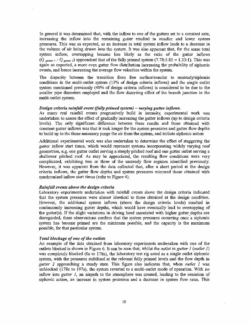
Total blockage of one of the outlets An example of the data obtained from laboratory experiments undertaken with one of the outlets blocked is shown in Figure 6. It can be seen that, whilst the outlet in gutter 1 (outlet 1) was completely blocked (0s to 178s), the laboratory test rig acted as a single outlet siphonic system, with the pressures stabilised at the relevant fully primed levels and the flow depth in gutter 2 approaching a steady state. This figure also indicates that, when outlet 1 was unblocked (178s to 197s), the system reverted to a multi-outlet mode of operation. With no inflow into gutter 1, an airpath to the atmosphere was created, leading to the cessation of siphonic action, an increase in system pressures and a decrease in system flow rates. This
resulted in a very rapid increase in the water level within gutter 2, and would have led to overtopping of this gutter if outlet 1 was not re-blocked (after 197s).
- Pressure in branch 1 (T3)
.--- Pressure in branch 2 (T4)
Time since start of simulated rainfall event (s)
Figure 6: Measured gutter depths and system pressures with the outlet in gutter I blocked/unblocked/blocked (gutter I inflow = OVs, gutter 2 inflow = 11.3Us)
Table 1 surnrnarises the salient system conditions pertaining to Figure 6. As shown, although the total system capacity was lower with outlet 1 blocked, the capacity of the open outlet (in gutter 2) was actually higher than was the case in an unblocked system. The data in Table 1 also highlight that system pressures were considerably lower when outlet 1 was blocked. This would indicate that, if a system were designed to operate at very low pressures (below approximately -7mHrO), a complete blockage of one of the outlets might result in. the onset of cavitation andlor failure of the system by pipe deformation.
Table 1: Measured system conditions with outlet I unblocked and blocked
Effect of different system termination configurations To ensure the efficient operation of a siphonic roof drainage system, it is essential that full bore flow conditions are broken upstream of any connection to the surface water sewer network. If not, the flows within the siphonic system and the sewer network may interact, leading to unpredictable conditions and potential problems. Breaking of 111 bore flow
Outlet blocked
none outlet 1
Fully primed capacity (l/s)
13.63 11.30
Capacity of outlet in gutter 2 (Us)
7.88 11.30
Minimum measured pressure (mH20) transducer 1
-0.552 -1.719
transducer 2 -0.595 -1.846
transducer 3 -1.388 -2.147
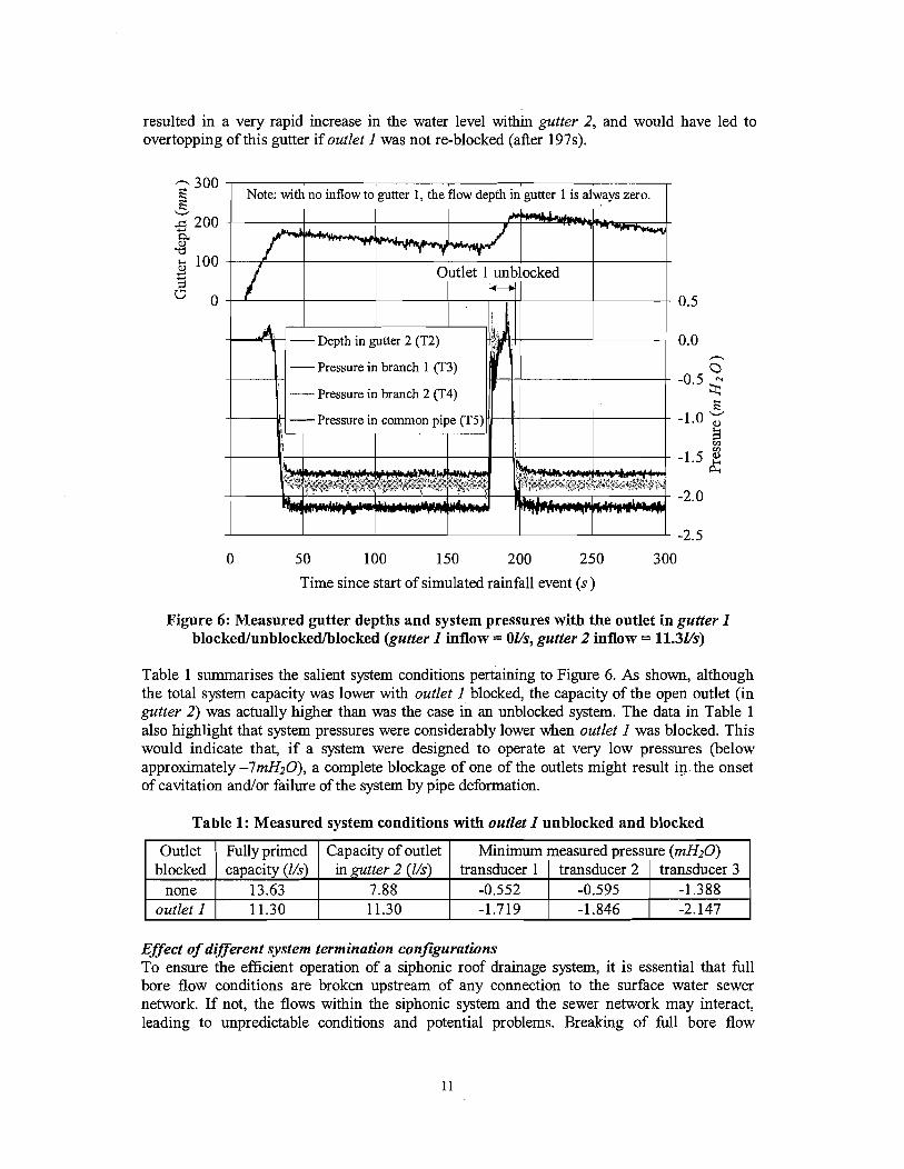
conditions can only be guaranteed by ensuring that the flow exits the siphonic system above the highest water level in the surface water sewer. However, surface water sewers occasionally surcharge, with the relevant European standard (BSI, 1997) stipulating a 2 year surcharge return period for conunercial and industrial areas (with a flood return period up to 30 years). Therefore, experimental work was undertaken to determine the effect of tenninating a siphonic roof drainage system under water. In addition, data was also collected to determine the effect of a right angled termination, which often proves necessary due to the site layout. The four different system terminations that were investigated are shown in Figure 7. It should be noted that, due to space restrictions, the length of the vertical downpipe in these configurations was reduced to 4.07m.
termination 2 termination 3 termination 4
Figure 7: Siphonic system termination configurations investigated
As the driving head for a siphonic roof drainage system is defined as the elevation difference between the gutter outlets and the point of discharge (fiee discharge case) or the point at which the downpipe enters water (submerged discharge case), it can be deduced fiom Figure 7 that the driving head for each of the four configurations was different. In addition, it is clear fiom Figure 7 that the head losses associated with each of the four configurations varied. As a result, the gutter inflows necessary to cause priming of the four different configurations were different. From the data shown in Table 2, it is clear that the use of any configuration other than a fieely discharging vertical downpipe will result in a lower system capacity.
Table 2: Variation in design criteria gutter inflows with termination configuration
Figures 8a and 8b show a sample of the experimental data obtained using the four different termination configurations. As shown, the configurations that discharged under water resulted in significantly longer priming times and higher gutter flow depths than those discharging directly to the atmosphere. This was because greater (positive) system pressures were required to purge the initial air pockets.
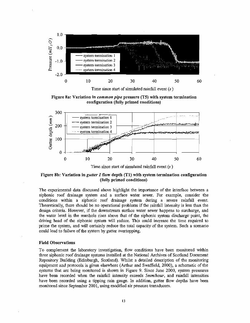
Time since start of simulated rainfall event (s )
Figure 8a: Variation in common pipe pressure (T5) with system termination configuration (fully primed conditions)
system termination 1
".....-*..-.-.
Time since start of simulated rainfall event (s )
Figure 8b: Variation in gutter I flow depth (TI) with system termination configuration (fully primed conditions)
The experimental data discussed above highlight the importance of the interface between a siphonic roof drainage system and a surface water sewer. For example, consider the conditions within a siphonic roof drainage system during a severe rainfall event. Theoretically, there should be no operational problems if the rainfall intensity is less than the design criteria. However, if the downstream surface water sewer happens to surcharge, and the water level in the manhole rises above that of the siphonic system discharge- point, the driving head of the siphonic system will reduce. This could increase the time required to prime the system, and will certainly reduce the total capacity of the system. Such a scenario could lead to failure of the system by gutter overtopping.
Field Observations
To complement the laboratory investigation, flow conditions have been monitored within three siphonic roof drainage systems installed at the National Archives of Scotland Document Repository Building (Edinburgh, Scotland). Whilst a detailed description of the monitoring equipment and protocols is given elsewhere (Arthur and Swaffield, 2000), a schematic of the systems that are being monitored is shown in Figure 9. Since June 2000, system pressures have been recorded when the rainfall intensity exceeds Smm/hour, and rainfall intensities have been recorded using a tipping rain gauge. Ln addition, gutter flow depths have been monitored since September 200 1, using modified air pressure transducers.
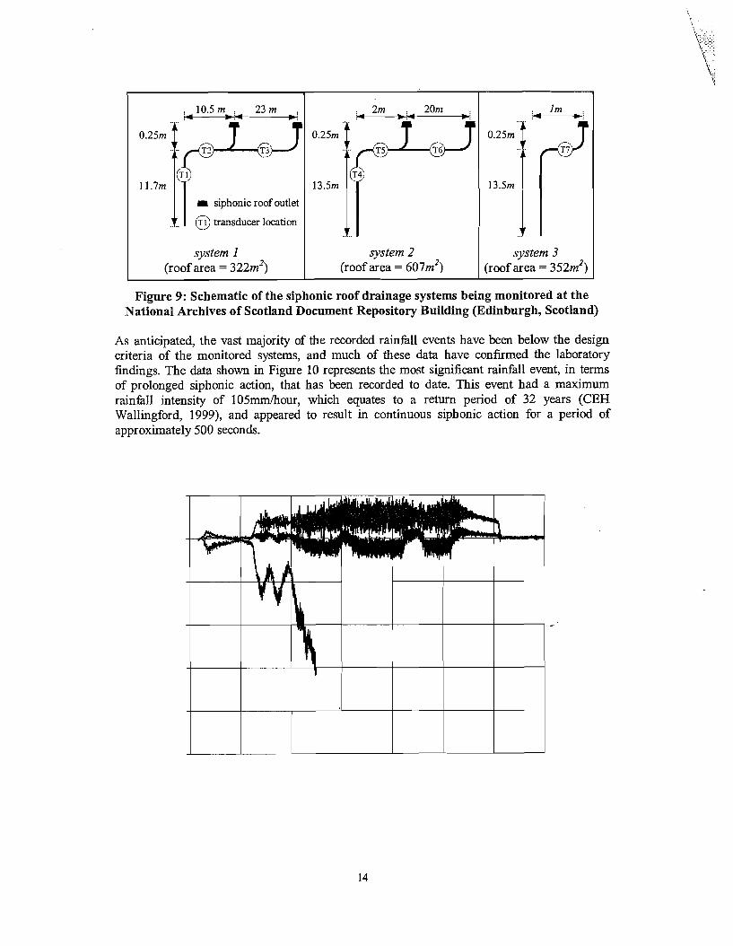
Figure 9: Schematic of the siphonic roof drainage systems being monitored at the National Archives of Scotland Document Repository Building (Edinburgh, Scotland)
11.7m 13.5m
r siphonic roof outlet
59 transducer location
As anticipated, the vast majority of the recorded rainfall events have been below the design criteria of the monitored systems, and much of these data have confirmed the laboratory fmdings. The data shown in Figure 10 represents the most significant rainfall event, in terms of prolonged siphonic action, that has been recorded to date. This event had a maximum rainfall intensity of 105mm/hour, which equates to a return period of 32 years (CEH Wallingford, 1999), and appeared to result in continuous siphonic action for a period of approximately 500 seconds.
system I (roof area = 322m2)
.. ..
system 2 (roof area = 607m2)
... .
system 3 (roof area = 352m2)
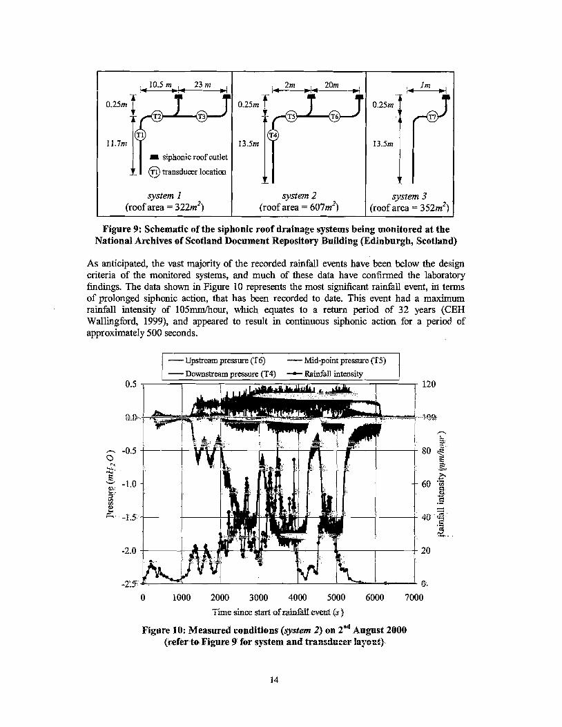
Figure 9: Schematic of the siphonic roof drainage systems being monitored at the National Archives of Scotland Document Repository Building (Edinburgh, Scotland)
As anticipated, the vast majority of the recorded rainfall events have been below the design criteria of the monitored systems, and much of these data have confirmed the laboratory findings. The data shown in Figure 10 represents the most significant rainfall event, in terms of prolonged siphonic action, that has been recorded to date. This event had a maximum rainfall intensity of 105mrn/hour, which equates to a return period of 32 years (CEH Wallingford, 199!3), and appeared to result in continuous siphonic action for a period of approximately 500 seconds.
: 10.5m : 23nz :
.. ..
0-25m - lF ..
- Upstream pressure (T6) - Mid-point pressure (T5)
- Downstream Dressure (T4) Rainfall intensity
: 2m : 20m :
0.25m .Ir T4
13.5n1
.. - system 2
(roof area = 607m2)
11.7nz
0 1000 2000 3000 4000 5000 6000 7000
T h e since start of rsliniill e~r,ni (8 3
: lm ;
.. .
0.25m -1 df 13.5m
-. .
system 3 (roof area = 352rn2)
I siphonic roof outlet
Figure 10: Measured conditions (system 2) on 2nd August 2000 (refer to Figure 9 for system and traasih~rer layoxt)
I. Tl transducer location
system 1 (roof area = 322m2)
An analysis of the field data collected to date indicates that 7% of recorded events resulted in prolonged siphonic action and 50% of recorded events resulted in significant negative system pressures.
Development of the Numerical Model
As mentioned previously, the existing numerical model developed at Heriot-Watt University (SIPHONET) is capable of simulating the priming phase of a single outlet siphonic roof drainage system. This model utilises a method of characteristics based solution technique, which has been employed successfidly at Heriot-Watt University in the simulation of both free surface and full bore flow conditions. However, during the development of the SIPHONET model it became clear that the method of characteristics was not particularly suited to the simulation of moving hydraulic jumps. In addition, numerical stability problems were also encountered with the transition between fiee surface and full bore flow conditions. As these deficiencies would become more limiting in the more complex case of multi-outlet systems, it was decided to employ a new modelling approach. This will incorporate the Lax- Wendroff finite difference solution technique.
Conclusions and Future Work
The conclusions of this ongoing research programme may be surnmarised as follows: The priming of a multi-outlet siphonic roof drainage system is similar, although more. complex, to that of a single outlet system. Current design programs may yield inaccurate system pressures, which wuld lead to operational problems andor system failure. At rainfall intensities below the design criteria, the flow conditions within a multi- outlet siphonic roof drainage system are unsteady, and may exhibit one of three different flow regimes. The complete blockage of one of the outlets in a multi-outlet siphonic roof drainage system may lead to system pressures falling below their design levels, and could result in system failure by cavitation andor pipe deformation. To ensure efficient operation of a siphonic roof drainage system, consideration must be given to its interaction with the downstream surface water sewer network.
The final phase of this current research programme involves the Wher development of the numerical model. It is intended that the final model will be capable of accurateIy simulating the flow conditions within multi-outlet siphonic roof drainage systems fbr all realistic rainfall events. It is anticipated that such a model will be used for diagnostic design purposes and code formulation, which should reduce the occurrence of the type of operational problems and system failures detailed previously.
References
Arthur, S. and Swaffield, J.A. (1999). Numerical modelling of the priming of a siphonic roof drainage system. Proceedings of CIBSE Building Services Engineering Research and Technology, Vol. 20, No. 2.
Arthw, S. and Swaffield, J.A. (2000). Onsite evaluation of an installed siphonic roof drainage system. Proceedings of Water Supply and Drainage for Buildings Seminar: CIBW62 2000. Rio de Janeiro.
Arthur, S. and Swaffield, J.A. (2001). Siphonic Roof Drainage: The State of the Art. Urban Water. Vol. 3, no. 1, pp.43-52.
Bowler, R and Arthur, S.A. (1999). Siphonic roof drainage - design considerations. Proceedings of Water Supply and Drainage for Buildings Seminar: CIB W62 1999. Edinburgh.
CEH Wallingford (1999). Flood Estimation Handbook. Wallingford: CEH Walliigford, NERC.
BSI (1997). BS EN 752-2 Drain and sewer systems outside buildings. Performance requirements. U K British Standards Institute.
BSI (2000). BS EN 12056-3 Gravity drainage systems inside buildings. Roof drainage, layout and calculation. UK. British Standards Institute.
May, RW.P. and Escarameia, M. (1996). Performance of siphonic drainage systems for roof gutters. Report No. SR463. Wallingford: HR Wallingford.
Rattenbury, J. (2001). Fundamentals of Siphonic Roof Drainage. http://wpmengineer.com
/CDA/ArticleInformation/fea~res/BNPNPPeatures~Item/0,2732,21863,00. html. (3fd January 2001).
Wylie, E.B. and Streeter, V.L. (1993). Fluid Transients in Systems. New Jersey: Prentice-Hall Inc.
Acknowledgements
The researchers remain grateful for the assistance given by Dales Fabrications Ltd (UK), EPSRC (UK), Fullflow Ltd (UK), Geberit AB (Switzerland), HR Wallingford Ltd (UK), Pick Everard (UK), Simona Ltd (Germany), Somrnerhein AT3 (Sweden), The Scottish Executive (UK), Vandenveil Engineering Inc (USA).