Embed Size (px)
Citation preview
Technical manual
MB FIRE-PRO ROOFMB ROOF SOUND
INFORMATIVE NOTE
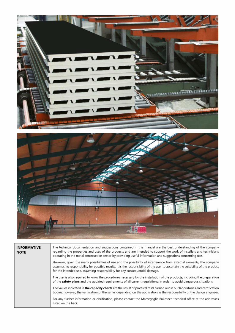
The technical documentation and suggestions contained in this manual are the best understanding of the company regarding the properties and uses of the products and are intended to support the work of installers and technicians operating in the metal construction sector by providing useful information and suggestions concerning use.
However, given the many possibilities of use and the possibility of interference from external elements, the company assumes no responsibility for possible results. It is the responsibility of the user to ascertain the suitability of the product for the intended use, assuming responsibility for any consequential damage.
The user is also required to know the procedures necessary for the installation of the products, including the preparation of the safety plans and the updated requirements of all current regulations, in order to avoid dangerous situations.
The values indicated in the capacity charts are the result of practical tests carried out in our laboratories and certification bodies; however, the verification of the same, depending on the application, is the responsibility of the design engineer.
For any further information or clarification, please contact the Marcegaglia Buildtech technical office at the addresses listed on the back.
Marcegaglia Buildtech 1
TABLE OF CONTENTS
MB FIRE-PRO ROOF AND MB ROOF SOUND ................................................................................................................... 2
Product typology ................................................................................................................................................................................................... 2
Joint typology .......................................................................................................................................................................................................... 3
Technical specifications ....................................................................................................................................................................................... 4
Metal supports ........................................................................................................................................................................................................ 5
Protection of the supports ................................................................................................................................................................................. 5
Panels weight ........................................................................................................................................................................................................... 5
Static characteristics .............................................................................................................................................................................................. 6
Fire behaviour .......................................................................................................................................................................................................... 7
Sound behaviour .................................................................................................................................................................................................... 9
Advice and instructions for use ........................................................................................................................................ 11
Thermal expansion .............................................................................................................................................................................................. 11
Useful design information ................................................................................................................................................................................ 12
Transport, storage and handling ...................................................................................................................................... 14
Transport and standard composition of the packages ......................................................................................................................... 14
Handling, storage and installation of panels ............................................................................................................................................ 15
Assembly instructions ........................................................................................................................................................ 16
Fixing system ......................................................................................................................................................................................................... 16
Installation and equipment .............................................................................................................................................................................. 17
Installation and fixing of roofing panels ..................................................................................................................................................... 18
Overlapping ............................................................................................................................................................................................................ 20
Assembly of translucent elements ................................................................................................................................................................ 22
Examples of solutions for the installation of roofing panels ...................................................................................... 23
Maintenance and disposal................................................................................................................................................. 27
Roof inspection ..................................................................................................................................................................................................... 27
Routine maintenance ......................................................................................................................................................................................... 27
Disposal.................................................................................................................................................................................................................... 27
Safety data ........................................................................................................................................................................... 28
The dissemination and copying of this document are prohibited - art. 1175 and 2015 of the Italian Civil code. Any violations will lead to a criminal prosecution as per art. 646 of the Italian Penal code.
2 Marcegaglia Buildtech
MB FIRE-PRO ROOF AND MB ROOF SOUND
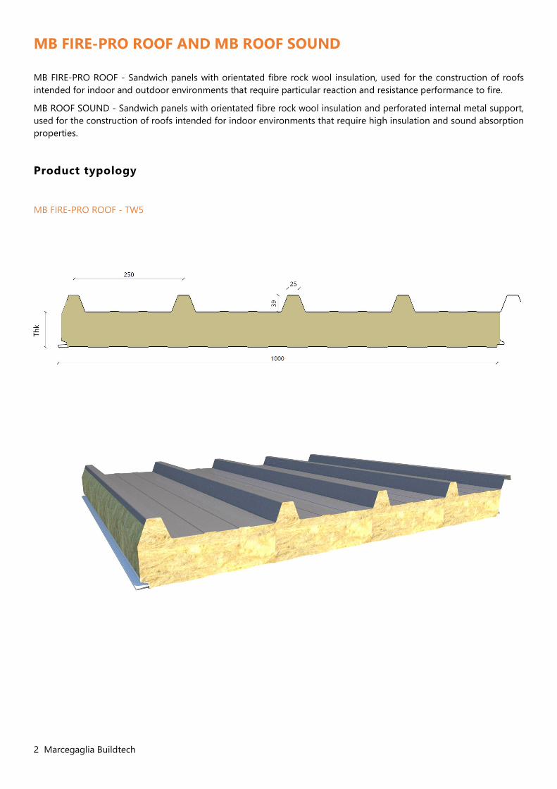
MB FIRE-PRO ROOF - Sandwich panels with orientated fibre rock wool insulation, used for the construction of roofs intended for indoor and outdoor environments that require particular reaction and resistance performance to fire.
MB ROOF SOUND - Sandwich panels with orientated fibre rock wool insulation and perforated internal metal support, used for the construction of roofs intended for indoor environments that require high insulation and sound absorption properties.
Product typology
MB FIRE-PRO ROOF - TW5
Thk
Marcegaglia Buildtech 3
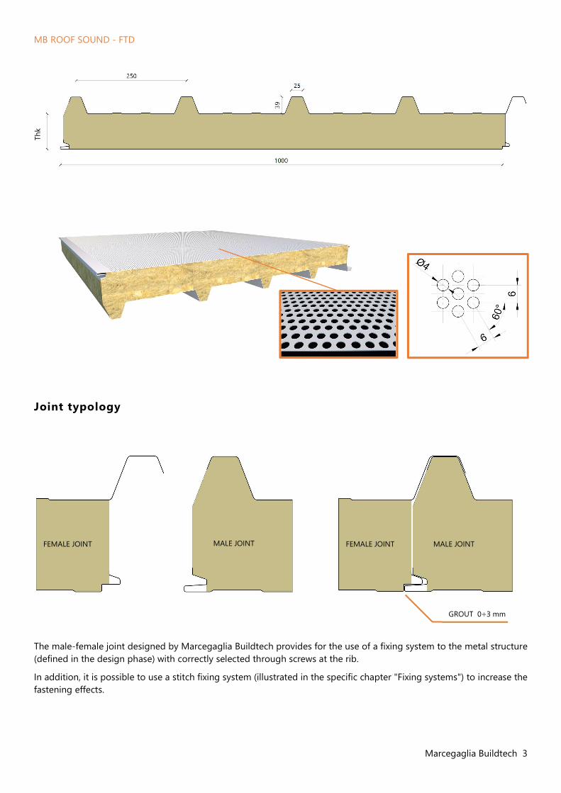
GROUT 0÷3 mm
MB ROOF SOUND - FTD
Joint typology
The male-female joint designed by Marcegaglia Buildtech provides for the use of a fixing system to the metal structure (defined in the design phase) with correctly selected through screws at the rib.
In addition, it is possible to use a stitch fixing system (illustrated in the specific chapter "Fixing systems") to increase the fastening effects.
FEMALE JOINT FEMALE JOINT MALE JOINT MALE JOINT
Thk
4 Marcegaglia Buildtech
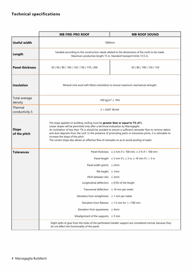
Technical specifications
MB FIRE-PRO ROOF MB ROOF SOUND
Useful width 1000mm
Length Variable according to the construction needs related to the dimensions of the roofs to be made.
Maximum productive length 15 m. Standard transport limits 13.5 m.
Panel thickness 50 / 60 / 80 / 100 / 120 / 150 / 170 / 200 50 / 80 / 100 / 120 / 150
Insulation Mineral rock wool with fibres orientation to ensure maximum mechanical strength.
Total average density
100 kg/m3 ± 10%
Thermal conductivity λ
λ = 0,041 W/mK
Slope of the pitch
The slope applied on building roofing must be greater than or equal to 7% (4°). Lesser slopes will be permitted only after a technical evaluation by Marcegaglia. An inclination of less than 7% is should be avoided to ensure a sufficient rainwater flow to remove debris and dust deposits from the roof. In the presence of protruding parts or transverse joints, it is advisable to increase the slope of the pitch. The correct slope also allows an effective flow of rainwater so as to avoid pooling of water.
Tolerances Panel thickness: ± 2 mm if ≤ 100 mm; ± 2 % if > 100 mm
Panel length: ± 5 mm if L ≤ 3 m, ± 10 mm if L > 3 m
Panel width (pitch): ± 2mm
Rib height: ± 1mm
Pitch between ribs: ± 2mm
Longitudinal deflection: ≤ 0,5% of the length
Transversal deflection: ± 10 mm per meter
Deviation from straightness: ≤ 1 mm per meter
Deviation from flatness: ≤ 1.5 mm for L >700 mm
Deviation from squareness: ± 3mm
Misalignment of the supports: ≤ 3 mm
Slight spills of glue from the holes of the perforated metallic support are considered normal, because they do not affect the functionality of the panel.
Marcegaglia Buildtech 5
Metal supports
Marcegaglia Buildtech provides for the configuration of the panels with the following metal support variants:
Pre-painted steel , in accordance with EN 10169 (coil coating) based on EURONORMS:
for normal production: with MP3 polyester coating
for special production: with modified MP5 polyester coating with MP10 polyvinylidene coating with MP20 polyurethane / polyamide coating.
Plasticized galvanized steel EN 10346
Natural aluminium, pre-painted EN 485-2, EN 573-3, EN 11396.
Stainless Steel, in accordance with requirements EN 1172, EN 1173, EN 1412.
Protection of the supports
To prevent the pre-painted metal supports from being damaged during production and subsequent movement of the panels, a polyethylene adhesive film is used which must be removed during the installation phase or in any case not later than 60 days from the production of the panels.
Please note that it is highly recommended not to store the panels in a place with prolonged sun exposure.
Marcegaglia Buildtech strongly advises against the request for material without a polyethylene adhesive film and assumes no responsibility for any damage in the event that such a request is submitted.
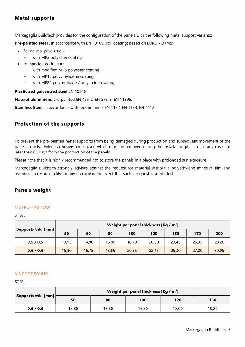
Panels weight
MB FIRE-PRO ROOF
STEEL
Supports thk. [mm] Weight per panel thickness [Kg / m2]
50 60 80 100 120 150 170 200
0,5 / 0,5 13,95 14,90 16,80 18,70 20,60 23,45 25,35 28,20
0,6 / 0,6 15,80 16,75 18,65 20,55 22,45 25,30 27,20 30,05
MB ROOF SOUND
STEEL
Supports thk. [mm] Weight per panel thickness [Kg / m2]
50 80 100 120 150
0,6 / 0,6 13,80 15,60 16,80 18,00 19,80
6 Marcegaglia Buildtech
Static characteristics
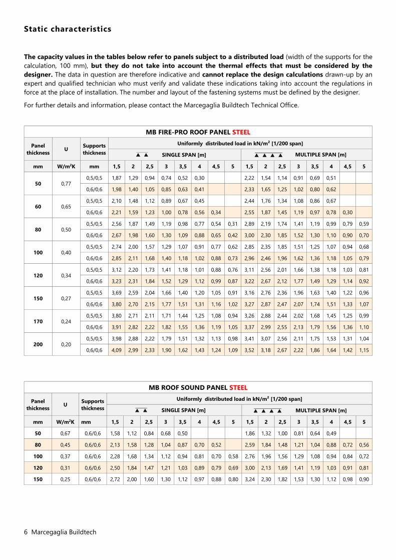
The capacity values in the tables below refer to panels subject to a distributed load (width of the supports for the calculation, 100 mm), but they do not take into account the thermal effects that must be considered by the designer. The data in question are therefore indicative and cannot replace the design calculations drawn-up by an expert and qualified technician who must verify and validate these indications taking into account the regulations in force at the place of installation. The number and layout of the fastening systems must be defined by the designer.
For further details and information, please contact the Marcegaglia Buildtech Technical Office.
MB FIRE-PRO ROOF PANEL STEEL
Panel thickness
U Supports thickness
Uniformly distributed load in kN/m² [1/200 span]
SINGLE SPAN [m] MULTIPLE SPAN [m]
mm W/m2K mm 1,5 2 2,5 3 3,5 4 4,5 5 1,5 2 2,5 3 3,5 4 4,5 5
50 0,77 0,5/0,5 1,87 1,29 0,94 0,74 0,52 0,30 2,22 1,54 1,14 0,91 0,69 0,51
0,6/0,6 1,98 1,40 1,05 0,85 0,63 0,41 2,33 1,65 1,25 1,02 0,80 0,62
60 0,65 0,5/0,5 2,10 1,48 1,12 0,89 0,67 0,45 2,44 1,76 1,34 1,08 0,86 0,67
0,6/0,6 2,21 1,59 1,23 1,00 0,78 0,56 0,34 2,55 1,87 1,45 1,19 0,97 0,78 0,30
80 0,50 0,5/0,5 2,56 1,87 1,49 1,19 0,98 0,77 0,54 0,31 2,89 2,19 1,74 1,41 1,19 0,99 0,79 0,59
0,6/0,6 2,67 1,98 1,60 1,30 1,09 0,88 0,65 0,42 3,00 2,30 1,85 1,52 1,30 1,10 0,90 0,70
100 0,40 0,5/0,5 2,74 2,00 1,57 1,29 1,07 0,91 0,77 0,62 2,85 2,35 1,85 1,51 1,25 1,07 0,94 0,68
0,6/0,6 2,85 2,11 1,68 1,40 1,18 1,02 0,88 0,73 2,96 2,46 1,96 1,62 1,36 1,18 1,05 0,79
120 0,34 0,5/0,5 3,12 2,20 1,73 1,41 1,18 1,01 0,88 0,76 3,11 2,56 2,01 1,66 1,38 1,18 1,03 0,81
0,6/0,6 3,23 2,31 1,84 1,52 1,29 1,12 0,99 0,87 3,22 2,67 2,12 1,77 1,49 1,29 1,14 0,92
150 0,27 0,5/0,5 3,69 2,59 2,04 1,66 1,40 1,20 1,05 0,91 3,16 2,76 2,36 1,96 1,63 1,40 1,22 0,96
0,6/0,6 3,80 2,70 2,15 1,77 1,51 1,31 1,16 1,02 3,27 2,87 2,47 2,07 1,74 1,51 1,33 1,07
170 0,24 0,5/0,5 3,80 2,71 2,11 1,71 1,44 1,25 1,08 0,94 3,26 2,88 2,44 2,02 1,68 1,45 1,25 0,99
0,6/0,6 3,91 2,82 2,22 1,82 1,55 1,36 1,19 1,05 3,37 2,99 2,55 2,13 1,79 1,56 1,36 1,10
200 0,20 0,5/0,5 3,98 2,88 2,22 1,79 1,51 1,32 1,13 0,98 3,41 3,07 2,56 2,11 1,75 1,53 1,31 1,04
0,6/0,6 4,09 2,99 2,33 1,90 1,62 1,43 1,24 1,09 3,52 3,18 2,67 2,22 1,86 1,64 1,42 1,15
MB ROOF SOUND PANEL STEEL
Panel thickness U Supports
thickness
Uniformly distributed load in kN/m² [1/200 span]
SINGLE SPAN [m] MULTIPLE SPAN [m]
mm W/m2K mm 1,5 2 2,5 3 3,5 4 4,5 5 1,5 2 2,5 3 3,5 4 4,5 5
50 0,67 0,6/0,6 1,58 1,12 0,84 0,68 0,50 1,86 1,32 1,00 0,81 0,64 0,49
80 0,45 0,6/0,6 2,13 1,58 1,28 1,04 0,87 0,70 0,52 2,59 1,84 1,48 1,21 1,04 0,88 0,72 0,56
100 0,37 0,6/0,6 2,28 1,68 1,34 1,12 0,94 0,81 0,70 0,58 2,76 1,96 1,56 1,29 1,08 0,94 0,84 0,72
120 0,31 0,6/0,6 2,50 1,84 1,47 1,21 1,03 0,89 0,79 0,69 3,00 2,13 1,69 1,41 1,19 1,03 0,91 0,81
150 0,25 0,6/0,6 2,72 2,00 1,60 1,30 1,12 0,97 0,88 0,80 3,24 2,30 1,82 1,53 1,30 1,12 0,98 0,90
Marcegaglia Buildtech 7
Fire behaviour
Reaction to fire
Indicates the degree of participation of a material in the fire to which it is subjected.
The European standard UNI EN 13501-1 of 2009 regulates the reaction to fire classification of construction products and elements by defining:
7 Euroclasses that indicate the contribution to fire of products in an increasing manner, from class A1 for non-
combustible products, to class F for products that are not tested or classified.
3 classes for smoke emission:
s1 smoke absent s2 low emission of smoke s3 high emission of smoke
3 classes for dripping: d0 absence of flaming particles d1 low presence of flaming particles d2 high presence of flaming particles (drips)
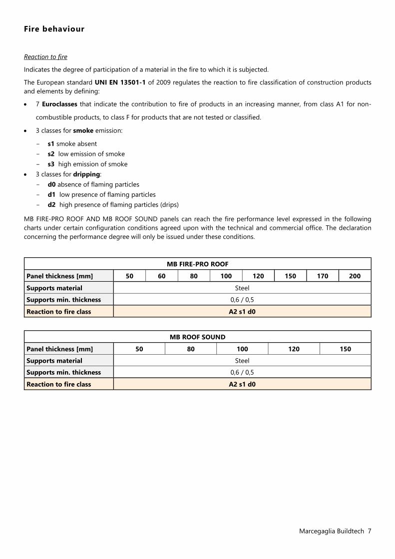
MB FIRE-PRO ROOF AND MB ROOF SOUND panels can reach the fire performance level expressed in the following charts under certain configuration conditions agreed upon with the technical and commercial office. The declaration concerning the performance degree will only be issued under these conditions.
MB FIRE-PRO ROOF
Panel thickness [mm] 50 60 80 100 120 150 170 200
Supports material Steel
Supports min. thickness 0,6 / 0,5
Reaction to fire class A2 s1 d0
MB ROOF SOUND
Panel thickness [mm] 50 80 100 120 150
Supports material Steel
Supports min. thickness 0,6 / 0,5
Reaction to fire class A2 s1 d0
8 Marcegaglia Buildtech
Fire resistance
This refers to the ability of a construction element (wall, intermediate floor, roof slab) to maintain the following requirements for a certain period of time under certain thermal and load conditions:
mechanical strength (R): ability of the construction element to withstand loading actions during exposure to fire; hermeticity (E): ability of the constructive element not to let pass or produce flames, vapours or hot gases on the
unexposed side; thermal insulation (I): ability of the construction element to limit the transmission of heat during exposure to fire.
The three requirements listed are combined in the following ways: REI / RE / EI / R followed by a number indicating the fire resistance class (time in minutes during which resistance is guaranteed.
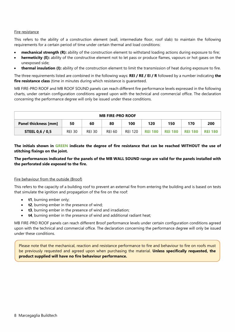
MB FIRE-PRO ROOF and MB ROOF SOUND panels can reach different fire performance levels expressed in the following charts, under certain configuration conditions agreed upon with the technical and commercial office. The declaration concerning the performance degree will only be issued under these conditions.
MB FIRE-PRO ROOF
Panel thickness [mm] 50 60 80 100 120 150 170 200
STEEL 0,6 / 0,5 REI 30 REI 30 REI 60 REI 120 REI 180 REI 180 REI 180 REI 180
The initials shown in GREEN indicate the degree of fire resistance that can be reached WITHOUT the use of stitching fixings on the joint.
The performances indicated for the panels of the MB WALL SOUND range are valid for the panels installed with the perforated side exposed to the fire.
Fire behaviour from the outside (Broof)
This refers to the capacity of a building roof to prevent an external fire from entering the building and is based on tests that simulate the ignition and propagation of the fire on the roof:
t1, burning ember only; t2, burning ember in the presence of wind; t3, burning ember in the presence of wind and irradiation; t4, burning ember in the presence of wind and additional radiant heat;
MB FIRE-PRO ROOF panels can reach different Broof performance levels under certain configuration conditions agreed upon with the technical and commercial office. The declaration concerning the performance degree will only be issued under these conditions.
Please note that the mechanical, reaction and resistance performance to fire and behaviour to fire on roofs must be previously requested and agreed upon when purchasing the material. Unless specifically requested, the product supplied will have no fire behaviour performance.
Marcegaglia Buildtech 9
Sound behaviour
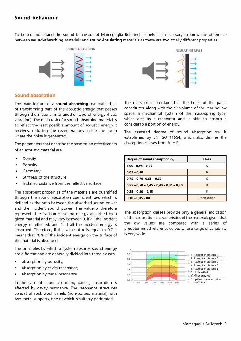
To better understand the sound behaviour of Marcegaglia Buildtech panels it is necessary to know the difference between sound-absorbing materials and sound-insulating materials as these are two totally different properties.
Sound absorption The main feature of a sound-absorbing material is that of transforming part of the acoustic energy that passes through the material into another type of energy (heat, vibration). The main task of a sound-absorbing material is to reflect the least possible amount of acoustic energy it receives, reducing the reverberations inside the room where the noise is generated.
The parameters that describe the absorption effectiveness of an acoustic material are:
• Density • Porosity • Geometry • Stiffness of the structure • Installed distance from the reflective surface
The absorbent properties of the materials are quantified through the sound absorption coefficient αw, which is defined as the ratio between the absorbed sound power and the incident sound power. The value α therefore represents the fraction of sound energy absorbed by a given material and may vary between 0, if all the incident energy is reflected, and 1, if all the incident energy is absorbed. Therefore, if the value of α is equal to 0.7 it means that 70% of the incident energy on the surface of the material is absorbed.
The principles by which a system absorbs sound energy are different and are generally divided into three classes:
• absorption by porosity; • absorption by cavity resonance; • absorption by panel resonance.
In the case of sound-absorbing panels, absorption is effected by cavity resonance. The resonance structures consist of rock wool panels (non-porous material) with two metal supports, one of which is suitably perforated.
The mass of air contained in the holes of the panel constitutes, along with the air volume of the rear hollow space, a mechanical system of the mass-spring type, which acts as a resonator and is able to absorb a considerable portion of energy.
The assessed degree of sound absorption αw is established by EN ISO 11654, which also defines the absorption classes from A to E.
Degree of sound absorption ɑw Class
1,00 - 0,95 - 0,90 A
0,85 – 0,80 B
0,75 – 0,70 -0,65 – 0,60 C
0,55 – 0,50 – 0,45 – 0,40 – 0,35 – 0,30 D
0,25 – 0,20 – 0,15 E
0,10 – 0,05 - 00 Unclassified
The absorption classes provide only a general indication of the absorption characteristics of the material, given that the αw values are compared with a series of predetermined reference curves whose range of variability is very wide.
SOUND ABSORBING INSULATING MASS
1. Absorption classes A 2. Absorption classes B 3. Absorption classes C 4. Absorption classes D 5. Absorption classes E 6. Unclassified 7. Frequency Hz 8. ɑp Practical absorption
coefficient
10 Marcegaglia Buildtech
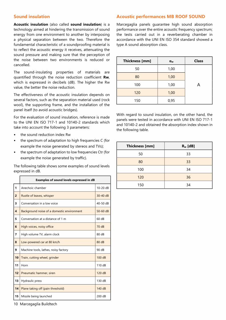
Sound insulation Acoustic insulation (also called sound insulation) is a technology aimed at hindering the transmission of sound energy from one environment to another by interposing a physical separation between the two. Therefore the fundamental characteristic of a soundproofing material is to reflect the acoustic energy it receives, attenuating the sound pressure and making sure that the perception of the noise between two environments is reduced or cancelled.
The sound-insulating properties of materials are quantified through the noise reduction coefficient Rw, which is expressed in decibels (dB). The higher the Rw value, the better the noise reduction.
The effectiveness of the acoustic insulation depends on several factors, such as the separation material used (rock wool), the supporting frame, and the installation of the panel itself (to avoid acoustic bridges).
For the evaluation of sound insulation, reference is made to the UNI EN ISO 717-1 and 10140-2 standards which take into account the following 3 parameters:
• the sound reduction index Rw • the spectrum of adaptation to high frequencies C (for
example the noise generated by stereos and TVs); • the spectrum of adaptation to low frequencies Ctr (for
example the noise generated by traffic).
The following table shows some examples of sound levels expressed in dB.
Examples of sound levels expressed in dB
1 Anechoic chamber 10-20 dB
2 Rustle of leaves, whisper 30-40 dB
3 Conversation in a low voice 40-50 dB
4 Background noise of a domestic environment 50-60 dB
5 Conversation at a distance of 1 m 60 dB
6 High voices, noisy office 70 dB
7 High volume TV, alarm clock 80 dB
8 Low-powered car at 80 km/h 80 dB
9 Machine tools, lathes, noisy factory 90 dB
10 Train, cutting wheel, grinder 100 dB
11 Horn 110 dB
12 Pneumatic hammer, siren 120 dB
13 Hydraulic press 130 dB
14 Plane taking off (pain threshold) 140 dB
15 Missile being launched 200 dB
Acoustic performances MB ROOF SOUND Marcegaglia panels guarantee high sound absorption performance over the entire acoustic frequency spectrum; the tests carried out in a reverberating chamber in accordance with the UNI EN ISO 354 standard showed a type A sound absorption class.
Thickness [mm] αw Class
50 1,00
A
80 1,00
100 1,00
120 1,00
150 0,95
With regard to sound insulation, on the other hand, the panels were tested in accordance with UNI EN ISO 717-1 and 10140-2 and obtained the absorption index shown in the following table.
Thickness [mm] Rw [dB]
50 33
80 33
100 34
120 36
150 34
Marcegaglia Buildtech 11
Advice and instructions for use
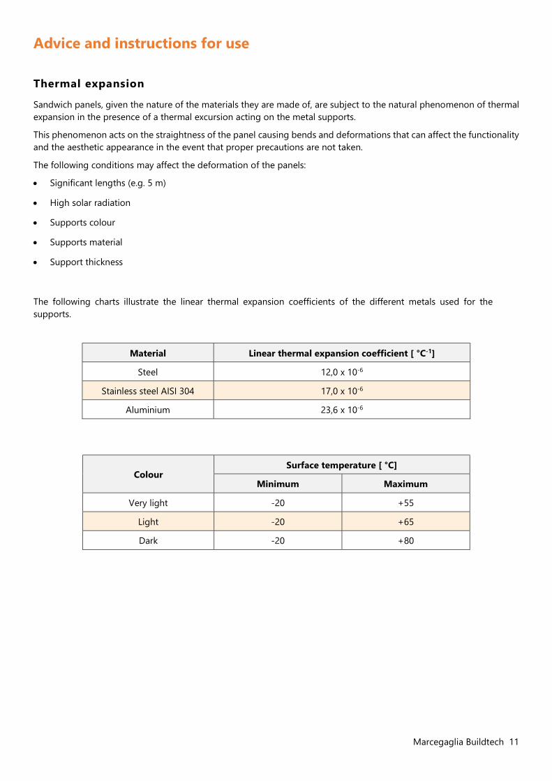
Thermal expansion
Sandwich panels, given the nature of the materials they are made of, are subject to the natural phenomenon of thermal expansion in the presence of a thermal excursion acting on the metal supports.
This phenomenon acts on the straightness of the panel causing bends and deformations that can affect the functionality and the aesthetic appearance in the event that proper precautions are not taken.
The following conditions may affect the deformation of the panels:
Significant lengths (e.g. 5 m)
High solar radiation
Supports colour
Supports material
Support thickness
The following charts illustrate the linear thermal expansion coefficients of the different metals used for the supports.
Material Linear thermal expansion coefficient [ °C-1]
Steel 12,0 x 10⁻⁶
Stainless steel AISI 304 17,0 x 10⁻⁶
Aluminium 23,6 x 10⁻⁶
Colour Surface temperature [ °C]
Minimum Maximum
Very light -20 +55
Light -20 +65
Dark -20 +80
12 Marcegaglia Buildtech
Useful design information
Marcegaglia Buildtech points out that it is necessary to dimension a load-bearing structure in the design phase that can absorb the external load stresses so as not to jeopardize the basic functionality of the panels due to excessive and permanent deformations.
The following environmental conditions must be taken into consideration during the design and selection of the panels:
Thermal stress: can lead to significant deformation of the panels and depends mainly on the exposure of the building and on the colour of the external metal support.
Wind action: exerts a loading pressure on the exposed surfaces of the panel according to the wind speed, which varies according to the climatic zone in which the installation takes place. It is necessary to define the type and number of fixings according to the intensity of the described action.
Atmospheric aggressiveness: it is necessary to choose the covering of the supports suitable for the environment in which the panels are installed (marine, industrial, urban, rural), since some environments are particularly aggressive in terms of corrosiveness of the panel surfaces.
Snow load: varies according to the climatic zone and the altitude above sea level of the place where the installation takes place. It is necessary to take into account the possible pooling of water on the roof when snow is melting, which can lead to infiltration at the overlapping joints. Marcegaglia Buildtech recommends the adoption of appropriate constructive measures and suitable sheet metalwork systems to optimize the runoff of water.
Rainfall: the slope of the pitch must be defined taking into account the amount of rainfall at the place of installation. To avoid oxidation of metal supports due to incorrect water runoff, it is necessary to define the slope of the pitch depending on the type of construction used:
roofing without intermediate butt joints; roofing with intermediate butt joints.
If intermediate butt joints are not used, Marcegaglia Buildtech recommends implementing a slope of not less than 7% in situations of reduced or medium snowfall; if intermediate butt joints are used, it is necessary to define the slope of the pitch during the design phase, providing for an increase compared to the previous situation due to the presence of overlaps.
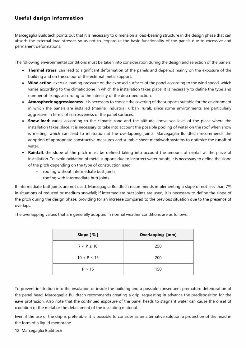
The overlapping values that are generally adopted in normal weather conditions are as follows:
Slope [ % ] Overlapping [mm]
7 < P ≤ 10 250
10 < P ≤ 15 200
P > 15 150
To prevent infiltration into the insulation or inside the building and a possible consequent premature deterioration of the panel head, Marcegaglia Buildtech recommends creating a drip, requesting in advance the predisposition for the eave protrusion. Also note that the continued exposure of the panel heads to stagnant water can cause the onset of oxidation of the metal or the detachment of the insulating material.
Even if the use of the drip is preferable, it is possible to consider as an alternative solution a protection of the head in the form of a liquid membrane.
Marcegaglia Buildtech 13
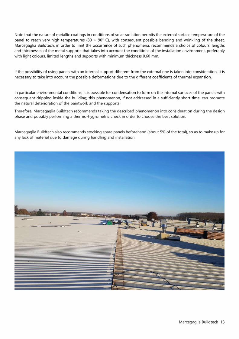
Note that the nature of metallic coatings in conditions of solar radiation permits the external surface temperature of the panel to reach very high temperatures (80 ÷ 90° C), with consequent possible bending and wrinkling of the sheet. Marcegaglia Buildtech, in order to limit the occurrence of such phenomena, recommends a choice of colours, lengths and thicknesses of the metal supports that takes into account the conditions of the installation environment, preferably with light colours, limited lengths and supports with minimum thickness 0.60 mm.
If the possibility of using panels with an internal support different from the external one is taken into consideration, it is necessary to take into account the possible deformations due to the different coefficients of thermal expansion.
In particular environmental conditions, it is possible for condensation to form on the internal surfaces of the panels with consequent dripping inside the building; this phenomenon, if not addressed in a sufficiently short time, can promote the natural deterioration of the paintwork and the supports.
Therefore, Marcegaglia Buildtech recommends taking the described phenomenon into consideration during the design phase and possibly performing a thermo-hygrometric check in order to choose the best solution.
Marcegaglia Buildtech also recommends stocking spare panels beforehand (about 5% of the total), so as to make up for any lack of material due to damage during handling and installation.
14 Marcegaglia Buildtech
Transport, storage and handling
Transport and standard composition of the packages
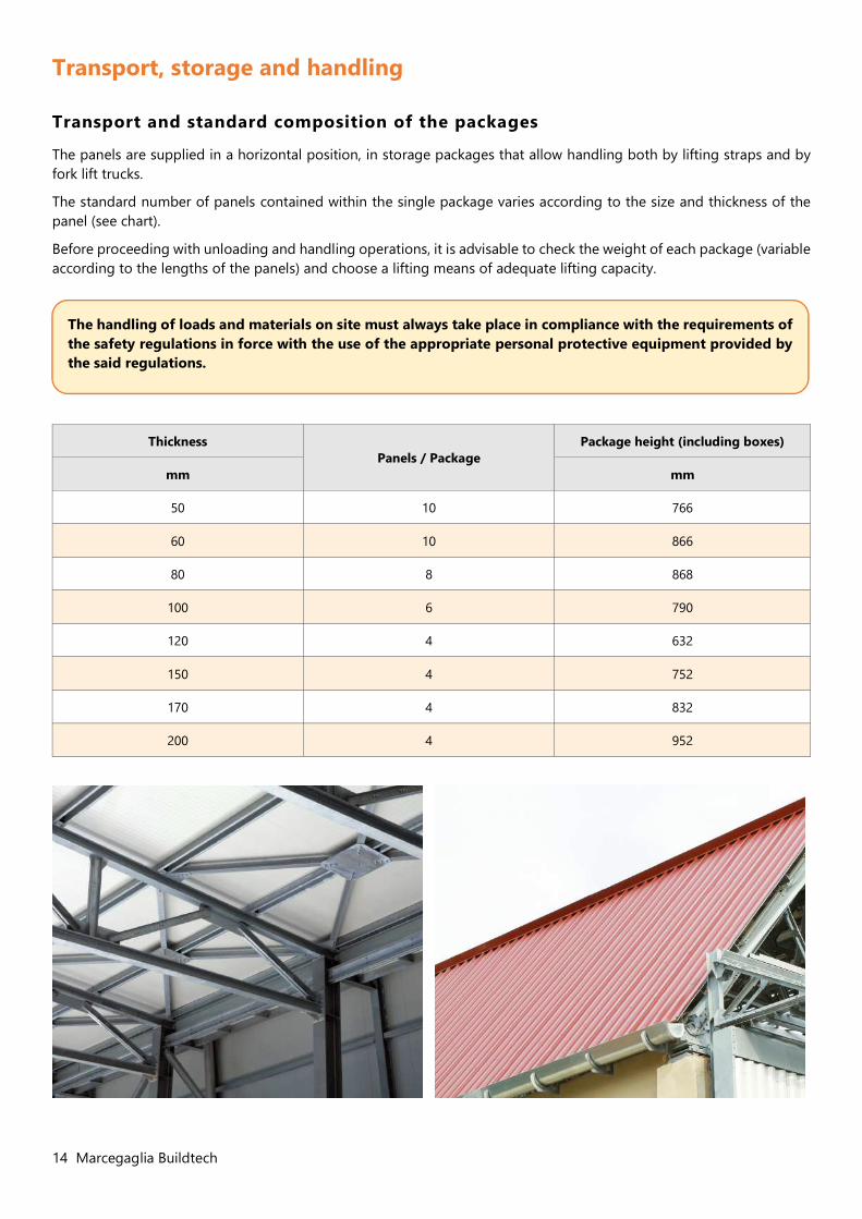
The panels are supplied in a horizontal position, in storage packages that allow handling both by lifting straps and by fork lift trucks.
The standard number of panels contained within the single package varies according to the size and thickness of the panel (see chart).
Before proceeding with unloading and handling operations, it is advisable to check the weight of each package (variable according to the lengths of the panels) and choose a lifting means of adequate lifting capacity.
Thickness Panels / Package
Package height (including boxes)
mm mm
50 10 766
60 10 866
80 8 868
100 6 790
120 4 632
150 4 752
170 4 832
200 4 952
The handling of loads and materials on site must always take place in compliance with the requirements of the safety regulations in force with the use of the appropriate personal protective equipment provided by the said regulations.
Marcegaglia Buildtech 15
Handling, storage and installation of panels
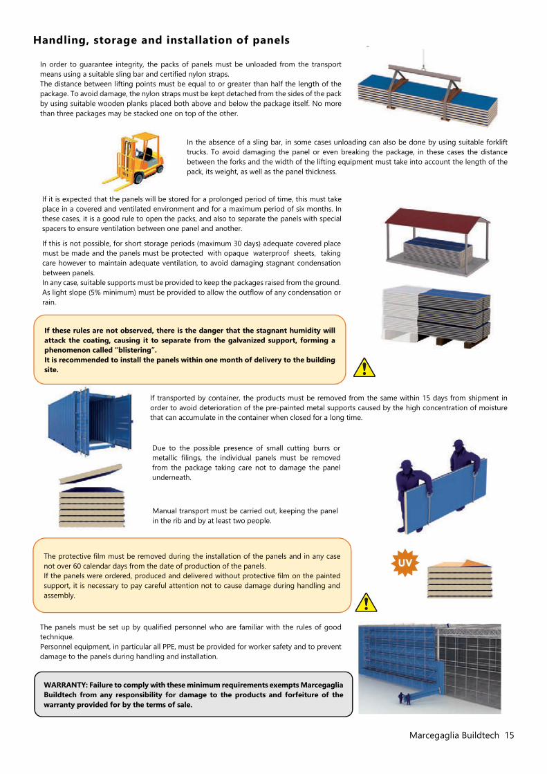
In order to guarantee integrity, the packs of panels must be unloaded from the transport means using a suitable sling bar and certified nylon straps. The distance between lifting points must be equal to or greater than half the length of the package. To avoid damage, the nylon straps must be kept detached from the sides of the pack by using suitable wooden planks placed both above and below the package itself. No more than three packages may be stacked one on top of the other.
If it is expected that the panels will be stored for a prolonged period of time, this must take place in a covered and ventilated environment and for a maximum period of six months. In these cases, it is a good rule to open the packs, and also to separate the panels with special spacers to ensure ventilation between one panel and another.
If this is not possible, for short storage periods (maximum 30 days) adequate covered place must be made and the panels must be protected with opaque waterproof sheets, taking care however to maintain adequate ventilation, to avoid damaging stagnant condensation between panels. In any case, suitable supports must be provided to keep the packages raised from the ground. As light slope (5% minimum) must be provided to allow the outflow of any condensation or rain.
If these rules are not observed, there is the danger that the stagnant humidity will attack the coating, causing it to separate from the galvanized support, forming a phenomenon called “blistering”. It is recommended to install the panels within one month of delivery to the building site.
If transported by container, the products must be removed from the same within 15 days from shipment in order to avoid deterioration of the pre-painted metal supports caused by the high concentration of moisture that can accumulate in the container when closed for a long time.
Due to the possible presence of small cutting burrs or metallic filings, the individual panels must be removed from the package taking care not to damage the panel underneath.
Manual transport must be carried out, keeping the panel in the rib and by at least two people.
The protective film must be removed during the installation of the panels and in any case not over 60 calendar days from the date of production of the panels. If the panels were ordered, produced and delivered without protective film on the painted support, it is necessary to pay careful attention not to cause damage during handling and assembly.
The panels must be set up by qualified personnel who are familiar with the rules of good technique. Personnel equipment, in particular all PPE, must be provided for worker safety and to prevent damage to the panels during handling and installation.
WARRANTY: Failure to comply with these minimum requirements exempts Marcegaglia Buildtech from any responsibility for damage to the products and forfeiture of the warranty provided for by the terms of sale.
In the absence of a sling bar, in some cases unloading can also be done by using suitable forklift trucks. To avoid damaging the panel or even breaking the package, in these cases the distance between the forks and the width of the lifting equipment must take into account the length of the pack, its weight, as well as the panel thickness.
16 Marcegaglia Buildtech
Assembly instructions
Fixing system
The most appropriate fixing system for the project must be established according to the type of assembly, considering the support structures (metal structural work) in order to guarantee safety, stability and tightness.
The fixing elements must be able to withstand the dynamic forces of the stresses to which the insulated panels are subjected (sudden changes in temperature, wind load, trampling, etc.) guaranteeing the mechanical tightness, load capacity and insulation .
The number and positioning of the fixings varies according to the design and to some variables including the local wind conditions, the distance between the purlins and the framework elements, and the height of the building.
The support system consists mainly of purlins: usually wooden, concrete or steel purlins are used (thickness ≥ 2mm), more rarely aluminium (thickness ≥ 3 mm).
The minimum surface of the end supports or intermediate supports depends on the characteristics of the panel and the material of the supports, therefore it is advisable to rely on the calculation section of the support reaction resistance of the UNI EN 14509 standard.
There are two types of fixing:
Main structural anchors
These fix the roof panel to the supporting structure and guarantee the anchoring, the mechanical resistance and the load capacity applied . The standard fixing group includes: self-tapping / self-drilling screw, cap with gasket and washer. The choice of the screw length will depend on the thickness of the panel and the type of underlying structure. The fixing is made in correspondence of the ribs: to have a better anchorage, a cap, pressure cap and cover is inserted between the screw and the profiled sheet, which adapts to the trapezoidal profile of the sheet, fitted with an internal gasket. A PVC washer , positioned between the cap and the screw, prevents the penetration of moisture.
Stitching
Non-structural, they are functional for fixing the sheet metal, the metal finishing elements and the sheets of the panel to each other.
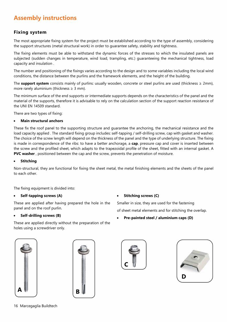
The fixing equipment is divided into:
Self-tapping screws (A)
These are applied after having prepared the hole in the panel and on the roof purlin.
Self-drilling screws (B)
These are applied directly without the preparation of the holes using a screwdriver only.
Stitching screws (C)
Smaller in size, they are used for the fastening
of sheet metal elements and for stitching the overlap.
Pre-painted steel / aluminium caps (D)
B A
C
D
Marcegaglia Buildtech 17
Marcegaglia Buildtech points out that the weight of mineral rock wool panels is considerable and must be taken into consideration and evaluated during handling and assembly.
It is advisable to define suitable lifting and handling means and to use suitable handling equipment to ensure maximum safety for the operators, for the works and for the panels themselves.
Installation and equipment
The supporting structures and the relative fixing devices of the panels must be adequately sized and must meet the conditions set by the project in terms of safety, stability and functionality. This section aims to provide reference information for the assembly of insulated metal roofing panels. The reference standard is constituted by the UNI 10372 standard "Discontinuously laid roof coverings - criteria for design, execution and maintenance of roofing made of metal sheets".
Preliminary operations:
View the project documents and follow the relevant instructions. Check that the support structure is positioned correctly, does not present deformations or misalignments and is
completely secured to the rest of the structure. Make sure that there is no interference with overhead power lines in the handling area of the materials. Prepare the appropriate accident prevention facilities according to the regulations in force for work at height. Check that all workers operating at height are equipped with the appropriate personal accident prevention devices
according to the regulations in force. Prepare all the power supply lines for the equipment used according to current regulations. Remove the protective film applied to the pre-painted sheets over the entire length of the panel.
Hoisting: the panels must be lifted with the utmost care and attention, avoiding to damage the surface. In most cases it is necessary to move the packs of panels onto the roof to be covered (hoisting). the use of steel cables or chains instead of nylon slings must be strictly avoided.
The hoisted panels must be placed on the purlins (never on the overhangs) near the trusses, avoiding laying more than one row of packs for each truss. Suitable stopping systems must also be set in place to prevent the packs from slipping due to the slope of the roof or due to the wind at high altitude, paying more attention once the package is opened. It is important to ensure that, at the end of the working day, open packs on the roof that are not yet finished are temporarily strapped so as to prevent them from sliding down or flying away under the action of the wind.
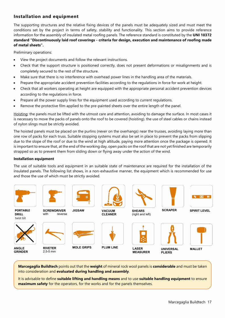
Installation equipment
The use of suitable tools and equipment in an suitable state of maintenance are required for the installation of the insulated panels. The following list shows, in a non-exhaustive manner, the equipment which is recommended for use and those the use of which must be strictly avoided.
PORTABLE DRILL twist bit
SCREWDRIVER with reverse function
SHEARS (right and left)
JIGSAW
VACUUM CLEANER
ANGLE GRINDER
MOLE GRIPS PLUM LINE LASER MEASURER
SCRAPER SPIRIT LEVEL
UNIVERSAL PLIERS
MALLET RIVETER 2,5-5 mm
18 Marcegaglia Buildtech
Installation and fixing of roofing panels
Once all the preliminary activities have been carried out, based on the project drawings, it is necessary to prepare and install the complementary sheet metalwork to complete the roofing, for example, under-ridges, gutter channels, flashings and anything under the panel.
Once the profiles have been laid, the starting point for the installation of the first panel must be carefully identified.
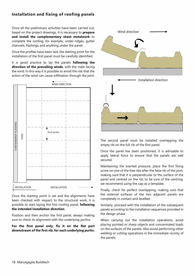
It is good practice to lay the panels following the direction of the prevailing winds, with the male facing the wind. In this way it is possible to avoid the risk that the action of the wind can cause infiltration through the joint.
Once the starting point is set and the alignments have been checked with respect to the structural work, it is possible to start laying the first roofing panel, following the intended installation direction.
Position and then anchor the first panel, always making sure to check its alignment with the underlying purlins.
For the first panel only, fix it on the flat part downstream of the first rib, for each underlying purlin.
The second panel must be installed overlapping the empty rib on the full rib of the first panel.
Once the panel has been positioned, it is advisable to apply lateral force to ensure that the panels are well secured.
Maintaining the exerted pressure, place the first fixing screw on one of the free ribs after the false rib of the joint, making sure that it is perpendicular to the surface of the panel and centred on the rib; to be sure of the centring, we recommend using the cap as a template.
Finally, check for perfect overlapping, making sure that the external surfaces of the two adjacent panels are completely in contact and levelled.
Similarly, proceed with the installation of the subsequent panels according to the installation sequences provided in the design phase.
When carrying out the installation operations, avoid placing pointed or sharp objects and concentrated loads on the surfaces of the panels. Also avoid performing other welding or cutting operations in the immediate vicinity of the panels.
Wind direction
Installation direction WIND DIRECTION
Roof purlins
PAN
EL
CON
TAIN
MEN
T FL
ASH
ING
INSTALLATION INSTALLATION
Marcegaglia Buildtech 19
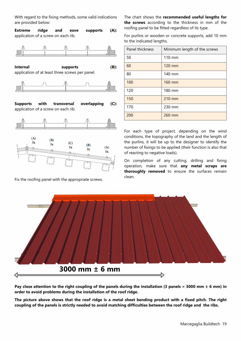
With regard to the fixing methods, some valid indications are provided below:
Extreme ridge and eave supports (A): application of a screw on each rib.
Internal supports (B): application of at least three screws per panel.
Supports with transversal overlapping (C): application of a screw on each rib.
Fix the roofing panel with the appropriate screws.
The chart shows the recommended useful lengths for the screws according to the thickness in mm of the roofing panel to be fitted regardless of its type.
For purlins or wooden or concrete supports, add 10 mm to the indicated lengths.
Panel thickness Minimum length of the screws
50 110 mm
60 120 mm
80 140 mm
100 160 mm
120 180 mm
150 210 mm
170 230 mm
200 260 mm
For each type of project, depending on the wind conditions, the topography of the land and the length of the purlins, it will be up to the designer to identify the number of fixings to be applied (their function is also that of reacting to negative loads).
On completion of any cutting, drilling and fixing operation, make sure that any metal scraps are thoroughly removed to ensure the surfaces remain clean.
Pay close attention to the right coupling of the panels during the installation (3 panels = 3000 mm ± 6 mm) in order to avoid problems during the installation of the roof ridge.
The picture above shows that the roof ridge is a metal sheet bending product with a fixed pitch. The right coupling of the panels is strictly needed to avoid matching difficulties between the roof ridge and the ribs.
3000 mm ± 6 mm
20 Marcegaglia Buildtech
Overlapping
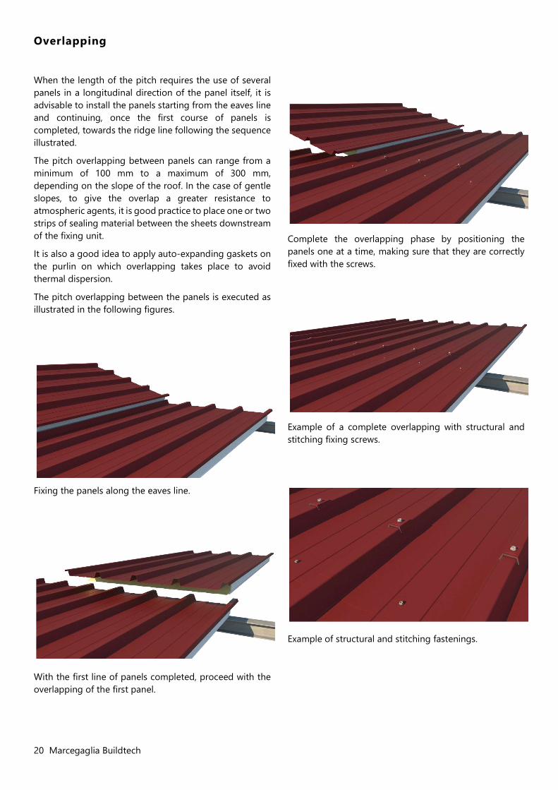
When the length of the pitch requires the use of several panels in a longitudinal direction of the panel itself, it is advisable to install the panels starting from the eaves line and continuing, once the first course of panels is completed, towards the ridge line following the sequence illustrated.
The pitch overlapping between panels can range from a minimum of 100 mm to a maximum of 300 mm, depending on the slope of the roof. In the case of gentle slopes, to give the overlap a greater resistance to atmospheric agents, it is good practice to place one or two strips of sealing material between the sheets downstream of the fixing unit.
It is also a good idea to apply auto-expanding gaskets on the purlin on which overlapping takes place to avoid thermal dispersion.
The pitch overlapping between the panels is executed as illustrated in the following figures.
Fixing the panels along the eaves line.
With the first line of panels completed, proceed with the overlapping of the first panel.
Complete the overlapping phase by positioning the panels one at a time, making sure that they are correctly fixed with the screws.
Example of a complete overlapping with structural and stitching fixing screws.
Example of structural and stitching fastenings.
Marcegaglia Buildtech 21
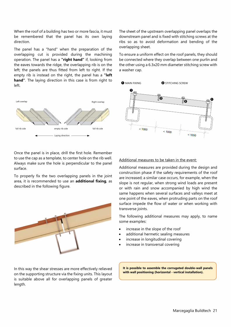
When the roof of a building has two or more fascia, it must be remembered that the panel has its own laying direction.
The panel has a "hand" when the preparation of the overlapping cut is provided during the machining operation. The panel has a "right hand" if, looking from the eaves towards the ridge, the overlapping rib is on the left; the panels are thus fitted from left to right. If the empty rib is instead on the right, the panel has a "left hand". The laying direction in this case is from right to left.
Once the panel is in place, drill the first hole. Remember to use the cap as a template, to center hole on the rib well. Always make sure the hole is perpendicular to the panel surface.
To properly fix the two overlapping panels in the joint area, it is recommended to use an additional fixing, as described in the following figure.
In this way the shear stresses are more effectively relieved on the supporting structure via the fixing units. This layout is suitable above all for overlapping panels of greater length.
The sheet of the upstream overlapping panel overlaps the downstream panel and is fixed with stitching screws at the ribs so as to avoid deformation and bending of the overlapping sheet.
To ensure a uniform effect on the roof panels, they should be connected where they overlap between one purlin and the other using a 6.3x20 mm diameter stitching screw with a washer cap.
Additional measures to be taken in the event:
Additional measures are provided during the design and construction phase if the safety requirements of the roof are increased; a similar case occurs, for example, when the slope is not regular, when strong wind loads are present or with rain and snow accompanied by high wind the same happens when several surfaces and valleys meet at one point of the eaves, when protruding parts on the roof surface impede the flow of water or when working with transverse joints.
The following additional measures may apply, to name some examples:
increase in the slope of the roof additional hermetic sealing measures increase in longitudinal covering increase in transversal covering
It is possible to assemble the corrugated double-wall panels with wall positioning (horizontal - vertical installation).
Left overlap Right overlap
full rib side empty rib side full rib side
Laying direction
MAIN FIXING STITCHING SCREW
22 Marcegaglia Buildtech
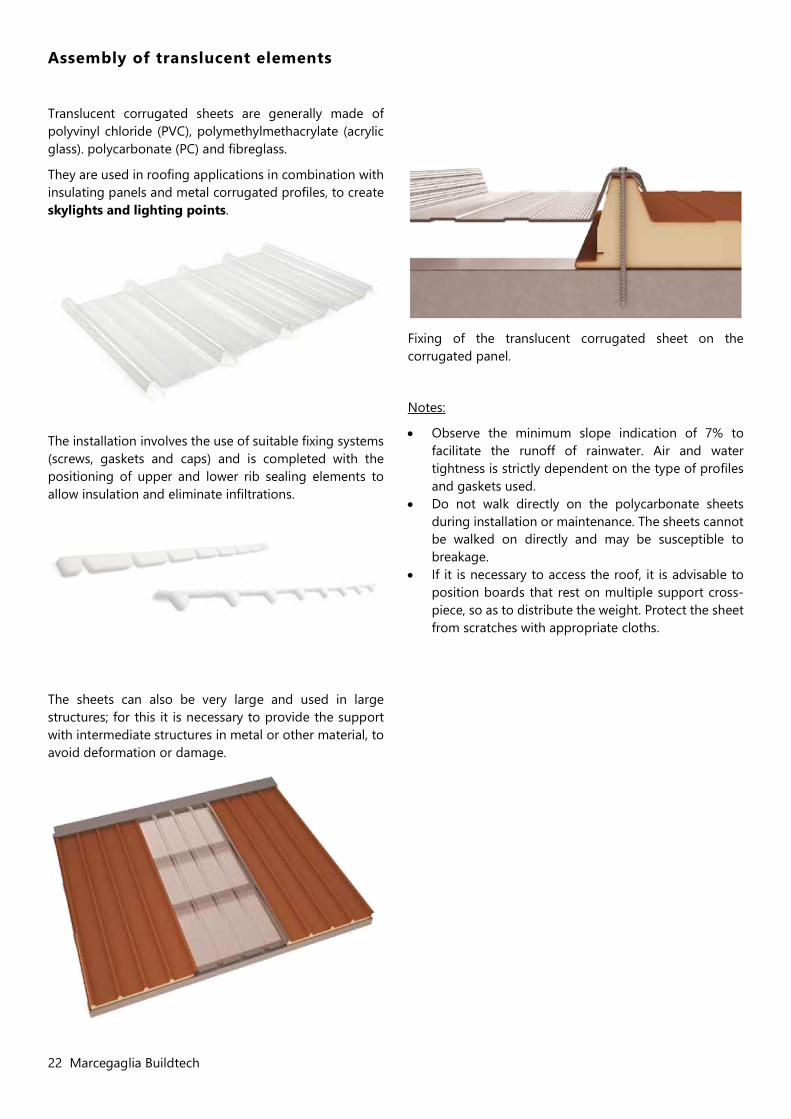
Assembly of translucent elements
Translucent corrugated sheets are generally made of polyvinyl chloride (PVC), polymethylmethacrylate (acrylic glass). polycarbonate (PC) and fibreglass.
They are used in roofing applications in combination with insulating panels and metal corrugated profiles, to create skylights and lighting points.
The installation involves the use of suitable fixing systems (screws, gaskets and caps) and is completed with the positioning of upper and lower rib sealing elements to allow insulation and eliminate infiltrations.
The sheets can also be very large and used in large structures; for this it is necessary to provide the support with intermediate structures in metal or other material, to avoid deformation or damage.
Fixing of the translucent corrugated sheet on the corrugated panel.
Notes:
Observe the minimum slope indication of 7% to facilitate the runoff of rainwater. Air and water tightness is strictly dependent on the type of profiles and gaskets used.
Do not walk directly on the polycarbonate sheets during installation or maintenance. The sheets cannot be walked on directly and may be susceptible to breakage.
If it is necessary to access the roof, it is advisable to position boards that rest on multiple support cross-piece, so as to distribute the weight. Protect the sheet from scratches with appropriate cloths.
Marcegaglia Buildtech 23
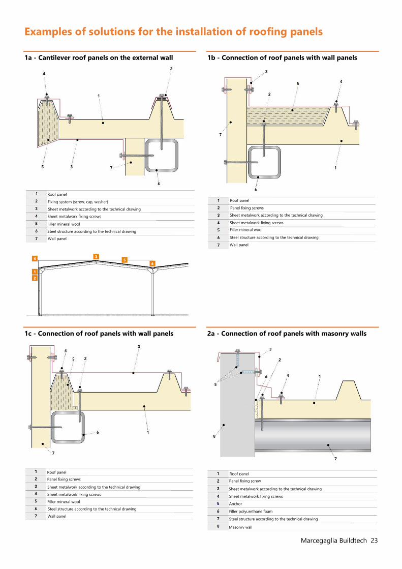
Roof panel
Fixing system (screw, cap, washer)
Sheet metalwork according to the technical drawing
Sheet metalwork fixing screws
Filler mineral wool
Steel structure according to the technical drawing
Wall panel
Examples of solutions for the installation of roofing panels
1a - Cantilever roof panels on the external wall
1c - Connection of roof panels with wall panels
1b - Connection of roof panels with wall panels
2a - Connection of roof panels with masonry walls
Roof panel Panel fixing screws
Sheet metalwork according to the technical drawing Sheet metalwork fixing screws
Filler mineral wool
Steel structure according to the technical drawing
Wall panel
Roof panel
Panel fixing screws
Sheet metalwork according to the technical drawing
Sheet metalwork fixing screws
Filler mineral wool
Steel structure according to the technical drawing
Wall panel
Roof panel
Panel fixing screw
Sheet metalwork according to the technical drawing
Sheet metalwork fixing screws
Anchor
Filler polyurethane foam
Steel structure according to the technical drawing
Masonry wall
24 Marcegaglia Buildtech
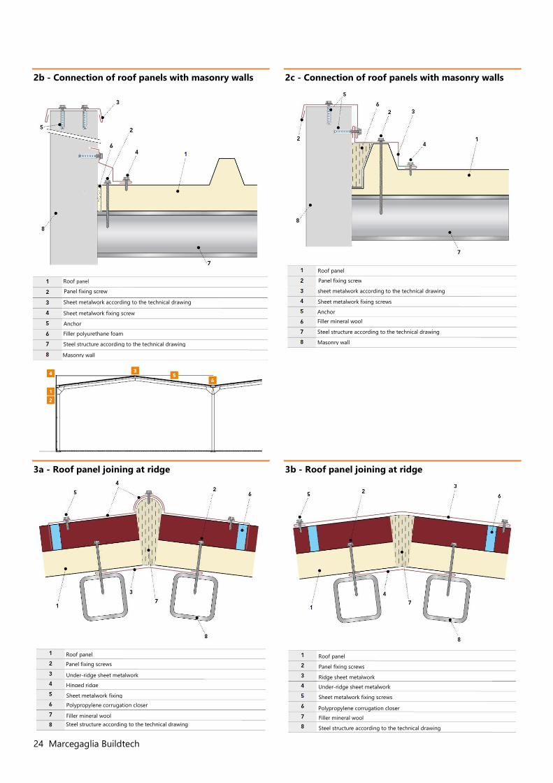
2b - Connection of roof panels with masonry walls
3a - Roof panel joining at ridge
2c - Connection of roof panels with masonry walls
3b - Roof panel joining at ridge
Roof panel Panel fixing screw
Sheet metalwork according to the technical drawing Sheet metalwork fixing screw
Anchor plug
Steel structure according to the technical drawing
Filler polyurethane foam
Masonry wall
Roof panel
Panel fixing screw
sheet metalwork according to the technical drawing
Sheet metalwork fixing screws
Anchor
Filler mineral wool
Steel structure according to the technical drawing
Masonry wall
Roof panel Panel fixing screws
Under-ridge sheet metalwork
Hinged ridge
Sheet metalwork fixing
Polypropylene corrugation closer
Filler mineral wool Steel structure according to the technical drawing
Roof panel Panel fixing screws
Ridge sheet metalwork
Sheet metalwork fixing screws
Under-ridge sheet metalwork
Steel structure according to the technical drawing
Polypropylene corrugation closer
Filler mineral wool
Marcegaglia Buildtech 25
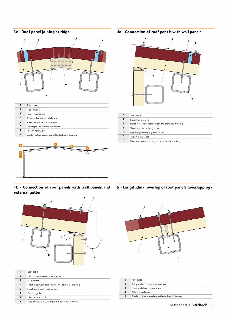
3c - Roof panel joining at ridge
4b - Connection of roof panels with wall panels and external gutter
4a - Connection of roof panels with wall panels
5 - Longitudinal overlap of roof panels (overlapping)
Roof panel Ribbed ridge
Panel fixing screws
Under-ridge sheet metalwork
Sheet metalwork fixing screws
Polypropylene corrugation closer
Filler mineral wool
Steel structure according to the technical drawing
Roof panel Panel fixing screws
Sheet metalwork according to the technical drawing
Sheet metalwork fixing screws
Steel structure according to the technical drawing
Polypropylene corrugation closer
Filler mineral wool
Flexible gasket
Roof panel Fixing system (screw, cap, washer)
Sheet metalwork according to the technical drawing
Steel gutter
Sheet metalwork fixing screws
Filler mineral wool
Steel structure according to the technical drawing
Roof panel Fixing system (screw, cap, washer)
Sheet metalwork fixing screw
Filler mineral wool
Steel structure according to the technical drawing
26 Marcegaglia Buildtech
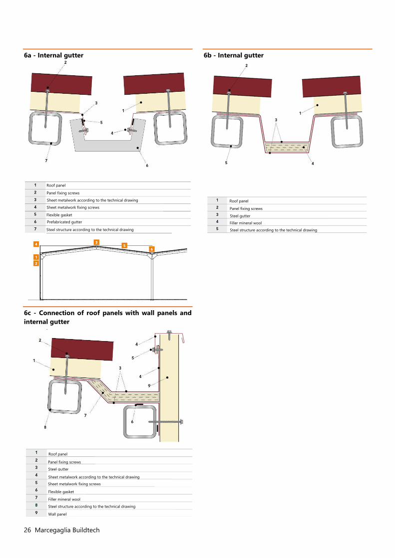
6a - Internal gutter
6c - Connection of roof panels with wall panels and internal gutter
6b - Internal gutter
Roof panel
Sheet metalwork according to the technical drawing
Prefabricated gutter
Sheet metalwork fixing screws
Panel fixing screws
Steel structure according to the technical drawing
Flexible gasket
Roof panel
Sheet metalwork according to the technical drawing
Steel gutter
Sheet metalwork fixing screws
Panel fixing screws
Steel structure according to the technical drawing
Flexible gasket
Filler mineral wool
Wall panel
Roof panel
Steel gutter
Filler mineral wool
Panel fixing screws
Steel structure according to the technical drawing
Marcegaglia Buildtech 27
Maintenance and disposal
Roof inspection
During the installation and completion of the panels installation, the installing company will be responsible for the removal of all the material no longer necessary, including the possible scraps of protective film.
The company must pay the utmost attention in eliminating metal shavings and abrasive elements in the event that they are deposited on the roof.
During the initial inspection, it is also necessary to check that foreign materials or processing scraps capable of triggering corrosion or damage to the building envelope or that can impede the correct runoff of rainwater have not been left behind.
Periodic inspections should therefore be carried out (recommended every 6 months) to check the conservation status of the surfaces. [roofing]
Routine maintenance
Routine maintenance is the responsibility of the end user and has the function of keeping the aesthetics and the functionality of the building's roof unchanged over the years following its construction.
A periodic maintenance plan is provided that must include the checking:
of seals, the deterioration and wear of which could cause a reduction in air and water tightness;
of all the fixings to verify they are correctly tightened.
The following are the main causes of intervention and the measures to be taken:
Deposits of aggressive substances present in an industrial atmosphere on the roof: remove the substances with jets of water, if the action of the rains is not sufficient. If the normal jets are not sufficient to remove the deposited substances, mild and non-abrasive detergents dissolved in water can be used. During the inspection, pay particular attention to products of an aggressive nature coming from chimneys or ventilation systems.
Confluence of materials deposited by the wind or the atmosphere in gutters and valleys: proceed with a vigorous washing to prevent the metallic support from being damaged or the normal flow of water to be obstructed.
Scratches or abrasions of the pre-painted parts caused by the transit of operators or by accidental causes: eliminate by touching up the paint.
Loss of the elastic or sealing properties of the seal in the joints of the sheet metalwork: restore the seal, after cleaning the pre-existing one.
Settling of the structures and panels with loosening of the fixing screws: check and carefully tighten the screws.
Dents caused by impacts: in some cases it will be possible to intervene by restoring the surface; if this type of intervention is not feasible, the damaged panel must be replaced.
Formation of mould and algae, possible in the case of environments with high humidity, in the shade or with stagnant water: moisten the area to be cleaned with cold water and then, using a non-abrasive brush, remove the deposits with a very diluted solution of water, bleach and a cup of liquid soap. Rinse with clean water.
Deposits of salt, for example in marine environments: in the case of light superficial incrustations, it is sufficient to use cold water through a garden hose at the standard pressure of the mains water supply. For all other cases, it is necessary to dampen the surface to be treated with cold water and then, using a non-abrasive brush, remove the deposits with a very diluted solution of water, bleach and a cup of liquid soap. Rinse with clean water.
Disposal
The disposal of insulated roofing panels must only be entrusted to authorized companies and carried out in compliance with the laws in force.
Failure to comply with these warnings, as well as the use of boiling water or abrasive material (brushes with metal bristles, etc.) can cause permanent damage to the surface, compromising the lifespan of the product. For further information consult the technical information, "Maintenance and restoration of pre-painted parts".
28 Marcegaglia Buildtech
Safety data
Please note that the product to which this document refers is classified in accordance with the regulation (EC) 1907/06-REACH as an article without intentional release of chemical substances and as such does not require the preparation of a safety data sheet.
However, Marcegaglia Buildtech wishes to identify the main dangers due to the use of the article in question.
1. Product identification
Insulated panel composed of two metal layers that contain a solid insulating layer of rock wool.
Company / business identification
MARCEGAGLIA Buildtech S.r.l.
Via Giovanni della Casa 12 - 20151 Milano - Italy
Phone +39.0230704.1 fax +39.0233402706
e-mail: [email protected]
2. Dangers identification
The product does not pose dangers to human health under normal conditions of use in accordance with REG EC 1272/08.
3. Composition / information on ingredients
The product is composed of two pre-painted steel sheets containing an insulating layer of rock wool.
Component % in weight Metal supports 25-54 Glue ≈1 Insulating material 46-75
4. First aid measures
The handling of the product without the appropriate PPE can cause injuries to the skin and eyes due to the presence of the steel sheets; in the event of injuries contact a doctor immediately. In case of prolonged exposure to the dust, transport the affected person to a ventilated place, rinse throat and blow nose to expel dust.
In case of skin contact with rock wool fibres, wash gently with soap and water.
In case of contact of the rock wool with the eyes, rinse thoroughly with running water and contact a doctor if necessary.
5. Fire prevention measures
The product is not combustible or flammable.
The material used for packaging is combustible and if involved in a fire produces gases and fumes which could reduce visibility.
Extinguishing media
All extinguishing media are applicable. For large fires, use water, alcohol-resistant foams or universal foams according to the manufacturer's instructions. For fires of limited proportion, use carbon dioxide or chemical powder.
6. Measures in case of accidental release
The product is stable; no special measures are expected to be taken.
In the event of accidental release of rock wool dusts (coming, for example, from cutting operations), remove the material preferably with suction systems, ventilate the room and keep away from sources of ignition.
7. Handling and storage
Handle using the appropriate personal protective equipment. For more information about handling and the personal protective equipment to be used, see section 8. For correct handling and correct storage, refer to the "Regulations for handling and storage of materials" in the technical manual.
8. Personal protection
Respiratory protection
Normal use does not require any protection for the respiratory tract. If it is necessary for work activities to cut the panels and carry out any operation that could lead to the generation of dust, it is advisable to install an appropriate extraction and reduction system.
When this is not possible or the concentrations of dust in the working environment remain at high concentrations, the possibility of isolating the dust production area or providing the operators with devices for the protection of the respiratory tract is evaluated.
Hands protection
The presence of steel sheets can cause cuts or injuries to the skin tissue, and in this regard during normal operations involving the handling of the panels, leather or hide gloves resistant to abrasion, cutting, tearing and perforation must be worn in conformity with the UNI EN 388 standard.
Eyes protection
Normal use does not require any protection for the eyes. If it is necessary for work activities to cut the panels and carry out any operation that could lead to the production of shards or projectile particles, it is advisable to wear polycarbonate glasses to protect against the projection of particles at high speed / low impact energy; compliant with standard EN 166.
Marcegaglia Buildtech 29
Skin protection
In order to protect against the action caused by the rock wool, it is advisable to use baggy clothes with narrow sleeves (e.g. Tyvek overalls).
Control of the environmental exposure
Normal use does not require any specific measure to reduce environmental exposure as the product is to be considered non-toxic. Should it be necessary to cut the panels and carry out any operation that could lead to the generation of dust, install an extraction system with an appropriate abatement system in order to limit environmental pollution.
9. Physical and chemical properties
Appearance: the product comes in the form of a panel clad in metal and a core of yellow-green-grey mineral rock wool.
Odour: Odourless
Boiling point: not applicable
Melting point: the sheet melts based on the metal, the rock wool at T > 1000°C.
Flash point: not applicable
Calorific value: not applicable
Auto-ignition: not applicable
Explosive properties: not applicable
Oxidizing properties: not applicable
Vapour pressure: not applicable
Water solubility: not applicable
Fat solubility: not applicable
Partition coefficient: not applicable
10. Stability and reactivity Pre-painted steel and rock wool are stable under normal weather conditions.
Conditions to avoid:
Avoid exposing rock wool to a naked flame and at temperatures over 200° C.
11. Toxicological information With the present state of knowledge, the material is to be considered non-toxic.
12. Ecological information There are no known harmful effects on the environment.
Should it be necessary to cut the panels and carry out any operation that could lead to the generation of dust, install an extraction system with an appropriate abatement system in order to limit environmental pollution.
13. Disposal considerations It is possible to de-laminate the panels so the operation of recycling metallic supports can be entrusted to specialized companies; the rock wool core, if not contaminated with other substances, can be disposed of in landfills for non-hazardous waste, such as inert waste.
14. Transport information No special measures must be taken during transport.
15. Regulatory information No restrictions pursuant to Annex XVII of the REACH Regulation. No ingredient is included in the REACH Candidate List (> 0.1 % m/m). Regulation (EC) No. 1907/2006 of the European Parliament and of the Council, of December 18, 2006, concerning the registration, evaluation, authorization and restriction of chemical substances (REACH).
Regulation (EC) No. 1272/2008 of the European Parliament and of the Council of December 16, 2008 concerning the classification, labelling and packaging of substances and mixtures which amends and repeals Directives 67/548/EEC and 1999/45/EC and amends regulation (EC) No. 1907/2006.
Regulation 830/2015 Annex II of REACH.
Legislative decree 81/2008 Consolidated Law on Occupational Health and Safety.
16. Other information The information contained in this sheet are based on our knowledge and experience at the date of the latest version. The user must verify the suitability and completeness of the information in relation to the specific use of the product.
This document must not be interpreted as a guarantee of any specific property of the product. Since the use of the product does not fall under our direct control, it is the user's obligation under its responsibility to observe the laws and regulations in force concerning hygiene and safety.
No liability is assumed for improper use. Provide adequate training for the personnel involved in the use of chemical products.
• mar
ch 2
020
Sales office:
Via Giovanni della Casa, 12 • 20151 Milano - ItalyPhone +39. 02 30 704.1 • fax +39. 02 33 402 [email protected]
Plant:
MARCEGAGLIA Pozzolo FormigaroStrada Roveri, 4 • 15068 Pozzolo Formigaro - ItalyPhone +39. 0143 77 61 • fax +39. 0143 77 63 [email protected]


![Download [PDF, 1.61 MB]](https://img.dokumen.tips/doc/110x75/6338bd005e32dc7d920e43eb/download-pdf-161-mb.jpg)