Embed Size (px)
Citation preview
ALC1
ALC PDH RADIOTechnical Training
InstructorMr. Monthien SatantoraninSenior Manager Technical Support
ALC2
Training TopicsTraining Topics1. ALC Equipment Structure2. Installation , Configuration
and Operating3. SCT Network Management4. Faults and Alarm Understanding5. Troubleshooting and Looback
Test6. Path/Link Calculation
ALC3
ALC Equipment StructureALC Equipment Structure1. ALC IDU ( Indoor Unit)2. ALC ODU ( Outdoor Unit)3. LIM ( Line Interface Module)4. RIM ( Radio Interface Module)5. Interconnection IDU to ODU
cable
ALC4
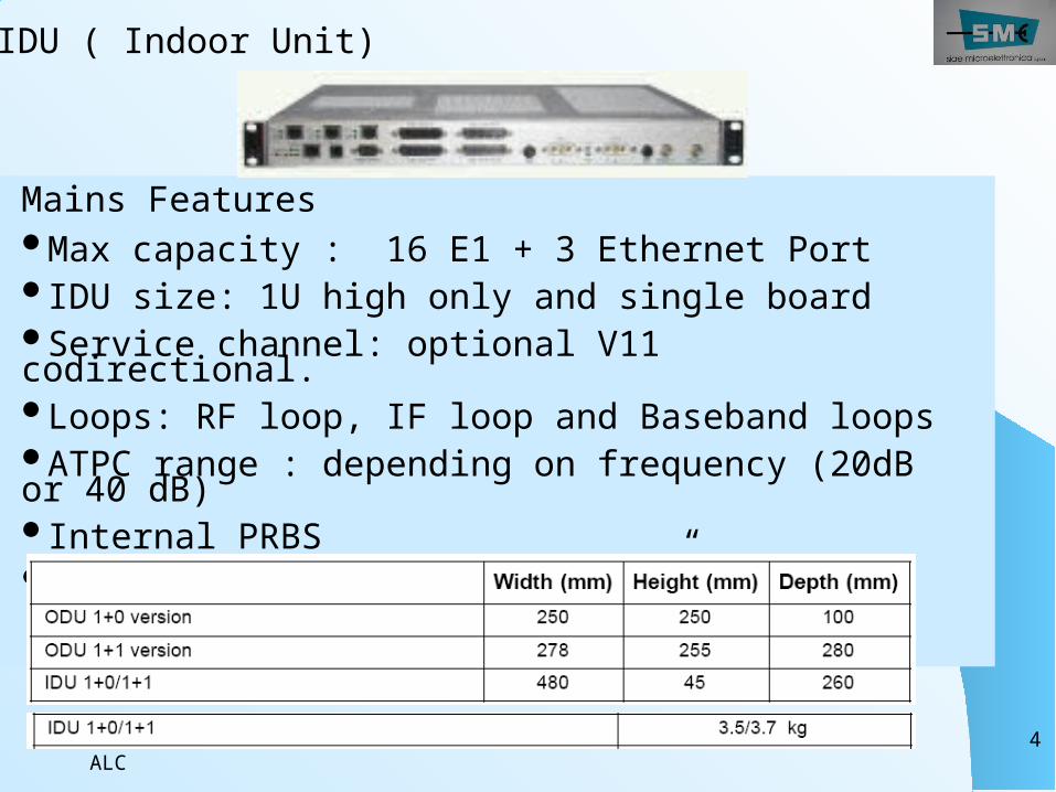
Mains FeaturesMax capacity : 16 E1 + 3 Ethernet PortIDU size: 1U high only and single boardService channel: optional V11 codirectional. Loops: RF loop, IF loop and Baseband loopsATPC range : depending on frequency (20dB or 40 dB)Internal PRBSIDU-ODU cable: 370 meter of ¼” or RG8
IDU ( Indoor Unit)
ALC5
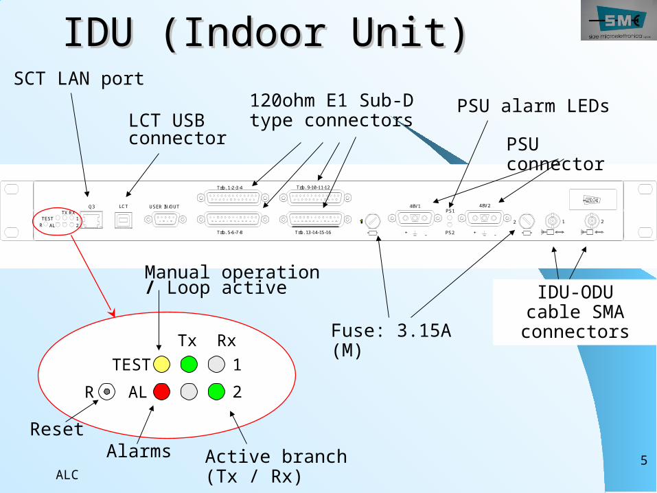
IDU (Indoor Unit)IDU (Indoor Unit)
21
RXTX
ALTESTR
USER IN/OUTQ3 LCT
Trib. 13-14-15-16Trib. 5-6-7-8
Trib. 9-10-11-12Trib. 1-2-3-4
PS2
PS1
212
48V2
+ --+
48V1
Fuse: 3.15A (M)
IDU-ODU cable SMA connectors
120ohm E1 Sub-D type connectorsLCT USB
connector
SCT LAN portPSU alarm LEDs
PSU connector
Tx Rx12
TESTALR
Active branch (Tx / Rx)
Manual operation / Loop active
AlarmsReset
ALC6
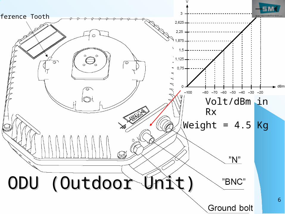
ODU (Outdoor Unit)ODU (Outdoor Unit)
Volt/dBm in Rx
Reference Tooth
Weight = 4.5 Kg

ALC7
ODU Mounting ODU Mounting
Max.1 dB Loss
ALC8
ALC9
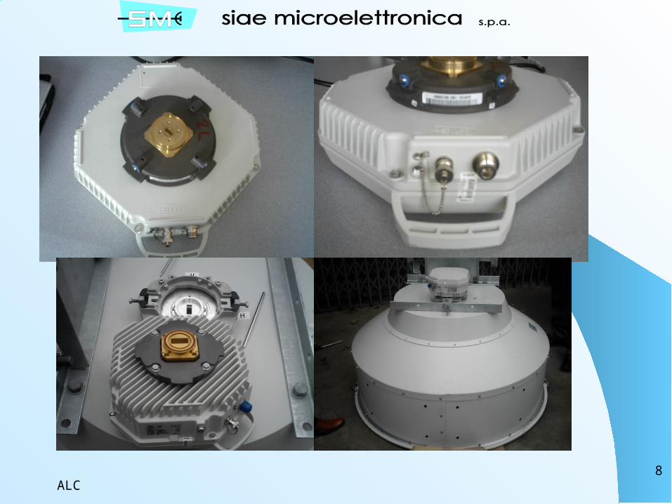
Unprotected ODU
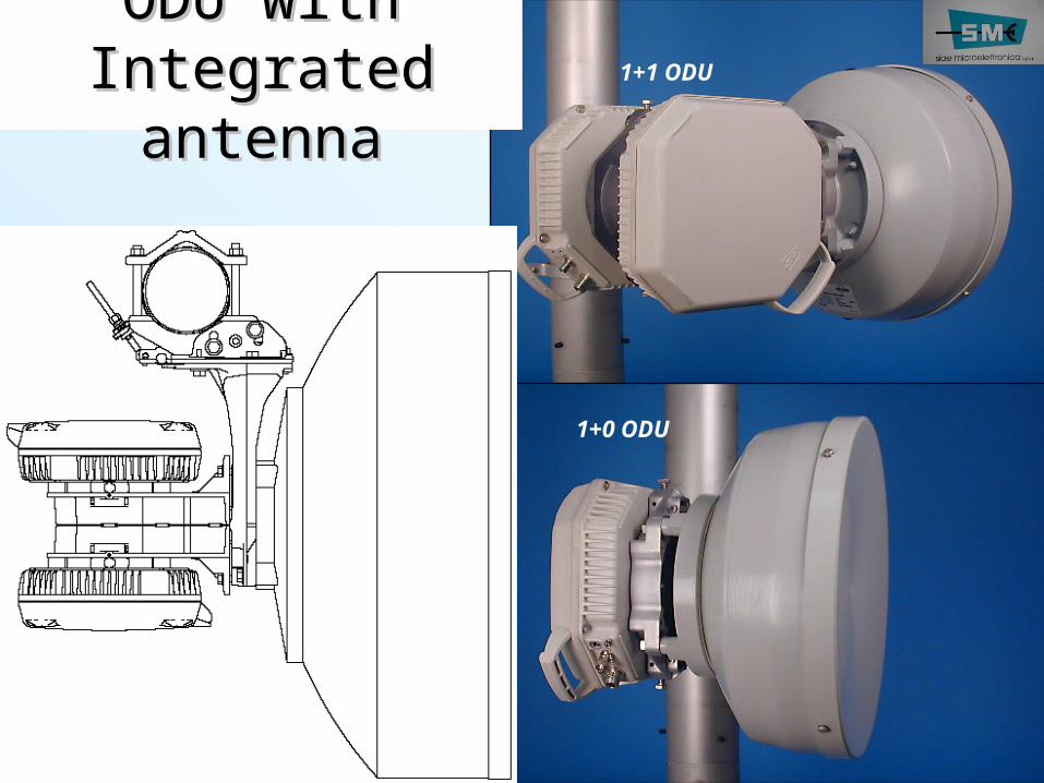
1+1 ODU
1+0 ODU
ODUODU with with Integrated Integrated antennaantenna
ALC10
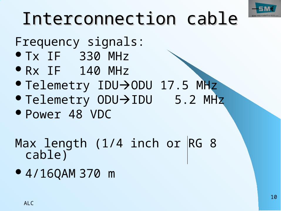
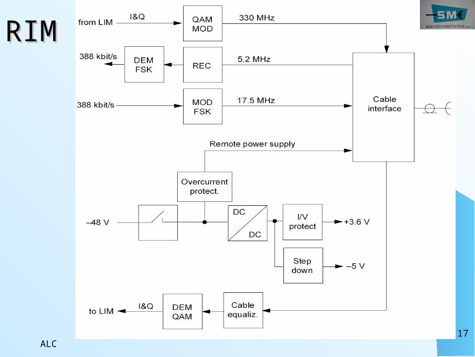
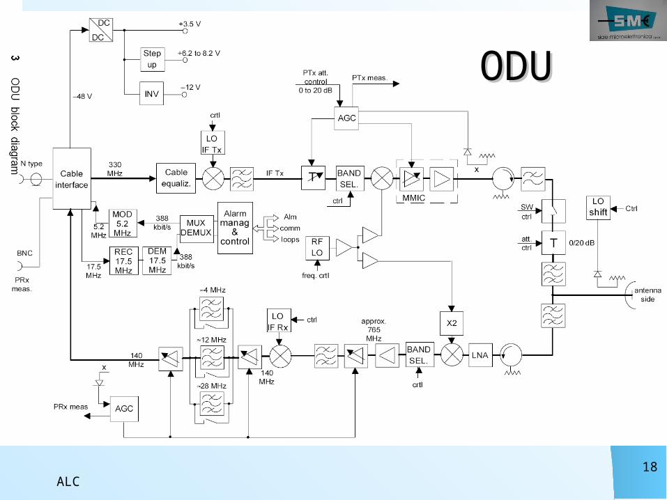
Frequency signals:Tx IF 330 MHzRx IF 140 MHzTelemetry IDUODU 17.5 MHzTelemetry ODUIDU 5.2 MHzPower 48 VDC
Max length (1/4 inch or RG 8 cable)
4/16QAM 370 m
Interconnection cableInterconnection cable
ALC11
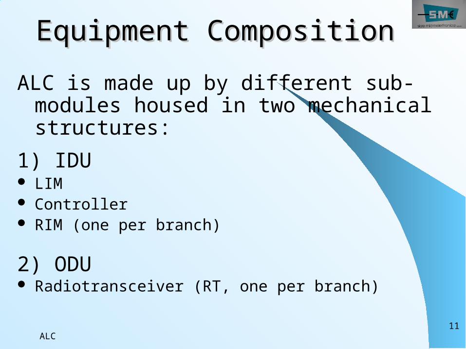
Equipment CompositionEquipment CompositionALC is made up by different sub-modules housed in two mechanical structures:
1) IDU LIM Controller RIM (one per branch)
2) ODU Radiotransceiver (RT, one per branch)
ALC12
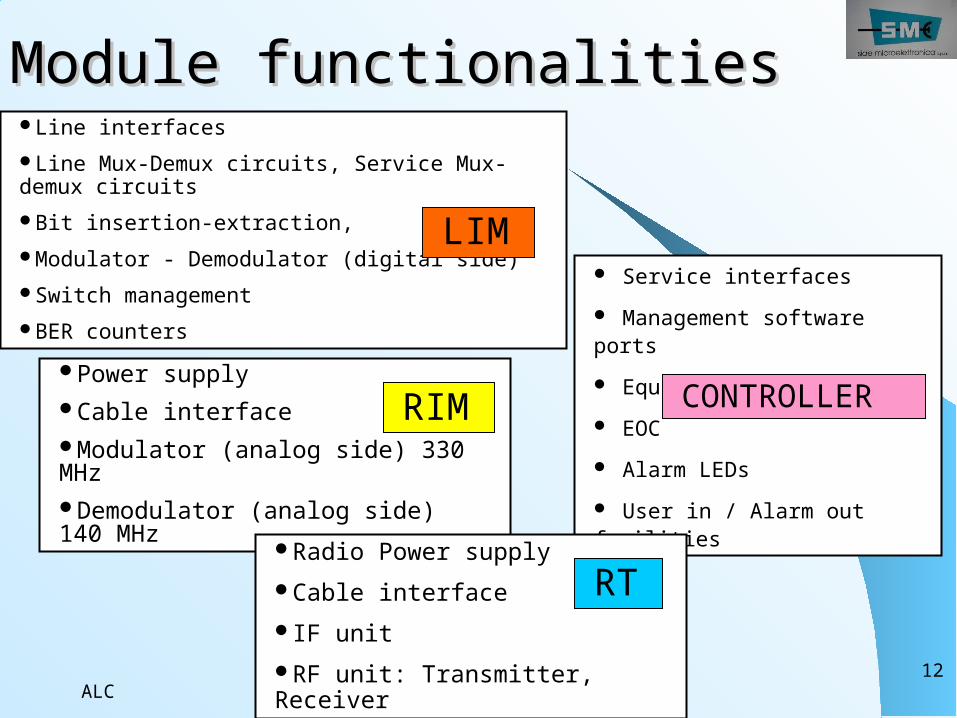
Module functionalitiesModule functionalities
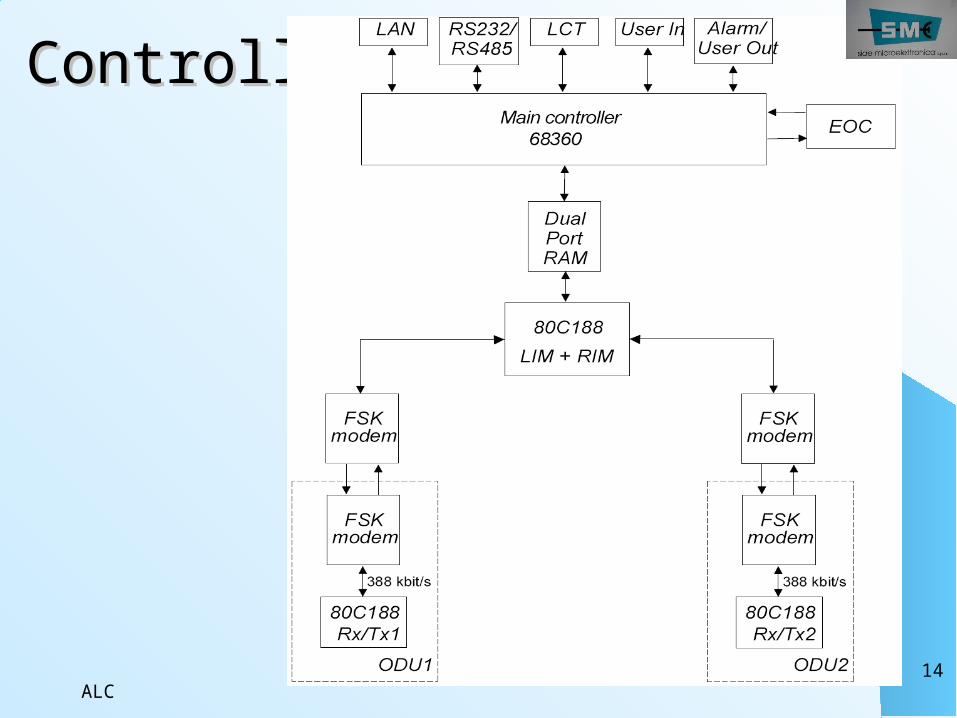
Service interfaces Management software ports Equipment controller EOC Alarm LEDs User in / Alarm out facilities
Power supplyCable interfaceModulator (analog side) 330 MHzDemodulator (analog side) 140 MHz
Radio Power supplyCable interfaceIF unitRF unit: Transmitter, Receiver
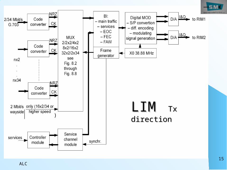
Line interfaces Line Mux-Demux circuits, Service Mux-demux circuitsBit insertion-extraction, Modulator - Demodulator (digital side)Switch managementBER counters
LIM
CONTROLLERRIM
RT
ALC13
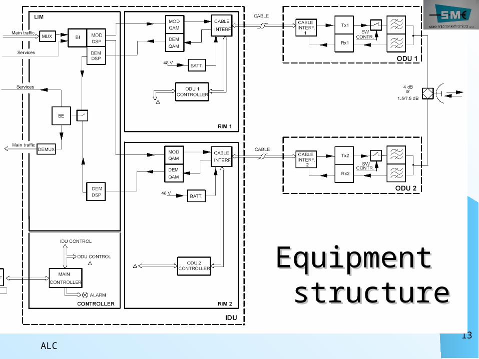
Equipment Equipment structurestructure
ALC14
ControllerController
ALC15
LIM LIM Tx Tx directiondirection)
ALC16
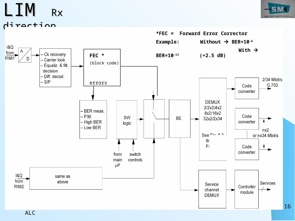
LIM LIM Rx Rx directiondirection
FEC *(block code)
errors
*FEC = Forward Error CorrectorExample: Without BER=10-6
With BER=10-13 (+2.5 dB)
ALC17
RIMRIM
ALC18
ODUODU
ALC19
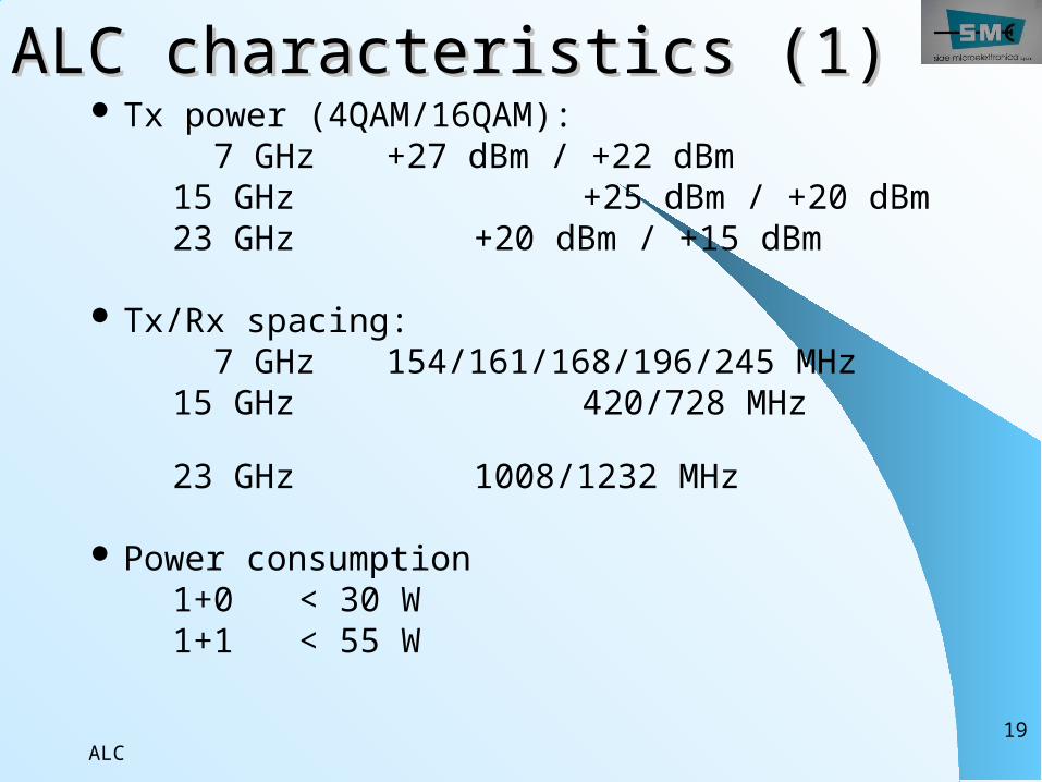
ALALCC characteristics (1) characteristics (1) Tx power (4QAM/16QAM): 7 GHz +27 dBm / +22 dBm 15 GHz +25 dBm / +20 dBm 23 GHz +20 dBm / +15 dBm Tx/Rx spacing: 7 GHz 154/161/168/196/245 MHz 15 GHz 420/728 MHz
23 GHz 1008/1232 MHz Power consumption 1+0 < 30 W 1+1 < 55 W
ALC20
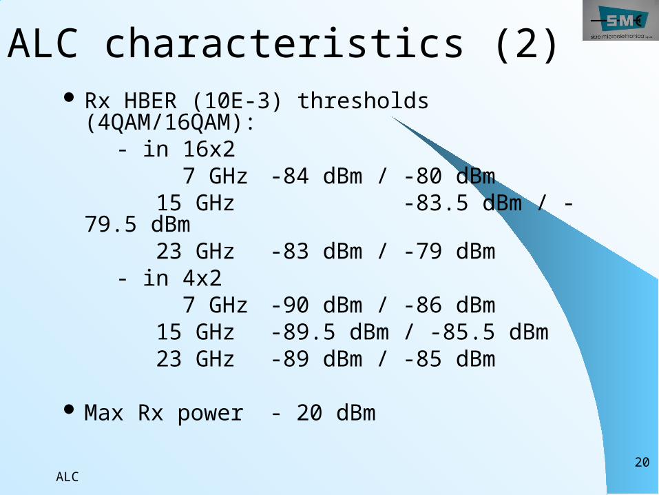
ALC characteristics (2) Rx HBER (10E-3) thresholds (4QAM/16QAM):
- in 16x2 7 GHz -84 dBm / -80 dBm 15 GHz -83.5 dBm / -79.5 dBm
23 GHz -83 dBm / -79 dBm - in 4x2 7 GHz -90 dBm / -86 dBm 15 GHz -89.5 dBm / -85.5 dBm 23 GHz -89 dBm / -85 dBm Max Rx power - 20 dBm
ALC21
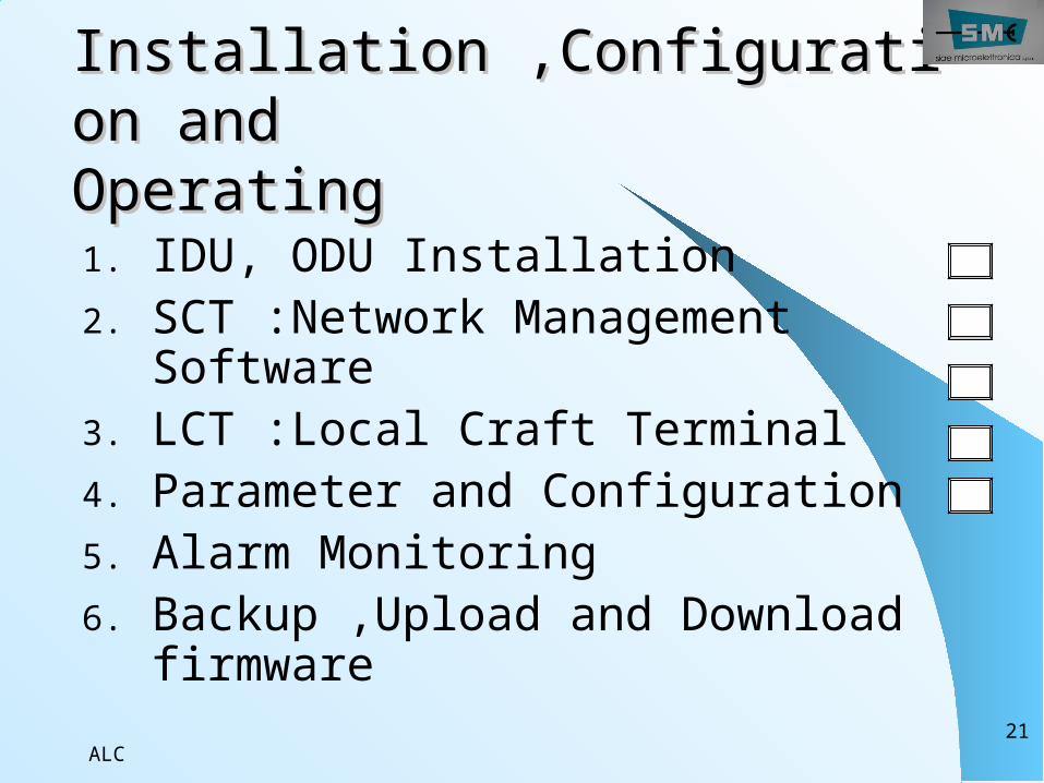
Installation ,ConfiguratiInstallation ,Configuration andon andOperatingOperating1. IDU, ODU Installation2. SCT :Network Management
Software3. LCT :Local Craft Terminal4. Parameter and Configuration5. Alarm Monitoring 6. Backup ,Upload and Download
firmware
ALC22
InstallationIDU InstallationPower Supply and GroundingE1 Cable and WiringAntenna and ODU Mounting
ALC23
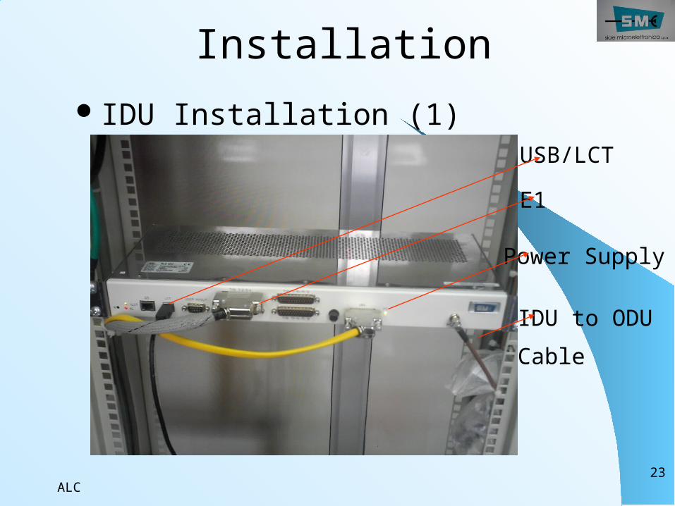
InstallationIDU Installation (1)
USB/LCTE1
Power Supply
IDU to ODUCable
ALC24
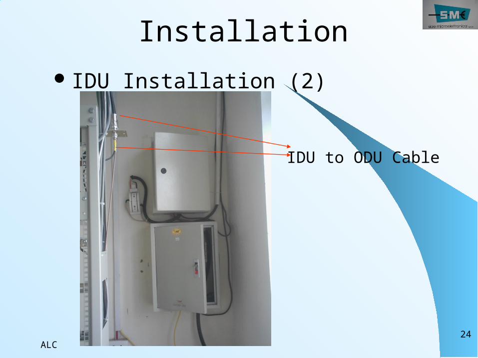
InstallationIDU Installation (2)
IDU to ODU Cable
ALC25
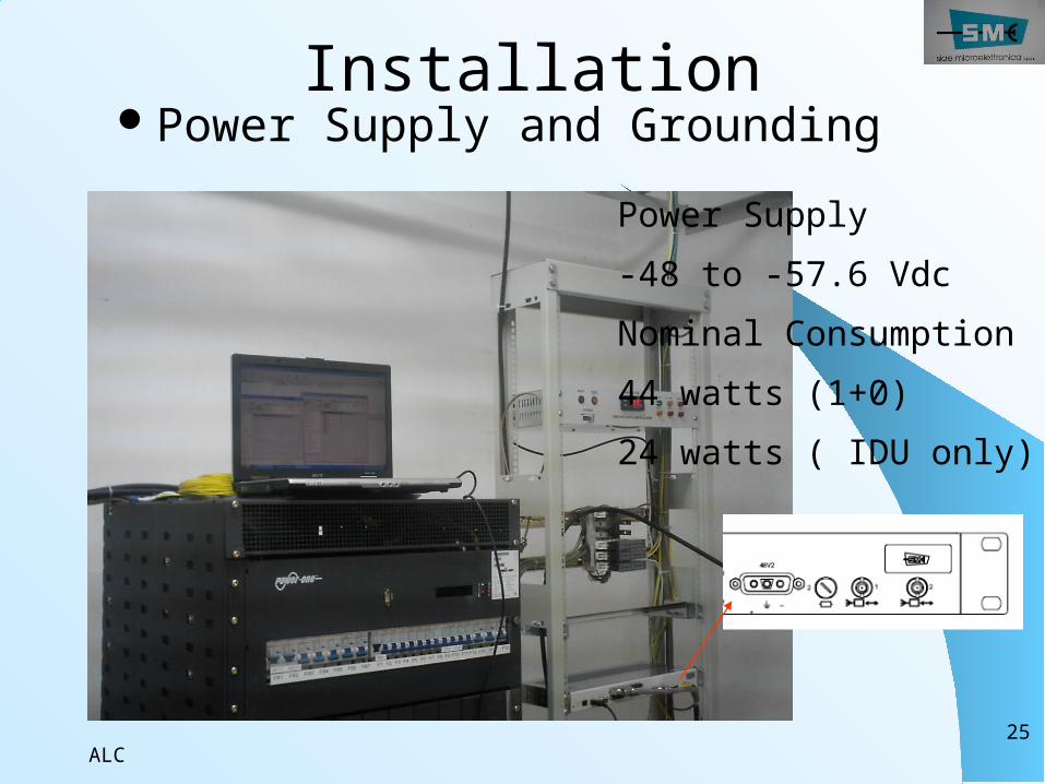
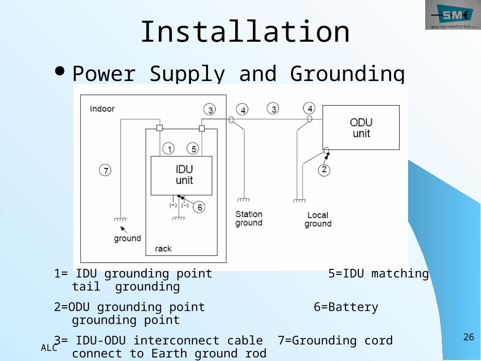
InstallationPower Supply and Grounding
Power Supply -48 to -57.6 VdcNominal Consumption44 watts (1+0)24 watts ( IDU only)
ALC26
InstallationPower Supply and Grounding
1= IDU grounding point 5=IDU matching tail grounding
2=ODU grounding point 6=Battery grounding point
3= IDU-ODU interconnect cable 7=Grounding cord connect to Earth ground rod
4=Cable grounding/Station ground
ALC27
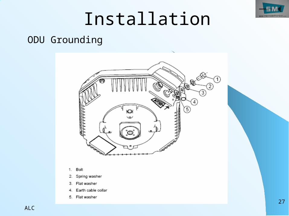
InstallationODU Grounding
ALC28
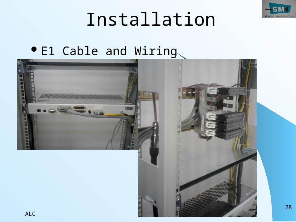
InstallationE1 Cable and Wiring
ALC29
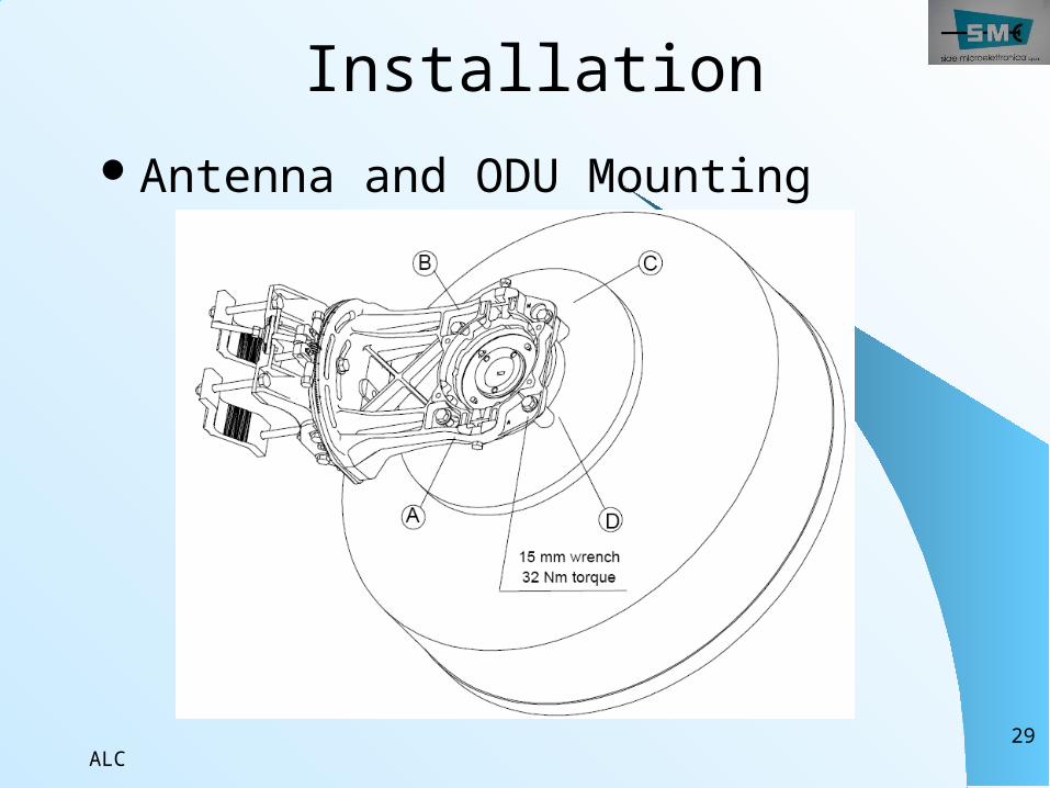
InstallationAntenna and ODU Mounting
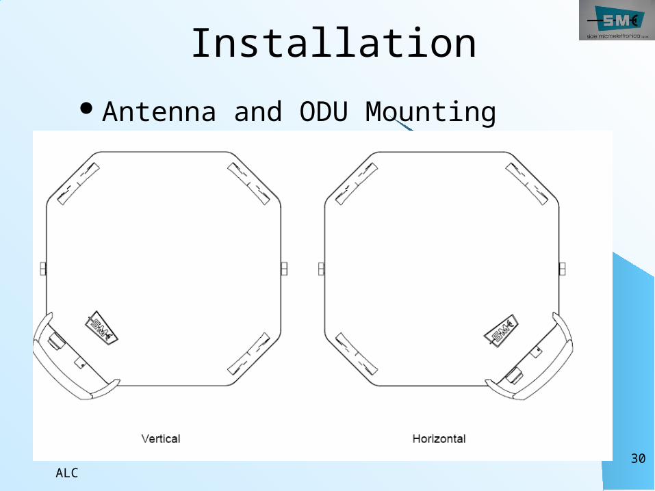
ALC30
InstallationAntenna and ODU Mounting
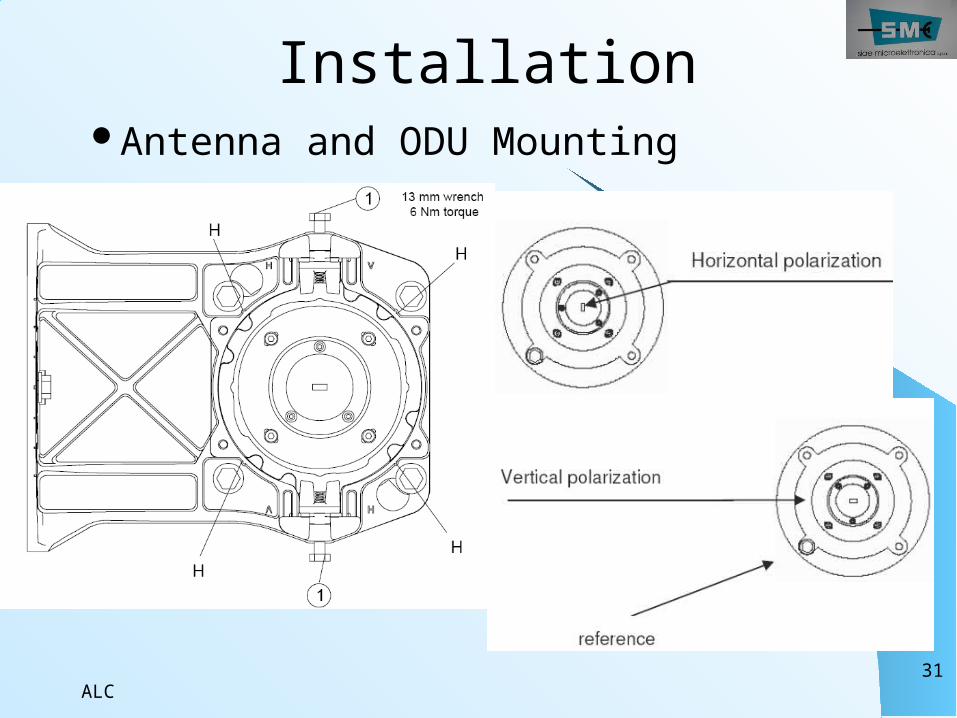
ALC31
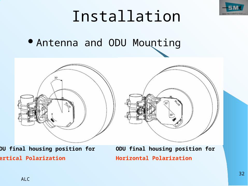
InstallationAntenna and ODU Mounting
ALC32
InstallationAntenna and ODU Mounting
ODU final housing position for Vertical Polarization
ODU final housing position for Horizontal Polarization
ALC33
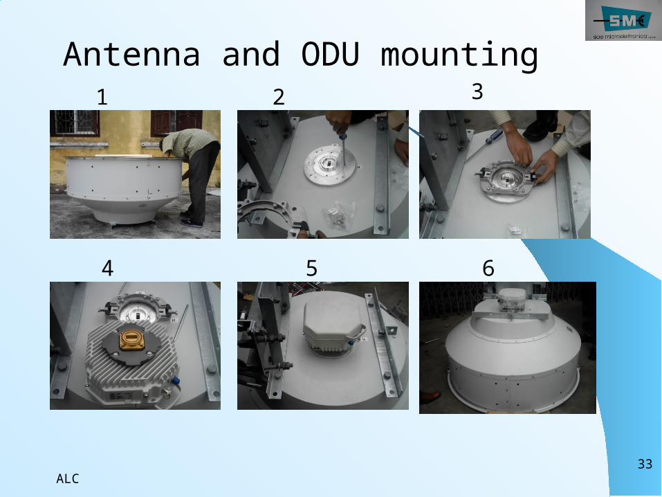
Antenna and ODU mounting1 2 3
4 5 6
ALC34
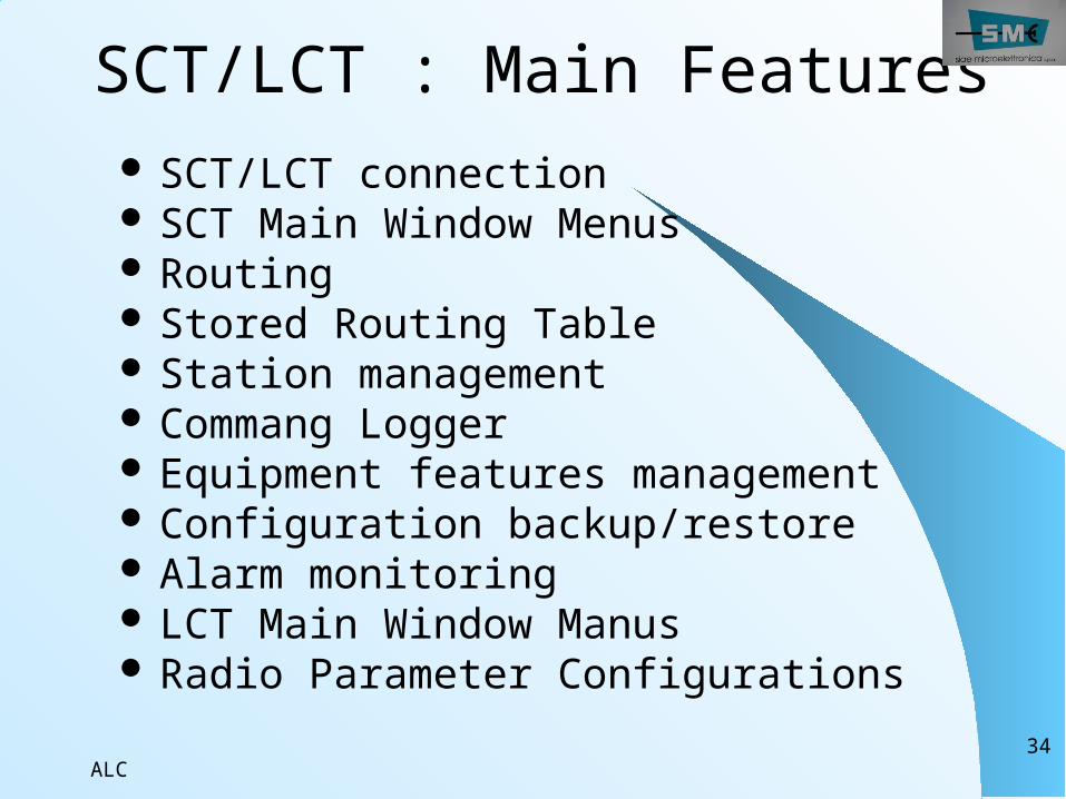
SCT/LCT : Main Features SCT/LCT connection SCT Main Window Menus Routing Stored Routing Table Station management Commang Logger Equipment features management Configuration backup/restore Alarm monitoring LCT Main Window Manus Radio Parameter Configurations
ALC35
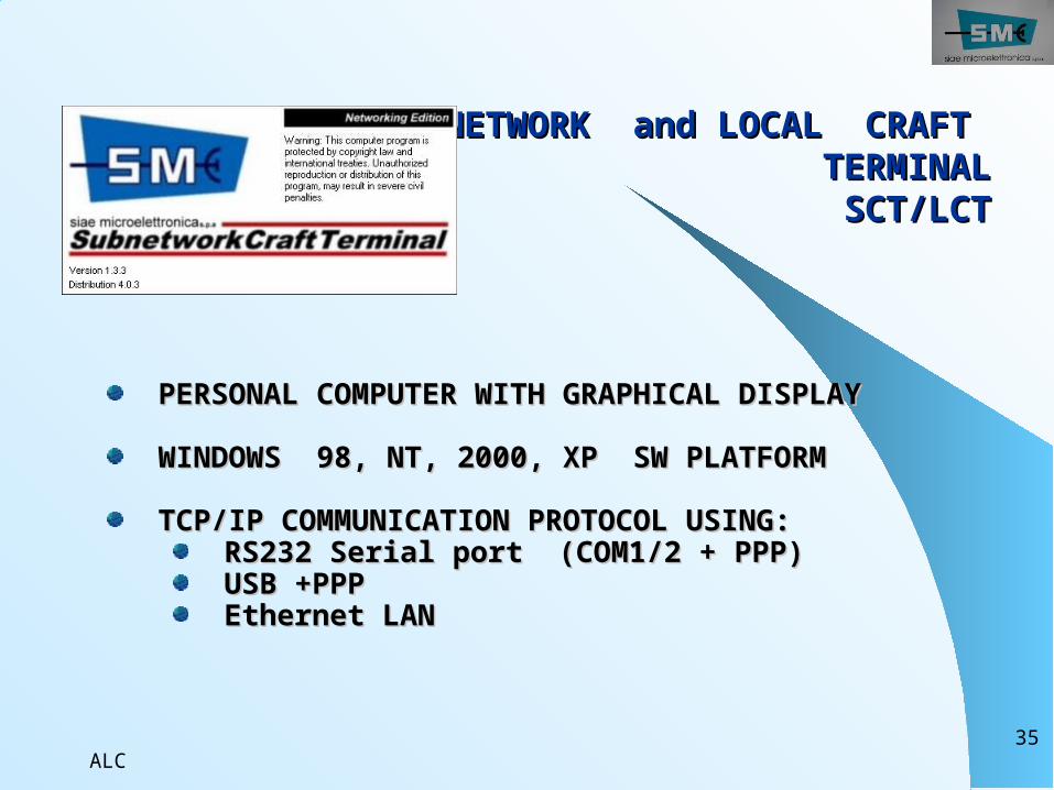
SUBNETWORK and LOCAL CRAFT SUBNETWORK and LOCAL CRAFT TERMINALTERMINALSCT/LCTSCT/LCT
PERSONAL COMPUTER WITH GRAPHICAL DISPLAYPERSONAL COMPUTER WITH GRAPHICAL DISPLAY
WINDOWS 98, NT, 2000, XP SW PLATFORMWINDOWS 98, NT, 2000, XP SW PLATFORM
TCP/IP COMMUNICATION PROTOCOL USING:TCP/IP COMMUNICATION PROTOCOL USING: RS232 Serial port (COM1/2 + PPP)RS232 Serial port (COM1/2 + PPP) USB +PPPUSB +PPP Ethernet LAN Ethernet LAN
ALC36
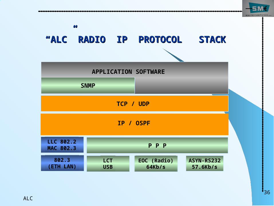
““ALC” RADIO IP PROTOCOL STACKALC” RADIO IP PROTOCOL STACK
TCP / UDP
LLC 802.2MAC 802.3
802.3(ETH LAN)
IP / OSPF
ASYN-RS23257.6Kb/s
APPLICATION SOFTWARE
SNMP
EOC (Radio)64Kb/s
P P P
LCTUSB
ALC37
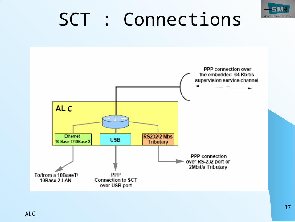
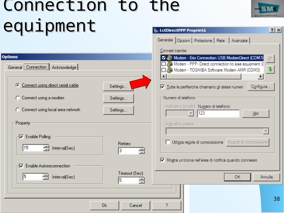
SCT : Connections
C
ALC38
Connection to the Connection to the equipmentequipment
ALC39
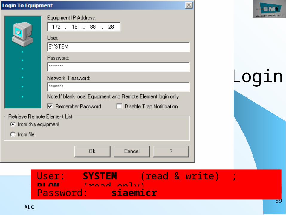
Login
User: SYSTEM (read & write) ; RLOM (read only)Password: siaemicr
ALC40
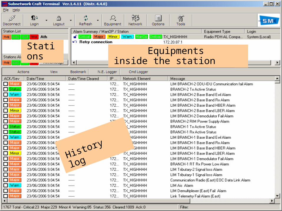
History
log
Equipments inside the station
Stations
ALC41
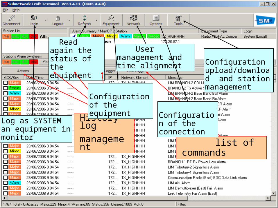
Log as SYSTEM an equipment in monitor
Read again the status of the equipment
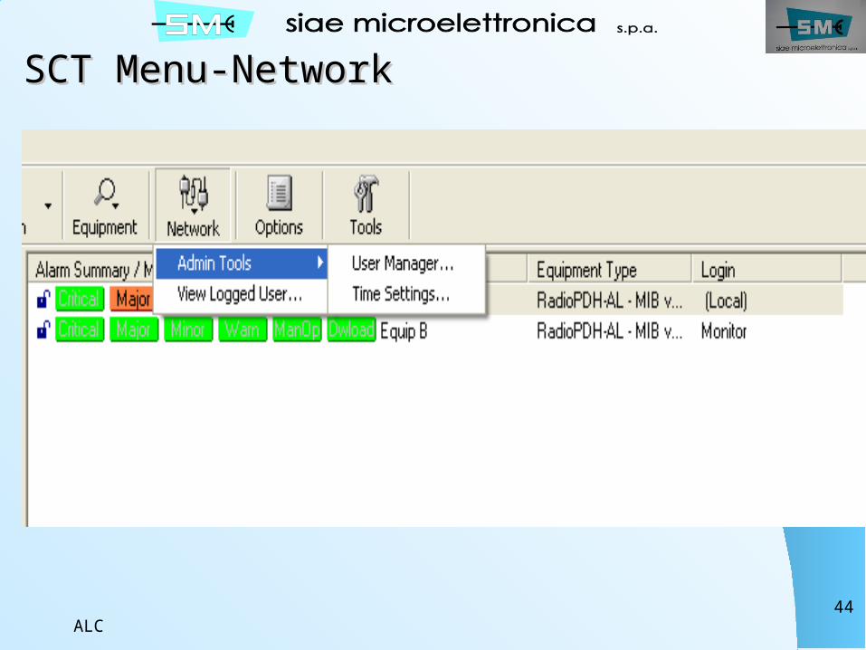
User management and time alignment
Configuration upload/download and station management
History logmanagement
Configuration of the equipment
list of commands
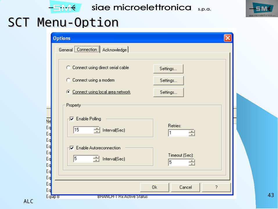
Configuration of the connection
ALC42
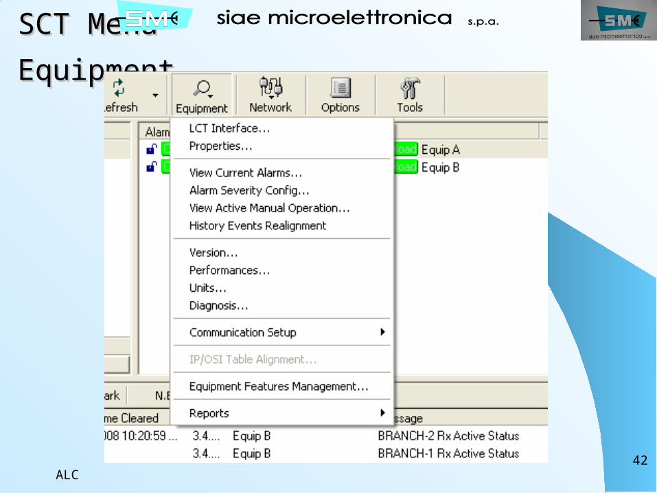
SCT Menu-SCT Menu-EquipmentEquipment
ALC43
SCT Menu-OptionSCT Menu-Option
ALC44
SCT Menu-NetworkSCT Menu-Network
ALC45
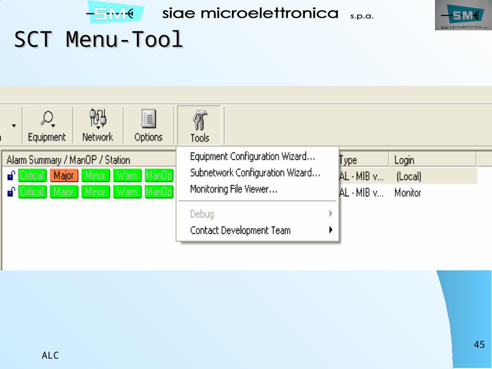
SCT Menu-ToolSCT Menu-Tool
ALC46
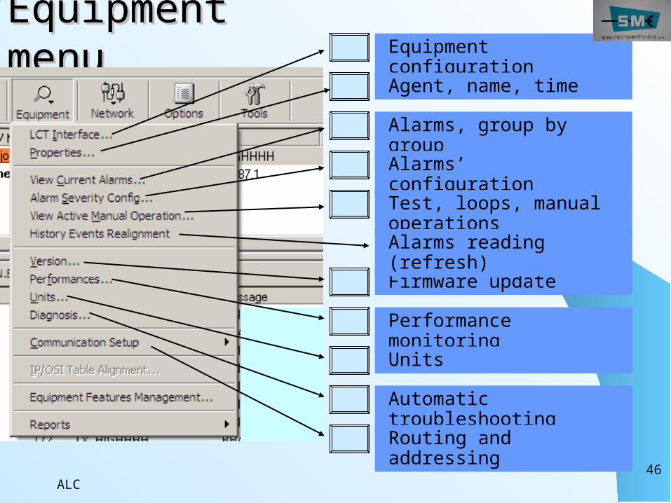
Equipment Equipment menumenu Equipment
configurationAgent, name, time
Alarms, group by groupAlarms’ configurationTest, loops, manual operations
Firmware update
Performance monitoringUnits
Automatic troubleshooting
Alarms reading (refresh)
Routing and addressing
ALC47
ALC48
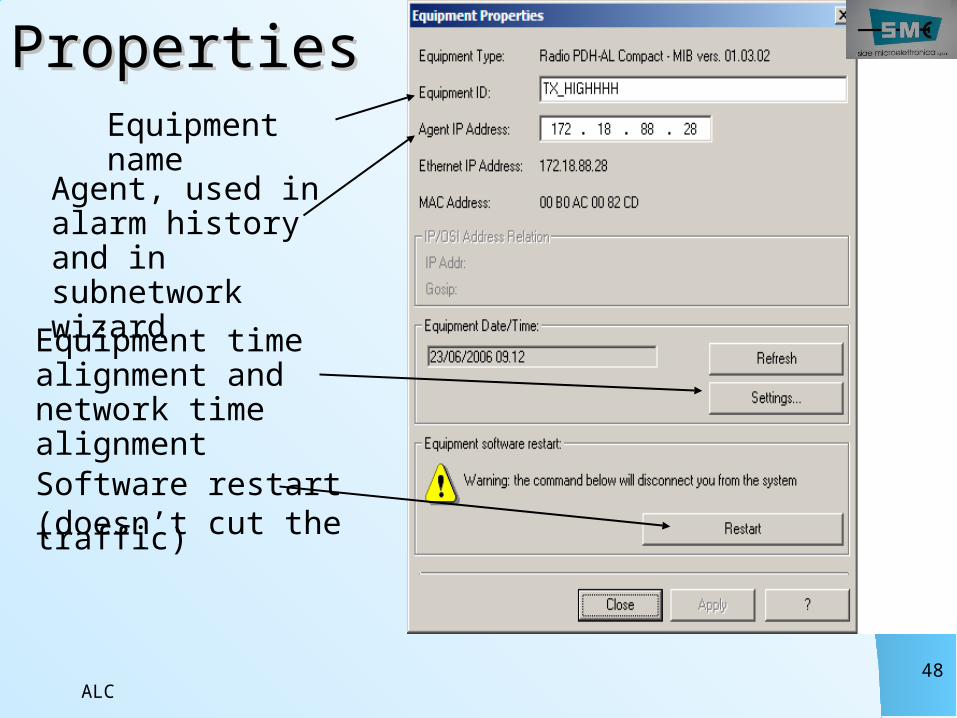
PropertiesPropertiesEquipment name
Agent, used in alarm history and in subnetwork wizardEquipment time alignment and network time alignmentSoftware restart (doesn’t cut the traffic)
ALC49
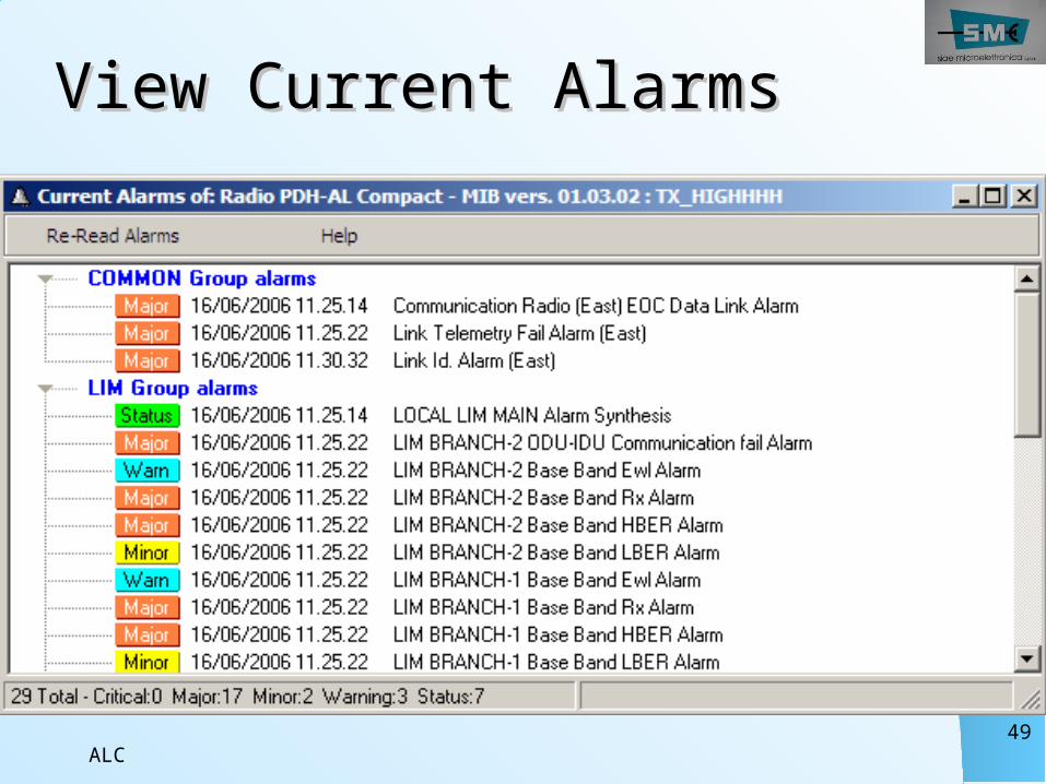
View Current AlarmsView Current Alarms
ALC50
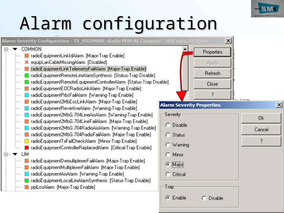
Alarm configurationAlarm configuration
ALC51
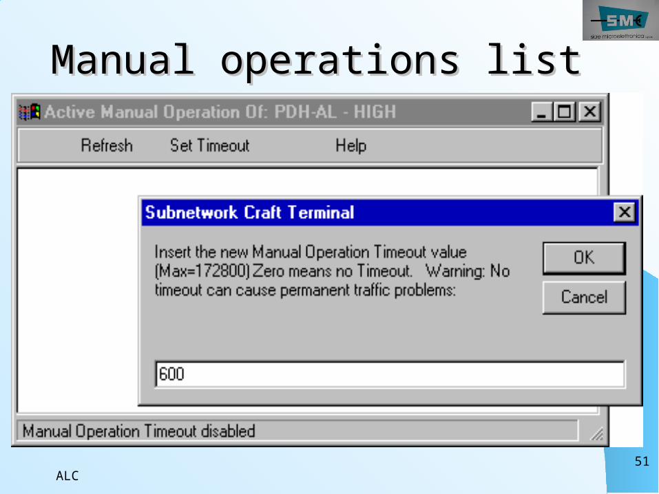
Manual operations listManual operations list
ALC52
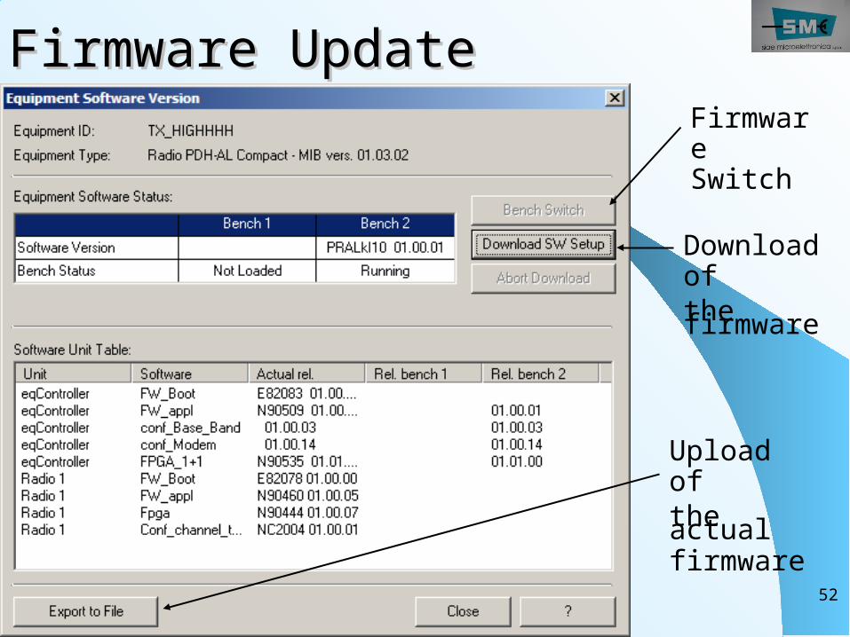
Firmware UpdateFirmware UpdateFirmware Switch
Download of the firmware
Upload of the actualfirmware
ALC53
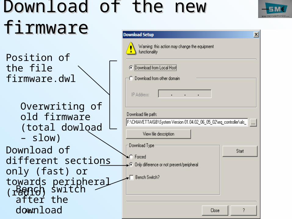
Download of the new Download of the new firmwarefirmwarePosition of the file firmware.dwl
Overwriting of old firmware (total dowload – slow)
Download of different sections only (fast) or towards peripheral (radio)Bench switch after the download
ALC54
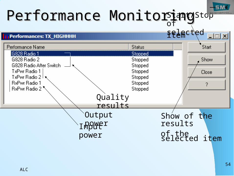
Performance MonitoringPerformance Monitoring
Quality results
Output powerInput
power
Start/Stop of selected item
Show of the resultsof the selected item
ALC55
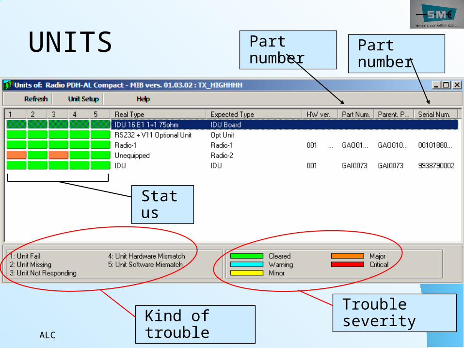
UNITS
Status
Part number
Part number
Kind of trouble
Trouble severity
ALC56
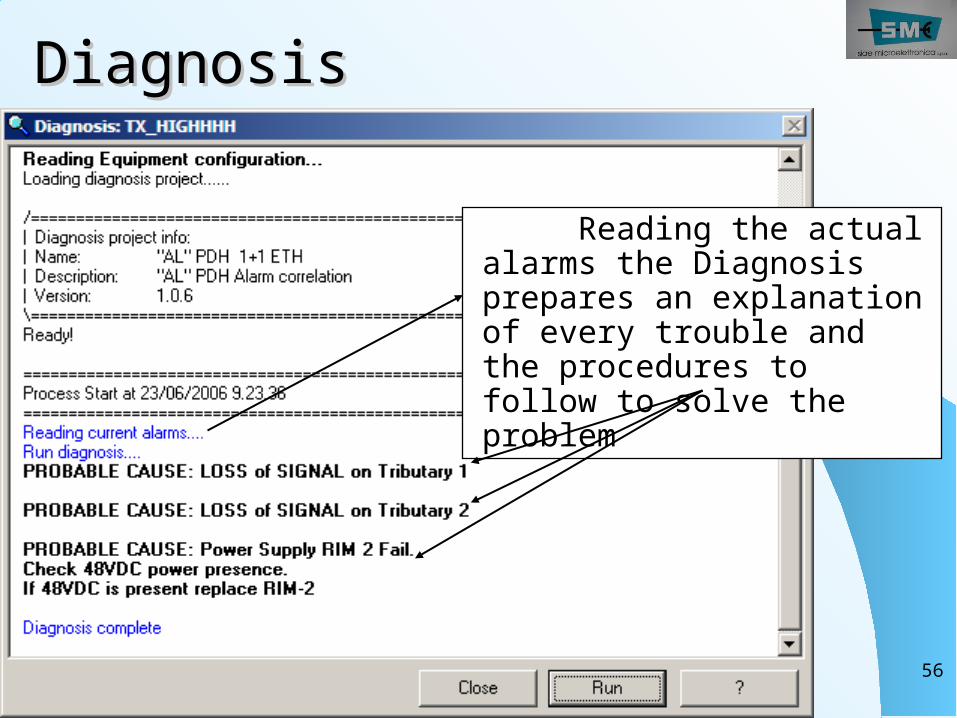
DiagnosisDiagnosis
Reading the actual alarms the Diagnosis prepares an explanation of every trouble and the procedures to follow to solve the problem
ALC57
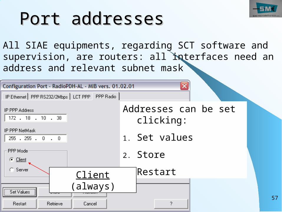
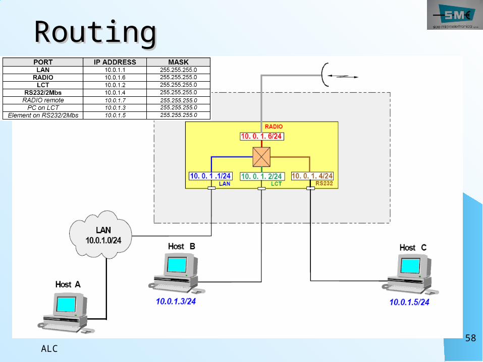
Port addressesPort addressesAll SIAE equipments, regarding SCT software and supervision, are routers: all interfaces need an address and relevant subnet mask
Addresses can be set clicking:
1. Set values2. Store3. Restart Client
(always)
ALC58
RoutingRouting
ALC59
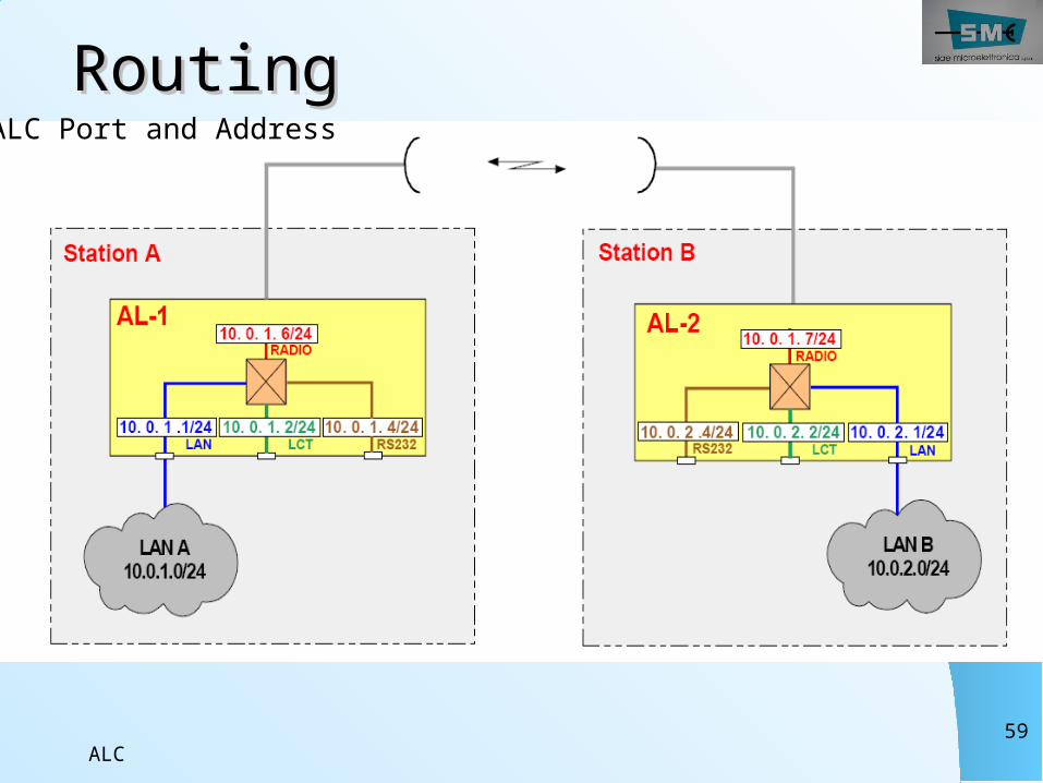
RoutingRoutingALC Port and Address
ALC60
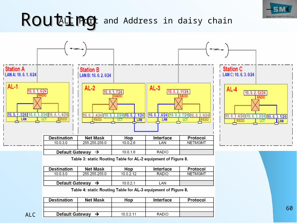
RoutingRoutingALC Port and Address in daisy chain
ALC61
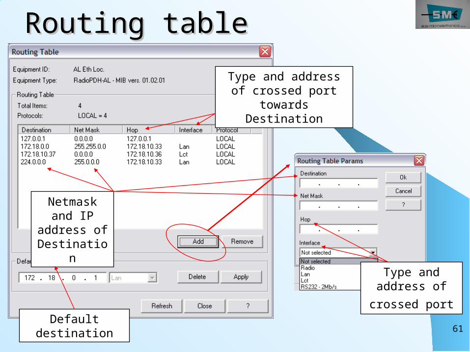
Routing tableRouting table
Type and address of crossed port
Type and address of crossed port
towards Destination
Netmask and IP
address of Destinatio
n
Default destination
ALC62
Stored Routing TableStored Routing TableThe “Stored Routing Table” adds routing lines,
after a Restart, to the running Routing Table of the NE.
In this way we can change Ports addresses (operation that needs a restart) without loosing a remote NE:
1. In “Stored Routing Table” add the routing lines relevant to new port addresses you are going to set
2. Set the new port addresses (…the equipment restarts)
3. After the restart the equipment has new addresses and the routing table configured already: the NE management is still running
ALC63
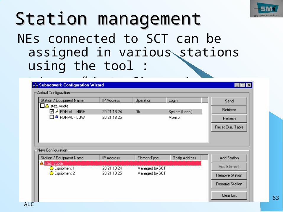
Station managementStation managementNEs connected to SCT can be assigned in various stations using the tool :
“Subnetwork Configuration Wizard”
ALC64
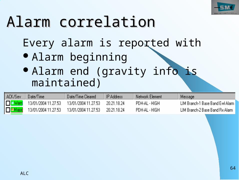
Alarm correlation Alarm correlation Every alarm is reported withAlarm beginning Alarm end (gravity info is maintained)
ALC65
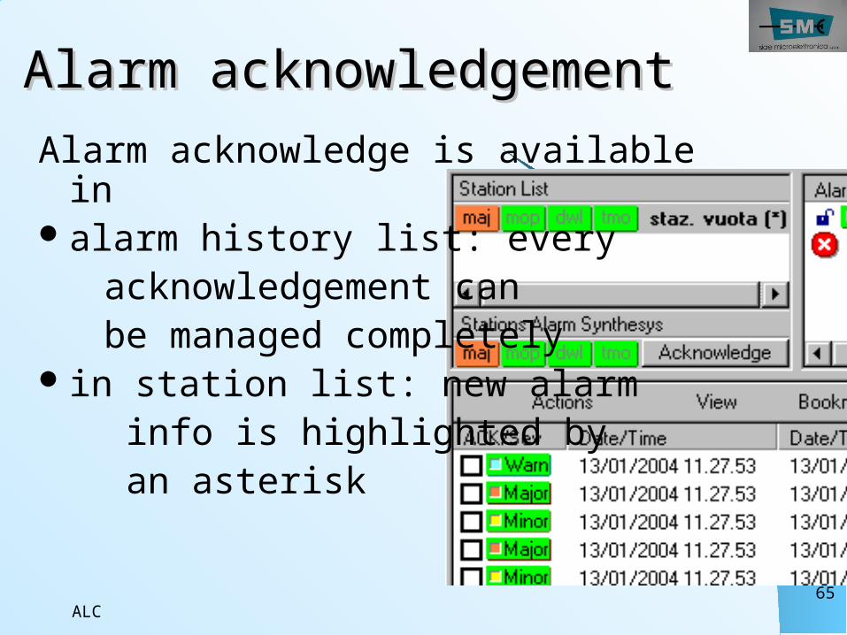
Alarm acknowledgementAlarm acknowledgementAlarm acknowledge is available in
alarm history list: every acknowledgement can be managed completelyin station list: new alarm info is highlighted by an asterisk
ALC66
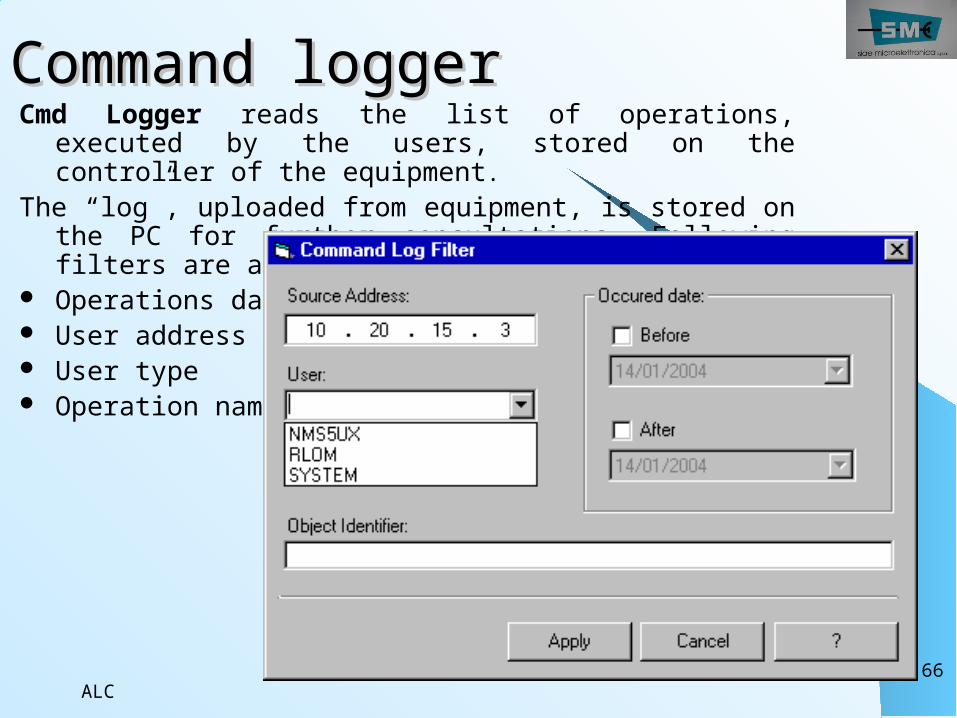
Command loggerCommand loggerCmd Logger reads the list of operations,
executed by the users, stored on the controller of the equipment.
The “log”, uploaded from equipment, is stored on the PC for further consultations. Following filters are available:
Operations date User address User type Operation name
ALC67
Configuration Configuration upload/downloadupload/download
Upload (from equipment)From Tool menu, open the proper TemplateSelect Upload operation and the equipment you want to upload information fromSave them in a file (*.cfg)Download (to equipment)From Tool menu, open the proper file (*.cfg)Select Download operation and the equipment you want to download information to
Uploaded parameters and *.cfg file are editable usingEquipment Configuration Wizard.
ALC68
Configuration TemplateConfiguration TemplateConfiguration template: it is relevant to equipment radio parameters as frequency, attenuation, capacity, thresholds,…Address configuration template: it is relevant to management parameters as port IP addresses, routing tables, remote elements tables, OSPF.
Both configurations are necessary during first installation or when Controller module is substituted with a spare one: you can use a file to download or set every parameter manually.
ALC69
Full backupFull backup The whole amount of parameters (equipment parameters, address parameters and remote element table) can be uploaded from equipment, saved in a file (*.bku), downloaded to equipment.
These parameters cannot be editated.
ALC70
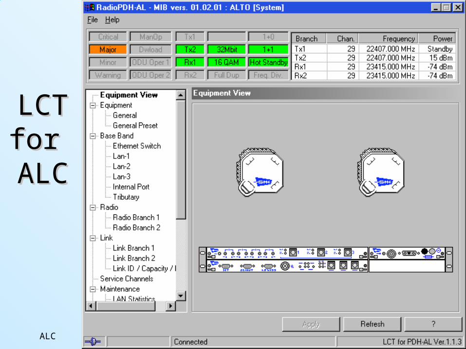
LCTLCTfor for ALALCC
ALC71
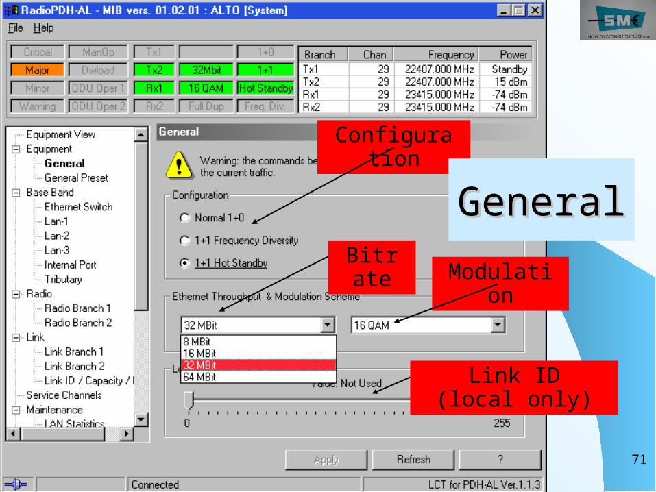
Configuration
Bitrate Modulati
on
Link ID (local only)
GeneralGeneral
ALC72
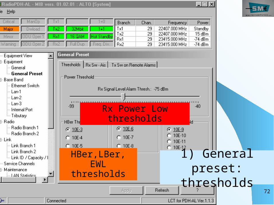
1) General preset:
thresholds
HBer,LBer, EWL
thresholds
Rx Power Low thresholds
ALC73
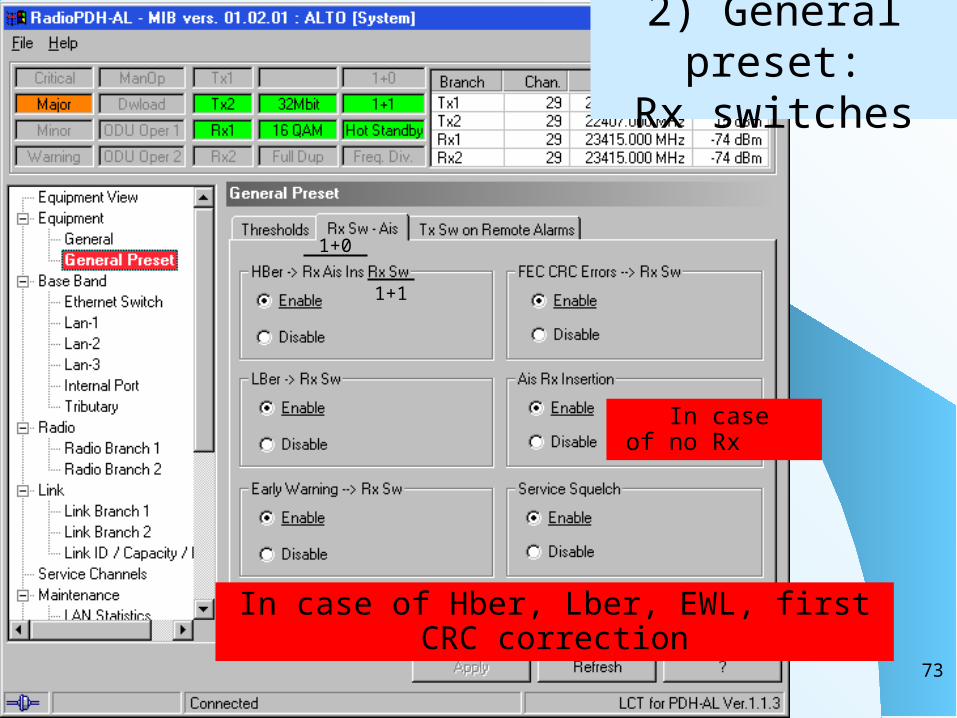
2) General preset:
Rx switches
1+1
1+0
In case of Hber, Lber, EWL, first CRC correction
In case of no Rx
ALC74
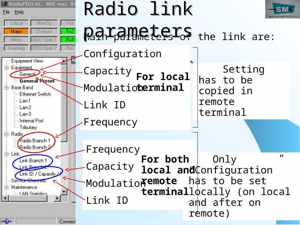
Main parameters of the link are:ConfigurationCapacityModulationLink IDFrequency
Radio link Radio link parametersparameters
For local terminal
Setting has to be copied in remote terminal
FrequencyCapacityModulationLink ID
Only “Configuration” has to be set locally (on local and after on remote)
For both local and remote terminal
ALC75
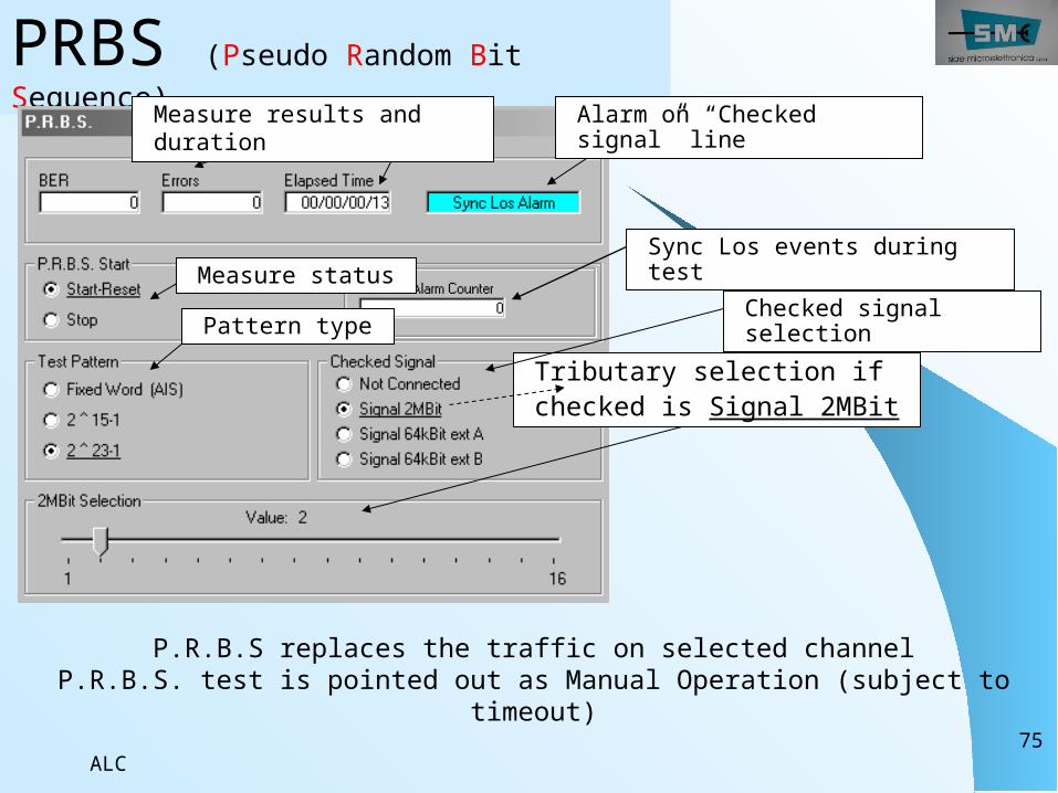
PRBS (Pseudo Random Bit Sequence) Alarm on “Checked
signal” lineMeasure results and duration
Tributary selection if checked is Signal 2MBit
P.R.B.S replaces the traffic on selected channelP.R.B.S. test is pointed out as Manual Operation (subject to
timeout)
Checked signal selection
Measure status
Pattern type
Sync Los events during test
ALC76
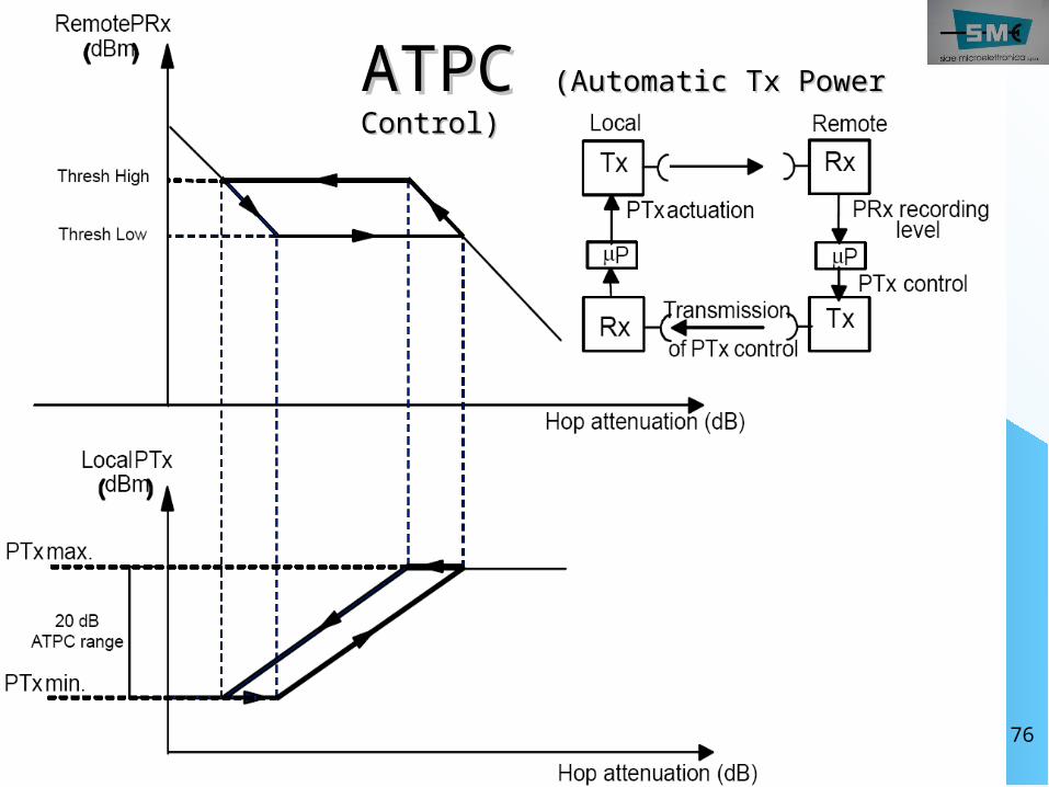
ATPC ATPC (Automatic Tx Power (Automatic Tx Power Control)Control)
ALC77
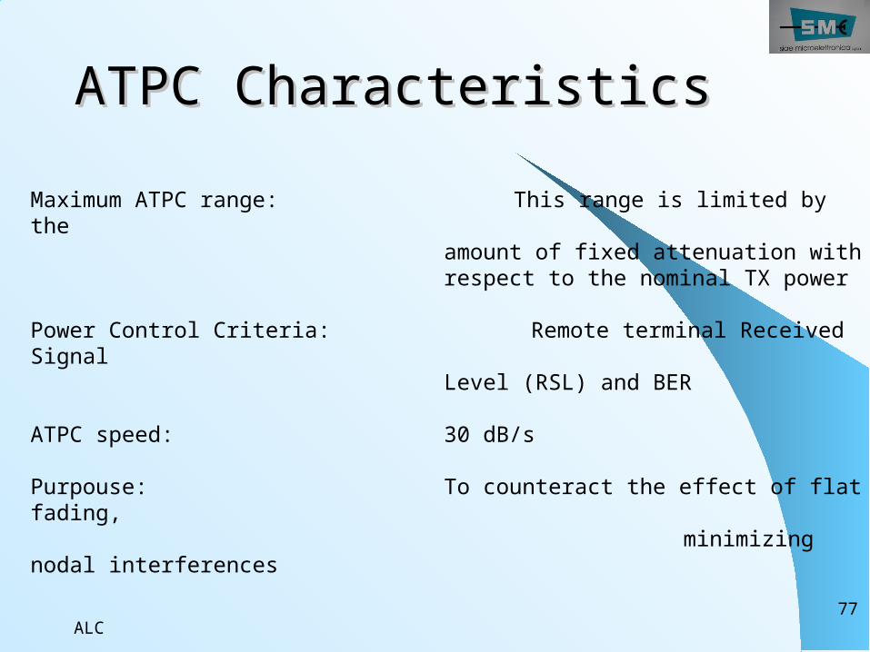
ATPC CharacteristicsATPC CharacteristicsMaximum ATPC range: This range is limited by the
amount of fixed attenuation with respect to the nominal TX power
Power Control Criteria: Remote terminal Received Signal
Level (RSL) and BER
ATPC speed: 30 dB/s
Purpouse: To counteract the effect of flat fading, minimizing nodal interferences
ALC78
MaintenanceMaintenance1. Reriodical Check2. Alarm Meaning3. Root Cause of Failure4. Troubleshooting 5. Loop Facilities
ALC79
Periodical Checks are used to check for radio equipment operation without the presence of any alarm conditions
Periodical Check
Check of the TX Power Check of the Receive Signal Strength ( Reading Value must be match with link hop Cal.) Check of BER and HOP performance
ALC80
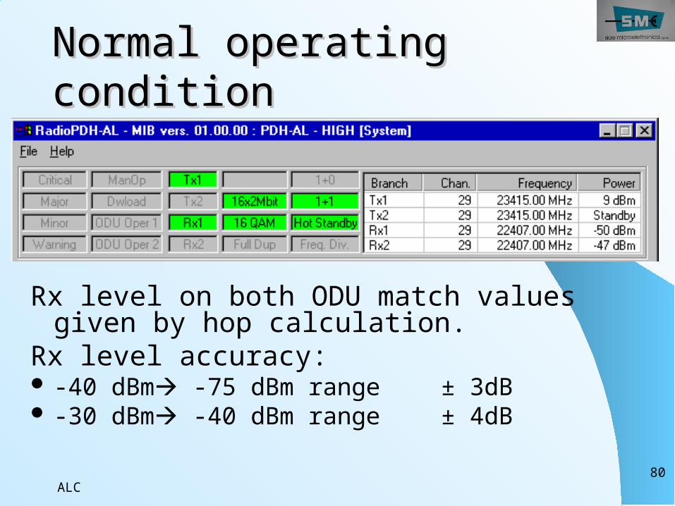
Normal operating Normal operating conditioncondition
Rx level on both ODU match values given by hop calculation.
Rx level accuracy: -40 dBm -75 dBm range ± 3dB -30 dBm -40 dBm range ± 4dB
ALC81
Faulty condition: alarm Faulty condition: alarm notificationnotificationA faulty condition is pointed
out byIDU front panel LEDs: - AL: alarms, internal or external- TEST: manual operation active
SCT window:- Log history area (with alarm correlation)- Equipment view current alarms (with alarms grouping)
ALC82
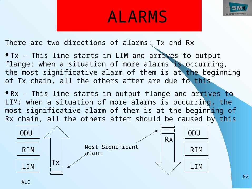
ALARMSThere are two directions of alarms: Tx and RxTx – This line starts in LIM and arrives to output flange: when a situation of more alarms is occurring, the most significative alarm of them is at the beginning of Tx chain, all the others after are due to this Rx – This line starts in output flange and arrives to LIM: when a situation of more alarms is occurring, the most significative alarm of them is at the beginning of Rx chain, all the others after should be caused by this
Most Significant alarm
Rx
TxRIM
LIM
ODU
LIM
RIM
ODU
ALC83
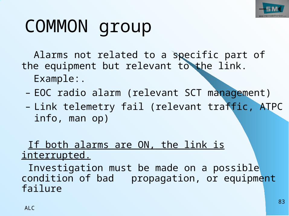
COMMON group Alarms not related to a specific part of the equipment but relevant to the link.
Example:.– EOC radio alarm (relevant SCT management)– Link telemetry fail (relevant traffic, ATPC info, man op)
If both alarms are ON, the link is interrupted.
Investigation must be made on a possible condition of bad propagation, or equipment failure
ALC84
ALC85
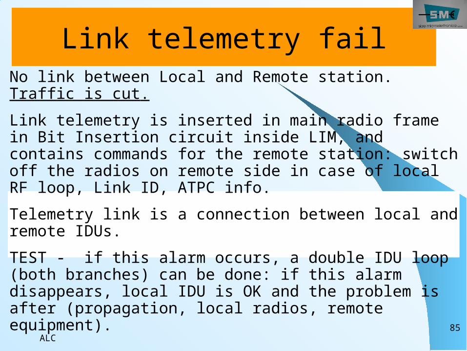
No link between Local and Remote station. Traffic is cut.Link telemetry is inserted in main radio frame in Bit Insertion circuit inside LIM, and contains commands for the remote station: switch off the radios on remote side in case of local RF loop, Link ID, ATPC info.Telemetry link is a connection between local and remote IDUs.TEST - if this alarm occurs, a double IDU loop (both branches) can be done: if this alarm disappears, local IDU is OK and the problem is after (propagation, local radios, remote equipment).
Link telemetry fail
ALC86
Communication Radio EOC Data link No link between Local and Remote station or wrong port address configuration.EOC is the channel involved in management communication. If EOC radio link is active: - Traffic is OK - Management is cut (no remote)
ALC87
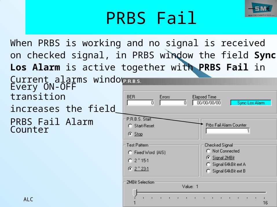
PRBS FailWhen PRBS is working and no signal is received on checked signal, in PRBS window the field Sync Los Alarm is active together with PRBS Fail in Current alarms windowEvery ON-OFF transitionincreases the fieldPRBS Fail Alarm Counter
ALC88
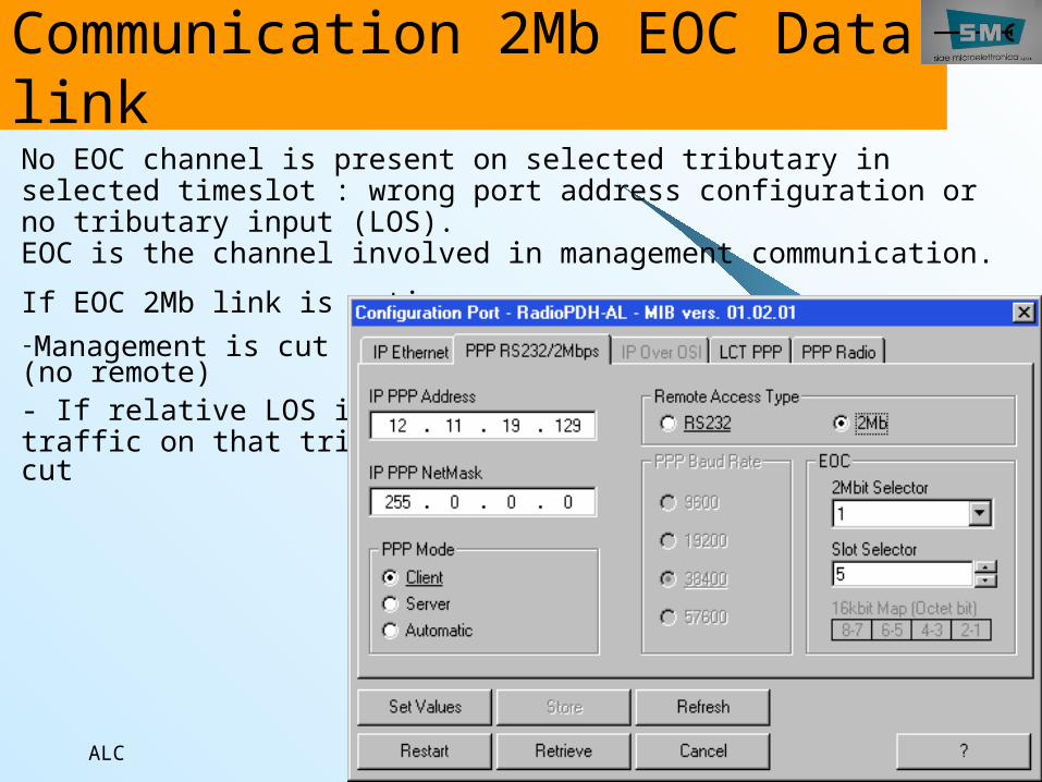
Communication 2Mb EOC Data linkNo EOC channel is present on selected tributary in selected timeslot : wrong port address configuration or no tributary input (LOS). EOC is the channel involved in management communication.If EOC 2Mb link is active:-Management is cut (no remote)- If relative LOS is active, traffic on that tributary is cut
ALC89
Revertive
When a branch is declared preferential, the switch on opposite branch gives Revertive alarm.The return to preferential branch, when available again, happens after “Wait Time” period.
ALC90
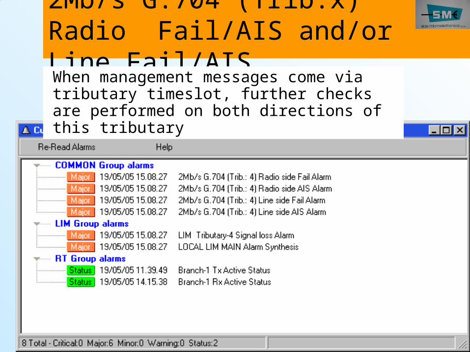
2Mb/s G.704 (Trib.x) Radio Fail/AIS and/or Line Fail/AISWhen management messages come via tributary timeslot, further checks are performed on both directions of this tributary
ALC91
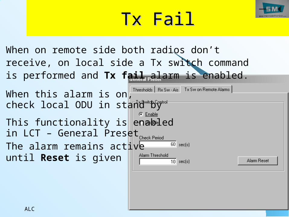
Tx FailTx FailWhen on remote side both radios don’t receive, on local side a Tx switch command is performed and Tx fail alarm is enabled.When this alarm is on,check local ODU in stand byThis functionality is enabledin LCT – General PresetThe alarm remains activeuntil Reset is given
ALC92
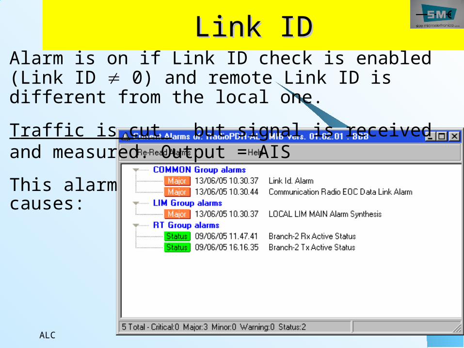
Link IDLink IDAlarm is on if Link ID check is enabled (Link ID 0) and remote Link ID is different from the local one. Traffic is cut but signal is received and measured. Output = AIS This alarm causes:
ALC93
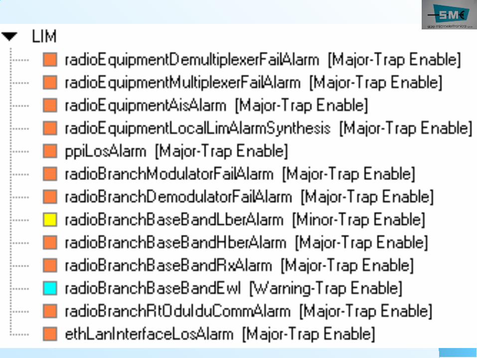
LIM groupLIM groupThese alarms come fromExternal fault: tributary LOSLIM failure: -Multiplexer/demultiplexer failure
-Modulator/demodulator failure Warning: modulator/demodulator circuitry is spread into LIM and RIM modules.
RIM or ODU alarms propagation (seen in LIM as Baseband RX alarm)
ALC94
ALC95
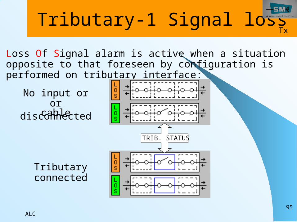
Tributary-1 Signal lossLoss Of Signal alarm is active when a situation opposite to that foreseen by configuration is performed on tributary interface:
No input oror
cable disconnected
Tributary connected
TRIB. STATUS
Tx
ALC96
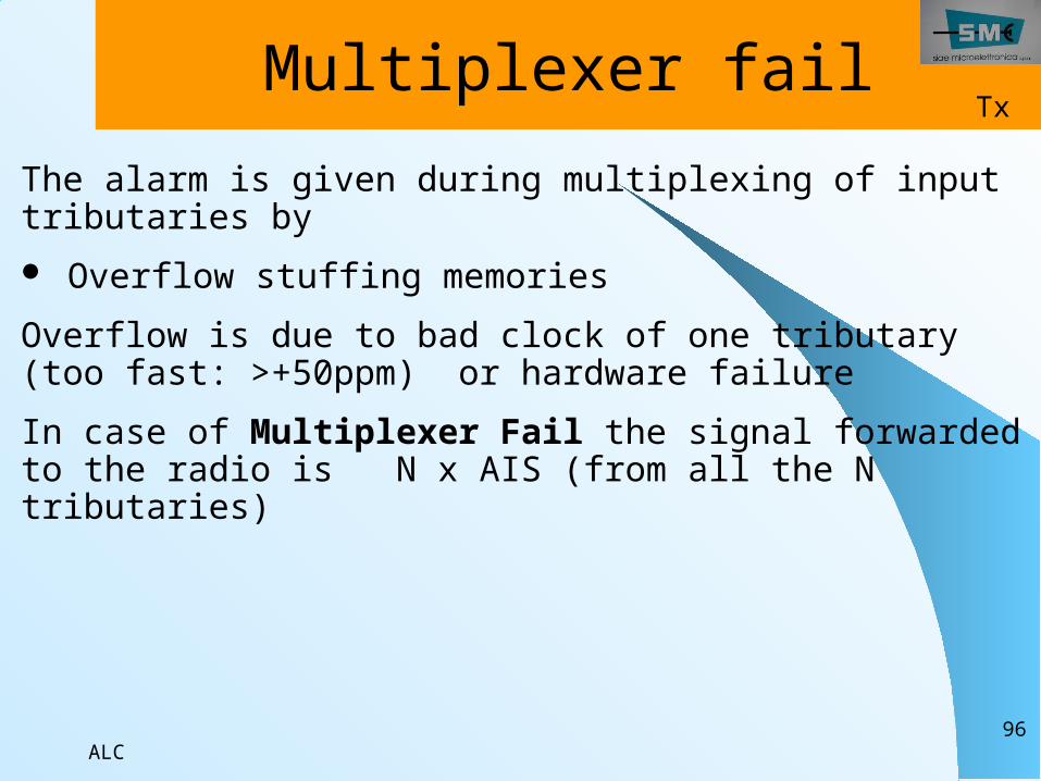
Multiplexer failThe alarm is given during multiplexing of input tributaries by Overflow stuffing memoriesOverflow is due to bad clock of one tributary (too fast: >+50ppm) or hardware failureIn case of Multiplexer Fail the signal forwarded to the radio is N x AIS (from all the N tributaries)
Tx
ALC97
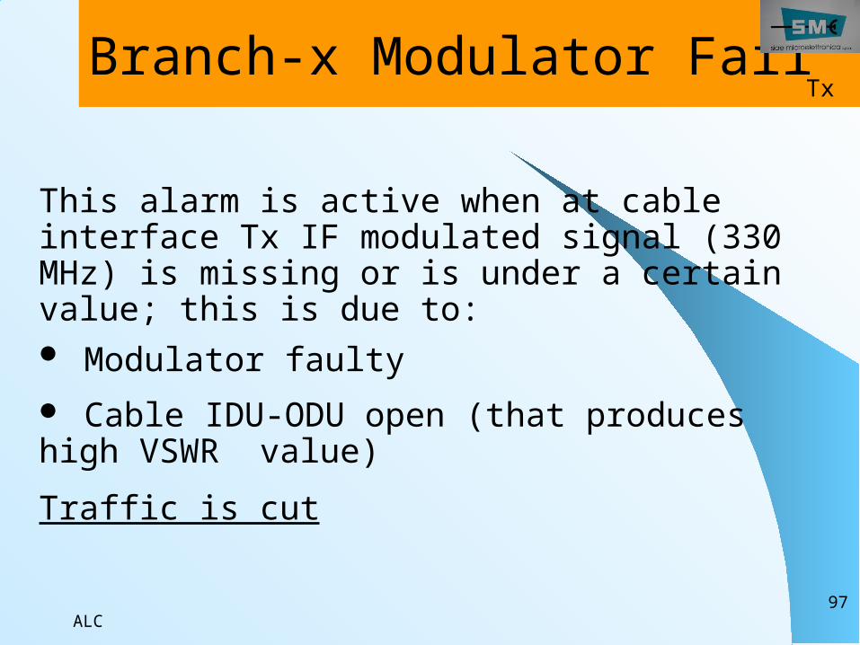
Branch-x Modulator Fail
This alarm is active when at cable interface Tx IF modulated signal (330 MHz) is missing or is under a certain value; this is due to: Modulator faulty Cable IDU-ODU open (that produces high VSWR value)Traffic is cut
Tx
ALC98
Branch-x ODU-IDU Communication fail
This alarm occurs when on carrier used to receive information from ODU, or remote commands from other side, are detected: CRC errors Loss of frame
This carrier is separated from carrier used for opposite direction (IDUODU) and from TX or RX carriers
ALC99
Branch-x Demodulator Fail
Traffic is cut
This alarm is active when average deviation of symbol recognition is higher of a certain level.Every problem in constellation gives Demodulator alarm: Problem of digital conversion of received signal from RIM I or Q signal missing High level of interference (bad quality but good Rx level) No Rx IF modulated signal (140 MHz) from ODU (no Rx, ODU faulty, IDU/ODU cable open)Demodulator alarm causes: Rx quality alarms (HBER, LBER, EWL) Rx signal alarms (BaseBand Rx)
Rx
Branch Rx quality alarm (software
settable)
ALC100
Branch-x BaseBand RxThis alarm is active when Bit Extraction does not work (in LIM) Demodulator does not work (in LIM) Demodulator does not receive from RIM or ODUBaseBand Rx causes: Demultiplexer Fail
Traffic is cut
Rx

ALC101
Demultiplexer Fail
The alarm is given during demultiplexing by: Frame Alignment Word not recognised (LOF - loss of frame) Overflow destuffing memories Overflow memories of hitless Rx switch BaseBand Rx alarm
In case of Demultiplexer Fail, output is AIS (from all the tributaries)
Rx
ALC102
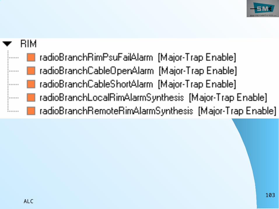
RIM groupThese alarms come from External fault: demodulator fail alarm and ODU alarm are generated when ODU becomes faulty
RIM failure: PSU alarm with cable open/short alarm or modulator/demodulator alarms are active
Warning: modulator/demodulator circuitry is spread into LIM and RIM modules.
ALC103
ALC104
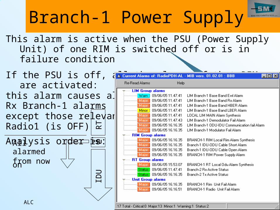
Branch-1 Power SupplyThis alarm is active when the PSU (Power Supply
Unit) of one RIM is switched off or is in failure condition
If the PSU is off, all the alarms of that RIM are activated:
this alarm causes allRx Branch-1 alarms except those relevantRadio1 (is OFF)Analysis order is:
PSUAll alarmedfrom now on
RTIDU
ALC105
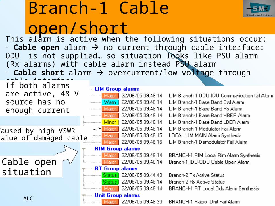
Branch-1 Cable open/short
This alarm is active when the following situations occur:- Cable open alarm no current through cable interface: ODU is not supplied… so situation looks like PSU alarm (Rx alarms) with cable alarm instead PSU alarm- Cable short alarm overcurrent/low voltage through cable interface
Caused by high VSWRvalue of damaged cable
Cable opensituation
If both alarms are active, 48 V source has no enough current
ALC106
RT groupThese alarms come fromExternal fault: Rx power low alarm is generated because of bad propagation or by remote terminal faulty
ODU failure: PSU fail alarm or RF VCO alarm or RF IF alarm is activated
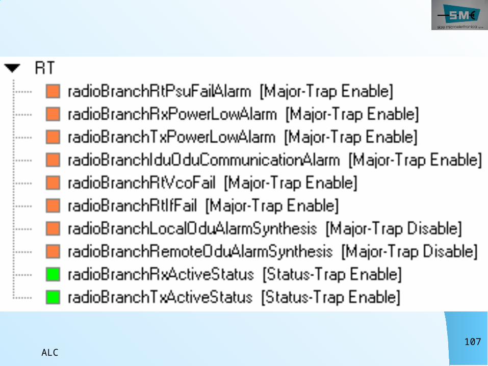
ALC107
ALC108
Branch-x IDU-ODU Communication fail
This alarm occurs in ODU when on carrier used to receive command from IDU, are detected: CRC errors Loss of frame
This carrier is separated from carrier used for opposite direction (ODUIDU) and from TX or RX carriers
ALC109
Branch-1 RT Radio Power
SupplyThis alarm is active when the Power Supply section of the radio doesn’t work properly or is in failure condition (voltage in input out of range).Depending voltage value, radio can work.When the under/over voltage is too high, radio is off and other alarms (cable open) cover this.
ALC110
Branch 1 RT VCO fail
This alarm occurs when VCO in RF unit is not able to lock any frequencies. Every problem in VCO causes alarms in both directions: RF unit is not able to convert IF Tx in RF Tx (Tx Power Low alarm) and RF Rx in IF Rx .In this situation the alarm is active together with Tx Power Low and all Rx alarms because RF channel is not locked.
Tx & Rx
ALC111
Branch 1 RT If failThis alarm occurs when is not present IF signal inside ODU. There are two different IF signals but one alarm only.No IF Tx : the alarm is on and causes Tx Power LowNo IF Rx: the alarm is on with all Rx alarmsRt If fail can be caused by Modulator fail (no IF Tx)When VCO is faulty, RF unit gives a IFRX signal made up of noise: this is enough to mantain IF fail alarm off (but Demodulator cannot work Rx alarms).
ALC112
Branch 1 RT Tx Power Low
This alarm occurs when Tx power is 3 dB under standard output of ODU-RF unit. ATPC and manual attenuation do not affect this alarm that is due by internal failure of RF unit.This alarm can be activated by a manual operation also: Tx Transmitter off in Radio Branch - SettingsIf both Rx Power Low and Tx Power Low are active, RF unit inside ODU is faulty
Tx
ALC113
Branch 1 RT Rx Power LowThis alarm occurs when Rx power is under a defined threshold (about 10 dB under standard Rx level)Threshold value can be set for both branches in range - 40 dBm- 99 dBm in LCT - General preset The alarm Rx Power Low is a branch alarm and it is used to drive Rx switch
Rx
ALC114
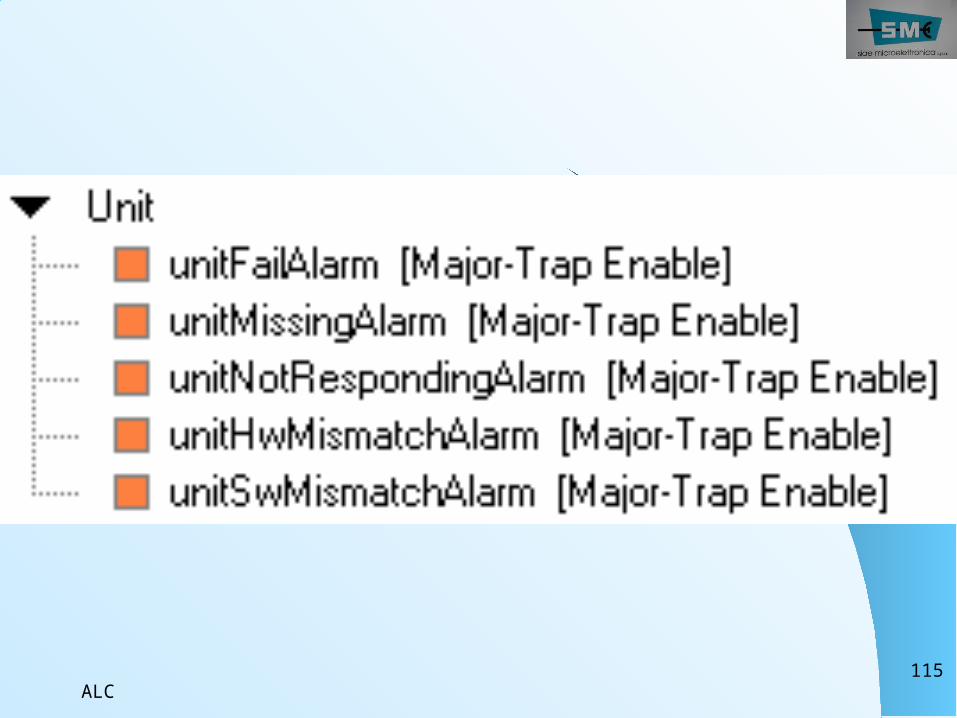
UNIT group
This group generates alarms when one of the units, the equipment consists of, is faulty or does not respond to controller polling:
Unit failUnit is not respondingUnit is missingUnit hardware mismatchUnit software mismatch
ALC115
ALC116
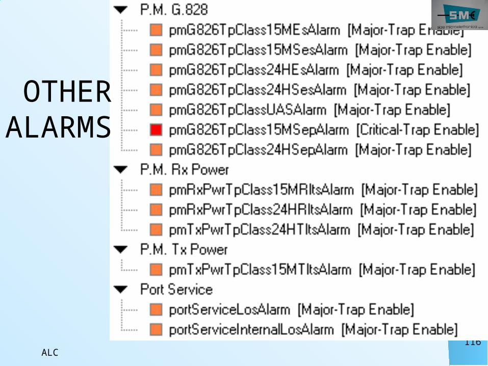
OTHERALARMS
ALC117
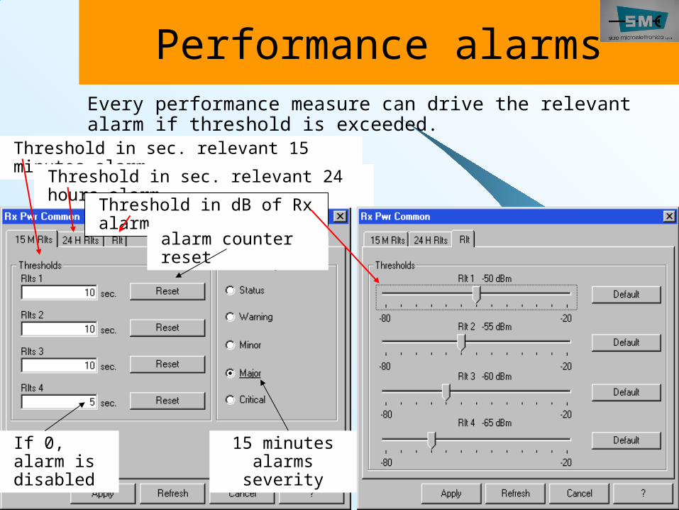
Performance alarmsEvery performance measure can drive the relevant alarm if threshold is exceeded.
Threshold in sec. relevant 15 minutes alarmThreshold in sec. relevant 24
hours alarmThreshold in dB of Rx alarm
alarm counter reset
15 minutes alarms
severity
If 0, alarm is disabled
ALC118
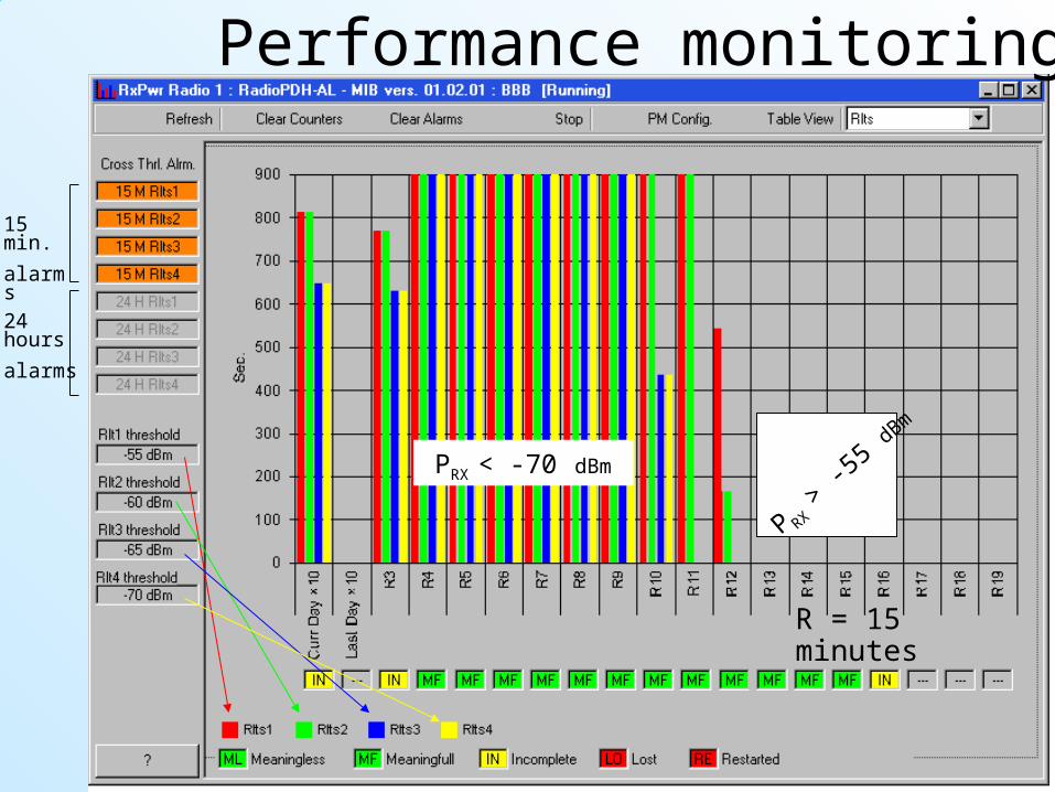
Performance monitoring
15 min.alarms24 hoursalarms
P RX > -
55 dBm
PRX < -70 dBm
R = 15 minutes
ALC119
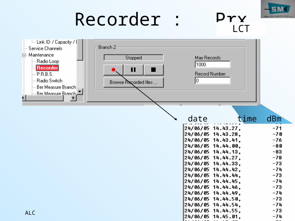
Recorder : Prx
date time dBm
LCT
ALC120
Measures“Performances” is a group of measures, 15 minutes by 15 minutes, day by day, recorded by the equipment itself and downloaded on the PC (the download needs bitrate).These measures remain active also with SCT (and PC) disconnected.“Recorder Prx “ is the recording of Rx power on a log file inside the PC: every time a new value is measured a new “record” is written inside the log file with info of when (day, hour, minutes and seconds) and how much (dBm measured). This recording remains active until SCT is connected to the equipment.
ALC121
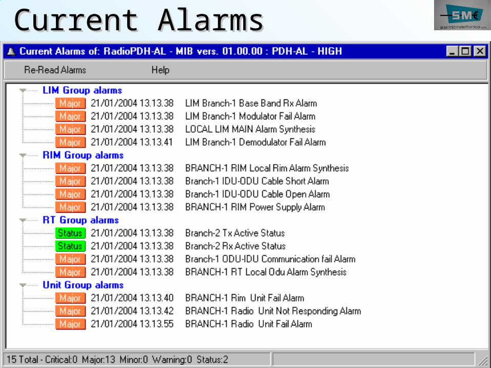
Current AlarmsCurrent Alarms
ALC122
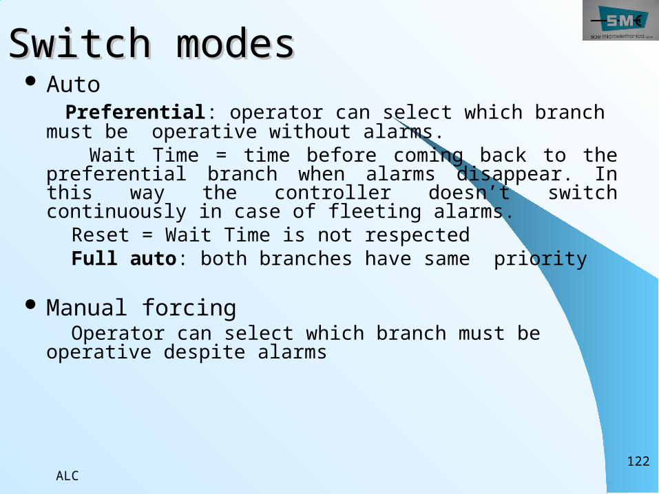
Switch modesSwitch modes Auto Preferential: operator can select which branch must be operative without alarms.
Wait Time = time before coming back to the preferential branch when alarms disappear. In this way the controller doesn’t switch continuously in case of fleeting alarms.
Reset = Wait Time is not respected Full auto: both branches have same priority
Manual forcing Operator can select which branch must be operative despite alarms
ALC123
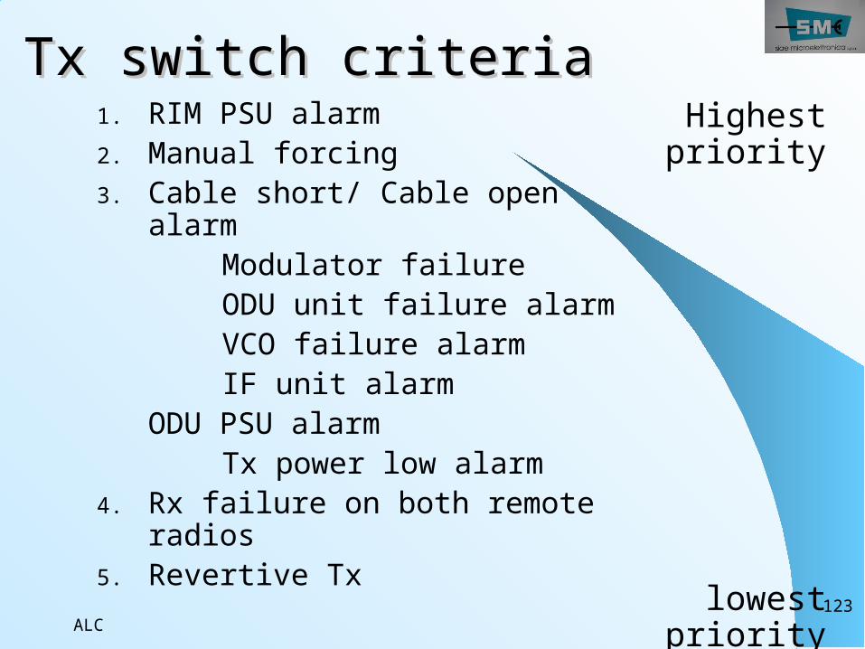
Tx switch criteriaTx switch criteria1. RIM PSU alarm2. Manual forcing3. Cable short/ Cable open
alarm Modulator failure ODU unit failure alarm VCO failure alarm IF unit alarm
ODU PSU alarm Tx power low alarm4. Rx failure on both remote
radios 5. Revertive Tx
Highest priority
lowest priority
ALC124
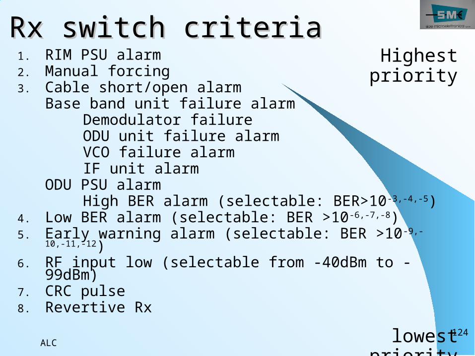
Rx switch criteriaRx switch criteria1. RIM PSU alarm2. Manual forcing3. Cable short/open alarm
Base band unit failure alarm Demodulator failure ODU unit failure alarm VCO failure alarm IF unit alarm
ODU PSU alarm High BER alarm (selectable: BER>10-3,-4,-5)4. Low BER alarm (selectable: BER >10-6,-7,-8) 5. Early warning alarm (selectable: BER >10-9,-
10,-11,-12) 6. RF input low (selectable from -40dBm to -
99dBm)7. CRC pulse8. Revertive Rx
Highest priority
lowest priority
ALC125
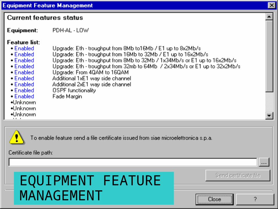
EQUIPMENT FEATURE MANAGEMENT
ALC126
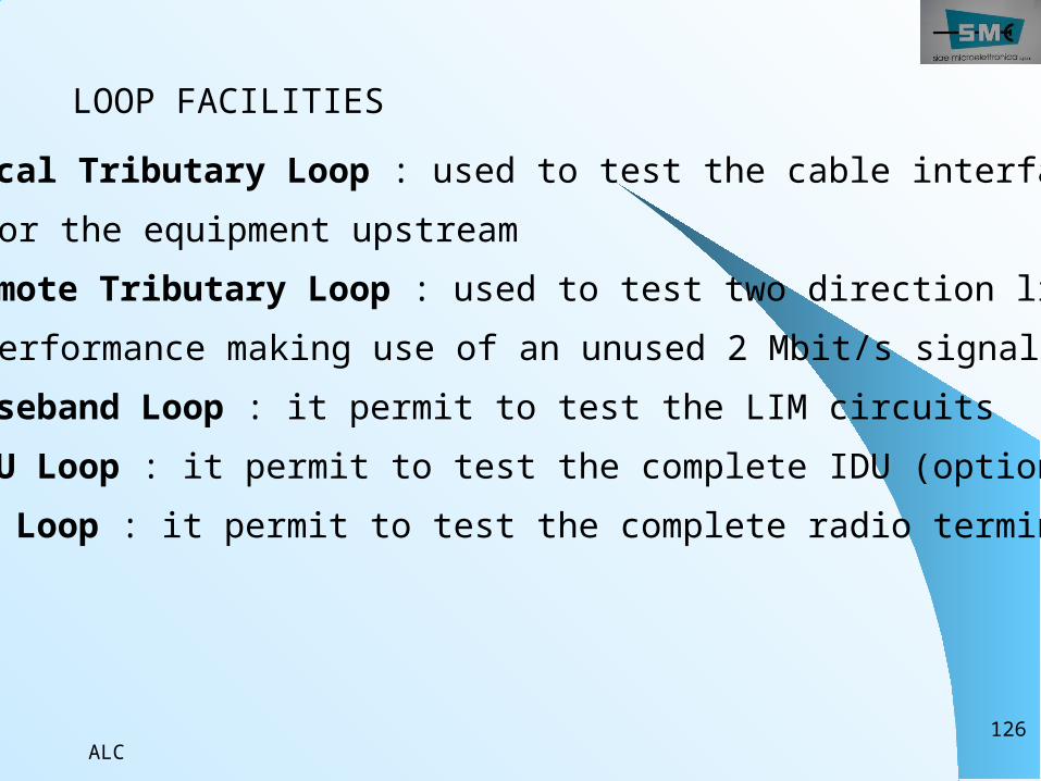
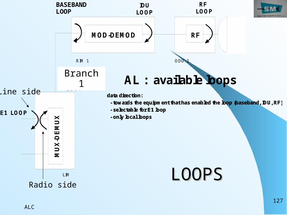
LOOP FACILITIES Local Tributary Loop : used to test the cable interfacing for the equipment upstream Remote Tributary Loop : used to test two direction link performance making use of an unused 2 Mbit/s signal Baseband Loop : it permit to test the LIM circuits IDU Loop : it permit to test the complete IDU (optional) RF Loop : it permit to test the complete radio terminal
ALC127
MUX
-DEM
UX
RF
E1 LO OP
BASEBAND LO OP
IDU LO O P
RF LOO P
LIM
RIM 1 O DU 1
AL : available loops data direction: - towards the equipm ent that has enabled the loop (baseband, IDU, RF) - selectable for E1 loop - only local loops
M OD- DEM OD
LOOPSLOOPS
MUX-DEMUX
RF
E1 LOOPBA SEBAND LOOP
IDU LOOP RF LOOP
LIM
RIM 1 ODU 1
AL : av ailable loops data direction: - towards t he equipmen t that has enabl ed the loop ( baseband, IDU, R F) - selectabl e for E1 loop - only loca l loops
M OD-DEMOD
Line side
Radio side
Branch 1
BASEBAND LOOP
ALC128
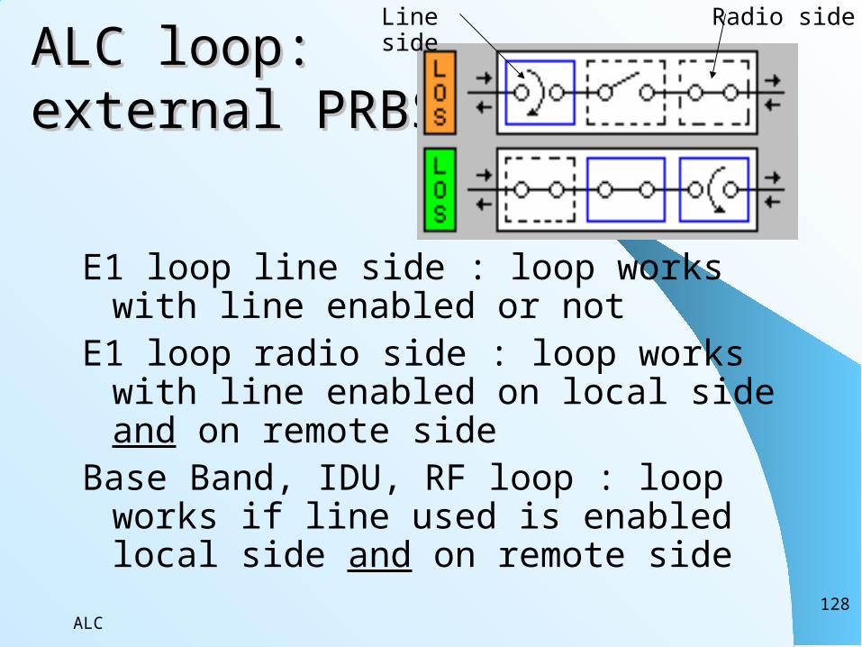
ALC loop:ALC loop:external PRBSexternal PRBS
E1 loop line side : loop works with line enabled or not
E1 loop radio side : loop works with line enabled on local side and on remote side
Base Band, IDU, RF loop : loop works if line used is enabled local side and on remote side
Line side
Radio side
ALC129
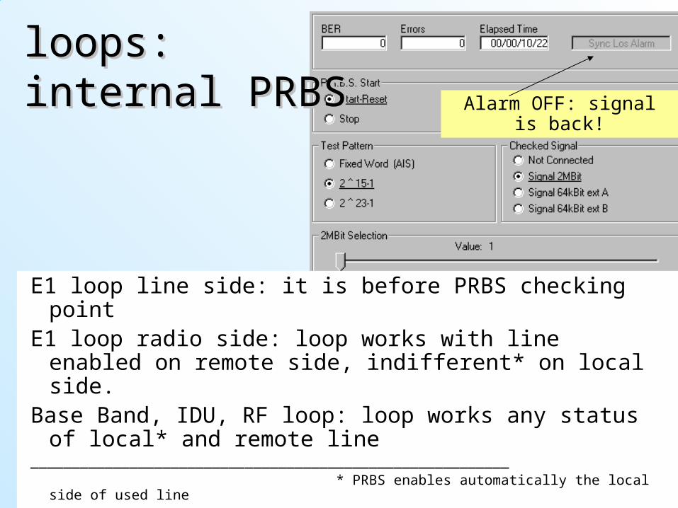
looploopss::internal PRBSinternal PRBS
E1 loop line side: it is before PRBS checking point
E1 loop radio side: loop works with line enabled on remote side, indifferent* on local side.
Base Band, IDU, RF loop: loop works any status of local* and remote line
__________________________________________________________ * PRBS enables automatically the local
side of used line
Alarm OFF: signal is back!
ALC130
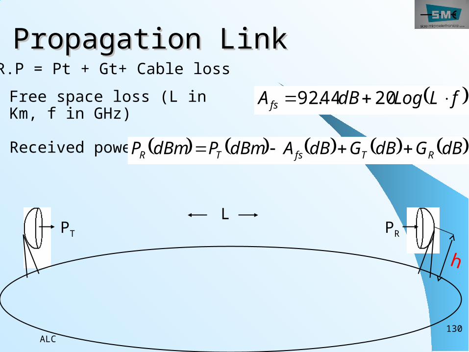
Propagation LinkPropagation Link fLLogdBA fs 2044.92Free space loss (L in
Km, f in GHz)
Received power dBGdBGdBAdBmPdBmP RTfsTR
LPT PR
h
E.I.R.P = Pt + Gt+ Cable loss
ALC131
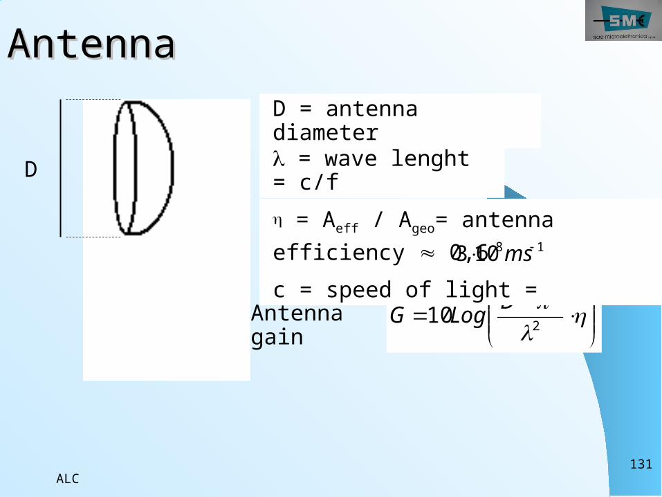
AntennaAntenna
2
2210 DLogGAntenna
gain
D
D = antenna diameter = wave lenght = c/f = Aeff / Ageo= antenna efficiency 0,6c = speed of light =
18103 ms
ALC132
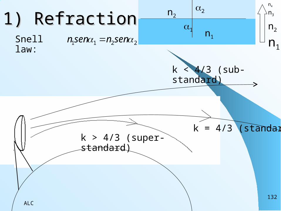
1) Refraction1) Refraction
k < 4/3 (sub-standard)
k = 4/3 (standard)k > 4/3 (super-standard)
Snell law:
2211 sennsenn 1
2
n1
n2
n1
n2
n3
n4

ALC133
2) h2) hgeogeo …earth is not …earth is not flatflat
hgeo
R0 = 6378 km
L
0
2
RLhgeo
0
2
RkLhgeo
with k<4/3 , k=4/3 , k>4/3 considering the troposphere refraction (previous page)
considering geometrical visibility on a planet with no air

ALC134
3) First Fresnel zone3) First Fresnel zone
RM
2LRM
L
A nth fresnel zone gives in phase contributes to radio waves propagation. In order to avoid attenuation is important that first fresnel zone is without obstacle: to tower height calculation, must be add the ray of biggest Fresnel zone, the first zone

ALC135
Height of the towersHeight of the towersWe have to consider: earth’s curvature k effect (refraction) first Fresnel zone freeFrom the first we obtain hgeo , with refraction hgeo becomesand from the last we have to add also RM
geoh
20
2 LRkLRhh Mgeotower
ALC136
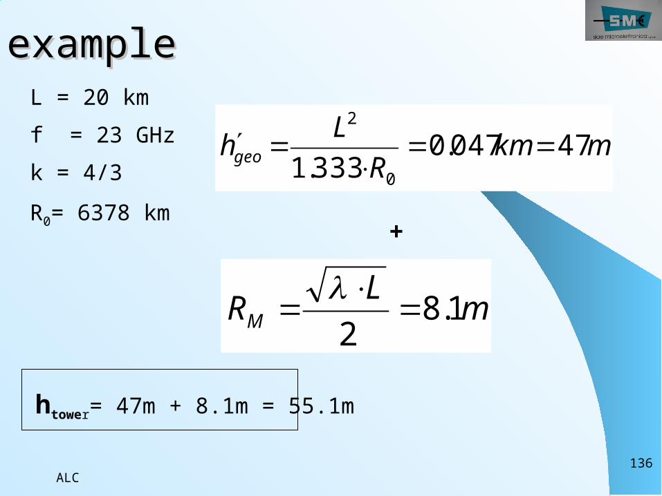
exampleexampleL = 20 kmf = 23 GHzk = 4/3R0= 6378 km
mkmR
Lhgeo 47047.0333.1 0
2
+
mLRM 1.82
htower= 47m + 8.1m = 55.1m
ALC137
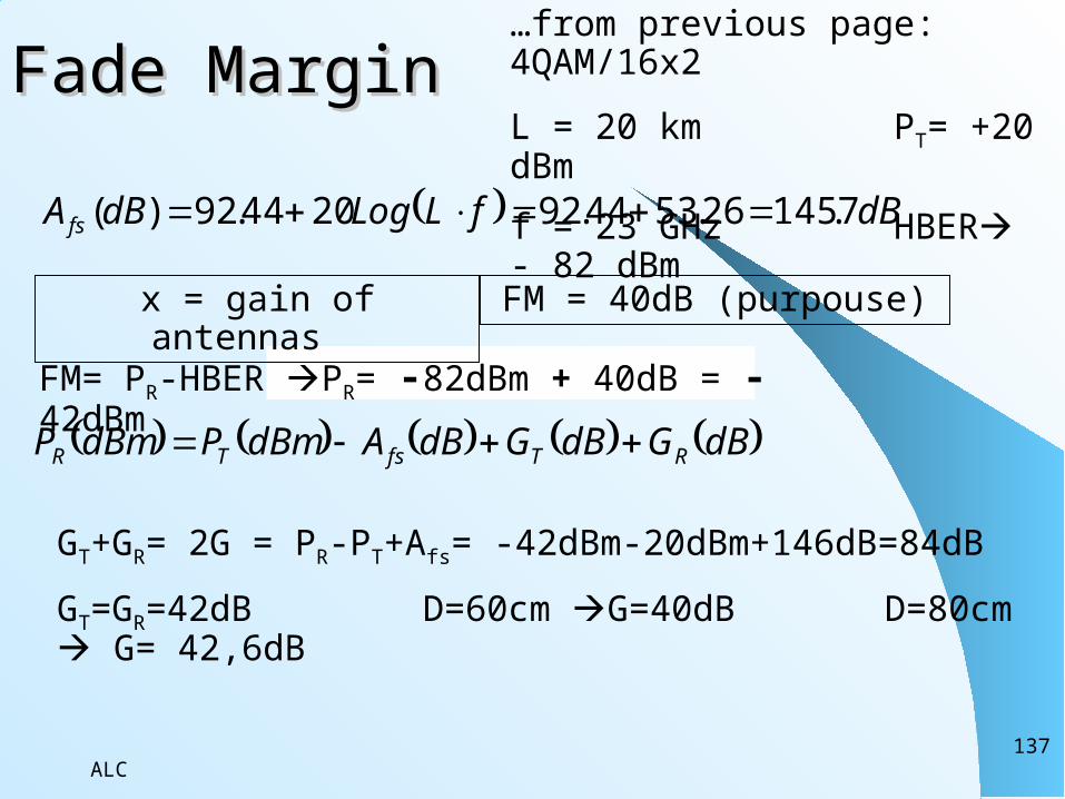
Fade MarginFade Margin…from previous page: 4QAM/16x2L = 20 km PT= +20 dBm f = 23 GHz HBER - 82 dBm
dBfLLogdBA fs 7.14526.5344.922044.92)(
x = gain of antennas
dBGdBGdBAdBmPdBmP RTfsTR
FM= PR-HBER PR= -82dBm + 40dB = -42dBm
FM = 40dB (purpouse)
GT+GR= 2G = PR-PT+Afs= -42dBm-20dBm+146dB=84dBGT=GR=42dB D=60cm G=40dB D=80cm G= 42,6dB
ALC138
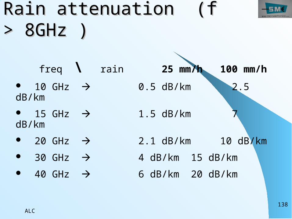
Rain attenuation (f Rain attenuation (f > 8GHz )> 8GHz )
freq \ rain 25 mm/h 100 mm/h 10 GHz 0.5 dB/km 2.5 dB/km 15 GHz 1.5 dB/km 7 dB/km 20 GHz 2.1 dB/km 10 dB/km 30 GHz 4 dB/km 15 dB/km 40 GHz 6 dB/km 20 dB/km
ALC139
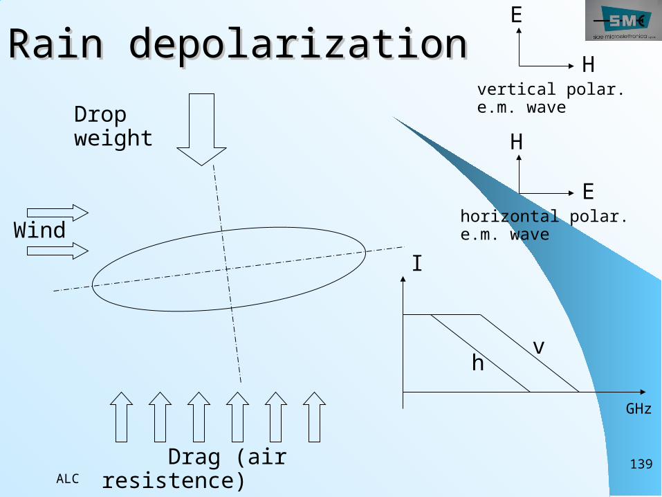
Rain depolarizationRain depolarization
Wind
Drag (air resistence)
Drop weight
E
Hvertical polar. e.m. wave
E
H
horizontal polar. e.m. wave
I
GHz
h v
ALC140
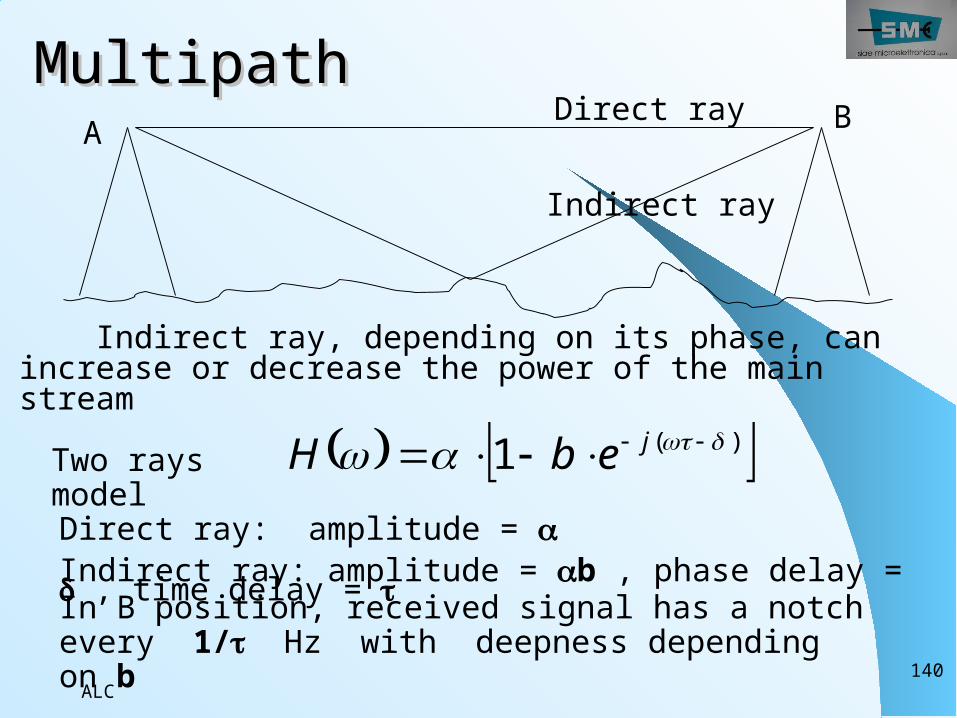
MultipathMultipath
Indirect ray, depending on its phase, can increase or decrease the power of the main stream Two rays model
)(1 jebHDirect ray: amplitude = Indirect ray: amplitude = b , phase delay = , time delay =
Direct ray
Indirect ray
A B
In B position, received signal has a notch every 1/ Hz with deepness depending on b

ALC141
THANK YOU


