Embed Size (px)
Citation preview

Keynote Papers
Keynote Papers Presented at the Opening Session
Too Condition Monitoring (TCM) - The Status o and Industrial Application
Research
G. Byrne (2), D. Dornfeld (21, I. lnasaki (11, G. Ketteler, W. Konig (I), and R. Teti (2)
ABSTRACT: The use of sensor systems for tool condition monitoring in machining and grinding is becoming more commonplace to enhance productivity. Many approaches have been proposed to accomplish tool condition monitoring and a number of these are successfully employed in industry. This paper reviews the motivation and basis for the utilization of these systems in industry, the sensors used in such systems including industrial application, new developments in signal and information processing, sensor based process optimization and control and directions for future developments. Main developments noted include the use of multiple sensors in systems for increased reliability, the development of intelligent sensors with improved signal processing and decisionmaking capability and the implementation of sensor systems in open architecture controllers for machine tool control.
KEYWORDS: tool monitoring, sensor, signal processing, machining, grinding, reliability, industrial application
1 Introduction
1.1 Background In recent years the manufacturing environment has undergone dramatic change. One of the most significant developments has been the trend towards cost savings through, for example, a reduction in staff numbers while at the same time desiring to improve product quality and reduce production time. New challenges are thus posed in relation to the reliability and applicability of sensor systems for tool condition monitoring such that high availability levels of the sophisticated manufacturing systems in conjunction with high quality levels of manufactured components can be achieved. It is widely accepted that intelligent, sensor based manufacturing is vital to achieve this. Advanced sensor design, coupled with signal processing technologies, permits improved information about the process condition enabling process optimization and control. It is not adequate to have information relating solely to the tool condition. Additional capabilities such as in- process quality control and machine tool diagnostics are a requirement of the future, i.e. a shift from monitoring the tool condition to monitoring the process condition and the resulting part quality.
A framework for investigating the international state of the art, technological challenges and developmental trends in tool condition monitoring in the manufacturing environment both from a research point of view and from within the manufacturing industry was established by the CIRP, in January 1993, within the context of the
Working Group for Tool Condition Monitoring /1- 4/. The working group focused on machining processes including milling, turning, drilling and grinding/abrasive processes with an emphasis on catastrophic tool failure, collision, progressive tool wear and tool chipping/fracture.
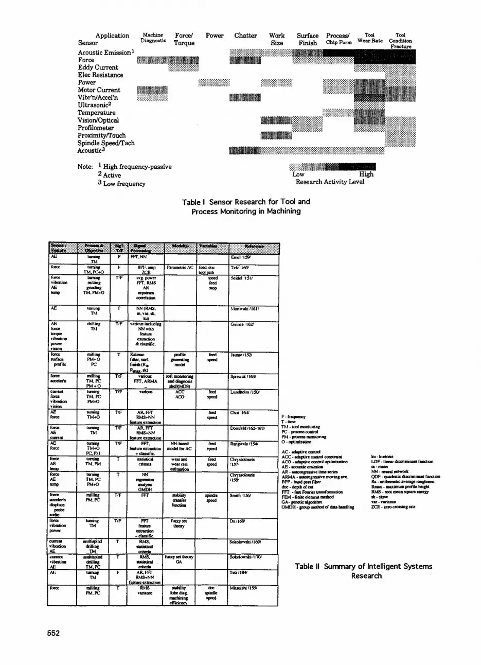
New demands are being placed on monitoring systems in the manufacturing environment because of recent developments and trends in machining technology and machine tool design (high speed machining and hard turning, for example). Remarkable progress has been made in the increase in cutting speeds since the early part of this century and this trend is still in evidence today for both cutting and abrasive processes. The trend in increase in precision of manufactured parts is coupled with the requirement for cleaner machining processes with minimized emissions and waste generation. Numerous different sensor types are available for monitoring aspects of the machining environments as illustrated by Moriwaki /5/ in Figure 1. Of the range indicated, the most common sensors in the industrial machining environment are force, power and acoustic emission sensors. These and the systems they comprise are reviewed in detail below.
This paper was prepared as part of the activities of the Tool Condition Monitoring Working Group of STC 'C' and STC "G' and is the result of four meetings on TCM with representatives from academic researchers, industrial system manufacturers and industrial system users. Acknowledgments are due to the working group members who generously provided their time and
Annals of the CIRP Vol. 44/2/1995 541

input to the preparation of this paper. In addition, the following colleagues are specifically acknowledged for their input and generous assistance: Prof. F. Klocke and Prof. H. K. Tonshoff.
Figure 1 Abundance of sensors for machine tool monitoring, from Moriwaki /5/
1.2 Industrial Use of Sensor Systems Technical issues raised by new and enhanced production processes and tooling are not the sole challenge to success in tool condition monitoring. In addition, there is often some uncertainty in the mind of the user regarding what is to be measured and which sensing system is most suitable. Secondly, the reasons for inadequate or unexpected performance of tool condition monitoring systems may not be related to the sensing technology but to other difficulties such as defects in machine interfaces or operating errors in setup of operation of the monitoring system. Finally, depending on whether you intend to build the system into your machine tool as a feature or are requesting the addition of a system as a user, your opinion of the function of the system may differ. Machine tool builders often prefer to see these sensing systems for protection of the machine tool or spindle from unexpected events or failure /6/.Several recent surveys of sensor system users in Japan, Germany and the US illustrate the needs and expectations, from the point of view of the user, of sensors.
lnasaki /7/ reported, based on a survey of 31 users in Japan, that sensor applications were distributed among the following four industries: machine tool manufacture (30%), automotive components (17%), tool manufacturing (13%) and electrical/mechanicaI product manufacture (25%) with 'others' (15%). Reliability of the system and information transmission were ranked of the highest importance (over 80% of the respondents) by the users with respect to the sensor technology. Reliability was more important to the
users than the cost/benefit ratio in evaluating the successful operation of the sensors, 87% vs. 45% ranking it 'very important,' respectively. Most applications related to tool breakage monitoring and tool wear was considered less important. The respondents felt that, for future sensor systems, the most important applications would be to insure the reliable operation of the process, with quality monitoring less important. Respondents also felt that the systems should have the capability for a self diagnostic and test function to be incorporated.
Some important work in relation to tool condition monitoring systems has been undertaken in the German automotive industry in recent years. Mercedes Benz AG undertook an evaluation of systems implemented in their production /l/. Of the monitoring systems evaluated, Figure 2, 57% were used for turning and 42% for drilling.
Figure 2 Performance 'of sensor systems
Only a small fraction were applied to milling. In evaluating the systems as installed in the factory, it was found that only 46% were fully functional, 16% had limited functionality and 25% of the systems were non-functional due to technical limitations. It should be noted that this survey relates to technology at least five years old and that extensive technological development of hardware and software has taken place since that time. Further analysis and discussion within the working group has shown that incorrect user interaction is one of the major causes for systems to be switched off in the production environment. The training of personnel is thus a vital element in the successful implementation of tool condition monitoring systems. In addition, there is an ongoing need for user training and expertise to be minimized by design of the system and its operator interface.
More recently, Weis /8 / surveyed 26 system manufacturers and 20 system users of tool condition monitoring (a total of 1161 installed systems) in a range of industries (with heavy emphasis on automotive). The sensor systems included acoustic emission sensors (27%), strain (22%), force (17%), current (17%) and others (17%). These systems were implemented to monitor for tool wear (28%), collision (22%) and
542

breakage (50%) showing similar results to Inasaki's. Collision detection is in addition to the simulation done by computer aided design and manufacturing (CAD/CAM) systems to try to prevent collision. Figure 3, from /a/, shows the distribution of monitoring systems by area of application with the preponderance applied to drilling and turning, as seen in the earlier survey reported above.
70
Figure 3 Distribution of monitoring systems by area of application , from /8/
The system user's perception of the success or failure of a specific sensing technology may depend on hidher expectations of the system's performance. Die1 /9/ illustrated the substantial differences (with respect to collision monitoring alone versus tool wear, breakage and collision mon i to rin g) bet ween the customer's in it ia I interest in investigating tool monitoring compared to the system eventually installed. Similarly, when evaluating the performance of tool monitoring systems only 15% of the failures were due to the sensor system itself, compared to the operator error (50%), defective machine interface (20%), selection of the wrong monitoring strategy (1 5%) and expectations of no faults (5%). The last number suggests that no system should be expected to operate with 100% reliability.
1.3 Overview The transformation of stand-a-lone sensors used primarily as diagnostic devices in a machining process to sensors part of an intelligent system for tool and process monitoring and control has occurred most actively over the last decade. Kegg /1 O/ summarized the history of machine tool applications of sensors and from the 1950's through the 1980's these sensors were characterized by application of specific physical phenomena to sensing (thermocouples, piezo crystals, accelerometers, strain gauges, acoustic emission, for example) a specific feature of the process (tool wear, spindle torque, tool vibration, for example). In the late 1980's and early 199O's, Dornfeld 111, 12/, the influence of advanced
signal processing techniques and artificial intelligence were felt in the development and application of sensors and sensing systems. These so-called intelligent sensors included as part of their 'packaging' abilities for self-calibration and self-diagnostics, signal conditioning, and, importantly, decision making. A new focus of much of the research on sensors was sensor fusion- the integration of information from several sensors to better and more robustly characterize a process or machine. This addresses Moriwaki's requirement for handling ambiguous or noisy inputs. It also lays the ground work for input to learning schemes, such as neural nets, to capture process knowledge when the process is sufficiently complex to defy clear mathematical modeling.
Monitoring of manufacturing systems is required now to insure that the optimum performance of these systems is obtained. The focus of monitoring is on either the machine (diagnostics and performance monitoring), the tools or tooling (state of wear, lubrication, alignment), the workpiece (geometry and dimensions, surface features and roughness, tolerances, metallurgical damage) or the process itself (chip formation, temperature, energy consumption). All four focus areas are subject to monitoring needs, often with competing requirements for time response or location of sensors. Thus, sensing systems for manufacturing processes must balance a number of options if they are to be effective /12/.
Sensors for tool condition monitoring must fulfill various requirements. From their signals it should be possible to detect tool breakage, tool wear and chatter in machining processes. In grinding operations chatter, dressing point and faults in dressing operations should be detectable. To achieve this, tool monitoring devices must function as in-process systems in most cases. Furthermore, it is desired that the workpiece quality can be determined. Additional requirements are due to the fact that the environmental conditions in a machine tool are very tough. Sensors for process monitoring must meet the following requirements /13/:
measurement as close to the machining
no reduction in the static and dynamic
no restriction of working space and
wear- and maintenance-free, easily
resistant to dirt, chips and mechanical,
function independent of tool or workpiece, adequate metrological characteristics,
point as possible,
stiffness of the machine tool,
cutting parameters,
changed, low costs,
electromagnetic and thermal influences,
543

reliable signal transmission, e.g. from rotating to fixed machine components. Therefore, only a fraction of sensors that are available on the market are suitable for tool condition monitoring for technical reasons.
1.4 Previous Reviews of TCM There is a substantial amount of information on this topic area- mostly associated with elements of the intelligent machine tool such as control or monitoring. The last comprehensive surveys published by ClRP on this subject were by Tonshoff et a/ 1131, covering monitoring and control, and Tlusty and Andrews [14] on sensors for unmanned machining. Prior to that one of the most complete reviews was done as part of the Machine Tool Task Force Study in 1980 by Birla I1 51. Other detailed reviews have been published on various aspects of machining and toollworkpiece monitoring. For example, Shiraishi I1 6-181 reviewed, with numerous examples of applications and specifications on performance, sensors for machine, tool, workpiece and process monitoring in machining and Dornfeld et a/ 1121 which reviewed recent sensing techniques with respect to future requirements and intelligent sensors. lwata [19] published the results of a survey of Japanese machine tool builders on their requirements and preferences on machine tool monitoring updating some of Birla's information on the same requirements. Finally, with a focus on drilling and tapping, Hoshi 1201 reviewed techniques for automatic tool failure monitoring. The complete literature on machining and tool condition monitoring is extensive and is not reviewed here. The most recent compilation by Teti I31 lists over 500 citations in the last several years. This will be published in a separate paper 11881. Finally, Szafarczyk 1211 has edited a volume of papers focusing on automatic supervision of manufacturing processes as part of an in lligent machine concept and includes, perhap: the most recent comprehensive review of the sLJject from the perspective of sensors, signal processing, control, process modeling and integration with product design.
2 Sensors for TCM
With regard to sensor systems for process monitoring, a distinction is to be made on the one hand between continuous and intermittent systems and, on the other hand, between direct and indirect measuring systems 1221. In the case of continuously measuring sensor systems, the measured variable is available throughout the machining process; intermittently measuring systems record the measured variable only during intervals in the machining process. Direct measuring systems employ the actual quantity of the measured variable, e.g. tool wear, while
indirect measuring systems measure suitable auxiliary quantities, such as the cutting force components, and deduce the actual quantity via empirically determined correlations. Direct measuring processes possess a higher degree of accuracy, while indirect methods are less complex and more suitable for practical application. Continuous measurement enables the continuous detection of all changes to the measuring signal and ensures that sudden, unexpected process disturbances, such as tool breakage, are responded to in good time. Intermittent measurement is dependent on interruptions in the machining process or special measuring intervals, which generally entail time losses and, subsequently, high costs. Furthermore, tool breakage cannot be identified until after completion of the machining cycle when using these systems, which means that consequential damage cannot be prevented. Intermittent wear measurement nevertheless has its practical uses, provided that it does not result in additional idle time. It would be conceivable, for example, for measurement .to be carried out in the magazine of the machine tool while the machining process is continued with a different tool. Intermittent wear-measuring methods can be implemented with mechanical 123-281, inductance-capacitance 129, 301, hydraulic- pneumatic 1311 and opto-electronic 128, 32-401 probes or sensor systems. In view of the described disadvantages, this paper will not enter into further detail with regard to these systems or simple systems which are limited to detecting the correct position or the presence of a tool 141- 501.
The direct sensor continuously measuring is the optimal combination with respect to accuracy and response time. For direct measurement of the wear land width, an opto-electronic system has been available, for example, whereby a wedge- shaped light gap below the cutting edge of the tool, which changes proportional to the wear land width, is evaluated 1511. The wear land width can also be measured directly by means of specially prepared cutting plates, the flanks of which are provided with strip conductors which act as electrical resistors 152-541. A number of measuring processes have been developed for turning and milling, in order to detect the offset of the cutting edge 123, 29-31, 34, 35, 52, 55- 601. In each instance, the change in the distance from the sensor to the cutting edge or from the sensor to the workpiece is determined as the cutting-edge offset. As the cutting-edge offset alone is insufficient to describe tool wear, in addition to which the stated measuring methods - including those for measuring the width of wear land - remain unsuitable for practical deployment, these processes can only be regarded as
544

laboratory methods for the time being. A new approach uses an image processing system based on a linear camera for on-line determination of the wear on a rotating inserted-tooth face mill. Non- productive time due to measurement is avoided and the system reacts quickly to tool breakage. There are, however, problems due to the short distance between the tool and the camera, which is mounted in the machine space to the side of the milling cutter, and due to chips and dirt on the inserts 1611.
In grinding operations a laser triangulation sensor can be used to sense grinding wheel profiles at working speed, Figure 4. Light emitted from a laser diode is reflected from the grinding wheel and focused on a receiver diode by a lens. The reduced peak roughness Rpk and the reduced valley roughness Rvk can be detected from the signal, allowing the wheel topography to be determined
triangulation sensor placing in the grinding machine I
0 2b io 60 Bo% loo
evaluation of the sensor signal
Figure 4 Optical system for monitoring of grinding wheel topography
Two types of sensors are used to measure workpiece surface quality, which is relevant for the finished product in a finishing process and from which inferences can be made on tool wear. These are, firstly, ultrasonic sensors, for example coupled to the workpiece via the coolant 1631. At their present stage of development, they can only be used to measure stationary tools; direct tactile sensors also suffer from this drawback. The second possibility is to use optical methods /64-681, which can again be subdivided into two types: Stray light and laser beam sensors Figure 5. With the stray light method, a diode, emits an infra-red beam which is focused on the workpiece, reflected from it and deflected onto a diode array. Various parameters can be deduced
- E B
sensor system working principle - features - sen= signal
lWdU* mpogtaml Fb p::?+: "%%,. * . .\ ..... . ... ... .
w*.- .., . ... rrwkpice qualit ~ circle tom e r m
. surlsce mughness
'&iY.+ k..... >;:..>:, Mpk. . excenlwi .. \ . . . I. .!
.. . . . .%,... . . .'. . . V2J)13m199'
Figure 5 Optical sensors'systems for surface quality measurement
from the intensity distribution, indicating the waviness and concentricity of the workpiece. Because of the large light spot diameter, it is, however, difficult to achieve a good correlation between these parameters and workpiece roughness. This method is also confined to surfaces which have been ground. In the laser focus method, a sharply-focused laser beam is substituted for the infra-red light, giving much higher resolution compared to tacti le measurements. The problem of correlating signal values with tactile roughness values has meanwhile been solved through the use of appropriate peak filters. This method can also be used to determine the waviness and concentricity of the workpiece. It is suitable for use in cutting processes with a geometrically-defined cutting edge 166-681. Because of the speed of measurement, the best that can be achieved with either method is quasi-on-line measurement, e.g. measurement during retraction of the grinding wheel. Generally, optical systems are sensitive to dirt and chips, and suitable countermeasures have to be taken. For these reasons, such measuring systems have been slow to find acceptance in industry.
The indirect continuous measuring processes, which are able to determine the relevant disturbance, e.g. tool wear, by measuring an auxiliary quantity and its changes, are generally less accurate than the direct methods. A valuable variable which can be measured for the purpose of indirect wear determination is the cutting temperature, which generally rises as the tool wear increases as a result of the increased friction and energy conversion. However, all the known measuring processes are pure laboratory methods for turning 169-741, which are furthermore unfeasible for milling and drilling, due to the rotating tools. Continuous measurement
545

of the electrical resistance between tool and workpiece 1751 is also unfeasible for practical applications, on account of the required measures, such as insulation of the workpiece and tool, and due to short circuits resulting from chips or cooling lubricant. Systems based on sound monitoring using microphones Ie. g. 761 also have not yet reached industrial application due to the problems caused by noises that are not generated by the machining process.
The following section deals in greater detail with the measured variables which are suitable for industrial application, e.g. cutting forces, extension, motor current, vibrations and acoustic emission, together with the appropriate sensors.
3 Sensor Technology Suitable for Practical Application
The most important sensor systems ,for indirect, continuously measuring monitoring facilities evaluate . the cutting force components or measured variables derived from these components (extension of the machine components, torque, drive power of the motors or bending I displacement of the tools) as the characteristic variable for the process. All the monitoring systems based on this principle utilize the fact that tool wear causes an increase in the cutting force components Ie. g. 64, 66, 69, 71 , 77-851. In the case of turning and milling, this force increase is substantially smaller in the primary cutting force or the torque than in the components orthogonal to these, i. e. the feed force and passive force 164, 69, 77 , 84, 861. In the case of drilling, the force increases are substantially lower, and sometimes totally absent 164, 7 7 , 07-891.
Essentially, tool breaks manifest themselves in the form of discontinuities or pulse-like changes in one or several force components 164, 69, 7 7 , 90-1 001. These typical break-related force characteristics are, of course, dependent on the machining process, the combination of workpiece material and cutting material, the cutting conditions and the breaking characteristics of the cutting material. Since tool breaks cause peaks in the acoustic emission signal they can also be detected using AE sensors Ie. g. 93-99, 101- 1071.
The various known sensor systems based on these variables are briefly outlined below. Systems which are strictly l imited to laboratory applications are not included here.
3.1 Sensors for Force-based Monitoring 3.1.1 Direct Measurement Dynamometers
Commercial dynamometers provide the most accurate measurement of cutting forces. They consist of four threecomponent force transducers fitted under high preload between a baseplate and a top plate. Such transducers are extremely stiff and have a large measuring range. Because they are based on the piezoelectric effect, it is difficult to measure static forces over a long period without drift. Different types of dynamometers are available allowing application under the tool in lathes and under the workpiece or in the tool holder at milling or drilling machines. They are widely used for fundamental studies of machining processes and force-based monitoring, but are unsuitable for process monitoring because of their lack of overload protection and their high costs. A similar approach is the use of force-measuring tool turrets. This involves applying the measuring principle of standard dynamometers to the tool turrets of turning machines. Piezoelectric 3- component force-measuring elements are installed between the cross slide and the tool turret 169, 1081, enabling optimal determination of the cutting force components from a metrological point of view. Disadvantageous aspects are the very high costs and the fact that they are not overload-protected in case of collision. It is now technically possible to seal the measuring elements off from the cooling lubricant. For the stated reasons, this measuring system has only been produced in a few isolated cases. Similar systems have been developed incorporating strain gauge measurements enable only the primary cutting force to be measured 133, 1091.
3.1.2 Plates and Rings Force-measuring plates consist of thin intermediate plates in which piezoelectric force- measuring elements are embedded, Figure 6. The measuring elements are thus subjected to only a small proportion of the total exerted force and are consequently overload-protected I1 10, 1 1 11. Force-measuring plates fitted with strain gauges have also become known as an alternative 1112, 1 1 31, though these possess substantially lower rigidity than piezoelectric force-measuring plates. These measuring systems are comparatively easy to retrofit, and are installed on turning machines between the turret housing and the cross slide or between the turret disc and the turret housing, Figure 7. They enable measurement of the cutting force components, whereby high levels of crosstalk may occur, however 1641. On machining centers, force-measuring rings are fitted behind the spindle flange, primarily to enable measurement of the axial force (in spindle direction); via suitable interconnection or evaluation of the signals from individual measuring elements, it is also possible to measure
546

X Y z
Range: 5, 5 -2,s kN ... 2.5 kN 5 -5 kN ... 5 16(
Threshold: N cO.01
Linearity: KFSO c fl %FSO c 1
3c1La1995
Figure 6 Piezoelectric quartz forcesensor for use in machine structure or in a bolted joint between
machine parts
d.: Ssndvik Iohnlrn
Figure 7 Force measuring ring and plate for process monitoring
piezoelectric longltudlnal transverse strain transducer measuring pln measuring pin
-retrofitting is possible -application of several sensors possible -crosstalk problems areas of cut -determination of a proper fixing
-sensitivitv when fitted awrox. 1 : 4 : 2
-collision and tool breakage detection -wear detection at large cross-sectional
point expensive -turning. milling, drilling
3 m 1 9 9 3 ref.: Kistler, Brankamp. Prometec
force measunna bearing e11en6H)n M e &ah aawm - -
tome measurina bushinq
@.c;mlSSS ref.: Sandvik
Figure 9 Bearing and bushing for indirect force measurement
main spindle motor -
\processing/
Figure 10 Spindle integrated torque measurement using piezo-quartz elements
Figure 8 Sensors for force-based tool monitoring - force and extension sensors
547

the transverse forces. To date, this force- measuring system has failed to produce satisfactory results on machining centers because the force measuring rings fitted at this point are subject to a diverse range of disturbing factors, such as changes in the temperature of the spindle lubricating oil, thermal expansion of the spindle, fluctuations in the temperature of the cooling lubricant in the case of internal coolant supply systems and thermal displacement of the headstock. New evaluation methods to compensate these disturbances are currently still in the development phase.
3.1.3 Pins, Extension Sensors These types of sensors detect the cutting force indirectly, via the extension which occurs in force-carrying machine elements, Figure 8. Retrofitting is easy but the suitable fitting positions for the sensors can only be determined by experimentation, which means that this is .a time-consuming process. In view of the unavoidable interference and the fact that these sensors generally possess a low level of sensitivity, they are normally suitable only for breakage identification during rough machining 1 6 4 1 .
3.1.4 Measurement of Displacement Measuring systems to detect the displacement or bending of tools have long been known and are implemented with non-contact displacement sensors which are mounted directly on the tool 164, 1141, on the spindle nose I1 15, 1161 or at the tailstock of grinding machines. In theory, this mode of measuring in the direct vicinity of the cutting point represents a good basis for tool monitoring systems, but the risk of disturbances in the form of chips, dirt and cooling lubricant is very high, and the use of such a sensor system is thus expedient in isolated cases only. Considerable difficulties are also imposed on automatic tool- changing. Displacement measuring systems on tool turrets 164, 1171 have yet to be perfected and are to be regarded only as collision identification systems 1118/; furthermore, they are unable to carry out interference-free measurement of individual force components 1641.
3.1.5 Force-measuring Bearings Force-measuring bearings are spindle rolling- contact bearings specially prepared for force- measuring applications, whereby strain gauges are incorporated into circumferential grooves /119/. Force-measuring bushings /120/ are additional components which are fitted between the normal rolling-contact bearing and the housing, Figure 9. Measurement is carried out with strain gauges which are fitted inside the hollow body of the bushing at certain points which have been weakened in order to increase
sensitivity. Force-measuring bearings do not permit interference-free measuring and require a low-pass filter to eliminate the ball contact frequency, as a result of which high-frequency process signals are not detectable. Force- measuring bushings reduce the rigidity of the spindle and are thus acceptable in special cases only 1641.
3.1.6 Force and Torque at Spindles In view of the generally acknowledged need to measure the cutting forces as closely as possible to the cutting point, it would appear expedient to accommodate sensors directly in machine tool spindles or in the tool holder. However, a very highly complex system is required in order to assess the torque with the required resolution throughout the entire power range of the machine tool concerned; furthermore, the measuring signal must be transmitted from the rotating spindle on a non-contact basis. This applies both to the measurement of cutting forces during turning operations and to spindle-integrated torque sensing systems in a machining center. In the first case, strain gauges on a 3-jaw chuck are used for in-process measurement of the cutting forces 11211. A change in cutting forces is reflected in the sensor signal, permitting inferences on the machining process. The second example is shown in Figure 10. A torque sensor consists of two piezoquartz force transducers. It measures spindle torsion between the locations of the two rings on the main machine spindle, supplying a torqueproportional signal which can be used to monitor drilling and milling processes. As an alternative, systems have also become established which evaluate the torsion of a torsionally elastic coupling or of two toothed discs or pulleys /122/. On many machines, however, the installation of a torque-measuring sensor system in the spindle is impossible for reasons of space alone 1641. While spindle-integrated sensor systems are still under development, sensors integrated in tool holders are already available on the market 1123, 1241. The system shown in Figure 11 is based on a strain gauge sensor and allows measurement of torque, axial and radial forces. However, the main disadvantage is that each tool requires to be fitted with the sensor system, making this alternative very expensive. Another approach based on changes in the permeability of the ferromagnetic material under mechanical stress are still under development 11251. This also applies to a torque sensor based on strain gauges and integrated in the feather key of a tool holder 11261.
3.2 Measurement of Motor Current and
Sensors to measure current or effective power of feed drives or main spindle represent the simplest
Effective Power
548

,---possibilities of current and effective power d e p p a o n 7 signal preprocsMlng and A/D converter
I
sensor based on strain gauge allaus wah measurement of
tVDkalfolc~). axial: 5kN 10kN 20kN radial: 1 kN 2kN 4kN toque: 100Nm 100Nm 200Nm
rad1al:lON 10N 15N mininalfoms axial: 8 N 60N lZON
QCZL1995 ref.: Sandvii torque: 0.4Nm 0.5 Nm 1 0 Nm
Figure 11 Sensor for torque and force measurement within the tool holder
1: i o y -10
Figure 13 Sensors for measurement of vibrations and low frequency acoustic
emission
fscd 0.4mm
8 2 3
+ -2- I 1- 0.0 0.1 0.2 0.3 0.4 8 0.5
1 I
' I 0.0 0.1 0.2 0.3 0.4 8 0.5 time t
-2 o'.o 6.1 6.2 0.3 0.4 s d.51
time 1
Cumng spesd: vc= 200 Wmin depm Of cut: ap=2 mm workpiece mahi& AlSl4137 H twl material: coated carbide
AE meor
strain transducer
1 feed force and feed motor Current due to tod wear in face milling r 1400T T 2.4
lLx m e e 3 t
D = vc = 1, = a= = arad I T -
f
125 mm 30 mlmin 0.15 mm 10 mm 7 mm 23 min
1 I 0 0.1 0.2 mm 0.3
ref.. Brons llank wear VB
Figure '1 2 Determination of motor current and power consumption for process
monitoring
Figure 14 Acoustic emission sensors for toolcondition monitoring
Figure 15 Acoustic emission and strain transducer signals a t tod breakage and in
interrupted cutting
549

alternative in technical terms and are also very simple to retrofit. Depending on motor type, there is a whole range of options for using appropriate sensors available in different versions, Figure 12 Nevertheless, this approach has some disadvantages. In case the current or power of the feed drives is measured the problems occur due to the friction component in the guideways which is contained in the measuring signal, whereby this component is often substantially higher than the components of the signal which are of relevance to the process and may fluctuate strongly in accordance with both the lubrication state and the traversing rate 11271. Due to the inert masses, the output signal has a low-pass filter characteristic. Therefore, tool breaks are not detected directly, but only after the consequential damage has occurred, due to the integrating characteristic of the measured parameter. A measurement of main spindle power often fails to produce better results since the cutting process consumes only a fraction of the measured power. Furthermore, the spindle power is proportional to the resultant cutting force in the direction of primary motion: the least wear-sensitive parameter. This makes wear monitoring very difficult. Despite these problems, such devices can be used to detect collision, tool breakage and wear if adequately large enough cross-sectional areas of cut are used 1128, 1291.
3.3 Vibrations Oscillations of cutting forces lead to vibrations of the machine structure. As shown in many publications Ie. g. 1301 these vibrations change due to tool wear. In case of tool fracture a peak occurs in the RMS-signal 193, 107, 1311. These vibrations can be measured using piezoelectric accelerometers or a sensor which was originally designed to be used as a knock detector on gasoline engines, Figure 13. It very well fulfills the requirements because of the tough environmental conditions in the machine tool in terms of splash protection, moisture-proofing, resistance to aggressive media and resistance to flying chips. Because of these advantages and i ts comparatively low price this type of sensor and similar ones are often used for tool condition monitoring 1128, 131-1341. They are used for measuring low frequency vibrations as well as structure-borne sound with a frequency of up to 150 kHz 11331.
3.4 Acoustic Emission As shown previously the cutting process produces elastic stress waves which propagate through the machine structure. These stress waves - known as acoustic emission (AE) - are generated by different sources. Significant sources of AE in metal cutting are friction on the rake face and the flank, plastic deformation in the shear zone, crack
formation and propagation, impact of the chip at the workpiece and chip breakage 1101, 102, 135- 1421. Since AE is generated by crack formation, a high-amplitude signal occurs due to tool breakage. This makes AE a very useful tool for breakage detection. Although many different sensors are available for AE measurement, only few can be used in a machine tool where aggressive ambient conditions occur. Most of the transducers were designed for non-destructive inspection or research work, meaning they can not withstand the high temperatures, large coolant volumes and abrasive wear through chips.
In recent years, AE sensors specially designed for monitoring purposes were brought on the market, Figure 14, avoiding most of the disadvantages mentioned before. Most of the transducers have to be attached to the machine tool surface 11431 but a new concept is using a coolant stream to transmit the AE waves 1106, 1441 from the workpiece or tool to the sensor 11321, the main advantage being that the distance between the cutting area and sensor is small - thereby minimizing the damping effects. Problems include the requirement for bubble-free coolant and avoiding the interruption of the monitoring process when chips pass the coolant stream. Another new approach is inductive contactless transmission of signals from the AE sensor to a receiver. The sensor can, for example, be fitted on the main spindle of a machine tool, allowing process-near measurement. This system has proved especially useful for the monitoring and control of grinding processes. An alternative method of transferring signals from rotating spindles on drilling or milling machines is to transmit them via a fluid other than the coolant. Two approaches have been proposed here. In the first version, the sensor is placed on a fixed housing surrounding the spindle. The space inside the housing is filled with the transmitting fluid and sealing rings are used to seal it off from the rotating spindle I 1 031. The second variant functions in a similar fashion, but a magnetizable fluid (H20 + FegO4) is used to transmit the signal between the spindle and the sensor, which is kept in place by permanent magnets; contacting seals are no longer required 11041.
The practical feasibility and reliability of these and other new devices for detecting the AE signal, e.g. the use of a spring steel acoustic waveguide contacting the workpiece or its fixture or contactless reception of sound waves from rotating components by maans of electromagnetic oscillations 11441, remain to be proved. This applies particularly to AE sensors based on fiber optics interferometry 11451 and thin film technology I1 46, 1471.
550

The main field of application for AE sensors is tool breakage detection. Figure 15 shows the AE-RMS signal of a sensor fitted to the turret base during a turning operation at differing feed rates /105/. The signal curves for a tool breakage are shown in the left, those for turning an outside hole diameter on the right. At the instant of breakage, there is a sudden jump in the signal. In order to detect this signal peak, a dynamic threshold crossed by a tool breakage is calculated on-line from the signal. The sliding mean from a fixed number of signal values is determined and a percentage value is added. The resulting threshold easily follows gradual changes in the signal, due for example to changing depths- of-cut, but is violated by steep-flanked signal peaks. Violation of the threshold therefore indicates a tool breakage. For comparison, the figure shows the signal from a piezoelectric strain transducer, in which the breakage is likewise apparent. There is no significant change in the AE signal when hole outside diameters are turned (right-hand side of the figure), so that interrupted cuts do,not trigger false alarms.
4. New Developments in Signal and Information Processing for TCM
4.1 Introduction The concern for the highest possible reliability, widest range of operating conditions (i.e. robust) and most sensitivity to the phenomena under observation (i.e. rich measurement vector) has driven the development of sensing methodologies for intelligent machining. The sensors most frequently utilized for research on machine monitoring, and especially tool condition monitoring, are shown in Table I from 11481. Table I categorizes research activity in terms of the sensor(s) used but not, uniquely, the physical principle of operation of the sensor. That is, rather than piezo-ceramic element for an accelerometer, ultrasonic sensor or acoustic emission sensor, the type of sensor is listed. In the cases just mentioned, distinction is made between 'active' high frequency as in ultrasonics and 'passive' high frequency as in acoustic emission. Audio sensors (i.e. in the range of 0-15 kHz) are listed as acoustic but low frequency. Although not a sensor, a category for 'system design' is included because several very good contributions were reviewed. Applications listed include quite generic 'machine diagnostics' as well as specific conditions monitored such as chatter or tool wear. This data was compiled from reviews of published literature and the research activity level indicated reflects the number of citations reviewed. In many of the references, a multi-sensor system or intelligent sensor is proposed as part of a monitoring strategy for machining.
Table I indicates a wide distribution in sensors and applications for machining monitoring. Over one quarter of the contributions can be classed as multi-sensor systems or intelligent sensors. This reflects the challenges of reliably detecting such phenomenon as tool wear over a reasonable range of industrial conditions using either only one sensor or straightforward signal processing. The bulk of the activity is in tool condition monitoring, fracture and wear, in turning and milling. The sensor technology showing the greatest 'activity' is acoustic emission (AE), often employed with force sensors, for tool wear monitoring. The additional sensitivity of acoustic emission to wear and fracture coupled with the high response rate of the signal has lead to increased utilization. However, this sensitivity has required coupling with more conventional sensor technology to reduce the heavy dependence of the AE signal with process parameters. As such, thus, it provides an excellent example of a sensor technology that requires careful signal processing/feature extraction and, often, integration with other sensor(s) to be most effective. Dornfeld and Konig /12/ reviewed many of the more prominent sensor applications and commented extensively on the applicability of acoustic emission.
4.2 Intelligent Sensors To a great extent, the multi-sensor systems referred to above exhibit many of the features of intelligent sensors. Generally, intelligent sensors have a much greater functionality than conventional sensors because they must respond to the special needs of the machine tool or process they are monitoring. Moriwaki refers to the capabilities of such sensors with respect to his discussion of the intelligent machine tool /149/ when he distinguishes an intelligent machine tool from conventional machines as one driven based on 'self decision making' as opposed to "predetermined commands.' In addition to sensor feedback of the machining process (which Moriwaki classifies as part of adaptively controlled machines driven by predetermined commands), the intelligent machine is able to utilize experience and know how accumulated during past operation, accumulates knowledge through learning and can accommodate ambiguous inputs. Clearly, one of the critical elements in information accumulation, knowledge acquisition and accommodating 'noisy" information, at least from the point of view of the process on the machine, is monitoring systems used in-process during machining, Figure 16, from 11491.
Intelligent sensors fill this requirement. They are able to do some or all of the following things:
-self-calibration -signal processing -decisionmaking
551
Application Sensor Acoustic Emission' Force Eddy Current Elec Resistance Power Motor Current Vibr'dAccel'n U1 trasonic2 Temperature VisionlOptical Profilometer Proximi tyrrouch Spindle SpeedR'ach Acoustic3
Note: 1 High frequency-passive 2 Active 3 LOW frequency
drilling
vibntlon
ZE milling
r.- milling vrrlcrn TM. FC
TM. FC vibmtim
pc. nl
TM. M
TM. PC PM&
f a milling mxkh PM. FC di.plmx.
luning vibmim
mullispind vibrplioa M i n g
rndtirpillli ribmim drilling
TM. PC luning
Thf
millin# PM. Fc
LOW High Research Activity Level
Table I Sensor Research for Tod and Process Monitoring in Machining
552

-fusion ability -learning capability
Signal processing in this case means that the sensor has the capability to do feature extraction from the measurement vector so that a data stream comes out of the sensor not just a signal. Decisionmaking as part of the sensor system enables it to do such things itself not relying on the controller or other processors to do this. Sensor fusion describes the ability to combine or add the output of other sensors to provide a more robust decision on the process state. A very important aspect of the sensor is that it should be able to 'learn' from past information using neural network or other knowledge representation scheme in order to continuously increase its reliability and robustness. An 'intelligent sensor' is, thus, more or less a combination of conventional sensors, signal processing and feature extraction methods as well as implementation strategies that are integra?ed in the sensor or sensor system.
Manual Machine - Q n
V AC Machine {- Sensor . Fced-back . d
Machining Roceu
a d I
d .................... -J L ....................................................................................................... -
Figure 16 Development of the intelligent machine tool, from Moriwaki 11491
Developments in signal and information processing for TCM include the application of advanced sensor signal analysis (e. g. frequency content, cepstrum, time series and higher order spectrum analysis) in order to do feature extraction (determine and extract sensor signal features useful for conventional and artificial intelligence- based pattern recognition procedures). Using different approaches, researchers attempt to characterize a sensor signal (measurement vector) through a limited number of parameters (feature vector). Feature determination and extraction is particularly important in the case of acoustic emission (AE) signals as the AE sensor will generate between lo6 and lo7 data points per second during monitoring if one wishes to capture the full dynamic range of the signal. Analysis of information at this rate for real time applications cannot be carried out at any level of
sophistication using currently available computers. The 'curse of dimensionality', which plagues so many pattern recognition procedures, reaches here an exceptional intensity. A variety of methods for dimensionality reduction have been proposed.
Table I I , from 11481, illustrates some of the characteristics of research proposing multi- sensor or intelligent sensor systems from Table I . The table is organized to indicate the sensor(s) used, the objective or condition(s) to be monitored, whether or not additional control or optimization is included in the study, nature of the signals processed (time or frequency domain), unique signal processing or fusion techniques employed or developed, any models used to relate the sensed parameters and extracted features to the process variables (usually spindle speed, feed or depth of cut), and the control variables used. The applications range from machine diagnostics to . surface finish control although the categorization of objectives used is restricted to tool monitoring (TM), process control (PC), process monitoring (PM), and optimization (0). Several of the contributions evaluate the linkage of sensor(s) to the process control through ACO or ACC-like approaches and a few utilize advanced artificial intelligence-based techniques, neural networks, fuzzy logic or genetic algorithms for sensor fusion or sensor signal characterization and decision making. Obviously this is only a representation of the activity in laboratories around the world but it indicates the breadth of approaches. Most of the approaches are, at least, complementary to Moriwaki's adaptive control level, Figure 16 and many form the basis of the sensor portion of the intelligent machine.
Although several of the references propose architectures for sensor system development for machine and process monitoring two are interesting in that they reflect a broader view of the problem. As represented in Table 11, Lundholm 11501 proposes a system for integrating a variety of sensors with ACC and ACO functions for real time process control. Seidel and Menzel 11511 propose a methodology for designing machine tool monitoring and diagnosis systems including a rather comprehensive sensor signallfeature identification link to process conditions and control actions. Most however, such as Jaume 11521 who uses models of surface roughness generation in milling with input from force and surface profile measurements for process optimization and control, focus on a narrow portion of the problem.
Some of the earliest work associated with 'learning' of the process using sensors was done by Sata 11531 and more recently, Rangwala et a/
553

I 1 541. Whereas Sata's work was focused primarily on process monitoring and relied on linear discriminant functions, Rangwala studied the learning abilities of back propagation neural networks in turning operations. The network 'learned' by observing the effect of the input variables of the operation (feed rate, cutting depth and cutting speed) on the output variables (cutting force, power, temperature and surface finish of the workpiece.) These output variables are monitored by sensors andlor can be estimated by process models if sufficiently accurate. The learning phase is followed by a synthesis phase during which the network predicts the metal removal rate subject to appropriate operating constraints. In simulation, the results demonstrated that neural networks can learn and synthesize knowledge effectively thus fulfilling some of Moriwaki's requirements and allowing for more 'self driven' decision making. The details of this are presented below.
In many cases, the machining system does not need to have global knowledge of machining (e.g. all materials at all conditions with all tools) but only needs to be able to acquire knowledge about the machining operation in the neighborhood of optimum for the operation in process. Rangwala investigated an "incremental' scheme that learns and synthesizes simultaneously. The neural network starts off with a random collection of learning parameters representing zero knowledge and predicts an 'optimal' set of input variables (feed, f, depth of cut, d, and cutting velocity, v) seen in Figure 17. The resulting output variables (cutting force, F, power, P, tool temperature, T, and material removal rate, R) are measured by
1 I
Figure 17 Schematic of incremental operation for neural net learning
sensors when these inputs are used to drive the machine tool. This yields a training sample used by the system to learn by suitable adjustment of the learning parameters. Based on this partial knowledge, the system again predicts an optimal input condition (optimal with respect to the current state of knowledge). The predicted inputs are also consistent with predetermined constraints (such as maximum material rate) or performance indices, PI, as in conventional adaptive control schemes. This sequence of
generating samples and learning from them continues until the predicted input is such that the sensor recorded output sufficiently close to the corresponding outputs of the nodes in the output layer of the neural network. At this point one can assume that although the network does not have global knowledge, it does have enough knowledge in the vicinity of the local optimum into which it drives the system. Since fewer samples need to be learned the system adjusts faster towards a locally optimal operating point.
More recently, Mitsuishi 11551 outlined a strategy for automatic determination of machining conditions, primarily with respect to chatter in end milling, using a model-based approach. The approach is similar to the work of Smith and Tlusty 11561 using the stability lobes of the milling process derived from measured forces for a variety of machining conditions and tool wear. The system uses a 'machining state judgment' algorithm to assess the stability of the process with respect to predetermined machining conditions derived from NC cut data. The spindle speed and feed speed are modified by the 'real time machining conditions controller.' Although there have been many machining adaptive control strategies proposed, this approach is interesting in its dependence on the sensor information in real time and the use of a data-base model for mapping out process stability. It does not address ambiguity in sensor data which is sure to limit the applicability of this technique.
The problems of handling noisy or contradictory information from sensors in machining has plagued researchers for decades. The most successful decision making strategy is limited if the input information is not sufficiently rich. The most successful sensing applications are those in single point turning for which sensor installation and in fo rmat ion co l lec t ion is the most straightforward. The list in Table II is dominated by applications in turning as a result of this. Multi-toothed tools, such as milling, with rotating spindles present several problems. As described earlier in the paper, recent commercial hardware is now capable of obtaining data from a rotating spindle, even at the higher frequencies seen with acoustic emission. And commercially available hardware with combined sensors, such as the Kistler combined force-AE sensor, make data collection from multiple sensors more achievable. The problem of extracting the most useful information from the measurement (i.e. determining the feature vector from the measurement vector) still frustrates the removal of ambiguous information. Several researchers, notably Chryssolouris /157, 1581, in Table I I have been addressing this problem through statistical means. Teti et a/ /184, 1851
554

demonstrate the application of high data rate spectrum feature estimation and tool condition decisionmaking from acoustic emission sensor data based upon time series parameter inputs to neural networks for machining of composite materials. Other approaches based on fuzzy logic and genetic algorithms are showing success as well.
4.3 Implementation Strategies The philosophy of implementation of any sensing methodology for diagnostics or process monitoring can be divided into two simple approaches. In one approach, one uses a sensing technique for which the output shows some relationship to the characteristics of the process. After determining the sensor output and behavior for 'normal' machine operation or processing one observes the behavior of the signal until it deviates from the normal thus indicating a problem. In the other approach, ' one. attempts to determine a model linking the sensor output to the process mechanics and then, with sensor information, use the model to predict the behavior of the process. Both methods are useful in differing circumstances. The first is, perhaps, the most straightforward but liable to misinterpretation if some change in the process occurs that was not foreseen (that is, 'normal' is no longer normal.) Thus some signal processing strategy is required.
The signal that is delivered by the sensor must be processed to detect disturbances. The simplest method is the use of a rigid threshold, Figure 18.
==-I - fw 10.111m CaIaJhled from aenw stgn.1
E 0.2
0.0 0.5 1,s 2.5 3.5 s 5.0 0,O 10 20 30 40 S 50 lime I lime I
. Ca,cu(.led orr(ln. ( dynamic - catcu(.t.d from from the algnal stcfed signal
threshold ] 1.0 -
v ..
0.2
0.0 0.5 1,5 2.5 3.5 s 5.0 0.0 0.5 1.5 2.5 3.5 s 5.0 'me I
Figure 18 Implementation strategies with thresholds
If the threshold is crossed by the signal due to some process change affecting the signal, collision or tool breakage can be detected. Since this method only works when all restrictions (depth of cut, workpiece material, etc.) remain constant, the use of a dynamic threshold is more appropriate in most cases /69/. The monitoring system calculates an upper threshold from the original signhl. The upper threshold time-lags the original signal. Slow changes of the signal can
occur without violating the threshold. At the instant of breakage, however, the upper threshold is crossed and, following a plausibility check (the signal must remain above the upper threshold for a certain time duration), a breakage is confirmed and signaled. Because of the high bandwidth of the AE signal fast response time to a breakage is insured. Of course, process changes not due to tool breakage (some interrupted cuts, for example) that affect the signal similarly to tool breakage, will cause a false reading.
Another method is based upon the comparison of the actual signal with a stored signal. The monitoring system calculates the upper and lower threshold value from the stored signal. In case of tool breakage, the upper threshold is violated. When the workpiece is missing the lower threshold is consequently crossed. The disadvantage of this type of monitoring strategy is that a 'teach-in' cycle is necessary. Furthermore, the fact that the signals must be stored means that more system memory must be allocated. These methods have found applicability to both force and AE signal- based monitoring strategies.
These strategies work well for discrete events such as tool breakage but are often more difficult to employ for continuous process changes such as tool wear. The continuous variation of material properties, cutting conditions, etc. can mask wear related signal features or, at least, limit the range of applicability or require extensive system training. A more successful technique is based on the tracking of parameters that are extracted from signal features that have been filtered to remove process related variables (e.g. cutting speed). Figure 19 illustrates an implementation strategy using parameters of an auto-regressive model (filter) of. the AE signal to track continuous
I panmete meter plane of the first and the fourth parameters
I I 0.0197" flank wear U
flank wear @
m fresh tool
I 0
0 0
0
I I I 0.5 0.6 0.7 0.9
a1 of AR(6) Figure 19 Implementation strategy with advanced
signal processing
555

I
wear 11711. The strategy works over a range of machining conditions.
4.4 Multisensor Approaches The combination of different, inexpensive sensors today is ever increasing to overcome shortages of single sensor devices. There are two possible ways to achieve a multisensor approach. Either one sensor is used that allows measurement of different variables or different sensors are attached to the machine tool to gain different variables. In the second case the sensors are the same as discussed above. Therefore, only the first approach will be discussed here. The so called dual-mode sensor permits the simultaneous measurement of AE and of one to three orthogonal force components, Figure 20. Mounted in the center of a sensor is an AE sensing element. The advantage of this sensor is the backing up of the force measurement by another process variable, the acoustic emission, necessitating only one installation point. With this sensor very reliable tool breakage detection becomes possible. As shown in Figure 21 on the instant of tool
Fx. Fy: -2.5 ... 2.5 kN FZ -5 ... 5 kN
I I xmim ref.: Kstbr
Figure 20 Dual-mode sensor for combined measurement of cutting force components and
acoustic emission
breakage both signals - AE and cutting force - change significantly, whereas only the forces change due to interrupted cutting and the AE signal may change due to interference disturbances.
The key challenge in many sensing systems (including those embedded in intelligent machining systems) is the reduction of large flows of data
cuttingspeed: vc=200 mlmin f e d 1. I 0.15 mm
workpiece material: 20 MoCr 4 cutting material coated carbide geometry: TNMG 1604oBQF
depthofcut: BP.1 m
Figure 2 1 Tool breakage detection by combined measurement of cutting forces and AE
from numerous sensors to a few well defined, reliable, features that can be used for learning (i.e. comparing experience with data patterns and archiving the results) and decision making for process monitoring (state determination) and control. Rehse et a11170, 1721 and Sokolowski et a / 11691 have extensively studied various methods of selection and evaluation of correlating features for tool monitoring in multi-spindle drilling. Of specific interest was identifying the wear and failure of individual tools out of an ensemble of 10 drills on the machine. The data (measurement vector) consisted of the output of spindle and feed motor current sensors, vibration sensors on both the drill bushing plate and the workpiece, and acoustic emission sensor on the bushing mask and the workpiece. As with most complex processes, the data had a substantial amount of noise and reflected the operating conditions of the machine as well as the tool conditions. In many cases, the significance of one variable on a feature examined (here 24 features were derived and included mean and standard deviation of signals as well as other moving average and other statistical parameters) was masked by that of another feature of sensor feature.
The bulk of the study centered on the selection of the appropriate features for the appropriate objective- either tool failure or wear in the multispindle setup for a variety of materials exhibiting substantially different machining characteristics. Statistical analysis and clustering, genetic algorithms, and neural networks were used as a basis for selection and evaluation of correlating features between the sensor information and the process behavior. The feature extraction using the three alternative
556

approaches, including a genetic algorithm technique, provided a set of suggested feature combinations for drill wear monitoring. In this instance, because of the great difference in machinability of two of the material used, cast iron and carbon steel, classification of tool wear based upon the neural network selected features showed better performance than classification using genetic algorithm derived features. To a great extent, however, these results were due to the fact that the features selected in either case were evaluated using a neural network for decision making so it is expected that neural network selected features would have an advantage.
5. TCM for Process Optimization and Control- Machining and Grinding
5.1 Machining Process optimization linked with control is a logical extension of monitoring. If the sensor outputs suitably characterize the state of the process, tool or machine (i. e. automatic supervision), strategies for improving the performance of the process by real-time control can be implemented. We cannot here go into detail on the many approaches proposed to do this. This is discussed in detail in Szafarczyk I211 and by others. We can, however, discuss briefly the requirements from a sensing point-of-view to encourage this.
Alternative decisionmaking strategies for machining process optimization and control have been proposed by a number of researchers. These have been reviewed in section 4.2 above under intelligent sensors and detailed in Table II.
Wu 11731 reviewed the opportunities of process optimization provided by sensor-based process control. Most manufacturing processes operate as constrained optimization problems with some number of design variables (for example, in machining speed and feed). These process constraints are functions of the design variables, process parameters and time. Since most manufacturing processes are not generally stationary in time, the locations of the constraints in the parameter and design variable space will vary. By utilizing sensing, process models and control, the design variables can be manipulated to ensure optimal operation at all time. To realize these benefits, enabling hardware and software must be compatible with 'plug-and-play' components (sensors, process models, etc.) to allow the easy integration of all levels of the system and all elements at each level. Wu illustrated this sensor, process and control system compatibility with software as in Figure 22 from \Nu 11731.
-- Figure 22 Plug-and-play software development
environment, from Wu 11731
5.2. Intelligent Systems for Grinding In order to establish unattended grinding
processes, it is necessary to monitor the process and to detect malfunctions with high reliability without human operators. Therefore, much research and development work has been conducted to meet this demandl62, 174, 1751. Very little of this work, however, has been, practically applied. This is mainly due to. the fact that, as with many machining monitoring approaches, most of the proposed systems are not reliable enough nor flexible enough to meet the practical demands. On the other hand, a shortage of skilled operators in recent years is accelerating the need to establish more autonomous monitoring systems which can replace the monitoring function of human operators.
One possible solution for making the monitoring system autonomous is the application of artificial intelligence (Al) technologies 1176, 1821. The functional combination of multiple sensors and artificial intelligence technologies -sensor fusion- appears to be a promising method to meet the demands. Several of these applications are described in more detail below.
5.2.1. Detection of Malfunctions Wheel surface characteristic-related: Typical problems and malfunctions in the grinding processes are due to chatter vibration, burn, and deterioration of surface roughness. These malfunctions are more or less related to the grinding wheel topography and its geometrical configurations. A grinding wheel is conditioned before it performs grinding to obtain the surface characteristics which can meet the required grinding output. However, the surface characteristics of the wheel change during the grinding process and, consequently, as the wheel reaches the end of its life there is more frequent occurrence of the malfunctions mentioned above. The life of super abrasive wheels should be assessed very carefully, if wear is assumed when little exists, excessive conditioning of the wheel will result in wasting time and expensive super abrasives.
557

AE Detection of chatter vibration: After a considerable time of grinding, vibration grows in the process. This vibration can be considered as self-excited chatter vibration associated with waves generated on the surface of the grinding wheeV177/. The acoustic emission (AE) sensor appears to be the most promising sensor for detecting such vibration /178/. Taking advantage of the special structure of super abrasive wheels, the AE sensor is integrated into the wheel as shown in Figure 23. By mounting a sensor into the grinding wheel itself, it is possible to detect
-
-!
! /aNWhee‘
Receiver * [+I
Figure 23 Sensor integrated wheel
0rMiaCrhtl:QUOUDOVNl w-: xM4lI wMlpod:11.4mh Woas*cc rped: 032 mh b k d nQ: 4.0
Figure 24 Change in power spectrum of enveloped AE signal
the AE from the grinding point as closely as possible to minimize attenuation or extraneous noise in the signal. The wheel was designed in such a way that the signal detected by this AE sensor could be transmitted outside the wheel without wires.
The detected AE signal was first preamplified and processed to obtain the signal envelope with a full wave rectifier with wheel mounted electronics. Then the enveloped AE wave was transmitted to a receiver outside of the wheel. As a result, the frequency characteristics of the monitored AE signal are not those of the raw signal itself but rather the frequency characteristics of the amplitude modulated component. The amplitude
level of the enveloped AE signal varied depending on the wheel revolution. This is caused by the fact that the farther the grinding wheel/work contact point is from the sensor, the greater the rate of attenuation of the AE signal becomes. As a result, at the time the grinding process was monitored, a low-pass filter and high-pass filter were used in order to eliminate this influence and to obtain the signal in two different ways, that is, the static (DC) component and the dynamic (AC) component of the AE signal. The latter AC component is monitored to detect the chatter vibration.
The results of the frequency analysis of the AE signal envelope obtained when grinding continuously are shown in Figure 24. There doesn’t appear to be any particularly noticeable peak when grinding immediately after wheel dressing, but, as the grinding time elapsed, there soon appeared a particular frequency component in a remarkable manner. The characteristics of the spectral pattern of the AE signal envelope are differentiated by means of a neural network for the automatic detection of the chatter vibration. For this, a multiple input/single output three- layered back-propagation model is employed. The method of calculating the input value of each unit in the input layer is as follows. First , the frequency that gives the maximum level is detected. Then, the spectral data in a range centered around this frequency and 500 Hz above and below are extracted. These data are normalized by dividing by the peak amplitude level so that they take values between 0 and 1. The 81 values thus obtained are then considered as the input data to the network. A fixed frequency range of observation was not used because it was desired that the neural network be constructed in such a way as to be capable of coping with changes in the chatter frequency due to alteration in grinding conditions. After training of the neural network using some typical spectral patterns with and without chatter vibration, it was possible to construct a network which recognized chatter vibration on the basis of the frequency spectra. The neural network was able to identify the spectra in other grinding tests as shown in Figure 25.
Another technique for acquiring the AE signal from the grinding process uses the lubricant as a couplant for the sensor. This approach is particularly useful for internal grinding where a grinding wheel of small diameter is used /179/.
Detection of grinding burn with power monitoring: The excessive attrition of abrasive grain cutting
558

p 0.2 0.0
2.0
a 1.5
-. . 0 2000 4ooo 6ooo
S@u Stock Removal mm%m
Glinding wheel: CBSOUOOVNl
Wheel spced 31.4 m/s Workpiece speed: 0.32 m/s Infeed nrc: 6.0 mm/min
Workpiece: SCM435
Figure 25 Detection of chatter vibration
Grinding Wliccl : PABOL7V Workpiecc : S45C us = 26.0 tnls
VJ= 0.8 mmlmin - U. = 0.55 14s
Figure 26 Detection of grinding burn through power monitoring
Figure 27 Changes in grinding power, AE signals and workpiece surface roughness
edges causes an increase in the grinding power and, consequently, results in grinding burn on the work surface. This is one of the important wheel life criteria. Such changes in the cutting edge sharpness can be detected by monitoring the grinding power. Figure 26 shows typical examples of grinding power measurement during one plunge internal grinding cycle 11801. Figure
26(a), top, shows the grinding power when the process is normal, while Figure 26(b), bottom, shows the case when grinding burn occurs. As can be seen in this figure, it is possible to detect the grinding burn through power monitoring.
Indirect assessment of surface roughness with A€: The determination of the life for super abrasive wheels is mostly done by observing the surface deterioration of the workpiece. In process measurement of the surface roughness is, however, very difficult and has not been established yet. The change in the workpiece surface roughness in cylindrical grinding is shown in Figure 27 together with the changes in the static component of the rectified AE waves and the grinding power /180/. As the stock removal increases, the AE signal and the grinding power decrease while the surface roughness increases. This phenomenon can be explained as follows. As the grinding time advances, the number of effective cutting edges on the wheel surface decreases due to the minute chipping of the grains. Thus, the grinding power and the signal level of the AE decrease and the surface roughness increases. The change in the AE signal level is much more significant than the change in the power in the most cases.
The above mentioned results show the possibility of indirectly assessing the workpiece surface roughness through monitoring of the AE signal. In order to achieve this, a neural network can again be applied. The following three different parameters were obtained from the rectified AE wave as the input data for the neural network: static and dynamic components of rectified AE wave and the parameter which characterizes the spectral patterns of the enveloped AE wave. The neural network adapted is a three-layered back- propagation model. For the learning process of the network, the measured workpiece surface roughness was chosen as output values. Figure 28 shows a comparison between the estimated surface roughness by means of the neural network and the measured value. The output from the neural network agrees well with the measured roughness. . A disadvantage of the present system is that training of the neural network is necessary for each combination of grinding conditions. This drawback will be, however, solved in an improved system being developed
5.2.2. Auto-supervision of Conditioning To minimize wheel consumption during the conditioning process, it is necessary to detect the contact between the conditioning tool and the
559

0.4
OJ L d
a2 - M a r u n d R l
-c O u ~ p t 0lN.N.
0.1 0 100 200 300
Numbu o l Orindin8
Figure 28 Estimation of workpiece surface roughness
Figure 29 Information obtained from the AE signal during the dressing process
grinding wheel. This becomes particularly crucial when super abrasive wheels are used /183/. The static component of the enveloped AE wave measured during conditioning (for example, from the sensor integrated CBN wheel described earlier) is useful for this purpose. As the signal obtained while the wheel is in contact with the conditioning tool has a level clearly distinguishable from the level of the signal resulting when the wheel is running idle, the contact between the wheel and the conditioning tool can be differentiated clearly. Incidentally, the grinding power consumed at the main spindle motor hardly changes during the dressing so is not suitable for dressing monitoring. On the basis of this, the effectiveness of the AE sensor as a gap eliminator can be verified. An important advantage of integrating the AE sensor into the grinding wheel is that both the dressing and the grinding process can be monitored with the same sensor.
As the enveloped AE signal measured during conditioning is affected by the degree of contact between the wheel and the conditioning tool, it is envisaged that the AE signal can be utilized for judging the completion of the reshaping of the
grinding wheel to the desired configuration /174/. Some pattern recognition algorithms can be adapted for this purpose. It is envisaged that the distortion of the AE signal pattern from the normal shape corresponds to the deviation of the cross-sectional shape of the wheel in the wheel axis direction. The periodical fluctuation of the AE signal is, on the other hand, considered to be caused by the out-of-roundness of the wheel.
Consequently, in-process monitoring of the AE signal during conditioning is effective for detecting the wheel-conditioning tool contact and the assessment of the grinding wheel configuration. These functions are particularly useful for minimizing the conditioning time and the wheel consumption. Furthermore, the higher frequency component of the AE signal may provide useful information concerning the wheel topography /181/. The information which can be possibly obtained from the AE signal during the conditioning process is summarized in Figure 29.
6. Conclusions and Outlook for Future Research and Development
The reasons for implementation of tool condition monitoring (TCM) systems from the user's perspective relate to improvement in the stability of the process, tool breakage detection, reduction of non-productive time, optimized tool usage, etc. This puts stringent demands on future TCM systems. These demands can be summarized as including:
reduced response time maximum operational reliability wide ranging integration capability into
the manufacturing system (including machine tool controller)
high robustness low installation costs simplicity for retro-fitting user friendly operation with minimal
calibration small space requirements minimum modification to manufacturing
little maintenance system to install
The suitability of the system will have to be proven in economic terms as related to reduced costs, content production workers, improved component quality, prevention of downtime (due, for example, to broken tools), and prevention of machine tool damage.
Besides the improvements as listed above, the future monitoring systems will be characterized by higher performance due to the integration of
560
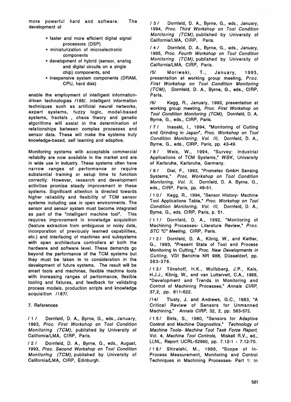
more powerful hard and software. The development of
faster and more efficient digital signal
miniaturization of microelectronic
development of hybrid (sensor, analog
processors (DSP)
components
and digital circuits on a single chip) components, and
CPU, hard disk) inexpensive system components (DRAM,
enable the employment of intelligent information- driven technologies I1 861. Intelligent information techniques such as artificial neural networks, expert systems, fuzzy logic, model-based systems, fractals , chaos theory and genetic algorithms will assist in the determination of relationships between complex processes and sensor data. These will make the systems truly knowledge-based, self learning and adaptive.
Monitoring systems with acceptable commercial reliabilty are now available in the market and are in wide use in industry. These systems often have narrow ranges of performance or require substantial training or setup time to function correctly. However, research and development activities promise steady improvement in these systems. Significant attention is directed towards higher reliability and flexibility of TCM sensor systems including use in open environments. The sensor and sensor system must become integrated as part of the 'intelligent machine tool'. This requires improvement in knowledge acquisition (feature extraction from ambiguous or noisy data, incorporation of previously learned capabilities, etc.) and interfacing of machines and subsystems with open architecture controllers at both the hardware and software level. These demands go beyond the performance of the TCM systems but they must be taken in to consideration in the development of future systems. The result will be smart tools and machines, flexible machine tools with increasing ranges of performance, flexible tooling and fixtures, and feedback for validating process models, production scripts and knowledge acquisition I1 871.
7. References
I 1 I Dornfeld, D. A., Byrne, G., eds., January, 1993, Proc. First Workshop on Tool Condition Monitoring (TCM), published by University of CaliforniaILMA, CI RP, Paris.
1 2 I Dornfeld, D. A., Byrne, G., eds., August, 1993, Proc. Second Workshop on Tool Condition Monitorhg (TCM), published by University of CaliforniaILMA, CIRP, Edinburgh.
1 3 I Dornfeld, D. A., Byrne, G., eds., January, 1994, Proc. Third Workshop on Tool Condition Monitoring (TCM), published by University of CaliforniaILMA, CIRP, Paris.
1 4 I Dornfeld, D. A., Byrne, G., eds., January, 1995, Proc. Fourth Workshop on Tool Condition Monitoring (TCM), published by University of California/LMA, CIRP, Paris.
I51 Moriwaki , T., January, 1993, presentation at working group meeting, Proc. First Workshop on Tool Condition Monitoring (TCM), Dornfeld, D. A., Byrne, G., eds., CIRP, Paris.
I61 Kegg, R., January, 1993, presentation at working group meeting, Proc. First Workshop on Tool Condition Monitoring (TCM), Dornfeld, D. A. Byrne, G., eds., CIRP, Paris.
1 7 I Inasaki, I., 1994, 'Monitoring of Cutting and Grinding in Japan', Proc. Workshop on Tool Condition Monitoring, Vol. 111, Dornfeld, D. A,, Byrne, G., eds., CIRP, Paris, pp. 43-49.
I 8 I Weis, W., 1994, "Survey: Industrial Applications of TCM Systems,' WBK, University of Karlsruhe, Karlsruhe, Germany.
I 9 I Diel, F., 1993, 'Prometec GmbH Sensing Systems,. Proc. Workshop on Tool Condition Monitoring, Vol. 11, Dornfeld, D. A. Byrne, G., eds., CIRP, Paris, pp. 49-51.
I1 0 1 Kegg, R., 1994, 'Sensor History- Machine Tool Applications Table,' Proc. Workshop on Tool Condition Monitoring, Vol. 111, Dornfeld, D. A., Byrne, G., eds. CIRP, Paris, p. 51.
I1 1 I Dornfeld, D. A., 1992, 'Monitoring of Machining Processes- Literature Review,' Proc. STC "C" Meeting, CIRP, Paris.
I1 2 1 Dornfeld, D. A., Konig, W., and Kettler, G., 1993, 'Present State of Tool and Process Monitoring in Cutting,' Proc. New Developments in Cutting, VDI Berichte NR 988, Dusseldorf, pp.
I1 3 1 Tonshoff, H.K., Wulfsberg, J.P., Kals, H.J.J., Konig, W., and van Luttervelt, C.A., 1988, "Development and Trends in Monitoring and Control of Machining Processes," Annals CIRP,
I141 Tlusty, J. and Andrews, G.C., 1983, "A Critical Review of Sensors for Unmanned Machining," Annals CIRP, 32, 2, pp. 563-572.
I1 5 1 Birla, S., 1980, 'Sensors for Adaptive Control and Machine Diagnostics,' Technology of Machine Tools- Machine Tool Task Force Report, Vol. 4, Machine Tool Controls, Miskell R.V., ed., LLNL, Report UCRL-52960, pp. 7.12-1 - 7.12-70.
I1 6 1 Shiraishi, M., 1988, "Scope of In- Process Measurement, Monitoring and Control Techniques in Machining Processes- Part 1: In
363-376.
37,2, pp. 611-622.
561

Process Techniques for Tools,” P r e c i s i o n Engineering, Vol. 10, No. 4, pp. 179-189.
I 1 7 1 Shiraishi, M., 1989, “Scope of In- Process Measurement, Monitoring and Control Techniques in Machining Processes- Part 2: In Process Techniques for Workpieces,” Precision Engineering, Vol. 11, No. 1, pp. 27-37.
I 1 8 1 Shiraishi, M., 1989, “Scope of In- Process Measurement, Monitoring and Control Techniques in Machining Processes- Part 3: In Process Techniques for Cutting Processes and Machine Tools,” Precision Engineering, Vol. 1 1, 1, pp. 39-47.
I 1 9 I Iwata, K., 1988, “Sensing Technologies for Improving the Machine Tool Function,” Proc. 3rd Int’l Machine Tool Engineer’s Conference,
I 2 0 I Hoshi, T., 1990, “Automatic Tool Failure Monitoring in Drilling and Thread Tapping,” Proc. 111 Intern’l Conf. on Automatic Supervision, Monitoring and Adaptive Control in Manuf., CIRP, Rydzyna, Poland, pp. 41-58.
I 2 1 I Szafarczyk, M., ed., 1994, Automat ic Supervision in Man ufa cturing, Springer- V e r I a g , London.
I 2 2 1 Micheletti, D. F., Koenig, W., and Victor, H. R., 1976, ‘In Process Tool Wear Sensors for Cutting Operations,. Annals CIRP , 25, 2, pp. 483
1231 Bellmann, B., 1978, Mepverfahren zur k o n t i n u i e r l i c h e n E r f a s s u n g d e s Freiflachenverschleipes beim Drehen, doctoral thesis, TH Darmstadt.
1241 Pfeiffer, T., Furst, A., and Vollard, W., 1 982, Proze p inter m i tti e re n d e Wer kze u g- u n d
Werkzeugmaschinen, lndustrie Anzeiger 104, 27.
/25/ Hammer, H., 1982, Automatisierung von Fertigungseinrichtungen, lndustrie Anzeiger, 104, 27.
1261 Lierath, F., 1984, Geratesystem zur Erfassung des Verschleipes an spanenden Werkzeugen bei bedienarmer Fertigung, Feingeratetechnik, Berlin 33, 2.
/27/ Ernst, P., 1978, Verschleiperfassung beim Bohren mit Wendelbohrern, doctoral thesis, TH Darmstadt.
/28/ Balakrishnan, P. and Macbain, J. C., 1985, ’Monitoring Systems for Unmanned Machining,’ Technical SME Paper.
1291 Dumbs, A. and Laun, H., 1983, Vermessung von Werkzeugen fur Metallbearbeitungsmaschinen, VDW-Forschungsbericht 2301, Fraunhofer-lnstitut fiir Physikalische Meptechnik, Freiburg.
/30/ Kamm, H., Mil ler, M., 1975, Kapazitiver Verschleipsensor fur das Messerkopf-Frasen, lndustrie Anzeiger, 97, 73, pp. 1602-1 603.
JMTBA, Tokyo, pp. 87-109.
- 496.
W e r k s t i i c k v e r m e s s u n g a u f N C -
1311 Stoferle, Th. and Bellmann, B., 1975, Kontinuierlich messende Verschleipsensoren fur die Drehbearbeitung, VDW-Forschungsbericht A 2551. /32/ Essel, K., 1972, Entwicklung einer Optimierregelung fur das Drehen, doctoral thesis, RWTH Aachen.
I331 Otto, F., 1976, Entwicklung eines gekoppelten AC-Systems fur die Drehbearbeitung, doctoral thesis, RWTH Aachen.
/34/ Leonards, F., Muller, W., and Otto, F., 1976, Prozeplenkungssysteme fur die Drehbearbeitung, PDV-Bericht, KfK-PDV 82.
I351 Takeyama, H., et. al., Sept., 1967, ‘Sensors of Tool Life for Optimization of Machining ’, Proc. 8th Int. M TDR-Conference, Manchester.
1361 Dormehl, E., 1984, Wirtschaftliche Drehbearbeitung mit aufgabenangepap t e n Automatisierungsbausteinen, VDI-Z 126, 5.
1371 Essel, K., Otto, F., and Kirchner, W., 1974, Sensor zum Erfassen des Freiflachenverschleipes an Drehwerkzeugen, VDI-Z 116, 17.
1381 Schwan, W., 1979, Verfahren zur Uberwachung der Werkzeugschneide sowie NC- gesteuerte Drehmaschine zur Durchfuhrung des Verfahrens, Deutsches Patentamt, OS-Nr. 27 47 487.
1391 He inze , W., Sept . , 1985, M ik ro rechnerges teuer te r Mepplatz zur automatischen Verschleiperfassung bei der Schneidstoffentwicklung fur Wendeschneidplatten, 3. F a c h t a g u n g ‘Ges ta l tung v o n Fertigungsprozessen im Maschinenbau’, 18, Magdeburg, DDR.
1401 Lierath, F., Scharfenort, U., and Pieper, H.- J., 1986, Sensorkontrollierte Werkzeugbruch- u nd We r kzeu gversc h lei p id en t if i kat ion an CNC- Drehmaschinen, Fertigungstechnik und Betrieb 36, 5.
1411 N.N., 1981, Der BK Mikro 2 Bohrerkontroller schaltet Folgeschiden bei Werkzeugbruch aus, brochure of the Leukhardt company, Tuttlingen:
/42/ N.N., 1983, Sensoren beugen Fehlern vor - Fertigungstechnik setzt auf automatisches Fiihlen, Hdren und Sehen, VDI-Nachrichten 37, 48.
1431 Schneider, A., 1981, Vorrichtung zum Abtasten von Gegenstanden, Deutsches Patentamt, OS-Nr. 30 30 431. /44/ N.N., 1982, Tooltronic - beriihrungslose Bohrbruchkontrolle, brochure of the Leuze Electronic Company, Owen.
I451 N.N., 1983, Die rationelle Fertigung fur morgen, brochure of the Fr. Deckel Company, Miinchen.
562

I461 Ductrohet, J.-M., 1975, Vorrichtung zur Fests t e I I u ng e i n es u m la u f e nd e n W er kze ug es , Deutsches Patentamt, OS-Nr. 24 47 245.
1471 Homburg, D., 1983, Methoden der Werkzeugbruchkontrolle, TR Technische Rundschau 75, 44.
1481 Thierfelder, A., 1988, Sensoren und Mepsysteme zur Prozepuberwachung, tz fur Metallbearbeitung 82, 3.
1491 Tuns, J., 1989, Weiter aufwarts - Gerate, Einrichtungen und Systeme zum Uberwachen von spanenden Werkzeugen auf der EM0 1989 in Hannover, Maschinenmarkt Wurzburg 95, 44.
1 5 0 I N.N., 1989, Fertigungssicherheit durch Werkzeuguberwachung, Flexible Fertigung, No. 2.
1511 Vollmer, H. J., Franke, N., and Radtke, U., 1974, Optisch-elektronisches Verfahren zur p r o z e p in te rnen Versch le ip m e s s u n g , Fertigungstechnik und Bertrieb 24, 12.
1521 Leonards, F., 1978, Ein Beitrag zur meptechnischen Erfassung von ProzePkenngroPen bei der Drehbearbeitung, doctoral thesis, TU Berlin.
I531 Uehara, K., 1973, 'New Attempts for Short Time Tool-Live Testing,' Annals CIRP, 22, 1.
I541 Aoyama, H., Kishinami, T., and Saito, K., July, 1989, 'A Method of Tool Management Based on an Intelligent Cutting Tool,' Adv. Manuf. Eng., VOl. 1.
1551 Leonards, F., 1974, Die Messung des Schneidkantenversatzes bei der Drehbearbeitung nach dem Ultraschall-Laufzeitverfahren, lndustrie Anzeiger 96, 1071108.
1 5 6 I N.N., 1980, Werkzeug-korrektursystem, Schneidenkontrolle VT 921, brochure of the Samsomatic company, Frankfurt.
1571 Brandstatter, A., 1981, Ein Adaptive- Control-Optimization-System fur das Frasen, doctoral thesis, TH Karlsruhe.
1581 Kamm, H., 1977, Beitrag zur Optimierung des Messerkopfstirnfrasens, doctoral thesis, TH Karlsruhe.
1591 Stoferle, Th., Hartmann, V., 1976, Beitrag zur Lagemessung aller Schneidkanten an Friiswerkzeugen, Werkstatt und Betrieb 109, 3.
I601 Krause, W., 1976, Messung des Freiflichenverschleipes beim Umfangsstirnfrgsen, Fertigungstechnik und Betrieb 26, 10.
I611 Weis, W., Lengeling, A., and Huntrup, V., 1994, Automatisierte Werkzeugijberwachung und -vermessung be im Frasen mit Hi l fe bildverarbeitender Systeme, tm - Technisches Messen 61, 12, pp. 473 - 476.
1621 Tonshoff, H. K. (1993), Fast Sensor Systems for the Diagnosis of Grinding Wheel and Workpiece, SME, Technical Paper, MR93-369.
1631 Crostack, H.-A., Cronjager, L., Hillmann, K., Muller, P., and Strunck, T., 1988, Rauhtiefe beruhrungslos gemessen - Erfassung des Oberflachenzustandes spanend bearbeiteter Bauteile mit Ultraschall, tz fur Metallbearbeitung 82, 10.
1641 Schehl, U., et. al., April, 1990, Sicherung des spanabhebenden Bearbeitungsprozesses, KfK Bericht, KfK-PFT 154.
I651 Hansel, W., 1974, Beitrag zur Technologie des Drehprozesses irn Hinblick auf Adaptive Control, doctoral thesis, RWTH Aachen.
I661 Kdnig, W. and Meyen, H. P., 1988, Rechnergestuztes System zur Werkstuckkontrolle, Qualitatskontrolle im Prozeptakt beim Schleifen machbar!, lndustrie Anzeiger 110, 61/62, pp.
1671 Konig, W. and Wunsche, U., 1991, Oberflachen mit lnfrarotlicht beurteilen, lndustrie Anzeiger 113, 72, pp. 60-61.
1681 Konig, W., Meyen, H. P., Klumpen, T., and Memis, F., 1992, Standzeituberwachung und integr ier te Qual i tatskontrol le fur den automatischen Schleifprozeb, VDI-Z 134, 5, pp.
I 691 Kluf t , W., 1983, Werkzeuguber- wa c h u n gssys t eme f r die D re h bearbe it ung , doctoral thesis, RWTH Aachen.
1701 Konig, W., 1990, Fertigungsverfahren, Band 1, Drehen, Bohren, Frasen, VDI-Verlag, Dusseldorf.
I 7 1 I Colwell, L. V. and Mazur, J. C., 1979, 'Real Time Computer Diagnostics - A Research Tool for Metal Cutting, " Annals CIRP, 28, 1.
1 7 2 1 Wiele, H. and Menz, P., 1983, Automatische Erfassung des Verschleipe s spanender Werkzeuge - Bestandteil der Prozepuberwachung beim bedienarmen Betrieb, Fertigungstechnik und Betrieb 33, 6.
1 7 3 1 Gomoll, P., 1978, Verfahren und Vorrichtung zur Uberwachung der Schneidplatten in Werkzeugmaschinen, Deutsches Patentamt, OS- Nr. 30 42 211.
I 7 4 1 Menz, P., Richter, H., 1984, Verschleipmessung an spanenden Werkzeugen durch rechnerbewertete Temperatur-messung, Wiss. Zeitg. TH Magdeburg 28, 5.
I 7 5 1 Uehara, K., Takeshita, H., 1989, 'Prognostication of the Chipping of Cutting Tools,' Annals CIRP, 38, 1.
I 7 6 1 Takata, S., Ahn, J. H., Miki, M., Miyao, Y., and Sata, T., 1986, 'A Sound Monitoring System for Fault Detection of Machine and
26-29.
71 -76.
563

Machining States,' Annals ClRP, 35, 1, pp. 289 - 292.
/ 7 7 / C h r i s t o f f e l , K . , 1 9 8 4 , Werkzeuguberwachung beim Bohren und Frasen, doctoral thesis, RWTH Aachen.
/ 7 8 / Schlesinger, G., 1932, Bearbeitbarkeit und Werkstattennutzung, Zeitschrift des VDI 76, 53.
/ 7 9 / Takeyama, H., 1970, Optimierende Steuerung bei Drehbearbeitungen, Werkstatt und Betrieb 103, 9.
/ 8 0 / Victor, H., 1956, Beitrag zur Kenntnis der Schnittkrafte beim Drehen, Hobeln und Bohren, doctoral thesis, TH Hannover.
/ 8 1 / Meyer, K. F., 1963, Vorschub- und R i j c k k r P f t e b e i m D r e h e n m i t Hartmetallwerkzeugen, doctoral thesis, RWTH Aachen.
/ 8 2 / Konig, W., Langhammer, K., and Schemmel, V., 1972, 'Correlations between Cutting Force Components and Tool Wear,' Annals CIRP, 21, 1.
/ 8 3 / Langhammer , K., 1972, Die Zerspankraftkomponenten als KenngroPen zur V e r s c h l e i P best immung an Hartmetal l - Drehwerkzeugen, doctoral thesis, RWTH Aachen. / 8 4 / Klicpera, U., 1975, Uberwachung des W e r k z e u g v e r s c h l e i P es mit Hilfe der Zerspankraftrichtung, doctoral thesis, TU Stuttgart.
/ 8 5 / Spira, K., 1978, Automatische Erstellung und Prijfung von Zerspaninformationen, doctoral thesis, RWTH Aachen.
/ 8 6 / Buchholz, T., 1987, ProzePmodell Frasen - Rechnerunterstutzte Analyse, Optimierung und Uberwachung, doctoral thesis, TH Karlsruhe.
/ 8 7 / N e d e p , C. and Himburg, T., 1986, Automatisierte Uberwachung des Bohrens, VDI-Z 128, 17.
/ 8 8 / Bandyopadhyay, P., 1986, 'A Flexibility Study of On-Line Drill Wear - Monitoring by DDS Methodology,' lnt. J. Mach. Tool Des. Res., Vol. 26, No. 3.
/ 8 9 / Stoferle, T. and Ernst, P., 1976, lndirekte V e r s c h l e i P messung beim Bohren mit Wendelbohrern, lndustrie Anzeiger 98, 28.
/ 9 O / Powell, J. W., et. al., May-Sept, 1984, 'Cutting Tool Sensors,' 2nd Biennial Int. Machine Tool Technical Conf., National Machine Tool Builders Association.
/ 9 1 / Huber, G., 1988, Analyse der Schnittkrafte bei Werkzeugbruch, ZWF 83, 11.
/ 9 2 / Stange, B., 1987, Mikrorechner- gesteuerte Werkzeuguberwachung auf der Basis von Dehnungsmessungen an Drehmaschinen, Feingeratetechnik 36, 10.
/ 9 3 / Hayashi, S. R., Thomas, C. E., and Wildes, D. G., 1988, 'Tool Break Detection by Monitoring Ultrasonic Vibrations,' Annals ClRP, 37, 1.
/ 9 4 / Hayashi, S. R., Thomas, C. E., Davis, R. K., McKnight, W. S., and Roberts, C. R., 1985, 'Automatic Tool Touch and Breakage Detection in Turning,' brochure of the General Electric company, Schenectady, New York.
/ 9 5/ Roget, J., Souquet, P., and Gsib, N., 1989, Werkzeugbrijche rnit der Schallemission detektieren, QZ - Qualitatstechnik 34, 7.
/ 9 6 / Gee, D.-J., Patterson, R. C., Zielaskiewicz, S. M., 'Automatic Detection of Turning Machine Tool Failure and Prefailure using Acoustic Emission, Force or Power Signals,' 2nd Biennial Int. Machine Tool Technical Conf., National Machine Tool Builders.
/ 9 7 / Moriwaki, T., 1984, 'Sensing and Prediction of Cutting Tool Failure,. Bull. Japan SOC. of Prec. Eng., Vol. 18, No. 2.
/ 9 8 / Lan, M. S. and Dornfeld, D. A., 1984, "In- Process Tool Fracture Detection,' Trans. ASME, Jour. Eng. lnd., Vol. 106, No. 2.
/ 9 9 / Kashimura, Y., 1986, 'Study on Detection of Drill Wear and Breakage,' Bull. Japan SOC. of Prec. Eng., Vol. 20, No. 3.
/ 1 0 0 / Himburg, T. and Keller, H., 1989, Universelles Rechnerkonzept fur die Entwicklung von Uberwachungssystemen, VDI-Z 131, 2.
/ 1 0 1 / Moriwaki, T., 1983, 'Application of Acoustic-Emission Measurement to Sensing of Wear and Breakage of Cutting Tool, ' Bull. Japan. SOC. of Prec. Eng., Vol. 17, No. 3.
/ 1 0 2 / Souquet, P., Gsib, N., Deschamps, M., Roget, J., and Tanguy, J. C., 1987, 'Tool Monitoring with Acoustic-Emission - Industrial Results and Future Prospects,' Annals ClRP, 36,
/ 1 0 3 / Yu, Q. and Hutton, D. V., 1988, 'Liquid- Coupled Acoustic Emission Measurement for Milling Operation,' Proc. of the 76th NAMRC, pp.
/ 1 0 4 / Inasaki, I., Blum, T., Suzuki, H., Itagaki, H., and Sato, M., 'A Pratical Mounting Device for an Acoustic Emission Sensor for the Failure Detection of Multipoint Cutting Tools, Crossing Bridges: Advances in Flexible Automation and Robotics,' Vol. II, No. 1.
/ 1 0 5/ KBnig, W., Ketteler, G., and Klumpen, T., 1994, 'Monitoring Turning, Milling, Drilling and Grinding Processes using Acoustic Emission Signals,' Progress in Acoustic Emission Wl, The Japanese Society for NDI, pp. 619 - 624.
/ 1 0 6 / Nordmann, K., 1990, Ein Beitrag zur VerschleiP- und Bruchijberwachung rotierender Werkzeuge, doctoral thesis, Universitat des Saarlandes.
1, pp. 57 - 60.
403 - 407.
564

I1 0 7 1 Lan, M. S., Dornfeld, D. A., 1984, 'In- Process Tool Fracture Detection,' Trans. ASME, J. Eng. Mats . Tech., 106, 2, pp. 111-118. I1 0 8 1 Albrecht, L., 1981, Vorrichtung zur Messung der Schnittkraft von Schneidwerkzeugen ei nes De u tsc h es Patentamt, OS-Nr. 30 19 751.
I 1 0 9 1 Weck, M., 1989, Werkzeugmaschinen, Band 3 - Automatisierung und Steuerungstechnik, VDI Verlag Dusseldorf.
I1 1 0 1 N. N., 1989, Piezoelektr ische Kraftsensoren fur Tool- und Process-Monitor, brochure of the Prometec Company, Aachen.
I1 1 1 1 N. N., 1992, 'Tool monitoring solutions for Duplomatic Turrets,' brochure of the Montronix Company, Raleigh.
I 1 1 2 1 Weck, B., Feb. -Mar . 1990, W er kze ug u b e rwa c h u n g , Tag u ngs ba nd zu m 5. Darmstadter Fertigungstechnischen Symposium.
Me hrf a ch wer kz e u g tra g e rs,
I1 1 31 N. N., 1992, IntelliTool - Plattensensoren fur die Werkzeuguberwachung, brochure of the Sandvik company.
11 1 4 1 Quante, F. and Fehrenbach, H., 1984, Vergleich von Kraft-, Drehmoment- und Schwingungsanalysen hinsichtlich ihrer Eignung zur Bohreruberwachung, QZ - Qualituatstechnik 29, 3.
I1 1 5 1 Arnold, W. and Scherer, J., 1982, Adaptive Control beim Drehen, Frlsen und Bohren, Werkstatt und Betrieb 115, 8.
I1 1 6 1 Adams, L. C. and Whetham, N. J., 1981, K r a f t m e p anordnung zur Messung von Kraftkomponenten, die an sich drehenden Werkzeugen von Werkzeugmaschinen auftreten, Deutsches Patentamt, OS-Nr. 21 06 703.
I 1 1 7 I Autorenkollektiv, 1987, Steigerung der P r o z e p s i c h e r h e i t und - f l ex ib i l i t a t , Produktionstechnik auf dem Weg zu integrierten Sys temen , ed i to r : AWK, Aachener Werkzeugmaschinen-Kolloquium, VDI-Verlag, Dusseldorf.
I1 1 8 1 N.N., 1989, Prozepuberwachung in der spanenden Fertigung, Firmenschrift der Fa. Brankamp Prozepautomation GmbH.
11 1 9 1 N. N., 1 9 9 2 , W e r k z e u g - lnformationssystem fur Mehrspindelbohrkdpfe, brochure of the Promess Company, Berlin.
I1 2 0 1 N. N., 1984, 'Tool Monitoring System - Feed Force Sensors,' brochure of the Sandvik Company.
I1 2 1 1 Spur, G. and Stelzer, C., 1992, Neue Wege bei der Prozepuberwachung an Drehmaschinen,
I1 2 2 1 Schapermeier, E. and Wiendl, J., 1989, Verschleib prozebbegleitend messen, Werkstatt und Betrieb 122, 10.
VDI-Z 134, 12, pp. 50-55.
I 1 2 3 1 N.N., 1989, Mimatic E-2, brochure of the Zettl Automation company, Munchen.
11241 N. N., 1992, In te l l iToo l - Schnittkraftuberwachung im Werkzeughalter, brochure of the Sandvik Company.
I 1 2 51 Tonshoff, H. K., Brinksmeier, E., and Husen, H., 1991, Beruhrungslose Messung des dynamischen Bearbeitungsmoments zur oberwachung schlanker rotierender Werkzeuge, e & i 108, 6, pp. 252 - 257.
I 1 2 61 Tcinshoff, H. K., Noske, H., and Nitidem- Ndengue, E., 1994, Sensorsytem und Analyseverfahren zur Brucherkennung beim mehrschneidigen Frasen, tm - Technisches Messen
I 1 2 71 Weck, M., 1989, Werkzeugmaschinen, Band 2, Konstruktion und Berechnung, VDI - Verlag, Dusseldorf.
I1 2 81 N. N., 1991, Werkzeuguberwachung und Diagnose, brochure of the Artis Company, Bispingen-Behringen.
I1 2 91 Brons, S., 1994, 'Application of Motor Current Sensing for Indirect Measurement of Cutting Forces - Possibilities and Limitations,' doctoral thesis No. 21, Royal Institute of Technology, KTH, Stockholm.
11 301 Shteinhauz, G., Braun, S., and Lenz, E., 1984, 'Automated Vibration Based Tool Wear Monitoring: Application to Face Milling', Proc. of the ASME International Computer in Engineering Conference, Las Vegas.
1 1 3 1 1 Scheh l , D. U. P., 1991, Werkzeuguberwachung mit Acoustic-Emission beim Drehen, Frasen und Bohren, doctoral thesis, RWTH Aachen.
11321 N. N., 1992, 'Tool Monitor System - Process Monitor System,' brochure of the Prometec Company, Aachen.
I1 331 Kutzner, K., 1991, Spanformerkennung beim Drehen, doctoral thesis, RWTH Aachen.
I 1 341 Meyen, H.-P., 1991, Acoustic Emission (AE) - Mikroseismik im Schleifprozep, doctoral thesis, RWTH Aachen.
I1 3 51 Blum, T. and Inasaki, I., 1990, 'Study on Acoustic-Emission from the Orthogonal Cutting Process,. Trans. ASME, J. of Eng. Ind., Vol. 112,
I 1 3 6 1 Carpenter, S. H., Heiple, C. R, and Armentrout, D. L., 1992, 'Relationship between Acoustic-Emission and Experimental Variables during Sliding Friction,' Progress in Acoustic- Emission VI, The Japanese Society for NDI, pp.
I1 3 7 1 Dornfeld, D. A., May, 1979, 'Acoustic- Emission and Metalworking - Survey of Potential
61, 4, pp. 271 - 279.
NO. 3, pp. 203 - 21 1.
353-360.
565

and Examples of Application,’ Proc. of the 8th NAMRC, Rolla, pp. 207 - 211.
I 1 3 8 1 Hommel, B. and Meyer, W., May, 1991, Qualitatssicherung in der Fertigungstechnik unter Nutzung akustischer Mepverfahren, Proceedings of the Quality ‘91, Stuttgart.
I1 3 9 1 Iwata, K. and Moriwaki, T., 1977, ‘An Application of Acoustic-Emission Measurment to In-Process Sensing of Tool Wear,’ Annals of the CIRP, Vol. 26, No. 1.
I 1 4 0 1 Jiaa, C. L. and Dornfeld, D. A., 1990, ’Experimental Studies of Sliding Friction and Wear via Acoustic-Emission-Signal Analysis,’ W e a r ,
I 1 4 1 I Waschkies, E., Sklarczyk, C., and Pitsch, H., 1993, Das Gerausch ist mabgebend - WerkzeugverschleiPuberwachung beim Drehen und Bohren, TR Technische Rundschau 85, 5. 11421 Weber, H. and Herberger, J., Aug., 1984, Berichte zur Festkdrperphysik der Spanbildung m e t a l l i s c h e r K o n s t r u k t i o n s w e r k s t o f f e , Wissenschaftliche Schriftenreihe der TH Karl- Marx-Stad t.
11431 Cavalloni, C. and Kirchheim, A., 1994, Neues Sensordesign als Basis optimierter Prozepuberwachung, Werkstatt und Betrieb 127,
11441 N. N., 1992, Werkzeuguberwachung, brochure of the Nordmann Company, Koln.
/145/ McBride, R., Carolan, T. A., Barton, J. S., Wilcox, S. J., Borthwick, W. K. D., and Jones, J. D. C., ‘Detection of acoustic emission in cutting processes by fibre optic interferometry,’ M e a s . Sci. Technol., No. 4, pp. 1122 - 1128.
11461 Ramalingam, S., Shi, T., Frohrib, D. A., and Moser, T., 1988, ‘Acoustic Emission Sensing with an Intelligent Insert and Tool Fracture Detection in Multi-Tooth Milling,’ Proceedings of the 76th NAMRC, pp. 245 - 255.
11471 NedeP, C. and Pflueg, C., Sept., 1994, ‘Chip Form Monitoring in Turning Internal Surfaces with Acoustic Emission using Thin Film Sensors,’ Proceedings of the 7th ICPE and the 4th ICHT, Chiba, Japan.
11481 Dornfeld, D. A., 1995, ‘Monitoring Technologies for Intelligent Machining,’ Proc. CIRP/VDI. Conference on Monitoring of Machining and Forming Processes, VDI Berichte Nr. 1179, Dijsseldorf Germany, pp. 71-90.
I 1 4 9 I Moriwaki, T., 1994, ‘Intelligent Machine Tool: Perspective and Themes for Future Development,’ Manufacturing Science and Engineering, Vol. 2, ASME, PED-Vol. 68-2, New York, pp. 841-849.
I 1 501 Lundholm, T., 1991, “A Flexible Real Time Adaptive Control System for Turning,” Annals CIRP, Vol. 40, No. 1, pp. 441-444.
VOI. 139, pp. 403-424.
4, pp. 248 - 252.
I 1 5 1 I Seidel, D. and Menzel, E., 1990, “A Modern Concept for the Design of Machine Tool Monitoring and Diagnosis Systems,” Advanced Manufacturing Engineering, 2, pp. 76-82.
I 1 5 2 1 Jaume, D., Verge, M., and Rault, A., 1990, “A Model-Based Diagnosis in Machine Tools: Application to the Milling Cutting Process,” Annals CIRP, Vol. 39, No. 1, pp. 443-446.
I 1 5 3 1 Sata, T., Matsushima, K., Nagakura, T., and Kono, E., 1973, ‘Learning and Recognition of the Cutting States by Spectrum Analysis,’ C l R P Annals, Vol. 22, No. 1, pp. 41-42.
I 1 5 41 Rangwala, S. and Dornfeld, D.A., 1989, ‘Learning and Optimization of Machining Operations using Computing Abilities of Neural Networks,. IEEE Trans. on Systems, Man and Cybernetics, Vol. 19, No. 2, pp. 299-314. I 1 5 51 Mitsuishi, M., Warisawa, S., Ohta, T., and Nagao, T., 1994, ‘Automatic Acquisition of Machining Conditions: Towards a Self-evolving Machining Center,‘ Proc. ASPE Ninth Annual Meeting, ASPE, pp. 338-341.
I 1 5 6 1 Smith, S. and Tlusty, J., 1992, ‘Stabilizing Chatter by Automatic Spindle Speed Regulation,’ ClRP Annals, Vol. 41, No. 1, pp. 433- 436.
I 1 5 7 1 Chryssolouris, G., Domroese, M., and Beaulieu, P., 1991, “A Statistical Approach to Sensor Synthesis,” Trans. NAMRC/SME, pp. 333-337. I 1 5 81 Chryssolouris, G., Domroese, M., 1989, “Experimental Study of Strategies for Integrating Sensor Information in Machining,” Annals CIRP,
I 1 5 9 1 Emel, E., 1991, “Tool Wear Detection by Neural Network Based Acoustic Emission Sen s i n g , ” Control of Manufacturing Processes, PED-Vol. 52, Danai, K., Malkin, S., eds., ASME, New York, pp. 79-85.
/ 1 6 0 1 Teltz, R. and Elbestawi, M.A., 1991, “Hierarchical, Knowledge Based Control in Turning ,” Control of Manufacturing Processes, PED-Vol. 52, Danai. K., Malkin, S., eds., ASME, New York, pp. 135-149.
I 1 6 1 1 Moriwaki, T. and Hino, R., 1991, “Application of Neural Network to AE Signal Processing for Automatic Detection of Cutting Tool Life,” Journal JSME, Vol. 57, No. 7, pp.
I 1 6 2 1 Guinea, D., Ruiz, A., and Barrios, L.J., 1991, “Multi-Sensor Integration: An Automatic Feature Selection and State Identification Methodology for Tool Wear Estimation,” Proc. Ist ClRP Workshop on Intelligent Manufacturing Systems, CIRP, Budapest, Hungary, pp. 159-175.
1 1 6 3 1 Spiewak, S., 1991, “A Predictive Monitoring and Diagnosis System for
38, 1, pp. 425-428.
1259-1 264.
566

Manufacturing," Annals CIRP, 40, No. 1, pp.
I 1 6 4 / Choi, G.S., Wang, Z.X., and Dornfeld, D.A., 1991, 'Adaptive Optimal Control of Machining Process Using Neural Networks,' Proc. I€€€ International Conference on Robotics and Automation, IEEE, Sacramento, CA., pp. 1567- 1572.
I 1 6 5 1 Jiaa, C.L. and Dornfeld, D.A., 1992, 'Detection of Tool Wear using Gradient Adaptive Lattice and Pattern Recognition Analysis,' J. Mechanical Systems and Signal Processing, Vol.
I 1 6 6 1 Rangwala, S.S. and Dornfeld, D.A., 1990, 'Sensor Integration using Neural Networks for Intelligent Tool Condition Monitoring,' Trans. ASME, J. Eng. Ind., Vol. 112, No. 3, pp. 2119- 228.
I 1 6 7 1 Dornfeld, D. A., 1990, 'Neural network Sensor Fusion for Tool Condition Monitoring,' CIRP Annals, Vol. 39, No. 1, pp. 101-105.
I 1 6 81 Du, R.X., Elbestawi, M.A., and Ullagaddi, B.C., 1991, "Chatter Detection in Milling Based on the Probability Distribution of Cutting Force Signal," Int. J. Mach. Tools and Man.
I 1 6 9 1 Sokolowski, A., Vincent, P., and Dornfeld, D. A., 1994, 'Drill State Monitoring during Multispindle Machining,' T r a n s .
I 1 7 O / Sokolowski, A., Rehse, M., and Dornfeld, D. A., 1993, 'Feature Selection in Tool Wear Monitoring using Fuzzy Logic and Genetic Algorithms,' L MA Research Reports, University of California at Berkeley, pp. 91-97.
I 1 7 1 I Liang, S. and Dornfeld, D. A., 1989, 'Tool Wear Detection using Time Series Analysis of Acoustic Emission,' Trans. ASME, J. Eng. Ind. , Vol. 11 1, No. 2.
I 1 7 2 1 Rehse, M., 1993, 'In Process Tool Wear Monitoring of Multispindle Drilling using a Multi- Sensor System,' Diplomarbeit, LMNUniversity of California at Berkeley and WZURWTH Aachen.
11731 Wu, C. and Furness, R., 1995, 'Intelligent Sensor-based Manufacturing Challenges and Opportunities,' Proc. CIRP/VDI Conference on Monitoring of Machining and Forming Processes, VDI Berichte Nr. 1179, Dusseldorf Germany, pp.
I 1 7 4 I Inasaki, I., 1985, 'Monitoring of Dressing and Grinding Process with Acoustic Emission Signals,' Annals CIRP, 34, 1, pp. 277-280.
/175/ Blum, T. and Dornfeld, D.A., 1990, 'Grinding Process Feedback using Acoustic Emission,' Proc. 4th International Grinding Conference and Exposition, SME, Dearborn, MI, USA.
401 -404.
6, NO. 2, pp. 92-102.
NAMRI/SME, Vol. 22, pp. 233-239.
1-15.
I 1 7 6 1 Rowe, W.B., Yan, L., Inasaki, I., and Malkin, S., 1994, 'Application of Artificial Intelligence to Grinding,' Annals CIRP, 43, 2.
I 1 7 7 1 Inasaki, I., 1974, Selbsterregte Schwingungen beim Auflenrundeinstechschleifen, Annals of the CIRP, Vo1.23, No. 1, pp. 117-118.
I 1 7 81 Wakuda, M., Inasaki, I., Ogawa, K., and Takahara, M., 1993, 'Monitoring of the Grinding Process with an AE sensor Integrated CBN Wheel,' Journal of Advanced Automation Technology,
I 1 7 9 1 Inasaki, I . , 1991, 'Monitoring and Optimization of Internal Grinding Process,' Annals
I1 8 01 Matsumoto, T., Inasaki, I., and Ogawa, K., 1993, 'Monitoring of Grinding Process with a Sensor Integrated CBN Wheel,' SME Technical paper, MR 93-367.
I 1 8 1 Hundt, W., Leuenberger, D., and Rehsteiner, F., 1994, 'An approach to Monitoring of the Grinding Process Using Acoustic Emission Technique,. Annals CIRP, 43, 1, pp. 295-298.
I 1 8 2 I Private communication, 1995, A Fuzzy logic Aided Adaptive Controller for Cylindrical Plunge Grinding, WZL, Aachen
I 1 8 3 / Tonshoff, H. K., Heuer, W., 1991, 'Method of Contact Detection of Dressing of Superabrasive Grinding Wheels' SME, Technical Paper, MR91-171.
/ 1 8 4 1 Teti, R., Buonadonna, P., 1994, 'Neural Network Applications for Process and Tool Condition Monitoring', Ist Conf. on Applications of A1 Techniques in Engineering, Naples, Italy, p. 90- 98.
I 1 8 51 Caprino, G., Nele, L., 1994, 'Orthogonal Cutting of Fiber Reinforced Composite Materials: A Preliminary Study", Proc. Advancing with Composites '94, Milan, Italy, pp. 397-408.
I 1 8 6 1 Tonshoff, H. K. , Wobker, H. G. , Hartmann, M., Kilsmark, P., 1995, 'The Future of Monitoring', Proc. C/RP/VD/ Conference on Monitoring of Machining and Forming Processes, VDI Berichte Nr. 1179, Dusseldorf Germany, pp.
I1 8 7 1 Dornfeld, D. and Wright, P., 1995, 'Intelligent Machining: Global Models, Local Scripts and Validations' Trans. NAMRI/SME. Vol.
VOI.514, pp. 179-1 84.
CIRP, 40, 1, 359-362.
347-360.
23, pp. 351-356.
11881 Teti, R., 1995, 'A Review of Tool Condition Monitoring Literature Database,' ClRP Annals, 4412.
567


