Embed Size (px)
Citation preview
701 S. RIDGE AVENUE
TROY, OHIO 45374-0001
TCP/IP SUPPLEMENTSCALE NETWORKING
FORM 34001 (5-98)

Hobart Corporation, 1998
Table of ContentsUnderstanding TCP/IP Communications Protocol ...............................................................3
Understanding the IP Address...................................................................................... 3
Setting Up Scale IP Addressing ...............................................................................................4Entering IP Address Information for Server and Client Scales................................4Setting Up Client Scale’s Department IP Address on the Server Scale ...................5Setting Up ScaleMaster Located on a Different Network.......................................7Backing Up Scales to Retain TCP/IP Information .....................................................7
Sample Ethernet Wiring Illustration.......................................................................................8Multi Scales Connected in Stand Alone Department
(Configured with IntraNet single point configuration) ...................................9Multi Scales Connected to a Hub with ScaleMaster ................................................10Multi Scales Connected to a Hub with ScaleMaster
(Departments Configured with IntraNet Single Point Configuration)....... 11
Scale IP Address Assignment Form....................................................................................... 13
Testing Scales TCP/IP Connection ....................................................................................... 14
Troubleshooting IP Addressing .............................................................................................16
Appendix ................................................................................................................................... 19
Glossary ...................................................................................................................................... 24

TCP/IP Scale Communication
1
Understanding TCP/IPCommunicationProtocol
Transmission Communications Protocol/Internet Protocol(TCP/IP) is a communication protocol which maybe used tomake your scale system communicate faster and morereliably. It serves as a traffic manager for sending andreceiving packets of information between scales anddevices. Scales can be automatically updated withinformation which is sent directly from a server scale orScaleMaster .
Understanding the IPAddress
The IP Address is a naming convention used to identify ascale or device located on a network. Each IP Address mustbe unique to each scale (other scales or devices on a networkcannot have the same IP Address).
☛ Note
If the scale is on an existing network, contact the NetworkAdministrator for the correct IP Address information.
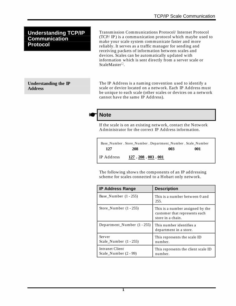
Base_Number . Store_Number . Department_Number . Scale_Number
127 208 003 001
IP Address 127 . 208 . 003 . 001
The following shows the components of an IP addressingscheme for scales connected to a Hobart only network.
IP Address Range Description
Base_Number (1 - 255) This is a number between 0 and255.
Store_Number (1 - 255) This is a number assigned by thecustomer that represents eachstore in a chain.
Department_Number (1 - 255) This number identifies adepartment in a store.
ServerScale_Number (1 - 255)
This represents the scale IDnumber.
Intranet ClientScale_Number (2 - 99)
This represents the client scale IDnumber.
TCP/IP Scale Communication
2
Setting Up Scale IP Addresses
Entering IP AddressInformation for Server andClient Scales
The following steps explain how to access and set up the IPAddresses for scales.
QUICK STEPS
From the Supervisor Menu:1. PRESS [F5]2. PRESS [F6]3. PRESS [F2]4. PRESS [F2]5. TYPE the IP Address6. PRESS [ESC]7. PRESS [ESC]8. Reset the scale
To set up Server and Client Scale IP Addresses:
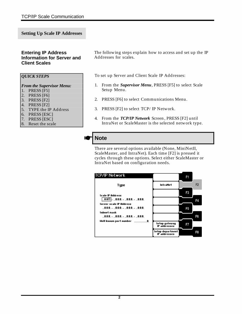
1. From the Supervisor Menu , PRESS [F5] to select ScaleSetup Menu.
2. PRESS [F6] to select Communications Menu. 3. PRESS [F2] to select TCP/IP Network. 4. From the TCP/IP Network Screen, PRESS [F2] until
IntraNet or ScaleMaster is the selected network type.
☛ Note
There are several options available (None, MiniNetII,ScaleMaster, and IntraNet). Each time [F2] is pressed itcycles through these options. Select either ScaleMaster orIntraNet based on configuration needs.
TCP/IP Scale Communication
3
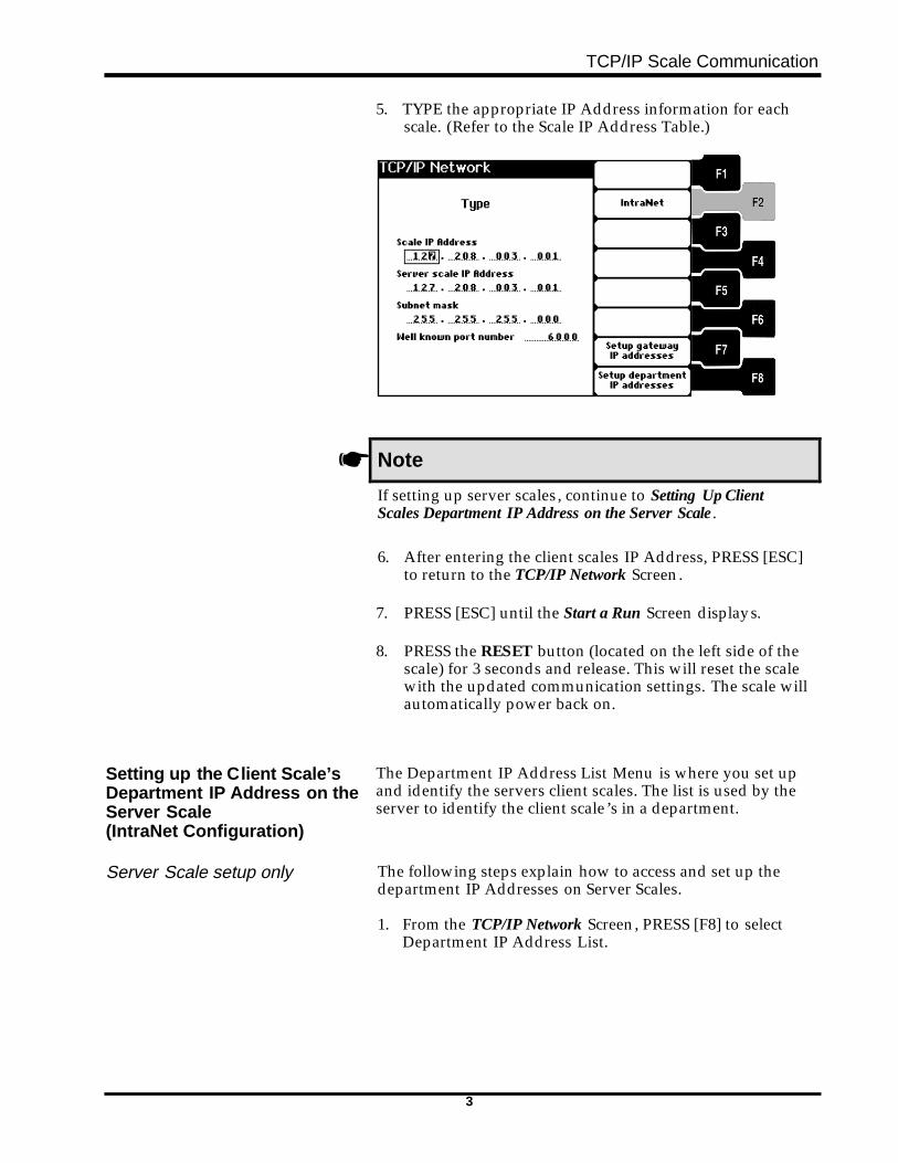
5. TYPE the appropriate IP Address information for eachscale. (Refer to the Scale IP Address Table.)
☛ Note
If setting up server scales, continue to Setting Up ClientScales Department IP Address on the Server Scale .
6. After entering the client scales IP Address, PRESS [ESC]to return to the TCP/IP Network Screen.
7. PRESS [ESC] until the Start a Run Screen displays.
8. PRESS the RESET button (located on the left side of thescale) for 3 seconds and release. This will reset the scalewith the updated communication settings. The scale willautomatically power back on.
Setting up the Client Scale’sDepartment IP Address on theServer Scale(IntraNet Configuration)
The Department IP Address List Menu is where you set upand identify the servers client scales. The list is used by theserver to identify the client scale’s in a department.
Server Scale setup only The following steps explain how to access and set up thedepartment IP Addresses on Server Scales.
1. From the TCP/IP Network Screen, PRESS [F8] to selectDepartment IP Address List.
TCP/IP Scale Communication
4
QUICK STEPS
From the Supervisor Menu:1. PRESS [F82. PRESS [F3]3. TYPE the IP Address4. PRESS [ESC]5. PRESS [ESC]6. Reset the scale
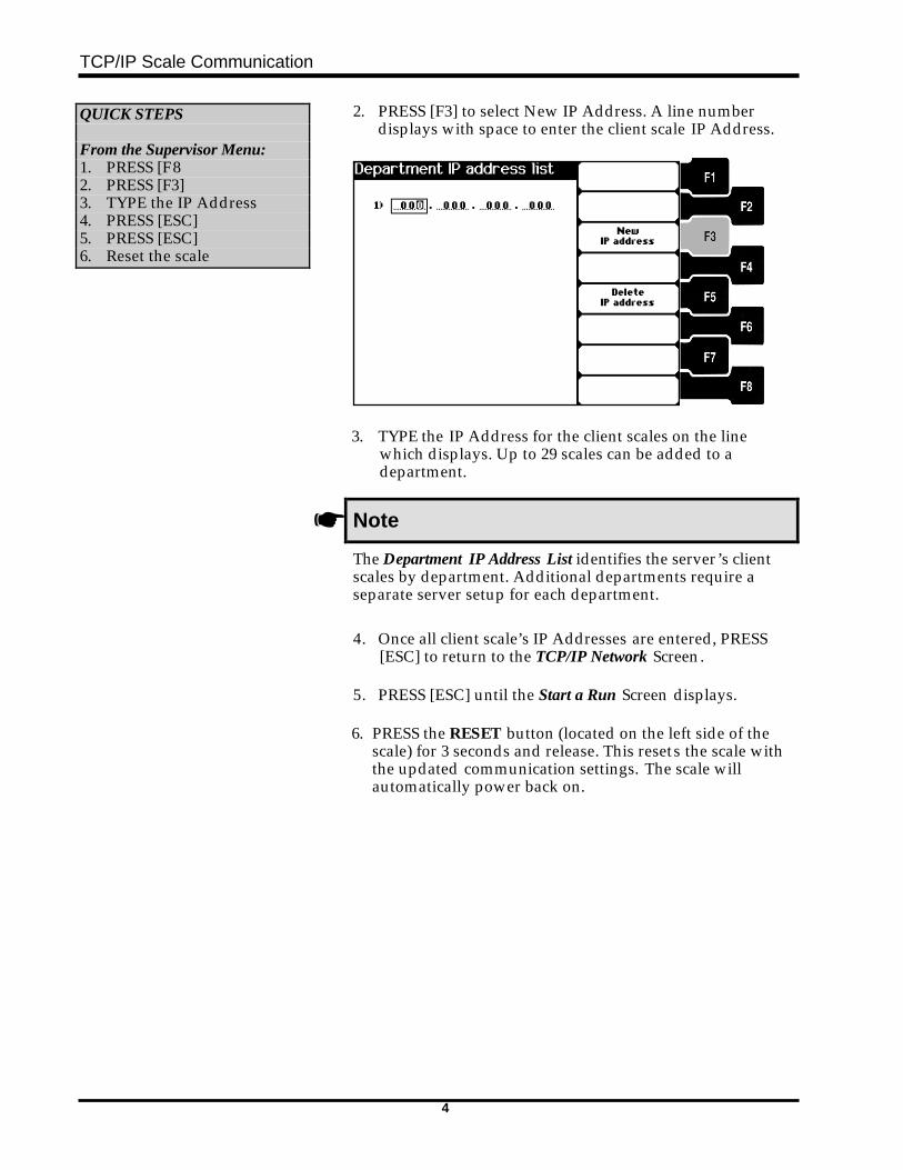
2. PRESS [F3] to select New IP Address. A line numberdisplays with space to enter the client scale IP Address.
3. TYPE the IP Address for the client scales on the linewhich displays. Up to 29 scales can be added to adepartment.
☛ Note
The Department IP Address List identifies the server’s clientscales by department. Additional departments require aseparate server setup for each department.
4. Once all client scale’s IP Addresses are entered, PRESS[ESC] to return to the TCP/IP Network Screen.
5. PRESS [ESC] until the Start a Run Screen displays.
6. PRESS the RESET button (located on the left side of thescale) for 3 seconds and release. This resets the scale withthe updated communication settings. The scale willautomatically power back on.
TCP/IP Scale Communication
5
Setting up ScaleMasterLocated on a DifferentNetwork
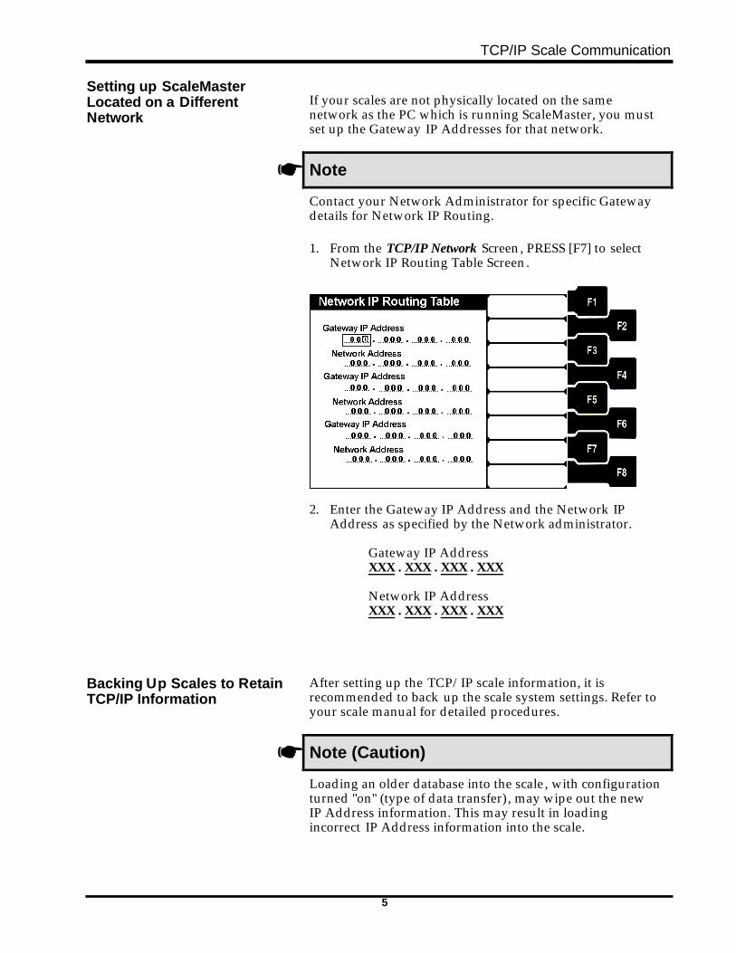
If your scales are not physically located on the samenetwork as the PC which is running ScaleMaster, you mustset up the Gateway IP Addresses for that network.
☛ Note
Contact your Network Administrator for specific Gatewaydetails for Network IP Routing.
1. From the TCP/IP Network Screen, PRESS [F7] to selectNetwork IP Routing Table Screen.
2. Enter the Gateway IP Address and the Network IPAddress as specified by the Network administrator.
Gateway IP AddressXXX . XXX . XXX . XXX
Network IP AddressXXX . XXX . XXX . XXX
Backing Up Scales to RetainTCP/IP Information
After setting up the TCP/IP scale information, it isrecommended to back up the scale system settings. Refer toyour scale manual for detailed procedures.
☛ Note (Caution)
Loading an older database into the scale, with configurationturned "on" (type of data transfer), may wipe out the newIP Address information. This may result in loadingincorrect IP Address information into the scale.
TCP/IP Scale Communication
6
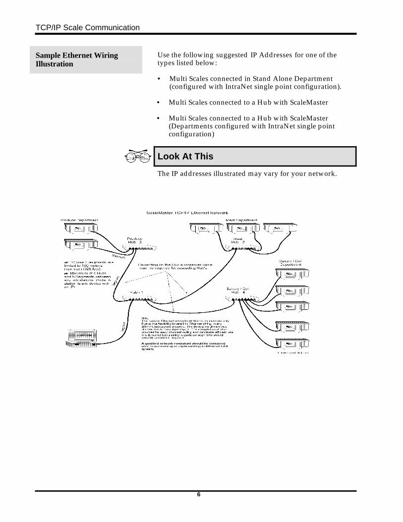
Sample Ethernet WiringIllustration
Use the following suggested IP Addresses for one of thetypes listed below:
• Multi Scales connected in Stand Alone Department (configured with IntraNet single point configuration).
• Multi Scales connected to a Hub with ScaleMaster • Multi Scales connected to a Hub with ScaleMaster
(Departments configured with IntraNet single pointconfiguration)
Look At This
The IP addresses illustrated may vary for your network.
TCP/IP Scale Communication
7
Multi Scales Connected inStand Alone Department(configured with IntraNet singlepoint configuration)
The following configuration shows 2 stand alone scalesconnected to a hub using the Intranet option.
From the TCP/IP Network Screen, ENTER the following:
Server ScaleTCP/IP Network Scale Menu
Type: Intranet (same for client)
Scale IP Address127 . 208 . 003 . 001
Server IP Address (same for client)127 . 208 . 003 . 001
Subnet Mask (same for client)255 . 255 . 255 . 000
Well known port number 6000 (same for client)
Server Scale From the Department IP Address List Screen, set up the ClientScale’s Department IP Address on the server. A maximumof 29 scales for a single department can be added to a Server.
Department IP Address List
1) 127 . 208 . 003 . 002 (Client scale 002 IP Address)
Client Scale 002 Setup From the TCP/IP Network Screen, ENTER the Client Scale’sIP Address. All other fields must be the same as the Serverinformation.
Scale IP Address127 . 208 . 003 . 002
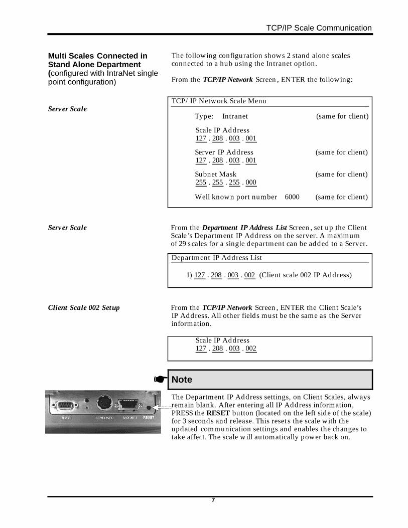
☛ Note
The Department IP Address settings, on Client Scales, alwaysremain blank. After entering all IP Address information,PRESS the RESET button (located on the left side of the scale)for 3 seconds and release. This resets the scale with theupdated communication settings and enables the changes totake affect. The scale will automatically power back on.
TCP/IP Scale Communication
8
Multi Scales Connected to aHub with ScaleMaster
The following illustrates scales connected to the network viaa Hub with ScaleMaster configuration.
☛ Note
If your scales are not physically located on the samenetwork as the PC which is running ScaleMaster, you mustset up the Gateway IP Addresses for that network. Contactyour Network Administrator for specific Gateway detailsfor Network IP Routing.
From the TCP/IP Network Screen, ENTER the following:
Each scale must us a unique IPaddress.
TCP/IP Network Scale Menu
Type: ScaleMaster
Scale IP Address127 . 208 . 003 . 001
Server IP Address000 . 000 . 000 . 000
Subnet Mask255 . 255 . 255 . 000
Well known port number 6000
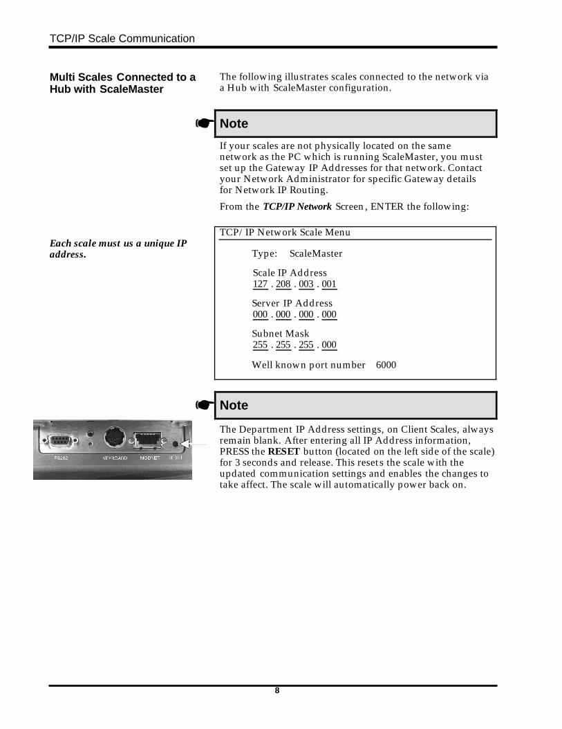
☛ Note
The Department IP Address settings, on Client Scales, alwaysremain blank. After entering all IP Address information,PRESS the RESET button (located on the left side of the scale)for 3 seconds and release. This resets the scale with theupdated communication settings and enables the changes totake affect. The scale will automatically power back on.
TCP/IP Scale Communication
9
Multi Scales connected to aHub with ScaleMaster(Departments configured withIntraNet single point configuration)
The following illustrates scales connected to the network viaa hub and configured for IntraNet.
From the TCP/IP Network Screen, ENTER the following:
Server Scale TCP/IP Network Scale Menu
Type: Intranet (same for client)
Scale IP Address127 . 208 . 003 . 001
Server IP Address (same for client)127 . 208 . 003 . 001
Subnet Mask (same for client)255 . 255 . 255 . 000
Well known port number 6000 (same for client)
Server Scale From the Department IP Address List Screen, set up the Clientscales Department IP Address information on the server. Amaximum of 29 Department Scales can be added to a Server.
Department IP Address List
1) 127 . 208 . 003 . 002 (Client Scale 002)2) 127 . 208 . 003 . 003 (Client Scale 003)
-Through -29) 127 . 208 . 003 . 029 (Client Scale 029)
TCP/IP Scale Communication
10
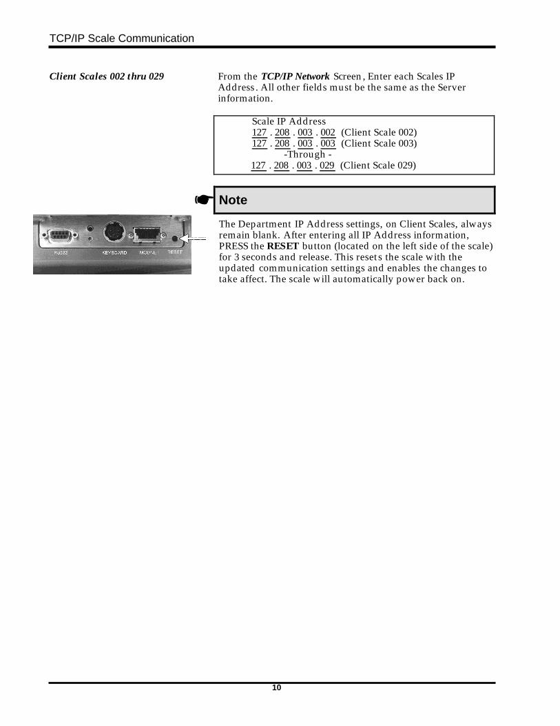
Client Scales 002 thru 029 From the TCP/IP Network Screen, Enter each Scales IPAddress. All other fields must be the same as the Serverinformation.
Scale IP Address127 . 208 . 003 . 002 (Client Scale 002)127 . 208 . 003 . 003 (Client Scale 003)
-Through -127 . 208 . 003 . 029 (Client Scale 029)
☛ Note
The Department IP Address settings, on Client Scales, alwaysremain blank. After entering all IP Address information,PRESS the RESET button (located on the left side of the scale)for 3 seconds and release. This resets the scale with theupdated communication settings and enables the changes totake affect. The scale will automatically power back on.
TCP/IP Scale Communication
11
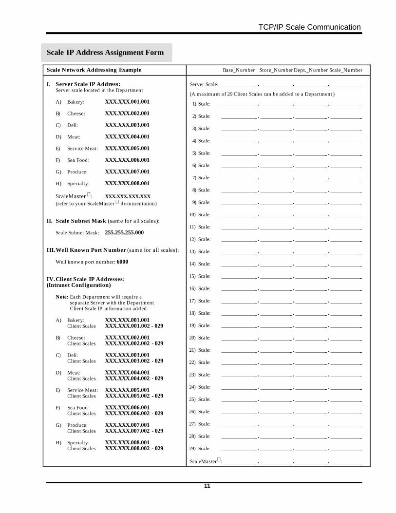
Scale IP Address Assignment Form
Scale Network Addressing Example Base_Number Store_NumberDept._Number Scale_Number
I. Server Scale IP Address:Server scale located in the Department
A) Bakery: XXX.XXX.001.001 B) Cheese: XXX.XXX.002.001 C) Deli: XXX.XXX.003.001 D) Meat: XXX.XXX.004.001 E) Service Meat: XXX.XXX.005.001 F) Sea Food: XXX.XXX.006.001 G) Produce: XXX.XXX.007.001 H) Specialty: XXX.XXX.008.001
ScaleMaster : XXX.XXX.XXX.XXX(refer to your ScaleMaster documentation)
II. Scale Subnet Mask (same for all scales):
Scale Subnet Mask: 255.255.255.000
III.Well Known Port Number (same for all scales):
Well known port number: 6000
IV.Client Scale IP Addresses:(Intranet Configuration)
Note: Each Department will require aseparate Server with the DepartmentClient Scale IP information added.
A) Bakery: XXX.XXX.001.001 Client Scales XXX.XXX.001.002 - 029 B) Cheese: XXX.XXX.002.001 Client Scales XXX.XXX.002.002 - 029 C) Deli: XXX.XXX.003.001 Client Scales XXX.XXX.003.002 - 029 D) Meat: XXX.XXX.004.001 Client Scales XXX.XXX.004.002 - 029 E) Service Meat: XXX.XXX.005.001 Client Scales XXX.XXX.005.002 - 029 F) Sea Food: XXX.XXX.006.001 Client Scales XXX.XXX.006.002 - 029 G) Produce: XXX.XXX.007.001 Client Scales XXX.XXX.007.002 - 029 H) Specialty: XXX.XXX.008.001
Client Scales XXX.XXX.008.002 - 029
Server Scale: . . .
(A maximum of 29 Client Scales can be added to a Department)
1) Scale: . . .
2) Scale: . . .
3) Scale: . . .
4) Scale: . . .
5) Scale: . . .
6) Scale: . . .
7) Scale: . . .
8) Scale: . . .
9) Scale: . . .
10) Scale: . . .
11) Scale: . . .
12) Scale: . . .
13) Scale: . . .
14) Scale: . . .
15) Scale: . . .
16) Scale: . . .
17) Scale: . . .
18) Scale: . . .
19) Scale: . . .
20) Scale: . . .
21) Scale: . . .
22) Scale: . . .
23) Scale: . . .
24) Scale: . . .
25) Scale: . . .
26) Scale: . . .
27) Scale: . . .
28) Scale: . . .
29) Scale: . . .
ScaleMaster : . . .
TCP/IP Scale Communication
12
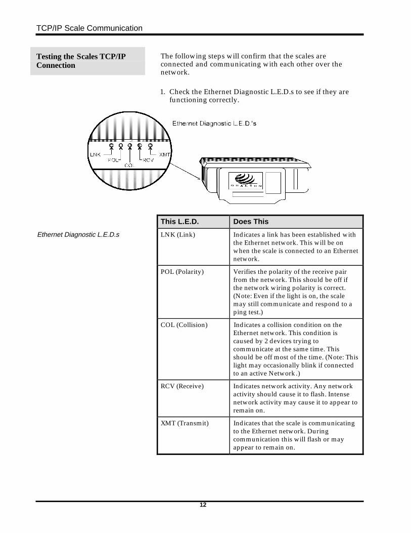
Testing the Scales TCP/IPConnection
The following steps will confirm that the scales areconnected and communicating with each other over thenetwork.
1. Check the Ethernet Diagnostic L.E.D.s to see if they arefunctioning correctly.
This L.E.D. Does This
Ethernet Diagnostic L.E.D.s LNK (Link) Indicates a link has been established withthe Ethernet network. This will be onwhen the scale is connected to an Ethernetnetwork.
POL (Polarity) Verifies the polarity of the receive pairfrom the network. This should be off ifthe network wiring polarity is correct.(Note: Even if the light is on, the scalemay still communicate and respond to aping test.)
COL (Collision) Indicates a collision condition on theEthernet network. This condition iscaused by 2 devices trying tocommunicate at the same time. Thisshould be off most of the time. (Note: Thislight may occasionally blink if connectedto an active Network.)
RCV (Receive) Indicates network activity. Any networkactivity should cause it to flash. Intensenetwork activity may cause it to appear toremain on.
XMT (Transmit) Indicates that the scale is communicatingto the Ethernet network. Duringcommunication this will flash or mayappear to remain on.
TCP/IP Scale Communication
13
2. Update a product on the Server Scale (updates areautomatic with the Intranet network selection).
3. Check the Server Scale for the Transmission Occuredmessage.
4. Verify that the product update is reflected on the ClientScales associated with the Server.
☛ Note
If an error occurred and the Ethernet Diagnostic L.E.D. arefunctioning correctly, check the error log, refer toTroubleshooting IP Addresses or reset each scale by pressingand releasing the Reset button then repeat steps 2 through 4.
TCP/IP Scale Communication
14
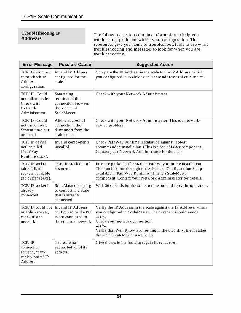
Troubleshooting IPAddresses
The following section contains information to help youtroubleshoot problems within your configuration. Thereferences give you items to troubleshoot, tools to use whiletroubleshooting and messages to look for when you aretroubleshooting.
Error Message Possible Cause Suggested Action
TCP/IP: Connecterror, check IPAddressconfiguration.
Invalid IP Addressconfigured for thescale.
Compare the IP Address in the scale to the IP Address, whichyou configured in ScaleMaster. These addresses should match.
TCP/IP: Couldnot talk to scale.Check withNetworkAdministrator.
Somethingterminated theconnection betweenthe scale andScaleMaster.
Check with your Network Administrator.
TCP/IP: Couldnot disconnect.System time-outoccurred.
After a successfulconnection, thedisconnect from thescale failed.
Check with your Network Administrator. This is a network-related problem.
TCP/IP devicenot installed(PathWayRuntime stack).
Invalid componentsinstalled.
Check PathWay Runtime installation against Hobartrecommended installation. (This is a ScaleMaster component.Contact your Network Administrator for details.)
TCP/IP sockettable full, nosockets available(no buffer space).
TCP/IP stack out ofresource.
Increase packet buffer sizes in PathWay Runtime installation.This can be done through the Advanced Configuration Setupavailable in PathWay Runtime. (This is a ScaleMastercomponent. Contact your Network Administrator for details.)
TCP/IP socket isalreadyconnected.
ScaleMaster is tryingto connect to a scalethat is alreadyconnected.
Wait 30 seconds for the scale to time out and retry the operation.
TCP/IP could notestablish socket,check IP andnetwork.
Invalid IP Addressconfigured or the PCis not connected tothe ethernet network.
Verify the IP Address in the scale against the IP Address, whichyou configured in ScaleMaster. The numbers should match.--OR--Check your network connection.--OR--Verify that Well Know Port setting in the uiconf.txt file matchesthe scale (ScaleMaster uses 6000).
TCP/IPconnectionrefused, checkcables/ports/IPAddress.
The scale hasexhausted all of itssockets.
Give the scale 1-minute to regain its resources.
TCP/IP Scale Communication
15
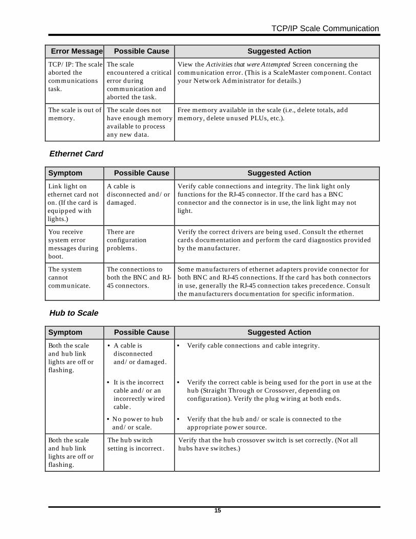
Error Message Possible Cause Suggested Action
TCP/IP: The scaleaborted thecommunicationstask.
The scaleencountered a criticalerror duringcommunication andaborted the task.
View the Activities that were Attempted Screen concerning thecommunication error. (This is a ScaleMaster component. Contactyour Network Administrator for details.)
The scale is out ofmemory.
The scale does nothave enough memoryavailable to processany new data.
Free memory available in the scale (i.e., delete totals, addmemory, delete unused PLUs, etc.).
Ethernet Card
Symptom Possible Cause Suggested Action
Link light onethernet card noton. (If the card isequipped withlights.)
A cable isdisconnected and/ordamaged.
Verify cable connections and integrity. The link light onlyfunctions for the RJ-45 connector. If the card has a BNCconnector and the connector is in use, the link light may notlight.
You receivesystem errormessages duringboot.
There areconfigurationproblems.
Verify the correct drivers are being used. Consult the ethernetcards documentation and perform the card diagnostics providedby the manufacturer.
The systemcannotcommunicate.
The connections toboth the BNC and RJ-45 connectors.
Some manufacturers of ethernet adapters provide connector forboth BNC and RJ-45 connections. If the card has both connectorsin use, generally the RJ-45 connection takes precedence. Consultthe manufacturers documentation for specific information.
Hub to Scale
Symptom Possible Cause Suggested Action
Both the scaleand hub linklights are off orflashing.
• A cable isdisconnectedand/or damaged.
• Verify cable connections and cable integrity.
• It is the incorrectcable and/or anincorrectly wiredcable.
• Verify the correct cable is being used for the port in use at thehub (Straight Through or Crossover, depending onconfiguration). Verify the plug wiring at both ends.
• No power to huband/or scale.
• Verify that the hub and/or scale is connected to theappropriate power source.
Both the scaleand hub linklights are off orflashing.
The hub switchsetting is incorrect .
Verify that the hub crossover switch is set correctly. (Not allhubs have switches.)
TCP/IP Scale Communication
16
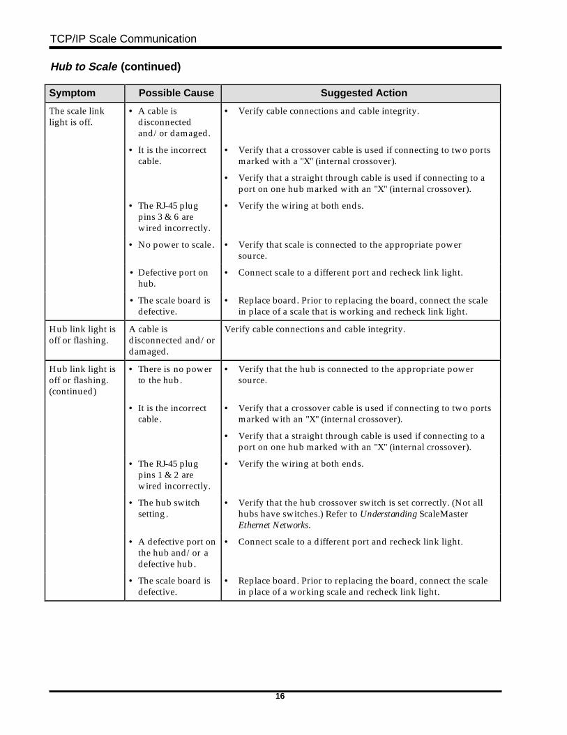
Hub to Scale (continued)
Symptom Possible Cause Suggested Action
The scale linklight is off.
• A cable isdisconnectedand/or damaged.
• Verify cable connections and cable integrity.
• It is the incorrectcable.
• Verify that a crossover cable is used if connecting to two portsmarked with a "X" (internal crossover).
• Verify that a straight through cable is used if connecting to aport on one hub marked with an "X" (internal crossover).
• The RJ-45 plugpins 3 & 6 arewired incorrectly.
• Verify the wiring at both ends.
• No power to scale. • Verify that scale is connected to the appropriate powersource.
• Defective port onhub.
• Connect scale to a different port and recheck link light.
• The scale board isdefective.
• Replace board. Prior to replacing the board, connect the scalein place of a scale that is working and recheck link light.
Hub link light isoff or flashing.
A cable isdisconnected and/ordamaged.
Verify cable connections and cable integrity.
Hub link light isoff or flashing.(continued)
• There is no powerto the hub.
• Verify that the hub is connected to the appropriate powersource.
• It is the incorrectcable.
• Verify that a crossover cable is used if connecting to two portsmarked with an "X" (internal crossover).
• Verify that a straight through cable is used if connecting to aport on one hub marked with an "X" (internal crossover).
• The RJ-45 plugpins 1 & 2 arewired incorrectly.
• Verify the wiring at both ends.
• The hub switchsetting.
• Verify that the hub crossover switch is set correctly. (Not allhubs have switches.) Refer to Understanding ScaleMasterEthernet Networks.
• A defective port onthe hub and/or adefective hub.
• Connect scale to a different port and recheck link light.
• The scale board isdefective.
• Replace board. Prior to replacing the board, connect the scalein place of a working scale and recheck link light.
TCP/IP Scale Communication
17
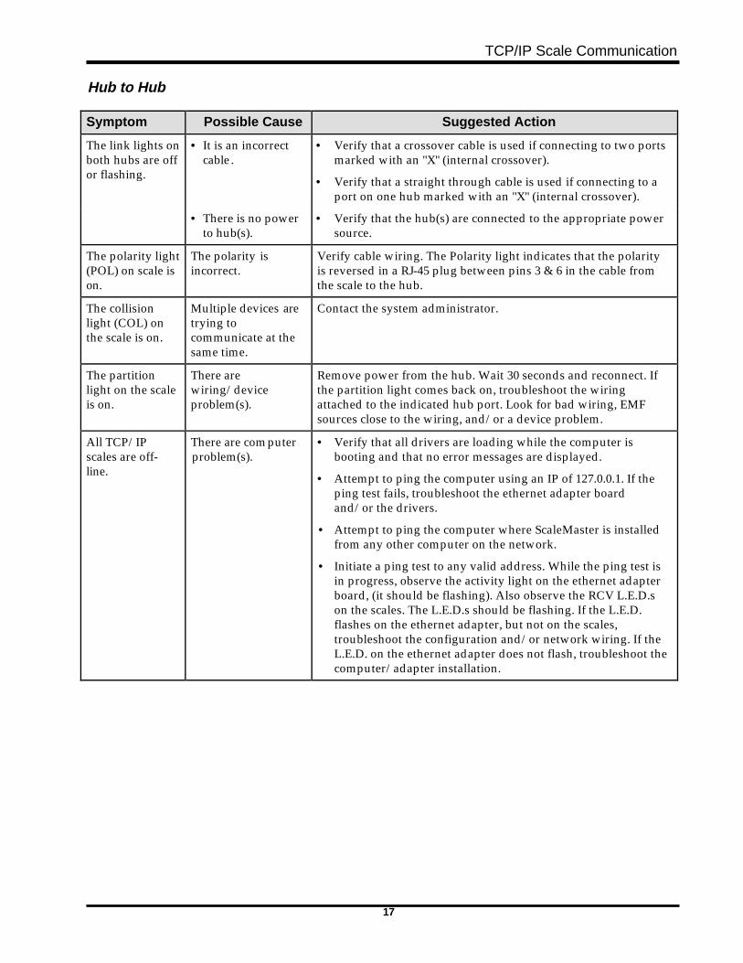
Hub to Hub
Symptom Possible Cause Suggested Action
The link lights onboth hubs are offor flashing.
• It is an incorrectcable.
• Verify that a crossover cable is used if connecting to two portsmarked with an "X" (internal crossover).
• Verify that a straight through cable is used if connecting to aport on one hub marked with an "X" (internal crossover).
• There is no powerto hub(s).
• Verify that the hub(s) are connected to the appropriate powersource.
The polarity light(POL) on scale ison.
The polarity isincorrect.
Verify cable wiring. The Polarity light indicates that the polarityis reversed in a RJ-45 plug between pins 3 & 6 in the cable fromthe scale to the hub.
The collisionlight (COL) onthe scale is on.
Multiple devices aretrying tocommunicate at thesame time.
Contact the system administrator.
The partitionlight on the scaleis on.
There arewiring/deviceproblem(s).
Remove power from the hub. Wait 30 seconds and reconnect. Ifthe partition light comes back on, troubleshoot the wiringattached to the indicated hub port. Look for bad wiring, EMFsources close to the wiring, and/or a device problem.
All TCP/IPscales are off-line.
There are computerproblem(s).
• Verify that all drivers are loading while the computer isbooting and that no error messages are displayed.
• Attempt to ping the computer using an IP of 127.0.0.1. If theping test fails, troubleshoot the ethernet adapter boardand/or the drivers.
• Attempt to ping the computer where ScaleMaster is installedfrom any other computer on the network.
• Initiate a ping test to any valid address. While the ping test isin progress, observe the activity light on the ethernet adapterboard, (it should be flashing). Also observe the RCV L.E.D.son the scales. The L.E.D.s should be flashing. If the L.E.D.flashes on the ethernet adapter, but not on the scales,troubleshoot the configuration and/or network wiring. If theL.E.D. on the ethernet adapter does not flash, troubleshoot thecomputer/adapter installation.
TCP/IP Scale Communication
18
Hub to Hub (continued)
Symptom Possible Cause Suggested Action
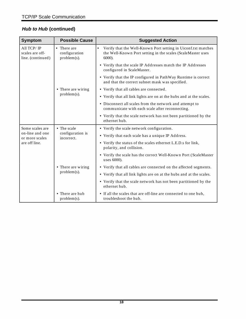
All TCP/IPscales are off-line. (continued)
• There areconfigurationproblem(s).
• Verify that the Well-Known Port setting in Uiconf.txt matchesthe Well-Known Port setting in the scales (ScaleMaster uses6000).
• Verify that the scale IP Addresses match the IP Addressesconfigured in ScaleMaster.
• Verify that the IP configured in PathWay Runtime is correctand that the correct subnet mask was specified.
• There are wiringproblem(s).
• Verify that all cables are connected.
• Verify that all link lights are on at the hubs and at the scales.
• Disconnect all scales from the network and attempt tocommunicate with each scale after reconnecting.
• Verify that the scale network has not been partitioned by theethernet hub.
Some scales areon-line and oneor more scalesare off line.
• The scaleconfiguration isincorrect.
• Verify the scale network configuration.
• Verify that each scale has a unique IP Address.
• Verify the status of the scales ethernet L.E.D.s for link,polarity, and collision.
• Verify the scale has the correct Well-Known Port (ScaleMasteruses 6000).
• There are wiringproblem(s).
• Verify that all cables are connected on the affected segments.
• Verify that all link lights are on at the hubs and at the scales.
• Verify that the scale network has not been partitioned by theethernet hub.
• There are hubproblem(s).
• If all the scales that are off-line are connected to one hub,troubleshoot the hub.
TCP/IP Scale Communication
19
Appendix
Understanding EthernetNetworks
To effectively set up Scales with TCP/IP, you should have abasic understanding of ethernet networking. A NetworkConsultant or Network Administrator should be contactedprior to implementing an Ethernet LAN system.
HubsHubs for 10BaseT are available with different numbers andtypes of ports. The IEEE 802.3 standard recommends that thesignal crossover function for 10BaseT connection is doneinside the hub port. This standard also notes that all portsfeaturing an internal crossover be designated with an "X".Some hubs provide a port where the crossover function iscontrolled by a switch. This port is generally used forcascading hubs using straight through cables. Hubs whereall ports feature an internal crossover generally require acrossover cable to cascade the hubs. stackable hubs, whichprovide a special connection for stacking 2 or more hubs, arealso available. Stacked hubs count as one hub whencalculating the number of hubs and segments between twostations.
☛ Note
10BaseT hubs are also available with connections forattaching to a 10Base2 (coax cable) network.
WiringAn Ethernet network may consist of several different cabletypes. ScaleMaster may be used successfully with any typeof Ethernet network if provisions are made to provide a10BaseT connection for each scale. Refer to your ScaleMasterTCP/IP supplement for more information (F-33863).
Wiring Specifications10BaseT (or UTP-Unshielded Twisted Pair) length segmentshave a maximum of 328Ì (100m). This is the maximumamount allowed between hubs or remote devices (i.e. scalesor computers). The network is also restricted to a maximumof 4 hubs between any two devices.
TCP/IP Scale Communication
20
Wiring CategoriesHobart Ethernet scales supporting TCP/IP require a networkconnection using 10BaseT wiring. Hobart recommends thatall wiring conform to Category 3 or 5 standards, publishedby EIA.
☛ Note
Category 3 wiring may be used but is not recommended.
Look At This
All wiring and cabling must be installed to meet Nationaland Local Electrical Codes.
All Ethernet wiring must conform to IEEE 802.3specifications.
All cabling should be installed to meet the cabling pathwayrequirements of EIA/TIA Standard 569, table 4.8-5.
Crossover FunctionTwo Ethernet 10BaseT devices can only communicate if thetransmitter on one device is connected to the receiver on theother device. When connecting two identical 10BaseT ports(ports that either both support the crossover function or bothdo not support the crossover function), the crossoverfunction must be implemented in the wiring.
Patch Cord WiringA patch cord is the connecting cable between two pieces ofhardware on an ethernet network. The recommendedstandard for wiring patch cords is the EIA/TIA 568Bstandard, using RJ-45 8 conductor connectors. The patchcords used may be wired to any standard as long as all cordsare wired using the same standard. The EIA/TIA 568Bstandard is recommended for conformity with industrystandards.
TCP/IP Scale Communication
21
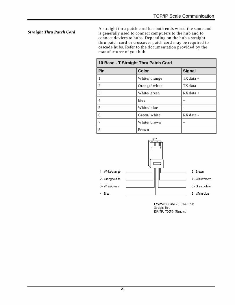
Straight Thru Patch CordA straight thru patch cord has both ends wired the same andis generally used to connect computers to the hub and toconnect devices to hubs. Depending on the hub a straightthru patch cord or crossover patch cord may be required tocascade hubs. Refer to the documentation provided by themanufacturer of you hub.
10 Base - T Straight Thru Patch Cord
Pin Color Signal
1 White/orange TX data +
2 Orange/white TX data -
3 White/green RX data +
4 Blue --
5 White/blue --
6 Green/white RX data -
7 White/brown --
8 Brown --
TCP/IP Scale Communication
22
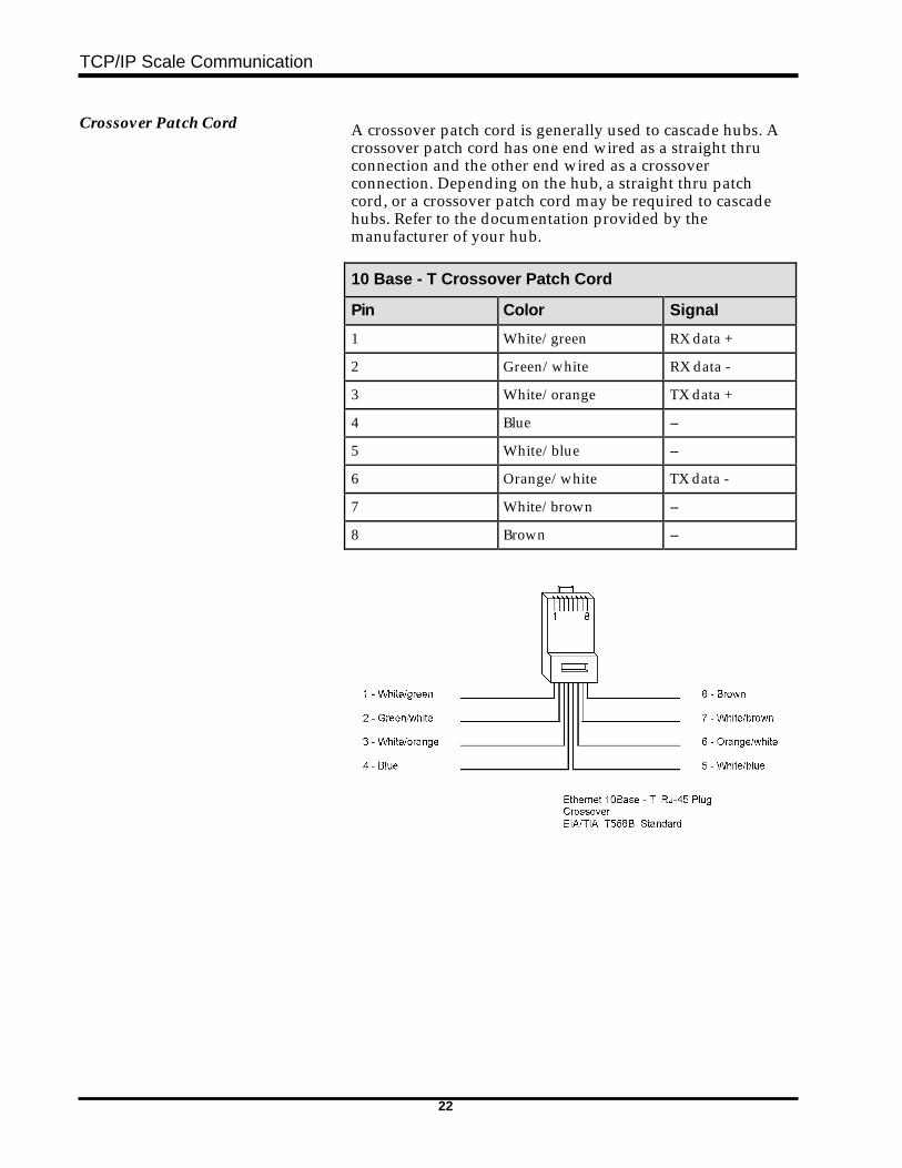
Crossover Patch Cord A crossover patch cord is generally used to cascade hubs. Acrossover patch cord has one end wired as a straight thruconnection and the other end wired as a crossoverconnection. Depending on the hub, a straight thru patchcord, or a crossover patch cord may be required to cascadehubs. Refer to the documentation provided by themanufacturer of your hub.
10 Base - T Crossover Patch Cord
Pin Color Signal
1 White/green RX data +
2 Green/white RX data -
3 White/orange TX data +
4 Blue --
5 White/blue --
6 Orange/white TX data -
7 White/brown --
8 Brown --
TCP/IP Scale Communication
23
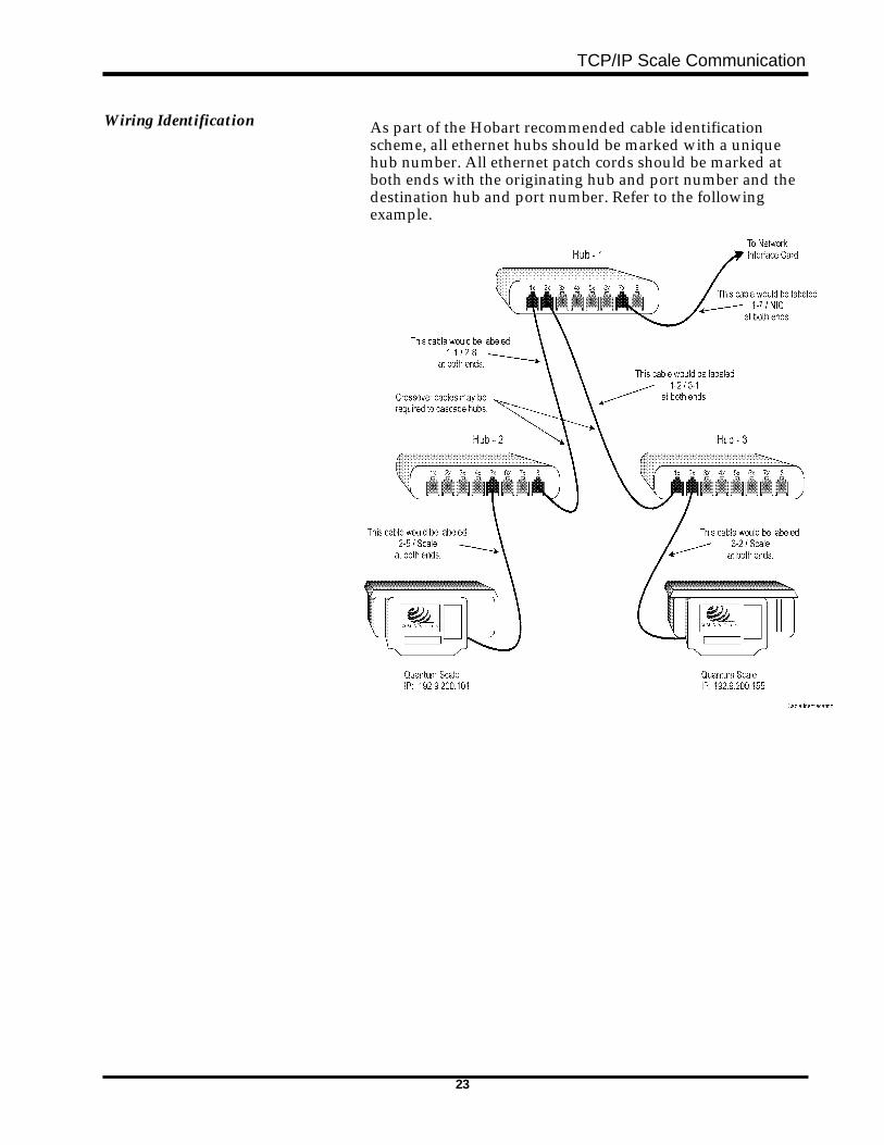
Wiring Identification As part of the Hobart recommended cable identificationscheme, all ethernet hubs should be marked with a uniquehub number. All ethernet patch cords should be marked atboth ends with the originating hub and port number and thedestination hub and port number. Refer to the followingexample.
TCP/IP Scale Communication
24
Glossary
Abstract Notation Syntax One(ASN.1)
A language used in OSI and TCP/IP networks to definedata types for use in network management.
Address An identifiable location. A location within memory. Alocation of a node within a network. A way of identifying anetwork, sub network, or node.
Address Mask A way of omitting certain parts of an IP Address in order toreach the target destination without broadcasting anaddress to unnecessary LAN segments or sub networks. It isalso referred to as a subnet mask. The address mask uses the32-bit IP Addressing scheme. A variation of 255.255.255.255is used.
Address Resolution The mapping of an IP Address to a hardware address. In theTCP/IP suite of protocols, Address Resolution Protocol(ARP) performs this function.
API Application Program Interface. Defined routines that arecallable services by a program.
Application Layer The topmost layer in the OSI reference model that aids inthe identification of communicating partners.
Backbone Used to refer to a set of nodes and links connected togethercompromising a network. It is also used to refer to thephysical media that connects components to a network.
Baseband A type of channel where data transmission is carried acrossonly one communication channel. Baseband supports onesignal transmission at a time. Ethernet is an example ofbaseband technology.
BER Bit Error Rate
Bit rate The rate, usually expressed in seconds, that bits aretransmitted.
Bridge A network device capable of connecting networks usingsimilar protocols.
Broadband A range of frequencies divided into narrow bands, each ofwhich can be used for different transmission purposes. Alsoknown as wideband.
Broadcast Simultaneous transmission of the same data to all nodesconnected to a network.
TCP/IP Scale Communication
25
Carrier Sense A signal generated at the physical network layer to informthe data link layer that one or more nodes are transmittingon the underlying medium.
Carrier Sense Multiple Accesswith Collision Detection(CSMA/CD)
This is the media access control protocol. Nodes using thisprotocol listen to the medium to which they are attached. Aslong as there is no signal on the medium being monitored, anode listening can send data across the medium.
Client A program that can be invoked by a user; a user being ahuman or a program.
Client/Server Architecture A general phrase used to refer to a distributed applicationenvironment where a program exists that can initiate asession and a program exists to answer the requests of aclient.
Client/Server Terms used to refer to a peer to peer method of operation ofapplications within hosts.
Collision An event that occurs when two or more nodes broadcast onthe same network medium at the same time.
Collision Detection The ability of a device to detect if a collision has occurred.
Crosstalk Signals that interfere with another signal being transmitted.
Daemon A common UNIX program that operates unattended,performing standard services. This type of program can betriggered by time intervals for execution.
Datagram A basic unit of data that traverses a TCP/IP internet.
Data Link The part of a node that is controlled by a data link protocol.It is the logical connection between two nodes.
Data Link Protocol A prescribed way of handling the establishment,maintenance, and termination of a logical link between twonodes.
Destination Address In an Ethernet network, this refers to the target nodeaddress.
Distributed Processing I/O processing, control functions, and actual processing isdispersed among two or more nodes.
Domain Name System A service used with TCP/IP to replace the previous methodof keeping track with host names, aliases, and internetaddresses. The domain name service is a distributeddatabase used to convert node names to internet addresses.
Dotted Decimal Notation A representation of addressing typically used in expressinginternet protocol addresses. For example, 137.1.1.100 is aninternet address identifying a network and host.
TCP/IP Scale Communication
26
Double Byte Character Set A character set where alphanumeric characters arerepresented by two bytes. Examples of languages where thisis used include: Japanese, Chinese, and Korean.
Encapsulation A technique used by layered network protocols where, asdata travels down the network layers, headers and trailersare added to represent that layer. For example, when data ispassed from an application above the TCP layer, TCP adds aheader and a trailer encapsulating the data; likewise, thisdatagram is passed to the IP layer where IP wraps an IPheader and trailer around the TCP portion, and so on foreach layer. When this arrives at the target host, the reverseoccurs, as the data travels up the layers, respective headersand trailers are removed.
Ethernet A data link level protocol. It comprises layers one and twowhen compared to the OSI reference model. Ethernet is abroadcast technology and can be implemented withdifferent media types, such as thick or thin coaxial cable ortwisted pair cable. Ethernet uses CSMA/CD mechanism toaccess the medium.
Ethernet Address A 48 bit address, commonly referred to as a hard address.This address identifies an Ethernet network interface card(NIC), thus identifying a host hardware address.
Frame Refers to the data and all headers and trailers.
Frame Check Sequence (FCS) A mathematical function used with bits in a frame. The FCSis appended to the frame and used by the receiving end torecalculate the value to determine if an error has occurred.
Frame Relay A switching mechanism for routing frames as quickly aspossible.
File Transfer Protocol (FTP) A TCP/IP based application used for transferring files fromone system to another. Part of FTP provides passwordprotection.
Gateway A networking device that translates all protocols of one typenetwork into all protocols of another type network. (i.e.Ethernet to Token Ring).
Hardware Address A low-level address associated with each node on thenetwork. This address is generally the address related to theinterface card in the node. This may also be referred to asthe Ethernet Address.
Internet Control Message Protocol(ICMP)
A protocol that works in conjunction with the InternetProtocol (IP) that handles error messages.
Interface A shared point between two entities, either software orhardware.
TCP/IP Scale Communication
27
Internet Address A 32-bit address used to identify hosts and networks.
Internet Protocol (IP) The part of the TCP/IP protocol that handles routing ofdata.
IP Datagram The basic unit of information passed through a TCP/IPnetwork. This datagram contains source and destinationaddresses.
ISO International Standards Organization
ISO Reference Model The networking model created by ISO defining seven layersof a network, isolating functions within each layer. It is usedas a baseline for comparison with other network types.
Jitter A situation that can occur with a 10BaseT network wheresignals are out of phase with each other.
Local Area Network (LAN) A collection of computer related equipment connected insuch a way that communication can occur between all nodesconnected to the medium.
Learning Bridge Serves as a bridge but has the capability to learn what nodesare connected and route data accordingly.
Leased Line A dedicated communication line between two points.
Link Used to refer to a connection between two end points.
Logical Link Control The upper part of the data link sublayer protocolresponsible for governing the exchange of data between twoendpoints.
Media Access Control (MAC) The lower half of the data link sublayer. It is responsible forframing data and controlling the physical link between twostations.
Maximum Transmission Unit(MTU)
The largest datagram that can transverse a given networksuch as Ethernet or Token Ring.
Medium Access Unit (MAU) A device for central connection of nodes operating in anetwork.
Management Information Base(MIB)
A database containing configuration and statisticalinformation about nodes on a network.
Name Resolution The process of mapping aliases to an address. The domainname system provides a mechanism to perform thisfunction.
Network Administrator The person designated to maintain the network. This personshould have working knowledge of network wiring,requirements, etc. See System Administrator.
TCP/IP Scale Communication
28
Network Basic Input OutputOperating System (NETBIOS)
An IBM and compatible network programming interface.
Network A collection of computers and related devices connected sothat communication can occur.
Network Address In TCP/IP networks, this refers to the IP Address of a node.
Network File System (NFS) Sun MicroSystems protocols that permit clients to mountremote directories onto their own local file system, thusappearing to be local.
Network Interface Card (NIC) A generic reference to a networking interface card.
Node Refers to different types of networking devices.
Open Systems Interconnection(OSI)
A set of ISO standards relating to data communications.
Packet In TCP/IP networks, this refers to the data passing betweenthe internet layer and the data link layer. A packet includesthe IP header, TCP header, and data.
Pathname The complete string of information that must be entered intoa system in order to access or identify a file.
Packet InterNet Groper (PING) A program used with TCP/IP networks. The PING programprovides a way of testing access to a destination by sendingan ICMP echo request, then waiting for a response from thetarget host.
Point to Point Protocol (PPP) A protocol that has the ability to provide host to networkand router to router connections over synchronous andasynchronous lines.
Port In TCP/IP, a number used to identify applications. Ingeneral, a port is referred to as an entry or exit point. Portsare associated with TCP or UDP transport protocols.
Protocol A set of rules governing the method of operation.
Protocol Conversion Changing one type of protocol to another type of protocol.
Repeater A network device that repeats signals so the length of anetwork can be extended.
Routing The process of determining which path is to be used for datatransmission.
Routing Table A list of valid paths through which data can be transmitted.
RS-232-C A physical layer specification for connecting devices.
TCP/IP Scale Communication
29
Segment A protocol data unit that consists of TCP header informationand optional data.
Parts of a network; typically Ethernet LANs are divided intoparts, generally referred to as segments.
Server An application that answers requests from clients.
Simple Mail Transfer Protocol(SMTP)
In TCP/IP, an application including a client and a serverproviding E-Mail services for all hosts with TCP/IPsoftware installed and enabled.
Serial Line Internet Protocol(SLIP)
A protocol used to utilize Internet protocol over serial lines,such as a switched telephone line.
Socket In TCP/IP, a socket is an addressable point that consists ofthe IP Address and the TCP or UDP port number. Itprovides access to TCP/IP protocols.
Socket Address The complete designation of a TCP/IP node. It consists of a32-bit IP Address and a 16 bit port number.
Subnet The part of a TCP/IP network identified by a portion of theinternet address.
Subnet Address The part of the IP Address that identifies the subnetwork.
Subnet Mask A way of isolating broadcasts to the desired network(s).
System Administrator The person responsible for maintaining the ScaleMastersystem. See Network Administrator.
Telnet A TCP/IP application using TCP as a transport mechanism.It consists of a client and a server. All TCP/IP protocolsuites have this application because it is part of thedefinition of TCP/IP.
TCP Transmission Control Protocol. A transport layer protocolthat is part of the TCP/IP protocol suite. TCP provides areliable stream mechanism performing re-transmissionwhen a positive acknowledgment is not returned to thesource from the destination node.
TCP/IP Transmission Control Protocol / Internet Protocol. TCP/IPis an upper layer networking protocol. It is client/serverbased at the application layer.
10Base2 A reference to the cabling used in an Ethernet network. Itliterally means 10Megabits per second, using basebandsignaling, with a continuous cable segment length of 100meters and a maximum of 2 segments.
TCP/IP Scale Communication
30
10Base5 A reference to the cabling used in an Ethernet network. Itliterally means 10Megabits per second, using basebandsignaling, with 5 continuous segments, not exceeding 100meters per segment.
10BaseT A reference to the cabling used in an Ethernet network.Meaning 10Megabits per second, using baseband signaling,and twisted pair cabling.
Throughput The amount of data that can be successfully moved across amedium or processed within a certain time period.
Token Ring A lower layer networking protocol using a token passingmethod controlling data traffic. It is connection oriented at adata link level.
Topology The configuration of network devices. Examples include:BUS, Star, Ring, Dual Ring, etc.
Traffic A generic term used to describe the amount of data on anetwork backbone at a given period in time.
Transceiver A network device required in baseband networks. It takes adigital signal and puts it on the analog baseband medium.Transceivers are devices that also sense collisions.
User Data Protocol (UDP) A transport layer protocol in the TCP/IP protocol suite.Unlike TCP it does not provide re-transmission.
Virtual Appearing to exist, but in reality the appearance is achievedby functions or processes.
Well Known Port In TCP/IP, an address for an expressed purpose generallyagreed upon by TCP/IP users.
Wide Area Network (WAN) A network spanning large geographic distances.


FORM 34001 (5-98)