Embed Size (px)
Citation preview
SupersededEngine Model
No0-320* LetterDesignation
0-320-A1A
0-320-A1 B
0-320-B1A
0-320-B1B
PropellerBushings
3/8 inch
3/8 inch
Lycoming652 Oliver StreetWilliamsport, PA 17701 U.S.A.717/323-6181Textron Lycoming/Subsidiary of Textron Inc
TECHNICAL PUBLICATIONSUPPLEMENT
SUPPLEMENT No.
SSP-488
ENGINE MODEL0-320, 10-320 and
LIO-320 Series
PUBLICATION No.
PC-103
PUBLICATION DATE
April, 1970
This supplement is arranged in the same basic format as the original parts catalogInsert in front of catalog for useage of subject matter.
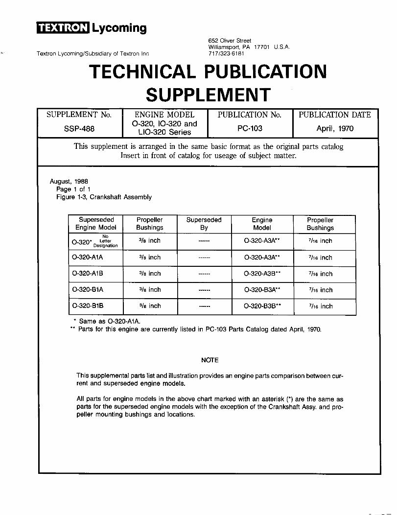
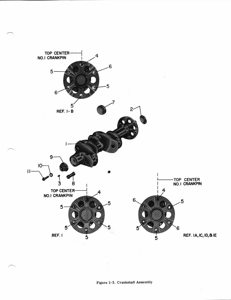
August, 1988Page 1 of 1Figure 1-3, Crankshaft Assembly
SupersededBy
EngineModel
0-320-A3A**
0-320-A3A**
PropellerBushings
7/16 inch
7/16 inch
7/16 inch
7/16 inch
7/16 inch
3/8 inch 0-320-A3B**
3/8 inch 0-320-B3A**
3/8 inch 0-320-B3B**
* Same as 0-320-A1A.** Parts for this engine are currently listed in PC-103 Parts Catalog dated April, 1970.
NOTE
This supplemental parts list and illustration provides an engine parts comparison between cur-rent and superseded engine models.
All parts for engine models in the above chart marked with an asterisk (*) are the same asparts for the superseded engine models with the exception of the Crankshaft Assy. and pro-peller mounting bushings and'locations.
l Lycoming 0-320, 10-320, LIO-320 SERIES PARTS CATALOGSTANDARD CYLINDER FLANGE CRANKCASE MODEL ENGINES
CRANKCASE, CRANKSHAFT AND CAMSHAFT GROUPCRANKSHAFT AND RELATED PARTS
QUANTITY PER ASSEMBLY
FIG.REF.1-3
PARTNUMBER DESCRIPTION 0-320, 0-320-A1A,
A1B, B1A and B1B
1 68864*2 STD-12113 72066-S4 72067-S5 72068-S6 61510
CRANKSHAFT ASSEMBLYPLUG, 2.00 dia. expansionBUSHING, Propeller flange, indexBUSHING, Propeller flangeBUSHING, Propeller flange, shortPLUG, 1-3/4 O.D.
11
1
321
* No longer available. Order Crankshaft Assembly Part No. 75011 as a replacement. Refer to latest edition of ServiceInstruction No. 1098 for bushing application.
2
NO. 1 3CRANKPIN
5 4
4 5
4
SSP-488 Page 1 of 1
SUPPLEMENTAL PARTS LIST
To Provide Parts Coverage for ModelO-320-E2G Lycoming Aircraft Engines
This supplemental parts list is written to provide an engine partscomparison between the O-320-E2D as listed in Lycoming PC-103, andengine model O-320-E2G. It is written to follow PC-103 page by page andpart by part. Figure reference numbers, part numbers and page numbersfollow exact construction of PC-103. Where necessary, because of numer-ous changes, all parts applicable to O-320-E2G model engines are listed.
If a part number in this supplement does not have a figure referencenumber, it denotes a new part, or a part not figure referenced in PC-103,or parts that are peculiar to O-320-E2G model engines. If a page inPC-103 is not applicable to O-320-E2G model engines, it is so designatedin this supplement.
NOTICE
The spark plugs listed herein, are those used in currentproduction only; this listing does not include additionalspark plugs that are approved for use in these engines.See latest edition of Service Instruction No. 1042 forcomplete listing of all spark plugs.
SSP276 February, 1976
1
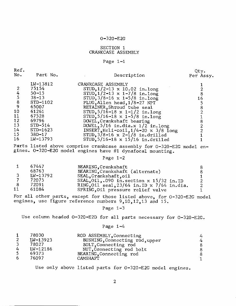
0-320-E2G
SECTION 1CRANKCASE ASSEMBLY
Page 1-1
Ref.No. Part No. Description
Qty.Per Assy.
24589
10111213141516
LW-138127515450-1538-13STD-110265007612616752869796STD-514STD-162338D-17LW-13793
CRANKCASE ASSEMBLYSTUD,1/2-13 x 10.02 in.longSTUD,1/2-13 x 1-7/8 in.longSTUD,3/8-16 x 1-5/8 in.longPLUG,Allen head,1/8-27 NPTRETAINER,Shroud tube sealSTUD,5/16-18 x 1-1/2 in.longSTUD,5/16-18 x 1-5/8 in.longDOWEL,Crankshaft bearingDOWEL,5/16 in.dia.x 1/2 in.longINSERT,Heli-coil,1/4-20 x 3/8 longSTUD,3/8-16 x 2-1/8 in.drilledSTUD,5/16-18 x 15/16 in.drilled
12816
582182211
Parts listed above comprise crankcase assembly for O-320-E2G modelgines. O-320-E2G model engines have #1 dynafocal mounting.
Page 1-2
en-
1 6744768763
3 LW-137927 720758 72091
11 61084
BEARING, CrankshaftBEARING,Crankshaft (alternate)SEAL,Crankshaft,oilSEAL,Oil,.090 in.section x 15/32 in.IDRING,Oil seal,23/64 in.ID x 7/64 in.dia.SPRING,Oil pressure relief valve
881221
For all other parts, except for those listed above, for O-320-E2G modelengines, use figure reference numbers 9,10,12,13 and 15.
Page 1-3
Use column headed O-320-E2D for all parts necessary for O-320-E2G.
Page 1-4
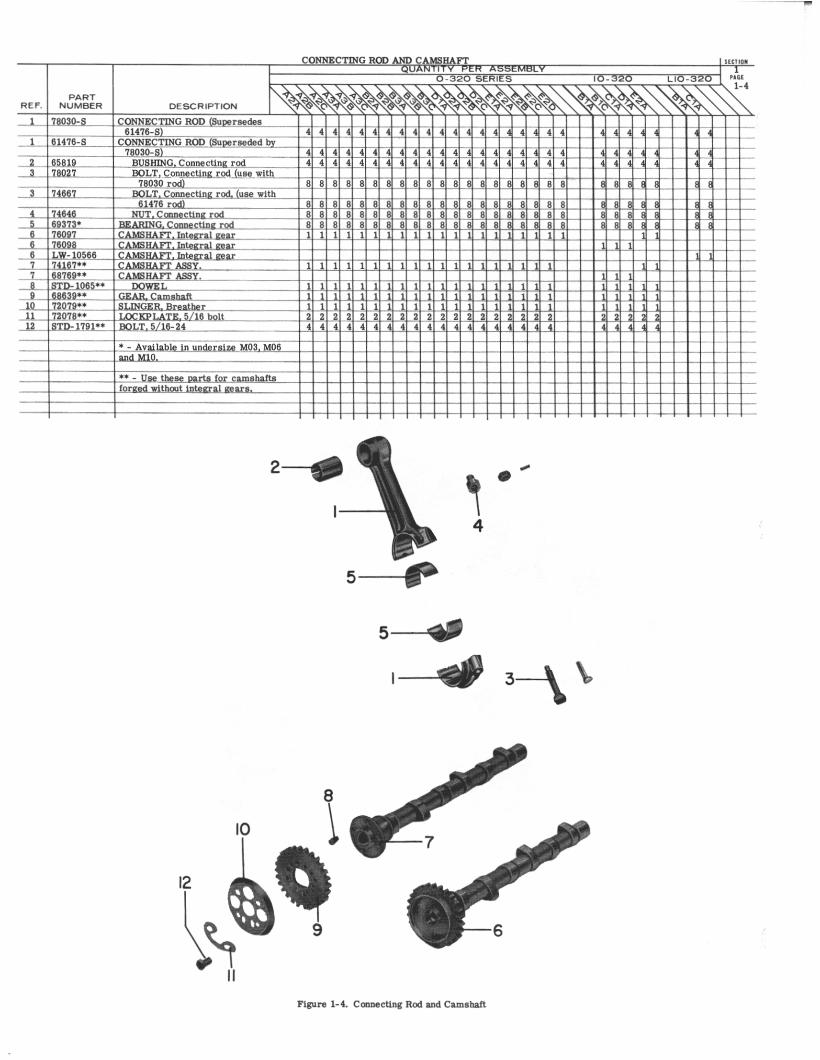
1 780302 LW-139233 780274 LW-121865 693736 76097
ROD ASSEMBLY, ConnectingBUSHING,Connecting rod,upperBOLT,Connecting rodNUT,Connecting rod bolt
BEARING,Connecting rodCAMSHAFT
448881
Use only above listed parts for 0-320-E2G model engines.
2
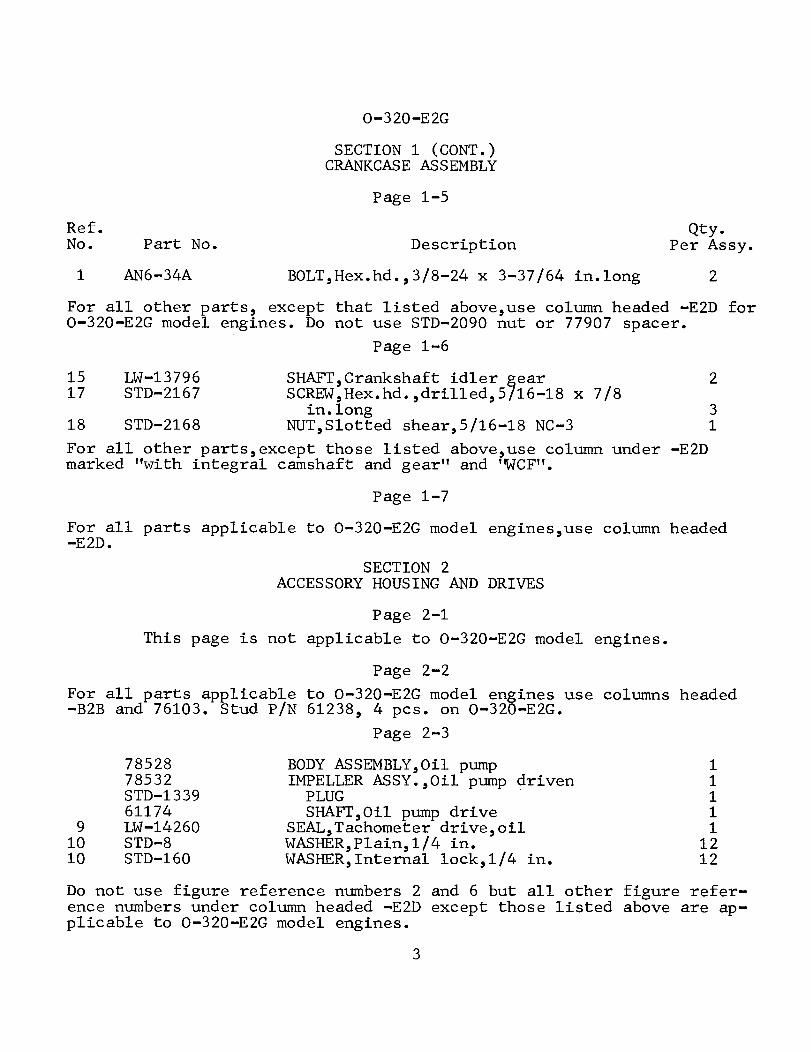
0-320-E2G
SECTION 1 (CONT.)CRANKCASE ASSEMBLY
Page 1-5
Ref.No. Part No. Description
Qty.Per Assy.
1 AN6-34A BOLT,Hex.hd.,3/8-24 x 3-37/64 in.long 2
For all other parts, except that listed above,use column headed -E2D for0-320-E2G model engines. Do not use STD-2090 nut or 77907 spacer.
Page 1-6
15 LW-1379617 STD-2167
SHAFT,Crankshaft idler gearSCREW,Hex.hd.,drilled,5/16-18 x 7/8
in.longNUT,Slotted shear,5/16-18 NC-3
2
3118 STD-2168
For all other parts,except those listed above,use column under -E2Dmarked "with integral camshaft and gear" and "WCF".
Page 1-7
For all parts applicable to 0-320-E2G model engines,use column headed-E2D.
SECTION 2ACCESSORY HOUSING AND DRIVES
Page 2-1
This page is not applicable to 0-320-E2G model engines.
Page 2-2
For all parts applicable to 0-320-E2G model engines use columns headed-B2B and 76103. Stud P/N 61238, 4 pcs. on O-320-E2G.
Page 2-3
7852878532STD-133961174
9 LW-1426010 STD-810 STD-160
BODY ASSEMBLY,Oil pumpIMPELLER ASSY.,Oil pump drivenPLUGSHAFT,Oil pump drive
SEAL,Tachometer drive,oilWASHER,Plain,1/4 in.WASHER,Internal lock,1/4 in.
11111
1212
Do not use figure reference numbers 2 and 6 but all other figure refer-ence numbers under column headed -E2D except those listed above are ap-plicable to 0-320-E2G model engines.
3
0-320-E2G
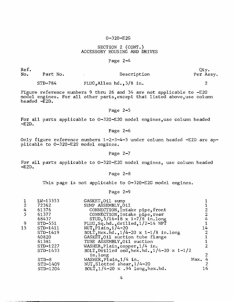
SECTION 2 (CONT.)ACCESSORY HOUSING AND DRIVES
Page 2-4
Ref.No.
Qty.Per Assy.Part No.
STD-784
Description
PLUG,Allen hd.,3/8 in. 2
Figure reference numbers 9 thru 26 and 34 are not applicable to -E2Gmodel engines. For all other parts,except that listed above,use columnheaded -E2D.
Page 2-5
For all parts applicable to 0-320-E2G model engines,use column headed-E2D.
Page 2-6
Only figure reference numbers 1-2-3-4-5 under column headed -E2D are ap-plicable to 0-320-E2G model engines.
Page 2-7
For all parts applicable to 0-320-E2G model engines, use column headed-E2D.
Page 2-8
This page is not applicable to 0-320-E2G model engines.
Page 2-9
1 LW-133532 723624 613765 61377
684379 STD-55115 STD-1411
STD-14196082061381STD-1227STD-1433
STD-8STD-1409STD-1204
GASKET,Oil sumpSUMP ASSEMBLY,Oil
CONNECTION, Intake pipe,frontCONNECTION,Intake pipe,rearSTUD,5/16-18 x 1-7/8 in.long
PLUG,Sq.hd.,drilled,1/2-14 NPTNUT,Plain, 1/4-20BOLT,Hex.hd.,1/4-20 x 1-1/8 in.longGASKET,Oil suction tube flangeTUBE ASSEMBLY,Oil suctionWASHER,Plain,copper,1/4 in.BOLT,Drilled end,hex.hd.,1/4-20 x 1-1/2
in. longWASHER,Plain,1/4 in.NUT,Slotted shear, 1/4-20BOLT,1/4-20 x .94 long,hex.hd.
112241142112
2Max. 4
216
4
O-320-E2G
SECTION 2 (CONT.)ACCESSORY HOUSING AND DRIVES
Page 2-9 (Cont.)
Ref.No.
Qty.Per Assy.Part No. Description
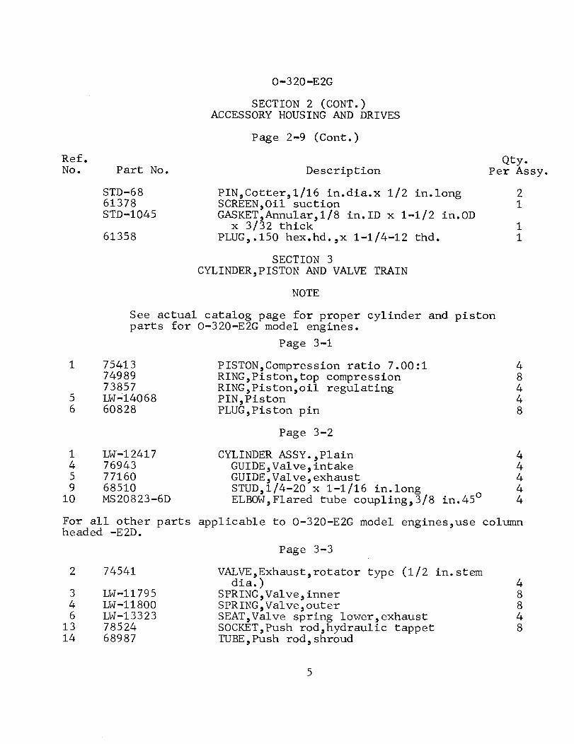
STD-6861378STD-1045
61358
PIN,Cotter,1/16 in.dia.x 1/2 in.longSCREEN,Oil suctionGASKET,Annular,1/8 in.ID x 1-1/2 in.ODx 3/32 thick
PLUG,.150 hex.hd.,x 1-1/4-12 thd.
21
11
SECTION 3CYLINDER,PISTON AND VALVE TRAIN
NOTE
See actual catalog page for proper cylinder and pistonparts for O-320-E2G model engines.
Page 3-1
1 754137498973857
5 LW-140686 60828
PISTON,Compression ratio 7.00:1RING,Piston,top compressionRING,Piston,oil regulatingPIN,PistonPLUG,Piston pin
48448
Page 3-2
1459
10
LW-12417769437716068510MS20823-6D
CYLINDER ASSY.,PlainGUIDE,Valve,intakeGUIDE,Valve,exhaustSTUD,1/4-20 x 1-1/16 in.longELBOW,Flared tube coupling,3/8 in.45°
44444
For all other parts applicable to O-320-E2G model engines,use columnheaded -E2D.
Page 3-3
2 74541
3 LW-117954 LW-118006 LW-1332313 7852414 68987
VALVE,Exhaust,rotator type (1/2 in.stemdia.)
SPRING,Valve, innerSPRING,Valve,outerSEAT,Valve spring lower,exhaustSOCKET,Push rod,hydraulic tappetTUBE,Push rod, shroud
48848
5
O-320-E2G
SECTION 3 (CONT.)CYLINDER,PISTON AND VALVE TRAIN
Page 3-3 (Cont.)
Ref.No. Part No. Description
Qty.Per Assy.
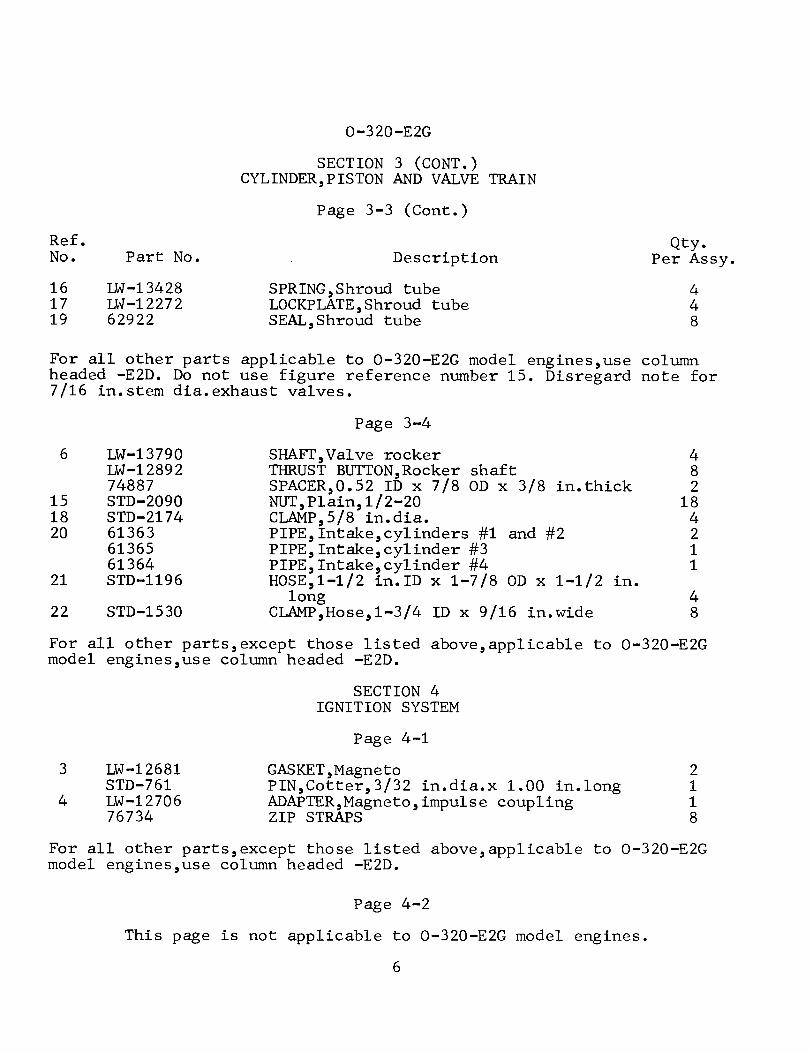
161719
LW-13428LW-1227262922
SPRING,Shroud tubeLOCKPLATE,Shroud tubeSEAL,Shroud tube
448
For all other parts applicable to O-320-E2G model engines,use columnheaded -E2D. Do not use figure reference number 15. Disregard note for7/16 in.stem dia.exhaust valves.
Page 3-4
6 LW-13790LW-1289274887
15 STD-209018 STD-217420 61363
6136561364
21 STD-1196
22 STD-1530
SHAFT,Valve rockerTHRUST BUTTON,Rocker shaftSPACER,0.52 ID x 7/8 OD x 3/8 in.thickNUT,Plain, 1/2-20CLAMP,5/8 in.dia.PIPE,Intake,cylinders #1 and #2PIPE,Intake,cylinder #3PIPE,Intake,cylinder #4HOSE,1-1/2 in.ID x 1-7/8 OD x 1-1/2 in.
longCLAMP,Hose,1-3/4 ID x 9/16 in.wide
482
184211
48
For all other parts,except those listed above,applicable to 0-320-E2Gmodel engines,use column headed -E2D.
SECTION 4IGNITION SYSTEM
Page 4-1
3 LW-12681STD-761
4 LW-1270676734
GASKET,MagnetoPIN,Cotter,3/32 in.dia.x 1.00 in.longADAPTER,Magneto,impulse couplingZIP STRAPS
2118
For all other parts,except those listed above,applicable to O-320-E2Gmodel engines,use column headed -E2D.
Page 4-2
This page is not applicable to O-320-E2G model engines.
6
O-320-E2G
SECTION 4 (CONT.)IGNITION SYSTEM
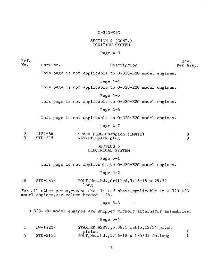
Page 4-3
Ref.No. Part No. Description
Qty.Per Assy.
This page is not applicable to O-320-E2G model engines.
Page 4-4
This page is not applicable to O-320-E2G model engines.
Page 4-5
This page is not applicable to O-320-E2G model engines.
Page 4-6
This page is not applicable to O-320-E2G model engines.
Page 4-7
2 1182-B63 STD-295
SPARK PLUG,Champion (EM41E)GASKET,Spark plug
88
SECTION 5ELECTRICAL SYSTEM
Page 5-1
This page is not applicable to O-320-E2G model engines.
Page 5-2
38 STD-1858 BOLT,Hex.hd.,drilled,5/16-18 x 29/32long 1
For all other parts,except that listed above,applicable to O-320-E2Gmodel engines,use column headed -E2D.
Page 5-3
O-320-E2G model engines are shipped without alternator assemblies.
Page 5-4
1 LW-14207
4 STD-2156
STARTER ASSY.,3.38:1 ratio,12/14 pitchpinion
BOLT,Hex.hd.,5/16-18 x 1-5/32 in.long11
7
0-320-E2G
SECTION 5 (CONT.)ELECTRICAL SYSTEM
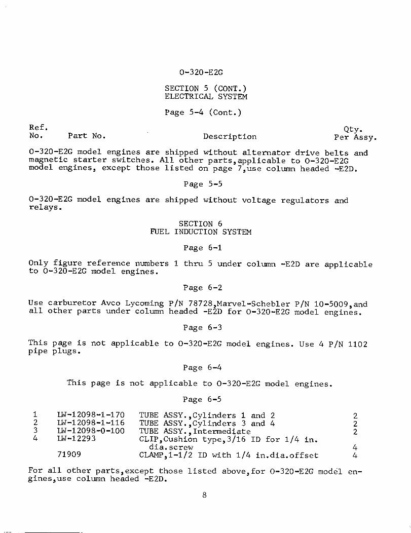
Page 5-4 (Cont.)
Ref. Qty.No. Part No. Description Per Assy.
O-320-E2G model engines are shipped without alternator drive belts andmagnetic starter switches. All other parts,applicable to O-320-E2Gmodel engines, except those listed on page 7,use column headed -E2D.
Page 5-5
O-320-E2G model engines are shipped without voltage regulators andrelays.
SECTION 6FUEL INDUCTION SYSTEM
Page 6-1
Only figure reference numbers 1 thru 5 under column -E2D are applicableto O-320-E2G model engines.
Page 6-2
Use carburetor Avco Lycoming P/N 78728,Marvel-Schebler P/N 10-5009,andall other parts under column headed -E2D for 0-320-E2G model engines.
Page 6-3
This page is not applicable to O-320-E2G model engines. Use 4 P/N 1102pipe plugs.
Page 6-4
This page is not applicable to 0-320-E2G model engines.
Page 6-5
1 LW-12098-1-170 TUBE ASSY.,Cylinders 1 and 2 22 LW-12098-1-116 TUBE ASSY.,Cylinders 3 and 4 23 LW-12098-0-100 TUBE ASSY., Intermediate 24 LW-12293 CLIP,Cushion type,3/16 ID for 1/4 in.
dia.screw 471909 CLAMP,1-1/2 ID with 1/4 in.dia.offset 4
For all other parts,except those listed above,for O-320-E2G model en-gines,use column headed -E2D.
8
O-320-E2G
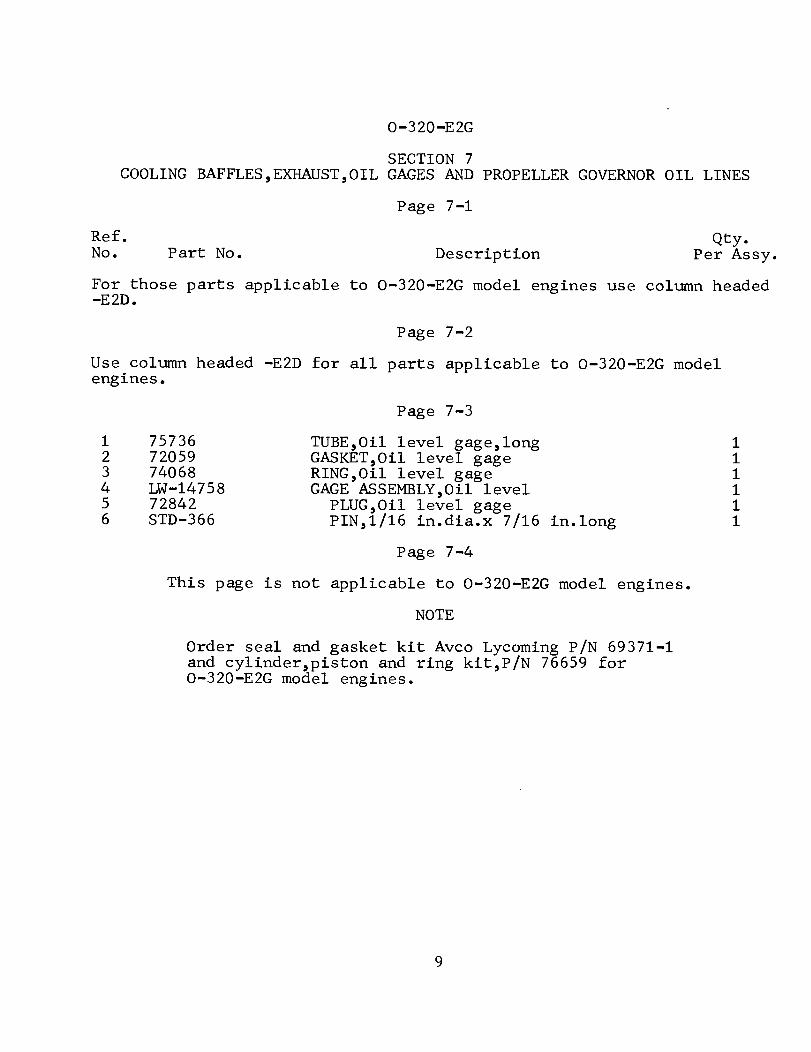
SECTION 7COOLING BAFFLES,EXHAUST,OIL GAGES AND PROPELLER GOVERNOR OIL LINES
Page 7-1
Ref.No.
Qty.Part No. Description Per Assy.
For those parts applicable to O-320-E2G model engines use column headed-E2D.
Page 7-2
Use column headed -E2D for all parts applicable to O-320-E2G modelengines.
Page 7-3
1 757362 720593 740684 LW-147585 728426 STD-366
TUBE,Oil level gage,longGASKET,Oil level gageRING,Oil level gageGAGE ASSEMBLY,Oil levelPLUG,Oil level gagePIN,1/16 in.dia.x 7/16 in.long
111111
Page 7-4
This page is not applicable to O-320-E2G model engines.
NOTE
Order seal and gasket kit Avco Lycoming P/N 69371-1and cylinder,piston and ring kit,P/N 76659 forO-320-E2G model engines.
9
LYCOMING WILLIAMSPORT DIVISIONCORPORATION
WILLIAMSPORT, PENNSYLVANIA 17701
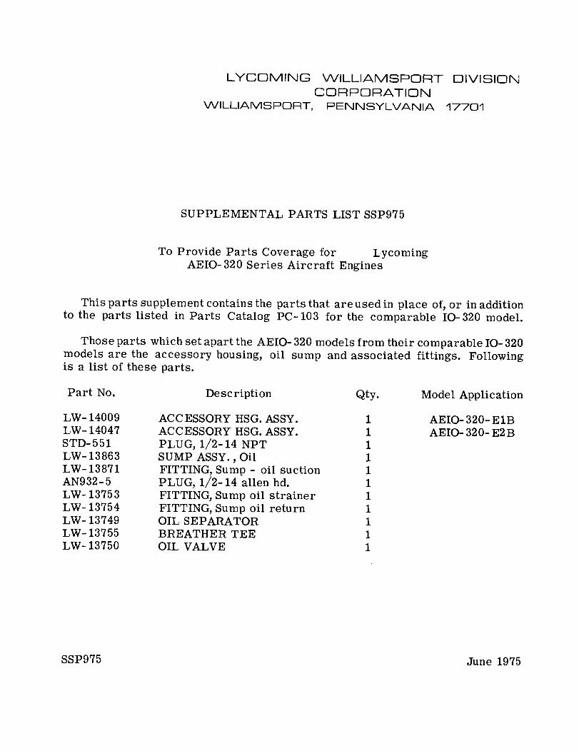
SUPPLEMENTAL PARTS LIST SSP975
To Provide Parts Coverage for LycomingAEIO-320 Series Aircraft Engines
This parts supplement contains the parts that are used in place of, or in additionto the parts listed in Parts Catalog PC-103 for the comparable 10-320 model.
Those parts which set apart the AEIO- 320 models from their comparable IO- 320models are the accessory housing, oil sump and associated fittings. Followingis a list of these parts.
Part No. Description Qty. Model Application
LW- 14009LW- 14047STD-551LW- 13863LW- 13871AN932-5LW- 13753LW- 13754LW- 13749LW-13755LW- 13750
ACCESSORY HSG. ASSY.ACCESSORY HSG. ASSY.PLUG, 1/2-14 NPTSUMP ASSY., OilFITTING, Sump - oil suctionPLUG, 1/2-14 allen hd.FITTING, Sump oil strainerFITTING, Sump oil returnOIL SEPARATORBREATHER TEEOIL VALVE
11111111111
AEIO- 320- E1BAEIO- 320- E2B
SSP975 June 1975
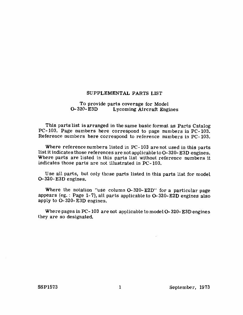
SUPPLEMENTAL PARTS LIST
To provide parts coverage for Model- 320- E3D Lycoming Aircraft Engines
This parts list is arranged in the same basic format as Parts CatalogPC-103. Page numbers here correspond to page numbers in PC-103.Reference numbers here correspond to reference numbers in PC-103.
Where reference numbers listed in PC-103 are not used in this partslist it indicates those references are not applicable to O- 320- E3D engines.Where parts are listed in this parts list without reference numbers itindicates those parts are not illustrated in PC-103.
Use all parts, but only those parts listed in this parts list for model- 320-E3D engines.
Where the notation "use column 0-320-E2D" for a particular pageappears (eg.: Page 1-7), all parts applicable to 0-320-E2D engines alsoapply to 0-320-E3D engines.
Where pages in PC- 103 are not applicable to model O- 320- E3D enginesthey are so designated.
SSP1573 1 September, 1973
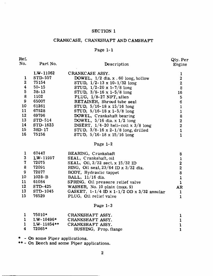
SECTION 1
CRANKCASE, CRANKSHAFT AND CAMSHAFT
Page 1-1
Ref.No. Part No.
Qty. PerEngine
LW- 110621 STD-5572 751544 50-155 38-138 11029 65007
10 6126111 6752812 6979613 STD-51414 STD- 162315 38D-1716 75156
Description
CRANKCASE ASSY.DOWEL, 1/2 dia. x . 60 long, hollowSTUD, 1/2-13 x 10-1/32 longSTUD, 1/2-20 x 1-7/8 longSTUD, 3/8-16 x 1-5/8 longPLUG, 1/8-27 NPT, allenRETAINER, Shroud tube sealSTUD, 5/16-18 x 15/16 longSTUD, 5/16-18 x 1-5/8 longDOWEL, Crankshaft bearingDOWEL, 5/16 dia. x 1/2 longINSERT, 1/4-20 heli-coil x 3/8 longSTUD, 3/8-16 x 2-1/8 long, drilledSTUD, 5/16-18 x 15/16 long
1228
16561182211
Page 1-2
1 674473 LW-119977 720758 720919 72877
10 1028-B11 6108412 STD-42513 STD- 104515 76529
BEARING, CrankshaftSEAL, Crankshaft, oilSEAL, Oil, 3/32 sect. x 15/32 IDRING, Oil seal, 23/64 ID x 3/32 dia.BODY, Hydraulic tappetBALL, 11/16 dia.SPRING, Oil pressure relief valveWASHER, No. 10 plain (max. 9)GASKET, 1-1/4 ID x 1-1/2 OD x 3/32 annularPLUG, Oil relief valve
8122811
AR11
Page 1-3
1 75010*1 LW-10496*1 LW-11854**4 72065*
CRANKSHAFT ASSY.CRANKSHAFT ASSY.CRANKSHAFT ASSY.
BUSHING, Prop. flange
1111
* - On some Piper applications.** - On Beech and some Piper applications.
2
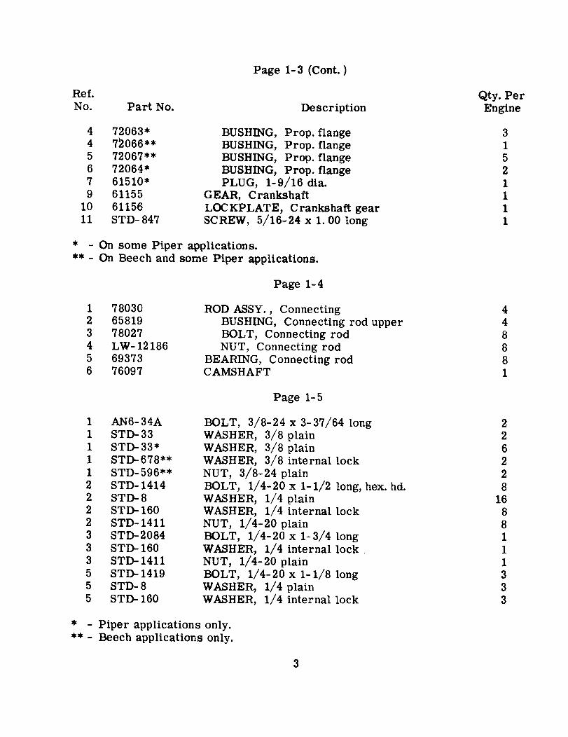
Page 1-3 (Cont. )
Ref.No.
Qty. PerEnginePart No. Description
4 72063*4 72066**5 72067**6 72064*7 61510*9 61155
10 6115611 STD- 847
BUSHING, Prop. flangeBUSHING, Prop. flangeBUSHING, Prop. flangeBUSHING, Prop. flangePLUG, 1-9/16 dia.
GEAR, CrankshaftLOCKPLATE, Crankshaft gearSCREW, 5/16-24 x 1. 00 long
31521111
* - On some Piper applications.** - On Beech and some Piper applications.
Page 1-4
1 780302 658193 780274 LW-121865 693736 76097
ROD ASSY., ConnectingBUSHING, Connecting rod upperBOLT, Connecting rodNUT, Connecting rod
BEARING, Connecting rodCAMSHAFT
448881
Page 1-5
1 AN6-34A1 STD-331 STD-33*1 STD-678**1 STD-596**2 STD-14142 STD-82 STD- 1602 STD- 14113 STD-20843 STD- 1603 STD-14115 STD- 14195 STD- 85 STD- 160
BOLT, 3/8-24 x 3-37/64 longWASHER, 3/8 plainWASHER, 3/8 plainWASHER, 3/8 internal lockNUT, 3/8-24 plainBOLT, 1/4-20 x 1-1/2 long, hex. hd.WASHER, 1/4 plainWASHER, 1/4 internal lockNUT, 1/4-20 plainBOLT, 1/4-20 x 1-3/4 longWASHER, 1/4 internal lockNUT, 1/4-20 plainBOLT, 1/4-20 x 1-1/8 longWASHER, 1/4 plainWASHER, 1/4 internal lock
226228
1688111333
* - Piper applications only.** - Beech applications only.
3
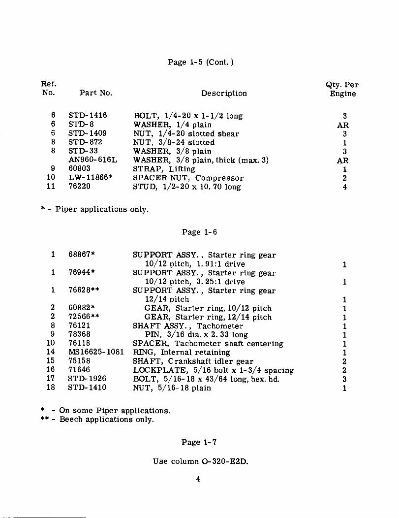
Page 1-5 (Cont. )
Ref.No.
Qty. PerPart No. Description Engine
6 STD-14166 STD- 86 STD- 14098 STD- 8728 STD-33
AN960-616L9 60803
10 LW- 11866*11 76220
BOLT, 1/4-20 x 1-1/2 longWASHER, 1/4 plainNUT, 1/4-20 slotted shearNUT, 3/8-24 slottedWASHER, 3/8 plainWASHER, 3/8 plain, thick (max. 3)STRAP, LiftingSPACER NUT, CompressorSTUD, 1/2-20 x 10. 70 long
3AR
313
AR124
* - Piper applications only.
Page 1-6
1 68867*
1 76944*
1 76628**
2 60882*2 72566**8 761219 78368
10 7611814 MS16625-108115 7515816 7164617 STD- 192618 STD- 1410
SUPPORT ASSY., Starter ring gear10/12 pitch, 1.91:1 drive
SUPPORT ASSY., Starter ring gear10/12 pitch, 3. 25:1 drive
SUPPORT ASSY., Starter ring gear12/14 pitchGEAR, Starter ring, 10/12 pitchGEAR, Starter ring, 12/14 pitch
SHAFT ASSY., TachometerPIN, 3/16 dia. x 2. 33 long
SPACER, Tachometer shaft centeringRING, Internal retainingSHAFT, Crankshaft idler gearLOCKPLATE, 5/16 bolt x 1-3/4 spacingBOLT, 5/16-18 x 43/64 long, hex. hd.NUT, 5/16-18 plain
1
1
11111112231
* - On some Piper applications.** - Beech applications only.
Page 1-7
Use column O-320-E2D.
4
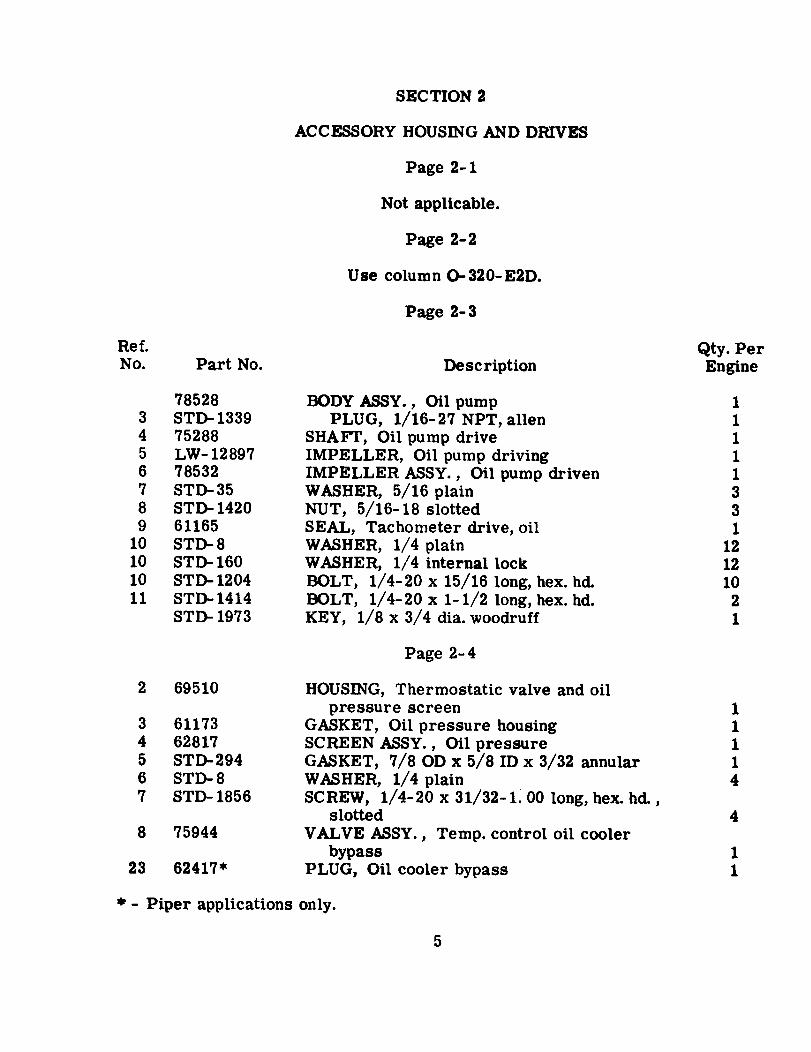
SECTION 2
ACCESSORY HOUSING AND DRIVES
Page 2-1
Not applicable.
Page 2-2
Use column 0-320-E2D.
Page 2-3
Ref.No.
Qty. PerEnginePart No. Description
785283 STD- 13394 752885 LW- 128976 785327 STD-358 STD- 14209 61165
10 STD- 810 STD- 16010 STD- 120411 STD-1414
STD- 1973
BODY ASSY., Oil pumpPLUG, 1/16-27 NPT, allen
SHAFT, Oil pump driveIMPELLER, Oil pump drivingIMPELLER ASSY., Oil pump drivenWASHER, 5/16 plainNUT, 5/16-18 slottedSEAL, Tachometer drive, oilWASHER, 1/4 plainWASHER, 1/4 internal lockBOLT, 1/4-20 x 15/16 long, hex. hd.BOLT, 1/4-20 x 1-1/2 long, hex. hd.KEY, 1/8 x 3/4 dia. woodruff
1
331
12121021
Page 2-4
2 69510
3 611734 628175 STD-2946 STD-87 STD- 1856
8 75944
23 62417*
HOUSING, Thermostatic valve and oilpressure screen
GASKET, Oil pressure housingSCREEN ASSY., Oil pressureGASKET, 7/8 OD x 5/8 ID x 3/32 annularWASHER, 1/4 plainSCREW, 1/4-20 x 31/32-1. 00 long, hex. hd.,
slottedVALVE ASSY., Temp. control oil cooler
bypassPLUG, Oil cooler bypass
11114
4
11
*- Piper applications only.
5
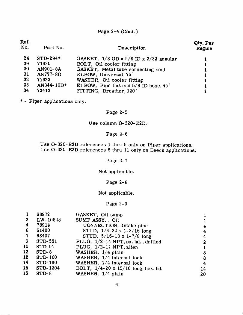
Page 2-4 (Cont.)
Ref.No. Part No.
Qty. PerEngineDescription
24 STD-294*29 7162030 AN901-8A31 AN777-8D32 7162333 AN844- 10D*34 72413
GASKET, 7/8 OD x 5/8 ID x 3/32 annularBOLT, Oil cooler fittingGASKET, Metal tube connecting sealELBOW, Universal, 75°
WASHER, Oil cooler fittingELBOW, Pipe thd. and 5/8 ID hose, 45°
FITTING, Breather, 120°
1111111
* - Piper applications only.
Page 2-5
Use column O-320-E2D.
Page 2-6
Use O-320-E2D references 1 thru 5 only on Piper applications.Use 0-320-E2D references 6 thru 11 only on Beech applications.
Page 2-7
Not applicable.
Page 2-8
Not applicable.
Page 2-9
1 689722 LW- 108284 789146 614007 684379 STD-551
10 STD-9112 STD- 812 STD-16014 STD- 16015 STD- 120415 STD- 8
GASKET, Oil sumpSUMP ASSY., Oil
CONNECTION, Intake pipeSTUD, 1/4-20 x 1-3/16 longSTUD, 5/16-18 x 1-7/8 long
PLUG, 1/2-14 NPT, sq. hd., drilledPLUG, 1/2-14 NPT, allenWASHER, 1/4 plainWASHER, 1/4 internal lockWASHER, 1/4 internal lockBOLT, 1/4-20 x 15/16 long, hex. hd.WASHER, 1/4 plain
1144421884
1420
6
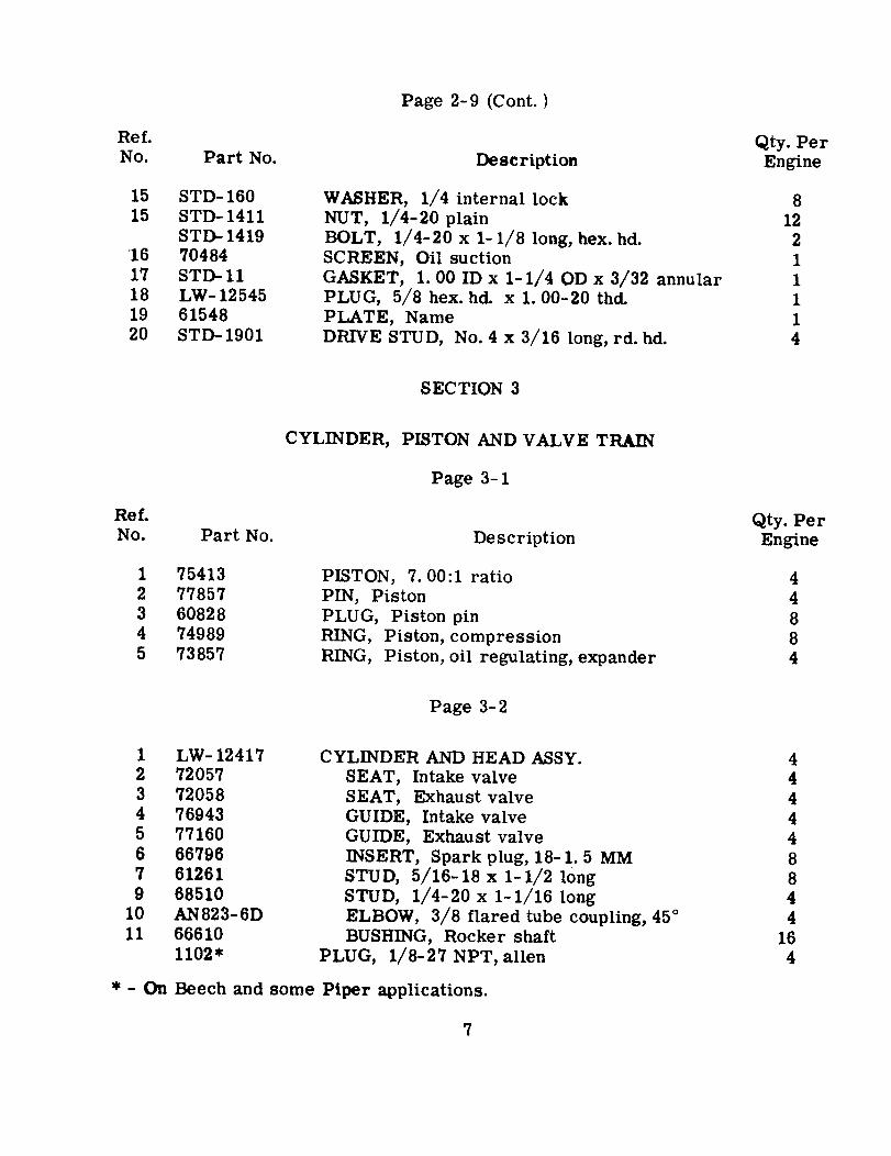
Page 2-9 (Cont. )
Ref.No. Part No.
15 STD- 16015 STD-1411
STD- 141916 7048417 STD- 1118 LW- 1254519 6154820 STD- 1901
Description
WASHER, 1/4 internal lockNUT, 1/4-20 plainBOLT, 1/4-20 x 1-1/8 long, hex. hd.SCREEN, Oil suctionGASKET, 1. 00 ID x 1-1/4 OD x 3/32 annularPLUG, 5/8 hex. hd. x 1. 00-20 thd.PLATE, NameDRIVE STUD, No. 4 x 3/16 long, rd. hd.
Qty. PerEngine
812211114
SECTION 3
CYLINDER, PISTON AND VALVE TRAIN
Page 3-1
Ref.No. Part No.
Qty. PerEngineDescription
1 754132 778573 608284 749895 73857
PISTON, 7. 00:1 ratioPIN, PistonPLUG, Piston pinRING, Piston, compressionRING, Piston, oil regulating, expander
44884
Page 3-2
1 LW- 124172 720573 720584 769435 771606 667967 612619 68510
10 AN823-6D11 66610
1102*
CYLINDER AND HEAD ASSY.SEAT, Intake valveSEAT, Exhaust valveGUIDE, Intake valveGUIDE, Exhaust valveINSERT, Spark plug, 18-1. 5 MMSTUD, 5/16-18 x 1-1/2 longSTUD, 1/4-20 x 1-1/16 longELBOW, 3/8 flared tube coupling, 45°
BUSHING, Rocker shaftPLUG, 1/8-27 NPT, allen
444448844
164
* - On Beech and some Piper applications.
7
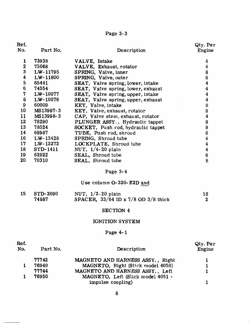
Page 3-3
Ref.No.
Qty. PerEnginePart No. Description
1 739382 750683 LW- 117954 LW- 118005 654416 745547 LW- 100778 LW- 100769 60009
10 MS13997- 311 MS13998-312 7829013 7852414 6898716 LW- 1342817 LW- 1227218 STD- 141119 6292220 70310
VALVE, IntakeVALVE, Exhaust, rotatorSPRING, Valve, innerSPRING, Valve, outerSEAT, Valve spring, lower, intakeSEAT, Valve spring, lower, exhaustSEAT, Valve spring, upper, intakeSEAT, Valve spring, upper, exhaustKEY, Valve, intakeKEY, Valve, exhaust, rotatorCAP, Valve stem, exhaust, rotatorPLUNGER ASSY., Hydraulic tappetSOCKET, Push rod, hydraulic tappetTUBE, Push rod, shroudSPRING, Shroud tubeLOCKPLATE, Shroud tubeNUT, 1/4-20 plainSEAL, Shroud tubeSEAL, Shroud tube
4488444488488844488
Page 3-4
Use column O-320-E2D and
15 STD- 209074887
NUT, 1/2-20 plainSPACER, 33/64 ID x 7/8 OD 3/8 thick
182
SECTION 4
IGNITION SYSTEM
Page 4-1
Ref.No.
Qty. PerEnginePart No. Description
777421 76949
777441 76950
MAGNETO AND HARNESS ASSY., RightMAGNETO, Right (Slick model 4050)
MAGNETO AND HARNESS ASSY., LeftMAGNETO, Left (Slick model 4051 -
impulse coupling)
111
1
8
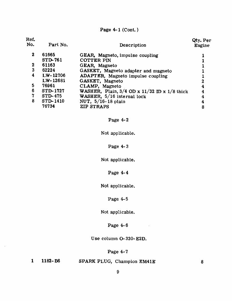
Page 4-1 (Cont. )
Ref.No. Part No.
2 61665STD-761
2 611633 622244 LW- 12706
LW- 126815 769616 STD- 17277 STD- 4758 STD- 1410
76734
Qty. PerEngineDescription
GEAR, Magneto, impulse couplingCOTTER PINGEAR, MagnetoGASKET, Magneto adapter and magnetoADAPTER, Magneto impulse couplingGASKET, MagnetoCLAMP, MagnetoWASHER, Plain, 3/4 OD x 11/32 ID x 1/8 thickWASHER, 5/16 internal lockNUT, 5/16-18 plainZIP STRAPS
11111244448
Page 4-2
Not applicable.
Page 4-3
Not applicable.
Page 4-4
Not applicable.
Page 4-5
Not applicable.
Page 4-6
Use column - 320- E2D.
Page 4-7
1 1182- B6 SPARK PLUG, Champion EM41E 8
9
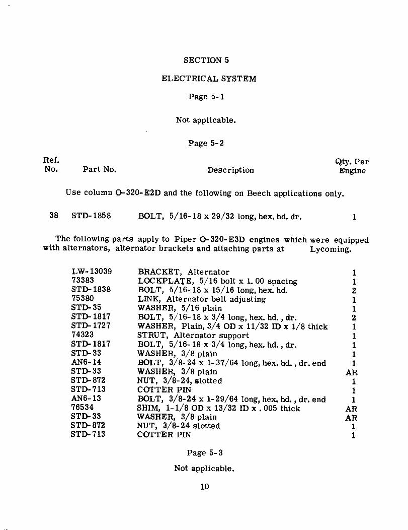
SECTION 5
ELECTRICAL SYSTEM
Page 5-1
Not applicable.
Page 5-2
Ref.No. Part No. Description
Qty. PerEngine
Use column O-320-E2D and the following on Beech applications only.
38 STD- 1858 BOLT, 5/16-18 x 29/32 long, hex. hd. dr. 1
The following parts apply to Piper 0-320-E3D engines which were equippedwith alternators, alternator brackets and attaching parts at Lycoming.
LW- 1303973383STD- 183875380STD- 35STD- 1817STD- 172774323STD- 1817STD- 33AN6-14STD-33STD- 872STD-713AN6- 1376534STD- 33STD- 872STD- 713
BRACKET, AlternatorLOCKPLATE, 5/16 bolt x 1. 00 spacingBOLT, 5/16-18 x 15/16 long, hex. hd.LINK, Alternator belt adjustingWASHER, 5/16 plainBOLT, 5/16- 18 x 3/4 long, hex. hd., dr.WASHER, Plain, 3/4 OD x 11/32 ID x 1/8 thickSTRUT, Alternator supportBOLT, 5/16- 18 x 3/4 long, hex. hd., dr.WASHER, 3/8 plainBOLT, 3/8-24 x 1-37/64 long, hex. hd. , dr. endWASHER, 3/8 plainNUT, 3/8-24, slottedCOTTER PINBOLT, 3/8-24 x 1-29/64 long, hex. hd., dr. endSHIM, 1-1/8 OD x 13/32 ID x . 005 thickWASHER, 3/8 plainNUT, 3/8-24 slottedCOTTER PIN
11211211111
AR111
ARAR
11
Page 5-3
Not applicable.
10
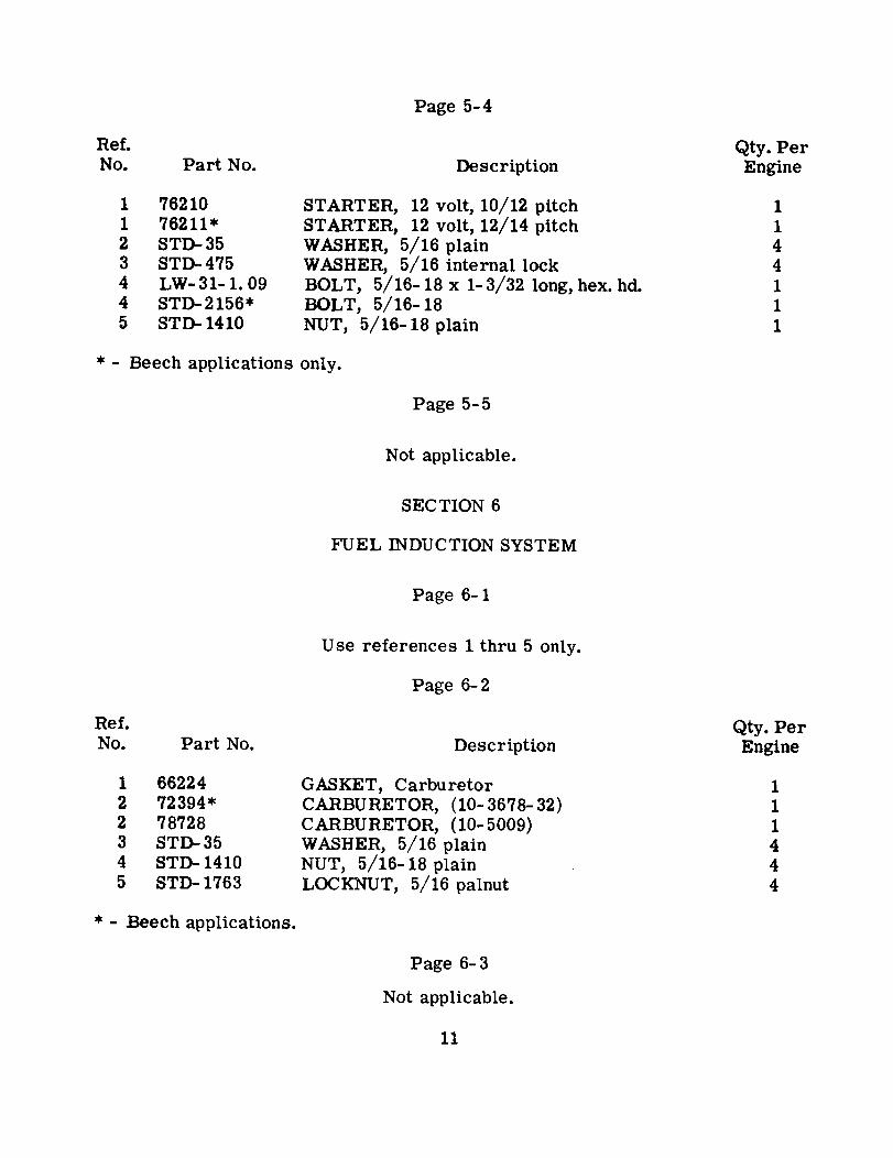
Page 5-4
Ref.No.
Qty. PerEnginePart No. Description
1 762101 76211*2 STD-353 STD-4754 LW-31-1.094 STD-2156*5 STD- 1410
STARTER, 12 volt, 10/12 pitchSTARTER, 12 volt, 12/14 pitchWASHER, 5/16 plainWASHER, 5/16 internal lockBOLT, 5/16- 18 x 1- 3/32 long, hex. hd.BOLT, 5/16-18NUT, 5/16-18 plain
1144111
* - Beech applications only.
Page 5-5
Not applicable.
SECTION 6
FUEL INDUCTION SYSTEM
Page 6-1
Use references 1 thru 5 only.
Page 6-2
Ref.No. Part No. Description
Qty. PerEngine
1 662242 72394*2 787283 STD-354 STD- 14105 STD- 1763
GASKET, CarburetorCARBURETOR, (10-3678-32)CARBURETOR, (10-5009)WASHER, 5/16 plainNUT, 5/16-18 plainLOCKNUT, 5/16 palnut
111444
* - Beech applications.
Page 6-3
Not applicable.
11
Page 6-4
Not applicable.
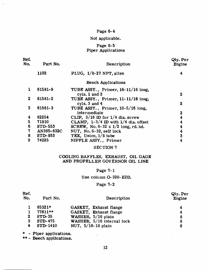
Page 6-5Piper Applications
Ref.No.
Qty. PerEnginePart No. Description
1102
1 61581-9
2 61581-2
3 61581-3
4 622545 719106 STD-5537 AN365-632C8 STD- 8539 74225
PLUG, 1/8-27 NPT, allen
Beech Applications
TUBE ASSY., Primer, 16-11/16 long,cyls. 1 and 2
TUBE ASSY., Primer, 11-11/16 long,cyls. 3 and 4
TUBE ASSY., Primer, 10-5/16 long,intermediate
CLIP, 3/16 ID for 1/4 dia. screwCLAMP, 1-3/4 ID with 1/4 dia. offsetSCREW, No. 6-32 x 1/2 long, rd. hd.NUT, No. 6-32, self lockTEE, Union, 1/8 tubeNIPPLE ASSY., Primer
4
2
2
2444434
SECTION 7
COOLING BAFFLES, EXHAUST, OIL GAGEAND PROPELLER GOVERNOR OIL LINE
Page 7-1
Use column 0-320-E2D.
Page 7-2
Ref.No. Part No.
Qty. PerEngineDescription
1 65321* (1 77611**2 STD-353 STD- 4754 STD- 1410
- Piper applications.
GASKET, Exhaust flangeGASKET, Exhaust flangeWASHER, 5/16 plainWASHER, 5/16 internal lockNUT, 5/16-18 plain
44888
*
** Beech applications.
12
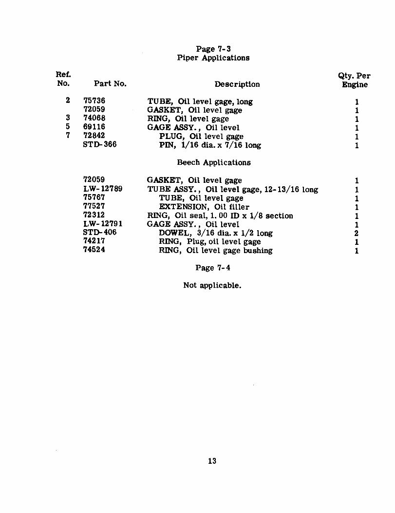
Page 7-3Piper Applications
Ref.No. Part No.
Qty. PerEngine
2 7573672059
3 740685 691167 72842
STD-366
Description
TUBE, Oil level gage, longGASKET, Oil level gageRING, Oil level gageGAGE ASSY., Oil level
PLUG, Oil level gagePIN, 1/16 dia. x 7/16 long
111111
Beech Applications
72059LW- 12789757677752772312LW- 12791STD- 4067421774524
GASKET, Oil level gageTUBE ASSY., Oil level gage, 12-13/16 long
TUBE, Oil level gageEXTENSION, Oil filler
RING, Oil seal, 1. 00 ID x 1/8 sectionGAGE ASSY., Oil level
DOWEL, 3/16 dia. x 1/2 longRING, Plug, oil level gageRING, Oil level gage bushing
111111211
Page 7-4
Not applicable.
13
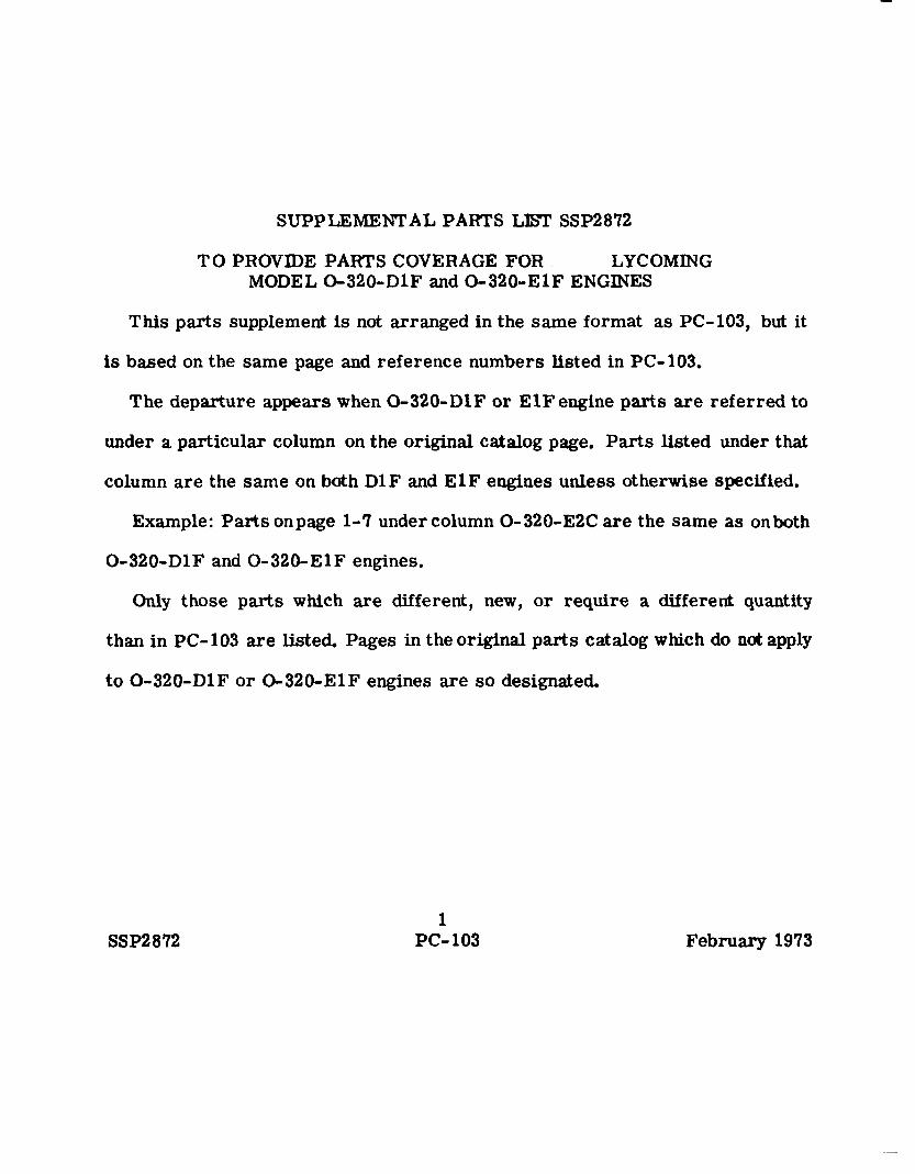
SUPPLEMENTAL PARTS LIST SSP2872
TO PROVIDE PARTS COVERAGE FOR LYCOMINGMODEL 0-320-D1F and 0-320-E1F ENGINES
This parts supplement is not arranged in the same format as PC-103, but it
is based on the same page and reference numbers listed in PC-103.
The departure appears when 0-320-D1F or ElF engine parts are referred to
under a particular column on the original catalog page. Parts listed under that
column are the same on both D1F and ElF engines unless otherwise specified.
Example: Parts onpage 1-7 under column 0-320-E2C are the same as onboth
0-320-D1F and 0-320-ElF engines.
Only those parts which are different, new, or require a different quantity
than in PC-103 are listed. Pages in the original parts catalog which do not apply
to 0-320-D1F or 0-320-EIF engines are so designated.
1SSP2872 PC- 103 February 1973
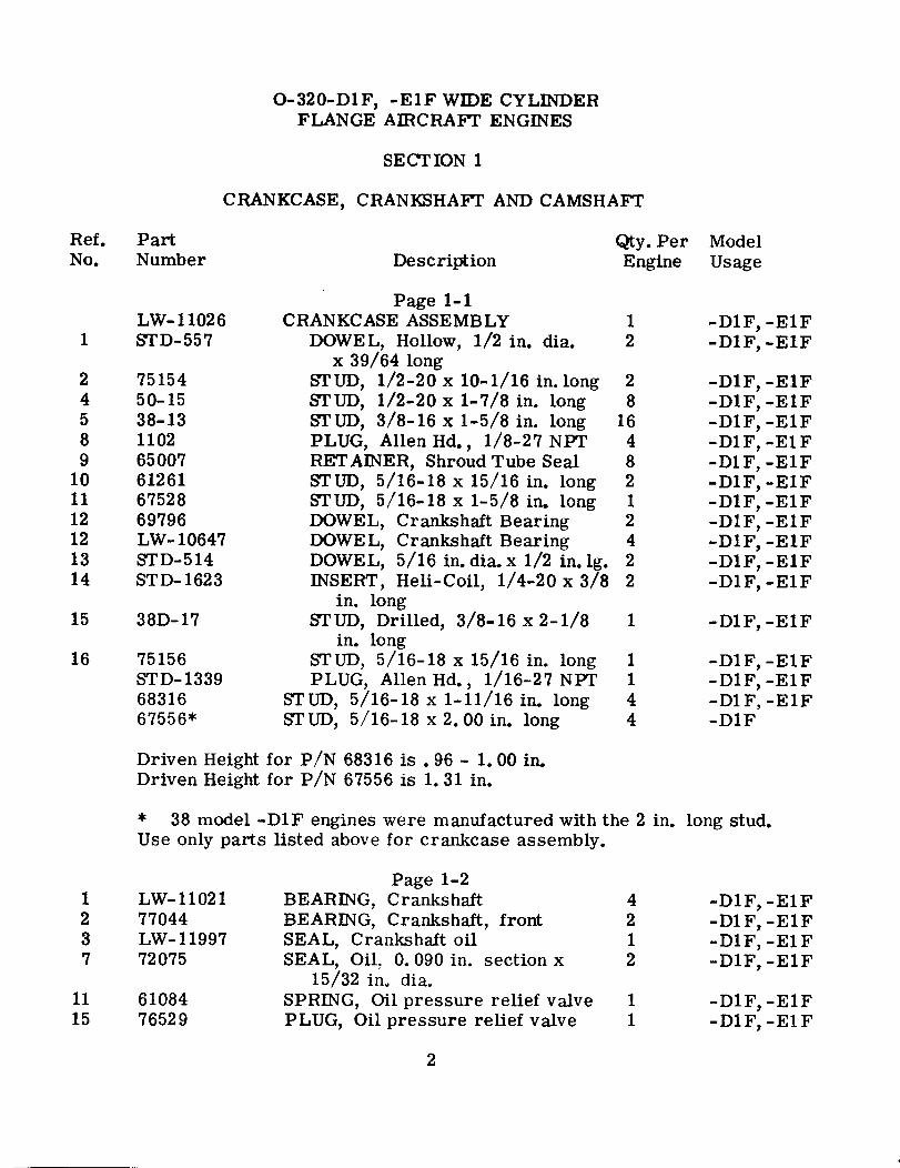
O-320-D1F, -ElF WIDE CYLINDERFLANGE AIRCRAFT ENGINES
SECTION 1
CRANKCASE, CRANKSHAFT AND CAMSHAFT
Qty. PerDescription Engine
Ref.No.
PartNumber
ModelUsage
LW-110261 STD-557
2 751544 50-155 38-138 11029 65007
10 6126111 6752812 6979612 LW-1064713 STD-51414 STD-1623
15 38D-17
16 75156STD-13396831667556*
Page 1-1CRANKCASE ASSEMBLY 1
DOWEL, Hollow, 1/2 in. dia. 2x 39/64 long
STUD, 1/2-20 x 10-1/16 in. long 2STUD, 1/2-20 x 1-7/8 in. long 8STUD, 3/8-16 x 1-5/8 in. long 16PLUG, Allen Hd., 1/8-27 NPT 4RETAINER, Shroud Tube Seal 8STUD, 5/16-18 x 15/16 in. long 2STUD, 5/16-18 x 1-5/8 in. long 1DOWEL, Crankshaft Bearing 2DOWEL, Crankshaft Bearing 4DOWEL, 5/16 in. dia. x 1/2 in. lg. 2INSERT, Heli-Coil, 1/4-20 x 3/8 2
-D1F, -ElF-D1F, -ElF
-D1F, -ElF-D1F, -ElF-D1F, -ElF-D1F, -ElF-D1F, -ElF-DIF, -ElF-D1F, -ElF-D1F, -ElF-D1F, -ElF-D1F, -ElF-D1F, -ElF
in. longSTUD, Drilled, 3/8-16 x 2-1/8
in. longSTUD, 5/16-18 x 15/16 in. longPLUG, Allen Hd., 1/16-27 NPT
STUD, 5/16-18 x 1-11/16 in. longSTUD, 5/16-18 x 2. 00 in. long
1 -D1F, -ElF
1144
-D1F, -ElF-D1F, -ElF-D1F, -ElF-D1F
Driven HeightDriven Height
for P/N 68316 is . 96 - 1.00 in.for P/N 67556 is 1.31 in.
* 38 model -D1F engines were manufactured with the 2 in. long stud.Use only parts listed above for crankcase assembly.
1 LW-110212 770443 LW-119977 72075
11 6108415 76529
Page 1-2BEARING, CrankshaftBEARING, Crankshaft, frontSEAL, Crankshaft oilSEAL, Oil, 0. 090 in. section x
15/32 in. dia.SPRING, Oil pressure relief valvePLUG, Oil pressure relief valve
4212
-D1F, -ElF-D1F, -ElF-D1F, -ElF-D1F, -E1F
11
-D1F, -ElF-D1F, -ElF
2
0-320-D1F, -ElF WIDE CYLINDERFLANGE AIRCRAFT ENGINES
SECTION 1 (CONT.)
CRANKCASE, CRANKSHAFT AND CAMSHAFT
Ref.No.
PartNumber
Qty. PerEngine
ModelUsageDescription
Page 1-2 (cont. )
For other parts applicable to 0-320-D1F, - E1F model enginesuse figure reference numbers 8-9-10-12-13.
Page 1-3For all parts on page 1-3 applicable to 0-320-D1F, -E1F model enginesuse column under 0-320-D1A (WCF) listings. Use illustration Ref. 1-Bfor prop. flange bushing locations.
4 LW-121866 78717
Page 1-4NUT, Connecting Rod
CAMSHAFT81
-D1F, -ElF-D1F, -E1F
For other parts applicable to 0-320-D1F, -ElF model engines usecolumn under 0-320-D1A.
1 STD-33AN960-616LAN6-34A
Page 1-5WASHER, Plain, 3/8 in. 5WASHER, Plain (Thick) 3/8 in. ARBOLT, Hex. Hd., 3/8-24 x 3-37/64 1
longSTUD, 1/2-20 x 10-45/64 in. long 4
-D1F,-E1F-D1F, -E1F-D1F, -E1F
-D1F, -E1F10 76220
For other parts applicable to 0-320-D1F, -E1F model engines usecolumn under 0-320-D1A (WCF).
2 72566Page 1-6
GEAR, Starter Ring, 12/14 Pitch 1 -D1F, -E1F
For other parts applicable to 0-320-D1F,-ElF model engines usecolumn under 0-320-D2A except for those figure references mar-ked "c" and 15-16-17.
Page 1-7For all parts on this page applicable to 0-320-D1F, -E1F modelengines use column under 0-320-D1A.
3
0-320-D1F, -E1F WIDE CYLINDERFLANGE AIRCRAFT ENGINES
SECTION 2
ACCESSORY HOUSING AND DRIVES
Ref. PartNo. Number
Qty. PerEngineDescription
ModelUsage
Page 2-1Page 2-1 does not apply to 0-320-D1F, -E1F model engines.
Page 2-2For accessory housing P/N applicable to 0-320-D1F, -E1F modelengines, use column under 0-320-D1A. For remaining parts usecolumn under 76110.
785283 STD-13394 752885 LW-128976 785327 STD-358 STD-14209 61165
10 STD-810 STD-1204
11 STD-16011 STD-1414
STD- 1973
STD-784For other partsDo not use Refs.
Page 2-3BODY ASSY., Oil pump
PLUG, 1/16-27 NPT allen hd.SHAFT, Oil pump driveIMPELLER, Oil pump drivingIMPELLER ASSY., Oil pump drivenWASHER, 5/16 plainNUT, 5/16-18 slottedSEAL, tachometer drive, oilWASHER, 1/4 plainBOLT, 1/4-20 x 15/16 long,
hex. hd.WASHER, 1/4 internal lockBOLT, 1/4-20 x 1-1/2 long,
hex. hd.KEY, 1/8 x 3/4 dia. Woodruff
1
31
1210
122
1
-D1F, -ElF-D1F, -ElF-D1F, -ElF-D1F, -E1F-D1F, -ElF-D1F, -ElF-D1F, -ElF-D1F, -E1F-D1F, -ElF-D1F, -ElF-D1F, -ElF
-D1F, -ElF
-D1F, -ElF
-D1F, -ElFand 34.
Page 2-4PLUG, 3/8 pipe, Allen 2use O-320-E2D. Refs. 2, 3, 4, 5, 6, 7, 8,27,28
9 thru 22.43 0-320-D1F engines were built with P/N 72413 (Ref. 34)
Page 2-5Use column under 0-320-D1A and:
778757787677874STD-1977872
GEAR, Propeller governor, drivenSHAFT, Prop. gov. idler gearGEAR ASSY., Prop gov. idler
DOWEL, .0907 dia. x .22 longBUSHING
4
11111
-D1F, -ElF-D1F, -ElF-D1F, -ElF-D1F, -ElF-D1F, -ElF
O-320-D1F, -ElF WIDE CYLINDERFLANGE AIRCRAFT ENGINES
SECTION 2 (CONT.)
ACCESSORY HOUSING AND DRIVES
Ref.No.
PartNumber
Qty. PerEngine
ModelUsageDescription
STD-79873249732507325173252MS9048-11170455
70454
DOWEL, .09 dia. x .28 longWASHER, ThrustWASHER, ThrustWASHER, ThrustWASHER, ThrustPIN, Spring, 1/8 dia. x 1-3/8 longGASKET, .78 ID x 1-1/8 OD x
.06 thickPLUG, 3/4-16 hex hd.
1ARARARAR
11
1
D1F, -ElFD1F, -ElFD1F, -ElFD1F, -ElFD1F, -ElFD1F, -ElFD1F, -ElF
D1F, -ElF
Page 2-6Use column under O-320-D1A, References 1 thru 5 only.
Page 2-7Use column under O-320-D1A (WCF) References 9 thru 18use P/N STD-783.
only. Do not
Page 2-8Page 2-8 does not apply to model O-320-D1F or O-320-E1F engines.
2 LW-108284 78914
12 STD- 120413 STD-814 STD-16015 STD-1411
STD-141918 LW-12545
Page 2-9SUMP ASSY., Oil
CONNECTION, Intake PipeBOLT, Hex. hd. 1/4-20 x 15/16 lg.WASHER, 1/4 plainWASHER, 1/4 internal lockNUT, 1/4-20 plainBOLT, 1/4-20 x 1-1/8 long, hex hd.PLUG, 5/8 x 1. 00-20 thd., hex hd.
14
1428201221
D1F,D1F,D1F,D1F,D1 F,D1F,D1F,D1F,
-ElF-ElF-ElF-ElF-ElF-ElF-ElF-ElF
For other parts use column under O-320-D1A.
SECTION 3
CYLINDER, PISTON, AND VALVE TRAIN
1 75089Page 3-1
PISTON, 8.50:1 4 -D1F
5
0-320-D1F, -E1F WIDE CYLINDERFLANGE AIRCRAFT ENGINES
SECTION 3 (CONT.)
CYLINDER, PISTON, AND VALVE TRAIN
Ref.No.
PartNumber
Qty. PerEngine
ModelUsageDescription
1 754132 742413 742412 749893 749894 73857
5 696505 778576 60828
Page 3-1 (Cont.)PISTON, 7.00:1RING, Piston, CompressiorRING, Piston, CompressiorRING, Piston, CompressiorRING, Piston, CompressiorRING, Piston, Oil Regulatir
ExpanderPIN, PistonPIN, PistonPLUG, Piston pin
Use above parts only.
1 LW-124161 LW-124174 769435 771608 STD-1872
1102
Page 3-2CYLINDER & HEAD ASSY., Nitrided 4CYLINDER & HEAD ASSY., Nitrided 4
GUIDE, Valve, Intake 4GUIDE, Valve, Exhaust 4INSERT, 1/8-27 helicoil taper 8
-D1F-ElF-D1F, -ElF-D1F, -ElF-D1F
-D1F, -E1Fpipe thd.
PLUG, 1/8-27 NPT, Allen 4
For other parts use column under 0-320-D1A.
3 LW-117954 LW-11800
13 65074
13 78524
14 6898716 LW-1227317 LW-1227219 62922
Page 3-3SPRING, Valve, InnerSPRING, Valve, OuterSOCKET, Push Rod, hydraulic
tappetSOCKET, Push Rod, hydraulic
tappetTUBE, Push Rod, ShroudSPRING, Shroud tubeLOCKPLATESEAL, Shroud tube
888
8
8848
-D1F, -E1F-D1F, -ElF-D1F, -E1F
-D1F, -E1F
-D1F, -E1F-D1F, -E1F-D1F, -ElF-D1F, -E F
For other parts on model 0-320-D1F use 0-320-D1A. For other partson model 0-320-E1F use 0-320-E1A but do not use Ref. 15.
6
O-320-D1F, -E1F WIDE CYLINDERFLANGE AIRCRAFT ENGINES
SECTION 3 (CONT.)
CYLINDER, PISTON, AND VALVE TRAIN
Ref.No.
PartNumber
Qty. PerEngine
ModelUsageDescription
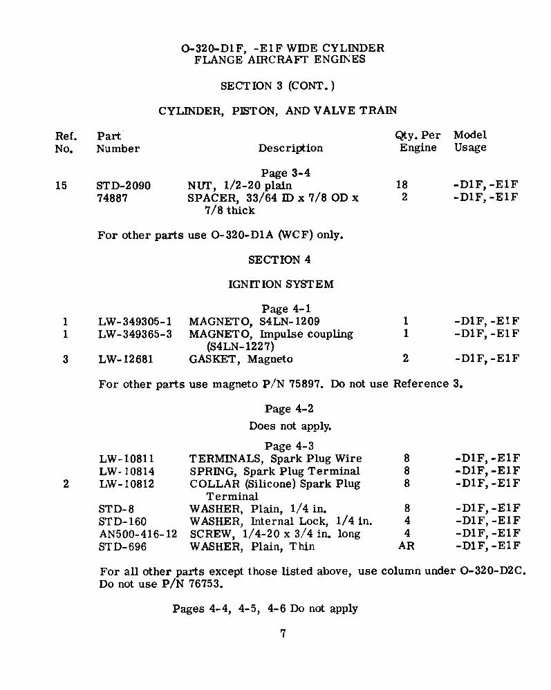
15 STD-209074887
Page 3-4NUT, 1/2-20 plainSPACER, 33/64 ID x 7/8 OD x
7/8 thick
182
-D1F, -E1F-D1F, -E1F
For other parts use O-320-D1A (WCF) only.
SECTION 4
IGNITION SYSTEM
1 LW-349305-11 LW-349365-3
3 LW- 12681
Page 4-1MAGNETO, S4LN-1209MAGNETO, Impulse coupling
(S4LN-1227)GASKET, Magneto
11
2
-D1F,-D1F,
-E1F-E1F
-D1F,-E1F
For other parts use magneto P/N 75897. Do not use Reference 3.
Page 4-2
Does not apply.
LW-10811LW- 10814
2 LW-10812
STD-8STD-160AN500-416-12STD-696
Page 4-3TERMINALS, Spark Plug WireSPRING, Spark Plug TerminalCOLLAR (Silicone) Spark Plug
TerminalWASHER, Plain, 1/4 in.WASHER, Internal Lock, 1/4 in.SCREW, 1/4-20 x 3/4 in. longWASHER, Plain, Thin
888
844
AR
-D1F, -E1F-D1F, -E1F-D1F,-E1F
-D1F, -E1F-D1F, -E1F-D1F, -E1F-D1F, -E1F
For all other parts except those listed above, use column under O-320-D2C.Do not use P/N 76753.
Pages 4-4, 4-5, 4-6 Do not apply
7
O-320-D1F, -ElF WIDE CYLINDERFLANGE AIRCRAFT ENGINES
SECTION 4 (CONT.)
IGNITION SYSTEM
Ref.No.
PartNumber
Qty. PerEngine
ModelUsageDescription
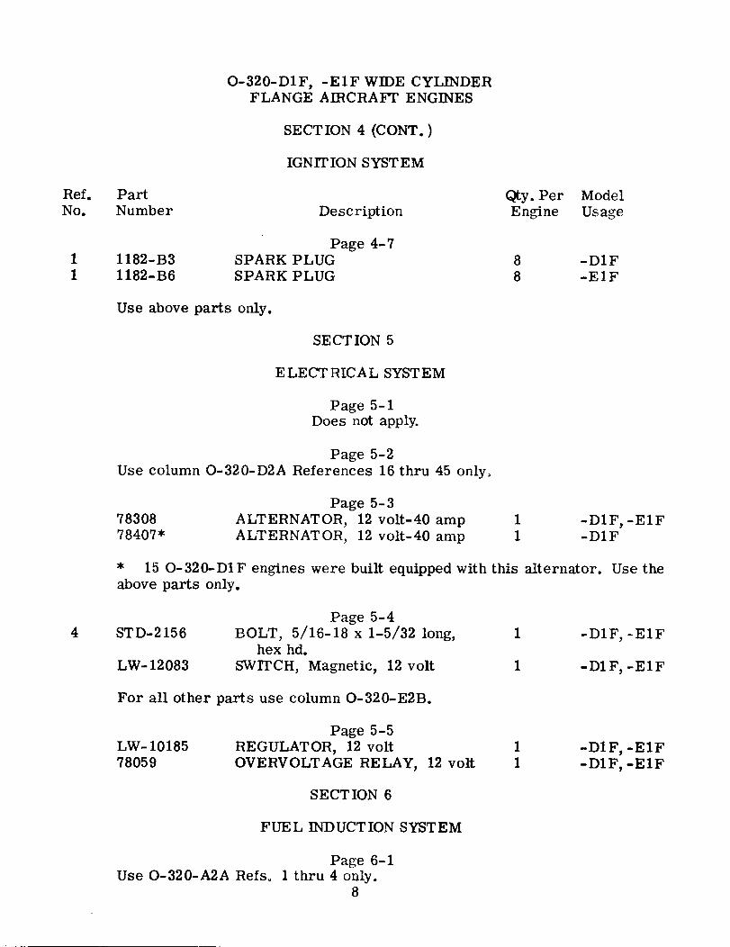
1 1182-B31 1182-B6
Page 4-7SPARK PLUGSPARK PLUG
88
-D1F-ElF
Use above parts only.
SECTION 5
ELECTRICAL SYSTEM
Page 5-1Does not apply.
Page 5-2Use column O-320-D2A References 16 thru 45 only.
7830878407*
Page 5-3ALTERNATOR, 12 volt-40 ampALTERNATOR, 12 volt-40 amp
11
-D1F, -ElF-D1F
* 15 O-320-D1F engines were built equipped with this alternator. Use theabove parts only.
4 STD-2156
LW-12083
Page 5-4BOLT, 5/16-18 x 1-5/32 long,
hex hd.SWITCH, Magnetic, 12 volt
1
1
-D1F, -ElF
-D1F, -ElF
For all other parts use column O-320-E2B.
LW-1018578059
Page 5-5REGULATOR, 12 voltOVERVOLTAGE RELAY, 12 volt
I1
-D1F, -ElF-D1F, -ElF
SECTION 6
FUEL INDUCTION SYSTEM
Page 6-1Use O-320-A2A Refs. 1 thru 4 only.
8
O-320-D1F, -ElF WIDE CYLINDERFLANGE AIRCRAFT ENGINES
SECTION 6
FUEL INDUCTION SYSTEM
Ref.No.
PartNumber
Qty. PerEngine
ModelUsageDescription
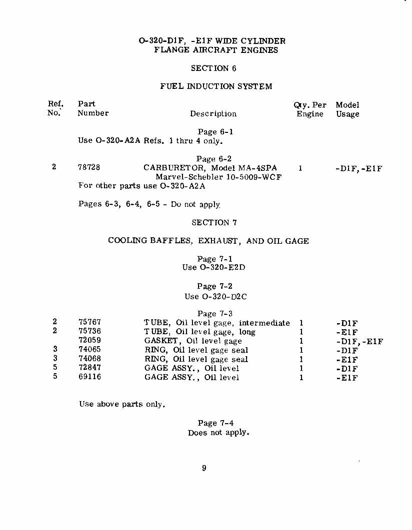
Page 6-1Use O-320-A2A Refs. 1 thru 4 only.
Page 6-22 78728 CARBURETOR, Model MA-4SPA
Marvel-Schebler 10-5009-WCFFor other parts use O-320-A2A
-D1F, -E1F
Pages 6-3, 6-4, 6-5 - Do not apply
SECTION 7
COOLING BAFFLES, EXHAUST, AND OIL GAGE
Page 7-1Use 0-320-E2D
Page 7-2Use O-320-D2C
2 757672 75736
720593 740653 740685 728475 69116
Page 7-3TUBE, Oil level gage, intermediateTUBE, Oil level gage, longGASKET, Oil level gageRING, Oil level gage sealRING, Oil level gage sealGAGE ASSY., Oil levelGAGE ASSY., Oil level
1111111
-D1F-ElF-D1F, -E1F-D1F-ElF-D1F-ElF
Use above parts only.
Page 7-4Does not apply.
9
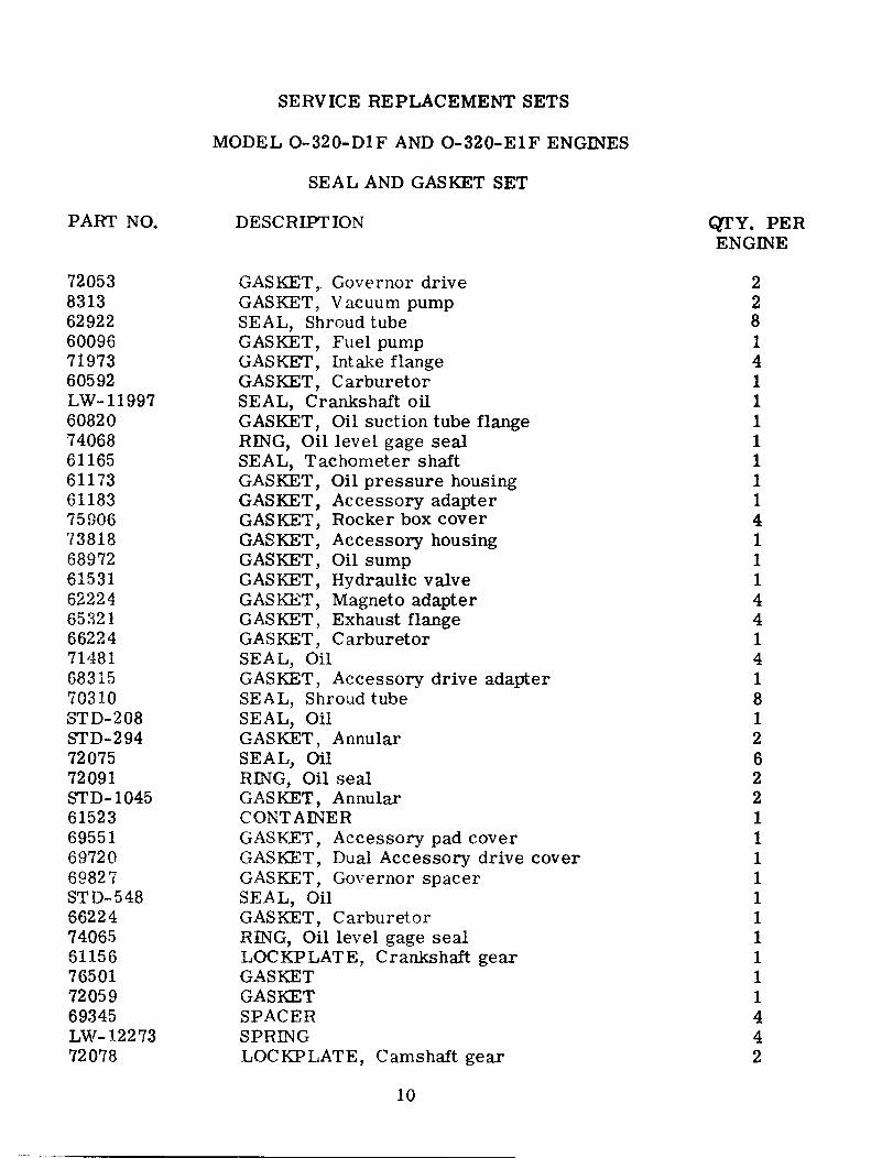
SERVICE REPLACEMENT SETS
MODEL 0-320-D1F AND 0-320-E1F ENGINES
SEAL AND GASKET SET
PART NO. DESCRIPTION QTY. PERENGINE
72053831362922600967197360592LW-11997608207406861165611736118375906738186897261531622246532166224714816831570310STD-208STD-2947207572091STD- 104561523695516972069827STD-548662247406561156765017205969345LW-1227372078
GASKET, Governor driveGASKET, Vacuum pumpSEAL, Shroud tubeGASKET, Fuel pumpGASKET, Intake flangeGASKET, CarburetorSEAL, Crankshaft oilGASKET, Oil suction tube flangeRING, Oil level gage sealSEAL, Tachometer shaftGASKET, Oil pressure housingGASKET, Accessory adapterGASKET, Rocker box coverGASKET, Accessory housingGASKET, Oil sumpGASKET, Hydraulic valveGASKET, Magneto adapterGASKET, Exhaust flangeGASKET, CarburetorSEAL, OilGASKET, Accessory drive adapterSEAL, Shroud tubeSEAL, OilGASKET, AnnularSEAL, OilRING, Oil sealGASKET, AnnularCONTAINERGASKET, Accessory pad coverGASKET, Dual Accessory drive coverGASKET, Governor spacerSEAL, OilGASKET, CarburetorRING, Oil level gage sealLOCKPLATE, Crankshaft gearGASKETGASKETSPACERSPRINGLOCKPLATE, Camshaft gear
2281411111114111441418126221111111111442
10
SEAL AND GASKET SET (CONT.)
PART NO. DESCRIPT ION QTY. PERENGINE
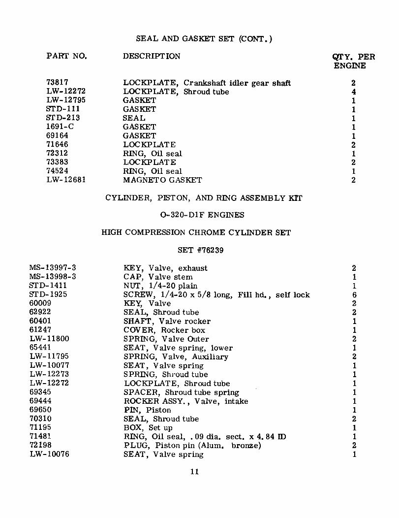
73817LW-12272LW-12795STD-111STD-2131691-C6916471646723127338374524LW-12681
LOCKPLATE, Crankshaft idler gear shaftLOCKPLATE, Shroud tubeGASKETGASKETSEALGASKETGASKETLOCKPLATERING, Oil sealLOCKPLATERING, Oil sealMAGNETO GASKET
241111121212
CYLINDER, PISTON, AND RING ASSEMBLY KIT
0-320-D1F ENGINES
HIGH COMPRESSION CHROME CYLINDER SET
SET #76239
MS-13997-3MS-13998-3STD- 1411STD-192560009629226040161247LW-1180065441LW-11795LW- 10077LW-12273LW- 1227269345694446965070310711957148172198LW- 10076
KEY, Valve, exhaustCAP, Valve stemNUT, 1/4-20 plainSCREW, 1/4-20 x 5/8 long, Fill hd., self lockKEY, ValveSEAL, Shroud tubeSHAFT, Valve rockerCOVER, Rocker boxSPRING, Valve OuterSEAT, Valve spring, lowerSPRING, Valve, AuxiliarySEAT, Valve springSPRING, Shroud tubeLOCKPLATE, Shroud tubeSPACER, Shroud tube springROCKER ASSY., Valve, intakePIN, PistonSEAL, Shroud tubeBOX, Set upRING, Oil seal, . 09 dia. sect. x 4. 84 IDPLUG, Piston pin (Alum. bronze)SEAT, Valve spring
2116221121211111121121
11
SET #76239 (CONT.)
PART NO. DESCRIPTION QTY. PERENGINE
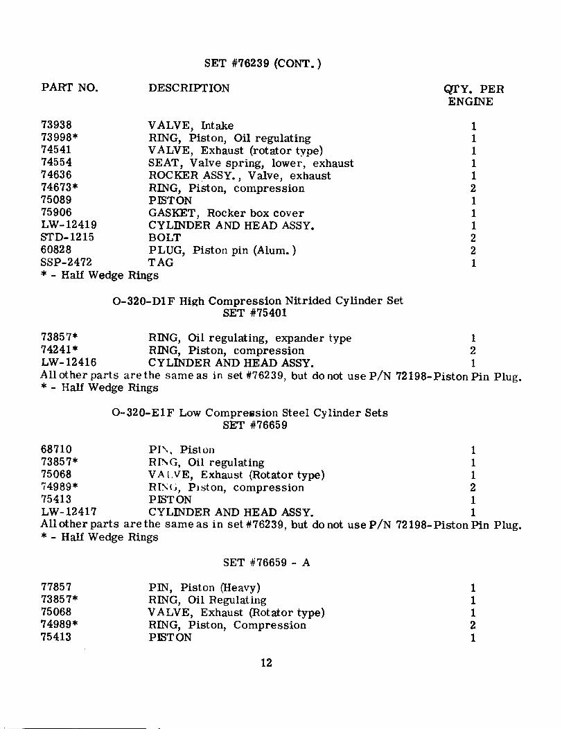
73938 VALVE, Intake73998* RING, Piston, Oil regulating74541 VALVE, Exhaust (rotator type)74554 SEAT, Valve spring, lower, exhaust74636 ROCKER ASSY., Valve, exhaust74673* RING, Piston, compression75089 PISTON75906 GASKET, Rocker box coverLW-12419 CYLINDER AND HEAD ASSY.STD-1215 BOLT60828 PLUG, Piston pin (Alum.)SSP-2472 TAG* - Half Wedge Rings
111112111221
0-320-D1F High Compression Nitrided Cylinder SetSET #75401
73857* RING, Oil regulating, expander type 174241* RING, Piston, compression 2LW-12416 CYLINDER AND HEAD ASSY. 1All other parts are the same as in set #76239, but donot use P/N 72198-Piston Pin Plug.* - Half Wedge Rings
O-320-E1F Low Compression Steel Cylinder SetsSET #76659
68710 PIN Piston 173857* RING, Oil regulating 175068 VALVE, Exhaust (Rotator type) 174989* RING Piston, compression 275413 PISTON 1LW-12417 CYLINDER AND HEAD ASSY. 1Allotherparts arethe sameas in set#76239, but donot useP/N 72198-PistonPin Plug.* - Half Wedge Rings
SET #76659 - A
7785773857*7506874989*75413
PIN, Piston (Heavy)RING, Oil RegulatingVALVE, Exhaust (Rotator type)RING, Piston, CompressionPISTON
11121
12
SET #76659 - A (CONT.)
QTY. PERPART NO. DESCRIPTION ENGINE
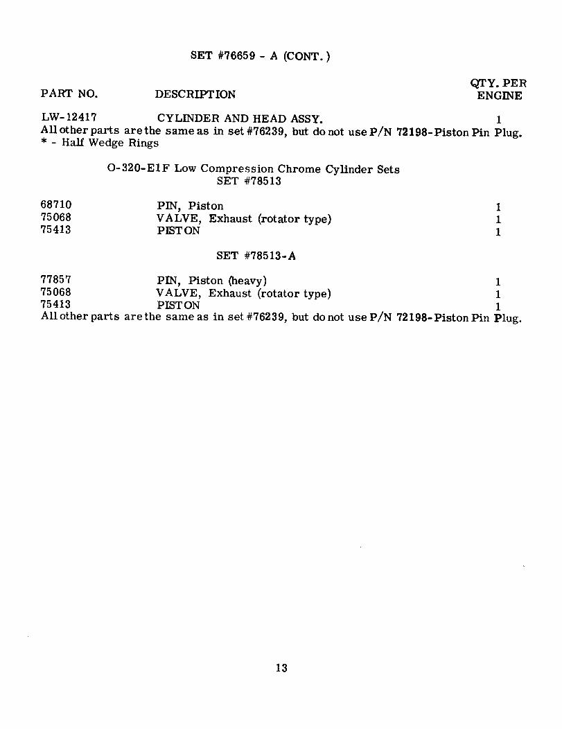
LW-12417 CYLINDER AND HEAD ASSY. 1All other parts are the same as in set #76239, but do not use P/N 72198-Piston Pin Plug.* - Half Wedge Rings
O-320-E1F Low Compression Chrome Cylinder SetsSET #78513
68710 PIN, Piston 175068 VALVE, Exhaust (rotator type) 175413 PISTON 1
SET #78513-A
77857 PIN, Piston (heavy) 175068 VALVE, Exhaust (rotator type) 175413 PISTON 1All other parts are the same as in set #76239, but do not use P/N 72198-Piston Pin Plug.
13
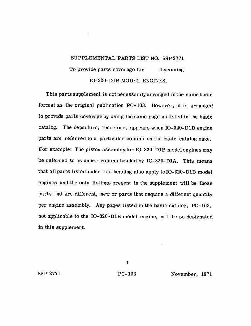
SUPPLEMENTAL PARTS LIST NO. SSP2771
To provide parts coverage for Lycoming
IO-320- DB MODEL ENGINES.
This parts supplement is not necessarily arranged in the same basic
format as the original publication PC-103. However, it is arranged
to provide parts coverage by using the same page as listed in the basic
catalog. The departure, therefore, appears when IO-320-D1B engine
parts are referred to a particular column on the basic catalog page.
For example: The piston assembly for IO-320- DB model engines may
be referred to as under column headed by IO-320-DIA. This means
that allparts listedunder this heading also apply toIO-320-D1B model
engines and the only listings present in the supplement will be those
parts that are different, new or parts that require a different quantity
per engine assembly. Any pages listed in the basic catalog, PC-103,
not applicable to the IO-320-D1B model engine, will be so designated
in this supplement.
1
SSP 2771 PC-103 November, 1971
LYCOMING AIRCRAFT ENGINE GROUP ASSEMBLY PARTS LIST
IO-320-D1B MODEL ENGINESSECTION 1
CRANKCASE, CRANKSHAFT AND CAMSHAFT
REF. PART DESCRIPTION QTY. MODEL
NO. NUMBER 1 2 3 4 5 ENG. USAGE
Page 1-1
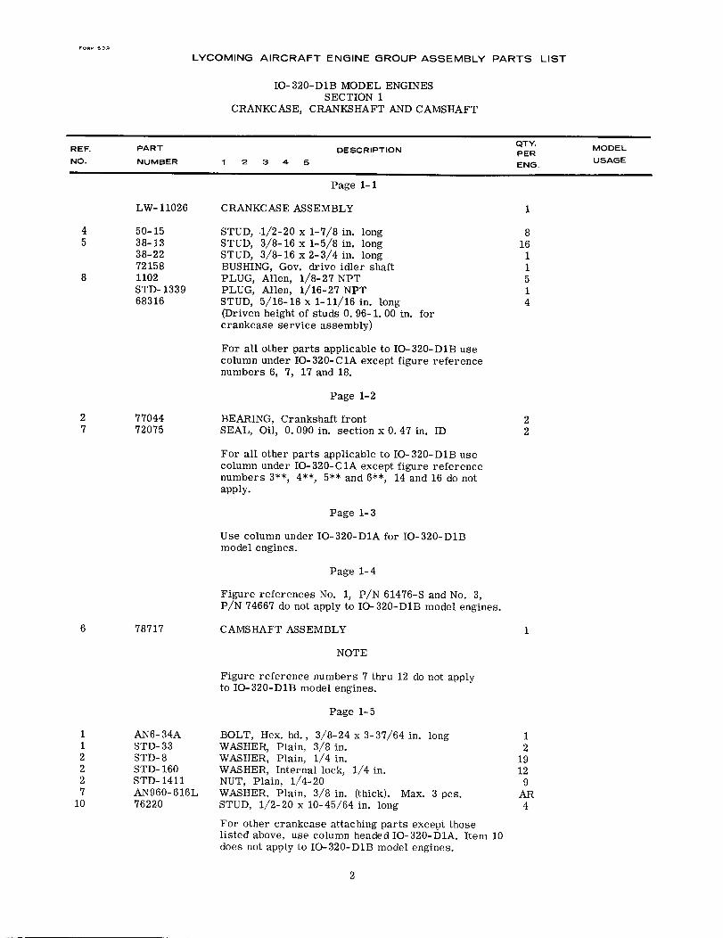
LW-11026 CRANKCASE ASSEMBLY 1
4 50-15 STUD, .1/2-20 x 1-7/8 in. long 85 38-13 STUD, 3/8-16 x 1-5/8 in. long 16
38-22 STUD, 3/8-16 x 2-3/4 in. long 172158 BUSHING, Gov. drive idler shaft 1
8 1102 PLUG, Allen, 1/8-27 NPT 5STD- 1339 PLUG, Allen, 1/16-27 NPT 168316 STUD, 5/16-18 x 1-11/16 in. long 4
(Driven height of studs 0. 96-1. 00 in. forcrankcase service assembly)
For all other parts applicable to IO-320-D1B usecolumn under IO-320-C1A except figure referencenumbers 6, 7, 17 and 18.
Page 1-2
2 77044 BEARING, Crankshaft front 27 72075 SEAL, Oil, 0. 090 in. section x 0. 47 in. ID 2
For all other parts applicable to IO-320-D1B usecolumn under IO-320-C1A except figure referencenumbers 3**, 4**, 5** and 6**, 14 and 16 do notapply.
Page 1-3
Use column under IO-320-D1A for IO-320-DlBmodel engines.
Page 1-4
Figure references No. 1, P/N 61476-S and No. 3,P/N 74667 do not apply to IO-320-DIB model engines.
6 78717 CAMSHAFT ASSEMBLY 1
NOTE
Figure reference numbers 7 thru 12 do not applyto IO-320-D1B model engines.
Page 1-5
1 AN6-34A BOLT, Hex. hd., 3/8-24 x 3-37/64 in. long 11 STD-33 WASHER, Plain, 3/8 in. 22 STD-8 WASHER, Plain, 1/4 in. 192 STD-160 WASHER, Internal lock, 1/4 in. 122 STD- 1411 NUT, Plain, 1/4-20 97 AN960-616L WASHER, Plain, 3/8 in. (thick). Max. 3 pcs. AR
10 76220 STUD, 1/2-20 x 10-45/64 in. long 4
For other crankcase attaching parts except thoselisted above, use column headed IO-320-D1A. Item 10does not apply to IO-320-D1B model engines.
2
LYCOMING AIRCRAFT ENGINE GROUP ASSEMBLY PARTS LIST
IO- 320-D1B MODEL ENGINESSECTION I (CONT.)
CRANKCASE, CRANKSHAFT AND CAMSHAFT
REF. PART DESCRIPTION QTY MODELPER
NO. NUMBER 1 2 3 4 5 ENG.USAGE
Page 1-6
NOTE
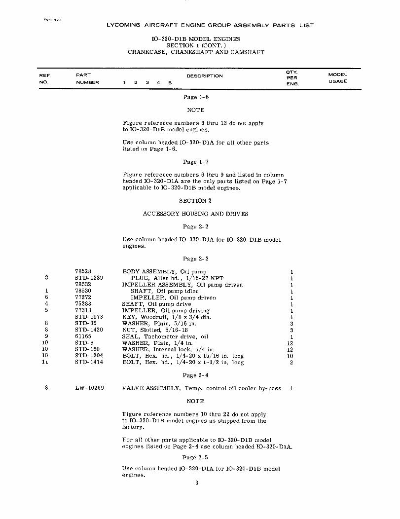
Figure reference numbers 3 thru 13 do not applyto IO-320-D1B model engines.
Use column headed IO-320-D1A for all other partslisted on Page 1-6.
Page 1-7
Figure reference numbers 6 thru 9 and listed in columnheaded IO-320-D1A are the only parts listed on Page 1-7applicable to IO-320-D1B model engines.
SECTION 2
ACCESSORY HOUSING AND DRIVES
Page 2-2
Use column headed IO-320-D1A for IO-320-D1B modelengines.
Page 2-3
78528 BODY ASSEMBLY, Oil pump 13 STD- 1339 PLUG, Allen hd., 1/16-27 NPT 1
78532 IMPELLER ASSEMBLY, Oil pump driven 11 78530 SHAFT, Oil pump idler 16 77272 IMPELLER, Oil pump driven 14 75288 SHAFT, Oil pump drive 15 77313 IMPELLER, Oil pump driving 1
STD- 1973 KEY, Woodruff, 1/8 x 3/4 dia. 18 STD-35 WASHER, Plain, 5/16 in. 38 STD- 1420 NUT, Slotted, 5/16- 18 39 61165 SEAL, Tachometer drive, oil 1
10 STD-8 WASHER, Plain, 1/4 in. 1210 STD-160 WASHER, Internal lock, 1/4 in. 1210 STD-1204 BOLT, Hex. hd., 1/4-20 x 15/16 in. long 1011 STD-1414 BOLT, Hex. hd., 1/4-20 x 1-1/2 in. long 2
Page 2-4
8 LW-10269 VALVE ASSEMBLY, Temp. control oil cooler. by-pass 1
NOTE
Figure reference numbers 10 thru 22 do not applyto IO-320-D1B model engines as shipped from thefactory.
For all other parts applicable to IO-320-D1B modelengines listed on Page 2-4 use column headed IO-320-D1A.
Page 2-5
Use column headed IO-320-D1A for IO-320-D1B modelengines.
3
FORM 633
LYCOMING AIRCRAFT ENGINE GROUP ASSEMBLY PARTS LIST
IO-320-D1B MODEL ENGINESSECTION 2 (CONT.)
ACCESSORY HOUSING AND DRIVES
REF.NO.
PART
NUMBER
DESCRIPTIONQTY.PERENG.
MODEL
USAGE12 3 4 5
Page 2-6
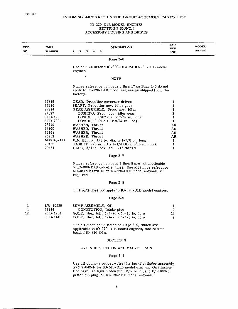
Use column headed IO-320-D1A for IO-320-B1B modelengines.
NOTE
Figure reference numbers 6 thru 17 on Page 2-6 do notapply to IO-320-D1B model engines as shipped from thefactory.
77875778767787477872STD-19STD-79873249732507325173252MS9048-1117045570454
GEAR, Propeller governor drivenSHAFT, Propeller gov. idler gearGEAR ASSEMBLY, Prop. gov. idler
BUSHING, Prop. gov. idler gearDOWEL, 0. 0907 dia. x 7/32 in. longDOWEL, 0. 09 dia. x 9/32 in. long
WASHER, ThrustWASHER, ThrustWASHER, ThrustWASHER, ThrustPIN, Spring, 1/8 in. dia. x 1-3/8 in. longGASKET, 7/8 in. ID x 1-1/8 OD x 1/16 in. thickPLUG, 3/4 in. hex. hd., -16 thread
111211
ARARARAR111
Page 2-7
Figure reference numbers 1 thru 8 are not applicableto IO-320-D1B model engines. Use all figure referencenumbers 9 thru 18 on IO-320-D1B model engines, ifrequired.
Page 2-8
This page does not apply to IO-320-D1B model engines.
Page 2-9
24
12
LW- 1083078914STD- 1204STD-1419
SUMP ASSEMBLY, OilCONNECTION, Intake pipe
BOLT, Hex. hd., 1/4-20 x 15/16 in. longBOLT, Hex. hd., 1/4-20 x 1-1/8 in. long
For all other parts listed on Page 2-9, which areapplicable to IO-320-D1B model engines, use columnheaded IO-320-D1A.
SECTION 3
CYLINDER, PISTON AND VALVE TRAIN
Page 3-1
14
142
Use all columns opposite first listing of cylinder assembly,P/N 75042-N for IO-320-D1B model engines. On illustra-tion page use light piston pin, P/N 69650 and P/N 60828piston pin plug for IO-320-D1B model engines.
4
FOR 633
LYCOMING AIRCRAFT ENGINE GROUP ASSEMBLY PARTS LIST
IO-320-DlB MODEL ENGINESSECTION 3 (CONT.)
CYLINDER, PISTON AND VALVE TRAIN
REF.
NO.
PART
NUMBERDESCRIPTION
QTY.PERENG.
MODEL
USAGE12 3 4 5
Page 3-2
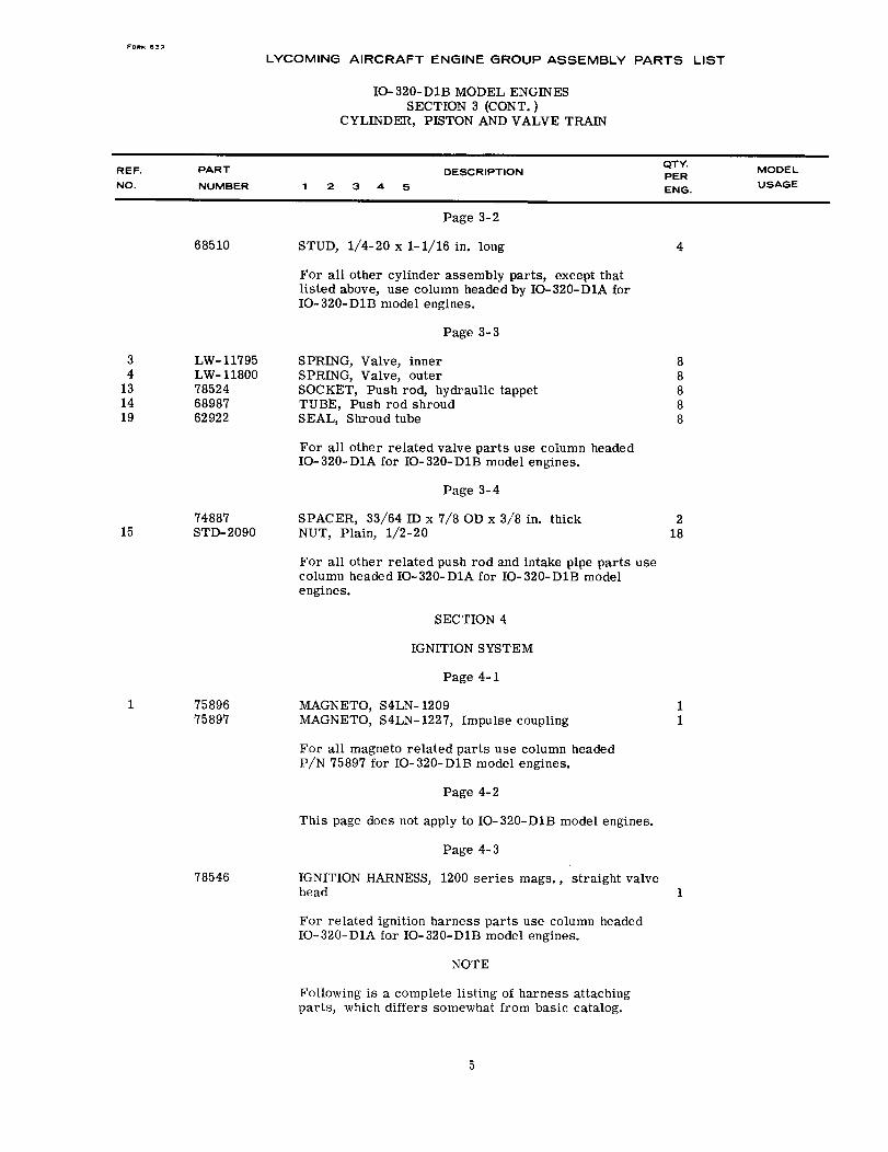
STUD, 1/4-20 x 1-1/16 in. long68510 4
For all other cylinder assembly parts, except thatlisted above, use column headed by IO-320-DIA forIO-320-D1B model engines.
Page 3-3
SPRING, Valve, innerSPRING, Valve, outerSOCKET, Push rod, hydraulic tappetTUBE, Push rod shroudSEAL, Shroud tube
34
131419
LW-11795LW-11800785246898762922
88888
For all other related valve parts use column headedIO-320-D1A for IO-320-D1B model engines.
Page 3-4
74887 SPACER, 33/64 ID x 7/8 OD x 3/8 in. thickSTD-2090 NUT, Plain, 1/2-2015
218
For all other related push rod and intake pipe parts usecolumn headed IO-320-D1A for IO-320-D1B modelengines.
SECTION 4
IGNITION SYSTEM
Page 4-1
1 7589675897
MAGNETO, S4LN- 1209MAGNETO, S4LN-1227, Impulse coupling
For all magneto related parts use column headedP/N 75897 for IO-320-D1B model engines.
Page 4-2
This page does not apply to IO-320-D1B model engines.
Page 4-3
11
78546 IGNITION HARNESS, 1200 series mags., straight valvehead
For related ignition harness parts use column headedIO-320-D1A for IO-320-D1B model engines.
NOTE
Following is a complete listing of harness attachingparts, which differs somewhat from basic catalog.
1
5
LYCOMING AIRCRAFT ENGINE GROUP ASSEMBLY PARTS LIST
IO-320-D1B MODEL ENGINESSECTION 4 (CONT.)IGNITION SYSTEM
REF.NO.
PART
NUMBERDESCRIPTION
QTY.PERENG.
MODELUSAGE1 2 3 4 5
Page 4-3 (cont. )
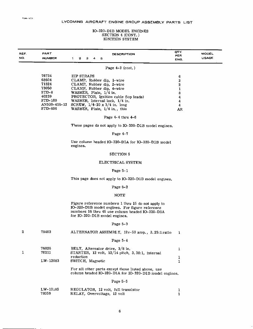
76734686047182473050STD-840239STD- 160AN500-416-12STD-696
ZIP STRAPSCLAMP, Rubber dip, 1-wireCLAMP, Rubber dip, 2-wireCLAMP, Rubber dip, 4-wireWASHER, Plain, 1/4 in.PROTECTOR, Ignition cable (top leads)WASHER, Internal lock, 1/4 in.SCREW, 1/4-20 x 3/4 in. longWASHER, Plain, 1/4 in., thin
62218444
AR
Page 4-4 thru 4-6
These pages do not apply to IO-320-D1B model engines.
Page 4-7
Use column headed IO-320-D1A for IO-320-D1B modelengines.
SECTION 5
ELECTRICAL SYSTEM
Page 5-1
This page does not apply to IO-320-D1B model engines.
Page 5-2
NOTE
Figure reference numbers 1 thru 15 do not apply toIO-320-D1B model engines. For figure referencenumbers 16 thru 45 use column headed IO-320-D1Afor IO-320-DIB model engines.
Page 5-3
2 78403 ALTERNATOR ASSEMBLY, 12v-50 amp., 3.25:1ratio 1
Page 5-4
176026 BELT, Alternator drive, 3/8 in.76211 STARTER, 12 volt, 12/14 pitch, 3. 38:1, internal
reductionLW- 12083 SWITCH, Magnetic
1
11
For all other parts except those listed above, usecolumn headed IO-320-D1A for IO-320-D1B model engines.
Page 5-5
LW-10185 REGULATOR, 12 volt, full transistor 178059 RELAY, Overvoltage, 12 volt 1
6
LYCOMING AIRCRAFT ENGINE GROUP ASSEMBLY PARTS LIST
IO-320-D1B MODEL ENGINESSECTION 6
FUEL INDUCTION SYSTEM
REF.
NO.
PART
NUMBER
DESCRIPTIONQTY.PER
ENG.
MODEL
USAGE1 2 3 4 5
12345
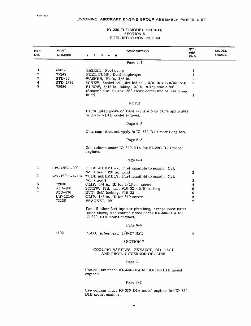
6009675247STD-33STD-188275686
Page 6-1
GASKET, Fuel pumpFUEL PUMP, Dual diaphragmWASHER, Plain, 3/8 in.SCREW, Socket hd., drilled hd., 3/8-16 x 1-9/32 longELBOW, 5/16 in. tubing, 9/16-18 adjustable 90 °
(Assemble aftapprox. 25 ° above centerline of fuel pumpinlet)
NOTE
1122
1
Parts listed above on Page 6-1 are only parts applicableto IO-320-D1B model engines.
Page 6-2
This page does not apply to IO-320-D1B model engines.
Page 6-3
Use column under IO-320-D1A for IO-320-D1B modelengines.
Page 6-4
1 LW- 12098-200
2 LW- 12098-1- 134
357
72036STD-860STD-670LW-1214573136
TUBE ASSEMBLY, Fuel manifold to nozzle, Cyl.No. 1 and 3 (20 in. long)TUBE ASSEMBLY, Fuel manifold to nozzle, Cyl.No. 2 and 4CLIP, 3/4 in. ID for 3/16 in. screwSCREW, Fill. hd., #10-32 x 5/8 in. longNUT, Self-locking, #10-32CLIP, 1/8 in. ID for #10 screwBRACKET, 90 °
2
246622
For all other fuel injector plumbing, except those partslisted above, use column listed under IO-320-D1A forIO-320-D1B model engines.
Page 6-5
PLUG, Allen head, 1/8-27 NPT
SECTION 7
1102 4
COOLING BAFFLES, EXHAUST, OIL GAGEAND PROP. GOVERNOR OIL LINE
Page 7-1
Use column under IO-320-D1A for IO-320-D1B modelengines.
Page 7-2
Use column under IO-320-D1A model engines for IO-320-D1B model engines.
7
FOr 633
LYCOMING AIRCRAFT ENGINE GROUP ASSEMBLY PARTS LIST
IO-320-D1B MODEL ENGINESSECTION 7 (CONT.)
COOLING BAFFLES, EXHAUST, OIL GAGEAND PROP. GOVERNOR OIL LINE
REF.
NO.
PART
NUMBER
DESCRIPTIONQTY.PERENG.
MODEL
USAGE1 2 3 4 5
Page 7-3
Use column under IO-320-D1A model engines forIO-320-D1B model engines.
Page 7-4
Page 7-4 is not applicable to IO-320-D1B model engines.
8
LYCOMING
PARTS CATALOG
O-320, IO-320 & LIO-320
SERIES AIRCRAFT ENGINES
LYCOMING DIVlSION WILLIAMSPORT, PA.
PC-103 April 1970
LYCOMING AIRCRAFT ENGINE GROUP ASSEMBLY PARTS LIST
0-320, IO-320, LIO-320 SERIES
INTRODUCTION
1. GENERAL.
This illustrated parts catalog lists and describes all procurable parts for the Lycoming engines listedherein.
2. SUPERSEDURE SECTION.
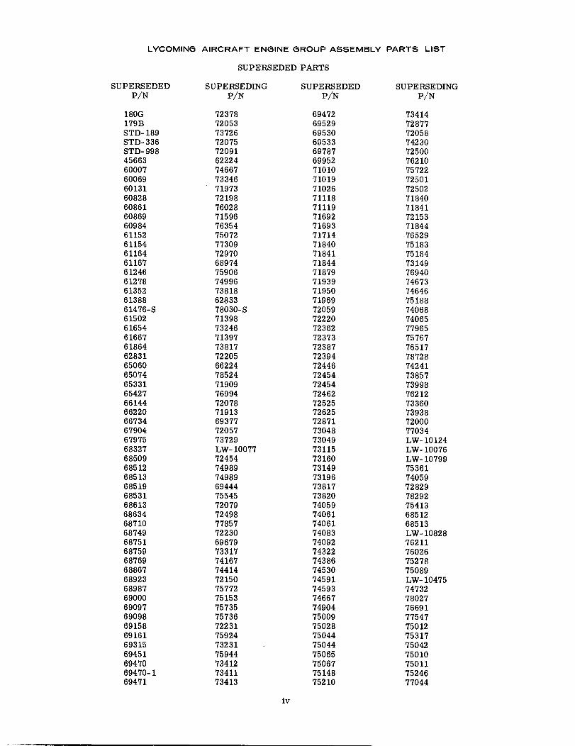
This section lists part numbers in numerical sequence, first by superseded number to the new, or supersedingpart number. The second portion of this section lists the superseding, or new part number to the old or supersedednumber.
3. GROUP ASSEMBLY PARTS LISTS.
This catalog is laid out in graph format indicating engine model number on each text page.
The sections of this catalog divide the engine into various assemblies and related parts. These parts are listedin the order of engine assembly at the factory. Illustrations are on the page directly opposite or beneath the partdescription.
The "Figure Reference Number" column (with heading "REF") provides cross reference to the part illustration.Those parts not numbered in this column are not illustrated.
The "Part Number" column contains the Lycoming, AN, MS, or vendor part number.
The "Description" column provides description or dimensional information required to describe the part. Sub-columns are employed here to differentiate parts of assemblies or sub-assemblies. Notes appearing in the textshould be checked prior to ordering parts. All references to Lycoming Service Bulletins, Instructions andLetters should be fully observed. The letters (STD) appearing beside the part description means this part fits anengine manufactured with the Standard cylinder base flange. The letters (WCF) means this part fits an enginemanufactured with the wide cylinder base flange. When neither appears in the description column, the part is ap-plicable to either configuration.
The "Quantity Per Assembly" portion of the text page indicates by model number the quantity required to com-plete the assembly on that page.
4. SERVICE REPLACEMENT SET SECTION.
This section consists of the seal and gasket set applicable to the 0-320 series engine. Individual parts con-tained in kits are also listed in the group assembly parts list and may be procured separately.
5. VENDOR ITEMS SECTION.
This section consists of assemblies produced by manufacturers other than Lycoming, for use onLycoming engines. Numbers in "Part Number" column are those of the particular vendor. Parts for these assem-blies can be obtained by ordering from Lycoming, Williamsport, Pa.
6. NUMERICAL INDEX.
This section lists all part numbers contained in the group assembly parts list (Sections 1 thru 7), in alpha-numerical sequence. Column headings are self-explanatory.
7. INSTRUCTIONS FOR ORDERING PARTS.
Use of this catalog is keyed to engine model number. The model number can best be determined by visual in-spection of the name plate located on the oil sump. Series of engines identified by the letter "A" following theserial number suffix are manufactured with the wide cylinder base flange. Example: 0-320-A, Serial NumberL- 12093- 39A.
After engine model number and type cylinder flange is determined, look in the Table of Contents for the part,or for the assembly on which it would normally be found. If the part number is known, look in the numericalindex (Section 10) in the back of the catalog. The illustrations can also be used to aid in finding the part.
8. OPTIONAL ITEMS.
Those optional items, such as electrical system components, vacuum and hydraulic dual drives etc., are cat-alogued by engine model number as the engine was assembled at the factory. See appropriate Service Instructionsfor further information. Use the illustrations to aid in determining the option you desire.
i
LYCOMING AIRCRAFT ENGINE GROUP ASSEMBLY PARTS LIST
0-320, IO-320, LIO- 320 SERIES
TABLE OF CONTENTS
SECTION PAGE
INTRODUCTION
TABLE OF CONTENTS...............
SUPERSEDURE SECTION .......
.............. . . . . . i
....ii .. . . . . . . . . . ii
. ..iv. . . . . . . . .. iv
1 . . . . . . . Crankcase, Crankshaft and CamshaftCrankcase Assembly . ..Crankcase Related Parts ..Crankshaft Assembly ..Connecting Rod ...Camshaft ....Crankcase Attaching Parts . . .Support Assembly, Starter Ring GearAccessory Idler Shafts ...Propeller Flange and Spacer . . .Fuel Pump Drive and Idler Gears
. . . . . . .
. . . . . . .
. . . . . . .
. . . . . . .
. . . . . . .
. . . . . . .
. . . . . . .
. . . . . . .
. . . . . . .
. . . . . . .
. . .1-1. 1-2. 1-3. 1-4. .1-4. 1-5. .1-6. .1-6. 1-6. 1-7
2...... Accessory Housings and DrivesAccessory Housing - Separate Cam Gear ....Accessory Housing - Integral Cam Gear ....Oil Pump ......Accessory Housing Attaching Parts . ..Oil Cooler and Oil Filter ....Vacuum Pump Drive . ....Dual Drive, Vacuum Pump and Hydraulic Pump .Dual Drive, Vacuum Pump and Propeller Governor.Propeller Governor Drive Shaftgear ..Cover, Vacuum Pump ....Cover, Vacuum and Hydraulic Pump ..Cover, Fuel Pump .....Propeller Governor Drive Adapter ...Cover, Governor Drive . ....Cover, Governor Drive Adapter ....Sump Assembly .....Sump Assembly ......
. 2-1. 2-2. 2-3. 2-3. 2-4. 2-5. 2-5. 2-5. 2-6. 2-6. 2-6. 2-6. 2-7. 2-7. 2-7. 2-8. 2-9
3. . . .. Cylinder, Piston and Valve TrainCylinder, Piston, Ring and Valve Application .Cylinder Assembly .....Valve Seats and Guides ....Spark Plug Inserts ....Valves, Springs and Plungers ...Shroud Tubes ......Valve Rocker Assemblies ....Valve Push Rods .....Valve Rocker Drain Tubes . ..Intake Pipes .....
... . . . . . 3-1
... . . . . . 3-2
... . . . . . 3-2
.. . . . . 3-2.. . . . . . 3-3
... . . . . . 3-3
... . . . . . 3-4
... . . . . . 3-4
... . . . . . 3-4
... . . . . . 3-4
4...... Ignition SystemMagnetos .............Unshielded Harness .....Harness Assy., 5MM, Avco Lycoming ....Harness Assy., Scintilla, -1200 Series MagnetosHarness Assy., Scintilla, -200 Series Magnetos.Harness Assy., Slick ....Spark Plug .......
.... 4-1
.... 4-2
.... 4-3
.... 4-4
.... 4-5
.... 4-6
.... 4-7
5 . Electrical SystemGenerator/Alternator Brackets, Standard Cylinder Flange EnginesGenerator/Alternator Brackets, Wide Cylinder Flange Engines.
. 5-1
. 5-2
ii
LYCOMING AIRCRAFT ENGINE GROUP ASSEMBLY PARTS LIST
0-320, IO-320, LIO-320 SERIES
TABLE OF CONTENTS (CONT. )
SECTION PAGE
5 . . . . . . . . . . Electrical System (Cont. )Generator/Alternator ..Generator/Alternator Drive Belt.Starter ....Magnetic Switch ...Voltage Regulator and Relay .
. . . . . . . . . . . . 5-3
. . . . . . . . . . . . 5-4
. . . . . . . . . . . . 5-4
. . . . . . . . . . . . 5-4
. . . . . . . . . . . . 5-5
6. Fuel Induction SystemFuel Pump ....Carburetor ....Fuel Injector ...Fuel Injection Tubes . .Priming System ...
. . . . . . . . . . . . 6-1
. . . . . . . . . . . . 6-2
. . . . . . . . . . . . 6-3
. . . . . . . . . . . . 6-4
. . . . . . . . . . . . 6-5
7 . . . . . . . . . Cooling Baffles, Exhaust, Oil Gage and Propeller GovernorOil Line
Intercylinder Cooling Baffles ....Exhaust Flanges and Gaskets .....Oil Level Gages .......Propeller Governor Oil Line .....
. . . . . 7-1
. . . . . 7-2
. . . . . 7-3
. . . . . 7-4
8. Service Replacement Set Section. . . . . 8-1
9... .. Vendor AccessoriesDelco-Remy Generator .Delco-Remy Alternator. . .Prestolite Alternator . . .Prestolite Starter . .Bendix Scintilla Magnetos:
-20 Series ...-200 Series . ..-1200 Series ..
Lear-Siegler Fuel Pump . .Marvel-Schebler Carburetor .Bendix Fuel Injector ..
. . . . . . . . . . . . . 9-1
. . . . . . . . . . . . . 9-2. . . . . . . . . . . . . 9-3. . . . . . . . . . . . . 9-4
. . . . . . . . . . . . . 9-5. . . . . . . . . . . . . 9-6. . . . . . . . . . . . . 9-7. . . . . . . . . . . . . 9-8. . . . . . . . . . . . . 9-9
.. . . . . . . . . . .9-10
10 . . . ... . Numerical Index . . .. . .. . 10-1
iii

LYCOMING AIRCRAFT ENGINE GROUP ASSEMBLY PARTS LIST
LYCOMING PARTS CATALOG
0-320, IO-320 AND LIO-320 SERIES
SUPERSEDURE SECTION
LYCOMING AIRCRAFT ENGINE GROUP ASSEMBLY PARTS LIST
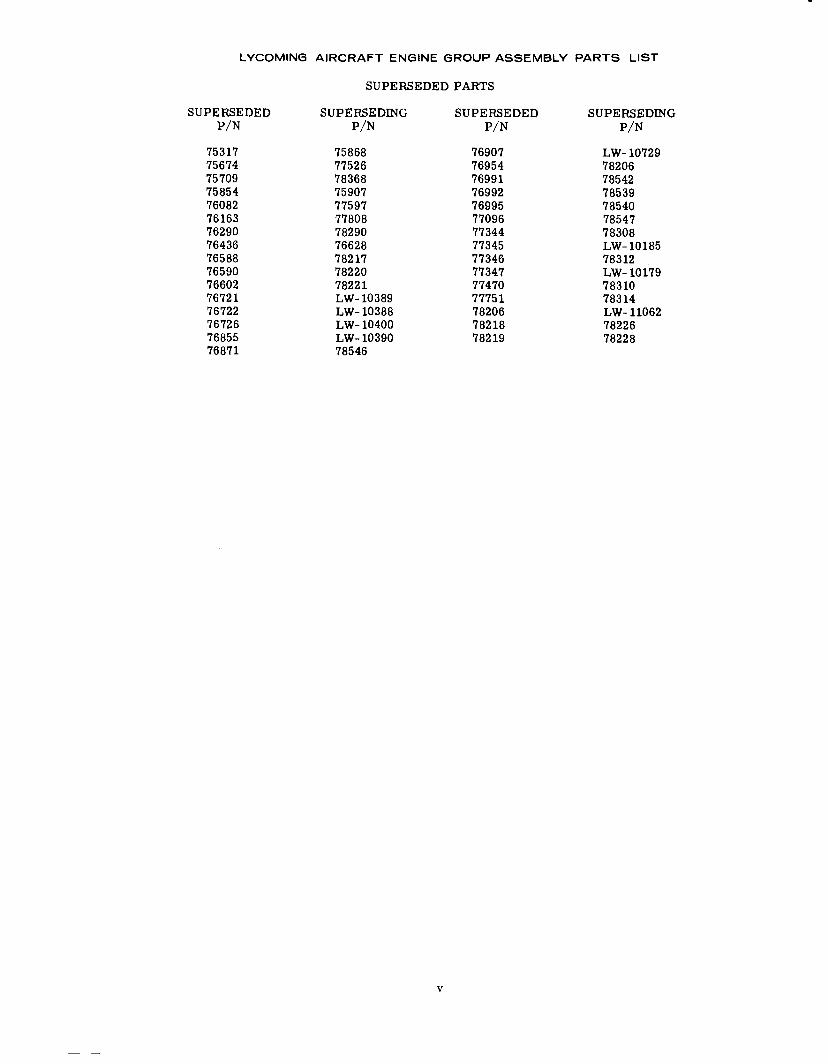
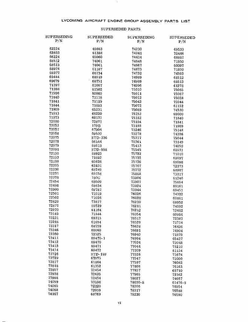
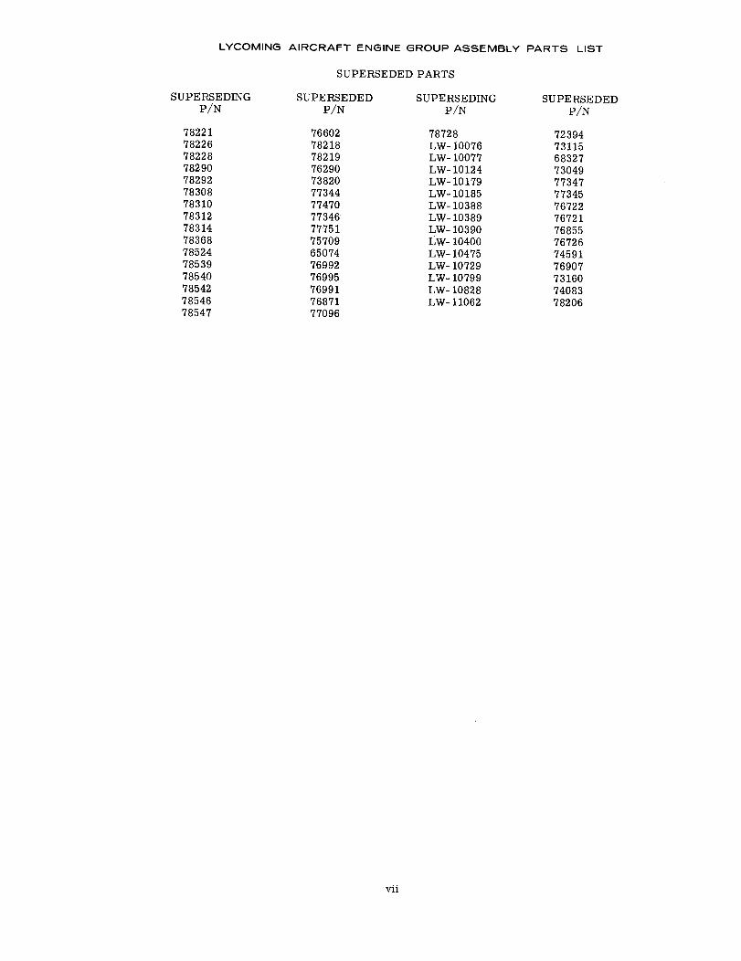
SUPERSEDED PARTS
SUPERSEDEDP/N
180G179BSTD- 189STD-336STD-9984566360007600696013160828608616086960984611526115461164611676124661278613526138861476-S615026165461667618646283165060650746533165427661446622066734679046797568327685096851268513685196853168613686346871068749687516875968769688676892368987690006909769098691586916169315694516947069470-169471
SUPERSEDINGP/N
72378720537372672075720916222474667733467197372198760287159676354750727730972970689747590674996738186283378030-S7139873246713977381772205662247852471909769947207871913693777205773729LW- 1007772454749897498969444755457207972498778577223069679733177416774414721507577275153757357573672231759247323175944734127341173413
SUPERSEDEDP/N
6947269529695306953369787699527101071019710267111871119716927169371714718407184171844718797193971950719697205972220723627237372387723947244672454724547246272525726257287173048730497311573160731497319673817738207405974061740617408374092743227438674530745917459374667749047500975028750447504475065750677514875210
SUPERSEDINGP/N
7341472877720587423072500762107572272501725027184071841721537184476529751837518473149769407467374646751887406874065779657576776517787287424173857739987621273360739387200077034LW- 10124LW- 10076LW- 1079975361740597282978292754136851268513LW- 1082876211760267527875089LW- 104757473278027766917754775012753177504275010750117524677044
iv
LYCOMING AIRCRAFT ENGINE GROUP ASSEMBLY PARTS LIST
SUPERSEDED PARTS
SUPERSEDEDP/N
75317756747570975854760827616376290764367658876590766027672176722767267685576871
SUPERSEDINGP/N
7586877526783687590777597778087829076628782177822078221LW- 10389LW- 10388LW- 10400LW- 1039078546
SUPERSEDEDP/N
769077695476991769927699577096773447734577346773477747077751782067821878219
SUPERSEDINGP/N
LW- 10729782067854278539785407854778308LW- 1018578312LW- 101797831078314LW- 110627822678228
v
LYCOMING AIRCRAFT ENGINE GROUP ASSEMBLY PARTS LIST
SUPERSEDED PARTS
SUPERSEDINGP/N
6222462833662246851268513689746937769444696797139771398715967184071841718447190971913719737200072053720577205872075720787207972091721507215372198722057223072231723787245472498725007250172502728297287772970731497323173246733177334673360734117341273413734147372673729738177381873857739387399874059740657406874167
SUPERSEDEDP/N
45663613886506074061740616116766734685196875161667615026086971118711197169365331662206013172871179B6790469530STD-3366614468613STD-998689237169260828628316874969158180G685096863469787710197102673817695296116471844693156165468759600697252569470-1694706947169472STD-18967975618646135272454726257245473196722207205968769
SUPERSEDINGP/N
7423074241744147464674667746737473274989749897499675010750117501275042750727508975153751837518475188752467527875317753617541375545757227573575736757677577275868759067590775924759447602676028762107621176212763547651776529766287669176940769947703477044773097752677547775977780877857779657802778030-S782067821778220
SUPERSEDEDP/N
6953372446688677195060007719397459368512685136127875065750677502875044611527453069000718407184171969751487438675044731497405968531710106909769098723736898775317612467585469161694517432260861699527409272462609847238771714764367490471879654277304875210611547567475009760827616368710723627466761476-S769547658876590
vi
LYCOMING AIRCRAFT ENGINE GROUP ASSEMBLY PARTS LIST
SUPERSEDED PARTS
SUPERSEDINGP/N
SUPERSEDEDP/N
78221782267822878290782927830878310783127831478368785247853978540785427854678547
76602782187821976290738207734477470773467775175709650747699276995769917687177096
SUPERSEDINGP/N
78728LW- 10076LW- 10077LW-10124LW- 10179LW- 10185LW- 10388LW- 10389LW- 10390LW- 10400LW- 10475LW- 10729LW- 10799LW- 10828LW- 11062
SUPERSEDEDP/N
723947311568327730497734777345767227672176855767267459176907731607408378206
vii
LYCOMING AIRCRAFT ENGINE GROUP ASSEMBLY PARTS LIST
LYCOMING PARTS CATALOG
0-320, IO-320 AND LIO-320 SERIES
SECTION 1
CRANKCASE, CRANKSHAFT AND CAMSHAFT
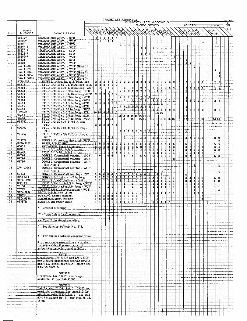
CRANKCASE ASSEMBLY SECTION
QUANTITY PER ASSEMBLY 10-320 SERIES 10-320 LIO-320 PAGE
PARTREF. NUMBER DESCRIPTION
78217* CRANKCASE ASSY. - STD 1 1 1 1 1 178222* CRANKCASEASSY. -WCF 1 1 1 1 1 1178226* CRANKCASE ASSY. -STD 1 1 1178223** CRANKCASE ASSY. -WCF 1 1 1 1 1 1 1178220** CRANKCASE ASSY. - STD 178228** CRANKCASE ASSY, -STD 1 1 178206** CRANKCASE ASSY. - WCF 178221+ CRANKCASE ASSY. - STD 178224+ CRANKCASE ASSY. -WCF 1 1LW-11025+ CRANKCASE ASSY. - WCF (Note 1) 1LW-11078+ CRANKCASE ASSY. - WCFLW-11237+ CRANKCASE ASSY. - WCF (Note 2) 1LW-11305+ CRANKCASE ASSY. - WCF (Note 1) 1LW-11062** CRANKCASE ASSY. - WCF (Note 3) 1
1 STD-557 DOWEL, 1/2in. dia. x 1 1/16in. long 22 2 2 2 2 2 2 2 2 2 22 2 2 2 2 2 2 2 2 2 2 2 2 2 22 69377 STUD, 1/2-13x9-11/16 in. long-STD 2 2 2 2 2 2 2
2 75154 STUD, 1/2-13x10-1/32in. long-WCF 2 2 2 2 2 2 22 2 2 2 2 2 2 2 2 2 22 66734 STUD,1/2-13x9-7/8 in.long-STD 222 2 2 222 2 2 2
3 69377 STUD, 1/2-13x9-11/16 in. long- STD 2 22 22 23 .66734 STUD, 1/2-13x9-7/8 in. long -STD 2 22 2 222 23 75154 STUD, 1/2-13x10.02in. long-WCF 2 2 2 2 2 2 2 22 2 2 2 2 2 2 2 2 2 24 50-14 STUD, 1/2-13x1-3/4in.long -STD 8 8 888 8 8 8 884 50-15 STUD, 1/2-13x 1-7/8 in. long-STD 8 8 8888 8 88 8 88 84 50-16 STUD, 1/2-30x2.00in. long-WCF .8 88 8 8 8 8 8 8 8 8 8 88 88 8 8 8 8 85 1025-B STUD, 3/8-16x 1-1/2in. long STD 16 16161616 16 16 165 .38-13 STUD,3/8-16x1-5/8in. long-STD 16 161616 116 16 16 165 38 14 STUD, 3/8-16x 1-3/4in. long-WCF 16 1616 16 16 16 16 16 16 16 16 1616 16 16 16 1616 16 166 69376¢ STUD, 1/2-20x10-17/64in. long- 22222
STD 2222 2 2 22 2 26 69679¢ STUD, 1/2-20 x 10-21/32 in.long-
STD 2 2 22 22 2 26 75155¢ STUD, 1/2-20 x 10-15/16 in. long- 22 2 2 2 2 2 2
WCF 2 2 22 2 22 2 2222 222 2 227 753202¢ DOWEL,Crankcase thru stud-WCF . 2 2
8 STD-1102 PLUG, 1/8-27 NPT.. 5 55 5 5 5 5_5555 55 5555 5 5 555 - 559 65007 RETAINER,Shroud tube seal ... 8 8888888888 8 8 88 8 88 88 8 8 88888 8
10 61261 STUD,5/16-18x1-1/2in. long 2 2 22 2 2 2 2 2 2 2 22 2 2 22 2 2 2 2 2 222 2 2 2 211 67528 STUD,5/16-18x 1-5/8in. long 1 11 1 1 1 1 1 1 1 1 1 1 1 1 1 1 112 69796 DOWEL, Crankshaft bearing-WCF 6 6 6 6 6 66 6 6 6 6 6 6 6 6 612 69796 DOWEL, Crankshaft bearing - WCF 812 69796 DOWEL, Crankshaft bearing- WCF
See Note 1) _ .2 212 LW-10647 DOWEL, Crankshaft bearing - WCF
(See Note 1)12 67453 DOWEL, Crankshaft bearing - STD 6 6 6 666 6 6 6 66 6 6 6 41267453 DOWEL, Crankshaft bearing - STD13 STD-514 DOWEL,I 5/16 dia.x 1/2 in. long 2 2 22 222 2 2 2 2 2 2 22 2 2 2 22222 22 2 22214 STD-1623 14 INSERT,1/4-20 helicoil x 3/8 in. 2 2 2 2 2 22 22 22 2 2 22 222 2215 38D-17 STUD, 3/8-16 x 2-1/8 in. long 1 1 1. 1 1 1I 111 1 1 I 116 75156 STUD, 5/8-18 x 15/16 in.long WCF 1 11 11-11.111 1 111_117 73772 NOZZLE ASSY, Piston cooling -WCF 418 STUD -783# PLUG,1/4-28 NPT Allen 1 111 1 1 1 111 11 119 71032* BUSHING,Engine support 8 8 88 8 8 8 8 8 888 8 820 STD-619* WASHER, Support bushing 8 8 _ 88 821 61387& SLEEVE, Oil relief valve 11 1 1111111 111 111
* - Conical mounting.
** - Type 1 dynafocal mountings.
+ - Type 2 dynafocal mounting.
¢-See Service Bulletin No. 273.
- # - For engines without governor drive.
& For crankcase with no provisionfor adjustable oil pressure reliefvalve (Available in oversizeP03).
N O T E 1Crankcases LW-11025 and LW-11305
use 2 69786 crankshaft bearing dowelsand 4 LW-10647 dowels. All others use6 69796 dowels.
. NOTE 2Crankcase LW-11237 is no longer
available. Order LW-11305
.. used this crankcase.See page 1-5 forattaching bolts 76220 Ref. 4 - use stud .50- 15 8 ea.and Ref.5 - use stud 38-13,16 ea. .
A
2 7
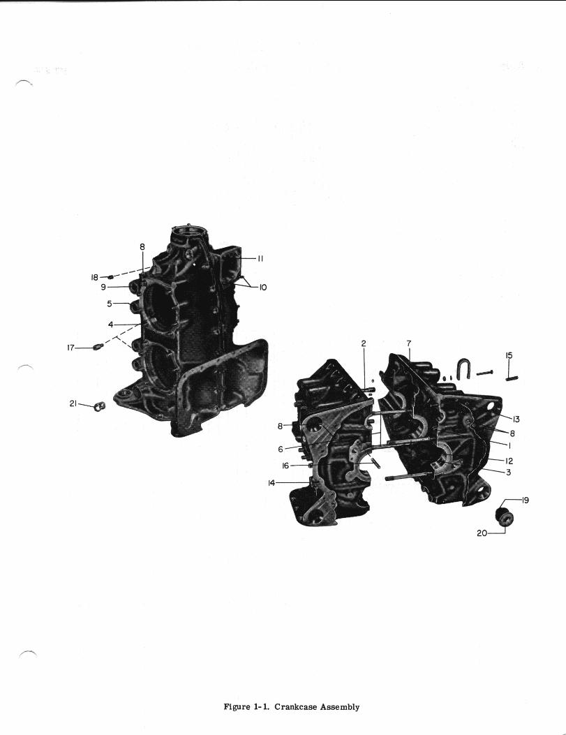
Figure l-l. Crankcase Assembly
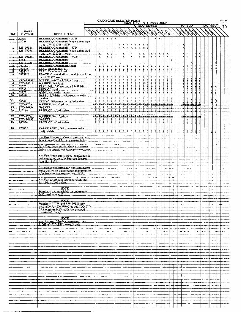
CRANKCASE RELATED PARTSQUANTITY PER ASSEMBLY
O-320 SERIES 10-320 LIO-320 PAGE
PARTREF. NUMBER DESCRIPTION
67447 BEARING, Crankshaft -STD 4 4 4 4 4 4 4 4 4 4 41 77034 BEARING, Crankshaft (when exhausted
4 4 4 4 4 4 4 4use LW-10124) - STD 4BEARING,Crankshaft-STD 4 4 4 4 4 4 4 4 4 4
LW-77034 BEARING, Crankshaft (when exhausteduse LW-10124) -4 4 4 4 4 4 4 4 4
24 BEARING,Crankshaft-WCF 4 4 4 4 4 4 4 4 4 4 4 4 4 4 4 4 4 41 BEARING, Crankshaft ........ ..... 8 8
LW-11021 BEARING,Crankshaft... ...... .......... ... 4.2 770Z44 BEARING, Crankshaft, front3 7377* SEAL Crankshaft, oi1 ..3 76940 SEAL, Crankshaft oil l11 1 1 1 1 1111
473952** PLATE, Crankshaft oil seal (do not usewith 77377 seal
5 STD-1919** S SCREW,l4-20x9/16in. long 6 6 6 6 6 6 6 6 6 6 6 6 6 6 6 6 6 6 6 6 66 STD-160** WASHER 1/4 lock 6 6 6 6 6 6 6 6 6 6 6 6 6 6 6 6 6 6 6 6 6 6 6 67 72075 SEAL, Oil 090 section x 15/32 OD 66 6 66 66 666 6 66 66 6 6 6 6 6666 6 66 46 6-6 48 72091 RING,Oil seal 2.2._2 222222222 2_2222_ 2 22 2.2_2_2 2 2_ 2222 2 29 72877 BODY Hydraulic tappet 8 8888 8 8 8888 8888 8 888 8 8 8 8 888 8
10 1028B BALL,11/16dia., oilpressure relief
11 68668 SPRING Oilpressure relief valve 1 1 1 1 1 1 1 1 1 1 1 1 1 1 1 1 112 STD-425+ WASHER No. 10 plain ARARARARARARARARARARAR RARARARARARARAR AAA
14 71714+ PLUG, Oil relief valve
12 STD-425 WASHER, No. 10 plain RARAARAARAR ARARARARA -13STD-1045 GASKET 111 1 1 1 l 1 1 1 1 1 1 1 1 1 1 115 76529 PLUG Oil relief valve 11111 111111111111 11111111 1 1
16 77808# VALVE ASSY. Oil pressure reliefadjustable 1 1 1 1 1 1 1 1 1 1 1 1 1 1 1 1 1 1 1 1 1
* - Use this seal when crankcase noseis not machined for six screw holes.
** - Use these parts when six screwholes are machined in crankcase nose.
+ - Use these partsnot machined in a/w Service Instruc-tion No. 1172.
- Use these parts for non-adjustablerelief valve in crankcases machined in .... ....... ..a/w Service Instructio No. 1172,
- For crankcase incorporating ad-justable relief valve.
NOTEBearings are available in undersizeM03,.M06 and M10.
NOTEBearings 77034 and LW-10124 areavailable for IO-320-CIA and LIO-320-C1A engines built with the steppedcrankshaft dowel.
NOTE
Ref. 7 -Seal 72075. Crankcase LW-11062 (O-320-E2D) uses 2 only
I
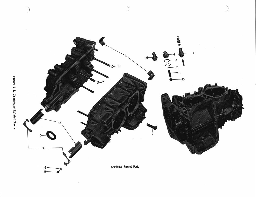
Figure l-2.
Crankcase
Related
Parts
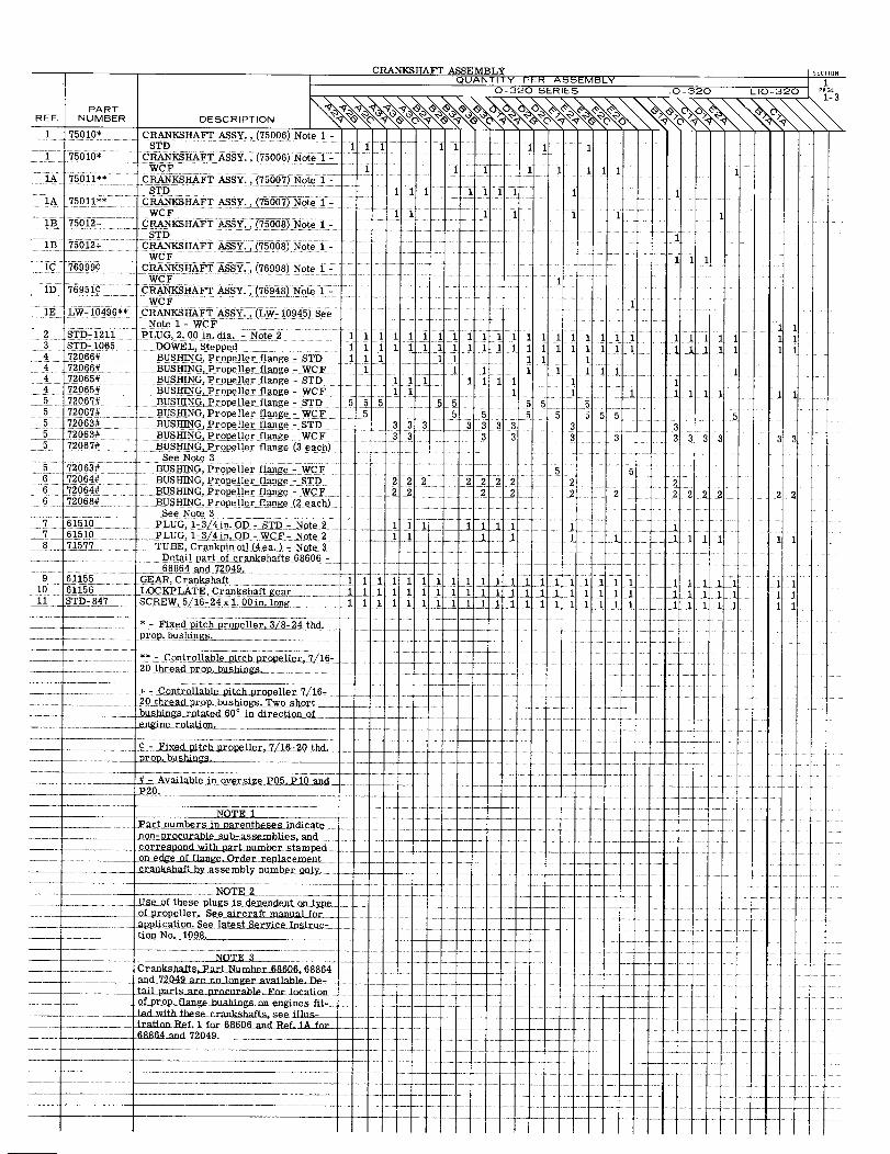
CRANKSHAFT ASSEMBLYQUANTITY PER ASSEMBLY
0-320 SERIES 10-320 LIO-320
PARTREF. NUMBER DESCRIPTION
1 75010* CRANKSHAFT ASSY., (75006) Note 1 -STD 1 1 1 1 1 1 1 1
1 75010* CRANKSHAFT ASSY., (75006) Note 1WCF 1 1 1 1 11
1A 75011** CRANKSHAFT ASSY., (75007) Note 1-STD 1 1 1 1 1 1 1 1
1A 75011** CRANKSHAFT ASSY., (75007) Note - 1....... WCF 1 1 1 1 1 1
1B 75012+ CRANKSHAFT ASSY., (75008) Note 1-STD
B1 75012+ CRANKSHAFT ASSY., (75008) Note 1-WCF 1 1
1C 769990 CRANKSHAFT ASSY., (76998) Note 1 -WCF 1
ID 769519 CRANKSHAFT ASSY., (76948) Note 1-WCF 1
IE LW-10496** CRANKSHAFT ASSY., (LW- 10945) SeeNote 1- WCF 11
2 STD-1211 PLUG, 2. 00in.dia.-Note2 11 1 1 11 1" 1 1 1 1 1 1 1 1 111 1111 1 13 STD-1065 DOWEL, Stepped 1111 111 111 1 11 11 111 1 11 11 114 72066# BUSHING, Propeller flange - STD 1 1 1 1 1 1 1 14 72066# BUSHING, Propeller flange - WCF 11 1 1 1 1 11 14 72065# BUSHING, Propeller flange - STD 11 1 1 111 14 72065# BUSHING,Propeller flange - WCF 1 1 1 1 1 1 1 1 15 72067# BUSHING, Propeller flange -STD 5 5 5 5 5 5 55 72067# BUSHING, Propeller flange - WCF 5 5 5 5 5 5 5 5 55 72063# BUSHING, Propeller flange- STD 3 3 3 3 3 3 3 3 35 72063# BUSHING, Propeller flange - WCF 3 3 3 3 3 3 3 3 3 3 3 35 72067# BUSHING, Propeller flange (3 each)
See Note 35 72063# BUSHING, Propeller flange - WCF 5 56 72064# BUSHING, Propeller flange - STD 2 2 2 2 2 2 2 2 26 72064# BUSHING, Propeller flange -WCF 22 2 2 2 2222 26 72068# BUSHING, Propeller flange (2 each)
See Note 37 61510 PLUG, 1-3/4in. OD - STD - Note 2 1 1 1 1 1 1 17 61510 PLUG, 1-3/4in. OD -WCF-Note 2 __ 1 1 1 1 1 1 18 71577 TUBE,Crankpin oil (4 ea.) - Note. 3
Detail part of crankshafts 6860668864 and 72049.
9 61155 _GEAR, Crankshaft 111 1 1 11 1 11 1 1 1 1 1 1 111 1 110 61156 LOCKPLATE, Crankshaft gear 1 1 1 1 1 1 1 1 1 1 1 11 1 1 1 111 STD-847 SCREW,5/16-24x1.00 in. long 111 11 111111 1 1 1 1 1 1 111 1 1
. * - Fixed pitch propeller,3/8-24 thd.
_
- Controllable pitch propeller 7/16-20 thread prop. bushings..........
+ Controllable pitch propeller 7/16-20thread prop. bushings,Two Short
prop. bushings
Available in oversize P05, P10 and
NOTE 1
-..- edgofedge age rderepla emen -... .......... ...crankshaft by assembly number only .
Use of these plugs is dependent on type
application.See latest Service Instrc-tion No. 1098, __
Crankshafts, Part Number_68606,68864.and 72049 are no longer available. De-tail parts are procurable. For location
.of prop. flange bushings on engines fit-ted with these crankshafts, See illus-tration Ref. 1 for 68606 and Ref. 1A for
68864 and 72049
l @
4
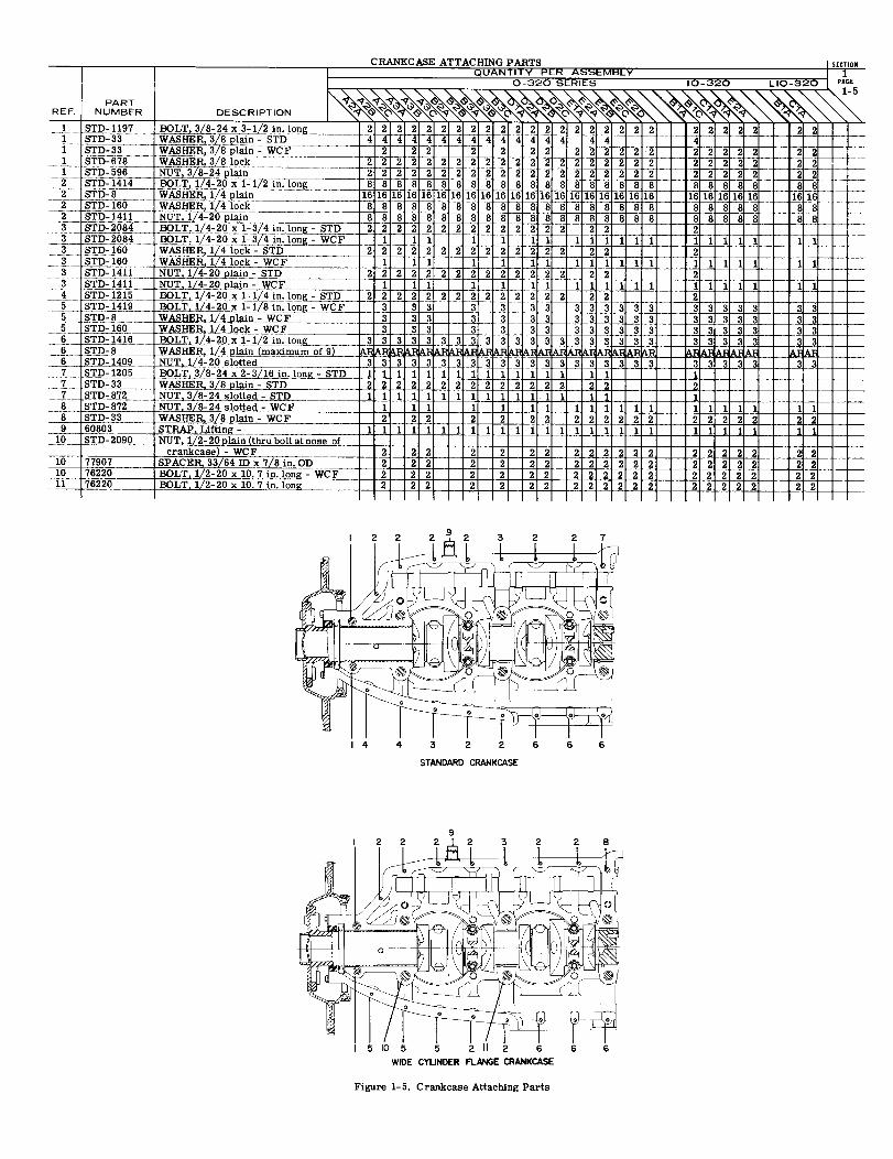
PARTREF. NUMBER DESCRIPTION
1 STD-1197 BOLT, 3/8-24x 3-1/2 in. long 2 2 2 2 2 221 STD-33 WASHER, 3/8 plain - STD 4 4 4 4 4 44
STD-33 WASHER, 3/8 plain- WCF plain 221 STD-678 WASHER, 3/8 lock l 2 2 22 22221 STD-596 NUT, 3/8-24 plain 4 2 2 2 2 2 2 22 STD-1414 BOLT, 1/4-20 x 1-1/2 in. long 8 8 8 8 8 82 STD-8 WASHER 1/4 plain 16 16 16 16 16 16 16 162 STD-160 WASHER, 1/4 lock 8 8 888 88 8 82 STD-1411 NUT, 1/4-20 plain 8 8 8 8 8 8 83 STD-2084 BOLT 1/4-20 x 1-3/4 in. long- STD 2 222 2 2 23 STD-2084 BOLT, 1/4-20x 1-3/4 in. long WCF 1 1 13 STD-160 WASHER 1/4ock-STD 2 2 2 2 2 2 23 STD- 160 WASHER, 1/4 lock - WC F 1 1 13 STD-1411 NUT, 1/4-20 plain -STD 2 2 2 2 2 2 23 STD-1411 NUT 1/4-20 plain- WCF 1 1 1
2
8
88
4 STD- 1215 BOLT, 1/4-20 x 1- 1/4 in. long- STD 25 STD- 1419 BOLT 1/4-20 x 1-1/8 in.long -WCF5 STD-8 WASHER, 1/4 plain - WCF5 STD-160 WASHER, 1/4 lock - WCF6 STD-1416 BOLT, 1/4-20 x 1-1/2 in. long 36 STD-8 WASHER, 1/4 plain (maximum of 9) AR6 STD-1409 NUT, 1-4-20 slotted 4-20 slotted 37 STD-1205 BOLT, 3/8-24 x 2-3/16 in. long - STD 1
7 STD-33 WASHER, 3/8plain- STD 27 STD-872 NUT, 3/8-24 slotted- STD 1
2 23333 3
888
2222222222222 2 2 2 2
2
2 2
8882 2 2
8 STD-8728 STD-33
CRANKCASE ATTA( HING PARTS SECTIONQUANTITY PER ASSEMBLY 1
O-320 SERIES 10-320 LIO-320 PAGE1-5
2222222222222 22222 22444444 44 4 4~
2 2 2 2 2 22 2 2 2 2 2 2 2 2 2
6 16 16 16 16 16 16 16 16 1 16 16 16
22 2 222 2 2 2222 22222 22
8a a a 8 8 8 8t8H88888888
888888888888882 2 2
8
212
8 888 8 8 88
1 1 1 1 11 11 12 2 2
1 11 11 1111 1 1 1 1222222 22 2
1111112 22
1 1111 1 1
3333332333
3333333 3333333 3
333333 3 3 3 3 333 3 3 33 3 33
- WCF- WCF
3333333333333333333 33333 331111111111111 112 2 2 2 2 2 2 2 2 2 2 2 2 2 2 21 1 1 1 1 1 1 1 11 1 1 1 1 1 11 1 1 1 1 1 1 1 1 11 1 1 1 1 1 1 1 1 12 2 2 2 2 2 2 2 222 2 2 2 2 2 2 2 2 21 1 1 1 1 1 1 1 1 1 1 1 1 1 1 1 1 1 1 1 1 1 1 1 11
2 2 2 2 2 2 2 2 2 2 2 2 2 2 2 2 2 2 2 22 2 2 2 2 2 2 2 2 2 2 2 2 2 2 2 2 2 2 22 2 2 2 2 2 2 2 2 2 2 2 2 2 2 2 2 2 2 22 2 2 2 2 2 2 2 2 2 2 2 2 2 2 2 2 2 2 2
9 60803 STRAP, Lifting - 110 STD- 2090 NUT, 1/2- 20 plain (thru bolt at nose of
crankcase) - WCF10 77907 SPACER, 33/64 IDx 7/8 in. OD10 76220 BOLT, 1/2-20 x 10. 7 in. long - WCF11 76220 BOLT, 1/2-20 x 10. 7 in. long
STANDARD CRANKCASE
10 5 2 11 2 6WIDE CYLINDER FLANGE CRANKCASE
Figure 1-5. Crankcase Attaching Parts
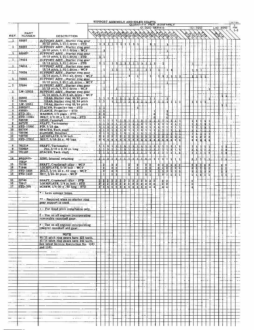
12/14 pitch. 3. 25:1 alt.drive-WCF2 60882 GEAR,Starter ring 10/12 pitch2 72566 GEAR,Starter ring 12/14 pitch2 LW- 10551 GEAR, Starter ring 12/14 pitch3 68939** SPACER, Propeller hub -STD 14 45688+ FLANGE, Propeller - STD5 STD-33+ WASHER,3/8 plain - STD 6 66 STD-1198+ BOLT, 3/8-24 x 4.44 long - STD 6 6 6 67 68639 GEAR. Camshaft8 68757 SHAFT, Tachometer9 STD-1199 PIN 3/16 dia.
1 1 1 1 1 1 1 i 1 11 1llllll111
10
11 72079 SLINGER, Breather12 72078 LOCKPLATE 5/16 bolt
8 76121# SHAFT. Tachometer 119 78368# PIN, 3/16 x 2. 33 in.long 1 1 1 1
10 76118# SPACER, Tach. shaft 1 1 1
41 MS16625- RING, Internal retaining 1 1 11081*
15 75158 SHAFT, Crankshaft idler - WCF 2 216 71646 LOCKPLATE, 5/16 bolt - WCF 2 217 STD- 1926 BOLT, 5/16-18 x. 67 long - WCF 3 318 STD- 1410 NUT, 5/16-18 plain - WCF 1 1
15 68749 SHAFT, Crankshaft idler - STD 2 2 2 216 73817 LOCKPLATE, 1/4 in. bolt - STD 2 2 2 217 STD-705 SCREW, 1/4-20 x .69 long - STD 4 4 4 4
* - Less spinner holes.
** - Required when no starter ringgear support is used.
+ - For fixed pitch installation only.
- Use on all engines incorporatingremovable camshaft gear.
* - Use on all engines incorporatingintegral camshaft and gear.
NOTE10/12 pitch ring gears have 122 teeth.12/14 pitch ring gears have 149 teeth.See latest Service Instruction No. 1121and 1141.
SUPPORT ASSEMBLY AND IDLER SHAFTS SECTIOQUANTITY PER ASSEMBLY 1
0-320 SERIES IO-320 LIO-320 PAGE
REF. NUMBER DESCRIPTION
1 68867 SUPPORT ASSY, Starter ring gear10/12 pitch, 1. 91:1 drive - STD 11 1 1 11 1 1 11 1 1
1 68867 SUPPORT ASSY., Starter ring gear10/12 pitch, 1. 91:1 drive - WCF
1 68942* SUPPORT ASSY. Starter ring gear10/12 pitch, 1.91:1 drive - STD
1 74414 SUPPORT ASSY., Starter ring gear12/14 pitch, 1.91:drive -STD 1 11111 11 1 1 1 1
1 74414 SUPPORT ASSY., Starter ring gear
12/14 pitch , 1.91:l drive- WCF 1 1 1 111 1 176628 SUPPORT ASSY., Starter ring gear
12/14 pitch, 3.25:1 alt. drive- WCF 1 1 1 1 1 11 1111 1 11 76899 SUPPORT ASSY. Starter ring gear
10/12 pitch, 3.25:1 alt. drive - WCF 1 11 76944 SUPPORT ASSY., Starter ring gear
1 pitch, 3.25:1 drive - WCF 1 1 11 LW-10552 SUPPORT ASSY. ,Starter ring gear
111111222
44444 4 4
1111 111111
1 1
111 1
1.
13 STD- 1791 BOLT. 5/16-24 x 66 long
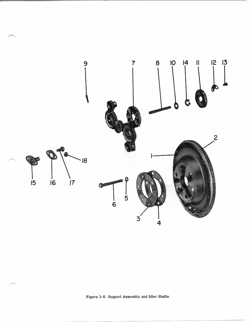
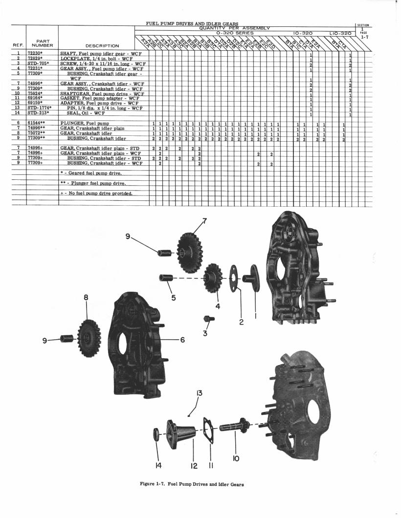
I
LYCOMING AIRCRAFT ENGINE GROUP ASSEMBLY PARTS LIST
.30
U
4J
LYCOMING PARTS CATALOG
0-320, 10-320 AND LIO-320 SERIES
SECTION 2
ACCESSORY HOUSING AND DRIVES
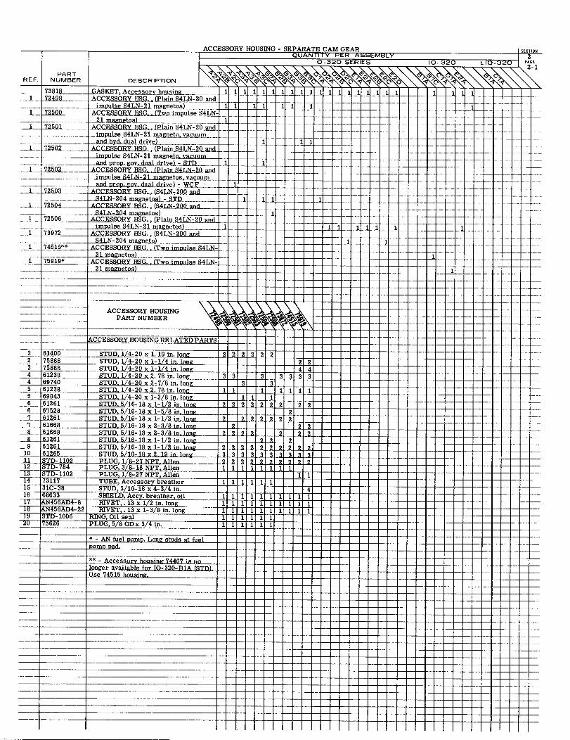
2 75888 STUD, 1/4-20 1-14 in. long3 75888 STUD, 1/4-20 x 1-1/4 in. long4 61238 STUD, 1/4-20 x 2. 78 in. long4 69740 STUD, 1/4-20 x 3-7/8 in. long5 61238 STUD, 1/4-20 x 2. 78 in. long5 69943 STUD, 1/4-20 x 1-3/8 in. long6 61261 STUD, 5/16-18 x 1-1/2 in. long6 67528 STUD, 5/16-18 x 1-5/8 in. long7 61261 STUD. 5/16-18 x 1-1/2 in. long7 61668 STUD, 5/16-18 x 2- 3/8 in. long
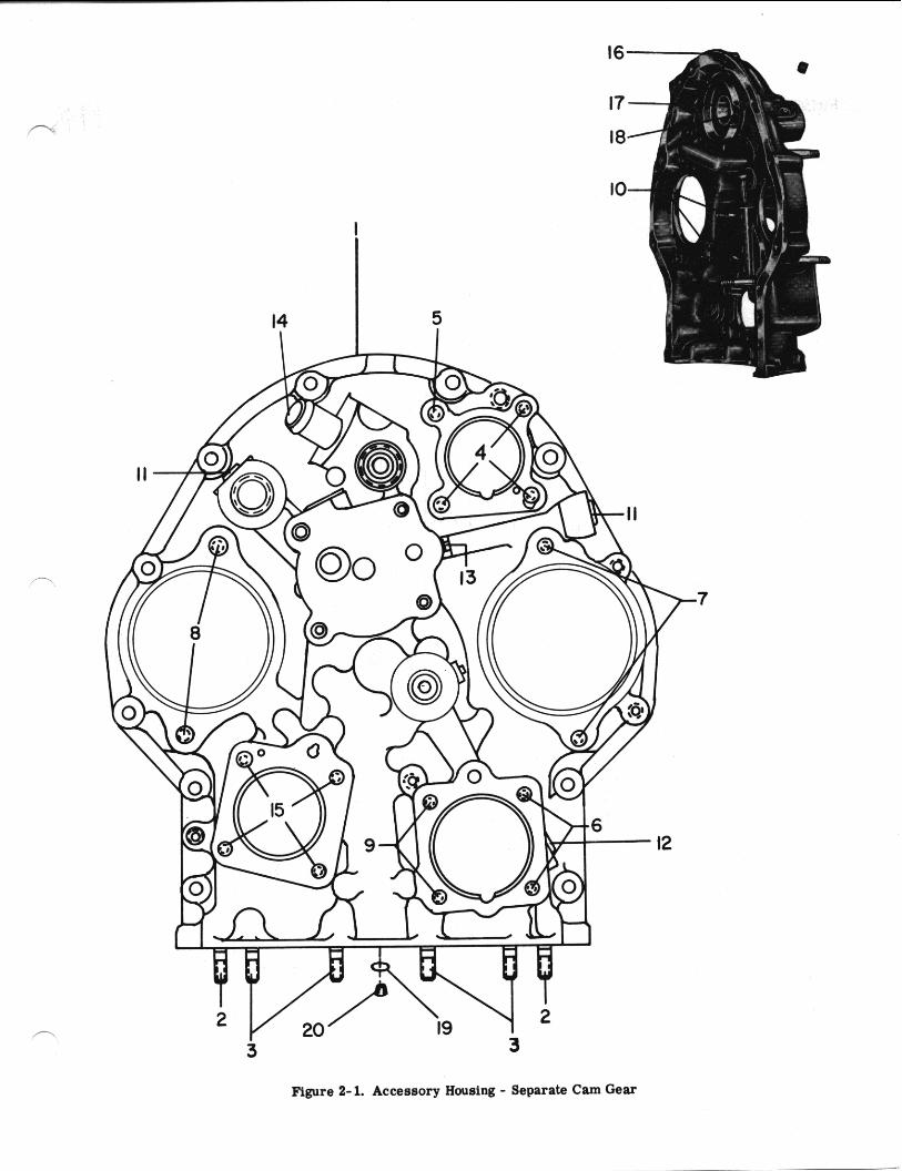
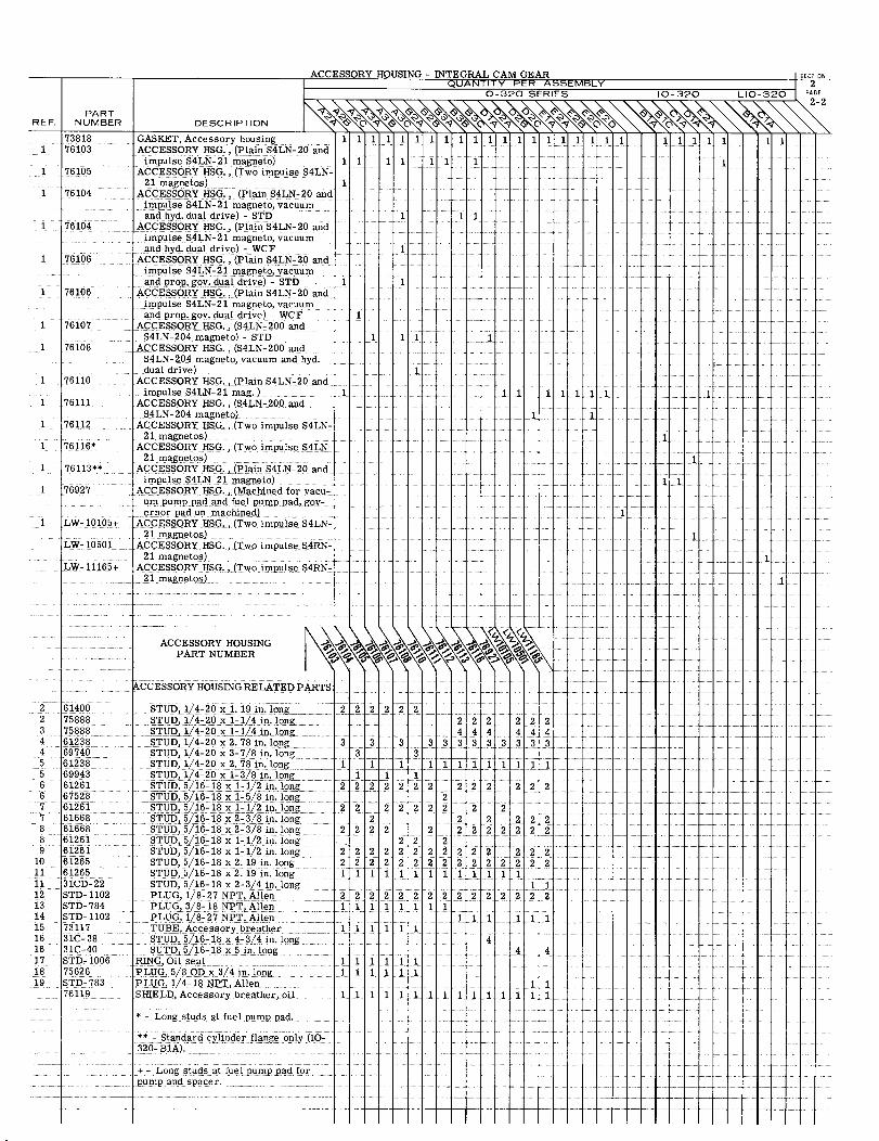
PARTREF. NUMBER
738181 76103
1 76105
1 76104
1 76104
1 76106
1 76106
1 76107
1 76108
1 76110
1 76111
1 76112
1 76116*
1 76113**
1 76927
1 LW- 10105+
LW- 10501
LW- 11165+
ACCESSORY
DESCRIPTION
GASKET, Accessory housing 1ACCESSORY HSG., (Plain S4LN-20 and
impulse S4LN-21 magneto) 1ACCESSORY HSG., (Two impulse S4LN-
21 magnetos) 1ACCESSORY HSG., (Plain S4LN-20 and
impulse S4LN-21 magneto, vacuumand hyd. dual drive) - STD
ACCESSORY HSG., (Plain S4LN-20 andimpulse S4LN-21 magneto, vacuumand hyd. dual drive) - WCF
ACCESSORY HSG., (Plain S4LN-20 andimpulse S4LN-21 magneto, vacuumand prop, gov. dual drive) - STD 1
ACCESSORY HSG., (Plain S4LN-20 andimpulse S4LN-21 magneto, vacuumand prop. gov. dual drive) - WCF
ACCESSORY HSG., (S4LN-200 andS4LN-204 magneto) - STD
ACCESSORY HSG., (S4LN-200 andS4LN-204 magneto, vacuum and hyd.dual drive)
ACCESSORY HSG., (Plain S4LN-20 andimpulse S4LN-21 mag. ) 1
ACCESSORY HSG., (S4LN-200 andS4LN-204 magneto)
ACCESSORY HSG., (Two impulse S4LN-21 magnetos)
ACCESSORY HSG., (Two impulse S4LN-21 magnetos)
ACCESSORY HSG., (Plain S4LN-20 andimpulse S4LN-21 magneto)
ACCESSORY HSG., (Machined for vacu-um pump pad and fuel pump pad, gov-ernor pad un-machined)
ACCESSORY HSG., (Two impulse S4LN-21 magnetos)
ACCESSORY HSG., (Two impulse S4RN-21 magnetos)
ACCESSORY HSG., (Two impulse S4RN-21 magnetos)
ORY HOUSING - INTEGRAL CAM GEAR SECTIQUANTITY PER ASSEMBLY 2
0-320 SERIES 10-320 LIO-320 PA
ON
2
1 1 1 1 1 1 1
1 1 1
1
1 1 1 1
11 11111
1 1
1
1
11
1
1
ACCESSORY HOUSINGPART NUMBER
2 614002 758883 758884 612384 697405 612385 699436 612616 675287 612617 616688 616688 612619 61261
10 6126511 6126511 31CD-2212 STD-110213 STD-78414 STD-110215 7311716 31C-3816 31C-4017 STD-100618 7562619 STD-783
76119
ACCESSORY HOUSING RELATED PARTS:
STUD, 1/4-20 x 1.19 in long 22 2 2 22 2STUD, 1/4-2 0 x 1-1/4 in.long 2 2 2 2 2 2STUD, 1/4-20 x l-1/4 in. long 4 44 4 4 4 4STUD, 1/4-20 x 2.78 in long 3 3 3 3 3 3 3 3 3 3 3 3STUD, 1/4-20 x 3-7/8 in. long 3 3STUD, 1/4-20x 2.78 in. long 1 1 11 1 1 1 1 1 1 1STUD, 1/4-20 x 1-3/8 in. long 1 1STUD, 5/16-18x1-1/2in. long 22 22 2 22 2 2 2 2 22STUD, 5/16-18 x 1-5/8 in. long 2STUD, 5/16-18x 1-1/2 in. long 2 2 2 2 2 2 2 2 2STUD, 5/16-18 x 2-3/8 in. long 2 2 2 2 2 2STUD,5/16-18 x2-3/8 in. long 2 2 2 2 2 2 2 2 2 2 2 2STUD, 5/16-18 x 1-1/2 in. long 2 2 2STUD, 5/16-18 x 1/2 in. long 2 2 2 2 2 2 2 2 2 2 2 2 2STUD, 5/16-18 x 2.19in. long 2 2 22 2 2 22 2 2 2 2 2 2 2STUD, 5/16-18 x2.19 in. long 1 1 1 1 1 1 1 1 1 11 1 1STUD, 5/16-18 x 2-3/4 in. long 1PLUG, 1/8-27 NPT, Allen 2 2 2 2 2 2 2 2 2222 2 2 2 2PLUG, 3/8-18 NPT, Allen 1 1 1 1 1 1 1 1PLUG, 1/8-27 NPT, Allen 1 1 1 1 1TUBE, Accessory breather 1 1 1 1 1 1STUD, 5/16-18 x 4-3/4 in. long 4SUTD, 5/16-18 x5 in. long 4 4
RING, Oil seal 1 1 1 1 1PLUG, 5/8 ODx 3/4 in. long 1 1 1 1 1 1PLUG, 1/4-18 NPT, Allen 1SHIELD, Accessory breather, oil 1 1 1 1 1 1 1 1 1 11 1 1 1 1
* - Long studs at fuel pump pad.
** - Standard cylinder flange only (IO-320- B1A).
+ - Long studs at fuel pump pad forpump and spacer.
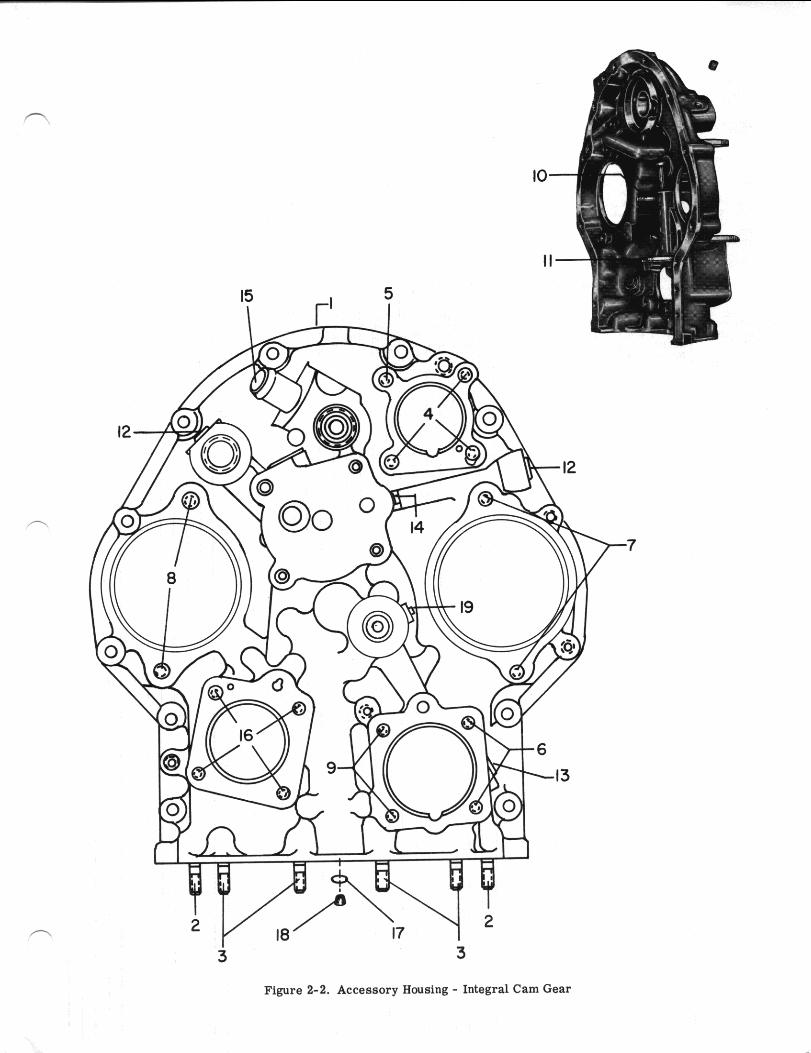
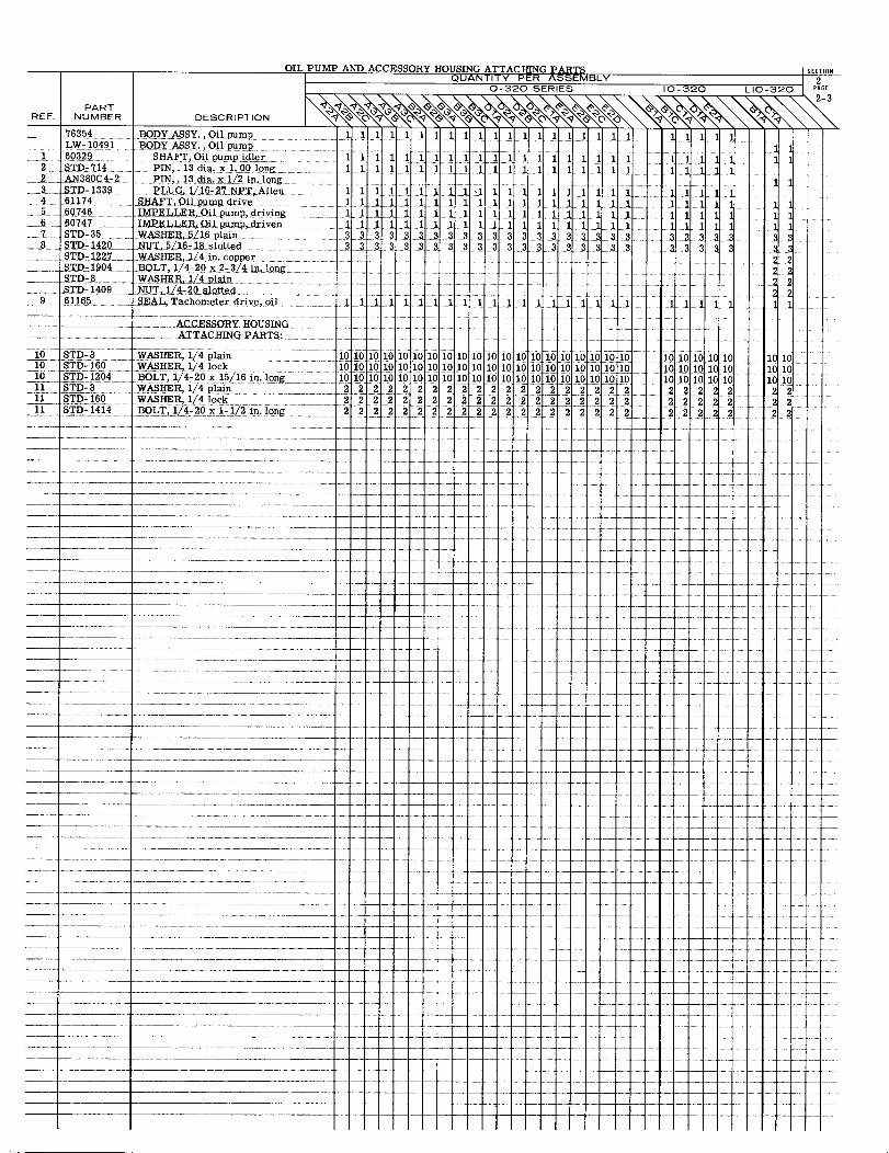
OIL PUMP AND ACCESSORY HOUSING ATTACHING PARTS SECTIONQUANTITY PER ASSEMBLY 2
0-320 SERIES 10-320 LIO-320 PAGE
2-3PART DESCRIPTION 2-REF. NUMBER DESCRIPTION
76354 BODYASSY.,Oil pump 111111111111111111 11111LW- 10491 BODY ASSY., Oil pump 1
1 60329 SHAFT pump idler 1 1 111111 1 11 1 160329 SHAFT Oil pump idler 1111 1 1 1 1 1 1 1 1 1 1 1 1 1 1 1 1 12 STD-714 PIN,.13dia. x 1.00 long, 1 1 1 1 111 1 1 1 1 11 1 1 12 AN380C4-2 PIN, 13 dia. x 1/2 in. long.3 STD-1339 PLUG,1/16-27 NPT, Allen 1 1 1 1 1 1 1 11 1 111 1 11 1 1 1 1 1 1
4 61174 SHAFT, Oil pump drive 1111 1111 111 1 1 11 1 1111 15 60746 1 IMPELLER, Oilpump, driving 111 11 11 1 1111 1 11 1 1 1 1 1 1 1 1 1 1 1 16 60747 IMPELLER, Oil pump, driven 1111 1 1 11 11 1 1111 1 11 11 1 1 1 1 17 STD-35 WASHER, 5/16plain 33 3 3 3 33 33 3 3333 3333 33333 33
STD- 1420 -MT, 5/-17 18 slotted 3 3 33 3 3 3 33 3 3 333 3 3 3 3 3 3 3 3 38 STD-1420 NUT, 5/16-18 slotted 333 3 33 3 3333 3.3 3 3 3 3 3 33STD- 1227 WASHER, 1/4 in, copper 22STD-1904 BOLT, 1/4-20 x 2-3/4 in. long 22STD-8 WASHER, 1/4 plain 22STD-1409 NUT, 1/4-20 slotted 22
9 61165 SEAL, Tachometer drive,oil 11 1 1 1 1 1 1 11 11 1 111 1 11 1 1 1 1 1
ACCESSORY HOUSING -
ATTACHING PARTS:
10 STD8 WASHER, 1/4 plain 1010 10 10 1010 1010 10 10 10 10 10 10 10 10 10 0 10 10 1010 STD-160 WASHER, 1/4 10 10 10 10 10 10 10 10 10 10 10 10 10 10 10 10 10 10 10 10 10 10 1010 10 10101010 STD- 1204 BOLT, 1/4 -20x 15/16 in. lo long 10 10 10 10 10 10 10 10 10 10 10 10 1010 10 10 1010 10 10 10 10 10 1 01010 10 10 1010 10 1011 STD-81204 BOLT, 1/4-20
2 2 2 2 22 2 2 2 2 2 2 2 2 2 2 2 2 2 2 2 2 2 2 211 STD-160 WASHER 1/4 lock 2 2 2 2 2 2 2 2 222 2 2 2 22 2 22 2 2 211 STD-1414 BOLT, 1/4-20 x 1-1/2 - 2 22 2 2 2 22222 2 2 22 22 22 2211 STD-1414 BOLT, 1/4-20 x 1- 1/2 in. long 2
2222222222222222222 2222222
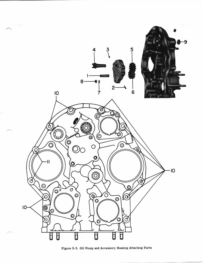
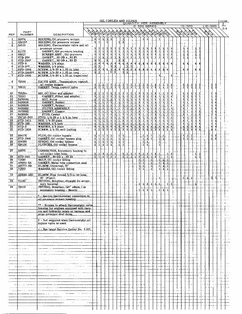
OIL COOLER AND FILTER SECTIONQUANTITY PER ASSEMBLY 2
O-320 SERIES 10-320 LIO-320 PAGE
2-4PART
REF. NUMBER DESCRIPTION
68974 HOUSING Oilpressure screen 1 11 1 1 1 1 1 11 62815* HOUSING,Oil pressure screen 1 1 1 1112 69510 HOUSING, Thermostatic valve and oil
pressurescreen 1 11 111111 111 1 11161173 GASKET, Oil pressure housing 1 1 111 1 1 1 11 1 1
4 62817 SCREEN ASSY,Oil. pressure 1 111 1 1 1 1 111 1 1 1 115 STD-294 GASKET,. 88 OD x.63 ID 1 11 11111 11111 1 1 11 1 15 STD-294* GASKET, .88 OD x. 63 ID 2 2 2 2 26 STD-8 WASHER, 1/4 plain 4 4 4 4 444 44 4 44 4 4 44 4 4 4 4
6 STD-8 ** WASHER, 1/4 plain 3 3 3 3 3 37 STD-1884 SCREW, 1/4-20 x 1.00 in.long 4 44 4 4 4 4 4 4 4 4 4 4 4 4 47 STD-1884* SCREW,1/4-20 x 1.00 in.long 37. STD- 1856 SCREW, 1/4-20 x 1/4-20x1.00 in.(capscrew)
8 75944 ....oil cooler bypass 1 1 1 1 1 1 1 1 1 1 11 1 1 11
9 76510 GASKET, Temp.control valve 1 I 1 1 1 1 1 1 I 1 1 1
10 75528+ KIT,Oil filter and adapter1176691 GASKET Filter and adapter __ 1 1 11 1 l 1 11 11 1 112 6436048 NUT, Nylon 1 1 1 1 1 1 11 1 1 1 113 6436636 GASKET Rubber 1 11 1111 1 1 11 11 114 6436638 GASKET, Rubber 11 11 1 11 1 11 1 1 1115 6435683 FILTER ASSEMBLY 1 11 1 111 1 1 1ll 11 1 l 116 5579983 GASKET, Copper17 6436624 STUD, Center18 25C10-P03 STUD, 1/4-20 x 1-1/4in.long 1 1 1 1 1 1 119 STD-1411 NUT,1/4-20 plain20 STD-160 WASHER, 1/4 lock21 STD-8 WASHER, 1/4 plain 4 4 4 4 4 4 4 4 4 4 4 4 4 4 4 4 44 422 STD-1856 SCREW, 1/4-20,self-locking 3 3 333 3 3 3 3 3 3 33 3
1 1111111
4 4
44
11111111
44
44
11 111111111
111111 1111
1111111111111111111111111111111 1 1 1 11 1 1 1 1
4444433333
111
1111111 111111 1111111114433
23 62417 PLUG, Oil cooler by pass ___ 1 1 1 1 i1i 1 124 STD-294 GASKET, Oil cooler by pass plug25 69436 SPRING,Oil cooler byass 11 1 11 1 1 1 1 1 126 62415 PLUNGER, Oil cooler bypass 1 1 1 1 1 1 1 1 1 1
27 69675 CONNECTOR,Accessory housing tooil cooler inlet hose 1 1 1 1 1 1 1 1 1 1 1 1 1
28 STD-294 GASKET,.88 OD x.63 ID 11 11111 111111111 1 1ll . 1 1129 71620 BOLT, Oil cooler fitting 130 AN901-8A GASKET, Metal tube connection seal 1 1 1 1 1 131 AN777-8D ELBOW, Universal, 7532 71623 WASHER, Oil cooler fitting
33 AN844-10D E LBOW, Pipe thread, 5/8 in. ID hose,45
°(Piper)
34 71140 FITTING, Breather, straight (in acces-sory housing)
34 72413 FITTING, Breather,120°elbow, (inaccessory housing -Beech)
*- Speial thermometer connection inoil pressure screen housing
** - Screws to attach thermostatichousing for engines equipped with vacu-um and hydraulic pump or vacuum and
prop. governor dual drive.
- Not required when thermostatic oilbypass valve is used.
+ - See latest Service Letter No.
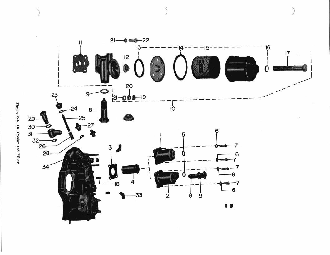
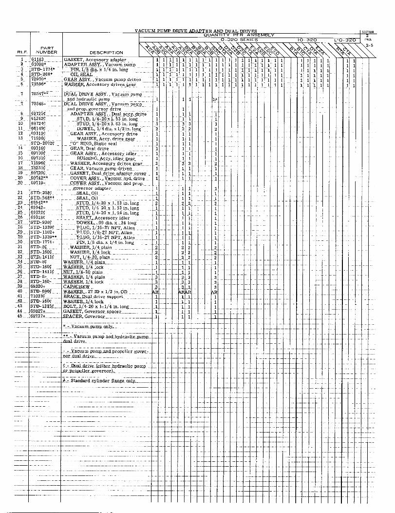
REF.
123456
PARTNUMBER
6118361098*STD-1774*STD-208*72970*71596*
VACUUM PUMP DRIVE ADAPTER AND DUAL DRIVES SECTIONQUANTITY PER ASSEMBLY 2
0-320 SERIES 10-320 LIO-320 PAGE
2-5
DESCRIPTION
GASKET, Accessory adapter 1 1 1 1 1 1 1 1 1 1 1 1 1 1 1 11111 11111 11ADAPTER ASSY.,Vacuum pump 1 1 1 1 1 1 1 1 1 1 1 1 1 1 1 1 1 1 1 11111 11
PIN, 1/8 dia.x 1/4 in. long 11 1 1 1 1 1 1 1 1 1 1 1 1 1 1 1 1 1 11111 1 1OIL SEAL 1 1 1 1 1 1 1 1 11 1 1 1 1 1 1 1 1 1 1 1 1 1 1 1 1
GEAR ASSY.,Vacuum pump driven 1 1 1 1 11 1 1 1 1 1 1 1 1 1 1 1 1 1 1 1 1 1 1 1 1 1WASHER, Accessory driven gear 1 1 1 1 1 1 1 1 1 1 1 1 1 1 1 1 1 1 1 1 1 1 1 1 1 1
7 70347** DUAL DRIVE ASSY., Vacuum pumpand hydraulic pump 1 1 1 1#
7 70348+ DUAL DRIVE ASSY., Vacuum pumpand prop. governor drive 1 1
8 69725¢ ADAPTER ASSY., Dual accy. drive 1 1 1 19 61262¢ STUD, 1/4-20x1. 53 in. long 1 1 1 1
10 69724¢ STUD, 1/4-20x3.63 in. long 3 3 3 311 66145¢ DOWEL, 1/4 dia. x 1/2 in. long' 2 2 2 212 69319¢ GEAR ASSY., Accessory drive 1 1 1 113 71596¢ WASHER, Accy. drive gear 1 1 1 1
STD-2072¢ "O" RING, Static seal 1 1 1 114 69316¢ GEAR, Dual drive 1 1 1 115 69730¢ GEAR ASSY., Accessory idler 1 1 1 116 69731¢ BUSHING, Accy. idler gear 1 1 1 117 71596¢ WASHER, Accessory driven gear 2 2 2 218 73231¢ GEAR, Vacuum pump driven 1 1 1 119 69720¢ GASKET, Dual drive adapter cover 1 1 1 120 69742** COVER ASSY., Vacuum hyd. drive 1 1 1 120 69719+ COVER ASSY.,.Vacuum and prop.
governor adapter 1 1 1 121 STD-208¢ SEAL, Oil 1 11 122 STD-548** SEAL, Oil 1 1 1 123 69942** STUD, 1/4-20 x 1. 53 in. long 2 2 2 224 69942+ STUD, 1/4-20 x 1.53 in. long 1 1 1 125 69722¢ STUD, 1/4-20 x 1. 94 in. long 1 1 1 126 69318¢ SHAFT, Accessory idler 1 1 1 127 STD-938¢ DOWEL,. 09 dia. x . 34 long 1 1 1 128 STD- 1339¢ PLUG, 1/16-27 NPT, Alien 1 1 1 129 STD- 1102+ PLUG, 1/8-27 NPT, Allen 1 1 1 129 STD-1339** PLUG, 1/16-27 NPT, Allen 1 1 1 130 STD-1774+ PIN, 1/8 dia. x 1/4 in. long 1 1 1 131 STD-8¢ WASHER, 1/4 plain 2 22 232 STD-160¢ WASHER, 1/4 lock 2 2 2233 STD-1411¢ NUT, 1/4-20, plain 2 2 2 234 STD-8?9 WASHER, 1/4 plain 1 1 1 135 STD- 160¢ WASHER, 1/4 lock 1 1 136 STD- 1411¢ NUT, 1/4-20 plain 1 1 1 137 STD-8+ WASHER, 1/4 plain 3 3 3 338 STD-160+ WASHER, 1/4 lock 3 3 3 339 69320+ CAPSCREW 3 3 3 340 STD-696¢ WASHER,. 27 ID x 1/2 in. OD AR ARAR AR41 71023¢ BRACE, Dual drive support 1 142 STD-160¢ WASHER, 1/4 lock 1 1 1_43 STD-1215¢ BOLT, 1/4-20 x 1-1/4 in. long 1 1 11 1 144 69827+ GASKET, Governor spacer 1 1 I45 69731+ SPACER, Governor
* - Vaccuum pump only.
** - Vacuum pump and hydraulic pumpdual drive.
+ -Vacuum pump and propeller gover-nor dual drive.
¢- Dual drive (either hydraulic pumpor propeller governor)...
#- Standard cylinder flange only.
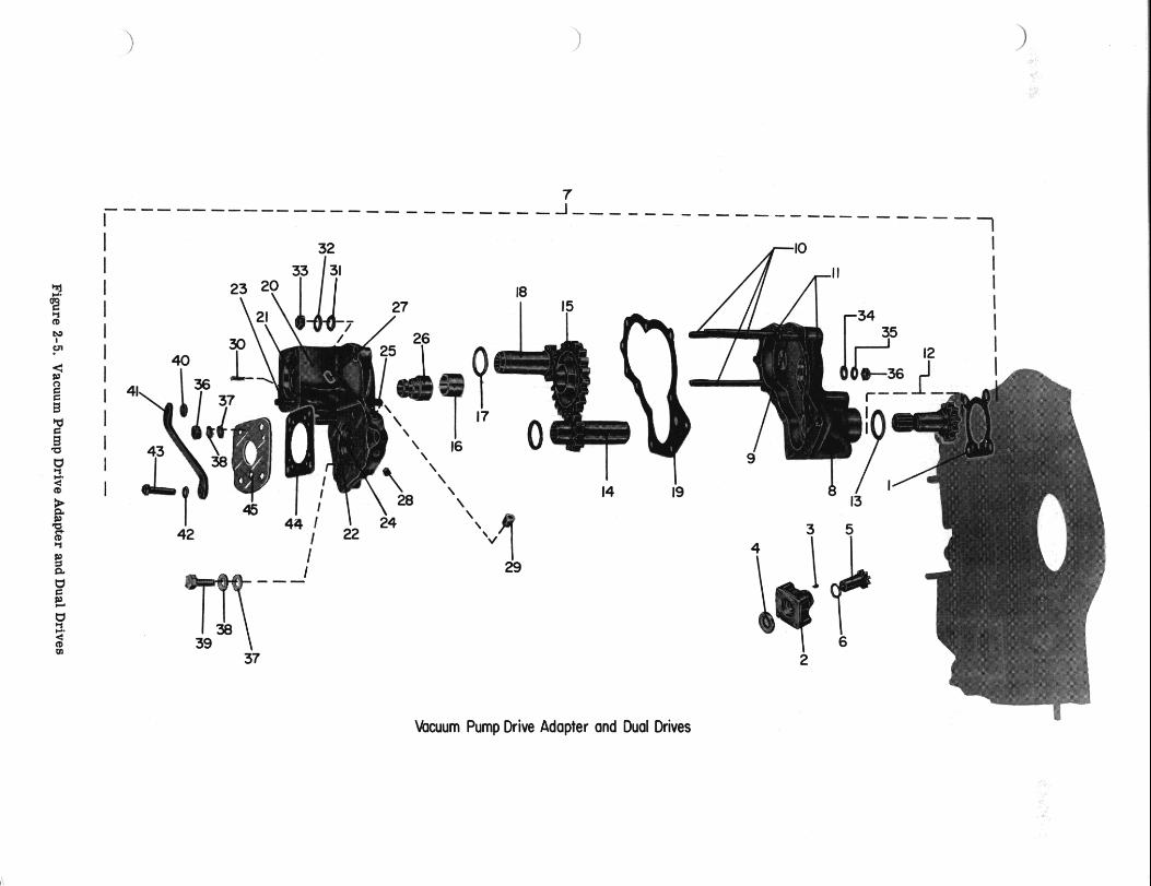
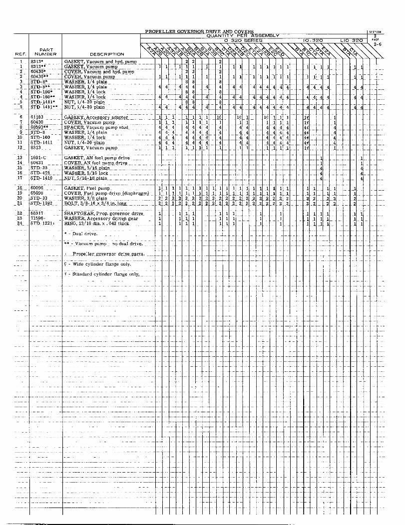
PARTREF. NUMBER
1 8313*1 8313**2 60430*2 60430**3 STD- 8*3 STD-8**4 STD- 160*4 STD- 160**5 STD- 1411*5 STD- 1411**
6 611837 604308 68593**9 STD- 8
10 STD- 16011 STD-141112 8313
13 1691-C14 6043115 STD-3516 STD-47517 STD- 1410
18 6009619 6509820 STD-3321 STD- 1592
22 68317+23 71596+24 STD-1221+
DESCRIPTION
GASKET, Vacuum and hyd. pumpGASKET, Vacuum pumpCOVER, Vacuum and hyd. pumpCOVER, Vacuum pumpWASHER, 1/4 plainWASHER, 1/4 plainWASHER, 1/4 lockWASHER, 1/4 lockNUT, 1/4-20 plainNUT, 1/4-20 plain
GASKET, Accessory adapterCOVER, Vacuum pumpSPACER, Vacuum pump studWASHER, 1/4 plainWASHER, 1/4 lockNUT, 1/4-20 plainGASKET, Vacuum pump
PROPELLER GOVERNOR DRIVE AND COVERSQUANTITY PER ASSEMBLY
0-320 SERIES 10-320
SECTION
2LIO-320 PAGE
2-6
22 211 111 1 1 11
22 2
4 44 44 4 4 4488 8
4 4 444 4 4 4488 8
44 444 4 4 44
444 4444 4 4444 4 4 4 4 4 4444 444 4 4 4111 1 111 1 1
1 1 1 1 11
111111
44444 4
4 44 4 4 4
444444
1 1¢ 1 1 11 11114 44444 44444 44444 4 4 4 44 44441 1111
1 1 1 1
11 1 1
4444
4 4 4 4
4 4 44
1# 11# 1
4# 4
4# 41# 1
11
11
44
44
44
GASKET, AN fuel pump driveCOVER, AN fuel pump driveWASHER, 5/16 plainWASHER, 5/16 lockNUT, 5/16-18 plain
GASKET, Fuel pumpCOVER, Fuel pump drive (diaphragm)WASHER, 3/8 plainBOLT, 3/8-16 x 3/4 in. long
SHAFTGEAR, Prop. governor driveWASHER, Accessory driven gearRING, 13/16 dia. x .042 thick
* - Dual drive.
** - Vacuum pump - no dual drive.
1 1 1 1 1 1 1 1 11 1 1 1 1 1 1 1 1 1 12 2 2 2 2 2 2 2 22 22 2 2 2 2 2 2 2 2 2 2
1 11 1 1 111 11 1 111 111 11
1 1 11 111 11 11 1 1 1 1 1 1 1 122 22 22 2 2 22 2 2 2 22 2 2 2
1 1 11 1 11 1 1
111 12 222
11 11 111
11444
1 11 12 22 2
1 11 11 1
111444
1
22
111 11 1
+ - Propeller governor drive parts .
¢ - Wide cylinder flange only .
# - Standard cylinder flange only.
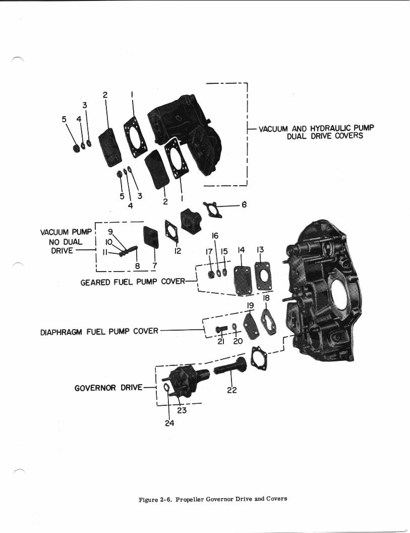
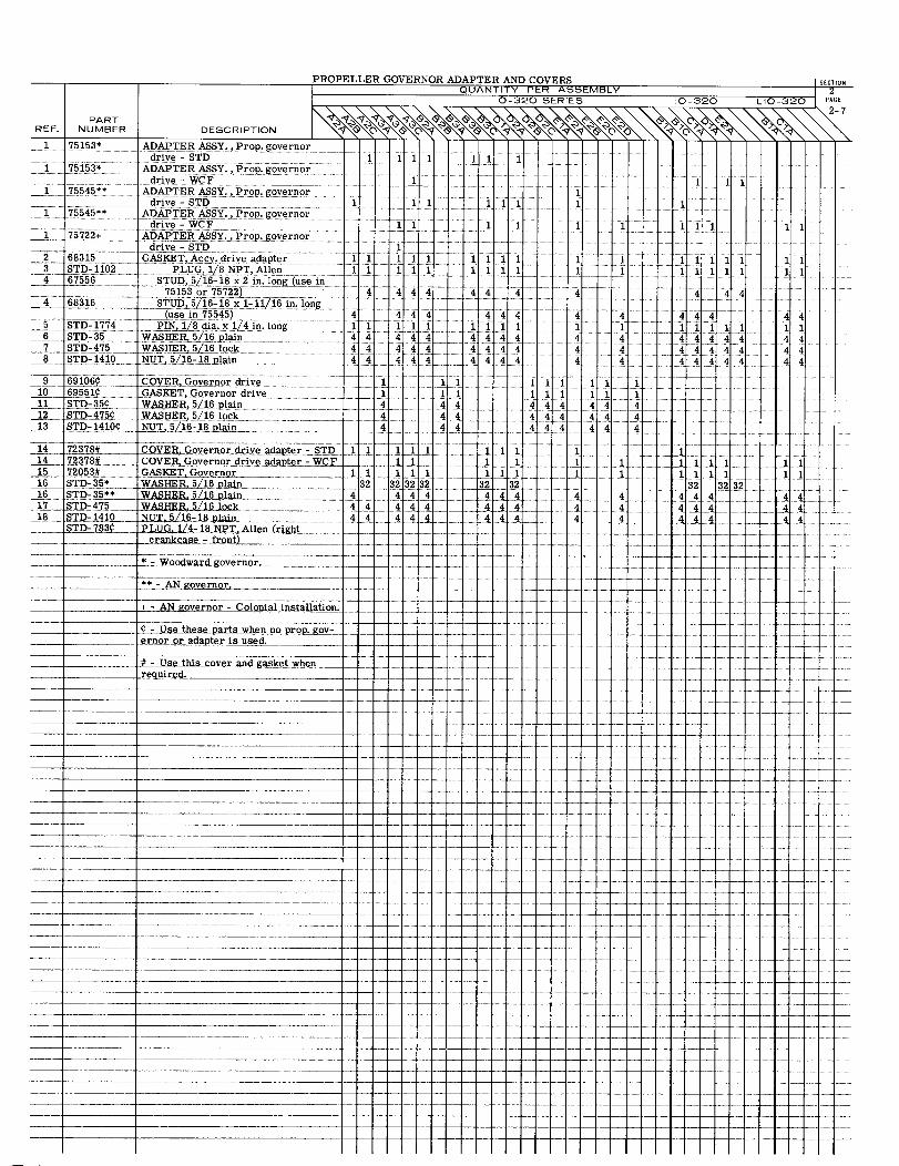
PROPELLER GOVERNOR ADAPTER AND COVERS SECTIONQUANTITY PER ASSEMBLY 2
0-320 SERIES I0-320 LIO-320 PAGE
PARTREF. NUMBER DESCRIPTION
1 75153* ADAPTER ASSY., Prop. governordrive - STD 1 1 1 1 1
1 75153* ADAPTER ASSY., Prop. governordriv e - WCF 1 1 1
1 75545** ADAPTER ASSY., Prop. governor 175545** drive-STD 1 1 1 1 1 1 1 1
75545** ADAPTER ASSY. ,Prop. governordrive - WCF 11 1 1 111 1 1 1 1
1 75722+ _ ADAPTER ASSY. Prop. governordrive - STD 1
2 68315 GASKET,Accy. drive adapter 1111 1 1 1 1 1 1 1 11 1I3 STD-1102 PLUG 1/8NPT, Allen 1 1111 1 1 1 1 11111 1 1 14 67556 STUD, 5/16-18 x2in.long(usein
75153 or 75722) 4 4 44 4 4 44 4 4 44 68316 _ STUD, 5/16-18x1-11/16 in. long
(use in 75545) 4 4 4 4 4 44 4 4 444 4 445 STD-1774 PIN, 1/8 dia.x 1/4in.lon g 1 1 1 1 1 1 1 1 1 11 1 1 1 1 16 STD-35 WASHER, 5/16 plain 444 44 4 444 4 4 47 STD-475 WASHER,5/16 lock 4 4 44 4444 4 4 44444 4
STD-1410 NUT, 5/16-18 plain 4 44 4 4 444 4 4 4 4 4 4 4 4
10 69551 GAS, Governor drive 1 1 1 11 STD-35¢ WASHER, 5/16 plain 4 44 4 4 4 4 44 4
12 STD-475¢ WASHER, 5/16 lock 4 4 4444 44 444 4 413 STD-1410¢. NUT, 5/16-18 plain 4 4 4
4 44 444 44 4
14 72378# COVER, Governor drive adapter -STD 1 1 1 11 1 11 1 1 114 72378# COVER, Governor drive adapter -WCF 11 1 1 11 1 1 1 1 115 72053# GASKET, Governor 111 1 1111 1 1 1 111 1116 STD-35* WASHER,5/16 plain 32 32 32 32 32 32 32 32 3216 STD-35** WASHER, 5/16 plain 4 4 44 4 4 4 4 4 4 4417 STD-475 WASHER,5/16 lock 44 44 4 4 44 4 44 4 418 STD 1410 NUT 5/16 -18 plain 4 4 4 4 4 44 4 44 4 4
STD-783¢ PLUG, 1/4-18 NPT, Allen (rightcrankcase -front)
* - Wooward governor.
* - Woodward governor .** - AN governor
+- AN governor - Colonial installation.
¢ - Use these parts when no prop. gov-ernoror adapter is used.
# -Use this cover and gasket whenrequired.
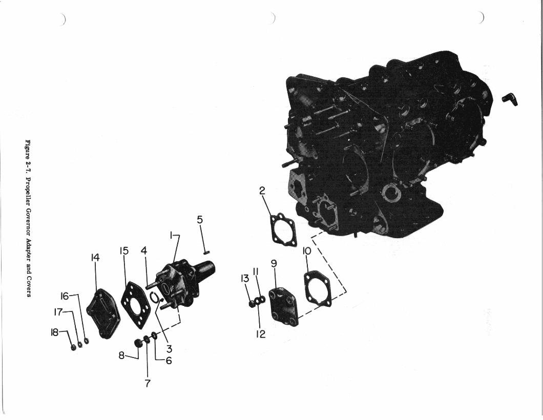
-
Figure 2-7.
Propeller
Governor
Adapter
and C
overs
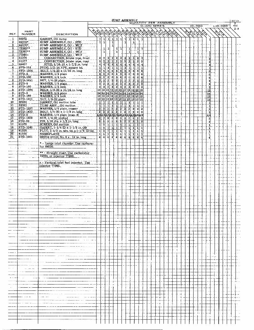
SUMP ASSEMBLY SECTIONQUANTITY PER ASSEMBLY 2
0-320 SERIES 10-320 LIO-320 PAGE
2-8PART
REF. NUMBER DESCRIPTION
1 68972 GASKET, Oil sump 11 11 11 1 1 12 69370* SUMP ASSEMBLY, Oil - STD 1 1 1 1
2 69370* SUMP ASSEMBLY, Oil WCF2 72362** SUMP ASSEMBLY, Oil - STD 1 1 1 1 1 12 72362** SUMP ASSEMBLY,Oil - WCF 1 1 1 12 77965+ SUMP ASSEMBLY, Oil - WCF 1
3 61376 CONNECTION, Intake pipe, front 2 2 22 22 2 22 22 24 61377 __ CONNECTION, Intake pipe, rear 2 22 222 2 2 2 2 2 2 25 68437 STUD, 5/16-18 x l-7/8 in. long6 STD-551 PLUG, 1/2-14 NPT,square hd. 11 1 1 1 1 1 1
STD-1204 BOLT, 1/4-20 x 15/16 in. long 6 6 6 6 6 6 6 6 6 67 STD-8 WASHER,1/4 plain7 STD-160 WASHER, 1/4 lock8 STD-1411 NUT, 1/4-20 plain 2 2 2 2 22 2 2 2 2 22
8 STD-8 WASHER, 1/4 plain8 STD-160 WASHER, 1/4 lock 2 2 2 2 2 2 2 2 2 2 2 29 STD-1204 BOLT, 1/4-20 x 15/16 in. long
9 STD 160 WASHER,1/4 plain9 STD- 160 WASHER 1/4 lock 12 12 12 12 12 12 12 12 12 12 12 129 STD-1411 NUT, 1/4-20 plain 12 12 12 1212 121212 12 12 12 12
10 60820 GASKET Oil suction tube 1 11 1 1 1 1 1 1 1 111 61381 TUBE ASSY. 1
12 STD-1227 WASHER, 1/4 plain, copper 2 2 2 2 2 22 2 2 2 2 213 STD-1433 BOLT,1/4-20 x 1/2 in. long 2 2 2 2 2 22 2 2 2 2 214 STD-8 WASHER, 1/4 plain(max.4) ARAARAARARARARAARA A15 STD-1409 NUT, 1/4-20 slotted 2 2 2 2 22 2 2 216 STD-68 PIN,1/16 dia.x 1/2 long17 61378 SCREEN Oil suction 1 1 1 1 1 1 1 1 1 118 STD- 1045 GASKET, 1/4ID x 1-1 ID x 1-1/2 in. OD19 61358 PLUG, 1-1/2in. hex.hd. x lxl-1/4 - 12 thd. 11 11 1 11 1 11 120 61548 NAMEPLATE 11 11 1 1 1 1 1
21 STD-1901 DRIVE STUD No. 4x. 19 in. long 4 4 4 4 4 4 4 4 4 4 4 4
* - Large inlet chamfer. Use carbure-tor 69250.
** - Straight riser. Use carburetor72394. or injector 77260.
injector 77260.
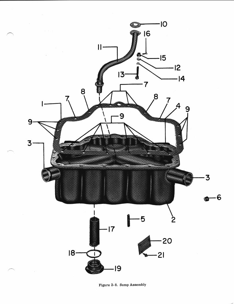
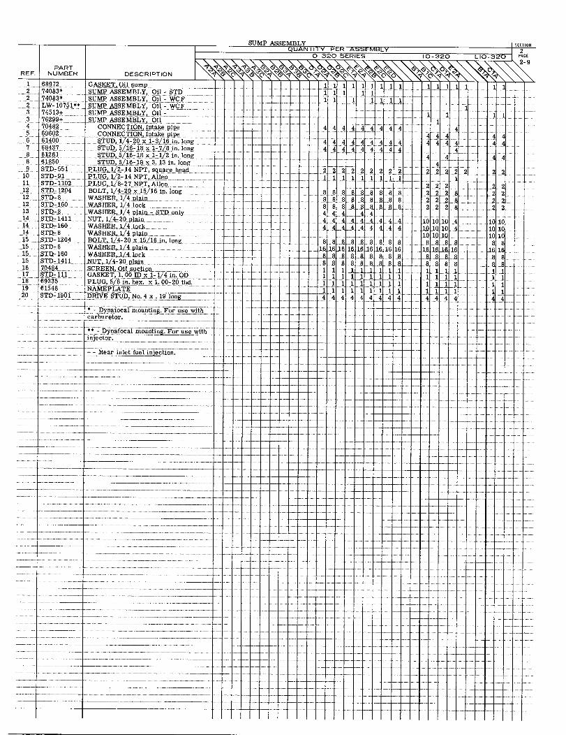
SUMP ASSEMBLY SECTIONQUANTITY PER ASSEMBLY 2
0-320 SERIES 10-320 LIO-320 PAGE
2-9PART
REF. NUMBER DESCRIPTION
1 68972 GASKET, Oil sump 111111111 1 1111 112 74083* SUMP ASSEMBLY, Oil - STD 1 1 1 12 74083* SUMP ASSEMBLY, Oil -WCF 1 1 1 1 111 12 LW-10751** SUMP ASSEMBLY, Oil - WCF3 74513+ SUMP ASSEMBLY, Oil - 113 76299+ SUMP ASSEMBLY, Oil4 70482 CONNECTION, Intake pipe 4 4 4 4 4 4 4 4 4 45 69602 CONNECTION, Intake pipe 4 4 46 61400 STUD, 1/4-20 x 1-3/16in. long 44 4 44 4 4 4 4 4 4 4 47 68437 STUD, 5/16-18 x 1-7/8 1n. long 4 4 4 4 4 4 4 4 4 48 61261 STUD, 5/16-18 x 1-1/2 in. long 4 448 61850 STUD, 5/16-18 x 3.13 in. long 49 STD-551 PLUG, 1/2-14 NPT, square head 22 2 2 2 2 2 2 22
10 STD-91 PLUG, 1/2-14 NPT, Allen 11 1 1 1 1 1 1 111 STD-1102 PLUG, 1/8-27 NPT, Allen 2 2 2 2 212 STD-1204 BOLT, 1/4-20x15/16in. long 8 8 88 8 8 8 8 2 22 8 2 212 STD-8 WASHER, 1/4 plain 28 88 8 88 2 2 8 2212 STD-160 WASHER, 1/4 lock 8 8 8 8 8 888 8 2228 2 213 STD-8 WASHER, 1/4 plain - STD only 4 4 4 4 414 STD- 1411 NUT, 1/4-20 plain 4 4 4 4 4 4 4 4 101010 4 101014 STD-160 WASHER, 1/4 lock 444 4 4 4 4 4 4 101010 4 10 1014 STD-8 WASHER, 1/4 plain 101010 10 1015 STD-1204 BOLT, 1/4-20 x 15/16 in. long 8 8888 8 8 88 8 88 8 8 815 STD-8 WASHER, 1/4 plain 16 16 16 161616 1616161 16161616 16 1615 STD-160 WASHER, 1/4 lock 8 88 8 8 88 8 88 8 8 8 815 STD-1411 NUT,1/4-20 plain 8 88 8 88 8 8 8 8 8 8 816 70484 SCREEN, Oil suction 1 1 11 11 117 STD-111 GASKET, 1.00 ID x1-1/4in. OD 11111111 1 1 1 1 1118 69335 PLUG, 5/8in.hex. x 1.00-. 1.00 -20 th ..... 1 1 1 11 1 1 11 1 1 1 1 1 119 61548 NAMEPLATE 111111111 1111 120 STD-1901 DRIVE STUD, No. 4 x .19 long 4 4 4 4 4 4 4 4 4 4 4 4 4 4
*-Dynafocal mounting. For use with -
**- Dynafocal mounting. For use withinjector.
+ - Rear inlet fuel injection.
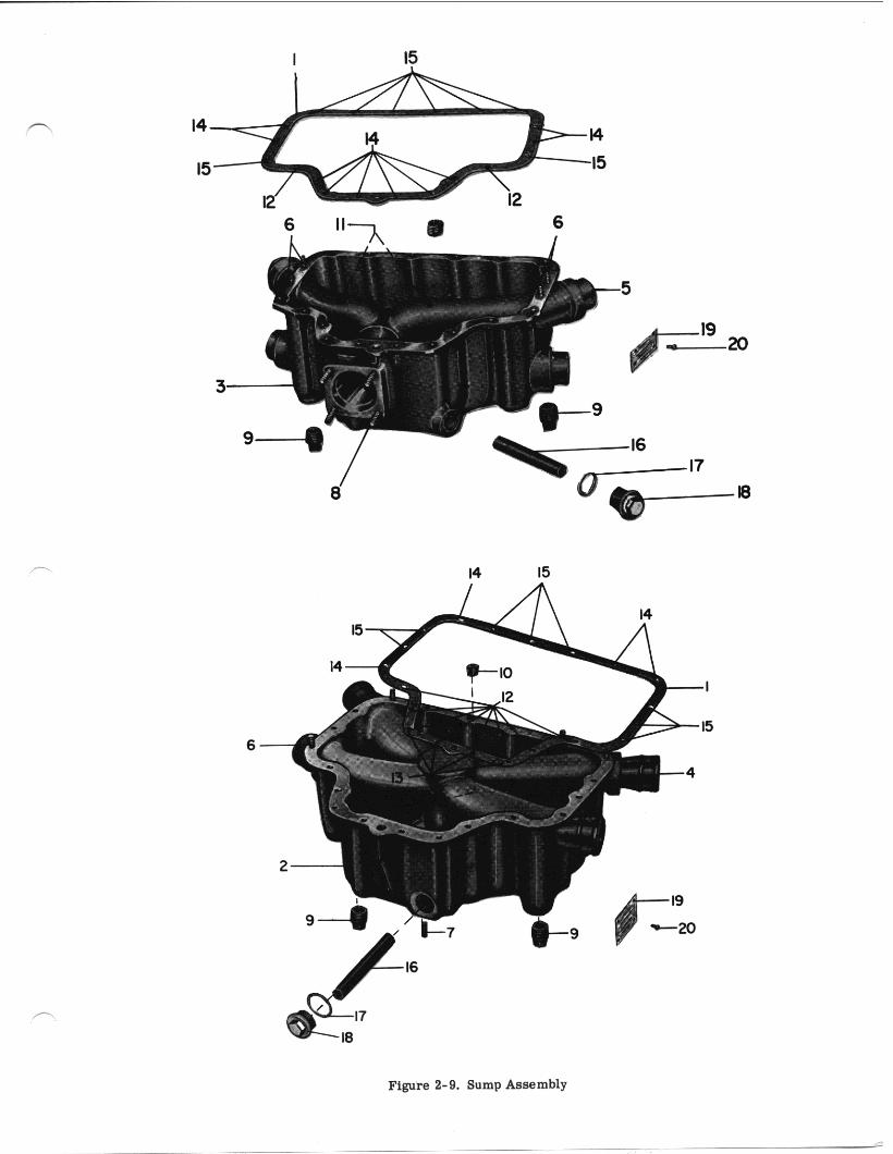
I 15
6
14
6-
LYCOMING AIRCRAFT ENGINE GROUP ASSEMBLY PARTS LIST
LYCOMING PARTS CATALOG
0-320, 10-320 AND LIO-320 SERIES
SECTION 3
CYLINDER, PISTON AND VALVE TRAIN
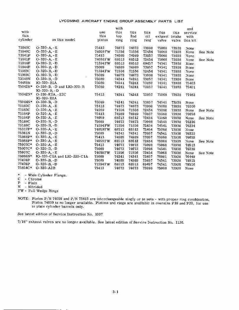
LYCOMING AIRCRAFT ENGINE GROUP ASSEMBLY PARTS LIST
withthis
cylinder on this model
71840C O-320-A,-E71840C 0-320-A,-E71841P 0-320-A,-E71841P O-320-A,-E71844P 0-320-B,-D71844P O-320-B,-D71969C 0-320-B,-D71969C 0-320-B,-D73149N 0-320-B,-D74468N IO-320-B1A75042N* 0-320-B, -D and LIO-320-B
IO-320-B, -D75042N* 0-320-E2A,-E2C
IO-320-E2A75044N* 0-320-B,-D75183C O-320-A,-E75183C O-320-A,-E75184P 0-320-A,-E75184P 0-320-A,-E75188C O-320-B,-D75188C 0-320-B,-D75317P* O-320-A,-E75361N 0-320-B,-D75868P* O-320-A,-E75868P* O-320-A,-E75907C* O-320-A,-E75907C* 0-320-B,-D75907C O-320-A,-E76086N* IO-320-C1A and LIO-320-C1A77476P 0-320-B,-D77476P 0-320-B,-D75854C* 0-320-A2B
usethis
piston
7541374059FW7541374059FW71594FW7508971594FW75089750897508975089
withthistopring
7467371556749896851368513749897155674673742417424174241
this2ndring
7467371556749896851268513749897155674673742417424174241
andthis this this serviceoil exhaust intake with
ring valve valve this kit
7399872454738577245469457738577245473998738577385773857
7506875068750687506874541745417454174541745417454174541
73938 None73938 None73938 None73938 None73938 None73938 None73938 None73938 None73938 None73938 7540373938 75401
See Note
See Note
75413 74241 74241 73857 75068 73938 77462
75089754137405975413740597508971594FW74059FW750897541374059FW754137508974059FW750897508971594FW75413
742417467371556749896851374673715566851374241749896851374673746737155674241749896851374673
742417467371556749896851274673715566851274241749896851274673746737155674241749896851374673
738577399872454738577245473998724547245473857738577245473998739987245473857738576945773998
745417506875068750687506874541745417506874541750687506875068745417506876081745417454175068
73938 None73938 7650073938 None73938 7665873938 None73938 7623673938 7623473938 None73938 7623573938 7665973938 None73938 7851373938 7623973938 None73938 7644973938 7851573938 7851673938 None
See Note
See Note
See Note
See Note
* - Wide Cylinder Flange.C - ChromeP - PlainN - NitridedFW - Full Wedge Rings
NOTE: Piston P/N 74059 and P/N 75413 are interchangeable singly or in sets - with proper ring combination.Piston 74059 is no longer available. Pistons and rings are available in oversize P10 and P20, for usein plain cylinder barrels only.
See latest edition of Service Instruction No. 1037
7/16" exhaust valves are no longer available. See latest edition of Service Instruction No. 1136.
3-1
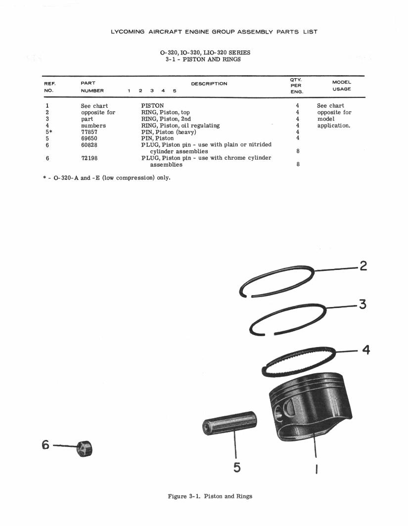
LYCOMING AIRCRAFT ENGINE GROUP ASSEMBLY PARTS LIST
O-320,10-320, LIO-320 SERIES 3-l - PISTON AND RINGS
1 See chart PISTON 4 see chart 2 opposite for RING, Piston, top 4 opposite for 3 part RING, Piston, 2nd 4 model 4 numbers RING, Piston, oil regulating 4 application. 5* 77857 PIN, Piston (heavy) 4 5 69650 PIN, Piston 4 6 60826 PLUG, Piston pin - use with plain or nitrided
cylinder assemblies 6 6 72198 PLUG, Piston pin - we with chrome cylinder
assemblies 8
* - 6320-A and -E (low compression) only.
6
Figure 3- 1. Piston and Rings
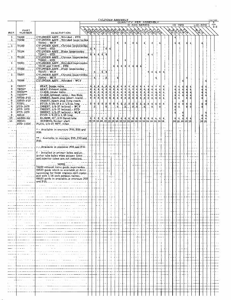
PARTREF. NUMBER
1 744681 75042
__ 1 75183
1 75184
1 75188
1 75361
1 75868
1 75907
1 76086
CYLINDER ASSEMBLY SECTIONQUANTITY PER ASSEMBLY 3
0-320 SERIES 10-320 LIO-320 PAGE3-2
TDESCRIPTION
CYLINDER ASSY., Nitrided - STD 4CYLINDER ASSY., Nitrided (supersedes
75044)- WCF 4 4 4 4 4 4 4 4 4 4 4 4CYLINDER ASSY., Chrome (supersedes
71840)- STD 4 4 4 4CYLINDER ASSY., Plain (supersedes
71841) - STD 4 4 4 4 4 4 4CYLINDER ASSY., Chrome (supersedes
__71969) - STD 4 4CYLINDER ASSY., Nitrided (supersedes
73149 and 71844) - STD) 4 4 4 4 4 4 4 4CYLINDER ASSY., Plain (supersedes
75317)- WCF 4 4 4 4 4 4 4 4CYLINDER ASSY., Chrome (supersedes
75854) - WCF 4 4 4CYLINDER ASSY., Nitrided - WCF 4 4
89
1011
72057* SEAT, Intake valve 472058* SEAT, Exhaust valve 460028** GUIDE, Intake valve 474230** GUIDE, Exhaust valve - See Note 466796-P10 INSERT,Spark plug (short reach) 869260-P10 INSERT, Sparkplug (long reach61261 STUD, 5/16-18 x 1-1/2 in. long 8STD- 1872 INSERT, 1/8-27 helicoil - WCFSTD-1872 INSERT, 1/8-27 helicoil - STDSTD-1872 INSERT, 1/8-27 helicoil- WCF68510 STUD, 1/4-20 x 1.06 longAN823-6D ELBOW,45 °
,3/8 flared tube 466610+ BUSHING, Rocker shaft 161STD- 1102¢ PLUG, 1/8-27 NPT, Allen
* - Available in oversize P10,P20 andP30.
** - Available in oversize P05,P10 andP30.
+ - Available in oversize P05 and P10,
- Installed in primer holes and in-jector tube holes when primer linesand injector tubes are not installed. _
NOTE74230 exhaust valve guide supersedes69533 guide which is available at AvcoLycoming for those engines still equip-ped with 7/16 inch exhaust valves.69533 guide is available in oversize P05and P 10.
4 4 4 4 4 4 4 44 4 444 4 4 4 4 4 44444 4 4 4 4 4 4 4 4 4 44 4 4 4 4 4 4 4 4 4 4 488 8 8 8 88 8 888 8 8
8 8 8 88.88 8 8 8 8.888 8 8 8_. 8 8
444444444444444444444
4 4 4 4 4 48 88 8 8 8 88
8 8 8 8 8 8 88 8 8
4444444 4 4 4
4 4 4 4444444444488 88
88 8 8 8 88888888 8844 4
444444
16 16 16 16 16
44448
88
4444
88
44 4 4 4 4 4 4 4 4 4 4 4 4 4 4 46 16 16161616 16 1616 16 16 16 16 16 16 16 16 16 16
44 44 4
16 16
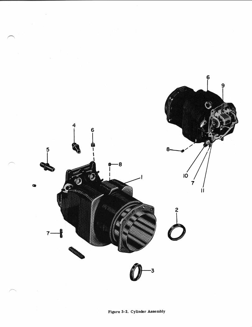
4 I 6
Figure 3-2. Cylinder Assembly
7 I II
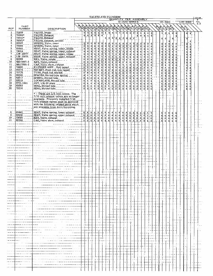
VALVES
PARTREF. NUMBER DESCRIPTION
1 73938 VALVE, Intake 4 4 4 4 42 75068* VALVE, Exhaust 4 4 4 4 42 74541* VALVE, Exhaust2 76081* VALVE, Exhaust, inconel3 65567 SPRING, Valve, inner 8 8 8 8 84 76994 SPRING, Valve, outer 8 8 8 8 85 65441 SEAT, Valve spring, lower,intake 4 4 4 46 74554 SEAT, Valve spring, lower, exhaust 4 4 4 4 47 LW- 10077 SEAT, Valve spring, upper, intake 4 4 44 48 LW-10076 SEAT, Valve spring, upper, exhaust 4 4 4 4 49 60009 KEY, Valve, intake 8 88 8 8
10 MS13997-3 KEY, Valve, exhaust 8 8 8 8 811 MS13998-3 CAP, Valve stem, exhaust 44 4 4 412 78290 PLUNGER ASSY., Hyd. tappet 8 8 8 8 813 65074 SOCKET, Push rod, hyd. tappet 8 8 8 8 814 75772 TUBE, Push rod, shroud 8 8 8 8 815 69345 SPACER, Shroud tube spring 4 4 4 4 416 68517 SPRING, Shroud tube 8 8 8 8 817 68518 LOCKPLATE, Shroud tube 4 4 4 4 418 STD-1411 NUT, 1/4-20plain 4 4 4 4419 60053 SEAL, Shroud tube 8 8 8 8 820 70310 SEAL, Shroud tube 8 8 88 8
* These are 1/2 inch valves.The.7/16 inch exhaust valves are no longeravailable. Presently installed 7/16inch exhaust valves must be servicedwith the following related parts which
are available from Avco Lycoming.
6 65441 SEAT,Valve spring,lower exhaust 4 4 4 4 48 69532 SEAT,Valve spring,upper exhaust 4 4 4 4 4
10 72050 KEY, Valve, exhaust 8 88 8 811 62388 CAP, Valve stem, exhaust 4 44 4 4
AND PLUNGERS SECTIONQUANTITY PER ASSEMBLY 3
O-320 SERIES 10-320 LIO-320
44444444444444 444444 444 44444 4
444444444 44 4 44 4
8 8 8 88 8 8 8 8 8 8 8 8 8 8 8 8 8 8 8 8 88 8 8 8 8 8 8 8 8 8 8 8 8 8 8 8888 884444444 4444444 444444 44
444444444444444 44444 44
44 4 4 4 4 4 4 4 4 4 4 4 4 4 4 4 4 4 4 4 4
8888 8 8 8 88 8 8 8 8 8 8 8 8888 8 844444444444444 444444 44888888888888888 88888 888 88888888888 8 8 8 8 8
44 4444444444444 44444 44
888888888888888 88888 884 4 4 4 4 4 4 4 4 4 4 4 4 4 4 4 4 4 4 4 4884 4 4 4 4 4 4 4 4 4 4 4 4 4 4 4 4 4 4 4 4 4888888888888888 888888 8 8
8 8 8 8 888888 8 8 8 8 8 8
4 4448844
444 4 44444444444444444444448888 8888888884444444444444
44444444448888844444
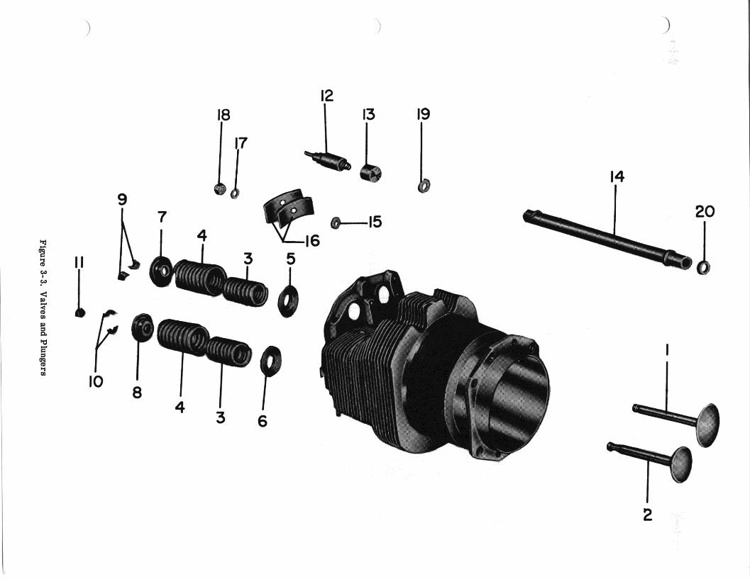
Figure 3-3.
Valves
and Plungers
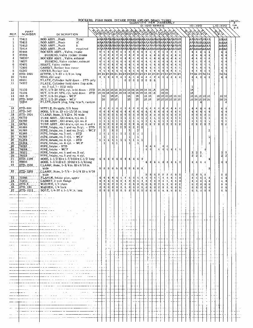
ROCKERS, PUSH RODS, INTAKE PIPES AND OIL DRAIN TUBES
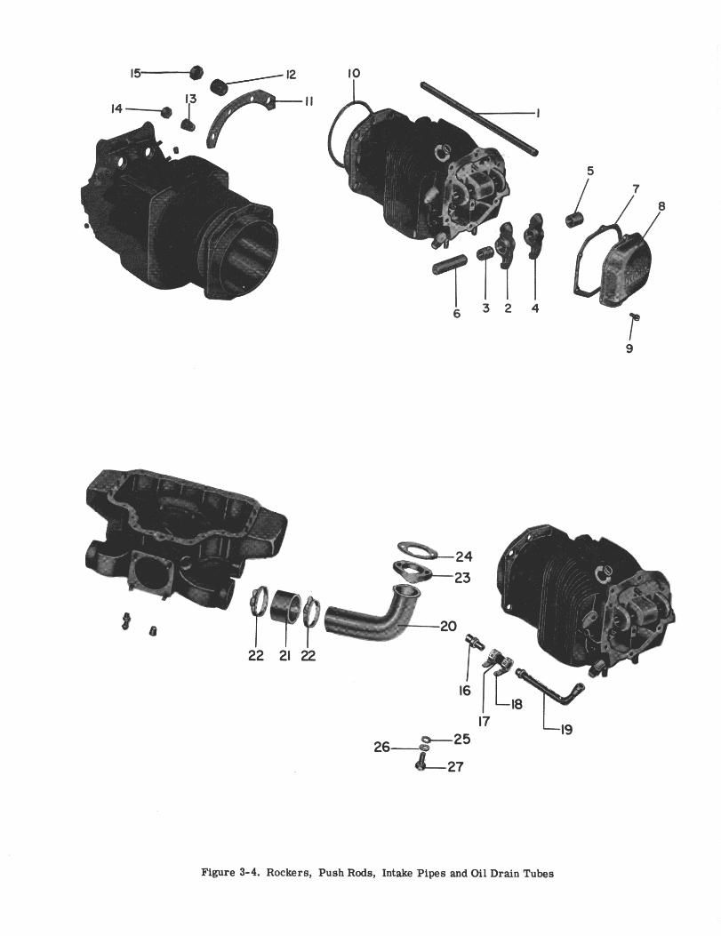
IO
5
Figure 3-4. Rockers, Push Rods, Intake Pipes and Oil Drain Tubes
LYCOMING AIRCRAFT ENGINE GROUP ASSEMBLY PARTS LIST
"
LYCOMING PARTS CATALOG
0-320, IO-320 AND LIO-320 SERIES
SECTION 4
IGNITION SYSTEM
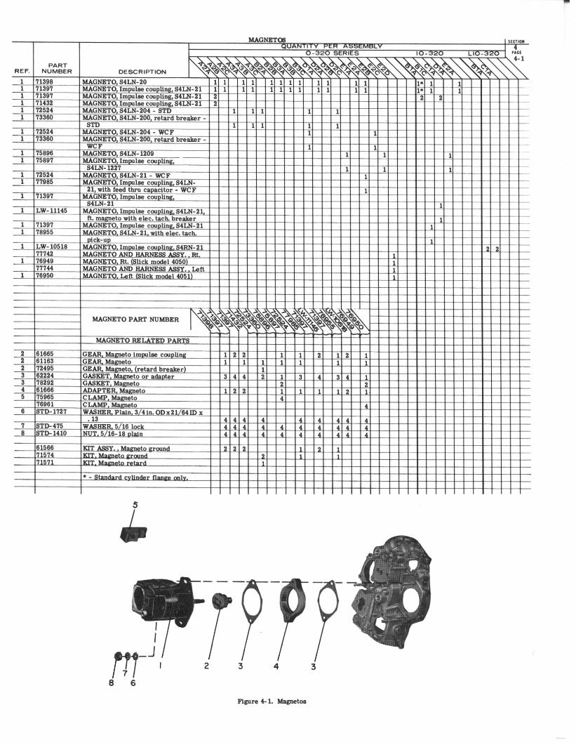
2 3 4
6 6
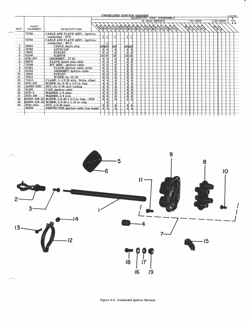
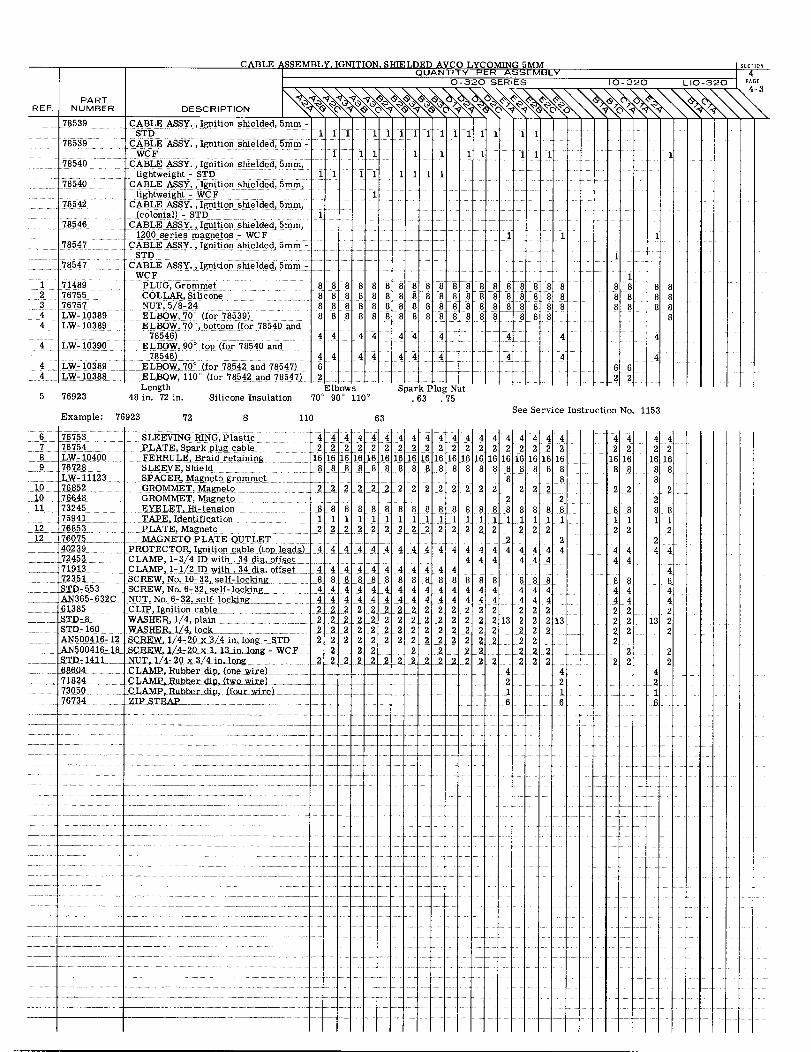
CABLE ASSEMBLY. IGNITION. SHIELDED AVCO LYCOMING 5MMQUANTITY PER ASSEMBLY
DESCRIPTIONPART
REF. NUMBER
78539
78539
78540
78540
78542
78546
78547
78547
1 714892 767553 767574 LW- 103894 LW-10389
4 LW-10390
4 LW- 103894 LW-10388
5 76923
Example: 7
CABLE ASSY., Ignition shielded, 5mm -STD
CABLE ASSY., Ignition shielded, 5mm -WCF
CABLE ASSY. , Ignition shielded, 5mm,ightweight - STD 1
CABLE ASSY., Ignition shielded, 5mm,lightweight - WCF
CABLE ASSY., Ignition shielded, 5mm,(colonial) - STD 1
CABLE ASSY., Ignition shielded, 5mm,1200 series magnetos - WCF
CABLE ASSY., Ignition shielded, 5mm -STD
CABLE ASSY., Ignition shielded, 5mm -WCF
PLUG, Grommet 8 8COLLAR, Silicone 8 8NUT, 5/8-24 8 8ELBOW, 70' (for 78539) 8 8ELBOW, 70, bottom (for 78540 and
78546) 4 4ELBOW, 90 top (for 78540 and
78546) 4 4ELBOW, 70 (for 78542 and 78547) 6ELBOW, 110 (for 78542 and 78547) 2Length Elb
48 in. 72 in. Silicone Insulation 70 90
1 1 1 11
11 1
11111 11
1 11 111
11 1111
1
1 1
1
8888888888888 8 88
44
44
888888888 8 888888 8 88888 8 8
44 4
44 4
Spark Plug Nut. 63 .75
88888888888888888888888 888
4 4
4 4
1888888
6622
888888
8
4
4
6923 S 110
ows110
°
63See Service Instruction No. 1153
72
6 76753 SLEEVING RING, Plastic 4 4 4 4 4 4 4 4 4 4 4 4 4 4 4 4 4 4 47 76754 PLATE, Spark plug cable 2 2 22 2 2 2 2 2 2 2 2 2 2 2 2 2 2 28 LW-10400 FERRULE, Braid retaining 16 16 16 16 16 16 16 16 16 16 16 16 16 16 16 16 16 16 16
.9 76728 SLEEVEShield 88 8 8 8 8 8 8 8 8 8 8 8 8 8 8 8 8 8LW-11123 SPACER, Magneto grommet 8 8
10 76852 GROMMET, Magneto 22 2 222 2 2 2 2 2 2 2 2 2 2 210 76648 GROMMET, Magneto 2 211 73245 EYELET,Hi-tension 8 8 8 8 8 8 8 88 8 8 8 8 8 8 8 8 8 888 88
1122
4444
8844442222222
222
4422
16 16888
2288
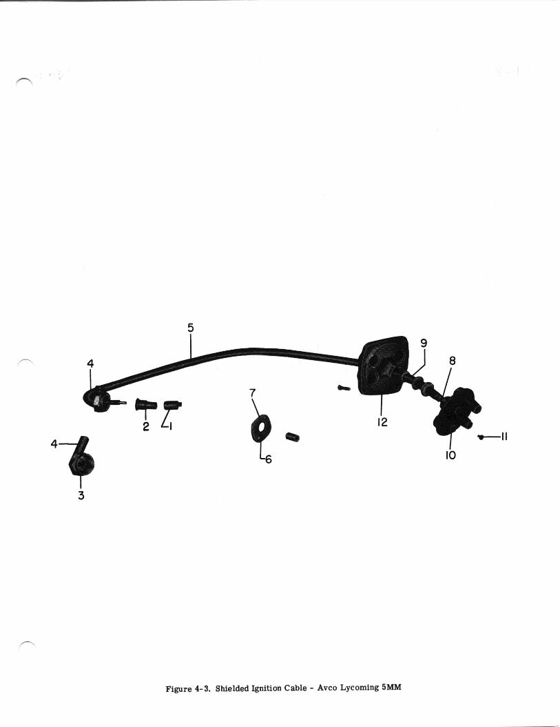
5
Figure 4-3. Shielded Ignition Cable - Avco Lycoming 5MM
8
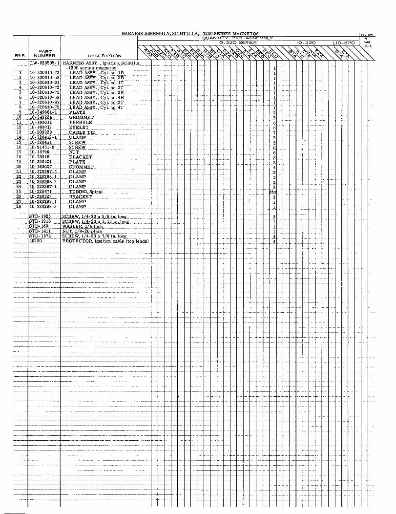
HARNESS ASSEMBLY, SCINTILLA, -1200 SERIES MAGNETOSQUANTITY PER
0-320 SE
PARTREF NUMBER DESCRIPTION
LW-620505-1 HARNESS ASSY., Ignition, Scintilla,-1200 series magnetos
1 10-320610-72 LEAD ASSY. ,Cyl. no. lB2 10-320610-58 LEAD ASSY., Cyl. no. 3B3 10-320610-91 LEAD ASSY., Cyl. no. 1T4 10-320610-72 LEAD ASSY., Cyl. no. 3T5 10-320610-75 LEAD ASSY., Cyl. no. 2B6 10-320610-59 LEAD ASSY., Cyl. no. 4B7 10-320610-87 LEAD ASSY., Cyl. no. 2T8 10-320610-75 LEAD ASSY., Cyl. no. 4T9 10-349661-1 PLATE
10 10- 349224 GROMMET11 10- 163011 FERRULE12 10- 163012 EYELET13 10-209328 CABLE TIE14 10-320412-1 CLAMP15 10-320411 SCREW16 10-91431-8 SCREW17 10-13799 NUT18 10- 78916 BRACKET19 10-320401 PLATE20 10-163007 GROMMET21 10-320297-3 CLAMP22 10-320298-1 CLAMP23 10-320298-2 CLAMP24 10-320297-1 CLAMP25 10-320471 TUBING Spiral26 10-320328 BRACKET27 10-320297-1 CLAMP28 10-320298-3 CLAMP
STD- 1925 SCREW, 1/4- 20 x 58 in. longSTD-1916 SCREW, 1/4-20 x 1. 13 in.longSTD- 160 WASHER, 1/4 lockSTD-1411 NUT, 1/4-20 plainSTD- 1874 SCREW, 1/4-20x7/8 in.long40239 PROTECTOR,Ignition cable (top!leads
NETOS SECTIONASSEMBLY 4
4-4RIES 10-320 LIO-320 PAGE
1
111111112288722663243323
311
311144
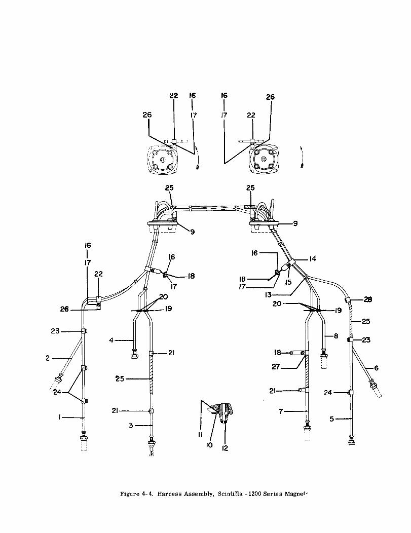
16
17
16
17
22
21
26
26
23
1920
2
187
25
24
3 5
Figure 4-4. Harness Assembly, Scintilla -1200 Series Magnet
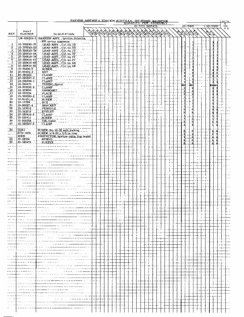
HARNESS ASSEMBLY. IGNITION, SCINTILLA, -200 SERIES MAGNETOS SECTIONQUANTITY PER ASSEMBLY 4
0-320 SERIES 10-320 LIO-320 PAGE
PARTREF. NUMBER DESCRIPTION
LW-620326-2 HARNESS ASSY., Ignition, Scintilla,-200 series magnetos 1 1 11
1 10-320610-72 LEAD ASSY., Cyl. no. 1B 1 1 12 10-320610-60 LEAD ASSY., Cyl. no. 3B 1 1 13 10-320610-79 LEAD ASSY., Cyl. no. 1T 1 1 14 10-320610-69 LEAD ASSY.,Cyl. no. 3T 1 1 15 10-320610-78 LEAD ASSY., Cyl. no. 4T 1 1 116 10-320610-87 LEAD ASSY., Cyl. no. 2T 1 1 117 10-320610-68 LEAD ASSY.,Cyl. no. 4B 1 1 1 18 10-320610-82 LEAD ASSY., Cyl. no. 2B 1 1 119 10-35936-6 SCREW 8 8 88
10 10-90404-4 NUT 8 8 8 811 10-320283 CLAMP 8 8 8 812 10-320297-2 CLAMP 1 1 1 113 10-320298-1 CLAMP 3 3 3 314 10-320471 TUBING, Spiral 53 653 65365315 10-320298-2 CLAMP16 10-320050 GROMMET17 10-320394 PLATE18 10-320300-1 CLAMP19 10-91431-8 SCREW20 10-13799 NUT21 10-89027-4 BRACKET22 10-163011 FERRULE23 10-163012 EYELET24 10-320412-3 CLAMP25 10-320411 SCREW26 10-209328 TIE, Cable27 10-320297-2 CLAMP
28 72351 SCREW, No. 10-32 self-lockingSTD- 1874 SCREW, 1/4-20 x 7/8 in long40239 PROTECTOR, Ignition cable (top leads)
29 10-32326 SPRING30 10-320473 SLEEVE
2 22 22 21 11 11 11 18 88 81 11 15 51 1
8 83 3
4 4
8 8
2 22 22 21 11 11 11 18 88 81 11 15 5
L
8 83 3
8 88 8
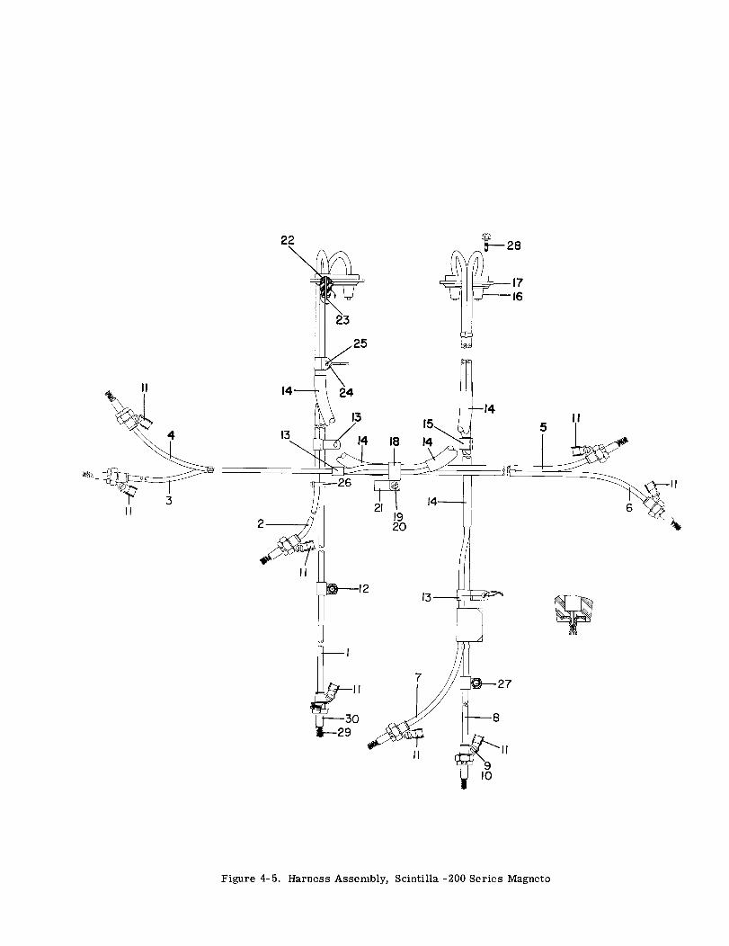
25
4
3
28
5
13
1
3029
11
Figure 4-5. Harness Assembly, Scintilla -200 Series Magneto
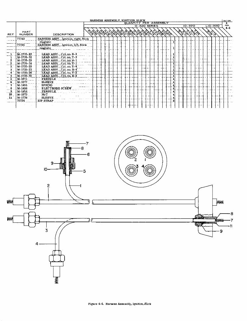
Figure 4-6. Harness Assembly, Ignition, Slick
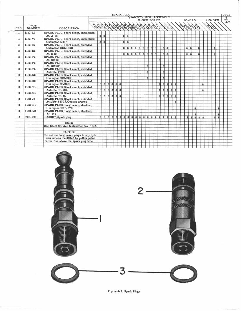

LYCOMING AIRCRAFT ENGINE GROUP ASSEMBLY PARTS LIST
0
LYCOMING PARTS CATALOG
0-320, I0-320 AND LIO-320 SERIES
SECTION 5
ELECTRICAL SYSTEM
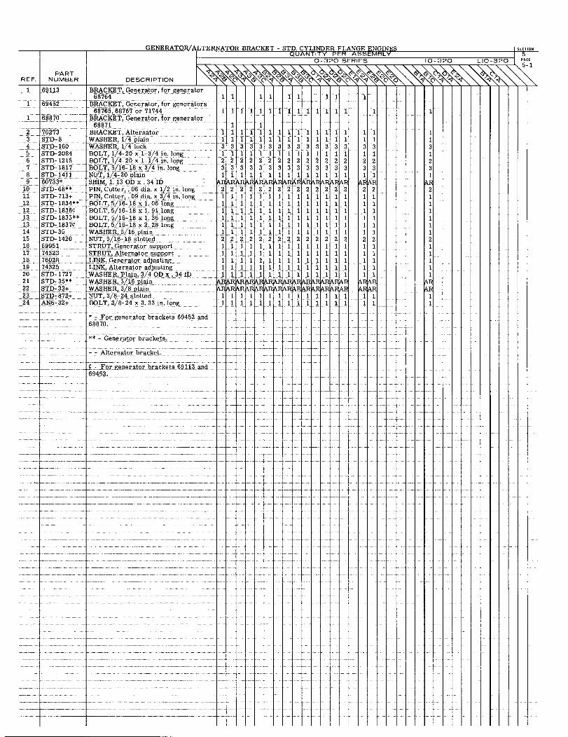
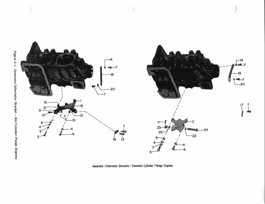
.
-d
Figure 5-1.
Generator/A
lternator B
racket -
Std. C
ylinder Flange
Engines
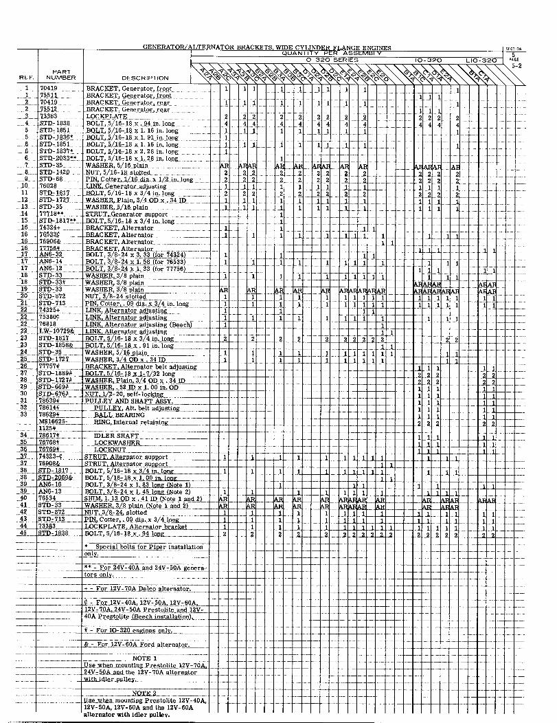
-_-- - ^ **- For 24V-40Aand'24V-50A'genera- -- _'
tors only.
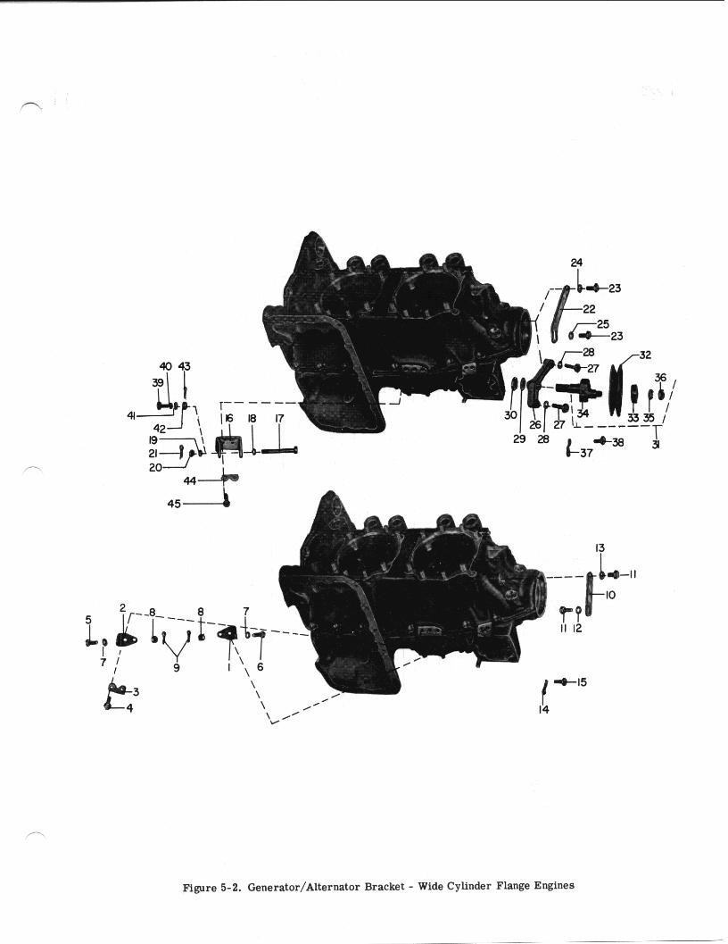
Figure 5-2. Generator/Alternator Bracket - Wide Cylinder Flange Engines
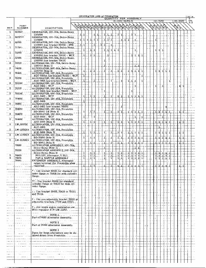
GENERATOR AND ALTERNATOR SECTIONQUANTITY PER ASSEMBLY
0-320 SERIES 10-320 LIO-320 PAGE5-3
PARTREF. NUMBER DESCRIPTION
1 68764* GENERATOR, 12V-20A, Delco-Remy1101899 1 1 111 11 11
1 68767** GENERATOR, 12V-35A,Delco-Remy1101900 111111 1111 1 11 1 1
1 68765 GENERATOR,24V-15A,Delco-Remy1101901 (use bracket 69452)- STD 1 1 1 1 1
1 71744+ GENERATOR, 12V-50A, Delco-Remy1101915 1 1 11
1 71980 GENERATOR, 24V-40A,Delco-Remy ....1105052 (use bracket 70419)-WCF 1 1 1 . 1 11 1
1 72695 GENERATOR, 24V- 50A, Delco-Remy .1105055 (use bracket 70419)
2 74319 ALTERNATOR, 12V-70A,Delco-Remy1100717 (Note 1)
2 74816 ALTERNATOR,24V-50A,Delco-Remy1100718 (Note 2) 1 11 1l L . 1.1.1 11-1 11111
2 76496 ALTERNATOR, 12V-40A, PrestoliteALE-8105A (usebracket76533) -WCF 1
2 78308 ALTERNATOR, 12V-40A, PrestoliteALE-8406 (usebracket76533)-WCF 1 111 1 1 1
2 783109 ALTERNATOR, 12V-70A, PrestoliteALX-8403- WCF
2 78312 ALTERNATOR, 24V-50A, PrestoliteALT-8404 (use bracket 76533)-WCF
2 783141 ALTERNATOR, 24V-70A, PrestoliteALU-8403 - WCF 1 l 1 1 l 1
2 784019 ALTERNATOR,12V-40A, PrestoliteALE-6406
2 78403 ALTERNATOR, 12V-50A,PrestoliteALZ-8401(use bracket 76533)
2 784059 ALTERNATOR, 12V-50A PrestoliteEO-20041 LB(Note 3) 1 11 11 1 1
2 78407 ALTERNATOR,12V-60A, PrestoliteALY-8403 - WCF 1
2 78409 ALTERNATOR, 12V-60APrestoliteALY-6403 (Note 3) 1 1 1
2 LW-10372 ALTERNATOR, 12V-60A, PrestoliteALY-8405
2 LW-10762# ALTERNATOR, 12V-40A, Prestolite2 ALE-8408 (Note 3) 1 1 1 1 l1 1 1 1 11 1 1 1
2 LW-113959# ALTERNATOR, 12V-50A Prestolite2 LW-11395 EO-20950(Note3) 1 . 1 1 1 1 12 LW-11396# ALTERNATOR, 12V-60A,Prestolite
EO-20951(Note 3) 1 1 1 1 l 1 11 1 174880 ALTERNATOR ASSEMBLY,12V-70A,
Delco-Remy (Note 1)75220 ALTERNATOR ASSEMBLY, 24V-50A,
Delco-Remy (Note 2)3 74863 PULLEY, Alternator, 3.25:1 1 1 1 1 1 1 1 1 l 14 74878 FAN & BAFFLE ASSEMBLY 1 1 1 11 1 1 1 11 1 1 1 1
78881 EXTENSION ASSEMBLY,Alternatoroutput terminal (for Prestolite whenrequired) ........
* - Use bracket 69113 for standard cyl-inder flange or 70419 for wide cylinderflange.
** - Use bracket 69452 for standardcylinder flange or 70419 for wide cyl- . . . . .....inder flange. . .
+ - Use bracket 69452, 70419 or 75111and 75112.
- Use non-adjustable bracket 76533 oradjustable brackets 77756 and 77757.
For single engine installation use..Wico regulator P/N LW-11357.
NOTE 1Part of 74880 Alternator Assembly
NOTE 2Part of 75220 Alternator Assembly.
NOTE.3Parts for these alternators may be ob- . ...... . .......... . ............ .....tained direct from Prestolite . . . . ...............
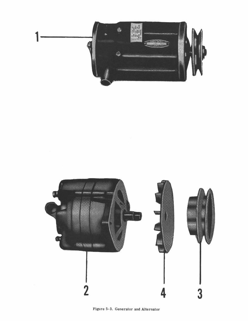
2 4 3 Figure 5-3. Generator and Alternator
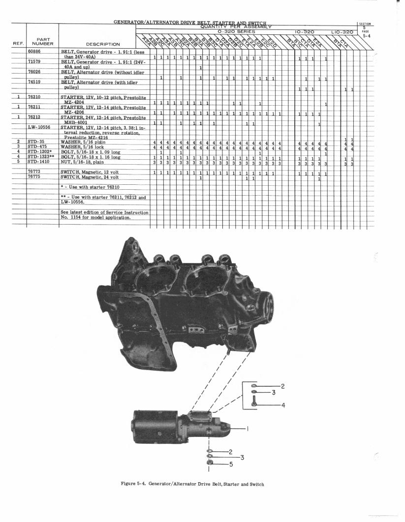
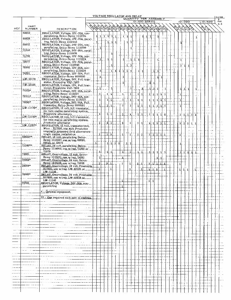
VOLTAGE REGULATOR AND RELAYQUANTITY PER ASSEMBLY
0-320 SERIES 10-320 LIO-3205-5
PARTREF. NUMBER DESCRIPTION
62833 REGULATOR, Voltage, 12V- 35A, non-paralleling, Delco-Remy 1118704 11 11 1 1 1 1 1 1 1
68626 REGULATOR, Voltage, 12V- 35A, paral-ling, Delco-Remy 1119145 1 1 1 1 11 1
68872 REGULATOR, Voltage, 24V-25A, non-paralleling, Delco-Remy 1118799 1 1
71350 REGULATOR, Voltage, 24V-25A, paral-ling, Delco-Remy 1118976 1
71745 REGULATOR, Voltage, 12V-50A, non-paralleling, Delco-Remy 1119224 1 11 1 11 1
72077 REGULATOR, Voltage, 12V- 50A, paral-leling, Delco-Remy 1119246 1 11 11 1
72205 REGULATOR, Voltage, 12V-20A, non-paralleling, Delco-Remy 1119226 1 1 1 11 11 1 1 1
74291 REGULATOR, Voltage, 12V-70A, Fulltransistor, Delco-Remy 9000590 1 i 1 1
LW-10179 REGULATOR, Voltage, 24V, Full tran-
LYCOMING AIRCRAFT ENGINE GROUP ASSEMBLY PARTS LIST
LYCOMING PARTS CATALOG
0-320, IO-320 AND LIO-320 SERIES
SECTION 6
FUEL INDUCTION SYSTEM
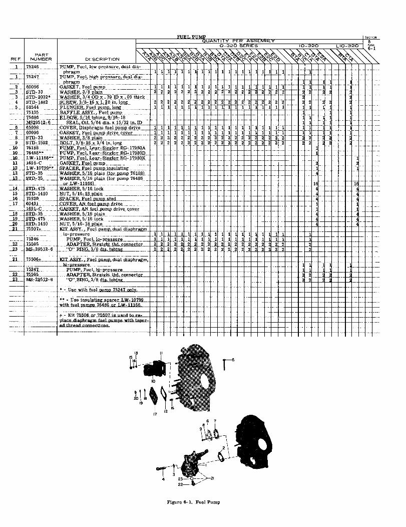
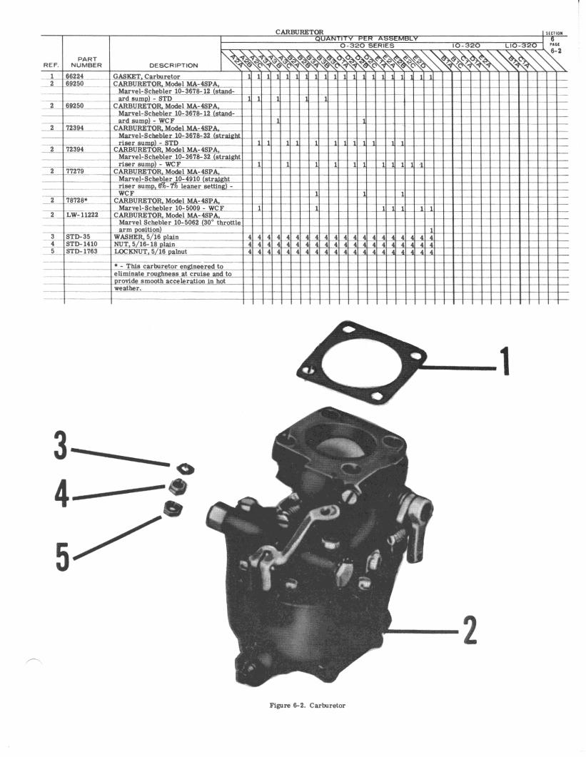
2
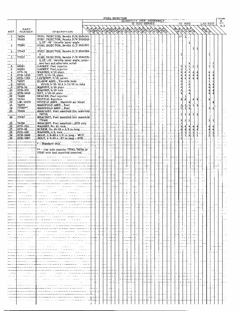
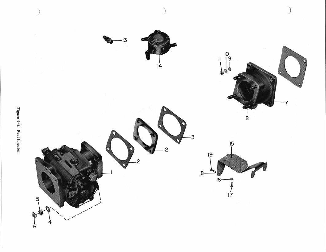
Figure 6-3.
Fuel Injector
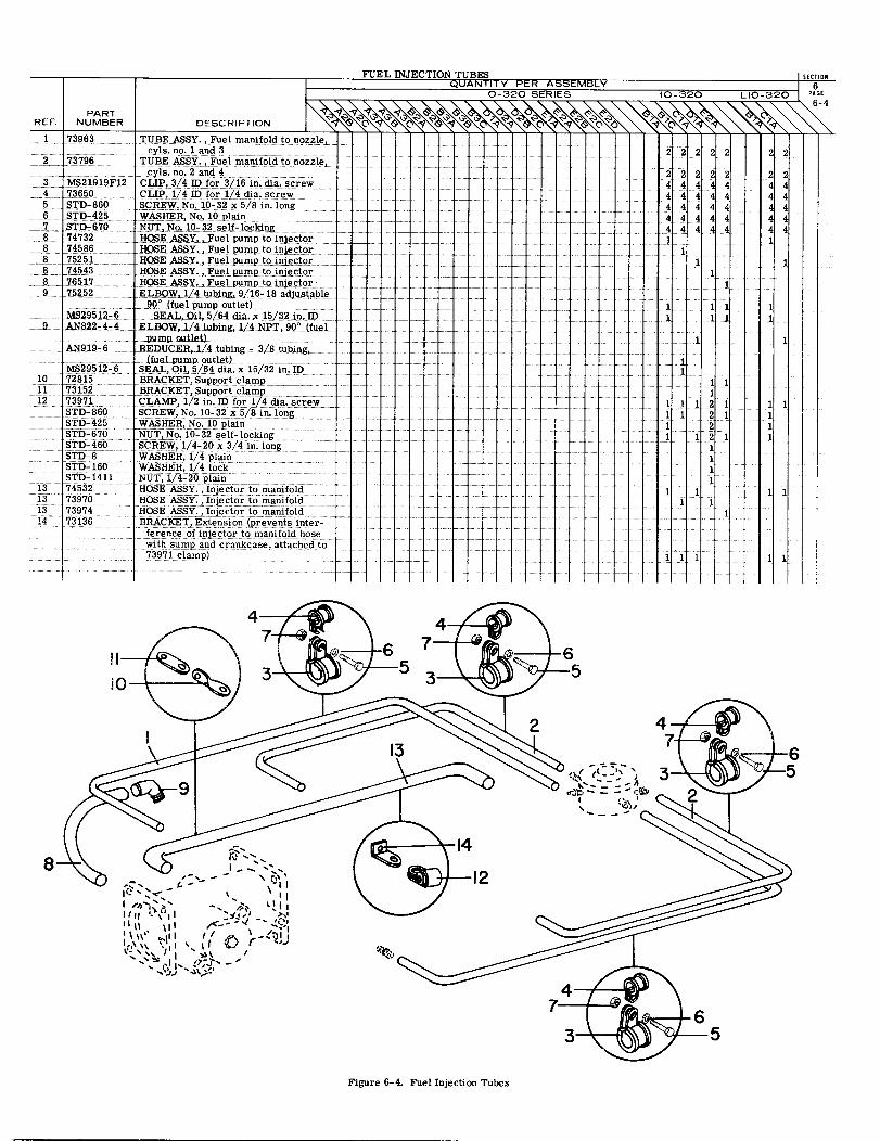
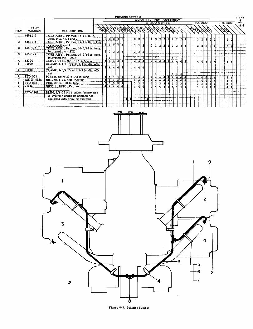
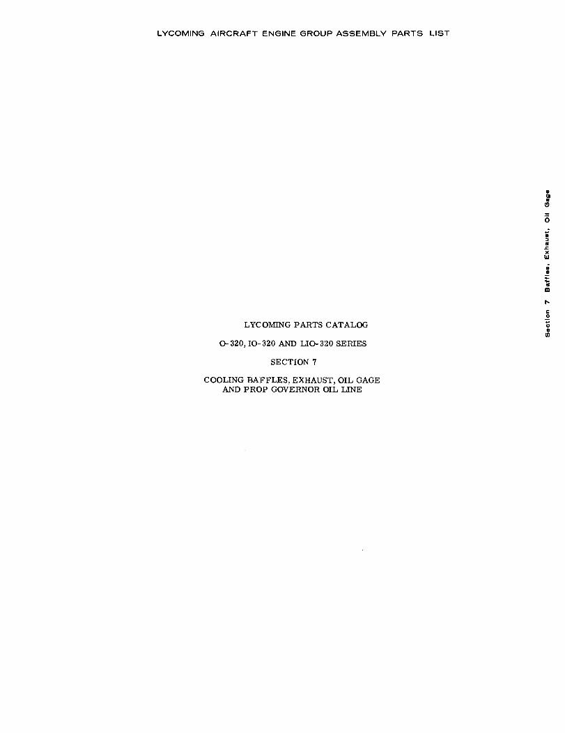
LYCOMING AIRCRAFT ENGINE GROUP ASSEMBLY PARTS LIST
COOLING BAFFLES, EXHAUST, OIL GAGEAND PROP GOVERNOR OIL LINE
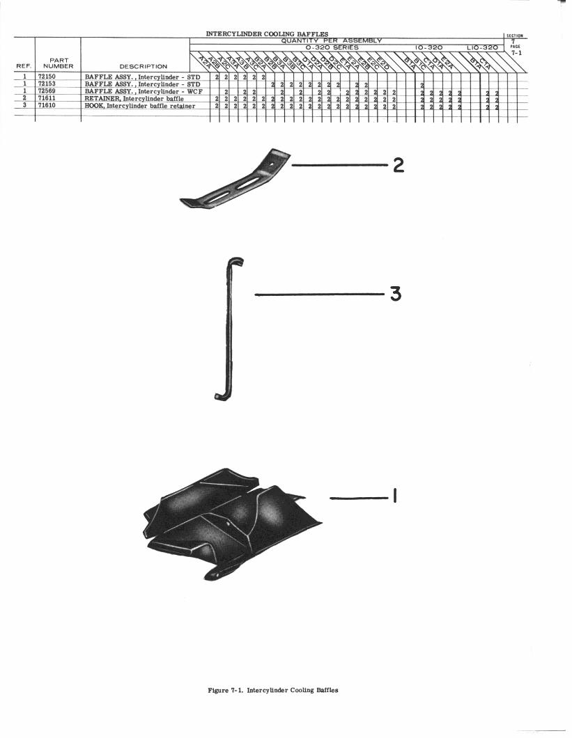
2
4
3
4 3
5
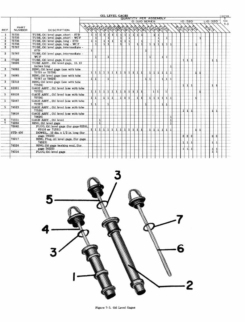
Figure ‘l-3. Oil Level Gages
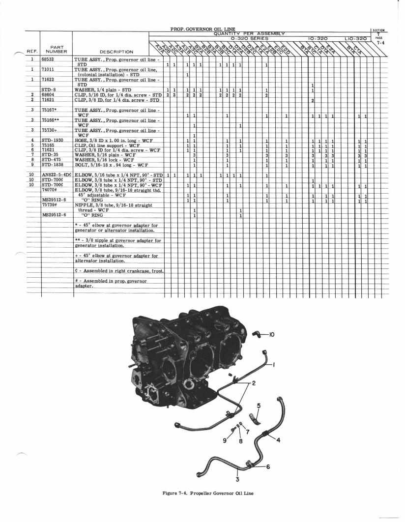
6

LYCOMING AIRCRAFT ENGINE GROUP ASSEMBLY PARTS LIST
LYCOMING PARTS CATALOG
0-320, IO-320 AND LIO-320 SERIES
SECTION 8
SERVICE REPLACEMENT SET SECTION
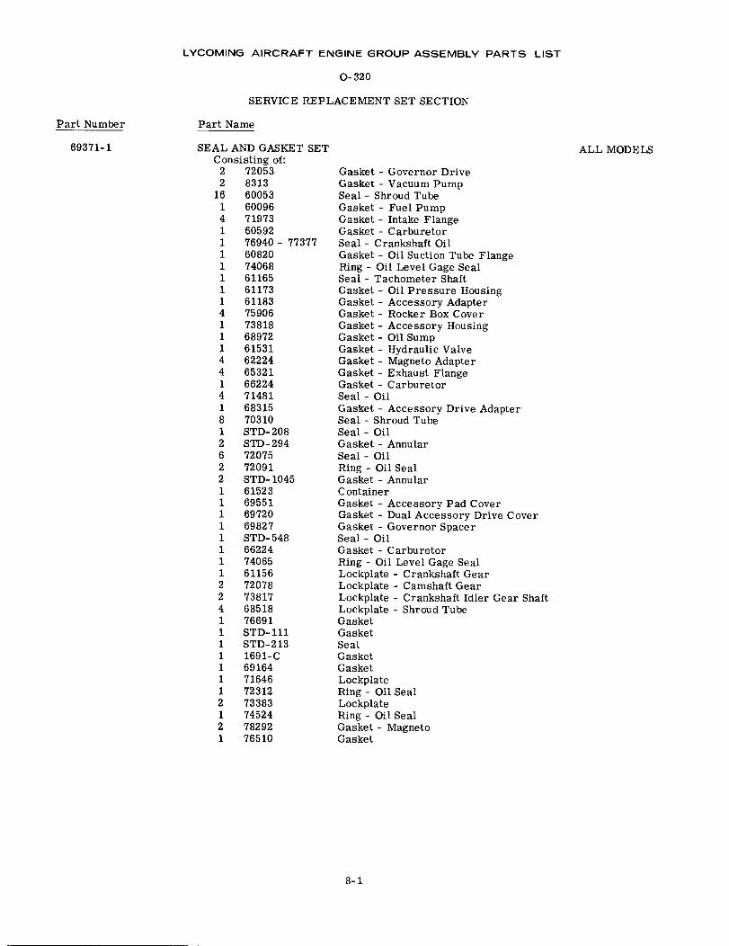
LYCOMING AIRCRAFT ENGINE GROUP ASSEMBLY PARTS LIST
0-320
SERVICE REPLACEMENT SET SECTION
Part Number
69371-1
Part Name
SEAL AND GASKET SETConsisting of:
2 720532 8313
16 600531 600964 719731 605921 76940 - 773771 608201 740681 611651 611731 611834 759061 738181 689721 615314 622244 653211 662244 714811 683158 703101 STD-2082 STD-2946 720752 720912 STD- 10451 615231 695511 697201 698271 STD-5481 662241 740651 611562 720782 738174 685181 766911 STD-1111 STD-2131 1691-C1 691641 716461 723122 733831 745242 782921 76510
ALL MODELS
Gasket - Governor DriveGasket - Vacuum PumpSeal - Shroud TubeGasket - Fuel PumpGasket - Intake FlangeGasket- CarburetorSeal - Crankshaft OilGasket - Oil Suction Tube FlangeRing - Oil Level Gage SealSeal - Tachometer ShaftGasket - Oil Pressure HousingGasket - Accessory AdapterGasket - Rocker Box CoverGasket - Accessory HousingGasket - Oil SumpGasket - Hydraulic ValveGasket - Magneto AdapterGasket - Exhaust FlangeGasket- CarburetorSeal - OilGasket - Accessory Drive AdapterSeal - Shroud TubeSeal- OilGasket- AnnularSeal- OilRing - Oil SealGasket- AnnularC ontainerGasket - Accessory Pad CoverGasket - Dual Accessory Drive CoverGasket - Governor SpacerSeal- OilGasket- CarburetorRing - Oil Level Gage SealLockplate - Crankshaft GearLockplate - Camshaft GearLockplate - Crankshaft Idler Gear ShaftLockplate - Shroud TubeGasketGasketSealGasketGasketLockplateRing - Oil SealLockplateRing - Oil SealGasket- MagnetoGasket
8-1
LYCOMING AIRCRAFT ENGINE GROUP ASSEMBLY PARTS LIST
LYCOMING PARTS CATALOG
0-320, IO-320 AND LIO-320 SERIES
SECTION 9
VENDOR ACCESSORIES
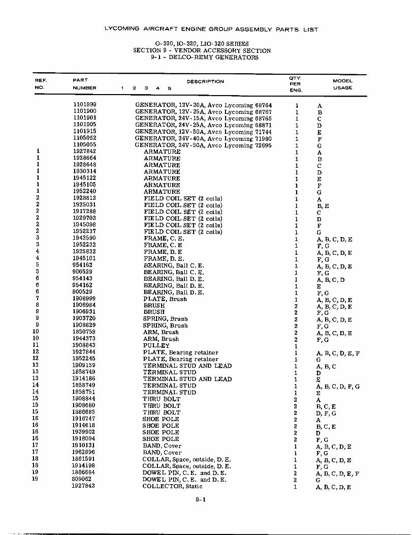
LYCOMING AIRCRAFT ENGINE GROUP ASSEMBLY PARTS LIST
0-320, IO-320, LIO-320 SERIESSECTION 9 - VENDOR ACCESSORY SECTION
9-1 - DELCO-REMY GENERATORS
REF.NO.
PART
NUMBERDESCRIPTION
QTY.PERENG.
MODEL
USAGE1 2 3 4 5
1101899110190011019011101905110191511050521105055
1 19278421 19286641 19286481 19303141 19451221 19451051 19522402 19288132 19250312 19172882 19297032 19450982 19522373 19435903 19522324 19258324 19451015 9541625 9005296 9541436 9541626 9005297 19089998 19069848 19069319 19037209 1908829
10 185075910 194437311 190884312 192784412 195224513 190915913 185874913 191418614 185874914 185875115 190884415 190868015 188668516 191674716 191461816 193990216 191800417 191013117 196289618 186159118 191419819 188668419 809062
1927843
GENERATOR, 12V-20A, Avco Lycoming 68764GENERATOR, 12V-25A, Avco Lycoming 68767GENERATOR, 24V- 15A, Avco Lycoming 68765GENERATOR, 24V-25A, Avco Lycoming 68871GENERATOR, 12V-50A, Avco Lycoming 71744GENERATOR, 24V-40A, Avco Lycoming 71980GENERATOR, 24V-50A, Avco Lycoming 72695
ARMATUREARMATUREARMATUREARMATUREARMATUREARMATUREARMATUREFIELD COIL SET (2 coils)FIELD COIL SET (2 coils)FIELD COIL SET (2 coils)FIELD COIL SET (2 coils)FIELD COIL SET (2 coils)FIELD COIL SET (2 coils)FRAME, C. E.FRAME, C. EFRAME, D. EFRAME, D. E.BEARING, Ball C. E.BEARING, Ball C. E.BEARING, Ball D. E.BEARING, Ball D. E.BEARING, Ball D. E.PLATE, BrushBRUSHBRUSHSPRING, BrushSPRING, BrushARM, BrushARM, BrushPULLEYPLATE, Bearing retainerPLATE, Bearing retainerTERMINAL STUD AND LEADTERMINAL STUDTERMINAL STUD AND LEADTERMINAL STUDTERMINAL STUDTHRU BOLTTHRU BOLTTHRU BOLTSHOE POLESHOE POLESHOE POLESHOE POLEBAND, CoverBAND, CoverCOLLAR, Space, outside, D. E.COLLAR, Space, outside, D. E.DOWEL PIN, C. E. and D. E.DOWEL PIN, C. E. and D. E.COLLECTOR, Static
1111111111111111111111111111112222221111111122222221111221
ABCDEFGABCDEFGAB, ECDFGA, B, C, D, EF, GA, B, C, D, EF, GA, B, C, D, EF, GA, B, C, DEF, GA, B, C, D, EA, B, C, D, EF, GA, B, C, D, EF,GA, B, C, D, EF, G
A, B, C, D, E, FGA, B, CDEA, B, C, D, F, GEAB, C, ED, F, GAB, C, EDF, GA, B, C, D, EF, GA, B, C, D, EF, GA, B, C, D, E, FGA, B, C, D, E
9-1
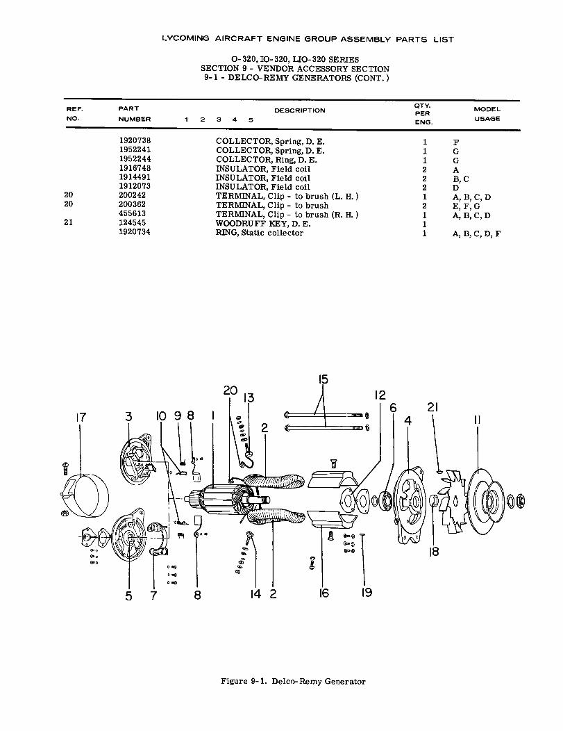
20
LYCOMING AIRCRAFT ENGINE GROUP ASSEMBLY PARTS LIST
O-320, IO- 320, LIO-320 SERIESSECTION 9 - VENDOR ACCESSORY SECTION9-1 - DELCO-REMY GENERATORS (CONT.)
DESCRIPTION2 3 4 5
REF.NO.
PART
NUMBER
QTY.PERENG.
MODEL
USAGE
192073819522411952244191674819144911912073
20 20024220 200362
45561321 124545
1920734
COLLECTOR, Spring, D. E.COLLECTOR, Spring, D. E.COLLECTOR, Ring, D. E.INSULATOR, Field coilINSULATOR, Field coilINSULATOR, Field coilTERMINAL, Clip - to brush (L. H. )TERMINAL, Clip - to brushTERMINAL, Clip - to brush (R. H. )WOODRUFF KEY, D. E.RING, Static collector
11122212111
FGGAB, CDA, B, C, DE, F, GA, B, C, D
A, B, C, D, F
15
Figure 9-1. Delco-Remy Generator
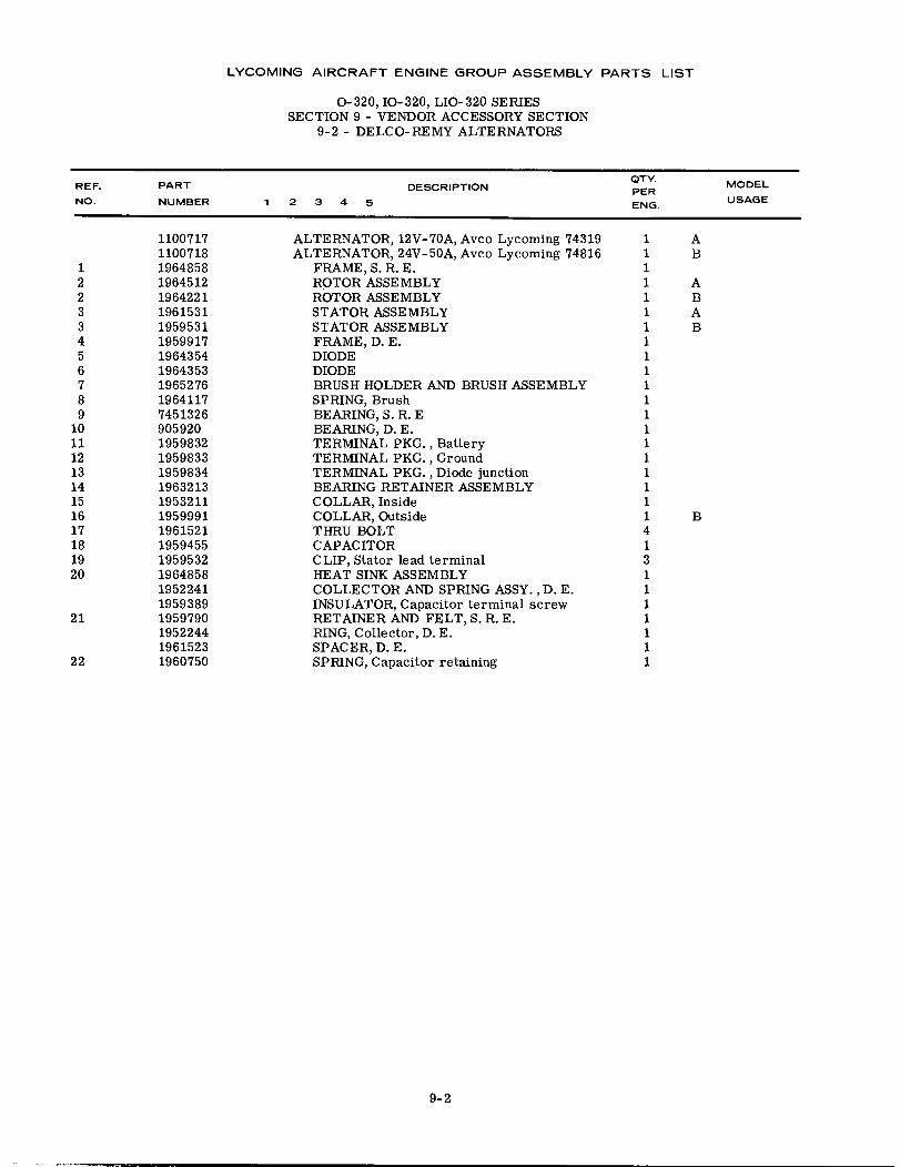
LYCOMING AIRCRAFT ENGINE GROUP ASSEMBLY PARTS LIST
0-320, IO-320, LIO-320 SERIESSECTION 9 - VENDOR ACCESSORY SECTION
9-2 - DELCO-REMY ALTERNATORS
REF. PART DESCRIPTION QTY. MODELPERNO. NUMBER 1 2 3 4 5 ENG. USAGE
1100717 ALTERNATOR, 12V-70A, Avco Lycoming 74319 1 A1100718 ALTERNATOR, 24V- 50A, Avco Lycoming 74816 1 B
1 1964858 FRAME, S. R.E. 12 1964512 ROTOR ASSEMBLY 1 A2 1964221 ROTOR ASSEMBLY 1 B3 1961531 STATOR ASSEMBLY 1 A3 1959531 STATOR ASSEMBLY 1 B4 1959917 FRAME, D. E. 15 1964354 DIODE 16 1964353 DIODE 17 1965276 BRUSH HOLDER AND BRUSH ASSEMBLY 18 1964117 SPRING, Brush 19 7451326 BEARING, S. R. E 1
10 905920 BEARING, D. E. 111 1959832 TERMINAL PKG., Battery 112 1959833 TERMINAL PKG., Ground 113 1959834 TERMINAL PKG., Diode junction 114 1963213 BEARING RETAINER ASSEMBLY 115 1953211 COLLAR, Inside 116 1959991 COLLAR, Outside 1 B17 1961521 THRU BOLT 418 1959455 CAPACITOR 119 1959532 CLIP, Stator lead terminal 320 1964858 HEAT SINK ASSEMBLY 1
1952241 COLLECTOR AND SPRING ASSY., D. E. 11959389 INSULATOR, Capacitor terminal screw 1
21 1959790 RETAINER AND FELT, S. R. E. 11952244 RING, Collector, D. E. 11961523 SPACER, D. E. 1
22 1960750 SPRING, Capacitor retaining 1
9-2
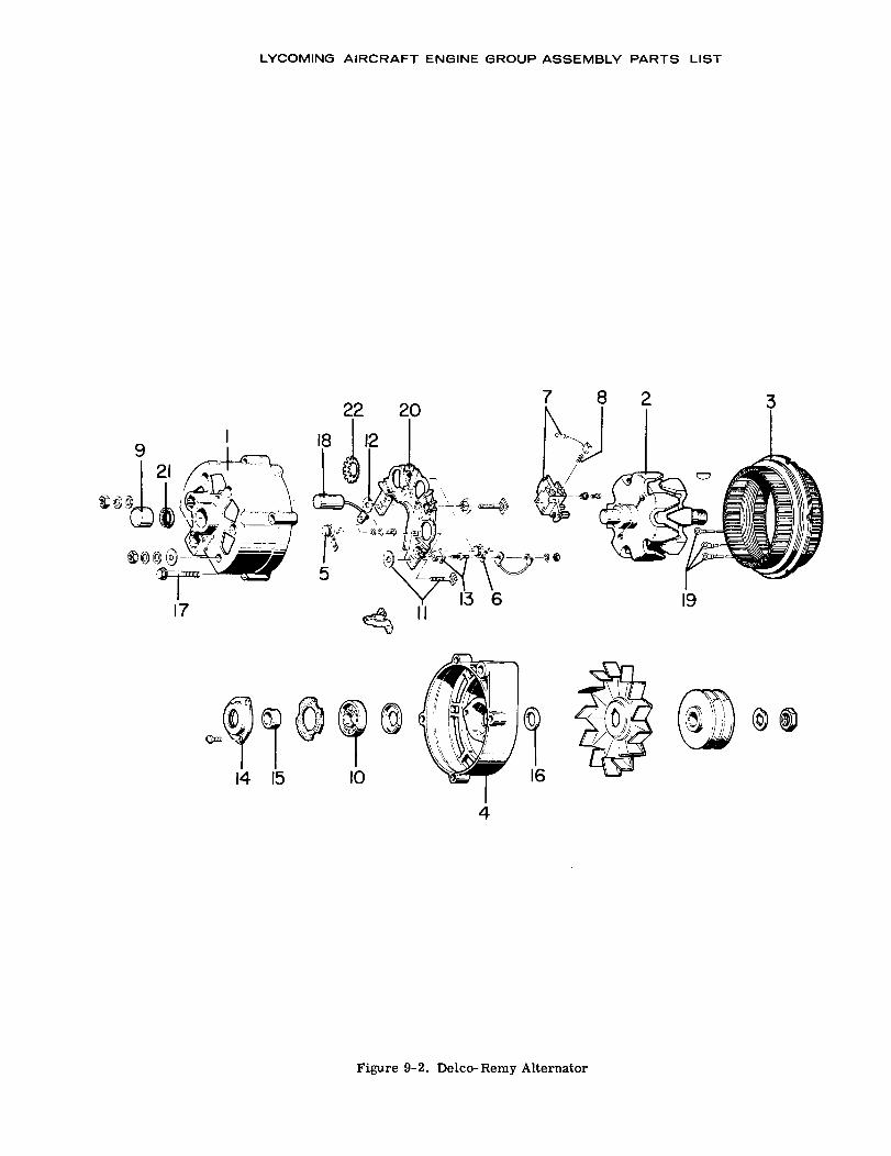
LYCOMING AIRCRAFT ENGINE GROUP ASSEMBLY PARTS LIST
5
17
Figure 9-2. Delco-Remy Alternator
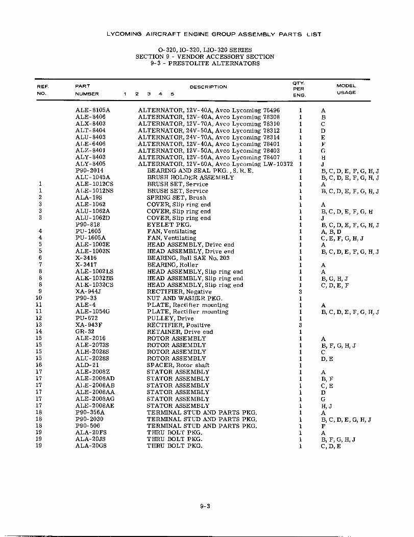
LYCOMING AIRCRAFT ENGINE GROUP ASSEMBLY PARTS LIST
O-320, IO- 320, LIO- 320 SERIESSECTION 9 - VENDOR ACCESSORY SECTION
9-3 - PRESTOLITE ALTERNATORS
REF.
NO.
PART
NUMBER
DESCRIPTIONQTY.PER
ENG.
MODEL
USAGE1 2 3 4 5
ALE-8105AALE-8406ALX- 8403ALT- 8404ALU- 8403ALE-6406ALZ- 8401ALY- 8403ALY- 8405P90-2014ALU- 1045A
1 ALE- 1012CS1 ALE- 1012NS2 ALA- 19S3 ALE-10623 ALU- 1062A3 ALU- 1062D
P90-8184 PU-16054 PU- 1605A5 ALE-1003E5 ALE- 1003N6 X-34167 X-34178 ALE- 1002LS8 ALK-1032BS8 ALK- 1032CS9 XA-944J
10 P90-3311 ALE-411 ALE-1054G12 PU-67213 XA-943F14 GR- 3215 ALE-201615 ALE-2073S15 ALH-2028S15 ALU-2028S16 ALD-2117 ALE-2008Z17 ALE-2008AD17 ALE-2008AB17 ALE-2008AA17 ALE-2008AG17 ALE-2008AE18 P90-356A18 P90-203018 P90-50619 ALA-20FS19 ALA-20JS19 ALA-20GS
ALTERNATOR, 12V-40A, Avco Lycoming 76496ALTERNATOR, 12V-40A, Avco Lycoming 78308ALTERNATOR, 12V-70A, Avco Lycoming 78310ALTERNATOR, 24V-50A, Avco Lycoming 78312ALTERNATOR, 24V- 70A, Avco Lycoming 78314ALTERNATOR, 12V-40A, Avco Lycoming 78401ALTERNATOR, 12V-50A, Avco Lycoming 78403ALTERNATOR, 12V-50A, Avco Lycoming 78407ALTERNATOR, 12V-60A, Avco Lycoming LW-10372
BEARING AND SEAL PKG., S. R. E.BRUSH HOLDER ASSEMBLYBRUSH SET, ServiceBRUSH SET, ServiceSPRING SET, BrushCOVER, Slip ring endCOVER, Slip ring endCOVER, Slip ring endEYELET PKG.FAN, VentilatingFAN, VentilatingHEAD ASSEMBLY, Drive endHEAD ASSEMBLY, Drive endBEARING, Ball SAE No. 203BEARING, RollerHEAD ASSEMBLY, Slip ring endHEAD ASSEMBLY, Slip ring endHEAD ASSEMBLY, Slip ring endRECTIFIER, NegativeNUT AND WASHER PKG.PLATE, Rectifier mountingPLATE, Rectifier mountingPULLEY, DriveRECTIFIER, PositiveRETAINER, Drive endROTOR ASSEMBLYROTOR ASSEMBLYROTOR ASSEMBLYROTOR ASSEMBLYSPACER, Rotor shaftSTATOR ASSEMBLYSTATOR ASSEMBLYSTATOR ASSEMBLYSTATOR ASSEMBLYSTATOR ASSEMBLYSTATOR ASSEMBLYTERMINAL STUD AND PARTS PKG.TERMINAL STUD AND PARTS PKG.TERMINAL STUD AND PARTS PKG.THRU BOLT PKG.THRU BOLT PKG.THRU BOLT PKG.
111111111111111111111111111311113111111111111111111
ABCDEFGHJB, C, D, E, F, G, H, JB, C, D, E, F, G, H, JAB, C, D, E, F, G, H, J
AB, C, D, E, F, G, HJB,C,D,E,F, G, H, JA, B, DC, E, F, G, H, JAB, C, D, E, F, G, H, J
AAB, G, H, JC, D, E, F
AB, C, D, E, F, G, H, J
AB, F, G, H, JCD, E
AB, FC,EDGH, JAB, C, D, E, G, H, JFAB, F, G, H, JC, D, E
9-3
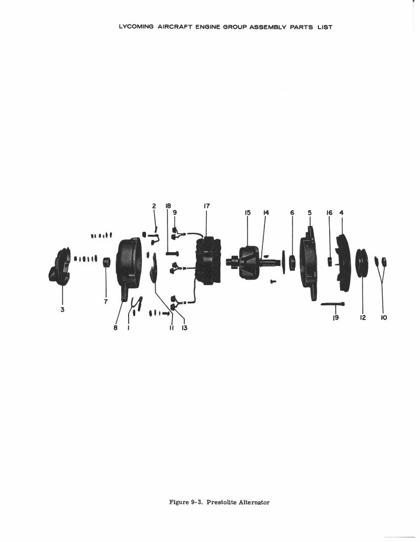
LYCOMING AIRCRAFT ENGINE GROUP ASSEMBLY PARTS LIST
. .
Figure 9-3. Prestolite Alternator
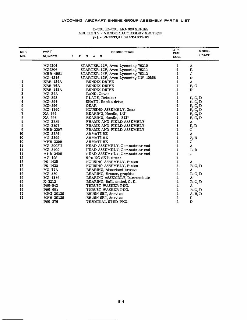
LYCOMING AIRCRAFT ENGINE GROUP ASSEMBLY PARTS LIST
0-320, 10-320, LIO-320 SERIESSECTION 9 - VENDOR ACCESSORY SECTION
9-4 - PRESTOLITE STARTERS
DESCRIPTION23 4 5
REF.NO.
PART
NUMBER
QTY.PERENG.
MODEL
USAGE
1112345678999
1010101111111213131414151516161717
MZ4204MZ4206MHB-4001MZ-4216EBB- 124AEBB-75AEBB- 142AMZ-24AMZ-393MZ-394MZ-396MZ- 1390XA-997XA-998MZ-2385MZ-2397MHB-2397MZ-2386MZ-2399MHB-2399MZ- 2002UMZ-2400MHB-2400MZ- 19SPS- 1435PS- 1432MG-77AMZ-389MZ- 1236X-3212P90-542P90-601MBG-2012SMHB- 2012SP90-876
STARTER, 12V, Avco Lycoming 76210STARTER, 12V, Avco Lycoming 76211STARTER, 24V, Avco Lycoming 76212STARTER, 12V, Avco Lycoming LW- 10556
BENDIX DRIVEBENDIX DRIVEBENDIX DRIVEBAND, CoverPLATE, RetainerSHAFT, Bendix driveGEARHOUSING ASSEMBLY, GearBEARING, Needle, 1/2"BEARING, Needle,. 812"FRAME AND FIELD ASSEMBLYFRAME AND FIELD ASSEMBLYFRAME AND FIELD ASSEMBLYARMATUREARMATUREARMATUREHEAD ASSEMBLY, Commutator endHEAD ASSEMBLY, Commutator endHEAD ASSEMBLY, Commutator endSPRING SET, BrushHOUSING ASSEMBLY, PinionHOUSING ASSEMBLY, PinionBEARING, Absorbent bronzeBEARING, Bronze, graphiteBEARING ASSEMBLY, IntermediateBEARING, Ball, sealed, C. E.THRUST WASHER PKG.THRUST WASHER PKG.BRUSH SET, ServiceBRUSH SET, ServiceTERMINAL STUD PKG.
11111111111111111111111111111111111
ABCDAB, CD
B, C, DB, C, DB, C, DB, C, DB, C, DB, C, DAB, DCAB, DCAB, DC
AB, C, DAB, C, DAB, C, DAB, C, DA, B, DCD
9-4
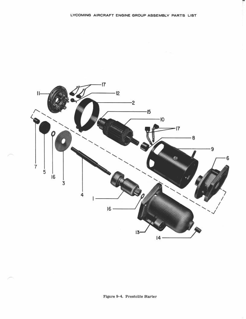
LYCOMING AIRCRAFT ENGINE GROUP ASSEMBLY PARTS LIST
Figure 9-4. Prestolite Starter
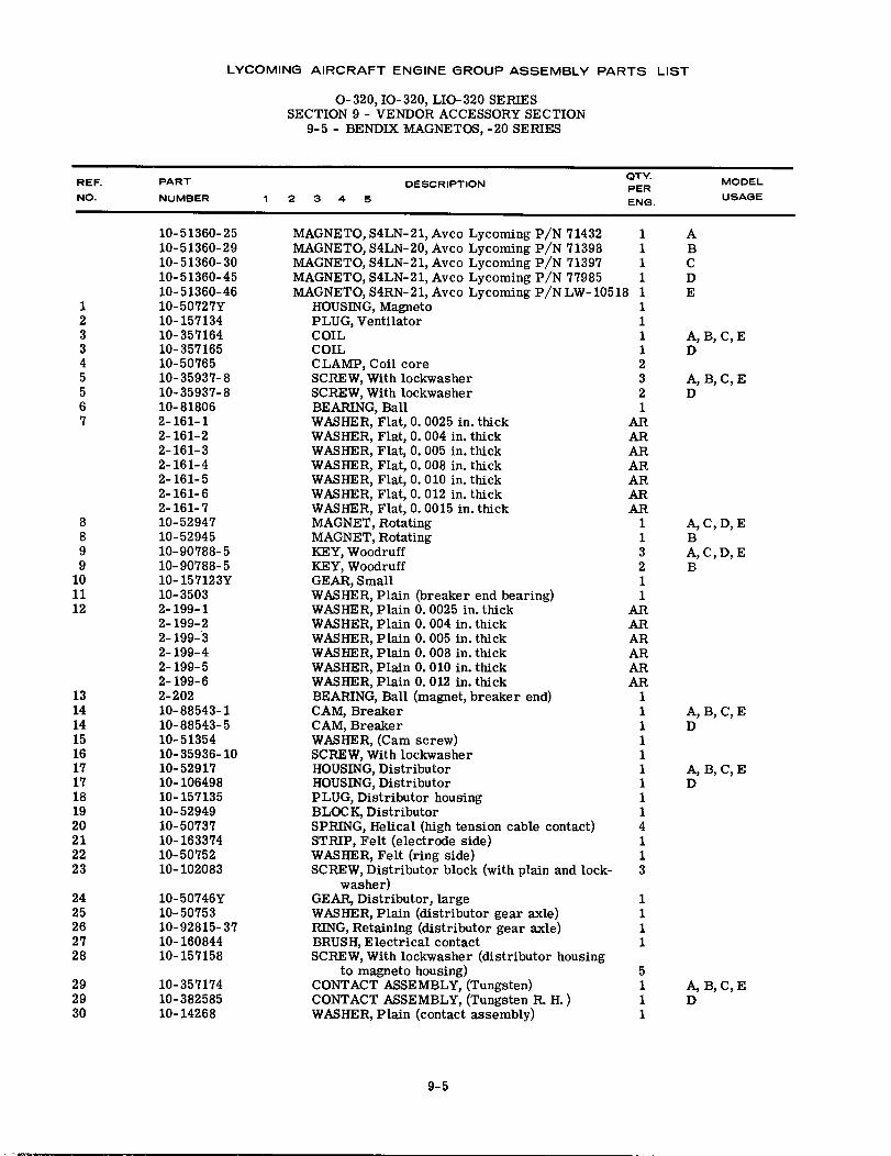
LYCOMING AIRCRAFT ENGINE GROUP ASSEMBLY PARTS LIST
O-320,10-320, LIO-320 SERIESSECTION 9 - VENDOR ACCESSORY SECTION
9-5 - BENDIX MAGNETOS, -20 SERIES
DESCRIPTION1 23 4 5
REF.NO.
PART
NUMBER
QTY.PERENG.
MODEL
USAGE
123345567
8899
101112
10-51360-2510-51360-2910-51360-3010-51360-4510-51360-4610-50727Y10-15713410-35716410-35716510-5076510-35937-810-35937-810- 818062-161-12-161-22-161-32-161-42-161-52-161-62-161-710-5294710-5294510-90788-510-90788-510-157123Y10- 35032-199-12-199-22-199- 32-199-42-199-52-199-62-20210-88543-110-88543-510-5135410-35936-1010-5291710-10649810-15713510-5294910-5073710-16337410-5075210-102083
10-50746Y10- 5075310-92815-3710-16084410-157158
10-35717410-38258510-14268
MAGNETO, S4LN-21, Avco Lycoming P/N 71432MAGNETO, S4LN-20, Avco Lycoming P/N 71398MAGNETO, S4LN-21, Avco Lycoming P/N 71397MAGNETO, S4LN-21, Avco Lycoming P/N 77985MAGNETO, S4RN- 21, Avco Lycoming P/N LW- 10518
HOUSING, MagnetoPLUG, VentilatorCOILCOILCLAMP, Coil coreSCREW, With lockwasherSCREW, With lockwasherBEARING, BallWASHER, Flat, 0. 0025 in. thickWASHER, Flat, 0. 004 in. thickWASHER, Flat, 0. 005 in. thickWASHER, Flat, 0. 008 in. thickWASHER, Flat, 0. 010 in. thickWASHER, Flat, 0. 012 in. thickWASHER, Flat, 0. 0015 in. thickMAGNET, RotatingMAGNET, RotatingKEY, WoodruffKEY, WoodruffGEAR, SmallWASHER, Plain (breaker end bearing)WASHER, Plain 0. 0025 in. thickWASHER, Plain 0. 004 in. thickWASHER, Plain 0. 005 in. thickWASHER, Plain 0. 008 in. thickWASHER, Plain 0. 010 in. thickWASHER, Plain 0. 012 in. thickBEARING, Ball (magnet, breaker end)CAM, BreakerCAM, BreakerWASHER, (Cam screw)SCREW, With lockwasherHOUSING, DistributorHOUSING, DistributorPLUG, Distributor housingBLOCK, DistributorSPRING, Helical (high tension cable contact)STRIP, Felt (electrode side)WASHER, Felt (ring side)SCREW, Distributor block (with plain and lock-
washer)GEAR, Distributor, largeWASHER, Plain (distributor gear axle)RING, Retaining (distributor gear axle)BRUSH, Electrical contactSCREW, With lockwasher (distributor housing
to magneto housing)CONTACT ASSEMBLY, (Tungsten)CONTACT ASSEMBLY, (Tungsten R. H. )WASHER, Plain (contact assembly)
1111111112321
ARARARARARARAR
113211
ARARARARARAR
1111111114113
ABCDE
A, B, C, ED
A, B, C, ED
A, C, D, EBA, C, D, EB
A, B, C, ED
A, B, C, ED
13141415161717181920212223
2425262728
1111
292930
5111
A, B, C, ED
9-5
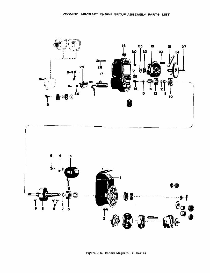
Figure 9-5. Bendix Magneto,-20 Series
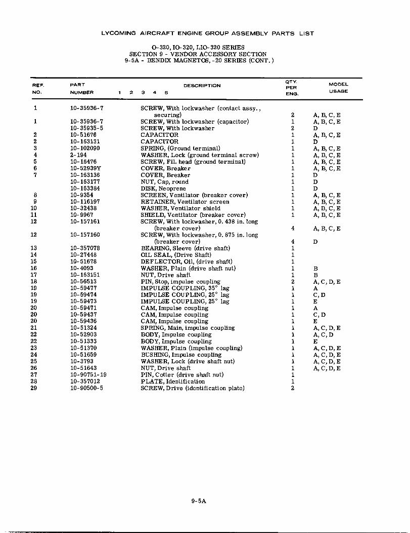
LYCOMING AIRCRAFT ENGINE GROUP ASSEMBLY PARTS LIST
O- 320, IO- 320, LIO- 320 SERIESSECTION 9 - VENDOR ACCESSORY SECTION
9-5A - BENDIX MAGNETOS, -20 SERIES (CONT.)
DESCRIPTION1 2 3 4 5
REF.
NO.
PART
NUMBER
QTY.PERENG.
MODEL
USAGE
1
1
2234567
89
101112
12
13141516171819191920202021222223242526272829
10-35936-7
10- 35936-710-35935-510- 5167610-16313110-1020902-19410-1647610-52939Y10-16313610-16317710-16338410-935410-11619710-3243810-996710-157161
10-157160
10-35707810-2744810- 5167810-409310-16315110-5651310-5947710-5947410-5947310- 5947110-5943710- 5943610- 5132410- 5290310- 5133310-5137010- 5165910-379310- 5164310-90751-1910-35701210-90500-5
SCREW, With lockwasher (contact assy.,securing)
SCREW, With lockwasher (capacitor)SCREW, With lockwasherCAPACITORCAPACITORSPRING, (Ground terminal)WASHER, Lock (ground terminal screw)SCREW, Fil. head (ground terminal)COVER, BreakerCOVER, BreakerNUT, Cap, roundDISK, NeopreneSCREEN, Ventilator (breaker cover)RETAINER, Ventilator screenWASHER, Ventilator shieldSHIELD, Ventilator (breaker cover)SCREW, With lockwasher, 0. 438 in. long
(breaker cover)SCREW, With lockwasher, 0. 875 in. long
(breaker cover)BEARING, Sleeve (drive shaft)OIL SEAL, (Drive Shaft)DEFLECTOR, Oil, (drive shaft)WASHER, Plain (drive shaft nut)NUT, Drive shaftPIN, Stop, impulse couplingIMPULSE COUPLING, 35° lagIMPULSE COUPLING, 25 ° lagIMPULSE COUPLING, 25 ° lagCAM, Impulse couplingCAM, Impulse couplingCAM, Impulse couplingSPRING, Main, impulse couplingBODY, Impulse couplingBODY, Impulse couplingWASHER, Plain (impulse coupling)BUSHING, Impulse couplingWASHER, Lock (drive shaft nut)NUT, Drive shaftPIN, Cotter (drive shaft nut)PLATE, IdentificationSCREW, Drive (identification plate)
41111121111111111111112
D
BBA, C, D, EAC,DEAC,DEA, C, D, EA, C, DEA, C, D, EA, C, D, EA, C, D, EA, C, D, E
2 A, B, C, E1 A, B, C, E2 D1 A, B, C, E1 D1 A, B, C, E1 A, B, C, E1 A, B, C, E1 A, B, C, E1 D1 D1 D1 A, B, C, E1 A, B, C, E1 A, B, C, E1 A, B, C, E
4 A, B, C, E
9-5A
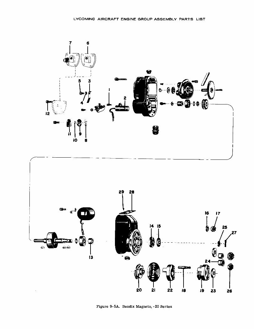
LYCOMING AIRCRAFT ENGINE GROUP ASSEMBLY PARTS LIST
7 6
12
1110
29 28
16 17
14 15
13
20 21 22 18 19 23 26
Figure 9-5A. Bendix Magneto, -20 Series
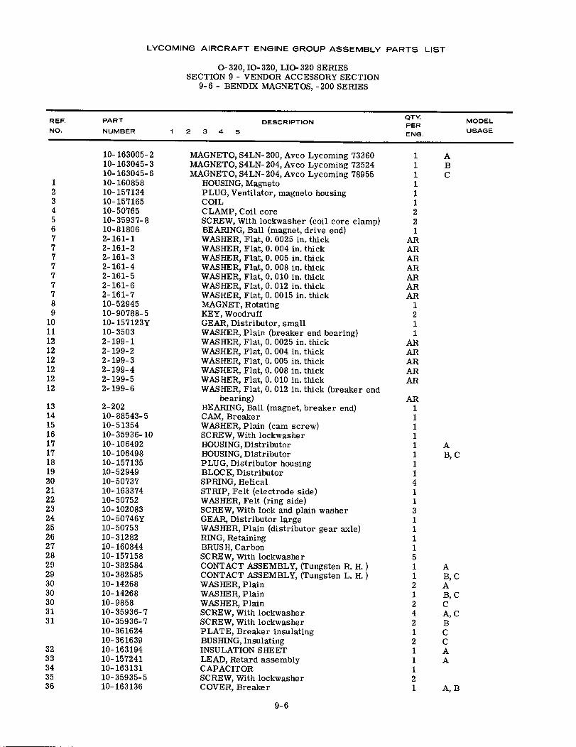
LYCOMING AIRCRAFT ENGINE GROUP ASSEMBLY PARTS LIST
0-320, IO-320, LIO-320 SERIESSECTION 9 - VENDOR ACCESSORY SECTION
9-6 - BENDIX MAGNETOS, -200 SERIES
DESCRIPTION2 3 4 5
REF.NO.
PART
NUMBER
QTY.PERENG.
MODEL
USAGE
123456777777789
1011121212121212
131415161717181920212223242526272829293030303131
10-163005-210-163045-310-163045-610-16085810-15713410-15716510-5076510-35937-810-818062-161-12-161-22-161-32-161-42-161-52-161-62-161-710-5294510-90788-510-157123Y10-35032-199-12-199-22-199-32-199-42-199-52-199-6
2-20210-88543-510-5135410-35936-1010-10649210-10649810-15713510-5294910-5073710-16337410-5075210-10208310-50746Y10-5075310-3128210-16084410-15715810-38258410-38258510-1426810-1426810-985810-35936-710-35936-710-36162410-36163910-16319410-15724110-16313110-35935-510-163136
MAGNETO, S4LN-200, Avco Lycoming 73360MAGNETO, S4LN-204, Avco Lycoming 72524MAGNETO, S4LN-204, Avco Lycoming 78955
HOUSING, MagnetoPLUG, Ventilator, magneto housingCOILCLAMP, Coil coreSCREW, With lockwasher (coil core clamp)BEARING, Ball (magnet, drive end)WASHER, Flat, 0. 0025 in. thickWASHER, Flat, 0. 004 in. thickWASHER, Flat, 0. 005 in. thickWASHER, Flat, 0. 008 in. thickWASHER, Flat, 0. 010 in. thickWASHER, Flat, 0. 012 in. thickWASHER, Flat, 0. 0015 in. thickMAGNET, RotatingKEY, WoodruffGEAR, Distributor, smallWASHER, Plain (breaker end bearing)WASHER, Flat, 0. 0025 in. thickWASHER, Flat, 0. 004 in. thickWASHER, Flat, 0. 005 in. thickWASHER, Flat, 0. 008 in. thickWASHER, Flat, 0. 010 in. thickWASHER, Flat, 0. 012 in. thick (breaker end
bearing)BEARING, Ball (magnet, breaker end)CAM, BreakerWASHER, Plain (cam screw)SCREW, With lockwasherHOUSING, DistributorHOUSING, DistributorPLUG, Distributor housingBLOCK, DistributorSPRING, HelicalSTRIP, Felt (electrode side)WASHER, Felt (ring side)SCREW, With lock and plain washerGEAR, Distributor largeWASHER, Plain (distributor gear axle)RING, RetainingBRUSH, CarbonSCREW, With lockwasherCONTACT ASSEMBLY, (Tungsten R. H. )CONTACT ASSEMBLY, (Tungsten L. H. )WASHER, PlainWASHER, PlainWASHER, PlainSCREW, With lockwasherSCREW, With lockwasherPLATE, Breaker insulatingBUSHING, InsulatingINSULATION SHEETLEAD, Retard assemblyCAPACITORSCREW, With lockwasherCOVER, Breaker
111111221
ARARARARARARAR
1211
ARARARARAR
AR11111111
1131111511212421211121
ABC
AB, C
AB, CAB, CCA, CBCCAA
A, B
3233343536
9-6
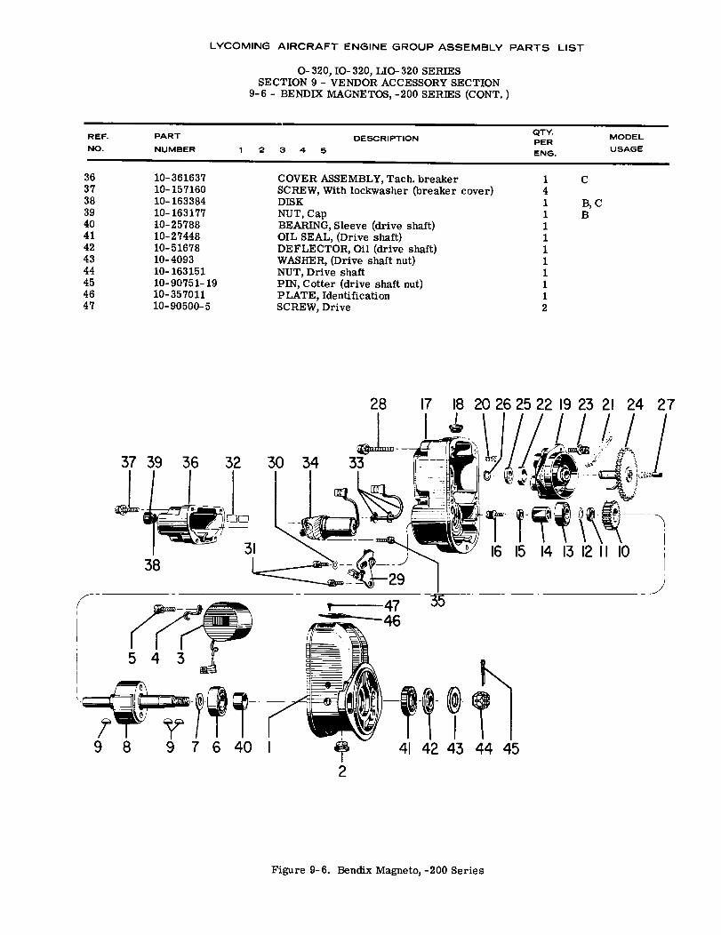
COVER ASSEMBLY, Tach. breakerSCREW, With lockwasher (breaker cover)DISKNUT, CapBEARING, Sleeve (drive shaft)OIL SEAL, (Drive shaft)DEFLECTOR, Oil (drive shaft)WASHER, (Drive shaft nut)NUT, Drive shaftPIN, Cotter (drive shaft nut)PLATE, IdentificationSCREW, Drive
141111111112
C
B, CB
17 18 20262522 19 23 21 24 27
16 15 14 13 1211 1038
Figure 9-6. Bendix Magneto, -200 Series
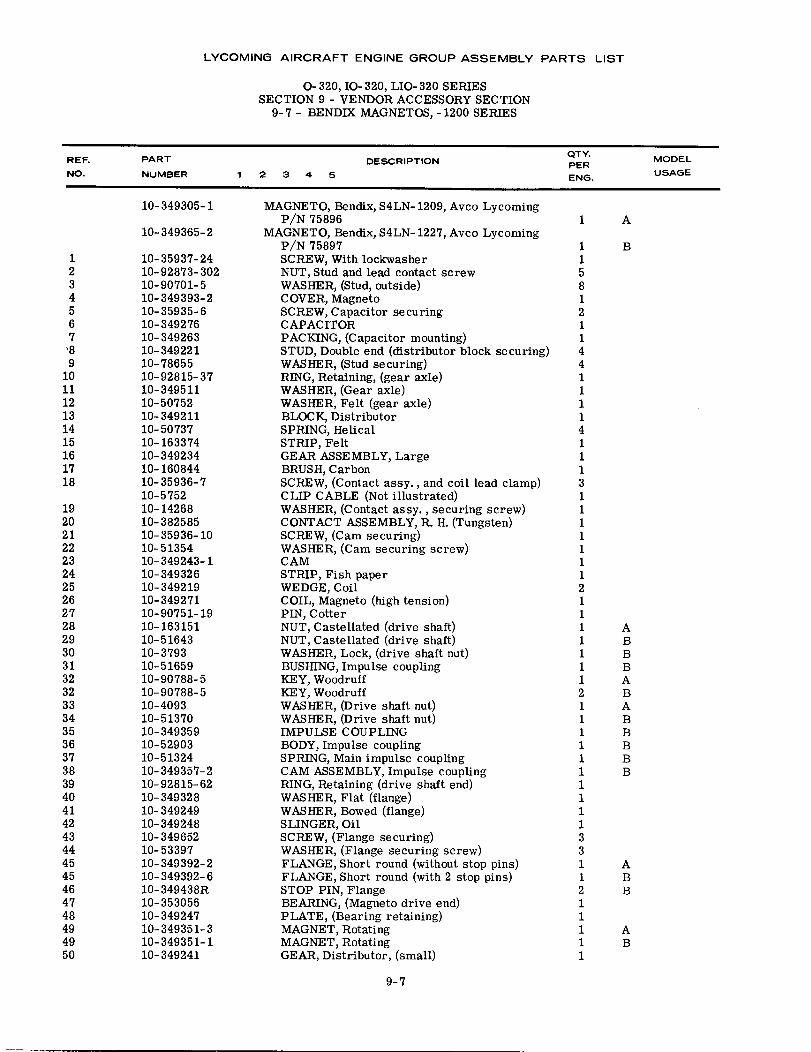
LYCOMING AIRCRAFT ENGINE GROUP ASSEMBLY PARTS LIST
O-320, IO-320, LIO- 320 SERIESSECTION 9 - VENDOR ACCESSORY SECTION
9-7 - BENDIX MAGNETOS, -1200 SERIES
DESCRIPTION1 2 3 4 5
REF.NO.
PART
NUMBER
QTY.PERENG.
MODEL
USAGE
1234567'89
101112131415161718
1920212223242526272829303132323334353637383940414243444545464748494950
10-349305-1
10-349365-2
10-35937-2410-92873-30210-90701-510-349393-210-35935-610-34927610-34926310-34922110-7865510-92815-3710-34951110-5075210-34921110-5073710-16337410-34923410-16084410-35936-710-575210-1426810-38258510-35936-1010-5135410-349243-110-34932610-34921910-34927110-90751-1910-16315110-5164310-379310-5165910-90788-510-90788-510-409310-5137010-34935910-5290310-5132410-349357-210-92815-6210-34932810-34924910-34924810-34965210-5339710-349392-210-349392-610-349438R10-35305610-34924710-349351-310-349351-110-349241
MAGNETO, Bendix, S4LN- 1209, Avco LycomingP/N 75896
MAGNETO, Bendix, S4LN- 1227, Avco LycomingP/N 75897SCREW, With lockwasherNUT, Stud and lead contact screwWASHER, (Stud, outside)COVER, MagnetoSCREW, Capacitor securingCAPACITORPACKING, (Capacitor mounting)STUD, Double end (distributor block securing)WASHER, (Stud securing)RING, Retaining, (gear axle)WASHER, (Gear axle)WASHER, Felt (gear axle)BLOCK, DistributorSPRING, HelicalSTRIP, FeltGEAR ASSEMBLY, LargeBRUSH, CarbonSCREW, (Contact assy., and coil lead clamp)CLIP CABLE (Not illustrated)WASHER, (Contact assy., securing screw)CONTACT ASSEMBLY, R. H. (Tungsten)SCREW, (Cam securing)WASHER, (Cam securing screw)CAMSTRIP, Fish paperWEDGE, CoilCOIL, Magneto (high tension)PIN, CotterNUT, Castellated (drive shaft)NUT, Castellated (drive shaft)WASHER, Lock, (drive shaft nut)BUSHING, Impulse couplingKEY, WoodruffKEY, WoodruffWASHER, (Drive shaft nut)WASHER, (Drive shaft nut)IMPULSE COUPLINGBODY, Impulse couplingSPRING, Main impulse couplingCAM ASSEMBLY, Impulse couplingRING, Retaining (drive shaft end)WASHER, Flat (flange)WASHER, Bowed (flange)SLINGER, OilSCREW, (Flange securing)WASHER, (Flange securing screw)FLANGE, Short round (without stop pins)FLANGE, Short round (with 2 stop pins)STOP PIN, FlangeBEARING, (Magneto drive end)PLATE, (Bearing retaining)MAGNET, RotatingMAGNET, RotatingGEAR, Distributor, (small)
1158121144111141113I11111121111111211111111113311211111
1 A
B
ABBBABABBBBB
ABB
AB
9-7
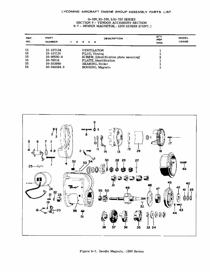
LYCOMING AIRCRAFT ENGINE GROUP ASSEMBLY PARTS LIST
O-320, IO- 320, LIO- 320 SERIESSECTION 9 - VENDOR ACCESSORY SECTION
9-7 - BENDIX MAGNETOS, -1200 SERIES (CONT. )
DESCRIPTION12 3 4 5
REF.
NO.
PART
NUMBER
QTY.PERENG.
MODEL
USAGE
515253545556
10-15713410-15713510-90500-810-7061610-35306010-349394-3
VENTILATORPLUG, TimingSCREW, (Identification plate securing)PLATE, IdentificationBEARING, RollerHOUSING, Magneto
112111
Figure 9-7. Bendix Magneto, -1200 Series
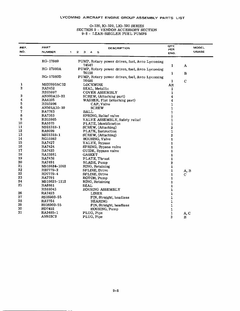
LYCOMING AIRCRAFT ENGINE GROUP ASSEMBLY PARTS LIST
0-320, IO-320, LIO-320 SERIESSECTION 9 - VENDOR ACCESSORY SECTION
9-8 - LEAR-SIEGLER FUEL PUMPS
REF.
NO.
PART
NUMBERDESCRIPTION
QTY.PERENG.
MODEL
USAGE1 2 3 4 5
12
3456789
1011121314151617181920212222232425
262728293031
RG-17980
RG- 17980A
RG- 17980D
MS20995NC32RA7452RB15997AN500A10- 22RA4105RB15996AN501A10- 10RA7763RA7363RB15985RA5575MS21318-1RA9099MS21318-1RG15982RA7427RA7424RA7425RA15981RA7438RA7491MS16624-1062RB7779- 2RD7779-4RA7791MS16625-1112RA6861RB16043RA7493RS16903-55RA7754RS16903-55RD7492RA3485-1AN932C2
PUMP, Rotary power driven, fuel, Avco Lycoming74547
PUMP, Rotary power driven, fuel, Avco Lycoming76188
PUMP, Rotary power driven, fuel, Avco Lycoming76486LOCKWIRESEAL, MetallicCOVER ASSEMBLYSCREW, (Attaching part)WASHER, Flat (attaching part)
CAP, ValveSCREW
BALLSPRING, Relief valveVALVE ASSEMBLY, Safety reliefPLATE, IdentificationSCREW, (Attaching)PLATE, InstructionSCREW, (Attaching)HOUSING, ValveVALVE, BypassSPRING, Bypass valveGUIDE, Bypass valveGASKETPLATE, ThrustBLADE, PumpRING, RetainingSPLINE, DriveSPLINE, DriveROTOR, PumpRING, RetainingSEALHOUSING ASSEMBLY
LINERPIN, Straight, headlessBEARINGPIN, Straight, headlessHOUSING, Pump
PLUG, PipePLUG, Pipe
1AR
1144111111212111111211111111111113
1 A
1 B
C
A, BC
A, CB
9-8
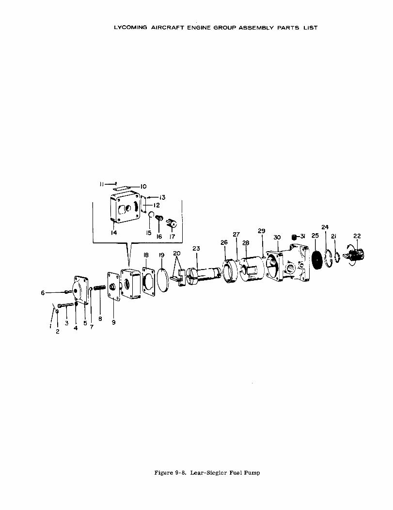
LYCOMING AIRCRAFT ENGINE GROUP ASSEMBLY PARTS LIST
11 1013
2 219 24
Figure 9-8. Lear-Siegler Fuel Pump
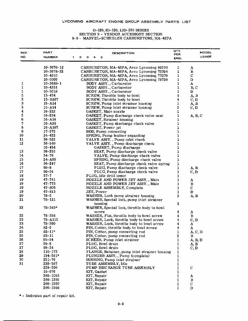
LYCOMING AIRCRAFT ENGINE GROUP ASSEMBLY PARTS LIST
O-320, IO-320, LIO-320 SERIESSECTION 9 - VENDOR ACCESSORY SECTION
9-9 - MARVEL-SCHEBLER CARBURETORS, MA-4SPA
REF. PART DESCRIPTION QTY. MODELPERNO. NUMBER 1 2 3 4 5 ENG. USAGE
10-3678-12 CARBURETOR, MA-4SPA, Avco Lycoming 69250 1 A10-3678-32 CARBURETOR, MA-4SPA, Avco Lycoming 72394 1 B10-4910 CARBURETOR, MA-4SPA, Avco Lycoming 77279 1 C10-5009 CARBURETOR, MA-4SPA, Avco Lycoming 78728 1 D
1 10-3689-1 BODY ASSY., Carburetor 1 A1 10-4331 BODY ASSY., Carburetor 1 B, C1 10-5018 BODY ASSY., Carburetor 1 D2 15-474 SCREW, Throttle body to bowl 4 A, B2 15- B107 SCREW, Throttle body to bowl 4 C, D3 15-A14 SCREW, Pump inlet strainer housing 1 A, B3 15-A14 SCREW, Pump inlet strainer housing 2 C, D4 16-222 GASKET, Main nozzle 15 16-224 GASKET, Pump discharge check valve seat 1 A, B, C6 16-A16 GASKET, Strainer housing 17 16-A28 GASKET, Pump discharge check valve 18 16-A107 GASKET, Power jet 19 17-372 ROD, Pump connecting 1
10 24-432 SPRING, Pump leather expanding 111 36-525 VALVE ASSY., Pump inlet check 112 36-540 VALVE ASSY., Pump discharge check 1
16-434 GASKET, Pump discharge 113 36-253 SEAT, Pump discharge check valve 114 34-78 VALVE, Pump discharge check valve 115 24-A60 SPRING, Pump discharge check valve 116 36-247 SEAT, Pump discharge check valve spring 117 99-8 PLUG, Pump discharge check valve 1 A, B17 99-34 PLUG, Pump discharge check valve 1 C, D18 37-7 PLUG, Idle drill lower 119 47-741 NOZZLE AND POWER JET ASSY., Main 1 A19 47-773 NOZZLE AND POWER JET ASSY., Main 1 B19 47-806 NOZZLE ASSEMBLY, Complete 1 C19 47-813 JET, Power 1 D20 78-5 WASHER, Lock pump strainer housing 2 A, B21 78-121 WASHER, Special lock, pump inlet strainer
housing 222 78- 345* WASHER, Special lock, throttle body to bowl
screw 4 A22 78-358 WASHER, Flat, throttle body to bowl screw 4 B23 78-A110 WASHER, Lock, throttle body to bowl screw 4 C, D23 78-360 WASHER, Lock, throttle body to bowl screw 4 A24 82-9 PIN, Cotter, throttle body to bowl screw 4 A25 82-11* PIN, Cotter, pump connecting rod 1 A, C, D25 82-11 PIN, Cotter, pump connecting rod 2 B26 95-54 SCREEN, Pump inlet strainer 1 A, B, D27 99-8 PLUG, Bowl drain 1 A, B27 99-34 PLUG, Bowl drain 1 C,D28 110-173 FLANGE, Retainer, pump inlet strainer housing 129 194-581* PLUNGER ASSY., Pump (complete) 130 221-76 HOUSING, Pump inlet strainer 131 229- 587 TUBE ASSEMBLY, Idle 1
229-550 PUMP DISCHARGE TUBE ASSEMBLY 1 C16-676 KIT, Gasket 1286-1063 KIT, Repair 1 A286-1285 KIT, Repair 1 B286- 1550 KIT, Repair 1 C286-1568 KIT, Repair 1 D
* - Indicates part of repair kit.
9-9
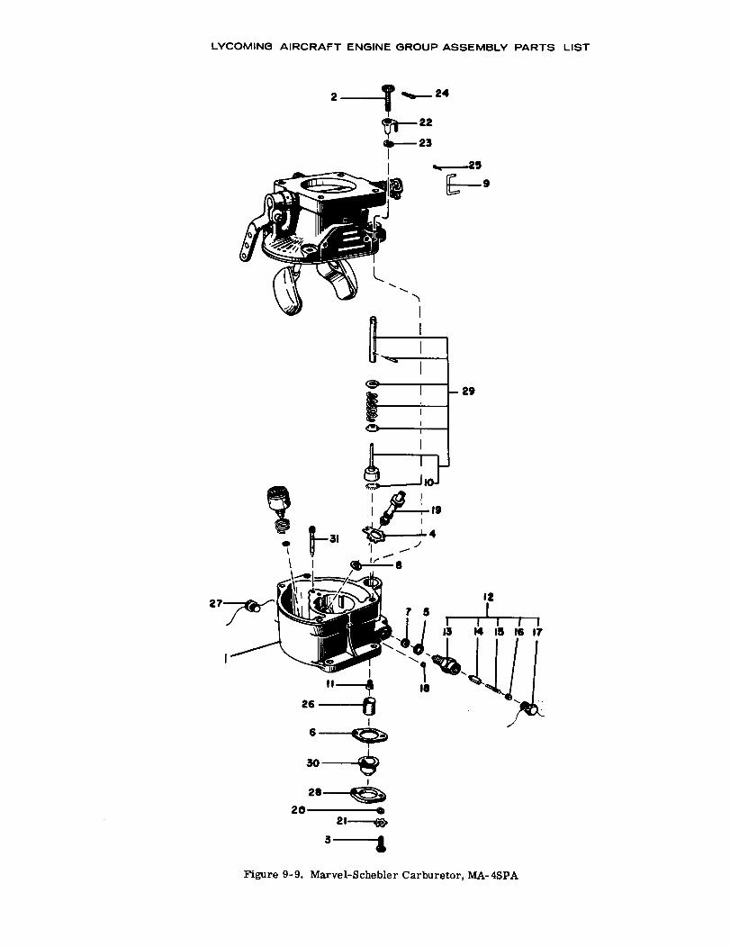
24
22
23 9
19
20
3
Figure 9-9. Marvel-Schebler Carburetor, MA-4SPA
LYCOMING AIRCRAFT ENGINE GROUP ASSEMBLY PARTS LIST
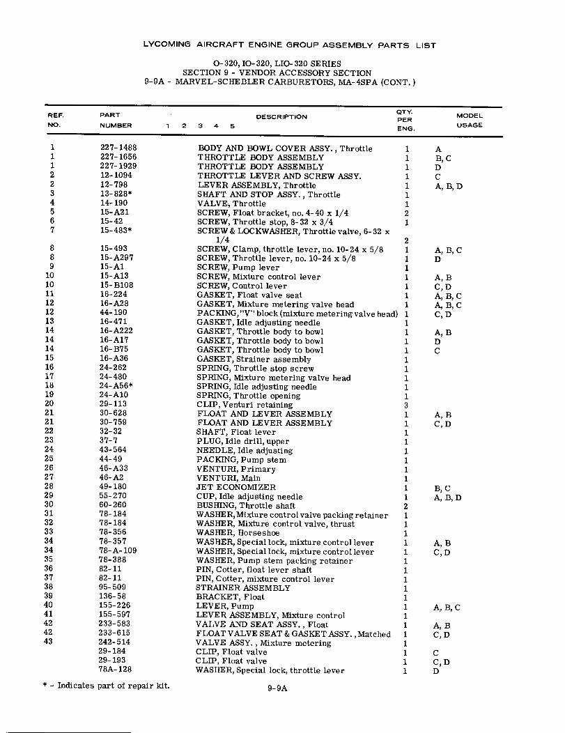
LYCOMING AIRCRAFT ENGINE GROUP ASSEMBLY PARTS LIST
O-320, IO-320, LIO-320 SERIESSECTION 9 - VENDOR ACCESSORY SECTION
9-9A - MARVEL-SCHEBLER CARBURETORS, MA-4SPA (CONT.)
QTY.REF. PART DESCRIPTION MODELPERNO. NUMBER 1 2 3 4 5 ENG. USAGE
1 227-1488 BODY AND BOWL COVER ASSY., Throttle 1 A1 227-1656 THROTTLE BODY ASSEMBLY 1 B, C1 227-1929 THROTTLE BODY ASSEMBLY 1 D2 12-1094 THROTTLE LEVER AND SCREW ASSY. 1 C2 12-798 LEVER ASSEMBLY, Throttle 1 A, B, D3 13-828* SHAFT AND STOP ASSY., Throttle 14 14-190 VALVE, Throttle 15 15-A21 SCREW, Float bracket, no. 4-40 x 1/4 26 15-42 SCREW, Throttle stop, 8-32 x 3/4 17 15-483* SCREW & LOCKWASHER, Throttle valve, 6- 32 x
1/4 28 15-493 SCREW, Clamp, throttle lever, no. 10-24 x 5/8 1 A, B, C8 15-A297 SCREW, Throttle lever, no. 10-24 x 5/8 1 D9 15-A1 SCREW, Pump lever 1
10 15-A13 SCREW, Mixture control lever 1 A, B10 15-B108 SCREW, Control lever 1 C, D11 16-224 GASKET, Float valve seat 1 A, B, C12 16-A28 GASKET, Mixture metering valve head 1 A, B, C12 44-190 PACKING,"V"block(mixturemeteringvalvehead) 1 C, D13 16-471 GASKET, Idle adjusting needle 114 16-A222 GASKET, Throttle body to bowl 1 A, B14 16-A17 GASKET, Throttle body to bowl 1 D14 16-B75 GASKET, Throttle body to bowl 1 C15 16-A36 GASKET, Strainer assembly 116 24-262 SPRING, Throttle stop screw 117 24-480 SPRING, Mixture metering valve head 118 24-A56* SPRING, Idle adjusting needle 119 24-A10 SPRING, Throttle opening 120 29-113 CLIP, Venturi retaining 321 30-628 FLOAT AND LEVER ASSEMBLY 1 A, B21 30-759 FLOAT AND LEVER ASSEMBLY 1 C, D22 32-32 SHAFT, Float lever 123 37-7 PLUG, Idle drill, upper 124 43-564 NEEDLE, Idle adjusting 125 44-49 PACKING, Pump stem 126 46-A33 VENTURI, Primary 127 46-A2 VENTURI, Main 128 49-180 JET ECONOMIZER 1 B, C29 55-270 CUP, Idle adjusting needle 1 A, B, D30 60-260 BUSHING, Throttle shaft 231 78-184 WASHER,Mixture controlvalve packing retainer 132 78-184 WASHER, Mixture control valve, thrust 133 78-356 WASHER, Horseshoe 134 78-357 WASHER, Special lock, mixture control lever 1 A, B34 78-A- 109 WASHER, Speciallock, mixture control lever 1 C,D35 78-388 WASHER, Pump stem packing retainer 136 82-11 PIN, Cotter, float lever shaft 137 82-11 PIN, Cotter, mixture control lever 138 95- 509 STRAINER ASSEMBLY 139 136-58 BRACKET, Float 140 155-226 LEVER, Pump 1 A, B, C41 155-597 LEVER ASSEMBLY, Mixture control 142 233-583 VALVE AND SEAT ASSY., Float 1 A, B42 233-615 FLOATVALVESEAT&GASKETASSY.,Matched 1 C,D43 242-514 VALVE ASSY., Mixture metering 1
29-184 CLIP, Float valve 1 C29-193 CLIP, Float valve 1 C, D78A- 128 WASHER, Special lock, throttle lever 1 D
* - Indicates part of repair kit. 9-9A
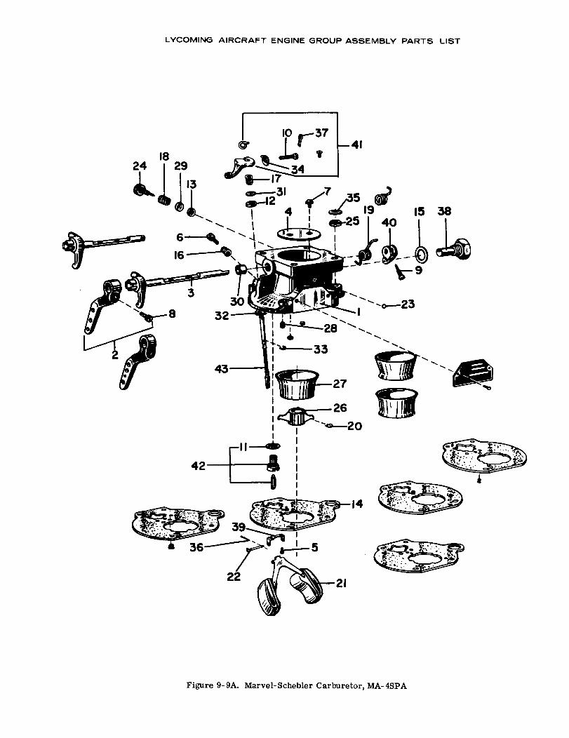
1824 29
16
3
LYCOMING AIRCRAFT ENGINE GROUP ASSEMBLY PARTS LIST
830
32
19 15 38
43
26
14
Figure 9-9A. Marvel-Schebler Carburetor, MA-4SPA
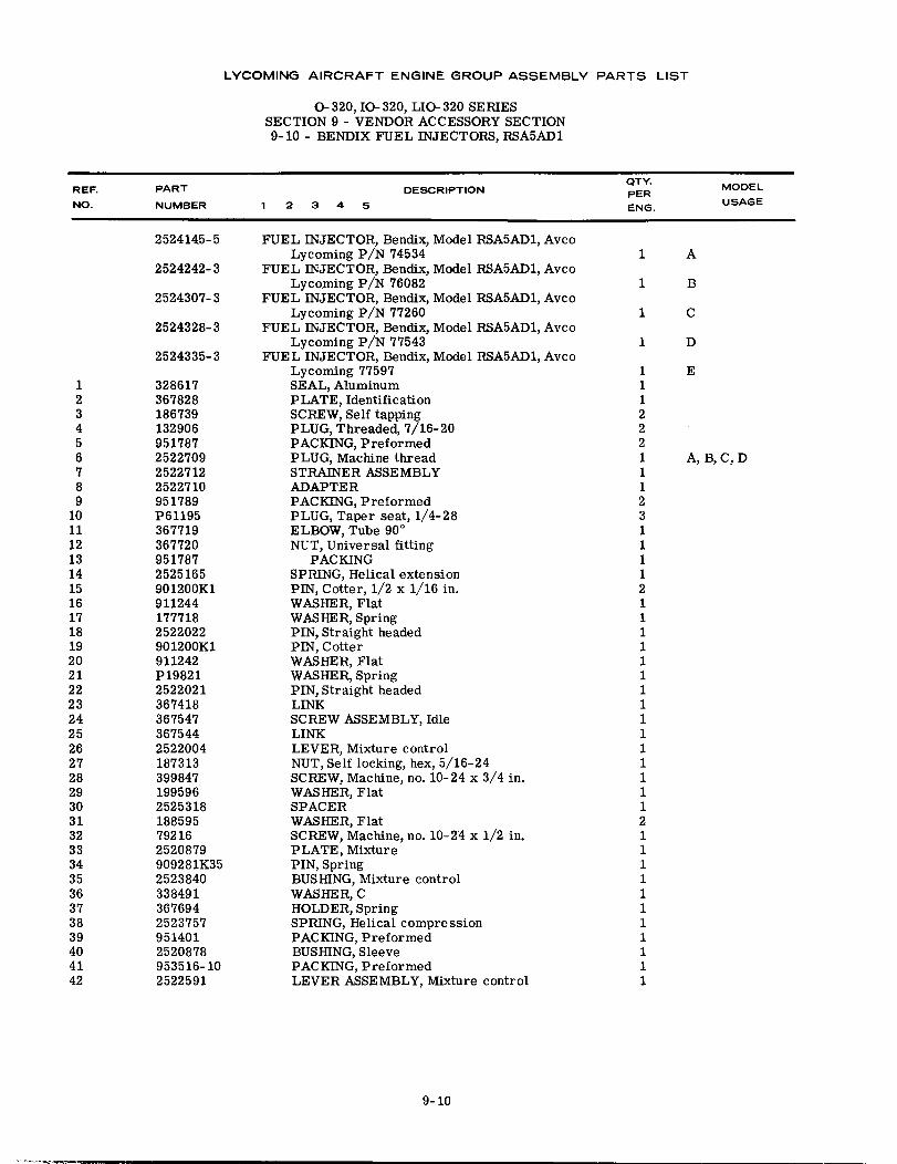
LYCOMING AIRCRAFT ENGINE GROUP ASSEMBLY PARTS LIST
O- 320, IO- 320, LIO- 320 SERIESSECTION 9 - VENDOR ACCESSORY SECTION9-10 - BENDIX FUEL INJECTORS, RSA5AD1
QTY.REF. PART DESCRIPTION QTY. MODEL
NO. NUMBER 1 2 3 4 5 ENG. USAGE
2524145-5 FUEL INJECTOR, Bendix, Model RSA5AD1, AvcoLycoming P/N 74534 1 A
2524242-3 FUEL INJECTOR, Bendix, Model RSA5AD1, AvcoLycoming P/N 76082 1 B
2524307-3 FUEL INJECTOR, Bendix, Model RSA5AD1, AvcoLycoming P/N 77260 1 C
2524328-3 FUEL INJECTOR, Bendix, Model RSA5AD1, AvcoLycoming P/N 77543 1 D
2524335-3 FUEL INJECTOR, Bendix, Model RSA5AD1, AvcoLycoming 77597 1 E
1 328617 SEAL, Aluminum 12 367828 PLATE, Identification 13 186739 SCREW, Self tapping 24 132906 PLUG, Threaded, 7/16-20 25 951787 PACKING, Preformed 26 2522709 PLUG, Machine thread 1 A, B, C, D7 2522712 STRAINER ASSEMBLY 18 2522710 ADAPTER 19 951789 PACKING, Preformed 2
10 P61195 PLUG, Taper seat, 1/4-28 311 367719 ELBOW, Tube 90 ° 112 367720 NUT, Universal fitting 113 951787 PACKING 114 2525165 SPRING, Helical extension 115 901200K1 PIN, Cotter, 1/2 x 1/16 in. 216 911244 WASHER, Flat 117 177718 WASHER, Spring 118 2522022 PIN, Straight headed 119 901200K1 PIN, Cotter 120 911242 WASHER, Flat 121 P19821 WASHER, Spring 122 2522021 PIN, Straight headed 123 367418 LINK 124 367547 SCREW ASSEMBLY, Idle 125 367544 LINK 126 2522004 LEVER, Mixture control 127 187313 NUT, Self locking, hex, 5/16-24 128 399847 SCREW, Machine, no. 10-24 x 3/4 in. 129 199596 WASHER, Flat 130 2525318 SPACER 131 188595 WASHER, Flat 232 79216 SCREW, Machine, no. 10-24 x 1/2 in. 133 2520879 PLATE, Mixture 134 909281K35 PIN, Spring 135 2523840 BUSHING, Mixture control 136 338491 WASHER, C 137 367694 HOLDER, Spring 138 2523757 SPRING, Helical compression 139 951401 PACKING, Preformed 140 2520878 BUSHING, Sleeve 141 953516-10 PACKING, Preformed 142 2522591 LEVER ASSEMBLY, Mixture control 1
9-10
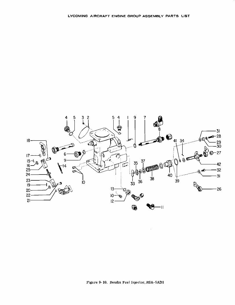
4 5
LYCOMING AIRCRAFT ENGINE GROUP ASSEMBLY PARTS LIST
-31
42
31
39 26
10
11
Figure 9-10. Bendix Fuel Injector, RSA-5AD1
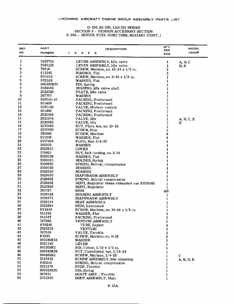
LYCOMING AIRCRAFT ENGINE GROUP ASSEMBLY PARTS LIST
0-320, IO-320, LIO-320 SERIESSECTION 9 - VENDOR ACCESSORY SECTION
9-10A - BENDIX FUEL INJECTORS, RSA5AD1 (CONT.)
REF. PART DESCRIPTION MODELNO. NUMBER 1 2 3 4 5 QTY. USAGENO. NUMBER 1 2 3 4 5 ENG. USAGE
1 2523718 LEVER ASSEMBLY, Idle valve 1 A, B, C1 2525152 LEVER ASSEMBLY, Idle valve 1 D, E2 79216 SCREW, Machine, no. 10-24 x 1/2 in. 23 911242 WASHER, Flat 24 P21818 SCREW, Machine, no. 8-32 x 1/2 in. 15 P22198 WASHER, Flat 16 909329K35 PIN, Spring 17 2526408 BUSHING, Idle valve shaft 18 2522326 PLATE, Idle valve 19 367757 WASHER 1
10 953516-10 PACKING, Preformed 111 951400 PACKING, Preformed 112 2525195 VALVE, Mixture control 113 951400 PACKING, Preformed 114 2525494 PACKING, Preformed 115 2521974 VALVE, Idle 1 A, B, C, E15 2520626 VALVE, Idle 1 D16 2537499 NUT, Plain, hex. no. 10-32 117 2537500 SCREW, Stop 118 362842 SCREW, Machine 619 911242 WASHER, Flat 620 2537498 PLUG, Hex, 3/4-20 121 365533 WASHER 122 2523501 COVER 123 178491 NUT, Self-locking, no. 2-56 124 2529180 WASHER, Flat 125 2529181 HOLDER, Spring 126 2520625 SPRING, Helical, compression 127 2529182 BUSHING 128 2529183 BUSHING 129 2529470 DIAPHRAGM ASSEMBLY 130 2520652 SPRING, Helical compression 131 2520882 BODY, Regulator (when exhausted use 2523506) 131 2523506 BODY, Regulator 132 367727 SHIM AR33 2529188 BUSHING ASSEMBLY 134 2529471 DIAPHRAGM ASSEMBLY 135 2529184 SEAT ASSEMBLY 136 2529294 SHIM, Laminated 137 P21819 SCREW, Machine, no. 10-24 x 1/2 in. 138 911242 WASHER, Flat 139 951437 PACKING, Preformed 340 367969 VENTURI ASSEMBLY 141 P70249 TUBE, Impact 442 2523509 VENTURI 143 367639 VALVE, Throttle 144 P4235 SCREW, Machine, no. 8-32 245 901045K12 WASHER 246 2521196 LEVER 147 901209K1 PIN, Cotter, 1/16 x 1/2 in. 148 900848K36 NUT, Castellated, hex, 5/16-24 149 904269K1 SCREW, Machine, 1/4-28 1 C50 2523432 SCREW ASSEMBLY, Idle adjusting 1 A, B, D, E51 P60219 SPRING, Helical compression 152 2521976 STOP, Throttle 153 909329K35 PIN, Spring 154 367631 SHAFT ASSY., Throttle 155 2521984 BODY ASSEMBLY, Main 1
9-10A
LYCOMING AIRCRAFT ENGINE GROUP ASSEMBLY PARTS LIST
z0
LYCOMING PARTS CATALOG
0-320, IO-320 AND LIO-320 SERIES
SECTION 10
NUMERICAL INDEX
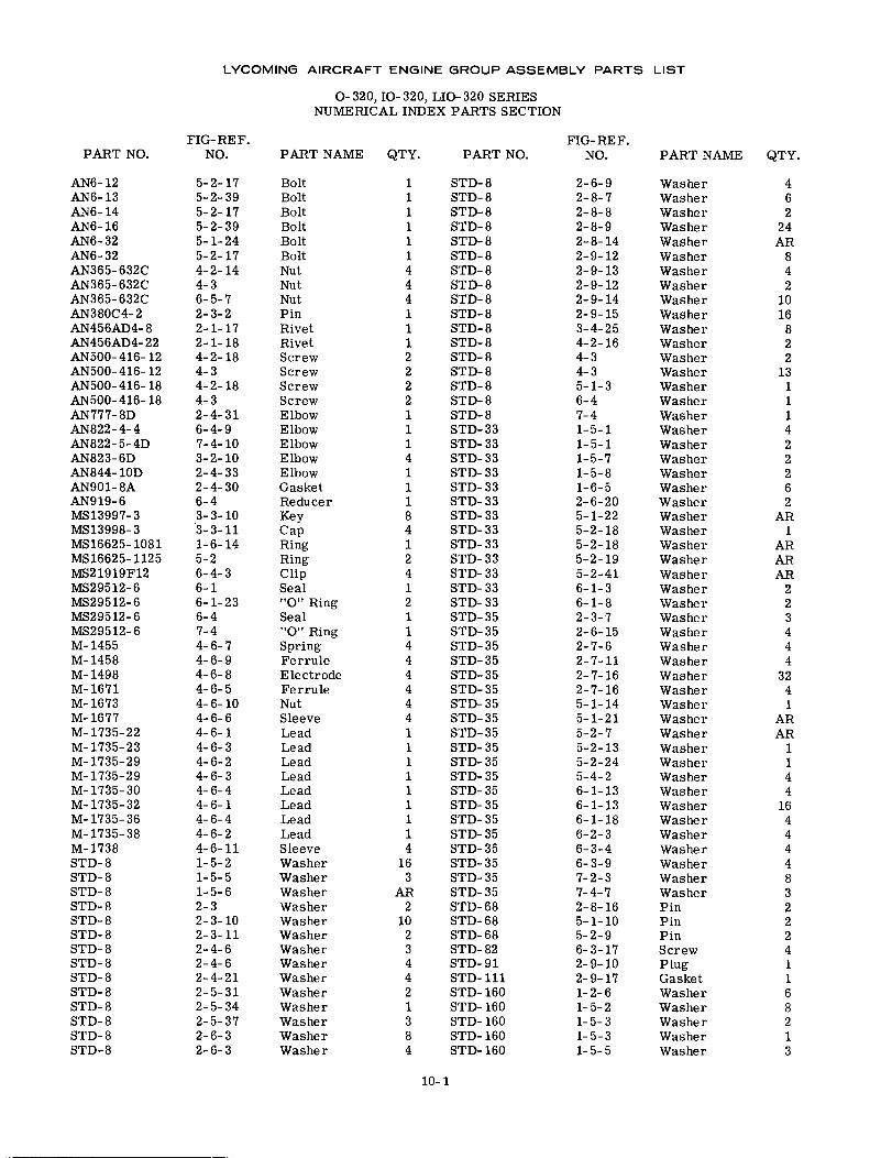
LYCOMING AIRCRAFT ENGINE GROUP ASSEMBLY PARTS LIST
O-320, IO-320, LIO- 320 SERIESNUMERICAL INDEX PARTS SECTION
FIG-REF.NO.
FIG-REF.NO.PART NO. PART NAME QTY. PART NO. PART NAME QTY.
AN6- 12AN6-13AN6- 14AN6-16AN6- 32AN6-32AN365-632CAN365-632CAN365- 632CAN380C4-2AN456AD4-8AN456AD4-22AN500-416- 12AN500-416- 12AN500-416- 18AN500-416- 18AN777- 8DAN822-4-4AN822-5-4DAN823- 6DAN844-10DAN901- 8AAN919-6MS13997-3MS13998-3MS16625-1081MS16625-1125MS21919F12MS29512-6MS29512-6MS29512-6MS29512-6M- 1455M-1458M-1498M-1671M-1673M-1677M- 1735-22M- 1735-23M- 1735-29M-1735-29M-1735-30M- 1735-32M-1735-36M- 1735-38M-1738STD-8STD-8STD-8STD-8STD-8STD-8STD-8STD-8STD-8STD-8STD-8STD-8STD-8STD-8
5-2-175-2-395-2-175-2-395-1-245-2-174-2-144-36-5-72-3-22-1-172-1-184-2-184-34-2-184-32-4-316-4-97-4-103-2-102-4-332-4-306-43-3-103-3-111-6-145-26-4-36-16-1-236-47-44-6-74-6-94-6-84-6-54-6-104-6-64-6-14-6-34-6-24-6-34-6-44-6-14-6-44-6-24-6-111-5-21-5-51-5-62-32-3-102-3-112-4-62-4-62-4-212-5-312-5-342-5-372-6-32-6-3
BoltBoltBoltBoltBoltBoltNutNutNutPinRivetRivetScrewScrewScrewScrewElbowElbowElbowElbowElbowGasketReducerKeyCapRingRingClipSeal"O" RingSeal"O" RingSpringFerruleElectrodeFerruleNutSleeveLeadLeadLeadLeadLeadLeadLeadLeadSleeveWasherWasherWasherWasherWasherWasherWasherWasherWasherWasherWasherWasherWasherWasher
1 STD- 81 STD- 81 STD-81 STD-81 STD-81 STD-84 STD- 84 STD-84 STD- 81 STD- 81 STD-81 STD-82 STD-82 STD-82 STD- 82 STD-81 STD-81 STD-331 STD- 334 STD-331 STD-331 STD-331 STD-338 STD-334 STD-331 STD- 332 STD-334 STD-331 STD- 332 STD-331 STD-351 STD-354 STD-354 STD-354 STD-354 STD-354 STD-354 STD-351 STD-351 STD-351 STD- 351 STD-351 STD-351 STD-351 STD-351 STD-354 STD-35
16 STD-353 STD- 35
AR STD-352 STD-68
10 STD-682 STD-683 STD-824 STD-914 STD-1112 STD- 1601 STD- 1603 STD- 1608 STD-1604 STD- 160
2-6-92-8-72-8-82-8-92-8-142-9-122-9-132-9-122-9-142-9-153-4-254-2-164-34-35-1-36-47-41-5-11-5-11-5-71-5-81-6-52-6-205-1-225-2-185-2-185-2-195-2-416-1-36-1-82-3-72-6-152-7-62-7-112-7-162-7-165-1-145-1-215-2-75-2-135-2-245-4-26-1-136-1-136-1-186-2-36-3-46-3-97-2-37-4-72-8-165-1-105-2-96-3-172-9-102-9-171-2-61-5-21-5-31-5-31-5-5
WasherWasherWasherWasherWasherWasherWasherWasherWasherWasherWasherWasherWasherWasherWasherWasherWasherWasherWasherWasherWasherWasherWasherWasherWasherWasherWasherWasherWasherWasherWasherWasherWasherWasherWasherWasherWasherWasherWasherWasherWasherWasherWasherWasherWasherWasherWasherWasherWasherWasherPinPinPinScrewPlugGasketWasherWasherWasherWasherWasher
462
24AR
842
1016822
13111422262
AR1
ARARAR
223444
3241
ARAR
1144
1644448322241168213
10-1
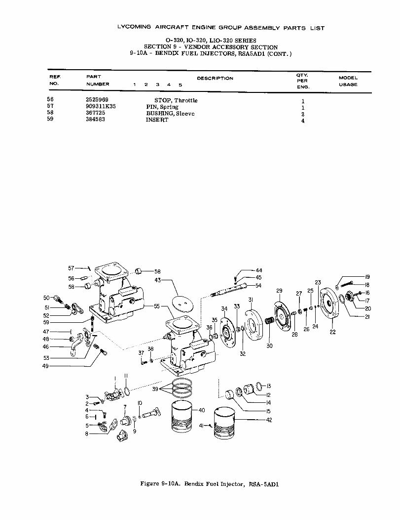
LYCOMING AIRCRAFT ENGINE GROUP ASSEMBLY PARTS LIST
O-320, IO-320, LIO- 320 SERIESSECTION 9 - VENDOR ACCESSORY SECTION
9-10A - BENDIX FUEL INJECTORS, RSA5AD1 (CONT.)
REF. PART QTY.
PART DESCRIPTION QTY. MODELPERNO. NUMBER 1 2 3 4 5 USAGE
56 2525969 STOP, Throttle 157 909311K35 PIN, Spring 158 367725 BUSHING, Sleeve 259 384583 INSERT 4
2316
2 1010
8
Figure 9-10A. Bendix Fuel Injector, RSA-5AD1
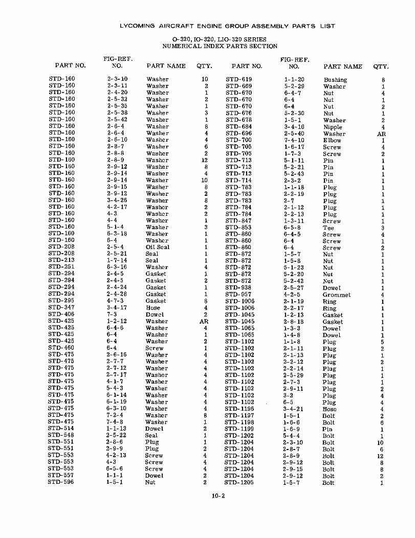
LYCOMING AIRCRAFT ENGINE GROUP ASSEMBLY PARTS LIST
O-320, IO- 320, LIO-320 SERIESNUMERICAL INDEX PARTS SECTION
FIG- RE F. FIG- RE F.PART NO. NO. PART NAME QTY. PART NO. NO. PART NAME QTY.
STD-160 2-3-10 Washer 10 STD-619 1-1-20 Bushing 8STD-160 2-3-11 Washer 2 STD-669 5-2-29 Washer 1STD- 160 2-4-20 Washer 1 STD-670 6-4-7 Nut 4STD-160 2-5-32 Washer 2 STD-670 6-4 Nut 1STD-160 2-5-35 Washer 1 STD-670 6-4 Nut 2STD-160 2-5-38 Washer 3 STD-676 5-2-30 Nut 1STD-160 2-5-42 Washer 1 STD-678 1-5-1 Washer 2STD-160 2-6-4 Washer 8 STD-684 3-4-16 Nipple 4STD- 160 2-6-4 Washer 4 STD-696 2-5-40 Washer ARSTD-160 2-6-10 Washer 4 STD-700 7-4-10 Elbow 1STD-160 2-8-7 Washer 6 STD-705 1-6-17 Screw 4STD-160 2-8-8 Washer 2 STD-705 1-7-3 Screw 2STD-160 2-8-9 Washer 12 STD-713 5-1-11 Pin 1STD-160 2-9-12 Washer 8 STD-713 5-2-21 Pin 1STD-160 2-9-14 Washer 4 STD-713 5-2-43 Pin 1STD-160 2-9-14 Washer 10 STD-714 2-3-2 Pin 1STD-160 2-9-15 Washer 8 STD-783 1-1-18 Plug 1STD-160 2-9-12 Washer 2 STD-783 2-2-19 Plug 1STD- 160 3-4-26 Washer 8 STD- 783 2-7 Plug 1STD- 160 4-2-17 Washer 2 STD- 784 2-1-12 Plug 1STD-160 4-3 Washer 2 STD-784 2-2-13 Plug 1STD-160 4-4 Washer 1 STD-847 1-3-11 Screw 1STD-160 5-1-4 Washer 3 STD-853 6-5-8 Tee 3STD-160 6-3-18 Washer 1 STD-860 6-4-5 Screw 4STD-160 6-4 Washer 1 STD-860 6-4 Screw 1STD-208 2-5-4 Oil Seal 1 STD-860 6-4 Screw 2STD-208 2-5-21 Seal 1 STD-872 1-5-7 Nut 1STD-213 1-7-14 Seal 1 STD-872 1-5-8 Nut 1STD-251 6-3-16 Washer 4 STD-872 5-1-23 Nut 1STD-294 2-4-5 Gasket 1 STD-872 5-2-20 Nut 1STD-294 2-4-5 Gasket 2 STD-872 5-2-42 Nut 1STD-294 2-4-24 Gasket 1 STD-938 2-5-27 Dowel 1STD-294 2-4-28 Gasket 1 STD-957 4-2-5 Grommet 4STD-295 4- 7-3 Gasket 8 STD- 1006 2-1-19 Ring 1STD-347 3-4-17 Hose 4 STD-1006 2-2-17 Ring 1STD-406 7-3 Dowel 2 STD-1045 1-2-13 Gasket 1STD-425 1-2-12 Washer AR STD- 1045 2-8-18 Gasket 1STD-425 6-4-6 Washer 4 STD-1065 1-3-3 Dowel 1STD-425 6-4 Washer 1 STD-1065 1-4-8 Dowel 1STD-425 6-4 Washer 2 STD-1102 1-1-8 Plug 5STD-460 6-4 Screw 1 STD-1102 2-1-11 Plug 2STD-475 2-6-16 Washer 4 STD-1102 2-1-13 Plug 1STD-475 2-7-7 Washer 4 STD-1102 2-2-12 Plug 2STD-475 2-7-12 Washer 4 STD-1102 2-2-14 Plug 1STD-475 2-7-17 Washer 4 STD-1102 2-5-29 Plug 1STD-475 4-1-7 Washer 4 STD-1102 2-7-3 Plug 1STD-475 5-4-3 Washer 4 STD- 1102 2-9-11 Plug 2STD-475 6-1-14 Washer 4 STD-1102 3-2 Plug 4STD-475 6-1-19 Washer 4 STD-1102 6-5 Plug 4STD-475 6-3-10 Washer 4 STD-1196 3-4-21 Hose 4STD-475 7-2-4 Washer 8 STD-1197 1-5-1 Bolt 2STD-475 7-4-8 Washer 1 STD- 1198 1-6-6 Bolt 6STD-514 1-1-13 Dowel 2 STD-1199 1-6-9 Pin 1STD-548 2-5-22 Seal 1 STD-1202 5-4-4 Bolt 1STD-551 2-8-6 Plug 1 STD-1204 2-3-10 Bolt 10STD-551 2-9-9 Plug 2 STD-1204 2-8-7 Bolt 6STD-553 4-2-13 Screw 4 STD-1204 2-8-9 Bolt 12STD-553 4-3 Screw 4 STD-1204 2-9-12 Bolt 8STD-553 6-5-6 Screw 4 STD-1204 2-9-15 Bolt 8STD-557 1-1-1 Dowel 2 STD-1204 2-9-12 Bolt 2STD-596 1-5-1 Nut 2 STD-1205 1-5-7 Bolt 1
10-2
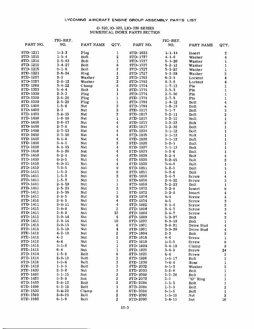
LYCOMING AIRCRAFT ENGINE GROUP ASSEMBLY PARTS LIST
O- 320, IO- 320, LIO-320 SERIESNUMERICAL INDEX PARTS SECTION
FIG-REF. FIG- RE F.PART NO. NO. PART NAME QTY. PART NO. NO. PART NAME QTY.
STD-1211 1-3-2 Plug 1 STD-1623 1-1-14 Insert 2STD-1215 1-5-4 Bolt 2 STD-1727 4-1-6 Washer 4STD-1215 2-5-43 Bolt 1 STD-1727 5-1-20 Washer 1STD-1215 3-4-27 Bolt 8 STD-1727 5-2-12 Washer 1STD-1215 5-1-6 Bolt 2 STD-1727 5-2-25 Washer 1STD-1221 2-6-24 Ring 1 STD-1727 5-2-28 Washer 2STD-1227 2-3 Washer 2 STD-1763 6-2-5 Locknut 4STD-1227 2-8-12 Washer 2 STD-1763 6-3-6 Locknut 4STD-1269 3-4-22 Clamp 8 STD-1774 1-7-13 Pin 1STD-1323 5-4-4 Bolt 1 STD- 1774 2-5-3 Pin 1STD-1339 2-3-3 Plug 1 STD-1774 2-5-30 Pin 1STD-1339 2-5-28 Plug 1 STD-1774 2-7-5 Pin 1STD-1339 2-5-29 Plug 1 STD-1791 1-4-12 Bolt 4STD-1409 1-5-6 Nut 3 STD-1791 1-6-13 Bolt 4STD-1409 2-3 Nut 2 STD-1817 5-1-7 Bolt 3STD-1409 2-8-15 Nut 2 STD-1817 5-2-11 Bolt 2STD-1410 1-6-18 Nut 1 STD-1817 5-2-15 Bolt 1STD-1410 2-6-17 Nut 4 STD-1817 5-2-23 Bolt 2STD-1410 2-7-8 Nut 4 STD-1817 5-2-38 Bolt 1STD-1410 2-7-13 Nut 4 STD-1834 5-1-12 Bolt 1STD- 1410 2-7-18 Nut 4 STD- 1835 5-1-13 Bolt 1STD-1410 4-1-8 Nut 4 STD-1836 5-1-12 Bolt 1STD-1410 5-4-5 Nut 3 STD-1836 5-2-5 Bolt 1STD- 1410 6-1-15 Nut 4 STD- 1837 5-1-13 Bolt 1STD-1410 6-1-20 Nut 4 STD-1837 5-2-6 Bolt 1STD- 1410 6-2-4 Nut 4 STD- 1838 5-2-4 Bolt 4STD-1410 6-3-5 Nut 4 STD-1838 5-2-45 Bolt 2STD-1410 6-3-11 Nut 4 STD-1838 7-4-9 Bolt 1STD-1410 7-2-5 Nut 8 STD-1851 5-2-5 Bolt 1STD-1411 1-5-2 Nut 8 STD-1851 5-2-6 Bolt 1STD-1411 1-5-3 Nut 2 STD-1856 2-4-7 Screw 4STD-1411 1-5-3 Nut 1 STD-1856 2-4-22 Screw 3STD-1411 2-4-19 Nut 1 STD-1858 5-2-23 Bolt 1STD-1411 2-5-33 Nut 2 STD-1872 3-2-8 Insert 8STD-1411 2-5-36 Nut 1 STD-1872 3-2-8 Insert 4STD-1411 2-6-5 Nut 8 STD-1874 4-4 Screw 4STD-1411 2-6-5 Nut 4 STD-1874 4-5 Screw 3STD-1411 2-6-11 Nut 4 STD-1882 6-1-4 Screw 2STD-1411 2-8-8 Nut 2 STD-1884 2-4-7 Screw 3STD-1411 2-8-9 Nut 12 STD-1884 2-4-7 Screw 4STD-1411 2-9-14 Nut 4 STD-1889 5-2-27 Bolt 2STD-1411 2-9-14 Nut 10 STD-1897 6-3-19 Bolt 1STD- 1411 2-9-15 Nut 8 STD- 1901 2-8-21 Drive Stud 4STD-1411 3-3-18 Nut 4 STD-1901 2-9-20 Drive Stud 4STD-1411 4-2-19 Nut 2 STD- 1904 2-3 Bolt 2STD-1411 4-3 Nut 2 STD-1916 4-4 Screw 1STD- 1411 4-4 Nut 1 STD- 1919 1-2-5 Screw 6STD-1411 5-1-8 Nut 1 STD-1924 3-4-18 Clamp 8STD-1411 6-4 Nut 1 STD-1925 3-4-9 Screw 24STD-1414 1-5-2 Bolt 8 STD-1925 4-4 Screw 3STD-1414 2-3-11 Bolt 2 STD-1926 1-6-17 Bolt 3STD-1416 1-5-6 Bolt 3 STD-1930 7-4-4 Hose 1STD- 1419 1- 5-5 Bolt 3 STD-2032 6-1-3 Washer 2STD-1420 2-3-8 Nut 3 STD-2033 5-2-6 Bolt 1STD-1420 5-1-15 Nut 2 STD-2069 5-2-38 Bolt 1STD-1420 5-2-8 Nut 2 STD-2072 2-5 "O" Ring 1STD-1433 2-8-13 Bolt 2 STD-2084 1-5-3 Bolt 1STD- 1499 6-3-19 Bolt 1 STD-2084 1-5-3 Bolt 2STD-1530 3-4-22 Clamp 8 STD-2084 5-1-5 Bolt 1STD- 1592 2-6-21 Bolt 2 STD-2090 1-5-10 Nut 2STD-1592 6-1-9 Bolt 2 STD-2090 3-4-15 Nut 16
10-3
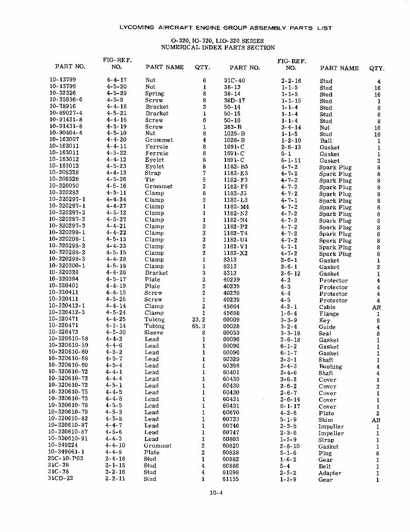
LYCOMING AIRCRAFT ENGINE GROUP ASSEMBLY PARTS LIST
O-320, IO- 320, LIO- 320 SERIESNUMERICAL INDEX PARTS SECTION
FIG-REF.NO.PART NO.
FIG- RE F.NO.PART NAME QTY. PART NO. PART NAME QTY.
10-1379910-1379910-3232610-35936-610-7891610-89027-410-91431-810-91431-810-90404-410-16300710-16301110-16301110-16301210-16301210-20932810-20932810-32005010-32028310-320297-110-320297-110-320297-210-320297-210-320297-310-320298-110-320298-110-320298-210-320298-210-320298-310-320300-110-32032810-32039410-32040110-32041110-32041110-320412-110-320412-310-32047110-32047110-32047310-320610-5810-320610-5910-320610-6010-320610-6810-320610-6910-320610-7210-320610-7210-320610-7210-320610-7510-320610-7510-320610-7810-320610-7910-320610-8210-320610-8710-320610-8710-320610-9110-34922410-349661-125C-10-P0331C-3831C-3831CD-22
4-4-174-5-204-5-294-5-94-4-184-5-214-4-164-5-194-5-104-4-204-4-114-5-224-4-124-5-234-4-134-5-264-5-164-5-114-4-244-4-274-5-124-5-274-4-214-4-224-5-134-4-234-5-154-4-284-5-184-4-264-5-174-4-194-4-154-5-254-4-144-5-244-4-254-5-144-5-304-4-24-4-64-5-24-5-74-5-44-4-14-4-44-5-14-4-54-4-84-5-54-5-34-5-84-4-74-5-64-4-34-4-104-4-92-4-182-1-152-2-162-2-11
NutNutSpringScrewBracketBracketScrewScrewNutGrommetFerruleFerruleEyeletEyeletStrapTieGrommetClampClampClampClampClampClampClampClampClampClampClampClampBracketPlatePlateScrewScrewClampClampTubingTubingSleeveLeadLeadLeadLeadLeadLeadLeadLeadLeadLeadLeadLeadLeadLeadLeadLeadGrommetPlateStudStudStudStud
618831618488887528311133322113222121
23. 265. 3
81111111111111111221441
31C-4038-1338-1438D-1750-1450-1550-16383-B1025-B1028-B1691-C1691-C1691-C1182-B31182-E31182- F31182- F51182-J51182- L31182-M41182-N31182-N41182-P21182-T41182-U41182-V11182-X283138313831340239402394023940239456644568860009600286005360096600966009660329603986040160430604306043060431604316067060733607466074760803608206082860882608866109861155
2-2-161-1-51-1-511--151-1-41-1-41-1-43-4-141-1-51-2-102-6-136-16-1-114-7-24-7-24-7-24-7-24-7-24-7-14-7-24-7-24-7-24-7-24-7-24-7-24-7-14-7-22-6-12-6-12-6-124-24-34-44-54-2-11-6-43-3-93-2-43-3-192-6-186-1-26-1-72-3-13-4-33-4-62-6-22-6-22-6-72-6-146-1-174-2-65-1-92-3-52-3-61-5-92-8-103-1-61-6-25-42-5-21-3-9
StudStudStudStudStudStudStudNutStudBallGasketGasketGasketSpark PlugSpark PlugSpark PlugSpark PlugSpark PlugSpark PlugSpark PlugSpark PlugSpark PlugSpark PlugSpark PlugSpark PlugSpark PlugSpark PlugGasketGasketGasketProtectorProtectorProtectorProtectorCableFlangeKeyGuideSealGasketGasketGasketShaftBushingShaftCoverCoverCoverCoverCoverPlateShimImpellerImpellerStrapGasketPlugGearBeltAdapterGear
41616
1888
1616
1112888888888888881214444
AR1848111144121112
AR111181111
10-4
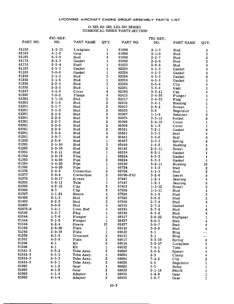
LYCOMING AIRCRAFT ENGINE GROUP ASSEMBLY PARTS LIST
0-320, IO-320, LIO-320 SERIESNUMERICAL INDEX PARTS SECTION
FIG-REF: FIG-RE F.PART NO. NO. PART NAME QTY. PART NO. NO. PART NAME QTY.
61156 1-3-10 Lockplate 1 61668 2-1-7 Stud 261163 4-1-2 Gear 1 61668 2-1-8 Stud 261165 2-3-9 Seal 1 61668 2-2-7 Stud 261173 2-4-3 Gasket 1 61668 2-2-8 Stud 261174 2-3-4 Shaft 1 61850 2-9-8 Stud 461183 2-5-1 Gasket 1 62224 4-1-3 Gasket 361183 2-6-6 Gasket 1 62224 4-1-3 Gasket 461238 2-1-4 Stud 3 62224 4-1-3 Gasket 261238 2-1-5 Stud 1 62224 4-1-3 Gasket 161238 2-2-4 Stud 3 62254 6-5-4 Clip 461238 2-2-5 Stud 1 62281 7-3-4 Gage 161247 3-4-8 Cover 4 62388 3-3-11 Cap 461260 7-2-2 Flange 4 62415 2-4-26 Plunger 161261 1-1-10 Stud 2 62417 2-4-23 Plug 161261 2-1-6 Stud 2 62815 2-4-1 Housing 161261 2-1-7 Stud 2 62817 2-4-4 Screen 161261 2-1-8 Stud 2 62833 5-5 Regulator 161261 2-1-9 Stud 2 65007 1-1-9 Retainer 861261 2-2-6 Stud 2 65074 3-3-13 Socket 861261 2-2-7 Stud 2 65098 2-6-19 Cover 161261 2-2-8 Stud 2 65098 6-1-6 Cover 161261 2-2-9 Stud 2 65321 7-2-1 Gasket 461261 2-9-8 Stud 4 65441 3-3-5 Seat 461261 3-2-7 Stud 8 65441 3-3-6 Seat 461262 2-5-9 Stud 1 65567 3-3-3 Spring 861265 2-1-10 Stud 3 65819 1-4-2 Bushing 461265 2-2-10 Stud 2 66145 2-5-11 Dowel 261265 2-2-11 Stud 1 66224 6-2-1 Gasket 161358 2-8-19 Plug 1 66224 6-3-2 Gasket 161363 3-4-20 Pipe 2 66224 6-3-3 Gasket 161364 3-4-20 Pipe 1 66610 3-2-11 Bushing 1661365 3-4-20 Pipe 1 66734 1-1-2 Stud 261376 2-8-3 Connection 2 66734 1-1-3 Stud 261377 2-8-4 Connection 2 66796-P10 3-2-6 Insert 861378 2-8-17 Screen 1 67447 1-2-1 Bearing 461381 2-8-11 Tube 1 67447 1-2-1 Bearing 861385 4-2-15 Clip 2 67453 1-1-12 Dowel 661385 4-3 Clip 2 67528 1-1-11 Stud 161387 1-1-21 Sleeve 1 67528 2-1-6 Stud 261400 2-1-2 Stud 2 67528 2-2-6 Stud 261400 2-2-2 Stud 2 67556 2-7-4 Stud 461400 2-9-6 Stud 4 68315 2-7-2 Gasket 161476-S 1-4-1 Conn. Rod 4 68316 2-7-4 Stud 461510 1-3-7 Plug 1 68316 6-3-8 Stud 461544 1-7-6 Plunger 1 68317 2-6-22 Shaftgear 161544 6-1-5 Plunger 1 68437 2-8-5 Stud 461546 4-2-4 Sleeve 12 68437 2-9-7 Stud 461548 2-8-20 Plate 1 68510 3-2-9 Stud 461548 2-9-19 Plate 1 68512 3-1 Ring61559 4-2-9 Grommet 2 68513 3-1 Ring61561 4-2-8 Plate 2 68517 3-3-16 Spring 861566 4-1 Kit 2 68518 3-3-17 Lockplate 461566 4-1 Kit 1 68532 7-4-1 Tube 161581-2 6-5-2 Tube Assy. 2 68593 2-6-8 Spacer 461581-3 6-5-3 Tube Assy. 1 68604 4-3 Clamp 461581-3 6-5-3 Tube Assy. 2 68604 7-4-2 Clip 261581-9 6-5-1 Tube Assy. 2 68626 5-5 Regulator 161665 4-1-2 Gear 1 68628 5-5 Relay 161665 4-1-2 Gear 2 68633 2-1-16 Shield 161666 4-1-4 Adapter 1 68639 1-4-9 Gear 161666 4-1-4 Adapter 2 68639 1-6-7 Gear 1
10-5
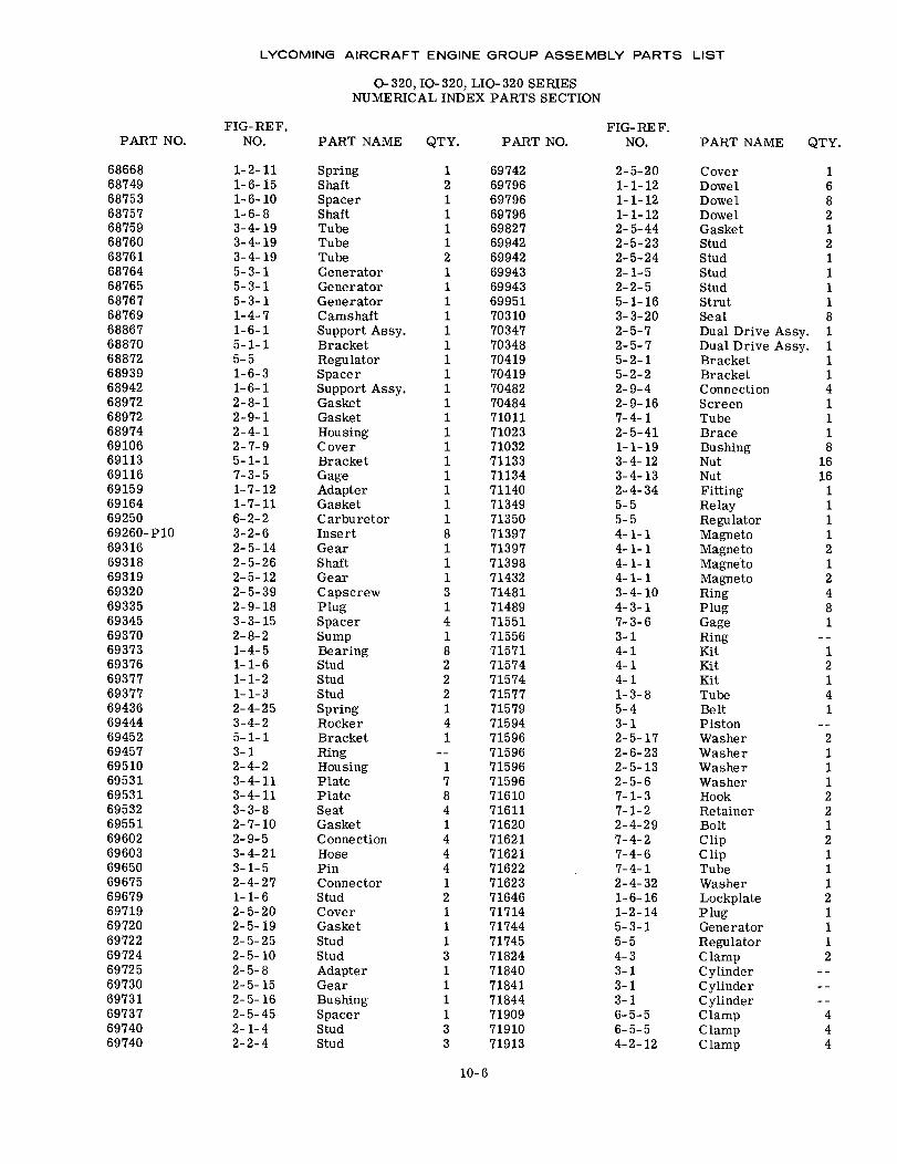
LYCOMING AIRCRAFT ENGINE GROUP ASSEMBLY PARTS LIST
0-320, IO-320, LIO-320 SERIESNUMERICAL INDEX PARTS SECTION
FIG- REF.NO.
FIG-REF.NO.PART NO. PART NAME QTY. PART NO. PART NAME QTY.
6866868749687536875768759687606876168764687656876768769688676887068872689396894268972689726897469106691136911669159691646925069260-P106931669318693196932069335693456937069373693766937769377694366944469452694576951069531695316953269551696026960369650696756967969719697206972269724697256973069731697376974069740
1-2-111-6-151-6-101-6-83-4-193-4-193-4-195-3-15-3-15-3-11-4-71-6-15-1-15-51-6-31-6-12-8-12-9-12-4-12-7-95-1-17-3-51-7-121-7-116-2-23-2-62-5-142-5-262-5-122-5-392-9-183-3-152-8-21-4-51-1-61-1-21-1-32-4-253-4-25-1-13-12-4-23-4-113-4-113-3-82-7-102-9-53-4-213-1-52-4-271-1-62-5-202-5-192-5-252-5-102-5-82-5-152-5-162-5-452-1-42-2-4
SpringShaftSpacerShaftTubeTubeTubeGeneratorGeneratorGeneratorC amshaftSupport Assy.BracketRegulatorSpacerSupport Assy.GasketGasketHousingCoverBracketGageAdapterGasketCarburetorInsertGearShaftGearCapscrewPlugSpacerSumpBearingStudStudStudSpringRockerBracketRingHousingPlatePlateSeatGasketConnectionHosePinConnectorStudCoverGasketStudStudAdapterGearBushingSpacerStudStud
1 697422 697961 697961 697961 698271 699422 699421 699431 699431 699511 703101 703471 703481 704191 704191 704821 704841 710111 710231 710321 711331 711341 711401 713491 713508 713971 713971 713981 714323 714811 714894 715511 715568 715712 715742 715742 715771 715794 715941 71596
715961 715967 715968 716104 716111 716204 716214 716214 716221 716232 716461 717141 717441 717453 718241 718401 718411 718441 719093 719103 71913
2-5-201-1-121-1-121-1-122-5-442-5-232-5-242-1-52-2-55-1-163-3-202-5-72-5-75-2-15-2-22-9-42-9-167-4-12-5-411-1-193-4-123-4-132-4-345-55-54-1-14-1-14-1-14-1-13-4-104-3-17-3-63-14-14-14-11-3-85-43-12-5-172-6-232-5-132-5-67-1-37-1-22-4-297-4-27-4-67-4-12-4-321-6-161-2-145-3-15-54-33-13-13-16-5-56-5-54-2-12
CoverDowelDowelDowelGasketStudStudStudStudStrutSealDual Drive Assy.Dual Drive Assy.BracketBracketConnectionScreenTubeBraceBushingNutNutFittingRelayRegulatorMagnetoMagnetoMagnetoMagnetoRingPlugGageRingKitKitKitTubeBeltPistonWasherWasherWasherWasherHookRetainerBoltClipC lipTubeWasherLockplatePlugGeneratorRegulatorClampCylinderCylinderCylinderClampClampClamp
16821211118111141118
1616
1111212481
12141
2111221211121112
444
10-6
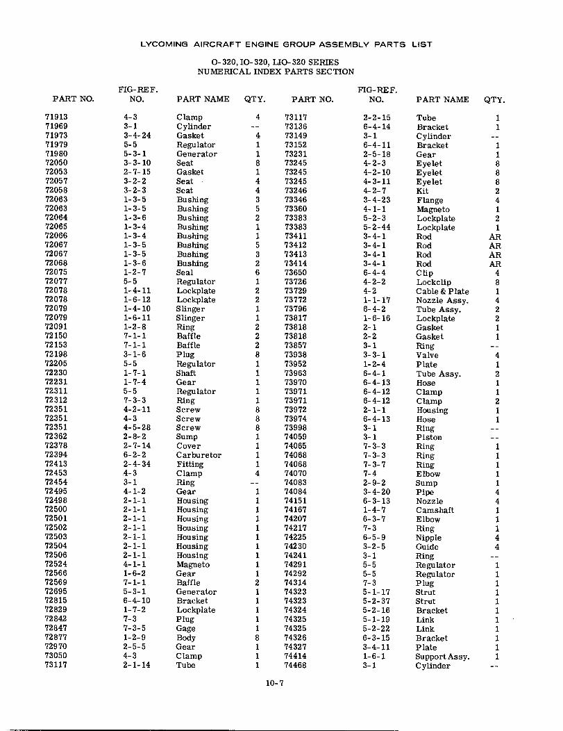
LYCOMING AIRCRAFT ENGINE GROUP ASSEMBLY PARTS LIST
0-320, IO-320, LIO-320 SERIESNUMERICAL INDEX PARTS SECTION
FIG-REF.NO.PART NO.
FIG- REF.NO.PART NAME QTY. PART NO. PART NAME QTY.
71913719697197371979719807205072053720577205872063720637206472065720667206772067720687207572077720787207872079720797209172150721537219872205722307223172311723127235172351723517236272378723947241372453724547249572498725007250172502725037250472506725247256672569726957281572829728427284772877729707305073117
4-33-13-4-245-55-3-13-3-102-7-153-2-23-2-31-3-51-3-51-3-61-3-41-3-41-3-51-3-51-3-61-2-75-51-4-111-6-121-4-101-6-111-2-87-1-17-1-13-1-65-51-7-11-7-45-57-3-34-2-114-34-5-282-8-22-7-146-2-22-4-344-33-14-1-22-1-12-1-12-1-12-1-12-1-12-1-12-1-14-1-11-6-27-1-15-3-16-4-101-7-27-37-3-51-2-92-5-54-32-1-14
ClampCylinderGasketRegulatorGeneratorSeatGasketSeatSeatBushingBushingBushingBushingBushingBushingBushingBushingSealRegulatorLockplateLockplateSlingerSlingerRingBaffleBafflePlugRegulatorShaftGearRegulatorRingScrewScrewScrewSumpCoverCarburetorFittingClampRingGearHousingHousingHousingHousingHousingHousingHousingMagnetoGearBaffleGeneratorBracketLockplatePlugGageBodyGearClampTube
4 7311773136
4 731491 731521 732318 732451 732454 732454 732463 733465 733602 733831 733831 734115 734123 734132 734146 736501 737262 737292 737721 737961 738172 738182 738182 738578 739381 739521 739631 739701 739711 739718 739728 739748 739981 740591 740651 740681 740684 74070
740831 740841 741511 741671 742071 742171 742251 742301 742411 742911 742922 743141 743231 743231 743241 743251 743258 743261 743271 744141 74468
2-2-156-4-143-16-4-112-5-184-2-34-2-104-3-114-2-73-4-234-1-15-2-35-2-443-4-13-4-13-4-13-4-16-4-44-2-24-21-1-176-4-21-6-162-12-23-13-3-11-2-46-4-16-4-136-4-126-4-122-1-16-4-133-13-17-3-37-3-37-3-77-42-9-23-4-206-3-131-4-76-3-77-36-5-93-2-53-15-55-57-35-1-175-2-375-2-165-1-195-2-226-3-153-4-111-6-13-1
TubeBracketCylinderBracketGearEyeletEyeletEyeletKitFlangeMagnetoLockplateLockplateRodRodRodRodClipLockclipCable & PlateNozzle Assy.Tube Assy.LockplateGasketGasketRingValvePlateTube Assy.HoseClampClampHousingHoseRingPistonRingRingRingElbowSumpPipeNozzleCamshaftElbowRingNippleGuideRingRegulatorRegulatorPlugStrutStrutBracketLinkLinkBracketPlateSupport Assy.Cylinder
11
1188824121
ARARARAR
48142211
41211211
111114411144
11111111111
10-7
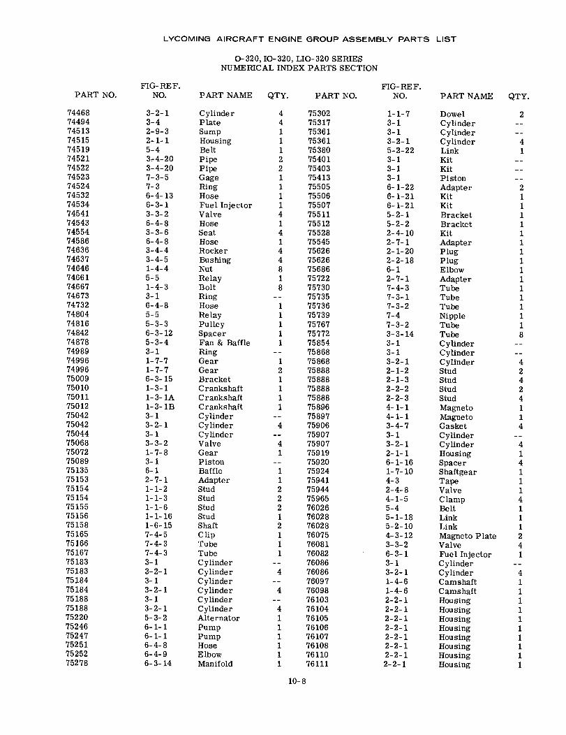
LYCOMING AIRCRAFT ENGINE GROUP ASSEMBLY PARTS LIST
O-320, IO-320, LIO-320 SERIESNUMERICAL INDEX PARTS SECTION
FIG-REF.NO.
FIG- RE F.NO.PART NO. PART NAME QTY. PART NO. PART NAME QTY.
74468744947451374515745197452174522745237452474532745347454174543745547458674636746377464674661746677467374732748047481674842748787498974996749967500975010750117501275042750427504475068750727508975135751537515475154751557515675158751657516675167751837518375184751847518875188752207524675247752517525275278
3-2-13-42-9-32-1-15-43-4-203-4-207-3-57-36-4-136-3-13-3-26-4-83-3-66-4-83-4-43-4-51-4-45-51-4-33-16-4-85-55-3-36-3-125-3-43-11-7-71-7-76-3-151-3-11-3-1A1-3-1B3-13-2-13-13-3-21-7-83-16-12-7-11-1-21-1-31-1-61-1-161-6-157-4-57-4-37-4-33-13-2-13-13-2-13-13-2-15-3-26-1-16-1-16-4-86-4-96-3-14
CylinderPlateSumpHousingBeltPipePipeGageRingHoseFuel InjectorValveHoseSeatHoseRockerBushingNutRelayBoltRingHoseRelayPulleySpacerFan & BaffleRingGearGearBracketCrankshaftCrankshaftCrankshaftCylinderCylinderCylinderValveGearPistonBaffleAdapterStudStudStudStudShaftC lipTubeTubeCylinderCylinderCylinderCylinderCylinderCylinderAlternatorPumpPumpHoseElbowManifold
4 753024 753171 753611 753611 753802 754012 754031 754131 755051 755061 755074 755111 755124 755281 755454 756264 756268 756861 757228 75730
757351 757361 757391 757671 757721 75854
758681 758682 758881 758881 758881 758881 75896
758974 75906
759074 759071 75919
759201 759241 759412 759442 759652 760261 760282 760281 760751 760811 76082
760864 76086
760974 76098
761034 761041 761051 761061 761071 761081 761101 76111
1-1-73-13-13-2-15-2-223-13-13-16-1-226-1-216-1-215-2-15-2-22-4-102-7-12-1-202-2-186-12-7-17-4-37-3-17-3-27-47-3-23-3-143-13-13-2-12-1-22-1-32-2-22-2-34-1-14-1-13-4-73-13-2-12-1-16-1-161-7-104-32-4-84-1-55-45-1-185-2-104-3-123-3-26-3-13-13-2-11-4-61-4-62-2-12-2-12-2-12-2-12-2-12-2-12-2-12-2-1
DowelCylinderCylinderCylinderLinkKitKitPistonAdapterKitKitBracketBracketKitAdapterPlugPlugElbowAdapterTubeTubeTubeNippleTubeTubeCylinderCylinderCylinderStudStudStudStudMagnetoMagnetoGasketCylinderCylinderHousingSpacerShaftgearTapeValveClampBeltLinkLinkMagneto PlateValveFuel InjectorCylinderCylinderCamshaftCamshaftHousingHousingHousingHousingHousingHousingHousingHousing
2
41
21111111111111118
42424114
4141114111241
41111111111
10-8
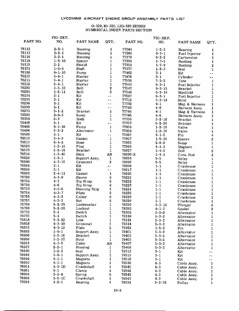
LYCOMING AIRCRAFT ENGINE GROUP ASSEMBLY PARTS LIST
O- 320, IO- 320, LIO- 320 SERIESNUMERICAL INDEX PARTS SECTION
FIG-REF.NO.PART NO.
76112761137611676118761197612176188762107621176212762207622076234762357623676239762737629976354764497648676496765007651076517765297653376534766287664876658766597669176728767347673476753767547675576757767687676976773767757681876852768537689976906769087692376927769407694476949769507695176961769947699977034
2-2-12-2-12-2-11-6-102-21-6-86-1-105-4-15-4-15-4-11-5-101-5-113-13-13-13-15-1-22-9-32-33-16-1-105-3-23-12-4-96-4-81-2-155-2-165-2-401-6-14-3-103-13-12-4-114-3-94-34-64-3-64-3-74-3-24-3-35-2-355-2-365-45-45-2-224-3-104-3-121-6-15-2-165-2-374-3-52-2-11-2-31-6-14-1-14-1-11-3-1D4-13-3-41-3-1C1-2-1
PART NAME
HousingHousingHousingSpacerShieldS haftPumpStarterStarterStarterBoltBoltKitKitKitKitBracketSumpBodyKitPumpAlternatorKitGasketHosePlugBracketShimSupport Assy.GrommetKitKitGasketSleeveZip StrapZip StrapSleeving RingPlateCollarNutLockwasherLocknutSwitchSwitchLinkGrommetPlateSupport Assy.BracketStrutCableHousingSealSupport Assy.MagnetoMagnetoCrankshaftC lampSpringCrankshaftBearing
QTY.
111111111122
111
11
1111
AR12
186842881111122111
AR1111114814
PART NO.
77044772607727977309773097737777462774767752677543775477754877597777187774277743777447774577756777577780877808778577790777965779857802778030-S780597806078206782177822078221782227822378224782257822678228782907829278308783107831278314783687840178403784057840778409785137851578516785397854078542785467854778614
FIG-REF.NO.
1-2-26-3-16-2-21-7-51-7-91-2-33-13-17-3-26-3-16-3-156-3-146-3-15-2-144-14-64-14-65-2-165-2-261-2-161-2-163-1-51-5-102-8-24-1-11-4-31-4-15-55-51-11-11-11-11-11-11-11-11-11-13-3-124-1-35-3-25-3-25-3-25-3-21-6-95-3-25-3-25-3-25-3-25-3-23-13-13-14-34-34-34-34-35-2-32
PART NAME
BearingFuel InjectorCarburetorBushingBushingSealKitCylinderTubeFuel InjectorBracketManifoldFuel InjectorStrutMag. & HarnessHarness Assy.Mag. & HarnessHarness Assy.BracketBracketValveValvePinSpacerSumpMagnetoBoltConn. RodRelayRelayCrankcaseCrankcaseCrankcaseCrankcaseCrankcaseCrankcaseCrankcaseCrankcaseCrankcaseCrankcasePlungerGasketAlternatorAlternatorAlternatorAlternatorPinAlternatorAlternatorAlternatorAlternatorAlternatorKitKitKitCable Assy.Cable Assy.Cable Assy.Cable Assy.Cable Assy.Pulley
QTY.
111121
11111111111111421184111111111111821111111111
1111
1114
10-9
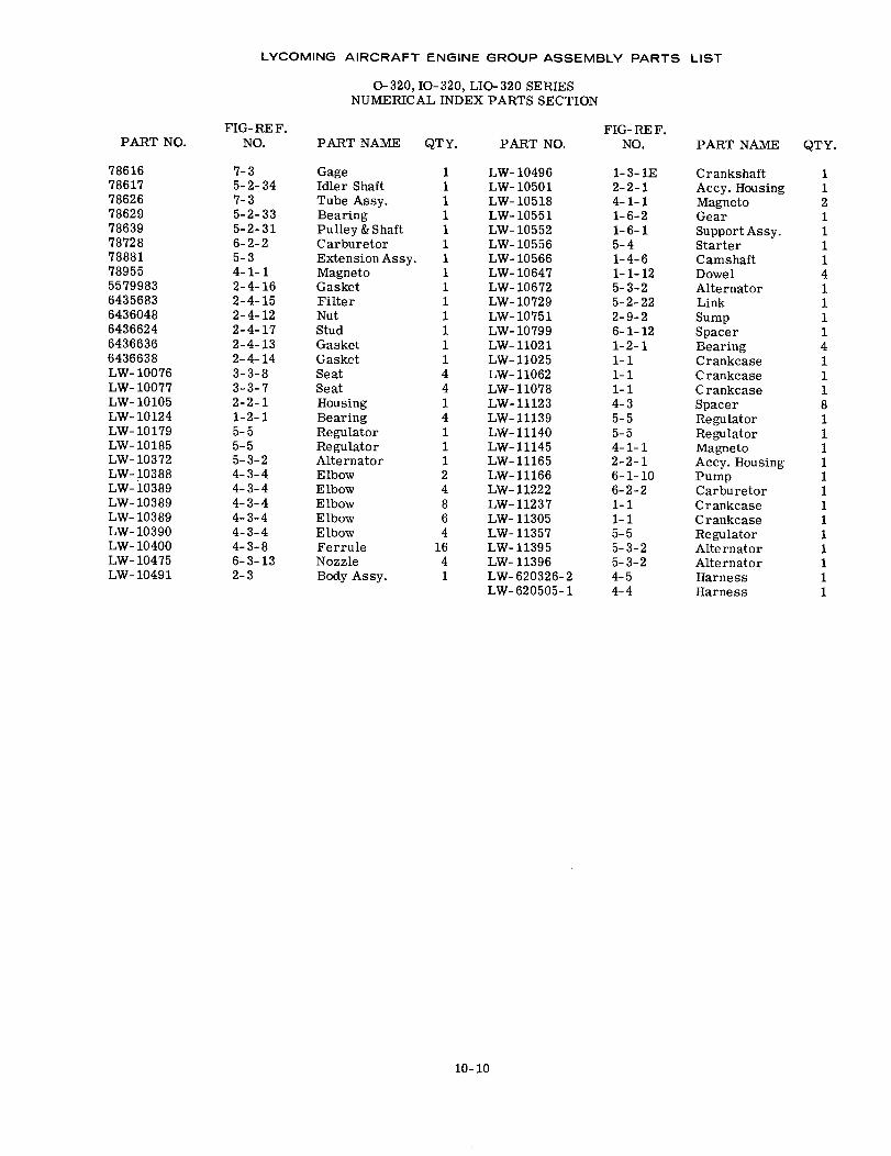
LYCOMING AIRCRAFT ENGINE GROUP ASSEMBLY PARTS LIST
0-320, 10-320, LIO-320 SERIESNUMERICAL INDEX PARTS SECTION
FIG- RE F.NO.PART NO.
FIG- RE F.NO.PART NAME QTY. PART NO. PART NAME QTY.
7861678617786267862978639787287888178955557998364356836436048643662464366366436638LW- 10076LW- 10077LW- 10105LW- 10124LW- 10179LW- 10185LW- 10372LW- 10388LW- 10389LW- 10389LW- 10389LW- 10390LW- 10400LW- 10475LW- 10491
7-35-2-347-35-2-335-2-316-2-25-34-1-12-4-162-4-152-4-122-4-172-4-132-4-143-3-83-3-72-2-11-2-15-55-55-3-24-3-44-3-44-3-44-3-44-3-44-3-86-3-132-3
GageIdler ShaftTube Assy.BearingPulley & ShaftCarburetorExtension Assy.MagnetoGasketFilterNutStudGasketGasketSeatSeatHousingBearingRegulatorRegulatorAlternatorElbowElbowElbowElbowElbowFerruleNozzleBody Assy.
1 LW- 104961 LW- 105011 LW-105181 LW- 105511 LW- 105521 LW- 105561 LW- 105661 LW- 106471 LW- 106721 LW- 107291 LW- 107511 LW- 107991 LW- 110211 LW- 110254 LW- 110624 LW-110781 LW-111234 LW- 111391 LW-111401 LW-111451 LW-111652 LW-111664 LW- 112228 LW-112376 LW- 113054 LW- 11357
16 LW-113954 LW- 113961 LW-620326-2
LW-620505-1
1-3-1E2-2-14-1-11-6-21-6-15-41-4-61-1-125-3-25-2-222-9-26-1-121-2-11-11-11-14-35-55-54-1-12-2-16-1-106-2-21-11-15-55-3-25-3-24-54-4
CrankshaftAccy. HousingMagnetoGearSupport Assy.StarterCamshaftDowelAlternatorLinkSumpSpacerBearingCrankcaseCrankcaseCrankcaseSpacerRegulatorRegulatorMagnetoAccy. HousingPumpCarburetorCrankcaseCrankcaseRegulatorAlternatorAlternatorHarnessHarness
112111141111411181111111111111
10-10