Embed Size (px)
Citation preview

Z245.15-17
Steel valves

Legal Notice for Standards
Canadian Standards Association (operating as “CSA Group”) develops standards through a consensus standards development process approved
by the Standards Council of Canada. This process brings together volunteers representing varied viewpoints and interests to achieve consensus
and develop a standard. Although CSA Group administers the process and establ ishes rules to promote fairness in achieving consensus, it does
not independently test, evaluate, or verify the content of standards.
Disclaimer and exclusion of liabilityThis document is provided without any representations, warranties, or conditions of any kind, express or impl ied, including, without l imitation,
impl ied warranties or conditions concerning this document’s fitness for a particular purpose or use, its merchantabil ity, or its non-infringement
of any third party’s intel lectual property rights. CSA Group does not warrant the accuracy, completeness, or currency of any of the information
publ ished in th is document. CSA Group makes no representations or warranties regarding this document’s compliance with any appl icable
statute, ru le, or regulation.
IN NO EVENT SH ALL CSA GROUP, I TS VOLUNTEERS, MEMBERS, SUBSIDI ARIES, OR AFFILIATED COMPANIES, OR TH EIR EMPLOYEES, DIRECTORS,
OR OFFICERS, BE LIABLE FOR ANY DI RECT, I NDIRECT, OR INCI DENTAL DAMAGES, I NJURY, LOSS, COSTS, OR EXPENSES, H OWSOEVER CAUSED,
INCLUDING BUT NOT LIMITED TO SPECIAL OR CONSEQUENTIAL DAMAGES, LOST REVENUE, BUSINESS INTERRUPTION, LOST OR DAMAGED
DATA, OR ANY OTHER COMMERCIAL OR ECONOMIC LOSS, WHETHER BASED IN CONTRACT, TORT ( INCLUDING NEGLIGENCE), OR ANY OTHER
THEORY OF LI ABILITY, ARI SING OUT OF OR RESULTING FROM ACCESS TO OR POSSESSION OR USE OF THIS DOCUMENT, EVEN IF CSA GROUP
HAS BEEN ADVISED OF THE POSSI BILITY OF SUCH DAMAGES, IN JURY, LOSS, COSTS, OR EXPENSES.
In publ ishing and making this document avai lable, CSA Group is not undertaking to render professional or other services for or on behalf of any
person or entity or to perform any duty owed by any person or entity to another person or entity. The information in th is document is d irected
to those who have the appropriate degree of experience to use and apply its contents, and CSA Group accepts no responsibi l ity whatsoever
arising in any way from any and a l l use of or rel iance on the information contained in this document.
CSA Group is a private not-for-profit company that publ ishes voluntary standards and related documents. CSA Group has no power, nor does it
undertake, to enforce compliance with the contents of the standards or other documents it publ ishes.
Intellectual property rights and ownershipAs between CSA Group and the users of this document (whether it be in printed or electronic form), CSA Group is the owner, or the authorized
l icensee, of a l l works contained herein that are protected by copyright, a l l trade-marks (except as otherwise noted to the contrary), and a l l
inventions and trade secrets that may be contained in th is document, whether or not such inventions and trade secrets are protected by
patents and appl ications for patents. Without l imitation, the unauthorized use, modification, copying, or d isclosure of th is document may
violate laws that protect CSA Group’s and/or others’ intel lectual property and may give rise to a right in CSA Group and/or others to seek legal
redress for such use, modification, copying, or d isclosure. To the extent permitted by l icence or by law, CSA Group reserves a l l intel lectual
property rights in th is document.
Patent rightsAttention is drawn to the possibi l ity that some of the elements of this standard may be the subject of patent rights. CSA Group shal l not be
held responsible for identifying any or a l l such patent rights. Users of this standard are expressly advised that determination of the val idity of
any such patent rights is entirely their own responsibi l ity.
Authorized use of this documentThis document is being provided by CSA Group for informational and non-commercial use only. The user of this document is authorized to do
only the fol lowing:
I f this document is in electronic form:
• load this document onto a computer for the sole purpose of reviewing it;
• search and browse this document; and
• print th is document if it is in PDF format.
Limited copies of th is document in print or paper form may be d istributed only to persons who are authorized by CSA Group to have such
copies, and only if this Legal Notice appears on each such copy.
In addition, users may not and may not permit others to
• a lter th is document in any way or remove this Legal Notice from the attached standard;
• sel l this document without authorization from CSA Group; or
• make an electronic copy of th is document.
I f you do not agree with any of the terms and conditions contained in this Legal Notice, you may not load or use this document or make any
copies of the contents hereof, and if you do make such copies, you are required to destroy them immediately. Use of th is document
constitutes your acceptance of the terms and conditions of th is Legal Notice.
Get more FREE standards from Standard Sharing Group and our chats

Standards Update Service
Z245.15-17
September 2017
Title: Steel valves
To register for e-mail notification about any updates to this publ ication
• go to shop.csa.ca
• cl ick on CSA Update Service
The List ID that you wil l need to register for updates to this publ ication is 2425342 .
I f you require assistance, please e-mail [email protected] or cal l 416-747-2233.
Visit CSA Group’s pol icy on privacy at www.csagroup.org/legal to find out how we protect your
personal information.

ISBN 978-1-4883-0843-7
© 2017 CSA Group All rights reserved. No part of this publication may be reproduced in any form whatsoever
without the prior permission of the publisher.
Published in September 2017 by CSA Group
A not-for-profit private sector organization 178 Rexdale Boulevard, Toronto, Ontario, Canada M9W 1R3
To purchase standards and related publications, visit our Online Store at shop.csa.ca
or call toll-free 1 -800-463-6727 or 416-747-4044.
®A trademark of the Canadian Standards Association, operating as “CSA Group”
Steel valves
Z245.15-17
Get more FREE standards from Standard Sharing Group and our chats

Z245.15-17 Steel valves
September 2017 © 2017 CSA Group 1
Contents
Technical Committee on Petroleum and Natural Gas Industry Pipel ine Systems and Materia ls 4
Subcommittee on Materia ls 10
Preface 12
1 Scope 14
1.1 General 14
1.2 Size, nominal pressure class, and category 14
1.2.1 Size 14
1.2.2 Nominal pressure class 14
1.2.3 Category 14
1.3 End configuration 14
1.4 Terminology 14
2 Reference publications 15
3 Definitions 19
4 General requirements 20
4.1 Product ordering requirements 20
4.1.1 Standard requirements 20
4.1.2 Optional requirements 20
4.1.3 Additional requirements 21
4.2 Weldabil ity 21
4.3 Rounding procedure 21
4.4 Qual ity program 21
5 Design 22
5.1 Configurations 22
5.1.1 Patterns 22
5.1.2 Gate valves 22
5.1.3 Plug valves (see Figure 4) 22
5.1.4 Bal l valves (see Figure 5) 23
5.1.5 Check valves 23
5.2 Pressure ratings 23
5.3 Sizes 24
5.4 End configurations 24
5.4.1 Flanged ends 24
5.4.2 Buttwelding ends 24
5.4.3 Wafer-type valve ends 24
5.5 Extended operating gear 24
5.6 Pressure rel ief 25
5.7 Drain and bypass connections 25
5.8 Sealant fittings 25
5.9 Bonnet and cover flanges 26
5.10 Stem packing 26
Z245.15-17 Steel valves
September 2017 © 2017 CSA Group 2
5.11 Wrenches or bars 26
5.12 Handle extensions 26
5.13 Handwheels 26
5.14 Torque 26
5.15 Locking device 26
5.16 Position indicator 26
5.17 Valve-closing d irection indicator 26
5.18 Stem protection 26
5.19 Support members 26
5.20 Lifting lugs 27
5.21 Noise levels 27
6 Materials and manufacture 27
6.1 Materia ls for pressure-containing parts other than bolting and other fasteners 27
6.1.1 Pressure-containing parts other than stems and shafts 27
6.1.2 Stems and shafts 27
6.2 Bolting and other fasteners for pressure-containing parts 27
6.3 Materia ls for miscel laneous metal parts 27
6.4 Materia ls for non-metal l ic parts 27
6.5 Welding qual ification 28
6.6 Cal ibration of heat treating equipment 28
7 Chemical test requirements 28
7.1 General 28
7.2 Heat analysis 28
7.3 Product analysis 28
8 Mechanical test requirements 29
8.1 Selection of test specimens for pressure-containing parts 29
8.1.1 General 29
8.1.2 Mechanical properties achieved by cold working 29
8.1.3 Mechanical properties achieved by a process other than cold working 29
8.2 Defective test specimens 29
8.3 Tension tests 29
8.3.1 General 29
8.3.2 Requirements 29
8.4 Notch-toughness tests — Category I I valves 30
8.4.1 General 30
8.4.2 Test specimen orientation 30
8.4.3 Test specimen size 30
8.4.4 Requirements 30
8.5 Testing of non-pressure-containing parts 31
9 Pressure test requirements 31
9.1 General 31
9.2 Test equipment 31
9.3 Shel l test 32
9.4 Seat tests 32
9.4.1 Hydrostatic seat tests 32
Get more FREE standards from Standard Sharing Group and our chats

Z245.15-17 Steel valves
September 2017 © 2017 CSA Group 3
9.4.2 Air seat tests 32
10 Dimensions and tolerances 33
10.1 Dimensions and tolerances of standard valves 33
10.1.1 Standard round-port ful l-bore pattern valves 33
10.1.2 Standard gate valves 33
10.1.3 Standard plug valves 33
10.1.4 Standard bal l va lves 33
10.1.5 Standard check valves 33
10.2 Dimensions and tolerances of non-standard valves 33
11 Inspection, work quality, and repair of valves containing defects 33
11.1 Plant inspection 33
11.2 Inspection notice 33
11.3 Plant access 33
11.4 Work qual ity 34
11.5 Repair of valves containing defects 34
12 Non-destructive inspection requirements 34
13 Sour service 34
14 Marking and shipping 35
14.1 Marking 35
14.2 Preparation for shipment 36
15 Certification 36
Annex A (informative) — Pipel ine component size nomenclature 74
Annex B ( informative) — Nominal pressure class nomenclature 76
Annex C ( informative) — Recommended practice for the cal ibration and survey of heat treating
equipment 77

Z245.15-17 Steel valves
September 2017 © 2017 CSA Group 4
Technical Committee on Petroleum and
Natural Gas Industry Pipeline Systems and
Materials
J.A. Fournell QAi Qual ity Assurance Inc. , Edmonton, Alberta Category: General Interest
Chair
D. Carnes Canadian Natural Resources Limited, Calgary, Alberta Category: Producer Interest
Vice-Chair
G. Mills Enbridge Gas Transmission & Midstream, Calgary, Alberta Category: User Transmission
Vice-Chair
D.J. Tchir ATCO Gas, Edmonton, Alberta Category: User Distribution
Vice-Chair
B. Wilson Acuren Group Inc. , Calgary, Alberta Category: Supplier/Fabricator/Contractor
Vice-Chair
J. Abes Det Norske Veritas Canada Ltd. , Calgary, Alberta Category: General Interest
A.J. Afaganis EVRAZ Inc. NA, Calgary, Alberta Category: Supplier/Fabricator/Contractor
F.B. Austin BC Oil & Gas Commission, Victoria, British Columbia Category: Government and/or Regulatory Authority
K. Baraniecki Enbridge Pipel ines Inc. , Edmonton, Alberta Category: User Transmission
M. Béland Gaz Métro, Montréal , Québec
Associate
Get more FREE standards from Standard Sharing Group and our chats

Z245.15-17 Steel valves
September 2017 © 2017 CSA Group 5
M. Binet Gaz Métro, Montréal , Québec Category: User Distribution
A. Bhatia Det Norske Veritas Canada Ltd. , Calgary, Alberta
Associate
R. Brousseau Régie du Bâtiment du Québec, Montréal , Québec Category: Government and/or Regulatory Authority
R.R. Bryant Aecon Util ity Engineering, Chatham, Ontario
Associate
P. Colwell Union Gas Limited, Chatham, Ontario Category: User Distribution
F. Cox Husky Energy Inc. , Calgary, Alberta Category: Producer Interest
K. Crichton Perma-Pipe Canada, Camrose, Alberta Category: Supplier/Fabricator/Contractor
C. Dubeau Union Gas Limited, Chatham, Ontario
Associate
D. Feser Kinder Morgan Canada Inc. , Calgary, Alberta Category: User Transmission
G. Forgeron Imperia l Oi l Resources, Calgary, Alberta Category: Producer Interest
L.H. Gales Transportation Safety Board of Canada, Gatineau, Québec
Associate
M.H. Glass Trans-Northern Pipel ines Inc. , Richmond Hi l l , Ontario Category: User Transmission

Z245.15-17 Steel valves
September 2017 © 2017 CSA Group 6
S. Gosse Encana Services Company Ltd. , Calgary, Alberta Category: Producer Interest
G.A. Harms Harms-Way Projects, Calgary, Alberta Category: General Interest
G.R. Johnson FortisBC Energy Inc. (FEI ), Surrey, British Columbia Category: User Distribution
T.N. Kee Alberta Agriculture and Rural Development, Edmonton, Alberta Category: Government and/or Regulatory Authority
Associate
S. Kenny Carleton University, Ottawa, Ontario
Associate
M. Kotchounian Transportation Safety Board of Canada, Gatineau, Québec
Associate
H. Kraft Harold Kraft Consulting, Calgary, Alberta
Associate
T.H. Lawrence TMK IPSCO, Houston, Texas, USA Category: Supplier/Fabricator/Contractor
K. Letendre Cenovus Energy Inc. , Calgary, Alberta
Associate
R. MacDonald Shel l Canada Limited, Calgary, Alberta Category: Producer Interest
J.D. Mackenzie Kiefner and Associates, Inc. , Bel l ingham, Washington, USA Category: General Interest
D.R. Mann SaskEnergy, Regina, Saskatchewan Category: User Transmission
K. Manouchehri Technical Standards & Safety Authority (TSSA), Toronto, Ontario
Associate
Get more FREE standards from Standard Sharing Group and our chats

Z245.15-17 Steel valves
September 2017 © 2017 CSA Group 7
R.A. Marsden Cenovus Energy Inc. , Calgary, Alberta Category: Producer Interest
T.W. McQuinn New Brunswick Energy and Uti l ities Board, Saint John, New Brunswick Category: Government and/or Regulatory Authority
G. McShane Tenaris, Calgary, Alberta Category: Supplier/Fabricator/Contractor
G.F. Palermo Palermo Plastics Pipe (P3) Consulting, Friendsvi l le, Tennessee, USA Category: Supplier/Fabricator/Contractor
R.B. Partington Federation of Alberta Gas Co-ops Ltd. , Sherwood Park, Alberta Category: User Distribution
J. Paviglianiti National Energy Board, Calgary, Alberta Category: Government and/or Regulatory Authority
T.J. Pesta Pesta Consulting Ltd. , Calgary, Alberta
Associate
D. Petursson Manitoba Hydro, Winnipeg, Manitoba Category: User Distribution
M. Poehlmann ABSA, Edmonton, Alberta Category: Government and/or Regulatory Authority
L. Radke ATCO Pipel ines, Edmonton, Alberta
Associate
C.E. Rollings H3R Inc. , Hal ifax, Nova Scotia
Associate
A.B. Rothwell Brian Rothwel l Consulting Inc. , Calgary, Alberta
Associate

Z245.15-17 Steel valves
September 2017 © 2017 CSA Group 8
J.D. Sandison CMC Consultants Inc. , Winnipeg, Manitoba Category: General Interest
W.A. Simpson North American Standards Assessment Corp. , Sherwood Park, Alberta
Associate
T. Starodub Manitoba Hydro, Winnipeg, Manitoba
Associate
J.K. Steeves AMEC Foster Wheeler, Calgary, Alberta
Associate
J. Sutherland PI I Pipel ine Solutions (GE Oi l & Gas), Calgary, Alberta Category: Supplier/Fabricator/Contractor
N. Thalassinos Entity Consulting Inc. , Richmond Hi l l , Ontario Category: General Interest
A. Van Der Veen TransCanada PipeLines Limited, Calgary, Alberta
Associate
M. Wagle Enbridge Gas Distribution, Toronto, Ontario Category: User Distribution
S. Walker Union Gas Limited, Chatham, Ontario
Associate
H. Wallace Alberta Energy Regulator, Calgary, Alberta Category: Government and/or Regulatory Authority
L. Wojtanowski Sun-Canadian Pipe Line Company Limited, Waterdown, Ontario Category: User Transmission
J. Zhou TransCanada PipeLines Limited, Calgary, Alberta Category: User Transmission
S. Capper CSA Group, Toronto, Ontario
Project Manager
Get more FREE standards from Standard Sharing Group and our chats

Z245.15-17 Steel valves
September 2017 © 2017 CSA Group 9
P. Fernandez Marchi CSA Group, Toronto, Ontario
Project Manager

Z245.15-17 Steel valves
September 2017 © 2017 CSA Group 10
Subcommittee on Materials
A.J. Afaganis EVRAZ Inc. NA, Calgary, Alberta
Chair
M. Whitehouse Enbridge Gas Distribution, Mooretown, Ontario
Vice-Chair
E.B. Willett Enbridge Gas Transmission & Midstream, Calgary, Alberta
Vice-Chair
D.M. Duan TransCanada PipeLines Limited, Calgary, Alberta
K. Durand Canadoil Forge Ltd. , Bécancour, Québec
T. Gorrell All ied Group, Houston, Texas, USA
C. Guan TransCanada PipeLines Limited, Calgary, Alberta
D. Horsley Horsley Consulting Ltd. , Calgary, Alberta
T.H. Lawrence TMK IPSCO, Houston, Texas, USA
M.Q. Li Fortune Group, Edmonton, Alberta
R. Mackenzie Enbridge Pipel ines Inc. , Edmonton, Alberta
S. Matsuno Marubeni-I tochu Tubulars Canada Ltd. , Calgary, Alberta
G. McShane Tenaris, Calgary, Alberta
G.T. Melnychuk Stream-Flo Industries Ltd. , Edmonton, Alberta
Get more FREE standards from Standard Sharing Group and our chats

Z245.15-17 Steel valves
September 2017 © 2017 CSA Group 11
D.P. Ochitwa National Energy Board, Calgary, Alberta
H.R. Ramay WorleyParsons, Calgary, Alberta
M. Saric Alberta Energy Regulator, Calgary, Alberta
R. Schmidt Canadoil , Russel lvi l le, Arkansas, USA
W. Tang Solaris Management Consultants Inc. , Surrey, British Columbia
S. Tracy EVRAZ Inc. NA, Calgary, Alberta
W.R. Tyson Natural Resources Canada, Ottawa, Ontario
I .A. Ward Shel l Global Solutions Canada, Calgary, Alberta
B. Wray Galperti Canada, Edmonton, Alberta
S. Xu CanmetMATERIALS Natural Resources Canada, Hamilton, Ontario
P. Fernandez Marchi CSA Group, Toronto, Ontario
Project Manager
In addition to the members of the Subcommittee on Materials, Jan Andersson made a valuable
contribution to the development of this Standard.

Z245.15-17 Steel valves
September 2017 © 2017 CSA Group 12
Preface
This is the ninth edition of CSA Z245.15, Steel valves . I t supersedes the previous editions publ ished in
2013, 2009, 2005, 2001, 1996, 1991, 1987, and 1981.
This Standard covers the requirements for steel valves intended to be used for transporting flu ids as
specified in CAN/CSA-Z662.
Some of the main changes to this edition include the fol lowing:
a) revised optional product ordering requirements (Clause 4.1.2 );
b) revised drain and bypass connections, and sealant fittings requirements (Clauses 5.7 and 5.8);
c) revised seat tests requirements (Clause 9.4);
d) revised sour service requirements (Clause 13);
e) revised Table 5 Ring and groove dimension C for PN 420 ful l -bore, NPS 2-1/2 valves;
f) revised Table 8; and
g) revised furnace cal ibration and survey requirements (Annex C).
In this 2017 edition, where a major change or addition to the previous edition of this Standard has been
made, the clause, table, or figure affected is identified by the symbol � in the margin. Users of this
Standard are advised that the change markers in the text are not intended to be a l l -inclusive and are
provided as a convenience only; such markers cannot constitute a comprehensive guide to the revisions
made to this Standard. Care must therefore be taken not to rely on the change markers to determine
the current requirements of this Standard. As a lways, users of this Standard must consider the entire
Standard.
This Standard was prepared by the Subcommittee on Materia ls, under the jurisdiction of the Technical
Committee on Petroleum and Natural Gas Industry Pipel ine Systems and Materia ls and the Strategic
Steering Committee on Petroleum and Natural Gas Industry Systems, and has been formal ly approved
by the Technical Committee.
Notes:
1) Use of the singular does not exclude the plural (and vice versa) when the sense allows.
2) Although the intended primary application of this Standard is stated in its Scope, it is important to note that it
remains the responsibility of the users of the Standard to judge its suitability for their particular purpose.
3) This Standard was developed by consensus, which is defined by CSA Pol icy governing standardization — Code
of good practice for standardization as “substantial agreement. Consensus implies much more than a simple
majority, but not necessarily unanimity”. It is consistent with this definition that a member may be included in
the Technical Committee list and yet not be in full agreement with all clauses of this Standard.
4) To submit a request for interpretation of this Standard, please send the following information to
[email protected] and include “Request for interpretation” in the subject line:
a) define the problem, making reference to the specific clause, and, where appropriate, include an
illustrative sketch;
b) provide an explanation of circumstances surrounding the actual field condition; and
c) where possible, phrase the request in such a way that a specific “yes” or “no” answer will address the
issue.
Committee interpretations are processed in accordance with the CSA Directives and guidelines governing
standardization and are available on the Current Standards Activities page at standardsactivities. csa.ca .
5) This Standard is subject to review within five years from the date of publication, and suggestions for its
improvement will be referred to the appropriate committee. To submit a proposal for change, please send the
following information to [email protected] and include “Proposal for change” in the subject line:
a) Standard designation (number);
b) relevant clause, table, and/or figure number;
Get more FREE standards from Standard Sharing Group and our chats

Z245.15-17 Steel valves
September 2017 © 2017 CSA Group 13
c) wording of the proposed change; and
d) rationale for the change.

Z245.15-17 Steel valves
September 2017 © 2017 CSA Group 14
Z245.15-17
Steel valves
1 Scope
1.1 General
This Standard covers steel valves primari ly intended for use in oi l or gas pipel ine systems. The fol lowing
types of valves are covered:
a) gate valves;
b) plug valves;
c) bal l valves; and
d) check valves.
1.2 Size, nominal pressure class, and category
1.2.1 Size
This Standard covers valves in sizes from NPS 2 to NPS 60. (See Table A.1. )
1.2.2 Nominal pressure class
This Standard covers valves having cold working-pressure ratings designated by nominal pressure
classes from PN 20 to PN 420. The standard nominal pressure classes are shown in Table 1. (ASME class
designations are shown in Table B.1.)
1.2.3 Category
This Standard covers valves in the fol lowing categories:
a) Category I : va lves without requirements for proven notch-toughness properties; and
b) Category I I : va lves with requirements for proven notch-toughness properties.
1.3 End configuration
This Standard covers standard end requirements for flanged, buttwelding, and wafer-type valves. Other
end configurations are considered non-standard and are subject to agreement between the purchaser
and the manufacturer.
1.4 Terminology
In this Standard, “shal l” is used to express a requirement, i .e. , a provision that the user is obl iged to
satisfy in order to comply with the standard; “should” is used to express a recommendation or that
which is advised but not required; and “may” is used to express an option or that which is permissible
within the l imits of the Standard.
Notes accompanying clauses do not include requirements or a lternative requirements; the purpose of a
note accompanying a clause is to separate from the text explanatory or informative material .
Notes to tables and figures are considered part of the table or figure and may be written as
requirements.
Get more FREE standards from Standard Sharing Group and our chats

Z245.15-17 Steel valves
September 2017 © 2017 CSA Group 15
Annexes are designated normative (mandatory) or informative (non-mandatory) to define their
appl ication.
� 2 Reference publicationsThis Standard refers to the fol lowing publ ications, and where such reference is made, it shal l be to the
edition l isted below, unless the user finds it more appropriate to use newer or amended editions of such
publ ications.
CSA Group
G40.20-13/G40.21-13
General requirements for rolled or welded structural quality steel/Structural quality steel
Z245.1-14
Steel pipe
Z245.11-17
Steel fittings
Z245.12-17
Steel flanges
CAN/CSA-Z662-15
Oil and gas pipeline systems
API (American Petroleum Institute)
5B-2008 (R2015) (SPEC)
Specification for Threading, Gauging, and Thread Inspection of Casing, Tubing, and Line Pipe Threads
5L-2013 (SPEC)
Specification for Line Pipe
Q1-2014 (SPEC)
Specification for Quality Management System Requirements for Manufacturing Organizations for the
Petroleum and Natural Gas Industry
ASME (The American Society of Mechanical Engineers)
Boiler and Pressure Vessel Code
Section VIII — Pressure Vessels, Division 1 , 2015
Section IX — Welding and Brazing Qualifications, 2015
B1.20.1-2013
Pipe Threads, General Purpose, Inch
B1.20.3-1976 (R2013)
Dryseal Pipe Threads, Inch
B1.20.5-1991 (R2014)
Gaging for Dryseal Pipe Threads — Inch

Z245.15-17 Steel valves
September 2017 © 2017 CSA Group 16
B16.5-2013
Pipe Flanges and Flanged Fittings: NPS 1/2 through NPS 24 Metric/Inch Standard
ASTM International (American Society for Testing and Materials)
A36/A36M-14
Standard Specification for Carbon Structural Steel
A53/A53M-12
Standard Specification for Pipe, Steel, Black and Hot-Dipped, Zinc-Coated, Welded and Seamless
A105/A105M-14
Standard Specification for Carbon Steel Forgings for Piping Applications
A106/A106M-15
Standard Specification for Seamless Carbon Steel Pipe for High-Temperature Service
A181/A181M-14
Standard Specification for Carbon Steel Forgings, for General-Purpose Piping
A182/A182M-16a
Standard Specification for Forged or Rolled Alloy and Stainless Steel Pipe Flanges, Forged Fittings, and
Valves and Parts for High-Temperature Service
A193/A193M-16
Standard Specification for Alloy-Steel and Stainless Steel Bolting for High Temperature or High Pressure
Service and Other Special Purpose Applications
A194/A194M-16a
Standard Specification for Carbon and Alloy Steel Nuts for Bolts for High Pressure or High Temperature
Service, or Both
A203/A203M12
Standard Specification for Pressure Vessel Plates, Alloy Steel, Nickel
A216/A216M-16
Standard Specification for Steel Castings, Carbon, Suitable for Fusion Welding, for High-Temperature
Service
A217/A217M-14
Standard Specification for Steel Castings, Martensitic Stainless and Alloy, for Pressure-Containing Parts,
Suitable for High-Temperature Service
A242/A242M-13
Standard Specification for High-Strength Low-Alloy Structural Steel
A285/A285M-12
Standard Specification for Pressure Vessel Plates, Carbon Steel, Low- and Intermediate-Tensile Strength
A320/A320M-15a
Standard Specification for Alloy-Steel and Stainless Steel Bolting Materials for Low-Temperature Service
Get more FREE standards from Standard Sharing Group and our chats

Z245.15-17 Steel valves
September 2017 © 2017 CSA Group 17
A333/A333M-16
Standard Specification for Seamless and Welded Steel Pipe for Low-Temperature Service
A350/A350M-15
Standard Specification for Carbon and Low-Alloy Steel Forgings, Requiring Notch Toughness Testing for
Piping Components
A351/A351M-16
Standard Specification for Castings, Austenitic, for Pressure-Containing Parts
A352/A352M-06 (2012)
Standard Specification for Steel Castings, Ferritic and Martensitic, for Pressure-Containing Parts, Suitable
for Low-Temperature Service
A354-11
Standard Specification for Quenched and Tempered Alloy Steel Bolts, Studs, and Other Externally
Threaded Fasteners
A370-17
Standard Test Methods and Definitions for Mechanical Testing of Steel Products
A381-96 (2012)
Standard Specification for Metal-Arc-Welded Steel Pipe for Use With High-Pressure Transmission
Systems
A487/A487M-14
Standard Specification for Steel Castings Suitable for Pressure Service
A515/A515M-10 (2015)
Standard Specification for Pressure Vessel Plates, Carbon Steel, for Intermediate- and Higher-
Temperature Service
A516/A516M-10 (2015)
Standard Specification for Pressure Vessel Plates, Carbon Steel, for Moderate- and Lower-Temperature
Service
A537/A537M-13
Standard Specification for Pressure Vessel Plates, Heat-Treated, Carbon-Manganese-Silicon Steel
A541/A541M-05 (2015)
Standard Specification for Quenched and Tempered Carbon and Alloy Steel Forgings for Pressure Vessel
Components
A572/A572M-15
Standard Specification for High-Strength Low-Alloy Columbium-Vanadium Structural Steel
A633/A633M-01 (2013)
Standard Specification for Normalized High-Strength Low-Alloy Structural Steel Plates

Z245.15-17 Steel valves
September 2017 © 2017 CSA Group 18
A694/A694M-16
Standard Specification for Carbon and Alloy Steel Forgings for Pipe Flanges, Fittings, Valves, and Parts
for High-Pressure Transmission Service
A707/A707M-14
Standard Specification for Forged Carbon and Alloy Steel Flanges for Low-Temperature Service
A710/A710M-02 (2013)
Standard Specification for Precipitation-Strengthened Low-Carbon Nickel-Copper-Chromium-
Molybdenum- Columbium Alloy Structural Steels Plates
A737/A737M-09 (2013)
Standard Specification for Pressure Vessel Plates, High-Strength, Low-Alloy Steel
A751-14a
Standard Test Methods, Practices, and Terminology for Chemical Analysis of Steel Products
A757/A757M-15
Standard Specification for Steel Castings, Ferritic and Martensitic, for Pressure-Containing and Other
Applications, for Low-Temperature Service
E18-16
Standard Test Methods for Rockwell Hardness of Metallic Materials
E29-13
Standard Practice for Using Significant Digits in Test Data to Determine Conformance with Specifications
E140-12be1
Standard Hardness Conversion Tables for Metals Relationship Among Brinell Hardness, Vickers Hardness,
Rockwell Hardness, Superficial Hardness, Knoop Hardness, and Scleroscope Hardness
E384-16
Standard Test Method for Knoop and Vickers Hardness of Materials
AWHEM (Association of Well Head Equipment Manufacturers)
TR0701-2007
Specifications for Bleeder Plugs Used in Wellhead Applications
ISO (International Organization for Standardization)
15156-2:2015
Petroleum and natural gas industries — Materials for use in H2S-containing environments in oil and gas
production — Part 2: Cracking-resistant carbon and low alloy steels, and the use of cast irons
15156-3:2015
Petroleum and natural gas industries — Materials for use in H2S-containing environments in oil and gas
production — Part 3: Cracking-resistant CRAs (corrosion-resistant alloys) and other alloys
ISO/TS 29001:2010
Petroleum, petrochemical and natural gas industries — Sector-specific quality management systems —
Requirements for product and service supply organizations
Get more FREE standards from Standard Sharing Group and our chats

Z245.15-17 Steel valves
September 2017 © 2017 CSA Group 19
MSS (Manufacturers Standardization Society of the Valve and Fittings Industry Inc.)
SP-25-2013
Standard Marking System for Valves, Fittings, Flanges and Unions
NACE International (National Association of Corrosion Engineers)/ISO (International Organization for
Standardization)
NACE MR0175/ISO 15156-2:2015
Petroleum and natural gas industries — Materials for use in H2S-containing environments in oil and gas
production — Part 2: Cracking-resistant carbon and low alloy steels, and the use of cast irons
NACE MR0175/ISO 15156-3:2015
Petroleum and natural gas industries — Materials for use in H2S-containing environments in oil and gas
production — Part 3: Cracking-resistant CRAs (corrosion-resistant alloys) and other alloys
3 DefinitionsThe fol lowing definitions shal l apply in this Standard:
Certificate of compliance — a document that states that the product was manufactured, sampled,
tested, and inspected as specified in this Standard (year of publ ication to be included) and the purchase
order, and was found to have met such requirements.
Defect — an imperfection of sufficient magnitude to warrant rejection based on the requirements of
this Standard.
Heat-affected zone — the portion of the base metal that has not been melted but whose mechanical
properties or microstructure has been a ltered by the heat of welding.
Heat analysis — the chemical analysis reported by the steel producer as being representative of the
heat of steel .
Imperfection — a materia l d iscontinuity or irregularity that is detectable by inspection in accordance
with the requirements of this Standard.
Maximum cold working pressure — the maximum pressure to which the operation of a valve at
temperatures of 120 °C and less may be l imited by virtue of some l imiting materia l or design element in
that particular valve.
Notch toughness — the resistance of the steel to fracture under suddenly appl ied loads at a notch.
Obturator — the movable portion of a va lve that causes stoppage of flow through the valve.
Pressure-containing parts — those valve parts that, when assembled, form the chamber(s) designed to
contain the pressurized flu id. Such parts include bodies, bonnets, covers, end flanges, buttwelding ends,
stems, shafts, and bolting.
Product analysis — the chemical analysis made on a sample taken from the finished valve or from
material representative of the finished valve.
Seat — the portion of the valve body against which the obturator presses to stop the flow.

Z245.15-17 Steel valves
September 2017 © 2017 CSA Group 20
Secondary sealing — provision for the appl ication of an injectable sealant against the seat face or the
stem of the valve, or both.
Shaft — a component in some check valves that supports the d isc mechanism and extends through the
wal l of the pressurized chamber. Shafts are sometimes fitted with items such as locking devices,
counterweights, and motion dampeners.
Stem — the component in the valve that is exposed to the pressurized media and causes movement of
the valve obturator when a sufficient force from the operating mechanism is appl ied.
4 General requirements
4.1 Product ordering requirements
� 4.1.1 Standard requirements
The fol lowing information shal l be included in the purchase order for valves:
a) CSA Standard designation and year of publ ication (Z245.15-17);
b) quantity;
c) type and pattern of valve (see Clauses 1.1 and 5.1);
d) nominal va lve size (see Clauses 1.2.1 and 10);
e) category (see Clause 1.2.3 );
f) end configuration (see Clauses 1.3 and 5.4);
g) nominal pressure class (see Clauses 1.2.2 and 5.2.1 and Table 1);
h) minimum and maximum design temperatures (see Clause 5.21);
i) for buttwelding end valves, matching pipe specified wal l thickness and grade and the inside
d iameter of the buttwelding end (see Clause 5.4.2);
j) for wafer-type valves, the matching flange (see Clause 5.4.3 );
k) test temperature for Category I I (see Clause 8.4.1.5 );
l ) for flanged-end valves, required bore size;
m) packaging and shipping instructions; and
n) required del ivery date.
� 4.1.2 Optional requirements
The purchase order shal l include information concerning the fol lowing items, when required by the
purchaser:
a) quantity, location, and orientation of Charpy test specimens for welding procedure specification
qual ification tests (see Clause 6.5.3 );
b) type of end flange (see Clause 5.4.1.1 );
c) a lternative design of buttwelding end (see Clause 5.4.2);
d) extended operating gear (see Clause 5.5);
e) pressure rel ief (see Clause 5.6.2);
f) drain and bypass connections (see Clause 5.7);
g) wrenches or bars (see Clause 5.11);
h) valve handle extension (see Clause 5.12);
i) locking device (see Clause 5.15);
j) position indicator (see Clause 5.16);
k) support members (see Clause 5.19);
l ) noise levels (see Clause 5.21);
Get more FREE standards from Standard Sharing Group and our chats

Z245.15-17 Steel valves
September 2017 © 2017 CSA Group 21
m) product analysis (see Clause 7.3);
n) increased absorbed energy values (see Clause 8.4.4.1 );
o) testing of non-pressure-containing parts (see Clause 8.5);
p) plant inspection by the purchaser (see Clauses 9.1.1 and 11.2);
q) a ir seat test (see Clause 9.4.2);
r) non-destructive inspection of welds (see Clause 12);
s) sour service (see Clause 13);
t) suitable packaging (see Clause 14.2.6);
u) report of heat analysis (see Clause 15.2);
v) report of product analysis (see Clause 15.3);
w) report of specific tests (see Clause 15.4);
x) report of pressure tests (see Clause 15.5);
y) report of non-destructive inspection (see Clause 15.6);
z) report of specific sour service items (see Clause 15.7);
aa) specific sealant fittings, inner check fittings, and body cavity drain/vent/bleed fittings; and
ab) other specia l requirements.
4.1.3 Additional requirements
Where appl icable, the purchase order shal l include information concerning the fol lowing items, as
agreed upon by the purchaser and the manufacturer:
a) materia ls of construction (see Clause 6.1 and asterisk note to Table 2);
b) temperature range for non-metal l ic seal ing materia ls (see Clause 5.2.2);
c) intermediate valve sizes (see Clause 5.3);
d) maximum force to operate handwheel (see Clause 5.13 );
e) maximum torque to operate valve (see Clause 5.14);
f) use of lower-strength bolting (see Clause 8.4.1.3 );
g) d imensions and tolerances of non-standard valves (see Clause 10.2);
h) type of non-destructive inspection (see Clause 12);
i) a lternative bolting for valves for sour service (see Clause 13.3);
j) a lternative test method or hardness value for certain fasteners for valves for sour service (see
Clause 13.3 ); and
k) coating on valves (see Clause 14.2.1 ).
� 4.2 Weldability
Buttwelding end valves shal l be capable of being welded in accordance with CAN/CSA-Z662 when using
welding procedure specifications that comply with that Standard.
4.3 Rounding procedure
Except as otherwise required by this Standard, to determine conformance with the specified
requirements, observed or ca lculated values shal l be rounded to the nearest unit in the last right-hand
place of figures used in expressing the l imiting value, in compl iance with the rounding method of
ASTM E29.
4.4 Quality program
The manufacturer shal l comply with the requirements of a qual ity management system.

Z245.15-17 Steel valves
September 2017 © 2017 CSA Group 22
� 5 DesignNote: For valves required to pass scrapers, inspection tools, or spheres, it is the responsibility of the purchaser to
determine that the valve design satisfies their requirements.
� 5.1 Configurations
Note: The valve sketches in Figures 1 to 11 are examples of valve types that illustrate the basis for the dimensions
specified in Tables 3 to 7. Although based on designs now available, the valve are not endorsement of such designs,
in whole or in part, nor are they intended to discriminate against other designs that comply with the requirements
of this Standard.
5.1.1 Patterns
Gate, bal l , plug, and check valves manufactured to this Standard shal l have one of the fol lowing
patterns:
a) Round-port ful l-bore pattern: this pattern of valve has a circular port through both the body and
the seat area, with a minimum bore as specified in Table 8.
b) Ful l -port pattern: this pattern of valve has a port (approaching pipe size), not necessarily circular,
through the obturator, with the in let and outlet sections tapered so that the d iameter at the pipe
end is round-port ful l -bore.
c) Reduced-port (regular pattern): this pattern of valve is designed as closely as possible for a
streamlined flow. The in let and outlet sections of this pattern of valve are tapered so that the
d iameter at the pipe end is round-port ful l -bore.
d) Reduced-port (short pattern): this pattern of valve appl ies only to plug- and bal l -valve
configurations.
e) Venturi-port pattern: this pattern of valve is designed for minimum pressure loss and has a
configuration that approximates that of a venturi throat. The in let and outlet d iameters of this
valve shal l be round-port ful l-bore.
5.1.2 Gate valves
5.1.2.1
Gate valve types are wedge, double-disc, and conduit (see Figures 1, 2, and 3, respectively).
5.1.2.2
Gate valves shal l be either rising-stem or non-rising-stem.
5.1.2.3
Gate valves shal l be round-port ful l-bore pattern, unless otherwise specified in the purchase order.
5.1.2.4
Gate valves other than round-port ful l -bore pattern and ful l -port pattern shal l be designated by two
nominal sizes, the first being the nominal size of the valve end and the second being the nominal size of
the reduced seat d iameter.
5.1.3 Plug valves (see Figure 4)
5.1.3.1
Plug valve patterns shal l be as specified in the purchase order.
Get more FREE standards from Standard Sharing Group and our chats

Z245.15-17 Steel valves
September 2017 © 2017 CSA Group 23
5.1.3.2
Plug valves shal l be either lubricated or non-lubricated.
5.1.4 Ball valves (see Figure 5)
5.1.4.1
Bal l valves shal l be round-port ful l-bore pattern, unless otherwise specified in the purchase order.
5.1.4.2
Bal l valves other than round-port ful l -bore pattern and ful l -port pattern shal l be designated by two
nominal sizes, the first being the nominal size of the valve end and the second being the nominal size of
the reduced seat d iameter.
5.1.5 Check valves
5.1.5.1
Check valve patterns shal l be as specified in the purchase order.
� 5.1.5.2
Check valve types shal l be as fol lows:
a) regular, swing (see Figure 6);
b) fu l l -opening, swing (see Figure 7);
c) single-plate wafer-type — long pattern (see Figure 8);
d) dual-plate wafer-type — long pattern (see Figure 9);
e) single-plate wafer-type — short pattern (see Figure 10); and
f) nozzle-type (see Figure 11).
Notes:
1) For wafer-type check valves, “long pattern” and “short pattern” refer to the end-to-end dimension (see Clause
10. 1 .5).
2) Nozzle-type check valves are also known as piston-type check valves. .
5.2 Pressure ratings
5.2.1
Maximum cold working-pressure ratings shal l be as specified in Table 1 and are appl icable at
temperatures up to and including 120 °C, except as l imited by Clause 5.2.2 . Pressure ratings at
temperatures in excess of 120 °C shal l be as specified in the appl icable instal lation code. Such ratings
shal l apply to a l l va lves, provided that for valves with ra ised face flanges, the gaskets are as specified in
ASME B16.5, Annex C.
5.2.2
I t is possible that the ratings specified in Clause 5.2.1 wil l not apply to non-metal l ic resil ient seal ing or
plastic seal ing materia ls. Unless otherwise agreed upon by the purchaser and the manufacturer, such
materials shal l be capable of withstanding the rated pressure over the temperature range specified by
the purchaser.

Z245.15-17 Steel valves
September 2017 © 2017 CSA Group 24
5.3 Sizes
Valve sizes shal l be as specified in Tables 3 to 8 unless an intermediate size is specified in the purchase
order.
5.4 End configurations
5.4.1 Flanged ends
5.4.1.1
End flanges shal l be ra ised-face or, if so specified in the purchase order, ring-joint face. Ring-joint-face
flanges shal l be either ra ised-face or ful l -face. Except as a l lowed by Clauses 5.4.1.2 and 5.4.1.3 ,
d imensions, contact face finish, and tolerances shal l be as specified in CSA Z245.12.
5.4.1.2
The transition d imensions from the flanged end to the valve body for integral ly cast or forged ends shal l
be determined by the valve manufacturer and the design stresses shal l not be greater than in an
equivalent weld neck flange in CSA Z245.12.
5.4.1.3
Where required by the valve body design, end flanges may be furnished with tapped holes for flange
bolting. Thread engagement in a pipe flange assembly with tapped holes shal l provide ful l effective
thread engagement (not including the chamfered thread) for a length at least equal to the nominal
d iameter of the thread.
Note: It is possible that headed bolts that are long enough to provide the required thread engagement will bottom
in the tapped hole before developing adequate flange loading. It is therefore important to avoid the use of headed
bolts in flange joints made with such flanges.
5.4.1.4
End flanges shal l be ful ly machine finished on the joint side. The bearing surfaces for bolting shal l be
paral lel within 1° to the flange face; back facing or spot facing can be required to accompl ish such
paral lel ism. Gasket contact surfaces for raised faces shal l have a finish as specified in CSA Z245.12.
5.4.2 Buttwelding ends
Unless otherwise specified in the purchase order, buttwelding ends shal l be as shown in Figure 12, with
the inside d iameter of the buttwelding end and the grade and specified wal l thickness of the matching
pipe being as specified in the purchase order. The land shal l be machined flat within 0.8 mm.
5.4.3 Wafer-type valve ends
Wafer-type valves shal l be suppl ied with finished ends compatible with the specified matching flanges.
5.5 Extended operating gear
Where specified in the purchase order, extended operating gear shal l be furnished, as appropriate, for
whichever of the fol lowing d istances is specified in the purchase order:
a) for a handwheel on a horizontal shaft, the d istance from the centrel ine of the valve bore to the
centrel ine of the handwheel ;
b) for a handwheel on a vertical shaft, the d istance from the centrel ine of the valve bore to the centre
of the rim of the handwheel; and
Get more FREE standards from Standard Sharing Group and our chats

Z245.15-17 Steel valves
September 2017 © 2017 CSA Group 25
c) for a power operator, the d istance from the centrel ine of the valve bore to the top of the operator
mounting flange.
5.6 Pressure relief
5.6.1
Where the valve is not inherently capable of rel ieving entrapped pressure, accessible tappings 10 mm
or greater in d iameter shal l be provided by the manufacturer for rel ieving pressure within the body or
bonnet cavity.
5.6.2
Where specified in the purchase order, va lves shal l be equipped with an integral pressure-rel ief device
set to rel ieve any d ifferentia l pressure within the body or bonnet cavity that exceeds a value agreed
upon by the purchaser and the manufacturer. Where requested, the valve manufacturer shal l advise the
purchaser of the opening force required to overcome this d ifferential pressure.
Note: Double-seated valves can entrap liquid in the body cavities, and not all such valves are inherently capable of
relieving the entrapped pressure. Inadequate pressure relief can render valves inoperable because of excessive
forces required to unseat the valve, as well as cause damage to the stem packing, the valve seat, or the valve body
itself.
� 5.7 Drain and bypass connections
5.7.1
The number and location of the drain and bypass connections shal l be at the option of the
manufacturer. Unless otherwise specified in the purchase order the minimum opening size of the drain
and bypass connections shal l be ½” NPT for NPS 2 to NPS 8 and 1” NPT for larger than NPS 8.
5.7.2
Unless otherwise specified in the purchase order, drain and bypass connections shal l be dri l led and
tapped using pipe threads as specified in ASME B1.20.1.
� 5.8 Sealant fittings
Valves that rely on sealant as a primary seal or a secondary backup seal shal l have provision for
in jection of sealant with fittings that meet the fol lowing requirements:
a) The lubricant fitting shal l be of the giant button-head type, of a one-piece body design, and shal l be
of a size consistent with standard North American lubricating devices.
Note: Fittings with significant dimensions conforming to those found on Stewart-Warner “Alemite” giant
button-head fittings are considered standard.
b) The lubricating part shal l be protected by a bal l check device independent of the lubricating fitting,
in order to provide for safe removal or replacement of the fitting when a valve is under l ine
pressure conditions.
c) The number and locations of the fittings shal l be such as to provide proper d istribution and
sufficient deposition of the sealant.
d) Valves that are intended for buried service or that are intended to be otherwise inaccessible shal l
have sealant piping extended to a convenient and accessible location. The piping shal l be
adequately supported and made of a materia l compatible with the valve and shal l be capable of
withstanding the maximum l ine pressure plus the sealant in jection pressure. Heavier wal l
thicknesses shal l be considered if the extended piping connection to the valve is threaded.

Z245.15-17 Steel valves
September 2017 © 2017 CSA Group 26
e) The sealant fitting shal l be furnished with a cap which possesses vent holes to release potential
leakage prior to complete removal of the cap.
Note: The sealant fitting cap threads and ball depth design may be in accordance with AWHEM TR0701 to
accommodate a pressure relieving tool.
5.9 Bonnet and cover flanges
The bearing surfaces for bolting shal l be paral lel within 1° to the flange face; back facing or spot facing
can be required to accompl ish such paral lel ism.
5.10 Stem packing
Stem packing shal l be replaceable.
Note: Not all valve designs allow the packing to be replaced under line pressure or without removing the topworks.
5.11 Wrenches or bars
Where specified in the purchase order, wrenches or bars shal l be suppl ied.
5.12 Handle extensions
Plug- and bal l -valve wrenches may be of an integral design or consist of a head that fits on an obturator
stem designed to take an extended handle. Such head designs shal l provide for permanent attachment
of the extended section. Where specified in the purchase order, handle extensions shal l be furnished.
5.13 Handwheels
Where required for valve operation, a handwheel shal l be furnished with each valve. Where specified in
the purchase order, the force required to operate the handwheel shal l not exceed the value specified in
the purchase order.
5.14 Torque
Where specified in the purchase order, the torque required to operate the valve at the design
conditions shal l not exceed the value specified in the purchase order.
5.15 Locking device
Where specified in the purchase order, va lves shal l be designed to accommodate a device for locking
the valve in the open position or the closed position, or both.
5.16 Position indicator
Where specified in the purchase order, gate, plug, and bal l valves shal l be furnished with indicators to
show the ful ly open and ful ly closed positions of the valve.
5.17 Valve-closing direction indicator
Where the valve-closing d irection is other than clockwise, the valve-closing d irection shal l be clearly
marked.
5.18 Stem protection
The stem of a rising-stem gate valve shal l be protected by a dustproof enclosure.
5.19 Support members
Where specified in the purchase order, va lves shal l be suppl ied with instal lation support members.
Get more FREE standards from Standard Sharing Group and our chats

Z245.15-17 Steel valves
September 2017 © 2017 CSA Group 27
5.20 Lifting lugs
Valves NPS 16 and larger shal l be fitted with appropriate l ifting lugs.
5.21 Noise levels
Where noise levels are a consideration, on request from the purchaser, the manufacturer shal l provide
estimated noise levels for the flow conditions specified.
6 Materials and manufacture
6.1 Materials for pressure-containing parts other than bolting and other fasteners
6.1.1 Pressure-containing parts other than stems and shafts
Pressure-containing parts other than stems and shafts shal l be manufactured from one or more of the
materials specified in Table 2, unless otherwise agreed upon by the purchaser and the manufacturer. I f
a material not specified in Table 2 is selected, it shal l meet a written specification and a l l other
requirements of this Standard. Two or more materia ls may be fabricated into a single weldment.
6.1.2 Stems and shafts
Materia l for stems and shafts shal l be selected by the manufacturer and be in accordance with a
material specification written by the manufacturer or a publ ished materia l standard or specification.
These documents shal l include mechanical properties and chemical composition requirements.
6.2 Bolting and other fasteners for pressure-containing parts
6.2.1
Carbon steel and low-al loy steel bolting and other fasteners used to join pressure-containing parts shal l
be as specified in written specifications. Except as a l lowed by Clause 8.4.1.3 , such materia ls shal l have
mechanical properties not less than ASTM A193/A193M, Grade B7, or ASTM A354, Grade BC, and nuts
shal l have mechanical properties not less than ASTM A194/A194M, Grade 1.
6.2.2
Bolting and other fastener materia ls, other than carbon or low-al loy steel , may be used provided that
such materia ls are as specified in the requirements of a written specification and the valve
manufacturer determines that such materia ls are suitable for the intended service.
6.3 Materials for miscellaneous metal parts
Miscel laneous metal parts such as yokes, yoke nuts, glands, gland bushings, gates, bal ls, plugs, d iscs,
seats, handwheels, gearing, and motor-drive attachments shal l be made of materia ls that are suitable
for the intended service and are selected by the manufacturer.
6.4 Materials for non-metallic parts
Non-metal l ic parts such as packing, seals, seat rings, sealant, and lubricants shal l be made of materia ls
that are suitable for the intended service and are selected by the manufacturer.
Notes:
1) The life expectancy of non-metallic materials used in the valve should be considered.
2) The sealant used to stop leakage effectively should have sufficient
a) resistance to solubility in the line fluid;

Z245.15-17 Steel valves
September 2017 © 2017 CSA Group 28
b) plasticity throughout the valve's operating temperature range;
c) load-bearing properties; and
d) film strength.
6.5 Welding qualification
6.5.1
Welds shal l be made
a) using welding procedure specifications qual ified in accordance with the ASME Boiler and Pressure
Vessel Code, Section IX; and
b) by welders qual ified as specified in the ASME Boiler and Pressure Vessel Code, Section IX.
6.5.2
For materia ls whose specification is not included in the Table of “P” numbers in the ASME Boiler and
Pressure Vessel Code, Section IX, qual ification tests shal l be conducted for each materia l .
6.5.3
For Category I I valves, the welding procedure specification qual ification tests shal l include Charpy
V-notch impact tests of both the weld metal and the heat-affected zone. Where specified by the
purchaser, specimen quantity, location, and orientation shal l be as specified in Paragraph UG 84 of the
ASME Boiler and Pressure Vessel Code, Section VI I I , Division 1. The absorbed energy shal l be as specified
in Clause 8.4.4.1 .
� 6.6 Calibration of heat treating equipment
A recommended practice for the cal ibration of heat treating equipment is included in Annex C.
7 Chemical test requirements
7.1 General
Except as otherwise required by this Standard, the methods, practices, and definitions pertaining to
chemical analysis shal l be as specified in ASTM A751.
7.2 Heat analysis
The requirements for heat analysis shal l be as specified in the appl icable standard or specification in
Clauses 6.1 and 6.2.
7.3 Product analysis
Where product analysis is specified in the purchase order, the product analysis shal l be as specified in
the appl icable standard or specification in Clause 6.1.
Get more FREE standards from Standard Sharing Group and our chats

Z245.15-17 Steel valves
September 2017 © 2017 CSA Group 29
8 Mechanical test requirements
8.1 Selection of test specimens for pressure-containing parts
� 8.1.1 General
Test specimens for mechanical tests shal l be representative of the part in the finished valve.
8.1.2 Mechanical properties achieved by cold working
Test specimens shal l be in the same heat treated condition ( including any stress-rel ieving) as the parts
they represent.
8.1.3 Mechanical properties achieved by a process other than cold working
8.1.3.1
Except as a l lowed by Clauses 8.1.3.2 and 8.1.3.3 , test specimens shal l be in the same heat treated
condition ( including any stress-rel ieving) as the parts they represent.
8.1.3.2
I t shal l not be necessary for parts to be retested for tensi le properties after a stress-rel ieving operation,
provided that the stress-rel ieving temperature was at, or lower than, the temperature at which the
original test specimens representative of the parts were heat treated.
8.1.3.3
I t shal l not be necessary for parts to be retested for notch-toughness properties after a stress-rel ieving
operation, provided that
a) such parts were tempered or stress rel ieved prior to the original testing, and the temperature at
which the final stress-rel ieving operation was carried out was at, or lower than, the temperature at
which the parts were tempered or stress rel ieved prior to the original testing; or
b) the notch-toughness properties of such parts determined prior to such a stress-rel ieving operation
is at least three times the appl icable value specified in Clause 8.4.4.1 .
8.2 Defective test specimens
For any of the mechanical tests specified in Clauses 8.3 and 8.4, specimens showing defective
preparation or materia l imperfections unrelated to the intent of the particular mechanical test, whether
observed before or after the testing, may be d iscarded, and replacements shal l be considered as
original specimens.
8.3 Tension tests
8.3.1 General
Except as otherwise specified in this Standard, test specimens and testing procedures shal l be as
specified in ASTM A370. Testing shal l be conducted with the test specimens at room temperature.
8.3.2 Requirements
The tensi le properties of each pressure-containing part in the valve shal l be as specified in the
appl icable standard or specification in Clauses 6.1 and 6.2.

Z245.15-17 Steel valves
September 2017 © 2017 CSA Group 30
8.4 Notch-toughness tests — Category II valves
8.4.1 General
8.4.1.1
Except for anci l lary components smal ler than NPS 2, anci l lary piping smal ler than 60.3 mm OD, and
specific bolting materia l (see Clause 8.4.1.3 ), steel materia l used for pressure-containing parts shal l have
proven notch-toughness properties.
8.4.1.2
Proven notch-toughness properties for stems and shafts shal l be as specified in Clause 8.4.4.1 . Proven
notch-toughness properties shal l not be required for stems and shafts manufactured from austenitic
stainless steel or austenitic n ickel a l loy materials.
8.4.1.3
In order to meet the notch-toughness properties specified in Clause 8.4.4.1 , ASTM A320/A320M Grade
L7 or L7M bolting may be used to join the pressure-containing parts. Proven notch-toughness properties
shal l not be required for bolts 13 mm or less in d iameter, fasteners 13 mm or less in d iameter, and nuts
of any size. Where specified in the purchase order, lower-strength bolting may be used, provided that
the cold working-pressure rating is as specified in Clause 5.2.1 .
8.4.1.4
Charpy V-notch impact tests shal l be conducted and evaluated as specified in ASTM A370. An impact
test shal l consist of testing three adjacent test specimens taken from a single test coupon. The result
shal l be the average of the results of the three test specimens.
8.4.1.5
The test temperature should be as specified in the purchase order, except that a lower test temperature
may be used if the specified absorbed energy requirements are met.
8.4.2 Test specimen orientation
The test specimen orientation shal l be as specified in the appl icable standard or specification in
Clauses 6.1 and 6.2. Where the appl icable standard or specification does not specify an orientation, the
orientation shal l be at the option of the manufacturer.
8.4.3 Test specimen size
The test specimens shal l be ful l -size, unless the size of the part or the testing machine energy capacity
d ictates the use of subsize test specimens; in such cases, the largest obtainable subsize test specimen
from those specified in Table 9 shal l be used.
8.4.4 Requirements
8.4.4.1
The absorbed energy (based on ful l -size test specimens) for each Charpy V-notch impact test shal l be
equal to or greater than
a) 18 J , for parts that are lower than Grade 359;
b) 27 J , for parts that are Grade 359 or h igher; or
c) a h igher value, if specified in the purchase order.
Get more FREE standards from Standard Sharing Group and our chats

Z245.15-17 Steel valves
September 2017 © 2017 CSA Group 31
8.4.4.2
Where subsize test specimens are used, the minimum energy absorption value requirement shal l be
that specified for ful l -size test specimens times the appl icable reduction ratio specified in Table 9.
8.5 Testing of non-pressure-containing parts
Where specified in the purchase order, non-pressure-containing parts shal l be tested as specified.
9 Pressure test requirements
9.1 General
9.1.1
Pressure tests shal l be made on the completed valves before shipment from the manufacturer's plant.
Where specified in the purchase order, the manufacturer shal l conduct such tests in the presence of the
purchaser's representative.
9.1.2
Valves shal l not be painted or otherwise coated with materia l capable of seal ing against leakage before
the shel l pressure test during manufacture is completed.
9.1.3
Tests shal l be performed as specified in the manufacturer's written procedures, which shal l be made
available to the purchaser on request.
9.1.4
Prior to shipment, a l l pressure-test l iquids shal l be removed from the valve to avoid the risk of
subsequent damage due to rusting or freezing.
9.1.5
Except where the sealant is the primary means of seal ing, pressure tests shal l be made with the bal l ,
gate, or plug and a l l seats free of sealant. I f necessary for assembly, a lubricant, such as a l ightweight
industria l oi l , may be used.
9.1.6
Shel l tests shal l be performed prior to seat tests but after final welding and heat treating of the
pressure-containing parts.
9.2 Test equipment
9.2.1
Test equipment shal l not subject the valve to external ly appl ied stresses that could affect the results of
the tests. The valve shal l be free of a ir while it is tested with a l iquid.

Z245.15-17 Steel valves
September 2017 © 2017 CSA Group 32
9.2.2
Where pressure recorders or gauges are used, the pressure range of the instrument shal l not exceed
twice the shel l test pressure. Where temperature charts are used, the temperature range shal l be
capable of indicating 1 °C fluctuations.
9.3 Shell test
Valves shal l be subjected to a hydrostatic shel l test and shal l show no leakage or permanent d istortion
under the test pressure when both ends are blanked and the obturator is partia l ly open. The test
pressure shal l be as specified in Table 10 and the test duration shal l be as specified in Table 11. For
valves larger than NPS 36, the pressure and temperature of the pressure-test l iquid shal l be
continuously recorded.
9.4 Seat tests
9.4.1 Hydrostatic seat tests
9.4.1.1
Valves shal l be subjected to a hydrostatic seat test and, except as a l lowed by Clause 9.4.1.2 , shal l show
no leakage during the test period or permanent d istortion under the test pressure when the test is
appl ied successively on each side of the gate, plug, or bal l and on the appropriate side of a valve
designed to operate in one d irection only with the other side open to the atmosphere. Body and bonnet
cavities shal l be fi l led with the pressure-test l iquid. Pressure shal l be appl ied successively to each side of
the closed valve and the valve subsequently checked for leakage. For valves with independent double
seating, such as a two-piece obturator or double-seated valves, testing may be conducted by applying
pressure to the volume between the seats; there shal l be no leakage across either seat. The test
pressure shal l be as specified in Table 10 and the test duration shal l be as specified in Table 11.
� 9.4.1.2
Valves having metal-to-metal seats that could be incapable of meeting the no-leakage requirement
specified in Clause 9.4.1.1 shal l be tested as specified in Clause 9.4.1.1 , except that the maximum
permissible rate of l iquid leakage per mil l imetre of nominal va lve size shal l be 0.4 mL/h. For reduced-
port valves, the nominal bore size of the reduced port shal l be used to determine maximum permissible
leakage.
9.4.2 Air seat tests
9.4.2.1
Where specified in the purchase order, va lves shal l be subjected to an a ir seat test subsequent to, and
in a manner identical to that specified for, hydrostatic testing in Clause 9.4.1.1 . The pressure for such a ir
tests shal l be at least 550 kPa, and the test duration shal l be as specified in Table 11. Except as a l lowed
by Clause 9.4.2.2 , valves subjected to an a ir seat test shal l show no leakage.
� 9.4.2.2
Valves having metal-to-metal seats shal l be tested as specified in Clause 9.4.2.1 , except that the
maximum permissible rate of a ir leakage per mil l imetre of nominal valve size shal l be 110 mL/h. For
reduced-port valves, the nominal bore size of the reduced port shal l be used to determine maximum
permissible leakage.
Get more FREE standards from Standard Sharing Group and our chats

Z245.15-17 Steel valves
September 2017 © 2017 CSA Group 33
10 Dimensions and tolerances
10.1 Dimensions and tolerances of standard valves
10.1.1 Standard round-port full-bore pattern valves
The bore sizes and tolerances of standard round-port ful l -bore pattern valves shal l be as specified in
Table 8.
10.1.2 Standard gate valves
Standard wedge, double-disc, and conduit gate valves shal l have face-to-face and end-to-end
d imensions and tolerances as specified in Table 3. Reduced-bore gate valves shal l have the same face-
to-face and end-to-end d imensions as fu l l-bore gate valves in the same size and nominal pressure class.
10.1.3 Standard plug valves
Standard plug valves shal l have face-to-face and end-to-end d imensions and tolerances as specified in
Table 4.
10.1.4 Standard ball valves
Standard bal l valves shal l have face-to-face and end-to-end d imensions and tolerances as specified in
Table 5.
10.1.5 Standard check valves
Standard check valves shal l have face-to-face and end-to-end d imensions and tolerances as specified in
Tables 6 and 7.
10.2 Dimensions and tolerances of non-standard valves
Valve d imensions not specified in Tables 3 to 8 are considered to be non-standard. Non-standard
d imensions and their tolerances shal l be as agreed upon by the purchaser and the manufacturer.
11 Inspection, work quality, and repair of valves containing defects
11.1 Plant inspection
Finished valves shal l be free, both internal ly and external ly, of loose mil l scale, foreign matter, oi l , and
grease, and shal l be clean and dry for final inspection. Valves shal l be visual ly inspected to detect
defects and to determine compl iance with the d imensional and work qual ity requirements.
11.2 Inspection notice
Where it is specified in the purchase order that the inspector representing the purchaser intends to
inspect the valves or witness the tests at the manufacturer's plant, the manufacturer shal l give the
purchaser reasonable notice of the production schedule.
11.3 Plant access
While work on the purchaser's order is being performed, the inspector representing the purchaser shal l
have unrestricted entry at a l l times to a l l parts of the manufacturer's plant concerned with the
manufacture of the ordered valves. The manufacturer shal l afford the inspector a l l reasonable faci l ities
to a l low the inspector to verify that the valves are being manufactured, sampled, tested, and inspected

Z245.15-17 Steel valves
September 2017 © 2017 CSA Group 34
as specified in this Standard and the purchase order. Inspections shal l be conducted without
unnecessary interference with normal plant operation.
11.4 Work quality
11.4.1
Valves shal l be free of defects and shal l have a competently produced finish.
11.4.2
Defects in pressure-containing parts shal l be as defined in the appl icable standard or specification in
Clause 6.1. Defects in fabrication welds shal l be as defined in the ASME Boiler and Pressure Vessel Code ,
Section VI I I , Division 1.
11.5 Repair of valves containing defects
11.5.1
Pressure-containing parts containing defects shal l be rejected or repaired as specified in the appl icable
standard or specification in Clause 6.1. Fabrication welds containing defects shal l be rejected or
repaired as specified in the ASME Boiler and Pressure Vessel Code , Section VI I I , Division 1.
11.5.2
Where grinding is performed, it shal l be done in a competent manner to ensure no damage is done to
the surrounding area and to provide gradual transitions not resulting in a stress concentrator.
12 Non-destructive inspection requirementsWhere specified in the purchase order, pressure-containing welds shal l be radiographical ly or
u ltrasonical ly inspected. Such welds shal l comply with Paragraph UW 51 of the ASME Boiler and
Pressure Vessel Code , Section VI I I , Division 1, or Appendix 12 of the ASME Boiler and Pressure Vessel
Code , Section VI I I , Division 1. Where practicable, the ful l length of such welds shal l be inspected.
13 Sour service
13.1
Where sour service is specified in the purchase order, the requirements of Clauses 1 to 12, 14, and 15
shal l apply, except when such requirements are modified by Clauses 13.2 to 13.8.
Note: Materials, including welding consumables, and manufacturing procedures should be selected in order to
avoid microstructures in the weld metal, heat-affected zones, and parent metal that are detrimental to sour
service.
� 13.2
Except as a l lowed by Clause 13.6 and Table 12, material requirements for valves shal l be
a) as specified in ISO 15156-2:2015 or NACE MR0175/ISO 15156-2:2015 Clause A.2; or
b) as specified in ISO 15156-3 or NACE MR0175/ISO 15156-3.
Note: Such material requirements include chemical composition, mechanical properties, material processing, and
heat treatment. Material selected using NACE MR0175/ISO 15156 is resistant to cracking in defined H2S containing
Get more FREE standards from Standard Sharing Group and our chats

Z245.15-17 Steel valves
September 2017 © 2017 CSA Group 35
environments in oil and gas production, but not necessarily immune to cracking under all service conditions. It is
the equipment user's responsibility to select the material suitable for the intended service.
13.3
Unless otherwise specified in the purchase order, pressure-containing steel bolting shal l be as specified
in ASTM A193/A193M, Grade B7M, or ASTM A320/A320M, Grade L7M, and nuts shal l be as specified in
ASTM A194/A194M, Grade 2HM or Grade 7M. Hardness for fasteners specified to the requirements of
an a lternate standard on the purchase order shal l be determined in accordance with the testing
requirements specified for Grade B7M in ASTM A193/A193M and shal l not exceed HRC 22.
13.4
For each welding procedure specification, a separate procedure qual ification record shal l be developed
for wrought material welds, cast material welds, and cast-to-wrought materia l welds, as appl icable.
13.5
The welding procedure specification shal l be qual ified under actual production conditions or under
simulated production conditions, including weld cool ing rates.
� 13.6
Macrohardness surveys on a cross-section of the procedure qual ification weld required by
Clauses 6.5 and 13.5 may be performed as specified in ASTM E18 or ASTM E384 using a load of 5 kg or
10 kg. Hardness values shal l be converted as specified in ASTM E140. The location and minimum
number of hardness impressions shal l be as defined in Clause 7.3.3.3 of ISO 15156-2:2015 or
NACE MR0175/ISO 15156-2:2015. The macrohardness results at any location shal l not exceed 22 HRC or
250 HV.
� 13.7
Where the welding procedure specification does not include post-weld heat treatment, microhardness
surveys on a cross-section of the procedure qual ification weld required by Clauses 6.5 and 13.5 shal l be
performed as specified in ASTM E384. The location and minimum number of hardness impressions shal l
be as defined in Clause 7.3.3.3 of ISO 15156-2:2015 or NACE MR0175/ISO 15156-2:2015. The
microhardness shal l not exceed 248 HV, using a Vickers indenter with a load of 500 g or less. Conversion
from other hardness scales shal l not be permitted.
13.8
For pressure-containing parts other than stems, shafts, bolting, and other fasteners, materials with a
specified minimum yield strength higher than 485 MPa shal l not be used.
14 Marking and shipping
14.1 Marking
14.1.1
The manufacturer shal l mark the valves as specified in Table 12. Additional markings desired by the
manufacturer or requested by the purchaser may be used.

Z245.15-17 Steel valves
September 2017 © 2017 CSA Group 36
� 14.1.2
Two nameplates shal l be provided for valves intended for buried service, one for the extension and one
for the body. One nameplate shal l be affixed to the portion of the extension that wil l be at or above
ground level . The information thereon shal l be the same as that on the body nameplate.
14.2 Preparation for shipment
14.2.1
Valves other than those having inherent corrosion resistance shal l be given a protective coating. Unless
otherwise specified in the purchase order, the selection of the coating shal l be at the option of the
manufacturer.
14.2.2
Threaded and machined surfaces subject to corrosion shal l be wel l protected by grease or other suitable
inhibitors that wil l remain in place and wil l not deteriorate under atmospheric conditions before or
during shipment.
14.2.3
Valves shal l be suitably protected for shipment in a manner that wil l prevent injury to the seating
surfaces, the entire contact faces of any flanges, and any buttwelding ends.
14.2.4
Openings shal l be covered to exclude d irt and foreign materia l from the interior of the valve.
14.2.5
Any items to be shipped separately or removed from the valve for shipment shal l be properly identified
and adequately secured to prevent loss.
14.2.6
Where specified in the purchase order, va lves shal l be suitably packed to prevent damage by sa lt a ir or
moisture.
15 Certification
15.1
The manufacturer shal l furnish a certificate of compl iance for each order item.
Note: A single document containing certificate of compliance information and test report information may be used.
15.2
Where specified in the purchase order, the manufacturer shal l furnish a report of the heat analysis for
each heat of steel suppl ied for the specified valve parts.
15.3
Where specified in the purchase order, the manufacturer shal l furnish a report of the product analysis
for each heat of steel suppl ied for the specified valve parts.
Get more FREE standards from Standard Sharing Group and our chats

Z245.15-17 Steel valves
September 2017 © 2017 CSA Group 37
15.4
Where specified in the purchase order, the manufacturer shal l furnish a report of the results of any of
the tests (see Clauses 8.3 to 8.5) specified by the purchaser to be reported, except that actual test
results need not be reported for bolting materia l .
15.5
Where specified in the purchase order, the manufacturer shal l furnish a report of the pressure tests
performed. Such reports shal l include the test pressures and test durations, and, where test charts are
required by Clause 9.3 , a copy of the test charts.
15.6
Where specified in the purchase order, the manufacturer shal l furnish a report outl ining the type of
non-destructive inspection used (see Clause 12) and the results of such inspection.
15.7
Where specified in the purchase order, the manufacturer shal l furnish a report of any sour service items
specified by the purchaser to be reported.
15.8
Reports of Charpy V-notch tests shal l include the fol lowing:
a) the test specimen size;
b) the test specimen orientation, if required by the appl icable materia l specification;
c) the test temperature; and
d) the actual test results for each test specimen.
Table 1
Maximum cold working-pressure ratings(See Clauses 1 .2 .2 , 4.1 .1 , and 5.2 .1 .)
Nominal pressure class Maximum cold working- pressure rating, kPa
PN 20 1 900
PN 50 4 960
PN 68 6 620
PN 100 9 930
PN 150 14 890
PN 250 24 820
PN 420 41 370
Note: “PN” means “pression nominale” (nominal pressure), and the PN system of nominal pressure class
designation is contained in Standards prepared by the International Organization for Standardization (ISO).The
numerical part of the designation approximates the maximum cold working pressure rating in bars (100 kPa) . (See
also Table B. 1 . )

Z245.15-17 Steel valves
September 2017 © 2017 CSA Group 38
Table 2
Material specifications(See Clauses 4.1 .3 and 6.1 .1 .)
Product
Applicable Standards and Specifications
Bodies, bonnets, and covers Valve end flanges Buttwelding ends
Castings ASTM A216 Gr. WCB ASTM A216 Gr. WCB ASTM A216 Gr. WCB
ASTM A216 Gr. WCC ASTM A216 Gr. WCC ASTM A216 Gr. WCC
ASTM A217 Gr. WC1 ASTM A217 Gr. CA15 ASTM A217 Gr. WC1
ASTM A217 Gr. CA15 ASTM A351 Gr. CF3N ASTM A352 Gr. LCB
ASTM A351 Gr. CF3N ASTM A351 Gr. CF8C ASTM A352 Gr. LCC
ASTM A351 Gr. CF8C ASTM A351 Gr. CF8M ASTM A487 Gr. 1, Cl . A
ASTM A351 Gr. CF8M ASTM A352 Gr. LCB ASTM A487 Gr. 1, Cl . B
ASTM A352 Gr. LCB ASTM A352 Gr. LCC ASTM A757 Gr. A1Q
ASTM A352 Gr. LCC ASTM A352 Gr. LC2 ASTM A757 Gr. A2Q
ASTM A352 Gr. LC1 ASTM A352 Gr. LC2.1
ASTM A352 Gr. LC2 ASTM A352 Gr. LC3
ASTM A352 Gr. LC2.1 ASTM A487 Gr. 1, Cl . A
ASTM A352 Gr. LC3 ASTM A487 Gr. 1, Cl . B
ASTM A487 Gr. 1, Cl . A ASTM A487 Gr. 2, Cl . A
ASTM A487 Gr. 1, Cl . B ASTM A487 Gr. 2, Cl . B
ASTM A487 Gr. 2, Cl . A ASTM A487 Gr. 4, Cl . A
ASTM A487 Gr. 2, Cl . B ASTM A487 Gr. 4, Cl . B
ASTM A487 Gr. 4, Cl . A ASTM A487 Gr. 4, Cl . E
ASTM A487 Gr. 4, Cl . B ASTM A487 Gr. CA6NM
ASTM A487 Gr. 4, CI . C ASTM A487 Gr. CA15M
ASTM A487 Gr. 4, Cl . E ASTM A757 Gr. A2Q
ASTM A487 Gr. CA6NM ASTM A757 Gr. B2N
ASTM A487 Gr. CA15M ASTM A757 Gr. B2Q
ASTM A757 Gr. A1Q ASTM A757 Gr. B3N
ASTM A757 Gr. A2Q ASTM A757 Gr. B4Q
ASTM A757 Gr. B2N ASTM A757 Gr. C1Q
ASTM A757 Gr. B2Q ASTM A757 Gr. D1N1
ASTM A757 Gr. B3N ASTM A757 Gr. D1N2
ASTM A757 Gr. B4Q ASTM A757 Gr. D1N3
ASTM A757 Gr. C1Q ASTM A757 Gr. D1Q1
ASTM A757 Gr. D1N1 ASTM A757 Gr. D1Q2
(Continued)
Get more FREE standards from Standard Sharing Group and our chats

Z245.15-17 Steel valves
September 2017 © 2017 CSA Group 39
Table 2 (Continued)
Product
Applicable Standards and Specifications
Bodies, bonnets, and covers Valve end flanges Buttwelding ends
ASTM A757 Gr. D1Q1 ASTM A757 Gr. D1Q3
Castings (continued)
ASTM A757 Gr. D1N2 ASTM A757 Gr. E1Q
ASTM A757 Gr. D1Q2 ASTM A757 Gr. E2N1
ASTM A757 Gr. D1N3 ASTM A757 Gr. E2N3
ASTM A757 Gr. D1Q3 ASTM A757 Gr. E2Q1
ASTM A757 Gr. E1Q ASTM A757 Gr. E2Q2
ASTM A757 Gr. E2N1 ASTM A757 Gr. E2Q3
ASTM A757 Gr. E2N3 ASTM A757 Gr. E3N
ASTM A757 Gr. E2Q1
ASTM A757 Gr. E2Q2
ASTM A757 Gr. E2Q3
ASTM A757 Gr. E3N
Forgings ASTM A105 ASTM A105 ASTM A105
ASTM A181 Cl . 60 ASTM A181 Cl . 70 ASTM A181 Cl . 70
ASTM A181 Cl . 70 ASTM A182 Gr. F2 ASTM A182 Gr. F1
ASTM A182 Gr. F1 ASTM A182 Gr. F11 ASTM A350 Gr. LF1
ASTM A182 Gr. F2 ASTM A182 Gr. F12 ASTM A350 Gr. LF2
ASTM A182 Gr. F11 ASTM A182 Gr. F51 ASTM A694
ASTM A182 Gr. F12 ASTM A182 Gr. F316 CSA Z245.11
ASTM A182 Gr. F51 ASTM A350 Gr. LF2
ASTM A182 Gr. F316 ASTM A350 Gr. LF3
ASTM A350 Gr. LF1 ASTM A694
ASTM A350 Gr. LF2 ASTM A707
ASTM A350 Gr. LF3 CSA Z245.12
ASTM A541 Cl . 1
ASTM A541 Cl . 4
ASTM A694
CSA Z245.11
CSA Z245.12
Rolled plates and shapes ASTM A36 ASTM A203 Gr. E* ASTM A36
ASTM A203 Gr. E ASTM A515 Gr. 70* ASTM A242 (for welding)
ASTM A242 (for welding) ASTM A516 Gr. 70* ASTM A515
ASTM A285 Gr. B ASTM A537 Cl . 1* ASTM A516
ASTM A285 Gr. C ASTM A537 Cl . 2* ASTM A537 Cl . 1
(Continued)

Z245.15-17 Steel valves
September 2017 © 2017 CSA Group 40
Table 2 (Concluded)
Product
Applicable Standards and Specifications
Bodies, bonnets, and covers Valve end flanges Buttwelding ends
ASTM A515 ASTM A737* ASTM A572
Rolled plates and shapes (continued)
ASTM A516 ASTM A633 Gr. A
ASTM A537 Cl . 1 ASTM A633 Gr. C
ASTM A537 Cl . 2 ASTM A737 Gr. B
ASTM A572 ASTM A737 Gr. C
ASTM A633 Gr. A CSA G40.21 Gr. 260W
ASTM A633 Gr. C CSA G40.21 Gr. 260WT
ASTM A633 Gr. D CSA G40.21 Gr. 300W
ASTM A710 CSA G40.21 Gr. 300WT
ASTM A737 Gr. B CSA G40.21 Gr. 350A
ASTM A37 Gr. C CSA G40.21 Gr. 350AT
CSA G40.21 Gr. 260W CSA G40.21 Gr. 350W
CSA G40.21 Gr. 260WT CSA G40.21 Gr. 350WT
CSA G40.21 Gr. 300W
CSA G40.21 Gr. 300WT
CSA G40.21 Gr. 350A
CSA G40.21 Gr. 350AT
CSA G40.21 Gr. 350W
CSA G40.21 Gr. 350WT
Pipe† API Spec 5L API Spec 5L
ASTM A53 ASTM A53
ASTM A106 Gr. A ASTM A106 Gr. B
ASTM A106 Gr. B ASTM A333 Gr. 1
ASTM A333 Gr. 1 ASTM A333 Gr. 3
ASTM A333 Gr. 3 ASTM A333 Gr. 6
ASTM A333 Gr. 6 ASTM A381
ASTM A381 CSA Z245.1
CSA Z245.1
* The use of plate material for flanges shall be subject to agreement between the purchaser and the manufacturer.† Only seamless and submerged arc welded pipe may be used.
Notes:
1) The grades of steel indicated for buttwelding ends represent materials that are generally suitable for field
welding into pipeline systems, but do not necessarily possess equal degrees of weldability.
2) Not all materials listed in this Standard have suitable properties for all operating conditions.
3) The SI (metric) designations in ASTM Standards with dual-dimension designations (e.g. , ASTM A182/A182M)
are omitted from this Table. See Clause 2 for complete designations.
Get more FREE standards from Standard Sharing Group and our chats

Z245.15-17 Steel valves
September 2017 © 2017 CSA Group 41
Table 3
Standard flanged end and buttwelding end gate valves, rising stem
and non-rising stem types: Face-to-face and end-to end-dim
ensions
(See C
lause
s 5.1, 5
.3, 10.1.2, and 10.2, Table 1
2, and Figure
s 1 to 3.)
Nominal valve
size
Face-to-face (A) and end-to-end (B and C) dim
ensions, m
m
PN 20
raised face,
A
PN 20
buttwelding
end, B
PN 20 ring
and groove, C
PN 50
raised face,
A
PN 50
buttwelding
end, B
PN 50 ring
and groove, C
PN 68
raised face,
A
PN 68
buttwelding
end, B
PN 68
ring and
groove, C
NPS 2
NPS 2-1/2
NPS 3
NPS 4
NPS 6
177.8
190.5
203.2
228.6
266.7
215.9
241.3
282.6
304.8
403.2
190.5
203.2
215.9
241.3
279.4
215.9
241.3
282.6
304.8
403.2
215.9
241.3
282.6
304.8
403.2
231.8
257.2
298.5
320.7
419.1
292.1
330.2
355.6
406.4
495.3
292.1
330.2
355.6
406.4
495.3
295.3
333.4
358.8
409.6
498.5
NPS 8
NPS 10
NPS 12
NPS 14
NPS 16
292.1
330.2
355.6
381.0
406.4
419.1
457.2
501.7
571.5
609.6
304.8
342.9
368.3
393.7
419.1
419.1
457.2
501.7
762.0
838.2
419.1
457.2
501.7
762.0
838.2
435.0
473.1
517.5
777.9
854.1
596.9
673.1
762.0
825.5
901.7
596.9
673.1
762.0
825.5
901.7
600.1
676.3
765.2
828.7
904.9
NPS 18
NPS 20
NPS 22
NPS 24
NPS 26
431.8
457.2
508.0
508.0
558.8
660.4
711.2
762.0
812.8
863.6
444.5
469.9
520.7
520.7
—
914.4
990.6
1092.2
1143.0
1244.6
914.4
990.6
1092.2
1143.0
1244.6
930.3
1009.7
1114.4
1165.2
1270.0
977.9
1054.1
1143.0
1231.9
1308.1
977.9
1054.1
1143.0
1231.9
1308.1
981.1
1060.5
1152.5
1241.4
1320.8
NPS 28
NPS 30
NPS 32
NPS 34
NPS 36
609.6
660.4
711.2
762.0
812.8
914.4
914.4
965.2
1016.0
1016.0
—
—
—
—
—
1346.2
1397.0
1524.0
1625.6
1727.2
1346.2
1397.0
1524.0
1625.6
1727.2
1371.6
1422.4
1552.6
1654.2
1755.8
1397.0
1524.0
1651.0
1778.0
1879.6
1397.0
1524.0
1651.0
1778.0
1879.6
1409.7
1536.7
1666.9
1793.9
1895.5
(Continued)

Z245.15-17 Steel valves
September 2017 © 2017 CSA Group 42
Table 3 (Continued)
Nominal valve size
Face-to-face (A) and end-to-end (B and C) dim
ensions, m
m
PN 100
raised face,
A
PN 100
buttwelding
end, B
PN 100 ring
and groove,
C
PN 150
raised face,
A
PN 150
buttwelding
end, B
PN 150 ring
and groove,
C
PN 250
raised face,
A
PN 250
buttwelding
end, B
PN 250 ring
and groove,
C
NPS 2
NPS 2-1/2
NPS 3
NPS 4
NPS 6
292.1
330.2
355.6
431.8
558.8
292.1
330.2
355.6
431.8
558.8
295.3
333.4
358.8
435.0
562.0
368.3
419.1
381.0
457.2
609.6
368.3
419.1
381.0
457.2
609.6
371.5
422.3
384.2
460.4
612.8
368.3
419.1
469.9
546.1
704.9
368.3
419.1
469.9
546.1
704.9
371.5
422.3
473.1
549.3
711.2
NPS 8
NPS 10
NPS 12
NPS 14
NPS 16
660.4
787.4
838.2
889.0
990.6
660.4
787.4
838.2
889.0
990.6
663.6
790.6
841.4
892.2
993.8
736.6
838.2
965.2
1028.7
1130.3
736.6
838.2
965.2
1028.7
1130.3
739.8
841.4
968.4
1038.2
1139.8
831.9
990.6
1130.3
1257.3
1384.3
831.9
990.6
1130.3
1257.3
1384.3
841.4
1000.1
1146.2
1276.4
1406.5
NPS 18
NPS 20
NPS 22
NPS 24
NPS 26
1092.2
1193.8
1295.4
1397.0
1447.8
1092.2
1193.8
1295.4
1397.0
1447.8
1095.4
1200.2
1304.9
1406.5
1460.5
1219.2
1320.8
—
1549.4
—
1219.2
1320.8
—
1549.4
—
1231.9
1333.5
—
1568.5
—
1536.7
1663.7
—
1943.1
—
1536.7
1663.7
—
1943.1
—
1558.9
1685.9
—
1971.7
—
NPS 28
NPS 30
NPS 32
NPS 34
NPS 36
1549.4
1651.0
1778.0
1930.4
2082.8
1549.4
1651.0
1778.0
1930.4
2082.8
1562.1
1663.7
1793.9
1946.3
2098.7
—
—
—
—
—
—
—
—
—
—
—
—
—
—
—
—
—
—
—
—
—
—
—
—
—
—
—
—
—
—
(Continued)
Get more FREE standards from Standard Sharing Group and our chats

Z245.15-17 Steel valves
September 2017 © 2017 CSA Group 43
Table 3 (Concluded)
Nominal valve size
Face-to-face (A) and end-to-end (B and C) dim
ensions, m
m
PN 420 raised face, A
PN 420 buttwelding end, B
PN 420 ring and groove, C
NPS 2
NPS 2-1/2
NPS 3
NPS 4
NPS 6
450.9
508.0
577.9
673.1
914.4
450.9
508.0
577.9
673.1
914.4
454.0
514.4
584.2
682.6
927.1
NPS 8
NPS 10
NPS 12
1022.4
1270.0
1422.4
1022.4
1270.0
1422.4
1038.2
1292.2
1444.6
Note
s:
1)
Reduced bore gate valves have the same face-to-face and end-to-end dim
ensions as full bore gate valves in the same size and nominal pressure class.
2)
Reduced bore gate valves are designated by tw
o nominal sizes (see Clause 5.1.2.4). As it is not practicable to include all the desirable size combinations of
reduced bore gate valves in this Table, and in order to give freedom of choice, no combination is specifically listed. In using this Table for reduced bore
valves, the first number is the nominal valve size, which determ
ines the face to face and end to end dim
ensions.
3)
Dim
ensions specified in this Table are standard. Valves with shorter or longer dim
ensions may be purchased under this Standard, subject to agreement
betw
een the purchaser and the m
anufacturer, provided that all other requirements of this Standard are m
et and that the valves are clearly m
arked on the
nameplate as 6D4 w
ith the face to face or end to end dim
ension.
4)
Dim
ensions for valves with one buttwelding end and one flanged end shall be determ
ined by adding one half the length of the buttwelding end valve to
one half the length of the flanged end valve of the same size and nominal pressure class as specified in this Table.
5)
Tolerance is ± 1.6 m
m for NPS 10 and smaller valves and ± 3.2 m
m for valves larger than NPS 10.

Z245.15-17 Steel valves
September 2017 © 2017 CSA Group 44
Table 4
Standard flanged-end and buttwelding-end plug valves: Face-to-face and end-to-end dim
ensions
(See Clause
s 5.1, 5.3, 1
0.1.3, and 10.2, T
able 1
2, a
nd Figure
4.)
Nominal
valve size
Face-to-face (A) and end-to-end (B and C) dim
ensions, m
m
PN 20 short pattern
PN 20 regular
PN 20 venturi
PN 20 round-port full-bore
Raised face,
AButt- welding
end, B
Ring and
gro
ove, C
Raised face,
AButt- welding
end, B
Ring and
groove,
CRaised
face, A
Butt-
welding
end, B
Ring and
groove,
CRaised
face, A
Butt-
welding
end, B
Ring and
groove,
C
NPS 2
NPS 2-1/2
NPS 3
NPS 4
NPS 6
177.8
190.5
203.2
228.6
266.7
266.7
304.8
330.2
355.6
457.2
190.5
203.2
215.9
241.3
279.4
—
—
—
—
393.7
—
—
—
—
—
—
—
—
—
406.4
—
—
—
—
—
—
—
—
—
—
—
—
—
—
—
266.7
298.5
342.9
431.8
546.1
—
—
—
—
—
279.4
311.2
355.6
444.5
558.8
NPS 8
NPS 10
NPS 12
NPS 14
292.1
330.2
355.6
—
520.7
558.8
635.0
—
304.8
342.9
368.3
—
457.2
533.4
609.6
—
—
—
—
—
469.9
546.1
622.3
—
—
533.4
609.6
685.8
—
558.8
635.0
685.8
—
546.1
622.3
698.5
622.3
660.4
762.0
—
—
—
—
—
635.0
673.1
774.7
—
NPS 16
NPS 18
NPS 20
NPS 24
—
—
—
—
—
—
—
—
—
—
—
—
—
—
—
—
—
—
—
—
—
—
—
—
762.0
863.6
914.4
1066.8
762.0
863.6
914.4
1066.8
774.7
876.3
927.1
1079.5
—
—
—
—
—
—
—
—
—
—
—
—
(Continued)
Get more FREE standards from Standard Sharing Group and our chats

Z245.15-17 Steel valves
September 2017 © 2017 CSA Group 45
Table 4 (Continued)
Nominal
valve size
Face-to-face (A) and end-to-end (B and C) dim
ensions, m
m
PN 50 short pattern
PN 50 regular
PN 50 venturi
PN 50 round-port full-bore
Raised
face, A
Butt-
welding
end, B
Ring and
groove, C
Raised
face, A
Butt-
welding
end, B
Ring
and
groove, C
Raised
face, A
Butt-
welding
end, B
Ring and
groove, C
Raised face,
A
Butt-
welding
end, B
Ring and
groove, C
NPS 2
NPS 2-1/2
NPS 3
NPS 4
NPS 6
215.9
241.3
282.6
304.8
403.2
266.7
304.8
330.2
355.6
457.2
231.8
257.2
298.5
320.7
419.1
—
—
—
—
403.2
—
—
—
—
—
—
—
—
—
419.1
—
—
—
—
403.2
—
—
—
—
457.2
—
—
—
—
419.1
282.6
330.2
387.4
457.2
558.8
282.6
330.2
387.4
457.2
558.8
298.5
346.1
403.2
473.1
574.7
NPS 8
NPS 10
NPS 12
NPS 14
NPS 16
419.1
457.2
501.7
—
—
520.7
558.8
635.0
—
—
435.0
473.1
517.5
—
—
501.7
568.3
—
—
—
—
—
—
—
—
517.5
584.2
—
—
—
419.1
457.2
501.7
762.0
838.2
520.7
558.8
635.0
762.0
838.2
435.0
473.1
517.5
777.9
854.1
685.8
825.5
965.2
—
—
685.8
825.5
965.2
—
—
701.7
841.4
981.1
—
—
NPS 18
NPS 20
NPS 22
NPS 24
NPS 26
—
—
—
—
—
—
—
—
—
—
—
—
—
—
—
914.4
990.6
1092.2
1143.0
1244.6
—
—
—
—
—
930.3
1009.7
1114.4
1165.2
1270.0
914.4
990.6
1092.2
1143.0
1244.6
914.4
990.6
1092.2
1143.0
1244.6
930.3
1009.7
1114.4
1165.2
1270.0
—
—
—
—
—
—
—
—
—
—
—
—
—
—
—
NPS 28
NPS 30
NPS 32
NPS 34
NPS 36
—
—
—
—
—
—
—
—
—
—
—
—
—
—
—
1346.2
1397.0
1524.0
1625.6
1727.2
—
—
—
—
—
1371.6
1422.4
1552.6
1654.2
1755.8
1346.2
1397.0
1524.0
1625.6
1727.2
1346.2
1397.0
1524.0
1625.6
1727.2
1371.6
1422.4
1552.6
1654.2
1755.8
—
—
—
—
—
—
—
—
—
—
—
—
—
—
— (Continued)

Z245.15-17 Steel valves
September 2017 © 2017 CSA Group 46
Table 4 (Continued)
Nominal valve
size
Face-to-face (A) and end-to-end (B and C) dim
ensions, m
m
PN 68 regular
PN 68 venturi
PN 68 round-port full-bore
Raised face, A
Butt- welding
end, B
Ring and
groove, C
Raised
face, A
Butt- welding
end, B
Ring and
groove, C
Raised face, A
Butt- welding
end, B
Ring and
groove, C
NPS 2
NPS 2-1/2
NPS 3
NPS 4
NPS 6
292.1
330.2
355.6
406.4
495.3
292.1
330.2
355.6
406.4
495.3
295.3
333.4
358.8
409.6
498.5
—
—
—
—
495.3
—
—
—
—
495.3
—
—
—
—
498.5
330.2
381.0
444.5
482.6
609.6
—
—
—
558.8
711.2
333.4
384.2
447.7
485.8
612.8
NPS 8
NPS 10
NPS 12
NPS 14
NPS 16
596.9
673.1
762.0
—
—
596.9
673.1
762.0
—
—
600.1
676.3
765.2
—
—
596.9
673.1
762.0
825.5
901.7
596.9
673.1
762.0
825.5
901.7
600.1
676.3
765.2
828.7
904.9
736.6
889.0
1016.0
—
—
844.6
889.0
1016.0
—
—
739.8
892.2
1019.2
—
—
NPS 18
NPS 20
NPS 22
NPS 24
NPS 26
—
—
—
—
—
—
—
—
—
—
—
—
—
—
—
977.9
1054.1
1143.0
1231.9
1308.1
977.9
1054.1
1143.0
1231.9
1308.1
981.1
1060.5
1152.5
1241.4
1320.8
—
—
—
—
—
—
—
—
—
—
—
—
—
—
—
NPS 28
NPS 30
NPS 32
NPS 34
NPS 36
—
—
—
—
—
—
—
—
—
—
—
—
—
—
—
1397.0
1524.0
1651.0
1778.0
1879.6
1397.0
1524.0
1651.0
1778.0
1879.6
1409.7
1536.7
1666.9
1793.9
1895.5
—
—
—
—
—
—
—
—
—
—
—
—
—
—
—
(Continued)
Get more FREE standards from Standard Sharing Group and our chats

Z245.15-17 Steel valves
September 2017 © 2017 CSA Group 47
Table 4 (Continued)
Nominal
valve size
Face-to-face (A) and end-to-end (B and C) dim
ensions, m
m
PN 100 regular
PN 100 venturi
PN 100 round-port full-bore
Raised
face, A
Butt-
welding
end, B
Ring and
groove, C
Raised face, A
Butt-
welding
end, B
Ring and
gro
ove, C
Raised face, A
Butt-
welding
end, B
Ring and
groove, C
NPS 2
292.1
292.1
295.3
——
—330.2
—333.4
NPS 2-1/2
330.2
330.2
333.4
——
—381.0
—384.2
NPS 3
355.6
355.6
358.8
——
—444.5
—447.7
NPS 4
431.8
431.8
435.0
——
—508.0
558.8
511.2
NPS 6
558.8
558.8
562.0
558.8
558.8
562.0
660.4
711.2
663.6
NPS 8
660.4
660.4
663.6
660.4
660.4
663.6
793.8
844.6
796.9
NPS 10
787.4
787.4
790.6
787.4
787.4
790.6
939.8
1016.0
943.0
NPS 12
——
—838.2
838.2
841.4
1066.8
1066.8
1070.0
NPS 14
——
—889.0
889.0
892.2
——
—
NPS 16
——
—990.6
990.6
993.8
——
—
NPS 18
——
—1092.2
1092.2
1095.4
——
—
NPS 20
——
—1193.8
1193.8
1200.2
——
—
NPS 22
——
—1295.4
1295.4
1304.9
——
—
NPS 24
——
—1397.0
1397.0
1406.5
——
—
NPS 26
——
—1447.8
1447.8
1460.5
——
—
NPS 30
——
—1651.0
1651.0
1663.7
——
—
NPS 32
——
—1778.0
1778.0
1793.9
——
—
NPS 34
——
—1930.4
1930.4
1946.3
——
—
NPS 36
——
—2082.8
2082.8
2098.7
——
—
(Continued)

Z245.15-17 Steel valves
September 2017 © 2017 CSA Group 48
Table 4 (Continued)
Nominal
valve size
Face–to–face (A) and end–to–end (B and C) dim
ensions, m
m
PN 150 regular
PN 150 venturi
PN 150 round–port full–bore
Raised
face, A
Butt–
welding
end, B
Ring and
gro
ove, C
Raised face, A
Butt–
welding
end, B
Ring and
groove, C
Raised face, A
Butt–
welding
end, B
Ring and
groove, C
NPS 2
368.3
—371.5
——
—381.0
—384.2
NPS 2-1/2
419.1
—422.3
——
—431.8
—435.0
NPS 3
381.0
381.0
384.2
——
—469.9
—473.1
NPS 4
457.2
457.2
460.4
——
—558.8
—562.0
NPS 6
609.6
609.6
612.8
609.6
609.6
612.8
736.6
—739.8
NPS 8
736.6
736.6
739.8
736.6
736.6
739.8
812.8
—816.0
NPS 10
838.2
838.2
841.4
838.2
838.2
841.4
965.2
—968.4
NPS 12
——
—965.2
965.2
968.4
1117.6
—1120.8
NPS 16
——
—1130.3
1130.3
1139.8
——
—
(Continued)
Get more FREE standards from Standard Sharing Group and our chats

Z245.15-17 Steel valves
September 2017 © 2017 CSA Group 49
Table 4 (Concluded)
Nominal
valve
size
Face–to–face (A) and end–to–end (B and C) dim
ensions, mm
PN 250 regular
PN 250 venturi
PN 250 round–port full–bore
PN 420 regular
Raised
face, A
Butt–
welding
end, B
Ring and
groove, C
Raised
face, A
Butt–
welding
end, B
Ring and
groove, C
Raised
face, A
Butt–
welding
end, B
Ring and
groove, C
Raised
face, A
Butt–
welding
end, B
Ring and
groove, C
NPS 2
368.3
—371.5
——
—390.5
—393.7
450.9
—454.0
NPS 2-1/2
419.1
—422.3
——
—454.0
—457.2
508.0
—514.4
NPS 3
469.9
469.9
473.1
——
—523.9
—527.1
577.9
—584.2
NPS 4
546.1
546.1
549.3
——
—625.5
—628.7
673.1
—682.6
NPS 6
704.9
704.9
711.2
704.9
704.9
711.2
787.4
—793.8
914.4
—927.1
NPS 8
831.9
831.9
841.4
831.9
831.9
841.4
889.0
—898.5
1022.4
—1038.2
NPS 10
990.6
990.6
1000.1
990.6
990.6
1000.1
1066.8
—1076.3
1270.0
—1292.2
NPS 12
1130.3
1130.3
1146.2
1130.3
1130.3
1146.2
1219.2
—1235.1
1422.4
—1444.6
Note
s:
1)
Dim
ensions specified in this Table are standard. Valves with shorter or longer dim
ensions may be purchased under this Standard, subject to agreement
betw
een the purchaser and the m
anufacturer, provided that all other requirements of this Standard are m
et and that the valves are clearly m
arked on the
nameplate as 6D4 w
ith the face-to-face or end-to-end dim
ension.
2)
Dim
ensions for valves with one buttwelding end and one flanged end shall be determ
ined by adding one half the length of the buttwelding end valve to
one half the length of the flanged end valve of the same size and nominal pressure class as specified in this Table.
3)
Tolerance is ± 1.6 m
m for NPS 10 and smaller valves and ± 3.2 m
m for valves larger than NPS 10.

Z245.15-17 Steel valves
September 2017 © 2017 CSA Group 50
�Table 5
Standard flanged-end and buttwelding-end ball valves:
Face-to-face and end-to-end dim
ensions
(See Clause
s 5.1, 5.3, 1
0.1.4, and 10.2, T
able 1
2, a
nd Figure
5.)
Nominal valve size
Face-to-face (A) and end-to-end (B and C) dim
ensions, m
m
PN 20 full-bore and reduced-bore
PN 20 short pattern
Raised face, A
Buttwelding end, B
Ring and gro
ove, C
Raised face, A
Buttwelding end, B
Ring and groove, C
NPS 2
NPS 2-1/2
NPS 3
NPS 4
NPS 6
177.8
190.5
203.2
228.6
393.7
215.9
241.3
282.6
304.8
457.2
190.5
203.2
215.9
241.3
406.4
—
—
—
—
266.7
—
—
—
—
403.2
—
—
—
—
279.4
NPS 8
NPS 10
NPS 12
NPS 14
NPS 16
457.2
533.4
609.6
685.8
762.0
520.7
558.8
635.0
762.0
838.2
469.9
546.1
622.3
698.5
774.7
292.1
330.2
355.6
—
—
419.1
457.2
501.7
—
—
304.8
342.9
368.3
—
—
NPS 18
NPS 20
NPS 22
NPS 24
NPS 26
863.6
914.4
—
1066.8
1143.0
914.4
990.6
—
1143.0
1244.6
876.3
927.1
—
1079.5
—
—
—
—
—
—
—
—
—
—
—
—
—
—
—
—
NPS 28
NPS 30
NPS 32
NPS 34
NPS 36
1244.6
1295.4
1371.6
1473.2
1524.0
1346.2
1397.0
1524.0
1625.6
1727.2
—
—
—
—
—
—
—
—
—
—
—
—
—
—
—
—
—
—
—
—
(Continued)
Get more FREE standards from Standard Sharing Group and our chats

Z245.15-17 Steel valves
September 2017 © 2017 CSA Group 51
Table 5 (Continued)
Nominal valve size
Face-to-face (A) and end-to-end (B and C) dim
ensions, m
m
PN 50 full-bore and reduced-bore
PN 50 short pattern
Raised face, A
Buttwelding end, B
Ring and gro
ove, C
Raised face, A
Buttwelding end, B
Ring and groove, C
NPS 2
NPS 2-1/2
NPS 3
NPS 4
NPS 6
215.9
241.3
282.6
304.8
403.2
215.9
241.3
282.6
304.8
457.2
231.8
257.2
298.5
320.7
419.1
—
—
—
—
—
—
—
—
—
—
—
—
—
—
—
NPS 8
NPS 10
NPS 12
NPS 14
NPS 16
501.7
568.3
647.7
762.0
838.2
520.7
558.8
635.0
762.0
838.2
517.5
584.2
663.6
777.9
854.1
419.1
457.2
501.7
—
—
419.1
457.2
501.7
—
—
435.0
473.1
517.5
—
—
NPS 18
NPS 20
NPS 22
NPS 24
NPS 26
914.4
990.6
1092.2
1143.0
1244.6
914.4
990.6
1092.2
1143.0
1244.6
930.3
1009.7
1114.4
1165.2
1270.0
—
—
—
—
—
—
—
—
—
—
—
—
—
—
—
NPS 28
NPS 30
NPS 32
NPS 34
NPS 36
1346.2
1397.0
1524.0
1625.6
1727.2
1346.2
1397.0
1524.0
1625.6
1727.2
1371.6
1422.4
1552.6
1654.2
1755.8
—
—
—
—
—
—
—
—
—
—
—
—
—
—
—
(Continued)

Z245.15-17 Steel valves
September 2017 © 2017 CSA Group 52
Table 5 (Continued)
Nominal valve
size
Face-to-face (A) and end-to-end (B and C) dim
ensions, mm
PN 68 full-bore
PN 100 full-bore
PN 150 full-bore
Raised
face, A
Buttwelding
end, B
Ring and
gro
ove, C
Raised
face, A
Buttwelding
end, B
Ring and
groove, C
Raised
face, A
Buttwelding
end, B
Ring and
groove, C
NPS 2
NPS 2-1/2
NPS 3
NPS 4
NPS 6
—
—
—
406.4
495.3
—
—
—
406.4
495.3
—
—
—
409.6
498.5
292.1
330.2
355.6
431.8
558.8
292.1
330.2
355.6
431.8
558.8
295.3
333.4
358.8
435.0
562.0
368.3
419.1
381.0
457.2
609.6
368.3
419.1
381.0
457.2
609.6
371.5
422.3
384.2
460.4
612.8
NPS 8
NPS 10
NPS 12
NPS 14
NPS 16
596.9
673.1
762.0
825.5
901.7
596.9
673.1
762.0
825.5
901.7
600.1
676.3
765.2
828.7
904.9
660.4
787.4
838.2
889.0
990.6
660.4
787.4
838.2
889.0
990.6
663.6
790.6
841.4
892.2
993.8
736.6
838.2
965.2
1028.7
1130.3
736.6
838.2
965.2
1028.7
1130.3
739.8
841.4
968.4
1038.2
1139.8
NPS 18
NPS 20
NPS 22
NPS 24
NPS 26
977.9
1054.1
1143.0
1231.9
1308.1
977.9
1054.1
1143.0
1231.9
1308.1
981.1
1060.5
1152.5
1241.4
1320.8
1092.2
1193.8
1295.4
1397.0
1447.8
1092.2
1193.8
1295.4
1397.0
1447.8
1095.4
1200.2
1304.9
1406.5
1460.5
1219.2
1320.8
—
1549.4
—
1219.2
1320.8
—
1549.4
—
1231.9
1333.5
—
1568.5
—
NPS 28
NPS 30
NPS 32
NPS 34
NPS 36
1397.0
1524.0
1651.0
1778.0
1879.6
1397.0
1524.0
1651.0
1778.0
1879.6
1409.7
1536.7
1666.9
1793.9
1895.5
1549.4
1651.0
1778.0
1930.4
2082.8
1549.4
1651.0
1778.0
1930.4
2082.8
1562.1
1663.7
1793.9
1946.3
2098.7
—
—
—
—
—
—
—
—
—
—
—
—
—
—
—
(Continued)
Get more FREE standards from Standard Sharing Group and our chats

Z245.15-17 Steel valves
September 2017 © 2017 CSA Group 53
Table 5 (Concluded)
Nominal valve size
Face-to-face (A) and end-to-end (B and C) dim
ensions, m
m
PN 250 full-bore
PN 420 full-bore
Raised face, A
Buttwelding
end, B
Ring and
gro
ove, C
Raised face, A
Buttwelding end, B
Ring and groove, C
NPS 2
NPS 2-1/2
NPS 3
NPS 4
NPS 6
368.3
419.1
469.9
546.1
704.9
368.3
419.1
469.9
546.1
704.9
371.5
422.3
473.1
549.3
711.2
450.9
508.0
577.9
673.1
914.4
450.9
508.0
577.9
673.1
914.4
454.0
514.4
584.2
682.6
927.1
NPS 8
NPS 10
NPS 12
NPS 14
NPS 16
831.9
990.6
1130.3
1257.3
1384.3
831.9
990.6
1130.3
1257.3
1384.3
841.4
1000.1
1146.2
1276.4
1406.5
1022.4
1270.0
1422.4
—
—
1022.4
1270.0
1422.4
—
—
1038.2
1292.2
1444.6
—
—
Note
s:
1)
Reduced bore ball valves have the same face to face and end to end dim
ensions as full bore ball valves in the same size and nominal pressure class.
2)
Reduced bore ball valves are designated by two nominal sizes (see Clause 5.1.4.2). As it is not practicable to include all the desirable size combinations of
reduced bore ball valves in this Table, and in order to give freedom of choice, no combination is specifically listed. In using this Table for reduced bore
valves, the first number is the nominal valve size, which determ
ines the face to face and end to end dim
ensions.
3)
Dim
ensions specified in this Table are standard. Valves with shorter or longer dim
ensions may be purchased under this Standard, subject to agreement
betw
een the purchaser and the m
anufacturer, provided that all other requirements of this Standard are m
et and that the valves are clearly m
arked on the
nameplate as 6D4 w
ith the face to face or end to end dim
ension.
4)
Dim
ensions for valves with one buttwelding end and one flanged end shall be determ
ined by adding one half the length of the buttwelding end valve to
one half the length of the flanged end valve of the same size and nominal pressure class as specified in this Table.
5)
Tolerance is ± 1.6 m
m for NPS 10 and smaller valves and ± 3.2 m
m for valves larger than NPS 10 .

Z245.15-17 Steel valves
September 2017 © 2017 CSA Group 54
Table 6
Standard flanged-end and buttwelding-end swing check valves, regular and full-opening types; standard flanged-end
and buttwelding-end n
ozzle check valves: Face-to-face and end-to-end dim
ensions
(See Clause
s 5.1, 5.3, 1
0.1.5, and 10.2, Table 12, and Figure
s 6, 7, and 11.)
Nominal valve size
Face-to-face (A) and end-to-end (B and C) dim
ensions, m
m
PN 20 raised face, A
PN 20 buttwelding
end, B
PN 20 ring and
gro
ove, C
PN 50 raised face, A
PN 50 buttwelding
end, B
PN 50 ring
and groove, C
NPS 2
NPS 2-1/2
NPS 3
NPS 4
NPS 6
203.2
215.9
241.3
292.1
355.6
203.2
215.9
241.3
292.1
355.6
215.9
228.6
254.0
304.8
368.3
266.7
292.1
317.5
355.6
444.5
266.7
292.1
317.5
355.6
444.5
282.6
308.0
333.4
371.5
460.4
NPS 8
NPS 10
NPS 12
NPS 14
NPS 16
495.3
622.3
698.5
787.4
863.6
495.3
622.3
698.5
787.4
863.6
508.0
635.0
711.2
800.1
876.3
533.4
622.3
711.2
838.2
863.6
533.4
622.3
711.2
838.2
863.6
549.3
638.2
727.1
854.1
879.5
NPS 18
NPS 20
NPS 22
NPS 24
NPS 26
977.9
977.9
1066.8
1295.4
1295.4
977.9
977.9
1066.8
1295.4
1295.4
990.6
990.6
1079.5
1308.1
—
977.9
1016.0
1117.6
1346.2
1346.2
977.9
1016.0
1117.6
1346.2
1346.2
993.8
1035.1
1139.8
1368.4
1371.6
NPS 28
NPS 30
NPS 36
1447.8
1524.0
1955.8
1447.8
1524.0
1955.8
—
—
—
1498.6
1593.9
2082.8
1498.6
1593.9
2082.8
1524.0
1619.3
—
(Continued)
Get more FREE standards from Standard Sharing Group and our chats

Z245.15-17 Steel valves
September 2017 © 2017 CSA Group 55
Table 6 (Continued)
Nominal valve size
Face-to-face (A) and end-to-end (B and C) dim
ensions, m
m
PN 68 raised face, A
PN 68 buttwelding
end, B
PN 68 ring and
groove, C
PN 100 raised face, A
PN 100 buttwelding
end, B
PN 100 ring
and groove, C
NPS 2
NPS 2-1/2
NPS 3
NPS 4
NPS 6
292.1
330.2
355.6
406.4
495.3
292.1
330.2
355.6
406.4
495.3
295.3
333.4
358.8
409.6
498.5
292.1
330.2
355.6
431.8
558.8
292.1
330.2
355.6
431.8
558.8
295.3
333.4
358.8
435.0
562.0
NPS 8
NPS 10
NPS 12
NPS 14
NPS 16
596.9
673.1
762.0
889.0
901.7
596.9
673.1
762.0
889.0
901.7
600.1
676.3
765.2
892.2
904.9
660.4
787.4
838.2
889.0
990.6
660.4
787.4
838.2
889.0
990.6
663.6
790.6
841.4
892.2
993.8
NPS 18
NPS 20
NPS 22
NPS 24
NPS 26
1016.0
1054.1
1143.0
1397.0
1397.0
1016.0
1054.1
1143.0
1397.0
1397.0
1019.2
1060.5
1152.5
1406.5
1409.7
1092.2
1193.8
1295.4
1397.0
1447.8
1092.2
1193.8
1295.4
1397.0
1447.8
1095.4
1200.2
1304.9
1406.5
1460.5
NPS 28
NPS 30
NPS 36
1600.2
1651.0
2082.8
1600.2
1651.0
2082.8
1612.9
1663.7
—
1600.2
1651.0
2082.8
1600.2
1651.0
2082.8
1612.9
1663.7
—
(Continued)

Z245.15-17 Steel valves
September 2017 © 2017 CSA Group 56
Table 6 (Continued)
Nominal valve size
Face-to-face (A) and end-to-end (B and C) dim
ensions, m
m
PN 150 raised face, A
PN 150 buttwelding
end, B
PN 150 ring and
groove, C
PN 250 raised face, A
PN 250 buttwelding
end, B
PN 250 ring
and groove, C
NPS 2
NPS 2-1/2
NPS 3
NPS 4
NPS 6
368.3
419.1
381.0
457.2
609.6
368.3
419.1
381.0
457.2
609.6
371.5
422.3
384.2
460.4
612.8
368.3
419.1
469.9
546.1
704.9
368.3
419.1
469.9
546.1
704.9
371.5
422.3
473.1
549.3
711.2
NPS 8
NPS 10
NPS 12
NPS 14
NPS 16
736.6
838.2
965.2
1028.7
1130.3
736.6
838.2
965.2
1028.7
1130.3
739.8
841.4
968.4
1038.2
1139.8
831.9
990.6
1130.3
1257.3
1384.3
831.9
990.6
1130.3
1257.3
1384.3
841.4
1000.1
1146.2
1276.4
1406.5
NPS 18
NPS 20
NPS 24
1219.2
1320.8
1549.4
1219.2
1320.8
1549.4
1231.9
1333.5
1568.5
1536.7
1663.7
1943.1
1536.7
1663.7
1943.1
1558.9
1685.9
1971.7
(Continued)
Get more FREE standards from Standard Sharing Group and our chats

Z245.15-17 Steel valves
September 2017 © 2017 CSA Group 57
Table 6 (Concluded)
Nominal valve size
Face-to-face (A) and end-to-end (B and C) dim
ensions, m
m
PN 420 raised face, A
PN 420 buttwelding end, B
PN 420 ring and groove, C
NPS 2
NPS 2-1/2
NPS 3
NPS 4
NPS 6
450.9
508.0
577.9
673.1
914.4
450.9
508.0
577.9
673.1
914.4
454.0
514.4
584.2
682.6
927.1
NPS 8
NPS 10
NPS 12
1022.4
1270.0
1422.4
1022.4
1270.0
1422.4
1038.2
1292.2
1444.6
Note
s:
1)
Dim
ensions specified in this Table are standard. Valves with shorter or longer dim
ensions may be purchased under this Standard, subject to agreement
betw
een the purchaser and the m
anufacturer, provided that all other requirements of this Standard are m
et and that the valves are clearly m
arked on the
nameplate as 6D4 w
ith the face-to-face or end-to-end dim
ension.
2)
Dim
ensions for valves with one buttwelding end and one flanged end shall be determ
ined by adding one half the length of the buttwelding end valve to
one half the length of the flanged end valve of the same size and nominal pressure class as given in this Table.
3)
Tolerance is ± 1.6 m
m for NPS 10 and smaller valves and ± 3.2 m
m for valves larger than NPS 10.

Z245.15-17 Steel valves
September 2017 © 2017 CSA Group 58
Table 7
Standard
single- and dual-plate w
afer-type check valves, long and short pattern
: Face-to-face dim
ensions
(See C
lause
s 5.1, 5.3, 1
0.1.5, and 10.2, T
able 1
2, and Figure
s 8 to 10.)
Nominal valve
size
Face-to-face dim
ension, mm
PN 20 short
pattern
PN 20 long
pattern
PN 50 short
pattern
PN 50 long
pattern
PN 68 short
pattern
PN 68 long
pattern
PN 100 short
pattern
PN 100 long
pattern
NPS 2
NPS 2-1/2
NPS 3
NPS 4
NPS 6
19.1
19.1
19.1
19.1
19.1
60.3
66.7
73.0
73.0
98.4
19.1
19.1
19.1
19.1
22.2
60.3
66.7
73.0
73.0
98.4
19.1
19.1
19.1
22.2
25.4
60.3
66.7
73.0
79.4
136.5
19.1
19.1
19.1
22.2
28.6
60.3
66.7
73.0
79.4
136.5
NPS 8
NPS 10
NPS 12
NPS 14
NPS 16
28.6
28.6
38.1
44.5
50.8
127.0
146.1
181.0
184.2
190.5
28.6
38.1
50.8
50.8
50.8
127.0
146.1
181.0
222.3
231.8
31.8
50.8
57.2
63.5
63.5
165.1
212.7
228.6
273.1
304.8
38.1
57.2
60.3
66.7
73.0
165.1
212.7
228.6
273.1
304.8
NPS 18
NPS 20
NPS 24
60.3
63.5
—
203.2
219.1
222.3
76.2
82.6
—
263.5
292.1
317.5
82.6
88.9
—
362.0
368.3
393.7
82.6
92.1
—
362.0
368.3
438.2
Nominal valve size
Face-to-face dim
ension, mm
PN 150 short
pattern
PN 150 long pattern
PN 250 short pattern
PN 250 long pattern
PN 250 short
pattern
PN 250 long pattern
NPS 2
NPS 2-1/2
NPS 3
NPS 4
NPS 6
19.1
19.1
19.1
22.2
34.9
69.9
82.6
82.6
101.6
158.8
19.1
19.1
22.2
31.8
44.5
69.9
82.6
82.6
101.6
158.8
—
—
—
—
—
69.9
82.6
85.7
104.8
158.8
NPS 8
NPS 10
NPS 12
NPS 14
NPS 16
44.5
57.2
—
—
—
206.4
241.3
292.1
355.6
384.2
57.2
73.1
—
—
—
206.4
247.7
304.8
355.6
384.2
—
—
—
—
—
206.4
254.0
304.8
—
—
NPS 18
NPS 20
NPS 24
—
—
—
450.9
450.9
495.3
—
—
—
468.3
533.4
558.8
—
—
—
—
—
—
Note
: Tolerance is ± 1.6 m
m for NPS 10 and smaller valves and ± 3.2 m
m, for valves larger than NPS 10.
Get more FREE standards from Standard Sharing Group and our chats

Z245.15-17 Steel valves
September 2017 © 2017 CSA Group 59
� Table 8
Minimum bore sizes for standard round-port full-bore pattern valves(See Clauses 5 .1 .1 , 5 .3 , 10.1 .1 , and 10.2 .)
Nominal valve size
Minimum bore size, mm
PN 20 to PN 100 PN 150 PN 250 PN 420
NPS 2 NPS 2-1/2 NPS 3 NPS 4 NPS 6
49.2 61.9 74.6
100.0 150.8
49.2 61.9 74.6
100.0 150.8
49.2 61.9 74.6
100.0 144.5
42.9 52.4 61.9 87.3
131.8
NPS 8 NPS 10 NPS 12 NPS 14 NPS 16
201.6 252.4 303.2 335.0 385.8
201.6 252.4 303.2 322.3 373.1
192.1 239.7 287.3 315.9 360.4
179.4 223.8 265.1
— —
NPS 18 NPS 20 NPS 22 NPS 24 NPS 26
436.6 487.4 538.2 589.0 633.4
423.9 471.5 522.3 569.9 617.5
— — — — —
— — — — —
NPS 28 NPS 30 NPS 32
NPS 34 NPS 36
684.2 735.0 779.5
830.3 874.7
665.2 712.8 760.4
808.0 855.7
— — — — —
— — — — —
NPS 38 NPS 40 NPS 42 NPS 48 NPS 54
925.5 976.3
1020.8 1166.8 1312.9
902.4 954.4
1004.4 1147.4 1285.0
— — — — —
— — — — —
NPS 60 1458.9 1427.9 — —
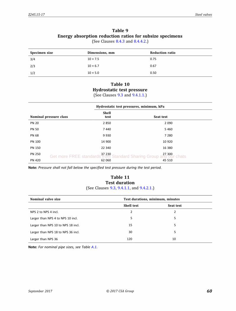
Z245.15-17 Steel valves
September 2017 © 2017 CSA Group 60
Table 9
Energy absorption reduction ratios for subsize specimens(See Clauses 8.4.3 and 8.4.4.2 .)
Specimen size Dimensions, mm Reduction ratio
3/4 10 × 7.5 0.75
2/3 10 × 6.7 0.67
1/2 10 × 5.0 0.50
Table 10
Hydrostatic test pressure(See Clauses 9.3 and 9.4.1 .1 .)
Nominal pressure class
Hydrostatic test pressures, minimum, kPa
Shell test Seat test
PN 20 2 850 2 090
PN 50 7 440 5 460
PN 68 9 930 7 280
PN 100 14 900 10 920
PN 150 22 340 16 380
PN 250 37 230 27 300
PN 420 62 060 45 510
Note: Pressure shall not fall below the specified test pressure during the test period.
Table 11
Test duration(See Clauses 9.3 , 9.4.1 .1 , and 9.4.2 .1 .)
Nominal valve size Test durations, minimum, minutes
Shell test Seat test
NPS 2 to NPS 4 incl . 2 2
Larger than NPS 4 to NPS 10 incl . 5 5
Larger than NPS 10 to NPS 18 incl . 15 5
Larger than NPS 18 to NPS 36 incl . 30 5
Larger than NPS 36 120 10
Note: For nominal pipe sizes, see Table A. 1 .
Get more FREE standards from Standard Sharing Group and our chats

Z245.15-17 Steel valves
September 2017 © 2017 CSA Group 61
Table 12
Valve markings(See Clauses 13.2 and 14.1 .1 .)
Markings Location
1. Standard designation: “CSA Z245.15-17” On nameplate
2. Manufacturer's name or trademark On both body and nameplate
3. Manufacturer's identifying reference for the valve design, such as a figure number or a catalogue number
On both body and nameplate
4. Nominal pressure class On nameplate
5. For Category I I va lves, impact test temperature* On nameplate
6. Maximum cold working-pressure rating (see Clause 5.2) On nameplate
7. Limiting maximum temperature, if less than 120 °C (see Clause 5.2) On nameplate
8. Body materia l† standard or specification On both body and nameplate
9. Melt identification, if made of a l loy steel On body
10. Trim identification: symbols indicating the material of the stem and seal ing faces of the closure members, if d ifferent from the valve body (see MSS SP-25)
On nameplate
11. Marking for va lves for sour service: “SOUR” On nameplate
12. Nominal valve size On nameplate
13. Ring-joint designation if appl icable: the letter “R” and a number indicating the size of ring
On the rim of the end flanges
14. Flow direction (check valves only) On body
15. Where required by Tables 3 to 7, mark “6D4” and the appropriate face-to-face or end-to-end d imension
On nameplate
16. Seria l number On both body and nameplate
* The notch-toughness test temperature shall be marked using the designation “MXC” or “PXC”, where “M” and “P” signify minus and plus, respectively, and “X” signifies the numerical value of the test temperature in degrees Celsius (e.g. , “M45C” for – 45 °C).† Where the body is fabricated from more than one type of steel, the weld end connection material shall govern the marking on the nameplate. Where more than one type of steel is used for weld end connections, all such types of steel shall be marked on the nameplate.

Z245.15-17 Steel valves
September 2017 © 2017 CSA Group 62
Figure 1
Typical wedge, rising-stem gate valve (for illustrative purposes only)(See Clauses 5 .1 and 5 .1 .2 .1 and Table 3 .)
Part names
1. Stem indicator
2. Stem enclosure
3. Handwheel
4. Yoke nut
5. Yoke
6. Stem
7. Yoke bolts and nuts
8. Stem packing
9. Rel ief valve
10. Bonnet
11. Bonnet bolts and nuts
12. Gate
13. Seat ring
14. Body
15. Support ribs or legs BButtwelding end
CRing joint
A
Raised face
Full face
Raised face
15
14
13
12
11
10
9
8
7
6
5
4
3
2
1
Get more FREE standards from Standard Sharing Group and our chats

Z245.15-17 Steel valves
September 2017 © 2017 CSA Group 63
Figure 2
Typical double-disc, rising-stem gate valve (for illustrative purposes only)(See Clauses 5 .1 and 5 .1 .2 .1 and Table 3 .)
Part names
1. Stem indicator
2. Stem enclosure
3. Handwheel
4. Yoke nut
5. Yoke
6. Stem
7. Yoke bolts and nuts
8. Stem packing
9. Rel ief va lve
10. Bonnet
11. Bonnet bolts and nuts
12. Disc guide
13. Disc assembly
14. Seat ring
15. Body
16. Support ribs or legs
B
Buttwelding end
CRing joint
Raised face
Full face
ARaised face
10
16
15
14
13
12
11
9
8
7
6
5
4
1
2
3

Z245.15-17 Steel valves
September 2017 © 2017 CSA Group 64
Figure 3
Typical conduit, rising-stem gate valve (for illustrative purposes only)(See Clauses 5 .1 and 5 .1 .2 .1 and Table 3 .)
Part names
1. Stem indicator
2. Stem enclosure
3. Handwheel
4. Yoke nut
5. Yoke
6. Stem
7. Yoke bolts and nuts
8. Stem packing
9. Rel ief valve
10. Bonnet
11. Bonnet bolts and nuts
12. Gate
13. Seat ring
14. Body
15. Support ribs or legs
Buttwelding end
B
CRing joint
Raised face
Full face
ARaised face
15
14
13
12
11
10
9
8
7
6
5
4
1
2
3
Get more FREE standards from Standard Sharing Group and our chats

Z245.15-17 Steel valves
September 2017 © 2017 CSA Group 65
Figure 4
Typical plug valve (for illustrative purposes only)(See Clauses 5 .1 and 5 .1 .3 and Table 4.)
Part names
1. Lubricator screw
2. G land studs and nuts
3. G land
4. Cover studs and nuts
5. Cover
6. Cover gasket
7. Stem packing
8. Lubricant check valve
9. Plug
10. Body
11. Stop col lar
12. Stem
B
C
Buttweld ing end
Raised face
A
Raised
face
Full face
Ring joint
1
2
3
4
5
6
7
8
9
10
11
12

Z245.15-17 Steel valves
September 2017 © 2017 CSA Group 66
Figure 5
Typical ball valve (for illustrative purposes only)(See Clauses 5 .1 and 5 .1 .4 and Table 5 .)
Part names
1. Indicator
2. Stem
3. Stem packing
4. Body nuts and bolts
5. Seat ring
6. Bal l
7. Body
A
C
B
Raised face
Ring joint
Buttwelding end
Full face
Raised face
1
2
3
4
5
6
7
Get more FREE standards from Standard Sharing Group and our chats

Z245.15-17 Steel valves
September 2017 © 2017 CSA Group 67
Figure 6
Typical regular, swing check valve (for illustrative purposes only)(See Clauses 5 .1 and 5 .1 .5.2 and Table 6.)
Part names
1. Cover studs and nuts
2. Cover
3. Body
4. Disc
5. Seat ring
6. Support ribs or legs
7. Pin
ARaised face
1
2
3
4
5
6
Raised face
C
Ring joint
Full face
B
Direction of flow
Buttwelding end
7
Note: The pin becomes a shaft if it is extended through the wall of the valve body.

Z245.15-17 Steel valves
September 2017 © 2017 CSA Group 68
Figure 7
Typical full-opening, swing check valve (for illustrative purposes only)(See Clauses 5 .1 and 5 .1 .5.2 and Table 6.)
Part names
1. Cover studs and nuts
2. Cover
3. Body
4. Disc
5. Seat ring
6. Support ribs or legs
7. Pin
B
Buttwelding end
Direction of flow
Full face
Ring jointC
Raised face
ARaised face
1
2
3
4
5
6
7
Note: The pin becomes a shaft if it is extended through the wall of the valve body.
Get more FREE standards from Standard Sharing Group and our chats

Z245.15-17 Steel valves
September 2017 © 2017 CSA Group 69
Figure 8
Typical single-plate wafer-type check valve — Long pattern (for illustrative
purposes only)(See Clauses 5 .1 and 5 .1 .5.2 and Table 7.)
Part names
1. Body
2. Closure plate
3. H inge
4. Nut
5. H inge pin
6. H inge pin retainers
7. Seat ring
8. Bearing spacers
7
3
4
2
1
Section A — A
Direction of flow
6
58A
3
4
2
A

Z245.15-17 Steel valves
September 2017 © 2017 CSA Group 70
Figure 9
Typical dual-plate wafer-type check valve — Long pattern (for illustrative purposes
only)(See Clauses 5 .1 and 5 .1 .5.2 and Table 7.)
Part names
1. Body
2. Closure plate
3. Stop pin
4. Spring
5. H inge pin
6. Plate lug bearings
7. Body lug bearings
8. Stop pin retainers
9. H inge pin retainers
10. Spring bearings
1
2
3
Section A — A
Direction of flow
A
4
5
6
10
9
A
8
7
Get more FREE standards from Standard Sharing Group and our chats

Z245.15-17 Steel valves
September 2017 © 2017 CSA Group 71
Figure 10
Typical single-plate wafer-type check valve — Short pattern (for illustrative
purposes only)(See Clauses 5 .1 and 5 .1 .5.2 and Table 7.)
Part names
1. Body
2. Clapper
3. Pin
4. Clapper seal
5. Body seal
6. Lifting eye
6
5 1
2 3
4
Section A — A
Direction of flow
A
A

Z245.15-17 Steel valves
September 2017 © 2017 CSA Group 72
Figure 11
Typical nozzle-type check valve (for illustrative purposes only)(See Clauses 5 .1 and 5 .1 .5.2 and Table 6.)
Part names
1. Body
2. Valve d isc rod
3. Compression spring
4. Valve d isc
5. Seat ring
6. Support pad
A
C
B
Direction of flow
Buttwelding end
Ring joint
Raised face
Full face
Raised face
1 2 3 4 5
6
Get more FREE standards from Standard Sharing Group and our chats

Z245.15-17 Steel valves
September 2017 © 2017 CSA Group 73
Figure 12
Design of buttwelding ends(See Clause 5 .4.2 .)
1.5t* 0.5t*
Valve
end
45° max
30° max
37.5º
± 2.5º
Outside
2t* transition
Radius > 0.05t–
30° max
18° max
Radius > 0.05t–
2t* transition
tD*Inside
tD
t1
t1.6 ± 0.8 mmPipe Pipe
1.5t* 0.5t*
Valve
end
45° max
30° max
37.5°
± 2.5°
Outside
2t* transition
Radius > 0.05t–
30° max
18° max
Radius > 0.05t–
2t* transition
tD*
Inside
tD
t1
t1.6 ± 0.8 mm
Radius > 0.05t–
Radius > 0.05t–
Radius > 0.05t–
Radius > 0.05t–
10° ± 1°
19 mm
a) Standard design b) Alternative design for ends
with tD greater than 22 mm
Radius > 0.05t–
Legend:
tI = I specified wal l thickness of matching pipe, mm
tDI = I design thickness of the buttwelding end
S1I = I specified minimum yield strength of pipe, MPa
S2I = I specified minimum yield strength of valve end, MPa
* Minimum dimension
Notes:
1) t1 maximum = 0. 5t
2) tD > t × (S1/S2) when specified minimum yield strength of the valve is less than the matching pipe.
3) tD minimum = t when specified minimum yield strength of the valve end is equal to or greater than the
matching pipe.

Z245.15-17 Steel valves
September 2017 © 2017 CSA Group 74
Annex A (informative)
Pipeline component size nomenclature
Note: This Annex is not a mandatory part of this Standard.
Table A.1
Pipeline component size nomenclature(See Clause 1 .2 .1 and Table 11 .)
Nominal valve size
Matching steel line
pipe size OD, mm
NPS 2 DN 50 60.3
NPS 2-1/2 DN 65 73.0
NPS 3 DN 80 88.9
NPS 3-1/2 DN 90 101.6
NPS 4 DN 100 114.3
NPS 5 DN 125 141.3
NPS 6 DN 150 168.3
NPS 8 DN 200 219.1
NPS 10 DN 250 273.1
NPS 12 DN 300 323.9
NPS 14 DN 350 355.6
NPS 16 DN 400 406.4
NPS 18 DN 450 457.0
NPS 20 DN 500 508.0
NPS 22 DN 550 559.0
NPS 24 DN 600 610.0
NPS 26 DN 650 660.0
NPS 28 DN 700 711.0
NPS 30 DN 750 762.0
NPS 32 DN 800 813.0
NPS 34 DN 850 864.0
NPS 36 DN 900 914.0
NPS 38 DN 950 965.0
NPS 40 DN 1000 1016.0
NPS 42 DN 1050 1067.0
NPS 44 DN 1100 1118.0
NPS 46 DN 1150 1168.0
(Continued)
Get more FREE standards from Standard Sharing Group and our chats

Z245.15-17 Steel valves
September 2017 © 2017 CSA Group 75
Table A.1 (Concluded)
Nominal valve size
Matching steel line
pipe size OD, mm
NPS 48 DN 1200 1219.0
NPS 50 DN 1250 1270.0
NPS 52 DN 1300 1321.0
NPS 54 DN 1350 1372.0
NPS 56 DN 1400 1422.0
NPS 58 DN 1450 1473.0
NPS 60 DN 1500 1524.0
Notes:
1) “NPS” means “nominal pipe size”, and the NPS system of nominal size designation is contained in Standards
prepared by the American Society of Mechanical Engineers (ASTM). The NPS size is dimensionless, and the
numerical portion of the designation is identical to the numerical portion of the previously used inch nominal
size designation.
2) “DN” means “diamètre nominal” (nominal diameter), and the DN system of nominal size designation is
contained in Standards prepared by the International Organization for Standardization (ISO).
3) The DN nominal sizes listed in this Table have generally been extracted from various ISO Standards, but in
some cases have been assigned arbitrarily. Caution should be exercised in the use of this Table, because in
many cases the DN nominal size shown is identical to that used in ISO Standards to designate components for
pipe having a specified outside diameter that differs slightly from the pipe OD size listed.

Z245.15-17 Steel valves
September 2017 © 2017 CSA Group 76
Annex B (informative)
Nominal pressure class nomenclature
Note: This Annex is not a mandatory part of this Standard.
Table B.1
Nominal pressure class nomenclature(See Clause 1 .2 .2 and Table 1 .)
ASME class designation Nominal pressure class
150 PN 20
300 PN 50
400 PN 68
600 PN 100
900 PN 150
1500 PN 250
2500 PN 420
Notes:
1) ASME class designations are designations given to valves to indicate the manufacturing dimensions and
maximum allowable non-shock working pressure, considering the material used and the operating
temperature.
2) “PN” means “pression nominale” (nominal pressure), and the PN system of nominal pressure class
designation is contained in Standards prepared by the International Organization for Standardization (ISO).
The numerical part of the designation approximates the maximum cold working pressure rating in bars
(100 kPa).
Get more FREE standards from Standard Sharing Group and our chats

Z245.15-17 Steel valves
September 2017 © 2017 CSA Group 77
Annex C (informative)
Recommended practice for the calibration and survey of
heat treating equipment
Note: This informative Annex has been written in mandatory language to facilitate its adoption by anyone wishing
to do so.
C.1 Furnace calibration and survey
C.1.1
A temperature survey within each furnace working zone shal l be performed on each furnace at the
maximum and minimum temperatures of the range for which the furnace is qual ified for use.
C.1.2
The total number of thermocouple test locations in the working zone of a furnace shal l be not fewer
than four for furnace working zones of 2 m 3 or less. The location of the thermocouples shal l be at the
manufacturer's d iscretion.
C.1.3
Furnace working zones greater than 2 m 3 and less than or equal to 10 m 3 shal l use not fewer than nine
thermocouples. The location of the thermocouples shal l be as specified in Figure C.1.
� C.1.4
Furnace working zones greater than 10 m 3 shal l use a minimum of n ine thermocouples, plus one
additional thermocouple for each 3 m 3 of working zone exceeding 10 m 3. Furnace working zones
greater than 43 m 3 shal l use a minimum of 20 thermocouples. Additional thermocouples may be used.
The location of the first n ine thermocouples shal l be as specified in Figure C.1. The placement of
additional thermocouples shal l be at the manufacturer's d iscretion and shal l be recorded on the survey
records.
C.1.5
After the thermocouples have been instal led, readings shal l be taken at least once every 3 min to
determine when the temperature of the furnace working zone approaches the bottom of the
temperature range being surveyed.
C.1.6
Once the furnace temperature has reached the set point temperature, the temperature of each
thermocouple shal l be recorded at maximum intervals of 2 min, for at least 10 min. Then, readings shal l
be taken at maximum intervals of 5 min for a time sufficient to determine the recurrent temperature
pattern of the working zone for at least 30 min.
C.1.7
After the furnace control set point temperature is reached, the temperature at any point in the working
zone shal l not vary by more than 15 °C from the set point temperature.

Z245.15-17 Steel valves
September 2017 © 2017 CSA Group 78
C.1.8
Furnaces that have been subjected to a change in burner quantity or location, or both, shal l be
surveyed, and the requirements of Clause C.1.7 shal l be met.
C.1.9
Furnaces that have been subjected to a change in the type of l in ing shal l be surveyed, and the
requirements of Clause C.1.7 shal l be met.
Note: An example of a change in the type of lining is from brick to fibre.
C.1.10
Except as specified by Clauses C.1.8 and C.1.9 , furnaces that have been repaired or rebuilt shal l be
surveyed if deemed necessary by the manufacturer. For any such survey, the requirements of
Clause C.1.7 shal l be met.
C.2 Instruments
C.2.1 Accuracy of production instruments
The production instruments (thermocouples, control lers, and recorders) used for the heat treatment
process shal l be accurate to within ± 1% over the heat treatment range.
C.2.2 Calibration of production instruments
Equipment used to cal ibrate production instruments shal l be accurate to within ± 0.25% of their fu l l-
scale range.
C.3 RecordsRecords of furnace cal ibration and surveys shal l be maintained for at least five years.
Get more FREE standards from Standard Sharing Group and our chats

Z245.15-17 Steel valves
September 2017 © 2017 CSA Group 79
Figure C.1
Thermocouple locations(See Clauses C.1 .3 and C.1 .4.)
Top view
Front
Rectangular furnace
Top view
Front
Cylindrical furnace
1) Front/left/top
2) Front/left/bottom
3) Front/right/top
4) Front/right/bottom
5) Centre/centre
6) Back/left/top
7) Back/left/bottom
8) Back/right/top
9) Back/right/bottom
1) Front/left/top
2) Front/left/bottom
3) Front/right/top
4) Front/right/bottom
5) Centre/top
6) Centre/centre
7) Centre/bottom
8) Back/centre/top
9) Back/centre/bottom
1 3
8
5
1
1
2
7
6
8
9 1
5
3
4
6
5
3
8
5
8
3
6
9
4
27
120°typ