Embed Size (px)
Citation preview

C-BV6
Ball Valves

2
NEW in this versionWe revised the layout and included tables and P-T charts for seat and seal materials.We add new product lines options and reference to the newest standards.
C-BV5 the previous version
30 Years of Innovation
The content of this catalog iscopyrighted by OMB Valves S.p.A. (c) 2009
Nothing included in this catalog can be reproduced in any form without obtaining prior written consent by OMB Valves S.p.A.
All photos and images published are copyrighted: the use of images, even if digitally modified to take away the OMB logo will be prosecuted to the maximum
extend of the law.
OMB is a family owned and managed business founded by Mr. Roberto Brevi in 1973. His goal was to build a company that would spe-cialize in the manufacturing of forged steel valves. Since its founding, OMB’s capabilities have grown to cover small diameter gate/globe/check valves, small and large diameter floaters and trunnion mounted ball valves, through conduit gate valves, and triple offset butterfly valves. Today OMB operates 5 plants in 3 countries with a worldwide network of agents, distributors, and sales offices.

3
The GroupAt OMB we have developed a comprehensive range of engineered valve products installed globally across a wide range of industries:
In these past 40 years OMB has supplied millions of valves to major oil and gas
OMB’s name has become synonymous with absolute reliability, superior quality, and competitive pricing.
In the early 80’s OMB was the first to introduce robotics in the valve manufacturing process. This included specialized equipment designed to reduce machining time, and increase the quality of the machined components.
Today OMB’s commitment to innovation and continuous improvement is higher than ever. With this in mind, OMB is focused on expanding our capacity at home, opening new plants abroad, and extending our distribution network to better serve our customers.
We invite you to visit any of our facilities to meet our experienced workers and see the state of the art equipment they are using to produce the best valve money can buy.
This is our promise!
Roberto, Simone and Fabio Brevi
The Brevi family is active in the management of the operations.Roberto Brevi, founder and chairman with Simone and Fabio managing directors.
OMB is based in Bergamo, a town 45 Km from Milan with easy access to airports, highways and seaport. Bergamo is the world center for the forged steel valves production with a large valve parts subcontracting base.

4
TECHNOLOGY & QUALITY
PRODUCTSOMB manufacture since the early ‘90 a wide range of engineered trunnion mounted ball valves for the oil & gas industry. We offer side entry, top entry and fully welded ball valves either manually operated or automated for on-off service.All our products are made from forgings sources from the most qualified suppliers in Italy.
RANGEWe offer trunnion mounted ball valves from 1/2” to 60”We complete our offer with floating ball valves from 1/4” to 6”.All available in ASME class 150, 300, 600, 900, 1500 and 2500.
MATERIALSWe offer a wide range of forged material for the body and the trim components. Please see available material in table at page 36.All materials MADE IN ITALY

5
TECHNOLOGY & QUALITY
QUALITY ASSURANCEOur activities are organized in accordance to procedure qualified to ISO 9001 since July 1991ISO 9001-2008 TUV-Sud cert no. 50 100 6209 Rev.02
COMPANY ACCREDITATIONSOMB is qualified to various international bodiesACHILLES FPALACHILLES JQSACHILLES RePro
PRODUCT CERTIFICATIONS
OMB is authorized by API to use the monogram or its products
API6A API cert no. 6A-0778
OMB is qualified to supply valves meeting the EC Pressure
marking on all our products
ATEX 95 equipment directive 94/9/EC, Equipment and protective systems intended for use in potentially explosive atmospheres ATEX cert no. TUV IT 11 ATEX 038 AR
OMB has qualified and certified its valves to the fugitive emission standard set by ISO 15848 part1
OMB products are certified in accordance to International Electrotechnical Commission’s (IEC) standard IEC 61508, now IEC EN 61508 and IEC EN 61511
OMB has qualified its valves to numerous certifications for fire safe according to: API 607 API 6FA ISO 10497

6
PRODUCT LINE
SIDE ENTRY TOP ENTRY FULL WELDED FLOATING API 6A
Body design Ring Forgings Ring Forgings / Castings Ring Forgings / Castings Forged bar Ring Forgings
Valve construction 3 Pieces 1 piece body with separate cover 2 or 3 Pieces 2 or 3 Pieces 2 or 3 Pieces
Size range size 1” to 60’” size 1” to 60’” size 1” to 60’” size 1/2” to 6” size 113/16” to 13”
ASME classes 150, 300, 600, 1500, 2500 150, 300, 600, 1500, 2500 150, 300, 600, 900, 1500 150, 300, 600, 800, 1500 3000, 5000, 10000
and 15000Specification reference
API608 - BS 5351 ISO17292 API6A
Soft and Metal Seated Soft and Metal Seated Soft Seated Soft and Metal Seated Soft and Metal Seated
Fire Safe Certified Certified Certified Certified Certified
Bore dimension Full and Standard Bore Full and Standard Bore Full and Standard Bore Full and Standard Bore Full and Special Bore
1/2”3/4”1”1.1/2”2”3”4”6”8”10”12”14”16”18”20”22”24”26”28”30”32”34”36”40”42”48”56”-60”
FORGED FORGED - CAST FORGED - CAST
SIDE ENTRY TOP ENTRY
FBRB-FB RB-FB RB
FULL WELDED
FORGED
FLOATING#1
50
#300
#600
#900
#150
0
#250
0
#150
#300
#600
#900
#150
0
#250
0
#150
#300
#600
#900
#150
0
#150
#300
#600
#900
#150
0
#250
0
See OMB API6A product range in Catalogue C-OV2
®
C-OV2Offshore Valves

7
PRODUCT LINE
1 piece body with separate cover
1500, 2500
14313
3 pieces
1500, 2500
ISO 14313
SIDE ENTRY TOP ENTRY
2 or 3 pieces
800, 1500
ISO 17292
2 or 3 pieces
900, 1500
14313
FULL WELDED FLOATING

8
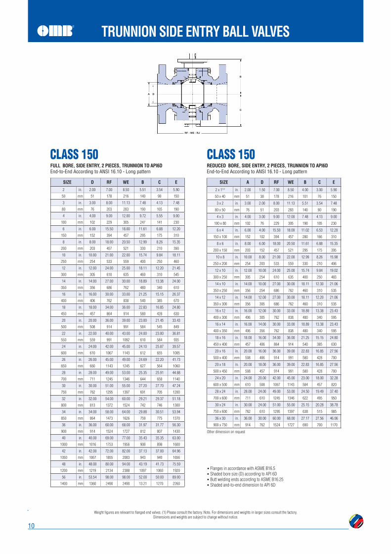
TRUNNION SIDE ENTRY BALL VALVES
Trunnion Mounted with external trunnion
Trunnion Mounted with bearing plates
In line maintenance yes
standard
API6A on request
Separate Ball and Stem standard
standard
Wetted area overlay on request
Internal lining on request
Forged construction standard
Cast construction no
Gear from 2"
Seal
Primary seal (body/closure): Soft standard
Secondary seal (Fire seal): Metal standard
Seal pocket overlay on request
Seat
Full, Reduced or Venturi Ports on request
Self Relieving seats standard
Single Piston Effect standard
on request
Soft insert seat standard
Metal seat standard
Elastomer, lipseal or Graphite seat seals on request
Seat pocket overlay on request
Emergency Seat injection on request
Ends
Flanged standard
Welded Ends on request
Welded ends with pups pieces on request
Hub Connection on request
Compact Flanges on request
RJ Wled Overlay on request
Anti Blowout design standard
Antistatic standard
Triple stem seal standard
Emergency Stem sealant injection on request
Extended bonnet for underground use on request
Opar
atio
n
Lever standard on small size
Gear, lockable standard
Motor Operated on request
Hydro/Pneu Operated on request
Feat
ures
standard
on request
Vent valve std from 8"
Lifting Lugs on request
Supporting Legs on request
Cavity pressure balance hole in ball standard
End-to- End
ASME B16.10 standard
Special Lenght on request
Fire Safe
API6FA standard
API607 on request
BS6755 on request

9
COMPONENT
NAMEPLATE Stainless steel STAINLESS STEEL Stainless steel
TOP FLANGE A105N A350 LF2 A182 F316
VENT A105N A350 LF2 A182 F316
BOLT A193 B7 A320 L7 A193 B8
NUT 2H 4H GR.8
STEM st/st 316 st/st 316 st/st 316
STEM SEAL FKM* FKM* FKM*
STEM PACKING Graphite Graphite Graphite
TRUNNION st/st 316 st/st 316 st/st 316
BALL st/st 316 st/st 316 st/st 316
SEAT st/st 316 st/st 316 st/st 316
SEAT INSERT PTFE+15% Glass PTFE+15% Glass PTFE+15% Glass
SEAT ORING FKM* FKM* FKM*
CLOSURE A105N A350 LF2 A182 F316
A105N A350 LF2 A182 F316
FKM* FKM* FKM*
Graphite Graphite Graphite
TRUNNION SIDE ENTRY BALL VALVES
FKM* = Viton® or equivalent. Viton is registrated trademark of DuPont Performance Elastomers
Weight figures are relevant to flanged end valves. (1) Please consult the factory. Note. For dimensions and weights in larger sizes consult the factory. Dimensions and weights are subject to change without notice.
10
TRUNNION SIDE ENTRY BALL VALVES
SIZE D RF WE B C E
2 in. 2.00 7.00 8.50 5.51 3.54 5.90
50 mm 51 178 216 140 90 150
3 in. 3.00 8.00 11.13 7.48 4.13 7.48
80 mm 76 203 283 190 105 190
4 in. 4.00 9.00 12.00 9.72 5.55 9.00
100 mm 102 229 305 247 141 230
6 in. 6.00 15.50 18.00 11.61 6.88 12.20
150 mm 152 394 457 295 175 310
8 in. 8.00 18.00 20.50 12.99 8.26 15.35
200 mm 203 457 521 330 210 390
10 in. 10.00 21.00 22.00 15.74 9.84 18.11
250 mm 254 533 559 400 250 460
12 in. 12.00 24.00 25.00 18.11 12.20 21.45
300 mm 305 610 635 460 310 545
14 in. 14.00 27.00 30.00 18.89 13.38 24.00
350 mm 356 686 762 480 340 610
16 in. 16.00 30.00 33.00 21.25 15.15 26.37
400 mm 406 762 838 540 385 670
18 in. 18.00 34.00 36.00 22.83 16.85 24.80
450 mm 457 864 914 580 428 630
20 in. 20.00 36.00 39.00 23.00 21.45 33.43
500 mm 508 914 991 584 545 849
22 in. 22.00 40.00 43.00 24.00 23.00 36.81
550 mm 559 991 1092 610 584 935
24 in. 24.00 42.00 45.00 24.10 25.87 39.57
600 mm 610 1067 1143 612 655 1005
26 in. 26.00 45.00 49.00 24.69 22.20 41.73
650 mm 660 1143 1245 627 564 1060
28 in. 28.00 49.00 53.00 25.35 25.91 44.88
700 mm 711 1245 1346 644 658 1140
30 in. 30.00 51.00 55.00 27.20 27.70 47.24
750 mm 762 1295 1397 691 705 1200
32 in. 32.00 54.00 60.00 29.21 29.37 51.18
800 mm 813 1372 1524 742 746 1300
34 in. 34.00 58.00 64.00 29.88 30.51 53.94
850 mm 864 1473 1626 759 775 1370
36 in. 36.00 60.00 68.00 31.97 31.77 56.30
900 mm 914 1524 1727 812 807 1430
40 in. 40.00 69.00 77.00 35.43 35.35 63.00
1000 mm 1016 1753 1956 900 898 1600
42 in. 42.00 72.00 82.00 37.13 37.00 64.96
1050 mm 1067 1855 2083 943 940 1656
48 in. 48.00 80.00 94.00 43.19 41.73 75.59
1200 mm 1219 2134 2388 1097 1060 1920
56 in. 53.54 98.00 98.00 52.00 50.00 89.00
1400 mm 1360 2490 2490 13.21 1270 2260
SIZE A D RF WE B C E
2 x 11/2 in. 2.00 1.50 7.00 8.50 4.00 3.00 5.90
50 x 40 mm 51 38 178 216 101 76 150
3 x 2 in. 3.00 2.00 8.00 11.13 5.51 3.54 7.48
80 x 50 mm 76 51 203 283 140 90 190
4 x 3 in. 4.00 3.00 9.00 12.00 7.48 4.13 9.00
100 x 80 mm 102 76 229 305 190 105 230
6 x 4 in. 6.00 4.00 15.50 18.00 11.02 6.53 12.20
150 x 100 mm 152 102 394 457 280 166 310
8 x 6 in. 8.00 6.00 18.00 20.50 11.61 6.88 15.35
200 x 150 mm 203 152 457 521 295 175 395
10 x 8 in. 10.00 8.00 21.00 22.00 12.99 8.26 15.98
250 x 200 mm 254 203 533 559 330 210 406
12 x 10 in. 12.00 10.00 24.00 25.00 15.74 9.84 19.02
300 x 250 mm 305 254 610 635 400 250 483
14 x 10 in. 14.00 10.00 27.00 30.00 18.11 12.30 21.06
350 x 250 mm 356 254 686 762 460 310 535
14 x 12 in. 14.00 12.00 27.00 30.00 18.11 12.20 21.06
350 x 300 mm 356 305 686 762 460 310 535
16 x 12 in. 16.00 12.00 30.00 33.00 18.89 13.38 23.43
400 x 300 mm 406 305 762 838 480 340 595
16 x 14 in. 16.00 14.00 30.00 33.00 18.89 13.38 23.43
400 x 350 mm 406 356 762 838 480 340 595
18 x 16 in. 18.00 16.00 34.00 36.00 21.25 15.15 24.80
450 x 400 mm 457 406 864 914 540 385 630
20 x 16 in. 20.00 16.00 36.00 39.00 22.83 16.85 27.56
500 x 400 mm 508 406 914 991 580 428 700
20 x 18 in. 20.00 18.00 36.00 39.00 22.83 16.85 27.56
500 x 450 mm 508 457 914 991 580 428 700
24 x 20 in. 24.00 20.00 42.00 45.00 23.00 18.00 32.28
600 x 500 mm 610 508 1067 1143 584 457 820
28 x 24 in. 28.00 24.00 49.00 53.00 24.50 19.49 37.40
700 x 600 mm 711 610 1245 1346 622 495 950
30 x 24 in. 30.00 24.00 51.00 55.00 25.15 20.28 38.78
750 x 600 mm 762 610 1295 1397 638 515 985
36 x 30 in. 36.00 30.00 60.00 68.00 27.17 27.56 46.06
900 x 750 mm 914 762 1524 1727 690 700 1170
Other dimension on request
Flanges in accordance with ASME B16.5 Shaded bore size (D) according to API 6D Butt welding ends according to ASME B16.25 Shaded and-to-end dimension to API 6D
CLASS 150 CLASS 150FULL BORE, SIDE ENTRY, 2 PIECES, TRUNNION TO API6DEnd-to-End According to ANSI 16.10 - Long pattern
REDUCED BORE, SIDE ENTRY, 2 PIECES, TRUNNION TO API6DEnd-to-End According to ANSI 16.10 - Long pattern

Weight figures are relevant to flanged end valves. (1) Please consult the factory. Note. For dimensions and weights in larger sizes consult the factory. Dimensions and weights are subject to change without notice.
11
TRUNNION SIDE ENTRY BALL VALVES
Other dimension on request
Flanges in accordance with ASME B16.5 Shaded bore size (D) according to API 6D Butt welding ends according to ASME B16.25 Shaded and-to-end dimension to API 6D
SIZE D RF WE B C E
2 in. 2.00 8.50 8.50 7.87 4.72 6.50
50 mm 51 216 216 200 120 165
3 in. 3.00 11.10 11.10 9.44 5.11 8.50
80 mm 76 283 283 240 130 218
4 in. 4.00 12.00 12.00 9.72 5.55 10.00
100 mm 102 305 305 247 141 254
6 in. 6.00 15.90 18.00 11.61 6.88 12.20
150 mm 152 457 457 295 175 310
8 in. 8.00 19.80 20.50 12.99 8.26 15.40
200 mm 203 502 521 330 210 390
10 in. 10.00 22.40 22.00 16.53 10.62 18.50
250 mm 254 568 559 420 270 470
12 in. 12.00 25.50 25.00 18.30 12.79 21.30
300 mm 305 648 635 465 325 545
14 in. 14.00 30.00 30.00 21.45 16.92 24.80
350 mm 356 762 762 545 430 630
16 in. 16.00 33.00 33.00 23.62 18.50 27.20
400 mm 406 838 838 600 470 690
18 in. 18.00 36.00 36.00 23.10 20.07 30.30
450 mm 457 914 914 586 510 770
20 in. 20.00 39.00 39.00 23.90 19.68 33.50
500 mm 508 991 991 607 500 850
22 in. 22.00 43.00 43.00 24.10 21.00 37.00
550 mm 559 1092 1092 612 533 940
24 in. 24.00 45.00 45.00 24.50 23.62 39.70
600 mm 610 1143 1143 622 600 1010
26 in. 26.00 49.00 49.00 24.80 22.80 42.50
650 mm 660 1245 1245 630 580 1080
28 in. 28.00 53.00 53.00 25.20 26.60 45.30
700 mm 711 1346 1346 640 675 1150
30 in. 30.00 55.00 55.00 27.60 28.70 48.40
750 mm 762 1397 1397 700 730 1230
32 in. 32.00 60.00 60.00 29.30 29.90 52.00
800 mm 813 1524 1524 745 760 1320
34 in. 34.00 64.00 64.00 29.90 31.50 54.50
850 mm 864 1626 1626 760 800 1380
36 in. 36.00 68.00 68.00 31.70 32.5 56.9
900 mm 914 1727 1727 805 825 1445
40 in. 40.00 77.00 77.00 35.40 36.2 64.10
1000 mm 1016 1956 1956 900 920 1630
42 in. 42.00 82.00 82.00 38.10 38.40 66.90
1050 mm 1067 2083 2083 968 980 1700
48 in. 48.00 85.40 85.40 43.30 45.60 74.80
1200 mm 1219 2170 2170 1100 1160 1960
56 in. 53.54 108.00 108.00 50.00 50.00 89.00
1400 mm 1360 2743 2743 1270 1270 2260
SIZE A D RF WE B C E
2 x 11/2 in. 2.00 1.50 8.50 8.50 6.88 3.14 6.50
50 x 40 mm 51 38 216 216 175 80 165
3 x 2 in. 3.00 2.00 11.10 11.10 7.87 4.72 8.50
80 x 50 mm 76 51 283 283 200 120 218
4 x 3 in. 4.00 3.00 12.00 12.00 9.44 5.11 10.00
100 x 80 mm 102 76 305 305 240 130 254
6 x 4 in. 6.00 4.00 15.90 18.00 11.02 5.90 12.20
150 x 100 mm 152 102 457 457 280 150 310
8 x 6 in. 8.00 6.00 19.80 20.50 11.61 6.88 15.40
200 x 150 mm 203 152 502 521 295 175 390
10 x 8 in. 10.00 8.00 22.40 22.00 12.99 8.26 17.50
250 x 200 mm 254 203 568 559 330 210 445
12 x 10 in. 12.00 10.00 25.50 25.00 16.53 10.62 20.50
300 x 250 mm 305 254 648 635 420 270 520
14 x 10 in. 14.00 10.00 30.00 30.00 18.30 12.79 23.00
350 x 250 mm 356 254 762 762 465 325 585
14 x 12 in. 14.00 12.00 30.00 30.00 18.30 12.79 23.00
350 x 250 mm 356 305 762 762 465 325 585
16 x 12 in. 16.00 12.00 33.00 33.00 21.45 16.92 25.60
400 x 300 mm 406 305 838 838 545 430 650
16 x 14 in. 16.00 14.00 33.00 33.00 21.45 16.92 25.60
400 x 350 mm 406 356 838 838 545 430 650
18 x 16 in. 18.00 16.00 36.00 36.00 23.62 18.50 28.00
450 x 400 mm 457 406 914 914 600 470 710
20 x 16 in. 20.00 16.00 39.00 39.00 24.40 20.07 30.70
500 x 400 mm 508 406 991 991 620 510 780
20 x 18 in. 20.00 18.00 39.00 39.00 24.40 20.07 30.40
500 x 450 mm 508 457 991 991 620 510 780
24 x 20 in. 24.00 20.00 45.00 45.00 25.10 19.68 36.00
600 x 500 mm 610 508 1143 1143 637 500 915
30 x 24 in. 30.00 24.00 55.00 55.00 25.80 21.20 42.90
750 x 600 mm 762 610 1397 1397 655 540 1090
36 x 30 in. 36.00 30.00 68.00 68.00 27.60 28.70 50.00
900 x 750 mm 914 762 1727 1727 700 730 1270
CLASS 300 CLASS 300FULL BORE, SIDE ENTRY, 2 PIECES, TRUNNION TO API6DEnd-to-End According to ANSI 16.10 - Long pattern
REDUCED BORE, SIDE ENTRY, 2 PIECES, TRUNNION TO API6DEnd-to-End According to ANSI 16.10 - Long pattern

Weight figures are relevant to flanged end valves. (1) Please consult the factory. Note. For dimensions and weights in larger sizes consult the factory. Dimensions and weights are subject to change without notice.
12
TRUNNION SIDE ENTRY BALL VALVES
Other dimension on request
Flanges in accordance with ASME B16.5 Shaded bore size (D) according to API 6D Butt welding ends according to ASME B16.25 Shaded and-to-end dimension to API 6D
SIZE D RF RJ WE B C E
2 in. 2.00 11.50 11.63 11.50 7.67 4.33 6.50
50 mm 51 292 295 292 195 110 165
3 in. 3.00 14.00 14.13 14.00 9.44 4.33 8.50
80 mm 76 356 359 356 240 110 218
4 in. 4.00 17.00 17.13 17.00 11.02 6.88 10.70
100 mm 102 432 435 432 280 175 273
6 in. 6.00 22.00 22.13 22.00 12.00 7.67 14.10
150 mm 152 559 562 559 305 195 360
8 in. 8.00 26.00 26.13 26.00 15.74 11.02 16.50
200 mm 203 660 664 660 400 280 419
10 in. 10.00 31.00 31.13 31.00 17.12 11.22 20.40
250 mm 254 787 791 787 435 285 520
12 in. 12.00 33.00 33.13 33.00 17.32 12.59 22.60
300 mm 305 838 841 838 440 320 575
14 in. 14.00 35.00 35.13 35.00 19.88 13.38 24.70
350 mm 356 889 892 889 505 340 628
16 in. 16.00 39.00 39.13 39.00 23.22 16.14 27.60
400 mm 406 991 994 991 590 410 700
18 in. 18.00 43.00 43.13 43.00 23.55 17.51 30.50
450 mm 457 1092 1095 1092 589 445 775
20 in. 20.00 47.00 47.25 47.00 23.80 20.07 34.10
500 mm 508 1194 1200 1194 604 510 865
22 in. 22.00 51.00 51.38 51.00 24.00 20.35 37.40
550 mm 559 1295 1305 1295 609 571 950
24 in. 24.00 55.00 55.38 55.00 24.50 25.19 40.50
600 mm 610 1397 1407 1397 622 640 1028
26 in. 26.00 57.00 57.50 57.00 24.80 24.30 40.10
650 mm 660 1448 1461 1448 630 618 1020
28 in. 28.00 61.00 61.50 61.00 26.20 27.20 46.10
700 mm 711 1549 1562 1549 665 692 1172
30 in. 30.00 66.30 65.50 66.30 29.20 31.50 50.80
750 mm 762 1651 1664 1651 741 800 1290
32 in. 32.00 70.00 70.72 70.00 29.80 31.70 52.40
800 mm 813 1778 1794 1778 756 804 1330
34 in. 34.00 76.00 76.52 76.00 30.80 32.20 57.10
850 mm 864 1930 1946 1930 782 817 1450
36 in. 36.00 82.00 82.63 82.00 34.20 37.20 60.90
900 mm 914 2083 2099 2083 869 945 1546
40 in. 40.00 85.40 85.43 85.40 36.10 38.60 64.80
1000 mm 1016 2170 2170 2170 916 980 1645
42 in. 42.00 85.60 85.63 85.60 39.20 43.70 70.80
1050 mm 1067 2175 2175 2175 995 1110 1800
48 in. 48.00 95.90 95.87 95.90 44.60 49.80 81.50
1200 mm 1219 2435 2435 2435 1132 1265 2070
56 in. 53.54 106.70 106.70 106.70 51.00 57.50 94.00
1400 mm 1360 2710 2710 2710 1295 1460 2390
SIZE A D RF RJ WE B C E
2 x 11/2 in. 2.00 1.50 11.50 11.63 11.50 7.48 3.54 6.50
50 x 40 mm 51 38 292 295 292 190 90 165
3 x 2 in. 3.00 2.00 14.00 14.13 14.00 14.01 4.33 8.30
80 x 50 mm 76 51 356 359 356 356 110 210
4 x 3 in. 4.00 3.00 17.00 17.13 17.00 9.44 4.33 14.70
100 x 80 mm 102 76 432 435 432 240 110 373
6 x 4 in. 6.00 4.00 22.00 22.13 22.00 11.02 6.88 14.00
150 x 100 mm 152 102 559 562 559 280 175 356
8 x 6 in. 8.00 6.00 26.00 26.13 26.00 12.00 7.67 16.50
200 x 150 mm 203 152 660 664 660 305 195 419
10 x 8 in. 10.00 8.00 31.00 31.13 31.00 15.74 11.02 20.10
250 x 200 mm 254 203 787 791 787 400 280 510
12 x 10 in. 12.00 10.00 33.00 33.13 33.00 17.12 11.22 22.00
300 x 250 mm 305 254 838 841 838 435 285 560
14 x 10 in. 14.00 10.00 35.00 35.13 35.00 17.32 12.59 23.80
350 x 250 mm 356 254 889 892 889 440 320 605
14 x 12 in. 14.00 12.00 35.00 35.13 35.00 17.32 12.59 23.80
350 x 250 mm 356 305 889 892 889 440 320 605
16 x 12 in. 16.00 12.00 39.00 39.13 39.00 19.88 13.38 27.00
400 x 300 mm 406 305 991 994 991 505 340 685
16 x 14 in. 16.00 14.00 39.00 39.13 39.00 19.88 13.38 24.70
400 x 350 mm 406 356 991 994 991 505 340 628
18 x 16 in. 18.00 16.00 43.00 43.13 43.00 23.22 16.10 29.30
450 x 400 mm 457 406 1092 1095 1092 590 410 745
20 x 16 in. 20.00 16.00 47.00 47.25 47.00 23.80 17.51 32.10
500 x 400 mm 508 406 1194 1200 1194 604 445 815
20 x 18 in. 20.00 18.00 47.00 47.25 47.00 24.00 17.51 32.10
500 x 450 mm 508 457 1194 1200 1194 609 445 815
24 x 20 in. 24.00 20.00 55.00 55.38 55.00 24.50 20.07 37.00
600 x 500 mm 610 508 1397 1407 1397 622 510 940
30 x 24 in. 30.00 24.00 66.30 65.50 66.30 24.80 22.40 44.50
750 x 600 mm 762 610 1651 1664 1651 629 570 1130
36 x 30 in. 36.00 30.00 82.00 82.63 82.00 27.90 29.90 51.80
900 x 750 mm 914 762 2083 2099 2083 708 760 1315
CLASS 600 CLASS 600FULL BORE, SIDE ENTRY, 2 PIECES, TRUNNION TO API6DEnd-to-End According to ANSI 16.10 - Long pattern
REDUCED BORE, SIDE ENTRY, 2 PIECES, TRUNNION TO API6DEnd-to-End According to ANSI 16.10 - Long pattern

Weight figures are relevant to flanged end valves. (1) Please consult the factory. Note. For dimensions and weights in larger sizes consult the factory. Dimensions and weights are subject to change without notice.
13
TRUNNION SIDE ENTRY BALL VALVES
Other dimension on request
Other dimension on request
Flanges in accordance with ASME B16.5 Shaded bore size (D) according to API 6D Butt welding ends according to ASME B16.25 Shaded and-to-end dimension to API 6D
SIZE D RF RJ WE B C E
2 in. 2.00 14.49 14.61 14.49 7.87 4.72 8.50
50 mm 51 368 371 368 200 120 220
3 in. 3.00 15.00 15.12 15.00 9.44 5.11 9.49
80 mm 76 381 384 381 240 130 241
4 in. 4.00 17.99 18.11 17.99 11.02 6.88 11.50
100 mm 102 457 460 457 280 175 290
6 in. 6.00 24.02 24.13 24.02 13.77 8.66 15.00
150 mm 152 610 613 610 350 220 381
8 in. 8.00 29.02 29.13 29.02 15.35 10.23 18.50
200 mm 203 737 740 737 390 260 470
10 in. 10.00 32.99 33.11 32.99 18.89 14.20 21.46
250 mm 254 838 841 838 480 310 545
12 in. 12.00 37.99 38.11 37.99 17.24 16.14 24.02
300 mm 305 965 968 965 438 410 610
14 in. 14.00 40.51 40.87 40.51 21.45 14.56 25.50
350 mm 356 1029 1038 1029 545 370 650
16 in. 16.00 44.49 44.88 44.49 24.59 16.53 27.95
400 mm 406 1130 1140 1130 624 420 710
18 in. 18.00 47.99 48.50 47.99 24.80 24.29 31.50
450 mm 457 1219 1232 1219 630 617 800
20 in. 20.00 52.01 52.48 52.01 25.00 28.54 35.04
500 mm 508 1321 1334 1321 635 725 890
24 in. 24.00 60.98 61.73 60.98 26.00 32.71 41.69
600 mm 610 1549 1568 1549 660 831 1059
28 in. 28.00 69.02 69.88 69.02 26.54 27.80 48.58
700 mm 711 1753 1775 1753 674 706 1234
30 in. 30.00 74.02 74.88 74.02 28.50 30.59 51.18
750 mm 762 1880 1902 1880 725 777 1300
32 in. 32.00 80.00 80.87 80.00 30.87 31.90 53.43
800 mm 813 2032 2054 2032 784 810 1357
34 in. 34.00 85.00 86.14 85.00 31.77 33.54 57.80
850 mm 864 2159 2188 2159 807 852 1468
36 in. 36.00 90.00 91.14 90.00 33.39 35.35 60.31
900 mm 914 2286 2315 2286 848 898 1532
SIDE ENTRY
SIZE A D RF RJ WE B C E
2 x 11/2 in. 2.00 1.50 14.49 14.61 14.49 6.10 4.25 8.60
50 x 40 mm 51 38 368 371 368 155 108 220
3 x 2 in. 3.00 2.00 15.00 15.12 15.00 7.87 4.72 9.49
80 x 50 mm 76 51 381 384 381 200 120 241
4 x 3 in. 4.00 3.00 17.99 18.11 17.99 9.44 5.11 11.50
100 x 80 mm 102 76 457 460 457 240 130 290
6 x 4 in. 6.00 4.00 24.02 24.13 24.02 11.02 6.88 14.90
150 x 100 mm 152 102 610 613 610 280 175 380
8 x 6 in. 8.00 6.00 29.02 29.13 29.02 13.77 8.66 18.50
200 x 150 mm 203 152 737 740 737 350 220 470
10 x 8 in. 10.00 8.00 32.99 33.11 32.99 15.35 10.23 21.46
250 x 200 mm 254 203 838 841 838 390 260 545
12 x 10 in. 12.00 10.00 37.99 38.11 37.99 18.89 12.20 24.02
300 x 250 mm 305 254 965 968 965 480 310 610
14 x 10 in. 14.00 10.00 40.51 40.87 40.51 17.24 16.14 25.50
350 x 250 mm 356 254 1029 1038 1029 438 410 650
14 x 12 in. 14.00 12.00 40.51 40.87 40.51 17.24 16.14 27.90
350 x 300 mm 356 305 1029 1038 1029 438 410 710
16 x 12 in. 16.00 12.00 44.49 44.88 44.49 21.45 14.56 29.50
400 x 300 mm 406 305 1130 1140 1130 545 370 750
16 x 14 in. 16.00 14.00 44.49 44.88 44.49 21.45 14.56 31.10
400 x 350 mm 406 356 1130 1140 1130 545 370 790
18 x 16 in. 18.00 16.00 47.99 48.50 47.99 24.59 16.53 31.50
450 x 400 mm 457 406 1219 1232 1219 624 420 800
20 x 16 in. 20.00 16.00 52.01 52.48 52.01 25.00 24.29 31.10
500 x 400 mm 508 406 1321 1334 1321 630 617 790
20 x 18 in. 20.00 18.00 52.01 52.48 52.01 25.57 24.29 35.04
500 x 450 mm 508 457 1321 1334 1321 649 617 890
24 x 20 in. 24.00 20.00 60.98 61.73 60.98 25.70 28.54 40.94
600 x 500 mm 610 508 1549 1568 1549 652 725 1040
30 x 24 in. 30.00 24.00 74.02 74.88 74.02 28.00 24.88 48.43
750 x 600 mm 762 610 1880 1902 1880 711 632 1230
36 x 30 in. 36.00 30.00 90.00 91.14 90.00 31.70 30.87 57.48
900 x 750 mm 914 762 2286 2315 2286 807 784 1460
CLASS 900 CLASS 900FULL BORE, SIDE ENTRY, 2 PIECES, TRUNNION TO API6DEnd-to-End According to ANSI 16.10 - Long pattern
REDUCED BORE, SIDE ENTRY, 2 PIECES, TRUNNION TO API6DEnd-to-End According to ANSI 16.10 - Long pattern

Weight figures are relevant to flanged end valves. (1) Please consult the factory. Note. For dimensions and weights in larger sizes consult the factory. Dimensions and weights are subject to change without notice.
14
TRUNNION SIDE ENTRY BALL VALVES
Other dimension on request
Other dimension on request
Flanges in accordance with ASME B16.5 Shaded bore size (D) according to API 6D Butt welding ends according to ASME B16.25 Shaded and-to-end dimension to API 6D
SIZE D RF RJ WE B C E
2 in. 2.00 14.49 14.61 14.49 8.07 4.72 8.60
50 mm 51 368 371 368 205 120 220
3 in. 3.00 18.50 18.62 18.50 8.26 4.92 10.51
80 mm 76 470 473 470 210 125 267
4 in. 4.00 21.50 21.61 21.50 9.64 6.29 12.20
100 mm 102 546 549 546 245 160 310
6 in. 6.00 27.76 27.99 27.76 13.18 10.03 15.51
150 mm 152 705 711 705 335 255 394
8 in. 8.00 32.76 33.11 32.76 17.20 13.38 19.09
200 mm 203 832 841 832 437 340 485
10 in. 10.00 39.02 39.37 39.02 19.76 15.00 23.03
250 mm 254 991 1000 991 502 381 585
12 in. 12.00 44.49 44.61 44.49 20.98 17.24 27.95
300 mm 305 1130 1146 1130 533 438 710
14 in. 14.00 49.49 50.24 49.49 24.64 19.60 30.12
350 mm 356 1257 1276 1257 626 498 765
16 in. 16.00 54.49 55.35 54.49 28.54 18.11 33.39
400 mm 406 1384 1407 1384 725 460 848
18 in. 18.00 60.51 61.38 60.51 29.00 23.90 38.58
450 mm 457 1537 1559 1537 736 607 980
20 in. 20.00 65.51 66.38 66.51 30.00 25.40 39.96
500 mm 508 1664 1686 1664 762 644 1015
24 in. 24.00 80.43 81,54 80.43 32.00 28.50 50.91
600 mm 610 2043 1972 2043 813 725 1295
SIZE A D RF RJ WE B C E
2 x 11/2 in. 2.00 1.50 14.49 14.61 14.49 7.48 4.33 8.66
50 x 40 mm 51 38 368 371 368 190 110 220
3 x 2 in. 3.00 2.00 18.50 18.62 18.50 8.07 4.72 10.51
80 x 50 mm 76 51 470 473 470 205 120 2.67
4 x 3 in. 4.00 3.00 21.50 21.61 21.50 8.26 4.92 12.20
100 x 80 mm 102 76 546 549 546 210 125 310
6 x 4 in. 6.00 4.00 27.76 27.99 27.76 9.64 6.29 15.51
150 x 100 mm 152 102 705 711 705 245 160 394
8 x 6 in. 8.00 6.00 32.76 33.11 32.76 13.18 10.03 19.09
200 x 150 mm 203 152 832 841 832 335 255 485
10 x 8 in. 10.00 8.00 39.02 39.37 39.02 16.14 11.41 23.03
250 x 200 mm 254 203 991 1000 991 410 290 585
12 x 10 in. 12.00 10.00 44.49 44.61 44.49 18.30 13.18 26.57
300 x 250 mm 305 254 1130 1146 1130 465 335 675
14 x 10 in. 14.00 10.00 49.49 50.24 49.49 21.77 17.24 27.95
350 x 250 mm 356 254 1257 1276 1257 553 439 710
14 x 12 in. 14.00 12.00 49.49 50.24 49.49 21.77 17.24 29.92
350 x 300 mm 356 305 1257 1276 1257 553 438 760
16 x 12 in. 16.00 12.00 54.49 55.35 54.49 24.64 19.60 32.48
400 x 300 mm 406 305 1384 1407 1384 626 498 825
16 x 14 in. 16.00 14.00 54.49 55.35 54.49 24.64 19.60 32.48
400 x 350 mm 406 356 1384 1407 1384 626 498 825
18 x 16 in. 18.00 16.00 60.51 61.38 60.51 25.00 20.00 36.22
450 x 400 mm 457 406 1537 1559 1537 630 508 920
20 x 16 in. 20.00 16.00 65.51 66.38 66.51 26.00 20.00 38.97
500 x 400 mm 508 406 1664 1686 1664 660 508 990
20 x 18 in. 20.00 18.00 65.51 66.38 66.51 28.00 23.00 38.97
500 x 450 mm 508 457 1664 1686 1664 711 542 990
24 x 20 in. 24.00 20.00 80.43 81,54 80.43 30.00 25.00 46.06
600 x 500 mm 610 508 2043 1972 2043 762 635 1170
CLASS 1500 CLASS 1500FULL BORE, SIDE ENTRY, 2 PIECES, TRUNNION TO API6DEnd-to-End According to ANSI 16.10 - Long pattern
REDUCED BORE, SIDE ENTRY, 2 PIECES, TRUNNION TO API6DEnd-to-End According to ANSI 16.10 - Long pattern

Weight figures are relevant to flanged end valves. (1) Please consult the factory. Note. For dimensions and weights in larger sizes consult the factory. Dimensions and weights are subject to change without notice.
15
TRUNNION SIDE ENTRY BALL VALVES
Other dimension on requestOther dimension on request
Flanges in accordance with ASME B16.5 Shaded bore size (D) according to API 6D Butt welding ends according to ASME B16.25 Shaded and-to-end dimension to API 6D
SIZE D RF RJ WE B C E
2 in. 2.00 17.76 17.87 17.76 8.46 5.11 9.05
50 mm 51 451 454 451 215 130 230
3 in. 3.00 22.76 22.99 22.76 8.66 5.31 11.08
80 mm 76 578 584 578 220 135 300
4 in. 4.00 26.50 26.89 26.50 10.03 6.96 14.02
100 mm 102 673 683 673 255 170 356
6 in. 6.00 35.98 36.50 35.98 16.92 10.43 19.09
150 mm 152 914 927 914 430 265 485
8 in. 8.00 40.24 40.87 40.24 16.92 13.30 24.41
200 mm 203 1022 1038 1022 430 340 620
10 in. 10.00 50.00 50.87 50.00 17.50 16.60 29.33
250 mm 254 1270 1292 1270 444 421 745
12 in. 12.00 55.98 56.89 55.98 18.00 18.90 34.44
300 mm 305 1422 1445 1422 457 480 875
SIZE A D RF RJ WE B C E
2 x 11/2 in. 2.00 1.50 17.76 17.87 17.76 7.78 4.72 9.25
50 x 40 mm 51 38 451 454 451 200 120 230
3 x 2 in. 3.00 2.00 22.76 22.99 22.76 8.46 5.11 11.01
80 x 50 mm 76 51 578 584 578 215 130 300
4 x 3 in. 4.00 3.00 26.50 26.89 26.50 8.66 5.31 14.02
100 x 80 mm 102 76 673 683 673 220 135 356
6 x 4 in. 6.00 4.00 35.98 36.50 35.98 10.03 6.96 19.09
150 x 100 mm 152 102 914 927 914 255 170 485
8 x 6 in. 8.00 6.00 40.24 40.87 40.24 12.00 9.00 22.05
200 x 150 mm 203 152 1022 1038 1022 348 228 560
10 x 8 in. 10.00 8.00 50.00 50.87 50.00 14.00 13.00 26.57
250 x 200 mm 254 203 1270 1292 1270 355 330 670
12 x 10 in. 12.00 10.00 55.98 56.89 55.98 16.00 18.00 30.70
300 x 250 mm 305 254 1422 1445 1422 406 475 780
CLASS 2500 CLASS 2500FULL BORE, SIDE ENTRY, 2 PIECES, TRUNNION TO API6DEnd-to-End According to ANSI 16.10 - Long pattern
REDUCED BORE, SIDE ENTRY, 2 PIECES, TRUNNION TO API6DEnd-to-End According to ANSI 16.10 - Long pattern

16
TRUNNION TOP ENTRY BALL VALVES
Trunnion Mounted with external trunnio
Trunnion Mounted with bearing plates
In line maintenance yes
standard
API6A on request
Separate Ball and Stem standard
standard
Wetted area overlay on request
Internal lining on request
Forged construction standard
Cast construction no
Gear from 2"
Seal
Primary seal (body/closure): Soft standard
Secondary seal (Fire seal): Metal standard
Seal pocket overlay on request
Seat
Full, Reduced or Venturi Ports on request
Self Relieving seats standard
Single Piston Effect standard
on request
Soft insert seat standard
Metal seat standard
Elastomer, lipseal or Graphite seat seals on request
Seat pocket overlay on request
Emergency Seat injection on request
Ends
Flanged standard
Welded Ends on request
Welded ends with pups pieces on request
Hub Connection on request
Compact Flanges on request
RJ Wled Overlay on request
Anti Blowout design standard
Antistatic standard
Triple stem seal standard
Emergency Stem sealant injection on request
Extended bonnet for underground use on request
Opar
atio
n
Lever standard on small size
Gear, lockable standard
Motor Operated on request
Hydro/Pneu Operated on request
Feat
ures
standard
on request
Vent valve std from 8"
Lifting Lugs on request
Supporting Legs on request
Cavity pressure balance hole in ball standard
End-to- End
ASME B16.10 standard
Special Lenght on request
Fire Safe
API6FA standard
API607 on request
BS6755 on request

17
TRUNNION TOP ENTRY BALL VALVES
COMPONENT
NAMEPLATE Stainless steel Stainless steel Stainless steel
TOP FLANGE A105N A350 LF2 A182 F316
VENT A105N A350 LF2 A182 F316
BOLT A193 B7 A320 L7 A193 B8
NUT 2H 4H GR.8
STEM st/st 316 st/st 316 st/st 316
STEM SEAL FKM* FKM* FKM*
STEM PACKING Graphite Graphite Graphite
TRUNNION st/st 316 st/st 316 st/st 316
BALL st/st 316 st/st 316 st/st 316
SEAT st/st 316 st/st 316 st/st 316
SEAT INSERT PTFE+15% Glass PTFE+15% Glass PTFE+15% Glass
SEAT ORING FKM* FKM* FKM*
TOP COVER A105N A350 LF2 A182 F316
A105N A350 LF2 A182 F316
FKM* FKM* FKM*
Graphite Graphite Graphite
FKM* = Viton® or equivalent. Viton is registrated trademark of DuPont Performance Elastomers

Weight figures are relevant to flanged end valves. (1) Please consult the factory. Note. For dimensions and weights in larger sizes consult the factory. Dimensions and weights are subject to change without notice.
18
TRUNNION TOP ENTRY BALL VALVES
SIZE D RF WE B C E
2 in. 2.00 7.00 8.50 5.51 3.54 5.00
50 mm 51 178 216 140 90 150
3 in. 3.00 8.00 11.13 7.48 4.13 7.48
80 mm 76 203 283 190 105 190
4 in. 4.00 9.00 12.00 11.02 6.53 9.00
100 mm 102 229 305 280 166 230
6 in. 6.00 15.50 18.00 11.61 6.88 12.20
150 mm 152 394 457 295 175 310
8 in. 8.00 18.00 20.50 12.99 8.26 15.35
200 mm 203 457 521 330 210 390
10 in. 10.00 21.00 22.00 15.74 9.84 18.11
250 mm 254 533 559 400 250 460
12 in. 12.00 24.00 25.00 18.11 12.20 21.45
300 mm 305 610 635 460 310 545
14 in. 14.00 27.00 30.00 18.89 13.38 24.00
350 mm 356 686 762 480 340 610
16 in. 16.00 30.00 33.00 21.25 15.15 26.37
400 mm 406 762 838 540 385 670
18 in. 18.00 34.00 36.00 23.00 16.85 24.80
450 mm 457 864 914 584 428 630
20 in. 20.00 36.00 39.00 24.00 21.45 33.43
500 mm 508 914 991 610 545 849
22 in. 22.00 40.00 43.00 24.10 23.00 36.81
550 mm 559 991 1092 612 584 935
24 in. 24.00 42.00 45.00 30.70 25.78 39.57
600 mm 610 1067 1143 780 655 1005
26 in. 26.00 45.00 49.00 24.69 22.20 41.73
650 mm 660 1143 1245 627 564 1060
28 in. 28.00 49.00 53.00 25.35 25.91 44.88
700 mm 711 1245 1346 644 658 1140
30 in. 30.00 51.00 55.00 27.20 27.70 47.24
750 mm 762 1295 1397 691 705 1200
32 in. 32.00 54.00 60.00 29.21 29.37 51.18
800 mm 813 1372 1524 742 746 1300
34 in. 34.00 58.00 64.00 29.88 30.51 53.94
850 mm 864 1473 1626 759 775 1370
36 in. 36.00 60.00 68.00 31.97 31.77 56.30
900 mm 914 1524 1727 812 807 1430
40 in. 40.00 69.00 77.00 35.43 35.35 63.00
1000 mm 1016 1753 1956 900 898 1600
42 in. 42.00 72.00 82.00 37.13 37.00 64.96
1050 mm 1067 1855 2083 943 940 1656
48 in. 48.00 80.00 94.00 43.19 41.73 75.59
1200 mm 1219 2134 2388 1097 1060 1920
SIZE A D RF WE B C E
2 x 11/2 in. 2.00 1.50 7.00 8.50 4.00 3.00 5.90
50 x 40 mm 51 38 178 216 101 76 150
3 x 2 in. 3.00 2.00 8.00 11.13 5.51 3.54 7.48
80 x 50 mm 76 51 203 283 140 90 190
4 x 3 in. 4.00 3.00 9.00 12.00 7.48 4.13 9.00
100 x 80 mm 102 76 229 305 190 105 230
6 x 4 in. 6.00 4.00 15.50 18.00 11.02 6.53 12.20
150 x 100 mm 152 102 394 457 280 166 310
8 x 6 in. 8.00 6.00 18.00 20.50 11.61 6.88 15.35
200 x 150 mm 203 152 457 521 295 175 395
10 x 8 in. 10.00 8.00 21.00 22.00 12.99 8.26 15.98
250 x 200 mm 254 203 533 559 330 210 406
12 x 10 in. 12.00 10.00 24.00 25.00 15.74 9.84 19.02
300 x 250 mm 305 254 610 635 400 250 483
14 x 10 in. 14.00 10.00 27.00 30.00 18.11 12.30 21.06
350 x 250 mm 356 254 686 762 460 310 535
14 x 12 in. 14.00 12.00 27.00 30.00 18.11 12.20 21.06
350 x 250 mm 356 305 686 762 460 310 535
16 x 12 in. 16.00 12.00 30.00 33.00 18.89 13.38 23.43
400 x 300 mm 406 305 762 838 480 340 595
16 x 14 in. 16.00 14.00 30.00 33.00 18.89 13.38 23.43
400 x 350 mm 406 356 762 838 480 340 595
18 x 16 in. 18.00 16.00 34.00 36.00 21.25 15.15 24.80
450 x 400 mm 457 406 864 914 540 385 630
20 x 16 in. 20.00 16.00 36.00 39.00 22.83 16.85 27.56
500 x 400 mm 508 406 914 991 580 428 700
20 x 18 in. 20.00 18.00 36.00 39.00 22.84 16.85 27.56
500 x 450 mm 508 457 914 991 580 428 700
24 x 20 in. 24.00 20.00 42.00 45.00 23 .00 18.00 32.28
600 x 500 mm 610 508 1067 1143 584 457 820
30 x 24 in. 30.00 24.00 51.00 55.00 25.15 19.49 38.78
750 x 600 mm 762 610 1295 1397 638 495 985
36 x 30 in. 36.00 30.00 60.00 68.00 27.17 27.56 46.06
900 x 750 mm 914 762 1524 1727 690 700 1170
Other dimension on request
Flanges in accordance with ASME B16.5 Shaded bore size (D) according to API 6D Butt welding ends according to ASME B16.25 Shaded and-to-end dimension to API 6D
CLASS 150 CLASS 150End-to-End According to ANSI 16.10 - Long pattern End-to-End According to ANSI 16.10 - Long pattern

Weight figures are relevant to flanged end valves. (1) Please consult the factory. Note. For dimensions and weights in larger sizes consult the factory. Dimensions and weights are subject to change without notice.
19
TRUNNION TOP ENTRY BALL VALVES
SIZE D RF WE B C E
2 in. 2.00 8.50 8.50 7.87 4.72 6.50
50 mm 51 216 216 200 120 165
3 in. 3.00 11.10 11.10 9.44 5.11 8.50
80 mm 76 283 283 240 130 218
4 in. 4.00 12.00 12.00 11.02 5.90 10.00
100 mm 102 305 305 280 150 254
6 in. 6.00 15.90 18.00 11.61 6.88 12.20
150 mm 152 457 457 295 175 310
8 in. 8.00 19.80 20.50 12.99 8.26 15.40
200 mm 203 502 521 330 210 390
10 in. 10.00 22.40 22.00 16.53 10.62 18.50
250 mm 254 568 559 420 270 470
12 in. 12.00 25.50 25.00 18.30 12.79 21.30
300 mm 305 648 635 465 325 545
14 in. 14.00 30.00 30.00 21.45 16.92 24.80
350 mm 356 762 762 545 430 630
16 in. 16.00 33.00 33.00 23.62 18.50 27.20
400 mm 406 838 838 600 470 690
18 in. 18.00 36.00 36.00 23.10 20.07 30.30
450 mm 457 914 914 586 510 770
20 in. 20.00 39.00 39.00 23.90 19.68 33.50
500 mm 508 991 991 607 500 850
22 in. 22.00 43.00 43.00 24.01 21.00 37.00
550 mm 559 1092 1092 612 533 940
24 in. 24.00 45.00 45.00 24.50 23.62 39.70
600 mm 610 1143 1143 622 600 1010
26 in. 26.00 49.00 49.00 24.80 22.80 42.50
650 mm 660 1245 1245 630 580 1080
28 in. 28.00 53.00 53.00 25.20 26.60 45.30
700 mm 711 1346 1346 640 675 1150
30 in. 30.00 55.00 55.00 27.60 28.70 48.40
750 mm 762 1397 1397 700 730 1230
32 in. 32.00 60.00 60.00 29.30 29.90 52.00
800 mm 813 1524 1524 745 760 1320
34 in. 34.00 64.00 64.00 29.90 31.50 54.50
850 mm 864 1626 1626 760 800 1380
36 in. 36.00 68.00 68.00 31.70 32.5 56.9
900 mm 914 1727 1727 805 825 1445
40 in. 40.00 77.00 77.00 35.40 36.2 64.10
1000 mm 1016 1956 1956 900 920 1630
42 in. 42.00 82.00 82.00 38.10 38.40 66.90
1050 mm 1067 2083 2083 968 980 1700
48 in. 48.00 85.40 85.40 43.30 45.60 74.80
1200 mm 1219 2170 2170 1100 1160 1960
SIZE A D RF WE B C E
2 x 11/2 in. 2.00 1.50 8.50 8.50 8.22 2.75 6.50
50 x 40 mm 51 38 216 216 209 70 165
3 x 2 in. 3.00 2.00 11.10 11.10 7.87 4.72 8.50
80 x 50 mm 76 51 283 283 200 120 218
4 x 3 in. 4.00 3.00 12.00 12.00 9.44 5.11 10.00
100 x 80 mm 102 76 305 305 240 130 254
6 x 4 in. 6.00 4.00 15.90 18.00 11.02 5.90 12.20
150 x 100 mm 152 102 457 457 280 150 310
8 x 6 in. 8.00 6.00 19.80 20.50 11.61 6.88 15.40
200 x 150 mm 203 152 502 521 295 175 390
10 x 8 in. 10.00 8.00 22.40 22.00 12.99 8.26 17.50
250 x 200 mm 254 203 568 559 330 210 445
12 x 10 in. 12.00 10.00 25.50 25.00 16.53 10.62 20.50
300 x 250 mm 305 254 648 635 420 270 520
14 x 10 in. 14.00 10.00 30.00 30.00 _ _ 23.00
350 x 250 mm 356 254 762 762 _ _ 585
14 x 12 in. 14.00 12.00 30.00 30.00 18.30 12.79 23.00
350 x 250 mm 356 305 762 762 465 325 585
16 x 12 in. 16.00 12.00 33.00 33.00 _ _ 25.60
400 x 300 mm 406 305 838 838 _ _ 650
16 x 14 in. 16.00 14.00 33.00 33.00 21.45 16.92 25.60
400 x 350 mm 406 356 838 838 545 430 650
18 x 16 in. 18.00 16.00 36.00 36.00 23.62 18.50 28.00
450 x 400 mm 457 406 914 914 600 470 710
20 x 16 in. 20.00 16.00 39.00 39.00 _ _ 30.70
500 x 400 mm 508 406 991 991 _ _ 780
20 x 18 in. 20.00 18.00 39.00 39.00 24.40 20.07 30.40
500 x 450 mm 508 457 991 991 620 510 780
24 x 20 in. 24.00 20.00 45.00 45.00 28.89 19.68 36.00
600 x 500 mm 610 508 1143 1143 734 500 915
30 x 24 in. 30.00 24.00 55.00 55.00 _ _ 42.90
750 x 600 mm 762 610 1397 1397 _ _ 1090
36 x 30 in. 36.00 30.00 68.00 68.00 _ _ 50.00
900 x 750 mm 914 762 1727 1727 _ _ 1270
Other dimension on request
Flanges in accordance with ASME B16.5 Shaded bore size (D) according to API 6D Butt welding ends according to ASME B16.25 Shaded and-to-end dimension to API 6D
CLASS 300 CLASS 300End-to-End According to ANSI 16.10 - Long pattern End-to-End According to ANSI 16.10 - Long pattern

Weight figures are relevant to flanged end valves. (1) Please consult the factory. Note. For dimensions and weights in larger sizes consult the factory. Dimensions and weights are subject to change without notice.
20
TRUNNION TOP ENTRY BALL VALVES
SIZE D RF RJ WE B C E
2 in. 2.00 11.50 11.63 11.50 7.67 4.33 6.50
50 mm 51 292 295 292 195 110 165
3 in. 3.00 14.00 14.13 14.00 9.44 4.33 8.50
80 mm 76 356 359 356 240 110 218
4 in. 4.00 17.00 17.13 17.00 11.02 6.88 10.70
100 mm 102 432 435 432 280 175 273
6 in. 6.00 22.00 22.13 22.00 12.00 7.67 14.10
150 mm 152 559 562 559 305 195 360
8 in. 8.00 26.00 26.13 26.00 15.74 11.02 16.50
200 mm 203 660 664 660 400 280 419
10 in. 10.00 31.00 31.13 31.00 17.12 11.22 20.40
250 mm 254 787 791 787 435 285 520
12 in. 12.00 33.00 33.13 33.00 17.32 12.59 22.60
300 mm 305 838 841 838 440 320 575
14 in. 14.00 35.00 35.13 35.00 19.88 13.38 24.70
350 mm 356 889 892 889 505 340 628
16 in. 16.00 39.00 39.13 39.00 23.22 16.14 27.60
400 mm 406 991 994 991 590 410 700
18 in. 18.00 43.00 43.13 43.00 23.55 17.51 30.50
450 mm 457 1092 1095 1092 589 445 775
20 in. 20.00 47.00 47.25 47.00 23.80 20.07 34.10
500 mm 508 1194 1200 1194 604 510 865
22 in. 22.00 51.00 51.38 51.00 24.00 20.35 37.40
550 mm 559 1295 1305 1295 609 571 950
24 in. 24.00 55.00 55.38 55.00 24.50 25.19 40.50
600 mm 610 1397 1407 1397 622 640 1028
26 in. 26.00 57.00 57.50 57.00 24.80 24.30 40.10
650 mm 660 1448 1461 1448 630 618 1020
28 in. 28.00 61.00 61.50 61.00 26.20 27.20 46.10
700 mm 711 1549 1562 1549 665 692 1172
30 in. 30.00 66.30 65.50 66.30 29.20 31.50 50.80
750 mm 762 1651 1664 1651 741 800 1290
32 in. 32.00 70.00 70.72 70.00 29.80 31.70 52.40
800 mm 813 1778 1794 1778 756 804 1330
34 in. 34.00 76.00 76.52 76.00 30.80 32.20 57.10
850 mm 864 1930 1946 1930 782 817 1450
36 in. 36.00 82.00 82.63 82.00 34.20 37.20 60.90
900 mm 914 2083 2099 2083 869 945 1546
40 in. 40.00 85.40 85.43 85.40 36.10 38.60 64.80
1000 mm 1016 2170 2170 2170 916 980 1645
42 in. 42.00 85.60 85.63 85.60 39.20 43.70 70.80
1050 mm 1067 2175 2175 2175 995 1110 1800
48 in. 48.00 95.90 95.87 95.90 44.60 49.80 81.50
1200 mm 1219 2435 2435 2435 1132 1265 2070
SIZE A D RF RJ WE B C E
2 x 11/2 in. 2.00 1.50 11.50 11.63 11.50 8.22 2.75 6.50
50 x 40 mm 51 38 292 295 292 209 70 165
3 x 2 in. 3.00 2.00 14.00 14.13 14.00 7.67 4.33 8.30
80 x 50 mm 76 51 356 359 356 195 110 210
4 x 3 in. 4.00 3.00 17.00 17.13 17.00 9.44 4.33 14.70
100 x 80 mm 102 76 432 435 432 240 110 373
6 x 4 in. 6.00 4.00 22.00 22.13 22.00 11.02 6.88 14.00
150 x 100 mm 152 102 559 562 559 280 175 356
8 x 6 in. 8.00 6.00 26.00 26.13 26.00 12.00 7.67 16.50
200 x 150 mm 203 152 660 664 660 305 195 419
10 x 8 in. 10.00 8.00 31.00 31.13 31.00 15.74 11.02 20.10
250 x 200 mm 254 203 787 791 787 400 280 510
12 x 10 in. 12.00 10.00 33.00 33.13 33.00 17.12 11.22 22.00
300 x 250 mm 305 254 838 841 838 435 285 560
14 x 10 in. 14.00 10.00 35.00 35.13 35.00 _ _ 23.80
350 x 250 mm 356 254 889 892 889 _ _ 605
14 x 12 in. 14.00 12.00 35.00 35.13 35.00 17.32 12.59 23.80
350 x 250 mm 356 305 889 892 889 440 320 605
16 x 12 in. 16.00 12.00 39.00 39.13 39.00 _ _ 27.00
400 x 300 mm 406 305 991 994 991 _ _ 685
16 x 14 in. 16.00 14.00 39.00 39.13 39.00 19.88 13.38 24.70
400 x 350 mm 406 356 991 994 991 505 340 628
18 x 16 in. 18.00 16.00 43.00 43.13 43.00 23.22 16.14 29.30
450 x 400 mm 457 406 1092 1095 1092 590 410 745
20 x 16 in. 20.00 16.00 47.00 47.25 47.00 _ _ 32.10
500 x 400 mm 508 406 1194 1200 1194 _ _ 815
20 x 18 in. 20.00 18.00 47.00 47.25 47.00 27.55 17.51 32.10
500 x 450 mm 508 457 1194 1200 1194 700 445 815
24 x 20 in. 24.00 20.00 55.00 55.38 55.00 30.51 20.07 37.00
600 x 500 mm 610 508 1397 1407 1397 775 510 940
30 x 24 in. 30.00 24.00 66.30 65.50 66.30 _ _ 44.50
750 x 600 mm 762 610 1651 1664 1651 _ _ 1130
36 x 30 in. 36.00 30.00 82.00 82.63 82.00 _ _ 51.80
900 x 750 mm 914 762 2083 2099 2083 _ _ 1315
Other dimension on request
Flanges in accordance with ASME B16.5 Shaded bore size (D) according to API 6D Butt welding ends according to ASME B16.25 Shaded and-to-end dimension to API 6D
CLASS 600 CLASS 600End-to-End According to ANSI 16.10 - Long pattern End-to-End According to ANSI 16.10 - Long pattern

Weight figures are relevant to flanged end valves. (1) Please consult the factory. Note. For dimensions and weights in larger sizes consult the factory. Dimensions and weights are subject to change without notice.
21
TRUNNION TOP ENTRY BALL VALVES
SIZE D RF RJ WE B C E
2 in. 2.00 14.49 14.61 14.49 7.87 4.72 8.50
50 mm 51 368 371 368 200 120 220
3 in. 3.00 15.00 15.12 15.00 9.44 5.11 9.49
80 mm 76 381 384 381 240 130 241
4 in. 4.00 17.99 18.11 17.99 11.02 6.88 11.50
100 mm 102 457 460 457 280 175 290
6 in. 6.00 24.02 24.13 24.02 13.77 8.66 15.00
150 mm 152 610 613 610 350 220 381
8 in. 8.00 29.02 29.13 29.02 15.35 10.23 18.50
200 mm 203 737 740 737 390 260 470
10 in. 10.00 32.99 33.11 32.99 18.89 14.20 21.46
250 mm 254 838 841 838 480 310 545
12 in. 12.00 37.99 38.11 37.99 17.24 16.14 24.02
300 mm 305 965 968 965 438 410 610
14 in. 14.00 40.51 40.87 40.51 21.45 14.56 25.50
350 mm 356 1029 1038 1029 545 370 650
16 in. 16.00 44.49 44.88 44.49 25.59 16.53 27.95
400 mm 406 1130 1140 1130 650 420 710
18 in. 18.00 47.99 48.50 47.99 26.57 24.29 31.50
450 mm 457 1219 1232 1219 675 617 800
20 in. 20.00 52.01 52.48 52.01 31.10 28.54 35.04
500 mm 508 1321 1334 1321 790 725 890
24 in. 24.00 60.98 61.73 60.98 36.02 32.71 41.69
600 mm 610 1549 1568 1549 915 831 1059
28 in. 28.00 69.02 69.88 69.02 _ _ 48.58
700 mm 711 1753 1775 1753 _ _ 1234
30 in. 30.00 74.02 74.88 74.02 _ _ 51.18
750 mm 762 1880 1902 1880 _ _ 1300
32 in. 32.00 80.00 80.87 80.00 _ _ 53.43
800 mm 813 2032 2054 2032 _ _ 1357
34 in. 34.00 85.00 86.14 85.00 _ _ 57.80
850 mm 864 2159 2188 2159 _ _ 1468
36 in. 36.00 90.00 91.14 90.00 _ _ 60.31
900 mm 914 2286 2315 2286 _ _ 1532
SIZE A D RF RJ WE B C E
2 x 11/2 in. 2.00 1.50 14.49 14.61 14.49 8.46 3.14 8.60
50 x 40 mm 51 38 368 371 368 215 80 220
3 x 2 in. 3.00 2.00 15.00 15.12 15.00 7.87 4.72 9.49
80 x 50 mm 76 51 381 384 381 200 120 241
4 x 3 in. 4.00 3.00 17.99 18.11 17.99 9.44 5.11 11.50
100 x 80 mm 102 76 457 460 457 240 130 290
6 x 4 in. 6.00 4.00 24.02 24.13 24.02 11.02 6.88 14.90
150 x 100 mm 152 102 610 613 610 280 175 380
8 x 6 in. 8.00 6.00 29.02 29.13 29.02 13.77 8.66 18.50
200 x 150 mm 203 152 737 740 737 350 220 470
10 x 8 in. 10.00 8.00 32.99 33.11 32.99 15.35 10.23 21.46
250 x 200 mm 254 203 838 841 838 390 260 545
12 x 10 in. 12.00 10.00 37.99 38.11 37.99 18.89 14.20 24.02
300 x 250 mm 305 254 965 968 965 480 310 610
14 x 10 in. 14.00 10.00 40.51 40.87 40.51 _ _ 25.50
350 x 250 mm 356 254 1029 1038 1029 _ _ 650
14 x 12 in. 14.00 12.00 40.51 40.87 40.51 17.24 16.14 27.90
350 x 300 mm 356 305 1029 1038 1029 438 410 710
16 x 12 in. 16.00 12.00 44.49 44.88 44.49 _ _ 29.50
400 x 300 mm 406 305 1130 1140 1130 _ _ 750
16 x 14 in. 16.00 14.00 44.49 44.88 44.49 21.45 14.56 31.10
400 x 350 mm 406 356 1130 1140 1130 545 370 790
18 x 16 in. 18.00 16.00 47.99 48.50 47.99 25.59 16.53 31.50
450 x 400 mm 457 406 1219 1232 1219 650 420 800
20 x 16 in. 20.00 16.00 52.01 52.48 52.01 _ _ 31.10
500 x 400 mm 508 406 1321 1334 1321 _ _ 790
20 x 18 in. 20.00 18.00 52.01 52.48 52.01 26.57 24.29 35.04
500 x 450 mm 508 457 1321 1334 1321 675 617 890
24 x 20 in. 24.00 20.00 60.98 61.73 60.98 31.10 28.54 40.94
600 x 500 mm 610 508 1549 1568 1549 790 725 1040
30 x 24 in. 30.00 24.00 74.02 74.88 74.02 _ _ 48.43
750 x 600 mm 762 610 1880 1902 1880 _ _ 1230
36 x 30 in. 36.00 30.00 90.00 91.14 90.00 _ _ 57.48
900 x 750 mm 914 762 2286 2315 2286 _ _ 1460
Other dimension on requestOther dimension on request
Flanges in accordance with ASME B16.5 Shaded bore size (D) according to API 6D Butt welding ends according to ASME B16.25 Shaded and-to-end dimension to API 6D
CLASS 900 CLASS 900End-to-End According to ANSI 16.10 - Long pattern End-to-End According to ANSI 16.10 - Long pattern

Weight figures are relevant to flanged end valves. (1) Please consult the factory. Note. For dimensions and weights in larger sizes consult the factory. Dimensions and weights are subject to change without notice.
22
TRUNNION TOP ENTRY BALL VALVES
SIZE D RF RJ WE B C E
2 in. 2.00 14.49 14.61 14.49 8.07 4.72 8.60
50 mm 51 368 371 368 205 120 220
3 in. 3.00 18.50 18.62 18.50 8.26 4.92 10.51
80 mm 76 470 473 470 210 125 267
4 in. 4.00 21.50 21.61 21.50 9.64 6.29 12.20
100 mm 102 546 549 546 245 160 310
6 in. 6.00 27.76 27.99 27.76 13.18 10.03 15.51
150 mm 152 705 711 705 335 255 394
8 in. 8.00 32.76 33.11 32.76 17.20 13.38 19.09
200 mm 203 832 841 832 437 340 485
10 in. 10.00 39.02 39.37 39.02 19.76 15.00 23.03
250 mm 254 991 1000 991 502 381 585
12 in. 12.00 44.49 44.61 44.49 20.98 17.24 27.95
300 mm 305 1130 1146 1130 533 438 710
14 in. 14.00 49.49 50.24 49.49 24.64 19.60 30.12
350 mm 356 1257 1276 1257 626 498 765
16 in. 16.00 54.49 55.35 54.49 28.54 18.11 33.39
400 mm 406 1384 1407 1384 725 460 848
18 in. 18.00 60.51 61.38 60.51 29.00 23.90 38.58
450 mm 457 1537 1559 1537 736 607 980
20 in. 20.00 65.51 66.38 66.51 30.00 25.40 39.96
500 mm 508 1664 1686 1664 763 644 1015
24 in. 24.00 80.43 81,54 80.43 32.00 28.50 50.91
600 mm 610 2043 1972 2043 813 725 1295
SIZE A D RF RJ WE B C E
2 x 11/2 in. 2.00 1.50 14.49 14.61 14.49 7.48 4.33 8.66
50 x 40 mm 51 38 368 371 368 190 110 220
3 x 2 in. 3.00 2.00 18.50 18.62 18.50 8.07 4.72 10.51
80 x 50 mm 76 51 470 473 470 205 120 2.67
4 x 3 in. 4.00 3.00 21.50 21.61 21.50 8.26 4.92 12.20
100 x 80 mm 102 76 546 549 546 210 125 310
6 x 4 in. 6.00 4.00 27.76 27.99 27.76 9.64 6.29 15.51
150 x 100 mm 152 102 705 711 705 245 160 394
8 x 6 in. 8.00 6.00 32.76 33.11 32.76 13.18 10.03 19.09
200 x 150 mm 203 152 832 841 832 335 255 485
10 x 8 in. 10.00 8.00 39.02 39.37 39.02 16.14 11.41 23.03
250 x 200 mm 254 203 991 1000 991 410 290 585
12 x 10 in. 12.00 10.00 44.49 44.61 44.49 18.30 13.18 26.57
300 x 250 mm 305 254 1130 1146 1130 465 335 675
14 x 10 in. 14.00 10.00 49.49 50.24 49.49 21.77 17.24 27.95
350 x 250 mm 356 254 1257 1276 1257 553 439 710
14 x 12 in. 14.00 12.00 49.49 50.24 49.49 21.77 17.24 29.92
350 x 300 mm 356 305 1257 1276 1257 553 438 760
16 x 12 in. 16.00 12.00 54.49 55.35 54.49 24.64 19.60 32.48
400 x 300 mm 406 305 1384 1407 1384 626 498 825
16 x 14 in. 16.00 14.00 54.49 55.35 54.49 24.64 19.60 32.48
400 x 350 mm 406 356 1384 1407 1384 626 498 825
18 x 16 in. 18.00 16.00 60.51 61.38 60.51 25.00 20.00 36.22
450 x 400 mm 457 406 1537 1559 1537 630 508 920
20 x 16 in. 20.00 16.00 65.51 66.38 66.51 26.00 20.00 38.97
500 x 400 mm 508 406 1664 1686 1664 660 508 990
20 x 18 in. 20.00 18.00 65.51 66.38 66.51 28.00 23.00 38.97
500 x 450 mm 508 457 1664 1686 1664 711 542 990
24 x 20 in. 24.00 20.00 80.43 81,54 80.43 30.00 25.00 46.06
600 x 500 mm 610 508 2043 1972 2043 762 635 1170
Other dimension on request
Other dimension on request
Flanges in accordance with ASME B16.5 Shaded bore size (D) according to API 6D Butt welding ends according to ASME B16.25 Shaded and-to-end dimension to API 6D
CLASS 1500 CLASS 1500End-to-End According to ANSI 16.10 - Long pattern End-to-End According to ANSI 16.10 - Long pattern

Weight figures are relevant to flanged end valves. (1) Please consult the factory. Note. For dimensions and weights in larger sizes consult the factory. Dimensions and weights are subject to change without notice.
23
TRUNNION TOP ENTRY BALL VALVES
SIZE D RF RJ WE B C E
2 in. 1.65 17.76 17.87 17.76 8.46 5.11 9.05
50 mm 42 451 454 451 215 130 230
3 in. 2.44 22.76 22.99 22.76 8.66 5.31 11.08
80 mm 62 578 584 578 220 135 300
4 in. 3.43 26.50 26.89 26.50 10.03 6.96 14.02
100 mm 87 673 683 673 255 170 356
6 in. 5.16 35.98 36.50 35.98 16.92 10.43 19.09
150 mm 131 914 927 914 430 265 485
8 in. 7.05 40.24 40.87 40.24 16.92 13.30 24.41
200 mm 179 1022 1038 1022 430 340 620
10 in. 8.78 50.00 50.87 50.00 17.50 16.60 29.33
250 mm 223 1270 1292 1270 444 421 745
12 in. 10.43 55.98 56.89 55.98 18.00 18.90 34.44
300 mm 265 1422 1445 1422 457 480 875
SIZE A D RF RJ WE B C E
2 x 11/2 in. 1.65 1.50 17.76 17.87 17.76 7.78 4.72 9.25
50 x 40 mm 42 38 451 454 451 200 120 230
3 x 2 in. 2.44 1.65 22.76 22.99 22.76 8.46 5.11 11.01
80 x 50 mm 62 42 578 584 578 215 130 300
4 x 3 in. 3.43 2.44 26.50 26.89 26.50 8.66 5.31 14.02
100 x 80 mm 87 62 673 683 673 220 135 356
6 x 4 in. 5.16 3.43 35.98 36.50 35.98 10.03 6.96 19.09
150 x 100 mm 131 87 914 927 914 255 170 485
8 x 6 in. 7.05 5.16 40.24 40.87 40.24 12.00 9.00 22.05
200 x 150 mm 179 131 1022 1038 1022 348 228 560
10 x 8 in. 8.78 7.05 50.00 50.87 50.00 14.00 13.00 26.57
250 x 200 mm 223 179 1270 1292 1270 355 330 670
12 x 10 in. 10.43 8.78 55.98 56.89 55.98 16.00 18.00 30.70
300 x 250 mm 265 223 1422 1445 1422 406 475 780
Other dimension on requestOther dimension on request
Flanges in accordance with ASME B16.5 Shaded bore size (D) according to API 6D Butt welding ends according to ASME B16.25 Shaded and-to-end dimension to API 6D
CLASS 2500 CLASS 2500End-to-End According to ANSI 16.10 - Long pattern End-to-End According to ANSI 16.10 - Long pattern

24
TRUNNION FULL WELDED BALL VALVES
Trunnion Mounted with external trunnio
Trunnion Mounted with bearing plates
In line maintenance no
standard
API6A on request
Separate Ball and Stem standard
standard
Wetted area overlay on request
Internal lining no
Forged construction standard
Cast construction no
Gear from 2”
Seal
Primary seal (body/closure): Metal standard
Secondary seal(Fire Seal): Weld standard
Seal Pocket overlay no
Seat
Full, Reduced or Venturi Ports on request
Self Relieving seats standard
Single Piston Effect standard
on request
Soft insert seat standard
Metal seat standard
Elastomer, lipseal or Graphite seat seals on request
Seat pocket overlay on request
Emergency Seat injection on request
Ends
Welded Ends standard
Flanged on request
Welded ends with pups pieces on request
Hub Connection on request
Compact Flanges on request
RJ Wled Overlay on request
Anti Blowout design standard
Antistatic standard
Triple stem seal standard
Emergency Stem sealant injection on request
Extended bonnet for underground use on request
Opar
atio
n
Lever standard
Gear, lockable standard
Motor Operated on request
Hydro/Pneu Operated on request
Feat
ures
standard
on request
Vend valve std from 8”
Lifting Lugs on request
Supporting Legs on request
Cavity pressure balance hole in ball standard
End-to- End
ASME B16.10 standard
Special Lenght on request
Fire Safe
API6FA standard
API607 on request
BS6755 on request

25
COMPONENT
NAMEPLATE Stainless steel Stainless steel Stainless steel
TOP FLANGE A105N A350 LF2 A182 F316
VENT A105N A350 LF2 A182 F316
BOLT A193 B7 A320 L7 A193 B8
NUT 2H 4H GR.8
STEM st/st 316 st/st 316 st/st 316
STEM SEAL FKM* FKM* FKM*
STEM PACKING Graphite Graphite Graphite
TRUNNION st/st 316 st/st 316 st/st 316
BALL st/st 316 st/st 316 st/st 316
SEAT st/st 316 st/st 316 st/st 316
SEAT INSERT PTFE+15% Glass PTFE+15% Glass PTFE+15% Glass
SEAT ORING FKM* FKM* FKM*
TOP COVER A105N A350 LF2 A182 F316
A105N A350 LF2 A182 F316
TRUNNION FULL WELDED BALL VALVES
FKM* = Viton® or equivalent. Viton is registrated trademark of DuPont Performance Elastomers

Weight figures are relevant to flanged end valves. (1) Please consult the factory. Note. For dimensions and weights in larger sizes consult the factory. Dimensions and weights are subject to change without notice.
26
TRUNNION FULL WELDED BALL VALVES
SIZE D RF WE B C E
2 in. 2.00 7.00 8.50 5.51 3.54 5.90
50 mm 51 178 216 140 90 150
3 in. 3.00 8.00 11.13 7.48 4.13 7.48
80 mm 76 203 283 190 105 190
4 in. 4.00 9.00 12.00 9.72 5.55 9.00
100 mm 102 229 305 247 141 230
6 in. 6.00 15.50 18.00 11.61 6.88 12.20
150 mm 152 394 457 295 175 310
8 in. 8.00 18.00 20.50 12.99 8.26 15.35
200 mm 203 457 521 330 210 390
10 in. 10.00 21.00 22.00 15.74 9.84 18.11
250 mm 254 533 559 400 250 460
12 in. 12.00 24.00 25.00 18.11 12.20 21.45
300 mm 305 610 635 460 310 545
14 in. 14.00 27.00 30.00 18.89 13.38 24.00
350 mm 356 686 762 480 340 610
16 in. 16.00 30.00 33.00 21.25 15.15 26.37
400 mm 406 762 838 540 385 670
18 in. 18.00 34.00 36.00 22.83 16.85 24.80
450 mm 457 864 914 580 428 630
20 in. 20.00 36.00 39.00 23.00 21.45 33.43
500 mm 508 914 991 584 545 849
22 in. 22.00 40.00 43.00 24.00 23.00 36.81
550 mm 559 991 1092 610 584 935
24 in. 24.00 42.00 45.00 24.10 25.87 39.57
600 mm 610 1067 1143 612 655 1005
26 in. 26.00 45.00 49.00 24.69 22.20 41.73
650 mm 660 1143 1245 627 564 1060
28 in. 28.00 49.00 53.00 25.35 25.91 44.88
700 mm 711 1245 1346 644 658 1140
30 in. 30.00 51.00 55.00 27.20 27.70 47.24
750 mm 762 1295 1397 691 705 1200
32 in. 32.00 54.00 60.00 29.21 29.37 51.18
800 mm 813 1372 1524 742 746 1300
34 in. 34.00 58.00 64.00 29.88 30.51 53.94
850 mm 864 1473 1626 759 775 1370
36 in. 36.00 60.00 68.00 31.97 31.77 56.30
900 mm 914 1524 1727 812 807 1430
40 in. 40.00 69.00 77.00 35.43 35.35 63.00
1000 mm 1016 1753 1956 900 898 1600
42 in. 42.00 72.00 82.00 37.13 37.00 64.96
1050 mm 1067 1855 2083 943 940 1656
48 in. 48.00 80.00 94.00 43.19 41.73 75.59
1200 mm 1219 2134 2388 1097 1060 1920
56 in. 53.54 98.00 98.00 52.00 50.00 89.00
1400 mm 1360 2490 2490 13.21 1270 2260
SIZE A D RF WE B C E
2 x 11/2 in. 2.00 1.50 7.00 8.50 4.00 3.00 5.90
50 x 40 mm 51 38 178 216 101 76 150
3 x 2 in. 3.00 2.00 8.00 11.13 5.51 3.54 7.48
80 x 50 mm 76 51 203 283 140 90 190
4 x 3 in. 4.00 3.00 9.00 12.00 7.48 4.13 9.00
100 x 80 mm 102 76 229 305 190 105 230
6 x 4 in. 6.00 4.00 15.50 18.00 11.02 6.53 12.20
150 x 100 mm 152 102 394 457 280 166 310
8 x 6 in. 8.00 6.00 18.00 20.50 11.61 6.88 15.35
200 x 150 mm 203 152 457 521 295 175 395
10 x 8 in. 10.00 8.00 21.00 22.00 12.99 8.26 15.98
250 x 200 mm 254 203 533 559 330 210 406
12 x 10 in. 12.00 10.00 24.00 25.00 15.74 9.84 19.02
300 x 250 mm 305 254 610 635 400 250 483
14 x 10 in. 14.00 10.00 27.00 30.00 18.11 12.30 21.06
350 x 250 mm 356 254 686 762 460 310 535
14 x 12 in. 14.00 12.00 27.00 30.00 18.11 12.20 21.06
350 x 300 mm 356 305 686 762 460 310 535
16 x 12 in. 16.00 12.00 30.00 33.00 18.89 13.38 23.43
400 x 300 mm 406 305 762 838 480 340 595
16 x 14 in. 16.00 14.00 30.00 33.00 18.89 13.38 23.43
400 x 350 mm 406 356 762 838 480 340 595
18 x 16 in. 18.00 16.00 34.00 36.00 21.25 15.15 24.80
450 x 400 mm 457 406 864 914 540 385 630
20 x 16 in. 20.00 16.00 36.00 39.00 22.83 16.85 27.56
500 x 400 mm 508 406 914 991 580 428 700
20 x 18 in. 20.00 18.00 36.00 39.00 22.83 16.85 27.56
500 x 450 mm 508 457 914 991 580 428 700
24 x 20 in. 24.00 20.00 42.00 45.00 23.00 18.00 32.28
600 x 500 mm 610 508 1067 1143 584 457 820
28 x 24 in. 28.00 24.00 49.00 53.00 24.50 19.49 37.40
700 x 600 mm 711 610 1245 1346 622 495 950
30 x 24 in. 30.00 24.00 51.00 55.00 25.15 20.28 38.78
750 x 600 mm 762 610 1295 1397 638 515 985
36 x 30 in. 36.00 30.00 60.00 68.00 27.17 27.56 46.06
900 x 750 mm 914 762 1524 1727 690 700 1170
Other dimension on request
Flanges in accordance with ASME B16.5 Shaded bore size (D) according to API 6D Butt welding ends according to ASME B16.25 Shaded and-to-end dimension to API 6D
CLASS 150 CLASS 150End-to-End According to ANSI 16.10 - Long pattern End-to-End According to ANSI 16.10 - Long pattern

Weight figures are relevant to flanged end valves. (1) Please consult the factory. Note. For dimensions and weights in larger sizes consult the factory. Dimensions and weights are subject to change without notice.
27
TRUNNION FULL WELDED BALL VALVES
SIZE D RF WE B C E
2 in. 2.00 7.00 8.50 5.51 3.54 5.90
50 mm 51 178 216 140 90 150
3 in. 3.00 8.00 11.13 7.48 4.13 7.48
80 mm 76 203 283 190 105 190
4 in. 4.00 9.00 12.00 9.72 5.55 9.00
100 mm 102 229 305 247 141 230
6 in. 6.00 15.50 18.00 11.61 6.88 12.20
150 mm 152 394 457 295 175 310
8 in. 8.00 18.00 20.50 12.99 8.26 15.35
200 mm 203 457 521 330 210 390
10 in. 10.00 21.00 22.00 15.74 9.84 18.11
250 mm 254 533 559 400 250 460
12 in. 12.00 24.00 25.00 18.11 12.20 21.45
300 mm 305 610 635 460 310 545
14 in. 14.00 27.00 30.00 18.89 13.38 24.00
350 mm 356 686 762 480 340 610
16 in. 16.00 30.00 33.00 21.25 15.15 26.37
400 mm 406 762 838 540 385 670
18 in. 18.00 34.00 36.00 22.83 16.85 24.80
450 mm 457 864 914 580 428 630
20 in. 20.00 36.00 39.00 23.00 21.45 33.43
500 mm 508 914 991 584 545 849
22 in. 22.00 40.00 43.00 24.00 23.00 36.81
550 mm 559 991 1092 610 584 935
24 in. 24.00 42.00 45.00 24.10 25.87 39.57
600 mm 610 1067 1143 612 655 1005
26 in. 26.00 45.00 49.00 24.69 22.20 41.73
650 mm 660 1143 1245 627 564 1060
28 in. 28.00 49.00 53.00 25.35 25.91 44.88
700 mm 711 1245 1346 644 658 1140
30 in. 30.00 51.00 55.00 27.20 27.70 47.24
750 mm 762 1295 1397 691 705 1200
32 in. 32.00 54.00 60.00 29.21 29.37 51.18
800 mm 813 1372 1524 742 746 1300
34 in. 34.00 58.00 64.00 29.88 30.51 53.94
850 mm 864 1473 1626 759 775 1370
36 in. 36.00 60.00 68.00 31.97 31.77 56.30
900 mm 914 1524 1727 812 807 1430
40 in. 40.00 69.00 77.00 35.43 35.35 63.00
1000 mm 1016 1753 1956 900 898 1600
42 in. 42.00 72.00 82.00 37.13 37.00 64.96
1050 mm 1067 1855 2083 943 940 1656
48 in. 48.00 80.00 94.00 43.19 41.73 75.59
1200 mm 1219 2134 2388 1097 1060 1920
56 in. 53.54 98.00 98.00 52.00 50.00 89.00
1400 mm 1360 2490 2490 13.21 1270 2260
SIZE A D RF WE B C E
2 x 11/2 in. 2.00 1.50 8.50 8.50 6.88 3.14 6.50
50 x 40 mm 51 38 216 216 175 80 165
3 x 2 in. 3.00 2.00 11.10 11.13 7.87 4.72 8.50
80 x 50 mm 76 51 283 283 200 120 218
4 x 3 in. 4.00 3.00 12.00 12.00 9.44 5.11 10.00
100 x 80 mm 102 76 305 305 240 130 254
6 x 4 in. 6.00 4.00 15.90 18.00 11.02 5.90 12.20
150 x 100 mm 152 102 403 457 280 150 310
8 x 6 in. 8.00 6.00 19.80 20.50 11.61 6.88 15.40
200 x 150 mm 203 152 502 521 295 175 390
10 x 8 in. 10.00 8.00 22.40 22.00 12.99 8.26 17.50
250 x 200 mm 254 203 568 559 330 210 445
12 x 10 in. 12.00 10.00 25.50 25.00 16.53 10.62 20.50
300 x 250 mm 305 254 648 635 420 270 520
14 x 10 in. 14.00 10.00 30.00 30.00 18.30 12.79 23.00
350 x 250 mm 356 254 762 762 465 325 585
14 x 12 in. 14.00 12.00 30.00 30.00 18.30 12.79 23.00
350 x 300 mm 356 305 762 762 465 325 585
16 x 12 in. 16.00 12.00 33.00 33.00 21.45 16.92 25.60
400 x 300 mm 406 305 838 838 545 430 650
16 x 14 in. 16.00 14.00 33.00 33.00 21.45 16.92 25.60
400 x 350 mm 406 356 838 838 545 430 650
18 x 16 in. 18.00 16.00 36.00 36.00 23.62 18.50 28.00
450 x 400 mm 457 406 914 914 600 470 710
20 x 16 in. 20.00 16.00 39.00 39.00 24.40 20.07 30.70
500 x 400 mm 508 406 991 991 620 510 780
20 x 18 in. 20.00 18.00 39.00 39.00 24.40 20.07 30.40
500 x 450 mm 508 457 991 991 620 510 780
24 x 20 in. 24.00 20.00 45.00 45.00 25.10 19.68 36.00
600 x 500 mm 610 508 1143 1143 637 500 915
30 x 24 in. 30.00 24.00 55.00 55.00 25.80 21.20 42.90
750 x 600 mm 762 610 1397 1397 655 540 1090
36 x 30 in. 36.00 30.00 68.00 68.00 27.60 28.70 50.00
900 x 750 mm 914 762 1727 1727 700 730 1270
Other dimension on request
Flanges in accordance with ASME B16.5 Shaded bore size (D) according to API 6D Butt welding ends according to ASME B16.25 Shaded and-to-end dimension to API 6D
CLASS 300 CLASS 300End-to-End According to ANSI 16.10 - Long pattern End-to-End According to ANSI 16.10 - Long pattern

Weight figures are relevant to flanged end valves. (1) Please consult the factory. Note. For dimensions and weights in larger sizes consult the factory. Dimensions and weights are subject to change without notice.
28
TRUNNION FULL WELDED BALL VALVES
SIZE D RF WE B C E
2 in. 2.00 11.50 11.50 6.67 4.33 6.50
50 mm 51 292 292 195 110 165
3 in. 3.00 14.00 14.00 9.44 4.33 8.50
80 mm 76 356 356 240 110 218
4 in. 4.00 17.00 17.00 11.02 6.88 10.70
100 mm 102 432 432 280 175 273
6 in. 6.00 22.00 22.00 12.00 7.67 14.10
150 mm 152 559 559 305 195 360
8 in. 8.00 26.00 26.00 15.74 11.02 16.50
200 mm 203 660 660 400 280 419
10 in. 10.00 31.00 31.00 17.12 11.22 20.40
250 mm 254 787 787 435 285 520
12 in. 12.00 33.00 33.00 17.32 12.59 22.60
300 mm 305 838 838 440 320 575
14 in. 14.00 35.00 35.00 19.88 13.38 24.70
350 mm 356 889 889 505 340 628
16 in. 16.00 39.00 39.00 23.22 16.14 27.60
400 mm 406 991 991 590 410 700
18 in. 18.00 43.00 43.00 23.55 17.51 30.50
450 mm 457 1092 1092 589 445 775
20 in. 20.00 47.00 47.00 23.80 20.07 34.10
500 mm 508 1194 1194 604 510 865
22 in. 22.00 51.00 51.00 24.00 20.35 37.40
550 mm 559 1296 1296 609 571 950
24 in. 24.00 55.00 55.00 24.50 25.19 40.50
600 mm 610 1397 1397 622 640 1028
26 in. 26.00 57.00 57.00 24.80 24.30 40.10
650 mm 660 1448 1448 630 618 1020
28 in. 28.00 61.00 61.00 26.20 27.20 46.10
700 mm 711 1549 1549 665 692 1172
30 in. 30.00 66.30 66.30 29.20 31.50 50.80
750 mm 762 1684 1684 741 800 1290
32 in. 32.00 70.00 70.00 29.80 31.70 52.40
800 mm 813 1778 1778 756 840 1330
34 in. 34.00 76.00 76.00 30.80 32.20 57.10
850 mm 864 1930 1930 782 817 1450
36 in. 36.00 82.00 82.00 34.20 37.20 60.90
900 mm 914 2083 2083 869 945 1546
40 in. 40.00 85.40 85.40 36.10 38.60 64.80
1000 mm 1016 2170 2170 916 98 1645
42 in. 42.00 85.60 85.60 39.20 43.70 70.80
1050 mm 1067 2175 2175 995 1110 1800
48 in. 48.00 95.90 95.90 44.60 49.80 81.50
1200 mm 1219 2435 2435 1132 1265 2070
56 in. 53.54 106.70 106.70 51.00 57.50 94.00
1400 mm 1360 2710 2710 1290 1460 2390
SIZE A D RF WE B C E
2 x 11/2 in. 2.00 1.50 11.50 11.50 7.48 3.54 6.50
50 x 40 mm 51 38 292 292 190 90 165
3 x 2 in. 3.00 2.00 14.09 14.09 7.67 4.33 8.30
80 x 50 mm 76 51 356 356 195 110 210
4 x 3 in. 4.00 3.00 17.00 17.00 9.44 4.33 14.70
100 x 80 mm 102 76 432 432 240 110 373
6 x 4 in. 6.00 4.00 22.00 22.00 11.02 6.88 14.00
150 x 100 mm 152 102 559 559 280 175 356
8 x 6 in. 8.00 6.00 26.00 26.00 12.00 6.67 16.50
200 x 150 mm 203 152 660 660 305 195 419
10 x 8 in. 10.00 8.00 31.00 31.00 15.74 11.02 20.10
250 x 200 mm 254 203 787 787 400 280 510
12 x 10 in. 12.00 10.00 33.00 33.00 17.12 11.22 22.00
300 x 250 mm 305 254 383 383 435 285 560
14 x 10 in. 14.00 10.00 35.00 35.00 17.32 12.59 23.80
350 x 250 mm 356 254 889 889 440 320 605
14 x 12 in. 14.00 12.00 35.00 35.00 17.32 12.59 23.80
350 x 300 mm 356 305 889 889 440 320 605
16 x 12 in. 16.00 12.00 39.00 39.00 19.88 13.38 27.00
400 x 300 mm 406 305 991 991 505 340 685
16 x 14 in. 16.00 14.00 35.00 35.00 19.88 13.38 24.70
400 x 350 mm 406 356 889 889 505 340 628
18 x 16 in. 18.00 16.00 43.00 43.00 23.22 16.14 29.30
450 x 400 mm 457 406 1092 1092 590 410 745
20 x 16 in. 20.00 16.00 47.00 47.00 23.80 17.51 32.10
500 x 400 mm 508 406 1194 1194 604 445 815
20 x 18 in. 20.00 18.00 47.00 47.00 24.00 17.51 32.10
500 x 450 mm 508 457 1194 1194 609 445 815
24 x 20 in. 24.00 20.00 55.00 55.00 24.50 20.07 37.00
600 x 500 mm 610 508 1397 1397 622 510 940
30 x 24 in. 30.00 24.00 66.30 66.30 24.80 22.40 44.50
750 x 600 mm 762 610 1684 1684 629 570 1130
36 x 30 in. 36.00 30.00 82.00 82.00 27.90 29.90 51.80
900 x 750 mm 914 762 2083 2083 708 760 1315
Other dimension on request
Flanges in accordance with ASME B16.5 Shaded bore size (D) according to API 6D Butt welding ends according to ASME B16.25 Shaded and-to-end dimension to API 6D
CLASS 600 CLASS 600End-to-End According to ANSI 16.10 - Long pattern End-to-End According to ANSI 16.10 - Long pattern

Weight figures are relevant to flanged end valves. (1) Please consult the factory. Note. For dimensions and weights in larger sizes consult the factory. Dimensions and weights are subject to change without notice.
29
TRUNNION FULL WELDED BALL VALVES
SIZE D RF RJ WE B C E
2 in. 2.00 14.49 14.61 14.49 7.87 4.72 8.50
50 mm 51 368 371 368 200 120 220
3 in. 3.00 15.00 15.12 15.00 9.44 5.11 9.49
80 mm 76 381 384 381 240 130 241
4 in. 4.00 17.99 18.11 17.99 11.02 6.88 11.50
100 mm 102 457 460 457 280 175 290
6 in. 6.00 24.02 24.13 24.02 13.77 8.66 15.00
150 mm 152 610 613 610 350 220 381
8 in. 8.00 29.02 29.13 29.02 15.35 10.23 18.50
200 mm 203 737 740 737 390 260 470
10 in. 10.00 32.99 33.11 32.99 18.89 14.20 21.46
250 mm 254 838 841 838 480 310 545
12 in. 12.00 37.99 38.11 37.99 17.24 16.14 24.02
300 mm 305 965 968 965 438 410 610
14 in. 14.00 40.51 40.87 40.51 21.45 14.56 25.50
350 mm 356 1029 1038 1029 545 370 650
16 in. 16.00 44.49 44.88 44.49 25.59 16.53 27.95
400 mm 406 1130 1140 1130 650 420 710
18 in. 18.00 47.99 48.50 47.99 26.57 24.29 31.50
450 mm 457 1219 1232 1219 675 617 800
20 in. 20.00 52.01 52.48 52.01 31.10 28.54 35.04
500 mm 508 1321 1334 1321 790 725 890
24 in. 24.00 60.98 61.73 60.98 36.02 32.71 41.69
600 mm 610 1549 1568 1549 915 831 1059
28 in. 28.00 69.02 69.88 69.02 26.54 27.80 48.58
700 mm 711 1753 1775 1753 674 706 1234
30 in. 30.00 74.02 74.88 74.02 28.50 30.59 51.18
750 mm 762 1880 1902 1880 725 777 1300
32 in. 32.00 80.00 80.87 80.00 30.87 31.90 53.43
800 mm 813 2032 2054 2032 784 810 1357
34 in. 34.00 85.00 86.14 85.00 31.77 33.54 57.80
850 mm 864 2159 2188 2159 807 852 1468
36 in. 36.00 90.00 91.14 90.00 33.39 35.35 60.31
900 mm 914 2286 2315 2286 848 898 1532
SIZE A D RF RJ WE B C E
2 x 11/2 in. 2.00 1.50 14.49 14.61 14.49 6.10 4.25 8.60
50 x 40 mm 51 38 368 371 368 155 108 220
3 x 2 in. 3.00 2.00 15.00 15.12 15.00 7.87 4.72 9.49
80 x 50 mm 76 51 381 384 381 200 120 241
4 x 3 in. 4.00 3.00 17.99 18.11 17.99 9.44 5.11 11.50
100 x 80 mm 102 76 457 460 457 240 130 290
6 x 4 in. 6.00 4.00 24.02 24.13 24.02 11.02 6.88 14.90
150 x 100 mm 152 102 610 613 610 280 175 380
8 x 6 in. 8.00 6.00 29.02 29.13 29.02 13.77 8.66 18.50
200 x 150 mm 203 152 737 740 737 350 220 470
10 x 8 in. 10.00 8.00 32.99 33.11 32.99 15.35 10.23 21.46
250 x 200 mm 254 203 838 841 838 390 260 545
12 x 10 in. 12.00 10.00 37.99 38.11 37.99 18.89 14.20 24.02
300 x 250 mm 305 254 965 968 965 480 310 610
14 x 10 in. 14.00 10.00 40.51 40.87 40.51 17.24 16.14 25.50
350 x 250 mm 356 254 1029 1038 1029 438 410 650
14 x 12 in. 14.00 12.00 40.51 40.87 40.51 17.24 16.14 27.90
350 x 300 mm 356 305 1029 1038 1029 438 410 710
16 x 12 in. 16.00 12.00 44.49 44.88 44.49 21.45 14.56 29.50
400 x 300 mm 406 305 1130 1140 1130 545 370 750
16 x 14 in. 16.00 14.00 44.49 44.88 44.49 21.45 14.56 31.10
400 x 350 mm 406 356 1130 1140 1130 545 370 790
18 x 16 in. 18.00 16.00 47.99 48.50 47.99 25.59 16.53 31.50
450 x 400 mm 457 406 1219 1232 1219 650 420 800
20 x 16 in. 20.00 16.00 52.01 52.48 52.01 25.00 24.29 31.10
500 x 400 mm 508 406 1321 1334 1321 630 617 790
20 x 18 in. 20.00 18.00 52.01 52.48 52.01 26.57 24.29 35.04
500 x 450 mm 508 457 1321 1334 1321 675 617 890
24 x 20 in. 24.00 20.00 60.98 61.73 60.98 25.70 28.54 40.94
600 x 500 mm 610 508 1549 1568 1549 652 725 1040
30 x 24 in. 30.00 24.00 74.02 74.88 74.02 28.00 24.88 48.43
750 x 600 mm 762 610 1880 1902 1880 711 632 1230
36 x 30 in. 36.00 30.00 90.00 91.14 90.00 31.70 30.87 57.48
900 x 750 mm 914 762 2286 2315 2286 807 784 1460
Other dimension on requestOther dimension on request
Flanges in accordance with ASME B16.5 Shaded bore size (D) according to API 6D Butt welding ends according to ASME B16.25 Shaded and-to-end dimension to API 6D
CLASS 900 CLASS 900End-to-End According to ANSI 16.10 - Long pattern End-to-End According to ANSI 16.10 - Long pattern

30
COMPACT BALL VALVES
Floating ball supported by the seats standard
2 pieces construction standard
API608 standard
BS 5351 / ISO17292 standard
Generally in accordance
Separate Ball and Stem standard
Antistatic/ Antiblowout stem design standard
Wetted area overlay on request, not available on small
Internal lining No
Forged construction, close to shape forgings standard
Cast construction No
Lever / Gear See table
MetalSeat
Full or Reduced ports on request
Self Relieving seats standard
Energized seat, floating (Metal) Single piston effect standard
effect on request
Elastomer, lipseal or Graphite seat seals on request
Seat pocket overlay Seat pocket overlay on request, not available on small sizes
Seal
Primary seal (body/closure) PTFE
O-Ring only on request
Secondary seal(Fire Seal) Graphite
O-Ring only on request
Seal Pocket overlay on request, not available on small sizes
SoftSeat
Full or Reduced ports on request
Self Relieving seats standard
Fixed seat, encapsulated (Soft) standard
Seat pocket overlay on request, not available on small sizes
Ends
Flanged standard
Welded Ends on request
Welded ends with pups pieces on request
Hub Connection on request on high pressure
Compact Flanges on request on high pressure
RJ Wled Overlay on request
Anti Blowout design standard
Antistatic standard
standard
Stem extension (not pressurized) on request
Extneded Stem for low/high temp service on request
Opar
atio
n
Lever standard
Oval Lever on request
Gear, lockable on request
Motor Operated on request
Hydro/Pneu Operated on request
Feat
ures
ISO mounting pad standard
Thru Bore (ball part equal to pipe schedule) on request
Bleed hole on ball on request
Cavity pressure balance hole in ball standard
End-to- End
ASME B16.10 standard
Special Lenght on request
Fire Safe
BS6755 standard
API607 on request
API6FA on request

31
COMPONENT
LEVER NUT Carbon Steel Carbon Steel Carbon Steel
NAMEPLATE Aluminium Aluminium Aluminium
LEVER Carbon Steel Carbon Steel Carbon Steel
PACKING Graphite Graphite Graphite
Stainless Steel Stainless Steel Stainless Steel
PACKING+STEM GASKET PTFE+25% Fiberglass PTFE+25% Fiberglass PTFE+25% Fiberglass
BOLTS A193 B7 A320 L7 A193 B8
SPRING Harmonic Steel Harmonic Steel Harmonic Steel
STEM st/st 316 st/st 316 st/st 316
A105N A350 LF2 A182 F316
PTFE+15% Glass PTFE+15% Glass PTFE+15% Glass
SEATS PTFE+15% Glass PTFE+15% Glass PTFE+15% Glass
A105N A350 LF2 A182 F316
BALL st/st 316 st/st 316 st/st 316
FIRE SAFE GASKET Graphite Graphite Graphite
STEM O-RING FKM* FKM* FKM*
FKM* = Viton® or equivalent. Viton is registrated trademark of DuPont Performance Elastomers
COMPACT BALL VALVES MATERIALS

Weight figures are relevant to flanged end valves. (1) Please consult the factory. Note. For dimensions and weights in larger sizes consult the factory. Dimensions and weights are subject to change without notice.
32
FLOATING BALL VALVES
CLASS 150
CLASS 300
CLASS 600
CLASS 1500
Integral Flanged - End According to ANSI 16.10
Integral Flanged - End According to ANSI 16.10
Integral Flanged - End According to ANSI 16.10
Integral Flanged - End According to ANSI 16.10
REDUCED BORE F1-C-800 1/2 x 3/8 3/4 x 1/2 1 x 3/4 1 1/2 x 1 1/4 2 x 1 1/2 3 x 2 4 x 3 6 x 4
mm in. mm in. mm in. mm in. mm in. mm in. mm in. mm in.
End to End A 108 4.3 117 4.6 127 5 165 6.5 178 7.0 203 8.0 229 9.0 394 15.5
Lever B 155 6.1 140 5.5 170 6.7 170 6.7 230 9.1 310 12.2 400 15.7 500 19.7
Center to Top C 75 3.0 98 3.9 98 3.9 100 3.9 130 5.1 155 6.1 150 5.9 190 7.5
Ball Bore D 11.1 0.4 14.2 0.6 20.5 0.8 31.7 1.2 38 1.5 51 2.0 76 3.0 102 4.0
*Grear operator suggest
*Grear operator suggest
*Grear operator suggest
REDUCED BORE F3-C-800 1/2 x 3/8 3/4 x 1/2 1 x 3/4 1 1/2 x 1 1/4 2 x 1 1/2 3 x 2 4 x 3 6 x 4
mm in. mm in. mm in. mm in. mm in. mm in. mm in. mm in.
End to End A 140 5.5 152 6.0 165 6.5 190 7.5 216 8.5 283 11.1 305 12.0 403 15.9
Lever B 155 6.1 155 6.1 170 6.7 170 6.7 230 9.1 310 12.2 400 15.7 500 19.7
Center to Top C 75 3.0 77 3.0 98 3.9 100 3.9 130 5.1 155 6.1 190 7.5 190 7.5
Ball Bore D 11.1 0.4 14.2 0.6 20.5 0.8 31.7 1.2 38 1.5 51 2.0 76 3.0 102 4.0
REDUCED BORE F6-C-800 1/2 x 3/8 3/4 x 1/2 1 x 3/4 1 1/2 x 1 1/4 2 x 1 1/2 3 x 2 4 x 3 6 x 4
mm in. mm in. mm in. mm in. mm in. mm in. mm in. mm in.
End to End A 165 6.5 191 7.5 216 8.5 241 9.5 292 11.5 356 14.0 432 17.0 559 22.0
Lever B 155 6.1 155 6.1 170 6.7 170 6.7 230 9.1 310 12.2 400 15.7 500 19.7
Center to Top C 75 3.0 77 3.0 98 3.9 105 4.1 130 5.1 155 6.1 182 7.2 208 8.2
Ball Bore D 11.1 0.4 14.2 0.6 20.5 0.8 31.7 1.2 38 1.5 51 2.0 76 3.0 102 4.0
REDUCED BORE F9-C-R900 1/2 x 3/8 3/4 x 1/2 1 x 3/4 1 1/2 x 1 1/4 2 x 1 1/2 3 x 2 4 x 3 6 x 4
mm in. mm in. mm in. mm in. mm in. mm in. mm in. mm in.
End to End A 216 8.5 229 9.0 254 10.0 305 12.0 368 14.5 - - - - - -
Lever B 170 6.7 170 6.7 170 6.7 230 9.1 310 12.2 - - - - - -
Center to Top C 95 3.7 95 3.7 98 3.9 120 4.7 155 6.1 - - - - - -
Ball Bore D 11.1 0.4 14.2 0.6 20.5 0.8 31.7 1.2 38 1.5 - - - - - -

Weight figures are relevant to flanged end valves. (1) Please consult the factory. Note. For dimensions and weights in larger sizes consult the factory. Dimensions and weights are subject to change without notice.
33
FLOATING BALL VALVES
CLASS 150
CLASS 300
CLASS 600
CLASS 1500
Integral Flanged - End According to ANSI 16.10
Integral Flanged - End According to ANSI 16.10
Integral Flanged - End According to ANSI 16.10
Integral Flanged - End According to ANSI 16.10
FULL BORE F1-C-600 1/2 3/4 1 1 1/2 2 3 4 6
mm in. mm in. mm in. mm in. mm in. mm in. mm in. mm in.
End to End A 108 4.3 117 4.6 127 5 165 6.5 178 7.0 203 8.0 229 9.0 394 15.5
Lever B 155 6.1 170 6.7 170 6.7 230 9.1 310 12.2 400 15.7 500 19.7 ** **
Center to Top C 75 3.0 98 3.9 100 3.9 135 5.3 155 6.1 150 5.9 190 7.5 190 7.5
Ball Bore D 14.2 0.6 20.5 0.8 25.4 1.0 38 1.5 51 2.0 76 3.0 102 4.0 102 4.0
*Grear operator suggest
*Grear operator suggest
*Grear operator suggest
*Grear operator suggest
FULL BORE F3-C-600 1/2 3/4 1 1 1/2 2 3 4 6
mm in. mm in. mm in. mm in. mm in. mm in. mm in. mm in.
End to End A 140 5.5 153 6.0 165 6.5 191 7.5 216 8.5 283 11.1 305 12.0 ** **
Lever B 155 6.1 170 6.7 170 6.7 230 9.1 310 12.2 400 15.7 ** ** ** **
Center to Top C 76 3.0 98 3.9 100 3.9 135 5.3 155 6.1 150 5.9 182 7.2 ** **
Ball Bore D 14.2 0.6 20.5 0.8 25.4 1.0 38 1.5 51 2.0 76 3.0 102 4.0 ** **
FULL BORE F6-C-600 1/2 3/4 1 1 1/2 2 3 4 6
mm in. mm in. mm in. mm in. mm in. mm in. mm in. mm in.
End to End A 165 6.5 191 7.5 216 8.5 241 9.5 292 11.5 356 14.0 432 17.0 ** **
Lever B 155 6.1 170 6.7 170 6.7 230 9.1 310 12.2 450 17.7 ** ** ** **
Center to Top C 76 3.0 98 3.9 100 3.9 135 5.3 155 6.1 200 7.9 244 9.6 ** **
Ball Bore D 14.2 0.6 20.5 0.8 25.4 1.0 38 1.5 51 2.0 76 3.0 102 4.0 ** **
FULL BORE F9-C-900 1/2 3/4 1 1 1/2 2 3 4 6
mm in. mm in. mm in. mm in. mm in. mm in. mm in. mm in.
End to End A 216 8.5 229 9.0 254 10.0 305 12.0 368 14.5 ** ** ** ** ** **
Lever B 170 6.7 170 6.7 230 9.1 310 12.2 400 15.7 ** ** ** ** ** **
Center to Top C 86 3.4 120 4.7 120 4.7 140 5.5 170 6.7 ** ** ** ** ** **
Ball Bore D 14.2 0.6 20.5 0.8 25.4 1.0 38 1.5 51 2.0 ** ** ** ** ** **

34
VALVE OPTIONS
Customized design are available for special servicesThe following tables show some of the most common option for valves configurations
Features
ST Standard
CR Cryogenic Extended bonnet design and special seat and seal materials
HT High temperature Metal Seated design with special seals and close tollerances to offset thermal expansion
UG Stem Extension - Underground Stem and vent/drain connection extensions
SS Sub sea
Special service Specific design, material selection and test are defined for special services such as Sand, Hydrogen, Oxigen ect
Valves Type Features
BSE Side entry Bolted, usually 3 pices design
BTE Top Entry On piece body, suitable for in line maintenance without removing the body form the line
WSE Welded side entry 2 or 3 pices fully welded design for gas transmission lines
CSE Compact side entry Special design in 2 or 3 pices with shorter dimension to minimize weight and lenght
Ends Features
F Flanged 2 or 3 pices fully welded design for gas transmission lines
W Butt weld 2 or 3 pices fully welded design for gas transmission lines
C Clamp 2 or 3 pices fully welded design for gas transmission lines
S Special Special design in 2 or 3 pices with shorter dimension to minimize weight and lenght
Bore Type Features
E Reduced bore Ball passage one size reduced from the end connection passage is standard
F Full bore Ball passage equivalent to end connection passage, fully piggable on request
D Reduced bore, double reduction Ball passage has 2 or more size reduction from end connection passage to lower weight and dimension on request
S Special bore Special bore dimensions to customer specification are available on request on request
Class Body Test HP Seat Test LP Seat Test
BAR PSI BAR PSI BAR PSI BAR PSI
150 19 275 28.5 413 20.9 303 6 100
3 300 50 720 75 1080 55 792 6 100
6 600 99 1140 148.5 2160 108.9 1584 6 100
900 149 2160 223.5 3240 163.9 2376 6 100
1500 248 3600 372 5400 272.8 3960 6 100
2 2500 413 5988 619.5 8982 454.3 6587 6 100

35
Seat Ends Ends Oper
OMB FIGURE NUMBER SYSTEMOMB valves are identified by a figure numebr system base don below table.
1 ST Standard2 CR Cryogenic3 HT High temperature4 UG Stem Extension - Underground5 SS Sub sea6 Special service
1 3 1/2” 152 3/4” 203 1” 254 6 1.1/2” 405 2” 506 3” 807 A 4” 1008 B 6” 1509 C 8” 20010 D 10” 25011 E 12” 30012 F 14” 35013 G 16” 40014 H 18” 45015 L 20” 50016 M 22” 55017 N 24” 60018 P 26” 65019 R 28” 70020 S 30” 75021 T 32” 80022 U 36” 90023 Z 38” 95024 J 40” 100025 K 42” 105026 48” - 60” ect
Serv Trun BoreType End Class
Valves Type
1 BSE Side entry2 BTE Top Entry3 WSE Welded side entry4 CSE Compact side entry
Ends
1 F Flanged2 W Butt weld3 C Clamp4 S Special
Trunnion
B Bearing Plate
2 T Trunnion End to EndL Long pattern
2 S Short pattern3 A Special
End to EndL Lever
2 G Gear3 B Bare stem
R ROVS Spring return
6 A Lever+lock deviceB Lever+padlockC Gear+lock deviceD Gear+padlockE Gear+chain
Ends details1 NT NPT Threaded Ends2 SW Socket Weld3 SN SW x NPT4 NS NPT x SW5 BW Sh 106 BW Sh 407 BW Sh 808 S6 BW Sh 1609 Sx BW Sh XXS10 SF RF Smooth Finish 3.2-6.3 - Spiral11 ST RF- Stock Finish 6.3-12.5 Spiral12 SS RF Stock Finish Spec 1.6:3.2 Spiral13 FC RF - Smooth Finish 3.2-6.3 -Conc.14 TC RF - Stock Finish 6.3-12.5 Conc.15 RJ Fl. Ring Joint16 SG Fl. Small Groove22 HB Hub Ends
Bore Type
F Full bore
2 R Reduced bore
3 D Reduced bore double red
S Special bore
Seat Type
SS SPE x SPE
2 DD
3 SD
DS
Class
1 1502 3 3003 6 6004 9005 15006 2 2500

36
CRYOGENIC AND LOW TEMPERATUREOMB has a long experience in valves for low temperature and cryogenic serviceWe have supplied most of the largest LNG trains projects worlwide, many of the receiving terminals and a number of petrochemical projects where low temeprature service is required.
We offer a wide range of products in the cryogenic service:- Floating Ball valves- Trunnion Ball valves- Gate, Globe and Check valves- Triple Offset Butterfly valvesAll our products are presented in the Catalog C-CR02 available on our web site
C-CR2Cryogenic Service Valves
Triple Offset butterfly
300 600 300 600 300 600
1/2” Floating Forged API602
3/4”
1”
1.1/2”
2”
3” Cast Steel API600
4”
6” Trunnion
8”
10”12”14”
16”
18”
20”
24”
28”
30”
32”
36”
40”
42”
48”
Floating Trunnion Gate, Globe & Check TOBV

37
CRYOGENIC AND LOW TEMPERATURE VALVE DESIGN STANDARDS
Extended bonnet: Valves in Cryogenic service are equipped as standard with an extended bonnet OMB design standard follows BS6364 section 2 para 4.5. in the selection of the valves extension lenght
Drip Plate: Valves extension can be equipped on request with drip plates.
Vend and Drain: Valves vent and drain are available in many configurations
Vent: as standard: Blind plug Threaded NPT, other option on request
As a standard OMB does not supply sealnt injector on Cryogenic valves
TEST FACILITIES
OMB plants are fully equipped to perform complete cryogenic test in liquid nitrogen to -196C in test bunkers qualified to the latest HSE standards.
Our fixed test benches can handle valves from 1/2” up to 36” 1500,
verify the design of our valves.
Bonnet Extension
BS6364 standard
x Special lenght to customer specification on request
Drip Plate
None standard
W Welded on request
A Adjustable on request
Vend and Drain
A standard
C std on small size
V Vent (only) on request
D on request
None on request
Vend and Drain
6 test benches 12 test per day
3 test benches 6 test per day
1 test bench 1 test per day
24” 900 class at low temp test 12” 150class at cryo test 16” 600 class gas test
Special extended bonnet valve vent/drain
Adjustable Drip Plate

38
HIGH TEMPERATUREOMB supplies valves in high temperature service with Metal seated construction.We offer different coating technologies to meet required temperature rangeWe offer both floating and trunnion designAll our high temperature valves have design appraisal done via FEA to verify thermal expansion.We are able to perform Hot Stroke Test on all the valves we offer.
Trunnion Mounted Ball valves Triple Offset butterfly300 600 300 600 300 600
1/2” Bolted
3/4”1”1.1/2”2” Pressure Seal
3”4”6”8”10”12”14”16”18”20”24”28”30”32”36”40”42”48”
32”/150 BW 20”, 300 8”, 600 12”, 600 - F22 Forged
Maximum temp applicable on TCC is 230°C Recommended thickness is 150 micronMaximum temp applicable on CCC is 450°C Recommended thickness is 150 micronMaximum temp applicable on SCC is 550°C Recommended thickness is 35 micron
-328°
-200°
F
C
212°
100°
356°
180°
446°
230°
482°
250°
572°
300°
599°
315°
698°
370°
716°
380°
752°
400°
842°
450°
1022°
550°
1202°
650°
TCC
ENP
SiC
CCC
Upper limit of KAFLON/KALREZ® Graphite seat seal - Special design/torque
on request
Mteal Seat coating are available in different grades: please see the table on following pages for more specific options

39
OMB can supply valves with stem extension for underground or special application.Valves can be supplied with gears or actuators.
OMB has specific guidelines for special services. These rules are applied in combination with customer specifications
Misc. valves diam. underground extension 20”, 300 42”, 600
SPECIAL SERVICES
HYDROGEN
NACE MR0175/ISO 15156, Petroleum and Natural Gas Industries - Materials for Use in H2S-containing Environments in Oil and Gas Production,and/or NACE MR0103, Materials Resistant to Sulfide Stress Cracking in Corrosive Petroleum Refining Environments, can be used as guidelines for general materials selection to avoid hydrogen embrittlement
on request
Special cleaning and preservation procedure are sused for Oxigen services on request
HYDROFLUORIC ACID (HF) Special material selection, preservation and packing procedure. on request
SAND SERVICE Special design of the seat to limit erosion and sand built up in the body cavitiesWe have qualified our design to specific Sand Slurry Test on request

40
SUBSEAOMB manufacture subsea ball, check and thru conduit gate valves to the latest specifications.
- Compact Flanges
6”, 1500 class
Top Entry vlves in Bend test
Top Entry Fully Welded
ROV operated Ball valves
20”, 300 class 8”, 600 class
Our valves can be supplied with- ROV interfaces- Actuators

41
SUBSEAOMB can perform in house all required test to ensure the highest quality of its subsea products in accordance to
In our test facility in Cenate Plant we are able to perform:- Hydraulic and Pneumatic Test up to 20,000 Class- High Pressure Gas Test- PR2 and endurance tests- High and Low Temperature tests- Hyperbaric Test- Bend Test
Hydro test API6A 15000 class, 1.1/13”
Hyperbaric test API6A 15000 class, 1.1/13”
Low temp test API6A 15000 class, 1.1/13”
Endurance test 15000 class, 24”
Gas test 15000 class, 24”
High temp. test API6A 15000 class, 1.1/13”

42
MODULAR VALVESOMB offers a comprehensive line of modula valves for double block and bleed applicationin a single body design
- floating ball- trunnion mounted ball- wedge gate- thru conduit gate- globe
Floating Ball modular valves
Trunnion Mounted valves
Thru conduit modular valves
Hub ends Trunnion Mounted modular valves
®
C-MV2Modular Valves

43
MODULAR VALVES
TRUNNION TOP ENTRY
TRUNNION TOP ENTRY
TRUNNION TOP ENTRY
TRUNNION TOP ENTRY

44
VALVES DESIGN
Trunnion Features
B Bearing Plate Bearing plates are used on large size valves as standard
T Trunnion External trunnion is used on small size valves
End to End Features
L Long pattern End to end to ASME B1610 Long Pattern is standard
S Short pattern End to end to ASME B1610 Short Pattern is available on request
A Special Special lenghts to customer specification are available on request on request
B type: bearing plate construction T type: external trunnion construction
Short Pattern Lugged Special lenghts
OMB Ball valves can be supplied in the following configurations
- Flanged to ASME/ANSI standards
- Compact Flanges to Norsok L005 or special design- Butt Weld Ends with or without transitions pups- Hub connectors

45
SEAT DESIGNWe offer a number of differnet seats sealing configurations according to service conditions
THERMOPLASTIC SEAT INSERTS with ORING
This configuration is standard and used for most applicationsWe offer a wide selection of Elastomer oring sealsPlease see followng page for seal selection and properties
THERMOPLASTIC SEAT INSERT with LIP SEALS
In low temeprature and cryogenic services we offeras a stanbdard a Thermolpastic insert with LIP SEAL
to service requirements
METAL SEAT with ORING
In severe service we offer a seat configuration withmetal sealing in either Tungsten Carbide, Chrome Carbideor Silicium Carbide and
METAL SEAT with GRAPHITE SEAL
In high temperature configuration we offer a metal sealingin Chrome Carbite or Silicium Carbite with graphite sealsSeat Type
Seat Type Features
SS SPE x SPE A dual set of Single Piston Effect seat is OMB standard offer
DD on request
SD on request
DS on request
As line pressure increases, the seat differential area
C = A - B creates a piston effect forcing the seat on the ball:
higher the line pressure, tighter the piston action.
SINGLE PISTON EFFECT
DOUBLE PISTON EFFECT
Seat seal may be designed to provide additional sealing capability :
the cavity pressure enhances the contact pressure between
seat and ball, as differential area D=A-B creates a piston effect
forcing the seat on the ball (a pressure relief valve is installed to
protect the cavity by excess pressure).
If pressure grows up into the cavity, it relieves to the line
as differential area F= D - E has greater force than the spring load.

46
OPERATORSOMB standards design offer levers or gear operators in accordance to the below tables
Lever heads are in forged material with lever made from 3/4” Sch 160 CS pipe
OperatorL Lever Standard application for low torque valvesG Gear Standard application for high torque valvesB Bare stem On request valves can be supplied bare stem on requestS Spring return Spring return (either standard or pneumatically assisted) are available on requestA Lever+lock device Locking devices are available on requestB Lever+padlock Padlock are available on requestC Gear+lock device Locking devices are available on requestD Gear+padlock Padlock are available on requestE Gear+chain Chain operated gear are available on requestR ROV SubSea valves can be equipped with ROV operator on request
L - Lever: standard design B - Lever + padlock: on request
300 600Lever Lever Lever Lever Lever LeverLever Lever Lever Lever Lever LeverLever Lever Lever Lever Lever LeverLever Lever Lever Lever Lever GearLever Lever Lever Lever Lever GearLever Lever GearLever Gear GearGear Gear Gear
300 600Lever Lever Lever Gear Gear GearLever Lever Lever Gear Gear GearLever Lever Lever Gear Gear GearLever Lever Lever Gear Gear GearLever Lever Gear Gear Gear GearGear Gear GearGear Gear GearGear Gear Gear
300 600Lever Lever Lever Lever Lever LeverLever Lever Lever Lever Lever LeverLever Lever Lever Lever Gear GearLever Lever Lever Lever Gear GearLever Lever Gear Gear Gear GearLever Lever Gear Gear Gear GearLever Lever Gear Gear Gear GearGear Gear Gear Gear Gear Gear
300 600Gear Gear Gear Gear Gear GearGear Gear Gear Gear Gear GearGear Gear Gear Gear Gear GearGear Gear Gear Gear Gear GearGear Gear Gear Gear Gear GearGear Gear Gear Gear Gear GearGear Gear Gear Gear Gear GearGear Gear Gear Gear Gear Gear

47
VENT & DRAINVent and DrainOMB offer as standard vent and drain with hole size according to the below table. Vend and drain material same as body.
Vent: as standard: Blind plug Threaded NPT, other option on request
Vent and Drain
A
C
V Vent (only)
D
None
S Steam
T Seat
A Steam + Seat
None
Vent Drain
Blind NPT pulg NPT check
1/4” 1/4”
1/2” 1/2”
1/2” 1/2”
1/2” 1/2”
3/4” 3/4”
3/4” 3/4”
1” 1”
on stem on seats
no on request
yes on request
yes on request
yes on request
yes on request
yes on request
yes on request
Emergency sealant injection is available on request to restore sealing integrity in case of damaged sealing surfaces
OMB offer as standard a stem sealant injector
An emergency sealant injection system through the seat up to the ball contact circle may provide temporary sealing until the time when it is possible to restore the primary seal.OMB offer seat injection on request.
SEALANT INJECTORS
Seat Sealant injector
Stem Sealant injector

48
ANTISTATIC
Internal parts that are insulated from the body maybuild up a static electric charge.When service conditions require electrical continuity to preventstatic discharge, this is ensured by the adoption of coil springsbetween body, ball and stem.This feature is standard on both Trunnion and Floating type valves
AThe design of the valve ensures that the stemcannot be blown out of the body, in the event of the glandbeing removed while the valve is under pressure.This feature is standard on both Trunnion and Floating type valves
OMB valves are equipped with Cradle/feet as per below table
OMB offer as standard lifting lugs on valves above 250 kg
ANTI-BLOWOUT
SUPPORTS
LIFTING LUGS
Feet Cradle
no no
no no
no no
no no
no no
no no
standard on request
no
no
no
no
no
no
standard

49
WELD OVERLAYS
This operation ensure a highly reliable surface while reducing the cost of the components.Cladding operation are done in house at OMB state-of-the-art welding shop
FBE-Fusion Bonded EpoxyOMB can supply valves for water, seawater and wastewater services with FBE coating in the wet area. The process guarantee a corrosion resistant protection by the mean of a epoxy-based powder coat which is irreversibly applied at high temperature to the wet surface of the valves body and closures.Ball and drive train components are usually machined from Alloy 625 or similar CRAs.The largest valves supplied with FBE is a 60” 600 class trunnion mounted valves
A number of other special design or feature are available on customer specific requirements
SPECIAL OPTIONS
F FBE
Weld overlay
W Wet areas Overlay on all are in contact with fluid
S All seal areas Overlay on all seal contact area
D Overlay on dynamic seals area
T Seat seal Overlay on seat seal area
M Stem seal Overlay on stem seal area
G Flange groove Overlay in flange groove
B Ball Overlay on all ball
E Stem Overlay on all stem
C Ball+stem Overlay on all stem and ball
W Wiper ring Special design of seats for dirty services
S Special seat Seat design can be engineered for special conditions
B Bypass ByPass are available on request
T Test port Special designed Test port are available on request
2 Second seal Second seal barrier are available on request
L Limit switch Limit Switches can be mounted on our valves on request
I Interlock Valves can be predisposed for Interlock application
36” Ball overlayed in Alloy 625
36” Ball overlayed in Alloy 625

50
*Excluding TCC coating
STANDARDS
VALVES MANUFACTURING E TEST SPECIFICATIONS
STANDARD REV API related std ContentISO 17292:2004 2004 API608/4th Design Metal ball valves for petroleum, petrochemical and allied industries
ISO 17292:2004 specifies the requirements for a series of metal ball valves suitable for petroleum, petrochemical, natural gas plants, and related industrial applications. It covers valves of the nominal sizes DN 8, 10, 15, 20, 25, 32, 40, 50, 65, 80, 100, 150, 200, 250, 300, 350, 400, 450 and 500, corresponding to nominal pipe sizes NPS 1/4, 3/8, 1/2, 3/4, 1, 1 1/4, 1 1/2, 2, 2 1/2, 3, 4, 6, 8, 10, 12, 14, 16, 18 and 20, and is applicable for pressure designations of Class 150, 300, 600 and 800 (the last applicable only for valves with reduced bore and with threaded and socket welding end), and PN 16, 25 and 40.
BS5351 (discontinued)
1986 Design Valve seat and body pressure/temperature ratings, the design, materials, dimensions, operation, performance, testing and marking of straightway steel ball valves having specified wall thickness, antistatic feature and fire tested design. Valves of PN 10 to PN 40 and classes 150, 300, 600 and 800 with a variety of end fittings.
ASME B16.34 2009 Design This standard applies to new construction and covers pressure-temperature ratings, dimensions, tolerances, materials, nondestructive examination requirements, testing, and marking for cast, forged, and fabricated flanged, threaded, and wel-ding end and wafer or flangeless valves of steel, nickel-base alloys, and other alloys shown in Table 1. Wafer or flangeless valves, bolted or through-bolt types, that are installed between flanges or against a flange are treated as flanged-end valves. Alternative rules for NPS 2½ and smaller valves are given in Mandatory Appendix V
ISO 14313:2007/Cor 1:2009
2009 API6D DesignPetroleum and natural gas industries - Pipeline transportation systems - Pipeline valves. - 3rd edition.
ISO5211 2001 Feature Industrial valves -- Part-turn actuator attachments
ISO5208:2008 2008 API598/9th Test Industrial valves -- Pressure testing of metallic valves
API598/9th 2009 TestThis standard covers inspection, examination, supplementary examinations, and pressure test requirements for resilient-seated, nonmetallic-seated (e.g. ceramic), and metal-to-metal-seated valves of the gate, globe, plug, ball, check, and butterfly types
ISO15848-1:2006 2006 API622/API624 Test Industrial valves -- Measurement, test and qualification procedures for fugitive emissions -- Part 1: Classification system and qualification procedures for type testing of valves
ISO15848-2:2006 2006 API622/API624 Test Industrial valves -- Measurement, test and qualification procedures for fugitive emissions -- Part 2: Production acceptance test of valves
ISO10497:2004 2004 API607/6th 2010 Testing of valves -- Fire type-testing requirements ISO 10497:2010 specifies fire type-testing requirements and a fire type-test method for confirming the pressure-containing capability of a valve under pressure during and after the fire test. It is not applicable to the testing requirements for valve actuators other than manually operated gear boxes or similar mechanisms when these form part of the normal valve assembly. Other types of valve actuators (e.g. electrical, pneumatic or hydraulic) can need special protection to operate in the environment considered in this valve test, and the fire testing of such actuators is outside the scope of ISO 10497:2010

51
MATERIALSMaterial Group
UNS
Carbon Steel CS A105N C-Si K03504 A216-WCB A105N -20F to 800F General non-corrosive service from -20F(-29C) to 800F(427C)
Low
Temp
eratur
e Ca
rbon
Stee
l
LTCS A350-LF2 C-Mn-Si K03011A352-LCA A352-LCBA352-LCC
A350-LF2 -50F to 800F General non-corrosive service from -50F(-46C) to 650F(340C), LF2 to 800F(427C).
LTCS A350-LF6 C-MN-SI-V with impact test -51CLTCS A350-LF6 cl2 C-MN-SI-V with impact test -51CLTCS A350-LF6 cl3 C-MN-SI-V with impact test -18CLTCS A350-LF3 31/2Ni A352-LC3 A352-LC3 -150F to 650F -150F(-101C) to 650F(340C)LTCS A350-LF1 C-Mn-Si A350-LF1 -20F to 800F -20F(-29C) to 800F(427C)
Low
Alloy
Stee
l
Moly Steel A182-F1 C-1/2Mo N02233 A217-WC1 A182-F1 -20F to 875F Up to 875F(468C)Moly Steel A182-F2 1/2Cr-1/2Mo -20F to 1000F
Alloy
Stee
l hr
ome M
oly
A182-F11cl.2 1.1/4Cr-1/2Mo K11572 A217-WC6 -20F to 1100FA182-F22 cl.3 2.1/4Cr-1Mo K21590 A217-WC9 -20F to 1100F
A182-F5 5Cr-1/2Mo K41583 -20F to 1200F High temp refinery serviceA182-F5a 5Cr-1/2Mo K41583 A217-C5 -20F to 1200F High temp refinery serviceA182-F9 9Cr-1Mo K90941 A217-C12 -20F to 1200F High temp erosive refinery serviceA182-F91 9Cr-1Mo-V K91560 A217-C12A -20F to 1200F High pressure steamAISI 4130 25-CrMo4 G41300 7Q (4130)AISI 4140 42-CrMo4 G41400 8Q (4140)
ASTM A694 F60 ASTM A694 F65
Martensitic stainless steel
F6 A182 F6 Cr 13 X12C 13F6NM A182-F6NM 13Cr-4Ni A217-CA6NM
Stain
less S
teel
Auste
nitic
S.St
eel
300 s
eries
S.S
teel
A182-F304 18Cr-8Ni S30400 A351-CF8 A182-F304 -425F TO 1000F 0.04% min. carbon for temp.>1000F(538C)A182-F304L 18Cr-8Ni S30403 A351-CF3 A182-F304L -425F TO 800FA182-F304H 18Cr-8nI S30409 A351-CF10 A182-F304H -20 TO 1500FA182-F316 16Cr-12Ni-2Mo S31600 A351-CF8M -425F TO 1000F 0.04% min. carbon for temp.>1000F(538C)A182-F316L 16Cr-12Ni-2Mo S31603 A351-CF3M A182-F316L -425F TO 800FA182-F316H 316H : S31609 A182-F316H -20 TO 1500FA182-F316Ti 316Ti: S31635
A182-F321 18Cr-10Ni-Ti S32100 - A182-F321 -425F TO 1000F 0.04% min. carbon (grade F321H) and heat treat at 2000F(1100C) for service temps.>1000F(538C)
A182-F321H 18Cr-10Ni-Ti S32109 A321-CF8C A182-F321H -20F TO 1500F
A182-F347 18Cr-10Ni-Cb(Nb) S34700 A351-CF8C A182-F347 -425F TO 1000F 0.04% min. carbon (grade F347H) and heat treat at 2000F(1100C) for service temps.>1000F(538C)
A182-F347H 18Cr-10Ni-Cb S34709 A351-CF8C A182-F347H -20F TO 1500FA182-F317L 317L S31703
DuplexA182-F51 22Cr-5Ni-3Mo-N S31803
S32205 A995-4A A478-S31803 -20F TO 600F service to 600F(316C) -The original S31803 UNS designation has been supplemented by S32205 which has higher minimum N, Cr, and Mo.
A182-F60 S32205
Super Duplex
A182-F53 25Cr-7Ni-4Mo-N S32750 A995-6A A351-CD3MW-CuN A479-S32750 -30F TO 600F service to 600F(316C)
A182-F55 25Cr-7Ni-3.5 Mo-N-Cu-w S32760 A351-CD3MWCuN
A182-F65 S32906 Sandvik SAFUREX(r): superduplex for UREA applicationNITRONIC 50 A182 XM-19 12Ni-23Cr-2Mo S20910
Supe
r Aus
tenitic Super
Austenitic 6Mo A182-F44 20Cr-18Ni-6Mo S31254 A351-CK3MCuN A479-S31254 -20F TO 750F
904L B649-N08904L 44Fe-25nI-21cR-Mo N08904 A351-CK3MCuN B649-N08904L -20f to 700f926 B649-N08926 N08926
Ni Cr Mo SS Alloy
Alloy 20 B462-N08020B473-N08020 35Ni-35Fe-20Cr-Cb N08020 A351-CN7M(obs)
A990-CN3MCu B473-N08020 -20F to 800F
Alloy 28 N08028
Nickel-Iron Alloy
Incoloy 800 B564-N08800 33Ni-42Fe-21Cr N08800 A351-CT15C B408-N08800 -20F TO 1500FIncoloy 802 35Ni-35Fe-20Cr-Cb N08802 A351-CN7MIncoloy 825 B425-N08825 42Ni-21.5Cr-3Mo-2.3Cu N08825 A494-CU5MCuC B425-N08825 -20F to 1000F
Nickel Nickel B160- N02200/1 99/95Ni N02200 A494-CZ-100 A494-CZ100 -423F TO 600F service to 600F(316C) for N02200, 1200F(648C) for N02201
Nick
el-M
olybd
enum
All
oy
Hastelloy B B335-N10001 62Ni-28Mo-5Fe A494-N-12MV B335-N10001 -425F TO 800FHastelloy B-2 B335-N10665 65Ni-28Mo-2Fe A494-N-7MHastelloy B-3 B564-N10675 65Ni-29.5Mo-2Fe
Nick
el Su
pera
lloys
Inconel 600 B564-N06600 72Ni-15Cr-8Fe N06600 A494-CY40 B164-N06600 -430F TO 1200F
Inconel 625 B564-N06625 60Ni-22Cr-9Mo-3.5Cb N06625 A494-CW-6MC B446-N06625 -430F TO 1200F *Difficult to forge in close dye
Inconel 718 UNS N07718 N07718Hastelloy C-4 B574-N06455 61Ni-16Cr-16Mo A494-CW-6M B574-N06455 -425F TO 800FHastelloy C-22 B564-N06022 54Ni-21Cr-13Mo N06022 A494-CXMW B574-N06022 -430 TO 1250FHastelloy C-276 B564-N10276 54Ni-15Cr-16Mo N10276 A494-CW2M B574-N010276 -425F TO 1250F *Difficult to forge in close dye
Nickel-Copper Monel 400 B564-N04400 67Ni-30Cu N04400 A494-M35-1 B164-N04400 -423F TO 900F Available as well in 500 grade
TitaniumTitanium gr.2 B381-F2 98Ti R50400 ASTM B367- C2Titanium gr.5 B381-F5 R56400Titanium gr.7 B381-F7
Allum/Bronze B150 C63200 B148-UNS-C95400

52
SEAT MATERIALS
P.T.F.E.
P.T.F.E./Glass
P.T.F.E./Carbon Graphite
Devlon
PEEK
Vespel®
PCTFE (Kel F®)
UHMWPE
POM (Derlin®)
Nylon 12 G
OMBDESIGNATION
CHEMICAL TEMPERATURE RANGE APPLICATION TRADEMARK
THER
MOP
LAST
IC
P.T.F.E Polytetrafluoroethylene -100° to + 180°/220°CVirgin PTFE is used as a standard material for its high
lubricity and superior sealing up to 180°C. It is white in colour.
DuPont™ Teflon®
R.P.T.F.E/Glass Polytetrafluoroethyleneglass filled -100° to + 200°/250°C
Reinforced PTFE seats are made with glass filled PTFE (20%). They are harder than virgin PTFE. White in colour
with green or blue speckles.
DuPont™ Teflon®
R.P.T.F.E/Carbon Graphite
Polytetrafluoroethylenecarbon-graphite filled -100° to + 200°/250°C Reinforced PTFE with 20% carbon and 5% Graphite. These
seats are black in colour. -
POM (Delrin®) Polyoxymethyleneacetal resin -57°C to 82°C
This material is very rigid it has a combination of strength, stiffness, hardness dimensional stability,
toughness, fatigue resistance, abrasion resistance low wear and low friction.
It can withstand pressure up to 5000 PSIG depending on valve size.
Do not use on oxygen service.
DuPont™Delrin®
Devlon® V Polyamide -100° to +150°CDevlon® V is similar to Nylon 12G, but with
a wider range of temperature application (lower and higher).
Devol Eng. Ltd.
PEEK Polyetheretherketone -100° to 260°C
Peek is recommended for high temperature (up to 260°C) but it is very hard compared to other non metallic materials.
Not applicable for concentrated sulphuric acid.
-
PCTFE (Kel F®) Polyclorotrifluoroethilene -250° + 150°C PCTFE is specifically recommended for cryogenic service.
3-M™ KEL-F®
Daikin™ Neoflon®
Vespel® Sp21 15% Graphite FilledPolyimide -100° to 340°C
15% Graphite filler. Performs well in a variety of chemical environments and a variety of industrial fluids at elevated
temperatures.
DuPont™ Vespel®
Nylon 12 G Polyamide -50° to + 120°C Nylon 12G is more suitable than PTFE for higher pressure, but has a limited range in temperature. -
UHMWPE Ultra High MolecularWeight Polyethylene -200°C to 80°C
UHMWPE (05) is a common substitute where PTFE is not permitted and has excellent
abrasion resistance.-
-148
-250°
F
C
-328
-200°
+238
-150°
-148
-100°
-58
-50
32
0
122
50°
212
100°
302
150°
392
200°
482
250°
572
300°
662
350°

53
SEAT MATERIAL PRESSURE - TEMPERATURE LIMIT
PTFE + 20% Graphite & 5% CarbonGraohite and Carbon content increase temperature and pressure range of this compound which is the OMB standard.
Derlin®
is very rigid and does not undergo cold flow. It has a combination of strength, stiffness, hardness, dimensional stability, toughness, fatigue resistance, abrasion resistance, low wear and low friction. it can withstand pressure up to 5000 PSIG depending on valve size. Has a temperature range of -70°F to 180°F (-57°C to 82°C). Better radiation rating than PTFE with maximum 1x10⁶
Color - glossy white.
250
100 200 300 400 5000-100-200
50
100
150
200
0
Temperature °C
Pres
sure
Bar
32 200 400 600 750 900-200-400
Temperature °F
500
1000
1500
2000
2500
3000
3500
Pres
sure
p.s.
i
PTFE +316 (code n° 03)
DELRIN (code n° 02)
432 Bar6175 Psi SIZE 1" FB
Deriln® is a DuPont’s trademark
PTFE + 15% FiberglassThe glass content decreases the characteristics when in the presence of alcohol and it can be corroded by hydrofluoric acid.
LIMITS FOR SWINGTYPE BALL VALVE
250
300
100 200 300 400 5000-100-200
50
100
150
200
0
Temperature °C
Pres
sure
Bar
32 200 400 600 750 900-200-400
Temperature °F
500
1000
1500
2000
2500
3000
3500
4000
Pres
sure
p.s.
i
PTFE +15% FIBER GLASS (code n° 04)
PTFE Virgin (code n° 05)

54
SEAT MATERIAL PRESSURE - TEMPERATURE LIMIT
Devlon®
with one material replacing several thermoplastics over a wide range of operating pressures and temperatures.
V-API has similar friction values at low and high temperatures, with the benefit of superior dimensional stability.It also has a considerable cost advantage over PTFE and PEEK, and can be manufactured up to 2.25m (88.6-inch) diameter.
DEVLON (code n° 09)
Pres
sure
p.s.
i
3500
3000
2500
2000
1500
1000
500
Temperature °F
-400 -200 90075060040020032
Pres
sure
Bar
Temperature °C
0
200
150
100
50
-200 -100 0 500400300200100
250
6175 Psi432 Bar
KEL-F® Polychlorotrifluoroethylene (PCTFE)PCTFE is a fluorocarbon based polymer. It offers a unique combination of physical and mechanical properties non-flammability, chemical resistance, and near zero moisture absorption. It has a temperature range of -400°F to 400°F (-240°C to 204°C) which is suitable for cryogenic applications.
KEL-F (code n° 07)
CARBON GRAPHITE (code n° 06)
Pres
sure
p.s.
i
4000
3500
3000
2500
2000
1500
1000
500
Temperature °F
-400 -200 90075060040020032
Pres
sure
Bar
Temperature °C
0
200
150
100
50
-200 -100 0 500400300200100
300
250
PEEK* (Unfilled) PolyetheretherketonePeek Polymer offers a unique combination of chemical, mechanical and thermal properties. Excellent for water and steam application at elevated temperatures up to 600°F and pressures up to 6000 PSIG. Not aplicable for concentrated sulfuric acid. Excellent resistance to radiation with maximum 1x10⁹ rads lifetime dose. Color-beige.
250
100 200 300 400 5000-100-200
50
100
150
200
0
Temperature °C
Pres
sure
Bar
32 200 400 600 750 900-200-400
Temperature °F
500
1000
1500
2000
2500
3000
3500
Pres
sure
p.s.
i
PEEK (code n° 11)
432 Bar SIZE 1" FB6175 Psi
KEL-F® is a 3-M’s trademark
Devlon® is a Devol Eng. Ltd trademark

55
SEAT MATERIAL PRESSURE - TEMPERATURE LIMIT
METAL TO METALTungsten carbide is an inorganic chemical compound containing equal parts of tungsten and carbon.It is approximately three times stiffer than steel leading to high abrasive resistance.TCC can be used in high temperatures service where Thermoplastic cannot survive.The application method is High velocity oxy-fuel HVOF thermal spray coating done on both ball and seats.This type of finish increase the torque value of the valve and the table on page 30 is not applicable to this option.
(See table on page 37)
VESPEL®
Vespel® SP-1 are high-performance polyimide shapes offer a broad combination of temperature resistance, chemical resistance, mechanical toughness, natural lubricity,wear-resistance and insulation properties.
6175 Psi432 Bar SIZE 1" FB
VESPEL (code n° 01)
Pres
sure
p.s.
i
4000
3500
3000
2500
2000
1500
1000
500
Temperature °F
-400 -200 90075060040020032
Pres
sure
Bar
Temperature °C
0
200
150
100
50
-200 -100 0 500400300200100
300
250
6175 Psi432 Bar SIZE 1" FB
METAL TO METAL (code n° 00)
Pres
sure
p.s.
i
4000
3500
3000
2500
2000
1500
1000
500
Temperature °F
-400 -200 90075060040020032
Pres
sure
Bar
Temperature °C
0
200
150
100
50
-200 -100 0 500400300200100
300
250
Vespel® is a DuPont’s trademark
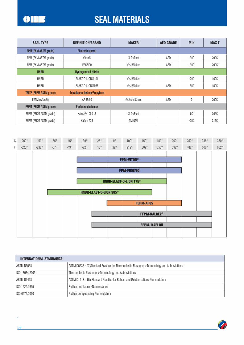
56
SEAL MATERIALS
SEAL TYPE MAKER AED GRADE MIN
FPM (FKM ASTM grade) Viton® -30C 200C
FPM (FKM ASTM grade) FR58/90 ® J Walker -30C 200C
HNBR
HNBR ELAST-O-LION®101 ® J Walker -29C 160C
HNBR ELAST-O-LION®985 ® J Walker -55C 150C
FEPM (Aflas®) AF 85/90 ® Asahi Chem 0 200C
FFPM (FFKM ASTM grade) Kalrez® 1050 LF 5C 365C
FFPM (FFKM ASTM grade) Kaflon 72B TM GMI -25C 315C
INTERNATIONAL STANDARDS
ISO 18064:2003 Thermoplastic Elastomers-Terminology and Abbreviations
ISO 1629:1995 Rubber and Latices-Nomenclature
ISO 6472:2010 Rubber compounding Nomenclature
-320°
-200°
F
C
-238°
-150°
-67°
-55°
-49°
-45°
-22°
-30°
13°
25°
32°
0°
212°
100°
302°
150°
356°
180°
392°
200°
482°
250°
662°
350°
600°
315°
FPM-VITON®
FPM-FR58/90
HNBR-ELAST-O-LION 175®
HNBR-ELAST-O-LION 985®
FEPM-AF85
FFPM-KALREZ®
FFPM- KAFLON

57
METAL TO METAL
High precision machining results in superior ball and seat interfacing for tight shutoff conforming to ANSI B16.104 class V and MSS SP-61.
Dependable OperationsSpring loaded seats maintain close contact with the ball assuring tight sealing even at low pressures. This results in stable opening and closing torques at high differential pressures over a wide range of temperatures as well as high frequency.
Fire SafeThe combination of metal seats and soft carbon seals insure fire-safe capabilities.
Various material components are available for a variety of service applications up to 500° C (932° F).
VersatilitySurface-hardened ball and seats allows use in more severe applications such asslurries, pulp stock and other abrasive media in long life.
CHARACTERISTICS
WIDE RANGEOF FLUID SERVICES
STANDARD AND
TEMPERATURES
BASE MATERIAL GRADES BASE MATERIAL Temp. Limit °C COATING COATING
Temp. Limit °CCOMBINED
Temp. Limit °C
ASTM A182 F51 ASTM A182 F55
370 TCC ENP SiC CCC
230 400 550 650
230 370 370 370
6Mo ASTM A182 F44 Alloy 20
427 TCC ENP SiC CCC
230 400 550 450
230 400 427 427
13Cr ASTM A 182 F6AASTM A182 F6NM
640 TCC ENP SiC CCC
230 400 550 450
230 400 550 450
CRA 625 718
X-750 825
700 TCC ENP SiC CCC
230 400 550 450
230 400 550 450
SS ASTM A182 F316ASTM A182 F304ASTM A182 F347
700 TCC ENP SiC CCC
230 400 550 450
230 400 550 450
Maximum temp applicable on TCC is 230°C Recommended thickness is 150 micronMaximum temp applicable on CCC is 450°C Recommended thickness is 150 micronMaximum temp applicable on SCC is 550°C Recommended thickness is 35 micron
-328°
-200°
F
C
212°
100°
356°
180°
446°
230°
482°
250°
572°
300°
599°
315°
698°
370°
716°
380°
752°
400°
842°
450°
1022°
550°
1202°
650°
TCC
ENP
SiC
CCC
Upper limit of KAFLON/KALREZ® Graphite seat seal - Special design/torque
on request

58
CORROSION
CORROSION MEDIA
Carb
on S
teel
Mon
el
Acetate Solvents, Crude D A A A BAcetate Solvents, Pure C A A A AAcetic Acid, 95% D B A A AAcetic Anhydride, Boiling D B A A AAcetone B A A A AAlcohols B A A A AAmines B A A A AAmmonia, Anhydrous B A A A AAmmonium Hydroxide, Hot B A A A DAmmonium Nitrate B A A A CAniline Hydrochloride D D C B BAntimony Trichloride D D C B BAsphalt B A A A ABarium Chloride, 5% C A A A ABarium Hydroxide C A A A ABarium Nitrate C A A B CBenzene, Hot B A A A ABenzoic Acid B A A A ABlood D A A A ABromine, Dry Gas D A A B ABromine, Moist Gas D D D D CButtermilk D A A A ACalcium Bisulfite, Hot D C B A ACalcium Chloride, Dilute C B A A ACalcium Hydroxide, 20%, Boiling D A A A ACalcium Hydrochloride, < 2% C C B B CCarbolic Acid, 90% C A A A BCarbon Dioxide, Dry C A A A ACarbon Disulphide B A A A BChloroacetic Acid D D C B BChloric Acid D D C C CChlorinated Water, Sat. D D C C CChlorine, Dry Gas B B B A AChlorine, Moist Gas D D C D CCitric Acid, Dilute D A A A ACitric Acid, Hot, Conc. D C B B BCreosote, Hot B A A A ACupric Chloride, 5% D D C D DEthyl Chloride A A A A AEthylene Glycol A A A A AFerric Chloride < 1% D C B B CFerric Nitrate, 5% D B A C DFerric Sulfate, 5% D B A B CFerrous Sulfate, 10% C A A B AFlourine, Dry Gas C C B A AFlourine, Moist Gas D D D B AFreon, Wet C C C B AFuel Oil, 140°F A A A A B
CORROSION MEDIA
Carb
on S
teel
Mon
el
Furfural B B B B BGasoline Sour B A A C CGasoline Refined A A A B AGelatine D B A A AGlucose B A A A AGlycerine B A A A AHydrofluoric Acid, Boiling D D D D BHydrofluosilicic Acid D D C B AHydrogen Chloride, Dry B D C A AHydrogen Chloride, Moist D D D D CHydrogen Fluoride, Dry C D C A AHydrogen Peroxide, Boiling D C B B BHydrogen Sulfide, Dry B A A A AHydrogen Sulfide, Moist C B A A BIodine, Dry D D B A AKerosene A A A A ALactic Acid, 5% D B A A BLactic Acid, 10% D B A A BLactic Acid, Boiling, 5% D C B B CLactic Acid, Boiling, 10% D D B B CLead Acetate, Hot D A A B BMagnesium Chloride, Hot, 5% D C B A AMagnesium Hydroxide B A A A AMagnesium Sulfate B A A B AMagnesium Sulfate, Boiling C A A C AMercury B A A A BMercuric Chloride, < 2% D D D D DMercuric Cyanide D B B B DMethyl Chloride, Dry D B B A AMilk D A A A BMolasses B A A A ANaptha B A A A ANickel Chloride D C B B BNickel Sulfate, Boiling D C C B ANitric Acid, 20% D A A B DNitric Acid, Boiling, Conc. D D D D DNitrous Acid D B B B CNitrobenzene D B A B BOils - Miner. B A A C BOxalic Acid, Boiling, 10% C A A A AOxalic Acid, Boiling, 50% D D C B BOxygen B A A A APicric Acid C A A D DPotassium Bromide D C B A APotassium Carbonate B A A A APotassium Chlorate B A A A BPotassium Chloride D A A A APotassium Chloride, Hot D C B B A
CORROSION MEDIA
Carb
on S
teel
Mon
el
Potassium Cyanide B B B B BPotassium Sulfate, Dil. B A A A APropane, Liquid & Gas B A A A APyrogallic Acid B A A B ARosin, Molten D A A A ASalicylic Acid D B B B BSilver Bromide D B A C BSilver Chloride D D D C BSilver Nitrate D A A A CSodium Acetate C A A A ASodium Bisulfate D B B B ASodium Bromide, Dil. D B B B ASodium Cyanide B B B B ASodium Fluoride, 5% D B A B ASodium Hydroxide, 50% B A A A ASodium Hyposulfite D B A B ASodium Nitrate B B A A BSodium Perborate C A A A BSodium Peroxide C A A A BSodium Phosphate, Tribasic C A A A ASodium Silicate B A A A BSodium Thiosulfate D B A B BStannous Chloride, Sat. D D B B BSteam, 212°F A A A A ASteam, 600°F C A A A ASulfite Liquors D C B D DSulfur Chloride D C D B BSulfur Dioxide, Moist D B A D DSulfuric Acid, Conc. B B B B DSulfurous Acid, Sat. D B B D DTannic Acid, 10% D A A B ATar, Hot B A A A BTartaric Acid, 120°F D B A A AToluene A A A A ATrichlorethylene B A A A ATurpentine B A A A AVarnish, Hot C A A A AVegetable Oils B A A A BVinegar D A A A AWater, Acid Mine D A A A CWater, Boiler Feed B A A A AWater, Distilled D A A A AWater, Salt Sea D C B B AWhiskey, Boiling D A A A CWine D A A A CXylene, Boiling D A A A AZinc Chloride, 5% D C B B BZinc Sulfate, Boiling D A A B A
A = Substantial residance - Preferred material of construction.B = Moderate resistance - Satisfactory for use under most condition.C = Questionable resistance - Use with caution.D = Inadequate resistance - Not recommended.


