Embed Size (px)
Citation preview
C o m m e r c i a l V e h i c l e S y s t e m s
P r o d u c t M a n u a l
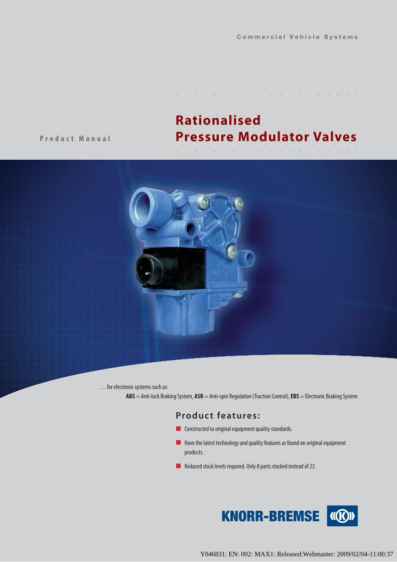
Rationalised Pressure Modulator Valves
… for electronic systems such as:ABS = Anti-lock Braking System, ASR = Anti-spin Regulation (Traction Control), EBS = Electronic Braking System
Produc t features:Constructed to original equipment quality standards.
Have the latest technology and quality features as found on original equipment products.
Reduced stock levels required. Only 8 parts stocked instead of 23
Y046831: EN: 002: MAX1: Released:Webmaster: 2009/02/04-11:00:37
Disclaimer
The information contained in this document is intended for the exclusive use of trained persons within the commercial vehicle industry, and must not be passed on to any third party. All recommendations regarding products and their servicing or usage are with reference to Knorr-Bremse products and should not be considered applicable to products from other manufacturers. This information does not purport to be all-inclusive and no responsibility is assumed as a result of its use. We cannot accept any liability nor offer any guarantee regarding data accuracy, completeness or timeliness. The information does not represent any guarantee or ensured characteristics of the Products or Systems described. No liability can be accepted based on the information, its use, recommendations or advice provided. In no event may we be held liable for any damage or loss except in the case of wilful intent or gross negligence on our part, or if any mandatory legal provisions apply. Any legal disputes arising from the use of this information shall be subject to German law.
If service work is carried out on the vehicle, it is the responsibility of the workshop to ensure the vehicle is fully tested and in full functional order before the vehicle is returned into service. Knorr-Bremse accepts no liability for problems caused as a result of appropriate tests not being carried out.
This disclaimer is an English translation of a German text, which should be referred to for all legal purposes.
Disposal of Waste Equipment by Business Users in the European Union
This symbol on the product, packaging or in user instructions, indicates that this product must not be disposed of with other general waste. Instead, it is your responsibility to dispose of the waste electrical and electronic parts of this product by handing them over to a company or organisation authorised for the recycling of waste electrical and electrical equipment. For more information about arrangements for waste equipment disposal please contact your Knorr-Bremse distributor or local Knorr-Bremse representative.
Y046831: EN: 002: MAX1: Released:Webmaster: 2009/02/04-11:00:37
�
R a t i o n a l i s e d P r e s s u r e M o d u l a t o r V a l v e s
S a f e t y A d v i c e
Note: The safety advice below is applicable to general service and diagnostic work on air braking systems and may not all be directly relevant to the activities and products described in this document.
Before and whilst working on or around air braking systems and devices, the following precautions should be observed in addition to any specific advice given in this document:
• Always wear safety glasses when working with air pressure.
• Never exceed manufacturer’s recommended air pressures.
• Never look into air jets or direct them at anyone.
• Never connect or disconnect a hose or line containing pressure; it may whip as air escapes.
• Never remove a device or pipe plug unless you are certain all system pressure has been depleted.
• Park the vehicle on a level surface, apply the parking brakes, and always chock the wheels as depleting vehicle air system pressure may cause the vehicle to roll.
• If work is being performed on the vehicle’s air braking system, or any auxiliary pressurised air systems, and if it is necessary to drain the air pressure from reservoirs, etc., keep clear of brake actuator push rods and levers since they may move as system pressure drops. Be aware that if the vehicle is equipped with an air dryer system, it can also contain air pressure along with its purge reservoir, if fitted, even after pressure has been drained from the other reservoirs.
• When working under or around the vehicle, and particularly when working in the engine compartment, the engine should be shut off and the ignition key removed. Where circumstances require that the engine be running, EXTREME CAUTION should be taken to prevent personal injury resulting from contact with moving, rotating, leaking, heated or electrically charged components. Additionally, it is advisable to place a clear sign on or near the steering wheel advising that there is work in progress on the vehicle.
• Examine all pipework for signs of kinks, dents, abrasion, drying out or overheating. Be aware that kinks in pipework may result in air pressure being trapped in the pipework and associated equipment. Replacement hardware, tubing, hose, fittings, etc. must be of equivalent size, type and strength as original equipment and be designed specifically for such applications and systems. Check the attachment of all pipework; it should be supported so that it cannot abrade or be subjected to excessive heat.
• Components with stripped threads or damaged/corroded parts should be replaced rather than repaired. Do not attempt repairs requiring machining or welding unless specifically stated and approved by the vehicle or component manufacturer.
• Never attempt to install, remove, disassemble or assemble a device until you have read and thoroughly understood the recommended procedures. Some units contain powerful springs and injury can result if not properly dismantled. Use only the correct tools and observe all precautions pertaining to use of those tools. Before removing any device note its position and the connections of all pipework so that the replacement/serviced device can be properly installed. Ensure that adequate support or assistance is provided for the removal/installation of heavy items.
• Use only genuine Knorr-Bremse replacement parts, components and kits.
• Prior to returning the vehicle to service, make certain all components and systems are leak free and restored to their proper operating condition.
Welding
To avoid damage to electronic components when carrying out electrical welding, the following precautions should be observed:
• In all cases, before starting any electrical welding, remove all connections from any electronic control units or modules, noting their position and the order in which they are removed.
• When re-inserting the electrical connectors (in reverse order) it is essential that they are fitted to their correct assigned position - if necessary this must be checked by PC Diagnostics.
Y046831: EN: 002: MAX1: Released:Webmaster: 2009/02/04-11:00:37
�
P r o d u c t M a n u a l
Introduction
Updated and extended product range only from Knorr-Bremse and suitable for the Aftermarket.
Replacing 23 OE pressure modulator valves with only 8 rationalised part numbers.
Product features
Constructed to original equipment quality standards
Have the latest technology and quality features as found on original equipment products.
•
•
•
•
I n t r o d u c t i o n a n d p r o d u c t f e a t u r e s
Y046831: EN: 002: MAX1: Released:Webmaster: 2009/02/04-11:00:37
�
R a t i o n a l i s e d P r e s s u r e M o d u l a t o r V a l v e s
P r o d u c t f e a t u r e s
Pressure modulator valve – applications:
In general, pressure modulator valves are used in electronically controlled braking systems, in order to modulate
pressure in the brake actuators in response to signals from the electronic control unit (ECU). Specific applications
are as follows:
ABS = Anti-lock Braking System - pressure modulator valves are used to modulate the brake pressure supplied by the foot brake valve, so that locking of the wheels is prevented.
ASR = Anti-spin Regulation (also known as Traction Control) - pressure modulator valves are used to balance the axle’s driving torque by supplying the brake actuator of the spinning drive wheel with air. The pressure is controlled so that wheel spin is reduced, allowing engine torque to be applied to the other drive wheel having a higher tyre to road adhesion.
EBS 5 and ABS 6 Advanced with integrated ESP (Electronic Stability Program) - pressure modulator valves are used to control the pressure to the brake actuators, when the brake is applied, to stabilise the vehicle. In the case of EBS 5, pressure modulator valves are used if only one single-channel pressure control module is installed on the front axle.
•
•
•
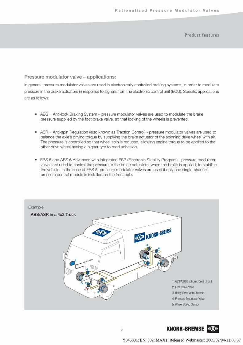
Example:
ABS/ASR in a 4x2 Truck
1. ABS/ASR Electronic Control Unit
2. Foot Brake Valve
�. Relay Valve with Solenoid
�. Pressure Modulator Valve
�. Wheel Speed Sensor
Y046831: EN: 002: MAX1: Released:Webmaster: 2009/02/04-11:00:37
�
1
33
33
2
2
2
2
P r o d u c t M a n u a l
P r o d u c t f e a t u r e s
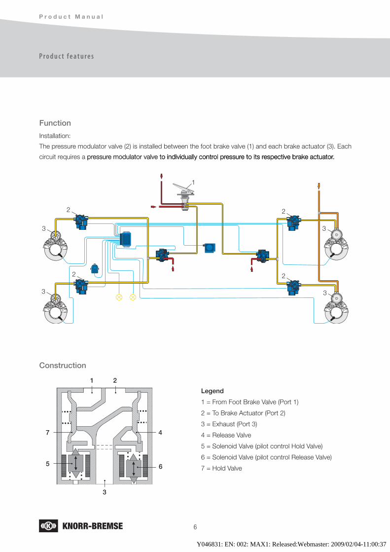
Function
Installation:
The pressure modulator valve (2) is installed between the foot brake valve (1) and each brake actuator (3). Each
circuit requires a pressure modulator valve to individually control pressure to its respective brake actuator.pressure modulator valve to individually control pressure to its respective brake actuator. to individually control pressure to its respective brake actuator.
Construction
Legend
1 = From Foot Brake Valve (Port 1)
2 = To Brake Actuator (Port 2)
3 = Exhaust (Port 3)
4 = Release Valve
5 = Solenoid Valve (pilot control Hold Valve)
6 = Solenoid Valve (pilot control Release Valve)
7 = Hold Valve
1 2
3
7 4
5 6
Y046831: EN: 002: MAX1: Released:Webmaster: 2009/02/04-11:00:37
�
R a t i o n a l i s e d P r e s s u r e M o d u l a t o r V a l v e s
P r o d u c t f e a t u r e s
Standardisation
The outer dimensions, mounting holes and position of the pneumatic and electrical connections of the
pressure modulator valve range are standardised. However, different pneumatic and electrical connections exist range are standardised. However, different pneumatic and electrical connections exist
as described below.
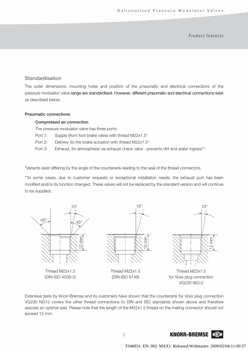
Pneumatic connections
Compressed air connection
The pressure modulator valve has three ports:
Port 1: Supply (from foot brake valve) with thread M22x1.5*
Port 2: Delivery (to the brake actuator) with thread M22x1.5*
Port 3: Exhaust, (to atmosphere) via exhaust check valve - prevents dirt and water ingress**
*Variants exist differing by the angle of the countersink leading to the seal of the thread connectors.
Extensive tests by Knorr-Bremse and its customers have shown that the countersink for Voss plug connection VG230 NG12 covers the other thread connections to DIN and ISO standards shown above and therefore assures an optimal seal. Please note that the length of the M22x1.5 thread on the mating connector should not exceed 12 mm.
Thread M22x1.5for Voss plug connection
VG230 NG12
Thread M22x1.5(DIN-ISO 4039-2)
Thread M22x1.5(DIN-ISO 6149)
15°10°
45°45°
12 m
m
12 m
m
12 m
m
**In some cases, due to customer requests or exceptional installation needs, the exhaust port has been
modified and/or its function changed. These valves will not be replaced by the standard version and will continue
to be supplied.
10°
Y046831: EN: 002: MAX1: Released:Webmaster: 2009/02/04-11:00:37
�
P r o d u c t M a n u a l
P r o d u c t f e a t u r e s
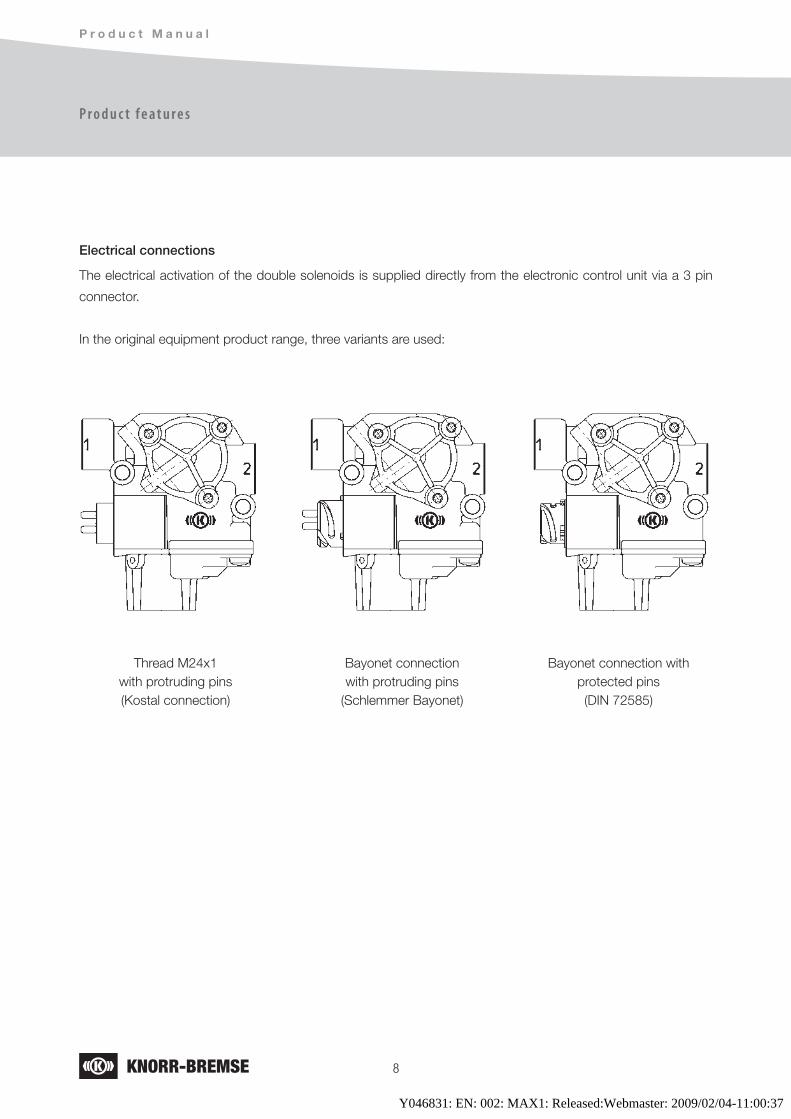
Electrical connections
The electrical activation of the double solenoids is supplied directly from the electronic control unit via a 3 pin
connector.
In the original equipment product range, three variants are used:
Thread M24x1with protruding pins(Kostal connection)
Bayonet connectionwith protruding pins
(Schlemmer Bayonet)
Bayonet connection withprotected pins(DIN 72585)
Y046831: EN: 002: MAX1: Released:Webmaster: 2009/02/04-11:00:37
�
R a t i o n a l i s e d P r e s s u r e M o d u l a t o r V a l v e s
P r o d u c t f e a t u r e s
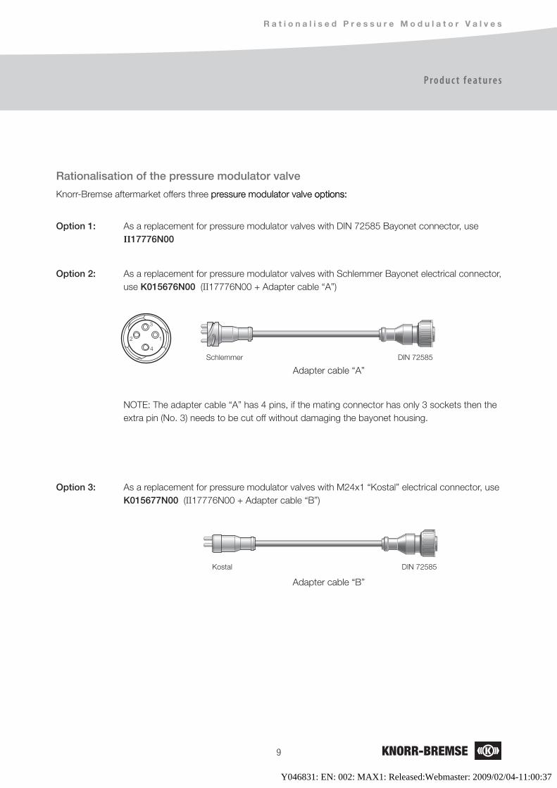
Rationalisation of the pressure modulator valve
Knorr-Bremse aftermarket offers three pressure modulator valve options:pressure modulator valve options: options:
Option 1: As a replacement for pressure modulator valves with DIN 72585 Bayonet connector, use II17776N00
Option 2: As a replacement for pressure modulator valves with Schlemmer Bayonet electrical connector, use K015676N00 (II17776N00 + Adapter cable “A”)
NOTE: The adapter cable “A” has 4 pins, if the mating connector has only 3 sockets then the extra pin (No. 3) needs to be cut off without damaging the bayonet housing.
Option 3: As a replacement for pressure modulator valves with M24x1 “Kostal” electrical connector, use K015677N00 (II17776N00 + Adapter cable “B”)
DIN 72585Schlemmer
DIN 72585Kostal
Adapter cable “B”
Adapter cable “A”
12
3
4
Y046831: EN: 002: MAX1: Released:Webmaster: 2009/02/04-11:00:37
10
P r o d u c t M a n u a l
C o m p a r i s o n C h a r t
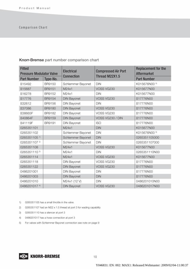
Fitted Pressure Modulator Valve
ElectricalConnection
Compressed Air Port Thread M22X1.5
Replacement for the Aftermarket
Part Number Type-No. Part NumberII15492 BR9150 Schlemmer Bayonet DIN K015676N00 5)
II15687 BR9151 M24x1 VOSS VG230 K015677N00
II16278 BR9152 M24x1 DIN K015677N00
II17776 BR9154 DIN Bayonet VOSS VG230 II17776N00
II32612 BR9156 DIN Bayonet DIN II17776N00
II37086 BR9180 DIN Bayonet VOSS VG230 II17776N00
II38665F BR9182 DIN Bayonet VOSS VG230 II17776N00
II40864F BR9159 DIN Bayonet VOSS VG230 / DIN II17776N00
II41119F BR9191 DIN Bayonet ISO II17776N00
0265351101 M24x1 DIN K015677N00
0265351102 Schlemmer Bayonet DIN K015676N00 5)
0265351105 1) Schlemmer Bayonet DIN 0265351105000
0265351107 2) Schlemmer Bayonet DIN 0265351107000
0265351108 M24x1 VOSS VG230 K015677N00
0265351110 3) M24x1 DIN 0265351110N00
0265351114 M24x1 VOSS VG230 K015677N00
0265351118 DIN Bayonet VOSS VG230 II17776N00
0265351122 DIN Bayonet VOSS VG230 II17776N00
0486201001 DIN Bayonet DIN II17776N00
0486201003 DIN Bayonet DIN II17776N00
0486201010 M24x1 (12 V) DIN 0486201010N00
0486201017 4) DIN Bayonet VOSS VG230 0486201017N00
Knorr-Bremse part number comparison chart
1) 0265351105 has a small throttle in the valve
2) 0265351107 had an M22 x 1.5 thread at port 3 for wading capability
3) 0265351110 has a silencer at port 3
4) 0486201017 has a hose connection at port 3
5) For valves with Schlemmer Bayonet connection see note on page 9
Y046831: EN: 002: MAX1: Released:Webmaster: 2009/02/04-11:00:37
11
R a t i o n a l i s e d P r e s s u r e M o d u l a t o r V a l v e s
C o m p a r i s o n C h a r t
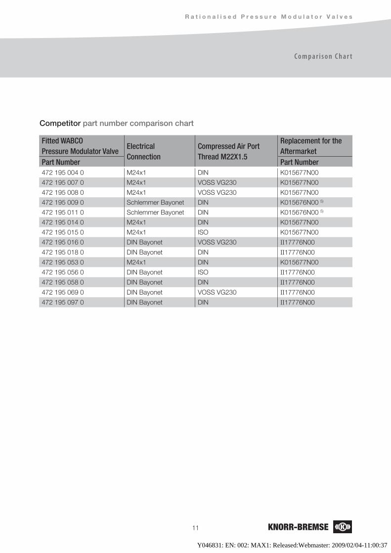
Competitor part number comparison chart
Fitted WABCO Pressure Modulator Valve
ElectricalConnection
Compressed Air Port Thread M22X1.5
Replacement for the Aftermarket
Part Number Part Number472 195 004 0 M24x1 DIN K015677N00
472 195 007 0 M24x1 VOSS VG230 K015677N00
472 195 008 0 M24x1 VOSS VG230 K015677N00
472 195 009 0 Schlemmer Bayonet DIN K015676N00 5)
472 195 011 0 Schlemmer Bayonet DIN K015676N00 5)
472 195 014 0 M24x1 DIN K015677N00
472 195 015 0 M24x1 ISO K015677N00
472 195 016 0 DIN Bayonet VOSS VG230 II17776N00
472 195 018 0 DIN Bayonet DIN II17776N00
472 195 053 0 M24x1 DIN K015677N00
472 195 056 0 DIN Bayonet ISO II17776N00
472 195 058 0 DIN Bayonet DIN II17776N00
472 195 069 0 DIN Bayonet VOSS VG230 II17776N00
472 195 097 0 DIN Bayonet DIN II17776N00
Y046831: EN: 002: MAX1: Released:Webmaster: 2009/02/04-11:00:37
C o m m e r c i a l V e h i c l e S y s t e m s
Knorr-Bremse Systeme für Nutzfahrzeuge GmbH Moosacher Straße 80 80809 Munich Germany Tel: +49 89 3547-0 Fax: +49 89 3547-2767www.knorr-bremseCVS.com
Sweden Knorr-BremseSystem for Tunga Fordon ABMalmöTel: +46 40 680 5880Fax: +46 40 937490
SwitzerlandKnorr-BremseSysteme für Nutzfahrzeuge GmbHBassersdorf Tel: +41 44 888 77-55Fax: +41 44 888 77-50
Turkey Knorr-BremseSysteme für Nutzfahrzeuge GmbHFindikli - IstanbulTel: +90 212 293-4742Fax: +90 212 293-4743
United Kingdom Knorr-Bremse Systems for Commercial Vehicles Ltd.BristolTel: +44 117 9846-100Fax: +44 117 9846-101
A m e r i c a
Brazil Knorr-BremseSistemas para Veículos Comerciais Brasil Ltda.São Paulo Tel: +55 11 5681 1104Fax: +55 11 5686 3905
USABendix Commercial Vehicle Systems LLC Elyria, OH Tel: +1 440 329-9100Fax: +1 440 329-9105
A s i a – A u s t r a l i a
AustraliaKnorr-Bremse Australia Pty. Ltd. Granville NSWTel: +61 2 8863-6500Fax: +61 2 8863-6151
China Knorr-Bremse Brake Equipment (Shanghai) Co. Ltd. ShanghaiTel: +86 21 6891-7500Fax: +86 21 6891-7510
China Knorr-Bremse Asia Pacific (Holding) LimitedTruck Brake Systems DivisionHong Kong Tel: +852 3657-9800Fax: +852 3657-9901
IndiaKnorr-BremseSystems for Commercial Vehicles India Private Ltd.PuneTel: +91 20 6674-6800Fax: +91 20 6674-6899
JapanKnorr-Bremse Commercial Vehicle Systems Japan Ltd.SaitamaTel: +81 49 273-9085Fax: +81 49 282-8601
Korea Knorr-Bremse Korea Ltd. Truck Brake DivisionSeoul Tel: +82 2 2273-1182Fax: +82 2 2273-1184
Europe – Africa
Austria Knorr-Bremse GmbHSysteme für NutzfahrzeugeMödlingTel: +43 2236 409-436Fax: +43 2236 409-434
BelgiumKnorr-Bremse Benelux B.V.B.A.Heist-op-den-BergTel: +32 1525 7900Fax: +32 1524 9240
Czech RepublicKnorr-Bremse Systémy pro uzitková vozidla, CR, s.r.o.HejniceTel: +420 482 363-611Fax: +420 482 363-711
France Knorr-Bremse Systèmes pour Véhicules Utilitaires France S.A.Lisieux CedexTel: +33 2 3132 1200Fax: +33 2 3132 1303
Germany Hasse & Wrede GmbH Berlin Tel: +49 30 9392-3101Fax: +49 30 7009-0811
Germany Knorr-Bremse Systeme für Nutzfahrzeuge GmbH MunichTel: +49 89 3547-0 Fax: +49 89 3547-2767
HungaryKnorr-Bremse Fékrendszerek Kft.Kecskemét Tel: +36 76 511 100Fax: +36 76 481 100
ItalyKnorr-Bremse Sistemi per Autoveicoli Commerciali S.p.A.Arcore Tel: +39 039 6075-1Fax: +39 039 6075-435
Netherlands Knorr-Bremse Benelux B.V.B.A.Mydrecht Tel: +31 297 239-330Fax: +31 297 239-339
PolandKnorr-Bremse Polska SfN Sp. z o.o.WarsawTel: +48 22 887-3870Fax: +48 22 531-4170
RussiaKnorr-Bremse RUS Nizhniy NovgorodTel: +7 8312 57-6661Fax: +7 8312 57-6791
RussiaKnorr-BremseSysteme für Nutzfahrzeuge GmbHMoscowTel: +7 495 234-4995Fax: +7 495 234-4996
South Africa Knorr-Bremse S.A. Pty. Ltd. Kempton Park Tel: +27 11 961-7800Fax: +27 11 975-8249
SpainBost Ibérica, S.L.Irun (Guipuzcoa) Tel: +34 902 100-569Fax: +34 943 614-063
Y046
831-
EN-0
00
This d
ocum
ent is
subje
ct to
altera
tion w
ithou
t noti
ce an
d the
refore
a pri
nted c
opy m
ay no
t be t
he la
test re
vision
. Plea
se ch
eck o
ur we
bsite
www
.knorr
-brem
seCV
S.com
for t
he la
test u
pdate
or co
ntact
your
local
Knorr
-Brem
se re
prese
ntativ
e.Th
e figu
rative
mark
“K” a
nd th
e trad
emark
s KNO
RR an
d KNO
RR-B
REMS
E are
regist
ered i
n the
name
of Kn
orr-B
remse
AG. A
dditio
nal te
rms a
nd co
nditio
ns ap
ply; p
lease
refer
to ou
r web
site k
norr-
brems
eCVS
.com
unde
r the
“Doc
umen
tation
” tab
. Note
: If se
rvice
work
is ca
rried
out o
n a ve
hicle
as a
result
of in
forma
tion t
aken
from
this
docu
ment,
it is
the r
espo
nsibi
lity of
the w
orksh
op to
ensu
re th
e veh
icle i
s full
y tes
ted an
d in f
ull fu
nctio
nal o
rder b
efore
the v
ehicl
e is r
eturn
ed in
to se
rvice
. Kno
rr-Bre
mse a
ccept
s no l
iabilit
y for
proble
ms ca
used
as a
result
of ap
propri
ate te
sts no
t bein
g carr
ied ou
t. Cop
yrigh
t 200
9 © Kn
orr-B
remse
AG -
all rig
hts re
serve
d, inc
luding
indu
strial
prop
erty r
ights
appli
catio
ns. K
norr-
Brems
e AG
retain
s any
powe
r of d
ispos
al, su
ch as
for c
opyin
g and
tran
sferri
ng. R
eleas
ed 01
/200
9
Y046831: EN: 002: MAX1: Released:Webmaster: 2009/02/04-11:00:37


