Embed Size (px)
Citation preview

Optical and Quantum Electronics 25 (1993) $899-$915
I N V I T E D PAPER
Guide/antiguide optical intensity modulator
T. C. H U A N G * , Y. C H U N G , L. A. C O L D R E N , N. D A G L I Department of Electrical and Computer Engineering, University of California, Santa Barbara, CA 93106, USA
Received 25 March; revised 23 June; accepted 9 July 1993
An electrorefractive index-controllable guide/antiguide optical intensity modulator has been created and characterized. The operating mechanism, beam propagation method simulation, device design and fabrication, and calculated and experimental results of this guide/antiguide modulator are given. The operational principle of the modulator is based on the field-induced waveguide (FIG) concept; that is, electric- field-induced refractive index changes cause the waveguide to be turned on and off electrically. The modulator is formed with a central narrow FIG electrode sandwiched between two antiguide electrodes. The electrooptic effects, along with carrier effects, have been exploited to adjust the refractive index under the guide and adjacent antiguide electrodes by changing reverse biases applied to them. The modulation is determined mainly by changing the lateral refractive index profiles. In the on state, a waveguide is formed under the central electrode, and the input light propagates along this waveguide. To realize the best off state, an antiguide situation is created that causes the light to diffract out of the central guide rapidly. An on/off ratio larger than 23dB, a propagation loss ,~ 1 dB, and a record optical bandwidth from 1.0 to 1.55#m have been obtained for this modulator.
1. I n t r o d u c t i o n Over the past few decades, there has been a great deal of interest in external optical inten- sity modulators because of increased performance demands of optical fibre transmission systems, as well as interconnect and signal-processing systems. Different kinds of modula- tors, in terms of the device structure [1-5] and operation mechanism [6-10], have been investigated. In this work, a novel guide/antiguide structure for lightwave modulation is reported. Combining the field-induced waveguide (FIG) concept [11] and a special guide/antiguide device configuration, high-contrast, wide optical bandwidth nonabsorp- tive optical intensity modulators have been achieved.
An important characteristic of an intensity modulator is its on/off ratio. For the guide/ antiguide modulator, large on/off modulation is achievable owing to the changing
* Present address: Army Research Laboratory, Adelphi, MD 20783, USA.
0306-8919 �9 1993 Chapman & Hall S899

T. C. Huang et aI.
direction of the propagated light. The input light is either propagated through the electric- field-induced central waveguide for the guide case, which provides the on-state operation, or, for the antiguide case, which gives the off state, the input light diffracts out of the cen- tral guide, and switches to a set of radiation modes that are not coupled to the single-mode output guide. Since the refractive index effect is utilized in this device, there is no critical wavelength-dependent balance required, and large on/off ratios are possible over a wide range of optical wavelengths. In addition, the optical absorption loss should be small for the modulator since it can be operated at wavelengths far below the band edge of the material, and thus it should be less sensitive to changes in temperature as well as optical intensity. Also, by operating the guiding and antiguiding electrodes in a push-pull fashion, it is possible to obtain a first-order chirp cancellation, since part of the energy propagates in both regions.
In the experiment, for an applied voltage swing from +1 to - 8 V on a device with an active length of 1 mm, a TE mode on/off ratio of 23 dB at 1.15 #m, and propagation loss of 1 dB has been achieved. On/off ratios larger than 13 dB for both TE and TM modes over an optical wavelength range from 1 to 1.55#m have also been observed [12]. In addition, a chirp-free operation of this modulator has been achieved [13].
This paper presents a detailed study and characterization of guide/antiguide modula- tors. The operating principles of the modulators are reviewed in Section 2. The fabrica- tion and measurement procedures are discussed in Section 3. Theoretical predictions
a) ,.-,.,v,,,,,,,, =
l ietal
oton antatio
. Guide electrode
V ~ / A n t i g u i d e electrodes
T 17 -3
<p.-A~).4Ga0.6As ( 0.7gin, 2x10 cm )
aAs ( 0.17gm, 4x10¹⁷cn~)
N § "~AI0.4Ga0.6As ( lpm, 2x10¹⁷crd3)
' ~ " GaAs Substrate _L (b) --=
Figure I (a) Schematic diagram of the modulator. The regions under the guide and antiguide electrodes are unimplanted. (b) Cross-section through points A-A' of part (a).
$900
Guide/antiguide optical intensity modulator
-20 -20
t n lmm
ON state Off=late
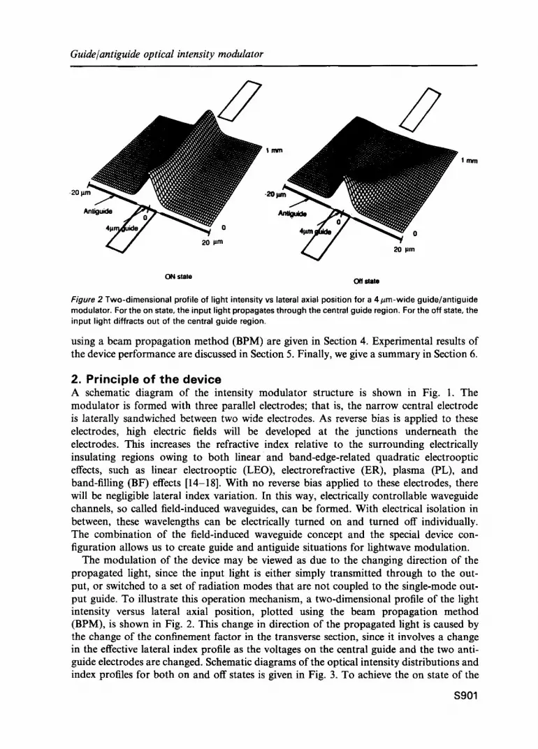
Figure 2 Two-dimensional profile of light intensity vs lateral axial position for a 4/~m-wide guide/antiguide modulator. For the on state, the input light propagates through the central guide region. For the off state, the input light diffracts out of the central guide region.
using a beam propagation method (BPM) are given in Section 4. Experimental results of the device performance are discussed in Section 5. Finally, we give a summary in Section 6.
2. Principle of the device A schematic diagram of the intensity modulator structure is shown in Fig. 1. The modulator is formed with three parallel electrodes; that is, the narrow central electrode is laterally sandwiched between two wide electrodes. As reverse bias is applied to these electrodes, high electric fields will be developed at the junctions underneath the electrodes. This increases the refractive index relative to the surrounding electrically insulating regions owing to both linear and band-edge-related quadratic electrooptic effects, such as linear electrooptic (LEO), electrorefractive (ER), plasma (PL), and band-filling (BF) effects [14-18]. With no reverse bias applied to these electrodes, there will be negligible lateral index variation. In this way, electrically controllable waveguide channels, so called field-induced waveguides, can be formed. With electrical isolation in between, these wavelengths can be electrically turned on and turned off individually. The combination of the field-induced waveguide concept and the special device con- figuration allows us to create guide and antiguide situations for lightwave modulation.
The modulation of the device may be viewed as due to the changing direction of the propagated light, since the input light is either simply transmitted through to the out- put, or switched to a set of radiation modes that are not coupled to the single-mode out- put guide. To illustrate this operation mechanism, a two-dimensional profile of the light intensity versus lateral axial position, plotted using the beam propagation method (BPM), is shown in Fig. 2. This change in direction of the propagated light is caused by the change of the confinement factor in the transverse section, since it involves a change in the effective lateral index profile as the voltages on the central guide and the two anti- guide electrodes are changed. Schematic diagrams of the optical intensity distributions and index profiles for both on and off states is given in Fig. 3. To achieve the on state of the
S901

T. C. Huang et al.
OV -8V OV -8V OV -8V
T T T T T T
N ~ ~ N
On state Off state
Figure 3 The index profiles and opti- cal intensity distributions for both the on and off states. For the on state, the input light wi l l be con- fined in and propagate through the central guide region, since the guide situation is created. For the off state, the input l ight wil l diffract out of the central guide region, since the antiguide situation is created.
device, a reverse bias is applied to the central electrode, and no bias or a small forward bias to eliminate the built-in voltage is applied to the outer electrodes. This creates an index increase under the centre electrode. Hence a waveguide with a relatively strong confine- ment factor is formed under the central electrode. Therefore the input light will be con- fined in and propagate along the central waveguide. Conversely, to achieve the off state of the device, a reverse bias is applied to the outer electrodes, and no bias or a small forward bias to the central electrode. This creates an antiguiding index profile and the light coupled into the modulator will diffract out of the central region rapidly. This scheme is found to be more efficient than simply removing the reverse bias on the central electrode and eliminating the field-induced waveguide between input and output.
3. Experimental details The device is fabricated from a GaAs/A1GaAs double heterostructure (DH) grown on an n-type substrate using molecular beam epitaxy (MBE). The DH sample consists, starting from the substrate, of a 1/zm A104Ga0.6As cladding, a 0.34/zm thick GaAs guide layer with a P -N junction at the middle, a 0.7 #m A10.4Ga0.6As cladding, and a 0.1 #m p-GaAs contact cap. All the electrodes are formed using gold electroplating to a thickness of 0.6- 0.8#m and are [ll0]-oriented, such that the refractive index change due to the linear electrooptic effect (LEO) is positive when a reverse bias is applied to the electrodes. A thin SiO2 layer (50 nm) is then plasma deposited on the wafer to avoid gold sputtering during the proton implantation.
To isolate the electrodes electrically, a proton implantation with an energy of 140 keV and dose of 1 x 1014cm -2 is carded out in the areas surrounding the gold-plated electrodes, creating semi-insulating regions around and in between the electrodes. This is followed by a 400~ 12-minute anneal using a graphite strip furnace to reduce the damage. The measured electrical resistivity between two adjacent electrodes with a 2 #m gap is larger than 20 Mf~, which indicates that proton implantation at this dose and the annealing conditions provide a good electrical isolation. The electrodes act as self-aligned ion implantation masks; hence no further critical lithography is necessary. In order to excite the modulator without exciting slab modes and to have a good clear output image, 100 #m-long spatial filters, which are deeply etched ridge waveguides, are formed at the two ends of the modulator using reactive ion etching (RIE). This mesa guide etched
$902
Guide/antiguide optical intensity modulator
HeNe Laser
Pin Lens Lens Hole Lens
I Sl "a' I Generator J
Beam Splitter
\
Lens
I1 TV Video IR Monitor Analyzer Camera
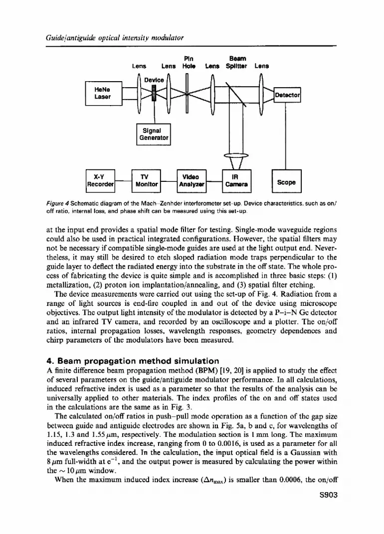
Figure 4 Schematic diagram of the Mach-Zenhder interferometer set-up. Device characteristic~ off ratio, internal loss, and phase shift can be measured using this set-up.
I Scope ]
,such as on/
at the input end provides a spatial mode filter for testing. Single-mode waveguide regions could also be used in practical integrated configurations. However, the spatial filters may not be necessary if compatible single-mode guides are used at the light output end. Never- theless, it may still be desired to etch sloped radiation mode traps perpendicular to the guide layer to deflect the radiated energy into the substrate in the off state. The whole pro- cess of fabricating the device is quite simple and is accomplished in three basic steps: (1) metallization, (2) proton ion implantation/annealing, and (3) spatial filter etching.
The device measurements were carried out using the set-up of Fig. 4. Radiation from a range of light sources is end-fire coupled in and out of the device using microscope objectives. The output light intensity of the modulator is detected by a P - i - N Ge detector and an infrared TV camera, and recorded by an oscilloscope and a plotter. The on/off ratios, internal propagation losses, wavelength responses, geometry dependences and chirp parameters of the modulators have been measured.
4. B e a m p r o p a g a t i o n m e t h o d s i m u l a t i o n A finite difference beam propagation method (BPM) [19, 20] is applied to study the effect of several parameters on the guide/antiguide modulator performance. In all calculations, induced refractive index is used as a parameter so that the results of the analysis can be universally applied to other materials. The index profiles of the on and off states used in the calculations are the same as in Fig. 3.
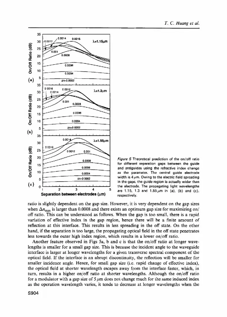
The calculated on/off ratios in push-pull mode operation as a function of the gap size between guide and antiguide electrodes are shown in Fig. 5a, b and c, for wavelengths of 1.15, 1.3 and 1.55#m, respectively. The modulation section is 1 mm long. The maximum induced refractive index increase, ranging from 0 to 0.0016, is used as a parameter for all the wavelengths considered. In the calculation, the input optical field is a Gaussian with 8 #m full-width at e -1, and the output power is measured by calculating the power within the ~ 10 #m window.
When the maximum induced index increase (Anmax) is smaller than 0.0006, the on/off
S903
T. C. Huang et al.
35 / 0.0014 0.0016
.0 ~'~ ~ ~ A ~ 25 30 20 " = "
:1:: 15 0.o006
0 o.ooo4
(a) S ~~
35 . . . . [ . . . . ! . . . . ~ . . . . i 0 0016
A 30 = ~
25 o '= 20 0= r,"
15 o.0006 o c 10 o.ooo4 0
5 An=0 0002
35 . . . . ' ' . . . . [ . . . . I 30 ~ ~ . : 1 . 5 5 p m i
III 25 ~ o.
.o 20 Figure 5 Theoretical prediction of the on/of f ratio m 0.0008 n- 15 for different separation gaps between the guide ~= / 0.o006 and antiguides using the refractive index change O 10 0.00o4 as the parameter. The central guide electrode O width is 4#m. Owing to the electric field spreading 5 &n=0 0002
in the gaps, the guide region is actually wider than ( c ) 0 , , ' ' ' . . . . ' . . . . ' . . . . the electrode. The propagating light wavelengths
2 3 4 5 are 1.15, 1.3 and 1.55#m in (a), (b) and (c), Se ~aration between e lectrodes (l~m) respectively.
ratio is slightly dependent on the gap size. However, it is very dependent on the gap sizes when Anma x is larger than 0.0008 and there exists an optimum gap size for maximizing on/ off ratio. This can be understood as follows. When the gap is too small, there is a rapid variation of effective index in the gap region, hence there will be a finite amount of reflection at this interface. This results in less spreading in the off state. On the other hand, if the separation is too large, the propagating optical field in the off state penetrates less towards the outer high index region, which results in a lower on/off ratio.
Another feature observed in Figs 5a, b and c is that the on/off ratio at longer wave- lengths is smaller for a small gap size. This is because the incident angle to the waveguide interface is larger at longer wavelengths for a given transverse spectral component of the optical field. If the interface is an abrupt discontinuity, the reflection will be smaller for smaller incidence angle. Hence, for small gap size (i.e. rapid change of effective index), the optical field at shorter wavelength escapes away from the interface faster, which, in turn, results in a higher on/off ratio at shorter wavelengths. Although the on/off ratio for a modulator with a gap size of 5/~m does not change much for the same induced index as the operation wavelength varies, it tends to decrease at longer wavelengths when the
(b)
$904
Guide/antiguide optical intensity modulator
0
-5
i -10 .-- -15
-20
-25
I-- -30 (,)
-35
,-, -5 "o ,-- -10 r
o �9 ~ -15 in "~" -20 in C .= P-
(b)
rn "O v i -
.o in
E in t -
.= I-
(c)
m
~ ~ 1 0 ~ 1 2 ~ I~m gap _ dB
-35 ~ _ _
-10 -15 ~ Xnou t = 16 x 10 -4
-20
-25 5rtm gap
-30
350 2 4 6 8 10 12 14 16 Index Change in Central Guide (10 4 )
Figure 6 The on/off ratio as a funct=on of the index change in the central guide region using the index in the antigulde regions as the parameter. The separation gaps are 2, 3 and 5/zm in (a), (b) and (c), respectively,
same voltage is applied because the refractive index effects decrease as wavelength becomes longer. In the experiments the on/off ratio at longer wavelengths for a 5/zm gap size tends to be smaller compared with that at shorter wavelengths.
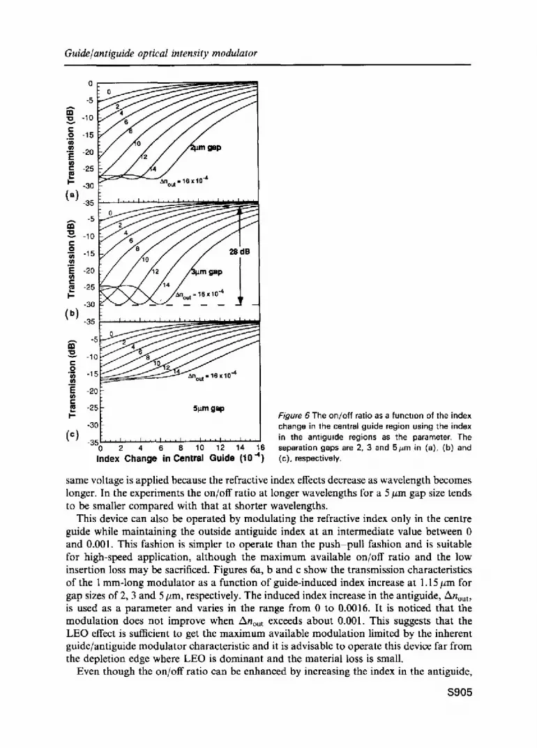
This device can also be operated by modulating the refractive index only in the centre guide while maintaining the outside antiguide index at an intermediate value between 0 and 0.001. This fashion is simpler to operate than the push-pull fashion and is suitable for high-speed application, although the maximum available on/off ratio and the low insertion loss may be sacrificed. Figures 6a, b and c show the transmission characteristics of the 1 mm-long modulator as a function of guide-induced index increase at 1.15 #m for gap sizes of 2, 3 and 5 #m, respectively. The induced index increase in the antiguide,/knout, is used as a parameter and varies in the range from 0 to 0.0016. It is noticed that the modulation does not improve when /knou t exceeds about 0.001. This suggests that the LEO effect is sufficient to get the maximum available modulation limited by the inherent guide/antiguide modulator characteristic and it is advisable to operate this device far from the depletion edge where LEO is dominant and the material loss is small.
Even though the on/off ratio can be enhanced by increasing the index in the antiguide,
$ 9 0 5
T. C. Huang et al.
(a) (b)
(c!
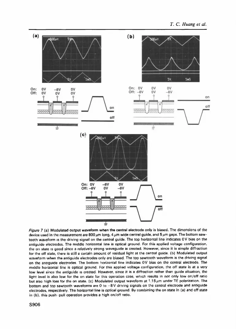
Figure 7 (a) Modulated output waveform when the central electrode only is biased. The dimensions of the device used in the measurement are 800/zm long, 4 #m wide central guide, and 5 #m gaps. The bottom saw- tooth waveform ~s the driving signal on the central guide. The top horizontal line indicates OV bias on the antiguide electrodes. The middle horizontal line is optical ground. For this applied voltage configuration, the on state is good since a relatively strong waveguide is created. However, since it is simple diffraction for the off state, there is still a certain amount of residual light at the central guide. (b) Modulated output waveform when the antiguide electrodes only are biased. The top sawtooth waveform is the driving signal on the antlguide electrodes. The bottom horizontal line indicates OV bias on the central electrode. The m=ddle horizontal line is optical ground. For this apphed voltage configuration, the off state is at a very low level since the antiguide =s created. However, since it is a diffraction rather than guide situat=on, the light level is also low for the on state for this operation case, which results in not only low on/of f ratio but also high loss for the on state. (c) Modulated output waveforrn at 1.15#m under TE polarization. The bottom and top sawtooth waveforms are 0 to - 8 V driving signals on the central electrode and antiguide electrodes, respectively. The horizontal line is optical ground. By combining the on state in (a) and off state in (b), this push-pul l operation provides a high on/of f ratio.
$ 9 0 6
Guide/antiguide optical intensity modulator
the on-state loss becomes higher. Thus the on/off ratio should be compromised with the on-state insertion loss. For the optimum gap size of 3 #m, the calculated on/off ratio is about 28 dB when Anin varies from 0 to 0.0016 and the Anou t is maintained at 0.001.
5. Results and discussion 5.1. On/off ratio Two synchronized function generators are used to provide balanced drive to the modula- tor for its optimum on and off states. The best on/off ratios obtained so far are about 23 dB for several modulators with different device dimensions. In Fig. 7, the oscilloscope traces of the modulated output waveforms for a device are shown. The dimensions of the device used in the measurement are 800 #m long, 4 #m wide central guide, with 5 #m gaps.
In order to check the guiding function of the central guide, measurement of the effect of modulating the voltage applied to the central guide is carried out. Figure 7a shows the modulated output waveform when only the central electrode is modulated keeping a 0 V bias on the antiguide electrodes. In the figure, the horizontal line below the modulated output waveform is the optical zero. The bottom sawtooth waveform indicates the driving signal from 0 to -8 V applied to the central electrode, and the top straight line indicates no bias to the antiguide electrodes. It can be seen that for this applied voltage configuration the on state is good since a relatively strong waveguide is created. On the other hand, since it is just simple diffraction for the off state, there still is a certain amount of residual light staying in the central guide, which gives a high level for the off state so that the on/off ratio is low for this operation.
To examine the diffraction function of the antiguides, measurements have been done with only the antiguide electrodes being modulated, keeping a 0 V bias on the central guide electrode. Figure 7b shows the output waveform for this case. The top sawtooth waveform is the driving signal applied to the antiguide electrodes, and the bottom straight line indicates no bias to the central guide electrode. From this figure it can be seen that for this applied voltage configuration the off state is at a very low level since the antiguide is created, and the light rapidly diffracts out of the central guide region. However, since it is a diffraction rather than guiding situation, the light level is also low for the on state for this operation case, which results in not only the low on/off ratio, but also the high loss for the on state.
From Figs 7a and b, it is clear that the optical waveguide or antiguide can be turned on and off by modulating only the guide or antiguide electrodes alone, but the contrast and modulation depth are not large enough for practical applications. However, since the first configuration gives a good on state, and the second gives a desirably low off state, these two operations can be combined to form a so-called push-pull operation. A large on/ off ratio with low insertion loss is thus achievable. Figure 7c shows the modulation result under this operation. In this push-pull fashion, for the on state, a -8 V bias is applied to the central waveguide and 0 V bias is applied to the antiguide electrodes. For the off state, - 8 V and 0V are applied to the antiguide electrodes and central electrode, respectively. Since the off state is very low, the on/off ratio for push-puU fashion can be very high.
So far, the best on/off ratio we have measured is about 23 dB. The BPM predicted that this guide/antiguide can have an on/off ratio of about 35 dB. This indicates that there still exists a big margin for the improvement of the on/off ratio.
It should be pointed out that the push-pull technique is not the only operation that can give a reasonable on/off ratio for this modulator. For this operation, keeping the driving
$907
T. C. Huang et al.
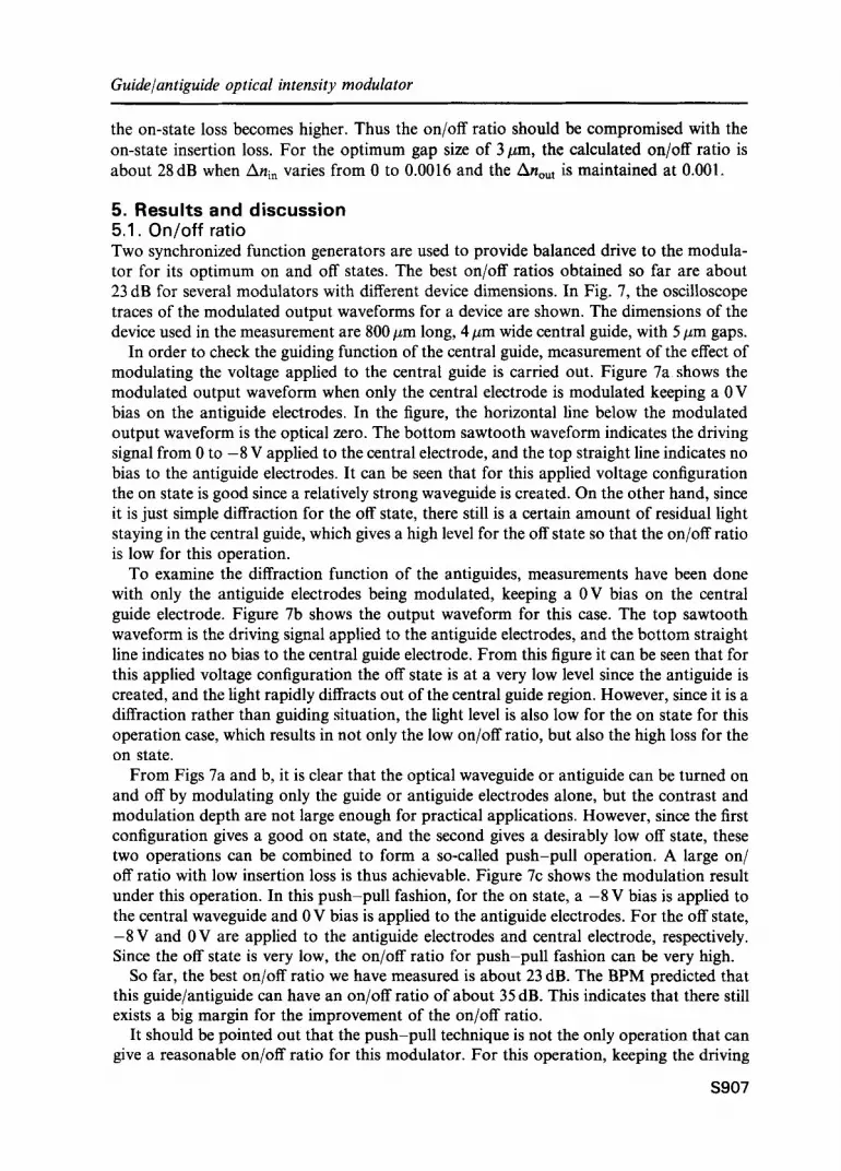
Figure 8 Modulated output waveform at 1.15/zm under the configuration of constant bias ( -4V) on the antiguide electrodes. Only the central guide is modulated. The device dimensions are the same as in Fig. 7. Grade (antiguide) situations can still be formed if the index underneath the cen- tral guide ts larger (smaller) than that of antiguide regions. By sacrificing some on/off ratio, this operatton provides a simple voltage configuration that is very desirable for high-speed operations
voltages on the electrodes balanced is rather complicated, especially for high-speed applications. Figure 8 illustrates another biasing scheme for this modulator that still can produce good performance.
From Fig. 8, it can be seen that a d.c. voltage is always on the antiguide electrodes to increase the index underneath the electrodes. The measured device has the same dimen- sions as in the previous measurement. By modulating only the applied voltage on the cen- tral guide electrode, a guide (antiguide) situation can still be formed if the index underneath the central guide is larger (smaller) than that of antiguide regions. The on (off) state for this operation is not as good as that of the push-pull fashion, since the guide (antiguide) is not as strong as in the push-pull operation. By sacrificing some on/ off ratio, however, this operation provides a simple voltage configuration that is very de- sirable for high-speed operation. In addition, the operation speed of this configuration should be much faster than that in the push-pull fashion since only the applied voltage on one narrow electrode, which has a smaller p-n junction area, needs to be modulated.
5.2 . W a v e l e n g t h r e s p o n s e Wide optical bandwidth modulation is another attractive feature of the guide/antiguide modulator. As is known, absorption type modulators, in order to obtain high on/off ratio, need to operate near the bandgap [21, 22], which results in increased spectral sensitivity as well as increased optical absorption in the on state, both of which are undesirable for low-loss, wide optical bandwidth intensity modulators. The temperature sensitivity for this kind of device is another limitation since the absorption edge is temperature-dependent. On the other hand, for the guide/antiguide modulator that utilizes refractive index effects there is no such critical spectrum resonance needing to be matched as with the absorption type modulators. The electrooptic index modulation can occur over a large range of optical wavelengths. Even for band edge-related index changes, the optical bandwidth is much larger than for absorption changes. Also, unlike the case for the interferometer or directional coupler, for the guide/antiguide modulator there is neither the phase match-up requirement of accurate interference, nor the exact
$908

Guide/antiguide optical &tensity modulator
25
~ 20 0
10 0.9
o l m m (TE) o 0 .8mm (TE) = 0 . 8 m m (TM)
I 1.0 1.1 1.2 1,3 1,4 1.5 1.6
Wavelength (pm)
Figure 9 The on/off ratio as a function of wavelength. Large on/off ratios over a large wavelength range have been achieved. The upper data are from a device with a 1 mm- long active region and the lower data are from a device with 0.8 ram-long active region. Both devices have 4#m-wide central guide elec- trodes, and 5#m gaps. High on/off ratios over a large wavelength region from 1 to 1.55#m are observed.
coupling length requirement for energy transfer [23-25]. Therefore, a large optical band- width modulation is achievable. In our study, an optical bandwidth of over 0.55 #m, which is the widest ever reported for an intensity modulator, is observed.
To verify how the modulation varies with wavelength, we used a 1.0 #m Ti:sapphire laser, a 1.15#m HeNe laser, and 1.3/zm and 1.55#m semiconductor lasers as the light sources for our measurement. In Fig. 9, the on/off ratio as a function of the wavelength is shown for two devices. The upper data are from a device with a 1 mm-long active region, and the lower data are from a device with a 0.8mm-long active region. Both devices have 4 #m-wide central guide electrodes, and 5 #m gaps. The results of these measurements show that the guide/antiguide modulators achieve high on/off ratios (> 15dB for TE mode) over a large wavelength region, from 1.0 to 1.55#m. In Fig. 9, the on/off ratio for the TM mode as a function of wavelength is also shown for the 0.8 mm-long device. The results show that the difference in the modulation depth between TE and TM modes decreases as the wavelength decreases because the index change difference for TE and TM polarizations becomes smaller as the quadratic band-edge effects begin to dominate.
5.3. Chirp parameter The chirp phenomenon is spectral broadening during intensity modulation. In a typical dispersive system, this broadening will cause pulse spreading and overlap in the time domain as they propagate, so they become indistinct at the receiver, which leads to increased bit error rate (BER) and a requirement to reduce the system capacity. An important reason for introducing external modulation as an alternative to direct modu- lation of lasers is to eliminate this chirp problem [26, 27]. However, it has been pointed out that owing to the phase modulation associated with refractive index changes inside an intensity modulator, the chirping problem can still exist for modulators using either index or absorption effects, resulting in severe dispersion penalties in optical fibre systems [28].
In this work, we have demonstrated that chirp-free operation is achievable for the guide- antiguide modulator by operating the guiding and antiguiding electrodes in a push-pull fashion [13]. A zero net phase modulation is achieved by changing the refractive index
S 9 0 9

T. C. Huang et al.
On-State Off-State
Figure 10 Schemat=c diagram of chirp-free opera- tion for the guide/antiguide modulator. As the index in the guide and antiguide regions change in opposite directions, the effective index of the device can be unchanged. A zero phase shift, and hence chirp-free operation, is achievable Meanwhile, intensity modulation can be obtained by changing the lateral confinement factor.
in the central waveguide and antiguide regions in opposite directions such that the phase shifts cancel each other when averaged over the mode, as shown in Fig. 10. In addition, this push-pull operation provides efficient intensity modulation, since the lateral confine- ment factor of the modulator changes as the lateral index profile changes. Since the defini- tion of chirp parameter for a modulator is proportional to the ratio of the phase and intensity modulations, chirp-flee operation is thus achievable for the guide/antiguide modulator.
In the experiment, - 9 V is applied to the central guide, and 0 V to the antiguide for the on state. When the reverse bias on the central guide is decreased, a phase shift is observed due to the decrease of the refractive index in the central guide region. Then, the reverse bias is increased on the antiguide electrodes to increase the refractive index in the anti- guide regions, until there is a zero effective index change. Thus a zero phase shift relative to the on state, can be observed. This procedure results in pairs of bias voltages that give zero phase shift relative to the on state (hence the chirp-•e points). Figure 11 gives the measurement results for a device at a wavelength of 1.15 #m. The data illustrate chirp-free (zero-phase-shift) operation up to an on/off ratio of - 7 dB for this 0.6 mm-long device. At this point the voltages have moved to -5.7 V on the central guide and -4.7 V on the anti- guide. For 0 V on the central guide and -9 V on the antiguide, the on/off ratio increases to
16dB. However, for most system applications it is only necessary to maintain zero chirping at the larger throughputs.
The calculated voltage change curves for chirp-free operation are also shown in Fig. 11 for different doping levels. If the applied voltages to the central guide and antiguide elec-
"2" 4 ~=1.151~m
9 8 7 6 5
Voltage on the central guide (-Volts)
Figure 11 Measured (points) and cal- culated (curves) data for chirp-free opera- tion. The calculated curves assume a p-n junction in the centre of the 0.34#m-thick GaAs waveguide with equal p and n dop- ings as indicated by the labels. If the applied biases to the guide and antiguide follow the curves, chirp-free operation is achievable.
S910

Guide/antiguide optical intensity modulator
Antiguides Ce tral Guide
I " w
Antiguides / Spatial fi lter
/ ,91- Modulat ion L e n g h - I ~
Figure 12 The guide/antiguide modulator with wider spatial filters. This structure should have lower mode excitation loss between the FIG and filters, since the mode shapes on the two sides have a better match.
trodes follow these curves, chirp-free operation should be obtained. Both measured and calculated data are demonstrated for a wavelength of 1.15 #m, but this principle should be applicable for 1.3 and 1.55 #m as well.
5.4. Internal loss The Fabry-Perot interference of straight-pass and multiply reflected light can be observed to determine the device internal loss for the guide/antiguide modulator with mode filters. By slightly heating the waveguide or slightly changing the wavelength of the light source, the optical length of the waveguide will change and the transmission of the waveguide will be modulated. The modulation depth of the output light intensity is related to the internal loss of the device and can be derived from the peak-to-valley ratio in the transmission spectrum of the Fabry-Perot cavity [29].
In principle, this kind of guide/antiguide modulator should have low insertion loss since there are no major scattering and mode coupling losses involved. Also, for devices operat- ing in the wavelength region from 1.0 to 1.55 #m, the effect of band edge absorption should be small. In experiments, an internal loss of less than 1 dB mm -l has been obtained.
The ion-implanted damage in the isolating region should be the main source of internal loss in the device [30], and removing the implanted damage should be the priority in order to reduce the device loss. In addition, free-carrier absorption in the doped guide layer, especially for highly-doped p-type material, will also bring some additional loss to the device. In order to increase the plasma and band-filling free-carrier effects, the guide layer of the device was intentionally doped at 4 x 1017 cm -3. This results in a 1 cm -1 loss of the as-grown material, so there is a trade-off between the on/off ratio and internal loss, with the choice of doping level being a compromise between minimizing the insertion loss and maximizing the on/off ratio.
As mentioned before, in order to excite the modulator without exciting slab modes and to have a good clear output image, 100 #m-long spatial filters have been formed at the two ends of the modulator. This structure, however, will introduce an interelement reflection and coupling loss between the interfaces of the FIG segment and the spatial filters, since the guided modes are different in those segments. The lateral optical confinement in the FIG for the on state is usually about 60-70%, while in the deeply etched spatial filter it is nearly 100%. This difference in the mode shapes will cause interelement reflections and mode excitation loss. By imposing a mode shape in the filters close to that in the FIG by changing the shape of the filters, one can expect a lower excitation loss for the modulator. Figure 12 gives a schematic diagram of a modified guide/antiguide structure
S911
T. C. Huang et al.
T A B L E I The measured on/of f ratios of devices with different dimensions for 2#m-w ide (upper data), and 5#m-w ide ( lower data) gaps. The devices are measured at a wavelength of 1.15#m under push-pul l operation. The applied biases are - 8 V
W(~m)
L (#m) 4 6 8 10
400 ~ 17.0dB ~ 8 . 2 d B ~ l l . 6 d B ~7 .8dB ~ 6 . 0 d B
600 ~21 .6dB ~20 .0dB ~ 10.8dB 13.5dB ~ 9 . 8 d B ~ 8 . 4 d B
800 ~18.1 dB ~15.1 dB ~ 15.0dB ~18 .5dB ~13 .2dB
1000 ~22.4 dB ~ 17.8dB ~18.1 dB ~21 .9dB ~13 .2dB
that still uses deeply etched sections. Since the spatial filter is wider in this structure, the mode shapes in the FIG and filter should be better matched, and the loss between the interface should be small. However, there is a trade-off between low loss and the function of the spatial filter. It should be pointed out that the spatial filters are not necessary for device applications in integrated photonic circuits, or fibre pig-tailed components, since the optical fibre or other waveguides will function as the filters.
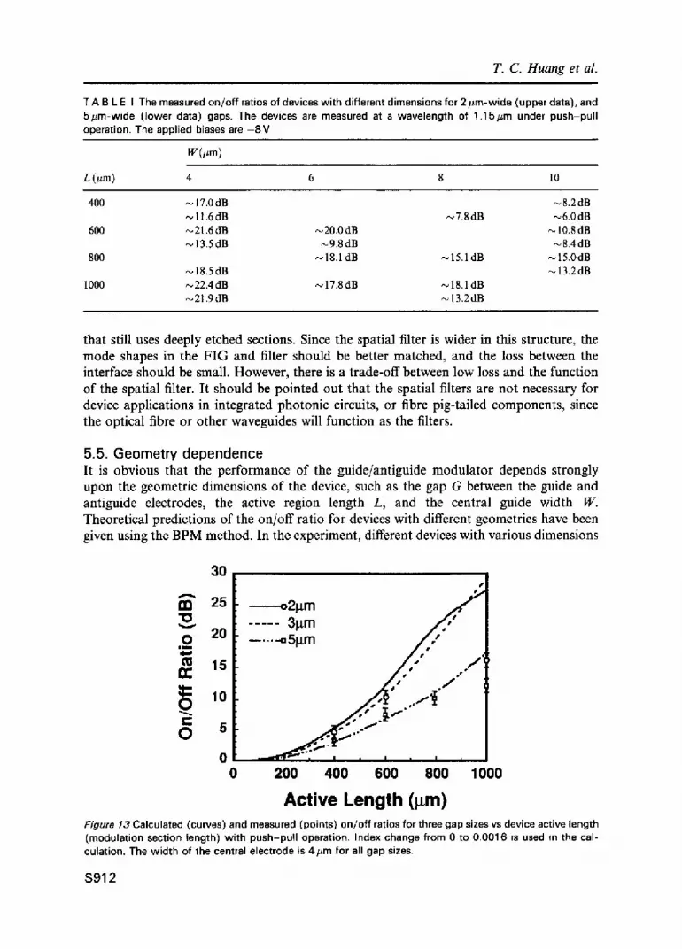
5.5. Geometry dependence It is obvious that the performance of the guide/antiguide modulator depends strongly upon the geometric dimensions of the device, such as the gap G between the guide and antiguide electrodes, the active region length L, and the central guide width W. Theoretical predictions of the on/off ratio for devices with different geometries have been given using the BPM method. In the experiment, different devices with various dimensions
30
A
133 25 '10 0 20
| m
15 n-
r 10 0 t- O 5
0 0
i
s ~
o2~tm . ~ ' . . . . . 3~m ~ , , ' . . . . -* 51~m / / /
/ / ..-i s . ~ j
- ~ ' = l q " ~ I I i I I I I
200 400 600 800 1000
Active Length (pm) Figure 13 Calculated (curves) and measured (points) on/of f ratios for three gap sizes vs device active length (modulation section length) with push-pul l operation. Index change from 0 to 0.0016 is used m the cal- culation. The width of the central electrode is 4#m for all gap sizes.
$91 2

Guide/antiguide optical intensity modulator
35
m 30 10 v 25 O
i t
20 n-
15
O 10 f-
O 5
0 , I , I = I i I =
0 2 4 6 8
o211m o.s ~ " i .
�9 ~ . . . . . 31.tm
" / "",~N .... -*51xm 2;'\
-~
Central Guide Width (l m) 10
Figure 14 Calculated (curves) and measured (points) on/off ratios for three gap widths as functions of the central guide widths. The optimum width varies as the separation gap changes. Again, index change from 0 to 0.0016 is used in the calculation. The length of the modulation section is I mm. The optimum guide width varies as the gap size changes.
have been fabricated and measured. In Table I, the measured on/off ratios for devices with 2 #m- and 5 #m-wide gaps are shown.
From the experimental data in the same column, it can be seen that, in general, the on/ off ratio increases as the active length increases. This is probably due to diffraction increas- ing exponentially with distance. From the figure, it can be seen that the device with a narrower central guide has larger on/off ratio if the devices have the same lengths and gap sizes. This is because the light diffracts out of the central guide region more easily for the narrower guide than the wider guide for the off state. Also, for devices with the same length and same central guide width, the devices with 2 #m gap size have larger on/off ratios, which indicates that the function of the antiguide is stronger for 2 #m gap devices than that of 5/zm gap devices. In the extreme case, if the gap size is too large, it will be very difficult for the input light to penetrate into the antiguide regions. There- fore, the diffracting function of the antiguide will vanish.
The dependence of the on/off ratio on the modulation section length has been calculated by BPM and measured. In Fig. 13, the curves are calculated results, and the points are measurement results. The index change from 0 to 0.0016 is used in the calculation. To reach this index change, the applied reverse bias is about - 5 V for the device structure at A = 1.15/zm. The width of the centre electrode is 4 #m for all gap sizes.
In Fig. 14, the dependence of on/off ratio on the guide width is plotted. The length of the modulation section is 1 mm. It is noted from the theoretical prediction that the optimum waveguide width varies as the gap size changes. The optimum waveguide width becomes smaller as the gap size increases. To achieve a large on/off ratio, the light energy in the guide and antiguide regions should have an optimum distribution. If the waveguide is too narrow or too wide, the light energy will be in the antiguide or guide region, which will reduce the modulation functions of the central guide or antiguide region and in turn reduce the on/off ratio. So it is expected that there is an optimum waveguide width with
S91 3
T. C. Huang et al.
1.4 V
r-
t- _e o 0.4
. m > a
__t_ High loss
High loss
High on /o f f Single mode
m m
Low on/off
3 8
m m -
Multimode Low on/off
Central guide width (pm)
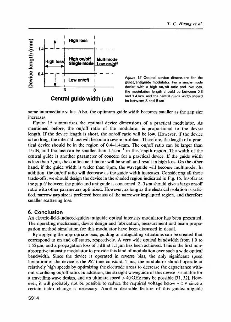
Figure 15 Optimal device dimensions for the guide/antiguide modulator. For a single-mode device with a high on/off ratio and low loss, the modulation length should be between 0.3 and 1.4 mm, and the central guide width should be between 3 and 8 #m.
some intermediate value. Also, the optimum guide width becomes smaller as the gap size increases.
Figure 15 summarizes the optimal device dimensions of a practical modulator. As mentioned before, the on/off ratio of the modulator is proportional to the device length. If the device length is short, the on/off ratio will be low. However, if the device is too long, the internal loss will become a severe problem. Therefore, the length of a prac- tical device should be in the region of 0.4-1.4mm. The on/off ratio can be larger than 15dB, and the loss can be smaller than 1.5cm -l in this length region. The width of the central guide is another parameter of concern for a practical device. If the guide width is less than 3 #m, the confinement factor will be small and result in high loss. On the other hand, if the guide width is wider than 8 #m, the waveguide will become multimode. In addition, the on/off ratio will decrease as the guide width increases. Considering all these trade-offs, we should design the device in the shaded region indicated in Fig. 15. Insofar as the gap G between the guide and antiguide is concerned, 2-3 #m should give a large on/off ratio with other parameters optimized. However, as long as the electrical isolation is satis- fied, narrow gap size is preferred because of the narrower implapted region, and therefore smaller scattering loss.
6. C o n c l u s i o n An electric-field-induced-guide/antiguide optical intensity modulator has been presented. The operating mechanism, device design and fabrication, measurement and beam propa- gation method simulation for this modulator have been discussed in detail.
By applying the appropriate bias, guiding or antiguiding situations can be created that correspond to on and off states, respectively. A very wide optical bandwidth from 1.0 to 1.55/zm, and a propagation loss of 1 dB at 1.3 #m has been achieved. This is the first non- absorptive intensity modulator to provide this kind of modulation over such a wide optical bandwidth. Since the device is operated in reverse bias, the only significant speed limitation of the device is the RC time constant. Thus, the modulator should operate at relatively high speeds by optimizing the electrode areas to decrease the capacitance with- out sacrificing on/off ratio. In addition, the straight waveguide of this device is suitable for a travelling-wave design, and an ultimate speed > 40 GHz may be possible [31, 32]. How- ever, it will probably not be possible to reduce the required voltage below ~ 5 V since a certain index change is necessary. Another desirable feature of this guide/antiguide
$ 9 1 4

Guide/antiguide optical intensity modulator
modulator is its simplicity. The technology of fabricating the device involves only one step of metallization and utilizes proton implantation/annealing, which is not only very easily implemented but also avoids complicated mask alignment and regrowth steps. Therefore, with this technology, complex and high-yield optoelectronic integrated circuits should be realizable.
References 1. M. ERMAN, P. JARRY, R. GAMONAL, P. AUTIER, J. P. CHANE and P. FRIJLINK, J. Lightwave Technol. 6
(1988) 837. 2. H. HAYASHI and K. TADA, Appl. Phys. Lett. 57 (1990) 227. 3. A.R. REISTINGER, D. W. BELLAVANCE and K. L. LAWLEY, Appl. Phys. Lett. 32 (1978) 663. 4. J.E. ZUCKER, K. L. JONES, B. I. MILLER and U. KOREN, IEEE Photon. Technol. Lett. 2 (1990) 32. 5. P. BUCHMANN, H. KAUFMANN, H. MELCHIOR and G. GUEKOS, Appl. Phys. Lett. 46 (1985) 462. 6. K. ISHIDA, H. NAKAMURA, H. MATSUMURS, T. KADOI and H. INOUE, AppL Phys. Lett. 50 (1987) 141. 7. Y. NODA, M. SUZUKI, Y. KUSHIRO and S. AKIBA, J. Lightwave Technol. LT-4 (1986) 1445. 8. K. WAKITA, I. KOTAKA, O. MITOMI, H. ASAI, Y. KAWAMURA and M. NAGANUMA, J. Lightwave Technol.
8 (1990) 1027. 9. T.H. WOOD, E. C. CARR, C. A BURRUS, R. S. TUCKER, T.-H. CHIU and W.-T. TSANG, Electron Lett. 23
(1987) 540. 10. D . A . B . MILLER, D. S. CHELMA, T. C. DAMEN, A. C. GOSSARD, W. WlEGMANN, T. H. WOOD and
C. A. BURRUS, Phys. Rev. B. 32 (1985) 1043. 11. T.C. HUANG, Y. CHUNG, N. DAGLI and L. A. COLDREN, Appl. Phys. Lett. 57 (1990) 114. 12. T. C. HUANG, Y. CHUNG, N. DAGLI and L A. COLDREN, AppI. Phys. Lett. 58 (1991) 2211. 13. T.C. HUANG, T C. YANG, Z. CHUANG, N. DAGLI and L. A. COLDREN, IEEE Photon. Technol. Lett. 4
(1992) 1018. 14. A. HERNANDEZ-CABRERA, C. TEJEDOR and F. MESEGUER, J. Appl. Phys. 58 (1985) 4666. 15. A. ALPING and L. A. COLDREN, J. AppL Phys. 61 (1987) 2430. 16. H.C. HUANG, S. YEE and M. SOMA, J. AppL Phys. 67 (1990) 1497. 17. B.R. BENNETT, R. A. SOREF and J. A. DEL ALAMO, IEEE J. Quantum Electron. QE-26 (1990) 113. 18. J.G. MENDONA-ALVAREZ, R. H. YAN and L. A. COLDREN, J. Appl. Phys. 62 (1987) 4548. 19. Y. CHUNG and N. DAGLI, IEEE J. Quantum Electron. QE-26 (1990) 1335. 20. Y. CHUNG and N. DAGLI, Electron. Lett. 26 (1990) 711. 21. J.S. WEINER, D. A. B. MILLER, D. S. CHELMA, T C. DAMEN, C. A. BURRUS, T. H. WOOD, A. C. GOSSARD
and W. WEIGMANN, AppL Phys. Lett. 47 (1985) 1148. 22. D . A . B . MILLER, D. S. CHELMA, T. C. DAMEN, A. C. GOSSARD, W. WlEGMANN, T. H. WOOD and
C. A. BURRUS, Phys. Rev. Lett. 53 (1984) 2173. 23. M. ERMAN, P. JARRY, R. GAMONAL, P. AUTIER, J. P. CHANE and P FRIJLINK, J. Lightwave Technol. 6
(1988) 837. 24. E.A.J. MARCATILI, Bell Syst. Tech. J. 49 (1969) 2071. 25. H. HAYASHI and K. TADA, Appl. Phys. Lett. 57 (1990) 227. 26. F. KOYAMA and K. IGA, Electron. Lett. 21 (1986) 1065. 27. K. WAKITA, I. KOTAKA, O. MITOMI, H ASAI and Y. KAWAMURA, IEEE Photon. Technol. Lett. 3 (1991)
167. 28. F. KOYAMA and K. IGA, J. Lightwave Technol. 6 (1988) 87. 29. R.G. WALKER, Electron. Lett. 21 (1985) 581. 30. J.M. ZAVADA, H. A. JENKINSON, R. G. WILSON and D. K. SADANA, Appl. Phys. Lett. 57 (1985) 2299. 31. S.Y. WANG and S. H. LIN, J. Lightwave Technol. 6 (1988) 758. 32. R.G. WALKER, IEEE J. Quantum Electron. QE-27 (1991) 654.
$915


