Embed Size (px)
Citation preview
Robust Attenuation of Direct-Drive Robot-Tip Vibrations
Dragan Kostić1, Bram de Jager2, Maarten Steinbuch3
Department of Mechanical Engineering, Eindhoven University of Technology, Eindhoven, The Netherlands [email protected], [email protected], [email protected]
Abstract
This paper suggests and employs a method for reducing vibrations at the tip of a robot. The vibrations, caused by structural flexibility, are detected using accelerome-ters. The robot control system consists of two comple-mentary sub-systems: a nominal motion controller and a vibration compensator. The former one realizes joint motions in accordance with a prescribed tip trajectory. The latter one robustly attenuates oscillations at the tip that are due to structural flexibility. The benefits of this set-up are experimentally verified for a spatial direct-drive robot with 3 revolute degrees of freedom.
1. Introduction
Elastic effects in robotic systems are under permanent research during the last two decades [1-11]. They became especially important when using lightweight materials for robot constructions that may enable faster movements of robots with the same actuators applied. As the stiffness of lightweight constructions is in general not sufficient to avoid their elastic bending, quick movements may cause undesirable vibrations of the robot end-effector. Such vibrations deteriorate the accuracy of trajectory tracking. A part of the research on robot flexibility is devoted to dynamic modeling of elastic effects [1-6]. The models can be used for simulation and control purposes. There are two classes of flexibility in robots: lumped elasticity in the transmission of torque [1,2], and distributed link flexibility [3-6]. The former one arises due to the use of elastic transmission elements, e.g., harmonic drives, belts, or long shafts. The latter one comes as a result of using lightweight materials and constructions to reduce mass and inertia of the links. Such materials and constructions increase the link compliance, which leads to structural vibrations at low frequencies and of signi-ficant amplitude. Dynamic models incorporating flexible behavior can be used for design of model-based controllers, which should counteract elastic effects [6-11]. The models implement feedforward control actions applied in addi-tion to suitable linear/nonlinear feedback [6]. Apart from simulation studies, experimental results in applica-tion of vibration compensators are rarely presented in the literature. The most frequently encountered are single [7,8] or two-link planar flexible robot arms [9]. There are only a few references treating more complex
spatial robot configurations, e.g., [10,11]. Possible rea-sons are the complexity of measuring equipment and a high dimension of the controllers, as advanced vibration control requires feedback from deformation variables in addition to nominal motion coordinates. Deformation variables represent link/joint deflections measured using strain gauges, accelerometers, visual systems, etc. In this paper we propose an efficient control strategy for attenuating tip vibrations, applicable to general spatial robot configurations. Accelerometers attached at the robot tip are used as vibration sensors. The number of translational and angular directions along which reduc-tion of vibrations is possible equals the number of degrees-of-freedom (d.o.f.). The dynamics along each direction is experimentally identified and used in the design of the vibration compensator. Benefits of the compensator are experimentally verified on a spatial robot with 3 revolute d.o.f. This robot belongs to the class of direct drive robots, which is usually recognized as very challenging for accurate control because of highly nonlinear and coupled dynamics. We achieved robust attenuation of vibrations arising at the tip, which encourages us that the suggested strategy is practically applicable to any mechanical system having an open kinematic chain. The key contributions of our approach are: (i) time-efficient identification of elastic effects and their incorporation into the model of rigid-body dynamics, (ii) use of the resulting non-linear dynamic model to simplify the problem of vibration compensa-tion to an ordinary regulation problem, solvable using a well-developed linear theory, and (iii) robust compen-sation of tip vibrations. In the next section we include elastic effects into a rigid-body model of robot dynamics. The extended model is used for design of a vibration compensator. Section 3 describes our robotic set-up and analyses sources and effects of the robot flexibility. Identification of the elastodynamics, as well as design of a vibration compensator, are presented in Section 4. Section 5 shows experimental results that validate our approach. Conclusions are given at the end.
2. Compensating for Flexible Dynamics
The standard model of rigid-body robot dynamics [12]
),()( qqhqqHτ &&& += (1)
is considered. Here, q , q& , and q&& are n×1 vectors of
joint motions, velocities and accelerations (n is the number of d.o.f.), τ an n×1 vector of generalized joint forces, H an n×n inertia matrix, and h an n×1 vector of Coriolis/centripetal, gravitational and friction forces. When structural flexibility is negligible, equation (1) defines joint torques that correspond to a certain loca-tion (position and orientation) of the end-effector. This location is mapped to displacements in the joints via an inverse kinematics mapping [13]. When flexible dyna-mics is present, the location of the end-effector deviates from its rigid-body location, as illustrated in Fig. 1.
q1
q2
qn
‘0’
‘ -1’n
‘1’
‘ ’n
x0
xn
y0
yn
z0
zn
zn
xn
ynpn
fn mn
nδx
nδy
nδz
‘n ’
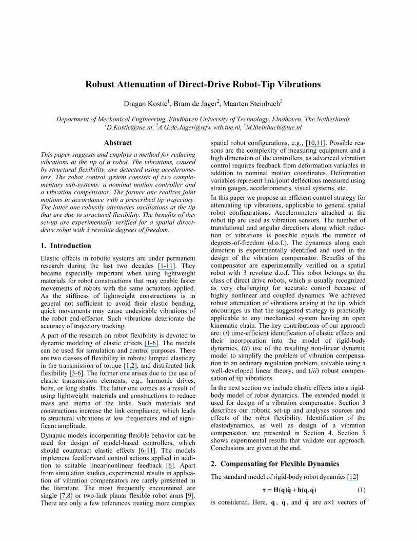
Figure 1: Elastic displacement of robot tip from
its rigid-body location We assume that dominant flexibility is due to elasticity in the most distal link. This is an important case in prac-tical applications − think of robots used in space miss-ions or machines for concrete pumping in civil enginee-ring (boom pumps). Reference [10] suggests that vibrations at the tip, caused by elasticity, are the result of two factors: an equivalent elastic force fn and an equivalent elastic torque mn . Both factors are indicated in Fig. 1, where they are referred to the tip coordinate frame ‘n’. They can be integrated into the model (1) using the well-known description of dynamic inter-action between the end-effector and environment [13]:
,
,
nn
nn
nn
nT
′′
+
++=
×
)()(
)()()()()(
)()(
0033
0
δmpf
qRqRpS0qRqJ
qqhqqHτ &&&
(2)
where )(qJ denotes a 6×n manipulator geometric Jaco-
bian reffered to the base (inertial) frame ‘0’, )(0 qRn is an orthogonal matrix mapping orientation of ‘n’ to ‘0’, p is a 3×1 vector of tip Cartesian coordinates referred to ‘0’, and the skew-symmetric matrix operator S is defined by:
−−
−=
00
0)(
xy
xz
yz
pppp
pppS . (3)
Variables p′n and δ′n denote 3×1 vectors of translatio-
nal and angular vibration coordinates, respectively, reffered to ‘n’. They represent displacement of the tip frame from its rigid-body location, as shown in Fig. 1. The last term in (2) points out how to compensate for the manipulator flexibility. It indicates that control of reference joint motions, which we denote with qτ , has to be corrected with a term counteracting the effects of
fn and mn . This term we denote with vτ . Let us adopt the computed torque control [13] for tracking a joint reference )(trq . If we define the tacking error as
)()()( ttt r qqe −= , (4)
then the system can be stabilized using a standard proportional-derivative (PD) feedback controller
),())(( rrdprrq qqheKeKqqHτ &&&& +++= , (5)
where
][diag 3,2,1, pppp kkk=K , ][diag 3,2,1, dddd kkk=K (6)
are positive definite gain matrices. Vibration compen-sation can be achieved by adding a term
′′
= ×
)()(
)()()()()( 00
330
δupu
qRqRpS0qRqJτ n
a
nl
nn
nTv (7)
to the controller (5). Feedback control laws that should ensure attenuation of both linear and angular elastic displacements are denoted by the 3×1 vector functions
lu and au . The vibration compensator (7) need to be active in the frequency range of vibrations and must not interfere with the computed torque controller. In practice, reference joint trajectories are chosen to lie below the lowest eigenfrequency of the structure. The motion controller (5) acts within the bandwidth of the joint references, while the compensator (7) acts in the frequency range of elastic vibrations. As qτ and vτ should act complementary to each other, we can determine them separately. The complete control law is:
vq τττ += . (8)
Design of the feedback laws lu and au requires know-
ledge on the functions )( pf ′nn and )( δm ′nn . A way to identify these relations will be presented in Section 4.
3. Experimental Set-up
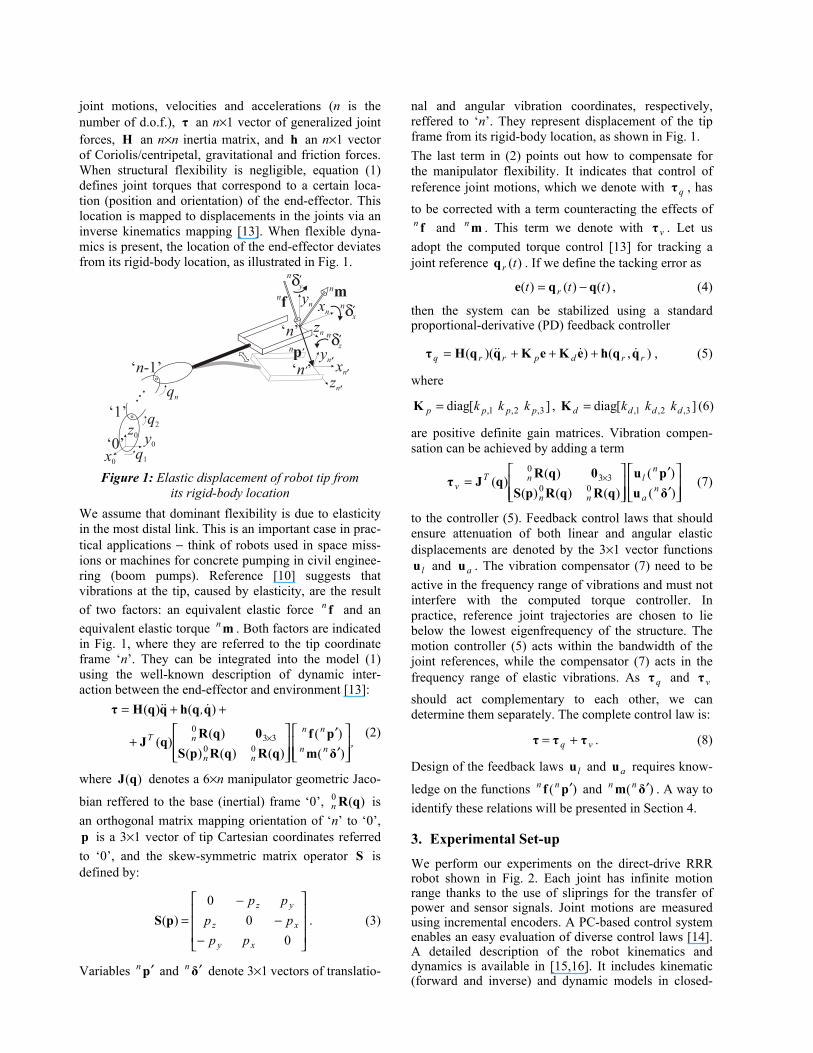
We perform our experiments on the direct-drive RRR robot shown in Fig. 2. Each joint has infinite motion range thanks to the use of sliprings for the transfer of power and sensor signals. Joint motions are measured using incremental encoders. A PC-based control system enables an easy evaluation of diverse control laws [14]. A detailed description of the robot kinematics and dynamics is available in [15,16]. It includes kinematic (forward and inverse) and dynamic models in closed-
form. The dynamic model is used for implementation of the control law (5)-(8). The direct-drive construction of the RRR robot implies a highly nonlinear and coupled robot dynamics that is quite challenging for accurate control. Joint flexibility is negligible. However, the last link is a plastic tube with a low rigidity. Its flexibility causes vibrations at the tip, complicating accurate tracking of reference tip trajec-tories. This link features translational elastic deflections along the y3 and z3 axes, indicated in Fig. 2. Deflections along y3 are more profound, as they arise inline with movement in the last joint. Elastic deformations of the link cause translational vibrations at the tip, as high torsional stiffness of the link prevents rotational vibrations. Therefore, a sensor of translational move-ments is required for measuring vibrations at the tip. We adopt a triaxial accelerometer as a measuring device. This sensor has poor low frequency characteristics, as it
cannot measure constant accelerations and does not pro-vide reliable measurements up to a lower cut-off frequ-ency of 3 Hz. However, the vibrations arising at the tip of our robot lie within the band of the sensor’s reliable measurements. We mount it at the origin of the coordi-nate frame ‘3’, aligning its mutually orthogonal princi-pal axes with the frame axes. This enables direct measu-rement of accelerations of translational tip vibrations.
x0
q1
q2
-q3x1
x2 x3
y0
y1
y2
y3
z0z1
z2
z3
waist
shoulderelbow
Figure 2: RRR robot experimental set-up
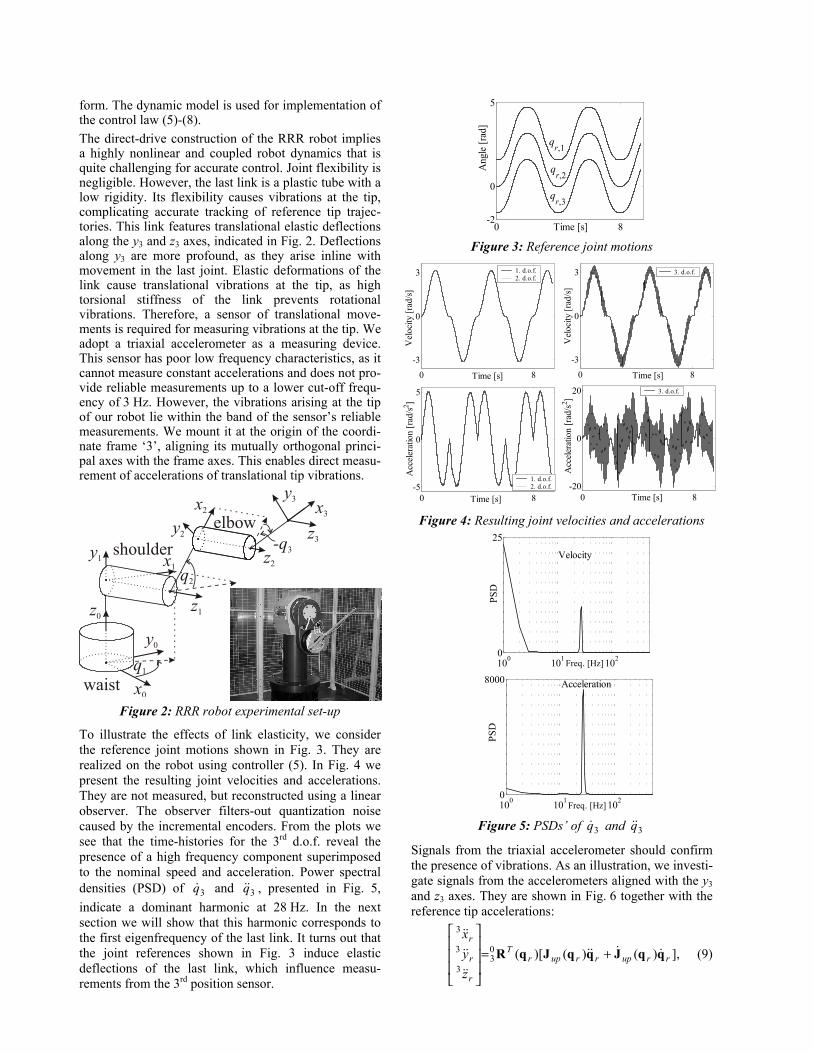
To illustrate the effects of link elasticity, we consider the reference joint motions shown in Fig. 3. They are realized on the robot using controller (5). In Fig. 4 we present the resulting joint velocities and accelerations. They are not measured, but reconstructed using a linear observer. The observer filters-out quantization noise caused by the incremental encoders. From the plots we see that the time-histories for the 3rd d.o.f. reveal the presence of a high frequency component superimposed to the nominal speed and acceleration. Power spectral densities (PSD) of 3q& and 3q&& , presented in Fig. 5, indicate a dominant harmonic at 28 Hz. In the next section we will show that this harmonic corresponds to the first eigenfrequency of the last link. It turns out that the joint references shown in Fig. 3 induce elastic deflections of the last link, which influence measu-rements from the 3rd position sensor.
0 8-2
0
5
Time [s]
Ang
le [r
ad]
qr,1
qr,2
qr,3
Figure 3: Reference joint motions
Figure 4: Resulting joint velocities and accelerations
Figure 5: PSDs’ of 3q& and 3q&&
Signals from the triaxial accelerometer should confirm the presence of vibrations. As an illustration, we investi-gate signals from the accelerometers aligned with the y3 and z3 axes. They are shown in Fig. 6 together with the reference tip accelerations:
],)()()[(03
3
3
3
rruprruprT
r
r
r
zyx
qqJqqJqR &&&&
&&
&&
&&
+=
(9)
0 8-3
0
3
Time [s]
Vel
ocity
[rad
/s]
1. d.o.f.2. d.o.f.
0 8-3
0
3
Time [s]
Vel
ocity
[rad
/s]
3. d.o.f.
0 8-5
0
5
Time [s]
Acc
eler
atio
n [r
ad/s2 ]
1. d.o.f.2. d.o.f.
0 8-20
0
20
Time [s]
Acc
eler
atio
n [r
ad/s
2 ]
3. d.o.f.
100 101 1020
25
PSD
Freq. [Hz]
Velocity
100 101 1020
8000
PSD
Freq. [Hz]
Acceleration
where upJ denotes the upper (3×n) part of the manipu-lator geometric Jacobian J . The right-hand side of (9) is premultiplied by )(0
3 qRT to represent the tip accele-rations in the same coordinate frame (‘3’) as the outputs from the triaxial accelerometer.
0 8-20
0
30
Time [s]
Acc
eler
atio
ns a
long
y3 [m
/s2 ]
Accelerometer outputReference
0 8
-10
0
20
Time [s]
Acc
eler
atio
ns a
long
z 3 [m/s2 ]
Accelerometer outputReference
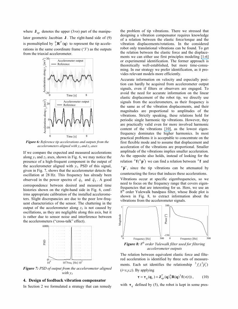
Figure 6: Reference tip accelerations and outputs from the
accelerometers aligned with y3 and z3 axes
If we compare the expected and measured accelerations along y3 and z3 axes, shown in Fig. 6, we may notice the presence of a high-frequent component in the output of the accelerometer aligned with y3. PSD of this signal, given in Fig. 7, shows that the accelerometer detects the oscillation at 28 Hz. This frequency has already been observed in the power spectra of 3q& and 3q&& . A good correspondence between desired and measured time histories shown on the right-hand side in Fig. 6, conf-irms appropriate calibration of the installed accelerome-ters. Slight discrepancies are due to the poor low-freq-uent characteristics of the sensor. The chattering in the output of the accelerometer along z3 is not caused by oscillations, as they are negligible along this axis, but it is rather due to sensor noise and interference between the accelerometers (“cross-talk” effect).
100 101 1020
6000
PSD
Freq. [Hz] Figure 7: PSD of output from the accelerometer aligned
with y3
4. Design of feedback vibration compensator In Section 2 we formulated a strategy that can remedy
the problem of tip vibrations. There we stressed that designing a vibration compensator requires knowledge of a relation between the elastic force/torque and the vibration displacements/rotations. In the considered robot only translational vibrations can be found. To get the relation between the elastic force and the displace-ments we can either use first principles modeling [1-6] or experimental identification. The former approach is theoretically well-established, but more time-consu-ming. In our strategy we prefer identification, as it pro-vides relevant models more efficiently. Accurate information on velocity and especially posi-tion can hardly be acquired from accelerometer output signals, even if filters or observers are engaged. To avoid the need for accurate information on the linear elastic displacement of the robot tip, we directly use signals from the accelerometers, as their frequency is the same as of the vibration displacements, and their magnitudes are proportional to amplitudes of the vibrations. Strictly speaking, these relations hold for periodic single harmonic tip vibrations. However, they are practically valid even for more involved harmonic content of the vibrations [10], as the lowest eigen-frequency dominates the higher harmonics. In most practical problems it is acceptable to concentrate on the first flexible mode and to assume that displacement and acceleration of the vibrations are proportional. Smaller amplitude of the vibrations implies smaller acceleration. As the opposite also holds, instead of looking for the relation )( pf ′nn we can find a relation between fn and
p&& ′n , since the tip vibrations can be attenuated by counteracting the force that induces these accelerations. Vibrations occur at specific eigenfrequencies, so we need to focus on the frequency range that covers eigen-frequencies that are interesting for us. Here, we use an 8th order Yulewalk bandpass filter, whose Bode plot is shown in Fig. 8, to extract information about the vibrations from the accelerometer signals.
Figure 8: 8th order Yulewalk filter used for filtering accelerometer outputs
The relation between equivalent elastic force and filte-red acceleration is identified by three sets of measure-ments. Each set identifies the relationship )(33
ii pf && ′ (i=x,y,z). By applying
))(()()()( 303 tvT
uprq fqRqJqττ += , (10)
with qτ defined by (5), the robot is kept in some pres-
0 5000
1
Frequency [Hz]
Mag
nitu
de
0 500-150
100
Frequency [Hz]
Phas
e [o ]
cribed static configuration rq ( 0q =r& ). A random
noise )(tv is injected into the system via )(3 tvf i =
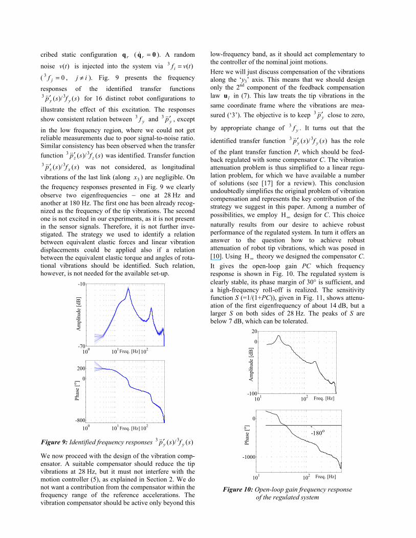
( 03 =jf , ij ≠ ). Fig. 9 presents the frequency responses of the identified transfer functions
)()/( 33 sfsp yy&& ′ for 16 distinct robot configurations to illustrate the effect of this excitation. The responses show consistent relation between yf3 and yp&& ′3 , except in the low frequency region, where we could not get reliable measurements due to poor signal-to-noise ratio. Similar consistency has been observed when the transfer function )()/( 33 sfsp zz&& ′ was identified. Transfer function
)()/( 33 sfsp xx&& ′ was not considered, as longitudinal vibrations of the last link (along 3x ) are negligible. On the frequency responses presented in Fig. 9 we clearly observe two eigenfrequencies − one at 28 Hz and another at 180 Hz. The first one has been already recog-nized as the frequency of the tip vibrations. The second one is not excited in our experiments, as it is not present in the sensor signals. Therefore, it is not further inve-stigated. The strategy we used to identify a relation between equivalent elastic forces and linear vibration displacements could be applied also if a relation between the equivalent elastic torque and angles of rota-tional vibrations should be identified. Such relation, however, is not needed for the available set-up.
Figure 9: Identified frequency responses )()/( 33 sfsp yy&& ′
We now proceed with the design of the vibration comp-ensator. A suitable compensator should reduce the tip vibrations at 28 Hz, but it must not interfere with the motion controller (5), as explained in Section 2. We do not want a contribution from the compensator within the frequency range of the reference accelerations. The vibration compensator should be active only beyond this
low-frequency band, as it should act complementary to the controller of the nominal joint motions. Here we will just discuss compensation of the vibrations along the ‘y3’ axis. This means that we should design only the 2nd component of the feedback compensation law lu in (7). This law treats the tip vibrations in the same coordinate frame where the vibrations are mea-sured (‘3’). The objective is to keep yp&& ′3 close to zero,
by appropriate change of yf3 . It turns out that the
identified transfer function )()/( 33 sfsp yy&& ′ has the role of the plant transfer function P, which should be feed-back regulated with some compensator C. The vibration attenuation problem is thus simplified to a linear regu-lation problem, for which we have available a number of solutions (see [17] for a review). This conclusion undoubtedly simplifies the original problem of vibration compensation and represents the key contribution of the strategy we suggest in this paper. Among a number of possibilities, we employ ∞H design for C. This choice naturally results from our desire to achieve robust performance of the regulated system. In turn it offers an answer to the question how to achieve robust attenuation of robot tip vibrations, which was posed in [10]. Using ∞H theory we designed the compensator C. It gives the open-loop gain PC which frequency response is shown in Fig. 10. The regulated system is clearly stable, its phase margin of 30° is sufficient, and a high-frequency roll-off is realized. The sensitivity function S (=1/(1+PC)), given in Fig. 11, shows attenu-ation of the first eigenfrequency of about 14 dB, but a larger S on both sides of 28 Hz. The peaks of S are below 7 dB, which can be tolerated.
Figure 10: Open-loop gain frequency response of the regulated system
100 101 102-70
-10
Am
plitu
de [d
B]
Freq. [Hz]
100 101 102-800
0
200
Phas
e [o ]
Freq. [Hz]
101 102-100
0
20
Am
plitu
de [d
B]
Freq. [Hz]
101 102
-1000
0
Phas
e [o ]
Freq. [Hz]
-180o

101 102-15
-10
-5
0
5
Am
plitu
de [d
B]
Freq. [Hz] Figure 11: Sensitivity function of the regulated system
5. Experimental evaluation
In this section we present experimental results in redu-cing vibrations using the designed compensator. First we consider the motion task illustrated in Fig. 3. If the vibration compensator is disabled, the output of the accelerometer aligned with the y3 axis is as shown on the left-hand side in Fig. 6. The accelerometer output shown on the left-hand side in Fig. 12 is obtained if the vibration compensator is enabled. Clearly, there is a significant attenuation of the vibrations in the latter case. This is also confirmed by the right side of Fig. 12, showing negligible power of the accelerometer output at 28 Hz if the vibration compensator is active.
Figure 12: Left: reference and measured acceleration along y3 with vibration compensator enabled;
right: PSDs’ of the measured acceleration along y3
To test robustness of the designed compensator, the 28 Hz resonance of the last link is amplified by increa-sing 3,dk gain in the motion controller (5). The frequ-
ency response )()/( 33 sfsp yy&& ′ corresponding to an incre-
ased 3,dk differs from the one shown in Fig. 9, which was used for the design of the vibration compensator. The difference may occur since increase of 3,dk ampli-fies high frequent eigenmodes and tilts the frequency response of P. The robot tip should write the letters
shown on the left-hand side in Fig. 13. The letters are written in a vertical surface, parallel to the x0z0 plane. The corresponding joint motions are given next to the letters. Writing the letters demands a considerable dynamic engagement from the robot [18]. At the begin-ning of the experiment the vibration compensator is disabled. Execution of the reference joint motions, shown in Fig. 13, generates significant chattering in the acceleration of the 3rd joint and in the outputs of the triaxial accelerometer. When the vibration compensator is enabled, an immediate attenuation of the vibration occurs. This is illustrated in Fig. 14, representing reference and actual accelerations of the 3rd joint (left), and reference and measured acceleration along the y3 axis (right). In Fig. 15 we show a photo of the executed sequence of letters. We may see that the compensator was enabled when writing the letter ‘o’. Before enabling the compensator, the letters were written with consi-derable oscillations around the reference path. When enabled, the compensator attenuates the oscillations and the writing proceeds smoothly and accurately. Cartesian errors along x0 and z0 directions, presented in Fig. 16, reduce when the vibration compensation is activated. This example shows robustness of the compensator with respect to variations in plant dynamics.
Figure 13: Left: reference path of the robot tip; right: the corresponding reference joint motions
Figure 14: Left: reconstructed executed acceleration of the 3rd joint; right: measured acceleration along y3
100 101 1020
6000
PSD
Freq. [Hz]
Comp. enabled Comp. disabled
0 8-20
0
30
Time [s]
Acc
eler
atio
ns a
long
y3 [m
/s2 ]
Accelerometer outputReference
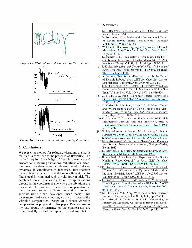
Figure 15: Photo of the path executed by the robot tip
Figure 16: Cartesian errors along x0 and z0 directions
6. Conclusions We present a method for reducing vibrations arising at the tip of a robot due to the presence of flexibility. The method requires knowledge of flexible dynamics and sensors for measuring vibrations. Vibrations are meas-ured using accelerometers. A relevant model of elasto-dynamics is experimentally identified. Identification makes obtaining a verified model more efficient. Identi-fied model is combined with a rigid-body model. The combined model enables regulation of tip vibrations directly in the coordinate frame where the vibrations are measured. The problem of vibration compensation is thus reduced to an ordinary regulation problem, solvable using a well-developed linear theory. This gives more freedom in choosing a particular form of the vibration compensator. Design of a robust vibration compensator is proposed in this paper. Practical usabi-lity and robust performance of the compensator are experimentally verified on a spatial direct-drive robot.
7. References [1] M.C. Readman, Flexible Joint Robots, CRC Press, Boca
Raton, Florida, 1994. [2] V. Potkonjak, “Contribution to the Dynamics and Control
of Robots Having Elastic Transmissions,” Robotica, Vol. 6, No.1, 1988, pp. 63-69.
[3] W.J. Book, “Recursive Lagrangian Dynamics of Flexible Manipulator Arms,” The Int. J. Rob. Res., Vol. 3, No. 3, 1984, pp. 87-101.
[4] D. Šurdilović, M. Vukobratović, “One Method for Effici-ent Dynamic Modeling of Flexible Manipulators,” Mech. and Mach. Theory, Vol. 31, No. 3, 1996, pp. 297-315.
[5] I. Kruise, Modelling and Control of a Flexible Beam and Robot Arm, PhD Thesis, University of Twente, Enschede, The Netherlands, 1990.
[6] A. De Luca, “Feedforward/Feedback Laws for the Control of Flexible Robots,” Proc. IEEE Int. Conf. Rob. Autom., San Francisco, California, April 2000, pp. 233-240.
[7] D.M. Gorinevski, A.V. Lensky, E.I. Savbitov, “Feedback Control of a One-link Flexible Manipulator With a Gear Train,” J. Rob. Sys., Vol. 8, No. 5, 1991, pp. 659-676.
[8] Z.H. Luo, D.X. Feng, “Nonlinear Torque Control of a Single-Link Flexible Robot,” J. Rob. Sys., Vol. 16, No. 1, 1999, pp. 25-35.
[9] S. Yurkovich, A.P. Tzes, I. Lee, K.L. Hillsley, “Control and System Identification of a Two-Link Flexible Mani-pulator,” Proc. IEEE Int. Conf. Rob. Autom., Cincinnati, Ohio, May 1990, pp. 1626-1631.
[10] F. Matsuno, Y. Sakawa, “A Simple Model of Flexible Manipulators with Six Axes and Vibration Control by Using Accelerometers,” J. Rob. Sys., Vol. 7, No. 4, 1990, pp. 575-597.
[11] S. López-Linares, A. Konno, M. Uchiyama, “Vibration Suppression Control of 3D Flexible Robots Using Velocity Inputs,” J. Rob. Sys., Vol. 14, No. 12, 1997, pp. 823-837.
[12] M. Vukobratović, V. Potkonjak, Dynamics of Manipula-tion Robots: Theory and Application, Springer-Verlag, Berlin, 1982.
[13] L. Sciavicco, B. Siciliano, Modeling and Control of Robot Manipulators, McGraw-Hill, Singapore, 1996.
[14] B. van Beek, B. de Jager, “An Experimental Facility for Nonlinear Robot Control,” in Proc. IEEE Int. Conf. Control Appl., Hawai’i, USA, 1999, pp. 668-673.
[15] D. Kostić, R. Hensen, B. de Jager, and M. Steinbuch, “Closed-form Kinematic and Dynamic Models of an Industrial-like RRR Robot,” IEEE Int. Conf. Rob. Autom., Washington D.C., May 2002, pp. 1309-1314.
[16] D. Kostić, R. Hensen, B. de Jager, and M. Steinbuch, “Modeling and Identification of an RRR-robot,” IEEE Conf. Dec. Control, Orlando, Florida, December 2001, pp. 1144-1149.
[17] M. Steinbuch, M.L. Norg, “Advanced Motion Control,” Europ. J. of Control, Vol. 4, No. 4, 1998, pp. 278-293.
[18] V. Potkonjak, S. Tzafestas, D. Kostić, “Concerning the Primary and Secondary Objectives in Robot Task Defini-tion−The “Learn From Humans” Principle,” Math. and Comp. in Simul., Vol. 54, No. 1-3, 2000, pp. 145-157.


