Embed Size (px)
Citation preview
Int. J. of Applied Mechanics and Engineering, 2020, vol.25, No.3, pp.117-132 DOI: 10.2478/ijame-2020-0038
LIQUID VIBRATIONS IN CYLINDRICAL TANKS WITH AND WITHOUT
BAFFLES UNDER LATERAL AND LONGITUDINAL EXCITATIONS
E. STRELNIKOVA*
A. Podgorny Institute of Mechanical Engineering Problems of the Ukrainian Academy of Sciences
UKRAINE V.N. Karazin Kharkiv National University
UKRAINE E-mails: [email protected]; [email protected]; estrel@ ipmach.kharkov.ua
D. KRIUTCHENKO and V. GNITKO
A. Podgorny Institute of Mechanical Engineering Problems of the Ukrainian Academy of Sciences
UKRAINE
A. TONKONOZHENKO
M.K. Yangel Yuzhnoye State Design Office
UKRAINE
The paper is devoted to issues of estimating free surface elevations in rigid cylindrical fluid-filled tanks under external loadings. The possibility of baffles installation is provided. The liquid vibrations caused by lateral and longitudinal harmonic loadings are under consideration. Free, forced and parametrical vibrations are examined. Modes of the free liquid vibrations are considered as basic functions for the analysis of forced and parametric vibrations. The modes of the free liquid vibrations in baffled and un-baffled cylindrical tanks are received by using single-domain and multi-domain boundary element methods. Effects of baffle installation are studied. The problems of forced vibrations are reduced to solving the systems of second order ordinary differential equations. For parametric vibrations the system of Mathieu equations is obtained. The numerical simulation of free surface elevations at different loadings and baffle configurations is accomplished. Beat phenomena effects are considered under lateral harmonic excitations. The phenomenon of parametric resonance is examined under longitudinal harmonic excitations. Key words: sloshing, cylindrical tank, baffle, free and forced vibrations, parametric resonance, boundary
element method, Ince-Strutt diagram.
1. Introduction
Thin-walled structures are widely used in different engineering areas: chemical and aerospace
industries, transportation, oil and gas producing. Usually these structures operate at intensive thermal and stress loadings, in interaction with fluids located in their containers. Many issues and challenges arise in design, and impact simulation of liquid storage tanks. Failures of these tanks, following destructive earthquakes or explosives, may lead to environmental catastrophes, loss of valuable contents, and disruption of fire-fighting efforts. Liquid sloshing often occurs when extreme loads are applied to the structures with
* To whom correspondence should be addressed
118 E.Strelnikova, D.Kriutchenko, V.Gnitko and A.Tonkonozhenko
compartments partially filled with different liquids. So the topical issue here is a problem of estimating frequencies and modes of vibrations of such facilities. The first research devoted to the fluid-structure interaction appeared in the 1960ies when the first missions to Jupiter failed. Among other studies the paper of Kumar [1] should be mentioned. Further research works were devoted to free vibrations of prismatic and cylindrical tanks in 2D formulations (Biswal et al. [2]). Liquid sloshing also a causes damage of roofs and upper walls of storage tanks. Many inadequately designed tanks and liquid storages have been damaged in extensive earthquakes.
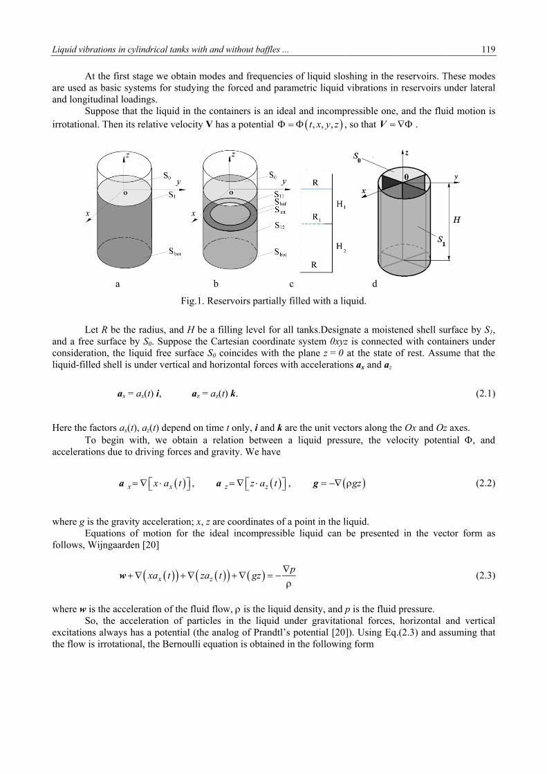
Sloshing frequencies and mode shapes for two- and three-dimensional rectangular tanks were obtained by Abramson [3] by the method of variables separation. A comprehensive review of sloshing phenomenon was made by Ibrahim [4]. It should be noted that it is difficult or impossible to obtain analytic solutions for tanks and reservoirs of complicated geometrical shapes. So, a lot of numerical methods have been employed for solving linear boundary value problems of liquid sloshing. Ru-De [5] presented finite element methods for analysis of linear liquid sloshing in the upright cylindrical tank under lateral excitations. Note that such 3-D finite element analysis of fluid-structure-soil interaction in nonlinear statement is complex and extremely time consuming. Several simplified theoretical investigations were conducted, eg. By Cho et al. [6], and other numerical methods were elaborated. Faltinsen and Timokha [7] developed analytical linear multimodal methods to analyze liquid slosh in spherical tanks. The volume-of-fluid method was developed by Kim and Lee [8] and Kim et al. [9]. The dynamic analysis of fluid-filled shell structures using coupled finite and boundary element methods was discussed in [10-11]. To damp the liquid motion, reduce structural loads and prevent instability a lot of slosh-suppression devices have been proposed (Choudhary and Bora [12]). These devices are rigid or elastic ring baffles of different sizes and orientation, vertical partitions, various plates partly covering the free surface [13-14]. Design of such devices also requires high accuracy in estimating the sloshing characteristics. Usually, the effect of baffles can be seen only after their installation. But such an experimental work is too expensive. So the development of computational technologies for qualified numerical simulation of baffle influence is a very topical issue. One of the pioneering papers in the area was written by Miles [15]. The effect of baffles on the natural sloshing frequencies was also studied by Gedikli and Erguven [16] with the boundary element method. This method has certain advantages and gives new qualitative possibilities in modeling fluid-structure interaction process (Brebbia et al. [17]). In the basic equations the functions and their derivatives are defined on the domain boundaries only. This allows us to reduce drastically the dimension of the problem. But matrixes of the linear algebraic systems of equations obtained at discretization are dense and non-symmetric, and it leads to increasing the computational costs. It was the reason why multi-domain or macro-element methods based on using boundary elements have been elaborated for solving boundary value problems [17-19]. The main idea of the multi-domain approach consists in dividing an initial domain into smaller ones (sub-domains or macro-elements). Auxiliary interface surfaces are involved to divide the domain, and unknowns here are the velocity potential and flux. Continuity conditions are formulated on fictitious boundaries. Then the systems of linear algebraic equations are established for each macro-element and a global system of equations is formed by assembling equations of all macro-elements using consistency conditions in common interface nodes. The multi-domain BEM is especially effective at numerical simulation of sloshing in tanks with baffles [13, 18, 19]. In spite of the considerable amount of research in the area there are a lot of problems which need to be scrutinized. This paper is devoted to free and forced liquid vibrations in baffled and un-baffled cylindrical tanks filled with an incompressible ideal liquid. Reservoirs with both horizontal and vertical baffles are considered. The lateral and longitudinal harmonic loadings are supposed to be applied to the structures under consideration. Beating effects and parametric resonances are analyzed. 2. Problem statement In this paper, problems connected with liquid vibrations in rigid cylindrical tanks with and without baffles are considered. The reservoirs under consideration are presented in Fig.1. The horizontal or vertical baffles are installed into cylindrical reservoirs.
Liquid vibrat
At tare used as and longitud Supirrotational.
Let
and a free sconsideratioliquid-filled
Here the fac To acceleration
where g is t Equfollows, Wi
where w is t So, excitations the flow is i
tions in cylind
the first stagbasic systemdinal loading
ppose that th. Then its rel
a
R be the radsurface by Son, the liquidd shell is und
ax = ax(t
ctors ax(t), az
begin with,ns due to driv
x a
the gravity acuations of mijngaarden [2
xw
the acceleratthe acceler
always has airrotational, t
drical tanks w
ge we obtain ms for studyigs. e liquid in thative velocit
Fig.
dius, and H bS0. Suppose td free surfac
der vertical an
t) i, az
z(t) depend o, we obtain ving forces a
xx a t ,
cceleration; xmotion for th20]
xxa t
tion of the fluration of para potential (tthe Bernoull
ith and withou
modes and fing the force
he containerty V has a po
b
1. Reservoirs
be a filling lthe Cartesiance S0 coincidnd horizonta
z = az(t) k.
on time t onlya relation
and gravity. W
z a
x, z are coordhe ideal inco
zza t
uid flow, isrticles in thethe analog oi equation is
ut baffles ...
frequencies oed and param
s is an ideal otential
c
s partially fil
level for all n coordinate des with the al forces with
y, i and k arebetween a
We have
zz a t ,
dinates of a pompressible
pgz
s the liquid de liquid undf Prandtl’s p obtained in
of liquid slosmetric liquid
and incomp , , ,t x y z ,
lled with a li
tanks.Designsystem 0xyzplane z = 0
h acceleration
e the unit vecliquid press
g
point in the lliquid can
density, and pder gravitatiopotential [20]the followin
shing in the vibrations in
pressible one, so that V
d
quid.
nate a moistez is connecteat the state ns ax and az
ctors along thsure, the ve
gz
iquid. be presented
p is the fluidonal forces, ]). Using Eq
ng form
reservoirs. Tn reservoirs u
e, and the flu .
ened shell sued with contof rest. Assu
he Ox and Ozlocity poten
d in the vec
d pressure. horizontal
q.(2.3) and as
119
These modesunder lateral
uid motion is
urface by S1,ainers underume that the
(2.1)
z axes. ntial , and
(2.2)
ctor form as
(2.3)
and verticalssuming that
9
s l
s
, r e
)
d
)
s
)
l t
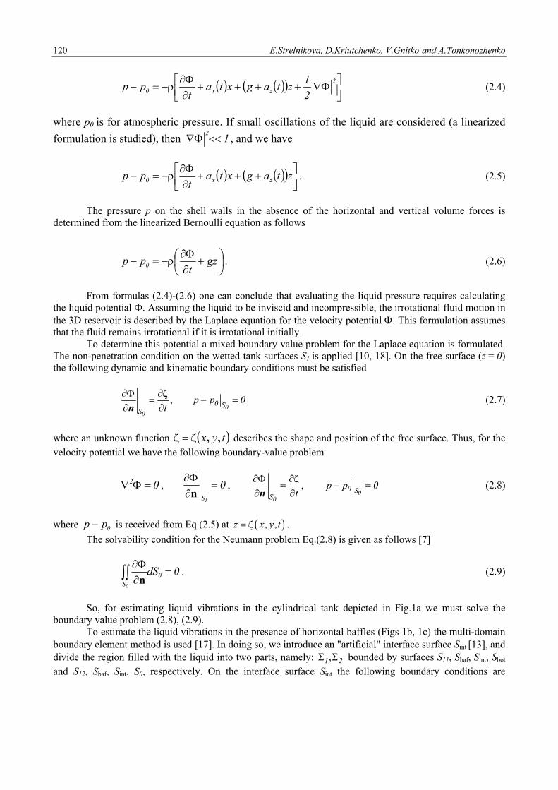
120 E.Strelnikova, D.Kriutchenko, V.Gnitko and A.Tonkonozhenko
2
zx0 2
1ztagxta
tpp (2.4)
where p0 is for atmospheric pressure. If small oscillations of the liquid are considered (a linearized
formulation is studied), then 12 , and we have
ztagxtat
pp zx0 . (2.5)
The pressure p on the shell walls in the absence of the horizontal and vertical volume forces is determined from the linearized Bernoulli equation as follows
gzt
pp 0 . (2.6)
From formulas (2.4)-(2.6) one can conclude that evaluating the liquid pressure requires calculating the liquid potential Ф. Assuming the liquid to be inviscid and incompressible, the irrotational fluid motion in the 3D reservoir is described by the Laplace equation for the velocity potential . This formulation assumes that the fluid remains irrotational if it is irrotational initially. To determine this potential a mixed boundary value problem for the Laplace equation is formulated. The non-penetration condition on the wetted tank surfaces S1 is applied [10, 18]. On the free surface (z = 0) the following dynamic and kinematic boundary conditions must be satisfied
,0
0
0 SS
p p 0t
n (2.7)
where an unknown function tyx ,, describes the shape and position of the free surface. Thus, for the velocity potential we have the following boundary-value problem
02 , 01S
n
, ,0
0
0 SS
p p 0t
n (2.8)
where 0pp is received from Eq.(2.5) at , ,z x y t .
The solvability condition for the Neumann problem Eq.(2.8) is given as follows [7]
0dS0S0
n. (2.9)
So, for estimating liquid vibrations in the cylindrical tank depicted in Fig.1a we must solve the boundary value problem (2.8), (2.9). To estimate the liquid vibrations in the presence of horizontal baffles (Figs 1b, 1c) the multi-domain boundary element method is used [17]. In doing so, we introduce an "artificial" interface surface Sint [13, and divide the region filled with the liquid into two parts, namely: ,1 2 bounded by surfaces S11, Sbaf, Sint, Sbot
and S12, Sbaf, Sint, S0, respectively. On the interface surface Sint the following boundary conditions are
Liquid vibrations in cylindrical tanks with and without baffles ... 121
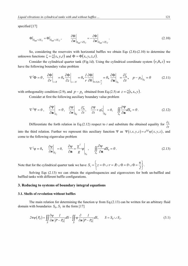
specified [17]
int int
int int
,1 2
1 2S S
S S
n n. (2.10)
So, considering the reservoirs with horizontal baffles we obtain Eqs (2.8)-(2.10) to determine the unknown functions tyx ,, and tzyx ,,, .
Consider the cylindrical quarter tank (Fig.1d). Using the cylindrical coordinate system zr ,, we have the following boundary value problem
02 , ,,,,
0r
10
z0
r2
0HzRr
0ppt 0
0
S0S
,n
(2.11)
with orthogonality condition (2.9), and 0pp obtained from Eq.(2.5) at yxtz ,, .
Consider at first the following auxiliary boundary value problem
02 , 01S
n
, ,0S t
n
,0S
g 0t
0dS0S0
n. (2.12)
Differentiate the forth relation in Eq.(2.12) respect to t and substitute the obtained equality for t
into the third relation. Further we represent this auxiliary function as , , , , ,i tt x y z e x y z , and
come to the following eigenvalue problem
,02 ,1S
0
n
0S
2
g
n
, 0dS0S0
n. (2.13)
Note that for the cylindrical quarter tank we have
2
0Rr0zS1 .
Solving Eqs (2.13) we can obtain the eigenfrequencies and eigenvectors for both un-baffled and baffled tanks with different baffle configurations.
3. Reducing to systems of boundary integral equations 3.1. Shells of revolution without baffles
The main relation for determining the function from Eq.(2.13) can be written for an arbitrary fluid domain with boundaries ,0 1S S in the form [17]
, .0 0 10 0S S
1 12 P dS dS S S S
P P P P
n n (3.1)
122 E.Strelnikova, D.Kriutchenko, V.Gnitko and A.Tonkonozhenko
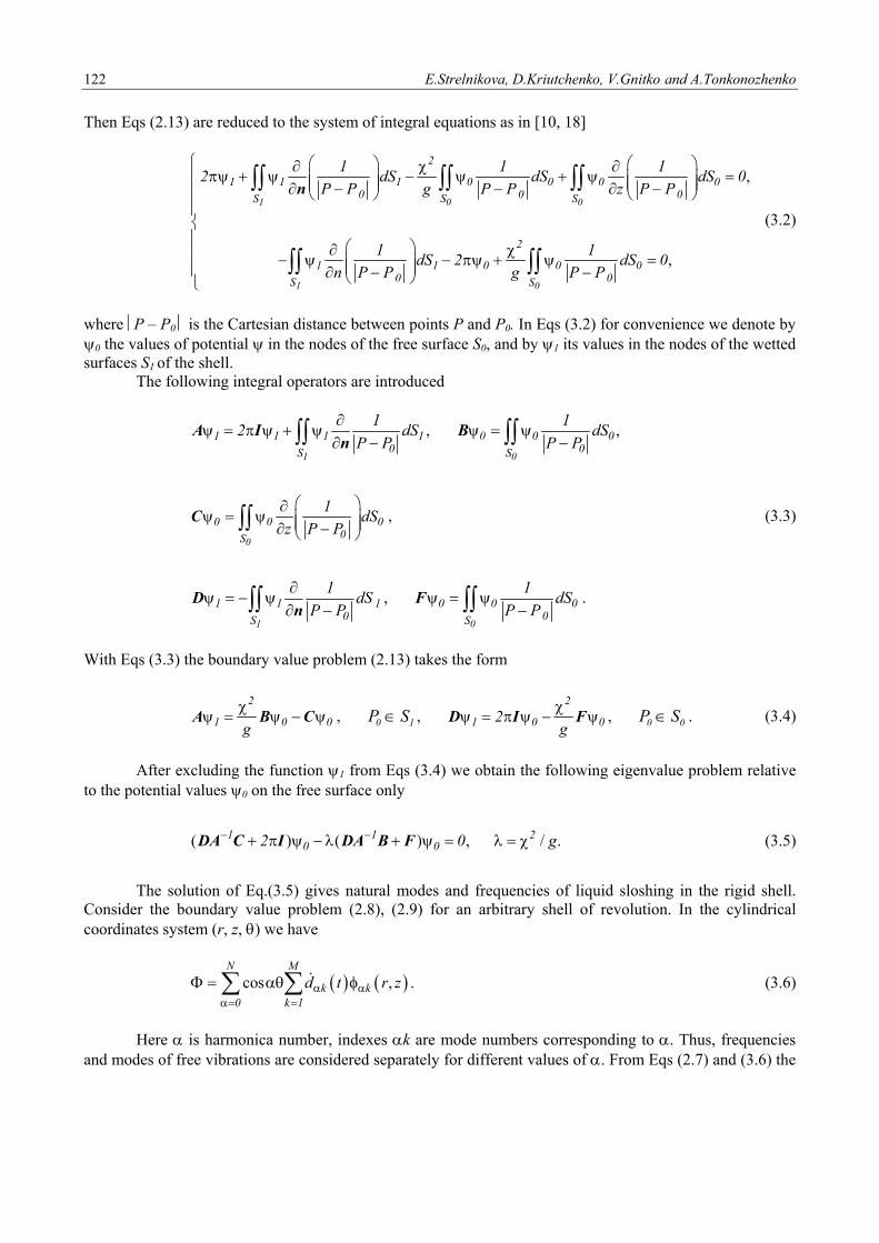
Then Eqs (2.13) are reduced to the system of integral equations as in [10, 18]
,
,
1 0 0
1 0
2
1 1 1 0 0 0 00 0 0S S S
2
1 1 0 0 00 0S S
1 1 12 dS dS dS 0
P P g P P z P P
1 1dS 2 dS 0
n P P g P P
n
(3.2)
where P – P0 is the Cartesian distance between points P and P0. In Eqs (3.2) for convenience we denote by 0 the values of potential in the nodes of the free surface S0, and by 1 its values in the nodes of the wetted surfaces S1 of the shell. The following integral operators are introduced
1
1 1 1 10S
12 dS
P P
A In
, ,
0
0 0 00S
1dS
P P
B
0
0 0 00S
1dS
z P P
C , (3.3)
1
1 1 10S
1dS
P P
Dn
,
0
0 0 00S
1dS
P P
F .
With Eqs (3.3) the boundary value problem (2.13) takes the form
2
1 0 0g
A B C , 10 SP ,
2
1 0 02g
D I F , 00 SP . (3.4)
After excluding the function 1 from Eqs (3.4) we obtain the following eigenvalue problem relative
to the potential values 0 on the free surface only
( ) ( ) , / .1 1 20 02 0 g DA C I DA B F (3.5)
The solution of Eq.(3.5) gives natural modes and frequencies of liquid sloshing in the rigid shell.
Consider the boundary value problem (2.8), (2.9) for an arbitrary shell of revolution. In the cylindrical coordinates system (r, z, ) we have
cos ,
N M
k k0 k 1
d t r z
. (3.6)
Here is harmonica number, indexes k are mode numbers corresponding to . Thus, frequencies
and modes of free vibrations are considered separately for different values of . From Eqs (2.7) and (3.6) the
Liquid vibrations in cylindrical tanks with and without baffles ... 123
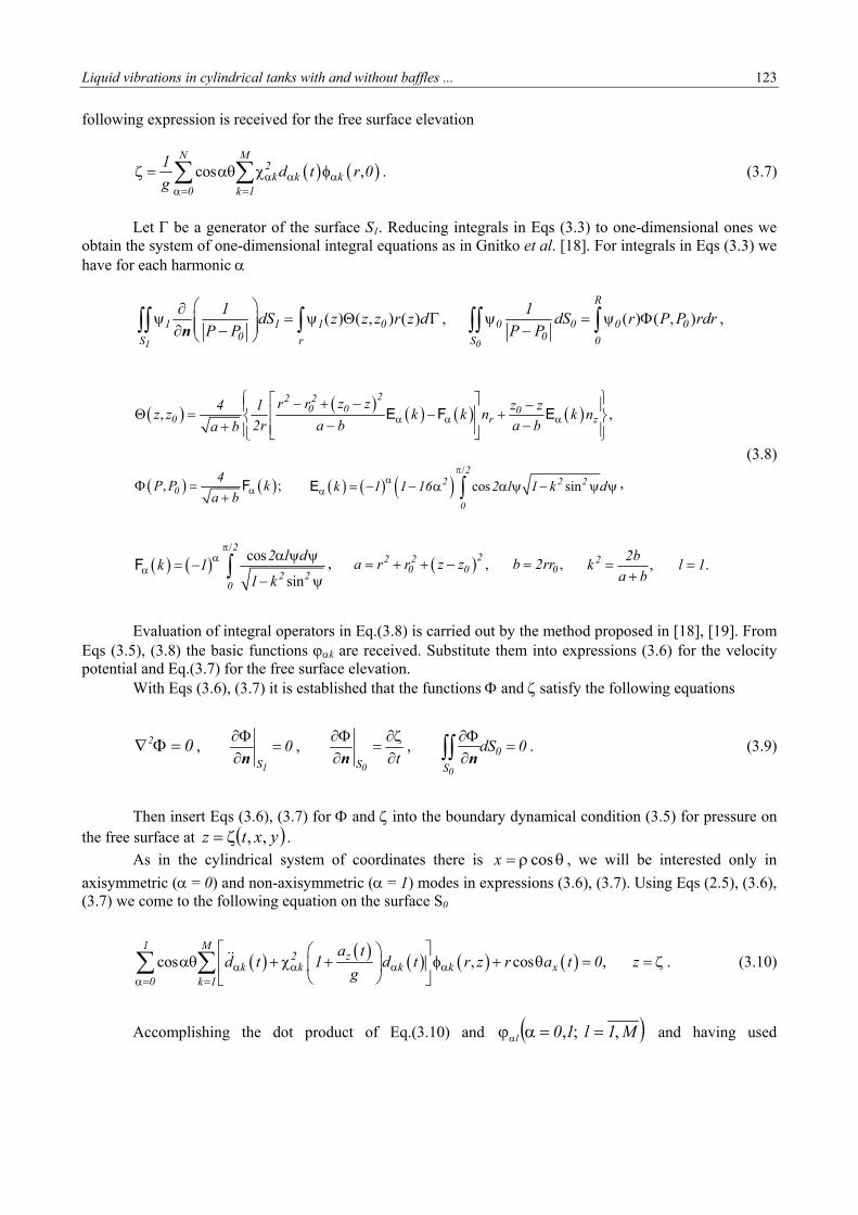
following expression is received for the free surface elevation
cos ,
N M2
k k k0 k 1
1d t r 0
g
. (3.7)
Let be a generator of the surface S1. Reducing integrals in Eqs (3.3) to one-dimensional ones we
obtain the system of one-dimensional integral equations as in Gnitko et al. [18]. For integrals in Eqs (3.3) we have for each harmonic
( ) ( , ) ( )
1
1 1 1 00S r
1dS z z z r z d
P P
n, ( ) ( , )
0
R
0 0 0 00S 0
1dS r P P rdr
P P
,
, ,22 2
0 0 00 r z
r r z z4 1 z zz z k k n k n
2r a b a ba b
E F E
(3.8)
, ;04
P P ka b
F
/
cos sin2
2 2 2
0
k 1 1 16 2 l 1 k d
E ,
/
cos
sin
2
2 20
2 l dk 1
1 k
F , , ,22 2
0 0 0a r r z z b 2rr , .2 2bk l 1
a b
Evaluation of integral operators in Eq.(3.8) is carried out by the method proposed in [18], [19]. From
Eqs (3.5), (3.8) the basic functions k are received. Substitute them into expressions (3.6) for the velocity potential and Eq.(3.7) for the free surface elevation.
With Eqs (3.6), (3.7) it is established that the functions and satisfy the following equations
02 , 1S
0
n
, 0S t
n,
0
0
S
dS 0
n
. (3.9)
Then insert Eqs (3.6), (3.7) for and into the boundary dynamical condition (3.5) for pressure on
the free surface at yxtz ,, .
As in the cylindrical system of coordinates there is cosx , we will be interested only in
axisymmetric ( = 0) and non-axisymmetric ( = 1) modes in expressions (3.6), (3.7). Using Eqs (2.5), (3.6), (3.7) we come to the following equation on the surface S0
cos , cos ,1 M
2 zk k k k x
0 k 1
a td t 1 d t r z r a t 0 z
g
. (3.10)
Accomplishing the dot product of Eq.(3.10) and M1l10l ,;, and having used
124 E.Strelnikova, D.Kriutchenko, V.Gnitko and A.Tonkonozhenko
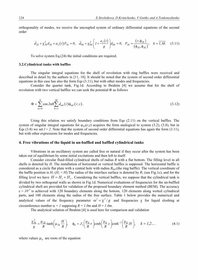
orthogonality of modes, we receive the uncoupled system of ordinary differential equations of the second order
,, , ; , .
,1k2 2 z
1k 1k 1k x 1k 0k 0k 0k 1k1k 1k
ra td d a t F 0 d 1 d 0 F k 1 M
g
(3.11)
To solve system Eq.(24) the initial conditions are required. 3.2.Cylindrical tanks with baffles The singular integral equations for the shell of revolution with ring baffles were received and described in detail by the authors in [11, 18]. It should be noted that the system of second order differential equations in this case has also the form Eqs (3.11), but with other modes and frequencies. Consider the quarter tank, Fig.1d. According to Ibrahim [4] we assume that for the shell of revolution with two vertical baffles we can seek the potential as follows
cos ,
N M
k k0 k 1
2 d t r z
. (3.12)
Using this relation we satisfy boundary conditions from Eqs (2.11) on the vertical baffles. The system of singular integral equations for k(r,z) acquires the form analogical to system (3.2), (3.8), but in Eqs (3.8) we set l = 2. Note that the system of second order differential equations has again the form (3.11), but with other expressions for modes and frequencies.
4. Free vibrations of the liquid in un-baffled and baffled cylindrical tanks
Vibrations in an oscillatory system are called free or natural if they occur after the system has been taken out of equilibrium by some initial excitations and then left to itself. Consider circular fluid-filled cylindrical shells of radius R with a flat bottom. The filling level in all shells is denoted by H. The installation of horizontal or vertical baffles is supposed. The horizontal baffle is considered as a circle flat plate with a central hole with radius Rbaf (the ring baffle). The vertical coordinate of the baffle position is H1 (H1 < H).The radius of the interface surface is denoted by R1 (see Fig.1c), and for the filling level we have 21 HHH . Considering the vertical baffles, we suppose that the cylindrical tank is divided by two orthogonal walls as shown in Fig.1d. Numerical evaluations of frequencies for the un-baffled cylindrical shell are provided for validation of the proposed boundary element method (BEM). The accuracy = 10-3 is achieved with 120 boundary elements along the bottom, 120 elements along wetted cylindrical parts, and 100 elements along the radius of the free surface. Table 1 below provides the numerical and
analytical values of the frequency parameter g22 / and frequencies for liquid sloshing at
circumference number = 1 supposing R = 1.0m and H = 1.0m. The analytical solution of Ibrahim [4] is used here for comparison and validation
tanh ,
21k 1k
1kH
g R R
cosh cosh 1k k kk 1J r z H
R R R
, ...,21k . (4.1)
where values k are roots of the equation
Liquid vibrations in cylindrical tanks with and without baffles ... 125
10 2
dJ x2 J x J x
dx , (4.2)
and xJxJxJ 210 ,, are Bessel functions of the first kind.
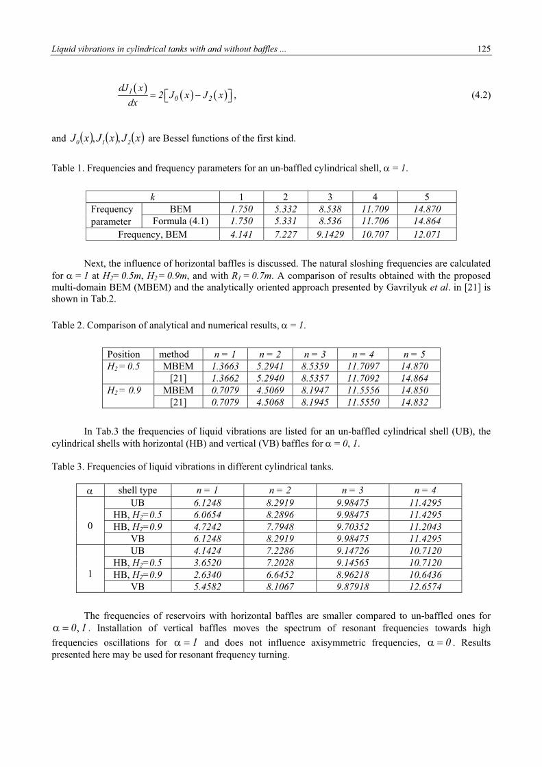
Table 1. Frequencies and frequency parameters for an un-baffled cylindrical shell, = 1.
k 1 2 3 4 5 Frequency parameter
BEM 1.750 5.332 8.538 11.709 14.870 Formula (4.1) 1.750 5.331 8.536 11.706 14.864
Frequency, BEM 4.141 7.227 9.1429 10.707 12.071
Next, the influence of horizontal baffles is discussed. The natural sloshing frequencies are calculated for = 1 at H2= 0.5m, H2 = 0.9m, and with R1 = 0.7m. A comparison of results obtained with the proposed multi-domain BEM (MBEM) and the analytically oriented approach presented by Gavrilyuk et al. in [21] is shown in Tab.2.
Table 2. Comparison of analytical and numerical results, = 1.
Position method n = 1 n = 2 n = 3 n = 4 n = 5 H2 = 0.5 MBEM 1.3663 5.2941 8.5359 11.7097 14.870
[21] 1.3662 5.2940 8.5357 11.7092 14.864 H2 = 0.9 MBEM 0.7079 4.5069 8.1947 11.5556 14.850
[21] 0.7079 4.5068 8.1945 11.5550 14.832
In Tab.3 the frequencies of liquid vibrations are listed for an un-baffled cylindrical shell (UB), the cylindrical shells with horizontal (HB) and vertical (VB) baffles for = 0, 1. Table 3. Frequencies of liquid vibrations in different cylindrical tanks.
shell type n = 1 n = 2 n = 3 n = 4
0
UB 6.1248 8.2919 9.98475 11.4295 HB, H2=0.5 6.0654 8.2896 9.98475 11.4295 HB, H2=0.9 4.7242 7.7948 9.70352 11.2043
VB 6.1248 8.2919 9.98475 11.4295
1
UB 4.1424 7.2286 9.14726 10.7120 HB, H2=0.5 3.6520 7.2028 9.14565 10.7120 HB, H2=0.9 2.6340 6.6452 8.96218 10.6436
VB 5.4582 8.1067 9.87918 12.6574
The frequencies of reservoirs with horizontal baffles are smaller compared to un-baffled ones for 10, . Installation of vertical baffles moves the spectrum of resonant frequencies towards high
frequencies oscillations for 1 and does not influence axisymmetric frequencies, 0 . Results presented here may be used for resonant frequency turning.
126 E.Strelnikova, D.Kriutchenko, V.Gnitko and A.Tonkonozhenko
5. Forced and parametric liquid vibrations 5.1. Cylindrical shells under lateral harmonic excitations Cylindrical shells with and without baffles are considered. Hereinafter, for all the shells we suppose that the radius is R = 1m, and filling level is H = 1m. The tank is subjected to periodic loading tata 1x cos that is applied in the horizontal direction. So, the only non-axisymmetric modes with
= 1 are under consideration. Suppose that before applying the horizontal loading the reservoir was at the state of rest. So, we need to solve system (3.11) under zero initial conditions. It follows from Eqs (3.11) that under these initial conditions we obtain
,
cos cos , , , .,
1k1 1k1k 1k 1k2 2
1k 1k1k
ra Fd t t t F k 1 M
(5.1)
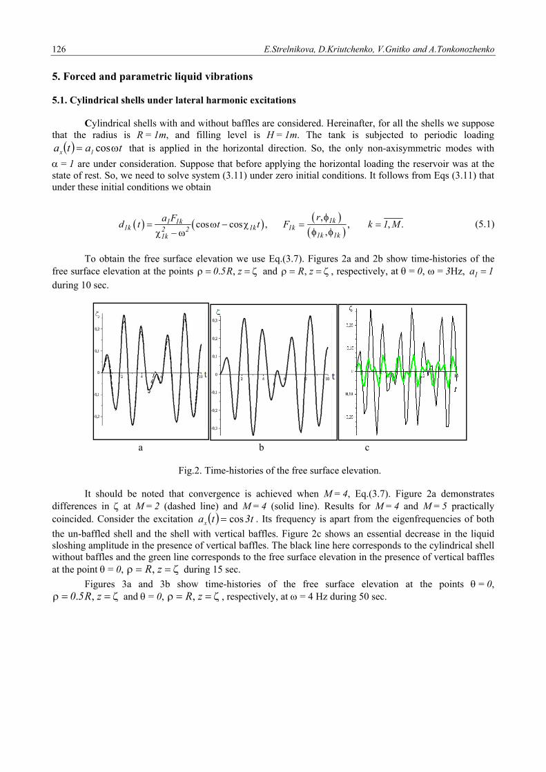
To obtain the free surface elevation we use Eq.(3.7). Figures 2a and 2b show time-histories of the
free surface elevation at the points . ,0 5R z and ,R z , respectively, at = 0, = 3Hz, 1a 1 during 10 sec.
a b c
Fig.2. Time-histories of the free surface elevation.
It should be noted that convergence is achieved when M = 4, Eq.(3.7). Figure 2a demonstrates
differences in at M = 2 (dashed line) and M = 4 (solid line). Results for M = 4 and M = 5 practically coincided. Consider the excitation t3tax cos . Its frequency is apart from the eigenfrequencies of both
the un-baffled shell and the shell with vertical baffles. Figure 2c shows an essential decrease in the liquid sloshing amplitude in the presence of vertical baffles. The black line here corresponds to the cylindrical shell without baffles and the green line corresponds to the free surface elevation in the presence of vertical baffles at the point = 0, zR, during 15 sec.
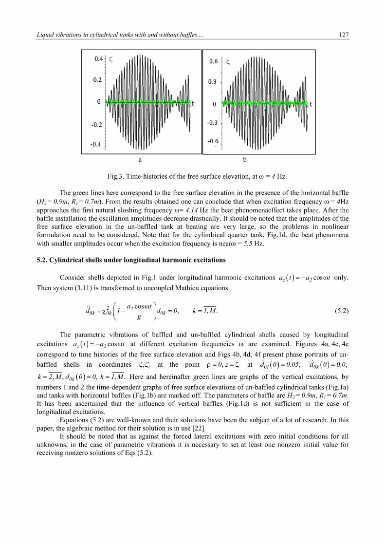
Figures 3a and 3b show time-histories of the free surface elevation at the points = 0, zR50 ,. and = 0, zR, , respectively, at = 4 Hz during 50 sec.
Liquid vibrations in cylindrical tanks with and without baffles ... 127
a b
Fig.3. Time-histories of the free surface elevation, at = 4 Hz.
The green lines here correspond to the free surface elevation in the presence of the horizontal baffle
(H2 = 0.9m, R1 = 0.7m). From the results obtained one can conclude that when excitation frequency = 4Hz approaches the first natural sloshing frequency = 4.14 Hz the beat phenomenaeffect takes place. After the baffle installation the oscillation amplitudes decrease drastically. It should be noted that the amplitudes of the free surface elevation in the un-baffled tank at beating are very large, so the problems in nonlinear formulation need to be considered. Note that for the cylindrical quarter tank, Fig.1d, the beat phenomena with smaller amplitudes occur when the excitation frequency is near = 5.5 Hz. 5.2. Cylindrical shells under longitudinal harmonic excitations
Consider shells depicted in Fig.1 under longitudinal harmonic excitations cosz 2a t a t only.
Then system (3.11) is transformed to uncoupled Mathieu equations
cos, , .2 2
0k 0k 0ka t
d 1 d 0 k 1 Mg
(5.2)
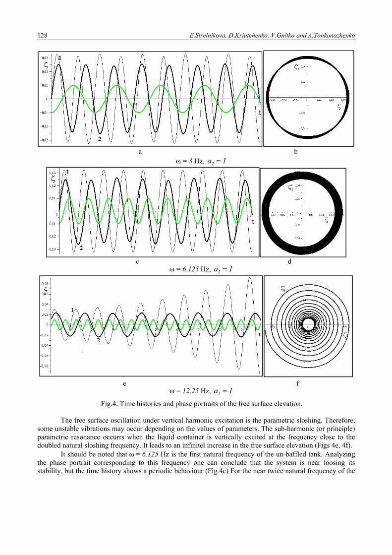
The parametric vibrations of baffled and un-baffled cylindrical shells caused by longitudinal
excitations cosz 2a t a t at different excitation frequencies are examined. Figures 4a, 4c, 4e
correspond to time histories of the free surface elevation and Figs 4b, 4d, 4f present phase portraits of un-
baffled shells in coordinates t, at the point ,0 z at . ,01d 0 0 05 . ,0kd 0 0 0
, , , , .0kk 2 M d 0 0 k 1 M Here and hereinafter green lines are graphs of the vertical excitations, by
numbers 1 and 2 the time-dependent graphs of free surface elevations of un-baffled cylindrical tanks (Fig.1a) and tanks with horizontal baffles (Fig.1b) are marked off. The parameters of baffle are H2 = 0.9m, R1 = 0.7m. It has been ascertained that the influence of vertical baffles (Fig.1d) is not sufficient in the case of longitudinal excitations.
Equations (5.2) are well-known and their solutions have been the subject of a lot of research. In this paper, the algebraic method for their solution is in use [22].
It should be noted that as against the forced lateral excitations with zero initial conditions for all unknowns, in the case of parametric vibrations it is necessary to set at least one nonzero initial value for receiving nonzero solutions of Eqs (5.2).
128 E.Strelnikova, D.Kriutchenko, V.Gnitko and A.Tonkonozhenko
a b
= 3 Hz, 1a2
c d
= 6.125 Hz, 1a2
e f
= 12.25 Hz, 1a2
Fig.4. Time histories and phase portraits of the free surface elevation. The free surface oscillation under vertical harmonic excitation is the parametric sloshing. Therefore,
some unstable vibrations may occur depending on the values of parameters. The sub-harmonic (or principle) parametric resonance occurrs when the liquid container is vertically excited at the frequency close to the doubled natural sloshing frequency. It leads to an infinitel increase in the free surface elevation (Figs 4e, 4f).
It should be noted that = 6.125 Hz is the first natural frequency of the un-baffled tank. Analyzing the phase portrait corresponding to this frequency one can conclude that the system is near loosing its stability, but the time history shows a periodic behaviour (Fig.4c) For the near twice natural frequency of the
Liquid vibrat
free surface For
presented by
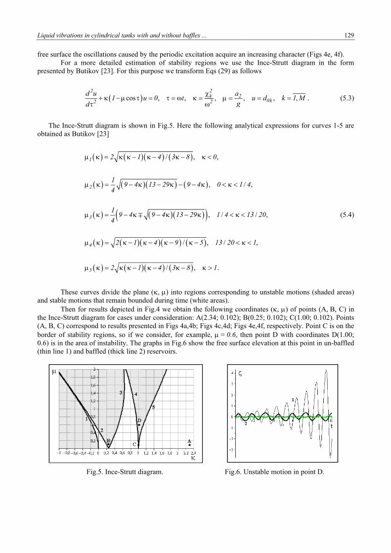
The Inc
obtained as
The
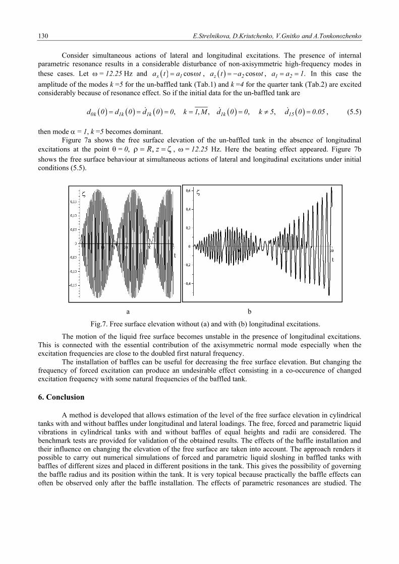
and stable m The
the Ince-Str(A, B, C) coborder of st0.6) is in th(thin line 1)
tions in cylind
e the oscillatir a more dety Butikov [2
2
2
d u
d
ce-Strutt diagButikov [23
1
2
3
4
5
ese curves dimotions that en for resultsrutt diagram orrespond to tability regioe area of inst) and baffled
Fig.5. I
drical tanks w
ions caused btailed estima
23]. For this p
cos1
gram is show]
2 1
19 4
4
19 4
4
2 1
2 1
ivide the plaremain bouns depicted infor cases unresults prese
ons, so if wetability. The (thick line 2
Ince-Strutt d
ith and withou
by the periodation of stabpurpose we t
,u 0
wn in Fig.5.
/
/
4 3
13 29
9 4 1
4 9
4 3
ane (, ) intnded during tn Fig.4 we obnder considerented in Figse consider, fgraphs in Fi
2) reservoirs.
diagram.
ut baffles ...
dic excitationbility regiontransform Eq
,2k2
t
Here the fol
,
,
,
/ ,
,
8
9 4
13 29
9 5
8
to regions cotime (white abtain the folration: A(2.3s 4a,4b; Figsfor example,ig.6 show the.
n acquire an ins we use thqs (29) as fol
, ,22
a
g
llowing analy
,
/
/
/
.
0
0 1 4
1 4 1
13 20
1
orrespondingareas). llowing coor4; 0.102); B
s 4c,4d; Figs = 0.6, thee free surface
Fig.6. U
increasing chhe Ince-Strullows
,0ku d k
ytical expres
,
/ ,
,
4
13 20
1
g to unstable
rdinates (, B(0.25; 0.102
4e,4f, respecen point D we elevation a
Unstable moti
haracter (Figutt diagram
,k 1 M .
ssions for cu
e motions (sh
) of points 2); C(1.00; 0.ctively. Poinwith coordinat this point i
ion in point D
129
gs 4e, 4f). in the form
(5.3)
urves 1-5 are
(5.4)
haded areas)
(A, B, C) in.102). Points
nt C is on theates D(1.00;in un-baffled
D.
9
m
)
e
)
)
n s e ; d
130 E.Strelnikova, D.Kriutchenko, V.Gnitko and A.Tonkonozhenko
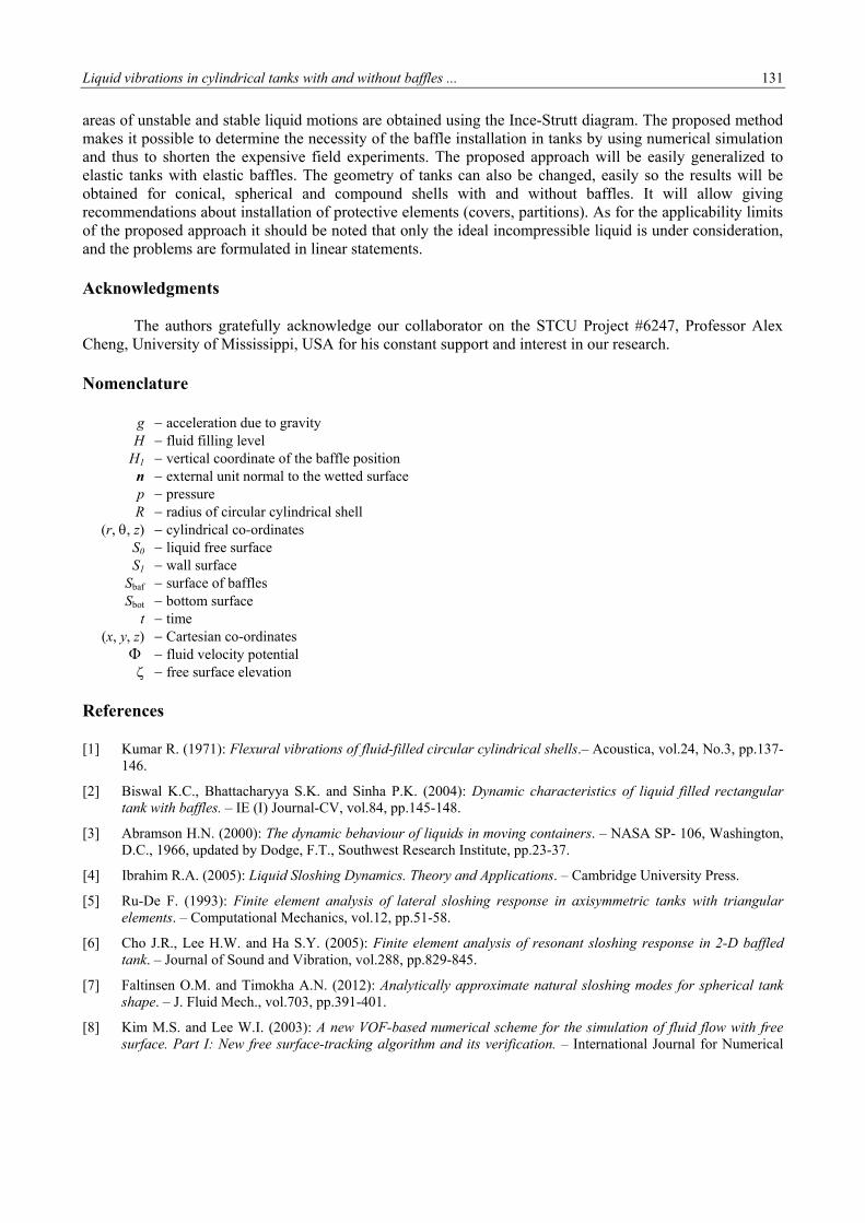
Consider simultaneous actions of lateral and longitudinal excitations. The presence of internal parametric resonance results in a considerable disturbance of non-axisymmetric high-frequency modes in these cases. Let = 12.25 Hz and cosx 1a t a t , cosz 2a t a t , .1 2a a 1 In this case the
amplitude of the modes k =5 for the un-baffled tank (Tab.1) and k =4 for the quarter tank (Tab.2) are excited considerably because of resonance effect. So if the initial data for the un-baffled tank are
, , , , , .0k 1k 1k 1k 15d 0 d 0 d 0 0 k 1 M d 0 0 k 5 d 0 0 05 , (5.5)
then mode = 1, k =5 becomes dominant.
Figure 7a shows the free surface elevation of the un-baffled tank in the absence of longitudinal excitations at the point = 0, zR, , = 12.25 Hz. Here the beating effect appeared. Figure 7b shows the free surface behaviour at simultaneous actions of lateral and longitudinal excitations under initial conditions (5.5).
a b
Fig.7. Free surface elevation without (a) and with (b) longitudinal excitations.
The motion of the liquid free surface becomes unstable in the presence of longitudinal excitations. This is connected with the essential contribution of the axisymmetric normal mode especially when the excitation frequencies are close to the doubled first natural frequency.
The installation of baffles can be useful for decreasing the free surface elevation. But changing the frequency of forced excitation can produce an undesirable effect consisting in a co-occurence of changed excitation frequency with some natural frequencies of the baffled tank.
6. Conclusion A method is developed that allows estimation of the level of the free surface elevation in cylindrical tanks with and without baffles under longitudinal and lateral loadings. The free, forced and parametric liquid vibrations in cylindrical tanks with and without baffles of equal heights and radii are considered. The benchmark tests are provided for validation of the obtained results. The effects of the baffle installation and their influence on changing the elevation of the free surface are taken into account. The approach renders it possible to carry out numerical simulations of forced and parametric liquid sloshing in baffled tanks with baffles of different sizes and placed in different positions in the tank. This gives the possibility of governing the baffle radius and its position within the tank. It is very topical because practically the baffle effects can often be observed only after the baffle installation. The effects of parametric resonances are studied. The
Liquid vibrations in cylindrical tanks with and without baffles ... 131
areas of unstable and stable liquid motions are obtained using the Ince-Strutt diagram. The proposed method makes it possible to determine the necessity of the baffle installation in tanks by using numerical simulation and thus to shorten the expensive field experiments. The proposed approach will be easily generalized to elastic tanks with elastic baffles. The geometry of tanks can also be changed, easily so the results will be obtained for conical, spherical and compound shells with and without baffles. It will allow giving recommendations about installation of protective elements (covers, partitions). As for the applicability limits of the proposed approach it should be noted that only the ideal incompressible liquid is under consideration, and the problems are formulated in linear statements. Acknowledgments The authors gratefully acknowledge our collaborator on the STCU Project #6247, Professor Alex Cheng, University of Mississippi, USA for his constant support and interest in our research. Nomenclature g acceleration due to gravity H fluid filling level H1 vertical coordinate of the baffle position n external unit normal to the wetted surface p pressure R radius of circular cylindrical shell (r,, z) cylindrical co-ordinates S0 liquid free surface S1 wall surface Sbaf surface of baffles Sbot bottom surface t time (x, y, z) Cartesian co-ordinates
fluid velocity potential free surface elevation References [1] Kumar R. (1971): Flexural vibrations of fluid-filled circular cylindrical shells.– Acoustica, vol.24, No.3, pp.137-
146.
[2] Biswal K.C., Bhattacharyya S.K. and Sinha P.K. (2004): Dynamic characteristics of liquid filled rectangular tank with baffles. – IE (I) Journal-CV, vol.84, pp.145-148.
[3] Abramson H.N. (2000): The dynamic behaviour of liquids in moving containers. – NASA SP- 106, Washington, D.C., 1966, updated by Dodge, F.T., Southwest Research Institute, pp.23-37.
[4] Ibrahim R.A. (2005): Liquid Sloshing Dynamics. Theory and Applications. – Cambridge University Press.
[5] Ru-De F. (1993): Finite element analysis of lateral sloshing response in axisymmetric tanks with triangular elements. – Computational Mechanics, vol.12, pp.51-58.
[6] Cho J.R., Lee H.W. and Ha S.Y. (2005): Finite element analysis of resonant sloshing response in 2-D baffled tank. – Journal of Sound and Vibration, vol.288, pp.829-845.
[7] Faltinsen O.M. and Timokha A.N. (2012): Analytically approximate natural sloshing modes for spherical tank shape. – J. Fluid Mech., vol.703, pp.391-401.
[8] Kim M.S. and Lee W.I. (2003): A new VOF-based numerical scheme for the simulation of fluid flow with free surface. Part I: New free surface-tracking algorithm and its verification. – International Journal for Numerical
132 E.Strelnikova, D.Kriutchenko, V.Gnitko and A.Tonkonozhenko
Methods in Fluids, vol.42, pp.765-790.
[9] Kim M.S., Park J.S. and Lee W.I. (2003): A new VOF-based numerical scheme for the simulation of fluid flow with free surface. Part II: application to the cavity filling and sloshing problems. – International Journal for Numerical Methods in Fluids, vol.42, pp.791-812.
[10] Strelnikova E., Yeseleva E., Gnitko V. and Naumenko V. (2010): Free and forced vibrations of the shells of revolution interacting with the liquid. – Proc. of XXXII Conference “Boundary elements and other mesh reduction methods”, WITPress, Transaction on Modeling and Simulation, vol.50, pp.203-211.
[11] Gnitko V., Marchenko U., Naumenko V. and Strelnikova E. (2011): Forced vibrations of tanks partially filled with the liquid under seismic load. – Proc. of XXXIII Conference “Boundary elements and other mesh reduction methods” WITPress, Transaction on Modeling and Simulation, vol.52, pp.285-296,
[12] Choudhary N. and Bora S.N. (2017): Linear sloshing frequencies in the annular region of a circular cylindrical container in presence of a rigid baffle. – Sadhana-Academy Proceedings in Engineering Sciences, vol.42, No.5, pp.805-815.
[13] Gnitko V., Naumemko Y. and Strelnikova E. (2017): Low frequency sloshing analysis of cylindrical containers with flat and conical baffles.– International Journal of Applied Mechanics and Engineering, vol.22, No.4, pp.867-881.
[14] Wang J., Wang Ch. and Liu J. (2019): Sloshing reduction in a pitching circular cylindrical container by multiple rigid annular baffles. – Ocean Engineering, vol.171, No.1, pp.241-249.
[15] Miles J.W. (1958): Ring damping of free surface oscillations on a circular tank. – J. Appl. Mech., vol.25, No.2, pp.274-276.
[16] Gedikli A. and Erguven M.E. (2003): Evaluation of sloshing problem by variational boundary element method. – Engineering Analysis with Boundary Elements, vol.27, pp.935-943.
[17] Brebbia C.A., Telles J.C.F. and Wrobel L.C. (1984): Boundary Element Techniques– Springer-Verlag: Berlin and New York.
[18] Gnitko V., Degtyarev K., Naumenko V. and Strelnikova E. (2018): Coupled BEM and FEM analysis of fluid-structure interaction in dual compartment tanks. – Int. Journal of Computational Methods and Experimental Measurements, vol.6, No.6, pp.976-988.
[19] Ravnik J., Strelnikova E., Gnitko V., Degtyarev K. and Ogorodnyk U. (2016): BEM and FEM analysis of fluid-structure interaction in a double tank.– Engineering Analysis with Boundary Elements, vol.67, pp.13-25.
[20] Wijngaarden Leen van. (2007): Prandtl–Batchelor flows revisited. – J. Fluid Dynamics Research, vol.39, pp.267-278.
[21] Gavrilyuk I., Lukovsky I., Trotsenko Yu. and Timokha A. (2006): Sloshing in a vertical circular cylindrical tank with an annular baffle. Part 1. Linear fundamental solutions. – Journal of Engineering Mathematics, vol.54, pp.71-88.
[22] Frenkel D. and Portugal R. (2001): Algebraic methods to compute Mathieu functions. – Journal of Physics A: Mathematical and General, vol.34, pp.3541-3551.
[23] Butikov E. (2018): Analytical expressions for stability regions in the Ince–Strutt diagram of Mathieu equation.– American Journal of Physics, vol.86, pp.257-267.
Received: May 26, 2019
Revised: May 23, 2020


