Embed Size (px)
Citation preview
Marine Coatings All products supplied and technical advice or recommendations given are subject to our standard Conditions of Sale. Registered in England No. 63604 Registered Office The AkzoNobel Building, Wexham Road, Slough, SL2 5DS Page 1
APPLICATION GUIDELINES
CARGO TANKS
Interline® 624
Revision 14
Issue Date: 18th March 2016
Marine Coatings All products supplied and technical advice or recommendations given are subject to our standard Conditions of Sale. Registered in England No. 63604 Registered Office The AkzoNobel Building, Wexham Road, Slough, SL2 5DS Page 2
Application Guidelines Interline® 624 Revision 13 Date 14th September 2015
CONTENTS Page 1. SCOPE AND PURPOSE 3 2. PRODUCT SPECIFICATION AND PRODUCT CURE GRAPHS 4
2.1 Surface Preparation 4 2.2 Specification 4 2.3 Film Thickness 4 2.4 Holding Primer 4 2.5 Notes 5 2.6 Product Cure Graphs 5
3. COATING APPLICATION PROCEDURES 7 4. TECHNICAL INSPECTION AND PROJECT CONTROL 12 5. GENERAL NOTES 13
5.1 Tank condition 13
5.2 Steelwork Preparation 14
5.3 Scaffolding 15
5.4 Cargo Lines 15
5.5 Heating Coils 16
5.6 Ventilation 16
5.7 Dehumidification 17
5.8 Heating 17
5.9 Lighting 17
5.10 Storage at point of application 18
5.11 Grit Blasting 18
5.12 Cleaning 19
5.13 Paint Application 20
5.13.1 Single Feed 20
5.13.2 Plural Feed 21
5.14 Stripe Coats 22
5.15 Coating Procedures 23 6. REPAIR PROCEDURES 24 7. HEALTH & SAFETY 25
Marine Coatings All products supplied and technical advice or recommendations given are subject to our standard Conditions of Sale. Registered in England No. 63604 Registered Office The AkzoNobel Building, Wexham Road, Slough, SL2 5DS Page 3
Application Guidelines Interline® 624 Revision 13 Date 14th September 2015
1. SCOPE AND PURPOSE
The International Paint Cargo Tank Coatings Application Guidelines have been produced and revised in line with the Worldwide Marine product range. The purpose of the guidelines is to ensure that a coating system, as applied, provides adequate protection against corrosion and resistance to cargoes in order to ensure that tanks are suitable for the carriage of products in accordance with the current revision of the International Paint Cargo Resistance Guide. Successful in-service performance of a tank coating system depends upon both the correct choice of coating and the adoption of the correct procedures for surface preparation and paint application. This document provides guidance to the specialised field of cargo tank coating application. It is the result of experience gained by International Paint during the application of sophisticated cargo tank coatings to vessels since 1960. The responsibilities for achieving the specific standards outlined and for carrying out surface preparation and paint application rest with the Contracting Company and Shipyard. Under no circumstances do these responsibilities rest with International Paint. We will generally provide for the presence of a Technical Service Representative at key stages during the performance of the contract. The role of the International Paint Technical Service Representative is advisory only unless otherwise specified in the terms and conditions of the contract.
Marine Coatings All products supplied and technical advice or recommendations given are subject to our standard Conditions of Sale. Registered in England No. 63604 Registered Office The AkzoNobel Building, Wexham Road, Slough, SL2 5DS Page 4
Application Guidelines Interline® 624 Revision 13 Date 14th September 2015
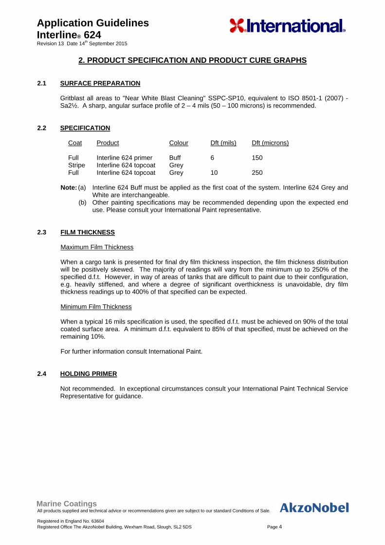
2. PRODUCT SPECIFICATION AND PRODUCT CURE GRAPHS 2.1 SURFACE PREPARATION
Gritblast all areas to "Near White Blast Cleaning" SSPC-SP10, equivalent to ISO 8501-1 (2007) - Sa2½. A sharp, angular surface profile of 2 – 4 mils (50 – 100 microns) is recommended.
2.2 SPECIFICATION
Coat Product Colour Dft (mils) Dft (microns) Full Interline 624 primer Buff 6 150 Stripe Interline 624 topcoat Grey Full Interline 624 topcoat Grey 10 250
Note: (a) Interline 624 Buff must be applied as the first coat of the system. Interline 624 Grey and
White are interchangeable. (b) Other painting specifications may be recommended depending upon the expected end
use. Please consult your International Paint representative. 2.3 FILM THICKNESS
Maximum Film Thickness When a cargo tank is presented for final dry film thickness inspection, the film thickness distribution
will be positively skewed. The majority of readings will vary from the minimum up to 250% of the specified d.f.t. However, in way of areas of tanks that are difficult to paint due to their configuration, e.g. heavily stiffened, and where a degree of significant overthickness is unavoidable, dry film thickness readings up to 400% of that specified can be expected.
Minimum Film Thickness When a typical 16 mils specification is used, the specified d.f.t. must be achieved on 90% of the total
coated surface area. A minimum d.f.t. equivalent to 85% of that specified, must be achieved on the remaining 10%.
For further information consult International Paint.
2.4 HOLDING PRIMER
Not recommended. In exceptional circumstances consult your International Paint Technical Service Representative for guidance.
Marine Coatings All products supplied and technical advice or recommendations given are subject to our standard Conditions of Sale. Registered in England No. 63604 Registered Office The AkzoNobel Building, Wexham Road, Slough, SL2 5DS Page 5
Application Guidelines Interline® 624 Revision 13 Date 14th September 2015
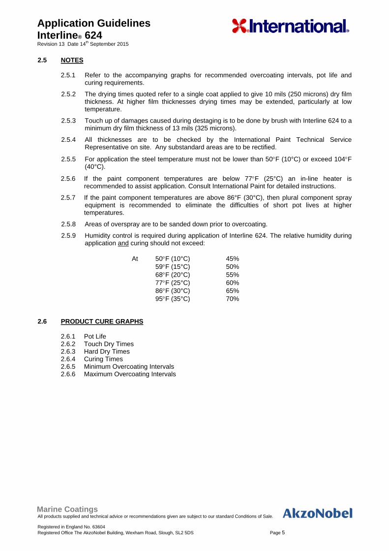
2.5 NOTES 2.5.1 Refer to the accompanying graphs for recommended overcoating intervals, pot life and
curing requirements.
2.5.2 The drying times quoted refer to a single coat applied to give 10 mils (250 microns) dry film thickness. At higher film thicknesses drying times may be extended, particularly at low temperature.
2.5.3 Touch up of damages caused during destaging is to be done by brush with Interline 624 to a minimum dry film thickness of 13 mils (325 microns).
2.5.4 All thicknesses are to be checked by the International Paint Technical Service Representative on site. Any substandard areas are to be rectified.
2.5.5 For application the steel temperature must not be lower than 50F (10°C) or exceed 104F (40°C).
2.5.6 If the paint component temperatures are below 77F (25°C) an in-line heater is recommended to assist application. Consult International Paint for detailed instructions.
2.5.7 If the paint component temperatures are above 86°F (30°C), then plural component spray equipment is recommended to eliminate the difficulties of short pot lives at higher temperatures.
2.5.8 Areas of overspray are to be sanded down prior to overcoating.
2.5.9 Humidity control is required during application of Interline 624. The relative humidity during application and curing should not exceed:
At 50F (10°C) 45% 59F (15°C) 50% 68F (20°C) 55% 77F (25°C) 60% 86F (30°C) 65% 95F (35°C) 70% 2.6 PRODUCT CURE GRAPHS
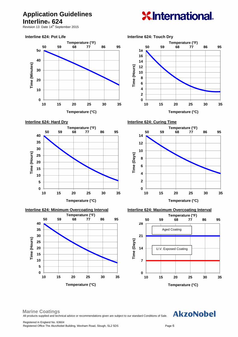
2.6.1 Pot Life 2.6.2 Touch Dry Times 2.6.3 Hard Dry Times 2.6.4 Curing Times 2.6.5 Minimum Overcoating Intervals 2.6.6 Maximum Overcoating Intervals
Marine Coatings All products supplied and technical advice or recommendations given are subject to our standard Conditions of Sale. Registered in England No. 63604 Registered Office The AkzoNobel Building, Wexham Road, Slough, SL2 5DS Page 6
Application Guidelines Interline® 624 Revision 13 Date 14th September 2015
Interline 624: Pot Life
Interline 624: Touch Dry
Interline 624: Hard Dry
Interline 624: Curing Time
Interline 624: Minimum Overcoating Interval
Interline 624: Maximum Overcoating Interval
0
10
20
30
40
50
10 15 20 25 30 35
Tim
e (M
inu
tes)
Temperature (°C)
0
2
4
6
8
10
12
14
16
18
10 15 20 25 30 35
Tim
e (H
ou
rs)
Temperature (°C)
0
5
10
15
20
25
30
35
40
10 15 20 25 30 35
Tim
e (H
ou
rs)
Temperature (°C)
0
2
4
6
8
10
12
14
10 15 20 25 30 35
Tim
e (D
ays)
Temperature (°C)
0
5
10
15
20
25
30
35
40
10 15 20 25 30 35
Tim
e (H
ou
rs)
Temperature (°C)
0
7
14
21
28
10 15 20 25 30 35
Tim
e (D
ays)
Temperature (°C)
Temperature (°F) 50 59 68 77 86 95
Temperature (°F)50 59 68 77 86 95
Temperature (°F) 50 59 68 77 86 95
Temperature (°F)50 59 68 77 86 95
Temperature (°F) 50 59 68 77 86 95
Temperature (°F)50 59 68 77 86 95
Aged Coating
U.V. Exposed Coating
Marine Coatings All products supplied and technical advice or recommendations given are subject to our standard Conditions of Sale. Registered in England No. 63604 Registered Office The AkzoNobel Building, Wexham Road, Slough, SL2 5DS Page 7
Application Guidelines Interline® 624 Revision 13 Date 14th September 2015
3. COATING APPLICATION PROCEDURES 3.1 FOR IN SITU APPLICATIONS
3.1.1 Erect the scaffolding. Refer to Section 5.3 for International Paint’s recommendations. 3.1.2 Prepare welds, cut edges and surface imperfections as described in ISO 8501-3: P3. Refer
to section 5.2 for preparation methods. 3.1.3 All surfaces to be coated should be clean, dry and free from contamination. Remove all oil,
grease and soluble contaminants in accordance with SSPC-SP1 solvent cleaning. If a detergent / fresh water mix is to be used, the detergent should be neutral and fresh water rinsable to ensure total removal of contamination.
3.1.4 For cargo tanks, grit blast the entire tank to “Near White Blast Cleaning SSPC-SP10,
equivalent to ISO Standard ISO 8501-1 (2007) - Sa2½. The specified surface profile is required - see Section 5.11.
3.1.5 Upon completion of the blasting, and after inspection by the Contractor Quality Control
Department, The International Paint Technical Service Representative will also inspect the whole area and mark up any substandard areas.
3.1.6 All marked areas shall be re-blasted and brought up to the required standard. The whole
blasted area is to be vacuum cleaned to remove dust and contamination. 3.1.7 Levels of substrate salt contamination should be determined as outlined in section 3.3 of this
procedure. This may not be necessary in certain Newbuilding shipyards were International Paint have detailed knowledge and experience of local practices, and where salt levels have always been shown to be low.
3.1.8 All the areas are to receive a full coat of the first coat of the system to the specified dry film
thickness. 3.1.9 When hard dry, and accepted by the Contractor Quality Control Department the International
Paint Technical Service Representative will check the dry film thickness. 3.1.10 The bottom area, up to 6 feet (2 metres) above the bottom, is to be covered in polythene to
prevent dry spray from the upper areas falling on to the bottom. 3.1.11 All the areas itemised in Section 5.14 in way of the upper area are to receive a stripe coat
with the second coat of the system. 3.1.12 The stripe coat is to be inspected by the International Paint Technical Service
Representative. 3.1.13 The upper areas are to receive a full coat of the second coat of the system. The total dry film
thickness of the first two coats should be as specified in Section 2.2, within the specified acceptable minimum and maximum thicknesses.
3.1.14 When hard dry, and accepted by the Contractor Quality Control Department, the
International Paint Technical Service Representative will check the dry film thickness. 3.1.15 Any areas of under thickness are to be brought up to the minimum thickness specified. 3.1.16 When the full upper area is coated to the required standard the polythene and scaffolding
are to be removed from tank.
Marine Coatings All products supplied and technical advice or recommendations given are subject to our standard Conditions of Sale. Registered in England No. 63604 Registered Office The AkzoNobel Building, Wexham Road, Slough, SL2 5DS Page 8
Application Guidelines Interline® 624 Revision 13 Date 14th September 2015
3.1.17 All damages caused by de-staging, plus areas covered by the scaffolding poles, are to be either vacublasted or disced to the required standard. The whole bottom area is to be cleaned and solvent washed where necessary. All damages are to be touched up with the correct coating scheme.
3.1.18 Areas itemised in Section 5.14, in way of the bottom area, are to receive a stripe coat of the
second coat of the system. 3.1.19 The stripe coat is to be inspected by the International Paint Technical Service
Representative. 3.1.20 All areas of the bottom up to a 6 feet (2 metre) level are to receive the second coat of the
system. The total dry film thickness of the first two coats should be as specified in Section 2.2, within the specified acceptable minimum and maximum thicknesses. (see Section 2.3)
3.1.21 When hard dry, and accepted by the Contractor Quality Control Department, the
International Paint Technical Service Representative will check the dry film thickness. 3.1.22 Any areas of under thickness are to be brought up to the minimum thickness specified. 3.1.23 Finished tanks must be subjected to a seawater or freshwater test to highlight
pinholes/irregularities in the tank coating which have not been identified by normal visual inspection. This may be carried out either by:
a) Full ballasting of the tank. After de-ballasting, the tank should remain closed up for at
least 48 hours. b) Seawater re-circulation using the tank washing system. A minimum of 2 full cycles is to
be run and the tank then left closed up for at least 48 hours. If fresh water is used the test duration should be doubled.
The minimum curing period prior to water testing is shown below:
Temperature °C Temperature °F Curing Days
10 15 20 25 30 35
50 59 68 77 86 95
14 11 9 7 6 5
3.1.24 Following testing, the tank should be thoroughly washed down with fresh water and dried,
and any defective area repaired in accordance with the recommendations of the International Paint Technical Service representative. These recommendations will be based upon those outlined in Section 6.
3.2 FOR APPLICATIONS AT BLOCK STAGE
At Block Stage
3.2.1 Prepare welds, cut edges and surface imperfections as described in ISO 8501-3: P3. Refer to section 5.2 for preparation methods.
3.2.2 All surfaces to be coated should be clean, dry and free from contamination. Remove all oil,
grease and soluble contaminants in accordance with SSPC-SP1 solvent cleaning. If a detergent / fresh water mix is to be used, the detergent should be neutral and fresh water rinsable to ensure total removal of contamination.
Marine Coatings All products supplied and technical advice or recommendations given are subject to our standard Conditions of Sale. Registered in England No. 63604 Registered Office The AkzoNobel Building, Wexham Road, Slough, SL2 5DS Page 9
Application Guidelines Interline® 624 Revision 13 Date 14th September 2015
3.2.3 Gritblast all areas to "Near White Blast Cleaning" SSPC-SP10, equivalent to ISO 8501-1 (2007) - Sa2½.
3.2.4 Upon completion of the blasting, and after inspection by the Contractor Quality Control
Department, the International Paint Technical Service Representative (if present) will also inspect the whole area and mark up any substandard areas.
3.2.5 All marked areas shall be brought up to the specified standard of preparation. The whole
blasted area is to be vacuum cleaned to remove dust and contamination.
3.2.6 Levels of substrate salt contamination should be determined as outlined in section 3.3 of this procedure. This may not be necessary in certain Newbuilding shipyards where International Paint have detailed knowledge and experience of local practices, and where salt levels have always been shown to be low.
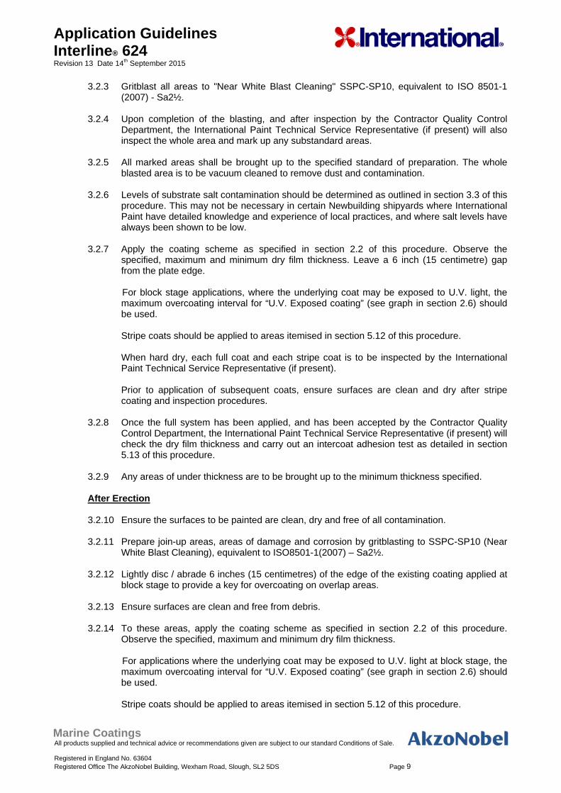
3.2.7 Apply the coating scheme as specified in section 2.2 of this procedure. Observe the
specified, maximum and minimum dry film thickness. Leave a 6 inch (15 centimetre) gap from the plate edge.
For block stage applications, where the underlying coat may be exposed to U.V. light, the maximum overcoating interval for “U.V. Exposed coating” (see graph in section 2.6) should be used.
Stripe coats should be applied to areas itemised in section 5.12 of this procedure. When hard dry, each full coat and each stripe coat is to be inspected by the International Paint Technical Service Representative (if present). Prior to application of subsequent coats, ensure surfaces are clean and dry after stripe coating and inspection procedures.
3.2.8 Once the full system has been applied, and has been accepted by the Contractor Quality
Control Department, the International Paint Technical Service Representative (if present) will check the dry film thickness and carry out an intercoat adhesion test as detailed in section 5.13 of this procedure.
3.2.9 Any areas of under thickness are to be brought up to the minimum thickness specified.
After Erection
3.2.10 Ensure the surfaces to be painted are clean, dry and free of all contamination.
3.2.11 Prepare join-up areas, areas of damage and corrosion by gritblasting to SSPC-SP10 (Near
White Blast Cleaning), equivalent to ISO8501-1(2007) – Sa2½.
3.2.12 Lightly disc / abrade 6 inches (15 centimetres) of the edge of the existing coating applied at block stage to provide a key for overcoating on overlap areas.
3.2.13 Ensure surfaces are clean and free from debris.
3.2.14 To these areas, apply the coating scheme as specified in section 2.2 of this procedure.
Observe the specified, maximum and minimum dry film thickness.
For applications where the underlying coat may be exposed to U.V. light at block stage, the maximum overcoating interval for “U.V. Exposed coating” (see graph in section 2.6) should be used. Stripe coats should be applied to areas itemised in section 5.12 of this procedure.
Marine Coatings All products supplied and technical advice or recommendations given are subject to our standard Conditions of Sale. Registered in England No. 63604 Registered Office The AkzoNobel Building, Wexham Road, Slough, SL2 5DS Page 10
Application Guidelines Interline® 624 Revision 13 Date 14th September 2015
When hard dry, each full coat and each stripe coat is to be inspected by the International Paint Technical Service Representative (if present).
Prior to application of subsequent coats, ensure surfaces are clean and dry after stripe coating and inspection procedures.
3.2.15 Once the full system has been applied, and has been accepted by the Contractor Quality
Control Department, the International Paint Technical Service Representative (if present) will check the dry film thickness and carry out an intercoat adhesion test as detailed in section 5.13 of this procedure.
3.2.16 Any areas of under thickness are to be brought up to the minimum thickness specified. This
must be carried out within the overcoating limits specified for the product.
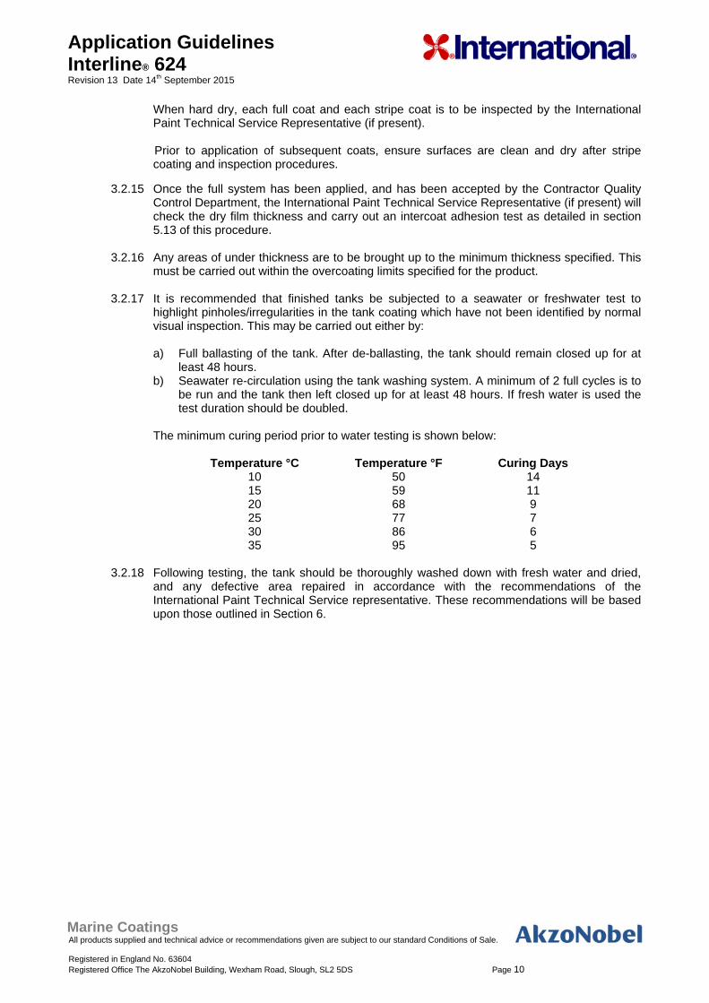
3.2.17 It is recommended that finished tanks be subjected to a seawater or freshwater test to highlight pinholes/irregularities in the tank coating which have not been identified by normal visual inspection. This may be carried out either by:
a) Full ballasting of the tank. After de-ballasting, the tank should remain closed up for at
least 48 hours. b) Seawater re-circulation using the tank washing system. A minimum of 2 full cycles is to
be run and the tank then left closed up for at least 48 hours. If fresh water is used the test duration should be doubled.
The minimum curing period prior to water testing is shown below:
Temperature °C Temperature °F Curing Days
10 15 20 25 30 35
50 59 68 77 86 95
14 11 9 7 6 5
3.2.18 Following testing, the tank should be thoroughly washed down with fresh water and dried,
and any defective area repaired in accordance with the recommendations of the International Paint Technical Service representative. These recommendations will be based upon those outlined in Section 6.
Marine Coatings All products supplied and technical advice or recommendations given are subject to our standard Conditions of Sale. Registered in England No. 63604 Registered Office The AkzoNobel Building, Wexham Road, Slough, SL2 5DS Page 11
Application Guidelines Interline® 624 Revision 13 Date 14th September 2015
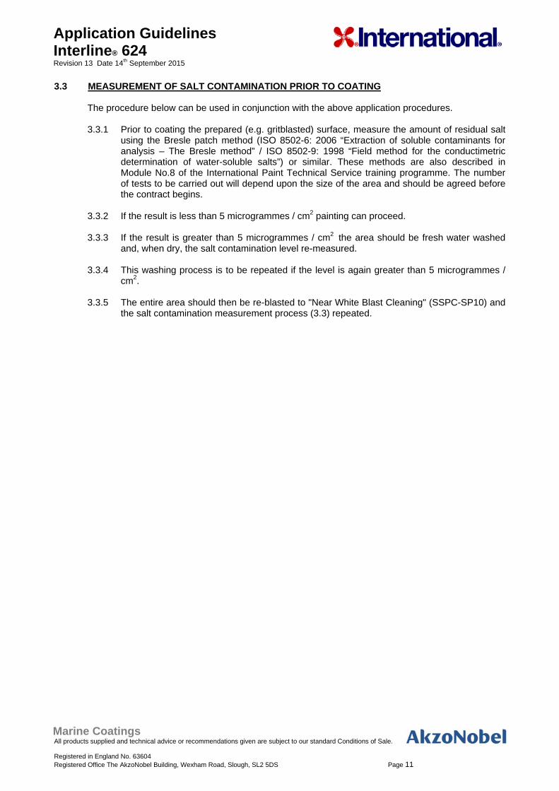
3.3 MEASUREMENT OF SALT CONTAMINATION PRIOR TO COATING
The procedure below can be used in conjunction with the above application procedures. 3.3.1 Prior to coating the prepared (e.g. gritblasted) surface, measure the amount of residual salt
using the Bresle patch method (ISO 8502-6: 2006 “Extraction of soluble contaminants for analysis – The Bresle method” / ISO 8502-9: 1998 “Field method for the conductimetric determination of water-soluble salts”) or similar. These methods are also described in Module No.8 of the International Paint Technical Service training programme. The number of tests to be carried out will depend upon the size of the area and should be agreed before the contract begins.
3.3.2 If the result is less than 5 microgrammes / cm2 painting can proceed. 3.3.3 If the result is greater than 5 microgrammes / cm2 the area should be fresh water washed
and, when dry, the salt contamination level re-measured. 3.3.4 This washing process is to be repeated if the level is again greater than 5 microgrammes /
cm2. 3.3.5 The entire area should then be re-blasted to "Near White Blast Cleaning" (SSPC-SP10) and
the salt contamination measurement process (3.3) repeated.
Marine Coatings All products supplied and technical advice or recommendations given are subject to our standard Conditions of Sale. Registered in England No. 63604 Registered Office The AkzoNobel Building, Wexham Road, Slough, SL2 5DS Page 12
Application Guidelines Interline® 624 Revision 13 Date 14th September 2015
4. TECHNICAL INSPECTION AND PROJECT CONTROL Project control by regular inspection and agreement on future action is vital to successful tank coating projects, and in maximising the potential of a coating system. All parties involved in the cargo tank coating work must agree an inspection procedure prior to work commencing, this should outline how and when both work and inspection will be undertaken. Prior to commencing the project the contractor(s) must be provided with copies of the relevant product data sheets. Attention should be drawn to pack sizes, mix ratios, thinning restrictions etc. The International Paint Technical Service Representative must be present during initial mixing of the first drums of product to be applied to ensure that all parties are aware of mixing and application characteristics. Daily meetings should be arranged to confirm performance of the work and inspection schedules, minutes of these meetings must be taken and circulated to all participants. Representatives of the contractor, shipyard and ship owner would normally be present at these meetings. In the event of work continuing at any stage without the approval of International Paint, the Company cannot be held responsible for any subsequent failure of the tank coating system on the areas concerned. Those areas MUST be specifically excluded from the performance guarantee. Such an event is termed an EXCEPTION. All parties MUST be officially informed in writing using the standard Exception Report Form immediately following the occurrence. International Paint, and any other authorised personnel, may inspect any stage in the process. If additional inspections are considered necessary because of on site conditions or by agreement prior to commencement of the contract, then the contractor must obtain written approval for that stage from International Paint before continuing. Contractors must supply interpreters if necessary. On completion of the contract all relevant documentation must be retained, and safely archived, by the Local Technical Service Manager. Inspection equipment for measurement of profile depth, humidity, wet and dry film thickness, etc should be of approved types and should be within calibration limits. NOTE: When measuring the dry film thickness of coatings, the d.f.t. gauge must be calibrated prior to use as follows: 1. Check that the probe is clean. 2. Place the probe on a sample of millscale-free smooth steel of thickness greater than 1mm. 3. Calibrate the instrument to zero. 4. Select a certified shim of similar thickness to that expected for the coating under test. 5. Calibrate the gauge to the shim thickness. 6. Check that the gauge reads zero when replaced on the smooth steel sample. Measurement of dry film thickness is described in ISO Standard 2808:2007.
Marine Coatings All products supplied and technical advice or recommendations given are subject to our standard Conditions of Sale. Registered in England No. 63604 Registered Office The AkzoNobel Building, Wexham Road, Slough, SL2 5DS Page 13
Application Guidelines Interline® 624 Revision 13 Date 14th September 2015
5. GENERAL NOTES 5.1 TANK CONDITION
5.1.1 Newbuilding
Prior to commencement of blasting it is essential that the tanks are clean, dry, and in a condition suitable for surface preparation and application of the tank coatings. The following briefly outlines the minimum requirements: All grease and oil must be removed from all surfaces. All hot work in way of tanks must be complete. Heating coils (if to be fitted) should be installed. All cargo lines should be fitted and tested. Cargo suction strums (if fitted) should be removed in order to give total access. After final tank testing, tanks should be fresh water washed and dried, especially if they have been in contact with sea water. Defective steelwork, prior to contract commencement, should be repaired in line with the guidance notes given in 5.2 (Steelwork Preparation).
5.1.2 Maintenance & Repair
Prior to the commencement of blasting it is essential that the tanks are clean, dry, and in a condition suitable for surface preparation and application of tank coatings. The following briefly outlines the minimum requirements: Tanks must be cleaned and gas free. Any blisters present must be burst and blister caps removed from surface. Heavy scale must be removed from all surfaces. Scale, debris and cargo residues must be removed from the tanks. All grease and oil must be removed from all surfaces. All hot work in way of tanks must be complete. Cargo suction strums (if fitted) should be removed in order to give total access. All tanks must be fresh water washed. Any areas of steel renewal should be prepared in the manner described in 5.2 Steelwork Preparation.
Marine Coatings All products supplied and technical advice or recommendations given are subject to our standard Conditions of Sale. Registered in England No. 63604 Registered Office The AkzoNobel Building, Wexham Road, Slough, SL2 5DS Page 14
Application Guidelines Interline® 624 Revision 13 Date 14th September 2015
5.2 STEELWORK PREPARATION
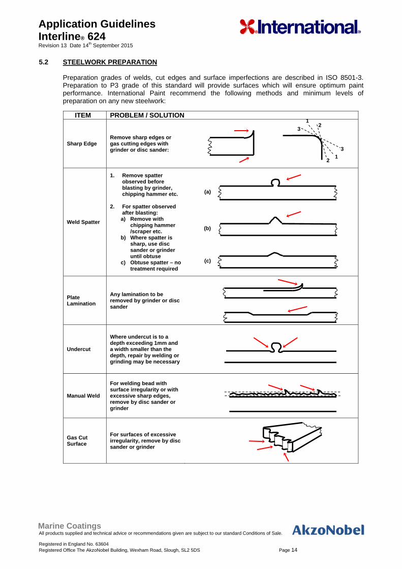
Preparation grades of welds, cut edges and surface imperfections are described in ISO 8501-3. Preparation to P3 grade of this standard will provide surfaces which will ensure optimum paint performance. International Paint recommend the following methods and minimum levels of preparation on any new steelwork:
ITEM PROBLEM / SOLUTION
Sharp Edge Remove sharp edges or gas cutting edges with grinder or disc sander:
Weld Spatter
1. Remove spatter observed before blasting by grinder, chipping hammer etc.
2. For spatter observed
after blasting: a) Remove with
chipping hammer /scraper etc.
b) Where spatter is sharp, use disc sander or grinder until obtuse
c) Obtuse spatter – no treatment required
Plate Lamination
Any lamination to be removed by grinder or disc sander
Undercut
Where undercut is to a depth exceeding 1mm and a width smaller than the depth, repair by welding or grinding may be necessary
Manual Weld
For welding bead with surface irregularity or with excessive sharp edges, remove by disc sander or grinder
Gas Cut Surface
For surfaces of excessive irregularity, remove by disc sander or grinder
2 1
2 1
3
3
(a)
(b)
(c)
Marine Coatings All products supplied and technical advice or recommendations given are subject to our standard Conditions of Sale. Registered in England No. 63604 Registered Office The AkzoNobel Building, Wexham Road, Slough, SL2 5DS Page 15
Application Guidelines Interline® 624 Revision 13 Date 14th September 2015
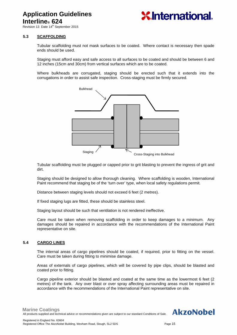
5.3 SCAFFOLDING Tubular scaffolding must not mask surfaces to be coated. Where contact is necessary then spade ends should be used. Staging must afford easy and safe access to all surfaces to be coated and should be between 6 and 12 inches (15cm and 30cm) from vertical surfaces which are to be coated. Where bulkheads are corrugated, staging should be erected such that it extends into the corrugations in order to assist safe inspection. Cross-staging must be firmly secured. Tubular scaffolding must be plugged or capped prior to grit blasting to prevent the ingress of grit and dirt. Staging should be designed to allow thorough cleaning. Where scaffolding is wooden, International Paint recommend that staging be of the ‘turn over’ type, when local safety regulations permit. Distance between staging levels should not exceed 6 feet (2 metres). If fixed staging lugs are fitted, these should be stainless steel. Staging layout should be such that ventilation is not rendered ineffective. Care must be taken when removing scaffolding in order to keep damages to a minimum. Any damages should be repaired in accordance with the recommendations of the International Paint representative on site.
5.4 CARGO LINES The internal areas of cargo pipelines should be coated, if required, prior to fitting on the vessel. Care must be taken during fitting to minimise damage. Areas of externals of cargo pipelines, which will be covered by pipe clips, should be blasted and coated prior to fitting. Cargo pipeline exterior should be blasted and coated at the same time as the lowermost 6 feet (2 metres) of the tank. Any over blast or over spray affecting surrounding areas must be repaired in accordance with the recommendations of the International Paint representative on site.
Bulkhead
Staging Cross-Staging into Bulkhead
Marine Coatings All products supplied and technical advice or recommendations given are subject to our standard Conditions of Sale. Registered in England No. 63604 Registered Office The AkzoNobel Building, Wexham Road, Slough, SL2 5DS Page 16
Application Guidelines Interline® 624 Revision 13 Date 14th September 2015
5.5 HEATING COILS (IF FITTED)
Heating coils in position during blasting and coating should be masked with suitable material. Masking, fitted to heating coils before blasting, must be removed and the coils cleaned prior to coating in order to avoid contamination caused by grit falling on to freshly applied paint. Coils should be re-wrapped prior to painting. The material used for masking when painting should (if possible) be of a type which is absorbent, thus ensuring no contamination from paint flaking from masking on to painted surfaces beneath. Whenever possible, heating coil brackets should be of stainless steel. The heating coils must be electrically insulated from the brackets to avoid any electrolytic action which would give rise to corrosion.
5.6 VENTILATION
Ventilation is necessary during abrasive blasting operations to ensure adequate visibility. Flexible trunking should be used to allow the point of extraction to be reasonably close to the personnel carrying out the blasting.
During and after coating application the ventilation system and trunking must be so arranged such that “dead spaces” do not exist. As solvent vapours are heavier than air, and will tend to accumulate in the lower areas of tanks, it is important that they are extracted from those areas. This must be balanced with fresh air being introduced into the tank. Equipment used must not re-introduce abrasive dust, solvent vapour etc. into the tank. For this reason a positive pressure, above normal atmospheric pressure, should be maintained inside the tank. As a “rule of thumb” fresh air supply/extraction should be in the approximate ratio of 4:3. Ventilation must be maintained during application and continue whilst solvent is released from the paint film during drying. Failure to do this may result in solvent retention within the coating system that will adversely affect it’s long term performance. It must be maintained for a minimum period of 48 hours after coating application has been completed unless otherwise agreed with International Paint. The level of ventilation employed must take account of the Lower Explosive Limit (LEL) of the product being applied and comply with local legislative requirements. (The LEL is the minimum concentration of vapour in air, expressed as a percentage, that will ignite). International Paint recommend that this is such that vapour concentrations do not exceed 10% of the LEL. This figure is in line with general industry standards and the requirements of the United Kingdom Health & Safety Executive (Information Document HSE 703/13 “Application of Surface Coatings to Ship’s Tanks”) and the United States Department of Labor Occupational Safety and Health Administration (OSHA) regulation 1915.36(a)(2). The ventilation requirement can be calculated from the required air quantity (RAQ) to 10% of the LEL figures and the product application rate. A typical paint application rate by airless spray is 19.7-26.3 U.S. Gallons (75-100 litres) per hour per sprayer. Venting to 10% of the LEL is considered to provide a reasonable margin of safety to allow for possible higher local concentrations due to the complex geometry of tanks. Nevertheless, care should be taken when setting up ventilation/extraction systems, to ensure that 10% figure is not exceeded.
If the level of ventilation is reduced during coating application, in order to minimise possible dry spray, the paint application rate must also be reduced to ensure that solvent vapour levels remain below 10% of the LEL.
Marine Coatings All products supplied and technical advice or recommendations given are subject to our standard Conditions of Sale. Registered in England No. 63604 Registered Office The AkzoNobel Building, Wexham Road, Slough, SL2 5DS Page 17
Application Guidelines Interline® 624 Revision 13 Date 14th September 2015
Responsibility rests with the shipyard/contractor to ensure that the requisite equipment is available and operated in such a way that these requirements are met. International Paint will provide all of the information needed to allow the shipyard/contractor to calculate ventilation requirements. However, International Paint does not accept responsibility for the equipment, it’s operation, or the monitoring necessary to ensure that the requisite ventilation requirements are met. All equipment used after the commencement of paint application must be electrically safe in operation. Provision must be made by the contractor/shipyard for continuous, round the clock, surveillance of ventilation equipment.
5.7 DEHUMIDIFICATION
Dehumidification equipment, when required, must be of adequate capacity to maintain the condition of blasted steelwork to the required standard. Additionally, in order to prevent condensation, the steel temperature must always be at least 5F (3°C) above the dew point. Coatings may only be applied to surfaces which have been maintained in a dry condition with the steel temperature at least 5F (3°C) above the dew point for more than one hour. The surfaces must be visibly dry and clean at the time of application. This condition must be maintained until the coating is cured. Tank Coating must only be undertaken under acceptable atmospheric conditions, otherwise adverse effects may occur. Refer to section 2.5.9 of this procedure for acceptable relative humidity conditions for application of Interline 624. Provision should be made for 24 hour surveillance of equipment.
5.8 HEATING
If heating is necessary to satisfy the painting specification, it should be by means of a heat exchange system, i.e. air admitted to the tank should not pass directly through a combustion chamber. Temperatures should be maintained for the duration of the contract from application to cure and provision should be made for 24 hour surveillance of equipment by the contractor/shipyard.
5.9 LIGHTING
Lighting during blasting and painting must be electrically safe and provide suitable illumination for all work. As a guide, lighting may be considered suitable if this text can be read at a distance of 30 centimetres (12 inches) from the eye. Ideally, the lighting should be powerful mains supplied spotlight with background lighting on at all times in the interests of safety. Powerful mains spotlighting must be provided when inspection work is being carried out.
Marine Coatings All products supplied and technical advice or recommendations given are subject to our standard Conditions of Sale. Registered in England No. 63604 Registered Office The AkzoNobel Building, Wexham Road, Slough, SL2 5DS Page 18
Application Guidelines Interline® 624 Revision 13 Date 14th September 2015
5.10 STORAGE (AT POINT OF APPLICATION)
The paint must be stored out of direct sunlight so that the temperature of the material will not exceed 77F (25°C) for prolonged periods of time. In winter months, when temperatures can be expected to fall below 41F (5°C), base and curing agent must be stored in premises, (storeroom, hut, etc), which are heated to a temperature in excess of 41F (5°C) for a period of not less than 48 hours immediately prior to use (unless stated otherwise on the product technical data sheet).
5.11 GRIT BLASTING
5.11.1 General
Two main universal standards of surface preparation are normally specified for cargo tank coatings - ISO Standard ISO 8501-1 (2007) – Sa2½ and Sa3. In general, the following comments apply to these standards.
Sa2½ - in practice, this is considered to be the best standard a skilled blasting operative can consistently achieve. Sa3 - the possibility of achieving a uniform standard of Sa3 throughout the tanks is remote and a more realistic achievement would be somewhere between Sa2½ and Sa3.
Comparative Standards ISO 8501-1: 2007 Japanese Standard on new steel SSPC Standard Sa2½ JA SH2 SSPC-SP10 Sa3 JA SH3 SSPC-SP5
In cases where the substrate is corroded or pitted, it may be necessary to fresh water wash the areas after abrasive blasting, then re-blast, in order to ensure complete removal of soluble corrosion products.
5.11.2 Compressed Air
Air used for blasting must be clean, oil free and dry. The pressure should be at least 7kg/cm² (100lb/sq inch) at the nozzle.
5.11.3 Abrasive
Abrasives used for blasting must be dry and free from dirt, oil, grease and suitable for producing the standard of cleanliness and profile specified. The abrasive must therefore be in accordance with the specifications given in ISO 11126 - Parts 1 to 8 and each delivery should carry a certificate of conformity to this specification.
If blasting abrasive is supplied on site without a certificate of conformity, the material should be tested by the yard or contractor in accordance with the methods given in ISO 11127 - Parts 1 to 7. Particular attention should be given to ISO 11127 - Part 6, where the level of water soluble contaminants must not give a conductivity value greater than 25mS/m, and ISO 11127 - Part 7, where the level of water soluble chlorides must not exceed 0.0025% by weight.
Marine Coatings All products supplied and technical advice or recommendations given are subject to our standard Conditions of Sale. Registered in England No. 63604 Registered Office The AkzoNobel Building, Wexham Road, Slough, SL2 5DS Page 19
Application Guidelines Interline® 624 Revision 13 Date 14th September 2015
Iron or steel abrasives can be used for in-situ open blasting. Specifications for metallic abrasives are given in ISO 11124 - Parts 1 to 4 and the corresponding test methods in ISO 11125 - Parts 1 to 7. If used, careful and thorough cleaning must be carried out at all stages of the operation to ensure that no abrasive remains in the tank as this may subsequently corrode. Although not recommended, recycled grit may be used providing it is dry, has been shown to be free from contamination by dirt, oil, grease, and has been tested in accordance with the above ISO standards.
5.11.4 Blast Profile
The amplitude of the blast profile depends upon the type of coating to be applied. Measurement on site should be by profile gauge or other mutually acceptable instruments. Measurement of surface profile using comparators is described in ISO 8503-2 using comparators detailed in ISO 8503-1. A medium 'G' type comparator should be used and a value of 2.17 – 3.74 mils (55-95 microns) is acceptable when measured by: a) ISO 8503-3: Focusing microscope b) ISO 8503-4: Stylus
5.12 CLEANING
Prior to initial blasting inspection, the bulk of spent grit must be removed. Any substandard areas should be identified and must be brought up to the specified standard. All marking paint, chalk, etc, used to identify substandard areas must be removed after substandard areas are rectified. The marks made, if left, will cause blistering and detachment of subsequent coats. Following provisional approval of the blast standard, all remaining traces of grit and dust must be removed from all areas including scaffolding, using industrial vacuum cleaners fitted with brushes, or by other suitable methods agreed by International Paint. The quantity of dust remaining should be no greater than Pictorial reference 1: ISO 8502-3 and be of no greater size than Class 2 : ISO 8502-3. Final approval of a substrate for coating application must be confirmed after final cleaning. Mats for wiping feet, (or overshoes), should be placed at the entrance of tanks, and the area immediately surrounding them kept in a clean condition.
Marine Coatings All products supplied and technical advice or recommendations given are subject to our standard Conditions of Sale. Registered in England No. 63604 Registered Office The AkzoNobel Building, Wexham Road, Slough, SL2 5DS Page 20
Application Guidelines Interline® 624 Revision 13 Date 14th September 2015
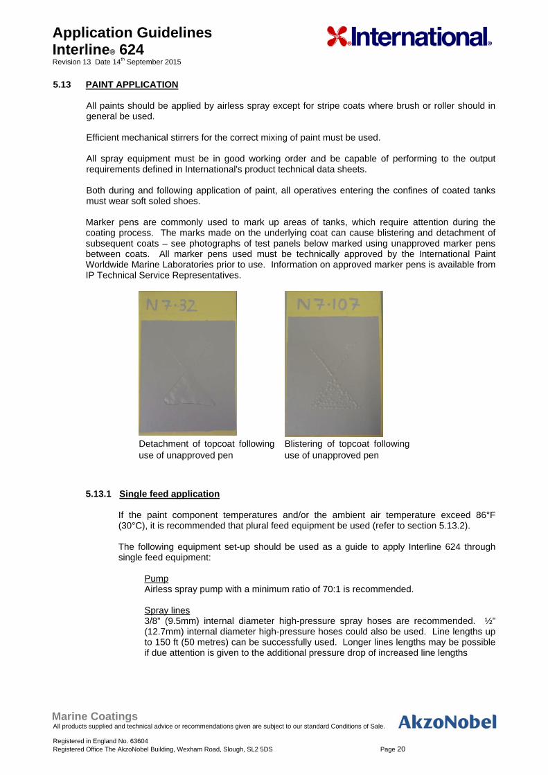
5.13 PAINT APPLICATION All paints should be applied by airless spray except for stripe coats where brush or roller should in general be used. Efficient mechanical stirrers for the correct mixing of paint must be used. All spray equipment must be in good working order and be capable of performing to the output requirements defined in International's product technical data sheets. Both during and following application of paint, all operatives entering the confines of coated tanks must wear soft soled shoes. Marker pens are commonly used to mark up areas of tanks, which require attention during the coating process. The marks made on the underlying coat can cause blistering and detachment of subsequent coats – see photographs of test panels below marked using unapproved marker pens between coats. All marker pens used must be technically approved by the International Paint Worldwide Marine Laboratories prior to use. Information on approved marker pens is available from IP Technical Service Representatives.
Detachment of topcoat following use of unapproved pen
Blistering of topcoat following use of unapproved pen
5.13.1 Single feed application
If the paint component temperatures and/or the ambient air temperature exceed 86°F (30°C), it is recommended that plural feed equipment be used (refer to section 5.13.2). The following equipment set-up should be used as a guide to apply Interline 624 through single feed equipment:
Pump Airless spray pump with a minimum ratio of 70:1 is recommended.
Spray lines 3/8” (9.5mm) internal diameter high-pressure spray hoses are recommended. ½” (12.7mm) internal diameter high-pressure hoses could also be used. Line lengths up to 150 ft (50 metres) can be successfully used. Longer lines lengths may be possible if due attention is given to the additional pressure drop of increased line lengths
Marine Coatings All products supplied and technical advice or recommendations given are subject to our standard Conditions of Sale. Registered in England No. 63604 Registered Office The AkzoNobel Building, Wexham Road, Slough, SL2 5DS Page 21
Application Guidelines Interline® 624 Revision 13 Date 14th September 2015
Tip sizes A tip orifice size of between 13 and 19 thou is recommended. Although 13 thou may appear low for application of a high build product, it has been shown to give excellent atomisation and film thickness control. The higher spray pressures ensure that the volume throughput is sufficient such that a typical number of passes are required to achieve the recommended wft. Tips must not be in a worn condition. In-line heater During the set-up of the single feed application equipment, it is recommended that an in-line heater is incorporated as near to the airless spray high-pressure outlet as possible. This is a precaution in case cool climatic conditions are encountered during the application. The in-line heater, if required, should be used at the minimum temperature setting to ensure a good spray fan. Pressure Paint pump outlet pressures of above 5000psi are recommended, to ensure that pressure drop due to long lines does not affect atomisation. As with all good spray techniques, the spray pressure should be set to achieve a good fan. It is not necessary to increase pressure beyond this point.
If an acceptable spray fan is not achieved, recirculation of a small amount of paint (1-3 quarts/litres) from the tip, back into the paint, will completely fill the pump and lines with moving homogeneous mixed paint, and will enable the paint to flow through the lines more efficiently. This simple technique will normally greatly improve spray fans and should therefore always be carried out first if poor spray fans are observed, before adjusting pressures or tips.
5.13.2 Plural Feed application
The following equipment set-up should be used as a guide to apply Interline 624 through plural feed equipment
Pump Standard commercially available plural component airless spray equipment. Mixing ratio set at 4:1 v/v Spray lines It is recommended that a ½” (12.7mm) internal diameter paint hose is used for the base component line, and a 3/8” (9.5mm) internal diameter paint line for the curing agent. This helps balance the flow through the lines, as the viscosity of the base component is higher than that of the curing agent. Mixed paint line to be kept as short as possible. Tip sizes A tip orifice size of between 13 and 19 thou is recommended. Although 13 thou may appear low for application of a high build product, it has been shown to give excellent atomisation and film thickness control. The higher spray pressures ensure that the volume throughput is sufficient so that a typical number of passes are required to achieve the recommended wft. Pressure It is recommended that pressures of greater than 3500 psi are used. Trials with a number of 2 component spray kits have demonstrated excellent spraying at 3500 – 4000 psi. Higher pressures are not required.
Marine Coatings All products supplied and technical advice or recommendations given are subject to our standard Conditions of Sale. Registered in England No. 63604 Registered Office The AkzoNobel Building, Wexham Road, Slough, SL2 5DS Page 22
Application Guidelines Interline® 624 Revision 13 Date 14th September 2015
In line heater Re-circulation through heated lines is recommended. The base component temperature should ideally reach 86-104°F (30-40°C). The curing agent should also be heated to a minimum temperature of 68°F (20°C) if the ambient temperature is below this figure.
When using plural component spray equipment it is important to ensure an adequate supply of both components to the main proportioning unit. If feeder pumps are employed, they should be carefully set in order to maintain the supply of Part A and Part B and to prevent cavitation in the feeder hoses. Failure to do this will result in an incorrect mix ratio that may cause slow cure, cracking, checking and have an adverse effect on mechanical properties.
5.14 STRIPE COATS
Stripe coating is an essential part of good painting practice. Typical areas where stripe coats must be applied include: - behind bars - plate edges - cut outs i.e. scallops, manholes etc - welds - areas of difficult access - ladders and handrails - small fitments of difficult configuration - areas of pitting Note: The above list is not comprehensive, all areas must be included. The diagrams following
indicate key areas requiring stripe coating:
In general, stripe coats should be applied by brush or roller, depending upon items concerned. In exceptional circumstances it may be acceptable to apply a stripe coat to the backs of angle bars by narrow angle spray. The use of spray applied stripe coats however, must be discussed and agreed with the International Paint representative on site.
Marine Coatings All products supplied and technical advice or recommendations given are subject to our standard Conditions of Sale. Registered in England No. 63604 Registered Office The AkzoNobel Building, Wexham Road, Slough, SL2 5DS Page 23
Application Guidelines Interline® 624 Revision 13 Date 14th September 2015
5.15 COATING PROCEDURES
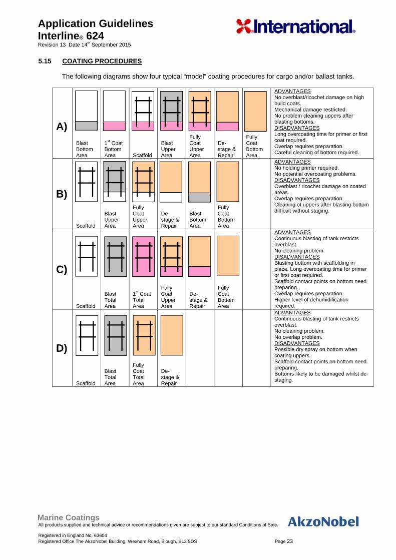
The following diagrams show four typical “model” coating procedures for cargo and/or ballast tanks.
A) Blast Bottom Area
1st Coat Bottom Area Scaffold
Blast Upper Area
Fully Coat Upper Area
De-stage & Repair
Fully Coat Bottom Area
ADVANTAGES No overblast/ricochet damage on high build coats. Mechanical damage restricted. No problem cleaning uppers after blasting bottoms. DISADVANTAGES Long overcoating time for primer or first coat required. Overlap requires preparation. Careful cleaning of bottom required.
B)
Scaffold
Blast Upper Area
Fully Coat Upper Area
De-stage & Repair
Blast Bottom Area
Fully Coat Bottom Area
ADVANTAGES No holding primer required. No potential overcoating problems. DISADVANTAGES Overblast / ricochet damage on coated areas. Overlap requires preparation. Cleaning of uppers after blasting bottom difficult without staging.
C)
Scaffold
Blast Total Area
1st Coat Total Area
Fully Coat Upper Area
De-stage & Repair
Fully Coat Bottom Area
ADVANTAGES Continuous blasting of tank restricts overblast. No cleaning problem. DISADVANTAGES Blasting bottom with scaffolding in place. Long overcoating time for primer or first coat required. Scaffold contact points on bottom need preparing. Overlap requires preparation. Higher level of dehumidification required.
D)
Scaffold
Blast Total Area
Fully Coat Total Area
De-stage & Repair
ADVANTAGES Continuous blasting of tank restricts overblast. No cleaning problem. No overlap problem. DISADVANTAGES Possible dry spray on bottom when coating uppers. Scaffold contact points on bottom need preparing. Bottoms likely to be damaged whilst de-staging.
Marine Coatings All products supplied and technical advice or recommendations given are subject to our standard Conditions of Sale. Registered in England No. 63604 Registered Office The AkzoNobel Building, Wexham Road, Slough, SL2 5DS Page 24
Application Guidelines Interline® 624 Revision 13 Date 14th September 2015
6. REPAIR PROCEDURES 6.1 INTRODUCTION
These repair procedures are recommended for damages either at the initial coating stage or where breakdown of coating has occurred during the service life of the vessel.
The repair procedure recommended will depend upon the extent of damage involved but can be split
into: i) Repairs of major areas ii) Repairs of minor areas
6.2 MAJOR REPAIRS
A Major repair should essentially be dealt with as if the project were beginning. The recommendations given earlier for steel preparation, coating application, etc. MUST all be adhered to.
6.3 MINOR REPAIRS
Under this heading are repairs to areas damaged either at the initial coating stage, i.e. caused by de-staging, etc or caused during service, i.e. tank cleaning equipment damages, spot corrosion, etc. The principle requirements are: The area to be repaired must be fresh water washed and dry. Remove any corrosion by means of either: - vacuum blasting - hand tools, i.e. disc sander and grinder. Any pittings which, in the opinion of the Classification Society, do not need re-welding, should be prepared by needle gun and/or cone shaped grinder to remove corrosion deposits. It is not normally recommended to use filler in pittings as it is likely to detach, taking with it any paint which has subsequently been applied, thus exposing the steelwork to possible further corrosion. If however, it is decided to use filler, it must be applied after the first coat of the system, then overcoated with the remaining coats. Abrade area immediately surrounding repair to provide key for subsequent paint application. Apply the paint system in accordance with our recommendations. If small areas are involved and application is by brush, several coats may be required to achieve the correct dry film thickness. Cure time - when minor repairs have been carried out the cure time can be reduced to 75% of that recommended for full tank applications.
Marine Coatings All products supplied and technical advice or recommendations given are subject to our standard Conditions of Sale. Registered in England No. 63604 Registered Office The AkzoNobel Building, Wexham Road, Slough, SL2 5DS Page 25
Application Guidelines Interline® 624 Revision 13 Date 14th September 2015
7. HEALTH & SAFETY
7.1 INTRODUCTION
Some tank coatings contain volatile flammable organic solvents which can form explosive mixtures with air. Definite safety precautions must be taken whilst applying this type of coating in the confines of a ship’s cargo tank. Detailed attention must be given to the following points: - Danger of explosion or fire. - Provision of a suitable breathing environment for workers. - Prevention of skin irritation problems. - Use of paints which have been specially formulated for use in tanks.
7.2 DANGER OF EXPLOSION OR FIRE
The key factors in preventing an explosion or fire are: Adequate ventilation. Elimination of naked flames, sparks and any ignition sources. Any organic solvent based coating could, merely by the normal process of drying, give off sufficient solvent vapour to produce an explosive mixture in a tank when the vapour concentration reaches or exceeds 1% by volume in air. However, at 1% the solvents in the coatings produce an unpleasant odour, (often with irritating skin effects) and smarting of the eyes. These symptoms must be taken as a warning sign that better ventilation is needed. 0.1% solvent vapour in air is normally recommended to give a tenfold safety margin and at this concentration, no explosion can occur and no operator effects should be noticed. Sampling apparatus to detect the exact concentration of solvents should be used at regular intervals, particularly in “dead spots” where locally high concentrations may occur.
7.3 VENTILATION (Note: This must be read in conjunction with General Note 5.6).
Ventilation is necessary during abrasive blasting operations to ensure adequate visibility. Flexible trunking should be used to allow the point of extraction to be reasonably close to the personnel carrying out the blasting. During and after coating application it is essential that solvent vapours are removed to ensure that the level present in the atmosphere does not rise above that recommended in the section (7.2) dealing with “Danger of Explosion and Fire”. This means that the ventilation system must be arranged such that “dead spaces” do not exist and the ventilation must be continued both during the time that application is proceeding and also whilst solvent is released from the paint film during the drying process. Particular care must be taken to ensure that solvent vapour, which is heavier than air, does not accumulate in the lower areas of the tanks. The amount of air per minute for ventilating to 10% of the LEL (lower explosive limit) can be regarded as the required air quantity multiplied by rate of application per minute. The required air quantity is the amount of air needed for each litre of paint to ventilate to the required level. RAQ = Required Air Quantity LEL = Low Explosive Limit
Marine Coatings All products supplied and technical advice or recommendations given are subject to our standard Conditions of Sale. Registered in England No. 63604 Registered Office The AkzoNobel Building, Wexham Road, Slough, SL2 5DS Page 26
Application Guidelines Interline® 624 Revision 13 Date 14th September 2015
Ventilation required (m3/minute) = RAQ x the application rate (litres/minute). The likely approximate application rate can be calculated from figures available from the application equipment supplier and will depend on the airless spray pump pressure and the orifice size of the tip used. The geometry and size of tanks makes each one a separate problem, and it is essential that the ventilation arrangement, fan type, etc is checked as being suitable before painting commences. Fore and aft peaks and double bottoms require special attention. Because of their construction adequate ventilation is difficult and rapid build-up of solvent vapour and explosive concentrations may occur. It is recommended that when workers are involved in such spaces, a careful check is kept that men are not in difficulty and that there is supervised continuity of essential services such as air and electricity. In the event of a failure of the extraction/ventilation system paint application must be stopped and the tanks evacuated of personnel immediately.
7.4 ELIMINATION OF IGNITION SOURCES
Safety is the overriding consideration with this type of tank coating work, and the Shipyard Safety Department must be made fully aware of all aspects of the operation. Welding, cutting or grinding in the tank should be forbidden until paint fumes are totally dispersed. This also applies to all areas within a 60 feet (20 metre) radius of tank and trunking outlets. Coamings and hatch openings must be covered so as to efficiently prevent spark entry where welding is being carried out on the superstructure. Lights, including hand torches, must be certified by the manufacturer as flash proof and suitable for use in solvent laden atmospheres. Smoking must be prohibited in or near tanks or extraction systems. No electrical junction boxes should be allowed in tanks. Airless spray equipment must be earthed (because of the danger of static electricity build-up) Mobile telephones and electrical cameras must not be used in or near tanks or extraction systems until paint fumes are totally dispersed.
7.5 SOLVENT VAPOUR AND PAINT MISTS - PROTECTION OF PAINTING PERSONNEL No ventilation system can reduce solvent vapour levels to below the Occupational Exposure Limit for
solvents whilst tank coating is in operation. Painters must, therefore, wear air fed hoods or pressure fed masks with additional eye protection. (Please note: air fed hoods which provide a curtain of air across the visor are available. These help to prevent settlement of spray mist on the visor). Normal protective clothing must be worn, e.g. overalls, gloves, and suitable footwear of non-spark type.
Marine Coatings All products supplied and technical advice or recommendations given are subject to our standard Conditions of Sale. Registered in England No. 63604 Registered Office The AkzoNobel Building, Wexham Road, Slough, SL2 5DS Page 27
Application Guidelines Interline® 624 Revision 13 Date 14th September 2015
7.6 SKIN IRRITATION If proper protective clothing has been worn, e.g. overalls, gloves, air fed hood, etc no discomfort
should be experienced from skin irritation. Any small areas not protected by clothing, e.g. wrists or neck, can be treated with a non-greasy barrier cream. (Petroleum jelly is not recommended as this can assist the transport of solvents into the skin).
Any areas of skin accidentally contaminated with paint must be thoroughly washed with soap and
water. A skin conditioner that is designed to replace the natural oils in the skin can be used. Note 1. The preceding safety information is given for guidance only. 2. It is imperative that, prior to the commencement of any tank coating project, local Regulations
regarding Health and Safety be consulted. All representations and statements concerning the product(s) in this publication are accurate to the best of our knowledge. Statements made in this publication are advisory only and are not intended to be specific recommendations or warranties of any product, combination of products or fitness for any particular purpose. To the extent permitted by law, we do not accept any liability to any person for any loss or damage (direct or indirect) that may arise from any use or reliance on any of the methods or information contained in this publication for any purpose. Unless otherwise agreed in writing, all products supplied and technical advice or recommendations given are subject to the Conditions of Sale of our supplying company. Any warranties, if given, are contained in those standard Conditions of Sale and are the only ones made with respect to any products we sell to your or advice or recommendations we give to you. We hereby disclaim any warranties or representations, expressed or implied, by operation of law or otherwise, including, without limitation, any implied warranty of merchantability or fitness for a particular purpose. For each of our products the relevant Product Data Sheet, Material Safety Data Sheet and package labelling comprise an integral information system about the product in question. Copies of our Product Data Sheets and Material Safety Data Sheets are available on request or from our website: www.international-marine.com.
, and all product names mentioned in this publication are trademarks of, or licensed to, Akzo Nobel.


