Embed Size (px)
Citation preview
Vibrations of Vertical Pressure VesselsC. E. FREESE
Mechanical Engineer, TheFluor Corporation, Ltd., LosAngeles, Calif. Mem. ASME
Introduction
For many years it was customary to apply guy wiresto tall ,slender pressure vessels. In, recent years, refinery andpetro-chemical officials have demanded self-supporting vesselsfrom the standpoint of plant appearance and safety.
In order to design a self-supporting vessel of this type, thefollowing problems must be carefully analyzed:
1 When it is necessary to deviate from the common practiceof designing a vertical vessel as a static structure and consider it asa dynamic structure?
Contributed by the Petroleum Division and presented at the ASME
Petroleum-Mechanical Engineering Conference, Denver, Colo., September
21-24, 1958, of THE AMERICAN SOCIETY OF MECHANICAL
ENGINEERS.
NOTE: Statements and opinions advanced in papers are to be
understood as individual expressions of their authors and not those of the
Society. Manuscript received at ASME Headquarters, July 9, 1958. Paper
No. 58 - PET-13.
Nomenclature
f = lowest natural frequency of vibration,
cycles per second
T = = period of vibration, sec
g = acceleration due to gravity
W = total weight of vessel or vessel section
above horizontal plane under construction, lb
WS = shear load at end of section, lb
w = unit weight; lb/ft
w' = weight of vessel element or internal
part, lb
L = total length, ft
l = length of element or section, ft
D = vessel diameter, ft
d = vessel diameter, in.
Journal of Engineering for Industryustrg
This paper is primarily concerned with the vibration of vertical pressure vessels
known as columns or towers.
The procedure for estimating the period of first mode of vibration for columns which
are the same diameter and thickness for their entire length is outlined. A graph is
included for this purpose which recommends limits between vessels considered to be
static structures and those considered dynamic.
A method for designing vessels considered as dynamic structures is described as well
as a detailed procedure for estimating the period of vibration of multithickness (stepped
shell) vessels and/or vessels built to two or more diameters with conical transitions where
the difference in diameter is small.
There is a brief resume of the “Karman vortexes” effect and a discussion regarding
vibration damping by liquid loading and the benefit of ladders and platforms which help
reduce the effect of periodic eddy shedding.
The design procedure outlined will be useful to the practical vessel designer
confronted with the task of investigating vibration possibilities in vertical pressure
vessels.
2 What is the most practical method for designing to meetdynamic conditions?3 Does the method used produce consistent results and does it
provide additional strength to resist the force due to the mass-acceleration resulting from the motion of the vessel ?
4 Is the period of vibration of the dynamically designed vesselsuch that prevailing winds are not apt to cause excessivemovement?
5 Are the external attachments ( such as piping, ladders, andplatforms) distributed all around the vessel to guard againstresonance due to eddy shedding in the “Karman vortex trail” atcritical wind velocities?
These problems will be discussed during the outline of a designprocedure presented in this paper.
Before proceeding, it should be pointed out that vesselvibrations induced by earthquakes are infrequent in occurrenceand this paper is more concerned with vibrations induced by windor other forces which may occur every day or many times duringthe day may depending upon the location.
t = thickness of vessel shell, in
h = = thickness of vessel shell, ft
y = deflection of element or section, ft
y = distance from e. g. of vessel element or
internal part (of weight w) to seam or
horizontal plane under consideration, ft
F3 = seismic factor
E' = 4320 X 106 = modulus of elasticity for
steel, Ib/ft2
E = welded joint efficiency
I = moment of inertia of vessel shell
cross-sectional area, ft4
V = velocity, ft/sec
k = Strouhal number
= end slope of element in bending as a
cantilever beam, radian4 (tan = )
P = internal pressure, psig
S = allowable stress of vessel material, psi
M = moment about vessel seam or
horizontal plane under consideration, lb - ft
MT = moment at end of vessel section
resulting from weight of sections to the right
section under consideration
C = corrosion allowance
R = Reynolds number
FEBRUARY 1959 / 77
1
f
t
12
83D h
Design
ProcedureIt is customary for most vessel designers to establish the
minimum vessel shell and trend thickness according to thepressure temperature conditions and then calculate the thicknessrequired at the bottom head seam due to bending momentsimposed by wind or earthquake forces [9].' Stresses in thelongitudinal direction are involved nod the following notation maybe used to summarize the thickness required:
The terms within the absolute value signs are positive for tensilestresses and negative for compressive stresses. The first term givesthe thickness required for the longitudinal stress resulting frominternal pressure and is positive for pressures above atmosphericand negative for pressures below atmospheric. The second term isthe thickness required to resist the longitudinal bending stress andboth positive and negative values exist at the same time. The thirdterm is the thickness required for the weight of the vessel above theseam being investigated and, since this is a compressive stress, ithas a negative value. The combination giving the highest valueestablishes the thickness required to resist the longitudinal stresses.
Consider equation (1) for a typical vessel operating at an
internally pressure greater than atmospheric:
The required thickness within the absolute value signs will havetwo values; namely, +0.519 in. and -0.095 in. Therefore theminimum thickness required is 0.519 + 0.125 in. corrosionallowance = 0.644 in.
Next consider equation (1) to appear as follows for the samevessel operating under vacuum conditions:
For this case, the two values within the absolute value signs are
-0.493 and + 0.121 in. resulting in a minimum thickness of 0.493
+ 0.125 in. = 0.618 in.As previously stated, the moment M is the longitudinal bending
moment due to wind or earthquake, either of which may becombined with eccentric loads imposed by mounting heavyequipment on the vessel. All designers are accustomed toevaluating moments due to eccentric and wind loads, but there area few who may not be familiar with the method used for estimatingmoments due to earthquake. Therefore, the following brief outlineis presented because this method is recommended as a designprocedure for vessels where dynamic considerations are required.The weight of each vessel element (shell, head, tray, or internalpart) is calculated. and then multiplied by the vertical distancefrom the circumferential seam (or horizontal plane) underconsideration to the center of gravity of the element. Thesummation of the moments so found is multiplied by the seismicfactor for the area where the vessel is to operate, thereby yielding amoment due to earthquake or seismic disturbance. For vessels, theseismic factor will usually have a value of 0.03 to 0.12, dependingupon the geographical location. Expressed mathematically,
After the vessel has been designed in the regular manner(considered as a static structure) it should be investigated regardingits possible behavior under vibration conditions. If the vessel
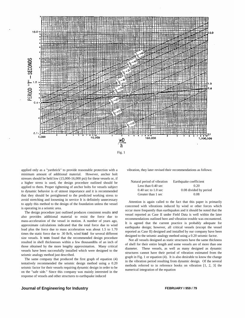
shell is of constant diameter and thickness for its full length, theperiod of vibration maybe easily found from the graph shown inFig. 1. This graph is plotted from the general formula for theperiod of the first mode of vibration of a cantilever beam [7]:
For a steel cylindrical shell, equation (3) may be written:
By rewriting equation (4) in the form:
(3)
(4)
1 Numbers in brackets designate References at end of paper.
78 / FEBRUARY 1959
the variables (L/D) and (wD/h) are used as parameters to plot thegraph in Fig. 1.
One of the first graphs of equation (4) was issued by a major oilcompany for their refinery work. In its original form, all vesselshaving a period of vibration over 0.4 sec were ordered designedas dynamic structures and those having a vibration period of 0.4sec or less were ordered designed as static structures. Experiencehas shown that a more practical limit for this division is a linedrawn from 0.4 sec at the extreme left of the graph to 0.8 sec at theextreme right and considering vessels having a period of vibrationabove this line to require dynamic consideration and those belowto require designing as a static structure. The reason for revisingthe former limit is the fact that many vessels having small (L/D)ratios and large values of (wD/h) have given satisfactory servicealthough their period of vibration exceeded 0.4 sec. In general,vessels having an (L/D) ratio less than 15 are not apt to be criticalfrom a vibration, standpoint. One exception to this statement,unofficially reported to the author, involved two vessels operatingnear a railroad whereby they were vibrated by railroad equipment.Both vessels had a period of vibration considerably less than 0.4sec and their frequency probably coincided with the frequency ofthe exciting force, thereby causing resonance. This type ofresponse is difficult, if not impossible, to predict accurately andshould be considered as a special case.
If investigation indicates that the vessel should be designed as adynamic structure, the method of seismic analogy isrecommended. This method consists of designing the vessel forearthquake conditions using a seismic factor F3 = 0.20, regardlessof the geographical location. In most cases, the vessel will havethicker shell and head material in the lower section. As anexample, consider a vessel 10 ft 0 in. diameter by 13/16 in. thick by190 ft 0 in. high which has an (L/D) ratio of 19, and period ofvibration (after being designed as a static structure) of 1.65 sec.This vessel, when designed as a dynamic structure by the methodof seismic analogy, resulted in a shell thickness of l3/16 in. for theupper 137 ft 0 in. and three 1ower sections consisting of 7/8, 15/16,
and 1-in. thick material (the supporting skirt increased from 1 to l9/16 in.). The period of vibration was reduced to approximately 1.4sec.Whereas the application of this method actually consists of trialand error, the experienced pressure vessel designer becomes veryproficient in estimating how far down the vessel he can utilize thematerial thickness which is based on pressure-temperaturerequirements, as well as the length of successive sections ofthicker material. It is usually unnecessary to carry the seismicanalogy into the design of the anchor bolts because this method is
Transactions of the ASME
AS M E
(1)
TwL
E Ig
wL
E Ig
2
352
1785
41 2
41 2
. '
.'
(5)
tPd
SE P
M
d SE
W
dSEC
4 0 8
482.
T x wL
D h
764 10 6 4
3
1 2
.
T x L
D
wD
h
7 64 10 6
2 1 2
.
t 0 275 0 307 0 063 0125. . . .
t 0123 0 307 0 063 0125. . . .
M F w y 3 ' ' (2)
applied only as a "yardstick" to provide reasonable protection with aminimum amount of additional material. However, anchor boltstresses should be held low (15,000-16,000 psi) for these vessels or, ifa higher stress is used, the design procedure outlined should beapplied to them. Proper tightening of anchor bolts for vessels subjectto dynamic behavior is of utmost importance and it is recommendedthat they should be pretightened to the predicted working stress toavoid stretching and loosening in service It is definitely unnecessaryto apply this method to the design of the foundation unless the vesselis operating in a seismic area.
The design procedure just outlined produces consistent results andalso provides additional material to resist the force due tomass-acceleration of the vessel in motion. A number of years ago,approximate calculations indicated that the total force due to windload plus the force due to mass acceleration was about 1.5 to 1.70times the static force due to 30 lb/ft, wind load for several differentsize vessels. It was found that the recommended design procedureresulted in shell thicknesses within a few thousandths of an inch ofthose obtained by the more lengthy approximation. Many criticalvessels have been successfully installed which were designed to theseismic analogy method just described.
The same company that produced the first graph of equation (4)tentatively recommended the seismic design method using a 0.20seismic factor for their vessels requiring dynamic design in order to beon the "safe side." Since this company was mainly interested in theresponse of vessels and other structures to earthquake induced
Journal of Engineering for Industry
Natural period of vibration Earthquake coefficientLess than 0.40 sec 0.200.40 sec to 1.0 sec 0.08 divided by periodGreater than 1 sec 0.08
Attention is again called to the fact that this paper is primarilyconcerned with vibrations induced by wind or other forces whichoccur more frequently than earthquakes and it should be noted that thevessel reported as Case II under Field Data is well within the laterrecommendations outlined here and vibration trouble was encountered.It is agreed that the current practice is probably adequate forearthquake design; however, all critical vessels (except the vesselreported as Case II) designed and installed by our company have beendesigned to the seismic analogy method using a 0.20 seismic factor.
Not all vessels designed as static structures have the same thicknessof shell for their entire length and some vessels are of more than onediameter. These vessels, as well as many designed as dynamicstructures cannot have their period of vibration estimated from thegraph in Fig. 1 or equation (4). It is also desirable to know the changein the vibration period resulting from dynamic design. Of the severalmethods referred to in reference books on vibration [1, 2, 3] thenumerical integration of the equation
FEBRUARY I 959 / 79
vibration, they later revised their recommendations as follows:
Fig. 1
is probably the easiest and safest method for the designer who is not aspecialist in vibration to apply. This equation follows the Rayleighmethod of approximation for finding the fundamental period ofvibration as applied to a shaft or loaded beam on too supports. It willbe shown that this equation is reasonably accurate for estimating theperiod of the first mode of vibration of vertical pressure vessels.
Equation (6) will result in an estimated period of vibration slightlylower than the actual period. The degree of accuracy is dependentupon the number of sections calculated in estimating the staticdeflections when the vessel is considered as a cantilever beamdeflecting under its own weight. As an example, the period ofvibration of a cylindrical shell 3 ft 0 in. diam by 3/4 in. thick by 90 ft0 in. high was estimated under two separate conditions. In order toeliminate nonuniformly distributed masses, this shell was consideredto have tray sections at one-foot intervals from the top to the groundand the heads were omitted. When calculated to equation (4), theperiod of vibration was found to be 1.088 sec. Dividing the shell intonine sections, each 10 ft 0 in. long and calculating the period toequation (6) resulted in an estimated period of 1.08 sec. which is0.735 per cent low. On the other hand, when this same shell is dividedinto five sections having lengths of 30 ft 0 in., 20 ft 0 in., 15 ft 0 in.,15 ft 0 in., and 10 ft 0 in., the estimated period of vibration to equation(6) was 1.068 sec which is 1.84 per cent lower than the results fromequation (4). Most vessels designed as dynamic structures have five toten sections similar to the latter division and the weight is not alwaysuniformly distributed. Field test have shown the calculated period ofvibration to be 1.5 to 4.5 per cent lower than the observed periods forseveral different size vessels. This is in good agreement for largestructures and it is reasonable to assume that the period of vibrationobtained by the numerical integration of equation (6) will beapproximately 5 per cent lower than the actual period .
Equation (6) is not difficult to integrate numerically, but care mustbe exercised to make certain that all factors affecting deflection areincluded. Instead of following a complete numerical integration, somedesigners prefer to estimate the deflections at the center of eachsection graphically by either the area-moment or conjugate beammethod. The same results will be obtained. The choice of methoddepends upon the personal preference of the individual. An outline forthe numerical integration of equation (6) when applied to verticalpressure vessels is given in the Appendix of this paper.
Discussion of Wind Effects
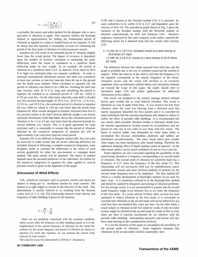
Tall, cylindrical structures such as pressure vessels and stacks aresubject to being put in oscillatory motion by wind currents. Themotion is at right angles or normal to the direction of the wind. Thisphenomenon is usually referred to as resulting from the Karmanvortex trail (4, 5, 6, 10). The relationship between wind velocity andfrequency of eddy shedding is given by the equation.
Since we are primarily concerned with the resonant conditionwhich occurs when the frequency of eddy shedding equals or is in the
neighborhood of the natural frequency of vibration for the vessel the
symbols for the vessel frequency and period of vibration are shown in
equation (7). From this equation, we can estimate the critical wind
velocity for most vessels.
The value for k was first determined in 1878 by V. Strouhal as
80 / FEBRUARY 1959
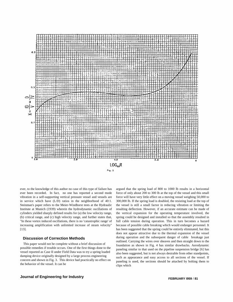
0.185 and is known as the Strouhal number [10]. It is assumed bysome authorities to be within 0.18 to 0.27 and dependent upon thevelocity of flow [4]. The reproduced graph shown in Fig. 2 gives thevariation of the Strouhal number with the Reynolds number asobtained experimentally by Relf and Simmons [10]. Researchengineers, employed by the same company as the author, reported thefollowing values for k obtained from full size vessels after erection[12]:
k = 0.133, for a 7.67 O.D. insulated vessel at a wind velocity of
39.6 ft/sec (27 mph)
= 0.189, for a 3.0 O.D. vessel at a wind velocity of 32.25 ft/sec
(22 mph)
The difference between the values reported from field data and thegraph is probably due to the size of cylinders tested and the method ofsupport. When the velocity of the wind is such that the frequency f inthe equation corresponds to the natural frequency of the vessel,resonance occurs and the vessel will oscillate at an excessiveamplitude. Since aerodynamic stability theory and calculation methodsare beyond the scope of this paper, the reader should refer toSteinman's paper [10] and similar publications for additionalinformation in this subject.
One vessel, not designed to the seismic analogy method outlinedherein, gave trouble due to wind induced vibration. This vessel isidentified as Case II under Field Data. It was found to be free fromvibration when the wind was blowing from a direction such thatnearby equipment disturbed the flow pattern and it is conceded bysome individuals that the external attachments also helped to reduce ornullify the effect of periodic eddy shedding. It is recommended thatany vessel, where possible vibration trouble is indicated, should havethe external appurtenances located around its circumference and notplaced on only one or two sides as was done with this vessel. Thebreak in vertical ladder runs demanded by some states helps toaccomplish this because intermediate platforms and ladders aredistributed circumferentially. The same vessel which gave troublewhen empty has been satisfactory after liquid loading. Therefore theadditional damping effect of liquid loading cannot be ignored - on theother hand, neither can too much confidence be put in it as a cure-all.
Some engineers are also concerned regarding the possibility of thevessel being vibrated at a frequency corresponding to its second modeof vibration. The second mode of vibration for cantilever beam has afrequency of 6.37 times the frequency of the first mode [7]. Thisrelationship will not necessarily hold true for multithickness and/ormultidiameter vessels and more involved methods of analysis for thesecond mode frequency have to be employed. The Ritz method [8]which is a further development of Rayleigh's method can be used forthese cases. It is sometimes referred to as the Rayleigh-Ritz methodand should be applied by designers specializing in vibration problems.For the average vessel, it is not unreasonable to assume that the secondmode frequency might occur between five to six times the frequencyof the first mode. If a wind velocity of thirty miles an hour has beenestimated to induce vibration in the first mode, it is reasonable toconclude that vibrations in the second mode will not be induced by anywind less than one hundred fifty miles per hour. On the other hand, avessel subject to vibration in the first mode by winds of only ten milesan hour might be vibrated in the second mode by winds of fifty to sixtymiles per hour if external attachments do not interfere with theperiodic eddy shedding. Surrounding structures and terrain will alsohave some bearing on the considerations involved.
It is not the intention of this paper to overamplify the possibility ofthe second mode of vibration. Some engineers maintain thatvibrations in the second mode could be catastrophic; how
TW y
g W y
2
2
VfD
k
D
Tk
Transactions of the ASME
(6)
(7)
ever, to the knowledge of this author no case of this type of failure hasever been recorded. In fact, no one has reported a second modevibration in a self-supporting vertical pressure vessel and vessels arein service which have (L/D) ratios in the neighborhood of 40:1.Steinman's paper refers to the Meier-Windhorst tests at the HydraulicInstitute at Munich (1939) wherein the hydrodynamic oscillations ofcylinders yielded sharply defined results for (a) the low velocity range,(b) critical range, and (c) high velocity range, and further states that,"In these vortex induced oscillations, there is no 'catastrophic range' ofincreasing amplification with unlimited increase of steam velocity"[13].
Discussion of Correction Methods
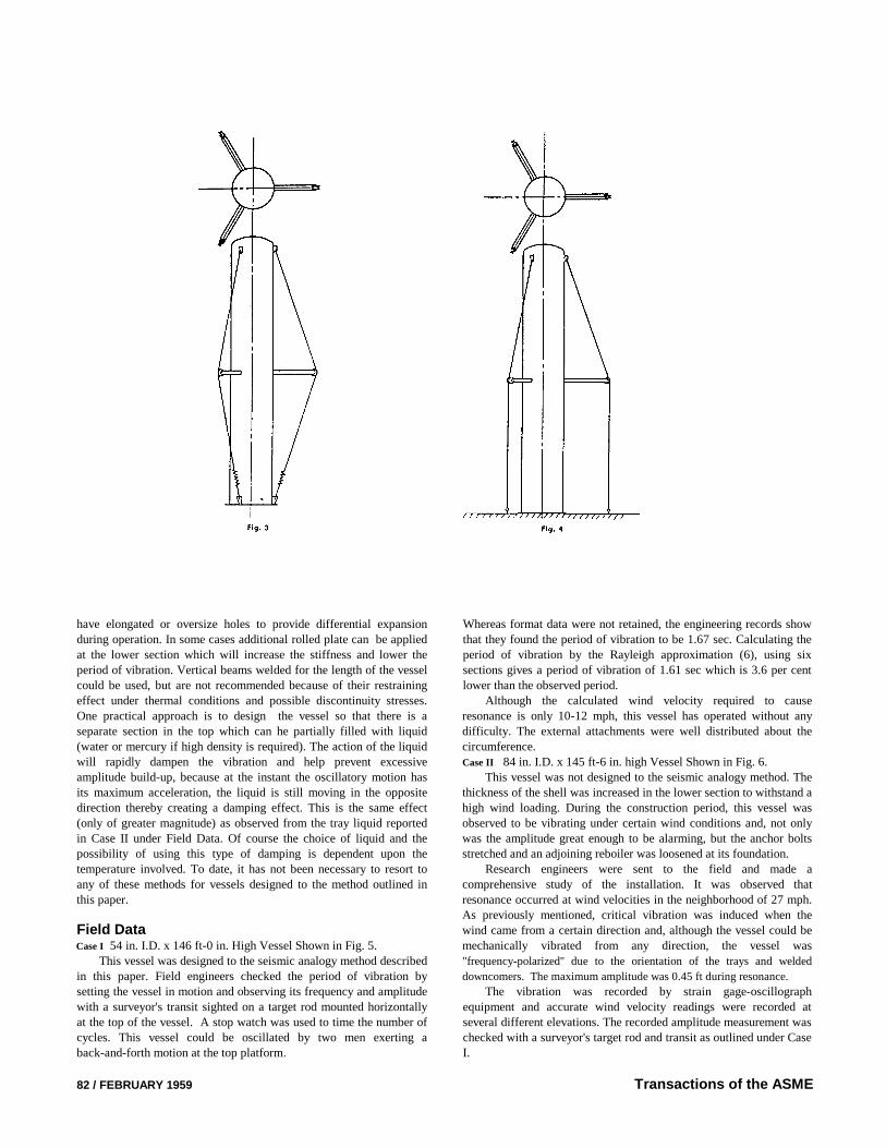
This paper would not be complete without a brief discussion ofpossible remedies if trouble occurs. One of the first things done to thevessel reported as Case II under Field Data was to try a spring loadeddamping device originally designed by a large process engineeringconcern and shown in Fig. 3. This device had practically no effect onthe behavior of the vessel. It can be
Journal of Engineering for Industry
argued that the spring load of 800 to 1000 lb results in a horizontalforce of only about 200 to 300 lb at the top of the vessel and this smallforce will have very little effect on a moving vessel weighing 50,000 to300,000 lb. If the spring load is doubled, the resisting load at the top ofthe vessel is still a small factor in reducing vibration or limiting theresulting deflection. However, if an accurate estimate can be made ofthe vertical expansion for the operating temperature involved, thespring could he designed and installed so that the assembly resulted infull cable tension during operation. This in turn becomes a hazardbecause of possible cable breaking which would endanger personnel. Ithas been suggested that the spring could be entirely eliminated, but thisdoes not appear attractive due to the thermal expansion of the vesselduring operation and the subsequent danger of cable breakage justoutlined. Carrying the wires over sheaves and then straight down to thefoundation as shown in Fig. 4 has similar drawbacks. Aerodynamicpaneling similar to that used on the pipeline suspension bridge [6] hasalso been suggested, but is not always desirable from other standpoints,such as appearance and easy access to all sections of the vessel. Ifpaneling is used, the sections should be attached by bolting them toclips which
FEBRUARY I959 / 81
have elongated or oversize holes to provide differential expansionduring operation. In some cases additional rolled plate can be appliedat the lower section which will increase the stiffness and lower theperiod of vibration. Vertical beams welded for the length of the vesselcould be used, but are not recommended because of their restrainingeffect under thermal conditions and possible discontinuity stresses.One practical approach is to design the vessel so that there is aseparate section in the top which can he partially filled with liquid(water or mercury if high density is required). The action of the liquidwill rapidly dampen the vibration and help prevent excessiveamplitude build-up, because at the instant the oscillatory motion hasits maximum acceleration, the liquid is still moving in the oppositedirection thereby creating a damping effect. This is the same effect(only of greater magnitude) as observed from the tray liquid reportedin Case II under Field Data. Of course the choice of liquid and thepossibility of using this type of damping is dependent upon thetemperature involved. To date, it has not been necessary to resort toany of these methods for vessels designed to the method outlined inthis paper.
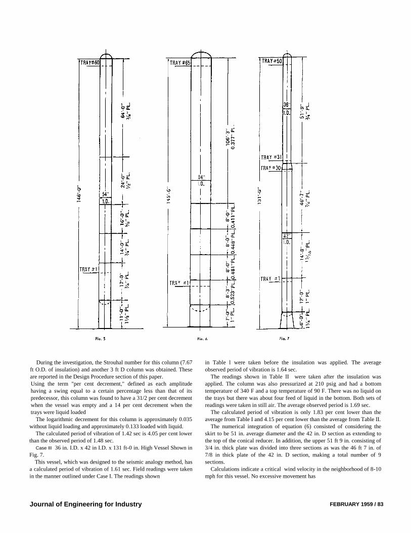
Field DataCase I 54 in. I.D. x 146 ft-0 in. High Vessel Shown in Fig. 5.
This vessel was designed to the seismic analogy method describedin this paper. Field engineers checked the period of vibration bysetting the vessel in motion and observing its frequency and amplitudewith a surveyor's transit sighted on a target rod mounted horizontallyat the top of the vessel. A stop watch was used to time the number ofcycles. This vessel could be oscillated by two men exerting aback-and-forth motion at the top platform.
Whereas format data were not retained, the engineering records showthat they found the period of vibration to be 1.67 sec. Calculating theperiod of vibration by the Rayleigh approximation (6), using sixsections gives a period of vibration of 1.61 sec which is 3.6 per centlower than the observed period.
Although the calculated wind velocity required to causeresonance is only 10-12 mph, this vessel has operated without anydifficulty. The external attachments were well distributed about thecircumference.Case II 84 in. I.D. x 145 ft-6 in. high Vessel Shown in Fig. 6.
This vessel was not designed to the seismic analogy method. Thethickness of the shell was increased in the lower section to withstand ahigh wind loading. During the construction period, this vessel wasobserved to be vibrating under certain wind conditions and, not onlywas the amplitude great enough to be alarming, but the anchor boltsstretched and an adjoining reboiler was loosened at its foundation.
Research engineers were sent to the field and made acomprehensive study of the installation. It was observed thatresonance occurred at wind velocities in the neighborhood of 27 mph.As previously mentioned, critical vibration was induced when thewind came from a certain direction and, although the vessel could bemechanically vibrated from any direction, the vessel was"frequency-polarized'' due to the orientation of the trays and welded
downcomers. The maximum amplitude was 0.45 ft during resonance.
The vibration was recorded by strain gage-oscillographequipment and accurate wind velocity readings were recorded atseveral different elevations. The recorded amplitude measurement waschecked with a surveyor's target rod and transit as outlined under CaseI.
Transactions of the ASME82 / FEBRUARY 1959
During the investigation, the Strouhal number for this column (7.67ft O.D. of insulation) and another 3 ft D column was obtained. Theseare reported in the Design Procedure section of this paper.Using the term "per cent decrement," defined as each amplitudehaving a swing equal to a certain percentage less than that of itspredecessor, this column was found to have a 31/2 per cent decrementwhen the vessel was empty and a 14 per cent decrement when thetrays were liquid loaded
The logarithmic decrement for this column is approximately 0.035without liquid loading and approximately 0.133 loaded with liquid.
The calculated period of vibration of 1.42 sec is 4.05 per cent lowerthan the observed period of 1.48 sec.
Case III 36 in. I.D. x 42 in I.D. x 131 ft-0 in. High Vessel Shown inFig. 7.
This vessel, which was designed to the seismic analogy method, hasa calculated period of vibration of 1.61 sec. Field readings were takenin the manner outlined under Case I. The readings shown
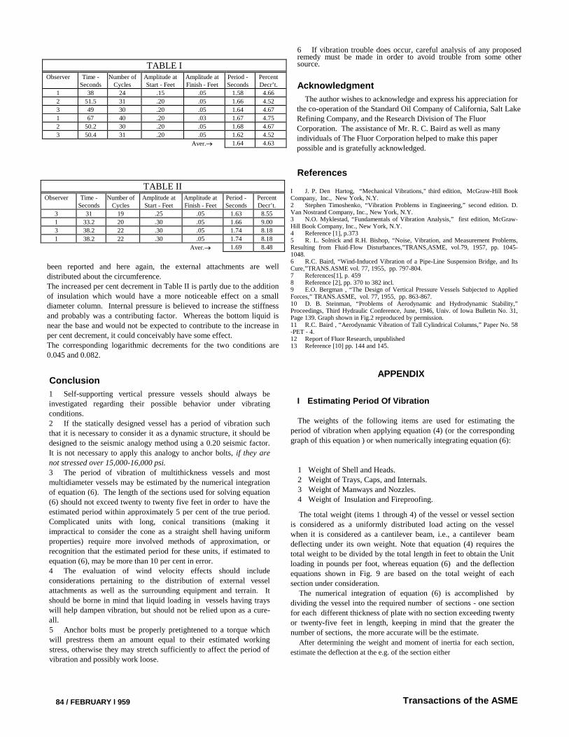
in Table l were taken before the insulation was applied. The averageobserved period of vibration is 1.64 sec.
The readings shown in Table II were taken after the insulation wasapplied. The column was also pressurized at 210 psig and had a bottomtemperature of 340 F and a top temperature of 90 F. There was no liquid onthe trays but there was about four feed of liquid in the bottom. Both sets ofreadings were taken in still air. The average observed period is 1.69 sec.
The calculated period of vibration is only 1.83 per cent lower than theaverage from Table I and 4.15 per cent lower than the average from Table II.
The numerical integration of equation (6) consisted of considering theskirt to be 51 in. average diameter and the 42 in. D section as extending tothe top of the conical reducer. In addition, the upper 51 ft 9 in. consisting of3/4 in. thick plate was divided into three sections as was the 46 ft 7 in. of7/8 in thick plate of the 42 in. D section, making a total number of 9sections.
Calculations indicate a critical wind velocity in the neighborhood of 8-10mph for this vessel. No excessive movement has
Journal of Engineering for Industry FEBRUARY 1959 / 83
been reported and here again, the external attachments are welldistributed about the circumference.The increased per cent decrement in Table II is partly due to the additionof insulation which would have a more noticeable effect on a smalldiameter column. Internal pressure is believed to increase the stiffnessand probably was a contributing factor. Whereas the bottom liquid isnear the base and would not be expected to contribute to the increase inper cent decrement, it could conceivably have some effect.The corresponding logarithmic decrements for the two conditions are0.045 and 0.082.
Conclusion
1 Self-supporting vertical pressure vessels should always beinvestigated regarding their possible behavior under vibratingconditions.2 If the statically designed vessel has a period of vibration suchthat it is necessary to consider it as a dynamic structure, it should bedesigned to the seismic analogy method using a 0.20 seismic factor.It is not necessary to apply this analogy to anchor bolts, if they arenot stressed over 15,000-16,000 psi.3 The period of vibration of multithickness vessels and mostmultidiameter vessels may be estimated by the numerical integrationof equation (6). The length of the sections used for solving equation(6) should not exceed twenty to twenty five feet in order to have theestimated period within approximately 5 per cent of the true period.Complicated units with long, conical transitions (making itimpractical to consider the cone as a straight shell having uniformproperties) require more involved methods of approximation, orrecognition that the estimated period for these units, if estimated toequation (6), may be more than 10 per cent in error.4 The evaluation of wind velocity effects should includeconsiderations pertaining to the distribution of external vesselattachments as well as the surrounding equipment and terrain. Itshould be borne in mind that liquid loading in vessels having trayswill help dampen vibration, but should not be relied upon as a cure-all.5 Anchor bolts must be properly pretightened to a torque whichwill prestress them an amount equal to their estimated workingstress, otherwise they may stretch sufficiently to affect the period ofvibration and possibly work loose.
84 / FEBRUARY l 959
Acknowledgment
6 If vibration trouble does occur, careful analysis of any proposedremedy must be made in order to avoid trouble from some othersource.
The author wishes to acknowledge and express his appreciation forthe co-operation of the Standard Oil Company of California, Salt LakeRefining Company, and the Research Division of The FluorCorporation. The assistance of Mr. R. C. Baird as well as manyindividuals of The Fluor Corporation helped to make this paperpossible and is gratefully acknowledged.
References
I J. P. Den Hartog, “Mechanical Vibrations," third edition, McGraw-Hill BookCompany, Inc., New York, N.Y.2 Stephen Timoshenko, “Vibration Problems in Engineering,” second edition. D.Van Nostrand Company, Inc., New York, N.Y.3 N.O. Myklestad, “Fundamentals of Vibration Analysis,” first edition, McGraw-Hill Book Company, Inc., New York, N.Y.4 Reference [1], p.3735 R. L. Solnick and R.H. Bishop, “Noise, Vibration, and Measurement Problems,Resulting from Fluid-Flow Disturbances,”TRANS,ASME, vol.79, 1957, pp. 1045-1048.6 R.C. Baird, “Wind-Induced Vibration of a Pipe-Line Suspension Bridge, and ItsCure,”TRANS.ASME vol. 77, 1955, pp. 797-804.7 References[1], p. 4598 Reference [2], pp. 370 to 382 incl.9 E.O. Bergman , “The Design of Vertical Pressure Vessels Subjected to AppliedForces,” TRANS.ASME, vol. 77, 1955, pp. 863-867.10 D. B. Steinman, “Problems of Aerodynamic and Hydrodynamic Stability,”Proceedings, Third Hydraulic Conference, June, 1946, Univ. of Iowa Bulletin No. 31,Page 139. Graph shown in Fig.2 reproduced by permission.11 R.C. Baird , “Aerodynamic Vibration of Tall Cylindrical Columns,” Paper No. 58-PET - 4.12 Report of Fluor Research, unpublished13 Reference [10] pp. 144 and 145.
APPENDIX
I Estimating Period Of Vibration
The weights of the following items are used for estimating theperiod of vibration when applying equation (4) (or the correspondinggraph of this equation ) or when numerically integrating equation (6):
1 Weight of Shell and Heads.2 Weight of Trays, Caps, and Internals.3 Weight of Manways and Nozzles.4 Weight of Insulation and Fireproofing.
The total weight (items 1 through 4) of the vessel or vessel sectionis considered as a uniformly distributed load acting on the vesselwhen it is considered as a cantilever beam, i.e., a cantilever beamdeflecting under its own weight. Note that equation (4) requires thetotal weight to be divided by the total length in feet to obtain the Unitloading in pounds per foot, whereas equation (6) and the deflectionequations shown in Fig. 9 are based on the total weight of eachsection under consideration.
The numerical integration of equation (6) is accomplished bydividing the vessel into the required number of sections - one sectionfor each different thickness of plate with no section exceeding twentyor twenty-five feet in length, keeping in mind that the greater thenumber of sections, the more accurate will be the estimate.
After determining the weight and moment of inertia for each section,
estimate the deflection at the e.g. of the section either
Transactions of the ASME
TABLE IObserver Time -
SecondsNumber of
CyclesAmplitude atStart - Feet
Amplitude atFinish - Feet
Period -Seconds
PercentDecr’t.
1 38 24 .15 .05 1.58 4.66
2 51.5 31 .20 .05 1.66 4.52
3 49 30 .20 .05 1.64 4.67
1 67 40 .20 .03 1.67 4.75
2 50.2 30 .20 .05 1.68 4.67
3 50.4 31 .20 .05 1.62 4.52
Aver. 1.64 4.63
TABLE IIObserver Time -
SecondsNumber of
CyclesAmplitude atStart - Feet
Amplitude atFinish - Feet
Period -Seconds
PercentDecr’t.
3 31 19 .25 .05 1.63 8.55
1 33.2 20 .30 .05 1.66 9.00
3 38.2 22 .30 .05 1.74 8.18
1 38.2 22 .30 .05 1.74 8.18
Aver. 1.69 8.48
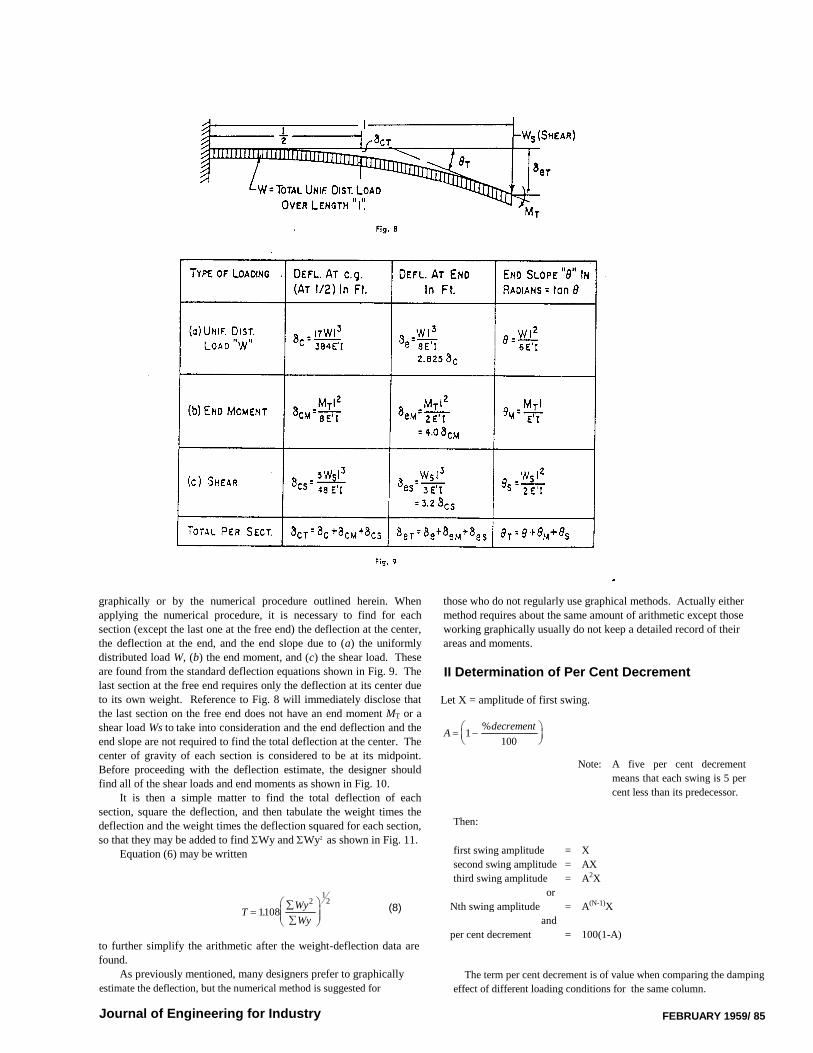
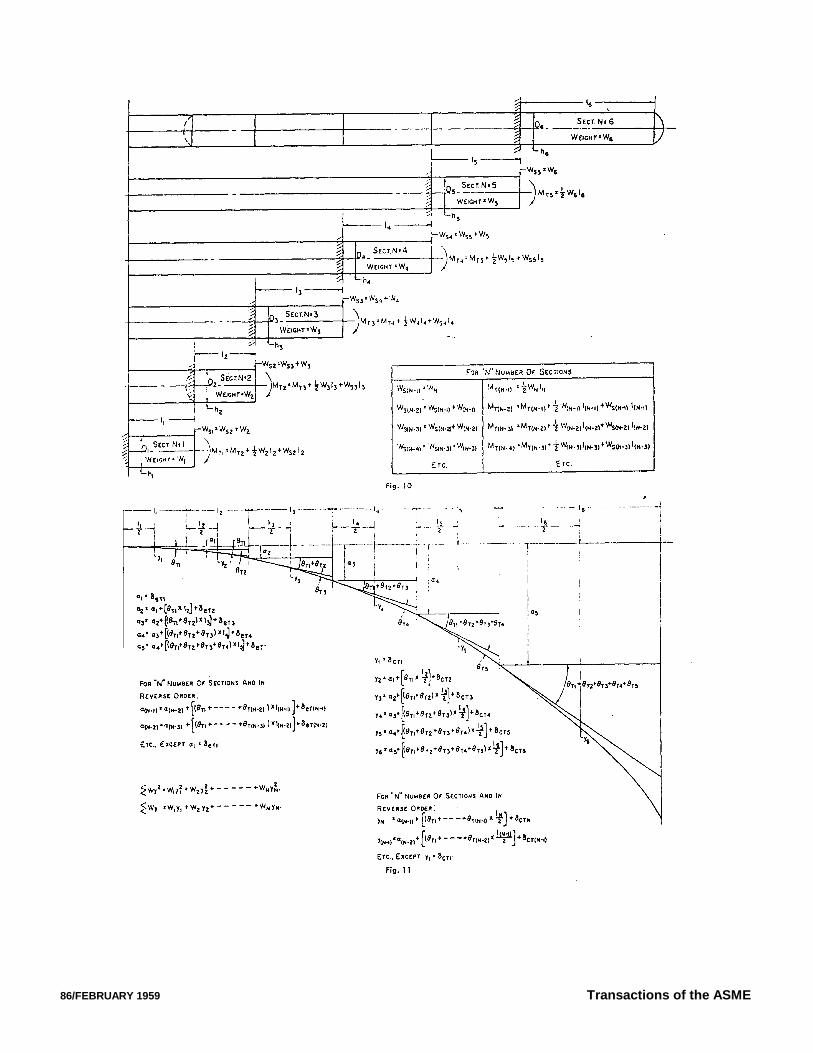
graphically or by the numerical procedure outlined herein. Whenapplying the numerical procedure, it is necessary to find for eachsection (except the last one at the free end) the deflection at the center,the deflection at the end, and the end slope due to (a) the uniformlydistributed load W, (b) the end moment, and (c) the shear load. Theseare found from the standard deflection equations shown in Fig. 9. Thelast section at the free end requires only the deflection at its center dueto its own weight. Reference to Fig. 8 will immediately disclose thatthe last section on the free end does not have an end moment MT or ashear load Ws to take into consideration and the end deflection and theend slope are not required to find the total deflection at the center. Thecenter of gravity of each section is considered to be at its midpoint.Before proceeding with the deflection estimate, the designer shouldfind all of the shear loads and end moments as shown in Fig. 10.
It is then a simple matter to find the total deflection of eachsection, square the deflection, and then tabulate the weight times thedeflection and the weight times the deflection squared for each section,so that they may be added to find Wy and Wy2 as shown in Fig. 11.
Equation (6) may be written
TWy
Wy
1108
21
2
. (8)
to further simplify the arithmetic after the weight-deflection data arefound.
As previously mentioned, many designers prefer to graphicallyestimate the deflection, but the numerical method is suggested for
Journal of Engineering for Industry
those who do not regularly use graphical methods. Actually eithermethod requires about the same amount of arithmetic except thoseworking graphically usually do not keep a detailed record of theirareas and moments.
II Determination of Per Cent Decrement
Let X = amplitude of first swing.
Adecrement
1
100
%
Note: A five per cent decrement
means that each swing is 5 per
cent less than its predecessor.
Then:
first swing amplitude = X
second swing amplitude = AX
third swing amplitude = A2X
or
Nth swing amplitude = A(N-1)X
and
per cent decrement = 100(1-A)
The term per cent decrement is of value when comparing the damping
effect of different loading conditions for the same column.
FEBRUARY 1959/ 85
86/FEBRUARY 1959 Transactions of the ASME
DISCUSSION
M. Ludwig2
This paper deals with a problem that has long challenged this writerand his associates. His recommended procedure for calculation ofdynamic wind forces can, however, lead to much more costly designsthan we have found to be necessary. The author is primarily concernedwith the possibility of forced resonant vibrations stimulated bytransverse cyclic wind forces associated with the Karman vortex trailand, to deal with this possibility, suggests that flexible verticalpressure vessels be designed to resist a lateral force equal to 20 percent of the gravity force. This lateral force is, for most flexible vessels(those with shell thicknesses greater than 0.4 in. if the total mass istwice the mass in the shell) greater than our customary design foreither wind or earthquake. The justification for use of this seismicforce is not presented, either as factor for a seismic design or foravoiding wind-induced vibrations.
An anomalous feature of the author's “seismic analogy” method ofdesign is that it logically leads to the conclusion that a simple verticalcylindrical shell, such as a steel smokestack up to 0.8 in. thick,requires no special consideration because of possible wind vibration,whereas a fractionating column of the same thickness and diametermust be strengthened because of the added mass due to the insulation,trays and fluid thereon, ladders, piping, and other appurtenances. Sucha conclusion cannot be supported by past experience; excessivevibration of steel stacks has occurred, whereas vibration offractionating columns has seldom been a problem. The author notesone case of fractionating column vibration but this stopped when thecolumn was put into operation; either the liquid on the trays providedadequate damping or the added mass of the liquid increased thenatural period to a less critical value.
Our own experience is that the fractionating columns can be safelydesigned for static wind loads alone. The possibility of excessivewind vibration simply appears too remote to justify any added expenseto prevent such vibration. Strengthening of the steel shell, by addingthickness, merely reduces the natural period of vibration and increasethe wind velocity necessary to produce forced oscillations; it is not atall safe to assume that it would eliminate or reduce the amplitude ofvibrations that might otherwise occur.
Why is it that tall vertical pressure vessels, such as fractionatingcolumns, are far less severely affected by wind vibration than areself-supporting steel smokestacks? The greater mass per unit of grosscross-sectional area cannot alone be responsible since largeabove-ground oil pipelines have been observed to vibrate in the wind.There will be added aerodynarnic damping because of attachedplatforms, piping, etc., but it can be shown that the energy absorbedby this form of damping is probably not enough to limit the vibrationamplitude to reasonable values. The external irregularities due toplatforms, piping, etc., could, however, reduce the applied periodicwind force.
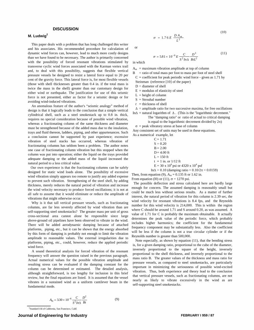
A sound theoretical analysis for forced vibration of the resonantfrequency will answer the question raised in the previous paragraph.Actual numerical values for the possible vibration amplitude andresulting stress can be evaluated if the damping constant for thecolumn can be determined or estimated. The detailed analysis,although straightforward, is too lengthy for inclusion in this briefreview, but the final equations are listed. It is assumed that the vesselvibrates in a sustained wind as a uniform cantilever beam in thefundamental mode.
Journal of Engineering for Industry
in which
(10)
Am = maximum vibration amplitude at top of column
B = ratio of total mass per foot to mass per foot of steel shell
C = coefficient for peak periodic wind force - given as 1.71 by
Steinman (reference [10] of the paper)
D = diameter of shell
E = modulus of elasticity of steel
L = height of column
S = Strouhal number
t = thickness of shell
= amplitude ratio for two successive maxima, for free oscillationsIn = natural logarithm of . (This is the "logarithmic decrement."
The "damping ratio" or ratio of actual to critical dampingis equal to the logarithmic decrement divided by 2)
= peak vibratory stress at base of columnAny consistent set of units may be used in these equations.As a numerical example, let
C = 1.71S = 0.20B = 2.00D= 4.00 ftL = 150 ftt = 1 in. or 1/12 ftE = 30 x 106 psi or 4320 x 104 psf
In = 0.10 (damping ratio = 0.10/2 = 0.0159)Then, from equation (9), Am = 0.135 ft or 1.62 in.From equation (l0) or (11), = 1270 psi.
The possible deflection and stress calculated here are hardly largeenough for concern. The assumed damping is reasonably small butcould be much less without serious results. As a matter of furtherinterest, the natural period of vibration for this column is 2.39 sec, thewind velocity for resonant vibrations is 8.4 fps, and the Reynoldsnumber for this wind velocity is 214,000. This is within the regionwhere C should be around 1.71 and S around 0.20, as was assumed. Avalue of 1.71 for C is probably the maximum obtainable. It actuallydetermines the peak value of the periodic force, which probablyincludes higher harmonics; the coefficient for the fundamentalfrequency component may be substantially less. Also the coefficientwill be less if the column is not a true circular cylinder or if theReynolds number is greater than 500,000.
Note especially, as shown by equation (11), that the bending stressis, for a given damping ratio, proportional to the cube of the diameter,inversely proportional to the square of the height, inverselyproportional to the shell thickness, and inversely proportional to themass ratio B. The greater values of the thickness and mass ratio forpressure vessels, as compared to steel smokestacks, are particularlyimportant in minimizing the seriousness of possible wind-excitedvibration. Thus, both experience and theory lead to the conclusionthat vertical pressure vessels, such as fractionating columns, are notnearly as likely to vibrate excessively in the wind as areself-supporting steel smokestacks.
FEBRUARY I 959 / 87
AC
S In
D
Btm 330 10 6
2
2
.
(9)
1 7 62
. ED A
L
m
or
5 81 10 62
3
2. E
C
S In
D
BtL
(11)
2Standard Oil of California, San Francisco, Calif.
Earl J. Hicks3
and J. R. Sellers4
The author implies that the vibration of a tall vessel is a case offorced vibration, with resonance occurring when the Karman vortextrail frequency corresponds with the natural frequency of the vessel.This is supported by Baird [14]5 in. his investigation of a pipelinebridge vibration. We have had a similar experience with a pipelinebridge in which a critical wind velocity was observed. A search of theliterature finds an exception to this with experimental data to supportthe claim that tall stacks vibrate as self-excited vibrational systemswith no critical wind velocity causing forced vibrational response.Ozker and Smith [15] make the following statements in the summaryand conclusions portion of their paper which are contrary to thispaper: (1) “The stack structure under wind action constitutes a self--excited vibration system": (2) “The vibrational frequency is the naturalfrequency of the structure and remains constant for all windvelocities'': (3) “The stack is at resonance at all times”; (4) “There isno critical wind velocity in the sense of forced vibrational response”;and (5) “The amplitude increases with increasing wind velocities.” Ifthis were found to be true for a stack, could it not also be true for a tallvessel? The bulk of the data seems to support the theory of forcedvibration excited by the Karman vortex trail, but there is this onenotable exception. There may be others.
The basic assumption in calculating the natural frequency of a tallcylindrical vessel is that the base is fixed at the top of the foundation.This implies that the horizontal displacement or deflection is due tothe elastic deformation of the vessel and that the horizontaldisplacement due to the elastic deformation of the soil is negligible.This means that the vessel would act like a true cantilever beam fixedat one end. This is one extreme assumption.
The opposition extreme assumption would be that the vessel andfoundation is a rigid structure resting on an elastic subgrade. Thisimplies that the horizontal displacements of the tower are negligiblecompared to the deflection due to deformation of the soil.
Assuming the latter assumption to be correct, it can be shown for avessel on an octagonal foundation resting on an elastic subgrade thatthe natural frequency of vibration is equal to the following:
where
B = short diameter of the base in feetH = distance between the base and the center of gravity of thefoundation and vesselds = coefficient of dynamic subgrade reactionq = static soil pressure per unit of area
From this equation the following conclusions can be drawn. Thesofter the supporting soil, the lower is the natural frequency and thefrequency may be raised by increasing the area if the foundation base[16].
In general, observed frequencies have been lower than thecalculated frequencies. This is probably due to the vessel andfoundation acting together in a manner somewhere in between the twoextreme assumptions. If the supporting soil is relatively strong, thefirst assumption is more nearly correct. If the
3Engineering Department, Phillips Petroleum Company, Bartlesville, Okla. Mem. ASME.4Engineering Department, Phillips Petroleum Company.5Numbers in brackets designate References at end of this discussion.
88 / FEBRUARY 1959
supporting soil is relatively soft, the actual condition tends toapproach the second assumption. Past observations on various stackshave indicated reasonably close agreement between the observedfrequency and the calculated frequency, the latter being based on thefixed cantilever beam assumption. If the frequency of a vessel isdetermined, assuming a fixed cantilever beam, and the supporting soilis soft, the error would be on the unsafe side; that is, the calculatedcritical wind velocity would be high.
The method of design suggested for wind induced vibration appearsto be arbitrary and most likely finds justification in the number ofsuccessful towers. It would be desirable to have a more analyticalapproach to the problem. Apparently, any relation between the windinduced vibration and the 0.2 seismic factor is purely coincidental.
It appears a more realistic approach would be to equate the energyinput in terms of amplitude to the energy dissipated in terms ofamplitude and solving for the amplitude where the energy input isequal to the energy dissipated. The vibrations at this point would bean undamped steady-state free vibration and the resulting amplitudewould be a maximum. Knowing the maximum deflection, themaximum stress could be readily calculated. If the resulting stressesare excessive, then other methods to dissipate the energy would haveto be used.
This method would require reasonably accurate knowledge of thecoefficient of lift CL, the Strouhal number S, and damping decrement. Only meager information on the numerical value of thesecoefficients is available at this time. It appears desirable to study theloads and dynamic response in a series of wind tunnel tests. Does theauthor know of any such studies?
Aerodynamic paneling, liquid loading on trays, and liquid chambersare practical solutions. One other worth mentioning is that of tieingadjacent vessels and structures together. Vessels arranged in a triangleor square with common ties have a different vibrational mode and ahigher resonant frequency than a single tower. In addition, moredamping is introduced. A single vessel tied at an immediate level toan adjacent structure will vibrate in a different mode and higherfrequency. These can be used as safeguards for vessels claimed ascritical.
The liquid chamber suggested is one form of Frahm dynamicabsorber system.. A word of caution should be given on thisapplication. The Frahm dynamic absorber system has two resonantfrequencies and one frequency of zero amplitude. A properly sizedliquid chamber would decrease the amplitude to zero at one frequency,reduce it over a limited range of frequencies, but amplify it at twofrequencies outside this range. In other words, at certain frequenciesthe liquid may not slosh to oppose vibration, but instead be in phase toamplify it. Frahm antiroll tanks for ships are dealt with in DenHartog’s book [17]. A liquid chamber appears to be an energyabsorber of this same type.
In Case III, no excessive movement has been reported although thecritical wind velocity is in the neighborhood of 8-10 miles per hour.In Case I, the vessel has operated successfully with a calculated windvelocity to cause resonance of 10-12 miles per hour. Both of thesevessels were designed to the seismic analogy method. In Case IIwhere the seismic analogy method of the design was not used, thevessel vibrated during the construction period. Does the author implythat since Case III and I were dynamically designed and Case II wasnot that this was the main reason that vibration did not occur or couldit be that the ladders and platforms were distributed around the formertwo vessels such that the formation of the Karman vortex trail does notmaterialize? It appears that the ladders, platforms, piping, andinsulation might be the major factor in preventing vessels fromvibrating. No doubt there are many vessels with a height to diameterratio greater than 20 which are operating
Transactions of the ASME
fB
H
d
qs
0 232
12
.
satisfactorily and have not been designed as recommended by theauthor. The author implies that any vessel with a period which fallsabove the line shown in Fig. I should be designed dynamically. Wouldthis be true for vessels whose heights are less than 100 or 75 or 50 ft?In general, is there some approximate height regardless of the H/Dratio where vessels below this height would not have to beinvestigated?
Although the author does not say specifically that the vessel shouldbe designed such that the "critical wind velocity" is high enough toexclude the possibility of the second mode of vibrations it ismentioned. If this item is not critical, then why is it necessary to usesuch an accurate and time consuming method to determine the periodwhen it could probably be estimated by other methods. Apparently,the designers were not concerned in Cases I and III about the lowcritical wind velocity since they were designed dynamically.
The author's paper is very timely indeed and is viewed withconsiderable interest since the trend in pressure vessel design is toincrease their height and decrease the internal pressure. We wish tocompliment him on a very excellent paper and also thank him forstimulating our interest in the subject.
References14 R. C. Baird, "Wind-Induced Vibration of a Pipe-Line Suspension Bridge, and Its
Cure," TRANS. ASME, vol. 77, 1955, pp 797-804.
15 M. S. Ozker and J. O. Smith. "Factors Influencing the Dynamic Behavior of Tall
Stacks Under the Action of Wind," TRANS. ASME, vol. 78, 1956, pp. 1381-1391.
16 Karl Terzaghi, “Theoretical Soil Mechanics,” John Wiley & Sons, Inc., New
York, N. Y., pp. 454-457.
17 J. P. Den Hartog, “Mechanical Vibrations,” McGraw-Hill Book Company, Inc.,
New York, N. Y., second edition, pp. 129-135.
18 W. L. Dickey and G. B. Woodruff, “The Vibrations of Steel Stacks,” Trans.
ASCE, vol. 121, 1956, p. 1088.
19 E. A. Dockstader, W. F. Swiger, and E. Ireland, “Resonant Vibration of Steel
Stacks,” Trans. ASCE, vol. 121, 1956, p. 1088.
L. Acquaviva6
The proposed criteria for dynamic design of pressure vesselsappears to yield more conservative results than the method we havebeen using for many years. It appears that the seismic coefficient of0.20 applied on all vessels with height to diameter ratio exceeding 15or natural period exceeding 1.0 sec may be too conservative based onour experience. For example, as an extreme case, there is a towerwithin the Esso interests which is 173 ft high., topmost 40 per cent ofheight is 6 ft 6 in. in diameter and lower 60 per cent 5 ft 0 in. indiameter. The approximate L/D ratio is 30, natural period of vibration3.7 sec and critical wind velocity 6.5 miles per hour for the topsection. The tower is on pile foundations and has given no vibrationdifficulties even though subjected many times to the critical windvelocity for the top section; nor has there been any tendency to vibrateat its second mode for which the critical wind velocity is about 40miles per hour. The bottom section shell thickness for this vessel is7/8 in. The thickness required to conform with proposed dynamicdesign would be 1 3/8 in.
Unlike steel stacks, for which there are many instances of excessivevibration reported in technical literature, Case II in the paper is thefirst example to our knowledge of such occurrence in vertical pressurevessels. In this case, the maximum amplitude of 0.45 ft duringresonance does not appear to be of sufficient magnitude to causeexcessive stresses in the vessel shell. It would be of interest to knowif an remedial measures were taken in this case.
6 Esso Research and Engineering Company, Linden, N. J.
Journal of Engineering for Industry
Donald J. Bergman7
This paper is particularly interesting because it includes some actualfield data which have been extremely difficult to get. It seemsimportant to note that minor changes in resonant frequency have littleeffect on the over-all situation as this merely results in a slightlydifferent wind velocity to reach resonance. It was much moreimportant to note how greatly the liquid on the trays of a columnincreased the damping effect. This absorbs the energy of the windforces and cuts down the magnification factor, decreasing themaximum. amplitude of vibration.
We had several instances of stack vibration starting in 1938, all farremoved and all solved by use of permanent guys. The first key to thecauses came from Sir James Jeans’ book "Science and Music." Herethe comment was made that a set of eddies broke off from a cylindricalsurface every 5.4 diam along the wind stream and that these eddiescaused a push from side to side. The example was given of a ship with1/2 in. rigging at sea in a 40-mile gale where the frequency comes outto correspond to middle "C" on a piano.
The policy of providing light guys and spreaders was adopted forcolumns with high L/D ratios and springs were provided to take careof column elongation by heat. Several hundred columns were thusequipped over past years without having one case of resonantvibration. Perhaps this was just fortuitous because of presence ofladders, platforms, etc., to interfere with resonance, and absence ofcritical winds. Most of these columns were within the critical range asdefined by the author.
Later study indicated the same conclusions that the author reached:That the guys and springs were probably not effective and,consequently, about a year ago provision of these guys was abandoned.Since then one tower was found to have a resonant period with thewind and permanent guys were added.
Perhaps it should be noted that the elasticity of fixed guys actuallymakes them springs with a very high constant. Limiting the movementof the tower is the desired result, and this the guys do by resisting thewind forces.
The lateral forces resulting from the action of the Karman eddiesseem to be somewhat greater than the normal wind drag for any windvelocity. With a low decrement, or high magnification, say, 20, only arelatively small force, 1 lb/sq ft, is required to give the deflectionobtained when designing for a 100-mile per hour wind at 20 lb/sq ft,on the projected area of the column.
The lateral forces generated on cylinders were actually utilizedshortly after World War I by the German Flettner rotor ship whichcruised from Germany to New York using two 10 x 60-ft cylindersmounted on the deck and rotated in order to furnish a fixed instead ofan oscillating force.
Rouse’s book “ Engineering Hydraulics” on page 130 gives formulas
for an approximation of the aerodynamic lift caused by the Karman eddies
on fixed and rotating cylinders. Additional information for higher
Reynolds numbers was obtained from Prof. L. Landweber of the Iowa
Institute of Hydraulic Research by correspondence. For the 7.67-ft column
which gave trouble with a 27-mph wind, I calculate a loading of 9.1 lb/ft or
1.18 lb/sq ft of projected area. Stiffening a column and increasing its
frequency will decrease the deflection for a given load, but the wind forces
increase as the square of the wind velocity.
Some comment was made regarding the second mode of vibration. This
will always require a very much higher wind velocity than the first mode,
but the column is so much more stiff because of the complicated second
mode curve that it is probable that the vibration is not noticeable if it does
occur.
7 Engineering and Development Department. Universal Oil Products Company, Des Plaines, III.
Mem. ASME.
FEBRUARY I 959 / 89
aThis is double the wt/ft for 7/16-in. plate.
Patent no. 2604838, dated July 29, 1952, to W. B. Traver, ofStandard Oil Company of Indiana, teaches provision of a roughenedsurface near the top of a stack either by small strips ranging from 1/4to 1 in. depth, or by the use of steel grating. This increases the skinresistance on the surface of the cylinder to prevent formation ofKarman eddies. However, it does not seem to be a very practicalremedy because of the cost of attaching the large number of smallstrips to the stack.
Author's ClosureBefore replying to specific questions or comments, the author
wishes to thank the discussers for their review and commentspertaining to the design of vertical vessels subject to vibration.
It is hoped that sufficient interest has been stimulated in this subjectto result in obtaining more field data than we presently have at ourdisposal. Up to the present time very little has been done to obtaininformation pertaining to tall, slender vessels. If no complaint wasreceived from the operators, it has been assumed that no criticalvibration would ever occur. This is a normal and expected attitude;however, it has not contributed to our knowledge of vessel behavior asheights have increased.
As pointed out in this paper and described more in detail in thepaper given by Mr. Baird, we have had definite experience with onevessel which did give trouble and, after completing this paper theauthor was informed that this vessel still has to have anchor boltsretightened at intervals which indicates that some excessive vibrationmay still be taking place.
The author does not agree with Mr. Ludwig that we can generalizeregarding the relationship of total mass to the mass of the shell itself.Mr. Ludwig's use of a mass equal to twice the mass of the shell in his4-ft 0-in. diam X l-in. thick example would result in very heavyinternals. To me, each vessel should be considered individually duringthe design stage. Obviously, there will be those where conditions ofterrain and prevailing winds will cast doubt regarding the justificationof added cost to the vessel.
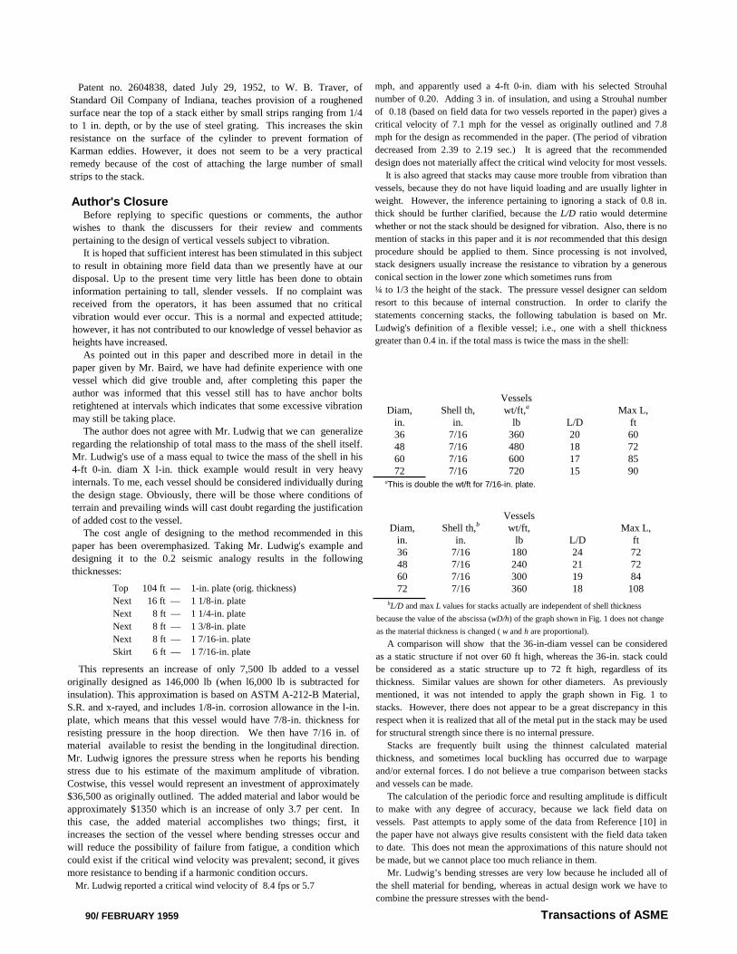
The cost angle of designing to the method recommended in thispaper has been overemphasized. Taking Mr. Ludwig's example anddesigning it to the 0.2 seismic analogy results in the followingthicknesses:
Diam,in.
Shell th,in.
Vesselswt/ft,a
lb L/DMax L,
ft36 7/16 360 20 6048 7/16 480 18 7260 7/16 600 17 8572 7/16 720 15 90
Top 104 ft — 1-in. plate (orig. thickness)
Next 16 ft — 1 1/8-in. plate
Next 8 ft — 1 1/4-in. plate
Next 8 ft — 1 3/8-in. plate
Next 8 ft — 1 7/16-in. plate
Skirt 6 ft — 1 7/16-in. plate
This represents an increase of only 7,500 lb added to a vesseloriginally designed as 146,000 lb (when l6,000 lb is subtracted forinsulation). This approximation is based on ASTM A-212-B Material,S.R. and x-rayed, and includes 1/8-in. corrosion allowance in the l-in.plate, which means that this vessel would have 7/8-in. thickness forresisting pressure in the hoop direction. We then have 7/16 in. ofmaterial available to resist the bending in the longitudinal direction.Mr. Ludwig ignores the pressure stress when he reports his bendingstress due to his estimate of the maximum amplitude of vibration.Costwise, this vessel would represent an investment of approximately$36,500 as originally outlined. The added material and labor would beapproximately $1350 which is an increase of only 3.7 per cent. Inthis case, the added material accomplishes two things; first, itincreases the section of the vessel where bending stresses occur andwill reduce the possibility of failure from fatigue, a condition whichcould exist if the critical wind velocity was prevalent; second, it givesmore resistance to bending if a harmonic condition occurs.
Mr. Ludwig reported a critical wind velocity of 8.4 fps or 5.7
90/ FEBRUARY 1959
mph, and apparently used a 4-ft 0-in. diam with his selected Strouhal
number of 0.20. Adding 3 in. of insulation, and using a Strouhal number
of 0.18 (based on field data for two vessels reported in the paper) gives a
critical velocity of 7.1 mph for the vessel as originally outlined and 7.8
mph for the design as recommended in the paper. (The period of vibration
decreased from 2.39 to 2.19 sec.) It is agreed that the recommended
design does not materially affect the critical wind velocity for most vessels.
It is also agreed that stacks may cause more trouble from vibration than
vessels, because they do not have liquid loading and are usually lighter in
weight. However, the inference pertaining to ignoring a stack of 0.8 in.
thick should be further clarified, because the L/D ratio would determine
whether or not the stack should be designed for vibration. Also, there is no
mention of stacks in this paper and it is not recommended that this design
procedure should be applied to them. Since processing is not involved,
stack designers usually increase the resistance to vibration by a generous
conical section in the lower zone which sometimes runs from
¼ to 1/3 the height of the stack. The pressure vessel designer can seldom
resort to this because of internal construction. In order to clarify the
statements concerning stacks, the following tabulation is based on Mr.
Ludwig's definition of a flexible vessel; i.e., one with a shell thickness
greater than 0.4 in. if the total mass is twice the mass in the shell:
Transactions of ASME
bL/D and max L values for stacks actually are independent of shell thickness
because the value of the abscissa (wD/h) of the graph shown in Fig. 1 does not change
as the material thickness is changed ( w and h are proportional).
A comparison will show that the 36-in-diam vessel can be considered
as a static structure if not over 60 ft high, whereas the 36-in. stack could
be considered as a static structure up to 72 ft high, regardless of its
thickness. Similar values are shown for other diameters. As previously
mentioned, it was not intended to apply the graph shown in Fig. 1 to
stacks. However, there does not appear to be a great discrepancy in this
respect when it is realized that all of the metal put in the stack may be used
for structural strength since there is no internal pressure.
Stacks are frequently built using the thinnest calculated material
thickness, and sometimes local buckling has occurred due to warpage
and/or external forces. I do not believe a true comparison between stacks
and vessels can be made.
The calculation of the periodic force and resulting amplitude is difficult
to make with any degree of accuracy, because we lack field data on
vessels. Past attempts to apply some of the data from Reference [10] in
the paper have not always give results consistent with the field data taken
to date. This does not mean the approximations of this nature should not
be made, but we cannot place too much reliance in them.
Mr. Ludwig’s bending stresses are very low because he included all of
the shell material for bending, whereas in actual design work we have to
combine the pressure stresses with the bend-
Diam,in.
Shell th,b
in.
Vesselswt/ft,
lb L/DMax L,
ft36 7/16 180 24 7248 7/16 240 21 7260 7/16 300 19 8472 7/16 360 18 108
ing stresses. Also, Mr. Ludwig's stress is based on his estimate of theamplitude and ignores the fact that a deflection exceeding the normalamplitude might result if resonance occurs, as reported for the vesseloutlined as Case II and reported by Baird.
Mr. Hicks and Mr. Sellers discuss the possibility of the foundationand soil-bearing capacity as contributing to the flexibility of thesystem. This possibility has not been ignored. However, there hasbeen no observation to justify this assumption. A check into the effectof anchor bolt stretch did not affect the period of vibration estimatesufficiently to bother with it—other than to require pretightening toreduce elongation during vessel deflection. When the total mass ofconcrete and the surface charge of earth is considered, it is difficult toagree that they materially influence the natural frequency. If the soilbearing capacity is low, it is usually necessary to drive piles to supportvessels and similar heavy equipment.
The desire for analytical approach is appreciated. However,pressure vessels do not always lend themselves to a true scientificanalysis. In this case, so many variables exist that assumptions madein order to solve equations are apt to produce misleading results. Thefact that a number of successful vessels have been built using thissornewhat empirical approach is reasonable justification for itsconsideration. If we cannot justify a design method on the basis ofsuccessful operation, then we would be forced to discard many of ourpractices which are based on experience, including earthquake design.It is also noted that some reviewers are equally positive that it isunnecessary to take any precautionary measures because they have notexperienced any difficulty in the past. Therefore, we have one moreinstance where the variables are too many to draw a definiteconclusion and data pertaining to location, terrain, wind currents,detail vessel design, and vibration for each case are not available. Ifwe had at our disposal sufficient data taken from existing units, weprobably could work out a more analytical approach.
To my knowledge there have been no wind-tunnel tests pertainingto vertical vessels except those mentioned in Reference [10].Investigation of testing models for tall, slender columns willimmediately reveal that, in order to obtain reliable data for L/D ratiosof 30 and 40 to one, the model size will be difficult to work with,because the diameter is so small in order to avoid excessive height.Some of the larger wind tunnels could probably handle models largeenough to be practical, but the cost would be very high.
Connecting critical vessels to nearby structures of to adjacentvessels is always desirable if the location of the equipment permits.This cannot be accomplished in many instances.
I do not agree that the use of a single liquid chamber is comparableto Frahm antiroll tanks. The type of motion differs and I believe thatthere is very little possibility of the liquid amplifying vibration.However, as pointed out in Conclusion No. 6 in the paper, anyproposed remedy must be carefully analyzed to avoid additionaltrouble from some other source.
The paper does imply that the vessel reported under Case II
Journal of Engineering for Industry
might have been satisfactory if designed to the seismic analogymethod, but there is no proof of this. Recognition is given to thedesirability of distributing ladders, platforms, and other accessoriescircumferentially about the vessel to reduce the effect of periodic eddyshedding.
The heavy reference line shown in Fig. 1 is independent of heightand considers L/D ratios more important than height. A vessel 30 in.in diameter and 90 It 0 in. high can be more critical than a 200-ft0-in-high vessel of a larger diameter. This reference line from 0.4 secon the left to the 0.8 sec on the right of the graph is empirical. Therecertainly are vessels having periods of vibration above this line whichwere not designed as recommended that are satisfactory. This line atone time was a horizontal line at 0.4 sec, and experience indicated thatit could be safely changed as shown. Future data may result in anotherrevision for this limit.
The method outlined in the paper for numerically estimating theperiod of vibration for a vessel having a shell varying in thickness isintended for designers who are not experts in vibration. We areprogramming this work for computing machines along with our othervessel program, but computing machines are not always available, andother methods of approximation are not very reliable unless performedby experts in the field of vibration. It is not always necessary toestimate this period and frequently it can be approximated by usingthe graph in Fig. 1. It is up to the designer to decide the degree ofaccuracy he wishes to attain.
The column described by Mr. Acquaviva has considerable difference in
the diameter of the top and bottom section. Our experience has been that
vessels of this type are not as critical as tall, slender columns which are the
same diameter for their entire length. I have some reservation regarding
the accuracy of estimating critical wind velocities for this type of vessel
when the diameter difference exceeds 6 to 12 in.
Here is another example of experience and each individual willhave his own idea of :a correct solution.
If I were compiling data pertaining to existing vessels, I woulddefinitely attempt to include all possible information on surroundingstructures, wind currents, and geological data, in addition to details ofvessel construction. A successful installation in one locality may notbe trouble free in another.
The vibration dampener shown in Fig. .3 in the paper was appliedto the vessel which vibrated at an excessive amplitude. This hadpractically no effect on the behavior of the vessel, but was notremoved. Liquid loading helped to prevent excessive amplitudebuild-up, but as previously mentioned, it was recently discovered thatthe anchor bolts have to he retightened at frequent intervals.
My reply regarding cost of designing to a 0.2 - seismic factor wasincluded with the reply to Mr. Ludwig’s comments.
Mr. Fred Ruud's statement that the U. S. Bureau of Reclamationuses a seismic analogy method for some of their tall vessels isparticularly interesting in view of the fact that seismic factors of 0.25to 0.30 were mentioned, and the author wishes to thank Mr. Ruud forhis interest and express regret that he did not have the opportunity toprepare written discussion on this paper.
FEBRUARY 1959 / 91


