Embed Size (px)
Citation preview
Meccanica32: 529–544, 1997.© 1997Kluwer Academic Publishers. Printed in the Netherlands.
Aspects of Passive Control of Structural Vibrations
B. PALAZZO and L. PETTIDepartment of Civil Engineering, University of Salerno, Via Ponte don Melillo; 84084 Fisciano, Salerno, Italy
(Received: 9 February 1996; accepted in revised version: 9 May 1997)
Abstract. A preliminary attempt to organize innovative strategies such as Base Isolation, Supplemental EnergyDissipation, Tuned Mass Damping and other combined approaches recently proposed by the authors, in a moregeneral theory of Structural Control, is presented. To visualize the relationships between dynamic variablesand subsystems, the block-diagram representations are used in order to obtain the regulation properties of thesystems. It has been proven that the Base Isolation technique applies an open-loop control law and that TunedMass Damping and Supplemental Energy Dissipation realize closed-loop control laws. The block-diagram of thenew combined strategy Base Isolation and Tuned Mass Damping is presented. The objectives of the regulatingcriteria are also discussed in order to shape the dynamic response in the frequency domain. TheH2 andH∞methods are considered as optimal control algorithms.
Sommario. Nel lavoro, si sviluppa un primo tentativo per inquadrare alcune strategie innovative comel’Isolamento Sismico, lo Smorzamento di massa, la Dissipazione Supplementare di Energia ed alcuni Siste-mi Ibridi o Combinati, proposti dagli autori, in una logica unitaria che si vuole definire del Controllo delleVibrazioni. Nella memoria si applica la rappresentazione degli schemi a blocchi, al fine di evidenziare i concettidi regolazione delle diverse componenti i sistemi analizzati. Con tale impostazione, viene dimostrato che il fun-zionamento dell’Isolamento Sismico alla Base puo essere inquadrato da una legge di regolazione a ciclo aperto.Si dimostra poi che la tecnica dello Smorzamento di massa, invece,e inquadrabile in una legge di regolazionea ciclo chiuso. In tale ottica, si ricavano inoltre gli schemi di comportamento di un sistema combinato recente-mente proposto dagli autori: Isolamento alla Base + Smorzamento di massa. Si esaminano infine alcuni metodidi controllo ottimo nel dominio delle frequenze in funzione degli obiettivi di regolazione propri dei sistemi dicontrollo.
Key words: Structural control (passive), Vibrations of structures.
1. Introduction
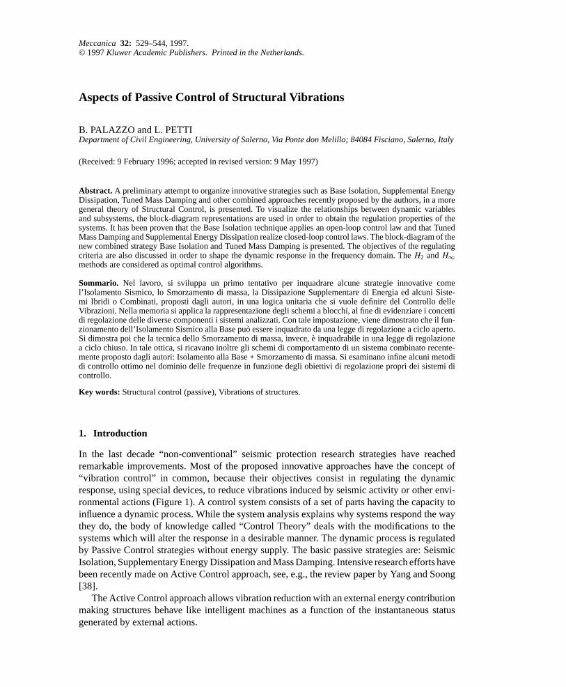
In the last decade “non-conventional” seismic protection research strategies have reachedremarkable improvements. Most of the proposed innovative approaches have the concept of“vibration control” in common, because their objectives consist in regulating the dynamicresponse, using special devices, to reduce vibrations induced by seismic activity or other envi-ronmental actions (Figure 1). A control system consists of a set of parts having the capacity toinfluence a dynamic process. While the system analysis explains why systems respond the waythey do, the body of knowledge called “Control Theory” deals with the modifications to thesystems which will alter the response in a desirable manner. The dynamic process is regulatedby Passive Control strategies without energy supply. The basic passive strategies are: SeismicIsolation, Supplementary Energy Dissipation and Mass Damping. Intensive research efforts havebeen recently made on Active Control approach, see, e.g., the review paper by Yang and Soong[38].
The Active Control approach allows vibration reduction with an external energy contributionmaking structures behave like intelligent machines as a function of the instantaneous statusgenerated by external actions.
530 B. Palazzo and L. Petti
Figure 1. Seismic protection strategies.
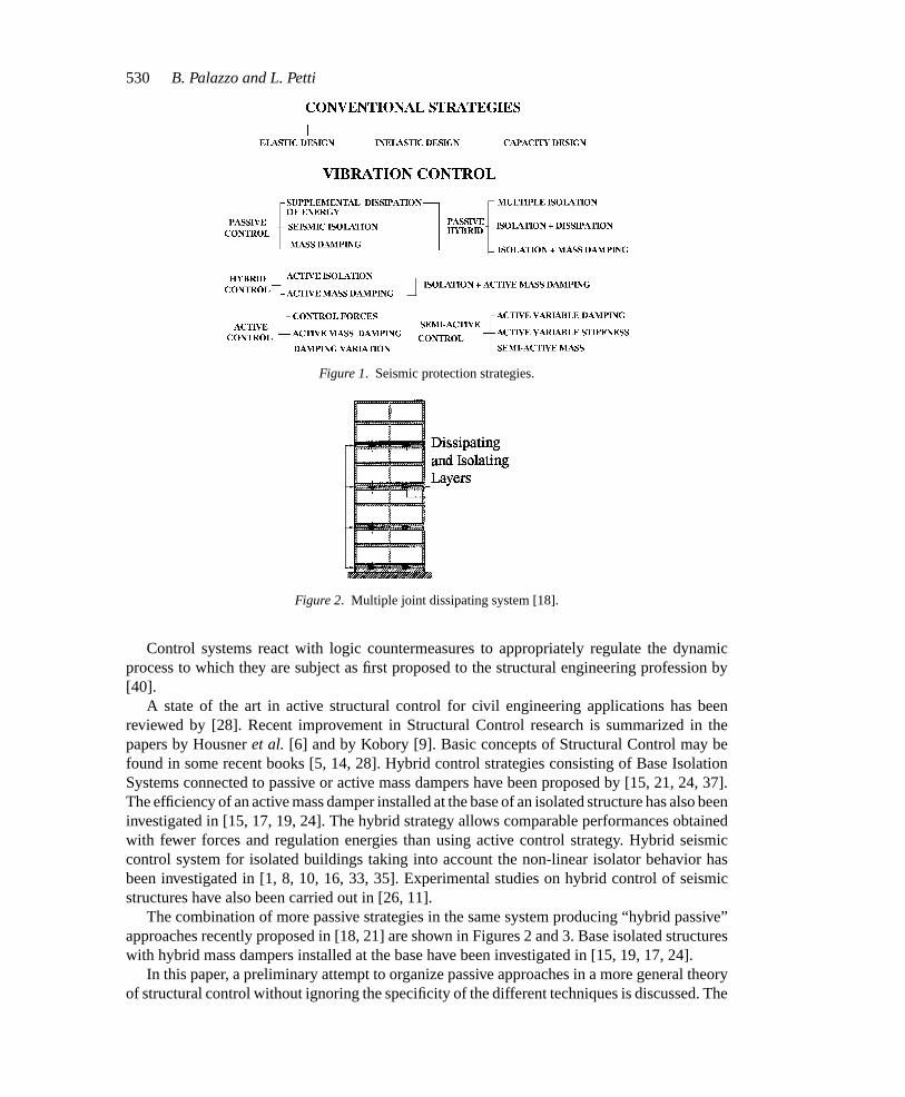
Figure 2. Multiple joint dissipating system [18].
Control systems react with logic countermeasures to appropriately regulate the dynamicprocess to which they are subject as first proposed to the structural engineering profession by[40].
A state of the art in active structural control for civil engineering applications has beenreviewed by [28]. Recent improvement in Structural Control research is summarized in thepapers by Housneret al. [6] and by Kobory [9]. Basic concepts of Structural Control may befound in some recent books [5, 14, 28]. Hybrid control strategies consisting of Base IsolationSystems connected to passive or active mass dampers have been proposed by [15, 21, 24, 37].The efficiency of an active mass damper installed at the base of an isolated structure has also beeninvestigated in [15, 17, 19, 24]. The hybrid strategy allows comparable performances obtainedwith fewer forces and regulation energies than using active control strategy. Hybrid seismiccontrol system for isolated buildings taking into account the non-linear isolator behavior hasbeen investigated in [1, 8, 10, 16, 33, 35]. Experimental studies on hybrid control of seismicstructures have also been carried out in [26, 11].
The combination of more passive strategies in the same system producing “hybrid passive”approaches recently proposed in [18, 21] are shown in Figures 2 and 3. Base isolated structureswith hybrid mass dampers installed at the base have been investigated in [15, 19, 17, 24].
In this paper, a preliminary attempt to organize passive approaches in a more general theoryof structural control without ignoring the specificity of the different techniques is discussed. The
MECC214.tex; 5/12/1997; 13:55; no v.; p.2
Aspects of Structural Vibration Passive Control531
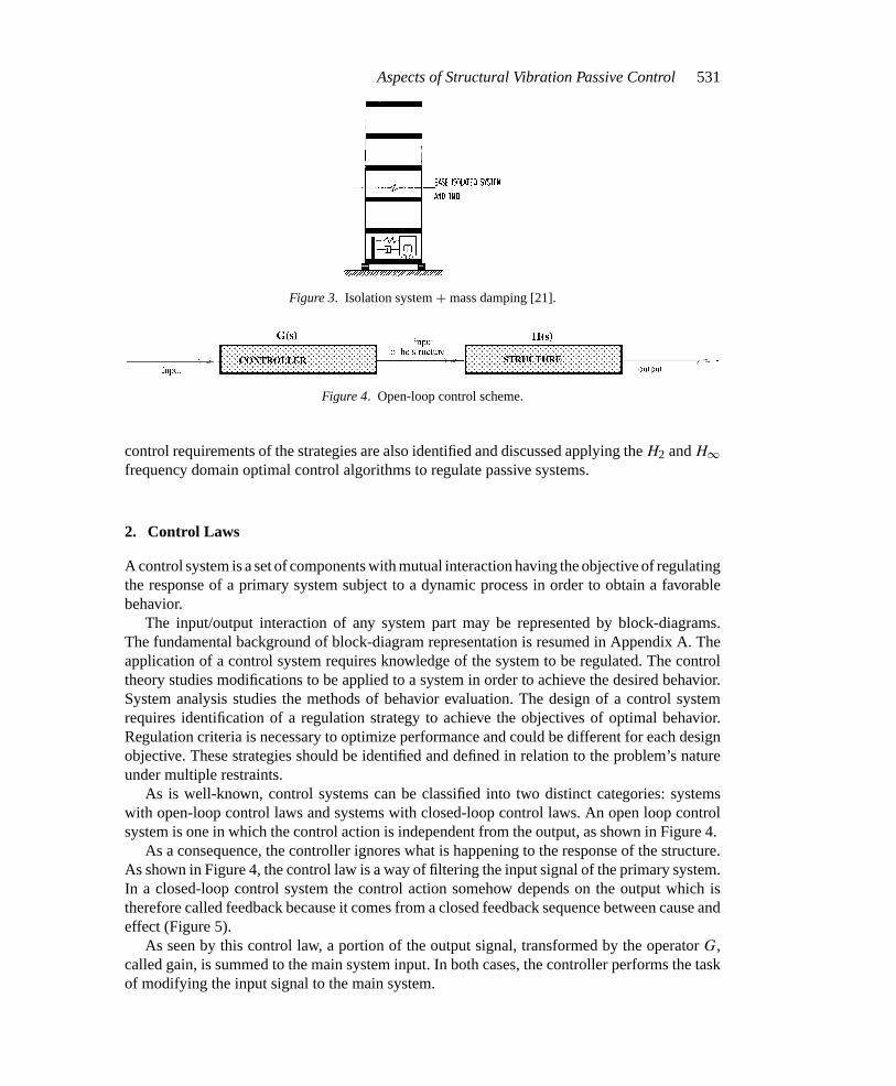
Figure 3. Isolation system+ mass damping [21].
Figure 4. Open-loop control scheme.
control requirements of the strategies are also identified and discussed applying theH2 andH∞frequency domain optimal control algorithms to regulate passive systems.
2. Control Laws
A control system is a set of components with mutual interaction having the objective of regulatingthe response of a primary system subject to a dynamic process in order to obtain a favorablebehavior.
The input/output interaction of any system part may be represented by block-diagrams.The fundamental background of block-diagram representation is resumed in Appendix A. Theapplication of a control system requires knowledge of the system to be regulated. The controltheory studies modifications to be applied to a system in order to achieve the desired behavior.System analysis studies the methods of behavior evaluation. The design of a control systemrequires identification of a regulation strategy to achieve the objectives of optimal behavior.Regulation criteria is necessary to optimize performance and could be different for each designobjective. These strategies should be identified and defined in relation to the problem’s natureunder multiple restraints.
As is well-known, control systems can be classified into two distinct categories: systemswith open-loop control laws and systems with closed-loop control laws. An open loop controlsystem is one in which the control action is independent from the output, as shown in Figure 4.
As a consequence, the controller ignores what is happening to the response of the structure.As shown in Figure 4, the control law is a way of filtering the input signal of the primary system.In a closed-loop control system the control action somehow depends on the output which istherefore called feedback because it comes from a closed feedback sequence between cause andeffect (Figure 5).
As seen by this control law, a portion of the output signal, transformed by the operatorG,called gain, is summed to the main system input. In both cases, the controller performs the taskof modifying the input signal to the main system.
MECC214.tex; 5/12/1997; 13:55; no v.; p.3
532 B. Palazzo and L. Petti
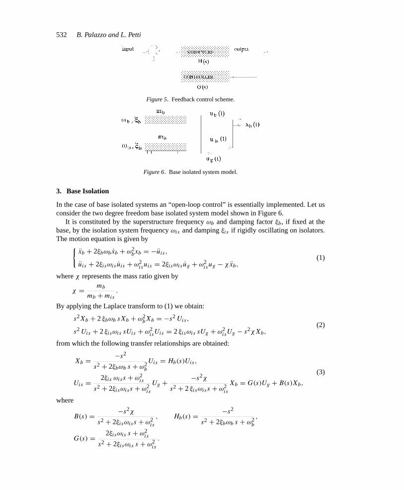
Figure 5. Feedback control scheme.
Figure 6. Base isolated system model.
3. Base Isolation
In the case of base isolated systems an “open-loop control” is essentially implemented. Let usconsider the two degree freedom base isolated system model shown in Figure 6.
It is constituted by the superstructure frequencyωb and damping factorξb, if fixed at thebase, by the isolation system frequencyωis and dampingξis if rigidly oscillating on isolators.The motion equation is given by
xb + 2ξbωbxb + ω2bxb = −uis ,
uis + 2ξisωis uis + ω2isuis = 2ξisωis ug + ω2
isug − χxb,(1)
whereχ represents the mass ratio given by
χ = mb
mb + mis.
By applying the Laplace transform to (1) we obtain:
s2Xb + 2ξbωb sXb + ω2bXb = −s2 Uis,
s2 Uis + 2ξisωis sUis + ω2isUis = 2ξisωis sUg + ω2
isUg − s2χXb,(2)
from which the following transfer relationships are obtained:
Xb = −s2
s2 + 2ξbωb s + ω2b
Uis = Hb(s)Uis,
Uis = 2ξis ωiss + ω2is
s2 + 2ξisωiss + ω2is
Ug + −s2χ
s2 + 2ξisωiss + ω2is
Xb = G(s)Ug + B(s)Xb,
(3)
where
B(s) = −s2χ
s2 + 2ξisωiss + ω2is
, Hb(s) = −s2
s2 + 2ξbωb s + ω2b
,
G(s) = 2ξisωis s + ω2is
s2 + 2ξisωis s + ω2is
.
MECC214.tex; 5/12/1997; 13:55; no v.; p.4
Aspects of Structural Vibration Passive Control533
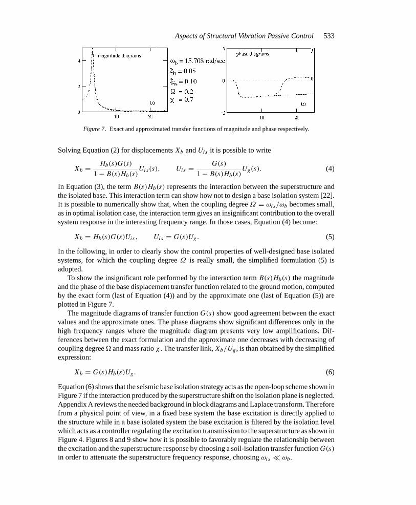
Figure 7. Exact and approximated transfer functions of magnitude and phase respectively.
Solving Equation (2) for displacementsXb andUis it is possible to write
Xb = Hb(s)G(s)
1 − B(s)Hb(s)Uis(s), Uis = G(s)
1 − B(s)Hb(s)Ug(s). (4)
In Equation (3), the termB(s)Hb(s) represents the interaction between the superstructure andthe isolated base. This interaction term can show how not to design a base isolation system [22].It is possible to numerically show that, when the coupling degreeΩ = ωis/ωb becomes small,as in optimal isolation case, the interaction term gives an insignificant contribution to the overallsystem response in the interesting frequency range. In those cases, Equation (4) become:
Xb = Hb(s)G(s)Uis, Uis = G(s)Ug. (5)
In the following, in order to clearly show the control properties of well-designed base isolatedsystems, for which the coupling degreeΩ is really small, the simplified formulation (5) isadopted.
To show the insignificant role performed by the interaction termB(s)Hb(s) the magnitudeand the phase of the base displacement transfer function related to the ground motion, computedby the exact form (last of Equation (4)) and by the approximate one (last of Equation (5)) areplotted in Figure 7.
The magnitude diagrams of transfer functionG(s) show good agreement between the exactvalues and the approximate ones. The phase diagrams show significant differences only in thehigh frequency ranges where the magnitude diagram presents very low amplifications. Dif-ferences between the exact formulation and the approximate one decreases with decreasing ofcoupling degree and mass ratioχ . The transfer link,Xb/Ug, is than obtained by the simplifiedexpression:
Xb = G(s)Hb(s)Ug. (6)
Equation (6) shows that the seismic base isolation strategy acts as the open-loop scheme shown inFigure 7 if the interaction produced by the superstructure shift on the isolation plane is neglected.Appendix A reviews the needed background in block diagrams and Laplace transform. Thereforefrom a physical point of view, in a fixed base system the base excitation is directly applied tothe structure while in a base isolated system the base excitation is filtered by the isolation levelwhich acts as a controller regulating the excitation transmission to the superstructure as shown inFigure 4. Figures 8 and 9 show how it is possible to favorably regulate the relationship betweenthe excitation and the superstructure response by choosing a soil-isolation transfer functionG(s)
in order to attenuate the superstructure frequency response, choosingωis ωb.
MECC214.tex; 5/12/1997; 13:55; no v.; p.5
534 B. Palazzo and L. Petti
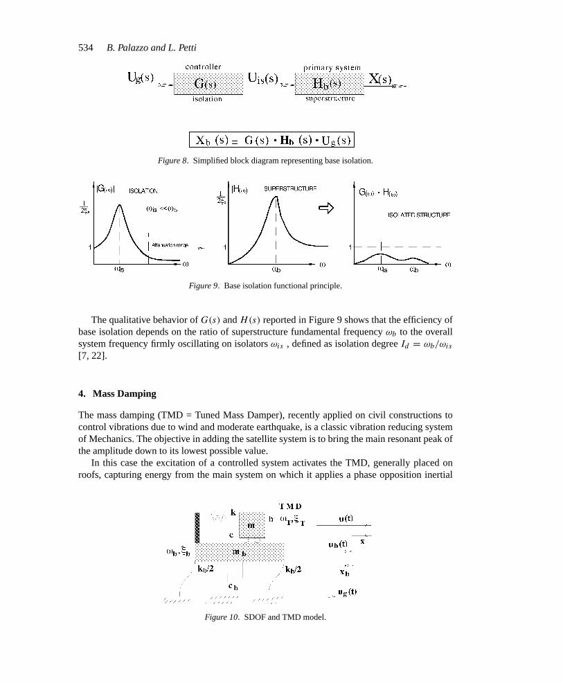
Figure 8. Simplified block diagram representing base isolation.
Figure 9. Base isolation functional principle.
The qualitative behavior ofG(s) andH(s) reported in Figure 9 shows that the efficiency ofbase isolation depends on the ratio of superstructure fundamental frequencyωb to the overallsystem frequency firmly oscillating on isolatorsωis , defined as isolation degreeId = ωb/ωis
[7, 22].
4. Mass Damping
The mass damping (TMD = Tuned Mass Damper), recently applied on civil constructions tocontrol vibrations due to wind and moderate earthquake, is a classic vibration reducing systemof Mechanics. The objective in adding the satellite system is to bring the main resonant peak ofthe amplitude down to its lowest possible value.
In this case the excitation of a controlled system activates the TMD, generally placed onroofs, capturing energy from the main system on which it applies a phase opposition inertial
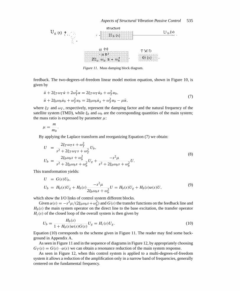
Figure 10. SDOF and TMD model.
MECC214.tex; 5/12/1997; 13:55; no v.; p.6
Aspects of Structural Vibration Passive Control535
Figure 11. Mass damping block diagram.
feedback. The two-degrees-of-freedom linear model motion equation, shown in Figure 10, isgiven by
u + 2ξT ωT u + 2ω2T u = 2ξT ωT ub + ω2
T ub,
u + 2ξbωbub + ω2T ub = 2ξbωbug + ω2
T ub − µu,(7)
whereξT andωT , respectively, represent the damping factor and the natural frequency of thesatellite system (TMD), whileξb andωb are the corresponding quantities of the main system;the mass ratio is expressed by parameterµ:
µ = m
mb.
By applying the Laplace transform and reorganizing Equation (7) we obtain:
U = 2ξT ωT s + ω2T
s2 + 2ξT ωT s + ω2T
Ub,
Ub = 2ξbωbs + ω2b
s2 + 2ξbωbs + ω2b
Ug + −s2µ
s2 + 2ξbωbs + ω2b
U.
(8)
This transformation yields:
U = G(s)Ub,
Ub = Hb(s)Ug + Hb(s)−s2µ
2ξbωbs + ω2b
U = Hb(s)Ug + Hb(s)α(s)U,(9)
which show the I/O links of control system different blocks.Givenα(s) = −s2µ/(2ξbωbs+ω2
b) andG(s) the transfer functions on the feedback line andHb(s) the main system operator on the direct line to the base excitation, the transfer operatorHc(s) of the closed loop of the overall system is then given by
Ub = Hb(s)
1 + Hb(s)α(s)G(s)Ug = Hc(s)Ug. (10)
Equation (10) corresponds to the scheme given in Figure 11. The reader may find some back-ground in Appendix A.
As seen in Figure 11 and in the sequence of diagrams in Figure 12, by appropriately choosingGT (s) = G(s) · α(s) we can obtain a resonance reduction of the main system response.
As seen in Figure 12, when this control system is applied to a multi-degrees-of-freedomsystem it allows a reduction of the amplification only in a narrow band of frequencies, generallycentered on the fundamental frequency.
MECC214.tex; 5/12/1997; 13:55; no v.; p.7
536 B. Palazzo and L. Petti
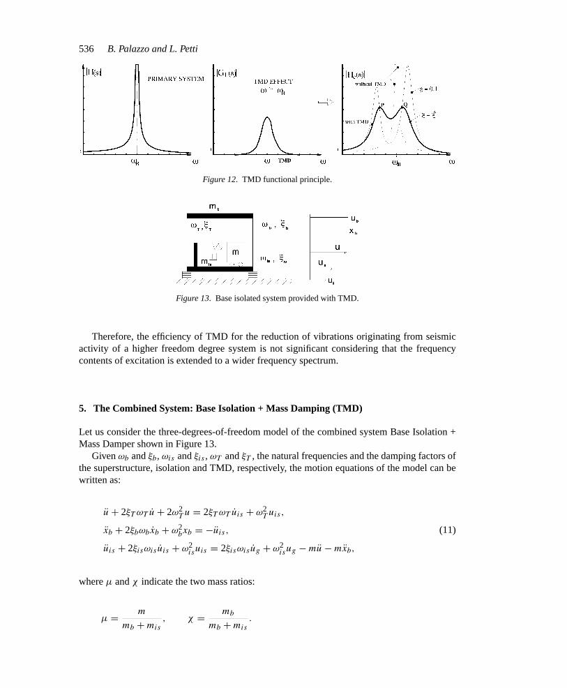
Figure 12. TMD functional principle.
Figure 13. Base isolated system provided with TMD.
Therefore, the efficiency of TMD for the reduction of vibrations originating from seismicactivity of a higher freedom degree system is not significant considering that the frequencycontents of excitation is extended to a wider frequency spectrum.
5. The Combined System: Base Isolation + Mass Damping (TMD)
Let us consider the three-degrees-of-freedom model of the combined system Base Isolation +Mass Damper shown in Figure 13.
Givenωb andξb, ωis andξis , ωT andξT , the natural frequencies and the damping factors ofthe superstructure, isolation and TMD, respectively, the motion equations of the model can bewritten as:
u + 2ξT ωT u + 2ω2T u = 2ξT ωT uis + ω2
T uis,
xb + 2ξbωbxb + ω2bxb = −uis ,
uis + 2ξisωis uis + ω2isuis = 2ξisωis ug + ω2
isug − mu − mxb,
(11)
whereµ andχ indicate the two mass ratios:
µ = m
mb + mis, χ = mb
mb + mis.
MECC214.tex; 5/12/1997; 13:55; no v.; p.8
Aspects of Structural Vibration Passive Control537
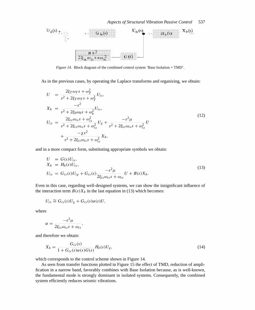
Figure 14. Block diagram of the combined control system ‘Base Isolation + TMD’.
As in the previous cases, by operating the Laplace transforms and organizing, we obtain:
U = 2ξT ωT s + ω2T
s2 + 2ξT ωT s + ω2T
Uis,
Xb = −s2
s2 + 2ξbωbs + ω2b
Uis,
Uis = 2ξisωiss + ω2is
s2 + 2ξisωiss + ω2is
Ug + −s2µ
s2 + 2ξisωiss + ω2is
U
+ −χs2
s2 + 2ξisωiss + ω2is
Xb,
(12)
and in a more compact form, substituting appropriate symbols we obtain:
U = G(s)Uis,
Xb = Hb(s)Uis,
Uis = Gis(s)Uig + Gis(s)−s2µ
2ξisωiss + ωisU + B(s)Xb.
(13)
Even in this case, regarding well-designed systems, we can show the insignificant influence ofthe interaction termB(s)Xb in the last equation in (13) which becomes:
Uis∼= Gis(s)Ug + Gis(s)α(s)U,
where
α = −s2µ
2ξisωiss + ωis,
and therefore we obtain:
Xb = Gis(s)
1 + Gis(s)α(s)G(s)Hb(s)Ug, (14)
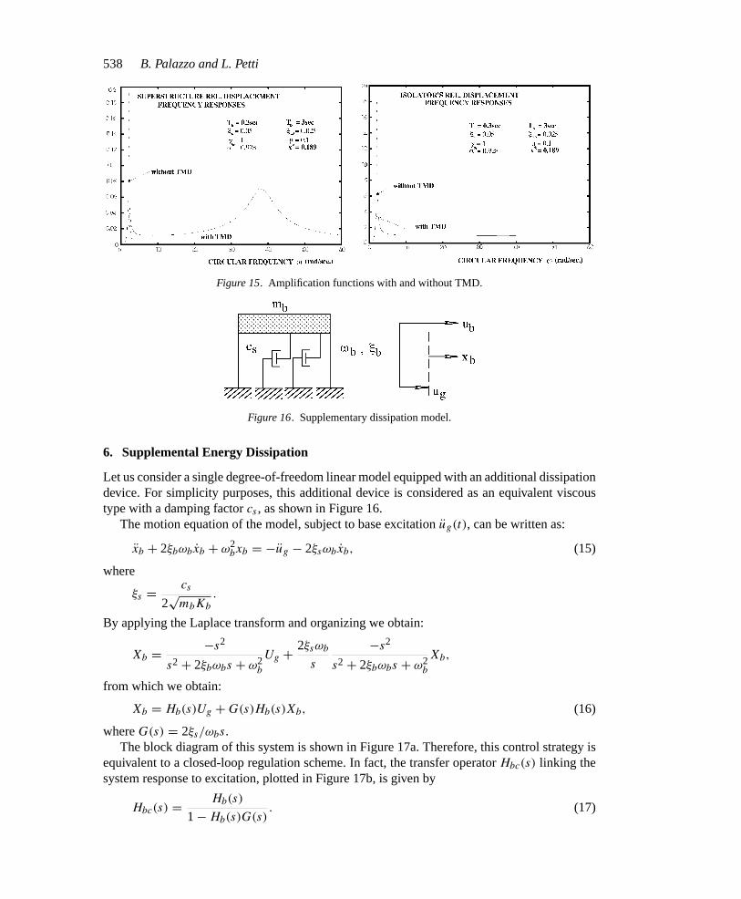
which corresponds to the control scheme shown in Figure 14.As seen from transfer functions plotted in Figure 15 the effect of TMD, reduction of ampli-
fication in a narrow band, favorably combines with Base Isolation because, as is well-known,the fundamental mode is strongly dominant in isolated systems. Consequently, the combinedsystem efficiently reduces seismic vibrations.
MECC214.tex; 5/12/1997; 13:55; no v.; p.9
538 B. Palazzo and L. Petti
Figure 15. Amplification functions with and without TMD.
Figure 16. Supplementary dissipation model.
6. Supplemental Energy Dissipation
Let us consider a single degree-of-freedom linear model equipped with an additional dissipationdevice. For simplicity purposes, this additional device is considered as an equivalent viscoustype with a damping factorcs , as shown in Figure 16.
The motion equation of the model, subject to base excitationug(t), can be written as:
xb + 2ξbωbxb + ω2bxb = −ug − 2ξsωbxb, (15)
where
ξs = cs
2√
mbKb
.
By applying the Laplace transform and organizing we obtain:
Xb = −s2
s2 + 2ξbωbs + ω2b
Ug + 2ξsωb
s
−s2
s2 + 2ξbωbs + ω2b
Xb,
from which we obtain:
Xb = Hb(s)Ug + G(s)Hb(s)Xb, (16)
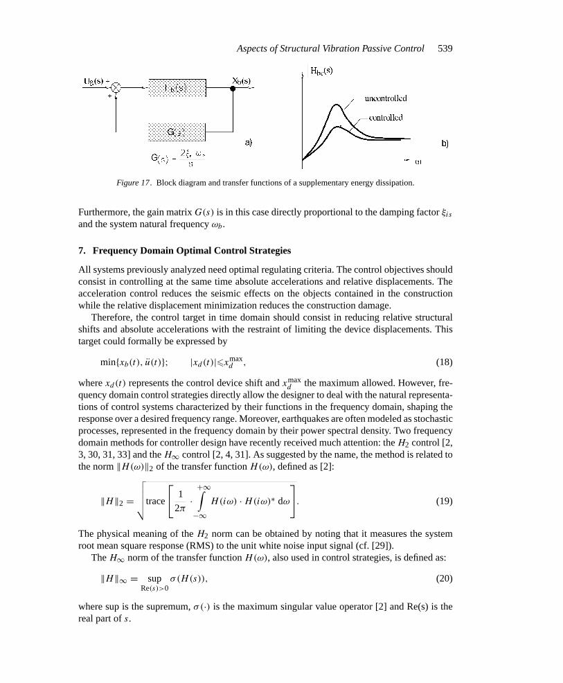
whereG(s) = 2ξs/ωbs.The block diagram of this system is shown in Figure 17a. Therefore, this control strategy is
equivalent to a closed-loop regulation scheme. In fact, the transfer operatorHbc(s) linking thesystem response to excitation, plotted in Figure 17b, is given by
Hbc(s) = Hb(s)
1 − Hb(s)G(s). (17)
MECC214.tex; 5/12/1997; 13:55; no v.; p.10
Aspects of Structural Vibration Passive Control539
Figure 17. Block diagram and transfer functions of a supplementary energy dissipation.
Furthermore, the gain matrixG(s) is in this case directly proportional to the damping factorξis
and the system natural frequencyωb.
7. Frequency Domain Optimal Control Strategies
All systems previously analyzed need optimal regulating criteria. The control objectives shouldconsist in controlling at the same time absolute accelerations and relative displacements. Theacceleration control reduces the seismic effects on the objects contained in the constructionwhile the relative displacement minimization reduces the construction damage.
Therefore, the control target in time domain should consist in reducing relative structuralshifts and absolute accelerations with the restraint of limiting the device displacements. Thistarget could formally be expressed by
minxb(t), u(t); |xd(t)|6 xmaxd , (18)
wherexd(t) represents the control device shift andxmaxd the maximum allowed. However, fre-
quency domain control strategies directly allow the designer to deal with the natural representa-tions of control systems characterized by their functions in the frequency domain, shaping theresponse over a desired frequency range. Moreover, earthquakes are often modeled as stochasticprocesses, represented in the frequency domain by their power spectral density. Two frequencydomain methods for controller design have recently received much attention: theH2 control [2,3, 30, 31, 33] and theH∞ control [2, 4, 31]. As suggested by the name, the method is related tothe norm‖H(ω)‖2 of the transfer functionH(ω), defined as [2]:
‖H‖2 =
√√√√√trace
1
2π·
+∞∫−∞
H(iω) · H(iω)∗ dω
. (19)
The physical meaning of theH2 norm can be obtained by noting that it measures the systemroot mean square response (RMS) to the unit white noise input signal (cf. [29]).
TheH∞ norm of the transfer functionH(ω), also used in control strategies, is defined as:
‖H‖∞ = supRe(s)>0
σ(H(s)), (20)
where sup is the supremum,σ(·) is the maximum singular value operator [2] and Re(s) is thereal part ofs.
MECC214.tex; 5/12/1997; 13:55; no v.; p.11
540 B. Palazzo and L. Petti
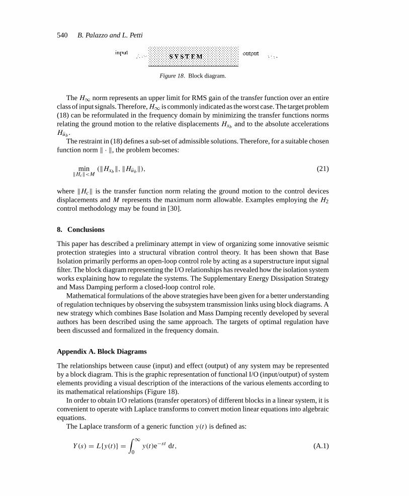
Figure 18. Block diagram.
TheH∞ norm represents an upper limit for RMS gain of the transfer function over an entireclass of input signals. Therefore,H∞ is commonly indicated as the worst case. The target problem(18) can be reformulated in the frequency domain by minimizing the transfer functions normsrelating the ground motion to the relative displacementsHxb
and to the absolute accelerationsHub
.The restraint in (18) defines a sub-set of admissible solutions. Therefore, for a suitable chosen
function norm‖ · ‖, the problem becomes:
min‖Hc‖<M
(‖Hxb‖, ‖Hub
‖), (21)
where‖Hc‖ is the transfer function norm relating the ground motion to the control devicesdisplacements andM represents the maximum norm allowable. Examples employing theH2control methodology may be found in [30].
8. Conclusions
This paper has described a preliminary attempt in view of organizing some innovative seismicprotection strategies into a structural vibration control theory. It has been shown that BaseIsolation primarily performs an open-loop control role by acting as a superstructure input signalfilter. The block diagram representing the I/O relationships has revealed how the isolation systemworks explaining how to regulate the systems. The Supplementary Energy Dissipation Strategyand Mass Damping perform a closed-loop control role.
Mathematical formulations of the above strategies have been given for a better understandingof regulation techniques by observing the subsystem transmission links using block diagrams. Anew strategy which combines Base Isolation and Mass Damping recently developed by severalauthors has been described using the same approach. The targets of optimal regulation havebeen discussed and formalized in the frequency domain.
Appendix A. Block Diagrams
The relationships between cause (input) and effect (output) of any system may be representedby a block diagram. This is the graphic representation of functional I/O (input/output) of systemelements providing a visual description of the interactions of the various elements according toits mathematical relationships (Figure 18).
In order to obtain I/O relations (transfer operators) of different blocks in a linear system, it isconvenient to operate with Laplace transforms to convert motion linear equations into algebraicequations.
The Laplace transform of a generic functiony(t) is defined as:
Y (s) = Ly(t) =∫ ∞
0y(t)e−st dt, (A.1)
MECC214.tex; 5/12/1997; 13:55; no v.; p.12
Aspects of Structural Vibration Passive Control541
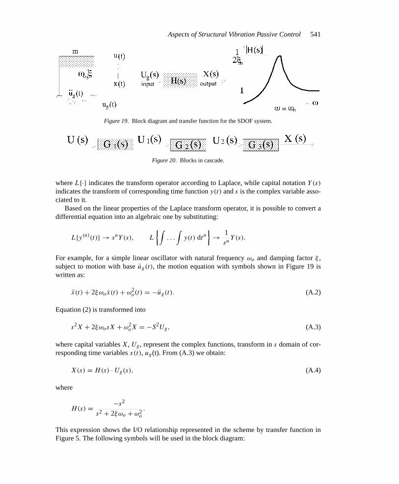
Figure 19. Block diagram and transfer function for the SDOF system.
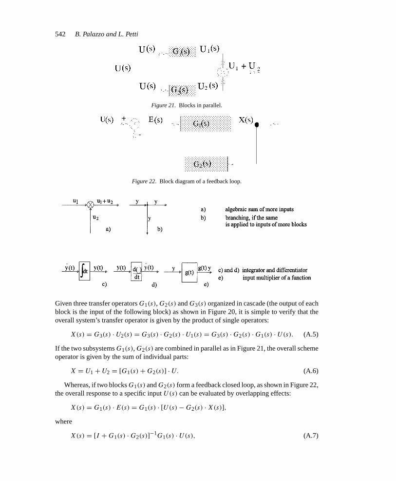
Figure 20. Blocks in cascade.
whereL· indicates the transform operator according to Laplace, while capital notationY (s)
indicates the transform of corresponding time functiony(t) ands is the complex variable asso-ciated to it.
Based on the linear properties of the Laplace transform operator, it is possible to convert adifferential equation into an algebraic one by substituting:
Ly(n)(t) → snY (s), L
∫. . .
∫y(t) dtn
→ 1
snY (s).
For example, for a simple linear oscillator with natural frequencyωo and damping factorξ ,subject to motion with baseug(t), the motion equation with symbols shown in Figure 19 iswritten as:
x(t) + 2ξωox(t) + ω2o(t) = −ug(t). (A.2)
Equation (2) is transformed into
s2X + 2ξωosX + ω2oX = −S2Ug, (A.3)
where capital variablesX, Ug, represent the complex functions, transform ins domain of cor-responding time variablesx(t), ug(t). From (A.3) we obtain:
X(s) = H(s) · Ug(s), (A.4)
where
H(s) = −s2
s2 + 2ξωo + ω2o
.
This expression shows the I/O relationship represented in the scheme by transfer function inFigure 5. The following symbols will be used in the block diagram:
MECC214.tex; 5/12/1997; 13:55; no v.; p.13
542 B. Palazzo and L. Petti
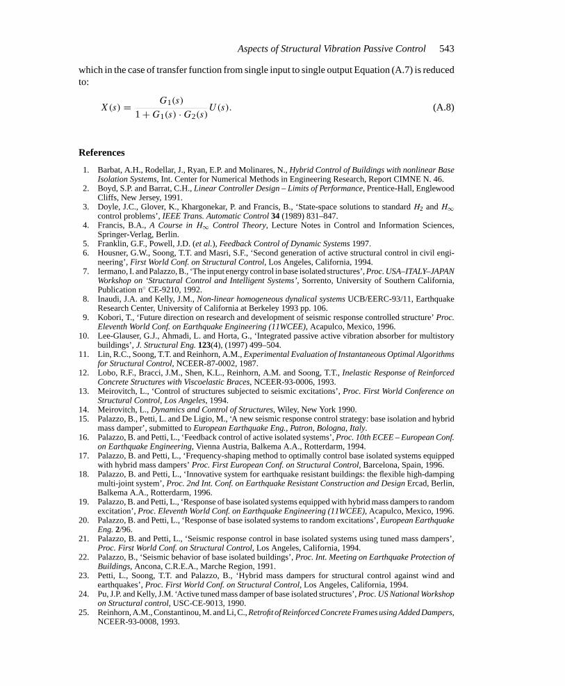
Figure 21. Blocks in parallel.
Figure 22. Block diagram of a feedback loop.
Given three transfer operatorsG1(s), G2(s) andG3(s) organized in cascade (the output of eachblock is the input of the following block) as shown in Figure 20, it is simple to verify that theoverall system’s transfer operator is given by the product of single operators:
X(s) = G3(s) · U2(s) = G3(s) · G2(s) · U1(s) = G3(s) · G2(s) · G1(s) · U(s). (A.5)
If the two subsystemsG1(s), G2(s) are combined in parallel as in Figure 21, the overall schemeoperator is given by the sum of individual parts:
X = U1 + U2 = [G1(s) + G2(s)] · U. (A.6)
Whereas, if two blocksG1(s) andG2(s) form a feedback closed loop, as shown in Figure 22,the overall response to a specific inputU(s) can be evaluated by overlapping effects:
X(s) = G1(s) · E(s) = G1(s) · [U(s) − G2(s) · X(s)],
where
X(s) = [I + G1(s) · G2(s)]−1G1(s) · U(s), (A.7)
MECC214.tex; 5/12/1997; 13:55; no v.; p.14
Aspects of Structural Vibration Passive Control543
which in the case of transfer function from single input to single output Equation (A.7) is reducedto:
X(s) = G1(s)
1 + G1(s) · G2(s)U(s). (A.8)
References
1. Barbat, A.H., Rodellar, J., Ryan, E.P. and Molinares, N.,Hybrid Control of Buildings with nonlinear BaseIsolation Systems, Int. Center for Numerical Methods in Engineering Research, Report CIMNE N. 46.
2. Boyd, S.P. and Barrat, C.H.,Linear Controller Design – Limits of Performance, Prentice-Hall, EnglewoodCliffs, New Jersey, 1991.
3. Doyle, J.C., Glover, K., Khargonekar, P. and Francis, B., ‘State-space solutions to standardH2 andH∞control problems’,IEEE Trans. Automatic Control34 (1989) 831–847.
4. Francis, B.A.,A Course inH∞ Control Theory, Lecture Notes in Control and Information Sciences,Springer-Verlag, Berlin.
5. Franklin, G.F., Powell, J.D. (et al.), Feedback Control of Dynamic Systems1997.6. Housner, G.W., Soong, T.T. and Masri, S.F., ‘Second generation of active structural control in civil engi-
neering’,First World Conf. on Structural Control, Los Angeles, California, 1994.7. Iermano, I. and Palazzo, B., ‘The input energy control in base isolated structures’,Proc. USA–ITALY–JAPAN
Workshop on ‘Structural Control and Intelligent Systems’, Sorrento, University of Southern California,Publication n CE-9210, 1992.
8. Inaudi, J.A. and Kelly, J.M.,Non-linear homogeneous dynalical systemsUCB/EERC-93/11, EarthquakeResearch Center, University of California at Berkeley 1993 pp. 106.
9. Kobori, T., ‘Future direction on research and development of seismic response controlled structure’Proc.Eleventh World Conf. on Earthquake Engineering (11WCEE), Acapulco, Mexico, 1996.
10. Lee-Glauser, G.J., Ahmadi, L. and Horta, G., ‘Integrated passive active vibration absorber for multistorybuildings’,J. Structural Eng.123(4), (1997) 499–504.
11. Lin, R.C., Soong, T.T. and Reinhorn, A.M.,Experimental Evaluation of Instantaneous Optimal Algorithmsfor Structural Control, NCEER-87-0002, 1987.
12. Lobo, R.F., Bracci, J.M., Shen, K.L., Reinhorn, A.M. and Soong, T.T.,Inelastic Response of ReinforcedConcrete Structures with Viscoelastic Braces, NCEER-93-0006, 1993.
13. Meirovitch, L., ‘Control of structures subjected to seismic excitations’,Proc. First World Conference onStructural Control, Los Angeles, 1994.
14. Meirovitch, L.,Dynamics and Control of Structures, Wiley, New York 1990.15. Palazzo, B., Petti, L. and De Ligio, M., ‘A new seismic response control strategy: base isolation and hybrid
mass damper’, submitted toEuropean Earthquake Eng., Patron, Bologna, Italy.16. Palazzo, B. and Petti, L., ‘Feedback control of active isolated systems’,Proc. 10th ECEE – European Conf.
on Earthquake Engineering, Vienna Austria, Balkema A.A., Rotterdarm, 1994.17. Palazzo, B. and Petti, L., ‘Frequency-shaping method to optimally control base isolated systems equipped
with hybrid mass dampers’Proc. First European Conf. on Structural Control, Barcelona, Spain, 1996.18. Palazzo, B. and Petti, L., ‘Innovative system for earthquake resistant buildings: the flexible high-damping
multi-joint system’,Proc. 2nd Int. Conf. on Earthquake Resistant Construction and DesignErcad, Berlin,Balkema A.A., Rotterdarm, 1996.
19. Palazzo, B. and Petti, L., ‘Response of base isolated systems equipped with hybrid mass dampers to randomexcitation’,Proc. Eleventh World Conf. on Earthquake Engineering (11WCEE), Acapulco, Mexico, 1996.
20. Palazzo, B. and Petti, L., ‘Response of base isolated systems to random excitations’,European EarthquakeEng.2/96.
21. Palazzo, B. and Petti, L., ‘Seismic response control in base isolated systems using tuned mass dampers’,Proc. First World Conf. on Structural Control, Los Angeles, California, 1994.
22. Palazzo, B., ‘Seismic behavior of base isolated buildings’,Proc. Int. Meeting on Earthquake Protection ofBuildings, Ancona, C.R.E.A., Marche Region, 1991.
23. Petti, L., Soong, T.T. and Palazzo, B., ‘Hybrid mass dampers for structural control against wind andearthquakes’,Proc. First World Conf. on Structural Control, Los Angeles, California, 1994.
24. Pu, J.P. and Kelly, J.M. ‘Active tuned mass damper of base isolated structures’,Proc. US National Workshopon Structural control, USC-CE-9013, 1990.
25. Reinhorn, A.M., Constantinou, M. and Li, C.,Retrofit of Reinforced Concrete Frames using Added Dampers,NCEER-93-0008, 1993.
MECC214.tex; 5/12/1997; 13:55; no v.; p.15
544 B. Palazzo and L. Petti
26. Reinhorn, A.M., Soong, T.T., Lin, R.C., Yang, Y.P., Fukao, Y., Abe, H. and Nakai, M.,1:4 Scale ModelStudies of Active Tendon Systems and Active Mass Dampers for Aseismic Protection, NCEER-89-0026,1989.
27. Songtao, X., Tobita, J., Kurita, S. and Izumi, M., ‘Mechanics and dynamics of intelligent passive vibrationcontrol system’,J. Eng. Mech.123(4), (1997) 322–327.
28. Soong T.T.,Active Structural Control Theory and Practice, Longman Scientific & Technical Wiley, NewYork, 1990.
29. Soong, T.T. and Grigoriu, M.,Random Vibration of Mechanical and Structural Systems, PTR – Prentice-Hall Englewood Cliffs, New Jersey 07632, 1993.
30. Spencer, B.F. Jr., Suhardjo J. and Sain M.K., ‘Frequency domain optimal control strategies for aseismicprotection’,J. Eng. Mech., ASCE120(1984) 135–159.
31. Suhardjo, J.,Frequency Domain Techniques for Control of Civil Engineering Structures whit Some Robust-ness Considerations, Ph. D. Dissertation, University of Notre Dame, Department of Civil Enginering,1990.
32. Suhardjo, J. Spencer, Jr., B.F. and Sain, M.K., ‘Feedback-feedforward control of structures under seismicexcitation’,Structural Safety8 (1990) 69–89.
33. Suhardjo, J. Spencer, Jr., B.F. and Tamasula, D., ‘Nonlinear control of tension leg platforms’,Proc., Int.Congress on Innovative Long Span Structures, Toronto, Canada, 1991.
34. Yang, J.N. and Li, Z.,Instantaneous Optimal Control with Acceleration and Velocity Feedback, NCEER-90-0016, 1992.
35. Yang, J.N., Li, Z. and Vongchavalitkul, S.,A Generalization of Optimal Control Theory: Linear and Non-linear Structures, Technical Report NCEER-92-0026, NCEER, State University of New York at Buffalo,1992.
36. Yang, J.N. and Danielans, A.,Two Hybrid Control Systems for Building Structures Under Strong Earth-quakes, NCEER-90-0015, 1990.
37. Yang, J.N. and Soong, T.T., ‘Recent advances in active control of civil engineering structures’,J. Eng.Mech., ASCE113(4), 179–185.
38. Yang, J.N., Akbarpour, A. and Ghaemmaghami, P., ‘New optimal control algorithms for structural control’,J. Eng. Mech., ASCE113(9), (1987), 1369–1386.
39. Yao, J.T.P., ‘Concept of structural control’,J. Sructural Div., ASCE98 (ST17), (1972), 1567–1574.
MECC214.tex; 5/12/1997; 13:55; no v.; p.16


