Embed Size (px)
Citation preview

Mechanics of finger-tip electronicsYewang Su, Rui Li, Huanyu Cheng, Ming Ying, Andrew P. Bonifas, Keh-Chih Hwang, John A. Rogers, and
Yonggang Huang
Citation: Journal of Applied Physics 114, 164511 (2013); doi: 10.1063/1.4828476 View online: http://dx.doi.org/10.1063/1.4828476 View Table of Contents: http://scitation.aip.org/content/aip/journal/jap/114/16?ver=pdfcov Published by the AIP Publishing Articles you may be interested in Three-dimensional finite element modeling of the human external ear: Simulation study of the bone conductionocclusion effecta) J. Acoust. Soc. Am. 135, 1433 (2014); 10.1121/1.4864484 Thermal deformation impacts on SOG Fresnel lens performance AIP Conf. Proc. 1477, 89 (2012); 10.1063/1.4753841 Flexible electronics sensors for tactile multiscanning Rev. Sci. Instrum. 80, 084701 (2009); 10.1063/1.3184022 Fingertip communication: A tactile communication device for a glove AIP Conf. Proc. 504, 154 (2000); 10.1063/1.1302473 The Mechanical Sensitivity of Soft Compressible Testing Machines J. Rheol. 33, 455 (1989); 10.1122/1.550022
[This article is copyrighted as indicated in the article. Reuse of AIP content is subject to the terms at: http://scitation.aip.org/termsconditions. Downloaded to ] IP:
202.118.74.210 On: Sun, 22 Jun 2014 08:24:38

Mechanics of finger-tip electronics
Yewang Su,1,2,a) Rui Li,3,a) Huanyu Cheng,2 Ming Ying,4 Andrew P. Bonifas,4
Keh-Chih Hwang,1 John A. Rogers,4,b) and Yonggang Huang2,b)
1Center for Mechanics and Materials, Tsinghua University, Beijing 100084, China2Department of Civil and Environmental Engineering, Department of Mechanical Engineering,Center for Engineering and Health and Skin Disease Research Center, Northwestern University,Evanston, IL 602083State Key Laboratory of Structural Analysis for Industrial Equipment, Department of Engineering Mechanics,Dalian University of Technology, Dalian 116024, China4Department of Materials Science and Engineering, Frederick Seitz Materials Research Laboratory,University of Illinois at Urbana-Champaign, Urbana, IL 61801, USA
(Received 9 September 2013; accepted 14 October 2013; published online 31 October 2013)
Tactile sensors and electrotactile stimulators can provide important links between humans and
virtual environments, through the sensation of touch. Soft materials, such as low modulus silicones,
are attractive as platforms and support matrices for arrays sensors and actuators that laminate
directly onto the fingertips. Analytic models for the mechanics of three dimensional, form-fitting
finger cuffs based on such designs are presented here, along with quantitative validation using the
finite element method. The results indicate that the maximum strains in the silicone and
the embedded devices are inversely proportional to the square root of radius of curvature of the
cuff. These and other findings can be useful in formulating designs for these and related classes of
body-worn, three dimensional devices. VC 2013 AIP Publishing LLC.
[http://dx.doi.org/10.1063/1.4828476]
I. INTRODUCTION
Tactile sensors and electrotactile stimulators mounted
on the fingertips can establish natural connections between a
human subject and a virtual environment. Such devices,
when designed using ultrathin, skin-like properties, offer
the potential to significantly improve interfaces needed
in simulated surgery, therapeutic devices, and robotic
manipulators.1–3 Tactile sensors measure the pressure cre-
ated by physical contact. Together with motion detection and
temperature sensing, such can serve in feedback loops with
electrotactile stimulators that create artificial sensations of
touch, commonly perceived as a vibration or tingling feel-
ing.4,5 Related technologies have been explored for program-
mable braille readers and displays for the visually impaired
as well as for balance control in individuals who suffer from
vestibular disorders.3,6–9
The concepts of stretchable electronics have potential
utility in these contexts.10–14 In particular, they create oppor-
tunities to incorporate tactile sensors and electrotactile stim-
ulators into conformal, skin-like platforms that intimately,
and non-invasively mount on the fingertips. Ying et al.15
reported materials, fabrication strategies and device designs
for ultrathin, stretchable silicon-based electronics and sen-
sors that can be mounted on the inner and outer surfaces of
soft, and elastomeric closed-tube structures for integration
directly on the fingertips. The active components and inter-
connects incorporate advanced mechanics designs, capable
of accommodating large strains induced not only by natural
deformations of the soft tubes during use but also during a
critical step in the fabrication process in which the soft tubes,
specially formed to match the shapes of fingertips, were
flipped inside-out, as illustrated in Fig. 1. Figure 1(a) shows
a finger-tube made of a very soft silicone elastomer (Ecoflex,
Smooth-On, Inc.) in three dimensional forms specifically
matched to those of fingers on a plastic model of the hand.
The fabrication involves pouring a polymer precursor to
Ecoflex onto a model finger multiple times, to create a
conformal sheet with �500 lm thickness. As illustrated in
Fig. 1(b), removing the Ecoflex from the model forms a free
standing finger-tube shown in Fig. 1(c). Ecoflex is an attrac-
tive material for this purpose because it has a low modulus
(�60 kPa) and large fracture strain (�900%). The former
allows soft, intimate contact with the skin; the latter enables
the above “flipping-over” process. Transfer printing delivers
the electrotactile stimulators to the outer surface of the
flipped finger-tube, while pressed into a flattened geometry
(Fig. 1(c)). The flipped finger-tube (with the electrotactile
stimulators on the outer surface) is then slipped onto the fin-
ger model (Fig. 1(d)), and is flipped inside-out, to move the
electrotactile stimulators from the outer to the inner surface
of the tube, as shown in Fig. 1(e).
This “flipping-over” process allows devices initially
mounted on the outer surface of the soft tube to be reversed
to the inner surface, where they can press directly against the
skin when mounted on the fingers. These concepts in multi-
functional fingertip devices were demonstrated with electro-
tactile electrode arrays multiplexed with Si nanomembrane
(NM) diodes, strain sensors based on Si NM gauges, and
tactile sensor arrays that use capacitors with low-modulus,
elastomeric dielectrics.
This paper aims at establishing analytic mechanics mod-
els that determine the maximum strain in the “flipping-over”
a)Y. Su and R. Li contributed equally to this work.b)Authors to whom correspondence should be addressed. Electronic
addresses: [email protected] and [email protected].
0021-8979/2013/114(16)/164511/6/$30.00 VC 2013 AIP Publishing LLC114, 164511-1
JOURNAL OF APPLIED PHYSICS 114, 164511 (2013)
[This article is copyrighted as indicated in the article. Reuse of AIP content is subject to the terms at: http://scitation.aip.org/termsconditions. Downloaded to ] IP:
202.118.74.210 On: Sun, 22 Jun 2014 08:24:38

process. The finite element method (FEM) is used to validate
the results. The predicted shape after the “flipping-over” pro-
cess agrees well with experiments. A scaling law for the
maximum strain in the device is established, which is useful
in optimizing the design of devices to survive the “flipping-
over” process used to fabricate fingertip electronics.
II. AN ANALYTIC MODEL FOR SOFT MATERIALS INFINGERTIP ELECTRONICS
The schematic diagrams in Fig. 2 further illustrate the
“flipping-over” process by tracking points a-h on the inner
and outer surfaces of the finger-tube, where Figures 2(a)–2(e)
correspond to Figures 1(a)–1(e), respectively. Figure 2(a)
shows a soft, ecoflex finger-tube at the natural, stress-free
state, with points a-d on the inner and e-h on the outer surfa-
ces, respectively, of the finger-tube. The soft finger-tube is
flipped over (Fig. 2(b)) to expose the inner surface out and
form a free standing finger-tube shown in Fig. 2(c), where
points a-d and e-h switch to be on the outer and inner surfaces
of the flipped finger-tube, respectively. As to be shown in the
following, the electrotactile stimulators transfer printed to the
outer surface of the flipped finger-tube (while pressed into a
flattened geometry) have very low stiffness. They have little
effect on the “flipping-over” process, and are neglected in the
analytic model. The flipped finger-tube (with the electrotactile
stimulators on the outer surface) is then slipped onto the fin-
ger model (Fig. 2(d)), and points a-d and e-h remain on the
outer and inner surfaces, respectively. The soft finger-tube is
then flipped over again (Fig. 2(e)) such that the electrotactile
stimulators are on the inner surface and the strain gauge
arrays and tactile sensors are transfer printed on the outer sur-
face (while pressed into a flattened geometry).
Figure 3 shows an axisymmetric model for the flipped
finger-tube, where Rfinger is the finger radius, t is the finger-
tube thickness, a and d represent the last section of contact,
and (r,z) are the axisymmetric coordinates. The contact
length L with the finger, the bend radius R of the finger-tube,
and contact length L0 of the “flipped over” part (Fig. 3) are to
be determined. The flipped figure tube consists of four parts,
with the corresponding profile r¼ r(z) for their mid planes
given in the following:
FIG. 1. The “flipping over” process in
the fabrication of finger-tip electronics:
(a) a finger-tube at the natural, stress-
free state on a plastic model of the
hand; (b) a “flipping-over” process
releases the finger-tube from the model
to expose its inner surface; (c) the
flipped finger-tube with the electrotac-
tile stimulators on the outer surface;
(d) the finger-tube slipped onto the fin-
ger model; (e) the “flipping-over” pro-
cess for the second time moves the
electrotactile stimulators from the
outer to the inner surface.
FIG. 2. The schematic diagrams of
the “flipping-over” process by track-
ing points a-h on the inner and outer
surfaces of the finger-tube, where
Figures 2(a)–2(e) correspond to
Figures 1(a)–1(e), respectively.
164511-2 Su et al. J. Appl. Phys. 114, 164511 (2013)
[This article is copyrighted as indicated in the article. Reuse of AIP content is subject to the terms at: http://scitation.aip.org/termsconditions. Downloaded to ] IP:
202.118.74.210 On: Sun, 22 Jun 2014 08:24:38
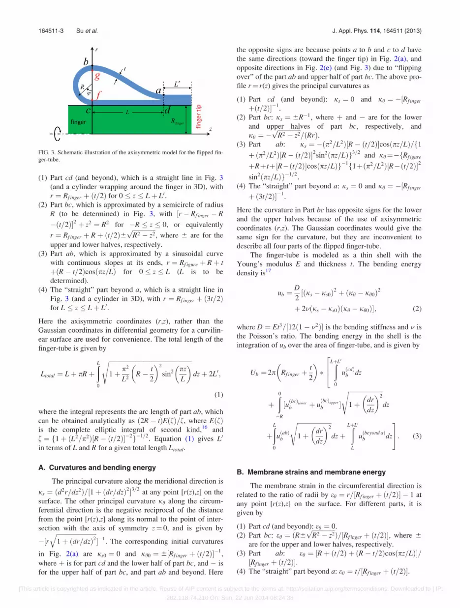
(1) Part cd (and beyond), which is a straight line in Fig. 3
(and a cylinder wrapping around the finger in 3D), with
r ¼ Rf inger þ ðt=2Þ for 0 � z � Lþ L0.(2) Part bc, which is approximated by a semicircle of radius
R (to be determined) in Fig. 3, with ½r � Rf inger � R
�ðt=2Þ�2 þ z2 ¼ R2 for �R � z � 0, or equivalently
r ¼ Rf inger þ Rþ ðt=2Þ6ffiffiffiffiffiffiffiffiffiffiffiffiffiffiffiR2 � z2p
, where 6 are for the
upper and lower halves, respectively.
(3) Part ab, which is approximated by a sinusoidal curve
with continuous slopes at its ends, r ¼ Rf igure þ Rþ tþðR� t=2Þcosðpz=LÞ for 0 � z � L (L is to be
determined).
(4) The “straight” part beyond a, which is a straight line in
Fig. 3 (and a cylinder in 3D), with r ¼ Rf inger þ ð3t=2Þfor L � z � Lþ L0.
Here the axisymmetric coordinates (r,z), rather than the
Gaussian coordinates in differential geometry for a curvilin-
ear surface are used for convenience. The total length of the
finger-tube is given by
Ltotal ¼ Lþ pRþðL0
ffiffiffiffiffiffiffiffiffiffiffiffiffiffiffiffiffiffiffiffiffiffiffiffiffiffiffiffiffiffiffiffiffiffiffiffiffiffiffiffiffiffiffiffiffiffiffiffiffiffiffiffiffi1þ p2
L2R� t
2
� �2
sin2 pz
L
� �sdzþ 2L0;
(1)
where the integral represents the arc length of part ab, which
can be obtained analytically as ð2R� tÞEðfÞ=f, where EðfÞis the complete elliptic integral of second kind,16 and
f ¼ f1þ ðL2=p2Þ½R� ðt=2Þ��2g�1=2. Equation (1) gives L0
in terms of L and R for a given total length Ltotal.
A. Curvatures and bending energy
The principal curvature along the meridional direction is
js ¼ ðd2r=dz2Þ=½1þ ðdr=dzÞ2�3=2at any point [r(z),z] on the
surface. The other principal curvature jh along the circum-
ferential direction is the negative reciprocal of the distance
from the point [r(z),z] along its normal to the point of inter-
section with the axis of symmetry z¼ 0, and is given by
�½rffiffiffiffiffiffiffiffiffiffiffiffiffiffiffiffiffiffiffiffiffiffiffiffiffiffi1þ ðdr=dzÞ2
q��1
. The corresponding initial curvatures
in Fig. 2(a) are js0 ¼ 0 and jh0 ¼ 6½Rf inger þ ðt=2Þ��1,
where þ is for part cd and the lower half of part bc, and � is
for the upper half of part bc, and part ab and beyond. Here
the opposite signs are because points a to b and c to d have
the same directions (toward the finger tip) in Fig. 2(a), and
opposite directions in Fig. 2(e) (and Fig. 3) due to “flipping
over” of the part ab and upper half of part bc. The above pro-
file r¼ r(z) gives the principal curvatures as
(1) Part cd (and beyond): js ¼ 0 and jh ¼ �½Rf inger
þðt=2Þ��1.
(2) Part bc: js ¼ 6R�1, where þ and � are for the lower
and upper halves of part bc, respectively, and
jh ¼ �ffiffiffiffiffiffiffiffiffiffiffiffiffiffiffiR2 � z2p
=ðRrÞ.(3) Part ab: js ¼ �ðp2=L2Þ½R� ðt=2Þ�cosðpz=LÞ=f1þðp2=L2Þ½R� ðt=2Þ�2sin2ðpz=LÞg3=2
and jh¼�fRf igure
þRþ tþ½R�ðt=2Þ�cosðpz=LÞg�1f1þðp2=L2Þ½R�ðt=2Þ�2
sin2ðpz=LÞg�1=2.
(4) The “straight” part beyond a: js ¼ 0 and jh ¼ �½Rf inger
þð3t=2Þ��1.
Here the curvature in Part bc has opposite signs for the lower
and the upper halves because of the use of axisymmetric
coordinates (r,z). The Gaussian coordinates would give the
same sign for the curvature, but they are inconvenient to
describe all four parts of the flipped finger-tube.
The finger-tube is modeled as a thin shell with the
Young’s modulus E and thickness t. The bending energy
density is17
ub ¼D
2½ðjs � js0Þ2 þ ðjh � jh0Þ2
þ 2�ðjs � js0Þðjh � jh0Þ�; (2)
where D ¼ Et3=½12ð1� �2Þ� is the bending stiffness and � is
the Poisson’s ratio. The bending energy in the shell is the
integration of ub over the area of finger-tube, and is given by
Ub ¼ 2p Rf inger þt
2
� ��
ðLþL0
0
uðcdÞb dz
264
þð0�R
½uðbcÞlower
b þ uðbcÞupper
b �
ffiffiffiffiffiffiffiffiffiffiffiffiffiffiffiffiffiffiffiffiffiffi1þ dr
dz
� �2s
dz
þðL0
uðabÞb
ffiffiffiffiffiffiffiffiffiffiffiffiffiffiffiffiffiffiffiffiffiffi1þ dr
dz
� �2s
dzþðLþL0
L
uðbeyond aÞb dz
35: (3)
B. Membrane strains and membrane energy
The membrane strain in the circumferential direction is
related to the ratio of radii by eh ¼ r=½Rf inger þ ðt=2Þ� � 1 at
any point [r(z),z] on the surface. For different parts, it is
given by
(1) Part cd (and beyond): eh ¼ 0.
(2) Part bc: eh ¼ ðR6ffiffiffiffiffiffiffiffiffiffiffiffiffiffiffiR2 � z2p
Þ=½Rf inger þ ðt=2Þ�, where 6
are for the upper and lower halves, respectively.
(3) Part ab: eh ¼ ½Rþ ðt=2Þ þ ðR� t=2Þcosðpz=LÞ�=½Rf inger þ ðt=2Þ�.
(4) The “straight” part beyond a: eh ¼ t=½Rf inger þ ðt=2Þ�.
FIG. 3. Schematic illustration of the axisymmetric model for the flipped fin-
ger-tube.
164511-3 Su et al. J. Appl. Phys. 114, 164511 (2013)
[This article is copyrighted as indicated in the article. Reuse of AIP content is subject to the terms at: http://scitation.aip.org/termsconditions. Downloaded to ] IP:
202.118.74.210 On: Sun, 22 Jun 2014 08:24:38
As shown in the Appendix, the membrane strain along the
meridional direction is es ¼ ��eh.
The membrane energy density is17
um ¼Et
2ð1� �2Þ ðe2s þ e2
h þ 2�esehÞ: (4)
The membrane energy in the shell is the integration of um
over the area of finger-tube, and is given by
Um ¼ 2p Rf inger þt
2
� ��
ðLþL0
0
uðcdÞm dz
264
þð0�R
½uðbcÞlowerm þ u
ðbcÞupperm �
ffiffiffiffiffiffiffiffiffiffiffiffiffiffiffiffiffiffiffiffiffiffi1þ dr
dz
� �2s
dz
þðL0
uðabÞm
ffiffiffiffiffiffiffiffiffiffiffiffiffiffiffiffiffiffiffiffiffiffi1þ dr
dz
� �2s
dzþðLþL0
L
uðbeyond aÞm dz
35: (5)
C. Energy minimization
The total energy Utotal, which consists of bending and
membrane energy, depends on L and R since L0 is obtained
(in terms of L and R) from Eq. (1) for a fixed total length.
They are determined by minimizing the total energy, i.e.,
@Utotal
@R¼ @Utotal
@L¼ 0; (6)
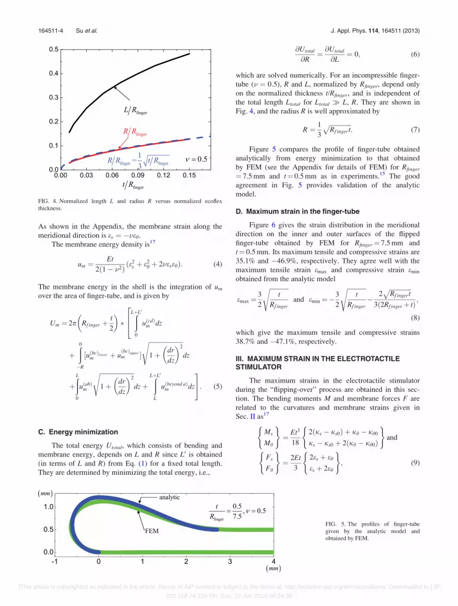
which are solved numerically. For an incompressible finger-
tube (� ¼ 0:5), R and L, normalized by Rfinger, depend only
on the normalized thickness t/Rfinger, and is independent of
the total length Ltotal for Ltotal � L, R. They are shown in
Fig. 4, and the radius R is well approximated by
R ¼ 1
3
ffiffiffiffiffiffiffiffiffiffiffiffiffiffiRf ingert
p: (7)
Figure 5 compares the profile of finger-tube obtained
analytically from energy minimization to that obtained
by FEM (see the Appendix for details of FEM) for Rfinger
¼ 7.5 mm and t¼ 0.5 mm as in experiments.15 The good
agreement in Fig. 5 provides validation of the analytic
model.
D. Maximum strain in the finger-tube
Figure 6 gives the strain distribution in the meridional
direction on the inner and outer surfaces of the flipped
finger-tube obtained by FEM for Rfinger¼ 7.5 mm and
t¼ 0.5 mm. Its maximum tensile and compressive strains are
35.1% and �46.9%, respectively. They agree well with the
maximum tensile strain emax and compressive strain emin
obtained from the analytic model
emax¼3
2
ffiffiffiffiffiffiffiffiffiffiffiffit
Rf inger
sand emin ¼�
3
2
ffiffiffiffiffiffiffiffiffiffiffiffit
Rf inger
s�
2ffiffiffiffiffiffiffiffiffiffiffiffiffiffiRf ingert
p3ð2Rf ingerþ tÞ ;
(8)
which give the maximum tensile and compressive strains
38.7% and �47.1%, respectively.
III. MAXIMUM STRAIN IN THE ELECTROTACTILESTIMULATOR
The maximum strains in the electrotactile stimulator
during the “flipping-over” process are obtained in this sec-
tion. The bending moments M and membrane forces F are
related to the curvatures and membrane strains given in
Sec. II as17
Ms
Mh
( )¼ Et3
18
2ðjs � js0Þ þ jh � jh0
js � js0 þ 2ðjh � jh0Þ
( )and
Fs
Fh
( )¼ 2Et
3
2es þ eh
es þ 2eh
( ); (9)
FIG. 4. Normalized length L and radius R versus normalized ecoflex
thickness.
FIG. 5. The profiles of finger-tube
given by the analytic model and
obtained by FEM.
164511-4 Su et al. J. Appl. Phys. 114, 164511 (2013)
[This article is copyrighted as indicated in the article. Reuse of AIP content is subject to the terms at: http://scitation.aip.org/termsconditions. Downloaded to ] IP:
202.118.74.210 On: Sun, 22 Jun 2014 08:24:38

where the Poisson’s ratio for the incompressible finger-tube
is � ¼ 0:5. The maximum bending moment and membrane
forces are reached in section bg (Fig. 3), and are given by
Ms;max ¼ 2Mh;max � �Et2
3
ffiffiffiffiffiffiffiffiffiffiffiffit
Rf inger
s; Fs;max � 0 and
Fh;max �2
3Et
ffiffiffiffiffiffiffiffiffiffiffiffit
Rf inger
s(10)
for t Rf inger as in the experiment.15
Figure 7 shows two representative cross sections of the
electrotactile stimulator on the finger-tube,15 which consist
of multiple layers of Au, Si, and PI. Let n denote the total
number of layers, with i¼ 1 being the finger-tube at the bot-
tom. The Young’s modulus, Poisson’s ratio and thickness of
the ith layers are Ei, �i, and ti, respectively, and E1¼E,
�1 ¼ 0:5 and t1¼ t. The coordinate y has its origin at the bot-
tom (Fig. 7). The strains in the electrotactile stimulator can
be generally written as
�es ¼ �jsyþ �es0 and �eh ¼ �jhyþ �eh0; (11)
where �js and �jh are curvatures of the electrotactile stimu-
lator, and �es0 and �eh0 are the strains at the bottom (y¼ 0).
The stresses in the ith layer are given by �rs ¼ ð�es þ �i�ehÞEi=ð1� �2
i Þ and �rh ¼ ð�i�es þ �ehÞEi=ð1� �2i Þ, which give
the membrane forces on the electrotactile stimulator as
Fs;max
Fh;max
( )¼ðPn
i¼1
ti
0
�rs
�rh
( )dy ¼
K11 K12
K12 K11
( )�es0
�eh0
( )
þK13 K14
K14 K13
( )�js
�jh
( ); (12)
where the maximum membrane forces in section bg
given in Eq. (10) are used, K11 ¼Pn
i¼1 Eiti=ð1� �2i Þ, K12
¼Pn
i¼1 �iEiti=ð1� �2i Þ, K13 ¼
Pni¼1 Eiti½ð
Pij¼1 tjÞ � ðti=2Þ�=
ð1� �2i Þ and K14 ¼
Pni¼1 �iEiti½ð
Pij¼1 tjÞ � ðti=2Þ�=ð1� �2
i Þ.Similarly, the bending moments around the bottom (y¼0) in
section bg can be obtained from the stresses by
Ms;max þ1
2Fs;maxt
Mh;max þ1
2Fh;maxt
8>><>>:
9>>=>>; ¼
ðPn
i¼1
ti
0
�rs
�rh
� �ydy
¼ K13 K14
K14 K13
� ��es0
�eh0
� �
þ K33 K34
K34 K33
� ��js
�jh
� �; (13)
where K33¼Pn
i¼1 Eiti½ðPi
j¼1 tjÞ2� ti
Pij¼1 tjþðt2i =3Þ�=ð1��2
i Þand K34¼
Pni¼1�iEiti½ð
Pij¼1 tjÞ2� ti
Pij¼1 tjþðt2
i =3Þ�=ð1��2i Þ.
The solution of �es0, �eh0, �js and �jh is obtained from Eqs. (12)
and (13) as
�es0
�eh0
�js
�jh
8>><>>:
9>>=>>; ¼
Et
6
ffiffiffiffiffiffiffiffiffiffiffiffit
Rf inger
s K11 K12 K13 K14
K12 K11 K14 K13
K13 K14 K33 K34
K14 K13 K34 K33
8>><>>:
9>>=>>;�1
0
4
�2tt
8>><>>:
9>>=>>;:
(14)
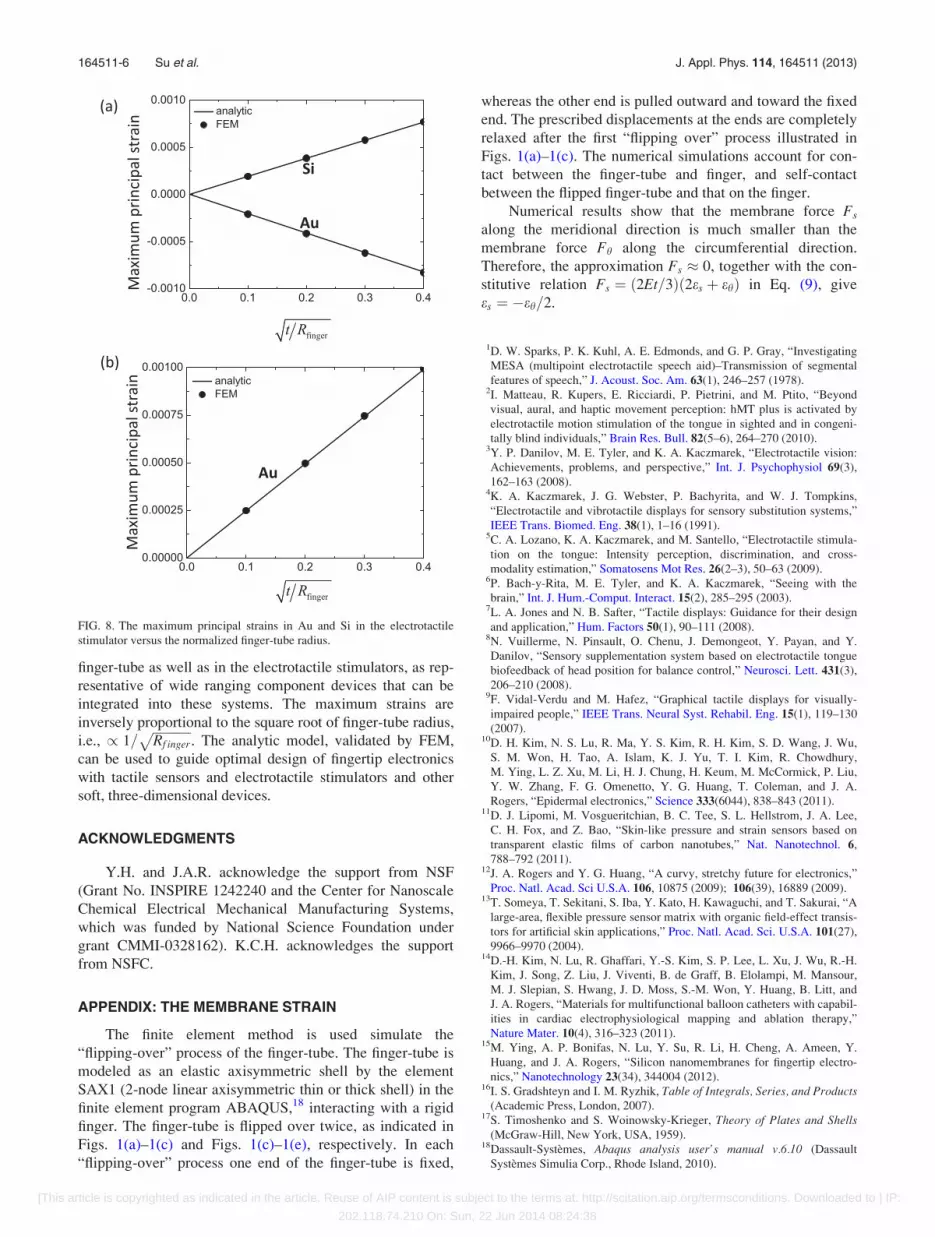
The maximum strains in the electrotactile stimulator can
then be obtained from Eq. (11), and they are linearly propor-
tional to 1=ffiffiffiffiffiffiffiffiffiffiffiffiRf inger
p. Figures 8(a) and 8(b) show the maxi-
mum principal strain in Au and Si versusffiffiffiffiffiffiffiffiffiffiffiffiffiffiffiffit=Rf inger
pfor the
two representative cross sections of the electrotactile stimu-
lator in Fig. 7. The Young’s moduli and Poisson’s ratios are
78 GPa and 0.44 for Au, 168 GPa and 0.28 for Si, 2.5 GPa
and 0.34 for PI, and 60 KPa and 0.5 for Ecoflex, respectively.
The numerical results obtained by FEM are also shown, and
they agree well with the analytic solution in Eq. (14).
IV. CONCLUDING REMARKS
Due to their extreme deformability, soft materials, such
as the classes of silicones described here, are ideal candidates
for the platforms and supporting matrices of devices such as
finger-tip electronics (e.g., tactile sensors and electrotactile
stimulators). The process fabrication, and sometimes use,
involves very large levels of mechanical deformation. The
analytic models presented here give maximum strains in theFIG. 7. Two representative cross sections of the electrotactile stimulator on
the finger-tube.
FIG. 6. The strain distribution in the
meridional direction on the inner and
outer surfaces of the flipped finger-
tube obtained by FEM.
164511-5 Su et al. J. Appl. Phys. 114, 164511 (2013)
[This article is copyrighted as indicated in the article. Reuse of AIP content is subject to the terms at: http://scitation.aip.org/termsconditions. Downloaded to ] IP:
202.118.74.210 On: Sun, 22 Jun 2014 08:24:38
finger-tube as well as in the electrotactile stimulators, as rep-
resentative of wide ranging component devices that can be
integrated into these systems. The maximum strains are
inversely proportional to the square root of finger-tube radius,
i.e., / 1=ffiffiffiffiffiffiffiffiffiffiffiffiRf inger
p. The analytic model, validated by FEM,
can be used to guide optimal design of fingertip electronics
with tactile sensors and electrotactile stimulators and other
soft, three-dimensional devices.
ACKNOWLEDGMENTS
Y.H. and J.A.R. acknowledge the support from NSF
(Grant No. INSPIRE 1242240 and the Center for Nanoscale
Chemical Electrical Mechanical Manufacturing Systems,
which was funded by National Science Foundation under
grant CMMI-0328162). K.C.H. acknowledges the support
from NSFC.
APPENDIX: THE MEMBRANE STRAIN
The finite element method is used simulate the
“flipping-over” process of the finger-tube. The finger-tube is
modeled as an elastic axisymmetric shell by the element
SAX1 (2-node linear axisymmetric thin or thick shell) in the
finite element program ABAQUS,18 interacting with a rigid
finger. The finger-tube is flipped over twice, as indicated in
Figs. 1(a)–1(c) and Figs. 1(c)–1(e), respectively. In each
“flipping-over” process one end of the finger-tube is fixed,
whereas the other end is pulled outward and toward the fixed
end. The prescribed displacements at the ends are completely
relaxed after the first “flipping over” process illustrated in
Figs. 1(a)–1(c). The numerical simulations account for con-
tact between the finger-tube and finger, and self-contact
between the flipped finger-tube and that on the finger.
Numerical results show that the membrane force Fs
along the meridional direction is much smaller than the
membrane force Fh along the circumferential direction.
Therefore, the approximation Fs � 0, together with the con-
stitutive relation Fs ¼ ð2Et=3Þð2es þ ehÞ in Eq. (9), give
es ¼ �eh=2.
1D. W. Sparks, P. K. Kuhl, A. E. Edmonds, and G. P. Gray, “Investigating
MESA (multipoint electrotactile speech aid)–Transmission of segmental
features of speech,” J. Acoust. Soc. Am. 63(1), 246–257 (1978).2I. Matteau, R. Kupers, E. Ricciardi, P. Pietrini, and M. Ptito, “Beyond
visual, aural, and haptic movement perception: hMT plus is activated by
electrotactile motion stimulation of the tongue in sighted and in congeni-
tally blind individuals,” Brain Res. Bull. 82(5–6), 264–270 (2010).3Y. P. Danilov, M. E. Tyler, and K. A. Kaczmarek, “Electrotactile vision:
Achievements, problems, and perspective,” Int. J. Psychophysiol 69(3),
162–163 (2008).4K. A. Kaczmarek, J. G. Webster, P. Bachyrita, and W. J. Tompkins,
“Electrotactile and vibrotactile displays for sensory substitution systems,”
IEEE Trans. Biomed. Eng. 38(1), 1–16 (1991).5C. A. Lozano, K. A. Kaczmarek, and M. Santello, “Electrotactile stimula-
tion on the tongue: Intensity perception, discrimination, and cross-
modality estimation,” Somatosens Mot Res. 26(2–3), 50–63 (2009).6P. Bach-y-Rita, M. E. Tyler, and K. A. Kaczmarek, “Seeing with the
brain,” Int. J. Hum.-Comput. Interact. 15(2), 285–295 (2003).7L. A. Jones and N. B. Safter, “Tactile displays: Guidance for their design
and application,” Hum. Factors 50(1), 90–111 (2008).8N. Vuillerme, N. Pinsault, O. Chenu, J. Demongeot, Y. Payan, and Y.
Danilov, “Sensory supplementation system based on electrotactile tongue
biofeedback of head position for balance control,” Neurosci. Lett. 431(3),
206–210 (2008).9F. Vidal-Verdu and M. Hafez, “Graphical tactile displays for visually-
impaired people,” IEEE Trans. Neural Syst. Rehabil. Eng. 15(1), 119–130
(2007).10D. H. Kim, N. S. Lu, R. Ma, Y. S. Kim, R. H. Kim, S. D. Wang, J. Wu,
S. M. Won, H. Tao, A. Islam, K. J. Yu, T. I. Kim, R. Chowdhury,
M. Ying, L. Z. Xu, M. Li, H. J. Chung, H. Keum, M. McCormick, P. Liu,
Y. W. Zhang, F. G. Omenetto, Y. G. Huang, T. Coleman, and J. A.
Rogers, “Epidermal electronics,” Science 333(6044), 838–843 (2011).11D. J. Lipomi, M. Vosgueritchian, B. C. Tee, S. L. Hellstrom, J. A. Lee,
C. H. Fox, and Z. Bao, “Skin-like pressure and strain sensors based on
transparent elastic films of carbon nanotubes,” Nat. Nanotechnol. 6,
788–792 (2011).12J. A. Rogers and Y. G. Huang, “A curvy, stretchy future for electronics,”
Proc. Natl. Acad. Sci U.S.A. 106, 10875 (2009); 106(39), 16889 (2009).13T. Someya, T. Sekitani, S. Iba, Y. Kato, H. Kawaguchi, and T. Sakurai, “A
large-area, flexible pressure sensor matrix with organic field-effect transis-
tors for artificial skin applications,” Proc. Natl. Acad. Sci. U.S.A. 101(27),
9966–9970 (2004).14D.-H. Kim, N. Lu, R. Ghaffari, Y.-S. Kim, S. P. Lee, L. Xu, J. Wu, R.-H.
Kim, J. Song, Z. Liu, J. Viventi, B. de Graff, B. Elolampi, M. Mansour,
M. J. Slepian, S. Hwang, J. D. Moss, S.-M. Won, Y. Huang, B. Litt, and
J. A. Rogers, “Materials for multifunctional balloon catheters with capabil-
ities in cardiac electrophysiological mapping and ablation therapy,”
Nature Mater. 10(4), 316–323 (2011).15M. Ying, A. P. Bonifas, N. Lu, Y. Su, R. Li, H. Cheng, A. Ameen, Y.
Huang, and J. A. Rogers, “Silicon nanomembranes for fingertip electro-
nics,” Nanotechnology 23(34), 344004 (2012).16I. S. Gradshteyn and I. M. Ryzhik, Table of Integrals, Series, and Products
(Academic Press, London, 2007).17S. Timoshenko and S. Woinowsky-Krieger, Theory of Plates and Shells
(McGraw-Hill, New York, USA, 1959).18Dassault-Systemes, Abaqus analysis user’s manual v.6.10 (Dassault
Systemes Simulia Corp., Rhode Island, 2010).
FIG. 8. The maximum principal strains in Au and Si in the electrotactile
stimulator versus the normalized finger-tube radius.
164511-6 Su et al. J. Appl. Phys. 114, 164511 (2013)
[This article is copyrighted as indicated in the article. Reuse of AIP content is subject to the terms at: http://scitation.aip.org/termsconditions. Downloaded to ] IP:
202.118.74.210 On: Sun, 22 Jun 2014 08:24:38