Embed Size (px)
Citation preview
Requirement Models
Enterprise Architect
User Guide Series
Author: Sparx Systems
Date: 30/06/2017
Version: 1.0
CREATED WITH
Table of Contents
Requirement Models 4Introduction 8Meet the Requirement Tools 10
Specification Manager 11Relationship Matrix 13Requirement Properties 15Requirements Diagram 17Scenario Builder 19Baseline Tool 21Traceability Window 23Dashboard Diagrams 25The MDG Link for DOORS Add-In 27
Requirements Overview 28What are Requirements 31Levels and Types of Requirements 32Characteristics of Good Requirements 36Business Context for Requirements 41Requirements Diagram 45Creating and Viewing Requirements 50
Requirements Development 55Elicitation 57
User Observations 58Stakeholder Workshops 59Creating Requirements 65
External and Internal Requirements 66Using the Specification Manager 68Requirement Properties 69Color Coded Requirements Status 72Displaying Properties on a Diagram 74Import Requirements 77Move Requirement External 82
Recording Requirement Types 84Analysis 85
Models Used to Document Requirements 86Requirements Naming and Numbering 88Model Assumptions and Constraints 91Create a Glossary 93Create a Domain Model 94Model the User Interface 96Prioritize the Requirements 97
Specification 99Specify Quality Attributes 100Requirement Sources 102Elaborate the Requirements 105
Validation 107Derive Test Cases 108Review Requirements 109
Requirements Management 111Tracing Requirements 112Tracking Requirements 115Managing Changing Requirements 117Impact Analysis of Changes 119Requirement Volatility 121Requirements Reuse 123
Requirements Documentation 125Project Glossary 126Software Requirement Specification 127Use Case Report 128Data Dictionary 130
Requirement Processes and Standards 131Agile Requirements Processes 132Business Analysis Body of Knowledge (BABOK) 134UML Requirements 139SysML Requirements 140
MDG Link for DOORS 141Getting Started 143Create a Link to a DOORS Module 144Export Requirements to DOORS 148Import Requirements from DOORS 153
Additional Requirements Tools 158Auto Names and Counters 159Import and Export Spreadsheets 161Requirements Checklist 162Documentation 164Glossary 166Auditing 168Element Discussions 170Maintenance Items 171Team Reviews 172
User Guide - Requirement Models 30 June, 2017
Requirement Models
The field of requirements engineering is one of the most critical disciplines in the solution development lifecycle and hasa documented impact on the success of projects.
Requirements Development
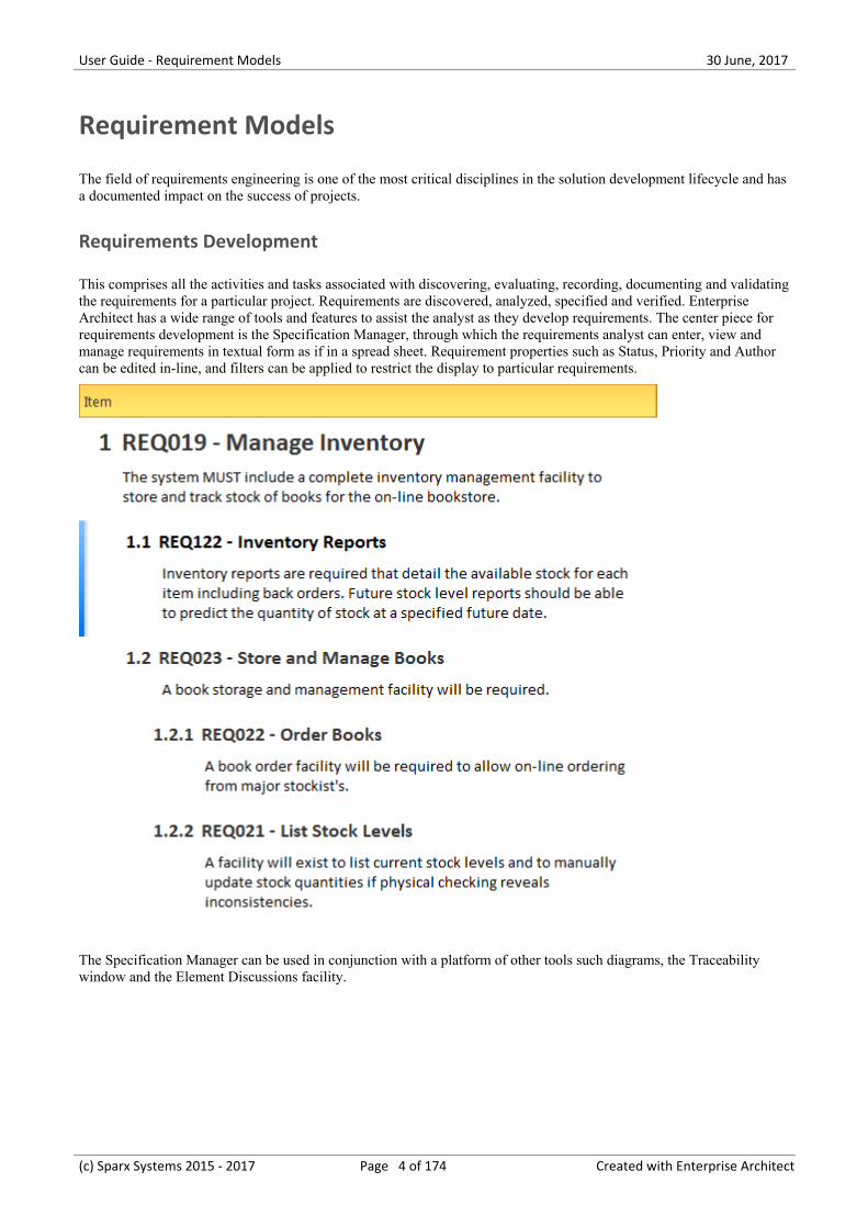
This comprises all the activities and tasks associated with discovering, evaluating, recording, documenting and validatingthe requirements for a particular project. Requirements are discovered, analyzed, specified and verified. EnterpriseArchitect has a wide range of tools and features to assist the analyst as they develop requirements. The center piece forrequirements development is the Specification Manager, through which the requirements analyst can enter, view andmanage requirements in textual form as if in a spread sheet. Requirement properties such as Status, Priority and Authorcan be edited in-line, and filters can be applied to restrict the display to particular requirements.
The Specification Manager can be used in conjunction with a platform of other tools such diagrams, the Traceabilitywindow and the Element Discussions facility.
(c) Sparx Systems 2015 - 2017 Page 4 of 174 Created with Enterprise Architect
User Guide - Requirement Models 30 June, 2017
REQ020 - Receive Books
REQ019 - Manage Inventory
REQ022 - Order Books
REQ023 - Store and Manage Books
REQ027 - Add Books
REQ021 - List Stock Levels
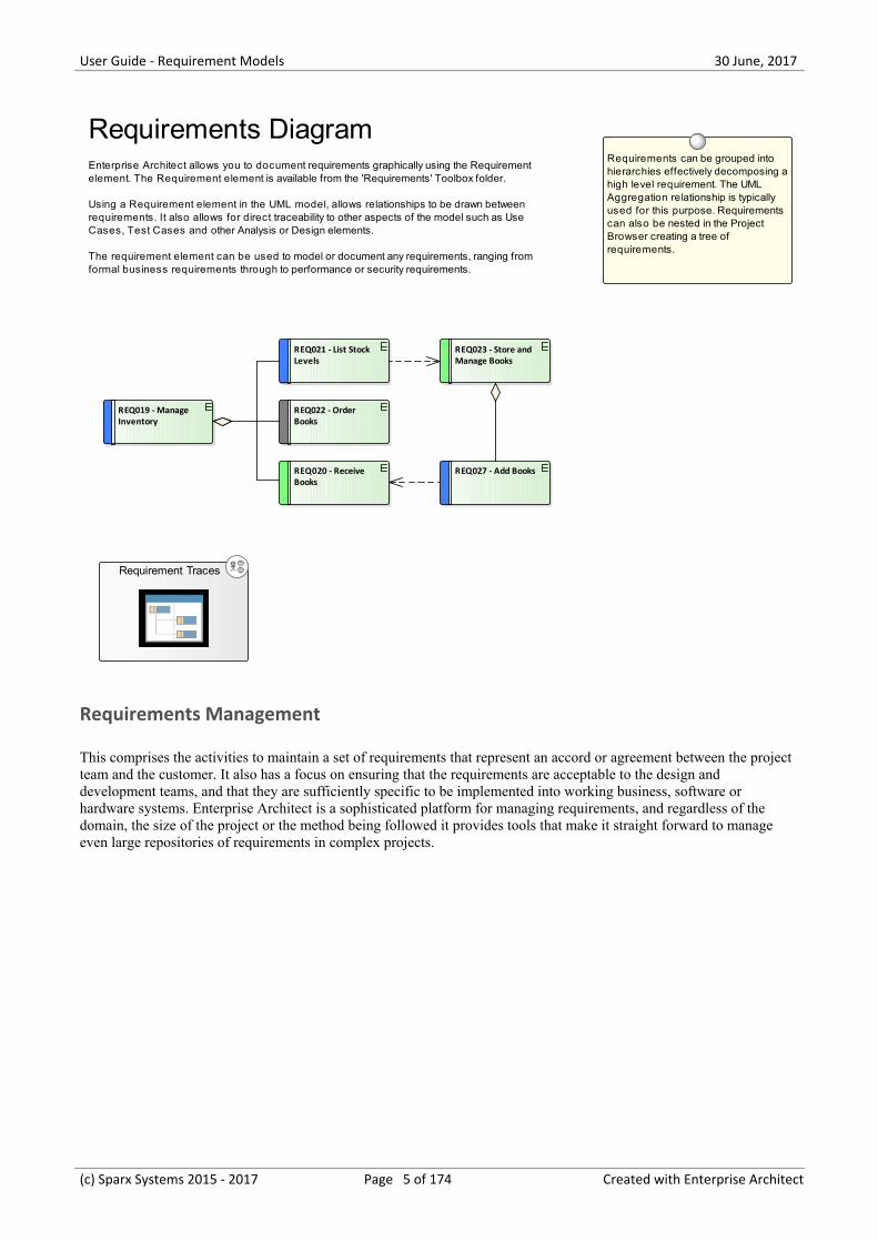
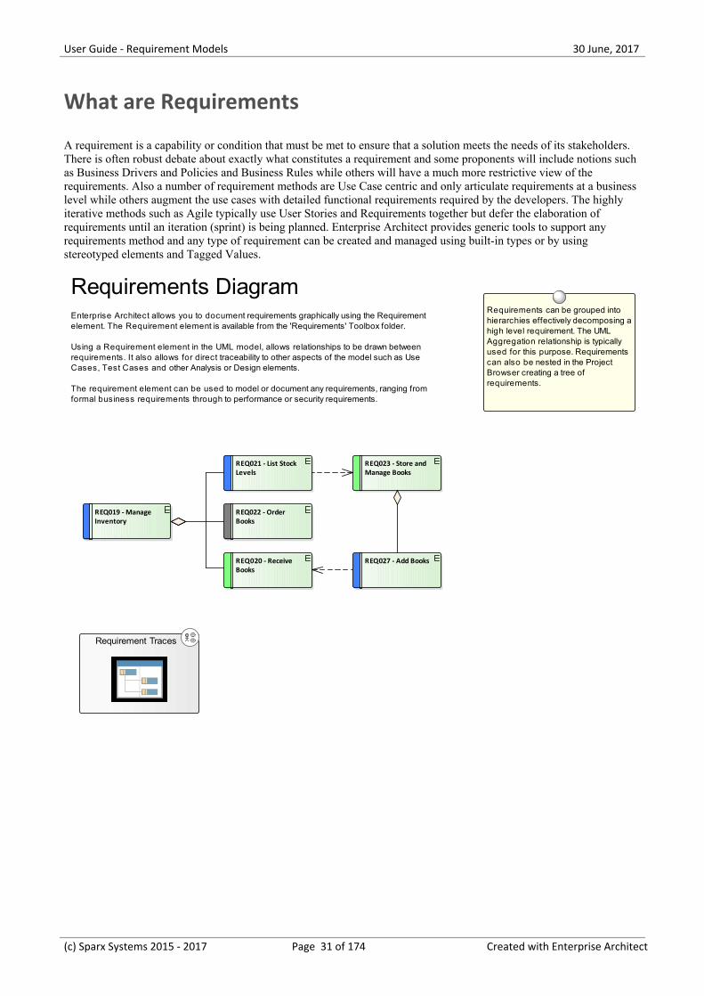
Requirements can be grouped into hierarchies effectively decomposing a high level requirement. The UML Aggregation relationship is typically used for this purpose. Requirements can also be nested in the Project Browser creating a tree of requirements.
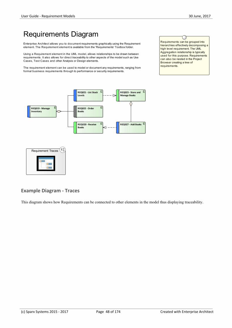
Requirements DiagramEnterprise Architect allows you to document requirements graphically using the Requirement element. The Requirement element is available from the 'Requirements' Toolbox folder.
Using a Requirement element in the UML model, allows relationships to be drawn between requirements. It also allows for direct traceability to other aspects of the model such as Use Cases, Test Cases and other Analysis or Design elements.
The requirement element can be used to model or document any requirements, ranging from formal business requirements through to performance or security requirements.
Requirement Traces
Requirements Management
This comprises the activities to maintain a set of requirements that represent an accord or agreement between the projectteam and the customer. It also has a focus on ensuring that the requirements are acceptable to the design anddevelopment teams, and that they are sufficiently specific to be implemented into working business, software orhardware systems. Enterprise Architect is a sophisticated platform for managing requirements, and regardless of thedomain, the size of the project or the method being followed it provides tools that make it straight forward to manageeven large repositories of requirements in complex projects.
(c) Sparx Systems 2015 - 2017 Page 5 of 174 Created with Enterprise Architect
User Guide - Requirement Models 30 June, 2017
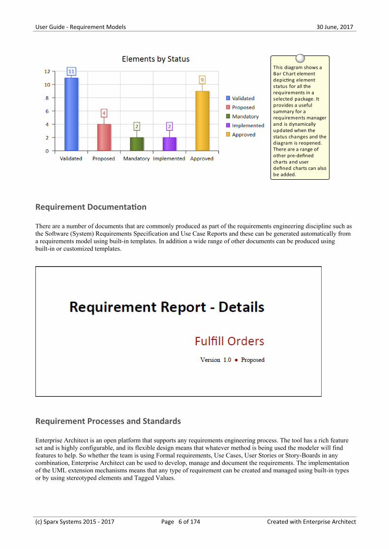
This diagram shows a Bar Chart element depicting element status for all the requirements in a selected package. It provides a useful summary for a requirements manager and is dynamically updated when the status changes and the diagram is reopened. There are a range of other pre-defined charts and user defined charts can also be added.
Requirement Documentation
There are a number of documents that are commonly produced as part of the requirements engineering discipline such asthe Software (System) Requirements Specification and Use Case Reports and these can be generated automatically froma requirements model using built-in templates. In addition a wide range of other documents can be produced usingbuilt-in or customized templates.
Requirement Processes and Standards
Enterprise Architect is an open platform that supports any requirements engineering process. The tool has a rich featureset and is highly configurable, and its flexible design means that whatever method is being used the modeler will findfeatures to help. So whether the team is using Formal requirements, Use Cases, User Stories or Story-Boards in anycombination, Enterprise Architect can be used to develop, manage and document the requirements. The implementationof the UML extension mechanisms means that any type of requirement can be created and managed using built-in typesor by using stereotyped elements and Tagged Values.
(c) Sparx Systems 2015 - 2017 Page 6 of 174 Created with Enterprise Architect
User Guide - Requirement Models 30 June, 2017
«User Story»As a Stock Control Manager I want to be able to list stock levels for a
selection of titles.
REQ021 - List Stock Levels
notesA facility will exist to list current stocklevels and to manually update stockquantities if physical checking revealsinconsistencies.
Stock Control Manager
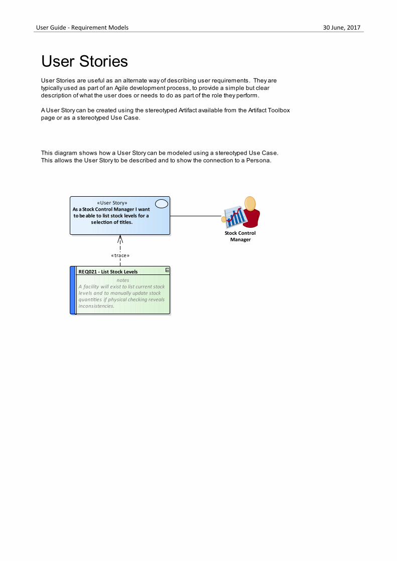
User StoriesUser Stories are useful as an alternate way of describing user requirements. They are typically used as part of an Agile development process, to provide a simple but clear description of what the user does or needs to do as part of the role they perform.
A User Story can be created using the stereotyped Artifact available from the Artifact Toolbox page or as a stereotyped Use Case.
This diagram shows how a User Story can be modeled using a stereotyped Use Case.This allows the User Story to be described and to show the connection to a Persona.
«trace»
(c) Sparx Systems 2015 - 2017 Page 7 of 174 Created with Enterprise Architect
User Guide - Requirement Models 30 June, 2017
Introduction
Requirements engineering is one of the most important disciplines in the system lifecycle and when done well it will setthe foundation for a successful project or program of work, ultimately ensuring that great value is delivered to the usersand other stakeholders. Enterprise Architect is a sophisticated and intuitive platform for developing and managingrequirements from modeling stakeholders and visions, business cases, business drivers and capabilities to detailedfunctional and non-functional requirements. Requirements can be prioritized, traced and tracked, and changes can berecorded, baselined, versioned and audited. Analysts can work together in a collaborative platform with role basedSecurity, Discussions, Team Reviews, Model Mail and a range of other tools to encourage best practice and productivity.
How it will help you
Readers will typically come to the topic of requirements engineering with some existing knowledge or experience even ifit is something that has been learnt in lectures or by on the job training, or perhaps by using a different tool. The readerswill benefit by understanding the product features and the tools that are available to develop and manage requirements inEnterprise Architect and this will enable them to be more productive as an individual and also as a member of a team.
Who will benefit
Anyone involved in the development or management of requirements whether at a strategic level, a business value levelor a system development level will benefit from reading this information. This includes a wide range of roles includingStrategic Thinkers, Business and Requirements Analysts, Enterprise, Business, Technical and Solution Architects,Project and Program Managers, Developers, Test Desingers and User Experience Designers.
What you will learn
This topic will teach you how to use the powerful features of Enterprise Architect to develop and manage Requirements,to create documentation and to work collaboratively as a member of a team using a formal or informal system life cycleprocess or standard.
Overview of the Documentation
Meet the RequirementsTools
Lists the key tools that are used for developing and managing requirements,including a picture of the tool in action, where to find the tool, how to use it andhow to become proficient in using the tool. There are a large number of additionaluseful tools that are described in the last topic, Additional Requirements Tools.
Requirements Overview Puts requirements engineering in context by defining what requirements are, thedifferent levels of requirements, characteristics of good requirements and thebusiness context of requirements. The information also includes the concept of aRequirements diagram that readers coming from text based tools might not befamiliar with, and how to create and view requirements in Enterprise Architect.
RequirementsDevelopment
Discusses the activities and tasks associated with discovering, evaluating,recording, documenting and validating the requirements. The topic is convenientlydivided into four sub-topics - Elicitation, Analysis, Specification and Validation -and identifies a wide range of features that can be used, from Mind Mappingdiagrams for recording information in elicitation workshops, to the Specification
(c) Sparx Systems 2015 - 2017 Page 8 of 174 Created with Enterprise Architect
User Guide - Requirement Models 30 June, 2017
Manager for creating requirements, to Test Cases for validating them.
RequirementsManagement
Describes the activities needed to maintain a set of requirements that represent anaccord or agreement between the project team and the customer. It includescomposing hierarchies of requirements, tracing other elements back torequirements, and tracking the properties of requirements including Status, Priority,and Difficulty. It also describes managing changing requirements, Volatility andassessing the impact of changing requirements.
RequirementsDocumentation
Describes how formal and informal Requirements Documentation can be generateddirectly from Enterprise Architect using a series of predefined and extensibletemplates. This includes Glossaries, Data Dictionaries, Use Case Reports andDocuments such as a System Requirements Specification.
Requirement Processesand Standards
Puts the usage of Enterprise Architect's requirements tools in the context of systemand requirements processes and standards. The topic describes how flexible thetools are and how they can be used with any process or standard.
Additional RequirementsTools
Lists a series of additional tools that can be used for requirements engineering,including a picture of the tool in action, where to find the tool, how to use it andhow to become proficient in using the tool. There are a number of key tools that arethe most important tools for requirement engineering that are described in the firsttopic entitled Meet the Requirements Tools.
(c) Sparx Systems 2015 - 2017 Page 9 of 174 Created with Enterprise Architect
User Guide - Requirement Models 30 June, 2017
Meet the Requirement Tools
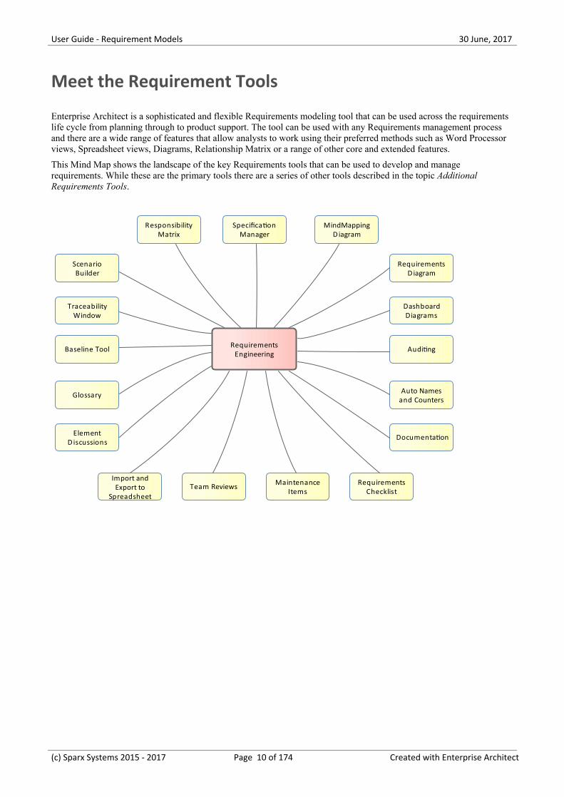
Enterprise Architect is a sophisticated and flexible Requirements modeling tool that can be used across the requirementslife cycle from planning through to product support. The tool can be used with any Requirements management processand there are a wide range of features that allow analysts to work using their preferred methods such as Word Processorviews, Spreadsheet views, Diagrams, Relationship Matrix or a range of other core and extended features.
This Mind Map shows the landscape of the key Requirements tools that can be used to develop and managerequirements. While these are the primary tools there are a series of other tools described in the topic AdditionalRequirements Tools.
RequirementsEngineering
MindMappingDiagram
RequirementsD iagram
SpecificationManager
ResponsibilityMatrix
ScenarioBuilder
TraceabilityWindow
Baseline Tool
DashboardDiagrams
Auditing
Auto Namesand Counters
DocumentationElementDiscussions
Glossary
Import andExport to
Spreadsheet
MaintenanceItems
RequirementsChecklist
Team Reviews
(c) Sparx Systems 2015 - 2017 Page 10 of 174 Created with Enterprise Architect
User Guide - Requirement Models 30 June, 2017
Specification Manager
Getting to Know the Specification Manager
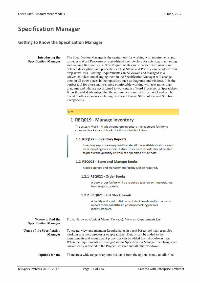
Introducing theSpecification Manager
The Specification Manager is the central tool for working with requirements andprovides a Word Processor or Spreadsheet like interface for entering, maintainingand viewing Requirements. New Requirements can be created with names anddetailed descriptions and properties such as Status and Priority can be added fromdrop-down lists. Existing Requirements can be viewed and managed in aconvenient view and changing them in the Specification Manager will changethem in all other places in the repository such as diagrams and windows. It is theperfect tool for those analysts more comfortable working with text rather thandiagrams and who are accustomed to working in a Word Processor or Spreadsheet.It has the added advantage that the requirements are part of a model and can betraced to other elements including Business Drivers, Stakeholders and SolutionComponents.
Where to find theSpecification Manager
Project Browser Context Menu (Package): View as Requirements List
Usage of the SpecificationManager
To create, view and maintain Requirements in a text based tool that resemblesworking in a word processor or spreadsheet. Details can be added to therequirements and requirement properties can be added from drop-down lists.When the requirements are changed in this Specification Manager the changes areconveniently reflected in the Project Browser and all other windows.
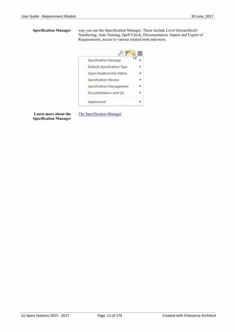
Options for the There are a wide range of options available from the options menu, to tailor the
(c) Sparx Systems 2015 - 2017 Page 11 of 174 Created with Enterprise Architect
User Guide - Requirement Models 30 June, 2017
Specification Manager way you use the Specification Manager. These include Level (hierarchical)Numbering, Auto Naming, Spell Check, Documentation, Import and Export ofRequirements, access to various related tools and more.
Learn more about theSpecification Manager
The Specification Manager
(c) Sparx Systems 2015 - 2017 Page 12 of 174 Created with Enterprise Architect
User Guide - Requirement Models 30 June, 2017
Relationship Matrix
Getting to Know the Relationship Matrix
Introducing theRelationship Matrix
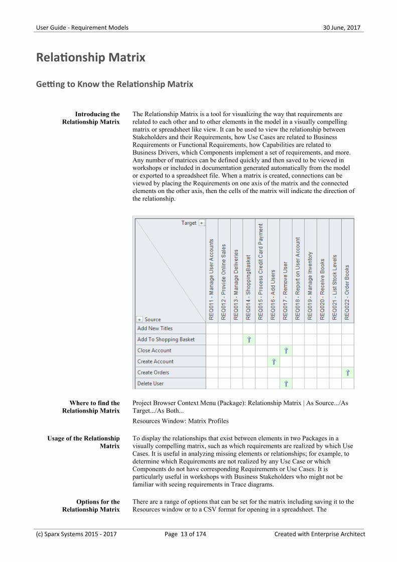
The Relationship Matrix is a tool for visualizing the way that requirements arerelated to each other and to other elements in the model in a visually compellingmatrix or spreadsheet like view. It can be used to view the relationship betweenStakeholders and their Requirements, how Use Cases are related to BusinessRequirements or Functional Requirements, how Capabilities are related toBusiness Drivers, which Components implement a set of requirements, and more.Any number of matrices can be defined quickly and then saved to be viewed inworkshops or included in documentation generated automatically from the modelor exported to a spreadsheet file. When a matrix is created, connections can beviewed by placing the Requirements on one axis of the matrix and the connectedelements on the other axis, then the cells of the matrix will indicate the direction ofthe relationship.
Where to find theRelationship Matrix
Project Browser Context Menu (Package): Relationship Matrix | As Source.../AsTarget.../As Both...
Resources Window: Matrix Profiles
Usage of the RelationshipMatrix
To display the relationships that exist between elements in two Packages in avisually compelling matrix, such as which requirements are realized by which UseCases. It is useful in analyzing missing elements or relationships; for example, todetermine which Requirements are not realized by any Use Case or whichComponents do not have corresponding Requirements or Use Cases. It isparticularly useful in workshops with Business Stakeholders who might not befamiliar with seeing requirements in Trace diagrams.
Options for theRelationship Matrix
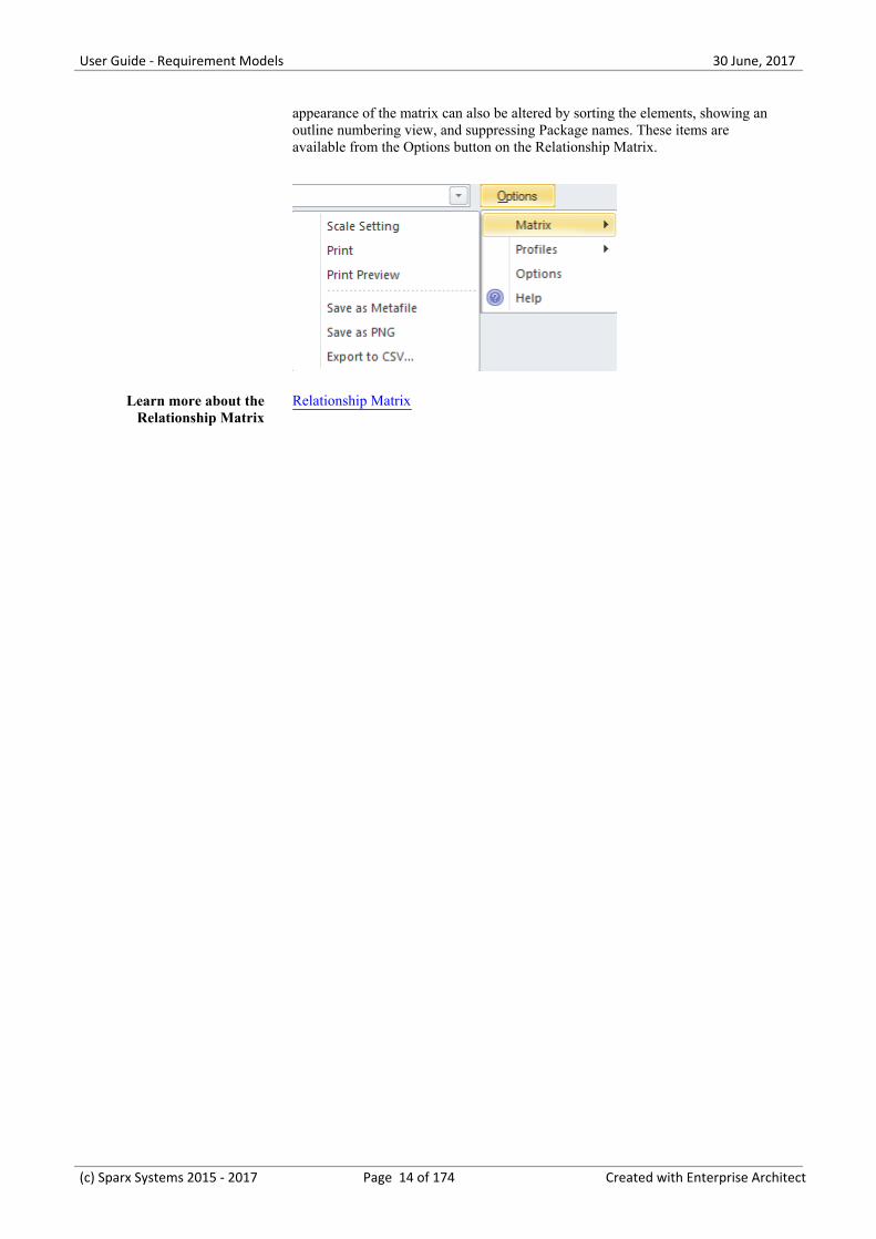
There are a range of options that can be set for the matrix including saving it to theResources window or to a CSV format for opening in a spreadsheet. The
(c) Sparx Systems 2015 - 2017 Page 13 of 174 Created with Enterprise Architect
User Guide - Requirement Models 30 June, 2017
appearance of the matrix can also be altered by sorting the elements, showing anoutline numbering view, and suppressing Package names. These items areavailable from the Options button on the Relationship Matrix.
Learn more about theRelationship Matrix
Relationship Matrix
(c) Sparx Systems 2015 - 2017 Page 14 of 174 Created with Enterprise Architect
User Guide - Requirement Models 30 June, 2017
Requirement Properties
Getting to Know the Requirement Properties
Introducing RequirementProperties
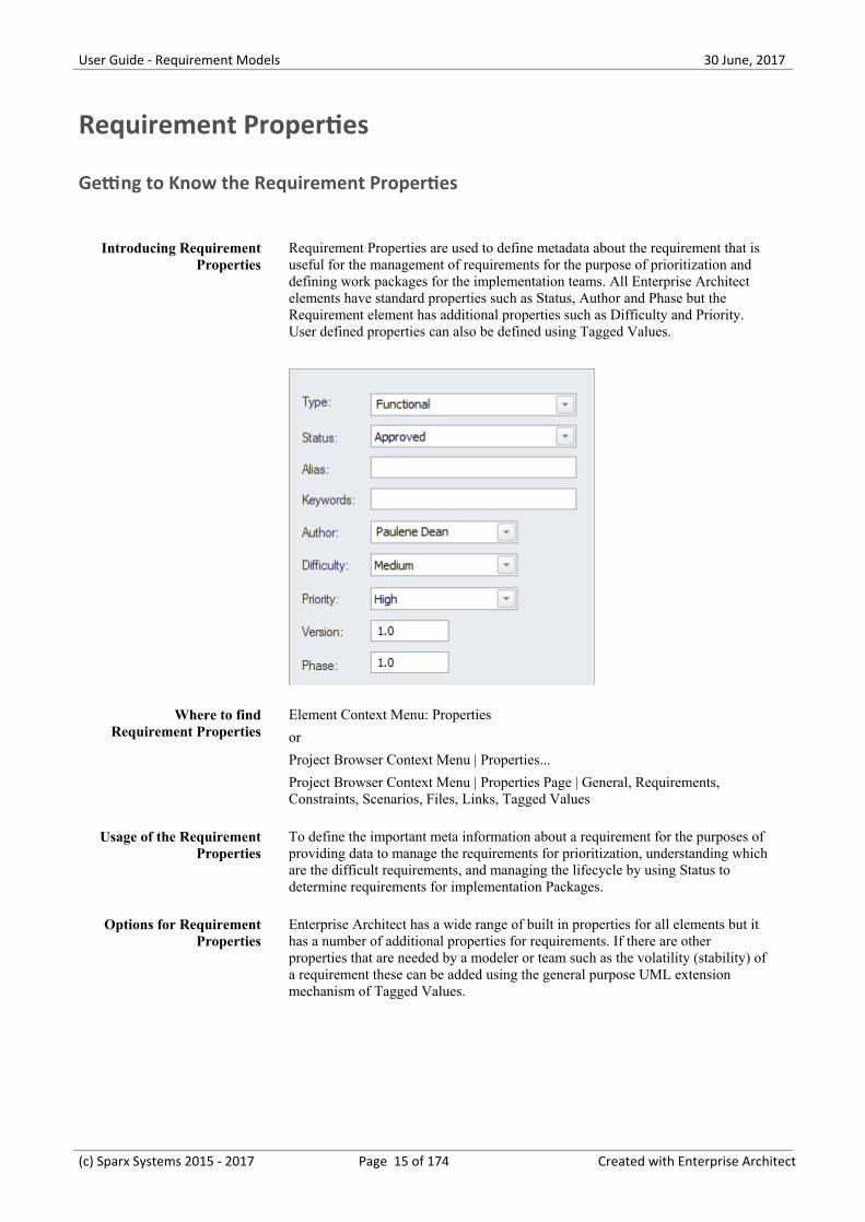
Requirement Properties are used to define metadata about the requirement that isuseful for the management of requirements for the purpose of prioritization anddefining work packages for the implementation teams. All Enterprise Architectelements have standard properties such as Status, Author and Phase but theRequirement element has additional properties such as Difficulty and Priority.User defined properties can also be defined using Tagged Values.
Where to findRequirement Properties
Element Context Menu: Properties
or
Project Browser Context Menu | Properties...
Project Browser Context Menu | Properties Page | General, Requirements,Constraints, Scenarios, Files, Links, Tagged Values
Usage of the RequirementProperties
To define the important meta information about a requirement for the purposes ofproviding data to manage the requirements for prioritization, understanding whichare the difficult requirements, and managing the lifecycle by using Status todetermine requirements for implementation Packages.
Options for RequirementProperties
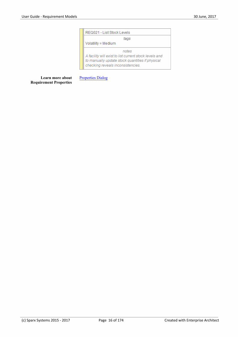
Enterprise Architect has a wide range of built in properties for all elements but ithas a number of additional properties for requirements. If there are otherproperties that are needed by a modeler or team such as the volatility (stability) ofa requirement these can be added using the general purpose UML extensionmechanism of Tagged Values.
(c) Sparx Systems 2015 - 2017 Page 15 of 174 Created with Enterprise Architect
User Guide - Requirement Models 30 June, 2017
Learn more aboutRequirement Properties
Properties Dialog
(c) Sparx Systems 2015 - 2017 Page 16 of 174 Created with Enterprise Architect
User Guide - Requirement Models 30 June, 2017
Requirements Diagram
Getting to Know the Requirements Diagram
Introducing theRequirements Diagram
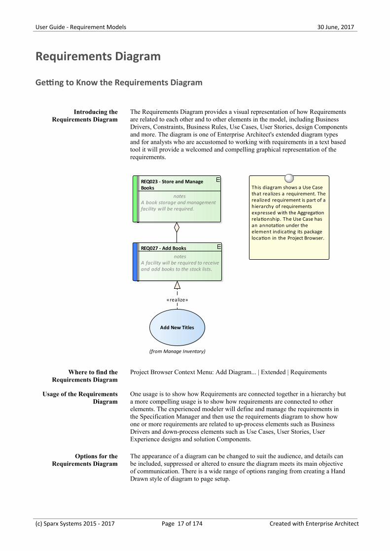
The Requirements Diagram provides a visual representation of how Requirementsare related to each other and to other elements in the model, including BusinessDrivers, Constraints, Business Rules, Use Cases, User Stories, design Componentsand more. The diagram is one of Enterprise Architect's extended diagram typesand for analysts who are accustomed to working with requirements in a text basedtool it will provide a welcomed and compelling graphical representation of therequirements.
REQ027 - Add Books
notesA facility will be required to receiveand add books to the stock lists.
(from Manage Inventory)
Add New Titles
REQ023 - Store and Manage Books
notesA book storage and managementfacility will be required.
This diagram shows a Use Case that realizes a requirement. The realized requirement is part of a hierarchy of requirements expressed with the Aggregation relationship. The Use Case has an annotation under the element indicating its package location in the Project Browser.
«realize»
Where to find theRequirements Diagram
Project Browser Context Menu: Add Diagram... | Extended | Requirements
Usage of the RequirementsDiagram
One usage is to show how Requirements are connected together in a hierarchy buta more compelling usage is to show how requirements are connected to otherelements. The experienced modeler will define and manage the requirements inthe Specification Manager and then use the requirements diagram to show howone or more requirements are related to up-process elements such as BusinessDrivers and down-process elements such as Use Cases, User Stories, UserExperience designs and solution Components.
Options for theRequirements Diagram
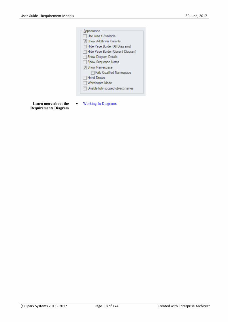
The appearance of a diagram can be changed to suit the audience, and details canbe included, suppressed or altered to ensure the diagram meets its main objectiveof communication. There is a wide range of options ranging from creating a HandDrawn style of diagram to page setup.
(c) Sparx Systems 2015 - 2017 Page 17 of 174 Created with Enterprise Architect
User Guide - Requirement Models 30 June, 2017
Learn more about theRequirements Diagram
Working In Diagrams·
(c) Sparx Systems 2015 - 2017 Page 18 of 174 Created with Enterprise Architect
User Guide - Requirement Models 30 June, 2017
Scenario Builder
Getting to Know the Scenario Builder
Introducing the ScenarioBuilder
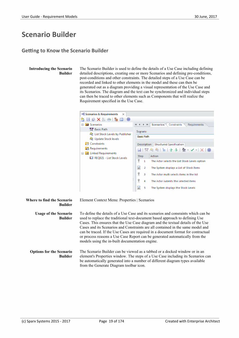
The Scenario Builder is used to define the details of a Use Case including definingdetailed descriptions, creating one or more Scenarios and defining pre-conditions,post-conditions and other constraints. The detailed steps of a Use Case can berecorded and linked to other elements in the model and these can then begenerated out as a diagram providing a visual representation of the Use Case andits Scenarios. The diagram and the text can be synchronized and individual stepscan then be traced to other elements such as Components that will realize theRequirement specified in the Use Case.
Where to find the ScenarioBuilder
Element Context Menu: Properties | Scenarios
Usage of the ScenarioBuilder
To define the details of a Use Case and its scenarios and consraints which can beused to replace the traditional text-document based approach to defining UseCases. This ensures that the Use Case diagram and the textual details of the UseCases and its Scenarios and Constraints are all contained in the same model andcan be traced. If the Use Cases are required in a document format for contractualor process reasons a Use Case Report can be generated automatically from themodels using the in-built documentation engine.
Options for the ScenarioBuilder
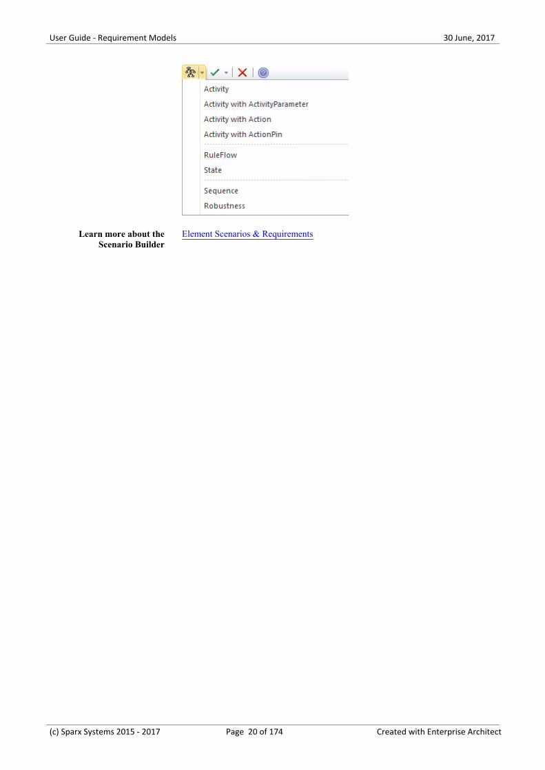
The Scenario Builder can be viewed as a tabbed or a docked window or in anelement's Properties window. The steps of a Use Case including its Scenarios canbe automatically generated into a number of different diagram types availablefrom the Generate Diagram toolbar icon.
(c) Sparx Systems 2015 - 2017 Page 19 of 174 Created with Enterprise Architect
User Guide - Requirement Models 30 June, 2017
Learn more about theScenario Builder
Element Scenarios & Requirements
(c) Sparx Systems 2015 - 2017 Page 20 of 174 Created with Enterprise Architect
User Guide - Requirement Models 30 June, 2017
Baseline Tool
Getting to Know the Baseline Tool
Introducing the BaselineTool
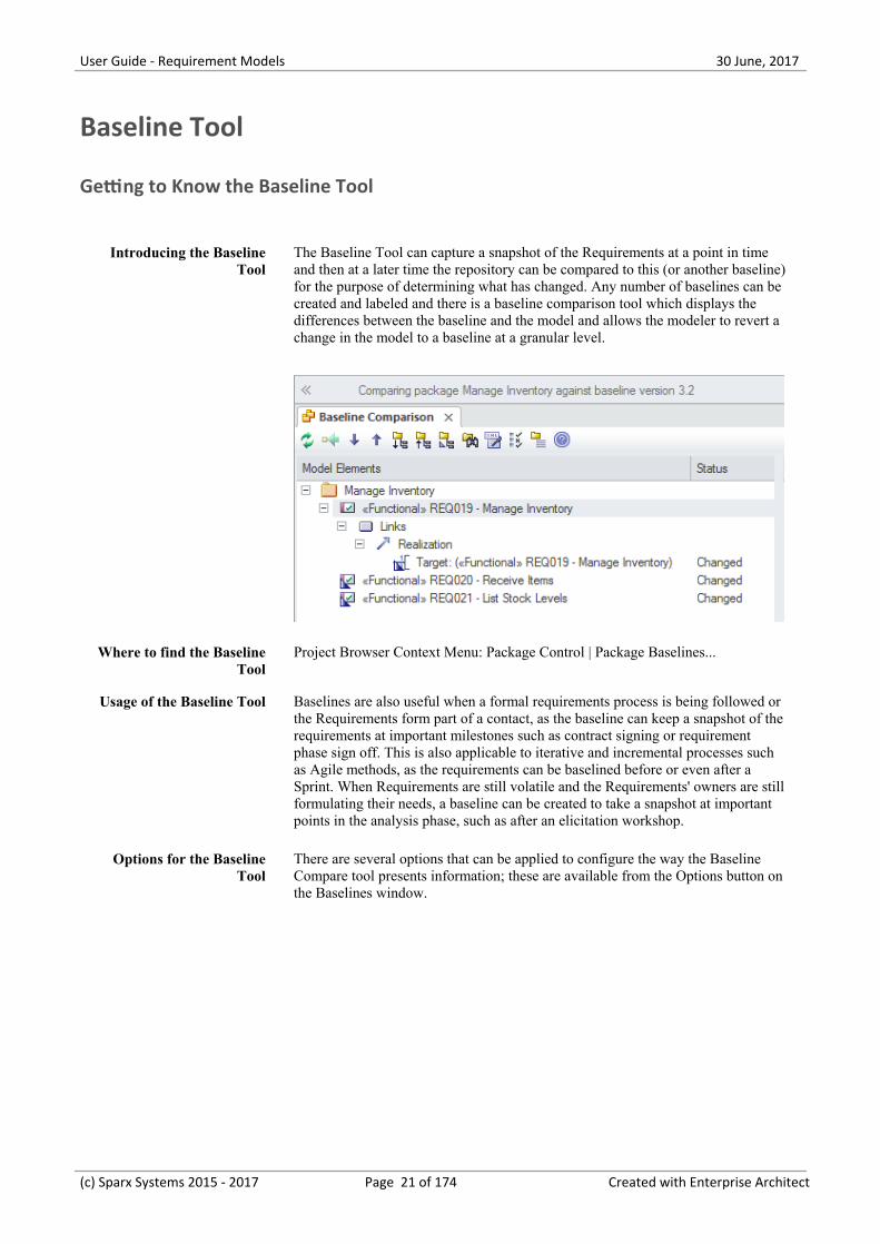
The Baseline Tool can capture a snapshot of the Requirements at a point in timeand then at a later time the repository can be compared to this (or another baseline)for the purpose of determining what has changed. Any number of baselines can becreated and labeled and there is a baseline comparison tool which displays thedifferences between the baseline and the model and allows the modeler to revert achange in the model to a baseline at a granular level.
Where to find the BaselineTool
Project Browser Context Menu: Package Control | Package Baselines...
Usage of the Baseline Tool Baselines are also useful when a formal requirements process is being followed orthe Requirements form part of a contact, as the baseline can keep a snapshot of therequirements at important milestones such as contract signing or requirementphase sign off. This is also applicable to iterative and incremental processes suchas Agile methods, as the requirements can be baselined before or even after aSprint. When Requirements are still volatile and the Requirements' owners are stillformulating their needs, a baseline can be created to take a snapshot at importantpoints in the analysis phase, such as after an elicitation workshop.
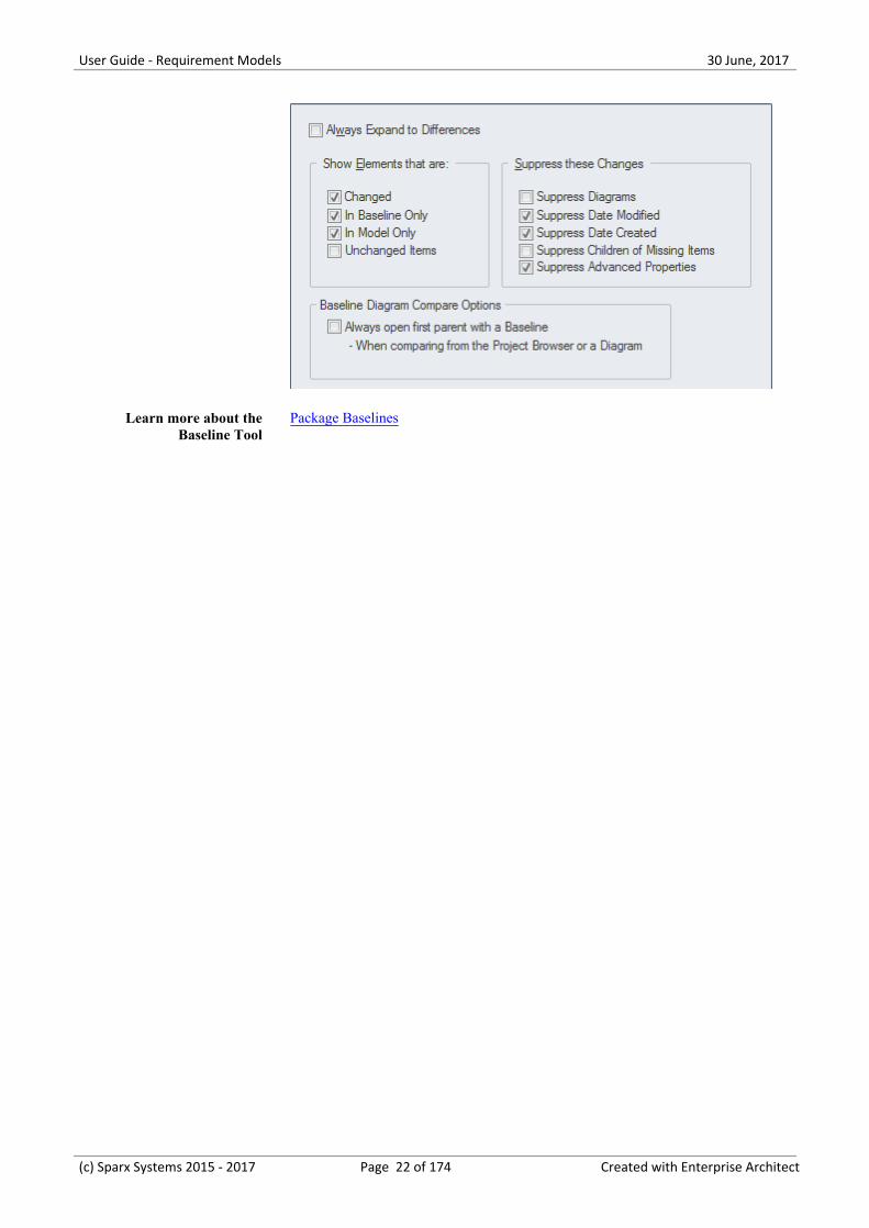
Options for the BaselineTool
There are several options that can be applied to configure the way the BaselineCompare tool presents information; these are available from the Options button onthe Baselines window.
(c) Sparx Systems 2015 - 2017 Page 21 of 174 Created with Enterprise Architect
User Guide - Requirement Models 30 June, 2017
Learn more about theBaseline Tool
Package Baselines
(c) Sparx Systems 2015 - 2017 Page 22 of 174 Created with Enterprise Architect
User Guide - Requirement Models 30 June, 2017
Traceability Window
Getting to Know the Traceability Window
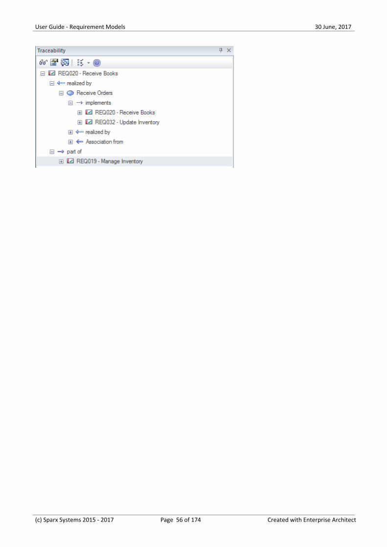
Introducing theTraceability Window
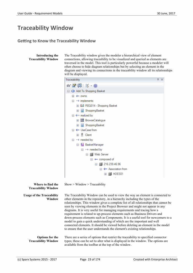
The Traceability window gives the modeler a hierarchical view of elementconnections, allowing traceability to be visualized and queried as elements aretraversed in the model. This tool is particularly powerful because a modeler willoften choose to hide diagram relationships but by selecting an element in thediagram and viewing its connections in the traceability window all its relationshipswill be displayed.
Where to find theTraceability Window
Show > Window > Traceability
Usage of the TraceabilityWindow
The Traceability Window can be used to view the way an element is connected toother elements in the repository, in a hierarchy including the types of therelationships. This window gives a complete list of all relationships that cannot beseen by viewing elements in the Project Browser and might not appear in anydiagrams. It is very useful for managing requirements and tracing how arequirement is related to up-process elements such as Business Drivers anddown-process elements such as Components. It is a useful tool for newcomers to amodel to gain a quick understanding of which are the important and wellconnected elements. It should be viewed before deleting an element in the modelto ensure that the user understands the element's existing relationships.
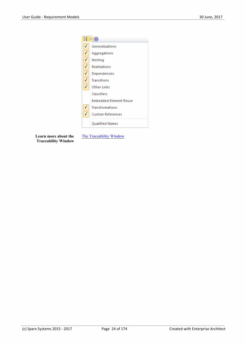
Options for theTraceability Window
There are a series of options that restrict the traceability to specified connectortypes; these can be set to alter what is displayed in the window. The options areavailable from the toolbar at the top of the window.
(c) Sparx Systems 2015 - 2017 Page 23 of 174 Created with Enterprise Architect
User Guide - Requirement Models 30 June, 2017
Learn more about theTraceability Window
The Traceability Window
(c) Sparx Systems 2015 - 2017 Page 24 of 174 Created with Enterprise Architect
User Guide - Requirement Models 30 June, 2017
Dashboard Diagrams
Getting to Know the Dashboard Diagrams
Introducing DashboardDiagrams
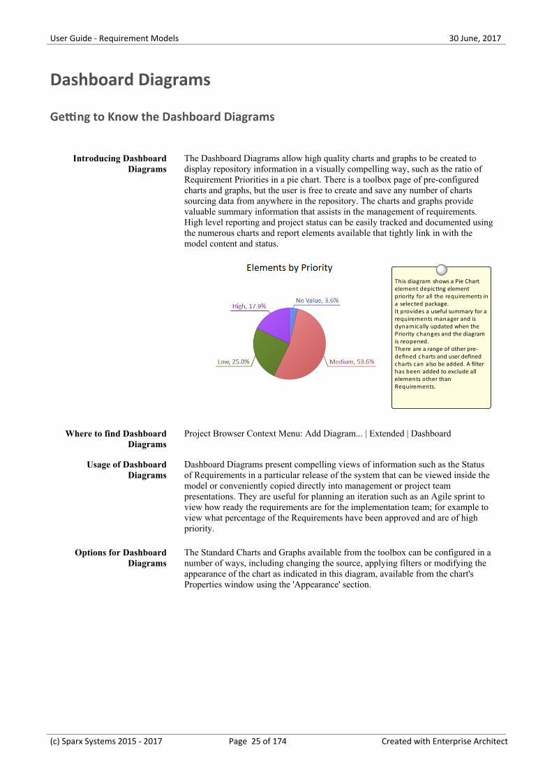
The Dashboard Diagrams allow high quality charts and graphs to be created todisplay repository information in a visually compelling way, such as the ratio ofRequirement Priorities in a pie chart. There is a toolbox page of pre-configuredcharts and graphs, but the user is free to create and save any number of chartssourcing data from anywhere in the repository. The charts and graphs providevaluable summary information that assists in the management of requirements.High level reporting and project status can be easily tracked and documented usingthe numerous charts and report elements available that tightly link in with themodel content and status.
This diagram shows a Pie Chart element depicting element priority for all the requirements ina selected package. It provides a useful summary for a requirements manager and is dynamically updated when the Priority changes and the diagram is reopened. There are a range of other pre-defined charts and user defined charts can also be added. A filter has been added to exclude all elements other than Requirements.
Where to find DashboardDiagrams
Project Browser Context Menu: Add Diagram... | Extended | Dashboard
Usage of DashboardDiagrams
Dashboard Diagrams present compelling views of information such as the Statusof Requirements in a particular release of the system that can be viewed inside themodel or conveniently copied directly into management or project teampresentations. They are useful for planning an iteration such as an Agile sprint toview how ready the requirements are for the implementation team; for example toview what percentage of the Requirements have been approved and are of highpriority.
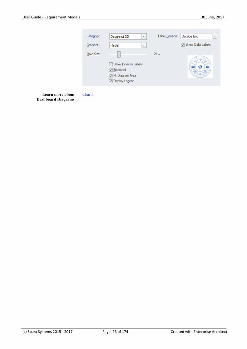
Options for DashboardDiagrams
The Standard Charts and Graphs available from the toolbox can be configured in anumber of ways, including changing the source, applying filters or modifying theappearance of the chart as indicated in this diagram, available from the chart'sProperties window using the 'Appearance' section.
(c) Sparx Systems 2015 - 2017 Page 25 of 174 Created with Enterprise Architect
User Guide - Requirement Models 30 June, 2017
Learn more aboutDashboard Diagrams
Charts
(c) Sparx Systems 2015 - 2017 Page 26 of 174 Created with Enterprise Architect
User Guide - Requirement Models 30 June, 2017
The MDG Link for DOORS Add-In
The Model Driven Generator (MDG) Link™ for DOORS Add-In provides support for linking an Enterprise Architectmodel to an IBM® Rational® DOORS® requirements package. This tool is very useful when you need to perform yourrequirements management external to your Model Driven Development. Using this Add-in you can interchangerequirements defined within IBM DOORS with the traceable Requirements used within Enterprise Architect'sRequirements Management features.
(c) Sparx Systems 2015 - 2017 Page 27 of 174 Created with Enterprise Architect
User Guide - Requirement Models 30 June, 2017
Requirements Overview
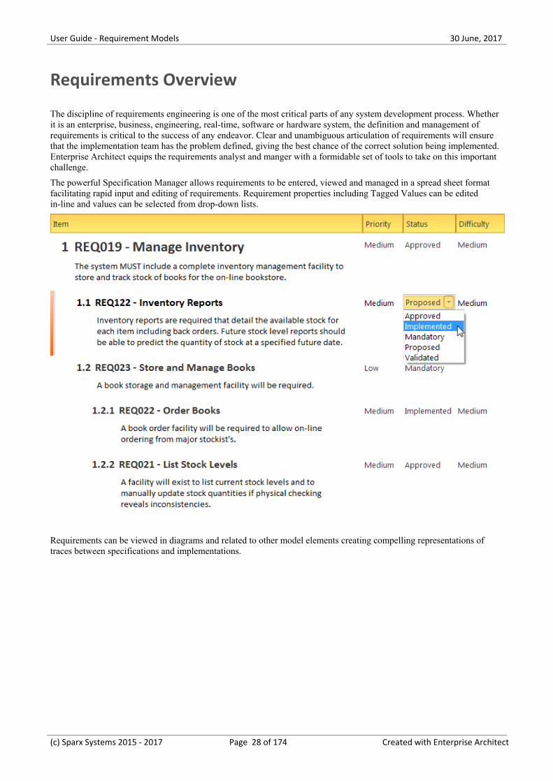
The discipline of requirements engineering is one of the most critical parts of any system development process. Whetherit is an enterprise, business, engineering, real-time, software or hardware system, the definition and management ofrequirements is critical to the success of any endeavor. Clear and unambiguous articulation of requirements will ensurethat the implementation team has the problem defined, giving the best chance of the correct solution being implemented.Enterprise Architect equips the requirements analyst and manger with a formidable set of tools to take on this importantchallenge.
The powerful Specification Manager allows requirements to be entered, viewed and managed in a spread sheet formatfacilitating rapid input and editing of requirements. Requirement properties including Tagged Values can be editedin-line and values can be selected from drop-down lists.
Requirements can be viewed in diagrams and related to other model elements creating compelling representations oftraces between specifications and implementations.
(c) Sparx Systems 2015 - 2017 Page 28 of 174 Created with Enterprise Architect
User Guide - Requirement Models 30 June, 2017
(from Take Orders)
View Shopping Basket
(from Take Orders)
Add To Shopping Basket
View Basket
(from View Basket)
BrowseCatalogue
(from Browse Catalogue)
REQ014 - Shopping Basket
notesThe system must provide a shoppingBasket facility that remembers thecontents between sessions.
(from Take Orders)
«goal»Provide customers with a competitive
online shopping experience
(from Goals)
BasketManager
responsibilitiesManages addition and deletion of items fromthe basket and serializes contents betweensessions.
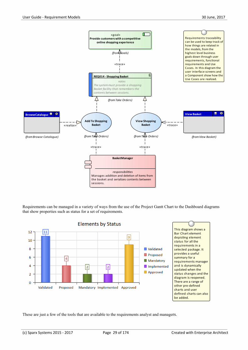
Requirements traceability can be used to keep track ofhow things are related in the models, from the highest level business goals down through user requirements, functional requirements and Use Cases. In this diagram the user interface screens and a Component show how theUse Cases are realized.
«trace»«trace»
«trace»
«realize» «trace»
Requirements can be managed in a variety of ways from the use of the Project Gantt Chart to the Dashboard diagramsthat show properties such as status for a set of requirements.
This diagram shows a Bar Chart element depicting element status for all the requirements in a selected package. It provides a useful summary for a requirements manager and is dynamically updated when the status changes and the diagram is reopened. There are a range of other pre-defined charts and user defined charts can also be added.
These are just a few of the tools that are available to the requirements analyst and managers.
(c) Sparx Systems 2015 - 2017 Page 29 of 174 Created with Enterprise Architect

User Guide - Requirement Models 30 June, 2017
(c) Sparx Systems 2015 - 2017 Page 30 of 174 Created with Enterprise Architect
User Guide - Requirement Models 30 June, 2017
What are Requirements
A requirement is a capability or condition that must be met to ensure that a solution meets the needs of its stakeholders.There is often robust debate about exactly what constitutes a requirement and some proponents will include notions suchas Business Drivers and Policies and Business Rules while others will have a much more restrictive view of therequirements. Also a number of requirement methods are Use Case centric and only articulate requirements at a businesslevel while others augment the use cases with detailed functional requirements required by the developers. The highlyiterative methods such as Agile typically use User Stories and Requirements together but defer the elaboration ofrequirements until an iteration (sprint) is being planned. Enterprise Architect provides generic tools to support anyrequirements method and any type of requirement can be created and managed using built-in types or by usingstereotyped elements and Tagged Values.
REQ020 - Receive Books
REQ019 - Manage Inventory
REQ022 - Order Books
REQ023 - Store and Manage Books
REQ027 - Add Books
REQ021 - List Stock Levels
Requirements can be grouped into hierarchies effectively decomposing a high level requirement. The UML Aggregation relationship is typically used for this purpose. Requirements can also be nested in the Project Browser creating a tree of requirements.
Requirements DiagramEnterprise Architect allows you to document requirements graphically using the Requirement element. The Requirement element is available from the 'Requirements' Toolbox folder.
Using a Requirement element in the UML model, allows relationships to be drawn between requirements. It also allows for direct traceability to other aspects of the model such as Use Cases, Test Cases and other Analysis or Design elements.
The requirement element can be used to model or document any requirements, ranging from formal business requirements through to performance or security requirements.
Requirement Traces
(c) Sparx Systems 2015 - 2017 Page 31 of 174 Created with Enterprise Architect

User Guide - Requirement Models 30 June, 2017
Levels and Types of Requirements
There are many different types of requirements ranging from high level business requirements down to detailed technicalrequirements that specify an intricate part of a computer algorithm or hardware device. There are also types based on thesource of the requirement such as stakeholder requirements or the location in the process such as transition requirements.There is often confusion and debate about exactly what constitutes a Requirement so some teams will define BusinessRules and Policies as Requirements and other will view them as business specifications. Regardless of the method or theprocess that is being followed Enterprise Architect allows the analyst to create sophisticated models of all requirementtypes.
Business Requirements
Business Requirements are high-level requirements that express the objectives and desired outcomes of an organization.They are often disregarded as being 'fluffy' by engineers who cannot see how they would be implemented, but if they arearticulated well they can be broken down to measurable statements. They are typically defined in a business case or otherstatements by the product owner or sponsor, the marketing department or the customer. They attempt to articulate whythe organization is spending money and resources on the project. Enterprise Architect has a Business Requirementelement available from the 'Requirements' toolbox page for this purpose.
REQ012 - Provide Online Sales
Provide customers with a competitive online shopping experience
REQ116 -The system must email the client a copy of the receipt
Requirement TracesThis diagram shows the traceability from a high level business requirement (goal), to a user requirement, down to a functional requirement. The requirements can be included on any diagram type to create expressive narratives of how the many parts of the system ensure the requirements are met.
«trace»«trace»
Functional Requirements
Functional Requirements are the bridge between the business and technical teams and provide the definition of what thesystem must do for its users that will in turn meet the business goals. Some methodologists believe that Functional
(c) Sparx Systems 2015 - 2017 Page 32 of 174 Created with Enterprise Architect
User Guide - Requirement Models 30 June, 2017
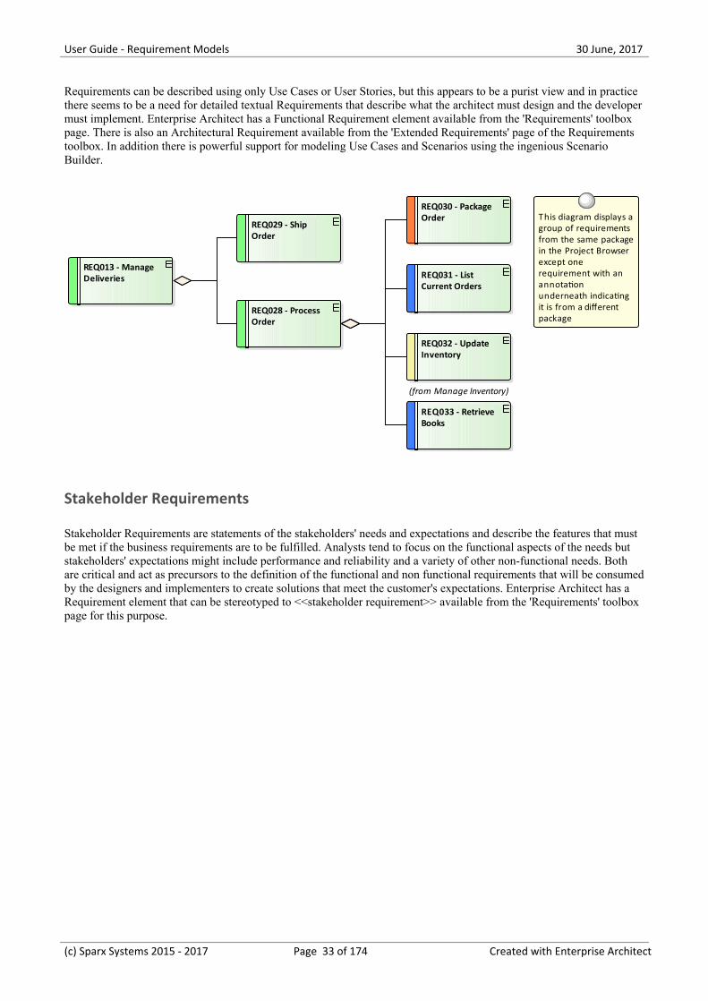
Requirements can be described using only Use Cases or User Stories, but this appears to be a purist view and in practicethere seems to be a need for detailed textual Requirements that describe what the architect must design and the developermust implement. Enterprise Architect has a Functional Requirement element available from the 'Requirements' toolboxpage. There is also an Architectural Requirement available from the 'Extended Requirements' page of the Requirementstoolbox. In addition there is powerful support for modeling Use Cases and Scenarios using the ingenious ScenarioBuilder.
REQ013 - Manage Deliveries
REQ028 - Process Order
REQ029 - Ship Order
REQ031 - List Current Orders
REQ030 - Package Order
REQ032 - Update Inventory
(from Manage Inventory)
REQ033 - Retrieve Books
This diagram displays a group of requirements from the same package in the Project Browser except one requirement with an annotation underneath indicating it is from a different package
Stakeholder Requirements
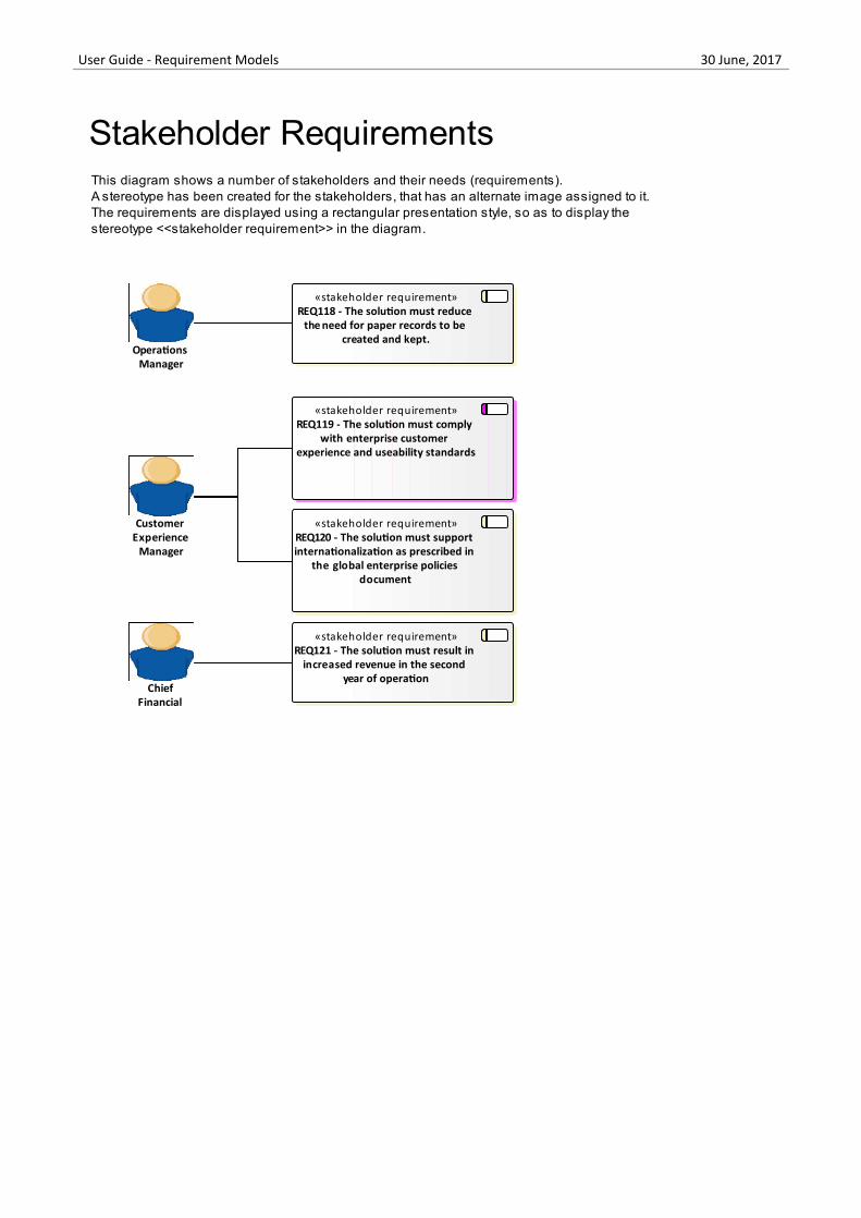
Stakeholder Requirements are statements of the stakeholders' needs and expectations and describe the features that mustbe met if the business requirements are to be fulfilled. Analysts tend to focus on the functional aspects of the needs butstakeholders' expectations might include performance and reliability and a variety of other non-functional needs. Bothare critical and act as precursors to the definition of the functional and non functional requirements that will be consumedby the designers and implementers to create solutions that meet the customer's expectations. Enterprise Architect has aRequirement element that can be stereotyped to <<stakeholder requirement>> available from the 'Requirements' toolboxpage for this purpose.
(c) Sparx Systems 2015 - 2017 Page 33 of 174 Created with Enterprise Architect

User Guide - Requirement Models 30 June, 2017
«stakeholder requirement»REQ118 - The solution must reduce
the need for paper records to be created and kept.
This diagram shows a number of stakeholders and their needs (requirements).A stereotype has been created for the stakeholders, that has an alternate image assigned to it.The requirements are displayed using a rectangular presentation style, so as to display the stereotype <<stakeholder requirement>> in the diagram.
Operations Manager
«stakeholder requirement»REQ119 - The solution must comply
with enterprise customer experience and useability standards
Customer Experience
Manager
«stakeholder requirement»REQ120 - The solution must support internationalization as prescribed in
the global enterprise policies document
Chief Financial
Officer
«stakeholder requirement»REQ121 - The solution must result in
increased revenue in the second year of operation
Stakeholder Requirements
Non Functional Requirements
Non-Functional Requirements and Quality Attributes describe how well a system will perform when it is operating.These typically define or constrain how the system should be behave as a whole and include attributes such as how wellit performs, how secure it is, how many times it develops a fault and how easily it can be extended.
(c) Sparx Systems 2015 - 2017 Page 34 of 174 Created with Enterprise Architect
User Guide - Requirement Models 30 June, 2017
REQ106 - Retrieval of historic information.
notesThe system must be able to retrieveall historic information includingdeleted transactions and theirattachments within the followingranges.
Importance High < 2 MinutesImportance Medium < 15 MinutesImportance Low < 120 Minutes
REQ107 - Access to the secure site must be no longer than 2 seconds delay.
notesIf any greater delay then thereshould be notification to the userthat the process has beencommenced.
REQ105 - Data access Speed
notesThere needs to be reasonable dataaccess speed on the Client side aswell as the staff user side of theapplication.
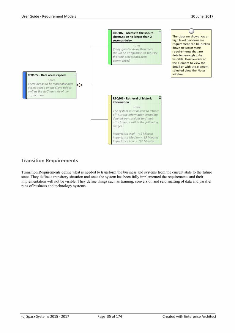
The diagram shows how a high level performance requirement can be broken down to two or more requirements that are detailed enough to be testable. Double-click on the element to view the detail or with the element selected view the Notes window.
Transition Requirements
Transition Requirements define what is needed to transform the business and systems from the current state to the futurestate. They define a transitory situation and once the system has been fully implemented the requirements and theirimplementation will not be visible. They define things such as training, conversion and reformatting of data and parallelruns of business and technology systems.
(c) Sparx Systems 2015 - 2017 Page 35 of 174 Created with Enterprise Architect
User Guide - Requirement Models 30 June, 2017
Characteristics of Good Requirements
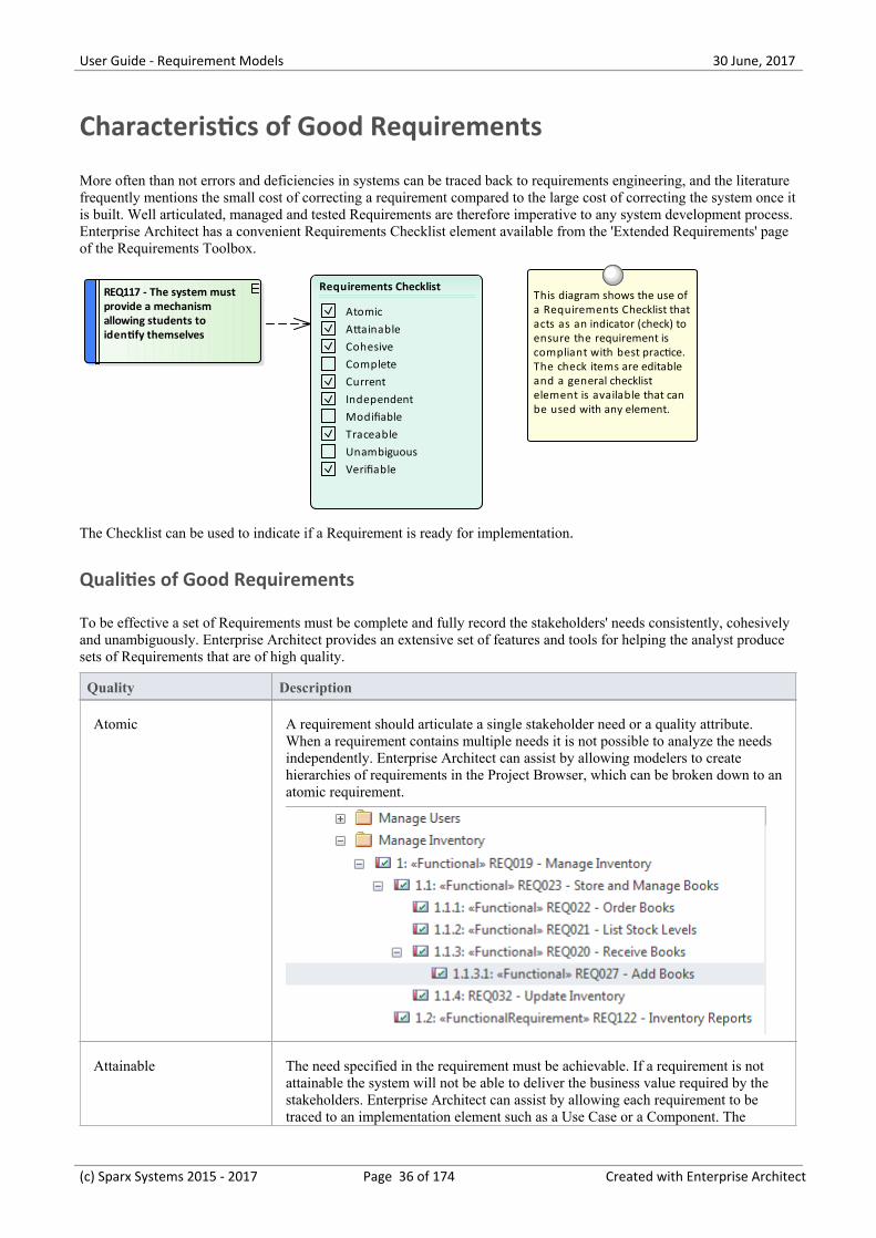
More often than not errors and deficiencies in systems can be traced back to requirements engineering, and the literaturefrequently mentions the small cost of correcting a requirement compared to the large cost of correcting the system once itis built. Well articulated, managed and tested Requirements are therefore imperative to any system development process.Enterprise Architect has a convenient Requirements Checklist element available from the 'Extended Requirements' pageof the Requirements Toolbox.
REQ117 - The system must provide a mechanism allowing students to identify themselves
This diagram shows the use of a Requirements Checklist that acts as an indicator (check) to ensure the requirement is compliant with best practice. The check items are editable and a general checklist element is available that can be used with any element.
Requirements Checklist
AtomicAttainableCohesiveCompleteCurrentIndependentModifiableTraceableUnambiguousVerifiable
The Checklist can be used to indicate if a Requirement is ready for implementation.
Qualities of Good Requirements
To be effective a set of Requirements must be complete and fully record the stakeholders' needs consistently, cohesivelyand unambiguously. Enterprise Architect provides an extensive set of features and tools for helping the analyst producesets of Requirements that are of high quality.
Quality Description
Atomic A requirement should articulate a single stakeholder need or a quality attribute.When a requirement contains multiple needs it is not possible to analyze the needsindependently. Enterprise Architect can assist by allowing modelers to createhierarchies of requirements in the Project Browser, which can be broken down to anatomic requirement.
Attainable The need specified in the requirement must be achievable. If a requirement is notattainable the system will not be able to deliver the business value required by thestakeholders. Enterprise Architect can assist by allowing each requirement to betraced to an implementation element such as a Use Case or a Component. The
(c) Sparx Systems 2015 - 2017 Page 36 of 174 Created with Enterprise Architect
User Guide - Requirement Models 30 June, 2017
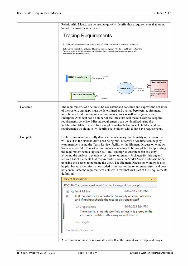
Relationship Matrix can be used to quickly identify those requirements that are nottraced to a lower level element.
Inventory Manager
responsibilitiesProvides services forthe management ofTitles.
REQ019 - Manage Inventory
REQ032 - Update Inventory
Manage Titles
Tracing Requirements
This diagram shows the expressive power of putting disparate elements onto a diagram.
It shows the traceability between different layers of a system. The traceability can be from the Requirements to the Use Cases that Realize them, to the logical Components that will deliver the required functionality.
«realize»
«realize»
«trace»
Cohesive The requirements as a set must be consistent and cohesive and express the behaviorof the system; any gaps must be determined and overlap between requirementsmust be resolved. Following a requirements process will assist greatly andEnterprise Architect has a number of facilities that will make it easy to keep therequirements cohesive. Missing requirements can be identified using theRelationship Matrix where for example a matrix between stakeholders and theirrequirements would quickly identify stakeholders who didn't have requirements.
Complete Each requirement must fully describe the necessary functionality or behavior thatwill result in the stakeholder's need being met. Enterprise Architect can help byteam members using the Team Review facility or the Element Discussion window.Some analysts like to mark requirements as needing to be completed by appendingthe requirement with a tag such as 'TBC'. Enterprise Architect can assist byallowing the analyst to search across the requirements Packages for this tag andreturn a list of elements that require further work. A Model View could also be setup using this search to populate the view. The Element Discussion window is alsohelpful because the information added is not part of the requirement itself and doesnot contaminate the requirement's notes with text that isn't part of the Requirementsdefinition.
A Requirement must be up-to-date and reflect the current knowledge and project
(c) Sparx Systems 2015 - 2017 Page 37 of 174 Created with Enterprise Architect
User Guide - Requirement Models 30 June, 2017
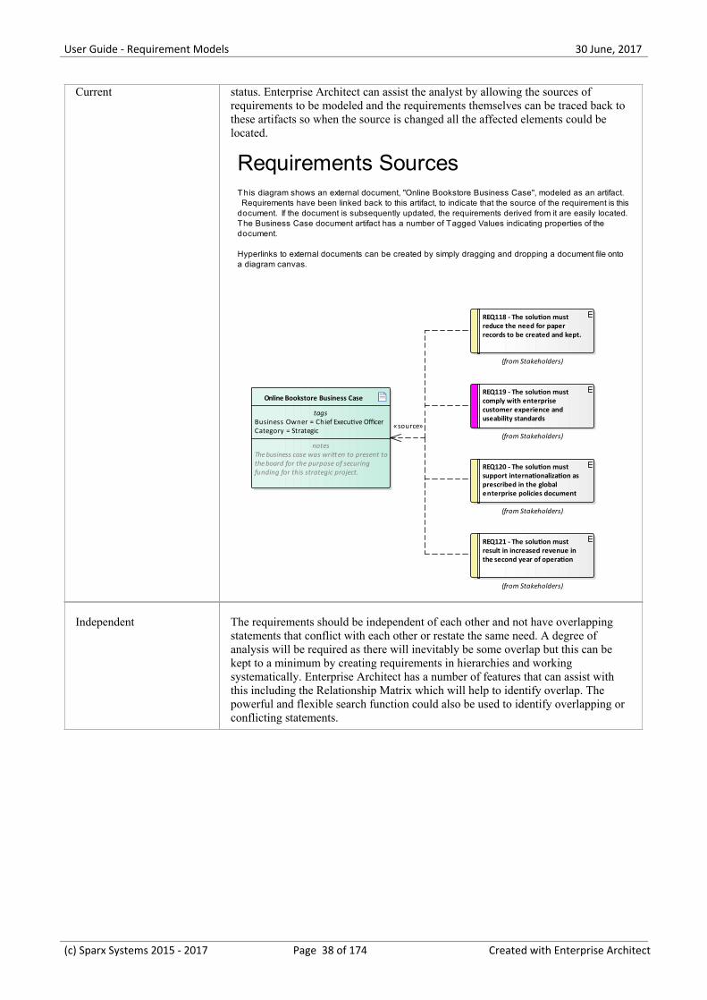
Current status. Enterprise Architect can assist the analyst by allowing the sources ofrequirements to be modeled and the requirements themselves can be traced back tothese artifacts so when the source is changed all the affected elements could belocated.
Online Bookstore Business Case
tagsBusiness Owner = Chief Executive OfficerCategory = Strategic
notesThe business case was written to present tothe board for the purpose of securingfunding for this strategic project.
REQ118 - The solution must reduce the need for paper records to be created and kept.
(from Stakeholders)
REQ119 - The solution must comply with enterprise customer experience and useability standards
(from Stakeholders)
REQ120 - The solution must support internationalization as prescribed in the global enterprise policies document
(from Stakeholders)
REQ121 - The solution must result in increased revenue in the second year of operation
(from Stakeholders)
Requirements SourcesT his diagram shows an external document, "Online Bookstore Business Case", modeled as an artifact. Requirements have been linked back to this artifact, to indicate that the source of the requirement is this document. If the document is subsequently updated, the requirements derived from it are easily located.The Business Case document artifact has a number of Tagged Values indicating properties of the document.
Hyperlinks to external documents can be created by simply dragging and dropping a document file onto a diagram canvas.
«source»
Independent The requirements should be independent of each other and not have overlappingstatements that conflict with each other or restate the same need. A degree ofanalysis will be required as there will inevitably be some overlap but this can bekept to a minimum by creating requirements in hierarchies and workingsystematically. Enterprise Architect has a number of features that can assist withthis including the Relationship Matrix which will help to identify overlap. Thepowerful and flexible search function could also be used to identify overlapping orconflicting statements.
(c) Sparx Systems 2015 - 2017 Page 38 of 174 Created with Enterprise Architect
User Guide - Requirement Models 30 June, 2017
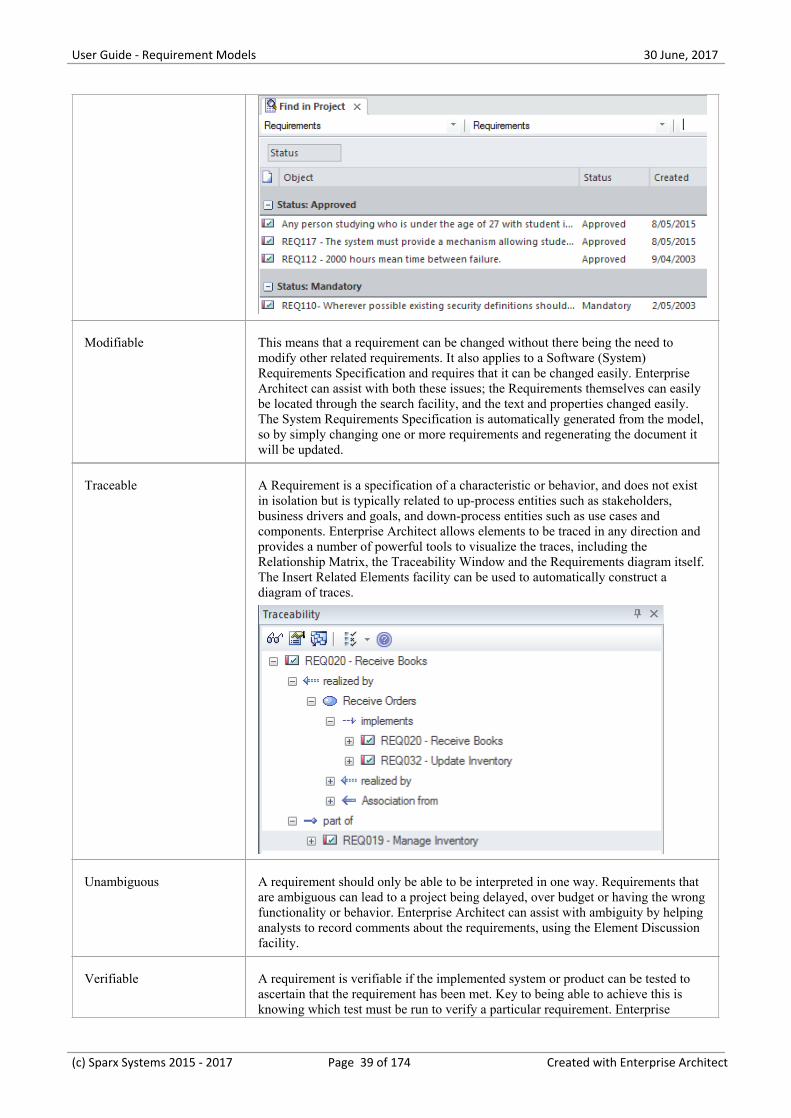
Modifiable This means that a requirement can be changed without there being the need tomodify other related requirements. It also applies to a Software (System)Requirements Specification and requires that it can be changed easily. EnterpriseArchitect can assist with both these issues; the Requirements themselves can easilybe located through the search facility, and the text and properties changed easily.The System Requirements Specification is automatically generated from the model,so by simply changing one or more requirements and regenerating the document itwill be updated.
Traceable A Requirement is a specification of a characteristic or behavior, and does not existin isolation but is typically related to up-process entities such as stakeholders,business drivers and goals, and down-process entities such as use cases andcomponents. Enterprise Architect allows elements to be traced in any direction andprovides a number of powerful tools to visualize the traces, including theRelationship Matrix, the Traceability Window and the Requirements diagram itself.The Insert Related Elements facility can be used to automatically construct adiagram of traces.
Unambiguous A requirement should only be able to be interpreted in one way. Requirements thatare ambiguous can lead to a project being delayed, over budget or having the wrongfunctionality or behavior. Enterprise Architect can assist with ambiguity by helpinganalysts to record comments about the requirements, using the Element Discussionfacility.
Verifiable A requirement is verifiable if the implemented system or product can be tested toascertain that the requirement has been met. Key to being able to achieve this isknowing which test must be run to verify a particular requirement. Enterprise
(c) Sparx Systems 2015 - 2017 Page 39 of 174 Created with Enterprise Architect
User Guide - Requirement Models 30 June, 2017
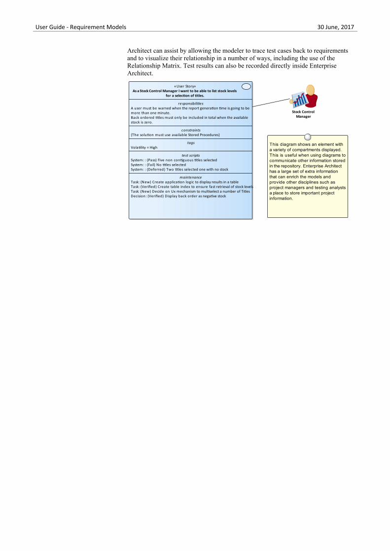
Architect can assist by allowing the modeler to trace test cases back to requirementsand to visualize their relationship in a number of ways, including the use of theRelationship Matrix. Test results can also be recorded directly inside EnterpriseArchitect.
«User Story»As a Stock Control Manager I want to be able to list stock levels
for a selection of titles.
responsibilitiesA user must be warned when the report generation time is going to bemore than one minute.Back ordered titles must only be included in total when the availablestock is zero.
constraints{The solution must use available Stored Procedures}
tagsVolatility = High
test scriptsSystem: : (Pass) Five non contiguous titles selectedSystem: : (Fail) No titles selectedSystem: : (Deferred) Two titles selected one with no stock
maintenanceTask: (New) Create application logic to display results in a tableTask: (Verified) Create table index to ensure fast retrieval of stock levelsTask: (New) Decide on Ux mechanism to multiselect a number of TitlesDecision: (Verified) Display back order as negative stock
This diagram shows an element with a variety of compartments displayed. This is useful when using diagrams to communicate other information stored in the repository. Enterprise Architect has a large set of extra information that can enrich the models and provide other disciplines such as project managers and testing analysts a place to store important project information.
Stock Control Manager
Necessary Requirements should record a capability or behavior that is really needed or thatspecifies that the system or product should comply with constraints such asstandards. Enterprise Architect can assist by allowing the modeler to relate eachrequirement back to its source and using the Relationship Matrix; requirements thathave no source will be obviously identified as unnecessary or needing furtherinvestigation.
Feasible A requirement that cannot be implemented will mean that the need of thestakeholder will not be met. It is best to identify these requirements as quickly aspossible so as not to disappoint the owner of the requirement. Enterprise Architectcan assist by allowing analysts, architects, designers and developers to discuss therequirement and determine its feasibility using the Element Discussion window.
(c) Sparx Systems 2015 - 2017 Page 40 of 174 Created with Enterprise Architect
User Guide - Requirement Models 30 June, 2017
Business Context for Requirements
Requirements don't appear in isolation but are usually defined or discovered in the context of a business problem oropportunity that has been defined in one or more business documents. These documents and the information they containcan be included in the models and provide an important anchor point for Requirements.
Business Case
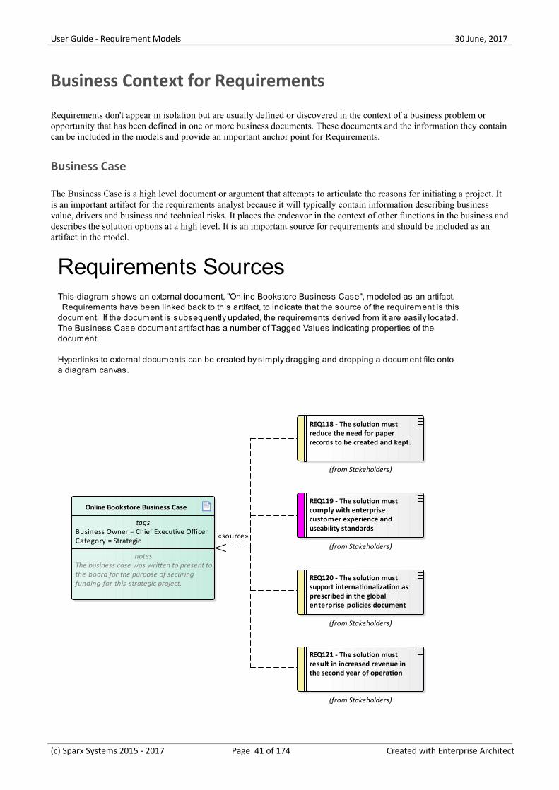
The Business Case is a high level document or argument that attempts to articulate the reasons for initiating a project. Itis an important artifact for the requirements analyst because it will typically contain information describing businessvalue, drivers and business and technical risks. It places the endeavor in the context of other functions in the business anddescribes the solution options at a high level. It is an important source for requirements and should be included as anartifact in the model.
Online Bookstore Business Case
tagsBusiness Owner = Chief Executive OfficerCategory = Strategic
notesThe business case was written to present tothe board for the purpose of securingfunding for this strategic project.
REQ118 - The solution must reduce the need for paper records to be created and kept.
(from Stakeholders)
REQ119 - The solution must comply with enterprise customer experience and useability standards
(from Stakeholders)
REQ120 - The solution must support internationalization as prescribed in the global enterprise policies document
(from Stakeholders)
REQ121 - The solution must result in increased revenue in the second year of operation
(from Stakeholders)
Requirements SourcesThis diagram shows an external document, "Online Bookstore Business Case", modeled as an artifact. Requirements have been linked back to this artifact, to indicate that the source of the requirement is this document. If the document is subsequently updated, the requirements derived from it are easily located.The Business Case document artifact has a number of Tagged Values indicating properties of the document.
Hyperlinks to external documents can be created by simply dragging and dropping a document file onto a diagram canvas.
«source»
(c) Sparx Systems 2015 - 2017 Page 41 of 174 Created with Enterprise Architect
User Guide - Requirement Models 30 June, 2017
Drivers and Goals
Business Drivers and Goals are often documented by high level strategic thinkers such as business or enterprisearchitects. Drivers define resources, processes or constraints that are vital to the operation of the organization and Goalsdescribe the position that the organization is wanting to attain. They are typically enterprise level concerns and so shouldbe modeled above the level of individual projects. They often exist in high level documentation and even when theyaren't clearly articulated at the organization level an analyst can mine them from previous project documentation such asa Vision document and model them in an enterprise package above the project packages in the repository.
Vision and Concept of Operation
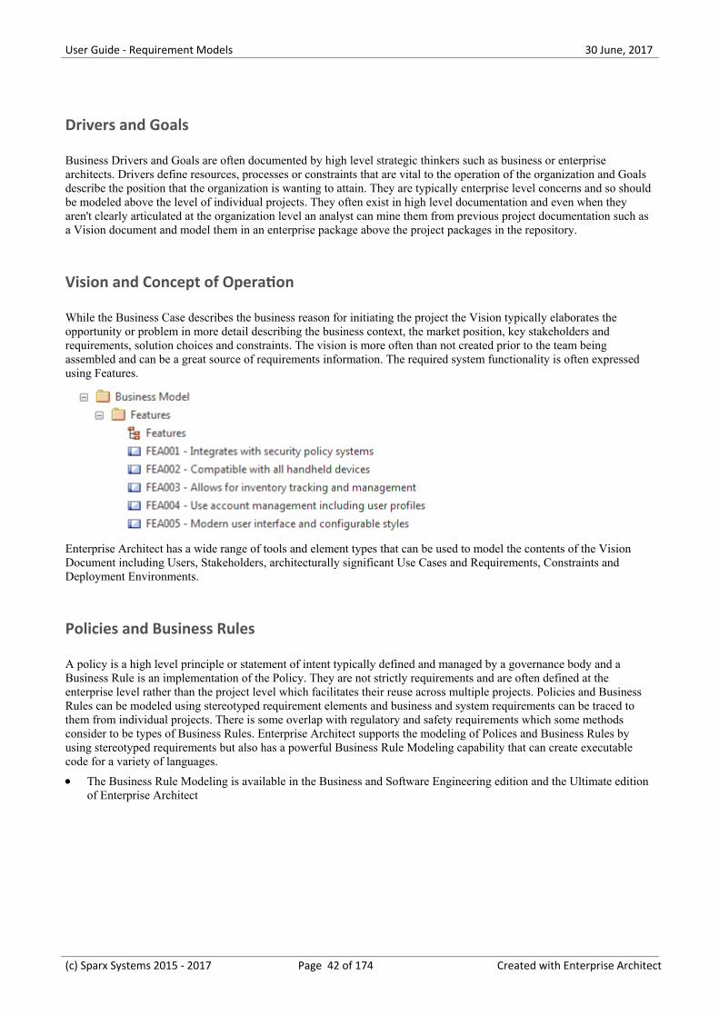
While the Business Case describes the business reason for initiating the project the Vision typically elaborates theopportunity or problem in more detail describing the business context, the market position, key stakeholders andrequirements, solution choices and constraints. The vision is more often than not created prior to the team beingassembled and can be a great source of requirements information. The required system functionality is often expressedusing Features.
Enterprise Architect has a wide range of tools and element types that can be used to model the contents of the VisionDocument including Users, Stakeholders, architecturally significant Use Cases and Requirements, Constraints andDeployment Environments.
Policies and Business Rules
A policy is a high level principle or statement of intent typically defined and managed by a governance body and aBusiness Rule is an implementation of the Policy. They are not strictly requirements and are often defined at theenterprise level rather than the project level which facilitates their reuse across multiple projects. Policies and BusinessRules can be modeled using stereotyped requirement elements and business and system requirements can be traced tothem from individual projects. There is some overlap with regulatory and safety requirements which some methodsconsider to be types of Business Rules. Enterprise Architect supports the modeling of Polices and Business Rules byusing stereotyped requirements but also has a powerful Business Rule Modeling capability that can create executablecode for a variety of languages.
The Business Rule Modeling is available in the Business and Software Engineering edition and the Ultimate edition·of Enterprise Architect
(c) Sparx Systems 2015 - 2017 Page 42 of 174 Created with Enterprise Architect
User Guide - Requirement Models 30 June, 2017
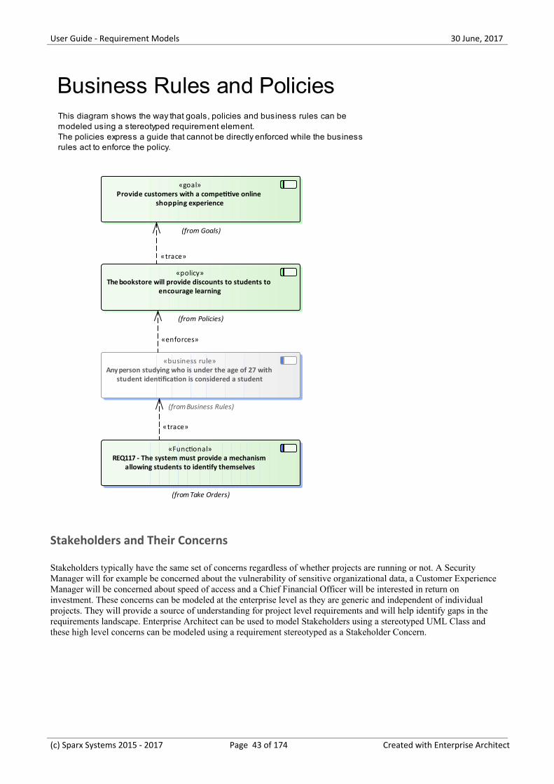
«policy»The bookstore will provide discounts to students to
encourage learning
(from Policies)
«business rule»Any person studying who is under the age of 27 with
student identification is considered a student
(from Business Rules)
«goal»Provide customers with a competitive online
shopping experience
(from Goals)
«Functional»REQ117 - The system must provide a mechanism
allowing students to identify themselves
(from Take Orders)
Business Rules and PoliciesThis diagram shows the way that goals, policies and business rules can be modeled using a stereotyped requirement element. The policies express a guide that cannot be directly enforced while the business rules act to enforce the policy.
«trace»
«trace»
«enforces»
Stakeholders and Their Concerns
Stakeholders typically have the same set of concerns regardless of whether projects are running or not. A SecurityManager will for example be concerned about the vulnerability of sensitive organizational data, a Customer ExperienceManager will be concerned about speed of access and a Chief Financial Officer will be interested in return oninvestment. These concerns can be modeled at the enterprise level as they are generic and independent of individualprojects. They will provide a source of understanding for project level requirements and will help identify gaps in therequirements landscape. Enterprise Architect can be used to model Stakeholders using a stereotyped UML Class andthese high level concerns can be modeled using a requirement stereotyped as a Stakeholder Concern.
(c) Sparx Systems 2015 - 2017 Page 43 of 174 Created with Enterprise Architect
User Guide - Requirement Models 30 June, 2017
«stakeholder requirement»REQ118 - The solution must reduce
the need for paper records to be created and kept.
This diagram shows a number of stakeholders and their needs (requirements).A stereotype has been created for the stakeholders, that has an alternate image assigned to it.The requirements are displayed using a rectangular presentation style, so as to display the stereotype <<stakeholder requirement>> in the diagram.
Operations Manager
«stakeholder requirement»REQ119 - The solution must comply
with enterprise customer experience and useability standards
Customer Experience
Manager
«stakeholder requirement»REQ120 - The solution must support internationalization as prescribed in
the global enterprise policies document
Chief Financial
Officer
«stakeholder requirement»REQ121 - The solution must result in
increased revenue in the second year of operation
Stakeholder Requirements
(c) Sparx Systems 2015 - 2017 Page 44 of 174 Created with Enterprise Architect
User Guide - Requirement Models 30 June, 2017
Requirements Diagram
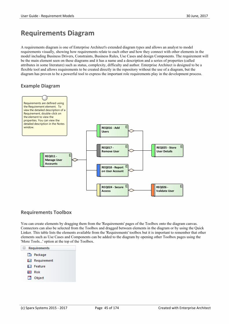
A requirements diagram is one of Enterprise Architect's extended diagram types and allows an analyst to modelrequirements visually, showing how requirements relate to each other and how they connect with other elements in themodel including Business Drivers, Constraints, Business Rules, Use Cases and design Components. The requirement willbe the main element seen on these diagrams and it has a name and a description and a series of properties (calledattributes in some literature) such as status, complexity, difficulty and author. Enterprise Architect is designed to be aflexible tool and allows requirements to be created directly in the repository without the use of a diagram, but thediagram has proven to be a powerful tool to express the important role requirements play in the development process.
Example Diagram
REQ011 - Manage User Accounts
REQ025 - Store User Details
REQ018 - Report on User Account
REQ024 - Secure Access
REQ017 - Remove User
REQ026 - Validate User
REQ016 - Add Users
Requirements are defined using the Requirement element. To view the detailed description of a Requirement, double-click on the element to view the properties. You can view the detailed description in the Notes window.
Requirements Toolbox
You can create elements by dragging them from the 'Requirements' pages of the Toolbox onto the diagram canvas.Connectors can also be selected from the Toolbox and dragged between elements in the diagram or by using the QuickLinker. This table lists the elements available from the 'Requirements' toolbox but it is important to remember that otherelements such as Use Cases and Components can be added to the diagram by opening other Toolbox pages using the'More Tools...' option at the top of the Toolbox.
(c) Sparx Systems 2015 - 2017 Page 45 of 174 Created with Enterprise Architect
User Guide - Requirement Models 30 June, 2017
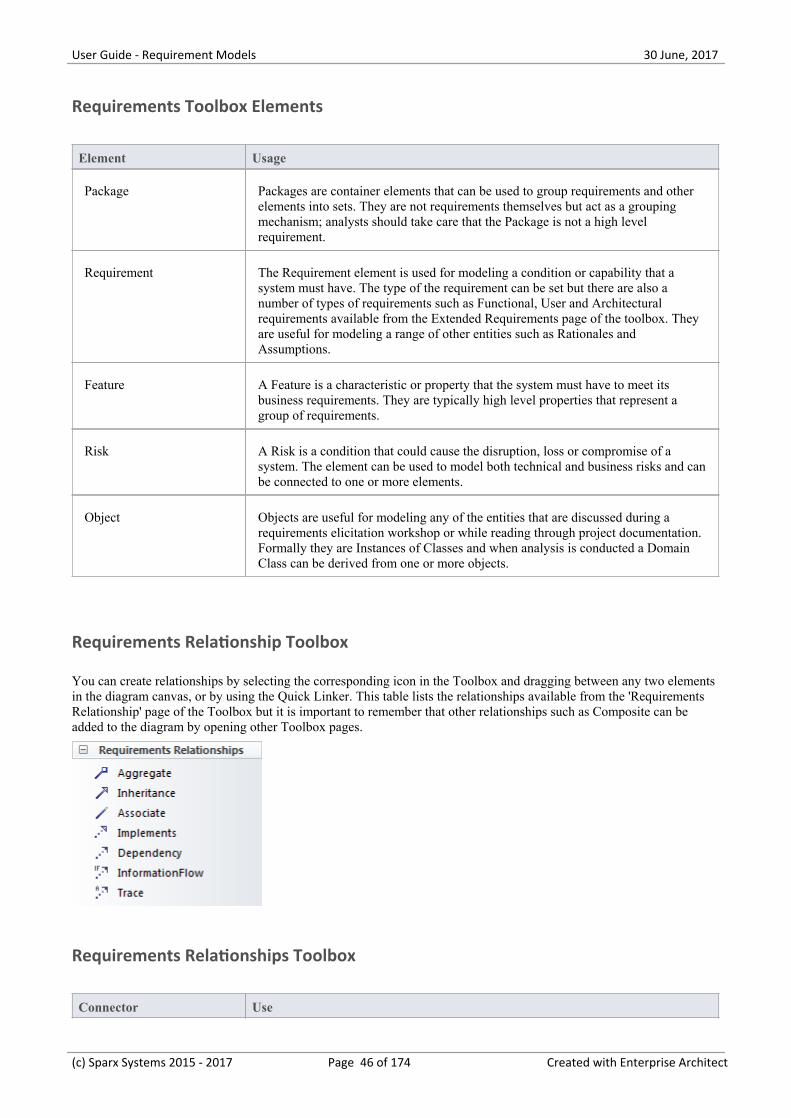
Requirements Toolbox Elements
Element Usage
Package Packages are container elements that can be used to group requirements and otherelements into sets. They are not requirements themselves but act as a groupingmechanism; analysts should take care that the Package is not a high levelrequirement.
Requirement The Requirement element is used for modeling a condition or capability that asystem must have. The type of the requirement can be set but there are also anumber of types of requirements such as Functional, User and Architecturalrequirements available from the Extended Requirements page of the toolbox. Theyare useful for modeling a range of other entities such as Rationales andAssumptions.
Feature A Feature is a characteristic or property that the system must have to meet itsbusiness requirements. They are typically high level properties that represent agroup of requirements.
Risk A Risk is a condition that could cause the disruption, loss or compromise of asystem. The element can be used to model both technical and business risks and canbe connected to one or more elements.
Object Objects are useful for modeling any of the entities that are discussed during arequirements elicitation workshop or while reading through project documentation.Formally they are Instances of Classes and when analysis is conducted a DomainClass can be derived from one or more objects.
Requirements Relationship Toolbox
You can create relationships by selecting the corresponding icon in the Toolbox and dragging between any two elementsin the diagram canvas, or by using the Quick Linker. This table lists the relationships available from the 'RequirementsRelationship' page of the Toolbox but it is important to remember that other relationships such as Composite can beadded to the diagram by opening other Toolbox pages.
Requirements Relationships Toolbox
Connector Use
(c) Sparx Systems 2015 - 2017 Page 46 of 174 Created with Enterprise Architect
User Guide - Requirement Models 30 June, 2017
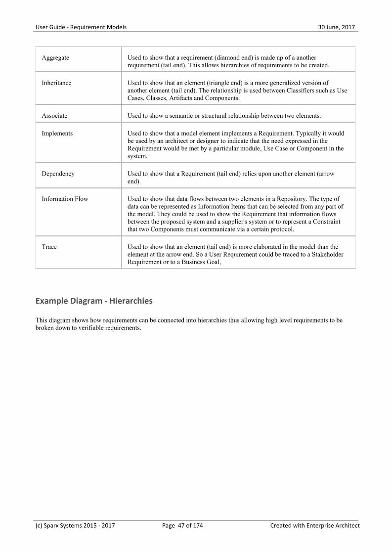
Aggregate Used to show that a requirement (diamond end) is made up of a anotherrequirement (tail end). This allows hierarchies of requirements to be created.
Inheritance Used to show that an element (triangle end) is a more generalized version ofanother element (tail end). The relationship is used between Classifiers such as UseCases, Classes, Artifacts and Components.
Associate Used to show a semantic or structural relationship between two elements.
Implements Used to show that a model element implements a Requirement. Typically it wouldbe used by an architect or designer to indicate that the need expressed in theRequirement would be met by a particular module, Use Case or Component in thesystem.
Dependency Used to show that a Requirement (tail end) relies upon another element (arrowend).
Information Flow Used to show that data flows between two elements in a Repository. The type ofdata can be represented as Information Items that can be selected from any part ofthe model. They could be used to show the Requirement that information flowsbetween the proposed system and a supplier's system or to represent a Constraintthat two Components must communicate via a certain protocol.
Trace Used to show that an element (tail end) is more elaborated in the model than theelement at the arrow end. So a User Requirement could be traced to a StakeholderRequirement or to a Business Goal,
Example Diagram - Hierarchies
This diagram shows how requirements can be connected into hierarchies thus allowing high level requirements to bebroken down to verifiable requirements.
(c) Sparx Systems 2015 - 2017 Page 47 of 174 Created with Enterprise Architect
User Guide - Requirement Models 30 June, 2017
REQ020 - Receive Books
REQ019 - Manage Inventory
REQ022 - Order Books
REQ023 - Store and Manage Books
REQ027 - Add Books
REQ021 - List Stock Levels
Requirements can be grouped into hierarchies effectively decomposing a high level requirement. The UML Aggregation relationship is typically used for this purpose. Requirements can also be nested in the Project Browser creating a tree of requirements.
Requirements DiagramEnterprise Architect allows you to document requirements graphically using the Requirement element. The Requirement element is available from the 'Requirements' Toolbox folder.
Using a Requirement element in the UML model, allows relationships to be drawn between requirements. It also allows for direct traceability to other aspects of the model such as Use Cases, Test Cases and other Analysis or Design elements.
The requirement element can be used to model or document any requirements, ranging from formal business requirements through to performance or security requirements.
Requirement Traces
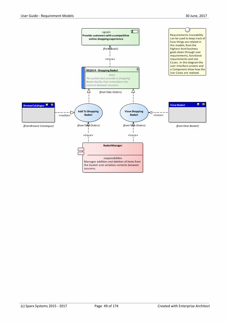
Example Diagram - Traces
This diagram shows how Requirements can be connected to other elements in the model thus displaying traceability.
(c) Sparx Systems 2015 - 2017 Page 48 of 174 Created with Enterprise Architect
User Guide - Requirement Models 30 June, 2017
(from Take Orders)
View Shopping Basket
(from Take Orders)
Add To Shopping Basket
View Basket
(from View Basket)
BrowseCatalogue
(from Browse Catalogue)
REQ014 - Shopping Basket
notesThe system must provide a shoppingBasket facility that remembers thecontents between sessions.
(from Take Orders)
«goal»Provide customers with a competitive
online shopping experience
(from Goals)
BasketManager
responsibilitiesManages addition and deletion of items fromthe basket and serializes contents betweensessions.
Requirements traceability can be used to keep track ofhow things are related in the models, from the highest level business goals down through user requirements, functional requirements and Use Cases. In this diagram the user interface screens and a Component show how theUse Cases are realized.
«realize» «trace»
«trace»
«trace»«trace»
(c) Sparx Systems 2015 - 2017 Page 49 of 174 Created with Enterprise Architect
User Guide - Requirement Models 30 June, 2017
Creating and Viewing Requirements
Enterprise Architect is a sophisticated and flexible modeling platform and the tool offers a rich set of features for boththe development and the management of requirements for any size project in any domain and using a variety ofprocesses. Requirements can be created in a variety of ways and then visualized in a series of windows and dialogs thatmake it easy to develop and manage them and to communicate within the team and to the business customers.
Viewing Requirements
Facility Description
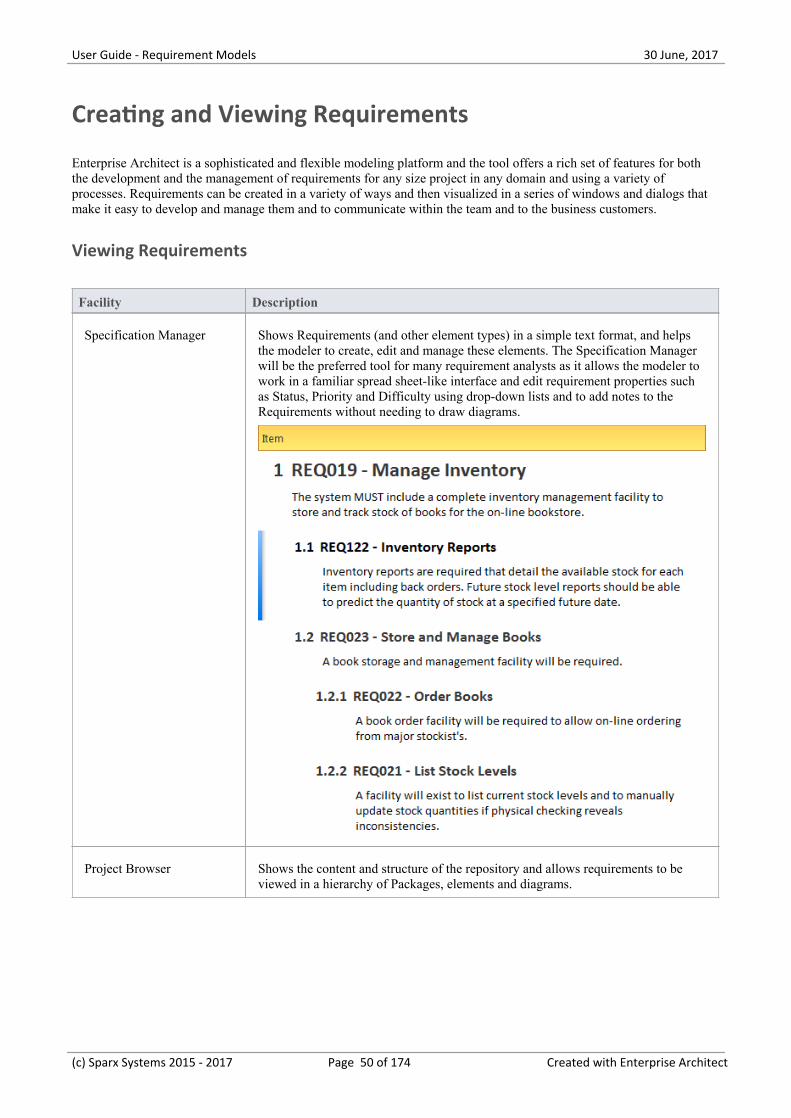
Specification Manager Shows Requirements (and other element types) in a simple text format, and helpsthe modeler to create, edit and manage these elements. The Specification Managerwill be the preferred tool for many requirement analysts as it allows the modeler towork in a familiar spread sheet-like interface and edit requirement properties suchas Status, Priority and Difficulty using drop-down lists and to add notes to theRequirements without needing to draw diagrams.
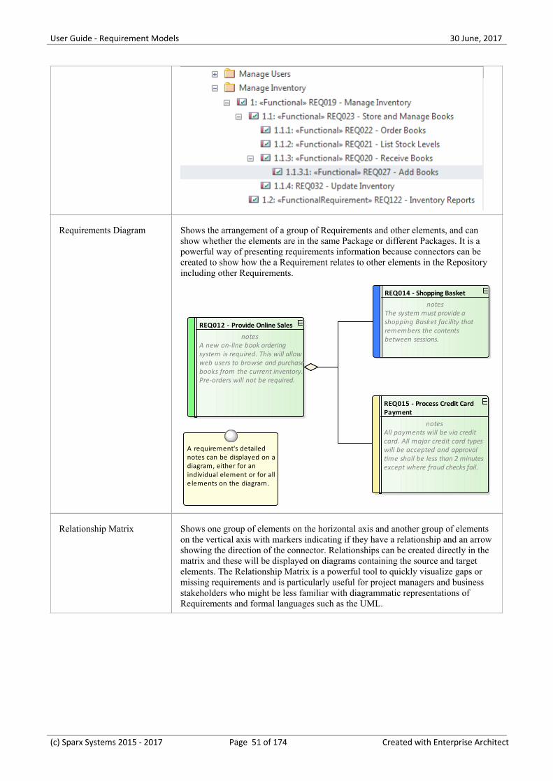
Project Browser Shows the content and structure of the repository and allows requirements to beviewed in a hierarchy of Packages, elements and diagrams.
(c) Sparx Systems 2015 - 2017 Page 50 of 174 Created with Enterprise Architect
User Guide - Requirement Models 30 June, 2017
Requirements Diagram Shows the arrangement of a group of Requirements and other elements, and canshow whether the elements are in the same Package or different Packages. It is apowerful way of presenting requirements information because connectors can becreated to show how the a Requirement relates to other elements in the Repositoryincluding other Requirements.
REQ012 - Provide Online Sales
notesA new on-line book orderingsystem is required. This will allowweb users to browse and purchasebooks from the current inventory.Pre-orders will not be required.
REQ014 - Shopping Basket
notesThe system must provide ashopping Basket facility thatremembers the contentsbetween sessions.
REQ015 - Process Credit Card Payment
notesAll payments will be via creditcard. All major credit card typeswill be accepted and approvaltime shall be less than 2 minutesexcept where fraud checks fail.
A requirement's detailed notes can be displayed on adiagram, either for an individual element or for alle lements on the diagram.
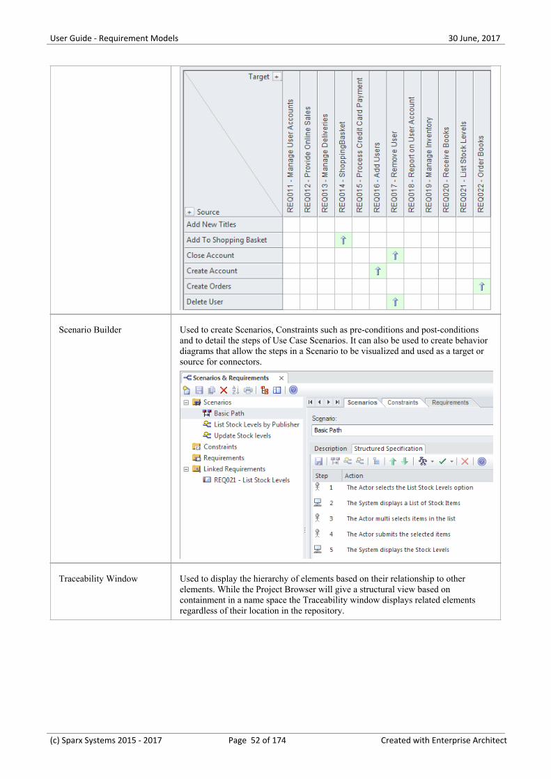
Relationship Matrix Shows one group of elements on the horizontal axis and another group of elementson the vertical axis with markers indicating if they have a relationship and an arrowshowing the direction of the connector. Relationships can be created directly in thematrix and these will be displayed on diagrams containing the source and targetelements. The Relationship Matrix is a powerful tool to quickly visualize gaps ormissing requirements and is particularly useful for project managers and businessstakeholders who might be less familiar with diagrammatic representations ofRequirements and formal languages such as the UML.
(c) Sparx Systems 2015 - 2017 Page 51 of 174 Created with Enterprise Architect
User Guide - Requirement Models 30 June, 2017
Scenario Builder Used to create Scenarios, Constraints such as pre-conditions and post-conditionsand to detail the steps of Use Case Scenarios. It can also be used to create behaviordiagrams that allow the steps in a Scenario to be visualized and used as a target orsource for connectors.
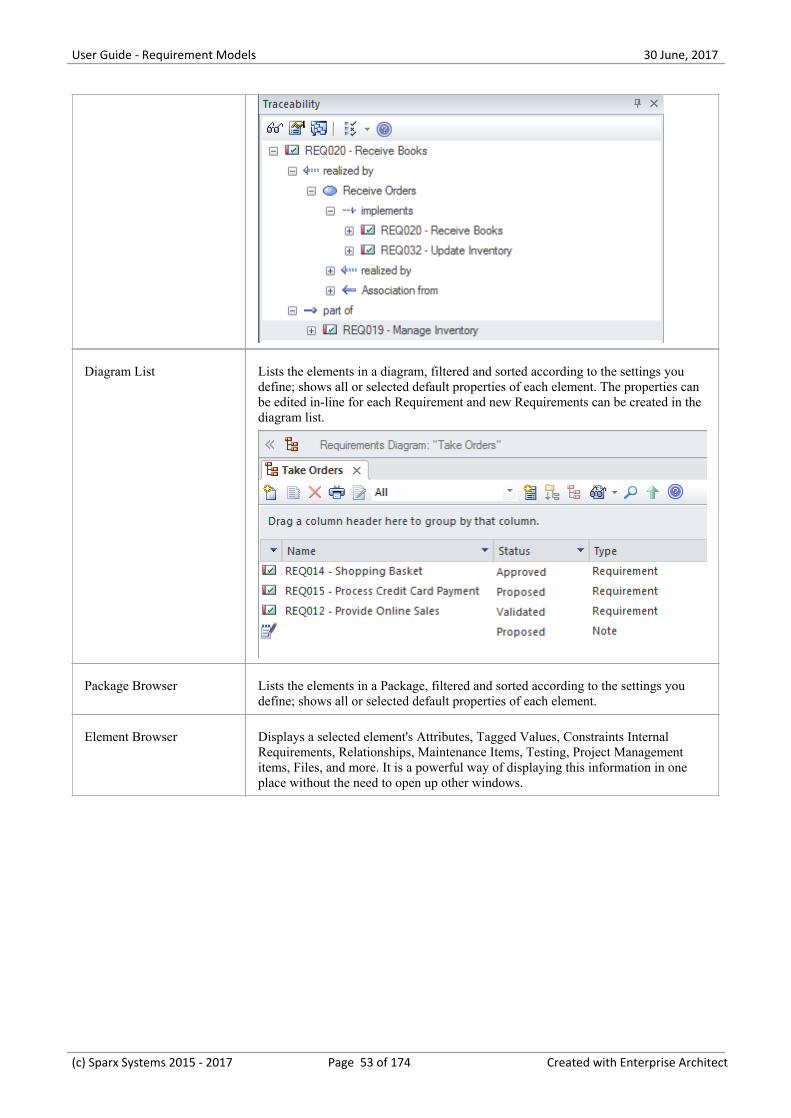
Traceability Window Used to display the hierarchy of elements based on their relationship to otherelements. While the Project Browser will give a structural view based oncontainment in a name space the Traceability window displays related elementsregardless of their location in the repository.
(c) Sparx Systems 2015 - 2017 Page 52 of 174 Created with Enterprise Architect
User Guide - Requirement Models 30 June, 2017
Diagram List Lists the elements in a diagram, filtered and sorted according to the settings youdefine; shows all or selected default properties of each element. The properties canbe edited in-line for each Requirement and new Requirements can be created in thediagram list.
Package Browser Lists the elements in a Package, filtered and sorted according to the settings youdefine; shows all or selected default properties of each element.
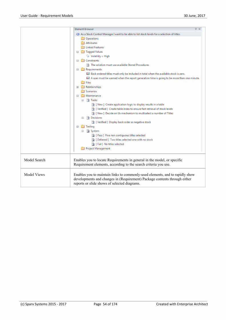
Element Browser Displays a selected element's Attributes, Tagged Values, Constraints InternalRequirements, Relationships, Maintenance Items, Testing, Project Managementitems, Files, and more. It is a powerful way of displaying this information in oneplace without the need to open up other windows.
(c) Sparx Systems 2015 - 2017 Page 53 of 174 Created with Enterprise Architect
User Guide - Requirement Models 30 June, 2017
Model Search Enables you to locate Requirements in general in the model, or specificRequirement elements, according to the search criteria you use.
Model Views Enables you to maintain links to commonly-used elements, and to rapidly showdevelopments and changes in (Requirement) Package contents through eitherreports or slide shows of selected diagrams.
(c) Sparx Systems 2015 - 2017 Page 54 of 174 Created with Enterprise Architect
User Guide - Requirement Models 30 June, 2017
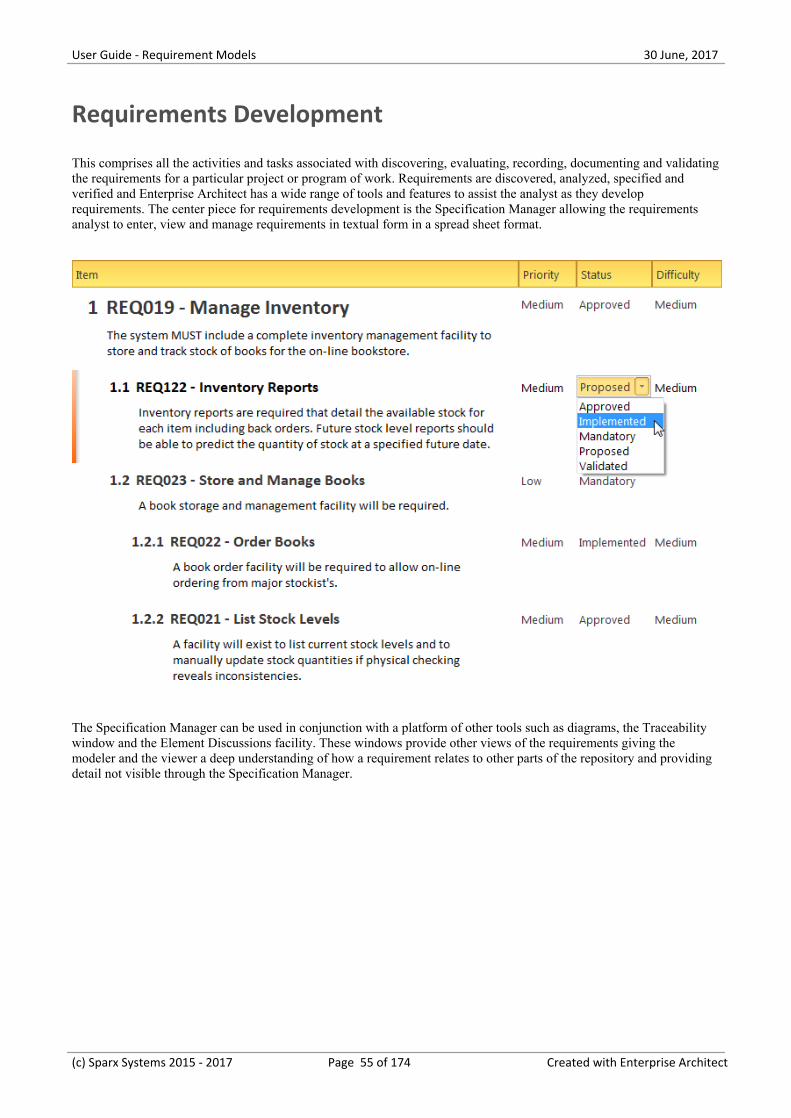
Requirements Development
This comprises all the activities and tasks associated with discovering, evaluating, recording, documenting and validatingthe requirements for a particular project or program of work. Requirements are discovered, analyzed, specified andverified and Enterprise Architect has a wide range of tools and features to assist the analyst as they developrequirements. The center piece for requirements development is the Specification Manager allowing the requirementsanalyst to enter, view and manage requirements in textual form in a spread sheet format.
The Specification Manager can be used in conjunction with a platform of other tools such as diagrams, the Traceabilitywindow and the Element Discussions facility. These windows provide other views of the requirements giving themodeler and the viewer a deep understanding of how a requirement relates to other parts of the repository and providingdetail not visible through the Specification Manager.
(c) Sparx Systems 2015 - 2017 Page 55 of 174 Created with Enterprise Architect
User Guide - Requirement Models 30 June, 2017
(c) Sparx Systems 2015 - 2017 Page 56 of 174 Created with Enterprise Architect
User Guide - Requirement Models 30 June, 2017
Elicitation
Elicitation is the process of information discovery; this information will form the precursors to requirements. Theinformation will typically be raw and often heterogeneous, and it will not be until the requirements analysis phase isperformed that true requirements will be able to be derived from this information. Elicitation will take many forms andall of the skills of the analyst will be needed to determine which documents, tools, people and processes to examine todiscover the information. Some of these locations are listed in this table.
Location of requirements information
Requirements are not handed to the analyst on a plate but rather will be discovered in a variety of places including: byobserving stakeholders performing their work, in business documents and a variety of other locations.
Source Description
Observing Users Observing users perform their work is a powerful way of gaining information aboutRequirements and often reveals details that would not be discovered by userinterviews.
Business Documents A number of business documents such as the Business Case, Vision or Concept ofOperation will provide a source for Business Requirements and should bediscovered and included as sources of Requirements.
Stakeholder Workshops Getting all the important stakeholders into a workshop is a powerful and productiveway to get information that will help with the Requirements definition. Typicallythere are fertile and robust discussions that provide the basis for derivingRequirements.
Current System Issues There will often be documented information recording errors, faults and issues withthe incumbent system that will provide the basis for Requirements for thereplacement system. Care needs to be taken that any Requirements derived fromthese list are owned by a stakeholder and that there is a business need to includethem in the new system.
(c) Sparx Systems 2015 - 2017 Page 57 of 174 Created with Enterprise Architect
User Guide - Requirement Models 30 June, 2017
User Observations
Observing users perform their work is a powerful and unobtrusive way of gaining an understanding of the tasks theycarry out and how they use information and other software and hardware devices to achieve an outcome. Even if theprocesses that support the planned system will be different, the observations of the current processes will provide auseful context for discussions. It will also help the analyst empathize with the user and can result in a deeperunderstanding of the issues they face and provide the basis for the discovery of potential solutions. An analyst will oftendiscover unmentioned documents, checklists and clue cards that can help illuminate the process. Equipped with a mobilephone or camera, it is also useful for the analyst to take photographs of the user working, which will help in therequirements analysis phase.
Enterprise Architect supports the modeler in representing files such as photos and scanned documents directly in themodel, creating a rich and expressive representation of the user at work. There is the option to represent these as anArtifact (which, with a single key stroke (F12), will launch the file) or to use a hyperlink or even to include the imageitself in a diagram.
(c) Sparx Systems 2015 - 2017 Page 58 of 174 Created with Enterprise Architect
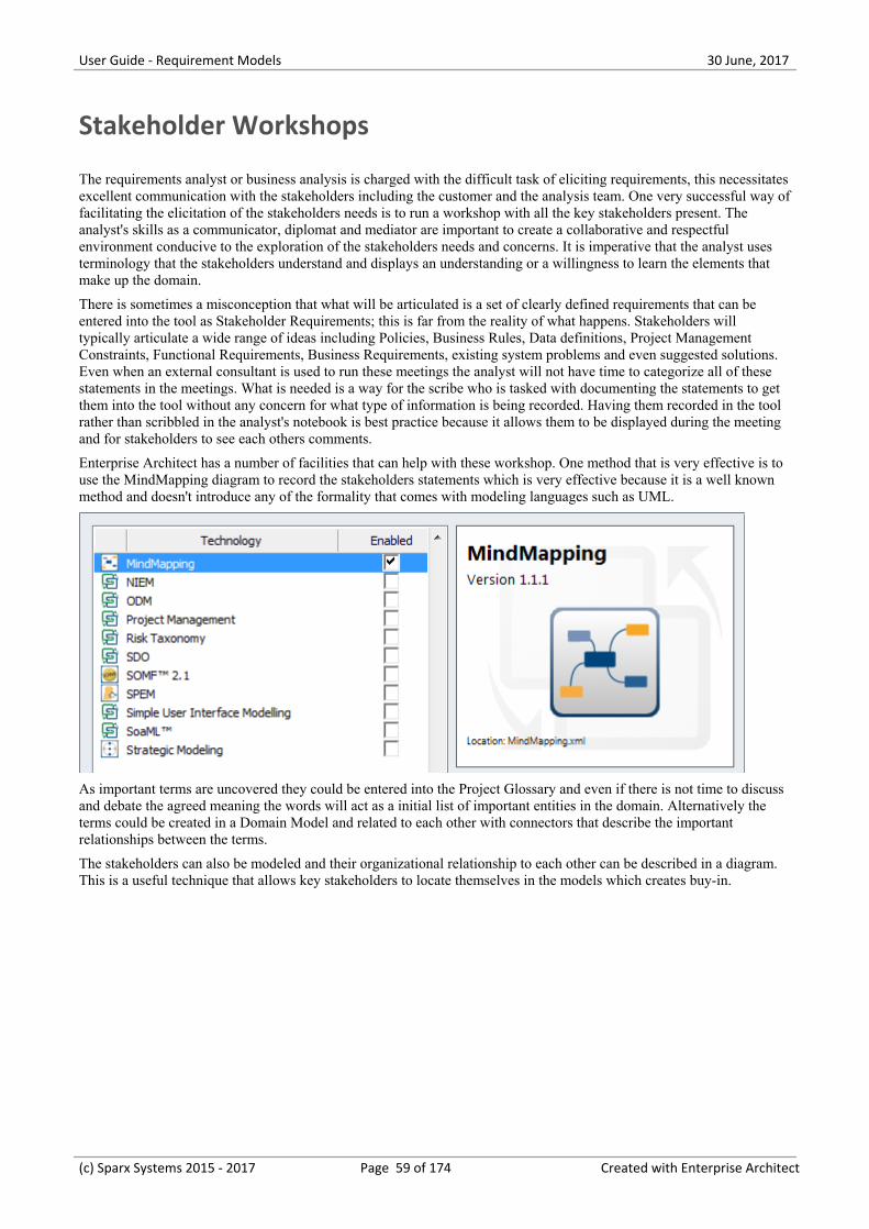
User Guide - Requirement Models 30 June, 2017
Stakeholder Workshops
The requirements analyst or business analysis is charged with the difficult task of eliciting requirements, this necessitatesexcellent communication with the stakeholders including the customer and the analysis team. One very successful way offacilitating the elicitation of the stakeholders needs is to run a workshop with all the key stakeholders present. Theanalyst's skills as a communicator, diplomat and mediator are important to create a collaborative and respectfulenvironment conducive to the exploration of the stakeholders needs and concerns. It is imperative that the analyst usesterminology that the stakeholders understand and displays an understanding or a willingness to learn the elements thatmake up the domain.
There is sometimes a misconception that what will be articulated is a set of clearly defined requirements that can beentered into the tool as Stakeholder Requirements; this is far from the reality of what happens. Stakeholders willtypically articulate a wide range of ideas including Policies, Business Rules, Data definitions, Project ManagementConstraints, Functional Requirements, Business Requirements, existing system problems and even suggested solutions.Even when an external consultant is used to run these meetings the analyst will not have time to categorize all of thesestatements in the meetings. What is needed is a way for the scribe who is tasked with documenting the statements to getthem into the tool without any concern for what type of information is being recorded. Having them recorded in the toolrather than scribbled in the analyst's notebook is best practice because it allows them to be displayed during the meetingand for stakeholders to see each others comments.
Enterprise Architect has a number of facilities that can help with these workshop. One method that is very effective is touse the MindMapping diagram to record the stakeholders statements which is very effective because it is a well knownmethod and doesn't introduce any of the formality that comes with modeling languages such as UML.
As important terms are uncovered they could be entered into the Project Glossary and even if there is not time to discussand debate the agreed meaning the words will act as a initial list of important entities in the domain. Alternatively theterms could be created in a Domain Model and related to each other with connectors that describe the importantrelationships between the terms.
The stakeholders can also be modeled and their organizational relationship to each other can be described in a diagram.This is a useful technique that allows key stakeholders to locate themselves in the models which creates buy-in.
(c) Sparx Systems 2015 - 2017 Page 59 of 174 Created with Enterprise Architect
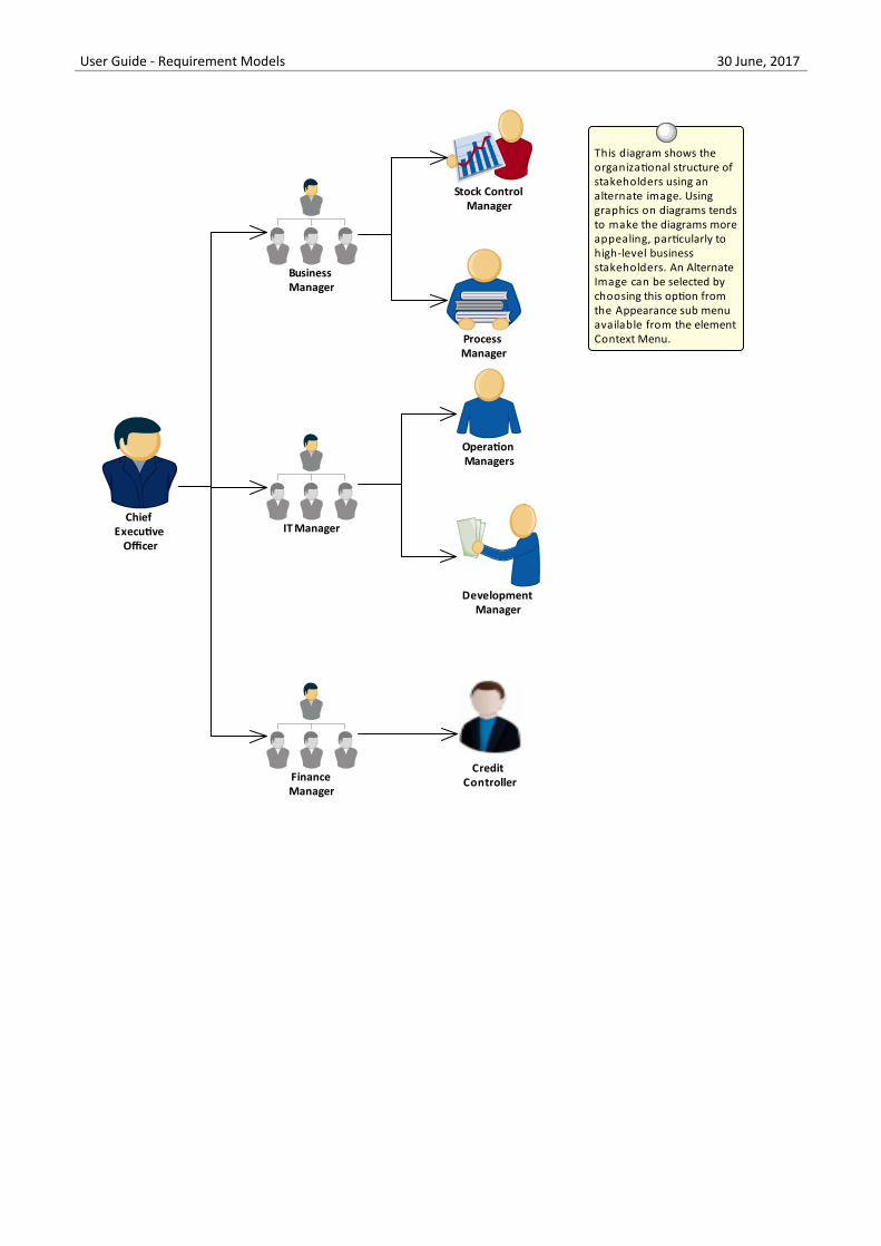
User Guide - Requirement Models 30 June, 2017
Chief Executive
Officer
This diagram shows the organizational structure of stakeholders using an alternate image. Using graphics on diagrams tends to make the diagrams more appealing, particularly to high-level business stakeholders. An Alternate Image can be selected by choosing this option from the Appearance sub menu available from the element Context Menu.
Finance Manager
Stock Control Manager
Development Manager
Process Manager
Business Manager
Operation Managers
IT Manager
Credit Controller
Mind Mapping Diagram
A Mind Mapping diagram can be used to record the stakeholder's statements during an elicitation workshop. Thestatements are not categorized but simply recorded and later during the analysis phase of Requirement's developmentthey can be converted to the appropriate elements or retained and the Requirements can be traced back to the topicseffectively creating a record of how the Requirement was derived. This is a powerful technique that shields thestakeholders from needing to know the modeling languages and allows them to concentrate on articulating their needs, italso frees the analyst up from concerns about which element to use to model the statements. This step is usuallyperformed in the analysis phase of the Requirement's Development process.
(c) Sparx Systems 2015 - 2017 Page 60 of 174 Created with Enterprise Architect
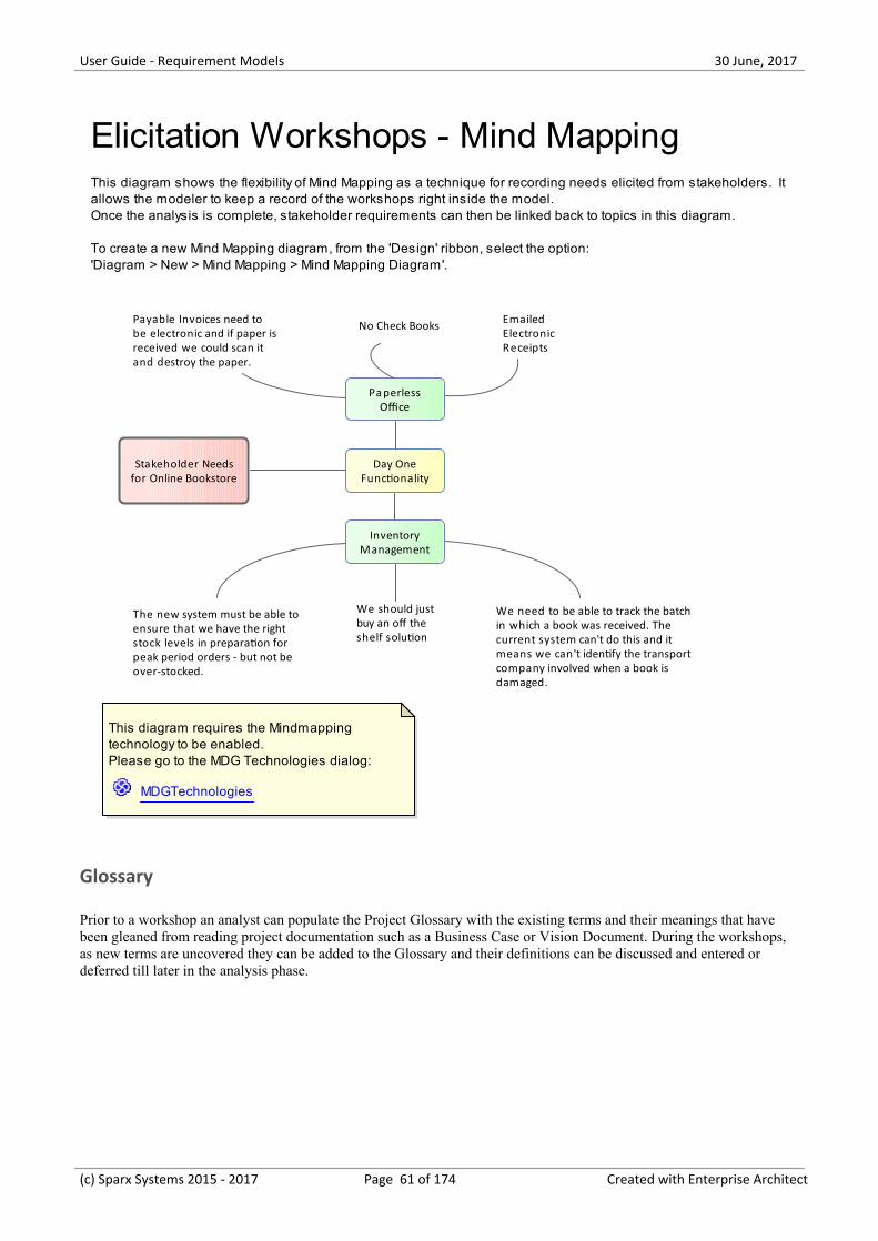
User Guide - Requirement Models 30 June, 2017
Stakeholder Needsfor Online Bookstore
Day OneFunctionality
PaperlessOffice
Payable Invoices need tobe electronic and if paper isreceived we could scan itand destroy the paper.
InventoryManagement
No Check Books EmailedElectronicReceipts
The new system must be able toensure that we have the rightstock levels in preparation forpeak period orders - but not beover-stocked.
We need to be able to track the batchin which a book was received. Thecurrent system can't do this and itmeans we can't identify the transportcompany involved when a book isdamaged.
We should justbuy an off theshelf solution
This diagram requires the Mindmapping technology to be enabled.Please go to the MDG Technologies dialog:
MDGTechnologies
Elicitation Workshops - Mind MappingThis diagram shows the flexibility of Mind Mapping as a technique for recording needs elicited from stakeholders. It allows the modeler to keep a record of the workshops right inside the model.Once the analysis is complete, stakeholder requirements can then be linked back to topics in this diagram.
To create a new Mind Mapping diagram, from the 'Design' ribbon, select the option:'Diagram > New > Mind Mapping > Mind Mapping Diagram'.
Glossary
Prior to a workshop an analyst can populate the Project Glossary with the existing terms and their meanings that havebeen gleaned from reading project documentation such as a Business Case or Vision Document. During the workshops,as new terms are uncovered they can be added to the Glossary and their definitions can be discussed and entered ordeferred till later in the analysis phase.
(c) Sparx Systems 2015 - 2017 Page 61 of 174 Created with Enterprise Architect
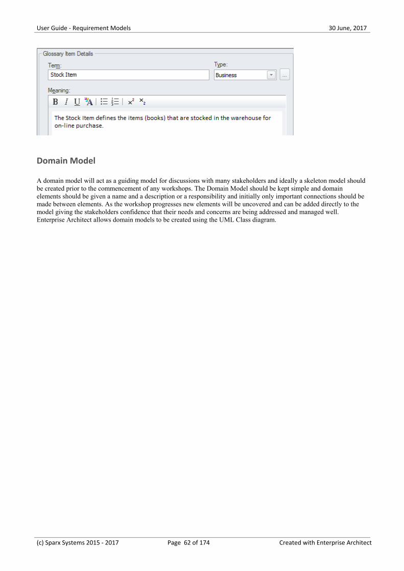
User Guide - Requirement Models 30 June, 2017
Domain Model
A domain model will act as a guiding model for discussions with many stakeholders and ideally a skeleton model shouldbe created prior to the commencement of any workshops. The Domain Model should be kept simple and domainelements should be given a name and a description or a responsibility and initially only important connections should bemade between elements. As the workshop progresses new elements will be uncovered and can be added directly to themodel giving the stakeholders confidence that their needs and concerns are being addressed and managed well.Enterprise Architect allows domain models to be created using the UML Class diagram.
(c) Sparx Systems 2015 - 2017 Page 62 of 174 Created with Enterprise Architect
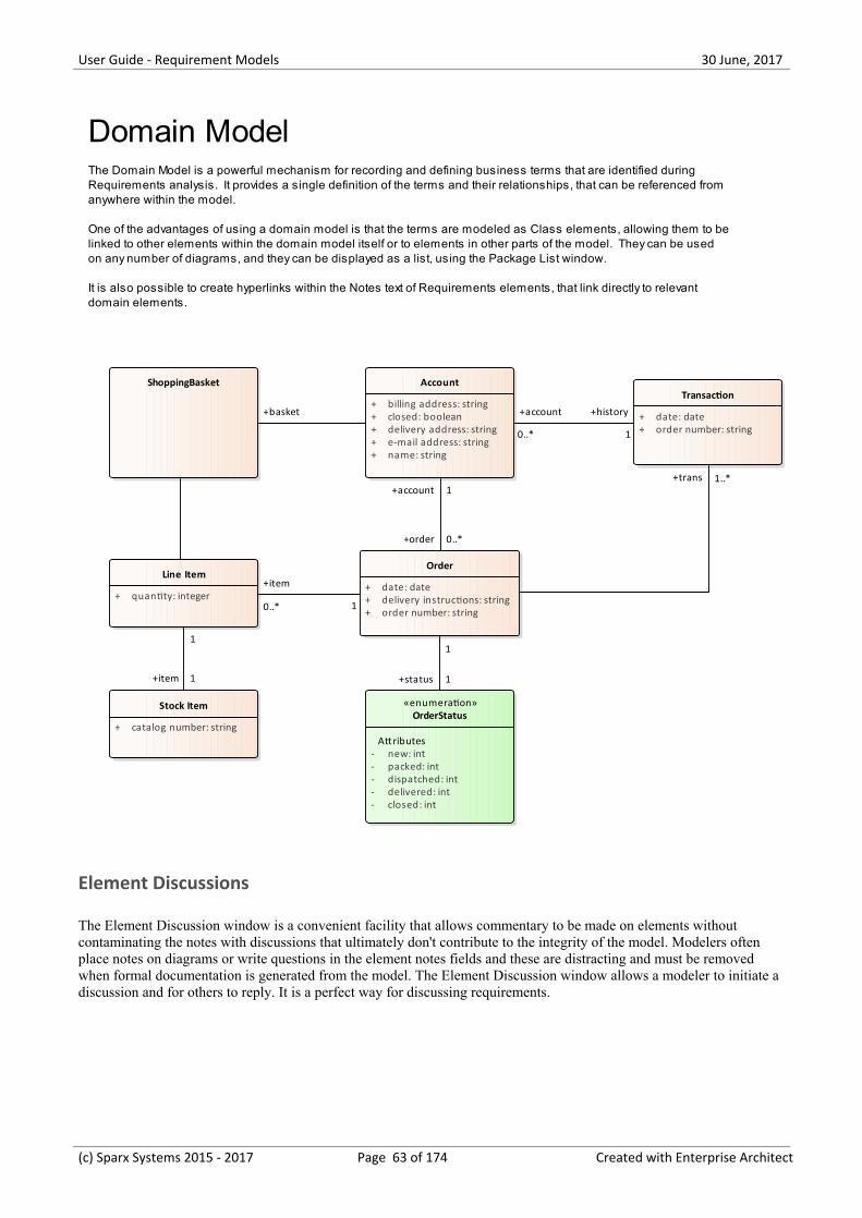
User Guide - Requirement Models 30 June, 2017
ShoppingBasket Account
+ billing address: string+ closed: boolean+ delivery address: string+ e-mail address: string+ name: string
Order
+ date: date+ delivery instructions: string+ order number: string
Transaction
+ date: date+ order number: string
Line Item
+ quantity: integer
Stock Item
+ catalog number: string
«enumeration»OrderStatus
Attributes- new: int- packed: int- dispatched: int- delivered: int- closed: int
Domain ModelThe Domain Model is a powerful mechanism for recording and defining business terms that are identified during Requirements analysis. It provides a single definition of the terms and their relationships, that can be referenced from anywhere within the model.
One of the advantages of using a domain model is that the terms are modeled as Class elements, allowing them to belinked to other elements within the domain model itself or to elements in other parts of the model. They can be used on any number of diagrams, and they can be displayed as a list, using the Package List window.
It is also possible to create hyperlinks within the Notes text of Requirements elements, that link directly to relevant domain elements.
1
+item 1
+trans 1..*
+history
1
+account
0..*
1
+status 1
+basket
1
+item
0..*
+account 1
+order 0..*
Element Discussions
The Element Discussion window is a convenient facility that allows commentary to be made on elements withoutcontaminating the notes with discussions that ultimately don't contribute to the integrity of the model. Modelers oftenplace notes on diagrams or write questions in the element notes fields and these are distracting and must be removedwhen formal documentation is generated from the model. The Element Discussion window allows a modeler to initiate adiscussion and for others to reply. It is a perfect way for discussing requirements.
(c) Sparx Systems 2015 - 2017 Page 63 of 174 Created with Enterprise Architect
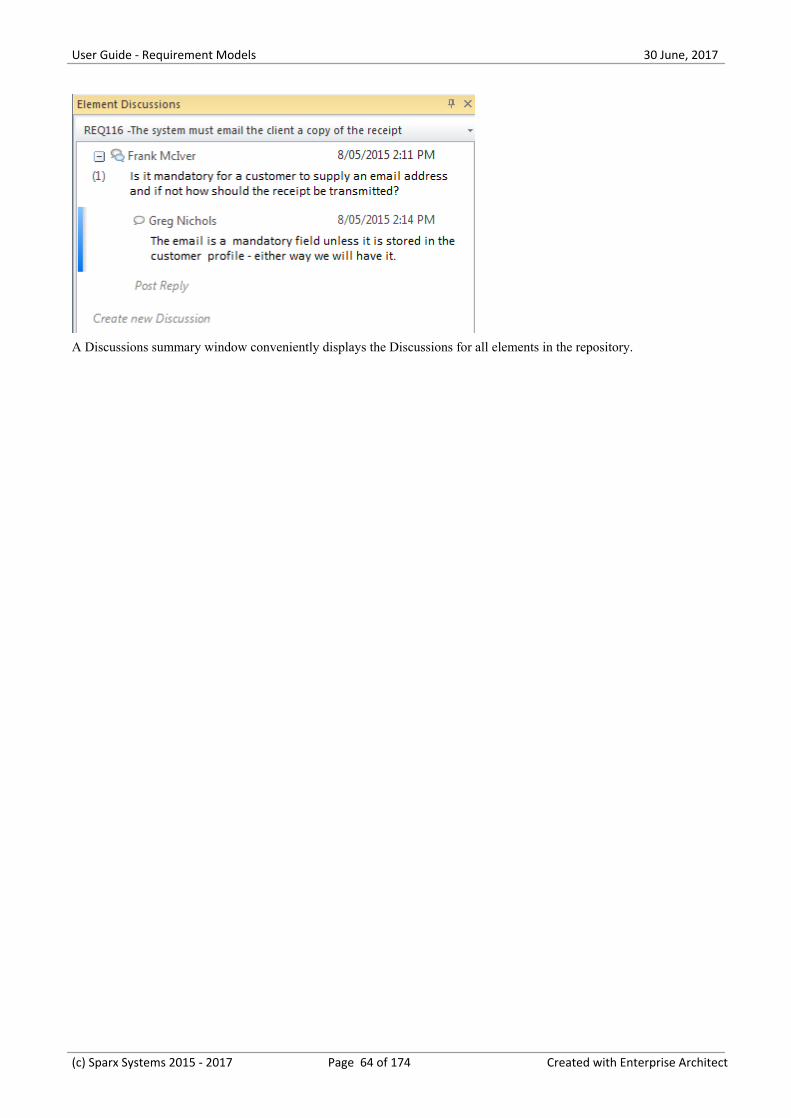
User Guide - Requirement Models 30 June, 2017
A Discussions summary window conveniently displays the Discussions for all elements in the repository.
(c) Sparx Systems 2015 - 2017 Page 64 of 174 Created with Enterprise Architect
User Guide - Requirement Models 30 June, 2017
Creating Requirements
Enterprise Architect has extensive support for developing Requirements and provides a number of specialized tools forthis purpose. As with all model content a modeler is encouraged to check whether the Requirements have been enteredinto the repository by someone else before embarking on the task of creating new Requirements. It is also possible thatthe Requirements have been defined in another tool such as a spread sheet and could be imported into EnterpriseArchitect without the need to create each Requirement manually. Enterprise Architect has two locations forRequirements; they can be created in the model as an element that will appear in the Project Browser, or they can becreated inside another element as an Internal Requirement.
(c) Sparx Systems 2015 - 2017 Page 65 of 174 Created with Enterprise Architect
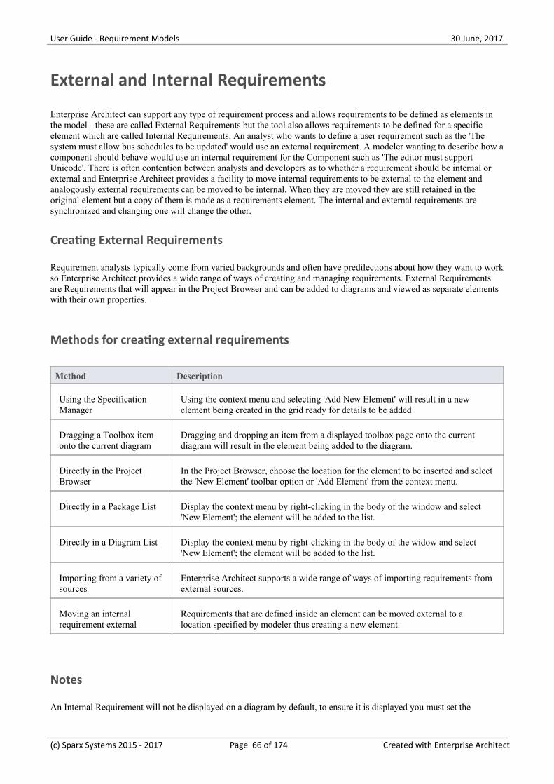
User Guide - Requirement Models 30 June, 2017
External and Internal Requirements
Enterprise Architect can support any type of requirement process and allows requirements to be defined as elements inthe model - these are called External Requirements but the tool also allows requirements to be defined for a specificelement which are called Internal Requirements. An analyst who wants to define a user requirement such as the 'Thesystem must allow bus schedules to be updated' would use an external requirement. A modeler wanting to describe how acomponent should behave would use an internal requirement for the Component such as 'The editor must supportUnicode'. There is often contention between analysts and developers as to whether a requirement should be internal orexternal and Enterprise Architect provides a facility to move internal requirements to be external to the element andanalogously external requirements can be moved to be internal. When they are moved they are still retained in theoriginal element but a copy of them is made as a requirements element. The internal and external requirements aresynchronized and changing one will change the other.
Creating External Requirements
Requirement analysts typically come from varied backgrounds and often have predilections about how they want to workso Enterprise Architect provides a wide range of ways of creating and managing requirements. External Requirementsare Requirements that will appear in the Project Browser and can be added to diagrams and viewed as separate elementswith their own properties.
Methods for creating external requirements
Method Description
Using the SpecificationManager
Using the context menu and selecting 'Add New Element' will result in a newelement being created in the grid ready for details to be added
Dragging a Toolbox itemonto the current diagram
Dragging and dropping an item from a displayed toolbox page onto the currentdiagram will result in the element being added to the diagram.
Directly in the ProjectBrowser
In the Project Browser, choose the location for the element to be inserted and selectthe 'New Element' toolbar option or 'Add Element' from the context menu.
Directly in a Package List Display the context menu by right-clicking in the body of the window and select'New Element'; the element will be added to the list.
Directly in a Diagram List Display the context menu by right-clicking in the body of the widow and select'New Element'; the element will be added to the list.
Importing from a variety ofsources
Enterprise Architect supports a wide range of ways of importing requirements fromexternal sources.
Moving an internalrequirement external
Requirements that are defined inside an element can be moved external to alocation specified by modeler thus creating a new element.
Notes
An Internal Requirement will not be displayed on a diagram by default, to ensure it is displayed you must set the
(c) Sparx Systems 2015 - 2017 Page 66 of 174 Created with Enterprise Architect
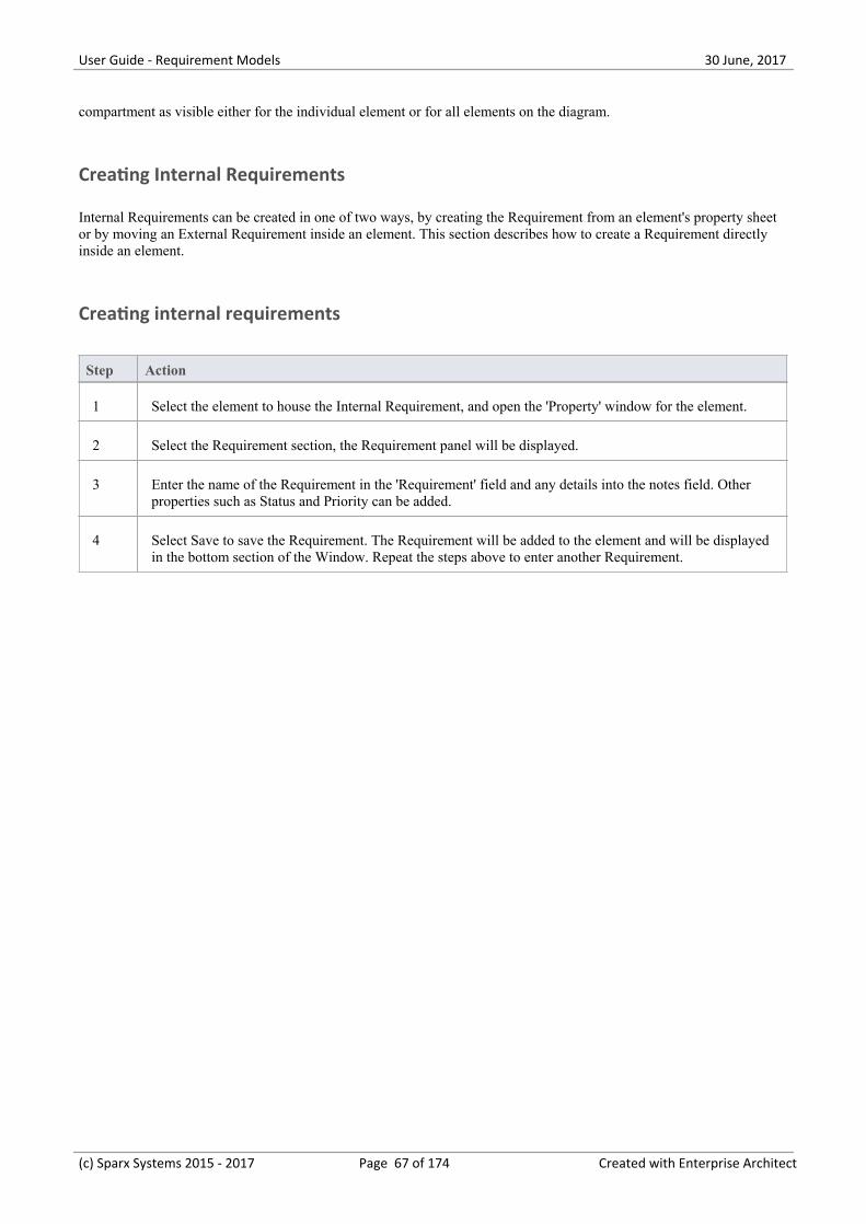
User Guide - Requirement Models 30 June, 2017
compartment as visible either for the individual element or for all elements on the diagram.
Creating Internal Requirements
Internal Requirements can be created in one of two ways, by creating the Requirement from an element's property sheetor by moving an External Requirement inside an element. This section describes how to create a Requirement directlyinside an element.
Creating internal requirements
Step Action
1 Select the element to house the Internal Requirement, and open the 'Property' window for the element.
2 Select the Requirement section, the Requirement panel will be displayed.
3 Enter the name of the Requirement in the 'Requirement' field and any details into the notes field. Otherproperties such as Status and Priority can be added.
4 Select Save to save the Requirement. The Requirement will be added to the element and will be displayedin the bottom section of the Window. Repeat the steps above to enter another Requirement.
(c) Sparx Systems 2015 - 2017 Page 67 of 174 Created with Enterprise Architect
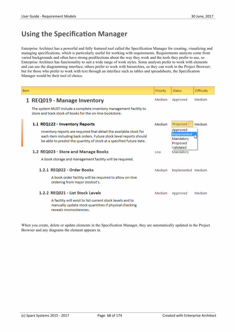
User Guide - Requirement Models 30 June, 2017
Using the Specification Manager
Enterprise Architect has a powerful and fully featured tool called the Specification Manager for creating, visualizing andmanaging specifications, which is particularly useful for working with requirements. Requirements analysts come fromvaried backgrounds and often have strong predilections about the way they work and the tools they prefer to use, soEnterprise Architect has functionality to suit a wide range of work styles. Some analysts prefer to work with elementsand can use the diagramming interface; others prefer to work with hierarchies, so they can work in the Project Browser;but for those who prefer to work with text through an interface such as tables and spreadsheets, the SpecificationManager would be their tool of choice.
When you create, delete or update elements in the Specification Manager, they are automatically updated in the ProjectBrowser and any diagrams the element appears in.
(c) Sparx Systems 2015 - 2017 Page 68 of 174 Created with Enterprise Architect
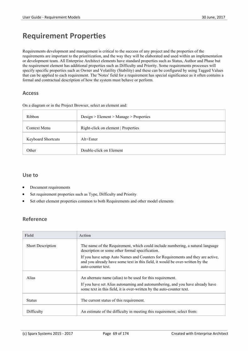
User Guide - Requirement Models 30 June, 2017
Requirement Properties
Requirements development and management is critical to the success of any project and the properties of therequirements are important to the prioritization, and the way they will be elaborated and used within an implementationor development team. All Enterprise Architect elements have standard properties such as Status, Author and Phase butthe requirement element has additional properties such as Difficulty and Priority. Some requirements processes willspecify specific properties such as Owner and Volatility (Stability) and these can be configured by using Tagged Valuesthat can be applied to each requirement. The 'Notes' field for a requirement has special significance as it often contains aformal and contractual description of how the system must behave or perform.
Access
On a diagram or in the Project Browser, select an element and:
Ribbon Design > Element > Manage > Properties
Context Menu Right-click on element | Properties
Keyboard Shortcuts Alt+Enter
Other Double-click on Element
Use to
Document requirements·Set requirement properties such as Type, Difficulty and Priority·Set other element properties common to both Requirements and other model elements·
Reference
Field Action
Short Description The name of the Requirement, which could include numbering, a natural languagedescription or some other formal specification.
If you have setup Auto Names and Counters for Requirements and they are active,and you already have some text in this field, it would be over-written by theauto-counter text.
Alias An alternate name (alias) to be used for this requirement.
If you have set Alias autonaming and autonumbering, and you have already havesome text in this field, it is over-written by the auto-counter text.
Status The current status of this requirement.
Difficulty An estimate of the difficulty in meeting this requirement; select from:
(c) Sparx Systems 2015 - 2017 Page 69 of 174 Created with Enterprise Architect
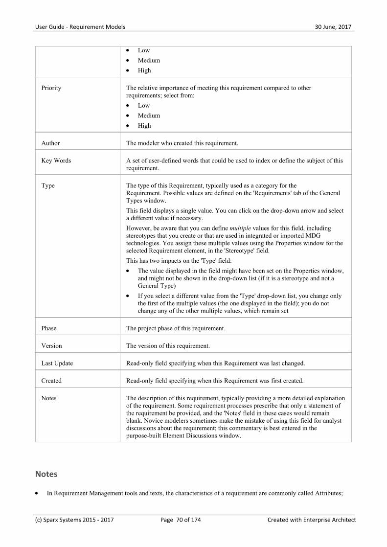
User Guide - Requirement Models 30 June, 2017
Low·Medium·High·
Priority The relative importance of meeting this requirement compared to otherrequirements; select from:
Low·Medium·High·
Author The modeler who created this requirement.
Key Words A set of user-defined words that could be used to index or define the subject of thisrequirement.
Type The type of this Requirement, typically used as a category for theRequirement. Possible values are defined on the 'Requirements' tab of the GeneralTypes window.
This field displays a single value. You can click on the drop-down arrow and selecta different value if necessary.
However, be aware that you can define multiple values for this field, includingstereotypes that you create or that are used in integrated or imported MDGtechnologies. You assign these multiple values using the Properties window for theselected Requirement element, in the 'Stereotype' field.
This has two impacts on the 'Type' field:
The value displayed in the field might have been set on the Properties window,·and might not be shown in the drop-down list (if it is a stereotype and not aGeneral Type)
If you select a different value from the 'Type' drop-down list, you change only·the first of the multiple values (the one displayed in the field); you do notchange any of the other multiple values, which remain set
Phase The project phase of this requirement.
Version The version of this requirement.
Last Update Read-only field specifying when this Requirement was last changed.
Created Read-only field specifying when this Requirement was first created.
Notes The description of this requirement, typically providing a more detailed explanationof the requirement. Some requirement processes prescribe that only a statement ofthe requirement be provided, and the 'Notes' field in these cases would remainblank. Novice modelers sometimes make the mistake of using this field for analystdiscussions about the requirement; this commentary is best entered in thepurpose-built Element Discussions window.
Notes
In Requirement Management tools and texts, the characteristics of a requirement are commonly called Attributes;·
(c) Sparx Systems 2015 - 2017 Page 70 of 174 Created with Enterprise Architect
User Guide - Requirement Models 30 June, 2017
however, in UML the term Attribute refers to a different type of feature, and the Requirement characteristics aredefined as properties - in this Enterprise Architect documentation, the term properties is used.
In a project, it might be necessary to define more information in a Requirement than is provided by the standard·properties and Tagged Values can be used for this purpose.
(c) Sparx Systems 2015 - 2017 Page 71 of 174 Created with Enterprise Architect
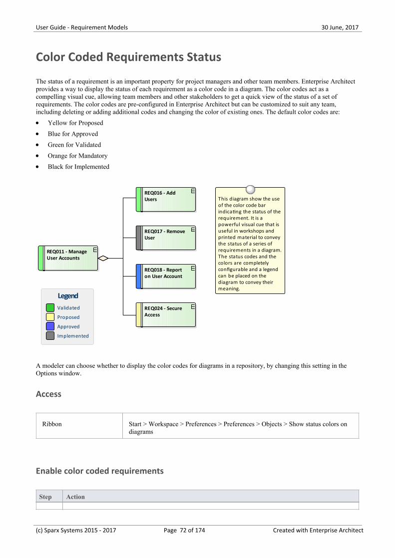
User Guide - Requirement Models 30 June, 2017
Color Coded Requirements Status
The status of a requirement is an important property for project managers and other team members. Enterprise Architectprovides a way to display the status of each requirement as a color code in a diagram. The color codes act as acompelling visual cue, allowing team members and other stakeholders to get a quick view of the status of a set ofrequirements. The color codes are pre-configured in Enterprise Architect but can be customized to suit any team,including deleting or adding additional codes and changing the color of existing ones. The default color codes are:
Yellow for Proposed·Blue for Approved·Green for Validated·Orange for Mandatory·Black for Implemented·
REQ011 - Manage User Accounts
REQ018 - Report on User Account
REQ024 - Secure Access
REQ017 - Remove User
REQ016 - Add Users This diagram show the use
of the color code bar indicating the status of the requirement. It is a powerful visual cue that is useful in workshops and printed material to convey the status of a series of requirements in a diagram. The status codes and the colors are completely configurable and a legend can be placed on the diagram to convey their meaning.
Validated
Proposed
Approved
Implemented
Legend
A modeler can choose whether to display the color codes for diagrams in a repository, by changing this setting in theOptions window.
Access
Ribbon Start > Workspace > Preferences > Preferences > Objects > Show status colors ondiagrams
Enable color coded requirements
Step Action
(c) Sparx Systems 2015 - 2017 Page 72 of 174 Created with Enterprise Architect
User Guide - Requirement Models 30 June, 2017
1 Select the 'Show status colors on diagrams' checkbox to enable the status of requirements to berepresented by color coding in a diagram.
(c) Sparx Systems 2015 - 2017 Page 73 of 174 Created with Enterprise Architect
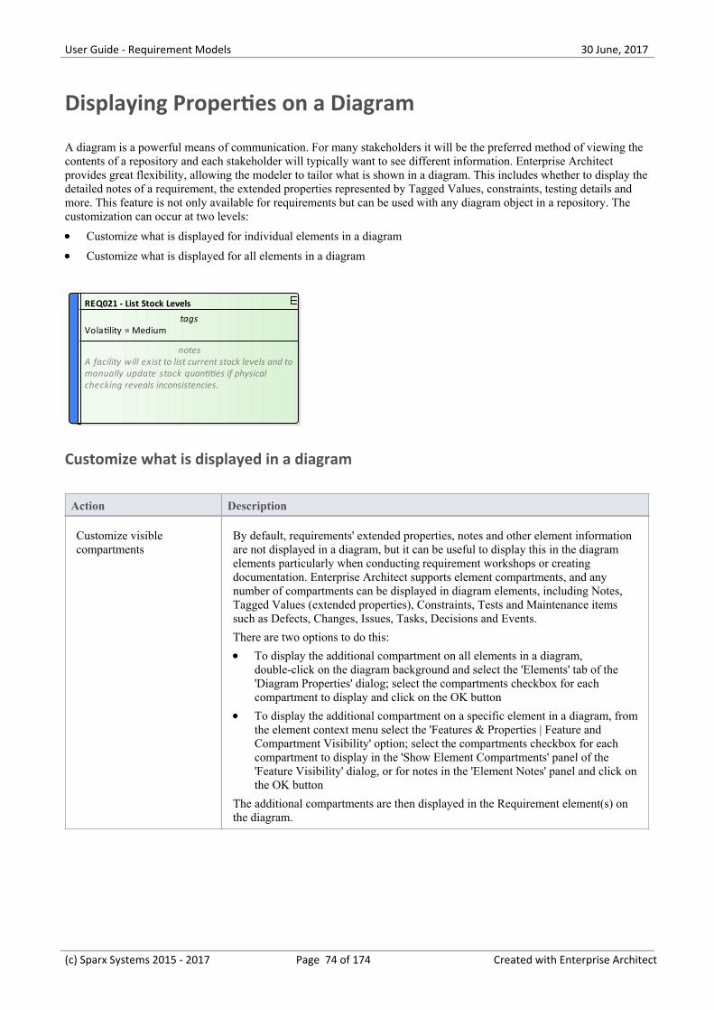
User Guide - Requirement Models 30 June, 2017
Displaying Properties on a Diagram
A diagram is a powerful means of communication. For many stakeholders it will be the preferred method of viewing thecontents of a repository and each stakeholder will typically want to see different information. Enterprise Architectprovides great flexibility, allowing the modeler to tailor what is shown in a diagram. This includes whether to display thedetailed notes of a requirement, the extended properties represented by Tagged Values, constraints, testing details andmore. This feature is not only available for requirements but can be used with any diagram object in a repository. Thecustomization can occur at two levels:
Customize what is displayed for individual elements in a diagram·Customize what is displayed for all elements in a diagram·
REQ021 - List Stock Levels
tagsVolatility = Medium
notesA facility will exist to list current stock levels and tomanually update stock quantities if physicalchecking reveals inconsistencies.
Customize what is displayed in a diagram
Action Description
Customize visiblecompartments
By default, requirements' extended properties, notes and other element informationare not displayed in a diagram, but it can be useful to display this in the diagramelements particularly when conducting requirement workshops or creatingdocumentation. Enterprise Architect supports element compartments, and anynumber of compartments can be displayed in diagram elements, including Notes,Tagged Values (extended properties), Constraints, Tests and Maintenance itemssuch as Defects, Changes, Issues, Tasks, Decisions and Events.
There are two options to do this:
To display the additional compartment on all elements in a diagram,·double-click on the diagram background and select the 'Elements' tab of the'Diagram Properties' dialog; select the compartments checkbox for eachcompartment to display and click on the OK button
To display the additional compartment on a specific element in a diagram, from·the element context menu select the 'Features & Properties | Feature andCompartment Visibility' option; select the compartments checkbox for eachcompartment to display in the 'Show Element Compartments' panel of the'Feature Visibility' dialog, or for notes in the 'Element Notes' panel and click onthe OK button
The additional compartments are then displayed in the Requirement element(s) onthe diagram.
(c) Sparx Systems 2015 - 2017 Page 74 of 174 Created with Enterprise Architect
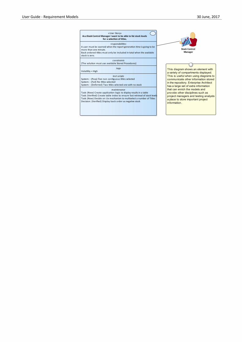
User Guide - Requirement Models 30 June, 2017
«User Story»As a Stock Control Manager I want to be able to list stock levels
for a selection of titles.
responsibilitiesA user must be warned when the report generation time is going to bemore than one minute.Back ordered titles must only be included in total when the availablestock is zero.
constraints{The solution must use available Stored Procedures}
tagsVolatility = High
test scriptsSystem: : (Pass) Five non contiguous titles selectedSystem: : (Fail) No titles selectedSystem: : (Deferred) Two titles selected one with no stock
maintenanceTask: (New) Create application logic to display results in a tableTask: (Verified) Create table index to ensure fast retrieval of stock levelsTask: (New) Decide on Ux mechanism to multiselect a number of TitlesDecision: (Verified) Display back order as negative stock
This diagram shows an element with a variety of compartments displayed. This is useful when using diagrams to communicate other information stored in the repository. Enterprise Architect has a large set of extra information that can enrich the models and provide other disciplines such as project managers and testing analysts a place to store important project information.
Stock Control Manager
Note: the available compartments for the diagram and the individual elements aredifferent.
Displaying a stereotype ina diagram
By default requirement stereotypes are not displayed in a diagram. EnterpriseArchitect allows the modeler to display the element in a rectangular notation whichdisplays the stereotype and an icon. They can be displayed for individual elementsusing the element context menu 'Advanced | Use Rectangle Notation' option.
If the elements status colors were configured to be shown in diagrams the statuscolor will be indicated in the requirements icon at the top right corner of theelement.
«User Story»As a Stock Control Manager I want to be able to list stock levels for a
selection of titles.
REQ021 - List Stock Levels
notesA facility will exist to list current stocklevels and to manually update stockquantities if physical checking revealsinconsistencies.
Stock Control Manager
User StoriesUser Stories are useful as an alternate way of describing user requirements. They are typically used as part of an Agile development process, to provide a simple but clear description of what the user does or needs to do as part of the role they perform.
A User Story can be created using the stereotyped Artifact available from the Artifact Toolbox page or as a stereotyped Use Case.
This diagram shows how a User Story can be modeled using a stereotyped Use Case.This allows the User Story to be described and to show the connection to a Persona.
«trace»
(c) Sparx Systems 2015 - 2017 Page 75 of 174 Created with Enterprise Architect
User Guide - Requirement Models 30 June, 2017
Notes
When the display is customized at the level of the diagram these settings will take precedence over the element level·settings
When the display is customized at the level of the requirement the length of the notes text displayed can be further·tailored to a particular number of characters and formatting options can be set
(c) Sparx Systems 2015 - 2017 Page 76 of 174 Created with Enterprise Architect
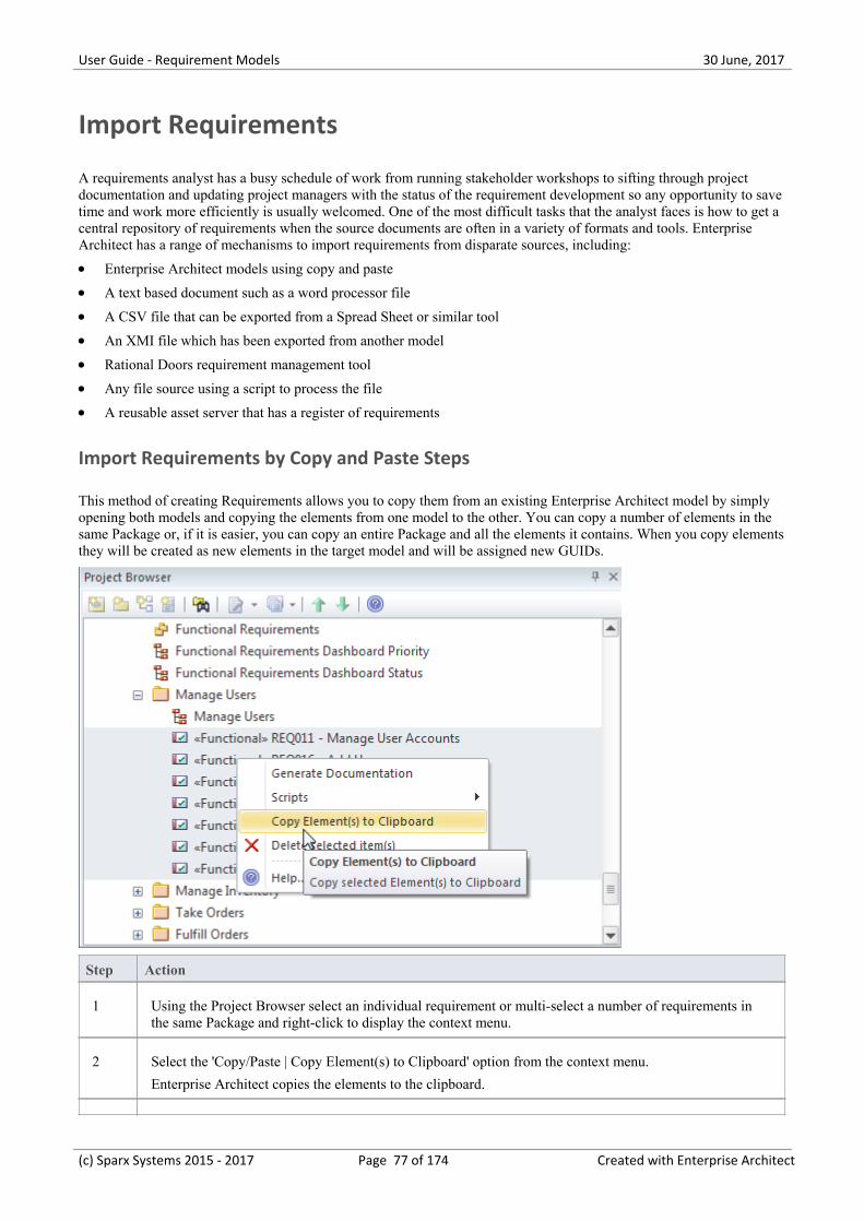
User Guide - Requirement Models 30 June, 2017
Import Requirements
A requirements analyst has a busy schedule of work from running stakeholder workshops to sifting through projectdocumentation and updating project managers with the status of the requirement development so any opportunity to savetime and work more efficiently is usually welcomed. One of the most difficult tasks that the analyst faces is how to get acentral repository of requirements when the source documents are often in a variety of formats and tools. EnterpriseArchitect has a range of mechanisms to import requirements from disparate sources, including:
Enterprise Architect models using copy and paste·A text based document such as a word processor file·A CSV file that can be exported from a Spread Sheet or similar tool·An XMI file which has been exported from another model·Rational Doors requirement management tool·Any file source using a script to process the file·A reusable asset server that has a register of requirements·
Import Requirements by Copy and Paste Steps
This method of creating Requirements allows you to copy them from an existing Enterprise Architect model by simplyopening both models and copying the elements from one model to the other. You can copy a number of elements in thesame Package or, if it is easier, you can copy an entire Package and all the elements it contains. When you copy elementsthey will be created as new elements in the target model and will be assigned new GUIDs.
Step Action
1 Using the Project Browser select an individual requirement or multi-select a number of requirements inthe same Package and right-click to display the context menu.
2 Select the 'Copy/Paste | Copy Element(s) to Clipboard' option from the context menu.
Enterprise Architect copies the elements to the clipboard.
(c) Sparx Systems 2015 - 2017 Page 77 of 174 Created with Enterprise Architect
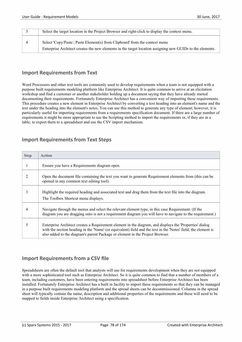
User Guide - Requirement Models 30 June, 2017
3 Select the target location in the Project Browser and right-click to display the context menu.
4 Select 'Copy/Paste | Paste Element(s) from Clipboard' from the context menu
Enterprise Architect creates the new elements in the target location assigning new GUIDs to the elements.
Import Requirements from Text
Word Processors and other text tools are commonly used to develop requirements when a team is not equipped with apurpose built requirements modeling platform like Enterprise Architect. It is quite common to arrive at an elicitationworkshop and find a customer or another stakeholder holding up a document saying that they have already starteddocumenting their requirements. Fortunately Enterprise Architect has a convenient way of importing these requirements.This procedure creates a new element in Enterprise Architect by converting a text heading into an element's name and thetext under the heading into the element's notes. You can use this method to generate any type of element; however, it isparticularly useful for importing requirements from a requirements specification document. If there are a large number ofrequirements it might be more appropriate to use the Scripting method to import the requirements or, if they are in atable, to export them to a spreadsheet and use the CSV import mechanism.
Import Requirements from Text Steps
Step Action
1 Ensure you have a Requirements diagram open.
2 Open the document file containing the text you want to generate Requirement elements from (this can beopened in any common text editing tool).
3 Highlight the required heading and associated text and drag them from the text file into the diagram.
The Toolbox Shortcut menu displays.
4 Navigate through the menus and select the relevant element type, in this case Requirement. (If thediagram you are dragging onto is not a requirement diagram you will have to navigate to the requirement.)
5 Enterprise Architect creates a Requirement element in the diagram, and displays the 'Properties' dialogwith the section heading in the 'Name' (or equivalent) field and the text in the 'Notes' field; the element isalso added to the diagram's parent Package or element in the Project Browser.
Import Requirements from a CSV file
Spreadsheets are often the default tool that analysts will use for requirements development when they are not equippedwith a more sophisticated tool such as Enterprise Architect. So it is quite common to find that a number of members of ateam, including customers, have been entering requirements into spreadsheet before Enterprise Architect has beeninstalled. Fortunately Enterprise Architect has a built in facility to import these requirements so that they can be managedin a purpose built requirements modeling platform and the spread sheets can be decommissioned. Columns in the spreadsheet will typically contain the name, description and additional properties of the requirements and these will need to bemapped to fields inside Enterprise Architect using a specification.
(c) Sparx Systems 2015 - 2017 Page 78 of 174 Created with Enterprise Architect
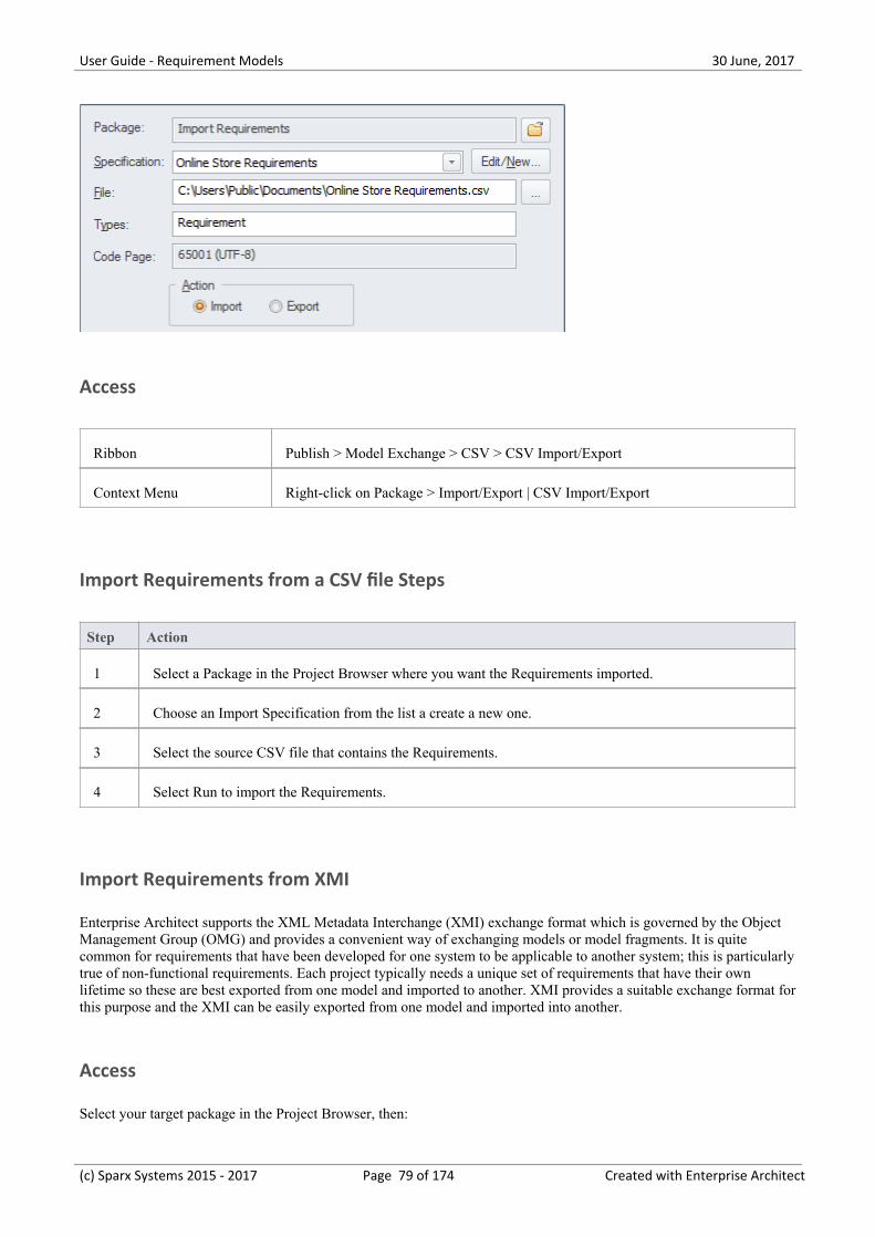
User Guide - Requirement Models 30 June, 2017
Access
Ribbon Publish > Model Exchange > CSV > CSV Import/Export
Context Menu Right-click on Package > Import/Export | CSV Import/Export
Import Requirements from a CSV file Steps
Step Action
1 Select a Package in the Project Browser where you want the Requirements imported.
2 Choose an Import Specification from the list a create a new one.
3 Select the source CSV file that contains the Requirements.
4 Select Run to import the Requirements.
Import Requirements from XMI
Enterprise Architect supports the XML Metadata Interchange (XMI) exchange format which is governed by the ObjectManagement Group (OMG) and provides a convenient way of exchanging models or model fragments. It is quitecommon for requirements that have been developed for one system to be applicable to another system; this is particularlytrue of non-functional requirements. Each project typically needs a unique set of requirements that have their ownlifetime so these are best exported from one model and imported to another. XMI provides a suitable exchange format forthis purpose and the XMI can be easily exported from one model and imported into another.
Access
Select your target package in the Project Browser, then:
(c) Sparx Systems 2015 - 2017 Page 79 of 174 Created with Enterprise Architect
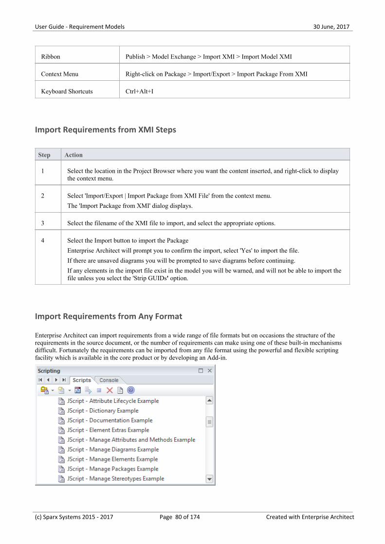
User Guide - Requirement Models 30 June, 2017
Ribbon Publish > Model Exchange > Import XMI > Import Model XMI
Context Menu Right-click on Package > Import/Export > Import Package From XMI
Keyboard Shortcuts Ctrl+Alt+I
Import Requirements from XMI Steps
Step Action
1 Select the location in the Project Browser where you want the content inserted, and right-click to displaythe context menu.
2 Select 'Import/Export | Import Package from XMI File' from the context menu.
The 'Import Package from XMI' dialog displays.
3 Select the filename of the XMI file to import, and select the appropriate options.
4 Select the Import button to import the Package
Enterprise Architect will prompt you to confirm the import, select 'Yes' to import the file.
If there are unsaved diagrams you will be prompted to save diagrams before continuing.
If any elements in the import file exist in the model you will be warned, and will not be able to import thefile unless you select the 'Strip GUIDs' option.
Import Requirements from Any Format
Enterprise Architect can import requirements from a wide range of file formats but on occasions the structure of therequirements in the source document, or the number of requirements can make using one of these built-in mechanismsdifficult. Fortunately the requirements can be imported from any file format using the powerful and flexible scriptingfacility which is available in the core product or by developing an Add-in.
(c) Sparx Systems 2015 - 2017 Page 80 of 174 Created with Enterprise Architect
User Guide - Requirement Models 30 June, 2017
Import Requirements from Rational Doors
The Model Driven Generation (MDG) technology for Doors provides a lightweight bridge between Enterprise Architectand IBM (formerly Telelogic) Doors. This allows the analyst to import the Requirements from Doors into an EnterpriseArchitect repository and to keep them synchronized with Doors. The entire hierarchy of Requirements will be importedand individual requirements can be linked to model elements such as Use Cases and Components. The EnterpriseArchitect model can be synchronized with Doors by re-importing the requirements. Any deleted items will be added to a'Trash Can' Package but will not be deleted from the model or the diagrams.
(c) Sparx Systems 2015 - 2017 Page 81 of 174 Created with Enterprise Architect
User Guide - Requirement Models 30 June, 2017
Move Requirement External
Elements in Enterprise Architect can have internal requirements (responsibilities) which define what the element mustaccomplish. These can overlap or duplicate more formal requirements that the system in general must meet, so a modelercould decide to make an element's internal requirement into an external requirement element. This is often done to allowa number of elements to implement the need expressed in the requirement. This can be achieved using the 'move external'function.
Access
On a diagram or in the Project Browser, select an element and:
Ribbon Design > Element > Manage > Properties > Requirements
Design > Element > Manage > Specific Properties Page > Requirements
Context Menu Right-click on element | Properties > Requirements or
Right-click on element | Properties Page | Requirements
Keyboard Shortcuts Alt+Enter : Requirements
Shift+Alt+R
Other Double-click on Element : Requirements
Change an element's internal requirement into an external requirement element
Step Action
1 Right-click on the internal requirement to change to an external requirement.
A short context menu displays.
2 Click on the 'Move External' menu option.
The 'Find Package' dialog displays.
3 Locate and click on the Package to place the new Requirement element in.
4 Click on the OK button.
A new Requirement element is created in the target Package, with a Realization connector from thecurrent element to the Requirement.
In the 'Properties' dialog, the Requirement is now marked with a 'Yes' in the 'External' column, and thedialog fields are disabled. To edit its details, double-click on the Requirement. The Requirement element'sown 'Properties' dialog displays.
Notes
(c) Sparx Systems 2015 - 2017 Page 82 of 174 Created with Enterprise Architect
User Guide - Requirement Models 30 June, 2017
When an internal requirement is made into an external requirement element it is still viewable from within the·element; any change to the external requirement will be reflected in the internal requirement and vice versa
When an internal requirement is made into an external requirement element, the 'Stability' field and its value for the·internal requirement are translated into the Stability Tagged Value in the external requirement
(c) Sparx Systems 2015 - 2017 Page 83 of 174 Created with Enterprise Architect
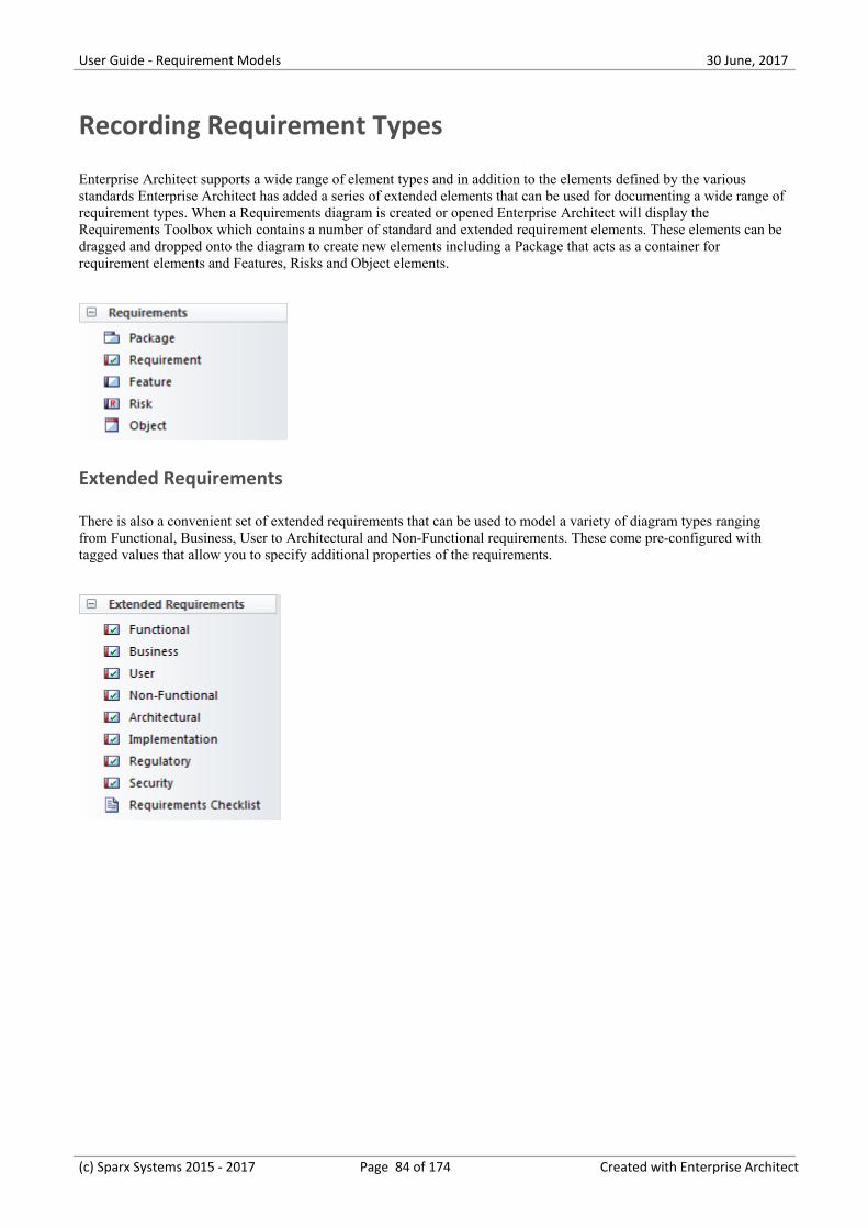
User Guide - Requirement Models 30 June, 2017
Recording Requirement Types
Enterprise Architect supports a wide range of element types and in addition to the elements defined by the variousstandards Enterprise Architect has added a series of extended elements that can be used for documenting a wide range ofrequirement types. When a Requirements diagram is created or opened Enterprise Architect will display theRequirements Toolbox which contains a number of standard and extended requirement elements. These elements can bedragged and dropped onto the diagram to create new elements including a Package that acts as a container forrequirement elements and Features, Risks and Object elements.
Extended Requirements
There is also a convenient set of extended requirements that can be used to model a variety of diagram types rangingfrom Functional, Business, User to Architectural and Non-Functional requirements. These come pre-configured withtagged values that allow you to specify additional properties of the requirements.
(c) Sparx Systems 2015 - 2017 Page 84 of 174 Created with Enterprise Architect
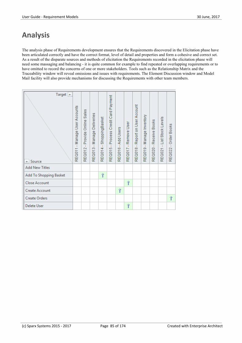
User Guide - Requirement Models 30 June, 2017
Analysis
The analysis phase of Requirements development ensures that the Requirements discovered in the Elicitation phase havebeen articulated correctly and have the correct format, level of detail and properties and form a cohesive and correct set.As a result of the disparate sources and methods of elicitation the Requirements recorded in the elicitation phase willneed some massaging and balancing - it is quite common for example to find repeated or overlapping requirements or tohave omitted to record the concerns of one or more stakeholders. Tools such as the Relationship Matrix and theTraceability window will reveal omissions and issues with requirements. The Element Discussion window and ModelMail facility will also provide mechanisms for discussing the Requirements with other team members.
(c) Sparx Systems 2015 - 2017 Page 85 of 174 Created with Enterprise Architect
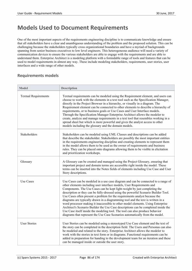
User Guide - Requirement Models 30 June, 2017
Models Used to Document Requirements
One of the most important aspects of the requirements engineering discipline is to communicate knowledge and ensurethat all stakeholders have a clear and unambiguous understanding of the problem and the proposed solution. This can bechallenging because the stakeholders typically cross organizational boundaries and have a myriad of backgroundsspanning from senior business executives to low level engineers. This heterogeneous audience will need a variety ofcommunication devices to ensure the various stakeholders are able to engage with the requirements and are able tounderstand them. Enterprise Architect is a modeling platform with a formidable range of tools and features that can beused to model requirements in almost any way. These include modeling stakeholders, requirements, user stories, userinterfaces and a wide range of other models.
Requirements models
Model Description
Textual Requirements Textual requirements can be modeled using the Requirement element, and users canchoose to work with the elements in a text tool such as the Specification Manager,directly in the Project Browser in a hierarchy, or visually in a diagram. TheRequirement element can be connected to other elements to describe a hierarchy ofrequirements, or to business goals or Use Cases and User Interface models.Through the Specification Manager Enterprise Architect allows the modeler tocreate, analyze and manage requirements in a text tool that resembles working in aspread sheet but which is more powerful and gives the analyst access to othermodels including the glossary and the domain models.
Stakeholders Stakeholders can be modeled using UML Classes and descriptions can be addedthat describe the stakeholder. Stakeholders are possibly the most important entitiesin the requirements engineering discipline and creating elements to represent themin the model allows them to be used as the owner of requirements and businessrules. They can be placed onto diagrams allowing them to be visible in elicitationand prioritization workshops.
Glossary A Glossary can be created and managed using the Project Glossary, ensuring thatimportant project and domain terms are accessible right inside the model. Theseterms can be inserted into the Notes fields of elements including Use Case and UserStory descriptions.
Use Cases Use Cases can be modeled in a use case diagram and can be connected to a range ofother elements including user interface models, User Requirements andComponents. The Use Cases can be kept light-weight by just completing thedescription or they can be fully-dressed using the powerful Scenario Builder Tool.Use Cases often present a problem for the requirements analyst because thediagrams are typically drawn in a diagramming tool and the text is written in aword processor making it inaccessible to other model elements. Using EnterpriseArchitect's Scenario Builder the Use Case descriptions can be completed inside theUse Case itself inside the modeling tool. The tool can also produce behaviordiagrams that represent the Use Case Scenarios automatically from the model.
User Stories User Stories can be modeled using a stereotyped Use Case element and the text ofthe story can be completed in the description field. The Users and Personas can alsobe modeled and related to the story. Enterprise Architect allows the modeler towork with the stories in text form or in diagrams. Functional requirements can beadded in preparation for handing to the development team for an iteration and thesecan be managed inside or outside the user story.
(c) Sparx Systems 2015 - 2017 Page 86 of 174 Created with Enterprise Architect
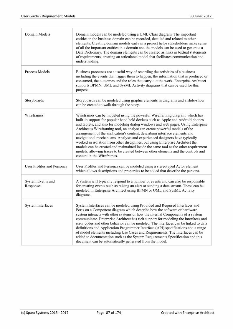
User Guide - Requirement Models 30 June, 2017
Domain Models Domain models can be modeled using a UML Class diagram. The importantentities in the business domain can be recorded, detailed and related to otherelements. Creating domain models early in a project helps stakeholders make senseof all the important entities in a domain and the models can be used to generate aData Dictionary. The domain elements can be created as links in textual statementsof requirements, creating an articulated model that facilitates communication andunderstanding.
Process Models Business processes are a useful way of recording the activities of a businessincluding the events that trigger them to happen, the information that is produced orconsumed, the outcomes and the roles that carry out the work. Enterprise Architectsupports BPMN, UML and SysML Activity diagrams that can be used for thispurpose.
Storyboards Storyboards can be modeled using graphic elements in diagrams and a slide-showcan be created to walk through the story.
Wireframes Wireframes can be modeled using the powerful Wireframing diagram, which hasbuilt-in support for popular hand held devices such as Apple and Android phonesand tablets, and also for modeling dialog windows and web pages. Using EnterpriseArchitect's Wireframing tool, an analyst can create powerful models of thearrangement of the application's content, describing interface elements andnavigational mechanisms. Analysts and experienced designers have typicallyworked in isolation from other disciplines, but using Enterprise Architect themodels can be created and maintained inside the same tool as the other requirementmodels, allowing traces to be created between other elements and the controls andcontent in the Wireframes.
User Profiles and Personas User Profiles and Personas can be modeled using a stereotyped Actor elementwhich allows descriptions and properties to be added that describe the persona.
System Events andResponses
A system will typically respond to a number of events and can also be responsiblefor creating events such as raising an alert or sending a data stream. These can bemodeled in Enterprise Architect using BPMN or UML and SysML Activitydiagrams.
System Interfaces System Interfaces can be modeled using Provided and Required Interfaces andPorts on a Component diagram which describe how the software or hardwaresystem interacts with other systems or how the internal Components of a systemcommunicate. Enterprise Architect has rich support for modeling the interfaces anderror codes and other behavior can be modeled. The interfaces can be linked to datadefinitions and Application Programmer Interface (API) specifications and a rangeof model elements including Use Cases and Requirements. The Interfaces can beadded to documentation such as the System Requirements Specification and thisdocument can be automatically generated from the model.
(c) Sparx Systems 2015 - 2017 Page 87 of 174 Created with Enterprise Architect
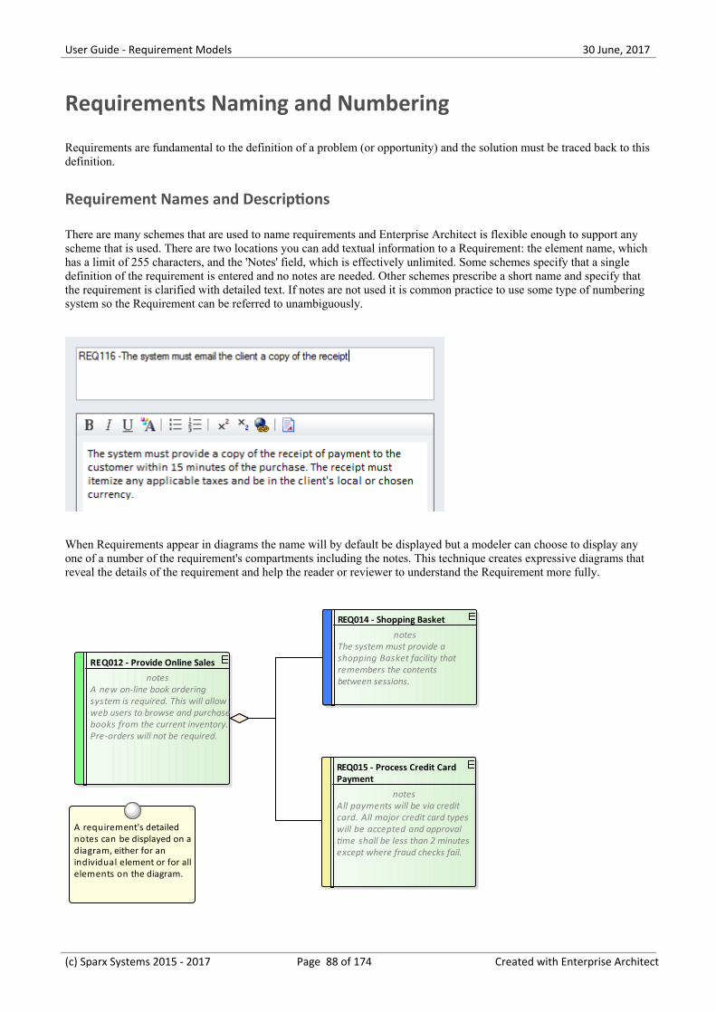
User Guide - Requirement Models 30 June, 2017
Requirements Naming and Numbering
Requirements are fundamental to the definition of a problem (or opportunity) and the solution must be traced back to thisdefinition.
Requirement Names and Descriptions
There are many schemes that are used to name requirements and Enterprise Architect is flexible enough to support anyscheme that is used. There are two locations you can add textual information to a Requirement: the element name, whichhas a limit of 255 characters, and the 'Notes' field, which is effectively unlimited. Some schemes specify that a singledefinition of the requirement is entered and no notes are needed. Other schemes prescribe a short name and specify thatthe requirement is clarified with detailed text. If notes are not used it is common practice to use some type of numberingsystem so the Requirement can be referred to unambiguously.
When Requirements appear in diagrams the name will by default be displayed but a modeler can choose to display anyone of a number of the requirement's compartments including the notes. This technique creates expressive diagrams thatreveal the details of the requirement and help the reader or reviewer to understand the Requirement more fully.
REQ012 - Provide Online Sales
notesA new on-line book orderingsystem is required. This will allowweb users to browse and purchasebooks from the current inventory.Pre-orders will not be required.
REQ014 - Shopping Basket
notesThe system must provide ashopping Basket facility thatremembers the contentsbetween sessions.
REQ015 - Process Credit Card Payment
notesAll payments will be via creditcard. All major credit card typeswill be accepted and approvaltime shall be less than 2 minutesexcept where fraud checks fail.
A requirement's detailed notes can be displayed on adiagram, either for an individual element or for allelements on the diagram.
(c) Sparx Systems 2015 - 2017 Page 88 of 174 Created with Enterprise Architect
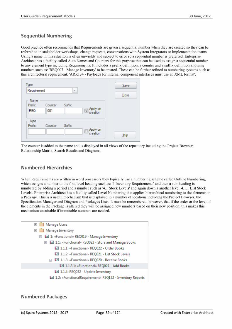
User Guide - Requirement Models 30 June, 2017
Sequential Numbering
Good practice often recommends that Requirements are given a sequential number when they are created so they can bereferred to in stakeholder workshops, change requests, conversations with System Integrators or implementation teams.Using a name in this situation is often unwieldy and subject to error so a sequential number is preferred. EnterpriseArchitect has a facility called Auto Names and Counters for this purpose that can be used to assign a sequential numberto any element type including Requirements. It includes a prefix definition, a counter and a suffix definition allowingnumbers such as: 'REQ007 - Manage Inventory' to be created. These can be further refined to numbering systems such asthis architectural requirement: 'ARR134 - Payloads for internal component interfaces must use an XML format'.
The counter is added to the name and is displayed in all views of the repository including the Project Browser,Relationship Matrix, Search Results and Diagrams.
Numbered Hierarchies
When Requirements are written in word processors they typically use a numbering scheme called Outline Numbering,which assigns a number to the first level heading such as: '4 Inventory Requirements' and then a sub-heading isnumbered by adding a period and a number such as '4.1 Stock Levels' and again down a another level '4.1.1 List StockLevels'. Enterprise Architect has a facility called Level Numbering that applies hierarchical numbering to the elements ina Package. This is a useful mechanism that is displayed in a number of locations including the Project Browser, theSpecification Manager and Diagram and Packages Lists. It must be remembered, however, that if the order or the level ofthe elements in the Package is altered they will be assigned new numbers based on their new position; this makes thismechanism unsuitable if immutable numbers are needed.
Numbered Packages
(c) Sparx Systems 2015 - 2017 Page 89 of 174 Created with Enterprise Architect
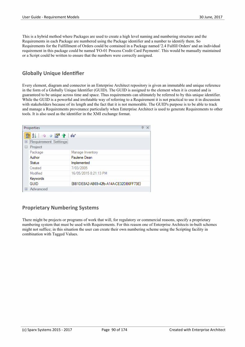
User Guide - Requirement Models 30 June, 2017
This is a hybrid method where Packages are used to create a high level naming and numbering structure and theRequirements in each Package are numbered using the Package identifier and a number to identify them. SoRequirements for the Fulfillment of Orders could be contained in a Package named '2.4 Fulfill Orders' and an individualrequirement in this package could be named 'FO-01 Process Credit Card Payments'. This would be manually maintainedor a Script could be written to ensure that the numbers were correctly assigned.
Globally Unique Identifier
Every element, diagram and connector in an Enterprise Architect repository is given an immutable and unique referencein the form of a Globally Unique Identifier (GUID). The GUID is assigned to the element when it is created and isguaranteed to be unique across time and space. Thus requirements can ultimately be referred to by this unique identifier.While the GUID is a powerful and irrefutable way of referring to a Requirement it is not practical to use it in discussionwith stakeholders because of its length and the fact that it is not memorable. The GUID's purpose is to be able to trackand manage a Requirements provenance particularly when Enterprise Architect is used to generate Requirements to othertools. It is also used as the identifier in the XMI exchange format.
Proprietary Numbering Systems
There might be projects or programs of work that will, for regulatory or commercial reasons, specify a proprietarynumbering system that must be used with Requirements. For this reason one of Enterprise Architects in-built schemesmight not suffice; in this situation the user can create their own numbering scheme using the Scripting facility incombination with Tagged Values.
(c) Sparx Systems 2015 - 2017 Page 90 of 174 Created with Enterprise Architect
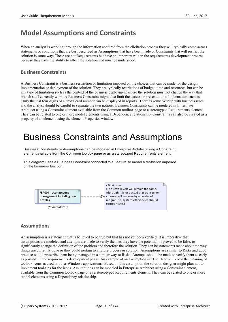
User Guide - Requirement Models 30 June, 2017
Model Assumptions and Constraints
When an analyst is working through the information acquired from the elicitation process they will typically come acrossstatements or conditions that are best described as Assumptions that have been made or Constraints that will restrict thesolution is some way. These are not Requirements but have an important role in the requirements development processbecause they have the ability to affect the solution and must be understood.
Business Constraints
A Business Constraint is a business restriction or limitation imposed on the choices that can be made for the design,implementation or deployment of the solution. They are typically restrictions of budget, time and resources, but can beany type of limitation such as the context of the business deployment where the solution must not change the way thatbranch staff currently work. A Business Constraint might also limit the access or presentation of information such as'Only the last four digits of a credit card number can be displayed in reports.' There is some overlap with business rulesand the analyst should be careful to separate the two notions. Business Constraints can be modeled in EnterpriseArchitect using a Constraint element available from the Common toolbox page or a stereotyped Requirements element.They can be related to one or more model elements using a Dependency relationship. Constraints can also be created as aproperty of an element using the element Properties window.
FEA004 - User account management including user profiles
(from Features)
«Business»{The staff levels will remain the same.Although it is expected that transactionvolume will increase by an order ofmagnitude, system efficiencies shouldcompensate.}
Business Constraints and AssumptionsBusiness Constraints or Assumptions can be modeled in Enterprise Architect using a Constraint element available from the Common toolbox page or as a stereotyped Requirements element.
This diagram uses a Business Constraint connected to a Feature, to model a restriction imposed on the business function.
Assumptions
An assumption is a statement that is believed to be true but that has not yet been verified. It is imperative thatassumptions are modeled and attempts are made to verify them as they have the potential, if proved to be false, tosignificantly change the definition of the problem and therefore the solution. They can be statements made about the waythings are currently done or they could pertain to a future process or solution. Assumptions are similar to Risks and goodpractice would prescribe them being managed in a similar way to Risks. Attempts should be made to verify them as earlyas possible in the requirements development phase. An example of an assumption is: 'The User will know the meaning oftoolbox icons as used in other Windows applications'. Based on this assumption the solution designer might plan not toimplement tool-tips for the icons. Assumptions can be modeled in Enterprise Architect using a Constraint element,available from the Common toolbox page or as a stereotyped Requirements element. They can be related to one or moremodel elements using a Dependency relationship.
(c) Sparx Systems 2015 - 2017 Page 91 of 174 Created with Enterprise Architect
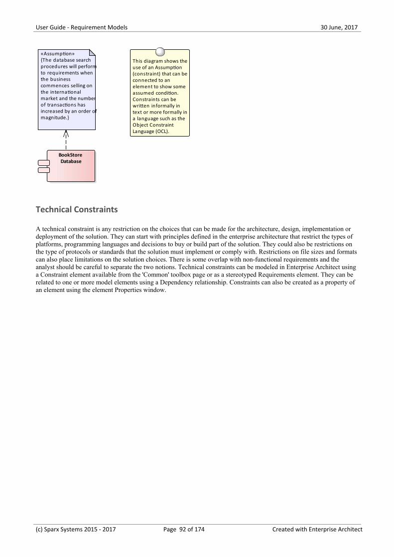
User Guide - Requirement Models 30 June, 2017
BookStore Database
This diagram shows theuse of an Assumption (constraint) that can beconnected to an element to show some assumed condition. Constraints can be written informally in text or more formally ina language such as the Object Constraint Language (OCL).
«Assumption»{The database searchprocedures will performto requirements whenthe businesscommences selling onthe internationalmarket and the numberof transactions hasincreased by an order ofmagnitude.}
Technical Constraints
A technical constraint is any restriction on the choices that can be made for the architecture, design, implementation ordeployment of the solution. They can start with principles defined in the enterprise architecture that restrict the types ofplatforms, programming languages and decisions to buy or build part of the solution. They could also be restrictions onthe type of protocols or standards that the solution must implement or comply with. Restrictions on file sizes and formatscan also place limitations on the solution choices. There is some overlap with non-functional requirements and theanalyst should be careful to separate the two notions. Technical constraints can be modeled in Enterprise Architect usinga Constraint element available from the 'Common' toolbox page or as a stereotyped Requirements element. They can berelated to one or more model elements using a Dependency relationship. Constraints can also be created as a property ofan element using the element Properties window.
(c) Sparx Systems 2015 - 2017 Page 92 of 174 Created with Enterprise Architect
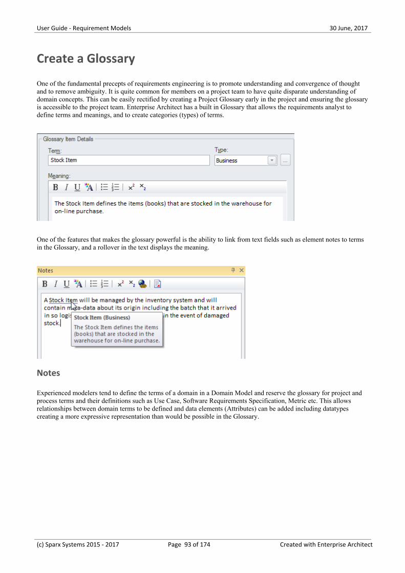
User Guide - Requirement Models 30 June, 2017
Create a Glossary
One of the fundamental precepts of requirements engineering is to promote understanding and convergence of thoughtand to remove ambiguity. It is quite common for members on a project team to have quite disparate understanding ofdomain concepts. This can be easily rectified by creating a Project Glossary early in the project and ensuring the glossaryis accessible to the project team. Enterprise Architect has a built in Glossary that allows the requirements analyst todefine terms and meanings, and to create categories (types) of terms.
One of the features that makes the glossary powerful is the ability to link from text fields such as element notes to termsin the Glossary, and a rollover in the text displays the meaning.
Notes
Experienced modelers tend to define the terms of a domain in a Domain Model and reserve the glossary for project andprocess terms and their definitions such as Use Case, Software Requirements Specification, Metric etc. This allowsrelationships between domain terms to be defined and data elements (Attributes) can be added including datatypescreating a more expressive representation than would be possible in the Glossary.
(c) Sparx Systems 2015 - 2017 Page 93 of 174 Created with Enterprise Architect
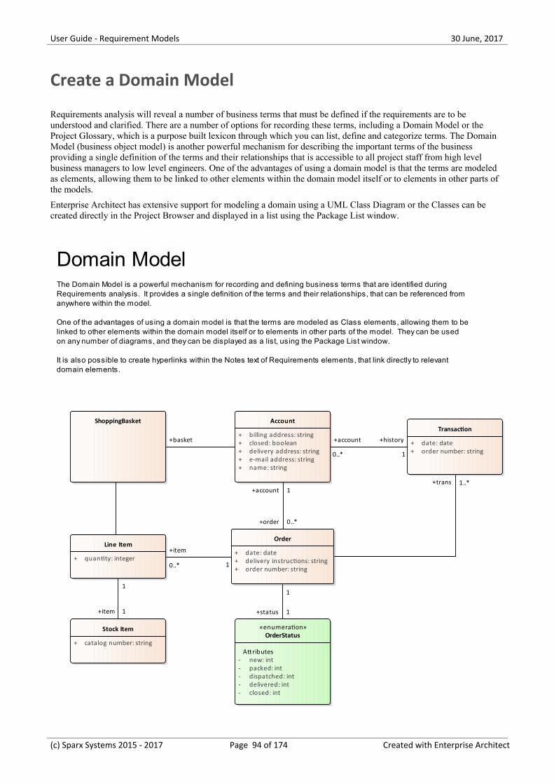
User Guide - Requirement Models 30 June, 2017
Create a Domain Model
Requirements analysis will reveal a number of business terms that must be defined if the requirements are to beunderstood and clarified. There are a number of options for recording these terms, including a Domain Model or theProject Glossary, which is a purpose built lexicon through which you can list, define and categorize terms. The DomainModel (business object model) is another powerful mechanism for describing the important terms of the businessproviding a single definition of the terms and their relationships that is accessible to all project staff from high levelbusiness managers to low level engineers. One of the advantages of using a domain model is that the terms are modeledas elements, allowing them to be linked to other elements within the domain model itself or to elements in other parts ofthe models.
Enterprise Architect has extensive support for modeling a domain using a UML Class Diagram or the Classes can becreated directly in the Project Browser and displayed in a list using the Package List window.
ShoppingBasket Account
+ billing address: string+ closed: boolean+ delivery address: string+ e-mail address: string+ name: string
Order
+ date: date+ delivery instructions: string+ order number: string
Transaction
+ date: date+ order number: string
Line Item
+ quantity: integer
Stock Item
+ catalog number: string
«enumeration»OrderStatus
Attributes- new: int- packed: int- dispatched: int- delivered: int- closed: int
Domain ModelThe Domain Model is a powerful mechanism for recording and defining business terms that are identified during Requirements analysis. It provides a single definition of the terms and their relationships, that can be referenced from anywhere within the model.
One of the advantages of using a domain model is that the terms are modeled as Class elements, allowing them to belinked to other elements within the domain model itself or to elements in other parts of the model. They can be used on any number of diagrams, and they can be displayed as a list, using the Package List window.
It is also possible to create hyperlinks within the Notes text of Requirements elements, that link directly to relevant domain elements.
+trans 1..*+account 1
+order 0..*
1
+status 1
1
+item 1
+history
1
+account
0..*
+basket
1
+item
0..*
(c) Sparx Systems 2015 - 2017 Page 94 of 174 Created with Enterprise Architect
User Guide - Requirement Models 30 June, 2017
The Domain Model elements can be added to other diagrams to make them more expressive and show importantinformation such as what data is being consumed or produced by a business process or what data is being passed betweenapplication interfaces.
Enterprise Architect allows you to link to the domain elements (or any element) from the text of a requirement's notes.(This facility is available from any element.)
Notes
Experienced modelers tend to define the terms of a domain in a Domain Model and reserve the Glossary for project andprocess terms and their definitions such as Use Case, Software Requirements Specification, Metric etc.
(c) Sparx Systems 2015 - 2017 Page 95 of 174 Created with Enterprise Architect
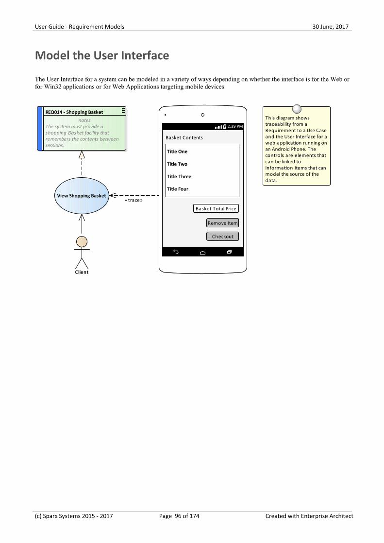
User Guide - Requirement Models 30 June, 2017
Model the User Interface
The User Interface for a system can be modeled in a variety of ways depending on whether the interface is for the Web orfor Win32 applications or for Web Applications targeting mobile devices.
View Shopping Basket
Client
REQ014 - Shopping Basket
notesThe system must provide ashopping Basket facility thatremembers the contents betweensessions.
This diagram shows traceability from a Requirement to a Use Case and the User Interface for a web application running on an Android Phone. The controls are elements that can be linked to information items that can model the source of the data.
2:39 PM2:39 PM
Basket Contents
Title One
Title Two
Title Three
Title Four
Basket Total Price
Remove Item
Checkout
«trace»
(c) Sparx Systems 2015 - 2017 Page 96 of 174 Created with Enterprise Architect
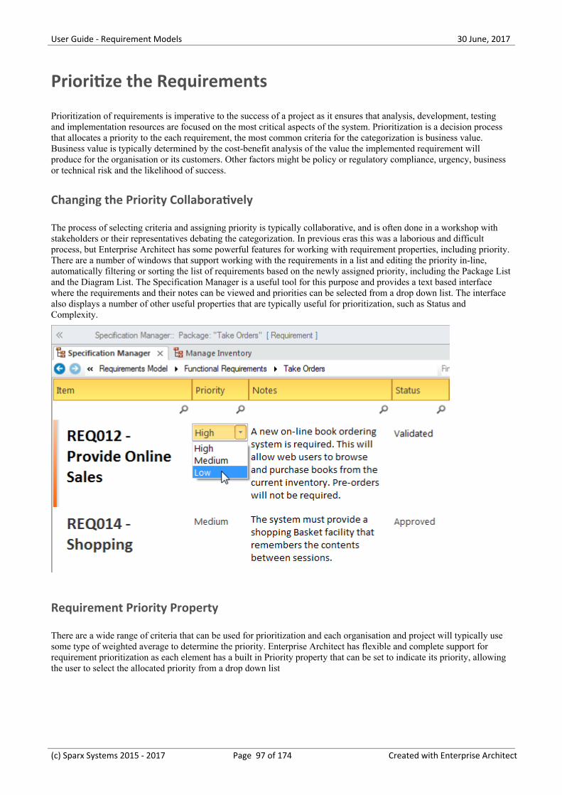
User Guide - Requirement Models 30 June, 2017
Prioritize the Requirements
Prioritization of requirements is imperative to the success of a project as it ensures that analysis, development, testingand implementation resources are focused on the most critical aspects of the system. Prioritization is a decision processthat allocates a priority to the each requirement, the most common criteria for the categorization is business value.Business value is typically determined by the cost-benefit analysis of the value the implemented requirement willproduce for the organisation or its customers. Other factors might be policy or regulatory compliance, urgency, businessor technical risk and the likelihood of success.
Changing the Priority Collaboratively
The process of selecting criteria and assigning priority is typically collaborative, and is often done in a workshop withstakeholders or their representatives debating the categorization. In previous eras this was a laborious and difficultprocess, but Enterprise Architect has some powerful features for working with requirement properties, including priority.There are a number of windows that support working with the requirements in a list and editing the priority in-line,automatically filtering or sorting the list of requirements based on the newly assigned priority, including the Package Listand the Diagram List. The Specification Manager is a useful tool for this purpose and provides a text based interfacewhere the requirements and their notes can be viewed and priorities can be selected from a drop down list. The interfacealso displays a number of other useful properties that are typically useful for prioritization, such as Status andComplexity.
Requirement Priority Property
There are a wide range of criteria that can be used for prioritization and each organisation and project will typically usesome type of weighted average to determine the priority. Enterprise Architect has flexible and complete support forrequirement prioritization as each element has a built in Priority property that can be set to indicate its priority, allowingthe user to select the allocated priority from a drop down list
(c) Sparx Systems 2015 - 2017 Page 97 of 174 Created with Enterprise Architect
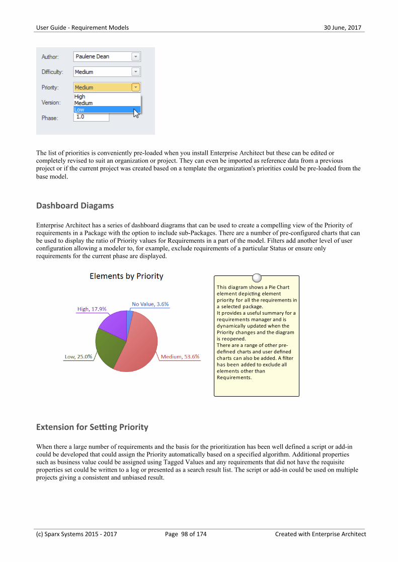
User Guide - Requirement Models 30 June, 2017
The list of priorities is conveniently pre-loaded when you install Enterprise Architect but these can be edited orcompletely revised to suit an organization or project. They can even be imported as reference data from a previousproject or if the current project was created based on a template the organization's priorities could be pre-loaded from thebase model.
Dashboard Diagams
Enterprise Architect has a series of dashboard diagrams that can be used to create a compelling view of the Priority ofrequirements in a Package with the option to include sub-Packages. There are a number of pre-configured charts that canbe used to display the ratio of Priority values for Requirements in a part of the model. Filters add another level of userconfiguration allowing a modeler to, for example, exclude requirements of a particular Status or ensure onlyrequirements for the current phase are displayed.
This diagram shows a Pie Chart element depicting element priority for all the requirements ina selected package. It provides a useful summary for a requirements manager and is dynamically updated when the Priority changes and the diagram is reopened. There are a range of other pre-defined charts and user defined charts can also be added. A filter has been added to exclude all elements other than Requirements.
Extension for Setting Priority
When there a large number of requirements and the basis for the prioritization has been well defined a script or add-incould be developed that could assign the Priority automatically based on a specified algorithm. Additional propertiessuch as business value could be assigned using Tagged Values and any requirements that did not have the requisiteproperties set could be written to a log or presented as a search result list. The script or add-in could be used on multipleprojects giving a consistent and unbiased result.
(c) Sparx Systems 2015 - 2017 Page 98 of 174 Created with Enterprise Architect
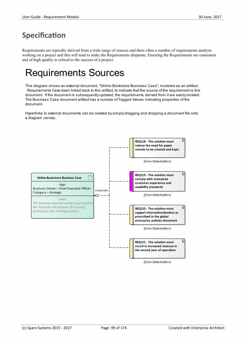
User Guide - Requirement Models 30 June, 2017
Specification
Requirements are typically derived from a wide range of sources and there often a number of requirements analystsworking on a project and this will tend to make the Requirements disparate. Ensuring the Requirements are consistentand of high quality is critical to the success of a project.
Online Bookstore Business Case
tagsBusiness Owner = Chief Executive OfficerCategory = Strategic
notesThe business case was written to present tothe board for the purpose of securingfunding for this strategic project.
REQ118 - The solution must reduce the need for paper records to be created and kept.
(from Stakeholders)
REQ119 - The solution must comply with enterprise customer experience and useability standards
(from Stakeholders)
REQ120 - The solution must support internationalization as prescribed in the global enterprise policies document
(from Stakeholders)
REQ121 - The solution must result in increased revenue in the second year of operation
(from Stakeholders)
Requirements SourcesThis diagram shows an external document, "Online Bookstore Business Case", modeled as an artifact. Requirements have been linked back to this artifact, to indicate that the source of the requirement is this document. If the document is subsequently updated, the requirements derived from it are easily located.The Business Case document artifact has a number of Tagged Values indicating properties of the document.
Hyperlinks to external documents can be created by simply dragging and dropping a document file onto a diagram canvas.
«source»
(c) Sparx Systems 2015 - 2017 Page 99 of 174 Created with Enterprise Architect
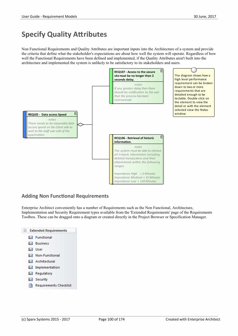
User Guide - Requirement Models 30 June, 2017
Specify Quality Attributes
Non Functional Requirements and Quality Attributes are important inputs into the Architecture of a system and providethe criteria that define what the stakeholder's expectations are about how well the system will operate. Regardless of howwell the Functional Requirements have been defined and implemented, if the Quality Attributes aren't built into thearchitecture and implemented the system is unlikely to be satisfactory to its stakeholders and users.
REQ106 - Retrieval of historic information.
notesThe system must be able to retrieveall historic information includingdeleted transactions and theirattachments within the followingranges.
Importance High < 2 MinutesImportance Medium < 15 MinutesImportance Low < 120 Minutes
REQ107 - Access to the secure site must be no longer than 2 seconds delay.
notesIf any greater delay then thereshould be notification to the userthat the process has beencommenced.
REQ105 - Data access Speed
notesThere needs to be reasonable dataaccess speed on the Client side aswell as the staff user side of theapplication.
The diagram shows how a high level performance requirement can be broken down to two or more requirements that are detailed enough to be testable. Double-click on the element to view the detail or with the element selected view the Notes window.
Adding Non Functional Requirements
Enterprise Architect conveniently has a number of Requirements such as the Non Functional, Architecture,Implementation and Security Requirement types available from the 'Extended Requirements' page of the RequirementsToolbox. These can be dragged onto a diagram or created directly in the Project Browser or Specification Manager.
(c) Sparx Systems 2015 - 2017 Page 100 of 174 Created with Enterprise Architect
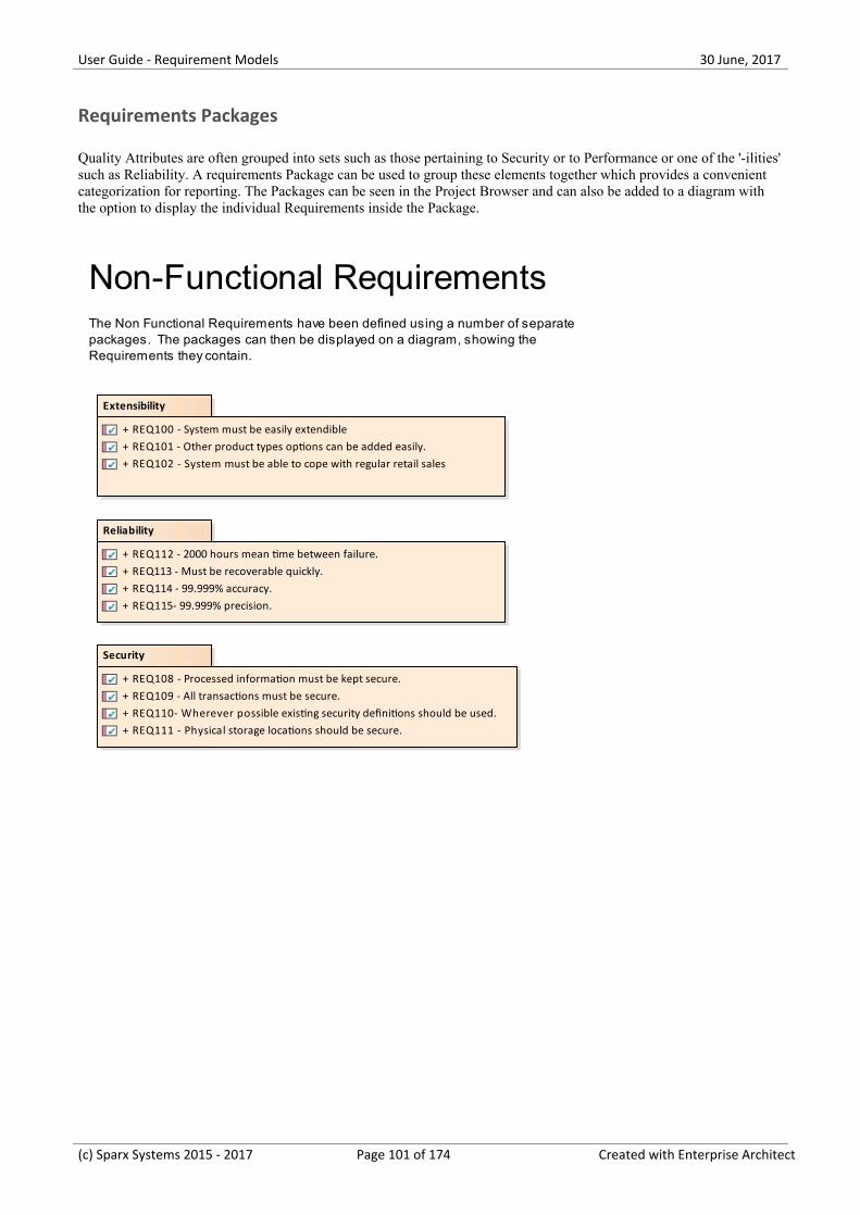
User Guide - Requirement Models 30 June, 2017
Requirements Packages
Quality Attributes are often grouped into sets such as those pertaining to Security or to Performance or one of the '-ilities'such as Reliability. A requirements Package can be used to group these elements together which provides a convenientcategorization for reporting. The Packages can be seen in the Project Browser and can also be added to a diagram withthe option to display the individual Requirements inside the Package.
Extensibility
+ REQ100 - System must be easily extendible+ REQ101 - Other product types options can be added easily.+ REQ102 - System must be able to cope with regular retail sales
Reliability
+ REQ112 - 2000 hours mean time between failure.+ REQ113 - Must be recoverable quickly.+ REQ114 - 99.999% accuracy.+ REQ115- 99.999% precision.
Security
+ REQ108 - Processed information must be kept secure.+ REQ109 - All transactions must be secure.+ REQ110- Wherever possible existing security definitions should be used.+ REQ111 - Physical storage locations should be secure.
Non-Functional RequirementsThe Non Functional Requirements have been defined using a number of separate packages. The packages can then be displayed on a diagram, showing the Requirements they contain.
(c) Sparx Systems 2015 - 2017 Page 101 of 174 Created with Enterprise Architect
User Guide - Requirement Models 30 June, 2017
Requirement Sources
Much of the literature on requirements development talks of 'gathering' requirements which implies that the analyst iswalking through an orchard picking low hanging fruit. In practice the process is quite the opposite and the requirementanalyst needs to have all the skills and tenacity of a detective to discover the sources of requirements. The requirementsources and the documents and artifacts that are discovered are first class citizens and can be modeled in EnterpriseArchitect to provide a register of the requirement sources. This is a list of common requirements sources:
Interviews with users and other stakeholders·Observations of users performing tasks·Business Case or Proposal·Concept of Operation or Vision document·Procedure manuals and user task lists·Enhancement Requests for the existing system·Marketing material and product definitions·Analysis of a market leader or competitor's products·
Modeling Requirement Sources
Requirement sources are typically documents or other file based artifacts and are best modeled as UML Artifacts usingTagged Values to add meta-data to the element to record such information as its type, location, who it is governed by andany other relevant properties. The document and files will typically be stored in a variety of places across anorganizations networks, but so long as there is a file path or a URL they can be opened from within Enterprise Architectby a single key stroke. The artifact will be opened either inside or outside Enterprise Architect using the appropriateeditor for the file type.
(c) Sparx Systems 2015 - 2017 Page 102 of 174 Created with Enterprise Architect
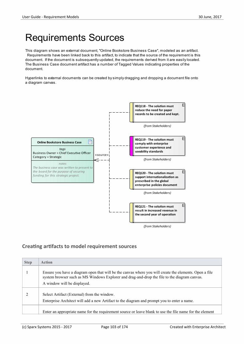
User Guide - Requirement Models 30 June, 2017
Online Bookstore Business Case
tagsBusiness Owner = Chief Executive OfficerCategory = Strategic
notesThe business case was written to present tothe board for the purpose of securingfunding for this strategic project.
REQ118 - The solution must reduce the need for paper records to be created and kept.
(from Stakeholders)
REQ119 - The solution must comply with enterprise customer experience and useability standards
(from Stakeholders)
REQ120 - The solution must support internationalization as prescribed in the global enterprise policies document
(from Stakeholders)
REQ121 - The solution must result in increased revenue in the second year of operation
(from Stakeholders)
Requirements SourcesThis diagram shows an external document, "Online Bookstore Business Case", modeled as an artifact. Requirements have been linked back to this artifact, to indicate that the source of the requirement is this document. If the document is subsequently updated, the requirements derived from it are easily located.The Business Case document artifact has a number of Tagged Values indicating properties of the document.
Hyperlinks to external documents can be created by simply dragging and dropping a document file onto a diagram canvas.
«source»
Creating artifacts to model requirement sources
Step Action
1 Ensure you have a diagram open that will be the canvas where you will create the elements. Open a filesystem browser such as MS Windows Explorer and drag-and-drop the file to the diagram canvas.
A window will be displayed.
2 Select Artifact (External) from the window.
Enterprise Architect will add a new Artifact to the diagram and prompt you to enter a name.
Enter an appropriate name for the requirement source or leave blank to use the file name for the element
(c) Sparx Systems 2015 - 2017 Page 103 of 174 Created with Enterprise Architect
User Guide - Requirement Models 30 June, 2017
3 name.
(c) Sparx Systems 2015 - 2017 Page 104 of 174 Created with Enterprise Architect
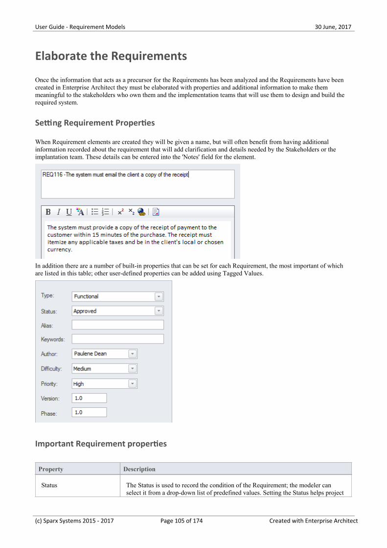
User Guide - Requirement Models 30 June, 2017
Elaborate the Requirements
Once the information that acts as a precursor for the Requirements has been analyzed and the Requirements have beencreated in Enterprise Architect they must be elaborated with properties and additional information to make themmeaningful to the stakeholders who own them and the implementation teams that will use them to design and build therequired system.
Setting Requirement Properties
When Requirement elements are created they will be given a name, but will often benefit from having additionalinformation recorded about the requirement that will add clarification and details needed by the Stakeholders or theimplantation team. These details can be entered into the 'Notes' field for the element.
In addition there are a number of built-in properties that can be set for each Requirement, the most important of whichare listed in this table; other user-defined properties can be added using Tagged Values.
Important Requirement properties
Property Description
Status The Status is used to record the condition of the Requirement; the modeler canselect it from a drop-down list of predefined values. Setting the Status helps project
(c) Sparx Systems 2015 - 2017 Page 105 of 174 Created with Enterprise Architect
User Guide - Requirement Models 30 June, 2017
managers and others involved in planning determine if a Requirement is ready to beincluded in a development Package of work or iteration.
Alias The Alias can be used to record a sequence number or identifier for theRequirement. A modeler can choose to display the Alias in a number of locationsincluding diagrams and reports.
Priority The Priority is used to set the precedence or relative importance of a Requirement;the modeler can select it from a drop-down list of predefined values. Setting thePriority helps project managers and others involved in planning to determine thoseRequirements that should take precedence over others for implementation.
Difficulty The Difficulty is a measure that attempts to describe the relative effort that wouldbe required to realize the Requirement in a system implementation. The modelercan select a value from a drop-down list of predefined values. Setting the Difficultyhelps project managers and others involved in planning determine the effort neededto implement the Requirement.
Phase The Phase is a value that can be set to indicate the stage of development at whichthe Requirement will be implemented. The modeler can enter any value into thisfield. Setting the Phase helps project managers and others involved in planningdetermine which Package of work or iteration the Requirement should be includedin.
(c) Sparx Systems 2015 - 2017 Page 106 of 174 Created with Enterprise Architect
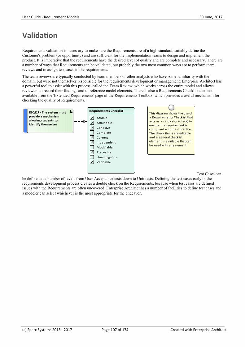
User Guide - Requirement Models 30 June, 2017
Validation
Requirements validation is necessary to make sure the Requirements are of a high standard, suitably define theCustomer's problem (or opportunity) and are sufficient for the implementation teams to design and implement theproduct. It is imperative that the requirements have the desired level of quality and are complete and necessary. There area number of ways that Requirements can be validated, but probably the two most common ways are to perform teamreviews and to assign test cases to the requirements.
The team reviews are typically conducted by team members or other analysts who have some familiarity with thedomain, but were not themselves responsible for the requirements development or management. Enterprise Architect hasa powerful tool to assist with this process, called the Team Review, which works across the entire model and allowsreviewers to record their findings and to reference model elements. There is also a Requirements Checklist elementavailable from the 'Extended Requirements' page of the Requirements Toolbox, which provides a useful mechanism forchecking the quality of Requirements.
REQ117 - The system must provide a mechanism allowing students to identify themselves
This diagram shows the use of a Requirements Checklist that acts as an indicator (check) to ensure the requirement is compliant with best practice. The check items are editable and a general checklist element is available that can be used with any element.
Requirements Checklist
AtomicAttainableCohesiveCompleteCurrentIndependentModifiableTraceableUnambiguousVerifiable
Test Cases canbe defined at a number of levels from User Acceptance tests down to Unit tests. Defining the test cases early in therequirements development process creates a double check on the Requirements, because when test cases are definedissues with the Requirements are often uncovered. Enterprise Architect has a number of facilities to define test cases anda modeler can select whichever is the most appropriate for the endeavor.
(c) Sparx Systems 2015 - 2017 Page 107 of 174 Created with Enterprise Architect
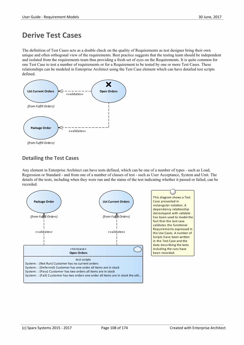
User Guide - Requirement Models 30 June, 2017
Derive Test Cases
The definition of Test Cases acts as a double check on the quality of Requirements as test designer bring their ownunique and often orthogonal view of the requirements. Best practice suggests that the testing team should be independentand isolated from the requirements team thus providing a fresh set of eyes on the Requirements. It is quite common forone Test Case to test a number of requirements or for a Requirement to be tested by one or more Test Cases. Theserelationships can be modeled in Enterprise Architect using the Test Case element which can have detailed test scriptsdefined.
(from Fulfill Orders)
List Current Orders Open Orders
(from Fulfill Orders)
Package Order
«validates»
«validates»
Detailing the Test Cases
Any element in Enterprise Architect can have tests defined, which can be one of a number of types - such as Load,Regression or Standard - and from one of a number of classes of test - such as User Acceptance, System and Unit. Thedetails of the tests, including when they were run and the status of the test indicating whether it passed or failed, can berecorded.
(from Fulfill Orders)
List Current Orders
(from Fulfill Orders)
Package Order
«testcase»Open Orders
test scriptsSystem: : (Not Run) Customer has no current ordersSystem: : (Deferred) Customer has one order all items are in stockSystem: : (Pass) Customer has two orders all items are in stockSystem: : (Fail) Customer has two orders one order all items are in stock the oth...
This diagram shows a Test Case presented in rectangular notation. A dependency relationship stereotyped with validate has been used to model thefact that the test case validates the functional Requirements expressed in the Use Cases. A number of Scripts have been written in the Test Case and the data describing the tests including the runs have been recorded.
«validates»«validates»
(c) Sparx Systems 2015 - 2017 Page 108 of 174 Created with Enterprise Architect
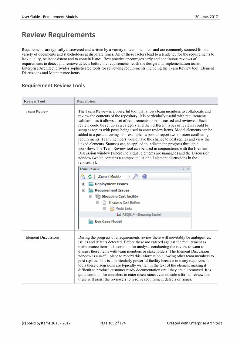
User Guide - Requirement Models 30 June, 2017
Review Requirements
Requirements are typically discovered and written by a variety of team members and are commonly sourced from avariety of documents and stakeholders at disparate times. All of these factors lead to a tendency for the requirements tolack quality, be inconsistent and to contain issues. Best practice encourages early and continuous reviews ofrequirements to detect and remove defects before the requirements reach the design and implementation teams.Enterprise Architect provides sophisticated tools for reviewing requirements including the Team Review tool, ElementDiscussions and Maintenance items.
Requirement Review Tools
Review Tool Description
Team Review The Team Review is a powerful tool that allows team members to collaborate andreview the contents of the repository. It is particularly useful with requirementsvalidation as it allows a set of requirements to be discussed and reviewed. Eachreview could be set up as a category and then different types of reviews could besetup as topics with posts being used to enter review items. Model elements can beadded to a post, allowing - for example - a post to report two or more conflictingrequirements. Team members would have the chance to post replies and view thelinked elements. Statuses can be applied to indicate the progress through aworkflow. The Team Review tool can be used in conjunctions with the ElementDiscussion window (where individual elements are managed) and the Discussionwindow (which contains a composite list of all element discussions in therepository).
Element Discussions During the progress of a requirements review there will inevitably be ambiguities,issues and defects detected. Before these are entered against the requirement asmaintenance items it is common for analysts conducting the review to want todiscuss these items with team members or stakeholders. The Element Discussionwindow is a useful place to record this information allowing other team members topost replies. This is a particularly powerful facility because in many requirementtools these discussions are typically written in the text of the element making itdifficult to produce customer ready documentation until they are all removed. It isquite common for modelers to enter discussions even outside a formal review andthese will assist the reviewers to resolve requirement defects or issues.
(c) Sparx Systems 2015 - 2017 Page 109 of 174 Created with Enterprise Architect
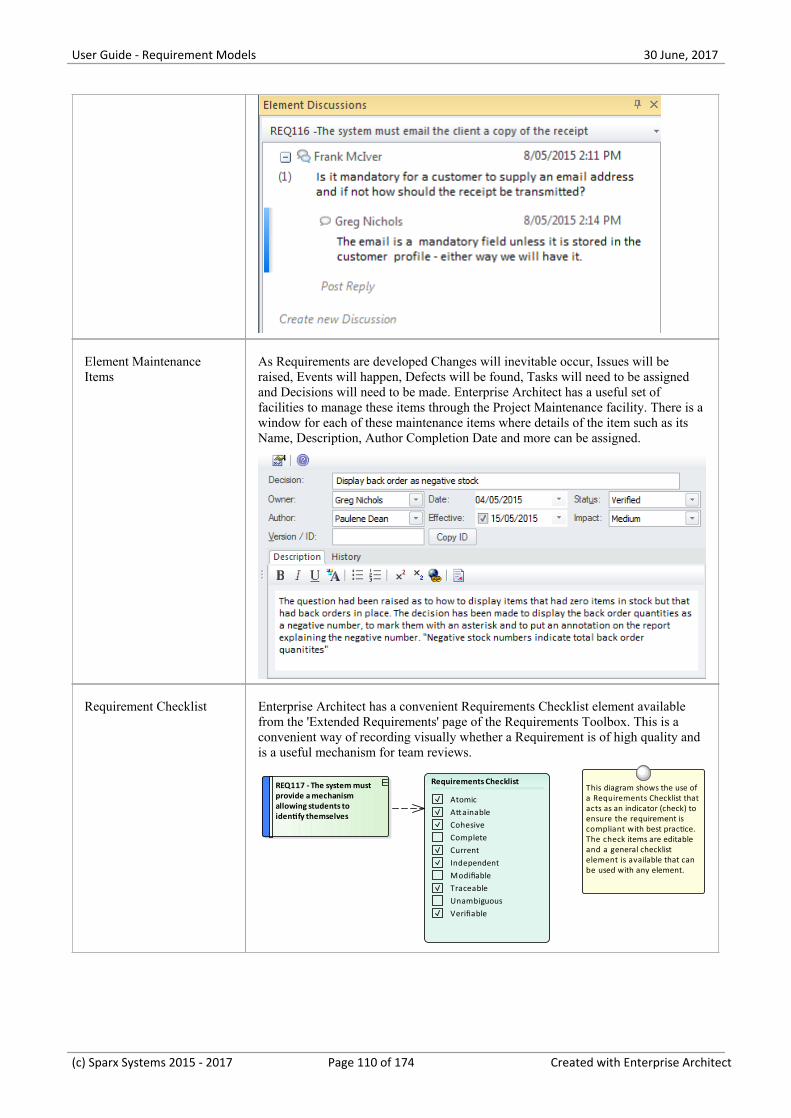
User Guide - Requirement Models 30 June, 2017
Element MaintenanceItems
As Requirements are developed Changes will inevitable occur, Issues will beraised, Events will happen, Defects will be found, Tasks will need to be assignedand Decisions will need to be made. Enterprise Architect has a useful set offacilities to manage these items through the Project Maintenance facility. There is awindow for each of these maintenance items where details of the item such as itsName, Description, Author Completion Date and more can be assigned.
Requirement Checklist Enterprise Architect has a convenient Requirements Checklist element availablefrom the 'Extended Requirements' page of the Requirements Toolbox. This is aconvenient way of recording visually whether a Requirement is of high quality andis a useful mechanism for team reviews.
REQ117 - The system must provide a mechanism allowing students to identify themselves
This diagram shows the use of a Requirements Checklist that acts as an indicator (check) to ensure the requirement is compliant with best practice. The check items are editable and a general checklist element is available that can be used with any element.
Requirements Checklist
AtomicAttainableCohesiveCompleteCurrentIndependentModifiableTraceableUnambiguousVerifiable
(c) Sparx Systems 2015 - 2017 Page 110 of 174 Created with Enterprise Architect
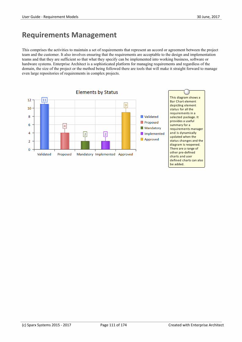
User Guide - Requirement Models 30 June, 2017
Requirements Management
This comprises the activities to maintain a set of requirements that represent an accord or agreement between the projectteam and the customer. It also involves ensuring that the requirements are acceptable to the design and implementationteams and that they are sufficient so that what they specify can be implemented into working business, software orhardware systems. Enterprise Architect is a sophisticated platform for managing requirements and regardless of thedomain, the size of the project or the method being followed there are tools that will make it straight forward to manageeven large repositories of requirements in complex projects.
This diagram shows a Bar Chart element depicting element status for all the requirements in a selected package. It provides a useful summary for a requirements manager and is dynamically updated when the status changes and the diagram is reopened. There are a range of other pre-defined charts and user defined charts can also be added.
(c) Sparx Systems 2015 - 2017 Page 111 of 174 Created with Enterprise Architect
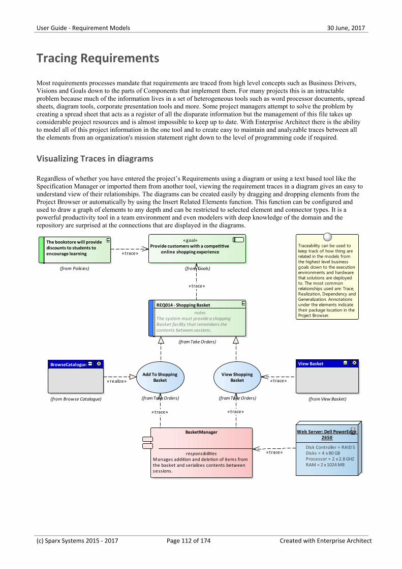
User Guide - Requirement Models 30 June, 2017
Tracing Requirements
Most requirements processes mandate that requirements are traced from high level concepts such as Business Drivers,Visions and Goals down to the parts of Components that implement them. For many projects this is an intractableproblem because much of the information lives in a set of heterogeneous tools such as word processor documents, spreadsheets, diagram tools, corporate presentation tools and more. Some project managers attempt to solve the problem bycreating a spread sheet that acts as a register of all the disparate information but the management of this file takes upconsiderable project resources and is almost impossible to keep up to date. With Enterprise Architect there is the abilityto model all of this project information in the one tool and to create easy to maintain and analyzable traces between allthe elements from an organization's mission statement right down to the level of programming code if required.
Visualizing Traces in diagrams
Regardless of whether you have entered the project’s Requirements using a diagram or using a text based tool like theSpecification Manager or imported them from another tool, viewing the requirement traces in a diagram gives an easy tounderstand view of their relationships. The diagrams can be created easily by dragging and dropping elements from theProject Browser or automatically by using the Insert Related Elements function. This function can be configured andused to draw a graph of elements to any depth and can be restricted to selected element and connector types. It is apowerful productivity tool in a team environment and even modelers with deep knowledge of the domain and therepository are surprised at the connections that are displayed in the diagrams.
View Basket
(from View Basket)
The bookstore will provide discounts to students to encourage learning
(from Policies)
(from Take Orders)
View Shopping Basket
(from Take Orders)
Add To Shopping Basket
BrowseCatalogue
(from Browse Catalogue)
REQ014 - Shopping Basket
notesThe system must provide a shoppingBasket facility that remembers thecontents between sessions.
(from Take Orders)
BasketManager
responsibilitiesManages addition and deletion of items fromthe basket and serializes contents betweensessions.
Web Server: Dell PowerEdge 2650
Disk Controller = RAID 5Disks = 4 x 80 GBProcessor = 2 x 2.8 GHZ RAM = 2 x 1024 MB
«goal»Provide customers with a competitive
online shopping experience
(from Goals)
Traceability can be used to keep track of how thing are related in the models from the highest level business goals down to the execution environments and hardware that solutions are deployed to. The most common relationships used are: Trace, Realization, Dependency and Generalization. Annotations under the elements indicate their package location in the Project Browser.
«trace»
«trace»
«trace»
«trace»
«realize»
«trace»
«trace»
(c) Sparx Systems 2015 - 2017 Page 112 of 174 Created with Enterprise Architect
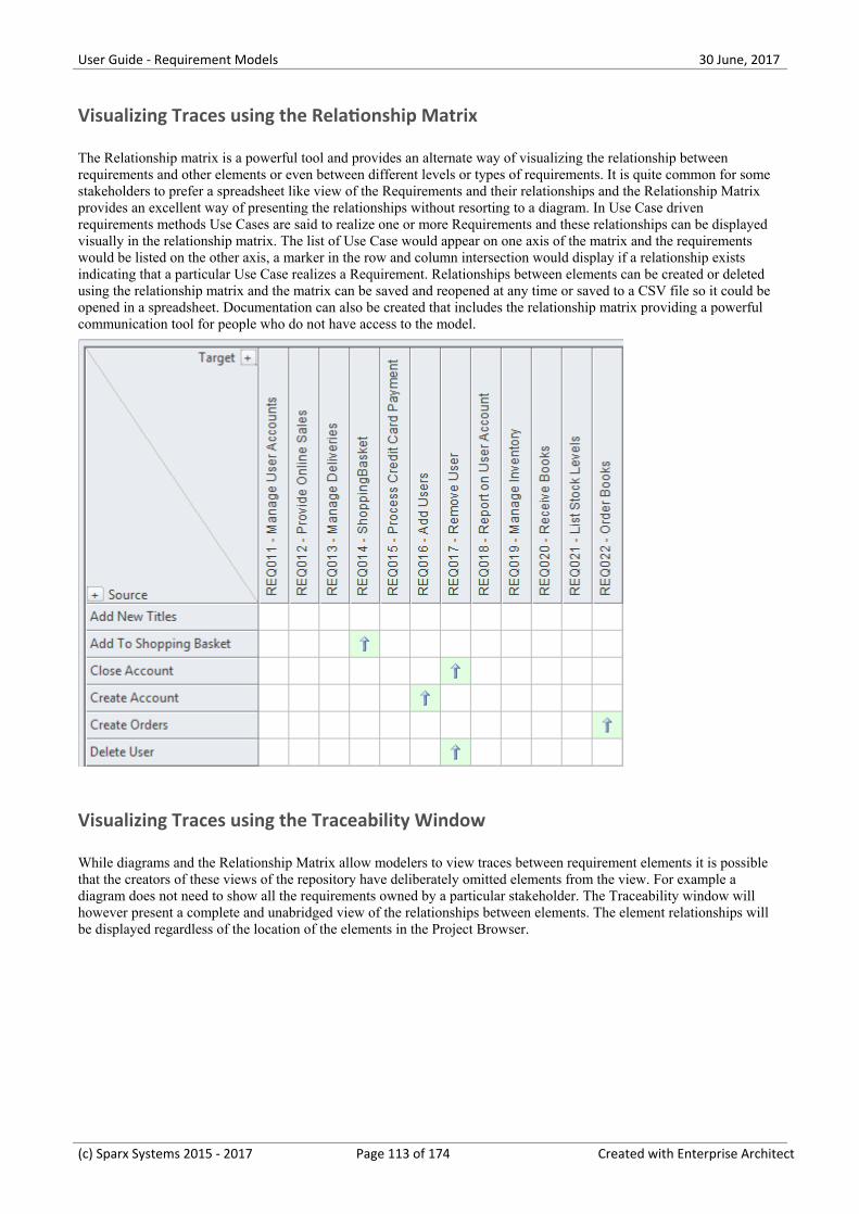
User Guide - Requirement Models 30 June, 2017
Visualizing Traces using the Relationship Matrix
The Relationship matrix is a powerful tool and provides an alternate way of visualizing the relationship betweenrequirements and other elements or even between different levels or types of requirements. It is quite common for somestakeholders to prefer a spreadsheet like view of the Requirements and their relationships and the Relationship Matrixprovides an excellent way of presenting the relationships without resorting to a diagram. In Use Case drivenrequirements methods Use Cases are said to realize one or more Requirements and these relationships can be displayedvisually in the relationship matrix. The list of Use Case would appear on one axis of the matrix and the requirementswould be listed on the other axis, a marker in the row and column intersection would display if a relationship existsindicating that a particular Use Case realizes a Requirement. Relationships between elements can be created or deletedusing the relationship matrix and the matrix can be saved and reopened at any time or saved to a CSV file so it could beopened in a spreadsheet. Documentation can also be created that includes the relationship matrix providing a powerfulcommunication tool for people who do not have access to the model.
Visualizing Traces using the Traceability Window
While diagrams and the Relationship Matrix allow modelers to view traces between requirement elements it is possiblethat the creators of these views of the repository have deliberately omitted elements from the view. For example adiagram does not need to show all the requirements owned by a particular stakeholder. The Traceability window willhowever present a complete and unabridged view of the relationships between elements. The element relationships willbe displayed regardless of the location of the elements in the Project Browser.
(c) Sparx Systems 2015 - 2017 Page 113 of 174 Created with Enterprise Architect
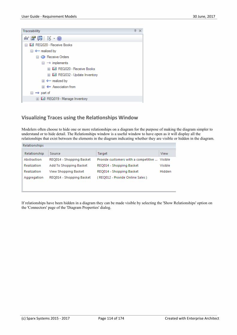
User Guide - Requirement Models 30 June, 2017
Visualizing Traces using the Relationships Window
Modelers often choose to hide one or more relationships on a diagram for the purpose of making the diagram simpler tounderstand or to hide detail. The Relationships window is a useful window to have open as it will display all therelationships that exist between the elements in the diagram indicating whether they are visible or hidden in the diagram.
If relationships have been hidden in a diagram they can be made visible by selecting the 'Show Relationships' option onthe 'Connectors' page of the 'Diagram Properties' dialog.
(c) Sparx Systems 2015 - 2017 Page 114 of 174 Created with Enterprise Architect
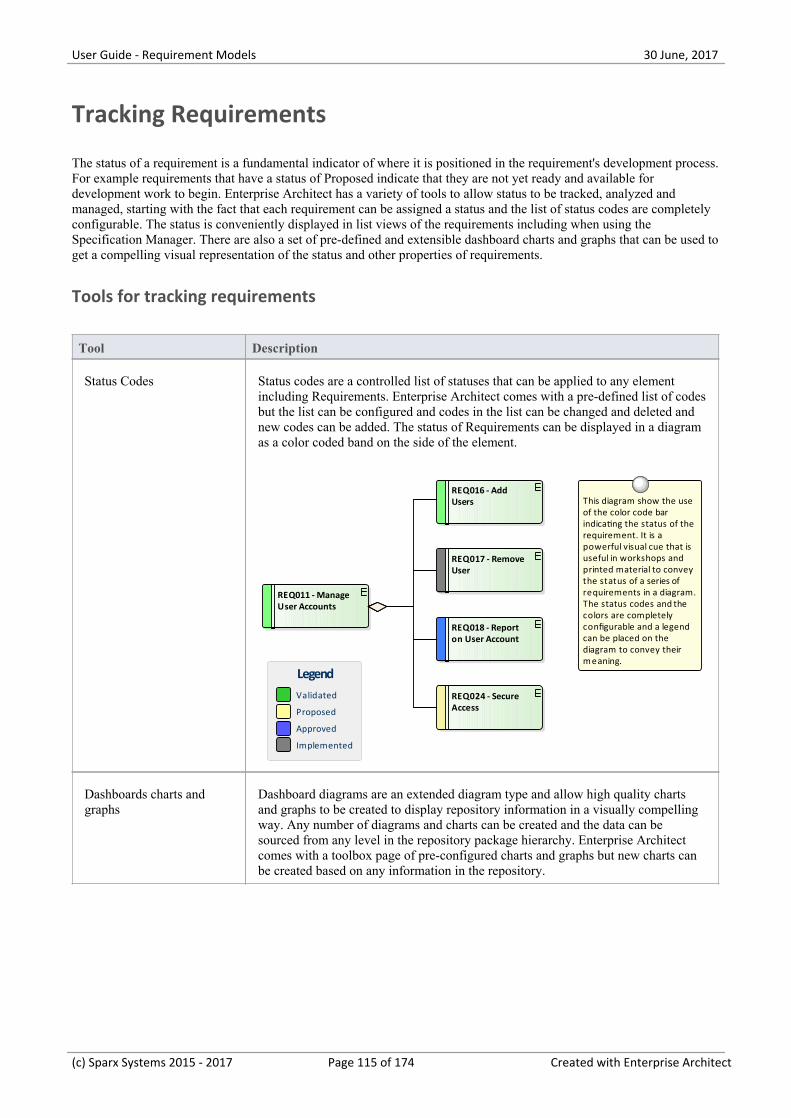
User Guide - Requirement Models 30 June, 2017
Tracking Requirements
The status of a requirement is a fundamental indicator of where it is positioned in the requirement's development process.For example requirements that have a status of Proposed indicate that they are not yet ready and available fordevelopment work to begin. Enterprise Architect has a variety of tools to allow status to be tracked, analyzed andmanaged, starting with the fact that each requirement can be assigned a status and the list of status codes are completelyconfigurable. The status is conveniently displayed in list views of the requirements including when using theSpecification Manager. There are also a set of pre-defined and extensible dashboard charts and graphs that can be used toget a compelling visual representation of the status and other properties of requirements.
Tools for tracking requirements
Tool Description
Status Codes Status codes are a controlled list of statuses that can be applied to any elementincluding Requirements. Enterprise Architect comes with a pre-defined list of codesbut the list can be configured and codes in the list can be changed and deleted andnew codes can be added. The status of Requirements can be displayed in a diagramas a color coded band on the side of the element.
REQ011 - Manage User Accounts
REQ018 - Report on User Account
REQ024 - Secure Access
REQ017 - Remove User
REQ016 - Add Users This diagram show the use
of the color code bar indicating the status of the requirement. It is a powerful visual cue that is useful in workshops and printed material to convey the status of a series of requirements in a diagram. The status codes and the colors are completely configurable and a legend can be placed on the diagram to convey their meaning.
Validated
Proposed
Approved
Implemented
Legend
Dashboards charts andgraphs
Dashboard diagrams are an extended diagram type and allow high quality chartsand graphs to be created to display repository information in a visually compellingway. Any number of diagrams and charts can be created and the data can besourced from any level in the repository package hierarchy. Enterprise Architectcomes with a toolbox page of pre-configured charts and graphs but new charts canbe created based on any information in the repository.
(c) Sparx Systems 2015 - 2017 Page 115 of 174 Created with Enterprise Architect
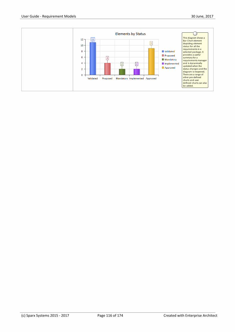
User Guide - Requirement Models 30 June, 2017
This diagram shows a Bar Chart element depicting element status for all the requirements in a selected package. It provides a useful summary for a requirements manager and is dynamically updated when the status changes and the diagram is reopened. There are a range of other pre-defined charts and user defined charts can also be added.
(c) Sparx Systems 2015 - 2017 Page 116 of 174 Created with Enterprise Architect
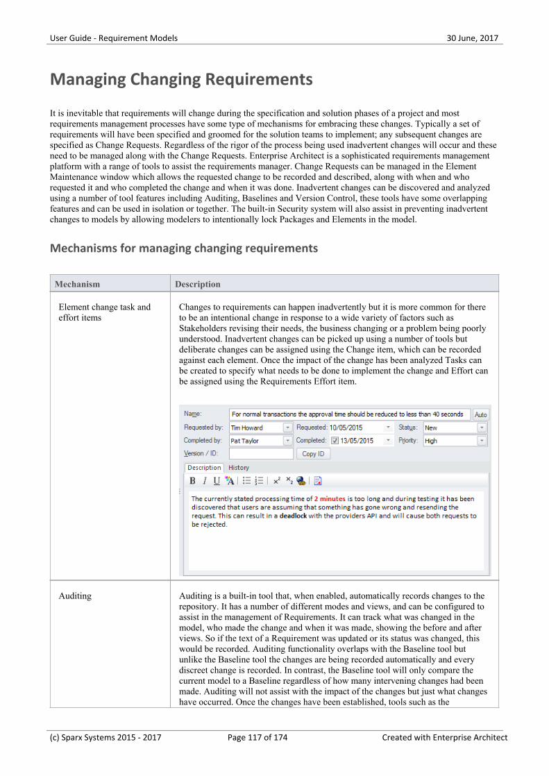
User Guide - Requirement Models 30 June, 2017
Managing Changing Requirements
It is inevitable that requirements will change during the specification and solution phases of a project and mostrequirements management processes have some type of mechanisms for embracing these changes. Typically a set ofrequirements will have been specified and groomed for the solution teams to implement; any subsequent changes arespecified as Change Requests. Regardless of the rigor of the process being used inadvertent changes will occur and theseneed to be managed along with the Change Requests. Enterprise Architect is a sophisticated requirements managementplatform with a range of tools to assist the requirements manager. Change Requests can be managed in the ElementMaintenance window which allows the requested change to be recorded and described, along with when and whorequested it and who completed the change and when it was done. Inadvertent changes can be discovered and analyzedusing a number of tool features including Auditing, Baselines and Version Control, these tools have some overlappingfeatures and can be used in isolation or together. The built-in Security system will also assist in preventing inadvertentchanges to models by allowing modelers to intentionally lock Packages and Elements in the model.
Mechanisms for managing changing requirements
Mechanism Description
Element change task andeffort items
Changes to requirements can happen inadvertently but it is more common for thereto be an intentional change in response to a wide variety of factors such asStakeholders revising their needs, the business changing or a problem being poorlyunderstood. Inadvertent changes can be picked up using a number of tools butdeliberate changes can be assigned using the Change item, which can be recordedagainst each element. Once the impact of the change has been analyzed Tasks canbe created to specify what needs to be done to implement the change and Effort canbe assigned using the Requirements Effort item.
Auditing Auditing is a built-in tool that, when enabled, automatically records changes to therepository. It has a number of different modes and views, and can be configured toassist in the management of Requirements. It can track what was changed in themodel, who made the change and when it was made, showing the before and afterviews. So if the text of a Requirement was updated or its status was changed, thiswould be recorded. Auditing functionality overlaps with the Baseline tool butunlike the Baseline tool the changes are being recorded automatically and everydiscreet change is recorded. In contrast, the Baseline tool will only compare thecurrent model to a Baseline regardless of how many intervening changes had beenmade. Auditing will not assist with the impact of the changes but just what changeshave occurred. Once the changes have been established, tools such as the
(c) Sparx Systems 2015 - 2017 Page 117 of 174 Created with Enterprise Architect
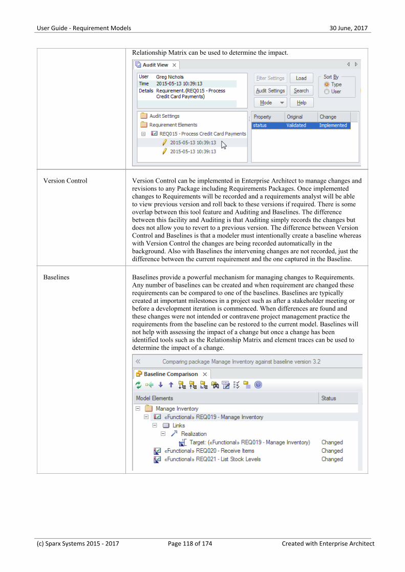
User Guide - Requirement Models 30 June, 2017
Relationship Matrix can be used to determine the impact.
Version Control Version Control can be implemented in Enterprise Architect to manage changes andrevisions to any Package including Requirements Packages. Once implementedchanges to Requirements will be recorded and a requirements analyst will be ableto view previous version and roll back to these versions if required. There is someoverlap between this tool feature and Auditing and Baselines. The differencebetween this facility and Auditing is that Auditing simply records the changes butdoes not allow you to revert to a previous version. The difference between VersionControl and Baselines is that a modeler must intentionally create a baseline whereaswith Version Control the changes are being recorded automatically in thebackground. Also with Baselines the intervening changes are not recorded, just thedifference between the current requirement and the one captured in the Baseline.
Baselines Baselines provide a powerful mechanism for managing changes to Requirements.Any number of baselines can be created and when requirement are changed theserequirements can be compared to one of the baselines. Baselines are typicallycreated at important milestones in a project such as after a stakeholder meeting orbefore a development iteration is commenced. When differences are found andthese changes were not intended or contravene project management practice therequirements from the baseline can be restored to the current model. Baselines willnot help with assessing the impact of a change but once a change has beenidentified tools such as the Relationship Matrix and element traces can be used todetermine the impact of a change.
(c) Sparx Systems 2015 - 2017 Page 118 of 174 Created with Enterprise Architect
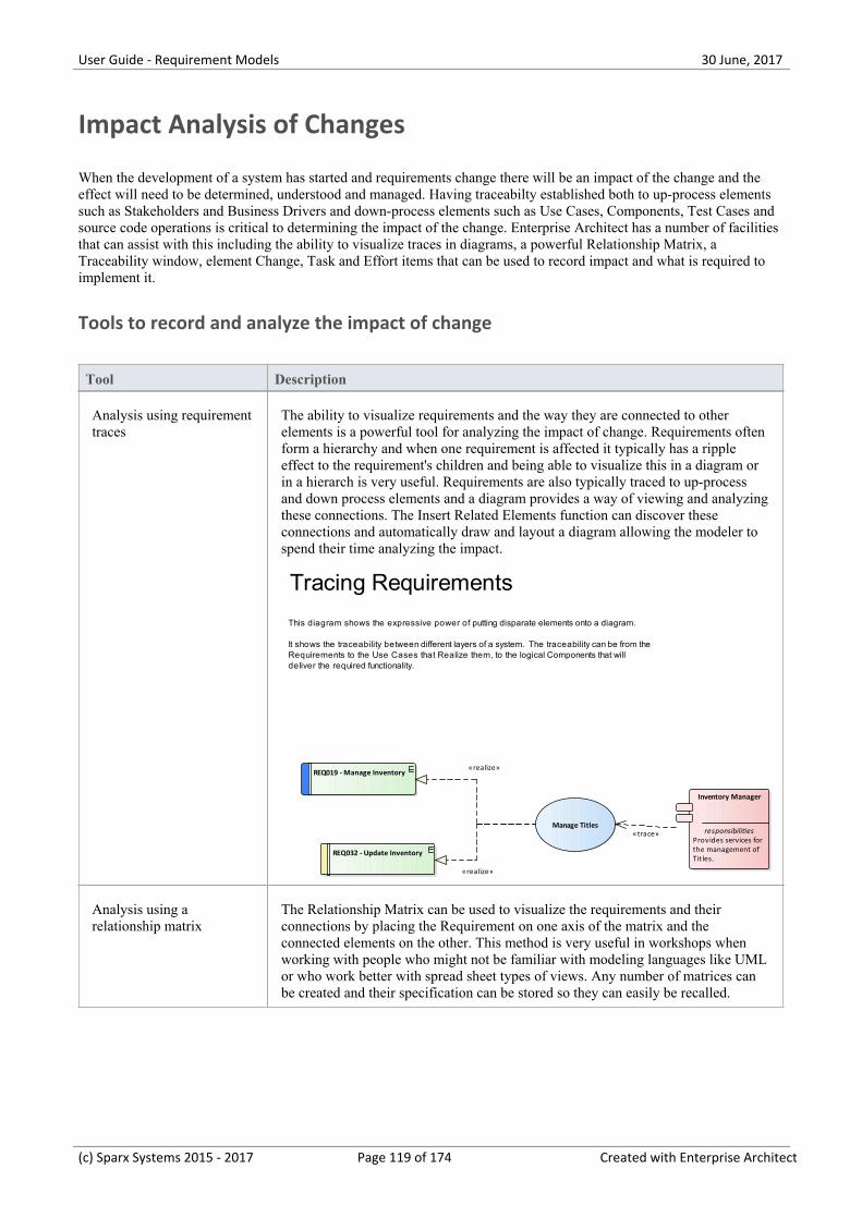
User Guide - Requirement Models 30 June, 2017
Impact Analysis of Changes
When the development of a system has started and requirements change there will be an impact of the change and theeffect will need to be determined, understood and managed. Having traceabilty established both to up-process elementssuch as Stakeholders and Business Drivers and down-process elements such as Use Cases, Components, Test Cases andsource code operations is critical to determining the impact of the change. Enterprise Architect has a number of facilitiesthat can assist with this including the ability to visualize traces in diagrams, a powerful Relationship Matrix, aTraceability window, element Change, Task and Effort items that can be used to record impact and what is required toimplement it.
Tools to record and analyze the impact of change
Tool Description
Analysis using requirementtraces
The ability to visualize requirements and the way they are connected to otherelements is a powerful tool for analyzing the impact of change. Requirements oftenform a hierarchy and when one requirement is affected it typically has a rippleeffect to the requirement's children and being able to visualize this in a diagram orin a hierarch is very useful. Requirements are also typically traced to up-processand down process elements and a diagram provides a way of viewing and analyzingthese connections. The Insert Related Elements function can discover theseconnections and automatically draw and layout a diagram allowing the modeler tospend their time analyzing the impact.
Inventory Manager
responsibilitiesProvides services forthe management ofTitles.
REQ019 - Manage Inventory
REQ032 - Update Inventory
Manage Titles
Tracing Requirements
This diagram shows the expressive power of putting disparate elements onto a diagram.
It shows the traceability between different layers of a system. The traceability can be from the Requirements to the Use Cases that Realize them, to the logical Components that will deliver the required functionality.
«realize»
«realize»
«trace»
Analysis using arelationship matrix
The Relationship Matrix can be used to visualize the requirements and theirconnections by placing the Requirement on one axis of the matrix and theconnected elements on the other. This method is very useful in workshops whenworking with people who might not be familiar with modeling languages like UMLor who work better with spread sheet types of views. Any number of matrices canbe created and their specification can be stored so they can easily be recalled.
(c) Sparx Systems 2015 - 2017 Page 119 of 174 Created with Enterprise Architect

User Guide - Requirement Models 30 June, 2017
Analysis using thetraceability window
The Traceability window is a powerful window that shows the hierarchy ofelements in the Repository. It is particularly useful because it unconditionallyshows how elements are related to each other. Other views of the repository couldbe configured just to display particular elements for the purpose of communicatingan idea whereas the Traceability window will display all relationship that anelement participates in which makes it particularly useful for analyzing the impactof change.
(c) Sparx Systems 2015 - 2017 Page 120 of 174 Created with Enterprise Architect
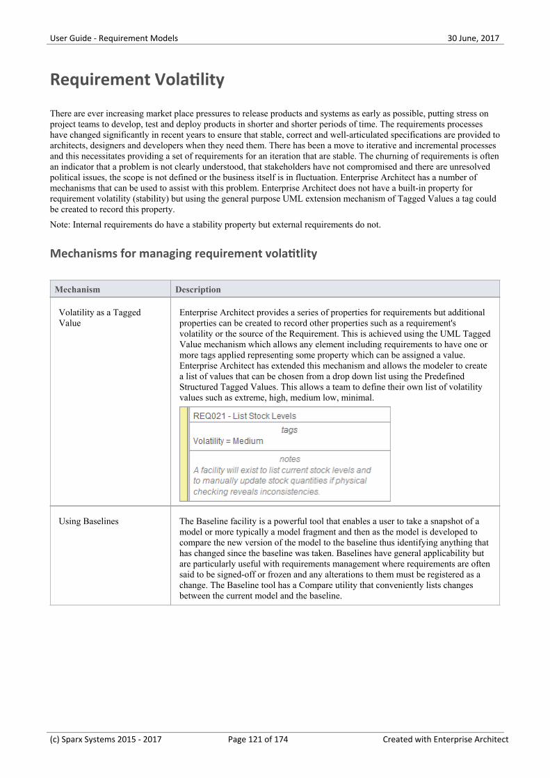
User Guide - Requirement Models 30 June, 2017
Requirement Volatility
There are ever increasing market place pressures to release products and systems as early as possible, putting stress onproject teams to develop, test and deploy products in shorter and shorter periods of time. The requirements processeshave changed significantly in recent years to ensure that stable, correct and well-articulated specifications are provided toarchitects, designers and developers when they need them. There has been a move to iterative and incremental processesand this necessitates providing a set of requirements for an iteration that are stable. The churning of requirements is oftenan indicator that a problem is not clearly understood, that stakeholders have not compromised and there are unresolvedpolitical issues, the scope is not defined or the business itself is in fluctuation. Enterprise Architect has a number ofmechanisms that can be used to assist with this problem. Enterprise Architect does not have a built-in property forrequirement volatility (stability) but using the general purpose UML extension mechanism of Tagged Values a tag couldbe created to record this property.
Note: Internal requirements do have a stability property but external requirements do not.
Mechanisms for managing requirement volatitlity
Mechanism Description
Volatility as a TaggedValue
Enterprise Architect provides a series of properties for requirements but additionalproperties can be created to record other properties such as a requirement'svolatility or the source of the Requirement. This is achieved using the UML TaggedValue mechanism which allows any element including requirements to have one ormore tags applied representing some property which can be assigned a value.Enterprise Architect has extended this mechanism and allows the modeler to createa list of values that can be chosen from a drop down list using the PredefinedStructured Tagged Values. This allows a team to define their own list of volatilityvalues such as extreme, high, medium low, minimal.
Using Baselines The Baseline facility is a powerful tool that enables a user to take a snapshot of amodel or more typically a model fragment and then as the model is developed tocompare the new version of the model to the baseline thus identifying anything thathas changed since the baseline was taken. Baselines have general applicability butare particularly useful with requirements management where requirements are oftensaid to be signed-off or frozen and any alterations to them must be registered as achange. The Baseline tool has a Compare utility that conveniently lists changesbetween the current model and the baseline.
(c) Sparx Systems 2015 - 2017 Page 121 of 174 Created with Enterprise Architect
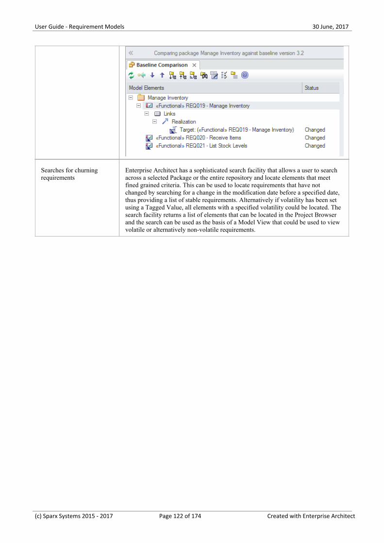
User Guide - Requirement Models 30 June, 2017
Searches for churningrequirements
Enterprise Architect has a sophisticated search facility that allows a user to searchacross a selected Package or the entire repository and locate elements that meetfined grained criteria. This can be used to locate requirements that have notchanged by searching for a change in the modification date before a specified date,thus providing a list of stable requirements. Alternatively if volatility has been setusing a Tagged Value, all elements with a specified volatility could be located. Thesearch facility returns a list of elements that can be located in the Project Browserand the search can be used as the basis of a Model View that could be used to viewvolatile or alternatively non-volatile requirements.
(c) Sparx Systems 2015 - 2017 Page 122 of 174 Created with Enterprise Architect
User Guide - Requirement Models 30 June, 2017
Requirements Reuse
The concept of reusing artifacts of a system development process has been written about in many papers and text booksbut has traditionally been confined to software components. In more recent years the notion of reusing specificationsincluding requirements has started to get traction. The reuse is particularly important where organizations create a familyof products with similar features or where there is a community of users within an industry or domain. Other types ofrequirements such as security and regulatory requirements will typically apply to a number of projects. Business Rulesand Stakeholders Concerns will also typically apply across many projects and are best catalogued outside individualprojects structures. Enterprise Architect provides a number of sophisticated mechanisms for managing the reuse ofelements across projects including structuring the repository for reuse, importing requirements from other sources and aReusable Asset Service.
Mechanism for requirements reuse
Mechanism Description
Structuring the repositoryfor requirements reuse
When you set up a repository you have the choice of structuring it for a singleproject or for multiple projects, which in turn could be organized by a number ofprograms of work. Enterprise Architect gives the modeler complete control on howthe repository is structured allowing Packages to be set up above the level ofprojects where some requirements such as Business, Regulatory and ArchitecturalRequirements can be added.
Creating a base model When you create a new repository in Enterprise Architect a modeler has the optionof creating a blank model, using the Model Wizard to help setup a repositorystructure or using a base model which acts as a template for the new model. Thebase model is a good place to store reusable assets such as Business, Regulatoryand Architectural Requirements and also Policies and Business Rules. A basemodel can be created using the 'Save Project As...' option under the 'File
Management' icon ( ).
Importing requirementsfrom other models
It is quite common to have a number of Enterprise Architect Repositories in anorganization and it is very easy to copy and reuse requirements (or any otherelements) from one model to another. This can be achieved by simply copying aselection of requirements or an entire Package from one repository to another oreven from one project to another in the same repository. Enterprise Architect workslike any other windows program, simply copying the selection to the clipboard andthen allowing it to be pasted in another location in the same model or another openrepository.
(c) Sparx Systems 2015 - 2017 Page 123 of 174 Created with Enterprise Architect
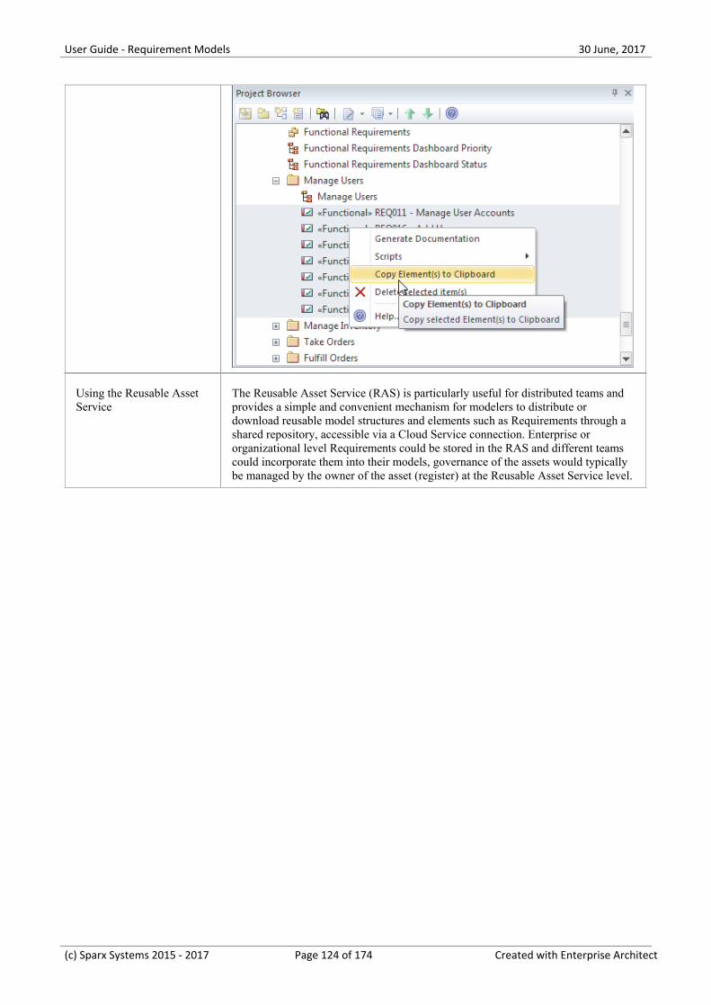
User Guide - Requirement Models 30 June, 2017
Using the Reusable AssetService
The Reusable Asset Service (RAS) is particularly useful for distributed teams andprovides a simple and convenient mechanism for modelers to distribute ordownload reusable model structures and elements such as Requirements through ashared repository, accessible via a Cloud Service connection. Enterprise ororganizational level Requirements could be stored in the RAS and different teamscould incorporate them into their models, governance of the assets would typicallybe managed by the owner of the asset (register) at the Reusable Asset Service level.
(c) Sparx Systems 2015 - 2017 Page 124 of 174 Created with Enterprise Architect
User Guide - Requirement Models 30 June, 2017
Requirements Documentation
A number of documents are commonly produced as part of the Requirements Engineering discipline, such as theSoftware (System) Requirements Specification and Use Case Report. These can be generated automatically from arequirements model using built-in templates. In addition a wide range of other documents can be produced using built-inor customized templates. The documentation facility in Enterprise Architect is highly configurable and many reports canbe produced using the template system, but for more complex reports there is a facility called Virtual Documents thatallows a publisher to model the structure of the document and to cherry pick content from anywhere in the repository,applying different templates to each section of the document. There is also a wide variety of options that can be appliedat the template or document generation level, and the Scripting engine can be used to inject content into a document or toproduce the entire report.
(c) Sparx Systems 2015 - 2017 Page 125 of 174 Created with Enterprise Architect
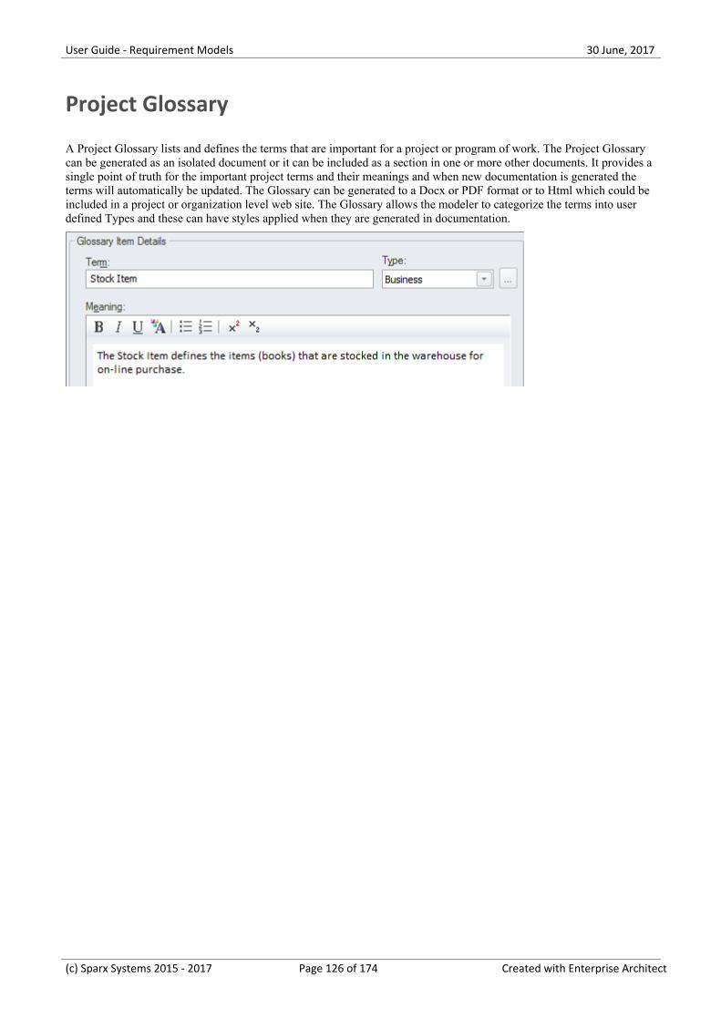
User Guide - Requirement Models 30 June, 2017
Project Glossary
A Project Glossary lists and defines the terms that are important for a project or program of work. The Project Glossarycan be generated as an isolated document or it can be included as a section in one or more other documents. It provides asingle point of truth for the important project terms and their meanings and when new documentation is generated theterms will automatically be updated. The Glossary can be generated to a Docx or PDF format or to Html which could beincluded in a project or organization level web site. The Glossary allows the modeler to categorize the terms into userdefined Types and these can have styles applied when they are generated in documentation.
(c) Sparx Systems 2015 - 2017 Page 126 of 174 Created with Enterprise Architect
User Guide - Requirement Models 30 June, 2017
Software Requirement Specification
This document describes the Requirements of the system and its behavior under defined conditions and the constraintsthat it must operate under; it will typically be read by a variety of stakeholders. There is a built-in Requirements templatethat can be used for this purpose and the modeler is free to create a new template which could be based on this or createdfrom a blank template. When the document is comprised of content from a variety of locations in the project browser itwould be most expedient to use the Virtual Documents facility which allows the user to create a model of the document(similar to a Master document in a Word Processor) which is comprised of a number of sections called model documents.These can contain content picked from anywhere in the project browser.
(c) Sparx Systems 2015 - 2017 Page 127 of 174 Created with Enterprise Architect
User Guide - Requirement Models 30 June, 2017
Use Case Report
The creation of Use Case documentation has traditionally been a manual process and with the documents in manyprojects running into hundreds of pages their production consumes valuable project resources. These hand-crafteddocuments become difficult to maintain and remain isolated from other parts of the project such as Requirements,Business Rules and solution Components. Enterprise Architect has a powerful tool called the Scenario Builder thatallows the modeler to specify Use Cases and Scenarios inside the model and these can be automatically generated to highquality documentation using built-in templates. There are two built-in templates that can be used for generating a UseCase report: one documents the Use Case at a summary level and the other at a detailed level.
Example content from a Use Case Report
The detailed Use Case report will list all the details of the Use Case and the detailed steps including Basic Paths,Alternate and Exception Scenarios. Other information including Internal Requirements and Pre and Post Conditions andother Constraints will also be included in the report. If a Behavioral diagram such as an Activity diagram has beenautomatically created this diagram will also be displayed in the report.
(c) Sparx Systems 2015 - 2017 Page 128 of 174 Created with Enterprise Architect
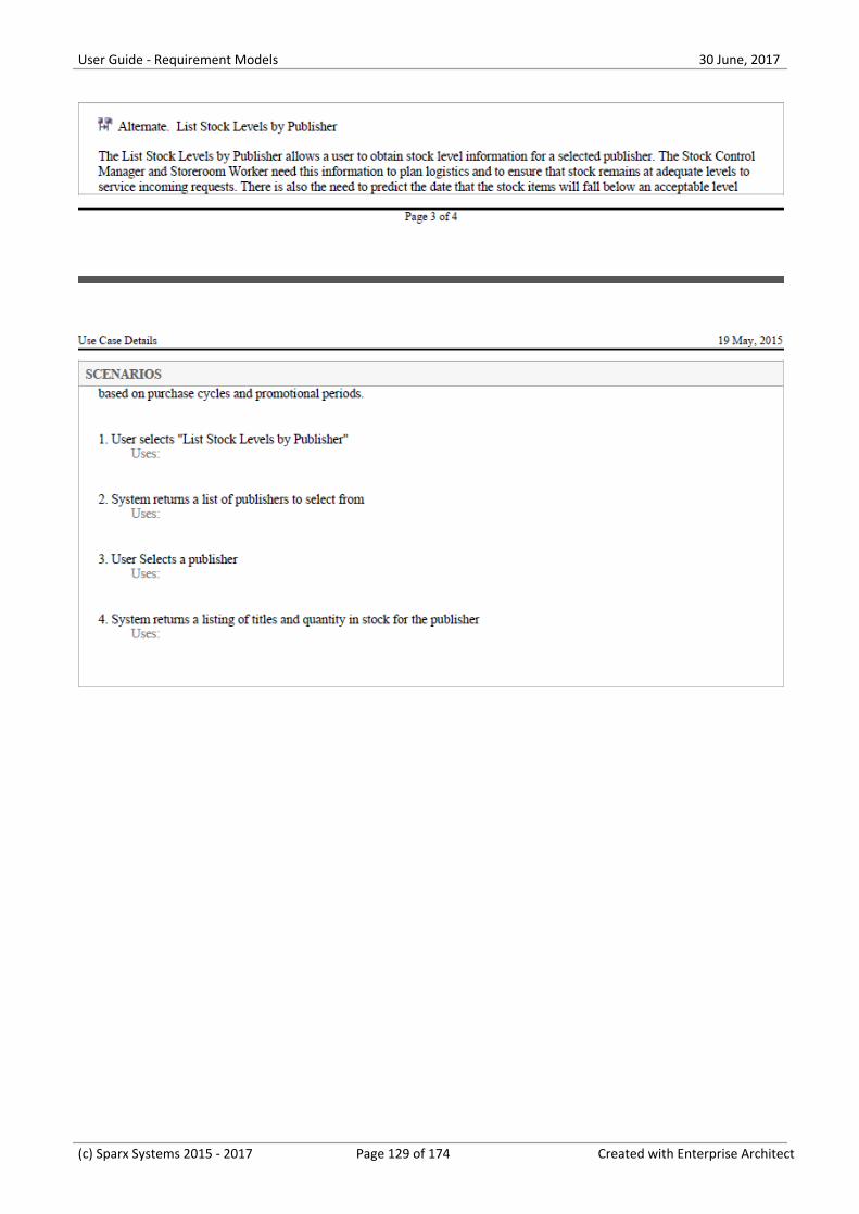
User Guide - Requirement Models 30 June, 2017
(c) Sparx Systems 2015 - 2017 Page 129 of 174 Created with Enterprise Architect
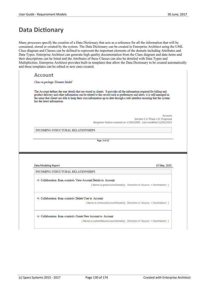
User Guide - Requirement Models 30 June, 2017
Data Dictionary
Many processes specify the creation of a Data Dictionary that acts as a reference for all the information that will beconsumed, stored or created by the system. The Data Dictionary can be created in Enterprise Architect using the UMLClass diagram and Classes can be defined to represent the important elements of the domain including Attributes andData Types. Enterprise Architect can generate high quality documentation from the Class diagram and data items andtheir descriptions can be listed and the Attributes of these Classes can also be detailed with Data Types andMultiplicities. Enterprise Architect provides built-in templates that allow the Data Dictionary to be created automaticallyand these templates can be edited or new ones created.
(c) Sparx Systems 2015 - 2017 Page 130 of 174 Created with Enterprise Architect
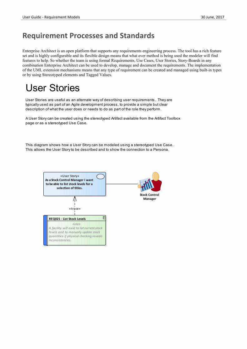
User Guide - Requirement Models 30 June, 2017
Requirement Processes and Standards
Enterprise Architect is an open platform that supports any requirements engineering process. The tool has a rich featureset and is highly configurable and its flexible design means that what ever method is being used the modeler will findfeatures to help. So whether the team is using formal Requirements, Use Cases, User Stories, Story-Boards in anycombination Enterprise Architect can be used to develop, manage and document the requirements. The implementationof the UML extension mechanisms means that any type of requirement can be created and managed using built-in typesor by using Stereotyped elements and Tagged Values.
«User Story»As a Stock Control Manager I want to be able to list stock levels for a
selection of titles.
REQ021 - List Stock Levels
notesA facility will exist to list current stocklevels and to manually update stockquantities if physical checking revealsinconsistencies.
Stock Control Manager
User StoriesUser Stories are useful as an alternate way of describing user requirements. They are typically used as part of an Agile development process, to provide a simple but clear description of what the user does or needs to do as part of the role they perform.
A User Story can be created using the stereotyped Artifact available from the Artifact Toolbox page or as a stereotyped Use Case.
This diagram shows how a User Story can be modeled using a stereotyped Use Case.This allows the User Story to be described and to show the connection to a Persona.
«trace»
(c) Sparx Systems 2015 - 2017 Page 131 of 174 Created with Enterprise Architect
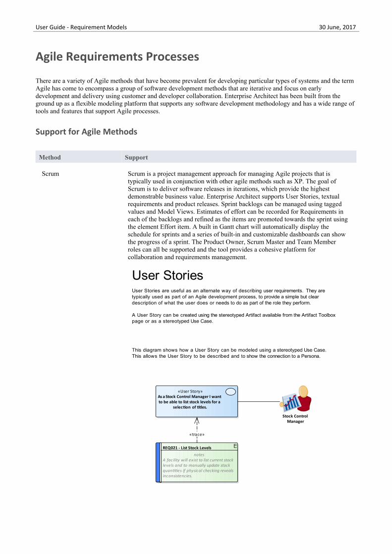
User Guide - Requirement Models 30 June, 2017
Agile Requirements Processes
There are a variety of Agile methods that have become prevalent for developing particular types of systems and the termAgile has come to encompass a group of software development methods that are iterative and focus on earlydevelopment and delivery using customer and developer collaboration. Enterprise Architect has been built from theground up as a flexible modeling platform that supports any software development methodology and has a wide range oftools and features that support Agile processes.
Support for Agile Methods
Method Support
Scrum Scrum is a project management approach for managing Agile projects that istypically used in conjunction with other agile methods such as XP. The goal ofScrum is to deliver software releases in iterations, which provide the highestdemonstrable business value. Enterprise Architect supports User Stories, textualrequirements and product releases. Sprint backlogs can be managed using taggedvalues and Model Views. Estimates of effort can be recorded for Requirements ineach of the backlogs and refined as the items are promoted towards the sprint usingthe element Effort item. A built in Gantt chart will automatically display theschedule for sprints and a series of built-in and customizable dashboards can showthe progress of a sprint. The Product Owner, Scrum Master and Team Memberroles can all be supported and the tool provides a cohesive platform forcollaboration and requirements management.
«User Story»As a Stock Control Manager I want to be able to list stock levels for a
selection of titles.
REQ021 - List Stock Levels
notesA facility will exist to list current stocklevels and to manually update stockquantities if physical checking revealsinconsistencies.
Stock Control Manager
User StoriesUser Stories are useful as an alternate way of describing user requirements. They are typically used as part of an Agile development process, to provide a simple but clear description of what the user does or needs to do as part of the role they perform.
A User Story can be created using the stereotyped Artifact available from the Artifact Toolbox page or as a stereotyped Use Case.
This diagram shows how a User Story can be modeled using a stereotyped Use Case.This allows the User Story to be described and to show the connection to a Persona.
«trace»
Extreme Programming Extreme Programming relies on the User Story (User Card) to express
(c) Sparx Systems 2015 - 2017 Page 132 of 174 Created with Enterprise Architect
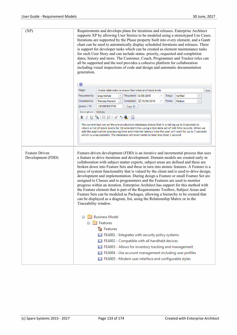
User Guide - Requirement Models 30 June, 2017
(XP) Requirements and develops plans for iterations and releases. Enterprise Architectsupports XP by allowing User Stories to be modeled using a stereotyped Use Cases.Iterations are supported by the Phase property built into every element, and a Ganttchart can be used to automatically display scheduled iterations and releases. Thereis support for developer tasks which can be created as element maintenance tasksfor each User Story and can include status. priority, requested and completiondates, history and more. The Customer, Coach, Programmer and Tracker roles canall be supported and the tool provides a cohesive platform for collaborationincluding visual inspections of code and design and automatic documentationgeneration.
Feature DrivenDevelopment (FDD)
Feature-driven development (FDD) is an iterative and incremental process that usesa feature to drive iterations and development. Domain models are created early incollaboration with subject matter experts, subject areas are defined and these arebroken down into Feature Sets and these in turn into atomic features. A Feature is apiece of system functionality that is valued by the client and is used to drive design,development and implementation. During design a Feature or small Feature Set areassigned to Classes and to programmers and the Features are used to monitorprogress within an iteration. Enterprise Architect has support for this method withthe Feature element that is part of the Requirements Toolbox, Subject Areas andFeature Sets can be modeled as Packages, allowing a hierarchy to be created thatcan be displayed as a diagram, list, using the Relationship Matrix or in theTraceability window.
(c) Sparx Systems 2015 - 2017 Page 133 of 174 Created with Enterprise Architect
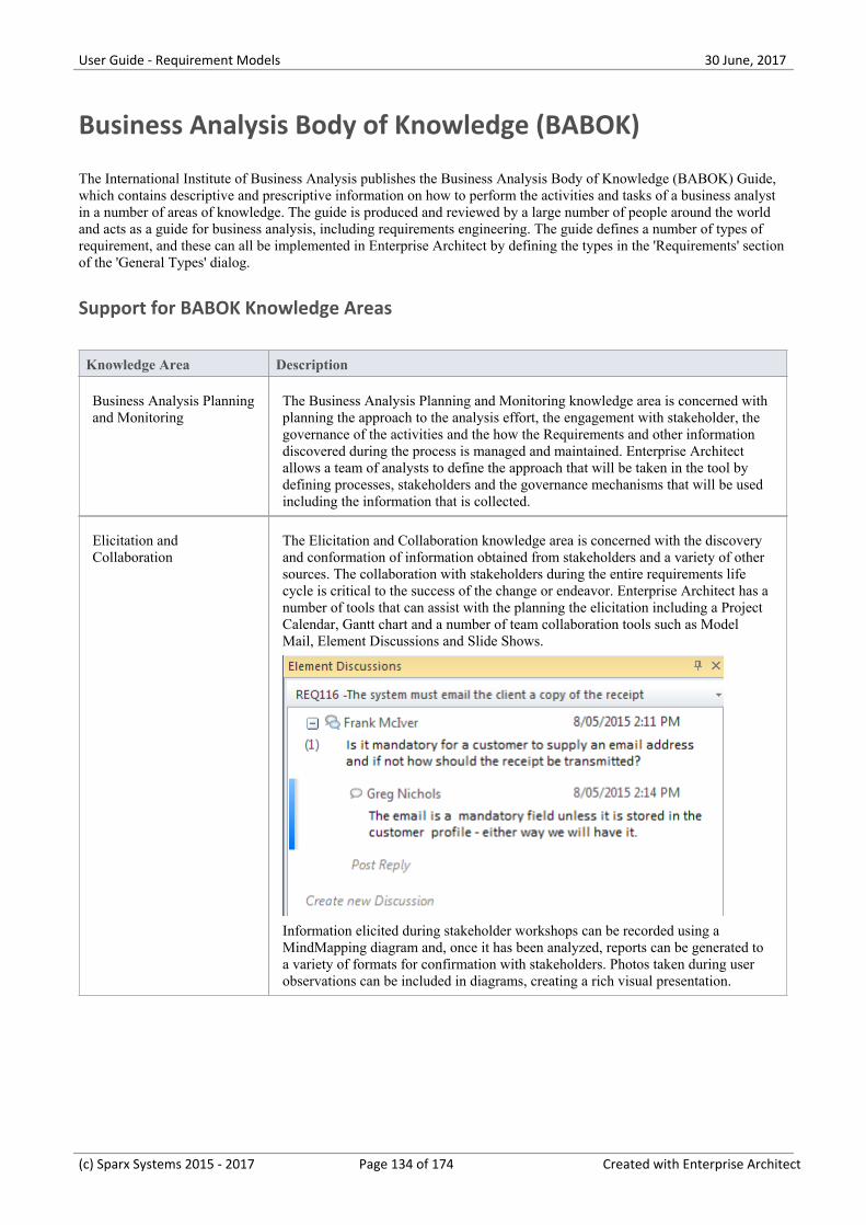
User Guide - Requirement Models 30 June, 2017
Business Analysis Body of Knowledge (BABOK)
The International Institute of Business Analysis publishes the Business Analysis Body of Knowledge (BABOK) Guide,which contains descriptive and prescriptive information on how to perform the activities and tasks of a business analystin a number of areas of knowledge. The guide is produced and reviewed by a large number of people around the worldand acts as a guide for business analysis, including requirements engineering. The guide defines a number of types ofrequirement, and these can all be implemented in Enterprise Architect by defining the types in the 'Requirements' sectionof the 'General Types' dialog.
Support for BABOK Knowledge Areas
Knowledge Area Description
Business Analysis Planningand Monitoring
The Business Analysis Planning and Monitoring knowledge area is concerned withplanning the approach to the analysis effort, the engagement with stakeholder, thegovernance of the activities and the how the Requirements and other informationdiscovered during the process is managed and maintained. Enterprise Architectallows a team of analysts to define the approach that will be taken in the tool bydefining processes, stakeholders and the governance mechanisms that will be usedincluding the information that is collected.
Elicitation andCollaboration
The Elicitation and Collaboration knowledge area is concerned with the discoveryand conformation of information obtained from stakeholders and a variety of othersources. The collaboration with stakeholders during the entire requirements lifecycle is critical to the success of the change or endeavor. Enterprise Architect has anumber of tools that can assist with the planning the elicitation including a ProjectCalendar, Gantt chart and a number of team collaboration tools such as ModelMail, Element Discussions and Slide Shows.
Information elicited during stakeholder workshops can be recorded using aMindMapping diagram and, once it has been analyzed, reports can be generated toa variety of formats for confirmation with stakeholders. Photos taken during userobservations can be included in diagrams, creating a rich visual presentation.
(c) Sparx Systems 2015 - 2017 Page 134 of 174 Created with Enterprise Architect
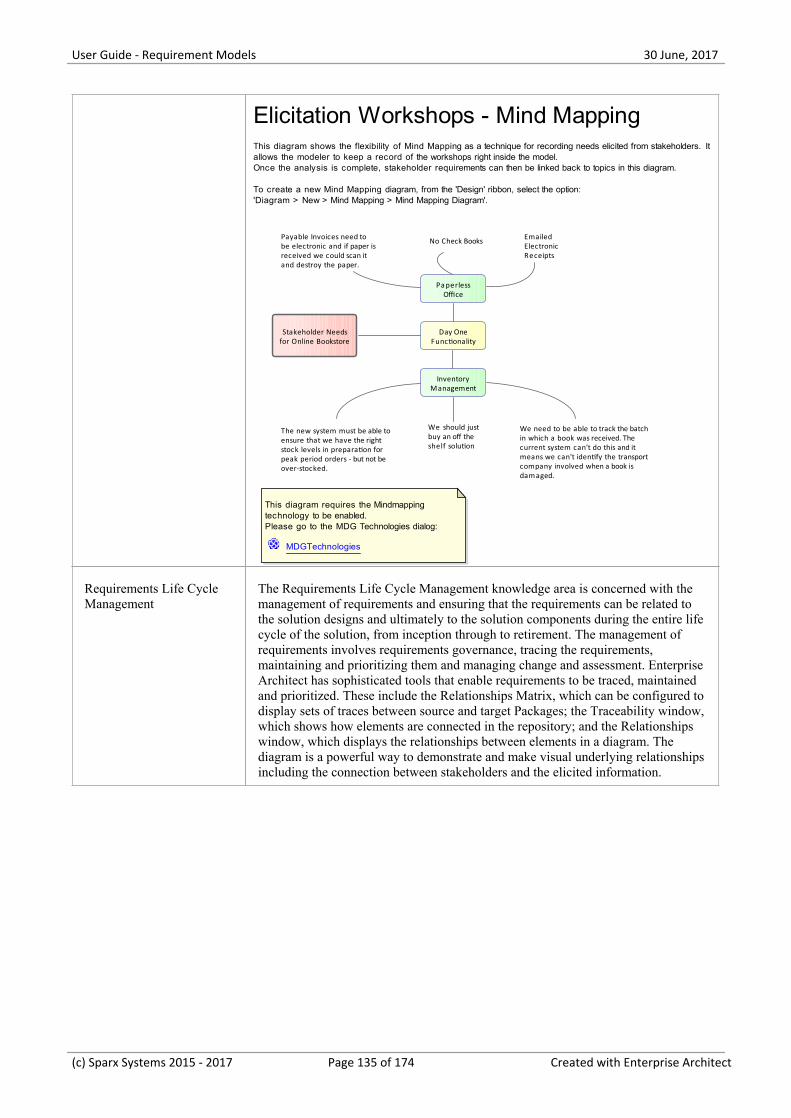
User Guide - Requirement Models 30 June, 2017
Stakeholder Needsfor Online Bookstore
Day OneFunctionality
PaperlessOffice
Payable Invoices need tobe electronic and if paper isreceived we could scan itand destroy the paper.
InventoryManagement
No Check Books EmailedElectronicReceipts
The new system must be able toensure that we have the rightstock levels in preparation forpeak period orders - but not beover-stocked.
We need to be able to track the batchin which a book was received. Thecurrent system can't do this and itmeans we can't identify the transportcompany involved when a book isdamaged.
We should justbuy an off theshelf solution
This diagram requires the Mindmapping technology to be enabled.Please go to the MDG Technologies dialog:
MDGTechnologies
Elicitation Workshops - Mind MappingThis diagram shows the flexibility of Mind Mapping as a technique for recording needs elicited from stakeholders. It allows the modeler to keep a record of the workshops right inside the model.Once the analysis is complete, stakeholder requirements can then be linked back to topics in this diagram.
To create a new Mind Mapping diagram, from the 'Design' ribbon, select the option:'Diagram > New > Mind Mapping > Mind Mapping Diagram'.
Requirements Life CycleManagement
The Requirements Life Cycle Management knowledge area is concerned with themanagement of requirements and ensuring that the requirements can be related tothe solution designs and ultimately to the solution components during the entire lifecycle of the solution, from inception through to retirement. The management ofrequirements involves requirements governance, tracing the requirements,maintaining and prioritizing them and managing change and assessment. EnterpriseArchitect has sophisticated tools that enable requirements to be traced, maintainedand prioritized. These include the Relationships Matrix, which can be configured todisplay sets of traces between source and target Packages; the Traceability window,which shows how elements are connected in the repository; and the Relationshipswindow, which displays the relationships between elements in a diagram. Thediagram is a powerful way to demonstrate and make visual underlying relationshipsincluding the connection between stakeholders and the elicited information.
(c) Sparx Systems 2015 - 2017 Page 135 of 174 Created with Enterprise Architect
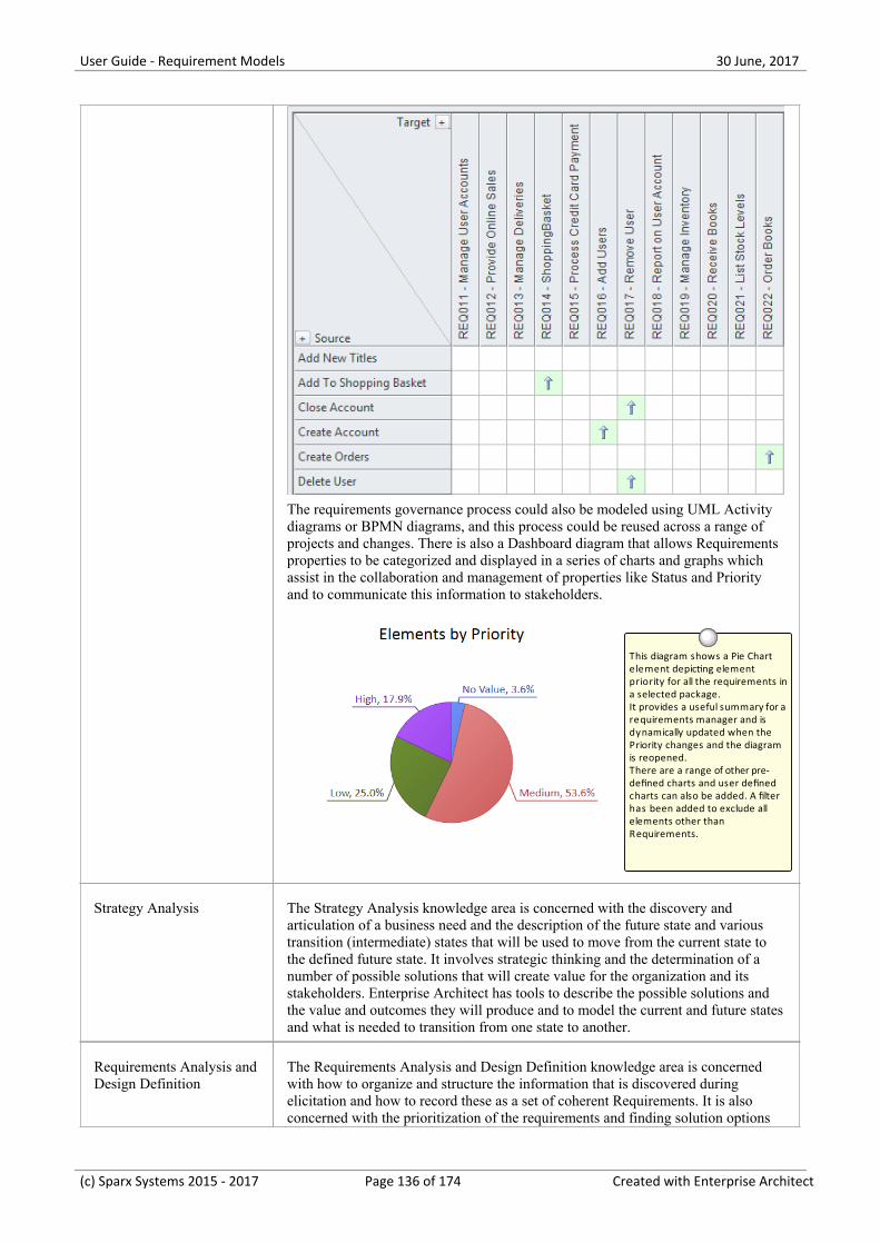
User Guide - Requirement Models 30 June, 2017
The requirements governance process could also be modeled using UML Activitydiagrams or BPMN diagrams, and this process could be reused across a range ofprojects and changes. There is also a Dashboard diagram that allows Requirementsproperties to be categorized and displayed in a series of charts and graphs whichassist in the collaboration and management of properties like Status and Priorityand to communicate this information to stakeholders.
This diagram shows a Pie Chart element depicting element priority for all the requirements ina selected package. It provides a useful summary for a requirements manager and is dynamically updated when the Priority changes and the diagram is reopened. There are a range of other pre-defined charts and user defined charts can also be added. A filter has been added to exclude all elements other than Requirements.
Strategy Analysis The Strategy Analysis knowledge area is concerned with the discovery andarticulation of a business need and the description of the future state and varioustransition (intermediate) states that will be used to move from the current state tothe defined future state. It involves strategic thinking and the determination of anumber of possible solutions that will create value for the organization and itsstakeholders. Enterprise Architect has tools to describe the possible solutions andthe value and outcomes they will produce and to model the current and future statesand what is needed to transition from one state to another.
Requirements Analysis andDesign Definition
The Requirements Analysis and Design Definition knowledge area is concernedwith how to organize and structure the information that is discovered duringelicitation and how to record these as a set of coherent Requirements. It is alsoconcerned with the prioritization of the requirements and finding solution options
(c) Sparx Systems 2015 - 2017 Page 136 of 174 Created with Enterprise Architect
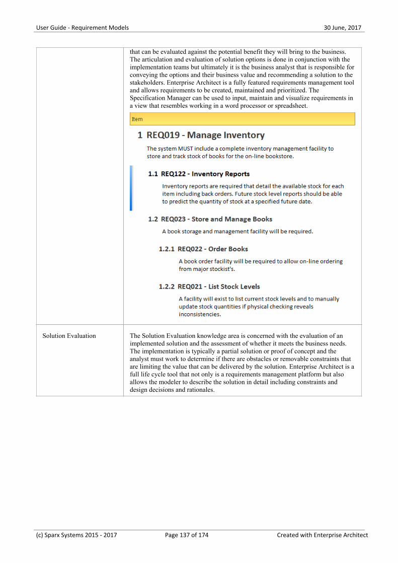
User Guide - Requirement Models 30 June, 2017
that can be evaluated against the potential benefit they will bring to the business.The articulation and evaluation of solution options is done in conjunction with theimplementation teams but ultimately it is the business analyst that is responsible forconveying the options and their business value and recommending a solution to thestakeholders. Enterprise Architect is a fully featured requirements management tooland allows requirements to be created, maintained and prioritized. TheSpecification Manager can be used to input, maintain and visualize requirements ina view that resembles working in a word processor or spreadsheet.
Solution Evaluation The Solution Evaluation knowledge area is concerned with the evaluation of animplemented solution and the assessment of whether it meets the business needs.The implementation is typically a partial solution or proof of concept and theanalyst must work to determine if there are obstacles or removable constraints thatare limiting the value that can be delivered by the solution. Enterprise Architect is afull life cycle tool that not only is a requirements management platform but alsoallows the modeler to describe the solution in detail including constraints anddesign decisions and rationales.
(c) Sparx Systems 2015 - 2017 Page 137 of 174 Created with Enterprise Architect
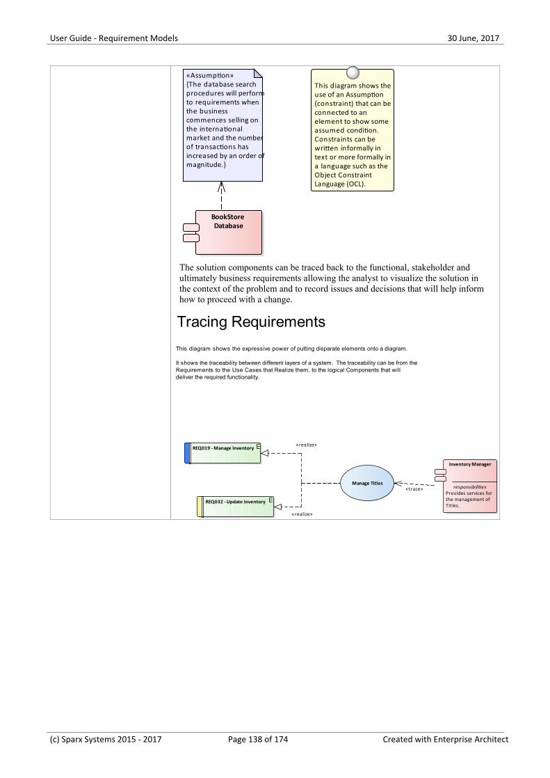
User Guide - Requirement Models 30 June, 2017
BookStore Database
This diagram shows theuse of an Assumption (constraint) that can beconnected to an element to show some assumed condition. Constraints can be written informally in text or more formally ina language such as the Object Constraint Language (OCL).
«Assumption»{The database searchprocedures will performto requirements whenthe businesscommences selling onthe internationalmarket and the numberof transactions hasincreased by an order ofmagnitude.}
The solution components can be traced back to the functional, stakeholder andultimately business requirements allowing the analyst to visualize the solution inthe context of the problem and to record issues and decisions that will help informhow to proceed with a change.
Inventory Manager
responsibilitiesProvides services forthe management ofTit les.
REQ019 - Manage Inventory
REQ032 - Update Inventory
Manage Titles
Tracing Requirements
This diagram shows the expressive power of putting disparate elements onto a diagram.
It shows the traceability between different layers of a system. The traceability can be from the Requirements to the Use Cases that Realize them, to the logical Components that will deliver the required functionality.
«trace»
«realize»
«realize»
(c) Sparx Systems 2015 - 2017 Page 138 of 174 Created with Enterprise Architect
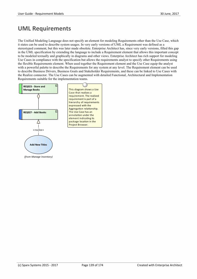
User Guide - Requirement Models 30 June, 2017
UML Requirements
The Unified Modeling Language does not specify an element for modeling Requirements other than the Use Case, whichit states can be used to describe system usages. In very early versions of UML a Requirement was defined as astereotyped comment, but this was later made obsolete. Enterprise Architect has, since very early versions, filled this gapin the UML specification by extending the language to include a Requirement element that allows this important conceptto be modeled textually and graphically in diagrams and other views. Enterprise Architect has rich support for modelingUse Cases in compliance with the specification but allows the requirements analyst to specify other Requirements usingthe flexible Requirements element. When used together the Requirement element and the Use Case equip the analystwith a powerful palette to describe the Requirements for any system at any level. The Requirement element can be usedto describe Business Drivers, Business Goals and Stakeholder Requirements, and these can be linked to Use Cases withthe Realize connector. The Use Cases can be augmented with detailed Functional, Architectural and ImplementationRequirements suitable for the implementation teams.
REQ027 - Add Books
(from Manage Inventory)
Add New Titles
REQ023 - Store and Manage Books This diagram shows a Use
Case that realizes a requirement. The realized requirement is part of a hierarchy of requirements expressed with the Aggregation relationship. The Use Case has an annotation under the element indicating its package location in the Project Browser.
«realize»
(c) Sparx Systems 2015 - 2017 Page 139 of 174 Created with Enterprise Architect
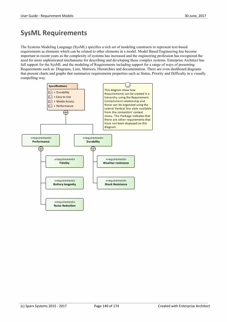
User Guide - Requirement Models 30 June, 2017
SysML Requirements
The Systems Modeling Language (SysML) specifies a rich set of modeling constructs to represent text-basedrequirements as elements which can be related to other elements in a model. Model Based Engineering has becomeimportant in recent years as the complexity of systems has increased and the engineering profession has recognized theneed for more sophisticated mechanisms for describing and developing these complex systems. Enterprise Architect hasfull support for the SysML and the modeling of Requirements including support for a range of ways of presentingRequirements such as: Diagrams, Lists, Matrices, Hierarchies and documentation. There are even dashboard diagramsthat present charts and graphs that summarize requirements properties such as Status, Priority and Difficulty in a visuallycompelling way.
«requirement»Performance
«requirement»Durability
«requirement»Fidelity
«requirement»Noise Reduction
«requirement»Battery longevity
«requirement»Weather resistance
«requirement»Shock Resistance
Specifications
+ Durability+ Easy to Use+ Media Access+ Performance
This diagram show how Requirements can be created in a hierarchy using the Requirement Containment relationship and these can be organized using the Lateral Vertical line style availablefrom the connectors' context menu. The Package indicates that there are other requirements that have not been displayed on this diagram.
(c) Sparx Systems 2015 - 2017 Page 140 of 174 Created with Enterprise Architect
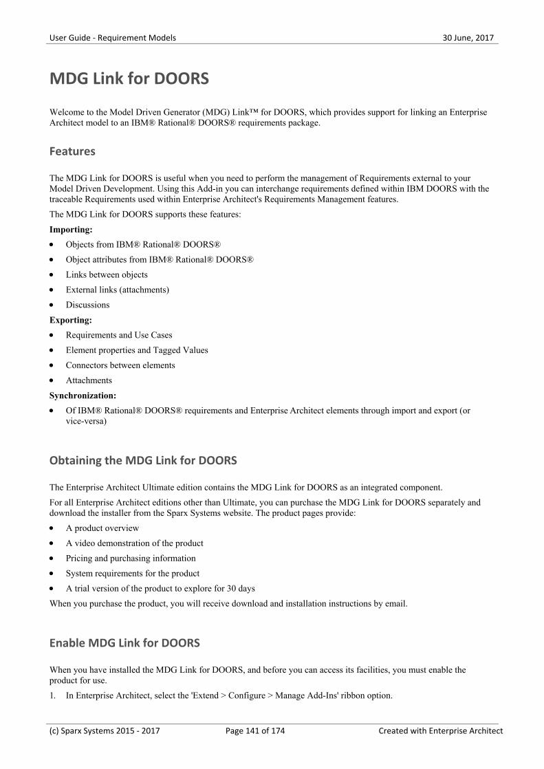
User Guide - Requirement Models 30 June, 2017
MDG Link for DOORS
Welcome to the Model Driven Generator (MDG) Link™ for DOORS, which provides support for linking an EnterpriseArchitect model to an IBM® Rational® DOORS® requirements package.
Features
The MDG Link for DOORS is useful when you need to perform the management of Requirements external to yourModel Driven Development. Using this Add-in you can interchange requirements defined within IBM DOORS with thetraceable Requirements used within Enterprise Architect's Requirements Management features.
The MDG Link for DOORS supports these features:
Importing:
Objects from IBM® Rational® DOORS®·Object attributes from IBM® Rational® DOORS®·Links between objects·External links (attachments)·Discussions·
Exporting:
Requirements and Use Cases·Element properties and Tagged Values·Connectors between elements·Attachments·
Synchronization:
Of IBM® Rational® DOORS® requirements and Enterprise Architect elements through import and export (or·vice-versa)
Obtaining the MDG Link for DOORS
The Enterprise Architect Ultimate edition contains the MDG Link for DOORS as an integrated component.
For all Enterprise Architect editions other than Ultimate, you can purchase the MDG Link for DOORS separately anddownload the installer from the Sparx Systems website. The product pages provide:
A product overview·A video demonstration of the product·Pricing and purchasing information·System requirements for the product·A trial version of the product to explore for 30 days·
When you purchase the product, you will receive download and installation instructions by email.
Enable MDG Link for DOORS
When you have installed the MDG Link for DOORS, and before you can access its facilities, you must enable theproduct for use.
In Enterprise Architect, select the 'Extend > Configure > Manage Add-Ins' ribbon option.1.
(c) Sparx Systems 2015 - 2017 Page 141 of 174 Created with Enterprise Architect
User Guide - Requirement Models 30 June, 2017
Against the 'DoorsEASync' entry, select the 'Load on Startup' checkbox.2.
Click on the OK button.3.
(c) Sparx Systems 2015 - 2017 Page 142 of 174 Created with Enterprise Architect
User Guide - Requirement Models 30 June, 2017
Getting Started
After installing and/or enabling the MDG Link for DOORS, you can access the facilities of the technology in EnterpriseArchitect.
Access
Ribbon Click on target Package, then:
Extend > DOORS > [option]
Context Menu Project Browser | Right-click on target Package | Extensions | Doors Extension
Tasks
There are three principal tasks that you can perform through the MDG Link for DOORS.
Task Description
Create a Module Link On the 'Doors Extension' menu you can select the 'Add/Edit Module' option tocreate a link between the selected Sparx Systems Enterprise Architect Package andan existing IBM® Rational® DOORS® module. You can also redirect a link to adifferent module.
The link enables you to exchange requirements data between DOORS andEnterprise Architect, importing data from DOORS to Enterprise Architect, andexporting data from Enterprise Architect to DOORS.
Export data to a DOORSmodule
On the 'Doors Extension' menu you can select the 'Export to Doors' option totransfer requirements from a selected Enterprise Architect Package to a linkedDOORS module.
As part of this process you can create an export profile to define what the exportshould operate on.
Import data from a DOORSmodule
On the 'Doors Extension' menu you can select the 'Import from Doors' option totransfer requirements into a selected Enterprise Architect Package from a linkedDOORS module.
As part of this process you can create an import profile to define what the importshould operate on.
(c) Sparx Systems 2015 - 2017 Page 143 of 174 Created with Enterprise Architect
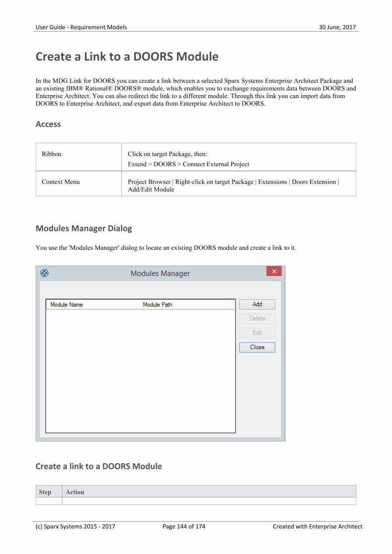
User Guide - Requirement Models 30 June, 2017
Create a Link to a DOORS Module
In the MDG Link for DOORS you can create a link between a selected Sparx Systems Enterprise Architect Package andan existing IBM® Rational® DOORS® module, which enables you to exchange requirements data between DOORS andEnterprise Architect. You can also redirect the link to a different module. Through this link you can import data fromDOORS to Enterprise Architect, and export data from Enterprise Architect to DOORS.
Access
Ribbon Click on target Package, then:
Extend > DOORS > Connect External Project
Context Menu Project Browser | Right-click on target Package | Extensions | Doors Extension |Add/Edit Module
Modules Manager Dialog
You use the 'Modules Manager' dialog to locate an existing DOORS module and create a link to it.
Create a link to a DOORS Module
Step Action
(c) Sparx Systems 2015 - 2017 Page 144 of 174 Created with Enterprise Architect
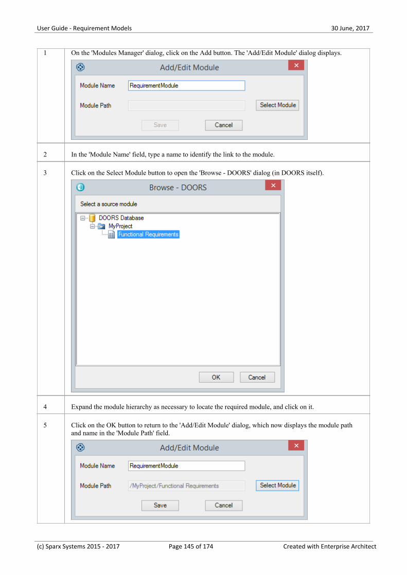
User Guide - Requirement Models 30 June, 2017
1 On the 'Modules Manager' dialog, click on the Add button. The 'Add/Edit Module' dialog displays.
2 In the 'Module Name' field, type a name to identify the link to the module.
3 Click on the Select Module button to open the 'Browse - DOORS' dialog (in DOORS itself).
4 Expand the module hierarchy as necessary to locate the required module, and click on it.
5 Click on the OK button to return to the 'Add/Edit Module' dialog, which now displays the module pathand name in the 'Module Path' field.
(c) Sparx Systems 2015 - 2017 Page 145 of 174 Created with Enterprise Architect
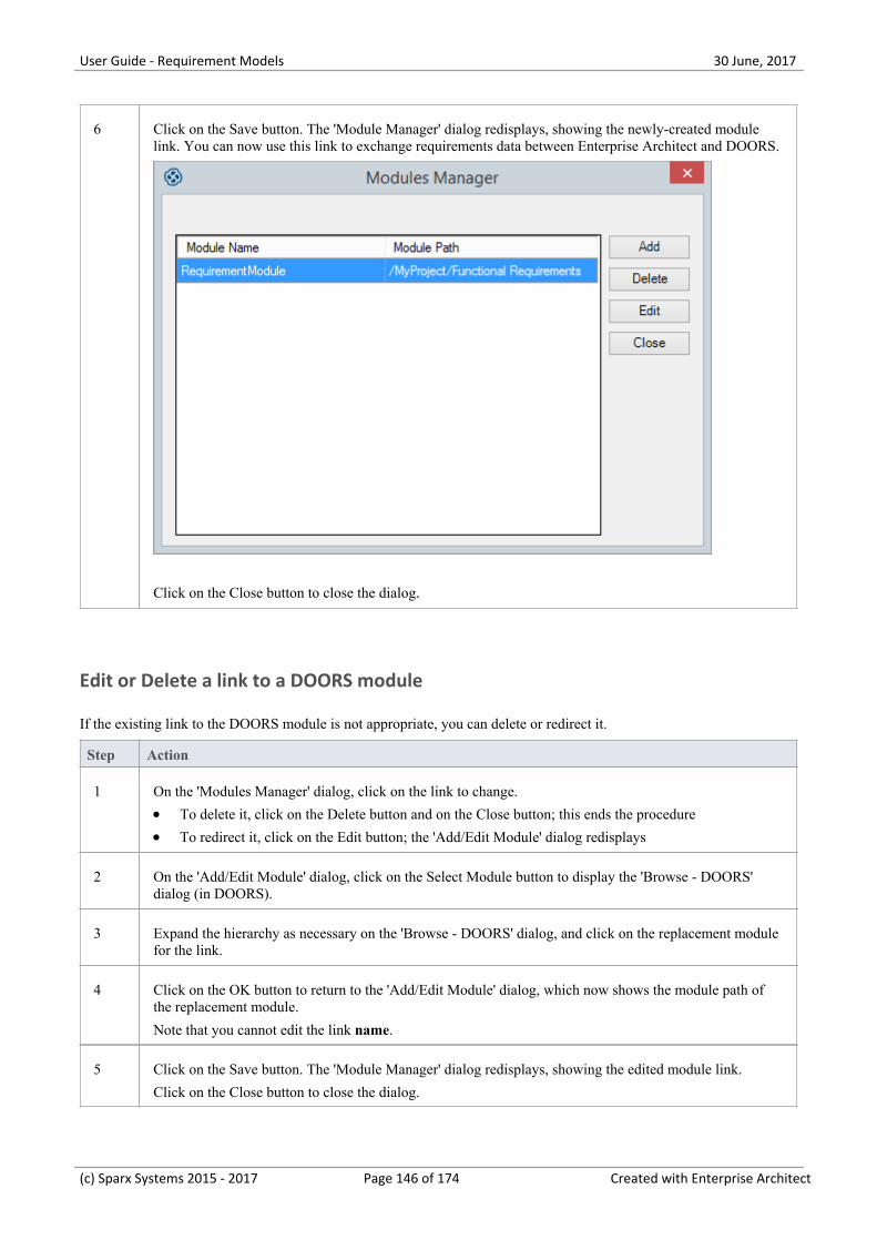
User Guide - Requirement Models 30 June, 2017
6 Click on the Save button. The 'Module Manager' dialog redisplays, showing the newly-created modulelink. You can now use this link to exchange requirements data between Enterprise Architect and DOORS.
Click on the Close button to close the dialog.
Edit or Delete a link to a DOORS module
If the existing link to the DOORS module is not appropriate, you can delete or redirect it.
Step Action
1 On the 'Modules Manager' dialog, click on the link to change.
To delete it, click on the Delete button and on the Close button; this ends the procedure·To redirect it, click on the Edit button; the 'Add/Edit Module' dialog redisplays·
2 On the 'Add/Edit Module' dialog, click on the Select Module button to display the 'Browse - DOORS'dialog (in DOORS).
3 Expand the hierarchy as necessary on the 'Browse - DOORS' dialog, and click on the replacement modulefor the link.
4 Click on the OK button to return to the 'Add/Edit Module' dialog, which now shows the module path ofthe replacement module.
Note that you cannot edit the link name.
5 Click on the Save button. The 'Module Manager' dialog redisplays, showing the edited module link.
Click on the Close button to close the dialog.
(c) Sparx Systems 2015 - 2017 Page 146 of 174 Created with Enterprise Architect
User Guide - Requirement Models 30 June, 2017
Notes
You can also create and edit links to DOORS modules through the 'Export to Doors' and 'Import from Doors'·dialogs, using the Module Manager button
(c) Sparx Systems 2015 - 2017 Page 147 of 174 Created with Enterprise Architect
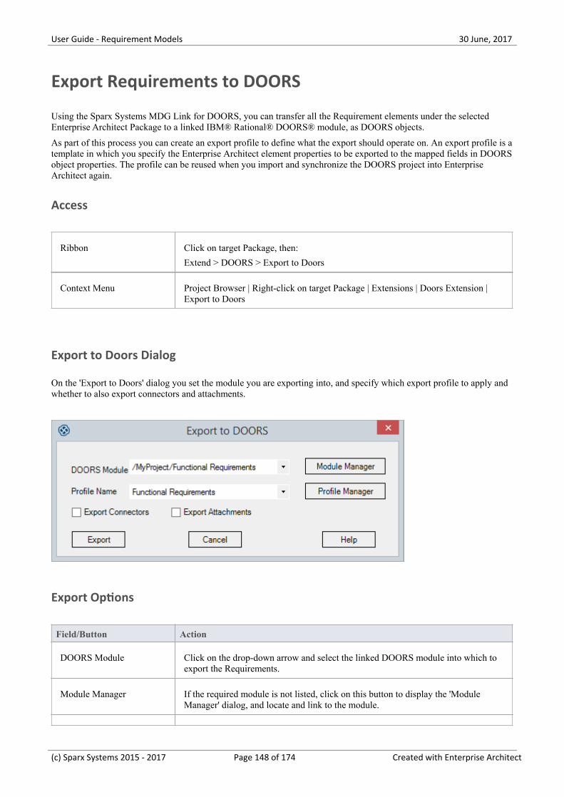
User Guide - Requirement Models 30 June, 2017
Export Requirements to DOORS
Using the Sparx Systems MDG Link for DOORS, you can transfer all the Requirement elements under the selectedEnterprise Architect Package to a linked IBM® Rational® DOORS® module, as DOORS objects.
As part of this process you can create an export profile to define what the export should operate on. An export profile is atemplate in which you specify the Enterprise Architect element properties to be exported to the mapped fields in DOORSobject properties. The profile can be reused when you import and synchronize the DOORS project into EnterpriseArchitect again.
Access
Ribbon Click on target Package, then:
Extend > DOORS > Export to Doors
Context Menu Project Browser | Right-click on target Package | Extensions | Doors Extension |Export to Doors
Export to Doors Dialog
On the 'Export to Doors' dialog you set the module you are exporting into, and specify which export profile to apply andwhether to also export connectors and attachments.
Export Options
Field/Button Action
DOORS Module Click on the drop-down arrow and select the linked DOORS module into which toexport the Requirements.
Module Manager If the required module is not listed, click on this button to display the 'ModuleManager' dialog, and locate and link to the module.
(c) Sparx Systems 2015 - 2017 Page 148 of 174 Created with Enterprise Architect
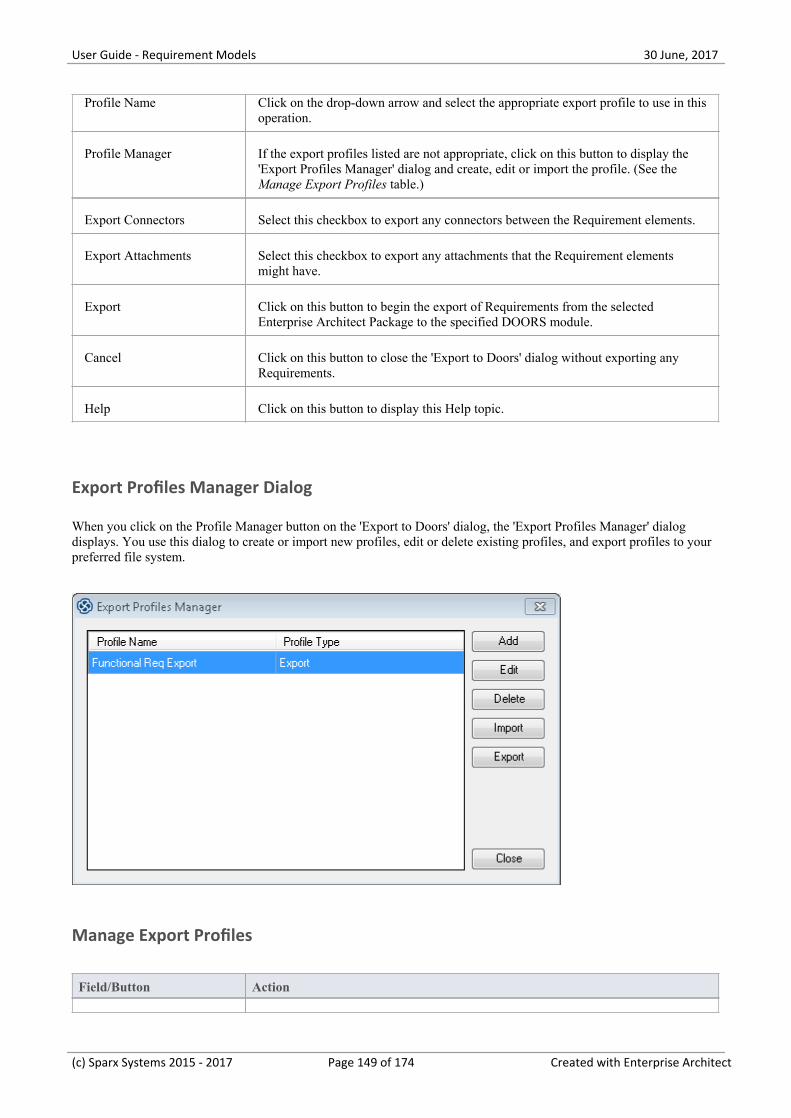
User Guide - Requirement Models 30 June, 2017
Profile Name Click on the drop-down arrow and select the appropriate export profile to use in thisoperation.
Profile Manager If the export profiles listed are not appropriate, click on this button to display the'Export Profiles Manager' dialog and create, edit or import the profile. (See theManage Export Profiles table.)
Export Connectors Select this checkbox to export any connectors between the Requirement elements.
Export Attachments Select this checkbox to export any attachments that the Requirement elementsmight have.
Export Click on this button to begin the export of Requirements from the selectedEnterprise Architect Package to the specified DOORS module.
Cancel Click on this button to close the 'Export to Doors' dialog without exporting anyRequirements.
Help Click on this button to display this Help topic.
Export Profiles Manager Dialog
When you click on the Profile Manager button on the 'Export to Doors' dialog, the 'Export Profiles Manager' dialogdisplays. You use this dialog to create or import new profiles, edit or delete existing profiles, and export profiles to yourpreferred file system.
Manage Export Profiles
Field/Button Action
(c) Sparx Systems 2015 - 2017 Page 149 of 174 Created with Enterprise Architect
User Guide - Requirement Models 30 June, 2017
Add Click on this button to add a new export profile. The 'Mapping Options' dialogdisplays; see the Create or Edit an Export Profile table.
Edit Click on an existing profile name and click on this button to edit the parameters ofthat profile. The 'Mapping Options' dialog displays, showing the current parametersof the profile; see the Create or Edit an Export Profile table.
Delete Click on an existing profile name and click on this button to immediately removethat profile from the list. There is no confirmatory prompt.
Import Click on this button to display the 'Import a Profile - Doors Extension' browser.Browse for the location of the required profile file (.eProfile), and click on the filename and on the Open button.
A status message displays. Click on the OK button; if the operation was successful,the profile name displays on the 'Export Profiles Manager' dialog. If unsuccessful,the profile is not added to the list.
Export Click on a profile name and click on this button to export that profile to a filesystem location as a .eProfile file. The 'Save As' browser displays. Browse to therequired location and click on the Save button. A status message displays; click onthe OK button to clear the message.
Close When you have finished using the 'Export Profiles Manager' dialog, click on thisbutton to return to the 'Export to Doors' dialog.
Export Mapping Options dialog
When you click on the Add button or Edit button on the 'Export Profiles Manager' dialog, the 'Mapping Options' dialogdisplays. This dialog maps Enterprise Architect element properties to IBM® Rational® DOORS® Object properties, andhelps you to define which properties - including Tagged Value properties - to export. You can use the selected profilemany times to update the DOORS module with changes in the Enterprise Architect Requirements.
(c) Sparx Systems 2015 - 2017 Page 150 of 174 Created with Enterprise Architect
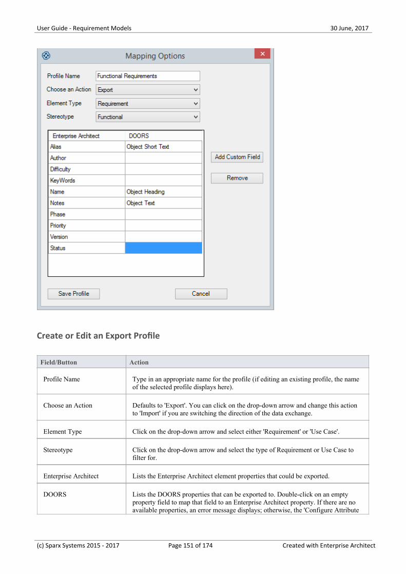
User Guide - Requirement Models 30 June, 2017
Create or Edit an Export Profile
Field/Button Action
Profile Name Type in an appropriate name for the profile (if editing an existing profile, the nameof the selected profile displays here).
Choose an Action Defaults to 'Export'. You can click on the drop-down arrow and change this actionto 'Import' if you are switching the direction of the data exchange.
Element Type Click on the drop-down arrow and select either 'Requirement' or 'Use Case'.
Stereotype Click on the drop-down arrow and select the type of Requirement or Use Case tofilter for.
Enterprise Architect Lists the Enterprise Architect element properties that could be exported.
DOORS Lists the DOORS properties that can be exported to. Double-click on an emptyproperty field to map that field to an Enterprise Architect property. If there are noavailable properties, an error message displays; otherwise, the 'Configure Attribute
(c) Sparx Systems 2015 - 2017 Page 151 of 174 Created with Enterprise Architect
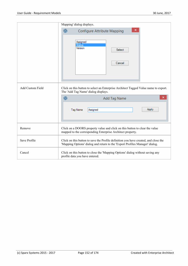
User Guide - Requirement Models 30 June, 2017
Mapping' dialog displays.
Add Custom Field Click on this button to select an Enterprise Architect Tagged Value name to export.The 'Add Tag Name' dialog displays.
Remove Click on a DOORS property value and click on this button to clear the valuemapped to the corresponding Enterprise Architect property.
Save Profile Click on this button to save the Profile definition you have created, and close the'Mapping Options' dialog and return to the 'Export Profiles Manager' dialog.
Cancel Click on this button to close the 'Mapping Options' dialog without saving anyprofile data you have entered.
(c) Sparx Systems 2015 - 2017 Page 152 of 174 Created with Enterprise Architect
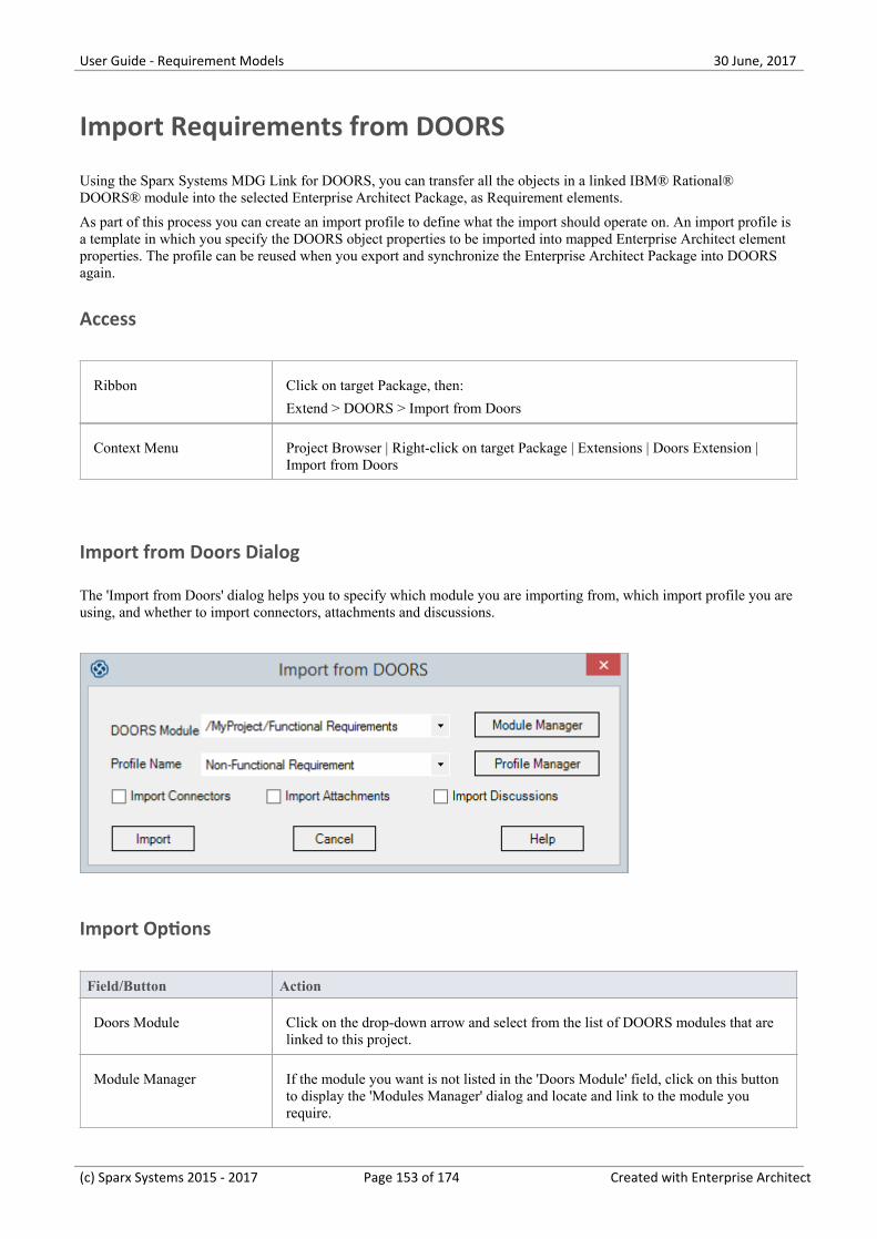
User Guide - Requirement Models 30 June, 2017
Import Requirements from DOORS
Using the Sparx Systems MDG Link for DOORS, you can transfer all the objects in a linked IBM® Rational®DOORS® module into the selected Enterprise Architect Package, as Requirement elements.
As part of this process you can create an import profile to define what the import should operate on. An import profile isa template in which you specify the DOORS object properties to be imported into mapped Enterprise Architect elementproperties. The profile can be reused when you export and synchronize the Enterprise Architect Package into DOORSagain.
Access
Ribbon Click on target Package, then:
Extend > DOORS > Import from Doors
Context Menu Project Browser | Right-click on target Package | Extensions | Doors Extension |Import from Doors
Import from Doors Dialog
The 'Import from Doors' dialog helps you to specify which module you are importing from, which import profile you areusing, and whether to import connectors, attachments and discussions.
Import Options
Field/Button Action
Doors Module Click on the drop-down arrow and select from the list of DOORS modules that arelinked to this project.
Module Manager If the module you want is not listed in the 'Doors Module' field, click on this buttonto display the 'Modules Manager' dialog and locate and link to the module yourequire.
(c) Sparx Systems 2015 - 2017 Page 153 of 174 Created with Enterprise Architect
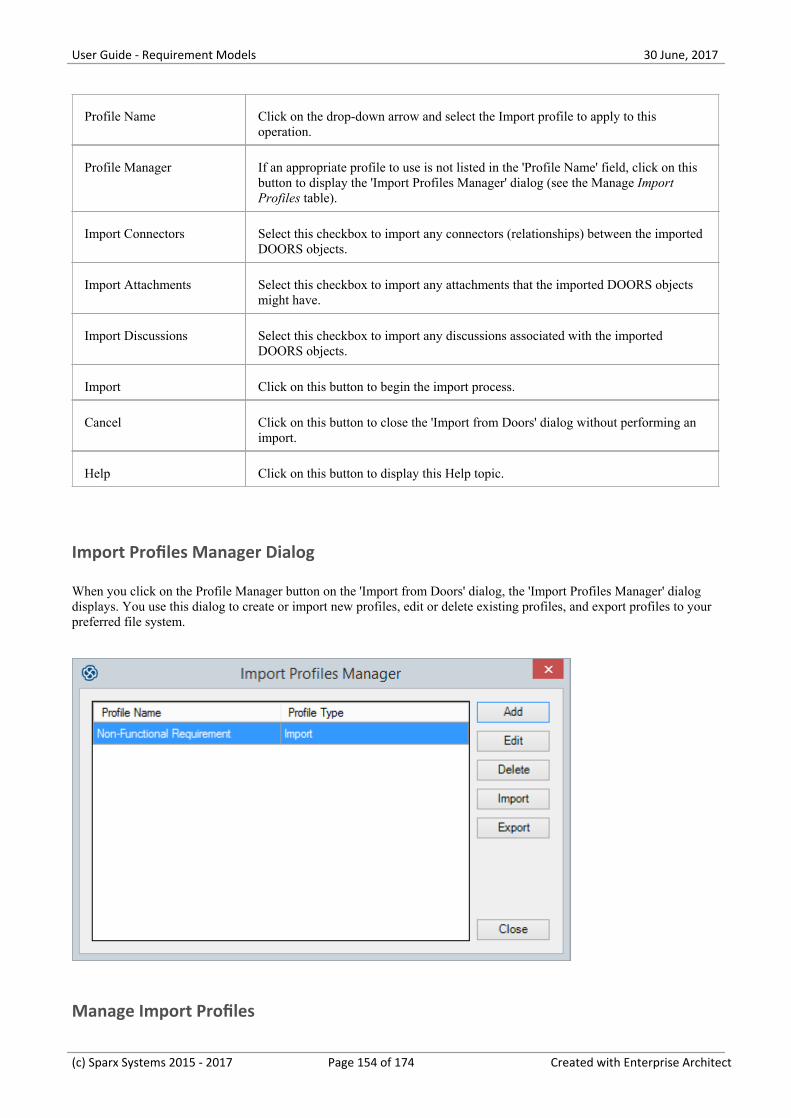
User Guide - Requirement Models 30 June, 2017
Profile Name Click on the drop-down arrow and select the Import profile to apply to thisoperation.
Profile Manager If an appropriate profile to use is not listed in the 'Profile Name' field, click on thisbutton to display the 'Import Profiles Manager' dialog (see the Manage ImportProfiles table).
Import Connectors Select this checkbox to import any connectors (relationships) between the importedDOORS objects.
Import Attachments Select this checkbox to import any attachments that the imported DOORS objectsmight have.
Import Discussions Select this checkbox to import any discussions associated with the importedDOORS objects.
Import Click on this button to begin the import process.
Cancel Click on this button to close the 'Import from Doors' dialog without performing animport.
Help Click on this button to display this Help topic.
Import Profiles Manager Dialog
When you click on the Profile Manager button on the 'Import from Doors' dialog, the 'Import Profiles Manager' dialogdisplays. You use this dialog to create or import new profiles, edit or delete existing profiles, and export profiles to yourpreferred file system.
Manage Import Profiles
(c) Sparx Systems 2015 - 2017 Page 154 of 174 Created with Enterprise Architect
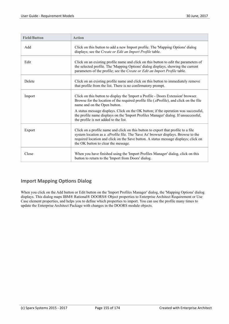
User Guide - Requirement Models 30 June, 2017
Field/Button Action
Add Click on this button to add a new Import profile. The 'Mapping Options' dialogdisplays; see the Create or Edit an Import Profile table.
Edit Click on an existing profile name and click on this button to edit the parameters ofthe selected profile. The 'Mapping Options' dialog displays, showing the currentparameters of the profile; see the Create or Edit an Import Profile table.
Delete Click on an existing profile name and click on this button to immediately removethat profile from the list. There is no confirmatory prompt.
Import Click on this button to display the 'Import a Profile - Doors Extension' browser.Browse for the location of the required profile file (.eProfile), and click on the filename and on the Open button.
A status message displays. Click on the OK button; if the operation was successful,the profile name displays on the 'Import Profiles Manager' dialog. If unsuccessful,the profile is not added to the list.
Export Click on a profile name and click on this button to export that profile to a filesystem location as a .eProfile file. The 'Save As' browser displays. Browse to therequired location and click on the Save button. A status message displays; click onthe OK button to clear the message.
Close When you have finished using the 'Import Profiles Manager' dialog, click on thisbutton to return to the 'Import from Doors' dialog.
Import Mapping Options Dialog
When you click on the Add button or Edit button on the 'Import Profiles Manager' dialog, the 'Mapping Options' dialogdisplays. This dialog maps IBM® Rational® DOORS® Object properties to Enterprise Architect Requirement or UseCase element properties, and helps you to define which properties to import. You can use the profile many times toupdate the Enterprise Architect Package with changes in the DOORS module objects.
(c) Sparx Systems 2015 - 2017 Page 155 of 174 Created with Enterprise Architect
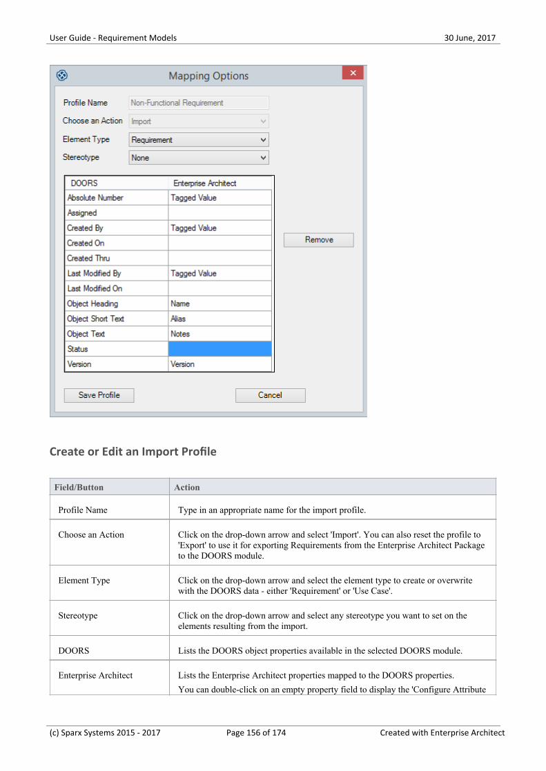
User Guide - Requirement Models 30 June, 2017
Create or Edit an Import Profile
Field/Button Action
Profile Name Type in an appropriate name for the import profile.
Choose an Action Click on the drop-down arrow and select 'Import'. You can also reset the profile to'Export' to use it for exporting Requirements from the Enterprise Architect Packageto the DOORS module.
Element Type Click on the drop-down arrow and select the element type to create or overwritewith the DOORS data - either 'Requirement' or 'Use Case'.
Stereotype Click on the drop-down arrow and select any stereotype you want to set on theelements resulting from the import.
DOORS Lists the DOORS object properties available in the selected DOORS module.
Enterprise Architect Lists the Enterprise Architect properties mapped to the DOORS properties.
You can double-click on an empty property field to display the 'Configure Attribute
(c) Sparx Systems 2015 - 2017 Page 156 of 174 Created with Enterprise Architect
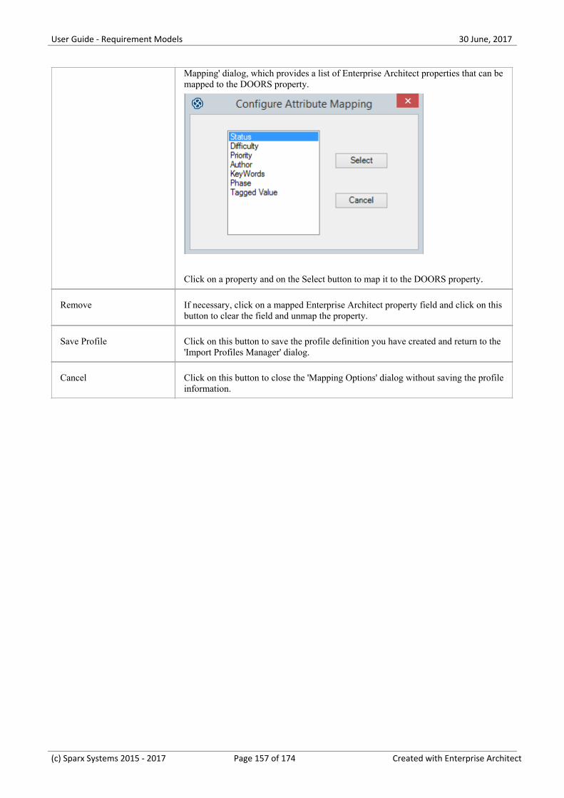
User Guide - Requirement Models 30 June, 2017
Mapping' dialog, which provides a list of Enterprise Architect properties that can bemapped to the DOORS property.
Click on a property and on the Select button to map it to the DOORS property.
Remove If necessary, click on a mapped Enterprise Architect property field and click on thisbutton to clear the field and unmap the property.
Save Profile Click on this button to save the profile definition you have created and return to the'Import Profiles Manager' dialog.
Cancel Click on this button to close the 'Mapping Options' dialog without saving the profileinformation.
(c) Sparx Systems 2015 - 2017 Page 157 of 174 Created with Enterprise Architect
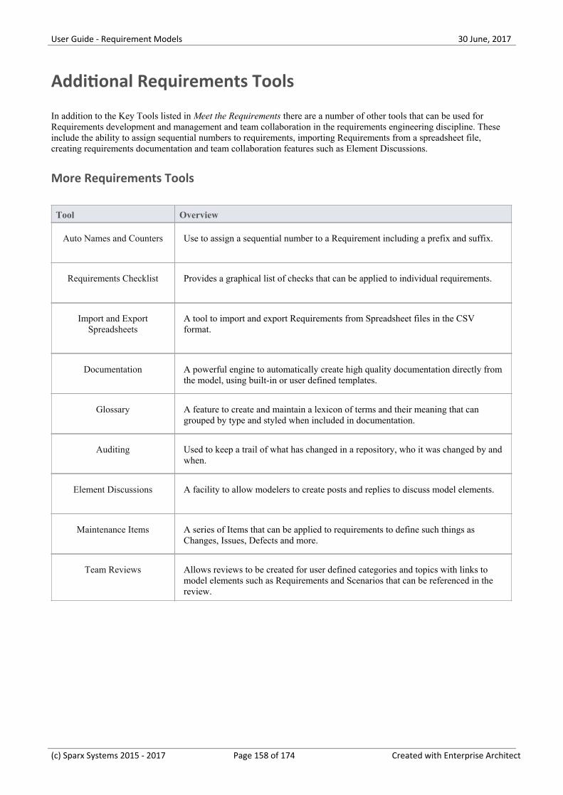
User Guide - Requirement Models 30 June, 2017
Additional Requirements Tools
In addition to the Key Tools listed in Meet the Requirements there are a number of other tools that can be used forRequirements development and management and team collaboration in the requirements engineering discipline. Theseinclude the ability to assign sequential numbers to requirements, importing Requirements from a spreadsheet file,creating requirements documentation and team collaboration features such as Element Discussions.
More Requirements Tools
Tool Overview
Auto Names and Counters Use to assign a sequential number to a Requirement including a prefix and suffix.
Requirements Checklist Provides a graphical list of checks that can be applied to individual requirements.
Import and ExportSpreadsheets
A tool to import and export Requirements from Spreadsheet files in the CSVformat.
Documentation A powerful engine to automatically create high quality documentation directly fromthe model, using built-in or user defined templates.
Glossary A feature to create and maintain a lexicon of terms and their meaning that cangrouped by type and styled when included in documentation.
Auditing Used to keep a trail of what has changed in a repository, who it was changed by andwhen.
Element Discussions A facility to allow modelers to create posts and replies to discuss model elements.
Maintenance Items A series of Items that can be applied to requirements to define such things asChanges, Issues, Defects and more.
Team Reviews Allows reviews to be created for user defined categories and topics with links tomodel elements such as Requirements and Scenarios that can be referenced in thereview.
(c) Sparx Systems 2015 - 2017 Page 158 of 174 Created with Enterprise Architect
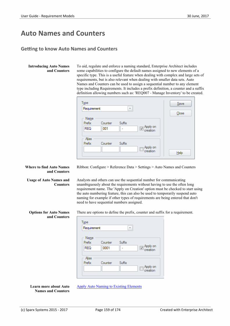
User Guide - Requirement Models 30 June, 2017
Auto Names and Counters
Getting to know Auto Names and Counters
Introducing Auto Namesand Counters
To aid, regulate and enforce a naming standard, Enterprise Architect includessome capabilities to configure the default names assigned to new elements of aspecific type. This is a useful feature when dealing with complex and large sets ofrequirements, but is also relevant when dealing with smaller data sets. AutoNames and Counters can be used to assign a sequential number to any elementtype including Requirements. It includes a prefix definition, a counter and a suffixdefinition allowing numbers such as: 'REQ007 - Manage Inventory' to be created.
Where to find Auto Namesand Counters
Ribbon: Configure > Reference Data > Settings > Auto Names and Counters
Usage of Auto Names andCounters
Analysts and others can use the sequential number for communicatingunambiguously about the requirements without having to use the often longrequirement name. The 'Apply on Creation' option must be checked to start usingthe auto numbering feature, this can also be used to temporarily suspend autonaming for example if other types of requirements are being entered that don'tneed to have sequential numbers assigned.
Options for Auto Namesand Counters
There are options to define the prefix, counter and suffix for a requirement.
Learn more about AutoNames and Counters
Apply Auto Naming to Existing Elements
(c) Sparx Systems 2015 - 2017 Page 159 of 174 Created with Enterprise Architect

User Guide - Requirement Models 30 June, 2017
(c) Sparx Systems 2015 - 2017 Page 160 of 174 Created with Enterprise Architect
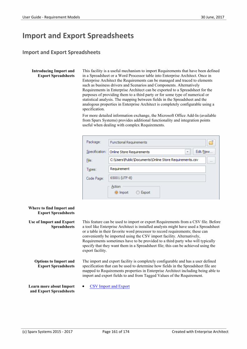
User Guide - Requirement Models 30 June, 2017
Import and Export Spreadsheets
Import and Export Spreadsheets
Introducing Import andExport Spreadsheets
This facility is a useful mechanism to import Requirements that have been definedin a Spreadsheet or a Word Processor table into Enterprise Architect. Once inEnterprise Architect the Requirements can be managed and traced to elementssuch as business drivers and Scenarios and Components. AlternativelyRequirements in Enterprise Architect can be exported to a Spreadsheet for thepurposes of providing them to a third party or for some type of numerical orstatistical analysis. The mapping between fields in the Spreadsheet and theanalogous properties in Enterprise Architect is completely configurable using aspecification.
For more detailed information exchange, the Microsoft Office Add-In (availablefrom Sparx Systems) provides additional functionality and integration pointsuseful when dealing with complex Requirements.
Where to find Import andExport Spreadsheets
Use of Import and ExportSpreadsheets
This feature can be used to import or export Requirements from a CSV file. Beforea tool like Enterprise Architect is installed analysts might have used a Spreadsheetor a table in their favorite word processor to record requirements; these canconveniently be imported using the CSV import facility. Alternatively,Requirements sometimes have to be provided to a third party who will typicallyspecify that they want them in a Spreadsheet file; this can be achieved using theexport facility.
Options to Import andExport Spreadsheets
The import and export facility is completely configurable and has a user definedspecification that can be used to determine how fields in the Spreadsheet file aremapped to Requirements properties in Enterprise Architect including being able toimport and export fields to and from Tagged Values of the Requirement.
Learn more about Importand Export Spreadsheets
CSV Import and Export·
(c) Sparx Systems 2015 - 2017 Page 161 of 174 Created with Enterprise Architect
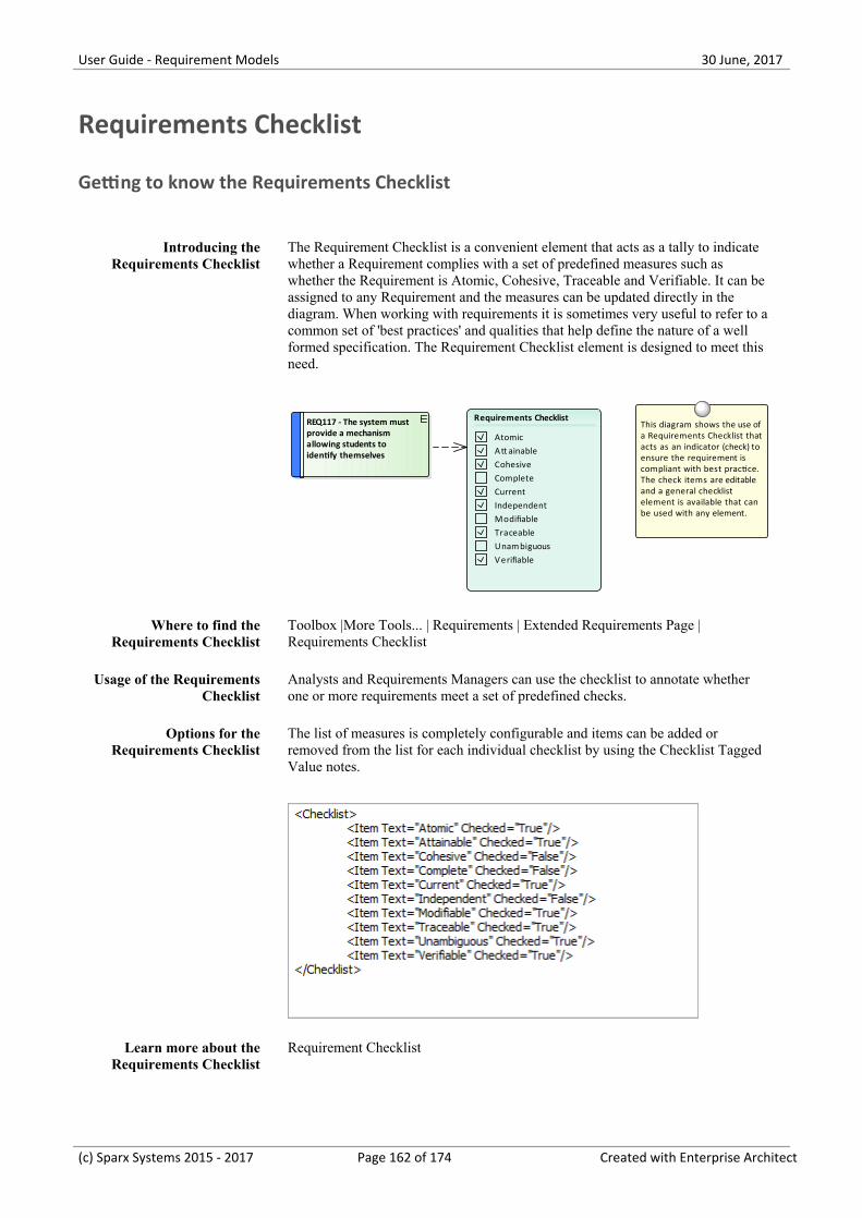
User Guide - Requirement Models 30 June, 2017
Requirements Checklist
Getting to know the Requirements Checklist
Introducing theRequirements Checklist
The Requirement Checklist is a convenient element that acts as a tally to indicatewhether a Requirement complies with a set of predefined measures such aswhether the Requirement is Atomic, Cohesive, Traceable and Verifiable. It can beassigned to any Requirement and the measures can be updated directly in thediagram. When working with requirements it is sometimes very useful to refer to acommon set of 'best practices' and qualities that help define the nature of a wellformed specification. The Requirement Checklist element is designed to meet thisneed.
REQ117 - The system must provide a mechanism allowing students to identify themselves
This diagram shows the use of a Requirements Checklist that acts as an indicator (check) to ensure the requirement is compliant with best practice. The check items are editable and a general checklist element is available that can be used with any element.
Requirements Checklist
AtomicAtt ainableCohesiveCompleteCurrentIndependentModifiableTraceableUnambiguousV erifiable
Where to find theRequirements Checklist
Toolbox |More Tools... | Requirements | Extended Requirements Page |Requirements Checklist
Usage of the RequirementsChecklist
Analysts and Requirements Managers can use the checklist to annotate whetherone or more requirements meet a set of predefined checks.
Options for theRequirements Checklist
The list of measures is completely configurable and items can be added orremoved from the list for each individual checklist by using the Checklist TaggedValue notes.
Learn more about theRequirements Checklist
Requirement Checklist
(c) Sparx Systems 2015 - 2017 Page 162 of 174 Created with Enterprise Architect

User Guide - Requirement Models 30 June, 2017
(c) Sparx Systems 2015 - 2017 Page 163 of 174 Created with Enterprise Architect
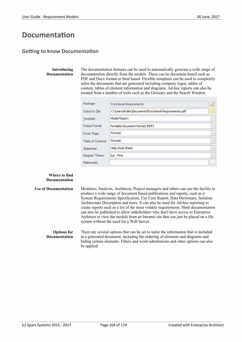
User Guide - Requirement Models 30 June, 2017
Documentation
Getting to know Documentation
IntroducingDocumentation
The documentation features can be used to automatically generate a wide range ofdocumentation directly from the models. These can be document based such asPDF and Docx format or html based. Flexible templates can be used to completelytailor the documents that are generated including company logos, tables ofcontent, tables of element information and diagrams. Ad-hoc reports can also becreated from a number of tools such as the Glossary and the Search Window.
Where to findDocumentation
Use of Documentation Modelers, Analysts, Architects, Project managers and others can use the facility toproduce a wide range of document based publications and reports, such as a:System Requirements Specification, Use Case Report, Data Dictionary, SolutionArchitecture Description and more. It can also be used for Ad-hoc reporting tocreate reports such as a list of the most volatile requirements. Html documentationcan also be published to allow stakeholders who don't have access to EnterpriseArchitect to view the models from an Intranet site that can just be placed on a filesystem without the need for a Web Server.
Options forDocumentation
There are several options that can be set to tailor the information that is includedin a generated document, including the ordering of elements and diagrams andhiding certain elements. Filters and word substitutions and other options can alsobe applied.
(c) Sparx Systems 2015 - 2017 Page 164 of 174 Created with Enterprise Architect
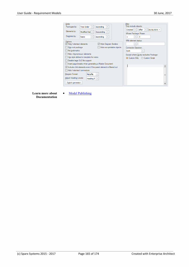
User Guide - Requirement Models 30 June, 2017
Learn more aboutDocumentation
Model Publishing·
(c) Sparx Systems 2015 - 2017 Page 165 of 174 Created with Enterprise Architect
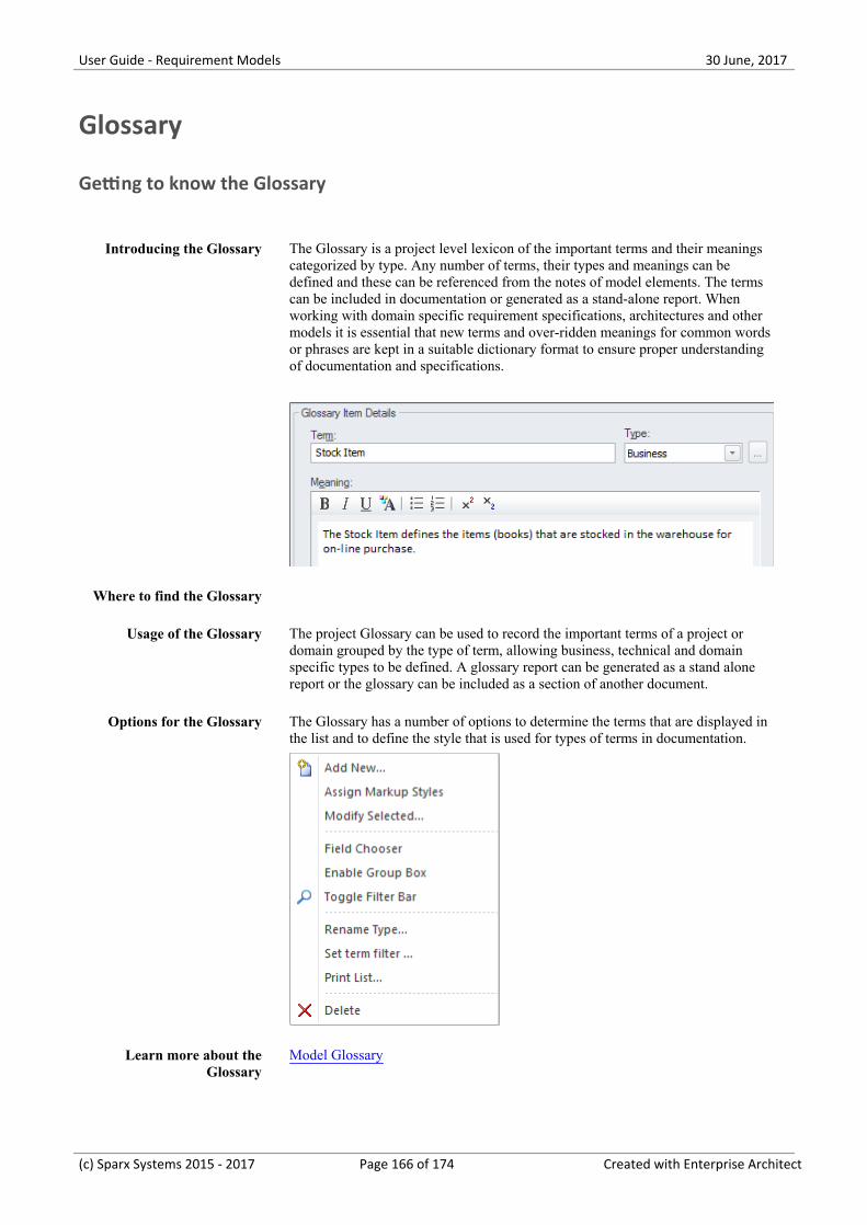
User Guide - Requirement Models 30 June, 2017
Glossary
Getting to know the Glossary
Introducing the Glossary The Glossary is a project level lexicon of the important terms and their meaningscategorized by type. Any number of terms, their types and meanings can bedefined and these can be referenced from the notes of model elements. The termscan be included in documentation or generated as a stand-alone report. Whenworking with domain specific requirement specifications, architectures and othermodels it is essential that new terms and over-ridden meanings for common wordsor phrases are kept in a suitable dictionary format to ensure proper understandingof documentation and specifications.
Where to find the Glossary
Usage of the Glossary The project Glossary can be used to record the important terms of a project ordomain grouped by the type of term, allowing business, technical and domainspecific types to be defined. A glossary report can be generated as a stand alonereport or the glossary can be included as a section of another document.
Options for the Glossary The Glossary has a number of options to determine the terms that are displayed inthe list and to define the style that is used for types of terms in documentation.
Learn more about theGlossary
Model Glossary
(c) Sparx Systems 2015 - 2017 Page 166 of 174 Created with Enterprise Architect
User Guide - Requirement Models 30 June, 2017
(c) Sparx Systems 2015 - 2017 Page 167 of 174 Created with Enterprise Architect
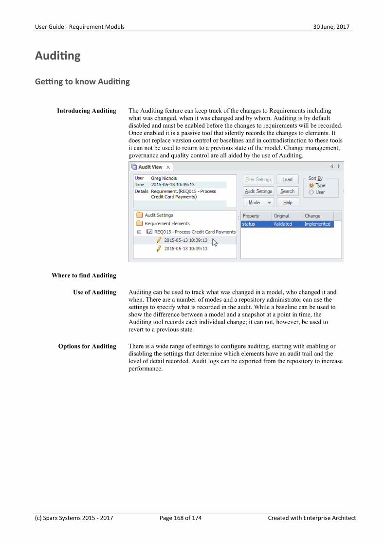
User Guide - Requirement Models 30 June, 2017
Auditing
Getting to know Auditing
Introducing Auditing The Auditing feature can keep track of the changes to Requirements includingwhat was changed, when it was changed and by whom. Auditing is by defaultdisabled and must be enabled before the changes to requirements will be recorded.Once enabled it is a passive tool that silently records the changes to elements. Itdoes not replace version control or baselines and in contradistinction to these toolsit can not be used to return to a previous state of the model. Change management,governance and quality control are all aided by the use of Auditing.
Where to find Auditing
Use of Auditing Auditing can be used to track what was changed in a model, who changed it andwhen. There are a number of modes and a repository administrator can use thesettings to specify what is recorded in the audit. While a baseline can be used toshow the difference between a model and a snapshot at a point in time, theAuditing tool records each individual change; it can not, however, be used torevert to a previous state.
Options for Auditing There is a wide range of settings to configure auditing, starting with enabling ordisabling the settings that determine which elements have an audit trail and thelevel of detail recorded. Audit logs can be exported from the repository to increaseperformance.
(c) Sparx Systems 2015 - 2017 Page 168 of 174 Created with Enterprise Architect
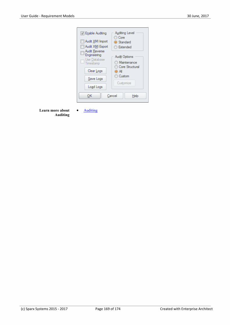
User Guide - Requirement Models 30 June, 2017
Learn more aboutAuditing
Auditing·
(c) Sparx Systems 2015 - 2017 Page 169 of 174 Created with Enterprise Architect
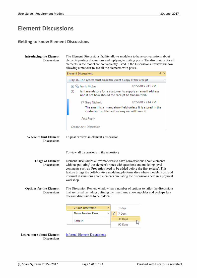
User Guide - Requirement Models 30 June, 2017
Element Discussions
Getting to know Element Discussions
Introducing the ElementDiscussions
The Element Discussions facility allows modelers to have conversations aboutelements posting discussions and replying to exiting posts. The discussions for allelements in the model are conveniently listed in the Discussions Review windowallowing a modeler to see all the elements with posts.
Where to find ElementDiscussions
To post or view an element's discussion
To view all discussions in the repository
Usage of ElementDiscussions
Element Discussions allow modelers to have conversations about elementswithout 'polluting' the element's notes with questions and modeling levelcomments such as 'Properties need to be added before the first release'. Thisfeature brings the collaborative modeling platform alive where modelers can addinformal discussions about elements emulating the discussions held in a physicalworkshop.
Options for the ElementDiscussions
The Discussion Review window has a number of options to tailor the discussionsthat are listed including defining the timeframe allowing older and perhaps lessrelevant discussions to be hidden.
Learn more about ElementDiscussions
Informal Element Discussions
(c) Sparx Systems 2015 - 2017 Page 170 of 174 Created with Enterprise Architect
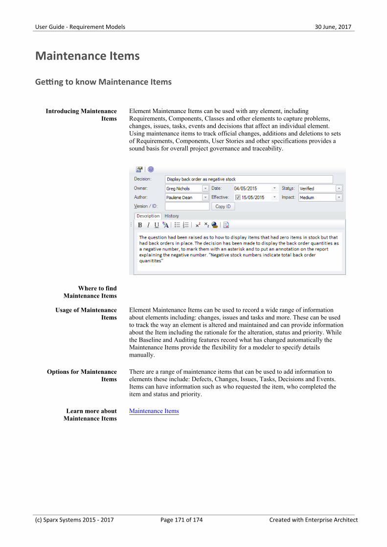
User Guide - Requirement Models 30 June, 2017
Maintenance Items
Getting to know Maintenance Items
Introducing MaintenanceItems
Element Maintenance Items can be used with any element, includingRequirements, Components, Classes and other elements to capture problems,changes, issues, tasks, events and decisions that affect an individual element.Using maintenance items to track official changes, additions and deletions to setsof Requirements, Components, User Stories and other specifications provides asound basis for overall project governance and traceability.
Where to findMaintenance Items
Usage of MaintenanceItems
Element Maintenance Items can be used to record a wide range of informationabout elements including: changes, issues and tasks and more. These can be usedto track the way an element is altered and maintained and can provide informationabout the Item including the rationale for the alteration, status and priority. Whilethe Baseline and Auditing features record what has changed automatically theMaintenance Items provide the flexibility for a modeler to specify detailsmanually.
Options for MaintenanceItems
There are a range of maintenance items that can be used to add information toelements these include: Defects, Changes, Issues, Tasks, Decisions and Events.Items can have information such as who requested the item, who completed theitem and status and priority.
Learn more aboutMaintenance Items
Maintenance Items
(c) Sparx Systems 2015 - 2017 Page 171 of 174 Created with Enterprise Architect
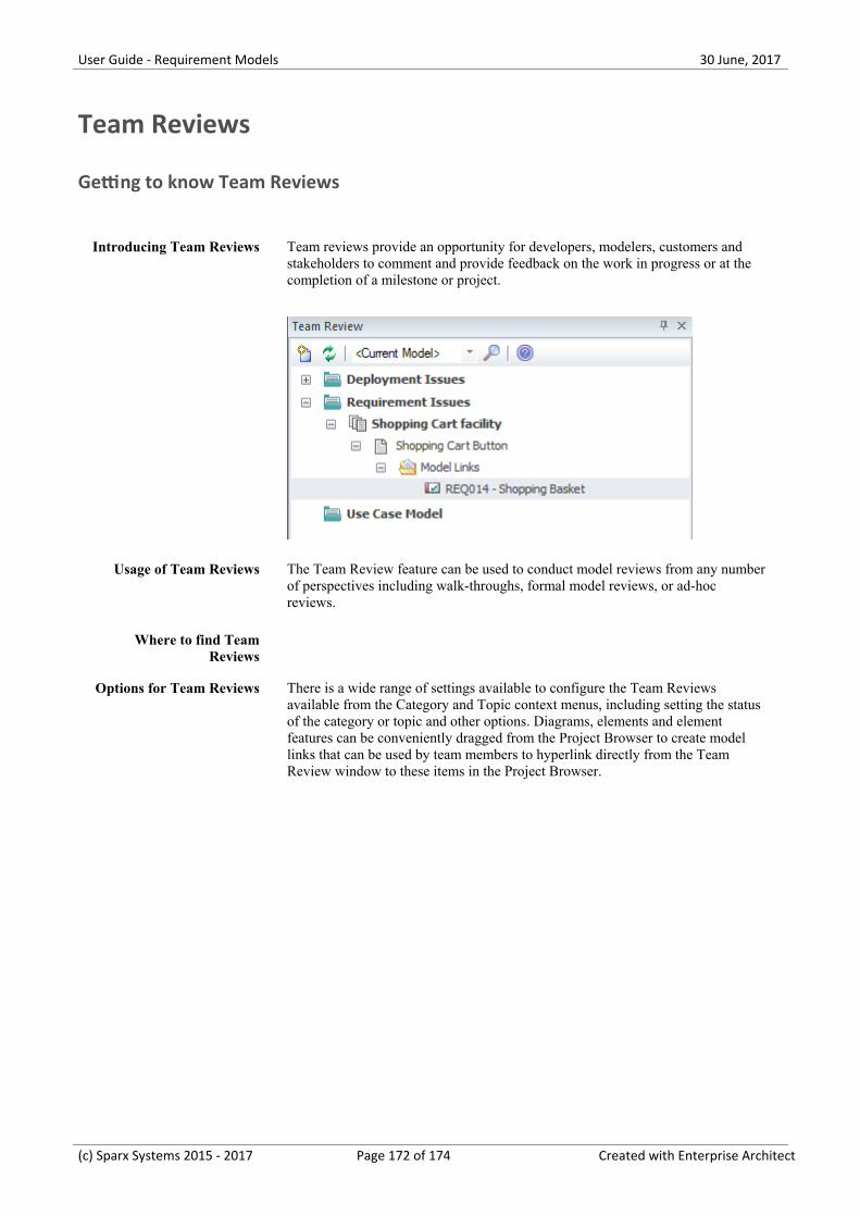
User Guide - Requirement Models 30 June, 2017
Team Reviews
Getting to know Team Reviews
Introducing Team Reviews Team reviews provide an opportunity for developers, modelers, customers andstakeholders to comment and provide feedback on the work in progress or at thecompletion of a milestone or project.
Usage of Team Reviews The Team Review feature can be used to conduct model reviews from any numberof perspectives including walk-throughs, formal model reviews, or ad-hocreviews.
Where to find TeamReviews
Options for Team Reviews There is a wide range of settings available to configure the Team Reviewsavailable from the Category and Topic context menus, including setting the statusof the category or topic and other options. Diagrams, elements and elementfeatures can be conveniently dragged from the Project Browser to create modellinks that can be used by team members to hyperlink directly from the TeamReview window to these items in the Project Browser.
(c) Sparx Systems 2015 - 2017 Page 172 of 174 Created with Enterprise Architect
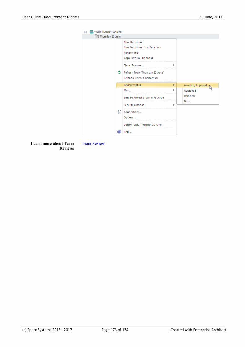
User Guide - Requirement Models 30 June, 2017
Learn more about TeamReviews
Team Review
(c) Sparx Systems 2015 - 2017 Page 173 of 174 Created with Enterprise Architect
User Guide - Requirement Models 30 June, 2017
(c) Sparx Systems 2015 - 2017 Page 174 of 174 Created with Enterprise Architect


