Embed Size (px)
Citation preview
CHAPTER 6
GRIHA REQUIREMENT

Contents
6.1 GRIHA Checklist .................................................................................................................... 3
6.2 Scope of Work ....................................................................................................................... 4
6.3 Abbreviations: ....................................................................................................................... 4
6.4 During Construction Guidelines: ......................................................................................... 5
6.5 Site level GRIHA certification Requirements ..................................................................... 7
6.6 Building level GRIHA certification Requirements ............................................................ 17
6.1 GRIHA Checklist
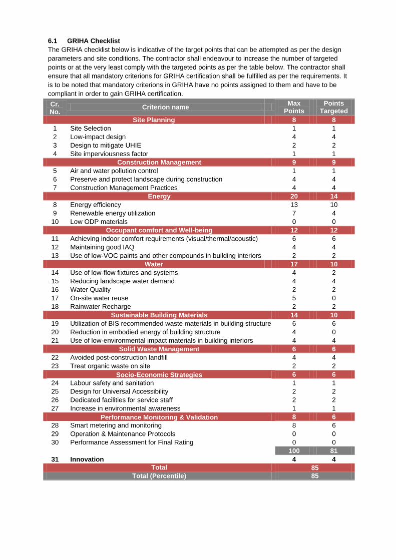
The GRIHA checklist below is indicative of the target points that can be attempted as per the design
parameters and site conditions. The contractor shall endeavour to increase the number of targeted
points or at the very least comply with the targeted points as per the table below. The contractor shall
ensure that all mandatory criterions for GRIHA certification shall be fulfilled as per the requirements. It
is to be noted that mandatory criterions in GRIHA have no points assigned to them and have to be
compliant in order to gain GRIHA certification.
Cr. No.
Criterion name Max
Points Points
Targeted
Site Planning 8 8
1 Site Selection 1 1
2 Low-impact design 4 4
3 Design to mitigate UHIE 2 2
4 Site imperviousness factor 1 1
Construction Management 9 9
5 Air and water pollution control 1 1
6 Preserve and protect landscape during construction 4 4
7 Construction Management Practices 4 4
Energy 20 14
8 Energy efficiency 13 10
9 Renewable energy utilization 7 4
10 Low ODP materials 0 0
Occupant comfort and Well-being 12 12
11 Achieving indoor comfort requirements (visual/thermal/acoustic) 6 6
12 Maintaining good IAQ 4 4
13 Use of low-VOC paints and other compounds in building interiors 2 2
Water 17 10
14 Use of low-flow fixtures and systems 4 2
15 Reducing landscape water demand 4 4
16 Water Quality 2 2
17 On-site water reuse 5 0
18 Rainwater Recharge 2 2
Sustainable Building Materials 14 10
19 Utilization of BIS recommended waste materials in building structure 6 6
20 Reduction in embodied energy of building structure 4 0
21 Use of low-environmental impact materials in building interiors 4 4
Solid Waste Management 6 6
22 Avoided post-construction landfill 4 4
23 Treat organic waste on site 2 2
Socio-Economic Strategies 6 6
24 Labour safety and sanitation 1 1
25 Design for Universal Accessibility 2 2
26 Dedicated facilities for service staff 2 2
27 Increase in environmental awareness 1 1
Performance Monitoring & Validation 8 6
28 Smart metering and monitoring 8 6
29 Operation & Maintenance Protocols 0 0
30 Performance Assessment for Final Rating 0 0
100 81
31 Innovation 4 4
Total 85
Total (Percentile) 85
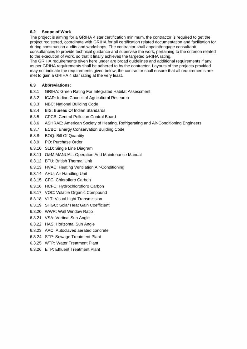
6.2 Scope of Work
The project is aiming for a GRIHA 4 star certification minimum, the contractor is required to get the project registered, coordinate with GRIHA for all certification related documentation and facilitation for during construction audits and workshops. The contractor shall appoint/engage consultant/ consultancies to provide technical guidance and supervise the work, pertaining to the criterion related to the execution of work, so that it finally achieves the targeted GRIHA rating. The GRIHA requirements given here under are broad guidelines and additional requirements if any, as per GRIHA requirements shall be adhered to by the contractor. Layouts of the projects provided may not indicate the requirements given below, the contractor shall ensure that all requirements are met to gain a GRIHA 4 star rating at the very least.
6.3 Abbreviations:
6.3.1 GRIHA: Green Rating For Integrated Habitat Assessment
6.3.2 ICAR: Indian Council of Agricultural Research
6.3.3 NBC: National Building Code
6.3.4 BIS: Bureau Of Indian Standards
6.3.5 CPCB: Central Pollution Control Board
6.3.6 ASHRAE: American Society of Heating, Refrigerating and Air-Conditioning Engineers
6.3.7 ECBC: Energy Conservation Building Code
6.3.8 BOQ: Bill Of Quantity
6.3.9 PO: Purchase Order
6.3.10 SLD: Single Line Diagram
6.3.11 O&M MANUAL: Operation And Maintenance Manual
6.3.12 BTU: British Thermal Unit
6.3.13 HVAC: Heating Ventilation Air-Conditioning
6.3.14 AHU: Air Handling Unit
6.3.15 CFC: Chlorofloro Carbon
6.3.16 HCFC: Hydrochlorofloro Carbon
6.3.17 VOC: Volatile Organic Compound
6.3.18 VLT: Visual Light Transmission
6.3.19 SHGC: Solar Heat Gain Coefficient
6.3.20 WWR: Wall Window Ratio
6.3.21 VSA: Vertical Sun Angle
6.3.22 HAS: Horizontal Sun Angle
6.3.23 AAC: Autoclaved aerated concrete
6.3.24 STP: Sewage Treatment Plant
6.3.25 WTP: Water Treatment Plant
6.3.26 ETP: Effluent Treatment Plant
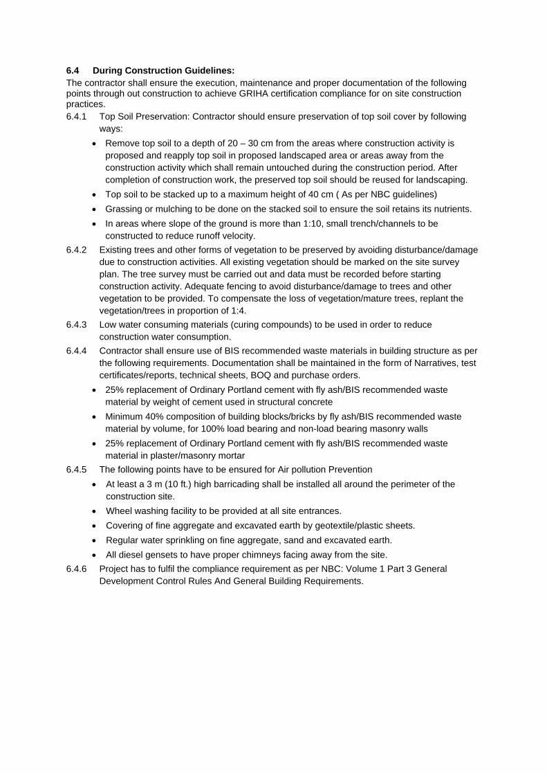
6.4 During Construction Guidelines:
The contractor shall ensure the execution, maintenance and proper documentation of the following points through out construction to achieve GRIHA certification compliance for on site construction practices.
6.4.1 Top Soil Preservation: Contractor should ensure preservation of top soil cover by following
ways:
Remove top soil to a depth of 20 – 30 cm from the areas where construction activity is
proposed and reapply top soil in proposed landscaped area or areas away from the
construction activity which shall remain untouched during the construction period. After
completion of construction work, the preserved top soil should be reused for landscaping.
Top soil to be stacked up to a maximum height of 40 cm ( As per NBC guidelines)
Grassing or mulching to be done on the stacked soil to ensure the soil retains its nutrients.
In areas where slope of the ground is more than 1:10, small trench/channels to be
constructed to reduce runoff velocity.
6.4.2 Existing trees and other forms of vegetation to be preserved by avoiding disturbance/damage
due to construction activities. All existing vegetation should be marked on the site survey
plan. The tree survey must be carried out and data must be recorded before starting
construction activity. Adequate fencing to avoid disturbance/damage to trees and other
vegetation to be provided. To compensate the loss of vegetation/mature trees, replant the
vegetation/trees in proportion of 1:4.
6.4.3 Low water consuming materials (curing compounds) to be used in order to reduce
construction water consumption.
6.4.4 Contractor shall ensure use of BIS recommended waste materials in building structure as per
the following requirements. Documentation shall be maintained in the form of Narratives, test
certificates/reports, technical sheets, BOQ and purchase orders.
25% replacement of Ordinary Portland cement with fly ash/BIS recommended waste
material by weight of cement used in structural concrete
Minimum 40% composition of building blocks/bricks by fly ash/BIS recommended waste
material by volume, for 100% load bearing and non-load bearing masonry walls
25% replacement of Ordinary Portland cement with fly ash/BIS recommended waste
material in plaster/masonry mortar
6.4.5 The following points have to be ensured for Air pollution Prevention
At least a 3 m (10 ft.) high barricading shall be installed all around the perimeter of the
construction site.
Wheel washing facility to be provided at all site entrances.
Covering of fine aggregate and excavated earth by geotextile/plastic sheets.
Regular water sprinkling on fine aggregate, sand and excavated earth.
All diesel gensets to have proper chimneys facing away from the site.
6.4.6 Project has to fulfil the compliance requirement as per NBC: Volume 1 Part 3 General
Development Control Rules And General Building Requirements.
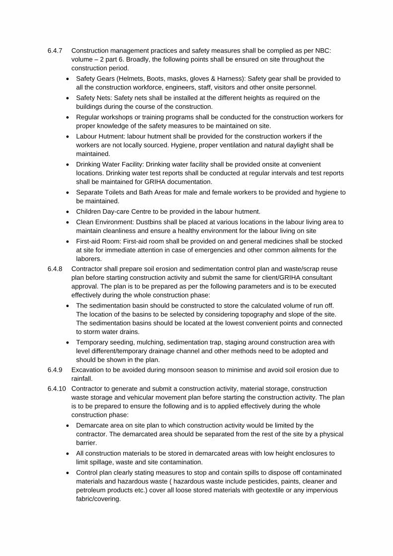
6.4.7 Construction management practices and safety measures shall be complied as per NBC:
volume – 2 part 6. Broadly, the following points shall be ensured on site throughout the
construction period.
Safety Gears (Helmets, Boots, masks, gloves & Harness): Safety gear shall be provided to
all the construction workforce, engineers, staff, visitors and other onsite personnel.
Safety Nets: Safety nets shall be installed at the different heights as required on the
buildings during the course of the construction.
Regular workshops or training programs shall be conducted for the construction workers for
proper knowledge of the safety measures to be maintained on site.
Labour Hutment: labour hutment shall be provided for the construction workers if the
workers are not locally sourced. Hygiene, proper ventilation and natural daylight shall be
maintained.
Drinking Water Facility: Drinking water facility shall be provided onsite at convenient
locations. Drinking water test reports shall be conducted at regular intervals and test reports
shall be maintained for GRIHA documentation.
Separate Toilets and Bath Areas for male and female workers to be provided and hygiene to
be maintained.
Children Day-care Centre to be provided in the labour hutment.
Clean Environment: Dustbins shall be placed at various locations in the labour living area to
maintain cleanliness and ensure a healthy environment for the labour living on site
First-aid Room: First-aid room shall be provided on and general medicines shall be stocked
at site for immediate attention in case of emergencies and other common ailments for the
laborers.
6.4.8 Contractor shall prepare soil erosion and sedimentation control plan and waste/scrap reuse
plan before starting construction activity and submit the same for client/GRIHA consultant
approval. The plan is to be prepared as per the following parameters and is to be executed
effectively during the whole construction phase:
The sedimentation basin should be constructed to store the calculated volume of run off.
The location of the basins to be selected by considering topography and slope of the site.
The sedimentation basins should be located at the lowest convenient points and connected
to storm water drains.
Temporary seeding, mulching, sedimentation trap, staging around construction area with
level different/temporary drainage channel and other methods need to be adopted and
should be shown in the plan.
6.4.9 Excavation to be avoided during monsoon season to minimise and avoid soil erosion due to
rainfall.
6.4.10 Contractor to generate and submit a construction activity, material storage, construction
waste storage and vehicular movement plan before starting the construction activity. The plan
is to be prepared to ensure the following and is to applied effectively during the whole
construction phase:
Demarcate area on site plan to which construction activity would be limited by the
contractor. The demarcated area should be separated from the rest of the site by a physical
barrier.
All construction materials to be stored in demarcated areas with low height enclosures to
limit spillage, waste and site contamination.
Control plan clearly stating measures to stop and contain spills to dispose off contaminated
materials and hazardous waste ( hazardous waste include pesticides, paints, cleaner and
petroleum products etc.) cover all loose stored materials with geotextile or any impervious
fabric/covering.
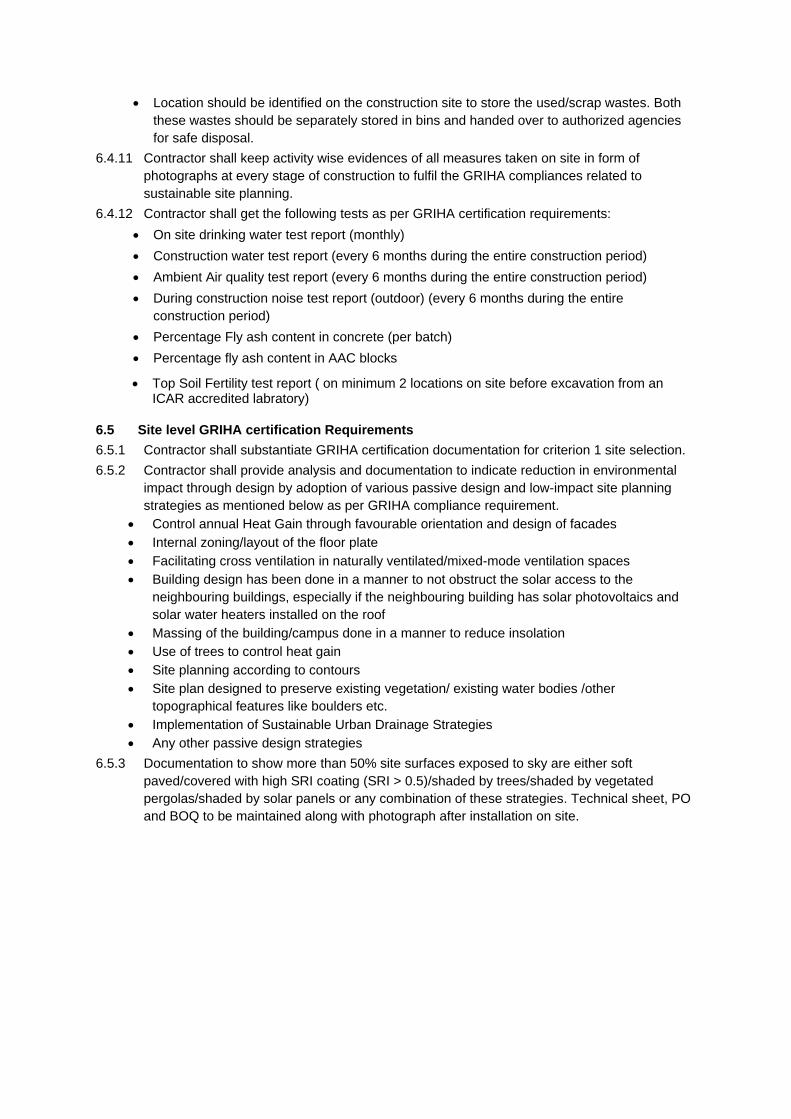
Location should be identified on the construction site to store the used/scrap wastes. Both
these wastes should be separately stored in bins and handed over to authorized agencies
for safe disposal.
6.4.11 Contractor shall keep activity wise evidences of all measures taken on site in form of
photographs at every stage of construction to fulfil the GRIHA compliances related to
sustainable site planning.
6.4.12 Contractor shall get the following tests as per GRIHA certification requirements:
On site drinking water test report (monthly)
Construction water test report (every 6 months during the entire construction period)
Ambient Air quality test report (every 6 months during the entire construction period)
During construction noise test report (outdoor) (every 6 months during the entire
construction period)
Percentage Fly ash content in concrete (per batch)
Percentage fly ash content in AAC blocks
Top Soil Fertility test report ( on minimum 2 locations on site before excavation from an ICAR accredited labratory)
6.5 Site level GRIHA certification Requirements
6.5.1 Contractor shall substantiate GRIHA certification documentation for criterion 1 site selection.
6.5.2 Contractor shall provide analysis and documentation to indicate reduction in environmental
impact through design by adoption of various passive design and low-impact site planning
strategies as mentioned below as per GRIHA compliance requirement.
Control annual Heat Gain through favourable orientation and design of facades
Internal zoning/layout of the floor plate
Facilitating cross ventilation in naturally ventilated/mixed-mode ventilation spaces
Building design has been done in a manner to not obstruct the solar access to the
neighbouring buildings, especially if the neighbouring building has solar photovoltaics and
solar water heaters installed on the roof
Massing of the building/campus done in a manner to reduce insolation
Use of trees to control heat gain
Site planning according to contours
Site plan designed to preserve existing vegetation/ existing water bodies /other
topographical features like boulders etc.
Implementation of Sustainable Urban Drainage Strategies
Any other passive design strategies
6.5.3 Documentation to show more than 50% site surfaces exposed to sky are either soft
paved/covered with high SRI coating (SRI > 0.5)/shaded by trees/shaded by vegetated
pergolas/shaded by solar panels or any combination of these strategies. Technical sheet, PO
and BOQ to be maintained along with photograph after installation on site.
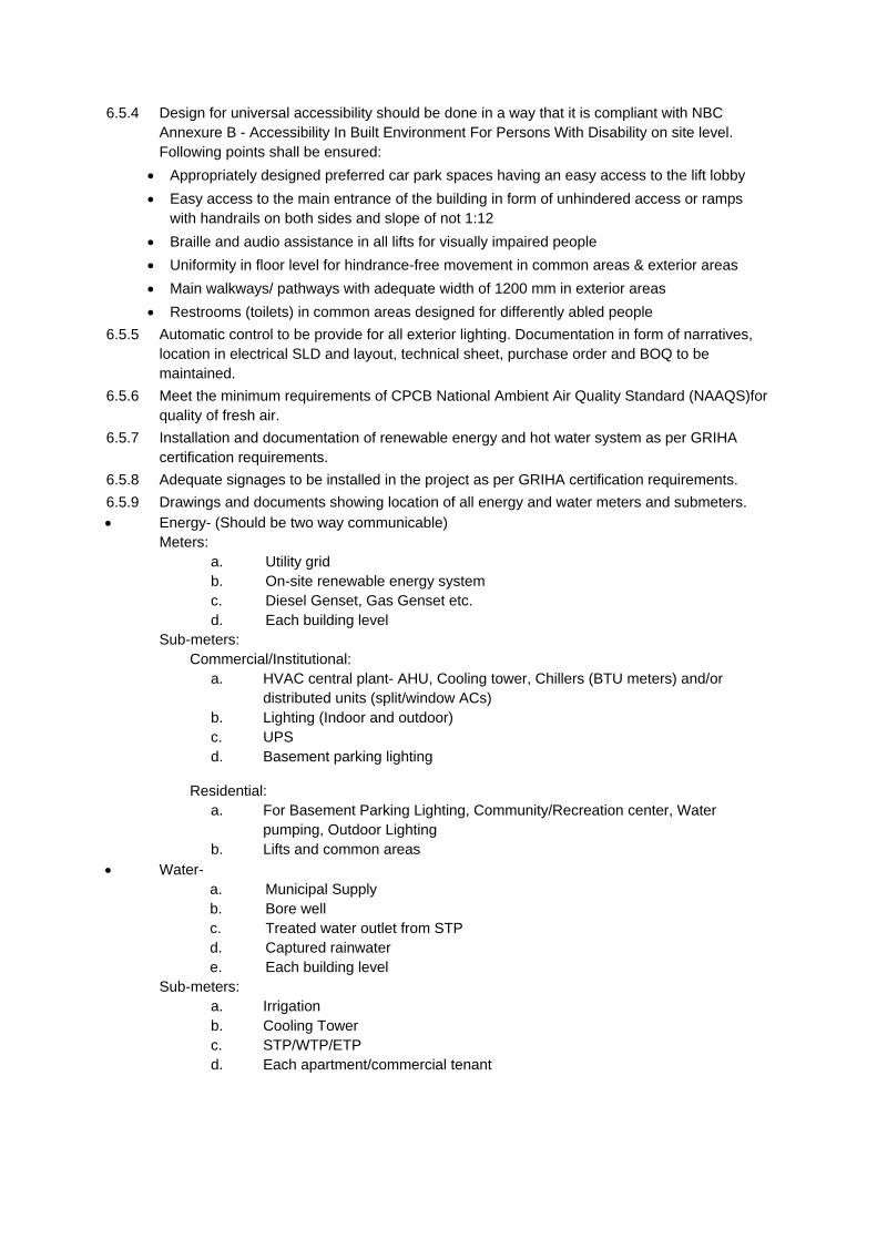
6.5.4 Design for universal accessibility should be done in a way that it is compliant with NBC
Annexure B - Accessibility In Built Environment For Persons With Disability on site level.
Following points shall be ensured:
Appropriately designed preferred car park spaces having an easy access to the lift lobby
Easy access to the main entrance of the building in form of unhindered access or ramps
with handrails on both sides and slope of not 1:12
Braille and audio assistance in all lifts for visually impaired people
Uniformity in floor level for hindrance-free movement in common areas & exterior areas
Main walkways/ pathways with adequate width of 1200 mm in exterior areas
Restrooms (toilets) in common areas designed for differently abled people
6.5.5 Automatic control to be provide for all exterior lighting. Documentation in form of narratives,
location in electrical SLD and layout, technical sheet, purchase order and BOQ to be
maintained.
6.5.6 Meet the minimum requirements of CPCB National Ambient Air Quality Standard (NAAQS)for
quality of fresh air.
6.5.7 Installation and documentation of renewable energy and hot water system as per GRIHA
certification requirements.
6.5.8 Adequate signages to be installed in the project as per GRIHA certification requirements.
6.5.9 Drawings and documents showing location of all energy and water meters and submeters.
Energy- (Should be two way communicable)
Meters:
a. Utility grid
b. On-site renewable energy system
c. Diesel Genset, Gas Genset etc.
d. Each building level
Sub-meters:
Commercial/Institutional:
a. HVAC central plant- AHU, Cooling tower, Chillers (BTU meters) and/or
distributed units (split/window ACs)
b. Lighting (Indoor and outdoor)
c. UPS
d. Basement parking lighting
Residential:
a. For Basement Parking Lighting, Community/Recreation center, Water
pumping, Outdoor Lighting
b. Lifts and common areas
Water-
a. Municipal Supply
b. Bore well
c. Treated water outlet from STP
d. Captured rainwater
e. Each building level
Sub-meters:
a. Irrigation
b. Cooling Tower
c. STP/WTP/ETP
d. Each apartment/commercial tenant
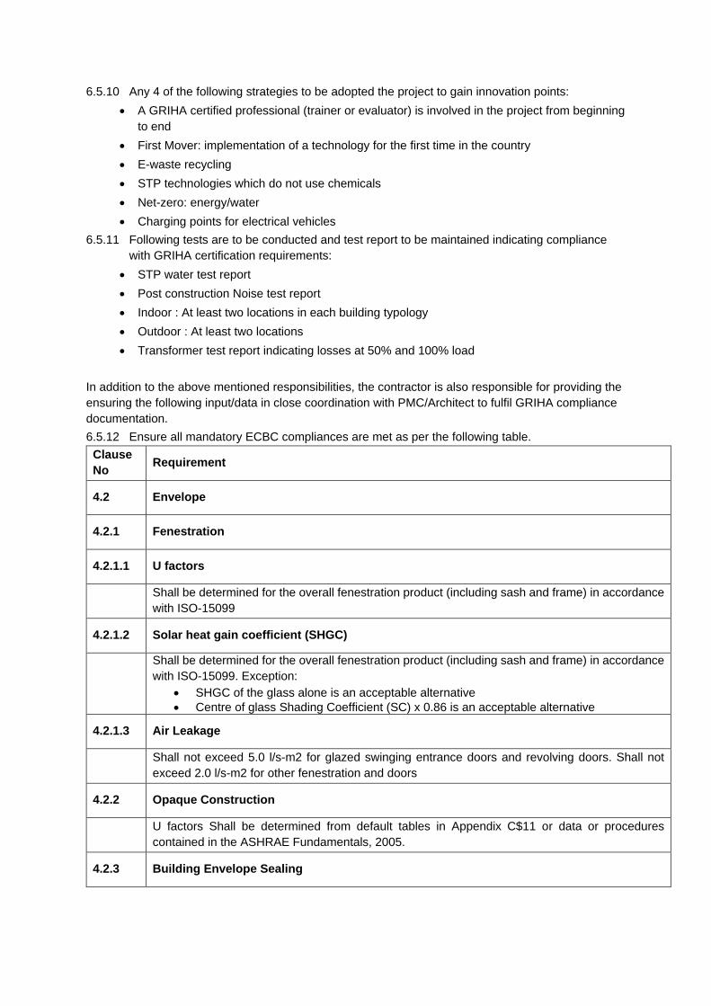
6.5.10 Any 4 of the following strategies to be adopted the project to gain innovation points:
A GRIHA certified professional (trainer or evaluator) is involved in the project from beginning
to end
First Mover: implementation of a technology for the first time in the country
E-waste recycling
STP technologies which do not use chemicals
Net-zero: energy/water
Charging points for electrical vehicles
6.5.11 Following tests are to be conducted and test report to be maintained indicating compliance
with GRIHA certification requirements:
STP water test report
Post construction Noise test report
Indoor : At least two locations in each building typology
Outdoor : At least two locations
Transformer test report indicating losses at 50% and 100% load
In addition to the above mentioned responsibilities, the contractor is also responsible for providing the
ensuring the following input/data in close coordination with PMC/Architect to fulfil GRIHA compliance
documentation.
6.5.12 Ensure all mandatory ECBC compliances are met as per the following table.
Clause
No Requirement
4.2 Envelope
4.2.1 Fenestration
4.2.1.1 U factors
Shall be determined for the overall fenestration product (including sash and frame) in accordance
with ISO-15099
4.2.1.2 Solar heat gain coefficient (SHGC)
Shall be determined for the overall fenestration product (including sash and frame) in accordance
with ISO-15099. Exception:
SHGC of the glass alone is an acceptable alternative
Centre of glass Shading Coefficient (SC) x 0.86 is an acceptable alternative
4.2.1.3 Air Leakage
Shall not exceed 5.0 l/s-m2 for glazed swinging entrance doors and revolving doors. Shall not
exceed 2.0 l/s-m2 for other fenestration and doors
4.2.2 Opaque Construction
U factors Shall be determined from default tables in Appendix C$11 or data or procedures
contained in the ASHRAE Fundamentals, 2005.
4.2.3 Building Envelope Sealing
The following envelope components shall be sealed, caulked, gasketed, or weather stripped to
minimize air leakage:
Joints around fenestration and door frames.
Openings between wall and foundations, and between walls and roof.
Penetration openings of utility services through roof, wall and floors.
Site built fenestration and doors.
Building assemblies used as ducts or plenums.
Any other opening in the building envelope.
5.2 Heating, Ventilation and Air Conditioning
5.2.1 Natural Ventilation
Natural ventilation shall comply with the design guidelines for natural ventilation in NBC 2005 part
8 5.4.3 & 5.7.1.1
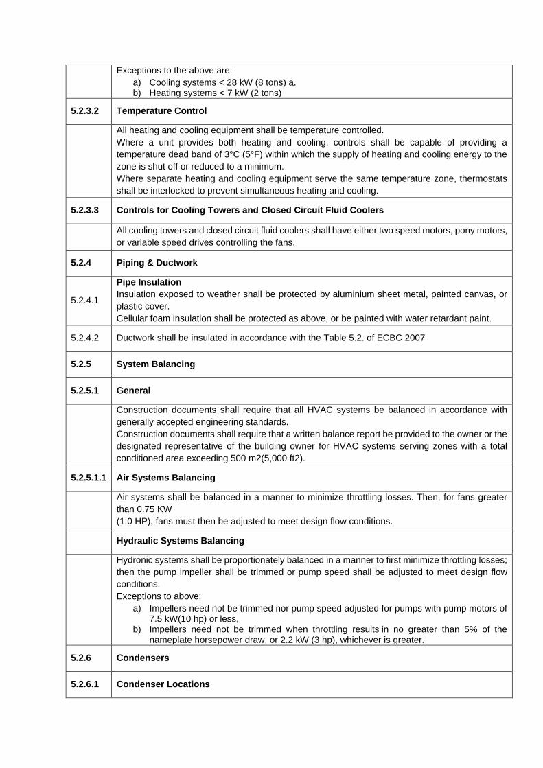
5.2.2 Minimum Equipment Efficiencies for HVAC
Minimum equipment efficiencies are required to be met for all HVAC equipment. These include chillers, unitary air conditioner, split air conditioner, packaged air conditioner, and boilers. Cooling equipment shall meet or exceed the minimum efficiency requirements presented in Table 5.2. Heating and cooling equipment not listed in the table shall comply with ASHRAE 90.1-2004 §6.4.1
In the above table, ignore the values for centrifugal Chillers. Instead, use the following:
COP 5 & IPLV 5.5 for Centrifugal water cooled Chillers ≤ 530 kW (≤150 tons)
COP 5.55 & IPLV 5.9 for Centrifugal water cooled Chillers ≥530 kW and <1050 kW (≥150 tons and <300 tons )
COP 6.1 & IPLV 6.4 for Centrifugal water cooled Chillers ≥1,050 kW (≥300 tons)
5.2.3 Controls
5.2.3.1
Time clock Control: All mechanical cooling & heating systems shall be controlled by a timeclock that:
a) Can start & stop the system under different schedules for three different day types per week
b) is capable of retaining programming and time setting during loss of power for period of 10 hours ( check BMS programming)
c) Includes an accessible manual override that allows temporary operation of the system for up to 2 hours
Exceptions to the above are:
a) Cooling systems < 28 kW (8 tons) a. b) Heating systems < 7 kW (2 tons)
5.2.3.2 Temperature Control
All heating and cooling equipment shall be temperature controlled.
Where a unit provides both heating and cooling, controls shall be capable of providing a
temperature dead band of 3°C (5°F) within which the supply of heating and cooling energy to the
zone is shut off or reduced to a minimum.
Where separate heating and cooling equipment serve the same temperature zone, thermostats
shall be interlocked to prevent simultaneous heating and cooling.
5.2.3.3 Controls for Cooling Towers and Closed Circuit Fluid Coolers
All cooling towers and closed circuit fluid coolers shall have either two speed motors, pony motors,
or variable speed drives controlling the fans.
5.2.4 Piping & Ductwork
5.2.4.1
Pipe Insulation
Insulation exposed to weather shall be protected by aluminium sheet metal, painted canvas, or
plastic cover.
Cellular foam insulation shall be protected as above, or be painted with water retardant paint.
5.2.4.2 Ductwork shall be insulated in accordance with the Table 5.2. of ECBC 2007
5.2.5 System Balancing
5.2.5.1 General
Construction documents shall require that all HVAC systems be balanced in accordance with
generally accepted engineering standards.
Construction documents shall require that a written balance report be provided to the owner or the
designated representative of the building owner for HVAC systems serving zones with a total
conditioned area exceeding 500 m2(5,000 ft2).
5.2.5.1.1 Air Systems Balancing
Air systems shall be balanced in a manner to minimize throttling losses. Then, for fans greater
than 0.75 KW
(1.0 HP), fans must then be adjusted to meet design flow conditions.
Hydraulic Systems Balancing
Hydronic systems shall be proportionately balanced in a manner to first minimize throttling losses;
then the pump impeller shall be trimmed or pump speed shall be adjusted to meet design flow
conditions.
Exceptions to above:
a) Impellers need not be trimmed nor pump speed adjusted for pumps with pump motors of 7.5 kW(10 hp) or less,
b) Impellers need not be trimmed when throttling results in no greater than 5% of the nameplate horsepower draw, or 2.2 kW (3 hp), whichever is greater.
5.2.6 Condensers
5.2.6.1 Condenser Locations
Care shall be exercised in locating the condensers in such a manner that the heat sink is free of
interference from heat discharge by devices located in adjoining spaces and also does not
interfere with such other systems installed nearby.
5.2.6.2 Treated Water for Condensers
All high-rise buildings using centralized cooling water system shall use soft water for the condenser
and chilled water system.
6.2.1 Solar Water Heating
Residential facilities, hotels and hospitals with a centralized system shall have solar water heating for at least 1/5 of the design capacity.
Exception: Systems that use heat recovery for at least 1/5 of the design capacity.
6.2.2 Equipment Efficiency
Solar water heater shall meet the performance/ minimum efficiency level mentioned in IS 13129 Part (1&2) Gas Instantaneous Water heaters shall meet the performance/minimum efficiency level mentioned in IS 15558 with above 80% thermal efficiency. Electric water heater shall meet the performance / minimum efficiency level mentioned in IS 2082.
6.2.3 Supplementary Water Heating System
Supplemental Water Heating System shall be designed to maximize efficiency and shall incorporate and prioritize the following design features as shown:
a) Maximum heat recovery from hot discharge system like condensers of air conditioning units
b) Use of gas fired heaters wherever gas is available c) Electric heater as last resort
6.2.4 Piping Insulation
Piping insulation shall comply with § 5.2.4.1, ECBC 2007
6.2.5 Heat Traps
Vertical pipe risers serving storage water heaters and storage tanks not having integral heat traps
and serving a non‐recirculating system shall have heat traps on both the inlet and outlet piping as
close as practical to the storage tank
6.2.6 Swimming Pools
Heated pools shall be provided with a vapor retardant pool cover on or at the water surface
Pools heated to more than 32°C (90°F) shall have a pool cover with a minimum insulation value
of R‐
2.1 (R‐12)
Exception: Pools deriving over 60% of their energy from site‐recovered energy or solar
energy source
7.2 Lighting
7.2.1 Lighting Control
7.2.1.1 Automatic Lighting Shutoff
Interior lighting systems in buildings larger than 500 m2 (5,000 ft²) shall be equipped with an
automatic control device. Within these buildings, all office areas less than 30 m2 (300 ft2) enclosed by walls or ceiling‐height partitions, all meeting and conference rooms, all school classrooms, and all storage
spaces shall be equipped with occupancy sensors. For other spaces, this automatic control device shall function on either a scheduled basis at specific programmed times. An independent program schedule shall be provided for areas of no more than 2,500 m2 (25,000 ft²) and not more than one floor. Occupancy sensors that shall turn the lighting off within 30 minutes of an occupant leaving the
space. Light fixtures controlled by occupancy sensors shall have a wall mounted, manual
switch capable of turning off lights when the space is occupied. Exception: Lighting systems designed for 24‐hour use.
7.2.1.2 Space Control
Each space enclosed by ceiling‐height partitions shall have at least one control device to independently control the general lighting within the space. Each control device shall be activated either manually by an occupant or automatically by sensing an occupant. Each control device shall control a maximum of 250 m2 (2,500 ft2) for a space less than or
equal to 1,000 m2 (10,000 ft2), and a maximum of 1,000 m2 (10,000 ft2) for a space greater
than 1,000 m2 (10,000 ft2). Each control device be capable of overriding the shutoff control required in 8.2.1.1 for no more
than 2 hours Each control device be readily accessible and located so the occupant can see the control. Exception: The required control device may be remotely installed if required for reasons of safety or security. A remotely located device shall have a pilot light indicator as part of or next to the control
device and shall be clearly labeled to identify the controlled lighting.
7.2.1.3 Control in Daylit Areas
Luminaires in daylit areas greater than 25 m2 (250 ft2) shall be equipped with either a manual or automatic control device that; Capable of reducing the light output of the luminaires in the daylit areas by at least 50%. Controls only the luminaires located entirely within the daylit area
7.2.1.4 Exterior Lighting Control
Lighting for all exterior applications not exempted in Table: 8.4, ECBC shall be controlled by a
photosensor or astronomical time switch that is capable of automatically turning off the exterior
lighting when daylight is available or the lighting is not required
7.2.1.5 Additional Control
Display/Accent Lighting. Display or accent lighting greater than 300 m2 (3,000 ft2) area shall have a separate control device Case Lighting. Lighting in cases used for display purposes greater than 300 m2 (3,000 ft2) area
shall be equipped with a separate control device
Hotel and Motel Guest Room Lighting. Hotel and motel guest rooms and guest suites
shall have a master control device at the main room entry that controls all permanently
installed luminaires and switched receptacles Task Lighting. Supplemental task lighting including permanently installed under shelf or under
cabinet lighting shall have a control device integral to the luminaires or be controlled by a wall‐mounted control device provided the control device complies with 7.2.1.2, ECBC 2007 Nonvisual Lighting. Lighting for nonvisual applications, such as plant growth and food‐warming,
shall be equipped with a separate control device
Demonstration Lighting. Lighting equipment that is for sale or for demonstrations in lighting
education shall be equipped with a separate control device accessible only to authorized
personnel
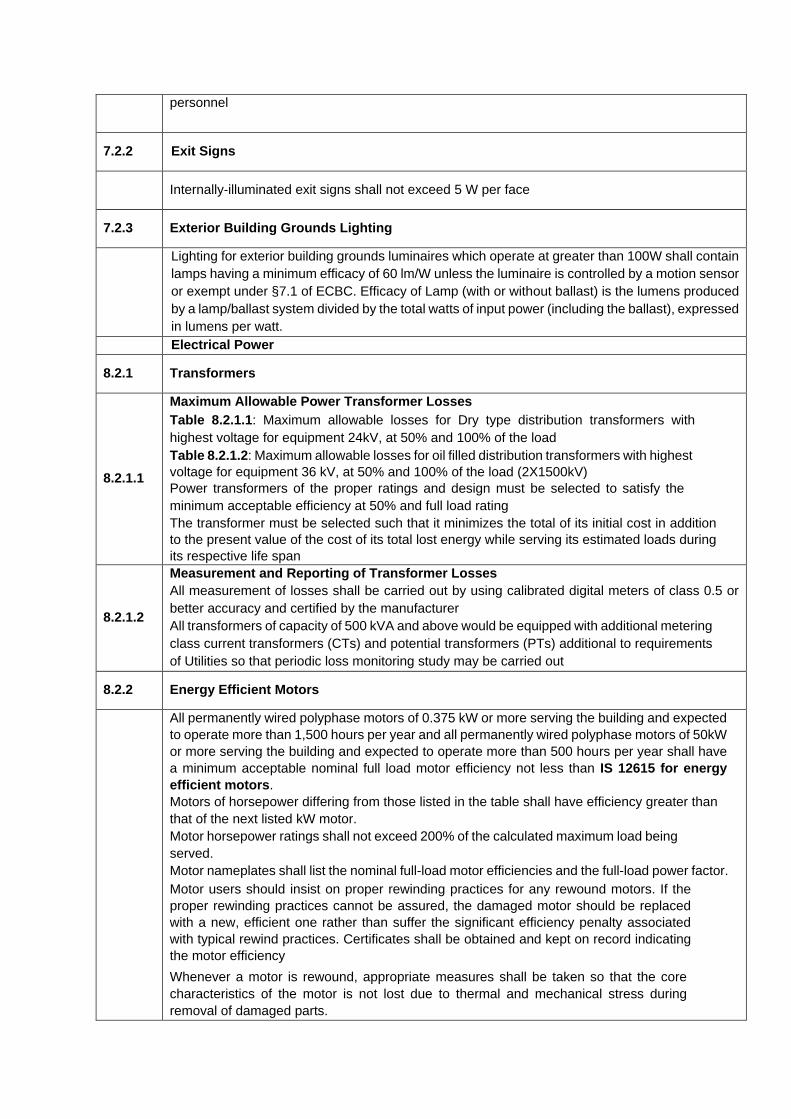
7.2.2 Exit Signs
Internally‐illuminated exit signs shall not exceed 5 W per face
7.2.3 Exterior Building Grounds Lighting
Lighting for exterior building grounds luminaires which operate at greater than 100W shall contain
lamps having a minimum efficacy of 60 lm/W unless the luminaire is controlled by a motion sensor
or exempt under §7.1 of ECBC. Efficacy of Lamp (with or without ballast) is the lumens produced
by a lamp/ballast system divided by the total watts of input power (including the ballast), expressed
in lumens per watt.
Electrical Power
8.2.1 Transformers
8.2.1.1
Maximum Allowable Power Transformer Losses Table 8.2.1.1: Maximum allowable losses for Dry type distribution transformers with
highest voltage for equipment 24kV, at 50% and 100% of the load Table 8.2.1.2: Maximum allowable losses for oil filled distribution transformers with highest
voltage for equipment 36 kV, at 50% and 100% of the load (2X1500kV)
Power transformers of the proper ratings and design must be selected to satisfy the
minimum acceptable efficiency at 50% and full load rating
The transformer must be selected such that it minimizes the total of its initial cost in addition
to the present value of the cost of its total lost energy while serving its estimated loads during
its respective life span
8.2.1.2
Measurement and Reporting of Transformer Losses
All measurement of losses shall be carried out by using calibrated digital meters of class 0.5 or
better accuracy and certified by the manufacturer
All transformers of capacity of 500 kVA and above would be equipped with additional metering
class current transformers (CTs) and potential transformers (PTs) additional to requirements
of Utilities so that periodic loss monitoring study may be carried out
8.2.2 Energy Efficient Motors
All permanently wired polyphase motors of 0.375 kW or more serving the building and expected
to operate more than 1,500 hours per year and all permanently wired polyphase motors of 50kW
or more serving the building and expected to operate more than 500 hours per year shall have
a minimum acceptable nominal full load motor efficiency not less than IS 12615 for energy
efficient motors. Motors of horsepower differing from those listed in the table shall have efficiency greater than
that of the next listed kW motor. Motor horsepower ratings shall not exceed 200% of the calculated maximum load being
served. Motor nameplates shall list the nominal full-load motor efficiencies and the full-load power factor.
Motor users should insist on proper rewinding practices for any rewound motors. If the
proper rewinding practices cannot be assured, the damaged motor should be replaced
with a new, efficient one rather than suffer the significant efficiency penalty associated
with typical rewind practices. Certificates shall be obtained and kept on record indicating
the motor efficiency Whenever a motor is rewound, appropriate measures shall be taken so that the core
characteristics of the motor is not lost due to thermal and mechanical stress during
removal of damaged parts.
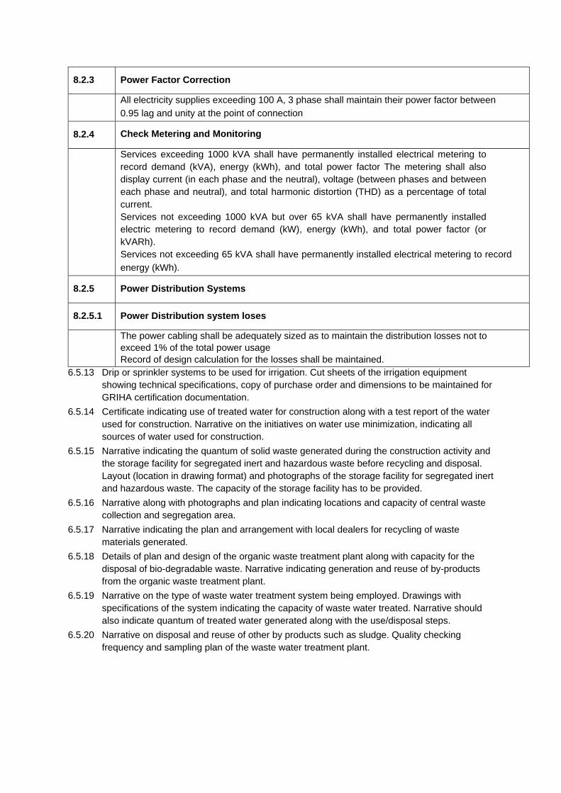
6.5.13 Drip or sprinkler systems to be used for irrigation. Cut sheets of the irrigation equipment
showing technical specifications, copy of purchase order and dimensions to be maintained for
GRIHA certification documentation.
6.5.14 Certificate indicating use of treated water for construction along with a test report of the water
used for construction. Narrative on the initiatives on water use minimization, indicating all
sources of water used for construction.
6.5.15 Narrative indicating the quantum of solid waste generated during the construction activity and
the storage facility for segregated inert and hazardous waste before recycling and disposal.
Layout (location in drawing format) and photographs of the storage facility for segregated inert
and hazardous waste. The capacity of the storage facility has to be provided.
6.5.16 Narrative along with photographs and plan indicating locations and capacity of central waste
collection and segregation area.
6.5.17 Narrative indicating the plan and arrangement with local dealers for recycling of waste
materials generated.
6.5.18 Details of plan and design of the organic waste treatment plant along with capacity for the
disposal of bio-degradable waste. Narrative indicating generation and reuse of by-products
from the organic waste treatment plant.
6.5.19 Narrative on the type of waste water treatment system being employed. Drawings with
specifications of the system indicating the capacity of waste water treated. Narrative should
also indicate quantum of treated water generated along with the use/disposal steps.
6.5.20 Narrative on disposal and reuse of other by products such as sludge. Quality checking
frequency and sampling plan of the waste water treatment plant.
8.2.3 Power Factor Correction
All electricity supplies exceeding 100 A, 3 phase shall maintain their power factor between
0.95 lag and unity at the point of connection
8.2.4 Check Metering and Monitoring
Services exceeding 1000 kVA shall have permanently installed electrical metering to
record demand (kVA), energy (kWh), and total power factor The metering shall also
display current (in each phase and the neutral), voltage (between phases and between
each phase and neutral), and total harmonic distortion (THD) as a percentage of total
current.
Services not exceeding 1000 kVA but over 65 kVA shall have permanently installed
electric metering to record demand (kW), energy (kWh), and total power factor (or
kVARh). Services not exceeding 65 kVA shall have permanently installed electrical metering to record
energy (kWh).
8.2.5 Power Distribution Systems
8.2.5.1 Power Distribution system loses
The power cabling shall be adequately sized as to maintain the distribution losses not to
exceed 1% of the total power usage
Record of design calculation for the losses shall be maintained.
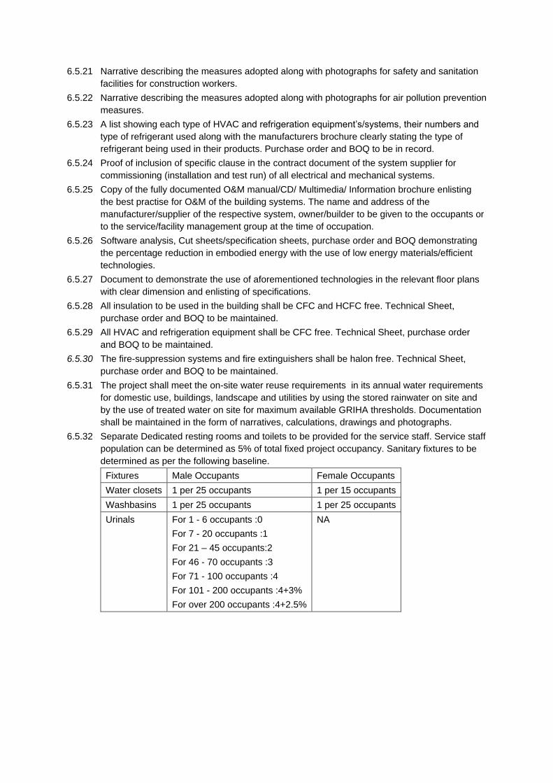
6.5.21 Narrative describing the measures adopted along with photographs for safety and sanitation
facilities for construction workers.
6.5.22 Narrative describing the measures adopted along with photographs for air pollution prevention
measures.
6.5.23 A list showing each type of HVAC and refrigeration equipment’s/systems, their numbers and
type of refrigerant used along with the manufacturers brochure clearly stating the type of
refrigerant being used in their products. Purchase order and BOQ to be in record.
6.5.24 Proof of inclusion of specific clause in the contract document of the system supplier for
commissioning (installation and test run) of all electrical and mechanical systems.
6.5.25 Copy of the fully documented O&M manual/CD/ Multimedia/ Information brochure enlisting
the best practise for O&M of the building systems. The name and address of the
manufacturer/supplier of the respective system, owner/builder to be given to the occupants or
to the service/facility management group at the time of occupation.
6.5.26 Software analysis, Cut sheets/specification sheets, purchase order and BOQ demonstrating
the percentage reduction in embodied energy with the use of low energy materials/efficient
technologies.
6.5.27 Document to demonstrate the use of aforementioned technologies in the relevant floor plans
with clear dimension and enlisting of specifications.
6.5.28 All insulation to be used in the building shall be CFC and HCFC free. Technical Sheet,
purchase order and BOQ to be maintained.
6.5.29 All HVAC and refrigeration equipment shall be CFC free. Technical Sheet, purchase order
and BOQ to be maintained.
6.5.30 The fire-suppression systems and fire extinguishers shall be halon free. Technical Sheet,
purchase order and BOQ to be maintained.
6.5.31 The project shall meet the on-site water reuse requirements in its annual water requirements
for domestic use, buildings, landscape and utilities by using the stored rainwater on site and
by the use of treated water on site for maximum available GRIHA thresholds. Documentation
shall be maintained in the form of narratives, calculations, drawings and photographs.
6.5.32 Separate Dedicated resting rooms and toilets to be provided for the service staff. Service staff
population can be determined as 5% of total fixed project occupancy. Sanitary fixtures to be
determined as per the following baseline.
Fixtures Male Occupants Female Occupants
Water closets 1 per 25 occupants 1 per 15 occupants
Washbasins 1 per 25 occupants 1 per 25 occupants
Urinals For 1 - 6 occupants :0
For 7 - 20 occupants :1
For 21 – 45 occupants:2
For 46 - 70 occupants :3
For 71 - 100 occupants :4
For 101 - 200 occupants :4+3%
For over 200 occupants :4+2.5%
NA
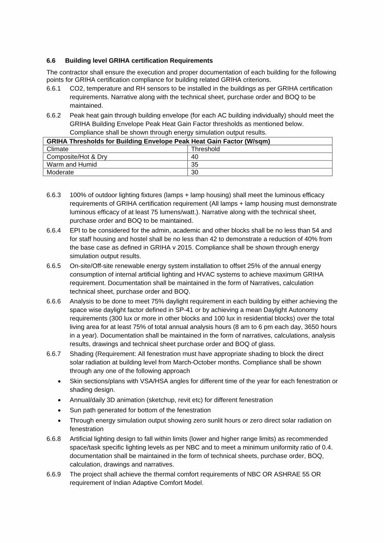
6.6 Building level GRIHA certification Requirements
The contractor shall ensure the execution and proper documentation of each building for the following points for GRIHA certification compliance for building related GRIHA criterions.
6.6.1 CO2, temperature and RH sensors to be installed in the buildings as per GRIHA certification
requirements. Narrative along with the technical sheet, purchase order and BOQ to be
maintained.
6.6.2 Peak heat gain through building envelope (for each AC building individually) should meet the
GRIHA Building Envelope Peak Heat Gain Factor thresholds as mentioned below.
Compliance shall be shown through energy simulation output results.
GRIHA Thresholds for Building Envelope Peak Heat Gain Factor (W/sqm)
Climate Threshold
Composite/Hot & Dry 40
Warm and Humid 35
Moderate 30
6.6.3 100% of outdoor lighting fixtures (lamps + lamp housing) shall meet the luminous efficacy
requirements of GRIHA certification requirement (All lamps + lamp housing must demonstrate
luminous efficacy of at least 75 lumens/watt.). Narrative along with the technical sheet,
purchase order and BOQ to be maintained.
6.6.4 EPI to be considered for the admin, academic and other blocks shall be no less than 54 and
for staff housing and hostel shall be no less than 42 to demonstrate a reduction of 40% from
the base case as defined in GRIHA v 2015. Compliance shall be shown through energy
simulation output results.
6.6.5 On-site/Off-site renewable energy system installation to offset 25% of the annual energy
consumption of internal artificial lighting and HVAC systems to achieve maximum GRIHA
requirement. Documentation shall be maintained in the form of Narratives, calculation
technical sheet, purchase order and BOQ.
6.6.6 Analysis to be done to meet 75% daylight requirement in each building by either achieving the
space wise daylight factor defined in SP-41 or by achieving a mean Daylight Autonomy
requirements (300 lux or more in other blocks and 100 lux in residential blocks) over the total
living area for at least 75% of total annual analysis hours (8 am to 6 pm each day, 3650 hours
in a year). Documentation shall be maintained in the form of narratives, calculations, analysis
results, drawings and technical sheet purchase order and BOQ of glass.
6.6.7 Shading (Requirement: All fenestration must have appropriate shading to block the direct
solar radiation at building level from March-October months. Compliance shall be shown
through any one of the following approach
Skin sections/plans with VSA/HSA angles for different time of the year for each fenestration or
shading design.
Annual/daily 3D animation (sketchup, revit etc) for different fenestration
Sun path generated for bottom of the fenestration
Through energy simulation output showing zero sunlit hours or zero direct solar radiation on
fenestration
6.6.8 Artificial lighting design to fall within limits (lower and higher range limits) as recommended
space/task specific lighting levels as per NBC and to meet a minimum uniformity ratio of 0.4.
documentation shall be maintained in the form of technical sheets, purchase order, BOQ,
calculation, drawings and narratives.
6.6.9 The project shall achieve the thermal comfort requirements of NBC OR ASHRAE 55 OR
requirement of Indian Adaptive Comfort Model.
6.6.10 The indoor noise levels shall meet the acceptable limits as specified in NBC and key noise
source on site (like DG sets, chiller plants etc.) shall have sufficient acoustic insulation as per
NBC norms.
6.6.11 Meet the minimum requirements of ASHRAE Standard 62.1–2010, Sections 4–7, Ventilation
for Acceptable Indoor Air Quality (with errata), or a NBC for quantity of fresh air
6.6.12 Cut sheets of the water fixture showing flow rate at 3 bar pressure, copy of purchase order
and dimensions.
Flow rate at 3 bar pressure for each fixture to achieve 50% water use reduction WC(Full Flush) : 6 LPF WC(Half Flush) : 3 LPF Urinal: 1 LPF Kitchen Faucet : 5 LPM Lavatory Faucet : 5 LPM Showers : 5 LPM
6.6.13 Design for universal accessibility should be done in a way that it is compliant with NBC
Annexure B - Accessibility In Built Environment For Persons With Disability in each block
excluding staff housing. Following points shall be ensured:
Appropriately designed preferred car park spaces having an easy access to the lift lobby
Easy access to the main entrance of the building
Braille and audio assistance in lifts for visually impaired people
Uniformity in floor level for hindrance-free movement in common areas & exterior areas
Main walkways/ pathways with adequate width in exterior areas
Restrooms (toilets) in common areas designed for differently abled people
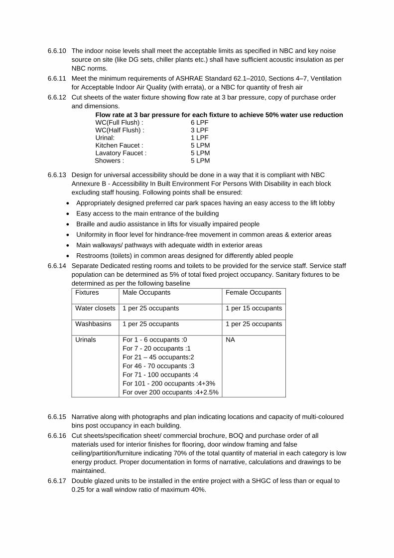
6.6.14 Separate Dedicated resting rooms and toilets to be provided for the service staff. Service staff
population can be determined as 5% of total fixed project occupancy. Sanitary fixtures to be
determined as per the following baseline
Fixtures Male Occupants Female Occupants
Water closets 1 per 25 occupants 1 per 15 occupants
Washbasins 1 per 25 occupants 1 per 25 occupants
Urinals For 1 - 6 occupants :0
For 7 - 20 occupants :1
For 21 – 45 occupants:2
For 46 - 70 occupants :3
For 71 - 100 occupants :4
For 101 - 200 occupants :4+3%
For over 200 occupants :4+2.5%
NA
6.6.15 Narrative along with photographs and plan indicating locations and capacity of multi-coloured
bins post occupancy in each building.
6.6.16 Cut sheets/specification sheet/ commercial brochure, BOQ and purchase order of all
materials used for interior finishes for flooring, door window framing and false
ceiling/partition/furniture indicating 70% of the total quantity of material in each category is low
energy product. Proper documentation in forms of narrative, calculations and drawings to be
maintained.
6.6.17 Double glazed units to be installed in the entire project with a SHGC of less than or equal to
0.25 for a wall window ratio of maximum 40%.
6.6.18 Cut sheets/specification sheet/ commercial brochure indicating bonding resins used in
wood/agri-fiber products are urea formaldehyde free for all wood/agri-fiber product used in the
finishing materials along with their BOQ and purchase order.
6.6.19 Drawings and documents showing location of all energy and water meters and submeters as
per following GRIHA requirements:
Energy-(Should be two way communicable)
Meters:
a. Utility grid
b. On-site renewable energy system
c. Diesel Genset, Gas Genset etc.
d. Each building level
Sub-meters:
Commercial/Institutional:
a. HVAC central plant- AHU, Cooling tower, Chillers (BTU meters) and/or
distributed units (split/window ACs)
b. Lighting (Indoor and outdoor)
c. UPS
d. Basement parking lighting
Residential:
a. For Basement Parking Lighting, Community/Recreation center, Water
pumping, Outdoor Lighting
b. Lifts and common areas
Water-
Meters:
a. Municipal Supply
b. Bore well
c. Treated water outlet from STP
d. Captured rainwater
e. Each building level
Sub-meters:
a. Irrigation
b. Cooling Tower
c. STP/WTP/ETP
d. Each apartment/commercial tenant
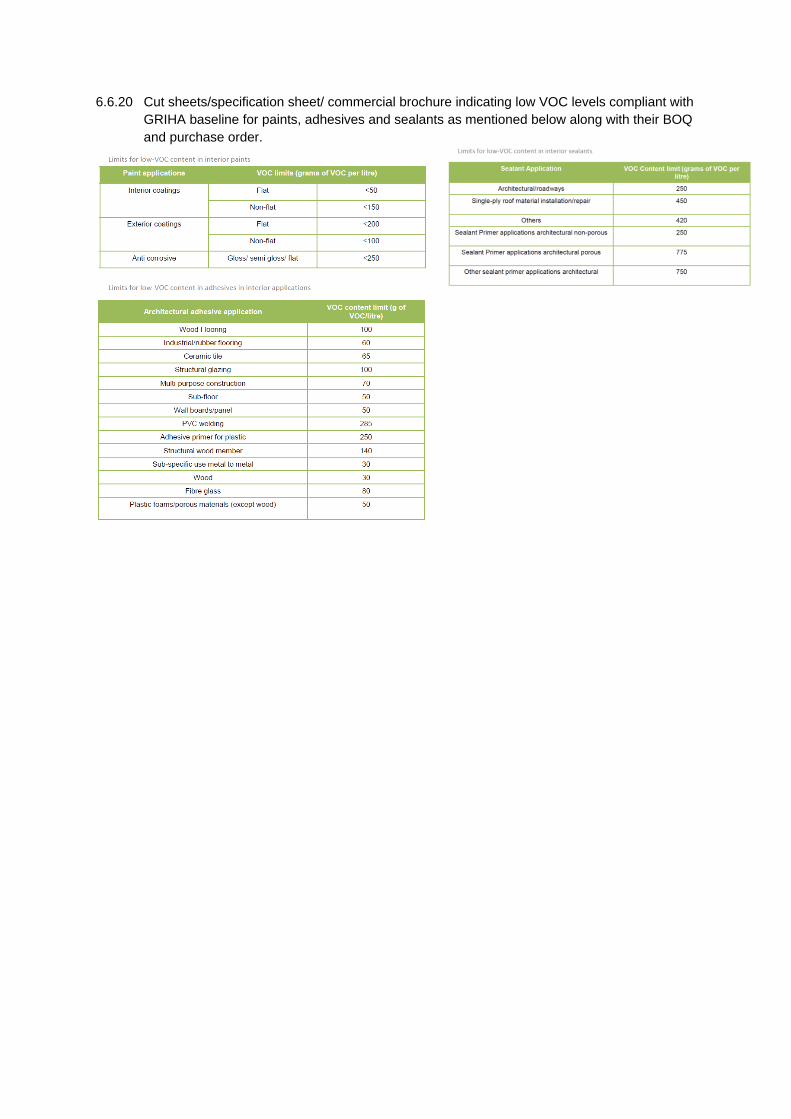
6.6.20 Cut sheets/specification sheet/ commercial brochure indicating low VOC levels compliant with
GRIHA baseline for paints, adhesives and sealants as mentioned below along with their BOQ
and purchase order.


