Embed Size (px)
Citation preview
!"#$%&'(#)'*+,%*-+&
.+,/'*01#2',01-(%3#.+&*1+3#41+5'(*6
αα#701-06#.+&*1+3#8+*+1#),/3-9-01701:+#),/3-9-01#;&-*
8%-&*0&%&(0#8%&'%3
!"#$%&'(&)*+,' -./.012'((&
PREFACE
This manual provides information necessary for maintenance of theFANUC Control MotorAmplifier α series (servo amplifier units SVU and SVUC).There are two servo amplifier unit types, as listed below.
Name Designation RemarkSVU A06B-6089-H*** · The specification of this type is partly different
from that of the C series servo amplifier.· Conforms to VDE0160.
SVUC A06B-6090-H*** · This type is designed to satisfy the compatibility with the C series servo amplifier.
· Does not conform to VDE0160.
Part I describes the procedure to start up the servo amplifier unit. Part IIdescribes the error recovery procedure. Part III describes the cautions that should be observed in switching fromthe C series servo amplifier to the α series servo amplifier unit SVU or SVUC.This document uses the abbreviations listed below.
Model AbbreviationA06B-6089-H*** SVUA06B-6090-H*** SVUCFANUC Series FS-FANUC Power Mate MODEL PM-
In this manual, the servo parameter numbers are arranged as shown below.
FS-15
Function name or bit of the servo parameterNo. 1877
Overload protection coefficient (OVC1)
FS-16, 18, 20, 21PM-D, F
FS-0C
No. 8X62No. 2062
In addition to this manual, those listed below are provided for the FANUCControl Motor Amplifier α series (servo amplifier unit).1) FANUC CONTROL MOTOR AMPLIFIER α series
SERVO AMPLIFIER UNIT DESCRIPTIONS B-65192EN2) FANUC AC SERVO MOTOR α series
DESCRIPTIONS B-65142E3) FANUC AC SERVO MOTOR α series
PARAMETER MANUAL B-65150E
Examples

When maintaining or inspecting the servo amplifiers, keep thepower supply switched off. Also make sure that the “CHARGING” LED (red) beside thecircuit breaker on the front panel of the servo amplifier is off.(See Appendix A.)
IMPORTANT
B–65195EN/01 Table of contents
i
I. START-UP PROCEDURE
1. OVERVIEW 3. . . . . . . . . . . . . . . . . . . . . . . . . . . . . . . . . . . . . . . . . . . . . . . . . . . . . . . . . . .
2. CONFIGURATION 4. . . . . . . . . . . . . . . . . . . . . . . . . . . . . . . . . . . . . . . . . . . . . . . . . . . . . 2.1 BASIC CONFIGURATION 5. . . . . . . . . . . . . . . . . . . . . . . . . . . . . . . . . . . . . . . . . . . . . . . . . . . . . . . . . 2.2 MAJOR COMPONENTS 6. . . . . . . . . . . . . . . . . . . . . . . . . . . . . . . . . . . . . . . . . . . . . . . . . . . . . . . . . . .
2.2.1 SVU 6. . . . . . . . . . . . . . . . . . . . . . . . . . . . . . . . . . . . . . . . . . . . . . . . . . . . . . . . . . . . . . . . . . . . . . . . . . . . 2.2.2 SVUC 7. . . . . . . . . . . . . . . . . . . . . . . . . . . . . . . . . . . . . . . . . . . . . . . . . . . . . . . . . . . . . . . . . . . . . . . . . .
3. START-UP PROCEDURE 8. . . . . . . . . . . . . . . . . . . . . . . . . . . . . . . . . . . . . . . . . . . . . . . 3.1 OVERVIEW OF THE START-UP PROCEDURE 9. . . . . . . . . . . . . . . . . . . . . . . . . . . . . . . . . . . . . . . . 3.2 CONNECTING THE POWER SUPPLY 10. . . . . . . . . . . . . . . . . . . . . . . . . . . . . . . . . . . . . . . . . . . . . . .
3.2.1 Confirming the Line Voltage and Power Requirements 10. . . . . . . . . . . . . . . . . . . . . . . . . . . . . . . . . . . . 3.2.2 Connecting to the Protection Ground 10. . . . . . . . . . . . . . . . . . . . . . . . . . . . . . . . . . . . . . . . . . . . . . . . . . 3.2.3 Leakage Current and Selecting a Ground Fault Interrupter 10. . . . . . . . . . . . . . . . . . . . . . . . . . . . . . . . .
3.3 SWITCH SETTING 12. . . . . . . . . . . . . . . . . . . . . . . . . . . . . . . . . . . . . . . . . . . . . . . . . . . . . . . . . . . . . . . 3.4 CONNECTING THE BATTERY FOR AN ABSOLUTE PULSE CODER 14. . . . . . . . . . . . . . . . . . . . 3.5 CONNECTING THE SEPARATE REGENERATIVE DISCHARGE UNIT 15. . . . . . . . . . . . . . . . . . . 3.6 INITIALIZING SERVO PARAMETERS 18. . . . . . . . . . . . . . . . . . . . . . . . . . . . . . . . . . . . . . . . . . . . . .
4. OPERATION CONFIRMATION METHOD 25. . . . . . . . . . . . . . . . . . . . . . . . . . . . . . . . . 4.1 CONFIRMATION PROCEDURE 26. . . . . . . . . . . . . . . . . . . . . . . . . . . . . . . . . . . . . . . . . . . . . . . . . . . . 4.2 SERVO AMPLIFIER UNIT CHECK PINS 27. . . . . . . . . . . . . . . . . . . . . . . . . . . . . . . . . . . . . . . . . . . . .
4.2.1 Checking the +5V Power Supply Voltage 27. . . . . . . . . . . . . . . . . . . . . . . . . . . . . . . . . . . . . . . . . . . . . . . 4.2.2 Checking the Motor Instantaneous Current 27. . . . . . . . . . . . . . . . . . . . . . . . . . . . . . . . . . . . . . . . . . . . . .
4.3 STATUS INDICATOR 29. . . . . . . . . . . . . . . . . . . . . . . . . . . . . . . . . . . . . . . . . . . . . . . . . . . . . . . . . . . . .
5. AXIS LEFT UNUSED IN A MULTI-AXIS AMPLIFIER 30. . . . . . . . . . . . . . . . . . . . . . .
6. SERVO CHECK BOARD 31. . . . . . . . . . . . . . . . . . . . . . . . . . . . . . . . . . . . . . . . . . . . . . . .
II. TROUBLESHOOTING AND RECOVERY
1. OVERVIEW 37. . . . . . . . . . . . . . . . . . . . . . . . . . . . . . . . . . . . . . . . . . . . . . . . . . . . . . . . . . .
2. ALARM NUMBER AND BRIEF DESCRIPTIONS 38. . . . . . . . . . . . . . . . . . . . . . . . . . . 2.1 ALARM NUMBER IN SERIES 15 (SERVO ALARMS) 39. . . . . . . . . . . . . . . . . . . . . . . . . . . . . . . . . . 2.2 ALARM NUMBER IN SERIES 0-C (SERVO ALARMS) 40. . . . . . . . . . . . . . . . . . . . . . . . . . . . . . . . . 2.3 ALARM NUMBER IN SERIES 16, 18, 20 (SERVO ALARMS) 41. . . . . . . . . . . . . . . . . . . . . . . . . . . .
3. TROUBLESHOOTING AND RECOVERY PROCEDURES 42. . . . . . . . . . . . . . . . . . . 3.1 SERVO AMPLIFIER UNIT 43. . . . . . . . . . . . . . . . . . . . . . . . . . . . . . . . . . . . . . . . . . . . . . . . . . . . . . . . .
3.1.1 LED Indications and Meanings 43. . . . . . . . . . . . . . . . . . . . . . . . . . . . . . . . . . . . . . . . . . . . . . . . . . . . . . . 3.1.2 Actions to be Taken on Each Alarm 44. . . . . . . . . . . . . . . . . . . . . . . . . . . . . . . . . . . . . . . . . . . . . . . . . . .
3.2 CURRENT CONVERSION FAILURE ALARM 48. . . . . . . . . . . . . . . . . . . . . . . . . . . . . . . . . . . . . . . . 3.3 SERVO SOFTWARE 49. . . . . . . . . . . . . . . . . . . . . . . . . . . . . . . . . . . . . . . . . . . . . . . . . . . . . . . . . . . . . .
B–65195EN/01Table of contents
ii
3.3.1 Servo Adjustment Screen 49. . . . . . . . . . . . . . . . . . . . . . . . . . . . . . . . . . . . . . . . . . . . . . . . . . . . . . . . . . . 3.3.2 Overload Alarm 50. . . . . . . . . . . . . . . . . . . . . . . . . . . . . . . . . . . . . . . . . . . . . . . . . . . . . . . . . . . . . . . . . . . 3.3.3 Feedback Disconnected Alarm 50. . . . . . . . . . . . . . . . . . . . . . . . . . . . . . . . . . . . . . . . . . . . . . . . . . . . . . . 3.3.4 Motor Overheat Alarm 51. . . . . . . . . . . . . . . . . . . . . . . . . . . . . . . . . . . . . . . . . . . . . . . . . . . . . . . . . . . . . 3.3.5 Invalid Servo Parameter Setting Parameters 51. . . . . . . . . . . . . . . . . . . . . . . . . . . . . . . . . . . . . . . . . . . . . 3.3.6 Pulse Coder Error Alarm 57. . . . . . . . . . . . . . . . . . . . . . . . . . . . . . . . . . . . . . . . . . . . . . . . . . . . . . . . . . . . 3.3.7 Rotation Speed Data Error Alarm 57. . . . . . . . . . . . . . . . . . . . . . . . . . . . . . . . . . . . . . . . . . . . . . . . . . . . . 3.3.8 Pulse Coder Communication Error Alarm 58. . . . . . . . . . . . . . . . . . . . . . . . . . . . . . . . . . . . . . . . . . . . . .
4. REPLACING THE FUSE 59. . . . . . . . . . . . . . . . . . . . . . . . . . . . . . . . . . . . . . . . . . . . . . . .
III. COMPATIBILITY OF THE SVU AND SVUC WITH THE C SERIES AMPLIFIER
1. OVERVIEW 63. . . . . . . . . . . . . . . . . . . . . . . . . . . . . . . . . . . . . . . . . . . . . . . . . . . . . . . . . . .
2. COMPATIBILITY OF THE SVU AND SVUC WITH THE C SERIES AMPLIFIER 64. . . . . . . . . . . . . . . . . . . . . . . . . . . . . . . . . . . . . . . . . . . . . . . . . .
3. SVUC SPECIFICATION CODE 66. . . . . . . . . . . . . . . . . . . . . . . . . . . . . . . . . . . . . . . . . .
APPENDIX
A. SERVO AMPLIFIER UNIT FRONT PANEL 69. . . . . . . . . . . . . . . . . . . . . . . . . . . . . . . .
B. MOTOR GROUNDING CONNECTION 70. . . . . . . . . . . . . . . . . . . . . . . . . . . . . . . . . . . .

I. START-UP PROCEDURE

B–65195EN/01 1. OVERVIEWSTART-UP PROCEDURE
3
1 OVERVIEW
This part provides information necessary to confirm the systemconfiguration and start up the servo amplifier units :– Configuration– Start- up procedure– Operation confirmation procedure
2. CONFIGURATION B–65195EN/01START-UP PROCEDURE
4
2 CONFIGURATION
B–65195EN/01 2. CONFIGURATIONSTART-UP PROCEDURE
5
The basic configuration is shown below.Refer to “FANUC CONTROL MOTOR AMPLIFIER α Series (SERVOAMPLIFIER UNIT) Descriptions” (B-65192EN) for detail.
Ex. Tow SVU2s
Power Supply ForControl Circuit
Servo AmplifierUnit
SVU2
ServoAmplifierUnit
SVU2
1 φAC200/220/230V+10, –15%
ACLineFilter
3φ (AC380V)(AC415V)(AC460V)
AC200VAC220VAC230V
BreakerMagneticContactor
ServoMotor
ServoMotor
ServoMotor
ServoMotor
(Note 1) (Note 2) (Note 3)PowerTransformer
: Basic : Optional : Units prepared by the machine tool builder
Notes1 This circuit breaker is intended to protect the power cord and related equipment. A circuit
breaker to protect a servo amplifier unit is provided within the servo amplifier unit.2 This AC line filter should always be used,so influence by harmonic noise to the power supply
can be reduced. When the line voltage is out of specification,and a power transformer (isolationtype) is used, the AC line filter can be omitted. If the AC line filter is ineffective in making the servo amplifier unit satisfy EMC standards, usean appropriate commercial noise filter.
3 The magnetic contactor is required if it is necessary to qualify for European CE marking.4 When using the SVU,install a surge absorber between the power lines and between a power
line and a ground line at the entrance of the power magnetic cabinet in order to protect theequipment from a surge voltage. For the SVUC, it is unnecessary to install an external surgeabsorber because the SVUC has a built- in surge absorber as the C series amplifier.
2.1BASICCONFIGURATION
2. CONFIGURATION B–65195EN/01START-UP PROCEDURE
6
(1) SVU 1Model Oder
specificationWiring boardspecification
P. C. B.specification
Remark
SVU1-12 A06B-6089-H101 A16B-2202-0950 A20B-2002-0030SVU1-20 A06B-6089-H102 A16B-2202-0951SVU1-40 A06B-6089-H104 A20B-2002-0040 A20B-2002-0031SVU1-80 A06B-6089-H105 A20B-2002-0041SVU1-130 A06B-6089-H106 A20B-2002-0050
(2) SVU 2Model Oder
specificationWiring boardspecification
P. C. B.specification
Remark
SVU2-12/12 A06B-6089-H201 A20B-2002-0060 A20B-2002-0032SVU2-12/20 A06B-6089-H202 A20B-2002-0061SVU2-20/20 A06B-6089-H203 A20B-2002-0062SVU2-12/40 A06B-6089-H204 A20B-2002-0063SVU2-20/40 A06B-6089-H205 A20B-2002-0064SVU2-40/40 A06B-6089-H206 A20B-2002-0065SVU2-40/80 A06B-6089-H207 A20B-2002-0066SVU2-80/80 A06B-6089-H208 A20B-2002-0067SVU2-12/80 A06B-6089-H209 A20B-2002-0068SVU2-20/80 A06B-6089-H210 A20B-2002-0069
2.2MAJORCOMPONENTS
2.2.1SVU
B–65195EN/01 2. CONFIGURATIONSTART-UP PROCEDURE
7
(1) SVUC 1Model Oder
specificationWiring boardspecification
P. C. B.specification
Remark
SVUC1-4 A06B-6090-H002 A16B-2202-0955 A20B-2002-0030/03B or laterSVUC1-12 A06B-6090-H003 A16B-2202-0956 /03B or later
SVUC1-40 A06B-6090-H004 A20B-2002-0045 A20B-2002-0031/03B or laterSVUC1-80 A06B-6090-H006 A20B-2002-0047 /03B or later
SVUC1-130 A06B-6090-H008 A20B-2002-0055
(2) SVUC 2Model Oder
specificationWiring boardspecification
P. C. B.specification
Remark
SVUC2-4/4 A06B-6090-H222 A20B-2002-0151 A20B-2002-0032/03B or laterSVUC2-4/12 A06B-6090-H223 A20B-2002-0152 /03B or later
SVUC2-4/40 A06B-6090-H224 A20B-2002-0153SVUC2-12/12 A06B-6090-H233 A20B-2002-0154SVUC2-12/40 A06B-6090-H234 A20B-2002-0155SVUC2-12/80 A06B-6090-H236 A20B-2002-0156SVUC2-40/40 A06B-6090-H244 A20B-2002-0157SVUC2-40/80 A06B-6090-H246 A20B-2002-0158SVUC2-80/80 A06B-6090-H266 A20B-2002-0159
2.2.2SVUC

3. START-UP PROCEDURE B–65195EN/01START-UP PROCEDURE
8
3 ↵ ↵
B–65195EN/01 3. START-UP PROCEDURESTART-UP PROCEDURE
9
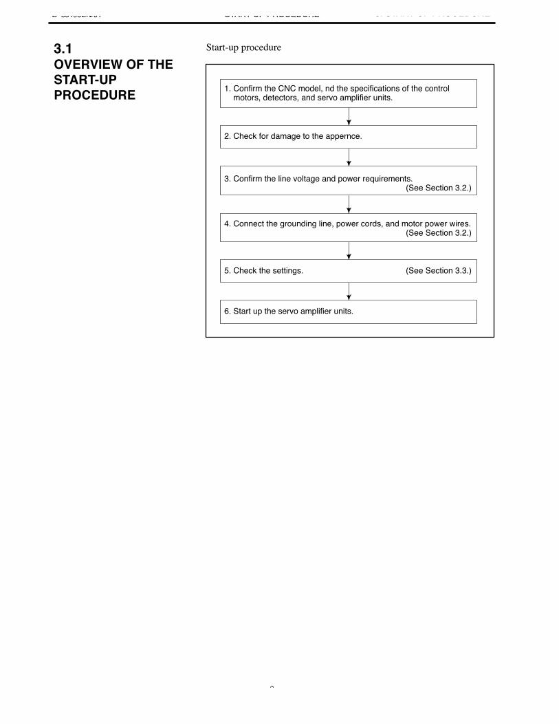
Start-up procedure
1. Confirm the CNC model, nd the specifications of the control motors, detectors, and servo amplifier units.
2. Check for damage to the appernce.
3. Confirm the line voltage and power requirements. (See Section 3.2.)
4. Connect the grounding line, power cords, and motor power wires. (See Section 3.2.)
5. Check the settings. (See Section 3.3.)
6. Start up the servo amplifier units.
3.1OVERVIEW OF THESTART-UPPROCEDURE
3. START-UP PROCEDURE B–65195EN/01START-UP PROCEDURE
10
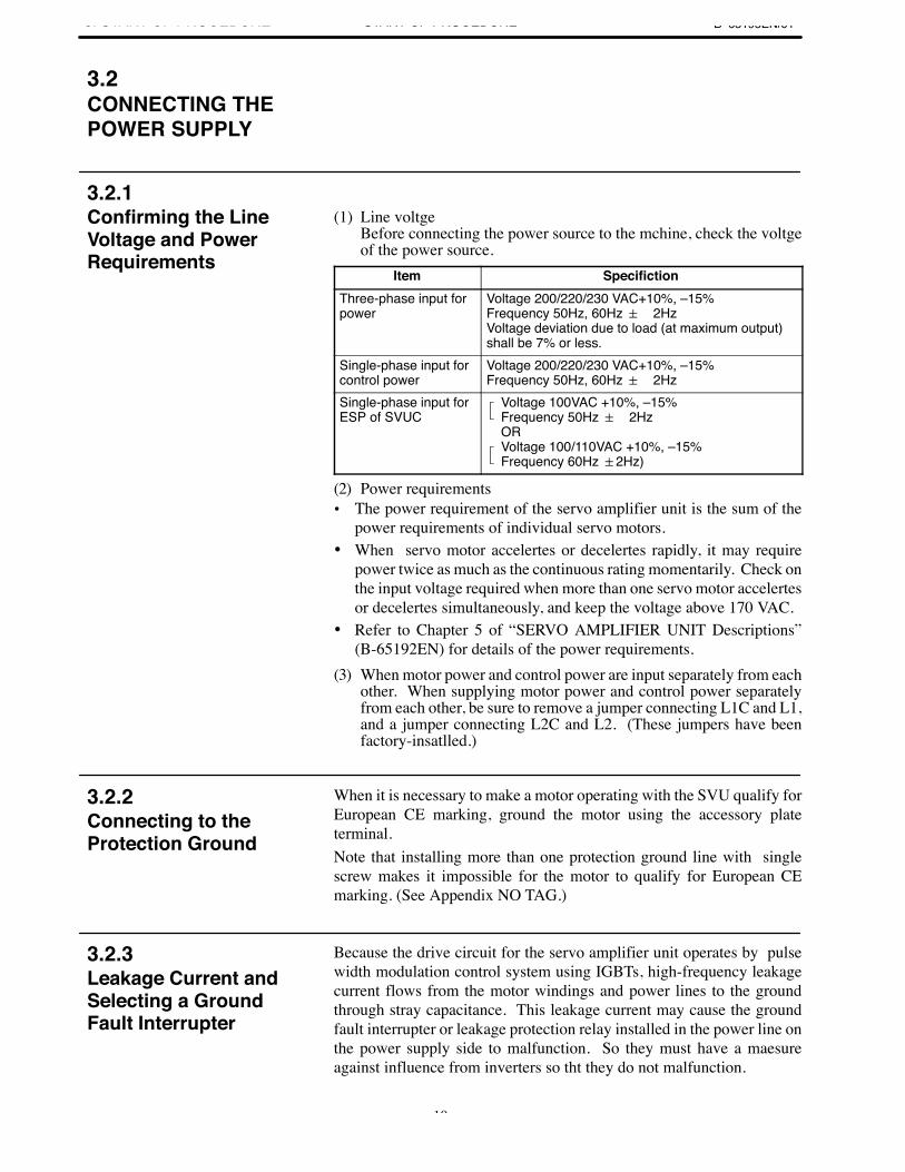
(1) Line voltgeBefore connecting the power source to the mchine, check the voltgeof the power source.
Item SpecifictionThree-phase input forpower
Voltage 200/220/230 VAC+10%, –15%Frequency 50Hz, 60Hz 2HzVoltage deviation due to load (at maximum output)shall be 7% or less.
Single-phase input forcontrol power
Voltage 200/220/230 VAC+10%, –15%Frequency 50Hz, 60Hz 2Hz
Single-phase input forESP of SVUC
Voltage 100VAC +10%, –15%Frequency 50Hz 2HzORVoltage 100/110VAC +10%, –15%Frequency 60Hz 2Hz)
(2) Power requirements• The power requirement of the servo amplifier unit is the sum of the
power requirements of individual servo motors.• When servo motor accelertes or decelertes rapidly, it may require
power twice as much as the continuous rating momentarily. Check onthe input voltage required when more than one servo motor accelertesor decelertes simultaneously, and keep the voltage above 170 VAC.
• Refer to Chapter 5 of “SERVO AMPLIFIER UNIT Descriptions”(B-65192EN) for details of the power requirements.
(3) When motor power and control power are input separately from eachother. When supplying motor power and control power separatelyfrom each other, be sure to remove a jumper connecting L1C and L1,and a jumper connecting L2C and L2. (These jumpers have beenfactory-insatlled.)
When it is necessary to make a motor operating with the SVU qualify forEuropean CE marking, ground the motor using the accessory plateterminal.Note that installing more than one protection ground line with singlescrew makes it impossible for the motor to qualify for European CEmarking. (See Appendix NO TAG.)
Because the drive circuit for the servo amplifier unit operates by pulsewidth modulation control system using IGBTs, high-frequency leakagecurrent flows from the motor windings and power lines to the groundthrough stray capacitance. This leakage current may cause the groundfault interrupter or leakage protection relay installed in the power line onthe power supply side to malfunction. So they must have a maesureagainst influence from inverters so tht they do not malfunction.
3.2CONNECTING THEPOWER SUPPLY
3.2.1Confirming the LineVoltage and PowerRequirements
3.2.2Connecting to theProtection Ground
3.2.3Leakage Current andSelecting a GroundFault Interrupter

B–65195EN/01 3. START-UP PROCEDURESTART-UP PROCEDURE
11
(1) Leakage current from the motorDetermine the leakage current from each motor according to the tablebelow.Motor model Leakage current of commercial
power frequency componentα0.5 to α6 1.8 mAα12 to α22 2.0 mAα30 to α40 2.5 mA
3. START-UP PROCEDURE B–65195EN/01START-UP PROCEDURE
12
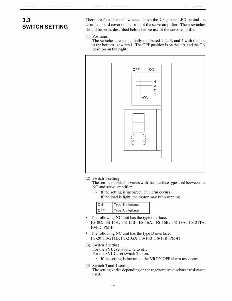
There are four channel switches above the 7-segment LED behind theterminal board cover on the front of the servo amplifier. These switchesshould be set as described below before use of the servo amplifier.(1) Positions
The switches are sequentially numbered 1, 2, 3, and 4 with the oneat the bottom as switch 1. The OFF position is on the left, and the ONposition on the right.
OFF ON
ON
4321
(2) Switch 1 settingThe setting of switch 1 varies with the interface type used between theNC and servo amplifier. If the setting is incorrect, an alarm occurs.
If the load is light, the motor may keep running.
ON Type B interfaceOFF Type A interface
• The following NC unit has the type interface.FS-0C, FS-15A, FS-15B, FS-16A, FS-16B, FS-18A, FS-21TA,PM-D, PM-F
• The following NC unit has the type B interface.FS-20, FS-21TB, FS-21GA, FS-16B, FS-18B, PM-H
(3) Switch 2 settingFor the SVU, set switch 2 to off.For the SVUC, set switch 2 to on. If the setting is incorrect, the VRDY OFF alarm my occur.
(4) Switch 3 and 4 setting The setting varies depending on the regenerative discharge resistanceused.
3.3SWITCH SETTING
B–65195EN/01 3. START-UP PROCEDURESTART-UP PROCEDURE
13
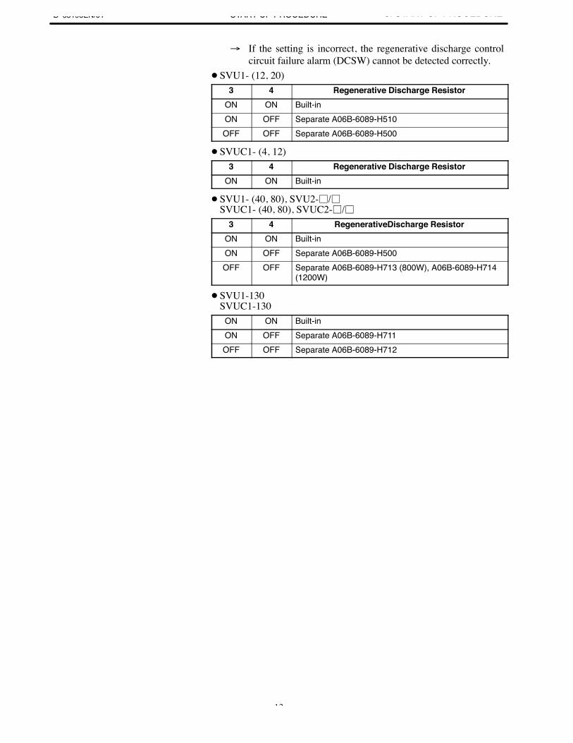
If the setting is incorrect, the regenerative discharge control circuit failure alarm (DCSW) cannot be detected correctly.
SVU1- (12, 20)3 4 Regenerative Discharge Resistor
ON ON Built-inON OFF Separate A06B-6089-H510OFF OFF Separate A06B-6089-H500
SVUC1- (4, 12)3 4 Regenerative Discharge Resistor
ON ON Built-in
SVU1- (40, 80), SVU2-/SVUC1- (40, 80), SVUC2-/
3 4 RegenerativeDischarge ResistorON ON Built-inON OFF Separate A06B-6089-H500OFF OFF Separate A06B-6089-H713 (800W), A06B-6089-H714
(1200W)
SVU1-130SVUC1-130
ON ON Built-inON OFF Separate A06B-6089-H711OFF OFF Separate A06B-6089-H712
3. START-UP PROCEDURE B–65195EN/01START-UP PROCEDURE
14
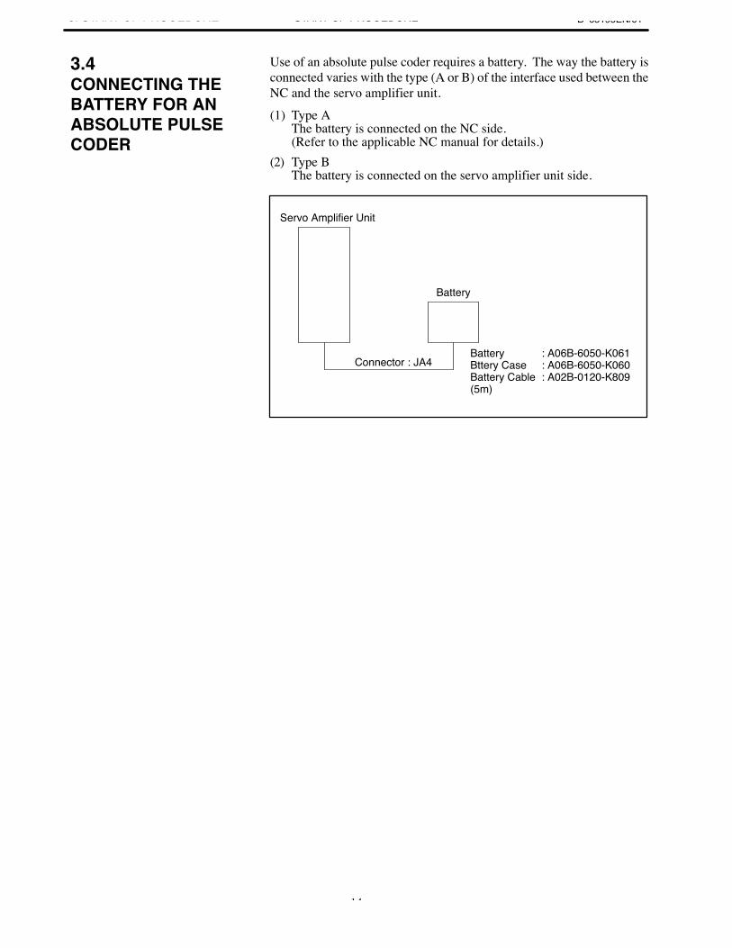
Use of an absolute pulse coder requires a battery. The way the battery isconnected varies with the type (A or B) of the interface used between theNC and the servo amplifier unit.
(1) Type AThe battery is connected on the NC side.(Refer to the applicable NC manual for details.)
(2) Type BThe battery is connected on the servo amplifier unit side.
Servo Amplifier Unit
Battery
Battery : A06B-6050-K061Bttery Case : A06B-6050-K060Battery Cable : A02B-0120-K809(5m)
Connector : JA4
3.4CONNECTING THEBATTERY FOR ANABSOLUTE PULSECODER
B–65195EN/01 3. START-UP PROCEDURESTART-UP PROCEDURE
15
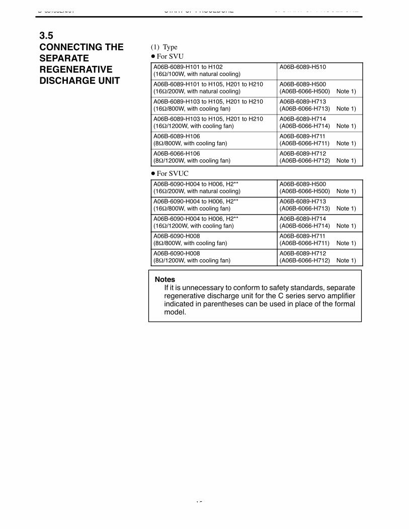
(1) Type For SVUA06B-6089-H101 to H102(16Ω/100W, with natural cooling)
A06B-6089-H510
A06B-6089-H101 to H105, H201 to H210(16Ω/200W, with natural cooling)
A06B-6089-H500(A06B-6066-H500) Note 1)
A06B-6089-H103 to H105, H201 to H210(16Ω/800W, with cooling fan)
A06B-6089-H713(A06B-6066-H713) Note 1)
A06B-6089-H103 to H105, H201 to H210(16Ω/1200W, with cooling fan)
A06B-6089-H714(A06B-6066-H714) Note 1)
A06B-6089-H106(8Ω/800W, with cooling fan)
A06B-6089-H711(A06B-6066-H711) Note 1)
A06B-6066-H106(8Ω/1200W, with cooling fan)
A06B-6089-H712(A06B-6066-H712) Note 1)
For SVUCA06B-6090-H004 to H006, H2**(16Ω/200W, with natural cooling)
A06B-6089-H500(A06B-6066-H500) Note 1)
A06B-6090-H004 to H006, H2**(16Ω/800W, with cooling fan)
A06B-6089-H713(A06B-6066-H713) Note 1)
A06B-6090-H004 to H006, H2**(16Ω/1200W, with cooling fan)
A06B-6089-H714(A06B-6066-H714) Note 1)
A06B-6090-H008(8Ω/800W, with cooling fan)
A06B-6089-H711(A06B-6066-H711) Note 1)
A06B-6090-H008(8Ω/1200W, with cooling fan)
A06B-6089-H712(A06B-6066-H712) Note 1)
NotesIf it is unnecessary to conform to safety standards, separateregenerative discharge unit for the C series servo amplifierindicated in parentheses can be used in place of the formalmodel.
3.5CONNECTING THESEPARATEREGENERATIVEDISCHARGE UNIT
3. START-UP PROCEDURE B–65195EN/01START-UP PROCEDURE
16
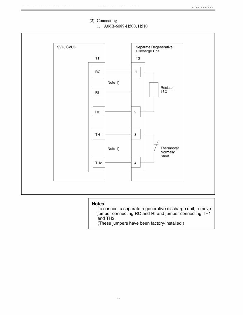
(2) Connecting1. A06B-6089-H500, H510
Note 1)
Note 1)
Resistor 16Ω
Separate RegenerativeDischarge Unit
ThermostatNormally Short
SVU, SVUC
T3
RC 1
RI
RE 2
TH1 3
TH2 4
T1
NotesTo connect a separate regenerative discharge unit, removejumper connecting RC and RI and jumper connecting TH1and TH2.(These jumpers have been factory-installed.)
B–65195EN/01 3. START-UP PROCEDURESTART-UP PROCEDURE
17
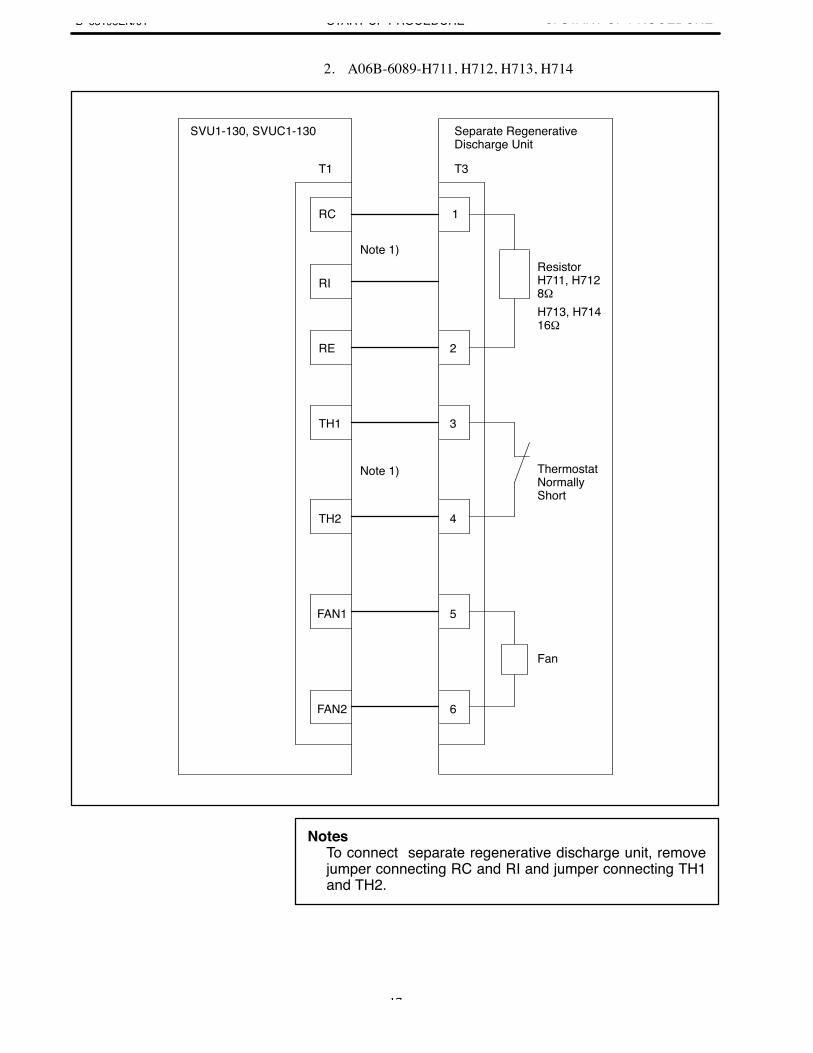
2. A06B-6089-H711, H712, H713, H714
Note 1)
Note 1)
ResistorH711, H7128ΩH713, H71416Ω
Separate RegenerativeDischarge Unit
ThermostatNormally Short
SVU1-130, SVUC1-130
T3
RC 1
RI
RE 2
TH1 3
TH2 4
T1
FAN1 5
FAN2 6
Fan
NotesTo connect separate regenerative discharge unit, removejumper connecting RC and RI and jumper connecting TH1and TH2.
3. START-UP PROCEDURE B–65195EN/01START-UP PROCEDURE
18
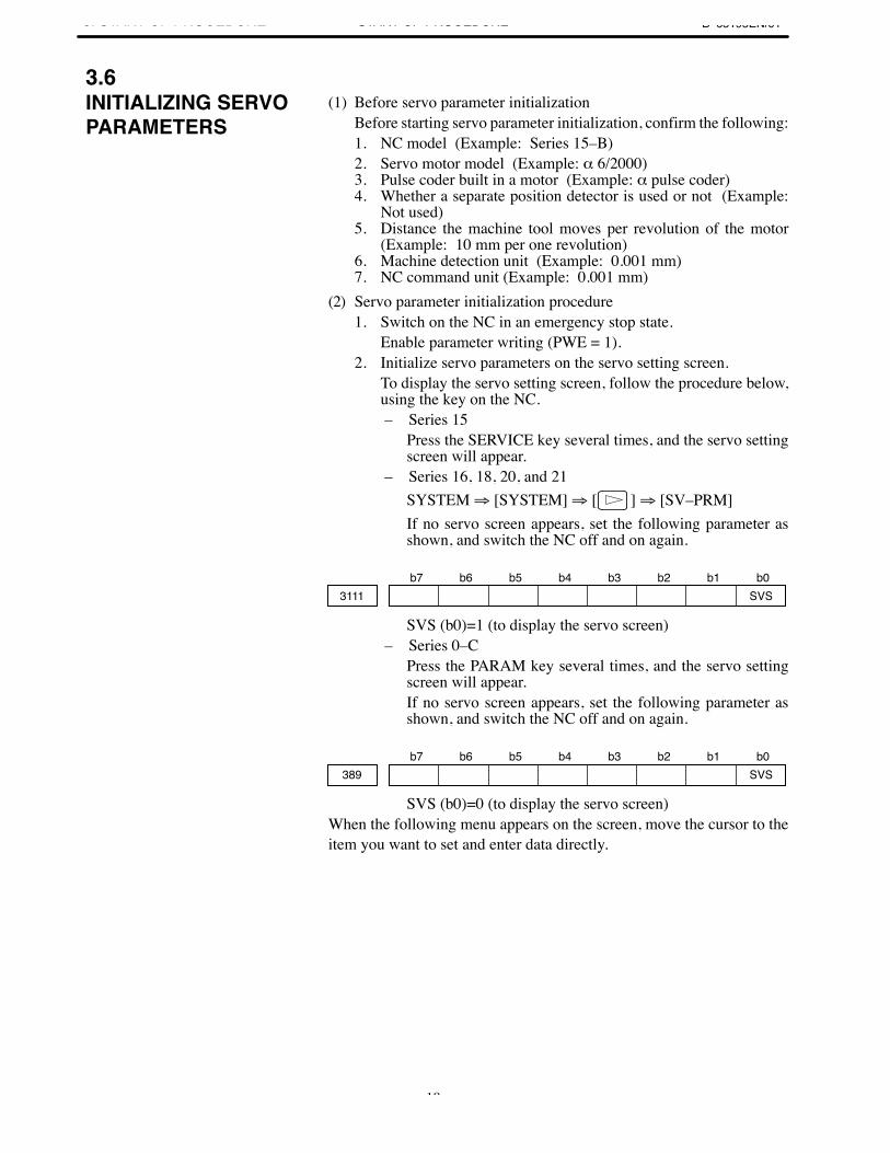
(1) Before servo parameter initializationBefore starting servo parameter initialization, confirm the following:1. NC model (Example: Series 15–B)2. Servo motor model (Example: α 6/2000)3. Pulse coder built in a motor (Example: α pulse coder)4. Whether a separate position detector is used or not (Example:
Not used)5. Distance the machine tool moves per revolution of the motor
(Example: 10 mm per one revolution)6. Machine detection unit (Example: 0.001 mm)7. NC command unit (Example: 0.001 mm)
(2) Servo parameter initialization procedure1. Switch on the NC in an emergency stop state.
Enable parameter writing (PWE = 1).2. Initialize servo parameters on the servo setting screen.
To display the servo setting screen, follow the procedure below,using the key on the NC.– Series 15
Press the SERVICE key several times, and the servo settingscreen will appear.
– Series 16, 18, 20, and 21SYSTEM ⇒ [SYSTEM] ⇒ [ ] ⇒ [SV–PRM]If no servo screen appears, set the following parameter asshown, and switch the NC off and on again.
b7 b6 b5 b4 b3 b2 b1 b03111 SVS
SVS (b0)=1 (to display the servo screen)– Series 0–C
Press the PARAM key several times, and the servo settingscreen will appear.If no servo screen appears, set the following parameter asshown, and switch the NC off and on again.
b7 b6 b5 b4 b3 b2 b1 b0389 SVS
SVS (b0)=0 (to display the servo screen)When the following menu appears on the screen, move the cursor to theitem you want to set and enter data directly.
3.6INITIALIZING SERVOPARAMETERS
B–65195EN/01 3. START-UP PROCEDURESTART-UP PROCEDURE
19
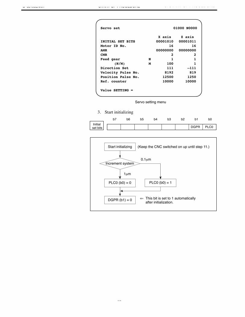
Servo set 01000 N0000
X axis Z axis INITIAL SET BITS 00001010 00001011Motor ID No. 16 16AMR 00000000 00000000CMR 2 2Feed gear N 1 1
(N/M) M 100 1Direction Set 111 –111Velocity Pulse No. 8192 819Position Palse No. 12500 1250Ref. counter 10000 10000
Value SETTING =
Servo setting menu
3. Start initializingb7 b6 b5 b4 b3 b2 b1 b0
DGPR PLC0Initial
set bits
0.1µm
PLC0 (b0) = 0
⇐ This bit is set to 1 automatically after initialization.
Start initializing (Keep the CNC switched on up until step 11.)
Increment system
1µm
PLC0 (b0) = 1
DGPR (b1) = 0
3. START-UP PROCEDURE B–65195EN/01START-UP PROCEDURE
20
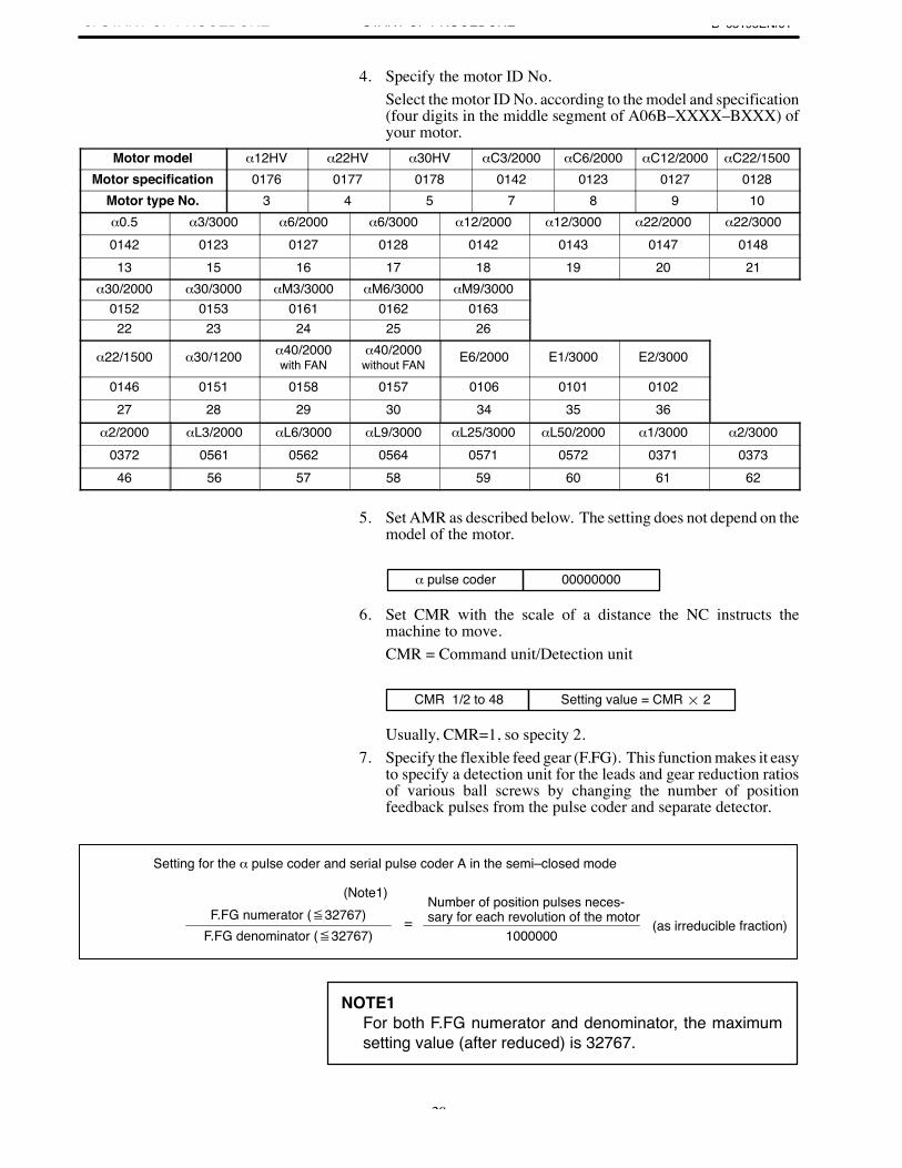
4. Specify the motor ID No.Select the motor ID No. according to the model and specification(four digits in the middle segment of A06B–XXXX–BXXX) ofyour motor.
Motor model α12HV α22HV α30HV αC3/2000 αC6/2000 αC12/2000 αC22/1500Motor specification 0176 0177 0178 0142 0123 0127 0128
Motor type No. 3 4 5 7 8 9 10α0.5 α3/3000 α6/2000 α6/3000 α12/2000 α12/3000 α22/2000 α22/30000142 0123 0127 0128 0142 0143 0147 014813 15 16 17 18 19 20 21
α30/2000 α30/3000 αM3/3000 αM6/3000 αM9/30000152 0153 0161 0162 016322 23 24 25 26
α22/1500 α30/1200 α40/2000with FAN
α40/2000without FAN E6/2000 E1/3000 E2/3000
0146 0151 0158 0157 0106 0101 010227 28 29 30 34 35 36
α2/2000 αL3/2000 αL6/3000 αL9/3000 αL25/3000 αL50/2000 α1/3000 α2/30000372 0561 0562 0564 0571 0572 0371 037346 56 57 58 59 60 61 62
5. Set AMR as described below. The setting does not depend on themodel of the motor.
α pulse coder 00000000
6. Set CMR with the scale of a distance the NC instructs themachine to move.CMR = Command unit/Detection unit
CMR 1/2 to 48 Setting value = CMR 2
Usually, CMR=1, so specity 2.7. Specify the flexible feed gear (F.FG). This function makes it easy
to specify a detection unit for the leads and gear reduction ratiosof various ball screws by changing the number of positionfeedback pulses from the pulse coder and separate detector.
1000000
Number of position pulses neces-sary for each revolution of the motor
Setting for the α pulse coder and serial pulse coder A in the semi–closed mode
=
(Note1)F.FG numerator (32767)
F.FG denominator (32767)(as irreducible fraction)
NOTE1For both F.FG numerator and denominator, the maximumsetting value (after reduced) is 32767.
B–65195EN/01 3. START-UP PROCEDURESTART-UP PROCEDURE
21
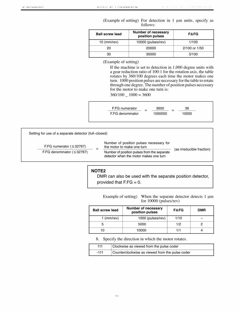
(Example of setting) For detection in 1 µm units, specify asfollows:
Ball screw lead Number of necessaryposition pulses F&FG
10 (mm/rev) 10000 (pulses/rev) 1/10020 20000 2/100 or 1/5030 30000 3/100
(Example of setting)If the machine is set to detection in 1,000 degree units witha gear reduction ratio of 100:1 for the rotation axis, the tablerotates by 360/100 degrees each time the motor makes oneturn. 1000 position pulses are necessary for the table to rotatethrough one degree. The number of position pulses necessaryfor the motor to make one turn is:360/100 _ 1000 = 3600
3600=F.FG numeratorF.FG denominator 1000000
= 3610000
Number of position pulses necessary forthe motor to make one turn
Setting for use of a separate detector (full–closed)
=F.FG numerator (32767)F.FG denominator (32767)
(as irreducible fraction)Number of position pulses from the separatedetector when the motor makes one turn
NOTE2DMR can also be used with the separate position detector,provided that F.FG = 0.
Example of setting) When the separate detector detects 1 µmfor 10000 (pulses/rev)
Ball screw lead Number of necessaryposition pulses F&FG DMR
1 (mm/rev) 1000 (pulses/rev) 1/10 –5 5000 1/2 2
10 10000 1/1 4
8. Specify the direction in which the motor rotates.111 Clockwise as viewed from the pulse coder-111 Counterclockwise as viewed from the pulse coder
3. START-UP PROCEDURE B–65195EN/01START-UP PROCEDURE
22
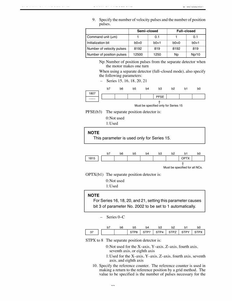
9. Specify the number of velocity pulses and the number of positionpulses.
Semi–closed Full–closedCommand unit (µm) 1 0.1 1 0.1Initialization bit b0=0 b0=1 b0=0 b0=1Number of velocity pulses 8192 819 8192 819Number of position pulses 12500 1250 Np Np/10
Np: Number of position pulses from the separate detector whenthe motor makes one turn
When using a separate detector (full–closed mode), also specifythe following parameters:– Series 15, 16, 18, 20, 21
b7 b6 b5 b4 b3 b2 b1 b01807
PFSE⇑
Must be specified only for Series 15
PFSE(b3) The separate position detector is:0:Not used1:Used
NOTEThis parameter is used only for Series 15.
b7 b6 b5 b4 b3 b2 b1 b01815 OPTX
⇑Must be specified for all NCs.
OPTX(b1) The separate position detector is:0:Not used1:Used
NOTEFor Series 16, 18, 20, and 21, setting this parameter causesbit 3 of parameter No. 2002 to be set to 1 automatically.
– Series 0–C
b7 b6 b5 b4 b3 b2 b1 b037 STP8 STP7 STP4 STPZ STPY STPX
STPX to 8 The separate position detector is:0:Not used for the X–axis, Y–axis, Z–axis, fourth axis,
seventh axis, or eighth axis1:Used for the X–axis, Y–axis, Z–axis, fourth axis, seventh
axis, and eighth axis10. Specify the reference counter. The reference counter is used in
making a return to the reference position by a grid method. Thevalue to be specified is the number of pulses necessary for the
B–65195EN/01 3. START-UP PROCEDURESTART-UP PROCEDURE
23
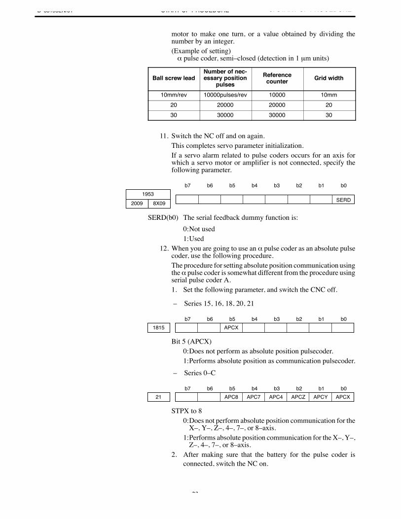
motor to make one turn, or a value obtained by dividing thenumber by an integer.(Example of setting)α pulse coder, semi–closed (detection in 1 µm units)
Ball screw leadNumber of nec-essary position
pulsesReference
counter Grid width
10mm/rev 10000pulses/rev 10000 10mm20 20000 20000 2030 30000 30000 30
11. Switch the NC off and on again.This completes servo parameter initialization.If a servo alarm related to pulse coders occurs for an axis forwhich a servo motor or amplifier is not connected, specify thefollowing parameter.
b7 b6 b5 b4 b3 b2 b1 b01953
8X09 SERD2009
SERD(b0) The serial feedback dummy function is:0:Not used1:Used
12. When you are going to use an α pulse coder as an absolute pulsecoder, use the following procedure.The procedure for setting absolute position communication usingthe α pulse coder is somewhat different from the procedure usingserial pulse coder A.1. Set the following parameter, and switch the CNC off.
– Series 15, 16, 18, 20, 21
b7 b6 b5 b4 b3 b2 b1 b01815 APCX
Bit 5 (APCX)0:Does not perform as absolute position pulsecoder.1:Performs absolute position as communication pulsecoder.
– Series 0–C
b7 b6 b5 b4 b3 b2 b1 b021 APC8 APC7 APC4 APCZ APCY APCX
STPX to 80:Does not perform absolute position communication for the
X–, Y–, Z–, 4–, 7–, or 8–axis.1:Performs absolute position communication for the X–, Y–,
Z–, 4–, 7–, or 8–axis.2. After making sure that the battery for the pulse coder is
connected, switch the NC on.
These steps were added.
⇐
3. START-UP PROCEDURE B–65195EN/01START-UP PROCEDURE
24
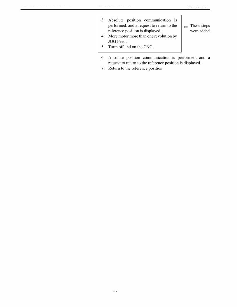
3. Absolute position communication isperformed, and a request to return to thereference position is displayed.
4. More motor more than one revolution byJOG Feed.
5. Turm off and on the CNC.
6. Absolute position communication is performed, and arequest to return to the reference position is displayed.
7. Return to the reference position.

B–65195EN/014. OPERATION CONFIRMATION
METHODSTART-UP PROCEDURE
25
4
4. OPERATION CONFIRMATIONMETHOD B–65195EN/01START-UP PROCEDURE
26
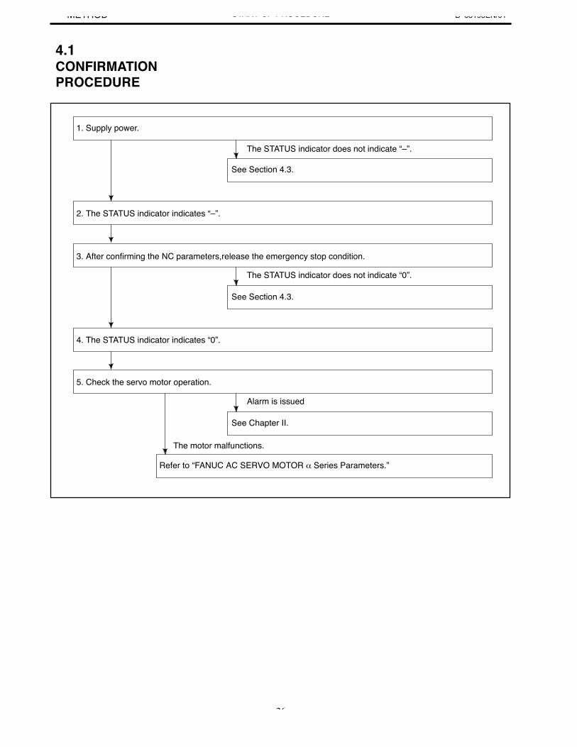
3. After confirming the NC parameters,release the emergency stop condition.
1. Supply power.
See Section 4.3.
2. The STATUS indicator indicates “–”.
The STATUS indicator does not indicate “–”.
The STATUS indicator does not indicate “0”.
See Section 4.3.
4. The STATUS indicator indicates “0”.
5. Check the servo motor operation.
Alarm is issued
See Chapter II.
The motor malfunctions.
Refer to “FANUC AC SERVO MOTOR α Series Parameters.”
4.1CONFIRMATIONPROCEDURE
B–65195EN/014. OPERATION CONFIRMATION
METHODSTART-UP PROCEDURE
27
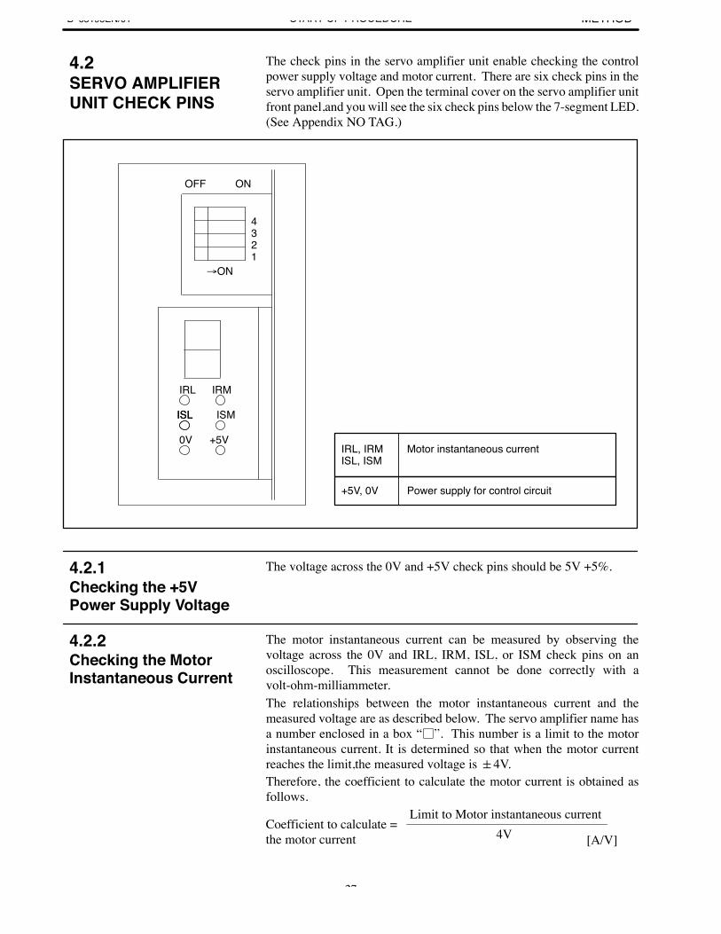
The check pins in the servo amplifier unit enable checking the controlpower supply voltage and motor current. There are six check pins in theservo amplifier unit. Open the terminal cover on the servo amplifier unitfront panel,and you will see the six check pins below the 7-segment LED.(See Appendix NO TAG.)
OFF ON
ON
4321
IRL IRM
ISL ISM
IRL, IRMISL, ISM
Motor instantaneous current
Power supply for control circuit
ISL
0V +5V
+5V, 0V
The voltage across the 0V and +5V check pins should be 5V +5%.
The motor instantaneous current can be measured by observing thevoltage across the 0V and IRL, IRM, ISL, or ISM check pins on anoscilloscope. This measurement cannot be done correctly with avolt-ohm-milliammeter.The relationships between the motor instantaneous current and themeasured voltage are as described below. The servo amplifier name hasa number enclosed in a box “”. This number is a limit to the motorinstantaneous current. It is determined so that when the motor currentreaches the limit,the measured voltage is 4V.Therefore, the coefficient to calculate the motor current is obtained asfollows.
Coefficient to calculate =the motor current
Limit to Motor instantaneous current4V [A/V]
4.2SERVO AMPLIFIERUNIT CHECK PINS
4.2.1Checking the +5VPower Supply Voltage
4.2.2Checking the MotorInstantaneous Current
4. OPERATION CONFIRMATIONMETHOD B–65195EN/01START-UP PROCEDURE
28
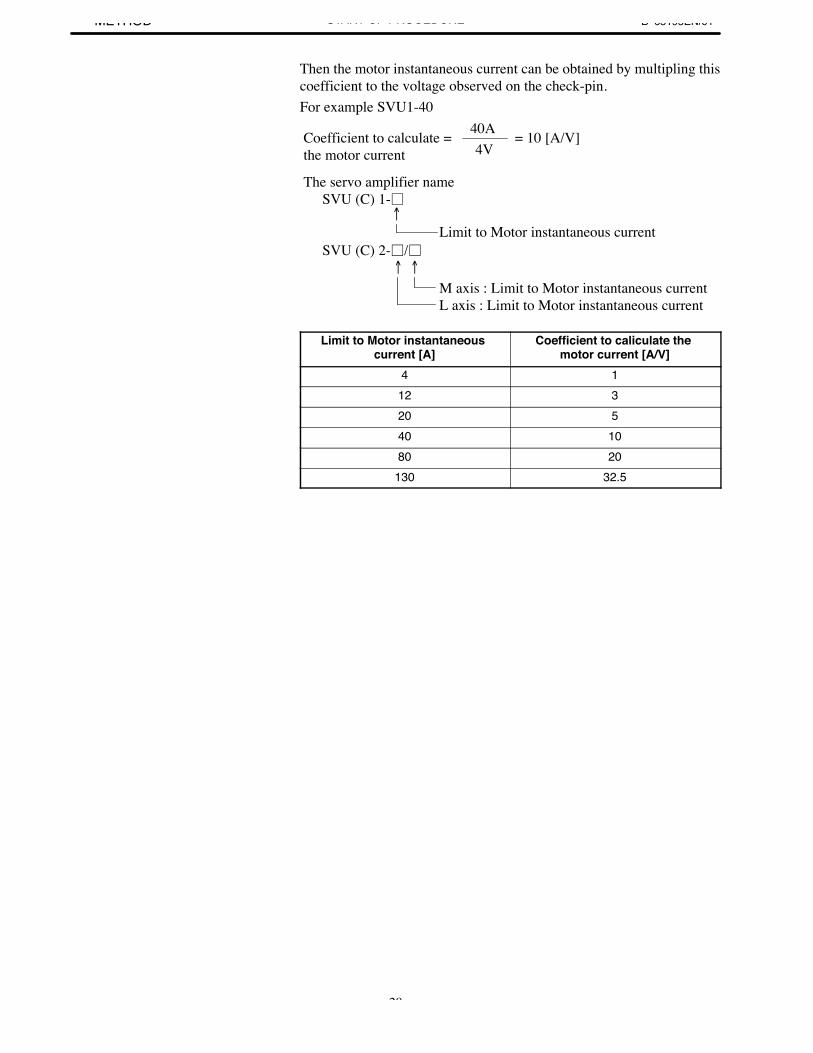
Then the motor instantaneous current can be obtained by multipling thiscoefficient to the voltage observed on the check-pin.For example SVU1-40
Coefficient to calculate =the motor current 4V
40A = 10 [A/V]
The servo amplifier nameSVU (C) 1-
Limit to Motor instantaneous current
SVU (C) 2-/
M axis : Limit to Motor instantaneous currentL axis : Limit to Motor instantaneous current
Limit to Motor instantaneous current [A]
Coefficient to caliculate the motor current [A/V]
4 112 320 540 1080 20
130 32.5
B–65195EN/014. OPERATION CONFIRMATION
METHODSTART-UP PROCEDURE
29
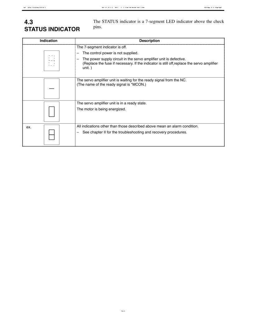
The STATUS indicator is a 7-segment LED indicator above the checkpins.
Indication DescriptionThe 7-segment indicator is off.– The control power is not supplied.– The power supply circuit in the servo amplifier unit is defective.
(Replace the fuse if necessary. If the indicator is still off,replace the servo amplifier unit. )
The servo amplifier unit is waiting for the ready signal from the NC.(The name of the ready signal is *MCON.)
The servo amplifier unit is in a ready state.The motor is being energized.
ex. All indications other than those described above mean an alarm condition.– See chapter II for the troubleshooting and recovery procedures.
4.3STATUS INDICATOR

5. AXIS LEFT UNUSED IN AMULTI-AXIS AMPLIFIER B–65195EN/01START-UP PROCEDURE
30
5 ↵↵ ↵
If an axis is left unused, for example, in a two-axis amplifier, remove thecable between the NC and servo amplifier unit, and insert a dummyconnector,with pins 8 and 10 strapped, into the JV*B (for type Ainterface) or JS*B (for type B interface) connector of that axis.If a dummy connector is inserted, it prevents the motor of thecorresponding axis from being energized. In this state, the dynamic brakeis not applied to the motor, leaving it in a free state. Be careful especiallyabout vertical- axis motors in this situation.
ServoAmplifier
JV*B or JS*B
Dummy Connector with pins 8 and 10 strapped
B–65195EN/01 6. SERVO CHECK BOARDSTART-UP PROCEDURE
31
6 SERVO CHECK BOARD
(1) GeneralThe servo check board receives the digital value used for controlinside the digital servo as numerical data and converts it to an analogform.
(2) Servo check board specificationsSpecification Name
A06B–6057–H602 Servo check board (with a cable having a provision to pre-vent incorrect insertion)
A02B–0120–C211 Servo adaptor board (not required for Series 0–C or 15–A)
(3) Connecting the servo check boardWhen connecting the check board, always keep the NC switched off.If you do not obtain a correct waveform, install strapping on the 5MHz side of clock pin S1 on the check board.
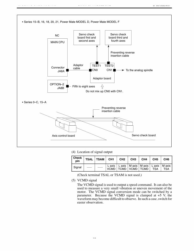
6. SERVO CHECK BOARD B–65195EN/01START-UP PROCEDURE
32
NC
MAIN CPU
ConnectorJA8A
Adaptorcable
Servo checkboard first andsecond axes
Servo checkboard third and
fourth axes
OPTION–2JA8B
Preventing reverseinsertion cable
To the analog spindle
Adaptor board
Fifth to eight axesDo not mix up CN0 with CN1.
Axis control board Servo check board
TEST1 TEST2CN0 CN1
Preventing reverseinsertion cable
Series 15–B, 16, 18, 20, 21, Power Mate MODEL D, Power Mate MODEL F
Series 0–C, 15–A
(4) Location of signal outputCheck
pin TSAL TSAM CH1 CH2 CH3 CH4 CH5 CH6
Signal L axisVCMD
L axisTCMD
M axisVCMD
M axisTCMD
L axisTSA
M axisTSA
(Check terminal TSAL or TSAM is not used.)(5) VCMD signal
The VCMD signal is used to output a speed command. It can also beused to measure a very small vibration or uneven movement of themotor. The VCMD signal conversion mode can be switched by aparameter. Because the VCMD signal is clamped at +5 V, thewaveform may become difficult to observe. In such a case, switch foreasier observation.
B–65195EN/01 6. SERVO CHECK BOARDSTART-UP PROCEDURE
33
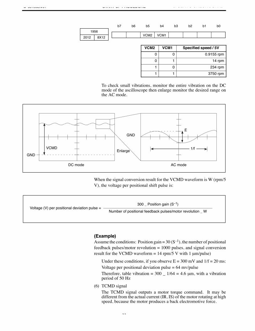
b7 b6 b5 b4 b3 b2 b1 b01956
8X12 VCM2 VCM12012
VCM2 VCM1 Specified speed / 5V0 0 0.9155 rpm0 1 14 rpm1 0 234 rpm1 1 3750 rpm
To check small vibrations, monitor the entire vibration on the DCmode of the ascilloscope then enlarge monitor the desired range onthe AC mode.
GND
DC mode
Enlarge
AC mode
VCMD
GNDE
1/f
When the signal conversion result for the VCMD waveform is W (rpm/5V), the voltage per positional shift pulse is:
Voltage (V) per positional deviation pulse =300 _ Position gain (S–1)
Number of positional feedback pulses/motor revolution _ W
(Example)Assume the conditions: Position gain = 30 (S–1), the number of positionalfeedback pulses/motor revolution = 1000 pulses, and signal conversionresult for the VCMD waveform = 14 rpm/5 V with 1 µm/pulse)
Under these conditions, if you observe E = 300 mV and 1/f = 20 ms:Voltage per positional deviation pulse = 64 mv/pulseTherefore, table vibration = 300 _ 1/64 = 4.6 µm, with a vibrationperiod of 50 Hz
(6) TCMD signalThe TCMD signal outputs a motor torque command. It may bedifferent from the actual current (IR, IS) of the motor rotating at highspeed, because the motor produces a back electromotive force.
6. SERVO CHECK BOARD B–65195EN/01START-UP PROCEDURE
34
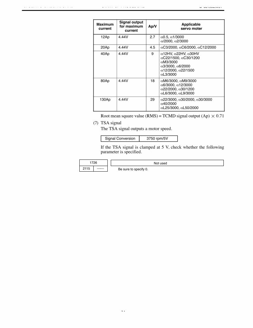
Maximumcurrent
Signal outputfor maximum
currentAp/V Applicable
servo moter
12Ap 4.44V 2.7 α0.5, α1/3000α/2000, α2/3000
20Ap 4.44V 4.5 αC3/2000, αC6/2000, αC12/200040Ap 4.44V 9 α12HV, α22HV, α30HV
αC22/1500, αC30/1200αM3/3000α3/3000, α6/2000α12/2000, α22/1500αL3/3000
80Ap 4.44V 18 αM6/3000, αM9/3000α6/3000, α12/3000α22/2000, α30/1200αL6/3000, αL9/3000
130Ap 4.44V 29 α22/3000, α30/2000, α30/3000α40/2000αL25/3000, αL50/2000
Root mean square value (RMS) = TCMD signal output (Ap) 0.71(7) TSA signal
The TSA signal outputs a motor speed.
Signal Conversion 3750 rpm/5V
If the TSA signal is clamped at 5 V, check whether the followingparameter is specified.
Be sure to specify 0.
1726
Not used2115

II. TROUBLESHOOTING ANDRECOVERY
B–65195EN/01 1. OVERVIEWTROUBLESHOOTING AND RECOVERY
37
1
This part describes troubleshooting and recovery procedures.Each itemshould be carefully followed to find the cause of trouble and takenecessary actions.
First, check the alarm No. (displayed on the CNC) and the STATUSindicator in the servo amplifier unit to find the cause of trouble byreferring to Chapter 2. Second, take appropriate actions according toChapter 3.

2. ALARM NUMBER ANDBRIEF DESCRIPTIONS B–65195EN/01TROUBLESHOOTING AND RECOVERY
38
2 ↵
B–65195EN/012. ALARM NUMBER AND
BRIEF DESCRIPTIONSTROUBLESHOOTING AND RECOVERY
39
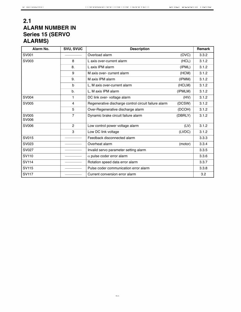
Alarm No. SVU, SVUC Description RemarkSV001 Overload alarm (OVC) 3.3.2SV003 8 L axis over-current alarm (HCL) 3.1.2
8. L axis IPM alarm (IPML) 3.1.29 M axis over- current alarm (HCM) 3.1.29. M axis IPM alarm (IPMM) 3.1.2b L, M axis over-current alarm (HCLM) 3.1.2b. L, M axis IPM alarm (IPMLM) 3.1.2
SV004 1 DC link over- voltage alarm (HV) 3.1.2SV005 4 Regenerative discharge control circuit failure alarm (DCSW) 3.1.2
5 Over-Regenerative discharge alarm (DCOH) 3.1.2SV005SV006
7 Dynamic brake circuit failure alarm (DBRLY) 3.1.2
SV006 2 Low control power voltage alarm (LV) 3.1.23 Low DC link voltage (LVDC) 3.1.2
SV015 Feedback disconnected alarm 3.3.3SV023 Overheat alarm (motor) 3.3.4SV027 Invalid servo parameter setting alarm 3.3.5SV110 α pulse coder error alarm 3.3.6SV114 Rotation speed data error alarm 3.3.7SV115 Pulse coder communication error alarm 3.3.8SV117 Current conversion error alarm 3.2
2.1ALARM NUMBER INSeries 15 (SERVOALARMS)
2. ALARM NUMBER ANDBRIEF DESCRIPTIONS B–65195EN/01TROUBLESHOOTING AND RECOVERY
40
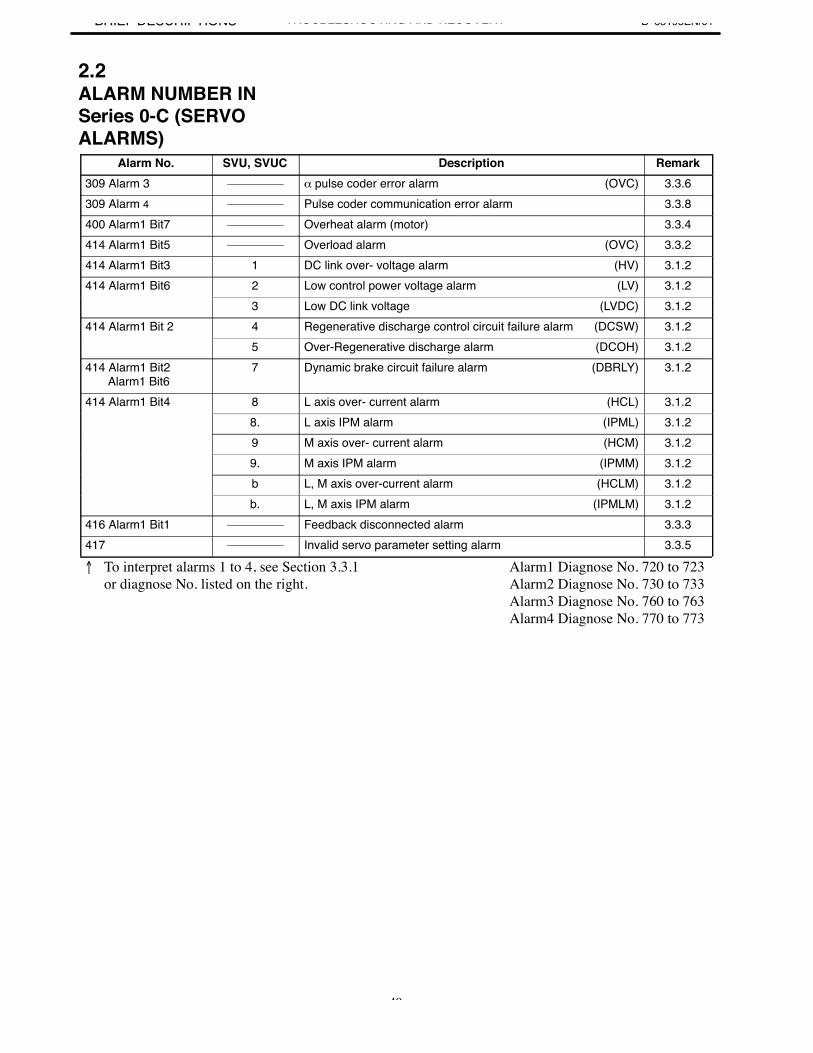
Alarm No. SVU, SVUC Description Remark309 Alarm 3 α pulse coder error alarm (OVC) 3.3.6309 Alarm 4 Pulse coder communication error alarm 3.3.8400 Alarm1 Bit7 Overheat alarm (motor) 3.3.4414 Alarm1 Bit5 Overload alarm (OVC) 3.3.2414 Alarm1 Bit3 1 DC link over- voltage alarm (HV) 3.1.2414 Alarm1 Bit6 2 Low control power voltage alarm (LV) 3.1.2
3 Low DC link voltage (LVDC) 3.1.2414 Alarm1 Bit 2 4 Regenerative discharge control circuit failure alarm (DCSW) 3.1.2
5 Over-Regenerative discharge alarm (DCOH) 3.1.2414 Alarm1 Bit2
Alarm1 Bit67 Dynamic brake circuit failure alarm (DBRLY) 3.1.2
414 Alarm1 Bit4 8 L axis over- current alarm (HCL) 3.1.28. L axis IPM alarm (IPML) 3.1.29 M axis over- current alarm (HCM) 3.1.29. M axis IPM alarm (IPMM) 3.1.2b L, M axis over-current alarm (HCLM) 3.1.2b. L, M axis IPM alarm (IPMLM) 3.1.2
416 Alarm1 Bit1 Feedback disconnected alarm 3.3.3417 Invalid servo parameter setting alarm 3.3.5
To interpret alarms 1 to 4, see Section 3.3.1 or diagnose No. listed on the right.
Alarm1 Diagnose No. 720 to 723Alarm2 Diagnose No. 730 to 733Alarm3 Diagnose No. 760 to 763Alarm4 Diagnose No. 770 to 773
2.2ALARM NUMBER INSeries 0-C (SERVOALARMS)
B–65195EN/012. ALARM NUMBER AND
BRIEF DESCRIPTIONSTROUBLESHOOTING AND RECOVERY
41
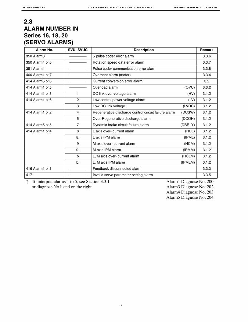
Alarm No. SVU, SVUC Description Remark350 Alarm3 α pulse coder error alarm 3.3.6350 Alarm4 bit6 Rotation speed data error alarm 3.3.7351 Alarm4 Pulse coder communication error alarm 3.3.8400 Alarm1 bit7 Overheat alarm (motor) 3.3.4414 Alarm5 bit6 Current conversion error alarm 3.2414 Alarm1 bit5 Overload alarm (OVC) 3.3.2414 Alarm1 bit3 1 DC link over-voltage alarm (HV) 3.1.2414 Alarm1 bit6 2 Low control power voltage alarm (LV) 3.1.2
3 Low DC link voltage (LVDC) 3.1.2414 Alarm1 bit2 4 Regenerative discharge control circuit failure alarm (DCSW) 3.1.2
5 Over-Regenerative discharge alarm (DCOH) 3.1.2414 Alarm5 bit5 7 Dynamic brake circuit failure alarm (DBRLY) 3.1.2414 Alarm1 bit4 8 L axis over- current alarm (HCL) 3.1.2
8. L axis IPM alarm (IPML) 3.1.29 M axis over- current alarm (HCM) 3.1.29. M axis IPM alarm (IPMM) 3.1.2b L, M axis over- current alarm (HCLM) 3.1.2b. L, M axis IPM alarm (IPMLM) 3.1.2
416 Alarm1 bit1 Feedback disconnected alarm 3.3.3417 Invalid servo parameter setting alarm 3.3.5
To interpret alarms 1 to 5, see Section 3.3.1 or diagnose No.listed on the right.
Alarm1 Diagnose No. 200Alarm3 Diagnose No. 202Alarm4 Diagnose No. 203Alarm5 Diagnose No. 204
2.3ALARM NUMBER INSeries 16, 18, 20(SERVO ALARMS)

3. TROUBLESHOOTING ANDRECOVERY PROCEDURES B–65195EN/01TROUBLESHOOTING AND RECOVERY
42
3 ↵ ↵
B–65195EN/013. TROUBLESHOOTING AND
RECOVERY PROCEDURESTROUBLESHOOTING AND RECOVERY
43
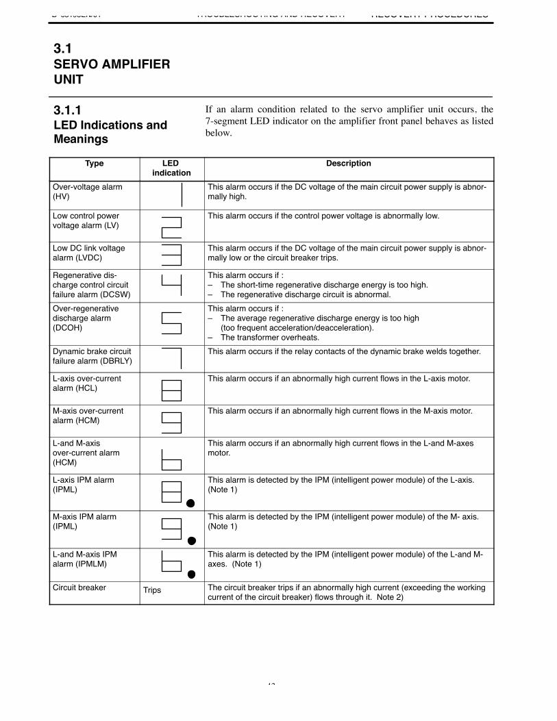
If an alarm condition related to the servo amplifier unit occurs, the7-segment LED indicator on the amplifier front panel behaves as listedbelow.
Type LED indication
Description
Over-voltage alarm(HV)
This alarm occurs if the DC voltage of the main circuit power supply is abnor-mally high.
Low control powervoltage alarm (LV)
This alarm occurs if the control power voltage is abnormally low.
Low DC link voltagealarm (LVDC)
This alarm occurs if the DC voltage of the main circuit power supply is abnor-mally low or the circuit breaker trips.
Regenerative dis-charge control circuitfailure alarm (DCSW)
This alarm occurs if : – The short-time regenerative discharge energy is too high.– The regenerative discharge circuit is abnormal.
Over-regenerative discharge alarm(DCOH)
This alarm occurs if : – The average regenerative discharge energy is too high
(too frequent acceleration/deacceleration).– The transformer overheats.
Dynamic brake circuitfailure alarm (DBRLY)
This alarm occurs if the relay contacts of the dynamic brake welds together.
L-axis over-currentalarm (HCL)
This alarm occurs if an abnormally high current flows in the L-axis motor.
M-axis over-currentalarm (HCM)
This alarm occurs if an abnormally high current flows in the M-axis motor.
L-and M-axis over-current alarm(HCM)
This alarm occurs if an abnormally high current flows in the L-and M-axesmotor.
L-axis IPM alarm(IPML)
This alarm is detected by the IPM (intelligent power module) of the L-axis.(Note 1)
M-axis IPM alarm(IPML)
This alarm is detected by the IPM (intelligent power module) of the M- axis.(Note 1)
L-and M-axis IPMalarm (IPMLM)
This alarm is detected by the IPM (intelligent power module) of the L-and M-axes. (Note 1)
Circuit breaker Trips The circuit breaker trips if an abnormally high current (exceeding the workingcurrent of the circuit breaker) flows through it. Note 2)
3.1SERVO AMPLIFIERUNIT
3.1.1LED Indications andMeanings
3. TROUBLESHOOTING ANDRECOVERY PROCEDURES B–65195EN/01TROUBLESHOOTING AND RECOVERY
44
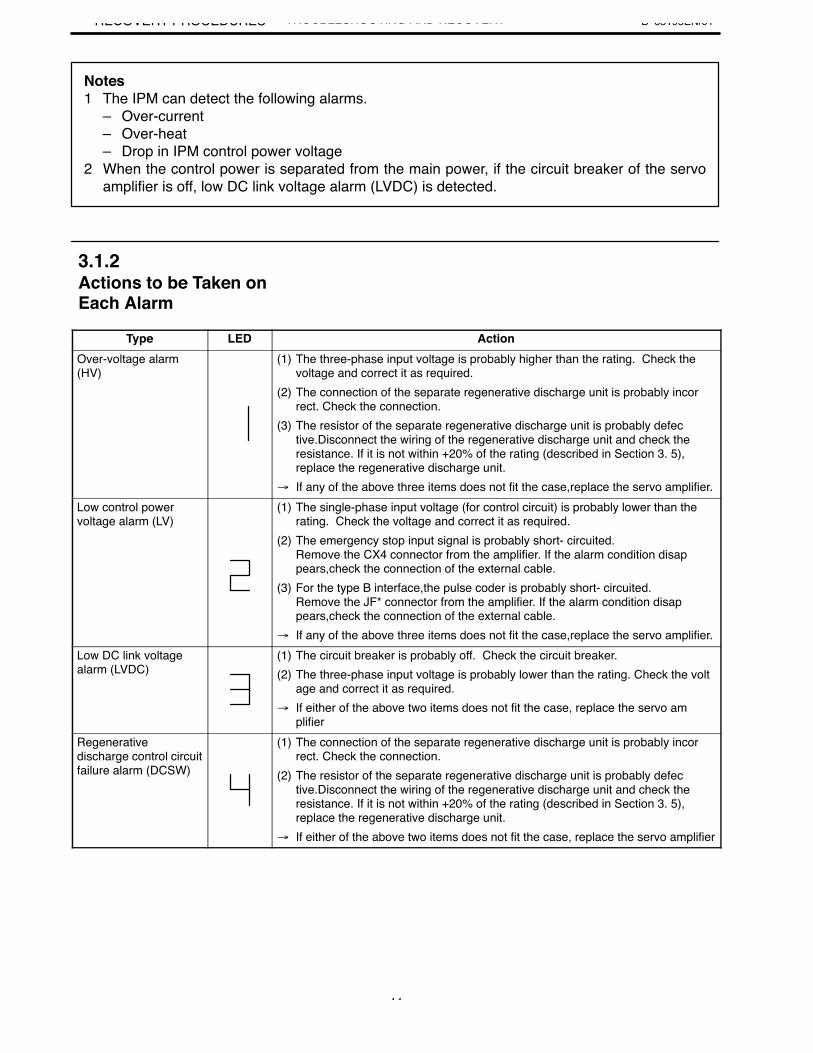
Notes1 The IPM can detect the following alarms.
– Over-current – Over-heat– Drop in IPM control power voltage
2 When the control power is separated from the main power, if the circuit breaker of the servoamplifier is off, low DC link voltage alarm (LVDC) is detected.
Type LED ActionOver-voltage alarm (HV)
(1) The three-phase input voltage is probably higher than the rating. Check the voltage and correct it as required.
(2) The connection of the separate regenerative discharge unit is probably incorrect. Check the connection.
(3) The resistor of the separate regenerative discharge unit is probably defective.Disconnect the wiring of the regenerative discharge unit and check the resistance. If it is not within +20% of the rating (described in Section 3. 5), replace the regenerative discharge unit.
If any of the above three items does not fit the case,replace the servo amplifier.Low control power voltage alarm (LV)
(1) The single-phase input voltage (for control circuit) is probably lower than the rating. Check the voltage and correct it as required.
(2) The emergency stop input signal is probably short- circuited. Remove the CX4 connector from the amplifier. If the alarm condition disappears,check the connection of the external cable.
(3) For the type B interface,the pulse coder is probably short- circuited. Remove the JF* connector from the amplifier. If the alarm condition disappears,check the connection of the external cable.
If any of the above three items does not fit the case,replace the servo amplifier.Low DC link voltagealarm (LVDC)
(1) The circuit breaker is probably off. Check the circuit breaker.(2) The three-phase input voltage is probably lower than the rating. Check the volt
age and correct it as required. If either of the above two items does not fit the case, replace the servo am
plifierRegenerative discharge control circuitfailure alarm (DCSW)
(1) The connection of the separate regenerative discharge unit is probably incorrect. Check the connection.
(2) The resistor of the separate regenerative discharge unit is probably defective.Disconnect the wiring of the regenerative discharge unit and check the resistance. If it is not within +20% of the rating (described in Section 3. 5), replace the regenerative discharge unit.
If either of the above two items does not fit the case, replace the servo amplifier
3.1.2Actions to be Taken onEach Alarm
B–65195EN/013. TROUBLESHOOTING AND
RECOVERY PROCEDURESTROUBLESHOOTING AND RECOVERY
45
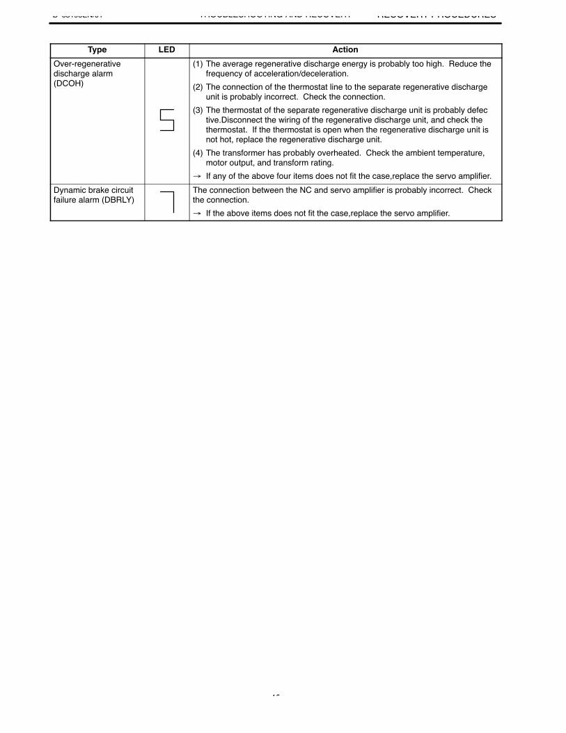
Type LED ActionOver-regenerative discharge alarm (DCOH)
(1) The average regenerative discharge energy is probably too high. Reduce the frequency of acceleration/deceleration.
(2) The connection of the thermostat line to the separate regenerative discharge unit is probably incorrect. Check the connection.
(3) The thermostat of the separate regenerative discharge unit is probably defective.Disconnect the wiring of the regenerative discharge unit, and check the thermostat. If the thermostat is open when the regenerative discharge unit is not hot, replace the regenerative discharge unit.
(4) The transformer has probably overheated. Check the ambient temperature, motor output, and transform rating.
If any of the above four items does not fit the case,replace the servo amplifier.Dynamic brake circuitfailure alarm (DBRLY)
The connection between the NC and servo amplifier is probably incorrect. Checkthe connection. If the above items does not fit the case,replace the servo amplifier.
3. TROUBLESHOOTING ANDRECOVERY PROCEDURES B–65195EN/01TROUBLESHOOTING AND RECOVERY
46
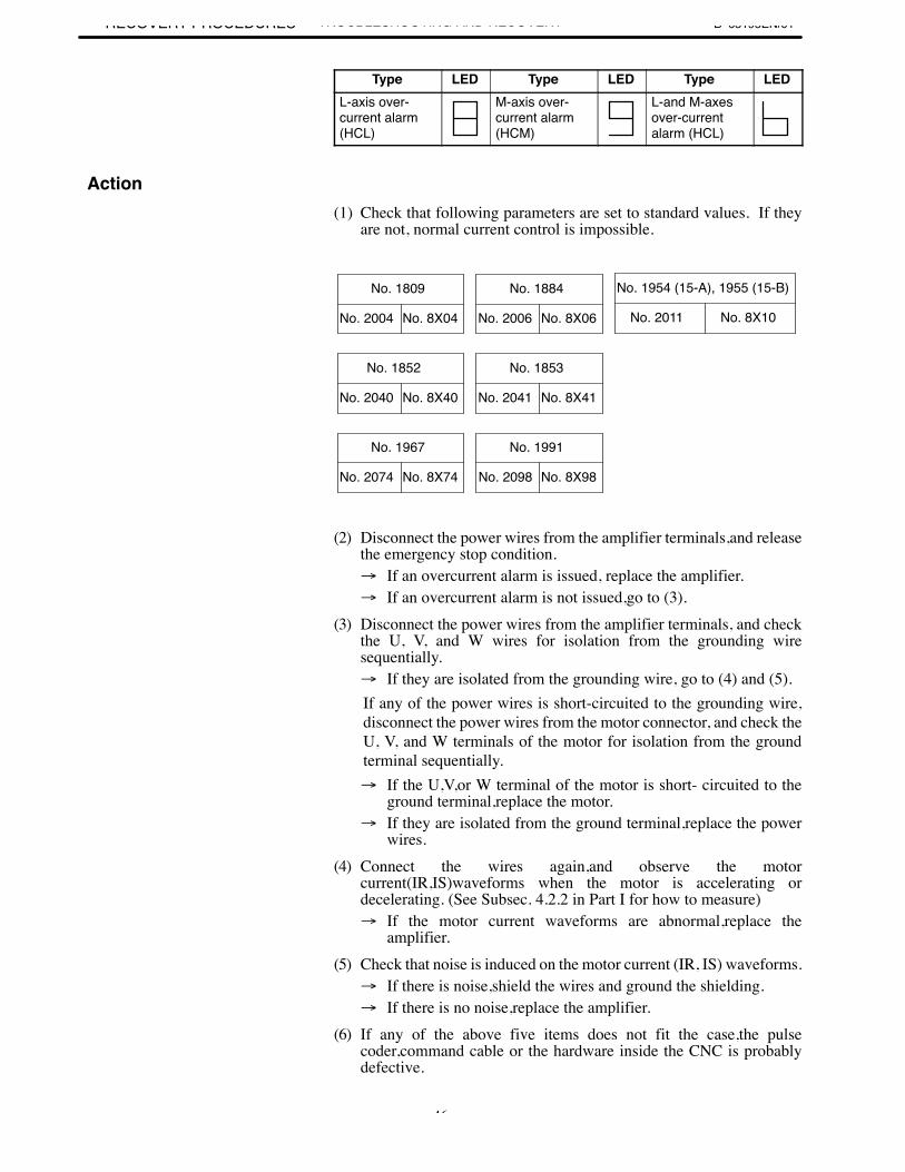
Type LED Type LED Type LEDL-axis over-current alarm(HCL)
M-axis over-current alarm(HCM)
L-and M-axesover-currentalarm (HCL)
(1) Check that following parameters are set to standard values. If theyare not, normal current control is impossible.
No. 1809
No. 2004 No. 8X04
No. 1884
No. 2006 No. 8X06
No. 1954 (15-A), 1955 (15-B)
No. 2011 No. 8X10
No. 1852
No. 2040 No. 8X40
No. 1853
No. 2041 No. 8X41
No. 1967
No. 2074 No. 8X74
No. 1991
No. 8X98No. 2098
(2) Disconnect the power wires from the amplifier terminals,and releasethe emergency stop condition. If an overcurrent alarm is issued, replace the amplifier. If an overcurrent alarm is not issued,go to (3).
(3) Disconnect the power wires from the amplifier terminals, and checkthe U, V, and W wires for isolation from the grounding wiresequentially. If they are isolated from the grounding wire, go to (4) and (5).If any of the power wires is short-circuited to the grounding wire,disconnect the power wires from the motor connector, and check theU, V, and W terminals of the motor for isolation from the groundterminal sequentially. If the U,V,or W terminal of the motor is short- circuited to the
ground terminal,replace the motor. If they are isolated from the ground terminal,replace the power
wires.(4) Connect the wires again,and observe the motor
current(IR,IS)waveforms when the motor is accelerating ordecelerating. (See Subsec. 4.2.2 in Part I for how to measure) If the motor current waveforms are abnormal,replace the
amplifier.(5) Check that noise is induced on the motor current (IR, IS) waveforms. If there is noise,shield the wires and ground the shielding. If there is no noise,replace the amplifier.
(6) If any of the above five items does not fit the case,the pulsecoder,command cable or the hardware inside the CNC is probablydefective.
Action
B–65195EN/013. TROUBLESHOOTING AND
RECOVERY PROCEDURESTROUBLESHOOTING AND RECOVERY
47
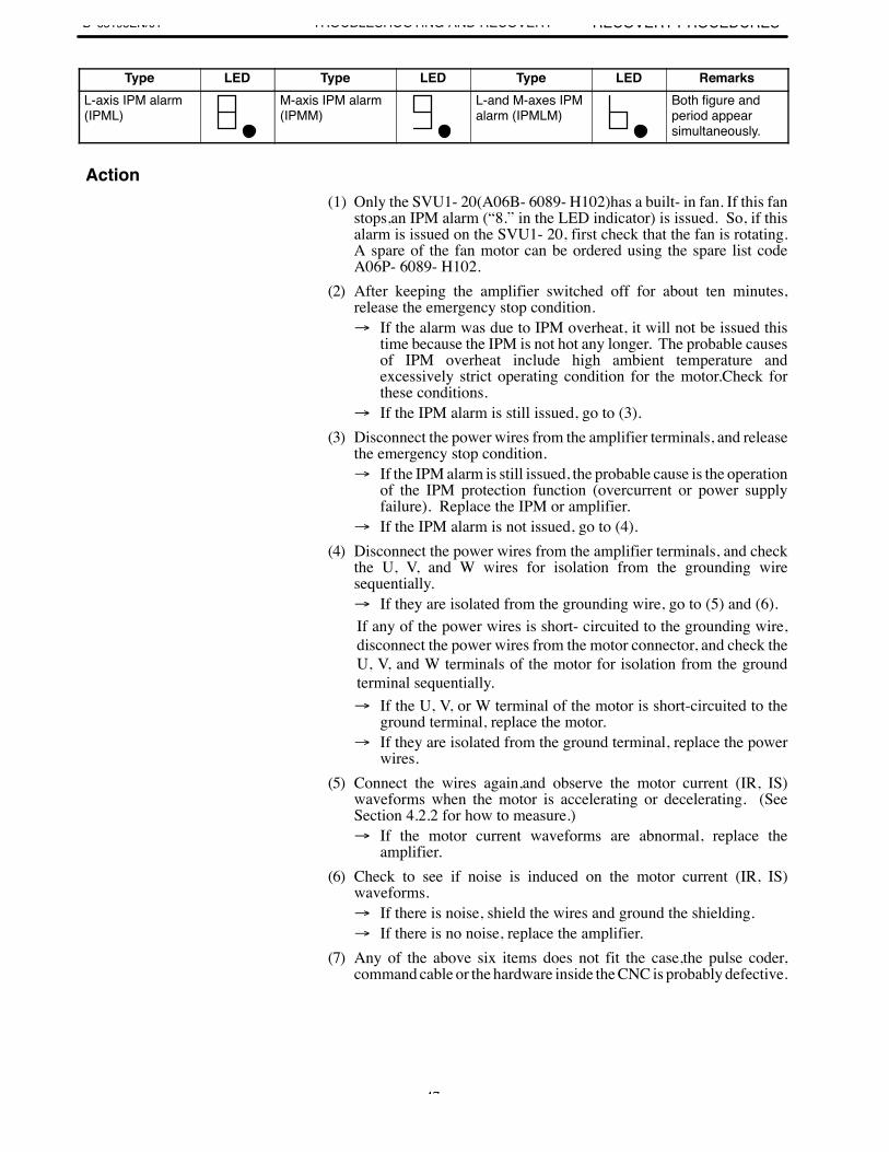
Type LED Type LED Type LED RemarksL-axis IPM alarm(IPML)
M-axis IPM alarm(IPMM)
L-and M-axes IPMalarm (IPMLM)
Both figure andperiod appear simultaneously.
(1) Only the SVU1- 20(A06B- 6089- H102)has a built- in fan. If this fanstops,an IPM alarm (“8.” in the LED indicator) is issued. So, if thisalarm is issued on the SVU1- 20, first check that the fan is rotating.A spare of the fan motor can be ordered using the spare list codeA06P- 6089- H102.
(2) After keeping the amplifier switched off for about ten minutes,release the emergency stop condition. If the alarm was due to IPM overheat, it will not be issued this
time because the IPM is not hot any longer. The probable causesof IPM overheat include high ambient temperature andexcessively strict operating condition for the motor.Check forthese conditions.
If the IPM alarm is still issued, go to (3).(3) Disconnect the power wires from the amplifier terminals, and release
the emergency stop condition. If the IPM alarm is still issued, the probable cause is the operation
of the IPM protection function (overcurrent or power supplyfailure). Replace the IPM or amplifier.
If the IPM alarm is not issued, go to (4).(4) Disconnect the power wires from the amplifier terminals, and check
the U, V, and W wires for isolation from the grounding wiresequentially. If they are isolated from the grounding wire, go to (5) and (6).If any of the power wires is short- circuited to the grounding wire,disconnect the power wires from the motor connector, and check theU, V, and W terminals of the motor for isolation from the groundterminal sequentially. If the U, V, or W terminal of the motor is short-circuited to the
ground terminal, replace the motor. If they are isolated from the ground terminal, replace the power
wires.(5) Connect the wires again,and observe the motor current (IR, IS)
waveforms when the motor is accelerating or decelerating. (SeeSection 4.2.2 for how to measure.) If the motor current waveforms are abnormal, replace the
amplifier.(6) Check to see if noise is induced on the motor current (IR, IS)
waveforms. If there is noise, shield the wires and ground the shielding. If there is no noise, replace the amplifier.
(7) Any of the above six items does not fit the case,the pulse coder,command cable or the hardware inside the CNC is probably defective.
Action
3. TROUBLESHOOTING ANDRECOVERY PROCEDURES B–65195EN/01TROUBLESHOOTING AND RECOVERY
48
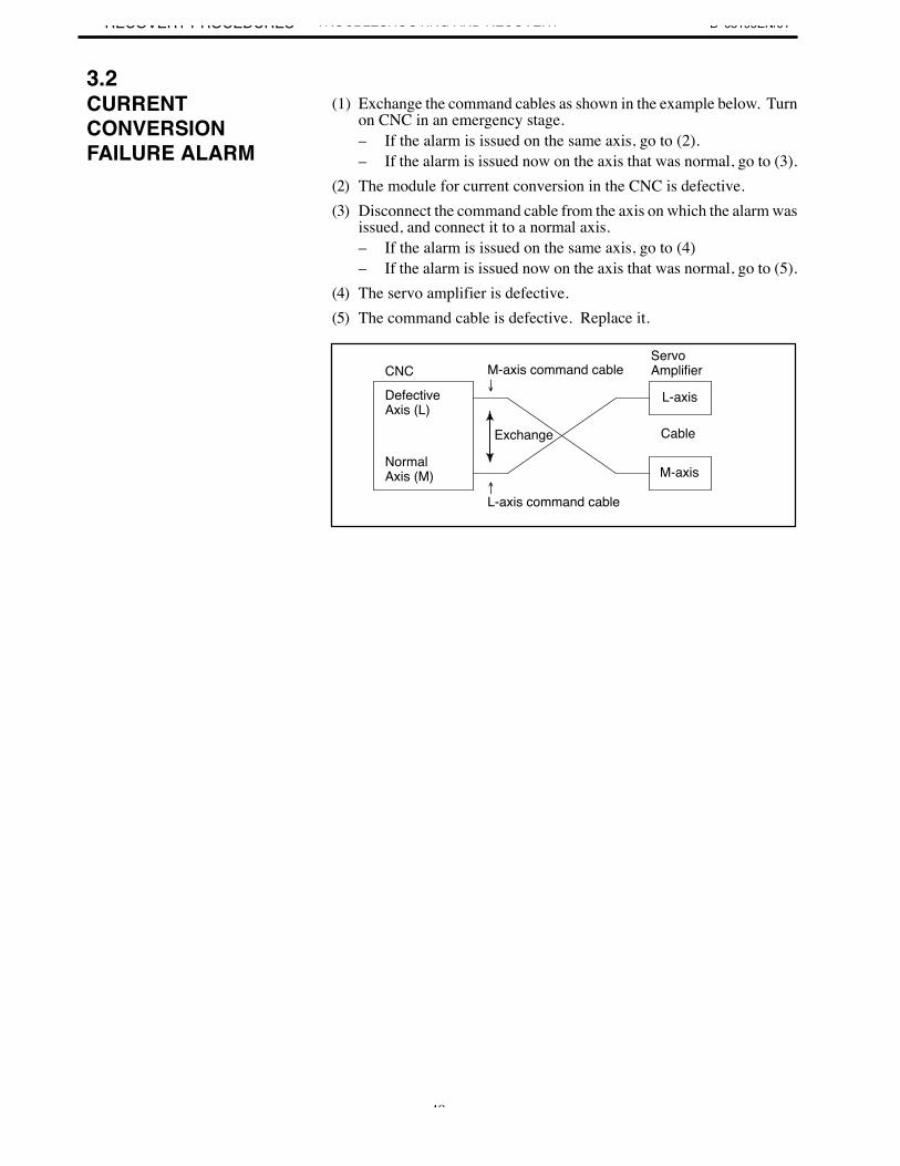
(1) Exchange the command cables as shown in the example below. Turnon CNC in an emergency stage.– If the alarm is issued on the same axis, go to (2).– If the alarm is issued now on the axis that was normal, go to (3).
(2) The module for current conversion in the CNC is defective.(3) Disconnect the command cable from the axis on which the alarm was
issued, and connect it to a normal axis.– If the alarm is issued on the same axis, go to (4)– If the alarm is issued now on the axis that was normal, go to (5).
(4) The servo amplifier is defective.(5) The command cable is defective. Replace it.
DefectiveAxis (L)
NormalAxis (M)
ServoAmplifierM-axis command cable
CableExchange
L-axis
M-axisL-axis command cable
CNC
3.2CURRENTCONVERSIONFAILURE ALARM
B–65195EN/013. TROUBLESHOOTING AND
RECOVERY PROCEDURESTROUBLESHOOTING AND RECOVERY
49
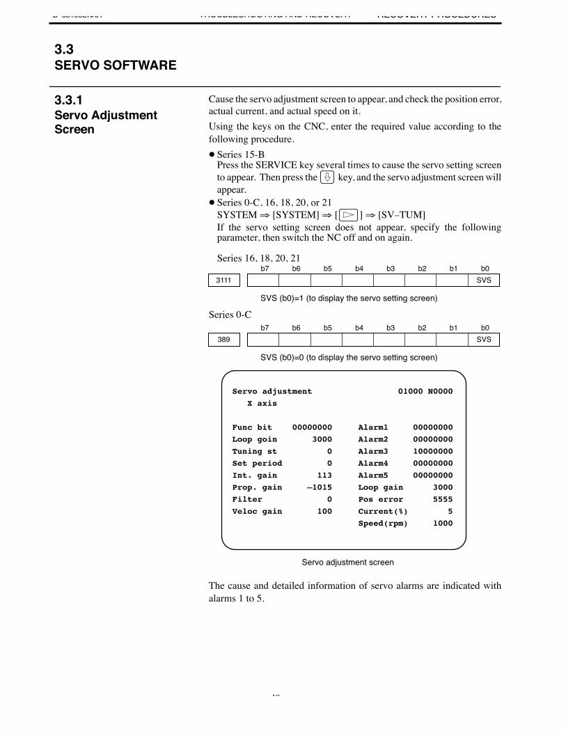
Cause the servo adjustment screen to appear, and check the position error,actual current, and actual speed on it.Using the keys on the CNC, enter the required value according to thefollowing procedure. Series 15-B
Press the SERVICE key several times to cause the servo setting screento appear. Then press the key, and the servo adjustment screen willappear.
Series 0-C, 16, 18, 20, or 21SYSTEM ⇒ [SYSTEM] ⇒ [ ] ⇒ [SV–TUM]If the servo setting screen does not appear, specify the followingparameter, then switch the NC off and on again.
Series 16, 18, 20, 21b7 b6 b5 b4 b3 b2 b1 b0
3111 SVS
SVS (b0)=1 (to display the servo setting screen)
Series 0-Cb7 b6 b5 b4 b3 b2 b1 b0
389 SVS
SVS (b0)=0 (to display the servo setting screen)
Servo adjustment 01000 N0000
X axis
Func bit 00000000 Alarm1 00000000
Loop goin 3000 Alarm2 00000000
Tuning st 0 Alarm3 10000000
Set period 0 Alarm4 00000000
Int. gain 113 Alarm5 00000000
Prop. gain –1015 Loop gain 3000
Filter 0 Pos error 5555
Veloc gain 100 Current(%) 5
Speed(rpm) 1000
Servo adjustment screen
The cause and detailed information of servo alarms are indicated withalarms 1 to 5.
3.3SERVO SOFTWARE
3.3.1Servo AdjustmentScreen
3. TROUBLESHOOTING ANDRECOVERY PROCEDURES B–65195EN/01TROUBLESHOOTING AND RECOVERY
50
(1) Make sure that the motor is not vibrating.⇒ If a motor vibrates, the current flowing in it becomes more than
necessary, resulting in an alarm.(2) Make sure that the power line to the motor is connected correctly.
⇒ If the connection is incorrect, an abnormal current flows in the motor, resulting in an alarm.
(3) Make sure that the following parameters are set correctly.⇒ An overload alarm is issued based on the result of calculation of
these parameters. Be sure to set them to the standard values.
8X62
1877 Overload protection coefficient (OVC1)2062
8X63
1878 Overload protection coefficient (OVC2)2063
8X65
1893 Overload protection coefficient (OVCLMT)2065
(4) Attach the check board (A06B–6071–K290) to connector JX5 tomeasure the waveform of the actual current (IR and IS) of the servoamplifier module. Start the motor and measure the actual current (IRand IS).⇒ If the actual current exceeds 1.4 times the rated current, the constant
for the acceleration/deceleration duration is too small,or the load onthe machine is too heavy for the capacity of the motor.
⇒ If the actual current exceeds 1.4 times the rated current during normal operation, the load on the machine is too heavy for the capacity of the motor.
This alarm is detailed with alarms 1 and 2 on the servo adjustment screen(⇒ 3.3.1).
Alarm1Alarm details
Alarm2b7 b2
Alarm detailsb7 b4
0 1 CM alarm (α pulse coder) 1 10 1 Pulse coder disconnected (soft ware) 0 00 1 Separate pulse coder disconnected (hard ware) 1 1
For the CM alarm, go to 3.3.7.For software disconnected, go to (1).For hardware disconnected, go to (3).
(1) For a full–closed Series 0–C system, make sure that the phase Csignal is not connected to full–closed feedback pins 10 to 13. Whenthe connection is correct, or when the system is not a Series 0–C, goto (2).
(2) If there is a large backlash; or if the number of position feedbackpulses divided by the motor one–rotation signal is equal to or less than640, and a software disconnected alarm is detected when it shouldnot, change the alarm level.
3.3.2Overload Alarm
3.3.3FeedbackDisconnected Alarm
B–65195EN/013. TROUBLESHOOTING AND
RECOVERY PROCEDURESTROUBLESHOOTING AND RECOVERY
51
b7 b6 b5 b4 b3 b2 b1 b01808
8X03 TGAL
TGAL (b1)=1 (the software disconnected alarm level is changed.)
2003
8X64
1892Software disconnected alarm levelStandard value: 4 ⇒ The setting is increased by 4.
2064
(3) If the alarm is a separate detector hardware disconnected alarm, checkthe specification and wiring of the separate detector.
(1) Check whether the motor has overheated; it is dangerous to touchthe motor by the hand or any other part of you body. If the motoris overheated, use it less frequently.
(2) When the motor is cooled enough, check whether an overheat alarmoccurs.⇒ If it occurs, the thermostat is defective.⇒ If not, use the motor less frequently.
The following table contains actions to be taken for invalid servoparameter setting alarms.Find the relevant guideline under ”Decision criterion,” and proceed to thecorresponding ”Adjustment item.”
Alarm Decision criterion Adjustmentitem
POA1 overflow Try resetting POA1 to 0.Parameter: No. 8X47–1859–2047–1047 = 0 Adjustment1
1 pulse suppression level overflow Disable the pulse suppression function.Function bit: No. 8X03–1808–2003–1003,B4 = 0 Adjustment2
Feed–forward coefficient overflowReset the feed–forward coefficient to 0.Parameter: No. 8X68–1961–2068 = 0Parameter: No. 8X92–1985–2092 (advance) = 0
Adjustment3
Position gain overflow Reset the position gain to 0.Parameter: No. 517–1825–1825 = 0 Adjustment4
Number of position pulses overflowThe number of position pulses is greater than 13100 (No. 8X00–1804–2000, bit 0 = 1).Parameter: No. 8X00–1804–2000, B0
Adjustment5
Motor ID No. Check whether the motor ID No. is correct.Parameter: No. 8X20–1874–2020 Adjustment6
Invalid axis selection parameter settingCheck whether the setting is correct.Series 0–C: No. 269 to 274Series 15, 16: No. 1023
Others
Number of position pulses 0Number of velocity pulses 0Direction of travel = 0Feed gear numerator 0, denominator 0Numerator > denominator(Serial A, α and semi-closed mode)
3.3.4Motor Overheat Alarm
3.3.5Invalid ServoParameter SettingParameters
3. TROUBLESHOOTING ANDRECOVERY PROCEDURES B–65195EN/01TROUBLESHOOTING AND RECOVERY
52
NOTEThe parameter numbers in the table are in the followingorder:No. (Series 0–C)–(Series 15)–(Series 16, 18, 20, 21)
SurveyIf the adjustments described below cannot eliminate overflow, let us workout the setting procedure individually.
Adjustment 1: POA1 overflow (No. 8X47–1859–2047)
Use the tenfold POA1 setting function.Note) This function is available for 9060/L. 9070/C, 9046/A, and later versions.
How to use the tenfold POA1 setting functionIf POA1 is specified as a negative value, the absolute value is internallymultiplied by 10. If the value you want to set is a positive value, specifyas follows:
(–1) the desired setting/10
Adjustment 2: One–pulse suppress (No. 1992–2099)Reduce the setting according to the flowchart shown below. If anoverflow occurs in the FS0C, stop using it, because the level parameteris fixed at a standard value of 400.
Number of velocity FB pulses
Is the system a semiclosed system with serial pulse coder A or an α pulse coder?
No Yes
One–pulse suppress parameter setting
Reduce the setting so that the value of the above formula falls within one word (32767).
Feed gear denominatorNumber of position FB pulses Feed gear numerator
100008192X X X 1
80XOne–pulse suppress parameter setting
Reduce the setting so that the value of the above formula falls within one word (32767).
Feed gear denominatorNumber of position FB pulses Feed gear numerator
100008192
180
One–pulse suppress parameter setting
Number of velocity FB pulses
Reduce the setting so that the value of the above formula falls within one word (32767).
Feed gear denominatorNumber of position FB pulses Feed gear numerator
100008192X X X
NOTENumber of velocity FB pulses (No. 8X23–1876–2023)Number of position FB pulses (No. 8X24–1891–2024)Feed gear numerator (No. 8X84–1977–2084)Feed gear denominator (No. 8X85–1978–2085)
B–65195EN/013. TROUBLESHOOTING AND
RECOVERY PROCEDURESTROUBLESHOOTING AND RECOVERY
53
Adjustment 3: Feed forward coefficient (No. 8X68–1961–2068,No. 8X92–1985–2092 (advance))[9060, 9070, Series]
Specify the position gain setting range expansion function.Function bit: No. 1804–2000–1000, B4=1 (Series 15–B, 16, 18, 20, 21)
The function also expands the feed–forward coefficient range.[9046 Series]If a negative number is specified for the feed–forward coefficient, theinternal processing assumes a value ten times the absolute number ofthe specified number.If the calculation result obtained during parameter setting exceeds32767, specify as follows:(–1) x calculation result/10
Adjustment 4: Position gain
Use the position gain setting range expansion function.Setting: No. 8X11–1955, B5 = 1 (Series 0–C, 15–A)Multiply 8X24–1891 by 8 and re–enter it.No. 2000–1804, B4 = 1 (Series 15–B, 16, 18, 20, 21)
If an overflow still occurs :1. Multiply the feed gear (or DMR) value by an integer.2. Increase the following values by the same integer.
Parameter Series 0–C Series 15 Series 16, 18, 20, 21
CMREffective areaLimit to a position errorduring travelLimit to a position errorat a haltBacklashReference counter
No. 100–103500–503504–507
593–596
535–538570–573
No. 18201826,271828
1829
1851,521896
No. 18201826,271828
1829
1851,521821
(Example)The position gain overflows internally under the followingconditions:
α pulse coder, Reduction gear ratio: 1/20, Ball screw: 1 mm/rev,Position gain: 30 (with 1µ scale)In this case, specify the position gain setting range expansionfunction. For 9046 series, multiply the number of position pulses by8.
Number of position pulses(No. 8X24–1891) 50 4008
Adjustment 5: Number of position pulsesMake the changes listed below. Value E must satisfy the following:Number of current position pulses/E < 13100
3. TROUBLESHOOTING ANDRECOVERY PROCEDURES B–65195EN/01TROUBLESHOOTING AND RECOVERY
54
Current setting value/E Current setting value/ESeries
0–C Series 15 Series 16 Series0–C Series 15 Series 16
No. 8X238X248X438X448X548X568X57
No. 1876189118551856186618681869
No. 2023202420432044205420562057
No. 8X538X748X76
No. 186519671969
No. 205320742076
Adjustment 6: Motor ID No.
The motor ID numbers valid for each series of models are listed below.9046 series9060 series
9070 series
15–89 (edition A)15–89 (edition K) 3–89 (edition L) 3–89 (edition C)
Feed–forward cosfficient overflow check (9060, 9070 series)If the result of any of the following calculations exceed 32767, anoverflow occurs.
XX
(Advance) feed–forwardparameter setting value
10000 (*)4096X
Feed geardenominator
X 180X
4DMR
(X4 serial A)...
Is 32767 exceeded?
Note) If the parameter setting value is 100 or less,use 100 instead of 1000 at a term indicated with *.
No
Number of velocitypulses
Number of positionpulses
X ...
No
Is your system a semi–closed systemwith serial pulse coder A or pulsecoder?
Feed gearnumerator
...Is the feed gear in use ? No
Yes
Feed geardenominator
Feed gearnumerator
...
Is 32767 exceeded?
...
Is 32767 exceeded?
Full closed or serial C
Reference
B–65195EN/013. TROUBLESHOOTING AND
RECOVERY PROCEDURESTROUBLESHOOTING AND RECOVERY
55
Position gain overflow check
X
2000655 X
Number of position pulsesX 4DMRX
DMR4 X X 1
10X DMR4 X
When is servo softwore series ?9060, 9070 seris
9046 seris
Position gain parameter setting value Number of velocity pulses ...
... ...
No
No
No
Yes
Yes
Is 32767 exceeded?
Is the feed gear in use? No overflow has occurred.
Is you system a semi–closed systemwith serial pulse coder A or pulsecoder?
Feed gear denominatorFeed gear numerator
Is 32767 exceeded? Is 32767 exceeded?
Feed gear denominatorFeed gear numerator
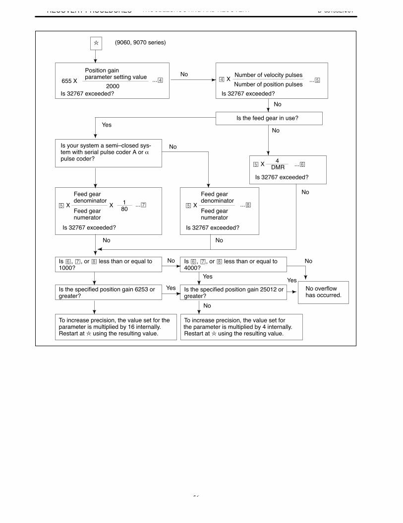
3. TROUBLESHOOTING ANDRECOVERY PROCEDURES B–65195EN/01TROUBLESHOOTING AND RECOVERY
56
X
2000655 X
Number of position pulses X
4 X
X 180
(9060, 9070 series)
No
Yes
No
No
No
No
No No
No
Yes
Yes
No
Yes
No
Position gain parameter setting value ...
Is 32767 exceeded?
Number of velocity pulses
Is 32767 exceeded?
...
Is the feed gear in use?
Is your system a semi–closed sys-tem with serial pulse coder A or αpulse coder?
DMR ...
Is 32767 exceeded?
Feed gear denominatorFeed gear numerator
... X
Feed gear denominatorFeed gear numerator
...
Is 32767 exceeded? Is 32767 exceeded?
Is , , or less than or equal to1000?
Is , , or less than or equal to4000?
Is the specified position gain 6253 orgreater?
Is the specified position gain 25012 orgreater?
No overflowhas occurred.
To increase precision, the value set for theparameter is multiplied by 16 internally.Restart at using the resulting value.
To increase precision, the value set forthe parameter is multiplied by 4 internally.Restart at using the resulting value.
B–65195EN/013. TROUBLESHOOTING AND
RECOVERY PROCEDURESTROUBLESHOOTING AND RECOVERY
57
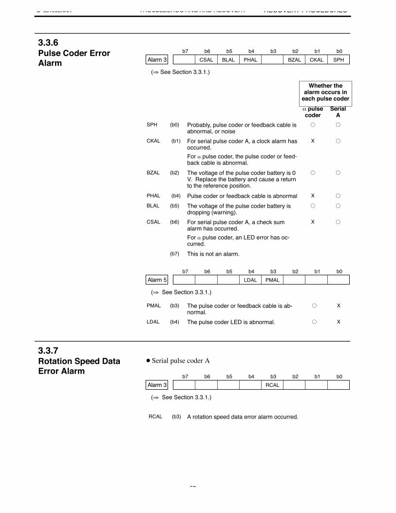
b7 b6 b5 b4 b3 b2 b1 b0Alarm 3 CSAL BLAL PHAL BZAL CKAL SPH
(⇒ See Section 3.3.1.)
Whether thealarm occurs in
each pulse coderα pulsecoder
SerialA
SPH (b0) Probably, pulse coder or feedback cable isabnormal, or noise
CKAL (b1) For serial pulse coder A, a clock alarm hasoccurred.For α pulse coder, the pulse coder or feed-back cable is abnormal.
X
BZAL (b2) The voltage of the pulse coder battery is 0V. Replace the battery and cause a returnto the reference position.
PHAL (b4) Pulse coder or feedback cable is abnormal X
BLAL (b5) The voltage of the pulse coder battery isdropping (warning).
CSAL (b6) For serial pulse coder A, a check sumalarm has occurred.For α pulse coder, an LED error has oc-curred.
X
(b7) This is not an alarm.
b7 b6 b5 b4 b3 b2 b1 b0Alarm 5 LDAL PMAL
(⇒ See Section 3.3.1.)
PMAL (b3) The pulse coder or feedback cable is ab-normal.
X
LDAL (b4) The pulse coder LED is abnormal. X
Serial pulse coder A
b7 b6 b5 b4 b3 b2 b1 b0Alarm 3 RCAL
(⇒ See Section 3.3.1.)
RCAL (b3) A rotation speed data error alarm occurred.
3.3.6Pulse Coder ErrorAlarm
3.3.7Rotation Speed DataError Alarm
3. TROUBLESHOOTING ANDRECOVERY PROCEDURES B–65195EN/01TROUBLESHOOTING AND RECOVERY
58
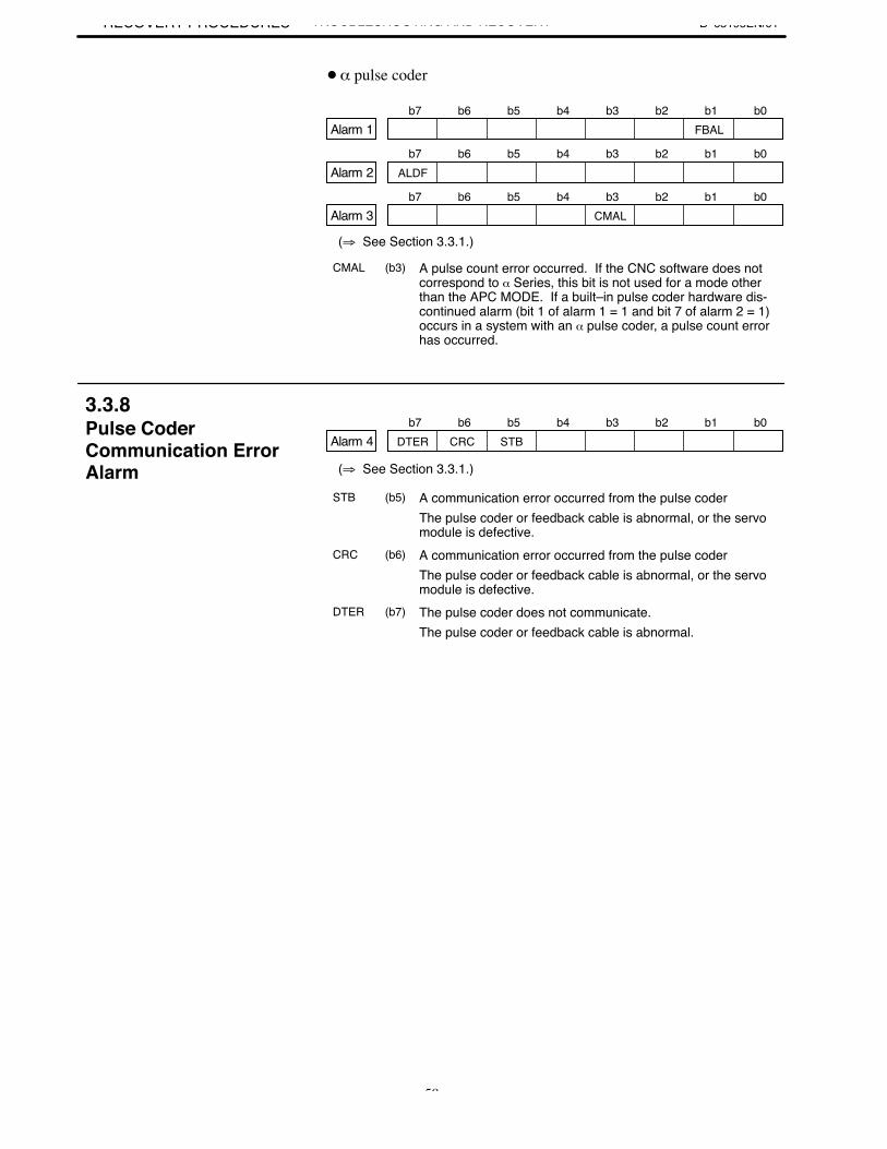
α pulse coder
b7 b6 b5 b4 b3 b2 b1 b0Alarm 1 FBAL
b7 b6 b5 b4 b3 b2 b1 b0Alarm 2 ALDF
b7 b6 b5 b4 b3 b2 b1 b0Alarm 3 CMAL
(⇒ See Section 3.3.1.)
CMAL (b3) A pulse count error occurred. If the CNC software does notcorrespond to α Series, this bit is not used for a mode otherthan the APC MODE. If a built–in pulse coder hardware dis-continued alarm (bit 1 of alarm 1 = 1 and bit 7 of alarm 2 = 1)occurs in a system with an α pulse coder, a pulse count errorhas occurred.
b7 b6 b5 b4 b3 b2 b1 b0Alarm 4 DTER CRC STB
(⇒ See Section 3.3.1.)
STB (b5) A communication error occurred from the pulse coderThe pulse coder or feedback cable is abnormal, or the servomodule is defective.
CRC (b6) A communication error occurred from the pulse coderThe pulse coder or feedback cable is abnormal, or the servomodule is defective.
DTER (b7) The pulse coder does not communicate.The pulse coder or feedback cable is abnormal.
3.3.8Pulse CoderCommunication ErrorAlarm
B–65195EN/01 4. REPLACING THE FUSETROUBLESHOOTING AND RECOVERY
59
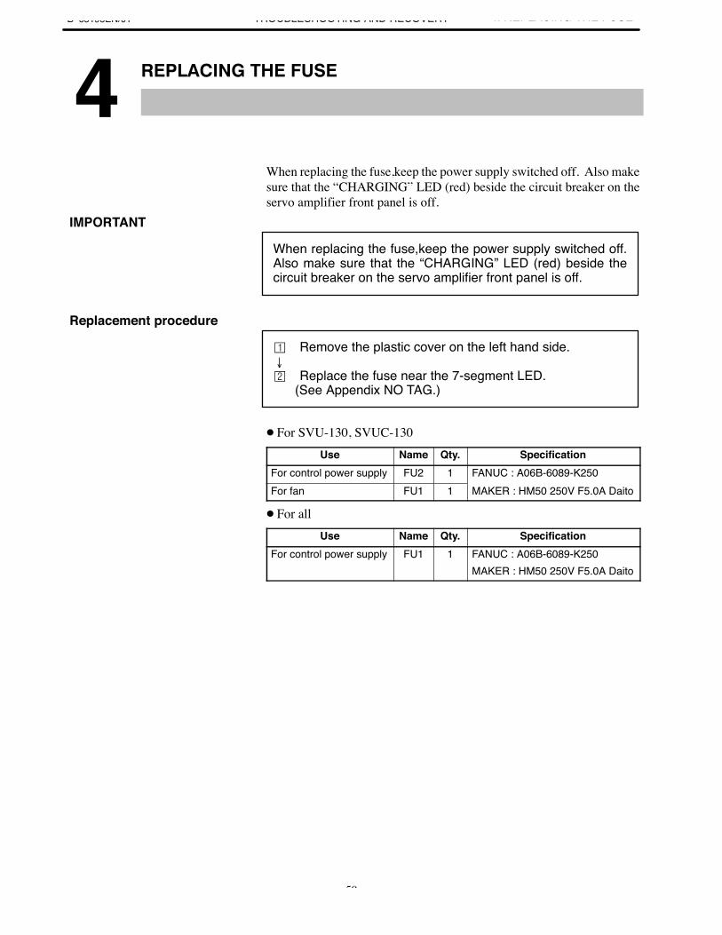
4 ↵
When replacing the fuse,keep the power supply switched off. Also makesure that the “CHARGING” LED (red) beside the circuit breaker on theservo amplifier front panel is off.
When replacing the fuse,keep the power supply switched off.Also make sure that the “CHARGING” LED (red) beside thecircuit breaker on the servo amplifier front panel is off.
Remove the plastic cover on the left hand side.
Replace the fuse near the 7-segment LED. (See Appendix NO TAG.)
For SVU-130, SVUC-130Use Name Qty. Specification
For control power supply FU2 1 FANUC : A06B-6089-K250For fan FU1 1 MAKER : HM50 250V F5.0A Daito
For allUse Name Qty. Specification
For control power supply FU1 1 FANUC : A06B-6089-K250MAKER : HM50 250V F5.0A Daito
IMPORTANT
Replacement procedure
III. COMPATIBILITY OF THE SVUAND SVUC WITH THE C SERIES AMPLIFIER

B–65195EN/01 1. OVERVIEW
COMPATIBILITY OF THE SVUAND SVUC WITH THE C SERIES AMPLIFIER
63
1
This part describes the cautions to be observed when replacing the Cseries amplifier with SVU or SVUC.
B–65195EN/01
2. COMPATIBILITY OF THE SVUAND SVUC WITH THE C SERIES AMPLIFIER
COMPATIBILITY OF THE SVUAND SVUC WITH THE C SERIES AMPLIFIER
64
2 ↵ ↵
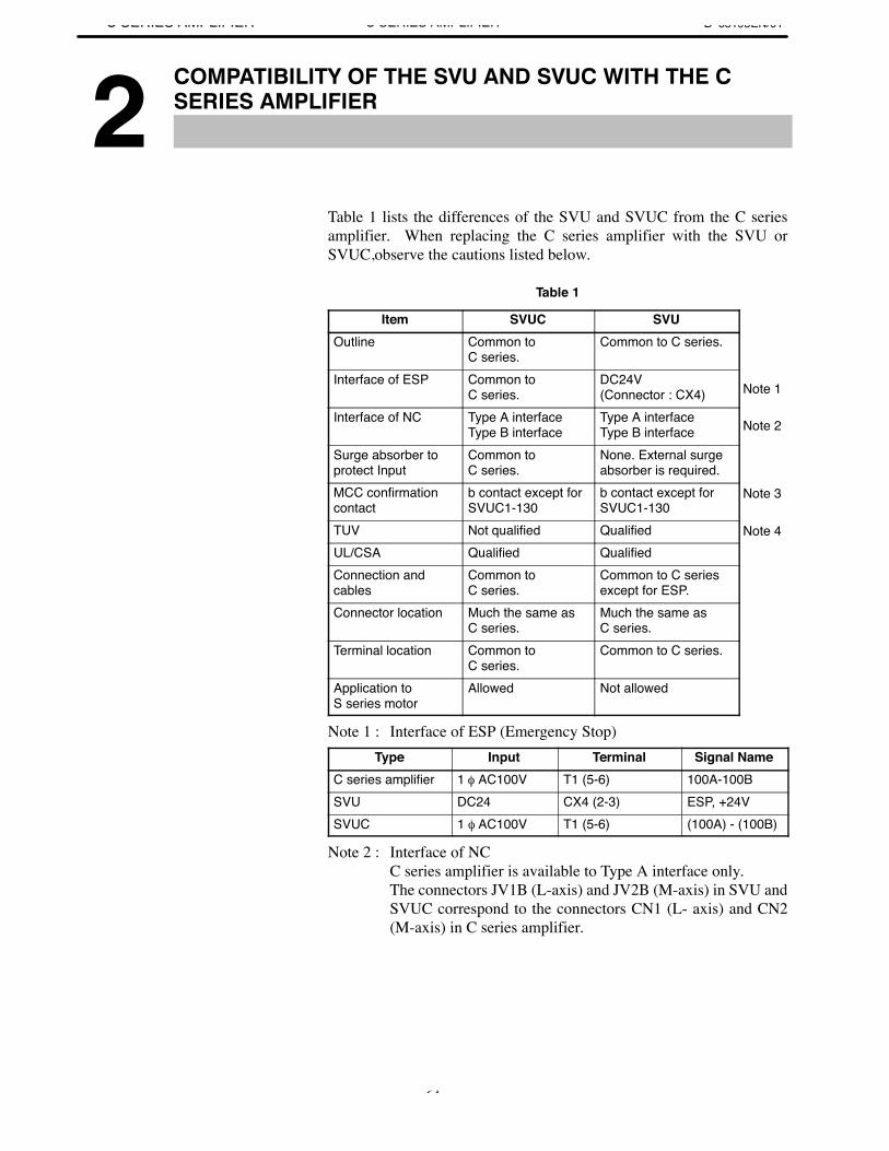
Table 1 lists the differences of the SVU and SVUC from the C seriesamplifier. When replacing the C series amplifier with the SVU orSVUC,observe the cautions listed below.
1
Item SVUC SVUOutline Common to
C series.Common to C series.
Interface of ESP Common to C series.
DC24V (Connector : CX4)
Interface of NC Type A interfaceType B interface
Type A interfaceType B interface
Surge absorber toprotect Input
Common to C series.
None. External surgeabsorber is required.
MCC confirmationcontact
b contact except forSVUC1-130
b contact except forSVUC1-130
TUV Not qualified QualifiedUL/CSA Qualified QualifiedConnection andcables
Common to C series.
Common to C seriesexcept for ESP.
Connector location Much the same asC series.
Much the same as C series.
Terminal location Common to C series.
Common to C series.
Application to S series motor
Allowed Not allowed
Note 1 : Interface of ESP (Emergency Stop)Type Input Terminal Signal Name
C series amplifier 1 φ AC100V T1 (5-6) 100A-100BSVU DC24 CX4 (2-3) ESP, +24VSVUC 1 φ AC100V T1 (5-6) (100A) - (100B)
Note 2 : Interface of NCC series amplifier is available to Type A interface only. The connectors JV1B (L-axis) and JV2B (M-axis) in SVU andSVUC correspond to the connectors CN1 (L- axis) and CN2(M-axis) in C series amplifier.
Note 1
Note 2
Note 3
Note 4
B–65195EN/01
2. COMPATIBILITY OF THE SVUAND SVUC WITH THE C SERIES AMPLIFIER
COMPATIBILITY OF THE SVUAND SVUC WITH THE C SERIES AMPLIFIER
65
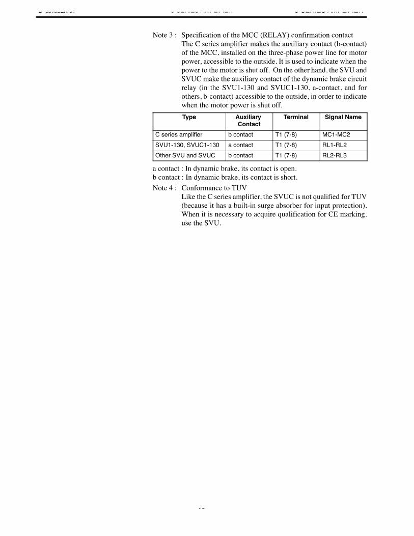
Note 3 : Specification of the MCC (RELAY) confirmation contactThe C series amplifier makes the auxiliary contact (b-contact)of the MCC, installed on the three-phase power line for motorpower, accessible to the outside. It is used to indicate when thepower to the motor is shut off. On the other hand, the SVU andSVUC make the auxiliary contact of the dynamic brake circuitrelay (in the SVU1-130 and SVUC1-130, a-contact, and forothers, b-contact) accessible to the outside, in order to indicatewhen the motor power is shut off.Type Auxiliary
ContactTerminal Signal Name
C series amplifier b contact T1 (7-8) MC1-MC2SVU1-130, SVUC1-130 a contact T1 (7-8) RL1-RL2Other SVU and SVUC b contact T1 (7-8) RL2-RL3
a contact : In dynamic brake, its contact is open. b contact : In dynamic brake, its contact is short.Note 4 : Conformance to TUV
Like the C series amplifier, the SVUC is not qualified for TUV(because it has a built-in surge absorber for input protection).When it is necessary to acquire qualification for CE marking,use the SVU.
B–65195EN/013. SVUC SPECIFICATION CODE
COMPATIBILITY OF THE SVUAND SVUC WITH THE C SERIES AMPLIFIER
66
3 ↵
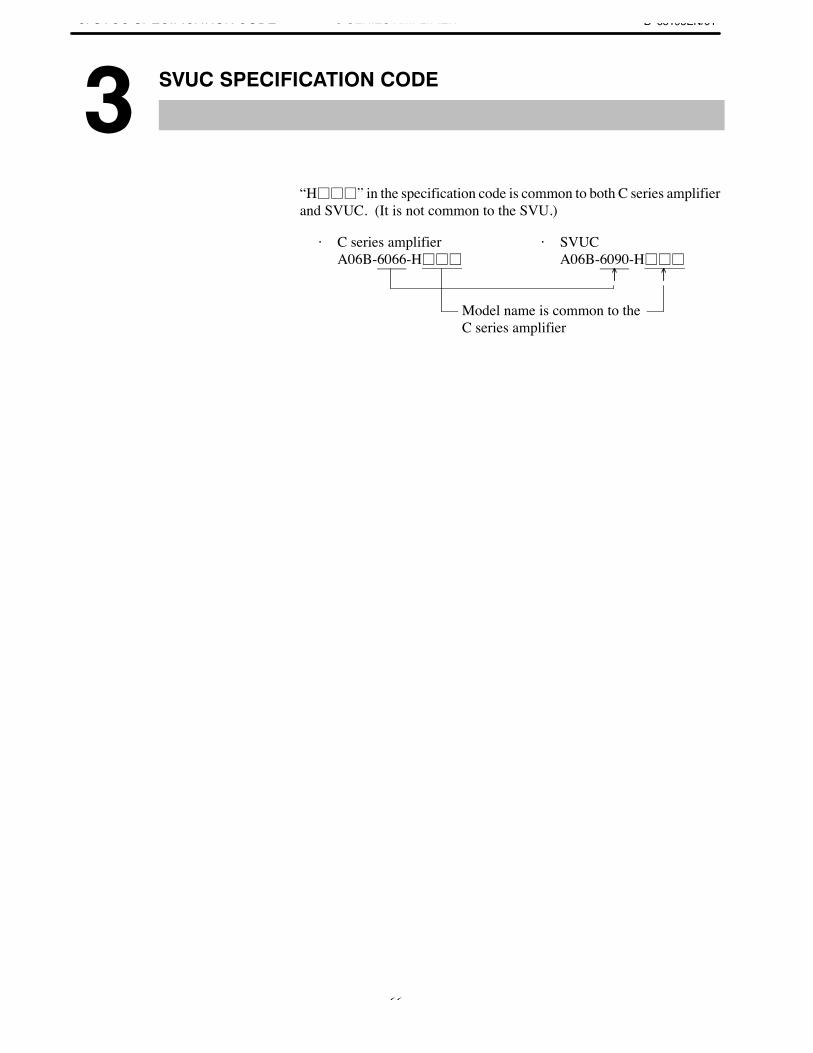
“H” in the specification code is common to both C series amplifierand SVUC. (It is not common to the SVU.)
· C series amplifier A06B-6066-H
· SVUC A06B-6090-H
Model name is common to theC series amplifier

APPENDIX
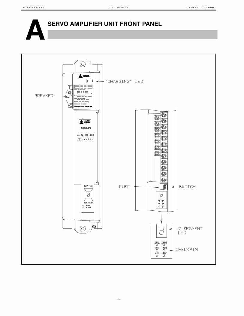
B–65195EN/01A. SERVO AMPLIFIER UNIT
FRONT PANELAPPENDIX
69
A ↵
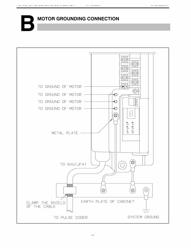
B–65195EN/01B. ↵ ↵ APPENDIX
70
B ↵
IndexB–65195EN/01
[A]Actions to be Taken on Each Alarm, 44Alarm Number and Brief Descriptions, 38Alarm Number in Series 0-C (Servo Alarms), 40Alarm Number in Series 15 (Servo Alarms), 39Alarm Number in Series 16, 18, 20 (Servo Alarms),
41Axis Left Unused in a Multi-axis Amplifier, 30
[B]Basic Configuration, 5
[C]Checking the +5V Power Supply Voltage, 27Checking the Motor Instantaneous Current, 27Compatibility of the SVU and SVUC with the C Se-
ries Amplifier, 64Confirmation Procedure, 26Confirming the Line Voltage and Power Require-
ments, 10Connecting the Battery for an Absolute Pulse Coder,
14Connecting the Power Supply, 10Connecting the Separate Regenerative Discharge Unit,
15Connecting to the Protection Ground, 10Current Conversion Failure Alarm, 48
[F]Feedback Disconnected Alarm, 50
[I]Initializing Servo Parameters, 18Invalid Servo Parameter Setting Parameters, 51
[L]Leakage Current and Selecting a Ground Fault Inter-
rupter, 10LED Indications and Meanings, 43
[M]Major Components, 6Motor Grounding Connection, 70Motor Overheat Alarm, 51
[O]Operation Confirmation Method, 25Overload Alarm, 50Overview of the Start-up Procedure, 9
[P]Pulse Coder Communication Error Alarm, 58Pulse Coder Error Alarm, 57
[R]Replacing the Fuse, 59Rotation Speed Data Error Alarm, 57
[S]Servo Adjustment Screen, 49Servo Amplifier Unit, 43Servo Amplifier Unit Check Pins, 27Servo Amplifier Unit Front Panel, 69Servo Check Board, 31Servo Software, 49Start-up Procedure, 8STATUS Indicator, 29SVU, 6SVUC, 7SVUC Specification Code, 66Switch Setting, 12
[T]Troubleshooting and Recovery Procedures, 42


![Predgovor [Preface.]](https://img.dokumen.tips/doc/110x75/6336ef3f20d9c9602f0b14a3/predgovor-preface.jpg)


