Embed Size (px)
Citation preview

General-Purpose AC Servo
MODEL
Servo MotorINSTRUCTION MANUAL
F

A - 1
Safety Instructions (Always read these instructions before using the equipment.)
Do not attempt to install, operate, maintain or inspect the servo amplifier and servo motor until you have read
through this Instruction Manual, MELSERVO Servo Amplifier Installation Guide/Instruction Manual and
appended documents carefully and can use the equipment correctly. Do not use the servo amplifier and servo
motor until you have a full knowledge of the equipment, safety information and instructions.
In this Instruction Manual, the safety instruction levels are classified into "WARNING" and "CAUTION".
WARNING Indicates that incorrect handling may cause hazardous conditions,
resulting in death or severe injury.
CAUTION Indicates that incorrect handling may cause hazardous conditions,
resulting in medium or slight injury to personnel or may cause physicaldamage.
Note that the CAUTION level may lead to a serious consequence according to conditions. Please follow the
instructions of both levels because they are important to personnel safety.
What must not be done and what must be done are indicated by the following diagrammatic symbols:
: Indicates what must not be done. For example, "No Fire" is indicated by .
: Indicates what must be done. For example, grounding is indicated by .
In this Instruction Manual, instructions at a lower level than the above, instructions for other functions, and so
on are classified into "POINT".
After reading this installation guide, always keep it accessible to the operator.

A - 2
1. To prevent electric shock, note the following:
WARNINGBefore wiring or inspection, switch power off and wait for more than 10 minutes. Then, confirm the voltage
is safe with voltage tester. Otherwise, you may get an electric shock.
Connect the servo amplifier and servo motor to ground.
Any person who is involved in wiring and inspection should be fully competent to do the work.
Do not attempt to wire the servo amplifier and servo motor until they have been installed. Otherwise, you
may get an electric shock.
Operate the switches with dry hand to prevent an electric shock.
The cables should not be damaged, stressed loaded, or pinched. Otherwise, you may get an electric
shock.
2. To prevent fire, note the following:
CAUTIONDo not install the servo motor on or near combustibles. Otherwise a fire may cause.
3. To prevent injury, note the follow
CAUTIONOnly the voltage specified in the Instruction Manual should be applied to each terminal, Otherwise, a
burst, damage, etc. may occur.
Connect the terminals correctly to prevent a burst, damage, etc.
Ensure that polarity ( , ) is correct. Otherwise, a burst, damage, etc. may occur.
During power-on or for some time after power-off, do not touch or close a parts (cable etc.) to the servo
motor, etc. Their temperatures may be high and you may get burnt or a parts may damaged.
A - 3
4. Additional instructionsThe following instructions should also be fully noted. Incorrect handling may cause a fault, injury, electricshock, etc.
(1) Transportation and installation
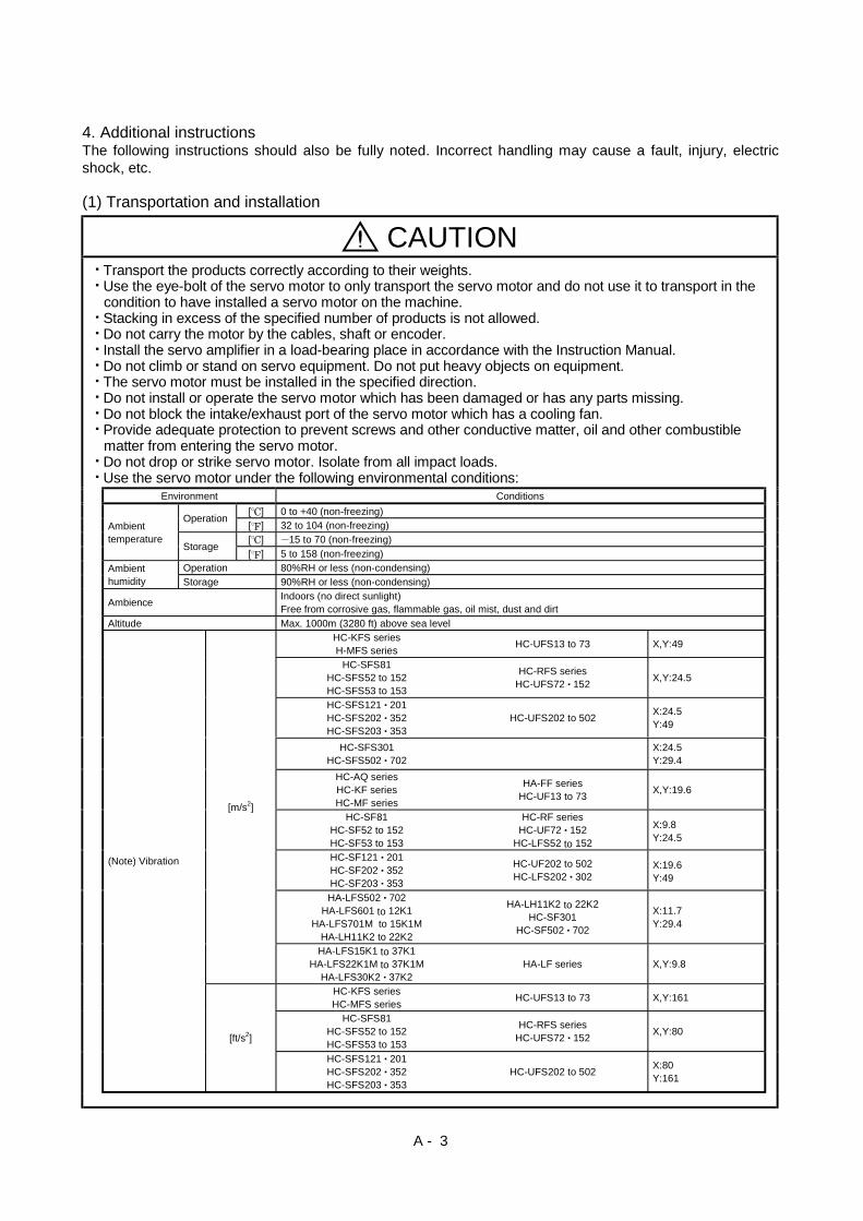
CAUTIONTransport the products correctly according to their weights.Use the eye-bolt of the servo motor to only transport the servo motor and do not use it to transport in thecondition to have installed a servo motor on the machine.Stacking in excess of the specified number of products is not allowed.Do not carry the motor by the cables, shaft or encoder.Install the servo amplifier in a load-bearing place in accordance with the Instruction Manual.Do not climb or stand on servo equipment. Do not put heavy objects on equipment.The servo motor must be installed in the specified direction.Do not install or operate the servo motor which has been damaged or has any parts missing.Do not block the intake/exhaust port of the servo motor which has a cooling fan.Provide adequate protection to prevent screws and other conductive matter, oil and other combustiblematter from entering the servo motor.Do not drop or strike servo motor. Isolate from all impact loads.Use the servo motor under the following environmental conditions:
Environment Conditions
[ ] 0 to 40 (non-freezing)Operation
[ ] 32 to 104 (non-freezing)
[ ] 15 to 70 (non-freezing)Ambienttemperature
Storage[ ] 5 to 158 (non-freezing)
Operation 80%RH or less (non-condensing)Ambienthumidity Storage 90%RH or less (non-condensing)
AmbienceIndoors (no direct sunlight)Free from corrosive gas, flammable gas, oil mist, dust and dirt
Altitude Max. 1000m (3280 ft) above sea level
HC-KFS seriesH-MFS series
HC-UFS13 to 73 X,Y:49
HC-SFS81HC-SFS52 to 152HC-SFS53 to 153
HC-RFS seriesHC-UFS72 152
X,Y:24.5
HC-SFS121 201HC-SFS202 352HC-SFS203 353
HC-UFS202 to 502X:24.5Y:49
HC-SFS301HC-SFS502 702
X:24.5Y:29.4
HC-AQ seriesHC-KF seriesHC-MF series
HA-FF seriesHC-UF13 to 73
X,Y:19.6
HC-SF81HC-SF52 to 152HC-SF53 to 153
HC-RF seriesHC-UF72 152
HC-LFS52 to 152
X:9.8Y:24.5
HC-SF121 201HC-SF202 352HC-SF203 353
HC-UF202 to 502HC-LFS202 302
X:19.6Y:49
HA-LFS502 702HA-LFS601 to 12K1
HA-LFS701M to 15K1MHA-LH11K2 to 22K2
HA-LH11K2 to 22K2HC-SF301
HC-SF502 702
X:11.7Y:29.4
[m/s2]
HA-LFS15K1 to 37K1HA-LFS22K1M to 37K1M
HA-LFS30K2 37K2HA-LF series X,Y:9.8
HC-KFS seriesHC-MFS series
HC-UFS13 to 73 X,Y:161
HC-SFS81HC-SFS52 to 152HC-SFS53 to 153
HC-RFS seriesHC-UFS72 152
X,Y:80
(Note) Vibration
[ft/s2]
HC-SFS121 201HC-SFS202 352HC-SFS203 353
HC-UFS202 to 502X:80Y:161

A - 4
CAUTIONEnvironment Conditions
HC-SFS301HC-SFS502 702
X:80Y:96
HC-AQ seriesHC-KF seriesHC-MF series
HA-FF seriesHC-UF13 to 73
X,Y:64
HC-SF81HC-SF52 to 152HC-SF53 to 153
HC-RF seriesHC-UFS72 152HC-LFS52 to 152
X:32Y:80
HC-SF121 201HC-SF202 352HC-SF203 353
HC-UF202 to 502HC-LFS202 302
X:64Y:161
HA-LFS502 702HA-LFS601 to 12K1
HA-LFS701M to 15K1MHA-LH11K2 to 22K2
HA-LH11K2 to 22K2HC-SF301
HC-SF502 702
X:38.4Y:96.5
(Note) Vibration [ft/s2]
HA-LFS15K1 to 37K1HA-LFS22K1M to 37K1M
HA-LFS30K2 37K2HA-LF series X,Y:32
Note: Except the servo motor with reduction gear.
Securely attach the servo motor to the machine. If attach insecurely, the servo motor may come off during
operation.
The servo motor with reduction gear must be installed in the specified direction to prevent oil leakage.
For safety of personnel, always cover rotating and moving parts.
Never hit the servo motor or shaft, especially when coupling the servo motor to the machine. The encoder
may become faulty.
Do not subject the servo motor shaft to more than the permissible load. Otherwise, the shaft may break.
When the equipment has been stored for an extended period of time, consult Mitsubishi.
(2) Wiring
CAUTIONWire the equipment correctly and securely. Otherwise, the servo motor may misoperate.
Do not install a power capacitor, surge absorber or radio noise filter (FR-BIF option) between the servo
motor and servo amplifier.
Connect the output terminals (U, V, W) correctly. Otherwise, the servo motor will operate improperly.
Do not connect AC power directly to the servo motor. Otherwise, a fault may occur.
(3) Test run adjustment
CAUTIONBefore operation, check the parameter settings. Improper settings may cause some machines to perform
unexpected operation.
The parameter settings must not be changed excessively. Operation will be instable.

A - 5
(4) Usage
CAUTIONProvide an external emergency stop circuit to ensure that operation can be stopped and power switchedoff immediately.
Any person who is involved in disassembly and repair should be fully competent to do the work.
Do not modify the equipment.
Use the servo amplifier with the specified servo motor.
The electromagnetic brake on the servo motor is designed to hold the motor shaft and should not be usedfor ordinary braking.
For such reasons as service life and mechanical structure (e.g. where a ballscrew and the servo motorare coupled via a timing belt), the electromagnetic brake may not hold the motor shaft. To ensure safety,install a stopper on the machine side.
(5) Corrective actions
CAUTIONWhen it is assumed that a hazardous condition may take place at the occur due to a power failure or aproduct fault, use a servo motor with electromagnetic brake or an external brake mechanism for thepurpose of prevention.
Configure the electromagnetic brake circuit so that it is activated not only by the servo amplifier signalsbut also by an external emergency (forced) stop signal.
EMGRA
24VDC
Contacts must be open whenservo-on signal is off, when analarm (trouble) is present and whenan electromagnetic brake signal.
Electromagnetic brake
Servo motor
Circuit must be opened duringemergency (force) stop.
When any alarm has occurred, eliminate its cause, ensure safety, and deactivate the alarm beforerestarting operation.When power is restored after an instantaneous power failure, keep away from the machine because themachine may be restarted suddenly (design the machine so that it is secured against hazard if restarted).
About processing of waste When you discard servo amplifier, a battery (primary battery), and other option articles, please follow the law ofeach country (area).
FOR MAXIMUM SAFETYThis product is not designed or manufactured to be used in equipment or systems in situations that canaffect or endanger human life.When considering this product for operation in special applications such as machinery or systems used inpassenger transportation, medical, aerospace, atomic power, electric power, or submarine repeatingapplications, please contact your nearest Mitsubishi sales representative.
Although this product was manufactured under conditions of strict quality control, you are strongly advisedto install safety devices to forestall serious accidents when it is used in facilities where a breakdown in theproduct is likely to cause a serious accident.

A - 6
COMPLIANCE WITH EC DIRECTIVES1. WHAT ARE EC DIRECTIVES?The EC Directives were issued to standardize the regulations of the EU countries and ensure smoothdistribution of safety-guaranteed products. In the EU countries, the Machinery Directive (effective inJanuary, 1995), EMC Directive (effective in January, 1996) and Low Voltage Directive (effective inJanuary, 1997) of the EC Directives require that products to be sold should meet their fundamental safetyrequirements and carry the CE marks (CE marking). CE marking applies to machines and equipmentinto which servo amplifiers have been installed.The servo amplifiers do not function independently but are designed for use with machines andequipment.Therefore, the CE marking does not apply to the servo amplifiers but applies to the machines andequipment into which the servo amplifiers are installed.This servo amplifier conforms to the standards related to the Low Voltage Directive to facilitate CEmarking on machines and equipment into which the servo amplifiers will be installed. To ensure ease ofcompliance with the EMC Directive, Mitsubishi Electric prepared the "EMC INSTALLATIONGUIDELINES" (IB(NA)67310) which provides servo amplifier installation, control box making and otherprocedures. Please contact your sales representative.
2. PRECAUTIONS FOR COMPLIANCEUse the servo motor compatible with the EN Standard.Unless otherwise specified, the handling, performance, specifications and others of the EN Standard-compatible models are the same as those of the standard models.To comply with the EN Standard, also observe the following items strictly.(1) Wiring
(a) Use a fixed terminal block to connect the power supply lead of the servo motor to the servoamplifier. Do not connect cables directly.
Terminal block
(b) Use the servo motor side power connector which complies with the EN Standard.The EN Standard-compliant power connector sets are available from us as options.
Power Connector Set Model Servo Motor ModelMR-PWCF HC-FF C(B)-UEMR-PWCNS1 HC-SF81(B)
HC-SF52(B) to 152(B)HC-SF53(B) to 153(B)HC-RF103(B) to 203(B)HC-UF72(B) 152(B)HC-SFS81(B)HC-SFS52(B) to 152(B)HC-SFS53(B) to 153(B)HC-RFS103(B) to 203(B)HC-UFS72(B) 152(B)HC-LFS52(B) to 152(B)
MR-PWCNS2 HC-SF121(B) to 301(B)HC-SF202(B) to 502(B)HC-SF203(B) 353(B)HC-RF353(B) 503(B)HC-UF202(B) to 502(B)HC-SFS121(B) to 301(B)HC-SFS202(B) to 502(B)HC-SFS203(B) 353(B)HC-RFS353(B) 503(B)HC-UFS202(B) to 502(B)HA-LFS502HC-LFS202(B) 302(B)
MR-PWCNS3 HC-SFS702(B) HC-SF702(B)HA-LFS702
(2) InstallationThe flange of the machine mounted with the HC-MF(HC-MF-UE)/HC-KF(HC-KF-UE)/HC-AQ/HC-MFS/HC-KFS must be connected to the earth.
A - 7
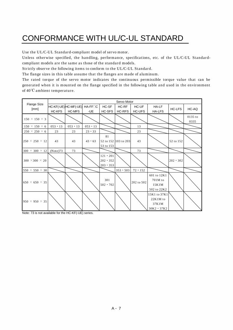
CONFORMANCE WITH UL/C-UL STANDARD
Use the UL/C-UL Standard-compliant model of servo motor.Unless otherwise specified, the handling, performance, specifications, etc. of the UL/C-UL Standard-compliant models are the same as those of the standard models.Strictly observe the following items to conform to the UL/C-UL Standard.The flange sizes in this table assume that the flanges are made of aluminum.The rated torque of the servo motor indicates the continuous permissible torque value that can begenerated when it is mounted on the flange specified in the following table and used in the environmentof 40 ambient temperature.
Servo MotorFlange Size
[mm]HC-KF(-UE)
HC-KFS
HC-MF(-UE)
HC-MFS
HA-FF C
-UE
HC-SF
HC-SFS
HC-RF
HC-RFS
HC-UF
HC-UFS
HA-LF
HA-LFSHC-LFS HC-AQ
150 150 30135 to
0335
150 150 6 053 13 053 13 053 13 13
250 250 6 23 23 23 33 23
250 250 12 43 43 43 6381
52 to 15253 to 153
103 to 203 43 52 to 152
300 300 12 (Note)73 73 73
300 300 20121 201202 352203 353
202 302
550 550 30 353 503 72 152
650 650 35301
502 702202 to 502
601 to 12K1701M to15K1M
502 to 22K2
950 950 35
15K1 to 37K122K1M to
37K1M30K2 37K2
Note: 73 is not available for the HC-KF(-UE) series.

A - 8
MEMO
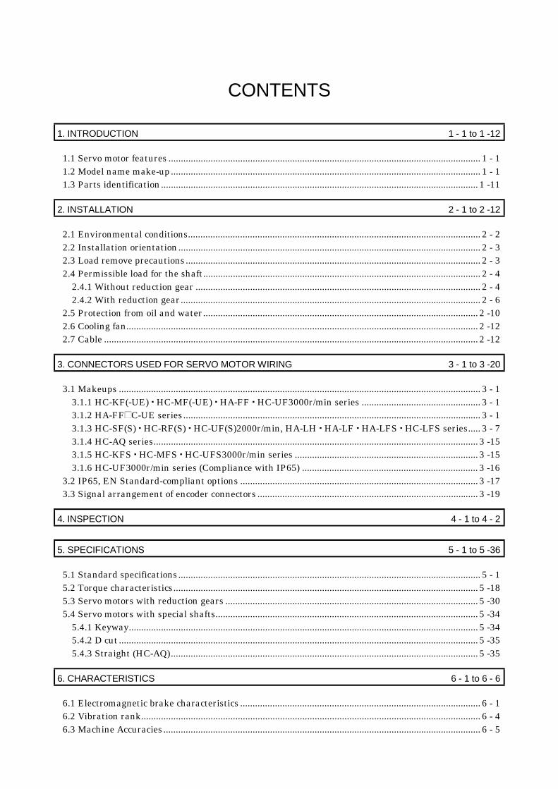
CONTENTS
1. INTRODUCTION 1 - 1 to 1 -12
1.1 Servo motor features .............................................................................................................................. 1 - 11.2 Model name make-up............................................................................................................................. 1 - 11.3 Parts identification................................................................................................................................ 1 -11
2. INSTALLATION 2 - 1 to 2 -12
2.1 Environmental conditions...................................................................................................................... 2 - 22.2 Installation orientation.......................................................................................................................... 2 - 32.3 Load remove precautions....................................................................................................................... 2 - 32.4 Permissible load for the shaft................................................................................................................ 2 - 4
2.4.1 Without reduction gear ................................................................................................................... 2 - 42.4.2 With reduction gear......................................................................................................................... 2 - 6
2.5 Protection from oil and water............................................................................................................... 2 -102.6 Cooling fan.............................................................................................................................................. 2 -122.7 Cable ....................................................................................................................................................... 2 -12
3. CONNECTORS USED FOR SERVO MOTOR WIRING 3 - 1 to 3 -20
3.1 Makeups .................................................................................................................................................. 3 - 13.1.1 HC-KF(-UE) HC-MF(-UE) HA-FF HC-UF3000r/min series ................................................ 3 - 13.1.2 HA-FF C-UE series........................................................................................................................ 3 - 13.1.3 HC-SF(S) HC-RF(S) HC-UF(S)2000r/min, HA-LH HA-LF HA-LFS HC-LFS series..... 3 - 73.1.4 HC-AQ series................................................................................................................................... 3 -153.1.5 HC-KFS HC-MFS HC-UFS3000r/min series .......................................................................... 3 -153.1.6 HC-UF3000r/min series (Compliance with IP65) ....................................................................... 3 -16
3.2 IP65, EN Standard-compliant options ................................................................................................ 3 -173.3 Signal arrangement of encoder connectors ......................................................................................... 3 -19
4. INSPECTION 4 - 1 to 4 - 2
5. SPECIFICATIONS 5 - 1 to 5 -36
5.1 Standard specifications.......................................................................................................................... 5 - 15.2 Torque characteristics........................................................................................................................... 5 -185.3 Servo motors with reduction gears ...................................................................................................... 5 -305.4 Servo motors with special shafts.......................................................................................................... 5 -34
5.4.1 Keyway............................................................................................................................................. 5 -345.4.2 D cut................................................................................................................................................. 5 -355.4.3 Straight (HC-AQ)............................................................................................................................ 5 -35
6. CHARACTERISTICS 6 - 1 to 6 - 6
6.1 Electromagnetic brake characteristics ................................................................................................. 6 - 16.2 Vibration rank......................................................................................................................................... 6 - 46.3 Machine Accuracies................................................................................................................................ 6 - 5

7. OUTLINE DIMENSION DRAWINGS 7 - 1 to 7 -312
7.1 Servo motors............................................................................................................................................ 7 - 17.1.1 HC-MF HC-KF series.................................................................................................................... 7 - 17.1.2 HA-FF series ................................................................................................................................... 7 -237.1.3 HC-SF HC-SFS series ..................................................................................................................7 -507.1.4 HC-RF HC-RFS series ................................................................................................................. 7 -907.1.5 HC-UF 2000r/min•HC-UFS 2000r/min series ............................................................................ 7 -977.1.6 HC-UF 3000r/min series ..............................................................................................................7 -1007.1.7 HC-UF3000r/min, HC-UFS3000r/min series with IP65-compliant connectors.....................7 -1037.1.8 HA-LH series.................................................................................................................................7 -1067.1.9 HC-AQ series.................................................................................................................................7 -1087.1.10 HA-LF series ...............................................................................................................................7 -1097.1.11 HC-MFS HC-KFS series..........................................................................................................7 -1137.1.12 HC-UFS 3000r/min series..........................................................................................................7 -1327.1.13 HA-LFS series.............................................................................................................................7 -1357.1.14 HC-LFS series.............................................................................................................................7 -147
7.2 Servo motors (in inches)......................................................................................................................7 -1527.2.1 HC-MF HC-KF series.................................................................................................................7 -1527.2.2 HA-FF series .................................................................................................................................7 -1747.2.3 HC-SF HC-SFS series ................................................................................................................7 -2017.2.4 HC-RF HC-RFS series ...............................................................................................................7 -2417.2.5 HC-UF 2000r/min HC-UFS 2000r/min series .........................................................................7 -2487.2.6 HC-UF 3000r/min series ..............................................................................................................7 -2517.2.7 HC-UF3000r/min, HC-UFS3000r/min series with IP65-compliant connectors.....................7 -2547.2.8 HA-LH series.................................................................................................................................7 -2577.2.9 HC-AQ series.................................................................................................................................7 -2597.2.10 HA-LF series ...............................................................................................................................7 -2607.2.11 HC-MFS HC-KFS series..........................................................................................................7 -2647.2.12 HC-UFS 3000r/min series..........................................................................................................7 -2837.2.13 HA-LFS series.............................................................................................................................7 -2867.2.14 HC-LFS series.............................................................................................................................7 -298
7.3 Connector..............................................................................................................................................7 -303
8. CALCULATION METHODS FOR DESIGNING 8 - 1 to 8 -14
8.1 Specification symbol list......................................................................................................................... 8 - 18.2 Position resolution and electronic gear setting ................................................................................... 8 - 28.3 Speed and command pulse frequency................................................................................................... 8 - 38.4 Stopping characteristics......................................................................................................................... 8 - 48.5 Capacity selection................................................................................................................................... 8 - 58.6 Load torque equations............................................................................................................................ 8 - 88.7 Expression for Calculating the Electromagnetic Brake Workload.................................................... 8 - 88.8 Load inertia moment equations ............................................................................................................ 8 - 98.9 Precautions for zeroing ......................................................................................................................... 8 -108.10 Selection example ................................................................................................................................ 8 -11

APPENDIX App - 1 to App - 2
Appendix.1 Servo motor ID codes .......................................................................................................... App - 1

MEMO

1 - 1
1. INTRODUCTION
1. INTRODUCTION
1.1 Servo motor featuresServoMotorSeries
Features(Points Different from Conventional
Products)
PositioningResolution[pulses/rev]
RatedSpeed[r/min]
Capacity [kW]Interchangeable
Servo MotorSeries
Compliance withOverseas Standards
EnvironmentalResistance
HC-KF 8192
EN StandardUL/C-UL Standard(Standard model iscompliant)
(Note1 2) IP44
HC-KFS
Low inertia, small capacity 4 to 5times greater in inertia moment thanHC-MF(S).Equipped with absolute positiondetector as standard 131072
3000 0.05 to 0.4HC-MFHC-MEHC-MH EN Standard
UL/C-UL Standard(Standard model iscompliant)
(Note1 2) IP55
HC-MF 8192
EN StandardUL/C-UL Standard(Standard model iscompliant)
(Note1 2) IP44
HC-MFS
Ultra low inertia, small capacity1.2 times higher in power rate thanHA-MEEquipped with absolute positiondetector as standard 131072
3000 0.05 to 0.75 HA-MEHA-MH EN Standard
UL/C-UL Standard(Standard model iscompliant)
(Note1 2) IP55
HA-FFLow inertia, small capacityEquipped with absolute positiondetector as standard
3000 8192 0.05 to 0.6 HA-FEHA-FH
EN StandardUL/C-UL Standard(HA-FF-UE iscompliant)
(Note1 2) IP44
HC-SF 16384
HC-SFS
Middle inertia, middle capacity1.5 times higher in power rate thanHA-SEEquipped with absolute positiondetector as standard
131072
100020003000
0.5 to 7 HA-SEHA-SH
EN StandardUL/C-UL Standard(Standard model iscompliant)
IP65
HC-RF 16384
HC-RFS
Ultra low inertia, middle capacityAbout 3 times higher in power ratethan HA-LHEquipped with absolute positiondetector as standard
1310723000 1 to 5
EN StandardUL/C-UL Standard(Standard model iscompliant)
IP65
Pancake type, small capacityEquipped with absolute positiondetector as standard
8192 3000 0.1 to 0.75 (Note1) IP65
HC-UF Pancake type, middle capacityEquipped with absolute positiondetector as standard
16384 2000 0.75 to 5
EN StandardUL/C-UL Standard(Standard model iscompliant) IP65
Pancake type small capacityEquipped with absolute positiondetector as standard
3000 0.1 to 0.75 (Note1) IP65
HC-UFS Pancake type middle capacityEquipped with absolute positiondetector as standard
131072
2000 0.75 to 5
EN StandardUL/C-UL Standard(Standard model iscompliant) IP65
HA-LH Low inertia, large capacity 16384 2000 11 to 22EN Standard(HA-LH-EC iscompliant)
JP44
HC-AQ 24VDC-compatible,ultra low inertia, small capacity 8192 3000 0.01 to 0.03
EN Standard,UL/C-UL Standard(Standard model iscompliant)
(Note1 2) IP55
Three-phase, 200VAC-compatible,low inertia, large capacityEquipped with absolute positiondetector as standard
30 37
HA-LF Three-phase, 400VAC-compatible,low inertia, large capacityEquipped with absolute positiondetector as standard
16384 2000
30 to 55
Scheduled to makeapplication IP44
1000 6 to 201500 7 to 30HA-LFS
Low inertia, large capacityEquipped with absolute positiondetector as standard 2000
1310725 to 37 HA-LH
Being planned IP44
HC-LFSLow inertia, middle capacityEquipped with absolute positiondetector as standard
2000 131072 0.5 to 3.0 HA-LH Scheduled to makeapplication IP65
Note 1: Except connector section.
2: Except for the shaft-through portion.
1.2 Model name make-up
(1) Name plate
AC SERVO MOTOR
HC-RF153INPUT 3AC 145V 8.2A
MITSUBISHI ELECTRIC CORPORATIONMADE IN JAPAN
SPEED 3000r/minSER.No. 001 DATE
OUTPUT 1.5Kw IEC34-1 1994
Model
Input powerRated output
Rated speedSerial number

1 - 2
1. INTRODUCTION
(2) Model
(a) HC-MF series (ultra low inertia, small capacity)
3
Symbol
Rated Output [W]
-UE
Symbol
Shaft type
K
D
Symbol
G1
Symbol
12
50100
200
05
Series name
Appearance
Compliance with Standard
Specifications
None
(Note) Standard model (EN UL/C-UL Standard)
EN UL/C-UL Standard
Shaft Shape
D-cut shaft
Note: With key
Reduction gear
Reduction Gear
None Without
For general industrial machine
For precision application
Electromagnetic brake
Electromagnetic Brake
Without
With
Rated speed3000 [r/min]
Rated output
None
Standard(Straight shaft)
(Note) With keyway
HC-MF
53 13
053 to 73
23 to 73
G2
Symbol
B
None
4 400
7 750
HC-MF
Note. The standard models produced in and after February, 2001 are compatible with the EN UL/C-UL Standard.
(b) HA-FF series (low inertia, small capacity)
Symbol
Rated Output [W]
-UE
Symbol
Shaft type
D
Symbol
G1
Symbol
1
2
50
100
200
05
Series name Compliance with Standard
Specifications
None
Standard model (Japan)
EN UL/C-UL Standard
Shaft Shape
D-cut shaft
Reduction gear
Reduction Gear
None Without
For general industrial machine
For precision application
Electromagnetic brake
Electromagnetic Brake
Without
With
Rated speed3000 [r/min]
Rated output
None
HA-FF
053 13
053 to 63
G2
Symbol
B
None
(Note) Standard
Note: The Standard shafts of the HA-FF23 to 63 are with keys and those of the other models are straight shafts.
Appearance
Rated Output [W]Symbol
4
6
300
400
600
3
Input power supply form
Standard model
Lead
Symbol
C
None
EN UL/C-UL Standard-compliant model
Cannon connector
3 HA-FF

1 - 3
1. INTRODUCTION
(c) HC-SF series (middle inertia, middle capacity)
Rated Output [W]
Symbol
G1
Symbol
8
10
500
850
1000
5
Series name
Reduction gear
None Without
Electromagnetic brake
Electromagnetic Brake
Without
With
Rated speed
Rated output
Appearance
Symbol
B
None
1000 [r/min]
(Note) Reduction Gear
Note: Not provided for 1000r/min and 3000r/min series.
Speed [r/min]
Symbol
Shaft type
None
Shaft Shape
With keyway
Note: Without key
Standard(Straight shaft)
K
For general industrial machine
(flange type)
For general industrial machine
(leg type)G1H
For precision applicationG2
Symbol
2
3
1000
2000
3000
1
2000 [r/min] 3000 [r/min]
15
20
1200
1500
2000
12
30
35
3000
3500
50 5000
70 7000
HC-SF

1 - 4
1. INTRODUCTION
(d) HC-RF series (ultra low inertia, middle capacity)
Rated Output [W]
Symbol
Symbol
20
1000
15 1500
2000
10
Series name
Appearance
Reduction gear
Reduction Gear
None Without
For precision application
Electromagnetic brake
Electromagnetic Brake
Without
With
Rated speed3000 [r/min]
Rated output
Symbol
Shaft type
K
None
Shaft Shape
Note: Without key
Standard(Straight shaft)
With keyway
G2
Symbol
B
None
35 3500
50 5000
3 HC-RF
(e) HC-UF series (pancake type, small and middle capacity)
HC-UF
Series name
Appearance
Rated Output [W]
Symbol
Shaft type
K
D
Symbol
2
4
100
200
400
1
None
Shaft Shape
D-cut shaft
Note: HC-UF 23 to 73 are provided with keys.
Electromagnetic brake
Electromagnetic Brake
Without
With
Rated speed
Rated output
Standard(Straight shaft)
(Note) With keyway
HC-UF
13
13 to 4372 to 202
Symbol
B
NoneSpeed [r/min]Symbol
3
2000
3000
2
20
750
2000
7
150015
350035
500050

1 - 5
1. INTRODUCTION
(f) HA-LH series (low inertia, large capacity)
HA-LH
Series name
Appearance
Compliant Standard
Encoder
Rated speed2000[r/min]
Rated Output [W]Symbol
15K
22K
11000
15000
22000
11K
Rated output
Symbol
None
Specifications
Standard model (in Japan)
EN Standard-EC
Symbol
None
Encoder
Incremental
Absolute-Y
2
(g) HC-KF series (low inertia, small capacity)
3000[r/min]
2 200
4004
Appearance
Compliance with StandardSymbol Specifications
None (Note) Standard model (EN UL/C-UL Standard)
-UE
Shaft typeSymbol Shaft Shape
None
K (Note) With keyway
Note: With key
Symbol Reduction Gear
None Without
G1 For general industrial machine
G2 For precision application
Electromagnetic brakeSymbol Electromagnetic Brake
None Without
B With
Rated speed
Rated output
Symbol Rated Output [W]
EN UL/C-UL Standard
Standard(Straight shaft)
Reduction gear
Series name
HC-KF 3
05 50
1001
Note. The standard models produced in and after February, 2001 are compatible with the EN UL/C-UL Standard.

1 - 6
1. INTRODUCTION
(h) HC-AQ series (24VDC-compatible, ultra low inertia, small capacity)
HC-AQ
Rated Output [W]Symbol
03
10
02 20
30
01
Series name
Appearance
Rated speed3000 [r/min]
Rated output
Symbol
Shaft type
Shaft Shape
Electromagnetic brake
Electromagnetic Brake
Without
With
Symbol
B
None
D D-cut shaft
S Straight shaft
Power supply voltage24VDC
3 5
(i) HA-LF series (Three-phase, 200 400VAC-compatible, low inertia, large capacity)
Three-phase 200 to 230VAC
HA-LF
Rated Output [kW]Symbol
45K
30
37K 37
45
30K
Series name
Appearance
Rated speed2000 [r/min]
Rated output
Power supply specification
55K 55
2
Power Supply VoltageSymbol
4
None
Three-phase 380 to 460VAC
Power supply specifications
Three-phase 200 to 230VAC Three-phase 380 to 460VAC

1 - 7
1. INTRODUCTION
(j) HC-KFS series (low inertia, small capacity, high resolution)
3000[r/min]
05 50
1001
Appearance
Shaft typeSymbol Shaft Shape
None
K (Note) With keyway
Note: With key
Symbol Reduction Gear
None Without
G1 For general industrial machine
G2 For precision application
Electromagnetic brakeSymbol Electromagnetic Brake
None Without
B With
Rated speed
Rated outputSymbol Rated Output [W]
Standard(Straight shaft)
Reduction gear
3
Series name
HC-KFS
2 200
4004
(k) HC-MFS series (ultra low inertia, small capacity, high resolution)
3
Rated Output [W]
Symbol
Shaft type
K
D
Symbol
G1
Symbol
1
2
50
100
200
05
Series name
Appearance
None
Shaft Shape
D-cut shaft
Note: With key
Reduction gear
Reduction Gear
None Without
For general industrial machine
For precision application
Electromagnetic brake
Electromagnetic Brake
Without
With
Rated speed3000 [r/min]
Rated output
Standard(Straight shaft)
(Note) With keyway
HC-MF
53 13
053 to 73
23 to 73
G2
Symbol
B
None
4 400
7 750
HC-MFS

1 - 8
1. INTRODUCTION
(l) HC-SFS series (middle inertia, middle capacity, high resolution)
Rated Output [W]
Symbol
G1
Symbol
8
10
500
850
1000
5
Series name
Reduction gear
None Without
Electromagnetic brake
Electromagnetic Brake
Without
With
Rated speed
Rated output
Appearance
Symbol
B
None
1000 [r/min]
(Note) Reduction Gear
Note: Not provided for 1000r/min and 3000r/min series.
Speed [r/min]
Symbol
Shaft type
None
Shaft Shape
With keyway
Note: Without key
Standard(Straight shaft)
K
For general industrial machine
(flange type)
For general industrial machine
(leg type)G1H
For precision applicationG2
Symbol
2
3
1000
2000
3000
1
2000 [r/min] 3000 [r/min]
15
20
1200
1500
2000
12
30
35
3000
3500
HC-SFS
50 5000
70 7000
1 - 9
1. INTRODUCTION
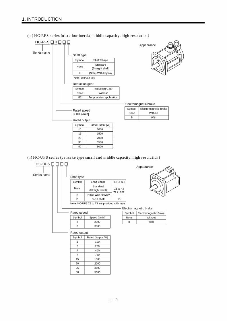
(m) HC-RFS series (ultra low inertia, middle capacity, high resolution)
Rated Output [W]
Symbol
Symbol
20
1000
15 1500
2000
10
Series name
Appearance
Reduction gear
Reduction Gear
None Without
For precision application
Electromagnetic brake
Electromagnetic Brake
Without
With
Rated speed3000 [r/min]
Rated output
Symbol
Shaft type
K
None
Shaft Shape
Note: Without key
Standard(Straight shaft)
(Note) With keyway
G2
Symbol
B
None
35 3500
50 5000
3 HC-RFS
(n) HC-UFS series (pancake type small and middle capacity, high resolution)
HC-UFS
Series name
Appearance
Rated Output [W]
Symbol
Shaft type
K
D
Symbol
2
4
100
200
400
1
None
Shaft Shape
D-cut shaft
Note: HC-UFS 23 to 73 are provided with keys.
Electromagnetic brake
Electromagnetic Brake
Without
With
Rated speed
Rated output
Standard(Straight shaft)
(Note) With keyway
HC-UFS
13
13 to 4372 to 202
Symbol
B
NoneSpeed [r/min]Symbol
3
2000
3000
2
20
750
2000
7
150015
350035
500050

1 - 10
1. INTRODUCTION
(o) HA-LFS series (low inertia, large capacity, high resolution)
1 1000
1M 1500
2 2000
50 5
1000[r/min]
1500[r/min]
2000[r/min]
60 6
70 7
80 8
11K 11
12K 12
15K 15
20K 20
22K 22
25K 25
30K 30
37K 37
HA-LFS
Rated speedSeries name
Symbol Speed [r/min]
Appearance
Symbol Rated Output [kW]
Rated output
(p) HC-LFS series (low inertia, middle capacity, high resolution)
5 0.5
10 1
15 1.5
20 2
30 3
HC-LFS 2
Series name Electromagnetic brake
Symbol
Rated speed2000 [r/min]
Rated output
Symbol
Electromagnetic Brake
Rated Output [kW]
None Without
WithB
Appearance

1 - 11
1. INTRODUCTION
1.3 Parts identification
Terminal box Power leads (U V W) Cooling fan leads Ground terminal Brake lead (for motor with electromagnetic brake)
Terminal box type
Lead typeName/Application Reference
Encoder Section 5.1
Encoder cable with encoder connector Section 3.2
Chapter 7
Servo motor shaft
Connector type
Encoder connector
Power cable Power lead (U V W) Earth lead Brake lead (for motor with electromagnetic brake)
Chapter 2Section 5.4
Name/Application Reference
Encoder Section 5.1
Section 3.2
Chapter 7
Servo motor shaft Chapter 2Section 5.4
Power connector Power supply (U V W) Earth Brake (for motor with electromagnetic brake) Some motors with electromagnetic brakes have brake connectors separately.
Name/Application Reference
Encoder
Encoder connector
Section 5.1
Section 3.2
Servo motor shaft Chapter 2
Chapter 7

1 - 12
1. INTRODUCTION
MEMO
2 - 1
2. INSTALLATION
2. INSTALLATION
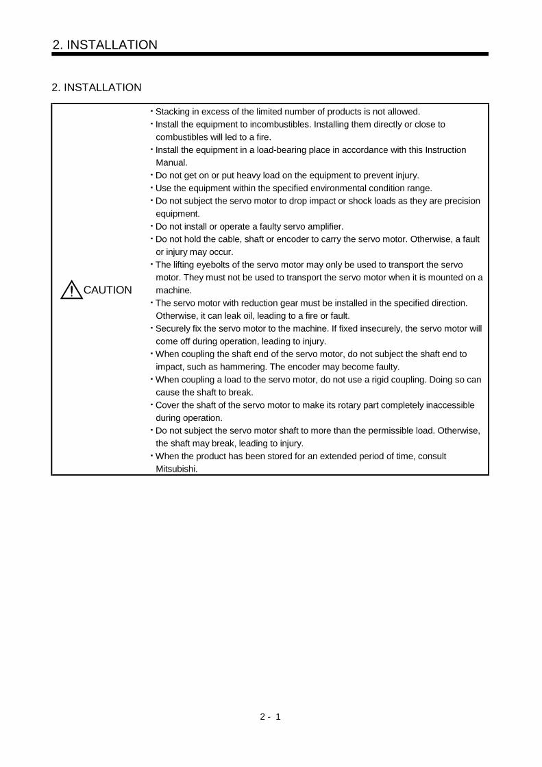
CAUTION
Stacking in excess of the limited number of products is not allowed.
Install the equipment to incombustibles. Installing them directly or close to
combustibles will led to a fire.
Install the equipment in a load-bearing place in accordance with this Instruction
Manual.
Do not get on or put heavy load on the equipment to prevent injury.
Use the equipment within the specified environmental condition range.
Do not subject the servo motor to drop impact or shock loads as they are precision
equipment.
Do not install or operate a faulty servo amplifier.
Do not hold the cable, shaft or encoder to carry the servo motor. Otherwise, a fault
or injury may occur.
The lifting eyebolts of the servo motor may only be used to transport the servo
motor. They must not be used to transport the servo motor when it is mounted on a
machine.
The servo motor with reduction gear must be installed in the specified direction.
Otherwise, it can leak oil, leading to a fire or fault.
Securely fix the servo motor to the machine. If fixed insecurely, the servo motor will
come off during operation, leading to injury.
When coupling the shaft end of the servo motor, do not subject the shaft end to
impact, such as hammering. The encoder may become faulty.
When coupling a load to the servo motor, do not use a rigid coupling. Doing so can
cause the shaft to break.
Cover the shaft of the servo motor to make its rotary part completely inaccessible
during operation.
Do not subject the servo motor shaft to more than the permissible load. Otherwise,
the shaft may break, leading to injury.
When the product has been stored for an extended period of time, consult
Mitsubishi.

2 - 2
2. INSTALLATION
2.1 Environmental conditionsEnvironment Conditions
[ ] 0 to 40 (non-freezing)Operation [ ] 32 to 104 (non-freezing)[ ] 15 to 70 (non-freezing)
Ambienttemperature
Storage [ ] 5 to 158 (non-freezing)Operation 80%RH or less (non-condensing)Ambient
humidity Storage 90%RH or less (non-condensing)
Ambience Indoors (no direct sunlight)Free from corrosive gas, flammable gas, oil mist, dust and dirt
Altitude Max. 1000m (3280 ft) above sea levelHC-KFS seriesH-MFS series HC-UFS13 to 73 X,Y:49
HC-SFS81HC-SFS52 to 152HC-SFS53 to 153
HC-RFS seriesHC-UFS72 152 X,Y:24.5
HC-SFS121 201HC-SFS202 352HC-SFS203 353
HC-UFS202 to 502 X:24.5Y:49
HC-SFS301HC-SFS502 702
X:24.5Y:29.4
HC-AQ seriesHC-KF seriesHC-MF series
HA-FF seriesHC-UF13 to 73 X,Y:19.6
HC-SF81HC-SF52 to 152HC-SF53 to 153
HC-RF seriesHC-UF72 152HC-LFS52 to152
X:9.8Y:24.5
HC-SF121 201HC-SF202 352HC-SF203 353
HC-UF202 to 502HC-LFS202 302
X:19.6Y:49
HA-LFS502 702HA-LFS601 to12K1HA-LFS701M to 15K1MHA-LH11K2 to 22K2
HA-LH11K2 to 22K2HC-SF301HC-SF502 702
X:11.7Y:29.4
[m/s2]
HA-LFS15K1 to 37K1HA-LFS22K1M to 37K1MHA-LFS30K2 37K2
HA-LF series X,Y:9.8
HC-KFS seriesHC-MFS series HC-UFS13 to 73 X,Y:161
HC-SFS81HC-SFS52 to 152HC-SFS53 to 153
HC-RFS seriesHC-UFS72 152 X,Y:80
HC-SFS121 201HC-SFS202 352HC-SFS203 353
HC-UFS202 to 502 X:80Y:161
HC-SFS301HC-SFS502 702
X:80Y:96
HC-AQ seriesHC-KF seriesHC-MF series
HA-FF seriesHC-UF13 to 73 X,Y:64
HC-SF81HC-SF52 to 152HC-SF53 to 153
HC-RF seriesHC-UF72 152HC-LFS52 to152
X:32Y:80
HC-SF121 201HC-SF202 352HC-SF203 353
HC-UF202 to 502HC-LFS202 302
X:64Y:161
HA-LFS502 702HA-LFS601 to12K1HA-LFS701M to 15K1MHA-LH11K2 to 22K2
HA-LH11K2 to 22K2HC-SF301HC-SF502 702
X:38.4Y:96.5
(Note) Vibration
[ft/s2]
HA-LFS15K1 to 37K1HA-LFS22K1M to 37K1MHA-LFS30K2 37K2
HA-LF series X,Y:32
Note: Except the servo motor with reduction gear.
Vibration occurs in the directions shown below.The values were measured at the portion whichindicates the maximum value (normally the bracketopposite to load side). When the servo motor is at astop, the bearings are likely to fret and vibrationshould therefore be suppressed to about half of thepermissible value.
Servo motor
Vibration
XY
Graph of vibration servo amplitude vs. speed
Speed [r/min] 500 1000 15002000250030003500
200
100
80
605040 30
20
Vib
ratio
n am
plit
ude
(bo
th a
mpl
itude
s) [
m]

2 - 3
2. INSTALLATION
2.2 Installation orientation
The following table lists directions of installation:Servo Motor Series Direction of Installation Remarks
HC-KFHA-FFHC-RFHC-KFSHC-SFSHC-UFS
HC-MFHC-SFHC-UFHC-MFSHC-RFSHC-LFS
HC-AQ
For installation in the horizontal direction, it is recommended to set theconnector section downward.
HA-LHHA-LFS (Flange type)
May be installed in anydirection.
HA-LFHA-LFS (Flange leg type)
Horizontal direction withthe legs downward.
Use either the legs or flange for installation.
When the servo motor with electromagnetic brake is installed with the shaft end at top, the brake platemay generate sliding sound but it is not a fault. Refer to Section 5.3 for the installation orientation of theservo motor with reduction gear.
2.3 Load remove precautions
POINT
During assembling, the shaft end must not be hammered. Doing so cancause the encoder to fail.
(1) When mounting a pulley to the servo motor shaft provided with a keyway, use the screw hole in theshaft end. To fit the pulley, first insert a double-end stud into the screw hole of the shaft, put a washeragainst the end face of the coupling, and insert and tighten a nut to force the pulley in.
Servo motor
Double-end stud
Nut
Washer
Pulley
(2) For the servo motor shaft with a keyway, use the screw hole in the shaft end. For the shaft without akeyway, use a friction coupling or the like.
(3) When removing the pulley, use a pulley remover to protect the shaft from impact.(4) To ensure safety, fit a protective cover or the like on the rotary area, such as the pulley, mounted to
the shaft.(5) When a threaded shaft end part is needed to mount a pulley on the shaft, please contact us.(6) The orientation of the encoder on the servo motor cannot be changed.(7) For installation of the servo motor, use spring washers, etc. and fully tighten the bolts so that they do
not become loose due to vibration.(8) For the HC-AQ series, use spring washers and apply Screw Lock to mount the servo motor. In
addition, use Helisert screws when the flange for mouthing the servo motor is made of aluminum.

2 - 4
2. INSTALLATION
2.4 Permissible load for the shaft
POINT
Do not use a rigid coupling as it may apply excessive bending load to theshaft, leading to shaft breakage.
(1) Use a flexible coupling and make sure that the misalignment of the shaft is less than the permissibleradial load.
(2) When using a pulley, sprocket or timing belt, select a diameter that will fit into the permissible radialload.
(3) Excess of the permissible load can cause the bearing life to reduce and the shaft to break.
2.4.1 Without reduction gear
(Note 1) L Permissible Radial Load Permissible Thrust LoadServo Motor
[mm] [in] [N] [lb] [N] [lb]
053 / 13 25 0.98 88 20 59 13
23 / 43 30 1.18 245 55 98 22HC-KF
HC-KFS(Note) 73 40 1.57 392 88 147 33053 / 13 25 0.98 88 20 59 1323 / 43 30 1.18 245 55 98 22
HC-MFHC-MFS
73 40 1.57 392 88 147 33053 30 1.18 108 24 98 2213 30 1.18 118 27 98 2223 / 33 30 1.18 176 40 147 33
HA-FF
43 / 63 40 1.57 323 73 284 6481 55 2.17 980 220 490 110121 to 301 79 3.11 2058 463 980 22052 to 152 55 2.17 980 220 490 110202 / 702 79 3.11 2058 463 980 22053 to 153 55 2.17 980 220 490 110
HC-SFHC-SFS
203 / 353 79 3.11 2058 463 980 22052 to 152 55 2.17 980 220 490 110
HC-LFS202/302 79 3.11 2058 463 980 220103 to 203 45 1.77 686 154 196 44HC-RF
HC-RFS 353 / 503 63 2.48 980 220 392 8872 / 152 55 2.17 637 143 490 110202 65 2.56 882 198 784 176352 / 502 65 2.56 1176 264 784 17613 25 0.98 88 20 59 1323 / 43 30 1.18 245 55 98 22
HC-UFHC-UFS
73 40 1.57 392 88 147 3311K2 85 3.35 2450 551 980 22015K2 / 22K2 100 3.94 2940 661 980 220HA-LH053/13 25 0.98 88 20 59 130135 16 0.63 34 8 14 30235 16 0.63 44 10 14 3HC-AQ0335 16 0.63 49 11 14 330K2/37K2/30K24/37K24
140 5.51 3234 727 1470 330HA-LF
45K24 /55K24 140 5.51 4900 1102 1960 441502/702/601/701M 85 3.35 2450 551 980 153801/11K1M/12K1/15K1M
110 4.33 2940 661 980 153
15K1/22K1M/20K1/30K1M/30K2/37K2
140 5.51 3234 727 1470 330
25K1/37K1M/30K1 140 5.51 4900 1102 1960 441
HA-LFS
37K1 170 6.69 6370 1432 1960 441
2 - 5
2. INSTALLATION
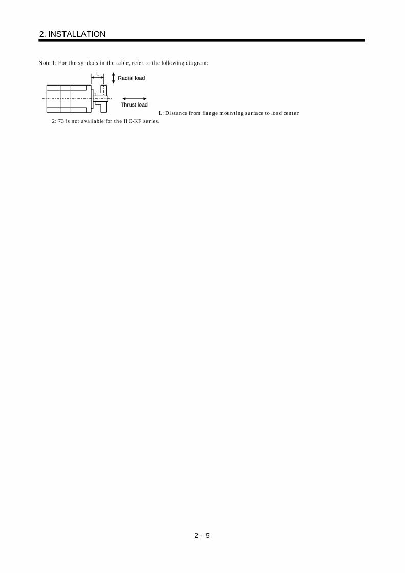
Note 1: For the symbols in the table, refer to the following diagram:
Radial load
Thrust load
L
L: Distance from flange mounting surface to load center
2: 73 is not available for the HC-KF series.

2 - 6
2. INSTALLATION
2.4.2 With reduction gear
The permissible radial loads in the table are the values at the center of the reduction gear output shaft.
Q/ 2
Q
(1) HC-MF HC-MFS HC-KF HC-KFS series
(a) General industrial machine-compliant
HC-MF(S)053(B)
G1
HC-MF(S)13(B)
G1
HC-MF(S)23(B)
G1
HC-MF(S)43(B)
G1
HC-MF(S)73(B)
G1Item
Gear
ratio HC-KF(S)053(B)
G1
HC-KF(S)13(B)
G1
HC-KF(S)23(B)
G1
HC-KF(S)43(B)
G1
HC-KFS73(B)
G1
1/5 150 330 430
1/12 240 710 620[N]
1/20 370 780 760 970
1/5 34 74 97
1/12 54 160 139
Permissible Radial Load
[lb]
1/20 83 175 171 218
1/5 200 350 430
1/12 320 720 620[N]
1/20 450 780 760 960
1/5 45 79 97
1/12 72 162 139
Permissible Thrust Load
[lb]
1/20 101 175 171 216
(b) Precision application-compliant
HC-MF(S)053(B)
G2
HC-MF(S)13(B)
G2
HC-MF(S)23(B)
G2
HC-MF(S)43(B)
G2
HC-MF(S)73(B)
G2Item
Gear
ratio HC-KF(S)053(B)
G2
HC-KF(S)13(B)
G2
HC-KF(S)23(B)
G2
HC-KF(S)43(B)
G2
HC-KFS73(B)
G2
1/5 160 160 160 340 390
1/9 200 200 420 480 600
1/20 260 540 610 790 1040[N]
1/29 290 610 700 900 1190
1/5 36 36 36 76 88
1/9 45 45 94 108 135
1/20 58 121 137 178 234
Permissible Radial Load
[lb]
1/29 65 137 157 202 268
1/5 220 220 220 370 390
1/9 270 270 450 490 600
1/20 400 660 640 790 1140[N]
1/29 450 750 830 1010 1290
1/5 49 49 49 83 87
1/9 61 61 101 110 135
1/20 90 148 144 178 256
Permissible Thrust Load
[lb]
1/29 101 167 187 227 290

2 - 7
2. INSTALLATION
(2) HA-FF series
(a) General industrial machine-compliant
ItemGear
ratioHA-FF053(B)G1 HA-FF13(B)G1 HA-FF23(B)G1 HA-FF33(B)G1 HA-FF43(B)G1 HA-FF63(B)G1
1/5 588 686 686 980
1/10 588 686 686 1470
1/20 588 1176 1568 1764[N]
1/30 686 1225 1764 2156
1/5 132 154 154 220
1/10 132 154 154 330
1/20 132 264 353 397
Permissible RadialLoad
[lb]
1/30 154 275 397 485
(b) Precision application-compliant
ItemGear
ratioHA-FF053(B)G2 HA-FF13(B)G2 HA-FF23(B)G2 HA-FF33(B)G2 HA-FF43(B)G2 HA-FF63(B)G2
1/5 69 69 98 216 216 588
1/9 735 735
1/10 88 127 265 265
1/15 137 216 392
1/20 980 980 1274 1274
1/25 392 784
1/29 1078 1470 1470 1470
[N]
1/45 1274 1666 1666 1666 3430
1/5 15 15 22 49 49 132
1/9 165 165
1/10 20 29 60 60
1/15 31 49 88
1/20 220 220 286 286
1/25 88 176
1/29 242 330 330 330
Permissible RadialLoad
[lb]
1/45 286 375 375 375 771
1/5 59 59 147 265 265 784
1/9 980 980
1/10 78 167 343 343
1/15 88 216 363
1/20 1372 1372 2254 2254
1/25 314 412
1/29 1764 2548 2548 2548
[N]
1/45 1960 3234 3234 3234 5390
1/5 13 13 33 60 60 176
1/9 220 220
1/10 16 38 77 77
1/15 20 49 82
1/20 308 308 507 507
1/25 71 93
1/29 397 573 573 573
Permissible ThrustLoad
[lb]
1/45 441 727 727 727 1212
2 - 8
2. INSTALLATION
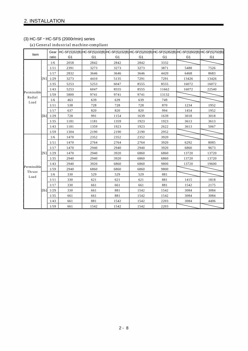
(3) HC-SF HC-SFS (2000r/min) series
(a) General industrial machine-compliant
ItemGear
ratio
HC-SF(S)52(B)
G1
HC-SF(S)102(B)
G1
HC-SF(S)152(B)
G1
HC-SF(S)202(B)
G1
HC-SF(S)352(B)
G1
HC-SF(S)502(B)
G1
HC-SF(S)702(B)
G1
1/6 2058 2842 2842 2842 3332
1/11 2391 3273 3273 3273 3871 5488 7526
1/17 2832 3646 3646 3646 4420 6468 8683
1/29 3273 4410 5135 7291 7291 13426 13426
1/35 5253 5253 6047 8555 8555 16072 16072
1/43 5253 6047 8555 8555 11662 16072 22540
[N]
1/59 5800 9741 9741 9741 13132
1/6 463 639 639 639 749
1/11 538 728 728 728 870 1234 1952
1/17 637 820 820 820 994 1454 1952
1/29 728 991 1154 1639 1639 3018 3018
1/35 1181 1181 1359 1923 1923 3613 3613
1/43 1181 1359 1923 1923 2622 3613 5067
PermissibleRadialLoad
[lb]
1/59 1304 2190 2190 2190 2952
1/6 1470 2352 2352 2352 3920
1/11 1470 2764 2764 2764 3920 6292 8085
1/17 1470 2940 2940 2940 3920 6860 9673
1/29 1470 2940 3920 6860 6860 13720 13720
1/35 2940 2940 3920 6860 6860 13720 13720
1/43 2940 3920 6860 6860 9800 13720 19600
[N]
1/59 2940 6860 6860 6860 9800
1/6 330 529 529 529 881
1/11 330 621 621 621 881 1415 1818
1/17 330 661 661 661 881 1542 2175
1/29 330 661 881 1542 1542 3084 3084
1/35 661 661 881 1542 1542 3084 3084
1/43 661 881 1542 1542 2203 3084 4406
PermissibleThrustLoad
[lb]
1/59 661 1542 1542 1542 2203

2 - 9
2. INSTALLATION
(b) Precision application-compliant
ItemGear
ratio
HC-SF(S)52(B)
G2
HC-SF(S)102(B)
G2
HC-SF(S)152(B)
G2
HC-SF(S)202(B)
G2
HC-SF(S)352(B)
G2
HC-SF(S)502(B)
G2
HC-SF(S)702(B)
G2
1/5 833 833 833 1666 3822 3822 3822
1/9 980 980 1960 1960 4704 4704
1/20 1274 2646 2646 6076 6076
1/29 2940 2940 6860 6860
[N]
1/45 3430 8036 8036 8036
1/5 187 187 187 375 859 859 859
1/9 220 220 441 441 1058 1058
1/20 286 595 595 1366 1366
1/29 661 661 1542 1542
PermissibleRadialLoad
[lb]
1/45 771 1807 1807 1807
1/5 1176 1176 1176 2156 5488 5488 5488
1/9 1568 1568 2646 2646 7252 7252
1/20 2254 3724 3724 9506 9506
1/29 4704 4704 11760 11760
[N]
1/45 5390 14700 14700 14700
1/5 264 264 264 485 1234 1234 1234
1/9 353 353 595 595 1630 1630
1/20 507 837 837 2137 2137
1/29 1058 1058 2644 2644
PermissibleThrustLoad
[lb]
1/45 1212 3305 3305 3305
(4) HC-RF HC-RFS series
ItemGear
ratio
HC-RF(S)103(B)
G2
HC-RF(S)153(B)
G2
HC-RF(S)203(B)
G2
HC-RF(S)353(B)
G2
HC-RF(S)503(B)
G2
1/5 833 833 833 1666 3822
1/9 980 1960 1960 4704 4704
1/20 2646 2646 2646 6076 6076
1/29 2940 2940 6860 6860
[N]
1/45 3430 8036 8036
1/5 187 187 187 375 859
1/9 220 441 441 1058 1058
1/20 595 595 595 1366 1366
1/29 661 661 1542 1542
Permissible RadialLoad
[lb]
1/45 771 1806 1806
1/5 1176 1176 1176 2156 5488
1/9 1568 2646 2646 7252 7252
1/20 38.8 3724 3724 9506 9506
1/29 4704 4704 11760 11760
[N]
1/45 5390 14700 14700
1/5 264 264 264 485 1234
1/9 353 595 595 1630 1630
1/20 8.7 837 837 2137 2137
1/29 1058 1058 2644 2644
Permissible ThrustLoad
[lb]
1/45 1212 3305 3305
2 - 10
2. INSTALLATION
2.5 Protection from oil and water
(1) Next, the servo motor is not waterproof (IP44). Do not subject the servo motor to oil and water.Especially for the HC-MF HC-KF HC-AQ HC-KFS HC-MFS and HA-FF series, do not subject theshaft-through portion to oil.
Servo Motor Series Protection
HC-KF/HC-MFHA-LF/HA-FF/HA-LFS
IP44
HC-AQ/HC-KFS/HC-MFS IP55HA-LH JP44
Oil or water
Servo motor
(2) When the gear box is mounted horizontally, the oil level in the gear box should always be lower thanthe oil seal lip on the servo motor shaft. If it is higher than the oil seal lip, oil will enter the servomotor, leading to a fault.The HC-MF HC-KF HC-AQ HC-MFS and HC-KFS series servo motor is not equipped with an oilseal and cannot be used with the gear box as described above. Oil should be shut off on the gear boxside.In a special specification article with an oil seal is available. Please contact Mitsubishi.
Servo motor
V ring
Gear
Lip
Height above oil level h
Height above Oil Level h Height above Oil Level hServo Motor
[mm] [in]Servo Motor
[mm] [in]
81 20 0.79 053/13 8 0.32121 to 1 25 0.98 23/33 12 0.4752 to 2 20 0.79
HA-FF43/63 14 0.55
202 to 2 25 0.98 11K2 30 0.1853 to 3 20 0.79
HA-LH15K2/22K2 40 1.58
HC-SFHC-SFS
203/353 25 0.9852 to 2 20 0.79
30K2/37K2/30K24/37K24
45 1.77HC-LFS
202/302 25 0.98HA-LF
45K24/55K24 48 1.89HC-RF
HC-RFS103 to 3 20 0.79
601/701M/11K2502/702
34 1.34
72/152 20 0.79202 to 2 25 0.98
15K1/22K1M/30K2/20K1/30K1M/37K2
45 1.77
13 12 0.4723/43 14 0.55
HC-UFHC-UFS
73 20 0.79
801/12K1/25K1/30K1/11K1M/15K1M/
37K1M/15K2/22K248 1.89
HA-LFS
37K1 55 2.17

2 - 11
2. INSTALLATION
(3) When installing the servo motor horizontally, face the power cable and encoder cable downward. Wheninstalling the servo motor vertically or obliquely, provide a trap for the cable.
Cable trap
(4) Do not use the servo motor with its cable soaked in oil or water. (Figure on the right)
Cover
<Incorrect> Capillary phenomenon
Oil/water pool
Servo motor
(5) When the servo motor is to be installed with the shaft end at top, provide measures so that it is notexposed to oil and water entering from the machine side, gear box, etc.
Gear
Lubricating oil
Servo motor
(6) If the servo motor is exposed to oil such as coolant, the sealant, packing, cable and others may beaffected depending on the oil type.
(7) In the environment where the servo motor is exposed to oil mist, oil, water and/or like, the servo motorof the standard specifications may not be usable. Contact us.
(8) In the case of the servo motor with oil seal, the oil seal may sound during operation. It poses noproblems in function.
2 - 12
2. INSTALLATION
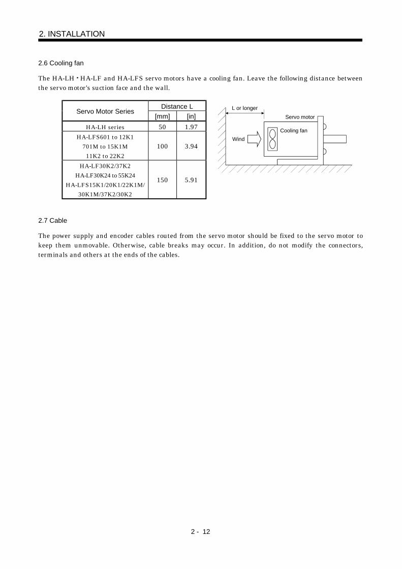
2.6 Cooling fan
The HA-LH HA-LF and HA-LFS servo motors have a cooling fan. Leave the following distance betweenthe servo motor's suction face and the wall.
Distance LServo Motor Series
[mm] [in]
HA-LH series 50 1.97HA-LFS601 to 12K1
701M to 15K1M
11K2 to 22K2
100 3.94
HA-LF30K2/37K2
HA-LF30K24 to 55K24
HA-LFS15K1/20K1/22K1M/
30K1M/37K2/30K2
150 5.91
L or longer
Wind
Servo motor
Cooling fan
2.7 Cable
The power supply and encoder cables routed from the servo motor should be fixed to the servo motor tokeep them unmovable. Otherwise, cable breaks may occur. In addition, do not modify the connectors,terminals and others at the ends of the cables.

3 - 1
3. CONNECTORS USED FOR SERVO MOTOR
3. CONNECTORS USED FOR SERVO MOTOR WIRING
3.1 Makeups
This section gives connector makeups on an operating environment basis. Use the models of themanufacturers given or equivalent.
3.1.1 HC-KF(-UE) HC-MF(-UE) HA-FF HC-UF3000r/min series
Use round crimping terminals (1.25-4) for connection of the power supply and electromagnetic brake. Forconnection of the encoder, use the connector indicated in this section or equivalent. This connector may beused with the EN Standard and UL/C-UL Standard but is not waterproof.
Cable Side Connector
Servo MotorConnector Supplied for
Servo Motor (AMP)Housing
(AMP)
Connector Pin
(AMP)
Cable Clamp
(Toa Electric Industry)
HC-KF (B)HC-KF (B)-UEHC-MF (B)HC-MF (B) -UEHA-FF (B)HC-UF13 to 73(B)
1-172169-9 1-172161-9170359-1
170363-1 (loose piece)MTI-0002
3.1.2 HA-FF C-UE series
If used with a waterproof connector, the HA-FF C(B)-UE does not improve in ingress protection (IP54).(1) Non-waterproof, UL/C-UL Standard-compliant
(a) When using cabtyre cables1) For connection of power supply
1) Plug2) Cable clamp Cable 1) Plug
2) Cable clamp Cable
Cable Side Connector
1) Plug (DDK)Servo MotorConnector Supplied for
Servo MotorType Model
2) Cable clamp
(DDK)
Straight MS3106B14S-2SHA-FF C(B) -UE CE05-2A14S-2PD-B
Angle MS3108B14S-2SMS3057-6A
3 - 2
3. CONNECTORS USED FOR SERVO MOTOR
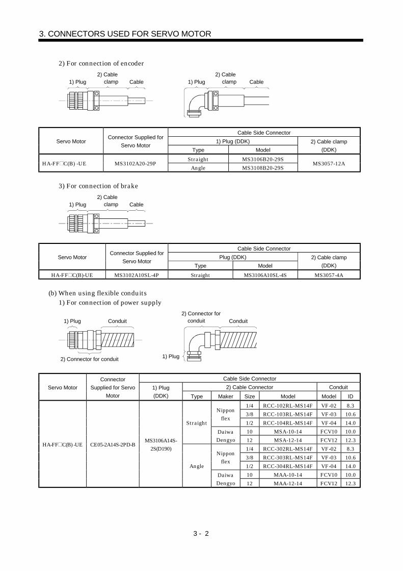
2) For connection of encoder
1) Plug2) Cable clamp Cable 1) Plug
2) Cable clamp Cable
Cable Side Connector
1) Plug (DDK)Servo MotorConnector Supplied for
Servo MotorType Model
2) Cable clamp
(DDK)
Straight MS3106B20-29SHA-FF C(B) -UE MS3102A20-29P
Angle MS3108B20-29SMS3057-12A
3) For connection of brake
1) Plug2) Cable clamp Cable
Cable Side Connector
Plug (DDK)Servo MotorConnector Supplied for
Servo MotorType Model
2) Cable clamp
(DDK)
HA-FF C(B)-UE MS3102A10SL-4P Straight MS3106A10SL-4S MS3057-4A
(b) When using flexible conduits1) For connection of power supply
1) Plug Conduit
1) Plug
2) Connector for conduit Conduit
2) Connector for conduit
Cable Side Connector
2) Cable Connector ConduitServo Motor
Connector
Supplied for Servo
Motor
1) Plug
(DDK) Type Maker Size Model Model ID
1/4 RCC-102RL-MS14F VF-02 8.3
3/8 RCC-103RL-MS14F VF-03 10.6Nippon
flex1/2 RCC-104RL-MS14F VF-04 14.0
10 MSA-10-14 FCV10 10.0
Straight
DaiwaDengyo 12 MSA-12-14 FCV12 12.3
1/4 RCC-302RL-MS14F VF-02 8.3
3/8 RCC-303RL-MS14F VF-03 10.6Nippon
flex1/2 RCC-304RL-MS14F VF-04 14.0
10 MAA-10-14 FCV10 10.0
HA-FF C(B) -UE CE05-2A14S-2PD-BMS3106A14S-
2S(D190)
Angle
DaiwaDengyo 12 MAA-12-14 FCV12 12.3

3 - 3
3. CONNECTORS USED FOR SERVO MOTOR
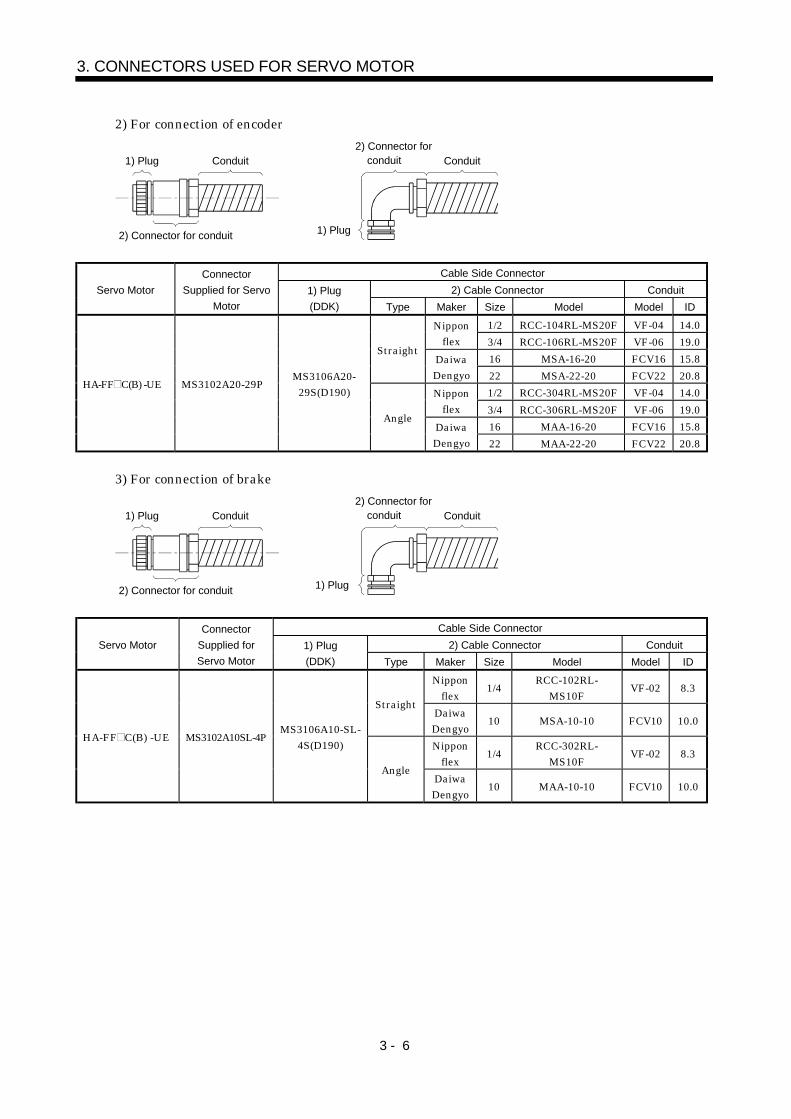
2) For connection of encoder
1) Plug Conduit
1) Plug
2) Connector for conduit Conduit
2) Connector for conduit
Cable Side Connector
2) Cable Connector ConduitServo Motor
Connector
Supplied for Servo
Motor
1) Plug
(DDK) Type Maker Size Model Model ID
1/2 RCC-104RL-MS20F VF-04 14.0Nipponflex 3/4 RCC-106RL-MS20F VF-06 19.0
16 MSA-16-20 FCV16 15.8Straight
DaiwaDengyo 22 MSA-22-20 FCV22 20.8
1/2 RCC-304RL-MS20F VF-04 14.0Nipponflex 3/4 RCC-306RL-MS20F VF-06 19.0
16 MAA-16-20 FCV16 15.8
HA-FF C(B) -UE MS3102A20-29PMS3106A20-
29S(D190)
AngleDaiwaDengyo 22 MAA-22-20 FCV22 20.8
3) For connection of brake
1) Plug Conduit
1) Plug
2) Connector for conduit Conduit
2) Connector for conduit
Cable Side Connector
2) Cable Connector ConduitServo Motor
Connector
Supplied for
Servo Motor
1) Plug
(DDK) Type Maker Size Model Model ID
Nipponflex
1/4 RCC-102RL-MS10F VF-02 8.3
StraightDaiwaDengyo
10 MSA-10-10 FCV10 10.0
Nipponflex
1/4 RCC-302RL-MS10F VF-02 8.3
HA-FF C(B) -UEMS3102A10SL
-4PMS3106A10SL-
4S(D190)
AngleDaiwaDengyo
10 MAA-10-10 FCV10 10.0

3 - 4
3. CONNECTORS USED FOR SERVO MOTOR
(2) EN Standard, UL/C-UL Standard-compliant
(a) When using cabtyre cables1) For connection of power supply
1) Plug Cable
1) Plug
Cable
2) Connector for cable
2) Connector for cable
Cable Side Connector
2) Connector for CableServo MotorConnector Supplied
for Servo Motor1) Plug
(DDK) Type Maker Cable OD Model
4 to 8 ACS-08RL-MS14FNipponflex 8 to 12 ACS-12RL-MS14F
5 to 8.3 YSO14-5 to 8Straight
DaiwaDengyo 8.3 to 11.3 YSO14-9 to 11
4 to 8 ACA-08RL-MS14FNipponflex 8 to 12 ACA-12RL-MS14F
5 to 8.3 YLO14-5 to 8
HA-FF C(B) -UE CE05-2A14S-2PD-B CE05-6A14S-2SD-B
AngleDaiwaDengyo 8.3 to 11.3 YLO14-9 to 11
2) For connection of encoder
1) Plug3) Cable clamp Cable 2) Back shell
3) Cable clamp
Cable
2) Back shell1) Plug
Cable Side Connector
2) Back Shell
(DDK)
3) Cable Clamp
(DDK)Servo Motor
Connector
Supplied for Servo
Motor
1) Plug
(DDK)Type Model Cable OD Model
Straight CE02-20BS-SHA-FF C(B) -UE MS3102A20-29P MS3106A20-29S(D190)
Angle CE-20BA-S6.8 to 10 CE3057-12A-3
3 - 5
3. CONNECTORS USED FOR SERVO MOTOR
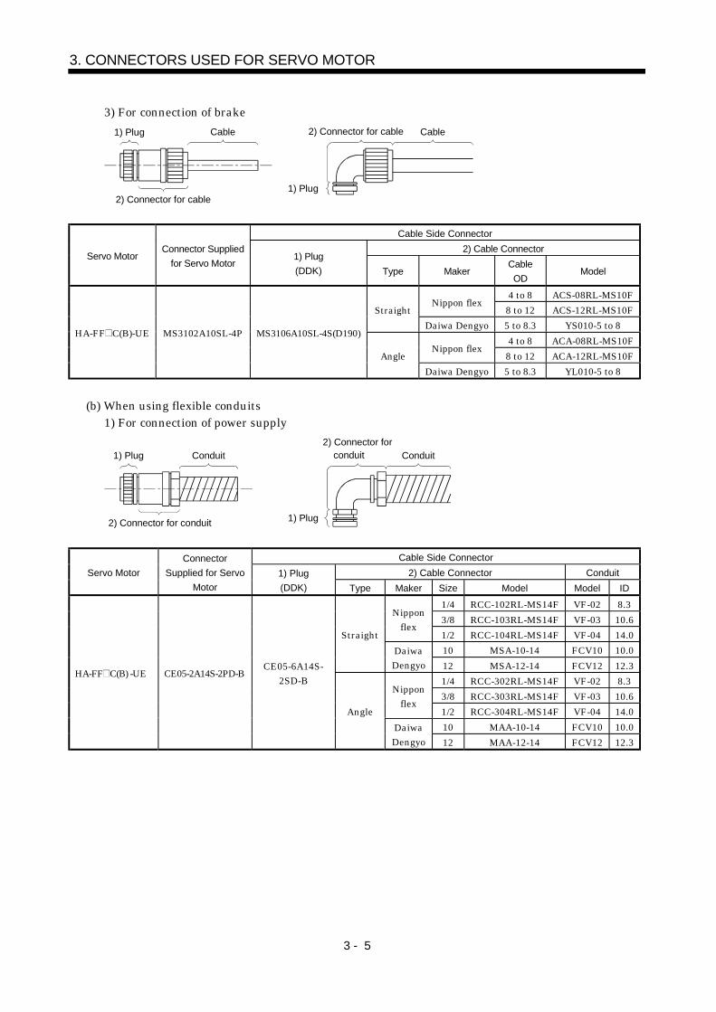
3) For connection of brake
1) Plug Cable
1) Plug
Cable2) Connector for cable
2) Connector for cable
Cable Side Connector
2) Cable ConnectorServo Motor
Connector Supplied
for Servo Motor1) Plug
(DDK) Type MakerCable
ODModel
4 to 8 ACS-08RL-MS10FNippon flex
8 to 12 ACS-12RL-MS10FStraight
Daiwa Dengyo 5 to 8.3 YS010-5 to 8
4 to 8 ACA-08RL-MS10FNippon flex
8 to 12 ACA-12RL-MS10F
HA-FF C(B)-UE MS3102A10SL-4P MS3106A10SL-4S(D190)
Angle
Daiwa Dengyo 5 to 8.3 YL010-5 to 8
(b) When using flexible conduits1) For connection of power supply
1) Plug Conduit
1) Plug
2) Connector for conduit Conduit
2) Connector for conduit
Cable Side Connector
2) Cable Connector ConduitServo Motor
Connector
Supplied for Servo
Motor
1) Plug
(DDK) Type Maker Size Model Model ID
1/4 RCC-102RL-MS14F VF-02 8.3
3/8 RCC-103RL-MS14F VF-03 10.6Nippon
flex1/2 RCC-104RL-MS14F VF-04 14.0
10 MSA-10-14 FCV10 10.0
Straight
DaiwaDengyo 12 MSA-12-14 FCV12 12.3
1/4 RCC-302RL-MS14F VF-02 8.3
3/8 RCC-303RL-MS14F VF-03 10.6Nippon
flex1/2 RCC-304RL-MS14F VF-04 14.0
10 MAA-10-14 FCV10 10.0
HA-FF C(B) -UE CE05-2A14S-2PD-BCE05-6A14S-
2SD-B
Angle
DaiwaDengyo 12 MAA-12-14 FCV12 12.3
3 - 6
3. CONNECTORS USED FOR SERVO MOTOR
2) For connection of encoder
1) Plug Conduit
1) Plug
2) Connector for conduit Conduit
2) Connector for conduit
Cable Side Connector
2) Cable Connector ConduitServo Motor
Connector
Supplied for Servo
Motor
1) Plug
(DDK) Type Maker Size Model Model ID
1/2 RCC-104RL-MS20F VF-04 14.0Nipponflex 3/4 RCC-106RL-MS20F VF-06 19.0
16 MSA-16-20 FCV16 15.8Straight
DaiwaDengyo 22 MSA-22-20 FCV22 20.8
1/2 RCC-304RL-MS20F VF-04 14.0Nipponflex 3/4 RCC-306RL-MS20F VF-06 19.0
16 MAA-16-20 FCV16 15.8
HA-FF C(B) -UE MS3102A20-29PMS3106A20-
29S(D190)
AngleDaiwaDengyo 22 MAA-22-20 FCV22 20.8
3) For connection of brake
1) Plug Conduit
1) Plug
2) Connector for conduit Conduit
2) Connector for conduit
Cable Side Connector
2) Cable Connector ConduitServo Motor
Connector
Supplied for
Servo Motor
1) Plug
(DDK) Type Maker Size Model Model ID
Nipponflex
1/4RCC-102RL-
MS10FVF-02 8.3
StraightDaiwaDengyo
10 MSA-10-10 FCV10 10.0
Nipponflex
1/4RCC-302RL-
MS10FVF-02 8.3
HA-FF C(B) -UE MS3102A10SL-4PMS3106A10-SL-
4S(D190)
AngleDaiwaDengyo
10 MAA-10-10 FCV10 10.0

3 - 7
3. CONNECTORS USED FOR SERVO MOTOR
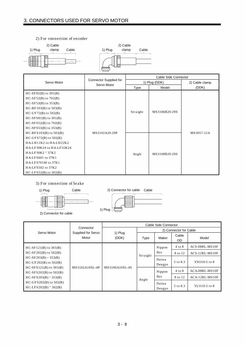
3.1.3 HC-SF(S) HC-RF(S) HC-UF(S)2000r/min, HA-LH HA-LF HA-LFS HC-LFS series
(1) Non-waterproof, UL/C-UL Standard-compliant
(a) When using cabtyre cables1) For connection of power supply
1) Plug2) Cable clamp Cable 1) Plug
2) Cable clamp Cable
Cable Side Connector
1) Plug (DDK)Servo Motor Connector Supplied for Servo Motor
Type Model
2) Cable clamp
(DDK)
Straight MS3106B22-23S
HC-SF81(B)HC-SF52(B) to 152(B)HC-SF53(B) to 153(B)HC-RF103(B) to 203(B)HC-UF72(B) 152(B)HC-SFS81(B)HC-SFS52(B) to 152(B)HC-SFS53(B) to 153(B)HC-RFS103(B) to 203(B)HC-UFS72(B) 152(B)HC-LFS52(B) to 152(B)
CE05-2A22-23PD-B
Angle MS3108B22-23S
MS3057-12A
Straight MS3106B24-10S
HC-SF121(B) to 301(B)HC-SF202(B) to 502(B)HC-SF203(B) 353(B)HC-RF353(B) to 503(B)HC-UF202(B) to 502(B)HC-SFS121(B) to 301(B)HC-SFS202(B) to 502(B)HC-SFS203(B) to 353(B)HC-RFS353(B) 503(B)HC-UFS202(B) to 502(B)HA-LFS502HC-LFS202(B) 302(B)
CE05-2A24-10PD-B
Angle MS3108B24-10S
MS3057-16A
Straight MS3106B32-17SHC-SF702HC-SFS702(B)HA-LFS702
CE05-2A32-17PD-BAngle MS3108B32-17S
MS3057-20A
3 - 8
3. CONNECTORS USED FOR SERVO MOTOR
2) For connection of encoder
1) Plug2) Cable clamp Cable 1) Plug
2) Cable clamp Cable
Cable Side Connector
1) Plug (DDK)Servo MotorConnector Supplied for
Servo MotorType Model
2) Cable clamp
(DDK)
Straight MS3106B20-29S
HC-SF81(B) to 301(B)HC-SF52(B) to 702(B)HC-SF53(B) to 353(B)HC-RF103(B) to 503(B)HC-UF72(B) to 502(B)HC-SFS81(B) to 301(B)HC-SFS52(B) to 702(B)HC-SFS53(B) to 353(B)HC-RFS103(B) to 503(B)HC-UFS72(B) to 502(B)HA-LH11K2 to HA-LH22K2HA-LF30K24 to HA-LF55K24HA-LF30K2 37K2HA-LFS601 to 37K1HA-LFS701M to 37K1HA-LFS502 to 37K2HC-LFS52(B) to 302(B)
MS3102A20-29P
Angle MS3108B20-29S
MS3057-12A
3) For connection of brake
1) Plug Cable
1) Plug
Cable2) Connector for cable
2) Connector for cable
Cable Side Connector
2) Connector for CableServo Motor
Connector
Supplied for Servo
Motor
1) Plug
(DDK) Type MakerCable
ODModel
4 to 8 ACS-08RL-MS10FNipponflex 8 to 12 ACS-12RL-MS10F
StraightDaiwaDengyo
5 to 8.3 YSO10-5 to 8
4 to 8 ACA-08RL-MS10FNipponflex 8 to 12 ACA-12RL-MS10F
HC-SF121(B) to 301(B)HC-SF202(B) to 502(B)HC-SF203(B) 353(B)HC-UF202(B) to 502(B)HC-SFS121(B) to 301(B)HC-SFS202(B) to 502(B)HC-SFS203(B) 353(B)HC-UFS202(B) to 502(B)HC-LFS202(B) 302(B)
MS3102A10SL-4P MS3106A10SL-4S
AngleDaiwaDengyo
5 to 8.3 YLO10-5 to 8

3 - 9
3. CONNECTORS USED FOR SERVO MOTOR
(b) When using flexible conduits1) For connection of power supply
1) Plug Conduit
1) Plug
2) Connector for conduit Conduit
2) Connector for conduit
Cable Side Connector
2) Connector for conduit ConduitServo Motor
Connector
Supplied for
Servo Motor
1) Plug
(DDK) Type Maker Size Model Model ID
1/2 RCC-104RL-MS22F VF-04 14.0
3/4 RCC-106RL-MS22F VF-06 19.0Nippon
flex1 RCC-108RL-MS22F VF-08 24.4
16 MSA-16-22 FCV16 15.8
22 MSA-22-22 FCV22 20.8
Straight
DaiwaDengyo
28 MSA-28-22 FCV28 26.4
1/2 RCC-304RL-MS22F VF-04 14.0
3/4 RCC-306RL-MS22F VF-06 19.0Nippon
flex1 RCC-308RL-MS22F VF-08 24.4
16 MAA-16-22 FCV16 15.8
22 MAA-22-22 FCV22 20.8
HC-SF81(B)HC-SF52(B) to 152(B)HC-SF53(B) to 153(B)HC-RF103(B) to 203(B)HC-UF72(B) 152(B)HC-SFS81(B)HC-SFS52(B) to 152(B)HC-SFS53(B) to 153(B)HC-RFS103(B) to 203(B)HC-UFS72(B) 152(B)HC-LFS52(B) to 152(B)
CE05-2A22-23PD-B
MS3106A22-23S(D190)
Angle
DaiwaDengyo
28 MAA-28-22 FCV28 26.4
1/2 RCC-104RL-MS24F VF-04 14.0
3/4 RCC-106RL-MS24F VF-06 19.0Nippon
flex1 RCC-108RL-MS24F VF-08 24.4
16 MSA-16-24 FCV16 15.8
22 MSA-22-24 FCV22 20.8
Straight
DaiwaDengyo
28 MSA-28-24 FCV28 26.4
1/2 RCC-304RL-MS24F VF-04 14.0
3/4 RCC-306RL-MS24F VF-06 19.0Nippon
flex1 RCC-308RL-MS24F VF-08 24.4
16 MAA-16-24 FCV16 15.8
22 MAA-22-24 FCV22 20.8
HC-SF121(B) to 301(B)HC-SF202(B) to 502(B)HC-SF203(B) 352(B)HC-RF353(B) to 503(B)HC-UF202(B) to 502(B)HC-SFS121(B) to 301(B)HC-SFS202(B) to 502(B)HC-SFS203(B) to 353(B)HC-RFS353(B) 503(B)HC-UFS202(B) to 502(B)HA-LFS502HC-LFS202(B) 302(B)
CE05-2A24-10PD-B
MS3106A24-10S(D190)
Angle
DaiwaDengyo
28 MAA-28-24 FCV28 26.4
3/4 RCC-106RL-MS32F VF-06 19.0Straight
Nipponflex 1 RCC-108RL-MS32F VF-08 24.4
3/4 RCC-306RL-MS32F VF-06 19.0
HC-SF702(B)HC-SFS702(B)HA-LFS702
CE05-2A32-17PD-B
MS3106A32-17S(D190)
AngleDaiwaDengyo 1 RCC-308RL-MS32F VF-08 24.4

3 - 10
3. CONNECTORS USED FOR SERVO MOTOR
2) For connection of encoder
1) Plug Conduit
1) Plug
2) Connector for conduit Conduit
2) Connector for conduit
Cable Side Connector
2) Connector for conduit ConduitServo Motor
Connector
Supplied for
Servo Motor
1) Plug
(DDK) Type Maker Size Model Model ID
1/2 RCC-104RL-MS20F VF-04 14.0Nippon
flex3/4 RCC-106RL-MS20F VF-06 19.0
16 MSA-16-20 FCV16 15.8
Straight
DaiwaDengyo
22 MSA-22-20 FCV22 20.8
1/2 RCC-304RL-MS20F VF-04 14.0Nippon
flex3/4 RCC-306RL-MS20F VF-06 19.0
16 MAA-16-20 FCV16 15.8
HC-SF81(B) to 301(B)HC-SF52(B) to 702(B)HC-SF53(B) to 353(B)HC-RF103(B) to 503(B)HC-UF72(B) to 502(B)HC-SFS81(B) to 301(B)HC-SFS52(B) to 702(B)HC-SFS53(B) to 353(B)HC-RFS103(B) to 503(B)HC-UFS72(B) to 502(B)HA-LH11K2 to 22K2(B)HA-LF30K24 to 55K24HA-LF30K2 37K2HA-LFS601 to 37K1HA-LFS701M to 37K1MHA-LFS502 to 37K2HC-LFS52(B) to 302(B)
MS3102A20-29P
MS3106A20-29S(D190)
Angle
DaiwaDengyo
22 MAA-22-20 FCV22 20.8
3) For connection of brake
1) Plug Conduit
1) Plug
2) Connector for conduit Conduit
2) Connector for conduit
Cable Side Connector
2) Connector for conduit ConduitServo Motor
Connector
Supplied
for Servo
Motor
1) Plug
(DDK) Type Maker Size Model Model ID
Nipponflex
1/4 RCC-102RL-MS10F VF-02 8.3
StraightDaiwaDengyo
10 MSA-10-10 FCV10 10
Nipponflex
1/4 RCC-302RL-MS10F VF-02 8.3
HC-SF121(B) to 301(B)HC-SF202(B) to 502(B)HC-SF203(B) 353(B)HC-UF202(B) to 502(B)HC-SFS121(B) to 301(B)HC-SFS202(B) to 502(B)HC-SFS203(B) 353(B)HC-UFS202(B) to 502(B)HC-LFS202(B) 302(B)
MS3102A10SL-4P
MS3106A10-SL-4S(D190)
AngleDaiwaDengyo
10 MAA-10-10 FCV10 10

3 - 11
3. CONNECTORS USED FOR SERVO MOTOR
(2) Waterproof (IP65), EN Standard, UL/C-UL Standard-compliant
(a) When using cabtyre cables1) For connection of power supply
1) Plug2) Cable clamp Cable 1) Plug
2) Cable clamp Cable
Cable Side Connector
1) Plug (DDK)2) Cable clamp
(DDK)Servo Motor
Connector
Supplied for
Servo MotorType Model Cable OD Model
Straight CE05-6A22-23SD-B-BSS 9.5 to 13 CE3057-12A-2(D265)
HC-SF81(B)HC-SF52(B) to 152(B)HC-SF53(B) to 153(B)HC-RF103(B) to 203(B)HC-UF72(B) 152(B)HC-SFS81(B)HC-SFS52(B) to 152(B)HC-SFS53(B) to 153(B)HC-RFS103(B) to 203(B)HC-UFS72(B) 152(B)HC-LFS52(B) to 152(B)
CE05-2A22-23PD-B
Angle CE05-8A22-23SD-B-BAS 12.5 to 16 CE3057-12A-1(D265)
Straight CE05-6A24-10SD-B-BSS 13 to 15.5 CE3057-16A-2(D265)
HC-SF121(B) to 301(B)HC-SF202(B) to 502(B)HC-SF203(B) 353(B)HC-RF353(B) to 503(B)HC-UF202(B) to 502(B)HC-SFS121(B) to 301(B)HC-SFS202(B) to 502(B)HC-SFS203(B) 353(B)HC-RFS353(B) 503(B)HC-UFS202(B) to 502(B)HA-LFS502HC-LFS202(B) 302(B)
CE05-2A24-10PD-B
Angle CE05-8A24-10SD-B-BAS 15 to 19.1 CE3057-16A-1(D265)
Straight CE05-6A32-17SD-B-BSSHC-SF702(B)HC-SFS702(B)HA-LFS702
CE05-2A32-17PD-B Angle CE05-8A32-17SD-B-BAS
22 to 23.8 CE3057-20A-1(D265)

3 - 12
3. CONNECTORS USED FOR SERVO MOTOR
2) For connection of encoder
1) Plug3) Cable clamp Cable 2) Back shell
3) Cable clamp
Cable
2) Back shell1) Plug
Cable Side Connector
2) Back shell3) Cable clamp
(DDK)Servo Motor
Connector
Supplied for
Servo Motor
1) Plug
(DDK)Type Model Cable OD Model
Straight CE02-20BS-S
HC-SF81(B) to 301(B)HC-SF52(B) to 702(B)HC-SF53(B) to 353(B)HC-RF103(B) to 503(B)HC-UF72(B) to 502(B)HC-SFS81(B) to 301(B)HC-SFS52(B) to 702(B)HC-SFS53(B) to 353(B)HC-RFS103(B) to 502(B)HC-UFS72(B) to 502(B)HA-LH11K2 to 22K2HA-LF30K24 to 55K24HA-LF30K2 37K2HA-LFS601 to 37K1HA-LFS701M to 37K1MHA-LFS502 to 37K2HC-LFS52(B) to 302(B)
MS3102A20-29P
MS3106A20-29S(D190)
Angle CE-20BA-S
6.8 to 10 CE3057-12A-3(D265)
3) For connection of brake
1) Plug Cable
1) Plug
Cable2) Connector for cable
2) Connector for cable
Cable Side Connector
2) Connector for CableServo Motor
Connector Supplied
for Servo Motor1) Plug
(DDK) Type MakerCable
ODModel
4 to 8 ACS-08RL-MS10FNipponflex 8 to 12 ACS-12RL-MS10F
StraightDaiwaDengyo
5 to 8.3 YSO-10-5 to 8
4 to 8 ACA-08RL-MS10FNipponflex 8 to 12 ACA-12RL-MS10F
HC-SF121(B) to 301(B)HC-SF202(B) to 502(B)HC-SF203(B) 353(B)HC-UF202(B) to 502(B)HC-SFS121(B) to 301(B)HC-SFS202(B) to 502(B)HC-SFS203(B) 353(B)HC-UFS202(B) to 502(B)HC-LFS202(B) 302(B)
MS3102A10SL-4PMS3106A10SL-
4S(D190)
AngleDaiwaDengyo
5 to 8.3 YLO-10-5 to 8
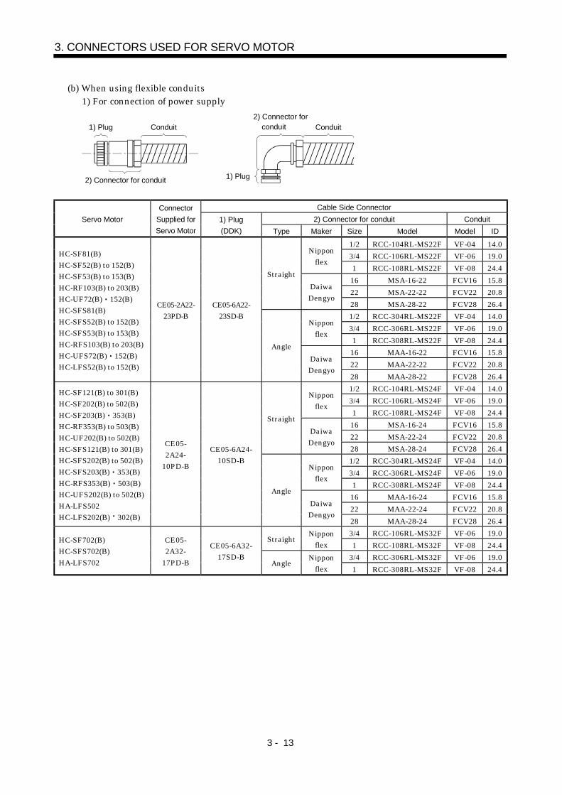
3 - 13
3. CONNECTORS USED FOR SERVO MOTOR
(b) When using flexible conduits1) For connection of power supply
1) Plug Conduit
1) Plug
2) Connector for conduit Conduit
2) Connector for conduit
Cable Side Connector
2) Connector for conduit ConduitServo Motor
Connector
Supplied for
Servo Motor
1) Plug
(DDK) Type Maker Size Model Model ID
1/2 RCC-104RL-MS22F VF-04 14.0
3/4 RCC-106RL-MS22F VF-06 19.0Nippon
flex1 RCC-108RL-MS22F VF-08 24.4
16 MSA-16-22 FCV16 15.8
22 MSA-22-22 FCV22 20.8
Straight
DaiwaDengyo
28 MSA-28-22 FCV28 26.4
1/2 RCC-304RL-MS22F VF-04 14.0
3/4 RCC-306RL-MS22F VF-06 19.0Nippon
flex1 RCC-308RL-MS22F VF-08 24.4
16 MAA-16-22 FCV16 15.8
22 MAA-22-22 FCV22 20.8
HC-SF81(B)HC-SF52(B) to 152(B)HC-SF53(B) to 153(B)HC-RF103(B) to 203(B)HC-UF72(B) 152(B)HC-SFS81(B)HC-SFS52(B) to 152(B)HC-SFS53(B) to 153(B)HC-RFS103(B) to 203(B)HC-UFS72(B) 152(B)HC-LFS52(B) to 152(B)
CE05-2A22-23PD-B
CE05-6A22-23SD-B
Angle
DaiwaDengyo
28 MAA-28-22 FCV28 26.4
1/2 RCC-104RL-MS24F VF-04 14.0
3/4 RCC-106RL-MS24F VF-06 19.0Nippon
flex1 RCC-108RL-MS24F VF-08 24.4
16 MSA-16-24 FCV16 15.8
22 MSA-22-24 FCV22 20.8
Straight
DaiwaDengyo
28 MSA-28-24 FCV28 26.4
1/2 RCC-304RL-MS24F VF-04 14.0
3/4 RCC-306RL-MS24F VF-06 19.0Nippon
flex1 RCC-308RL-MS24F VF-08 24.4
16 MAA-16-24 FCV16 15.8
22 MAA-22-24 FCV22 20.8
HC-SF121(B) to 301(B)HC-SF202(B) to 502(B)HC-SF203(B) 353(B)HC-RF353(B) to 503(B)HC-UF202(B) to 502(B)HC-SFS121(B) to 301(B)HC-SFS202(B) to 502(B)HC-SFS203(B) 353(B)HC-RFS353(B) 503(B)HC-UFS202(B) to 502(B)HA-LFS502HC-LFS202(B) 302(B)
CE05-2A24-
10PD-B
CE05-6A24-10SD-B
Angle
DaiwaDengyo
28 MAA-28-24 FCV28 26.4
3/4 RCC-106RL-MS32F VF-06 19.0Straight
Nipponflex 1 RCC-108RL-MS32F VF-08 24.4
3/4 RCC-306RL-MS32F VF-06 19.0
HC-SF702(B)HC-SFS702(B)HA-LFS702
CE05-2A32-
17PD-B
CE05-6A32-17SD-B
AngleNippon
flex 1 RCC-308RL-MS32F VF-08 24.4

3 - 14
3. CONNECTORS USED FOR SERVO MOTOR
2) For connection of encoder
1) Plug Conduit
1) Plug
2) Connector for conduit Conduit
2) Connector for conduit
Cable Side Connector
2) Connector for conduit ConduitServo Motor
Connector
Supplied for
Servo Motor
1) Plug
(DDK) Type Maker Size Model Model ID
1/2 RCC-104RL-MS20F VF-04 14.0Nippon
flex3/4 RCC-106RL-MS20F VF-06 19.0
16 MSA-16-20 FCV16 15.8
Straight
DaiwaDengyo
22 MSA-22-20 FCV22 20.8
1/2 RCC-304RL-MS20F VF-04 14.0Nippon
flex3/4 RCC-306RL-MS20F VF-06 19.0
16 MAA-16-20 FCV16 15.8
HC-SF81(B) to 301(B)HC-SF52(B) to 702(B)HC-SF53(B) to 353(B)HC-RF103(B) to 503(B)HC-UF72(B) to 502(B)HC-SFS81(B) to 301(B)HC-SFS52(B) to 702(B)HC-SFS53(B) to 353(B)HC-RFS103(B) to 502(B)HC-UFS72(B) to 502(B)HA-LH11K2 to 22K2HA-LF30K24 to 55K24HA-LF30K2 37K2HA-LFS601 to 37K1HA-LFS701M to 37K1MHA-LFS502 to 37K2HC-LFS52(B) to 302 (B)
MS3102A20-29P
MS3106A20-29S(D190)
Angle
DaiwaDengyo
22 MAA-22-20 FCV22 20.8
3) For connection of brake
1) Plug Conduit
1) Plug
2) Connector for conduit Conduit
2) Connector for conduit
Cable Side Connector
2) Connector for conduit ConduitServo Motor
Connector
Supplied for
Servo Motor
1) Plug
(DDK) Type Maker Size Model Model ID
Nipponflex
1/4 RCC-102RL-MS10F VF-02 8.3
StraightDaiwaDengyo
10 MSA-10-10 FCV10 10
Nipponflex
1/4 RCC-302RL-MS10F VF-02 8.3
HC-SF121(B) to 301(B)HC-SF202(B) to 502(B)HC-SF203(B) 353(B)HC-UF202(B) to 502(B)HC-SFS121(B) to 301(B)HC-SFS202(B) to 502(B)HC-SFS203(B) 353(B)HC-UFS202(B) to 502(B)HC-LFS202(B) 302(B)
MS3102A10SL-4P
MS3106A10SL-4S(D190)
AngleDaiwaDengyo
10 MAA-10-10 FCV10 10

3 - 15
3. CONNECTORS USED FOR SERVO MOTOR
3.1.4 HC-AQ series
Cable Side Connector (molex)Servo Motor
Servo Motor Side Connector
(molex) Plug Terminal
HC-AQ (B) (Note) 5557-12R-210 5559-12P-210 5558
Note: Terminal: 5556
3.1.5 HC-KFS HC-MFS HC-UFS3000r/min series
Use the connectors indicated in this section or equivalent for connection of the power supply,electromagnetic brake and encoder. These connectors may be used for the EN Standard and UL/C-ULStandard but are not waterproof.
(1) For connection of power supply and brake
Cable Side ConnectorServo Motor
Connector Supplied for
Servo Motor (molex) Plug (molex) Terminal (molex)Manual crimping tool
HC-KFSHC-MFSHC-UFS13 to 73
5557-04R-210 5559-04P-210 5558PBT3L 57022-5300
Cable Side ConnectorServo Motor
Connector Supplied for
Servo Motor (molex) Plug (molex) Terminal (molex)Manual crimping tool
HC-KFS BHC-MFS BHC-UFS13 to 73B
5557-06R-210 5559-06P-210 5558PBT3L 57022-5300
(2) For connection of encoder
Cable Side Connector
Servo MotorConnector Supplied for
Servo Motor (AMP) Housing (AMP) Connector pin (AMP)Cable clamp
(Toa Electric Industry)
HC-KFS (B)HC-MFS (B)HC-UFS13 to 73(B)
1-172169-9 1-172161-9170359-1
170363-1 (loose piece)MTI-0002
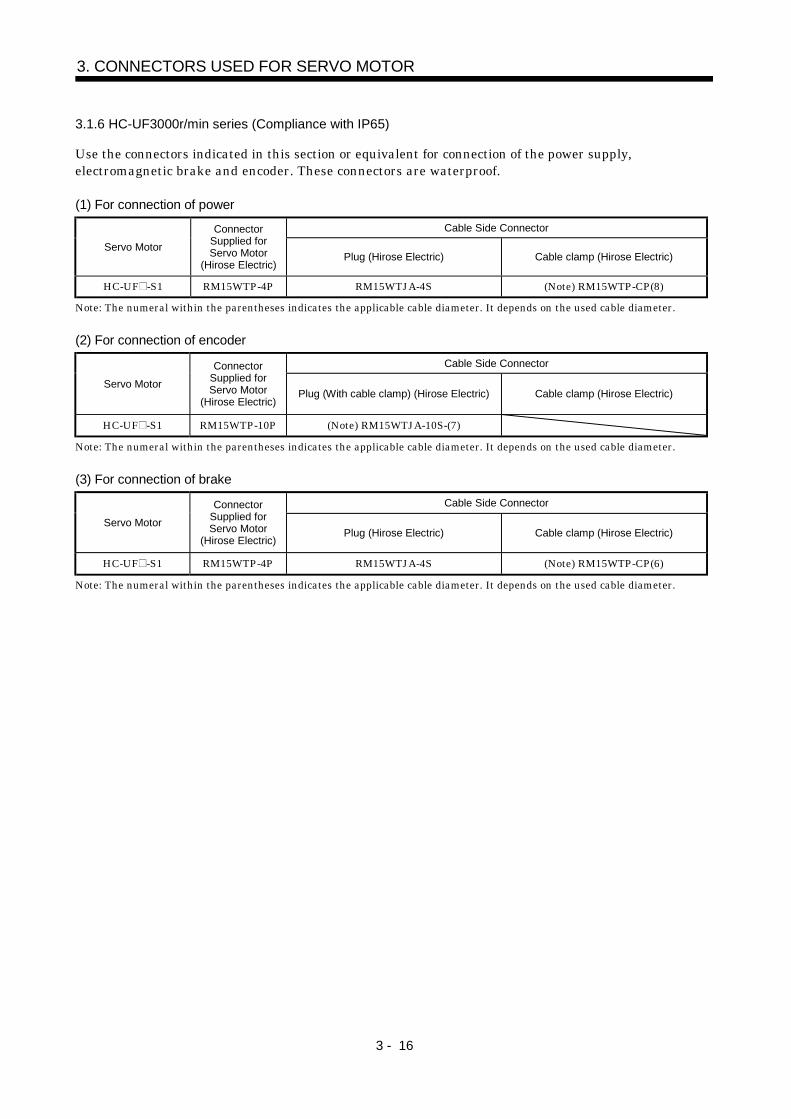
3 - 16
3. CONNECTORS USED FOR SERVO MOTOR
3.1.6 HC-UF3000r/min series (Compliance with IP65)
Use the connectors indicated in this section or equivalent for connection of the power supply,electromagnetic brake and encoder. These connectors are waterproof.
(1) For connection of power
Cable Side Connector
Servo Motor
ConnectorSupplied forServo Motor
(Hirose Electric)Plug (Hirose Electric) Cable clamp (Hirose Electric)
HC-UF -S1 RM15WTP-4P RM15WTJA-4S (Note) RM15WTP-CP(8)
Note: The numeral within the parentheses indicates the applicable cable diameter. It depends on the used cable diameter.
(2) For connection of encoder
Cable Side Connector
Servo Motor
ConnectorSupplied forServo Motor
(Hirose Electric)Plug (With cable clamp) (Hirose Electric) Cable clamp (Hirose Electric)
HC-UF -S1 RM15WTP-10P (Note) RM15WTJA-10S-(7)
Note: The numeral within the parentheses indicates the applicable cable diameter. It depends on the used cable diameter.
(3) For connection of brake
Cable Side Connector
Servo Motor
ConnectorSupplied forServo Motor
(Hirose Electric)Plug (Hirose Electric) Cable clamp (Hirose Electric)
HC-UF -S1 RM15WTP-4P RM15WTJA-4S (Note) RM15WTP-CP(6)
Note: The numeral within the parentheses indicates the applicable cable diameter. It depends on the used cable diameter.
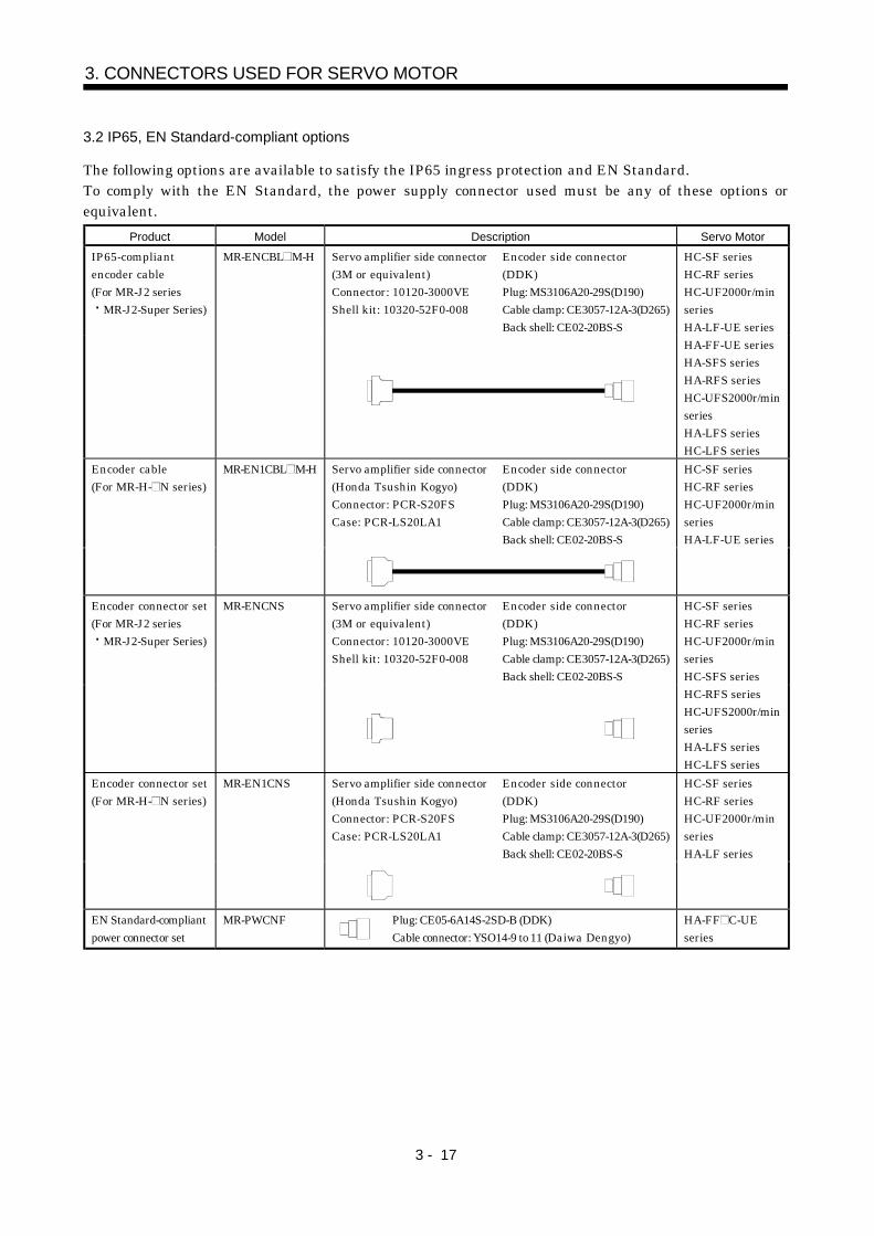
3 - 17
3. CONNECTORS USED FOR SERVO MOTOR
3.2 IP65, EN Standard-compliant options
The following options are available to satisfy the IP65 ingress protection and EN Standard.To comply with the EN Standard, the power supply connector used must be any of these options orequivalent.
Product Model Description Servo Motor
Servo amplifier side connector(3M or equivalent)Connector: 10120-3000VEShell kit: 10320-52F0-008
Encoder side connector(DDK)Plug: MS3106A20-29S(D190)Cable clamp: CE3057-12A-3(D265)Back shell: CE02-20BS-S
IP65-compliantencoder cable(For MR-J2 series
MR-J2-Super Series)
MR-ENCBL M-H HC-SF seriesHC-RF seriesHC-UF2000r/minseriesHA-LF-UE seriesHA-FF-UE seriesHA-SFS seriesHA-RFS seriesHC-UFS2000r/minseriesHA-LFS seriesHC-LFS series
Servo amplifier side connector(Honda Tsushin Kogyo)Connector: PCR-S20FSCase: PCR-LS20LA1
Encoder side connector(DDK)Plug: MS3106A20-29S(D190)Cable clamp: CE3057-12A-3(D265)Back shell: CE02-20BS-S
Encoder cable(For MR-H- N series)
MR-EN1CBL M-H HC-SF seriesHC-RF seriesHC-UF2000r/minseriesHA-LF-UE series
Servo amplifier side connector(3M or equivalent)Connector: 10120-3000VEShell kit: 10320-52F0-008
Encoder side connector(DDK)Plug: MS3106A20-29S(D190)Cable clamp: CE3057-12A-3(D265)Back shell: CE02-20BS-S
Encoder connector set(For MR-J2 series
MR-J2-Super Series)
MR-ENCNS HC-SF seriesHC-RF seriesHC-UF2000r/minseriesHC-SFS seriesHC-RFS seriesHC-UFS2000r/minseriesHA-LFS seriesHC-LFS series
Servo amplifier side connector(Honda Tsushin Kogyo)Connector: PCR-S20FSCase: PCR-LS20LA1
Encoder side connector(DDK)Plug: MS3106A20-29S(D190)Cable clamp: CE3057-12A-3(D265)Back shell: CE02-20BS-S
Encoder connector set(For MR-H- N series)
MR-EN1CNS HC-SF seriesHC-RF seriesHC-UF2000r/minseriesHA-LF series
EN Standard-compliantpower connector set
MR-PWCNF Plug: CE05-6A14S-2SD-B (DDK)Cable connector: YSO14-9 to 11 (Daiwa Dengyo)
HA-FF C-UEseries

3 - 18
3. CONNECTORS USED FOR SERVO MOTOR
Product Model Description Servo Motor
IP65/ENStandard-compliantpower connector set
MR-PWCNS1 Plug: CE05-6A22-23SD-B-BSSCable clamp: CE3057-12A-2 (D265) (DDK)
HC-SF81(B)HC-SF52(B) to 152(B)HC-SF53(B) to 153(B)HC-RF103(B) to 203(B)HC-UF72(B) 152(B)HC-SFS81(B)HC-SFS52(B) to 152(B)HC-SFS53(B) to 153(B)HC-RFS103(B) to 203(B)HC-UFS72(B) 152(B)HC-LFS52(B) to 152(B)
IP65/ENStandard-compliantpower connector set
MR-PWCNS2 Plug: CE05-6A22-10SD-B-BSSCable clamp: CE3057-16A-2 (D265) (DDK)
HC-SF121(B) to 301(B)HC-SF202(B) to 502(B)HC-SF203(B) 353(B)HC-RF353(B) 503(B)HC-UF202(B) to 502(B)HC-SFS121(B) to 301(B)HC-SFS202(B) to 502(B)HC-SFS203(B) 353(B)HC-RFS353(B) 503(B)HC-UFS202(B) 352(B)HA-LFS502HC-LFS202(B) 302(B)
Power connector set MR-PWCNS3 Plug:CE05-6A32-17SD-B-BSSCable clamp: CE3057-20A-1 (D265) (DDK)
HC-SF702(B)HC-SFS702(B)HA-LFS702
IP65/ENStandard-compliantbrake connector set
MR-BKCN (Note) Plug: MS3106A10SL-4S(D190) (DDK)Cable connector: YSO10-5 to 8 (Daiwa Dengyo)
HA-FF CB-UEHC-SF121B to 301BHC-SF202B to 502BHC-SF203B 353BHC-UF202B 502BHC-SFS121B to 301BHC-SFS202B to 502BHC-SFS203B 353BHC-UFS202B to 502BHC-LFS202B 302B
Note: If it is used with the HA-FF C-UE, the servo motor does not improve in ingress protection (IP54).

3 - 19
3. CONNECTORS USED FOR SERVO MOTOR
3.3 Signal arrangement of encoder connectors
The encoder connector of each servo motor has the following signal arrangement. The connectors shownare as seen from the pin side.
Servo Motor Series Signal Arrangement
HC-KF(-UE) seriesHC-MF(-UE) seriesHA-FF seriesHC-UF3000r/min seriesHC-KFS seriesHC-MFS seriesHC-UFS3000r/min series
Encoder connectors1-172169-9 (AMP)
1 2 3
4 5 6
7 8 9
MR MRR BAT
MD MDR
P5 LG SHD
HA-FF C-UE seriesHC-SF seriesHC-RF seriesHC-UF2000r/min seriesHA-LH seriesHA-LF seriesHC-SFS seriesHC-RFS seriesHC-UFS2000r/min seriesHA-LFS seriesHC-LFS series
A BC
D
E
FGH
J
K
LM
Pin Signal
A
B
C MR
D MRR
E
F BAT
G LG
H
J
Pin Signal
K
L
M
N SHD
P
R LG
S P5
T
Encoder connectors
RS
T PN
MDR
MD
HC-AQ series
12 6
11 5
10 4
MRR MR
LG P5
SHD
9 3
8 2
7 1
W U
V E
B1 B2
Motor connector

3 - 20
3. CONNECTORS USED FOR SERVO MOTOR
MEMO

4 - 1
4. INSPECTION
4. INSPECTION
WARNING
Before starting maintenance and/or inspection, make sure that the charge lamp is
off more than 10 minutes after power-off. Then, confirm that the voltage is safe in
the tester or the like. Otherwise, you may get an electric shock.
Any person who is involved in inspection should be fully competent to do the work.
Otherwise, you may get an electric shock. For repair and parts replacement,
contact your safes representative.
POINT
Do not disassemble and/or repair the equipment on customer side.
(1) Inspection
It is recommended to make the following checks periodically:(a) Check the servo motor bearings, brake section, etc. for unusual noise.
(b) Check the cables and the like for scratches and cracks. Especially when the junction cable ismovable, perform periodic inspection according to operating conditions.
(c) Check the servo motor shaft and coupling for misalignment.
(d) Check the power supply connector and encoder connector tightening screws for looseness.
(2) Life
The following parts must be changed periodically as listed below. If any part is found faulty, it must bechanged immediately even when it has not yet reached the end of its life, which depends on theoperating method and environmental conditions. For parts replacement, please contact your salesrepresentative.
Part Name Guideline of Life Remarks
Bearings 20,000 to 30,000 hours
Encoder 20,000 to 30,000 hours
Oil seal 5,000 hours
Cooling fan 20,000 hours
The Guideline of Life field gives the reference time. If any faultis found before this time is reached, the part must be changed.
(a) BearingsWhen the servo motor is run at rated speed under rated load, change the bearings in 20,000 to30,000 hours as a guideline. This differs on the operating conditions. The bearings must also bechanged if unusual noise or vibration is found during inspection.
(b) Oil sealMust be changed in 5,000 hours of operation at rated speed as a guideline. These parts must alsobe changed if oil leakage, etc. is found during inspection.

4 - 2
4. INSPECTION
MEMO

5 - 1
5. SPECIFICATIONS
5. SPECIFICATIONS
5.1 Standard specifications
HC-MF Series(ultra low inertia, small capacity)
HA-FF Series(low inertia, small capacity)
Servo Motor
Item 053 13 23 43 73 053 13 23 33 43 63
MR-H AN/BN/ACN/TN 20 20 40 60 100 10 10 20 40 40 60Applicable servoamplifier MR-J2- A/B/C 10 10 20 40 70 10 10 20 40 40 60
Rated output [kW] 0.05 0.1 0.2 0.4 0.75 0.05 0.1 0.2 0.3 0.4 0.6[N m] 0.16 0.32 0.64 1.3 2.4 0.16 0.32 0.64 0.95 1.3 1.9
Continuouscharacteristics(Note 1 11)
Ratedtorque [oz in] 22.7 45.3 90.7 184 340 22.7 45.3 90.7 135 184 269
Rated speed (Note 1) [r/min] 3000 3000Maximum speed [r/min] 4500 4000Instantaneous permissible speed [r/min] 5175 4600
[N m] 0.48 0.95 1.9 3.8 7.2 0.48 0.95 1.9 2.9 3.8 5.7Maximum torque
[oz in] 68.0 135 269 538 1020 68.0 135 269 411 538 808Power rate at continuous rated torque
[kW/s]13.47 34.13 46.02 116.55 94.43 4.0 10.2 11.7 18.1 17.2 30.1
J [ 10 4kg m2] 0.019 0.03 0.088 0.143 0.6 0.063 0.10 0.35 0.50 0.98 1.2Inertia moment(Note 3) WK2 [oz in2] 0.104 0.16 0.48 0.78 3.28 0.344 0.55 1.91 2.73 5.36 6.56Recommended ratio of load inertia moment toservo motor shaft inertia moment (Note 2)
30 times or less 10 times or less
Servo amplifier' built-inregenerative brakeresistor
(Note 5) (Note 5) (Note 5) 4275 1726 (Note 5) (Note 5) (Note 5) 1500 750 600
MR-RB013(10W) (Note 5) (Note 5) 2071 1363 370
MR-RB033(30W) (Note 5) (Note 5) (Note 5) 4088 1109
MR-Hseries
MR-RB32(300W) (Note 5) (Note 5) (Note 5) (Note 5) 3983 3046
Servo amplifier' built-inregenerative brakeresistor
(Note 5) (Note 5) (Note 5) 1010 400 (Note 5) (Note 5) (Note 5) 320 150 120
MR-RB032(30W) 3000 600 950 450 360
Regenerativebrake duty[times/min](Note 4)
MR-J2series
MR-RB12(100W) (Note 5) 2400 3200 1500 1200
Power supply capacityRefer to "Power supply equipment capacity and generated loss of servo amplifiers"in Servo Amplifier Instruction Manual.
Rated current [A] 0.85 0.85 1.5 2.8 5.1 0.6 1.1 1.3 1.9 2.5 3.6Maximum current [A] 2.6 2.6 5 9 18 1.8 3.3 3.9 5.7 7.5 10.8Speed/position detector Encoder (resolution : 8192 pulse/rev) Encoder (resolution : 8192 pulse/rev)Accessories Encoder Encoder, V ringInsulation class Class B Class B
StructureTotally-enclosed, self-cooled
(protection type: IP44 (Note 6 12))Totally-enclosed, self-cooled
(protection type: IP44 (Note 8 9 12))Environmental conditions (Note 7) Refer to section 2.1 Refer to section 2.1
[kg] 0.4 0.53 0.99 1.45 3.0 1.3 1.5 2.3 2.6 4.2 4.8Weight (Note 3)
[lb] 0.88 1.17 2.18 3.20 6.61 2.87 3.31 5.07 5.73 9.26 10.6

5 - 2
5. SPECIFICATIONS
HC-SF 1000r/min Series(middle inertia, middle capacity)
HC-SF 2000r/min Series(middle inertia, middle capacity)
Servo Motor
Item 81 121 201 301 52 102 152 202 352 502 702
MR-H AN/BN/ACN/TN 100 200 200 350 60 100 200 200 350 500 700Applicable servoamplifier MR-J2- A/B/C 100 200 200 350 60 100 200 200 350
Rated output [kW] 0.85 1.2 2.0 3.0 0.5 1.0 1.5 2.0 3.5 5.0 7.0[N m] 8.12 11.5 19.1 28.6 2.39 4.78 7.16 9.55 16.7 23.9 33.4
Continuouscharacteristics(Note 1 11)
Ratedtorque [oz in] 1151 1630 2707 4053 339 677 1015 1353 2367 3387 4733
Rated speed (Note 1) [r/min] 1000 2000Maximum speed [r/min] 1500 1200 3000 2500 2000Instantaneous permissible speed [r/min] 1725 1380 345 2850 2300
[N m] 24.4 34.4 57.3 85.9 7.16 14.4 21.6 28.5 50.1 71.6 100.0Maximum torque
[oz in] 3458 4875 8120 12173 1015 2041 3061 4039 7100 10146 14171Power rate at continuous rated torque
[kW/s]32.9 30.9 44.5 81.3 8.7 16.7 25.6 21.5 34.1 56.5 69.7
J [ 10 4kg m2] 20.0 42.5 82 101 6.6 13.7 20.0 4.5 82.0 101 160Inertia moment(Note 3) WK2 [oz in2] 109 232 448 552 36.1 74.9 109 232 448 552 875Recommended ratio of load inertia moment toservo motor shaft inertia moment (Note 2)
15 times or less 15 times or less
Servo amplifier' built-inregenerative brakeresistor
440 335 174 141 207 170 179 84 43 39 32
MR-RB31(300W) 57MR-RB32(300W) 1649 1241 638MR-RB30(300W) 326 100 90MR-RB34(300W) 774 401 412 193MR-RB50(500W) 543 167 150MR-RB51(500W) 95
MR-Hseries
MR-RB54(500W) 1290 669 687 322Servo amplifier' built-inregenerative brakeresistor
140 240 100 84 56 54 136 64 31
MR-RB032(30W) 220 165 80MR-RB12(100W) 740 560 270MR-RB32(300W) 2220 810MR-RB30(300W) 730 330 250 408 192 95
Regenerativebrake duty[times/min](Note 4)
MR-J2series
MR-RB50(500W) 1216 550 430 680 320 158Power supply capacity Refer to "Power supply equipment capacity and generated loss of servo amplifiers"
in Servo Amplifier Instruction Manual.Rated current [A] 5.1 7.1 9.6 16 3.2 6 9 11 17 28 35Maximum current [A] 15.3 21.3 28.8 48 9.6 18 27 33 51 84 105
Speed/position detectorEncoder
(resolution: 16384 pulse/rev)Encoder
(resolution: 16384 pulse/rev)Accessories Encoder Oil seal Encoder Oil sealInsulation class Class F Class F
StructureTotally-enclosed, self-cooled
(protection type: IP65)Totally-enclosed, self-cooled
(protection type: IP65(Note 12))Environmental conditions (Note 7) Refer to section 2.1 Refer to section 2.1
[kg] 9.0 12 19 23 5.0 7.0 9.0 12.0 19.0 23 32Weight (Note 3)
[lb] 19.8 26.5 41.9 50.7 11.0 15.4 19.8 26.5 41.9 50.7 70.5
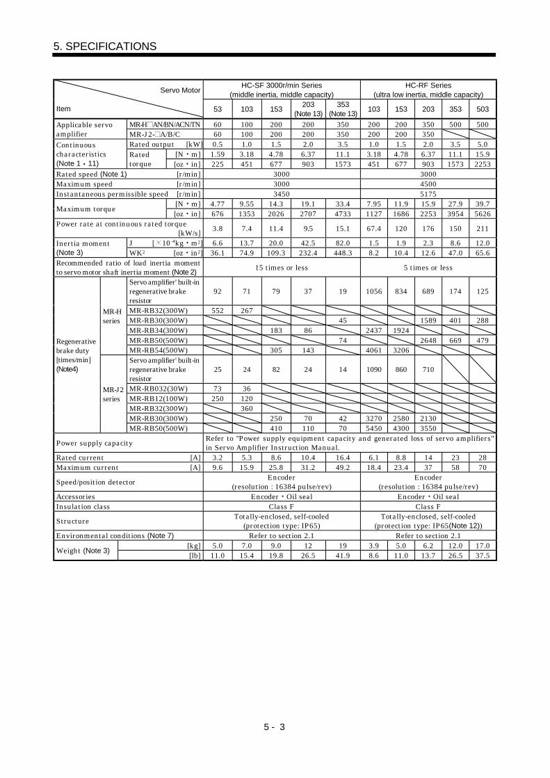
5 - 3
5. SPECIFICATIONS
HC-SF 3000r/min Series(middle inertia, middle capacity)
HC-RF Series(ultra low inertia, middle capacity)
Servo Motor
Item 53 103 153203
(Note 13)353
(Note 13)103 153 203 353 503
MR-H AN/BN/ACN/TN 60 100 200 200 350 200 200 350 500 500Applicable servoamplifier MR-J2- A/B/C 60 100 200 200 350 200 200 350
Rated output [kW] 0.5 1.0 1.5 2.0 3.5 1.0 1.5 2.0 3.5 5.0[N m] 1.59 3.18 4.78 6.37 11.1 3.18 4.78 6.37 11.1 15.9
Continuouscharacteristics(Note 1 11)
Ratedtorque [oz in] 225 451 677 903 1573 451 677 903 1573 2253
Rated speed (Note 1) [r/min] 3000 3000Maximum speed [r/min] 3000 4500Instantaneous permissible speed [r/min] 3450 5175
[N m] 4.77 9.55 14.3 19.1 33.4 7.95 11.9 15.9 27.9 39.7Maximum torque
[oz in] 676 1353 2026 2707 4733 1127 1686 2253 3954 5626Power rate at continuous rated torque
[kW/s]3.8 7.4 11.4 9.5 15.1 67.4 120 176 150 211
J [ 10 4kg m2] 6.6 13.7 20.0 42.5 82.0 1.5 1.9 2.3 8.6 12.0Inertia moment(Note 3) WK2 [oz in2] 36.1 74.9 109.3 232.4 448.3 8.2 10.4 12.6 47.0 65.6Recommended ratio of load inertia momentto servo motor shaft inertia moment (Note 2)
15 times or less 5 times or less
Servo amplifier' built-inregenerative brakeresistor
92 71 79 37 19 1056 834 689 174 125
MR-RB32(300W) 552 267MR-RB30(300W) 45 1589 401 288MR-RB34(300W) 183 86 2437 1924MR-RB50(500W) 74 2648 669 479
MR-Hseries
MR-RB54(500W) 305 143 4061 3206Servo amplifier' built-inregenerative brakeresistor
25 24 82 24 14 1090 860 710
MR-RB032(30W) 73 36MR-RB12(100W) 250 120MR-RB32(300W) 360MR-RB30(300W) 250 70 42 3270 2580 2130
Regenerativebrake duty[times/min](Note4)
MR-J2series
MR-RB50(500W) 410 110 70 5450 4300 3550
Power supply capacityRefer to "Power supply equipment capacity and generated loss of servo amplifiers"in Servo Amplifier Instruction Manual.
Rated current [A] 3.2 5.3 8.6 10.4 16.4 6.1 8.8 14 23 28Maximum current [A] 9.6 15.9 25.8 31.2 49.2 18.4 23.4 37 58 70
Speed/position detectorEncoder
(resolution : 16384 pulse/rev)Encoder
(resolution : 16384 pulse/rev)Accessories Encoder Oil seal Encoder Oil sealInsulation class Class F Class F
StructureTotally-enclosed, self-cooled
(protection type: IP65)Totally-enclosed, self-cooled
(protection type: IP65(Note 12))Environmental conditions (Note 7) Refer to section 2.1 Refer to section 2.1
[kg] 5.0 7.0 9.0 12 19 3.9 5.0 6.2 12.0 17.0Weight (Note 3)
[lb] 11.0 15.4 19.8 26.5 41.9 8.6 11.0 13.7 26.5 37.5

5 - 4
5. SPECIFICATIONS
HC-UF 2000r/min Series(pancake type middle capacity)
HC-UF 3000r/min Series(pancake type small capacity)
HA-LH Series(low inertia large
capacity)
Servo Motor
Item 72 152 202 352 502 13 23 4373
(Note 13)11K 15K 22K
MR-H AN/BN/ACN/TN 100 200 350 500 500 10 40 60 100 11K 15K 22KApplicable servoamplifier MR-J2 A/B/C 70 200 350 10 20 40 70
Rated output [kW] 0.75 1.5 2.0 3.5 5.0 0.1 0.2 0.4 0.75 11 15 22[N m] 3.58 7.16 9.55 16.7 23.9 0.32 0.64 1.3 2.4 52.5 71.6 105
Continuouscharacteristics(Note 1 11)
Ratedtorque [oz in] 507 1015 1353 2367 3387 45 91 184 340 7435 10139 14869
Rated speed (Note 1) [r/min] 2000 3000 2000Maximum speed [r/min] 3000 2500 4500 2000Instantaneous permissible speed [r/min] 3450 2875 5175 2300
[N m] 10.7 21.6 28.5 50.1 71.6 0.95 1.9 3.8 7.2 158 215 263Maximum torque
[oz in] 1516 3061 4039 7100 10146 135 269 538 1020 22375 30447 37244Power rate at continuous rated torque
[kW/s] 12.3 23.2 23.9 36.5 49.6 15.5 19.2 47.7 9.66 235 177 278
J [ 10 4kg m2] 10.4 22.1 38.2 76.5 115 0.066 0.241 0.365 5.90 118 290 395Inertia moment(Note 3) WK2 [oz in2] 56.9 120.8 208.9 418.3 628.8 0.4 1.3 2.0 32.3 642.4 1585.6 2159.6Recommended ratio of load inertia momentto servo motor shaft inertia moment (Note 2)
15 times or less 10 times or less
Servo amplifier' built-inregenerative brakeresistor
211 161 93 44 31 (Note5) 2530 1669 16585
(Note10)
70
(Note10)
55
(Note10)
MR-RB013(10W) 2241
MR-RB033(30W) (Note5)
MR-RB32(300W) 791 (Note5) (Note5) 619
MR-RB30(300W) 215 102 72MR-RB34(300W) 372MR-RB50(500W) 358 169 119MR-RB54(500W) 620
MR-RB65(800W)500
(Note10)
MR-RB66(1300W)850
(Note10)
MR-HSeries
MR-RB67(1300W)850
(Note10)
Servo amplifier' built-inregenerative brakeresistor
53 124 68 (Note5) (Note5) 410 41
MR-RB032(30W) 79 1230 62
MR-RB12(100W) 87 4106 206
MR-RB30(300W) 372 203
Regenerativebrake duty[times/min](Note4)
MR-J2series
MR-RB50(300W) 620 338
Power supply capacityRefer to "Power supply equipment capacity and generated loss of servo amplifiers" inServo Amplifier Instruction Manual.
Rated current [A] 5.4 9.7 14 23 28 0.76 1.5 2.8 4.3 68 87 126Maximum current [A] 16.2 29.1 42 69 84 2.5 4.95 9.24 12.9 204 261 315
Speed/position detectorEncoder
(resolution : 16384 pulse/rev)Encoder
(resolution : 8192 pulse/rev)Encoder (resolution :
16384 pulse/rev)Voltage, frequency 200/220V 50/60HzPower
supply Power consumption [W] 42/54WRated current [A] 0.21/0.25A
Coolingfan
Speed [r/min] 3000/3600r/minAccessories Encoder Oil seal Encoder Oil seal Encoder Oil sealInsulation class Class F Class B Class F
StructureTotally-enclosed, self-cooled
(protection type: IP65(Note9))Totally-enclosed, self-cooled
(protection type: IP65(Note9))
Totally-enclosed,force-cooling
(protection type: JP44)Environmental conditions (Note 7) Refer to section 2.1 Refer to section 2.1 Refer to section 2.1
[kg] 8.0 11.0 16.0 20.0 24.0 0.8 1.5 1.7 5.0 70 108 135Weight (Note 3)
[lb] 17.6 24.3 35.3 44.1 52.9 1.8 3.3 3.7 11.0 154.3 238.1 297.6

5 - 5
5. SPECIFICATIONS
HC-KF Series (low inertia small capacity)Servo MotorItem 053 13 23 43
MR-H AN/BN/ACN/TN
10 10 20 40
Applicable servo amplifierMR-J2-
10A-A1610B-A1610C-A16
10A-A1510B-A1510C-A15
20A-A1520B-A1520C-A15
40A-A1540B-A1540C-A15
Ratedoutput
[kW] 0.05 0.1 0.2 0.4
[N m] 0.16 0.32 0.64 1.3
Continuouscharacteristics(Note 1 11)
Ratedtorque [oz in] 22.7 45.3 90.7 184
Rated speed (Note 1) [r/min] 3000Maximum speed [r/min] 4500Instantaneous permissible speed [r/min] 5175
[N m] 0.48 0.95 1.9 3.8Maximum torque
[oz in] 68.0 135 269 538Power rate at continuous rated torque
[kW/s]4.78 12.1 9.65 24.2
J [ 10 4kg m2] 0.053 0.084 0.42 0.67Inertiamoment(Note 3)
WK2 [oz in2] 0.29 0.459 2.296 3.663
Recommended ratio of load inertiamoment to servo motor shaft inertiamoment(Note 2)
15 times or less
Servo amplifier'sbuilt-inregenerativebrake resistor
(Note 5) (Note 5) (Note 5)
MR-RB013(10W) (Note 5) (Note 5)MR-RB033(30W) (Note 5) (Note 5)
MR-Hseries
MR-RB32(300W) (Note 5) (Note 5)Servo amplifier'sbuilt-inregenerativebrake resistor
(Note 5) (Note 5) (Note 5) 220
MR-RB032(30W) (Note 5) 660
Regenerativebrake duty[times/min](Note 4)
MR-J2series
MR-RB12(100W) (Note 5) 2200
Power supply capacityRefer to "Power supply equipment capacity and generated loss of servo amplifiers"in Servo Amplifier Instruction Manual.
Rated current [A] 0.83 0.71 1.1 2.3Maximum current [A] 2.5 2.2 3.4 6.9Speed/position detector Encoder (resolution: 8192 pulses/rev)Accessory EncoderInsulation class Class BStructure Totally-enclosed, self-cooled (protection type: IP44 (Note 6))Environmental conditions (Note 7) Refer to Section 2.1.
[kg] 0.40 0.53 0.99 1.45Weight
[lb] 0.882 1.168 2.18 3.20

5 - 6
5. SPECIFICATIONS
HC-AQ Series (24VDC-compatible ultra low inertia small capacity)Servo Motor
Item 0135 0235 0335
Applicable servo amplifierMR-J2-03A5MR-J2-03B5MR-J2-03C5
Rated output [kW] 0.01 0.02 0.03
[N m] 0.0318 0.0637 0.0955Continuouscharacteristics(Note 1 11)
Rated torque[oz in] 4.503 9.021 13.524
Rated speed (Note 1) [r/min] 3000
Maximum speed [r/min] 5000 4500
Instantaneous permissible speed [r/min] 5750 5175
[N m] 0.0955 0.191 0.287Maximum torque
[oz in] 13.524 27.048 40.643
Power rate at continuous rated torque[kW/s]
2.0 5.6 9.7
J [ 10 4kg m2] 0.0050 0.0072 0.0094Inertia moment(Note 3) WK2 [oz in2] 0.027 0.039 0.051
Recommended ratio of load inertiamoment to servo motor shaft inertiamoment (Note 2)
30 times or less
Power supply capacityRefer to "Power supply equipment capacity and generated loss of servo amplifiers"in Servo Amplifier Instruction Manual.
Rated current [A] 2.4 2.4 2.3
Maximum current [A] 7.7 7.7 7.4
Speed/position detector Encoder (resolution: 8192 pulses/rev)
Accessory Encoder
Insulation class Class B
Structure Totally-enclosed, self-cooled (protection type: IP55 (Note 6))
Environmental conditions (Note 7) Refer to Section 2.1.
[kg] 0.19 0.22 0.25Weight (Note 3)
[lb] 0.419 0.485 0.551
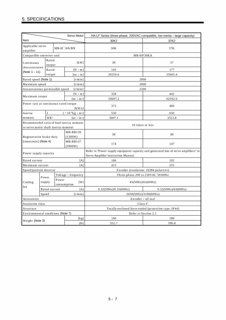
5 - 7
5. SPECIFICATIONS
HA-LF Series (three-phase, 200VAC-compatible, low inertia large capacity)Servo Motor
Item 30K2 37K2
Applicable servoamplifier
MR-H AN/BN 30K 37K
Compatible converter unit MR-HP30KA
Ratedoutput
[kW] 30 37
[N m] 143 177
Continuouscharacteristics(Note 1 11)
Ratedtorque [oz in] 20250.6 25065.4
Rated speed (Note 1) [r/min] 2000
Maximum speed [r/min] 2000
Instantaneous permissible speed [r/min] 2300
[N m] 358 442Maximum torque
[oz in2] 50697.2 62592.6
Power rate at continuous rated torque[kW/s]
373 480
J [ 10 4kg m2] 550 650Inertiamoment WK2 [oz in2] 3007.1 3553.8
Recommended ratio of load inertia momentto servo motor shaft inertia moment
10 times or less
MR-RB139(1300W)
58 49Regenerative brake duty[times/min] (Note 4) MR-RB137
(3900W)174 147
Power supply capacityRefer to “Power supply equipment capacity and generated loss of servo amplifiers” inServo Amplifier Instruction Manual.
Rated current [A] 166 102
Maximum current [A] 415 255
Speed/position detector Encoder (resolution: 16384 pulse/rev)
Voltage frequency Three-phase 200 to 230VAC 50/60HzPowersupply
Powerconsumption
[W] 45(50Hz)/63(60Hz)
Rated current [A] 0.32(50Hz)/0.35(60Hz) 0.32(50Hz)/63(60Hz)
Coolingfan
Speed [r/min] 2650(50Hz)/3100(60Hz)
Accessories Encoder oil seal
Insulation class Class F
Structure Totally-enclosed force-cooled (protection type: IP44)
Environmental conditions (Note 7) Refer to Section 2.1
[kg] 160 180Weight (Note 3)
[lb] 352.7 396.8

5 - 8
5. SPECIFICATIONS
HA-LF Series (three-phase, 400VAC-compatible, low Inertia, large Capacity)Servo Motor
Item 30K24 37K24 45K24 55K24
Applicable servoamplifier
MR-H AN4/BN4 30K 37K 45K 55K
Compatible converter unit MR-HP55KA4
Ratedoutput
[kW] 30 37 45 55
[N m] 143 177 215 263
Continuouscharacteristics(Note 1 11)
Ratedtorque [oz in] 20250.6 25065.4 30446.6 37244.0
Rated speed (Note 1) [r/min] 2000
Maximum speed [r/min] 2000
Instantaneous permissible speed [r/min] 2300
[N m] 358 442 537 657Maximum torque
[oz in] 50697.2 62592.6 76045.8 930392
Power rate at continuous rated torque[kW/s]
373 480 427 526
J [ 10 4kg m2] 550 650 1080 1310Inertia moment(Note 3) WK2 [oz in2] 3007.095 3553.84 5904.84 7162.354
Recommended ratio of load inertia momentto servo motor shaft inertia moment(Note 2)
10 times or less
MR-RB136-4(1300W)
58 49 30 24
Regenerative brake duty[times/min] (Note 4)
Three MR-B138-4’s(3900W)
174 147 89 73
Power supply capacityRefer to "Power supply equipment capacity and generated loss of servoamplifiers" in Servo Amplifier Instruction Manual.
Rated current [A] 83 102 131 143
Maximum current [A] 208 255 328 358
Speed/position detector Encoder (resolution: 16384 pulses/rev)
Voltage frequency Three-phase 380 to 460VAC 50/60HzPowersupply
Powerconsumption
[W] 63(50Hz)/83(60Hz) 110(50Hz)/150(60Hz)
Rated current [A] 0.09(50Hz)/0.11(60Hz) 0.20(50Hz)/0.22(60Hz)
Cooling fan
Speed [r/min] 2720(50Hz)/2980(60Hz) 2650(50Hz)/3000(60Hz)
Accessories Encoder, oil seal
Insulation class Class F
Structure Totally-enclosed, force-cooled (protection type: IP44)
Environmental conditions (Note 7) Refer to Section 2.1.
[kg] 160 180 230 250Weight (Note 3)
[lb] 352.739 396.832 507.063 551.155

5 - 9
5. SPECIFICATIONS
HC-MFS Series(ultra low inertia small capacity)
HC-KFS Series(low inertia small capacity)
Servo Motor
Item 053 13 23 43 73 053 13 23 43 73
MR-J2S- A/B/CP 10 10 20 40 70 10 10 20 40 70Applicable servoamplifier/drive unit MR-J2M- DU 10 10 20 40 70 10 10 20 40 70
Rated output [kW] 0.05 0.1 0.2 0.4 0.75 0.05 0.1 0.2 0.4 0.75[N m] 0.16 0.32 0.64 1.3 2.4 0.16 0.32 0.64 1.3 2.4
Continuouscharacteristics(Note 1 11)
Ratedtorque [oz in] 22.7 45.3 90.7 184 340 22.7 45.3 90.7 184 340
Rated speed (Note 1) [r/min] 3000 3000Maximum speed [r/min] 4500 4500Instantaneous permissible speed [r/min] 5175 5175
[N m] 0.48 0.95 1.9 3.8 7.2 0.48 0.95 1.9 3.8 7.2Maximum torque
[oz in] 68.0 135 269 538 1020 68.0 135 269 538 1020Power rate at continuous rated torque
[kW/s]13.47 34.13 46.02 116.55 94.43 4.78 12.1 9.65 24.2 37.7
J [ 10 4kg m2] 0.019 0.03 0.088 0.143 0.6 0.053 0.084 0.42 0.67 1.51Inertia moment(Note 3) WK2 [oz in2] 0.104 0.16 0.48 0.78 3.28 0.29 0.459 2.296 3.663 8.26Recommended ratio of load inertia moment toservo motor shaft inertia moment (Note 2)
30 times or less 10 times or less
Servo amplifier' built-in regenerative brakeresistor
(Note 5) (Note 5) (Note 5) 1010 400 (Note 5) (Note 5) (Note 5) 220 190
MR-RB032(30W) 3000 600 (Note 5) (Note 5) (Note 5) 660 280
MR-RB12(100W) (Note5) 2400 (Note 5) (Note 5) (Note 5) 2200 940
Regenerativebrake duty[times/min](Note4)
MR-J2Sseries
MR-RB32(300W) (Note5) 2800
Power supply capacityRefer to "Power supply equipment capacity and generated loss of servo amplifiers"in Servo Amplifier Instruction Manual.
Rated current [A] 0.85 0.85 1.5 2.8 5.1 0.83 0.71 1.1 2.3 5.8Maximum current [A] 2.6 2.6 5 9 18 2.5 2.2 3.4 6.9 18.6Speed/position detector Encoder (resolution : 131072 pulse/rev) Encoder (resolution : 131072 pulse/rev)Accessories Encoder Encoder, V ringInsulation class Class B Class B
StructureTotally-enclosed, self-cooled
(protection type: IP55 (Note 6,7))Totally-enclosed, self-cooled
(protection type: IP44 (Note 6,12))Environmental conditions (Note 7) Refer to section 2.1 Refer to section 2.1
[kg] 0.4 0.53 0.99 1.45 3.0 0.40 0.53 0.99 1.45 3.0Weight (Note 3)
[lb] 0.88 1.17 2.18 3.20 6.61 0.882 1.168 2.18 3.20 6.61

5 - 10
5. SPECIFICATIONS
HC-SFS1000r/min Series(middle inertia, middle capacity)
HC-SFS 2000r/min Series(middle inertia, middle capacity)
Servo Motor
Item 81 121 201 301 52 102 152 202 352 502 702
Applicable servoamplifier/drive unit
MR-J2S- A/B/CP 100 200 200 350 60 100 200 200 350 500 700
Rated output [kW] 0.85 1.2 2.0 3.0 0.5 1.0 1.5 2.0 3.5 5.0 7.0[N m] 8.12 11.5 19.1 28.6 2.39 4.78 7.16 9.55 16.7 23.9 33.4
Continuouscharacteristics(Note 1 11)
Ratedtorque [oz in] 1151 1630 2707 4053 339 677 1015 1353 2367 3387 4733
Rated speed (Note 1) [r/min] 1000 2000Maximum speed [r/min] 1500 1200 3000 2500 2000Instantaneous permissible speed [r/min] 1725 1380 345 2850 2300
[N m] 24.4 34.4 57.3 85.9 7.16 14.4 21.6 28.5 50.1 71.6 100.0Maximum torque
[oz in] 3458 4875 8120 12173 1015 2041 3061 4039 7100 10146 14171Power rate at continuous rated torque
[kW/s]32.9 30.9 44.5 81.3 8.7 16.7 25.6 21.5 34.1 56.5 69.7
J [ 10 4kg m2] 20.0 42.5 82 101 6.6 13.7 20.0 4.5 82.0 101 160Inertia moment(Note 3) WK2 [oz in2] 109 232 448 552 36.1 74.9 109 232 448 552 875Recommended ratio of load inertia moment toservo motor shaft inertia moment (Note 2)
15 times or less 15 times or less
Servo amplifier' built-in regenerative brakeresistor
140 240 100 84 56 54 136 64 31 39 32
MR-RB032(30W) 220 165 80MR-RB12(100W) 740 560 270MR-RB32(300W) 2220 810MR-RB30(300W) 730 330 250 408 192 95 90MR-RB50(500W) 1216 550 430 680 320 158 150MR-RB31(300W) 57
Regenerativebrake duty[times/min](Note4)
MR-J2Sseries
MR-RB51(500W) 95Power supply capacity Refer to "Power supply equipment capacity and generated loss of servo amplifiers"
in Servo Amplifier Instruction Manual.Rated current [A] 5.1 7.1 9.6 16 3.2 6 9 11 17 28 35Maximum current [A] 15.3 21.3 28.8 48 9.6 18 27 33 51 84 105
Speed/position detectorEncoder
(resolution: 131072 pulse/rev)Encoder
(resolution: 131072 pulse/rev)Accessories Encoder Oil seal Encoder Oil sealInsulation class Class F Class F
StructureTotally-enclosed, self-cooled
(protection type: IP65)Totally-enclosed, self-cooled
(protection type: IP65(Note 12))Environmental conditions (Note 7) Refer to section 2.1 Refer to section 2.1
[kg] 9.0 12 19 23 5.0 7.0 9.0 12.0 19.0 23 32Weight (Note 3)
[lb] 19.8 26.5 41.9 50.7 11.0 15.4 19.8 26.5 41.9 50.7 70.5

5 - 11
5. SPECIFICATIONS
HC-SFS 3000r/min Series(middle inertia middle capacity)
HC-RFS Series(ultra low inertia middle capacity)
Servo Motor
Item 53 103 153 203 353 103 153 203 353 503
Applicable servoamplifier
MR-J2S- A/B/CP 60 100 200 200 350 200 200 350 500 500
Rated output [kW] 0.5 1.0 1.5 2.0 3.5 1.0 1.5 2.0 3.5 5.0[N m] 1.59 3.18 4.78 6.37 11.1 3.18 4.78 6.37 11.1 15.9
Continuouscharacteristics(Note 1 11)
Ratedtorque [oz in] 225 451 677 903 1573 451 677 903 1573 2253
Rated speed (Note 1) [r/min] 3000 3000Maximum speed [r/min] 3000 4500Instantaneous permissible speed [r/min] 3450 5175
[N m] 4.77 9.55 14.3 19.1 33.4 7.95 11.9 15.9 27.9 39.7Maximum torque
[oz in] 676 1353 2026 2707 4733 1127 1686 2253 3954 5626Power rate at continuous rated torque
[kW/s]3.8 7.4 11.4 9.5 15.1 67.4 120 176 150 211
J [ 10 4kg m2] 6.6 13.7 20.0 42.5 82.0 1.5 1.9 2.3 8.6 12.0Inertia moment(Note 3) WK2 [oz in2] 36.1 74.9 109.3 232.4 448.3 8.2 10.4 12.6 47.0 65.6Recommended ratio of load inertia momentto servo motor shaft inertia moment (Note 2)
15 times or less 5 times or less
Servo amplifier' built-in regenerative brakeresistor
25 24 82 24 14 1090 860 710 174 125
MR-RB032(30W) 73 36MR-RB12(100W) 250 120MR-RB32(300W) 360MR-RB30(300W) 250 70 42 3270 2580 2130 401MR-RB50(500W) 410 110 70 5450 4300 3550 669MR-RB31(300W) 288
Regenerativebrake duty[times/min](Note 4)
MR-J2Sseries
MR-RB51(500W) 479
Power supply capacityRefer to "Power supply equipment capacity and generated loss of servo amplifiers"in Servo Amplifier Instruction Manual.
Rated current [A] 3.2 5.3 8.6 10.4 16.4 6.1 8.8 14 23 28Maximum current [A] 9.6 15.9 25.8 31.2 49.2 18.4 23.4 37 58 70
Speed/position detectorEncoder
(resolution : 131072 pulse/rev)Encoder
(resolution : 131072 pulse/rev)Accessories Encoder Oil seal Encoder Oil sealInsulation class Class F Class F
StructureTotally-enclosed, self-cooled
(protection type: IP65)Totally-enclosed, self-cooled
(protection type: IP65(Note 12))Environmental conditions (Note 7) Refer to section 2.1 Refer to section 2.1
[kg] 5.0 7.0 9.0 12 19 3.9 5.0 6.2 12.0 17.0Weight (Note 3)
[lb] 11.0 15.4 19.8 26.5 41.9 8.6 11.0 13.7 26.5 37.5

5 - 12
5. SPECIFICATIONS
HC-UFS 2000r/min Series(pancake type middle capacity)
HC-UFS 3000r/min Series(pancake type small capacity)
Servo Motor
Item 72 152 202 352 502 13 23 43 73
MR-J2S A/B/CP 70 200 350 500 500 10 20 40 70Applicable servoamplifier/drive unit MR-J2M DU 10 20 40 70
Rated output [kW] 0.75 1.5 2.0 3.5 5.0 0.1 0.2 0.4 0.75[N m] 3.58 7.16 9.55 16.7 23.9 0.32 0.64 1.3 2.4
Continuouscharacteristics(Note 1 11)
Ratedtorque [oz in] 507 1015 1353 2367 3387 45 91 184 340
Rated speed (Note 1) [r/min] 2000 3000Maximum speed [r/min] 3000 2500 4500Instantaneous permissible speed [r/min] 3450 2875 5175
[N m] 10.7 21.6 28.5 50.1 71.6 0.95 1.9 3.8 7.2Maximum torque
[oz in] 1516 3061 4039 7100 10146 135 269 538 1020Power rate at continuous rated torque
[kW/s]12.3 23.2 23.9 36.5 49.6 15.5 19.2 47.7 9.66
J [ 10 4kg m2] 10.4 22.1 38.2 76.5 115 0.066 0.241 0.365 5.90Inertia moment(Note 3) WK2 [oz in2] 56.9 120.8 208.9 418.3 628.8 0.4 1.3 2.0 32.3Recommended ratio of load inertia momentto servo motor shaft inertia moment (Note 2)
15 times or less 15 times or less
Servo amplifier' built-in regenerative brakeresistor
53 124 68 44 31 (Note5) (Note5) 410 41
MR-RB032(30W) 79 1230 62MR-RB12(100W) 87 4106 206MR-RB30(300W) 372 203 109 72
Regenerativebrake duty[times/min](Note4)
MR-J2Sseries
MR-RB50(300W) 620 338 169 119
Power supply capacityRefer to "Power supply equipment capacity and generated loss of servo amplifiers"in Servo Amplifier Instruction Manual.
Rated current [A] 5.4 9.7 14 23 28 0.76 1.5 2.8 4.3Maximum current [A] 16.2 29.1 42 69 84 2.5 4.95 9.24 12.9
Speed/position detectorEncoder
(resolution : 131072 pulse/rev)Encoder
(resolution : 131072 pulse/rev)Accessories Encoder Oil seal Encoder Oil sealInsulation class Class F Class B
StructureTotally-enclosed, self-cooled
(protection type: IP65(Note9))Totally-enclosed, self-cooled
(protection type: IP65(Note9))Environmental conditions (Note 7) Refer to section 2.1 Refer to section 2.1
[kg] 8.0 11.0 16.0 20.0 24.0 0.8 1.5 1.7 5.0Weight (Note 3)
[lb] 17.6 24.3 35.3 44.1 52.9 1.8 3.3 3.7 11.0
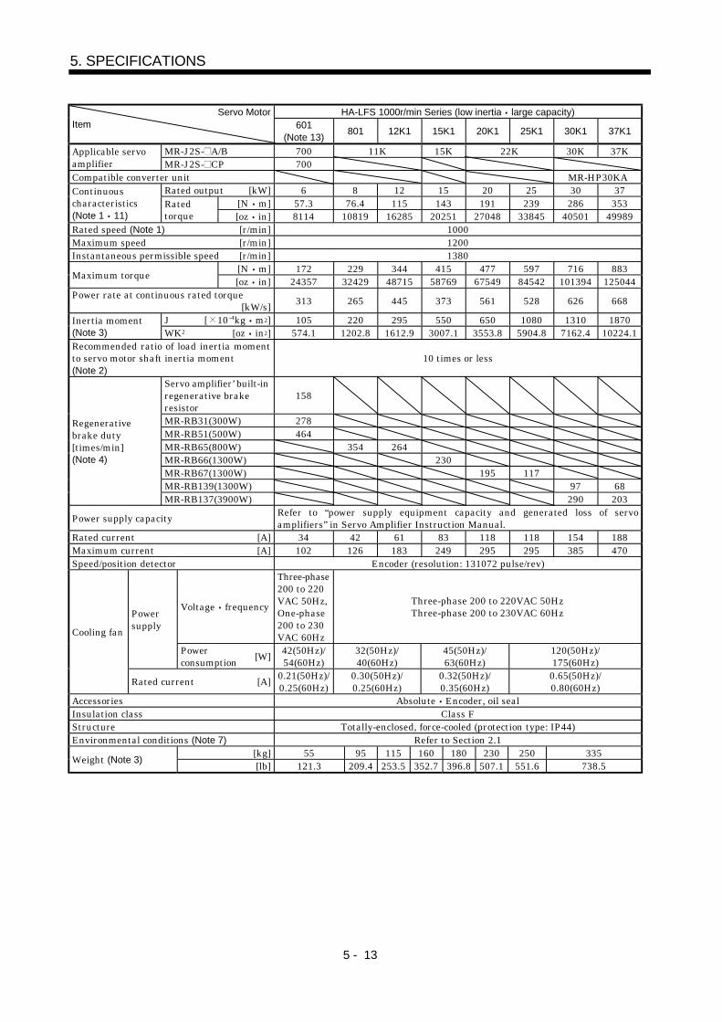
5 - 13
5. SPECIFICATIONS
HA-LFS 1000r/min Series (low inertia large capacity)Servo MotorItem 601
(Note 13)801 12K1 15K1 20K1 25K1 30K1 37K1
MR-J2S- A/B 700 11K 15K 22K 30K 37KApplicable servoamplifier MR-J2S- CP 700Compatible converter unit MR-HP30KA
Rated output [kW] 6 8 12 15 20 25 30 37[N m] 57.3 76.4 115 143 191 239 286 353
Continuouscharacteristics(Note 1 11)
Ratedtorque [oz in] 8114 10819 16285 20251 27048 33845 40501 49989
Rated speed (Note 1) [r/min] 1000Maximum speed [r/min] 1200Instantaneous permissible speed [r/min] 1380
[N m] 172 229 344 415 477 597 716 883Maximum torque
[oz in] 24357 32429 48715 58769 67549 84542 101394 125044Power rate at continuous rated torque
[kW/s]313 265 445 373 561 528 626 668
J [ 10 4kg m2] 105 220 295 550 650 1080 1310 1870Inertia moment(Note 3) WK2 [oz in2] 574.1 1202.8 1612.9 3007.1 3553.8 5904.8 7162.4 10224.1Recommended ratio of load inertia momentto servo motor shaft inertia moment(Note 2)
10 times or less
Servo amplifier’ built-inregenerative brakeresistor
158
MR-RB31(300W) 278MR-RB51(500W) 464MR-RB65(800W) 354 264MR-RB66(1300W) 230MR-RB67(1300W) 195 117MR-RB139(1300W) 97 68
Regenerativebrake duty[times/min](Note 4)
MR-RB137(3900W) 290 203
Power supply capacityRefer to “power supply equipment capacity and generated loss of servoamplifiers” in Servo Amplifier Instruction Manual.
Rated current [A] 34 42 61 83 118 118 154 188Maximum current [A] 102 126 183 249 295 295 385 470Speed/position detector Encoder (resolution: 131072 pulse/rev)
Voltage frequency
Three-phase200 to 220VAC 50Hz,One-phase200 to 230VAC 60Hz
Three-phase 200 to 220VAC 50HzThree-phase 200 to 230VAC 60HzPower
supply
Powerconsumption
[W]42(50Hz)/54(60Hz)
32(50Hz)/40(60Hz)
45(50Hz)/63(60Hz)
120(50Hz)/175(60Hz)
Cooling fan
Rated current [A]0.21(50Hz)/0.25(60Hz)
0.30(50Hz)/0.25(60Hz)
0.32(50Hz)/0.35(60Hz)
0.65(50Hz)/0.80(60Hz)
Accessories Absolute Encoder, oil sealInsulation class Class FStructure Totally-enclosed, force-cooled (protection type: IP44)Environmental conditions (Note 7) Refer to Section 2.1
[kg] 55 95 115 160 180 230 250 335Weight (Note 3)
[lb] 121.3 209.4 253.5 352.7 396.8 507.1 551.6 738.5

5 - 14
5. SPECIFICATIONS
HA-LFS 1500r/min Series (low inertia large capacity)Servo Motor
Item701M
(Note 13)11K1M 15K1M 22K1M 30K1M 37K1M
MR-J2S- A/B 700 11K 15K 22K 30K 37KApplicable servoamplifier MR-J2S- CP 700Compatible converter unit MR-HP30KA
Rated output [kW] 7 11 15 22 30 37[N m] 44.6 70.0 95.5 140 191 236
Continuouscharacteristics(Note 1 11)
Ratedtorque [oz in] 6315.9 9912.9 13524 19825.7 27047.9 33420.5
Rated speed (Note1) [r/min] 1500Maximum speed [r/min] 2000Instantaneous permissible speed [r/min] 2300
[N m] 134 210 286 350 477 589Maximum torque
[oz in] 18976 29738.6 40501.1 49564.3 67549.1 83409.6Power rate at continuous rated torque
[kW/s]189 223 309 357 561 514
J [ 10 4kg m2] 105 220 295 550 650 1080Inertia moment(Note 3) WK2 [oz in2] 574.1 1202.8 1612.9 3007.1 3553.8 5904.8Recommended ratio if load inertia momentto servo motor shaft inertia moment(Note 2)
10 times or less
Servo amplifier’ built-inregenerative brakeresistor
70
MR-RB31(300W) 124MR-RB51(500W) 206MR-RB65(800W) 158MR-RB66(1300W) 191MR-RB67(1300W) 102MR-RB139(1300W) 87 52
Regenerativebrake duty[times/min](Note4)
MR-RB137(3900W) 260 156
Power supply capacityRefer to “power supply equipment capacity and generated loss of servoamplifiers” in Servo Amplifier Instruction Manual.
Rated current [A] 37 65 87 126 174 202Maximum current [A] 111 195 261 315 435 505Speed/position detector Encoder (resolution: 131072 pulse/rev)
Voltage frequency
One-phase200 to 220VAC 50Hz,One-phase200 to 230VAC 60Hz
Three-phase 200 to 220VAC 50HzThree-phase 200 to 230VAC 60HzPower
supply
Powerconsumption
[W]42(50Hz)/54(60Hz)
32(50Hz)/40(60Hz)
45(50Hz)/63(60Hz)
120(50Hz)/175(60Hz)
cooling fan
Rated current [A]0.21(50Hz)/0.25(60Hz)
0.30(50Hz)/0.25(60Hz)
0.32(50Hz)/0.35(60Hz)
0.65(50Hz)/0.80(60Hz)
Accessories Absolute Encoder, oil sealInsulation class Class FStructure Totally-enclosed, force-cooled (protection type: IP44)Environmental conditions (Note 7) Refer to Section 2.1
[kg] 55 95 115 160 180 230Weight (Note 3)
[lb] 121.3 209.4 253.5 352.7 396.8 507.1

5 - 15
5. SPECIFICATIONS
HA-LFS 2000r/min Series (low inertia large capacity)Servo Motor
Item502
(Note 13)702
(Note 13)11K2 15K2 22K2 30K2 37K2
MR-J2S- A/B 500 700 11K 15K 22K 30K 37KApplicable servoamplifier MR-J2S- CP 500 700Compatible converter unit MR-HP30KA
Rated output [kW] 5.0 7.0 11 15 22 30 37[N m] 23.9 33.4 52.5 71.6 105 143 177
Continuouscharacteristics(Note 1 11)
Ratedtorque [oz in] 3384.5 4729.9 7434.6 10139.4 14869.3 20250.6 25065.4
Rated speed (Note 1) [r/min] 2000Maximum speed [r/min] 2000Instantaneous permissible speed [r/min] 2300
[N m] 71.6 100 158 215 263 358 442Maximum torque
[oz in] 10139.4 14161.2 22374.7 30446.6 37244 50697.2 62592.6Power rate at continuous rated torque
[kW/s]77.2 118 263 233 374 373 480
J [ 10 4kg m2] 74.0 94.2 105 220 295 550 650Inertia moment(Note 3) WK2 [oz in2] 404.6 515 574.1 1202.8 1612.9 3007.1 3553.8Recommended ratio of load inertia momentto servo motor shaft inertia moment(Note 2)
10 times or less
Servo amplifier’ built-inregenerative brakeresistor
50 50
MR-RB30(300W) 120MR-RB31(300W) 95MR-RB50(500W) 200MR-RB51(500W) 160MR-RB65(800W) 186MR-RB66(1300W) 144MR-RB67(1300W) 107MR-RB139(1300W) 58 49
Regenerativebrake duty[times/min](Note 4)
MR-RB137(3900W) 174 147
Power supply capacityRefer to “power supply equipment capacity and generated loss of servoamplifiers” in Servo Amplifier Instruction Manual.
Rated current [A] 25 34 63 77 112 166 204Maximum current [A] 75 102 189 231 280 415 510Speed/position detector Encoder (resolution: 131072 pulse/rev)
Voltage frequency
One-phase200 to 220VAC 50Hz,One-phase200 to 230VAC 60Hz
Three-phase 200 to 220VAC 50HzThree-phase 200 to 230VAC 60HzPower
supply
Powerconsumption
[W]42(50Hz)/54(60Hz)
32(50Hz)/40(60Hz)
40(50Hz)/63(60Hz)
Cooling fan
Rated current [A]0.21(50Hz)/0.25(60Hz)
0.30(50Hz)/0.25(60Hz)
0.32(50Hz)/0.35(60Hz)
Accessories Absolute Encoder, oil sealInsulation class Class F
StructureTotally-enclosed,
self-cooled(protection: IP65)
Totally-enclosed, force-cooled (protection: IP44)
Environmental conditions (Note 7) Refer to Section 2.1[kg] 28 35 55 95 115 160 180
Weight (Note 3)[lb] 61.7 77.2 121.3 209.4 253.5 352.7 396.8

5 - 16
5. SPECIFICATIONS
HC-LFS Series (low inertia middle capacity)Servo MotorItem 52 102 152 202 302
Applicable servoamplifier
MR-J2S-60A-U02660B-U026
60CP-U026
100A-U027100B-U027
100CP-U027
200A-U028200B-U028
200CP-U028
350A-U029350B-U029
350CP-U029
500A-U029500B-U029
500CP-U029Rated output [kW] 0.5 1.0 1.5 2.0 3.0
[N m] 2.39 4.78 7.16 9.55 14.3Continuouscharacteristics(Note 1 11)
Ratedtorque [oz in] 338.5 676.9 1013.9 1352.4 2025.1
Rated speed (Note 1) [r/min] 2000Maximum speed [r/min] 3000Instantaneous permissible speed [r/min] 3450
[N m] 7.16 14.4 21.6 28.5 42.9Maximum torque
[oz in] 1013.9 2039.2 3058.8 4036 6075.2Power rate at continuous rated torque
[kW/s]17.9 49.7 80.1 41.5 56.8
J [ 10 4kg m2] 3.2 4.6 6.4 22 36Inertia moment(Note 3) WK2 [oz in2] 17.5 25.2 35 120.3 196.8Recommended ratio of load inertia momentto servo motor shaft inertia moment(Note 2)
10 times or less
Servo amplifier’ built-inregenerative brakeresistor
115 160 425 120 70
MR-RB032(30W) 340 235MR-RB12(100W) 1150 800MR-RB30(300W) 1270 370 215MR-RB32(300W) 2410
Regenerativebrake duty[times/min](Note 4)
MR-RB50(500W) 2120 615 355
Power supply capacityRefer to “power supply equipment capacity and generated loss of servoamplifiers” in Servo Amplifier Instruction Manual.
Rated current [A] 3.2 5.9 9.9 14 23Maximum current [A] 9.6 18 30 42 69Speed/position detector Encoder (resolution: 131072 pulse/rev)Accessories Absolute Encoder oil sealInsulation class Class FStructure Totally-enclosed, self-cooled (protection type: IP65)Environmental conditions (Note 7) Refer to Section 2.1
[kg] 6.5 8.0 10.0 21 28Weight (Note 3)
[lb] 14.33 17.6 22 46.3 61.7

5 - 17
5. SPECIFICATIONS
Note: 1.When the power supply voltage drops, we cannot guarantee the output and rated speed.2.If the load inertia moment ratio exceeds the indicated value, please consult us.3.When the servo motor is equipped with reduction gear or electromagnetic brake, refer to the
corresponding outline dimension drawing. For the EN Standard- and UL/C-UL Standard-compliant models, please consult us.
4.The regenerative brake duty indicated is the permissible duty when the servo motor runningwithout load at the rated speed is decelerated to a stop. When a load is connected, the value inthe table is multiplied by 1/(m 1), where m load inertia moment/motor inertia moment. Atthe speed higher than the rated, the permissible number of times is in inverse proportion to thesquare of (running speed/rated speed). When the running speed varies frequently or when theregenerative mode continues as in vertical feed, calculate regenerative heat generated duringoperation. Provisions must be made to keep this generated heat below the permissible value.
5. If the effective torque is within the rated torque range, there are no restrictions on theregenerative duty.
6. Except for the shaft-through portion and connector end.7. In the environment where the servo motor is exposed to oil mist, oil and/or water, the servo
motor of the standard specifications may not be usable. Contact us.8. IP54 for the EN Standard-compliant model.9. Except the connector section.
10. Values for use of the supplied regenerative brake unit (regenerative brake resistor).11. 80%ED at low noise.
80%ED: Indicates the condition in which operation time at read torque accounts for 80% andthe other no-load time accounts for 20% in a single operation cycle.
Torque100% tb
tc time
tb 60 sec. (continuous operation time)
%EDtc
tb100
12. When the servo motor is provided with the reduction gear, the protection type of the reductiongear section is IP44.
13. Consult us since they may not be connected depending on the production period of the servoamplifier.

5 - 18
5. SPECIFICATIONS
5.2 Torque characteristics
POINT
For machines which produce unbalance torque, e.g. vertical liftapplications, it is recommended to use the servo motor so that theunbalance torque will be within 70% of the rated torque.
(1) HC-MF series
POINT
The continuous broken line in the graph assumes that the servo motor is usedwith the servo amplifier of single-phase 100VAC power supply specifications.
1000 2000 3000 40004500
Continuous operation
region
Speed [r/min]
To
rqu
e [N
m
]
0
0.2
0.4
0.6
[HC-MF053]
Short-duration
operation region
1000 2000 3000 40004500
Speed [r/min]
To
rqu
e [N
m
]
0
0.25
0.5
1.0
[HC-MF13]
0.75
Speed [r/min]T
orq
ue
[N
m]
0
0.5
1.0
2.0
[HC-MF23]
1.5
1000 2000 3000 40004500
Continuous operation
region
Short-duration
operation region
Continuous operation
region
Short-duration
operation region
1000 2000 3000 40004500
Speed [r/min]
0
1.0
2.0
4.0
[HC-MF43]
3.0
Tor
que
[N
m
]
Short-duration
operation region
Speed [r/min]
1000 2000 3000 40004500
Tor
que
[N
m
]
0
2.0
4.0
8.0
[HC-MF73]
6.0 Short-duration
operation region
Continuous operation
region
Continuous operation
region
(2) HA-FF series
POINT
The continuous broken line in the graph assumes that the servo motor is usedwith the servo amplifier of single-phase 100VAC power supply specifications.
1000 2000 3000
Tor
que
[N
m
]
0
0.5
1.0
2.0
[HA-FF23]
1.5
4000
Speed [r/min]
Tor
que
[N
m
]
0
0.2
0.4
0.6
[HA-FF053]
1000 2000 3000 4000
Speed [r/min]
3000
Tor
que
[N
m
]
0
0.25
0.5
1.0
[HA-FF13]
0.75
1000 2000 4000
Speed [r/min]
Short-duration
operation region
Continuous operation
region
Continuous operation
region
Short-duration
operation region
Short-duration
operation region
Continuous operationregion

5 - 19
5. SPECIFICATIONS
1000 2000 3000 4000
Speed [r/min]
Tor
que
[N
m
]
0
1.0
2.0
3.0
[HA-FF33]
40000
1.0
2.0
4.0
[HA-FF43]
3.0
Tor
que
[N
m
]1000 2000 3000
Speed [r/min]
Short-durationoperation region
Continuous operation
region
Short-durationoperation region
Continuous operation
region
40001000 2000 3000
Speed [r/min]
Tor
que
[N
m
]
0
2.0
4.0
6.0
[HA-FF63]
Short-durationoperation region
Continuous operation
region
(3) HC-SF/HC-SFS series
Tor
que
[N
m]
10
20
40
[HC-SF121][HC-SFS121]
0
Speed [r/min]500 1000
30
Tor
que
[N
m]
20
40
60
[HC-SF201][HC-SFS201]
0
Speed [r/min]500 1000
Tor
que
[N
m]
10
20
30
[HC-SF81][HC-SFS81]
0500 1000 1500
Speed [r/min]
Short-duration
operation region
Continuous operationregion
Short-duration
operation region
Continuous operation
region
Continuous operation
region
Short-duration
operation region
Tor
que
[N
m]
25
50
100
[HC-SF301][HC-SFS301]
0
Speed [r/min]500 1000
75
Continuous operation
region
Short-durationoperation region
5
10
15
[HC-SF102][HC-SFS102]
0
Speed [r/min]1000 2000 3000
Short-duration
operation region
Continuous operationregion
Tor
que
[N
m]
Tor
que
[N
m]
3
6
9
[HC-SF52][HC-SFS52]
01000 2000 3000
Speed [r/min]
Continuous operation
region
Short-duration
operation region
8
16
24
[HC-SF152][HC-SFS152]
0
Speed [r/min]1000 2000 3000
Short-duration
operation region
Continuous operation
region
To
rqu
e [N
m
]
Tor
que
[N
m
]
10
20
30
[HC-SF202][HC-SFS202]
0
Speed [r/min]
1000 2000
Short-duration
operation region
Continuous operation
region
[HC-SF352][HC-SFS352]
Tor
que
[N
m
]
20
40
60
0
Speed [r/min]
1000 2000
Short-duration
operation region
Continuous operation
region

5 - 20
5. SPECIFICATIONS
20
60
80
[HC-SF502][HC-SFS502]
0
Speed [r/min]
1000 2000
40
Short-duration
operation region
Continuous operation
region
To
rqu
e [N
m
]
To
rqu
e [N
m
]
40
80
120
[HC-SF702][HC-SFS702]
0
Speed [r/min]
1000 2000
Short-duration
operation region
Continuous operation
region
To
rqu
e [N
m
]
2
4
6
[HC-SF53][HC-SFS53]
01000 2000 3000
Speed [r/min]
Continuous operation
region
Short-duration
operation region
Tor
que
[N
m
]
4
8
12
[HC-SF103][HC-SFS103]
01000 2000 3000
Speed [r/min]
Continuous operation
region
Short-durationoperation region
Tor
que
[N
m
]
5
10
15
[HC-SF153][HC-SFS153]
01000 2000 3000
Speed [r/min]
Continuous operation
region
Short-duration
operation region
Tor
que
[N
m
]
7
14
21
[HC-SF203][HC-SFS203]
01000 2000 3000
Speed [r/min]
Continuous operation
region
Short-duration
operation region
Tor
que
[N
m
]
13
26
39
[HC-SF353][HC-SFS353]
01000 2000 3000
Speed [r/min]
Continuous operation
region
Short-duration
operation region

5 - 21
5. SPECIFICATIONS
(4) HC-RF/HC-RFS series
1000 2000 3000 4000
Speed [r/min]
Tor
que
[N
m
]
0
3
6
9
[HC-RF103][HC-RFS103]
Continuous operation
region
Short-duration
operation region
1000 2000 3000 4000
Speed [r/min]
Tor
que
[N
m
]
0
5
10
15
[HC-RF153][HC-RFS153]
Continuous operation
region
Short-durationoperation region
Speed [r/min]
Tor
que
[N
m
]
0
6
12
18
[HC-RF203][HC-RFS203]
1000 2000 3000 4000
Continuous operation
region
Short-durationoperation region
[HC-RF353][HC-RFS353]
Speed [r/min]
Tor
que
[N
m
]
0
15
30
45
[HC-RF503][HC-RFS503]
1000 2000 3000 4000
Continuous operationregion
Short-duration
operation region
1000 2000 3000 4000
Speed [r/min]
Tor
que
[N
m
]
0
3
6
9
Continuous operation
region
Short-duration
operation region
(5) HC-UF/HC-UFS series
POINT
The continuous broken line in the graph assumes that the servo motor is usedwith the servo amplifier of single-phase 100VAC power supply specifications.
Tor
que
[N
m
]
4
8
12
[HC-UF72][HC-UFS72]
01000 2000 3000
Speed [r/min]
Continuous operation
region
Short-duration
operation region
Tor
que
[N
m]
8
16
24
[HC-UF152][HC-UFS152]
01000 2000 3000
Speed [r/min]
Continuous operation
region
Short-duration
operation region
Tor
que
[N
m]
10
20
30
[HC-UF202][HC-UFS202]
01000 2000 3000
Speed [r/min]
Continuous operation
region
Short-duration
operation region

5 - 22
5. SPECIFICATIONS
500 100015002000
Speed [r/min]
To
rqu
e [N
m
]
0
20
40
60
[HC-UF352][HC-UFS352]
2500
Continuous operation
region
Short-duration
operation region
500 100015002000
Speed [r/min]
To
rqu
e [N
m
]0
20
40
80
[HC-UF502][HC-UFS502]
2500
60Short-durationoperation region
Continuous operation
region
1000 2000 3000 40004500
Speed [r/min]
To
rqu
e [N
m
]
0
0.25
0.5
1.0
[HC-UF13]
0.75 Short-duration
operation region
Continuous operation
region
Speed [r/min]
Tor
que
[N
m]
0
0.5
1.0
2.0
[HC-UF23]
1.5
1000 2000 3000 40004500
Short-durationoperation region
Continuous operation
region
1000 2000 3000 40004500
Speed [r/min]
0
1.0
2.0
4.0
[HC-UF43]
3.0
Tor
que
[N
m]
Short-duration
operation region
Continuous operation
region
Speed [r/min]
Tor
que
[N
m]
0
2
4
8
[HC-UF73]
6
1000 2000 3000 40004500
Short-durationoperation region
Continuous operationregion
1000 2000 3000 40004500
Speed [r/min]
To
rqu
e [N
m
]
0.25
0.5
1.0[HC-UFS13]
0.75
Speed [r/min]
To
rqu
e [N
m
]
0
0.5
1.0
2.0[HC-UFS23]
1.5
1000 2000 3000 40004500 1000 2000 3000 40004500
Speed [r/min]
0
1.0
2.0
4.0
[HC-UFS43]
3.0
To
rqu
e [N
m
]
Short-duration
operation region
Continuous operation
region
Short-duration
operation region
Continuous operation
region
Short-duration
operation region
Continuous operation
region
0
Speed [r/min]
Tor
que
[N
m
]
0
2.0
4.0
8.0
[HC-UFS73]
6.0
1000 2000 3000 40004500
Short-durationoperation region
Continuous operation
region

5 - 23
5. SPECIFICATIONS
(6) HA-LH seriesT
orq
ue [
N
m]
50
200
[HA-LH11K2]
0
Speed [r/min]1000 2000
100
150
Short-duration
operation region
Continuous operation
regionT
orq
ue [
N
m]
100
250
[HA-LH15K2]
0
Speed [r/min]1000 2000
200Short-durationoperation region
Continuous operationregion
Tor
que
[N
m
]
100
300
[HA-LH22K2]
0
Speed [r/min]1000 2000
200
Short-durationoperation region
Continuous operation
region
(7) HC-KF series
1000 2000 3000 400045000
0.2
0.4
0.6
[HC-KF053]
1000 2000 3000 400045000
0.25
0.5
1.0
0.75
[HC-KF13] [HC-KF23]
Tor
que
[N
m
]
Tor
que
[N
m
]
Speed [r/min]Speed [r/min]
Continuous operation
region
Short-duration
operation region
Continuous operation
region
Short-duration
operation region
Speed [r/min]
Tor
que
[N
m
]
0
0.5
1.0
2.0
1.5
1000 2000 3000 40004500
Continuous operation
region
Short-durationoperation region
[HC-KF43]
1000 2000 3000 40004500Speed [r/min]
0
1.0
2.0
4.0
3.0
To
rqu
e [N
m
]
Short-duration
operation region
Continuous operation
region

5 - 24
5. SPECIFICATIONS
(8) HC-AQ series
10002000300040000
0.025
0.05
0.1
5000
0.075
Short-durationoperation region
Continuous operationregion
[HC-AQ0135]
Speed [r/min]1000200030004000
0
0.05
0.1
0.2
5000
0.15
[HC-AQ0235]
Speed [r/min]
Short-duration
operation region
Continuous operation
region
[HC-AQ0335]
Tor
que
[N
m
]
1000 2000 3000 40000
0.1
0.3
4500
0.2
Short-duration
operation region
Continuous operation
region
Speed [r/min]
Tor
que
[N
m
]
Tor
que
[N
m
]
(9) HA-LF series
Tor
que
[N
m]
[HA-LF30K24]
0
Speed [r/min]
100
400
1000 2000
300
200
Short-duration
operation region
Continuous operation
region
Tor
que
[N
m]
0
Speed [r/min]
[HA-LF37K24]
200
600
1000 2000
400Short-durationoperation region
Continuous operation
region
Tor
que
[N
m]
0
Speed [r/min]
[HA-LF45K24]
200
600
1000 2000
400
Short-duration
operation region
Continuous operation
region
To
rqu
e [N
m
]
0
Speed [r/min]
[HA-LF55K24]
200
800
1000 2000
600
400
Short-duration
operation region
Continuous operation
region
To
rqu
e [N
m
]
0
Speed [r/min]
[HA-LF30K2]
100
400
1000 2000
300
200
Short-durationoperation region
Continuous operation
region

5 - 25
5. SPECIFICATIONS
(10) HA-LFS series
Speed [r/min]
To
rqu
e [N
m
]
Speed [r/min]
To
rqu
e [N
m
]
Speed [r/min]
To
rqu
e [N
m
]
500 100012000
100
200
300
400[HA-LFS12K1]
Continuous operation
region
Short-duration
operation region
5000
180
[HA-LFS601]
120
60
10001200
Continuous operation
region
Short-durationoperation region
5000
300
[HA-LFS801]
200
100
10001200
Continuous operation
region
Short-duration
operation region
Speed [r/min]
Tor
que
[N
m
]
Speed [r/min]
Tor
que
[N
m
]
Speed [r/min]
Tor
que
[N
m
]
5000
450
[HA-LFS15K1]
300
150
10001200
Continuous operation
region
Short-duration
operation region
5000
600
[HA-LFS20K1]
400
200
10001200
Continuous operationregion
Short-duration
operation region
500 100012000
200
400
600
800
[HA-LFS25K1]
Continuous operationregion
Short-duration
operation region
Speed [r/min]
Tor
que
[N
m]
Speed [r/min]
Tor
que
[N
m
]
Speed [r/min]
Tor
que
[N
m
]
500 100012000
200
400
600
800[HA-LFS30K1]
Continuous operation
region
Short-duration
operation region
5000
900
[HA-LFS37K1]
600
300
10001200
Continuous operation
region
Short-durationoperation region
5000
150[HA-LFS701M]
100
50
1000 20001500
Continuous operationregion
Short-duration
operation region
Speed [r/min]
Tor
que
[N
m
]
Speed [r/min]
Tor
que
[N
m
]
Speed [r/min]
Tor
que
[N
m
]
5000
240
[HA-LFS11K1M]
160
80
1500 20001000
Continuous operation
region
Short-durationoperation region
5000
300
[HA-LFS15K1M]
200
100
1500 20001000
Continuous operation
region
Short-duration
operation region
500 1000 20000
100
200
300
400[HA-LFS22K1M]
1500
Continuous operation
region
Short-duration
operation region

5 - 26
5. SPECIFICATIONS
Speed [r/min]
To
rqu
e [N
m
]
Speed [r/min]T
orq
ue
[N
m]
Speed [r/min]
To
rqu
e [N
m
]
5000
600[HA-LFS30K1M]
400
200
1500 20001000
Continuous operation
region
Short-duration
operation region
5000
600
[HA-LFS37K1M]
400
200
1500 20001000
Continuous operation
region
Short-duration
operation region
1000 20000
20
40
60
80[HA-LFS502]
Continuous operation
region
Short-duration
operation region
Speed [r/min]
To
rqu
e [N
m
]
0
120
[HA-LFS702]
80
40
20001000
Continuous operationregion
Short-duration
operation region
Speed [r/min]
To
rqu
e [N
m
]
10000
200[HA-LFS11K2]
2000
150
100
50
Continuous operationregion
Short-durationoperation region
Speed [r/min]
To
rqu
e [N
m
]
10000
240[HA-LFS15K2]
2000
180
120
60
Continuous operation
region
Short-duration
operation region
Speed [r/min]
Tor
que
[N
m
]
10000
300[HA-LFS22K2]
2000
200
100
Continuous operation
region
Short-durationoperation region
Speed [r/min]
Tor
que
[N
m
]
Speed [r/min]
Tor
que
[N
m
]
10000
400
[HA-LFS30K2]
2000
300
200
100
Continuous operationregion
Short-duration
operation region
10000
600
[HA-LFS37K2]
2000
400
200
Continuous operation
region
Short-duration
operation region

5 - 27
5. SPECIFICATIONS
(11) HC-MFS series
POINT
The continuous broken line in the graph assumes that the servo motor is usedwith the servo amplifier of single-phase 100VAC power supply specifications.
Speed [r/min]
To
rqu
e [N
m
]
Speed [r/min]
To
rqu
e [N
m
]
Speed [r/min]
To
rqu
e [N
m
]
1000 2000 3000 400045000
0.6
[HC-MFS053]
0.4
0.2
Continuous operation
region
Short-durationoperation region
1000 2000 3000 400045000
0.25
0.5
0.75
1.0
[HC-MFS13]
Continuous operation
region
Short-duration
operation region
1000 2000 3000 400045000
0.5
1.0
1.5
2.0
[HC-MFS23]
Continuous operation
region
Short-durationoperation region
Speed [r/min]
To
rqu
e [N
m
]
Speed [r/min]
To
rqu
e [N
m
]
1000 2000 3000 400045000
1.0
2.0
3.0
4.0[HC-MFS43]
Continuous operation
region
Short-duration
operation region
1000 2000 3000 400045000
2.0
4.0
6.0
8.0
[HC-MFS73]
Continuous operation
region
Short-duration
operation region
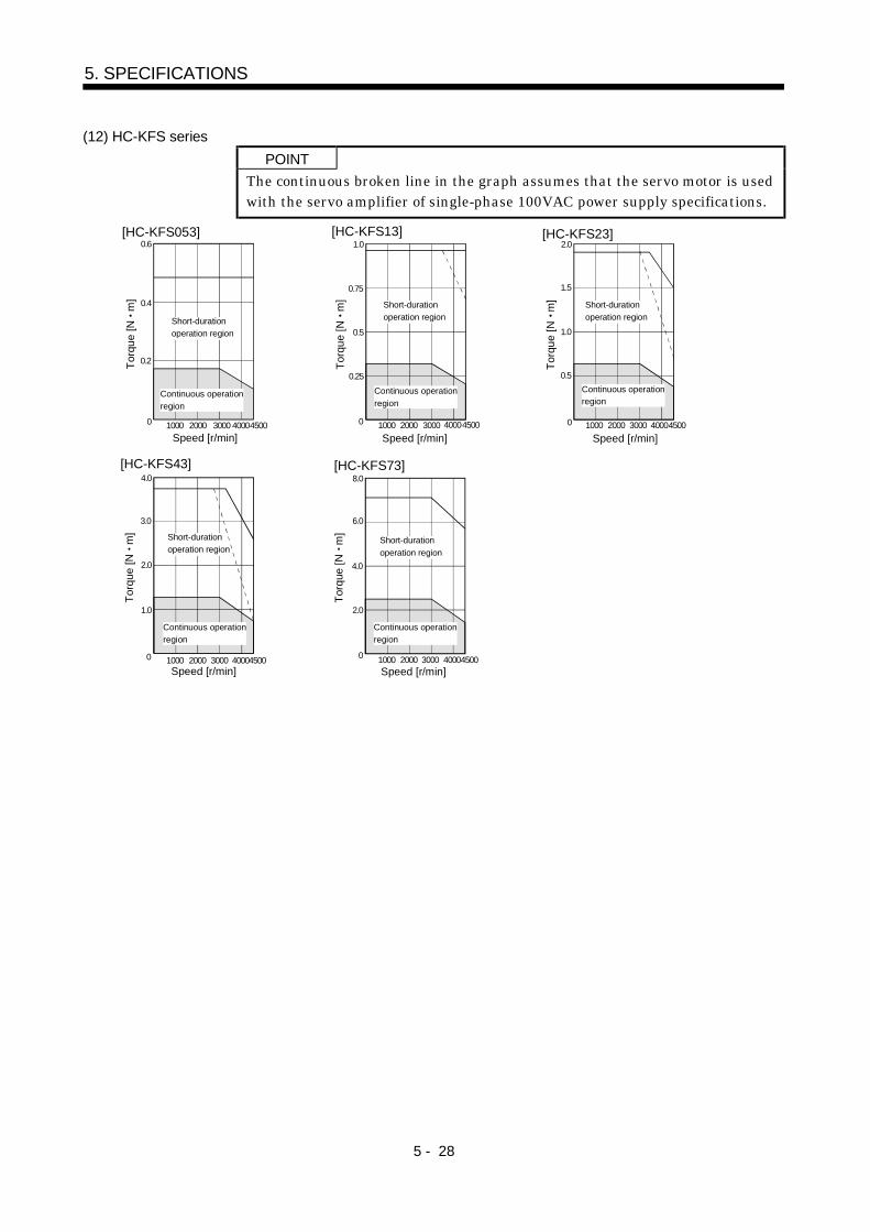
5 - 28
5. SPECIFICATIONS
(12) HC-KFS series
POINT
The continuous broken line in the graph assumes that the servo motor is usedwith the servo amplifier of single-phase 100VAC power supply specifications.
Speed [r/min]
Tor
que
[N
m]
Speed [r/min]
Tor
que
[N
m]
Speed [r/min]
Tor
que
[N
m]
1000 2000 3000 400045000
0.6[HC-KFS053]
0.4
0.2
1000 2000 3000 400045000
0.25
0.5
0.75
1.0[HC-KFS13]
Continuous operation
region
Short-duration
operation region
Continuous operation
region
Short-duration
operation region
1000 2000 3000 400045000
0.5
1.0
1.5
2.0[HC-KFS23]
Continuous operationregion
Short-duration
operation region
Speed [r/min]
Tor
que
[N
m]
Speed [r/min]
Tor
que
[N
m]
1000 2000 3000 400045000
1.0
2.0
3.0
4.0
[HC-KFS43]
Continuous operation
region
Short-duration
operation region
1000 2000 3000 400045000
2.0
4.0
6.0
8.0[HC-KFS73]
Continuous operation
region
Short-duration
operation region

5 - 29
5. SPECIFICATIONS
(13) HC-LFS series
Speed [r/min]
Tor
que
[N
m
]
Speed [r/min]
Tor
que
[N
m
]
Speed [r/min]
Tor
que
[N
m
]
10000
8
[HC-LFS52]
6
2
2000 3000
4
Continuous operation
region
Short-duration
operation region
10000
20
[HC-LFS102]
15
5
2000 3000
10
10000
32
[HC-LFS152]
24
8
2000 3000
16
Continuous operation
region
Short-duration
operation region
Continuous operation
region
Short-duration
operation region
Speed [r/min]
Tor
que
[N
m
]
Speed [r/min]
Tor
que
[N
m
]
1000
[HC-LFS302]
2000 3000
Continuous operation
region
Short-duration
operation region
0
56
42
14
28
10000
40
[HC-LFS202]
30
10
2000 3000
20
Continuous operation
region
Short-durationoperation region

5 - 30
5. SPECIFICATIONS
5.3 Servo motors with reduction gears
CAUTION
The servo motor with reduction gear must be installed in the specified direction.Otherwise , it can leak oil, leading to a fire or fault.For the servo motor with reduction gear, transport it in the same status as in theinstallation method. Tipping it over can cause oil leakage.
Servo motors are available with reduction gears designed for: general industrial machines and precisionapplications.Servo motors with electromagnetic brakes are also available.
(1) Manufacturing range of servo motor with reduction gearServo motors with reduction gears that may be manufactured are indicated by symbols (G1(H), G2) inthe following table. G1 (H) and G2 are symbols appended to the servo motor models.
For General Industrial Machines For Precision ApplicationsReduction Gear SeriesReduction ratio
Servo Motor(Note)
1/51/6
(Note)
1/101/11
(Note)
1/121/17
(Note)
1/201/29
(Note)
1/301/35 1/43 1/59 1/5 1/9 1/10 1/15 1/20 1/25 1/29 1/45
HC-KF053 to 43HC-KFS053 to 73
G1 G1 G1 G2 G2 G2 G2
HC-MF053 to 73HC-MFS053 to 73
G1 G1 G1 G2 G2 G2 G2
HA-FF053 G1 G1 G1 G1 G2 G2 G2 G2HA-FF13 G1 G1 G1 G1 G2 G2 G2 G2 G2HA-FF23 G1 G1 G1 G1 G2 G2 G2 G2 G2 G2HA-FF33 G1 G1 G1 G1 G2 G2 G2 G2 G2HA-FF43 63 G1 G1 G1 G1 G2 G2 G2 G2 G2HC-SF52 to 202HC-SFS52 to 202
G1(H)
G1(H)
G1(H)
G1(H)
G1(H)
G1(H)
G1(H)
G2 G2 G2 G2 G2
HC-SF352HC-SFS352
G1(H)
G1(H)
G1(H)
G1(H)
G1(H)
G1(H)
G1(H)
G2 G2 G2
HC-SF502HC-SFS502
G1(H)
G1(H)
G1(H)
G1(H)
G1(H)
G2 G2
HC-SF702HC-SFS702
G1(H)
G1(H)
G1(H)
G1(H)
G1(H)
G2
HC-RF103 to 203HC-RFS103 to 203
G2 G2 G2 G2 G2
HC-RF353HC-RFS353
G2 G2 G2 G2
HC-RF503HC-RFS503
G2 G2 G2
Note : Reduction ratios for general industrial machines are nominal values. For actual reduction ratios, refer to (2) and (3) in this section.
For those without (Note), the nominal value is equal to the actual reduction ratio.
(2) HC-MF/HC-KF series
Reduction Gear SeriesFor General Industrial Machines
(HC-KF G1/HC-MF G1)(HC-KFS G1/HC-MFS G1)
For Precision Applications(HC-KF G2/HC-MF G2)
(HC-KFS G2/HC-MFS G2)
Mounting method Flange mountingMounting direction In any directions
Grease lubrication (Already packed) Grease lubrication (Already packed)200W 400W
50 100W1/12 1/20 1/5
750WLubrication Recommended
grease Mobilplex 46Mobil Oil
New MolynocNo.2 NissekiMitsubishi
Mobil GreaseSP Mobil Oil
LDR101BV American Oil Center Research
Output shaft rotating direction Same as the servo motor output shaft direction.With electromagnetic brake AvailableBacklash 60 minutes or less at reduction gear output shaft 3 minutes or less at reduction gear output shaftPermissible load inertia momentratio (when converting into theservo motor shaft)
HC-KF HC-KFS:5 times or lessHC-MF HC-MFS:25 times or less
Permissible speed(at servo motor shaft)
4500 r/min

5 - 31
5. SPECIFICATIONS
The actual reduction ratios of the servo motors with reduction gears designed for general industrialmachines are as listed below:
Servo Motor
Nominal
Reduction Ratio
HC-KF053(B)G1
HC-MF053(B)G1
HC-KFS053(B)G1
HC-MFS053(B)G1
HC-KF13(B)G1
HC-MF13(B)G1
HC-KFS13(B)G1
HC-MFS13(B)G1
HC-KF23(B)G1
HC-MF23(B)G1
HC-KFS23(B)G1
HC-MFS23(B)G1
HC-KF43(B)G1
HC-MF43(B)G1
HC-KFS43(B)G1
HC-MFS43(B)G1
HC-KFS73(B)G1
HC-MF73(B)G1
HC-MFS73(B)G1
1/5 9/44 19/96 1/5
1/12 49/576 25/288 525/6048
1/20 25/484 253/5000 625/12544
(3) HA-FF series
Reduction Gear SeriesFor General Industrial Machines
(HA-FF G1)
For Precision Applications
(HA-FF G2)
Mounting method Flange mounting
Mounting direction In any directions
Grease lubrication (Already packed) Grease lubrication (Already packed)
50 100W 200 to 600WLubrication Recommended
greaseSUMICO
LUBRICANT MOLYPS GREASE No.2
PYRONOCUNIVERSAL No.000
NIPPON PETRQLEUM
LDR101BJ American Oil Center Research
Output shaft rotating direction
Servo motor shaft and reduction gear outputshaft rotate in the same direction. For theHA-FF053G1 1/30 and HA-FF3G1 1/30, how-ever, the servo motor shaft and reduction gearoutput shaft rotate in the opposite directions.
Servo motor shaft and reduction gearoutput-shaft rotate in the same direction.
With electromagnetic brake Available
Backlash (Note) 40 minutes to 1.5 Within 3 minutes
Permissible load inertia momentratio (when converting into theservo motor shaft)
5 times or less
Permissible speed(at servo motor shaft)
3000 r/min
Note. The above values are typical values and not guaranteed values.
The actual reduction ratios of the servo motors with reduction gears designed for general industrialmachines are as listed below:
Servo Motor
Nominal Reduction RatioHA-FF053G1 HA-FF13G1 HA-FF23G1 HA-FF33G1 HA-FF43G1 HA-FF63G1
1/5 9/44 57/280 19/94 10/49
1/10 3/29 39/400 39/376 243/2401
1/20 99/1972 51/980 72/1363 153/2891
1/30 144/4205 1/30 11/329 27/784

5 - 32
5. SPECIFICATIONS
(4) HC-SF series
Reduction Gear SeriesFor General Industrial Machines
(HC-SF G1(H)/HC-SFS G1(H))
For Precision Applications
(HC-SF G2/ HC-SFS G2)
Mounting method As in (a) in this section Flange mounting
Mounting direction As in (a) in this section In any directions
As in (a) (b) in this section Grease lubrication (Already packed)
Lubrication Recommendedgrease
As in (b) in this sectionLDR101BJ of American Oil Center
Research
Output shaft rotating direction Opposite direction to the servo motor shaft Same direction as the servo motor shaft
With electromagnetic brake Available
Backlash40 minutes to 2*at reduction gear outputshaft (Note)
3 minutes or less at reduction gear outputshaft
Permissible load inertia momentratio (when converting into theservo motor shaft)
4 times or less 5 times or less
Permissible speed(at servo motor shaft)
2000 r/min0.5 to 1.5kW:3000 r/min2 to 3.5kW:2500 r/min
5 7kW:2000 r/min
Note. The above values are typical values and not guaranteed values.
(a) Lubrication of reduction gears for general industrial machinesOil lubrication cannot be used in applications where the servo motor will move. Specify greaselubrication.For grease lubrication, the reduction gear is already grease-packed.For oil lubrication, pack the reduction gear with oil on the customer side.
MountingDirection
Shaft in Any Direction Shaft Horizontal Shaft Downward Shaft Upward
Reduction gearmodel
Reduction gearframe No.
CNHM(leg type)
CNVM(flange type)
CHHM(leg type)
CHVM(flange type)
CVHM(leg type)
CVVM(flange type)
CWHM(leg type)
CWVM(flange type)
4105 Grease Grease4115 Grease Grease4135 (Note) Oil (Note) Oil (Note) Oil (Note) Oil Grease Grease4165 (Note) Oil (Note) Oil (Note) Oil (Note) Oil Grease Grease4175 Oil Oil Oil Oil4185 Oil Oil Oil Oil4195 Oil Oil Oil Oil
Note: Grease-lubricated type is also available.
The reduction gear frame numbers are as follows:
Reduction RatioServo Motor
1/6 1/11 1/17 1/29 1/35 1/43 1/59
HC-SF52(B)G1 (H)HC-SFS52(B)G1 (H)
4105 4115
HC-SF102(B)G1 (H)HC-SFS102(B)G1 (H)
4115 4135 4165
HC-SF152(B)G1 (H)HC-SFS152(B)G1 (H)
4115 4135 4165
HC-SF202(B)G1 (H)HC-SFS202(B)G1 (H)
4115 4165
HC-SF352(B)G1 (H)HC-SFS352(B)G1 (H)
4135 4165 4175
HC-SF502(B)G1 (H)HC-SFS502(B)G1 (H)
4165 4185
HC-SF702(B)G1 (H)HC-SFS702(B)G1 (H)
4175 4185 4195

5 - 33
5. SPECIFICATIONS
(b) Recommended lubricants1) Grease
Albania Grease/Shell OIL2) Lubricating oil
AmbientTemperature COSMO OIL
NISSEKIMITSUBISHI
OIL
IDEMITSUKOSAN
CO., LTD
GENERALOIL
ShellOIL
ESSO OIL Mobil OILJapanEnergy
10 to 5 COSMOGEAR
SE68
BONNOCSP68
DIAMONDGEAR LUBE
SP68
DAPHNE CE68S
DAPHNE SUPERGEAR OIL
68
OmalaOils68
SPARTANEP68
Mobilgear626
(ISO VG68)
JOMO.Reductus
68
0 to 35 COSMOGEAR
SE100, 150
BONNOCSP
100, 150DIAMOND
GEAR LUBESP
100 150
DAPHNE CE100S,150S
DAPHNE SUPERGEAR OIL100 150
GENERALSP
GEAROL100 150
OmalaOils
100 150
SPARTANEP150
Mobilgear629
(ISO VG150)
JOMO.Reductus100 150
30 to 50 COSMOGEAR
SE200,320,460
BONNOCSP
200 to 460DIAMOND
GEAR LUBESP
220 to 460
DAPHNE CE220S to 460S
GENERALSP
GEAROL200 to 260
OmalaOils
200 to460
SPARTANEP220 to 460
Mobilgear630 to 634(ISO VG
220 to 460)
JOMO.Reductus200 to 460
Lubricating oil fill amount ( )
Fill amount [ ]Reduction gear frame No.
Horizontal type Vertical type
4135 0.7 1.14165 1.4 1.04175 1.9 1.94185 2.5 2.04195 4.0 2.7
(c) Changing intervals of lubricant for general industrial machines1) Grease:
20000 hours or 3 to 5 years2) Lubricant
Operation hours per dayChanging intervals
Less than 10 hours 10 to 24 hours
First time 500 hoursSecond time and later Half year 2500 hours
(5) HC-RF series
Reduction Gear Series For Precision Applications (HC-RF G2/HC-RFS G2)
Mounting method Flange mounting
Mounting direction In any directions
Grease lubrication (Already packed)Lubrication
Recommended grease LDR101BJ of American Oil Center Research
Output shaft rotating direction Same direction as the servo motor shaft
With electromagnetic brake Available
Backlash Within 3 minutes at reduction gear output shaft
Permissible load inertia moment ratio(when converting into the servo motor shaft)
5 times or less
Permissible speed (at servo motor shaft) 4000 r/min

5 - 34
5. SPECIFICATIONS
5.4 Servo motors with special shafts
The standard shaft of the servo motor is straight without a keyway. Shafts with keyway and D cut arealso available. Except for the servo motor with reduction gear.These shafts are not appropriate for applications where the servo motor is started and stopped frequently.Use a friction coupling or the like with such keys since we cannot guarantee such trouble as broken shaftsdue to loose keys.
Shaft Shape Shaft ShapeServo Motor
Keyway D cut StraightServo Motor Model
Keyway D cut Straight
HC-MF053 13HC-MFS053 13
(Note 3) HC-RF103 to 503HC-RFS103 to 503
(Note 3)
HC-MF23 to 73HC-MFS23 to 73
(Note 1) (Note 3) HC-UF72 to 502HC-UFS72 to 502
(Note 3)
HA-FF053 13 (Note 3)
HA-FF23 to 63 (Note 2) (Note 3)
HC-UF13HC-UFS13
(Note 3)
HC-UF23 to 73HC-UFS23 to 73
(Note 1) (Note 3)
HC-KF053 13HC-KFS053 13
(Note 3)
HC-SF81 to 301HC-SF52 to 702HC-SF53 to 353HC-SFS81 to 301HC-SFS52 to 702HC-SFS53 to 353
(Note 3)
HC-KF23 43HC-KFS23 to 73
(Note 1) (Note 3)
HC-AQ0135 to 0335 (Note 3)
HC-LFS series (Note 3)
Note: 1. With a key.
2. Standard with a key. For shape, refer to chapter 7.
3. This is a standard. For shape, refer to chapter 7.
5.4.1 Keyway
(1) With key
R
Q
QLQK
A
A
HC-MF(S)23K to 73K
R
HC-UF(S)23K to 43K
QLQK
A
A
Q
H
W
U
SY
Section A-A
R
HC-UF(S) 73K
QLQK
A
A
3.52.5Q
[Unit: mm]([Unit: in])
Variable DimensionsServo Motor Model
S R Q W QK QL U H Y
HC-MF23K 43KHC-MFS23K 43K
14h6(14)
30(1.18)
27(1.06)
5(0.20)
20(0.79)
3(0.12)
3(0.12)
5(0.20)
M4 Depth 15(0.59)
HC-MF73KHC-MFS73K
19h6(19)
40(1.57)
37(1.46)
6(0.24)
25(0.98)
5(0.20)
3.5(0.14)
6(0.24)
M5 Depth 20(0.79)
HC-UF23K 43KHC-UFS23K 43K
14h6(14)
30(1.18)
23.5(0.93)
5(0.20)
20(0.79)
3(0.12)
3(0.12)
5(0.20)
M4 Depth 15(0.59)
HC-UF73KHC-UFS73K
19h6(19)
40(1.57)
32.5(1.28)
6(0.24)
25(0.98)
5(0.20)
3.5(0.14)
6(0.24)
M5 Depth 20(0.79)
HC-KF23K 43KHC-KFS23K 43K
14h6(14)
30(1.18)
27(1.06)
5(0.20)
20(0.79)
3(0.12)
3(0.12)
5(0.20)
M4 Depth 15(0.59)
HC-KFS73K19h6(19)
40(1.57)
37(1.46)
6(0.24)
25(0.98)
5(0.20)
3.5(0.14)
6(0.24)
M5 Depth 20(0.79)
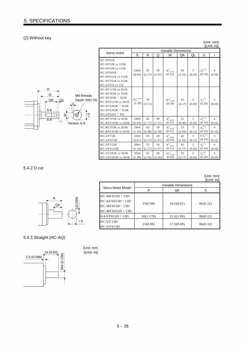
5 - 35
5. SPECIFICATIONS
(2) Without key[Unit: mm]([Unit: in])
Variable DimensionsServo motor
S R Q W QK QL U r
HC-SF81KHC-SF52K to 152KHC-SF53K to 153KHC-SFS81KHC-SFS52K to 152KHC-SFS53K to 153KHC-LFS52 to 152
24h6(0.94)
55(2.17)
50(1.97)
8 00.036
(0.31)36
(1.42)5
(0.20)4 0.2
0
(0.16)4
(0.16)
HC-SF121K to 301KHC-SF202K to 702KHC-SF203K 353KHC-SFS121K to 301KHC-SFS202K 352KHC-SFS203K 353KHC-LFS202 302
35 0.0100
(1.38)79
(3.11)-
10 00.036
(0.39)55
(2.17)5
(0.20)5 0.2
0
(0.20)5
(0.20)
HC-RF103K to 203KHC-RFS103K to 203K
24h6(0.94)
45(1.77)
40(1.57)
800.036
(0.31)25
(0.98)5
(0.20)4 0.2
0
(0.16)4
(0.16)
HC-RF353K to 503KHC-RFS353K to 503K
28h6(1.10)
63(2.48)
58(2.28)
8 00.036
(0.31)53
(2.09)3
(0.12)4 0.2
0
(0.16)4
(0.16)
HC-UF72KHC-UFS72K
22h6(0.87)
55(2.17)
50(1.97)
6 00.030
(0.24)42
(1.65)3
(0.12)
3.5 0.10
(0.14)3
(0.12)
HC-UF152KHC-UFS152K
28h6(1.10)
55(2.17)
50(1.97)
8 00.036
(0.31)45
(1.77)5
(0.20)4 0.2
0
(0.16)4
(0.16)
R
Q
QLQK
S
U
A
A
r
W
Section A-A
M8 threadsDepth 20(0.79)
HC-UF202K to 502KHC-UFS202K to 502K
35h6(1.38)
65(2.56)
60(2.36)
10 00.036
(0.39)55
(2.17)5
(0.20)5 0.2
0
(0.20)5
(0.20)
5.4.2 D cut
[Unit: mm]([Unit: in])
Variable DimensionsServo Motor Model
R QK S
HC-MF053D 13DHC-KFS053D 13DHC-MF053D 13DHC-MFS053D 13D
25(0.98) 20.5(0.81) 8h(0.32)
HA-FF053D 13D 30(1.178) 25.5(1.00) 8h(0.32)
R
S
QK
1(0
.039
)
HC-UF13DHC-UFS13D
25(0.98) 17.5(0.69) 8h(0.32)
5.4.3 Straight (HC-AQ)
16 (0.63)
2.5 (0.098)
6h6
(0.
236
)
[Unit: mm]([Unit: in])

5 - 36
5. SPECIFICATIONS
MEMO

6 - 1
6. CHARACTERISTICS
6. CHARACTERISTICS
6.1 Electromagnetic brake characteristics
CAUTIONConfigure the electromagnetic brake operation circuit so that it is activated not
only by the servo amplifier signals but also by an external emergency stop signal.
The electromagnetic brake is designed to hold a load. Do not use it for braking.
The characteristics of the electromagnetic brake provided for the servo motor with electromagneticbrake are indicated below:(1) Characteristics
Though the brake lining may rattle during operation, it poses no functional problem.A leakage magnetic flux will occur at the shaft end of the servo motor equipped with electromagneticbrake.If braking sound occurs, it may be improved by setting the machine resonance suppression filter oradaptive vibration suppression control in the servo amplifier parameters. For details, refer to theservo amplifier instruction manual.
Table 6.1 Electromagnetic Brake CharacteristicsHC-MF Series
HC-MFS SeriesHA-FF Series
Servo Motor
Item 053B 13B 23B 43B 73B 053B 13B 23B 33B 43B 63B
(Note 1) Type Spring-loaded safety brake
(Note 4) Rated voltage 24V 010% DC
Capacity [W] 6.3 7.9 9 7 7.4 11
[N m] 0.32 1.3 2.4 0.39 1.18 2.3Static friction torque
[oz in] 45.3 184.2 340 55.3 167 326
(Note 2) Release delay time [s] 0.03 0.03 0.03 0.03 0.03 0.03
Braking delay time [s](Note 2)
DC off 0.01 0.02 0.03 0.01 0.03 0.03
[J] 5.6 22.0 64.0 3.9 18.0 46.0Per braking
[oz in] 793.6 3117.6 9069.3 552.7 2550.7 6518.6
[J] 56 220 640 39 180 460Permissible braking work
Per hour[oz in] 7936 31176 90693 5527 25507 65186
Brake looseness at servo motor shaft [degrees](Note 5)
0.19 to 2.5 0.12 to 1.2 0.1 to 0.9 0.3 to 3.5 0.2 to 2.0 0.2 to 1.3
Number of brakingcycles [times]
20000 20000 20000 30000 30000 30000
[J] 4 15 32 4 18 47Brake life (Note 3)
Work perbraking [oz in] 567 2126 4535 567 2551 6660

6 - 2
6. CHARACTERISTICS
HC-SF SeriesHC-SFS Series
HC-RF SeriesHC-RFS Series
HC-KF SeriesHC-KFS Series
HC-AQSeries
(Note 5) Servo Motor
Item
81B
52B to 152B
53B to 153B
121B to 301B
202B to 702B
203B 353B
103B to
203B353B 503B
053B
13B23B 43B
(Note 6)
73B
0135B to
0335B
(Note 1) Type Spring-loaded safety brake(Note 4) Rated voltage 24V 0
10% DCCapacity [W] 19 34 19 23 6.3 7.9 9 4.8
[N m] 8.3 43.1 6.8 16.7 0.32 1.3 2.4 0.098Static friction torque
[oz in] 1176 6103 964 2367 45 6108 340 13.878(Note 2) Release delay time [s] 0.04 0.1 0.03 0.04 0.03 0.1 0.03 0.02Braking delay time [s](Note 2)
DC off 0.03 0.03 0.03 0.03 0.01 0.03 0.03 0.01
[J] 400 4500 400 400 5.6 22.0 64.0 4.6Perbraking [oz in] 56683.3 637687.1 56683.3 56683.3 793.6 3117.6 9069.3 63.882
[J] 4000 45000 4000 4000 56 220 640 46Permissible brakingwork Per
hour [oz in] 566833 6376871 566833 566833 7936 31176 90693 638.821Brake looseness at servo motor shaft(Note 5) [degrees]
0.2 to 0.6 0.2 to 0.6 0.2 to 0.6 0.2 to 0.60.19 to
2.50.12 to
1.20.1 to 0.9 0.1 to 2.5
Number of brakingcycles [times]
20000 20000 20000 20000 20000 20000 20000 20000
[J] 200 1000 200 200 4 15 32 1Brake life (Note 3)
Work perbraking [oz in] 28342 141708 28342 28342 567 2124.18 4535 141.612
HC-UF SeriesHC-UFS Series
HC-LFS Series(Note 5) Servo Motor
Item 13B 23B 43B 73B 72B 152B202B to
502B52B to152B
202B to302B
(Note 1) Type Spring-loaded safety brake
(Note 4) Rated voltage 24V 010% DC
Capacity [W] 6.3 7.9 10 19 34 19 34[N m] 0.32 1.3 2.4 8.3 43.1 8.3 43.1
Static friction torque[oz in] 45 184 340 1175 6103 1175 6103
(Note 2) Release delay time [s] 0.03 0.03 0.03 0.04 0.1 0.04 0.1Braking delay time [s](Note 2)
DC off 0.01 0.02 0.03 0.03 0.03 0.03 0.03
[J] 5.6 22 64 400 4500 400 4500Perbraking [oz in] 793.6 3117.6 9069.3 56683.3 637687.1 56683.3 637687.1
[J] 56 220 640 4000 45000 4000 45000Permissible braking work
Per hour[oz in] 7936 31176 90693 566833 6376871 566833 6376871
Brake looseness at servo motor shaft [degrees](Note 5)
0.19 to 2.5 0.12 to 1.2 0.1 to 0.9 0.2 to 0.6 0.2 to 0.6 0.2 to 0.6 0.2 to 0.6
Number of brakingcycles [times]
20000 20000 20000 20000 20000 20000 20000
[J] 4 15 32 200 1000 200 1000Brake life (Note3)
Work perbraking [oz in] 567 2126 4535 28342 141708 28342 141708
Note:1. There is no manual release mechanism. When it is necessary to hand-turn the servo motor shaft for machine centering, etc.,use a separate 24VDC power supply to release the brake electrically.
2. The value for initial ON gap at 20 .3. The brake gap will increase as the brake lining wears, but the gap is not adjustable. The brake life indicated is the number of
braking cycles after which adjustment will be required.4. 24VDC of the internal power output for interface (VDD) cannot be used. Always use a separate power supply.5. The above values are typical initial values and not guaranteed values.6. 73B is not available for the HC-KF.

6 - 3
6. CHARACTERISTICS
(2) Electromagnetic brake power supply
24VDC of the internal power output for interface (VDD) cannot be used. Prepare the following powersupply for use with the electromagnetic brake only. Examples of connection of the brake excitingpower supply are shown in the following diagram. The surge absorber must be installed on the braketerminal. For the selection of the surge absorber, refer to OPTIONS AND AUXILIARY EQUIPMENTof the Servo Amplifier Instruction Manual.
Switch
Electromagnetic brake
VAR24VDCVAR : Surge absorber
(3) Coasting distance
At an emergency stop, the servo motor will decelerate to a stop in the pattern shown in the followingdiagram. Here, the maximum coasting distance (during fast feed), Lmax, will be the area shown withthe diagonal line in the figure and can be calculated approximately with Equation 6.1. The effect of theload torque is greater near the stopping area. When the load torque is large, the servo motor will stopfaster than the value obtained in the equation.
Emergency stop
Brake current
Machine speed
V0
t1 t2 t3

6 - 4
6. CHARACTERISTICS
L max =60Vo
t1 t22t3
................................................................................................... (6.1)
Where,L max :Maximum coasting distance [mm]Vo: Machine's fast feed speed [mm/min]t1: Delay time of control section [s]t2: Braking delay time of brake (Note) [s]t3: Braking time [s]
9.55 104 (TL 0.8TB)(JL JL) No
t3
JL : Load inertia moment converted into equivalent [kg cm2]value on servo motor shaft
JM : Servo motor inertia moment [kg cm2]No : Servomotor speed during fast feed [r/min]TL : Load torque converted into equivalent [N m]
value on servo motor shaftTB : Brake static friction torque (Note) [N m]
Note: t2 and TB are the values noted in Table 6.1 Characteristics. JL is the machine's inertia moment atthe servo motor shaft.
6.2 Vibration rank
The vibration rank of the servo motor is V-10 at the rated speed. Measure vibration in the followingposition with the servo motor installed as shown below.
Top
Bottom
Servo motor
Measuring position
Servo Motor Vibration Measuring Conditions

6 - 5
6. CHARACTERISTICS
6.3 Machine Accuracies
The following table indicates the machine accuracies of the servo motor around the output shaft andmounting.
Flange SizeAccuracy TIR (Total Indicator Reading)
[mm]
Measuring
Position Less than 100 100 130 176 to 250 280 or more
Squareness of flange surface to outputshaft
a) 0.05 0.06 0.08 0.08
Eccentricity of fitting OD of flange surface b) 0.04 0.04 0.06 0.08
Runout of output shaft end c) 0.02 0.02 0.03 0.03
Reference diagram
a)
b) c)

6 - 6
6. CHARACTERISTICS
MEMO
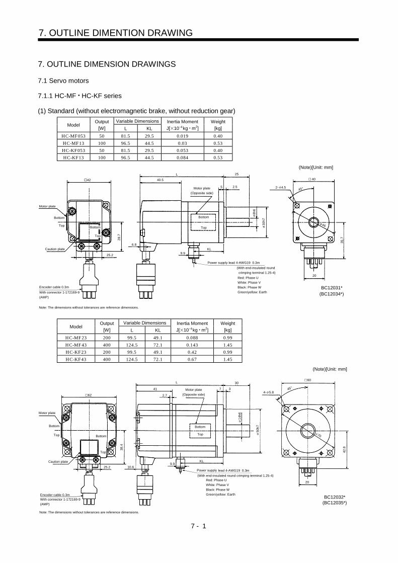
7 - 1
7. OUTLINE DIMENTION DRAWING
7. OUTLINE DIMENSION DRAWINGS
7.1 Servo motors
7.1.1 HC-MF HC-KF series
(1) Standard (without electromagnetic brake, without reduction gear)
Variable DimensionsModel
Output
[W] L KL
Inertia Moment
J[ 10 4kg m2]
Weight
[kg]
HC-MF053 50 81.5 29.5 0.019 0.40
HC-MF13 100 96.5 44.5 0.03 0.53
HC-KF053 50 81.5 29.5 0.053 0.40
HC-KF13 100 96.5 44.5 0.084 0.53
Power supply lead 4-AWG19 0.3m
(With end-insulated round
crimping terminal 1.25-4)
Red: Phase U
White: Phase V
Black: Phase W
Green/yellow: Earth
Top
Bottom
Motor plate
(Opposite side)
Encoder cable 0.3m
With connector 1-172169-9
(AMP)
Motor plate
25.2
25
30
h7
2.55
20
2- 4.545
4040.5
L
28.
7
6.8
42
Top
Bottom
35
.7
KL9.9
8h
6
BC12031*(BC12034*)
Caution plate
Top
Bottom46
(Note)[Unit: mm]
Note: The dimensions without tolerances are reference dimensions.
Variable DimensionsModel
Output
[W] L KL
Inertia Moment
J[ 10 4kg m2]
Weight
[kg]
HC-MF23 200 99.5 49.1 0.088 0.99
HC-MF43 400 124.5 72.1 0.143 1.45
HC-KF23 200 99.5 49.1 0.42 0.99
HC-KF43 400 124.5 72.1 0.67 1.45
Encoder cable 0.3mWith connector 1-172169-9
(AMP)
Power supply lead 4-AWG19 0.3m
Red: Phase U
White: Phase V
Black: Phase W
Green/yellow: Earth
60
454- 5.8
Motor plate
(Opposite side)
30
1
4h
6Motor plate
Bottom
Top Bottom
Top
62
L
41
2.7
Bottom
Top
10.6
50
h7
(With end-insulated round crimping terminal 1.25-4)
20
38
.4
70
42
.8
9.9KL
BC12032*
7 3
Caution plate
25.2
(BC12035*)
(Note)[Unit: mm]
Note: The dimensions without tolerances are reference dimensions.

7 - 2
7. OUTLINE DIMENSION DRAWING
ModelOutput
[W]
Inertia Moment
J[ 10 4kg m2]
Weight
[kg]
HC-MF73 750 0.6 3
48.7
Encoder cable 0.3mWith connector 1-172169-9
(AMP)
Power supply lead 4-AWG19 0.3m
Red: Phase U
White: Phase V
Black: Phase W
Green/yellow: Earth
90
804- 6.6
Motor plate
(Opposite side)
142
8 3
40
19h6
70h7
58.1
20
86.7
(With end-insulated round crimping terminal 1.25-4)
Top
Bottom
Top
Bottom
25.2
82
39
2.7
Top
9.911
Motor plate
Bottom
BC12033*
Caution plate
(Note)[Unit: mm]
45
Note: The dimensions without tolerances are reference dimensions.
(2) With electromagnetic brake
Variable DimensionsModel
Output
[W] L KL
Braking Force
[N m]
Inertia Moment
J[ 10 4kg m2]
Weight
[kg]
HC-MF053B 50 109.5 29.5 0.32 0.022 0.75
HC-MF13B 100 124.5 44.5 0.32 0.032 0.89
HC-KF053B 50 109.5 29.5 0.32 0.056 0.75
HC-KF13B 100 124.5 44.5 0.32 0.087 0.89
Motor plate
(Opposite side)
Top
Bottom
Power supply lead 4-AWG19 0.3m
Red: Phase U
White: Phase V
Black: Phase W
Green/yellow: Earth
40
2- 4.5
KL
9.9
6.8
42
Brake lead2-0.3 0.3m
(With end-insulated round
crimping terminal 1.25-4)
35.7
20
8h6
30h
7
5 2.5
25L
40.5
65.5
Motor plate
Top
Bottom
Top
Bottom
25.2
28.7
2Encoder cable 0.3mWith connector 1-172169-9
(AMP)
Caution plate
(With end-insulated round crimping terminal 1.25-4)
(BC12039*)BC12036*
46
(Note)[Unit: mm]
45
Note: The dimensions without tolerances are reference dimensions.

7 - 3
7. OUTLINE DIMENSION DRAWING
Variable DimensionsModel
Output
[W] L KL
Braking Force
[N m]
Inertia Moment
J[ 10 4kg m2]Weight
[kg]
HC-MF23B 200 131.5 49.1 1.3 0.136 1.6
HC-MF43B 400 156.5 72.1 1.3 0.191 2.1
HC-KF23B 200 131.5 49.1 1.3 0.47 1.6
HC-KF43B 400 156.5 72.1 1.3 0.72 2.1
Brake lead
2-0.32 0.3m
(With end-insulated round
crimping terminal 1.25-4)
Power supply lead 4-AWG19 0.3m
Red: Phase U
White: Phase V
Black: Phase W
Green/yellow: EarthEncoder cable 0.3m
With connector 1-172169-9
(AMP)
62
25.2
33
.4
68 9.9KL
41
2.7
L 30
7 3Motor plate
(Opposite side)
Top
Bottom
50h
7
60
70
42.
8
4- 5.8
10.6
Top
Bottom
Top
Bottom
BC12037*
20
14h
6
(With end-insulated round crimping terminal 1.25-4)
Motor plate
Caution plate
(BC12039*)
(Note)[Unit: mm]
45
Note: The dimensions without tolerances are reference dimensions.
ModelOutput
[W]
Braking Force
[N m]
Inertia Moment
J[ 10 4kg m2]Weight
[kg]
HC-MF73B 750 2.4 0.725 4.0
Encoder cable 0.3mWith connector 1-172169-9
(AMP)
Brake lead
2-0.3 0.3m
(With end-insulated round
crimping terminal 1.25-4)
2
Power supply lead 4-AWG19 0.3m
Red: Phase U
White: Phase V
Black: Phase W
Green/yellow: Earth
Motor plate
(Opposite side)
Motor plate
82
Top
Bottom
Top
Bottom
25.2
48
.7
177.5
39
2.7
11
72
86.79.9
(With end-insulated round crimping terminal 1.25-4)
BC12038*
40
38
80
Caution plate
Top
Bottom
19.5
58
.1
20
19h
6
70h
7
4- 6.6
90
(Note)[Unit: mm]
45
Note: The dimensions without tolerances are reference dimensions.

7 - 4
7. OUTLINE DIMENSION DRAWING
(3) With reduction gear for general industrial machineThe outer frame of the reduction gear is a material surface such as casting. Its actual dimensions maybe 1 to 3mm larger than the drawing dimensions. Design the machine side with allowances.(a) Without electromagnetic brake
Variable DimensionsModel
Output
[W] L KL
Reduction
Gear Model
Reduction Ratio
(Actual Reduction Ratio)
Inertia Moment
J[ 10 4kg m2]Backlash
Weight
[kg]
HC-MF053G1 50 126 74 K6505 1/5(9/44) 0.055 60min. max. 1.4
HC-MF053G1 50 144 92 K6512 1/12(49/576) 0.077 60min. max. 1.8
HC-MF053G1 50 144 92 K6520 1/20(25/484) 0.059 60min. max. 1.8
HC-KF053G1 50 126 74 K6505 1/5(9/44) 0.090 60min. max. 1.4
HC-KF053G1 50 144 92 K6512 1/12(49/576) 0.112 60min. max. 1.8
HC-KF053G1 50 144 92 K6520 1/20(25/484) 0.094 60min. max. 1.8
BC12066A(BC12086A)
L 60.5
2534.5
6.58
40.5
9.9
28.
7
25.2
35.
7
20
6.8
(R4)Motorplate
Cautionplate
Encoder cable 0.3m
With connector 1-172169-9 (AMP)
Power supply lead 4-AWG19 0.3m
(Opposite side)
(With end-insulated round crimping terminal 1.25-4)Red: Phase UWhite: Phase VBlack: Phase WGreen/yellow: Earth
"Rotation direction"
For forward rotation command
For reverse rotation command
M4 threads, depth 8
16h
6
48
( 5
0)
60h
7
75
88
4- 7
65
Motor plate
Top
BottomTop
Bottom
4542
KL
(Note)[Unit: mm]
Note: The dimensions without tolerances are reference dimensions.
Bottom
Top
Variable DimensionsModel
Output
[W] L KL
Reduction
Gear Model
Reduction Ratio
(Actual Reduction Ratio)
Inertia Moment
J[ 10 4kg m2]Backlash
Weight
[kg]
HC-MF13G1 100 141 89 K6505 1/5(9/44) 0.067 60min. max. 1.5
HC-MF13G1 100 159 107 K6512 1/12(49/576) 0.089 60min. max. 1.9
HC-MF13G1 100 159 107 K6520 1/20(25/484) 0.071 60min. max. 1.9
HC-KF13G1 100 141 89 K6505 1/5(9/44) 0.121 60min. max. 1.5
HC-KF13G1 100 159 107 K6512 1/12(49/576) 0.143 60min. max. 1.9
HC-KF13G1 100 159 107 K6520 1/20(25/484) 0.125 60min. max. 1.9
BC12067A(BC12087A)
28
.7
25.2
2534.540.5
6.8
8 6.5
9.9
KL
35
.7
20
60.5L
(R4)
Motorplate
Cautionplate
TopBottom
Encoder cable 0.3m
With connector 1-172169-9 (AMP)
Power supply lead 4-AWG19 0.3m
(With end-insulated round crimping terminal 1.25-4)Red: Phase UWhite: Phase VBlack: Phase WGreen/yellow: Earth
Motor plate(Opposite side)
TopBottom
"Rotation direction"
For forward rotation command
For reverse rotation command
M4 threads, depth 8
16h
6
48
( 5
0)
60h
7
7588
4- 7
65
45
42
(Note)[Unit: mm]
Note: The dimensions without tolerances are reference dimensions.
Bottom
Top

7 - 5
7. OUTLINE DIMENSION DRAWING
Variable DimensionsModel
Output
[W] L KL
Reduction
Gear Model
Reduction Ratio
(Actual Reduction Ratio)
Inertia Moment
J[ 10 4kg m2]
Weight
[kg]
HC-MF23G1 200 153 102.6 K9005 1/5(19/96) 0.249 3.3
HC-MF23G1 200 173 122.6 K9012 1/12(25/288) 0.293 3.9
HC-MF23G1 200 173 122.6 K9020 1/20(253/5000) 0.266 3.9
HC-KF23G1 200 153 102.6 K9005 1/5(19/96) 0.58 3.3
HC-KF23G1 200 173 122.6 K9012 1/12(25/288) 0.63 3.9
HC-KF23G1 200 173 122.6 K9020 1/20(253/5000) 0.60 3.93
8.4
25.2
L
35
810
Top
Bottom
30
74
M6 threads,
depth12
"Rotation
direction"For forward rotation command
For reverse rotation command
Encoder cable 0.3mWith connector 1-172169-9
(AMP)
Power supply lead 4-AWG19 0.3m
(With end-insulated round crimping terminal 1.25-4)
Red: Phase U
White: Phase V
Black: Phase W
Green/yellow: Earth
Top
Bottom
Motor plate
(Opposite side)
Motor plate
62 41
10.6Caution plate
25
h6
73
82
h7
2.7
KL
42
.8
9.9
100
4- 9
BC12068*(BC12088*)
20
90
Top
Bottom
114
(Note)[Unit: mm]
45
Note: The dimensions without tolerances are reference dimensions.
Variable DimensionsModel
Output
[W] L KL
Reduction
Gear Model
Reduction Ratio
(Actual Reduction Ratio)
Inertia Moment
J[ 10 4kg m2]
Weight
[kg]
HC-MF43G1 400 178 125.6 K9005 1/5(19/96) 0.296 3.8
HC-MF43G1 400 198 145.6 K9012 1/12(25/288) 0.339 4.4
HC-KF43G1 400 178 125.6 K9005 1/5(19/96) 0.82 3.8
HC-KF43G1 400 198 145.6 K9012 1/12(25/288) 0.87 4.4
Motor plate
38.4
25.2
4- 9
Top
Bottom
BC12069*
M6 threads,
depth12
Encoder cable 0.3mWith connector 1-172169-9
(AMP)
Power supply lead 4-AWG19 0.3m
(With end-insulated round crimping terminal 1.25-4)
Red: Phase U
White: Phase V
Black: Phase W
Green/yellow: Earth
10.6
Top
Bottom
Top
Bottom
Motor plate
(Opposite side)
Caution plate
62 41
2.7
"Rotation
direction"For forward rotation command
For reverse rotation command
KL
74
30 35
10 8
100
114
90
20
(BC12089*)
9.9
L
42.8
82h773
25h6
(Note)[Unit: mm]
45
Note: The dimensions without tolerances are reference dimensions.
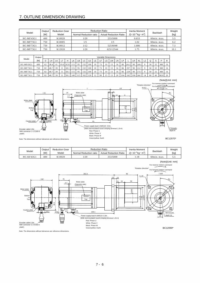
7 - 6
7. OUTLINE DIMENSION DRAWING
Reduction RatioModel
Output
[W]
Reduction Gear
Model Normal Reduction ratio Actual Reduction Ratio
Inertia Moment
J[ 10 4kg m2]Backlash
Weight
[kg]
HC-MF43G1 400 K10020 1/20 253/5000 0.653 60min. max. 5.5
HC-MF73G1 750 K10005 1/5 1/5 1.02 60min. max. 6.2
HC-MF73G1 750 K10012 1/12 525/6048 1.686 60min. max. 7.3
HC-MF73G1 750 K12020 1/20 625/12544 1.75 60min. max. 10.1
Variable DimensionsModel
Output
[W] D LH LK LT H LA LB LC LD LE LF LG LM LN LP L LR KL LZ Q S P R
HC-MF43G1 400 62 38.4 41 10.6 42.8 115 95 132 100 10 73 10 13 16 86 201.5 90 149.1 9 50 32 M8 16
HC-MF73G1 750 82 48.7 39 11 58.1 115 95 132 100 10 73 10 13 16 86 207 90 151.7 9 50 32 M8 16
HC-MF73G1 750 82 48.7 39 11 58.1 115 95 132 100 10 73 10 13 16 86 229 90 173.7 9 50 32 M8 16
HC-MF73G1 750 82 48.7 39 11 58.1 140 115 162 120 12 90 15 13 20 104 242 106 186.7 14 60 40 M10 20
LD4- LZ
Top
Bottom
BC12070*
P threads,
depth R
"Rotation direction"For forward rotation command
For reverse rotation command
Power supply lead 4-AWG19 0.3m
(With end-insulated round crimping terminal 1.25-4)Encoder cable 0.3mWith connector 1-172169-9
(AMP)
Red: Phase U
White: Phase V
Black: Phase W
Green/yellow: Earth
LH
25.2
D
TopBottom
Top
Bottom
Motor plate
(Opposite side)
Motor plate
LK
KL
LR
LT H 9.9
2.7
LG LE
LM LM Q
Sh6
LF LP LBh7
20
Caution plate
L
LCLA
(Note)[Unit: mm]
45
Note: The dimensions without tolerances are reference dimensions.
Reduction RatioModel
Output
[W]
Reduction Gear
Model Normal Reduction ratio Actual Reduction Ratio
Inertia Moment
J[ 10 4kg m2]Backlash
Weight
[kg]
HC-KF43G1 400 K10020 1/20 253/5000 1.18 60min. max. 5.5
38
.4
25.2
201.5
16
1010
13
90
M8 threads,
depth 16
6250
"Rotation direction"For forward rotation command
For reverse rotation command
Power supply lead 4-AWG19 0.3m
(With end-insulated round crimping terminal 1.25-4)
Encoder cable 0.3mWith connector 1-172169-9
(AMP)
Red: Phase U
White: Phase V
Black: Phase W
Green/yellow: Earth
Motor plate
(Opposite side)
Motor plate
Caution plate
Top
Bottom
Top
Bottom
41
2.7
10.6 42
.8
9.9149.1
95
h7
86
73
32h6
4- 9
100
Top
Bottom
BC12090*
20
115
132
(Note)[Unit: mm]
45
Note: The dimensions without tolerances are reference dimensions.

7 - 7
7. OUTLINE DIMENSION DRAWING
(b) With electromagnetic brakeVariable Dimensions
ModelOutput
[W] L KL
Braking Force
[N m]
Reduction
Gear Model
Reduction Ratio
(Actual Reduction
Ratio)
Inertia Moment
J[ 10 4kg m2]Backlash
Weight
[kg]
HC-MF053BG1 50 154 74 0.32 K6505 1/5(9/44) 0.058 60min. max. 1.8
HC-MF053BG1 50 172 92 0.32 K6512 1/12(49/576) 0.080 60min. max. 2.2
HC-MF053BG1 50 172 92 0.32 K6520 1/20(25/484) 0.062 60min. max. 2.2
HC-KF053BG1 50 154 74 0.32 K6505 1/5(9/44) 0.093 60min. max. 1.8
HC-KF053BG1 50 172 92 0.32 K6512 1/12(49/576) 0.115 60min. max. 2.2
HC-KF053BG1 50 172 92 0.32 K6520 1/20(25/484) 0.097 60min. max. 2.2
BC12071A(BC12091A)
60.5L
2534.5
6.58
40.5
KL
28.7
25.2
35.7
20
6.8
65.5
9.9
(R4)Motorplate
Cautionplate
Top
Bottom
Encoder cable 0.3m
With connector 1-172169-9 (AMP)
(Opposite side)Motor plate
Brake lead2-0.3 0.3m(With end-insulatedround crimping terminal 1.25-4)
Power supply lead 4-AWG19 0.3m(With end-insulated round crimping terminal 1.25-4)
Red: Phase UWhite: Phase VBlack: Phase WGreen/yellow: Earth
M4 threads, depth 8
"Rotation direction"
For forward rotation command
For reverse rotation command
45
65
42
(Note)[Unit: mm]
Note: The dimensions without tolerances are reference dimensions.
2
TopBottom
16h
6
48
( 5
0)
60h
7
75
88
4- 7
Bottom
Top
Variable Dimensions
ModelOutput
[W] L KL
Braking
Force
[N m]
Reduction
Gear Model
Reduction Ratio
(Actual Reduction
Ratio)
Inertia Moment
J[ 10 4kg m2]Backlash
Weight
[kg]
HC-MF13BG1 100 169 89 0.32 K6505 1/5(9/44) 0.069 60min. max. 1.9
HC-MF13BG1 100 187 107 0.32 K6512 1/12(49/576) 0.091 60min. max. 2.3
HC-MF13BG1 100 187 107 0.32 K6520 1/20(25/484) 0.073 60min. max. 2.3
HC-KF13BG1 100 169 89 0.32 K6505 1/5(9/44) 0.124 60min. max. 1.9
HC-KF13BG1 100 187 107 0.32 K6512 1/12(49/576) 0.146 60min. max. 2.3
HC-KF13BG1 100 187 107 0.32 K6520 1/20(25/484) 0.128 60min. max. 2.3
BC12072A(BC12092A)
28.
7
35.
7
25.2
20
40.5
L
8 6.5
60.5
2534.5
(R4)
6.8 9.9
KL65.5
Motorplate
Cautionplate
Top
Bottom
Encoder cable 0.3m
With connector 1-172169-9 (AMP)
Power supply lead 4-AWG19(With end-insulated round crimping terminal 1.25-4)
Red: Phase UWhite: Phase VBlack: Phase WGreen/yellow: Earth
(Opposite side)Motor plate
"Rotation direction"
For forward rotation command
For reverse rotation command
M4 threads, depth 8
65
TopBottom
Brake lead2-0.3 0.3m(With end-insulatedround crimping terminal 1.25-4)
42
(Note)[Unit: mm]
Note: The dimensions without tolerances are reference dimensions.
2
16h
6
48
( 5
0)
60h
7
45
75
88
4- 7
Top
Bottom

7 - 8
7. OUTLINE DIMENSION DRAWING
Variable DimensionsModel
Output
[W] L KL
Reduction
Gear Model
Reduction Ratio
(Actual Reduction Ratio)
Inertia Moment
J[ 10 4kg m2]
Weight
[kg]
Braking Force
[N m]
HC-MF23BG1 200 185 102.6 K9005 1/5(19/96) 0.289 3.9 1.3
HC-MF23BG1 200 205 122.6 K9012 1/12(25/288) 0.333 4.5 1.3
HC-MF23BG1 200 205 122.6 K9020 1/20(253/5000) 0.306 4.5 1.3
HC-KF23BG1 200 185 102.6 K9005 1/5(19/96) 0.63 3.9 1.3
HC-KF23BG1 200 205 122.6 K9012 1/12(25/288) 0.68 4.5 1.3
HC-KF23BG1 200 205 122.6 K9020 1/20(253/5000) 0.65 4.5 1.3
Motor plate
(Opposite side)
L
35
810
Top
Bottom
30
74
M6 threads,
depth 12
Encoder cable 0.3mWith connector 1-172169-9
(AMP)
Brake lead 2-0.3 0.3m
(With end-insulated round
crimping terminal 1.25-4)
2Power supply lead 4-AWG19 0.3m
(With end-insulated round crimping terminal 1.25-4)Red: Phase U
White: Phase V
Black: Phase W
Green/yellow: Earth
25
h6
BC12073*
73
82
h7
(BC120793*)
Top
Bottom
Top
Bottom
62
Caution plate 25.2
38
.4
10.6
41
9.9
42
.8
KL
90
4- 9
100114
"Rotation direction"
For forward rotation command
For reverse rotation command
20
2.7
68
(Note)[Unit: mm]
45
Motor plate
Note: The dimensions without tolerances are reference dimensions.
Variable DimensionsModel
Output
[W] L KL
Braking Force
[N m]
Reduction
Gear Model
Reduction Ratio
(Actual Reduction Ratio)
Inertia Moment
J[ 10 4kg m2]
Weight
[kg]
HC-MF43BG1 400 210 125.6 1.3 K9005 1/5(19/96) 0.344 4.4
HC-MF43BG1 400 230 145.6 1.3 K9012 1/12(25/288) 0.388 5.0
HC-KF43BG1 400 210 125.6 1.3 K9005 1/5(19/96) 0.87 4.4
HC-KF43BG1 400 230 145.6 1.3 K9012 1/12(25/288) 0.92 5.0
Motor plate
(Opposite side)
Top
Bottom
M6 threads,
depth 12
"Rotation direction"
For forward rotation command
For reverse rotation command
90
4- 9
(BC12094*)BC12074*
35
810
30
74L
62
25
h6
73
82
h7
20Power supply lead 4-AWG19 0.3m
(With end-insulated round crimping terminal 1.25-4)
Red: Phase U
White: Phase V
Black: Phase W
Green/yellow: Earth
Brake lead 2-0.3 0.3m(With end-insulated round
crimping terminal 1.25-4)
2
Encoder cable 0.3mWith connector 1-172169-9
(AMP)
Caution plate
Top
Bottom
Top
Bottom
25.2
38
.4
10.6
41
2.7
42.8
9.9KL
68
100114
(Note)[Unit: mm]
45
Motor plate
Note: The dimensions without tolerances are reference dimensions.

7 - 9
7. OUTLINE DIMENSION DRAWING
Reduction Ratio
ModelOutput
[W]
Braking Force
[N m]
Reduction
Gear ModelNormal
Reduction ratio
Actual
Reduction Ratio
Inertia Moment
J[ 10 4kg m2]Backlash
Weight
[kg]
HC-MF43BG1 400 1.3 K10020 1/20 253/5000 0.700 60min. max. 6.1
HC-MF73BG1 750 2.4 K10005 1/5 1/5 1.145 60min. max. 7.2
HC-MF73BG1 750 2.4 K10012 1/12 525/6048 1.811 60min. max. 8.3
HC-MF73BG1 750 2.4 K12020 1/20 625/12544 1.875 60min. max. 11.1
Variable DimensionsModel
Output
[W] D LH LK LT LX H LA LB LC LD LE LF LG LM LN LP L LR KL LZ Q S P R
HC-MF43BG1 400 62 38.4 41 10.6 68 42.8 115 95 132 100 10 73 10 13 16 86 232.5 90 149.1 9 50 32 M8 16
HC-MF73BG1 750 82 48.7 39 11 72 58.1 115 95 132 100 10 73 10 13 16 86 242.5 90 151.7 9 50 32 M8 16
HC-MF73BG1 750 82 48.7 39 11 72 58.1 115 95 132 100 10 73 10 13 16 86 264.5 90 173.7 9 50 32 M8 16
HC-MF73BG1 750 82 48.7 39 11 72 58.1 140 115 162 120 12 90 15 13 20 104 277.5 106 186.7 14 60 40 M10 20
Motor plate
(Opposite side) LNLELG
Top
Bottom
LM
LR
P threads,
depth R
Q
Sh6
"Rotation direction"For forward rotation command
For reverse rotation command
Brake lead 2-0.3 0.3m
(With end-insulated round
crimping terminal 1.25-4)
Encoder cable 0.3mWith connector 1-172169-9
(AMP)
Power supply lead 4-AWG19 0.3m
(With end-insulated round crimping terminal 1.25-4)
2 Red: Phase U
White: Phase V
Black: Phase W
Green/yellow: Earth
4- LZ LD
LC
LA
20L
F
LB
h7
LP
Top
Bottom
Motor plate
Caution plate
D
LK2.7
L
25.2
LH
LTLX
H 9.9
KL
Top
Bottom
BC12075*
(Note)[Unit: mm]
45
Note: The dimensions without tolerances are reference dimensions.
Reduction Ratio
ModelOutput
[W]
Braking Force
[N m]
Reduction
Gear ModelNormal
Reduction ratio
Actual
Reduction Ratio
Inertia Moment
J[ 10 4kg m2]Backlash
Weight
[kg]
HC-KF43BG1 400 1.3 K10020 1/20 253/5000 1.23 60min. max. 6.1
Motor plate
(Opposite side) 16
1010
Top
Bottom
13
90
8 threads,
depth 16
50
"Rotation direction"For forward rotation command
For reverse rotation command
Brake lead 2-0.3 0.3m
(With end-insulated round
crimping terminal 1.25-4)
Encoder cable 0.3mWith connector 1-172169-9
(AMP)
Power supply lead 4-AWG19 0.3m
(With end-insulated round crimping terminal 1.25-4)
2
Red: Phase U
White: Phase V
Black: Phase W
Green/yellow: Earth
4- 9
20
Top
Bottom
100
Top
Bottom
41
2.7
233.5
Caution plate25.2
38
.4
62
10.668
42
.8
9.9149.1
73 8695
h7
BC12095*
32h6
13211
5(Note)[Unit: mm]
45
Motor plate
Note: The dimensions without tolerances are reference dimensions.

7 - 10
7. OUTLINE DIMENSION DRAWING
(4) With reduction gear for precision application
The outer frame of the reduction gear is a material surface such as casting. Its actual dimensions maybe 1 to 3mm larger than the drawing dimensions. Design the machine side with allowances.(a) Without electromagnetic brake
Variable DimensionsModel
Output
[W] L KL
Reduction Gear
ModelReduction Ratio
Inertia Moment
J[ 10 4kg m2]Backlash
Weight
[kg]
HC-MF053G2 50 130 78 BK1-05B-A5MEKA 1/5 0.067 3 min. max. 1.4
HC-MF053G2 50 146 94 BK1-09B-A5MEKA 1/9 0.060 3 min. max. 1.7
HC-MF053G2 50 146 94 BK1-20B-A5MEKA 1/20 0.069 3 min. max. 1.8
HC-MF053G2 50 146 94 BK1-29B-A5MEKA 1/29 0.057 3 min. max. 1.8
HC-KF053G2 50 130 78 BK1-05B-A5MEKA 1/5 0.101 3 min. max. 1.4
HC-KF053G2 50 146 94 BK1-09B-A5MEKA 1/9 0.095 3 min. max. 1.7
HC-KF053G2 50 146 94 BK1-20B-A5MEKA 1/20 0.104 3 min. max. 1.8
HC-KF053G2 50 146 94 BK1-29B-A5MEKA 1/29 0.092 3 min. max. 1.8
Motor plate
(Opposite side)
28
.7
25.2
L
25
8 6
Top
Bottom
23
55
M4 threads,
depth 8
"Rotation direction"
For forward rotation command
For reverse rotation command
Power supply lead 4-AWG19 0.3m
(With end-insulated round crimping terminal 1.25-4)
Encoder cable 0.3mWith connector 172169-9
(AMP)
Red: Phase U
White: Phase V
Black: Phase W
Green/yellow: Earth
Top
Bottom
70
4- 6.6
16
h6
80
48
60
65
h7
95
BC12076*(BC12096*)
Motor plate
Caution plate
42 40.5
6.8
KL9.9
20
35
.7
(Note)[Unit: mm]
Top
Bottom
45
Note: The dimensions without tolerances are reference dimensions.

7 - 11
7. OUTLINE DIMENSION DRAWING
ModelOutput
[W]
Reduction Gear
ModelReduction Ratio
Inertia Moment
J[ 10 4kg m2]Backlash
Weight
[kg]
HC-MF13G2 100 BK1-05B-01MEKA 1/5 0.078 3 min. max. 1.5
HC-MF13G2 100 BK1-09B-01MEKA 1/9 0.072 3 min. max. 1.8
HC-MF13G2 100 BK1-20B-01MEKA 1/20 0.122 3 min. max. 3.0
HC-MF13G2 100 BK1-29B-01MEKA 1/29 0.096 3 min. max. 3.0
Variable DimensionsModel
Output
[W] LA LB LC LD LE LF LG LH LK L LR KL LZ Q S P R
HC-MF13G2 100 80 65 95 70 6 48 8 60 23 145 55 93 6.6 25 16 M4 8
HC-MF13G2 100 80 65 95 70 6 48 8 60 23 161 55 109 6.6 25 16 M4 8
HC-MF13G2 100 100 80 115 85 6 65 10 74 33 167 75 115 6.6 35 20 M5 10
HC-MF13G2 100 100 80 115 85 6 65 10 74 33 167 75 115 6.6 35 20 M5 10
ModelOutput
[W]
Reduction Gear
ModelReduction Ratio
Inertia Moment
J[ 10 4kg m2]Backlash
Weight
[kg]
HC-KF13G2 100 BK1-05B-01MEKA 1/5 0.132 3 min. max. 1.5
HC-KF13G2 100 BK1-09B-01MEKA 1/9 0.126 3 min. max. 1.8
HC-KF13G2 100 BK2-20B-01MEKA 1/20 0.176 3 min. max. 3.0
HC-KF13G2 100 BK2-29B-01MEKA 1/29 0.150 3 min. max. 3.0
Variable DimensionsModel
Output
[W] LA LB LC LD LE LF LG LH LK L LR KL LZ Q S P R
HC-KF13G2 100 80 65 95 70 6 48 8 60 23 145 55 93 6.6 25 16 M4 8
HC-KF13G2 100 80 65 95 70 6 48 8 60 23 161 55 109 6.6 25 16 M4 8
HC-KF13G2 100 100 80 115 85 6 65 10 74 33 167 75 115 6.6 35 20 M5 10
HC-KF13G2 100 100 80 115 85 6 65 10 74 33 167 75 115 6.6 35 20 M5 10
Motor plate
(Opposite side)
28.7
25.2 9.9
LELG
LF
LH
LD4- LZ
Top
Bottom
LB
h7
LK
P threads,
depth R
Q
Sh
6
"Rotation direction"
For forward rotation command
For reverse rotation command
Encoder cable 0.3mWith connector 1-172169-9
(AMP)
Power supply lead 4-AWG19 0.3m
(With end-insulated round crimping terminal 1.25-4)
LR
Red: Phase U
White: Phase V
Black: Phase W
Green/yellow: Earth
Motor plate
Caution plate
42 40.5
6.8
KL
20
LC
Top
Bottom
Top
Bottom
L
BC12077*(BC12097*)
35.7
LA
(Note)[Unit: mm]
45
Note: The dimensions without tolerances are reference dimensions.

7 - 12
7. OUTLINE DIMENSION DRAWING
ModelOutput
[W]
Reduction Gear
ModelReduction Ratio
Inertia Moment
J[ 10 4kg m2]
Weight
[kg]
HC-MF23G2 200 BK1-05B-02MEKA 1/5 0.191 2.1
HC-MF23G2 200 BK2-09B-02MEKA 1/9 0.208 3.5
HC-MF23G2 200 BK3-20B-02MEKA 1/20 0.357 5.0
HC-MF23G2 200 BK3-29B-02MEKA 1/29 0.276 5.0
Variable DimensionsModel
Output
[W] LA LB LC LD LE LF LG LH LK L LR KL LZ Q S P R
HC-MF23G2 200 80 65 95 70 6 48 8 60 23 157 55 106.6 6.6 25 16 M4 8
HC-MF23G2 200 100 80 115 85 6 65 10 74 33 175 75 124.6 6.6 35 20 M5 10
HC-MF23G2 200 115 95 135 100 8 75 10 85 35 180 85 129.6 9 40 25 M6 12
HC-MF23G2 200 115 95 135 100 8 75 10 85 35 180 85 129.6 9 40 25 M6 12
ModelOutput
[W]
Reduction Gear
ModelReduction Ratio
Inertia Moment
J[ 10 4kg m2]
Weight
[kg]
HC-KF23G2 200 BK1-05B-02MEKA 1/5 0.52 2.1
HC-KF23G2 200 BK2-09B-02MEKA 1/9 0.54 3.5
HC-KF23G2 200 BK3-20B-02MEKA 1/20 0.69 5.0
HC-KF23G2 200 BK3-29B-02MEKA 1/29 0.61 5.0
Variable DimensionsModel
Output
[W] LA LB LC LD LE LF LG LH LK L LR KL LZ Q S P R
HC-KF23G2 200 80 65 95 70 6 48 8 60 23 157 55 106.6 6.6 25 16 M4 8
HC-KF23G2 200 100 80 115 85 6 65 10 74 33 175 75 124.6 6.6 35 20 M5 10
HC-KF23G2 200 115 95 135 100 8 75 10 85 35 180 85 129.6 9 40 25 M6 12
HC-KF23G2 200 115 95 135 100 8 75 10 85 35 180 85 129.6 9 40 25 M6 12
38
.4
25.2
LELG
LD
Top
Bottom
LK
LR
P threads,
depth R
Q
LA
LC
"Rotation direction"For forward rotation command
For reverse rotation command
Power supply lead 4-AWG19 0.3m
Encoder cable 0.3mWith connector 1-172169-9
(AMP)
Red: Phase U
White: Phase V
Black: Phase W
Green/yellow: Earth
(With end-insulated round crimping terminal 1.25-4)
Motor plate
(Opposite side)
Top
Bottom
L
Sh
6
LF
LH
LB
h7
10.6 9.9
42
.8
KL
62
Motor plate
Caution plate
Top
Bottom
41
2.7
4- LZ
BC12078*(BC12098*)
20
(Note)[Unit: mm]
45
Note: The dimensions without tolerances are reference dimensions.

7 - 13
7. OUTLINE DIMENSION DRAWING
ModelOutput
[W]
Reduction Gear
ModelReduction Ratio
Inertia Moment
J[ 10 4kg m2]
Weight
[kg]
HC-MF43G2 400 BK2-05B-04MEKA 1/5 0.295 3.7
HC-MF43G2 400 BK3-09B-04MEKA 1/9 0.323 5.3
HC-MF43G2 400 BK4-20B-04MEKA 1/20 0.426 7.5
HC-MF43G2 400 BK4-29B-04MEKA 1/29 0.338 7.5
Variable DimensionsModel
Output
[W] LA LB LC LD LE LF LG LH LK L LR KL LZ Q S P R
HC-MF43G2 400 100 80 115 85 6 65 10 74 33 184 75 131.6 6.6 35 20 M5 10
HC-MF43G2 400 115 95 135 100 8 75 10 85 35 205 85 152.6 9 40 25 M6 12
HC-MF43G2 400 135 110 155 115 8 90 12 100 40 211 100 158.6 11 50 32 M8 16
HC-MF43G2 400 135 110 155 115 8 90 12 100 40 211 100 158.6 11 50 32 M8 16
ModelOutput
[W]
Reduction Gear
ModelReduction Ratio
Inertia Moment
J[ 10 4kg m2]
Weight
[kg]
HC-KF43G2 400 BK2-05B-04MEKA 1/5 0.82 3.7
HC-KF43G2 400 BK3-09B-04MEKA 1/9 0.85 5.3
HC-KF43G2 400 BK4-20B-04MEKA 1/20 0.95 7.5
HC-KF43G2 400 BK4-29B-04MEKA 1/29 0.87 7.5
Variable DimensionsModel
Output
[W] LA LB LC LD LE LF LG LH LK L LR KL LZ Q S P R
HC-KF43G2 400 100 80 115 85 6 65 10 74 33 184 75 131.6 6.6 35 20 M5 10
HC-KF43G2 400 115 95 135 100 8 75 10 85 35 205 85 152.6 9 40 25 M6 12
HC-KF43G2 400 135 110 155 115 8 90 12 100 40 211 100 158.6 11 50 32 M8 16
HC-KF43G2 400 135 110 155 115 8 90 12 100 40 211 100 158.6 11 50 32 M8 16
Motor plate
(Opposite side)
38
.4
25.2
LELG
LD4- LZ
Top
Bottom
LK
LR
P threads,
depth R
Q
Sh
6
LALC
"Rotation direction"
For forward rotation command
For reverse rotation command
Power supply lead 4-AWG19 0.3m
(With end-insulated round crimping terminal 1.25-4)
Encoder cable 0.3mWith connector 1-172169-9
(AMP)
Red: Phase U
White: Phase V
Black: Phase W
Green/yellow: Earth
Motor plate
Caution plate
LF
LH
LB
h7
62
Top
Bottom
Top
Bottom
41
2.7
L
10.6
42
.8
9.9KL
20
BC12079(BC12099*)
(Note)[Unit: mm]
45
Note: The dimensions without tolerances are reference dimensions.
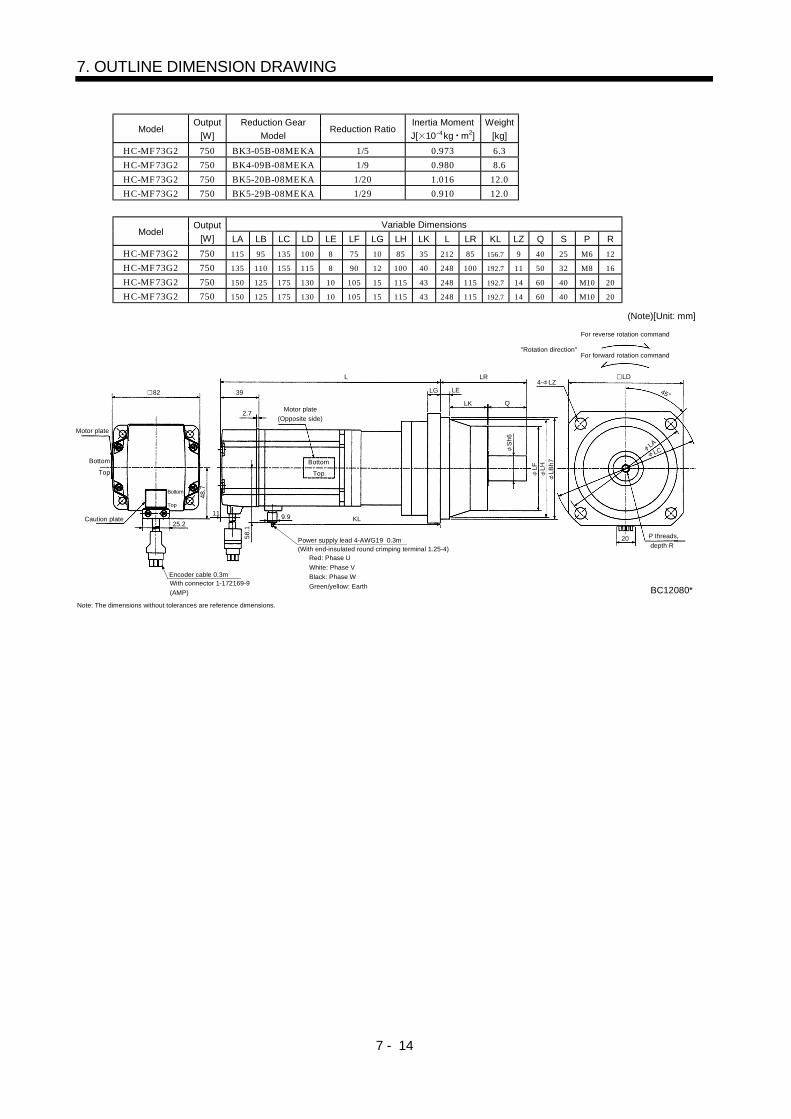
7 - 14
7. OUTLINE DIMENSION DRAWING
ModelOutput
[W]
Reduction Gear
ModelReduction Ratio
Inertia Moment
J[ 10 4kg m2]
Weight
[kg]
HC-MF73G2 750 BK3-05B-08MEKA 1/5 0.973 6.3
HC-MF73G2 750 BK4-09B-08MEKA 1/9 0.980 8.6
HC-MF73G2 750 BK5-20B-08MEKA 1/20 1.016 12.0
HC-MF73G2 750 BK5-29B-08MEKA 1/29 0.910 12.0
Variable DimensionsModel
Output
[W] LA LB LC LD LE LF LG LH LK L LR KL LZ Q S P R
HC-MF73G2 750 115 95 135 100 8 75 10 85 35 212 85 156.7 9 40 25 M6 12
HC-MF73G2 750 135 110 155 115 8 90 12 100 40 248 100 192.7 11 50 32 M8 16
HC-MF73G2 750 150 125 175 130 10 105 15 115 43 248 115 192.7 14 60 40 M10 20
HC-MF73G2 750 150 125 175 130 10 105 15 115 43 248 115 192.7 14 60 40 M10 20
Motor plate
(Opposite side)
KL
LELG
LF
LH
LD4- LZ
Top
Bottom
LB
h7
LK
LR
P threads,
depth R
Q
Sh
6
"Rotation direction"For forward rotation command
For reverse rotation command
Power supply lead 4-AWG19 0.3m
Encoder cable 0.3mWith connector 1-172169-9
(AMP)
Red: Phase U
White: Phase V
Black: Phase W
Green/yellow: Earth
Motor plate
Caution plate
Top
Bottom
Top
Bottom
82 39
2.7
25.2
48
.7
(With end-insulated round crimping terminal 1.25-4)
20
11 9.9
58
.1
BC12080*
L
LA
LC
(Note)[Unit: mm]
45
Note: The dimensions without tolerances are reference dimensions.

7 - 15
7. OUTLINE DIMENSION DRAWING
(b) With electromagnetic brakeVariable Dimensions
ModelOutput
[W] L KL
Braking Force
[N m]Reduction Gear
Model
Reduction
Ratio
Inertia Moment
J[ 10 4kg m2]Backlash
Weight
[kg]
HC-MF053G2 50 158 78 0.32 BK1-05B-A5MEKA 1/5 0.070 3 min. max. 1.8
HC-MF053G2 50 174 94 0.32 BK1-09B-A5MEKA 1/9 0.063 3 min. max. 2.1
HC-MF053G2 50 174 94 0.32 BK1-20B-A5MEKA 1/20 0.072 3 min. max. 2.2
HC-MF053G2 50 174 94 0.32 BK1-29B-A5MEKA 1/29 0.060 3 min. max. 2.2
HC-KF053G2 50 158 78 0.32 BK1-05B-A5MEKA 1/5 0.104 3 min. max. 1.8
HC-KF053G2 50 174 94 0.32 BK1-09B-A5MEKA 1/9 0.098 3 min. max. 2.1
HC-KF053G2 50 174 94 0.32 BK1-20B-A5MEKA 1/20 0.107 3 min. max. 2.2
HC-KF053G2 50 174 94 0.32 BK1-29B-A5MEKA 1/29 0.095 3 min. max. 2.2
Motor plate
(Opposite side)
258 6
Top
Bottom
23
55
"Rotation direction"
For forward rotation command
For reverse rotation command
Power supply lead 4-AWG19 0.3m
(With end-insulated round crimping terminal 1.25-4)
Encoder cable 0.3mWith connector 172169-9
(AMP)
Brake lead
2-0.3 0.3m(With end-insulated round
crimping terminal 1.25-4)
Blue: B1,B2
2
Red: Phase U
White: Phase V
Black: Phase W
Green/yellow: Earth
Motor plate
48
60
65
h7
16
h6
M4 threads,
depth 8
35
.7
20
70
4- 6.6
L
40.5
Caution plate25.2
28
.7
42
Top
Bottom
Top
Bottom
65.59.9
KL
(BC12100*)BC12081*
6.8
95
80
(Note)[Unit: mm]
45
Note: The dimensions without tolerances are reference dimensions.

7 - 16
7. OUTLINE DIMENSION DRAWING
ModelOutput
[W]
Braking Force
[N m]
Reduction Gear
ModelReduction Ratio
Inertia Moment
J[ 10 4kg m2]Backlash
Weight
[kg]
HC-MF13BG2 100 0.32 BK1-05B-01MEKA 1/5 0.080 3 min. max. 1.9
HC-MF13BG2 100 0.32 BK1-09B-01MEKA 1/9 0.074 3 min. max. 2.2
HC-MF13BG2 100 0.32 BK2-20B-01MEKA 1/20 0.124 3 min. max. 3.4
HC-MF13BG2 100 0.32 BK2-29B-01MEKA 1/29 0.098 3 min. max. 3.4
Variable DimensionsModel
Output
[W] LA LB LC LD LE LF LG LH LK L LR KL LZ Q S P R
HC-MF13BG2 100 80 65 95 70 6 48 8 60 23 173 55 93 6.6 25 16 M4 8
HC-MF13BG2 100 80 65 95 70 6 48 8 60 23 189 55 109 6.6 25 16 M4 8
HC-MF13BG2 100 100 80 115 85 6 65 10 74 33 195 75 115 6.6 35 20 M5 10
HC-MF13BG2 100 100 80 115 85 6 65 10 74 33 195 75 115 6.6 35 20 M5 10
ModelOutput
[W]
Braking Force
[N m]
Reduction Gear
ModelReduction Ratio
Inertia Moment
J[ 10 4kg m2]Backlash
Weight
[kg]
HC-KF13BG2 100 0.32 BK1-05B-01MEKA 1/5 0.135 3 min. max. 1.9
HC-KF13BG2 100 0.32 BK1-09B-01MEKA 1/9 0.129 3 min. max. 2.2
HC-KF13BG2 100 0.32 BK2-20B-01MEKA 1/20 0.179 3 min. max. 3.4
HC-KF13BG2 100 0.32 BK2-29B-01MEKA 1/29 0.153 3 min. max. 3.4
Variable DimensionsModel
Output
[W] LA LB LC LD LE LF LG LH LK L LR KL LZ Q S P R
HC-KF13BG2 100 80 65 95 70 6 48 8 60 23 173 55 93 6.6 25 16 M4 8
HC-KF13BG2 100 80 65 95 70 6 48 8 60 23 189 55 109 6.6 25 16 M4 8
HC-KF13BG2 100 100 80 115 85 6 65 10 74 33 195 75 115 6.6 35 20 M5 10
HC-KF13BG2 100 100 80 115 85 6 65 10 74 33 195 75 115 6.6 35 20 M5 10
Motor plate
(Opposite side)
L
LELG
Top
Bottom
LK
LR
P threads,
depth R
Q
"Rotation direction"
For forward rotation command
For reverse rotation command
Power supply lead 4-AWG19 0.3m
(With end-insulated round crimping terminal 1.25-4)
Brake lead
2-0.3 0.3m(With end-insulated round
crimping terminal 1.25-4)
2
Encoder cable 0.3mWith connector 1-172169-9
(AMP)
Red: Phase U
White: Phase V
Black: Phase W
Green/yellow: Earth
Sh
6L
FL
HL
Bh
7
LD4- LZ
20
40.542
Motor plate
Caution plate
25.2
28
.7
65.5
6.8
KL
(BC12101*)BC12082*
35
.7
Top
Bottom
Top
Bottom
LA
LC
(Note)[Unit: mm]
45
Note: The dimensions without tolerances are reference dimensions.
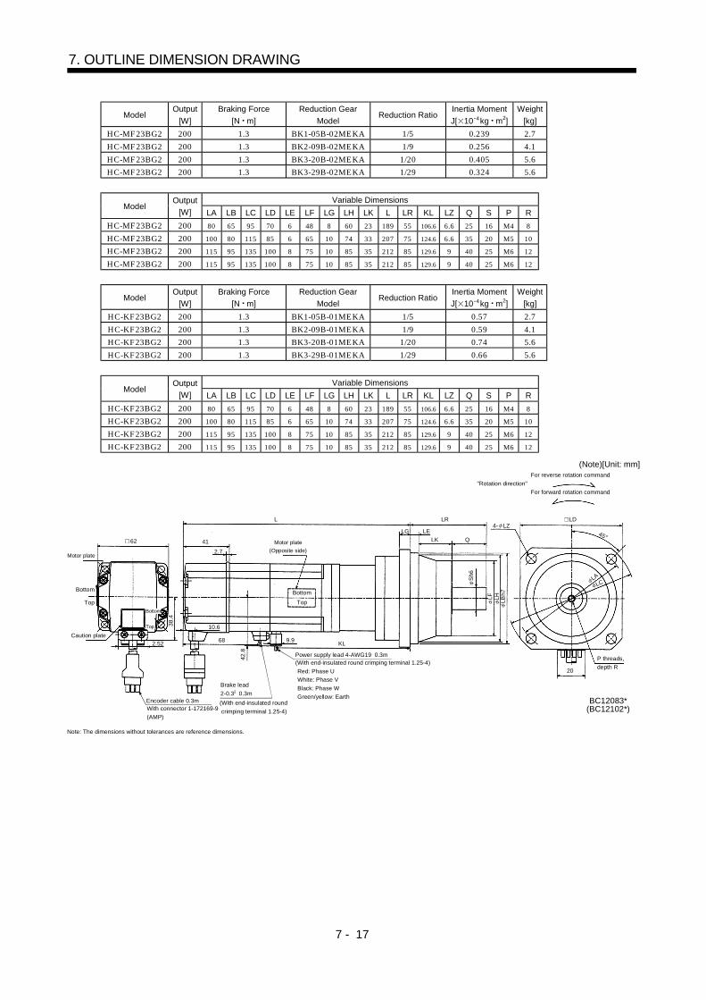
7 - 17
7. OUTLINE DIMENSION DRAWING
ModelOutput
[W]
Braking Force
[N m]
Reduction Gear
ModelReduction Ratio
Inertia Moment
J[ 10 4kg m2]
Weight
[kg]
HC-MF23BG2 200 1.3 BK1-05B-02MEKA 1/5 0.239 2.7
HC-MF23BG2 200 1.3 BK2-09B-02MEKA 1/9 0.256 4.1
HC-MF23BG2 200 1.3 BK3-20B-02MEKA 1/20 0.405 5.6
HC-MF23BG2 200 1.3 BK3-29B-02MEKA 1/29 0.324 5.6
Variable DimensionsModel
Output
[W] LA LB LC LD LE LF LG LH LK L LR KL LZ Q S P R
HC-MF23BG2 200 80 65 95 70 6 48 8 60 23 189 55 106.6 6.6 25 16 M4 8
HC-MF23BG2 200 100 80 115 85 6 65 10 74 33 207 75 124.6 6.6 35 20 M5 10
HC-MF23BG2 200 115 95 135 100 8 75 10 85 35 212 85 129.6 9 40 25 M6 12
HC-MF23BG2 200 115 95 135 100 8 75 10 85 35 212 85 129.6 9 40 25 M6 12
ModelOutput
[W]
Braking Force
[N m]
Reduction Gear
ModelReduction Ratio
Inertia Moment
J[ 10 4kg m2]
Weight
[kg]
HC-KF23BG2 200 1.3 BK1-05B-01MEKA 1/5 0.57 2.7
HC-KF23BG2 200 1.3 BK2-09B-01MEKA 1/9 0.59 4.1
HC-KF23BG2 200 1.3 BK3-20B-01MEKA 1/20 0.74 5.6
HC-KF23BG2 200 1.3 BK3-29B-01MEKA 1/29 0.66 5.6
Variable DimensionsModel
Output
[W] LA LB LC LD LE LF LG LH LK L LR KL LZ Q S P R
HC-KF23BG2 200 80 65 95 70 6 48 8 60 23 189 55 106.6 6.6 25 16 M4 8
HC-KF23BG2 200 100 80 115 85 6 65 10 74 33 207 75 124.6 6.6 35 20 M5 10
HC-KF23BG2 200 115 95 135 100 8 75 10 85 35 212 85 129.6 9 40 25 M6 12
HC-KF23BG2 200 115 95 135 100 8 75 10 85 35 212 85 129.6 9 40 25 M6 12
Motor plate
(Opposite side)
L
LELG
Top
Bottom
LK
LR
P threads,
depth R
Q
"Rotation direction"
For forward rotation command
For reverse rotation command
Power supply lead 4-AWG19 0.3m(With end-insulated round crimping terminal 1.25-4)
Brake lead
2-0.3 0.3m
(With end-insulated round
crimping terminal 1.25-4)
2
Encoder cable 0.3mWith connector 1-172169-9
(AMP)
Red: Phase U
White: Phase V
Black: Phase W
Green/yellow: Earth
Top
Bottom
Sh
6
LF
LH
LB
h7
LCLA
20
4- LZLD
Top
Bottom
Motor plate
Caution plate
2.5268
38
.4
10.6
42
.8
9.9KL
62
BC12083*(BC12102*)
41
2.7
(Note)[Unit: mm]
45
Note: The dimensions without tolerances are reference dimensions.

7 - 18
7. OUTLINE DIMENSION DRAWING
ModelOutput
[W]
Braking Force
[N m]
Reduction Gear
ModelReduction Ratio
Inertia Moment
J[ 10 4kg m2]
Weight
[kg]
HC-MF43BG2 400 1.3 BK2-05B-04MEKA 1/5 0.344 4.3
HC-MF43BG2 400 1.3 BK3-09B-04MEKA 1/9 0.372 5.9
HC-MF43BG2 400 1.3 BK4-20B-04MEKA 1/20 0.475 8.1
HC-MF43BG2 400 1.3 BK4-29B-04MEKA 1/29 0.386 8.1
Variable DimensionsModel
Output
[W] LA LB LC LD LE LF LG LH LK L LR KL LZ Q S P R
HC-MF43BG2 400 100 80 115 85 6 65 10 74 33 216 75 131.6 6.6 35 20 M5 10
HC-MF43BG2 400 115 95 135 100 8 75 10 85 35 237 85 152.6 9 40 25 M6 12
HC-MF43BG2 400 135 110 155 115 8 90 12 100 40 243 100 158.6 11 50 32 M8 16
HC-MF43BG2 400 135 110 155 115 8 90 12 100 40 243 100 158.6 11 50 32 M8 16
ModelOutput
[W]
Braking Force
[N m]
Reduction Gear
ModelReduction Ratio
Inertia Moment
J[ 10 4kg m2]
Weight
[kg]
HC-KF43BG2 400 1.3 BK2-05B-04MEKA 1/5 0.87 4.3
HC-KF43BG2 400 1.3 BK3-09B-04MEKA 1/9 0.90 5.9
HC-KF43BG2 400 1.3 BK4-20B-04MEKA 1/20 1.00 8.1
HC-KF43BG2 400 1.3 BK4-29B-04MEKA 1/29 0.92 8.1
Variable DimensionsModel
Output
[W] LA LB LC LD LE LF LG LH LK L LR KL LZ Q S P R
HC-MF43BG2 400 100 80 115 85 6 65 10 74 33 216 75 131.6 6.6 35 20 M5 10
HC-MF43BG2 400 115 95 135 100 8 75 10 85 35 237 85 152.6 9 40 25 M6 12
HC-MF43BG2 400 135 110 155 115 8 90 12 100 40 243 100 158.6 11 50 32 M8 16
HC-MF43BG2 400 135 110 155 115 8 90 12 100 40 243 100 158.6 11 50 32 M8 16
LELG
LK LR
Q
With connector 1-172169-9
(AMP)
Bottom
Top
Power supply lead 4-AWG19 0.3m
(With end-insulated round crimping terminal 1.25-4)
Red: Phase U
White: Phase V
Black: Phase W
Green/yellow: EarthEncoder cable 0.3m
P threads,
depth R
For forward rotation command"Rotation direction"
For reverse rotation command
Brake lead
2-0.3 0.3m(With end-insulated roundcrimping terminal 1.25-4)
2
Sh
6
LF
LH
LB
h7
LCLA
4- LZLD
(BC12103*)BC12084*
20
Bottom
Top
Caution plate
LK62 41
2.7Motor plate
(Opposite side)
Bottom
Top
KL9.9
68
25.2
38
.4
10.6
42
.8
(Note)[Unit: mm]
45
Motor plate
Note: The dimensions without tolerances are reference dimensions.
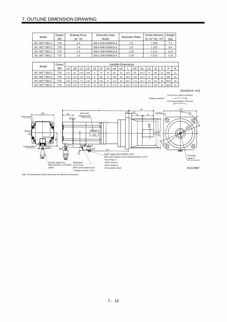
7 - 19
7. OUTLINE DIMENSION DRAWING
ModelOutput
[W]
Braking Force
[N m]
Reduction Gear
ModelReduction Ratio
Inertia Moment
J[ 10 4kg m2]
Weight
[kg]
HC-MF73BG2 750 2.4 BK3-05B-08MEKA 1/5 1.098 7.3
HC-MF73BG2 750 2.4 BK4-09B-08MEKA 1/9 1.105 9.6
HC-MF73BG2 750 2.4 BK5-20B-08MEKA 1/20 1.141 13.0
HC-MF73BG2 750 2.4 BK5-29B-08MEKA 1/29 1.035 13.0
Variable DimensionsModel
Output
[W] LA LB LC LD LE LF LG LH LK L LR KL LZ Q S P R
HC-MF73BG2 750 115 95 135 100 8 75 10 85 35 247.5 85 156.7 9 40 25 M6 12
HC-MF73BG2 750 135 110 155 115 8 90 12 100 40 283.5 100 192.7 11 50 32 M8 16
HC-MF73BG2 750 150 125 175 130 10 105 15 115 43 283.5 115 192.7 14 60 40 M10 20
HC-MF73BG2 750 150 125 175 130 10 105 15 115 43 283.5 115 192.7 14 60 40 M10 20
Motor plate
(Opposite side)
LELG 4- LZ
Top
Bottom
LK
LR
Q
"Rotation direction"
For forward rotation command
For reverse rotation command
Power supply lead 4-AWG19 0.3m
(With end-insulated round crimping terminal 1.25-4)
Brake lead
2-0.3 0.3m(With end-insulated round
crimping terminal 1.25-4)
2
Encoder cable 0.3mWith connector 1-172169-9
(AMP)
Red: Phase U
White: Phase V
Black: Phase W
Green/yellow: Earth
P threads,
depth R
Sh
6
LF
LH
LB
h7
L
Motor plate
82
Caution plate 25.2
48
.7
Top
Bottom
Top
Bottom
39
2.7
1172
9.9KL
LD
BC12085*
58
.1
LA
LC
(Note)[Unit: mm]
45
Note: The dimensions without tolerances are reference dimensions.

7 - 20
7. OUTLINE DIMENSION DRAWING
(5) HC-MF-UE HC-KF-UE series
(a) Standard (without electromagnetic brake, without reduction gear)Variable Dimensions
ModelOutput
[W] L KL
Inertia Moment
J[ 10 4kg m2]
Weight
[kg]
HC-MF053-UE 50 89.5 37.5 0.019 0.5
HC-MF13-UE 100 104.5 52.5 0.03 0.6
HC-KF053-UE 50 89.5 37.5 0.054 0.5
HC-KF13-UE 100 104.5 52.5 0.085 0.53
Motor plate
Caution plate
Bottom
Top
Bottom
Top
25.2
28
.7
42
Encoder cable
0.3m
Encoder cable 0.3m With connector 1-172169-9
(AMP)
Power supply lead 4-AWG19 0.3m (With end-insulated round crimping terminal 1.25-4)
Red: Phase U
White: Phase V
Black: Phase W
Green/yellow: Earth
Motor plate(Opposite side)
Bottom
Top
Bottom
Top
40.5
L 25
5 2.5
KL
TUV plate
8h
6
30
h7
V-10A
2- 4.5 40
35
.7
20
BC07328A
9.9
6.8
V ring
(Note)[Unit: mm]
45
46
Note: The dimensions without tolerances are reference dimensions.
Variable DimensionsModel
Output
[W] L KL
Inertia Moment
J[ 10 4kg m2]
Weight
[kg]
HC-MF23-UE 200 108.5 58 0.09 1.2
HC-MF43-UE 400 133.5 81 0.14 1.7
HC-KF23-UE 200 108.5 58 0.43 1.2
HC-KF43-UE 400 133.5 81 0.68 1.7
62
Motor plate
Caution plate
25.2
38
.4
plate
Bottom
Top
Bottom
Top
Bottom
Top
10.69.9
41
2.7
L 30
37Motor plate
(Opposite side)
Bottom
Top
KL
V ring
V-16A
Encoder cable 0.3m With connector 1-172169-9(AMP)
Power supply lead 4-AWG19 0.3m (With end-insulated round crimping terminal 1.25-4)
Red: Phase U
White: Phase V
Black: Phase W
Green/yellow: Earth
20
BC07329A
42
.8
70
4- 5.8
30
14
h6
50
h7
TUV
(Note)[Unit: mm]
45
Note: The dimensions without tolerances are reference dimensions.

7 - 21
7. OUTLINE DIMENSION DRAWING
ModelOutput
[W]
Inertia Moment
J[ 10 4kg m2]
Weight
[kg]
HC-MF73-UE 750 0.675 3.1
Encoder cable 0.3m With connector 1-172169-9(AMP)
Motor plate(Opposite side)
Motor plate
Caution plate25.2
48
.7
TUV plate
82
Bottom
Top
Bottom
Top
150
39
2.7
Bottom
Top
119.9
95
40
38
19
h6
70
h7
Power supply lead 4-AWG19 0.3m (With end-insulated round crimping terminal 1.25-4)Red: Phase U White: Phase VBlack: Phase WGreen/yellow: Earth
V ringV-25A
4- 6.6
80
90
58
.5
20
BC07330A
(Note)[Unit: mm]
45
Note: The dimensions without tolerances are reference dimensions.
(b) With electromagnetic brakeVariable Dimensions
ModelOutput
[W] L KL
Braking Force
[N m]
Inertia Moment
J[ 10 4kg m2]Weight
[kg]
HC-MF053B-UE 50 117.5 37.5 0.022 0.9
HC-MF13B-UE 100 132.5 52.5 0.032 1
HC-KF053B-UE 50 117.5 37.5 0.057 0.9
HC-KF13B-UE 100 132.5 52.5
0.32
0.088 1
42
Motor plate(Opposite side)
40.5
L 25
2.55
TUV plate
Encoder cable 0.3m With connector 1-172169-9(AMP)
Brake lead2-0.32 0.3m (With end-insulated round crimping terminal 1.25-4)
Power supply lead 4-AWG19 0.3m (With end-insulated round crimping terminal 1.25-4)
Red: Phase U
White: Phase V
Black: Phase W
Green/yellow: Earth
B1,B2
KL
Motor plate
Caution plate
25.2
28
.7
Top
Bottom
Top
Bottom
6.8
30
h7
8h
6
V-10A
V ring
402- 4.5
20
35
.7
BC07369A
Top
Bottom
Top
Bottom
46
(Note)[Unit: mm]
45
Note: The dimensions without tolerances are reference dimensions.

7 - 22
7. OUTLINE DIMENSION DRAWING
Variable DimensionsModel
Output
[W] L KL
Braking Force
[N m]
Inertia Moment
J[ 10 4kg m2]
Weight
[kg]
HC-MF23B-UE 200 140.5 58 0.136 1.7
HC-MF43B-UE 400 165.5 81 0.191 2.2
HC-KF23B-UE 200 140.5 58 0.48 1.7
HC-KF43B-UE 400 165.5 81
1.3
0.73 2.2
Encoder cable 0.3m
With connector 1-172169-9
(AMP)
Brake lead
2-0.3 0.3m
(With end-insulated round
crimping terminal 1.25-4)
B1,B2
Power supply lead 4-AWG19 0.3m
(With end-insulated round crimping terminal 1.25-4)
Red: Phase U
White: Phase V
Black: Phase W
Green/yellow: Earth
Motor plate
(Opposite side)
Bottom
Top
Motor plate
Caution plate
Top
Bottom
Bottom
Top
Top
Bottom
25.2
38.
4
TUV plate
10.6
41
2.7
L 30
37
95
9.9
14h6
50h
7
V-16A
60
4- 5.8
42.
8
20
BC07354A
V ring
62
70
(Note)[Unit: mm]
2
45
Note: The dimensions without tolerances are reference dimensions.
ModelOutput
[W]
Braking Force
[N m]
Inertia Moment
J[ 10 4kg m2]
Weight
[kg]
HC-MF73B-UE 750 2.4 0.75 4.2
Encoder cable 0.3m
With connector 1-172169-9
(AMP)
Brake lead
2-0.3 0.3m
(With end-insulated round
crimping terminal 1.25-4)
B1,B2
Power supply lead 4-AWG19 0.3m
(With end-insulated round crimping terminal 1.25-4)Red: Phase U
White: Phase V
Black: Phase W
Green/yellow: Earth
BC07606A
20
58
.190
4- 6.6
80
40
38
19
h6
70
h7
95
9.9V-25A
Bottom
Top
Motor plate
Caution plate25.2
48
.7
plateTUV
Bottom
Top
Bottom
Top
39
2.7
Motor plate
(Opposite side)
185.5
11 V ring
82
2
(Note)[Unit: mm]
45
Note: The dimensions without tolerances are reference dimensions.


