Embed Size (px)
Citation preview

Preface, Contents
System Overview1
Hardware Description andCommissioning
2
Function Description3
Overview of System Integration4
SIMATIC S75
SIMATIC M76
SIMATIC S57
Standard DP Master8
Serial Coupling9
Data Record Description10
Connection of Digital RemoteDisplays
11
SIWATOOL - Description and Use12
Error Diagnostics and Treatment13
Technical Specifications14
Distribution/Hotline/Repairs/Replacement Parts/Training
15
Index
Release 09/2001
(One and Two-Channel Model)
Equipment Manual
SIWAREX U

This manual contains notices which you should observe to ensure your own personal safety,as well to protect the product and connected equipment. These notices are highlighted in themanual by a warning triangle and are marked as follows to the level of danger.
!Danger
indicates an imminently hazardous situation which, if not avoided, will result in death orserious injury.
!Warning
indicates a potentially hazardous situation which, if not avoided, could result in death orserious injury.
!Caution
used with the safety alert symbol indicates a potentially hazardous situation which, if notavoided, may result in minor or moderate injury.
Caution
used without safety alert symbol indicates a potentially hazardous situation which, if notavoided, may result in property damage.
Notice
NOTICE used without the safety alert symbol indicates a potential situation which, ifnot avoided, may result in an undesireable result or state.
The device/system may only be set up and operated in conjunction with this manual. Only quali-fied personnel should be allowed to install and work on this equipment. Qualified persons aredefined as persons who are authorized to commission, to ground, and to tag circuits, equipment,and systems in accordance with established safety practices and standards.
Note the following:
!Warning
This device and its components may only be used for the applications described in the cata-log or technical description, and only in connection with devices or components from othermanufactorers which have been approved or recommended by Siemens.
This product can only function correctly and savely if it is transported, stored, set up, and instal-led correctly, and operated and maintained as recommended.
SIMATIC and SIWAREX are registered trademarks of Siemens AG.
Copyright Siemens AG 2000 All rights reserved
The reproduction, transmission or use of this document or its contents is not per-mitted without express written authority. Offenders will be liable for damages. Allrights, including rights created by patent grant or registration of a utility model ordesign, are reserved.
Disclaimer of Liability
We have checked the contents of this manual for agreement with the hardware andsoftware described. Since deviations cannot be precluded entirely, we cannot gua-rantee full agreement. However, the data in the manual are reviewed regularly andany necessary corrections included in subsequent editions. Suggestions for impro-vement are welcomed.
Tecnical data subject to change.
Editor: A&D SE ES4Publisher: A&D PI 14
Siemens Aktiengesellschaft Order No.
Safety Guidelines
Qualified Personnel
Correct Usage
Trademarks

iSIWAREX U Equipment Manual(4) J31069-D0605-U001-A2-7618
Table of Contents
1 System Overview 1-1. . . . . . . . . . . . . . . . . . . . . . . . . . . . . . . . . . . . . . . . . . . . . . . . . .
1.1 Introduction 1-2. . . . . . . . . . . . . . . . . . . . . . . . . . . . . . . . . . . . . . . . . . . . . . . .
1.2 Setup and Components of a Weighing Machine 1-8. . . . . . . . . . . . . . . .
1.3 Weighing Functions 1-9. . . . . . . . . . . . . . . . . . . . . . . . . . . . . . . . . . . . . . . . .
2 Hardware Description and Commissioning 2-1. . . . . . . . . . . . . . . . . . . . . . . . . .
2.1 Installing the SIWAREX U 2-3. . . . . . . . . . . . . . . . . . . . . . . . . . . . . . . . . . .
2.2 Mounting the Module on the Rail 2-5. . . . . . . . . . . . . . . . . . . . . . . . . . . . .
2.3 Connection and Wiring 2-7. . . . . . . . . . . . . . . . . . . . . . . . . . . . . . . . . . . . . . 2.3.1 Load Cell Connection 2-10. . . . . . . . . . . . . . . . . . . . . . . . . . . . . . . . . . . . . . . 2.3.2 RS 232C Interface 2-13. . . . . . . . . . . . . . . . . . . . . . . . . . . . . . . . . . . . . . . . . . 2.3.3 TTY Interface 2-15. . . . . . . . . . . . . . . . . . . . . . . . . . . . . . . . . . . . . . . . . . . . . .
2.4 Preparing the SIWAREX U for Operation 2-16. . . . . . . . . . . . . . . . . . . . . .
2.5 Assigning Parameters 2-18. . . . . . . . . . . . . . . . . . . . . . . . . . . . . . . . . . . . . . .
3 Function Description 3-1. . . . . . . . . . . . . . . . . . . . . . . . . . . . . . . . . . . . . . . . . . . . . .
3.1 A/D Conversion (Measured Value Acquisition) 3-2. . . . . . . . . . . . . . . . . .
3.2 Digital Filtering 3-3. . . . . . . . . . . . . . . . . . . . . . . . . . . . . . . . . . . . . . . . . . . . .
3.3 Weight Calculation and Adjustment 3-4. . . . . . . . . . . . . . . . . . . . . . . . . . .
3.4 Setting to Zero 3-10. . . . . . . . . . . . . . . . . . . . . . . . . . . . . . . . . . . . . . . . . . . . .
3.5 Limit Values 3-12. . . . . . . . . . . . . . . . . . . . . . . . . . . . . . . . . . . . . . . . . . . . . . .
3.6 Operational Reliability 3-14. . . . . . . . . . . . . . . . . . . . . . . . . . . . . . . . . . . . . . .
3.7 Special Functions 3-17. . . . . . . . . . . . . . . . . . . . . . . . . . . . . . . . . . . . . . . . . .
4 Overview of System Integration 4-1. . . . . . . . . . . . . . . . . . . . . . . . . . . . . . . . . . . .
4.1 System Integration 4-2. . . . . . . . . . . . . . . . . . . . . . . . . . . . . . . . . . . . . . . . .
5 SIMATIC S7 5-1. . . . . . . . . . . . . . . . . . . . . . . . . . . . . . . . . . . . . . . . . . . . . . . . . . . . . . .
5.1 Diagnostic Capabilities in the SIMATIC S7 Program 5-4. . . . . . . . . . . . .
5.2 Evaluation of the Process Interrupts 5-6. . . . . . . . . . . . . . . . . . . . . . . . . .
5.3 Writing a Data Record with SFC58 “WR_REC” 5-7. . . . . . . . . . . . . . . . .
5.4 Read Data Record with SFC 59 “RD_REC” 5-9. . . . . . . . . . . . . . . . . . . .
5.5 Sample Program 5-13. . . . . . . . . . . . . . . . . . . . . . . . . . . . . . . . . . . . . . . . . . .

iiSIWAREX U Equipment Manual
(4) J31069-D0605-U001-A2-7618
6 SIMATIC M7 6-1. . . . . . . . . . . . . . . . . . . . . . . . . . . . . . . . . . . . . . . . . . . . . . . . . . . . . . .
7 SIMATIC S5 7-1. . . . . . . . . . . . . . . . . . . . . . . . . . . . . . . . . . . . . . . . . . . . . . . . . . . . . . .
7.1 Hardware Prerequisites 7-1. . . . . . . . . . . . . . . . . . . . . . . . . . . . . . . . . . . . .
7.2 Delivery Form 7-4. . . . . . . . . . . . . . . . . . . . . . . . . . . . . . . . . . . . . . . . . . . . . .
7.3 Parameterization 7-5. . . . . . . . . . . . . . . . . . . . . . . . . . . . . . . . . . . . . . . . . . .
7.4 Addressing the SIWAREX U 7-7. . . . . . . . . . . . . . . . . . . . . . . . . . . . . . . . .
7.5 Types of Addressing of the IM 308-C 7-9. . . . . . . . . . . . . . . . . . . . . . . . . .
7.6 Types of Addressing of the S5-95U 7-10. . . . . . . . . . . . . . . . . . . . . . . . . . .
7.7 Principle of Communication 7-11. . . . . . . . . . . . . . . . . . . . . . . . . . . . . . . . . .
7.8 Allocation of the Input/Output Area 7-12. . . . . . . . . . . . . . . . . . . . . . . . . . .
7.9 Description of Data Transmission 7-14. . . . . . . . . . . . . . . . . . . . . . . . . . . . .
7.10 Sample Program 7-17. . . . . . . . . . . . . . . . . . . . . . . . . . . . . . . . . . . . . . . . . . .
7.11 Diagnostic Capabilities with Link to SIMATIC S5 7-25. . . . . . . . . . . . . . . . 7.11.1 Diagnostic Capabilities with the IM 308-C 7-25. . . . . . . . . . . . . . . . . . . . . . 7.11.2 Diagnostic Capabilities with the S5-95U/DP Master 7-29. . . . . . . . . . . . .
8 Standard DP Master 8-1. . . . . . . . . . . . . . . . . . . . . . . . . . . . . . . . . . . . . . . . . . . . . . .
8.1 Link to the Standard DP Master 8-1. . . . . . . . . . . . . . . . . . . . . . . . . . . . . .
9 Serial Coupling 9-1. . . . . . . . . . . . . . . . . . . . . . . . . . . . . . . . . . . . . . . . . . . . . . . . . . . .
9.1 Transmission Protocol (SIWAREX Driver) 9-1. . . . . . . . . . . . . . . . . . . . .
10 Data Record Description 10-1. . . . . . . . . . . . . . . . . . . . . . . . . . . . . . . . . . . . . . . . . . .
10.1 Overview of Data Records 10-1. . . . . . . . . . . . . . . . . . . . . . . . . . . . . . . . . . .
10.2 Data Formats 10-4. . . . . . . . . . . . . . . . . . . . . . . . . . . . . . . . . . . . . . . . . . . . . .
10.3 Description of the Data Records 10-5. . . . . . . . . . . . . . . . . . . . . . . . . . . . . . 10.3.1 DR0: Basic Parameters (Write) 10-5. . . . . . . . . . . . . . . . . . . . . . . . . . . . . . . 10.3.2 DR1 - Parameter (Write) 10-5. . . . . . . . . . . . . . . . . . . . . . . . . . . . . . . . . . . . 10.3.3 DR0: Diagnosis, Part 1 (Read) 10-6. . . . . . . . . . . . . . . . . . . . . . . . . . . . . . . 10.3.4 DR1 - Diagnosis, Part 2 (Read) 10-7. . . . . . . . . . . . . . . . . . . . . . . . . . . . . . 10.3.5 DR3: Adjustment Data, Channel 1 10-8. . . . . . . . . . . . . . . . . . . . . . . . . . . . 10.3.6 DR4: Adjustment Data, Channel 2 10-10. . . . . . . . . . . . . . . . . . . . . . . . . . . . 10.3.7 DR5: General Parameters (Regardless of Channel) 10-10. . . . . . . . . . . . . 10.3.8 DR6: Specified Values, Remote Display 10-11. . . . . . . . . . . . . . . . . . . . . . . 10.3.9 DR11: Commands, Channel 1 10-12. . . . . . . . . . . . . . . . . . . . . . . . . . . . . . . . 10.3.10 DR12: Commands, Channel 2 10-12. . . . . . . . . . . . . . . . . . . . . . . . . . . . . . . 10.3.11 DR21: Limit Values, Channel 1 10-13. . . . . . . . . . . . . . . . . . . . . . . . . . . . . . . 10.3.12 DR22: Limit Values, Channel 2 10-13. . . . . . . . . . . . . . . . . . . . . . . . . . . . . . . 10.3.13 DR31: Measured Values/Status/Error, Channel 1 10-14. . . . . . . . . . . . . . . 10.3.14 DR32: Measured Values/Status/Error, Channel 2 10-14. . . . . . . . . . . . . . . 10.3.15 DR40: Version/Checksum/Switches 10-17. . . . . . . . . . . . . . . . . . . . . . . . . . . 10.3.16 DR57 to 79: Data Records for I/O Area (S5 Data Records) 10-18. . . . . . . 10.3.17 DR100: Fetch Telegram 10-19. . . . . . . . . . . . . . . . . . . . . . . . . . . . . . . . . . . . . 10.3.18 DR101: Acknowledgment Telegram 10-19. . . . . . . . . . . . . . . . . . . . . . . . . . .
Table of Contents

iiiSIWAREX U Equipment Manual(4) J31069-D0605-U001-A2-7618
11 Optional Components 11-1. . . . . . . . . . . . . . . . . . . . . . . . . . . . . . . . . . . . . . . . . . . . .
11.1 Connection of Digital Remote Displays 11-2. . . . . . . . . . . . . . . . . . . . . . . .
11.2 Ex-i Interface SIWAREX Pi 11-11. . . . . . . . . . . . . . . . . . . . . . . . . . . . . . . . . . 11.2.1 Layout 11-12. . . . . . . . . . . . . . . . . . . . . . . . . . . . . . . . . . . . . . . . . . . . . . . . . . . .
12 SIWATOOL - Description and Use 12-1. . . . . . . . . . . . . . . . . . . . . . . . . . . . . . . . . . .
12.1 Installing SIWATOOL on PC/PG 12-2. . . . . . . . . . . . . . . . . . . . . . . . . . . . . .
12.2 Commissioning SIWAREX U with SIWATOOL 12-3. . . . . . . . . . . . . . . . . .
12.3 SIWATOOL Menu Tree 12-5. . . . . . . . . . . . . . . . . . . . . . . . . . . . . . . . . . . . . .
12.4 Adjustment of the Scales 12-6. . . . . . . . . . . . . . . . . . . . . . . . . . . . . . . . . . . .
12.5 Important Notes on Settings in SIWATOOL 12-8. . . . . . . . . . . . . . . . . . . .
12.6 Weighing Status 12-9. . . . . . . . . . . . . . . . . . . . . . . . . . . . . . . . . . . . . . . . . . . .
12.7 Diagnostic Capabilities with SIWATOOL 12-10. . . . . . . . . . . . . . . . . . . . . . .
13 Error Diagnostics and Treatment 13-1. . . . . . . . . . . . . . . . . . . . . . . . . . . . . . . . . . .
13.1 Error Treatment 13-4. . . . . . . . . . . . . . . . . . . . . . . . . . . . . . . . . . . . . . . . . . . .
13.2 General Behavior During Malfunctions 13-5. . . . . . . . . . . . . . . . . . . . . . . .
14 Technical Specifications 14-1. . . . . . . . . . . . . . . . . . . . . . . . . . . . . . . . . . . . . . . . . . .
14.1 Interfaces 14-2. . . . . . . . . . . . . . . . . . . . . . . . . . . . . . . . . . . . . . . . . . . . . . . . .
14.2 Physical Requirements and Data 14-5. . . . . . . . . . . . . . . . . . . . . . . . . . . . .
14.3 Electrical, EMC and Climatic Requirements 14-6. . . . . . . . . . . . . . . . . . . .
14.4 Potential Isolation 14-8. . . . . . . . . . . . . . . . . . . . . . . . . . . . . . . . . . . . . . . . . .
15 Hotline/Repairs/Replacement Parts/Internet 15-1. . . . . . . . . . . . . . . . . . . . . . . . .
Index Index-1. . . . . . . . . . . . . . . . . . . . . . . . . . . . . . . . . . . . . . . . . . . . . . . . . . . . . . . . . . . . .
Table of Contents

ivSIWAREX U Equipment Manual
(4) J31069-D0605-U001-A2-7618
Figures
1-1 SIWAREX U with the SIMATIC S7-300 1-2. . . . . . . . . . . . . . . . . . . . . . . . 1-2 SIWAREX U in the SIMATIC S7-300 1-4. . . . . . . . . . . . . . . . . . . . . . . . . . 1-3 The SIWAREX U as distributed periphery in the
SIMATIC S5/S7/M7 1-5. . . . . . . . . . . . . . . . . . . . . . . . . . . . . . . . . . . . . . . . . 1-4 Representation of the SIWAREX U in the ES engineering
system (left) and on the OS operator station (right) 1-6. . . . . . . . . . . . . 1-5 The SIWAREX U as a controller-independent field device 1-7. . . . . . . . 1-6 Diagram of the SIWAREX U setup 1-7. . . . . . . . . . . . . . . . . . . . . . . . . . . . 1-7 Setup of the weighing system with a SIWAREX U 1-8. . . . . . . . . . . . . . 1-8 SIWAREX U fill level scales 1-9. . . . . . . . . . . . . . . . . . . . . . . . . . . . . . . . . 1-9 Scales for potentially explosive area 1-11. . . . . . . . . . . . . . . . . . . . . . . . . . 2-1 Shield connecting element 2-6. . . . . . . . . . . . . . . . . . . . . . . . . . . . . . . . . . . 2-2 Mounting the shield terminals 2-7. . . . . . . . . . . . . . . . . . . . . . . . . . . . . . . . 2-3 Connection elements on the front of the SIWAREX U 2-8. . . . . . . . . . . 2-4 Connection of load cells using the 6-wire technique
(example: connection to channel 1) 2-11. . . . . . . . . . . . . . . . . . . . . . . . . . . 2-5 Connection of load cells using the 4-wire technique
(example: connection to channel 2) 2-12. . . . . . . . . . . . . . . . . . . . . . . . . . . 2-6 Connection of a PC to the RS 232 interface 2-13. . . . . . . . . . . . . . . . . . . . 2-7 Connection of digital remote displays 2-15. . . . . . . . . . . . . . . . . . . . . . . . . . 2-8 Location of the LEDs to be tested 2-17. . . . . . . . . . . . . . . . . . . . . . . . . . . . 2-9 Methods of parameter assignment for various system
configurations 2-18. . . . . . . . . . . . . . . . . . . . . . . . . . . . . . . . . . . . . . . . . . . . . . 3-1 Filtering principle of the SIWAREX U 3-3. . . . . . . . . . . . . . . . . . . . . . . . . . 3-2 Adjustment procedure 3-5. . . . . . . . . . . . . . . . . . . . . . . . . . . . . . . . . . . . . . . 3-3 Example of assigning parameters 3-12. . . . . . . . . . . . . . . . . . . . . . . . . . . . 4-1 Possible links to a host system 4-2. . . . . . . . . . . . . . . . . . . . . . . . . . . . . . . 5-1 Parameterization configuration 5-2. . . . . . . . . . . . . . . . . . . . . . . . . . . . . . . 5-2 Module status in STEP 7 5-5. . . . . . . . . . . . . . . . . . . . . . . . . . . . . . . . . . . . 7-1 Selection of SIWAREX U module during configuration of the
ET 200M 7-4. . . . . . . . . . . . . . . . . . . . . . . . . . . . . . . . . . . . . . . . . . . . . . . . . . 7-2 Parameter assignment with COM PROFIBUS 7-17. . . . . . . . . . . . . . . . . . 10-1 Comparison of data addressing with STEP 5 and STEP 7 10-3. . . . . . . 11-1 Connection of optional components 11-1. . . . . . . . . . . . . . . . . . . . . . . . . . . 11-2 Example: Connection of 4 digital remote displays to the
SIWAREX U 11-2. . . . . . . . . . . . . . . . . . . . . . . . . . . . . . . . . . . . . . . . . . . . . . . 11-3 Connection of remote displays 11-3. . . . . . . . . . . . . . . . . . . . . . . . . . . . . . . 11-4 Diagram of the Ex-i interface 11-11. . . . . . . . . . . . . . . . . . . . . . . . . . . . . . . . . 12-1 S7 setup 12-2. . . . . . . . . . . . . . . . . . . . . . . . . . . . . . . . . . . . . . . . . . . . . . . . . . 12-2 Dialog on scales adjustment 12-6. . . . . . . . . . . . . . . . . . . . . . . . . . . . . . . . . 12-3 Status window of the set scales 12-9. . . . . . . . . . . . . . . . . . . . . . . . . . . . . . 12-4 Online error report 12-10. . . . . . . . . . . . . . . . . . . . . . . . . . . . . . . . . . . . . . . . . . 14-1 Dimensions 14-5. . . . . . . . . . . . . . . . . . . . . . . . . . . . . . . . . . . . . . . . . . . . . . . .
Table of Contents

vSIWAREX U Equipment Manual(4) J31069-D0605-U001-A2-7618
Tables
2-1 Technical data of the SIMATIC 2-4. . . . . . . . . . . . . . . . . . . . . . . . . . . . . . . 2-2 Requirements on the SIWAREX U side 2-4. . . . . . . . . . . . . . . . . . . . . . . . 2-3 Rules for wiring 2-7. . . . . . . . . . . . . . . . . . . . . . . . . . . . . . . . . . . . . . . . . . . . 2-4 Indication elements on the front of the SIWAREX U 2-8. . . . . . . . . . . . . 2-5 Allocation of the load cell connection 2-10. . . . . . . . . . . . . . . . . . . . . . . . . . 2-6 Assignment of the RS 232C interface for SIWAREX U 2-13. . . . . . . . . . . 2-7 Assignment of the interface converter 2-14. . . . . . . . . . . . . . . . . . . . . . . . . 2-8 Assignment 2-15. . . . . . . . . . . . . . . . . . . . . . . . . . . . . . . . . . . . . . . . . . . . . . . . 3-1 A/D conversion 3-3. . . . . . . . . . . . . . . . . . . . . . . . . . . . . . . . . . . . . . . . . . . . 3-2 Commands and messages for adjustment 3-9. . . . . . . . . . . . . . . . . . . . . 3-3 Setting to zero 3-10. . . . . . . . . . . . . . . . . . . . . . . . . . . . . . . . . . . . . . . . . . . . . 3-4 Limit values - special cases 3-13. . . . . . . . . . . . . . . . . . . . . . . . . . . . . . . . . . 3-5 Limit values 3-13. . . . . . . . . . . . . . . . . . . . . . . . . . . . . . . . . . . . . . . . . . . . . . . 3-6 Messages for the test routines 3-15. . . . . . . . . . . . . . . . . . . . . . . . . . . . . . . 3-7 Storage of the limit values and zero setting value 3-16. . . . . . . . . . . . . . . 3-8 Allocation of the status LEDs 3-17. . . . . . . . . . . . . . . . . . . . . . . . . . . . . . . . 3-9 Messages for the special functions 3-18. . . . . . . . . . . . . . . . . . . . . . . . . . . 4-1 Overview of the data records 4-4. . . . . . . . . . . . . . . . . . . . . . . . . . . . . . . . 5-1 Parameters for SFC 58 “WR_REC” 5-7. . . . . . . . . . . . . . . . . . . . . . . . . . . 5-2 Parameters for SFC 59 “RD_REC” 5-9. . . . . . . . . . . . . . . . . . . . . . . . . . . 5-3 Specific error information for SFC 58 “WR_REC” and
SFC 59 “RD_REC” 5-10. . . . . . . . . . . . . . . . . . . . . . . . . . . . . . . . . . . . . . . . . 7-1 Maximum transmission speeds 7-2. . . . . . . . . . . . . . . . . . . . . . . . . . . . . . . 7-2 Type and GSD files 7-5. . . . . . . . . . . . . . . . . . . . . . . . . . . . . . . . . . . . . . . . . 7-3 Possible addresses 7-6. . . . . . . . . . . . . . . . . . . . . . . . . . . . . . . . . . . . . . . . . 7-4 Possible addresses 7-6. . . . . . . . . . . . . . . . . . . . . . . . . . . . . . . . . . . . . . . . . 7-5 Input/output of the SIWAREX U 7-11. . . . . . . . . . . . . . . . . . . . . . . . . . . . . . 7-6 Job control (output byte 3) 7-11. . . . . . . . . . . . . . . . . . . . . . . . . . . . . . . . . . . 7-7 Status byte (input byte 1) 7-12. . . . . . . . . . . . . . . . . . . . . . . . . . . . . . . . . . . . 7-8 Sample program DEMO 7-16. . . . . . . . . . . . . . . . . . . . . . . . . . . . . . . . . . . . . 7-9 Call interface 7-18. . . . . . . . . . . . . . . . . . . . . . . . . . . . . . . . . . . . . . . . . . . . . . 7-10 Structure of DW49 7-19. . . . . . . . . . . . . . . . . . . . . . . . . . . . . . . . . . . . . . . . . . 7-11 Structure of the scales DB 7-20. . . . . . . . . . . . . . . . . . . . . . . . . . . . . . . . . . . 7-12 User DB interface 7-23. . . . . . . . . . . . . . . . . . . . . . . . . . . . . . . . . . . . . . . . . . 7-13 Call FB192 7-24. . . . . . . . . . . . . . . . . . . . . . . . . . . . . . . . . . . . . . . . . . . . . . . . 7-14 Contents and layout of the diagnostic data 7-25. . . . . . . . . . . . . . . . . . . . . 7-15 Contents and layout of the process interrupt data 7-26. . . . . . . . . . . . . . . 7-16 Contents and layout of the diagnostic alarm data
(contents of data record DR1) 7-27. . . . . . . . . . . . . . . . . . . . . . . . . . . . . . . . 7-17 Example 7-29. . . . . . . . . . . . . . . . . . . . . . . . . . . . . . . . . . . . . . . . . . . . . . . . . . 7-18 Contents and structure of the diagnostic data 7-29. . . . . . . . . . . . . . . . . . 9-1 Telegram layout 9-2. . . . . . . . . . . . . . . . . . . . . . . . . . . . . . . . . . . . . . . . . . . . 9-2 Interface data 9-2. . . . . . . . . . . . . . . . . . . . . . . . . . . . . . . . . . . . . . . . . . . . . . 9-3 RS 232 interface and SIWAREX driver 9-3. . . . . . . . . . . . . . . . . . . . . . . . 10-1 Overview of the data records 10-1. . . . . . . . . . . . . . . . . . . . . . . . . . . . . . . . 10-2 Data record formats 10-3. . . . . . . . . . . . . . . . . . . . . . . . . . . . . . . . . . . . . . . . 10-3 DR0: Basic parameters (length: 4) 10-4. . . . . . . . . . . . . . . . . . . . . . . . . . . . 10-4 DR1 - Parameter (length: 16) 10-4. . . . . . . . . . . . . . . . . . . . . . . . . . . . . . . . 10-5 Diagnostic data 10-5. . . . . . . . . . . . . . . . . . . . . . . . . . . . . . . . . . . . . . . . . . . . 10-6 Diagnostic data 10-6. . . . . . . . . . . . . . . . . . . . . . . . . . . . . . . . . . . . . . . . . . . . 10-7 DR3: Adjustment data, channel 1 (length: 10 bytes) 10-7. . . . . . . . . . . . .
Table of Contents

viSIWAREX U Equipment Manual
(4) J31069-D0605-U001-A2-7618
10-8 Char. value, LC/filter setting/setting data 10-8. . . . . . . . . . . . . . . . . . . . . . . 10-9 DR4: Adjustment data, channel 2 (for two-channel modules only)
(length: 10 bytes) 10-9. . . . . . . . . . . . . . . . . . . . . . . . . . . . . . . . . . . . . . . . . . 10-10 DR5: General parameters (length: 6 bytes) 10-9. . . . . . . . . . . . . . . . . . . . 10-11 TTY/RS 232C interface parameters
(fixed: 8 data bits, 1 stop bit, 9600 baud) 10-9. . . . . . . . . . . . . . . . . . . . . . 10-12 Type of remote display 10-9. . . . . . . . . . . . . . . . . . . . . . . . . . . . . . . . . . . . . . 10-13 Allocation of LED 1 or LED 2 10-10. . . . . . . . . . . . . . . . . . . . . . . . . . . . . . . . . 10-14 DR6: Specified values, remote display (length: 4 bytes) 10-10. . . . . . . . . . 10-15 DR11: Commands, channel 1 (length: 2 bytes) 10-11. . . . . . . . . . . . . . . . . 10-16 Possible entries, command word 10-11. . . . . . . . . . . . . . . . . . . . . . . . . . . . . 10-17 DR12: Commands, channel 2 (for two-channel modules only)
(length: 2 bytes) 10-12. . . . . . . . . . . . . . . . . . . . . . . . . . . . . . . . . . . . . . . . . . . 10-18 DR21: Limit values, channel 1 (length: 8 bytes) 10-12. . . . . . . . . . . . . . . . 10-19 DR22: Limit values, channel 2 (for two-channel modules only)
(length: 8 bytes) 10-12. . . . . . . . . . . . . . . . . . . . . . . . . . . . . . . . . . . . . . . . . . . 10-20 DR31: Measured values/status/error, channel 1 (length: 10 bytes) 10-1310-21 DR32: Measured values/status/error, channel 2 (length: 10 bytes) 10-1310-22 Status byte 10-13. . . . . . . . . . . . . . . . . . . . . . . . . . . . . . . . . . . . . . . . . . . . . . . . 10-23 Asynchronous errors 10-14. . . . . . . . . . . . . . . . . . . . . . . . . . . . . . . . . . . . . . . . 10-24 Synchronous error 10-15. . . . . . . . . . . . . . . . . . . . . . . . . . . . . . . . . . . . . . . . . . 10-25 DR40: Version/checksum/switches (length: 8 bytes) 10-15. . . . . . . . . . . . . 10-26 DR57 to 79: Data records for I/O area (S5 data records) 10-16. . . . . . . . . 10-27 DR100: Fetch telegram (length: 1 byte) 10-17. . . . . . . . . . . . . . . . . . . . . . . . 10-28 DR101: Acknowledgment telegram (length: 3 bytes) 10-17. . . . . . . . . . . . 10-29 Error types in the acknowledgment telegram 10-17. . . . . . . . . . . . . . . . . . . 11-1 Special operating states 11-3. . . . . . . . . . . . . . . . . . . . . . . . . . . . . . . . . . . . 11-2 Pin assignment of the TTY interface 11-4. . . . . . . . . . . . . . . . . . . . . . . . . . 11-3 Remote display 11-4. . . . . . . . . . . . . . . . . . . . . . . . . . . . . . . . . . . . . . . . . . . . 11-4 Settings of the remote display 11-5. . . . . . . . . . . . . . . . . . . . . . . . . . . . . . . . 11-5 Number range which can be indicated on the remote display 11-6. . . . . 11-6 Assignment of the addresses on the remote display 11-7. . . . . . . . . . . . . 11-7 Description of the string layout 11-8. . . . . . . . . . . . . . . . . . . . . . . . . . . . . . . 11-8 Character set used for display data 11-8. . . . . . . . . . . . . . . . . . . . . . . . . . . 12-1 Example 12-8. . . . . . . . . . . . . . . . . . . . . . . . . . . . . . . . . . . . . . . . . . . . . . . . . . 13-1 Types of errors 13-1. . . . . . . . . . . . . . . . . . . . . . . . . . . . . . . . . . . . . . . . . . . . . 13-2 Synchronous errors 13-2. . . . . . . . . . . . . . . . . . . . . . . . . . . . . . . . . . . . . . . . . 13-3 Asynchronous errors 13-3. . . . . . . . . . . . . . . . . . . . . . . . . . . . . . . . . . . . . . . . 13-4 Diverse errors 13-5. . . . . . . . . . . . . . . . . . . . . . . . . . . . . . . . . . . . . . . . . . . . .
Table of Contents

1-1SIWAREX U Equipment Manual(4) J31069-D0605-U001-A2-7618
System Overview
This section gives you an overview of the functions of the SIWAREX Uweighing module and a description of its integration into the system.
1

1-2SIWAREX U Equipment Manual
(4) J31069-D0605-U001-A2-7618
1.1 Introduction
Everywhere where loads and forces must be weighed precisely and reliably, theSIWAREX U offers the best solution. A few examples: For fill levels of binsand hoppers, for monitoring trolley loads, for load measurement of conveyorbelts or as overload protection for industrial elevators or milling lines.
The SIWAREX U is a weighing module which permits complete integration ofweighing functions in the SIMATIC. The basic system is the SIMATICS7-300.
The SIWAREX U is available in both one-channel and two-channel models.
SIWAREX U with one weighing channel: Order no. 7MH4 601-1AA01SIWAREX U with two weighing channels: Order no. 7MH4 601-1BA01
By using standard components from the SIMATIC family, the SIWAREX Ucan be expanded as desired and thus offers an optimal hardware and softwareenvironment for implementation of system-specific solutions.
Using the ET 200M modular I/O device, the SIWAREX U can also be con-nected decentrally to a SIMATIC S5/S7/M7/PCS 7, or another standardDP master.
PS 3072A
6ES7307-1BA00-0AA0
21 3X
SIMATICS7-300
CPU 312 IFM
6ES7312-5AC00-0AB0
21 3X
SIEMENS
SIMATICS7-300
SIWAREX UWEIGHING MODULE SF
24V
ST1
ST2
7MH4601-1BA01
21 3X
CP 342-5
6GK7342-5DA00-0XE0
SIMATICS7-300
1X
32
Figure 1-1 SIWAREX U with the SIMATIC S7-300
Just what is SIWA-REX U?
System Overview

1-3SIWAREX U Equipment Manual(4) J31069-D0605-U001-A2-7618
The SIWAREX U handles execution of all weighing functions in process engi-neering.
The SIWAREX U generates the weight value and checks this value to deter-mine whether a limit value has been exceeded.
The SIWAREX U can be used in potentially explosive areas (i.e., zones 1 and2). The optional Ex-i interface (SIWAREX IS) ensures intrinsically safe sup-ply of the load cells.
Additional features:
2 models (for one or two scales)
Integration in SIMATIC S7/M7-300 as a function module (FM)
Connection to PROFIBUS-DP via ET 200M
2 serial interfaces for remote display and PC connection
Easy parameterization with Windows
Module can be exchanged without readjusting the scales
Theoretical adjustment without adjustment weights
Setting to zero, parameterizable limit values and adjustable digital filter
High degree of measuring precision (0.05%) or (3000d in accordance withEN 45 501, not appropriate for verification) with an internal measured va-lue resolution of up to 65,535 parts
CE, UL, CSA, FM, and ISO 9001 certification
Choice of parameterization methods:
– “SIWATOOL” parameterization software under WINDOWS on PC;direct transfer to the RS 232 interface of the SIWAREX U
– Via data record transfer or via “ForceVar.”
Load cell interfaces:
– Short circuit and overload-proof load cell supply at max. of 240 mA
– Wire break detection (sensor, supply and measuring lines)
– Load cell adaptation via software
What can theSIWAREX U do?
System Overview

1-4SIWAREX U Equipment Manual
(4) J31069-D0605-U001-A2-7618
Integration of the SIWAREX U into the SIMATIC provides a freely program-mable weighing system with which even complex tasks (e.g., multi-scale sy-stems) can be implemented easily.
The SIWAREX U is snapped directly onto the SIMATIC S7 bus as a functionmodule (FM). This direct integration of the SIWAREX U into the SIMATIC S7-300/M7-300 permits optimal utilization of all functions of the automation system.
Hardware and software flexibility permits the implementation of a wide varietyof applications (e.g., in the chemicals industry and foodstuffs industry). Thecomplete family of SIMATIC S7-300 modules is available as the hardwareplatform. SIMATIC HMI operator panels are available for easy operator control and monitoring.
MPI-BUS
SIMATIC S7-300/400
K 1K 9 K10
K 2 K 3K11
K 8K16
K 4K12
K 5K13
K 6K14
K 7K15
F 1 F 2 F 3 F 8F 4 F 5 F 6 F 7
7 8 9 04 5 6 +/-3 2 1 .ABC
FED
SIMATIC HMI OP17
B> 243,23 kg
LC LC LC LC
JBJunction box
Scale 1 Scale 2
SIWATOOL
TTY
RS232 C
Option: Channel 2
CPU 312 IFMPS SIWAREX U
CPU 312 IFM
6ES7312-5AC00-0AB0 213X
SIEMENS
SIMATICS7-300
SIWAREX UWEIGHING MODULESF
24VST1ST2
7MH4601-1BA01213X
PS 3072A
6ES7307-1BA00-0AA0213X
SIMATICS7-300
JBJunction box
SIMATIC OP17
WeightScale 1
WeightScale 2
Spec.value 1
Spec.value 2
I/O of CPU 312 IFM:- 10 digital inputs- 6 digital outputs
Figure 1-2 SIWAREX U in the SIMATIC S7-300
The SIWAREX U can also be operated centrally in the SIMATIC M7-300.
System integrationof the SIWAREX Uinto the SIMATIC
Central integration into the S7-300/M7-300
System Overview

1-5SIWAREX U Equipment Manual(4) J31069-D0605-U001-A2-7618
Since the SIWAREX U can be connected to the PROFIBUS-DP via the ET 200M modular I/O system (IM 153-1 or IM 153-2 interface), theSIWAREX U can be linked as distributed periphery to the SIMATIC S5-95U,S5-115U/H, S5-135U or S5-155U/H or to the SIMATIC S7-300/M7-300 orS7-400/M7-400.
Transmission distances of up to 23 km are permitted.
Several SIWAREX U modules can be connected together with additional I/O modules on an IM 153-1 or IM 153-2.
SIMATIC S7-300SIMATIC M7-300
PROFIBUS-DP
SIMATIC S5-95USIMATIC S5-115U/135U/155U
SIMATIC S7-400SIMATIC M7-400
PS: Power supplySIW. U SIWAREX U
IM: IM 153-1DO: Dig. output moduleDI: Dig. input module
PS IM SIW. U DO DI
6ES7153-1AA02-0XB0
21 3X
SIEMENS
SIMATICET 200M
SIWAREX UWEIGHING MODULE SF
24V
ST1
ST2
7MH4601-1BA01
21 3X
PS 3072A
6ES7307-1BA00-0AA0
21 3X
SIMATICS7-300
SM 3228 DO, DC24V
6ES7322-1BF01-0AA0
21 3X
SM 32116 DI, DC24V
6ES7321-1BH00-0AA0
21 3X
Figure 1-3 The SIWAREX U as distributed periphery in the SIMATIC S5/S7/M7
The central unit or expansion unit of the SIMATIC S5-115U/135U/155U re-quires an IM 308-C interface. Up to 122 bus nodes (32 without repeater) canbe connected to this interface. In addition, a S5-95U with DP master interfacecan also be used as the master.
However, when the SIWAREX U is connected decentrally to a SIMATIC S7-300 or SIMATIC S7-400, an S7 CPU with PROFIBUS-DP inter-face or a CP 443-5 (release status 2 or later) or IM 467 for the bus connectionis required. The CP 342-5 cannot be used for the bus connection.
Decentral connection to a SIMATIC M7 requires an IFM interface.
Distributedintegrationinto the S7/S5/M7
System Overview

1-6SIWAREX U Equipment Manual
(4) J31069-D0605-U001-A2-7618
While the SIWAREX U is usually integrated in SIMATIC S5/S7 programma-ble controllers with the typical PLC programming languages STL (statementlist), LAD (ladder diagram) or FBD (function block diagram), integration inthe SIMATIC PCS 7 process control system is performed via graphic configu-ration in the CFC (continuous function chart). In other words, integration isstructured instead of programmed.
The SIWAREX U modules are represented in the ES (i.e., engineering system)by “technology blocks” in the CFC. In contrast, with the OS (operator station),WinCC faceplates are used by the visualization system to re-present theSIWAREX U modules.
The faceplates can be used to monitor the weight values and control theSIWAREX U modules.
A separate SIWAREX U configuration package is available for the SIMATIC PCS 7 process control system which contains a block for the CFC chart, a faceplate for WinCC and the documentation.
Figure 1-4 Representation of the SIWAREX U in the ES engineering system (left)and on the OS operator station (right)
Distributed inte-gration into the SI-MATIC PCS 7
System Overview

1-7SIWAREX U Equipment Manual(4) J31069-D0605-U001-A2-7618
Using the serial interfaces of the SIWAREX U for a remote display or the con-nection of PC or host, the SIWAREX U can also be used as a field devicewhich is not dependent on a controller. When the SIWAREX U is used wi-thout the SIMATIC S7/M7, an IM 153-1 interface must be used to power theSIWAREX U with 5 V over the backplane bus. The interface can be used lateras a PROFIBUS interface.
JBJunction box
LC LC LC LC
JBJunction box
WeightScale 1
WeightScale 2
Spec.value 1
Spec.value 2
Scale 1 Scale 2
TTY
RS232 C
Option: Channel 2
6ES7153-1AA02-0XB0
21 3X
SIEMENS
SIMATICET 200M
SIWAREX UWEIGHING MODULE SF
24VST1ST2
7MH4601-1BA01
21 3X
PS 3072A
6ES7307-1BA00-0AA0
21 3X
SIMATICS7-300
SIWATOOL
Figure 1-5 The SIWAREX U as a controller-independent field device
In addition to the bus interface for the SIMATIC, the SIWAREX U is equippedwith two other serial interfaces (i.e., TTY and RS 232C).
PC or host
CPUSIMATICS7-300M7-300
PROFIBUS-DPinterface(IM 153-1or IM 153-2)
SIMATIC S7bus
RS 232C TTY Meas. val.acquisition
Load cellsupply
Remote display
SIWAREX U
EX-iinterface(option)
Junctionbox
LC LCLCLC
EX-iinterface(option)
LC LCLCLC
JunctionboxDotted lines::
Only for two-channelSIWAREX U
Meas. val.acquisition
Load cellsupply
Figure 1-6 Diagram of the SIWAREX U setup
Integration of theSIWAREX U inde-pendent of thecontroller
Periphery
System Overview

1-8SIWAREX U Equipment Manual
(4) J31069-D0605-U001-A2-7618
1.2 Setup and Components of a Weighing Machine
A complete industrial weighing machine (scales) consists of the following pri-mary components.
SIMATIC busconnection
PC connection
Remote displayconnection
JB
ÍÍÍÍÍÍÍÍÍÍ
Load
Connection cable
ÉÉÉÉÉÉÉÉÉÉÉÉÉÉÉÉÉÉÉÉ
Load cell Load cell
Foundation
Load bearing elementSIWAREX U module
Figure 1-7 Setup of the weighing system with a SIWAREX U
Load bearing implements are used to hold the load to be weighed. Examplesinclude platforms, hoppers, trolleys, containers and so on.
Load cells are measuring sensors which convert a physical value (i.e., weight)into a proportionate electrical signal.
Mounting elements ensure that the load cells function correctly. Mounting andguide elements prevent faulty loading which can cause measuring errors anddamage to the load cells. Faulty loading is caused by forces (e.g., lateral for-ces) for which the direction of action of the load cell springs is not designed.
The junction box (JB) is used to add together the load cell signals from severalload cells switched in parallel.
The SIWAREX U module is used as an electronic evaluation device whichacquires and further evaluates the signal coming from the load cell.
Load bearing im-plement
Load cell
Mounting elements
Junction box
SIWAREX U
System Overview

1-9SIWAREX U Equipment Manual(4) J31069-D0605-U001-A2-7618
1.3 Weighing Functions
SIWAREX U offers the following functions:
Adjustment of the scales (theoretical adjustment also)
Measured value filtering
Weight determination
Setting to zero
Limit value monitoring (min./max.)
Filling
LC LC
JBJunction box
6ES7153-1AA02-0XB0
21 3X
SIEMENS
SIMATICET 200M
SIWAREX UWEIGHING MODULE SF
24VST1ST2
7MH4601-1BA01
21 3X
PS 3072A
6ES7307-1BA00-0AA0
21 3X
SIMATICS7-300
SM 3228 DO, DC24V
6ES7322-1BF01-0AA0
21 3X
SM 32116 DI, DC24V
6ES7321-1BH00-0AA0
21 3X
Mixer
PROFIBUS
Figure 1-8 SIWAREX U fill level scales
Fill level scales are used to acquire the fill levels of hoppers, tanks or othercontainers. The SIWAREX U offers weighing functions such as gross weightcalculation, setting to zero and limit value monitoring. These basic weighingfunctions can also be used to implement other types of scales such as:
– Monitoring trolley loads
– Load measurement of conveyor belts
– Overload protection of industrial elevators or milling lines and so on
Many other types of scales can also be implemented when standard compo-nents from the SIMATIC family are used.
Weighing electro-nics for fill levelmeasurement andload and forcemeasurement
System Overview

1-10SIWAREX U Equipment Manual
(4) J31069-D0605-U001-A2-7618
Connection of load cells located in potentially explosive areas requires an Ex-i-Interface (type SIWAREX IS) which is placed between theSIWAREX weighing module and the load cell (special model for potentiallyexplosive areas) or the junction box (JB).
The intermediate box contains an Ex-i interface and must be mounted outsidethe potentially explosive area.
Appropriate SIMATIC modules are available for digital or analog inputs/out-puts in the potentially explosive area.
Ex modules are used in the automation of chemical plants and are suitable forapplications in measuring, and open-loop and closed-loop control technology.The primary task of the Ex modules is to separate the intrinsically safe electri-cal circuits of the potentially explosive area and the non-intrinsically safe, in-ternal electrical circuits of the programmable controller.
Remote displays with an analog interface can be used, for example, as remotedisplays for the Ex area. These remote displays are connected to the intrinsi-cally safe analog output of the SIMATIC. Another choice is to use pressureencapsulated remote displays.
Special intrinsically safe operator panels are available from various manufactu-rers for use in the potentially explosive areas of zones 1 and 2. These operatorpanels can be connected to the SIMATIC S7 via the MPI interface of theS7 CPU or via an additive communications module (CP), for example.
Pressure encapsulated operator panels (SIMATIC HMI) can also be usedinstead of intrinsically safe devices.
Scales for poten-tially explosiveareas, zones 1and 2
Process I/O in theEx area
Remote displays inthe Ex area
Controlling andmonitoring in theEx area
System Overview

1-11SIWAREX U Equipment Manual(4) J31069-D0605-U001-A2-7618
IB= Intermediate box (Ex-i interface), JB= Junction box, LC= Load cell
ExI ExI
Figure 1-9 Scales for potentially explosive area
System Overview

1-12SIWAREX U Equipment Manual
(4) J31069-D0605-U001-A2-7618
System Overview

2-1SIWAREX U Equipment Manual(4) J31069-D0605-U001-A2-7618
Hardware Description and Commissioning
This section contains all information required for commissioning. Subjectsinclude mounting, connection, assignment of parameters, and a description ofthe interfaces and indicator elements.
Adherence to these safety notes is mandatory. Non-compliance will invali-date your warranty.
!Warning
Persons who are not qualified should not be allowed to handle this equip-ment/system. Non-compliance with warnings appearing on the equipmentitself or on the system cabinet can result in severe personal injury or substan-tial property damage. Only qualified personnel should be allowed to workon this equipment/system.
Note
This product has been developed, manufactured, tested and documented inaccordance with relevant safety standards. Under normal conditions, thisproduct will not be a source of danger to property or life.
!Danger
Commissioning is prohibited until it has been determined that the machine inwhich these components are to be installed meets the requirements of the89/392/EC guidelines.
General safety no-tes
2

2-2SIWAREX U Equipment Manual
(4) J31069-D0605-U001-A2-7618
!Warning
The following rules must be complied with to ensure that the requirementscontained in EU guidelines 89/336/EC are complied with.
The setup guidelines and safety notes in the applicable manuals and sup-plementary documentation must be adhered to for both the automationsystem and the SIWAREX U.
All signal lines to the SIWAREX U must be shielded and applied to agrounded shield retainer rail (see section 2).
Hardware Description and Commissioning

2-3SIWAREX U Equipment Manual(4) J31069-D0605-U001-A2-7618
2.1 Installing the SIWAREX U
Before beginning actual, physical installation, relevant safety precautionsmust be taken and the following points adhered to or clarified.
Was the module still in its original packaging ?
Check the shipment for transportation damages.
Check the shipment for completeness.
In case of damage or other discrepancies, contact your SIEMENS representa-tive.
The S7 interface of the SIWAREX U corresponds to the serial I/O bus(P bus) of the SIMATIC S7-300.
All slots of the SIMATIC S7/M7 which can be used by function modules(FM) can also be used for the SIWAREX U.
For additional information, see the SIMATIC S7/M7-300 manual.
The maximum number of SIWAREX U modules which can be installed inthe SIMATIC depends on the following factors:
Maximum number of modules in the central/expansion rack (CR/ER) ormodular ET 200M I/O device.
Memory requirements on the S5-/S7-/C7-/M7-CPU
Current consumption (5 V) from the S7 backplane bus
Preparations
Slot
Hardware Description and Commissioning

2-4SIWAREX U Equipment Manual
(4) J31069-D0605-U001-A2-7618
Table 2-1 Technical data of the SIMATIC
Number of plug-in modules in the CR/ERpower feed-in (5 V) on the S7 backplane bus
Type of setup Central setup Distributed setup
1-line 2-line Max. of4-line
CPU Working storage of theCPU in Kbytes
CR IM 365 1 • IM 360 3 • IM 361
ET 200M
Interface:IM 153-1 orIM 153-2
CPU 312 IFM 6 8 MOD Multiple-line setup not possi-ble
7 MOD per IM1000 mA
CPU 313 12 800 mAble 1000 mA
CPU 313 12 800 mA
CPU 314 24 8 MOD 8 + 8 MOD 1 • 8 MODExceptions:M f 8 MOD
CPU 314 IFM 32 1200 mA Total of1100 mA
1 • 850 mAMax. of 8 MOD perIMFor
CPU 315 48 Plus
3 • 8 MOD
For- CPU 318-2 CP- CPU 417-4 DP
CP 443 5 E tCPU 315-2 DP 64
3 • 8 MOD
3 • 800 mA
- CP 443-5 Ext.- IM 467Max. of 1 MOD per
CPU 316 1283 • 800 mA Max. of 1 MOD per
IMForSIMATIC S5 95U/
CPU 318-2 DP 512,
Of this, max. of
256 for code
256 for data
Exception:
For CPU 314IFM, total ofup to 31 mo-dules
SIMATIC S5-95U/DP master
The number of slavestations (ET 200M) perCPU depends on theCPU d
CPU 31X-2 DP
CPU 41X-X DP
C7-6XX DP
S5-1X5U withIM 308C
Depends on the CPUused
- - -CPU used.
Example:CPU 315-2 DP withmax. of 32 slave sta-tions (ET 200M) perCPU
MOD = SIWAREX U modules, CR = central rack, ER = expansion rack
Table 2-2 Requirements on the SIWAREX U side
For use of Power requirements (5 V) fromS7 backplane bus
Requirements on CPU working sto-rage
m • SIWAREX U m • 100 mA Approx. m • 100 bytes
m = Number of SIWAREX U modules
Hardware Description and Commissioning

2-5SIWAREX U Equipment Manual(4) J31069-D0605-U001-A2-7618
2.2 Mounting the Module on the Rail
Note
It is imperative to adhere to EMC guidelines when installing the cables (alsothose outside the cabinets).
Do not place cables next to energy-technology cables, and shield the cablesas described.
In most cases, two-sided shield application is recommended. However, ifinterference is primarily low-frequency, one-sided shield application may bemore effective.
Adhere to the grounding concept of the SIMATIC S7-300 to avoid problemswith the potential.
The setup guidelines of the SIMATIC S7 (see manual of the S7-300 pro-grammable controller under setup and CPU data) must be adhered to for allmounting steps, and the following instructions must be performed in the or-der shown below.
1. Switch off all voltages on the SIMATIC S7, ensure that it cannot be swit-ched back on again, and mark accordingly.
2. Make or check protective conductor connection. (See setup guidelines)
3. Mount shield connecting element.
– The shield connecting element must be mounted on the rail directlyunder the slot in which the SIWAREX U is installed.
– Each cable to be connected to the SIWAREX U requires a shield ter-minal on the shield rail of the shield connecting element (see section2.3 on connection and wiring).
4. Insert bus connector. (See setup guidelines)
– A bus connector is supplied with each SIWAREX U. The bus connec-tor must be inserted first on the module installed in the slot to the leftof the SIWAREX U.
5. Hang SIWAREX U. (See setup guidelines)
6. Screw down SIWAREX U. (See setup guidelines)
7. Label SIWAREX U. (See setup guidelines)
Mounting steps
Hardware Description and Commissioning

2-6SIWAREX U Equipment Manual
(4) J31069-D0605-U001-A2-7618
Shield connectingelement
Figure 2-1 Shield connecting element
Hardware Description and Commissioning

2-7SIWAREX U Equipment Manual(4) J31069-D0605-U001-A2-7618
2.3 Connection and Wiring
Since the rules for wiring listed in the table below apply to SIMATIC S7-300modules, they must also be used for the wiring of front connector on the SIWAREX U.
Table 2-3 Rules for wiring
ÁÁÁÁÁÁÁÁÁÁÁÁÁÁ
Rule for ÁÁÁÁÁÁÁÁÁÁÁÁ
Flexible Line ÁÁÁÁÁÁÁÁÁÁÁÁÁÁÁÁÁÁÁÁ
Flexible Line with Core End Sleeves
ÁÁÁÁÁÁÁÁÁÁÁÁÁÁ
Max. line cross sectionÁÁÁÁÁÁÁÁÁÁÁÁ
0.25 to 1.5 mm2 ÁÁÁÁÁÁÁÁÁÁÁÁÁÁÁÁÁÁÁÁ
0.25 to 1.5 mm2
ÁÁÁÁÁÁÁÁÁÁÁÁÁÁ
Number per connectionÁÁÁÁÁÁÁÁÁÁÁÁ
1 ÁÁÁÁÁÁÁÁÁÁÁÁÁÁÁÁÁÁÁÁ
Max. of 2 (in one end sleeve)
ÁÁÁÁÁÁÁÁÁÁÁÁÁÁ
Stripping length ÁÁÁÁÁÁÁÁÁÁÁÁ
6 mm ÁÁÁÁÁÁÁÁÁÁÁÁÁÁÁÁÁÁÁÁ
6 mm
ÁÁÁÁÁÁÁÁÁÁÁÁÁÁÁÁÁÁÁÁÁ
Core end sleeves ÁÁÁÁÁÁÁÁÁÁÁÁÁÁÁÁÁÁ
- ÁÁÁÁÁÁÁÁÁÁÁÁÁÁÁÁÁÁÁÁÁÁÁÁÁÁÁÁÁÁ
Without insulation collar (short) DIN 46228ÁÁÁÁÁÁÁ
ÁÁÁÁÁÁÁÁÁÁÁÁÁÁ
Turning momentÁÁÁÁÁÁÁÁÁÁÁÁÁÁÁÁÁÁ
60-80 NcmÁÁÁÁÁÁÁÁÁÁÁÁÁÁÁÁÁÁÁÁÁÁÁÁÁÁÁÁÁÁ
60-80 Ncm
Non-flexible lines may not be used.
Select the shield terminal size appropriate to the cable diameter.
Securing a cable with the shield terminal requires that approximately 1.5 cmof the cable insulation be cut away at the appropriate location so that theshield is bared. The shield must be cut away starting at the shield terminal(i.e., the cables are not shielded between the shield terminal and the 20-way,multi-point connector strip).
1
2 Shield terminal
Shield rail(fixed)
Figure 2-2 Mounting the shield terminals
!Caution
Make sure that you do not damage the shield braiding when stripping thecable.
When applying shields to all cables connected to the SIWAREX U, makesure that there is enough cable between the shield connecting element andthe SIWAREX U so that the SIWAREX U can be removed with all its cablesstill connected.
Rules for wiring
Shield terminals
Hardware Description and Commissioning

2-8SIWAREX U Equipment Manual
(4) J31069-D0605-U001-A2-7618
The following figure shows all available indication and connection elementson the front of the SIWAREX U.
7 TxD2-
8 SENSE2+
9 SENSE2-
11 SIG2-
13 EXC2-
15 SENSE1+
16 SENSE1-
17 SIG1+
18 SIG1-
19 EXC1+
20 EXC1-
1 L+
2 M
12 EXC2+
24V
ST1
ST2
SFDC24V
6 TxD2+
5 TxD1
4 GND1
3 RxD1
X1
10 SIG2+
Power supply
Load cell connection 1R
S23
2T
TY
RS 232 interface
Load cell connection 2(for two-channelSIWAREX U only)
TTY interface
Figure 2-3 Connection elements on the front of the SIWAREX U
Table 2-4 Indication elements on the front of the SIWAREX U
ÁÁÁÁÁÁÁÁÁÁÁÁ
Label ÁÁÁÁÁÁÁÁÁÁÁÁ
LED Color ÁÁÁÁÁÁÁÁÁÁÁÁ
Position ÁÁÁÁÁÁÁÁÁÁÁÁ
ExplanationÁÁÁÁÁÁÁÁÁÁÁÁ
SF ÁÁÁÁÁÁÁÁÁÁÁÁ
Red ÁÁÁÁÁÁÁÁÁÁÁÁ
LED 1 ÁÁÁÁÁÁÁÁÁÁÁÁ
System faultÁÁÁÁÁÁÁÁÁÁÁÁ
24 V ÁÁÁÁÁÁÁÁÁÁÁÁ
Green ÁÁÁÁÁÁÁÁÁÁÁÁ
LED 2 ÁÁÁÁÁÁÁÁÁÁÁÁ
Power supplyÁÁÁÁÁÁÁÁÁÁÁÁ
ST1 ÁÁÁÁÁÁÁÁÁÁÁÁ
Yellow ÁÁÁÁÁÁÁÁÁÁÁÁ
LED 3 ÁÁÁÁÁÁÁÁÁÁÁÁ
Status 1ÁÁÁÁÁÁÁÁÁÁÁÁ
ST2 ÁÁÁÁÁÁÁÁÁÁÁÁ
Yellow ÁÁÁÁÁÁÁÁÁÁÁÁ
LED 4 ÁÁÁÁÁÁÁÁÁÁÁÁ
Status 2
You can label the individual connections of the front plug connector with alabel strip which is included in delivery. This provides customized identifi-cation.
Indication andconnection ele-ments
Indication elements
Labelling
Hardware Description and Commissioning

2-9SIWAREX U Equipment Manual(4) J31069-D0605-U001-A2-7618
The SIWAREX U module requires a 24 V power supply.
Its maximum current consumption is 220 mA.
The cables are connected to front connector X1 on screw contacts 1 and 2.(see figure 2-3).
Note
In addition to the 24 V supply via the front connector, the SIWAREX U ispowered with 5 V via the backplane bus of the SIMATIC S7. The 5 V cur-rent is fed in by the S7 CPU or the IM module.
The front connector is equipped with 20 screw contacts for wiring the follo-wing connections.
Power supply
Load cells
Serial interfaces (TTY and RS 232C)
The required cable cross sections can be found in this section.
Disconnect the front connector from the module to make connection workeasier.
Power supply
Front connector
Hardware Description and Commissioning

2-10SIWAREX U Equipment Manual
(4) J31069-D0605-U001-A2-7618
2.3.1 Load Cell Connection
In principle, all measured value sensors (i.e., load sensors) can be connectedto the SIWAREX U provided they meet the following requirements:
Characteristic value up to 4 mV/V
Supply voltage 10.3 V
Measuring procedure based on the Wheatstone bridge
Table 2-5 Allocation of the load cell connectionÁÁÁÁÁÁÁÁÁÁÁÁ
ScrewTerminal
ÁÁÁÁÁÁÁÁÁÁÁÁ
Load CellÁÁÁÁÁÁÁÁÁÁÁÁÁÁÁÁÁÁÁÁÁ
SignalÁÁÁÁÁÁÁÁÁÁÁÁÁÁÁÁÁÁÁÁÁÁÁÁÁÁÁ
Meaning
ÁÁÁÁÁÁÁÁ
8ÁÁÁÁÁÁÁÁ
UF +ÁÁÁÁÁÁÁÁÁÁÁÁÁÁ
SENSE2 +ÁÁÁÁÁÁÁÁÁÁÁÁÁÁÁÁÁÁ
Sensor line + (channel 2)ÁÁÁÁÁÁÁÁ
9ÁÁÁÁÁÁÁÁ
UF -ÁÁÁÁÁÁÁÁÁÁÁÁÁÁ
SENSE2 -ÁÁÁÁÁÁÁÁÁÁÁÁÁÁÁÁÁÁ
Sensor line - (channel 2)ÁÁÁÁÁÁÁÁ
10 ÁÁÁÁÁÁÁÁ
UM + ÁÁÁÁÁÁÁÁÁÁÁÁÁÁ
SIG2 + ÁÁÁÁÁÁÁÁÁÁÁÁÁÁÁÁÁÁ
Meas. voltage + (channel 2)ÁÁÁÁÁÁÁÁ
11 ÁÁÁÁÁÁÁÁ
UM - ÁÁÁÁÁÁÁÁÁÁÁÁÁÁ
SIG2 - ÁÁÁÁÁÁÁÁÁÁÁÁÁÁÁÁÁÁ
Meas. voltage - (channel 2)ÁÁÁÁÁÁÁÁ
12 ÁÁÁÁÁÁÁÁ
US + ÁÁÁÁÁÁÁÁÁÁÁÁÁÁ
EXC2 + ÁÁÁÁÁÁÁÁÁÁÁÁÁÁÁÁÁÁ
Supply voltage + (channel 2)ÁÁÁÁÁÁÁÁ
13 ÁÁÁÁÁÁÁÁ
US - ÁÁÁÁÁÁÁÁÁÁÁÁÁÁ
EXC2 - ÁÁÁÁÁÁÁÁÁÁÁÁÁÁÁÁÁÁ
Supply voltage - (channel 2)ÁÁÁÁÁÁÁÁÁÁÁÁ
14 ÁÁÁÁÁÁÁÁÁÁÁÁ
- ÁÁÁÁÁÁÁÁÁÁÁÁÁÁÁÁÁÁÁÁÁ
- ÁÁÁÁÁÁÁÁÁÁÁÁÁÁÁÁÁÁÁÁÁÁÁÁÁÁÁ
Reserved(Do not use.)
ÁÁÁÁÁÁÁÁ
15 ÁÁÁÁÁÁÁÁ
UF + ÁÁÁÁÁÁÁÁÁÁÁÁÁÁ
SENSE1 + ÁÁÁÁÁÁÁÁÁÁÁÁÁÁÁÁÁÁ
Sensor line + (channel 1)
ÁÁÁÁÁÁÁÁ
16 ÁÁÁÁÁÁÁÁ
UF - ÁÁÁÁÁÁÁÁÁÁÁÁÁÁ
SENSE1 - ÁÁÁÁÁÁÁÁÁÁÁÁÁÁÁÁÁÁ
Sensor line - (channel 1)
ÁÁÁÁÁÁÁÁ
17 ÁÁÁÁÁÁÁÁ
UM + ÁÁÁÁÁÁÁÁÁÁÁÁÁÁ
SIG1 + ÁÁÁÁÁÁÁÁÁÁÁÁÁÁÁÁÁÁ
Meas. voltage + (channel 1)
ÁÁÁÁÁÁÁÁ
18 ÁÁÁÁÁÁÁÁ
UM - ÁÁÁÁÁÁÁÁÁÁÁÁÁÁ
SIG1 - ÁÁÁÁÁÁÁÁÁÁÁÁÁÁÁÁÁÁ
Meas. voltage - (channel 1)
ÁÁÁÁÁÁÁÁ
19 ÁÁÁÁÁÁÁÁ
US + ÁÁÁÁÁÁÁÁÁÁÁÁÁÁ
EXC1 + ÁÁÁÁÁÁÁÁÁÁÁÁÁÁÁÁÁÁ
Supply voltage + (channel 1)
ÁÁÁÁÁÁÁÁ
20 ÁÁÁÁÁÁÁÁ
US - ÁÁÁÁÁÁÁÁÁÁÁÁÁÁ
EXC1 - ÁÁÁÁÁÁÁÁÁÁÁÁÁÁÁÁÁÁ
Supply voltage - (channel 1)
Load cells whichcan be connected
Hardware Description and Commissioning

2-11SIWAREX U Equipment Manual(4) J31069-D0605-U001-A2-7618
Load cells must be connected in accordance with the following rules:
1. A junction box must be used under the following conditions:
– More than one load cell is connected. (Remember that the load cellsmust then be switched in parallel.)
– The distance between load cell and SIWAREX U is greater than thelongest available length of load cell connection cable.
2. Under normal conditions, the shield is applied to the cable leadin supportsof the junction box. When there is a danger of equipotential bonding cur-rents from the cable shield, an equipotential bonding conductor must beinstalled parallel to the load cell cable, or the shield terminal in the junc-tion box must be used to apply the shield. An equipotential bonding con-ductor should be used for EMC (Electro-Magnetic Compatibility) purpo-ses.
3. Twisted core pairs should be used for the lines specified below.
– (+) and (-) sensor line
– (+) and (-) measuring voltage line
– (+) and (-) supply voltage line
4. The shield on the SIWAREX U must be applied to the shield holder ele-ment.
The “SIWAREX IS” Ex-i interface is required when load cells are to be ope-rated in potentially explosive areas.
SIWAREX U
X120
16
18
19
15
17
PAL
SHIELD
EXC-
SENSE-
SIG-
EXC+
SENSE+
SIG+
Figure 2-4 Connection of load cells using the 6-wire technique (example: connection to channel 1)
Load cell connection fornormal areas(standard)
Load cell connec-tion for potentiallyexplosive areas
Load cell connec-tion, 6-wire techni-que with junctionbox
Hardware Description and Commissioning

2-12SIWAREX U Equipment Manual
(4) J31069-D0605-U001-A2-7618
SIWAREX U
X120
16
18
19
15
17
PAL
SHIELD
EXC-
SENSE-
SIG-
EXC+
SENSE+
SIG+
Figure 2-5 Connection of load cells using the 4-wire technique (example: connection to channel 2)
When the 4-wire technique is used to connect the load cells, the signals(SUPPLY+) and (SENSE+), as well as (SUPPLY-) and (SENSE-) must bejumpered in the junction box.
The 6-wire technique must always be used for the connection of the junctionbox to the SIWAREX U to compensate for temperature and line influences.
When the 4-wire technique is used to connect the load cells directly to theSIWAREX U the following must be jumpered in the front connector of theSIWAREX U.
Screw contacts 15 with 19, and 16 with 20 or
Screw contacts 8 with 12, and 9 with 13
The cable of each load cell is led through the cable leadin supports (PGscrew-type connection). The cable shield must be applied to the PG screw-type connection.
The individual cores of the load cell cable are circuited in parallel to the re-spective soldering tags (i.e., SUPPLY, SENSE and SIGNAL).
– Solder all feeder voltage lines (+) of the load cells and the weighingelectronics to soldering tag “SUPPLY +”.
– Solder all feeder voltage lines (-) of the load cells and the weighingelectronics to soldering tag “SUPPLY -”.
– Use the same procedure on all remaining lines.
Soldering tags A and B are reserve connection elements (e.g., for installationof precision resistors for the cut-off load calibration). A cut-off load calibra-tion is usually only performed for scales on which cut-off loads occur(e.g., vehicle scales).
Load cell connec-tion, 4-wire techni-que with junctionbox
Load cell connec-tion, 4-wire techni-que without junc-tion box
Parallel circuitingof the load cells inthe junction box
Hardware Description and Commissioning

2-13SIWAREX U Equipment Manual(4) J31069-D0605-U001-A2-7618
2.3.2 RS 232C Interface
The RS 232C interface uses the RxD and TxD signals.
The interface is non-floating.
The screw contacts of the 20-way multi-point connector strip are used for theconnection. A SIWAREX protocol driver is available on the RS 232C inter-face.
The following components can be connected to the RS 232C interface.
PC (for commissioning/parameterization)
HOST (link to a control system)
345 2
53
Hoste.g. PC
15 m (e.g., LIYCY 2 x 2 x 0.2 mm< 2)
Sub D,9–way socket
SIWAREX U
Figure 2-6 Connection of a PC to the RS 232 interface
Table 2-6 Assignment of the RS 232C interface for SIWAREX U
ÁÁÁÁÁÁÁÁÁÁÁÁÁÁÁÁÁÁÁÁ
SIWAREX UScrewTerminals
ÁÁÁÁÁÁÁÁÁÁÁÁÁÁÁÁÁÁÁÁ
Pin Assign-ment of 9-WayPCInterface
ÁÁÁÁÁÁÁÁÁÁÁÁÁÁÁÁÁÁÁÁÁÁÁÁ
Pin Assign-ment of25-Way PCInterface
ÁÁÁÁÁÁÁÁÁÁÁÁÁÁÁÁ
SignalName
ÁÁÁÁÁÁÁÁÁÁÁÁÁÁÁÁÁÁÁÁ
Explanation
ÁÁÁÁÁÁÁÁÁÁ
3 ÁÁÁÁÁÁÁÁÁÁ
3 ÁÁÁÁÁÁÁÁÁÁÁÁ
2 ÁÁÁÁÁÁÁÁ
RxD1 ÁÁÁÁÁÁÁÁÁÁ
Receiving data
ÁÁÁÁÁÁÁÁÁÁÁÁÁÁÁ
4 ÁÁÁÁÁÁÁÁÁÁÁÁÁÁÁ
5 ÁÁÁÁÁÁÁÁÁÁÁÁÁÁÁÁÁÁ
7 ÁÁÁÁÁÁÁÁÁÁÁÁ
GND1 ÁÁÁÁÁÁÁÁÁÁÁÁÁÁÁ
Operatingground
ÁÁÁÁÁÁÁÁÁÁ
5 ÁÁÁÁÁÁÁÁÁÁ
2 ÁÁÁÁÁÁÁÁÁÁÁÁ
3 ÁÁÁÁÁÁÁÁ
TxD1 ÁÁÁÁÁÁÁÁÁÁ
Sending data
Description
Componentswhich can beconnected
Connection
Assignment
Hardware Description and Commissioning

2-14SIWAREX U Equipment Manual
(4) J31069-D0605-U001-A2-7618
When the RS 232C interface is to be available for connection during parame-terization and diagnostic, this can be done with an interface converter (e.g.,from Weidmüller). The interface converter converts the screw terminals tosub D plug connectors (9-way socket).
When an interface converter from screw terminal to 9-way sub D socket isused, the socket should be allocated as shown below so that the same PCplug-in cables (order no. 7MH4 702-8C...) can be used as for theSIWAREX M weighing and proportioning module.
Table 2-7 Assignment of the interface converter
ÁÁÁÁÁÁÁÁÁÁÁÁÁÁÁÁÁÁÁÁÁ
Screw Terminals ÁÁÁÁÁÁÁÁÁÁÁÁÁÁÁÁÁÁÁÁÁ
Assignment to Sub DSocket
ÁÁÁÁÁÁÁÁÁÁÁÁÁÁÁÁÁÁÁÁÁÁÁÁÁÁÁ
Explanation
ÁÁÁÁÁÁÁÁÁÁÁÁÁÁ
3 ÁÁÁÁÁÁÁÁÁÁÁÁÁÁ
2 ÁÁÁÁÁÁÁÁÁÁÁÁÁÁÁÁÁÁ
Receiving data, SIWAREX U
ÁÁÁÁÁÁÁÁÁÁÁÁÁÁ
4 ÁÁÁÁÁÁÁÁÁÁÁÁÁÁ
5 ÁÁÁÁÁÁÁÁÁÁÁÁÁÁÁÁÁÁ
Operating ground, SIWAREX U
ÁÁÁÁÁÁÁÁÁÁÁÁÁÁ
5 ÁÁÁÁÁÁÁÁÁÁÁÁÁÁ
3 ÁÁÁÁÁÁÁÁÁÁÁÁÁÁÁÁÁÁ
Sending data, SIWAREX U
Interface converter
Hardware Description and Commissioning

2-15SIWAREX U Equipment Manual(4) J31069-D0605-U001-A2-7618
2.3.3 TTY Interface
The TTY interface uses the TxD signal and must be operated in passive mode(floating).
The screw contacts of the 20-way multi-point connector strip are used for theconnection.
Up to four digital remote displays can be connected to the TTY interface.The following values can be indicated on the remote display:
Weight, measuring channel 1
Weight, measuring channel 2 (for two-channel SIWAREX U only)
Specification value 1(can be assigned as desired via SIMATIC, PC or host)
Specification value 2(can be assigned as desired via SIMATIC, PC or host)
TxD2+(Pin 6)
TxD2-(Pin 7)
RXD-
RXD+
RXD-
RXD+
20mA/R
M/R
Display 1
(passive)
Display 2
(active)
SIWAREX U(passive)
< 1000 m(e.g.: LIYCY 2x2x0.5mm2)
Figure 2-7 Connection of digital remote displays
Table 2-8 Assignment
ÁÁÁÁÁÁÁÁÁÁÁÁÁÁÁÁÁÁÁÁÁÁ
Connection ÁÁÁÁÁÁÁÁÁÁÁÁÁÁÁÁÁÁÁÁÁÁ
Meaning of the TTY Interface
ÁÁÁÁÁÁÁÁÁÁÁÁ
PIN ÁÁÁÁÁÁÁÁÁÁÁÁ
Signal ÁÁÁÁÁÁÁÁÁÁÁÁÁÁÁÁÁÁÁÁÁÁÁÁÁÁÁÁ
ÁÁÁÁÁÁ
6 ÁÁÁÁÁÁÁÁÁÁÁÁ
TxD2 + ÁÁÁÁÁÁÁÁÁÁÁÁÁÁÁÁÁÁÁÁÁÁ
Sending data + of the SIWAREX U
ÁÁÁÁÁÁÁÁÁÁÁÁ
7 ÁÁÁÁÁÁÁÁÁÁÁÁ
TxD2 - ÁÁÁÁÁÁÁÁÁÁÁÁÁÁÁÁÁÁÁÁÁÁ
Sending data - of the SIWAREX U
Description
Connection
Assignment
Hardware Description and Commissioning

2-16SIWAREX U Equipment Manual
(4) J31069-D0605-U001-A2-7618
2.4 Preparing the SIWAREX U for Operation
After the module has been mounted and all connections have been set up, apartial function test of the SIWAREX U and all connected components mustbe performed at this stage of the commissioning procedure.
Perform the individual steps of the partial test in the order specified below.
Check to determine whether you have performed all steps up to now cor-rectly.
Is the exterior of the module undamaged ?
Is the module installed in the correct slot ?
Have all mounting screws been tightened correctly ?
Have all connection cables been connected correctly and secured ?
Has the front plug connector been plugged in correctly ?
Have all shields been applied to the shield holder element ?
Have you removed all tools, materials and parts not belonging to the S7or the SIWAREX U from the mounting rail and the modules ?
Turn on the power supply.
Note
The SIWAREX U must be powered over the S7 backplane bus. When theSIWAREX U is used without the SIMATIC S7/M7, an IM 153-1 interfacemust be used so that the SIWAREX U is supplied with 5 V over the back-plane bus.
Introduction
Visual inspection
Applying 24 V to the SIWAREX U
Hardware Description and Commissioning

2-17SIWAREX U Equipment Manual(4) J31069-D0605-U001-A2-7618
After the power is turned on, the SIWAREX U switches to operation mode.If operating correctly, the LEDs below will indicate the following states:
LED (24 V) ON status
LED (SF) OFF status
If the LEDs do not indicate the correct states, proceed as described in section 13.
1 L+
24V
SF
Figure 2-8 Location of the LEDs to be tested
LED test on the SIWAREX U
Hardware Description and Commissioning

2-18SIWAREX U Equipment Manual
(4) J31069-D0605-U001-A2-7618
2.5 Assigning Parameters
Depending on your system configuration, there are various ways to assignparameters and commission the SIWAREX U.
Use the overview below to select the best method of parameter assignmentand commissioning for your special system configuration.
S7–300SIWAREX U S5
S7-300 backplane bus
RS 485 RS 232 TTY
PG interface
MPI bus
Par
amet
eriz
atio
n
SFC
STEP 7
PG
I/O
STEP 5
Host PGPC/PG
for para.assign.
SIWATOOLParameteriz.
Com
mis
sion
ing
CPU
IM 308-Cor IM 153-2
IM 153-1
telegram
PROFIBUS-DPP
aram
eter
izat
ion
Com
mis
sion
ing
Par
amet
eriz
atio
n
Com
mis
sion
ing
Par
amet
eriz
atio
n
Com
mis
sion
ing
I/O
Figure 2-9 Methods of parameter assignment for various system configurations
Introduction
Overview of possi-ble parameter as-signments andcommissioning
Hardware Description and Commissioning

2-19SIWAREX U Equipment Manual(4) J31069-D0605-U001-A2-7618
Via SFC call (DR communication)
The data records are transferred by SFC calls.
Via I/O area
The data records are transferred over the I/O area.
Via M7 record call (DR communication)
The data records are transferred via M7LoadRecord or M7StoreRecord calls.
Via I/O area
The data records are tranferred via M7Load_ or M7Store_.
Via I/O area
The data records are transferred over the I/O area.
Edit I/O bar of the SIWAREX block in the CFC chart, and then transfer themodified data to the SIWAREX U.
Via PC/PG with SIWATOOL
Install SIWATOOL on the PC/PG.
SIWATOOL uses pull-down menus and runs under WINDOWS.
Note
See section 12 for a description of SIWATOOL and how to use it.
Via data telegram
Data telegrams are used to perform parameter assignment and commission-ing.
Link to theSIMATIC S7
Link to the SIMATIC M7
Link to the SIMATIC S5
Link to theSIMATIC PCS 7
Link to a PC with SIWATOOL
Link to the host
Hardware Description and Commissioning

2-20SIWAREX U Equipment Manual
(4) J31069-D0605-U001-A2-7618
Hardware Description and Commissioning

3-1SIWAREX U Equipment Manual(4) J31069-D0605-U001-A2-7618
Function Description
The SIWAREX U can be integrated in SIMATIC S7-300 and M7-300 automation systems and can also be used as modular periphery in theET 200M. The SIWAREX U can also communicate with other host systemsvia the serial interface.
The SIWAREX U handles execution of the weighing functions of a fill levelscale within a complete weighing system.
The SIWAREX U can also be used in potentially explosive areas.
SIWAREX U offers functions, which are listed below:
Measured value filtering
Weight calculation
Setting to zero
Adjustment of the scales
Limit value monitoring (min./max.)
This section contains a function description of the SIWAREX U weighingmodule.
Introduction
Overview
3

3-2SIWAREX U Equipment Manual
(4) J31069-D0605-U001-A2-7618
3.1 A/D Conversion (Measured Value Acquisition)
The analog/digital converter supplies a raw measuring value of 16 bits. Thiscorresponds to a resolution of 65,535 parts. The A/D converter is operated inuni-polar mode, but low negative voltages (-4% full scale = total weighingrange) can also be acquired.
The raw measuring value (converter value) is determined every 20 msec(every 100 msec for SIWAREX U up to release status 4) and is represented asuni-polar (i.e., without sign).
Since the SIWAREX U has been precalibrated at the factory, the module canbe exchanged without having to adjust the scales again. A test weight can beused to adjust the SIWAREX U, or a theoretical adjustment can be performedusing the characteristic value and nominal load of the load cell.
Adjustment weights are not required for the theoretical adjustment.
Description
Calibration
Function Description

3-3SIWAREX U Equipment Manual(4) J31069-D0605-U001-A2-7618
3.2 Digital Filtering
An adjustable digital filter compensates for interference caused by vibrationand load fluctuations, for example. This filter is particularly recommended ifyou are using worm drives, vibrating troughs and mixers.
The digital filter has the following features:
Critical damped filter to the 4th power
Settable filter frequencies: 0.05 to 5 Hz (factory setting = 2 Hz)
A floating mean value filter (MVF) can be switched in front of the digitalfilter.
Illegal filter settings are rejected, and the old value is retained. The filtered,raw, measured value can be viewed in the service data area.
Meanvaluefilter
Digital filter Filteredraw value
Unfilteredraw value
Mean value of 32measured values
Figure 3-1 Filtering principle of the SIWAREX U
Table 3-1 A/D conversion
Function Data Record, Channel 1 (Channel 2) Format Comments
S5 S7
DRNo.
DRNo.
FromDRByte
DRBit
Length(Byte)
Filter setting 65 3 (4) 2 5-8 10 WORD Bit 8=0: MVF Inactive (*)
Bit 8=1: MVF Active
Bit 7-5=000: DF = offBit 7-5=001: DF = 5 HzBit 7-5=010: DF = 2 Hz (*)Bit 7-5=010: DF = 2 Hz (*)Bit 7-5=011: DF = 1 HzBit 7-5=100: DF = 0.5 HzBit 7-5=101: DF = 0.2 HzBit 7-5=110: DF = 0.1 HzBit 7-5=111: DF = 0.05 Hz
Filtered raw va- 73 31 4 - 10 INT Unit = digitlue (32)
g
(*) Factory setting of SIWAREX U
Description
Filtering principle
Function Description

3-4SIWAREX U Equipment Manual
(4) J31069-D0605-U001-A2-7618
3.3 Weight Calculation and Adjustment
Weight calculation is used to convert raw measured values into standardized,gross weight values. The required standardization or adjustment factor isdetermined during adjustment.
The weight values are represented in integer format, providing a numberrange from -32,768 to 32,767 for the representation of weight values.
The characteristic value entry specifies the measuring range set for theA/D converter. Possible entries are 1, 2 and 4 (i.e., three measuring ranges).
The next greater characteristic value must be specified for the values whichare between 1, 2 or 4. In individual cases, it is also possible to specify asmaller characteristic value when the load cell(s) is (are) not utilized up totheir nominal load.
All input and output values related to weight refer to the same decimal place.This makes the internal calculations independent of the decimal place. Thedecimal place can be specified between XXXXX and .XXXXX . The deci-mal place is only relevant for indications.
Adjustment is performed in 2 steps.
During the first step, the filtered raw value is stored (via “set as zero” com-mand) for the scales zero point in adjustment digit 0.
During the second step, the filtered raw value is stored (via “adjust” com-mand) for the adjustment weight in adjustment digit 1, and the adjustmentfactor is calculated.
Adjustment digits 0 and 1 are indicated when adjustment has been com-pleted.
Note
When certain commands (i.e., “set as zero”, “adjust” or “factory setting”)are called directly after each other, a waiting period of 5 seconds must bemaintained between calls. Otherwise the commands will be rejected by theSIWAREX U.
A timeout prevents the maximum permissible number of write cycles for anEEPROM from being exceeded by an accidental cyclic call of these com-mands (see section 3.6).
When an attempt is made to call one of these three commands again withinthese 5 seconds, the command is rejected and the 5-second waiting period isretriggered again.
Weight calculation
Characteristic va-lue
Decimal place
Adjustment
Function Description

3-5SIWAREX U Equipment Manual(4) J31069-D0605-U001-A2-7618
The minimum adjustment weight must be at least 5 % of the measuring rangeset. This is checked by the SIWAREX U during the adjustment procedure ( 3,000 digits).
The scales are also adjusted by transferring plausible adjustment digits JD0and JD1 (JD1 JD 0 + 3,000 digits).
Weight
Full scale65,535
2,427 Adjustmentdigit 0
Adjustmentdigit 1
Adjustmentweight
Adjustedscales zero
point
Dea
d lo
ad
Adjustment diagonal
Digits
Figure 3-2 Adjustment procedure
When the scales have already been adjusted, readjustment can be performedwith the “set as zero” and/or “adjust” command.
Note
The analog/digital converter supplies a raw measuring value of 16 bits. Thiscorresponds to a resolution of 65,535 parts. The A/D converter is operatedin uni-polar mode, but low negative voltages (-4 % full scale = total weig-hing range) can also be acquired.
Readjustment
Function Description

3-6SIWAREX U Equipment Manual
(4) J31069-D0605-U001-A2-7618
In special situations (e.g., no adjustment weights are available, etc.), a theo-retical adjustment can be performed although this reduces accuracy depen-ding on the characteristic value tolerances of the load cells. The theoreticaladjustment is possible because the modules have already been pre-calibratedat the factory. Use of the theoretical adjustment requires that the physicalsetup of the scales be correct (e.g., free of force bypasses, cut-off loads, etc.).
There are 2 ways to perform theoretical adjustment.
1. Calculation of the adjustment digits based on the nominal data of the loadcells
2. Calculation of the adjustment digits based on the measuring logs of theload cells
Transmission of the JD0 adjustment digits for the zero point of the scales and the JD1 adjustment digits for the nominal load of the load cells on theSIWAREX U then replaces adjustment with adjustment weights. You can calculate the adjustment digits yourself. Or you can enter the loadcell parameters in SIWATOOL and have the calculation done by the program.
Calculation of the adjustment digits also calculates the characteristic curve ofthe scales. To conclude theoretical adjustment, the empty scales must be setto zero. This determines the dead weight and deducts it from the presentweight value.
Calculation of the adjustment digits based on the nominal data of theload cells
1. Set characteristic value range of the SIWAREX U (i.e., 1, 2 or 4 mV/V).
2. Specify the sum of the load cell nominal loads as the adjustment weight.
3. Enter the value 2,427 digits in “JD0 adjustment digits ”.
4. Calculate JD1:
JD1 Char. value_WZ 60, 680 digitsChar. val. range of SIWAREX U
2, 427 digits; enter and send
5. Unload the scales, and activate the “set to zero” command.Remember to use the “set to zero” command and not the “zero pointvalid” adjustment command.
An even more precise theoretical adjustment can be achieved if the exactdata (offset and characteristic value) of the load cells used is known (seemeasuring log of the load cells).
Theoretical adjustment
Function Description

3-7SIWAREX U Equipment Manual(4) J31069-D0605-U001-A2-7618
Calculation of the adjustment digits based on the test records of the loadcells
1. The load cells have a nominal characteristic value of 2 mV/V. Therefore,the characteristic value range of the SIWAREX U must be set to 0 to2 mV/V.
2. Specify the sum of the load cell nominal loads as the adjustment weight.
3. Calculate JD0: JD0 Offset_WZ 60, 680 digits
Char. val. range of SIWAREX U2, 427 digits
4. Calculate JD1:
JD1 Char. value_WZ 60, 680 digitsChar. val. range of SIWAREX U
JD0; enter and send
5. Unload the scales and activate the “set to zero” command(“set to zero” not “zero point valid”!)
Function Description

3-8SIWAREX U Equipment Manual
(4) J31069-D0605-U001-A2-7618
Since there are no adjustment weights for 20-ton, pig iron scales, a theoreti-cal adjustment is to be performed. The following technical information canbe taken from the measuring logs for the 3 load cells used.
Characteristic Value Offset
Load cell 1 2.0511 mV/V +17.23 V/V
Load cell 2 1.9998 mV/V -12.47 V/V
Load cell 3 2.0245 mV/V -9.01 V/V
Calculated mean values 2.0251 mV/V -1.42 V/V
Calculation of the adjustment digits:
JD0 1.42VV 60, 680digits
2mVV2, 427digits 2, 384digits
JD1 2.0251mVV 60, 680digits
2mVV2, 384digits 63, 826digits
Starting with release status 5, the measured value update counter and mea-sured value update bit functions are available with SIWAREX U modules.
These two functions can be used to determine via the SIMATIC user programwhen the SIWAREX U updates its weighing and status values. The functionsare only required for special applications (e.g., when an exact time base isrequired for calculation of material flow).
Measured value update bit
The measured value update bit is inverted on the SIWAREX U module eachtime the module updates its weighing value. Evaluation of the measuredvalue update bit makes it mandatory that DR31/DR32 (with SFC commu-nication) or the I/O area (with I/O communication) be read out at least every10 msec.
Measured value update counter
The measured value update counter is incremented on the SIWAREX U mod-ule each time the module updates its weighing value.
When the counter reaches 255, it is reset to 0 during the next measuringcycle.
The measured value update counter is only available for SFC communica-tion.
Example:
Ten increments of the measured value update counter (e.g., from 240 to 250or from 250 to 4) represent ten 20-msec measuring cycles of theSIWAREX U (i.e., a time period of 200 msec).
Example
Measured valueupdate counterMeasured valueupdate bit
Function Description

3-9SIWAREX U Equipment Manual(4) J31069-D0605-U001-A2-7618
Commands and Messages
Table 3-2 Commands and messages for adjustment
Function Data Record, Channel 1 (Channel 2) Format Comments
S5 S7
DRNo.
DRNo.
FromDRByte
DRBit
Length(Byte)
Decimal point 65 3 (4) 2 2-4 10 WORD Bit 4-2=000: xxxxx (*)Bit 4-2=001: xxxx.xBit 4-2=010: xxx.xxBit 4-2=011: xx.xxxBit 4-2=100: x.xxxxBit 4-2=101: .xxxxx
Characteristic value range 65 3 (4) 2 0-1 10 WORD Bit 1-0=00: < 1 mV/VBit 1-0=01: < 2 mV/V (*)Bit 1-0=10: < 4 mV/VBit 1-0=11: Reserved
Adjustment digit 0 60 3 (4) 4 10 WORD 0 (*)
Adjustment digit 1 61 3 (4) 6 10 WORD 0 (*)
Adjustment weight 62 3 (4) 8 10 INT 10000 (*)
Set as zero 57 11 (12) 0 2 WORD Selection code (dec.) = 1
Adjust 57 11 (12) 0 2 WORD Selection code (dec.) = 2
Measured value update bit I1.531
(32)2 5 10 BYTE Starting with release status 5
Measured value updatecounter
-31
(32)3 10 BYTE Starting with release status 5
Illegal code 76I1.1(**)
31(32)
8 3 10 WORD Synchronous error Pertains to- decimal point, for example.
Scales adjusted I1.4 31(32)
2 4 10 BYTE
Adjustment weight toosmall
76 I1.1(**)
31(32)
8 0 10 WORD Synchronous error
Wait time of 5 secondsnot adhered to
76 I1.1(**)
31(32)
8 6 10 WORD Synchronous error
Job could not be executeddue to a malfunction.
76 I1.1(**)
31(32)
8 1 10 WORD Synchronous error
The adjustment weight isnegative.
76 I1.1(**)
31(32)
8 7 10 WORD Synchronous error
I/O area: Relative address(*) Factory setting of SIWAREX U(**) Group error bit for synchronous errors over input area
Function Description

3-10SIWAREX U Equipment Manual
(4) J31069-D0605-U001-A2-7618
3.4 Setting to Zero
Soiled scales can cause a shift in the zero point of the scales.
The move zero point command sets the scales zero point of the gross weightagain. This zero point is then used for all subsequent weighing proceduresuntil the “setting to zero” command is triggered again.
During execution of the setting to zero command, the current digit value isstored in memory where it is available to the interfaces. When calculatingthe weight, the zero setting value is calculated from the difference to the ad-justed zero point.
The SIWAREX U can be set to zero over the entire measuring range.
Note
A parameterization bit can be selected to specify whether the new zero set-ting value (calculated when the setting to zero command was triggered) isonly to be stored in the RAM or in both the RAM and the EEPROM. Whenthe setting to zero command is used frequently, the zero setting value shouldonly be stored in the RAM since the maximum number of write cycles of anEEPROM is limited to 100,000 write cycles. See also maximum number ofwrite cycles of an EEPROM in section 3.6.
When a new zero setting value is specified by a data record transfer (e.g.,transfer of data records DR3/DR4/DR64 from the SIMATIC to the SIWA-REX U), the zero setting value is always stored in the EEPROM.
Table 3-3 Setting to zero
Function Data Record, Channel 1 (Channel 2) Format Comments
S5 S7
DRNo.
DRNo.
FromDRByte
DRBit
Length(Byte)
Weight value 74 IB2,3
31(32)
0 10 WORD
Setting to zero 57 11 (12) 0 2 WORD Selection code (dec.) = 3
Zero setting value 64 3 (4) 0 10 WORD 0 (*)
Command cannot be ex-ecuted since scales are notadjusted.
76 I1.1(**)
31(32)
8 5 10 WORD Synchronous error
Waiting time of 5 sec notadhered to
76 I1.1(**)
31(32)
8 6 10 WORD Synchronous error
Job could not be executeddue to malfunction.
76 I1.1(**)
31(32)
8 1 10 WORD Synchronous error
Setting to zero
Function Description

3-11SIWAREX U Equipment Manual(4) J31069-D0605-U001-A2-7618
Table 3-3 Setting to zero
Function CommentsFormatData Record, Channel 1 (Channel 2)Function CommentsFormat
S7S5
Function CommentsFormat
Length(Byte)
DRBit
FromDRByte
DRNo.
DRNo.
Storage of the limit valuesand the zero setting value
65 3 (4) 2 9 10 WORD Storage inBit 9=0: EEPROM (*)Bit 9=1: RAM
Illegal code 76 I1.1(**)
31(32)
8 3 10 WORD Synchronous error
I/O area: Relative address(*) Factory setting of SIWAREX U(**) Group error bit for synchronous errors over input area
Function Description

3-12SIWAREX U Equipment Manual
(4) J31069-D0605-U001-A2-7618
3.5 Limit Values
The SIWAREX U has two parameterizable limit values whose switch-on andswitch-off points can be specified as desired in units of weight. The entriesrefer to the gross weight. Any minimum and maximum functions can be pa-rameterized. The status of the limit values is available as status information.
Separate specification of the switch-on and switch-off point makes it possibleto specify whether the limit value is to be used as minimum or maximumlimit value and how large the hysteresis is to be. A parameterized hysteresisprevents the limit value output from switching on and off continuously whenthe weight value is hovering around the parameterized limit value, for exam-ple.
Specifying switch-on value > switch-off value provides a maximum limitvalue. Specifying switch-off value > switch-on value provides a minimumlimit value.
Note
A parameterization bit can be used to select whether the limit values areonly to be stored in the RAM or in both the RAM and the EEPROM. Whenthe limit values are changed frequently, the limit values should only be sto-red in the RAM since the maximum number of write cycles of an EEPROMis limited to 100,000 write cycles. See also maximum number of write cy-cles of an EEPROM in section 3.6.
Output Output
ON ON
OFF OFF
Gross Gross
Parameterized as max. limit value Parameterized as min. limit value
Figure 3-3 Example of assigning parameters
!Warning
The limiting values may not be used for safety-related functions.
Description oflimit values
Example
Function Description

3-13SIWAREX U Equipment Manual(4) J31069-D0605-U001-A2-7618
Specification of switchon value = cutoff value represents a special case.
The table below provides information on this special case.
Table 3-4 Limit values - special casesÁÁÁÁÁÁÁÁÁÁÁÁÁÁÁÁÁÁÁÁÁÁÁÁÁÁÁÁÁÁÁÁÁÁÁÁÁÁÁÁÁÁÁÁLimit value 1 operates as max. function without hysteresis.ÁÁÁÁÁÁÁÁÁÁÁÁÁÁÁÁÁÁÁÁÁÁÁÁÁÁÁÁActive if gross
ÁÁÁÁÁÁÁÁÁÁÁÁÁÁÁÁ> Switchon/cutoff point 1ÁÁÁÁÁÁÁÁÁÁÁÁÁÁ
ÁÁÁÁÁÁÁÁÁÁÁÁÁÁInactive if grossÁÁÁÁÁÁÁÁÁÁÁÁÁÁÁÁ≤ Switchon/cutoff point 1ÁÁÁÁÁÁÁÁÁÁÁÁÁÁÁÁÁÁÁÁÁÁ
ÁÁÁÁÁÁÁÁÁÁÁÁÁÁÁÁÁÁÁÁÁÁLimit value 2 operates as min. function without hysteresis.ÁÁÁÁÁÁÁÁÁÁÁÁÁÁÁÁÁÁÁÁÁÁÁÁÁÁÁÁActive if gross
ÁÁÁÁÁÁÁÁÁÁÁÁÁÁÁÁ< Switchon/cutoff point 2ÁÁÁÁÁÁÁÁÁÁÁÁÁÁ
ÁÁÁÁÁÁÁÁÁÁÁÁÁÁInactive if grossÁÁÁÁÁÁÁÁÁÁÁÁÁÁÁÁ≥ Switchon/cutoff point 2
Messages and Data
Table 3-5 Limit values
Function Data Record, Channel 1 (Channel 2) Format Comments
S5 S7
DRNo.
DRNo.
FromDRByte
DRBit
Length(Byte)
Switch-on point for limit va-lue 1
66 21(22)
0 8 INT 10000 (*)
Switch-off point for limitvalue 1
67 21(22)
2 8 INT 9990 (*)
Switch-on point for limit va-lue 2
68 21(22)
4 8 INT 1000 (*)
Switch-off point for limitvalue 2
69 21(22)
6 8 INT 1010 (*)
Storage of the limit valuesand the zero setting value
65 3 (4) 2 9 10 WORD Storage in:Bit=0: EEPROM (*)Bit=1: RAM
Limit value 1 has been trig-gered
I1.2 31(32)
2 2 10 WORD Bit=0: LV inactive Bit=1: LV active
Limit value 2 has been trig-gered.
I1.3 31(32)
2 3 10 WORD Bit=0: LV inactive Bit=1: LV active
I/O area: Relative address(*) Factory setting of SIWAREX U
Special case
Function Description

3-14SIWAREX U Equipment Manual
(4) J31069-D0605-U001-A2-7618
3.6 Operational Reliability
To increase operational reliability, the following test procedures are automati-cally performed during each boot procedure.
Initialization of the micro-controller
Initialization of the I/O blocks (e.g., UART, A/D converter, etc.)
Initialization of the RAM (e.g., pointers, etc.)
EPROM test
RAM test
EEPROM test
Load parameterization and adjustment data from EEPROM
Check load cell input for wire break
The signal and sense lines are monitored for wire break. When several loadcells are circuited in parallel, the failure of one load cell is not detected (i.e.,wire break monitoring only up to the junction box). A wire break in the si-gnal lines is detected when the control limit of the A/D converter is excee-ded. A wire break in the sense lines is reported when a drop below a mini-mum voltage occurs. A wire break in the supply lines is detected indirectlyover the sense lines.
The test is performed by the self-test during the booting phase, and then cyclically during operation.
Booting
Wire break monitoring
Function Description

3-15SIWAREX U Equipment Manual(4) J31069-D0605-U001-A2-7618
Table 3-6 Messages for the test routines
Function Data Record, Channel 1 (Channel 2) Format Comments
S5 S7
DRNo.
DRNo.
FromDRByte
DRBit
Length(Byte)
Control limit of AD conver-ter dropped below or excee-ded
75 I1.0(**)
31(32)
6 0 10 WORD Asynchronous error
Minimum voltage on senseline dropped below
75 I1.0(**)
31(32)
6 1 10 WORD Asynchronous error
Watchdog error 75 I1.0(**)
31(32)
6 2 10 WORD Asynchronous error
EPROM error 75 I1.0(**)
31(32)
6 3 10 WORD Asynchronous error
EEPROM error 75 I1.0(**)
31(32)
6 4 10 WORD Asynchronous error
RAM error 75 I1.0(**)
31(32)
6 5 10 WORD Asynchronous error
AD converter error duringread-in
75 I1.0(**)
31(32)
6 6 10 WORD Asynchronous error
Number overflow for grossweight
75 I1.0(**)
31(32)
6 7 10 WORD Asynchronous error
Ext. supply voltage (24 V)missing
75 I1.0(**)
31(32)
7 0 10 WORD Asynchronous error
I/O area: Relative address(*) Factory setting of SIWAREX U(**) Group error bit for synchronous errors over input area
Function Description

3-16SIWAREX U Equipment Manual
(4) J31069-D0605-U001-A2-7618
The parameters are stored on an EEPROM, safe from loss due to a powerfailure.
!Caution
Since the permissible number of write cycles on the EEPROM is 100,000cycles, a write-access is only performed when the data to be written differsfrom the data already stored on the EEPROM. The parameter data (i.e., set-ting data, limit values, etc.) are stored on the EEPROM. See section 4 for alist of data records which are stored in the EEPROM.
When the limit values are changed continuously or the move zero pointcommand is used frequently, the limit values and the zero setting valueshould only be stored in the RAM.
Since the number of write cycles on an EEPROM is limited, cyclic write-ac-cesses to the EEPROM by the user program should be avoided.
Table 3-7 Storage of the limit values and zero setting value
Function Data Record, Channel 1 (Channel 2) Format Comments
S5 S7
DRNo.
DRNo.
FromDRByte
DRBit
Length(Byte)
Storage of the limit valuesand the zero setting value
65 3 (4) 2 9 10 WORD Storage in:Bit=0: EEPROM (*)Bit=1: RAM
(*) Factory setting of SIWAREX U
Data backup du-ring power failure
Function Description

3-17SIWAREX U Equipment Manual(4) J31069-D0605-U001-A2-7618
3.7 Special Functions
When a data loss occurs or errors are made during parameterization, the fac-tory setting status of the SIWAREX U can be restored with the “factory set-ting” command.
The SIWAREX U changes to the “not adjusted” operating mode and acceptsthe factory setting as described in section 10. The basic SIMATIC parame-ters (DR0/DR1) are not affected by this.
!Caution
When the two-channel model of the SIWAREX U is used, the “factory set-ting” command takes effect on both channels.
Note
When certain commands (i.e., “set as zero”, “adjust” or “factory setting”)are called directly after each other, a waiting period of 5 seconds must bemaintained between calls. Otherwise the commands will be rejected by theSIWAREX U.
A timeout prevents the maximum permissible number of write cycles for anEEPROM from being exceeded by an accidental cyclic call of these com-mands (see section 3.6).
When an attempt is made to call one of these three commands again withinthese 5 seconds, the command is rejected and the 5-second waiting periodretriggered again.
The status LEDs can be allocated as desired to an internal status bit, permit-ting the two most important status messages to be indicated for a particularapplication.
Table 3-8 Allocation of the status LEDs
Code Status Channel
100 Channel error Channel 1
101 Limit value 1 Channel 1
102 Limit value 2 Channel 1
103 Scales adjusted Channel 1
200 Channel error Channel 2
201 Limit value1 Channel 2
202 Limit value 2 Channel 2
203 Scales adjusted Channel 2
Load default values
Allocation of thestatus LEDs
Function Description

3-18SIWAREX U Equipment Manual
(4) J31069-D0605-U001-A2-7618
The measuring channel (measuring channels for two-channel SIWAREX Umodels) can be switched on and off. If, for example, only one measuringchannel of a two-channel SIWAREX U is used at first, the second unusedchannel should be switched off to prevent it from continuously generating anerror message indicating that the scales are not connected.
The OD (i.e., Output Disable) or BASP (i.e., command output disable) arenot evaluated by the SIWAREX U since the SIWAREX U is not equippedwith I/O devices. In the S5, S7 and M7 system, the OD/BASP signal (i.e.,CPU operating state Stop) stops interrupts from being output.
The “100 msec measuring cycle” command sets the measuring cycle from20 msec to 100 msec for SIWAREX U modules starting with release status 5.The command is used exclusively for service purposes and affects both chan-nels on a two-channel module. Since the setting is only stored in the RAM,the command must be repeated each time the power is turned off/on.TheSIWAREX U can also be reset to 20-msec mode by the “load factory set-tings” command.
Table 3-9 Messages for the special functions
Function Data Record, Channel 1 (Channel 2) Format Comments
S5 S7
DRNo.
DRNo.
FromDRByte
DRBit
Length(Byte)
Load factory setting 57 11 (12) 0 2 WORD Selection code (dec.) = 5
100 msec measuring cycle(only for service purposes)
57 11 (12) 0 2 WORD
Selection code (dec.) = 100(only for SIWAREX U star-ting with releasestatus 5)
Allocation, LED 1 63 5 3 6 BYTE Selection code 101 (*)
Allocation, LED 2 63 5 4 6 BYTE Selection code 102 (*)
Channel in operation 65 3 (4) 2 10 10 WORD 0 = channel on (*)1 = channel off
A nonexistent or inactivechannel was addressed.
76 I1.1(**)
31(32)
8 2 10 WORD Synchronous error
Illegal code 76 I1.1(**)
31(32)
8 3 10 WORD Synchronous error
I/O area: Relative address(*) Factory setting of SIWAREX U(**) Group error bit for synchronous errors over input area
Channel on/off
OD/BASP function
100 msec measu-ring cycle (only forservice purposes)
Function Description

4-1SIWAREX U Equipment Manual(4) J31069-D0605-U001-A2-7618
Overview of System Integration
This section describes the available links to various host systems.
4

4-2SIWAREX U Equipment Manual
(4) J31069-D0605-U001-A2-7618
4.1 System Integration
There are several ways to link the SIWAREX U with a higher order host sy-stem.
The P bus interface (i.e., the internal I/O bus of the SIMATIC S7) on the backof the housing can be used to integrate the SIWAREX U as a function moduledirectly in the SIMATIC S7-300 or SIMATIC M7-300. The SIWAREX Ucan also be decentrally connected to the SIMATIC S5, SIMATIC S7 orSIMATIC M7 with the modular ET 200M I/O device (slave interfaceIM 153–1 or IM 153–2).
The RS 232C serial interface permits connection to other host systems (e.g.,a host computer).
!Caution
No priorities or modification rights are assigned to the individual interfaceswith respect to the use of various interfaces. This means that all commandsassigned to the interfaces can be issued without restriction to all interfaces atall times. It is up to the user to ensure realistic utilization.
IM 153-1/2IM 308-C
S7/M7
S5
Host
SIWAREX U
P bus
RS 232C
PROFIBUS-DPS7C7PCS 7
Figure 4-1 Possible links to a host system
Description
Configurator
Overview of System Integration

4-3SIWAREX U Equipment Manual(4) J31069-D0605-U001-A2-7618
!Caution
Since only 100,000 write cycles are guaranteed for the EEPROM, write-ac-cesses are only performed when the data to be written differ from the data inthe EEPROM. Parameter data (i.e., settings, limit values, etc.) are stored onthe EEPROM.
Since the number of write cycles is limited with an EEPROM, cyclic write-accesses to the EEPROM by the user program should be avoided.
Overview of System Integration

4-4SIWAREX U Equipment Manual
(4) J31069-D0605-U001-A2-7618
The following table gives you an overview of data records which are provi-ded by the SIWAREX U and are required for communication with a host sy-stem.
Table 4-1 Overview of the data records
DR No. Function Chan-l1)
LengthB t
Interfaces2)
Hex. Dec. nel1) BytesSFC/DR I/O RS 232 EEPROM
S7 data dÁÁÁÁÁÁ
0/1 ÁÁÁÁ
0/1ÁÁÁÁÁÁÁÁÁÁÁÁÁÁ
Diagnostic data ÁÁÁÁÁÁÁÁ
- ÁÁÁÁÁÁ
4/16ÁÁÁÁÁÁÁÁ
O ÁÁÁÁÁÁ
- ÁÁÁÁÁÁ
- ÁÁÁÁÁÁÁÁ
Norecords ÁÁÁ
ÁÁÁ0/1 ÁÁÁÁ
0/1ÁÁÁÁÁÁÁÁÁÁÁÁÁÁ
Basic parameters ÁÁÁÁÁÁÁÁ
- ÁÁÁÁÁÁ
4/16ÁÁÁÁÁÁÁÁ
I ÁÁÁÁÁÁ
I ÁÁÁÁÁÁ
- ÁÁÁÁÁÁÁÁ
No
ÁÁÁÁÁÁÁÁÁ
3 ÁÁÁÁÁÁ
3ÁÁÁÁÁÁÁÁÁÁÁÁÁÁÁÁÁÁÁÁÁ
Adjustment data andscales parameters
ÁÁÁÁÁÁÁÁÁÁÁÁ
1 ÁÁÁÁÁÁÁÁÁ
10 ÁÁÁÁÁÁÁÁÁÁÁÁ
I/O ÁÁÁÁÁÁÁÁÁ
- ÁÁÁÁÁÁÁÁÁ
I/OÁÁÁÁÁÁÁÁÁÁÁÁ
Yes
ÁÁÁÁÁÁÁÁÁ
4ÁÁÁÁÁÁ
4ÁÁÁÁÁÁÁÁÁÁÁÁÁÁÁÁÁÁÁÁÁ
Adjustment data andscales parameters
ÁÁÁÁÁÁÁÁÁÁÁÁ
2ÁÁÁÁÁÁÁÁÁ
10ÁÁÁÁÁÁÁÁÁÁÁÁ
I/OÁÁÁÁÁÁÁÁÁ
-ÁÁÁÁÁÁÁÁÁ
I/OÁÁÁÁÁÁÁÁÁÁÁÁ
Yes
ÁÁÁÁÁÁ
5 ÁÁÁÁ
5ÁÁÁÁÁÁÁÁÁÁÁÁÁÁ
General parametersÁÁÁÁÁÁÁÁ
- ÁÁÁÁÁÁ
6 ÁÁÁÁÁÁÁÁ
I/O ÁÁÁÁÁÁ
- ÁÁÁÁÁÁ
I/OÁÁÁÁÁÁÁÁ
YesÁÁÁÁÁÁÁÁÁ
6 ÁÁÁÁÁÁ
6ÁÁÁÁÁÁÁÁÁÁÁÁÁÁÁÁÁÁÁÁÁ
Specified value, remote display
ÁÁÁÁÁÁÁÁÁÁÁÁ
- ÁÁÁÁÁÁÁÁÁ
4 ÁÁÁÁÁÁÁÁÁÁÁÁ
I/O ÁÁÁÁÁÁÁÁÁ
- ÁÁÁÁÁÁÁÁÁ
I/OÁÁÁÁÁÁÁÁÁÁÁÁ
No
ÁÁÁÁÁÁ
B ÁÁÁÁ
11ÁÁÁÁÁÁÁÁÁÁÁÁÁÁ
Commands ÁÁÁÁÁÁÁÁ
1 ÁÁÁÁÁÁ
2 ÁÁÁÁÁÁÁÁ
I ÁÁÁÁÁÁ
- ÁÁÁÁÁÁ
I ÁÁÁÁÁÁÁÁ
No
ÁÁÁÁÁÁ
C ÁÁÁÁ
12ÁÁÁÁÁÁÁÁÁÁÁÁÁÁ
Commands ÁÁÁÁÁÁÁÁ
2 ÁÁÁÁÁÁ
2 ÁÁÁÁÁÁÁÁ
I ÁÁÁÁÁÁ
- ÁÁÁÁÁÁ
I ÁÁÁÁÁÁÁÁ
No
ÁÁÁÁÁÁ
15 ÁÁÁÁ
21ÁÁÁÁÁÁÁÁÁÁÁÁÁÁ
Limit values ÁÁÁÁÁÁÁÁ
1 ÁÁÁÁÁÁ
8 ÁÁÁÁÁÁÁÁ
I/O ÁÁÁÁÁÁ
- ÁÁÁÁÁÁ
I/OÁÁÁÁÁÁÁÁ
3)
ÁÁÁÁÁÁ
16 ÁÁÁÁ
22ÁÁÁÁÁÁÁÁÁÁÁÁÁÁ
Limit values ÁÁÁÁÁÁÁÁ
2 ÁÁÁÁÁÁ
8 ÁÁÁÁÁÁÁÁ
I/O ÁÁÁÁÁÁ
- ÁÁÁÁÁÁ
I/OÁÁÁÁÁÁÁÁ
3)
ÁÁÁÁÁÁ
1F ÁÁÁÁ
31ÁÁÁÁÁÁÁÁÁÁÁÁÁÁ
Measured values/status/error
ÁÁÁÁÁÁÁÁ
1 ÁÁÁÁÁÁ
10 ÁÁÁÁÁÁÁÁ
O ÁÁÁÁÁÁ
- ÁÁÁÁÁÁ
I ÁÁÁÁÁÁÁÁ
No
ÁÁÁÁÁÁÁÁÁ
20ÁÁÁÁÁÁ
32ÁÁÁÁÁÁÁÁÁÁÁÁÁÁÁÁÁÁÁÁÁ
Measured values/status/error
ÁÁÁÁÁÁÁÁÁÁÁÁ
2ÁÁÁÁÁÁÁÁÁ
10ÁÁÁÁÁÁÁÁÁÁÁÁ
OÁÁÁÁÁÁÁÁÁ
-ÁÁÁÁÁÁÁÁÁ
IÁÁÁÁÁÁÁÁÁÁÁÁ
No
ÁÁÁÁÁÁ
28 ÁÁÁÁ
40ÁÁÁÁÁÁÁÁÁÁÁÁÁÁ
Version/checksumÁÁÁÁÁÁÁÁ
- ÁÁÁÁÁÁ
8 ÁÁÁÁÁÁÁÁ
O ÁÁÁÁÁÁ
- ÁÁÁÁÁÁ
I ÁÁÁÁÁÁÁÁ
No
S5/S7d t
ÁÁÁÁÁÁ
39 ÁÁÁÁ
57ÁÁÁÁÁÁÁÁÁÁÁÁÁÁ
Commands ÁÁÁÁÁÁÁÁ
X ÁÁÁÁÁÁ
2 ÁÁÁÁÁÁÁÁ
- ÁÁÁÁÁÁ
I ÁÁÁÁÁÁ
- ÁÁÁÁÁÁÁÁ
Nodata records
ÁÁÁÁÁÁ
3A ÁÁÁÁ
58ÁÁÁÁÁÁÁÁÁÁÁÁÁÁ
Module number ÁÁÁÁÁÁÁÁ
- ÁÁÁÁÁÁ
2 ÁÁÁÁÁÁÁÁ
- ÁÁÁÁÁÁ
I/O ÁÁÁÁÁÁ
- ÁÁÁÁÁÁÁÁ
Yesrecords(once perÁÁÁ
ÁÁÁ3B ÁÁÁÁ
59ÁÁÁÁÁÁÁÁÁÁÁÁÁÁ
Interface parametersÁÁÁÁÁÁÁÁ
- ÁÁÁÁÁÁ
2 ÁÁÁÁÁÁÁÁ
- ÁÁÁÁÁÁ
I/O ÁÁÁÁÁÁ
- ÁÁÁÁÁÁÁÁ
Yes( pchannel)ÁÁÁ
ÁÁÁ3C ÁÁÁÁ
60ÁÁÁÁÁÁÁÁÁÁÁÁÁÁ
Adjustment digit 0 ÁÁÁÁÁÁÁÁ
X ÁÁÁÁÁÁ
2 ÁÁÁÁÁÁÁÁ
- ÁÁÁÁÁÁ
I/O ÁÁÁÁÁÁ
- ÁÁÁÁÁÁÁÁ
Yes
ÁÁÁÁÁÁ
3D ÁÁÁÁ
61ÁÁÁÁÁÁÁÁÁÁÁÁÁÁ
Adjustment digit 1 ÁÁÁÁÁÁÁÁ
X ÁÁÁÁÁÁ
2 ÁÁÁÁÁÁÁÁ
- ÁÁÁÁÁÁ
I/O ÁÁÁÁÁÁ
- ÁÁÁÁÁÁÁÁ
Yes
ÁÁÁÁÁÁ
3E ÁÁÁÁ
62ÁÁÁÁÁÁÁÁÁÁÁÁÁÁ
Adjustment weightÁÁÁÁÁÁÁÁ
X ÁÁÁÁÁÁ
2 ÁÁÁÁÁÁÁÁ
- ÁÁÁÁÁÁ
I/O ÁÁÁÁÁÁ
- ÁÁÁÁÁÁÁÁ
Yes
ÁÁÁÁÁÁ
3F ÁÁÁÁ
63ÁÁÁÁÁÁÁÁÁÁÁÁÁÁ
LED allocation ÁÁÁÁÁÁÁÁ
- ÁÁÁÁÁÁ
2 ÁÁÁÁÁÁÁÁ
- ÁÁÁÁÁÁ
I/O ÁÁÁÁÁÁ
- ÁÁÁÁÁÁÁÁ
Yes
ÁÁÁÁÁÁ
40 ÁÁÁÁ
64ÁÁÁÁÁÁÁÁÁÁÁÁÁÁ
Zero setting value ÁÁÁÁÁÁÁÁ
X ÁÁÁÁÁÁ
2 ÁÁÁÁÁÁÁÁ
- ÁÁÁÁÁÁ
I/O ÁÁÁÁÁÁ
- ÁÁÁÁÁÁÁÁ
Yes
ÁÁÁÁÁÁÁÁÁ
41 ÁÁÁÁÁÁ
62ÁÁÁÁÁÁÁÁÁÁÁÁÁÁÁÁÁÁÁÁÁ
Char. value of LC/filter/setting data
ÁÁÁÁÁÁÁÁÁÁÁÁ
X ÁÁÁÁÁÁÁÁÁ
2 ÁÁÁÁÁÁÁÁÁÁÁÁ
- ÁÁÁÁÁÁÁÁÁ
I/O ÁÁÁÁÁÁÁÁÁ
- ÁÁÁÁÁÁÁÁÁÁÁÁ
Yes
1) Explanation:1: Only channel 12: Only channel 2X: Both channels-: Not dependent on channel
2) I: Input (from external source to SIWAREX U)O: Output (from SIWAREX U to external source)
3) Dependent on parameterization bit
Overview of data records
Overview of System Integration

4-5SIWAREX U Equipment Manual(4) J31069-D0605-U001-A2-7618
Table 4-1 Overview of the data records
Interfaces2)LengthBytes
Chan-nel1)
FunctionDR No.
EEPROMRS 232I/OSFC/DR
LengthBytes
Chan-nel1)
Function
Dec.Hex.
S5/S7d t
ÁÁÁÁÁÁ42
ÁÁÁÁ66ÁÁÁÁÁÁÁÁÁÁÁÁÁÁLimit value 1 on
ÁÁÁÁÁÁÁÁX
ÁÁÁÁÁÁ2
ÁÁÁÁÁÁÁÁ-
ÁÁÁÁÁÁI/O
ÁÁÁÁÁÁ-
ÁÁÁÁÁÁÁÁ3)
data records
ÁÁÁÁÁÁ43
ÁÁÁÁ67ÁÁÁÁÁÁÁÁÁÁÁÁÁÁLimit value 1 off
ÁÁÁÁÁÁÁÁX
ÁÁÁÁÁÁ2
ÁÁÁÁÁÁÁÁ-
ÁÁÁÁÁÁI/O
ÁÁÁÁÁÁ-
ÁÁÁÁÁÁÁÁ3)
records(once per
ÁÁÁÁÁÁ44
ÁÁÁÁ68ÁÁÁÁÁÁÁÁÁÁÁÁÁÁLimit value 2 on
ÁÁÁÁÁÁÁÁX
ÁÁÁÁÁÁ2
ÁÁÁÁÁÁÁÁ-
ÁÁÁÁÁÁI/O
ÁÁÁÁÁÁ-
ÁÁÁÁÁÁÁÁ3)( p
channel)ÁÁÁÁÁÁ
45ÁÁÁÁ
69ÁÁÁÁÁÁÁÁÁÁÁÁÁÁ
Limit value 2 offÁÁÁÁÁÁÁÁ
XÁÁÁÁÁÁ
2ÁÁÁÁÁÁÁÁ
-ÁÁÁÁÁÁ
I/OÁÁÁÁÁÁ
-ÁÁÁÁÁÁÁÁ
3)ÁÁÁÁÁÁÁÁÁ
46ÁÁÁÁÁÁ
70ÁÁÁÁÁÁÁÁÁÁÁÁÁÁÁÁÁÁÁÁÁ
Specification value1 forTTY
ÁÁÁÁÁÁÁÁÁÁÁÁ
-ÁÁÁÁÁÁÁÁÁ
2ÁÁÁÁÁÁÁÁÁÁÁÁ
-ÁÁÁÁÁÁÁÁÁ
I/OÁÁÁÁÁÁÁÁÁ
-ÁÁÁÁÁÁÁÁÁÁÁÁ
No
ÁÁÁÁÁÁÁÁÁ
47 ÁÁÁÁÁÁ
71ÁÁÁÁÁÁÁÁÁÁÁÁÁÁÁÁÁÁÁÁÁ
Specification value2 forTTY
ÁÁÁÁÁÁÁÁÁÁÁÁ
- ÁÁÁÁÁÁÁÁÁ
2 ÁÁÁÁÁÁÁÁÁÁÁÁ
- ÁÁÁÁÁÁÁÁÁ
I/O ÁÁÁÁÁÁÁÁÁ
- ÁÁÁÁÁÁÁÁÁÁÁÁ
No
ÁÁÁÁÁÁ
48 ÁÁÁÁ
72ÁÁÁÁÁÁÁÁÁÁÁÁÁÁ
Remote display typeÁÁÁÁÁÁÁÁ
- ÁÁÁÁÁÁ
2 ÁÁÁÁÁÁÁÁ
- ÁÁÁÁÁÁ
I/O ÁÁÁÁÁÁ
- ÁÁÁÁÁÁÁÁ
Yes
ÁÁÁÁÁÁ
49 ÁÁÁÁ
73ÁÁÁÁÁÁÁÁÁÁÁÁÁÁ
Current digit valueÁÁÁÁÁÁÁÁ
X ÁÁÁÁÁÁ
2 ÁÁÁÁÁÁÁÁ
- ÁÁÁÁÁÁ
O ÁÁÁÁÁÁ
- ÁÁÁÁÁÁÁÁ
No
ÁÁÁÁÁÁ
4A ÁÁÁÁ
74ÁÁÁÁÁÁÁÁÁÁÁÁÁÁ
Gross ÁÁÁÁÁÁÁÁ
X ÁÁÁÁÁÁ
2 ÁÁÁÁÁÁÁÁ
- ÁÁÁÁÁÁ
O ÁÁÁÁÁÁ
- ÁÁÁÁÁÁÁÁ
No
ÁÁÁÁÁÁ
4B ÁÁÁÁ
75ÁÁÁÁÁÁÁÁÁÁÁÁÁÁ
Asynchronous errorsÁÁÁÁÁÁÁÁ
X ÁÁÁÁÁÁ
2 ÁÁÁÁÁÁÁÁ
- ÁÁÁÁÁÁ
O ÁÁÁÁÁÁ
- ÁÁÁÁÁÁÁÁ
No
ÁÁÁÁÁÁ
4C ÁÁÁÁ
76ÁÁÁÁÁÁÁÁÁÁÁÁÁÁ
Synchronous errorsÁÁÁÁÁÁÁÁ
X ÁÁÁÁÁÁ
2 ÁÁÁÁÁÁÁÁ
- ÁÁÁÁÁÁ
O ÁÁÁÁÁÁ
- ÁÁÁÁÁÁÁÁ
No
ÁÁÁÁÁÁ
4D ÁÁÁÁ
77ÁÁÁÁÁÁÁÁÁÁÁÁÁÁ
Version ÁÁÁÁÁÁÁÁ
- ÁÁÁÁÁÁ
2 ÁÁÁÁÁÁÁÁ
- ÁÁÁÁÁÁ
O ÁÁÁÁÁÁ
- ÁÁÁÁÁÁÁÁ
No
ÁÁÁÁÁÁ
4E ÁÁÁÁ
78ÁÁÁÁÁÁÁÁÁÁÁÁÁÁ
Checksum ÁÁÁÁÁÁÁÁ
- ÁÁÁÁÁÁ
2 ÁÁÁÁÁÁÁÁ
- ÁÁÁÁÁÁ
O ÁÁÁÁÁÁ
- ÁÁÁÁÁÁÁÁ
No
ÁÁÁÁÁÁ
4F ÁÁÁÁ
79ÁÁÁÁÁÁÁÁÁÁÁÁÁÁ
Reserved ÁÁÁÁÁÁÁÁ
- ÁÁÁÁÁÁ
2 ÁÁÁÁÁÁÁÁ
- ÁÁÁÁÁÁ
O ÁÁÁÁÁÁ
- ÁÁÁÁÁÁÁÁ
No
Commu-nication
ÁÁÁÁÁÁ
64 ÁÁÁÁ
100ÁÁÁÁÁÁÁÁÁÁÁÁÁÁ
Fetch telegram ÁÁÁÁÁÁÁÁ
- ÁÁÁÁÁÁ
1 ÁÁÁÁÁÁÁÁ
- ÁÁÁÁÁÁ
- ÁÁÁÁÁÁ
I ÁÁÁÁÁÁÁÁ
Non cat ontele-grams
ÁÁÁÁÁÁÁÁÁ
65 ÁÁÁÁÁÁ
101ÁÁÁÁÁÁÁÁÁÁÁÁÁÁÁÁÁÁÁÁÁ
Acknowledgment telegram
ÁÁÁÁÁÁÁÁÁÁÁÁ
- ÁÁÁÁÁÁÁÁÁ
3 ÁÁÁÁÁÁÁÁÁÁÁÁ
- ÁÁÁÁÁÁÁÁÁ
- ÁÁÁÁÁÁÁÁÁ
O ÁÁÁÁÁÁÁÁÁÁÁÁ
No
1) Explanation:1: Only channel 12: Only channel 2X: Both channels-: Not dependent on channel
2) I: Input (from external source to SIWAREX U)O: Output (from SIWAREX U to external source)
3) Dependent on parameterization bit
!Caution
When channel independent data records are transfered to the module and atwo-channel module is used, the data can be transferred for the first or se-cond channel. When different values are transferred for both channels si-multaneously, the value for channel 2 overwrites the value for channel 1.
Overview of System Integration

4-6SIWAREX U Equipment Manual
(4) J31069-D0605-U001-A2-7618
Overview of System Integration

5-1SIWAREX U Equipment Manual(4) J31069-D0605-U001-A2-7618
SIMATIC S7
Note
A knowledge of the SIMATIC S7 is required for comprehension of the stepsdescribed in this section.
The SIWAREX U is linked as an intelligent function module to the SIMATIC S7-300 system. The interface to the S7 CPU is the backplane I/Obus (P-bus). Since communication between the CPU and the SIWAREX U ishandled by either the system functions (SFCs) of the S7 CPU or via the I/Oarea, no special function block is required for this communication.
Communication will be discussed using a sample STEP 7 program. TheRD_REC (SFC 59) and WR_REC (SFC 58) system functions are used in thesample program.
The S7 SETUP program must be executed so that the SIWAREX U module islisted in the STEP 7 module catalog. In addition to linking the SIWAREX Uin STEP 7, sample STEP 7 programs and SIWATOOL are installed.
Basic parameters DR0 and DR1 can be modified in HW-CONFIG (STEP 7).During rack configuration, the parameterization window of the basic parame-ters (DR0 and DR1) can be accessed with a double-click after theSIWAREX U modules have been entered (either one or two-channel SIWA-REX U models possible). Modified data are stored in an SDB and thus trans-ferred from the CPU to the module each time a startup occurs.
The following can be selected for the basic parameters in the parameter as-signment window.
SFC communication (data record communication)
Or
I/O communication
In addition, the process interrupts and/or diagnostic alarms can be enabled ordisabled.
Introduction
SETUP
DR0 and DR1 basicparameters
5

5-2SIWAREX U Equipment Manual
(4) J31069-D0605-U001-A2-7618
The section only describes SFC communication. I/O communication is de-scribed in Chapter 7.8. (Connection to SIMATIC S5) and can also be used inSIMATIC S7.
User-related parameters (i.e., parameters for the scales) are kept in data re-cords (DR3 to DR6, 21 and 22, 57 to 79) by the SIWAREX U. They can betransferred in both directions (i.e., read/write).
The transfer can be triggered in the following ways:
a) By the user program (communication via SFCs or I/O)
b) By the user, using SIWATOOL
RS 232CDR3-DR22
MPIDR0/DR1
Program-mer (PG)
S7-CPU SIW. U
Figure 5-1 Parameterization configuration
Connecting and disconnecting the SIWAREX U under power can only beperformed in connection with an active backplane bus of the S7-300.
The active backplane bus is based on a special version of the modularET 200M I/O device which is connected to a SIMATIC S7-400 viaPROFIBUS-DP.
When limit values 1 and 2 are exceeded, a process interrupt can be trigge-red based on the entry in parameter data record 0.
User-related datarecords
Parameterizationconfiguration
Active backplanebus
Process interrupt
SIMATIC S7

5-3SIWAREX U Equipment Manual(4) J31069-D0605-U001-A2-7618
If enabled in parameter data record 0, external or internal asynchronous er-rors are reported with a diagnostic alarm.
Handling or data errors which may occur when data or commands are beingtransferred are made available to the user in a data record. See section 5.1.An interrupt is not triggered.
The sample programs are installed in STEP 7 via the S7 setup and locatedunder “Projects”.
Diagnostic alarm(asynchronous errors)
Handling and dataerrors(synchronous errors)
Sample programsfor SIMATIC S7
SIMATIC S7

5-4SIWAREX U Equipment Manual
(4) J31069-D0605-U001-A2-7618
5.1 Diagnostic Capabilities in the SIMATIC S7 Program
Synchronous errors are reported in data records DR31 (for weighing channel 1) and DR32 (for weighing channel 2 of a two-channel module).
Proceed as follows.
1. Transfer a data record to the SIWAREX U or trigger a command.
2. Read DR31 or DR32 to determine whether an error has occurred when thedata were transferred or the command was triggered. Any error informa-tion remains entered in DR31 or DR32 until new data are transferred or acommand is triggered.
If a diagnostic alarm is enabled (see parameter data record 0), asynchronouserrors are reported with diagnostic alarms to the S7 CPU. The diagnosticmessages can be evaluated via local data of OB82 or via diagnostic data re-cords 0 and 1.
Proceed as follows.
1. When a diagnostic alarm is triggered, the diagnostic alarm OB (OB82) iscalled. If the S7 CPU does not have this OB, the CPU assumes STOPstatus.
2. When the diagnostic alarm is to be evaluated, a program for evaluatingthe local data of OB82 or diagnostic data records DR0 and DR1 must beimplemented in OB82. See section 10 for the layout of data records DR0and DR1.
For additional details on evaluating DR0 and DR1, see the reference ma-nual of the SIMATIC S7-300/400.
Alternate methods:Asynchronous errors can also be determined by reading data records D31/32(e.g., when the diagnostic alarm is disabled). Remember, however, thatshort-term errors may not be acquired when the duration of the error is shortin comparison to the cycle in which the data records are read out.
!Warning
In the event of errors and faults, suitable measures must be implemented tomake the system safe.
Synchronous errors
Asynchronous errors
SIMATIC S7

5-5SIWAREX U Equipment Manual(4) J31069-D0605-U001-A2-7618
The module status of the SIWAREX U can be indicated via STEP 7.
Asynchronous errorsAsynchronous errors are reported to the SIMATIC CPU as diagnostic alarmswhich can be indicated with STEP 7. See figure on diagnostic alarm register.
Diagnostic buffer on the SIWAREX UStarting with release status 5, SIWAREX U modules have their own diagnos-tic buffer. Synchronous and asynchronous error messages are entered in thisdiagnostic buffer and, if necessary, can be indicated via the module informa-tion in STEP 7. See figure on diagnostic buffer register. The last 9 entriesare listed chronologically. Since the SIWAREX U does not have a clock,time information is relative to the time the SIWAREX U module was turnedon.No entries are made for the date.
To be able to indicate the diagnostic buffer of the SIWAREX U in STEP 7,you will need a SIWAREX U configuration package(order no. 7MH4 683-3AA6* and at least version 5 of STEP 7).
Figure 5-2 Module status in STEP 7
Module status(STEP 7)
SIMATIC S7

5-6SIWAREX U Equipment Manual
(4) J31069-D0605-U001-A2-7618
5.2 Evaluation of the Process Interrupts
When process interrupts are enabled (see parameter data record 0), exceededlimit values are reported to the S7 CPU with process interrupts. These pro-cess interrupt messages can be evaluated via the local data of OB40.
Procedure:
1. When a process interrupt is triggered, the process interrupt OB (i.e.,OB40) is called. If this OB is not loaded in the S7 CPU, the CPU assumes the “STOP” operating state.
2. When a process interrupt is to be evaluated, a program for evaluating thelocal data of OB40 must be provided in OB40.
For additional information on evaluation of the local data of OB40, seethe reference manual of the SIMATIC S7-300/400.
Example of evaluating the local data of OB40:
OB40_MDL_ADDR: Reports the logical base address of the modulewhich triggered the interrupt
OB40_POINT_ADDR: Corresponds to local data double word 8
The meanings of the individual bits of local databyte 8 are listed below.
Bit 0: Channel 1, limit value 1, arrivingBit 1: Channel 1, limit value 1, departingBit 2: Channel 1, limit value 2, arrivingBit 3: Channel 1, limit value 2, departingBit 4: Channel 2, limit value 1, arrivingBit 5: Channel 2, limit value 1, departingBit 6: Channel 2, limit value 2, arrivingBit 7: Channel 2, limit value 2, departing
Alternate method:
Another method (e.g., when process interrupts are disabled) is to determineexceeded limit values by reading one of the following.
Data records DR31/32 (for data record communication)
The status in the input area of the CPU (for I/O communication)
Remember, however, that briefly exceeded limit values may sometimes notbe acquired if the duration of the message is short in comparison to the readcycle of the data records.
Process interrupts
SIMATIC S7

5-7SIWAREX U Equipment Manual(4) J31069-D0605-U001-A2-7618
5.3 Writing a Data Record with SFC58 “WR_REC”
With SFC58 “WR_REC” (write record), you transfer the data record contai-ned in RECORD to the addressed module.You start the write job by assigning the value 1 to the input parameter REQwhen SFC58 is called. If the write job could be executed immediately, theSFC returns the value 0 at the output parameter BUSY. If BUSY has the va-lue 1, writing is not yet completed.
Table 5-1 Parameters for SFC 58 “WR_REC”
Parameter Declaration DataType
Memory Area Description
REQ INPUT BOOL I, Q, M, D, L, const. REQ = 1: Request to write
IOID INPUT BYTE I, Q, M, D, L, const. For SIWAREX U: Always B#16#54
LADDR INPUT WORD I, Q, M, D, L, const. Logical address of the module
RECNUM INPUT BYTE I, Q, M, D, L, const. Data record number (permissible values: 3 to 22)
For description of the data records,see section 10.
RECORD INPUT ANY I, Q, M, D, L Data record. Only data type BYTE is permitted.
RET_VAL OUTPUT INT I, Q, M, D, L If an error occurs while the function is being pro-cessed, the return value contains an error code.
BUSY OUTPUT BOOL I, Q, M, D, L BUSY = 1: The write-access has not been conc-luded yet.
The data to be transferred are read from the RECORD parameter when theSFC is first called. If transmission of the data record takes longer than onecall, the contents of the RECORD parameter are no longer relevant the nexttime the SFC is called for the same job.
Description
Parameters
Input parameterRECORD
SIMATIC S7

5-8SIWAREX U Equipment Manual
(4) J31069-D0605-U001-A2-7618
If an error occurs while the function is being processed, the return value con-tains an error code. See table 5-3.
Note
(Only for S7-400)
If general error W#16#8544 occurs, this only means that access to at leastone byte of the I/O memory area containing the data record was denied.Data transmission was continued.
Specification of the number of the data record to be written.For a detailed description of the data records, see section 10.
Error information
Input parameterRECNUM
SIMATIC S7

5-9SIWAREX U Equipment Manual(4) J31069-D0605-U001-A2-7618
5.4 Read Data Record with SFC 59 “RD_REC”
SFC 59 “RD_REC” (read record) is used to read the data record with thenumber RECNUM from the addressed SIWAREX U module. The read pro-cedure is started by assigning 1 to the REQ input parameter when SFC 59 iscalled. If the read-access was able to be executed immediately, the SFC re-turns the value 0 in the BUSY output parameter. If BUSY contains the value1, the read-access has not been concluded yet. After correct data transmis-sion, the data record which was read is entered in the target area specified byRECORD.
Table 5-2 Parameters for SFC 59 “RD_REC”
Parameter Declaration Data Type Memory Area Description
REQ INPUT BOOL I, Q, M, D, L, const. REQ = 1: Request to read
IOID INPUT BYTE I, Q, M, D, L, const. For SIWAREX U: Always B#16#54
LADDR INPUT WORD I, Q, M, D, L, const. Logical address of the module
RECNUM INPUT BYTE I, Q, M, D, L, const. Data record number(permissible values: 3 to 40)
For description of the data records,see section 10.
RET_VAL OUTPUT INT I, Q, M, D, L If an error occurs while the function is beingprocessed, the return value contains an errorcode.
BUSY OUTPUT BOOL I, Q, M, D, L BUSY = 1:
The read-access has not been concluded yet.
RECORD OUTPUT ANY I, Q, M, D, L Target area for the data record which wasread
Specification of the number of the data record to be writtenFor a detailed description of the data records, see section 10.
Description
Parameters
Input parameterRECNUM
SIMATIC S7

5-10SIWAREX U Equipment Manual
(4) J31069-D0605-U001-A2-7618
If an error occurred while the function was being processed, the return valuecontains an error code. See table 5-3.
Note
(Only for S7-400)
If general error W#16#8745 occurs, this only means that access to at leastone byte was not possible during the write-access to the process image. Thedata record was read correctly by the module and written to the I/O memoryarea.
The length information contained in the RECORD output parameter is inter-preted as follows.
Length of the data to be read from the selected data record (i.e., the lengthinformation contained in RECORD may not be greater than the actual lengthof the data record).
We recommend selecting the length of the actual data record as the length ofRECORD.
A distinction is made between two types of errors in the “real” error informa-tion (error codes W#16#8xyz) in table 5-3.
Temporary errors (error codes W#16#80A2 to 80A4, and 80Cx)⇒ Repeat the procedure (call SFC again).Example of a temporary error:Required resources are temporarily busy (W#16#80C3).
Permanent errors (error codes W#16#809x, 80A0, 80A1, and 80Bx)This type of error will not correct itself (i.e., its correction requires action byyou). There is no point in calling the SFC again until you have corrected theerror.
Example of a permanent error:Wrong length specified in RECORD (W#16#80B1)
Table 5-3 Specific error information for SFC 58 “WR_REC” and SFC 59 “RD_REC”
Error Code (W#16#...)
Explanation Restrictions
7000 First call with REQ = 0: No data transmission active. BUSY hasvalue 0.
-
7001 First call with REQ = 1: Data transmission triggered. BUSY hasvalue 1.
Distributed I/O
7002 Interim call (REQ irrelevant): Data transmission already active.BUSY has value 1.
Distributed I/O
8090 Specified logical base address invalid: No assignment exists inSDB1/SDB2x or there is no base address.
-
Output parameterRET_VAL
RECORD
Error information
SIMATIC S7

5-11SIWAREX U Equipment Manual(4) J31069-D0605-U001-A2-7618
Table 5-3 Specific error information for SFC 58 “WR_REC” and SFC 59 “RD_REC”
Error Code (W#16#...)
RestrictionsExplanation
8092 ANY reference contains a type other than BYTE. Only with S7-400
8093 The module selected via LADDR and IOID is not permitted forthis SFC. Permitted are S7-300 modules for S7-300, S7-400modules for S7-400, and S7-DP modules for S7-300 andS7-400.
-
80A0 Negative acknowledgment while reading from the module (i.e.,module removed during the read-access or module defective).
Only for SFC 59 “RD_REC”
80A1 Negative acknowledgment while writing to the module (i.e.,module removed during the write-access or module defective).
Only for SFC 58 “WR_REC”
80A2 DP protocol error in layer 2, possibly hardware fault. Distributed I/O
80A3 DP protocol error for user interface/user, possibly hardware fault. Distributed I/O
80B0 SFC for module type not possibleModule does not recognize the data record.Data record number ≥ 241 not permitted.Data records 0 and 1 are not permitted for SFC 58 “WR_REC.”This error can also occur when the SIWAREX U is addressed viaSFCs although I/O communication is set as the type of commu-nication.
-
80B1 Wrong length in RECORD parameter For SFC 58 “WR_REC”:
Wrong length
For SFC 59 “RD_REC”:
Specification > DR length
80B2 The configured slot is not being used. -
80B3 Actual module type is not the module type in SDB1. -
80C0 The module has the data record, but there are still no data to beread
-
80C1 The data of the previous write job on the module for the samedata record have not yet been processed by the module.
-
80C2 The module is currently processing the maximum possibleamount of jobs for a CPU.
-
80C3 Required resources (e.g., memory, and so on) are currently busy. -
80C4 Communication error:
Parity error
SW-Ready not set
Error in block length calculation
Checksum error on CPU side
Checksum error on module side
-
80C5 Distributed I/O not available Distributed I/O
80C6 Transmission of data record was terminated due to priority classtermination (restart or background).
Distributed I/O
SIMATIC S7

5-12SIWAREX U Equipment Manual
(4) J31069-D0605-U001-A2-7618
Note
For additional information on error codes which are not listed here, see thedocumentation of the SIMATIC S7.
SIMATIC S7

5-13SIWAREX U Equipment Manual(4) J31069-D0605-U001-A2-7618
5.5 Sample Program
The specified values are stored in data block DB50 starting at address 30(4 bytes). These values should be transferred to the SIWAREX U.
CALL SFC 58
REQ :=TRUE // Request to write
IOID :=B#16#54 // 54 means I/O module
LADDR :=W#16#100 // Module address 256
RECNUM :=B#16#6 // Data record number 6 (specified values)
RECORD :=P#DB50.DBX 30.0 BYTE 4
RET_VAL :=MW200 // Return value (error code)
BUSY :=M210.0 // BUSY status
Note on RECORD: Data from data block DB50 Starting at address 30.0 Data record length: 4 bytesIf the data record length is specified incorrectly, this is reported with an appropriate error code.
The measured value, status and so on (data record 31) is to be read from theSIWAREX U and stored in data block DB50 starting at address 0.0 (total of10 bytes).
CALL SFC 59
REQ :=TRUE // Request to read
IOID :=B#16#54 // 54 means I/O module
LADDR :=W#16#100 // Module address 256
RECNUM :=B#16#1F // Data record number 31 (measured values, etc.)
RET_VAL :=MW200 // Return value (error code)
BUSY :=M210.0 // BUSY status
RECORD :=P#DB50.DBX 0.0 BYTE 10
Note on RECORD: Data in data block DB50 Starting at address 0.0 Data record length: 10 bytesIf the data record length is specified incorrectly, this is reported with an appropriate error code.
For the S7 400 CPUs and data set lengths of 2 or 4 bytes, the data sourcemust be absolutely defined as 2 or 4 bytes because the S7 program editorotherwise calculates a direct address from the ANY pointer.
Example:DB10.DBW10 is defined as a word in DB 10 and you write RECORD=:P#DB10.DBX10.0 Byte 2. The S7 program editor converts thisto DB 10.DBW18, which is not accepted by a S7-400 CPU. Error 0x8092 isoutput in the “RET_VAL” of the SFC.
Example of writinga data record
Example of rea-ding a data record
SIMATIC S7

5-14SIWAREX U Equipment Manual
(4) J31069-D0605-U001-A2-7618
SIMATIC S7

6-1SIWAREX U Equipment Manual(4) J31069-D0605-U001-A2-7618
SIMATIC M7
Note
A knowledge of the SIMATIC M7 is required for comprehension of the stepsdescribed in this section.
The option packages for the “M7-SYS,” “M7-ProC/C++” and “Borland C++”M7 programming were installed for STEP 7.
The S7 setup for SIWAREX U was performed. See section 5, SETUP.
The data records of the SIWAREX U are read from the module or transferredto the module by the user program using M7-API functions.
There are two types of communication with which the SIWAREX U can beaddressed by the SIMATIC M7.
Data record communication(via M7LoadRecord or M7StoreRecord)
I/O communication(via M7Load_ or M7Store_)
This section only describes data record communication. I/O communicationis described in section 7.8, Link to the SIMATIC S5.
The basic parameters (i.e., DR0 and DR1) can be modified in HW-CONFIG(STEP 7). After entering the SIWAREX U modules (i.e., either one or two-channel SIWAREX U modules) during configuration of the rack, you canaccess the parameter assignment window for the basic parameters (i.e., DR0and DR1) with a double click.
A choice of communication types is available in the parameter assignmentwindow for the basic parameters.
SFC communication (i.e., data record communication)
I/O communication
In addition, the process interrupts and/or diagnostic alarms can be disabled orenabled.
Software prerequisites
Communication
Basic parameters
6

6-2SIWAREX U Equipment Manual
(4) J31069-D0605-U001-A2-7618
The SIWAREX U is linked as a function module in the SIMATIC M7-300system. The interface to the M7 CPU is provided by the S7-300 backplanebus (i.e., P bus). Communication between the CPU and the SIWAREX U ishandled by M7 servers which are integrated in the M7 RMOS32 operatingsystem of the CPU.
Communication will now be explained using an example of M7 program-ming. The sample program (i.e., C program) is an independent user task forthe operating system of the M7 CPU. The SIWAREX U is accessed via func-tions and services which the M7-API provides.
If enabled in the basic parameters of the SIWAREX U, processing of a pro-cess interrupt triggered by one of the SIWAREX U modules is handled viaM7-API by the user task with the aid of the alarm server. The alarm serverreceives and identifies the interrupts and acknowledges them to the SIWA-REX U. The user task receives 4 bytes of additional alarm information fromthe SIWAREX U.
If enabled in the basic parameters of the SIWAREX U, processing of a dia-gnostic alarm triggered by one of the SIWAREX U modules is also handledwith the aid of the alarm server.
The module provides the user task with additional alarm information (i.e., the 4 bytes of diagnostic data record DR0). Using the M7-API function“M7LoadRecord,” the user task can read the 16 bytes of diagnostic data record DR1 of the module.
Any handling or data errors, which occurred while transferring data or com-mands with “M7StoreRecord,” are made available to the user in data record31 and/or 32 where they can be read with “M7LoadRecord.”
The sample programs are installed in STEP 7 via the S7 setup and are locatedunder “Projects.”
For additional information see the applicable SIMATIC M7 manuals.
Link to the M7-300system
Process interrupt
Diagnostic alarm(asynchr. error)
Handling and dataerrors (synchr. errors)
Sample programsfor SIMATIC M7
Additional information
SIMATIC M7

6-3SIWAREX U Equipment Manual(4) J31069-D0605-U001-A2-7618
//------------------------------------------------------------------------// Module: p0000001.C////// Description:// Example of communication with SIWAREX U////--------------------------------------------------------------------------
#include <memory.h>#include <stdlib.h>#include <stdio.h>#include “m7api.h” // M7-API calls#include “rmapi.h” // RMOS-API calls#include “cm7def.h” // Macro and structure definitions
// Processing functions
// Function prototypesvoid OnCycle(void);void OnIOAlarm(void);void OnDiagAlarm(void);
// Constants#define BASEADDR272 // Basic address of SIWAREX U from
// hardware configuration (STEP 7)#define CYCLE_TAG 1 // Tag for free cycle server message#define FREECYCLE_PRIO 90 // Priority of free cycle server message#define IOALARM_MASK 0x00000000 // Process all channels#define IOALARM_TAG 1 // Tag for IOAlarm message#define IOALARM_PRIO 64 // Priority of IOAlarm message#define DIAGALARM_PRIO 64 // Priority of DiagAlarm message
// Global dataM7FSCFRB FscFrb;M7DIAGALARM_FRB_PTR pDiagFrb;M7IOALARM_FRB IOFrb;UBYTE byTest = 0
;void _FAR main()
uint TaskId;M7ERR_CODE m7_err; //M7API error codeuint MsgId;void* pMsgPar;M7IO_BASEADDRAdDR= BASEADDR;
// Generate message queue// M7 servers use messages to communication with user task
if (RmGetTaskID(RM_OWN_TASK, &TaskId) != RM_OK)
exit(1);if (RmCreateMessageQueue(NULL, Taskid) != RM_OK)
exit(1);
// Initialize M7-API
im (M7InitAPI() != M7SUCCESS)
exit(1);
// Register free cycle server// See M7SYS\EXAMPLES\M7API\fzserv.c
// Free cycle server images OB1 of an S7 CPU
Programming example
SIMATIC M7

6-4SIWAREX U Equipment Manual
(4) J31069-D0605-U001-A2-7618
M7SetFRBTag(&FscFrb,(UDWORD)CYCLE_TAG); /* Set FRB tag */m7_err = M7LinkCycle(&FscFrb, M7S_FREECYCLE, FREECYCLE_PRIO);if(m7_err != M7SUCCESS)
exit(1);
// Register process interrupt// See M7SYS\EXAMPLES\M7API\alarm.c
M7SetFRBTag(&IOFrb,(UDWORD)IOALARM_TAG); /* Set FRB tag */m7_err = M7LinkIOAlarm( &IOFrb, M7IO_IN, Addr, IOALARM_MASK, IOALARM_PRIO);if(m7_err != M7SUCCESS)
exit(1);
// Register diagnostic alarm
m7_err = M7LinkDiagAlarm( pDiagFrb, M7IO_IN, Addr, DIAGALARM_PRIO);if(m7_err != M7SUCCESS)
exit(1);
// Wait for message
while(1)
if (RmReadMessage(RM_WAIT, &MsgId, &pMsgPar) == RM_OK)
// Evaluate contents of message
switch(MsgId)case M7MSG_CYCLE:
// Message from free cycle serverOnCycle(); break;
case M7MSG_IO_ALARM:// Message from alarm server for process interruptOnIOAlarm();
break;
case M7MSG_DIAG_ALARM://Message from alarm server for diagnostic alarmOnDiagAlarm();break;
default:// Unknown messageexit(1);break;
void OnCycle()// Process message from free cycle server
M7ERR_CODE ret;UBYTE Buffer[16];UBYTE byNr;UBYTE byLen;
...
// Example for meas. value, status and error (DR31), read channel 1 of SIWAREX U
byNr = 31; // Data record number byLen = 10; // Data record length in bytes
SIMATIC M7

6-5SIWAREX U Equipment Manual(4) J31069-D0605-U001-A2-7618
ret = M7LoadRecord( byNr, &Buffer, byLen, M7IO_IN, BASEADDR);
if ( ret == M7SUCCESS)// The high/low order of read data in local “Buffer”// corresponds to S7 format. The data must be converted
// to Intel format before being processed further// See programming manual of M7-300/400
. . .
// Example of transferring general parameters (DR5) to SIWAREX U// The high/low order of data to be transferred in local “Buffer” // must conform to S7 format// See programming manual of M7-300/400
byNr = 5; // Data record numberByLen = 6; // Data record length in bytes
ret = M7StoreRecord( byNr, &Buffer, byLen, M7IO_OUT, BASEADDR);
if ( ret != M7SUCCESS) // Error treatment
.
.
.
// Acknowledge message of free cycle server at end of processingM7ConfirmCycle(&FscFrb);
void OnIOAlarm()// Process process interrupt
UDWORD State;
// Read additional informationState = M7GetIOAlarmState(&IOFrb);
.
.
.// Acknowledge interrupt at end of processingM7ConfirmIOAlarm(&IOFrb);
void OnDiagAlarm()// Process diagnostic alarm
UBYTE Buffer[4];M7ERR_CODE ret
; // Read diagnostic information
M7GetDiagAlarmInfo(pDiagFrb, &Buffer);...
// Acknowledge interrupt at end of processingM7ConfirmDiagAlarm(pDiagFrb);
SIMATIC M7

6-6SIWAREX U Equipment Manual
(4) J31069-D0605-U001-A2-7618
SIMATIC M7

7-1SIWAREX U Equipment Manual(4) J31069-D0605-U001-A2-7618
SIMATIC S5
Note
A knowledge of the SIMATIC S5 and COM ET200 Windows or COM PROFIBUS is required for comprehension of the steps described inthis section.
The SIWAREX U module can be linked as distributed I/O to theSIMATIC S5 using PROFIBUS-DP.
The modular ET 200M I/O device (IM 153-1 or IM 153-2 interface) is required to link the SIWAREX U modules to PROFIBUS-DP. The SIMATIC S5 is coupled to PROFIBUS-DP with the IM 308-C interface. ASIMATIC S5-95U/DP master with integrated PROFIBUS-DP interface canalso be used instead.
7.1 Hardware Prerequisites
Release status 4 or later
When the diagnostics are used:
IM 308-C, starting with release status 6(firmware status starting with V3.0)
FB 192 starting with library number ...-A3 (i.e., release status 3)
Note
An FB 192 with release status 3 can only be used with an IM 308-C startingwith release status 6.
When release status 2 of the FB 192 is used, all versions of the IM 308-Ccan be used starting with release status 3.
Note
Loading the firmware to the IM 308-C is described in section 3.5 of the ma-nual on the ET 200 (release 3). V 3.0 firmware can only be executed on anIM 308-C starting with release status 6.
Link to the SIMA-TIC S5
IM 308-C
7

7-2SIWAREX U Equipment Manual
(4) J31069-D0605-U001-A2-7618
Release status 2 or later
The maximum transmission speed is 9600 Kbaud to 1.5 Mbaud, dependingon the cable length.
The transmission speed is limited for the IM 308-C with release status 3(firmware status 2.0). The speed depends on the capacity of the CPU. Thetable below shows the maximum speeds. The values shown in the table arecalculated values.
Table 7-1 Maximum transmission speeds
CPU IM 308-C with ReleaseStatus 3
IM 308-C with ReleaseStatus 4 or Later
CPU 941, 942 19.2 Kbaud 12 Mbaud
CPU 943 93.75 Kbaud 12 Mbaud
CPU 944 1.5 Mbaud 12 Mbaud
CPU 945 12 Mbaud 12 Mbaud
CPU 922 187.5 Kbaud 12 Mbaud
CPU 928 500 Kbaud 12 Mbaud
CPU 946/947 3 Mbaud 12 Mbaud
CPU 948 12 Mbaud 12 Mbaud
SIMATIC S5-95U (starting with release status 2): 1.5 Mbaud
An IM 153-1 (MLFB no: 6ES7 153-1AA02-0XB0), Release status 2 or lateris required for the link.
Up to 7 SIWAREX U modules can be connected to one IM 153-1 interface.
Exception: Maximum of one SIWAREX U per IM 153-1 with distrib-uted connection to a SIMATIC S5-95U/master DPMaximum of 8 SIWAREX Us per IM 153-1 with distributedconnection to a SIMATIC S7 (CPU 318-2 DP,CPU 417-4 DP, CP 443-5 Ext., and IM 467)
An IM 153-2 is only required when other modules need it (e.g., FM 353).Prerequisite for connection is an IM 153-2(MLFB no. 6ES7 153-2AA01-0XB0) with release status 2 or greater.
A maximum of 7 SIWAREX U modules can be connected to one IM 153-2.
Exception: Maximum of one SIWAREX U per IM 153-2 with distrib-uted connection to a SIMATIC S5-95U/master DPMaximum of 8 SIWAREX Us per IM 153-2 with distributedconnection to a SIMATIC S7 (CPU 318-2 DP,CPU 417-4 DP, CP 443-5 Ext., and IM 467)
S5-95U/DP master
Transmissionspeeds
IM 153-1
IM 153-2
SIMATIC S5

7-3SIWAREX U Equipment Manual(4) J31069-D0605-U001-A2-7618
7.2 Delivery Form
The SIWAREX U configuration package is delivered on CD-ROM.
For additional information, see the documentation of the configuration pack-age.
SIMATIC S5

7-4SIWAREX U Equipment Manual
(4) J31069-D0605-U001-A2-7618
7.3 Parameterization
There are two ways to parameterize the SIWAREX U.
Parameterization of the SIWAREX U via the PC parameterization soft-ware “SIWATOOL”
Parameterization of the SIWAREX U via the SIMATIC S5 (via data record transmission or ForceVar)
The DR0 basic parameters are parameterized with COM PROFIBUS.
The SIWAREX U module is informed of the type of CPU master it is connec-ted to when the programmable controller starts up. PROFIBUS-DP can beused to connect the SIWAREX U to a SIMATIC S7 or a SIMATIC S5.
The S5-95U/DP master or IM 308-C interface module is parameterized withthe COM PROFIBUS software. With newer COM PROFIBUS versions, you should be able to find the SIWAREX U module within the ET 200M(i.e., the IM 153-1 interface) under its order number 7MH4 601-1*A01. Seefigure 7-1.
If you are unable to find the SIWAREX U, you must copy the type or GSDfiles contained in the SIWAREX configuration package to the appropriatedirectory of COM PROFIBUS. Which files must be copied depends on theversion of COM PROFIBUS which you are using.
COM PROFIBUS (version 3.2): Copy the type files to directory“TYPDAT5X”.
COM PROFIBUS (version 3.3): Copy the GSD files to the directory“GSD”.
Figure 7-1 Selection of SIWAREX U module during configuration of the ET 200M
SIWAREX U
COM PROFIBUS
SIMATIC S5

7-5SIWAREX U Equipment Manual(4) J31069-D0605-U001-A2-7618
Table 7-2 Type and GSD files
File Name Use
SI801DV*.200 Typ file for IM 153-1
ST801EU*.200 Typ file for IM 153-2
SIM801D.GS* GSD file for IM 153-1
SIM801E.GS* GSD file for IM 153-2
SIM8071.GS* GSD file for IM 153-2 FO
* Identifies the particular language version
Note
The latest GSD files (only for COM PROFIBUS versions 3.3) can bedownloaded from the Internet (SIMATIC customer support).
Copy the new GSD files to the “GSD” directory, and execute the menu com-mand “read file > GSD files.”
The disadvantage of using the GSD files included in the SIWAREX configu-ration package is that you will not have the latest GSD file and may not beable to find other new modules, for example.
The type files are only required for older COM PROFIBUS versions 3.2.In the future, they will be completely replaced by the GSD files.
SIMATIC S5

7-6SIWAREX U Equipment Manual
(4) J31069-D0605-U001-A2-7618
7.4 Addressing the SIWAREX U
The same start address is used for the input area and the output area. TheSIWAREX U module occupies 16 bytes in the input area and 16 bytes in theoutput area. The module address must be a whole-number multiple of 16.The start address is also required for the configuration via COM PROFIBUS.
Addressing in the process image (i.e., PY0 to PY127) is not permitted.
Table 7-3 Possible addresses
SIWAREX U number1) 1 2 3 4 5 6 7 8
Possible SIWAREX U addresses P: 128 144 160 176 192 208 224 240
SIWAREX U number 9 10 11 12 13 14 15 16
Possible SIWAREX U addresses Q: 0 16 32 48 64 80 96 112
SIWAREX U number 17 18 19 20 21 22 23 24
Possible SIWAREX U addresses Q: 128 144 160 176 192 208 224 240
1) There is no fixed relationship between the SIWAREX U number and the address. Up to 24 SIWAREX U modulescan be connected to each IM 308-C interface.
Input/output bytes 64 to 127 are used for both the local I/O (e.g., analog in-put/output modules, slots 0 to 7) and the distributed I/O (i.e., DP slaves).When the local I/O is used (e.g., analog input/output modules), the addressareas must be reserved by the user in the host parameters with COM PROFIBUS.
Table 7-4 Possible addresses
SIWAREX U number 1 2 3 4 5 6 7 8
Possible SIWAREX U addresses P: 64 80 96 112 128 144 160 176
Module address(when IM 308-C isused)
Module addresswhen using theS5-95U/DP
SIMATIC S5

7-7SIWAREX U Equipment Manual(4) J31069-D0605-U001-A2-7618
Data consistency must be ensured when accessing the distributed I/O. Dataare called consistent when their contents belong together.
SIMATIC S5-95U/DP masterThere are two areas of consistency (i.e., I/O addresses 64 to 127 and 128 to191). Overlapping of these areas in a DP slave causes data inconsistency andmust thus be avoided.
IM 308-CData consistency for the IM 308-C is enabled on by read or write accessingan enable byte. As long as data consistency is on, the DP slaves are notpoled and the data cannot be changed during the access procedure. Data con-sistency is disabled again by read or write accessing a disable byte.
Which byte is the enable byte and which is the disable byte depends on theCPU used. For more information see the manual of the ET 200.
Data consistency
SIMATIC S5

7-8SIWAREX U Equipment Manual
(4) J31069-D0605-U001-A2-7618
7.5 Types of Addressing of the IM 308-C
The IM 308-C can be operated in the operating modes “linear addressing”and “page frame addressing.”
Linear addressing can be used in the P and Q area of the CPU. Linear ad-dressing has the advantage of not having to first select an appropriate pageframe before SIWAREX U modules can be accessed.
If possible, use linear addressing.
When page frame addressing is used, 16 page frames with page frame num-bers n to (n+15) are set up on each IM 308-C. The first page frame number(i.e., n) is used as the number of the IM 308-C. The number of the IM 308-Cis a multiple of 16. It is entered with COM PROFIBUS under the masterparameters.
Using a maximum configuration, 256 page frames can be set up distributedover 8 IM 308-C modules.
Before the I/O area is called for a SIWAREX U, the appropriate page framemust be entered in the address area of the CPU. The number of the desiredchannel is written in the page frame selection address (PY 255 for P-pageframe addressing and QB 255 for Q-page frame addressing).
Note
Remember that after the page frame is selected via the page frame selectionaddress, it is very important to ensure that communication via the I/O areacannot be interrupted by a time OB or an interrupt OB since this wouldchange the page frame in the OB which was called.
There are two ways to prevent such a conflict.
1. Calls of time OBs, interrupt OBs and similar are disabled until a pageframe is selected via the page frame selection address. The page frame isthen selected and communication with the SIWAREX U takes place. Af-ter communication is concluded, the time and interrupt OBs are enabledagain.
2. If, for example, a time OB is called while the I/O area of theSIWAREX U is being processed, the page frame selection must be savedin a flag byte. All page frames can now be selected in the time OB. The“old” page frame must be reset before the time OB is exited so that theuser program can continue processing under the same page frame number.
If none of these measures are taken, the wrong SIWAREX U module may beaccessed.
For further information, see the appropriate documentation of the IM 308-C.
Linear addressing
Page frame addressing
SIMATIC S5

7-9SIWAREX U Equipment Manual(4) J31069-D0605-U001-A2-7618
7.6 Types of Addressing of the S5-95U
Only linear addressing can be used for the S5-95U/DP master.
SIMATIC S5

7-10SIWAREX U Equipment Manual
(4) J31069-D0605-U001-A2-7618
7.7 Principle of Communication
The basic parameters DR0 and DR1 are permanently stored in a type or GSDfile (ET 200M) and are transferred to the SIWAREX U each time the SIMA-TIC S5 CPU starts up.
The following parameters can be assigned via COM PROFIBUS.
Process interrupts: On/off
Diagnostic alarms: On/off
Because of an entry in DR0, the SIWAREX U switches the interface to S5mode. In S5 mode, the SIWAREX U can be addressed via the I/O area.
User-related parameters can be modified by transferring data records DR57to DR79 (byte or word accesses in the I/O area). The type or GSD file of theSIWAREX U only permits byte accesses.
Any handling or data errors (synchronous errors) are reported to the user, andthe error information is made available.
Data records 3 to 40 cannot be transferred via the I/O area.
The SIWAREX U can be decentrally linked to the SIMATIC S5 via thePROFIBUS interface modules IM 308-C (SIMATIC S5) and IM 153-1 orIM 153-2 (ET 200M). Data are transferred in 2-byte data records. A specialfunction block for communication with the SIWAREX U is not required.
The one-channel and the two-channel SIWAREX U modules each occupy16 bytes in the input area and 16 bytes in the output area.
Basic parametersDR0 and DR1
User-related parameters
Interface to the SI-MATIC S5
SIMATIC S5

7-11SIWAREX U Equipment Manual(4) J31069-D0605-U001-A2-7618
7.8 Allocation of the Input/Output Area
Table 7-5 Input/output of the SIWAREX U
Weigh-ing
Chan-nel
Byte S5 Output Area 2) S5 Input Area2)
0 Read read-identifier (n) for DR (n) and DR (n+1)Read read-identifier acknowledgment n for DR (n) and DR (n+1)
1 Write write-identifier m for DR (m) Status byte
2 Not yet used Weight (H) (is updated cyclically)
1 3 Job control Weight (L) (is updated cyclically)
4 Value input (H) in acc. w. identifier m Value output (H) in acc. w. identifier n
5 Value input (L) in acc. w. identifier m Value output (L) in acc. w. identifier n
6 Specified value 1 (H) (is transferred cyclically) Value output (H) in acc. w. identifier n+1
7 Specified value 1 (L) (is transferred cyclically) Value output (L) in acc. w. identifier n+1
8 1) Read read-identifier (n) for DR (n) and DR (n+1)Read read-identifier acknowledgment n for DR (n) and DR (n+1)
9 1) Write write-identifier m for DR (m) Status byte
10 1) Not yet used Weight (H) (is updated cyclically)
2 1) 11 1) Job control Weight (L) (is updated cyclically)
12 1) Value input (H) in acc. w. identifier m Value output (H) in acc. w. identifier n
13 1) Value input (L) in acc. w. identifier m Value output (L) in acc. w. identifier n
14 1) Specified value 2 (H) (is transferred cyclically) Value output (H) in acc. w. identifier n+1
15 1) Specified value 2 (L) (is transferred cyclically) Value output (L) in acc. w. identifier n+1
1) Only used by two-channel SIWAREX U (same meaning as bytes 0 to 7)2) Corresponds to the P or Q area of the SIMATIC S5
SIWAREX U starting at address 128 (P area)
Commands to read the status byte:
L PY 129T MB 200
Table 7-6 Job control (output byte 3)
Bit No. Designation Bit = 0 Bit = 1
0-5 Reserved
6 Life bit Can be specified by the user as desired. Is imaged by the SIWAREX U in the sta-tus bits.
7 Job bit Must be checked by the user for equality with job acknowledgment bit. See status.
Must be inverted by the user to trigger a new job (data transfer, command)
Example
SIMATIC S5

7-12SIWAREX U Equipment Manual
(4) J31069-D0605-U001-A2-7618
Table 7-7 Status byte (input byte 1)
Bit No. Designation Bit = 0 Bit = 1
0 Group error(asynchr. error)
No int./ext. error exists. Int./ext. error exists.
1 Synchr. error No error occurred during last write ac-cess.
Error occurred during last write access.
2 Limit value 1 Limit value 1 not active Limit value 1 active
3 Limit value 2 Limit value 2 not active Limit value 2 active
4 Scales adjusted Scales not adjusted Scales adjusted
5 Measured value up-date bit
Is inverted each time the SIWAREX U updates its measured value(starting with release status 5)
6 Life bit acknowledgment
Is set or cleared based on the life bit
7 Job acknowledgmentbit
Is set or cleared based on the job bit after the job has been executed
SIMATIC S5

7-13SIWAREX U Equipment Manual(4) J31069-D0605-U001-A2-7618
7.9 Description of Data Transmission
The addresses are specified relative to the base address of the SIWAREX Umodule. The addresses for weighing channel 1, are given below.
The life bit can be used to determine whether the module is still “alive.” Thelife bit must be evaluated for this purpose in status (I1.6). When the status ofthe life bit in status (I1.6) is equal to that in the job control (Q3.6), the SIWA-REX U is still “alive.”
The life bit must then be inverted in job control. The SIWAREX U resetsstatus to the same status for the life bit.
When this does not happen within a certain period of time, a module or com-munication failure has occurred. The time starting at which a module is de-clared as failed can be specified via the user program.
The measured value update bit is inverted on the SIWAREX U module eachtime the weight value is updated. See also section 3.3.
The weight value (IW2) and the status byte (IB1) are all cyclically updatedby the SIWAREX U every 20 msec (every 100 msec up to release status 4).
The specified value for the remote displays can be specified via QW6. It iscyclically read by the SIWAREX U and output to the remote displays.
When the life bit determines that the SIWAREX U is “alive,” the measuredvalue, status and specified value have also been updated.
Note
Since synchronous errors cannot be triggered by the specified value, infor-mation provided by QW6 has no effect on the error status (synchronous er-rors).
If other data records are required in the SIMATIC S5 in addition to the mea-sured value and the status, these can be read via the value output area (IW4,IW6).
Only the data records selected are read in the 4-byte value output area.Read-identifier n (QB0) is used to determine which data records are to beread from the SIWAREX U. Data record n and the next data record (n+1) areread and entered in the value output area.
Addresses
Life bit
Measured valueupdate bit(starting with re-lease status 5)
Measured value,status and specified value
Read data records
SIMATIC S5

7-14SIWAREX U Equipment Manual
(4) J31069-D0605-U001-A2-7618
The read-identifier acknowledgment (IB0) is now used to check to determinewhether the SIWAREX U has already made the requested data records avail-able in the value output area. Depending on the cycle time of the program-mable controller, it may require several CPU cycles before the requested datarecords are available.
If read-identifier and read-identifier acknowledgment are equal and the lifebit has determined that the module is “alive,” the requested actual data re-cords are now available in the value output area.
When a command or a data transmission is executed before reading a datarecord and the data record to be read is changed by this, the read access mayonly be performed when the job bit and the job acknowledgment bit are equal(i.e., no write job is running).
Example:The “Adjust” command affects data record DR61 (i.e., adjustment digits).
When other data records are to be written to the SIWAREX U in addition tothe specified value, this can be implemented via the value input area (QW4).
The data to be written must be entered by the user program in the 2-bytevalue input area. Write identifier m (QB1) is used to specify which data record is to be written to the SIWAREX U.
The job acknowledgment bit (I1.7) in status must now be used to checkwhether the SIWAREX U has read the data record. Depending on the cycletime of the programmable controller, it may require several CPU cycles be-fore the SIWAREX U has accepted the data record.
The job acknowledgment bit (I1.7) in status signals whether a job has beenconcluded. When a job has been concluded, status can be used to determinewhether an error occurred while the data record was being transferred or acommand was being triggered.
For a detailed description of the data records, see section 10.
Writing data records
Data recorddescription
SIMATIC S5

7-15SIWAREX U Equipment Manual(4) J31069-D0605-U001-A2-7618
The job bit is only required for writing data records. Proceed as follows:
Scan the job acknowledgment bit in status (I1.7) until it is identical to thejob bit (Q3.7) in job control.
Place desired data record m in the output area of the S5, and invert the jobbit in job control.
Scan the job acknowledgment bit in status until it is identical to the jobbit in job control.
When the job bit and the job acknowledgment bit are equal, the job hasbeen concluded.
When no further data records are to be written, the write identifiermust be set to 0. See note below.
Error scan: The status byte in the input area must be scanned.
When a synchronous error has occurred, data record 76 (synchronous errors) can be requested for detailed information.
Note
To prevent undesired triggering of scales commands (e.g., during a restart ofthe CPU), we recommend setting the write identifier to 0 particularly afterwriting scales commands, if no further data records are to be written).
Write data recordsA write request is only accepted by the SIWAREX U when the job bit differsfrom the job acknowledgment bit. When a job has been accepted, other jobsare not accepted until the SIWAREX U has made the two job bits equal again(i.e., the data transfer is concluded).
This mechanism prevents write-accesses from being performed continuously(i.e., cyclically). It is mandatory that the job bit be inverted when a data re-cord is written again to the SIWAREX U.
Update data recordsWhen data records are read from the SIWAREX U, these records are updatedevery 20 msec in accordance with the measuring cycle if the identifier re-mains the same. Up to release status 4: every 100 msec.
When different data records are requested (e.g., DR66 -> DR68 -> DR70 ->...), the data records are read from the SIWAREX U as quickly as the proces-sor load permits. This has the advantage of being able to read out the para-meterization of the SIWAREX U very quickly.
The parameters themselves are only updated every 20 msec on theSIWAREX U. Up to release status 4: every 100 msec.
Job acknow-ledgment bit
Special features
SIMATIC S5

7-16SIWAREX U Equipment Manual
(4) J31069-D0605-U001-A2-7618
7.10 Sample Program
Using a decentral link with PROFIBUS-DP, the SIWAREX U module canalso be used with the SIMATIC S5. The connection is provided by theIM 308-C in the central controller of the SIMATIC S5 and an ET 200M dis-tributed I/O device with the IM 153-1 or IM 153-2 interface module. Theexample here describes linking the SIWAREX U module to a user program.
The sample program is included with the configuration package.
The table below shows the CPUs which can be used and the address areaswhich can be addressed by the FB10.
Table 7-8 Sample program DEMO
CPU Type P Area Q Area
CPU 941 PY128 to PY240 Not possible with FB 10
CPU 942 PY128 to PY240 Not possible with FB 10
CPU 943 PY128 to PY240 Not possible with FB 10
CPU 944 PY128 to PY240 Not possible with FB 10
CPU 945 PY128 to PY240 QB0 to QB240
CPU 922 PY128 to PY240 QB0 to QB240
CPU 928 PY128 to PY240 QB0 to QB240
CPU 946/947 PY128 to PY240 QB0 to QB240
CPU 948 PY128 to PY240 QB0 to QB240
The I/O area is always accessed by byte. See also parameter assignment ofthe ET 200.
The IM 308-C interface module is parameterized with the COM PROFIBUSsoftware. With newer COM PROFIBUS versions, you should be able to findthe SIWAREX U module within the ET 200M (IM 153-1 interface) under itsorder number 7MH4 601-1*A01.If you are unable to find the SIWAREX U, copy the type or GSD files contai-ned in the SIWAREX configuration package to the appropriate directory ofCOM PROFIBUS. Which files must be copied depends on the particularversion of COM PROFIBUS which you are using.
COM PROFIBUS (version 3.2): Copy the type files to the directory“TYPDAT5X”.
COM PROFIBUS (version 3.3): Copy the GSD files to the directory“GSD”.
The following files are supplied for the sample program.
Description
DEMO
Parameter assignment of theIM 308-C
SIMATIC S5

7-17SIWAREX U Equipment Manual(4) J31069-D0605-U001-A2-7618
SIW115DP.ET2 S5-115U / CPU 943B / P area(2 SIWAREX U + 2 digital inputs)
SIW135P.ET2 S5-135U / CPU 928B / P area(2 SIWAREX U + 2 digital inputs)
SIW135Q.ET2 S5-135U / CPU 928B / Q area(2 SIWAREX U + 2 digital inputs)
The host parameters must be adjusted accordingly when other S5 CPUs areused.
A similar screen appears after COM PROFIBUS has been called, “File/Open/SIW115DP.ET2” has been entered, and the text “Master 1” has been double-clicked.
Figure 7-2 Parameter assignment with COM PROFIBUS
Using COM PROFIBUS, two SIWAREX U modules have been parameteri-zed with start I/O addresses P128 and P144 for the inputs and outputs. Thisoccupies the address area P128 to P159. The address area for inputs and out-puts must be identical.
In addition, 2 digital input SM321 modules have been parameterized withstart I/O addresses P000 and P002.
Using “File/Export/Memory Card,” the configuration is loaded to the flashEPROM module of the IM 308-C.
Parameter assignment of theIM 308-C
SIMATIC S5

7-18SIWAREX U Equipment Manual
(4) J31069-D0605-U001-A2-7618
Note
When the S5-95U/DP is being used, the parameter assignment is loaded tothe 32-Kbyte EEPROM memory module.
The SIWAREX U must be connected as described in section 2. We recom-mend using SIWATOOL to perform commissioning (e.g., adjustment, para-meterization, and so on). You can start linking the SIWAREX U as soon asthe measured values are indicated correctly by SIWATOOL.
After an overall reset of the CPU (i.e., operating mode STOP), transfer thecomplete example to user memory. With the power off, install the flashEPROM which was loaded via COM PROFIBUS in the memory slot of theIM 308-C.
Turn on the power again, and turn the operating mode switch from STOP toRUN. The interfaces indicate the RUN state (i.e., permanent light). Shortlyafterwards, the CPU also assumes RUN status.
Using FB10, a single data record or all data records can be read or written.The data which were read are stored in a scales DB. The data which werewritten are fetched from there and written to the SIWAREX U.
When called, FB10 must be supplied with the following parameters.
Table 7-9 Call interface
Parameter Format Meaning Value Range
WADB B No. of the scales DB Depends on CPU, permissi-ble DB numbers
WADR KY Address area and baseaddress of the scales
KY 0,128 to KY0,240;0 = P areaKY1,0 to KY1,240;1 = Q area
NRCH KF Number of channels of theSIWAREX U
1 or 2
LIFE KF Counting value for LIFEmonitoring
1 to 32767 CPU cycles
Parameter assignment of theSIWAREX U
Installation
Function of thesample program(FB10)
Call interface
SIMATIC S5

7-19SIWAREX U Equipment Manual(4) J31069-D0605-U001-A2-7618
SEGMENT 2In segment 2 the parameters WADR and NRCH are checked for compliancewith permissible limits and, if errors are detected, an error identifier is ent-ered in DW19 of the scales DB. When parameter errors occur, the FB is ex-ited, and communication is not possible.
SEGMENT 3The 16-byte I/O inputs are read and stored in the I/O area of the scales DB(i.e., DW0 to DW7).
SEGMENT 4In segment 4 the life bit is processed for channel 1. If the SIWAREX U doesnot return the life bit correctly within the number of CPU cycles specified bythe “LIFE” parameter, the error identifier KH1001 is entered in DW19 of thescales DB.
SEGMENT 5Segment 5 handles the read data record jobs for channel 1. The user entersthe DR no. to be read in DW44. If a communication error is queued, the readaccess is not performed and DW44 is cleared. Permissible DR numbers forread accesses: DR58 to DR78. When DR255 is specified as the identifier,all data records will be read.
If no communication errors are queued and the contents of DW44 have beenset to 0, this ensures that the specified DR(s) has/have actually been read. Atimeout is not required since this function has already been included in LIFEmonitoring.
SEGMENT 6Segment 6 handles the write jobs for channel 1. The user enters the DR no.to be written in DW46. If a communication error is queued, the write accessis not executed and DW46 is cleared. Permissible DR numbers for write ac-cesses: DR57 to DR72. If DR255 is specified as the identifier, all data re-cords are written. When the identifier is “write all DR,” DR57 (scales com-mands) is not written since this DR must always be transferred as a singlewrite job. This prevents a command from being mistakenly issued for thischannel. If no communication errors are queued and the contents of DW46have been set to 0, all DRs have arrived at the scales. Using DW49 of thescales DB, the user can check to determine whether certain DRs have beenrejected with a synchronous error message. The structure of DW49 is shownbelow.
Table 7-10 Structure of DW49
DW49Bit No.
Meaning for Value of 0 Meaning for Value of 1
0 No error detected in DR58. Error detected in DR58.
1 No error detected in DR59. Error detected in DR59.
2 No error detected in DR60. Error detected in DR60.
3 No error detected in DR61. Error detected in DR61.
4 No error detected in DR62. Error detected in DR62.
5 No error detected in DR63. Error detected in DR63.
6 No error detected in DR64. Error detected in DR64.
Short descriptionof FB10
SIMATIC S5

7-20SIWAREX U Equipment Manual
(4) J31069-D0605-U001-A2-7618
Table 7-10 Structure of DW49
DW49Bit No.
Meaning for Value of 1Meaning for Value of 0
7 No error detected in DR65. Error detected in DR65.
8 No error detected in DR66. Error detected in DR66.
9 No error detected in DR67. Error detected in DR67.
10 No error detected in DR68. Error detected in DR68.
11 No error detected in DR69. Error detected in DR69.
12 No error detected in DR70. Error detected in DR70.
13 No error detected in DR71. Error detected in DR71.
14 No error detected in DR72. Error detected in DR72.
15 Not used Not used
RemarksDW49 is only updated when all DRs are transferred. During writing singleDRs, the user can recognize any errors directly in the status byte.
A timeout is not necessary since this function is already included in LIFEmonitoring.
SEGMENT 7 to 9Same as segments 4 to 6, except applicable to channel 2 (see DB structure)
SEGMENT 10The I/O output area in DB (DW10 to DW17) is written to the output address.
Table 7-11 Structure of the scales DB
DW No. Meaning
0 Channel 1: IB0 image, IB1 image
1 Channel 1: IB2 image, IB3 image
2 Channel 1: IB4 image, IB5 image
3 Channel 1: IB6 image, IB7 image
4 Channel 2: IB0 image, IB1 image
5 Channel 2: IB2 image, IB3 image
6 Channel 2: IB4 image, IB5 image
7 Channel 2: IB6 image, IB7 image
8 Reserved
9 Reserved
10 Channel 1: QB0 image, QB1 image
11 Channel 1: QB2 image, QB3 image
12 Channel 1: QB4 image, QB5 image
13 Channel 1: QB6 image, QB7 image
14 Channel 2: QB0 image, QB1 image
Structure of thescales DB
SIMATIC S5

7-21SIWAREX U Equipment Manual(4) J31069-D0605-U001-A2-7618
Table 7-11 Structure of the scales DB
DW No. Meaning
15 Channel 2: QB2 image, QB3 image
16 Channel 2: QB4 image, QB5 image
17 Channel 2: QB6 image, QB7 image
18
19 Error indications for parameter assignment errors and communication mal-functionsKH 0201: Error in WADR para. (area identifier not 0 or 1)KH 0301: Error in NRCH para. (number of channels not permitted)KH 1001: Comm. malfunction for chan. 1 (life counter has expired.)KH 2001: Comm. malfunction for chan. 2 (life counter has expired.)KH 3001: Communication malfunction channel 1+ 2
(life counter has expired.)
20 Reserved
21 Channel 1: DR57 = commands
22 Channel 1: DR58 = module number
23 Channel 1: DR59 = interface parameter
24 Channel 1: DR60 = adjustment digit 0
25 Channel 1: DR61 = adjustment digit 1
26 Channel 1: DR62 = adjustment weight
27 Channel 1: DR63 = LED allocation
28 Channel 1: DR64 = zero setting value
29 Channel 1: DR65 = LC char. values, filter, decimal point, setting data
30 Channel 1: DR66 = limit value 1 ON
31 Channel 1: DR67 = limit value 1 OFF
32 Channel 1: DR68 = limit value 2 ON
33 Channel 1: DR69 = limit value 2 OFF
34 Channel 1: DR70 = specified value 1, remote display
35 Channel 1: DR71 = specified value 2, remote display
36 Channel 1: DR72 = type of remote display
37 Channel 1: DR73 = current digit value
38 Channel 1: DR74 = gross weight
39 Channel 1: DR75 = asynchronous error word
40 Channel 1: DR76 = synchronous error word
41 Channel 1: DR77 = version
42 Channel 1: DR78 = checksum
43 Channel 1: DR79 = reserved
44 Channel 1: User entry, “DR to be read”
45 Channel 1: Auxiliary word for read DR
46 Channel 1: User entry, “DR to be written”
47 Channel 1: Auxiliary word for write DR
48 Channel 1: Counter for LIFE monitoring
SIMATIC S5

7-22SIWAREX U Equipment Manual
(4) J31069-D0605-U001-A2-7618
Table 7-11 Structure of the scales DB
DW No. Meaning
49 Channel 1: Status word for writing all DRs
50 Reserved
51 Channel 2: DR57 = commands
52 Channel 2: DR58 = scales number
53 Channel 2: DR59 = interface parameter
54 Channel 2: DR60 = adjustment digit 0
55 Channel 2: DR61 = adjustment digit 1
56 Channel 2: DR62 = adjustment weight
57 Channel 2: DR63 = LED allocation
58 Channel 2: DR64 = zero setting value
59 Channel 2: DR65 = LC char. values, filter, decimal point, setting data
60 Channel 2: DR66 = limit value 1 ON
61 Channel 2: DR67 = limit value 1 OFF
62 Channel 2: DR68 = limit value 2 ON
63 Channel 2: DR69 = limit value 2 OFF
64 Channel 2: DR70 = specified value 1, remote display
65 Channel 2: DR71 = specified value 2, remote display
66 Channel 2: DR72 = type of remote display
67 Channel 2: DR73 = current digit value
68 Channel 2: DR74 = gross weight
69 Channel 2: DR75 = asynchronous error word
70 Channel 2: DR76 = synchronous error word
71 Channel 2: DR77 = version
72 Channel 2: DR78 = checksum
73 Channel 2: DR79 = reserved
74 Channel 2: User entry, “DR to be read”
75 Channel 2: Auxiliary word for read DR
76 Channel 2: User entry, “DR to be written”
77 Channel 2: Auxiliary word for write DR
78 Channel 2: Counter for LIFE monitoring
79 Channel 2: Status word for writing all DRs
80 Not used
SIMATIC S5

7-23SIWAREX U Equipment Manual(4) J31069-D0605-U001-A2-7618
The following data words (DW) are available to the user for handling thecommunication functions.
Table 7-12 User DB interface
DW Meaning
DR0 Status byte of channel 1
DR4 Status byte of channel 2
DW19 Error indications for WADR and NRCH parameters and indication of com-munication errors
DW44 Channel 1: Specification of the DR to be read (58 to 78, or 255 for all DRs)
DW46 Channel 1: Specification of the DR to be written (57 to 72, or 255 for all DRs)
DW49 Channel 1: Indication of write errors for DW46 = 255
DW74 Channel 2: Specification of the DR to be read (58 to 78, or 255 for all DRs)
DW76 Channel 2: Specification of the DR to be written (57 to 72, or 255 for all DRs)
DW79 Channel 2: Indication of write errors for DW76 = 255
When no communication errors are queued (i.e., DW19 = 0), the user entersthe number of the DR to be written in DW46. After x CPU cycles DW46 isset to 0 by FB10 and the write access is concluded. If no synchronous errorsare indicated in DR0, the write access was performed correctly. If, however,a synchronous error is queued, the contents of the DR which was writtenmust be checked for plausibility.
If all DRs are to be written, DW46 must be preset to 255. When FB10 hasset DW46 to 0 again, a check can be performed in DW49 to determinewhether one of the written DRs contained an error. DW49 = 0 indicates thatno errors occurred and all DRs were transferred correctly to the scales.
When no communication errors are queued (i.e., DW19 = 0), the user entersthe number of the DR to be read in DW44. After x CPU cycles, DW44 is setto 0 by FB10. This concludes the read access. When a communication erroroccurs during the read access, the read access is canceled and DW44 is clea-red. DW19 contains the error message KH 1001.
The sample program contains commentary and is self-explanatory.
The programming example is located under the sub-directory DEMO on thefloppy disk 3/3.
User DB interface
Write access,channel 1
Read access,channel 1
STEP 5 program
SIMATIC S5

7-24SIWAREX U Equipment Manual
(4) J31069-D0605-U001-A2-7618
7.11 Diagnostic Capabilities with Link to SIMATIC S5
The occurrence of a synchronous error is reported in the input area (bit 1 ofthe status byte). Data record 76 contains additional information on the error.
The occurrence of an asynchronous error is reported in the input area (bit 0of the status byte). Data record 75 contains additional information on theerror.
7.11.1 Diagnostic Capabilities with the IM 308-C
The standard FB for the IM 308-C (FB192) must be linked to cyclic programprocessing so that a diagnostic alarm can be triggered on the SIMATIC S5.FB192 is included with COM PROFIBUS.
Note
If FB192 is not required for other modules on the ET 200M interface, westrongly recommend not using diagnostic alarms to perform error evaluationfor the SIWAREX U. Since FB192 has to be linked to the cyclic program,this increases run time. The SIWAREX U reliably reports internal and exter-nal errors via the I/O area so that FB192 can be omitted.
Table 7-13 Call FB192
SPA FB 192
NAME: IM308C
DPAD: KH F800 ;IM 308-C address = F800h
IMST: KY 0,3 ;No. of the IM 308-C = 0, no. of the IM 153-1 = 3
FCT: KC SD ;SD = Read slave diagnosis
GCGR: KM 00000000 00000000 ;Irrelevant for slave diagnosis
TYP: KY 0,10 ;Data are located in DB10
STAD: KF +0 ;Data are located in DB starting at DW0
LENG: KF 29 ;Length of diagnostic data in bytes
ERR: MW 20 ;Error message
A M21.7 ;If group error set,
JU = ERRO ;then error evaluation
Synchronous errors
Asynchronous errors
SIMATIC S5

7-25SIWAREX U Equipment Manual(4) J31069-D0605-U001-A2-7618
The slave diagnosis provides the user with up to 29 bytes of diagnostic infor-mation (i.e., bytes 0 to 28). A data block of 15 data words (i.e., 30 bytes)must be set up for the diagnostic data.
Since the SIWAREX U is a SIMATIC S7-300 module, the diagnostic infor-mation provided by the SIWAREX U is presented in accordance withSIMATIC S7 conventions.
For additional information, see the manuals of COM PROFIBUS and themodular ET 200M I/O device.
Table 7-14 Contents and layout of the diagnostic data
Byte Explanation
0 Station status 1
1 Station status 2
2 Station status 3
3 Master station number
4 Manufacturer’s identifier (high byte)
5 Manufacturer’s identifier (low byte)
6-8 Identifier-related diagnosis:
The identifier-related diagnosis specifies which module in which slot is faulty.
6 Bit 7-6=01
Bit 5-0=000011
Code for identifier-related diagnosis
Length of the identifier-related diagnosis incl. byte 6 (=3)
7 Bit 7:
Bit 6:
Bit 5:
Bit 4:
Bit 3:
Bit 2:
Bit 1:
Bit 0:
Module in slot 8 is faulty.
Module in slot 7 is faulty.
Module in slot 6 is faulty.
Module in slot 5 is faulty.
Module in slot 4 is faulty.
Reserved
Module in slot 2 is faulty (i.e., IM 153-1)
Reserved
8 Bit 7-3:
Bit 2:
Bit 1:
Bit 0:
Reserved
Module in slot 11 is faulty.
Module in slot 10 is faulty.
Module in slot 9 is faulty.
9-28 Device-related diagnosis:
The device-related diagnosis provides detailed information on the DP slave.
Data record 1 (typical for SIMATIC S7) is stored in the device-related diagnosis. The data records anddiagnostic data are described for the SIMATIC S7/M7 in the STEP 7 manual in the section on standardand system functions. The contents of the device-related diagnosis depend on which module of theET 200 M has reported a diagnosis.
9 Bit 7-6=00
Bit 5-0=??????
Code for device-related diagnosis
Length of the device-related diagnosis incl. byte 9:
For diagnostic alarms: Max. of 20 bytes
For process interrupts: Max. of 8 bytes
10 01 hex: Code for S7 diagnosis
02 hex: Code for S7 process interrupt
SIMATIC S5

7-26SIWAREX U Equipment Manual
(4) J31069-D0605-U001-A2-7618
Table 7-14 Contents and layout of the diagnostic data
Byte Explanation
11 S7 diagnosis:
Slot of the module with diagnosis (2, 4 to 11)
S7 process interrupt:
Slot of the module with process interrupt(4 to 11)
12 Reserved Reserved
Table 7-15 Contents and layout of the process interrupt data
Byte Explanation
13 Bit 7:
Bit 6:
Bit 5:
Bit 4:
Bit 3:
Bit 2:
Bit 1:
Bit 0:
Limit value 2, departing, channel 2
Limit value 2, arriving, channel 2
Limit value 1, departing, channel 2
Limit value 1, arriving, channel 2
Limit value 2, departing, channel 1
Limit value 2, arriving, channel 1
Limit value 1, departing, channel 1
Limit value 1, arriving, channel 1
14-16 Not used currently for SIWAREX U
SIMATIC S5

7-27SIWAREX U Equipment Manual(4) J31069-D0605-U001-A2-7618
Table 7-16 Contents and layout of the diagnostic alarm data (contents of data record DR1)
Byte Bit Meaning Remarks
13 0 Module error
1 Internal error
2 External error
3 Channel error exists
4 External auxiliary voltage missing
5 Not used, always 0
6 Parameterization missing
7 Wrong parameters on the module (EEPROM error here)
14 0to3
Module class 0101 = Analog module0000 = CPU1000 = Function module = SIWAREX U1100 = CP1111 = Digital module
4 Channel information exists
5 User information exists
6 Not used, always 0
7 Not used, always 0
15 0 Not used, always 0
1 Not used, always 0
2 Not used, always 0
3 Watchdog error
4 Not used, always 0
5 Not used, always 0
6 Not used, always 0
7 Not used, always 0
16 0 Not used, always 0
1 Not used, always 0
2 EPROM error
3 RAM error
4 ADC error (ADC error during read-access)
5 Not used, always 0
6 Process interrupt lost
7 Not used, always 0
17 0to6
Channel type 0x50
7 (Additional channel type present) -
18 0to7
Number of diagnostic bits per channel All bits are used.
SIMATIC S5

7-28SIWAREX U Equipment Manual
(4) J31069-D0605-U001-A2-7618
Table 7-16 Contents and layout of the diagnostic alarm data (contents of data record DR1)
Byte RemarksMeaningBit
19 0to7
Number of channels (Here 1 or 2)
20 0 Channel error, channel 0(SIWAREX U: Weighing channel 1)
Channel-related errors, see byte 9/10
1 Channel error, channel 1(SIWAREX U: Weighing channel 2)
2
3
4
5
6
7
21/22 0 0 Byte 9 = channel 1
1 0 Byte 10 = channel 2
2 0
3 0
4 Min. voltage underranged on sense lines
5 0
6 Number overflow for gross weight
7 Measuring area exceeded
23-28 Not used (default 0)
7.11.2 Diagnostic Capabilities with the S5-95U/DP Master
The standard FB (i.e., FB230) must be linked to cyclic program processing sothat a diagnostic alarm can be triggered on the SIMATIC S5-95U/DP master.
Each bit of diagnostic word IW56 is allocated to a DP slave. A “1” meansthat the DP slave has reported a diagnosis or that the DP slave cannot be ad-dressed by the master.
Lowest station number: I56.0 = Station 0Highest station number: I57.7 = Station 15
Overview diagnostics
SIMATIC S5

7-29SIWAREX U Equipment Manual(4) J31069-D0605-U001-A2-7618
Scan IW56 in the STEP 5 user program, and call FB230. The bits in IW56are reset when FB230 is called.
Table 7-17 Example
L KM 00000000 00000000
L IW56 ;Load diagnostic word IW56
!=F ;No station with errors?
BEC
JC FB 230 ;If error, then request station diagnosis
NAME: S_DIAG
S_NR: KY 0,0 ;Indirect parameter assignment, station number 0
DBNR: KY 230,0 ;Diagnostic data are stored in DB230 starting with DW0
The slave diagnosis provides the user with up to 34 bytes of diagnostic infor-mation (i.e., bytes 0 to 33). A 17-data word data block (i.e., 34 bytes) mustbe set up for the diagnostic data.
Since the SIWAREX U is a SIMATIC S7-300 module, the diagnostic infor-mation provided by the SIWAREX U are presented in accordance with theSIMATIC S7 convention.
For more information see the manuals of COM PROFIBUS and the modularET 200M I/O device.
Table 7-18 Contents and structure of the diagnostic data
DW Meaning of DL Meaning of DR
0 Number of the slave station for which diagnosticdata are available
Number of subsequent diagnostic bytes
1 Station status 1 Station status 2
2 Station status 3 Master station number
3 Manufacturer’s identifier
4 to16
Additional slave-related diagnostic data(device-related, identifier-related or channel-related diagnostics)Cf. also diagnostic capabilities of the IM 308-C
Evaluation of over-view diagnostics
Structure of theslave diagnosis
SIMATIC S5

7-30SIWAREX U Equipment Manual
(4) J31069-D0605-U001-A2-7618
SIMATIC S5

8-1SIWAREX U Equipment Manual(4) J31069-D0605-U001-A2-7618
Standard DP Master
8.1 Link to the Standard DP Master
GSD files are required for connection of modular ET 200M I/O devices tostandard DP masters of other manufacturers. GSD files are an easy and con-venient way to parameterize the standard DP master with the configurationsoftware.
Note
The latest GSD files can be downloaded from the Internet (SIMATIC custo-mer support).
The disadvantage of using the GSD files included with the SIWAREX confi-guration package is that you will not have the latest GSD file and may not beable to find other new modules, for example.
Connection tostandard master
8

8-2SIWAREX U Equipment Manual
(4) J31069-D0605-U001-A2-7618
Standard DP Master

9-1SIWAREX U Equipment Manual(4) J31069-D0605-U001-A2-7618
Serial Coupling
A link can be established to other host systems with the RS 232 serial inter-face. A SIWAREX driver is available for this purpose. By transferring orfetching (fetch telegrams) data records, the SIWAREX U can be adjusted,parameterized and controlled.
9.1 Transmission Protocol (SIWAREX Driver)
The SIWAREX U is always the slave when a host system link is establishedwith the SIWAREX driver.
When the partner (i.e., master) wants to read a data record from theSIWAREX U, this must be requested beforehand with a fetch telegram(DR100). The SIWAREX U returns the requested data record in a responsetelegram. When the master transfers a data telegram (e.g., DR3), theSIWAREX U returns an acknowledgment telegram (DR101). The acknowl-edge telegram can contain positive and negative response messages.
The SIWAREX driver operates at the lowest level with a simple protocolwith two end characters. The telegrams contain additional characters to im-prove transmission reliability and identification (i.e., BCC and length infor-mation). These must be evaluated at a higher level (e.g., with PC software).
A module number is stored in every telegram header for identification. Module numbers from 1 to 16 are permitted. When the module number doesnot correspond to the entry in DR5/DR58, the telegram received by theSIWAREX U is rejected. When the module number and the entry corre-spond, the sender address of the request telegram is entered as the receiveraddress in the response telegram. Every scale can not only be addressed byits individual module number but also with address 0. The host uses the default sender address 255.
The data records which are available are listed in section 10.
Introduction
How it works
Data records available
9

9-2SIWAREX U Equipment Manual
(4) J31069-D0605-U001-A2-7618
When the character delay time is exceeded on the SIWAREX module, theinterface is reset to its basic state. An error message is not generated. Inaddition, the block check character and the length information are verified onthe SIWAREX module. Any errors are reported in the acknowledgment tele-gram with the identifier 60hex. This information is not checked when thelength byte and the BCC byte in the telegram are zero.
Table 9-1 Telegram layout
1st byte Receiver address
2nd byte Sender address
3rd byte Data record number
4th byte Length in n bytes (user data length + 7)
5th byte User data DRx, first byte
.
n-3rd byte
.
User data DRx, last byte
n-2nd byte BCC (EXOR)
n-1st byte End identifier 1 (DLE) 0x10
nth byte End identifier 2 (ETX) 0x3
When a byte with the code DLE (0x10) occurs within bytes 1 to n-2, this byteis doubled by the sender (to prevent a chance end identifier within the userdata) but not counted for the length.
The receiver must cancel this doubled byte.
The BCC block check character is generated with bytes 1 up to and includingn-3.
Table 9-2 Interface data
baud rate 9600 bit/sec
Parity bit Even or odd
With or without parity bit
Number of data bits 8
Number of stop bits 1
Character frame 11 bits
Character delay time 220 msec
Mode SIWAREX driver interpretation with 2 end identifiers
Signals TxD, RxD
Special features
Telegram layout
Technical data ofthe SIWAREX dri-ver
Serial Coupling

9-3SIWAREX U Equipment Manual(4) J31069-D0605-U001-A2-7618
Table 9-3 RS 232 interface and SIWAREX driver
Function Data Record, Channel 1 (Channel 2) Format Comments
S5 S7
DRNo.
DRNo.
DRByte
DRBit
Length(Byte)
Module number 58 5 0 6 BYTE 0 (*)Module number 58 5 0 6 BYTE 0 (*)
Interface parameter forRS 232C and TTY inter-face
59 5 1 6 BYTE Bit 0 = 0: With parity (*)
Bit 0 = 1: Without parityface
p y
Bit 1 = 0: Even parity (*)
Bit 1 = 1: Odd parity
(*) Factory setting
Serial Coupling

9-4SIWAREX U Equipment Manual
(4) J31069-D0605-U001-A2-7618
Serial Coupling

10-1SIWAREX U Equipment Manual(4) J31069-D0605-U001-A2-7618
Data Record Description
10.1 Overview of Data Records
The following table gives you an overview of data records which are provi-ded by the SIWAREX U and are required for communication with a host sy-stem.
Table 10-1 Overview of the data records
DR No. Function Chan-l1)
LengthB t
Interfaces2)
Hex. Dec. nel1) BytesSFC/DR I/O RS 232 EEPROM
S7 datad
ÁÁÁÁÁÁ
0/1 ÁÁÁÁÁÁ
0/1 ÁÁÁÁÁÁÁÁÁÁÁÁÁÁ
Diagnostic data ÁÁÁÁÁÁ
- ÁÁÁÁÁÁ
4/16ÁÁÁÁÁÁÁÁ
O ÁÁÁÁÁÁ
- ÁÁÁÁÁÁ
- ÁÁÁÁÁÁÁÁ
Norecords ÁÁÁ
ÁÁÁ0/1 ÁÁÁÁÁÁ
0/1 ÁÁÁÁÁÁÁÁÁÁÁÁÁÁ
Basic parameters ÁÁÁÁÁÁ
- ÁÁÁÁÁÁ
4/16ÁÁÁÁÁÁÁÁ
I ÁÁÁÁÁÁ
I ÁÁÁÁÁÁ
- ÁÁÁÁÁÁÁÁ
NoÁÁÁÁÁÁÁÁÁ
3 ÁÁÁÁÁÁÁÁÁ
3 ÁÁÁÁÁÁÁÁÁÁÁÁÁÁÁÁÁÁÁÁÁ
Adjustment data andscales parameters
ÁÁÁÁÁÁÁÁÁ
1 ÁÁÁÁÁÁÁÁÁ
10ÁÁÁÁÁÁÁÁÁÁÁÁ
I/O ÁÁÁÁÁÁÁÁÁ
- ÁÁÁÁÁÁÁÁÁ
I/OÁÁÁÁÁÁÁÁÁÁÁÁ
Yes
ÁÁÁÁÁÁ
4 ÁÁÁÁÁÁ
4 ÁÁÁÁÁÁÁÁÁÁÁÁÁÁ
Adjustment data andscales parameters
ÁÁÁÁÁÁ
2 ÁÁÁÁÁÁ
10ÁÁÁÁÁÁÁÁ
I/O ÁÁÁÁÁÁ
- ÁÁÁÁÁÁ
I/OÁÁÁÁÁÁÁÁ
Yes
ÁÁÁÁÁÁ5
ÁÁÁÁÁÁ5
ÁÁÁÁÁÁÁÁÁÁÁÁÁÁGeneral parameters
ÁÁÁÁÁÁ-
ÁÁÁÁÁÁ6
ÁÁÁÁÁÁÁÁI/O
ÁÁÁÁÁÁ-
ÁÁÁÁÁÁI/O
ÁÁÁÁÁÁÁÁYesÁÁÁ
ÁÁÁÁÁÁ
6ÁÁÁÁÁÁÁÁÁ
6ÁÁÁÁÁÁÁÁÁÁÁÁÁÁÁÁÁÁÁÁÁ
Specified value, remote display
ÁÁÁÁÁÁÁÁÁ
-ÁÁÁÁÁÁÁÁÁ
4ÁÁÁÁÁÁÁÁÁÁÁÁ
I/OÁÁÁÁÁÁÁÁÁ
-ÁÁÁÁÁÁÁÁÁ
I/OÁÁÁÁÁÁÁÁÁÁÁÁ
No
ÁÁÁÁÁÁ
B ÁÁÁÁÁÁ
11 ÁÁÁÁÁÁÁÁÁÁÁÁÁÁ
Commands ÁÁÁÁÁÁ
1 ÁÁÁÁÁÁ
2ÁÁÁÁÁÁÁÁ
I ÁÁÁÁÁÁ
- ÁÁÁÁÁÁ
I ÁÁÁÁÁÁÁÁ
NoÁÁÁÁÁÁ
C ÁÁÁÁÁÁ
12 ÁÁÁÁÁÁÁÁÁÁÁÁÁÁ
Commands ÁÁÁÁÁÁ
2 ÁÁÁÁÁÁ
2ÁÁÁÁÁÁÁÁ
I ÁÁÁÁÁÁ
- ÁÁÁÁÁÁ
I ÁÁÁÁÁÁÁÁ
No
ÁÁÁÁÁÁ
15 ÁÁÁÁÁÁ
21 ÁÁÁÁÁÁÁÁÁÁÁÁÁÁ
Limit values ÁÁÁÁÁÁ
1 ÁÁÁÁÁÁ
8ÁÁÁÁÁÁÁÁ
I/O ÁÁÁÁÁÁ
- ÁÁÁÁÁÁ
I/OÁÁÁÁÁÁÁÁ
3)
ÁÁÁÁÁÁ
16 ÁÁÁÁÁÁ
22 ÁÁÁÁÁÁÁÁÁÁÁÁÁÁ
Limit values ÁÁÁÁÁÁ
2 ÁÁÁÁÁÁ
8ÁÁÁÁÁÁÁÁ
I/O ÁÁÁÁÁÁ
- ÁÁÁÁÁÁ
I/OÁÁÁÁÁÁÁÁ
3)
ÁÁÁÁÁÁÁÁÁ
1F ÁÁÁÁÁÁÁÁÁ
31 ÁÁÁÁÁÁÁÁÁÁÁÁÁÁÁÁÁÁÁÁÁ
Measured values/status/error
ÁÁÁÁÁÁÁÁÁ
1 ÁÁÁÁÁÁÁÁÁ
10ÁÁÁÁÁÁÁÁÁÁÁÁ
O ÁÁÁÁÁÁÁÁÁ
- ÁÁÁÁÁÁÁÁÁ
I ÁÁÁÁÁÁÁÁÁÁÁÁ
No
ÁÁÁÁÁÁ
20 ÁÁÁÁÁÁ
32 ÁÁÁÁÁÁÁÁÁÁÁÁÁÁ
Measured values/status/error
ÁÁÁÁÁÁ
2 ÁÁÁÁÁÁ
10ÁÁÁÁÁÁÁÁ
O ÁÁÁÁÁÁ
- ÁÁÁÁÁÁ
I ÁÁÁÁÁÁÁÁ
No
ÁÁÁÁÁÁ
28ÁÁÁÁÁÁ
40ÁÁÁÁÁÁÁÁÁÁÁÁÁÁ
Version/checksumÁÁÁÁÁÁ
-ÁÁÁÁÁÁ
8ÁÁÁÁÁÁÁÁ
OÁÁÁÁÁÁ
-ÁÁÁÁÁÁ
IÁÁÁÁÁÁÁÁ
No
1) Explanation:1: Only channel 12: Only channel 2X: Both channels-: Not dependent on channel
2) I: Input (from external source to SIWAREX U)O: Output (from SIWAREX U to external source)
3) Dependent on parameterization bit
Overview of data records
10

10-2SIWAREX U Equipment Manual
(4) J31069-D0605-U001-A2-7618
Table 10-1 Overview of the data records
Interfaces2)LengthBytes
Chan-nel1)
FunctionDR No.
EEPROMRS 232I/OSFC/DR
LengthBytes
Chan-nel1)
Function
Dec.Hex.
S5/S7d
ÁÁÁÁÁÁ39
ÁÁÁÁÁÁ57
ÁÁÁÁÁÁÁÁÁÁÁÁÁÁCommands
ÁÁÁÁÁÁX
ÁÁÁÁÁÁ2
ÁÁÁÁÁÁÁÁ-
ÁÁÁÁÁÁI
ÁÁÁÁÁÁ-
ÁÁÁÁÁÁÁÁNo
data re-cords
ÁÁÁÁÁÁ
3AÁÁÁÁÁÁ
58ÁÁÁÁÁÁÁÁÁÁÁÁÁÁ
Module numberÁÁÁÁÁÁ
-ÁÁÁÁÁÁ
2ÁÁÁÁÁÁÁÁ
-ÁÁÁÁÁÁ
I/OÁÁÁÁÁÁ
-ÁÁÁÁÁÁÁÁ
Yescords(once per
ÁÁÁÁÁÁ
3BÁÁÁÁÁÁ
59ÁÁÁÁÁÁÁÁÁÁÁÁÁÁ
Interface parametersÁÁÁÁÁÁ
-ÁÁÁÁÁÁ
2ÁÁÁÁÁÁÁÁ
-ÁÁÁÁÁÁ
I/OÁÁÁÁÁÁ
-ÁÁÁÁÁÁÁÁ
Yes(once perchannel)ÁÁÁ
ÁÁÁ3C ÁÁÁÁÁÁ
60 ÁÁÁÁÁÁÁÁÁÁÁÁÁÁ
Adjustment digit 0 ÁÁÁÁÁÁ
X ÁÁÁÁÁÁ
2ÁÁÁÁÁÁÁÁ
- ÁÁÁÁÁÁ
I/OÁÁÁÁÁÁ
- ÁÁÁÁÁÁÁÁ
Yes)ÁÁÁÁÁÁ
3D ÁÁÁÁÁÁ
61 ÁÁÁÁÁÁÁÁÁÁÁÁÁÁ
Adjustment digit 1 ÁÁÁÁÁÁ
X ÁÁÁÁÁÁ
2ÁÁÁÁÁÁÁÁ
- ÁÁÁÁÁÁ
I/OÁÁÁÁÁÁ
- ÁÁÁÁÁÁÁÁ
YesÁÁÁÁÁÁ
3E ÁÁÁÁÁÁ
62 ÁÁÁÁÁÁÁÁÁÁÁÁÁÁ
Adjustment weight ÁÁÁÁÁÁ
X ÁÁÁÁÁÁ
2ÁÁÁÁÁÁÁÁ
- ÁÁÁÁÁÁ
I/OÁÁÁÁÁÁ
- ÁÁÁÁÁÁÁÁ
Yes
ÁÁÁÁÁÁ
3F ÁÁÁÁÁÁ
63 ÁÁÁÁÁÁÁÁÁÁÁÁÁÁ
LED allocation ÁÁÁÁÁÁ
- ÁÁÁÁÁÁ
2ÁÁÁÁÁÁÁÁ
- ÁÁÁÁÁÁ
I/OÁÁÁÁÁÁ
- ÁÁÁÁÁÁÁÁ
Yes
ÁÁÁÁÁÁ
40 ÁÁÁÁÁÁ
64 ÁÁÁÁÁÁÁÁÁÁÁÁÁÁ
Zero setting value ÁÁÁÁÁÁ
X ÁÁÁÁÁÁ
2ÁÁÁÁÁÁÁÁ
- ÁÁÁÁÁÁ
I/OÁÁÁÁÁÁ
- ÁÁÁÁÁÁÁÁ
Yes
ÁÁÁÁÁÁ
41 ÁÁÁÁÁÁ
65 ÁÁÁÁÁÁÁÁÁÁÁÁÁÁ
Char. value of LC/filter/setting data
ÁÁÁÁÁÁ
X ÁÁÁÁÁÁ
2ÁÁÁÁÁÁÁÁ
- ÁÁÁÁÁÁ
I/OÁÁÁÁÁÁ
- ÁÁÁÁÁÁÁÁ
Yes
ÁÁÁÁÁÁ42
ÁÁÁÁÁÁ66
ÁÁÁÁÁÁÁÁÁÁÁÁÁÁLimit value 1 on
ÁÁÁÁÁÁX
ÁÁÁÁÁÁ2
ÁÁÁÁÁÁÁÁ-
ÁÁÁÁÁÁI/O
ÁÁÁÁÁÁ-
ÁÁÁÁÁÁÁÁ3)ÁÁÁ
ÁÁÁ43ÁÁÁÁÁÁ
67ÁÁÁÁÁÁÁÁÁÁÁÁÁÁ
Limit value 1 offÁÁÁÁÁÁ
XÁÁÁÁÁÁ
2ÁÁÁÁÁÁÁÁ
-ÁÁÁÁÁÁ
I/OÁÁÁÁÁÁ
-ÁÁÁÁÁÁÁÁ
3)ÁÁÁÁÁÁ
44ÁÁÁÁÁÁ
68ÁÁÁÁÁÁÁÁÁÁÁÁÁÁ
Limit value 2 onÁÁÁÁÁÁ
XÁÁÁÁÁÁ
2ÁÁÁÁÁÁÁÁ
-ÁÁÁÁÁÁ
I/OÁÁÁÁÁÁ
-ÁÁÁÁÁÁÁÁ
3)ÁÁÁÁÁÁ
45 ÁÁÁÁÁÁ
69 ÁÁÁÁÁÁÁÁÁÁÁÁÁÁ
Limit value 2 off ÁÁÁÁÁÁ
X ÁÁÁÁÁÁ
2ÁÁÁÁÁÁÁÁ
- ÁÁÁÁÁÁ
I/OÁÁÁÁÁÁ
- ÁÁÁÁÁÁÁÁ
3)ÁÁÁÁÁÁÁÁÁ
46 ÁÁÁÁÁÁÁÁÁ
70 ÁÁÁÁÁÁÁÁÁÁÁÁÁÁÁÁÁÁÁÁÁ
Specification value 1for TTY
ÁÁÁÁÁÁÁÁÁ
- ÁÁÁÁÁÁÁÁÁ
2ÁÁÁÁÁÁÁÁÁÁÁÁ
- ÁÁÁÁÁÁÁÁÁ
I/OÁÁÁÁÁÁÁÁÁ
- ÁÁÁÁÁÁÁÁÁÁÁÁ
No
ÁÁÁÁÁÁ
47 ÁÁÁÁÁÁ
71 ÁÁÁÁÁÁÁÁÁÁÁÁÁÁ
Specification value 2for TTY
ÁÁÁÁÁÁ
- ÁÁÁÁÁÁ
2ÁÁÁÁÁÁÁÁ
- ÁÁÁÁÁÁ
I/OÁÁÁÁÁÁ
- ÁÁÁÁÁÁÁÁ
No
ÁÁÁÁÁÁ
48ÁÁÁÁÁÁ
72ÁÁÁÁÁÁÁÁÁÁÁÁÁÁ
Remote display typeÁÁÁÁÁÁ
-ÁÁÁÁÁÁ
2ÁÁÁÁÁÁÁÁ
-ÁÁÁÁÁÁ
I/OÁÁÁÁÁÁ
-ÁÁÁÁÁÁÁÁ
YesÁÁÁÁÁÁ
49ÁÁÁÁÁÁ
73ÁÁÁÁÁÁÁÁÁÁÁÁÁÁ
Current digit valueÁÁÁÁÁÁ
XÁÁÁÁÁÁ
2ÁÁÁÁÁÁÁÁ
-ÁÁÁÁÁÁ
OÁÁÁÁÁÁ
-ÁÁÁÁÁÁÁÁ
NoÁÁÁÁÁÁ
4A ÁÁÁÁÁÁ
74 ÁÁÁÁÁÁÁÁÁÁÁÁÁÁ
Gross ÁÁÁÁÁÁ
X ÁÁÁÁÁÁ
2ÁÁÁÁÁÁÁÁ
- ÁÁÁÁÁÁ
O ÁÁÁÁÁÁ
- ÁÁÁÁÁÁÁÁ
NoÁÁÁÁÁÁ
4B ÁÁÁÁÁÁ
75 ÁÁÁÁÁÁÁÁÁÁÁÁÁÁ
Asynchronous errorsÁÁÁÁÁÁ
X ÁÁÁÁÁÁ
2ÁÁÁÁÁÁÁÁ
- ÁÁÁÁÁÁ
O ÁÁÁÁÁÁ
- ÁÁÁÁÁÁÁÁ
No
ÁÁÁÁÁÁ
4C ÁÁÁÁÁÁ
76 ÁÁÁÁÁÁÁÁÁÁÁÁÁÁ
Synchronous errors ÁÁÁÁÁÁ
X ÁÁÁÁÁÁ
2ÁÁÁÁÁÁÁÁ
- ÁÁÁÁÁÁ
O ÁÁÁÁÁÁ
- ÁÁÁÁÁÁÁÁ
No
ÁÁÁÁÁÁ
4D ÁÁÁÁÁÁ
77 ÁÁÁÁÁÁÁÁÁÁÁÁÁÁ
Version ÁÁÁÁÁÁ
- ÁÁÁÁÁÁ
2ÁÁÁÁÁÁÁÁ
- ÁÁÁÁÁÁ
O ÁÁÁÁÁÁ
- ÁÁÁÁÁÁÁÁ
No
ÁÁÁÁÁÁ
4E ÁÁÁÁÁÁ
78 ÁÁÁÁÁÁÁÁÁÁÁÁÁÁ
Checksum ÁÁÁÁÁÁ
- ÁÁÁÁÁÁ
2ÁÁÁÁÁÁÁÁ
- ÁÁÁÁÁÁ
O ÁÁÁÁÁÁ
- ÁÁÁÁÁÁÁÁ
No
ÁÁÁÁÁÁ
4F ÁÁÁÁÁÁ
79 ÁÁÁÁÁÁÁÁÁÁÁÁÁÁ
Reserved ÁÁÁÁÁÁ
- ÁÁÁÁÁÁ
2ÁÁÁÁÁÁÁÁ
- ÁÁÁÁÁÁ
O ÁÁÁÁÁÁ
- ÁÁÁÁÁÁÁÁ
No
Commu-nication
ÁÁÁÁÁÁ
64 ÁÁÁÁÁÁ
100ÁÁÁÁÁÁÁÁÁÁÁÁÁÁ
Fetch telegram ÁÁÁÁÁÁ
- ÁÁÁÁÁÁ
1ÁÁÁÁÁÁÁÁ
- ÁÁÁÁÁÁ
- ÁÁÁÁÁÁ
I ÁÁÁÁÁÁÁÁ
Nonicationtele-grams
ÁÁÁÁÁÁÁÁÁ
65 ÁÁÁÁÁÁÁÁÁ
101ÁÁÁÁÁÁÁÁÁÁÁÁÁÁÁÁÁÁÁÁÁ
Acknowledgment telegram
ÁÁÁÁÁÁÁÁÁ
- ÁÁÁÁÁÁÁÁÁ
3ÁÁÁÁÁÁÁÁÁÁÁÁ
- ÁÁÁÁÁÁÁÁÁ
- ÁÁÁÁÁÁÁÁÁ
O ÁÁÁÁÁÁÁÁÁÁÁÁ
No
1) Explanation:1: Only channel 12: Only channel 2X: Both channels-: Not dependent on channel
2) I: Input (from external source to SIWAREX U)O: Output (from SIWAREX U to external source)
3) Dependent on parameterization bit
!Caution
With channel-independent data records, the data for the first or second chan-nel can be transferred for a two-channel module. When different values aretransferred simultaneously for both channels, the value for channel 2 over-writes the value for channel 1.
Data Record Description
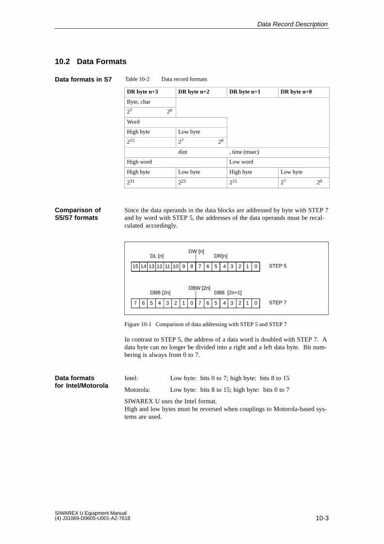
10-3SIWAREX U Equipment Manual(4) J31069-D0605-U001-A2-7618
10.2 Data Formats
Table 10-2 Data record formats
ÁÁÁÁÁÁÁÁÁÁÁÁ
DR byte n+3 ÁÁÁÁÁÁÁÁÁÁÁÁ
DR byte n+2 ÁÁÁÁÁÁÁÁÁÁÁÁ
DR byte n+1 ÁÁÁÁÁÁÁÁÁÁÁÁ
DR byte n+0ÁÁÁÁÁÁÁÁÁÁÁÁ
Byte, char ÁÁÁÁÁÁÁÁÁÁÁÁ
ÁÁÁÁÁÁÁÁÁÁÁÁ
ÁÁÁÁÁÁÁÁÁÁÁÁÁÁÁÁÁÁ
ÁÁÁÁÁÁ27 20ÁÁÁÁÁÁ
ÁÁÁÁÁÁÁÁÁÁÁÁÁÁÁÁÁÁ
ÁÁÁÁÁÁÁÁÁÁÁÁÁÁÁÁÁÁÁÁÁÁÁ
ÁÁÁÁÁÁÁÁÁÁÁWord ÁÁÁÁÁÁ
ÁÁÁÁÁÁÁÁÁÁÁÁÁÁÁÁÁÁÁÁÁÁÁÁ
ÁÁÁÁÁÁHigh byte ÁÁÁÁÁÁ
ÁÁÁÁÁÁLow byte ÁÁÁÁÁÁ
ÁÁÁÁÁÁÁÁÁÁÁÁÁÁÁÁÁÁÁÁÁÁÁÁ
ÁÁÁÁÁÁ215 ÁÁÁÁÁÁ
ÁÁÁÁÁÁ27 20ÁÁÁÁÁÁ
ÁÁÁÁÁÁÁÁÁÁÁÁÁÁÁÁÁÁÁÁÁÁÁÁ
ÁÁÁÁÁÁÁÁÁÁÁÁÁÁÁÁÁÁ
dint ÁÁÁÁÁÁÁÁÁÁÁÁ
, time (msec) ÁÁÁÁÁÁÁÁÁÁÁÁÁÁÁÁÁÁÁÁÁÁÁ
ÁÁÁÁÁÁÁÁÁÁÁHigh word ÁÁÁÁÁÁÁÁÁÁÁ
ÁÁÁÁÁÁÁÁÁÁÁLow word
ÁÁÁÁÁÁÁÁÁÁÁÁ
High byte ÁÁÁÁÁÁÁÁÁÁÁÁ
Low byte ÁÁÁÁÁÁÁÁÁÁÁÁ
High byte ÁÁÁÁÁÁÁÁÁÁÁÁ
Low byte
231 223 215 27 20
Since the data operands in the data blocks are addressed by byte with STEP 7and by word with STEP 5, the addresses of the data operands must be recal-culated accordingly.
891012131415 2356711 4
DL [n] DR[n]
1 0
DW [n]
STEP 5
0124567 235673 4
DBB [2n] DBB [2n+1]
1 0
DBW [2n]
STEP 7
Figure 10-1 Comparison of data addressing with STEP 5 and STEP 7
In contrast to STEP 5, the address of a data word is doubled with STEP 7. Adata byte can no longer be divided into a right and a left data byte. Bit num-bering is always from 0 to 7.
Intel: Low byte: bits 0 to 7; high byte: bits 8 to 15
Motorola: Low byte: bits 8 to 15; high byte: bits 0 to 7
SIWAREX U uses the Intel format.High and low bytes must be reversed when couplings to Motorola-based sys-tems are used.
Data formats in S7
Comparison ofS5/S7 formats
Data formatsfor Intel/Motorola
Data Record Description

10-4SIWAREX U Equipment Manual
(4) J31069-D0605-U001-A2-7618
10.3 Description of the Data Records
These basic parameters are transferred to the module by the applicable SI-MATIC system during startup. They contain settings which determine thebehavior of the module in the SIMATIC system. The basic parameters arestored in the SIWAREX U in a memory area which is not protected againstpower failure.
These parameters can be transferred via the SIMATIC or via the serial inter-face. The parameters are checked on the module for plausibility and, after apositive check, stored in a memory area which is protected against powerfailure . If a data record contains parameters which are not plausible, theentire data record is rejected (i.e., the data are not accepted by the SIWAREX U).
10.3.1 DR0: Basic Parameters (Write)
Table 10-3 DR0: Basic parameters (length: 4)
DRNo.
PNo.
Mode Parameter(Menu String)
Data Format
Value Range(Visible)
Value Range(Coding)
FactorySetting
ADRByte
ADRBit
0 1 BPAR Alarm generation
BYTE NO | YES 0|1 1 0 -
0 2 SPAR Alarm selection
BYTE (none) | diagnosis | process |
diagnosis+ process )
(0) | (1|2|3) 1 1 -
0 3 Not used by SIWAREX U -
0 4 0 Data interface BYTE SFC| I/O 0 | 1 0 4 -
BPAR: Parameter is a basic parameter.
SPAR: Parameter is a sub parameter.
10.3.2 DR1 - Parameter (Write)
Table 10-4 DR1 - Parameter (length: 16)
DRNo.
PNo.
Mode Parameter(Menu String)
Data Format
Value Range(Visible)
Value Range(Coding)
FactorySetting
ADRByte
ADRBit
1 5 In reserve 0
1 6-16 In reserve 0
Basic parametersDR0 and DR1
User-related parameters, starting with DR3
Data Record Description

10-5SIWAREX U Equipment Manual(4) J31069-D0605-U001-A2-7618
10.3.3 DR0: Diagnosis, Part 1 (Read)
Table 10-5 Diagnostic data
Byte Bit Meaning Remarks
0 0 Module error
1 Internal error
2 External error
3 Channel error exists
4 External auxiliary voltage missing
5 Not used, always 0
6 Parameterization missing
7 Wrong parameters on the module (EEPROM error here)
1 0to3
Module class 0101 = Analog module0000 = CPU1000 = Function module = SIWAREX U1100 = CP1111 = Digital module
4 Channel information exists
5 User information exists
6 Not used, always 0
7 Not used, always 0
2 0 Not used, always 0
1 Not used, always 0
2 Not used, always 0
3 Watchdog error
4 Not used, always 0
5 Not used, always 0
6 Not used, always 0
7 Not used, always 0
3 0 Not used, always 0
1 Not used, always 0
2 EPROM error
3 RAM error
4 ADC error (ADC error during read-access)
5 Not used, always 0
6 Process interrupt lost
7 Not used, always 0
Note
The data of DR0 are also available in the local data of OB82.
Data Record Description

10-6SIWAREX U Equipment Manual
(4) J31069-D0605-U001-A2-7618
10.3.4 DR1 - Diagnosis, Part 2 (Read)
Table 10-6 Diagnostic data
Byte Bit Meaning Remarks
4 0to6
Channel type
7 (Other channel type present) -
5 0to7
Number of diagnostic bits per channel All bits are used
6 0to7
Number of channels (Here 1 or 2)
7 0 Channel error, channel 0 (SIWAREX U: Weighing channel 1)
Channel-related error, see byte 9/10
1 Channel error, channel 1(SIWAREX U: Weighing channel 2)
2
3
4
5
6
7
8, 9 0 0 Byte 9 = channel 1
1 0 Byte 10 = channel 2
2 0
3 0
4 Min. voltage underranged on sense lines
5 0
6 Number overflow for gross weight
7 Measuring area exceeded
10-15 Not used (factory setting 0)
Data Record Description

10-7SIWAREX U Equipment Manual(4) J31069-D0605-U001-A2-7618
10.3.5 DR3: Adjustment Data, Channel 1
Table 10-7 DR3: Adjustment data, channel 1 (length: 10 bytes)
Meaning Byte Unit Format Factory Setting
Explanation
Zero setting value 0, 1 Digits WORD 0
Char. value, LC/filter setting/setting data
2, 3 - 16 x BOOL 0000 00000100 0001
Adjustment digit 0 4, 5 Digits WORD 0
Adjustment digit 1 6, 7 Digits WORD 0
Adjustment weight 8, 9 Weight INT 10000 -32768 to +32767
Data Record Description

10-8SIWAREX U Equipment Manual
(4) J31069-D0605-U001-A2-7618
Table 10-8 Char. value, LC/filter setting/setting data
Bit Meaning
15 14 13 12 11 10 9 8 7 6 5 4 3 2 1 0
Characteristic value of the load cell
0 0 ≤ 1 mV/V
0 1 ≤ 2 mV/V (factory setting)
1 0 ≤ 4 mV/V
1 1 In reserve
Decimal point for remote display
0 0 0 Decimal point 0 (factory setting)
0 0 1 Decimal point 1
0 1 0 Decimal point 2
0 1 1 Decimal point 3
1 0 0 Decimal point 4
1 0 1 Decimal point 5
Filter setting
0 0 0 Not filtering
0 0 1 Limit frequency: 5 Hz
0 1 0 Limit frequency: 2 Hz (factory setting)
0 1 1 Limit frequency: 1 Hz
1 0 0 Limit frequency: 0.5 Hz
1 0 1 Limit frequency: 0.2 Hz
1 1 0 Limit frequency: 0.1 Hz
1 1 1 Limit frequency: 0.05 Hz
Average value filter
0 Average value filter disabled(factory setting)
1 Average value filter enabled
Data to EEPROM(Only applicable to limit values andzero setting value via command)
0 Store in EEPROM(factory setting)
1 Store only in RAM
Channel in operation
0 Channel enabled
1 Channel disabled
Data Record Description

10-9SIWAREX U Equipment Manual(4) J31069-D0605-U001-A2-7618
10.3.6 DR4: Adjustment Data, Channel 2
Table 10-9 DR4: Adjustment data, channel 2 (for two-channel modules only) (length: 10 bytes)
Meaning Unit Format FactorySetting
Explanation
- Allocation same as DR3 -
10.3.7 DR5: General Parameters (Regardless of Channel)
Table 10-10 DR5: General parameters (length: 6 bytes)
Meaning Byte Unit Format FactorySetting
Explanation
Module number 0 BYTE 0
Interface parameters 1 BYTE 0
Type of remote display 2 BYTE 0
Allocation, LED 1 3 BYTE 101 Limit 1, channel 1
Allocation, LED 2 4 BYTE 102 Limit 2, channel 1
In reserve 5 BYTE 0
Table 10-11 TTY/RS 232C interface parameters (fixed: 8 data bits, 1 stop bit, 9600 baud)
Bit No. Reset Set
0 With parity bit (default setting) Without parity bit
1 Even parity (default setting) Odd parity
2 In reserve
3 In reserve
4 In reserve
5 In reserve
6 In reserve
7 In reserve
Table 10-12 Type of remote display
Code (Dec.) Meaning
0 No remote display
1 4-position remote display
2 5-position remote display
3 6-position remote display
Data Record Description

10-10SIWAREX U Equipment Manual
(4) J31069-D0605-U001-A2-7618
Table 10-13 Allocation of LED 1 or LED 2
Code(Hex.)
Code(Dec.)
Status Channel
64 100 Channel error Channel 1
65 101 Limit value 1 Channel 1
66 102 Limit value 2 Channel 1
67 103 Scales adjusted Channel 1
C8 200 Channel error Channel 2
C9 201 Limit value 1 Channel 2
CA 202 Limit value 2 Channel 2
CB 203 Scales adjusted Channel 2
10.3.8 DR6: Specified Values, Remote Display
Table 10-14 DR6: Specified values, remote display (length: 4 bytes)
Meaning Byte Unit Format FactorySetting
Explanation
Specified value 1 0, 1 INT 0
Specified value 2 2, 3 INT 0
Data Record Description

10-11SIWAREX U Equipment Manual(4) J31069-D0605-U001-A2-7618
10.3.9 DR11: Commands, Channel 1
Table 10-15 DR11: Commands, channel 1 (length: 2 bytes)
Meaning Unit Format FactorySetting
Explanation
Command word - WORD 0
Table 10-16 Possible entries, command word
Code (Dec.) Meaning
0 No command (Synchronous errors are deleted)
1 Set as zero
2 Adjust
3 Move zero point (set to zero)
4
5 Load factory setting (affects both channels of a two-channel SIWAREX U)
100 100 msec measuring cycle, sevice command, starting with release status5 (affects both channels of a two-channel SIWAREX U)
Data Record Description

10-12SIWAREX U Equipment Manual
(4) J31069-D0605-U001-A2-7618
10.3.10 DR12: Commands, Channel 2
Table 10-17 DR12: Commands, channel 2 (for two-channel modules only) (length: 2 bytes)
Meaning Unit Format FactorySetting
Explanation
- Allocation same as DR11 -
10.3.11 DR21: Limit Values, Channel 1
Table 10-18 DR21: Limit values, channel 1 (length: 8 bytes)
Meaning Byte Unit Format FactorySetting
Explanation
Limit value 1 ON 0, 1 Weight INT 10000
Limit value 1 OFF 2, 3 Weight INT 9990
Limit value 2 ON 4, 5 Weight INT 1000
Limit value 2 OFF 6, 7 Weight INT 1010
10.3.12 DR22: Limit Values, Channel 2
Table 10-19 DR22: Limit values, channel 2 (for two-channel modules only) (length: 8 bytes)
Meaning Byte Unit Format FactorySetting
Explanation
Limit value 1 ON 0, 1 Weight INT 10000
Limit value 1 OFF 2, 3 Weight INT 9990
Limit value 2 ON 4, 5 Weight INT 1000
Limit value 2 OFF 6, 7 Weight INT 1010
Data Record Description

10-13SIWAREX U Equipment Manual(4) J31069-D0605-U001-A2-7618
10.3.13 DR31: Measured Values/Status/Error, Channel 1
Table 10-20 DR31: Measured values/status/error, channel 1 (length: 10 bytes)
Meaning Byte Unit Format FactorySetting
Explanation
Gross 0, 1 Weight INT - -32768 to +32767
Status 2 8 x BOOL -
Measured value update counter 3 BYTE - Starting with releasestatus 5
Current digit value (filtered) 4, 5 Digits WORD - 0 to 65535
Asynchronous error 6, 7 16 x BOOL -
Synchronous error 8, 9 16 x BOOL -
10.3.14 DR32: Measured Values/Status/Error, Channel 2
Table 10-21 DR32: Measured values/status/error, channel 2 (length: 10 bytes)
Meaning Byte Unit Format FactorySetting
Explanation
Gross 0, 1 Weight INT - -32768 to +32767
Status 2 8 x BOOL -
Measured value update counter 3 BYTE - Starting with releasestatus 5
Current digit value (filtered) 4, 5 Digits WORD - 0 to 65535
Asynchronous error 6, 7 16 x BOOL -
Synchronous error 8, 9 16 x BOOL -
Contains current status information
Table 10-22 Status byte
BitNo.
Designation Bit = 0 Bit = 1
0 Asynchronous error(group error)
No internal/external error Internal/external error
1 Synchronous error No error occurred duringlast write-access
An error occurred duringlast write-access
2 Limit value 1 Limit value 1 not active Limit value 1 active
3 Limit value 2 Limit value 2 not active Limit value 2 active
4 Scales adjusted Scales not adjusted Scales adjusted
Status byte
Data Record Description

10-14SIWAREX U Equipment Manual
(4) J31069-D0605-U001-A2-7618
Table 10-22 Status byte
BitNo.
Bit = 1Bit = 0Designation
5 Measured value updatebit
Is inverted each time the SIWAREX U updates itsmeasured value (starting with release status 5)
6 Life bit Only used for I/O communication
7 Job acknowledgmentbit
Only used for I/O communication
Can happen any time
Are automatically deleted when error disappears
Several errors can be queued at the same time.
Table 10-23 Asynchronous errors
BitNo.
Designation Bit = 0 Bit = 1
0 Control limit ADC1) Not exceeded Exceeded
1 Minimum voltage on senseline 1)
Not underranged Underranged
2 Watchdog Has not been triggeredHas been triggered
3 Error in EPROM (program) Does not exist Exists
4 Error in EEPROM (data) Does not exist Exists
5 RAM error (read/write error) Does not exist Exists
6 ADC error during read-access
Does not exist Exists
7 Number overflow for grossweight 1)
Does not exist Exists
8 Ext. supply voltage (24 V) Is available Is not available
9 In reserve
10 In reserve
11 In reserve
12 In reserve
13 In reserve
14 In reserve
15 In reserve
1) These errors are only reported for the specific channel. The other errors are enteredfor both channels.
Asynchronous errors
Data Record Description

10-15SIWAREX U Equipment Manual(4) J31069-D0605-U001-A2-7618
Can occur after command input
Are reported in DR31, 32 and 76 only on the interface which caused thesynchronous error
Are only output to the interface via which the applicable job arrived
This DR is not updated again until a new command is issued or a resetoccurs.
Table 10-24 Synchronous error
BitNo.
Bit = 0 Bit = 1
0 - Adjustment command could not be executed since distance to ad-justment points is too small.
1 - Job could not be executed due to malfunction.
2 - A non-existent or inactive channel was addressed.
3 - Code not defined (e.g., limit frequency, digital filter and so on)
4 - Data record/identifier unknown
5 - Command not possible since scales not adjusted
6 - Wait time of 5 sec not adhered to during adjustment commands
7 - The adjustment weight is negative.
8 - In reserve
9 - In reserve
10 - In reserve
11 - In reserve
12 - In reserve
13 - In reserve
14 - In reserve
15 - In reserve
10.3.15 DR40: Version/Checksum/Switches
Table 10-25 DR40: Version/checksum/switches (length: 8 bytes)
Meaning Byte Unit Format FactorySetting
Explanation
Version 0, 1 WORD - FW version
Checksum 2, 3 WORD - 0 to 65535
In reserve 4 8 x BOOL -
Module type 5 BYTE 1/2 Depends on number of channels
In reserve 6, 7 INT -
Synchronous errors
Data Record Description

10-16SIWAREX U Equipment Manual
(4) J31069-D0605-U001-A2-7618
10.3.16 DR57 to 79: Data Records for I/O Area
Table 10-26 DR57 to 79: Data records for I/O area (S5 data records)
DRNo.
Meaning Unit Format FactorySetting
Explanation
57 Commands Digit WORD 0
58 Module number Digit CHAR 0
59 Interface parameters Digit BOOL 0
60 Adjustment digits 0 Digit WORD 0
61 Adjustment digits 1 Digit WORD 0
62 Adjustment weight Weight INT 1000
63 LED allocation Code 2 x BYTE 101102
64 Zero setting value Digit WORD 0
65 Characteristic value, LC/filter setting/setting data
16 x BOOL 0000 00000100 0001
66 Limit value 1 ON Weight INT 10000
67 Limit value 1 OFF Weight INT 9990
68 Limit value 2 ON Weight INT 1000
69 Limit value 2 OFF Weight INT 1010
70 Specified value 1 for remote display - INT 0
71 Specified value 2 for remote display - INT 0
72 Type of remote display - WORD 0 Only low byte used
73 Current digit value Digit WORD - 0 to 65535
74 Gross Weight INT - -32768 to +32767
75 Asynchronous errors - 16 x BOOL -
76 Synchronous errors - 16 x BOOL -
77 Version - WORD -
78 Checksum - WORD -
79 Reserved - BOOL -
The setup of data records DR57 to DR78 is similar to the setup of data re-cords DR3 to DR40.
Example:For DR65, see setup of byte 2–3 of DR3.
Setup of data re-cords DR57 to 78
Data Record Description

10-17SIWAREX U Equipment Manual(4) J31069-D0605-U001-A2-7618
10.3.17 DR100: Fetch Telegram
Table 10-27 DR100: Fetch telegram (length: 1 byte)
Meaning Format Factory Setting
Number of request data record BYTE 0
10.3.18 DR101: Acknowledgment Telegram
Table 10-28 DR101: Acknowledgment telegram (length: 3 bytes)
Meaning Format Factory Setting
No. for acknowledged data record (0 forerror type 60hex)
BYTE 0
Type of error BYTE 0
Error number (See also section 13) BYTE 0
Table 10-29 Error types in the acknowledgment telegram
Code Meaning
00 hex No error
40 hex Synchronous errors (handling or data errors)
60 hex Transmission error
The error number is only valid for the “synchronous error” type of error andcorresponds to the less significant byte of the synchronous error word.
Error number
Data Record Description

10-18SIWAREX U Equipment Manual
(4) J31069-D0605-U001-A2-7618
Data Record Description

11-1SIWAREX U Equipment Manual(4) J31069-D0605-U001-A2-7618
Optional Components
Optional components are external devices such as remote displays and so on.
The figure below shows how external devices can be connected.
Operator panel
Remote display
PC
PS S7-300
RS 485 TTYRS 232C
SIWAREX U
MPI bus
CPU
Figure 11-1 Connection of optional components
A remote display can be connected to the TTY interface. A PC can be con-nected to the RS 232 interface for commissioning purposes, or a host can beconnected.
11

11-2SIWAREX U Equipment Manual
(4) J31069-D0605-U001-A2-7618
11.1 Connection of Digital Remote Displays
Digital remote displays can be connected to the TTY interface of theSIWAREX U. The SIWAREX U contains an appropriate protocol for con-nection of digital remote displays. All digital remote displays which supportthis protocol and are equipped with a TTY interface can be connected to theSIWAREX U. 4-digit, 5-digit and 6-digit remote displays are supported.
Note
It is the user’s responsibility to determine whether the digital remote displaychosen actually supports this protocol. Siemens AG accepts no liability fordamage caused by connection of remote displays.
The documentation of the remote display manufacturer must be adhered to.
WeightScale 1
TTY
SIWAREX UWEIGHING MODULE SF
24VST1ST2
7MH4601-1BA01
21 3X
WeightScale 2
Specified value 1
Specifiedvalue 2
Figure 11-2 Example: Connection of 4 digital remote displays to the SIWAREX U
The following values can be indicated on a digital remote display:
Gross weight value, weighing channel 1
Gross weight value, weighing channel 2 (for two-channel SIWAREX Uonly)
Specified value 1 (can be assigned as desired via SIMATIC)
Specified value 2 (can be assigned as desired via SIMATIC)
The value to be indicated is set on the remote display.
Introduction
Description
Value output
Optional Components

11-3SIWAREX U Equipment Manual(4) J31069-D0605-U001-A2-7618
Note
Since the specified values are stored in the RAM of the SIWAREX U, thespecified values must be supplied again by the SIMATIC CPU after a powerOFF/ON.
When special operating states occur (e.g., the indication range of the remotedisplay is exceeded), the SIWAREX U sends appropriate ASCII charactersvia the protocol. If the remote display can indicate these ASCII characters,the special operating state is indicated on the remote display. See also cha-racter set used for display data, table 5-8.
Table 11-1 Special operating states
Indication Description
“_ _ _ _ _” The indication range of the remote display has been exceeded(e.g., 11.456 kg cannot be shown on a 4-digit display).
“E r r” The SIWAREX U reports a system error SF
(e.g., EEPROM error).
“_ _ _ _ _”
or
“≡ ≡ ≡ ≡ ≡”
Timeout function for monitoring the serial connection for wirebreak. This function must be included in the remote display.The function is indicated differently depending on the type ofdisplay.
The connection to the remote display is made with the free-floating TTY in-terface of the SIWAREX U (via 20-way multipoint connection strip). Theinterface is unidirectional (i.e., the weight values are transferred cyclically tothe remote display(s)).
Several digital remote displays can be connected to the SIWAREX U.
Example: Connection of two remote displays, remote display 2 active.
TxD+
(Pin 6)
TxD-
(Pin 7)
RXD-
RXD+
RXD-
RXD+
20mA/R
M/R
Display 1
(passive)
Display 2
(active)SIWAREX U(passive)
< 1000 m(e.g.: LIYCY 2x2x0.5mm2)
Figure 11-3 Connection of remote displays
Special operatingstates
Connection of theremote displays
Optional Components

11-4SIWAREX U Equipment Manual
(4) J31069-D0605-U001-A2-7618
Table 11-2 Pin assignment of the TTY interface
Connection Assignment of the TTY Interface
Pin Signal Name
6 TxD2+ Sending data + of SIWAREX U
7 TxD2- Sending data - of SIWAREX U
For pin assignment of the remote display, see the documentation of your re-mote display.
Note
Pin assignment of the remote displays may differ depending on the manufac-turer. For example, S+/S- is used for sender power, and TX+/TX-/RX+/RX-is used for sender or receiver lines. Some remote displays use the 24 V con-nection instead of 20 mA/R and GND instead of M/R since these types ofremote displays are equipped with constant current control which limits thecurrent on the TTY interface. For details, see the documentation of yourremote display.When several remote displays are to be connected to the TTY interface ofthe SIWAREX U, we recommend asking the manufacturer of the remotedisplays whether the power capacity of the active remote display is suffi-cient.
4-digit, 5-digit and 6-digit displays can be connected to theSIWAREX U. Selection of the display to be connected is made in the appro-priate data record via the SIMATIC or via SIWATOOL.
The number of positions set applies to all remote displays connected to theTTY interface.
In addition, the specified values can be specified via the SIMATIC.
Table 11-3 Remote display
Function Data Record, Channel 1 (Channel 2) Format Comments
S5 S7
DRNo.
DRNo.
DRByte
DRBit
Length(Byte)
Number of posi-tions of the re-mote display
72 5 2 6 BYTE Selection code (dec.)
No indication = 0 (*)
4-position indication = 1
5-position indication = 2
6-position indication = 3
Specified value 1for remote dis-play
70QB6, 7
6 0 6 INT 0 (*)
Assignment
Settings on theSIWAREX U
Optional Components

11-5SIWAREX U Equipment Manual(4) J31069-D0605-U001-A2-7618
Table 11-3 Remote display
Function CommentsFormatData Record, Channel 1 (Channel 2)
S7S5
Length(Byte)
DRBit
DRByte
DRNo.
DRNo.
Specified value 2for remote dis-play
71QB14, 15
6 2 6 INT 0 (*)
Interface parame-ters for RS 232Cand TTY inter-face
59 5 1 6 BYTE Bit0=0: With parity (*)
Bit0=1: Without parity
Bit1=0: Even parity (*)
Bit1=1: Odd parity
(*) Factory setting
When the type of indication is set via data record 5 or 72 (parameters notdependent on the channel), the indication data are output on the TTY inter-face every 100 msec.
Gross, scales 1 Spec. value 1 Gross, scales 2 Spec. value 2
After 100 msec After 100 msec After 100 msec
After 100 msec
When a digital remote display is connected to the SIWAREX U, settingsmust be made on the remote display. The number of settings depends on theremote display used.
For detailed information on the parameterization of remote displays, see thedocumentation of the manufacturer of your remote display.
Table 11-4 Settings of the remote display
Meaning Setting
Interface TTY
Data format 8 bit
Parity Even/odd/without
Baud rate 9600 Baud
Protocol STX/ETX
Protocol response None
Ignore characters (See protocol layout) Ignore one character
Address length 2 positions
Output of the indication data
Settings on the re-mote display
Optional Components

11-6SIWAREX U Equipment Manual
(4) J31069-D0605-U001-A2-7618
Table 11-4 Settings of the remote display
Meaning Setting
Address Gross value, channel 1 = 01Specified value 1 = 05Gross value, channel 2 = 21Specified value 2 = 06
Timeout Example: timeout after 2 sec
Decimal point No decimal point
Leading zeros Leading zeros are indicated.
Segment test If present on the remote display, segmenttest should be enabled.
Depending on the remote display selected, the weight value can be indicatedwith 4, 5 or 6 digits. When negative values are involved, the minus signtakes up one of the positions.
Example of a 5-digit display with 2 positions after the decimal point: Display range -99.99 to 999.99.
When the number range which can be represented is exceeded, this is shownby “- - - -”.
The following configurations should be avoided when representing outputvalues since negative values cannot be represented otherwise.
Table 11-5 Number range which can be indicated on the remote display
Remote Display Type Number of Positions Con-figured after the DecimalPoint
Example
4-digit remote display 3 positions after the decimalpoint
0.123
-0.123 cannot be representedsince 5 positions required.
5-digit remote display 4 positions after the decimalpoint
0.1234
-0.1234 cannot be representedsince 6 positions required.
6-digit remote display 5 positions after the decimalpoint
0.12345
-0.12345 cannot be represen-ted since 7 positions required.
Number rangewhich can berepresented
Optional Components

11-7SIWAREX U Equipment Manual(4) J31069-D0605-U001-A2-7618
Weight valuesThe position of the decimal point can be specified via SIWATOOL or via theSIMATIC separately for weight channel 1 and weight channel 2.The decimal point position is kept static. After a decimal point position hasbeen parameterized, it is transferred with the protocol. When several remotedisplays are used, the decimal point position can be set individually on someremote displays by not specifying a decimal point position for theSIWAREX U. The desired decimal point position must then be set directlyon the remote display.
Specified valueThe SIWAREX U always transfers the specified values to the remotedisplay(s) without a decimal point. If you want to have a decimal point indi-cated, this must be set on the remote display.
An address must be set on each display (e.g., by using the appropriate para-meterization menu of the display). The address determines the value to beindicated.
The following settings are possible
Table 11-6 Assignment of the addresses on the remote display
AddressASCII coded 1)
Remote Display Data
01 Gross value, channel 1
05 Specified value 1
06 Specified value 2
21 Gross value, channel 2
1) Since the address is represented as ASCII characters in the remote display protocol,address “01” corresponds to the ASCII characters 30h and 31h.
The layout of the protocol will now be described. All digital remote displayswhich can be connected electrically to the SIWAREX U and which can beoperated with the described protocol can be used with the SIWAREX U.
Description of the protocolData format: 8 bits, 1 stop bitBaud rate: 9600 BaudProtocol: STX/ETX without protocol responseAddressing: 2 bytes for addressing the displays
Position of the de-cimal point
Addressing
Protocol layout
Optional Components

11-8SIWAREX U Equipment Manual
(4) J31069-D0605-U001-A2-7618
Table 11-7 Description of the string layout
Byte No. Contents Commentary/Example
4-DigitDisplay
5-DigitDisplay
6-DigitDisplay
HEX(Ex.)
1 1 1 STX 02 02h
2 2 2 Address 30 2 digits, ASCII-coded
3 3 3 Address 31 (can be parameterized ondisplay)
4 4 4 Reserved 20 Blank
5 5 5 1st digit 35 Weight value channel 1, 2Specified value 1, 2
6 6 6 2nd digit 34
7 7 7 Decimal point 2C (*)
8 8 8 3rd digit 33
9 9 9 4th digit 32
Blank 10 10 5th digit 31
Blank Blank 11 6th digit 30
12 12 12 Reserved 20 Blank
13 13 13 Reserved 20 Blank
14 14 14 Reserved 20 Blank
15 15 15 ETX 03
(*) Position depends on the decimal point position parameterized for SIWAREX U.If no decimal point is parameterized, the data string has one byte less.
Table 11-8 Character set used for display data
Character Hexadecimal Code Commentary
Digits 0 to 9 30 to 39 Representation of the digits
Minus sign “-” 2D Sign for negative values
Underline “_” 5F For “range exceeded” - indicated inall character positions
Decimal point 2C Decimal point representation
Blank 20 For blanking out characters
Letter E
Letter r
45
72
For error display:
“Error”
STX 02 Protocol control character for start ofdata string
ETX 03 Protocol control character for end ofdata string
Optional Components

11-9SIWAREX U Equipment Manual(4) J31069-D0605-U001-A2-7618
Digital remote displays from the company Siebert Industrieelektronik GmbHcan be directly connected to the SIWAREX U via the TTY interface.
Remote displays which can be used:-S10/SX10-S30-S70 (with option 97/16)-S300
Siebert Industrieelektronik GmbHPostfach 1180D-66565 EppelbornTel: +49 (0) 6806/980-0Fax: +49 (0) 6806/980-111Internet: http://www.siebert.de
Contact the manufacturer for detailed information.
Digital remote displays from the company Link Electronics GmbH can bedirectly connected to the SIWAREX U via the TTY interface.
The remote displays (types FA14 and FA20) are equipped with a push buttonwhich can be used to switch between weight value cannel 1, weight valuecannel 2, specified value 1 and specified value 2.
Remote displays which can be used:Remote displays for Siemens mosaic technology M25 and M50 x 25(grid dimensions: 25 x 25 mm)-FA7
Remote displays with push button-FA14-FA20
Link Electronics GmbHBahnhofstr. 18D-76764 RheinzabernTel: +49 (0) 7272/7000-0Fax: +49 (0) 7272/7000-27
Contact the manufacturer for detailed information.
Siebert remotedisplays
Link Electronicsremote displays
Optional Components

11-10SIWAREX U Equipment Manual
(4) J31069-D0605-U001-A2-7618
11.2 Ex-i Interface for SIWAREX U
An Ex-i interface must be switched between the SIWAREX U and the forceand pressure sensors when these sensors are located in potentially explosiveareas. The Ex-i interface SIWAREX Pi or SIWAREX IS is used for this pur-pose. This interface can be used for the SIWAREX U, P, M.
When the two-channel model of the SIWAREX U is used, each measuringchannel requires an Ex-i interface.
The Ex-i interface makes the 6 lines for connection of a load cell (i.e., sup-ply, sense and measuring lines) intrinsically safe in accordance with ignitionprotection type [EEx ib] IIC. ATEX approval certifies that pertinent stan-dards and regulations have been complied with.
!Danger
The safety of the potentially explosive area is dependent on this device.Only qualified personnel may perform the required connection and installa-tion work.
In case of non-adherence:
D A N G E R O F E X P L O S I O N !
Description
Optional Components

11-11SIWAREX U Equipment Manual(4) J31069-D0605-U001-A2-7618
11.2.1 Layout
The Ex-i interface provides 6 safety barriers.
Two voltage limiters and 2 active current limiters are provided for each of thetwo supply lines.
Two voltage limiters and 2 passive current limiters are provided for each ofthe measured value lines and sense lines.
Supply lines
Senselines
Measuredvalue lines
Voltage limiter
Intrinsi-cally safe area
Currentlimiter(active)
1 4
2 5
3 6
Shield Shield
Voltage limiter
Voltage limiter
Currentlimiter(passive)
Currentlimiter(passive)
Figure 11-4 Diagram of the Ex-i interface
Optional Components

11-12SIWAREX U Equipment Manual
(4) J31069-D0605-U001-A2-7618
Optional Components

12-1SIWAREX U Equipment Manual(4) J31069-D0605-U001-A2-7618
SIWATOOL - Description and Use
SIWATOOL is used for error diagnostics and to parameterize and commis-sion the SIWAREX U. SIWATOOL can be started with Windows andSTEP 7.
SIWATOOL permits several SIWAREX U modules to be processed at thesame time.
However, only one SIWAREX U module can be parameterized online at thesame time.
When several scales are parameterized, the individual parameterization win-dows of several offline modules and one online module can be indicated si-multaneously on the monitor screen.
This makes it easy to adjust parameters of different modules to each other, orcompare them.
SIWATOOL runs under WINDOWS. It uses the typical WINDOWS environ-ment and structure.
WINDOWS users will have no trouble using SIWATOOL. Its well-organizedpull-down menus make it almost self-explanatory. On-line aids provide sup-port when commissioning the scales.
The status of the scales can be used as a diagnostic tool or for error diagnos-tics.
Purpose
Use
12

12-2SIWAREX U Equipment Manual
(4) J31069-D0605-U001-A2-7618
12.1 Installing SIWATOOL on PC/PG
The following requirements apply to the installation and use of SIWATOOL.
PC (processor 80486 or later)
Working storage (min. of 4 Mbytes)
Windows 95/98/NT/ME/2000
Hard disk (10 Mbytes free memory space)
Free serial interface (COM n)
Proceed as follows to install SIWATOOL:
1. Place the installation CD (SIWAREX U configuration package) in the drive.
2. Call the installation program via the Windows Explorer.
– SETUP.EXE is located in the “SIWATOOL” directory
3. Specify the installation directory and a program group.
4. Setup is now performed automatically.
Figure 12-1 S7 setup
Requirements
Installation
SIWATOOL - Description and Use

12-3SIWAREX U Equipment Manual(4) J31069-D0605-U001-A2-7618
12.2 Commissioning SIWAREX U with SIWATOOL
If your SIWAREX U is to be commissioned online, the SIWAREX U must beconnected to the PC or PG (i.e., programmer) with a suitable, serial interfacecable (order no. 7MH4 607-8CA).
Call SIWATOOL:
Double click the program icon
Or double click SIWATOOL.EXE in Explorer
After the interface has been selected, a new set of scales can be set up via themenu command “File > New”. The scales names and units of weights mustbe set. The numbers 0 to 15 may be used as module numbers.
Note
Every SIWAREX U can be addressed with module number “0” regardless ofwhich module number is assigned to it.
If, for example, the module number “4” was assigned to a SIWAREX U, thisSIWAREX U can be addressed under module number “0” and “4”.
On delivery, the module number for the SIWAREX U has been set to “0” atthe factory. This means that the module number must always be specified as“0” during initial commissioning. The module number can then be changedlater in the menu.
After SIWATOOL has been started, the serial interface used on the PC/PG(e.g., COM1) must be set via the menu command “Option > Select Inter-face”.
Start SIWATOOL
Set up newscales
Select interface
SIWATOOL - Description and Use

12-4SIWAREX U Equipment Manual
(4) J31069-D0605-U001-A2-7618
After the new set of scales has been set up, the message “No communication”appears in the status bar. To establish communication, the serial RS 232 in-terface must now be set via the menu command “Option > Select Parity”.
Factory setting of SIWAREX U: Even parity
The menu command “Module > Connect” causes the PC to establish commu-nication with the SIWAREX U. The message “offline” disappears, and ameasured value is indicated.
If the SIWAREX U has not been adjusted yet, the measured value is still“frozen” (i.e., it does not change when the scales are loaded).
Note
Even if the parity of the RS 232 interface has been set incorrectly, SIWATOOL determines the correct interface setting automatically. If com-munication cannot be established after 20 seconds, check the following.
The wiring
The COM setting (COM1, COM2 ...)
The module number
Set interface
Activate communication
SIWATOOL - Description and Use

12-5SIWAREX U Equipment Manual(4) J31069-D0605-U001-A2-7618
12.3 SIWATOOL Menu Tree
After a new set of scales has been set up, the main menu bar is displayed.The main menu bar contains the following submenus.
Help ContentsAbout
View Error ReportToolbarStatus Bar
Option Select InterfaceSelect Parity
File NewOpenSaveSave As...ClosePrintPrint PreviewPrinter SetExit
Edit CutCopyDelete
Module ConnectDisconnectRead All DataSend All DataDigit ValuesRead Memory
Window ArrangeArrange Icons
CascadeHorizontallyVertically
SIWATOOL - Description and Use

12-6SIWAREX U Equipment Manual
(4) J31069-D0605-U001-A2-7618
12.4 Adjustment of the Scales
Before adjusting the scales, you should always know the number of positionsafter the decimal point since it determines the available resolution (see alsosection 12.5).
Use the button to access the “Adjustment Data” dialog.
Figure 12-2 Dialog on scales adjustment
When a new adjustment is to be performed, the factory settings should al-ways be loaded first (“Factory” button).
The number of positions after the decimal point should then be specifiedsince the format of all other entries are based on this factor.
As the next step, enter the adjustment weight. These values are transferred tothe SIWAREX U by activating the Send button.
Note
Decimal points are indicated as “.” in SIWATOOL.
New adjustment
SIWATOOL - Description and Use

12-7SIWAREX U Equipment Manual(4) J31069-D0605-U001-A2-7618
Adjustment with a test weight is described in detail in section 3.3.
Proceed as follows with SIWATOOL.
Enter characteristic value, decimal point and adjustment weight and thenpress the “Send” button.
Empty the scales, and activate the “Set as Zero” button.
Load the scales with the test weight, and activate the “Adjust” button.
The adjustment digits “0” and “1” are not indicated by SIWATOOL until thescales are in adjusted status (i.e., both the zero point and the adjustmentweight have been declared valid).
Theoretical adjustment is also described in section 3.3.
After the scales have been adjusted, you can then enter the remaining settings(e.g., filter and so on).
Clicking the “Send” button sends the settings entered with SIWATOOL to theSIWAREX U.
In reverse, the parameters set in SIWAREX U can be sent to SIWATOOL byclicking the “Receive” button.
Adjust with testweight
Theoretical adjust-ment
Other settings
SEND
RECEIVE
SIWATOOL - Description and Use

12-8SIWAREX U Equipment Manual
(4) J31069-D0605-U001-A2-7618
12.5 Important Notes on Settings in SIWATOOL
The decimal point only applies to the remote displays. The weighing valuesare represented as fixed point numbers without decimal point on the S7 busand the serial interfaces.
Example:
If the decimal point XX.XXX is set via SIWATOOL, a weighing value is in-dicated by SIWATOOL as 4,123 kg for example, and as the fixed point num-ber 4123 by the SIMATIC.
(The weight values are shown on a remote display as they are shown inSIWATOOL.)
The setting of the number of positions after the decimal point determines theresolution available.
Table 12-1 Example
AdjustmentWeight
MeasuringRange
DigitIncrement
Resolutionin g
Resolution ofMeasuring Range
100 kg 0 to 200 kg 1 1000 g 200 parts
100.00 kg 0 to 200.00 kg 1 10 g 20,000 parts
Changing the decimal point later may mean that you will also have to makechanges on the SIMATIC side.
Module number
Interface parameters
Indication type
Allocation of the LEDs
are parameterized in different SIWATOOL screens but are all stored in datarecord DR5 of the SIWAREX U.
Remember that these 4 settings can only be read and written together.
Example:
When the indication type is written to the SIWAREX U, the module number,interface parameters and LED allocation are also written to the SIWAREX U.
Decimal point
Special case, DR5
SIWATOOL - Description and Use

12-9SIWAREX U Equipment Manual(4) J31069-D0605-U001-A2-7618
12.6 Weighing Status
The status window can be used to view the weighing status of theSIWAREX U.
Figure 12-3 Status window of the set scales
Functions of the function keys (from left to right)
1st function key: Set new weighing parameters
2nd function key: Load weighing parameters
3rd function key: Store weighing parameters
4th function key: Print
5th function key: Indicate program information
6th function key: Error report
The weighing status and the weighing value are displayed on the monitorscreen.
SIWATOOL - Description and Use

12-10SIWAREX U Equipment Manual
(4) J31069-D0605-U001-A2-7618
12.7 Diagnostic Capabilities with SIWATOOL
When an online connection exists, the synchronous errors triggered bySIWATOOL actions are indicated in an online error report. “Cut” or “De-lete” can be used to delete the synchronous errors from the error report. Cur-rently queued asynchronous errors are also indicated in the online error re-port. The error status of the SIWAREX U (i.e., group errors) is also indicatedin the main window.
During online operation, SIWATOOL acquires and logs the errors of the sca-les.
The online error report is indicated by clicking on .
Figure 12-4 Online error report
The menu command “Help > About” can be used to read the firmware ver-sion of the SIWAREX U. In addition, the software status of SIWATOOL isindicated. Before contacting our hotline for technical problems, please read:
1. The firmware version of SIWAREX U
2. The software status of SIWATOOL
This function is only used by the Siemens hotline for service purposes.
Error handling
Online error report
Versioninformation
Read memory
SIWATOOL - Description and Use

13-1SIWAREX U Equipment Manual(4) J31069-D0605-U001-A2-7618
Error Diagnostics and Treatment
The SIWAREX U supports the user during commissioning and trouble-shooting with a structured diagnostic concept. The malfunction and errormessages are divided into various classes of errors.
When an error causes the SIWAREX U to switch to FAULT operating mode,no weighing commands are possible. This operating mode is retained untilthe fault has been corrected. An error acknowledgment is not required.
In this state, a command is rejected with an error message. Reading andwriting of data records is still possible if the type of error permits.
Internal errors and external errors cause the group error status ( SF LEDgoes on). The module switches to FAULT operating mode.
FAULT operating mode is exited automatically after the fault has been cor-rected (e.g., A/D converter, control level limit exceeded).
The following table provides an overview of the various types of fault anderror messages and their differences.
Table 13-1 Types of errors
Type of Error Description
ÁÁÁÁÁÁÁÁÁÁÁÁÁÁ
Data errors (synchronous error) (*)
ÁÁÁÁÁÁÁÁÁÁÁÁÁÁÁÁÁÁÁÁÁÁÁÁÁÁÁÁÁÁ
Plausibility errors which occur when parameters and pre-specified values are transferred
ÁÁÁÁÁÁÁÁÁÁÁÁÁÁÁÁÁÁÁÁÁ
Handling errors(synchronous error) (*)
ÁÁÁÁÁÁÁÁÁÁÁÁÁÁÁÁÁÁÁÁÁÁÁÁÁÁÁÁÁÁÁÁÁÁÁÁÁÁÁÁÁÁÁÁÁ
Errors which occur while a command is being executed.The command is then not executed.
ÁÁÁÁÁÁÁÁÁÁÁÁÁÁÁÁÁÁÁÁÁ
Internal errors(asynchronous error)
ÁÁÁÁÁÁÁÁÁÁÁÁÁÁÁÁÁÁÁÁÁÁÁÁÁÁÁÁÁÁÁÁÁÁÁÁÁÁÁÁÁÁÁÁÁ
Hardware errors which can be detected by the module andwhich are reported
ÁÁÁÁÁÁÁÁÁÁÁÁÁÁ
External errors(asynchronous error)
ÁÁÁÁÁÁÁÁÁÁÁÁÁÁÁÁÁÁÁÁÁÁÁÁÁÁÁÁÁÁ
Errors of the connected periphery (hardware errors)
ÁÁÁÁÁÁÁÁÁÁÁÁÁÁÁÁÁÁÁÁÁ
Other errors(section 13.2)
ÁÁÁÁÁÁÁÁÁÁÁÁÁÁÁÁÁÁÁÁÁÁÁÁÁÁÁÁÁÁÁÁÁÁÁÁÁÁÁÁÁÁÁÁÁ
Errors which do not fit into one of the above mentionedclasses
(*) Synchronous errors are only reported back to the interface which caused the error.
General faults
Error classification
13

13-2SIWAREX U Equipment Manual
(4) J31069-D0605-U001-A2-7618
Synchronous errors are only output on the interface which caused the error.
Evaluation via data record DR31, 32 or 76.
Table 13-2 Synchronous errors
BitNo.
Bit = 1 Corrective Measures
0 Adjustment command could not beexecuted since the distance to the ad-justment point is too short.
Use heavier adjustment weight (atleast 5% of the set measuring range).
1 Job could not be executed due to mal-function.
Correct module malfunction first.
2 A non-existent or inactive channelwas addressed.
Use another channel or enable thechannel.
3 Code not defined (e.g., limit fre-quency, digital filter and so on)
Use correct code.
4 Data record identifier unknown Check data record identifier.
5 Command not possible since scalesnot adjusted
Adjust scales first.
6 Wait time of 5 sec not adhered to du-ring adjustment command
Adhere to the 5-sec wait time betweentwo adjustment commands.
7 The adjustment weight is negative. Adhere to the permissible numberrange.
7-15 Reserved
When the SIWAREX U is coupled to a host system with the RS 232C inter-face, a synchronous error in the acknowledgment telegram (DR101) may bereported to the host. The error number is only valid for synchronous errorsand corresponds to the less significant byte of the synchronous error word.
!Warning
In the event of an error, take appropriate measures by evaluating the error.
Synchronous errors
Error Diagnostics and Treatment

13-3SIWAREX U Equipment Manual(4) J31069-D0605-U001-A2-7618
Asynchronous errors cause the group error state. The SF LED goes on, andthe module assumes malfunction status. This malfunction state is automati-cally exited as soon as the error is corrected. When a channel-related erroroccurs on a two-channel module, the channel which is not malfunctioningremains fully functional although the malfunction state is assumed.
Asynchronous errors are available on all interfaces.
Evaluation via data records DR31, 32 or 75
Table 13-3 Asynchronous errors
BitNo.
Bit = 1 Corrective Measures
0 Control limit, ADC (*) Is SIWAREX U characteristic valuerange set incorrectly, or are the scalesoverloaded?
1 Minimum voltage on sense line(Usense± < 5V) (*)
Check lines for wire breaks
Load cells with 4-conductor tech-nology:Were wire jumpers forgotten?
Max. cable length exceeded
Short circuit in the power lines? Ifso, both channels are affected.
2 Watchdog Reset module via power OFF/ON. Ifth ti t t3 Error in EPROM (program) the error continues to occur, executethe load factory settings command. If
4 Error in EEPROM (data)the load factory settings command. Ifthe error is still reported, contact the
5 RAM error (read/write error)
p ,hotline.
6 ADC error during read-access
7 Number overflow for gross weight (*)Is SIWAREX U characteristic valuerange set incorrectly, or are the scalesoverloaded?
8 Ext. supply voltage (24 V) Check 24 V supply.
9-15 Reserved
(*) These errors are only reported for specific channels. The other errors are entered forboth channels.
Asynchronous errors
Error Diagnostics and Treatment

13-4SIWAREX U Equipment Manual
(4) J31069-D0605-U001-A2-7618
13.1 Error Treatment
Data errors are plausibility errors which occur during the transmission of pa-rameters and prespecified values.
These error messages are reported in the acknowledgment telegram and indata record DR31/32 on the serial RS 232C interface.
When a data error occurs, none of the data of this data record are acceptedand processing continues with the old data.
Handling errors are errors which usually occur while a command is beingexecuted. When a handling error occurs, the desired command is not execu-ted.
These error messages are reported in the acknowledgment telegram and indata record DR31/32 on the serial interface.
Internal errors are hardware errors which have been detected by the moduleand which can be reported.
These errors are reported on the S7 interface with a diagnosis alarm.The current error states can be fetched with a fetch telegram on the serialinterfaces.
External errors are hardware errors of the connected periphery.
These errors are reported on the S7 interface with a diagnosis alarm.The current error states can be fetched with a fetch telegram on the serialinterfaces.
Data errors
Handling errors
Internal errors
External errors
Error Diagnostics and Treatment

13-5SIWAREX U Equipment Manual(4) J31069-D0605-U001-A2-7618
13.2 General Behavior During Malfunctions
When one channel of the module is malfunctioning due to an internal or ex-ternal hardware error, commands cannot be issued to this channel. This doesnot affect reading and writing data, or commands for other channels.
Channel-related asynchronous errors (minimum voltage underranged onsense lines or measuring range exceeded, and so on) are only reported byindividual channel when the channel is enabled or is present. This makes itpossible to use only one channel of a two-channel module without wirebreaks being reported for the unused channel.
Other errors are errors which do not fit the error classes previously mentio-ned. Examples include errors which can be deduced from the front LEDs orerrors which cause unusual behavior.
Various status and error message lamps are located on the right side of thehousing (see view of the front). These LEDs indicate various operating sta-tes.
Table 13-4 Diverse errors
ÁÁÁÁÁÁÁÁÁÁÁÁÁÁÁÁ
Behavior ÁÁÁÁÁÁÁÁÁÁÁÁÁÁÁÁ
Possible Cause ÁÁÁÁÁÁÁÁÁÁÁÁÁÁÁÁ
Corrective MeasuresÁÁÁÁÁÁÁÁÁÁÁÁÁÁÁÁÁÁÁÁÁÁÁÁÁÁÁÁÁÁÁÁÁÁÁÁÁÁÁÁ
24 V present (24 V LED on), but noother function
ÁÁÁÁÁÁÁÁÁÁÁÁÁÁÁÁÁÁÁÁÁÁÁÁÁÁÁÁÁÁÁÁÁÁÁÁÁÁÁÁ
Soldered in fuse on thepower supply PCB is de-fective, or other hardwaredefect
ÁÁÁÁÁÁÁÁÁÁÁÁÁÁÁÁÁÁÁÁÁÁÁÁÁÁÁÁÁÁÁÁÁÁÁÁÁÁÁÁ
Send in module for repairs
ÁÁÁÁÁÁÁÁÁÁÁÁÁÁÁÁÁÁÁÁÁÁÁÁ
24 V present (24 V LED on), but noother function
ÁÁÁÁÁÁÁÁÁÁÁÁÁÁÁÁÁÁÁÁÁÁÁÁ
SIWAREX U is not beingsupplied with 5 V by theS7 bus
ÁÁÁÁÁÁÁÁÁÁÁÁÁÁÁÁÁÁÁÁÁÁÁÁ
Check bus plug connector.Is S7 CPU or IM 153-1turned on?
24 V LED off 24 V supply voltage is notpresent
Turn on supply voltage
SF-LED on Internal or external error Cf. description of internaland external errors
Failure of the 24 V supply voltage triggers a diagnostic alarm on theSIMATIC S7.
Behavior duringmalfunctions
Other errors
Error Diagnostics and Treatment

13-6SIWAREX U Equipment Manual
(4) J31069-D0605-U001-A2-7618
Error Diagnostics and Treatment

14-1SIWAREX U Equipment Manual(4) J31069-D0605-U001-A2-7618
Technical Specifications 14

14-2SIWAREX U Equipment Manual
(4) J31069-D0605-U001-A2-7618
14.1 Interfaces
A function low voltage with safe isolation (in accordance with EN 60 204-1,section 6.4, PELV) must be provided by the system voltage supply.
Nominal voltage 24 V DC (Protection AgainstPole Reversal)
Lower/upper limits, static 20.4 V/28.8 V DC (in acc. with DIN 19 240)
Lower/upper limits, dynamic 18.5 V/30.2 V DC (in acc. with DIN 19 240)
Noncyclic overvoltages 35 V DC for 500 msec at a recovery time of 50 sec
Maximum current consumption 220 mA
Power loss of the module (typical) 4.8 W
Switchon current surge at 25° C (typical) 2.5 A
Current consumption from S7-300 backplane bus 100 mA (typical)
Voltage supply,24 V DC
Voltage supplyfrom theSIMATIC S7-300backplane bus
Technical Specifications

14-3SIWAREX U Equipment Manual(4) J31069-D0605-U001-A2-7618
ÁÁÁÁÁÁÁÁÁÁÁÁÁÁÁÁÁÁÁÁÁÁÁÁÁÁÁÁÁÁÁÁÁÁÁÁÁÁÁÁÁÁ
Class accuracy at 20° C 10 KÁÁÁÁÁÁÁÁÁÁÁÁÁÁÁÁÁÁÁÁÁÁÁÁ
0.05 % (0.05% with Ex-i interface)
nIND in acc. w. EN 45501(not appropriate for verification)
3000 d
Minimum measuring signal uMin per d 1.5 V
ÁÁÁÁÁÁÁÁÁÁÁÁÁÁÁÁÁÁÁÁÁÁÁÁÁÁÁÁÁÁÁÁÁÁÁÁÁÁÁÁÁÁ
Update rate ÁÁÁÁÁÁÁÁÁÁÁÁÁÁÁÁÁÁÁÁÁÁÁÁ
20 msec100 msec (up to releasestatus 4)
ÁÁÁÁÁÁÁÁÁÁÁÁÁÁÁÁÁÁÁÁÁÁÁÁÁÁÁÁ
Internal resolution ÁÁÁÁÁÁÁÁÁÁÁÁÁÁÁÁ
16 bits (65,535 parts)
Representation range of the weight values -32,768 to 32,767
ÁÁÁÁÁÁÁÁÁÁÁÁÁÁÁÁÁÁÁÁÁÁÁÁÁÁÁÁÁÁÁÁÁÁÁÁÁÁÁÁÁÁÁÁÁÁÁÁÁÁÁÁÁÁÁÁ
3 measuring ranges ÁÁÁÁÁÁÁÁÁÁÁÁÁÁÁÁÁÁÁÁÁÁÁÁÁÁÁÁÁÁÁÁ
0 to 1 mV/V
0 to 2 mV/V
0 to 4 mV/V
Permissible range of the measuring signal (largestcharacteristic value set)
–1.5 to 42.5 mV
ÁÁÁÁÁÁÁÁÁÁÁÁÁÁÁÁÁÁÁÁÁÁÁÁÁÁÁÁMax. distance of the load cell
ÁÁÁÁÁÁÁÁÁÁÁÁÁÁÁÁ1000 m (*)
ÁÁÁÁÁÁÁÁÁÁÁÁÁÁÁÁÁÁÁÁÁÁÁÁÁÁÁÁÁÁÁÁÁÁÁÁÁÁÁÁÁÁ
Max. distance of the load cell to the Ex-i interface inEx area
ÁÁÁÁÁÁÁÁÁÁÁÁÁÁÁÁÁÁÁÁÁÁÁÁ
Gas group II B: 1000 m (*)Gas group II C: 300 m (*)
ÁÁÁÁÁÁÁÁÁÁÁÁÁÁÁÁÁÁÁÁÁÁÁÁÁÁÁÁÁÁÁÁÁÁÁÁÁÁÁÁÁÁÁÁÁÁÁÁÁÁÁÁÁÁÁÁÁÁÁÁÁÁÁÁÁÁÁÁÁÁÁÁÁÁÁÁÁÁÁÁÁÁÁÁÁÁÁÁÁÁÁÁÁÁÁÁÁÁÁÁÁÁÁÁÁÁÁÁÁÁÁÁÁÁÁÁÁÁÁÁÁÁÁÁÁÁ
Load cell supply
Voltage
Current per channel
ÁÁÁÁÁÁÁÁÁÁÁÁÁÁÁÁÁÁÁÁÁÁÁÁÁÁÁÁÁÁÁÁÁÁÁÁÁÁÁÁÁÁÁÁÁÁÁÁÁÁÁÁÁÁÁÁÁÁÁÁÁÁÁÁÁÁÁÁÁÁÁÁ
Short circuit and overload-proof
6-conductor technology
Wire break monitoring
Typical DC 10.3 V (**)
240 mA (one-channel SI-WAREX U)
120 mA (two-channel SI-WAREX U per channel)ÁÁÁÁÁÁÁÁÁÁÁÁÁÁ
ÁÁÁÁÁÁÁÁÁÁÁÁÁÁÁÁÁÁÁÁÁÁÁÁÁÁÁÁÁÁÁÁÁÁÁÁÁÁÁÁÁÁÁÁÁÁÁÁÁÁÁÁÁÁÁÁÁÁÁÁÁÁÁÁÁÁÁÁÁÁ
Permissible load cell resistance without Ex-i interface
ÁÁÁÁÁÁÁÁÁÁÁÁÁÁÁÁÁÁÁÁÁÁÁÁÁÁÁÁÁÁÁÁÁÁÁÁÁÁÁÁÁÁÁÁÁÁÁÁ
> 41 Ω (one-channel SIWA-REX U)
> 82 Ω (two-channel SIWA-REX U)
< 4010 ΩÁÁÁÁÁÁÁÁÁÁÁÁÁÁÁÁÁÁÁÁÁÁÁÁÁÁÁÁÁÁÁÁÁÁÁÁÁÁÁÁÁÁ
Permissible load cell resistance with Ex-i interfaceÁÁÁÁÁÁÁÁÁÁÁÁÁÁÁÁÁÁÁÁÁÁÁÁ
> 87
< 4010 ÁÁÁÁÁÁÁÁÁÁÁÁÁÁÁÁÁÁÁÁÁÁÁÁÁÁÁÁÁÁÁÁÁÁÁÁÁÁÁÁÁÁ
Monitoring of the sense inputsÁÁÁÁÁÁÁÁÁÁÁÁÁÁÁÁÁÁÁÁÁÁÁÁ
2.5 V
Hysteresis, 300 mV
Max. permissible input voltage on the signal andsense inputs
15 V
ÁÁÁÁÁÁÁÁÁÁÁÁÁÁÁÁÁÁÁÁÁÁÁÁÁÁÁÁ
Triggering time of the sense line monitor ÁÁÁÁÁÁÁÁÁÁÁÁÁÁÁÁ
1 sec
ÁÁÁÁÁÁÁÁÁÁÁÁÁÁÁÁÁÁÁÁÁÁÁÁÁÁÁÁ
Noise (band width of 10 Hz) ÁÁÁÁÁÁÁÁÁÁÁÁÁÁÁÁ
150 nV, typical
ÁÁÁÁÁÁÁÁÁÁÁÁÁÁÁÁÁÁÁÁÁÁÁÁÁÁÁÁ
Common mode suppression, CMRR @ 50 Hz ÁÁÁÁÁÁÁÁÁÁÁÁÁÁÁÁ
200 dB, typical
ÁÁÁÁÁÁÁÁÁÁÁÁÁÁÁÁÁÁÁÁÁÁÁÁÁÁÁÁÁÁÁÁÁÁÁÁÁÁÁÁÁÁÁÁÁÁÁÁÁÁÁÁÁÁÁÁ
Measured value filter
- Digital filter, 4th order, critical attenuation
- Switchable, average value filter
ÁÁÁÁÁÁÁÁÁÁÁÁÁÁÁÁÁÁÁÁÁÁÁÁÁÁÁÁÁÁÁÁ
0.5 to 5 Hz
Average value over 32 measured values
(*) The minimum voltage must be maintained on the sense lines.(**) Measured values apply to the output of the module.
Load cell interface
Technical Specifications

14-4SIWAREX U Equipment Manual
(4) J31069-D0605-U001-A2-7618
Baud rate 9600 baud
Max. distance 15 m
Signal level In acc. with EIA-RS 232C
Max. loop current for external supply(Must be provided by the user)
25 mA
Operating mode One-direction (i.e., only sending (TxD))
Typ. loop current 20 mA
Potential isolation (external supply) 500 V
Baud rate 9600 baud
Max. distance (external supply) 1000 m
Max. external voltage, sender Max. of 28.8 V
Voltage drop, sender (typ.) 0.5 V
Basic data (i.e., parameterization data and adjustment data) are backed up onEEPROM memory safe from loss due to a power failure.
Since it is not equipped with a battery, the module is completely maintenancefree.
Buffering time of the data in the EEPROM 100 years
Permissible number of write accesses forEEPROM
100,000
MTBF in acc. with SN 29500 40 years
The SIWAREX U is prepared to handle the year 2000.
The SIWAREX U does not have date and time functions.
RS 232 interface
TTY interface
Data buffering
Reliability
Year 2000 compati-bility (Y2K)
Technical Specifications

14-5SIWAREX U Equipment Manual(4) J31069-D0605-U001-A2-7618
14.2 Physical Requirements and Data
130 mm 40 mm
125 mm
Weight: Approx. 325 g
SIWAREX UWEIGHING MODULE SF
ST1ST2
24V
X 23 4
Figure 14-1 Dimensions
Tests
Test Standards Test Values
Vibration stress
during operation
DIN IEC 68-2-6
DIN IEC 721, part 3-3
IEC 1131-2
Class 3M3
Test Fc
10 to 58 Hz: 0.075 mm displacement
58 to 150 Hz: 9.8 m/sec2
10 cycles per axis
1 octave/min.
Shock stress
during operation
DIN IEC 68-2-27
DIN IEC 721, part 3-3
IEC 1131-2
Class 3M3
Test Ea
150 m/sec2, semi-sinus
Duration: 11 msec
Number: 3 per axis
In neg. and pos. direction
Dimensions
Technical Specifications

14-6SIWAREX U Equipment Manual
(4) J31069-D0605-U001-A2-7618
14.3 Electrical, EMC and Climatic Requirements
Electrical Protection and Safety Requirements
Requirement Met Standards Remarks
Safety regulations EN 60 204, DIN VDE 0113
IEC 1131, UL 508
CSA C22.2, no. 142
FM class I, div. 2
UL/CSA
The electrical protection and safetyrequirements stated in UL, CSA andFM are met. UL, CSA, and FM cer-tification has been granted.
Protection class VDE 0106, part 1
IEC 536
Protection class I, with protectiveconductor
IP protection class DIN 60 529 (x.xx)
IEC 529
In S7 rack: IP20
SIWAREX U alone: IP10
Air and creep paths IEC 1131
UL 508
CSA C22.2, no. 142
Overvoltage category II
Degree of soiling: 2
PCB material IIIa
Printed circuit interval: 0.5 mm
Isolation test IEC 1131-2: 1992
CSA C22.2, no. 142
Nominal voltage: 24 V
Test voltage: 500 V DC
Fire resistance For open type controller:
IEC 1131-2: 1992, UL 508
Manufacturing materials SN 36350 (3.93)
Electromagnetic Compatibility
Remarks Standards Accuracy
Burst pulses on current supply lines:DIN EN 61 000-4-4(DIN VDE 0843 T4)
2 kV(in acc. with 90/384/EWG 1 kV)
Burst pulses on data and signal lines:DIN EN 61 000-4-4(DIN VDE 0843 T4)
2 kV(in acc. with 90/384/EWG 0,5 kV)
Electrostatic contact discharge (ESD)DIN EN 61 000-4-4(DIN VDE 0843 T2)
6 kV
Electrostatic air discharge (ESD) DIN EN 61 000-4-4(DIN VDE 0843 T4)
8 kV
ÁÁÁÁÁÁÁÁÁÁÁÁÁÁÁÁÁÁÁÁÁÁÁÁÁÁÁÁÁÁ
Impulse voltage/surge on current supply lines
ÁÁÁÁÁÁÁÁÁÁÁÁÁÁÁÁÁÁÁÁÁÁÁÁÁÁÁÁÁÁ
DIN EN 61 000-4-5(DIN VDE 0843 T10)
ÁÁÁÁÁÁÁÁÁÁÁÁÁÁÁÁÁÁÁÁÁÁÁÁÁÁÁÁÁÁ
2 kV non-symmetric(*) 1 kV symmetric
ÁÁÁÁÁÁÁÁÁÁÁÁÁÁÁÁÁÁÁÁ
Impulse voltage/surge on data andsignal lines:
ÁÁÁÁÁÁÁÁÁÁÁÁÁÁÁÁÁÁÁÁ
DIN EN 61 000-4-5(DIN VDE 0839 T10)
ÁÁÁÁÁÁÁÁÁÁÁÁÁÁÁÁÁÁÁÁ
1 kV non-symmetric(*)
RF emission (electromagnetic fields),10 kHz to 80 MHz
DIN EN 61 000-4-3(DIN VDE 0843 T3)
Up to 3 V/m
RF emission (electromagnetic fields),80 MHz to 1000 MHz
DIN EN 61 000-4-3(DIN VDE 0843 T3)
Up to 10 V/m(in acc. with 90/384/EWG 3 V/m)
RF electrification 10 kHz to 80 MHz IEC 801-6 10 V (mod: 80% AM with 1 kHz)
Interference suppression (**) EN 55 011, VDE 0875, part 11 Class A
(*) Must be ensured via external protective components(**) Additional measures are required (e.g., installation in 8MC cabinets) when used in residential areas.
Technical Specifications

14-7SIWAREX U Equipment Manual(4) J31069-D0605-U001-A2-7618
The guidelines contained in part 1 of NAMUR NE21, and 89/336/EWG covering emission and resistance to electromagnetic interferences have beencomplied with for electromagnetic compatibility.
The SIWAREX U is designed for permanent use in SIMATIC S7-300 sy-stems, protected from the weather. IEC 1131-2 describes the conditions ofuse.
When used under particularly rugged operating conditions (e.g., high degreeof dust, presence of caustic fumes or gases, etc.), additional protection mustbe provided (e.g., encapsulation).
Climatic Requirements
Remarks Environmental Requirements Application Areas
Operating temperature:
Vertical installation in S7-300
Horizontal installation in S7-300
0° to +60° C
0° to +40° C
The standard S7-300 modules maynot be operated at temperatures ofunder 0° C.
Storage and transportation tempera-ture
-40° to +70° C
Relative humidity 5 to 95% Without condensation. Correspondsto relative humidity degree 2 in acc.with DIN IEC 1131-2.
Air pressure during operation 795 to 1080 hPa Corresponds to a height of
(-1000 to 1500 m above sea level)
Air pressure during storage 660 to 1080 hPa Corresponds to a height of
(-1000 to 3500 m above sea level)
Pollution concentration SO2: < 0.5 ppm
H2S: < 0.1 ppm
Rel. hum. < 60%, no condensation
EMC
Environmentalrequirements
Technical Specifications

14-8SIWAREX U Equipment Manual
(4) J31069-D0605-U001-A2-7618
14.4 Potential Isolation
100K24 V supplypin 1/2
Load cellpin 8-13* orpin 15-20
RS 232Cinterface
TTY interface
S7 bus interface
* Only for two-channel SIWAREX U
100K
100K
Technical Specifications

15-1SIWAREX U Equipment Manual(4) J31069-D0605-U001-A2-7618
Hotline/Repairs/Replacement Parts/Inter-net
Siemens AGA&D PI 14Tel: +49 (0)721 595 2811Fax: +49 (0)721 595 2901
Contact your Siemens representative at your local or national branch.
Information available under Internet addresshttp://www.siwarex.de/
Product information
Training courses
Information on current software states
Downloads
Hotline
Repairs/replacement parts
Internet
15

15-2SIWAREX U Equipment Manual
(4) J31069-D0605-U001-A2-7618
Hotline/Repairs/Replacement Parts/Internet
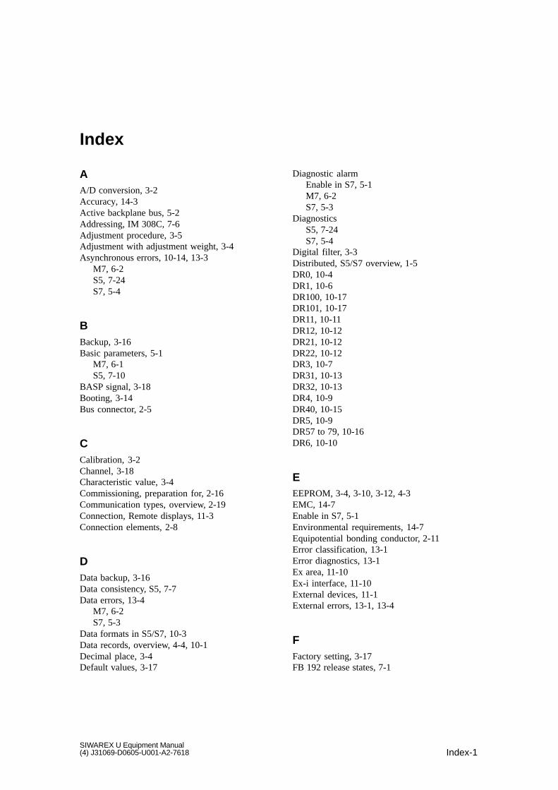
Index-1SIWAREX U Equipment Manual(4) J31069-D0605-U001-A2-7618
Index
AA/D conversion, 3-2Accuracy, 14-3Active backplane bus, 5-2Addressing, IM 308C, 7-6Adjustment procedure, 3-5Adjustment with adjustment weight, 3-4Asynchronous errors, 10-14, 13-3
M7, 6-2S5, 7-24S7, 5-4
BBackup, 3-16Basic parameters, 5-1
M7, 6-1S5, 7-10
BASP signal, 3-18Booting, 3-14Bus connector, 2-5
CCalibration, 3-2Channel, 3-18Characteristic value, 3-4Commissioning, preparation for, 2-16Communication types, overview, 2-19Connection, Remote displays, 11-3Connection elements, 2-8
DData backup, 3-16Data consistency, S5, 7-7Data errors, 13-4
M7, 6-2S7, 5-3
Data formats in S5/S7, 10-3Data records, overview, 4-4, 10-1Decimal place, 3-4Default values, 3-17
Diagnostic alarmEnable in S7, 5-1M7, 6-2S7, 5-3
DiagnosticsS5, 7-24S7, 5-4
Digital filter, 3-3Distributed, S5/S7 overview, 1-5DR0, 10-4DR1, 10-6DR100, 10-17DR101, 10-17DR11, 10-11DR12, 10-12DR21, 10-12DR22, 10-12DR3, 10-7DR31, 10-13DR32, 10-13DR4, 10-9DR40, 10-15DR5, 10-9DR57 to 79, 10-16DR6, 10-10
EEEPROM, 3-4, 3-10, 3-12, 4-3EMC, 14-7Enable in S7, 5-1Environmental requirements, 14-7Equipotential bonding conductor, 2-11Error classification, 13-1Error diagnostics, 13-1Ex area, 11-10Ex-i interface, 11-10External devices, 11-1External errors, 13-1, 13-4
FFactory setting, 3-17FB 192 release states, 7-1

Index-2SIWAREX U Equipment Manual
(4) J31069-D0605-U001-A2-7618
Fill level scales, 1-9Front, 2-8Functions, 3-1
GGSD files, 8-1
HHandling errors, 13-4
M7, 6-2S7, 5-3
Hotline, 15-1
II/O area, allocation, 7-11I/O communication in S7, 5-2IM 153-1, release states, 7-2IM 308-C
Release states, 7-1Transmission speeds, 7-2
Indicators, 2-8Installation, SIWATOOL, 12-2Internal errors, 13-1Internet, 15-1Introduction to SIWAREX U, 1-2
JJob control, I/O communication, 7-11
LLED, 2-8, 2-17
Allocation of, 3-17Error message, 13-5
LED color, 2-8Life bit, I/O communicaton, 7-13Limit values, 3-12Load cell connection, 2-10Load cell interface
4-wire technique, 2-116-wire technique, 2-11
MM7-300, Overview, 1-4Mean value filter, 3-3
Measured value acquisition, 3-2Max. limit values, 3-12Min. limit values, 3-12Mounting, how to, 2-5Mounting elements, load cells, 1-8
NNumber of SIWAREX U, 2-3
OOD signal, 3-18Overview, 1-9
SIWAREX U, 1-3system intagration, 1-4
PParameter assignment, overview, 2-18PC connection, wiring, 2-13Periphery, Overview, 1-7Potential isolation, 14-8Power failure, 3-16Power supply, 2-8, 2-9Printer, 11-1Process interrupts
Enable in S7, 5-1M7, 6-2S7, 5-2
RReadjustment, 3-5Remote display connection, wiring, 2-15Remote displays, 11-2
Protocol layout, 11-7Settings, 11-5
Repair, 15-1Replacement parts, 15-1RS 232C interface, 2-13
SS5-95U/DP
Release states, 7-2Transmission speeds, 7-2
S7 setup, 5-1S7-300, Overview, 1-4
Index

Index-3SIWAREX U Equipment Manual(4) J31069-D0605-U001-A2-7618
Safety, 3-14Notes on, 2-1
Safety precautions, 2-3Sample program
S5, 7-16S7, 5-3
Scales functions, 3-1Screw terminals, 2-10, 2-13, 2-14Serial interface, 2-13, 2-15Setting to zero, 3-10Setup
Scales, mechanical, 1-8SIWAREX Pi, 11-11SIWAREX U, 1-7
Setup for STEP7, 5-1SFC communication in S7, 5-2Shield, mounting, 2-7Shield holder element, 2-5Shield terminal, 2-5, 2-7SIWAREX Pi, 11-10SIWATOOL, 12-1Slot, SIWAREX U, 2-3Stand alone, 1-7Standard master, 8-1
Status byte, 10-13I/O communication, 7-12
Synchronous errors, 13-2M7, 6-2S5, 10-15S7, 5-4
System integration, Overview, 1-4, 4-2
TTechnical specifications, 14-2Theoretical adjustment, 3-6TTY interface, 2-15Typendateien, 7-5Types of access, S5, 7-10Types of addressing, IM 308-C, 7-8
WWeighing channel, 3-18Weighing functions, overview, 1-9Weight calculation, 3-4Wire break monitoring, 3-14Wiring, 2-7
Index

Index-4SIWAREX U Equipment Manual
(4) J31069-D0605-U001-A2-7618
Index


![Predgovor [Preface.]](https://img.dokumen.tips/doc/110x75/6336ef3f20d9c9602f0b14a3/predgovor-preface.jpg)