Embed Size (px)
Citation preview
Phase unwrapping through demodulationby use of the regularized phase-tracking technique
Manuel Servin, Francisco Javier Cuevas, Daniel Malacara, Jose Luis Marroquin, andRamon Rodriguez-Vera
Most interferogram demodulation techniques give the detected phase wrapped owing to the arctangentfunction involved in the final step of the demodulation process. To obtain a continuous detected phase,an unwrapping process must be performed. Here we propose a phase-unwrapping technique based ona regularized phase-tracking ~RPT! system. Phase unwrapping is achieved in two steps. First, weobtain two phase-shifted fringe patterns from the demodulated wrapped phase ~the sine and the cosine!,then demodulate them by using the RPT technique. In the RPT technique the unwrapping process isachieved simultaneously with the demodulation process so that the final goal of unwrapping is thereforeachieved. The RPT method for unwrapping the phase is compared with the technique of least-squaresintegration of wrapped phase differences to outline the substantial noise robustness of the RPT tech-nique. © 1999 Optical Society of America
OCIS codes: 100.2650, 100.5070, 120.5050.
1. Introduction
Optical metrology generally uses optical interferom-eters to measure a wide range of physical quanti-ties.1,2 Depending on the application, many types ofinterferometers may be used, but their common ob-jective is to produce a fringe pattern phase-modulated by the physical quantity being measured.The range of physical magnitudes that may be de-tected with this beam-encoding procedure is verylarge: depth measurement, strain analysis, temper-ature gradients, surface deformation, among others.
An interferogram may be represented by the fol-lowing mathematical expression:
I~x, y! 5 a~x, y! 1 b~x, y!cos@f~x, y!# 1 n~x, y!, (1)
where a~x, y! is a slowly varying background illumi-nation, b~x, y! is the amplitude modulation that alsois a low-frequency signal, and f~x, y! is the phaseterm related to the physical quantity being mea-
M. Servin, F. J. Cuevas, D. Malacara, and R. Rodriguez-Vera arewith Centro de Investigaciones en Optica A. C., Apartado Postal1-948, 37150 Leon, Gto., Mexico. J. L. Marroquin is with Centrode Investigacion en Matematicas A. C., Apartado Postal 402, 36000Guanajuato, Gto., Mexico.
Received 2 July 1998; revised manuscript received 18 September1998.
0003-6935y99y101934-08$15.00y0© 1999 Optical Society of America
1934 APPLIED OPTICS y Vol. 38, No. 10 y 1 April 1999
sured. The term n~x, y! is an additive noise, al-though it may also be multiplicative as in the case ofelectronic speckle-pattern interferometry ~ESPI!.The continuous interferogram is then imaged over aCCD video camera and digitized with a video framegrabber for further analysis in a digital computer.The purpose of computer-aided fringe analysis is todetect automatically the two-dimensional phase vari-ation f~x, y! that occurs over the interferogram be-cause of the spatial change of the physical variablebeing measured.
There are a number of techniques for measuringthe interesting spatial phase variation f~x, y!.Among them we can mention phase-stepping inter-ferometry ~PSI!,3,4 which requires at least threephase-shifted interferograms. The phase shiftamong the interferograms must be known through-out the interferogram. In this case one may esti-mate the modulating phase at each resolvable imagepixel. The PSI is the first-choice technique when-ever the atmospheric turbulence and the mechanicalconditions of the interferometer remain constantthroughout the time necessary to obtain the threephase-shifted interferograms. When the above re-quirements are not fulfilled one may analyze only oneinterferogram if carrier fringes are introduced intothe fringe pattern to obtain a carrier-frequency inter-ferogram. One may then analyze this interferogramby using such well-known techniques as the Fourier-transform,5 the synchronous,6,7 the spatial-phase-
8–11 12,13
itw
p
pqwmi
ie
s
17
twUngoctapt
sP
Titdnu
bwa
shifting, the phase-locked-loop ~PLL!, amongothers.
Except for the PLL technique all the other methods~Fourier, synchronous, PSI, and spatial phase shift-ing! give the detected phase wrapped ~the modulo 2pof the true phase! because of the arctangent functionnvolved in the phase-estimation process. The rela-ionship between the wrapped phase and the un-rapped phase may be stated as
f~x, y! 5 fW~x, y! 1 2pk~x, y!, (2)
where f~x, y! is the unwrapped phase, fW~x, y! is theunwrapped phase, and k~x, y! is an integer valuedcorrecting field. The unwrapping problem is trivialfor phase maps calculated from good quality fringedata; in such phase maps the absolute phase differ-ence between consecutive phase samples in both thehorizontal and the vertical directions is less than p,except for the expected 2p discontinuities. Unwrap-ping is therefore a simple matter of adding or sub-tracting 2p offsets at each discontinuity encounteredin the phase data14,15 or integrating the wrapped-
hase differences.16,17
Unwrapping becomes more difficult when the ab-solute phase difference between adjacent pixels atpoints other than discontinuities in the arctan~! func-tion is greater than p. These discontinuities may beintroduced, for example, by high-frequency, high-amplitude noise, discontinuous phase jumps, and re-gional undersampling in the fringe pattern. Ghigliaet al.18 considered unwrapping the phase by isolatingthese erroneous discontinuities before starting theunwrapping process. Erroneous discontinuities orphase inconsistencies are detected when the sum ofthe wrapped-phase differences around a square pathof size L is different from zero. Inconsistencies gen-erate phase errors ~unexpected phase jumps! that
ropagate along the unwrapping direction ~in se-uential unwrapping!. As a consequence the un-rapping process becomes path dependent, i.e., oneay obtain different unwrapped phase fields depend-
ng on the unwrapping direction chosen.An important step toward obtaining a robust path-
ndependent phase unwrapper was given by Ghigliat al.17 applying the ideas of Fried19 and Hudgin20 of
least-squares integration of phase gradients21–23 tothe unwrapping problem. The phase gradientneeded in Ref. 17 is obtained as wrapped-phase dif-ferences along the x and the y directions of thewrapped estimated phase. One then least-squaresintegrates this wrapped gradient field to obtain thecontinuous phase searched for. More recently Mar-roquin et al.24,25 extended the technique of least-squares integration of the wrapped-phase gradientby adding a regularization term to the solutionsearched for in the form of a norm of potentials.When this technique is used, it is possible to filter outsome noise in the unwrapped phase as well as tointerpolate the solution over regions of invalid phasedata ~such as holes! with a well-defined behavior in-ide them.
One drawback of the least-squares integration orits regularized extension25 stems from the assump-tion that the phase difference between adjacent pix-els is less than p in absolute value. That is, theseechniques take the wrapped differences of therapped phase as if it were a true gradient field.nfortunately this is not the case when severelyoisy phase maps are being unwrapped. The phaseradient obtained here is actually wrapped in regionsf high noise and high phase gradients. This is thease in very noisy situations such as those encoun-ered in ESPI in which one may have such a largemount of noise that adjacent pixels may have ahase difference greater that p rad in regions otherhan the expected 2p jumps.
The unwrapping system presented here may beeen as a generalization of the previously reportedLL system.12,13 The regularized phase-tracking
~RPT! system has a substantially higher signal-to-noise ratio in the estimated phase with respect to theFourier, synchronous, or PSI techniques. The rea-son is that the RPT system behaves as an extremelynarrow-band-pass filter tracking a wide-band fringe-pattern signal. To date the RPT system has beenreported in several different applications26–28 rang-ing from demodulation of a single closed-fringe inter-ferogram to PSI. In all these applications the RPTtechnique has been demonstrated to be far more ro-bust to noise and insensitive to the fringe-patternboundary than previously well-known interferomet-ric techniques.3–18
An above-mentioned advantage of the proposedRPT method is that it lacks phase distortion at theinterferogram’s edges. This is especially usefulwhen the interferograms have invalid fringe-data re-gions within them ~such as shadows and holes!.
his is a common case when one is analyzing strainsn mechanical parts by using ESPI. Note, however,hat the RPT technique presented here is limited toemodulating smooth wave fronts. That is, we haveot considered the demodulation of piecewise contin-ous functions.However, a similar RPT technique has already
een applied to unwrapping phase maps in a directay ~without the need for generating two intermedi-te fringe patterns! by Servin et al.26; the RPT pre-
sented here is easier to understand and more robustto noise.
2. Unwrapping by Demodulation by Using theRegularized-Phase-Tracking Technique
As mentioned above the first step in unwrapping agiven phase map by using the technique proposedhere is to put the wrapped phase into two phase-shifted fringe patterns. We may obtain these fringepatterns by using the cosine and the sine of the mapphase being unwrapped, that is,
IC~x, y! 5 cos@fW~x, y!#,
IS~x, y! 5 sin@fW~x, y!#, (3)
where fW~x, y! is the phase map being unwrapped.
1 April 1999 y Vol. 38, No. 10 y APPLIED OPTICS 1935

tbacitptotucbi
wf
ahTlre
~mrf
tf
1
Now the problem of phase unwrapping may betreated as a demodulation of two phase-shifted fringepatterns by using the RPT technique.28 Now weoutline the basic principles behind the RPT techniqueas used to demodulate–unwrap these phase-shiftedfringe patterns.
Given that the technique presented uses a regular-ized phase tracker we briefly explain the motivationfor regularizing the problem of phase estimation. Toregularize the phase-detection problem in fringeanalysis, it is necessary to find a suitable energy orcost function that uses at least two terms that con-tribute to constraining the estimated phase field.These terms are related to:
~1! Fidelity between the estimated function and theobservation.
~2! Smoothness of the modulated phase field.
We then assume that the phase function searchedfor is the one that minimizes the cost function.
In particular in the unwrapping RPT techniqueproposed here we have assumed that locally thefringe patterns @Eq. ~3!# may be considered as spa-ially monochromatic, so that their irradiance maye modeled as a cosinusoidal function modulated byplane in the phase space. The amplitude of this
osinusoidal function must be close to the observedrradiance @statement ~1!#. A phase plane such ashis must adapt itself to every region in the fringeattern given that its local frequency changes con-inuously in the two-dimensional space. The sec-nd term of the proposed cost function refers tohe expected smoothness and continuity of thenwrapped-detected phase @statement ~2!#. Spe-ifically, the proposed cost function to be minimizedy the unwrapped phase f0~x, y! at each site ~x, y!s
U~x, y! 5 (~e,h!e~Nx,yùL!
$@IC~e, h!
2 cos p~x, y, e, h!#2 1 @IS~e, h!
2 sin p~x, y, e, h!#2 1 l@f0~e, h!
2 p~x, y, e, h!#2m~e, h!%, (4)
p~x, y, e, h! 5 f0~x, y! 1 vx~x, y!~x 2 e!
1 vy~x, y!~y 2 h!, (5)
here L is a two-dimensional lattice having validringe data ~good amplitude modulation!, Nx,y is a
neighborhood region around the coordinate ~x, y!where the phase is being unwrapped, and m~x, y! is
n indicator field that equals one if the site ~x, y!as already been unwrapped and zero otherwise.he functions vx~x, y! and vy~x, y! are the estimated
ocal frequencies along the x and the y directions,espectively. Finally l is the regularizing param-ter that controls ~along with the size of Nx,y! the
smoothness of the detected-unwrapped phase.The first two terms in Eq. ~4! attempt to keep the
936 APPLIED OPTICS y Vol. 38, No. 10 y 1 April 1999
local fringe model close to the observed irradiances ina least-squares sense within the neighborhood Nx,y@statement ~1!#. The third term enforces the as-sumption of smoothness and continuity @statement2!# when only previously detected pixels marked by
~x, y! are used. In other words the third termeinforces the fact that unwrapped-phase values0~x, y! must be close to the adapting phase plane
p~x, y, e, h! in the least-squares sense within theneighborhood Nx,y. Note also that the local phaseplane is adapted simultaneously to the observed data~through its cosinusoidal and sinusoidal models! andto the phase values f0~x, y! already estimatedmarked by m~x, y!. This is done to find the smooth-est phase compatible with the observed fringe irradi-ances.
To demodulate–unwrap the fringe patterns givenby Eq. ~3!, we must find the minimum of the costfunction U~x, y! with respect to the fields f0~x, y!,vx~x, y!, and vy~x, y!. To this end we propose ademodulating algorithm optimizing for each U~x, y!in L by adapting the triad f0~x, y!, vx~x, y!, vy~x, y! inthe following sequential manner and obtaining thenwhat we call our first global unwrapped-phase esti-mation.
The first global unwrapped-phase estimation on Lis performed as follows: To start, the indicator func-tion m~x, y! is set to zero @m~x, y! 5 0 in L#. Thenone chooses a seed or starting point ~x0, y0! inside Lo begin the demodulation of the fringe pattern. Theunction U~x0, y0! is then optimized with respect to
f0~x0, y0!, vx~x0, y0!, vy~x0, y0!. The visited site ismarked as unwrapped; i.e., we set m~x0, y0! 5 1.Once the seed pixel is unwrapped the sequentialphase unwrapping proceeds as follows:
1. Choose the ~x, y! pixel inside L ~randomly orwith a prescribed scanning order!.
2. If m~x, y! 5 1, return to the first statement.If m~x, y! 5 0, test to determine if m~x9, y9! 5
1 for any adjacent pixel ~x9, y9!.If no adjacent pixel has already been esti-
mated, return to the first statement.If m~x9, y9! 5 1 for an adjacent pixel, take
@f0~x9, y9!, vx~x9, y9!, vy~x9, y9!# as the initial conditionto minimize U~x, y! with respect to @f0~x, y!, vx~x, y!,vy~x, y!#.
3. Set m~x, y! 5 1.4. Return to the first statement until all the pixels
in L are estimated.
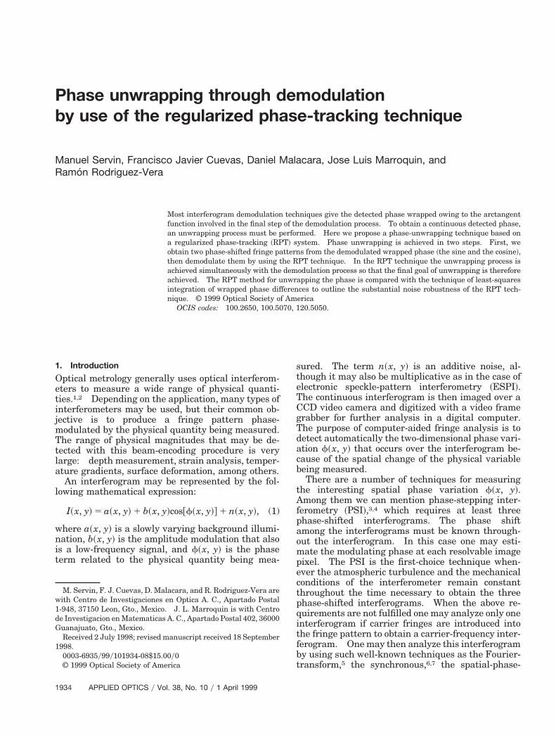
An intuitive way of considering the first iterationjust presented is as a crystal-growing ~CG! process,where new molecules are added to the bulk in thatparticular orientation that minimizes the local crys-tal energy given the geometric orientation of the ad-jacent and previously positioned molecules. We cansee in Fig. 1 a particular example of the spatial dis-tribution of the previously defined two-dimensionalregions where the fringe pattern is being demodu-lated when we choose the particular sequential scan-ning shown.
Epcp
t
btinlL
on
Aopsivto~dn~
st
t
To optimize U~x, y! at site ~x, y! with respect to ~f0,vx, vy!, we have used a simple gradient descent:
f0k11~x, y! 5 f0
k~x, y! 2 t]U~x, y!
]f0~x, y!,
vxk11~x, y! 5 vx
k~x, y! 2 t]U~x, y!
]vx~x, y!,
vyk11~x, y! 5 vy
k~x, y! 2 t]U~x, y!
]vy~x, y!, (6)
where t 5 0.05 is the step size and k is the iterationnumber. Only two iterations in Eqs. ~6! are nor-mally needed ~except for the demodulation of thestarting seed point, which may take approximately10 iterations!. This is due to the initial conditions in
qs. ~6! being taken from a neighborhood unwrappedixel so that the initial conditions are already verylose to the stable point of Eq. ~4!. In practice the tarameter in the first relation in Eqs. ~6! may be
multiplied by approximately 10 to accelerate the con-vergence rate of the gradient search.
The first global phase estimation @when Eqs. ~6! areused along with the CG algorithm# is usually veryclose to the actual modulating phase; if needed, onemay perform additional global iterations to improvethe phase-unwrapping process. One may performadditional iterations, using again Eqs. ~6! but nowaking as an initial condition the optimized triad ~f0,
vx, vy! at the same site ~x, y! ~not the one at a neigh-orhood site as is done in the first global CG itera-ion!. Note that for the additional unwrappingterations, the indicator function m~x, y! in Eq. ~4! isow equal to one in L. Therefore one may scan the
attice in any desired order whenever all the sites inare visited at each global iteration. In practice
Fig. 1. Possible sequence of the demodulation process followed bythe RPT, shown to have a graphic reference to the different do-mains involved.
nly three or four additional global iterations areeeded to reach a stable minimum of U~x, y! at each
site ~x, y! in the two-dimensional lattice L.For convenience we may comment that the cost
function U~x, y! was stated in a previous study onunwrapping where an RPT system was used.26 Wehave used the following form for the cost function:
U~x, y! 5 (~e,h!e~Nx,yùL!
$V@fw~e, h! 2 p~x, y, e, h!#
1 l@f0~e, h! 2 p~x, y, e, h!#2m~e, h!%, (7)
where V~x! 5 @x 2 2p int~xyp!#2 and int~y! takes theinteger part of y. All other variables and functionsin Eq. ~7! are the same as those defined for Eq. ~4!.
s shown in Ref. 26 the sequential technique used toptimize Eq. ~7! is the same as that used in thisaper. The two main drawbacks of Eq. ~7! with re-pect to Eq. ~4! are that the wrapping operator V~ z !s not as easy to derive with reference to the triad ~f0,x, vy! as the sin~ z ! and cos~ z ! functions in Eq. ~4! and
hat computer simulations have shown us that theptimizing system ~the RPT system! derived from Eq.4! is more robust to noise with respect to the oneerived from Eq. ~7!. One hypothesis of the superioroise robustness of the RPT system derived from Eq.4! may be a result of the use of two data fields, IC~x,
y! and IS~x, y!. @A mathematical demonstration ofthis could be very difficult given the nonlinearity ofthe RPT dynamic system given in Eq. ~6!#. In theRPT dynamic system given in Eq. ~6! we preserve theame edge robustness that in general characterizeshe RPT systems.26–28
3. Discussion
We can now give a frequency-domain interpretationof this RPT unwrapping system. In the CG algo-rithms the fact that one obtains the initial conditionsfor the gradient search system @Eq. ~6!# from the es-imated triad ~f0, vx, vy! of an adjacent detected pixel
makes the RPT system look for the smoothest mod-ulating phase compatible with the observed irradi-ance. In the frequency domain the RPT unwrappingtechnique may be interpreted as a narrow-band-passadaptive filter tracking the instantaneous phase andfrequency of the irradiance of the phase-shifted in-terferograms. The frequency spectrum of the signalbeing detected may be much wider than the trackingRPT detecting filter. This narrow-band phase-tracking system has great inertia so that it can movesmoothly all over the two-dimensional spectrum ofthe fringe patterns. An additional advantage ofhaving an adaptive narrow-band filter tracking awider signal spectrum is a large gain in the signal-to-noise ratio of the detected phase. In other words,using a narrow-band phase-tracking system, one hasthe noise rejection power of the adaptive narrow filterwhile demodulating a signal that may have a sub-stantially wider spectrum. The signal-to-noise gainin the unwrapped phase is well known and exten-sively used in electrical communications wherephase-tracking systems are commonly used nowa-
1 April 1999 y Vol. 38, No. 10 y APPLIED OPTICS 1937
at
wt
W
l
1
days. Finally as we see in Sections 4 and 5 the RPTtechnique is almost insensitive to boundary-edge ef-fects, which is a serious drawback in standard phase-shifting techniques where in practice one must use aconvolution low-pass filter over the fringe patterns tofilter out some phase noise.
As mentioned above, parameter l and the size ofthe neighborhood Nx,y are related to the bandwidth ofthe detected phase as well as to the robustness of theRPT algorithm. For example, for very noisy fringepatterns, the size of Nx,y should be large so that theRPT system can track the smooth modulating phaseand overlook the faster changing noise. If the size ofthe neighborhood Nx,y is too small, the system may betrapped by the phase noise. In other words, the sizeof Nx,y is related to the scale of the expected phase tobe recovered and the amount of noise. On the otherhand, once the size of Nx,y is chosen, the value of thel parameter in Eq. ~4! is not very critical. A value ofl 5 1 was used throughout. The computer simu-lated and experimental results are presented here.The computational speed of the RPT technique islinearly related to the size of the neighborhood Nx,yand to the size of lattice L. In the experiments pre-sented the size of Nx,y ranged from 9 3 9 to 17 3 17pixels.
As in a CG process the first iteration of the RPTtechnique is very critical. If it succeeds, the firstRPT iteration will move the whole unwrapping sys-tem to the right attractor, so that further refinementscomputing additional global iterations will move theestimated phase only slightly. If the RPT systemreaches a wrong attractor, the RPT system will betrapped by this local minimum and further iterationsmay not pull the system out of it. In these circum-stances one may need to try another neighborhoodsize Nx,y to reach the desired attractor.
4. Computer Simulations
We have carried out a computer simulation to com-pare the RPT unwrapper presented here against thewell-known technique of phase unwrapping by least-squares integration of wrapped-phase differences.18
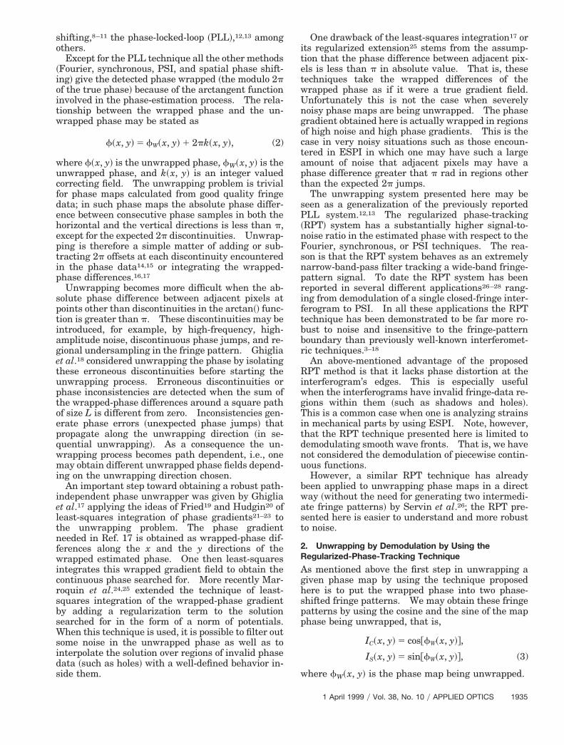
In Fig. 2 is shown a noise-free computer-generatedwrapped phase f~x, y!. We have added to this phase
white and uniformly distributed random noise inhe range of ~0.0, 1.55p! rad. Using this noisy phase,
Fig. 2. Noiseless wrapped phase used in the numerical experi-ments. This image has 128 3 128 pixels with 256 gray levels.
938 APPLIED OPTICS y Vol. 38, No. 10 y 1 April 1999
e have generated three phase-shifted fringe pat-erns as
I1~x, y! 5 1 1 cosFf~x, y! 1 noise~x, y! 22p
3 G ,
I2~x, y! 5 1 1 cos@f~x, y! 1 noise~x, y!#,
I3~x, y! 5 1 1 cosFf~x, y! 1 noise~x, y! 12p
3 G . (8)
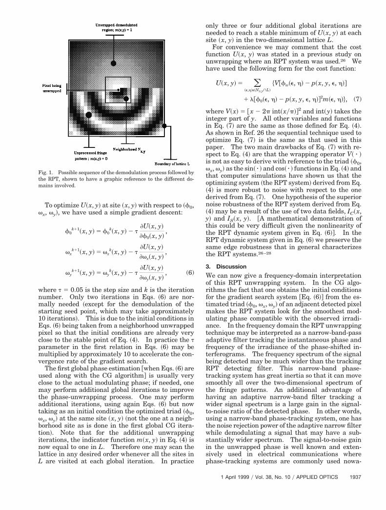
e calculated these fringe patterns by using 128 3128 pixels with 256 gray levels. The noisy fringepatterns were low pass filtered with a 3 3 3 convo-ution averager. Furthermore the 3 3 3 averager
was convolved three times with the phase-shifted
Fig. 3. Three phase-shifted interferograms ~2py3 phase shift! ob-tained when a white and uniformly distributed phase noise in therange of ~0.0, 1.55p! rad was added to the phase shown in Fig. 2.Then the interferograms were convolved three times with an av-erage of 3 3 3 pixels. The low-pass-filtered interferograms areshown.
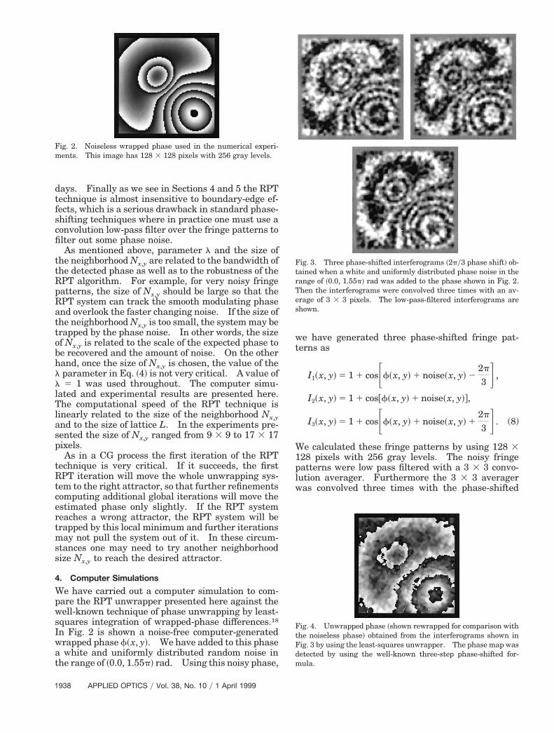
Fig. 4. Unwrapped phase ~shown rewrapped for comparison withthe noiseless phase! obtained from the interferograms shown inFig. 3 by using the least-squares unwrapper. The phase map wasdetected by using the well-known three-step phase-shifted for-mula.

p
fringe patterns @Eq. ~8!#. The low pass filtering wasachieved to obtain the best possible phase estimationfrom the three available fringe patterns by using thetechnique of least-squares unwrapping. The result-ing fringe patterns are shown in Fig. 3. Then the
Fig. 5. Unwrapped phase ~also shown rewrapped! obtained byusing the RPT unwrapping proposed here. The input phase mapin this case was obtained directly from the noisy phase-shiftedinterferograms, that is, the low pass filtering used in the least-squares unwrapping was not required. This method was usedbecause the RPT unwrapped works better this way.
Fig. 6. Three phase-shifted ESPI patterns of a clamped metallicplate heated by a soldering tip. The phase shift among theseinterferograms is py2 rad.
modulating phase of these fringe patterns was esti-mated according to
fW~x, y! 5 arctanH1 2 cos~a!
sin a
3LPF@I1~x, y!# 2 LPF@I3~x, y!#
2LPF@I2~x, y!# 2 LPF@I1~x, y!# 2 LPF@I3~x, y!#J ,
(9)
where the operator LPF@.# represents the low-pass-filtering process. This wrapped phase was then un-wrapped by using the least-squares integration ofwrapped differences reported by Ghiglia and Ro-mero,17 and the result is shown rewrapped in Fig. 4.As mentioned above, the unwrapped phase obtainedis rewrapped for comparison against the true modu-lating phase shown in Fig. 2. We can see how thedynamic range of the true phase has substantially
Fig. 7. Wrapped phase estimated directly ~no low pass filtering!from the three phase-shifted interferograms shown in Fig. 6.
Fig. 8. ~a! Cosine of the wrapped phase; ~b! sine of the wrappedhase.
1 April 1999 y Vol. 38, No. 10 y APPLIED OPTICS 1939
wWwpu
ww
Apb
p
f~ucpfwsp
1
decreased. This decrease occurs because in aheavily noisy situation the wrapped difference oper-ator is a bad estimator of the true phase gradientbecause the high noise makes some phase differencesappear outside the range of ~2p, p! rad, so that the
rapping operator will give a wrong phase gradient.e have tried a different number of convolutionsith the 3 3 3 averager low pass filter over the fringeatterns in Eq. ~8!, but we found that the estimatednwrapped phase was in every case worst.On the other hand, we have tested the RPT un-rapping method proposed here by using the noisyrapped phase given by
fW~x, y! 5 arctanF1 2 cos~a!
sin a
3I1~x, y! 2 I3~x, y!
2I2~x, y! 2 I1~x, y! 2 I3~x, y!G . (10)
As we can see this time we did not use the low-pass-filtering process, because our technique works betterin this way. The unwrapped phase obtained withthe RPT unwrapped as presented here is shown~again rewrapped for comparison purposes! in Fig. 5.
s Fig. 5 shows, the RPT unwrapper proposed herereserves the dynamic range of the true phase muchetter. A neighborhood Nx,y equal to 11 3 11 pixels
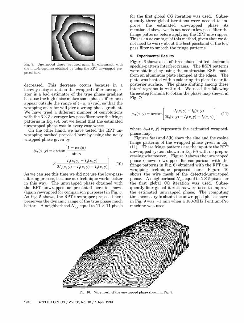
Fig. 9. Unwrapped phase ~wrapped again for comparison withthe interferograms! obtained by using the RPT unwrapped pro-posed here.
Fig. 10. Wire mesh of the u
940 APPLIED OPTICS y Vol. 38, No. 10 y 1 April 1999
for the first global CG iteration was used. Subse-quently three global iterations were needed to im-prove the estimated unwrapped phase. Asmentioned above, we do not need to low pass filter thefringe patterns before applying the RPT unwrapper.This is an advantage of this method, given that we donot need to worry about the best passband of the lowpass filter to smooth the fringe patterns.
5. Experimental Results
Figure 6 shows a set of three phase-shifted electronicspeckle-pattern interferograms. The ESPI patternswere obtained by using the subtraction ESPI modefrom an aluminum plate clamped at the edges. Theplate was heated with a soldering tip placed near itsposterior surface. The phase shifting among theseinterferograms is py2 rad. We used the followingthree-step formula to obtain the phase map shown inFig. 7:
fW~x, y! 5 arctanF I1~x, y! 2 I3~x, y!
2I2~x, y! 2 I1~x, y! 2 I3~x, y!G , (11)
where fW~x, y! represents the estimated wrapped-hase map.Figures 8~a! and 8~b! show the sine and the cosine
ringe patterns of the wrapped phase given in Eq.11!. These fringe patterns are the input to the RPTnwrapped system shown in Eq. ~6! with no prepro-essing whatsoever. Figure 9 shows the unwrappedhase ~shown rewrapped for comparison with theringe patterns in Fig. 6! obtained with the RPT un-rapping technique proposed here. Figure 10
hows the wire mesh of the detected-unwrappedhase. A neighborhood Nx,y equal to 5 3 5 pixels for
the first global CG iteration was used. Subse-quently four global iterations were used to improvethe estimated unwrapped phase. The computingtime necessary to obtain the unwrapped phase shownin Fig. 9 was ;1 min when a 180-MHz Pentium-Promachine was used.
pped phase shown in Fig. 9.
nwra
iWv
10. D. W. Shough, O. Y. Kwon, and D. F. Leavy, “High speed
6. ConclusionThe two-dimensional regularized phase-unwrappedtechnique presented in this paper is capable of un-wrapping extremely noisy phase maps. As far as weknow this is the most robust technique that can un-wrap the phase from a very noisy phase map. TheRPT unwrapping system tracks the modulatingphase as well as the modulating frequency continu-ously as the two-dimensional fringe pattern isscanned.
The proposed RPT regularizer differs substantiallyfrom the ones used in classical regularization theo-ry.27 In classical regularization one uses a pixelwiseerror between the solution searched for and the ob-served data and the norm of a differential operator asthe regularizer. On the other hand, in RPT we usea neighborhood Nx,y of several pixels to measure theerror between our former model and the observationand a robust tangent plane adapted to the processedpixels in Nx,y as regularized. This new approach,along with the CG algorithm presented, permits oneto obtain the most robust phase-unwrapping tech-nique to date to deal with smooth modulating phases.Additional iterations may then be used to move evencloser to the actual modulating phase.
This research was supported in part by the ConsejoNacional de Ciencia y Tecnologia ~CONACYT!, Mex-co under grants 0580P-E, 4424-A, and 2608P-A.
e also appreciate the useful comments of the re-iewers of this paper.
References1. K. J. Gasvik, Optical Metrology ~Wiley, New York, 1987!.2. D. Malacara, ed., Optical Shop Testing ~Wiley, New York,
1992!.3. J. H. Bruning, D. R. Herriott, J. E. Gallager, D. P. Rosenfel,
A. D. White, and D. J. Brangaccio, “Digital wavefront measur-ing interferometer for testing optical surfaces and lenses,”Appl. Opt. 13, 2693–2703 ~1974!.
4. J. E. Greivenkamp and J. H. Bruning, “Phase shifting inter-ferometry,” in Optical Shop Testing, D. Malacara, ed. ~Wiley,New York, 1992!, pp. 501–598.
5. M. Takeda, H. Ina, and S. Kobayashi, “Fourier transformmethods of fringe-pattern analysis for computer-based topog-raphy and interferometry,” J. Opt. Soc. Am. 72, 156–160~1982!.
6. Y. Ichioka and M. Inuiya, “Direct phase detecting system,”Appl. Opt. 11, 1507–1514 ~1972!.
7. K. H. Womack, “Interferometric phase measurement usingspatial synchronous detection,” Opt. Eng. 23, 391–395 ~1984a!.
8. L. Mertz, “Real-time fringe-pattern analysis,” Appl. Opt. 22,1535–1539 ~1983!.
9. P. L. Ransom and J. V. Kokal, “Interferogram analysis by amodified sinusoidal fitting technique,” Appl. Opt. 25, 4199–4205 ~1986!.
interferometric measurements of aerodynamic phenomena,” inPropagation of High-Energy Laser Beams through the Eart’sAtmosphere, P. B. Ulrich and L. E. Wilson, eds., Proc. SPIE1221, 394–403 ~1990!.
11. M. Servin and F. J. Cuevas, “A novel technique for spatialphase-shifting interferometry,” J. Mod. Opt. 42, 1853–1862~1995!.
12. M. Servin, D. Malacara, and F. J. Cuevas, “Direct phase de-tection of modulated Ronchi rulings using a phase locked loop,”Opt. Eng. 33, 1193–1199 ~1994!.
13. M. Servin and R. Rodriguez-Vera, “Two dimensional phaselocked loop demodulation of carrier frequency interferograms,”J. Mod. Opt. 40, 2087–2094 ~1993!.
14. W. Macy, Jr., “Two dimensional fringe pattern analysis,” Appl.Opt. 22, 3898–3901 ~1983!.
15. D. J. Bone, “Fourier fringe analysis: the two dimensionalphase unwrapping problem,” Appl. Opt. 30, 3627–3632 ~1991!.
16. K. Itoh, “Analysis of the phase unwrapping algorithm,” Appl.Opt. 21, 2470 ~1982!.
17. D. C. Ghiglia and L. A. Romero, “Robust two-dimensionalweighted and unweighted phase unwrapping that uses fasttransforms and iterative methods,” J. Opt. Soc. Am. A 11,107–117 ~1994!.
18. D. C. Ghiglia, G. A. Mastin, and L. A. Romero, “Cellular au-tomata method for phase unwrapping,” J. Opt. Soc. Am. 4,267–280 ~1987!.
19. D. L. Fried, “Least-squares fitting a wave-front distortion es-timate to an array of phase difference measurements,” J. Opt.Soc. Am. 67, 370–375 ~1977!.
20. R. H. Hudgin, “Wave-front reconstruction for compensated im-aging,” J. Opt. Soc. Am. 67, 375–378 ~1977!.
21. R. J. Noll, “Phase estimates from slope-type wave-front sen-sors,” J. Opt. Soc. Am. 68, 139–140 ~1978!.
22. B. R. Hunt, “Matrix formulation of the reconstruction of phasevalues from phase differences,” J. Opt. Soc. Am. 69, 393–399~1979!.
23. H. Takajo and Takahashi, “Least-squares phase estimationfrom phase differences,” J. Opt. Soc. Am. A 5, 416–425~1988!.
24. J. L. Marroquin, R. Rodriguez-Vera, M. Servin, and M. Tapia,“Parallel phase-unwrapping algorithms based on Markov ran-dom field models,” J. Opt. Soc. Am. A 12, 2578–2585 ~1995!.
25. J. L. Marroquin and M. Rivera, “Quadratic regularizationfunctionals for phase unwrapping,” J. Opt. Soc. Am. A 12,2393–2400 ~1995!.
26. M. Servin, J. L. Marroquin, D. Malacara, and F. J. Cuevas,“Phase unwrapping with a regularized phase-tracking sys-tem,” Appl. Opt. 37, 1917–1923 ~1998!.
27. M. Servin, J. L. Marroquin, and F. J. Cuevas, “Demodulationof a single interferogram by use of a two-dimensional regular-ized phase-tracking technique,” Appl. Opt. 36, 4540–4548~1997!.
28. M. Servin, R. Rodriguez-Vera, J. L. Marroquin, and D. Ma-lacara, “Phase-shifting interferometry using a two-dimensional regularized phase-tracking technique,” J. Mod.Opt. 45, 1809–1820 ~1998!.
1 April 1999 y Vol. 38, No. 10 y APPLIED OPTICS 1941


