Embed Size (px)
Citation preview

1/20
OVERVIEW AND FUTURE TRENDS OF SHRINKAGE RESEARCH
Konstantin Kovler and Semion Zhutovsky Faculty of Civil and Environmental Engineering, Technion – Israel Institute of Technology, Haifa, Israel
ABSTRACT
Non-structural cracking of concrete is a serious problem and the underlying phenomena, namely, shrinkage and creep, need to be better understood. For this reason, much research has been devoted to this complex problem. However, despite major successes, the phenomenon of shrinkage is still far from being fully understood. The paper discusses and summarizes the main aspects of concrete shrinkage, with a focus on autogenous and drying shrinkage, which are especially important in high-strength and normal-strength concretes, respectively. These aspects include the theories of physical mechanism, prediction models and future research trends.
Shrinkage of concrete due to (a) moisture changes, which result in surface and capillary tension, movement of interlayer water and disjoining pressure and (b) chemical reactions
(hydration/dehydration shrinkage, thermal shrinkage, crystallization swelling, carbonation shrinkage and phase transition shrinkage, is reviewed. Many of these mechanisms often cannot be directly linked to the macroscopically observed dilatation/contraction. In some case, volume changes due to chemical reactions result mainly in an increase or decrease of porosity and degree of saturation. Most chemically induced volume changes are affected by temperature, since chemical reactions are generally accelerated by the temperature elevation and slowed down by the temperature reduction. An overview of recent model developments is presented. Shrinkage reduction methods (cement modification, using admixtures and fibers, proper mix design, methods of internal curing) are discussed.

1/20
1. SHRINKAGE THROUGH THE EYES OF A PRACTICING
ENGINEER
Shrinkage of concrete is the time-dependent strain measured in an unloaded and unrestrained specimen at constant temperature. From the viewpoint of practicing engineer it is important from the outset to distinguish between plastic shrinkage, chemical shrinkage and drying shrinkage. For example, some high strength concretes are prone to plastic shrinkage, which occurs in the wet concrete, and may result in significant cracking during the setting process. This cracking occurs due to capillary tension in the pore water. Since the bond between the plastic concrete and the reinforcement has not yet developed, the steel is ineffective in controlling such cracks. This problem may be severe in the case of low water content, silica fume concrete and the use of such concrete in elements such as slabs with large exposed surfaces is not recommended [1].
Drying shrinkage is the reduction in volume caused principally by the loss of water during the drying process. Chemical (or endogenous) shrinkage results from various chemical reactions within the cement paste and includes hydration shrinkage, which is related to the degree of hydration of the binder in a sealed specimen. Concrete shrinkage strain, which is usually considered to be the sum of the drying and chemical shrinkage components, continues to increase with time at a decreasing rate. Shrinkage is assumed to approach a final value, as time approaches infinity and is dependent on all the factors which affect the drying of concrete, including the relative humidity and temperature, the mix characteristics (in particular, the type and quantity of the binder, the water content and water-to-cement ratio, the ratio of fine to coarse aggregate, and the type of aggregate), and the size and shape of the member.
All these aspects are important for the practical engineer. However, the focus of the present paper is physical and chemical mechanisms of shrinkage, especially those of drying and autogenous shrinkage. Drying shrinkage has been intensively studied since the 40s and autogenous shrinkage has become a "hot topic" of concrete research only recently, in the last decade; with developing of high-strength / high-performance concrete (HSC/HPC).
How shrinkage can be explained? It has to be noted that the same common physical mechanisms can be used for explaining both drying and autogenous shrinkage. There are many interesting theories suggested, and we would like to review the most popular ones.
2. SHRINKAGE DUE TO MOISTURE CHANGES
2.1. Capillary tension
One of the first theories is that of shrinkage (or swelling) stress, in which the liquid phase is placed under stress in relation to its initial state. Freyssinet [2] suggested that the stresses, which can be developed are capillary stresses. The force in this case should be proportional to the surface tension of the liquid that fills the capillaries and inversely proportional to the radii of curvature r1 and r2 of the menisci that limit the liquid phase. If the quantity of water diminishes, the radii do likewise and the capillary force increases.
The idea of Freyssinet since been adopted by various authors, but almost completely abandoned in a few years [3]. Only in 50s the capillary mechanism of shrinkage became again popular among the researchers [4].
When vapor pressure over the liquid (P) is equal to the saturation vapor pressure (P0), equilibrium between liquid and vapor exists, i.e. number of molecules leaving the liquid equal to the number of molecules returning to the liquid at any given time. This state corresponds to relative humidity of 100%. When relative humidity drops below 100%, or, in other words, vapor pressure is below saturated pressure, evaporation takes place.
In capillary pores, the vapor pressure over meniscus is different from that over a plane surface liquid. This difference can be explained by Fig. 1. In this figure, the circle represents the sphere of attraction of one molecule on the surface of liquid [5].
Fig. 1 - Effect of surface curvature on vapor pressure [6]
It can be seen that number of molecules
hindering evaporation of the molecule, represented by shaded part of the circle, is greater in the case of

2/20
concave surface. Thus, at presence of the meniscus, equilibrium is achieved at vapor pressure lower than the saturated vapor pressure that is at relative humidity below 100%.
On the other hand, due to surface tension difference in pressure of the liquid and air pressure just after the meniscus exists. The difference in pressure can be calculated from equilibrium equation, which can be written as follows:
rPrPr outin 422 22 (1)
where γ is surface tension of the liquid, r is
radius of menisci curvature, Pin pressure inside the liquid and Pout is gas pressure above the meniscus. Here the meniscus is considered to have spherical shape, so the menisci radius is equal to radius of the capillary. This equation can be rearranged to the Laplace equation:
rPPP inoutc
2
(2)
The difference between Pout and Pin is called
capillary pressure (Pc). The capillary pressure, given by the air pressure minus water pressure, is always negative [7]. This means the water is in the state of tension (or depression).
The relation between capillary pressure and relative humidity is given by Kelvin equation:
mc V
PRTln(RH)
(3)
where R is the gas constant, T is temperature in Kelvin and Vm is the molar volume of water. The Kelvin and Laplace equations can be combined, giving us relationship between radius of curvature and relative humidity:
RTr
2)
P
Pln(ln(RH)
0
mV
(4)
This equation is often related as Kelvin-Laplace
equation. The implication of this equation is demonstrated in Fig. 2.
Fig. 2 - Relation between radius of curvature and vapor
pressure [6] When relative humidity is 100% (P=P0), the
water surface in the capillary is plane (r=∞) and no evaporation takes place. With a decrease in relative humidity (RH1=P1/P0), water starts to evaporate until a meniscus with radius of curvature r1 corresponding to RH1 in Kelvin-Laplace equation is formed. Further decrease in relative humidity causes further evaporation with corresponding decrease in the curvature radius of the meniscus. The minimum radius of meniscus curvature is equal to the radius of the capillary. Therefore, if relative humidity drops below relative humidity corresponding to the minimum meniscus curvature radius, evaporation takes place until all the water evaporates. This is correct for the cylindrical capillary with constant diameter. However, in capillary pores of concrete that have certain size distribution, evaporation takes place until bigger pores are emptied and meniscus if formed in the pores of the radius equal to the meniscus curvature radius corresponding to the relative humidity. By this means, in concrete, pores that have radius lower that meniscus radius are filled by water and pores with bigger radius are empty.
As was stated by Laplace equation, water in capillaries is under depression, i.e. under tensile stress. This tensile stress in capillary water must be balanced by compressive stress of the surrounding solid. Thus, emptying of capillary pores in cement paste by any drying or throughout chemical reaction will subject the paste to compressive stress, which in its turn, will result in volume decrease, i.e. shrinkage. Portland cement paste is considered to be viscoelastic material, therefore this volume change have both elastic and viscous, i.e. creep,

3/20
components. Both components vary with age and w/b ratio.
According to the Laplace equation the capillary water depression, or simply capillary depression, depends on radius of curvature of meniscus, which is, as stated above, close to the capillary radius. Therefore, capillary induced shrinkage is dependent on pore size distribution of the cement paste, which is affected by w/b ratio, by mineral admixtures used and varies with age.
The linear strain of shrinkage of a partially saturated porous medium due to the capillary stresses cap in the water-filled pores, , was estimated by D. Bentz and O. Jensen [8] as:
(5)
where S is the saturation fraction or fraction of water-filled pores, K is the bulk modulus of the porous material, and Ks is the bulk modulus of the solid framework within the porous material.
This equation is valid for a fully saturated linear elastic material and is only approximate for partial saturation. In terms of shrinkage, two counteracting effects of removing water from a porous material can be observed. As hydration proceeds, smaller and smaller pores are emptied. The schematic representation of the process is presented on Fig. 3. It can be seen that as more empty porosity is created due to self desiccation, smaller and smaller pores are being emptied while hydration proceeds. Consequently, the values of cap increase. On the other hand, as water is removed, the saturation value, S, decreases. Thus, the resulting behaviour of shrinkage depends on the system being examined and the relationship between S and r determined by the pore size distribution.
Fig. 3 - Hypothetical pore size distribution for cement-
based materials indicating that as more empty porosity is created due to self-desiccation, smaller and smaller pores
are being emptied (adopted from [8])
This mechanism is operative only when capillary water becomes continuous [7], i.e. at RH exceeding 40% [9]. Some researchers suggest that capillary tension is of great importance at relative humidity in the range of 50-100% [10], when others consider this range to be 35-100% [11].
2.2. Surface tension
Interaction forces between molecule in the bulk of liquid and its neighbors are balanced from all sides and pressure in the bulk of the liquid is uniform. On the contrary, at the surface of the liquid, interaction forces between surface molecule and interior molecules are not balanced by similar forces from outside of the phase. Equilibrium conditions require compensating force equal by value, but with opposite direction, to be applied to the surface layer of molecules. This force is surface tension of the liquid. As a result, the surface tends to contract and behaves like a stretched elastic skin.
The surface tension induces compressive stress inside the material. In particles of colloidal size, such as the cement gel particles having large specific surface area, surface tension induces huge compressive stresses of the order 250 MPa [5, 6]. Variations in the level of such stresses will cause noticeable volume changes. The surface tension, or rather surface energy of the colloidal system, may be changed by adsorption of gases or vapors. If a film of thickness Γ is adsorbed at given vapor pressure P the surface energy decreases by Δγ [12, 13]:
P
PdRT0
0 )ln(
(6)
where R is the gas constant (8.31441 JK-1mol-1) and T is temperature in Kelvin. It can be seen from the equation that drying, or vapor pressure reduction, or relative humidity reduction, which are all equivalent, increases surface tension and compressive stress, induced by it, causing volume decrease, i.e. shrinkage. The length changes (Δl/l), are directly related to the corresponding changes in surface tension or, likewise, in surface energy [5, 13]. It was shown by Bangham that, in certain limits, this relation is linear [14]:
ll
(7)
The proportionality factor λ that relates the dimensional changes to the surface tension in the

4/20
pore system was expressed by Hiller in terms of colloidal system properties [15, 16]:
E3
(8)
where Σ is pore wall area of empty pores, ρ is specific mass and E is elasticity modulus of the material. It should be noted that as only physically adsorbed water affects surface tension, hence this mechanism is valid only at low humidities, when variation in water content of the paste are mainly due to variations in amount of absorbed water. At higher humidity, water starts to fill capillary pores in the paste, which is outside the range of surface forces and disjoining pressure causes additional expansion of the colloidal system. For that reason, it has been suggested that surface tension mechanism is valid only up to the relative humidity of 40%. Later it was suggested that this mechanism is operative in the range of relative humidity of 5-50% [5, 13]. Hence, Equation (7) cannot be applied outside of this range.
2.3. Movement of interlayer water
C-S-H particles of the cement gel are composed of laminar sheets, which large surface area having electrical charge. This particles forming layered microstructure, attract highly polarized water molecules at interface up to few monolayers apart. Movement of this water into and out of layered C-S-H particles structure will affect spacing between the layers causing in this way volume changes. Schematic representation of this process after Munich model is shown in Fig. 4 (a) and (b) [13].
Fig. 4 - Schematic representation of different stages of
interlayer water movement (adopted from [13]) Exit and reentry of interlayer water causes length
change Δl0. Most researchers attribute shrinkage at relative humidity below 35-40% to this mechanism [6, 9, 11, 13].
2.4. Disjoining pressure
As was already stated, reentry of interlayer water induces repulsive forces between layers of CSH particle. However, by the adsorption of interlayer water, not only repulsive forces arise. There is decrease in attractive van der Waals’ forces between solid layers, i.e. in cohesion, induced as well. The net surface repulsion force and loss of attraction forces is usually called disjoining pressure and, sometimes, is referred as swelling pressure [7, 17]. The change in disjoining pressure results in volume changes, i.e. shrinkage. This mechanism is illustrated by Fig. 4.
Fig. 5 - Disjoining pressure pd: (a) dry matrix material
and (b) matrix material with adhered water (adopted from [7])
The simplified sketch of the fundamental aspects
of Munich model regarding disjoining pressure mechanism is shown in Fig. 6.
Fig. 6 - Capillary pressure and induced disjoining
pressure: (a) wedge model and (b) interlayer model (adopted from [7])
Additional disjoining pressure can arise under
the action of capillary pressure. The disjoining pressure arises by repulsion between water molecules keeping the CSH particles at certain distance, which is illustrated in Fig. 6 (b) [7].
According to Powers [10], the disjoining pressure is a result of capillary and adhesive forces giving rise to a negative pressure in the water in the wedge-like structure of two CSH particles held together by capillary pressure, see Fig. 6 (a).
Powers model suggests that this mechanism is valid over the whole range of relative humidity, while Munich model considers that disjoining pressure is important beyond 50% relative humidity. Feldman and Sereda, on the contrary, completely reject this mechanism.

5/20
2.5. Influence of degree of saturation/RH on shrinkage
mechanism involved
Variations in moisture content of cement paste are associated with volume changes. The volume decrease of the cement paste is often referred, as shrinkage. The four different mechanisms were discussed in this section. The appearance of one or another is strongly dependent on degree of saturation of the cement paste. Capillary pressure, for example, becomes important when pore water becomes continuous, whereas disjoining pressure is important at low degree of saturation [7].
Another concern in the shrinkage mechanisms activation is relative humidity of the cement paste, which however is obviously connected with degree of saturation since the equilibrium between adsorbed water and vapor pressure must exist. Indeed, any change in relative humidity disturbs the equilibrium and causes evaporation or condensation, respectively depending on ether RH is decreased or increased.
By this means, shrinkage and swelling are described by more than one mechanism. There is some disagreement on which mechanism is active at particular relative humidity. Different opinions of several authors concerning relative importance of each mechanism are presented in Table 1.
Most researchers attribute volume changes at
relative humidity above 40% to the capillary tension. Movement of interlayer water, for the most part, is considered responsible for the volume changes at relative humidity below 35%. Most researchers assume that variations in surface energy is the cause of shrinkage/swelling at relative humidity below 40%, and some, on the contrary, believe that this mechanism is active at relative humidity above 40%. Disjoining pressure is also the
object of controversy. Some researchers suppose that disjoining pressure is responsible for the volume changes at high relative humidity, some consider it is operative at low relative humidity, and some completely reject this mechanism.
3. SHRINKAGE DUE TO CHEMICAL REACTIONS
3.1. Mechanisms involved
Practically all cement paste properties depend on cement hydration, which is actually exothermic chemical reaction. Since temperature variation caused by chemical reaction produce volume changes and since volume of reactants typically differs from reaction products volume, chemical reactions are unignorable source of cement paste volume changes.
Several mechanisms of shrinkage (or swelling) caused by chemical reactions can be distinct (the authors would like to follow the classification suggested in the excellent review of F.H. Wittmann [13]).
The major mechanisms include: hydration shrinkage; thermal shrinkage; crystallization swelling; carbonation shrinkage; phase transition shrinkage; dehydration shrinkage.
Many of these mechanisms often cannot be directly linked to the macroscopically observed dilatation. In some case, volume changes due to
Table 1 Shrinkage mechanisms after various authors (adopted from [6])
Authority Relative humidity, %
0 10 20 30 40 50 60 70 80 90 100
Powers
Variations in swelling pressure
Augmentaion by capillary effects
Ishai Variations in surface energy Capillary tension
Feldman & Sereda
Movement of interlayer water Capillary tension and variations in surface energy
Wittmann Variations in surface energy Variations in swelling pressure

6/20
chemical reactions results mainly in an increase or decrease of porosity and degree of saturation. Most chemically induced volume changes are affected by temperature, since chemical reactions generally accelerated by the temperature elevation and slowed down by the temperature reduction.
3.2. Hydration shrinkage
Nearly all chemical reactions are accompanied by volume changes. Minerals constituting Portland cement, the major of which are alite (C3S), belite (C2S), celite (C4AF) and tricalcium aluminate (C3A), react with water forming hillebrandite, xonolite, tobermorite, afwillete, foshagite, riversideite, plombierite, gyrolite, okenite, hydrocalumite and some other minerals building up cementitious gel [18]. By this means, cement hydration is not single chemical reaction, but complex set of quite a few reactions and each reaction has its own volume stoichiometry.
As far as hydration proceeds, the two calcium silicates result most probably in the same products: calcium silicate hydrate (with an uncertain and variable stoichiometric composition, known in abbreviated form as C-S-H) and calcium hydroxide [Ca(OH)2], known also as portlandite. The C3A, in the presence of calcium sulfate and water, reacts to form ettringite (C3A·CaSO4·12H2O), and finally a stable calcium aluminate hydrate (C3AH6) is formed. C4AF reaction with calcium sulfate proceeds more slowly than the reaction of C3A, forming C3AH6 and C3FH6.
Because the calcium silicates represent the bulk of Portland cement, the volumetric change that occurs during their hydration is of paramount importance. Nevertheless, what follows refers to a great extent to the reduction in the volume of the whole hydrating cement paste system. If, for instance, volume C of dry cement reacts with volume W of water, being the nonevaporable water (i.e. more or less chemically combined), the resultant volume P of the products of hydration is always such that P < C + W. There is some uncertainty about the precise magnitude of the reduction of the volume of hydrating cement paste system, i.e. the sum of the volume of the solid products of hydration and of the water-filled gel space.
More than 100 years ago, Le Chatelier estimated the volume reduction to be between 8 and 12 percent of the original space occupied by unhydrated cement and by water which was destined to become part of the hydrated cement paste system. Nearly 60 years ago, Powers found the volume reduction to be 0.254 of the volume of
nonevaporable water [3]. He also found that the nonevaporable water represents about 23 percent of the mass of unhydrous cement (that has a specific gravity of about 3.15) and that the hydrated cement paste has a characteristic porosity of 28 percent. Fig. 7 represents the volumetric proportion of a paste with a w/c ratio of about 0.48 at three stages: prior to hydration, at 50 % hydration, and at 100 % hydration.
Fig. 7 - Schematic representation of the volumetric proportions of sealed cement paste (w/c = 0.475) at
different stages of hydration (adopted from [19]) Assume that the paste has initial volumes of 60
ml of water and 40 ml of cement, and it is in a sealed condition (no outside moisture is involved). Bleeding is not considered. Fig. 7 (a) represents this initial state and Fig. 7 (c) represents the volumetric composition when the paste has fully hydrated. It may be summarized, that the 40 ml of cement produces 61.6 ml of solid hydration products, which include 21.6 ml of chemically bounded water.
These solid products represent the solid constituent of the cement gel. Within the cement gel there are 24.0 ml of pores that are filled with adsorbed gel water. Of the original 60 ml of mix water, 7 ml remains in the capillary pores. The volume of cement gel plus water in the capillaries equals 92.6 ml, which is 7.4 ml less than the original volume of 100 ml. Thus 7.4 ml of the capillary pores are empty. Fig. 7 (b) shows the composition when 50 % of the cement has hydrated; the volume of cement gel is exactly 50 % of the volume for the fully hydrated condition.
The above volumetric relationships were derived using the following assumptions based on previous experimental findings [19, 20]:

7/20
1. The chemically combined water equals 23 % of the mass of hydrated cement.
2. The volume of the solid reaction products equals the volume of hydrated cement plus 74.6 % of the volume of chemically combined water.
3. The gel water cannot migrate into capillary pores.
Furthermore, the following assumptions can be made about the hydration of this particular paste under sealed conditions:
1. At complete hydration, the hardened cement paste is made up of the solid particles, gel water, capillary water, and capillary pores.
2. The capillary water is consumed in the formation of the solid hydration products and filling the gel pores.
3. There is a certain reduction in the volume occupied by hardened paste compared with the original volume of the freshly mixed paste. It can be seen from Fig. 7 that the total volume of reaction products is by 7.4% smaller than the volume of reactants. This kind of shrinkage is called hydration shrinkage, sometimes hardening shrinkage or, more often, simply chemical shrinkage, and results in partially empty capillary pores under sealed conditions.
However, since it is impossible to estimate quantitatively all cement hydration reactions, the final chemical shrinkage cannot be calculated precisely even if the mineral composition of cement is known. Experimental assessments of chemical shrinkage usually give a value of chemical shrinkage in the range of 0.05-0.06 liter per kg of cement hydrated, which is in fact 7-8% [13]. Obviously, the ultimate chemical shrinkage depends not only on cement type, but also on cement content and degree of hydration.
Self desiccation is the reduction in the internal relative humidity of a sealed system when empty pores are generated. This occurs when chemical shrinkage takes place at the stage when the paste matrix has developed a self-supportive skeleton. The chemical shrinkage (which is an internal phenomenon) is larger than autogenous shrinkage (which is an external, bulk phenomenon). Autogenous shrinkage occurs under isothermal unrestrained conditions without exchange of moisture or any other substance with the surrounding (i.e. sealed curing).
Since the products of hydration can form only in water-filled space [21], only a part of the water in the capillary system can be used in hydration to
take place; there must be enough water present both for the chemical reactions and for filling of gel pores. Thus, if the w/c is 0.42 or greater, full hydration of cement is possible. If, however, the w/c is lower, at some state of hydration there will not be enough water to saturate the solid surfaces of the capillary pores. The hydration stops commonly when the vapor pressure in the capillary pores falls below 0.8 of the saturation pressure. Within certain limitations, e.g. if concrete is isolated from a moisture source, this can be considered as self desiccation. Such isolation exists usually when a concrete element is perfectly sealed. Practically, the same situation may be found also in the interior of a large concrete mass.
On the other hand, if water can enter into the hydrating cement paste from outside, hydration will continue until there is not enough space left to accommodate hydration products. This occurs when the w/c is smaller than about 0.38. P.-C. Aitcin, A.M. Neville, and P. Acker consider that the presence of remnants of unhydrated cement is not a disadvantage. Cement can serve an excellent, although expensive, “aggregate” [22].
Consequently, when concrete is continuously wet-cured (basically internally in case of HSC), the capillary system will always be full of water so that hydration will proceed uninterrupted.
3.3. Thermal shrinkage
Since cement hydration is exothermal reaction, a certain degree of heat is liberated when Portland cement react with water. Portland cement has complicated mineral composition. Each mineral can react with water by several ways, as was previously described. For each chemical reaction amount of liberated heat is different. Hence, the specific heat of hydration depends on the mineral composition of cement. The values of the heat of hydration for the main components of Portland cement are shown in Table 2.
Table 2 Specific heat of hydration of the main
Portland cement minerals [13] Mineral Specific heat, cal/g
C3S 120 C2S 62 C3A 207
C4AF 100 Taking into account a typical mineralogical
composition of ordinary Portland cement, the value of about 110 cal/g for ordinary concrete can be obtained. A significant portion of heat is liberated while concrete is still fresh and easily deformable.

8/20
As a result, thermal swelling can be observed at this stage.
The amount of heat generated and the development of concrete strength are influenced by several factors. The resulting temperature depends not only on cement content, but also on dimensions and geometry of concrete element. In massive element, thermal deformations are especially significant. As a rate of hydration declines, the temperature decreases and, as a consequence, the concrete undergoes thermal shrinkage. Since at this stage the concrete have a hard microstructure, thermal shrinkage can cause serious cracking [6, 13].
Generally, the main factors influencing the temperature history and consequently the development of thermal shrinkage/swelling in time are:
1. the respective proportion of the four main compounds in Portland cement;
2. the specific surface of the cement; 3. the initial temperature of the concrete 4. the ambient temperature during the
progress of hydration, and 5. the mass and shape of the concrete
element (the last controls the heat flow to outside).
It should be noted that the ultimate value of thermal shrinkage is strongly dependent on the coefficient of thermal expansion. The thermal expansion coefficient of cement paste, and therefore thermal shrinkage as well, depend on curing conditions and moisture content [23, 24]. The effect of relative humidity on the thermal expansion coefficient of cement paste is shown in Fig. 8[23].
Fig. 8 - Effect of relative humidity on coefficient
of thermal expansion of cement paste (adopted from [23])
3.4. Crystallization swelling
During cement hydration both colloidal products and crystallized phases are formed. At the early
age, when concrete is still plastic, the hydration products can expand in the water filled space. One solid skeleton is build up, further crystal growth is hindered and as consequence internal pressure is created. This crystallization pressure can cause moderate swelling [13].
Generally, under normal conditions and for ordinary cement drying, autogenous or other type of shrinkage overcompensates crystallization swelling. In expanded or shrinkage compensated cements this mechanism is used. By addition of sulphates, for example, voluminous sulphonate hydrates are formed during hydration, which results in crystallization pressure hat may balance normal shrinkage over a certain period if well proportioned [13].
3.5. Carbonation shrinkage
The cement paste, generally, contains free calcium hydroxide, which is produced during cement hydration. In the presence of water the calcium hydroxide reacts with atmospheric carbon dioxide:
OHCaCOCOOHCa 2322)( (9)
This reaction, called carbonation, is
accompanied by decrease of the cement paste volume, i.e. by carbonation shrinkage. Carbonation shrinkage is affected by ambient relative humidity, CO2 concentration, paste porosity and its moisture content [6, 13].
The mechanism of carbonation shrinkage is not completely clear, because CaCO3 formation implicates volume increase. Powers associates carbonation shrinkage with dissolution of calcium hydroxide crystals, which are under crystallization pressure [25]. By this means, carbonation shrinkage is the result of crystallization pressure reduction. Deposition of the resulting calcium carbonate does not involve volume changes, according to Powers, because it occurs in pores, i.e. in places were the sample is not under pressure. However, this mechanism cannot completely explain all available experimental data [6].
Carbonation reaction takes place only at presence of carbon dioxide found in atmosphere. Thus, carbonation proceeds from the surface of concrete to the interior. Depending on the quality of concrete and ambient conditions, carbonation depth can vary from several millimeters to several centimeters. Therefore, carbonation shrinkage is limited to the surface zones only [6, 13].

9/20
3.6. Shrinkage due to phase transitions
Some phases in hydrated cement paste, especially aluminate hydrates, slowly undergo transition to a more stable form. This phase transition, or as it is also called conversion, is accompanied by volume changes. This mechanism is often called conversion shrinkage. The conversion shrinkage is pronounced in cements with high alumina content [13].
3.7. Dehydration shrinkage
As was previously stated, during hydration numerous hydration products are formed. Some of the hydration products are not stable with respect to a decrease of relative humidity. Well-crystallized phases can lose they hydrate water at precise values of relative humidity. This loss of hydrate water is associated with volume change, i.e. dehydration shrinkage [13].
4. SHRINKAGE PREDICTION AND MODELING
The focus of shrinkage research today is to understand more the phenomenon of autogenous and drying shrinkage and to predict the deformation behavior of modern concrete structures in various combinations of mechanical load and environmental conditions. Therefore, the models reviewed hereafter deal mainly with autogenous and drying shrinkage, which are justly considered as the most important shrinkage components in high-strength and normal-strength concretes, respectively.
4.1. E.A.B. Koenders and K. van Breugel (1997)
E.A.B. Koenders and K. van Breugel developed a model that uses thermodynamic approach to determine autogenous shrinkage of hardening cement paste [16, 26]. This model is, in fact, an extension of numerical simulation model of hydration and microstructure development presented earlier by K. van Breugel and called HYMOSTRUC (abbreviation of HYdration, MOrphology and STRUCtural development) [27, 28]. In this model, variation in surface tension is considered as the major driving force of autogenous shrinkage.
Since the model is based on thermodynamic equilibrium in capillary pore space, pore size
distribution model was initially established, which is described mathematically by the following function:
0ln)( d
dadV p (10)
where Vp(d) is volume of all capillary pores with diameter ≤d; d0 is the minimum capillary pore diameter and a is the constant which reflects increase of pore space with respect to the pore diameter. Since only capillary pore are considered to be playing a significant role in autogenous deformations, d0 was set to 0.002 μm, which was assumed to be the boundary between capillary and gel porosity.
The total pore volume can be presented as the sum of volume functions that are occupied by the capillary water (Vc) and the empty pore volume that was created by chemical shrinkage (Vch). These volume functions are all a function of the degree of hydration (α):
)()()( chcp VVV (11)
Therefore, a menisci diameter (d) can be
calculated, as the maximum capillary pore diameter, which is still completely filled with water:
a
V p
edd
)(
0)(
(12)
Accordingly, this pore structure model can be
presented graphically as shown in Fig. 9.
Fig. 9 - Schematic representation of pore size
distribution according to Equation (10) [16]

10/20
Consequently, using equations (10) - (12) and assuming a cylindrical pore shape, the pore wall area of empty pores can be calculated. Thermodynamic equilibrium in the pore space leads us to the Equation (6), which describes relationship between surface energy and pore pressure in the pore system. Autogenous deformations are calculated using Bangham formula (see Equation (7)). The proportionality factor (λ) in the Bangham equation is calculated according to Equation (8), which utilizes the empty pore wall area found from pore size distribution.
The authors found that numerical simulations are in good agreement with experimental results. However, the use of the Bangham formula in this model of autogenous shrinkage seems to be questionable. As was mentioned before, even in concrete that exhibits severe self-desiccation, the relative humidity does not drop below 75%, whereas, Bangham equation is valid only at a relative humidity below 40% [13].
4.2. C. Hua, P. Acker and A. Erlacher (1995)
Hua et al presented a macroscopic scale analytical model of autogenous shrinkage [29]. It introduced a macroscopic stress induced by capillary depression and applied it to viscoelastic aging behavior of the material.
The three possible shrinkage mechanisms were discussed: (i) variation of capillary depression, (ii) variation of surface tension of colloidal particles and (iii) variation of disjoining pressure. The mechanism of surface tension variation was considered inappropriate for their case, because it operates predominantly at low relative humidity; above a certain relative humidity the whole surface is covered by absorbed water molecules and variation of surface energy can no longer alter the surface tension. Disjoining pressure mechanism was rejected because experimental measurements demonstrated that the disjoining pressure is practically constant when the relative humidity varies from 80 to 100%. Indeed, disjoining pressure induced by interaction of two solid surfaces, in close proximity to each other and in the presence of absorbed water, depends on thickness of a layer of adsorbed water. The thickness of the adsorbed layer depends on relative humidity, but when the relative humidity remains high, its variation does not cause much change in the adsorbed water, and therefore the disjoining pressure does not vary at high relative humidity. Based on these eliminations, the capillary depression was assumed to be the only
driving force of autogenous shrinkage in this model.
According to Laplace law (Equation (2)), there exists, for a given unsaturated state, radius r0 such that all the pores with radius smaller than r0 are full of water and all the pores with radius larger than r0 are empty. Radius r0 is precisely the radius that determines the curvature of the meniscus, and therefore the capillary depression as well. Thus, capillary depression (Pc) is a function of the empty pore volume produced by the chemical shrinkage (ΔV). In this model, in order to obtain capillary depression as function of empty pore space (Pc (ΔV)), MIP (Mercury Intrusion Porosimetry) was used.
Theoretically, if we stop hydration at certain time t0, to which a chemical shrinkage of ΔV(t0) corresponds, and completely dry the cement paste, we will have solid microstructure identical to that shown in Fig. 10 (a). Then, as shown in Fig. 10 (b), we cause the same volume of mercury ΔV(t0), to penetrate under a pressure of PHg(ΔV(t0)) appended in the MIP test. Since the pressure PHg(ΔV(t0)) and depression Pc(ΔV(t0)) correspond to the same volume ΔV(t0), and solid microstructure in the two cases (Fig. 10 (a) and (b)) is assumed to be identical, the equality of access radius r0 leads us to Equation (13).
Fig. 10 - (a) Diagram of water evacuation under
depression; (b) and (c) Diagram of mercury intrusion under pressure [29]
))((cos
cos))(( 00 tVPtVP Hg
HgHg
wwc
(13)
In this equation, γw and γHg are surface tensions
of water/water vapor and mercury/vacuum, respectively. θw and θHg are moistening angles of water and mercury, respectively, on the solid walls (hydrates). Chemical shrinkage as function of time (ΔV(t)) can be known either by direct measurement or via the degree of hydration. The latter method was used by the authors.
The final target of a material model is to quantify the engineering properties of the material, which in this case is the autogenous shrinkage strain. This characteristic used to be applied to a continuum medium. Hardening cement paste is considered as a continuum medium with aging viscoelastic
11/20
behavior, which can be generally characterized by a creep function (J(t,t')). The authors used an empirical creep function proposed by P. Acker (Equation (14)):
)'()'(
)'()'(
)'(
1)',(
)(
)(
tbtt
ttt
tEttJ
t
t
(14)
where ε∞(t'), α(t') and b(t') are empirical
parameters, which were obtained through a series of the experiments, as well as the values of Young's modulus.
Shrinkage strain is generated as a consequence of stress induced by capillary depression. The real stress induced at the microscopic scale can be assessed from the capillary depression as follows:
ijcij P
(15)
Accordingly, macroscopic stress (Σs) is introduced. It is defined by Equation (16).
V
lijgsij dVy
VX )(
1)(
(16)
In this equation, Xg and yl are global and local variable (vectors), respectively. With a number of assumptions about the continuity of the liquid phase, stress distribution and homogenous - isotropic behavior of cement paste, this equation is reduced to the following form:
pPcs
(17)
where p is total porosity of the material. The self-desiccation phenomenon, i.e. relative humidity reduction, can be observed by computation of relative humidity using Kelvin equation (Equation (3)).
Shrinkage strain was calculated using the creep function:
t
s tdttJt0
)'()',()21()(
(18)
The authors pointed out that the calculated
results were in good agreement with the experimental data. They also came to the conclusion that the viscous effect of cement paste is considerable, and thus cannot be ignored. By this means, calculations confirmed the assumption that capillary effect by itself can explain autogenous shrinkage.
4.3. C. Hua, A. Erlacher and P. Acker (1997)
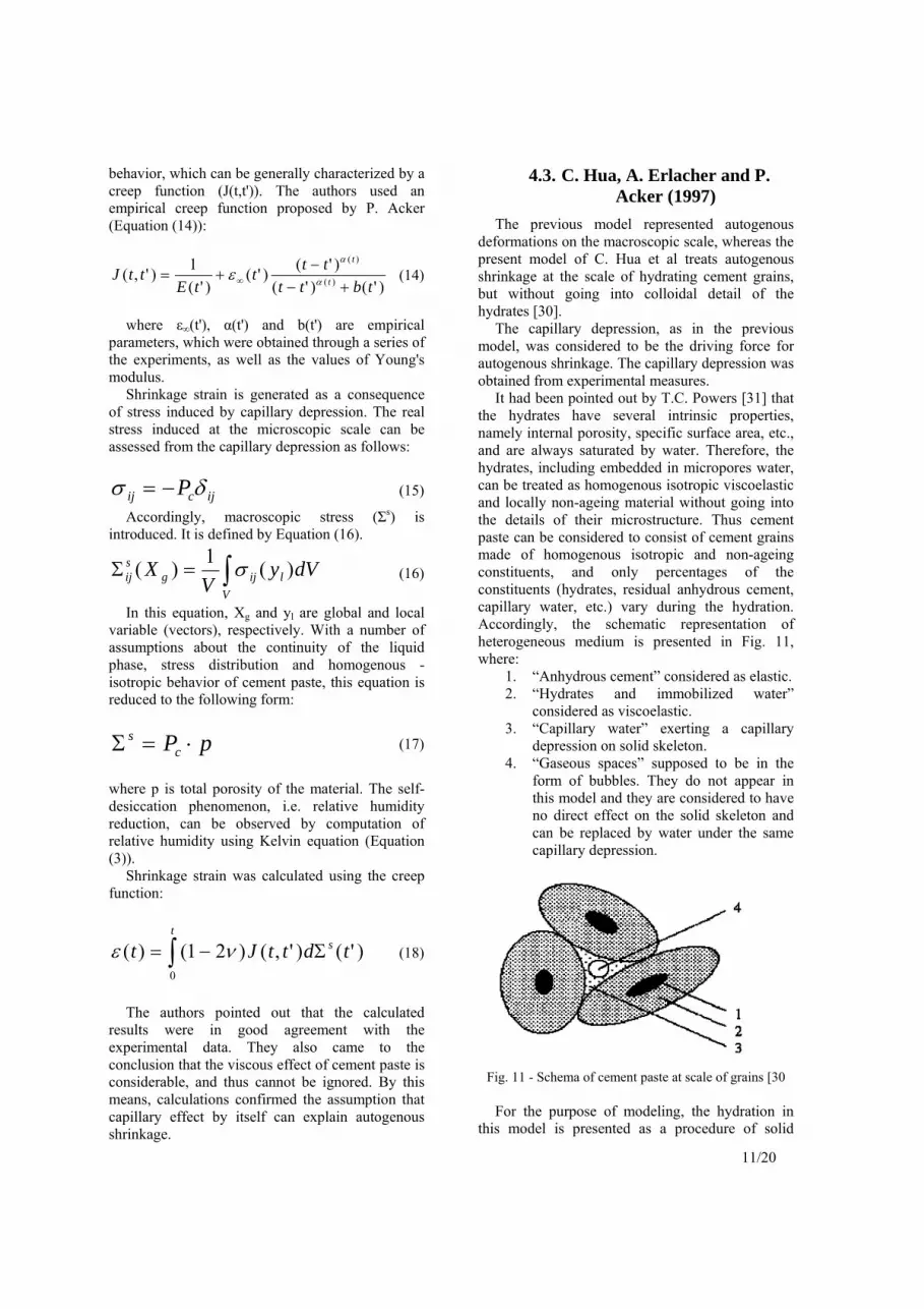
The previous model represented autogenous deformations on the macroscopic scale, whereas the present model of C. Hua et al treats autogenous shrinkage at the scale of hydrating cement grains, but without going into colloidal detail of the hydrates [30].
The capillary depression, as in the previous model, was considered to be the driving force for autogenous shrinkage. The capillary depression was obtained from experimental measures.
It had been pointed out by T.C. Powers [31] that the hydrates have several intrinsic properties, namely internal porosity, specific surface area, etc., and are always saturated by water. Therefore, the hydrates, including embedded in micropores water, can be treated as homogenous isotropic viscoelastic and locally non-ageing material without going into the details of their microstructure. Thus cement paste can be considered to consist of cement grains made of homogenous isotropic and non-ageing constituents, and only percentages of the constituents (hydrates, residual anhydrous cement, capillary water, etc.) vary during the hydration. Accordingly, the schematic representation of heterogeneous medium is presented in Fig. 11, where:
1. “Anhydrous cement” considered as elastic. 2. “Hydrates and immobilized water”
considered as viscoelastic. 3. “Capillary water” exerting a capillary
depression on solid skeleton. 4. “Gaseous spaces” supposed to be in the
form of bubbles. They do not appear in this model and they are considered to have no direct effect on the solid skeleton and can be replaced by water under the same capillary depression.
Fig. 11 - Schema of cement paste at scale of grains [30
For the purpose of modeling, the hydration in
this model is presented as a procedure of solid

12/20
volume development, which is described in Fig. 12 with:
1. Hydrates at time t; 2. Anhydrous cement at time t; 3. New external hydrate at time t + Δt; 4. New internal hydrate at time t + Δt.
Fig. 12 - Diagram of cement grain development [30] In view of that, it is necessary to know volume
of corresponding components during hydration. The equation (19), which connects between volume of cement hydrated (Vch) and apparent volume of hydrates (Vh
ap), can be obtained taking into account quantity of chemically bonded water, chemical shrinkage and the intrinsic porosity (28%) of the hydrates.
)(156.2)( tVtV chap
h
(19)
In this model, the initial state is taken as the time
of setting when continuous skeleton is formed and begins to undergo the capillary depression. To simplify the model, it was assumed that all cement grains are spherical and identical, and that distribution of grains is periodical. These assumptions allow working on periodic cell. When hydrating grains touch each other, it is the time of setting. The two distributions were tested: (i) simple cubical distribution and (ii) centered cubical distribution. The first distribution gave degree of hydration of 17.76% at time of setting, while the second showed that degree of hydration at time of setting is 48.94%. Typical degree of hydration observed experimentally at time of setting reaches approximately 20%, whatever is w/c ratio [32]. The simple cubical distribution is therefore was considered closer to reality and for this reason was used for the calculations in this model. Accordingly, because of the symmetry, an eighth of the sphere, as shown in [30], can be taken as a unit cell (Fig. 13).
Fig. 13 - Diagram of an eighth of hydrating grain
at time of setting [30] In the mechanical model, as was already
mentioned, the material is composed of three constituents with locally non-ageing properties:
Anhydrous cement was considered as elastic isotropic. Its behavior is therefore characterized by stiffness tensor Aijkl(Ea,νa) depending on Ea (Young modulus of anhydrous cement) and νa (Poisson's ratio of anhydrous cement). During hydration, it is successively replaced by internal hydrate layers.
1. Hydrates and immobilized water was considered as a viscoelastic isotropic component corresponding to the rheological model of Zener, shown by Fig. 14. Its behavior is therefore represented by three stiffness tensors H1
ijkl(Eh1,νh1), H1ijkl(Eh1,νh1) and
ηijkl(η,νη). The viscoelastic deformation of each layer begins when it forms. Accordingly, each new layer is deposited on layers already deformed by capillary depression and thus each hydrate layer has its own history of deformation.
Fig. 14 - Rheological model of viscoelastic material [30]
Capillary water exerts a capillary depression on
the solid skeleton. It is gradually replaced by external hydrate layers.
According to hypothesis of periodicity and symmetry, the boundary conditions shown in Fig. 15 were imposed. The load in the boundary conditions was calculated from the capillary depression obtained from experimental measures.

13/20
Fig. 15 - Boundary conditions imposed on the faces [30]
Although there is a sensitivity of the results
obtained with the model to the material parameters, which are not known precisely, the proposed micro-mechanics calculation confirmed that the mechanism of capillary depression gives completely acceptable estimation of autogenous shrinkage. The proposed model allows modeling of a macroscopically ageing material, while constituents have very simple behaviors. This idea can be also used for the modeling of viscoelastoplastic behavior of the cement paste under external load during hydration, because the loading history of each hydrate layer is taken into account.
4.4. Ishida et al (1998)
The proposed autogenous and drying shrinkage model was derived from micro-mechanical physics of water in pore structure of concrete [33]. The capillary tension was assumed driving force of autogenous and drying shrinkage. The material properties of ageing concrete were obtained by the analysis considering the interrelation of hydration, moisture transport and pore structure development process. For this purpose, hydration, microstructure development and shrinkage models were combined. Only the relevant aspects are presented here.
Cement hydration model provided hydration level of each mineral and temperature development due to heat of hydration. The three types of porosity were distinguished: interlayer (pl), gel (pg) and capillary (pc) porosity, which were calculated as follows:
2slw
l
stp
(20)
lsg pVp 28.0 (21)
p
psc
WVp
)1(1 (22)
where tw is interlayer thickness, sl is specific area of interlayer, Wp is weight of powder material per unit volume, ρp is density of powder material, ρs is dry density of solid crystals, Vs is volume of gel solids (while 0.28 represent characteristic CSH porosity, which is assumed to be constant during the hydration process). Volume of gel solids was computed according to Equation (23).
wp
ps
WV
1
28.01
(23)
where β is amount of chemically bound water per unit weight of powder material. Consequently, porosity distribution is modeled by total porosity function p(r):
rBc
rBgl
cg epepprp 11)( (24)
where r is pore radius, Bg and Bc are distribution parameters, which represent the peak of porosity distribution on logarithmic scale, corresponding to the gel and capillary porosity, respectively. Adsorption-desorption characteristics of interlayer water are modeled based on Feldman-Sereda interlayer model [34].
The capillary tension is assumed a driving force of both autogenous and drying shrinkage. Accordingly, the modeling of volume changes is based on Laplace equation (Equation (2)), which was modified by “the area factor” (As [m3/m3]), since the capillary stress is applied on pore walls were liquid water exists. Hence, the area factor (As) was defined as the total liquid water content per unit concrete volume. The final form of capillary stress, which is origin of shrinkage, is represented by Equation (25).
sss r
A 2
(25)
Cement paste is extremely non-linear material, hence it is logically to suggest that stress-stain relationship, which describes micro-deformation of cement paste due to capillary stress, is non-linear. However, in this model effective elastic modulus for capillary stress (Es) was used in stress-strain relationship described by Equation (26), where εsh is unrestrained macroscopic shrinkage strain.
s
ssh E
(26)

14/20
Several experimental tests were conducted in
order to verify the model. The results demonstrated acceptable correlation.
5. SHRINKAGE REDUCTION METHODS
5.1. Cement Modification
As was already stated, autogenous shrinkage is induced by chemical shrinkage. All cement components have different volume stoichiometry of hydration reaction. Thus, reducing content of minerals entering into cement composition and giving higher chemical shrinkage can diminish autogenous shrinkage to some degree [35]. Lower autogenous shrinkage of Portland cement containing higher belite (C2S) content and lower contents of alite (C3A) or celite (C4AF) is reported [36]. Therefore, autogenous shrinkage of concrete made with a moderate heat Portland cement and low heat Portland cement should be inferior in comparison to the ordinary Portland cement [35]. However, it is very difficult to evaluate a pure effect of cement composition on autogenous shrinkage, because compressive strength is also affected by it.
Additionally, the increased gypsum content in cement, which causes autogenous expansion, can be used to counteract autogenous shrinkage. However, the investigation for stability of such cement is necessary [35].
5.2. Expansive additives
Use of expansive additive can reduce total shrinkage in comparison to that of ordinary concrete, although autogenous shrinkage occurs even in concrete with expansive additives. Action of expansive additive differs for different type of additive and for different concentrations [37]. Effect of various expansive additives is shown in Fig. 16. It can be seen that use of expansive additive alone does not completely compensate autogenous shrinkage of high-strength concrete made of ordinary Portland concrete. Use of expansive additive in combination with high belite or low heat Portland cement can be more effective, which is demonstrated in Fig. 17 and Fig. 18.
There is an indication that a replacement of part of Portland cement by fly ash can significantly decrease autogenous shrinkage of high-strength / high-performance concrete [35]. On the other hand,
a partial replacement of cement by fly ash results in decrease in the rate of strength development. Therefore, selecting additive, a balance between the strength development and the effect of reducing autogenous shrinkage should be considered.
Fig. 16 - Autogenous shrinkage of HSC made of ordinary
Portland cement and blast furnace slag powder with expansive additives [37]
Fig. 17 - Autogenous shrinkage of HSC made of high
belite cement with expansive additives [37]
Fig. 18 - Autogenous shrinkage of HSC made of ordinary
Portland cement (AS) and low heat Portland cement combined with shrinkage reducing agent and expansive
additive (adopted from [39])

15/20
It is confirmed that powder treated by water repellent is also effective to reduce autogenous shrinkage [38]. However, effect of most expansive additives on hydration process and autogenous shrinkage has not been clear yet [35].
5.3. Admixtures reducing drying shrinkage
Autogenous shrinkage can be also reduced using drying shrinkage reducing admixtures [35]. Drying shrinkage reducing agent directly affects surface tension of capillary pore water resulting in a decrease of both surface tension and capillary tension mechanisms of shrinkage. In other words, autogenous shrinkage is reduced without changing other properties of hardened concrete.
The reducing effect of drying shrinkage admixtures on autogenous shrinkage compared with that of expansive additives is shown in Fig. 19 [36]. As we can see, a combination of drying shrinkage reducing agent and expansive additive can be highly effective. Autogenous shrinkage of high-strength concrete with w/b ratio of 0.23 made of (a) ordinary Portland cement (AS) and (b) low heat Portland cement, using both expansive additive and shrinkage reducing agent is demonstrated in Fig. 18 [39].
Fig. 19 - Influence of expansive additives and drying
shrinkage reducing agents on autogenous shrinkage of concrete (adopted from [36])
It has to be noted that self-desiccation still occurs
in the mixes with expansive additives and drying shrinkage reducing agent, consequently causing autogenous deformations, which is indicated by the slope of the shrinkage curves in Fig. 19.
5.4. Fibers
Incorporation of fibers into cementitious matrix has been proven effective extending toughness and ability of cracking resistance [40]. The most appropriate type of fibers, which may be applied to high-performance matrix, is steel fibers. Plastic fibers present little interest for HPC applications owing to their intrinsic properties, except possibly impact capacity improvement [41].
It was shown that certain types of fibers could reduce drying shrinkage of HPC by up to 65% [42]. There are some indications that fibers with high elasticity modulus can be effective reducing autogenous shrinkage as well [43]. However, numerous tests on early age shrinkage showed that the addition of steel fibers does not practically influence the free shrinkage, i.e. unrestrained shrinkage, of concrete, whereas the major effect of fiber reinforcement is cracking reduction when external restrain is applied [44].
Obviously, reinforcement with fibers, having high elasticity modulus, greatly decreases cracking sensitivity and increases the ultimate tensile stress the concrete can sustain, although the fiber reinforced concrete still exhibits substantial autogenous shrinkage.
5.5. Mix proportions
The major factor, which affects autogenous shrinkage, is w/c or w/b ratio [35]. However, reduction of autogenous shrinkage by means of w/c or w/b ratio increase is not practical, because water to cement ratio is determined by the strength and durability requirements.
Aggregate content affects volume changes as well [41, 6]. Still, it cannot be the instrument reducing autogenous shrinkage, since low w/b ratio of high-performance concrete, requiring higher cement content and thus higher paste volume, predetermines low aggregate concentration.
As aggregate restrains the shrinkage of the paste, the concrete shrinkage will also decrease with increase of aggregate stiffness [6]. Nevertheless, this is neither always possible, nor economically proved.
As we can see, mix proportioning cannot be used as effective shrinkage reducing method.
6. INTERNAL CURING
Internal curing is a new and quickly developing trend in modern concrete technology. The primary goal of internal curing is to counteract autogenous shrinkage in HSC/HPC, however it can be

16/20
considered more than just a new strategy to combat against one of the types of shrinkage. In fact, internal curing influences majority of physical and mechanical properties of concrete, and what is the most important – its durability.
The term internal curing implies introduction to the concrete mixture of a new component, which will serve as curing agent. In this relation, internal curing, as well as normal curing, can be classified into two categories: water adding, when curing agent performs as water container slowly releasing water, and non water adding, when curing agent intended in delay or prevent loss of water present in the system.
With regard to high-strength concrete, water adding internal curing is preferable, since non-water adding internal curing is unable to prevent self-desiccation. As internal curing agent is part of the system and is finely dispersed, it can overcome the problem of low permeability of low w/b ratio cementations system, which harmfully affects efficiency of traditional curing. Therefore, water-adding internal curing can be considered as most effective method of reducing autogenous shrinkage, since it straightforwardly affects the cause of autogenous shrinkage, namely self-desiccation.
Internal curing, as well as external curing, can be classified into two categories:
1. Internal sealing, when the curing agent is intended to delay or prevent loss of water from the hardening concrete, and
2. Internal water curing (sometimes called “water entrainment”), when the curing agent performs as a water reservoir, which gradually releases water.
6.1. Internal sealing ("self-curing")
The concept of concrete, which does not need any externally applied curing and involves adding to the concrete during the mixing water-soluble chemicals, was called “self-curing” [45]. Instead of this term the name "internal sealing" introduced recently by RILEM Technical Committee TC-196 ICC (Internal Curing of Concrete) is widely used nowadays. These water-soluble chemicals are intended to reduce water evaporation as the concrete is exposed to air-drying. Water-soluble polymers, having hydroxyl (-OH) and ether (-O-) functional groups, were found satisfying requirements set out for a “self-cure chemical”, i.e. they enhanced water retention in the concrete and increased degree of hydration. Hydrogen bonding occurred between these functional groups reduced water pressure of water and decreased evaporation [45]. Experimental research on effects of these
additives on concrete microstructure showed that strength was greater than the control at the low dosage; but at higher concentrations, the strength was lower, which can be explained by the fact that higher concentrations affect the paste-aggregate bond. This research also showed that admixture alters the C-S-H gel morphology, reducing absorptivity of the concrete [46]. The research was conducted on ordinary concrete. This concept may be applied to HPC as well, which, however, requires additional research [47].
6.2. Internal water curing ("water entrainment") using pre-
saturated lightweight aggregate
The idea that self-desiccation can be counteracted by use of pre-saturated lightweight aggregate was conceived by several authors [21, 48, 49]. This method received name of “autogenous curing” in work [49]. Later it was suggested that if self-desiccation can be diminished or even prevented by this means, thus autogenous shrinkage, caused by self-desiccation, is also affected by this method. The autogenous deformation of lightweight concretes with pre-saturated lightweight aggregate and concretes, where normal weight aggregate was partly replaced by pre-saturated lightweight aggregate, were investigated. The experiments showed that high-strength concrete, which exhibits no autogenous shrinkage, can be obtained by this method [50 - 53].
6.3. Internal water curing ("water entrainment") using super-
absorbent polymers
A new method for prevention of self-desiccation by use of super-absorbent polymer particles as concrete admixture was proposed recently [54]. During concrete mixing, the particles of super-absorbent polymer will absorb water and form macroinclusions containing free water. This free water intended to be consumed during cement hydration providing internal curing to the surrounding paste matrix and preventing, by this means, self-desiccation. This concept is analogous to the air entrainment, used for frost protection of concrete, and thus is often called "water entrainment".
SUMMARY
It is widely accepted that autogenous volume changes are caused by chemical contraction of

17/20
hydrating cement. Chemical contraction phenomena have been extensively studied and can be readily calculated. Consequently, most of the researchers attempted to reveal the relation between chemical shrinkage and external volume changes and proposed a prediction formula based on this relation.
Most of the researchers arrived to the conclusion that the mechanism responsible for autogenous shrinkage is capillary tension, which is considered as one of the decisive mechanisms of drying shrinkage as well. However, A.E.B. Koenders and K. van Breugel built their model on the assumption that the driving force for autogenous shrinkage is variation in surface energy, though this mechanism is operative only at relative humidity below 40% [6, 13]. Both mechanisms are closely related to humidity reduction, i.e. self-desiccation. By this means, the mechanism of chemical source, i.e. chemical shrinkage, activates the other mechanism, which is related to moisture variations.
All of the investigators recognized the importance of the role that pore structure plays in autogenous deformations, which follows from the Laplace equation (Equation (2)). For that reason, the pore size distribution found either theoretically or experimentally is essential and integral part of all the reviewed models of autogenous shrinkage. Moreover, the accurate representation of pore size distribution is a necessary condition for proper calculation of autogenous deformation.
Several approaches to mechanical behavior of the cement paste were suggested. The simplest approach proposed elastic response to the stress induced by humidity changes at microscopic level. The more sophisticated approach considered viscoelastic behavior of the cement paste by means of creep function. Finally, in one of the models, a micro-mechanics method was applied to analyze behavior of the cement paste at scale of hydrating cement paste. The last method allows modeling of a macroscopically ageing material with viscoelastic behavior, and additionally taking into account a loading history. A comparison of elastic and viscous components leads to the conclusion that the creep component is considerable and cannot be neglected.
With regard to the modern developments of the methods preventing or mitigating shrinkage, especially autogenous and drying shrinkage, the following ones are noteworthy:
cement modification by reducing content of minerals giving higher chemical shrinkage and increasing gypsum (however, in this case investigation of stability is essential);
use of expansive additive can reduce total shrinkage, although autogenous shrinkage occurs (use of expansive additive in combination with high belite or low heat Portland cement can be more effective);
use of drying shrinkage reducing admixtures, which directly affecting surface tension of capillary pore water resulting in a decrease of both surface tension and capillary tension mechanisms of shrinkage (such admixtures reduce also autogenous shrinkage);
use of internal curing methods, which are based on water-soluble chemicals intended to reduce water evaporation as the concrete is exposed to air-drying, pre-saturated lightweight aggregates and super-absorbent polymers ("water- entraining" agents).
REFERENCES
[1] R.I. Gilbert, "Shrinkage, Cracking and
Deflection-the Serviceability of Concrete Structures", Electronic Journal of Structural Engineering 1 (1) (2001) 2-14.
[2] E. Freyssinet, "Théorié Générale de la Prise des Liants Hydrauliques; les Phénomènes de Retrait et de Deformation Lente des Bétons et Mortiers", C. R. Centre d'Etudes Supérieures de l'Inst. Techn. Bâtiment Trav. Publ., Paris, 1934, p. 321.
[3] T.C. Powers and T.L. Brownyard, "Studies of the Physical Properties of Hardened Portland Cement Paste", J. Am. Concr. Inst. (1947) 549.
[4] R. L'Hermite, “Volume Changes of Concrete", Proceedings of Fourth International Symposium on the Chemistry of Cement, Washington, D.C., 1960, pp. 659-694.
[5] F.H. Wittmann, “Surface Tension, Shrinkage and Strength of Hardened Cement Paste”, Materials & Structures 1 (6) (1968) 547-552.
[6] I. Soroka, “Portland Cement Paste and Concrete”, the Macmillan Press Ltd., London, 1979.
[7] J.H.M. Visser, “Extensile Hydraulic Fracturing of (Saturated) Porous Materials”, Ph.D. Thesis, Delft University, the Netherlands, 1998.
[8] D.P. Bentz and O.M. Jensen, “Mitigation Strategies for Autogenous Shrinkage Cracking”, http://ciks.cbt.nist.gov/~bentz/aci2001/ascrack.html

18/20
[9] O. Ishai, “The Time-Dependent Deformational
Behavior of Cement Paste, Mortar and Concrete”, Proceedings of Conference on Structure of Concrete and its Behavior under Load, Cement and Concrete Association, London, 1968, pp. 345-364.
[10] T.C. Powers, “Mechanism of Shrinkage and Reversible Creep of Hardened Cement Paste”, Proceedings of Conference on Structure of Concrete and its Behavior under Load, Cement and Concrete Association, London, 1968, pp. 319-344.
[11] R.F. Feldman and P.J. Sereda, “A New Model for Hydrated Cement and its Practical Implementations”, Engineering Journal 53 (1970) 53-59.
[12] J.W. Gibbs, Collected Works, Yale University Press, New Haven, 1957.
[13] F.H. Wittmann, “Creep and Shrinkage Mechanisms”, Part II in “Creep and Shrinkage in Concrete Structures”, Ed. by Z.P. Bažant and F.H. Wittmann, John Wiley & Sons, 1982, pp. 129-163.
[14] D.H. Bangham and N. Fackhoury, “The Swelling of Charcoal”, Proceedings of Royal Society of London, Series A, 130, 1931, pp. 81-89.
[15] K.H. Hiller, “Strength Reduction and Length Changes in Porous Glass Caused by Vapor Adsorption”, Journal of Applied Physics 35 (1964) 1622-1628.
[16] E.A.B. Koenders and K. van Breugel, “Numerical Modelling of Autogenous Shrinkage of Hardening Cement Paste”, Cement and Concrete Research 27 (10) (1997) 1489-1499.
[17] S. Mindess and J.F. Jang, “Concrete”, Prentice and Hall, New York/London, 1981.
[18] V.I. Babushkin, G.M. Matveyev and O.P. Mchedlov-Petrossyan, “Thermodynamics of Silicates”, Springer-Verlag, Berlin, 1985.
[19] A.M. Neville, “Suggestions of Research Areas Likely to Improve Concrete,” Concrete International 18 (5) (1996) 44-49.
[20] A.M. Neville, “Properties of Concrete”, Fourth Edition, John Wiley and Sons, New York, NY, 1996, pp. 25-37.
[21] S. Weber and H.W. Reinhardt, “A Blend of Aggregates to Support Curing of Concrete”, Proceedings of International Symposium on Structural Lightweight Concrete, Ed. by I. Holand, T.A. Hammer and F. Fluge, Sandefjord, Norway, 1996, pp. 662-671.
[22] P.-C. Aitcin, A.M. Neville, and P. Acker,
“Integrated View of Shrinkage Deformation”, Concrete International 19 (9) (1997) 35-41.
[23] S.L. Mayers, “Thermal Expansion Characteristics of Hardened Cement Paste and of Concrete”, Proceeding of Highway Research Board 30 (1950) 193-203.
[24] F. Wittmann and J. Lukas, “Experimental Study of Thermal Expansion of Hardened Cement Paste”, Materials & Structures 7 (40) (1974) 247-252.
[25] T.C. Powers, “A Hypothesis on Carbonation Shrinkage”, J. Res. Dev. Labs. Portland Cement. Ass. 4 (2) (1962) 40-45.
[26] E.A.B. Koenders and K. van Breugel, “Modeling Dimensional Changes in Low Water/Cement Ratio Pastes”, Proc. of Intern. Workshop on Autogenous Shrinkage of Concrete, JCI, Ed. by E. Tazawa, June 13-14, 1998, Hiroshima, Japan, pp. 271-280.
[27] K. van Breugel, “Simulation of Hydration and Formation of Structure in Hardening Cement-Based Materials - HYMOSTRUC”, Ph.D. Thesis, Deft University, The Netherlands, 1991.
[28] K. van Breugel, “Numerical Simulation of Hydration and Microstructural Development in Hardening Cement-Based Materials, (I) Theory”, Cement and Concrete Research, 25 (2) (1995) 319-331.
[29] C. Hua, P. Acker and A. Ehrlacher, “Analyses and Models of the Autogenous Shrinkage of Hardening Cement Paste: I. Modelling at macroscopic scale”, Cement and Concrete Research 25 (7) (1995) 1457-1468.
[30] C. Hua, A. Ehrlacher and P. Acker, “Analyses and Models of the Autogenous Shrinkage of Hardening Cement Paste: II. Modeling at Scale of Hydrating Grains”, Cement and Concrete Research 27 (2) (1997) 245-258.
[31] T.C. Powers, “Properties of Cement Paste and Concrete – Paper V-1. Physical Properties of Cement Paste”, Proceedings of Fourth International Symposium on Chemistry of Cement, 1960, pp. 577-609.
[32] H.M. Jennings, “The Developing Microstructure in Portland Cement”, Advances in Cement Technology, Edited by D.N. Ghosh, 1983, pp. 349-396.
[33] T. Ishida, R.P. Chaube, T. Kishi and K. Maekawa, “Micro-Physical Approach to Coupled Autogenous and Drying Shrinkage of Concrete”, Proc. of Intern. Workshop on Autogenous Shrinkage of Concrete, JCI, Ed. by E. Tazawa, June 13-14, 1998, Hiroshima, Japan, pp. 301-312.

19/20
[34] R.F. Feldman and P.J. Sereda, “A Model of
Hydrated Portland Cement Paste as Deduced from Sorption Length Change and Mechanical Properties”, Materials & Structures 1 (1968) 509-519.
[35] "Report of JCI Committee on Autogenous Shrinkage of Concrete", Proc. of Intern. Workshop on Autogenous Shrinkage of Concrete, JCI, Ed. by E. Tazawa, June 13-14, 1998, Hiroshima, Japan, pp. 5-28.
[36] E. Tazawa and S. Miyazawa, “Influence of Constituent and Composition on Autogenous shrinkage of Cementitious Materials”, Magazine of Concrete Research 49 (178) (1997) 15-22.
[37] A. Hori, M. Morioka, E. Sakai and M. Daimon, ”Influence of Expansive Additives on Autogenous Shrinkage”, Proc. of Intern. Workshop on Autogenous Shrinkage of Concrete, JCI, Ed. by E. Tazawa, June 13-14, 1998, Hiroshima, Japan, pp. 177-184.
[38] E. Tazawa, “Autogenous Shrinkage of Cement Paste Caused by Hydration”, Cement and Concrete 565 (1994) 35-44.
[39] R. Sato, S. Tanaka, T. Hayakawa and M. Tanimura, “Experimental Studies on Reduction of Autogenous Shrinkage and Its Induced Stress in High-Strength Concrete”, Proc. of the 2nd Intern. Res. Seminar “Self-Desiccation and Its Importance in Concrete Technology”, Ed. by B. Persson and G. Fagerlund, Lund, Sweden, 1999, pp. 163-171.
[40] R.N. Swamy (Ed.), “Fiber Reinforced Cement and Concrete”, 4th RILEM International Symposium, Chapman and Hall, Sheffield, UK, 1992.
[41] P.C. Aïtcin, “High-Performance Concrete”, E&FN SPON, 1998.
[42] W. Sun, H. Chen, X. Luo and H. Qian, “The Effect of Hybrid Fibers and Expansive Agent on the Shrinkage and Permeability of High-Performance concrete”, Cement and Concrete Research 31 (2001) 595-601.
[43] S. Miyazawa, T. Kuroi and H. Shimomura, “Autogenous Shrinkage Stress of Fiber Reinforced Mortar”, Cement & Concrete, JCA (1997) 560-565.
[44] K. Kovler and A. Bentur, “Shrinkage of Early Age Steel Fiber Reinforced Concrete”, Archives of Civil Engineering (1997) 431-439.
[45] R.K. Dhir, P.C. Hewlett, J.S. Lota and T.D. Dyer, “An Investigation Into the Feasibility of Formulating ‘Self-Cure’ Concrete”, Materials & Structures 27 (1994) 606-615.
[46] R.K. Dhir, P.C. Hewlett and T.D. Dyer, “Influence of Microstructure on the Physical
Properties of Self-Curing Concrete”, ACI Materials Journal 93 (5) (1996) 465-471.
[47] K.W. Meeks and N.J. Carino, “Curing of High-Performance Concrete: Report of the State-of-the-Art”, NISTIR 6295, 1999.
[48] A.M. Vaysburd “Durability of Lightweight Concrete Bridges in Severe Environments”, Concrete International 18 (1996) 33-38.
[49] S. Weber and H.W. Reinhardt, “A New Generation of High Performance Concrete: Concrete with Autogenous Curing”, Advanced Cement Based Materials 6 (1997) 59-68.
[50] K. Takada, K. van Breugel, E.A.B. Koenders and N. Kaptijn, “Experimental Evaluation of Autogenous Shrinkage of Lightweight Aggregate Concrete”, Proceedings of International Workshop on Autogenous Shrinkage of Concrete, JCI, Edited by E. Tazawa, June 13-14, 1998, Hiroshima, Japan, pp. 221-230.
[51] A. Bentur, S. Igarashi and K. Kovler, “Prevention of Autogenous Shrinkage in High Strength Concrete by Internal Curing Using Wet Lightweight Aggregates”, Cement and Concrete Research 31 (2001) 1587-1591.
[52] P. Schwesinger and G. Sickert, “Reducing Shrinkage in HPC by Internal Curing by Using Pre-soaked LWA”, Proceedings of International Workshop on Control of Cracking in Early-Age Concrete, Tohoku University, Japan (2000), pp. 313-318.
[53] S. Zhutovsky, K. Kovler, and A. Bentur, "Influence of Wet Lightweight Aggregate on Mechanical Properties of Concrete at Early Ages", Materials & Structures 35 (2002) 97-101.
[54] O.M. Jensen and P.F. Hansen, “Water-Entrained Cement-Based Materials: I. Principle and Theoretical Background”, Cement and Concrete Research 31 (2001) 647-654.


![Regionalization amidst 'State-Shrinkage' [p.p. 5-28]](https://img.dokumen.tips/doc/110x75/631b937b3e8acd9977057dea/regionalization-amidst-state-shrinkage-pp-5-28.jpg)


