Embed Size (px)
Citation preview

NATO UNCLASSIFIED
Acquisition Directorate
Boulevard Léopold III
B-1110 Brussels, Belgium
NATO UNCLASSIFIED Page 1 of 7
NCIA/ACQ/2018/1938 17 December 2018
To : See Distribution List
Subject : INVITATION FOR BID Provide DCIS Equipment for Small NRF HQs IFB-CO-14760-FIREFLY
Reference(s) : A. AC/4-2261 (1996 Edition B. AC/4(PP)D/26972-ADD1 C. AC/4-DS(2017)0029 D. AC/4-DS(2018)0021 E. Notification of Intent (NOI) NCIA/ACQ/2018/1292
Dear Nominated Bidders,
1. Your firm is hereby invited to participate in an International Competitive Bid for the procurement, design and testing of DCIS Transmission Systems.
2. The scope of the project is described in the prospective Contract – Book II of this IFB.
3. NATO intends to place one contract to cover the entire scope of the project. No partial bidding will be allowed.
4. Contract award will be based on the proposal evaluated as the lowest priced bid in compliance with the requirements of this IFB and in accordance with the selection criteria set forth in the Bidding Instructions (Book I) and which follow the procedures for Lowest Compliant Bidding as described in this IFB.
5. The reference for the Invitation for Bid is IFB-CO-14760-FIREFLY, and all correspondence concerning the IFB should reference this number.
6. THE CLOSING TIME FOR SUBMISSION OF BIDS IN RESPONSE TO THIS INVITATION FOR BID IS 1200 HOURS (BRUSSELS TIME) ON 11 March 2019.

NATO UNCLASSIFIED
NCIA/ACQ/2018/1938
Bidders List Continued
NATO UNCLASSIFIED Page 2 of 7
7. This Invitation for Bid consists of the following:
o Book I: Bidding Instructions, including Administrative Certificates and Bidding Sheets
o Book II: Prospective Contract:
o Part I: The Schedule of Supplies and Services; o Part II: The Contract Special Provisions; o Part III: The Contract General Provisions; o Part IV: The Statement of Work (SOW). The SOW and the Annexes
thereto set forth detailed specifications governing the performance requirements of the Contract.
8. The overall security classification of this bid is “NATO UNCLASSIFIED”. This Invitation for Bid remains the property of the NCI Agency and shall be protected in accordance with the applicable national security regulations.
9. You are requested to complete and return the enclosed acknowledgement of receipt (Attachment A) as soon as possible, informing this Agency of your intention to bid. Your firm is not bound by its initial decision, and if you decide to reverse your stated intention at a later date, you are requested to advise us by a separate letter.
10. Prospective Bidders are advised that the NCI Agency reserves the right to cancel this IFB at any time in its entirety and bears no liability for bid preparation costs incurred by firms or any other collateral costs if bid cancellation occurs.
11. The NCI Agency point of contact for all information concerning this IFB is:
NCI Agency Boulevard Léopold III 1110 Brussels, Belgium Attention: Joseph Vitale – Senior Contracting Officer E-mail: [email protected]
For the Director of Acquisition: Joseph L Vitale Senior Contracting Officer
Attachment: A) Acknowledgement of Receipt of IFB-CO-14760-FIREFLY
B) Bidders List

NATO UNCLASSIFIED
NCIA/ACQ/2018/1938
Bidders List Continued
NATO UNCLASSIFIED Page 3 of 7
ATTACHMENT A
ACKNOWLEDGEMENT OF RECEIPT OF INVITATION FOR BID
IFB-CO-14760-FIREFLY
Please complete and return by e-mail to
Joseph Vitale at: [email protected]
We hereby advise that we have received the Invitation for Bid and have accessed the bidding
documentation related to IFB-CO-14760-FIREFLY on __________________(date), together
with all enclosures listed in the Table of Contents.
PLEASE CHECK ONE:
As of this date and without commitment on our part, we do intend to submit a bid.
We do not intend to submit a bid.
We are reviewing the requirements of the IFB and will notify you of our decision as soon as possible.
Signature: _________________________________________
Printed Name: _________________________________________
Title: _________________________________________
Company: _________________________________________
Address: _________________________________________
NATO UNCLASSIFIED
NCIA/ACQ/2018/1938
Bidders List Continued
NATO UNCLASSIFIED Page 4 of 7
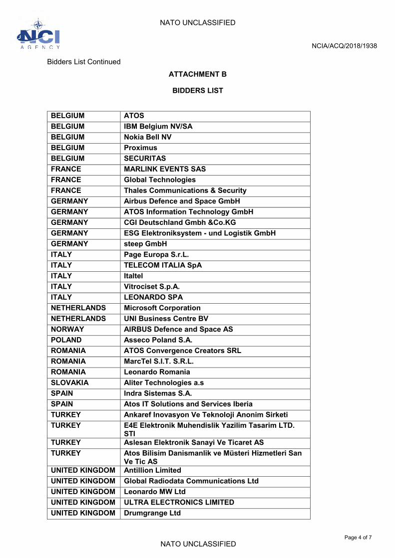
ATTACHMENT B
BIDDERS LIST
BELGIUM ATOS BELGIUM IBM Belgium NV/SA BELGIUM Nokia Bell NV BELGIUM Proximus BELGIUM SECURITAS FRANCE MARLINK EVENTS SAS FRANCE Global Technologies FRANCE Thales Communications & Security GERMANY Airbus Defence and Space GmbH GERMANY ATOS Information Technology GmbH GERMANY CGI Deutschland Gmbh &Co.KG GERMANY ESG Elektroniksystem - und Logistik GmbH GERMANY steep GmbH ITALY Page Europa S.r.L. ITALY TELECOM ITALIA SpA ITALY Italtel ITALY Vitrociset S.p.A. ITALY LEONARDO SPA NETHERLANDS Microsoft Corporation NETHERLANDS UNI Business Centre BV NORWAY AIRBUS Defence and Space AS POLAND Asseco Poland S.A. ROMANIA ATOS Convergence Creators SRL ROMANIA MarcTel S.I.T. S.R.L. ROMANIA Leonardo Romania SLOVAKIA Aliter Technologies a.s SPAIN Indra Sistemas S.A. SPAIN Atos IT Solutions and Services Iberia TURKEY Ankaref Inovasyon Ve Teknoloji Anonim Sirketi TURKEY E4E Elektronik Muhendislik Yazilim Tasarim LTD.
STI TURKEY Aslesan Elektronik Sanayi Ve Ticaret AS TURKEY Atos Bilisim Danismanlik ve Müsteri Hizmetleri San
Ve Tic AS UNITED KINGDOM Antillion Limited UNITED KINGDOM Global Radiodata Communications Ltd UNITED KINGDOM Leonardo MW Ltd UNITED KINGDOM ULTRA ELECTRONICS LIMITED UNITED KINGDOM Drumgrange Ltd

NATO UNCLASSIFIED
NCIA/ACQ/2018/1938
Bidders List Continued
NATO UNCLASSIFIED Page 5 of 7
UNITED STATES Electromagnetic Technologies Industries, Inc. UNITED STATES GATR Technologies Inc. UNITED STATES General Dynamics Government Systems Overseas
Corporation UNITED STATES General Dynamics Information Technology, Inc. UNITED STATES Information Assurance Specialists, Inc. UNITED STATES Leidos, Inc. UNITED STATES NexTech Solutions LLC UNITED STATES Pacific Star Communications, Inc. UNITED STATES UltiSat Inc. UNITED STATES U.S. International Development Consortium, Inc UNITED STATES World Wide Technology, Inc

NATO UNCLASSIFIED
NCIA/ACQ/2018/1938
Bidders List Continued
NATO UNCLASSIFIED Page 6 of 7
Distribution List for IFB-CO-14760-FIREFLY
NATO Delegations (Attn: Infrastructure Adviser):
Albania Belgium Bulgaria Canada Croatia Czech Republic Denmark Estonia France Germany Greece Hungary Iceland Italy Latvia Lithuania Luxembourg The Netherlands Norway Poland Portugal Romania Slovakia Slovenia Spain Turkey United Kingdom United States
NATO HQ
NATO Office of Resources, Management and Implementation Branch – Attn: Deputy Branch Chief
Director, NATO HQ C3 Staff, Attn: Executive Co-ordinator SACTREPEUR, Attn: Infrastructure Assistant SHAPE, Attn: J3 & J2
Strategic Commands
HQ SACT Attn: R&D Contracting Office ACO Liaison Office

NATO UNCLASSIFIED
NCIA/ACQ/2018/1938
Bidders List Continued
NATO UNCLASSIFIED Page 7 of 7
Embassies in Brussels (Attn: Commercial Attaché):
Albania Belgian Ministry of Economic Affairs Bulgaria Canada Croatia Czech Republic Denmark Estonia France Germany Greece Hungary Iceland Italy Latvia Lithuania Luxembourg The Netherlands Norway Poland Portugal Romania Slovakia Slovenia Spain Turkey United Kingdom United States (electronic copy to [email protected])
All NATEXs NCI Agency – Internal

N A T O U N C L A S S I F I E D CO-14760-FIREFLY
N A T O U N C L A S S I F I E D
Provide DCIS Equipment for Small NRF HQ
IFB-CO-14760-FIREFLY
Book II
CONTRACT SIGNATURE PAGE

N A T O U N C L A S S I F I E D CO-14760-FIREFLY
N A T O U N C L A S S I F I E D
NCI Agency Contract 1. Original Number: of 3 2. Purchase Order Number:
3. Contract Number: CO-14760-FIREFLY 4. Effective date:
5. Contractor:
6. Purchaser: General Manager NCI Agency Avenue du Bourget 140 1110 Brussels Belgium Tel:+32 2 707 8321 Attn: Joseph L Vitale, Senior Contracting Officer
7. CONTRACT SCOPE: This is a Firm-Fixed-Price NATO Security and Investment Program (NSIP) Contract for the provision of the design, procurement and testing of Deployable Communications Information System (DCIS) Transmission Systems. The Contractor shall deliver the Supplies and Services as detailed in the attached Schedule of Supplies and Services (Part I) and the Statement of Work (Part IV) and the Systems Requirements Specification Core Document and annexes (Part V). 8. TOTAL VALUE OF CONTRACT :
9. PERIOD OF PERFORMANCE
As stated in the Schedule of Supplies and Services.
10. DELIVERY SITE As stated in the Statement of Work
11. CONTRACT AGREEMENT The Contractor agrees to furnish all items and perform all the services set forth or otherwise identified in the scope above and on any continuation sheets for the consideration stated herein. This agreement supercedes all previous communications, representations or understandings, either written or oral, and shall constitute the sole and only agreement between the Contractor and the Contracting Authority with respect to the subject matter hereof. The rights and obligations of the parties to this Contract shall be subject to and governed by Contract Special Provisions and Contract General Provisons herein attached to this Contract. 12. Signature of Contractor 13. Signature of Purchaser
14. Name and Title of Signer
15. Name and Title of Signer Kevin J. Scheid General Manager
16. Date signed by the Contractor 17. Date signed by the Purchaser

N A T O U N C L A S S I F I E D CO-14760-FIREFLY
N A T O U N C L A S S I F I E D
TABLE OF CONTENTS
PART I CONTRACT SCHEDULES PART II CONTRACT SPECIAL PROVISIONS PART III CONTRACT GENERAL PROVISIONS PART IV STATEMENT OF WORK (SOW) WITH ANNEXES

NATO UNCLASSIFIED
IFB-CO-14760-FIREFLY
NATO UNCLASSIFIED
Book I, Page I-1 Version: IFB 1.0
Provide DCIS Equipment for Small NRF HQ
BOOK I
INSTRUCTIONS TO BIDDERS
NATO UNCLASSIFIED
IFB-CO-14760-FIREFLY
NATO UNCLASSIFIED
Book I, Page I-2 Version: IFB 1.0
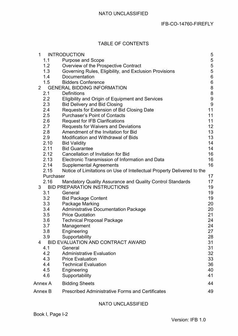
TABLE OF CONTENTS 1 INTRODUCTION 5
1.1 Purpose and Scope 5 1.2 Overview of the Prospective Contract 5 1.3 Governing Rules, Eligibility, and Exclusion Provisions 5 1.4 Documentation 6 1.5 Bidders Conference 6
2 GENERAL BIDDING INFORMATION 8 2.1 Definitions 8 2.2 Eligibility and Origin of Equipment and Services 9 2.3 Bid Delivery and Bid Closing 9 2.4 Requests for Extension of Bid Closing Date 11 2.5 Purchaser’s Point of Contacts 11 2.6 Request for IFB Clarifications 11 2.7 Requests for Waivers and Deviations 12 2.8 Amendment of the Invitation for Bid 13 2.9 Modification and Withdrawal of Bids 13 2.10 Bid Validity 14 2.11 Bid Guarantee 14 2.12 Cancellation of Invitation for Bid 16 2.13 Electronic Transmission of Information and Data 16 2.14 Supplemental Agreements 16 2.15 Notice of Limitations on Use of Intellectual Property Delivered to the Purchaser 17 2.16 Mandatory Quality Assurance and Quality Control Standards 17
3 BID PREPARATION INSTRUCTIONS 19 3.1 General 19 3.2 Bid Package Content 19 3.3 Package Marking 20 3.4 Administrative Documentation Package 20 3.5 Price Quotation 21 3.6 Technical Proposal Package 24 3.7 Management 24 3.8 Engineering 27 3.9 Supportability 28
4 BID EVALUATION AND CONTRACT AWARD 31 4.1 General 31 4.2 Administrative Evaluation 32 4.3 Price Evaluation 33 4.4 Technical Evaluation 36 4.5 Engineering 40 4.6 Supportability 41
Annex A Bidding Sheets 44 Annex B Prescribed Administrative Forms and Certificates 49
NATO UNCLASSIFIED
IFB-CO-14760-FIREFLY
NATO UNCLASSIFIED
Book I, Page I-3 Version: IFB 1.0
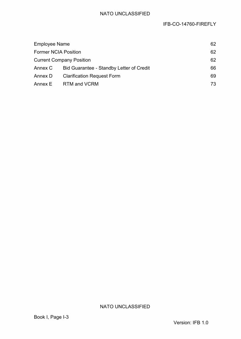
Employee Name 62 Former NCIA Position 62 Current Company Position 62 Annex C Bid Guarantee - Standby Letter of Credit 66 Annex D Clarification Request Form 69 Annex E RTM and VCRM 73

NATO UNCLASSIFIED
IFB-CO-14760-FIREFLY
NATO UNCLASSIFIED
Book I, Page I-4 Version: IFB 1.0
THIS PAGE INTENTIONALLY BLANK
NATO UNCLASSIFIED
IFB-CO-14760-FIREFLY
NATO UNCLASSIFIED
Book I, Page I-5 Version: IFB 1.0
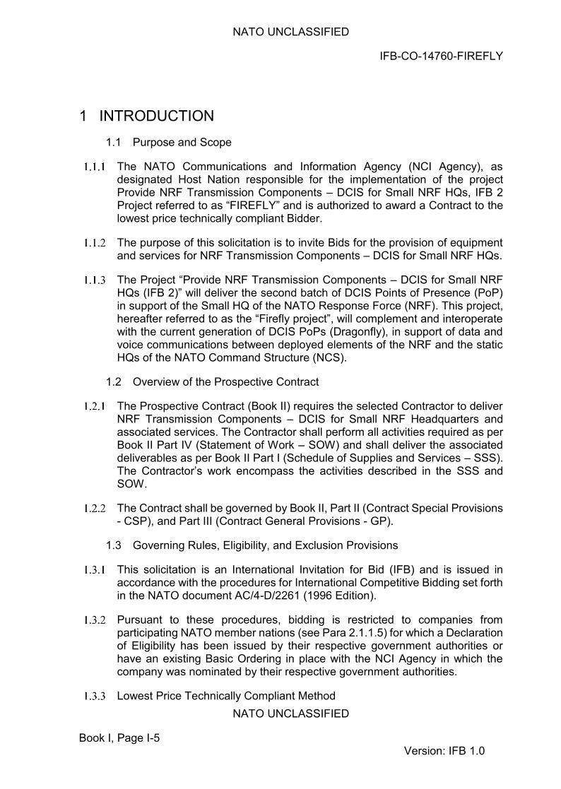
1 INTRODUCTION
1.1 Purpose and Scope
The NATO Communications and Information Agency (NCI Agency), as designated Host Nation responsible for the implementation of the project Provide NRF Transmission Components – DCIS for Small NRF HQs, IFB 2 Project referred to as “FIREFLY” and is authorized to award a Contract to the lowest price technically compliant Bidder.
The purpose of this solicitation is to invite Bids for the provision of equipment and services for NRF Transmission Components – DCIS for Small NRF HQs.
The Project “Provide NRF Transmission Components – DCIS for Small NRF HQs (IFB 2)” will deliver the second batch of DCIS Points of Presence (PoP) in support of the Small HQ of the NATO Response Force (NRF). This project, hereafter referred to as the “Firefly project”, will complement and interoperate with the current generation of DCIS PoPs (Dragonfly), in support of data and voice communications between deployed elements of the NRF and the static HQs of the NATO Command Structure (NCS).
1.2 Overview of the Prospective Contract
The Prospective Contract (Book II) requires the selected Contractor to deliver NRF Transmission Components – DCIS for Small NRF Headquarters and associated services. The Contractor shall perform all activities required as per Book II Part IV (Statement of Work – SOW) and shall deliver the associated deliverables as per Book II Part I (Schedule of Supplies and Services – SSS). The Contractor’s work encompass the activities described in the SSS and SOW.
The Contract shall be governed by Book II, Part II (Contract Special Provisions - CSP), and Part III (Contract General Provisions - GP).
1.3 Governing Rules, Eligibility, and Exclusion Provisions
This solicitation is an International Invitation for Bid (IFB) and is issued in accordance with the procedures for International Competitive Bidding set forth in the NATO document AC/4-D/2261 (1996 Edition).
Pursuant to these procedures, bidding is restricted to companies from participating NATO member nations (see Para 2.1.1.5) for which a Declaration of Eligibility has been issued by their respective government authorities or have an existing Basic Ordering in place with the NCI Agency in which the company was nominated by their respective government authorities.
Lowest Price Technically Compliant Method

NATO UNCLASSIFIED
IFB-CO-14760-FIREFLY
NATO UNCLASSIFIED
Book I, Page I-6 Version: IFB 1.0
The evaluation method to be used in the selection of the successful Bidder under this solicitation shall follow AC/4-D-2261 (1996 Edition). Award of a Contract pursuant to this IFB will be made to the firm that has offered the lowest evaluated price and has been determined to be technically compliant with the requirements of the IFB in accordance with the evaluation criteria. The bid evaluation criteria and the detailed evaluation procedure are described in Section IV of these Bidding Instructions
The bid evaluation criteria and the detailed evaluation procedures are described in Section 4.
This Invitation for Bid will not be the subject of a public Bid opening.
The Bidder shall refer to the Purchaser all queries for resolution of any conflicts found in information contained in this document in accordance with the procedures set forth in Section 2.6 "Request for IFB Clarifications”.
1.4 Documentation
All documentation, including the IFB itself, all applicable documents and any reference documents provided by the Purchaser are solely to be used for the purpose of preparing a response to this IFB. They are to be safeguarded at the appropriate level according to their classification and reference documents are provided “as is“, without any warranty as to quality or accuracy.
1.5 Bidders Conference
Prospective Bidders are invited to a Bidders Conference that will be held between four to six weeks after IFB release in Brussels. The Purchaser will notify all Bidders of the final date and time. Registration forms and relevant information will be provided at the time of notification.
The purpose of the Bidders Conference will be to present the Project, and present the key members of the Purchaser project management team, as well as to allow the Prospective Bidders to clarify aspects of the Invitation for Bid for which they may have questions at that time.
The Bidder’s Conference is planned to include a briefing on the bidding process; the bidding sheets; the prospective contract; and the technical and project management aspects of the project.
The participation to the Conference is limited to a maximum of two (2) attendees per Bidder. No exception to this number of attendees will be made. A detailed agenda for the Bidder’s Conference will be sent to the participating companies in due course
NATO UNCLASSIFIED
IFB-CO-14760-FIREFLY
NATO UNCLASSIFIED
Book I, Page I-7 Version: IFB 1.0
The potential Bidders may submit questions in writing not later than 7 days prior to the date of the Conference to the POC, at the address mentioned under paragraph 2.5.1 “Purchaser Point of Contact. The Purchaser will endeavour to respond to the previously submitted questions at the Bidders Conference. If any additional questions are asked by the potential Bidders at the Bidders Conference, the Purchaser might attempt to answer them at that time, but any answer that might appear to amend terms, conditions and/or specifications of the Contract shall be considered to be formally included in the Invitation for Bid only when a written amendment to the IFB issued in writing by the Purchaser.
Answers to all questions will be issued in writing to all Bidders as soon as practicable after the Conference, whether or not the Bidders attended the Conference. The formal written answers will be the official response of the Agency, even if the written answer differs from the verbal response provided at the Conference.
Notwithstanding the written answers provided by the NCI Agency after the Bidders’ Conference, the terms, conditions and language of the IFB remains unaltered unless a formal IFB amendment is issued by the NCI Agency and is identified as such.
NATO UNCLASSIFIED
IFB-CO-14760-FIREFLY
NATO UNCLASSIFIED
Book I, Page I-8 Version: IFB 1.0
2 GENERAL BIDDING INFORMATION
2.1 Definitions
In addition to the definitions and acronyms set in the Contract Special Provisions (Part II) of the prospective Contract, and the definitions and acronyms set in the Clause entitled “Definitions of Terms and Acronyms” of the Contract General Provisions (Part III) of the prospective Contract, the following terms and acronyms, as used in this Invitation for Bid shall have the meanings specified below:
"Bidder": a firm, consortium, or joint venture which submits an offer in response to this solicitation. Bidders are at liberty to constitute themselves into any form of Contractual arrangements or legal entity they desire, bearing in mind that in consortium-type arrangements a single judicial personality shall be established to represent that legal entity. A legal entity, such as an individual, Partnership or Corporation, herein referred to as the “Principal Contractor”, shall represent all members of the consortium with the NCI Agency and/or NATO. The “Principal Contractor” shall be vested with full power and authority to act on behalf of all members of the consortium, within the prescribed powers stated in an irrevocable Power of Attorney issued to the “Principal Contractor” by all members associated with the consortium. Evidence of authority to act on behalf of the consortium by the “Principal Contractor” shall be enclosed and sent with the Bid. Failure to furnish proof of authority shall be a reason for the Bid being declared non-compliant.
"Compliance": strict conformity to the requirements and standards specified in this IFB and its attachments.
"Contractor": the awardee of this solicitation of offers, which shall be responsible for the fulfilment of the requirements established in the prospective contract.
“Firm of a Participating Country”: a firm legally constituted or chartered under the laws of, and geographically located in, or falling under the jurisdiction of a Participating Country.
“Participating Country”: any of the NATO nations contributing to the project, namely, (in alphabetical order): ALBANIA, BELGIUM, BULGARIA, CANADA, CROATIA, CZECH REPUBLIC, DENMARK, ESTONIA, FRANCE, GERMANY, GREECE, HUNGARY, ICELAND, ITALY, LATVIA, LITHUANIA, LUXEMBOURG, THE NETHERLANDS, NORWAY, POLAND,
NATO UNCLASSIFIED
IFB-CO-14760-FIREFLY
NATO UNCLASSIFIED
Book I, Page I-9 Version: IFB 1.0
PORTUGAL, ROMANIA, SLOVAKIA, SLOVENIA, SPAIN, TURKEY, THE UNITED KINGDOM and THE UNITED STATES.
“Quotation” or “Bid”: a binding offer to perform the work specified in the attached prospective Contract (Book II).
“IFB”: Invitation for Bid.
The Purchaser is defined as the current NCI Agency or its legal successor.
2.2 Eligibility and Origin of Equipment and Services
As stated in Section 1.3.2 above only firms from a Participating Country are eligible to engage in this competitive Bidding process.
In addition, all contractors, sub-contractors and manufacturers, at any tier, must be from Participating Countries.
None of the work, including project design, labour and services shall be performed other than by firms from and within Participating Countries.
No materials or items of equipment down to and including identifiable Sub-assemblies shall be manufactured or assembled by a firm other than from and within a Participating Country.
Unless otherwise authorised by the terms of the prospective Contract, the Intellectual Property Rights to all design documentation and related system operating software shall reside in NATO member countries, and no license fees or royalty charges shall be paid by the Contractor to firms, individuals or governments other than within the NATO member community.
2.3 Bid Delivery and Bid Closing
All Bids shall be in the possession of the Purchaser at the address given below in Section 2.3.2 on/or before 12.00 hours (Brussels Time) on 11 March 2019, at which time and date Bidding shall be closed.
Bids shall be delivered hand carried or via courier service to the following address:
NATO Industrial Infrastructure Reception Service NATO Communications and Information Agency
ACQ/Contracting (ATTN: Mr. Joseph Vitale) 1, rue Arthur Maes 1130 Brussels, BELGIUM
NATO UNCLASSIFIED
IFB-CO-14760-FIREFLY
NATO UNCLASSIFIED
Book I, Page I-10 Version: IFB 1.0
Bids submitted by electronic means are not permitted and will not be considered. Bidders are advised that security or other personnel remaining on the premises outside of normal business hours may decline to sign or issue receipts for delivered items.
Late Bids
Bids which are delivered to the Purchaser after the specified time and date set forth above for Bid Closing are "Late Bids" and shall not be considered for award. Such Bids will be returned unopened to the Bidder at the Bidder's expense unless the Purchaser can determine that the Bid in question meets the criteria for consideration as specified below.
Consideration of Late Bid – The Purchaser considers that it is the responsibility of the Bidder to ensure that the Bid submission arrives by the specified Bid Closing time. Considering the number and quality of express delivery services, courier services and special services provided by the national postal systems, a late Bid shall only be considered for award under the following circumstances:
2.3.4.2.1 A contract has not already been awarded pursuant to the Invitation for Bid, and,
2.3.4.2.2 The Bid was sent to the address specified in the IFB by ordinary, registered or certified mail not later than ten (10) calendar days before the Bid closing date and the delay was due solely to the national or international postal system for which the Bidder bears no responsibility (the official postmark for ordinary and Registered Mail or the date of the receipt for Certified Mail will be used to determine the date of mailing), or,
2.3.4.2.3 The Bid was hand carried, or delivered by a private courier service and the Bidder can produce a receipt which demonstrates that the delivery was made to the correct address and received by a member of the NCI Agency and the failure to be received by the Contracting Authority was due to mishandling within the Purchaser’s organisation. Adverse weather, technical issues, traffic conditions, or circumstances of a similar nature will not be considered as grounds for acceptance of late bids.
A Late Bid which was hand-carried, or delivered by a private courier, for which a proper receipt cannot be produced, cannot be considered for award under any circumstances nor can late Bids which bear no post marks or for which documentary evidence of mailing date cannot be produced.
NATO UNCLASSIFIED
IFB-CO-14760-FIREFLY
NATO UNCLASSIFIED
Book I, Page I-11 Version: IFB 1.0
2.4 Requests for Extension of Bid Closing Date
Bidders are informed that requests for extension to the closing date for the IFB shall be submitted by the Bidder only through its respective country’s NATO Delegation or Embassy to the Purchaser Point of Contact indicated in Section 2.5.1 below. Any request for extension shall be submitted by the respective NATO Delegation or Embassy no later than fourteen (14) calendar days prior to the established Bid closing date. Bidders are advised to submit their request in sufficient time as to allow their respective NATO Delegation or Embassy to deliver the formal request to the Purchaser within the above time limit.
2.5 Purchaser’s Point of Contacts
The Purchaser point of contacts for all information concerning this Invitation for Bid is:
Mr. Joseph Vitale, Senior Contracting Officer Acquisition Directorate E-mail: [email protected]
All correspondence related to the IFB will be forwarded to:
NCI Agency Boulevard Leopold III 1110 Brussels, Belgium Acquisition Directorate Attn: Mr. Joseph Vitale (contact details stated above).
2.6 Request for IFB Clarifications
Bidders, during the solicitation period, are encouraged to query and seek clarification of any matters of a contractual, administrative and technical nature pertaining to this IFB.
All questions and requests for clarification shall be forwarded to the Purchaser via email using the Clarification Request Form provided at Annex D of this Book I. Such questions shall be forwarded to the point of contact specified in Section 2.5.1 above and shall arrive not later than before half of the bidding period has passed prior to the stated "Bid Closing Date". The Purchaser is under no obligation to answer requests for clarification submitted after this time. Requests for clarification must address the totality of the concerns of the Bidder, as the Bidder will not be permitted to revisit areas of the IFB for additional clarification except as noted in Section 2.6.3, below.
Additional requests for clarification are limited only to the information provided as answers by the Purchaser to Bidder requests for clarification. Such
NATO UNCLASSIFIED
IFB-CO-14760-FIREFLY
NATO UNCLASSIFIED
Book I, Page I-12 Version: IFB 1.0
additional requests shall arrive not later than fourteen (14) calendar days before the established Bid Closing Date.
It is the responsibility of the Bidders to ensure that all Clarification Requests submitted bear no mark, logo or any other form or sign that may lead to reveal the Bidders’ identity in the language constituting the clarification itself. This prescription is not applicable to the means used for the transmission of the clarification (i.e. email or form by which the clarification is forwarded).
The Purchaser declines all responsibilities associated to any and all circumstances regardless of the nature or subject matter arising from the Bidders’ failure or inability to abide to the prescription in Section 2.6.4.
The Purchaser may provide for the removal of any form of identification in the body of the clarification request in those instances in which such practice is feasible as well as providing for a re-wording of the clarification request in those cases in which the original language submitted is deemed ambiguous, unclear, subject to different interpretation or revelatory of the Bidder’s identity.
Bidders are advised that subsequent questions and/or requests for clarification included in a Bid shall neither be answered nor considered for evaluation.
Except as provided above, all questions will be answered by the Purchaser and the questions and answers (but not the identity of the questioner) will be issued in writing to all prospective Bidders. The Bidders shall immediately inform the Purchaser in the event that questions posed are not reflected in the answers published.
Where the extent of the changes implied by the response to a clarification request is of such a magnitude that the Purchaser deems necessary to issue revised documentation, the Purchaser will do so by the mean of the issuance of a formal IFB amendment pursuant to AC/4-D-2261 and in accordance with Section 2.8 below.
The Purchaser reserves the right to reject frivolous clarification requests clearly devised or submitted for the purpose of artificially obtaining an extension of the bidding time (i.e. clarifications re-submitted using different wording where such wording does not change the essence of the clarification being requested).
The published responses issued by the Purchaser shall be regarded as the authoritative interpretation of the Invitation for Bid. Any amendment to the language of the IFB included in the answers will be issued as an IFB Amendment and shall be incorporated by the Bidder in his offer.
2.7 Requests for Waivers and Deviations
Bidders are informed that requests for alteration to, waivers or deviations from the terms and conditions of this IFB and attached Prospective Contract (Book
NATO UNCLASSIFIED
IFB-CO-14760-FIREFLY
NATO UNCLASSIFIED
Book I, Page I-13 Version: IFB 1.0
II) will not be considered after the request for clarification process. Requests for alterations to the other requirements, terms or conditions of the Invitation for Bid or the Prospective Contract may only be considered as part of the clarification process set forth in Section 2.6 above. Requests for alterations to the specifications, terms and conditions of the Contract which are included in a Bid as submitted may be regarded by the Purchaser as a qualification or condition of the Bid and may be grounds for a determination of non-compliance.
2.8 Amendment of the Invitation for Bid
The Purchaser may revise, amend or correct the terms, conditions and/or specifications and provisions of the IFB at any time prior to the date set for the Bid Closing. Any and all modifications will be transmitted to all Bidders by an official amendment designated as such and signed by the Contracting Authority. Such amendment will be accompanied by an acknowledgement of receipt which the Bidder shall complete and enclose as part of its Bid. This process may be part of the clarification procedures set forth in Section 2.6 above or may be an independent action on the part of the Purchaser.
The Purchaser will consider the potential impact of amendments on the ability of prospective Bidders to prepare a proper Bid within the allotted time. The Purchaser may extend the "Bid Closing Date" at its discretion and such extension will be set forth in the amendment document.
All revision or amendments issued by the Purchaser shall also be acknowledged by the Bidder in its Bid by completing the “Acknowledgement of Receipt of IFB Amendments” at Annex B-2. Failure to acknowledge receipt of all amendments may be grounds to determine the Bid to be non-compliant.
2.9 Modification and Withdrawal of Bids
Bids, once submitted, may be modified by Bidders, but only to the extent that the modifications are in writing, conform to the requirements of the IFB, and are received by the Purchaser prior to the exact time and date established for Bid Closing. Such modifications shall be considered as an integral part of the submitted Bid.
Modifications to Bids which arrive after the Bid Closing Date will be considered as "Late Modifications" and will be processed in accordance with the procedure set forth above concerning "Late Bids", except that unlike a "Late Bid", the Purchaser will retain the modification until a selection is made. A modification to a Bid which is determined to be late will not be considered in the evaluation and selection process. If the Bidder submitting the modification is determined to be the successful Bidder on the basis of the unmodified Bid, the modification may then be opened. If the modification makes the terms of the Bid more favourable to the Purchaser, the modified Bid may be used as the basis of contract award. The Purchaser, however, reserves the right to
NATO UNCLASSIFIED
IFB-CO-14760-FIREFLY
NATO UNCLASSIFIED
Book I, Page I-14 Version: IFB 1.0
award a contract to the apparent successful Bidder on the basis of the Bid submitted and disregard the late modification.
A Bidder may withdraw its Bid at any time prior to Bid Opening without penalty. In order to do so, an authorised agent or employee of the Bidder must provide an original statement of the firm's decision to withdraw the Bid and remove the Bid from the Purchaser’s premises.
Except as provided in Section 2.10.4.2, below, a Bidder may withdraw its Bid after Bid Opening only by forfeiture of the Bid Guarantee.
2.10 Bid Validity
Bidders shall be bound by the term of their Bids for a period of six (6) months starting from the Bid Closing Date specified in Section 2.3.1 above.
In order to comply with this requirement, the Bidder shall complete the Certificate of Bid Validity set forth in Annex B-4. Bids offering less than the period of time referred to above for acceptance by the Purchaser may be determined to be non-compliant.
The Purchaser will endeavour to complete the evaluation and make an award within the period referred to above. However, should that period of time prove insufficient to render an award, the Purchaser reserves the right to request an extension of the period of validity of all Bids which remain under consideration for award.
Upon notification by the Purchaser of such a request for a time extension, the Bidders shall have the right to:
accept this extension of time in which case Bidders shall be bound by the terms of their offer for the extended period of time and the Bid Guarantee and Certificate of Bid Validity extended accordingly; or;
refuse this extension of time and withdraw the Bid, in which case the Purchaser will return to the Bidder its Bid Guarantee in the full amount without penalty.
Bidders shall not have the right to modify their Bids due to a Purchaser request for extension of the Bid validity unless expressly stated in such request.
2.11 Bid Guarantee
The Bidder shall furnish with its Bid a guarantee in an amount equal to Three Hundred Thousand Euro (€300,000). The Bid Guarantee shall be substantially similar to Annex C as an irrevocable, unqualified and unconditional Standby Letter of Credit (SLC) issued by a Belgian banking institution fully governed by Belgian legislation or issued by a non-Belgian financial institution and
NATO UNCLASSIFIED
IFB-CO-14760-FIREFLY
NATO UNCLASSIFIED
Book I, Page I-15 Version: IFB 1.0
confirmed by a Belgian banking institution fully governed by Belgian legislation. In the latter case signed original letters from both the issuing institution and the confirming institution must be provided. The confirming Belgian bank shall clearly state that it will guarantee the funds, the drawing against can be made by the NCI Agency at its premises in Belgium. Bid Guarantees shall be made payable to the Treasurer, NCI Agency.
Alternatively, a Bidder may elect to post the required Guarantee by certified cheque. If the latter method is selected, Bidders are informed that the Purchaser will cash the cheque on the Bid Closing Date.
If the Bid Closing Date is extended after a Bidder's financial institution has issued a Bid Guarantee, it is the obligation of the Bidder to have such Bid Guarantee (and confirmation, as applicable) extended to reflect the revised Bid Validity date occasioned by such extension.
Failure to furnish the required Bid Guarantee in the proper amount, and in the proper form and for the appropriate duration by the Bid Closing Date may be cause for the Bid to be determined non-compliant.
In the event that a Bid Guarantee is submitted directly by a banking institution, the Bidder shall furnish a copy of said document in the Bid Administration Package.
The Purchaser will make withdrawals against the amount stipulated in the Bid Guarantee under the following conditions:
The Bidder has submitted a bid and, after Bid Closing Date (including extensions thereto) and prior to the selection the compliant bid, withdraws its Bid, or states that he does not consider its bid valid or agree to be bound by its bid;
The Bidder has submitted a compliant bid, but the Bidder declines to sign the contract offered by the Agency, such contract being consistent with the terms of the Invitation for Bid;
The Purchaser has offered the Bidder the contract for execution but the Bidder has been unable to demonstrate compliance with the security requirements of the contract within a reasonable time; or
The Purchaser has entered into the contract with the Bidder but the Bidder has been unable or unwilling to provide the Performance Guarantee required under the terms of the contract within the time frame required.
Bid Guarantees will be returned to Bidders as follows:
NATO UNCLASSIFIED
IFB-CO-14760-FIREFLY
NATO UNCLASSIFIED
Book I, Page I-16 Version: IFB 1.0
To non-compliant Bidders forty-five (45) days after notification by the Purchaser of a non-compliant Bid (except where such determination is challenged by the Bidder; in which case the Bid Guarantee will be returned forty-five (45) days after a final determination of non-compliance);
To all other unsuccessful Bidders within thirty (30) days following the award of the contract to the successful Bidder;
To the successful Bidder upon submission of the Performance Guarantee required by the Contract or, if there is no requirement for such a Performance Guarantee, upon contract execution by both parties;
Pursuant to Section 2.10.4.2 above:
“Standby Letter of Credit" or “SLC” as used herein, means a written commitment by a Belgian financial institution either on its own behalf or as a confirmation of the Standby Letter of Credit issued by a non-Belgian bank to pay all or part of a stated amount of money, until the expiration date of the letter, upon presentation by the Purchaser of a written demand therefore. Neither the financial institution nor the Contractor can revoke or condition the Standby Letter of Credit. The term “Belgian financial institution” includes non-Belgian financial institutions licensed to operate in Belgium.
2.12 Cancellation of Invitation for Bid
The Purchaser may cancel, suspend or withdraw for re-issue at a later date this IFB at any time prior to contract award. No legal liability on the part of the Purchaser for payment of any sort shall arise and in no event will any Bidder have cause for action against the Purchaser for the recovery of costs incurred in connection with preparation and submission of a Bid in response to this IFB.
2.13 Electronic Transmission of Information and Data
The Purchaser will endeavour to communicate answers to requests for clarification and amendments to this IFB to the prospective Bidders as soon as practicable.
Bidders are cautioned that the Purchaser, when permissible under security classifications, will rely exclusively on electronic mail or portal communication to manage all correspondence related to this IFB, including IFB amendments and clarifications.
2.14 Supplemental Agreements
Bidders are required, in accordance with the certificate at Annex B-7 of these Instructions to Bidders, to disclose any prospective Supplemental Agreements
NATO UNCLASSIFIED
IFB-CO-14760-FIREFLY
NATO UNCLASSIFIED
Book I, Page I-17 Version: IFB 1.0
that are required by national governments to be executed by NATO/NCI Agency or successor organisations as a condition of contract performance.
Supplemental Agreements are typically associated with, but not necessarily limited to, national export control regulations, technology transfer restrictions and end user agreements or undertakings.
Bidders are cautioned that failure to provide full disclosure of the anticipated requirements and the terms thereof, to the best of the Bidder’s knowledge and experience, may result in the Purchaser withholding award of the contract or cancelling an executed contract if it is discovered that the terms of such Supplemental Agreements contradict salient conditions of the Prospective Contract to the extent that either key objectives cannot be accomplished or basic contract principles and Purchaser rights have been abridged.
2.15 Notice of Limitations on Use of Intellectual Property Delivered to the Purchaser
Bidders are instructed to review Articles 19 and 20 of the Contract Special Provisions and Clause 30 of the Contract General Provisions set forth Parts II and III of Book II herein. These Clauses sets forth the definitions, terms and conditions regarding the rights of the Parties concerning Intellectual Property developed and/or delivered under this contract or used as a basis of development under this contract.
Bidders are required to disclose, in accordance with Annex B-10 and Annex B-11, the Intellectual Property proposed to be used by the Bidder that will be delivered with either Background Intellectual Property Rights or Third Party Intellectual Property Rights. Bidders are required to identify such Intellectual Property and the basis on which the claim of Background or Third Party Intellectual Property is made.
Bidders are further required to identify any restrictions on Purchaser use of the Intellectual Property that is not in accordance with the definitions and rights set forth in the provisions of the Book II prospective Contract concerning use or dissemination of such Intellectual Property.
Bidders are reminded that restrictions on use or dissemination of Intellectual Property conflicting with the Book II terms and conditions or with the objectives and purposes of the Purchaser as stated in the Prospective Contract shall result in a determination of non-compliant bid.
2.16 Mandatory Quality Assurance and Quality Control Standards
Bidders are requested to note that, in accordance with the Certificate at Annex B-8 hereto, Bidders shall provide documentary evidence that the Bidder possesses a current certification that is compliant with the requirements of Allied Quality Assurance Publication (AQAP) 2110, ISO 9001:2008, or an equivalent QA/QC regime.
NATO UNCLASSIFIED
IFB-CO-14760-FIREFLY
NATO UNCLASSIFIED
Book I, Page I-18 Version: IFB 1.0
Bidders shall further demonstrate that such regime is applied within the Bidder’s internal organisation, as well as extended to its relationships with Subcontractors.
If the Bidder is offering a QA/QC regime that is claimed to be equivalent to AQAP 2110 or ISO 9001:2008, the burden of proof of such equivalency shall be on the Bidder and such evidence of equivalency shall be submitted with the Certificate at Annex B-8 in the Bid Administration Package.
Failure to execute this Certificate, or failure to provide documentary evidence of compliance with this requirement may result in a determination of non-compliance for the submitted Bid.
NATO UNCLASSIFIED
IFB-CO-14760-FIREFLY
NATO UNCLASSIFIED
Book I, Page I-19 Version: IFB 1.0
3 BID PREPARATION INSTRUCTIONS
3.1 General
Bidders shall prepare and submit their Bid in accordance with the requirements and format set forth in this IFB. Compliance with all bid submission requirements is mandatory. Failure to submit a bid in conformance with the stated requirements may result in a determination of non-compliance by the Purchaser and the elimination of the bid from further consideration.
Bidders shall not simply restate the IFB requirements. A Bid shall demonstrate that the Bidder understands the terms, conditions and requirements of the IFB and shall demonstrate the Bidder’s ability to provide all the services and deliverables listed in the Schedules of the prospective Contract. Bidders shall take good note of Para 4.1.4 below in this regard.
Bidders are informed that the quality, thoroughness and clarity of the bid will affect the overall evaluation of the bid. Although the Purchaser may request clarification of the bid, it is not required to do so and may make its determination on the content of the bid as written. Therefore, Bidders shall assume that inconsistencies, omissions, errors, lack of detail and other qualitative deficiencies in the submitted bid will have a negative impact.
Partial Bids and/or bids containing conditional statements will be declared non-compliant.
Bidders are advised that the Purchaser reserves the right to incorporate the successful Bidder’s Offer in whole or in part by reference in the resulting contract.
If no specific format has been established for electronic versions, Bidders shall deliver documentation in an electronic format which is best suited for review and maintenance by the Purchaser (e.g., Project Master Schedule in MS Project format, Project Highlight Reports in MS Word).
All documentation submitted as part of the Bid shall be classified no higher than “NATO UNCLASSIFIED”.
3.2 Bid Package Content
The complete Bid shall consist of three distinct and separated parts described in the following subparagraphs. Detailed requirements for the structure and content of each of these packages are contained in these Bidding Instructions.
The Bid Administration Package, containing one (1) hard copy of the documents specified in Section 3.4 below.
NATO UNCLASSIFIED
IFB-CO-14760-FIREFLY
NATO UNCLASSIFIED
Book I, Page I-20 Version: IFB 1.0
The Price Quotation Envelope, containing one (1) paper Original, and two (2 CD ROM or DVD) soft copies in MS Excel format of the Price Quotation specified in Section 3.5. The soft copy shall be in MS Excel format which can be manipulated i.e. not an image and be the full and complete price proposal including the CLIN (Contract Line Item Number) Price breakdown sheets.
The Technical Proposal Package shall be submitted in two (2) soft copies in searchable PDF format.
Bidding instructions describing the expected contents of the Technical Proposal Package are in Section 3.6 of this document. Advice to Bidders on how the Purchaser plans to conduct the technical evaluation is contained in Section 4.4 of this document.
An unpriced version of the Schedule of Supplies and Services submitted in Excel format. This shall be submitted with the Technical Proposal Package on a separate CD Rom
3.3 Package Marking
The separate parts of the bid shall be placed in outer containers for delivery. All outer containers into which bidding documents are placed shall be opaque or wrapped in opaque paper, sealed and identified with the following markings:
SEALED BID IFB-CO-14760-FIREFLY
BOX X of Y (1 of 3, 2 of 3, etc.)
NOTIFY Mr. Joseph Vitale (Ext. 8321) UPON RECEIPT
Each of the bid parts placed in the outer container(s) shall be separately wrapped (multiple copies of the same document may be wrapped together), and marked as follows:
Name and address of the Bidder, and
The words “SEALED BID” followed by the reference “IFB-CO-14760-FIREFLY”; and the appropriate package marking (i.e., Administration Documentation, Price Proposal etc.).
3.4 Administrative Documentation Package
The Package must include the original of the Bid Guarantee required by Section 2.11 of the Bidding Instructions. If the Bid Guarantee is sent to the Purchaser directly from the Bidder's bank, a letter, in lieu of the actual Guarantee, shall be included specifying the details of the transmittal. Bidders are reminded that the Bid Guarantee shall reflect any extensions to the Bid Validity Date due to extensions in the Bid Closing Date.
NATO UNCLASSIFIED
IFB-CO-14760-FIREFLY
NATO UNCLASSIFIED
Book I, Page I-21 Version: IFB 1.0
The Package shall include the Certificates set forth in Annex B to these Bidding Instructions, signed in the original by an authorised representative of the Bidder. The Certificates are as follows:
Annex B-1 (Certificate of Legal Name of Bidder);
Annex B-2 (Acknowledgement of Receipt of IFB Amendments);
Annex B-3 (Certificate of Independent Determination);
Annex B-4 (Certificate of Bid Validity);
Annex B-5 (Certificate of Exclusion of Taxes, Duties and Charges);
Annex B-6 (Comprehension and Acceptance of Contract Special and General Provisions);
Annex B-7 (Disclosure of Requirements for NCI Agency Execution of Supplemental Agreements) with the prospective text of such Agreements, as applicable;
Annex B-8 (Certificate of Compliance AQAP 2110 or ISO 9001:2008 or Equivalent), with a copy of the relevant quality certification attached to it;
Annex B-9 (List of Prospective Major Subcontractors);
Annex B-10 (Bidder Background IPR);
Annex B-11 (List of Subcontractor IPR);
Annex B-12 (Certificate of Origin of Equipment, Services, and Intellectual Property);
Annex B-13 (Disclosure of Involvement of Former NCI Agency Employment.
In accordance with Section 3.2.2, the administrative package shall include one (1) hard copy of the documentation stated in Sections 3.4.2.1 through 3.4.2.13 above.
3.5 Price Quotation
Package Contents
This envelope must contain the following documentation and media in the quantities provided in Section 3.2.3:
NATO UNCLASSIFIED
IFB-CO-14760-FIREFLY
NATO UNCLASSIFIED
Book I, Page I-22 Version: IFB 1.0
3.5.1.1.1 Annex A-1 “Bidding Sheets” and, as an annex, the complete set of sheets contained in the electronic file number “1A” (“1A_IFB-CO-14760-FIREFLY Book I Annex A Bidding Sheets.xlsx”) issued as part of this IFB; and
3.5.1.1.2 CD or DVDs (one (1) copy) each containing an electronic version, in MS Excel, of the documentation stated in Section 3.5.1.1.1 above.
General Rules
Bidders shall prepare their Price Quotation by completing the Bidding Sheets referred in Section 3.5.1.1.1 above, in accordance with the instructions specified in Book I Annex A-2.
The structure of the Bidding Sheets shall not be changed, other than as indicated elsewhere, nor should any quantity or item description in the Bidding Sheets. The currency(ies) of each Contract Line Item and sub-item shall be shown. The prices provided shall be intended as the comprehensive total price offered for the fulfilment of all requirements as expressed in the IFB documentation including but not limited to those expressed in the SOW.
When completing the Bidding Sheets the Bidder shall insert information in all yellow/white cells of the Bidding Sheets and complete the Pricing Summary as instructed. A price for each specified element needs to be supplied on each CLIN. Prices should not be grouped. The prices and quantities entered on the document shall reflect the total items required to meet the contractual requirements. The total price shall be indicated in the appropriate columns and in the currency quoted. If the price of a line item is expressed in different currencies, these shall be identified, and there shall be as many totals on that line item as there are currencies. In preparing the Price Quotation, Bidders shall ensure that the prices of the Sub-items total the price of the major item of which they constitute a part.
Bidders shall furnish Firm Fixed Prices for all required items in accordance with the format set forth in the Instructions for preparation of the Bidding Sheets.
Bidders shall furnish Firm Fixed Prices for all CLINs as defined in the SSS. Purchaser evaluation of the submitted bids will be on the basis of the complete submission including administrative, price and technical components for all CLINs. The Base Contract will be awarded for CLINs 1 through 10. CLINS 1 through 10 and

NATO UNCLASSIFIED
IFB-CO-14760-FIREFLY
NATO UNCLASSIFIED
Book I, Page I-23 Version: IFB 1.0
Option CLIN 11 will be evaluated. Option CLINS 12 through 13 will be unevaluated.
Offered prices shall not be “conditional" in nature. Any comments supplied in the Bidding Sheets or in any part of the bid package which are conditional in nature, relative to the offered prices may result in a determination that the bid is non-compliant.
Bidders are responsible for the accuracy of their Price Quotations. Price Quotations that have apparent computational errors may have such errors resolved in the Purchaser’s favour or, in the case of gross omissions, inconsistencies or errors, may be determined to be non-compliant. In the case of inconsistencies between the electronic version of the Bidding Sheets and the paper “hard copy” of the Bidding Sheets, the “hard copy” will be considered by the Purchaser to have precedence over the electronic version.
Bidders shall quote in their own national currency or in EURO. Bidders may also submit bids in multiple currencies including other NATO member states' currencies under the following conditions:
3.5.2.8.1 The currency is of a "participating country" in the project; and
3.5.2.8.2 The Bidder can demonstrate, either through sub-contract arrangements or in its proposed work methodology, that it will have equivalent expenses in that currency. All major subcontracts and their approximate anticipated value should be listed on a separate sheet and included with the Price Quotation.
The Purchaser, by virtue of his status under the terms of Article IX and X of the Ottawa Agreement, is exempt from all direct and indirect taxes (incl. VAT) and all customs duties on merchandise imported or exported.
Bidders shall therefore exclude from their price Bid all taxes, duties and customs charges from which the Purchaser is exempted by international agreement and are required to certify that they have done so through execution of the Certificate at Annex B-5.
Unless otherwise specified in the instructions for the preparation of Bidding Sheets in Annex A-1, all prices quoted in the proposal shall be on the basis that all deliverable items shall be delivered “Delivery Duty Paid (DDP)” in accordance with the International Chamber of Commerce INCOTERMS ® 2010.
The Bidder’s attention is directed to the fact that Price Quotation shall contain no document and/or information other than the
NATO UNCLASSIFIED
IFB-CO-14760-FIREFLY
NATO UNCLASSIFIED
Book I, Page I-24 Version: IFB 1.0
priced copies of the Bidding Sheets. Any other document will not be considered for evaluation.
All prices bid shall be clearly traceable in the detailed bidding sheets.
Any adjustment or discount to prices should be clearly traceable to the lowest level of breakdown in the bidding sheets and should not be aggregated or summed. Any lack of clarity or traceability may render the bid non-compliant.
The Bidder understands that there is no obligation under this contract for the Purchaser to exercise any of the optional line items (if any) and that the Purchaser bears no liability should it decide not to exercise the options (totally or partially). Further, the Purchaser reserves the right to order another Contractor (or the same), to perform the tasks described in the optional line items of the current contract through a new contract with other conditions.
3.6 Technical Proposal Package
It is of the utmost importance that Bidders respond to all of the technical requirements of the Purchaser Statement of Work (including all Annexes) and all the bidding instructions, not only with an affirmation of compliance but also with an explanation of how the requirements will be met.
Bidders shall include only material relating to the Technical Proposal and the fulfilment of the requirements of this section. Additional materials may be included in a separate volume but must not be labelled as the Technical Proposal.
Bidders shall demonstrate in their Technical Proposal a detailed understanding of, and compliance with, the technical requirements of the IFB.
3.7 Management
Executive Summary - Bidders shall provide an overview of the salient features of their technical proposal in the form of an executive summary.
This summary shall provide a clear description of the major points contained in each of the required sections of the technical proposal and shall demonstrate the depth of the Bidder’s understanding of the project, implementation environment and the problems and risks of the project implementation. The Bidder shall highlight the strengths which it and its team bring to the project in terms of minimising the problems and reducing the risks as perceived and specified by the bidder, and the key points of the technical approach and solution. This summary shall be at least 10 pages and not exceed 15 pages.
NATO UNCLASSIFIED
IFB-CO-14760-FIREFLY
NATO UNCLASSIFIED
Book I, Page I-25 Version: IFB 1.0
Plans and Documentation – The Bidder shall provide a draft Requirement Traceability Matrix (RTM) and the Verification Cross-Reference Matrix (VCRM), as detailed in SOW, Annex D. These documents shall be comprehensive addressing all requirements and shall fully trace the individual IFB requirements to the Bidder’s proposal and how the requirements are proposed to be met.
The RTM and VCRM shall cover both the project execution requirements contained in the SOW, and system and subsystem-specific functional and non-functional requirements contained in the SRS and Annexes.
The RTM and VCRM shall be fully compliant with the Annex E format to this document.
The Bidder shall provide the following draft documentation as detailed in the SOW section 3. The draft documentation listed below shall address all of the requirements listed under the individual plans, as stated in the SOW:
Project Management Plan (PMP), this shall state how the bidding organisation will be organised and resourced to work with Purchaser to achieve successful delivery.
Project Implementation Plan (PIP), this shall identify all key stages and how they will be managed to maintain control.
Project Work Breakdown Structure (PWBS).
Project Master Schedule (PMS), this shall identify the critical path.
Risk Management Plan (RMP), this shall include the list of the 5 top most risks to the Project and how they should be mitigated.
Key Personnel - Bidders shall provide the resumes of the individuals designated as Key Personnel to this project as identified in SOW paragraph 3.1 and Annex F. For each role identified (at least one person per role and a maximum of one role per person), the resumes shall meet or exceed the experience, knowledge and educational criteria stated in the SoW paragraph 2.3 and demonstrate that they have the expected knowledge, capability and experience to meet the requirements of this Contract. The key personnel are:
Project Manager
Technical Lead
Test Director
CIS Security Manager
ILS Manager
NATO UNCLASSIFIED
IFB-CO-14760-FIREFLY
NATO UNCLASSIFIED
Book I, Page I-26 Version: IFB 1.0
Training Manager
Configuration Manager
Bidders shall provide for all of the above Key Staff personnel at least one of the following valid Certificates:
Common European Framework of Reference for Languages (CEFR) C1 for the English language.
Test of English as a Foreign Language (TOEFL) Internet-based Test (iBT) 110 – 120.
Cambridge English Language Assessment CPE (45 to 59)/ CAE grade B or C / FCE grade A.
International English Language Testing System (IELTS) 6 points.
Bachelor’s Degree or Higher from an accredited Institution in which program of study has been completed fully in the English language.
Corporate Experience - Bidders shall describe the corporate structure of the Contractor and the administration of the prospective Project within the overall corporate structure. This information, labelled as “Corporate Capability”, should indicate the chain of authority within the Contractor’s organisation from the Project Manager to the Chief Executive Officer.
Bidders shall describe the corporate resources which are available to support the Project which are resident in the organisation of the Contractor but not directly under the authority of the Project Manager.
Bidders shall describe the process by which the Project Manager may have access to these “in-house” corporate resources and what level of authority is required in the Corporation hierarchy to secure the needed resources.
Bidders shall describe the Corporate Experience which shall provide evidence of relevant and recent experience of the Bidder in the design, implementation and integration of projects similar to the subject procurement.
The Bidder shall provide relevant and successful corporate experience in at least two Contracts within the last five years for which the Bidder has executed the design, configuration, installation, integration and testing of similar systems to meet military or government requirements. For each of the Contracts the following data shall be provided:
The Bidder shall provide a description of the key requirements and how far these requirements were met by the solution fielded, preferably with customer evaluation report.
NATO UNCLASSIFIED
IFB-CO-14760-FIREFLY
NATO UNCLASSIFIED
Book I, Page I-27 Version: IFB 1.0
A brief description of the financial and physical scope of the project including the number of systems deployed/delivered.
The purchaser(s) of these systems.
The user(s) of these systems.
The Contract number(s).
The start date and end date of the Contract.
A valid Point of Contact for verification purposes.
The Bidder shall provide relevant and successful corporate experience in at least two Contracts within the last five years of the major sub-Contractors for the delivery of projects similar to the respective parts the subject procurement. For each of the Contracts the following data shall be provided:
A description of the key requirements and how far these requirements were met by the solution fielded, preferably with customer evaluation reports.
Brief description of the financial and physical scope of the project including the number of systems deployed/delivered.
The purchaser(s) of these systems.
The user(s) of these systems.
The Contract number(s).
The start date and end date of the Contract.
A valid Point of Contact for verification purposes.
3.8 Engineering
Bidders shall provide a draft System Design Plan (SDP), as detailed in the SOW 2.1.1. The SDP shall address all SDP requirements as listed in the SOW.
Bidders shall provide a draft High Level Design (HLD), as detailed in the SOW 2.1.4.1. The HLD shall address all HLD requirements as detailed in the SOW.
The HLD shall identify how they intend to meet the Staging and Deployment Environment (SDE), identifying tools and capabilities.
The draft HLD shall be sufficiently detailed to demonstrate understanding of the design objective, constraints and the need to integrate with PFE and external connectivity.
NATO UNCLASSIFIED
IFB-CO-14760-FIREFLY
NATO UNCLASSIFIED
Book I, Page I-28 Version: IFB 1.0
Bidders shall provide a draft Security Accreditation Plan (SAP), as detailed in the SOW section 2.3. The SAP shall address all SAP requirements.
This shall detail when each of the deliverables will be provided and describe how that they shall be aligned with the project delivery schedule.
Bidders shall provide a draft Project Master Test Plan (PMTP), as detailed in the SOW section 1.5 and Annex D. The PMTP shall address all PMTP requirements.
The PMTP shall address the Bidders approach to testing, resourcing, structure, draft Test Plan for each SOW Work Package, where testing is required.
3.9 Supportability
Bidders shall provide a draft Integrated Logistic Support Plan (ILSP), as detailed in the SOW section 4.1. The ILSP shall address all the ILSP requirements.
This shall address The Contractor’s ILS organization, roles, responsibilities and procedures;
Maintenance Concept (Maintenance Plan, detailed Maintenance Level definitions and tasks);
Planning of supply support (System Inventory, Codification, Recommended Spare Parts and Consumables list template);
Planning, resourcing, calculating, procuring and providing the Initial Provisioning (spares, consumables, tools and test equipment);
Reliability, Availability, Maintainability and Testability (RAMT Programme).
Packaging, Handling, Storage and Transportation
Documentation (reviews, manuals and documentation)
Bidders shall provide a detailed approach for the Maintenance and Support Concept in the draft ILS Plan.
The Maintenance Concept shall explain how the logistics support resources (documentation, training, manpower and personnel, tools, supply support and test equipment etc.) will be designed, acquired and provided to enable the Purchaser to obtain the assigned maintenance level capabilities.
NATO UNCLASSIFIED
IFB-CO-14760-FIREFLY
NATO UNCLASSIFIED
Book I, Page I-29 Version: IFB 1.0
3.9.1.9.1 The Support Concept shall explain how the Bidder will plan, resource and provide the required support levels throughout the contract and during the in-service (warranty) phase as it’s detailed in Section 4.4.
3.9.1.9.2 The draft Maintenance and Support Concept shall be compliant with the SOW requirements in Section 4.
Bidders shall provide a separate, stand-alone draft In-Service Support Plan (ISSP), as detailed in the SOW section 4. The ISSP shall address all the ISSP requirements.
This shall include the Contractor ISS organisation;
Description of the system in scope of integrated support;
Description of the parties involved, their responsibilities for the various levels of support.
Description and allocation of operation, SM&C and corrective and preventive maintenance tasks required to operate and maintain the system;
Warranty and Support requirements as detailed in Section 4.8
Bidders shall provide a draft Support Case, as detailed in the SOW section 4.3.
The Support Case shall provide sufficient details at least for the following to show the Bidder’s approach and capability to perform the required LSA and RAMT studies. In particular how the:
3.9.3.1.1 Various SRS and RAMT requirements will be integrated into the Firefly System
3.9.3.1.2 RAMT allocation, prediction, calculation and testing activities will be planned, resourced and performed
3.9.3.1.3 Task analysis will be performed including inputs, methods, tools, standards and outputs
3.9.3.1.4 FMECA will be performed including inputs, methods, tools, standards and outputs
3.9.3.1.5 FMECA report will be provided as compliant with MIL-STD-1629A
3.9.3.1.6 Reliability allocation, prediction, RBD analysis will be performed including inputs, methods, tools, standards and outputs
3.9.3.1.7 Testability report will be provided (template)
NATO UNCLASSIFIED
IFB-CO-14760-FIREFLY
NATO UNCLASSIFIED
Book I, Page I-30 Version: IFB 1.0
3.9.3.1.8 Calculations will be performed for availability, reliability, maintainability, and testability;
3.9.3.1.9 Critical items will be identified
3.9.3.1.10 Single point of failures will be identified and eliminated
3.9.3.1.11 Maintenance Allocation Chart (MAC) will be provided (template)
3.9.3.1.12 Spare part calculations and reporting will be undertaken.
Bidders shall provide a draft Training Plan (TP), as detailed in the SOW section 4.10 and Section 2.7 WP7. The TP shall address all the TP requirements.
The training plan shall detail how the Training Needs Analysis will be conducted, training material will be provided, and courses will be conducted.
The training plan shall explain how the Bidder will schedule, resource and manage the various training requirements (TNA, training schedule, training courses and material, training tools, media, training personnel, training reviews, meetings, assessment, evaluation and reporting) starting from the contract award until the acceptance.
The Bidder shall provide a draft Configuration Management Plan (CMP) as detailed in the SOW Section 6.
The draft CMP shall at least cover how the CM process will be planned, managed, resourced, executed and provided including the organization and personnel, CM tools, directives and standards, meetings, reviews and deliverables (baselines, documents, CMDB etc.).
This shall address all the CM sections (Organization, Configuration identification and Documentation, Baselines, Configuration control, Interface management, Change request Process, Configuration Status Accounting, Configuration Audits and Reviews and Configuration Management Tools).
The Bidder shall provide a draft Quality Assurance (QA) Plan as detailed in SOW Section 7.
The draft QA Plan shall provide sufficient information that the Quality Management processes and organization are in place for
NATO UNCLASSIFIED
IFB-CO-14760-FIREFLY
NATO UNCLASSIFIED
Book I, Page I-31 Version: IFB 1.0
the project in accordance with AQAP-2110 and /or equivalent ISO standards.
The QAP shall detail QA procedures for requirements analysis, design, development, production, installation, test, acceptance, certification, support, defects and corrective actions, documentation, reviews and audits including subcontractor management specified for this project.
The Bidder shall provide a draft Documentation Plan as detailed in SOW Section 5.3.
The Bidder shall provide s draft System Safety Programme Plan compliant with SOW Section 4.5.5.
The Bidder shall explain how the Safety Programme will be planned, managed, resourced and performed.
The draft System Safety Programme Plan shall address how the Bidder will perform the safety analyses including the standards, inputs, outputs; safety verification and how the System Safety Hazard Analysis Report will be prepared and provided including the templates, inputs, outputs, risk assessment methods.
The draft System Safety Programme Plan shall detail how the outcomes of safety analyses will be reflected to the design, documentation, labelling, marking, and maintenance concept.
4 BID EVALUATION AND CONTRACT AWARD
4.1 General
The evaluation of Bids will be made by the Purchaser solely on the basis of the requirements specified in this IFB.
All bids will be evaluated solely using the formulae, evaluation criteria and factors contained herein. Technical Proposals will be evaluated strictly against the technical criteria and not against other Technical Proposals submitted.
The evaluation of bids will be based only on that information furnished by the Bidder and contained in its Bid. The Purchaser shall not be responsible for locating or securing any information that is not identified in the Bid.
The Bidder shall furnish with its Bid all information requested by the Purchaser in Book 1, Section 3 Bid Preparation Instructions. Significant omissions and/or cursory submissions may result in a determination of non-compliance without recourse to further clarification. The information provided by the Bidder in its
NATO UNCLASSIFIED
IFB-CO-14760-FIREFLY
NATO UNCLASSIFIED
Book I, Page I-32 Version: IFB 1.0
proposal shall be to a level of detail necessary for the Purchaser to fully comprehend exactly what the Bidder proposes to furnish as well as its approach and methodologies.
During the evaluation, the Purchaser may request clarification of the Bid from the Bidder and the Bidder shall provide sufficient detailed information in connection with such requests as to permit the Purchaser to make a final assessment of the bid based upon the facts. The purpose of such clarifications will be to resolve ambiguities in the bid and to permit the Bidder to state its intentions regarding certain statements contained therein. The purpose of the clarification stage is not to elicit additional information from the Bidder that was not contained in the original submission or to allow the Bidder to supplement cursory answers or omitted aspects of the Bid. The Bidder is not permitted any cardinal alteration of the Bid regarding technical matters and shall not make any change to its price quotation at any time.
The Purchaser reserves the right, during the evaluation and selection process, to verify any statements made concerning experience, facilities, or existing designs or materials by making a physical inspection of the Bidder's facilities and capital assets. This includes the right to validate, by physical inspection, the facilities and assets of proposed subcontractors.
The Contract resulting from this IFB will be awarded to the Bidder whose offer, as evaluated by the Purchaser, is the lowest priced Bid in compliance with the requirements of this IFB. The evaluation will be conducted in accordance with NATO Bidding Procedures as set forth in document AC/4-D/2261 (1996 Edition). Evaluation of this IFB will be conducted in accordance with the “One Envelope” procedure in which only the Technical Proposal of the lowest Bidder is evaluated for compliance with the requirements of the IFB. The Bidder who has offered the lowest priced, technically compliant Bid will then be offered the Contract for award.
Failure to satisfy any of the bidding requirements may result in a determination of non-compliance for the entire Bid. In such a case the technical proposal of the Bidder who has submitted the apparent second lowest priced bid will be evaluated.
4.2 Administrative Evaluation
Prior to opening the Price Proposal Package, Bids will be reviewed for compliance with the Bid Submission Requirements of this Invitation for Bid. These are as follows:
The Bid was received by the Bid Closing Date and Time;
The Bid was packaged and marked properly;
NATO UNCLASSIFIED
IFB-CO-14760-FIREFLY
NATO UNCLASSIFIED
Book I, Page I-33 Version: IFB 1.0
The Bidder has submitted a Bid Guarantee in the required form, in the required amount and for the required validity in the Administrative Package;
The Administrative Package contained all the information required in the originally signed copies of the required Certificates in BOOK I Annex B hereto;
A Bid that fails to conform to the above requirements may be declared non-compliant and may not be evaluated further by the Purchaser;
If it is discovered, during either the Technical or Price evaluation, that the Bidder has taken exception to the Terms and Conditions of the Bidding Instructions or Prospective Contract, or has qualified and/or otherwise conditioned its offer on a modification or alteration of the Terms and Conditions or the language of the Statement of Work, the Bidder may be determined to have submitted a non-compliant Bid.
4.3 Price Evaluation
The Bidder’s Price Quotation will be first assessed for compliance against the following criteria:
The Price Quotation meets the requirements set forth in the Bid Preparation Section paragraph 3.5, and the Instructions for Preparation of the Bidding Sheets in Annex A;
Detailed pricing information has been provided and is adequate, accurate, traceable, and complete; and
The Price Quotation meets requirements for price realism and balance as described below in Section 4.3.2;
A bid which fails to meet the compliance standards defined in this section may be declared non-compliant and may not be evaluated further by the Purchaser.
Basis of Price Comparison:
4.3.1.5.1 The Purchaser will convert all prices quoted into EURO for purposes of comparison and computation of grand total price. The exchange rate to be utilised by the Purchaser will be the average of the official buying and selling rates of the European Central Bank at close of business on the last working day preceding the Bid Closing Date.

NATO UNCLASSIFIED
IFB-CO-14760-FIREFLY
NATO UNCLASSIFIED
Book I, Page I-34 Version: IFB 1.0
4.3.1.5.2 The Evaluated Bid Price will be the summation of Base CLINs 1 through 10 and Option CLIN 11.
Inconsistencies and discrepancies in bid price quotation.
4.3.1.6.1 In case of inconsistencies, discrepancies and/or contradictory pricing information in the different parts of the bid price submission and notwithstanding the possibility for the Purchaser, at its sole discretion to obtain clarification from the bidder, for the purpose of determining the total price of the Bid, the following order of precedence shall apply:
4.3.1.6.1.1 Hard Copy Submission;
4.3.1.6.1.2 Bidding Sheet Grand Total as indicated by the Bidder;
4.3.1.6.1.3 Total of the Bid calculated from the indicated Total Prices(s) indicated per CLIN(s);
4.3.1.6.1.4 Electronic Submission;
4.3.1.6.1.5 Bidding Sheet Grand Total as indicated by the Bidder;
4.3.1.6.1.6 Total of the Bid calculated from the indicated Total Prices(s) indicated per CLIN(s).
Price Balance and Realism
4.3.2.1.1 Otherwise successful Bidders that submit a price quotation so low that it is not a realistic reflection of the objective cost of performance of the associated technical proposal may be considered by the Purchaser to have submitted an unrealistic offer and that offer may be determined to be non-compliant.
4.3.2.1.2 Indicators of an unrealistically low bid may be the following, amongst others:
4.3.2.1.3 Labour Costs that, when amortised over the expected or proposed direct labour hours, indicate average labour rates far below those prevailing in the Bidders locality for the types of labour proposed;
4.3.2.1.4 Direct Material costs that are considered to be too low for the amounts and types of material proposed, based on prevailing market prices for such material;
4.3.2.1.5 Numerous Line Item prices for supplies and services that are provided at no cost or at nominal prices.
NATO UNCLASSIFIED
IFB-CO-14760-FIREFLY
NATO UNCLASSIFIED
Book I, Page I-35 Version: IFB 1.0
4.3.2.1.6 If the Purchaser has reason to suspect that a Bidder has artificially debased its prices in order to secure Contract award, the Purchaser will request clarification of the bid in this regard and the Bidder shall provide explanation on one of the following bases:
4.3.2.1.6.1 If an error was made in the preparation of the price quotation, the Bidder must document the nature of the error and show background documentation regarding the preparation of the price quotation that convincingly demonstrates that an error was made by the Bidder. In such a case the Bidder may request to remain in the competition and accept the contract at the bid price, or to withdraw from the competition;
4.3.2.1.6.2 The Bidder has a competitive advantage due to prior experience or internal business/technological processes that demonstrably reduce cost to the Bidder resulting in an offered price that is realistic. The Bidders explanation must support the technical proposal offered and convincingly and objectively describe the competitive advantage of and savings achieved by the advantage over the standard marked costs, practices and technology;
4.3.2.1.6.3 The Bidder understands that the submitted price quotations are unrealistically low in comparison with the level of effort required. In this case, the Bidder is required to estimate the potential loss and show that the financial resources of the Bidder are adequate to withstand such a reduction in revenue.
4.3.2.1.7 If a Bidder fails to submit a comprehensive and convincing explanation for one of the based above, the Purchaser shall declare the bid non-compliant and the Bidder will so be notified in accordance with the procedures set forth in paragraph 13(iii)(b) of AC/4-D/2261(1996 Edition). Non-compliance for reasons of bid realism is a basis for lodging a complaint under the dispute procedure.
4.3.2.1.8 If the Purchaser accepts the Bidder’s explanation of mistake in paragraph 4.3.2.1.6 and allows the Bidder to accept the Contract at the offered price, or the Purchaser accepts the Bidder’s explanation pursuant to paragraph 4.3.2.1.6 above, the Bidder shall agree that the supporting pricing data submitted with its Bid will be incorporated by reference in the resultant Contract. The Bidder shall agree as a condition of Contract signature, that the pricing data will be the basis of determining fair and reasonable pricing for all subsequent negotiations for modifications of or additions to the Contract and that no revisions of proposed prices will be made.
NATO UNCLASSIFIED
IFB-CO-14760-FIREFLY
NATO UNCLASSIFIED
Book I, Page I-36 Version: IFB 1.0
4.3.2.1.9 If the Bidder presents a convincing rationale pursuant to paragraph 4.3.2.1.6 above, no additional action will be warranted. The Purchaser, however, reserves its right to reject such an argument if the rationale is not compelling or capable of objective analysis. In such a case the Bid may be determined to be non-compliant.
4.3.2.1.10 In the case of incrementally funded projects, the cost and pricing methodology used by the winning Bidder on the base contract will be used as the basis for all follow-on contracts or amendments to the base contract where these are proposed for IC agreement without competition.
4.4 Technical Evaluation
Upon determination of the lowest-priced Bid as described above, the Bid shall be evaluated to confirm compliance with the SOW associated with the respective sections of the Technical Proposal.
In order for a Bid to be determined to be technically compliant, the Bidder shall have submitted a Technical Proposal (TP) that has met the following criteria after evaluation by the Purchaser:
Management
Executive Summary - Bidders shall provide an overview of the salient features of their technical proposal in the form of an executive summary.
The Bid provides an Executive Summary between 10 and 15 pages in length that demonstrates:
4.4.3.2.1 A clear description of the major points contained in each of the required sections of the technical proposal and shall demonstrate the depth of the Bidder’s understanding of the project, implementation environment and the problems and risks of project implementation.
4.4.3.2.2 The strengths which the Bidder and its team bring to the project in terms of minimising the problems and reducing the risks as perceived and specified by the bidder. The key points of the technical approach and solution that the Bidder believes deserves recognition.
4.4.3.2.3 The clarity of the written plans. Non-relevant information, non-functional duplicated information or any information directly copied
NATO UNCLASSIFIED
IFB-CO-14760-FIREFLY
NATO UNCLASSIFIED
Book I, Page I-37 Version: IFB 1.0
from the IFB will negatively influence the scoring. The Bidder shall not simply restate the SoW or SRS.
Plans and Documentation - The Bidder shall provide a draft Requirement Traceability Matrix (RTM) and the Verification Cross-Reference Matrix (VCRM), as detailed in SOW, Annex D. These documents shall be comprehensive addressing all requirements and shall fully trace the individual IFB requirements to the Bidder’s proposal and how the requirements are proposed to be met.
The draft RTM and VCRM shall cover both the project execution requirements contained in the SOW, and system and subsystem-specific functional and non-functional requirements contained in the SRS and Annexes. The draft RTM and VCRM shall be fully compliant with the Annex E format of this document, and be comprehensive in scope.
4.4.3.4.1 The Bidder shall provide the following draft documentation as detailed in the SOW section 3. The draft documentation listed below shall address all of the requirements listed under the individual plans, as stated in the SOW:
4.4.3.4.1.1 Project Management Plan (PMP), this shall state how the bidding organisation will be organised and resourced to work with the Purchaser in order to achieve successful delivery.
4.4.3.4.1.2 Project Implementation Plan (PIP), this shall identify all key stages and how they will be managed to maintain control.
4.4.3.4.1.3 Project Work Breakdown Structure (PWBS),
4.4.3.4.1.4 Project Master Schedule (PMS), this shall identify the critical path
4.4.3.4.1.5 Risk Management Plan (RMP), this shall include the list of what the Bidder considers to be the 5 most significant risks to the Project and how they should be mitigated.
The assessment of these plans will be based on:
4.4.3.5.1 Meeting the requirements and the level of maturity of the plan;
4.4.3.5.2 The insight shown in understanding the requirements and applying that in the synthesis of the provided plans;
4.4.3.5.3 The clarity of the written plans. Non-relevant information, non-functional duplicated information or any information directly copied from the IFB will negatively influence the scoring. The Bidder shall not simply restate the SoW or SRS.
NATO UNCLASSIFIED
IFB-CO-14760-FIREFLY
NATO UNCLASSIFIED
Book I, Page I-38 Version: IFB 1.0
Key Personnel – Bidders shall provide the resumes of the individuals designated as Key Personnel to this project as identified in SOW paragraph 3.1 and Annex F. For each role identified (at least one person per role and a maximum of one role per person), the resumes shall meet or exceed the experience, knowledge and educational criteria stated in the SoW paragraph 2.3 and demonstrate that they have the expected knowledge, capability and experience to meet the requirements of this Contract. The key personnel are:
Project Manager
Technical Lead
Test Director
CIS Security Manager
ILS Manager
Training Manager
Configuration Manager
The Bid provides for all of the above Key Staff personnel at least one of the following valid Certificates:
Common European Framework of Reference for Languages (CEFR) C1 for the English language.
Test of English as a Foreign Language (TOEFL) Internet-based Test (iBT) 110 – 120.
Cambridge English Language Assessment CPE (45 to 59)/ CAE grade B or C / FCE grade A.
International English Language Testing System (IELTS) 6 points.
Bachelor’s Degree or Higher from an accredited Institution in which program of study has been completed fully in the English language.
Corporate Experience - The Bid describes the corporate structure of the Contractor and the administration of the prospective Project within the overall corporate structure. This information, labelled as “Corporate Capability”, indicates the chain of authority within the Contractor’s organisation from the Project Manager to the Chief Executive Officer.
The Bid describes the corporate resources which are available to support the Project which are resident in the organisation of the Contractor but not directly under the authority of the Project Manager.
NATO UNCLASSIFIED
IFB-CO-14760-FIREFLY
NATO UNCLASSIFIED
Book I, Page I-39 Version: IFB 1.0
The Bid describes the process by which the Project Manager may have access to these “in-house” corporate resources and what level of authority is required in the Corporation hierarchy to secure the needed resources.
The Bid describes the Corporate Experience which provides evidence of relevant and recent experience of the Bidder in the design, implementation and integration of projects similar to the subject procurement, including:
Provides relevant and successful corporate experience in at least two Contracts within the last five years for which the Bidder has executed the design, configuration, installation, integration and testing of similar systems to meet military or government requirements. For each of the Contracts the following data shall be provided:
A description of the key requirements and how these requirements were met by the solution fielded, preferably documented with a customer evaluation report.
A brief description of the financial and physical scope of the project including the number of systems deployed/delivered.
The purchaser(s) of these systems.
The user(s) of these systems.
The Contract number(s).
The start date and end date of the Contract.
A valid Point of Contact for verification purposes.
The Bid provides relevant and successful corporate experience in at least two Contracts within the last five years of the major sub-Contractors for the delivery of projects similar to the respective parts the subject procurement. For each of the Contracts the following data shall be provided:
A description of the key requirements and how these requirements were met by the solution fielded, preferably with customer evaluation report.
Brief description of the financial and physical scope of the project including the number of systems deployed/delivered.
The purchaser(s) of these systems.
The user(s) of these systems.
The Contract number(s).
NATO UNCLASSIFIED
IFB-CO-14760-FIREFLY
NATO UNCLASSIFIED
Book I, Page I-40 Version: IFB 1.0
The start date and end date of the Contract.
A valid Point of Contact for verification purposes.
4.5 Engineering
Bidders shall provide a draft System Design Plan (SDP), as detailed in the SOW 2.1.1. The SDP shall address all SDP requirements as listed in the SOW.
The draft SDP shall also be evaluated against meeting all the requirements, how concise and clear the SDP is written. Non-relevant information, non-functional duplicated information or any information directly copied from the IFB will negatively influence the scoring. The Bidder shall not simply restate the SoW or SRS.
Bidders shall provide a draft HLD, as detailed in the SOW 2.1.4.1. The HLD shall address all HLD requirements as detailed in the SOW.
The HLD shall identify how they intend to meet the Staging and Deployment Environment (SDE), identifying tools and capabilities.
The draft HLD shall be sufficiently detailed to demonstrate understanding of the design objective, constraints and the need to integrate with PFE and external connectivity.
The draft HLD shall be sufficiently detailed to demonstrate understanding of the design modules, systems, sub-systems, constraints and the need to integrate with PFE and external connectivity.
The draft SDP shall also be evaluated against meeting all the requirements, how concise and clear the SDP is written. Non-relevant information, non-functional duplicated information or any information directly copied from the IFB will negatively influence the scoring.
Bidders shall provide a draft Security Accreditation Plan (SAP), as detailed in the SOW section 2.3. The SAP shall address al SAP requirements.
Apart from meeting all the requirements and the level of maturity, the draft SAP will also be evaluated against how concise and clear it is written. Non-relevant information, non-functional duplicated information or any information directly copied from the IFB will negatively influence the scoring.
Bidders shall provide a draft Project Master Test Plan (PMTP), as detailed in the SOW section 1.5 and Annex D. The PMTP shall address all PMTP requirements.
NATO UNCLASSIFIED
IFB-CO-14760-FIREFLY
NATO UNCLASSIFIED
Book I, Page I-41 Version: IFB 1.0
The PMTP shall address the Bidders approach to testing, resourcing, structure, draft Test Plan for each SOW Work Package, where testing is required.
Apart from meeting all the requirements and the level of maturity, the draft PMTP will also be evaluated against how concise and clear it is written. Non-relevant information, non-functional duplicated information or any information directly copied from the IFB will negatively influence the scoring.
4.6 Supportability
Bidders shall provide a draft Integrated Logistic Support Plan (ILSP), as detailed in the SOW section 4.1. The ILSP shall address all the ILSP requirements.
This shall address The Contractor’s ILS organization, roles, responsibilities and procedures;
Maintenance Concept (Maintenance Plan, detailed Maintenance Level definitions and tasks);
Planning of supply support (System Inventory, Codification, Recommended Spare Parts and Consumables list template);
Planning, resourcing, calculating, procuring and providing the Initial Provisioning (spares, consumables, tools and test equipment);
Reliability, Availability, Maintainability and Testability (RAMT Programme).
Packaging, Handling, Storage and Transportation
Documentation (reviews, manuals and documentation)
Bidders shall provide a detailed approach for the Maintenance and Support Concept in the draft ILS Plan.
4.6.1.8.1 The Maintenance Concept shall explain how the logistics support resources (documentation, training, manpower and personnel, tools, supply support and test equipment etc.) will be designed, acquired and provided to enable the Purchaser to obtain the assigned maintenance level capabilities.
4.6.1.8.2 The Support Concept shall explain how the Bidder will plan, resource and provide the required support levels throughout the contract and during the in-service (warranty) phase as it’s detailed in Section 4.4.
NATO UNCLASSIFIED
IFB-CO-14760-FIREFLY
NATO UNCLASSIFIED
Book I, Page I-42 Version: IFB 1.0
4.6.1.8.3 The draft Maintenance and Support Concept shall be compliant with the SOW requirements in Section 4.
Apart from meeting all the requirements and the level of maturity, the draft ILSP will also be evaluated against how concise and clear it is written. Non-relevant information, non-functional duplicated information or any information directly copied from the IFB will negatively influence the scoring.
Bidders shall provide a separate, stand-alone draft In-Service Support Plan (ISSP), as detailed in the SOW section 4. The ISSP shall address all the ISSP requirements.
This shall include the Contractor ISS organisation;
Description of the system in scope of integrated support;
Description of the parties involved, their responsibilities for the various levels of support;
Description and allocation of operation, SM&C and corrective and preventative maintenance tasks required to operate and maintain the system;
Warranty and Support requirements as detailed in Section 4.8.
Apart from meeting all the requirements and the level of maturity, the draft ISSP will also be evaluated against how concise and clear it is written. Non-relevant information, non-functional duplicated information or any information directly copied from the IFB will negatively influence the scoring.
Bidders shall provide a draft Support Case, as detailed in the SOW section 4.3.
The Support Case shall provide sufficient details at least for the following to show the Bidder’s approach and capability to perform the required LSA and RAMT studies. In particular how the:
4.6.5.1.1 Various SRS and SOW RAMT requirements will be integrated into the Firefly System;
4.6.5.1.2 RAMT allocation, prediction, calculation and testing activities will be planned, resourced and performed;
4.6.5.1.3 Task analysis will be performed including inputs, methods, tools, standards and outputs;
4.6.5.1.4 FMECA will be performed including inputs, methods, tools, standards and outputs;
NATO UNCLASSIFIED
IFB-CO-14760-FIREFLY
NATO UNCLASSIFIED
Book I, Page I-43 Version: IFB 1.0
4.6.5.1.5 FMECA report will be provided as compliant with MIL-STD-1629A;
4.6.5.1.6 Reliability allocation, prediction, RBD analysis will be performed including inputs, methods, tools, standards and outputs;
4.6.5.1.7 Testability report will be provided (template);
4.6.5.1.8 Calculations will be performed for availability, reliability, maintainability, and testability;
4.6.5.1.9 Critical items will be identified;
4.6.5.1.10 Single point failures will be identified and eliminated;
4.6.5.1.11 Maintenance Allocation Chart (MAC) will be provided (template);
4.6.5.1.12 Spare part calculations and reporting will be undertaken.
Apart from meeting all the requirements and the level of maturity, the draft Support Case will also be evaluated against how concise and clear it is written. Non-relevant information, non-functional duplicated information or any information directly copied from the IFB will negatively influence the scoring.
Bidders shall provide a draft Training Plan (TP), as detailed in the SOW section 4.10 and Section 2.7 WP7. The TP shall address all the TP requirements.
The training plan shall detail how the Training Needs Analysis will be conducted, training material will be provided, and courses will be conducted.
The training plan shall explain how the Bidder will schedule, resource and manage the various training requirements (TNA, training schedule, training courses and material, training tools, media, training personnel, training reviews, meetings, assessment, evaluation and reporting) starting from the contract award until the acceptance.
Apart from meeting all the requirements and the level of maturity, the draft TP will also be evaluated against how concise and clear it is written. Non-relevant information, non-functional duplicated information or any information directly copied from the IFB will negatively influence the scoring.
The Bidder shall provide a draft Configuration Management Plan (CMP) as detailed in the SOW Section 6.
The draft CMP shall at least cover how the CM process will be planned, managed, resourced, executed and provided including the organization and personnel, CM tools, directives and
NATO UNCLASSIFIED
IFB-CO-14760-FIREFLY
NATO UNCLASSIFIED
Book I, Page I-44 Version: IFB 1.0
standards, meetings, reviews and deliverables (baselines, documents, CMDB etc.).
This shall address all the CM sections (Organization, Configuration identification and Documentation, Baselines, Configuration control, Interface management, Change request Process, Configuration Status Accounting, Configuration Audits and Reviews and Configuration Management Tools).
Apart from meeting all the requirements and the level of maturity, the draft CMP will also be evaluated against how concise and clear it is written. Non-relevant information, non-functional duplicated information or any information directly copied from the IFB will negatively influence the scoring.
The Bidder shall provide a draft Quality Assurance (QA) Plan as detailed in SOW Section 7.
The draft QA Plan shall provide sufficient information that the Quality Management processes and organization are in place for the project in accordance with AQAP-2110 and /or equivalent ISO standards.
The QAP shall detail QA procedures for requirements analysis, design, development, production, installation, test, acceptance, certification, support, defects and corrective actions, documentation, reviews and audits including subcontractor management specified for this project.
Apart from meeting all the requirements and the level of maturity, the draft QA Plan will also be evaluated against how concise and clear it is written. Non-relevant information, non-functional duplicated information or any information directly copied from the IFB will negatively influence the scoring.
The Bidder shall provide a draft Documentation Plan as detailed in SOW Section 5.3.
Apart from meeting all the requirements and the level of maturity, the draft Documentation Plan will also be evaluated against how concise and clear it is written. Non-relevant information, non-functional duplicated information or any information directly copied from the IFB will negatively influence the scoring.
The Bidder shall provide s draft System Safety Programme Plan compliant with SOW Section 4.5.5.
The Bidder shall explain how the Safety Programme will be planned, managed, resourced and performed.
The draft System Safety Programme Plan shall address how the Bidder will perform the safety analyses including the standards,
NATO UNCLASSIFIED
IFB-CO-14760-FIREFLY
NATO UNCLASSIFIED
Book I, Page I-45 Version: IFB 1.0
inputs, outputs; safety verification and how the System Safety Hazard Analysis Report will be prepared and provided including the templates, inputs, outputs, risk assessment methods.
The draft System Safety Programme Plan shall detail how the outcomes of safety analyses will be reflected to the design, documentation, labelling, marking, and maintenance concept.
Apart from meeting all the requirements and the level of maturity, the draft System Safety Programme Plan will also be evaluated against how concise and clear it is written. Non-relevant information, non-functional duplicated information or any information directly copied from the IFB will negatively influence the scoring.
NATO UNCLASSIFIED
IFB-CO-14760-FIREFLY
NATO UNCLASSIFIED
Book I, Annex A, Page I-44 Version: IFB 1.0
Annex A Bidding Sheets Provided as Excel Workbook file (“1A_IFB-CO-14760-FIREFLY Book I Annex A Bidding Sheets FINAL.xlsx”)
NATO UNCLASSIFIED
IFB-CO-14760-FIREFLY
NATO UNCLASSIFIED
Book I, Annex A, Page I-45 Version: IFB 1.0
Annex A-1. Bidding Sheets
On behalf of the firm stated below I hereby offer the Purchaser the services and deliverables (collectively referred as “ITEMS”) set forth in the attached schedules1, at the specified prices, and subject to the terms and conditions stated in IFB-CO-14760-FIREFLY.
Date : ........................ Signature : ........................ Name & Title : ........................ Company : ........................ Bid Reference : ........................
1 Bidders must fill out, print, and attach to this cover page a hardcopy of the worksheets contained in the file “1A_IFB-CO-14687-AFORS - Book I Annex A Bidding Sheets.xlsx” that was provided to them as part of the IFB package.

NATO UNCLASSIFIED
IFB-CO-14760-FIREFLY
NATO UNCLASSIFIED
Book I, Annex A, Page I-46 Version: IFB 1.0
Annex A-2. Instructions for the Preparation of Bidding
Sheets
1. INTRODUCTION Bid pricing requirements as addressed in this Annex are mandatory. Failure to abide to the prescriptions of bid submission referred in this section may lead to the bid being declared non-compliant and not being taken into consideration for award. No alteration of the bidding sheets including but not limited to quantity indications, descriptions or titles are allowed with the sole exception of those explicitly indicated as allowed in this document. Additional price columns may be added if multiple currencies are bid, including extra provisions for all totals. 2. GENERAL REQUIREMENTS Bidders shall follow the specific instructions provided in each worksheet. Bidders shall insert information in all yellow cells. The prices and quantities entered on the document shall reflect the total items required to meet the contractual requirements. The total price shall be indicated in the appropriate columns. In preparing the Bidding Sheets, Bidders shall ensure that the prices of the Sub-items total the price of the major item of which they constitute a part. All metrics (e.g., cost associated with labour) will be assumed to be standard or normalised to 7.6 hour/day, for a five day working week at NATO sites and Contractor facilities located within Europe and 8 hours/day at NATO sites and Contractor facilities located in the United States. Should the bid be in other than Euro currency, the award of the contract will be made in the currency or currencies of the bid. Bidders are advised that formulae are designed to ease evaluation of the Bidders proposal have been inserted in the electronic copies of the Bidding Sheets. Notwithstanding this the Bidder remains responsible for ensuring that their figures are correctly calculated and should not rely on the accuracy of the formulae electronic copies of the Bidding Sheets. If the Bidder identifies an error in the spreadsheet, it should notify the Purchaser who will make a correction and notify all the Bidders of the update.
NATO UNCLASSIFIED
IFB-CO-14760-FIREFLY
NATO UNCLASSIFIED
Book I, Annex A, Page I-47 Version: IFB 1.0
Any discounted or reduced prices offered by the Bidder must be traceable to a CLIN or CLINs at the lowest level. Prices and detail of the traceability of application of the discount shall be clearly identified in the supporting detail sheets and applied at the unit price level. 3. STRUCTURE OF BIDDING SHEETS. The Bidding Sheets provided in MS Office Excel format are organised according to the following structure:
Instructions Section 1:
Offer Summary CLIN Summary Sheet
Section 2:
Detailed Bidding Sheets 4. COMPLETING SECTION 1 (Offer Summary & CLIN Summary Sheet) Section 1, CLIN X Sheets correspond to the Schedule of Supplies and Services of the Prospective Contract. Each Work Package (WP) included in the contract is represented by a detailed schedule showing the Contract Line Items (CLINs) included within the scope of the Work Package (Detailed bidding sheet tabs) and a detailed cost breakdown attached to each WP schedule. 4.1 Filling the CLIN Summary & Offer Sheet Bidders shall fill in the CLIN summary sheet based on the information provided in the detailed bidding sheets (CLIN Price Breakdown sheets). The detailed bidding sheets are broken down in to the categories listed in Section 5. Bidders are expected to aggregate the prices in the detailed bidding sheets that make up the line items in the CLIN summary sheet. The line items in the CLIN Summary Sheet shall be all INCLUSIVE of the price being bid in order to fulfil the requirement for the line item in the CLIN Summary Sheet. Bidders shall make sure that the total price indicated in the Detailed Bidding Sheets matches the price stated in the CLIN summary sheet for the same corresponding CLIN or sub-CLIN. The Offer Summary must be traceable to the CLIN Summary Sheet to provide a high level summary. 5. COMPLETING SECTIONS (Detailed Bidding Sheets) Bidders are instructed to prepare their cost proposals in sufficient detail to permit thorough and complete evaluation. For each of the CLINs the Bidder shall use the separate Detailed CLIN Breakdown Sheets as provided, adding additional sheets if multiple currencies are used. Bidders shall change the currency in the header of the Sheets if necessary. Bidders do not need to fill in yellow cells not pertinent to their bid.
NATO UNCLASSIFIED
IFB-CO-14760-FIREFLY
NATO UNCLASSIFIED
Book I, Annex A, Page I-48 Version: IFB 1.0
5.1. MATERIAL A. Purchased Parts: Provide a consolidated priced summary of individual material quantities included in the various tasks, orders, or contract line items being proposed and the basis for pricing. (1) Raw Material: Consists of material in a form or state that requires further processing. Provide priced quantities of items required for the proposal. Show total cost. (2) Standard Commercial Items: Consists of items that the Bidder normally fabricates, in whole or in part, and that are generally stocked in inventory. Provide an appropriate explanation of the basis for pricing on attached schedule. (3) The Bidder shall provide a level of detail down the unique sellable item level. (4) The Bidder shall provide unit prices that shall be EXCLUSIVE of any applicable overhead, general and administrative costs, profit, costs associated to travel, per-diem and/or incidentals as well as Personnel Installation costs at the sites of performance. Factors for overhead shall be applied in the MATERIAL LABOUR OVERHEAD section of the detailed bidding sheet to the total cost of material. 5.2 OTHER DIRECT COSTS
a. Special Tooling/Equipment. Identify and support specific equipment and unit prices. Use a separate schedule if necessary.
b. Individual Consultant Services. Identify and support the proposed contemplated consulting. State the amount of services estimated to be required and the consultant’s quoted daily or hourly rate.
c. Other Costs. List all other direct charge costs not otherwise included in the categories described above (e.g., services of specialized trades, computer services, preservation, packaging and packing, leasing of equipment, ex-pat costs etc.) and provide bases for pricing.
6. GRAND TOTAL This is the Bidders final Firm Fixed Price total for the identified CLIN or sub-CLIN and should match the price entered in the corresponding summary sheets in Section 1 of the bidding sheets.

NATO UNCLASSIFIED
IFB-CO-14760-FIREFLY
NATO UNCLASSIFIED
Book I, Annex B, Page I-49 Version: IFB 1.0
Annex B Prescribed Administrative Forms and Certificates
NATO UNCLASSIFIED
IFB-CO-14760-FIREFLY
NATO UNCLASSIFIED
Book I, Annex B, Page I-50 Version: IFB 1.0
Annex B-1. Certificate of Legal Name of Bidder
This Bid is prepared and submitted on behalf of the legal corporate entity specified below: FULL NAME OF CORPORATION:
________________________________________
DIVISION (IF APPLICABLE): ________________________________________ SUB DIVISION (IF APPLICABLE): ________________________________________ OFFICIAL MAILING ADDRESS ________________________________________________________________________________________________________________________________________________________________________________________________________________________ E-MAIL ADDRESS: ________________________________________ TELEFAX No: ________________________________________ POINT OF CONTACT REGARDING THIS BID: NAME: ________________________________________ POSITION: ________________________________________ TELEPHONE: ________________________________________ ALTERNATIVE POINT OF CONTACT: NAME: ________________________________________ POSITION: ________________________________________ TELEPHONE: ________________________________________
Date Signature of Authorised Representative Printed Name Title Company
NATO UNCLASSIFIED
IFB-CO-14760-FIREFLY
NATO UNCLASSIFIED
Book I, Annex B, Page I-51 Version: IFB 1.0
Annex B-2. Acknowledgement of Receipt of IFB Amendments
I confirm that the following amendments to Invitation for Bid IFB-CO-14760-FIREFLY have been received and the Bid, as submitted, reflects the content of such amendments.
Date Signature of Authorised Representative Printed Name Title Company
Amendment no. Date of Issued
Date of receipt
Initials

NATO UNCLASSIFIED
IFB-CO-14760-FIREFLY
NATO UNCLASSIFIED
Book I, Annex B, Page I-52 Version: IFB 1.0
Annex B-3. Certificate of Independent Determination It is hereby stated that: a. We have read and understand all documentation issued as part of IFB-CO-14760-FIREFLY. Our Bid submitted in response to the referred solicitation is fully compliant with the provisions of the IFB and the prospective contract. b. Our Bid has been arrived at independently, without consultation, communication or agreement, for the purpose of restricting competition, with any other Bidder or with any competitor; b. The contents of our Bid have not been knowingly disclosed by the Bidder and will not knowingly be disclosed by the Bidder prior to award, directly or indirectly to any other Bidder or to any competitor; and c. No attempt has been made, or will be made by the Bidder to induce any other person or firm to submit, or not to submit, a Bid for the purpose of restricting competition. Date : ........................ Signature : ........................ Name & Title : ........................ Company : ........................ Bid Reference : ........................
NATO UNCLASSIFIED
IFB-CO-14760-FIREFLY
NATO UNCLASSIFIED
Book I, Annex B, Page I-53 Version: IFB 1.0
Annex B-4. Certificate of Bid Validity
I, the undersigned, as an authorised representative of the firm submitting this Bid, do hereby certify that the pricing and all other aspects of our Bid will remain valid for a period of six months from the Bid Closing Date of this Invitation for Bid. …................................................. Date
…............................................................. Signature of Authorised Representative
…............................................................. Title
…............................................................. Company
NATO UNCLASSIFIED
IFB-CO-14760-FIREFLY
NATO UNCLASSIFIED
Book I, Annex B, Page I-54 Version: IFB 1.0
Annex B-5. Certificate of Exclusion of Taxes, Duties and Charges
I hereby certify that the prices offered in the price quotation of this Bid exclude all taxes, duties and customs charges from which the Purchaser has been exempted by international agreement. …................................................. Date
…............................................................. Signature of Authorised Representative
…............................................................. Title
…............................................................. Company

NATO UNCLASSIFIED
IFB-CO-14760-FIREFLY
NATO UNCLASSIFIED
Book I, Annex B, Page I-55 Version: IFB 1.0
Annex B-6. Comprehension and Acceptance of Contract
Special and General Provisions
The Bidder hereby certifies that he has reviewed the Special Contract Provisions and the NCI Agency General Provisions set forth in the Prospective Contract, Book II of this Invitation for Bid. The Bidder hereby provides its confirmation that he fully comprehends the rights, obligations and responsibilities of the Contractor as set forth in the Articles and Clauses of the Prospective Contract. The Bidder additionally certifies that the offer submitted by the Bidder is without prejudice, qualification or exception to any of the Terms and Conditions and he will accept and abide by the stated Special and General Provisions if awarded the contract as a result of this Invitation for Bid. …................................................. Date
…............................................................. Signature of Authorised Representative
…............................................................. Title
…............................................................. Company

NATO UNCLASSIFIED
IFB-CO-14760-FIREFLY
NATO UNCLASSIFIED
Book I, Annex B, Page I-56 Version: IFB 1.0
Annex B-7. Disclosure of Requirements for NCI Agency
Execution of Supplemental Agreements
I, the undersigned, as an authorised representative of ____________________, certify the following statement: All supplemental agreements, defined as agreements, documents and/or permissions outside the body of the Contract but are expected to be required by my Government, and the governments of my subcontractors, to be executed by the NCI Agency, or its legal successors, as a condition of my firm’s performance of the Contract, have been identified, as part of the Bid. These supplemental agreements are listed as follows: Examples of the terms and conditions of these agreements have been provided in our Offer. The anticipated restrictions to be imposed on NATO, if any, have been identified in our offer along with any potential conflicts with the terms, conditions and specifications of the Prospective Contract. These anticipated restrictions and potential conflicts are based on our knowledge of and prior experience with such agreements and their implementing regulations. We do not certify that the language or the terms of these agreements will be exactly as we have anticipated. The processing time for these agreements has been calculated into our delivery and performance plans and contingency plans made in the case that there is delay in processing on the part of the issuing government(s). We recognise that additional supplemental agreements, documents and permissions presented as a condition of Contract performance or MOU signature after our firm would be selected as the successful Bidder may be cause for the NCI Agency, or its legal successors, to determine the submitted bid to be non-compliant with the requirements of the IFB; We accept that should the resultant supplemental agreements issued in final form by the government(s) result in an impossibility to perform the Contract in accordance with its schedule, terms or specifications, the contract may be terminated by the Purchaser at no cost to either Party. …................................................. Date
…............................................................. Signature of Authorised Representative
…............................................................. Title
…............................................................. Company
NATO UNCLASSIFIED
IFB-CO-14760-FIREFLY
NATO UNCLASSIFIED
Book I, Annex B, Page I-57 Version: IFB 1.0
Annex B-8. Certificate of Compliance AQAP 2110 or ISO 9001:2008 or Equivalent
I hereby certify that _________________________(name of Company) possesses and applies Quality Assurance Procedures/Plans that are equivalent to the AQAP 2110 or ISO 9001:2008 as evidenced through the attached documentation2. Date Signature of Authorised Representative Printed Name Title Company
2 Bidders must attach copies of any relevant quality certification.
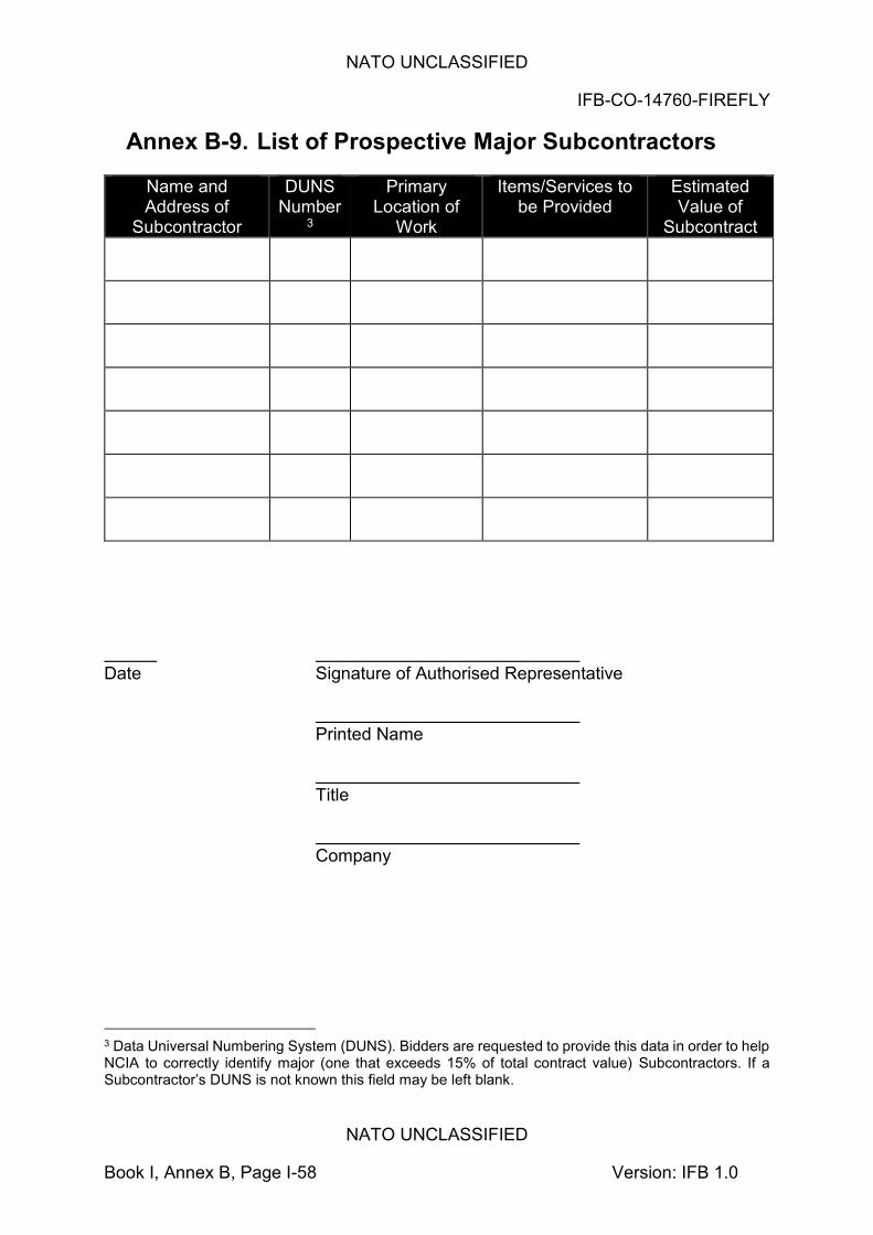
NATO UNCLASSIFIED
IFB-CO-14760-FIREFLY
NATO UNCLASSIFIED
Book I, Annex B, Page I-58 Version: IFB 1.0
Annex B-9. List of Prospective Major Subcontractors
Name and Address of
Subcontractor
DUNS Number
3
Primary Location of
Work
Items/Services to be Provided
Estimated Value of
Subcontract
Date Signature of Authorised Representative Printed Name Title Company
3 Data Universal Numbering System (DUNS). Bidders are requested to provide this data in order to help NCIA to correctly identify major (one that exceeds 15% of total contract value) Subcontractors. If a Subcontractor’s DUNS is not known this field may be left blank.
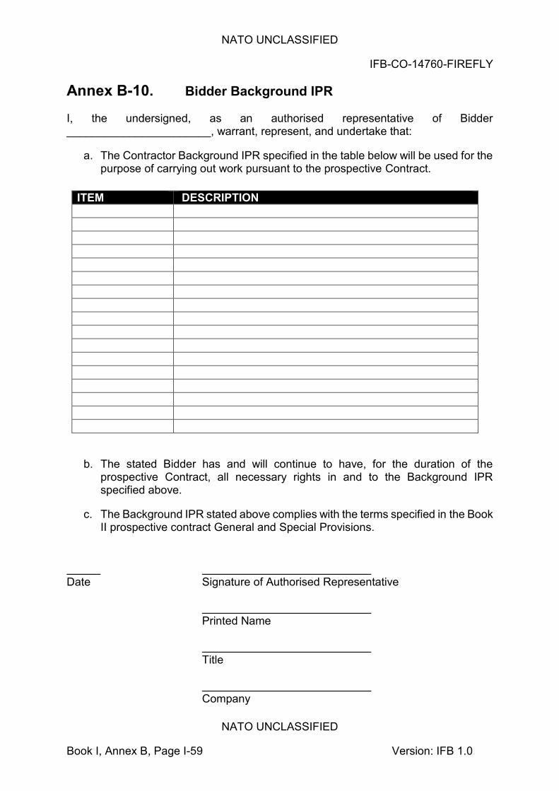
NATO UNCLASSIFIED
IFB-CO-14760-FIREFLY
NATO UNCLASSIFIED
Book I, Annex B, Page I-59 Version: IFB 1.0
Annex B-10. Bidder Background IPR I, the undersigned, as an authorised representative of Bidder _______________________, warrant, represent, and undertake that:
a. The Contractor Background IPR specified in the table below will be used for the purpose of carrying out work pursuant to the prospective Contract.
ITEM DESCRIPTION
b. The stated Bidder has and will continue to have, for the duration of the prospective Contract, all necessary rights in and to the Background IPR specified above.
c. The Background IPR stated above complies with the terms specified in the Book II prospective contract General and Special Provisions.
Date Signature of Authorised Representative Printed Name Title Company
NATO UNCLASSIFIED
IFB-CO-14760-FIREFLY
NATO UNCLASSIFIED
Book I, Annex B, Page I-60 Version: IFB 1.0
Annex B-11. List of Subcontractor IPR I, the undersigned, as an authorised representative of Bidder _______________________, warrant, represent, and undertake that:
a. The Subcontractor IPR specified in the table below will be used for the purpose of carrying out work pursuant to the prospective Contract.
ITEM DESCRIPTION
b. The stated Bidder has and will continue to have, for the duration of the prospective Contract, all necessary rights in and to the IPR specified above necessary to perform the Contractor’s obligations under the Contract.
c. The Subcontractor IPR stated above complies with terms specified in the Book II prospective contract General and Special Provisions.
Date Signature of Authorised Representative Printed Name Title Company
NATO UNCLASSIFIED
IFB-CO-14760-FIREFLY
NATO UNCLASSIFIED
Book I, Annex B, Page I-61 Version: IFB 1.0
Annex B-12. Certificate of Origin of Equipment, Services, and Intellectual Property
The Bidder hereby certifies that, if awarded the Contract pursuant to this solicitation, he will perform the Contract subject to the following conditions:
(a) none of the work, including project design, labour and services shall be performed other than by firms from and within participating NATO member countries;
(b) no material or items of equipment down to and including identifiable sub-
assemblies shall be manufactured or assembled by a firm other than from and within a participating NATO member country. (A sub-assembly is defined as a portion of an assembly consisting of two or more parts that can be provisioned and replaced as an entity); and
(c) the intellectual property rights for all software and documentation
incorporated by the prospective Contractor and/or its Sub-contractors into the work shall vest with persons or legal entities from and within NATO participating nations and no royalties or licence fees for such software and documentation shall be paid by the Contractor to any source that does not reside within a NATO participating nation Date Signature of Authorised Representative Printed Name Title Company

NATO UNCLASSIFIED
IFB-CO-14760-FIREFLY
NATO UNCLASSIFIED
Book I, Annex B, Page I-62 Version: IFB 1.0
Annex B-13. DISCLOSURE OF INVOLVEMENT OF FORMER NCI AGENCY EMPLOYMENT The Bidder herebyThe Bidder hereby certifies that, in preparing its Bid, the Bidder did not have access to solicitation information prior to such information been authorized for release to Bidders (e.g., draft statement of work and requirement documentation). The Bidder hereby acknowledges the post-employment measures applicable to former NCI Agency Personnel as per the NCI Agency Code of Conduct. The Bidder hereby certifies that its personnel working as part of the company’s team, at any tier, preparing the Bid.. Have not held employment with NCI Agency within the last two years.
Has obtained a signed statement from the former NCI Agency personnel below, who departed the NCI Agency within the last two years, that they were not previously involved in the project under competition (as defined in the extract of the NCI Agency Code of Conduct provided below):
Employee Name Former NCIA Position Current Company
Position
The Bidder also hereby certifies that it does not employ and/or receive services from former NCI Agency Personnel at grades A5 and above or ranks OF-5 and above, who departed the NCI Agency within the last 12 months. This prohibitions covers negotiations, representational communications and/or advisory activities.
Date:........................ Signature:........................ Name & Title:........................ Company:........................ Bid Reference:.......................

NATO UNCLASSIFIED
IFB-CO-14760-FIREFLY
NATO UNCLASSIFIED
Book I, Annex B, Page I-63 Version: IFB 1.0
Excerpt of NCI Agency AD. 05.00, Code of Conduct dated May 2017. Article 14 PROCUREMENT AND CONTRACTORS 14.1 NCI Agency Personnel are required to maintain unquestionable integrity and
impartiality in relation to procurements initiated by the NCI Agency. 14.2 NCI Agency Personnel shall not disclose any proprietary or contract related
information regarding procurement directly or indirectly to any person other than a person authorized by the NCI Agency to receive such information. NCI Agency Personnel shall not disclose any documentation related to a procurement action to any third party without a need to know (e.g., draft statement of work, statement of requirements) unless this is expressly provided under NATO Procurement Regulations or authorized in writing by the Director of Acquisition. During an on-going selection, NCI Agency Personnel shall not disclose any information on the selection procedure unless authorized by the Chairman of the award committee/board. The NCI Agency Personnel concerned will ensure that proper access controls are put in place to prevent disclosure of procurement information that has not yet been authorized for release for outside distribution, including draft statements of work and requirement documentations.
14.3 NCI Agency Personnel will not participate in a source selection if an offer has been provided by a friend, family member, a relative, or by a business concern owned, substantially owned, or controlled by him/her or by a friend, family member or a relative. NCI Agency Personnel appointed as part of an evaluation shall report such links to the Director of Acquisition immediately upon becoming aware of it.
14.4 Contractors and consultants shall not be allowed to participate in the drafting of the statement of work or in the source selection process unless they and their company/employer will be excluded from competition of the related contract. The same will apply to contractors and consultants involved in the definition and development of requirements.
14.5 Contractors will be given specific and coherent statements of work, providing precise explanation of how she/he is going to be employed. Tasks to be performed and minimum qualifications are to be well defined from the start. In addition, supervisors will ensure that contractors do not occupy managerial positions within the Agency.
14.6 NCI Agency Personnel shall not enter into authorized commitments in the name of NCI Agency or NATO unless specifically authorized. NCI Agency Personnel must abstain from making promises or commitment to award or amend a contract or otherwise create the appearance of a commitment from the NCI Agency unless properly authorized by the NCI Agency.
14.7 NCI Agency Personnel shall not endorse directly or indirectly products from industry. Therefore, NCI Agency Personnel shall not name or make statements endorsing or appearing to endorse products of specific companies.
NATO UNCLASSIFIED
IFB-CO-14760-FIREFLY
NATO UNCLASSIFIED
Book I, Annex B, Page I-64 Version: IFB 1.0
14.8 Industry partners will need to abide with the post-employment measures under this Directive upon submission of their bids / proposals to the NCI Agency. As part of the selection process, industry will be requested to agree with an ethical statement.
Article 15 INDUSTRY INITIATIVES 15.1 Industry initiatives may include loans, displays, tests or evaluation of
equipment and software, requesting NCI Agency speakers at industry gatherings and conferences, inviting speakers from industry to NCI Agency events, consultancy or studies of technical or organizational issues, etc. These initiatives are usually at no cost to the NCI Agency and take place at a pre-contractual phase or before the development of requirements and specifications. While there are benefits associated with the early involvement of industry in the definition of requirements and specifications, this also raises the potential for unfair treatment of potential competitors.
15.2 Industry initiatives which go beyond routine interaction in connection with on-going contracts must be reported to and coordinated by the NCI Agency Acquisition Directorate for approval. Industry initiatives shall be properly documented and governed by written agreements between the NCI Agency and the company concerned where relevant. Such agreements may contain provisions describing the nature of the initiative, the non-disclosure of NCI Agency/NATO information, NCI Agency ownership of any resulting work, the NCI Agency’s right to release such work product to future competitors for any follow-on competition or contract, the requirement that any studies must provide non-proprietary solutions and/or an acknowledgement that the participating companies will not receive any preferential treatment in the contracting process.
15.3 Any authorized industry initiatives must be conducted in such a way that it does not confer an unfair advantage to the industry concerned or create competitive hurdles for potential competitors.
Article 16 POST EMPLOYMENT MEASURES 16.1 The NCI Agency will not offer employment contracts to former NCI Agency
Personnel who departed less than 2 years earlier, unless prior approval by the General Manager has been received.
16.2 Former NCI Agency Personnel will not be accepted as consultants or commercial counterpart for two (2) years after finalization of their employment at NCI Agency, unless the General Manager decides otherwise in the interest of the Agency and as long as NATO rules on double remuneration are observed. Such decision shall be recorded in writing. Commercial counterparts include owners or majority shareholders, key account managers, or staff member, agent or consultant of a company and/or subcontractors seeking business at any tier with the NCI Agency in relation to a procurement action in which the departing NCI Agency staff member was involved when he/she was

NATO UNCLASSIFIED
IFB-CO-14760-FIREFLY
NATO UNCLASSIFIED
Book I, Annex B, Page I-65 Version: IFB 1.0
under the employment of the NCI Agency. As per the Prince 2 Project methodology, a Project is defined as a “temporary organization that is created for the purpose of delivering one or more business products according to an agreed business case”. For the purpose of this provision, involvement requires (i) drafting, review or coordination of internal procurement activities and documentation, such as statement of work and statement of requirement; and/or (ii) access to procurement information that has not yet been authorized for release for outside distribution, including draft statements of work and requirement documentations; and/or (iii) being appointed as a representative to the Project governance (e.g., Project Board) with access to procurement information as per (ii) above; and/or (iv) having provided strategic guidance to the project, with access to procurement information as per (ii) above.
16.3 In addition to Section 17.2 above, former NCI Agency Personnel at grades A5 and above or ranks OF-5 and above are prohibited during twelve months following the end of their employment with the NCI Agency to engaging in negotiations, representational communications and/or advisory activities with the NCI Agency on behalf of a private entity, unless this has been agreed in advance by the NCI Agency General Manager and notified to the ASB.
16.4 NCI Agency Personnel leaving the Agency shall not contact their former colleagues in view of obtaining any information or documentation about procurement activities not yet authorized’ release. NCI Agency Personnel shall immediately report such contacts to the Director of Acquisition.
16.5 The ASB Chairman will be the approving authority upon recommendation by the Legal Adviser when the NCI Agency Personnel concerned by the above is the NCI Agency General Manager and will notify the ASB.
16.6 NCI Agency Personnel leaving the Agency shall sign a statement that they are aware of the post-employment measures set out in this Directive.
16.7 The post-employment measures set out in this Directive shall be reflected in the NCI Agency procurement documents, such as IFBs, and contract provisions.

NATO UNCLASSIFIED
IFB-CO-14760-FIREFLY
NATO UNCLASSIFIED
Book I, Annex B, Page I-66 Version: IFB 1.0
Annex C Bid Guarantee - Standby Letter of Credit Standby Letter of Credit Number: Issue Date: ___________________________ Beneficiary: NCI Agency, Financial Management Office Boulevard Leopold III, B-1110, Brussels Belgium Expiry Date: ___________________________ 1. We, (issuing bank) hereby establish in your favour our irrevocable standby letter of credit number {insert number} by order and for the account of (NAME AND ADDRESS OF BIDDER) in the original amount of € 40,000 (Forty Thousand Euro). We are advised this Guarantee fulfils a requirement under Invitation for Bid IFB-CO-14760-FIREFLY dated __________________. 2. Funds under this standby letter of credit are available to you upon first demand and without question or delay against presentation of a certificate from the NCI Agency Contracting Officer that: a) (NAME OF BIDDER) has submitted a Bid and, after Bid Closing Date
(including extensions thereto) and prior to the selection of the lowest priced, technically compliant Bid, has withdrawn its Bid, or stated that he does not consider its Bid valid or agree to be bound by its Bid, or
b) (NAME OF BIDDER) has submitted a Bid determined by the Agency to
be the lowest priced, technically compliant Bid, but (NAME OF BIDDER) has declined to execute the contract offered by the Agency, such contract being consistent with the terms of the Invitation for Bid, or
c) The NCI Agency has offered (NAME OF BIDDER) the contract for
execution but (NAME OF BIDDER) has been unable to demonstrate compliance with the security requirements of the contract within a reasonable time, or
d) The NCI Agency has entered into the contract with (NAME OF BIDDER)
but (NAME OF BIDDER) has been unable or unwilling to provide the Performance Guarantee required under the terms of the contract within the time frame required.
3. This Letter of Credit is effective the date hereof and shall expire at our office located at (Bank Address) on __________________. All demands for payment must be made prior to the expiry date. 4. It is a condition of this letter of credit that the expiry date will be automatically extended without amendment for a period of sixty (60) calendar days from the current

NATO UNCLASSIFIED
IFB-CO-14760-FIREFLY
NATO UNCLASSIFIED
Book I, Annex B, Page I-67 Version: IFB 1.0
or any successive expiry date unless at least thirty (30) calendar days prior to the then current expiry date the NCI Agency Contracting Officer notifies us that the Letter of Credit is not required to be extended or is required to be extended for a shorter duration. 5. We may terminate this letter of credit at any time upon sixty (60) calendar days’ notice furnished to both (NAME OF BIDDER) and the NCI Agency by registered mail. 6. In the event we (the issuing bank) notify you that we elect not to extend the expiry date in accordance with paragraph 4 above, or, at any time, to terminate the letter of credit, funds under this credit will be available to you without question or delay against presentation of a certificate signed by the NCI Agency Contracting Officer which states “The NCI Agency has been notified by {issuing bank} of its election not to automatically extend the expiry date of letter of credit number {insert number} dated {date} pursuant to the automatic renewal clause (or to terminate the letter of credit). As of the date of this certificate, no suitable replacement letter of credit, or equivalent financial guarantee has been received by the NCI Agency from, or on behalf of (NAME OF BIDDER), and the NCI Agency, as beneficiary, hereby draws on the standby letter of credit number ________ in the amount of € (Amount up to the maximum available under the LOC), such funds to be transferred to the account of the Beneficiary number ___________________ (to be identified when certificate is presented).” Such certificate shall be accompanied by the original of this letter of credit and a copy of the letter from the issuing bank that it elects not to automatically extend the standby letter of credit, or terminating the letter of credit. 7. The Beneficiary may not present the certificate described in paragraph 6 above until 20 (twenty) calendar days prior to a) the date of expiration of the letter of credit should {issuing bank} elect not to automatically extend the expiration date of the letter of credit, b) the date of termination of the letter of credit if {issuing bank} notifies the Beneficiary that the letter of credit is to be terminated in accordance with paragraph 6 above. 8. Multiple drawings are allowed. 9. Drafts drawn hereunder must be marked, “Drawn under {issuing bank} Letter of Credit No. {Insert number} “and indicate the date hereof. 10. This letter of credit sets forth in full the terms of our undertaking, and this undertaking shall not in any way be modified, amended, or amplified by reference to any document, instrument, or agreement referred to herein (except the International Standby Practices (ISP 98) hereinafter defined) or in which this letter of credit is referred to or to which this letter of credit relates, and any such reference shall not be deemed to incorporate herein by reference any document, instrument, or agreement.
NATO UNCLASSIFIED
IFB-CO-14760-FIREFLY
NATO UNCLASSIFIED
Book I, Annex B, Page I-68 Version: IFB 1.0
11. We hereby engage with you that drafts drawn under and in compliance with the terms of this letter of credit will be duly honoured upon presentation of documents to us on or before the expiration date of this letter of credit. 12. This Letter of Credit is subject to The International Standby Practices-ISP98 (1998 Publication) International Chamber of Commerce Publication No.590.
NATO UNCLASSIFIED
IFB-CO-14760-FIREFLY
NATO UNCLASSIFIED
Book I, Annex D, Page I-69 Version: IFB 1.0
Annex D Clarification Request Form INSERT COMPANY NAME HERE INSERT SUBMISSION DATE HERE
INVITATION FOR BID IFB-CO-14760-FIREFLY
Provide NRF Transmission Components – DCIS for Small NRF HQs (IFB 2)
Annex D CLARIFICATION REQUEST FORM
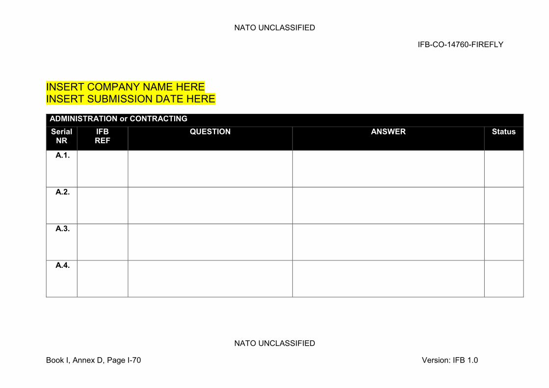
NATO UNCLASSIFIED
IFB-CO-14760-FIREFLY
NATO UNCLASSIFIED
Book I, Annex D, Page I-70 Version: IFB 1.0
INSERT COMPANY NAME HERE INSERT SUBMISSION DATE HERE ADMINISTRATION or CONTRACTING Serial
NR IFB REF
QUESTION ANSWER Status
A.1.
A.2.
A.3.
A.4.
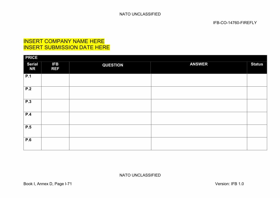
NATO UNCLASSIFIED
IFB-CO-14760-FIREFLY
NATO UNCLASSIFIED
Book I, Annex D, Page I-71 Version: IFB 1.0
INSERT COMPANY NAME HERE INSERT SUBMISSION DATE HERE PRICE Serial
NR IFB REF
QUESTION ANSWER Status
P.1
P.2
P.3
P.4
P.5
P.6
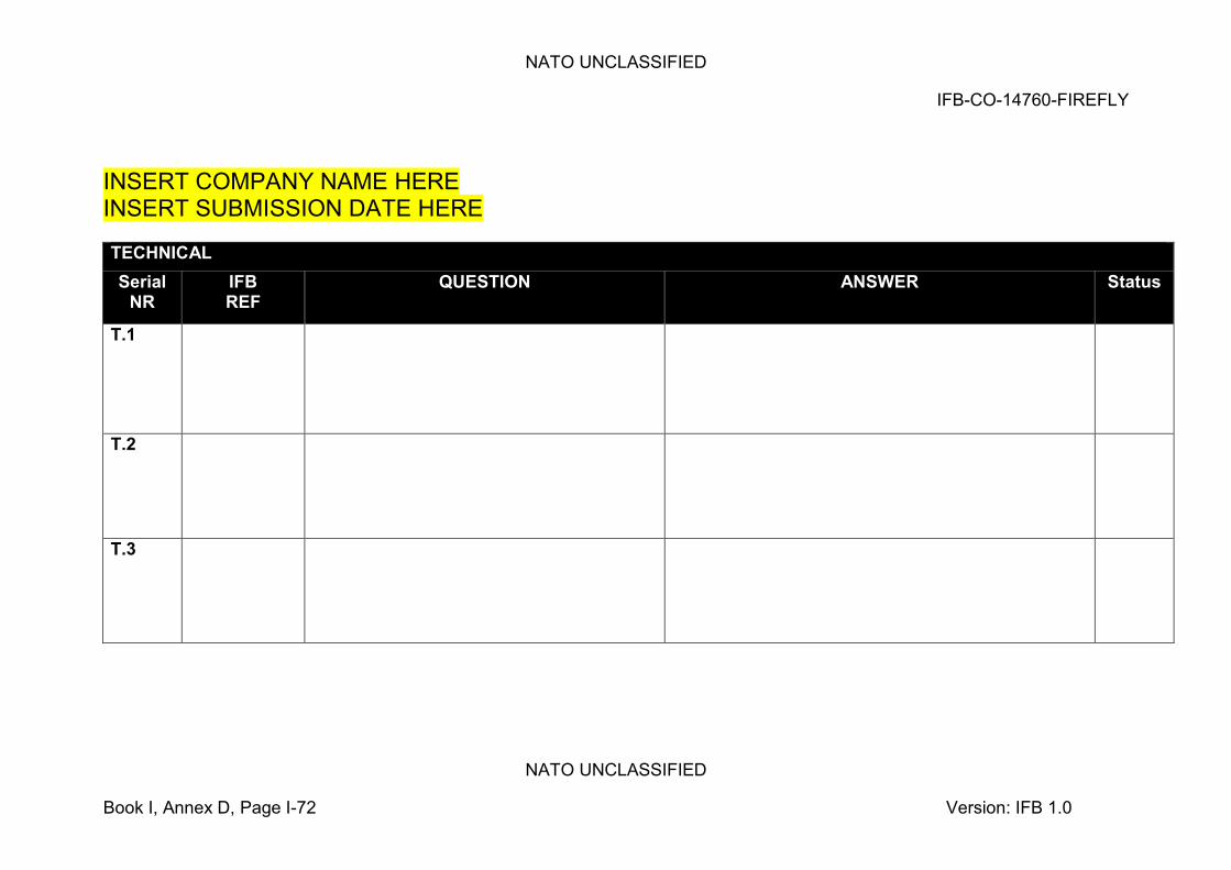
NATO UNCLASSIFIED
IFB-CO-14760-FIREFLY
NATO UNCLASSIFIED
Book I, Annex D, Page I-72 Version: IFB 1.0
INSERT COMPANY NAME HERE INSERT SUBMISSION DATE HERE TECHNICAL Serial
NR IFB REF
QUESTION ANSWER Status
T.1
T.2
T.3
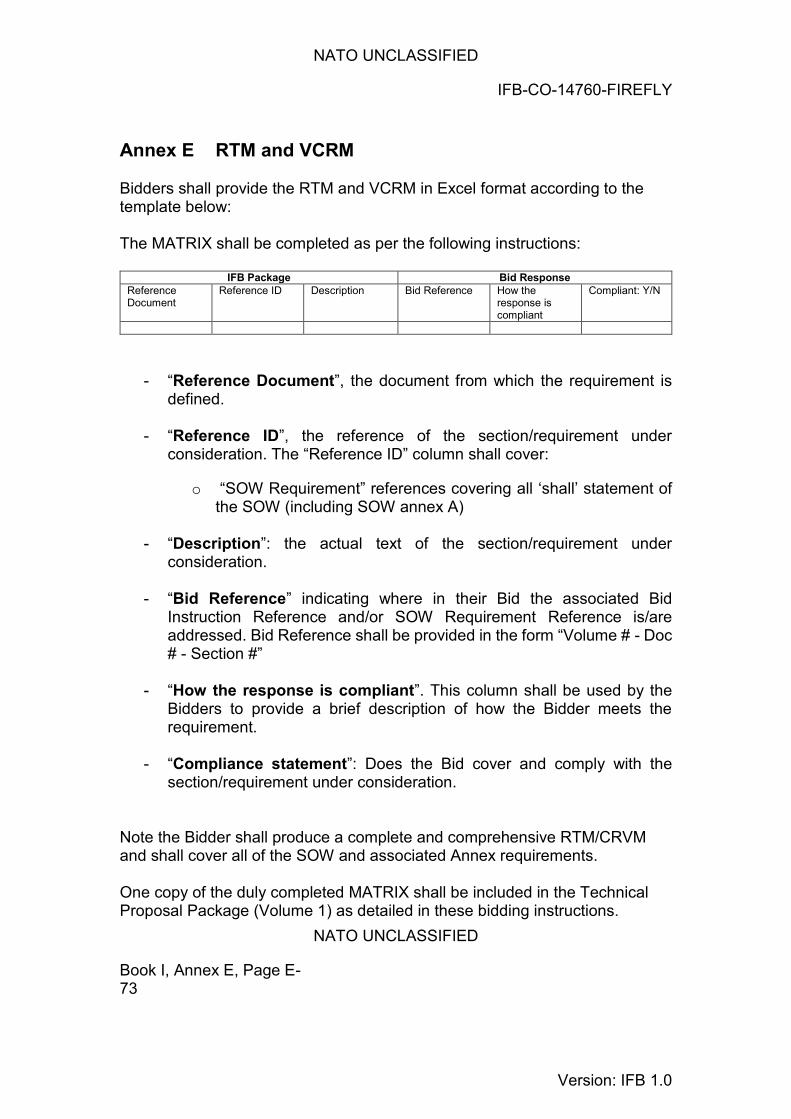
NATO UNCLASSIFIED
IFB-CO-14760-FIREFLY
NATO UNCLASSIFIED
Book I, Annex E, Page E-73 Version: IFB 1.0
Annex E RTM and VCRM Bidders shall provide the RTM and VCRM in Excel format according to the template below: The MATRIX shall be completed as per the following instructions:
IFB Package Bid Response Reference Document
Reference ID Description Bid Reference How the response is compliant
Compliant: Y/N
- “Reference Document”, the document from which the requirement is
defined.
- “Reference ID”, the reference of the section/requirement under consideration. The “Reference ID” column shall cover:
o “SOW Requirement” references covering all ‘shall’ statement of the SOW (including SOW annex A)
- “Description”: the actual text of the section/requirement under consideration.
- “Bid Reference” indicating where in their Bid the associated Bid Instruction Reference and/or SOW Requirement Reference is/are addressed. Bid Reference shall be provided in the form “Volume # - Doc # - Section #”
- “How the response is compliant”. This column shall be used by the Bidders to provide a brief description of how the Bidder meets the requirement.
- “Compliance statement”: Does the Bid cover and comply with the
section/requirement under consideration.
Note the Bidder shall produce a complete and comprehensive RTM/CRVM and shall cover all of the SOW and associated Annex requirements. One copy of the duly completed MATRIX shall be included in the Technical Proposal Package (Volume 1) as detailed in these bidding instructions.

NATO UNCLASSIFIED
IFB-CO-14760-FIREFLY
NATO UNCLASSIFIED
Book I, Annex E, Page E-74 Version: IFB 1.0

N A T O U N C L A S S I F I E D
IFB-CO-14760-FIREFLY Book II Part II - Contract Special Provisions
N A T O U N C L A S S I F I E D Page 1 of 23
Provide DCIS Equipment for Small NRF HQ
IFB-CO-14760-FIREFLY
Book II - Part II
CONTRACT SPECIAL PROVISIONS
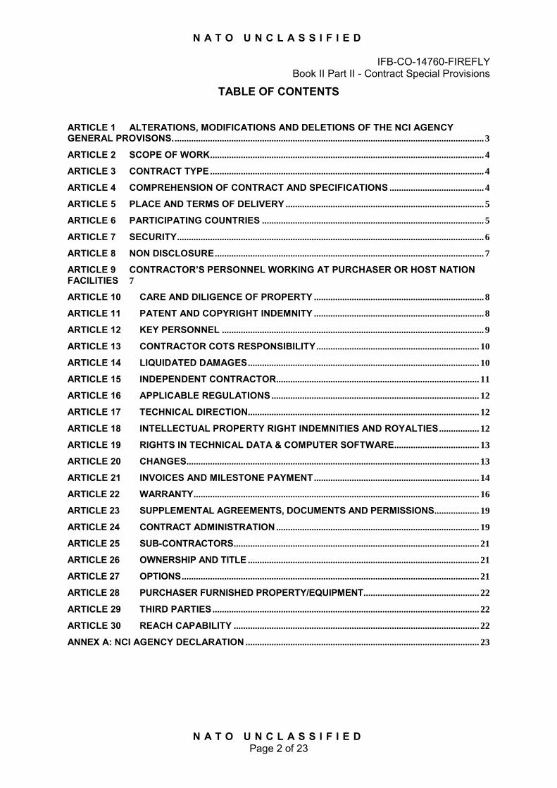
N A T O U N C L A S S I F I E D
IFB-CO-14760-FIREFLY Book II Part II - Contract Special Provisions
N A T O U N C L A S S I F I E D Page 2 of 23
TABLE OF CONTENTS
ARTICLE 1 ALTERATIONS, MODIFICATIONS AND DELETIONS OF THE NCI AGENCY GENERAL PROVISONS. ................................................................................................................................... 3
ARTICLE 2 SCOPE OF WORK .................................................................................................................... 4
ARTICLE 3 CONTRACT TYPE .................................................................................................................... 4
ARTICLE 4 COMPREHENSION OF CONTRACT AND SPECIFICATIONS ........................................ 4
ARTICLE 5 PLACE AND TERMS OF DELIVERY .................................................................................... 5
ARTICLE 6 PARTICIPATING COUNTRIES .............................................................................................. 5
ARTICLE 7 SECURITY .................................................................................................................................. 6
ARTICLE 8 NON DISCLOSURE .................................................................................................................. 7
ARTICLE 9 CONTRACTOR’S PERSONNEL WORKING AT PURCHASER OR HOST NATION FACILITIES 7
ARTICLE 10 CARE AND DILIGENCE OF PROPERTY ........................................................................ 8
ARTICLE 11 PATENT AND COPYRIGHT INDEMNITY ........................................................................ 8
ARTICLE 12 KEY PERSONNEL ............................................................................................................... 9
ARTICLE 13 CONTRACTOR COTS RESPONSIBILITY ..................................................................... 10
ARTICLE 14 LIQUIDATED DAMAGES .................................................................................................. 10
ARTICLE 15 INDEPENDENT CONTRACTOR ...................................................................................... 11
ARTICLE 16 APPLICABLE REGULATIONS ........................................................................................ 12
ARTICLE 17 TECHNICAL DIRECTION.................................................................................................. 12
ARTICLE 18 INTELLECTUAL PROPERTY RIGHT INDEMNITIES AND ROYALTIES ................. 12
ARTICLE 19 RIGHTS IN TECHNICAL DATA & COMPUTER SOFTWARE .................................... 13
ARTICLE 20 CHANGES............................................................................................................................ 13
ARTICLE 21 INVOICES AND MILESTONE PAYMENT ...................................................................... 14
ARTICLE 22 WARRANTY ......................................................................................................................... 16
ARTICLE 23 SUPPLEMENTAL AGREEMENTS, DOCUMENTS AND PERMISSIONS ................... 19
ARTICLE 24 CONTRACT ADMINISTRATION ...................................................................................... 19
ARTICLE 25 SUB-CONTRACTORS ........................................................................................................ 21
ARTICLE 26 OWNERSHIP AND TITLE .................................................................................................. 21
ARTICLE 27 OPTIONS .............................................................................................................................. 21
ARTICLE 28 PURCHASER FURNISHED PROPERTY/EQUIPMENT ................................................. 22
ARTICLE 29 THIRD PARTIES ................................................................................................................. 22
ARTICLE 30 REACH CAPABILITY ........................................................................................................ 22
ANNEX A: NCI AGENCY DECLARATION ................................................................................................... 23
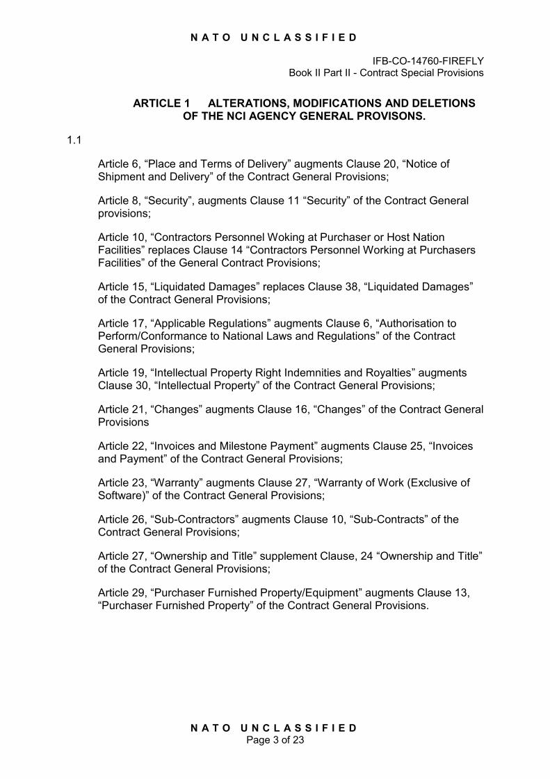
N A T O U N C L A S S I F I E D
IFB-CO-14760-FIREFLY Book II Part II - Contract Special Provisions
N A T O U N C L A S S I F I E D Page 3 of 23
ARTICLE 1 ALTERATIONS, MODIFICATIONS AND DELETIONS
OF THE NCI AGENCY GENERAL PROVISONS.
1.1
Article 6, “Place and Terms of Delivery” augments Clause 20, “Notice of Shipment and Delivery” of the Contract General Provisions;
Article 8, “Security”, augments Clause 11 “Security” of the Contract General provisions;
Article 10, “Contractors Personnel Woking at Purchaser or Host Nation Facilities” replaces Clause 14 “Contractors Personnel Working at Purchasers Facilities” of the General Contract Provisions;
Article 15, “Liquidated Damages” replaces Clause 38, “Liquidated Damages” of the Contract General Provisions;
Article 17, “Applicable Regulations” augments Clause 6, “Authorisation to Perform/Conformance to National Laws and Regulations” of the Contract General Provisions;
Article 19, “Intellectual Property Right Indemnities and Royalties” augments Clause 30, “Intellectual Property” of the Contract General Provisions;
Article 21, “Changes” augments Clause 16, “Changes” of the Contract General Provisions
Article 22, “Invoices and Milestone Payment” augments Clause 25, “Invoices and Payment” of the Contract General Provisions;
Article 23, “Warranty” augments Clause 27, “Warranty of Work (Exclusive of Software)” of the Contract General Provisions;
Article 26, “Sub-Contractors” augments Clause 10, “Sub-Contracts” of the Contract General Provisions;
Article 27, “Ownership and Title” supplement Clause, 24 “Ownership and Title” of the Contract General Provisions;
Article 29, “Purchaser Furnished Property/Equipment” augments Clause 13, “Purchaser Furnished Property” of the Contract General Provisions.
N A T O U N C L A S S I F I E D
IFB-CO-14760-FIREFLY Book II Part II - Contract Special Provisions
N A T O U N C L A S S I F I E D Page 4 of 23
ARTICLE 2 SCOPE OF WORK
2.1 The scope of this Contract is for the provision of NATO Communication and Information Systems (CIS) Services as specified in the Schedule of Supplies and Services and in accordance with Part IV - Statement of Work (SOW) for the firm fixed prices stated in this Contract.
2.2 In order to fulfil that purpose the Contractor shall deliver, as per the Contract Prices specified in the Schedule of Supplies and Services in the manner and at the time and location specified in the terms of this Contract, and more particularly, in the SOW.
2.3 This Contract does not imply an obligation on either part to extend the Contract beyond the specified scope or terms, nor prohibits the Parties from mutually negotiating modifications thereto.
ARTICLE 3 CONTRACT TYPE
3.1 This is a Firm Fixed Price Contract. Firm Fixed Prices are established for the
supplies and services defined in Part I - Schedule of Supplies and Services.
3.2 The Purchaser assumes no liability for costs incurred by the Contractor in excess of the stated Firm Fixed Price except as provided under other provisions of this Contract.
3.3 The Total Contract price is inclusive of all expenses related to the performance of the present contract.
3.4 The Total Contract price in this Contract is Delivered Duty Paid (INCOTERMS 2010). It shall be noted, however, that because the Purchaser is exempted from direct taxes and duties as set forth in Clause 26 (Taxes and Duties) of the NCI Agency Contract General Provisions, there is no duty to be paid by the Contractor.
ARTICLE 4 COMPREHENSION OF CONTRACT AND SPECIFICATIONS
4.1 The Contractor warrants that it has read, understood and agreed to each and
all terms, clauses, specifications and conditions specified in the Contract and that this signature of the Contract is an acceptance, without reservations, of the said Contract terms within their normal and common meaning.
4.2 The specifications set forth the performance requirements for the Contractor’s proposed work as called for under this Contract. Accordingly, notwithstanding any conflict or inconsistency which hereafter may be found between achievement of the aforesaid performance requirements and adherence to the Contractor’s proposed design for the work, the Contractor hereby warrants that the work to be delivered will meet or exceed the performance requirements of the said specifications.

N A T O U N C L A S S I F I E D
IFB-CO-14760-FIREFLY Book II Part II - Contract Special Provisions
N A T O U N C L A S S I F I E D Page 5 of 23
4.3 The Contractor hereby acknowledges that it has no right to assert against the
Purchaser, its officers, agents or employees, any claims or demands with respect to the aforesaid specifications as are in effect on the date of award of this Contract.
4.4 Based upon impossibility of performance, defective, inaccurate, impracticable,
insufficient or invalid specifications, implied warranties of suitability of such specifications, or;
4.5 Otherwise derived from the aforesaid specifications, and hereby waives any
claims or demands so based or derived as might otherwise arise.
4.6 Notwithstanding the “Changes” clause or any other clause of the Contract, the Contractor hereby agrees that no changes to the aforesaid specifications which may be necessary to permit achievement of the performance requirements specified herein for the Contractor’s proposed work shall entitle the Contractor either to any increase in the firm fixed price as set forth in this Contract or to any extension of the delivery times for the work beyond the period of performance in the Schedule of Supplies and Services.
ARTICLE 5 PLACE AND TERMS OF DELIVERY
5.1 Deliverables under this Contract shall be delivered DDP (Delivered Duty Paid) in accordance with the International Chamber of Commerce INCOTERMS 2010 to the destination(s) and at such times as set forth in the Schedule of Supplies and Services. The Contractor shall note that the Purchaser is exempt from customs duties and VAT. The Purchaser shall not be liable for any storage, damage, accessorial or any other charges involved in such transporting of supplies.
ARTICLE 6 PARTICIPATING COUNTRIES
6.1 The Contractor may issue subcontracts to firms and purchase from qualified
vendors from and within NATO Countries. The Participating NATO Countries are listed below in alphabetical order: ALBANIA, BELGIUM, BULGARIA, CANADA, CROATIA, CZECH REPUBLIC, DENMARK, ESTONIA, FRANCE, GERMANY, GREECE, HUNGARY, ICELAND, ITALY, LATVIA, LITHUANIA, LUXEMBOURG, NETHERLANDS, NORWAY, POLAND, PORTUGAL, ROMANIA, SLOVAKIA, SLOVENIA, SPAIN, TURKEY, UNITED KINGDOM, UNITED STATES OF AMERICA.
6.2 None of the work, including project design, labour and services, shall be performed other than by firms from and within participating NATO Countries.
6.3 No material or items of equipment down to and including identifiable sub-assemblies shall be manufactured or assembled by a firm other than from and within a participating NATO Country.
N A T O U N C L A S S I F I E D
IFB-CO-14760-FIREFLY Book II Part II - Contract Special Provisions
N A T O U N C L A S S I F I E D Page 6 of 23
6.4 The Intellectual Property Rights for all software and documentation used by
the Contractor in the performance of the Contract shall vest with firms from and within participating NATO Countries and no royalties or license fees for such software and documentation shall be paid by the Contractor to any source that does not reside within a NATO Country.
ARTICLE 7 SECURITY
7.1 This Article augments Clause 11 of the NCI Agency Contract General
Provisions.
7.2 The security classification of the contract is NATO UNCLASSIFIED.
7.3 The Contractor's facilities shall meet NATO security regulations to permit handling and storage of information and equipment classified up to and including NATO SECRET.
7.4 The personnel working at the Purchaser’s facilities shall have a confirmed security clearance of “NATO SECRET” at the Contract award stage. Failure to obtain or maintain the required level of security for Contractor personnel for the period of performance of this contract shall not be grounds for any delay in the scheduled performance of this Contract and may be grounds for Liquidated Damages under Article 15 below and/or termination under Clause 39 – “Termination for Default” of the NCI Agency General Provisions.
7.5 It shall be the Contractor’s responsibility to obtain the necessary clearances and to have such clearances confirmed to the Purchaser by the relevant national security authority when providing staff under a task.
7.6 The personnel working at the Purchaser’s facilities shall own a valid passport and is required to maintain its validity for the duration of the contract.
7.7 Failure to meet the timely security requirement shall not constitute a valid reason to delay commencement of a task and shall constitute a material breach of the contract, which, at the discretion of the Purchaser shall enable immediate termination of the contract with no further remedy.
7.8 In the performance of all works under this contract it shall be the Contractor’s responsibility to ascertain and comply with all applicable NATO security regulations as implemented by the Host Nation and by the local Headquarters.
7.9 The Contractor shall note that there are restrictions regarding the carriage and use of electronic device (e.g. laptops) in Purchaser secured locations. The Contractor shall be responsible for satisfying and obtaining from the appropriate site authorities the necessary clearance to bring any such equipment into the facility.
N A T O U N C L A S S I F I E D
IFB-CO-14760-FIREFLY Book II Part II - Contract Special Provisions
N A T O U N C L A S S I F I E D Page 7 of 23
ARTICLE 8 NON DISCLOSURE
8.1 Contractor’s performance under this Contract may require access to third party data and information. The Contractor shall exercise the same degree of care for such third party data and information that it undertakes to preserve and protect its own data and information.
8.2 All Contractor and Subcontractor Key Personnel working at any NATO Organizations/ Commands premises or having access to NATO classified/commercial-in-confidence information must certify and sign the Non-Disclosure Declaration at Annex A hereto and provide it to the NCI Agency Contracting Officer.
8.3 The Contractor and Subcontractors may be required to sign other non-disclosure agreements or certificates for access to specific information to complete tasks.
8.4 The Contractor shall ensure that its officers, employees, agents and Sub-contractors shall have been made aware of the requirements of confidentiality and shall not cause or permit the data and/or information to be either totally or partially disclosed to any unauthorised Contractor personnel or third party personnel.
8.5 The Contractor shall be liable for all damages resulting from the non-authorised use of the data and/or information.
ARTICLE 9 CONTRACTOR’S PERSONNEL WORKING AT PURCHASER OR HOST NATION FACILITIES
9.1 The term “Purchaser Facilities” or “Host Nation Facilities” as used in this
clause shall be deemed to include sites, property, utilities, ships or vessels and the term “Facility Representative” shall be deemed to refer to the authority designated by the Purchaser or Host Nation responsible for the site, property, utility, ship or vessel.
9.2 The Facility Representative shall provide such available administrative and technical facilities for Contractor’s personnel working at Purchaser’s Facilities for the purpose of the Contract as in the opinion of the Facility Representative may be necessary for the effective and economical discharge of work under the Contract. The Purchaser shall be responsible for ascertaining what necessary facilities will be available and whether they will be provided free of charge, or determining what charges are payable. The Contractor shall have no claim against the Purchaser for any such additional cost or delay occasioned by the closure for holidays, or other reasons, where this is generally published or made known to the Contractor by the Purchaser or his authorised representatives.
N A T O U N C L A S S I F I E D
IFB-CO-14760-FIREFLY Book II Part II - Contract Special Provisions
N A T O U N C L A S S I F I E D Page 8 of 23
9.3 Notwithstanding, the provisions of the “Purchaser Furnished Facilities” Clauses above, where those conditions form part of the Contract, the Contractor shall except as otherwise provided for in the Contract, restore or, at the option of the Purchaser, pay compensation for all damage occurring to any Purchaser’s Facilities occasioned by the Contractor, or by his servants, agents or sub-contractors, arising from his or their presence on Purchaser Facilities in connection with the Contract; provided that this Conditions shall not apply to the extent that the Contractor is able to show that any such damage was not caused or contributed to, by his neglect, or default or the neglect or default of his servants, agents of sub-contractors, or by any circumstances within his or their control.
9.4 All property of the Contractor while at a Purchaser Facility shall be at the risk of the Contractor, and the Purchaser shall accept no liability for any loss or damage, except to the extent that any loss or damage is the result of a wilful act or gross negligence on the part of the Purchaser’s employees or agents.
ARTICLE 10 CARE AND DILIGENCE OF PROPERTY
10.1 The Contractor shall use reasonable care of avoid damaging building,
equipment work site premises. If the Contractor damages any such building or equipment, it shall repair the damage as directed by the Purchaser and at no expenses to the Purchaser. If it fails or refuses to make such repair or replacement, the Contractor shall be liable for the cost thereof, which may be deducted from the Contract price.
10.2 The Purchaser shall exercise due care and diligence for Contractor's furnished equipment, tools and materials on site premises. The Purchaser will not assume any liability except for gross negligence and willful misconduct.
ARTICLE 11 PATENT AND COPYRIGHT INDEMNITY
11.1 The Contractor shall exclude from its prices any royalty pertaining to patents
which, in accordance with agreements reached between NATO countries, may be utilized free of charge by member nations of NATO and by NATO organization
11.2 The Contractor shall report in writing to the Purchaser during the performance of this Contract the royalties excluded from its price for patent utilized under the agreements mentioned in paragraph above and the amount of royalties paid or to be paid by the Contractor directly to others in performance of this Contract.
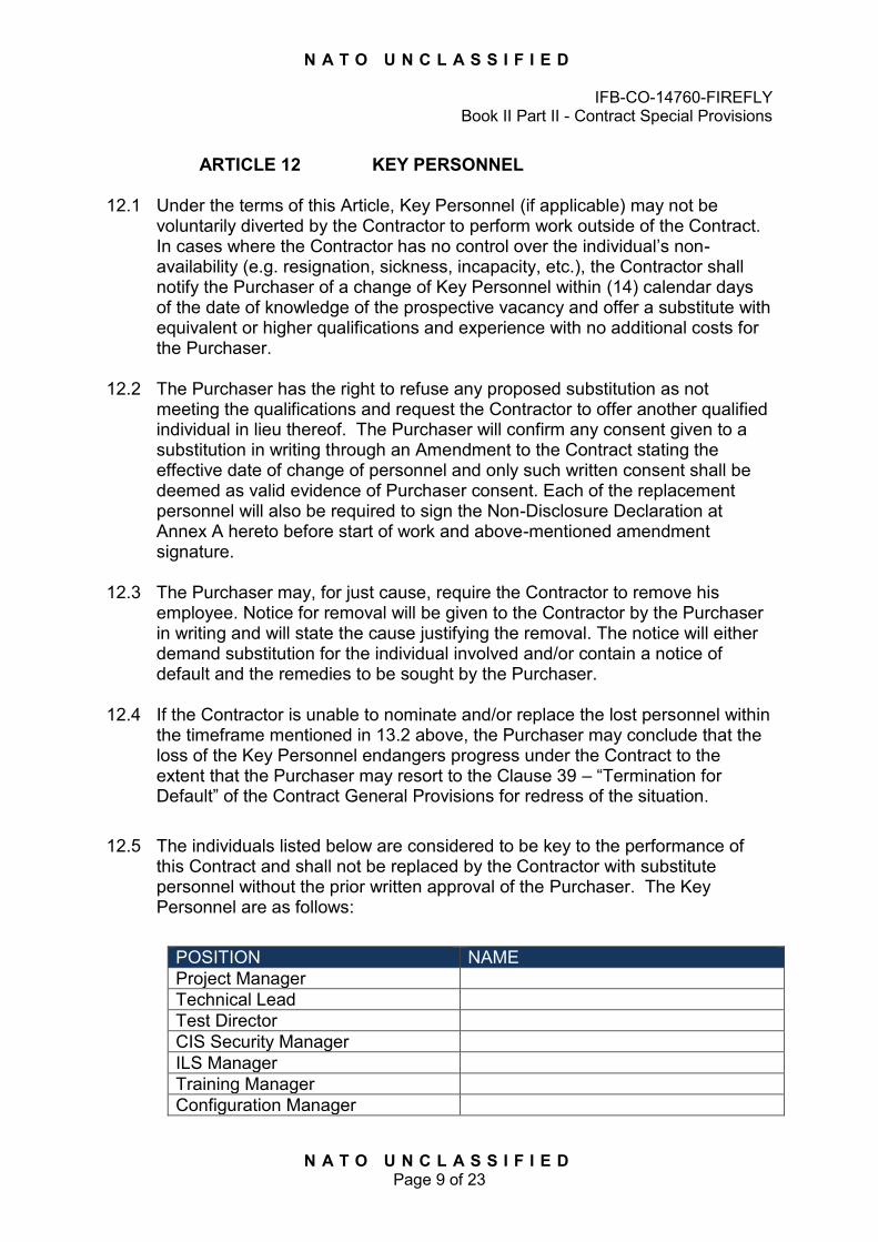
N A T O U N C L A S S I F I E D
IFB-CO-14760-FIREFLY Book II Part II - Contract Special Provisions
N A T O U N C L A S S I F I E D Page 9 of 23
ARTICLE 12 KEY PERSONNEL
12.1 Under the terms of this Article, Key Personnel (if applicable) may not be
voluntarily diverted by the Contractor to perform work outside of the Contract. In cases where the Contractor has no control over the individual’s non-availability (e.g. resignation, sickness, incapacity, etc.), the Contractor shall notify the Purchaser of a change of Key Personnel within (14) calendar days of the date of knowledge of the prospective vacancy and offer a substitute with equivalent or higher qualifications and experience with no additional costs for the Purchaser.
12.2 The Purchaser has the right to refuse any proposed substitution as not meeting the qualifications and request the Contractor to offer another qualified individual in lieu thereof. The Purchaser will confirm any consent given to a substitution in writing through an Amendment to the Contract stating the effective date of change of personnel and only such written consent shall be deemed as valid evidence of Purchaser consent. Each of the replacement personnel will also be required to sign the Non-Disclosure Declaration at Annex A hereto before start of work and above-mentioned amendment signature.
12.3 The Purchaser may, for just cause, require the Contractor to remove his
employee. Notice for removal will be given to the Contractor by the Purchaser in writing and will state the cause justifying the removal. The notice will either demand substitution for the individual involved and/or contain a notice of default and the remedies to be sought by the Purchaser.
12.4 If the Contractor is unable to nominate and/or replace the lost personnel within the timeframe mentioned in 13.2 above, the Purchaser may conclude that the loss of the Key Personnel endangers progress under the Contract to the extent that the Purchaser may resort to the Clause 39 – “Termination for Default” of the Contract General Provisions for redress of the situation.
12.5 The individuals listed below are considered to be key to the performance of
this Contract and shall not be replaced by the Contractor with substitute personnel without the prior written approval of the Purchaser. The Key Personnel are as follows:
POSITION NAME Project Manager Technical Lead Test Director CIS Security Manager ILS Manager Training Manager Configuration Manager
N A T O U N C L A S S I F I E D
IFB-CO-14760-FIREFLY Book II Part II - Contract Special Provisions
N A T O U N C L A S S I F I E D Page 10 of 23
ARTICLE 13 CONTRACTOR COTS RESPONSIBILITY
13.1 The Contractor shall monitor changes and/or upgrades to Commercial Off-The-Shelf (COTS) software or hardware to be utilized under subject Contract.
13.2 For COTS items which are or could be impacted by obsolescence issues, as changes in technology occur, the Contractor shall immediately inform the Purchaser in writing and shall propose substitution of new products/items for inclusion in this Contract. The proposed items should provide at least equivalent performance and/or lower life-cycle support costs, or enhanced performance without a price or cost increase.
13.3 The Contractor will provide evidence with respect to price and performance of the equipment being proposed as well as data proving an improvement in performance and/or a reduction in price and/or life-cycle support costs. If necessary for evaluation by the Purchaser, the Contractor shall provide a demonstration of the proposed items. Should the Purchaser decide that the proposed item(s) should be included in the Contract, an equitable price adjustment will be negotiated and the proposed item(s) shall be added to the Contract by bilateral modification under the authority of this Article.
13.4 The Contractor shall notify the Purchaser of any proposed changes in the commercial off the shelf software or hardware to be utilized. Such notification shall provide an assessment of the changes and the impact to any other items to be delivered under this Contract.
13.5 The End User of all COTS software shall be NATO. Any third party COTS or Open Source Software (OSS) items are provided “as is” in accordance with the License terms and conditions applicable for such software items, the details of which shall be provided in accordance with the terms of this Contract.
13.6 For the avoidance of doubt, any Contractor liability in respect of such items shall be limited to those provided within the respective licenses.
ARTICLE 14 LIQUIDATED DAMAGES
14.1 If the Contractor fails to:
a. successfully meet the required performance dates as defined in the
Schedule of Supplies and Services, or any extension thereof, or;
b. deliver and obtain acceptance of the Deliverables or to acceptably perform the services as specified in the Schedule of Supplies and Services to this Contract,
N A T O U N C L A S S I F I E D
IFB-CO-14760-FIREFLY Book II Part II - Contract Special Provisions
N A T O U N C L A S S I F I E D Page 11 of 23
c. the actual damage to the Purchaser for the delay will be difficult or impossible to determine. Therefore, in lieu of actual damages the Contractor shall pay to the Purchaser, for each day of delinquency in achieving the requirements of the Contract a fixed and agreed liquidated damages of 0.1% (one tenth of one per cent) per day of the requisite Payment Milestone not to exceed Fifteen Percent (15%) of the Payment Milestone value as scheduled in the Article 22 “Invoices and Milestone Payment” of the Contract Special Provisions.
14.2 Liquidated damages shall be payable to the Purchaser from the first day of
delinquency in delivery and shall accrue at the rate specified in the paragraph above to an aggregate sum of all delinquent items not to exceed Fifteen Percent (15%) of the total value of the Contract. These liquidated damages shall accrue automatically and without any further notice being required.
14.3 The Contractor shall not be charged with liquidated damages when the delay arises out of causes beyond the control and without the fault or negligence of the Contractor as defined in Clause 39 “Termination for Default” of NCI Agency Contract General Provisions. In such event, subject to the provisions of the Disputes and Arbitration Clause, the Purchaser shall ascertain the facts and extent of the delay and shall extend the time for performance of the Contract when in its judgment the findings of fact justify an extension.
14.4 In addition, the Purchaser may terminate this Contract in whole or in part as provided in Clause 39 “Termination for Default” of the NCI Agency Contract General Provisions. In the event of such a termination, the Contractor shall be liable for Liquidated Damages accruing to the date of termination, as well as the excess costs stated in the referred clause.
14.5 The amount of Liquidated Damages due by the Contractor shall be recovered by the Purchaser in the following order of priority:
14.5.1 By deducting such damages from the amounts due to the Contractor against the Contractor's invoices.
14.5.2 By proceeding against any surety or deducting from the Performance Guarantee if any
14.5.3 By reclaiming such damages through appropriate legal remedies.
ARTICLE 15 INDEPENDENT CONTRACTOR
15.1 The Personnel provided by the Contractor in response to this contract are at all times employees of the Contractor and not the Purchaser. In no case shall Contractor personnel act on behalf of or as an agent for NATO or any of its bodies. In no way shall the Contractor personnel claim directly or indirectly to represent NATO in an official capacity or claim themselves to be NATO employees.
N A T O U N C L A S S I F I E D
IFB-CO-14760-FIREFLY Book II Part II - Contract Special Provisions
N A T O U N C L A S S I F I E D Page 12 of 23
ARTICLE 16 APPLICABLE REGULATIONS
16.1 The Contractor shall be responsible for obtaining permits or licences to comply
with national codes, laws and regulations or local rules and practices of the country of work with respect of any works carried out at the designated work sites stated under this Contract.
16.2 The Contractor shall take any necessary measure to protect the life and health of persons working or visiting the work area occupied by him. These measures include compliance with the country of work’s safety provisions.
ARTICLE 17 TECHNICAL DIRECTION
17.1 The Contract will be administered by the NCI Agency in accordance with
Article 27 of these Special Contract Provisions entitled “Contract Administration”.
17.2 The Purchaser will assign a Technical Representative (see paragraph 27.6) who will provide the Contractor personnel with instruction and guidance (within the general scope of work) in performance of their duties and working schedule.
17.3 The Technical Representative does not have the authority to change the terms of the Contract or to increase the overall cost, duration or level of effort of the Contract. The Technical Representative does have the authority to interpret the Statement of Work and provide direction to the Contractor personnel in performance of their duties. In addition, the Technical Representative will monitor Contractor performance and recommend whether the services provided by the Contractor’s personnel are satisfactory and acceptable for payment.
17.4 The individuals working on this Contract shall perform effort within the general scope of work identified as the Statement of Work herein. The NCI Agency Project Manager will direct the effort on a higher level and the Technical Representative will provide tasking and instruction as to how to proceed. The use of the resources set forth in the Schedule of Supplies and Services will be directed by the Purchaser Technical Representative in co-ordination with the Contractor.
ARTICLE 18 INTELLECTUAL PROPERTY RIGHT INDEMNITIES AND ROYALTIES
18.1 The Contractor shall assume all liability and indemnify the Purchaser, its
officers, agents and employees against liability, including costs for the infringement of any patents or copyright in force in any countries arising out of the manufacture, services performed or delivery of supplies, or out of the use or disposal by or for the account of the Purchaser of such supplies. The
N A T O U N C L A S S I F I E D
IFB-CO-14760-FIREFLY Book II Part II - Contract Special Provisions
N A T O U N C L A S S I F I E D Page 13 of 23
Contractor shall be responsible for obtaining any patent or copyright licences necessary for the performance of this Contract and for making all other arrangements required to indemnify the Purchaser from any liability for patent or copyright infringement in said countries.
18.2 The Contractor shall exclude from his prices any royalty pertaining to patents which in accordance with agreements reached between NATO countries may be utilised free of charge by member nations of NATO and by NATO organisations.
18.3 The Contractor shall report in writing to the Purchaser during the performance of this Contract:
18.3.1 The royalties excluded from his price for patent utilised under the agreements mentioned in the paragraph above.
18.3.2 The amount of royalties paid or to be paid by the Contractor directly to others in performance of this Contract.
ARTICLE 19 RIGHTS IN TECHNICAL DATA & COMPUTER SOFTWARE
19.1 Unless the Contractor has advised the Purchaser before contract award on
existing third parties or Contractor’s rights arising otherwise than by virtue of this contract, and with due regard to national security regulations, all rights in the results of work undertaken by or on behalf of the Purchaser for the purposes of this contract, including any technical data specifications, report, drawings, computer software data, computer programs, computer databases, computer software, documentation including software documentation, design data, specifications, instructions, test procedures, training material produced or acquired in the course of such work and, in particular, all rights, including copyright therein, shall vest in and be the sole and exclusive property of the Purchaser.
ARTICLE 20 CHANGES
20.1 The Purchaser may at any time, by written order designated or indicated to be
a change order, and without notice to the sureties, if any, make changes within the scope of any Contract or Task Order, as described in the “Changes” clause of the NCI Agency Contract, General Provisions.
20.2 Except as otherwise provided for in this Contract, prices quoted for the changes, modifications, etc. shall have a minimum validity period of 6 months from submission.
N A T O U N C L A S S I F I E D
IFB-CO-14760-FIREFLY Book II Part II - Contract Special Provisions
N A T O U N C L A S S I F I E D Page 14 of 23
ARTICLE 21 INVOICES AND MILESTONE PAYMENT
21.1 Following Purchaser acceptance, in writing, payment for supplies and services furnished shall be made in the currency specified for the relevant portion of the Contract.
21.2 The term of the Contract may not be exceeded without prior approval of the Purchaser. In no case will the Purchaser make payment above the total of the corresponding CLINs.
21.3 No payment shall be made with respect to undelivered supplies; works not
performed, services not rendered and/or incorrectly submitted invoices.
21.4 No payment shall be made for additional items delivered that are not specified in the contractual document.
21.5 The Contractor shall be entitled to submit invoices in accordance with the Payment Milestone table located in IFB-CO-14760-FIREFLY Schedule of Supplies and Services (SSS).
21.6 Evidence of the acceptance by the Purchaser shall be attached to all invoices.
21.7 The invoice amount shall be exclusive of VAT and exclusive of all Taxes and Duties as per Clause “Taxes and Duties” of the NCI Agency General Provisions.
21.8 The Contractor shall render all invoices in a manner, which shall provide a clear reference to the Contract. Invoices in respect of any service and/or deliverable shall be prepared and submitted as specified hereafter and shall contain:
21.8.1 Contract number CO-14760-FIREFLY 21.8.2 Purchase Order number as follows: (TBD at Contract Award) 21.8.3 Contract Amendment number (if any) 21.8.4 Contract Line Item(s) (CLIN) as they are defined in the priced Schedule of
Supplies and Services. 21.8.5 Bank Account details for International wire transfers 21.9 The invoice shall contain the following certificate:
“I certify that the above invoice is true and correct, that the delivery of the above described items has been duly effected and/or that the above mentioned services have been rendered and the payment therefore has not been received.”
21.10 The certificate shall be signed by a duly authorised company official on the designated original.
21.11 Invoices referencing “IFB-CO-14760-FIREFLY (for USD)” shall be submitted in electronic format to: [email protected]. (see the PO numbers listed in table 21.8.2 above (PO # TBD at Contract Award)).
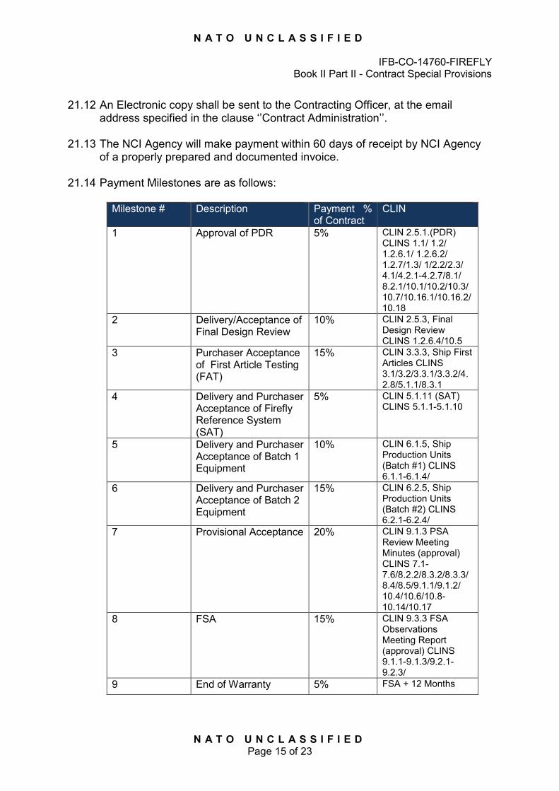
N A T O U N C L A S S I F I E D
IFB-CO-14760-FIREFLY Book II Part II - Contract Special Provisions
N A T O U N C L A S S I F I E D Page 15 of 23
21.12 An Electronic copy shall be sent to the Contracting Officer, at the email
address specified in the clause ‘’Contract Administration’’.
21.13 The NCI Agency will make payment within 60 days of receipt by NCI Agency of a properly prepared and documented invoice.
21.14 Payment Milestones are as follows: Milestone # Description Payment %
of Contract CLIN
1 Approval of PDR 5% CLIN 2.5.1.(PDR) CLINS 1.1/ 1.2/ 1.2.6.1/ 1.2.6.2/ 1.2.7/1.3/ 1/2.2/2.3/ 4.1/4.2.1-4.2.7/8.1/ 8.2.1/10.1/10.2/10.3/10.7/10.16.1/10.16.2/10.18
2 Delivery/Acceptance of Final Design Review
10% CLIN 2.5.3, Final Design Review CLINS 1.2.6.4/10.5
3 Purchaser Acceptance of First Article Testing (FAT)
15% CLIN 3.3.3, Ship First Articles CLINS 3.1/3.2/3.3.1/3.3.2/4.2.8/5.1.1/8.3.1
4 Delivery and Purchaser Acceptance of Firefly Reference System (SAT)
5% CLIN 5.1.11 (SAT) CLINS 5.1.1-5.1.10
5 Delivery and Purchaser Acceptance of Batch 1 Equipment
10% CLIN 6.1.5, Ship Production Units (Batch #1) CLINS 6.1.1-6.1.4/
6 Delivery and Purchaser Acceptance of Batch 2 Equipment
15% CLIN 6.2.5, Ship Production Units (Batch #2) CLINS 6.2.1-6.2.4/
7 Provisional Acceptance 20% CLIN 9.1.3 PSA Review Meeting Minutes (approval) CLINS 7.1-7.6/8.2.2/8.3.2/8.3.3/8.4/8.5/9.1.1/9.1.2/ 10.4/10.6/10.8-10.14/10.17
8 FSA 15% CLIN 9.3.3 FSA Observations Meeting Report (approval) CLINS 9.1.1-9.1.3/9.2.1-9.2.3/
9 End of Warranty 5% FSA + 12 Months
N A T O U N C L A S S I F I E D
IFB-CO-14760-FIREFLY Book II Part II - Contract Special Provisions
N A T O U N C L A S S I F I E D Page 16 of 23
ARTICLE 22 WARRANTY
22.1 This Article augments Clause 27 Warranty of Work (Exclusive of Software) of the NCI Agency Contract Special Provisions.
22.2 The warranty period shall start after Purchaser confirmed Provisional System Acceptance (PSA), as indicated in the SOW, and shall be the standard warranty with a minimum duration of 12 months from FSA for all hardware, software and for all services to be provided as part of this Contract, except for the hardware of which the warranty duration is specified in SSS, SOW and/or SRS. Until successful PSA, all hardware and software to be provided under this Contract shall be under the Contractor’s responsibility.
22.3 Notwithstanding inspection and acceptance by the Purchaser or its appointed agents of supplies furnished under the Contract or any provision of this Contract concerning the conclusiveness thereof, the Contractor warrants for the total duration of the above referred period and covering all items of hardware and software, that:
22.3.1 All deliverables furnished under this Contract shall be free from defect and will conform with the specifications and all other requirements of this Contract; and;
22.3.2 The system will, under normal conditions, perform without errors which make it unusable; and;
22.3.3 The preservation, packaging, packing and marking and the preparation for and method of, shipment of such supplies will conform to the requirements of this Contract.
22.4 During the System Warranty period, the Contractor shall provide a Warranty Performance Report in every 3 months starting from the PSA. In the report, the Contractor shall summarize all the warranty cases opened during the period, response times, corrective actions and resolution times. The Contractor shall also update the user documentation to reflect any baseline changes due to corrective actions in the system. Within the warranty performance report, the Contractor shall provide the updated spare parts calculation based on the actual reliability parameters and provide this additional spares within 7 days of approval of the Warranty Performance Report if the calculation for the initial set of spares proven to be inadequate.
22.5 In the case that, the Contractor fails to provide the additional spares within 7
calendar days, the Purchaser will reserve the right to purchase the additional spare item from alternative suppliers and the cost shall be deducted from the remaining payments under warranty.
N A T O U N C L A S S I F I E D
IFB-CO-14760-FIREFLY Book II Part II - Contract Special Provisions
N A T O U N C L A S S I F I E D Page 17 of 23
22.6 During the warranty period, the Contractor shall perform the Obsolescence Management actions including continuous obsolescence monitoring and reporting for end of sales, end of production and end of support with the corresponding mitigation options. The Contractor shall provide the Obsolescence Management report in every 3 months starting from PSA until the end of warranty to document any obsolescence risk. However, the Contractor shall notify the Purchaser as soon as any obsolescence case has been declared by manufacturers for end-of-production, end-of-sale or end-of-support including the proposal of urgent mitigation actions without waiting for the 3-month reporting.
22.7 During the System Warranty period the Contractor shall perform in-depth analysis of failures of equipment and components and parts thereof, and functional performance failures due to sub-system or equipment group malfunctions. Such failures shall not be limited to hardware, but shall include failures due to application or developed and embedded software. Software Warranty and all post FSA support requirements are to be implemented as described in detail in the SOW.
22.8 The Purchaser will inform the Contractor in writing of any defect after its discovery and the circumstances of its discovery. The Contractor shall respond to a defect notification within one working day, by engaging with the Purchaser’s personnel to identify the cause of the defect and to agree a resolution approach. The resolution of defects remains the Contractors responsibility within the warranty. In the case of a failure could not be identified to an LRU level and/or could not be isolated within 3 business day (starting with the warranty request) even with on-call assistance from the Contractor, the Contractor shall dispatch a field engineer to provide a solution on-site. The Contractor shall resolve all defects within (7) calendar days of their first being reported for those items that need not be returned to the Contractor’s facility for service or repair. Items needing service or repair at the Contractor’s facility shall be repaired/replaced and dispatched back to the Purchaser within (15) days of their arrival at the Contractor’s facility.
22.9 In the case that, the Contractor fails to repair or replace the item within 15 days of its arrival at the Contractor’s facility, the Purchaser will reserve the right to purchase the replacement item from alternative suppliers and the cost shall be deducted from the remaining payments under warranty.
22.10 The Contractor shall stipulate the address to which the Purchaser shall deliver equipment and material returned to the Contractor in accordance with the provisions of this Article. Transportation and handling charges for items returned under warranty claim to the Contractor will be the responsibility of the Purchaser, as well as responsibility for such supplies, i.e. damage and loss that may occur during transportation under warranty.
22.11 The Contractor shall, at its option, repair, adjust or replace defective equipment and restore to the Purchaser equipment, which functions in accordance with the requirements of the Contract.
N A T O U N C L A S S I F I E D
IFB-CO-14760-FIREFLY Book II Part II - Contract Special Provisions
N A T O U N C L A S S I F I E D Page 18 of 23
22.12 In the event of the Contractor’s failure to repair or replace failed equipment within the timeframes expressed in this Article, the Purchaser will have the right, at its discretion, and having given the Contractor due notice, to:
22.12.1 remedy, or have remedied, the defective or non-conforming supplies, in both cases at the Contractor’s expenses;
22.12.2 equitably reduce the Contract price; and/or 22.12.3 terminate for default that portion of the Contract relating to the defective
work. 22.13 Notwithstanding the provision of above paragraph 23.2, the warranty period
shall be suspended for the length of time necessary to carry out repair or replacement.
22.14 This right will be exercised although other contractual obligations remain in force. In the event that it is later determined that such supplies were found not to be defective or non-conforming within the provision of this Article, an equitable adjustment will be made. Failure to reach such an equitable adjustment will be considered a dispute under the Contract and subject to resolution in accordance with the Clause 41 “Disputes” of the NCI Agency Contract General Provisions.
22.15 Repeated failure of the same equipment, component or part, as well as failures due to software malfunctions may be considered by the Purchaser to be evidence of latent defect in the subject equipment (and or its associated software). In such a case the Purchaser may require the Contractor to redesign such elements of the system as may be necessary in order to correct the repeated failure, or to substitute the failed element with a more reliable version or functional equivalent thereof. Such redesign and/or substitution shall be tested, and if found appropriate, applied to the entire System.
22.16 Critical faults during the System Warranty period that take one of the Systems sites offline (except for normally scheduled downtime due to maintenance procedures) will have the result of extending the System Warranty for all sites by the period for which the single site is offline. This period is determined by the entry of the critical failure in the System Manager's logbook until the time the System Manager makes the entry into the logbook that the System has been restored to full operation.
22.17 Such extension of the Systems Warranty period will not apply in cases where the Contractor can convincingly demonstrate that the critical failure was due to Purchaser’s negligence or a willful act on the part of its personnel.
22.18 Corrective action required by the Contractor under the System Warranty shall also apply to errors or omissions in any delivered documentation which could not have reasonably been discovered prior to the FSA under this Contract. Errors or omissions in delivered documentation shall not be considered a basis for extension of the System Warranty as set forth in paragraphs above, except as can be demonstrated that such error or omission was the cause of a critical system failure that caused a site to be offline.
N A T O U N C L A S S I F I E D
IFB-CO-14760-FIREFLY Book II Part II - Contract Special Provisions
N A T O U N C L A S S I F I E D Page 19 of 23
22.19 All transportation and any related handling charges for items returned under warranty claim to the Contractor shall be the responsibility of the Contractor, as well as responsibility for such supplies, i.e. damage and loss that may occur during transportation under System Warranty.
ARTICLE 23 SUPPLEMENTAL AGREEMENTS, DOCUMENTS AND PERMISSIONS
23.1 The Contractor has submitted all relevant draft supplemental agreement(s),
documents and permissions prior to Contract award, the execution of which by the Purchaser is/are required by national law or regulation. If any supplemental agreements, documents and permissions are introduced after Contract award, and it is determined that the Contractor failed to disclose the requirement for the execution of such agreement from the Purchaser prior to Contract signature, the Purchaser may terminate this Contract for Default, in accordance with the Article 39 of the NCI Agency Contract General Provisions hereafter.
23.2 Supplemental agreement(s), documents and permissions, the execution of which by the Purchaser is/are required by national law or regulation and that have been identified by the Contractor prior to the signature of this Contract, but have not yet been finalized and issued by the appropriate governmental authority, are subject to review by the Purchaser.
If such supplemental agreement(s), documents and permissions are contrary to cardinal conditions of the signed Contract between the Parties, and the Purchaser and the appropriate governmental authority cannot reach a mutual satisfactory resolution of the contradictions, the Purchaser reserves the right to terminate this Contract and the Parties agree that in such case the Parties mutually release each other from claim for damages and costs of any kind, and any payments received by the Contractor from the Purchaser will be refunded to the Purchaser by the Contractor.
23.3 For the purpose of this Contract the following National mandatory Supplemental Agreements are identified:
Type of Agreement National Authority of
Reference Subject
To be added at Contract Award if required
To be added at Contract Award if required
To be added at Contract Award if required
ARTICLE 24 CONTRACT ADMINISTRATION
24.1 The Purchaser reserves the right to re-assign this Contract to a
representative(s) for administrative purposes, in whole or in part, provided that the Purchaser shall always be responsible for its obligations under the Contract and for actions or lack of actions of its assigned administrator. The Purchaser undertakes to advise the Contractor in writing whenever this right is to be exercised.
N A T O U N C L A S S I F I E D
IFB-CO-14760-FIREFLY Book II Part II - Contract Special Provisions
N A T O U N C L A S S I F I E D Page 20 of 23
24.2 All notices and communications between the Contractor and the Purchaser
shall be written and conducted in the English language. Contract modifications shall only be valid when received in writing from the General Manager, NCI Agency, and/or the NCI Agency Contracting Authority.
24.3 Formal letters and communications shall subsequently be personally delivered or sent by mail, registered mail, courier or other delivery service, to the official points of contact quoted in this Contract. Facsimile and e-mail may be used to provide an advance copy of a formal letter or notice which shall subsequently be delivered through the formal communication means.
24.4 Informal notices and informal communications may be exchanged by all communication means, including telephone and e-mail. All informal communication must be confirmed by a formal letter or other formal communication to be contractually binding.
24.5 All notices and communications shall be effective on receipt.
24.6 Official Points of Contact: Purchaser Contractor NCI Agency For contractual matters: Attn: Mr. Joseph Vitale Senior Contracting Officer Address: NCI Agency ACQ Boulevard Léopold III B-1110 Brussels Belgium Tel: +32 2 707 8321 E-mail: [email protected] CC: [email protected]
For contractual matters: Attn: Address: Tel: + E-mail:
For technical/project management matters: Attn. Mr. Kayhan Vardareri Project Manager Address: NCI Agency DIS/NSII SHAPE B-7010, Mons Belgium Tel: +32 65 44 2360 5253 E-mail : [email protected] CC: [email protected]
For technical/project management matters: Attn: Address: Tel: + E-mail:
N A T O U N C L A S S I F I E D
IFB-CO-14760-FIREFLY Book II Part II - Contract Special Provisions
N A T O U N C L A S S I F I E D Page 21 of 23
ARTICLE 25 SUB-CONTRACTORS
25.1 The Contractor shall place and be responsible for the administration and
performance of all sub-contracts including terms and conditions which it deems necessary to meet the requirements of this Contract in full.
25.2 The Contractor shall not place sub-contracts outside the NATO member Nations unless the prior authorization of the Purchaser has been obtained. Such authorization will not be granted when the sub-contract involves the carrying out of classified work.
ARTICLE 26 OWNERSHIP AND TITLE
26.1 Ownership to all work will pass to the Purchaser in accordance with the SOW
upon Final System Acceptance (FSA). Title to all deliveries shall pass to the Purchaser upon receipt of payment by the Contractor.
ARTICLE 27 OPTIONS
27.1 The Purchaser’s liabilities and obligations under this Contract at the time of its
signature, and unless a formal Contract Amendment is issued in accordance with the terms of this Article 28, are limited in scope and amount to performance and deliverables as described in the SSS and SOW.
27.2 CLIN 11, Alliance Ground Surveillance (AGS) and 12, Special Operations Component Command (SOCC) are optional and are available for unilateral exercise by the Purchaser at any time either totally or partially from Effective Date of Contract through FSA. The Purchaser may unilaterally exercise CLIN 13, Additional Equipment multiple times and in multiple quantitates up to the end of the warranty period.
27.3 The Contractor understands that there are no obligations under this Contract for the Purchaser to exercise any of the Options and that the Purchaser bears no liability should it decide not to exercise them (either totally or partially).
27.4 Further, the Purchaser reserves the right to order another Contractor (or the same), to perform the tasks or deliver the items described in the Options of the current Contract through a new Contract with other conditions.
27.5 If an option is exercised, the Contractor will have a minimum period of (30) days between notification and the required Performance Start Date (PSD).
27.6 Any Contract option shall be exercised by written amendment to the Contract.
N A T O U N C L A S S I F I E D
IFB-CO-14760-FIREFLY Book II Part II - Contract Special Provisions
N A T O U N C L A S S I F I E D Page 22 of 23
ARTICLE 28 PURCHASER FURNISHED PROPERTY/EQUIPMENT
28.1 The term “Purchaser Furnished Property/Equipment” as used in this Article refers to items of equipment, material or property furnished by the Purchaser to the Contractor that shall be subject to overhaul, repair, modification, test embodiment or other work as specified in the Contract, as listed in SOW at Appendix D.
28.2 The Contractor shall have no right for any claims in reference to a delay in the
Purchaser’s confirmation of site readiness and PFE availability, as long as the delay does not exceed (90) calendar days from the declared availability dates.
ARTICLE 29 THIRD PARTIES
29.1 The Contractor shall be aware of the possible need to work closely with and participate in meetings and reviews to be held jointly with third parties who perform work which contributes to, or is strongly related to, work conducted under this Project, mainly constituted by, but not limited to, the Contractor performing work under the NCIRC contract and other related NATO Contractors.
29.2 The Contractor shall have no rights to raise claims, ask for delays or interrupt the performance of the Contract on the basis of, or in connection with, his responsibilities to work/ co-ordinate with third parties running work on or related to this Project.
29.3 The above described effort is already included in the Total Firm Fixed price of this Contract and the Contractor shall have no recourse for additional costs or delays in the performance of this Contract on the basis of the above described effort.
29.4 The Purchaser reserves the right to make technical documentation available to third parties.
ARTICLE 30 REACH CAPABILITY
30.1 The purpose of this Article is to define the conditions under which specific Purchaser provided REACH capability is made available to the Contractor in the course of CO-14764-FIREFLY.
30.2 The provision of the REACH capability is not governed by the standard Clause 13 of the Contract General Provisions (Purchaser Furnished Property) but solely by Article 31 of the Contract Special Provisions and by the Service Level Agreement (SLA) to be established between the parties.
30.3 Should the Purchaser not be able to meet the Service Level Agreement (SLA) related to the provision of the REACH capability the Contractor shall not be entitled to claim an excusable delay nor any compensation against the Contract.
END OF CLAUSES

N A T O U N C L A S S I F I E D
IFB-CO-14760-FIREFLY Book II Part II - Contract Special Provisions
N A T O U N C L A S S I F I E D Page 23 of 23
ANNEX A: NCI AGENCY DECLARATION To be signed by the Contractor’s Key Personnel working under Contract CO-14760-FIREFLY upon commencement of this Contract. I UNDERSTAND: That I must preserve the security of all classified /commercial-in-confidence information which comes to my knowledge as a result of this contract with the NCI Agency and that I undertake to comply with all relevant security regulations. That I must not divulge to any unauthorised person, any classified/commercial-in confidence information gained by me as a result of my contract with NCI Agency, unless prior permission for such disclosure has been granted by the General Manager of the NCI Agency. That I must not, without the approval of the General Manager of the NCI Agency, publish (in any document, article, book, CD, video, film, play, or other form) any classified /commercial-in-confidence information which I have acquired in the course of my official duties for NCI Agency. That, at the end of contract and after performance of all required tasks, I must surrender any official document or material made or acquired by me in the course of my official duties, save such as I have been duly authorised to retain. That if I violate prescribed security practices either intentionally or accidentally, my contract shall be immediately terminated. That the provisions of the above Declaration apply not only during the period of my contract with the Agency, but also after my contract has ceased and that I am liable to prosecution if either by intent or negligence I allow classified/commercial-in-confidence information to pass into unauthorised hands. That by accepting the position of Engineering Support Contractor for NATO corresponding to the tasks and duties described in the present contract, I will be considered as a Key Personnel as specified in Special Provision Article 13. That I commit to fulfil my obligations for the period of performance mentioned in the Schedule of Supplies and Services (including the optional periods) unless major events beyond my reasonable control happen. That should I decide for personal interest to leave the position, I will do my best effort to fulfil my obligations until the Company that is currently employing me has provided NATO with an acceptable suitable substitute in accordance with Special Provision – Article 13. Date Full name (in block capitals) Signature

NATO UNCLASSIFIED IFB-CO-14760-FIREFLY
Part III – Contract General Provisions
Provide DCIS Equipment for Small NRF HQ
IFB-CO-14760-FIREFLY
Book II - Part III
CONTRACT GENERAL PROVISIONS
V 1.0 dated 16 Oct 2014

NATO UNCLASSIFIED
IFB-CO-14760-FIREFLY Part III – Contract General Provisions
ii NATO UNCLASSIFIED
NATO UNCLASSIFIED IFB-CO-14760-FIREFLY
Part III – Contract General Provisions
i NATO UNCLASSIFIED
Index of Clauses
1. ORDER OF PRECEDENCE ................................................................................................................. 1
2. DEFINITIONS OF TERMS AND ACRONYMS .................................................................................. 1
3. AUTHORITY ............................................................................................................................................ 4
4. APPROVAL AND ACCEPTANCE OF CONTRACT TERMS ........................................................... 5
5. LANGUAGE ............................................................................................................................................. 5
6. AUTHORISATION TO PERFORM/CONFORMANCE TO NATIONAL LAWS AND REGULATIONS ..................................................................................................................................... 5
7. FIRM FIXED PRICE CONTRACT ........................................................................................................ 5
8. PERFORMANCE GUARANTEE .......................................................................................................... 5
9. PARTICIPATING COUNTRIES.............................................................................................................. 9
10. SUB-CONTRACTS ............................................................................................................................... 10
11. SECURITY ............................................................................................................................................. 11
12. RELEASE OF INFORMATION ........................................................................................................... 12
13. PURCHASER FURNISHED PROPERTY ......................................................................................... 13
14. CONTRACTOR'S PERSONNEL WORKING AT PURCHASER'S FACILITIES ......................... 14
15. HEALTH, SAFETY AND ACCIDENT PREVENTION ...................................................................... 15
16. CHANGES ............................................................................................................................................. 15
17. STOP WORK ORDER ......................................................................................................................... 17
18. CLAIMS .................................................................................................................................................. 18
19. PRICING OF CHANGES, AMENDMENTS AND CLAIMS ............................................................. 20
20. NOTICE OF SHIPMENT AND DELIVERY ....................................................................................... 23
21. INSPECTION AND ACCEPTANCE OF WORK ............................................................................... 24
22. INSPECTION AND ACCEPTANCE OF DOCUMENTATION ........................................................ 27
23. USE AND POSSESSION PRIOR TO ACCEPTANCE .................................................................... 28
24. OWNERSHIP AND TITLE ................................................................................................................... 28
25. INVOICES AND PAYMENT ................................................................................................................ 28
26. TAXES AND DUTIES ........................................................................................................................... 30
27. WARRANTY OF WORK (Exclusive of Software) ............................................................................ 31
28. RIGHT OF ACCESS, EXAMINATION OF RECORDS ................................................................... 35
29. PATENT AND COPYRIGHT INDEMNITY ........................................................................................ 35
30. INTELLECTUAL PROPERTY ............................................................................................................. 36
31. SOFTWARE WARRANTY ................................................................................................................... 39
32. NATO CODIFICATION ........................................................................................................................ 42
33. RELEASE FROM CLAIMS .................................................................................................................. 44
34. ASSIGNMENT OF CONTRACT ......................................................................................................... 44
35. TRANSFER AND SUB-LETTING ....................................................................................................... 45
36. PURCHASER DELAY OF WORK ...................................................................................................... 45
NATO UNCLASSIFIED
IFB-CO-14760-FIREFLY Part III – Contract General Provisions
ii NATO UNCLASSIFIED
37. CONTRACTOR NOTICE OF DELAY ................................................................................................ 46
38. LIQUIDATED DAMAGES .................................................................................................................... 46
39. TERMINATION FOR DEFAULT ......................................................................................................... 47
40. TERMINATION FOR THE CONVENIENCE OF THE PURCHASER ........................................... 50
41. DISPUTES ............................................................................................................................................. 55
42. ARBITRATION ...................................................................................................................................... 56
43. SEVERABILITY ..................................................................................................................................... 57
44. APPLICABLE LAW ............................................................................................................................... 57
ANNEX 1 TO GENERAL PROVISONS: PURCHASER'S PRICING PRINCIPLES .......................... A1-1

NATO UNCLASSIFIED
IFB-CO-14760-FIREFLY Part III – Contract General Provisions
1 NATO UNCLASSIFIED
1. ORDER OF PRECEDENCE In the event of any inconsistency in language, terms or conditions of the various parts of this Contract, precedence will be given in the following order:
1.1. The Signature Page;
1.2. The Contract Schedules, Part I;
1.3. The Contract Special Provisions, Part II;
1.4. The Contract General Provisions, Part III;
1.5. The Statement of Work, Part IV of the Contract;
1.6. The Annexes to the Statement of Work.
2. DEFINITIONS OF TERMS AND ACRONYMS
2.1 Assembly - An item forming a portion of equipment that can be provisioned and replaced as an entity and which normally incorporates replaceable parts or groups of parts.
2.2 Acceptance - Acceptance is the act by which the Contracting Authority recognises in writing that the delivered Work meets the Contract requirements.
2.3 Claims - A written demand or written assertion by one of the Parties seeking, as a matter of right, the payment of money in a sum certain, the adjustment or interpretation of Contract terms, or other relief arising under or in relation to this Contract.
2.4 Clause - A provision of the Special or General Provisions of this Contract. 2.5 Codification Authority - The National Codification Bureau (NCB) or
authorised agency of the country in which the Work is produced. 2.6 Commercial Off-the-Shelf Items (COTS) - The term “Commercially Off-the-
Shelf Item (COTS)” means any item that is a commercial item, customarily used by the general public, that has been sold, leased, or licensed to the general public or has been offered for sale, lease or license to the general public;
a) is sold in substantial quantities in the commercial marketplace; and b) is offered to the Purchaser, under a contract or subcontract at any tier,
without modification, in the same form in which it is sold in the commercial marketplace.
2.7 Component - A part or combination of parts, having a specific function, which can be installed or replaced only as an entity.
NATO UNCLASSIFIED
IFB-CO-14760-FIREFLY Part III – Contract General Provisions
2 NATO UNCLASSIFIED
2.8 Contractor Background IPR - Any IPR owned by the Contractor and/or any Sub-contractor or licensed by a third party to the Contractor which is not created in relation to or as the result of work undertaken for any purpose contemplated by the Contract and which is needed for the performance of the Contract or for the exploitation of Foreground IPR.
2.9 Correction - Elimination of a Defect. 2.10 Contract - The agreement concluded between the Purchaser and Contractor,
duly signed by both contracting parties. The Contract includes the documents referred to in Clause 1 (Order of Preference).
2.11 Contracting Authority - The General Manager of the NCI Agency, the Director of Acquisition, the Chief of Contracts of the NCI Agency or the authorised representatives of the Chief of Contracts of the NCI Agency.
2.12 Contractor - The person or legal entity from a Participating Country which has signed this Contract and is a Party thereto.
2.13 Day - A calendar day 2.14 Defect - Any condition or characteristic in any Work furnished by the Contractor
under the Contract that is not in compliance with the requirements of the Contract.
2.15 Deliverable - Any and all goods (including movable and immovable goods) to be delivered pursuant to the terms of this Contract including, without limitation, building, raw materials, components, intermediate Assemblies, Parts, end products, equipment, documentation, data, software.
2.16 Design Defect - Defect attributable to incompatibility, unsuitability or erroneous application of theory, drawings or formula.
2.17 Effective Date of Contract (or “EDC”) - The date upon which this Contract is deemed to start. Unless otherwise specified, a Contract enters into force on the date of the last signature of the Contract by the Parties.
2.18 Failed Component - A part or combination of parts, having a specific function, which can be installed or replaced only as an entity which ceases to perform in a manner consistent with its intended use and specifications of the Contract.
2.19 Foreground IPR - Any IPR created by the Contractor or any subcontractor of the Contractor in the course of or as the result of work undertaken for any purpose contemplated by the Contract.
2.20 IPR - Any intellectual property rights of any qualification irrespective of their stage of development or finalisation, including but not limited to patents, trademarks (registered of not), designs and models (registered or not) and applications for the same, copyright (including on computer software), rights in databases, know-how, confidential information and rights in records (whether or not stored on computer) which includes technical and other data and documents.
NATO UNCLASSIFIED
IFB-CO-14760-FIREFLY Part III – Contract General Provisions
3 NATO UNCLASSIFIED
2.21 Manufacturing Defect - Defect attributable to improper manufacturing processes, testing or quality control procedures.
2.22 NATO - The North Atlantic Treaty Organisation. For the purpose of this contract, the term NATO includes NATO bodies, the NATO military command structure, agencies and NATO nations.
2.23 NCI AGENCY - The NATO Communications and Information Agency. The NCI Agency is part of the NCIO. The General Manager of the Agency is authorised to enter into contracts on behalf of the NATO CI Organisation.
2.24 NATO COMMUNICATIONS AND INFORMATION ORGANISATION (NCIO)-The NATO Communications and Information Organisation. The NCI Organisation constitutes an integral part of the North Atlantic Treaty Organisation (NATO) The NCI Organisation is the legal personality from whence flows the authority of its agent, the NCI Agency, to enter into contracts.
2.25 NATO Purposes - Activities conducted by or on behalf of NATO to promote the common defence and common interests of NATO, such as, among others, NATO operations, NATO procurement, NATO training and NATO maintenance.
2.26 Part - An item of an assembly or sub-assembly, which is not normally further broken down.
2.27 Participating Country - A NATO member country that participates in financing the effort.
2.28 Parties - The Contracting Parties to this Contract, i.e., the Purchaser and the Contractor.
2.29 Purchaser - The NCI Organisation, as represented by the General Manager, NCI Agency. The Purchaser is the legal entity who awards and administers the Contract on behalf of NATO and stands as one of the Contracting Parties.
2.30 Purchaser Background IPR - Any IPR owned by the Purchaser as of the Effective Date of Contract and which has been developed by, assigned to or licensed to the Purchaser prior to the Effective Date of Contract.
2.31 Purchaser Furnished Property - Any item of equipment, material, document, technical data, information and Software or any other item of property furnished by the Purchaser to the Contractor required or useful for the performance of the Contract. The Purchaser Furnished Property, if any, shall be detailed in the Contract.
2.32 Software (Computer Software) - A computer program comprising a series of instructions, rules, routines regardless of the media in which it is recorded, that allows or cause a computer to perform a specific operation or a series of operations.
2.33 Software Defect - Any condition or characteristic of Software that does not conform with the requirements of the Contract.
NATO UNCLASSIFIED
IFB-CO-14760-FIREFLY Part III – Contract General Provisions
4 NATO UNCLASSIFIED
2.34 Sub-Assembly - A portion of an Assembly consisting of two or more parts that can be provisioned and replaced as an entity. The definition purposely excludes Components and/or Parts.
2.35 Sub-contract - Any agreement made by the Contractor with any third party in order to fulfil any part of the obligations under this Contract. Sub-contracts may be in any legal binding form, e.g., contract, purchase order, etc.
2.36 Sub-contractor - Any person or legal entity directly or indirectly under Sub-contract to the Contractor in performance of this Contract.
2.37 Third Party IPR - Any IPR owned by a third party not being the Purchaser or the Contractor or its Subcontractor, which is needed for the performance of the Contract or for the exploitation of Foreground IPR. This includes, for example, third party software, including open source software.
2.38 Work - Any deliverable, project design, labour or any service or any other activity to be performed by the Contractor under the terms of this Contract.
3. AUTHORITY
3.1. All binding contractual instruments and changes, including amendments, additions or deletions, as well as interpretation of and instructions issued pursuant to this Contract shall be valid only when issued in writing by the Purchaser and signed by the Contracting Authority only.
3.2. No direction which may be received from any person employed by the Purchaser or a third party shall be considered as grounds for deviation from any of the terms, conditions, specifications or requirements of this Contract except as such direction may be contained in an authorised amendment to this Contract or instruction duly issued and executed by the Contracting Authority. Constructive change may not be invoked by the Contractor as a basis for Claims under this Contract.
3.3. The entire agreement between the Parties is contained in this Contract and is not affected by any oral understanding or representation, whether made previously to or subsequently to this Contract.
3.4. Personal notes, signed minutes of meetings, comments to delivered documentation and letters, e-mails and informal messages from project or other Purchaser staff which may indicate the intent and willingness to make changes to the Contract, do not implement the change to the Contract and shall not be used as a basis for claiming change to the Contract by the Contractor.

NATO UNCLASSIFIED
IFB-CO-14760-FIREFLY Part III – Contract General Provisions
5 NATO UNCLASSIFIED
4. APPROVAL AND ACCEPTANCE OF CONTRACT TERMS
4.1. By his signature of the Contract, the Contractor certifies that he has read and unreservedly accepts and approves of all terms and conditions, specifications, plans, drawings and other documents which form part of and/or are relevant to the Contract. The Contractor further agrees that the terms of the Contract take precedence over any proposals or prior commitments made by the Contractor in order to secure the Contract. Contractor also hereby waives any and all rights to invoke any of the Contractor’s general and special terms and conditions of sales and/or supply.
5. LANGUAGE
5.1. All written correspondence, reports, documentation and text of drawings delivered to the Purchaser by the Contractor shall be in the English language.
6. AUTHORISATION TO PERFORM/CONFORMANCE TO NATIONAL LAWS AND REGULATIONS
6.1. The Contractor warrants that he and his Sub-contractors are duly authorised to operate and do business in the country or countries in which this Contract is to be performed and that he and his Sub-contractors have obtained or will obtain all necessary licences and permits required in connection with the Contract. No claim for additional monies with respect to any costs or delay to obtain the authorisations to perform shall be made by the Contractor.
6.2. The Contractor acknowledges that he and his Sub-contractors are responsible during the performance of this Contract for ascertaining and complying with all applicable laws and regulations, including without limitation: labour standards, environmental laws, health and safety regulations and export controls laws and regulations in effect at the time of Contract signature or scheduled to go into effect during Contract performance. Failure to fully ascertain and comply with such laws, regulations or standards shall not be the basis for claims for change to the specifications, terms, conditions or monetary value of this Contract.
7. FIRM FIXED PRICE CONTRACT 7.1 This is a Firm Fixed Price Contract. The Firm Fixed Price of this Contract is as
stated on the signature page of the Contract or any amendments thereto. The Purchaser assumes no liability for costs incurred by the Contractor in excess of the stated Firm Fixed Price except as may be authorised under certain provisions of this Contract.
8. PERFORMANCE GUARANTEE

NATO UNCLASSIFIED
IFB-CO-14760-FIREFLY Part III – Contract General Provisions
6 NATO UNCLASSIFIED
8.1. As a guarantee of performance under the Contract, the Contractor shall
deposit with the Purchaser within thirty (30) calendar days from the Effective Date of Contract a bank guarantee (the “Performance Guarantee”) denominated in the currency of the Contract, to the value of ten per cent (10%) of the total Contract price.
8.2. The Performance Guarantee, the negotiability of which shall not elapse before
the expiration of the warranty period, or such other period as may be specified in the Contract, shall be made payable to the Purchaser and shall be in the form of certified cheques or a Standby Letter of Credit subject to the agreement of the Purchaser. In the case of a Standby Letter of Credit, payment shall be made to the Purchaser without question and upon first demand by the Purchaser against a certificate from the Purchaser's Contracting Authority that the Contractor has not fulfilled its obligations under the Contract. The Contractor shall have no right to enjoin or delay such payment.
8.3. Certified Cheques issued to fulfil the requirements of the Performance
Guarantee will be cashed by the Purchaser upon receipt and held in the Purchaser's account until the term of the Performance Guarantee has expired.
8.4. The standby letter of credit shall be subject to Belgian Law and shall be issued
by (i) a Belgian bank, (ii) the Belgian subsidiary of a foreign bank licensed to provide financial services in Belgium; or (iii) an insurance company licensed to do business in Belgium and belonging to a Belgian banking institution provided the banking institution guarantees explicitly the demand for payment, unless otherwise specified by the Purchaser.
8.5. The Contractor shall request in writing relief from the Performance Guarantee
upon expiration of the warranty period or such other period as may be specified in the Contract and such relief may be granted by the Purchaser.
8.6. The Contractor shall be responsible, as a result of duly authorised adjustments
in the total contract price and/or period of performance by the Purchaser, for obtaining a commensurate extension and increase in the Performance Guarantee, the value of which shall not be less than ten per cent (10%) of the total contract price (including all amendments), and for depositing such guarantee with the Purchaser, within thirty (30) calendar days from the effective date of aforesaid duly authorised adjustment.
8.7. The failure of the Contractor to deposit and maintain such Performance
Guarantee with the Purchaser within the specified time frame, or any extension thereto granted by the Purchaser's Contracting Authority, is a material breach of the Contract terms and conditions subject to the provisions of the Contract regarding Termination for Default.

NATO UNCLASSIFIED
IFB-CO-14760-FIREFLY Part III – Contract General Provisions
7 NATO UNCLASSIFIED
8.8. The rights and remedies provided to the Purchaser under the present Clause
are in addition to any other rights and remedies provided by law or under this Contract. The certificate described in Clause 8.2 above shall not be regarded as a Termination for Default and this Clause is in addition to and separate from the Clause of the Contract detailing termination for default.
8.9. If the Contractor elects to post the Performance Guarantee by Standby Letter
of Credit, the form of the document shall be substantially as follows:
PERFORMANCE GUARANTEE STANDBY LETTER OF CREDIT
Standby Letter of Credit Number: Issue Date: ________________ Initial Expiry Date: _________________ Final Expiry Date: _________________ Beneficiary: NCI Agency, Finance, Accounting & Operations Boulevard Leopold III, B-1110, Brussels Belgium 1. We hereby establish in your favour our irrevocable standby letter of credit number
{number} by order and for the account of (NAME AND ADDRESS OF CONTRACTOR) in the amount of _______________________________________. We are advised this undertaking represents fulfilment by (NAME OF CONTRACTOR) of certain performance requirements under Contract No. ______________________ dated ____________________ between the NCI Agency (“NCIA and (NAME OF CONTRACTOR).
2. We hereby engage with you that drafts drawn under and in compliance with the
terms of this letter of credit will be duly honoured upon presentation of documents to us on or before the expiration date of this letter of credit.
3. Funds under this letter of credit are available to you without question or delay
against presentation of a certificate signed by the NCI Agency Contracting Officer which states:
“(NAME OF CONTRACTOR) has not fulfilled its obligations under Contract No. __________ dated _________ between NCI Agency and (NAME OF CONTRACTOR) (herein called the “Contract”), and the NCI Agency, as beneficiary, hereby draws on the standby letter of credit number ________ in the amount denominated in the currency of the Contract, Amount up to the maximum available under the LOC), such funds to be transferred to the account of the Beneficiary number

NATO UNCLASSIFIED
IFB-CO-14760-FIREFLY Part III – Contract General Provisions
8 NATO UNCLASSIFIED
___________________(to be identified when certificate is presented).”
Such certificate shall be accompanied by the original of this letter of credit.
4. This Letter of Credit is effective the date hereof and shall expire at our office
located at (Bank Address) on _________________. All demands for payment must be made prior to the expiry date.
5. It is a condition of this letter of credit that the expiry date will be automatically
extended without amendment for a period of one (1) year from the current or any successive expiry date unless at least 90 (ninety) calendar days prior to the then current expiry date we notify you by registered mail and notify (NAME OF CONTRACTOR) that we elect not to extend this letter of credit for such additional period. However, under no circumstances will the expiry date extend beyond ______________________ (“Final Expiry Date”) without amendment.
6. We may terminate this letter of credit at any time upon 90 (ninety) calendar days
notice furnished to both (NAME OF CONTRACTOR) and the NCI Agency by registered mail.
7. In the event we (the issuing bank) notify you that we elect not to extend the expiry
date in accordance with paragraph 6 above, or, at any time, to terminate the letter of credit, funds under this credit will be available to you without question or delay against presentation of a certificate signed by the NCI Agency Contracting Officer which states:
“The NCI Agency has been notified by {issuing bank} of its election not to automatically extend the expiry date of letter of credit number {number} dated {date} pursuant to the automatic renewal clause (or to terminate the letter of credit). As of the date of this certificate, no suitable replacement letter of credit, or equivalent financial guarantee has been received by the NCI Agency from, or on behalf of (NAME OF CONTRACTOR). (NAME OF CONTRACTOR) has, therefore, not fulfilled its obligations under Contract No. _______________ dated _____________ between NCI Agency and (NAME OF CONTRACTOR), and the NCI Agency, as beneficiary, hereby draws on the standby letter of credit number ________ in the amount of (Amount up to the maximum available under the LOC), such funds to be transferred to the account of the Beneficiary number ___________________ (to be identified when certificate is presented).”
Such certificate shall be accompanied by the original of this letter of credit and a copy of the letter from the issuing bank that it elects not to automatically extend the standby letter of credit, or terminating the letter of credit.

NATO UNCLASSIFIED
IFB-CO-14760-FIREFLY Part III – Contract General Provisions
9 NATO UNCLASSIFIED
8. The Beneficiary may not present the certificate described in paragraph 7 above until 20 (twenty) calendar days prior to a) the date of expiration of the letter of credit should {issuing bank} elect not to automatically extend the expiration date of the letter of credit, b) the date of termination of the letter of credit if {issuing bank} notifies the Beneficiary that the letter of credit is to be terminated in accordance with paragraph 6 above.
9. Multiple partial drawings are allowed to the maximum value of the standby letter
of credit. 10. This letter of credit sets forth in full the terms of our undertaking, and this
undertaking shall not in any way be modified, amended, or amplified by reference to any document, instrument, or agreement referred to herein (except the International Standby Practices (ISP 98) hereinafter defined) or in which this letter of credit is referred to or to which this letter of credit relates, and any such reference shall not be deemed to incorporate herein by reference any document, instrument, or agreement.
11. This Letter of Credit is subject to The International Standby Practices-ISP98
(1998 Publication) International Chamber of Commerce Publication No.590.
9. PARTICIPATING COUNTRIES 9.1 Unless prior written authorisation of the Purchaser has been obtained, none of
the Work, shall be performed other than by firms from and within NATO Participating Countries. Unless otherwise specified in the Contract Special Provisions, the Participating Countries are the twenty-eight (28) Member Nations of the North Atlantic Treaty Organisation.
9.2 Unless prior written authorisation of the Purchaser has been obtained, no
material or items of equipment down to and including identifiable Sub-Assemblies shall be manufactured or assembled by a firm other than from and within a NATO Participating Country.
9.3 The Contractor shall not place any Sub-contracts outside the NATO
Participating Countries without the prior written authorisation of the Purchaser. 9.4 Unless prior written authorisation of the Purchaser has been obtained, the
intellectual property rights for all software and documentation incorporated by the Contractor and/or its Sub-contractors into the Work shall vest with persons or legal entities from and within NATO participating nations and no royalties or licence fees for such software and documentation shall be paid by the Contractor to any source that does not reside within a NATO participating nation.
9.5 Any modification in the nationality, ownership and/or change of control of the
Contractor and/or its Sub-contractor(s) shall be immediately notified in writing
NATO UNCLASSIFIED
IFB-CO-14760-FIREFLY Part III – Contract General Provisions
10 NATO UNCLASSIFIED
to the Purchaser with all necessary details to allow the Purchaser to determine whether or not the Contractor and/or its Sub-contractors continue to comply with the Clauses above. Non-compliance with the Clauses above, by the Contractor and/or its Subcontractor may constitute ground for termination of this Contract under Clause 39 (Termination for Default).
10. SUB-CONTRACTS
10.1 The Contractor shall place and be responsible for the administration and performance of all Sub-contracts including terms and conditions which he deems necessary to meet the requirements of this Contract in full.
10.2 Prior to the Sub-contractors being given access to any classified information, the Contractor shall ensure that any Sub-contractor that has a need to access classified information for the performance of any part of this Contract has been granted the appropriate facility and personnel security clearances by the Sub-contractor's national authorities and that such clearances are still in effect at the time the information is disclosed and remains in effect throughout the performance of the work to be carried out under the Sub-contract concerned.
10.3 The Contractor shall seek the approval in writing of the Purchaser prior to the placing of any Sub-contract if:
10.3.1 the Sub-contract was not part of the Contractor’s original proposal;
and
10.3.2 the value of the Sub-contract is known or estimated to exceed 15 per cent of the total Contract value; or
10.3.3 the Sub-contract is one of a number of Sub-contracts with a single
Sub-contractor for the same or related Work under this Contract that in the aggregate are known or expected to exceed 15 per cent of the total Contract value.
10.4 The Contractor shall inform the Purchaser of any change in Sub-contractors for Sub-contracts of a value known or estimated to exceed 15 per cent of the total Contract value.
10.5 The Contractor shall submit a copy of any such proposed Sub-contract including prices when seeking approval to the Contracting Authority but such approval by the Contracting Authority shall in no way relieve the Contractor of his responsibilities to fully achieve the contractual and technical requirements of this Contract.
10.6 The Contractor shall, as far as practicable, select Sub-contractors on a competitive basis consistent with the objectives and requirements of the
NATO UNCLASSIFIED
IFB-CO-14760-FIREFLY Part III – Contract General Provisions
11 NATO UNCLASSIFIED
Contract.
11. SECURITY 11.1 The Contractor shall comply with all security measures as are prescribed by the
Purchaser and the national security authority or designated security agency of each of the NATO countries in which the Contract is being performed. The Contractor shall be responsible for the safeguarding of classified information, documentation, material and equipment entrusted to him or generated by him in connection with the performance of the Contract.
11.2 In particular the Contractor undertakes to: 11.2.1 appoint an official responsible for supervising and directing
security measures in relation to the Contract and communicating details of such measures to the Purchaser on request;
11.2.2 maintain, preferably through the official responsible for security
measures, a continuing relationship with the national security authority or designated security agency charged with ensuring that all NATO classified information involved in the Contract is properly safeguarded;
11.2.3 abstain from copying by any means, without the authorisation of
the Purchaser, the national security authority or designated security agency, any classified documents, plans, photographs or other classified material entrusted to him;
11.2.4 furnish, on request, information to the national security authority
or designated security agency pertaining to all persons who will be required to have access to NATO classified information;
11.2.5 maintain at the work site a current record of his employees at the
site who have been cleared for access to NATO classified information. The record should show the date of issue, the date of expiration and the level of clearance;
11.2.6 deny access to NATO classified information to any person other
than those persons authorised to have such access by the national security authority or designated security agency;
11.2.7 limit the dissemination of NATO classified information to the
smallest number of persons (“need to know basis”) as is consistent with the proper execution of the Contract;
11.2.8 comply with any request from the national security authority or
designated security agency that persons entrusted with NATO classified information sign a statement undertaking to safeguard
NATO UNCLASSIFIED
IFB-CO-14760-FIREFLY Part III – Contract General Provisions
12 NATO UNCLASSIFIED
that information and signifying their understanding both of their obligations under national legislation affecting the safeguarding of classified information, and of their comparable obligations under the laws of the other NATO nations in which they may have access to classified information;
11.2.9 report to the national security authority or designated security
agency any breaches, suspected breaches of security, suspected sabotage, or other matters of security significance which would include any changes that may occur in the ownership, control or management of the facility or any changes that affect the security arrangements and security status of the facility and to make such other reports as may be required by the national security authority or designated security agency, e.g. reports on the holdings of NATO classified material;
11.2.10 apply to the Purchaser for approval before Sub-contracting any
part of the work, if the Sub-contract would involve that the Sub-contractor would have access to NATO classified information, and to place the Sub-contractor under appropriate security obligations no less stringent than those applied to his own contract;
11.2.11 undertake not to utilise, other than for the specific purpose of the
Contract, without the prior written permission of the Purchaser or his authorised representative, any NATO classified information furnished to him, including all reproductions thereof in connection with the Contract, and to return all NATO classified information referred to above as well as that developed in connection with the Contract, unless such information has been destroyed, or its retention has been duly authorised with the approval of the Purchaser. Such NATO classified information will be returned at such time as the Purchaser or his authorised representative may direct;
11.2.12 classify any produced document with the highest classification of
the NATO classified information disclosed in that document.
12. RELEASE OF INFORMATION 12.1 Except as otherwise specified elsewhere in the Contract and to the extent that
it is demonstratively unavoidable and without prejudice to the Clause 11 (Security), the Contractor and/or his employees shall not, without prior authorisation from the Purchaser, release to third parties any information pertaining to this Contract, its subject matter, performance there under or any other aspect thereof.
NATO UNCLASSIFIED
IFB-CO-14760-FIREFLY Part III – Contract General Provisions
13 NATO UNCLASSIFIED
12.2 The Contractor shall seek the prior written approval of the Purchaser before publishing any press release or disclosing any other information, orally or in writing, in relation to the Contract. The approval of the Purchaser shall be required for both the opportunity and the content of the information.
12.3 This provision shall remain in effect after the termination of the Contract and shall cease to apply to any particular piece of information once that information becomes public knowledge other than through an act, default or omission of the Contractor or its Sub-contractors.
13. PURCHASER FURNISHED PROPERTY
13.1 The Purchaser shall deliver to the Contractor, for use only in connection with this Contract, the Purchaser Furnished Property at the times and locations stated in the Contract. In the event that Purchaser Furnished Property is not delivered by such time or times stated in the Schedule, or if not so stated, in sufficient time to enable the Contractor to meet such delivery or performance dates the Purchaser shall, upon timely written request made by the Contractor, and if the facts warrant such action, equitably adjust any affected provision of this Contract pursuant to Clause 16 (Changes). 13.2 In the event that Purchaser Furnished Property is received by the Contractor in a condition not suitable for its intended use, the Contractor shall immediately notify the Purchaser. The Purchaser shall within a reasonable time of receipt of such notice replace, re-issue, authorise repair or otherwise issue instructions for the disposal of Purchaser Furnished Property agreed to be unsuitable. The Purchaser shall, upon timely written request of the Contractor, equitably adjust any affected provision of this\ Contract pursuant to Clause 16 (Changes). 13.3 Title to Purchaser Furnished Property will remain in the Purchaser. The Contractor shall maintain adequate property control records of Purchaser Furnished Property in accordance with sound industrial practice and security regulations. 13.4 Unless otherwise provided in this Contract, the Contractor, upon delivery to him of any Purchaser Furnished Property, assumes the risk of, and shall be responsible for, any loss thereof or damage thereof except for reasonable wear and tear, and except to the extent that Purchaser Furnished Property is consumed in the performance of this Contract. 13.5 Upon completion of this Contract, or at such earlier dates as may be specified by the Purchaser, the Contractor shall submit, in a form acceptable to the Purchaser, inventory schedules covering all items of Purchaser Furnished Property.

NATO UNCLASSIFIED
IFB-CO-14760-FIREFLY Part III – Contract General Provisions
14 NATO UNCLASSIFIED
13.6 The inventory shall note whether:
13.6.1 The property was consumed or incorporated in fabrication of final deliverable(s);
13.6.2 The property was otherwise destroyed;
13.6.3 The property remains in possession of the Contractor;
13.6.4 The property was previously returned
13.7 The Contractor shall prepare for shipment, deliver DDP at a destination agreed with the Purchaser, or otherwise dispose of Purchaser Furnished Property as may be directed or authorised by the Purchaser. The net proceeds of any such disposal shall be credited to the Contract price or paid to the Purchaser in such other manner as the Purchaser may direct. 13.8 The Contractor shall not modify any Purchaser Furnished Property unless specifically authorised by the Purchaser or directed by the terms of the Contract. 13.9 The Contractor shall indemnify and hold the Purchaser harmless against claims for injury to persons or damages to property of the Contractor or others arising from the Contractor’s possession or use of the Purchaser Furnished Property. The Contractor shall indemnify the Purchaser for damages caused by the Contractor to the Purchaser, its property and staff and arising out of the Contractor’s use of the Purchaser Furnished Property.
14. CONTRACTOR'S PERSONNEL WORKING AT PURCHASER'S FACILITIES
14.1 The term "Purchaser Facilities" as used in this Clause shall be deemed to include sites, property, utilities, ships or vessels and the term "Facility Representative" shall be deemed to refer to the authority designated by the Purchaser responsible for the site, property, utility, ship or vessel. 14.2 The Facility Representative shall provide such available administrative and technical facilities for Contractor's personnel working at Purchaser's Facilities for the purpose of the Contract as in the opinion of the Facility Representative may be necessary for the effective and economical discharge of Work. The Facility Representative shall also determine whether these facilities will be provided free of charge to the Contractor or determine what charges are payable. The Contractor shall have no claim against the Purchaser for any such additional cost or delay or any additional cost or delay occasioned by the closure for holidays of said facilities, or other reasons, where this is generally published or made known to the Contractor
NATO UNCLASSIFIED
IFB-CO-14760-FIREFLY Part III – Contract General Provisions
15 NATO UNCLASSIFIED
by the Purchaser or his authorised representatives. 14.3 The Contractor shall, except as otherwise provided for in the Contract, make good or, at the option of the Purchaser, pay compensation for all damage occurring to any Purchaser's Facilities occasioned by the Contractor, his servants, agents or Sub-contractors, arising from his or their presence and activities in, and use of, the Purchaser’s Facilities; provided that this Condition shall not apply to the extent that the Contractor is able to show that any such damage was not caused or contributed to, by his neglect, or default or the neglect or default of his servants, agents or Sub-contractors, or by any circumstances within his or their control. 14.4 All property of the Contractor while at a Purchaser Facility shall be at the risk of the Contractor, and the Purchaser shall accept no liability for any loss or damage, except to the extent that any loss or damage is the result of a wilful act or gross negligence on the part of the Purchaser's employees or agents.
15. HEALTH, SAFETY AND ACCIDENT PREVENTION 15.1 If the Purchaser notifies the Contractor in writing of any non-compliance in the
performance of this Contract with safety and health rules and requirements prescribed on the date of this Contract by applicable national or local laws, ordinances and codes, and the Contractor fails to take immediate corrective action, the Purchaser may order the Contractor to stop all or part of the Work until satisfactory corrective action has been taken. Such an order shall not entitle the Contractor to an adjustment of the Contract price or other reimbursement for resulting increased costs, or to an adjustment of the delivery or performance schedule.
16. CHANGES
16.1 The Purchaser may at any time, by written order of the Contracting Authority designated or indicated to be a change order (“Change Order”) make changes within the general scope of this Contract, including, without limitation, in any one or more of the following:
16.1.1 Specifications (including drawings and designs);
16.1.2 Method and manner of performance of the work, including engineering standards, quality assurance and configuration management procedures;
16.1.3 Marking and method of shipment and packing;
16.1.4 Place of delivery;

NATO UNCLASSIFIED
IFB-CO-14760-FIREFLY Part III – Contract General Provisions
16 NATO UNCLASSIFIED
16.1.5 Amount, availability and condition of Purchaser Furnished Property.
16.2 The Purchaser shall submit a proposal for Contract amendment describing
the change to the Contract. 16.3 If any such Change Order causes an increase in the Contractor's cost of, or the
time required for, the performance of any part of the Work under this Contract, whether or not changed by any such order, the Contractor shall submit a written proposal for adjustment to the Purchaser describing the general nature and amount of the proposal for adjustment. The Contractor shall submit this proposal for adjustment within thirty (30) days after receipt of a written Change Order under (a) above unless this period is extended by the Purchaser.
16.4 If any such Change Order causes a decrease in the Contractor's cost of, or the
time required for, the performance of any part of the Work under this Contract, whether or not changed by any such order, the Purchaser shall submit a proposal for adjustment within thirty (30) days from the issuance of the Change Order by submitting to the Contractor a written statement describing the general nature and amount of the proposal for adjustment.
16.5 Where the cost of property made obsolete or in excess as a result of a change
is included in the Contractor's claim for adjustment, the Purchaser shall have the right to prescribe the manner of disposition of such property.
16.6 The Purchaser reserves the right to reject the introduction of the change, after
the evaluation of the change proposal, even if the Purchaser initiated such change.
16.7 Failure to agree to any requested adjustment shall be a dispute within the
meaning of the Clause 41 (Disputes). However, nothing in this Clause shall excuse the Contractor from proceeding with the Contract as changed.
16.8 No proposal for adjustment by the Contractor for an equitable adjustment shall
be allowed if asserted after final payment and acceptance under this Contract. 16.9 Any other written or oral order (which, as used in this paragraph includes
direction, instruction, interpretation, or determination) from the Purchaser that causes a change shall be treated as a Change Order under this Clause, provided, that the Contractor gives the Purchaser a written notice within thirty (30) Days after receipt of such order stating (i) the date, circumstances, and source of the order; (ii) that the Contractor regards the order as a Change Order; and (iii) a detailed cost and time analysis of the impact of the change, and that the Order is accepted in writing by the Purchaser as a Change Order. The timely written notice requirement, as detailed above, remains in force in all cases, even where, for example, the Purchaser has positive knowledge of the
NATO UNCLASSIFIED
IFB-CO-14760-FIREFLY Part III – Contract General Provisions
17 NATO UNCLASSIFIED
relevant facts. 16.10 All tasks and activities carried out by the Contractor in relation to the processing
of the Change Order or in relation to this Clause shall form part of the Contractor’s routine work and cannot be charged as additional work.
17. STOP WORK ORDER 17.1 The Purchaser may, at any time, by written order to the Contractor, require the Contractor to stop all, or any part, of the Work called for by this Contract for a period of ninety (90) days after the order is delivered to the Contractor, and for any further period to which the Parties may agree. 17.2 Any such stop work order shall be specifically identified as a stop work order
issued pursuant to this Clause (the “Stop Work Order”). The Stop Work Order may include a description of the Work to be suspended, instructions concerning the Contractor’s issuance of further orders for material or services, guidance to the Contractor on actions to be taken on any Sub-contracts and any suggestion to the Contractor for minimizing costs.
17.3 Upon receipt of such a Stop Work Order, the Contractor shall forthwith comply with its terms and take all reasonable steps to minimise costs incurred allocable to the Work covered by the Stop Work Order during the period of work stoppage. Within a period of ninety (90) days after a Stop Work Order is delivered to the Contractor, or within any extension of that period to which the Parties shall have agreed, the Purchaser shall either:
17.3.1 cancel the Stop Work Order; or
17.3.2 terminate the Work covered by such Stop Work Order as provided in Clause 40 (Termination for Convenience of the Purchaser).
17.4 If a Stop Work Order issued under this Clause is cancelled or the period of the Stop Work Order or any extension thereof expires, the Contractor shall resume work.
17.5 An equitable adjustment shall be made in the delivery schedule or Contract price, or both, and the Contract shall be modified in writing accordingly, if:
17.5.1 the Stop Work Order results in an increase in the time required for, or in the Contractor's cost properly allocable to, the performance of any part of this Contract, and;
17.5.2 the Contractor asserts a Claim for such adjustment within thirty (30)
days after the end of the period of work stoppage; provided that, if the Purchaser decides the facts justify such action, he may receive
NATO UNCLASSIFIED
IFB-CO-14760-FIREFLY Part III – Contract General Provisions
18 NATO UNCLASSIFIED
and act upon any such claim asserted at a later date but prior to final payment under this Contract.
17.6 If a Stop Work Order is not cancelled and the Work covered by such Stop Work Order is terminated for the convenience of the Purchaser the reasonable costs resulting from the Stop Work Order shall be allowed in arriving at the termination settlement.
18. CLAIMS
18.1 The Contractor shall specifically identify the Contract Clause(s) under which the Claim(s) is/are based.
18.2 Claims shall be specifically identified as such and submitted:
18.2.1 within the time specified in the Clause under which the Contractor alleges to have a Claim. If no time is specified in the Clause under which the Contractor intends to base his Claim, the time limit shall be sixty (60) days from the date the Contractor has knowledge or should have had knowledge of the facts on which he bases his Claim; and
18.2.2 before final payment, pursuant to and with the exceptions specified in Clause 33 entitled” Release of Claims”.
18.2.3 Section 18.2.2 above shall only apply to those Claims for which the Contractor could not have had earlier knowledge and were not foreseeable.
18.3 The Contractor shall be foreclosed from his Claim unless he presents complete documentary evidence, justification and costs for each of his Claims within ninety (90) calendar days from the assertion date of such Claims. Claims shall be supported by specifically identified evidence (including applicable historical and planned cost and production data from the Contractor's books and records). Opinions, conclusions or judgmental assertions not supported by such evidence will be rejected by the Purchaser.
18.4 An individual breakdown of cost is required for each element of Contractor's Claims at the time of claim submission or for any material revision of the Claim.
18.5 The Contractor shall present, at the time of submission of a Claim, an attestation as follows:
I ....................................the responsible senior company official authorised to commit the ......................... with respect to its claims dated ...................................... being duly sworn, do hereby depose and say that: (i) the facts described in the claim are current, complete and accurate; and (ii) the conclusions in the claim accurately reflect the material
NATO UNCLASSIFIED
IFB-CO-14760-FIREFLY Part III – Contract General Provisions
19 NATO UNCLASSIFIED
damages or contract adjustments for which the Purchaser is allegedly liable.
..................................……….. ……………………………..
SIGNATURE Date
18.6 Failure to comply with any of the above requirements shall result in automatic foreclosure of the Claim. This foreclosure takes effect in all cases and also where, for example, the Claim is based on additional orders, where the facts are known to the Purchaser, where the Claim is based on defective specifications of the Purchaser or an alleged negligence in the pre-contractual stage.
18.7 Claims submitted by the Contractor will be reviewed by the Contracting Authority. The Contracting Authority will respond within sixty (60) days with a preliminary decision, based on an assessment and evaluation of the facts presented by the Parties, as to whether the Contracting Authority considers the Claim to have merit for consideration. If the preliminary decision of the Contracting Authority is that the Claim, as submitted is without merit, the Contractor shall have fourteen (14) days to present a rebuttal to the Contracting Authority and request reconsideration of the Contracting Authority’s decision. Within thirty (30) days receipt of the Contractor’s request for reconsideration, the Contracting Authority will issue a decision. The time requirements stated herein may be extended by the Contracting Authority in order to accommodate additional preparation efforts and fact finding discussions but the Contracting Authority may not unreasonable extend such a period. A decision that the submitted claim is without merit will be identified as such, will be issued in writing by the Contracting Authority and will be conclusive. A decision may only be challenged by the Contractor through the Disputes provisions described herein.
18.8 A decision by the Purchaser that the claim has merit will result in a Contracting Authority request to enter into negotiations with the Contractor to arrive at a mutually agreed fair and equitable settlement. The Contracting Authority’s decision will contain a target date for the commencement and conclusion of such operations. If the Parties are unable to arrive at an agreement on a fair and reasonable settlement by the target date for conclusion, or any extension thereto made by the Contracting Authority, the latter may declare that negotiations are at an impasse and issue a preliminary decision as to the fair and reasonable settlement and the reasons supporting this decision. The

NATO UNCLASSIFIED
IFB-CO-14760-FIREFLY Part III – Contract General Provisions
20 NATO UNCLASSIFIED
Contractor shall have a period of thirty (30) days to present a rebuttal to the Contracting Authority and request reconsideration of the Contracting Authority’s decision. Within sixty (60) days of receipt of the Contractor’s request for reconsideration, the Contracting Authority will issue its decision on the request for reconsideration. This timeframe will be respected unless an authorisation is needed from a NATO or other authority, the schedule for which is beyond the Contracting Authority’s control. A decision of the Contracting Authority on the reconsideration of the matter will be identified as such, will be issued in writing by the Contracting Authority and will be conclusive. A decision on the reconsideration may only be challenged by the Contractor through the Disputes provisions described herein.
18.9 No Claim arising under this Contract may be assigned by the Contractor without prior approval of the Purchaser.
18.10 The Contractor shall proceed diligently with performance of this Contract,
pending final resolution of any request for relief, claim appeal, or action arising under the Contract, and comply with any decision of the Contracting Authority.
19. PRICING OF CHANGES, AMENDMENTS AND CLAIMS
19.1 Contractor’s pricing proposals for Changes, amendments and Claims shall be priced in accordance with the Purchaser's Pricing Principles (Annex 1 hereto and the sample spreadsheet and its “ Instructions to Complete” at Appendix 1) or the national government pricing rules and regulations for the Contractor's own country, where in force. The Contractor shall provide cost information accompanied by appropriate substantiation as required by the Purchaser in accordance with Purchaser’s Pricing Principles, or such other format as may be agreed between the Contractor and the Purchaser.
19.2 With respect to Clause 19.1 above, when the price or price adjustment is based on adequate price competition, established catalogue or market price of commercial items sold in substantial quantities to the general public, or prices set by law or regulation, the Contractor shall be responsible for substantiation of such cases to the satisfaction of the Purchaser.
19.3 For the purposes of verifying that the cost or pricing data submitted in conjunction with Clause 19.1 above are accurate, complete and current, the Purchaser or any Purchaser authorised representative shall have the right of access to the Contractor's facilities to examine, until the expiration of three (3) years from the date of final payment of all sums due under the Contract: 19.3.1 those books, records, documents and other supporting data which will permit adequate evaluation and verification of the cost or pricing data submitted; and/or 19.3.2 the computations and projections which were available to the Contractor as of the date of the Contractor price proposal.
NATO UNCLASSIFIED
IFB-CO-14760-FIREFLY Part III – Contract General Provisions
21 NATO UNCLASSIFIED
19.4 The Contractor, subject to the provisions of this Clause, shall require Sub-contractors to provide to the Purchaser, either directly or indirectly: 19.4.1 cost or pricing data; 19.4.2 access to Sub-contractor's facilities and records for the purposes of verification of such cost or pricing data; and 19.4.3 a Certificate of Current Cost or Pricing Data, when required.
19.5 If any price, including profit, negotiated in connection with this Contract was proposed, taking any of the following into account:
19.5.1 the Contractor furnished cost or pricing data which was not complete, accurate and current as certified in the Contractor's Certificate of Current Cost or Pricing Data provided in accordance with Clause 19.6 below;
19.5.2 a Sub-contractor, pursuant to Clause 19.4 above or any Sub-contract clause therein required, furnished cost or pricing data which was not complete, accurate and current as certified in the Sub-contractor's Certificate of Current Cost or Pricing Data;
19.5.3 a Sub-contractor or prospective Sub-contractor furnished cost or pricing data which was required to be complete, accurate and current and to be submitted to support a Sub-contract cost estimate furnished by the Contractor but which was not complete, accurate and current as of the date certified in the Contractor's Certificate of Current Cost or Pricing Data; or
19.5.4 the Contractor or a Sub-contractor or prospective Sub-contractor furnished any data, not within 19.5.1 through 19.5.3 above, which, as submitted, was not complete, accurate and current;
19.5.5 then the price and/or cost shall be adjusted accordingly and the Contract shall be modified in writing as may be necessary to reflect such.
19.6 At the time of negotiating any price, including profit, which is based upon the submission of cost or pricing data by the Contractor, the Contractor shall be required to submit a certificate of current cost or pricing data (“Certificate”).
19.6.1 Such Certificates will certify that, to the best of the Contractor's knowledge and belief, cost or pricing data submitted to the Purchaser in support of any proposal for a price, price adjustment or claim, are accurate, complete and current, as per the completion of the negotiations or, in the case of a claim, as per the submission date of the claim.

NATO UNCLASSIFIED
IFB-CO-14760-FIREFLY Part III – Contract General Provisions
22 NATO UNCLASSIFIED
19.6.2 All such Certificates shall be in the format shown below and shall be dated and signed by a responsible officer of the company:
CERTIFICATE OF CURRENT COST OR PRICING DATA
This is to certify that cost or pricing data as submitted, either actually or by specific identification in writing to the Purchaser or his representative in support of......................................................(Claim, Amendment, ECP#, etc.,) are accurate, complete and current as of .................................(Date).
By submitting the price proposal, the Contractor/sub-Contractor or prospective sub-Contractor grant the Purchaser or his authorized representative(s) the right to examine those records, data and supporting information, used as a basis for the pricing submitted.
_______________________________________________ Name of Company
_______________________________________________
Signature
_______________________________________________
Printed Name of Signatory
_______________________________________________ Title of Signatory
_______________________________________________ Date of Signature
19.6.3 The Contractor shall insert the substance of this Clause 19.7 in each Sub-contract.
NATO UNCLASSIFIED
IFB-CO-14760-FIREFLY Part III – Contract General Provisions
23 NATO UNCLASSIFIED
19.7 For all additional or follow-up agreements which are made for Work which are furnished to the Purchaser without competition, the Contractor shall offer prices on a “Preferred Customer” basis, that is offer prices which are as favourable as those extended to any Government, Agency, Company, Organisation or individual purchasing or handling like quantities of equipment and/or Parts covered by the Contract under similar conditions. In the event that prior to completing delivery under this Contract the Contractor offers any of such items in substantially similar quantities to any customer at prices lower than those set forth herein, the Contractor shall so notify the Purchaser and the prices of such items shall be correspondingly reduced by a supplement to this Contract. Price in this sense means "Base Price" prior to applying any bonus, export tax reduction, turn-over tax exemptions and other reductions based on National Policies.
20. NOTICE OF SHIPMENT AND DELIVERY 20.1 Except as may be specified in the Contract Special Provisions, delivery of all
items under this Contract shall be made by the Contractor on the basis of “Delivery Duty Paid” (DDP) as defined by the INCOTERMS 2000 (International Chamber of Commerce Publication No. 560). It shall be noted, however, that because the Purchaser is exempted from direct taxes and duty as set forth in Clause 26 (Taxes and Duties), there is no duty to be paid by the Contractor.
20.2 "Delivery" of required Work by the Contractor does not constitute "Acceptance"
by the Purchaser for purposes of meeting the requirements of the Contract Schedule where Purchaser acceptance is the stated payment or schedule milestone.
20.3 Thirty (30) Days, or such other period as specified in the Contract, prior to the
delivery of any shipment of Work, the Contractor shall give prepaid notice of shipment to the Purchaser. The Notice of Shipment shall contain, as appropriate, the request for customs form 302, or equivalent document, which shall enable any carrier to conduct duty free import/export clearance through customs for the Purchaser on behalf of NATO.
20.4 The customs form 302 is an official customs clearance declaration issued in
advance of shipment by the Purchaser to provide certified information as to the duty free import, export, or transit of NATO consignments between NATO countries.
20.5 The Notice of Shipment and request for Form 302 or equivalent document shall
contain the following information: 20.5.1 Purchaser's Contract number; 20.5.2 Contract item number, designation and quantities; 20.5.3 destination;

NATO UNCLASSIFIED
IFB-CO-14760-FIREFLY Part III – Contract General Provisions
24 NATO UNCLASSIFIED
20.5.4 number and description of the packages (gross and net weight); 20.5.5 description of the goods and their value (for custom purpose
only, not commercial value) 20.5.6 consignor's name and address; 20.5.7 consignee's name and address; 20.5.8 method of shipment (i.e. road, rail, sea, air, etc.); 20.5.9 name and address of freight forwarder.
20.6 Forwarding Agents, Carriers or other responsible organisations shall be informed by the Contractor of the availability of Form 302 or equivalent document and how the form shall be utilised to avoid the payment of custom duties. Form 302 or equivalent document shall be incorporated in all shipping documents provided to the carrier.
20.7 Upon receipt of the Notice of Shipment from the Contractor, the Purchaser may require the Contractor to send copies of the Notice of Shipment to the receiving parties and the Contractor shall comply with this requirement.
21. INSPECTION AND ACCEPTANCE OF WORK
21.1 For the purposes of this Clause, Work does not include documentation which is addressed in Clause 22 (Inspection and Acceptance of Documentation) hereafter.
21.2 Unless otherwise specifically provided for in the Contract, all Work and all Parts and equipment incorporated in the Work are to be new and of the most suitable grade of their respective kinds for the purpose, notwithstanding the requirements for testing, inspection and performance as required under this Contract. All workmanship shall be as specified under the Contract or, if no workmanship standards are specified, best commercial or “state of the art” complying with relevant (National and International) standards.
21.3 All Work may be subject to inspection and test by the Purchaser or his authorised representative(s) to the extent practicable at all times and places prior to Acceptance, including the period of manufacture, or after delivery or as otherwise specified in the Contract. For the purposes of inspection and testing the Purchaser may delegate as his representative the authorised National Quality Assurance Representative (NQAR) in accordance with STANAG 4107.
21.4 No representative or NQAR appointed by the Purchaser for the purpose of determining the Contractor's compliance with the technical requirements of the Contract shall have the authority to change any of the specifications. Such changes may only be made by the Contracting Authority in writing in accordance with Clause 16 (Changes).
21.5 The presence or absence of an NQAR or other Purchaser representative shall
NATO UNCLASSIFIED
IFB-CO-14760-FIREFLY Part III – Contract General Provisions
25 NATO UNCLASSIFIED
not relieve the Contractor from conforming to the requirements of this Contract. 21.6 Acceptance or rejection of the Work shall be made as promptly as practicable
after delivery, except as otherwise provided in the Contract. Failure to timely accept or reject the Work shall neither relieve the Contractor from responsibility for such Work nor impose liability on the Purchaser.
21.7 In the event that any Work, or lots thereof, or services are defective in design, material, workmanship or manufacturing quality, or as a result of undue wear and tear or otherwise not in conformity with the requirements of this Contract, including any characteristic or condition which is or becomes at variance to the performance specifications, to the intended function of the Work or the function to which it could reasonably be expected that the Work would perform, the Purchaser shall have the right either to reject them (with or without instructions as to their disposition) or to require their correction or replacement. Work which has been rejected or required to be corrected or replaced shall, at the expense of the Contractor, be removed, or, if permitted or required by the Contracting Authority, corrected in place by the Contractor promptly after notice, and shall not thereafter be tendered for acceptance by the Contractor unless the former rejection or requirement of correction or replacement is withdrawn. If the Contractor fails promptly to remove, replace or correct such Work the Purchaser may either: 21.7.1 by contract or otherwise return, replace or correct such Work or
services and charge to the Contractor the cost incurred by the Purchaser; and/or
21.7.2 terminate this Contract for default as provided in Clause 39 (Termination for Default).
21.8 When NQAR is not applicable based on the scale of the project, the Purchaser reserves the right to perform inspections through his own staff in accordance with the latest ISO standard at the time of inspection.
21.9 Unless the Contractor corrects or replaces such Work within the delivery schedule, the Purchaser may require the delivery of such Work at a reduction in price which is equitable under the circumstances. Failure to agree to such reduction of price shall be a dispute within the meaning of Clause 41 (Disputes).
21.10 If any inspection or test is made by the Purchaser's representatives on the premises of the Contractor or Sub-contractor, the Contractor, without additional charge, shall provide all reasonable facilities and assistance for the safety and convenience of the Purchaser's representatives in the performance of their duties. The NQAR or other Purchaser representatives shall have the right of access to any area of the Contractor's or his Sub-contractor's premises where any part of the contractual work is being performed.
21.11 If Purchaser inspection or test is made at a point other than the premises of the Contractor or Sub-contractor, it shall be at the expense of the Purchaser except as otherwise provided in this Contract; provided, that in case of
NATO UNCLASSIFIED
IFB-CO-14760-FIREFLY Part III – Contract General Provisions
26 NATO UNCLASSIFIED
rejection the Purchaser shall not be liable for any reduction in value of samples used in connection with such inspection or test.
21.12 All inspections and tests by the Purchaser shall be performed in such a manner as not to unduly delay the Work.
21.13 The Purchaser reserves the right to charge to the Contractor any additional cost of Purchaser inspection and test when Work is not ready at the time such inspection and test is requested by the Contractor or when re-inspection or retest is necessitated by prior rejection.
21.14 Acceptance or rejection of the Work shall be made as promptly as practicable after delivery, except as otherwise provided in this Contract, but failure to inspect and accept or reject Work shall neither relieve the Contractor from responsibility for such Work as are not in accordance with the Contract requirements nor impose liability on the Purchaser thereof.
21.15 The inspection and test by the Purchaser of any Work or lots thereof, or services, does not relieve the Contractor from any responsibility regarding defects or other failures to meet the Contract requirements which may be discovered prior to acceptance.
21.16 Acceptance of Work shall take place when the Contracting Authority confirms acceptance in writing of the Work in accordance with the procedure specified in the Contract, or if none is so specified then the Contracting Authority shall be deemed to have accepted the Work without prejudice to any other remedies, when and as soon as any of the following events have occurred: 21.16.1 the Purchaser has taken the Work into use, except as specifically
provided by Clause 23 (Use and Possession Prior to Acceptance); 21.16.2 the Purchaser has not exercised its right of rejection of the Work
within any period specified for that purpose in the Contract; 21.16.3 there being no period for exercising the right of rejection specified in
the Contract, a reasonable time, all the circumstances having been taken into account, has elapsed since inspection of the Work was effected in accordance with the Contract.
21.17 Except as otherwise provided in this Contract, acceptance shall be conclusive except as regards latent defects, fraud, or such gross mistakes as amount to fraud.
21.18 Unless otherwise specified in this Contract, the Contractor shall have or establish, implement and maintain an effective and economical quality control system necessary to satisfy the Contract requirement. The system shall provide for the early and prompt detection of deficiencies, trends and conditions which could result in unsatisfactory quality and for timely and effective corrective action. Objective evidence that the system is effective shall be readily available to the Purchaser and its authorised representatives. Records of all inspection and testing work by the Contractor shall be kept complete and available to the Purchaser’s representatives during the
NATO UNCLASSIFIED
IFB-CO-14760-FIREFLY Part III – Contract General Provisions
27 NATO UNCLASSIFIED
performance of this Contract and for such longer periods as may be specified elsewhere in this Contract.
22. INSPECTION AND ACCEPTANCE OF DOCUMENTATION 22.1 The Contractor shall provide to the Purchaser a draft version of the required
documentation as provided by the Contract Schedule and the Statement of Work. Review of draft documentation under this Contract will be made by the Purchaser upon the delivery of these items by the Contractor. The review will be conducted by the Purchaser through duly authorised representatives.
22.2 Upon delivery of the draft documentation, the Purchaser will have a period of
review as provided by the Statement of Work. At the end of the review period or before if deemed practical by the Purchaser, the Purchaser's comments will be presented to the Contractor in writing. The substance of such comments will pertain to items of error, non-conformity, omission and guidance in relation to the requirements of the Statement of Work.
22.3 Purchaser Review of the delivered items will emphasise the conformity with the
requirements of the Statement of Work, thoroughness of analysis, logical bases of conclusions and models and coherence and completeness of presentation. The review process will also examine editorial and grammatical correctness and the suitability and accuracy of graphics supporting the text.
22.4 The Contractor shall, after receipt of Purchaser comments, incorporate
changes, revisions and corrections required by the Purchaser and present the revised documentation in final form to the Purchaser for inspection in accordance with the delivery date specified in the Schedule.
22.5 During the review process the Contractor is not required to halt efforts on further
tasks as identified in the Statement of Work. The Purchaser, however, shall not be held liable for any work carried out by the Contractor which is based on draft documentation yet to be reviewed.
22.6 Upon receipt of the items in final form, the Purchaser will inspect the items for
a period not exceeding two weeks (or as otherwise stated in the Statement of Work). At the end of the inspection, the Purchaser will notify the Contractor that:
22.6.1 the items have been accepted;
22.6.2 the acceptance of the items is deferred pending further revision; or
NATO UNCLASSIFIED
IFB-CO-14760-FIREFLY Part III – Contract General Provisions
28 NATO UNCLASSIFIED
22.6.3 The items are rejected and significantly fail to meet Contract requirements.
22.7 In the case of Clause 22.6.2 above, the Contractor shall only be responsible for
those revisions and corrections requested by the Purchaser and the Purchaser may not request additional revisions during inspection after required revisions have been made. However, if the Purchaser determines that a directed revision has not been made or if such directed revision was cause for revision of other portions of content which were not made by the Contractor, the Purchaser may withhold acceptance until such revisions are made by the Contractor.
22.8 The Contractor shall provide to the Purchaser on request supporting technical
data, computer software, databases and background analyses in order to validate findings contained in the delivered items.
22.9 Purchaser acceptance shall be made in writing by the Contracting Authority.
23. USE AND POSSESSION PRIOR TO ACCEPTANCE
23.1 Except as otherwise provided in the Contract Special Provisions, the Purchaser shall have the right to take possession of, or use, any completed or partially completed Work under the Contract at any time, when notified by the Contracting Authority, however such possession or use shall not constitute Acceptance by the Purchaser, as defined in the Contract.
23.2 While the Purchaser has such use or is in such possession, the Contractor shall be relieved of the responsibility for loss or damage to the Work concerned other than that resulting from the Contractor's fault, negligence or defect to the Work.
23.3 If such prior possession or use by the Purchaser delays the progress of the Work or causes additional expense to the Contractor, an equitable adjustment in the Contract price or the time of delivery will be made, in accordance with the Clause 16 (Changes), and the Contract shall be modified in writing accordingly.
24. OWNERSHIP AND TITLE 24.1 Except as may be otherwise stated in the Contract Special Provisions and
Clause 23 (Use and Possession prior to Acceptance), ownership and title to all Work will pass to the Purchaser only upon Acceptance by the Contracting Authority in writing. Where the Contract provides for Provisional Acceptance and Final Acceptance, ownership and title will pass to the Purchaser upon written notification of Final Acceptance.
25. INVOICES AND PAYMENT
NATO UNCLASSIFIED
IFB-CO-14760-FIREFLY Part III – Contract General Provisions
29 NATO UNCLASSIFIED
25.1 Unless otherwise specified in the Contract Special Provisions, invoices shall
only be submitted after delivery and Acceptance of the Work and for the total prices and currency(ies) as set out under the Schedule of Work.
25.2 Invoices in respect of any Work or services shall be prepared and submitted to the Purchaser and shall contain all of the elements listed below:
25.2.1 Contract number;
25.2.2 Purchaser’s Purchase Order number;
25.2.3 accounting codes (as specified in this Contract);
25.2.4 item number (as defined in the Contract);
25.2.5 Contract description of Work or services, sizes, quantities, unit prices, and extended totals (exclusive of taxes and duties for which relief is available); and
25.2.6 extended totals. Details of Bills of Lading or Freight Warrant numbers and weight of shipment shall be identified on each invoice as appropriate.
25.3 In addition, documentary evidence of Acceptance including copies of certificates of conformity shall be submitted together with each invoice. Invoices shall not be submitted to the Purchaser without Acceptance having been previously made by the Purchaser.
25.4 Each copy of the invoice shall contain the following certificate which shall be signed by a duly authorised company official on the designated original invoice:
"I certify that the above invoice is true and correct, that the delivery of the above described items has been duly carried out and the payment thereof has not been received.
Order placed for official use. Exemption from VAT Article 42,§3&3*of VAT Code for Belgium or Article 151, §1b of the Council Directive 2006/112/EC dd. 28 November 2006 on intra-community purchases and/or services.”.
25.5 All invoices shall be addressed to the NCI Agency - Financial Management
Either at the following addresses:
NCI Agency * If used for NCI Agency Brussels NATO Communications and Information Agency
NATO UNCLASSIFIED
IFB-CO-14760-FIREFLY Part III – Contract General Provisions
30 NATO UNCLASSIFIED
Finance, Accounting & Operations Batiment Z Av du Bourget 140 B-1140 Belgium OR shall be addressed to Financial Management at the following electronic address: [email protected] Note: When used for NCI Agency The Hague or Mons the addresses shall be dictated in the Contract Special Provisions Once the manner of forwarding the invoice is chosen, the contractor shall keep this manner throughout the contract.
25.6 All invoices submitted shall include the address of the bank to which payment shall be made, together with either pertinent information concerning the International Bank Account Number (IBAN) and BIC/SWIFT address or pertinent information concerning transit number/sort code, account number and SWIFT address. The Purchaser makes payment only by wire transfer and therefore wire transfer particulars shall be included on the invoice.
25.7 Invoices will be settled by the Purchaser within sixty (60) days of receipt of a properly prepared and submitted invoice.
25.8 The Contractor shall mention on the invoice the payment conditions in line with the Contract.
26. TAXES AND DUTIES 26.1 The Purchaser, by virtue of his status under the terms of Article IX and X of the Ottawa Agreement, is exempt from all direct taxes (incl. VAT) and all customs duties on merchandise imported or exported. The Contractor, therefore, certifies that the prices stipulated in this Contract do not include amounts to cover such direct taxes or customs duties. 26.2 The Contractor shall be responsible for ensuring that his respective Sub- contractors are aware that the Purchaser is exempt from taxes and customs duties. The Contractor (and his respective Sub-contractors) shall be responsible for complying with all applicable national and local legal and administrative procedures to ensure that authorities do not attempt to assess taxes and customs duties on goods and property imported or exported through NATO member nation frontiers under this Contract nor assess direct taxation (VAT) on goods sold to the NCI Agency under this Contract. 26.3 The Purchaser shall give reasonable assistance in providing
NATO UNCLASSIFIED
IFB-CO-14760-FIREFLY Part III – Contract General Provisions
31 NATO UNCLASSIFIED
evidence/documents which might be required by the Contractor to ensure that NCI Agency receives tax exemption by virtue of its status under the Ottawa Agreement. 26.4 If, after complying with all national and local legal and administrative procedures, the authorities persist in attempting to impose taxes or duties on goods provided under this Contract, the Contractor shall inform the Contracting Authority providing the particulars of the situation, the procedures which have been followed and the point of contact at the national authority which is attempting to impose taxation or duty. The Contracting Authority will examine the situation and attempt to clarify the legal and administrative basis of the difficulty. If the Contracting Authority so directs, the Contractor shall pay the required taxes and duties and file for reimbursement or rebate from the national authorities in accordance with national legislative and administrative procedures. 26.5 In the event that the petition for reimbursement or rebate is denied by the
national authorities concerned and providing that the Contractor and/or his Sub-contractor have complied with the national legislative and administrative procedures, the Purchaser shall reimburse the full amount of the payment(s) upon receipt of the Contractor's invoice indicating such tax or duty as a separate item of cost and fully identified by reference to any governmental law, regulation and/or instruction pursuant to which such tax or duty is enforced. The Contractor shall offer assistance and execute any such document that may be useful or required to ensure that Purchaser obtains the reimbursement of any tax or duty retained by a national authority.
26.6 In the event of the Contractor and/or Sub-contractor not complying with national legislative or administrative procedures, taxes and duties paid by the Contractor and/or Sub-contractors shall not be reimbursed by the Purchaser.
26.7 Following payment by the Purchaser of the taxes and/or duties pursuant to Clause 26.4 above, should the Contractor subsequently receive a rebate of any amount paid by the Purchaser, the Contractor shall immediately notify the Purchaser and the amount of such rebate shall be credited or reimbursed to the Purchaser, as directed. The Contractor shall be responsible for taking any and all action that could reasonably be required in order to obtain such rebate.
26.8 The Contractor shall be liable for all other taxes, assessments, fees, licences, administrative charges or other Government assessments or charges which are applicable to the performance of this Contract. It is the Contractor's responsibility to inform himself of his liability in each country where such liability may arise.
27. WARRANTY OF WORK (Exclusive of Software)
NATO UNCLASSIFIED
IFB-CO-14760-FIREFLY Part III – Contract General Provisions
32 NATO UNCLASSIFIED
27.1 For the purpose of this Clause: 27.1.1 “Acceptance” shall mean the act of an authorised representative
of the Purchaser by which the Purchaser assumes title and ownership of delivered Work rendered as partial or complete performance of the Contract. “Acceptance” in this regard, unless specifically provided otherwise in the Contract Special Provisions, means final Acceptance where the Contract provides for Provisional or Partial Acceptance;
27.1.2 “Correction” shall mean the elimination of a defect;
27.1.3 “Work” shall not include software.
27.2 The Contractor shall not be responsible under this Clause for the Correction of Defects in Purchaser Furnished Property, except for Defects in Contractor performed installation, unless the Contractor performs, or is obligated to perform, any modifications or other work on Purchaser Furnished Property. In that event, the Contractor shall be responsible for Correction of Defects that result from the modifications or other Work.
27.3 Unless another period of time is indicated in the Contract Special Provisions, the duration of the warranty provided by the Contractor and its Subcontractors shall be twelve (12) months from the date of Acceptance under this Contract as notified in writing by the Contracting Authority.
27.4 Any Work or parts thereof corrected or furnished in replacement and any services re-performed shall also be subject to the conditions of this Clause 27 to the same extent as Work initially accepted. The warranty, with respect to these Work, or parts thereof shall be equal in duration to that set forth in Clause 27.3, and shall run from the date of delivery of the corrected or replaced Work.
27.5 If the Contractor becomes aware at any time before Acceptance by the Purchaser (whether before or after tender to the Purchaser) or at a later time, that a Defect exists in any Work, the Contractor shall either promptly correct the Defect or promptly notify the Purchaser, in writing, of the Defect, using the same procedures prescribed in Clause 27.8.
27.6 The Purchaser will notify in writing the Contractor of the existence of a Failed Component and return to the Contractor the Failed Component within thirty (30) Days of the discovery of such failure. The transport of the Failed Component shall be at the expense of the Purchaser. The notification of the failure will include as much information as practicable about the circumstances and operating environment at the time of the failure. Upon receipt of such notification by the Purchaser (which may precede receipt of the Failed Component), the Contractor shall ship to the location of the Failed Component an identical component for installation by Purchaser personnel. The Contractor shall ship such replacement component(s) Delivery Duty Paid. Such transportation and replenishment charges are included in the cost of line
NATO UNCLASSIFIED
IFB-CO-14760-FIREFLY Part III – Contract General Provisions
33 NATO UNCLASSIFIED
item of the Contract identified as the warranty. 27.7 In such rare cases where the Failed Component is either too large to be easily
transported or the Failed Component cannot be readily identified and isolated within the larger entity, the Contractor shall be notified by the Purchaser of the failure immediately by telephone, fax or e-mail. The Contractor shall provide technical support to the Purchaser personnel in identifying the Failed Component so as to afford the Purchaser the opportunity to return the Failed Component. In such a case where the Failed Component cannot be identified or is not cost effective or practical to ship to the Contractor’s facility, the Contractor may elect to send field service personnel to the site of the failure and repair such equipment on location. In this event, such field service personnel shall be dispatched to the site of the failure within forty-eight (48) hours of initial notification. The expense of the technical support and field service shall be borne by the Contractor.
27.8 The Contractor shall conduct analysis of all Failed Components which are returned to him by the Purchaser or repaired in the field by Contractor field service personnel to determine the cause of the failure. The Contractor shall issue a report to the Purchaser within thirty (30) days of receipt of a returned item or field repair which contains the results of the analysis. The report shall contain the conclusion of the Contractor as to whether the cause of the failure was due to a Manufacturing Defect or a Design Defect and declare what course of remedial action the Contractor shall implement to prevent further failures of a similar nature. Repetitive failures of the same component may be grounds for a de facto determination by the Purchaser that a Design Defect exists.
27.9 If the Purchaser determines that a Design Defect exists in any of the Work accepted by the Purchaser under this Contract, the Purchaser shall promptly notify the Contractor of the Defect, in writing, within ninety (90) days after discovery of the Defect. Upon timely notification of the existence of a Defect, or if the Contractor independently discovers a Design Defect or Manufacturing Defect in accepted Work, the Contractor shall submit to the Purchaser, in writing within thirty (30) days, a recommendation for corrective actions, together with supporting information in sufficient detail for the Purchaser to determine what corrective action, if any, shall be undertaken.
27.10 The Contractor shall also prepare and furnish to the Purchaser data and reports applicable to any Correction required under this Clause (including revision and updating of all other affected data and already accepted documentation called for under this Contract) at no increase in the Contract price.
27.11 In the event of timely notice of a decision not to correct or only to partially correct, the Contractor shall submit a technical and cost proposal within forty-five (45) days to amend the Contract to permit Acceptance of the affected Work in accordance with the revised requirement, and an equitable reduction in the Contract price shall promptly be negotiated by the Parties and be reflected in
NATO UNCLASSIFIED
IFB-CO-14760-FIREFLY Part III – Contract General Provisions
34 NATO UNCLASSIFIED
a supplemental agreement to this Contract. 27.12 Within thirty (30) days after receipt of the Contractor's recommendations for
corrective action and adequate supporting information in accordance with Clause 27.9, the Purchaser using sole discretion, shall give the Contractor written notice not to correct any Defect, or to correct or partially correct any Defect within a reasonable time.
27.13 The Contractor shall promptly comply with any timely written direction from the Purchaser to correct or partially correct a manufacturing or Design Defect, at no increase in the Contract price.
27.14 The Purchaser shall give the Contractor a written notice specifying any failure or refusal of the Contractor to: 27.14.1 conduct analyses of Failed components and implement a course of
remedial action as required by Clauses 27.7 and 27.8; 27.14.2 provide replacement components, technical support or on-location
field repair service in accordance with Clauses 27.6 and 27.7; or 27.14.3 prepare and furnish data and reports as required by Clause 27.10.
27.15 The notice referred to in Clause 27.14 shall specify a period of time following receipt of the notice by the Contractor in which the Contractor must remedy the failure or refusal specified in the notice.
27.16 If the Contractor does not comply with the Purchaser's written notice in Clause
27.14, the Purchaser may by Contract or otherwise:
27.16.1 Obtain detailed recommendations for corrective action from its own resources or third parties and either:
27.16.2 correct the Work;
27.16.3 replace the Work, and if the Contractor fails to furnish timely disposition instructions, the Purchaser may dispose of the non-confirming Work for the Purchaser's account in a reasonable manner, in which case the Purchaser is entitled to reimbursement from the Contractor, or from the proceeds, for the reasonable expenses of care and disposition, as well as for excess costs incurred or to be incurred; 27.16.3.1 obtain applicable data and reports; and/or 27.16.3.2 charge the Contractor for the costs incurred by the
Purchaser.
27.17 In no event shall the Purchaser be responsible for any extension or delays in the scheduled deliveries or periods of performance under this Contract as a

NATO UNCLASSIFIED
IFB-CO-14760-FIREFLY Part III – Contract General Provisions
35 NATO UNCLASSIFIED
result of the Contractor's obligations to correct Defects, nor shall there be any adjustment of the delivery schedule or period of performance as a result of the Correction of Defects unless provided by a supplemental agreement with adequate consideration.
27.18 The rights and remedies of the Purchaser provided in this Clause shall not be
affected in any way by any terms or conditions of this Contract concerning the conclusiveness of inspection and Acceptance and are in addition to, and do not limit, any rights afforded to the Purchaser by any other Clause of this Contract or applicable law.
28. RIGHT OF ACCESS, EXAMINATION OF RECORDS 28.1 The Contractor shall give to the Purchaser and/or his representative(s) full and free access to his premises as and when required for the purpose of this Contract and shall ensure the same right of access to the premises of his Sub-contractors, by the inclusion in any such Sub-contracts of a provision substantially as set forth in this Clause. 28.2 The Purchaser and/or his representative(s) shall continue to have such right of access and examination of records as set forth in Clause 28.1 above until final payment under the Contract or the end of the warranty provisions under the Contract, whichever occurs later. 28.3 The expiration of the Purchaser’s rights as set forth in Clause 28.2 is further subject to the provisions of Clause 19 (Pricing of Changes, Amendments and Claims), where a three (3) year right is established following the agreement of contractual amendments or the settlement of claims based upon the submission of cost and pricing data. 28.4 The period of access and examination described in Clause 28.1 above for
records not related to cost aspects of a dispute or claim but which relate to issues of fact arising under either proceedings under Clause 41 (Disputes) or Clause 42 (Arbitration), or the settlement of claims made by either Party pursuant to the performance of this Contract, shall continue until such appeals, litigation or claims have been disposed of.
29. PATENT AND COPYRIGHT INDEMNITY 29.1 The Contractor shall assume all liability against any and all third party claims
that the services, Work and/or parts thereof, in whole or in part, infringe(s) an IPR in force in any countries, arising out of the manufacture, import, export, performance of the services or delivery of Work and/or out of the use or disposal by, or for the account of, the Purchaser of such Services and/or Work. The Contractor shall reimburse and/or indemnify the Purchaser, its officers, agents, employees and/or consultants: (i) for all costs, fees, damages, awards, settlement amounts and any other expenses awarded to

NATO UNCLASSIFIED
IFB-CO-14760-FIREFLY Part III – Contract General Provisions
36 NATO UNCLASSIFIED
the third party right holder against Purchaser and/or the final beneficiaries of the Work in relation to said third party claim; and (ii) for the costs and expenses incurred by the Purchaser in relation to said third party claims, including attorney fees. The Contractor shall be responsible for obtaining any licences necessary for the performance of this Contract and for making all other arrangements required to indemnify the Purchaser from any liability for IPR infringement in said countries.
29.2 Each Party shall immediately notify the other of any intellectual property infringement claims of which he has knowledge and which pertain to the Work under this Contract.
29.3 This indemnity shall not apply under the following circumstances:
29.3.1 Patents or copyright which may be withheld from issue by order of the applicable government whether due to security regulations or otherwise;
29.3.2 An infringement resulting from specific written instructions from the Purchaser under this Contract;
29.3.3 An infringement resulting from changes made to the Work by the Purchaser without the Contractor prior written consent;
29.3.4 An infringement resulting from changes or additions to the Work subsequent to final delivery and Acceptance under this Contract.
30. INTELLECTUAL PROPERTY
30.1 Purchaser Background IPR
30.1.1 The Contractor is licensed to use, non-exclusively and royalty-free any Purchaser Background IPR that is or will be made available for the sole purpose of carrying out the Work.
30.1.2 The Contractor shall not use any Purchaser Background IPR other than for the purpose of carrying out the Work without the prior written agreement of the Purchaser. Any such agreement shall include the terms relating to such use.
30.1.3 The Purchaser gives no warranty as to the validity of any Purchaser Background IPR. The Contractor shall not do anything or act in any way which is inconsistent with or prejudicial to the ownership by the Purchaser of any Purchaser Background IPR.
30.2 Contractor Background IPR
30.2.1 Any use of Contractor Background IPR for the purpose of
NATO UNCLASSIFIED
IFB-CO-14760-FIREFLY Part III – Contract General Provisions
37 NATO UNCLASSIFIED
carrying out the Work pursuant to the Contract shall be free of any charge to Purchaser. The Contractor hereby grants to NATO a non-exclusive, royalty-free and irrevocable licence to use and authorise others to use any Contractor Background IPR for the purpose of exploiting or otherwise using the Foreground IPR.
30.2.2 Any use of Contractor Background IPR is not limited to the number of users or the number of licenses required by the Contract for the use of system. The Purchaser reserves the right to use the Contractor Background IPR for any number of users and number of licenses as required, at no additional cost to the Purchaser.
30.3 Foreground IPR
30.3.1 All Foreground IPR is the property of the Purchaser on behalf of NATO. Consequently, no statement shall be made restricting the rights of the Purchaser in the Foreground IPR.
30.3.2 The Contractor shall ensure that suitable arrangements are in
place between its employees, agents, consultants and itself regarding Foreground IPR generated by said employees, agents, Subcontractors and consultants to allow the Contractor to fulfil its obligations under Clause 30.3.1 above.
30.3.3 The Contractor shall be entitled to use Foreground IPR on a non-
exclusive, royalty free basis solely for the purpose of carrying out the Work.
30.3.4 The Contractor shall not use any Foreground IPR other than for
the purpose of carrying out the Work without the Purchaser's prior written agreement. Any such agreement shall include terms relating to such use.
30.3.5 The Contractor shall provide the Purchaser, at the latest upon
delivery of the Work and thereafter for the duration of the warranty and any purchased CLS agreement period, with full documented records of information in relation to the Work, including but not limited to, all drawings, specifications and other data that is necessary or useful to further develop, maintain and operate the Work.
30.3.6 The Contractor shall: 30.3.6.1 do all things necessary and sign all necessary or
useful documents to enable the Purchaser to obtain
NATO UNCLASSIFIED
IFB-CO-14760-FIREFLY Part III – Contract General Provisions
38 NATO UNCLASSIFIED
the registration of the Foreground IPR as the Purchaser may require and select; and
30.3.6.2 to execute any formal assignment or other
documents as may be necessary or useful to vest title to any Foreground IPR in the Purchaser.
30.3.7 The Contractor undertakes:
30.3.7.1 to notify the Purchaser promptly of any invention or
improvement to an invention or any design conceived or made by the Contractor; and
30.3.7.2 to provide the Purchaser with such information as
the Purchaser may reasonably request in order to: (i) determine the patentability of such invention or improvement; (ii) assess the need for registering such invention or improvement; and (iii) evaluate the potential value to the Purchaser of such a patent or registration if issued.
30.3.8 If the Purchaser determines that it wishes to apply for one or more
patents for the disclosed invention or improvement or for a registration for the disclosed design, it will prosecute such application(s) at its own expense. The Contractor undertakes to provide the Purchaser, at the Purchaser's expense, with such information and assistance as the Purchaser shall reasonably require to prosecute such application(s).
30.4 Third Party IPR
30.4.1 Any use of Third Party IPR for the purpose of carrying out the Work pursuant to the Contract shall be free of any charge to the Purchaser. The Contractor hereby grants to NATO a non-exclusive, royalty-free and irrevocable licence to use and authorise others to use any Third Party IPR for the purpose of exploiting or otherwise using the Foreground IPR.
30.4.2 With the exception of COTS items, any use of Third Party IPR is not limited to the number of users or the number of licenses required by the Contract for the use of system. With the exception of COTS items, the Purchaser reserves the right to use the Third Party IPR for any number of users and number of licenses as required, at no additional cost to the Purchaser.
30.4.3 For COTS items, the Contractor shall be responsible for
NATO UNCLASSIFIED
IFB-CO-14760-FIREFLY Part III – Contract General Provisions
39 NATO UNCLASSIFIED
obtaining licences from the Third Party in line with the requirements of the Statement of Work (including numbers and locations of licences).
30.4.4 Where Third Party IPR is the subject of a licence or other agreement between the third party and the Purchaser or the Contractor, the Contractor shall not use any Third Party IPR for the purposes of carrying out work pursuant to the Contract without the prior written approval of the Purchaser. Contractor shall inform Purchaser in advance of any restrictions on the Purchaser’s use.
30.4.5 If, after the award of the Contract, the Contractor becomes aware
of the existence of any Third Party IPR which the Contractor is using or believes is needed for the performance of the Contract, the Contractor shall immediately give the Purchaser a written report identifying such IPR and if they are compliant with the other provisions in the contract. Any Third Party IPR under this clause is subject to the prior written approval by the Purchaser.
30.4.6 The Purchaser may consider open source solutions alongside
proprietary ones in developments provided that such solutions are fully compliant with the requirements of this Contract. Contractor shall disclose in advance the open source license associated with the contemplated open source solution. The Purchaser reserves the right to refuse the incorporation of open source solutions that are deemed inadequate for incorporation in a NATO application (e.g. post-back obligations).
30.5 Subcontractor IPR
30.5.1 When placing a Sub-contract which is concerned with or involves the
creation of IPR, the Contractor shall ensure that the Sub-contractor enters into the same agreement for the use of the IPR as stipulated in this Contract in such a way that the Purchaser will be entitled to use the IPR as agreed between the Purchaser and the Contractor. The Contractor shall include in the Sub-contract the content of the provisions of this Clause.
31. SOFTWARE WARRANTY
31.1 Statement of the Warranties
31.1.1 The Contractor warrants that each Software delivered under this Contract will conform to all requirements specified in the Contract.
NATO UNCLASSIFIED
IFB-CO-14760-FIREFLY Part III – Contract General Provisions
40 NATO UNCLASSIFIED
This will also include Software design specifications, including software configuration.
31.1.2 Regardless of the Purchaser initiation of or participation in developing Software design or specifications, each Software delivered under this Contract will conform to the essential Performance requirements set forth in this Contract, as those essential Performance requirements measured, tested, and verified by tests and procedures set forth in this Contract.
31.2 Notification Requirement
31.2.1 The Contractor agrees to notify the Purchaser in writing immediately after he first discovers that a defect(s) may exist in Software delivered under this Contract, unless the Purchaser has first notified the Contractor, in writing, of the same defect(s).
31.2.2 The Purchaser shall notify the Contractor upon discovery that a defect(s) may exist in any Software accepted by the Purchaser under this Contract, unless the Contractor has first notified the Purchaser, in writing of the same defect(s).
31.3 Duration of the Warranty
31.3.1 For each Software delivered under this Contract, the Contractor Warranties stated in paragraph 31.1 above shall extend to all defects discovered within 12 months from the date of acceptance of the Software by the Purchaser.
31.4 Purchaser Remedies for Breach
31.4.1 The rights and remedies of the Purchaser under this Software Warranty:
31.4.2 Are in addition to any rights and remedies of the Purchaser under any other provision of this Contract, including, but not limited to, the Purchaser’s rights in relation to latent defects, fraud, or gross mistakes that amount to fraud; and
31.4.3 Shall apply notwithstanding inspection, acceptance, or any other clauses or terms of this Contract;
31.4.4 In the event of any defect as defined herein with respect to a Software delivered under this Contract, the Purchaser, in its sole discretion may:
31.4.4.1 Require the Contractor to take such action as may be necessary to eliminate the defect, at no
NATO UNCLASSIFIED
IFB-CO-14760-FIREFLY Part III – Contract General Provisions
41 NATO UNCLASSIFIED
additional cost to the Purchaser for materials, labour, transportation, or otherwise;
31.4.4.2 Require the Contractor to supply, at no additional cost to the Purchaser, all materials and instructions necessary for the Purchaser to eliminate the defect and to pay costs reasonably incurred by the Purchaser in taking such action as may be necessary to eliminate the defect, or;
31.4.4.3 Equitably reduce the contract price
31.4.5 The Purchaser may elect the remedies provided in paragraph 31.4.4.1 or 31.4.4.2 above notwithstanding any dispute respecting the existence of or responsibility for any alleged defect as defined herein with respect to any Software delivered under this contract, provided that the Contractor will not be required to pay costs incurred by the Purchaser under paragraph 31.4.4.2 until final determination of the defect. In the event that the alleged defect is subsequently determined not to be a defect subject to this warranty but the Contractor has incurred costs under paragraph 31.4.4.1 and 31.4.4.2 as required by the Contract by virtue of this paragraph 31.4.3, the contract price under this contract shall be equitably adjusted.
31.4.6 Election by the Purchaser of the remedy provided under paragraph 31.4.4.1 and 31.4.4.2 above shall not preclude subsequent election of a different remedy under paragraph 31.4.4 if the defect is not successfully eliminated under the prior election with one month of the notification under paragraph 31.4.2 above.
31.5 Limitations and Exclusions from Warranty Coverage
31.5.1 This Software Warranty shall not apply to alleged defects that the Contractor demonstrates to be in or otherwise attributable to the Purchaser furnished property as determined, tested, and verified by the tests and procedures set forth in this Contract. Notwithstanding this paragraph, a defect is not attributable to Purchaser furnished property if it is the result of installation or modification of Purchaser furnished property by the Contractor or of the integration of Purchaser furnished property into any Software delivered under this Contract.
31.5.2 Any Purchaser Furnished Property needs to be checked and approved by the Contractor. Approval is implied once the Contractor starts using the Purchaser Furnished Property.
NATO UNCLASSIFIED
IFB-CO-14760-FIREFLY Part III – Contract General Provisions
42 NATO UNCLASSIFIED
31.6 Markings
31.6.1 All Deliverables under this Contract will identify the owner of the Deliverable and if applicable, will prominently include notice of the existence of its warranty, its substance, its duration, and instructions to notify the Purchaser promptly if the Software is found to be defective. The markings should also be included in the operating and/or maintenance manuals or instructions accompanying such Software.
31.6.2 All Deliverables regardless of the media they are delivered onto
and which are subject to export control restrictions shall be clearly marked indicating the type and nature of restriction as well as the national law imposing such restrictions. Nothing in this provision is intended to invalidate, void, or otherwise limit the rights of the Purchaser under this Contract.
32. NATO CODIFICATION 32.1 For the purposes of this Clause "Technical Data" means the drawings, specifications and technical documentation of those items designated by the Purchaser to support the equipment covered by the Contract, and required to fully identify the items and, if applicable, draft item identifications to the extent and in the form to be agreed between the Codification Authority and the Contractor. 32.2 In order to ensure the orderly identification of equipment, the Contractor shall furnish at the request of the Codification Authority the Technical Data required for the identification of the items of supply to the NATO codification system in the time scale stated in this Contract. 32.3 A recommended spare parts list or a similar data carrier prepared in accordance with instructions provided by the Purchaser as the basis for codification shall be supplied by the Contractor by the date established in this Contract. 32.4 The Contractor shall supply or require his Sub-contractor(s)/supplier(s) to supply on request for the period of time specified in the Contract the relevant Technical Data for all items and sub-contracted items to the Codification Authority and the Purchaser. The Contractor shall require that each Sub-contractor/supplier shall include identical conditions in any subsequent order which he may place. 32.5 The drawings, specifications, related documentation and, if applicable, draft
NATO UNCLASSIFIED
IFB-CO-14760-FIREFLY Part III – Contract General Provisions
43 NATO UNCLASSIFIED
item identifications, prepared when possible by the true manufacturer of the item, shall be supplied by the Contractor or his Sub-contractor(s)/supplier(s) direct to the Codification Authority and, if required, to the Purchaser as and when they become available or, at the latest within the time limits specified in the Contract. The Contractor shall inform the Codification Authority and Purchaser within 21 Days of receipt of the request if the required Technical Data are not immediately available, and shall impose a similar obligation upon his Sub-contractor(s)/supplier(s). 32.6 Except as hereinafter provided, the Contractor shall require the Sub-
contractor(s)/supplier(s) to furnish on request the information direct to the Codification Authority in the Sub-contractor(s)/supplier(s)' country, but the Contractor shall remain responsible for ensuring that the information is so furnished. In the event of a Sub-contract order being placed with a manufacturer in a non-NATO country, the Contractor shall be responsible for obtaining Technical Data from the Sub-contractor/supplier and furnishing it to the Purchaser. 32.7 Technical Data relating to any Sub-contractor's/supplier's items shall include but not be limited to the name and address of the true manufacturer(s), his/their true reference number(s), drawing or item Part number(s) and applicable data in addition to any Part or reference number(s) allocated by the Contractor, plus draft item identification(s) if required by the Codification Authority. 32.8 The Contractor shall provide the Technical Data required for codification of those items ordered with this Contract and also for the pertaining support items ordered with future contracts, including updating information regarding all agreed modifications, design or drawing changes made to the equipment or detailed Parts. 32.9 If the Contractor has previously supplied Technical Data (for the purpose stated in Clause 31.2), the Contractor is to state this fact and indicate to whom they were supplied and the Contractor shall not under normal circumstances be required to make a further supply of the Technical Data already provided. The Technical Data furnished by the Contractor and Sub- contractor(s)/supplier(s) are to be presented in accordance with the requirements for the preparation of item identification(s) as outlined in the Guide for Industry provided by the Codification Authority. 32.10 The Contractor should contact the Codification Authority for any information concerning the NATO codification system. This information is to be found at:
“http://www.nato.int/structur/ac/135/ncs_guide/e_guide.htm”
NATO UNCLASSIFIED
IFB-CO-14760-FIREFLY Part III – Contract General Provisions
44 NATO UNCLASSIFIED
32.11 Markings
32.11.1 All Deliverables under this Contract will identify the owner of the Deliverable and, if applicable, will prominently include notice of the existence of its warranty, its substance, its duration, and instructions to notify the Purchaser promptly if the Software is found to be defective. The markings should also be included in the operating and/or maintenance manuals or instructions accompanying such Software.
32.11.2 All Deliverables regardless of the media they are delivered onto and which are subject to export control restrictions shall be clearly marked indicating the type and nature of restriction as well as the national law imposing such restrictions. Nothing in this provision is intended to invalidate, void, or otherwise limit the rights of the Purchaser under this Contract.
33. RELEASE FROM CLAIMS
33.1 Prior to final payment under this Contract, the Contractor and each assignee under this Contract shall execute and deliver a release discharging the Purchaser, its officers, agents and employees from all liabilities, obligations and claims arising out of or under this Contract subject only to the following exceptions:
33.1.1 specified claims in stated amounts or in estimated amounts where the amounts are not susceptible to exact statement by the Contractor;
33.1.2 claims for reimbursement of costs (other than expenses of the
Contractor by reason of his indemnification of the Purchaser against patent liability) including reasonable expenses incidental thereto, incurred by the Contractor under the provisions of this Contract relating to patents.
33.1.3 a patent infringement resulting from specific written instructions from
the Purchaser under this Contract.
33.1.4 a patent infringement resulting from changes or additions to the goods and services subsequent to final delivery and acceptance under this Contract.
34. ASSIGNMENT OF CONTRACT
34.1 The Purchaser reserves the right to assign this Contract, in whole or in part, to another NATO body, agency or representative within NATO or NATO Nations.

NATO UNCLASSIFIED
IFB-CO-14760-FIREFLY Part III – Contract General Provisions
45 NATO UNCLASSIFIED
In such a case, the Purchaser shall notify the Contractor accordingly in writing. 34.2 NATO shall remain responsible for its obligations under the Contract and for
the actions of the body, agency or representative to which this Contract may be assigned.
35. TRANSFER AND SUB-LETTING
35.1 The Contractor shall not give, bargain, sell, assign, sub-let or otherwise dispose of the Contract or any part thereof or the benefit or advantage of the Contract or any part thereof without the prior written consent of the Purchaser.
36. PURCHASER DELAY OF WORK 36.1 If the performance of all or any part of the Work is delayed or interrupted by an
act of the Purchaser in the administration of this Contract, which act is not expressly or implicitly authorised by this Contract, or by the Purchaser’s failure to act within the time specified in this Contract (or within a reasonable time if no time is specified), an adjustment shall be made for any increase in the cost of performance of this Contract caused by such delay or interruption and the Contract modified in writing accordingly.
36.2 Adjustment shall be made also in the delivery or performance dates and any other contractual provision affected by such delay or interruption. However, no adjustment shall be made under this Clause for any delay or interruption:
36.2.1 to the extent that performance would have been delayed or interrupted by any other cause, including the fault or negligence of the Contractor; or
36.2.2 for which an adjustment is provided or excluded under any other provision of this Contract.
36.3 No claim under this Clause shall be allowed:
36.3.1 if the Contractor has failed to notify the Purchaser in writing of the act or failure to act, indicating that this act or failure to act will result in a delay or increased costs;
36.3.2 for any costs incurred more than twenty (20) Days before the Contractor shall have notified the Purchaser in writing of the act or failure to act involved; and
36.3.3 unless the monetary claim, in an amount stated, is asserted in writing as soon as practicable after the termination of such delay or interruption, but not later than the date of final payment under the Contract.
NATO UNCLASSIFIED
IFB-CO-14760-FIREFLY Part III – Contract General Provisions
46 NATO UNCLASSIFIED
37. CONTRACTOR NOTICE OF DELAY 37.1 In the event that the Contractor encounters difficulty in complying with the
Contract schedule date(s) for whatever reason, including actual or potential labour disputes, the Contractor shall immediately notify the Contracting Authority in writing, giving pertinent details. This data shall be deemed to be informational in character and shall not be construed as a waiver by the Purchaser of any schedule or date, or of any rights or remedies provided by law or under this Contract.
37.2 Notwithstanding the above the Contractor shall be deemed to be in delay without notice from the Purchaser and only by simple expiry of the due date.
38. LIQUIDATED DAMAGES 38.1 If the Contractor:
38.1.1 fails to meet the delivery schedule of the Work or any performance milestones specified in the Schedule of Work to this Contract, or any extension thereof, or
38.1.2 fails to obtain acceptance of the delivered Work as specified in the Contract, or, if no time for acceptance is specified in the contract within a reasonable time after work is delivered.
the actual damage to the Purchaser for the delay will be difficult or impossible to determine. Therefore, in lieu of actual damages the Contractor shall pay to the Purchaser, for each day of delinquency in achieving the deadline or milestone, fixed and agreed liquidated damages of .1% (one tenth of per cent) per day of the associated payment set forth in the Schedule of Payments provided in the Contract Special Provisions. If no Schedule of Payments is specifically set forth in the Contract Special Provisions, the liquidated damages will be assessed against the price of the applicable contract line item (CLIN) of the Schedule of Supplies, Services and Prices.
38.2 In addition to the liquidated damages referred to above, the Purchaser shall have the possibility of terminating this Contract in whole or in part, as provided in Clause 39 (Termination for Default). In the event of such termination, the Contractor shall be liable to pay the excess costs provided in Clause 38.5.
38.3 The Contractor shall not be charged with liquidated damages when the delay arises out of causes beyond the control and without the fault or negligence of the Contractor as defined in Clause 39.6 (Termination for Default). In such event, subject to the provisions of Clause 41 (Disputes), the Purchaser shall ascertain the facts and extent of the delay and shall extend the time for performance of the Contract when in his judgement the findings of the fact justify an extension.
38.4 Liquidated damages shall be payable to the Purchaser from the first day of
NATO UNCLASSIFIED
IFB-CO-14760-FIREFLY Part III – Contract General Provisions
47 NATO UNCLASSIFIED
delinquency and shall accrue at the rate specified in Clause 38.1 to 20% of the value of each line item individually not to exceed 15% of the value of the total Contract. These liquidated damages shall accrue automatically and without any further notice being required.
38.5 The rights and remedies of the Purchaser under this clause are in addition to
any other rights and remedies provided by law or under this Contract.
39. TERMINATION FOR DEFAULT 39.1 The Purchaser may, subject to Clause 39.6 below, by written notice of default
to the Contractor, terminate the whole or any part of this Contract if the Contractor, inclusive but not limited to:
39.1.1 fails to make delivery of all or part of the Work within the time
specified in the contract or any agreed extension thereof;
39.1.2 fails to make progress as to endanger performance of this Contract in accordance with its terms;
39.1.3 fails to meet the technical requirements or the Specifications of
the Contract;
39.1.4 fails to comply with Clause 11 (Security);
39.1.5 transfer this Contract without the Purchaser’s prior written consent; or,
39.1.6 breaches any provision of this Contract.
39.2 In the case of any of the circumstances set forth in Clause 39.1 above, the
Purchaser shall issue a letter to the Contractor stating that an actual or potential default exists and requiring a response from the Contractor within ten (10) Days that identifies:
39.2.1 in the case of late delivery of Work, when the Contractor shall deliver the Work and what circumstances exist which may be considered excusable delays under Clause 39.6.
39.2.2 in the case of the other circumstances identified in Clause
39.1 above, what steps the Contractor is taking to cure such failure(s) within a period of ten Days (or such longer period as the Purchaser may authorise in writing) after receipt of notice in writing from the Purchaser specifying such failure and identifying any circumstances which exist
NATO UNCLASSIFIED
IFB-CO-14760-FIREFLY Part III – Contract General Provisions
48 NATO UNCLASSIFIED
which may be considered excusable under Clause 39.6.
39.3 The Purchaser shall evaluate the response provided by the Contractor or, in the absence of a reply within the time period mentioned in Clause 39.2, all relevant elements of the case, and make a written determination within a reasonable period of time that:
39.3.1 sufficient grounds exist to terminate the Contract in whole
or in part in accordance with this Clause and that the Contract is so terminated;
39.3.2 there are mitigating circumstances and the Contract
should be amended accordingly; or
39.3.3 the Purchaser will enter a period of forbearance in which the Contractor must show progress, make deliveries, or comply with the Contract provisions as specified by the Purchaser. The Purchaser may apply other remedial actions as provided by this Contract during such period of forbearance. This period of forbearance shall in no event constitute a waiver of Purchaser’s rights to terminate the Contract for default.
39.4 At the end of the period of forbearance, which may be extended at the Purchaser's discretion, the Purchaser may terminate this Contract in whole or in part as provided in Clause 39.1 if the Contractor has not made adequate progress, deliveries or compliance with the Contract provisions which were the terms of the period of forbearance.
39.5 In the event the Purchaser terminates this Contract in whole or in part, as provided in Clause 39.1, the Purchaser may procure, upon such terms and in such manner as the Purchaser may deem appropriate, Work similar to those so terminated, and the Contractor shall be liable to the Purchaser for any excess costs for such similar Work; however, the Contractor shall continue the performance of this Contract to the extent not terminated under the provisions of this clause.
39.6 Except with respect to the default of Sub-contractors, the Contractor shall not be held liable for a termination of the Contract for default if the failure to perform the Contract arises out of causes beyond the control and without the fault or negligence of the Contractor.
39.6.1 Such causes may include, but are not restricted to, acts of God, acts of the public enemy, acts of the Purchaser in its contractual capacity, acts of sovereign governments which the Contractor could not reasonably have anticipated, fires, floods, epidemics, quarantine restrictions, strikes, freight embargoes, and unusually severe weather; but in
NATO UNCLASSIFIED
IFB-CO-14760-FIREFLY Part III – Contract General Provisions
49 NATO UNCLASSIFIED
every case the failure to perform must be beyond the control and without the fault or negligence of the Contractor.
39.6.2 If the failure to perform is caused by the default of a Sub-contractor, and if such default arises out of causes beyond the control of both the Contractor and Sub-contractor, without the fault or negligence of either of them, the Contractor shall not be held liable for a termination for default for failure to perform unless the Work to be furnished by the Sub-contractor were obtainable from other sources in sufficient time to permit the Contractor to meet the required delivery schedule.
39.7 If this Contract is terminated as provided in Clause 39.1, the Purchaser, in addition to any other rights provided in this Clause and the Contract, may require the Contractor to transfer title and deliver to the Purchaser, in the manner and to the extent directed by the Purchaser:
39.7.1 any completed Work with associated rights ;
39.7.2 such partially completed Work, materials, Parts, tools,
dies, jigs, fixtures, plans, drawings, information, and Contract rights (hereinafter called "Manufacturing materials") with associated rights as the Contractor has specifically produced or specifically acquired for the performance of such part of this Contract as has been terminated;
39.8 In addition to Clause 39.7, the Contractor shall, upon direction of the Purchaser,
protect and preserve property in the possession of the Contractor in which the Purchaser has an interest.
39.9 Payment for completed Work delivered to and accepted by the Purchaser shall
be at the Contract price. 39.10 Payment for manufacturing materials delivered to and accepted by the
Purchaser and for the protection and preservation of property shall be in an amount agreed upon by the Contractor and Purchaser, failure to agree to such amount shall be a dispute within the meaning of Clause 41 (Disputes).
39.11 The Purchaser may withhold from amounts otherwise due to the Contractor for
such completed Work or manufacturing materials such sum as the Purchaser determines to be necessary to protect the Purchaser against loss because of outstanding liens or claims of former lien holders.
39.12 If, after notice of termination of this Contract under the provisions of this Clause, it is determined for any reason that the Contractor was not in default under the
NATO UNCLASSIFIED
IFB-CO-14760-FIREFLY Part III – Contract General Provisions
50 NATO UNCLASSIFIED
provisions of this Clause, or that the default was excusable under the provisions of this Clause, the rights and obligations of the Parties shall be the same as if the notice of termination had been issued pursuant to Clause 40 (Termination for the Convenience of the Purchaser).
39.13 If after such notice of termination of this Contract under the provisions of this Clause, it is determined for any reason that the Contractor was not in default under the provisions of this Clause and that the Parties agree that the Contract should be continued, the Contract shall be equitably adjusted to compensate for such termination and the Contract modified accordingly. Failure to agree to any such adjustment shall be a dispute within the meaning of Clause 41 (Disputes).
39.14 The rights and remedies of the Purchaser provided in this Clause shall not be exclusive and are in addition to any other rights and remedies provided by law or under this Contract.
40. TERMINATION FOR THE CONVENIENCE OF THE PURCHASER 40.1 The performance of Work under this Contract may be terminated by the
Purchaser in accordance with this Clause in whole, or from time to time in part, whenever the Purchaser shall determine that such termination is in the best interest of the Purchaser.
40.2 Any such termination shall be effected by delivery to the Contractor of a written
notice of termination, signed by the Contracting Authority, specifying the extent to which performance of Work under the Contract is terminated, and the date upon which such termination becomes effective.
40.3 After receipt of a Notice of Termination and except as otherwise directed by the
Contracting Authority, the Contractor shall:
40.3.1 stop the Work on the date and to the extent specified in the notice of termination;
40.3.2 place no further orders or Sub-contracts for Work, Parts,
materials, services or facilities, except as may be necessary for completion of such portion of the Work under the Contract as is not terminated;
40.3.3 terminate all orders and Sub-contracts to the extent that they
relate to the performance of Work terminated by the Notice of Termination;
40.3.4 assign to the Purchaser, in the manner, at the times and to the
extent directed by the Purchaser, all of the right, title and interest of the Contractor under the orders and Sub-contracts so
NATO UNCLASSIFIED
IFB-CO-14760-FIREFLY Part III – Contract General Provisions
51 NATO UNCLASSIFIED
terminated, in which case the Purchaser shall have the right, in its discretion, to settle or pay any or all claims arising out of the termination of such orders and Sub-contracts;
40.3.5 settle all outstanding liabilities and all claims arising out of such
termination of orders and Sub-contracts, with the approval or ratification of the Purchaser to the extent he may require, which approval or ratification shall be final for all the purposes of this Clause;
40.3.6 transfer title and deliver to the Purchaser in the manner, at the
times, and to the extent, if any, directed by the Contracting Authority of:
40.3.6.1 the fabricated parts, work in process,
completed work, Work, and other material produced as a part of, or acquired in connection with the performance of the Work terminated by the notice of termination, and
40.3.6.2 the completed or partially completed plans,
drawings, information, and other property which, if the Contract had been completed, would have been required to be furnished to the Purchaser;
40.3.7 use his best efforts to sell, in the manner, at the times, to the
extent, and at the price or prices directed or authorised by the Contracting Authority, any property of the types referred to in Clause 40.3.6 above. However, the Contractor:
40.3.7.1 shall not be required to extend credit to any
Buyer; and
40.3.7.2 may acquire any such property under the conditions prescribed by and at a price or prices approved by the Purchaser; and provided further that the proceeds of any such transfer or disposition shall be applied in reduction of any payments to be made by the Purchaser to the Contractor under this Contract or shall otherwise be credited to the price or cost of the Work or paid in such manner as the Contracting Authority may direct;
NATO UNCLASSIFIED
IFB-CO-14760-FIREFLY Part III – Contract General Provisions
52 NATO UNCLASSIFIED
40.3.8 complete performance of such part of the Work as shall not have been terminated by the Notice of Termination; and
40.3.9 take such action as may be necessary, or as the Purchaser may
direct, for the protection and preservation of the property related to this Contract which is in the possession of the Contractor and in which the Purchaser has or may acquire an interest.
40.4 The Contractor may submit to the Purchaser a list, certified as to quantity and
quality, of any or all items of termination inventory not previously disposed of, exclusive of items the disposition of which has been directed or authorised by the Purchaser, and may request the Purchaser to remove such items or enter into a storage agreement covering the same; provided that the list submitted shall be subject to verification by the Purchaser upon removal of the items, or if the items are stored, within forty-five (45) Days from the date of submission of the list, and any necessary adjustment to correct the list as submitted shall be made prior to final settlement.
40.5 After receipt of a notice of termination, the Contractor shall submit to the
Purchaser his termination Claim for the Work covered by the notice of termination, in the form and with certification prescribed by the Purchaser. Such claim shall be submitted promptly but in no event later than six (6) months from the effective date of termination, unless one or more extensions are granted in writing by the Purchaser, upon request of the Contractor made in writing within such six-month period or authorised extension thereof. However, if the Purchaser determines that the facts justify such action, the Purchaser may receive and act upon any such termination claim at any time after such six-month period or any extension thereof. Upon failure of the Contractor to submit his termination claim within the time allowed, the Purchaser may determine on the basis of information available to him, the amount, if any, due to the Contractor by reason of the termination and shall thereupon pay to the Contractor the amount so determined.
40.6 Subject to the provisions of Clause 40.5, the Contractor and the Purchaser may
agree upon the whole or any part of the amount or amounts to be paid to the Contractor by reason of the total or partial termination of Work pursuant to this Clause, which amount or amounts may include a reasonable allowance for profit on work done; provided that such agreed amount or amounts exclusive of settlement costs shall not exceed total Contract price as reduced by the amount of payments otherwise made and as further reduced by the Contract price of the Work not terminated. The Contract shall be amended accordingly and the Contractor shall be paid the amount agreed.
40.7 In the event of the failure of the Contractor and the Purchaser to agree as
provided in Clause 40.6 upon the whole amount to be paid to the Contractor by reason of the termination of Work pursuant to Clause 40, the Purchaser shall
NATO UNCLASSIFIED
IFB-CO-14760-FIREFLY Part III – Contract General Provisions
53 NATO UNCLASSIFIED
pay to the Contractor the amounts determined by the Purchaser as follows, but without duplication of any amounts agreed upon in accordance with Clause 40.6 the total of:
40.7.1 for completed Work accepted by the Purchaser (or sold or
acquired as provided in Clause 40.3 above) and not therefore paid for, a sum equivalent to the aggregate price for such Work computed in accordance with the price or prices specified in the Contract, appropriately adjusted for any saving of freight or other charges;
40.7.2 the costs incurred in the performance of the Work
terminated including initial costs and preparatory expense allocable thereto, but exclusive of any costs attributable to Work paid or to be paid for under Clause 40.7.1;
40.7.3 the cost of settling and paying claims arising out of the
termination of work under Sub-contracts or orders, as provided in Clause 40.3.5, which are properly chargeable to the terminated portion of the Contract, exclusive of amounts paid or payable on account of Work or materials delivered or services furnished by Sub-contractors or vendors prior to the effective date of the notice of termination, which amounts shall be included in the costs payable under Clause 40.7.2; and
40.7.4 a sum, as profit on Clause 40.7.1 above, determined by
the Purchaser to be fair and reasonable; provided, however, that if it appears that the Contractor would have sustained a loss on the entire Contract, had it been completed, no profit shall be included or allowed and an appropriate adjustment shall be made reducing the amount of the settlement to reflect the indicated rate of loss; and
40.7.5 the reasonable costs of settlement, including accounting,
legal, clerical and other expenses reasonably necessary for the preparation of settlement claims and supporting data with respect to the terminated portion of the Contract and for the termination and settlement of Sub-contracts there under, together with reasonable storage, transportation, and other costs incurred in connection with the protection, or disposition of property allocable to this Contract.
40.8 The total sum to be paid to the Contractor under Clause 40.7 shall not exceed
NATO UNCLASSIFIED
IFB-CO-14760-FIREFLY Part III – Contract General Provisions
54 NATO UNCLASSIFIED
the total Contract price as reduced by the amount of payments otherwise made and as further reduced by the Contract price of Work not terminated.
40.9 Except for normal spoilage, and except to the extent that the Purchaser shall
have otherwise expressly assumed the risk of loss, there shall be excluded from the amounts payable to the Contractor, as provided in Clause 40.7 above, the fair value, as determined by the Purchaser, of property which is destroyed, lost, stolen, or damaged so as to become undeliverable to the Purchaser, or to a buyer pursuant to Clause 40.3.7 above.
40.10 The Contractor shall have the right to dispute, under the Clause 41 (Disputes),
any determination made by the Purchaser under Clauses 40.5 and 40.7, except that if the Contractor has failed to submit his claim within the time provided in Clause 40.5 and has failed to request extension of such time, the Contractor shall be foreclosed from his right to dispute said determination. In any case where the Purchaser has made a determination of the amount due under Clauses 40.5 and 40.7, the Purchaser shall pay the Contractor the following:
40.10.1 if there is no right of appeal hereunder or if no timely appeal has been
taken, the amount so determined by the Purchaser, or
40.10.2 if an appeal has been taken, the amount finally determined on such appeal.
40.11 In arriving at the amount due to the Contractor under this Clause there shall be
deducted: 40.11.1 all unliquidated advance or other payments on account theretofore
made to the Contractor, applicable to the terminated portion of this Contract;
40.11.2 any claim which the Purchaser may have against the Contractor in connection with this Contract; and
40.11.3 the agreed price for, or the proceeds of the sale of, any materials,
Work, or other things acquired by the Contractor or sold, pursuant to the provisions of this Clause, and not otherwise recovered by or credited to the Purchaser.
40.12 If the termination hereunder is partial, prior to the settlement of the terminated
portion of this Contract, the Contractor may file with the Purchaser, in accordance with Clause 16 (Changes), a request in writing for an equitable adjustment of the price or prices relating to the continued portion of the Contract (the portion not terminated by the notice of termination), and such equitable adjustment as may be agreed upon shall be made in such price or prices.
NATO UNCLASSIFIED
IFB-CO-14760-FIREFLY Part III – Contract General Provisions
55 NATO UNCLASSIFIED
40.13 The Purchaser may from time to time, under such terms and conditions as it may prescribe, make partial payments and payments on account against costs incurred by the Contractor in connection with the terminated portion of this Contract whenever in the opinion of the Purchaser the aggregate of such payments shall be within the amount to which the Contractor will be entitled hereunder. If the total of such payment is in excess of the amount finally agreed or determined to be due under this Clause, such excess shall be payable by the Contractor to the Purchaser upon demand, together with interest calculated using the average of the official base rate(s) per annum of the deposit facility rate as notified by the European Central Bank or such other official source as may be determined by the Purchaser, for the period from the date the excess is received by the Contractor to the date such excess is repaid to the Purchaser, provided, however, that no interest shall be charged with respect to any such excess payment attributed to a reduction in the Contractor's claim by reason of retention or other disposition of termination inventory until ten days after the date of such retention or disposition or such later date as determined by the Purchaser by reason of the circumstances.
40.14 Unless otherwise provided for in this Contract, the Contractor, from the effective
date of termination and for a period of three years after final settlement under this Contract, shall preserve and make available to the Purchaser at all reasonable times at the office of the Contractor, but without direct charge to the Purchaser, all his books, records, documents, computer files and other evidence bearing on the costs and expenses of the Contractor under this Contract and relating to the work terminated hereunder, or, to the extent approved by the Purchaser, photographs, micro-photographs, or other authentic reproductions thereof.
41. DISPUTES
41.1 Except to the extent to which special provision is made elsewhere in the Contract, all disputes, differences or questions which are not disposed of by agreement between the Parties to the Contract with respect to any matter arising out of or relating to the Contract, other than a matter as to which the decision of the Contracting Authority under the Contract is said to be final and conclusive, shall be decided by the Contracting Authority. The Contracting Authority shall reduce his decision to writing and mail or otherwise furnish a copy thereof to the Contractor.
41.2 The Contracting Authority shall not proceed with the evaluation and decision in
respect of any claim until and unless the Contractor has submitted the attestation as foreseen in Clause 18 (Claims), as well as the complete proof and evidence of the claim (either by submission or by identification of the relevant documentation).
41.3 The Contracting Authority's decision shall be final and conclusive unless, within
30 Days from the date of receipt of such copy, the Contractor mails or otherwise
NATO UNCLASSIFIED
IFB-CO-14760-FIREFLY Part III – Contract General Provisions
56 NATO UNCLASSIFIED
furnishes to the Contracting Authority his decision to open arbitration proceedings in accordance with the Clause 42 (Arbitration). The burden of proof for both receipt and delivery of such documentation shall be by signed and dated registered mail receipt or by hand receipt as acknowledged and signed by the Contracting Authority.
41.4 Pending final decision of a dispute, the Contractor shall proceed diligently with
the performance of the Contract, unless otherwise instructed by the Contracting Authority.
42. ARBITRATION 42.1 Within a period of thirty days from the date of receipt of the notification referred
to in Clause 41.3 above, the Parties shall jointly appoint an arbitrator. In the event of failure to appoint an arbitrator, the dispute or disputes shall be submitted to an Arbitration Tribunal consisting of three arbitrators, one being appointed by the Purchaser, another by the other contracting party and the third, who shall act as President of the Tribunal, by these two arbitrators. Should one of the Parties fail to appoint an arbitrator during the fifteen days following the expiration of the first period of thirty days, or should the two arbitrators be unable to agree on the choice of the third member of the Arbitration Tribunal within thirty days following the expiration of the said first period, the appointment shall be made, within twenty-one days, at the request of the Party instituting the proceedings, by the Secretary General of the Permanent Court of Arbitration at The Hague.
42.2 Regardless of the procedure concerning the appointment of this Arbitration
Tribunal, the third arbitrator will have to be of a nationality different from the nationality of the other two members of the Tribunal.
42.3 Any arbitrator must be of the nationality of any one of the member states of
NATO and shall be bound by the rules of security in force within NATO. 42.4 Any person appearing before the Arbitration Tribunal in the capacity of an
expert witness shall, if he is of the nationality of one of the member states of NATO, be bound by the rules of security in force within NATO. If he is of another nationality, no NATO classified documents or information shall be communicated to him.
42.5 An arbitrator, who, for any reason whatsoever, ceases to act as an arbitrator,
shall be replaced under the procedure laid down in Clause 42.1 above. 42.6 The Contractor agrees to submit to the Arbitration Tribunal only such issues,
facts, evidence and proof which the Contractor had beforehand identified and submitted to the Contracting Authority for decision in accordance with Clause 41 (Disputes). The jurisdictional authority of the Arbitration Tribunal shall be restricted to consider only those identical issues, facts, evidence and proof so

NATO UNCLASSIFIED
IFB-CO-14760-FIREFLY Part III – Contract General Provisions
57 NATO UNCLASSIFIED
identified and submitted to the Contracting Authority. 42.7 The Purchaser likewise agrees to restrict its submissions only to the information
on which the Contracting Authority based its decision and not to introduce new information and arguments which cannot reasonably be deduced or inferred from the written decision of the Contracting Authority in response to the original dispute.
42.8 The Arbitration Tribunal will take its decisions by a majority vote. It shall decide
where it will meet and, unless it decides otherwise, shall follow the arbitration procedures of the International Chamber of Commerce in force at the date of signature of the present Contract.
42.9 The awards of the arbitrator or of the Arbitration Tribunal shall be final and there
shall be no right of appeal or recourse of any kind. These awards shall determine the apportionment of the arbitration expenses.
42.10 Pending final decision of a dispute, the Contractor shall proceed diligently with
the performance of the Contract, unless otherwise instructed by the Contracting Authority.
43. SEVERABILITY
43.1 If one or more of the provisions of this Contract is declared to be invalid, illegal or unenforceable in any respect under any applicable law, the validity, legality and enforceability of the remaining provisions shall not be affected. Each of the Parties shall use its best efforts to immediately and in good faith negotiate a legally valid replacement provision.
44. APPLICABLE LAW
44.1 This Contract shall be governed, interpreted and construed in accordance with the private contract law of the Kingdom of Belgium.
* *

NATO UNCLASSIFIED The General Provisions
Annex 1: Purchaser’s Pricing Principles
A1-1 NATO UNCLASSIFIED
ANNEX 1 TO GENERAL PROVISONS: PURCHASER'S PRICING PRINCIPLES A. General
1. With regard to all actions included in Clause 19,” Pricing of Changes, Amendments and Claims”, the Parties agree that the Purchaser’s Pricing Principles contained herein shall govern.
2. As may be requested by the Purchaser, the Contractor shall provide documentation that the standards or principles employed in the submission of cost or pricing data are in conformance with governing national policies and regulation. The Contractor, when submitting a price proposal based upon national standards and regulations, shall provide a point of contact within the national body governing such standards and regulations in order to allow Purchaser verification and audit.
3. Where such conformance cannot be demonstrated to the satisfaction of the Purchaser, the Purchaser’s Pricing Principles will govern.
4. The Contractor shall clearly state whether national standards and rules or the
Purchaser’s Pricing Principles and formats are the basis for the price proposal.
5. Whether national standards or Purchaser pricing principles are applied, all cost and pricing data shall be verifiable, factual and include information reasonably required to explain the estimating process.
6. The Contractor shall also incorporate provisions corresponding to those mentioned
herein in all sub-contracts, and shall require price and cost analysis provisions be included therein.
B. Purchaser’s Pricing Principles
1. Allowable cost
A cost is allowable for consideration by the Purchaser if the following conditions are fulfilled:
(a) it is incurred specifically for the Contract or benefits both the Contract and other work or is necessary to the overall operation of the business although a direct relationship to any particular product or service cannot be established and is allocated to them in respective proportion according to the benefit received;
i. Direct Costs A direct cost is any cost which can be identified specifically with a particular cost objective as generally accepted. Direct costs are not limited to items which are incorporated in the end product as material or labour.
ii. Indirect Costs

NATO UNCLASSIFIED
The Contract General Provisions Annex 1: Purchaser’s Pricing Principles
A1-2 NATO UNCLASSIFIED
An indirect cost is one which is not readily subject to treatment as a direct cost. When presented these costs shall be accumulated in logical cost groupings in accordance with sound accounting principles and the Contractor’s established practices. An indirect cost may be allocated to more than one final cost objective. An indirect cost shall not be allocated to a final cost objective if other costs incurred for the same purpose, in like circumstances, have been included as a direct cost of that or any other final cost objective. Such costs shall be presented as overhead rates and be applied to each related direct cost grouping.
(b) The Contractor shall specify the allocation of costs to either of the cost groupings. The
method by which costs are accumulated and distributed as part of direct or indirect costs cannot be modified during the duration of the Contract.
(c) It is reasonable and expedient in its nature and amount and does not exceed that which would be incurred by an ordinary prudent person in the conduct of competitive business;
(d) It is not liable to any limitations or exclusion as to types or amounts of cost items as set
forth herein.
(e) The Purchaser will review other costs presented against the contract and will determine if they would be allowable.
2. Unallowable Costs
In general all costs which cannot be shown by the contractor to be directly or indirectly of benefit to the Contract are totally unallowable. Examples of such costs are, among others:
(a) Advertising costs (b) Costs of remuneration, having the nature of profit sharing. (c) Costs of maintaining, repairing and housing idle and excess facilities. (d) Fines and penalties as well as legal and administrative expenses resulting from a
violation of laws and regulations. (e) Losses on other contracts or on expected follow-on contracts (f) Costs incurred for the creation of reserves for general contingencies or other reserves
(e.g. for bad debts, including losses). (g) Losses on bad debts, including legal expenses and collection costs in connection with
bad debts. (h) Costs incurred to raise capital.
NATO UNCLASSIFIED
The Contract General Provisions Annex 1: Purchaser’s Pricing Principles
A1-3 NATO UNCLASSIFIED
(i) Gains and losses of any nature arising from the sale or exchange of capital assets other than depreciable property.
(j) Taxes on profits. (k) Contractual penalties incurred. (l) Commissions and gratuities. (m) Interest on borrowings.
3. Rates and Factors
(a) The Contractor shall inform the Purchaser of his rates and factors the basis upon
which they were computed.
(b) If the Contractor’s rates and factors for similar contracts placed with national or
international public services have not been established or approved by a government agency or an agency accepted by his government, the Contractor shall provide the necessary data to support the proposed rates.
(c) The term "provisional " used in the title of a rate or factor means a tentative rate
established for interim billing purposes pending negotiation and agreement to the final rate or factor.
(d) A rate or factor is pre-determined if it is fixed before or during a certain period and
based on (estimated) costs to be incurred during this period. A rate or factor is post-determined if it is fixed after a certain period and based on costs actually incurred during this period. Pre-determined rates or factors shall be agreed upon as final rates whenever possible; otherwise the provisions of paragraph 3c above shall apply pending agreement to post-determined rates or factors.
(e) Such rates or factors shall be determined on the basis of Contractor's properly
supported actual cost experience.
(f) If the rates or factors of the Contractor for similar contracts placed by national or international public services have been established or approved by a government agency or an agency accepted by his government and the Contractor proposes the application of these rates, he shall state the name and address of the agency which has accepted or approved the rates and the period for which they were established. If he proposes rates which vary from the rates mentioned above, he shall furthermore provide a justification for the difference.
4. Profit/Benefit

NATO UNCLASSIFIED
The Contract General Provisions Annex 1: Purchaser’s Pricing Principles
A1-4 NATO UNCLASSIFIED
(a) Over the entire life cycle of a given acquisition, Profit and/or Benefit may be subject to
negotiation. (b) Subcontracting profit/benefit amounts are dependent upon the size, nature and
oversight needs of the subcontract(s) the prime contractor will use for work performance period.
(c) Profit/benefit is considered by the Purchaser to be directly related to the anticipated risk
of the Contractor during the performance of the Contract.
N A T O U N C L A S S I F I E D
N A T O U N C L A S S I F I E D
Provide DCIS Equipment for Small NRF HQ
IFB-CO-14760-FIREFLY
Book II - Part IV
Statement of Work (SOW)
Reference: IFB-CO-14760-Firefly
Publication Date: 14/12/2018
Classification: NATO UNCLASSIFIED
Status: Final
Version: 1.00
No. of pages 184

N A T O U N C L A S S I F I E D Final IFB-CO-14760-Firefly
i
Book II, Part IV, SOW
N A T O U N C L A S S I F I E D
This page is intentionally left blank.
N A T O U N C L A S S I F I E D Final IFB-CO-14760-Firefly
ii
Book II, Part IV, SOW
N A T O U N C L A S S I F I E D
TABLE OF CONTENTS
TABLE OF CONTENTS ....................................................................................................... ii
Index of figures .................................................................................................................. iv
Index of Tables .................................................................................................................... v
1 Introduction .................................................................................................................. 1
1.1 BACKGROUND .......................................................................................................... 1
1.2 PURPOSE ................................................................................................................. 1
1.3 SCOPE ..................................................................................................................... 3
1.4 REQUIREMENTS STRUCTURE ................................................................................... 12
1.5 TEST, VERIFICATION AND VALIDATION APPROACH .................................................... 14
1.6 IMPLEMENTATION STAGING ..................................................................................... 14
1.7 PURCHASER’S RESPONSIBILITIES ............................................................................ 14
1.8 CONVENTIONS ........................................................................................................ 16
1.9 OPTIONS ................................................................................................................ 17
2 Scope of Work ............................................................................................................ 18
2.1 PROVIDE SYSTEM DESIGN (WP1) ............................................................................ 18
2.2 QUALIFY FIRST ARTICLES (WP2) ............................................................................. 28
2.3 SUPPORT SECURITY ACCREDITATION PROCESS (WP3) ............................................ 34
2.4 SUPPORT INDEPENDENT VERIFICATION AND VALIDATION ASSESSMENT (WP4) ........... 39
2.5 PROVIDE PRODUCTION UNITS (WP5) ....................................................................... 48 2.6 PERFORM SYSTEM INSTALLATION (WP6) ................................................................. 52
2.7 CONDUCT TRAINING (WP7) ..................................................................................... 58
2.8 SUPPORT OPERATIONAL TEST AND EVALUATION (WP8) ........................................... 65
3 Project Management .................................................................................................. 70
3.1 CONTRACTOR’S PROJECT MANAGEMENT OFFICE ..................................................... 70
3.2 PROJECT MANAGEMENT PLAN ................................................................................. 71
3.3 PROJECT IMPLEMENTATION PLAN ............................................................................ 73
3.4 PROJECT MEETINGS ............................................................................................... 79
3.5 PROJECT PROGRESS REPORTS ............................................................................... 83
3.6 SITE SURVEYS ....................................................................................................... 85
3.7 COLLABORATIVE ENVIRONMENT .............................................................................. 85
3.8 SECURITY ASPECTS ................................................................................................ 86
4 Integrated Logistics Support .................................................................................... 87
4.1 INTEGRATED LOGISTICS SUPPORT PLAN .................................................................. 87
4.2 MAINTENANCE AND SUPPORT CONCEPT .................................................................. 89
4.3 MAINTENANCE CONCEPT ........................................................................................ 90
4.4 SUPPORT REQUIREMENTS ...................................................................................... 93
4.5 RELIABILITY, AVAILABILITY, MAINTAINABILITY AND TESTABILITY (RAMT) .................... 95
4.6 SUPPLY SUPPORT ................................................................................................ 100
4.7 PACKAGING, HANDLING, STORAGE AND TRANSPORTATION ...................................... 105 4.8 WARRANTY AND SUPPORT .................................................................................... 108
4.9 TRANSFER OF OWNERSHIP ................................................................................... 110
4.10 TRAINING ............................................................................................................. 110
N A T O U N C L A S S I F I E D Final IFB-CO-14760-Firefly
iii
Book II, Part IV, SOW
N A T O U N C L A S S I F I E D
4.11 LOAD PLAN .......................................................................................................... 115
4.12 MATERIAL HANDLING ............................................................................................ 116
5 Documentation ......................................................................................................... 118
5.1 DOCUMENTATION FORMAT .................................................................................... 118
5.2 DOCUMENT ACCEPTANCE PROCESS ...................................................................... 121
5.3 DOCUMENTATION PLAN ......................................................................................... 123
5.4 OPERATION MANUALS ........................................................................................... 123
5.5 DEPLOYMENT MANUAL .......................................................................................... 124
5.6 MAINTENANCE MANUALS....................................................................................... 125
5.7 AS-BUILT DRAWINGS ............................................................................................ 126
5.8 COTS DOCUMENTATION ....................................................................................... 127
5.9 TECHNICAL MANUAL ............................................................................................. 127
6 Configuration Management ..................................................................................... 129
6.1 CONFIGURATION MANAGEMENT PLAN .................................................................... 129
6.2 CONFIGURATION MANAGEMENT BASELINES ........................................................... 130
6.3 CONFIGURATION ITEM IDENTIFICATION ................................................................... 132
6.4 CONFIGURATION CONTROL ................................................................................... 132
6.5 ENGINEERING CHANGE PROPOSALS ...................................................................... 133
6.6 REQUESTS FOR DEVIATION AND REQUESTS FOR WAIVER ........................................ 134
6.7 DEFICIENCY REPORTS .......................................................................................... 134
6.8 CONFIGURATION STATUS ACCOUNTING ................................................................. 135
6.9 CONFIGURATION AUDITING .................................................................................... 135
7 Quality Assurance and Control (QA) ...................................................................... 138
7.1 QUALITY ASSURANCE PLAN ................................................................................... 139
7.2 QUALITY ASSURANCE PROCESS ............................................................................ 140
7.3 AUDITING OF CONTRACTOR PERFORMANCE ........................................................... 141
7.4 CERTIFICATE OF CONFORMITY .............................................................................. 141
8 System Acceptance ................................................................................................. 143
8.1 PROVISIONAL SYSTEM ACCEPTANCE ..................................................................... 143
8.2 FINAL SYSTEM ACCEPTANCE ................................................................................. 145
Appendix A Applicable and Reference Documents ..................................................... 1
A.1 APPLICABLE DOCUMENTS ......................................................................................... 1
A.2 REFERENCE DOCUMENTS ......................................................................................... 2
Contract Documentation Requirements List ............................................ 5
Appendix C Project Meetings Calendar ...................................................................... 10
Appendix D Purchaser Furnished Equipment ............................................................ 11
D.1 INTRODUCTION ....................................................................................................... 11
D.2 INTEGRATION OF PFE ............................................................................................. 12
D.3 INTEGRATION WITH PFE .......................................................................................... 13
D.4 SOFTWARE UNDER NATO ENTERPRISE AGREEMENT ................................................ 14
D.5 NR LAPTOPS AND ACCESS TO FIREFLY PORTAL ....................................................... 14
D.6 ACCESS TO DCIS SMES ......................................................................................... 14
N A T O U N C L A S S I F I E D Final IFB-CO-14760-Firefly
iv
Book II, Part IV, SOW
N A T O U N C L A S S I F I E D
D.7 CCT HOSTING ........................................................................................................ 15
D.8 SRTS TRAINING ..................................................................................................... 15
D.9 ACCESS TO IVV TOOLS ........................................................................................... 15
D.10 ILS INVENTORY TEMPLATE ...................................................................................... 15
D.11 SECURITY DOCUMENTATION TEMPLATES ................................................................. 15
D.12 CROSS DOMAIN GATEWAY SOFTWARE .................................................................... 15
Project Activity Flow ................................................................................ 16
Key Personnel Requirements .................................................................. 17
List of Acronyms ........................................................................................ 0
INDEX OF FIGURES
Figure 1-1 DPOP Breakdown Structure............................................................................... 2
Figure 1-2 Contract Scope Overview (Firefly nodes) ........................................................... 7
Figure 1-3 Notional breakdown of Firefly nodes (Operational systems) ............................... 8
Figure 1-4 Notional breakdown of Firefly nodes (Training Systems) .................................... 9
Figure 1-5 Notional breakdown of Firefly nodes (Firefly Reference System) ..................... 10
Figure 2-1 Activity Flow for WP1 – Provide System Design ............................................... 19
Figure 2-2 Activity Flow for WP2 – Quality First Articles .................................................... 28
Figure 2-3 Activity Flow for WP3 – Support Security Accreditation Process ...................... 34
Figure 2-4 Security Testing instances and their outcomes ................................................ 38
Figure 2-5 Activity Flow for WP4 – Support Independent Verification and Validation......... 39
Figure 2-6 Firefly Reference System in context (notional representation). ......................... 47
Figure 2-7 Staging and Deployment Environment (SDE) (notional representation). .......... 48
Figure 2-8 Activity Flow for WP5 – Provide Production Units ............................................ 48
Figure 2-9 Activity Flow for WP6 – Perform System Installation ........................................ 53
Figure 2-10 Activity Flow for WP7 – Conduct Training ...................................................... 58
Figure 2-11 Activity Flow for WP7 – Support OpTEval ...................................................... 66
N A T O U N C L A S S I F I E D Final IFB-CO-14760-Firefly
v
Book II, Part IV, SOW
N A T O U N C L A S S I F I E D
INDEX OF TABLES
Table 1-1 Project scope – Infrastructure (CIS) .................................................................... 6
Table 1-2 Project scope – Infrastructure (non-CIS) ............................................................. 6
Table 1-3 Project Scope – Services .................................................................................. 12
Table 2-1 User Appliances for First Articles (Core Node and Remote Nodes) ................... 30
Table 2-2 User Appliances for First Articles (Small Team Node) ....................................... 31
Table 2-3 Instances of Firefly Security Testing .................................................................. 36
Table 2-4 AfT and I(SA) enablers ...................................................................................... 37
Table 2-5 Release Package items ..................................................................................... 42
Table 2-6 Scenarios for UAT ............................................................................................... 43
Table 2-7 Batch #1 and Batch #2 equipment quantities and allocation .............................. 49
Table 2-8 User Appliances for Production Units (Core Node and Remote Node) .............. 50
Table 2-9 User Appliances for Production Units (Small Team Node) ................................ 51
Table 2-10 Site Acceptance Testing Scenarios ................................................................. 56
Table 2-11 Training Modules ............................................................................................. 62
Table 2-12 Training Scope ................................................................................................ 63
Table 4-1 Project Stage Responsibilities ........................................................................... 94
Table 5-1 Documentation Review Process ...................................................................... 121
Table 8-1 CDRL metadata .................................................................................................. 5
Table 8-2 Firefly Project CDRL ........................................................................................... 6
Table 8-3 PFE crypto deliverables for integration into Firefly DPOP subsystems .............. 12
Table 8-4 Allocation of TCE-621C (Qty. 48) to CNM modules ........................................... 13
Table 8-5 Allocation of TCE-621C (Qty. 70) to RNM (Type-A and Type-B) ....................... 13
Table 8-6 Allocation of TCE-621M (Qty. 10) to STK modules ............................................ 13
N A T O U N C L A S S I F I E D Final IFB-CO-14760-Firefly
1
Section 1 - Introduction Book II, Part IV, SOW
N A T O U N C L A S S I F I E D
1 Introduction
1.1 Background
[1] The NATO Response Force (NRF) is a high readiness, joint and combined force, capable of performing missions on its own, as well as participating in an operation as part of a larger force, or serving as an initial entry force that prepares the theatre for follow-on forces. The NRF provides a rapidly deployable, credible force for collective defence and crisis operations.
[2] NATO DCIS provides a Deployable Communications and Information System (DCIS) capability for NATO deployed forces in support of the NRF. The NRF DCIS supports Command Control (C2) Services for NATO led operations and enables collaboration between static and deployed users operating in support of Major Joint Operations (MJO) or other Small Joint Operations (SJO).
[3] NATO DCIS is to provide the NRF and other expeditionary forces with a secure, modular, scalable, deployable, sustainable capability which will provide; communication services between deployed C2 Elements; reachback to strategic networks; Information Services (IS) at deployed C2 Elements; and integrated information sharing with IS services across the static and deployed environments.
[4] NATO DCIS capabilities to be delivered within the scope of this project will enable the extension of connectivity and services provided by the NATO General Communications System (NGCS) to the NRF Deployed Joint Force Headquarters (HQ) and their subordinate Component Commands (CCs) HQs, Joint Logistics Support Group (JLSG) HQ, Ports of Debarkation (POD), Deployed Operating Bases (DOB), and other C2 elements that could be deployed within or outside of NATO’s Area of Responsibility (AOR).
1.2 Purpose
[5] This Project “Provide NRF Transmission Components – DCIS for Small NRF HQs” will deliver the second batch of DCIS Points of Presence (DPOP) in support of the Small HQ of the NATO Response Force (NRF).
[6] This Statement of Work (SOW) defines the tasks to be performed by the Contractor in order to meet NATO’s requirement to deliver a fully coherent and interoperable NATO DCIS in support of the purpose above.
[7] The systems to be delivered, hereafter referred to as the Firefly, will give NATO deployed forces access to NATO’s strategic communications infrastructure and provide secure and non-secure voice and data services.
[8] This project will complement and interoperate with the current generation of DCIS POPs (or DPOPs), e.g. Dragonfly, in support of data and voice communications between deployed elements of the NRF and the static HQs of the NATO Command Structure (NCS).
[9] The Firefly consists of so-called Core, Remote and Small Team nodes including the supporting non-CIS elements and a Staging and Deployment Environment (SDE).
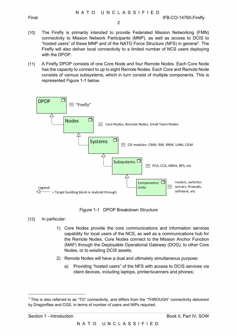
N A T O U N C L A S S I F I E D Final IFB-CO-14760-Firefly
2
Section 1 - Introduction Book II, Part IV, SOW
N A T O U N C L A S S I F I E D
[10] The Firefly is primarily intended to provide Federated Mission Networking (FMN) connectivity to Mission Network Participants (MNP), as well as access to DCIS to “hosted users” of these MNP and of the NATO Force Structure (NFS) in general1. The Firefly will also deliver local connectivity to a limited number of NCS users deploying with the DPOP.
[11] A Firefly DPOP consists of one Core Node and four Remote Nodes. Each Core Node has the capacity to connect to up to eight Remote Nodes. Each Core and Remote Node consists of various subsystems, which in turn consist of multiple components. This is represented Figure 1-1 below.
DPOP
Nodes
Systems
Subsystems
Components/Units
Core Nodes, Remote Nodes, Small Team Nodes
“Firefly”
CIS modules: CNM, ISM, RNM, UAM, CGM
PCA, CCA, MMA, BPS, etc
routers, switchesservers, firewalls, software, etc= Target building block is realized through
Legend:
Figure 1-1 DPOP Breakdown Structure
[12] In particular:
1) Core Nodes provide the core communications and information services capability for local users of the NCS, as well as a communications hub for the Remote Nodes. Core Nodes connect to the Mission Anchor Function (MAF) through the Deployable Operational Gateway (DOG), to other Core Nodes, or to exisiting DCIS assets;
2) Remote Nodes will have a dual and ultimately simultaneous purpose:
a) Providing “hosted users” of the NFS with access to DCIS services via client devices, including laptops, printer/scanners and phones;
1 This is also referred to as “TO” connectivity, and differs from the “THROUGH” connectivity delivered by Dragonflies and CGS, in terms of number of users and NIPs required.
N A T O U N C L A S S I F I E D Final IFB-CO-14760-Firefly
3
Section 1 - Introduction Book II, Part IV, SOW
N A T O U N C L A S S I F I E D
b) Providing Network Interconnection Points (NIP) compliant with FMN Spiral 3, to federate the DCIS elements of MNP and members of the NFS at large with NATO DCIS (the NCS Affiliate, in FMN terms).
[13] Furthermore:
1) Small Team Nodes (not present in the Dragonfly) provide the Operational Liaison and Reconnaissance Team (OLRT) with access to DCIS services hosted in the static domain (through the MAF) or in the Core Nodes;
2) A dedicated SDE supports the automated configuration of the Information Services elements of the Firefly Core Nodes.
[14] Core Node infrastructure will be hosted in a dedicated Biological and Chemical (BC) protected tent. System Administrators in charge of the configuration and operation of the DPOP, as well as Service Desk operators, will be hosted in a separate tent.
[15] Remote Nodes will deploy in the vicinity of the Core Node locations (at line of sight distance) collocated with the supported National/ NFS DPOP. Remote Nodes will deploy beyond line of sight if required, and connect to either the Core Node (default configuration) or, exceptionally, directly to the MAF, over SATCOM (Purchaser Furnished Equipment (PFE)). Remote Nodes will not necessarily be hosted in a BC-protected, environmentally and power conditioned environment (e.g. they may be placed outside national tents or shelters). For that reason they will require their own BC, environmental and power conditioning capability.
[16] Remote Nodes are used to interface to deployed assets, which could be National DPOPs (MNP, NFS), AGS deployed assets (i.e. mobile ground stations of the NATO AGS Force, NAGSF).
1.3 Scope
[17] The project scope is to provide the DCIS infrastructure for the Small NRF HQ, and to prove that the DCIS-specific technical services can operate over this infrastructure. In addition, the Project will prove that PFE Business Applications (also referred to as Core Services) can run over the above technical services. The details of PFE are given in Appendix D.
[18] Each Firefly DPOP consists of a set of DCIS nodes that need to be integrated into the existing DCIS infrastructure and services. In support of a given deployed HQ, these nodes will be interconnected within the geographical footprint of the HQ, connecting to other DPOPs, be those other Fireflies, Dragonflies, Communication Gateway Shelter (CGS) or LINC-E (see Annex C for details), or to the MAF enclaves in the static domain, using Wide Area Network (WAN) bearers, e.g. SATCOM.
[19] The project also introduces automation capabilities for the provisioning and deployment of Information Services, with the initial scope limited to the Information Services Modules (ISM) of the Firefly.
N A T O U N C L A S S I F I E D Final IFB-CO-14760-Firefly
4
Section 1 - Introduction Book II, Part IV, SOW
N A T O U N C L A S S I F I E D
[20] The Firefly Point of Presence (DPOP) consists of:
1) CIS nodes (refer to Section 3 of the SRS), consisting of:
a) CIS Modules encompassing the following:
(i) Core Network Modules (CNM), Remote Network Modules (RNM), and Small Team Kits (STK), each featuring different needs for connection to the Wide Area Network (WAN);
(ii) ISM and Cross-domain Gateway Modules (CGM), the latter implemented as instantiations of the ISM.
b) User Appliances, encompassing phones, printers/scanners, SysAdmin laptops, ruggedized laptops (for the Small Team Nodes) and PFE workstations;
c) Transmission Systems, consisting of SATCOM Transportable Satellite Ground Terminal (TSGT) and Deployable Satellite Ground System (DSGT) (PFE, with the exception of the Inmarsat Broadband Global Area Network (BGAN) terminals in the Small Team Nodes), fibre optic reels, and Line of Sight (LOS);
d) Service Management and Control (SMC) consisting of licenses to integrate the Firefly into the extant SMC environment of the Dragonfly in the DOG, as well as tools to enable the (optional) Deployable Network Operations Centre (DNOC) capability, collocated with a deployed Firefly DPOP.
2) Staging and Deployment Environment (SDE) (refer to Section 6 of SRS), with static and (Optional) deployable instances in the MAF and in the ISM, respectively, and including Release Development and Release Testing Environments, each instantiated in a dedicated ISM (ISM-DEV, ISM-TST), with rack-mounted components in the Mission Preparation Center at Mons;
3) Non-CIS Elements (refer to Section 6 of SRS for details), including:
a) Housing Elements;
b) Environment Control Elements;
c) Transport Elements;
d) Power Supply Elements;
e) Ancillary Elements.
1.3.1 Infrastructure
[21] Table 1-1 and Table 1-2 in the following pages outline the CIS and non-CIS infrastructure scope, with the node types, function, purpose and quantities to be delivered under this project. Footnotes to the first table identify the functional correspondence between those CIS elements and the existing Dragonfly components (see Annex C). The table contents can be visualized in the following figures of the pages thereafter, i.e.:

N A T O U N C L A S S I F I E D Final IFB-CO-14760-Firefly
5
Section 1 - Introduction Book II, Part IV, SOW
N A T O U N C L A S S I F I E D
Figure 1-2, provides the overview of the scope;
Figure 1-3, depicts the scope of the Operational systems;
Figure 1-4, depicts the scope of the Training systems;
Figure 1-5, depicts the scope of the Reference systems.
[22] The scope represented in the figures is notional. The detailed scope applicable to the contract is provided in the SSS.
[23] The referenced CIS Nodes, the SDE, and non-CIS elements are further described and specified in Annex A to this SOW (SRS). The requirements in the SRS build upon the NRF DCIS Target Architecture (hereafter referred to as the DCIS TA2), and its current instantiation in the Dragonfly. The Firefly is conceived as a streamlined version of a Dragonfly, seeking the reduction of the deployed footprint, in terms of size, weight and power requirements of the corresponding transit cases.
[24] Conversely, the requirements concerning the Information Services Module (ISM) and the Staging and Deployment Environment (SDE), build upon the DCIS CUBE Architecture Definition Document [DCIS Cube ADD Main, 2018] and its Annexes [DCIS Cube ADD Annexes, 2018], hereafter referred to as the DCIS CA. Future CIS modules, outside the scope of this Contract, may be solely built upon the DCIS CA.
INT-1 The implementation of the Core Network Module, Remote Network Module, User Access Module, Small Team Kit and the SDE, shall strictly adhere to the technical requirements in this SRS.
2 The DCIS TA is neither an Applicable nor a Reference document in this SOW. The interpretation of the TA and its translation into requirements in Annex A to this SOW (SRS) is the responsibility of the Purchaser.
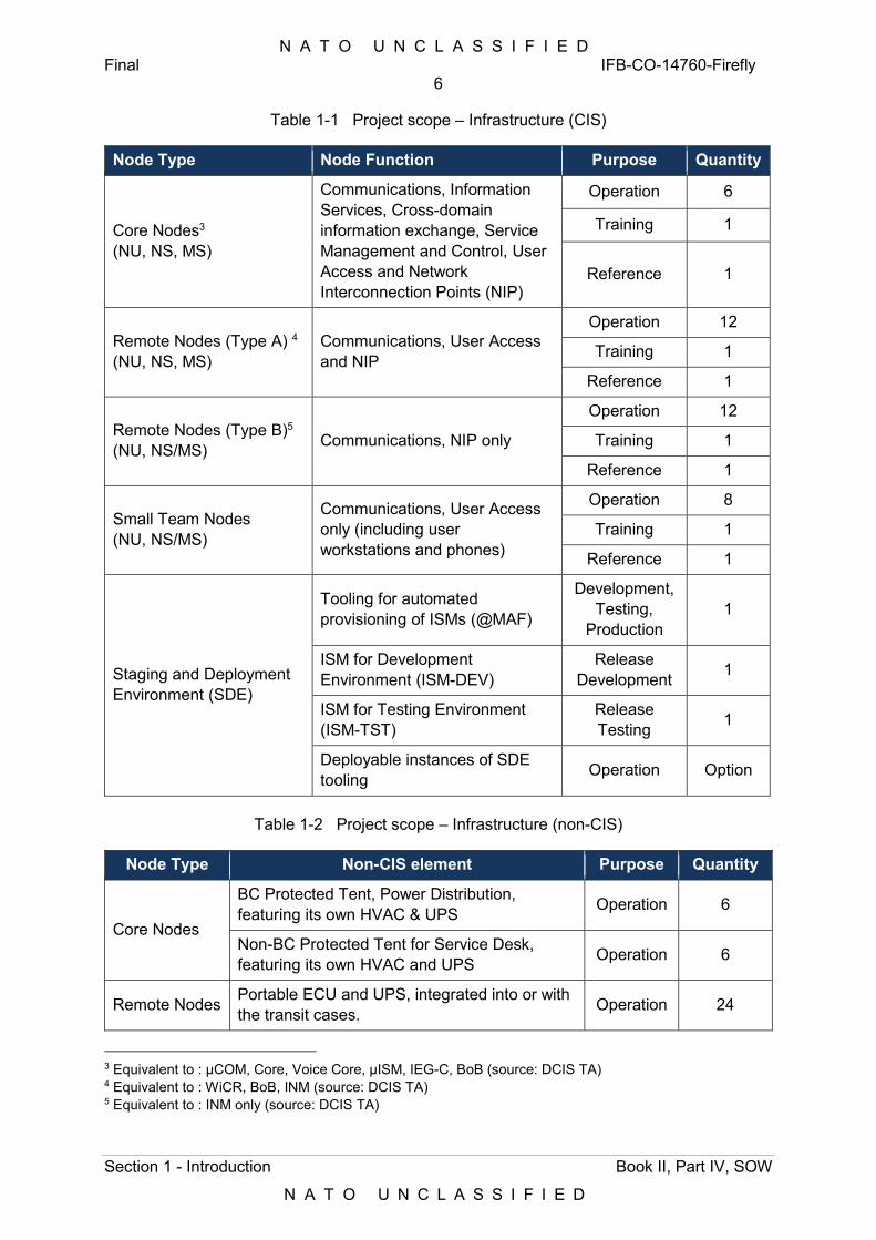
N A T O U N C L A S S I F I E D Final IFB-CO-14760-Firefly
6
Section 1 - Introduction Book II, Part IV, SOW
N A T O U N C L A S S I F I E D
Table 1-1 Project scope – Infrastructure (CIS)
Node Type Node Function Purpose Quantity
Core Nodes3 (NU, NS, MS)
Communications, Information Services, Cross-domain information exchange, Service Management and Control, User Access and Network Interconnection Points (NIP)
Operation 6
Training 1
Reference 1
Remote Nodes (Type A) 4 (NU, NS, MS)
Communications, User Access and NIP
Operation 12
Training 1
Reference 1
Remote Nodes (Type B)5 (NU, NS/MS) Communications, NIP only
Operation 12
Training 1
Reference 1
Small Team Nodes (NU, NS/MS)
Communications, User Access only (including user workstations and phones)
Operation 8
Training 1
Reference 1
Staging and Deployment Environment (SDE)
Tooling for automated provisioning of ISMs (@MAF)
Development, Testing,
Production 1
ISM for Development Environment (ISM-DEV)
Release Development 1
ISM for Testing Environment (ISM-TST)
Release Testing 1
Deployable instances of SDE tooling Operation Option
Table 1-2 Project scope – Infrastructure (non-CIS)
Node Type Non-CIS element Purpose Quantity
Core Nodes
BC Protected Tent, Power Distribution, featuring its own HVAC & UPS Operation 6
Non-BC Protected Tent for Service Desk, featuring its own HVAC and UPS Operation 6
Remote Nodes Portable ECU and UPS, integrated into or with the transit cases. Operation 24
3 Equivalent to : µCOM, Core, Voice Core, µISM, IEG-C, BoB (source: DCIS TA) 4 Equivalent to : WiCR, BoB, INM (source: DCIS TA) 5 Equivalent to : INM only (source: DCIS TA)
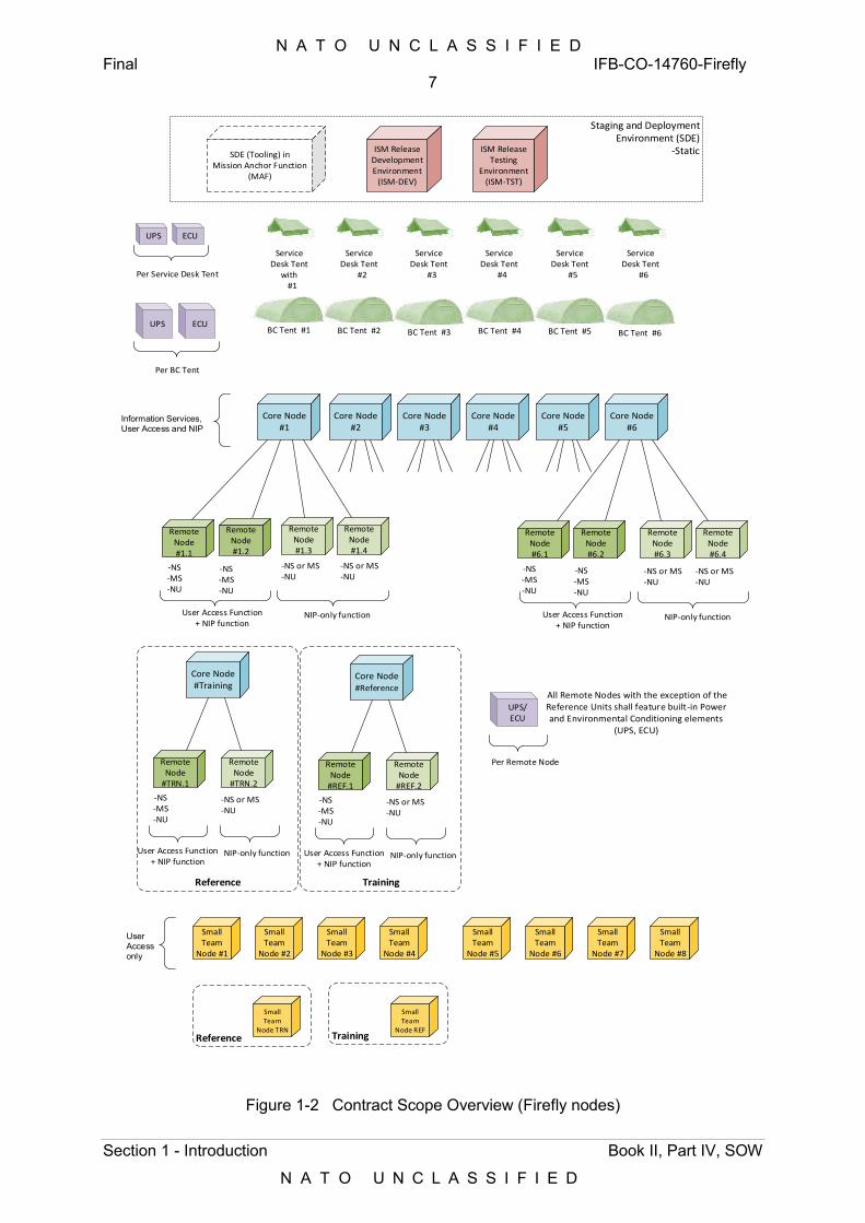
N A T O U N C L A S S I F I E D Final IFB-CO-14760-Firefly
7
Section 1 - Introduction Book II, Part IV, SOW
N A T O U N C L A S S I F I E D
Core Node#1
Remote Node #1.1
Remote Node #1.2
Remote Node #1.3
-NS-MS-NU
-NS-MS-NU
-NS or MS-NU
Remote Node #1.4
-NS or MS-NU
Core Node#6
Remote Node #6.1
Remote Node #6.2
Remote Node #6.3
-NS-MS-NU
-NS-MS-NU
-NS or MS-NU
Remote Node #6.4
-NS or MS-NU
Core Node#2
Core Node#3
Core Node#4
Core Node#5
Core Node#Training
Remote Node
#TRN.1
-NS-MS-NU
Remote Node
#TRN.2
-NS or MS-NU
User Access Function+ NIP function
NIP-only function
NIP-only functionUser Access Function+ NIP function
User Access Function+ NIP function
NIP-only function
Core Node#Reference
Remote Node
#REF.1
-NS-MS-NU
Remote Node
#REF.2
-NS or MS-NU
NIP-only functionUser Access Function+ NIP function
Small Team
Node #1
Small Team
Node #2
Small Team
Node #3
Small Team
Node #4
Small Team
Node #5
Small Team
Node #6
Small Team
Node #7
Small Team
Node #8
Small Team
Node TRN
Small Team
Node REF
ISM Release Development Environment
(ISM-DEV)
ISM Release Testing
Environment (ISM-TST)
Service Desk Tent
with #1
BC Tent #3BC Tent #2BC Tent #1 BC Tent #6BC Tent #5BC Tent #4
All Remote Nodes with the exception of the Reference Units shall feature built-in Power and Environmental Conditioning elements
(UPS, ECU)
UPS/ECU
Information Services, User Access and NIP
User Access only
Service Desk Tent
#2
Service Desk Tent
#3
Service Desk Tent
#4
Service Desk Tent
#5
Service Desk Tent
#6
Per Remote Node
UPS ECU
Per BC Tent
UPS ECU
Per Service Desk Tent
SDE (Tooling) in Mission Anchor Function
(MAF)
Staging and Deployment Environment (SDE)
-Static
TrainingReference
Reference Training
Figure 1-2 Contract Scope Overview (Firefly nodes)
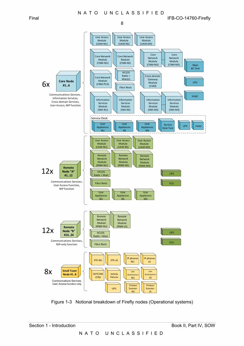
N A T O U N C L A S S I F I E D Final IFB-CO-14760-Firefly
8
Section 1 - Introduction Book II, Part IV, SOW
N A T O U N C L A S S I F I E D
Information Services Module
(ISM-NU)
User Access Module
(UAM-NU)
HCLOSRadio + Mast(s)
Remote Network Module
(RNM-NU)
HCLOSRadio + Mast
User Access Module
(UAM-NU)
STK-NU
Core Network Module
(CNM-NU)
Fibre Reels
Core Network Module
(CNM-NS)
Core Network Module
(CNM-MS)
User Access Module
(UAM-NS)
User Access Module
(UAM-MS)
Information Services Module (ISM-NS)
Information Services Module
(ISM-MS)
Remote Network Module
(RNM-NS)
Remote Network Module
(RNM-MS)
Fibre Reels
User Access Module
(UAM-NS)
User Access Module
(UAM-MS)
Remote Network Module
(RNM-NU)
HCLOSRadio + Mast
Remote Network Module
(RNM-xS)
Fibre Reels
Core Node#1..6
Remote Node “A”
#1..12
Remote Node “B”#13..24
Communications Services, User Access Function,
NIP function
Communications Services,NIP-only function
Communications Services , Information Services,
Cross-domain Services,User Access, NIP function
Small Team Node #1..8
Communications Services, User Access function only
SATCOMOTM
User
Workstations NU
6x
12x
12x
8x
STK-xS
User Appliances
NU
User Appliances
NS
User Appliances
MS
Cross-domain Gateway Module (CGM)
Printer/Scanner-
NU
Printer/Scanner-
xS
IP phones NU
IP phones xS
User
Workstations xS
UPS
ECU
Main BC Tent
HVAC
UPS
UPS
UPS
ECU
Service Desk Tent
Vehicle fixtures
HVACUPS
Information Services Module
(ISM-MS)
Core Network Module
(CNM-MS)
Service Desk
User Appliances
NU
User Appliances
NS
User Appliances
MS
Core Network Module
(CNM-PCA)
Figure 1-3 Notional breakdown of Firefly nodes (Operational systems)
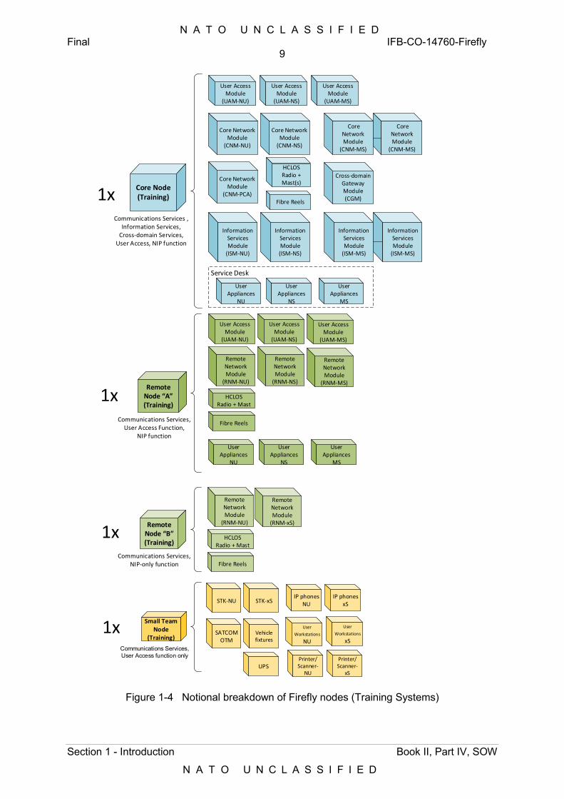
N A T O U N C L A S S I F I E D Final IFB-CO-14760-Firefly
9
Section 1 - Introduction Book II, Part IV, SOW
N A T O U N C L A S S I F I E D
Information Services Module
(ISM-NU)
User Access Module
(UAM-NU)
Remote Network Module
(RNM-NU)
HCLOSRadio + Mast
User Access Module
(UAM-NU)
STK-NU
Core Network Module
(CNM-NU)
Core Network Module
(CNM-NS)
Core Network Module
(CNM-MS)
User Access Module
(UAM-NS)
User Access Module
(UAM-MS)
Information Services Module (ISM-NS)
Information Services Module
(ISM-MS)
Remote Network Module
(RNM-NS)
Remote Network Module
(RNM-MS)
Fibre Reels
User Access Module
(UAM-NS)
User Access Module
(UAM-MS)
Remote Network Module
(RNM-NU)
HCLOSRadio + Mast
Remote Network Module
(RNM-xS)
Fibre Reels
Core Node(Training)
Remote Node “A”(Training)
Remote Node “B”(Training)
Communications Services, User Access Function,
NIP function
Communications Services,NIP-only function
Communications Services , Information Services,
Cross-domain Services,User Access, NIP function
Small Team Node
(Training)
Communications Services, User Access function only
SATCOMOTM
User
Workstations NU
1x
1x
1x
1x
STK-xS
Printer/Scanner-
NU
Printer/Scanner-
xS
IP phones NU
IP phones xS
User
Workstations xS
UPS
Vehicle fixtures
Information Services Module
(ISM-MS)
Core Network Module
(CNM-MS)
Service Desk
User Appliances
NU
User Appliances
NS
User Appliances
MS
User Appliances
NU
User Appliances
NS
User Appliances
MS
HCLOSRadio + Mast(s)
Fibre Reels
Cross-domain Gateway Module (CGM)
Core Network Module
(CNM-PCA)
Figure 1-4 Notional breakdown of Firefly nodes (Training Systems)
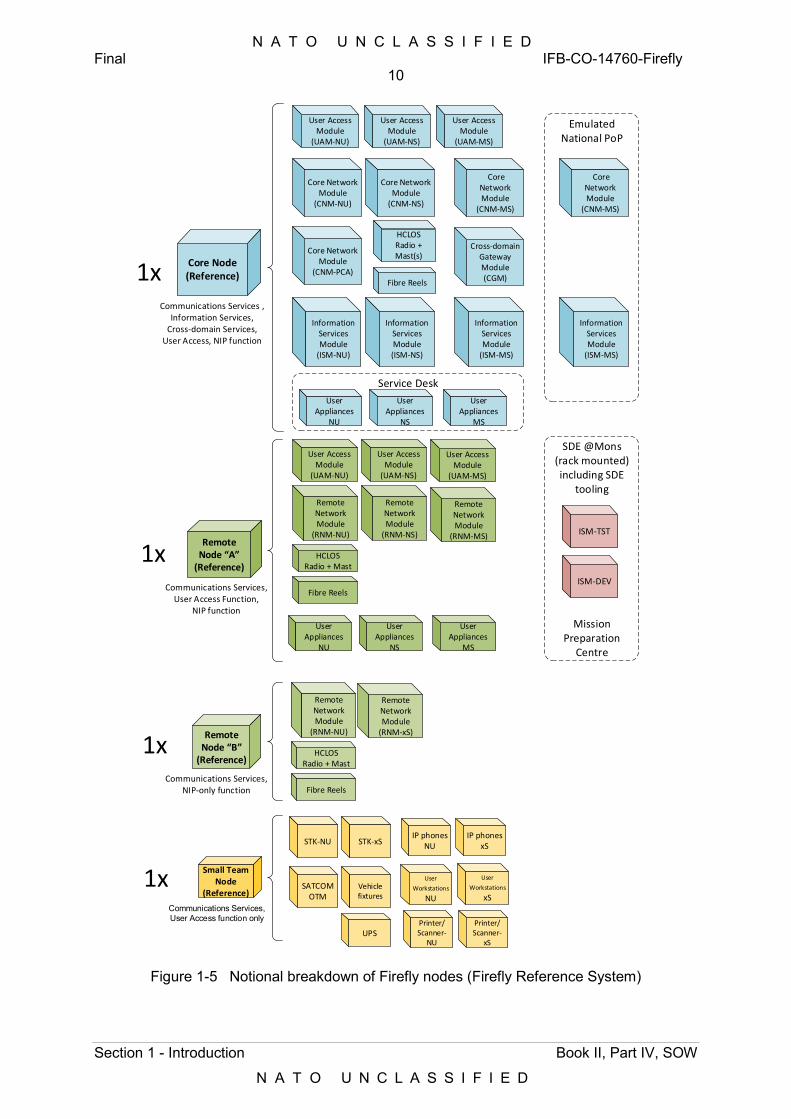
N A T O U N C L A S S I F I E D Final IFB-CO-14760-Firefly
10
Section 1 - Introduction Book II, Part IV, SOW
N A T O U N C L A S S I F I E D
Information Services Module
(ISM-NU)
User Access Module
(UAM-NU)
Remote Network Module
(RNM-NU)
HCLOSRadio + Mast
User Access Module
(UAM-NU)
STK-NU
Core Network Module
(CNM-NU)
Core Network Module
(CNM-NS)
Core Network Module
(CNM-MS)
User Access Module
(UAM-NS)
User Access Module
(UAM-MS)
Information Services Module (ISM-NS)
Information Services Module
(ISM-MS)
Remote Network Module
(RNM-NS)
Remote Network Module
(RNM-MS)
Fibre Reels
User Access Module
(UAM-NS)
User Access Module
(UAM-MS)
Remote Network Module
(RNM-NU)
HCLOSRadio + Mast
Remote Network Module
(RNM-xS)
Fibre Reels
Core Node(Reference)
Remote Node “A”
(Reference)
Remote Node “B”
(Reference)
Communications Services, User Access Function,
NIP function
Communications Services,NIP-only function
Communications Services , Information Services,
Cross-domain Services,User Access, NIP function
Small Team Node
(Reference)
Communications Services, User Access function only
SATCOMOTM
User
Workstations NU
1x
1x
1x
1x
STK-xS
Printer/Scanner-
NU
Printer/Scanner-
xS
IP phones NU
IP phones xS
User
Workstations xS
UPS
Vehicle fixtures
Information Services Module
(ISM-MS)
Core Network Module
(CNM-MS)
Service Desk
Emulated National PoP
ISM-DEV
ISM-TST
SDE @Mons(rack mounted)including SDE
tooling
Mission Preparation
Centre
User Appliances
NU
User Appliances
NS
User Appliances
MS
User Appliances
NU
User Appliances
NS
User Appliances
MS
HCLOSRadio + Mast(s)
Fibre Reels
Cross-domain Gateway Module (CGM)
Core Network Module
(CNM-PCA)
Figure 1-5 Notional breakdown of Firefly nodes (Firefly Reference System)
N A T O U N C L A S S I F I E D Final IFB-CO-14760-Firefly
11
Section 1 - Introduction Book II, Part IV, SOW
N A T O U N C L A S S I F I E D
1.3.2 Services
[25] In terms of Services, the scope of the procurement includes the adaptation, integration and validation of PFE networking and CIS security configurations, as used today with the Dragonfly, modified to interoperate with exisiting DCIS assets and to meet FMN Spiral 3 specifications where required. Services comprise the following:
1) Communications Services, encompassing IP routing and switching, IP interworking (FMN NIPs), multimedia (voice) and transmission (wired and wireless, both LOS and Beyond LOS);
2) Infrastructure Services, encompassing: Authentication services (Active Directory), Domain Name Services (DNS), Windows Internet Name Services (WINS), Dynamic Host Configuration Protocol (DHCP), Time services (NTP), Certificate services, File and Printer services, Back-up and Restore services;
3) Business Support Services, also referred to as Core Services, encompassing Informal Messaging (Email), Database, Document Collaboration, Web Services, etc.
[26] In support of the automatic provisioning of the Infrastructure Services above in the ISM, the project will deliver the aforementioned Staging and Deployment Environment (SDE), with static instances in the MAF, as well as (optional) deployable instances to locally stage the ISM.
[27] The project will also deliver and integrate applications and licenses in support of:
1) CIS Security Services, consisting of: Boundary Protection (including Network-based Intrusion Detection), IP encryption, Access Control for servers and user workstations, Anti-virus and Anti-malware, Auditing, Network, Host Intrusion Protection, and Patch management;
2) Service Management and Control services, fully integrated with the current service management and control environment in the DOG/MAF, as additional licenses, as well as local instances of the relevant applications, in the Firefly, in support of an optional DNOC capability.
INT-2 Table 1-3 below outlines the services that shall be implemented and proven over the Firefly DPOP:
1) The Contractor shall install and configure the asset and / or hosting the service, that are marked “X”;
2) Services marked with “O” are the responsibility of the Purchaser to install and configure. These will be hosted in the corresponding nodes. They shall be in the testing scope, subject to the provision of the PFE.
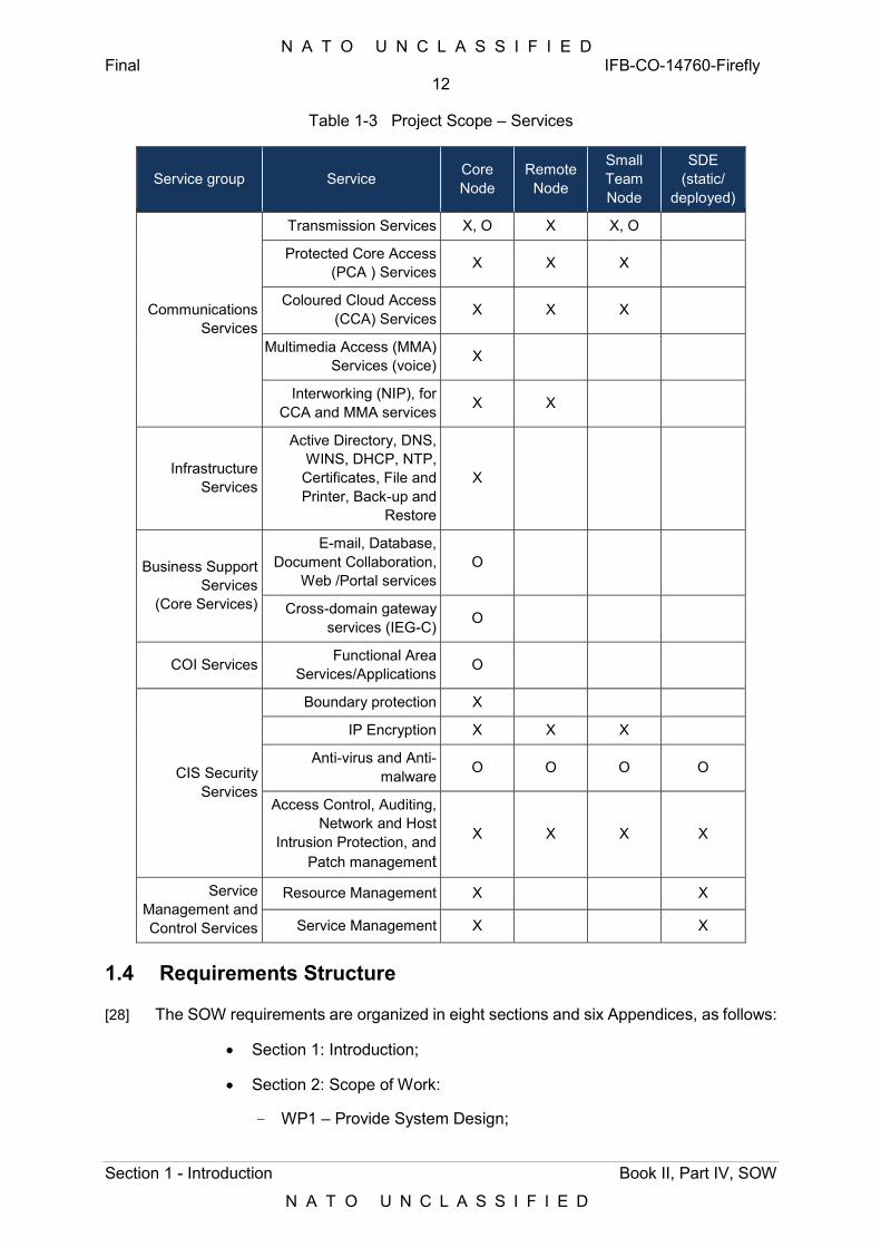
N A T O U N C L A S S I F I E D Final IFB-CO-14760-Firefly
12
Section 1 - Introduction Book II, Part IV, SOW
N A T O U N C L A S S I F I E D
Table 1-3 Project Scope – Services
Service group Service Core Node
Remote Node
Small Team Node
SDE (static/
deployed)
Communications Services
Transmission Services X, O X X, O
Protected Core Access (PCA ) Services X X X
Coloured Cloud Access (CCA) Services X X X
Multimedia Access (MMA) Services (voice) X
Interworking (NIP), for CCA and MMA services X X
Infrastructure Services
Active Directory, DNS, WINS, DHCP, NTP, Certificates, File and Printer, Back-up and
Restore
X
Business Support Services
(Core Services)
E-mail, Database, Document Collaboration,
Web /Portal services O
Cross-domain gateway services (IEG-C) O
COI Services Functional Area Services/Applications O
CIS Security Services
Boundary protection X
IP Encryption X X X
Anti-virus and Anti-malware O O O O
Access Control, Auditing, Network and Host
Intrusion Protection, and Patch management
X X X X
Service Management and Control Services
Resource Management X X
Service Management X X
1.4 Requirements Structure
[28] The SOW requirements are organized in eight sections and six Appendices, as follows:
Section 1: Introduction;
Section 2: Scope of Work:
WP1 – Provide System Design;
N A T O U N C L A S S I F I E D Final IFB-CO-14760-Firefly
13
Section 1 - Introduction Book II, Part IV, SOW
N A T O U N C L A S S I F I E D
WP2 – Qualify First Articles;
WP3 – Support Security Accreditation Process;
WP4 – Support Independent Verification and Validation Assessment;
WP5 – Provide Production Units;
WP6 – Perform System Installation;
WP7 – Conduct Training;
WP8 – Support Operational Test and Evaluation (OpTEval).
Section 3: Project Management;
Section 4: Integrated Logistics Support;
Section 5: Documentation;
Section 6: Configuration Management;
Section 7: Quality Assurance and Control;
Section 8: System Acceptance;
Appendices:
Appendix A Applicable and Reference Documents;
Appendix B Contract Documentation Requirements List;
Appendix C Project Meetings Calendar;
Appendix D Purchaser Furnished Equipment;
Appendix E Project Activity Flow;
Appendix F Key Personnel Requirements;
Appendix G List of Acronyms.
[29] The SOW has four Annexes, as follows:
Annex A – System Requirements Specifications (SRS) contains the functional and technical requirements for the Firefly. The SRS conveys a preliminary design specification, in the form of a Purchaser-driven high level design, with the notion of a DPOP being a collection of nodes serving a given deployed HQ;
Annex B – CIS Security Requirements outlines the security accreditation process and security-related deliverables sought under this contract;
Annex C – Existing DCIS Infrastructure and Services, provides information on the current configuration of the Dragonfly and other DCIS assets in NATO, ahead of the Configuration Capturing exercise to be undertaken by the Contractor as part of the design activities in WP1;
N A T O U N C L A S S I F I E D Final IFB-CO-14760-Firefly
14
Section 1 - Introduction Book II, Part IV, SOW
N A T O U N C L A S S I F I E D
Annex D – Testing, Verification and Validation Requirements, outlines the testing processes and activities occurring under each of the WPs above, including the Independent Verification and Validation (IV&V) Assessment under WP4. The detailed scope of the tests is provided in the SOW, as part of the WP description, where relevant:
Note: Test, Verification and Validation Documentation Templates are to be used as instructed in Annex D and are provided as mature drafts, the final versions will be provided at the time of Contract Award.
1.5 Test, Verification and Validation Approach
INT-3 All testing, verification and validation activities to be conducted by the Contractor shall be based on the full and detailed breakdown of test events derived from the Requirements Traceability Matrix (RTM) and Verification Cross-Refrence Matrix (VCRM), as required in Annex D.
INT-4 The distribution of the testing efforts derived from the RTM and VCRM over the different Work Packages (and events supporting those Work Packages) shall:
1) Refine the testing scope under each Work Package, down to specific events;
2) Be documented at high level in the Project Master Test Plan (PMTP);
3) Be further detailed in the Test Plans of each of the events supporting the different Work Packages. This is to ensure comprehensive testing is undertaken.
INT-5 The testing requirements contained under the various Work Packages of Section 2 are intended to highlight the focus of the test events in the Work Package and shall in no-way dilute the requirement for a full comprehensive testing in line with the RTM and VCRM, as detailed in Annex D.
INT-6 In case of conflict between the scope of the test events as described in the the Work Package and the testing requirements derived form the RTM and VCRM, the latter shall take precedence.
1.6 Implementation Staging
[30] The project will be executed in three stages, spanning from the Effective Date of Contract (EDC) to 1 year following the declaration of FSA. The stages are:
Stage 1: WP1 to WP4, up to receiving Deployment Authorization (DA);
Stage 2: WP5 to WP8, up to FSA;
Stage 3: Support (FSA + 1 year).
1.7 Purchaser’s Responsibilities
[31] The following services and items will be provided by the Purchaser for the performance of the Contract:
N A T O U N C L A S S I F I E D Final IFB-CO-14760-Firefly
15
Section 1 - Introduction Book II, Part IV, SOW
N A T O U N C L A S S I F I E D
1) Access to DCIS Reference Environment for the Independent Verification and Validation (IV&V) Assessment, including Security Testing;
2) Access to Dragonfly and general DCIS Service Management and Control environment, for configuration capturing purposes;
3) Access to Dragonfly physical assets, if required;
4) Access to Subject Matter Experts (SME) and DCIS documentation during Configuration Capturing;
5) Providing licenses for all Core Services and COI-specific services (FAS). The installation and configuration (using PFE configuration data) remains responsibility of the Contractor;
6) Provide key material for crypto as well as network access to NATO DCIS centralized Security Management Centres (SMC);
7) Ensure FMN compliance through the specification in Annex A to this SOW (SRS) and guidance provided to the Contractor during Configuration Capturing activities;
8) Provide information diodes for the provisioning of production ISMs across security classifications, through the Staging and Deployment Environment (SDE);
9) Provide SATCOM bandwidth and SATCOM ground segment infrastructure (TSGT and SGS) for Site Acceptance Testing (SAT) and OpTEval;
10) Provide SRTS training to the Contractor, in order to enable his later involvement in SRTS6 production during the system provisioning stage;
11) Coordinating access to sites following Request for Visits (RfV) issued by the Purchaser. The following sites are considered:
a) Mons, for Configuration Capturing, installation of the Firefly Reference System into the DCIS Reference Environment, installation of the Staging & Deployment Environment (SDE);
b) Lago Patria, installation of SDE tools;
c) Brunssum CIS Sustainment Support Centre (CSSC), for delivery of systems and configurations;
d) NATO Signal Battalion (NSB) HQ in Wessel, Grazzanize and Bydgoszcz, for Site Acceptance Testing (SAT);
e) NSB Deployable CIS Modules (DCM) and Forward Support Points (FSP) for OpTEval (scenario-based testing).
12) Provide Purchaser Furnished Equipment (PFE) as per Appendix D of this SOW.
[32] The Purchaser’s Project Manager (PM) will act as the Purchaser’s representative and will be the primary and technical interface between the Contractor and Purchaser after EDC.
6 SRTS: Service Request Tracking System
N A T O U N C L A S S I F I E D Final IFB-CO-14760-Firefly
16
Section 1 - Introduction Book II, Part IV, SOW
N A T O U N C L A S S I F I E D
[33] The Purchaser’s Project Manager will be supported by specialists who may, from time to time, be delegated to act on the Project Manager’s behalf in their area of expertise.
[34] All changes to the Contract will be made through the Purchaser’s contracting office only. Neither the Project Manager, nor any other NATO personnel may make changes to the terms and conditions of the Contract but may only provide the Purchaser’s interpretation of technical matters.
[35] The Purchaser will provide the Contractor with available technical descriptions of existing NATO systems as required for the purpose of determining specific interface requirements between the DCIS components and these systems.
[36] The Purchaser will make available to the Contractor the facilities necessary to test and demonstrate DCIS components compliance with required interfaces to existing NATO systems.
1.8 Conventions
[37] The term “the Purchaser” means the NCI Agency or its authorised representatives. Where referenced standards, specifications, refer to “the Government”, this shall be construed to mean “the Purchaser”.
[38] The Schedule of Supplies and Services (SSS) details the dates the activities and deliverables are to be provided.
[39] The SOW and its Annexes shall take precedence over the Applicable Documents in Appendix A of this SOW.
[40] This SOW invokes a variety of Standard NATO Agreements (STANAGS), Allied Quality Assurance Publications (AQAPs), Military Standards (MIL-STDs) and International Standards. While these are NATO reference documents, there are national and international standards that are considered to be equivalent and are cited as such within these documents.
[41] Where a national or international standard exists that is not specifically referenced in the STANAGs, AQAPs, or MIL-STDs as being equivalent, the Contractor may propose to utilise such a standard if it can demonstrate to the satisfaction of the Purchaser that such a standard is equivalent to the STANAG, AQAPs, or MIL-STD in question. The Purchaser, however, reserves the right to deny such a request and demand performance in accordance with the standard cited in the SOW.
[42] Requirements in the SOW are formulated using the form “shall”. Context information supporting the requirements definition is provided using the form “will”.
[43] “Shall” statements are contractually binding; “Will” statements are informative.
[44] Mandatory requirements in the SOW are preceded by a unique heading number, consisting of a prefix, followed by a number.
[45] Informational or context information not conveying any requirement on the Providers is preceded by a number heading in brackets, [xx], without prefix letters.
[46] Whenever requirements are stated herein to “include” a group of items, parameters, or other considerations, “include” means “include but not limited to”.
N A T O U N C L A S S I F I E D Final IFB-CO-14760-Firefly
17
Section 1 - Introduction Book II, Part IV, SOW
N A T O U N C L A S S I F I E D
[47] Whenever reference is made to a section or paragraph, the reference includes all subordinate and referenced paragraphs.
[48] The order of the SOW requirements is not intended to specify the order in which they must be carried out unless explicitly stated. The SOW defines all of the activities the Provider shall provide. The Provider’s approved programme implementation plans determine the actual timing of detailed activities of the Providers.
[49] The convention to be used for dates appearing in free text (e.g. quoting dates of meetings) is day-month-year and not month-day-year.
1.9 Options
[50] This scope of the work includes a number of options, which the Purchaser may wish to exercise. These include:
1) Air Ground Surveillance (AGS);
2) Special Operations Commponent Command (SOCC).
[51] The AGS requires two sets of Remote Nodes, each set containing one Type A and one Type B.
[52] SOCC HQ requires one complete DPOP.
INT-7 For each of these optional requirements the Contractor shall identify, separately additional equipment and also implementation costs.
N A T O U N C L A S S I F I E D Final IFB-CO-14760-Firefly
18
Section 2 - Scope of Work Book II, Part IV, SOW
N A T O U N C L A S S I F I E D
2 Scope of Work
[53] The project scope is translated into Work Packages (WP1 to WP8). Each is addressed in greater detail below.
[54] Activity flows are provided under each Work Package. Some activities are conditional upon the completion of activities in other WPs. These dependencies are depicted with numbered circles, acting as cross-references between WPs.
[55] The full representation of the activities across all eight WPs is provided in Appendix E.
2.1 Provide System Design (WP1)
WP1-1 The Firefly design documentation shall cover the full scope of the Firefly systems. This includes:
1) Firefly nodes and the SDE, as described in Annex A (SRS). These are the requirements that Firefly shall meet;
2) Interfacing to existing DCIS Infrastructure and Services described in Annex C. These are the existing systems that the Firefly shall interface to and interoperate with, both at CIS level (e.g. Dragonflies), as well as non-CIS (e.g. Power Generators).
WP1-2 This design documentation shall separately identify the design for the operational (production), training and reference systems.
WP1-3 The scope of the design shall encompass all the components needed to achieve the capability, including:
1) CIS Hardware;
2) Software and licensing;
3) Tooling to manage and support the Firefly systems;
4) Non-CIS hardware (e.g. transit cases, tents, etc.);
5) Test, Verification and Validation.
WP1-4 The design shall strictly follow the structure in which requirements are formulated in Annex A (SRS).
WP1-5 The design shall include the configuration of infrastructure and services, based on the information collected during the Configuration Capturing exercise, augmented with information provided by the Purchaser, as inputs to the design, during the period between EDC and the Final Design Review (FDR).
WP1-6 Any hardware proposed shall not be end-of-life or targeted for end-of-life within 24 months at the time of Final Design Review (FDR).
[56] The implementation of the Firefly DPOP consists of the assembly, connection, integration and configuration of Commercial of The Shelf (COTS) components, into bespoke systems that are fit for purpose and use in support of NATO expeditionary operations.
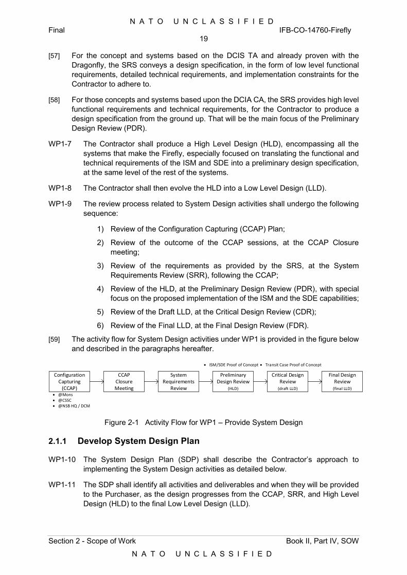
N A T O U N C L A S S I F I E D Final IFB-CO-14760-Firefly
19
Section 2 - Scope of Work Book II, Part IV, SOW
N A T O U N C L A S S I F I E D
[57] For the concept and systems based on the DCIS TA and already proven with the Dragonfly, the SRS conveys a design specification, in the form of low level functional requirements, detailed technical requirements, and implementation constraints for the Contractor to adhere to.
[58] For those concepts and systems based upon the DCIA CA, the SRS provides high level functional requirements and technical requirements, for the Contractor to produce a design specification from the ground up. That will be the main focus of the Preliminary Design Review (PDR).
WP1-7 The Contractor shall produce a High Level Design (HLD), encompassing all the systems that make the Firefly, especially focused on translating the functional and technical requirements of the ISM and SDE into a preliminary design specification, at the same level of the rest of the systems.
WP1-8 The Contractor shall then evolve the HLD into a Low Level Design (LLD).
WP1-9 The review process related to System Design activities shall undergo the following sequence:
1) Review of the Configuration Capturing (CCAP) Plan;
2) Review of the outcome of the CCAP sessions, at the CCAP Closure meeting;
3) Review of the requirements as provided by the SRS, at the System Requirements Review (SRR), following the CCAP;
4) Review of the HLD, at the Preliminary Design Review (PDR), with special focus on the proposed implementation of the ISM and the SDE capabilities;
5) Review of the Draft LLD, at the Critical Design Review (CDR);
6) Review of the Final LLD, at the Final Design Review (FDR).
[59] The activity flow for System Design activities under WP1 is provided in the figure below and described in the paragraphs hereafter.
Figure 2-1 Activity Flow for WP1 – Provide System Design
2.1.1 Develop System Design Plan
WP1-10 The System Design Plan (SDP) shall describe the Contractor’s approach to implementing the System Design activities as detailed below.
WP1-11 The SDP shall identify all activities and deliverables and when they will be provided to the Purchaser, as the design progresses from the CCAP, SRR, and High Level Design (HLD) to the final Low Level Design (LLD).
Configuration Capturing
(CCAP)
CCAPClosure Meeting
System Requirements
Review
Critical Design Review
(draft LLD)
Final Design Review
(final LLD)
ISM/SDE Proof of Concept Transit Case Proof of Concept
@Mons @CSSC @NSB HQ / DCM
Preliminary Design Review
(HLD)
N A T O U N C L A S S I F I E D Final IFB-CO-14760-Firefly
20
Section 2 - Scope of Work Book II, Part IV, SOW
N A T O U N C L A S S I F I E D
2.1.2 Conduct Configuration Capture
WP1-12 In order to ensure full interoperability with existing NATO DCIS assets (i.e. Dragonfly, LINC-E, CGS, Mission Anchor Function (MAF)), the Contractor shall capture the configuration of the corresponding assets and services prior to starting any low level design activities after PDR, leading to CDR.
WP1-13 The configuration captures shall be used in direct support of the design activities, in the following terms:
1) Minimizing design risks by adopting current and proven configurations where possible, adapted in fulfilment of the requirements in Annex A (SRS);
2) Ensuring that the services implemented by the Firefly are compatible and interoperable with those of the existing DCIS assets (Dragonfly, CGS, LINC-E and DOG/MAF).
[60] The Purchaser will enable a knowledge transfer process during the CCAP sessions, by providing access to DCIS Subject Matter Experts (SME), and to documentation pertaining to all existing DCIS assets and their configuration.
[61] The CCAP sessions are also intended for the Contractor to become acquainted with any Purchaser-provided Test facilities, DCIS Reference Environment and Mission Preparation Centre in Mons.
WP1-14 In support of the CCAP, the Contractor shall establish a team with representatives from all the disciplines related to the System Design and the System Implementation of the Firefly. This team is hereafter referred to as the Configuration Capturing Team (CCT). The CCT shall at least consist of the technical experts leading the design covering the areas identified below.
WP1-15 The CCT skillsets shall cover the following areas:
1) Communications services, encompassing Routing and Switching, and Multimedia (voice and video teleconferencing);
2) Infrastructure services (processing, storage, networking);
3) Service Management and Control;
4) Orchestration and Automation, in the context of the ISM and SDE;
5) Information Assurance and CIS Security;
6) Configuration Management;
7) Integrated Logistics support;
8) Training Need Analysis; and
9) Non-CIS.
WP1-16 The CCT shall be led by the Technical Lead or by the individual leading the design activities, in order to ensure that the outcome of the configuration capturing process is directly supporting the design.
N A T O U N C L A S S I F I E D Final IFB-CO-14760-Firefly
21
Section 2 - Scope of Work Book II, Part IV, SOW
N A T O U N C L A S S I F I E D
WP1-17 CCAP activities shall be conducted by the CCT, at their own initiative, at the Purchaser’s premises, in preparation and in direct support of System Design activities (WP2).
WP1-18 The Contractor shall provide a Configuration Capturing Plan. The plan shall include the following:
1) The breakdown of the exisiting DCIS assets into nodes, systems, subsystems, down to components / Units, including the Identification of interfaces to external systems;
2) The strategy intended to capture and process the information, including the allocation of tasks to different memebers of the Configuration Capturing Team.
WP1-19 For each of the identified above items the Contractor shall identify the type and format of information expected from the Purchaser.
WP1-20 The Contractor shall deploy the CCT immediately following the Effective Date of Contract (EDC).
WP1-21 The CCT shall capture information about the skill sets of the current system administrators, of the network administrators, of the engineers and of the operators, in support of the Training Need Analysis (refer to Section 4.10.2).
WP1-22 The CCT shall deploy to Mons and visit CSSC in Brunssum, NSB HQ locations (Bydgoszcz, Grazzanise, Wessel), and the NCISS (NATO Training School), as required.
[62] The Purchaser will furnish office space and workstations with user accounts for the CCT, over the CCAP period, in Mons.
WP1-23 Throughout the CCAP period and in order to minimize the risk of any incompatibilities between the design and the existing DCIS infrastructure and services (Annex C to this SOW), the Contractor shall collect and assess the differences between the configuration of current DCIS assets (as captured) and his preliminary design resulting from the interpretation of the requirement in the SRS.
[63] In support of the assessment above, the Purchaser will accommodate a3-day workshop with the CCT and the design team, to provide clarifications and guidance on how to use the Configuration Capturing data in support of the design.
WP1-24 The outcome of the CCAP sessions shall be documented in the Draft CCAP Report, to be issued 1 week after the sessions are completed. The report shall be briefed during the CCAP Closure Meeting, in Mons.
WP1-25 The Draft CCAP Report shall describe the relevant captured configuration data and how configuration data are interpreted and contribute to the HLD.
WP1-26 The Draft CCAP Report shall further develop the contents of Annex C (Existing DCIS Infrastructure and Services) of this SOW, identifying the interoperability aspects and risk areas of the design, for each of the topics in WP1-15 above.
N A T O U N C L A S S I F I E D Final IFB-CO-14760-Firefly
22
Section 2 - Scope of Work Book II, Part IV, SOW
N A T O U N C L A S S I F I E D
WP1-27 Half way through the CCAP period, the Contractor shall provide an interim version of the Draft CCAP report, highlighting what has been achieved, where further information or clarifications are needed, or issues have been identified that need to be addressed.
WP1-28 Following the CCAP Closure Meeting, the Final CCAP Report shall be issued within 1 week, in support of the System Requirements Review (SRR).
WP1-29 The Final CCAP Report shall be provided as an Annex to the HLD.
[64] Should additional configuration capturing activities be required following CDR, in support of the last design iteration before CDR, the associated level of effort and travel expenses shall be borne by the Contractor.
2.1.3 Conduct System Requirements Review
[65] The System Requirements Review (SRR) is intended to assess the Contractor’s understanding and interpretation of the all the requirements contained in the SRS, following the Configuration Capturing activities.
[66] The SRS constitutes the Functional Baseline (FBL) of the Firefly. Any updates resulting from the SRR become updates to the Firefly FBL and shall be managed by formal change process.
WP1-30 The SRR shall occur after the CCAP Closure meeting.
WP1-31 The SRR shall take place at Purchaser’s premises, in the form of SRR meetings between the Contractor and the Purchaser, and should not take more than 2 weeks.
WP1-32 The Contractor shall review the SRS and map system-level requirements to allocated/derived requirements in the HLD.
[67] During the SRR, the Contractor may propose changes to the SRS, resulting from one or more of the following analyses:
1) Configuration Capturing Results Analysis, including the outcome of the Configuration Capturing workshops;
2) Requirements Accuracy Analysis;
3) Requirement Consistency Analysis;
4) Preliminary Requirements Allocation in the draft HLD;
5) System/Cost Effectiveness Analysis;
6) Test, Verification and Validation Analysis;
7) Trade studies (e.g. system functions implemented in HW/SW);
8) Logistics Support Analysis;
9) System Interface Analysis;
10) Specification Development;
11) Project Risk Analysis.
N A T O U N C L A S S I F I E D Final IFB-CO-14760-Firefly
23
Section 2 - Scope of Work Book II, Part IV, SOW
N A T O U N C L A S S I F I E D
[68] During the SRR, changes to requirements, including updates or deletion of requirements that are no longer valid, may be introduced by mutual agreement.
[69] The SRR is also intended to enable a first instance of the change process, for the Purchaser to introduce new requirements that were not contemplated at the time of writing this SOW. Such changes will be documented by the Purchaser in the form of Request for Changes (RFC), intended for the Contractor to produce an Engineering Change Proposal (ECP) in response. The formal change process shall be then followed in adherence to section 6.5.
WP1-33 The outcome of the SRR discussions shall be documented in the SRR Report. The SRR Report shall be initialized during the first day of the SRR and shall evolve during the SRR meeting.
WP1-34 The Draft SRR Report shall contain an updated Requirements Traceability Matrix (RTM).
WP1-35 The Draft SRR Report shall contain references to any ECP resulting from the SRR discussions.
WP1-36 A new SRS baseline incorporating all the changes to the original SRS agreed during the SRR meeting and documented in the Final SRR Report, shall be produced by the Contractor.
WP1-37 The Contractor shall produce the Final SRR Report and provide it as an Annex to the HLD, for review at the PDR meeting.
WP1-38 Following the approval of the Final SRR report at PDR the Contractor shall update the FBL. At this point the FBL shall be frozen and put under configuration control, with any change to the SRS (and thus the FBL) involving the formal change process as specified in Section 6.4.
WP1-39 Following the SRR, the RTM shall become part of the HLD, as an Annex.
2.1.4 Develop Design Documentation
[70] The Contractor shall produce High Level Design (HLD) documents, followed by Draft and Final Low Level Design (LLD) documents, to be submitted for the Preliminary, Critical and Final Design Reviews (CDR and FDR), respectively.
2.1.4.1 High Level Design Document
WP1-40 The High Level Design (HLD) document shall include, but shall not be limited to:
1) End to end Service perspective;
2) Overall architecture of the systems of systems;
3) Overall system breakdown structure down to component level, including their functions and interfaces;
4) Identification of high level CI’s (can be a separate document);
5) Interoperability with existing DCIS assets;
N A T O U N C L A S S I F I E D Final IFB-CO-14760-Firefly
24
Section 2 - Scope of Work Book II, Part IV, SOW
N A T O U N C L A S S I F I E D
6) Implementation Constraints;
7) Project Master Test Plan (PMTP);
8) Defect Management Plan;
9) Support Case.
WP1-41 The HLD shall include the following Annexes as a minimum:
1) Final CCAP Report;
2) Final SRR Report;
3) Requirement Traceability Matrix (RTM).
2.1.4.2 Low Level Design Documents
WP1-42 The Draft LLD shall include, but shall not be limited to:
1) Detailed subsystem and associated design specifications;
2) Hardware and software functional descriptions;
3) Component, subsystem and system-level:
a) Performance calculations;
b) Availability; and
c) Capacity, where applicable.
4) The justification for functional and performance allocations to various subsystems and components, in order to achieve the overall system-level requirements, per subsystem;
5) The methodology for the identification and resolution of technical problem areas that may develop at system or subsystem level, during design, production, installation and testing;
6) Identification of internal (intra-nodal) and external interfaces throughout the system to ensure interface compatibility, with special focus on the interfaces to the (external) PFE elements;
7) Engineering drawings, including hardware physical installations, connectivity to other components, power cooling;
8) Technical reviews and reports;
9) Test, Verification and Validation:
a) Requirement Traceability Matrix (RTM);
b) Verification Cross Reference Matrix (VCRM);
c) Test Plan for each Test Phase. Each Test Phase will have one or more events supporting the coverage required, as stated in RTM and VCRM.
WP1-43 The Final LLD shall go down to the Configuration Item level. In this context, Configuration Items (CI) shall be defined based on ACMP-2 specifications and presented for Purchaser approval, and shall be grouped under each subsystem
N A T O U N C L A S S I F I E D Final IFB-CO-14760-Firefly
25
Section 2 - Scope of Work Book II, Part IV, SOW
N A T O U N C L A S S I F I E D
identified in the system breakdown as defined in the HLD, for each of the three Nodes (Core, Remote and Small Team).
WP1-44 The Final LLD shall contain, as a minimum:
1) A link to the Requirements Traceability Matrix (RTM) (See Annex D), matching System Requirements (as per the SRS) to entries of the LLD, and to test procedures in the Project Master Test Plan (PMTP) (see Annex D). This update shall reflect any changes effecting the original RTM proposed by the Contractor in his Bid;
2) Definition of the Configuration Items (CIs), as applicable;
3) The Low Level Design documents of each CI;
4) Initial security design documentation (based on the system-level and functional-level Security Requirements);
5) Detailed engineering drawings;
6) List of software licensing, support and warranty agreements, if and where applicable;
7) Test, Verification and Validation:
a) Requirement Traceability Matrix (RTM);
b) Verification Cross Reference Matrix (VCRM);
c) Test Plan for each Test Phase. Each Test Phase will have one or more events supporting the coverage required,a s stated in RTM and VCRM.
WP1-45 This Final LLD shall include, for each CI:
1) Allocated functional and non-functional requirements, as derived from the overall requirements specified in the SRS;
2) CI specifications, including drawings, schematic diagrams, models, manuals and other data as appropriate.
WP1-46 For the Transit Cases (TC) in particular, the Final LLD shall include:
1) Transit Case layout plan, covering all communications, information systems, cabling, and power supply equipment and distribution in the TC;
2) Electrical safety systems;
3) Environmental Control Unit (ECU) budget calculation, as applicable;
4) Power budget calculations;
5) Estimated weight budget.
WP1-47 For the Racks of the ISM-DEV and ISM-TST of the Mission Preparation Center, the Final LLD shall include the rack layout plan, cooling requirements and power budget calculations.
[71] It should be noted that the Final LLD:
N A T O U N C L A S S I F I E D Final IFB-CO-14760-Firefly
26
Section 2 - Scope of Work Book II, Part IV, SOW
N A T O U N C L A S S I F I E D
1) is the product of the Contractor, and review of the draft version and delivery of the final version does not imply acceptance of the low level design by the Purchaser;
2) is intended to provide visibility for the Purchaser into the system development and to provide documentation against which the Purchaser may evaluate progress, foresee difficulties, provide guidance and recommendations to protect its interests, and to approve the Contractor’s design.
[72] It remains the sole responsibility of the Contractor to prove the design through the regime of testing set forth in the SOW Annex D and it will be the sole responsibility of the Contractor in the event that the design proves deficient in terms of the Contract functional and/or performance requirements.
WP1-48 In the Final LLD sufficient detailed information and test data (at component and subsystem level) shall be provided to assure the Purchaser that all functional and performance requirements have been achieved, or have been modified to achievable limits, always without prejudice to contractual specifications.
[73] Annex A to this SOW (SRS) provides Functional Description and Technical requirements. The Functional Descriptions are at system-level, whereas the Technical Requirements are provided down to subsystem-level. This is based on the preliminary design specification (High Level Design Description) derived from existing architectures and systems that are already in operation (DCIS TA) and that the Firefly nodes needs to adhere to and interoperate with, respectively.
WP1-49 The requirements provided in the SRS at subsystem level include implementation constraints that the Contractor shall adhere to when preparing the Final LLD.
WP1-50 The High Level Design shall address the availability, reliability, and maintainability requirements as detailed in Section 4.5.
WP1-51 The Contractor shall present the Bid Design Specification during the Kick-off Meeting.
WP1-52 The Contractor shall provide the Draft LLD, which shall be an updated version of the Bid Design Specification at Contract Award.
WP1-53 Design activities by the Contractor shall separately cover infrastructure and services, following the structure of the SRS, as per the requirements below.
WP1-54 The Draft LLD and Final LLD shall separately address the operations, reference and training infrastructures.
2.1.5 Conduct System Design Reviews
[74] System Design Reviews are intended to:
1) Verify and discuss the correct allocation of SRS requirements to system design specifications and to verification methodologies, as documented by the Contractor in the RTM and VCRM (See Annex D); and
2) Verify and approve the overall design proposed by the Contractor;
N A T O U N C L A S S I F I E D Final IFB-CO-14760-Firefly
27
Section 2 - Scope of Work Book II, Part IV, SOW
N A T O U N C L A S S I F I E D
3) Verify and approve the overall verification and validation approach proposed by the Contractor.
WP1-55 The Contractor shall support three System Design Reviews (Preliminary, Critical and Final, PDR, CDR and FDR respectively).
WP1-56 System Design Review meetings shall take place at the Purchaser’s premises.
2.1.5.1 Preliminary Design Review
WP1-57 The Preliminary Design Review (PDR) shall focus primarily on the ISM and the SDE.
WP1-58 The HLD at PDR shall document and demonstrate a proof of concept for the infrastructure and platform orchestration capabilities sought.
WP1-59 The demonstration shall be in the form of a representative live system of the functionality required by the ISM and SDE.
WP1-60 The HLD shall be submitted 4 weeks before the PDR event.
WP1-61 The HLD shall be updated, based on the Purchaser’s comments and the decisions reached at the PDR Meeting.
2.1.5.2 Critical Design Review
WP1-62 The Critical Design Review (CDR) shall be devoted to reviewing and approving the Draft LLD submitted by the Contractor 4 weeks earlier.
[75] The Purchaser will provide his assessment of the Draft LLD not later than 2 weeks prior to the CDR meeting.
WP1-63 At CDR, the preliminary allocation of SRS requirements to system design specifications and to verification methodologies will be assessed and will be subject of approval by the Purchaser.
WP1-64 At CDR, the Contractor shall propose those requirements that can be verified before FDR, either through :
1) Analysis or Inspection, based on review of the Draft LLD and supporting documents;
2) Inspection of Certificates of Conformity (CoC).
WP1-65 The Draft LLD at CDR shall document and demonstrate a proof of concept for the transit cases sought for the various CIS Modules of the Firefly, including BC protection and environmental control capabilities.
WP1-66 The approval of the Draft LLD by the Purchaser at CDR shall in no way relieve the Contractor of his responsibilities to achieve the contractual and technical requirements of this SOW and SRS.
WP1-67 Approval of the Draft LLD at the CDR, and for those areas that are not subject of further revisions and changes before the Final Design Review (FDR), shall trigger the Contractor to identify long-lead items required by the First Articles systems.
WP1-68 The Contractor shall seek Purchaser approval before placement of equipment.
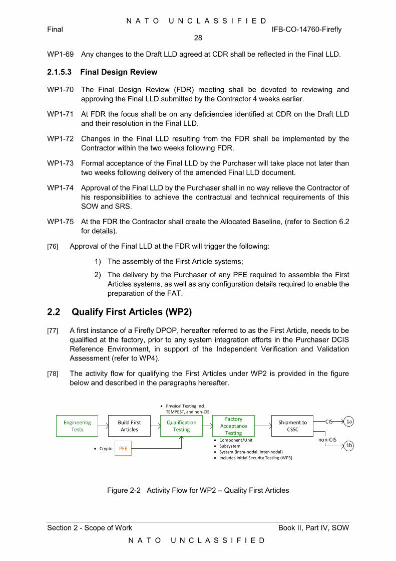
N A T O U N C L A S S I F I E D Final IFB-CO-14760-Firefly
28
Section 2 - Scope of Work Book II, Part IV, SOW
N A T O U N C L A S S I F I E D
WP1-69 Any changes to the Draft LLD agreed at CDR shall be reflected in the Final LLD.
2.1.5.3 Final Design Review
WP1-70 The Final Design Review (FDR) meeting shall be devoted to reviewing and approving the Final LLD submitted by the Contractor 4 weeks earlier.
WP1-71 At FDR the focus shall be on any deficiencies identified at CDR on the Draft LLD and their resolution in the Final LLD.
WP1-72 Changes in the Final LLD resulting from the FDR shall be implemented by the Contractor within the two weeks following FDR.
WP1-73 Formal acceptance of the Final LLD by the Purchaser will take place not later than two weeks following delivery of the amended Final LLD document.
WP1-74 Approval of the Final LLD by the Purchaser shall in no way relieve the Contractor of his responsibilities to achieve the contractual and technical requirements of this SOW and SRS.
WP1-75 At the FDR the Contractor shall create the Allocated Baseline, (refer to Section 6.2 for details).
[76] Approval of the Final LLD at the FDR will trigger the following:
1) The assembly of the First Article systems;
2) The delivery by the Purchaser of any PFE required to assemble the First Articles systems, as well as any configuration details required to enable the preparation of the FAT.
2.2 Qualify First Articles (WP2)
[77] A first instance of a Firefly DPOP, hereafter referred to as the First Article, needs to be qualified at the factory, prior to any system integration efforts in the Purchaser DCIS Reference Environment, in support of the Independent Verification and Validation Assessment (refer to WP4).
[78] The activity flow for qualifying the First Articles under WP2 is provided in the figure below and described in the paragraphs hereafter.
Engineering Tests
Build First Articles
Qualification Testing
Factory Acceptance
Testing
Shipment to CSSC
CIS
Component/Unit Subsystem System (intra-nodal, inter-nodal) Includes Initial Security Testing (WP3)
Physical Testing incl. TEMPEST, and non-CIS
PFE Crypto
1a
1bnon-CIS
Figure 2-2 Activity Flow for WP2 – Quality First Articles
N A T O U N C L A S S I F I E D Final IFB-CO-14760-Firefly
29
Section 2 - Scope of Work Book II, Part IV, SOW
N A T O U N C L A S S I F I E D
2.2.1 Build First Articles
WP2-1 First Articles shall encompass both the infrastructure of a Firefly DPOP (one full set of CIS nodes), including the set of non-CIS elements supporting those nodes, as per the following paragraphs.
WP2-2 First Articles shall be built as per the Final LLD approved at FDR.
WP2-3 First Articles shall be subject of the following test events (refer to Annex D):
1) Qualification Tests (QT);
2) Factory Acceptance Tests (FAT).
WP2-4 The production of the First Articles shall be preceded by Engineering Tests (ET) (refer to Annex D) to be conducted at the discretion of the Contractor.
WP2-5 The Purchaser shall be entitled to witness Engineering Tests and/or request access to Engineering Test Reports.
WP2-6 Shipment and receipt of any PFE components shall not be a pre-condition for the Contractor to:
1) Integrate the subsystems without those devices, and conduct the FAT;
2) Integrate the 1st article systems without those devices, and conduct a limited FAT, the scope of which would be agreed with the Purchaser.
WP2-7 Any PFE Cryptographic Controlled Items (CCI) required in support of ET and QT shall be requested by the Contractor not later than 6 weeks prior to the tests in order to allow for transport by crypto channels.
[79] Crypto delivery will always occur at the Purchaser`s premises in CSSC Brunssum. The Purchaser will carry no shipments of crypto devices to the Contractor`s premises.
2.2.1.1 CIS Nodes
WP2-8 The following CIS nodes shall be produced for QT and FAT purposes:
1) One Core Node, consisting of:
a) Core Network Modules: CNM-PCA, CNM-NU, CNM-NS, 2x CNM-MS;
b) Information Services Modules: ISM-NU, ISM-NS, 2x INM-MS;
c) Cross-domain Gateway Module: CGM;
d) User Access Modules: UAM-NU, UAM-NS, UAM-MS;
e) High Capacity Line of Sight (HCLOS) radio set (IDU and ODU).
2) One Remote Node Type A, supporting both User Access and NIP, and consisting of the following:
a) Remote Network Modules: RNM-NU, RNM-NS, RNM-MS;
b) User Access Modules UAM-NU, UAM-NS, UAM-MS;
c) HCLOS radio set (IDU and ODU).
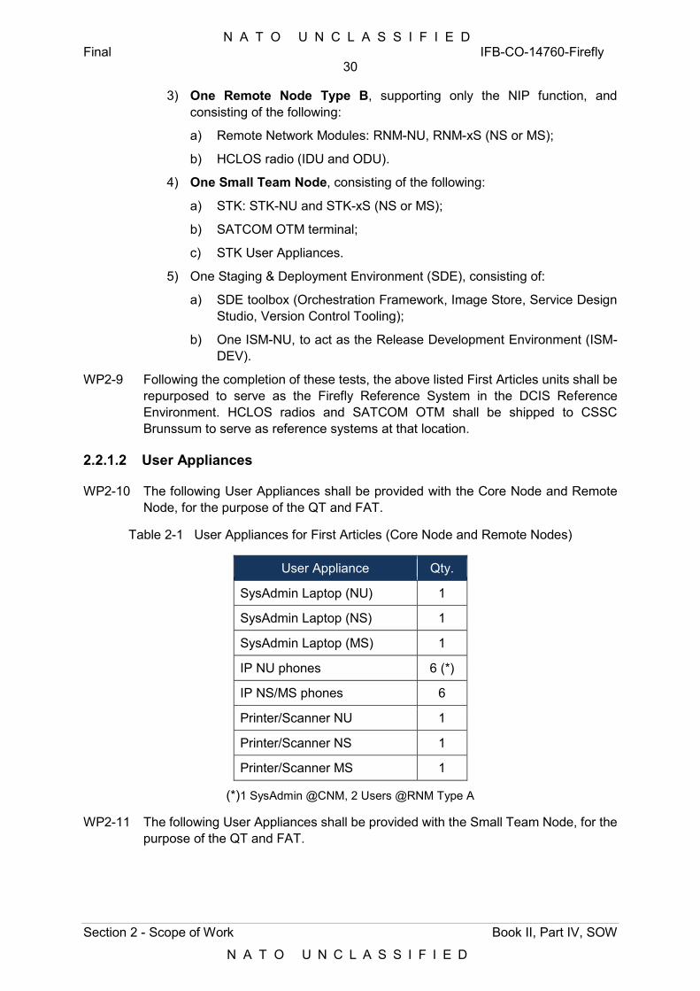
N A T O U N C L A S S I F I E D Final IFB-CO-14760-Firefly
30
Section 2 - Scope of Work Book II, Part IV, SOW
N A T O U N C L A S S I F I E D
3) One Remote Node Type B, supporting only the NIP function, and consisting of the following:
a) Remote Network Modules: RNM-NU, RNM-xS (NS or MS);
b) HCLOS radio (IDU and ODU).
4) One Small Team Node, consisting of the following:
a) STK: STK-NU and STK-xS (NS or MS);
b) SATCOM OTM terminal;
c) STK User Appliances.
5) One Staging & Deployment Environment (SDE), consisting of:
a) SDE toolbox (Orchestration Framework, Image Store, Service Design Studio, Version Control Tooling);
b) One ISM-NU, to act as the Release Development Environment (ISM-DEV).
WP2-9 Following the completion of these tests, the above listed First Articles units shall be repurposed to serve as the Firefly Reference System in the DCIS Reference Environment. HCLOS radios and SATCOM OTM shall be shipped to CSSC Brunssum to serve as reference systems at that location.
2.2.1.2 User Appliances
WP2-10 The following User Appliances shall be provided with the Core Node and Remote Node, for the purpose of the QT and FAT.
Table 2-1 User Appliances for First Articles (Core Node and Remote Nodes)
User Appliance Qty.
SysAdmin Laptop (NU) 1
SysAdmin Laptop (NS) 1
SysAdmin Laptop (MS) 1
IP NU phones 6 (*)
IP NS/MS phones 6
Printer/Scanner NU 1
Printer/Scanner NS 1
Printer/Scanner MS 1
(*)1 SysAdmin @CNM, 2 Users @RNM Type A
WP2-11 The following User Appliances shall be provided with the Small Team Node, for the purpose of the QT and FAT.
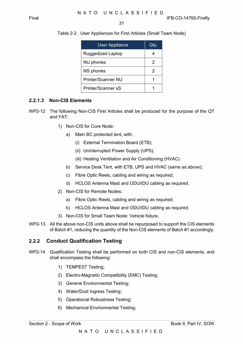
N A T O U N C L A S S I F I E D Final IFB-CO-14760-Firefly
31
Section 2 - Scope of Work Book II, Part IV, SOW
N A T O U N C L A S S I F I E D
Table 2-2 User Appliances for First Articles (Small Team Node)
User Appliance Qty.
Ruggedized Laptop 4
NU phones 2
NS phones 2
Printer/Scanner NU 1
Printer/Scanner xS 1
2.2.1.3 Non-CIS Elements
WP2-12 The following Non-CIS First Articles shall be produced for the purpose of the QT and FAT:
1) Non-CIS for Core Node:
a) Main BC protected tent, with:
(i) External Termination Board (ETB);
(ii) Uninterrupted Power Supply (UPS);
(iii) Heating Ventilation and Air Conditioning (HVAC).
b) Service Desk Tent, with ETB, UPS and HVAC (same as above);
c) Fibre Optic Reels, cabling and wiring as required;
d) HCLOS Antenna Mast and ODU/IDU cabling as required.
2) Non-CIS for Remote Nodes:
a) Fibre Optic Reels, cabling and wiring as required;
b) HCLOS Antenna Mast and ODU/IDU cabling as required.
3) Non-CIS for Small Team Node: Vehicle fixture.
WP2-13 All the above non-CIS units above shall be repurposed to support the CIS elements of Batch #1, reducing the quantity of the Non-CIS elements of Batch #1 accordingly.
2.2.2 Conduct Qualification Testing
WP2-14 Qualification Testing shall be performed on both CIS and non-CIS elements, and shall encompass the following:
1) TEMPEST Testing;
2) Electro-Magnetic Compatibility (EMC) Testing;
3) General Environmental Testing;
4) Water/Dust Ingress Testing;
5) Operational Robustness Testing;
6) Mechanical Environmental Testing;
N A T O U N C L A S S I F I E D Final IFB-CO-14760-Firefly
32
Section 2 - Scope of Work Book II, Part IV, SOW
N A T O U N C L A S S I F I E D
7) Environmental Control Testing;
8) Biological & Chemical Testing;
9) Transportation Testing;
10) Physical Functional System Testing;
11) Product Safety Testing;
12) User Interface Testing.
WP2-15 An authorized technical surveillance authority shall approve the mechanical and electrical safety of the units under test.
WP2-16 All Qualification Tests shall be performed with all components (including PFE crypto) physically integrated.
2.2.3 Conduct Factory Acceptance Testing
WP2-17 Factory Acceptance Testing shall be performed following the test regime detailed in Annex D.
WP2-18 Through Factory Acceptance testing, the Contractor shall demonstrate that:
1) Each Firefly module (system) is successfully integrated at subsystem and component levels and can communicate with other modules within a given Firefly node (Core Node, Remote Node, or Small Team Node);
2) Each Firefly node (collection of Firefly modules) is successfully integrated at system (module) level and can communicate with other Firefly nodes within a given DPOP.
WP2-19 In particular, Factory Acceptance Testing shall verify the following, with the First Articles installed at the Contractor’s test environment:
1) Functionality of the various subsystems integrated in each of the network modules of each Firefly node (CNM, RNM and STK), including:
a) Protected Core Access (PCA);
b) Coloured Cloud Access (CCA);
c) Multi-Media Access (MMA);
d) Boundary Protection System (BPS);
e) Local Area Network Subsystem (LAN);
f) Uninterrupted Power Supply (buint-into Remote Node modules).
2) Functionality of the transmission bearers:
a) HCLOS radio;
b) SATCOM On-the-move.
3) Interfaces within each of the modules (between subsystems), including subsystems outside the module (e.g. HCLOS radio);
4) Intra-nodal connectivity, i.e. testing of the interfaces between the various modules that make each Firefly node, i.e.
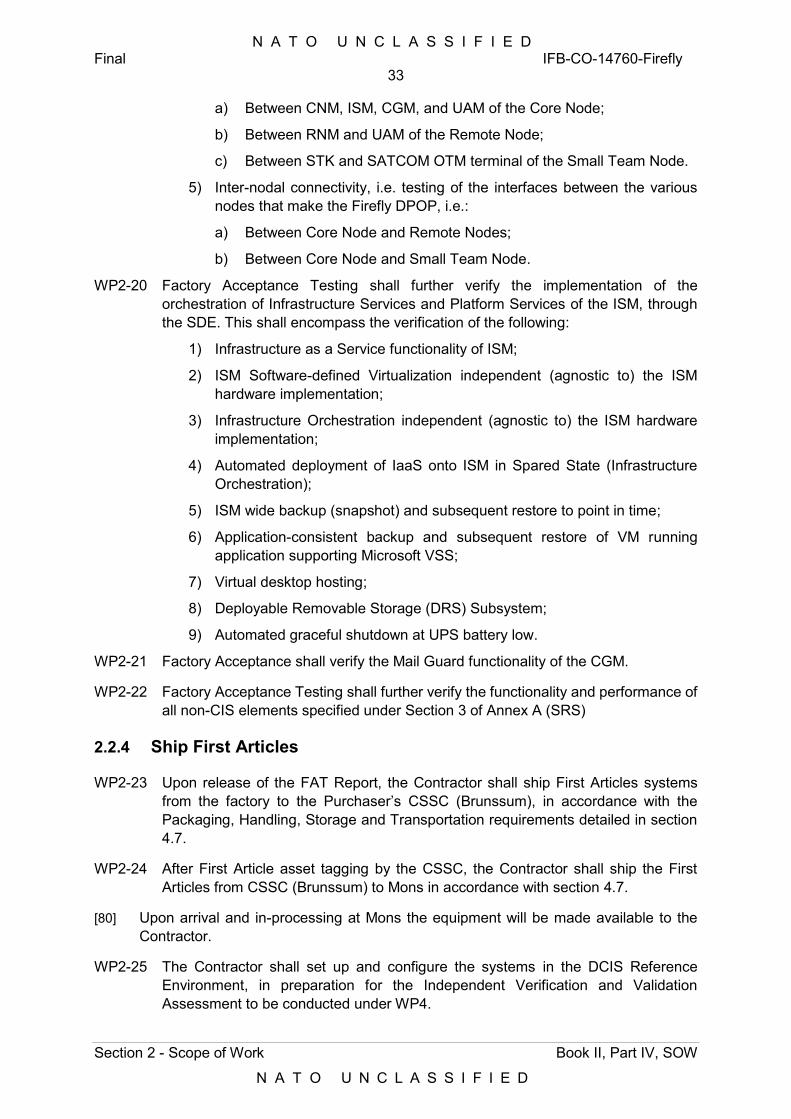
N A T O U N C L A S S I F I E D Final IFB-CO-14760-Firefly
33
Section 2 - Scope of Work Book II, Part IV, SOW
N A T O U N C L A S S I F I E D
a) Between CNM, ISM, CGM, and UAM of the Core Node;
b) Between RNM and UAM of the Remote Node;
c) Between STK and SATCOM OTM terminal of the Small Team Node.
5) Inter-nodal connectivity, i.e. testing of the interfaces between the various nodes that make the Firefly DPOP, i.e.:
a) Between Core Node and Remote Nodes;
b) Between Core Node and Small Team Node.
WP2-20 Factory Acceptance Testing shall further verify the implementation of the orchestration of Infrastructure Services and Platform Services of the ISM, through the SDE. This shall encompass the verification of the following:
1) Infrastructure as a Service functionality of ISM;
2) ISM Software-defined Virtualization independent (agnostic to) the ISM hardware implementation;
3) Infrastructure Orchestration independent (agnostic to) the ISM hardware implementation;
4) Automated deployment of IaaS onto ISM in Spared State (Infrastructure Orchestration);
5) ISM wide backup (snapshot) and subsequent restore to point in time;
6) Application-consistent backup and subsequent restore of VM running application supporting Microsoft VSS;
7) Virtual desktop hosting;
8) Deployable Removable Storage (DRS) Subsystem;
9) Automated graceful shutdown at UPS battery low.
WP2-21 Factory Acceptance shall verify the Mail Guard functionality of the CGM.
WP2-22 Factory Acceptance Testing shall further verify the functionality and performance of all non-CIS elements specified under Section 3 of Annex A (SRS)
2.2.4 Ship First Articles
WP2-23 Upon release of the FAT Report, the Contractor shall ship First Articles systems from the factory to the Purchaser’s CSSC (Brunssum), in accordance with the Packaging, Handling, Storage and Transportation requirements detailed in section 4.7.
WP2-24 After First Article asset tagging by the CSSC, the Contractor shall ship the First Articles from CSSC (Brunssum) to Mons in accordance with section 4.7.
[80] Upon arrival and in-processing at Mons the equipment will be made available to the Contractor.
WP2-25 The Contractor shall set up and configure the systems in the DCIS Reference Environment, in preparation for the Independent Verification and Validation Assessment to be conducted under WP4.
N A T O U N C L A S S I F I E D Final IFB-CO-14760-Firefly
34
Section 2 - Scope of Work Book II, Part IV, SOW
N A T O U N C L A S S I F I E D
WP2-26 The Contractor shall be responsible for shipping any First Article systems from the Purchaser’s premises back to the factory, for rectification of non-compliances or deficiencies found under WP4. This will require shipping the First Articles system(s) back to the Purchaser’s location, for regression testing.
2.3 Support Security Accreditation Process (WP3)
[81] Firefly CIS needs to achieve security accreditation in order to be granted the authorisation for operational use.
[82] The activity flow for the Support to the Security Accreditation process under WP3 is provided in the figure below and described in the paragraphs hereafter.
Develop Security-related
Doc. (SRD)
Obtain Authorization
for Testing (AfT)
Security Testing(for AfT)
Obtain Interim SA, I(SA)
2 3 Initial Security Testing (WP2) Main Secutity Testing (WP4)
Security Testing(for I-SA)
Supplementary Security Testing (WP6) Addiitional Secutity Testing (WP8)
Figure 2-3 Activity Flow for WP3 – Support Security Accreditation Process
WP3-1 The security accreditation process established by the Security Accreditation Authority (SAA) shall be followed.
[83] The primary objective of security accreditation of the Firefly is to ensure that the required level of protection is achieved and maintained throughout its life cycle. This includes ensuring that the Firefly conforms to NATO Security Policies and Directives identified at Annex B, and in the Firefly security-related documentation listed in Annex B to this SOW (Security Accreditation Requirements).
WP3-2 The Contractor shall develop initial version of the Security Accreditation Plan (SAP) for the Firefly. The SAP shall identify all Security-related Documentation (SRD) deliverables and their timing. The Contractor shall strictly adhere to the security accreditation activities described in the SAP as approved by the SAA. All activities related with the security accreditation process shall be identified in the respective Project Implementation Plan (PIP) and in the Project Management Plan (PMP).
WP3-3 The Contractor shall develop and maintain the following documents as part of the SRD, in line with the requirements identified in Annex B:
1) CIS Description;
2) Security Risk Assessment (SRA);
3) System-Specific Security Requirement Statement (SSRS);
4) Generic System Interconnection Security Requirement Statement (SISRS);
5) Security Operating Procedures (SecOPs);
6) Security Test and Verification Plan (STVP);
7) Security Test and Verification Report (STVR); and,
8) Electronic Security Environment (ESE) Conformance statement (ESECS).
N A T O U N C L A S S I F I E D Final IFB-CO-14760-Firefly
35
Section 2 - Scope of Work Book II, Part IV, SOW
N A T O U N C L A S S I F I E D
WP3-4 Security-related documentation will be subject to Purchaser and Security Accreditation Authority (SAA) review and approval. The Contractor should expect a number of review rounds per document before it will be approved by the Purchaser’s SAA.
WP3-5 The Contractor shall take into account any comments from the Purchaser’s reviewers and SAA and shall update the documents as necessary in order to gain SAA approval of the SRD.
WP3-6 The SRD shall be presented by the Contractor to the Purchaser and its SAA, including but not limited to a formal presentation. The location of this presentation shall be defined by the Purchaser and shall typically take place at the Purchaser’s facility.
WP3-7 Coordination with the SAA will be conducted by the Purchaser. The Contractor might be invited to provide briefings and/or technical expertise for meeting(s) with the SAA.
WP3-8 The SAA might give advice and guidance to the Contractor (through the Purchaser’s Project Manager) on any security implication or any proposed change based on the findings and results of the assessments and/or security tests. The Contractor shall assess the necessary work required to follow the advice given by the SAA and will liaise with the Purchaser’s Project Manager for its implementation.
WP3-9 It is the overall responsibility of the Contractor to develop an appropriate Firefly system design and security-related documentation in order to achieve security accreditation of the Firefly. The design and the SRD deliverables shall be compliant with NATO Security Policies and Directives (refer to Annex B, section 2).
WP3-10 The SRD should be developed in parallel to appropriate deliverables under all the WPs concerned, and within the timeline as per the Contractual Data Requirement List (CDRL) in Appendix B.
WP3-11 Initial versions of CIS Description, Security Risk Assessment and System-specific Security Requirements Statement shall be developed and released by the Contractor by the same time as the HLD (refer to WP1). Intial versions of CIS Description, SRA and SSRS shall fully reflect Firelfy’s architecture as depicted in the HLD.
WP3-12 As a minimum 2 workshops shall be planned for for a duration of 2-5days, as detailed in Annex B.
1) One Workshop at the end of the SRA output; and
2) One Workshop prior to the PDR.
WP3-13 Initial versions of CIS Description, SRA and SSRS shall be reviewed during the Preliminary Design Review (PDR) under the same regime as the HLD.
WP3-14 Updated versions of CIS Description, SRA and SSRS shall be developed and provided to the Purchaser under the same regime as the Draft LLD and shall be reviewed during the Critical Design Review (CDR).
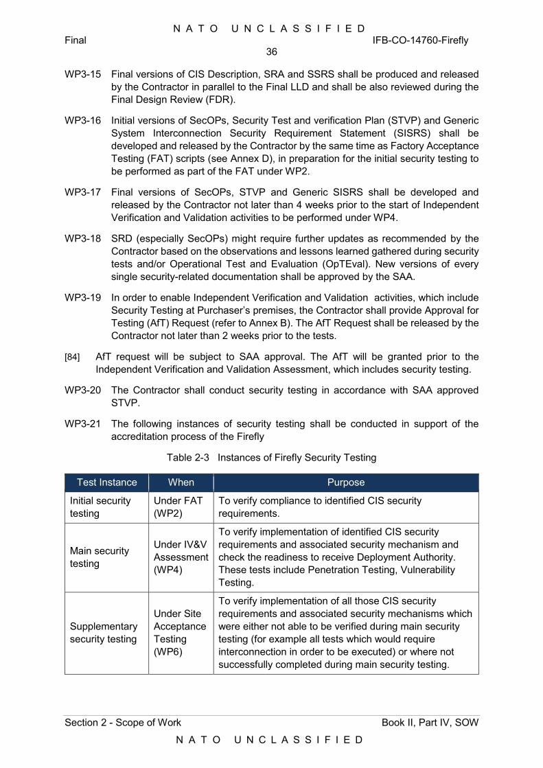
N A T O U N C L A S S I F I E D Final IFB-CO-14760-Firefly
36
Section 2 - Scope of Work Book II, Part IV, SOW
N A T O U N C L A S S I F I E D
WP3-15 Final versions of CIS Description, SRA and SSRS shall be produced and released by the Contractor in parallel to the Final LLD and shall be also reviewed during the Final Design Review (FDR).
WP3-16 Initial versions of SecOPs, Security Test and verification Plan (STVP) and Generic System Interconnection Security Requirement Statement (SISRS) shall be developed and released by the Contractor by the same time as Factory Acceptance Testing (FAT) scripts (see Annex D), in preparation for the initial security testing to be performed as part of the FAT under WP2.
WP3-17 Final versions of SecOPs, STVP and Generic SISRS shall be developed and released by the Contractor not later than 4 weeks prior to the start of Independent Verification and Validation activities to be performed under WP4.
WP3-18 SRD (especially SecOPs) might require further updates as recommended by the Contractor based on the observations and lessons learned gathered during security tests and/or Operational Test and Evaluation (OpTEval). New versions of every single security-related documentation shall be approved by the SAA.
WP3-19 In order to enable Independent Verification and Validation activities, which include Security Testing at Purchaser’s premises, the Contractor shall provide Approval for Testing (AfT) Request (refer to Annex B). The AfT Request shall be released by the Contractor not later than 2 weeks prior to the tests.
[84] AfT request will be subject to SAA approval. The AfT will be granted prior to the Independent Verification and Validation Assessment, which includes security testing.
WP3-20 The Contractor shall conduct security testing in accordance with SAA approved STVP.
WP3-21 The following instances of security testing shall be conducted in support of the accreditation process of the Firefly
Table 2-3 Instances of Firefly Security Testing
Test Instance When Purpose
Initial security testing
Under FAT (WP2)
To verify compliance to identified CIS security requirements.
Main security testing
Under IV&V Assessment (WP4)
To verify implementation of identified CIS security requirements and associated security mechanism and check the readiness to receive Deployment Authority. These tests include Penetration Testing, Vulnerability Testing.
Supplementary security testing
Under Site Acceptance Testing (WP6)
To verify implementation of all those CIS security requirements and associated security mechanisms which were either not able to be verified during main security testing (for example all tests which would require interconnection in order to be executed) or where not successfully completed during main security testing.
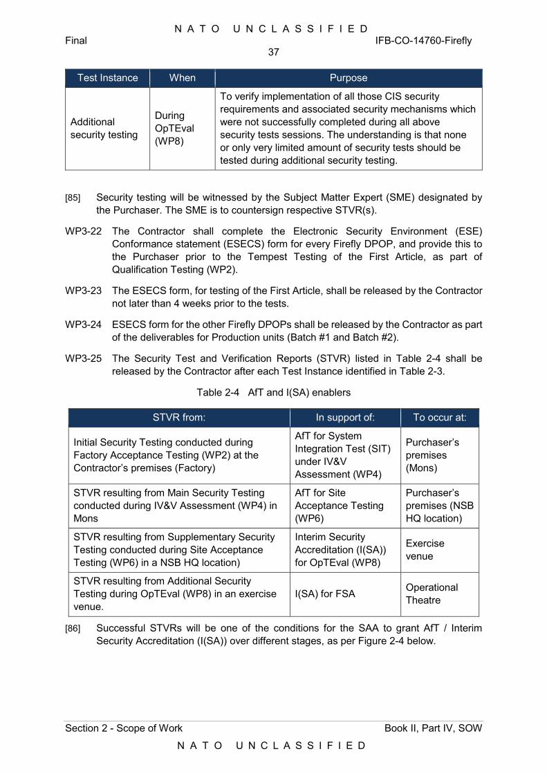
N A T O U N C L A S S I F I E D Final IFB-CO-14760-Firefly
37
Section 2 - Scope of Work Book II, Part IV, SOW
N A T O U N C L A S S I F I E D
Test Instance When Purpose
Additional security testing
During OpTEval (WP8)
To verify implementation of all those CIS security requirements and associated security mechanisms which were not successfully completed during all above security tests sessions. The understanding is that none or only very limited amount of security tests should be tested during additional security testing.
[85] Security testing will be witnessed by the Subject Matter Expert (SME) designated by the Purchaser. The SME is to countersign respective STVR(s).
WP3-22 The Contractor shall complete the Electronic Security Environment (ESE) Conformance statement (ESECS) form for every Firefly DPOP, and provide this to the Purchaser prior to the Tempest Testing of the First Article, as part of Qualification Testing (WP2).
WP3-23 The ESECS form, for testing of the First Article, shall be released by the Contractor not later than 4 weeks prior to the tests.
WP3-24 ESECS form for the other Firefly DPOPs shall be released by the Contractor as part of the deliverables for Production units (Batch #1 and Batch #2).
WP3-25 The Security Test and Verification Reports (STVR) listed in Table 2-4 shall be released by the Contractor after each Test Instance identified in Table 2-3.
Table 2-4 AfT and I(SA) enablers
STVR from: In support of: To occur at:
Initial Security Testing conducted during Factory Acceptance Testing (WP2) at the Contractor’s premises (Factory)
AfT for System Integration Test (SIT) under IV&V Assessment (WP4)
Purchaser’s premises (Mons)
STVR resulting from Main Security Testing conducted during IV&V Assessment (WP4) in Mons
AfT for Site Acceptance Testing (WP6)
Purchaser’s premises (NSB HQ location)
STVR resulting from Supplementary Security Testing conducted during Site Acceptance Testing (WP6) in a NSB HQ location)
Interim Security Accreditation (I(SA)) for OpTEval (WP8)
Exercise venue
STVR resulting from Additional Security Testing during OpTEval (WP8) in an exercise venue.
I(SA) for FSA Operational Theatre
[86] Successful STVRs will be one of the conditions for the SAA to grant AfT / Interim Security Accreditation (I(SA)) over different stages, as per Figure 2-4 below.
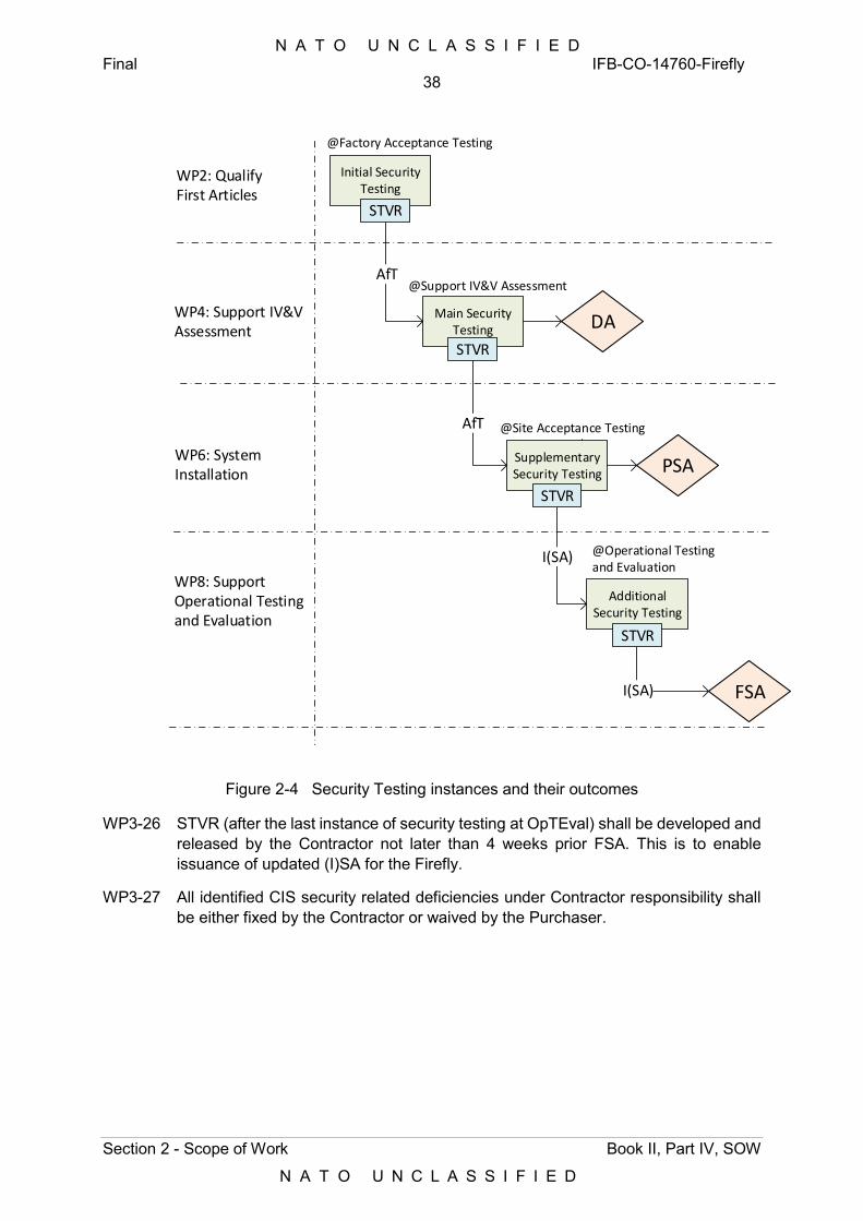
N A T O U N C L A S S I F I E D Final IFB-CO-14760-Firefly
38
Section 2 - Scope of Work Book II, Part IV, SOW
N A T O U N C L A S S I F I E D
WP2: Qualify First Articles
WP4: Support IV&V Assessment
WP6: System Installation
WP8: Support Operational Testing and Evaluation
Initial Security Testing
Main Security Testing
Supplementary Security Testing
@Factory Acceptance Testing
@Support IV&V Assessment
@Site Acceptance Testing
Additional Security Testing
@Operational Testing and Evaluation
AfT
AfT
I(SA)
I(SA) FSA
STVR
STVR
STVR
STVR
DA
PSA
Figure 2-4 Security Testing instances and their outcomes
WP3-26 STVR (after the last instance of security testing at OpTEval) shall be developed and released by the Contractor not later than 4 weeks prior FSA. This is to enable issuance of updated (I)SA for the Firefly.
WP3-27 All identified CIS security related deficiencies under Contractor responsibility shall be either fixed by the Contractor or waived by the Purchaser.
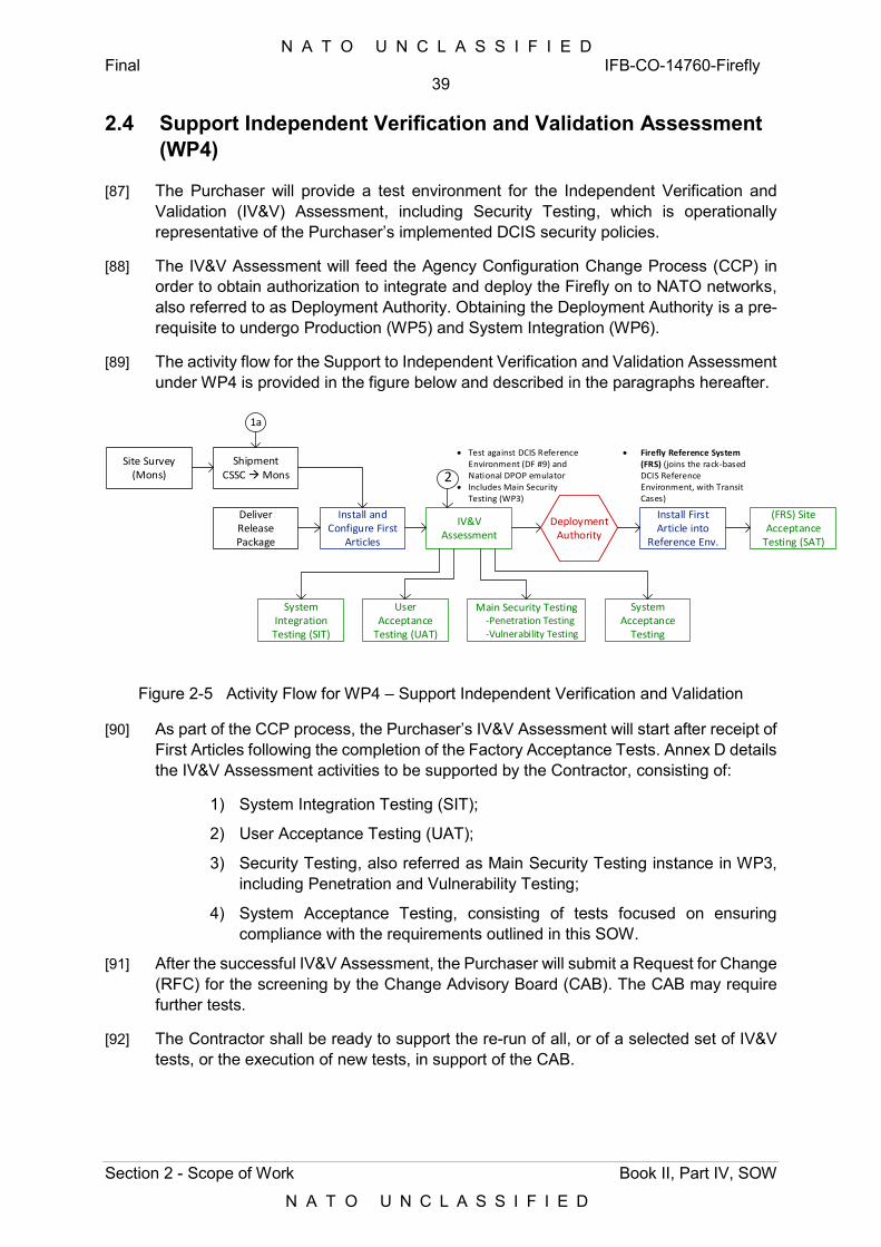
N A T O U N C L A S S I F I E D Final IFB-CO-14760-Firefly
39
Section 2 - Scope of Work Book II, Part IV, SOW
N A T O U N C L A S S I F I E D
2.4 Support Independent Verification and Validation Assessment (WP4)
[87] The Purchaser will provide a test environment for the Independent Verification and Validation (IV&V) Assessment, including Security Testing, which is operationally representative of the Purchaser’s implemented DCIS security policies.
[88] The IV&V Assessment will feed the Agency Configuration Change Process (CCP) in order to obtain authorization to integrate and deploy the Firefly on to NATO networks, also referred to as Deployment Authority. Obtaining the Deployment Authority is a pre-requisite to undergo Production (WP5) and System Integration (WP6).
[89] The activity flow for the Support to Independent Verification and Validation Assessment under WP4 is provided in the figure below and described in the paragraphs hereafter.
Shipment CSSC Mons
DeliverRelease Package
Install and Configure First
Articles
IV&V Assessment
Install First Article into
Reference Env.
Deployment Authority
System Integration Testing (SIT)
User Acceptance
Testing (UAT)
Main Security Testing -Penetration Testing
-Vulnerability Testing
Site Survey (Mons)
Firefly Reference System (FRS) (joins the rack-based DCIS Reference Environment, with Transit Cases)
Test against DCIS Reference Environment (DF #9) and National DPOP emulator
Includes Main Security Testing (WP3)
System Acceptance
Testing
2
1a
(FRS) Site Acceptance
Testing (SAT)
Figure 2-5 Activity Flow for WP4 – Support Independent Verification and Validation
[90] As part of the CCP process, the Purchaser’s IV&V Assessment will start after receipt of First Articles following the completion of the Factory Acceptance Tests. Annex D details the IV&V Assessment activities to be supported by the Contractor, consisting of:
1) System Integration Testing (SIT);
2) User Acceptance Testing (UAT);
3) Security Testing, also referred as Main Security Testing instance in WP3, including Penetration and Vulnerability Testing;
4) System Acceptance Testing, consisting of tests focused on ensuring compliance with the requirements outlined in this SOW.
[91] After the successful IV&V Assessment, the Purchaser will submit a Request for Change (RFC) for the screening by the Change Advisory Board (CAB). The CAB may require further tests.
[92] The Contractor shall be ready to support the re-run of all, or of a selected set of IV&V tests, or the execution of new tests, in support of the CAB.
N A T O U N C L A S S I F I E D Final IFB-CO-14760-Firefly
40
Section 2 - Scope of Work Book II, Part IV, SOW
N A T O U N C L A S S I F I E D
[93] Once all the final documents required for the RFC (Release Package) have been submitted and the production baseline has successfully completed the IV&V Assessment the CAB may grant the Deployment Authority, i.e. the approval to deploy the Firefly on NATO Operational targeted networks.
[94] As part of the change process the new baseline including the Firefly components will be incorporated into the relevant Approved Fielded Products List (AFPL). The AFPL process is a NATO-owned and managed via an internal process, to which the Contractor will need to provide support as described in this section.
WP4-1 The Contractor shall support IV&V Assessment by the Purchaser.
WP4-2 Before the IV&V Assessment, the Contractor shall perform a demonstration to verify system installation, configuration, performance and functionality. After successful demonstration, the system will be handed-over to the Purchaser’s IV&V team for further evaluation.
WP4-3 The Contractor shall provide all the necessary System Specifications, Hardware i.e. Virtual and Storage capacity and Licenses, for the Purchaser to conduct the required IV&V Assessment in the Purchaser’s DCIS Reference Environment.
WP4-4 The Contractor shall install and configure the system in the Purchaser’s Reference System Environment.
WP4-5 The Contractor shall perform all or selected Factory Acceptance Tests as agreed by the Purchaser in the Purchaser’s DCIS Reference Environment to demonstrate that the system works with its affiliate system (interoperability) and functions successfully in an Operationally Representative environment.
WP4-6 The Contractor shall perform the Performance Assessment Test in the Purchaser’s DCIS Reference Environment as part of the IV&V Assessment.
WP4-7 The Contractor shall fix incidents found during demonstration and then handover the system to IV&V Team for further test activities.
WP4-8 After achieving Deployment Authorityof the system, the Contractor shall install and configure the system in the DCIS Reference Environment and execute IV&V tests.
WP4-9 The Contractor shall support the Purchaser’s IV&V installation and Test Activities, including Purchaser performed security testing.
WP4-10 The Contractor shall provide the technical experts on the Purchaser’s DCIS Reference Environment site to assist all IV&V Assessment activities.
[95] The Purchaser will execute his own set of IV&V test cases and has right to use the Contractor developed test cases during the pre-IV&V Evaluation.
[96] The Purchaser has right to repeat the IV&V Assessment process until complete RFC package is ready and mature to start CAB process or additional tests if requested by CAB.
N A T O U N C L A S S I F I E D Final IFB-CO-14760-Firefly
41
Section 2 - Scope of Work Book II, Part IV, SOW
N A T O U N C L A S S I F I E D
2.4.1 Conduct Site Survey
WP4-11 The Contractor shall conduct a Site Survey at the DCIS Reference Environment in Mons.
WP4-12 The Site Survey shall adhere to the site survey requirements in Section 3.6
WP4-13 The Site Survey Report (SSR) shall be delivered to the Purchaser for review and acceptance following the document requirements at Section 5, not later than 2 weeks following the Site Survey.
2.4.2 Provide Release Package
[97] A Release Package is a planned release of a product or product edition. The content of a Release Package is defined by the features and associated Requests for Change (RFC) that it implements.
WP4-14 The Contractor shall supply the documents and media in final form listed in Table 2-5 below, for inclusion in the Purchaser Release Package for the RFC. These shall be provided 3 weeks before planned tests.
[98] Architecture documents will be provided by the Purchaser as a part of the Release Package.
WP4-15 The Contractor shall submit a complete build including source and object code, version description document (including issues and workarounds), including deployment and installation instructions prior to the start of the IV&V Assessment.
N A T O U N C L A S S I F I E D Final IFB-CO-14760-Firefly
42
Section 2 - Scope of Work Book II, Part IV, SOW
N A T O U N C L A S S I F I E D
Table 2-5 Release Package items Serial Item Source
1 System Media (system installation executables) Contractor
2 System Installation Instructions Contractor
3 System User Manual (or equivalent User Documentation) Contractor
4 Version Release Description/System Release Notes Contractor
5 System Implementation Plan Contractor
6 End User Licence Agreement (EULA) for embedded Open Source Software (OSS)
Contractor
7 Architecture Document - High-Level Operational Concept Description (NOV-1)
Purchaser
8 Architecture Document - Operational Node Connectivity Description (NOV-2)
Purchaser
9 Architecture Document - System Interface Description (NSV 1) Purchaser
10 Unit/Component Test Report(s) Contractor
12 First Articles Test Report Contractor
13 Requirements Traceability Matrix Contractor
2.4.3 Install First Articles
WP4-16 The Contractor shall install and verify the First Articles systems in the Purchaser’s DCIS Reference Environment (PFE), in preparation for the IV&V Assessment.
WP4-17 The installation shall be temporary, only for the purpose of supporting these tests.
WP4-18 Installation activities shall be followed by the configuration of the systems and provisioning of services in accordance with the Final LLD, which shall in turn be based upon the configuration captured in WP1.
WP4-19 The installation of the First Articles shall mimic a deployment in an environmentally controlled room (indoors).
[99] The Purchaser will be responsible for connecting the First Articles to the DCIS Reference Environment.
2.4.4 Conduct System Integration Testing (SIT)
WP4-20 System Integration Testing shall verify the following at the Purchaser’s test environment:
1) Inter-nodal connectivity between Firefly nodes of the same DPOP, using different WAN bearers (SATCOM, HCLOS radio, terrestrial). The following two scenarios to be covered:
a) Remote Node to Core Node;
b) Small Team Node to Core Node.
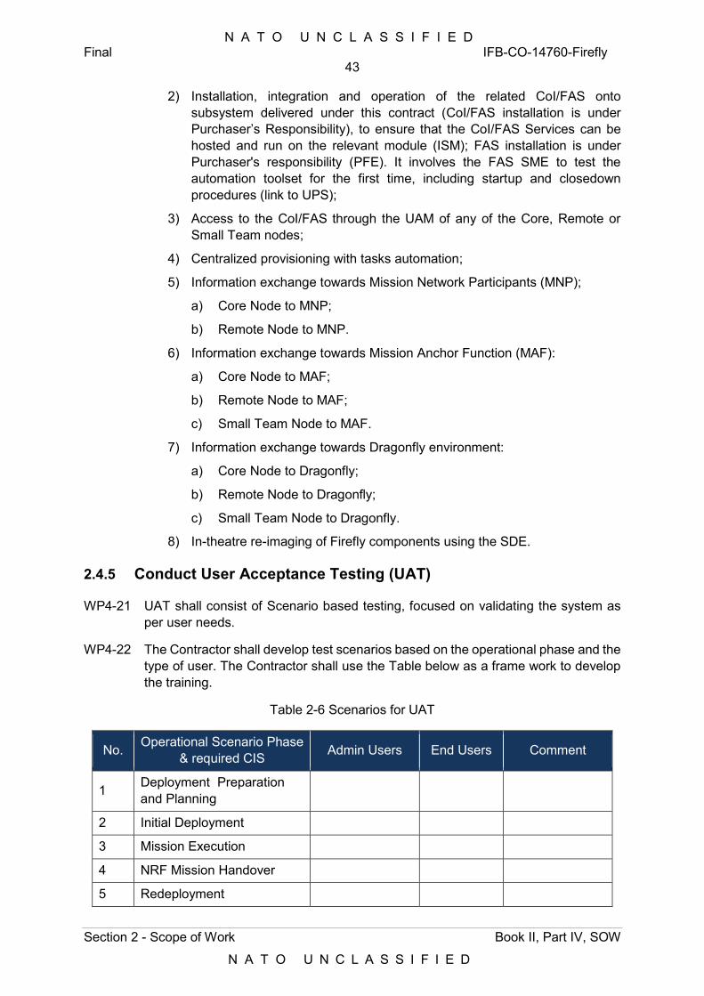
N A T O U N C L A S S I F I E D Final IFB-CO-14760-Firefly
43
Section 2 - Scope of Work Book II, Part IV, SOW
N A T O U N C L A S S I F I E D
2) Installation, integration and operation of the related CoI/FAS onto subsystem delivered under this contract (CoI/FAS installation is under Purchaser’s Responsibility), to ensure that the CoI/FAS Services can be hosted and run on the relevant module (ISM); FAS installation is under Purchaser's responsibility (PFE). It involves the FAS SME to test the automation toolset for the first time, including startup and closedown procedures (link to UPS);
3) Access to the CoI/FAS through the UAM of any of the Core, Remote or Small Team nodes;
4) Centralized provisioning with tasks automation;
5) Information exchange towards Mission Network Participants (MNP);
a) Core Node to MNP;
b) Remote Node to MNP.
6) Information exchange towards Mission Anchor Function (MAF):
a) Core Node to MAF;
b) Remote Node to MAF;
c) Small Team Node to MAF.
7) Information exchange towards Dragonfly environment:
a) Core Node to Dragonfly;
b) Remote Node to Dragonfly;
c) Small Team Node to Dragonfly.
8) In-theatre re-imaging of Firefly components using the SDE.
2.4.5 Conduct User Acceptance Testing (UAT)
WP4-21 UAT shall consist of Scenario based testing, focused on validating the system as per user needs.
WP4-22 The Contractor shall develop test scenarios based on the operational phase and the type of user. The Contractor shall use the Table below as a frame work to develop the training.
Table 2-6 Scenarios for UAT
No. Operational Scenario Phase & required CIS Admin Users End Users Comment
1 Deployment Preparation and Planning
2 Initial Deployment
3 Mission Execution
4 NRF Mission Handover
5 Redeployment
N A T O U N C L A S S I F I E D Final IFB-CO-14760-Firefly
44
Section 2 - Scope of Work Book II, Part IV, SOW
N A T O U N C L A S S I F I E D
[100] Operational scenarios are detailed in Annex C, Appendix B.
WP4-23 The scope of the UAT for the Admin Users shall be determined from the user functions as identified from the TNA.
WP4-24 The End User will mainly focus on the End User Business Support Services and COI services (i.e. Core Services and COI-specific services (FAS). Noting that the provision and configuration of these is PFEThe Contractor shall undertake UAT, as detailed in Annex D.
2.4.6 Conduct Security Testing
[101] Security testing is to confirm that all CIS security requirements and associated security mechanisms identified for the Firefly have been properly implemented.
[102] Security testing will be conducted in Purchaser-provided and Purchaser-managed DCIS Reference Environment, representative of the target network/security domain, including security settings, patches, network configurations and interfacing systems and services, as necessary to represent the live environment as viewed from the perspective of the product, system or service being tested.
[103] Security testing conducted during the IV&V Assessment is to verify implementation of identified CIS security requirements and associated security mechanism and check the readiness (from the security accreditation point of view) to SAT and enable deployment authority.
WP4-25 The Security testing shall comply with Section 2.3, specifically the STVP and STVR.
WP4-26 The STV tests shall be cross-referenced to the security specific requirements, and corresponding security design functions. This cross-referencing shall be via the Reference Traceability Matrix (RTM).
[104] For any Software, Operating Systems, Middleware, and Firmware that is submitted by the Contractor for inclusion in the AFPL, as well as for any other security-related aspect of the solution, the CCP process requires security testing, including penetration testing and vulnerability assessment.
WP4-27 The Contractor shall ensure that all the security countermeasures detailed in SSRS and SISRs have been installed and configured for all delivered DCIS equipment.
WP4-28 The Contractor shall address and fix any issues resulting from the Penetration Testing and Vulnerability Assessment before FAT.
WP4-29 The Purchaser shall have the right to repeat this process until all identified issues are confirmed fixed.
WP4-30 As a part of the AFPL process the Contractor shall provide personnel at the Purchasers facility in support of Purchaser Security testing, including and Penetration testing of Software, Operating Systems, Middleware, and Firmware AFPL.
WP4-31 For any hardware component or subsystem involving Software, Operating Systems, Middleware, and Firmware, penetration testing may be requested to be performed.
N A T O U N C L A S S I F I E D Final IFB-CO-14760-Firefly
45
Section 2 - Scope of Work Book II, Part IV, SOW
N A T O U N C L A S S I F I E D
WP4-32 The Contractor's CIS Security Manager shall participate in the Vulnerability Assessment tests under the direction of the Purchaser.
WP4-33 Contractor's support to Vulnerability Assessment tests shall be available during the test at the Purchaser’s premises.
2.4.7 System Acceptance Testing
WP4-34 System Acceptance Test shall assess the requirements for all quality characteristics, beyond security, interoperability and functionality. This will encompass requirements (e.g. Performance, Reliability, etc.) as described in Annex D.
[105] In particular, performance assessment during System Acceptance Testing is required to measure responsiveness, effectiveness and stability under a particular workload, as well as to ensure that the Firefly systems are behaving and generating results within specified performance criteria. Performance Testing can also serve to investigate, measure, validate or verify other quality attributes of the capability, such as scalability, reliability and resource usage. Specific forms of performance testing are throughput and speed testing, load testing and stress testing.
WP4-35 The Contractor shall run tests in order to find out the actual capacity of the different services implemented, based on the individual performance benchmark of the components specified in the SRS (as technical constraints, e.g. routers, firewalls, number of CPUs and storage, etc.).
WP4-36 In particular, throughput shall be measured using traffic generators programmed to produce the mix of IP packet sizes representative for the NATO DCIS networks (refer to packet mix in Section 1.3 of Annex A, Conventions).
WP4-37 The Contractor shall plan the performance test also for the purpose of reliability testing and consider the related reliability metrics in the planning of the test.
[106] Note that the System Acceptance Test during the IV&V Assessment does not imply PSA or FSA.
2.4.8 Install and Validate Reference Environment
WP4-38 Following the IV&V Assessment, including Security testing, the First Articles systems (excluding non-CIS) shall be re-configured as required, in order to become the Firefly Reference System, within the wider DCIS Reference Environment, consisting of:
1) One CNM Node;
2) One RNM Type A Node;
3) One RNM Type B Node;
4) One Small Team Node.
WP4-39 The Firefly Reference System shall use one of the two CNM-MS and ISM-MS for emulating the communications and IS systems of a National DPOP when required. These modules shall be configured following Purchaser’s guidance.
N A T O U N C L A S S I F I E D Final IFB-CO-14760-Firefly
46
Section 2 - Scope of Work Book II, Part IV, SOW
N A T O U N C L A S S I F I E D
[107] A notional representation of the Firefly Reference System and its interfaces to the Staging and Deployment Environment (SDE) and the existing DCIS Reference Environment, is provided in Figure 2-6.
WP4-40 Any change required on the First Article systems as delivered, resulting from the outcome of the IV&V Assessment shall be implemented prior to integrating those systems into the Firefly Reference System.
WP4-41 The Firefly Reference System shall have all its components integrated in the original transit cases, collocated and interconnected in order to represent an actual deployment.
WP4-42 The reference units of the HCLOS radios of Core and Remote Nodes, as well as the SATCOM On-the-move (OTM) terminal of the Small Team Node, shall be provided as standalone units, ready to be operated outdoors as reference systems in CSSC in Brunssum.
[108] The Firefly Reference System will be used in support of troubleshooting and issue resolution during the Site Acceptance Testing (WP6) and OpTEval (WP8) and beyond, throughout the lifecycle of the Firefly DPOPs.
[109] To that end, the Firefly Reference System will be configured to be representative of the actual operational environment, in particular network configurations, security settings and software versions.
WP4-43 The Contractor shall provide the tools and procedures to ensure that the Firefly Reference System is kept up to date and in line with the current Firefly baseline.
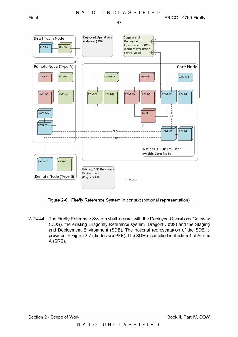
N A T O U N C L A S S I F I E D Final IFB-CO-14760-Firefly
47
Section 2 - Scope of Work Book II, Part IV, SOW
N A T O U N C L A S S I F I E D
CNM-NS
UAM-NU
CNM-NU
CNM-MS
CNM-MS ISM-MSISM-NS
ISM-MS
UAM-NU
ISM-NURMN-NU
National DPOP Emulator (within Core Node)
UAM-MSUAM-NS
NIP
RMN-NS
RMN-MS
NIP
RMN-NURMN-xS
CGM
Core Node
UAM-NS
UAM-MS
NIP
Remote Node (Type A)
Remote Node (Type B)
Small Team Node
STK-NUSTK-xS
Existing DCIS Reference Environment (Dragonfly #09)
Deployed Operations Gateway (DOG)
DOG
Staging and Deployment Environment (SDE) – @Mission Preparation
Centre (Mons)
to DOG
Figure 2-6 Firefly Reference System in context (notional representation).
WP4-44 The Firefly Reference System shall interact with the Deployed Operations Gateway (DOG), the existing Dragonfly Reference system (Dragonfly #09) and the Staging and Deployment Environment (SDE). The notional representation of the SDE is provided in Figure 2-7 (diodes are PFE). The SDE is specified in Section 4 of Annex A (SRS).
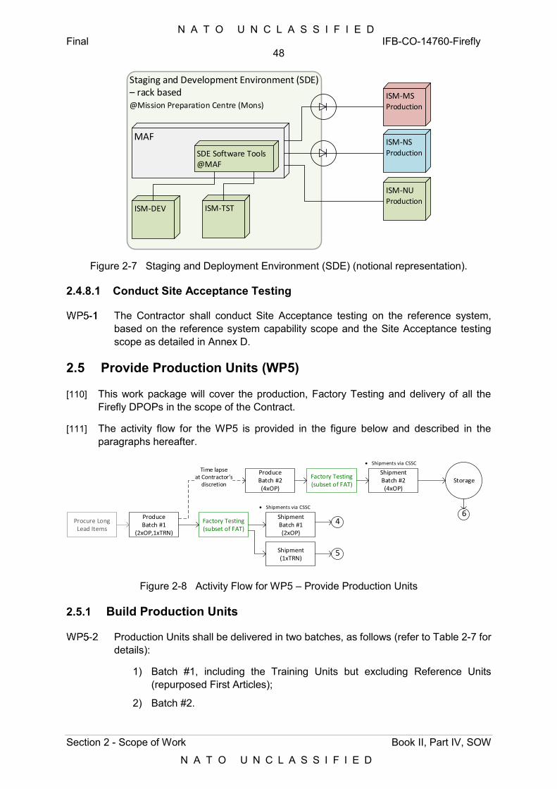
N A T O U N C L A S S I F I E D Final IFB-CO-14760-Firefly
48
Section 2 - Scope of Work Book II, Part IV, SOW
N A T O U N C L A S S I F I E D
Staging and Development Environment (SDE) – rack based@Mission Preparation Centre (Mons)
MAF
ISM-TSTISM-DEV
SDE Software Tools @MAF
ISM-NUProduction
ISM-NSProduction
ISM-MSProduction
Figure 2-7 Staging and Deployment Environment (SDE) (notional representation).
2.4.8.1 Conduct Site Acceptance Testing
The Contractor shall conduct Site Acceptance testing on the reference system, based on the reference system capability scope and the Site Acceptance testing scope as detailed in Annex D.
2.5 Provide Production Units (WP5)
[110] This work package will cover the production, Factory Testing and delivery of all the Firefly DPOPs in the scope of the Contract.
[111] The activity flow for the WP5 is provided in the figure below and described in the paragraphs hereafter.
Procure Long Lead Items
Produce Batch #1
(2xOP,1xTRN)
Factory Testing (subset of FAT)
Shipment Batch #1(2xOP)
Shipment (1xTRN)
Produce Batch #2 (4xOP)
Factory Testing (subset of FAT)
Shipment Batch #2 (4xOP)
Storage
Time lapseat Contractor’s
discretion
Shipments via CSSC
Shipments via CSSC
5
46
Figure 2-8 Activity Flow for WP5 – Provide Production Units
2.5.1 Build Production Units
Production Units shall be delivered in two batches, as follows (refer to Table 2-7 for details):
1) Batch #1, including the Training Units but excluding Reference Units (repurposed First Articles);
2) Batch #2.
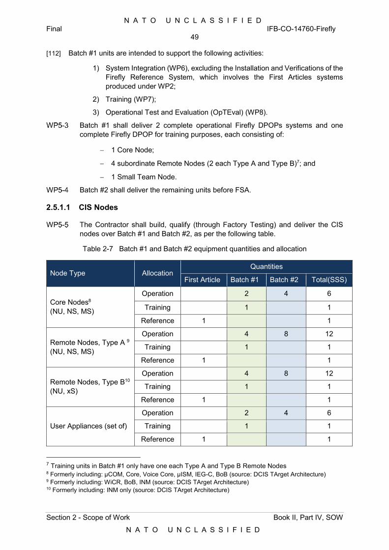
N A T O U N C L A S S I F I E D Final IFB-CO-14760-Firefly
49
Section 2 - Scope of Work Book II, Part IV, SOW
N A T O U N C L A S S I F I E D
[112] Batch #1 units are intended to support the following activities:
1) System Integration (WP6), excluding the Installation and Verifications of the Firefly Reference System, which involves the First Articles systems produced under WP2;
2) Training (WP7);
3) Operational Test and Evaluation (OpTEval) (WP8).
Batch #1 shall deliver 2 complete operational Firefly DPOPs systems and one complete Firefly DPOP for training purposes, each consisting of:
1 Core Node;
4 subordinate Remote Nodes (2 each Type A and Type B)7; and
1 Small Team Node.
Batch #2 shall deliver the remaining units before FSA.
2.5.1.1 CIS Nodes
The Contractor shall build, qualify (through Factory Testing) and deliver the CIS nodes over Batch #1 and Batch #2, as per the following table.
Table 2-7 Batch #1 and Batch #2 equipment quantities and allocation
Node Type Allocation Quantities
First Article Batch #1 Batch #2 Total(SSS)
Core Nodes8 (NU, NS, MS)
Operation 2 4 6
Training 1 1
Reference 1 1
Remote Nodes, Type A 9 (NU, NS, MS)
Operation 4 8 12
Training 1 1
Reference 1 1
Remote Nodes, Type B10 (NU, xS)
Operation 4 8 12
Training 1 1
Reference 1 1
User Appliances (set of)
Operation 2 4 6
Training 1 1
Reference 1 1
7 Training units in Batch #1 only have one each Type A and Type B Remote Nodes 8 Formerly including: µCOM, Core, Voice Core, µISM, IEG-C, BoB (source: DCIS TArget Architecture) 9 Formerly including: WiCR, BoB, INM (source: DCIS TArget Architecture) 10 Formerly including: INM only (source: DCIS TArget Architecture)
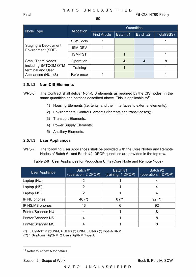
N A T O U N C L A S S I F I E D Final IFB-CO-14760-Firefly
50
Section 2 - Scope of Work Book II, Part IV, SOW
N A T O U N C L A S S I F I E D
Node Type Allocation Quantities
First Article Batch #1 Batch #2 Total(SSS)
Staging & Deployment Environment (SDE)
S/W Tools 1 1
ISM-DEV 1 1
ISM-TST 1 1
Small Team Nodes including SATCOM OTM terminal and User Appliances (NU, xS)
Operation 4 4 8
Training 1 1
Reference 1 1
2.5.1.2 Non-CIS Elements
The Contract shall deliver Non-CIS elements as required by the CIS nodes, in the same quantities and batches described above. This is applicable to11:
1) Housing Elements (i.e. tents, and their interfaces to external elements);
2) Environmental Control Elements (for tents and transit cases);
3) Transport Elements;
4) Power Supply Elements;
5) Ancillary Elements.
2.5.1.3 User Appliances
The following User Appliances shall be provided with the Core Nodes and Remote Nodes of Batch #1 and Batch #2. DPOP quantities are provided in the top row.
Table 2-8 User Appliances for Production Units (Core Node and Remote Node)
User Appliance Batch #1 (operation, 2 DPOP)
Batch #1 (training, 1 DPOP)
Batch #2 (operation, 4 DPOP)
Laptop (NU) 2 1 4
Laptop (NS) 2 1 4
Laptop MS) 2 1 4
IP NU phones 46 (*) 6 (**) 92 (*)
IP NS/MS phones 46 6 92
Printer/Scanner NU 4 1 8
Printer/Scanner NS 4 1 8
Printer/Scanner MS 4 1 8
(*) 3 SysAdmin @CNM, 4 Users @ CNM, 8 Users @Type-A RNM (**) 1 SysAdmin @CNM, 2 Users @RNM Type A
11 Refer to Annex A for details.
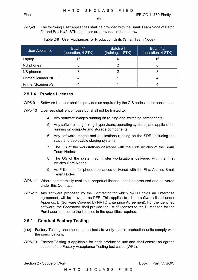
N A T O U N C L A S S I F I E D Final IFB-CO-14760-Firefly
51
Section 2 - Scope of Work Book II, Part IV, SOW
N A T O U N C L A S S I F I E D
The following User Appliances shall be provided with the Small Team Node of Batch #1 and Batch #2. STK quantities are provided in the top row.
Table 2-9 User Appliances for Production Units (Small Team Node)
User Appliance Batch #1 (operation, 4 STK)
Batch #1 (training, 1 STK)
Batch #2 (operation, 4 STK)
Laptop 16 4 16
NU phones 8 2 8
NS phones 8 2 8
Printer/Scanner NU 4 1 4
Printer/Scanner xS 4 1 4
2.5.1.4 Provide Licenses
Software licenses shall be provided as required by the CIS nodes under each batch.
Licenses shall encompass but shall not be limited to:
4) Any software images running on routing and switching components;
5) Any software images (e.g. hypervisors, operating systems) and applications running on compute and storage components;
6) Any software images and applications running on the SDE, including the static and deployable staging systems;
7) The OS of the workstations delivered with the First Articles of the Small Team Nodes;
8) The OS of the system administer workstations delivered with the First Articles Core Nodes;
9) VoIP licenses for phone appliances delivered with the First Articles Small Team Nodes.
Where commercially available, perpetual licenses shall be procured and delivered under this Contract.
Any software proposed by the Contractor for which NATO holds an Enterprise agreement, will be provided as PFE. This applies to all the software listed under Appendix D (Software Covered by NATO Enterprise Agreement). For the identified software, the Contractor shall provide the list of licenses to the Purchaser, for the Purchaser to procure the licenses in the quantities required.
2.5.2 Conduct Factory Testing
[113] Factory Testing encompasses the tests to verify that all production units comply with the specifications.
Factory Testing is applicable for each production unit and shall consist an agreed subset of the Factory Acceptance Testing test cases (WP2).
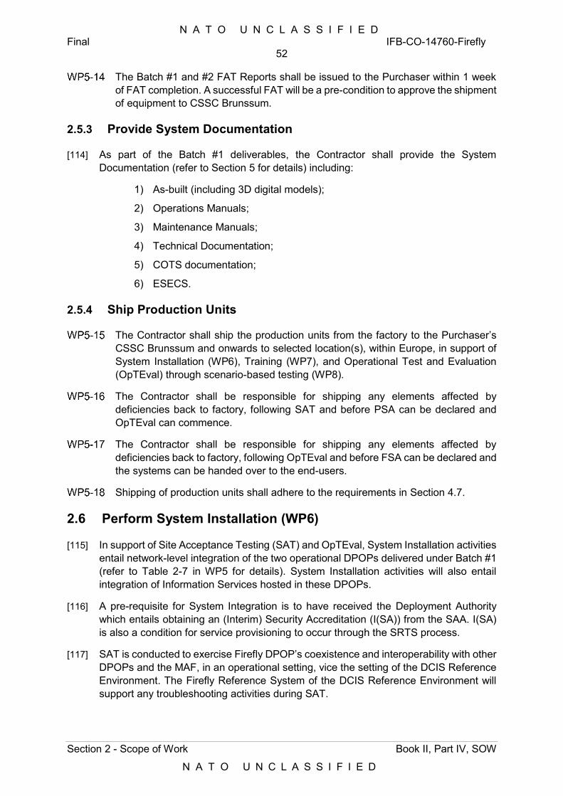
N A T O U N C L A S S I F I E D Final IFB-CO-14760-Firefly
52
Section 2 - Scope of Work Book II, Part IV, SOW
N A T O U N C L A S S I F I E D
The Batch #1 and #2 FAT Reports shall be issued to the Purchaser within 1 week of FAT completion. A successful FAT will be a pre-condition to approve the shipment of equipment to CSSC Brunssum.
2.5.3 Provide System Documentation
[114] As part of the Batch #1 deliverables, the Contractor shall provide the System Documentation (refer to Section 5 for details) including:
1) As-built (including 3D digital models);
2) Operations Manuals;
3) Maintenance Manuals;
4) Technical Documentation;
5) COTS documentation;
6) ESECS.
2.5.4 Ship Production Units
The Contractor shall ship the production units from the factory to the Purchaser’s CSSC Brunssum and onwards to selected location(s), within Europe, in support of System Installation (WP6), Training (WP7), and Operational Test and Evaluation (OpTEval) through scenario-based testing (WP8).
The Contractor shall be responsible for shipping any elements affected by deficiencies back to factory, following SAT and before PSA can be declared and OpTEval can commence.
The Contractor shall be responsible for shipping any elements affected by deficiencies back to factory, following OpTEval and before FSA can be declared and the systems can be handed over to the end-users.
Shipping of production units shall adhere to the requirements in Section 4.7.
2.6 Perform System Installation (WP6)
[115] In support of Site Acceptance Testing (SAT) and OpTEval, System Installation activities entail network-level integration of the two operational DPOPs delivered under Batch #1 (refer to Table 2-7 in WP5 for details). System Installation activities will also entail integration of Information Services hosted in these DPOPs.
[116] A pre-requisite for System Integration is to have received the Deployment Authority which entails obtaining an (Interim) Security Accreditation (I(SA)) from the SAA. I(SA) is also a condition for service provisioning to occur through the SRTS process.
[117] SAT is conducted to exercise Firefly DPOP’s coexistence and interoperability with other DPOPs and the MAF, in an operational setting, vice the setting of the DCIS Reference Environment. The Firefly Reference System of the DCIS Reference Environment will support any troubleshooting activities during SAT.
N A T O U N C L A S S I F I E D Final IFB-CO-14760-Firefly
53
Section 2 - Scope of Work Book II, Part IV, SOW
N A T O U N C L A S S I F I E D
[118] SAT assesses the Firefly DPOP’s use of resources in the target implementation environment to identify any undesirable effects on other systems.
WP6-1 The Contractor shall demonstrate that at the end of SAT all the functional and non-functional requirements in Annex A (SRS) are either tested or demonstrated, in adherence to the processes described in Annex D.
[119] The SAT will involve two operational Firefly DPOPs including Core, Remote and Small Team Nodes. These assets will be installed in one of the three NSB HQ locations and use resources from the collocated DCMs.
[120] The SAT will be conducted in environmentally controlled environment with the minimum necessary non-CIS assets deployed.
[121] The activity flow for the System Installation activities under WP6 is provided in the figure below and described in the paragraphs hereafter.
Site Survey (DCM sites)
System Provisioning
(SRTS)
System Installation and Configuration
(Batch #1)
Site Acceptance
Testing (SAT)
Provisional System
Acceptance
SUPPORT Kicks-off
Live-readySystem
2 DPOPs installed at one of the below garrison locations: Wesel Bydgoszcz Grazzanise
Test against operational system (DF, CGS, MAF/DOG) and National PoP emulator (deployed)
Includes Supplementary Security Testing (WP3) Supported by Firefly Reference System in Mons TESTER: NCIA IV&V SME, supported by
Contractor
PFE Crypto SATCOM PFE applications (FAS)
24 1b
Node State
Figure 2-9 Activity Flow for WP6 – Perform System Installation
2.6.1 Develop System Installation Plan
WP6-2 The System Installation Plan (SIP) shall describe the Contractor’s approach to implementing the System Integration activities in fulfilment of the requirements in the paragraphs below.
2.6.2 Conduct Site Survey
[122] System Installation activities in preparation of Site Acceptance testing will be conducted at one or more NSB HQ locations out of: Wesel (DEU), Bydgoszcz (POL) and Grazzanise (ITA).
WP6-3 The Contractor shall conduct a Site Survey at those locations selected by the Purchaser for performing the System Installation activities described under this WP.
WP6-4 The Site Survey shall adhere to the site survey requirements in Section 3.6.
WP6-5 The Site Survey Report (SSR) shall be delivered to the Purchaser for review and acceptance following the document requirements at Section 5, not later than 2 weeks following the Site Survey.
N A T O U N C L A S S I F I E D Final IFB-CO-14760-Firefly
54
Section 2 - Scope of Work Book II, Part IV, SOW
N A T O U N C L A S S I F I E D
2.6.3 Perform Service Provisioning
WP6-6 The Contractor shall engage with the Purchaser for executing the processes required to conduct the provisioning of communications and CIS Security services of the Firefly. The Contractor shall undertake the following:
1) Provide a detailed request for IP addresses (IP Address plan, with a single scheme of IP subnets for all Core Nodes, Remote Nodes and Small Team Nodes);
2) Provide the naming schema;
3) Submit requests for the provisioning of connectivity services (SRTS) through the completion of Service Request forms (XLS or NS web-based) for each Firefly node. This entails providing details on network design, equipment, the agreed IP address plan, multimedia services (VoIP), interfaces etc.;
4) Provide the network diagrams, using the Purchaser’s standard Visio template, of each Firefly node and the connection into other Firefly nodes and DPOPs, Dragonfly DPOPs, and the MAF;
5) Specify firewall rules where applicable;
6) Specify the crypto configuration.
[123] The SRTS process will require Approval for Testing (AfT), which will be granted upon successful completion of Main Security Testing under the IV&V Assessment (WP4), upon the condition that no classified operational data is used, even though the testing will involve connecting to operational networks (e.g. the MAF).
WP6-7 The Contractor shall further implement provisioning of Information Services (Infrastructure Services and Platform Services) using the SDE in the Mission Preparation Centre (Mons).
WP6-8 Through the SDE, the Service Provisioning activities above shall result in a Firefly DPOP delivered in Node-state (refer to SRS for details), i.e. with all the Infrastructure and Platform Services installed and pre-configured (in the ISM), but not yet configured to support a specific mission.
2.6.4 Perform System Configuration
[124] As described in Annex A (SRS), the Firefly DPOP configuration has four states, which are:
1) Factory State;
2) Spared State;
3) Node Specific State, with a pre-defined and strictly configuration controlled hardware and software build and configuration, in a garrison location; and,
4) Mission Specific State, ready for operational use in a deployed environment.
WP6-9 The Contractor shall configure the two Firefly DPOPs in a Node Specific state, ready for the Purchaser to orchestrate it into a Mission Specific State.
N A T O U N C L A S S I F I E D Final IFB-CO-14760-Firefly
55
Section 2 - Scope of Work Book II, Part IV, SOW
N A T O U N C L A S S I F I E D
[125] Detailed service configuration for Node Specific State and Mission Specific State will be provided by the Purchaser, during the Configuration Capturing sessions conducted during the System Design stage (see WP1). This information will be further refined by the Purchaser, throughout the execution of WP2 and WP4.
[126] The installation of any CoI services and applications (Functional Area Services, FAS) over the IS infrastructure of the Firefly DPOP will be the responsibility of the Purchaser. The Purchaser will use quality test data from relevant exercise scenarios, in order to test the system at the maximum possible capacity and system load. Test data will be loaded both on the DCIS Reference Environment and on the DPOPs as required.
WP6-10 The Contractor shall document the detailed service configuration into a System Configuration Package. The System Configuration Package shall build upon the Configuration Capturing Report (CCAP Report) delivered under WP1.
WP6-11 The System Configuration Package shall include:
1) Physical, networking and information service architecture diagrams;
2) Fully documented router, switch, Call Managers, Session Border Controllers and firewall configurations for CNM, RNM and UAM (for Core and Remote Nodes), and STK (for Small Team Nodes);
3) Fully documented service templates and blueprints for ISM, hosted in the static SDE, as well as locally in the ISM itself; and,
4) Fully documented Application Programming Interfaces (API) for integration purposes.
WP6-12 Any architecture diagrams delivered as part of the System Configuration Package shall be modelled in ArchiMate 3.0 (ArchiMate Exchange File Format), describing all building blocks, functions, interfaces and standards used.
WP6-13 For any software and scripts, developed as part of this procurement, the System Configuration Package shall include descriptions, diagrams/modelling as applicable and documented source code.
2.6.5 Conduct Site Acceptance Testing
[127] The purpose of the Site Acceptance Testing (SAT) is:
1) To demonstrate that the Product Baseline complies with the FBL concerning the integration with externally interfacing systems;
2) To demonstrate interoperability between Firefly DPOPs and other systems in DCIS, both at the level of physical interfaces and services (communications, CIS security, infrastructure and SMC);
3) To demonstrate end-to-end service functionality through a series of service end-point tests;
4) To demonstrate federation with external elements simulation Mission Network Participants (MNP).
WP6-14 SAT shall involve the following assets:
1) Two Firefly DPOPs, named FFHQ-1 and FFHQ-2, and each consisting of:
N A T O U N C L A S S I F I E D Final IFB-CO-14760-Firefly
56
Section 2 - Scope of Work Book II, Part IV, SOW
N A T O U N C L A S S I F I E D
a) One Core Node and their subordinate four Remote Nodes (two each Type A and Type B), including fibre-based and HCLOS transmission systems for metro-area communications;
b) One SATCOM TSGT per Core Node, provided as PFE, and provisioned with military SATCOM bandwidth;
c) Two Small Team Nodes, named OLRT1-2 (OLRT3-4 for the second DPOP), each equipped with a SATCOM OTM terminal.
2) National DPOP emulator (CNM-MS and ISM-MS) detached from the Firefly Reference System and configured by the Purchaser;
3) The SDE in the MAF, and one (optional) deployable SDE.
WP6-15 During SAT, the Purchaser will provide:
1) A test environment for SAT, which is operationally representative in respect to Purchaser’s security policies;
2) The required affiliated systems and the interfaces for the interoperability tests;
3) Access to the Purchaser’s DCIS Reference Environment, including Firefly Reference System, will be available over terrestrial connectivity.
WP6-16 The Contractor shall be responsible for the following:
1) Transportation of the Firefly DPOPs (FFHQ-1 and FFHQ-2) from CSSC (Brunssum) and return at the completion of the testing;
2) Transportation of the National DPOP emulator from the Firefly Reference System in Mons to the SAT location and its return at the completion of the testing.
WP6-17 SAT shall rely upon terrestrial connectivity between the site hosting the Firefly DPOP in garrison (NSB HQ) and the MAF, as well as local connectivity (fibre based) to collocated DCIS assets.
WP6-18 SAT shall further rely upon SATCOM connectivity between the Firefly DPOP and the MAF as well as to non-collocated DCIS assets.
[128] SATCOM assets (TSGTs) as well as SATCOM bandwidth will be provided as PFE.
WP6-19 Connectivity between Core Nodes and Remote Nodes during SAT shall either rely on local connectivity (fibre based) or HCLOS radios.
WP6-20 In support of the above, and unless communicated otherwise by the Purchaser, the SAT shall cover the following scenarios as detailed in the Table below:
Table 2-10 Site Acceptance Testing Scenarios
No. Scenario Connectivity Required
1 Intra-nodal connectivity and services within a Firefly node
1.1 Remote Node to Core Node
1.2 Small Team Node to Core Node
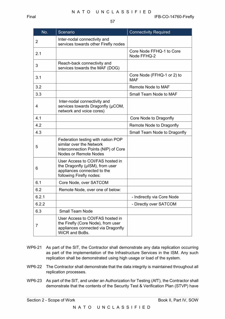
N A T O U N C L A S S I F I E D Final IFB-CO-14760-Firefly
57
Section 2 - Scope of Work Book II, Part IV, SOW
N A T O U N C L A S S I F I E D
No. Scenario Connectivity Required
2 Inter-nodal connectivity and services towards other Firefly nodes
2.1 Core Node FFHQ-1 to Core Node FFHQ-2
3 Reach-back connectivity and services towards the MAF (DOG)
3.1 Core Node (FFHQ-1 or 2) to MAF
3.2 Remote Node to MAF
3.3 Small Team Node to MAF
4 Inter-nodal connectivity and services towards Dragonfly (µCOM, network and voice cores)
4.1 Core Node to Dragonfly
4.2 Remote Node to Dragonfly
4.3 Small Team Node to Dragonfly
5
Federation testing with nation POP similar over the Network Interconnection Points (NIP) of Core Nodes or Remote Nodes
6
User Access to COI/FAS hosted in the Dragonfly (µISM), from user appliances connected to the following Firefly nodes:
6.1 Core Node, over SATCOM
6.2 Remote Node, over one of below:
6.2.1 - Indirectly via Core Node
6.2.2 - Directly over SATCOM
6.3 Small Team Node
7
User Access to COI/FAS hosted in the Firefly (Core Node), from user appliances connected via Dragonfly WiCR and BoBs.
WP6-21 As part of the SIT, the Contractor shall demonstrate any data replication occurring as part of the implementation of the Infrastructure Services in the ISM. Any such replication shall be demonstrated using high usage or load of the system.
WP6-22 The Contractor shall demonstrate that the data integrity is maintained throughout all replication processes.
WP6-23 As part of the SIT, and under an Authorization for Testing (AfT), the Contractor shall demonstrate that the contents of the Security Test & Verification Plan (STVP) have
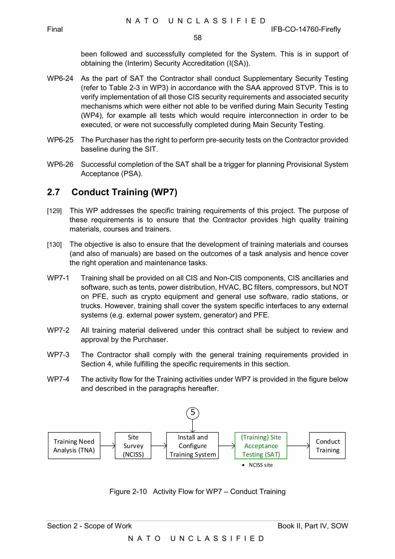
N A T O U N C L A S S I F I E D Final IFB-CO-14760-Firefly
58
Section 2 - Scope of Work Book II, Part IV, SOW
N A T O U N C L A S S I F I E D
been followed and successfully completed for the System. This is in support of obtaining the (Interim) Security Accreditation (I(SA)).
WP6-24 As the part of SAT the Contractor shall conduct Supplementary Security Testing (refer to Table 2-3 in WP3) in accordance with the SAA approved STVP. This is to verify implementation of all those CIS security requirements and associated security mechanisms which were either not able to be verified during Main Security Testing (WP4), for example all tests which would require interconnection in order to be executed, or were not successfully completed during Main Security Testing.
WP6-25 The Purchaser has the right to perform pre-security tests on the Contractor provided baseline during the SIT.
WP6-26 Successful completion of the SAT shall be a trigger for planning Provisional System Acceptance (PSA).
2.7 Conduct Training (WP7)
[129] This WP addresses the specific training requirements of this project. The purpose of these requirements is to ensure that the Contractor provides high quality training materials, courses and trainers.
[130] The objective is also to ensure that the development of training materials and courses (and also of manuals) are based on the outcomes of a task analysis and hence cover the right operation and maintenance tasks.
WP7-1 Training shall be provided on all CIS and Non-CIS components, CIS ancillaries and software, such as tents, power distribution, HVAC, BC filters, compressors, but NOT on PFE, such as crypto equipment and general use software, radio stations, or trucks. However, training shall cover the system specific interfaces to any external systems (e.g. external power system, generator) and PFE.
WP7-2 All training material delivered under this contract shall be subject to review and approval by the Purchaser.
WP7-3 The Contractor shall comply with the general training requirements provided in Section 4, while fulfilling the specific requirements in this section.
WP7-4 The activity flow for the Training activities under WP7 is provided in the figure below and described in the paragraphs hereafter.
Training Need Analysis (TNA)
Install and Configure
Training System
Conduct Training
Site Survey (NCISS)
5
NCISS site
(Training) Site Acceptance
Testing (SAT)
Figure 2-10 Activity Flow for WP7 – Conduct Training
N A T O U N C L A S S I F I E D Final IFB-CO-14760-Firefly
59
Section 2 - Scope of Work Book II, Part IV, SOW
N A T O U N C L A S S I F I E D
2.7.1 Capture Training Needs
WP7-5 The Contractor shall perform a Training Needs Analysis (TNA) as specified in SOW Section 4.10.2.
WP7-6 Training Needs Analysis shall commence during the Configuration Capturing sessions conducted during the System Design stage (WP2).
WP7-7 The Contractor shall organize a meeting at the Purchaser’s facility (NATO CIS School – Latina – Italy or Oeiras - Portugal) to review Training Needs requirements as collected during the Configuration Capturing sessions, with NATO Stakeholders:
1) NCI Agency;
2) NATO CIS School;
3) NATO CIS Group; and
4) CIS Sustainment Support Centre – CSSC Brunssum.
WP7-8 This meeting shall last two days. To support this meeting, the Contractor shall send ten (10) working days before the meeting:
1) A Draft TNA report with Contractor’s assessments;
2) A list of questions to be addressed to NATO Stakeholders to complete the assessment;
3) A site survey questionnaire to prepare the installation of Training equipment in Latina, Italy / Oeiras, Portugal.
WP7-9 The Contractor shall provide the TNA Report and a preliminary Training Site survey report two (2) weeks prior to the Final Design Review meeting.
WP7-10 The Contractor shall deliver Course Control Documents (CCD) I, II, and III in accordance with Bi-SC Directive 075-007.
WP7-11 The Contractor shall update the Training Plan based on the Training Needs Analysis and submit a revised version two (2) weeks prior to the Final Design Review meeting. TNA report.
2.7.2 Conduct Site Survey
WP7-12 The Contractor shall conduct a Site Survey at those locations selected by the Purchaser for performing Training activities described under this WP.
WP7-13 The Site Survey shall adhere to the requirements in Section 3.6.
WP7-14 The Contactor shall document the outcome of the Site Survey in a Site Survey Report (SSR).
WP7-15 The Contractor shall perform a site survey in NATO CIS School as defined section 3.6. Following this site survey, the Contractor shall complement and update the preliminary Training Site survey report.
N A T O U N C L A S S I F I E D Final IFB-CO-14760-Firefly
60
Section 2 - Scope of Work Book II, Part IV, SOW
N A T O U N C L A S S I F I E D
WP7-16 The Contractor shall identify all facilities support issues, including modifications or additions required, within one week after the Site Survey.
WP7-17 This notification shall be in the form of a letter to the Purchaser, accompanied by engineering drawings, checklists, or any other supporting information.
WP7-18 The Contractor shall monitor the progress of any required Purchaser facilities preparations and ensure that anything that may delay installation is brought to the attention of the Purchaser promptly.
WP7-19 The Contractor shall provide the Purchaser and each respective Site POC with a list of hardware and software to be shipped and a list of Contractor personnel who will be involved in site installation and activation at least 20 working days prior to the installation date.
2.7.3 Deliver Training Equipment
[131] The Training equipment is listed in section 1.3 (Table 1-1 and Figure 1-4).
WP7-20 The Training equipment shall be developed in parallel to the other Firefly equipment.
WP7-21 The Training equipment shall be tested during Factory Tests as defined in section 2.5.2.
WP7-22 Upon completion of Factory Testing of Batch #1 (WP6), the Contractor shall package, preserve, ship, transport, document and deliver the Training equipment to the NATO CIS School – Latina (ITA) or Oeiras (PRT) in accordance with section 4.7. The Contractor shall provide the necessary delivery documentation (Inventory List, Packing List, Notice of Shipment) as detailed in Section 4.7 and 4.8.
2.7.3.1 Conduct Site Acceptance Testing
WP7-23 The Contractor shall conduct Site Acceptance testing on the training system, based on the training system capability scope and the Site Acceptance testing scope as detailed in Annex D.
N A T O U N C L A S S I F I E D Final IFB-CO-14760-Firefly
61
Section 2 - Scope of Work Book II, Part IV, SOW
N A T O U N C L A S S I F I E D
2.7.3.2 Training Equipment Documentation
WP7-24 To support the installation, configuration and maintenance of the Training equipment, the Contractor shall deliver the following documentation:
1) Hardware and software inventory as defined in Section 4.6.1;
2) Installation Manuals and As-Built Drawings as defined in Section 5.7;
3) Technical Manual as defined in Section 5.9;
4) COTS documentation as defined in Appendix B (CDRL).
WP7-25 The Training Units Technical Manual shall be provided 4 weeks before Factory Tests.
WP7-26 The COTS documentation and As-Built drawings shall be provided for site acceptance.
2.7.3.3 Training Equipment Installation
WP7-27 The Contractor shall unpack in the presence of the Purchaser representative all Purchaser-furnished and Contractor-furnished equipment at the installation location and dispose of packing materials as directed by the Purchaser's Site POC. The Contractor shall perform an Inventory Check with the Purchaser representatives based on the delivery documentation provided by the Contractor accordingly with Section 4.7 and 4.8.
WP7-28 The installation of the Training equipment shall be done with NATO CIS School representatives and shall follow the procedures defined in the Training equipment Technical Manual.
WP7-29 The Contractor shall obtain server address and other site configuration details from the Site POC and activate all installed servers, workstation, and ancillary equipment on the Site’s local area network.
WP7-30 The Contractor shall configure all hardware/software settings to match the Product Baseline and site-specific requirements such as number of Trainees per training course. The Contractor shall provide all necessary information, documents and assistance for Purchaser to perform an interim PCA on the system.
WP7-31 The Contractor shall ensure all equipment is asset marked in accordance with the requirements of the site and the Purchaser’s Configuration Management requirements.
WP7-32 The Training Units shall be interconnected with the NATO CIS School Training MAF/DOG, and tests / training courses shall consider the tests listed under Section 2.6.5.
WP7-33 The Contractor shall populate the Training equipment with:
1) Test data to support training prior to Site Acceptance Testing (WP6);
2) Training data to support recurrent training sessions.
2.7.3.4 Training Equipment Validation
N A T O U N C L A S S I F I E D Final IFB-CO-14760-Firefly
62
Section 2 - Scope of Work Book II, Part IV, SOW
N A T O U N C L A S S I F I E D
WP7-34 The Contractor shall perform a subset of the Site Acceptance Tests as defined Section 2.6.5 to demonstrate that the training system is configured as an operational DPOP and ready for training.
WP7-35 Site Acceptance Testing shall take place upon completion of the installation and configuration work at the training site and shall not last more than three calendar days.
WP7-36 Site Acceptance Testing shall be conducted in adherence to Annex D.
[132] The Purchaser will support the execution of a subset of the Site Acceptance Testing along the lines described in WP6.
WP7-37 As a part of the Work Pakage deliverables the Contractor shall present the Purchaser with:
1) Witnessed and approved test results;
2) Technical Manual;
3) Hardware and software inventory;
4) Firefly maintenance manual as defined in Section 5.6;
5) Firefly Operational Manual as defined in Section 5.4.
WP7-38 Upon completion of site installation work, the Contractor shall provide the Purchaser a site installation report.
2.7.4 Develop Training Material
WP7-39 The Contractor shall develop and deliver the Training Courses in accordance with Bi-SC Directive 075-003 on Course Development and the Training Need Analysis.
WP7-40 The training modules and scope shall at least include the following:
Table 2-11 Training Modules
Training module Training Scope
Core Node
Routing & Switching, Multimedia services Infrastructure Services Cross-domain Gateway Services CIS Security services Service Management and Control Services Transmission Services Node Deployment and Operation incl. non-CIS
Remote Node
Routing & Switching services Transmission Services CIS Security requirements Node Deployment and Operation incl. non-CIS
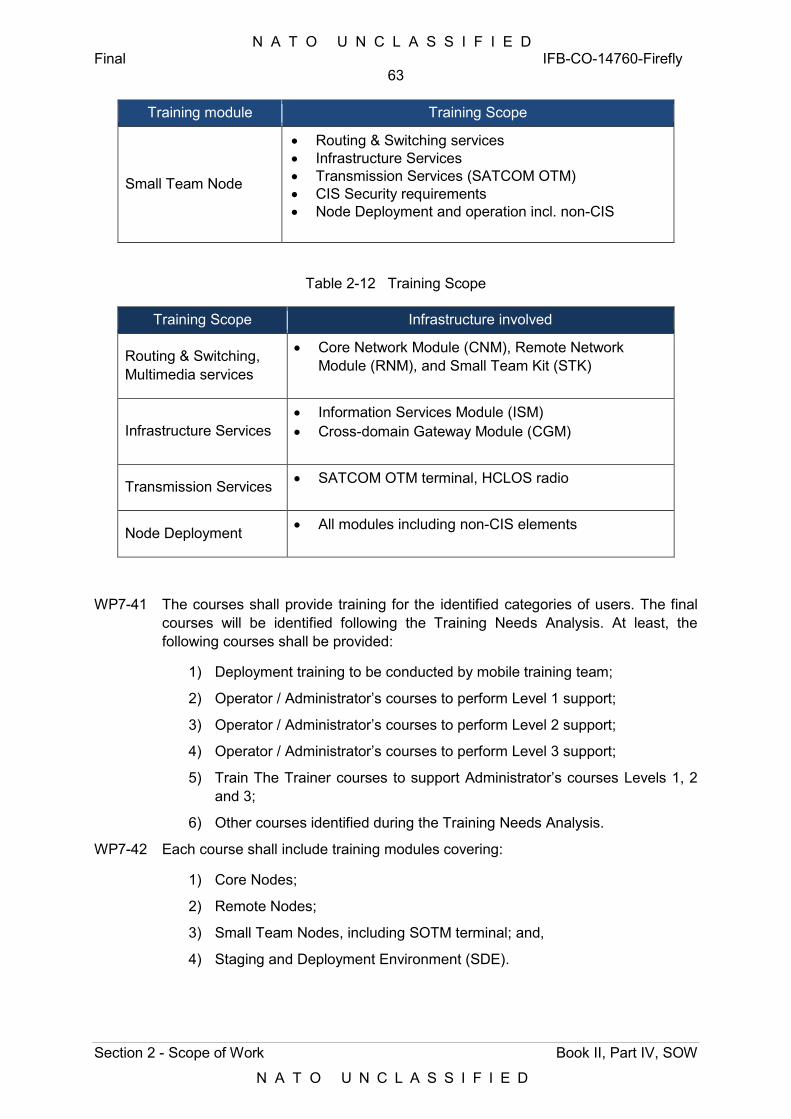
N A T O U N C L A S S I F I E D Final IFB-CO-14760-Firefly
63
Section 2 - Scope of Work Book II, Part IV, SOW
N A T O U N C L A S S I F I E D
Training module Training Scope
Small Team Node
Routing & Switching services Infrastructure Services Transmission Services (SATCOM OTM) CIS Security requirements Node Deployment and operation incl. non-CIS
Table 2-12 Training Scope
Training Scope Infrastructure involved
Routing & Switching, Multimedia services
Core Network Module (CNM), Remote Network Module (RNM), and Small Team Kit (STK)
Infrastructure Services Information Services Module (ISM) Cross-domain Gateway Module (CGM)
Transmission Services SATCOM OTM terminal, HCLOS radio
Node Deployment All modules including non-CIS elements
WP7-41 The courses shall provide training for the identified categories of users. The final courses will be identified following the Training Needs Analysis. At least, the following courses shall be provided:
1) Deployment training to be conducted by mobile training team;
2) Operator / Administrator’s courses to perform Level 1 support;
3) Operator / Administrator’s courses to perform Level 2 support;
4) Operator / Administrator’s courses to perform Level 3 support;
5) Train The Trainer courses to support Administrator’s courses Levels 1, 2 and 3;
6) Other courses identified during the Training Needs Analysis.
WP7-42 Each course shall include training modules covering:
1) Core Nodes;
2) Remote Nodes;
3) Small Team Nodes, including SOTM terminal; and,
4) Staging and Deployment Environment (SDE).

N A T O U N C L A S S I F I E D Final IFB-CO-14760-Firefly
64
Section 2 - Scope of Work Book II, Part IV, SOW
N A T O U N C L A S S I F I E D
[133] In support of the training sessions, the Staging and Deployment Environment (SDE) in the Mission Preparation Centre in the MAF (Mons), will be accessed by the training systems over the network.
WP7-43 For each training course and each module, the Contractor shall provide the training material in accordance with Section 4.10.4.
WP7-44 The Contractor shall deliver to the Purchaser a complete draft of all training material no later than 4 weeks prior to the Factory Tests.
2.7.5 Provide Training Courses
WP7-45 The Contractor shall deliver training at NATO CIS School – Latina (ITA) or Oeiras (PRT).
[134] The exact location will be agreed nearer the time of implementation.
WP7-46 Duration and structure of the training shall be confirmed during the TNA. It shall employ the most effective and efficient way to deliver modern IT Training:
1) Each session of Deployment training shall be no less than five days in duration;
2) Each session of Operator / Administrator training – Level 1 shall be no less than 10 days in duration;
3) Each session of Operator / Administrator training – Level 2 shall be no less than 10 days in duration;
4) Each session of Operator / Administrator training – Level 3 shall be no less than 10 days in duration;
5) Each session of Train the Trainer training shall be no less 5 days for Deployment Training and 15 days in duration for the other courses, as this encompasses all three levels (assuming trainees will have went through previous courses as a prerequisite to attend Train the Trainer training).
WP7-47 The number of training courses shall be:
1) Deployment Training: three courses per module;
2) Operator / Administrator training – level 1: three courses;
3) Operator / Administrator training – level 2: three courses;
4) Operator / Administrator training – level 3: three courses;
5) Train The Trainer training: three comprehensive courses or as defined during the Training Need Analysis.
[135] With the exception of Train the Trainer Training, the three courses should be understood as follows: The first course is provided by the Contractor. The second course is led by the Contractor with NCISS Instructors. The third course is led by NCISS with support from the Contractor.
WP7-48 Each training session shall have no more than ten (10) trainees per session.
N A T O U N C L A S S I F I E D Final IFB-CO-14760-Firefly
65
Section 2 - Scope of Work Book II, Part IV, SOW
N A T O U N C L A S S I F I E D
WP7-49 The Contractor shall provide each student attending Training Courses with a hard copy of:
1) The student handbook;
2) A Training Certificate, upon completion of the course; and
3) A course evaluation feedback form.
WP7-50 The Contractor shall perform Training Evaluation in accordance with section 4.10.5.
WP7-51 The Contractor shall submit to the Purchaser a course report written within two weeks after completion of each course. This report shall contain:
1) Student attendance and performance record;
2) Consolidated student feedback from feedback forms;
3) Problems encountered (if any);
4) Actions taken or recommended;
5) Suggested follow-up actions.
WP7-52 The Contractor shall, as directed by the Purchaser’s Project Manager, revise the Training Materials for each course to reflect student feedback from the initial session of each course and provide the updated material for Provisional System Acceptance.
WP7-53 The Contractor shall support the Training System starting from the system activation till the successful completion of FSA in accordance with the support requirements detailed in Section 4.4.
2.8 Support Operational Test and Evaluation (WP8)
[136] The OpTEval will be conducted by the Purchaser as part of a NATO annual exercise, with preparation of equipment in a garrison location, deployment to outdoor environment, installation of the Firefly systems and continuous operation of these assets, introduction of fault scenarios, finishing with the redeployment of the system back to the garrison location and its reconfiguration back to Node state.
[137] Operational Test and Evaluation (OpTEval) occurs after the system has been granted Provisional System Acceptance (PSA) and Interim Security Accreditation (I(SA)).
[138] Successful completion of OpTEval is a condition to achieve Final System Acceptance (FSA).
[139] The activity flow for the support to OpTEval under WP8 is provided in the figure below and described in the paragraphs hereafter.
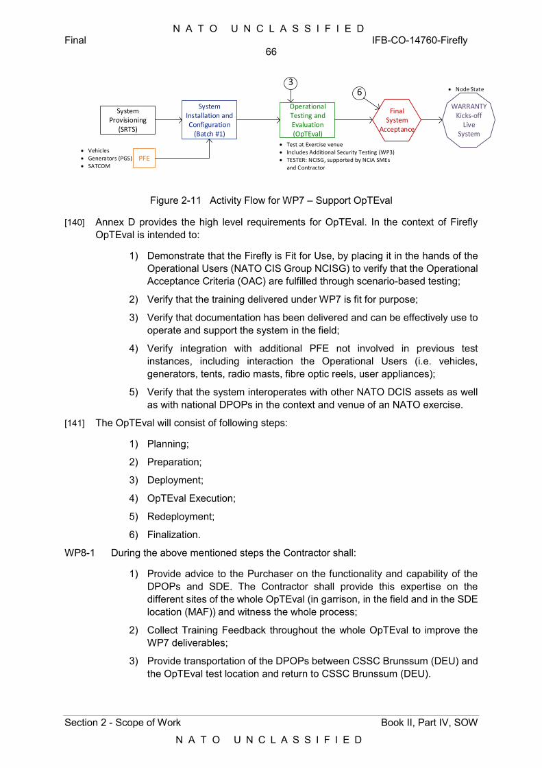
N A T O U N C L A S S I F I E D Final IFB-CO-14760-Firefly
66
Section 2 - Scope of Work Book II, Part IV, SOW
N A T O U N C L A S S I F I E D
System Provisioning
(SRTS)
System Installation and Configuration
(Batch #1)
Operational Testing and Evaluation (OpTEval)
WARRANTYKicks-off
LiveSystem
Final System
Acceptance
Test at Exercise venue Includes Additional Security Testing (WP3) TESTER: NCISG, supported by NCIA SMEs
and Contractor
PFE Vehicles Generators (PGS) SATCOM
3 Node State6
Figure 2-11 Activity Flow for WP7 – Support OpTEval
[140] Annex D provides the high level requirements for OpTEval. In the context of Firefly OpTEval is intended to:
1) Demonstrate that the Firefly is Fit for Use, by placing it in the hands of the Operational Users (NATO CIS Group NCISG) to verify that the Operational Acceptance Criteria (OAC) are fulfilled through scenario-based testing;
2) Verify that the training delivered under WP7 is fit for purpose;
3) Verify that documentation has been delivered and can be effectively use to operate and support the system in the field;
4) Verify integration with additional PFE not involved in previous test instances, including interaction the Operational Users (i.e. vehicles, generators, tents, radio masts, fibre optic reels, user appliances);
5) Verify that the system interoperates with other NATO DCIS assets as well as with national DPOPs in the context and venue of an NATO exercise.
[141] The OpTEval will consist of following steps:
1) Planning;
2) Preparation;
3) Deployment;
4) OpTEval Execution;
5) Redeployment;
6) Finalization.
WP8-1 During the above mentioned steps the Contractor shall:
1) Provide advice to the Purchaser on the functionality and capability of the DPOPs and SDE. The Contractor shall provide this expertise on the different sites of the whole OpTEval (in garrison, in the field and in the SDE location (MAF)) and witness the whole process;
2) Collect Training Feedback throughout the whole OpTEval to improve the WP7 deliverables;
3) Provide transportation of the DPOPs between CSSC Brunssum (DEU) and the OpTEval test location and return to CSSC Brunssum (DEU).
N A T O U N C L A S S I F I E D Final IFB-CO-14760-Firefly
67
Section 2 - Scope of Work Book II, Part IV, SOW
N A T O U N C L A S S I F I E D
[142] The Purchaser has the right to conduct User Test as part of OpTEval. Prior to the OpTEval, the Users will provide scenarios to be tested, and the Purchaser will create test plans that will be shared with the Contractor.
WP8-2 The Contractor shall support Purchaser-conducted series of User tests at Network level, which will be minimum of one week long.
[143] The OpTEval will include testing interfaces to other NATO DCIS assets, which will be configured and operated by the Purchaser in support to the tests.
[144] During the OpTEval, the equipment will be operated by trained NATO DCIS personnel.
[145] As part of OpTEval, all DCIS equipment will be delivered in mission-specific state, with all IP addresses defined in the NRF exercise domain.
WP8-3 The Contractor shall be responsible for generating the SRTS for any link involving one or more Firefly DPOPs, in support of OptEval under this WP8.
[146] The OpTEval will be performed in a tactical training environment suitably replicating the operational conditions of a NATO deployed operation to the greatest extent possible.
WP8-4 Either just before or as the part of the OpTEval, the Contractor shall conduct Additional Security Testing (refer to Table 2-3 in Section 2.4) in accordance with the SAA-approved STVP. This is to verify the successful implementation of all those CIS security requirements and associated security mechanisms that were not successfully completed during previously conducted security testing instances.
[147] Depending on the results for the previous security testing instance(s), none or only very limited amount of security tests should be tested during additional security testing.
WP8-5 Security Test and Verification Reports (STVR) shall be developed and released by the Contractor one week after completion the Additional Security Testing but not later not later than 4 weeks prior FSA. This is to enable issuance of (I)SA for the Firefly.
WP8-6 The Contractor shall be responsible for the Operational and Maintenance (O&M) support of the system throughout the OpTEval’s full duration, as follows:
2 weeks of hands-on training to prepare the users who will conduct the OpTEval;
2 weeks for setting up the system at the OpTEval locations. This duration could change subject to the amount of effort estimated by the Contractor;
3 weeks of OpTEval, including User Tests;
1 week (back-up).
WP8-7 The Contractor shall be responsible for correcting the faults founds during the test and amending, if necessary, the corresponding documentation and any other documentation (including training) affected by those changes.
WP8-8 The Contractor shall ensure that all critical spare parts are on location throughout the OpTEval period.
N A T O U N C L A S S I F I E D Final IFB-CO-14760-Firefly
68
Section 2 - Scope of Work Book II, Part IV, SOW
N A T O U N C L A S S I F I E D
WP8-9 The Contractor shall ensure the system remains fully operational with no service outages greater than 60 minutes occurring during each working day.
WP8-10 The Contractor shall plan the support concept for OpTEval accordingly with the Support Requirements provided in Section 4.4. The Contractor shall provide Subject Matter Experts (SME) onsite over the OpTEval period and resolve major issues outside of normal working hours, working overnight if required.
WP8-11 The Contractor shall maintain a logbook recording any significant event for the acceptance and final testing. The logbook shall contain, as a minimum, the details of the test executed, their ratings, deficiencies noted, test duration, and important remarks.
WP8-12 OpTEval shall be preceded by pre-OpTEval against the Firefly Reference System established in WP4.
WP8-13 The Contractor shall provide technical support to the Purchaser for configuring and readying the Firefly system for testing. Contractor support will be sought for the following:
1) Verifying that the Firefly system (preconfigured in its mission-specific state) is able to meet the notice to move of 5 days, i.e. patching and initial functional testing activities shall not require more than 5 days;
2) Testing services following FMN design and principles where applicable, based on the service requirements as defined for the corresponding NRF during the corresponding exercise planning cycle. The Purchaser will provide the service requirements to the Contractor whenever available;
3) Testing of CoI services, in accordance to the exercise Steadfast Cobalt verification and validation (V&V) approach. The focus of the CoI V&V will be testing the ability of the Firefly to support the end-to-end provision of the service (e.g. including all the underlying communication services, firewalls, etc.) between the nodes and external services (i.e. nations). The Purchaser will share the applicable Steadfast Cobalt V&V approach when available, after Contract Award.
[148] Unless communicated otherwise by the Purchaser, the following scenarios will be in the scope of the OpTEval:
1) Information exchange within Firefly environment:
a) Core to Core;
b) Core to Remote;
c) Small Team Node to Core.
2) Information exchange towards Mission Network Participants (MNP):
a) Core to MNP;
b) Remote to MNP.
3) Information exchange towards Mission Anchor Function (MAF):
a) Core to MAF;
N A T O U N C L A S S I F I E D Final IFB-CO-14760-Firefly
69
Section 2 - Scope of Work Book II, Part IV, SOW
N A T O U N C L A S S I F I E D
b) Remote to MAF;
c) Small Team Node to MAF.
4) Information exchange towards Dragonfly environment:
a) Core to Dragonfly;
b) Remote to Dragonfly (not depicted in the figures, but it will be);
c) Small Team Node to Dragonfly.
5) In-theatre re-imaging of Firefly components using the SDE.
[149] The Purchaser will deploy the National DPOP emulator of the Firefly Reference System in support of those scenarios involving interaction with MNP, in absence of actual MNPs.
[150] Successful completion of the OpTEval will be a contribution to the Final System Acceptance (FSA).

N A T O U N C L A S S I F I E D Final IFB-CO-14760-Firefly
70
Section 3 - Project Management Book II, Part IV, SOW
N A T O U N C L A S S I F I E D
3 Project Management
[151] The goal of the Contractor’s project management is to guide the project through a controlled, well-managed, visible set of activities to achieve the desired results and, wherever possible, to eliminate problems and to ensure that those problems that do occur are identified early, assessed accurately, and resolved quickly in partnership with the Purchaser.
[152] The Project will be managed and be subject to review by the Purchaser, who will be represented by the NCI Agency Project Management Team (PMT). This team will include relevant NCI Agency personnel (Project Manager, Contracting Officer, Project Engineers, Subject Matter Experts, Independent Verification and Validation engineers).
3.1 Contractor’s Project Management Office
MNG-1 The Contractor shall establish a project management organization and maintain a Project Management Office (PMO) to perform and manage all efforts necessary to meet all his responsibilities under this Contract.
MNG-2 The Contractor shall provide all necessary manpower and resources to conduct and support the management and administration of operations in order to meet the objectives of the project, including taking all reasonable steps to ensure continuity of personnel assigned to work on this project.
MNG-3 The Contractor shall use PRINCE2 or a similar and internationally recognized Project Management standard for the direction, governance and management activities for the entire project.
MNG-4 The personnel identified below shall be considered as Key Personnel:
1) Project Manager;
2) Technical Lead;
3) Test Director;
4) CIS Security Manager;
5) ILS Manager;
6) Training Manager;
7) Configuration Manager;
MNG-5 The key Personnel shall meet the requirements as detailed at Annex F.
MNG-6 The Purchaser’s Project Manager (PM) will act as the Purchaser’s representative and will be the primary interface between the Contractor and Purchaser after the EDC.
MNG-7 The Contractor`s Project Manager shall be prepared at all times to present and discuss the status of Contract activities with the Purchaser’s Project Manager, Contracting Officer, or Technical Lead.
MNG-8 The Contractor`s Project Manager shall have experience managing projects similar to this project in technical and financial scope.
N A T O U N C L A S S I F I E D Final IFB-CO-14760-Firefly
71
Section 3 - Project Management Book II, Part IV, SOW
N A T O U N C L A S S I F I E D
MNG-9 Key personnel on the Contractor side shall actively liaise with Purchaser’s personnel with equivalent roles, as required.
MNG-10 The Quality Assurance Manager shall report to a separate manager within the Contractor’s organization at a level equivalent to or higher than the Project Manager.
MNG-11 The Contractor shall consult regularly with the Purchaser to ensure that project management practices are compatible, meet their joint requirements and are tailored to meet the requirements of the project.
MNG-12 All documentation produced under this Contract shall following the document convention and format as detailed in Section 5.1.
MNG-13 Unless otherwise stated documentation shall follow the review process under Section 5.2.
3.2 Project Management Plan
MNG-14 The Project Management Plan (PMP) shall describe how the Contractor will implement the totality of the project, including details of the project control that will be applied.
MNG-15 The PMP shall describe how the Contractor shall implement project/contract administration, including details of the controls that shall be applied to supervise Sub-Contractor performance.
MNG-16 The PMP shall provide sufficient detail to allow the Purchaser to assess the Contractor’s plans and capabilities in implementing the entire project in conformance with the requirements specified.
MNG-17 After approval by the Purchaser, the final version of the PMP shall be the official document against which the Contractor is expected to conduct the performance of the Contract. The approved PMP shall however not supersede the Contract, and the Schedule of Supplies and Services (SSS) in particular.
MNG-18 The PMP shall describe the contractor’s organization, assignment of functions, duties, and responsibilities, management procedures and policies, and reporting requirements for the conduct of contractually-imposed tasks, projects, or programmes.
MNG-19 The PMP shall identify all major Contractor operating units and any Subcontractors involved in the development of System and a description of the portion of the overall effort or deliverable item for which they are responsible.
MNG-20 The PMP shall cover all aspects of the project implementation, including the Contractor’s project management structure and project control processes, personnel assignments, and external relationships necessary to provide the System as required by this Contract.
MNG-21 The Contractor shall ensure that the PMP remains current throughout the duration of the Project to reflect the actual state of the Contractor’s organization and efforts, and maintain a current copy on the Collaborative Environment.
N A T O U N C L A S S I F I E D Final IFB-CO-14760-Firefly
72
Section 3 - Project Management Book II, Part IV, SOW
N A T O U N C L A S S I F I E D
MNG-22 The Contractor shall maintain the baseline version of the PMP on the Collaborative Environment (Section 3.7).
MNG-23 The Contractor shall brief any changes to the PMP at all Project Review Meetings.
MNG-24 The PMP shall cover at least the following areas:
1) Project organization:
a) Internal structure, including a project organizational diagram;
b) Roles and responsibilities of each organizational unit;
c) Key personnel, their qualifications, and their responsibilities;
d) Organizational boundaries between the project organization and the parent and subcontracted organizations.
2) Project management processes:
a) A description of the Contractor’s project management methodology and approach to be used for this project;
b) Project start-up, including staffing, basis of cost and schedule estimates, and project infrastructure;
c) Project control, including monitoring, reporting of work packages.
3) Communications management, including the Collaborative Environment and its establishment, maintenance and use; Project Progress Reports; Project Checkpoint Reviews; and all other communications with the Purchaser and Sub-contractors;
4) Lessons Learned management, including the identification, reporting, and logging of lessons learned in a Lessons Learned Log;
5) Security management:
a) Security management, including personnel and facility security;
b) System security accreditation process;
6) Purchaser involvement:
a) Purchaser involvement via Joint Reviews, informal meetings, reporting, modification and change, implementation, verification, approval, acceptance and access to facilities;
b) Expected Purchaser Furnished Equipment and associated timelines;
c) Delivery procedures for the documentation and the products. This includes control of Purchaser Property, export control process.
7) Subcontracting plan demonstrating that the Contractor can effectively manage, monitor and control the sub-contractors and that the sub-Contractors will agree to abide by the requirements of the prime Contract as pertains to flow-down provisions.
N A T O U N C L A S S I F I E D Final IFB-CO-14760-Firefly
73
Section 3 - Project Management Book II, Part IV, SOW
N A T O U N C L A S S I F I E D
3.3 Project Implementation Plan
MNG-25 The Project Implementation Plan (PIP) shall describe how the Contractor shall implement project/contract administration.
MNG-26 The PIP shall consider all project implementation aspects, which include management provisions, facilities, schedules, personnel assignments, external relationships and project control.
MNG-27 The PIP shall provide sufficient detail to allow the Purchaser to assess the Contractor's plans and capabilities in implementing the entire project in conformance with the requirements specified.
MNG-28 The Contractor shall ensure that the PIP accurately reflects Contractor’s plans for the full duration of the period of performance of the Contract.
MNG-29 After approval by the Purchaser, the final version of the PIP shall be the official document against which the Contractor is expected to conduct the performance of the Contract. The approved PIP shall however not supersede the Contract, and the Schedule of Supplies and Services (SSS) in particular.
MNG-30 The content of the plans in PIP is described in detail in the related sections of this SOW.
MNG-31 All plans in the PIP above involve a sequence of activities. For each major activity, the plan shall at least provide the following information:
1) Timeline of the activity;
2) Locations where the activity will take place;
3) Methodology and processes followed to implement the activity;
4) Actors involved in the activity, covering:
a) On the Contractor's side, both prime and Sub-Contractors, with detailed information on the roles and responsibilities of each;
b) On the Purchaser's side, required players and description of how they will engage in the activities and with the actors on the Contractor's side.
5) Information required from the Purchaser for the activity to take place;
6) Documentation tree and deliverables for the activity, where applicable;
7) Review and acceptance process of the documentation above, where applicable.
MNG-32 In all plans of the PIP, the Contractor’s proposed timelines shall be commensurate and contingent upon the nature of the risks relevant to the efforts concerned, as identified in the Risk Management Plan (Section 3.3.4).
MNG-33 All plans in the PIP shall provide:
1) Tables listing activities and dates, as tabular version of the Gantt charts;
2) Lists of deliverables under each plan (in turn mapped to CLIN numbers).
N A T O U N C L A S S I F I E D Final IFB-CO-14760-Firefly
74
Section 3 - Project Management Book II, Part IV, SOW
N A T O U N C L A S S I F I E D
MNG-34 All plans in the PIP shall contain a mechanism to visually track the changes in any of the artefacts above, throughout the various revisions of the PIP. Alternatively, the changes can be itemized in Release Notes or similar (in tabular form).
MNG-35 The Contractor shall provide the first outline of the PIP with the Bid. This is referred to as the Bid PIP.
MNG-36 The Bid PIP shall cover all aspects of project implementation including management, schedules, personnel assignments and Project Controls, necessary to provide the Firefly capabilities, as required by this SOW.
MNG-37 The Bid PIP shall be sufficiently detailed to ensure that the Purchaser is able to assess the Contractor’s plans, capabilities, and ability to satisfactorily implement the entire Project in conformance with the requirements as specified in this SOW.
MNG-38 The Contractor shall produce Draft PIP. The Draft PIP shall address all comments received at Contract Award.
MNG-39 The Draft PIP shall be reviewed during SRR.
MNG-40 The Contractor shall continue to update the Project Implementation Plan (PIP) produced and delivered at the time of the Bid, until FSA.
MNG-41 The Contractor shall ensure that the PIP accurately reflects Contractor’s plans for the full duration of the period of performance of the Contract.
MNG-42 The PIP shall bundle the following products:
1) Product Breakdown Structure (PBS);
2) Project Work Breakdown Structure (PWBS);
3) Project Master Schedule (PMS);
4) Risk Management Plan, including Risk Log;
5) Issue Management Plan, including Issue Log.
[153] The Contractor shall provide the following Plans specific to specialist areas. The Contractor may want to include these in the PIP, but as a separate section:
1) System Design Plan (SDP) (Section 2.1.1);
2) Security Accreditation Plan (SAP) (Section 2.3);
3) System Installation Plan (SIP) (Section 2.6.1);
4) Project Master Test Plan (PMTP) (See Annex D);
5) Integrated Logistics Support Plan (ILSP) (Section 4.1);
6) Training Plan (TP) (Section 4.10.1);
7) Documentation Plan (DP) (Section 5.3).
MNG-43 The approval of the PIP and of any updated plan of the PIP by the Purchaser signifies that the Purchaser considers the plan to be a logical and satisfactory approach to the management of the required activities, based upon the information provided by the Contractor.
N A T O U N C L A S S I F I E D Final IFB-CO-14760-Firefly
75
Section 3 - Project Management Book II, Part IV, SOW
N A T O U N C L A S S I F I E D
MNG-44 The approval of the PIP shall in no way relieve the Contractor from his responsibilities to satisfy the contractual and technical requirements of this Contract. The requirements of the Contract supersede the statements of the PIP in the case of any conflict, ambiguity or omission.
MNG-45 The PIP shall be updated 2 weeks prior to every Project Review Meeting, up to FDR, at which time the PIP shall become final.
MNG-46 From FDR onwards, the following plans shall be updated by the Contractor as appropriate throughout the duration of the contract, beyond the time of release of the Final PIP:
1) Project Master Test Plan;
2) Training Plan;
3) Documentation Plan;
4) Integrated Logistics Support Plan.
MNG-47 Each revision of the PIP shall entail a revision of each of the plans.
MNG-48 Any revisions of the PIP shall be subject to Purchaser approval.
MNG-49 The approval of the PIP and of any updated plan of the PIP by the Purchaser signifies that the Purchaser considers the plan to be a logical and satisfactory approach to the management of the required activities, based upon the information provided by the Contractor.
MNG-50 The approval of the PIP shall in no way relieve the Contractor from his responsibilities to satisfy the contractual and technical requirements of this Contract. The requirements of the Contract supersede the statements of the PIP in the case of any conflict, ambiguity or omission.
3.3.1 Product Breakdown Structure
MNG-51 The PBS shall identify the physical outcomes of the project. It shall define all the products that the project has to produce. The product breakdown structure shall show the scope broken down in a hierarchical manner and at a sufficient level to ensure a clear understanding of the product and its status. It shall identify all components of the system, hardware and software, the Infrastructure, the Service, and documentation required by the Contract.
MNG-52 Each constituent sub-product shall be related to a precise sub-set of the System Requirements Specification (SRS) and be identifiable to the Contract (SSS).
MNG-53 The Product Description shall be sufficient to understand the purpose and function of the product and the level of quality required of the product.
MNG-54 The PBS shall include the percentage of accomplishment for each sub component. This status shall be included in the highlight reports.
MNG-55 The Contractor shall provide the initial baseline version of the PBS within four weeks after WP1 PDR.
MNG-56 The PBS shall be put under Configuration and Change Control.
N A T O U N C L A S S I F I E D Final IFB-CO-14760-Firefly
76
Section 3 - Project Management Book II, Part IV, SOW
N A T O U N C L A S S I F I E D
3.3.2 Project Work Breakdown Structure
MNG-57 The Contractor shall establish and maintain a Project Work Breakdown Structure (PWBS).
MNG-58 The contractor shall capture 100% of the work defined by the project scope, as well as all deliverables in terms of the work to be completed, including project management, in the PWBS.
MNG-59 The Project Work Breakdown Structure shall include:
1) The definition of all the work packages and the relationship between the work packages and the end product;
2) The description of the work packages to a level that exposes all project risk factors and allows accurate estimate of each work item’s duration, resource requirements, inputs and outputs, and predecessors and successors;
3) For each work item its duration, resource requirements, inputs and outputs, predecessors and successors, assumptions, constraints, dependencies, and requirements for Purchaser support;
4) The PWBS shall include a PWBS Dictionary that identifies for each work item its duration, resource requirements, inputs and outputs, predecessors and successors, assumptions, constraints, dependencies, and requirements for the Purchaser support.
MNG-60 The Contractor shall not change the PWBS or PWBS Dictionary without the approval of the Purchaser.
3.3.3 Project Master Schedule
MNG-61 The Contractor shall establish and maintain a Project Master Schedule (PMS).
MNG-62 The PMS shall contain all Contract events and milestones, including Contract-related Purchaser activities and events (e.g., Purchaser reviews, provision of specific Purchaser-furnished items).
MNG-63 The PMS shall identify, when PFE are required throughout the Project life so that it can be implemented/integrated in a timely fashion. The identified PFE items are at Appendix D.
MNG-64 All Contractor and Purchaser activities and milestones related to Documentation, Training, Integrated Logistics Support (ILS), Quality Assurance (QA) and Configuration Management (CM) shall be identified and included in the PMS.
MNG-65 The PMS shall provide the duration, sequence, and resource effort to deliver tasks providing a realistic assessment of the scope of work involved.
MNG-66 The PMS shall include the delivery dates for all products identified in the SSS.
MNG-67 The PMS shall correlate with the PWBS and also be traceable to performance and delivery requirements of this SOW.
N A T O U N C L A S S I F I E D Final IFB-CO-14760-Firefly
77
Section 3 - Project Management Book II, Part IV, SOW
N A T O U N C L A S S I F I E D
MNG-68 The PMS shall identify the start and finish dates, duration, predecessors, successors, and resource requirements for each work item.
MNG-69 The PMS shall identify the progress for each task.
MNG-70 The PMS shall include the delivery dates for all management products (e.g., project plans, Project Progress Reports), including at least the initial submission, the review cycles and the final delivery.
MNG-71 The PMS shall include activity network, activity Gantt, milestone, and critical path views of the project schedule.
MNG-72 The PMS shall be based on Microsoft Project 2010. Any changes to this version shall be approved by the Purchaser.
3.3.4 Risk Management
MNG-73 The Contractor shall establish a risk management process and perform risk management throughout the period of performance of this Contract.
MNG-74 The Contractor’s Risk Management process shall enable and define identification of all types of risks, evaluation and prioritization of each risk, definition of proposed response strategy, owner and actions and suggested monitor and control mechanisms.
MNG-75 The Contractor shall establish a Risk Management Plan (RMP).
MNG-76 The Contractor shall document, update and maintain status of all risks in the Risk Log, as an Annex to the RMP.
MNG-77 The Contractor shall update the Risk Log at minimum on a monthly basis and upload it on the Collaborative Environment in a format agreed with the Purchaser.
MNG-78 The Contractor shall brief the Risk Log at all Project Progress Meetings and Design Reviews.
MNG-79 The RMP shall be developed by establishing and maintaining a strategy for identifying, analyzing, and mitigating risks.
MNG-80 The risk management strategy shall address the specific actions and management approach used to apply and control the risk management program. This shall include identifying the sources of the risk, the scheme used to categorize risks, and the parameters used to evaluate.
MNG-81 The RMP shall be under configuration control.
MNG-82 The RMP shall include:
1) Risk Management processes and measurement methodology;
2) Key Risk Categories;
3) Risk Prioritization Matrix;
4) Risk Management organization, roles and responsibilities;
5) Requirements for communicating risks and risk status with the Purchaser;
N A T O U N C L A S S I F I E D Final IFB-CO-14760-Firefly
78
Section 3 - Project Management Book II, Part IV, SOW
N A T O U N C L A S S I F I E D
6) Risk Log.
MNG-83 The Risk Log shall list all the risks, and indicate for each one the following information (but not limited to):
1) Risk identifier: unique code to allow grouping of all information on this risk;
2) Description: brief description of the risk;
3) Risk category (e.g. management, technical, schedule, quality and cost risks);
4) Impact: effect on the project if this risk were to occur;
5) Probability: estimate of the likelihood of the risk occurring;
6) Risk rating (High, Medium, Low);
7) Proximity: how close in time is the risk likely to occur;
8) Response strategy: avoidance, mitigation, acceptance, transference;
9) Response plan(s): what actions have been taken/will be taken to counter this risk;
10) Owner: who has been appointed to keep an eye on this risk;
11) Author: who submitted the risk;
12) Risk Stakeholders;
13) Date identified: when was the risk first identified;
14) Date of last update: when was the status of this risk last checked;
15) Status: e.g. closed, reducing, increasing, no change.
3.3.5 Issue Management
MNG-84 The Contractor shall establish and maintain a process for identifying, tracking, reviewing, reporting and resolving all project issues.
MNG-85 The Contractor shall propose an Issue Management Plan (IMP)
MNG-86 The Contractor shall develop and maintain an Issue Log where all project issues are recorded and tracked regardless of their status, as an Annex to the IMP.
MNG-87 The Contractor shall update and maintain the Issue Log throughout the period of performance of this Work Package.
MNG-88 The Contractor shall update the Issue Log at minimum on a monthly basis on the Collaborative Environment in a format agreed with the Purchaser.
MNG-89 The Contractor shall brief the Issue Log at all Project Review Meetings and Design Reviews.
MNG-90 The IMP shall outline the general processes and techniques to monitor, control, report the issues affecting the project both in technical and administrative terms in all phases of the project. The IMP shall be under configuration control.
MNG-91 The IMP shall include:
N A T O U N C L A S S I F I E D Final IFB-CO-14760-Firefly
79
Section 3 - Project Management Book II, Part IV, SOW
N A T O U N C L A S S I F I E D
1) Issue Management processes (identification, reporting, assessment, and logging of project issues);
2) Issue Log.
[154] A Project Issue is anything that affects the Project, either detrimental or beneficial (e.g. problem, error, anomaly, risk occurring, query, change in the project environment, change request, off-specification).
[155] In accordance with PRINCE2 an issue is defined as, “a relevant event that has happened, that was not planned, and requires management action”. It can be any concern, query, and request for change, suggestion or off-specification raised during a project. Project issues can be about anything to do with the project”.
MNG-92 The Issue Log shall comprise the following information (but not limited to):
1) Project Issue Number;
2) Project Issue Type (Request for change, Off-specification, general issue such as a question or a statement of concern);
3) Author;
4) Date identified;
5) Date of last update;
6) Description;
7) Action item/Decision;
8) Responsible person (individual in charge of the action item);
9) Suspense date (Suspense date for the action item);
10) Priority;
11) Status. [156] The Issue Log shall be maintained in a format where sorting and filtering of issues is
possible.
3.4 Project Meetings
3.4.1 Kick-off Meeting
MNG-93 The Contractor shall support a Contract Kick-off Meeting (KOM).
MNG-94 For the KOM, the Contractor shall meet with the Purchaser’s Project Manager at the Purchaser’s facility (The Hague-Netherlands, Brussels-Belgium or Mons-Belgium) within two weeks after Contract Award to review the schedule of activities and to discuss any preparations or coordination required to support DCIS implementation effort.
[157] Attendance in person is necessary.
MNG-95 At KOM, the Contractor shall present updated Project Management Plan, the Project Master Schedule, the Risk log, the Configuration Management process, the
N A T O U N C L A S S I F I E D Final IFB-CO-14760-Firefly
80
Section 3 - Project Management Book II, Part IV, SOW
N A T O U N C L A S S I F I E D
Configuration Status Accounting database, the Quality Management process and the Collaborative Environment.
MNG-96 At the KOM, the Contractor shall identify any pre-requisites to support the implementation of present contract.
MNG-97 At the KOM, the Contractor shall provide templates for all types of site surveys for review and approval by the Purchaser.
MNG-98 Following the KOM, the Contractor shall conduct Project Review Meetings (PRM) every 6 weeks, in adherence to the requirements in the following section.
3.4.2 Project Review Meetings
MNG-99 The Contractor shall arrange Project Review Meetings (PRM) with the Purchaser to occur on a regular basis or at the request of the Purchaser if the situation requires.
MNG-100 The location of the meetings will ordinarily be at Purchaser`s premises. Other NATO locations, or at the Contractor’s premises may be used if Purchaser and Contractor both consent.
MNG-101 Unless otherwise specified, at least two weeks before all meetings required under this Contract, the Contractor shall send an invitation, including:
1) Purpose;
2) Agenda;
3) List of participants;
4) Date, hour, place, duration.
MNG-102 If meeting facilities at a Purchaser location are not available at the specified Purchaser location in the time frame required to support a meeting, the Contractor shall:
1) Reschedule the meeting to such time as meeting facilities are available at the Purchaser location, with no further adjustment to schedule or cost; or
2) Provide suitable meeting facilities (e.g., hotel meeting facility) for the meeting/review at no additional cost to the Purchaser; or
3) Arrange to host the meeting at the Contractor’s facility. This facility shall be provided at no additional cost to the Purchaser.
MNG-103 The Contractor shall provide minutes of all meetings. The Minutes shall include:
1) Date, place, and time of the meeting;
2) Purpose of the meeting;
3) Name of participants;
4) Approval of previous meeting’s minutes and all resolutions;
5) Record of principle points discussed, actions taken, and decisions made;
6) Copies of materials distributed at the meeting.
N A T O U N C L A S S I F I E D Final IFB-CO-14760-Firefly
81
Section 3 - Project Management Book II, Part IV, SOW
N A T O U N C L A S S I F I E D
MNG-104 The minutes shall not be used as a mechanism to change the terms, conditions or specifications of the Contract nor as a vehicle to alter the design or configuration of equipment or systems. Such changes shall only be made by agreement, amendment or by authorized mechanisms as set forth in the Contract.
MNG-105 In addition to the mandatory meetings, the Contractor shall support ad-hoc meetings. These meetings will be held in NCI Agency The Hague, Brussels or Mons. They will last 2 days maximum. These meetings will be devoted to discussing management issues, technical issues, or both. Technical issues will be discussed through Joint Technical Reviews (refer to 3.4.4).
MNG-106 Dates for the PRM shall be mutually agreed between the Purchaser and the Contractor.
MNG-107 PRM shall by default take place at the Purchaser’s premises. When coinciding with System Design Reviews, the PRM shall take place at the Contractor premises.
MNG-108 All types of communication including the meetings, phone calls, correspondences and project documentation shall be in English.
MNG-109 The PRM sequence and list of review products of each PRM shall follow the pattern and entry conditions in Appendix B in 3.1.2. If the programme of a given PRM cannot be fulfilled at the intended date owing to one or more CDRL products being late and/or failure to meet the required quality criteria, the PRM shall be delayed and re-scheduled following mutual agreement between the Purchaser and the Contractor. In such circumstances the Purchaser may call one or more Ad-Hoc Meetings, in order to discuss project progress outside the nominal PRM sequence.
[158] Video-Teleconference (VTC) may be used at PRM in circumstances where it may be difficult to otherwise ensure attendance by the required personnel.
MNG-110 Use of VTC over the NR Collaborative Environment shall be at the Purchaser’s discretion.
MNG-111 Should the Contractor wish to use VTC, a written request with justifications shall be submitted to the Purchaser not less than eight working days in advance of the scheduled meeting.
[159] The Purchaser’s PM will chair the meetings.
MNG-112 The normal PRM agenda shall include:
1) Review of the minutes recorded and agreed at the previous PRM;
2) The Contractor’s presentation of the Project Progress Report;
3) Schedule Review;
4) Risk Log Review;
5) Issue Log Review;
6) Discussion/resolution of problems and areas of concern;
7) If necessary, a summary of items to be discussed; and
8) Any other business.
N A T O U N C L A S S I F I E D Final IFB-CO-14760-Firefly
82
Section 3 - Project Management Book II, Part IV, SOW
N A T O U N C L A S S I F I E D
MNG-113 During the meetings, the Contractor shall present slides covering all the points of the planned agenda. These slides shall be accessible by the Purchaser at least 5 working days before the meeting.
MNG-114 The Contractor shall attend and provide the meeting’s Secretary in all meetings, including those held over VTC links.
MNG-115 During the meeting, the meeting’s Secretary shall be fully devoted to capturing the minutes of the meeting.
MNG-116 Draft minutes shall be produced real time during the PRM and shall be agreed, signed and countersigned by the Contractor and the Purchaser representatives, daily, by close of business.
MNG-117 The approval (signatures) of the final content, both recorded discussion items and agreed action items, shall be possible by close of business on the last day of the meeting.
MNG-118 The minutes shall document the topics, problems, discussions and all decisions made and include copies of the current Action Item List (AIL), Project Schedule and Risk Analysis/Assessment, as Annexes.
MNG-119 These minutes shall not be regarded by the Parties as a mechanism to change the terms, conditions or specifications of the Contract nor as a vehicle to alter the design or configuration of equipment or systems. Any such changes shall only be made by Contract amendment or by authorized mechanisms as set forth in this Contract.
MNG-120 The minutes shall not exceed ten (10) pages, unless specifically approved by the Purchaser.
MNG-121 The Contractor shall not consider the minutes as the basis for changes to the terms and conditions of the Scope of Work of the Contract in the absence of a formal Contract Amendment.
MNG-122 The Contractor shall send the final version of the signed draft minutes to the Purchaser not later than 5 working days after the meeting, for final approval by the Purchaser.
[160] The Purchaser can send questions and comments concerning the documentation delivered between two meetings.
MNG-123 The KOM or a PRM shall not last more than 2 (two) days.
MNG-124 PRM shall host the formal revisions and approval of the CDRL products as per the CDRL table in Appendix B.
MNG-125 These meetings will normally be held at the Purchaser’s premises. They can be held at Contractor’s premises or at another location.
3.4.3 Ad-Hoc Meetings
[161] Ad Hoc Working Meetings (AHM) may be organized by on request of either the Purchaser or the Contractor, pending Purchaser agreement, to resolve problems, clarify project requirements and review progress in between the nominal PRM sequence.
N A T O U N C L A S S I F I E D Final IFB-CO-14760-Firefly
83
Section 3 - Project Management Book II, Part IV, SOW
N A T O U N C L A S S I F I E D
[162] These meetings will normally be held at the Purchaser’s premises.
MNG-126 Minutes of the Ad Hoc Working Meetings shall be written real time by the Contractor and sent to the Purchaser within 5 working days following the meeting. Comments received will be taken into account and incorporated. Once the Minutes are accepted by both parties’ respective Project Managers, the Contractor shall upload the final version.
3.4.4 Joint Technical Reviews
MNG-127 The Contractor shall organize and conduct joint technical reviews, as defined in IEEE 12207 [IEEE 12207] , to address and resolve critical technical issues in advance of major reviews such as Requirements, Design or Test Reviews.
MNG-128 The Contractor shall propose the subject and the timing of the joint technical reviews to ensure the most critical technical risks are raised and mitigated as early as possible. The joint technical reviews should be planned as early as possible but as a minimum 4 weeks in advance to provide sufficient time for the identification of appropriate operational users and arrangements for their participation.
MNG-129 The Contractor shall deliver the following information at least two weeks prior to each review: a meeting agenda and a list of issues to be reviewed, with an impact assessment, root cause of the issue (evidence) and possible solutions per issue.
MNG-130 Unless otherwise agreed by the Purchaser, all joint technical reviews shall be conducted at a Purchaser facility. The specific date and location must be agreed between the Contractor and the Purchaser’s Project Manager.
MNG-131 The Contractor shall provide all relevant resources including personnel, hardware, software, and tools at each review.
MNG-132 The Contractor shall provide the following items at each review: presentation and discussion of each issue, including relevant technical material, such as requirements references, design specifications, views, use cases, operational employment scenarios, screenshots, or prototypes, or developmental baseline release.
3.5 Project Progress Reports
MNG-133 This PPR shall summarize the progress since the previous PRM or since the last PPR, any accomplishments, schedule of deliveries against progress, difficulties encountered and resolution of any issues raised in previous PRMs. The Highlight Reports shall include:
1) Overall project progress: the activities performed and works completed during the preceding period including major milestones achieved as applicable;
2) Description of issues/problems/risks that have occurred in the preceding period and the identified/proposed solution (Issue Log);
3) A list of Change Proposals with the current status;
N A T O U N C L A S S I F I E D Final IFB-CO-14760-Firefly
84
Section 3 - Project Management Book II, Part IV, SOW
N A T O U N C L A S S I F I E D
4) Configuration Status Reports (CSR) for the system and all documentation (CDRL);
5) Answers to questions addressed by the Purchaser between two meetings;
6) The progress of work related to the schedule in the current PMP;
7) Status of the equipment (equipment order, in Contractor’s office, packing, transfer to site, deploy and test);
8) Any foreseen or possible changes to project performance or schedule. In case of changes, the Contractor shall give the updated performance or schedule;
9) Description of any identified problems and high risk areas and the proposed solutions and corrective actions;
10) Activities planned for the next period;
11) Supplies to be delivered by the Contractor and those to be provided by the Purchaser;
12) Update on the status of Action Items List (AIL).
[163] Upon receipt of the PPR, and in absence of a Project Review Meeting opportunity near, the Purchaser can call for an Ad-hoc meeting with the Contractor (refer to Section 3.4.3), for the purpose of reviewing or discussing the PPR contents. The meeting may either involve physical presence, or take place over a video conference session.
MNG-134 The Contractor shall maintain an archive of PPR.
MNG-135 The Contractor shall prepare and submit a Project Progress Report (PPR) to the Purchaser every 6 weeks, 2 weeks prior to the PRM, and throughout the performance period of the contract.
MNG-136 This PPR shall summarize the progress since the previous PRM or since the last PPR, any accomplishments, schedule of deliveries against progress, difficulties encountered and resolution of any issues raised in previous PRMs. The PPRs shall include:
1) Overall project progress: the activities performed and works completed during the preceding period including major milestones achieved as applicable;
2) Description of issues/problems/risks that have occurred in the preceding period and the identified/proposed solution (Issue Log);
3) A list of Change Proposals with the current status;
4) Configuration Status Reports (CSR) for the system and all documentation (CDRL);
5) Answers to questions addressed by the Purchaser between two meetings;
6) The progress of work related to the schedule in the current PMP;
7) Status of the equipment (equipment order, in Contractor’s office, packing, transfer to site, deploy and test);
N A T O U N C L A S S I F I E D Final IFB-CO-14760-Firefly
85
Section 3 - Project Management Book II, Part IV, SOW
N A T O U N C L A S S I F I E D
8) Any foreseen or possible changes to project performance or schedule. In case of changes, the Contractor shall give the updated performance or schedule;
9) Description of any identified problems and high risk areas and the proposed solutions and corrective actions;
10) Activities planned for the next period;
11) Supplies to be delivered by the Contractor and those to be provided by the Purchaser;
12) Update on the status of Action Items List (AIL).
MNG-137 The Contractor shall maintain an archive of PPR on the Firefly Collaborative Environment (see below).
3.6 Site Surveys
MNG-138 Site Surveys shall collect information on the site or sites of interest, into a Site Survey Report (SSR), covering at least the following data:
1) All the information relevant to the physical installation of the new equipment at the site;
2) Any CIS security implications (in terms of Security Accreditation) at each site, including integration and interaction with already existing cybersecurity components;
3) Floor plan layouts of installation spaces (equipment rooms, corridors, offices);
4) Temporary equipment storage spaces;
5) Cabling (routing, configuration and wiring assignment);
6) Availability of electrical power and electrical power conditioning;
7) Environmental conditioning;
8) Points of contact, including the local Security Accreditation Authority of the site.
3.7 Collaborative Environment
MNG-139 The Contractor will be provided with 7, one per identified key Personnel, Agency NATO R*STRICT*D (NR) Reach laptops (PFE) and access to Firefly Portal/website, hosted by the Purchaser at NR level. This shall be used as the master repository where the Contractor shall store all Project related documentation deliverables and maintain their up keep for the duration of the Contract.
[164] The Reachservice will be a Contractor paid-for-service, as detailed in the Contract.
MNG-140 The website shall be used to share working documentation to ensure easy access.
MNG-141 The website structure shall be proposed and shall be subject to agreement by the Purchaser PM.
N A T O U N C L A S S I F I E D Final IFB-CO-14760-Firefly
86
Section 3 - Project Management Book II, Part IV, SOW
N A T O U N C L A S S I F I E D
MNG-142 All documentation, subject to formal review and acceptance by the Purchaser, shall be clearly identified up front to allow the Purchaser to conduct the review. The Contractor shall provide a review sheet with each document for Purchaser to list their comments. The Contractor shall provide the proposed actions and responses in the same sheet before the next review cycle.
MNG-143 The Contractor shall use organized folder structure to clearly identify the documents (with their CI numbers) and their working versions from the released versions. Each document type folder should have two separate folders to clearly distinguish the released versions from the working versions including the document review sheet.
MNG-144 The Contractor shall implement an access control mechanism to restrict viewing of all documentation on the Website to a list of users approved by the Purchaser and administered by the Contractor.
MNG-145 The Portal site shall allow the Purchaser access to the management documentation required at Section 3.1.
MNG-146 The Website shall allow the Purchaser access to the finished and in-progress items, including design specifications, documentation, source code, installers and executables.
MNG-147 The Contractor shall present a proposed design for this website no later than two weeks at KOM.
MNG-148 The Contractor shall populate and activate this website within 4 weeks after the KOM, on the provision of the PFE Reach Laptop and access.
3.8 Security Aspects
MNG-149 Contractor’s premises shall be able to handle information up to and including NATO S*CR*T.
MNG-150 All information items used in support of the execution of the project shall be classified and handled according to their security classification.
MNG-151 The Contractor’s premises shall be approved by their Government authority to receive, handle and store crypto material.
MNG-152 The Contractor shall ensure that all Contractor and Subcontractor personnel that shall work for this Project or have at a minimum, a valid NATO S*CR*T clearance as required by NATO policy.
MNG-153 The Contractor shall follow the Purchaser site access procedure to gain access to the site for the conduct of Project business. The Contractor shall allow time in their planning to achieve this.
N A T O U N C L A S S I F I E D Final IFB-CO-14760-Firefly
87
Section 4 - Integrated Logistics Support Book II, Part IV, SOW
N A T O U N C L A S S I F I E D
4 Integrated Logistics Support
[165] This section addresses the ILS requirements of the project. The purpose of this section is to ensure that the Contractor uses sound, best practice logistics to plan and implement the Logistics Support Concept, as well as to ensure timely and correct delivery of equipment.
ILS-1 The Contractor shall use [ADMP-1], [ADMP-2], [MIL-HDBK-338B], [MIL-HDBK-470A], MIL-STD-1388-1A, MIL-STD-1388-2B and [ASD S3000L] as guidance when establishing and conducting the Logistic Support Analysis (LSA) programme, including the RAMT programme, in accordance with the requirements of the Contract.
ILS-2 The Contractor shall use the [ALP 10 – 2016 and AIA/ASD SX000i, 2016] specification as guidance when establishing and conducting the ILS Process, in accordance with the requirements of the contract.
ILS-3 The Contractor shall develop and maintain the Integrated Logistics Support Plan (ILSP) that encapsulates all support element plans and concepts and covers both the project implementation period (from first delivery through to FSA) and the follow-on, until the end of the warranty.
ILS-4 The Contractor shall produce and maintain a separate In-Service Support Plan (ISSP) that describes in detail the practical instructions necessary for the Purchaser’s in-service support organization to operate and maintain the equipment and software delivered under this Contract.
ILS-5 The Contractor shall develop and maintain the system Maintenance Concept that defines the maintenance and support environment, constraints, locations, procedures, artefacts, organization and personnel skills to maintain the Delivered Baselines of the System.
4.1 Integrated Logistics Support Plan
[166] The ILSP is a Product Lifecycle document that will survive the project post-FSA.
ILS-6 The ILSP shall cover and detail all the requirements defined under related sections of this SOW, encapsulate all support element plans and concepts and cover both the project implementation period (from first delivery through to FSA) and refer to the In Service Support Plan for the follow-on, in-service support period (from FSA onwards).
ILS-7 The ILSP shall document the Contractor’s plans, organizational structure, roles, responsibilities, procedures and activities to be implemented, followed and performed to ensure that logistics and the logistics support elements influence and interface with system design and other functional areas and to satisfy all supportability criteria of the fielded system.
ILS-8 The ILSP shall contain an introduction that explains in detail the scope and purpose of the plan; includes a detailed description of the project scope and product baseline; and contains references and definitions as applicable.
N A T O U N C L A S S I F I E D Final IFB-CO-14760-Firefly
88
Section 4 - Integrated Logistics Support Book II, Part IV, SOW
N A T O U N C L A S S I F I E D
ILS-9 The ILSP shall especially address:
1) The Contractor’s ILS organization, roles, responsibilities and procedures;
2) Maintenance Concept (Maintenance Plan, detailed Maintenance Level definitions and tasks );
3) Planning of supply support (System Inventory, Codification, Recommended Spare Parts and Consumables list);
4) Reliability, Availability, Maintainability and Testability (RAMT Programme);
5) Support and Test Equipment Lists;
6) Warranty;
7) Computer Resources (licenses, etc.);
8) Manpower and Personnel Requirements;
9) Planning of packaging, handling, storage, and transportation (PHS&T);
10) Planning of supply chain security.
ILS-10 In-Service Support Plan Practical instructions of ISSP shall include:
1) The Contractor’s In-Service Support (during warranty) organization, roles, responsibilities, processes and procedures;
2) Description of the system in scope of integrated support;
3) Description of the integrated support concept, including the maintenance concept, warranty concept, customer support concept, service management & control concept and supply concept;
4) Details of the designing and planning the support concept and required resources (manpower, training, supply support, tools etc.) for different support stages for each system type as required in Section 4.4;
5) Description of the parties involved, their responsibilities for the various levels of support (with indication of start and end dates), and PoC details;
6) Description and allocation of operation, SM&C and corrective and preventive maintenance tasks required to operate and maintain the system;
7) Description of the Sustainability measures (obsolescence management, failure reporting, performance monitoring, reliability and availability assessment and reporting;
8) Procedures to follow when any part of the system fails;
9) Forms to use in the process of affecting system restoration after a failure;
10) Detailed listing of the equipment and software in scope for warranty;
11) Warranty instructions;
12) Comprehensive lists of required L1/2/3 spares, consumables, tools and test equipment, and support equipment where applicable;
13) Comprehensive lists of all available COTS documentation, as-built drawings, and manuals;
N A T O U N C L A S S I F I E D Final IFB-CO-14760-Firefly
89
Section 4 - Integrated Logistics Support Book II, Part IV, SOW
N A T O U N C L A S S I F I E D
14) Comprehensive lists of all available training material and training courses;
15) Load plan for airline, sea, road or/and rail transportation, taking into account the different nature of possible missions.
ILS-11 The ISSP shall cover the period starting at first PSA until End of Life of the equipment and software comprising the system. The ISSP shall not be limited to the Contractor’s involvement in the life-cycle of the system, only, but include the responsibilities of all parties involved in the integrated support of the system.
ILS-12 The Final ISSP shall be part of the FSA Report.
4.2 Maintenance and Support Concept
[167] Level of support indicates a specific extent of technical assistance in the total range of assistance that is provided by an information technology product to its customer.
[168] Level of Maintenance is various echelons at which maintenance tasks are performed on systems and equipment. The levels are distinguished by the relative sophistication of skills, facilities and equipment available at them. Thus, although typically associated with specific organisations and/or geographic locations, in their purest form, the individual maintenance levels denote differences in inherent complexity of maintenance capability.
ILS-13 The Contractor’s Maintenance and Support Concept shall refer to the functional and non-functional Requirements of the system.
ILS-14 The Contractor’s Maintenance Concept shall define the Maintenance Operational and Support tasks at each level of support and at any level of maintenance for the Firefly systems.
ILS-15 The Contractor’s Maintenance Concept shall define the Delivered Baselines maintenance and supply flow amongst the various NATO locations, organizations, groups, and people.
ILS-16 The Contractor’s Maintenance and Support Concept shall define and describe the Maintenance and Support process interfaces to the other processes.
ILS-17 The Contractor shall define the support process interfaces to the Purchaser`s existing Service Management Framework.
ILS-18 The Contractor’s Support process interface definition shall include the input and output information, its structure, the communication path, POCs, the time constraints for sending and receiving information, and quality criteria to evaluate the integrity of the interface.
ILS-19 At each Support and Maintenance Level, the Contractor’s Support Concept shall describe the support environment, constraints, locations, procedures, artefacts, organization and personnel requirements customized for the Firefly system specifications.
ILS-20 LRU’s shall be defined down to the component level inside racks and transit cases. Entire transit cases shall not be defined as LRU. LRUs inside transit cases shall be accessible and replaceable without requiring re-tempesting.
N A T O U N C L A S S I F I E D Final IFB-CO-14760-Firefly
90
Section 4 - Integrated Logistics Support Book II, Part IV, SOW
N A T O U N C L A S S I F I E D
4.3 Maintenance Concept
ILS-21 Maintenance shall be provided at four distinct levels, covering both maintenance and service management & control (SM&C) of both hardware and software.
[169] The Maintenance Concept is the set of activities and processes in charge of restoring the system functionality in the shortest time possible. The baseline maintenance process is defined at four levels as 1st, 2nd, 3rd and 4th level maintenance.
[170] First level maintenance and support is user facing and is the first line of technical support. It shall entail on-site, day-to-day housekeeping tasks, loading back-up configuration, visual inspections, opening the tickets, verification of baseline function and performance, and implementation of simple changes to the baseline configuration, and exchange of consumables.
[171] Second level maintenance and support will focus on using Built-In Test Equipment (BITE), standard tools and test equipment, and the provided manuals to perform on-site (and off-site when possible), on-equipment, day-to-day corrective and preventive maintenance. This shall include replacement of LRU’s, manual reconfiguration and adjustments, detailed baseline inspections and checkouts, fault identification and isolation, problem management, limited calibrations, and minor equipment repairs. At this level, software shall be maintained through shutdown/ restart, reset, and check out. This level performs end-to-end service monitoring and takes actions to resolve the incident and recover the services impacted.
[172] First and second level of maintenance and support (L1/2) shall be carried out by NATO personnel deployed with the system, starting from PSA of each DPOP.
[173] Third level of maintenance and support will constitute the engineering level. It shall include in-depth testing, problem and modification analysis, release management, complex repairs and replacements (Shop Replaceable Unit (SRU) level), spare state and node state configuration, calibration, scheduled servicing, overhaul and rebuild, implementation of major and/or critical changes, baseline restoration, post-maintenance review, supply support and PHS&T. This level provides specialist service and resource support for individual services and systems.
[174] Fourth level maintenance will entail the repair or replacement of faulty items (OEM level) beyond the capability of third level maintenance. This level shall also perform corrective software maintenance (bug fixing). Patches and maintenance releases will be tested by the Contractor and submitted to the Purchaser for accreditation and verification, before deployment. Acceptance of software releases will only be granted after successful re-accreditation by the Purchaser.
ILS-22 Fourth level maintenance shall be carried out by the Contractor. L4 services shall be provided off site from the Purchaser`s central support facilities. On-site intervention shall be provided when needed and allowed by the Purchaser.
ILS-23 The Contractor shall develop and propose an integrated support concept in line with the requirements in this Contract. The integrated support concept shall be approved by the Purchaser and described in the ISSP.
N A T O U N C L A S S I F I E D Final IFB-CO-14760-Firefly
91
Section 4 - Integrated Logistics Support Book II, Part IV, SOW
N A T O U N C L A S S I F I E D
ILS-24 The Contractor shall provide his support on all items, ancillaries, and software provided under the Contract. This includes tents, power distribution, HVAC, BC filters, antenna masts and compressors. This shall not include support of PFE-equipment and software, such as purchaser provided crypto equipment and general use software, or Purchaser provided radios. However, the support shall include the interfaces between the system and any external systems, PFE or otherwise.
[175] Support for Purchaser Provided Equipment and software will be provided through separate support contract provided with the PFE.
ILS-25 Scheduled maintenance shall consist of preventive maintenance and major servicing/overhaul. Scheduled maintenance down time should be avoided during deployment (i.e. shall be 0 hours).
ILS-26 The Contractor shall perform Logistics Support Analysis (LSA) in accordance with ASD S3000L and/or MIL-STD-1388-1A/2B standards. The Contractor shall create and provide a Logistics Breakdown Structure (LBS) and Logistics Control Numbering (LCN) structure for Purchaser approval. The LBS shall be in parallel with the CI structure additionally considering the functional and physical interfaces and lowest maintenance significant components. The Contractor shall provide the draft LBS after CDR and finalize it with the completion of FDR. The depth of LBS shall reflect the lowest maintenance significant item.
ILS-27 The Contractor shall perform operational and maintenance task analysis to identify the related maintenance (corrective and preventive) and operational tasks for LRU, module and system level and determine the logistics support resources and requirements to perform each task which shall entail the manpower and personnel requirements, task durations and frequencies and supply support information and resources.
ILS-28 The Contractor shall utilize the results of failure analysis to define failure modes, identification and troubleshooting activities.
ILS-29 Based on the task analysis, after the CDR the Contractor shall provide a draft task list clearly identifying the associated maintenance levels. The Contractor shall finalize this task list with the completion of FDR and shall provide an updated version for Purchaser approval. The Contractor shall prepare a Maintenance Allocation Chart (MAC) listing all corrective and preventive maintenance tasks with corresponsing maintenance levels, task duration and required tools and test equipment. The MAC shall be provided in Support Case.
ILS-30 The Contractor shall provide a preventive maintenance plan/schedule based on calendar or operational time covering both CIS and non-CIS components of the system. This shall entail the daily tasks such as check and back-up tasks as well.
ILS-31 The Contractor shall clearly identify how each task is reflected to the training scope. This information shall be referred to or included in the updated TNA.
N A T O U N C L A S S I F I E D Final IFB-CO-14760-Firefly
92
Section 4 - Integrated Logistics Support Book II, Part IV, SOW
N A T O U N C L A S S I F I E D
[176] The Maintenance Process need to ensure the maintainability of the PBL and the OBL. The Baseline Maintenance Process implements modifications to be made either proactively or reactively to the PBL to correct faults and/or deficiencies, to improve performance or other PBL attributes, or adapt the PBL/OBL to a modified environment.
[177] The maintenance concept includes the following activities:
1) the Maintenance of all the Configuration Items and all related items;
2) the execution of all the required preventive and corrective maintenance activities for all the system and its subsystems for each level;
3) the allocation of the Maintenance tasks to the respective maintenance levels and the related organization.
[178] The Maintenance Concept is the set of activities and processes in charge of restoring the system functionality in the shortest time possible.
ILS-32 The Contractor shall develop and maintain a Support Case in which all LSA activities, including RAMT activities, shall be documented. The Contractor shall provide and update the Support Case in each design milestone starting from PDR.
ILS-33 The Contractor shall provide the Support Case format as an annex to the ILS Plan. The Support Case shall include:
1) all COTS equipment data sheets and references, clearly indicating the COTS equipment's reliability and maintainability characteristics used as data input to any of the LSA activities, including RAMT activities;
2) the complete set of Reliability Block Diagrams, including reliability and maintainability allocations per subsystem and system,
3) per system node and for the entire system;
4) all intermediate and final calculations on availability, reliability, maintainability, and testability;
5) the complete data set of the FMECA, including a list of critical items;
6) testability report
7) the complete data set of the Task Analysis, including listings of all operation tasks, SMC tasks, corrective maintenance tasks and preventive maintenance tasks;
8) Maintenance Allocation Chart (MAC)
9) Spare part calculations and
10) The complete Recommended Items List (RIL) which is comprised of RSPL and Tools and test equipment list.
ILS-34 The Support case shall form a body of evidence, providing sufficient credibility that all LSA requirements, including all RAMT requirements, have been met and providing credibility to the data used and the results achieved in all calculations and models.
ILS-35 The Support Case shall provide rationale and justifications for all data and formulas used in any of the calculations and models.
N A T O U N C L A S S I F I E D Final IFB-CO-14760-Firefly
93
Section 4 - Integrated Logistics Support Book II, Part IV, SOW
N A T O U N C L A S S I F I E D
[179]
4.4 Support Requirements
ILS-36 The Contractor shall provide the operation and maintenance support as detailed in Table 4-1 below.
ILS-37 The Contractor shall provide the necessary documentation for the operation and required level of maintenance for the Reference Environment with the site activation.
ILS-38 In case of a critical failure in Reference Environment effecting the continuity of the reference environment operation, the Contractor shall restore the system maximum within NBD (until PSA). In case of a non-critical failure not effecting the operation, the Contractor shall fix the failure within 3 business days (until PSA). The Contractor shall apply the formal Change Management process for the fixes requiring the change of the approved baseline. To minimize the down-time effecting the operational availability, the Contractor shall keep on-site critical spares with the reference system activation.
ILS-39 In case of a critical failure in Training System effecting the continuity of the training, the Contractor shall restore the system within NBD latest (until PSA). In case of a non-critical failure not effecting the operation, the Contractor shall fix the failure within 3 business days (until PSA). The Contractor shall apply the formal Change Management process for the fixes requiring the change of the approved baseline. To minimize the down-time effecting the operational availability, the Contractor shall keep on-site critical spares with the training system activation.
ILS-40 Before PSA, the Contractor shall provide a Pre-PSA Report with the failures and corrective actions applied during the site activation and operation period including any baseline changes.
ILS-41 Before PSA, the Contractor shall update the Reference Environment and Training System configuration baseline and documentation resulted from the changes during the operation of this systems. The Contractor shall deliver the updated baseline with the rest of the PSA deliverables.
ILS-42 The Contractor shall provide on-site support (SME) during OpTEval as detailed in 2.8. In case of a critical failure during OpTEval, the Contractor shall fix the failure and restore the system within maximum 1 hour. To minimize the down-time effecting the operational availability, the Contractor shall keep on-site critical spares during OpTEval. The Contractor shall apply the formal Change Management process for the fixes requiring the change of the approved baseline. The Contractor shall update the system configuration baseline and documentation resulted from the changes during or resulted from OpTEval. The Contractor shall deliver the updated baseline before FSA.
ILS-43 Before FSA, the Contractor shall update the user documentation (deployment, operation and maintenance manuals), if there are any missing and incorrect information spotted during OpTEval.
ILS-44 Starting from Reference Environment activation till end of OpTEval, all configuration changes and testing activities effecting the baseline of the reference environment
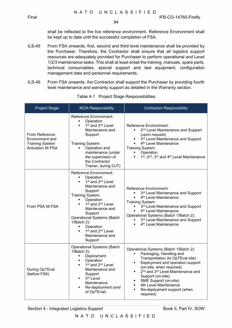
N A T O U N C L A S S I F I E D Final IFB-CO-14760-Firefly
94
Section 4 - Integrated Logistics Support Book II, Part IV, SOW
N A T O U N C L A S S I F I E D
shall be reflected to the live reference environment. Reference Environment shall be kept up to date until the successful completion of FSA.
ILS-45 From FSA onwards, first, second and third level maintenance shall be provided by the Purchaser. Therefore, the Contractor shall ensure that all logistics support resources are adequately provided for Purchaser to perform operational and Level 1/2/3 maintenance tasks. This shall at least entail the training, manuals, spare parts, technical consumables, special support and test equipment, configuration management data and personnel requirements.
ILS-46 From FSA onwards, the Contractor shall support the Purchaser by providing fourth level maintenance and warranty support as detailed in the Warranty section.
Table 4-1 Project Stage Responsibilities
Project Stage NCIA Responsibility Contractor Responsibility
From Reference Environment and Training System Activation till PSA
Reference Environment: Operation 1st and 2nd Level
Maintenance and Support
Training System:
Operation and maintenance (under the supervision of the Contractor Trainer, during OJT)
Reference Environment: 2nd Level Maintenance and Support
(upon request) 3rd Level Maintenance and Support 4th Level Maintenance
Training System: Operation 1st, 2nd, 3rd and 4th Level Maintenance
From PSA till FSA
Reference Environment: Operation 1st and 2nd Level
Maintenance and Support
Training System: Operation 1st and 2nd Level
Maintenance and Support
Operational Systems (Batch 1/Batch 2):
Operation 1st and 2nd Level
Maintenance and Support
Reference Environment: 3rd Level Maintenance and Support 4th Level Maintenance
Training System: 3rd Level Maintenance and Support 4th Level Maintenance
Operational Systems (Batch 1/Batch 2): 3rd Level Maintenance and Support 4th Level Maintenance
During OpTEval (before FSA)
Operational Systems (Batch 1/Batch 2):
Deployment Operation 1st and 2nd Level
Maintenance and Support
3rd Level Maintenance
Re-deployment (end of OpTEval)
Operational Systems (Batch 1/Batch 2): Packaging, Handling and
Transportation (to OpTEval site) Deployment and operation support
(on-site, when required) 2nd and 3rd Level Maintenance and
Support (on-site) SME Support (on-site) 4th Level Maintenance Re-deployment support (when
required)
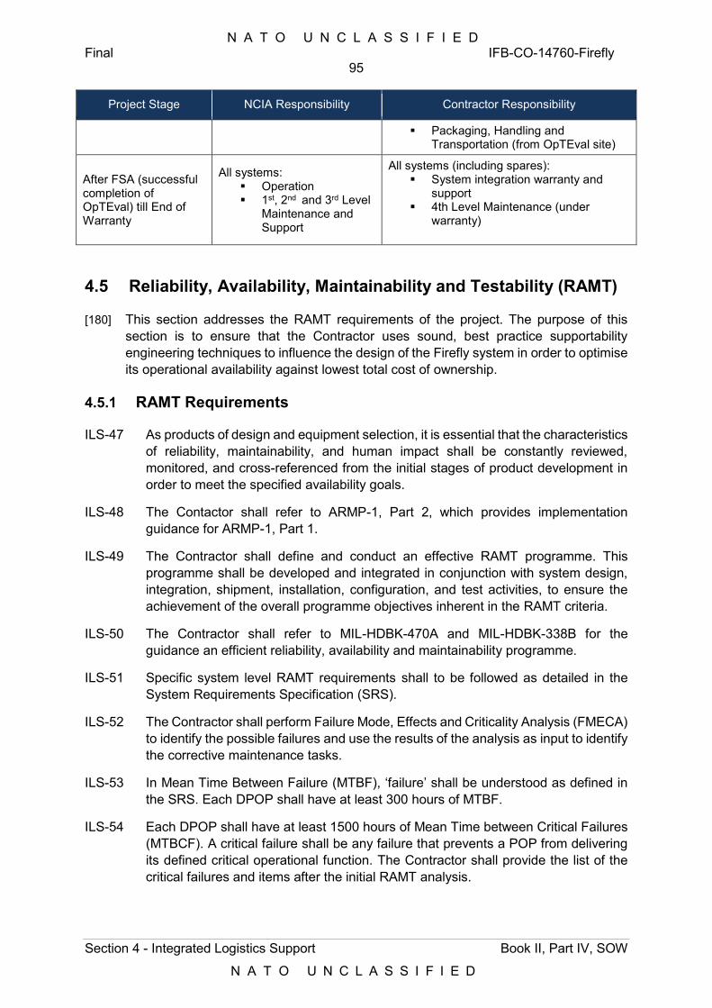
N A T O U N C L A S S I F I E D Final IFB-CO-14760-Firefly
95
Section 4 - Integrated Logistics Support Book II, Part IV, SOW
N A T O U N C L A S S I F I E D
Project Stage NCIA Responsibility Contractor Responsibility
Packaging, Handling and Transportation (from OpTEval site)
After FSA (successful completion of OpTEval) till End of Warranty
All systems: Operation 1st, 2nd and 3rd Level
Maintenance and Support
All systems (including spares): System integration warranty and
support 4th Level Maintenance (under
warranty)
4.5 Reliability, Availability, Maintainability and Testability (RAMT)
[180] This section addresses the RAMT requirements of the project. The purpose of this section is to ensure that the Contractor uses sound, best practice supportability engineering techniques to influence the design of the Firefly system in order to optimise its operational availability against lowest total cost of ownership.
4.5.1 RAMT Requirements
ILS-47 As products of design and equipment selection, it is essential that the characteristics of reliability, maintainability, and human impact shall be constantly reviewed, monitored, and cross-referenced from the initial stages of product development in order to meet the specified availability goals.
ILS-48 The Contactor shall refer to ARMP-1, Part 2, which provides implementation guidance for ARMP-1, Part 1.
ILS-49 The Contractor shall define and conduct an effective RAMT programme. This programme shall be developed and integrated in conjunction with system design, integration, shipment, installation, configuration, and test activities, to ensure the achievement of the overall programme objectives inherent in the RAMT criteria.
ILS-50 The Contractor shall refer to MIL-HDBK-470A and MIL-HDBK-338B for the guidance an efficient reliability, availability and maintainability programme.
ILS-51 Specific system level RAMT requirements shall to be followed as detailed in the System Requirements Specification (SRS).
ILS-52 The Contractor shall perform Failure Mode, Effects and Criticality Analysis (FMECA) to identify the possible failures and use the results of the analysis as input to identify the corrective maintenance tasks.
ILS-53 In Mean Time Between Failure (MTBF), ‘failure’ shall be understood as defined in the SRS. Each DPOP shall have at least 300 hours of MTBF.
ILS-54 Each DPOP shall have at least 1500 hours of Mean Time between Critical Failures (MTBCF). A critical failure shall be any failure that prevents a POP from delivering its defined critical operational function. The Contractor shall provide the list of the critical failures and items after the initial RAMT analysis.
N A T O U N C L A S S I F I E D Final IFB-CO-14760-Firefly
96
Section 4 - Integrated Logistics Support Book II, Part IV, SOW
N A T O U N C L A S S I F I E D
ILS-55 The Contractor shall provide the necessary redundancies in the system design to ensure the reliability metrics are achieved.
ILS-56 MTTR shall be understood as Mean Time To Repair, including fault isolation, access, disassembly, remove and replace, reassembly, configuration, check-out and start up, and excluding administrative and logistics delay times. MTTR shall not be longer than 4 hours.
ILS-57 The Mean Time To Restore the System (MTTRS) of each DPOP shall not be more than 2 hours, this shall entail only the critical item replacements and settings with the assumption of the replaced parts are preconfigured.
ILS-58 The design of the system shall include sufficient redundancy and other reliability, maintainability, availability and testability measures to ensure the RAMT requirements in this Contract are achieved and attained at an optimal Total Cost of Ownership (TCO), minimizing preventive maintenance, spare parts consumption, manpower requirement and usage of special-to-type tools and test equipment.
ILS-59 At least 95% of detected faults shall be restorable by L1/2/3, and no more than 5% of detected faults shall require on-site intervention by L4.
ILS-60 Fault detection and isolation shall be performed by Built-In Test Equipment (BITE), as well as by condition monitoring. At least 95% of all hardware faults shall be detected by online BITE and subsequently displayed on a local central console with appropriate audible and visible alarms. Fault isolation shall be down to a single LRU for 80% of detected faults, and down to assembly level for 100% of detected faults.
ILS-61 The Contractor shall provide necessary provisions in the transit cases for the purposes of maintenance. This shall entail quick identification of the equipment in the transit cases, easy replacement of LRUs from the transit cases, fixed cabling with provisions of adequate length of cables, cable and connector identification. For easier and accurate identification, the Contractor shall provide reference designators to identify each equipment assigned to a specific location (within the rack, where applicable) with an assigned function.
ILS-62 For consistency, reference designators shall also be used for the identification of units within the wiring and functional diagrams. The Contractor shall provide the reference designator information in the related parts of the manuals and on the racks with the form of labelling or marking.
4.5.2 RAMT Prediction
ILS-63 The Contractor shall create and maintain a Reliability Block Diagram (RBD) of the entire system, relating all components (i.e. based on the CI structure and LBS), based on critical items, failure dependencies, and explaining how the RMA characteristics (i.e. MTBF, MTTR, LDT, Ai, and Ao, where appropriate) of each component contributes to the success or failure of the entire system. Firmware shall be treated as being part of the pertinent LRU.
ILS-64 The Contractor shall perform a Failure Modes, Effects and Criticality Analysis (FMECA) in accordance with MIL-STD-1629A, or equivalent. The FMECA shall include all LRUs and software modules identified in the RBDs.
N A T O U N C L A S S I F I E D Final IFB-CO-14760-Firefly
97
Section 4 - Integrated Logistics Support Book II, Part IV, SOW
N A T O U N C L A S S I F I E D
ILS-65 The FMECA assigned/calculated criticality number of an item shall consider at least the reliability, maintainability, testability, safety, and security implications of the item.
ILS-66 The FMECA shall identify, list and describe: all critical items, corrective maintenance tasks, and preventive maintenance tasks.
ILS-67 The FMECA shall analyse the system failure modes of each LRU and of each software module. Per item, failure modes with a failure mode ratio less than 10% shall be consolidated into a single aggregated failure mode and listed through a single entry in the FMECA table for that item.
ILS-68 The FMECA and the RAMT analysis and prediction activities shall utilize each other's data and results to the maximum extent possible.
ILS-69 The Contractor shall ensure that the FMECA is performed and delivered before the CDR and accepted at CDR.
ILS-70 The Contractor shall deliver the RBD and FMECA reports in Support Case.
ILS-71 The Contractor shall deliver a reliability prediction, using Reliability Block Diagrams (RBDs). The prediction shall calculate and predict the overall reliability characteristic of the system (i.e.MTBF and MTBCF), for each type of DPOP.
ILS-72 The RBDs shall address hardware items, as well as software and firmware and shall clearly capture and display the RMA characteristics of each component and assembly, aggregated up to the level of sub-system, and subsequently the entire system.
ILS-73 The Contractor shall ensure that RAMT analysis and prediction is performed and delivered before FDR and accepted at FDR.
ILS-74 The Contractor shall calculate and predict the system MTTR value.
ILS-75 Based on the reliability (MTBCF) and maintainability (MTTRS) predictions, the Contractor shall calculate the intrinsic availability value Ai. The Ai values shall be consistent with the targets that are defined in the SRS.
4.5.3 RAMT Tools
ILS-76 A professional tool shall be used to develop and analyse RBDs, Failure modes and Tasks as addressed in this section. A general purpose tool such as Microsoft Excel shall not be used as the main tool.
ILS-77 The tool shall be capable of exporting and reporting data and results in a non-proprietary, editable format. All data, relevant to the development and analysis of RBDs, Failure modes and Tasks, in this tool shall be made available to the Purchaser at the request of the Purchaser. The purpose of this requirement is to enable the Purchaser to analyze and review the data and results.
ILS-78 If a proprietary tool or a proprietary or non-editable data format is used then the Contractor shall provide the Purchaser with the software tool, including a license valid until the end of warranty period.
N A T O U N C L A S S I F I E D Final IFB-CO-14760-Firefly
98
Section 4 - Integrated Logistics Support Book II, Part IV, SOW
N A T O U N C L A S S I F I E D
4.5.4 RAMT Testing
ILS-79 RAMT tests shall be conducted as on-site operational tests in accordance with MILHDBK- 781. The test shall provide a 90% (ninety percent) confidence that the specified RAMT requirements have been achieved for each principal operational configuration.
ILS-80 Unless approved otherwise by the Purchaser, the test shall comprise not less than 10,000 hours of operations in total. For the purposes of RAMT testing, the Contractor shall monitor and measure the reliability of the reference system starting with the site activation, giving that there is no baseline change during the operation of the reference system. The Contractor shall re-start the clock for measurement after any baseline change on the system due to modifications and repairs.
ILS-81 The Contractor shall propose a RAMT test scenario within the scope of the test activities and provide the proposed metrics and methods.
ILS-82 The Contractor shall ensure that the reliability and maintainability tests and analyses address both software and hardware maintenance/support tasks. The system diagnostic capability, fault detection and isolation and maintenance/support task characteristics shall be addressed in the tests.
ILS-83 The Contractor shall propose a Maintainability Demo scenario including a list of tasks from each task type that are defined in the MAC and references to the operation and maintenance manuals. The Maintainability Demo shall be completed before PSA.
4.5.5 System Safety Programme Plan
ILS-84 The Contractor shall apply engineering principles, criteria, and techniques to identify and eliminate safety hazards in the systems in accordance with Military Standards (MIL-STD)-882E.
ILS-85 The Contractor shall design and/or select all equipment on the basis of inherent safety features that protect not only the human operators and maintainers but also the equipment itself.
ILS-86 The Contractor shall establish a System Safety Programme in accordance with “MIL-STD-882E, Section 4”, to fulfil the safety requirements of the Contract.
ILS-87 The Contractor shall provide, a System Safety Program Plan (SSPP) in accordance with MIL-STD- 882E.
ILS-88 The Contractor shall describe his risk assessment method in the SSPP.
ILS-89 The Contractor shall document the procedures to control design, selection, procurement and manufacture of parts and materials. Revisions to the SSPP shall incorporate Purchaser-agreed changes, additions or deletions that have evolved during the conduct of the Programme.
ILS-90 Safety verification shall be conducted at each site prior to each SAT to ensure compliance with the SSPP. The safety verification shall verify the safety requirements for all types of hazards not eliminated by design. The Contractor shall
N A T O U N C L A S S I F I E D Final IFB-CO-14760-Firefly
99
Section 4 - Integrated Logistics Support Book II, Part IV, SOW
N A T O U N C L A S S I F I E D
document the safety verification process in the SSPP. The Contractor’s responsibilities shall be defined in the SSPP.
ILS-91 The SSPP shall also include System Safety Hazard Analysis Report (SSHAR) as mentioned in MIL-STD- 882E.
ILS-92 The SSPP shall also define Environmental and Safety Requirements as defined at following sub-paragraphs:
ILS-93 Environmental requirements shall be implemented and verified by the Contractor in accordance with National laws and regulations.
ILS-94 The Contractor shall comply with the national legislation concerning job accidents, incident prevention and hygiene at work. The Contractor shall also make legal arrangements for protection of the life and security of all the personnel and to guarantee medical assistance whenever necessary due to job accidents. The same legal arrangements shall be applied to sub-contractor personnel under Contractor’s responsibility.
ILS-95 Health and Safety Hazards: The physical presence, operation and maintenance of the system shall pose no health or safety hazards to personnel.
ILS-96 Carcinogenic and Radio-active Materials, Mercury: Materials containing known carcinogenic substances, radio-active materials or mercury shall only be used with the prior authorisation of the Purchaser with the exception of Radium that is not to be used to achieve self-luminosity.
ILS-97 Hazard Warning Labels: Equipment warning labels shall be attached wherever there is any potential heavy lifting, electrical, chemical, electromagnetic radiation or heat hazard or a potential hazard caused by human contact with materials, particularly when removal of covers will expose the hazard.
ILS-98 Production of Toxic or Corrosive Fumes: Materials used, under the specified environmental and service conditions or as a result of heating due to conflagration, shall not liberate:
1) Gases that combine with the atmosphere to form an acid or corrosive alkali;
2) Toxic or corrosive fumes that would be detrimental to the performance of the equipment or health of personnel;
3) Gases that will produce an explosive atmosphere.
ILS-99 Equipment shall not contain any asbestos material.
ILS-100 Glass Fibre Materials: Glass fibre materials shall not be used as the outer surface or covering on cables, wire or other items where they may cause skin irritation to operating personnel.
ILS-101 Moving Part Protection: Any rotating or other moving part such as ventilators, blowers, drive belts etc., shall be shielded or protected adequately to prevent accidental contact by and injury to any personnel during operation and maintenance.
ILS-102 Equipment Edges: Projecting and overhanging edges of equipment items shall be kept to a minimum. Edges and corners shall be rounded.
N A T O U N C L A S S I F I E D Final IFB-CO-14760-Firefly
100
Section 4 - Integrated Logistics Support Book II, Part IV, SOW
N A T O U N C L A S S I F I E D
ILS-103 Environmental Conditions Indoors, temperature, humidity: Equipment shall function without degradation under the environmental conditions as specified.
ILS-104 Noise generated by the system in operation shall not exceed the levels specified in the local regulations or Environmental Noise Directive (2002/49/EC) whichever it is more restrictive for operational, maintenance areas.
ILS-105 Any safety related warnings and cautions shall be documented in the related sections of the manuals. Adequate labelling and marking shall be provided on the equipment and systems
4.6 Supply Support
4.6.1 System Inventory
ILS-106 The Contractor shall provide the Purchaser’s ILS PoC with a System Inventory in electronic Microsoft Excel format at least 15 (fifteen) working days before the first delivery of equipment.
ILS-107 The System Inventory is site-specific and shall include all items furnished under this Contract, as follows:
4) All main equipment – i.e. all CIS items, both COTS and Developed, down to replaceable item level, hierarchically listed conform configuration item decomposition, including groups and assemblies; all installed hardware, such as equipment racks; all LRU interconnecting equipment when they are special-to-type (e.g. special-to-type cables);
5) All ancillary equipment – i.e. all secondary items not essential to the functioning of the system, but deemed essential to the operation of the system, such as an all-weather canopy or a tool box;
6) All support equipment – i.e. all tools, test equipment and PHS&T equipment;
7) All Purchaser Furnished Item (PFE);
8) All Purchaser and Contractor provided software;
9) All spare parts, to include all spares, repair parts, and consumables, separated into technical and non-technical consumables;
10) All documentation, such as manuals, handbooks and drawings; and
11) All training materials.
ILS-108 The Contractor shall use the inventory template provided the Purchaser to develop and submit the System Inventory. This template will be provided by the Purchaser after Contract Award.
ILS-109 The Contractor shall provide the tempest specific part information additionally in the Inventory List for the tempested items.
ILS-110 The depth and content of the Inventory List shall be subject to the Purchaser Approval.
N A T O U N C L A S S I F I E D Final IFB-CO-14760-Firefly
101
Section 4 - Integrated Logistics Support Book II, Part IV, SOW
N A T O U N C L A S S I F I E D
4.6.2 Codification
ILS-111 On the basis that an adequate manufacturer’s identification numbering system is in place, NATO codification (the request and assignment of NATO Stock Codes – NSN) are not be required. In all other cases, NATO codification shall be required and the Contractor shall support the NATO codification process in accordance with the requirements of AcodP-1 and the requirements of the STANAGs referenced and included in AcodP-1, i.e. STANAG 3150, STANAG 3151, STANAG 4177, STANAG 4199 and STANAG 4438.
4.6.3 Labelling
ILS-112 All equipment shall be labelled in compliance with the Purchaser regulation and guidance. Labels shall at least contain the Contractor/OEM’s name, identification, part number and serial number to ensure proper and quick identification of equipment down to the LRU level. Additional labels shall be provided for equipment inside transport cases where necessary. These additional labels shall be applied to the outside of the transport case or to the inside of the removable case lid. Alternatively, laminated pack-out lists may be supplied with transport cases, instead of the additional labels.
ILS-113 The Contractor shall provide the details of the labelling approach in the CM Plan for Purchaser approval. The Contractor shall provide its labelling for the items that are configured and/or modified after procurement from the OEM. For these items, the Contractor shall assign a P/N for that specific configuration. The format and content of the labelling shall be provided to the Purchaser for review and approval before the start of the labelling activities.
ILS-114 Labelling shall be accomplished in a manner that will not adversely affect the life and utility of the assembly or module. Whenever practicable, the label shall be located in such a manner as to allow it to be visible after installation.
ILS-115 Marking shall be as permanent as the normal life expectancy of the material on which it is applied and shall be such as required for ready legibility and identification.
ILS-116 Marking shall be capable of withstanding the same environment tests required of the part and any other tests specified for the label itself. When possible, letters, numerals, and other characters shall be of such a size as to be clearly legible.
ILS-117 All labelling and marking shall be in English language.
ILS-118 Nameplates shall be attached to all major units of the system. Nameplates shall be in the English language with non-erasable letters/ numbers, clearly identifying the unit (unit designator); location code; as well as the Contractor or OEM CAGE code, part number and serial number. These plates shall be properly attached in a prominent position on each major unit to enable reading and control with easy access when installed. For the items requiring special handling and/or lifting up with additional tools due to heavy weight or high volume (dimensions), special plates including the weight, dimensions and lifting points information shall be provided on the items. Also these items shall have the adequate provisioning points to enable such special handling and lifting conditions.
N A T O U N C L A S S I F I E D Final IFB-CO-14760-Firefly
102
Section 4 - Integrated Logistics Support Book II, Part IV, SOW
N A T O U N C L A S S I F I E D
ILS-119 All equipment labels delivered by the Contractor shall contain a machine-readable code (e.g. barcode) compliant with [STANAG 4329] and [AAP-44(A)] and in accordance with the NATO coding scheme, which will be provided by the Purchaser at the request of the Contractor.
ILS-120 The Contractor shall utilize these machine readable codes during the project to ensure that the following activities are carried out as efficiently as possible:
1) inventory checking;
2) codification, when required;
3) configuration auditing;
4) equipment PHS&T;
5) equipment delivery, placement and acceptance;
6) Maintenance.
ILS-121 The labels shall enable positive identification of assemblies and modules upon removal for maintenance purposes and to prevent loss of utilization of items that have been separated from their original packages or containers.
ILS-122 Labelling shall be accomplished in a manner that will not adversely affect the life and utility of the assembly or module.
ILS-123 The Contractor shall deliver the transport boxes with the graphical depiction and the list of the contents attached to the inside of the transport case lid.
ILS-124 The Contractor shall provide adequate identification for the Non-CIS components as well as the CIS components. This shall entail the labelling for the transit and transport cases, marking of the tents, nameplates on the containers etc.
4.6.4 Initial Provisioning
ILS-125 The Contractor shall provide a single, fully detailed, site-specific (each DPOP, reference and training system) and priced Recommended Spare parts List (RSPL) that shall detail comprehensively all spare parts, tools, test equipment, and consumables required to operate and maintain the system at all levels of support, and in accordance with the RAMT requirements specified in the Contract, no later than 8 weeks before PSA meeting.
ILS-126 The RSPL shall separately list L1/2/3 (LRUs) items and L4 items (SRUs).
[181] The RSPL will be used by the Purchaser to evaluate the support concept and initial provisioning of Contractor-provided spares.
ILS-127 The RSPL shall include, the following items:
1) Spare LRUs;
2) Spare special-to-type LRU interconnecting equipment;
3) Spare ancillaries;
4) Spare support equipment, such as tools, test equipment and PHS&T equipment;
N A T O U N C L A S S I F I E D Final IFB-CO-14760-Firefly
103
Section 4 - Integrated Logistics Support Book II, Part IV, SOW
N A T O U N C L A S S I F I E D
5) Repair parts;
6) Technical and non-technical consumables.
ILS-128 The RSPL shall include the following data elements:
1) Nomenclature;
2) Contractor/OEM CAGE code, part number and serial number;
3) Mean Time Between Failures (MTBF) – when applicable;
4) Indication Repairable (ND) or Non-Repairable (XB);
5) Turn Around Time (when repairable), lead time (new items);
6) Population, by DPOP and total;
7) Recommended quantity;
8) Indication SPOF or part of a redundant array;
9) Unit price (including warranty and PHS&T) and minimum order quantity;
10) Unit repair cost (for repairable items; including warranty and PHS&T);
11) Location of where the unit is provisioned (e.g. for which DPOP).
ILS-129 The Contractor shall provide a set of spares calculated with 98% confidence level (site level) and assumption of continuous operation for a year. The Contractor shall provide the spare part calculations as a part of the Support Case. The Contractor shall also provide the technical consumables (filters, batteries, etc.) for preventive maintenance that will be enough for approximately a year after FSA. The shelf life of these consumables shall be long enough to be usable until the end of first year from FSA. The Contractor shall deliver the set of the spares and consumables before PSA. Additionally, the Contractor shall provide adequate critical spares and consumables on each corresponding site after the activation of reference system and training system to ensure the continuity of the training and testing phase.
ILS-130 The Contractor shall provide all tools and test equipment required to perform L1/2/3 maintenance, as identified in the RSPL.
ILS-131 Procurement and replenishment of L1/2/3 spare parts, including PHS&T, shall be the responsibility of the Contractor as per the Contract until FSA. Procurement, provisioning and replenishment of technical and non-technical consumables shall also be the responsibility of the Contractor.
ILS-132 After the successful completion of FSA by the Contractor, the above responsibility transitions to the Purchaser. However, the Contractor shall be responsible to replenish the initial set of spares during the warranty period, if the initial set of spares provided by the Contractor is proven to be inadequate due to:
High number of warranty repairs requiring all spares to be utilized in the same time period and/or (updating the spare part calculations based on realized MTBF values)
Failures in the items that were not classified as critical and not provided within the initial set of spares but results in downtime effecting operational availability
N A T O U N C L A S S I F I E D Final IFB-CO-14760-Firefly
104
Section 4 - Integrated Logistics Support Book II, Part IV, SOW
N A T O U N C L A S S I F I E D
ILS-133 The Contractor shall organize a Provisioning Meeting that shall take place at least 6 months prior to the PSA Meeting. The purpose of the meeting is to ensure that proper assumptions, procedures, and calculations are being used in the Contractor’s proposal to provide Contractor-owned spares, tools and test equipment, support equipment, repair parts, and consumables, in response to RAMT requirements in this Contract.
ILS-134 The Contractor shall present at Provisioning Meeting an initial provisioning proposal with justification and calculations.
ILS-135 The Contractor shall make available all relevant data and documentation required for the Purchaser to properly assess the Contractor’s initial provisioning proposal.
ILS-136 The Contractor shall make available appropriate technical staff with knowledge of the system to answer questions from the Purchaser regarding initial provisioning.
ILS-137 Any spare parts, tools, and test equipment required to implement, test, and evaluate the system prior to each DPOP-PSA shall be the responsibility of the Contractor at no additional cost to the Purchaser.
ILS-138 The Contractor shall submit the Provisioning Meeting Minutes within a week after the Provisioning Meeting, for the Purchaser for approval.
4.6.5 Software Delivery
ILS-139 The Contractor shall provide a detailed Software Distribution List (SWDL), which shall detail comprehensively all Computer Software Configuration Items (CSCI) and associated software, firmware or feature/performance licenses provided under this Contract. The SWDL shall include, the following data elements:
1) CSCI identification number;
2) nomenclature;
3) version number;
4) license key (if applicable);
5) license renewal date (if applicable);
6) warranty expiration date;
7) date of distribution;
8) distribution location (geographically);
9) distribution target (server); and
10) Owner.
ILS-140 The Contractor shall make sure that all licenses are originally registered with the Purchaser as end-user.
N A T O U N C L A S S I F I E D Final IFB-CO-14760-Firefly
105
Section 4 - Integrated Logistics Support Book II, Part IV, SOW
N A T O U N C L A S S I F I E D
4.7 Packaging, Handling, Storage and Transportation
4.7.1 Packaging
ILS-141 The Contractor shall, for the purpose of transportation, package, crate, or otherwise prepare items in accordance with the best commercial practices for the types of supplies involved, giving due consideration to shipping and other hazards associated with the transportation of consignments overseas.
ILS-142 Any special packaging materials required for the shipment of items shall be provided by the Contractor at no extra cost to the Purchaser.
ILS-143 The packages, palettes and/or containers in which supplies are transported shall, in addition to normal mercantile marking, show on a separate nameplate the name of this project, contract number and shipping address.
ILS-144 In the case of dangerous goods and goods requiring export licenses, the Contractor shall ensure that all required forms and certificates are provided and that all regulations for such goods are followed.
ILS-145 For the purpose of transportation, all supplies shall be packaged to withstand the shipping hazards applicable to the chosen mode of transportation. Any special packaging materials required shall be provided by the Contractor and disposed off by the Contractor after unpacking, insofar as the packaging is not retained with the system (e.g. for storage of spares or return of failed equipment).
ILS-146 All deliveries shall be notified through issuing of a Notice of Shipment to the Purchaser’s ILS PoC, at least 15 (fifteen) working days in advance of each shipment. The Notice of Shipment shall be accompanied by a packing list, compliant with the Purchaser’s templates content. The packing list shall include the following data:
the Purchaser’s contract number;
names and addresses of the Contractor, Freight Forwarder, and Consignee;
final destination address and PoC;
method of shipment;
for each item shipped: CLIN number as per the Schedule of Supplies and Services (SSS); nomenclature; part number; serial number; and quantity; and
for each box, pallet and container identification number, number of boxes, weight, and dimensions.
ILS-147 Two copies of the packing list shall be fastened in a weather-proof, sealed envelope on the outside of each box, palette and container, and one packing list shall be put inside each container/box.
ILS-148 The Contractor shall provide a confirmation of delivery to the Purchaser’s ILS PoC within two weeks after each shipment. This confirmation shall summarize the
N A T O U N C L A S S I F I E D Final IFB-CO-14760-Firefly
106
Section 4 - Integrated Logistics Support Book II, Part IV, SOW
N A T O U N C L A S S I F I E D
supplies delivered, state the date of delivery, and provide a scan of the signature of the Purchaser PoC on-site, receiving the supplies.
ILS-149 The Contractor shall be responsible of removal and disposal of the packaging material.
4.7.2 Handling and Storage
ILS-150 The Contractor shall be responsible for all handling and storage of equipment, packages, boxes and containers during the project. The Contractor shall also be responsible for acquiring, organizing and operating any handling equipment and storage facilities required.
ILS-151 The Contractor shall arrange all that is necessary to access the sites where equipment is handled or stored.
ILS-152 In the case of dangerous goods and goods requiring export licenses, the Contractor shall ensure that all required forms and certificates are provided and that all Host Nation regulations for such goods are followed. The Contractor shall provide a list of such equipment.
4.7.3 Transportation
ILS-153 The Contractor shall be responsible for transportation of all equipment furnished under this Contract as specified in the different work packages. Until the successful completion of FSA, the Contractor shall be responsible for the packaging, handling, transportation (to interim and to end locations), storage and shipment of the equipment between the identified sites as specified in each work package.
ILS-154 The Contractor shall be responsible for any insurance covering these shipments.
[182] The Purchaser will be responsible for all PFE deliveries in accordance to the implementation programme.
ILS-155 The Contractor shall also be responsible for transportation of repaired/ replacement items under warranty to the original location. Return of unserviceable equipment to Contractor facility for (warranty) repair/replacement is the responsibility of the Purchaser. However, if there are any special packaging requirements and materials required for the shipment, the Contractor shall be responsible providing the guidance and the special packaging material. Additionally, any export/import regulations and requirements shall be specified and directed by the Contractor.
ILS-156 The Contractor shall provide the ILS PoC with a Notice of Shipment at least two (2) weeks in advance of each shipment. One additional copy of the packing list shall be attached to this notice. All equipment under this project shall be transported in close co-ordination with the Purchaser’s ILS PoC and the Purchaser’s PoC at final destination.
ILS-157 At final destination, the Purchaser will visually inspect all deliveries for transportation damage and verification against packing and inventory lists. The Contractor shall take back and replace any damaged items, and correct any discrepancies with the packing and inventory lists, at no additional cost to the Purchaser, and without
N A T O U N C L A S S I F I E D Final IFB-CO-14760-Firefly
107
Section 4 - Integrated Logistics Support Book II, Part IV, SOW
N A T O U N C L A S S I F I E D
affecting the major milestone dates. The Purchaser will in no case open palettes or packages.
ILS-158 At the Purchaser designated staging area, the Contractor shall unload the equipment and move the equipment to its final destination. The Contractor may use any support equipment provided by the Purchaser, but remains responsible for organizing and using any support equipment required to offload and move equipment to its final destination. The Contractor shall ensure that any requirements related to delivery of the system are obtained from the Purchaser in advance of shipments. The Contractor shall be responsible for any insurance covering the delivery.
ILS-159 The Contractor shall include the processes for loading and unloading, packing and unpacking, as well as setup and dismantle in the operation and maintenance manuals, training materials and training courses.
ILS-160 The Contractor shall provide a Transportation Report within two (2) weeks after each shipment has arrived at final destination. The Transportation Report shall include:
1) A copy of the packing list;
2) Date of arrival at final destination;
3) Date of delivery acceptance by the Purchaser’s PoC at final destination; and
4) Signature of delivery acceptance by the Purchaser’s PoC at final destination.
4.7.4 Customs and Export Licences
ILS-161 The Contractor shall be responsible for customs clearance of all shipments into the destination countries. It is the Contractor’s responsibility to take into account delays at customs. He shall therefore consider eventual delays and arrange for shipment in time. Under no circumstances can the Purchaser be held responsible for delays incurred, even when utilizing Purchaser provided Customs Form 302.
ILS-162 Prior to a shipment by the Contractor, the Purchaser will upon request issue a Customs form 302, which in some cases may facilitate the duty free import/export of goods. The Contractor shall be responsible for requesting the issue of a form 302 at least 10 (ten) working days prior to shipment. The request for a Form 302 shall be included with the Notice of Shipment and accompanied by one (1) additional packing list. The request is normally processed by the Purchaser within three (3) working days. The requested 302 forms will be sent by courier. The original 302 forms shall accompany the shipment and therefore no fax or electronic copy will be used, nor provided to the Contractor.
ILS-163 If a country refuses to accept the Form 302 and requires the payment of customs duties, the Contractor shall pay these customs duties and the Purchaser shall reimburse the Contractor at actual cost against presentation of pertinent supporting documents. Should such an event occur, the Contractor shall immediately inform the Purchaser by the fastest means available and before paying, obtain from the
N A T O U N C L A S S I F I E D Final IFB-CO-14760-Firefly
108
Section 4 - Integrated Logistics Support Book II, Part IV, SOW
N A T O U N C L A S S I F I E D
Customs Officer a written statement establishing that his Country refuses to accept the Form 302.
ILS-164 The Contractor shall be responsible for managing and performing all activities that is necessary to obtain export licenses for the goods requiring such licenses.
ILS-165 The Contractor shall provide a detailed list of the equipment requiring export licenses. The Contractor shall provide the necessary procedures that needs to be applied for items to be relocated for repair or any other purposes.
4.8 Warranty and Support
ILS-166 The Contractor shall warrant that all equipment, software, documents, system design, production and implementation provided under this Contract and all installation work performed under this Contract conform to the requirements and is free of any defect in material, code or workmanship for a period starting at date of PSA to date of FSA plus minimum one (1) year.
ILS-167 Any replaced part during the warranty period shall be under minimum 1 (one) year warranty beginning from the replacement date, if the remaining warranty period is less than one year.
ILS-168 The Contractor shall warrant that all equipment and software delivered under the Contract are genuine and free of any malicious components, firmware and software, for a period of at least 1 year, starting at FSA.
ILS-169 The Contractor shall be responsible for establishing an adequate supply chain security process and taking the necessary measures. The Contractor shall allow and support ad-hoc spot checks and audits by the Purchaser of any of his supply chain security measures at any of the Contractor’s locations and facilities used in the Contractor’s supply chain relevant to this Contract.
ILS-170 The Contractor shall fix/repair/replace all items received as per his internal procedures with the highest priority allocated. The Contractor shall acknowledge and provide a corrective action for the failed components within NBD after the initiation of the warranty request. In the case of a failure could not be identified to an LRU level and/or could not be isolated within 3 business day (starting with the warranty request) even with on-call assistance from the Contractor, the Contractor shall dispatch a field engineer to provide a solution on-site. If the conditions for replenishment of the spare set is realized based on the requirements in Section 4.6.4 Initial Provisioning, the Contractor shall ship this additional items within 7 calendar days.
ILS-171 The Contractor shall provide a specific Customer PoC for all warranty and support requests. The Contractor shall detail all the warranty and support requirements in its ISSP including the roles and responsibilities.
ILS-172 The Contractor shall ensure that the warranty conditions remain valid even if the equipment is moved or relocated during the warranty period.
ILS-173 When the Contractor becomes aware at any time before acceptance by the Purchaser that a defect exists in any supplies, the Contractor shall coordinate with the Purchaser and promptly correct the defect.
N A T O U N C L A S S I F I E D Final IFB-CO-14760-Firefly
109
Section 4 - Integrated Logistics Support Book II, Part IV, SOW
N A T O U N C L A S S I F I E D
ILS-174 The Contractor shall repair/replace all hardware items and received through the support level as per their internal procedures with the highest priority allocated and shall be responsible to return the item to the original location, through express delivery.
ILS-175 Transportation of repaired/replacement items from Contractor location to any NATO premises shall be the responsibility of the Contractor and at the expense of the Contractor.
ILS-176 The Contractor shall be responsible for the provision of any alternative or superseding items, should the original part be no longer available, ensuring compliance with the original design and System provided by this Contract. However, in such cases the Contractor shall propose the original alternative item for the Purchaser approval. The alternative item shall conform with all the specified quality requirements within the scope of the contract and standards.
ILS-177 Defect magnetic, solid state and electronic media storage devices shall remain the Purchaser’s property, at no additional cost, and not be returned to the Contractor when being replaced under warranty. Any such defect storage devices shall be replaced by the Contractor with new storage devices at no additional cost to the Purchaser.
ILS-178 For equipment with TEMPEST certification, after warranty repair or replacement, The Contractor shall perform re-tempesting and re-testing of the equipment free of charge and shall provide the TEMPEST certification with return of the equipment. The Contractor shall not be responsible for re-tempesting after repairs for User induced failures (repairs not being performed under warranty).
ILS-179 In the event of such electronic media storage devices being a part of a Tempest equipment, the Purchaser will be allowed to break the Tempest and remove such storage devices without disrupting the warranty rights. The Contractor shall guarantee that normal warranty conditions shall be applicable to such equipment after removal of their storage devices.
ILS-180 Any such defective storage devices shall be replaced by the Contractor with new storage devices at no additional cost to the Purchaser.
ILS-181 During the warranty period, the Contractor shall be responsible for supplying all COTS hardware and software upgrades and updates.
ILS-182 The availability of COTS hardware and software upgrades and updates shall be made known to the Purchaser and, if proposed for introduction by the Contractor for whatever reason, including any corrective action for an identified fault, shall always be subject to Purchaser approval.
ILS-183 The Contractor will not be responsible for the correction of defects in the Purchaser furnished property, except for defects in installation, unless the Contractor performs, or is obligated to perform, any modifications or other work on such property. In that event, the Contractor shall be responsible for correction of defects that result from the modifications or other work.
ILS-184 The Contractor shall be responsible for shipment and delivery of faulty items for repair or replacement, and of the repaired or replaced item to the affected site. This
N A T O U N C L A S S I F I E D Final IFB-CO-14760-Firefly
110
Section 4 - Integrated Logistics Support Book II, Part IV, SOW
N A T O U N C L A S S I F I E D
support shall include cost of parts, travel and per diem and shall be provided at no additional cost to the Purchaser.
ILS-185 The Contractor shall provide a Technical Assistance to the Purchaser or his representatives during the warranty period. Technical assistance information details shall be indicated in the ISSP.
ILS-186 The Technical Assistance shall provide on-call and/or on-site support in English for requests that correspond to information demands limited to the perimeter of delivered products, evolution proposals, problem reports, or any information needed by the Purchaser or its representatives, which are not included in the supplied technical documentation.
ILS-187 The Contractor shall provide a Performance Report every 3 months to summarize the failures and corrective actions. The Contractor shall detect and report any failures that has become problem and take the necessary measurements to correct such failures that occur due to a design defect. The Contractor shall summarize the change in PBL and OBL in the report and shall update the user documentation (operation, maintenance, deployment) every 3 months to reflect the baseline change in the system.
ILS-188 The Contractor shall perform the Obsolescence Management during the warranty period and inform the Purchaser about any obsolescence risks, end of sales, production and support and mitigation options. The Contractor shall provide such information either in the 3 months report or ad hoc depending on the time criticality.
4.9 Transfer of Ownership
ILS-189 Transfer of ownership of the system shall occur at FSA when the Purchaser has confirmed final acceptance in writing.
ILS-190 However, usage of the system for training, testing and evaluation purposes shall commence at each DPOP-PSA or site activation (reference system, training system). During the period from PSA (of the first site) to FSA, the Contractor is responsible for overall continuity of operation, maintenance and support of the Firefly infrastructure.
ILS-191 During the period from PSA (of the first site) to FSA, the Contractor shall incrementally transfer the ability to conduct first, second and third level of support from the Contractor staff to the Purchaser.
ILS-192 Liability for usage induced failures shall hence be transferred to the Purchaser at each DPOP-PSA.
ILS-193 Liability with regard to the function and performance of the system shall remain with the Contractor.
4.10 Training
TRN-1 This section addresses the general training requirements applicable to this project. The purpose of these requirements is to ensure that the Contractor provides high quality training materials, courses and trainers. Training material and delivery shall
N A T O U N C L A S S I F I E D Final IFB-CO-14760-Firefly
111
Section 4 - Integrated Logistics Support Book II, Part IV, SOW
N A T O U N C L A S S I F I E D
meet the training Accreditation Requirements of the Purchaser as defined in BiSC 075-007 directive.
TRN-2 The development of training materials and courses (and manuals) shall be based on the outcomes of maintenance task analysis, as well as the TNA, and hence cover the right operation and maintenance tasks.
TRN-3 The Contractor shall distinguish separate roles for the distinct operation and maintenance functions of the system. Training shall be provided in a highly modular fashion to ensure that the right mix of modules can be assembled into role-based courses that cover the various operation and maintenance roles within the Purchaser support organization.
TRN-4 All training material delivered under this contract shall be subject to review and approval by the Purchaser. The Contractor shall deliver to the Purchaser a complete draft of all training material no later than 20 working days in advance of each course.
TRN-5 At least 2 weeks prior to the start of any course the Contractor shall provide written notification that all required training equipment and other resources are ready for the commencement of the Training Course.
4.10.1 Training Plan
TRN-6 The Contractor shall provide a Training Plan that explains in detail how the Contractor shall fulfil all training requirements in this Contract. The Training Plan and supporting PMS shall include the following for each course:
1) Description of the Contractor training organization;
2) Planning of the training stages and activities, including the TNA, development of training material and corresponding schedule for each training course material, organization of courses, course execution, learning methods for each type of course;
3) Course description. This shall be a narrative explanation of the subject matter of the specific course. The course format, objectives, and training materials shall be described in sufficient detail to ensure the students will receive required training. A proposed syllabus shall be included, detailing the subject matter to be covered. Any breakdown into modules shall be described, following the format of Course Control Documents (CCD) I, II, and III as of Bi-SC Directive 075-007;
4) Student prerequisites (if required);
5) Course length (including time devoted to each area of the course);
6) Method of presentation for each element of the syllabus (show breakdown of methods, i.e., lecture, demonstration, hands-on and directed study, online etc.);
7) Method of evaluation. Establish minimum acceptable written and performance standards and a method of evaluation of directed study. A plan shall be included to show that each student achieved at least minimum training objectives by written and performance tests;
N A T O U N C L A S S I F I E D Final IFB-CO-14760-Firefly
112
Section 4 - Integrated Logistics Support Book II, Part IV, SOW
N A T O U N C L A S S I F I E D
8) List of training material and training equipment required (contractor-provided documents or materials shall be included). This shall include the appropriate standards for electronic data;
9) Description of the minimum capabilities of necessary training equipment, together with the logistic implications of using the training equipment;
10) Recommended maximum size of course. Recommended location of training and type of facility required (i.e., classroom, auditorium, site, etc.);
11) List of measurable objectives (tasks) required by graduates to demonstrate successful completion of course;
12) Proposed schedule for training courses;
13) Relationship to related programme milestones and to the equipment delivery schedule;
14) Number of hours of “hands-on” training to be provided to each student.
4.10.2 Training Needs Analysis
TRN-7 The Training Need Analysis (TNA) shall be produced in accordance with the Bi-SC Directive 075-007. The TNA shall include:
1) a Target Audience Analysis;
2) a Performance Gap Analysis;
3) a Difficulty, Importance and Frequency (DIF) Analysis;
4) a Training Options Analysis.
TRN-8 The Target Audience Analysis shall identify user and support categories, including end users, support staff (to perform Levels 1, 2 or 3) and Purchaser instructor personnel (for follow-on training).
TRN-9 The Performance Gap Analysis shall assess the gap between the current skills of users, support staff or Instructor and the tasks they will be expected to perform in the use and support of the Firefly Operational Baseline.
TRN-10 The Difficulty, Importance and Frequency (DIF) Analysis shall identify the difficulty and importance of each major task to be performed by each category of users, support staff or Instructor and the frequency with which the task will be performed.
TRN-11 For each task identified, the Contractor shall assess the knowledge and skill required to perform the task, determine performance objectives, and recommend how training should be provided to meet these requirements.
TRN-12 The TNA shall identify which operation and maintenance tasks are required to operate and maintain the system at Level ½/3 of support. These tasks shall be documented in the Operation and Maintenance Manual, and listed in the TNA Report.
TRN-13 Training shall be through the most effective training option identified by the TNA. Options shall include: bespoke Contractor courses, commercial training courses, or a mix of bespoke and commercial courses. Courses shall be organised as self-study
N A T O U N C L A S S I F I E D Final IFB-CO-14760-Firefly
113
Section 4 - Integrated Logistics Support Book II, Part IV, SOW
N A T O U N C L A S S I F I E D
courses through the use of Computer Based Training (CBT), instructor-led classroom training, On-The-Job practical training (OTJ), or a combination thereof. The selected methods and their combination weight shall be proposed in the Training Plan for Purchaser approval.
TRN-14 The TNA shall also identify the course pre-requisites for all training courses. The pre-requisite training shall be described in such a way as to allow Host Nation to select students and organize Host Nation pre-requisite training, in time, before execution of the Contractor’s training programme commences.
TRN-15 The results of the TNA shall be captured in a TNA report. The TNA report shall capture the results of the TNA. The structuring of training modules, role-based training programmes, and training material, as well as the training sequence, mode and duration shall be based on the outcomes of the TNA.
4.10.3 Training Courses
TRN-16 The Contractor shall provide all training modules and courses required to enable all initially assigned the Purchaser personnel to operate and maintain the system at Level 1, 2 and 3. This shall include also a comprehensive and standalone hands-on training of load/unload, pack/unpack, and setup/dismantle of POPs including a full-scale deployment scenario. The Contractor shall provide the Deployment Manual in a mature state to be utilized during the deployment training and demonstrate that the manual covers adequate details and guidance for the deployment. The Contractor shall make the necessary changes and update the manual based on the trainee feedback and assessment after the training. All training courses shall be provided before PSA.
TRN-17 Training shall incorporate sufficient hands-on, practical lessons on the actual system equipment provided through this Contract.
TRN-18 Training shall take place at the Purchaser’s central facility designated for this purpose. The Contractor shall be fully responsible for planning, organizing, installing, operating and maintaining all that is required to perform the training. This includes any training equipment used in the classroom.
TRN-19 An adequate training facility, as well as adequate standard class room furniture and equipment, such as beamer, screen, white board, paper and writing utensils, will be provided by the Purchaser.
TRN-20 Training and all related training documentation shall be provided in the English language. Training shall be able to accommodate Purchaser students with an English language skill level of 2222 (STANAG 6001). Contractor trainers shall have English language skill level 3332.
4.10.4 Training Material
TRN-21 The Contractor shall prepare and provide all materials that will be used for the training. All documentation and training material delivered shall include an electronic editable version. The training material shall be available in a Purchaser approved version and formatting before the start of the training course(s).
N A T O U N C L A S S I F I E D Final IFB-CO-14760-Firefly
114
Section 4 - Integrated Logistics Support Book II, Part IV, SOW
N A T O U N C L A S S I F I E D
TRN-22 The Contractor shall organize or develop and issue course material to ensure that each course provides all students / instructors with:
1) A student handbook;
2) Slides to support the course;
3) Instructor Manual as defined in Section 4.10.6;
4) A Training Certificate, upon completion of the course; and
5) A course evaluation feedback form.
TRN-23 Training handbooks shall include all training content required to teach and comprehend the course. This includes an introduction to the training course; training course and lesson objectives; lesson overview and instructor / learning guide; course schedule; administrative and safety instructions; quick reference cards; and exercise material.
TRN-24 All training material shall be provided to the Purchaser in the requested format (e.g. NATO CIS School presentation / handbook formats and style guides) for review and approval. The review process shall be proposed in the Training Plan and organized by the Contractor in time to ensure training material is approved before start of the training programme.
TRN-25 Training material shall be designed and developed to be suitable for use during the Contractor-conducted training and for the future training of all categories of replacement personnel by Purchaser Instructors.
4.10.5 Training Evaluation
TRN-26 The Contractor shall ensure that each student is instructed at the end of each course to complete and return the course evaluation feedback form.
TRN-27 The Contractor shall consolidate and forward student feedback to the Purchaser following each training course in the form of a Training Evaluation Report. The report shall also recommend changes and improvements to the training courses based on the consolidated student feedback. The report shall also address student attendance, problems encountered and actions taken to resolve the problems.
TRN-28 The Contractor shall revise/ refine and reissue any course material to reflect the consolidated student feedback and proposed improvements in the training evaluation report.
TRN-29 Training courses shall include final theory and practical assessment tests that shall be graded based on the NATO CIS School standards. However, no pass/fail decision shall be made by the Contractor.
TRN-30 The Contractor shall produce Training Certificates for each training session and student. The certificates shall be issued to students at the end of each course.
N A T O U N C L A S S I F I E D Final IFB-CO-14760-Firefly
115
Section 4 - Integrated Logistics Support Book II, Part IV, SOW
N A T O U N C L A S S I F I E D
4.10.6 Instructor Manual
TRN-31 The Instructor Manual shall enable the instructor to prepare, conduct, and conclude the training course to meet the learning objective within the allocated training period.
TRN-32 The Instructor Manual shall follow the CCD II and III format include all fields on those control documents, including but not limited to:
1) A Course Overview;
2) Course organization;
3) Course coordination;
4) Target audience;
5) Course Goals and outcomes;
6) Class size;
7) Host Agency responsibilities:
a) Audio-visual equipment requirements;
b) Room requirements;
c) Local coordinator’s responsibilities;
d) Training site;
e) Participants and instructors;
f) Final arrangements;
g) Student requirements.
8) Course agenda;
9) For the instructor: presentation requirements:
a) Before the training event – preparation and device configuration list;
b) During the training event;
c) After the training event, to include resetting of devices.
10) Course evaluation templates.
4.11 Load Plan
[183] Load planning is a critical exercise to ensure the equipment can be dis-assembled, packaged, loaded, transported and re-assembled at the end location with minimal damage and minimal effort.
ILS-194 The Load Plan shall take into account:
1) The mission function (modules needed);
N A T O U N C L A S S I F I E D Final IFB-CO-14760-Firefly
116
Section 4 - Integrated Logistics Support Book II, Part IV, SOW
N A T O U N C L A S S I F I E D
2) The means of transport (see ILS-196 below);
3) Location of deployment (Building of Oportunity, Field deployment, etc.)
ILS-195 The Load Plan shall identify the distribution of the load along the different loading platforms (containers, vans, etc.) and the internal distribution in each of those platforms taking into account weight distribution (for centre of gravity considerations) and required order of use during deployment.
ILS-196 The equipment shall be transportable in:
1) ISO containers for aircraft cargo and trucks; and
2) Transit cases on pallets for vans.
ILS-197 The Contractor shall provide a tool that will be able to provide detailed loading guidance.
ILS-198 The Load Plan tool shall be:
1) Pre-configured to accept the PFE transport vehicle such as vans and ISO containers;
2) Have pre-loaded with the different types of equipment:
a) The range of transit cases;
b) Tentage and other non-CIS;
3) Configurable so that in the future further transport vehicles and different dimention transit cases can be added.
4) Able to accept input including:
a) The size of the equipment for deployment (e.g. a full DPOP, a remote node, STK, based on expected deployment scenarios);
b) The type of transport (vans, ISO containers).
5) Able to determine:
a) What needs to be loaded in terms of the number and sizes of transit cases and other equipment, including all relevant the CIS and non-CIS;
b) In what order to load to optimize weight loading, space untilisation, and minimal damage.
ILS-199 The tool shall be available and demonstrated as a part of the IV&V testing, and be available as a part of the training.
4.12 Material Handling
[184] The DCIS systems may be deployed at locations where theres are no roads or other areas which are not easily accessable. Thererfore there will be no forklift trucks or other lifting equipment to handle the transit cases.
N A T O U N C L A S S I F I E D Final IFB-CO-14760-Firefly
117
Section 4 - Integrated Logistics Support Book II, Part IV, SOW
N A T O U N C L A S S I F I E D
[185] In such circumstances material handling equipment is needed to dismount the equipement from the vans and to take them to the end locations where they will be set up.
ILS-200 The Contractor shall provide material handling equipment that shall allow the transport of the DCIS systems over rough terrain. This is especially important for the heavy transit cases.
ILS-201 There shall be 1 set of material handling per DPOP (refer to Annex A, para. 6.3.3., Material Handling Equipment, for details).
N A T O U N C L A S S I F I E D Final IFB-CO-14760-Firefly
118
Section 5 - Documentation Book II, Part IV, SOW
N A T O U N C L A S S I F I E D
5 Documentation
[186] This section addresses the documentation requirements of the project. The purpose of these requirements is to ensure that the Contractor develops and provides high quality, comprehensive documentation, manuals, and as-built drawings that will enable the Purchaser to operate and maintain the system at all assigned levels of support.
DOC-1 All project documentation shall be compliant with the requirements identified in the SOW below.
5.1 Documentation Format
DOC-2 Non-COTS documentation shall neither be marked with corporate logos nor contain warnings limiting the rights to use or reproduction.
DOC-3 Documentation shall not contain warnings limiting the rights to use or reproduce the document. The Purchaser reserves the right to make additional copies of any documentation (including the training documentation) provided under this contract for his internal use.
DOC-4 All contractual documentation (e.g., change proposals, invoices, etc.) shall be delivered in electronically unless specified otherwise by the Purchaser Contractor Officer. The Purchaser reserves the right to request printed versions of any project documentation.
DOC-5 Every document shall include a hyperlinked index.
DOC-6 The Purchaser’s default software packages for managing projects and processing documentation deliverables are the versions which will be decided at Contract Award by the Contractor:
1) Microsoft Office Professional;
2) Microsoft Project;
3) Microsoft Visio Enterprise.
DOC-7 The Contractor shall submit documentation, intended for review by the Purchaser in electronic format:
1) In the native format compatible with the Purchaser’s software packages above; or
2) In the Contractors toolset of choice in which case the Contractor shall provide the Purchaser with 5 licenses of each tool/application used.
DOC-8 All project management documentation (e.g., plans, schedules, reports, etc.) shall be delivered as electronic, editable copies in MS Office format. This format shall be agreed with the Purchaser.
DOC-9 The Contractor shall submit documentation, intended for review by the Purchaser, with each modification identified through the change tracking feature or otherwise marked in the revision table.
N A T O U N C L A S S I F I E D Final IFB-CO-14760-Firefly
119
Section 5 - Documentation Book II, Part IV, SOW
N A T O U N C L A S S I F I E D
DOC-10 The Contractor shall submit all final and accepted versions of documentation deliverables in electronic format, as PDF (OCR), accompanied with a Microsoft Office version for editing purposes.
DOC-11 All documents produced under this Contract shall use sans-serif fonts (e.g. Arial, Helvetica, Calibri, etc), and obey the following principles:
1) Headings shall be numbered and use bold font-types of sizes higher than the body text (the higher the Heading in the document hierarchy, the larger the font-size);
2) No document shall use Headings below level 6 (i.e. 1.1.1.2.3.1 Heading Text);
3) Body text (under the headings) shall not use fonts smaller than April 10 pt (or equivalent size if another font type(s) is (are) selected);
4) Any graphic material generated under this Contract, including network diagrams, shall not use font sizes smaller than Arial 8 (or equivalent size if another font type(s) is (are) selected).
DOC-12 Larger font sizes than those specified above shall be selected if the corresponding text or drawing is to be reduced in size when embedded in the document, in order to guarantee that the PDF output keeps the font size as specified.
DOC-13 All documentation produced under this contract shall adhere to the same presentation style (cover pages, approval pages, headers, footers, headings and paragraphs, font types and sizes within headings and paragraphs), irrespective of the source of the document within the Contractor’s team, including any except COTS equipment documentation.subcontractor documentati..
DOC-14 Every page shall include a header and footer indicating the highest classification of content on that page using one of the following labels: NATO CONFID*NTIAL, NATO R*STRICT*D (sensitive information identifying e.g. a named location or security assessment), or NATO UNCLASSIFIED.
DOC-15 One set of printed Deployment Guides printed on water-proofed paper shall be delivered for each DPOP. In addition, all COTS Documentation, manuals and drawings shall be provided in electronical format, both in PDF (OCR) format and, for non-COTS documentation, in an editable Microsoft Office/Visio format.
DOC-16 Manuals shall take into consideration the information gained through the Training Needs Analysis (TNA) to ensure that all operation and maintenance tasks are identified and covered by the documentation.
DOC-17 Manuals and as-built drawings shall be provided for all CIS-components, CIS ancillaries and software, such as tents, power distribution, HVAC, BC filters, compressors, and generators, but NOT on PFE (crypto equipment, general use software, etc.). Manuals on PFE will be delivered as PFE manuals together with the PFE. However, manuals and drawings shall cover all the system specific interfaces to/from PFE or any external asset.
DOC-18 All electronic copies shall be delivered in a format which is best suited for review and maintenance by the Purchaser (e.g., Project Master Schedule in MS Project format, Project Progress Reports in MS Word). In general the following guidelines
N A T O U N C L A S S I F I E D Final IFB-CO-14760-Firefly
120
Section 5 - Documentation Book II, Part IV, SOW
N A T O U N C L A S S I F I E D
shall be used: Microsoft Word shall be used for generating text document; Microsoft Excel shall be used for tabular or matrix data; Microsoft Visio shall be used for drawings; Microsoft Project shall be used for schedule; and Microsoft PowerPoint shall be used for briefings. The rest of deliverables will be furnished as electronic copy of the agreed tools/media used.
DOC-19 All documentation, such as COTS documentation, manuals, drawings and training materials shall be provided in English.
DOC-20 The convention for numbers appearing in textual documents shall be a comma to be the thousands separator and a period to be the decimal separator (e.g., 1,365,276.24).
DOC-21 The convention for dates appearing in free text (e.g., quoting dates of meetings) shall be day-month-year and not month-day-year.
DOC-22 The first page shall show the document title, project title, contract number as well as version number and issue date, if applicable, and which shall also be shown on each subsequent page bottom.
DOC-23 Developed documentation shall contain a Table of Contents. It shall be noted that depending on the type of document, a Table of Content might not be required. This shall be agreed between the Purchaser and Contractor beforehand.
DOC-24 All documents shall contain a preface, containing details of related documents and information on how to navigate the document.
DOC-25 Where documents contain many complex specialized or strongly domain oriented terminologies these shall be defined in a glossary.
DOC-26 Each document shall contain the following information for identification:
1) Version of the document and version history;
2) Due date;
3) Delivery date;
4) CLIN number;
5) Status (e.g., accepted/approved/draft).
DOC-27 The Contractor shall remain responsible for updating the documentation that is affected by the changes in the system requirements, design, or support arrangements throughout the project.
DOC-28 The Contractor shall use filenames for all documentation deliverables in compliance with the following filename convention:
DOC-29 [NU|NR]_[Contract number]_[Contract Line Item number]_[Name of deliverable]_[v0.x|v1.0].[filename extension]
1) Example of a compliant filename:
a) NU_CO-14760-Firefly_3.2.1_QA Plan_v0.1.pdf.
2) The fields used in the filename convention shall be used as follows:
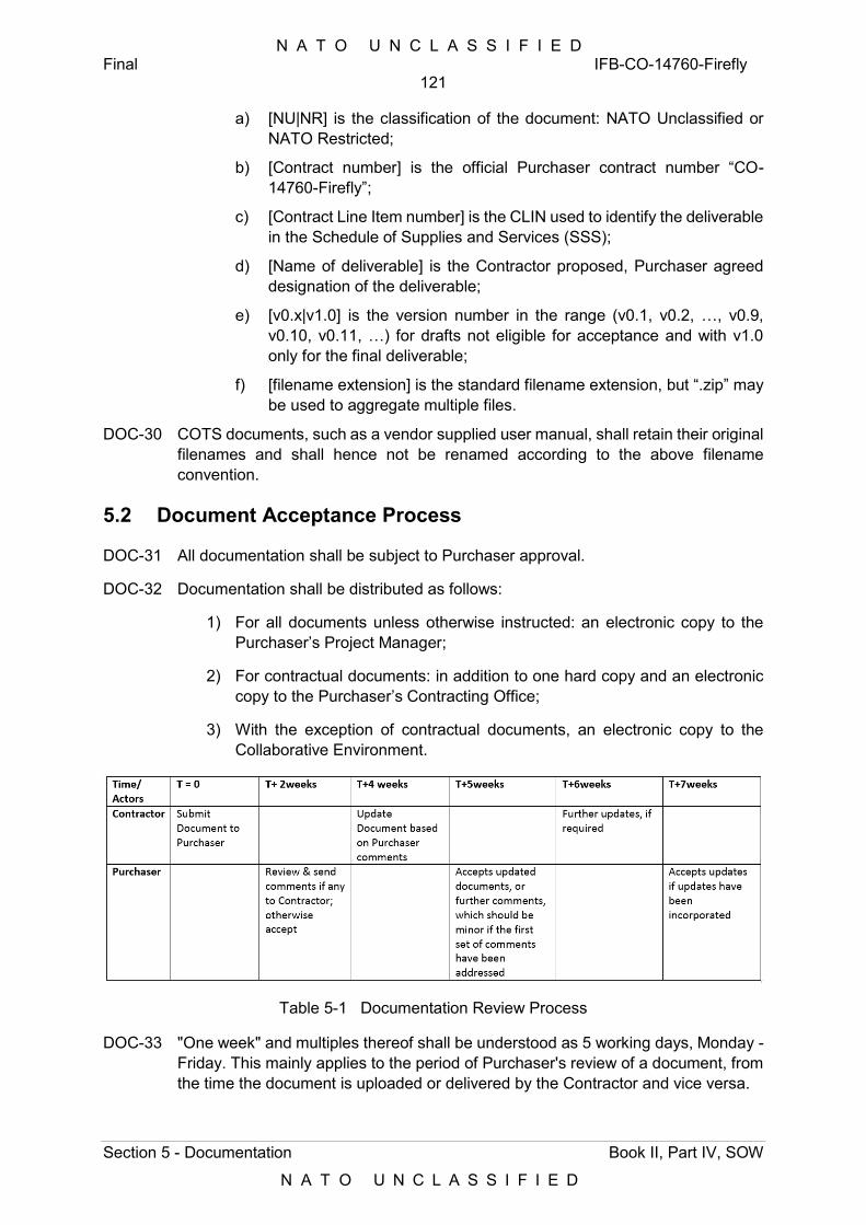
N A T O U N C L A S S I F I E D Final IFB-CO-14760-Firefly
121
Section 5 - Documentation Book II, Part IV, SOW
N A T O U N C L A S S I F I E D
a) [NU|NR] is the classification of the document: NATO Unclassified or NATO Restricted;
b) [Contract number] is the official Purchaser contract number “CO-14760-Firefly”;
c) [Contract Line Item number] is the CLIN used to identify the deliverable in the Schedule of Supplies and Services (SSS);
d) [Name of deliverable] is the Contractor proposed, Purchaser agreed designation of the deliverable;
e) [v0.x|v1.0] is the version number in the range (v0.1, v0.2, …, v0.9, v0.10, v0.11, …) for drafts not eligible for acceptance and with v1.0 only for the final deliverable;
f) [filename extension] is the standard filename extension, but “.zip” may be used to aggregate multiple files.
DOC-30 COTS documents, such as a vendor supplied user manual, shall retain their original filenames and shall hence not be renamed according to the above filename convention.
5.2 Document Acceptance Process
DOC-31 All documentation shall be subject to Purchaser approval.
DOC-32 Documentation shall be distributed as follows:
1) For all documents unless otherwise instructed: an electronic copy to the Purchaser’s Project Manager;
2) For contractual documents: in addition to one hard copy and an electronic copy to the Purchaser’s Contracting Office;
3) With the exception of contractual documents, an electronic copy to the Collaborative Environment.
Table 5-1 Documentation Review Process
DOC-33 "One week" and multiples thereof shall be understood as 5 working days, Monday - Friday. This mainly applies to the period of Purchaser's review of a document, from the time the document is uploaded or delivered by the Contractor and vice versa.
N A T O U N C L A S S I F I E D Final IFB-CO-14760-Firefly
122
Section 5 - Documentation Book II, Part IV, SOW
N A T O U N C L A S S I F I E D
DOC-34 Approval of a document or other deliverable shall not be interpreted to imply any Purchaser endorsement of the content. It shall remain the sole responsibility of the Contractor to meet the full system performance requirements and to prove such performance through the regime of testing and other assurance mechanisms set forth in the Contract and it shall be the sole responsibility of the Contractor to remedy any performance shortfall in the event of any identified deficiency in terms of the contract functional and/or performance requirements. The Contractor’s responsibility in this regard extends beyond FSA through warranty, responsibility for any latent defects.
DOC-35 All the documentation within the scope of this project shall be consistent in terms of content. Any inconsistencies that are detected between documents at any time until the end of this project shall be corrected upon Purchaser notification.
DOC-36 The Contractor shall provide a first draft (version 0.1) of each deliverable for Purchaser review by the date specified in the Schedule of Supplies and Services or as agreed between the Purchaser and Contractor.
DOC-37 The first draft shall be substantially complete and correct, and delivered in accordance with the delivery dates specified in the Work Package and the Schedule of Supplies and Services. To ensure the completeness and correctness, the Contractor shall complete the internal review cycle between the related functions before presenting a version to the Purchaser.
DOC-38 The Purchaser reserves the right to return without review a document that has significant deficiencies.
DOC-39 The Contractor shall not rely on the Purchaser review to fill in deficiencies or obtain missing Purchaser information.
DOC-40 The Contractor shall resubmit the document as a revised draft incorporating the Purchaser’s comments within two weeks after receipt, unless specified differently in the Work Package.
DOC-41 The Purchaser shall provide comments, corrections, and suggested changes to the Contractor within two weeks of receipt, unless specified differently in the Work Package. If the Contractor submits more than one document (or more than 400 pages of content in total) for review at the same time, the Purchaser will reserve the right to extend the review period accordingly.
DOC-42 The Contractor shall provide the Final (version 1.0) document within two weeks of receipt of the Purchaser’s comments on the revised draft, unless specified differently in the Work Package.
DOC-43 The Contractor shall include and integrate all document review and acceptance activities in the overall Project Master Schedule (PMS) of the PMP in the PIP.
N A T O U N C L A S S I F I E D Final IFB-CO-14760-Firefly
123
Section 5 - Documentation Book II, Part IV, SOW
N A T O U N C L A S S I F I E D
5.3 Documentation Plan
DOC-44 As part of the PIP, the Contractor shall submit a Documentation Plan (DP). The DP shall explain in detail how the Contractor shall fulfil all documentation requirements in this Contract. The DP shall include:
1) a list of all documentation deliverables to be provided and defined in this Contract and it’s annexes (including SOW, SRS) , in the form of a Contract Data Requirements List (CDRL) and organized according to the Contract Line Item Number (CLIN) structure of the Schedule of Supplies and Services (SSS);
2) a schedule of release of all CDRL items, including draft versions (for review) and final versions (for the purpose of acceptance);
3) a detailed description of the file naming convention in accordance with the requirements in this section;
4) a detailed description of the document review process in accordance with the requirements in this section;
5) a detailed description of the change control and version control processes through which the Contractor proposes to manage and control change during the life cycle of each documentation deliverable.
DOC-45 Any deviation from the CDRL shall be coordinated with and requires approval by the Purchaser.
DOC-46 Should it be found that there are documentation requirements within the SOW and Annexes, that are not identified in the CDRL, the CDRL shall be updated to reflect this.
5.4 Operation Manuals
DOC-47 The Contractor shall create, update and deliver the Operation Manual for each DPOP type, Training and Reference Unit. The Contractor shall maintain the Operational Manual until the end of warranty. . The Operation Manual shall define the in-depth, step-by-step procedures on how to operate the system, addressing all hardware and software items comprising the system. In addition, the Operation Manual shall list and describe all roles, operation tasks, and tools needed to operate the system.
DOC-48 The Operation Manual shall describe the complete system by the explanation of functional blocks and Configuration Items. The Operation Manual shall contain descriptions, with appropriate drawings, of the mechanical, electrical, and electronic assemblies and sub-assemblies that comprise the applicable major product components.
DOC-49 The Operation Manual shall take maximum advantage of the existing COTS-vendor Original Equipment Manufacturer (OEM) manuals and documentation, supplemented with adaptations, and additions relevant to the products furnished under this Contract.
N A T O U N C L A S S I F I E D Final IFB-CO-14760-Firefly
124
Section 5 - Documentation Book II, Part IV, SOW
N A T O U N C L A S S I F I E D
DOC-50 The Operation Manual shall provide documentation dealing with the instructions and procedures for operators to handle the integrated system, to manage the system’s operations and to support maintenance actions.
DOC-51 The Operation Manual shall describe in detail all hardware and software items that comprise the system.
DOC-52 The Operation Manual shall describe in detail the operational performance and the means of control for the operators.
DOC-53 The Operation Manual shall be a system level document and shall describe the complete system by the explanation of functional blocks and Configuration Items.
DOC-54 The Operation Manual shall provide information to interpret (computer aided-) diagnostics and measurements.
DOC-55 The Operation Manual shall describe in detail all software features, menus, and supporting graphics.
DOC-56 The Contractor shall provide the draft Maintenance Manual template after the completion of FDR for Purchaser approval on the Contractor’s approach.
DOC-57 The Contractor shall provide the Operation Manual for Purchaser review at least two times, first time being at least 6 months before each PSA.
5.5 Deployment Manual
DOC-58 The Contractor shall provide a Deployment Manual for each DPOP covering the specific needs for each type.
DOC-59 The Contractor shall provide the deployment scenario during FDR with the number of personnel, skill sets and task durations. The Contractor shall make necessary adjustments and improvements to the scenario based on Purchaser review and suggestions.
DOC-60 The Contractor shall provide each task clearly indicating the steps, duration, number of personnel and their skilled levels to successfully complete the deployment.
DOC-61 The Deployment Manual shall at least include the following: Preparation for the deployment:
1) Preparing the deployment set based on the mission/exercise configuration (HW and SW configuration and functional check of the modules to be deployed);
2) Container loading plan based on the mission priority (packing, stacking and loading to the containers):
a) Deployment:
(i) Container unloading and unpacking;
(ii) Set-up, installation and connections;
(iii) Power-up;
(iv) Configuration and settings;
N A T O U N C L A S S I F I E D Final IFB-CO-14760-Firefly
125
Section 5 - Documentation Book II, Part IV, SOW
N A T O U N C L A S S I F I E D
(v) Functional check.
b) Operation (referring to the manuals);
c) End of Deployment:
(i) Functional tasks (Configuration and data back-up etc.);
(ii) Controlled shut down;
(iii) Disconnecting and dismantling;
(iv) Container loading plan (packing, stacking and loading to the containers).
d) Post-deployment:
(i) Post-deployment checks;
(ii) Back-up configuration and mission data;
(iii) Node-state configuration;
(iv) HW storage conditions.
5.6 Maintenance Manuals
DOC-62 The Contractor shall create, update, maintain, and deliver the Maintenance Manual for each DPOP type, Training and Reference unit.. The Maintenance Manual shall define the in-depth, step-by-step procedures on how to perform L1/2/3 corrective and preventive maintenance, addressing all hardware and software items that comprise the system.
DOC-63 The Maintenance Manual shall contain, but not limited to, the following subject areas:
1) A full illustrated product/parts breakdown list;
2) Functional descriptions and specifications, with appropriate drawings, of the mechanical, electrical, and electronic assemblies, sub-assemblies, components, and interfaces that comprise the system;
3) Information, illustrations, and procedures required for: deployment, installation, configuration, disaster recovery, backup/restore, BIT/condition monitoring, fault finding and fault isolation/ troubleshooting techniques, test remove/ replace; and check out of each hardware and software item;
4) Description of all the configuration settings for the modules, services and components/ how configuring the logging and uses of performance counters/ where finding the log files/ the different categories of logging/ the different performance counter categories;
5) Description the usage of all third-party applications needed to configure, manage and maintain the system.
6) Descriptions of all indicators, switches, switch positions, and displays;
7) Safety instructions;
8) Identification of the required maintenance tools and test equipment;
N A T O U N C L A S S I F I E D Final IFB-CO-14760-Firefly
126
Section 5 - Documentation Book II, Part IV, SOW
N A T O U N C L A S S I F I E D
9) A scheduled maintenance plan;
10) A list of all L1/2/3 corrective and preventive maintenance tasks, linked to the pertinent Maintenance Significant Items (MSI);
11) Defining the in-depth, step-by-step procedure how to perform the 1st, 2nd and 3rd level corrective and preventive maintenance tasks and SM&C tasks;
12) Setup and dismantle instructions for each type of DPOP;
13) Installation and uninstallation procedures for Training and Reference units;
14) Loading and unloading, as well as packing and unpacking instructions for each type of DPOP. (or refer to the Deployment Guide).
DOC-64 The Maintenance Manual shall take maximum advantage of the existing COTS OEM manuals and documentation by adequate referencing, supplemented with adaptations, and additions relevant to the products furnished under this Contract.
DOC-65 The Contractor shall provide the draft Maintenance Manual template after the completion of FDR for Purchaser approval on the Contractor’s approach.
DOC-66 The Contractor shall provide the Maintenance Manual for Purchaser review at least two times, first time being at least 6 months before each PSA.
DOC-67 The Contractor shall provide a maintenance scenario including a subset of each task (remove, replace, test, troubleshoot, configure) and perform a maintainability demo using the maintenance manuals to demonstrate the adequacy of the manuals. The Contractor shall complete the maintainability demo before the start of the PSA activities.
DOC-68 For any developed software under this Contract the Contractor shall provide Software Build Instructions providing all information how to compile and build the Software. The instructions shall include but are not limited to:
1) The system modules, services and components;
2) The interfaces;
3) The file structure and files;
4) How building the software, including: descriptions of project and system directory structures/ specification of the build environment/settings and configuration files.
5.7 As-Built Drawings
DOC-69 The Contractor shall provide as-built installation drawings, which reflect the complete installation conducted by the Contractor for each type of DPOP, Training, Reference unit and the entire system.
DOC-70 The as-built drawings shall comprise of:
1) Layout Plans showing the locations of all Contractor installed assets;
2) Cabling Plans showing all Contractor installed cabling, per security classification, clearly identifying the location and labelling of each cable, together with the terminations at both ends and the use of the cable;
N A T O U N C L A S S I F I E D Final IFB-CO-14760-Firefly
127
Section 5 - Documentation Book II, Part IV, SOW
N A T O U N C L A S S I F I E D
3) Rack Layout Plans for all Contractor installed racks;
4) System Configuration Plan showing all installed assets with all their interfaces and interconnections, both internal and external.
DOC-71 The Contractor shall ensure that all as-built drawings are cross-referenced and consistent with each other and with any other documents provided under this Contract, such as manuals and training material.
DOC-72 As-build drawings representing technical networking and service configuration diagrams shall use layered views, as follows:
1) One layer shall be created for the physical view, covering hardware, ports and cable-connections (including also signal flow, electrical power and grounding);
2) One layer for the logical view, covering VLANs, virtual servers, logical links;
3) One layer for the addressing and routing information;
4) Service view schematics.
5.8 COTS Documentation
DOC-73 The Contractor shall provide Original Equipment Manufacturer (OEM) manuals for all Commercial off the Shelf (COTS) hardware and software installed in electronic format.
DOC-74 All OEM COTS manuals shall cover:
1) Functional descriptions;
2) Performance descriptions;
3) Detailed specifications;
4) Interfaces to external systems;
5) Descriptions of all indicators, switches, switch positions, and displays;
6) Installation instructions;
7) Operating instructions;
8) Corrective and preventive maintenance instructions;
9) Fault isolation and fault finding techniques; and
10) Support equipment/tools description.
DOC-75 OEM COTS manuals shall be supplemented to make them fully acceptable for Purchaser use if an OEM COTS manual does not cover the above minimum topics
5.9 Technical Manual
DOC-76 The Contractor shall provide the Technical Documentation including:
1) A Firefly DPOP Installation/Uninstallation Guide. The Installation/ Uninstallation Guide shall:
N A T O U N C L A S S I F I E D Final IFB-CO-14760-Firefly
128
Section 5 - Documentation Book II, Part IV, SOW
N A T O U N C L A S S I F I E D
a) Explain all actions to take in order to install/uninstall and configure/restore the system, including COTS components. Every action shall be followed by a description (text and/or screenshots) of the feedback which will be displayed;
b) Provide detailed installation/Uninstallation procedures for all services installed/uninstalled or migrated on new or existing platforms, allowing system administrators to rebuild services from scratch;
c) Describe at least prerequisites for installing/uninstalling the system;
d) Define how configuring the system.
2) A Technical Manual. The Technical Manual shall:
e) Describe all the configuration settings for the modules, services and components/ how configuring the logging and uses of performance counters/ where finding the log files/ the different categories of logging/ the different performance counter categories;
f) Describe the usage of all third-party applications needed to configure, manage and maintain the system;
g) Include an annex with troubleshooting information. The trouble shooting annex shall provide a break-down on actions to solve a full range of (potential) problems or provide workarounds. The Technical Manual shall provide sufficient information such that a technician who has attended the Contractor-conducted training course will be able to operate the system without supervision and to perform fault finding in support of first level maintenance;
h) Include an annex with database management information. The database management annex shall describe: a break-down from the user interface (fields and actions) down to the effected database tables, triggers and stored procedures;
i) Include an annex on back-up and restore procedures.
N A T O U N C L A S S I F I E D Final IFB-CO-14760-Firefly
129
Section 6 - Configuration Management Book II, Part IV, SOW
N A T O U N C L A S S I F I E D
6 Configuration Management
[187] This section addresses the configuration management requirements of the project. The purpose of these requirements is to ensure that the Contractor establishes and executes NATO-compliant and effective configuration management during the execution of the project until FSA.
CM-1 The Contractor shall establish and maintain an effective Configuration Management (CM) organization to implement the CM program and manage the CM functions (configuration identification and documentation, configuration control, configuration status accounting, configuration audits).
CM-2 The Contractor shall establish a CM program compliant with the requirements of [STANAG 4427] and the requirements of [ACMP-1] through [ACMP-7].
CM-3 The Contractor shall be responsible for the application of all necessary CM procedures throughout the duration of the Contract.
CM-4 The Contractor shall maintain a version control system as part of its CM program.
CM-5 The Contractor shall ensure that there is full traceability through all baselines back to the functional baseline.
CM-6 The Contractor shall populate and maintain the Firefly Baselines and their CI’s in the Configuration Management Database (CMDB).
CM-7 The Contractor shall deliver a fully populated CMDB to the Purchaser before FSA.
6.1 Configuration Management Plan
CM-8 The Contractor shall establish, execute, and maintain an effective Configuration Management Plan (CMP) throughout the period of performance of this Work Package. The Contractor shall organize review meetings for CM progress starting from the first draft of CMP.
CM-9 The CMP shall assure the establishment and maintenance of configuration item records, configuration item life cycle records, and baselines throughout the duration of the contract and provide assurance that all changes to the baselines are performed through a formal change control process once a baseline has been established and agreed.
CM-10 The CMP shall be compliant with ACMP-1.
CM-11 The CMP shall be structured as a living document subject to revisions and updates, as required. The Contractor shall place the plan under configuration control prior to its implementation and for the life of the Contract.
CM-12 The CMP shall identify, document and justify the organizational structure, roles and responsibilities, tasks, milestones and procedures to be used by the Contractor to implement the CMP and fulfil the requirements of this Contract.
CM-13 The CMP shall be compatible and consistent with all other plans, specifications, standards, documents and schedules.
N A T O U N C L A S S I F I E D Final IFB-CO-14760-Firefly
130
Section 6 - Configuration Management Book II, Part IV, SOW
N A T O U N C L A S S I F I E D
CM-14 All Contractor and Purchaser activities and milestones related to CM shall be identified and included in the Project Master Schedule (PMS) of the PMP in the PIP.
CM-15 The CMP shall address and detail all requirements within Section 3.7 and shall at a minimum include the following Sections:
1) Introduction;
2) Organization;
3) Configuration Identification and Documentation;
4) Baselines;
5) Configuration Control;
6) Interface Management;
7) Change Request Process;
8) Configuration Status accounting;
9) Configuration Audits and Reviews;
10) Management Tools.
CM-16 The CMP shall be a Product Lifecycle document that will outlast the project post-FSA. As such, this document is not to be submitted as part of the PIP, but shall be part of the Technical Proposal.
6.2 Configuration Management Baselines
CM-17 The Contractor shall provide and maintain Configuration Baselines throughout the performance period of the project. The following baselines shall be created and maintained (refer to Section 4 Section 6.2 for baseline definitions):
1) Functional Baseline (FBL);
2) Allocated Baseline (ABL);
3) Product Baseline (PBL);
4) Operational Baseline (OBL).
CM-18 The Contractor shall be responsible for the consistency between the baselines throughout the project. Any update or change shall be introduced formally and revision controlled.
6.2.1 Functional Baseline
[188] The Contractor’s developed Functional Baseline (FBL) is a set of documents that specifies the functional and non-functional requirements of a service or product and that is used as the approved basis for comparison.
CM-19 The Contractor’s developed FBL shall be derived from the Firefly SRS and shall be established at the successful completion of the SRR with the approved updated SRS.
N A T O U N C L A S S I F I E D Final IFB-CO-14760-Firefly
131
Section 6 - Configuration Management Book II, Part IV, SOW
N A T O U N C L A S S I F I E D
CM-20 The Contractor shall provide the frozen Firefly FBL for Purchaser approval following the approval of Final SRR Report. Any changes on the approved FBL shall be requested through ECP.
CM-21 The Contractor shall use an industry recognised requirements management tool to support requirements management.
CM-22 The Contractor shall provide access to the Requirements Management tool if requested by Purchaser to have an overview of the requirements management system of the Contractor.
CM-23 The Contractor shall provide the exported requirements lists from the Requirements Management tool in Firefly FBL documentation.
6.2.2 Allocated Baseline
[189] The Allocated Baseline (ABL) is a set of documents that specifies the design of a service or product and is used as the approved basis for comparison.
CM-24 The Contractor’s design in the ABL shall meet the functional and non-functional requirements allocated in the FBL.
CM-25 The Contractor’s ABL set of documents and Artefacts shall contain (but is not limited to) the following documents: :
1) System Design Specification;
2) Test Plan;
3) Requirement Traceability Matrix (RTM).
CM-26 The Contractor’s ABL shall be established at the successful completion of the FDR.
6.2.3 Product Baseline
[190] The Product Baseline (PBL) is a set of products and/or services, including supporting documents, which is used as the approved basis for comparison.
CM-27 The Contractor’s PBL shall meet the functional and non-functional requirements allocated in the FBL and the design of the ABL.
CM-28 The Contractor’s developed PBL shall be established after successful completion of the IV&V Assessment. It reflects the “as-built” configuration of the system.
CM-29 The Contractor shall provide the CMDB to reflect the PBL with all related documentation, software, hardware, configuration files, services and any other related information or deliverable necessary to establish the PBL completely.
6.2.4 Operational Baseline
CM-30 The Contractor’s developed Operational Baseline (OBL) shall be initially established after successful completion of the PSA and then finally established after successful completion of FSA. It reflects the “as-deployed” (“as-delivered”) configuration of the system.
N A T O U N C L A S S I F I E D Final IFB-CO-14760-Firefly
132
Section 6 - Configuration Management Book II, Part IV, SOW
N A T O U N C L A S S I F I E D
CM-31 The Contractor shall provide the CMDB to reflect the OBL upon completion of FSA.
6.3 Configuration Item Identification
CM-32 The Contractor shall identify and describe hardware, software and documentation Configuration Items (CI’s) as defined in ACMP-2.
CM-33 The Contractor shall also identify any PFEs provided for implementation as Configuration Items (CI’s) and integrate them within their CM and related part of the CI structure. The revision or change information for CI control will be provided by the Purchaser.
CM-34 In the CM Plan, the Contractor shall provide the rationale and criteria for the CI identification and CI numbering for the Purchaser approval, based on the criteria for selection of Cis as detailed in [NATO ACMP 2009, 2017]..
CM-35 As the initial CMDB product release, the Contractor shall provide a full CI-tree structure prior to CDR. The CI-tree shall be reviewed by the Purchaser for acceptance. The CI-tree shall identify all CI’s and structure them in a functional tree hierarchy from system down to sub-system to assembly down to replaceable item level (i.e. LRUs; SRUs down to replaceable card/port level; software modules).
CM-36 The CIs shall be chosen in a way to assure visibility throughout the development effort and easy support to the operational system after acceptance.
CM-37 Every CI and its associated documentation shall have a unique identifier and name.
CM-38 All COTS, adapted, and developed software shall be designated as Computer Software CIs (CSCIs).
CM-39 All subsystem configuration files (in PCA, CCA, MMA, Management subsystems, and in Reference and Testing Facility) shall be designated as CSCIs.
CM-40 All stand-alone, bespoke documentation that is not a specification of a CI, but required to operate and maintain the system shall be designated as Documentation Cis (e.g. non-COTS training material and manuals).
[191] The Purchaser reserves the right to modify the CI structure prior to its baselining.
CM-41 The Contractor shall create a Configuration item (CI) – tree. The Draft CI tree shall be delivered 4 weeks before Critical Design Review (CDR) and Final CI tree shall delivered 4 weeks before Final Design Review (FDR). The definition of the CI shall adhere to the requirements in Section 4 Section 6.3.
6.4 Configuration Control
CM-42 The Contractor shall be fully responsible for the Configuration Control of all CI’s and baselines until FSA, and in accordance with ACMP-3.
CM-43 The Contractor shall be responsible for issuing in a timely manner, as required by this SOW, all approved changes and revisions to all baseline documents included in the Contract. This includes changes originated both by the Contractor and the Purchaser.
N A T O U N C L A S S I F I E D Final IFB-CO-14760-Firefly
133
Section 6 - Configuration Management Book II, Part IV, SOW
N A T O U N C L A S S I F I E D
CM-44 Where a change affects more than one document, or affects documents previously approved and delivered, the Contractor shall ensure that the change is properly reflected in all baseline documents affected by that change.
CM-45 The Contractor shall define the Configuration Baseline Change procedures and shall submit Notice of Revision or Request for Deviations and Waivers when required and approved by the Purchaser. All proposed changes to the baselines (FBL, ABL, PBL, OBL) shall be submitted to the contractor’s Configuration Control Board (CCB) prior to the submission to the Purchaser for approval. The Contractor’s internal CCB process shall be defined in the CM Plan. Additionally, the Contractor shall propose an external CCB process to communicate and discuss the changes with Purchaser before officially presenting the changes for approval.
6.5 Engineering Change Proposals
CM-46 The Contractor shall submit change requests in the form of Engineering Change Proposals (ECP) or Requests for Deviation (RfD) or Requests for Waiver (RfW), when required. All requests shall be captured and logged in a change request register to be identified in CM Plan. Forms designed by the Contractor for this purpose shall be submitted for approval by the Purchaser prior to use.
CM-47 Changes to the Contractor’s baselined Cis shall be processed as either Class I or Class II ECPs.
CM-48 When submitting ECPs, the Contractor shall assign a priority rating of Emergency, Urgent or Routine Extensions to the target times for processing.
CM-49 The Contractor shall use the configuration control procedures specified in the CMP for the preparation, submission for approval implementation and handling of ECPs to baselined Cis.
CM-50 The Contractor shall propose in the CMP an ECP format based on ACMP requirements.
CM-51 Class I ECPs shall have to be mutually agreed upon by the Contractor and Purchaser. Extensions to the target times for processing Class I ECPs shall be mutually agreed upon by the Contractor and Purchaser.
CM-52 Prior to implementation, all Class II ECPs shall be submitted by the Contractor to the Purchaser for review and classification concurrence.
CM-53 If the Purchaser’s representative does not concur in the classification, Class I ECP procedures shall be applied by the Contractor and the ECP and then formally submitted to the Purchaser for approval or rejection.
CM-54 Any Engineering Change Proposal shall include, as a minimum, the following information:
1) Reference Number;
2) requirement affected;
3) nature of change;
4) rationale for the change;
N A T O U N C L A S S I F I E D Final IFB-CO-14760-Firefly
134
Section 6 - Configuration Management Book II, Part IV, SOW
N A T O U N C L A S S I F I E D
5) impact of change / CIs affected;
6) Description of how the change will be reflected in the delivered system’s cost, schedule, and/or performance. This description shall include any trade-offs that shall be considered;
7) Status; and
8) Priority.
CM-55 All design changes shall be appropriately reflected in the technical documentation by the issue of appropriate changes or revisions. Changes/revisions shall be provided for consideration and approval to the Purchaser by the Contractor in accordance with ECP procedures.
CM-56 Any ECP affecting FBL shall be submitted by the Contractor to the Purchaser for review, classification concurrence and approval. No Class I ECP affecting the FBL, including a change to a baseline document shall be implemented until it has been approved by the Purchaser.
6.6 Requests for Deviation and Requests for Waiver
CM-57 If required, the Contractor shall prepare, handle, and submit for Purchaser’s approval, Requests for Deviation (RFD) and Request for Waivers, (RFW) as defined in ACMP.
CM-58 The Contractor shall propose in the CMP a RFD/RFW format based on the requirements in ACMP.
CM-59 The Contractor shall be aware that permanent departures from a baseline shall be accomplished by ECP action rather than by RFD.
6.7 Deficiency Reports
CM-60 The Contractor shall establish and maintain a process for reporting, tracking, and resolving deficiencies in the Developmental and Product Baselines.
CM-61 Deficiency Reports (DRs) shall document problems during the design, configuration, implementation, or operation of the system.
CM-62 DRs shall be closed when the identified problem is resolved through procedure or other action that does not affect the system baselines, or when a corresponding Change Request is opened to correct the deficiency through a change to a baseline.
CM-63 The Deficiency Log shall be maintained by the Contractor and contain the following information:
1) a serial number for each deficiency;
2) description of the deficiency;
3) Test and test case or event under which the deficiency was first observed (FAT, FAT, SIT);
4) date of the observation of the deficiency and expected date of its correction;
5) the personnel raising and endorsing the observation;
N A T O U N C L A S S I F I E D Final IFB-CO-14760-Firefly
135
Section 6 - Configuration Management Book II, Part IV, SOW
N A T O U N C L A S S I F I E D
6) any clearance action taken such as repair and testing, notification, receipt of a written reply from the Contractor;
7) the authorized personnel endorsing the correction, and the date of correction;
8) The Contractor’s proposed way forward, in case the deficiency remains, with target dates and description of the intended resolution strategy.
CM-64 The Deficiency Log shall be first created at the time of First Articles Acceptance Testing, and shall remain updated at PSA and then until FSA.
CM-65 It shall be noted that during testing or other inspection procedures, the Purchaser may observe perceived deficiencies. These Purchaser observations shall be included in the Contractor’s Deficiency Log, and appropriately documented.
6.8 Configuration Status Accounting
CM-66 The Contractor shall be fully responsible for the Configuration Status Accounting (CSA) for all baselines and CIs in accordance with ACMP-4.
CM-67 The Contractor shall propose the format of CSA report in the CMP for Purchaser’s approval.
CM-68 The Contractor shall deliver CSA reports to the Purchaser both as part of management and specialist products in this contract and also as standalone documents at the Purchaser’s request.
CM-69 At the end of the Contract, the Contractor shall deliver a set of final CSA reports for each CI in both hard copy and in electronic media.
CM-70 The Contractor shall provide its Configuration Status Accounting (CSA) database (as defined in Section 3.7.8) and maintain the database throughout the period of performance of this Work Package.
6.9 Configuration Auditing
6.9.1 Physical Configuration Audits (PCA)
CM-71 The Contractor shall organize and support Purchaser witnessed configuration audits to demonstrate that the actual status of all Cis matches the authorized state of Cis as registered in the CSA Reports compliant with STANAG 4427, edition 3 and ACMP-5.
CM-72 The Contractor shall organize and execute Physical Configuration Audits (PCA) on site at each location, to occur before PSA. The PCA shall be witnessed by the Purchaser. The PCA shall include:
1) A full inventory check of all equipment ,software and documentation delivered on site, including auditing of equipment and cable labelling and marking, safety marking and warnings, part numbers and serial numbers;
2) Verification of manuals and training material to assess consistency between documentation and equipment and software found on site;
N A T O U N C L A S S I F I E D Final IFB-CO-14760-Firefly
136
Section 6 - Configuration Management Book II, Part IV, SOW
N A T O U N C L A S S I F I E D
3) Verification of design configuration specification against equipment and software found on site;
4) Verification of all change requests against equipment and software found on site.
CM-73 Before each configuration audit, the Contractor shall provide the Purchaser with all baseline documentation required to perform the configuration audit. At each audit, the Contractor shall make available the technical personnel capable of answering questions from the Purchaser’s auditor.
CM-74 The Contractor shall draft and deliver a PCA Report after each PCA, summarizing the results of the audit and for the Purchaser’s approval not later than two weeks after the PCA.
CM-75 The Contractor shall solve any deficiencies found during a PCA within the agreed timeframe and update the baseline accordingly.
CM-76 The Contractor shall undergo the Physical Configuration Audit (PCA) not later than two weeks after successful WP2 FAT. The PCA shall adhere to the requirements in section 4, Section 6.9.1. The outcome of the PCA shall be documented in the PCA report, to be delivered not later than 4 weeks after successful WP2 FAT.
6.9.2 Functional Control Audits (FCA)
CM-77 The FCA is the Purchaser’s formal audit of the equipment performance with regard to the contract’s specifications and shall be conducted upon the delivery of the first of each configuration type to be delivered by the Contractor.
CM-78 The Contractor shall organize and support at least one Functional Configuration Audit (FCA), to occur between FDR and the PSA.
CM-79 Before each configuration audit, the Contractor shall provide the Purchaser with all baseline documentation required to perform the configuration audit. At each audit, the Contractor shall make available the technical personnel capable of answering questions from the Purchaser’s auditor.
CM-80 During the FCA, the Contractor shall demonstrate by means of the system design and test documentation that each of the technical requirements have been satisfied.
CM-81 For the purposes of FCA before each testing activity and after the changes based on the tests, the Contractor shall demonstrate the configuration documented is the same with the configuration installed in the physical system. This shall entail the demonstration of HW and SW configuration.
CM-82 The Contractor shall undergo the Functional Configuration Audit FCA) not later than 2 weeks after successful WP4 SAT. The FCA shall adhere to the requirements in section 4, Section 6.9.2. The outcome of the FCA shall be documented in the FCA report, to be delivered not later than 4 weeks after successful WP4 SAT.
N A T O U N C L A S S I F I E D Final IFB-CO-14760-Firefly
137
Section 6 - Configuration Management Book II, Part IV, SOW
N A T O U N C L A S S I F I E D
6.9.3 Configuration Management Database
CM-83 In the execution of his Configuration Management responsibilities, the Contractor shall employ a Configuration Management System (CMS) incorporating the Configuration Management Database (CMDB).
CM-84 The Contractor shall deliver a fully populated CMDB to the Purchaser before PSA. The CMDB shall be in a non-proprietary format, unless otherwise stated by the Purchaser, and free of any use restrictions to the Purchaser.
CM-85 The Contractor shall provide its entire CMDB file set for Purchaser to be able to import to his CMDB tools and databases products if requested by the Contractor.
CM-86 The Contractor shall provide the overall CI structure in a format that can be imported to the Purchaser’s existent CM tools. The Contractor shall request the necessary information from Purchaser for existing CM tools and approach during the CM workshops.
CM-87 The Contractor shall propose a document repository method within the scope of its CMDB solution.
CM-88 The Contractor shall allow the Purchaser access to his CMDB and to the status of all baselines, Configuration Items, Configuration Item Records and Change Records at all times during the execution of the contract.
CM-89 The Contractor shall ensure that the CMDB records all Configuration Items’ attributes, relationships, and Configuration Baselines.
CM-90 The Contractor shall ensure that the CMDB can manage Configuration Items that are operational and Configuration Items that are non-operational or in development (i.e. Firefly OBL vs. Firefly PBL, respectively).

N A T O U N C L A S S I F I E D Final IFB-CO-14760-Firefly
138
Section 7 - Quality Assurance and Control (QA)
Book II, Part IV, SOW
N A T O U N C L A S S I F I E D
7 Quality Assurance and Control (QA)
[192] This section addresses the Quality Assurance (QA) requirements of the project.
[193] The purpose of these requirements is to ensure that the Contractor provides all deliverables on time and at the required level of quality by utilising a professional, best practice quality assurance framework and through internal quality control independent from the Contractor’s project organisation.
[194] A second objective is to minimise the duration of the review cycles and decrease the review workload by ensuring that the Contractor provides mature deliverables only.
[195] Quality Assurance (QA) is as a procedure or set of procedures intended to ensure that a product or service under development meets specified requirements.
[196] Quality Control (QC) is a procedure or set of procedures intended to ensure that a manufactured product or performed service adheres to a defined set of quality criteria or meets the requirements of the Purchaser.
[197] Under this contract the Quality Assurance process is intended as Quality Assurance and Control Process. The term Quality Assurance will include also the Quality Control definition.
[198] The QA multilateral agreement, existing between NATO countries and NATO organizations, is laid down in STANAG 4107 – Mutual Acceptance of Government Quality Assurance.
QA-1 The QA program shall ensure that procedures are developed, implemented and maintained to adequately control the design, development, production, testing, configuration management, and support of all deliverables.
QA-2 The Contractor shall recognize and accept the application of STANAG 4107 for this Contract and sub-contracts thereof. The Contractor shall use AQAP 2070 as guidance to the delegation of QA.
QA-3 The Contractor shall provide all necessary assistance to the Purchaser QA Representative (QAR), or his delegated National Quality Assurance Representative (NQAR), if and when Quality Assurance (QA) activities are delegated in accordance with STANAG 4107.
QA-4 If sub-contracted quality resources are used, the Contractor’s Quality Assurance Process shall describe the controls and processes in place for monitoring the sub-Contractor’s work against agreed timelines and levels of quality.
QA-5 The Contractor shall comply with the AQAP-160, AQAP-169, AQAP-2000/2009/2105/2110/2130/2210/2070. Additionally, the Contractor shall provide sufficient details in the QA Plan to explain how the referenced standards are applied in QA process throughout the project.
N A T O U N C L A S S I F I E D Final IFB-CO-14760-Firefly
139
Section 7 - Quality Assurance and Control (QA)
Book II, Part IV, SOW
N A T O U N C L A S S I F I E D
7.1 Quality Assurance Plan
QA-6 The Contractor shall establish, execute, and maintain an effective Quality Assurance Plan (QAP) throughout the period of performance of this Contract. The Contractor’s QA Process shall be described in the QA Plan. The process is subject to approval by the Purchaser, or its delegated representative(s), whenever it does not meet the Quality Assurance requirements that are stated in this contract. The Contractor shall organize QA Review meetings starting from the first draft of QA Plan. The location of the first meeting shall be Contractor’s facilities and ad-hoc meetings shall be arranged upon agreement.
QA-7 The Contractor shall establish and maintain an effective QA organization to implement the QAP and manage the QA functions. It shall be managed independently of the management of the project.
QA-8 The QAP shall describe the Contractor’s QA organization, QA programme, roles and responsibilities and procedures to ensure that all activities are performed in accordance with the requirements of this Contract.
QA-9 The Contractor’s designated Quality Assurance Manager shall ensure that all required roles, responsibilities, processes and control mechanisms are identified and implemented to make sure that all the functional, non-functional requirements within the scope of the contract are analyzed, planned and satisfied.
QA-10 The Contractor’s QAP shall be structured as a living document subject to revision/update, as required.
QA-11 The Contractor’s QAP shall reference or document and explain the Contractor’s QA procedures for analysis, software support, development, design, production, installation, configuration management, control of Purchaser furnished property, documentation, records, programming standards and coding conventions, library controls, reviews and audits, testing, corrective action and certification as specifically related to this project.
QA-12 The QAP shall apply to all hardware, software, documentation, activities, services and supplies that are designed, developed, acquired, maintained or used, including deliverable and non-deliverable items.
QA-13 The QAP shall also ensure that the exchange of deliverables from the Contractor to the Purchaser shall be adequately controlled, and that no deliverables shall be presented by the Contractor without adequate quality control and sign-off by the Contractor’s QA Manager.
QA-14 The Contractor’s QAP shall be compatible and consistent with all other plans, specifications, standards, documents and schedules, which are utilized under this Contract.
QA-15 All Contractor procedures referenced in the QA Plan shall either be submitted with the plan, or described in the plan and made available for review by the Purchaser upon demand.
QA-16 All Contractor and Purchaser activities and milestones related to QA shall be identified and included in the Project Master Schedule (PMS) of the PMP in the PIP.
N A T O U N C L A S S I F I E D Final IFB-CO-14760-Firefly
140
Section 7 - Quality Assurance and Control (QA)
Book II, Part IV, SOW
N A T O U N C L A S S I F I E D
QA-17 The QA Plan and all related QA procedures shall be subject to Purchaser approval.
QA-18 The Contractor’s QAP and the QA organization and processes described in QA Plan shall be compliant with [AQAP-2105], [STANAG 4107] and [AQAP-2110]
QA-19 The Contractor shall place the plan under configuration control prior to its implementation and for the life of the Contract.
QA-20 The Contractor shall maintain a QA log during the lifetime of the project in which records are kept accounting for all QA-activities, most notably all QA reviews. All accounting shall be done through dating and sign off by the responsible QA person. The QA log shall enable the Purchaser to verify if and when a deliverable has been QA reviewed and by whom and with what result.
7.2 Quality Assurance Process
QA-21 The Quality Assurance (QA) implemented by the Contractor shall apply to all hardware, software (including firmware) and documentation being developed, designed, acquired, integrated, maintained, or used under the Contract. This includes non-deliverable test and support hardware and software.
QA-22 The Contractor’s QA Process shall ensure that procedures are developed, implemented and maintained to adequately control the development, design, production, testing and configuration of all deliverables.
QA-23 Personnel performing QA functions shall have specific documented definitions of their assigned duties. In no case shall the QA personnel managing or performing QA functions be the same personnel responsible for performing other tasks that are reviewed by QA.
QA-24 The Contractor shall demonstrate, with the Quality Assurance process, that the processes set up for design, develop, produce and maintain the product will assure the product will meet all the requirements.
QA-25 If sub-contracted quality resources are used, the Contractor’s Quality Management Process shall describe the controls and processes in place for monitoring the sub-Contractor’s work against agreed timelines and levels of quality.
QA-26 The Contractor shall assure that all the test and procedure used to demonstrate the requirements will be monitored and controlled under the QA process.
QA-27 The Contractor shall document all the identified risks in accordance with Risk Management.
QA-28 The Contractor shall periodically review the QA process and audit it for adequacy, compliance and effectiveness, and report any changes to the Purchaser POC.
QA-29 The Contractor shall on request provide the Purchaser with a copy of any subcontracts or orders for products related to the contract.
QA-30 The Contractor shall notify Purchaser if a subcontract or order has been identified as constituting or involving risk.
N A T O U N C L A S S I F I E D Final IFB-CO-14760-Firefly
141
Section 7 - Quality Assurance and Control (QA)
Book II, Part IV, SOW
N A T O U N C L A S S I F I E D
QA-31 The Contractor shall flow down the applicable contractual requirements to Sub-suppliers by referencing the stated contractual requirement, including relevant AQAP(s).
QA-32 The Contractor shall be responsible of ensure that the procedures and processes required to fulfil contract requirements are fully implemented at the Sub-supplier’s facilities.
7.3 Auditing of Contractor Performance
[199] The Purchaser reserves the right to perform Reviews and Quality audits at any of the Contractor (or Sub-Contractor(s)) facilities.
[200] Audit activities at Sub-supplier’s facilities do not relieve the Contractor and Subcontractors from any contractual quality responsibilities.
[201] The Purchaser may engage auditors to evaluate the performance of the Contractor (or Sub-Contractor(s)) and verify, validate Contractor (or Sub-Contractor(s)) deliverables. The auditors can also monitor, assess, and report any perceived problem areas.
[202] The auditors may be requested by the Purchaser to monitor Contractor activities at Contractors’ facilities or other sites related to the development, testing and implementation of the contract. The Contractor shall fully support such activities and in particular:
1) Host inspection visits by Purchaser’s auditors;
2) Make himself available for answering questions and furnishing all the information related to the project;
3) Allow the Purchaser’s auditors to inspect and monitor testing activities; and
4) Allow the Purchaser’s auditors to inspect and monitor the Contractor’s processes and tools applicable to this project.
QA-33 The Contractor shall transfer to the Purchaser’s auditors all information deemed necessary to perform the activities, on his own initiative or on request by Purchaser’s auditors.
QA-34 A non-exhaustive list of information that the Contractor shall transfer to the Purchaser’s auditors includes minutes of meetings, planning documents, source code, requirements documents, and database, design, test and other technical documentation.
QA-35 QA-37 Based on the Audit results if there are any disconformities or irregularities with the contract requirements, The Contractor shall immediately make necessary corrections and take necessary precautions to ensure the satisfaction of the requirements.
7.4 Certificate of Conformity
QA-36 The Contractor shall be solely responsible for the conformance to requirements, of products provided to the Purchaser.
N A T O U N C L A S S I F I E D Final IFB-CO-14760-Firefly
142
Section 7 - Quality Assurance and Control (QA)
Book II, Part IV, SOW
N A T O U N C L A S S I F I E D
QA-37 The Contractor shall deliver all the Certificate of Conformity (CoC) for products, COTS SW (including firmware) and hardware released by the COTS Vendors unless otherwise instructed.
[203] The CoC is a document, signed by the Supplier, which states that the product conforms with contractual requirements and regulations
[204] The CoC verifies the process quality-enabled items produced or shipped comply with test procedures and quality specifications prescribed by the customer. It presents data derived from quality management information.
QA-38 Any CoC delivered by the Contractor shall be part of the acceptance data package of the product and shall be provided before the start of any Site Acceptance Tests.
N A T O U N C L A S S I F I E D Final IFB-CO-14760-Firefly
143
Section 8 - System Acceptance Book II, Part IV, SOW
N A T O U N C L A S S I F I E D
8 System Acceptance
8.1 Provisional System Acceptance
[205] The concept of Provisional System Acceptance (PSA) is based upon the knowledge that complex and technically sophisticated systems may not be delivered without some deficiencies in the compliance with the totality of the Contract requirements.
To progress to PSA the Contractor shall have successfully completed WP6 Site Acceptance Testing (see Section 2.6.5).
Should there be any outstanding deficiencies, they shall be handled as detailed in Section 6.7.
The Contractor shall identify, document and maintain a complete Deficiency Log, listing of all deficiencies discovered during the testing leading up to its request for PSA and those which otherwise may exist at the time that the systems are offered to the Purchaser for PSA.
In order to request PSA of the systems delivered under this Contract, the Contractor shall have completed the following actions:
1) All deliverables under the Contract, have been supplied;
2) Approval of the SAT reports by the Purchaser;
3) The training courses and delivery of all training materials;
4) The delivery of all required special tools and test equipment, all spares and consumable items;
5) The delivery of all required documentation;
6) A deliverables inventory has been provided which details all the deliverables to be supplied under the terms of the contract;
7) The design documents have been supplied with updates to accurately reflect the “As Built” configuration and verification of the accuracy of the Documentation has taken place;
8) Certificates of Conformity (CoC) have been supplied that the equipment conforms to the contractual standards and applicable manufacturing standards;
9) A complete list of cryptographic keys, such as activation keys, feature keys, password lists and any other password and/or codes necessary for the Purchaser to operate the system from day to day, has been supplied to the Purchaser.
At such time as the Contractor has completed the prerequisites defined above, he shall notify the Purchaser in writing that the systems are offered for PSA.
This notification shall be accompanied by the PSA Report for the systems being offered.
N A T O U N C L A S S I F I E D Final IFB-CO-14760-Firefly
144
Section 8 - System Acceptance Book II, Part IV, SOW
N A T O U N C L A S S I F I E D
[206] The process of PSA review starts with the delivery of the PSA Report.
The PSA Reports submitted to the Purchaser for PSA (one report for each of the systems delivered under this Contract, i.e. Reference, Training and Operational (Batch #1 and 2) and shall include the following information:
1) Status of each individual equipment, sub-systems i.e. installation, integration, notification, operation;
2) Complete test reports, for each of the all testing and acceptance events leading to PSA;
3) Reliability Maintainability and Availability (RMA) Analysis Report;
4) Status of inventory;
5) Status of documentation relevant to the acceptance e.g. as-built drawings, handbooks, quality assurance reports;
6) Status of codification action;
7) Status of training package;
8) The Deficiency Log, listing all the open deficiencies, and describing the resolution strategies and target dates, as agreed with the Purchaser.
[207] Within 4 weeks of receipt of the PSA Report, the Purchaser will schedule a PSA Review Meeting.
The PSA Meeting will be chaired by the Purchaser with the objectives of:
1) providing a review of the status of each system, specifically reviewing and discussing the status of all observed deficiencies, as listed in the system’s specific Deficiency Log;
2) establishing a list of all observed deficiencies which have yet to be corrected by the Contractor;
3) evaluating the list of outstanding deficiencies in relation to their combined effect on the suitability of the system for hand-over for actual operation, service delivery;
4) Providing an initial determination as to whether PSA may be granted. If PSA is not granted, establishing the basis for such determination. If PSA is granted, establishing the final list of deficiencies which shall be corrected by the Contractor prior to Final System Acceptance and a schedule for such corrections to take place.
The Contractor shall prepare a written record of the PSA Review in the form of PSA Meeting minutes and submit to the Purchaser, within 1 week of the meeting.
This PSA Review minutes shall be completed and signed by the representatives of the Contractor and Purchaser respectively.
The PSA Review Minutes shall be forwarded to the Purchaser’s Contracting Authority who will formalize the decisions of the PSA Meeting in writing and officially
N A T O U N C L A S S I F I E D Final IFB-CO-14760-Firefly
145
Section 8 - System Acceptance Book II, Part IV, SOW
N A T O U N C L A S S I F I E D
notify the Contractor of such decisions within two (2) weeks of receipt of the PSA Minutes.
The Contractor shall note that any Certificate of Conformity provided at the time of the PSA meeting is considered to also be provisional pending correction of noted deficiencies before Final System Acceptance.
8.2 Final System Acceptance
[208] Final System Acceptance (FSA) is the act by which the Purchaser has evaluated and determined that the implemented Firefly System meets the requirements of the Contract, and that the Contractor has fully delivered all requirements.
To achieve FSA, the Contractor shall demonstrate the following:
1) The Contractor has met all of the PSA milestone requirements to be implemented under this contract;
2) The Contractor has successfully completed OpTEval;
3) The Contractor has executed all milestones and all implementation activities in accordance with this document to be implemented under this contract;
4) The Contractor has delivered a complete and updated set of documents;
5) The Contractor has executed all agreed test cases, and all tests shall have a status “PASS”;
6) All the identified deficiencies are either fixed or waived by the Purchaser;
7) All training sessions have been conducted to the satisfaction of the Purchaser’s staff participating in the sessions;
8) Any regression testing of any changes resulting from OpTEval activities has been completed;
9) The Contractor has delivered all deliverables, and conduct all activities, as specified in this contract;
10) The Contractor shall close to the satisfaction of the Purchaser all outstanding issues, failures, and deficiencies;
11) The Contractor shall update the training material as required, based on the Training Evaluation report and the training feedback from the OpTEval.
[209] A FSA meeting will be conveyed and chaired by the Purchaser when he considers that the deliverables are ready for Final Acceptance.
[210] The achievement of FSA is subject to the Purchaser approval.
The FSA Report shall include the following documentation:
1) FSA Meeting Agenda;
2) OpTEval Report;
3) FSA Observations sheet;
N A T O U N C L A S S I F I E D Final IFB-CO-14760-Firefly
146
Section 8 - System Acceptance Book II, Part IV, SOW
N A T O U N C L A S S I F I E D
4) Final In-Service Support Plan (ISSP);
5) Final Support case;
6) Final System Inventories;
7) Final Software Distribution List (SWDL);
8) Final Quality Assurance Log;
9) Final Configuration Status Accounting (CSA) Reports;
10) Configuration Management Database (CMDB), containing the Final Baseline Configuration (FBC), down to component-level configuration files (part of the Firefly OBL);
11) Complete Requirements Management Database, in electronic form (e.g. USB or CD/DVD).
The FSA Observations sheet shall be the log of any discrepancies and omissions carried over from PSAs and/or raised during the OpTEval, and not qualifying as off-specifications. These shall be listed together with a statement on the proposed resolution and resolution timeline (for discrepancies) or rationale for accepting them (for omissions), prior to declaring FSA.
N A T O U N C L A S S I F I E D Final IFB-CO-14760-Firefly
1
Applicable and Reference Documents Book II, Part IV, SOW
N A T O U N C L A S S I F I E D
Appendix A Applicable and Reference Documents
A.1 Applicable Documents
A.1.1 Integrated Logistics Support
[ALP-10 Ed C. Ver. 1 – 2017] – NATO Guidance on Integrated Logistics Support for Multinational Armament Programs
[AIA/ASD SX000i, 2016], ASD SX000i – International guide for the use of the S-Series Integrated Logistic Support (ILS) specifications (issue 1.1)
A.1.2 Configuration Management
[NATO STANAG 4427, 2014], NATO Standardization Agreement 4427, “Configuration Management in System Life Cycle Management”, Ed. 3
[NATO ACMP-2000, 2017], Policy on configuration management, Ed. A, Version 2.
[NATO ACMP 2009, 2017], Guidance on Configuration Management, Ed. A, Version 2.
[NATO ACMP-2100, 2017], Configuration Management Contractual Requirements, Ed. A, Version 2.
A.1.3 Quality Management
[AQAP-160] – NATO Integrated Quality Requirements for Software throughout the Life Cycle, Edition 1, July 2001, NU
[AQAP-169] – NATO Guidance on the Use of AQAP-160 Edition 1, Edition 1, July 2001, NU
[NATO AQAP-2000, 2016], NATO – Allied Quality Assurance Publication 2000, “NATO Policy on an integrated system approach to Quality through the life cycle”, Edition 3, 2009.
[NATO AQAP-2009, 2010], NATO – Allied Quality Assurance Publication 2009, “NATO guidance on the use of the AQAP 2000 series”, Edition 3, 2010
[NATO AQAP-2070, 2015], NATO – Allied Quality Assurance Publication 2070, “NATO Mutual Government Quality Assurance (GQA) Process”, Edition B, Version 3, 2015
[NATO AQAP-2105, 2011], NATO – Allied Quality Assurance Publication 2105, “NATO Requirements for Deliverable Q plans”, Edition 2, 2011
[NATO AQAP-2110, 2016], NATO – Allied Quality Assurance Publication 2110, “NATO QA Requirements for Design, Development and Production”, Edition D, Version 1, 2016
[NATO AQAP-2120, 2010], NATO – Allied Quality Assurance Publication 2120, “NATO QA requirements for production”, Edition 3, 2010
[NATO AQAP-2210, 2015] NATO – Allied Quality Assurance Publication 2210, “NATO Supplementary Software Quality Assurance Requirements to AQAP-2110”, Edition A, Version 2, 2015
N A T O U N C L A S S I F I E D Final IFB-CO-14760-Firefly
2
Applicable and Reference Documents Book II, Part IV, SOW
N A T O U N C L A S S I F I E D
[NATO STANAG 4107, 2017], NATO Standardization Agreement 4107, “Mutual Acceptance of Government Quality Assurance and Usage of the Allied Quality Assurance Publication (AQAP)] Ed 10
A.1.4 DCIS Cube Architecture
[DCIS Cube ADD Main, 2018], DCIS Cube Architecture Definition Document”, Version 1.0, NCIA/TR/2018/02530, NCI Agency, The Hague, Netherlands, 8 May 2018
[DCIS Cube ADD Annexes, 2018], DCIS Cube Architecture – Annexes, DCIS Cube CBB and Dependencies on External ABB, Version 1.0, Annex to NCIA/TR/2018/02530, NCI Agency, The Hague, Netherlands, 8 May 2018
A.1.5 Security
[Vmware ESXi 6.5 Security Settings, 2018], Security Settings for VMware ESXi 6.5 Description and Values, Version 1.0, June 2018, NCI Agency, Mons, Belgium (NATO Unclassified)
A.2 Reference Documents
A.2.1 AFPL
[AFPL] Approved Fielded Product List, relevant to the NGCS (also known as NGCS AFPL), “NGCS AFPL 30 September 2014.xls”.
[AAP-44(A)] – NATO Standard Bar Code Handbook, September 2010, NATO non-classified
A.2.2 Security
List of security related references is to be found in Annex B.
A.2.3 Configuration Management
[ACMP-1] – NATO Requirements for the Preparation of Configuration Management Plans, Edition 2, February 2007, NU
[ACMP-2] – NATO Requirements for Configuration Identification, Edition 2, February 2007, NU
[ACMP-3] – NATO Requirements for Configuration Control – Engineering Changes, Deviations and Waivers, Edition 2, February 2007, NU
[ACMP-4] – NATO Requirements for Configuration Status Accounting and Configuration Data Management, Edition 2, February 2007, NU
[ACMP-5] – NATO Requirements for Configuration Audits, Edition 2, February 2007, NU
[ACMP-6] – NATO Configuration Management Terms and Definitions, Edition 2, February 2007, NU
[ACMP-7] – NATO Configuration Management Guidance on the Application of ACMP 1-6, Edition 2, February 2007, NU
N A T O U N C L A S S I F I E D Final IFB-CO-14760-Firefly
3
Applicable and Reference Documents Book II, Part IV, SOW
N A T O U N C L A S S I F I E D
[ACMP-2000] – Policy on Configuration Management, Edition A, Version 1, December 2014, NATO non-classified
[ACMP-2009] – Guidance on Configuration Management, Edition A, Version 1, December 2014, NATO non-classified
[STANAG 3150] – Codification – Uniform System of Supply Classification, STANAG 3150, Edition 8, January 2012, NU
[STANAG 3151 – Codification – Uniform System of Supply Classification, STANAG 3151, Edition 9, January 2012, NU
[STANREC 4174] – Guidance for Dependability Management, Edition 4, August 2014, NATO non-classified
[STANAG 4177] – Codification – Uniform System of Data Acquisition, Edition 5, January 2012, NU
[STANAG 4199] – Codification – Uniform System of Exchange of Materiel Management Data, STANAG 4199, Edition 4, January 2012, NU
[STANAG 4329] – NATO Standard Bar Code Symbologies (AAP-44A), Edition 4, September 2010, NATO non-classified
[STANAG 4427] –Configuration Management in System Life Cycle Management, Edition 3, 18 December 2014, NATO non-classified
[STANAG 4438] – Codification of Equipment – Uniform System of Dissemination of Data Associated with NATO Stock Numbers, STANAG 4438, Edition 2, January 2012, NU
[ACMP-2100] – Configuration Management Contractual Requirements, Edition A, Version 1, December 2014, NATO non-classified
[AcodP-1] – NATO Manual on Codification, January 2012, NU
[ADMP-1] – Guidance for Developing Dependability Requirements, Edition A, Version 1, 14 August 2014, NATO non-classified
[ADMP-2] – Guidance for Dependability In-Service, Edition A, Version 1, August 2014, NATO non-classified
[ArchiMate Exchange File Format] – ArchiMate® Model Exchange File Format for the ArchiMate Modeling Language, Version 3.0, Reference C174, 26 May 2017, at https://publications.opengroup.org/c174
A.2.4 Training
[Bi-SC Directive 075-003] – Collective Training and Exercise Directive, 02 October 2013, NU
[Bi-SC Directive 075-007] – Education and Individual Training Directive, 10 September 2015, NU
[NATO C3 Taxonomy] Enclosure 1 to AC/322-D(2016)0017, “C3 Taxonomy Baseline 2.0”, 10 November 2015
N A T O U N C L A S S I F I E D Final IFB-CO-14760-Firefly
4
Applicable and Reference Documents Book II, Part IV, SOW
N A T O U N C L A S S I F I E D
A.2.5 Integrated Logistic Support
[MIL-HDBK-338B] – Electronic Reliability Design Handbook, US Department of Defense, 1 October 1998
[MIL-HDBK-470A] – Designing and Developing Maintainable Products and Systems, Volume 1, US Department of Defense, 4 August 1997
[MIL-HDBK-217F] (Reliability prediction of electronic equipment), 2 December 1991
[MIL-HDBK-2165] (Testability handbook), 31 Julv 1995
[MIL-STD-470B] (Maintainability program for systems and equipment), 30 May 1989
[MIL-STD-781D] (Reliability testing), 17 October 1986
[MIL-STD-1388-1A] (LSA), 11 April 1983
[MIL-STD-1388-2B] (LSAR), 28 March 1991
[MIL-STD-1629A] (FMECA), 24 November 1980
ASD S3000L Issue 1.1 International procedure specification for LSA
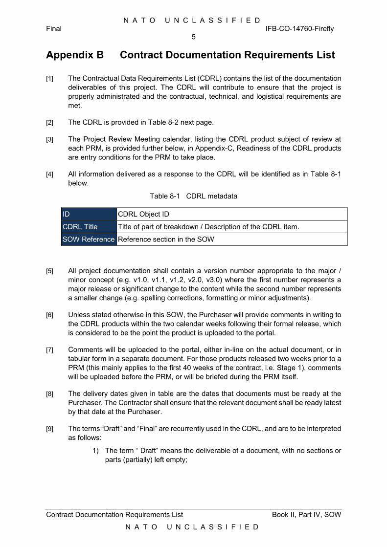
N A T O U N C L A S S I F I E D Final IFB-CO-14760-Firefly
5
Contract Documentation Requirements List Book II, Part IV, SOW
N A T O U N C L A S S I F I E D
Contract Documentation Requirements List
[1] The Contractual Data Requirements List (CDRL) contains the list of the documentation deliverables of this project. The CDRL will contribute to ensure that the project is properly administrated and the contractual, technical, and logistical requirements are met.
[2] The CDRL is provided in Table 8-2 next page.
[3] The Project Review Meeting calendar, listing the CDRL product subject of review at each PRM, is provided further below, in Appendix-C, Readiness of the CDRL products are entry conditions for the PRM to take place.
[4] All information delivered as a response to the CDRL will be identified as in Table 8-1 below.
Table 8-1 CDRL metadata
ID CDRL Object ID
CDRL Title Title of part of breakdown / Description of the CDRL item.
SOW Reference Reference section in the SOW
[5] All project documentation shall contain a version number appropriate to the major / minor concept (e.g. v1.0, v1.1, v1.2, v2.0, v3.0) where the first number represents a major release or significant change to the content while the second number represents a smaller change (e.g. spelling corrections, formatting or minor adjustments).
[6] Unless stated otherwise in this SOW, the Purchaser will provide comments in writing to the CDRL products within the two calendar weeks following their formal release, which is considered to be the point the product is uploaded to the portal.
[7] Comments will be uploaded to the portal, either in-line on the actual document, or in tabular form in a separate document. For those products released two weeks prior to a PRM (this mainly applies to the first 40 weeks of the contract, i.e. Stage 1), comments will be uploaded before the PRM, or will be briefed during the PRM itself.
[8] The delivery dates given in table are the dates that documents must be ready at the Purchaser. The Contractor shall ensure that the relevant document shall be ready latest by that date at the Purchaser.
[9] The terms “Draft” and “Final” are recurrently used in the CDRL, and are to be interpreted as follows:
1) The term “ Draft” means the deliverable of a document, with no sections or parts (partially) left empty;
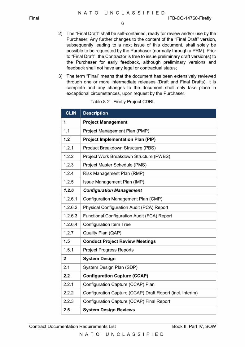
N A T O U N C L A S S I F I E D Final IFB-CO-14760-Firefly
6
Contract Documentation Requirements List Book II, Part IV, SOW
N A T O U N C L A S S I F I E D
2) The “Final Draft” shall be self-contained, ready for review and/or use by the Purchaser. Any further changes to the content of the “Final Draft” version, subsequently leading to a next issue of this document, shall solely be possible to be requested by the Purchaser (normally through a PRM). Prior to “Final Draft”, the Contractor is free to issue preliminary draft version(s) to the Purchaser for early feedback, although preliminary versions and feedback shall not have any legal or contractual status;
3) The term “Final” means that the document has been extensively reviewed through one or more intermediate releases (Draft and Final Drafts), it is complete and any changes to the document shall only take place in exceptional circumstances, upon request by the Purchaser.
Table 8-2 Firefly Project CDRL
CLIN Description
1 Project Management
1.1 Project Management Plan (PMP)
1.2 Project Implementation Plan (PIP)
1.2.1 Product Breakdown Structure (PBS)
1.2.2 Project Work Breakdown Structure (PWBS)
1.2.3 Project Master Schedule (PMS)
1.2.4 Risk Management Plan (RMP)
1.2.5 Issue Management Plan (IMP)
1.2.6 Configuration Management
1.2.6.1 Configuration Management Plan (CMP)
1.2.6.2 Physical Configuration Audit (PCA) Report
1.2.6.3 Functional Configuration Audit (FCA) Report
1.2.6.4 Configuration Item Tree
1.2.7 Quality Plan (QAP)
1.5 Conduct Project Review Meetings
1.5.1 Project Progress Reports
2 System Design
2.1 System Design Plan (SDP)
2.2 Configuration Capture (CCAP)
2.2.1 Configuration Capture (CCAP) Plan
2.2.2 Configuration Capture (CCAP) Draft Report (incl. Interim)
2.2.3 Configuration Capture (CCAP) Final Report
2.5 System Design Reviews
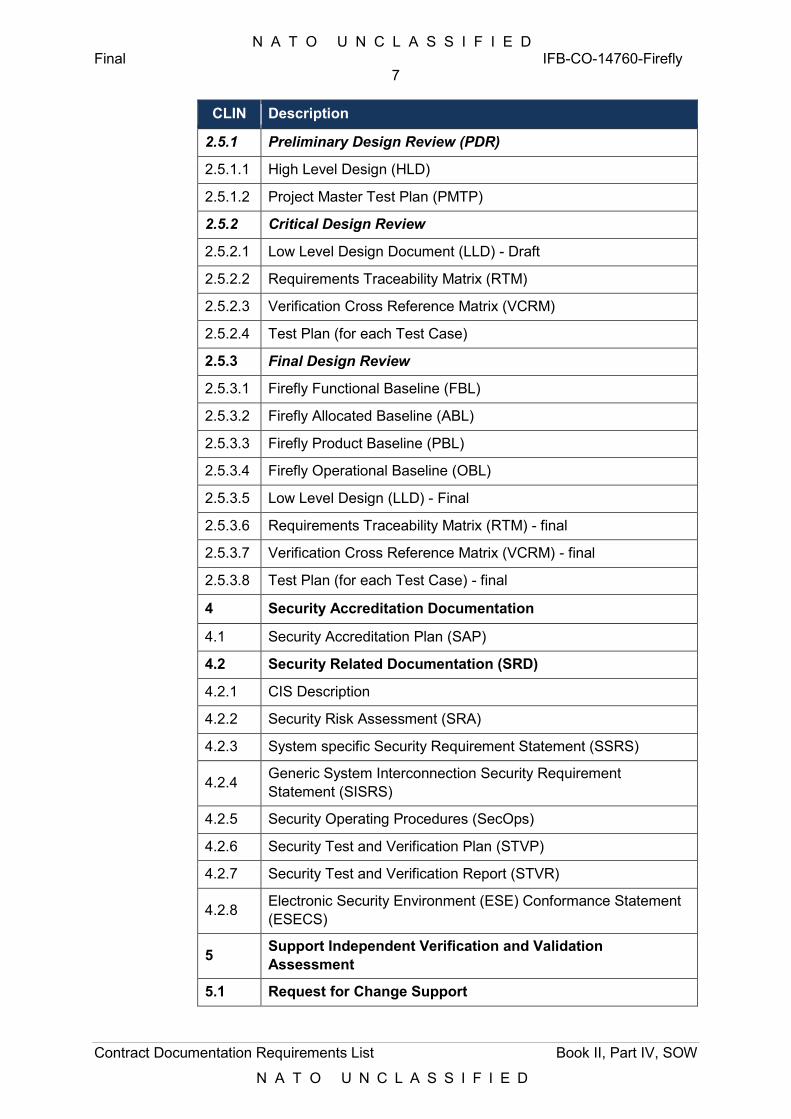
N A T O U N C L A S S I F I E D Final IFB-CO-14760-Firefly
7
Contract Documentation Requirements List Book II, Part IV, SOW
N A T O U N C L A S S I F I E D
CLIN Description
2.5.1 Preliminary Design Review (PDR)
2.5.1.1 High Level Design (HLD)
2.5.1.2 Project Master Test Plan (PMTP)
2.5.2 Critical Design Review
2.5.2.1 Low Level Design Document (LLD) - Draft
2.5.2.2 Requirements Traceability Matrix (RTM)
2.5.2.3 Verification Cross Reference Matrix (VCRM)
2.5.2.4 Test Plan (for each Test Case)
2.5.3 Final Design Review
2.5.3.1 Firefly Functional Baseline (FBL)
2.5.3.2 Firefly Allocated Baseline (ABL)
2.5.3.3 Firefly Product Baseline (PBL)
2.5.3.4 Firefly Operational Baseline (OBL)
2.5.3.5 Low Level Design (LLD) - Final
2.5.3.6 Requirements Traceability Matrix (RTM) - final
2.5.3.7 Verification Cross Reference Matrix (VCRM) - final
2.5.3.8 Test Plan (for each Test Case) - final
4 Security Accreditation Documentation
4.1 Security Accreditation Plan (SAP)
4.2 Security Related Documentation (SRD)
4.2.1 CIS Description
4.2.2 Security Risk Assessment (SRA)
4.2.3 System specific Security Requirement Statement (SSRS)
4.2.4 Generic System Interconnection Security Requirement Statement (SISRS)
4.2.5 Security Operating Procedures (SecOps)
4.2.6 Security Test and Verification Plan (STVP)
4.2.7 Security Test and Verification Report (STVR)
4.2.8 Electronic Security Environment (ESE) Conformance Statement (ESECS)
5 Support Independent Verification and Validation Assessment
5.1 Request for Change Support
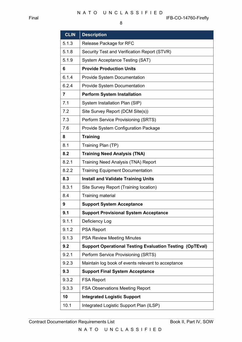
N A T O U N C L A S S I F I E D Final IFB-CO-14760-Firefly
8
Contract Documentation Requirements List Book II, Part IV, SOW
N A T O U N C L A S S I F I E D
CLIN Description
5.1.3 Release Package for RFC
5.1.8 Security Test and Verification Report (STVR)
5.1.9 System Acceptance Testing (SAT)
6 Provide Production Units
6.1.4 Provide System Documentation
6.2.4 Provide System Documentation
7 Perform System Installation
7.1 System Installation Plan (SIP)
7.2 Site Survey Report (DCM Site(s))
7.3 Perform Service Provisioning (SRTS)
7.6 Provide System Configuration Package
8 Training
8.1 Training Plan (TP)
8.2 Training Need Analysis (TNA)
8.2.1 Training Need Analysis (TNA) Report
8.2.2 Training Equipment Documentation
8.3 Install and Validate Training Units
8.3.1 Site Survey Report (Training location)
8.4 Training material
9 Support System Acceptance
9.1 Support Provisional System Acceptance
9.1.1 Deficiency Log
9.1.2 PSA Report
9.1.3 PSA Review Meeting Minutes
9.2 Support Operational Testing Evaluation Testing (OpTEval)
9.2.1 Perform Service Provisioning (SRTS)
9.2.3 Maintain log book of events relevant to acceptance
9.3 Support Final System Acceptance
9.3.2 FSA Report
9.3.3 FSA Observations Meeting Report
10 Integrated Logistic Support
10.1 Integrated Logistic Support Plan (ILSP)
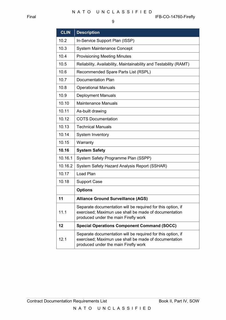
N A T O U N C L A S S I F I E D Final IFB-CO-14760-Firefly
9
Contract Documentation Requirements List Book II, Part IV, SOW
N A T O U N C L A S S I F I E D
CLIN Description
10.2 In-Service Support Plan (ISSP)
10.3 System Maintenance Concept
10.4 Provisioning Meeting Minutes
10.5 Reliability, Availability, Maintainability and Testability (RAMT)
10.6 Recommended Spare Parts List (RSPL)
10.7 Documentation Plan
10.8 Operational Manuals
10.9 Deployment Manuals
10.10 Maintenance Manuals
10.11 As-built drawing
10.12 COTS Documentation
10.13 Technical Manuals
10.14 System Inventory
10.15 Warranty
10.16 System Safety
10.16.1 System Safety Programme Plan (SSPP)
10.16.2 System Safety Hazard Analysis Report (SSHAR)
10.17 Load Plan
10.18 Support Case
Options
11 Alliance Ground Surveillance (AGS)
11.1 Separate documentation will be required for this option, if exercised; Maximun use shall be made of documentation produced under the main Firefly work
12 Special Operations Component Command (SOCC)
12.1 Separate documentation will be required for this option, if exercised; Maximun use shall be made of documentation produced under the main Firefly work
N A T O U N C L A S S I F I E D Final IFB-CO-14760-Firefly
10
Project Meetings Calendar Book II, Part IV, SOW
N A T O U N C L A S S I F I E D
Appendix C Project Meetings Calendar
Project Meetings Calendar to be provided by the Contractor after agreement with the Purchaser.
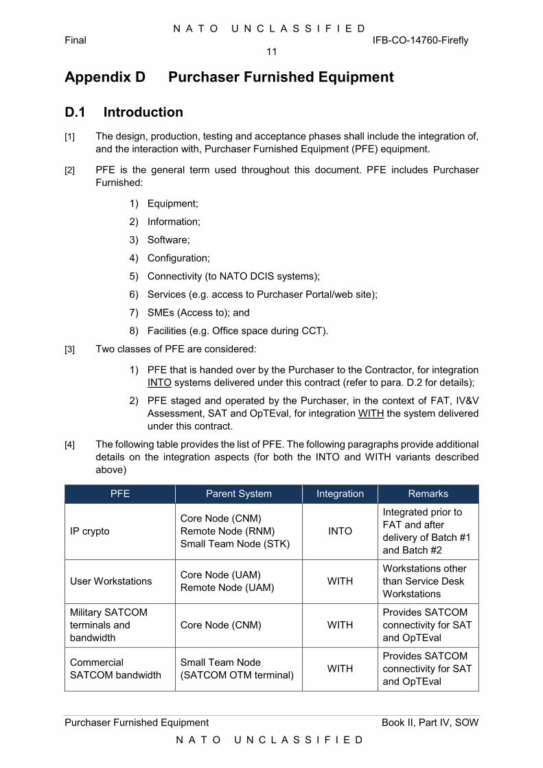
N A T O U N C L A S S I F I E D Final IFB-CO-14760-Firefly
11
Purchaser Furnished Equipment Book II, Part IV, SOW
N A T O U N C L A S S I F I E D
Appendix D Purchaser Furnished Equipment
D.1 Introduction
[1] The design, production, testing and acceptance phases shall include the integration of, and the interaction with, Purchaser Furnished Equipment (PFE) equipment.
[2] PFE is the general term used throughout this document. PFE includes Purchaser Furnished:
1) Equipment;
2) Information;
3) Software;
4) Configuration;
5) Connectivity (to NATO DCIS systems);
6) Services (e.g. access to Purchaser Portal/web site);
7) SMEs (Access to); and
8) Facilities (e.g. Office space during CCT).
[3] Two classes of PFE are considered:
1) PFE that is handed over by the Purchaser to the Contractor, for integration INTO systems delivered under this contract (refer to para. D.2 for details);
2) PFE staged and operated by the Purchaser, in the context of FAT, IV&V Assessment, SAT and OpTEval, for integration WITH the system delivered under this contract.
[4] The following table provides the list of PFE. The following paragraphs provide additional details on the integration aspects (for both the INTO and WITH variants described above)
PFE Parent System Integration Remarks
IP crypto Core Node (CNM) Remote Node (RNM) Small Team Node (STK)
INTO
Integrated prior to FAT and after delivery of Batch #1 and Batch #2
User Workstations Core Node (UAM) Remote Node (UAM) WITH
Workstations other than Service Desk Workstations
Military SATCOM terminals and bandwidth
Core Node (CNM) WITH Provides SATCOM connectivity for SAT and OpTEval
Commercial SATCOM bandwidth
Small Team Node (SATCOM OTM terminal) WITH
Provides SATCOM connectivity for SAT and OpTEval
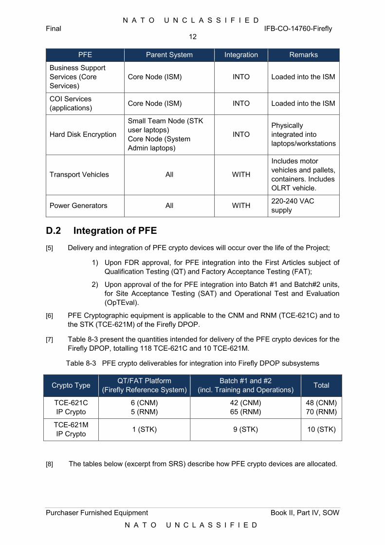
N A T O U N C L A S S I F I E D Final IFB-CO-14760-Firefly
12
Purchaser Furnished Equipment Book II, Part IV, SOW
N A T O U N C L A S S I F I E D
PFE Parent System Integration Remarks
Business Support Services (Core Services)
Core Node (ISM) INTO Loaded into the ISM
COI Services (applications) Core Node (ISM) INTO Loaded into the ISM
Hard Disk Encryption
Small Team Node (STK user laptops) Core Node (System Admin laptops)
INTO Physically integrated into laptops/workstations
Transport Vehicles All WITH
Includes motor vehicles and pallets, containers. Includes OLRT vehicle.
Power Generators All WITH 220-240 VAC supply
D.2 Integration of PFE
[5] Delivery and integration of PFE crypto devices will occur over the life of the Project;
1) Upon FDR approval, for PFE integration into the First Articles subject of Qualification Testing (QT) and Factory Acceptance Testing (FAT);
2) Upon approval of the for PFE integration into Batch #1 and Batch#2 units, for Site Acceptance Testing (SAT) and Operational Test and Evaluation (OpTEval).
[6] PFE Cryptographic equipment is applicable to the CNM and RNM (TCE-621C) and to the STK (TCE-621M) of the Firefly DPOP.
[7] Table 8-3 present the quantities intended for delivery of the PFE crypto devices for the Firefly DPOP, totalling 118 TCE-621C and 10 TCE-621M.
Table 8-3 PFE crypto deliverables for integration into Firefly DPOP subsystems
Crypto Type QT/FAT Platform (Firefly Reference System)
Batch #1 and #2 (incl. Training and Operations) Total
TCE-621C IP Crypto
6 (CNM) 5 (RNM)
42 (CNM) 65 (RNM)
48 (CNM) 70 (RNM)
TCE-621M IP Crypto 1 (STK) 9 (STK) 10 (STK)
[8] The tables below (excerpt from SRS) describe how PFE crypto devices are allocated.
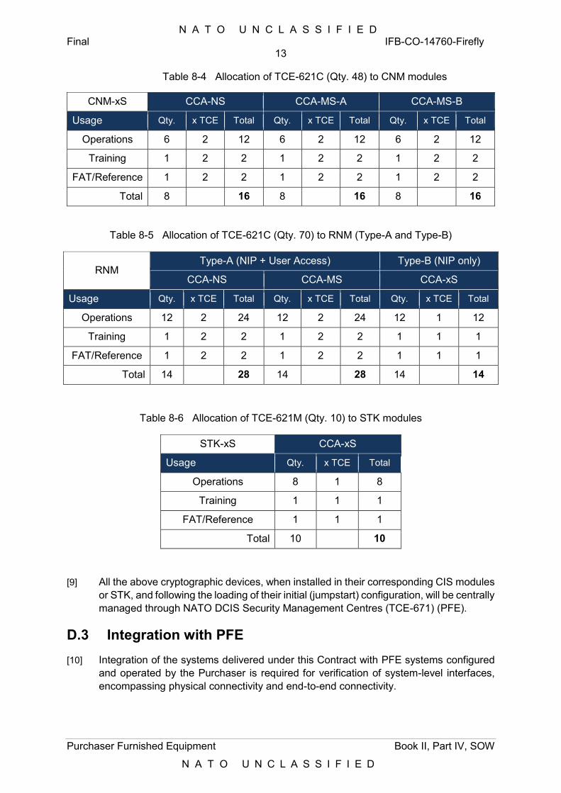
N A T O U N C L A S S I F I E D Final IFB-CO-14760-Firefly
13
Purchaser Furnished Equipment Book II, Part IV, SOW
N A T O U N C L A S S I F I E D
Table 8-4 Allocation of TCE-621C (Qty. 48) to CNM modules
CNM-xS CCA-NS CCA-MS-A CCA-MS-B
Usage Qty. x TCE Total Qty. x TCE Total Qty. x TCE Total
Operations 6 2 12 6 2 12 6 2 12
Training 1 2 2 1 2 2 1 2 2
FAT/Reference 1 2 2 1 2 2 1 2 2
Total 8 16 8 16 8 16
Table 8-5 Allocation of TCE-621C (Qty. 70) to RNM (Type-A and Type-B)
RNM Type-A (NIP + User Access) Type-B (NIP only)
CCA-NS CCA-MS CCA-xS
Usage Qty. x TCE Total Qty. x TCE Total Qty. x TCE Total
Operations 12 2 24 12 2 24 12 1 12
Training 1 2 2 1 2 2 1 1 1
FAT/Reference 1 2 2 1 2 2 1 1 1
Total 14 28 14 28 14 14
Table 8-6 Allocation of TCE-621M (Qty. 10) to STK modules
STK-xS CCA-xS
Usage Qty. x TCE Total
Operations 8 1 8
Training 1 1 1
FAT/Reference 1 1 1
Total 10 10
[9] All the above cryptographic devices, when installed in their corresponding CIS modules or STK, and following the loading of their initial (jumpstart) configuration, will be centrally managed through NATO DCIS Security Management Centres (TCE-671) (PFE).
D.3 Integration with PFE
[10] Integration of the systems delivered under this Contract with PFE systems configured and operated by the Purchaser is required for verification of system-level interfaces, encompassing physical connectivity and end-to-end connectivity.
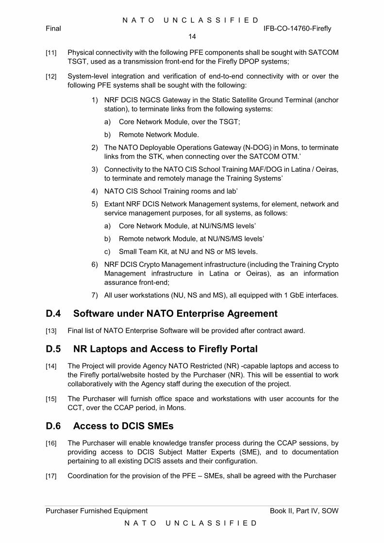
N A T O U N C L A S S I F I E D Final IFB-CO-14760-Firefly
14
Purchaser Furnished Equipment Book II, Part IV, SOW
N A T O U N C L A S S I F I E D
[11] Physical connectivity with the following PFE components shall be sought with SATCOM TSGT, used as a transmission front-end for the Firefly DPOP systems;
[12] System-level integration and verification of end-to-end connectivity with or over the following PFE systems shall be sought with the following:
1) NRF DCIS NGCS Gateway in the Static Satellite Ground Terminal (anchor station), to terminate links from the following systems:
a) Core Network Module, over the TSGT;
b) Remote Network Module.
2) The NATO Deployable Operations Gateway (N-DOG) in Mons, to terminate links from the STK, when connecting over the SATCOM OTM.’
3) Connectivity to the NATO CIS School Training MAF/DOG in Latina / Oeiras, to terminate and remotely manage the Training Systems’
4) NATO CIS School Training rooms and lab’
5) Extant NRF DCIS Network Management systems, for element, network and service management purposes, for all systems, as follows:
a) Core Network Module, at NU/NS/MS levels’
b) Remote network Module, at NU/NS/MS levels’
c) Small Team Kit, at NU and NS or MS levels.
6) NRF DCIS Crypto Management infrastructure (including the Training Crypto Management infrastructure in Latina or Oeiras), as an information assurance front-end;
7) All user workstations (NU, NS and MS), all equipped with 1 GbE interfaces.
D.4 Software under NATO Enterprise Agreement
[13] Final list of NATO Enterprise Software will be provided after contract award.
D.5 NR Laptops and Access to Firefly Portal
[14] The Project will provide Agency NATO Restricted (NR) -capable laptops and access to the Firefly portal/website hosted by the Purchaser (NR). This will be essential to work collaboratively with the Agency staff during the execution of the project.
[15] The Purchaser will furnish office space and workstations with user accounts for the CCT, over the CCAP period, in Mons.
D.6 Access to DCIS SMEs
[16] The Purchaser will enable knowledge transfer process during the CCAP sessions, by providing access to DCIS Subject Matter Experts (SME), and to documentation pertaining to all existing DCIS assets and their configuration.
[17] Coordination for the provision of the PFE – SMEs, shall be agreed with the Purchaser
N A T O U N C L A S S I F I E D Final IFB-CO-14760-Firefly
15
Purchaser Furnished Equipment Book II, Part IV, SOW
N A T O U N C L A S S I F I E D
D.7 CCT Hosting
[18] The Purchaser will furnish office space and workstations with guest accounts for the CCT, over the CCAP period, in Mons.
D.8 SRTS Training
[19] The Purchaser will provide training on the SRTS toolset in Mons, in support of the provisioning of Firefly DPOPs for testing by the Contractor.
D.9 Access to IVV Tools
[20] Requirements Coverage, Defect Management and Test Management tools to be used in this project will be hosted by the Purchaser.
[21] The Purchaser will grant access to the above tools to an agreed number of individuals nominated by the Contractor.
[22] Access will be provided through the REACH laptops mentioned in D.5 above.
[23] Details of the tools will be made available after Contract Award.
D.10 ILS Inventory Template
[24] The Contractor shall use the inventory template provided the Purchaser to develop and submit the System Inventory. To be provided after Contract Award.
D.11 Security Documentation Templates
[25] For the documentation list see Annex B
D.12 Cross Domain Gateway Software
[26] As per the SRS, any XML guards intended to support cross-domain services in the CGM will be provided as PFE, if and when required in support of testing activities.
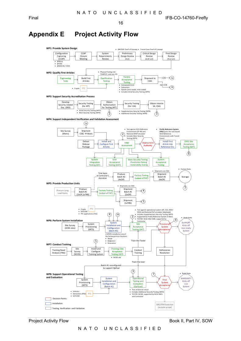
N A T O U N C L A S S I F I E D Final IFB-CO-14760-Firefly
16
Project Activity Flow Book II, Part IV, SOW
N A T O U N C L A S S I F I E D
Project Activity Flow
Configuration Capturing
(CCAP)
CCAPClosure Meeting
System Requirements
Review
Critical Design Review
(draft LLD)
Final Design Review
(final LLD)
Engineering Tests
Build First Articles
Qualification Testing
Factory Acceptance
Testing
Shipment to CSSC
Develop Security-related
Doc. (SRD)
Obtain Authorization
for Testing (AfT)
Shipment CSSC Mons
DeliverRelease Package
Install and Configure First
Articles
IV&VAssessment
Install First Article into
Reference Env.
Deployment Authority
Procure Long Lead Items
Produce Batch #1
(2xOP,1xTRN)
Factory Testing (subset of FAT)
Shipment Batch #1(2xOP)
Shipment (1xTRN)
Produce Batch #2 (4xOP)
Factory Testing (subset of FAT)
Shipment Batch #2 (4xOP)
Site Survey (DCM sites)
System Provisioning
(SRTS)
System Installation and Configuration
(Batch #1)
Site Acceptance
Testing (SAT)
Provisional System
Acceptance
SUPPORT Kicks-off
Live-readySystem
Training Need Analysis (TNA)
Install and Configure
Training System
Conduct Training
Train the Tester
Site Survey (NCISS)
System Provisioning
(SRTS)
System Installation and Configuration
(Batch #1)
Operational Testing and Evaluation (OpTEval)
WARRANTYKicks-off
LiveSystem
Batch #1 reconfigured to support OpEval
System Integration Testing (SIT)
User Acceptance
Testing (UAT)
Main Security Testing -Penetration Testing
-Vulnerability Testing
Final System
Acceptance
Site Survey (Mons)
CIS
Component/Unit Subsystem System (intra-nodal, inter-nodal) Includes Initial Security Testing (WP3)
Physical Testing incl. TEMPEST, and non-CIS
Train the User
WP1: Provide System Design
WP2: Qualify First Articles
WP3: Support Security Accreditation Process
WP4: Support Independent Verification and Validation Assessment
Storage
WP5: Provide Production Units
Time lapseat Contractor’s
discretion
2 DPOPs installed at one of the below garrison locations: Wesel Bydgoszcz Grazzanise
WP6: Perform System Installation
WP7: Conduct Training
WP8: Support Operational Testing and Evaluation
ISM/SDE Proof of Concept Transit Case Proof of Concept
@Mons @CSSC @NSB HQ / DCM
Firefly Reference System (FRS) (joins the rack-based DCIS Reference Environment, with Transit Cases)
Test against DCIS Reference Environment (DF #9) and National DPOP emulator
Includes Main Security Testing (WP3)
Shipments via CSSC
Shipments via CSSC
5
5
Test against operational system (DF, CGS, MAF/DOG) and National PoP emulator (deployed)
Includes Supplementary Security Testing (WP3) Supported by Firefly Reference System in Mons TESTER: NCIA IV&V SME, supported by
Contractor
Test at Exercise venue Includes Additional Security Testing (WP3) TESTER: NCISG, supported by NCIA SMEs
and Contractor
Deficiencies Resolution
PFE
PFE
PFE Crypto
Crypto SATCOM PFE applications (FAS)
Vehicles Generators (PGS) SATCOM
SDE/ITM Evolution(outside scope)
Decision Points
Installation
Testing, Verification and Validation
System Acceptance
Testing
Security Testing(for AfT)
Obtain Interim SA, I(SA)
2 3 Initial Security Testing (WP2) Main Secutity Testing (WP4)
1a
Security Testing(for I-SA)
2
Supplementary Security Testing (WP6) Addiitional Secutity Testing (WP8)
2
3
4
4
1bnon-CIS
1b
NCISS site
(Training) Site Acceptance
Testing (SAT)
Factory State
Node State
Node State
7
7
1a
(FRS) Site Acceptance
Testing (SAT)
6
6
Preliminary Design Review
(HLD)
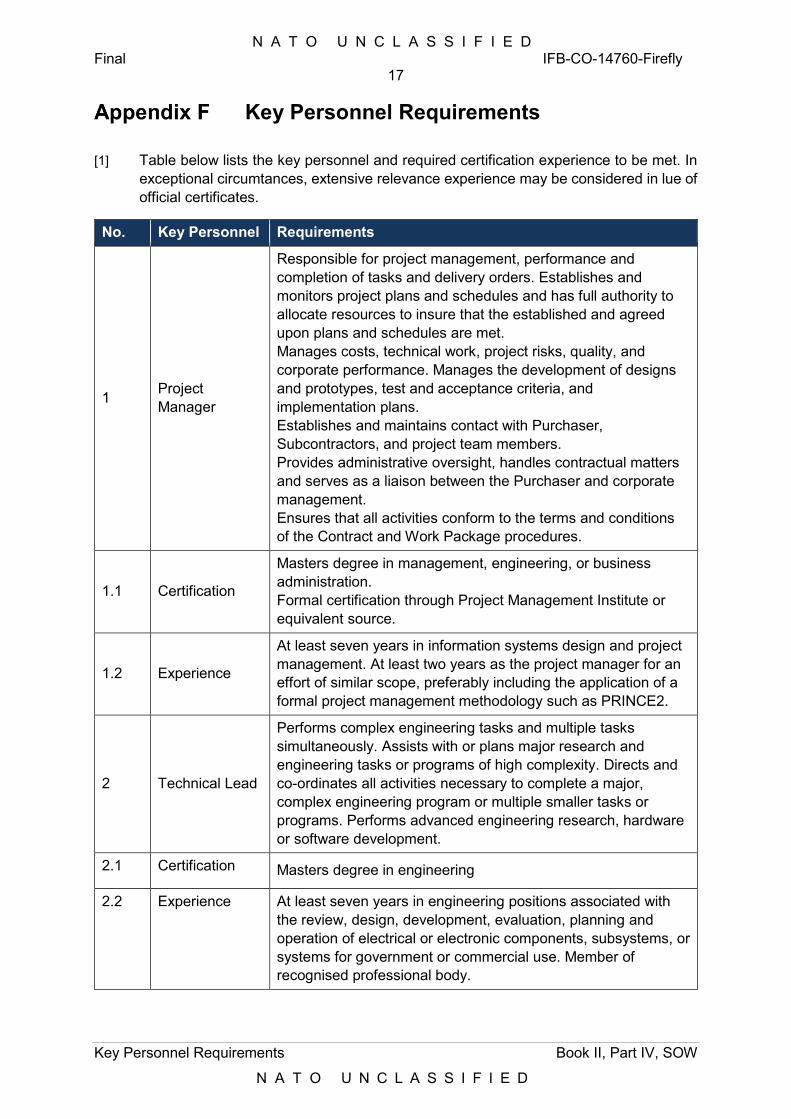
N A T O U N C L A S S I F I E D Final IFB-CO-14760-Firefly
17
Key Personnel Requirements Book II, Part IV, SOW
N A T O U N C L A S S I F I E D
Key Personnel Requirements
[1] Table below lists the key personnel and required certification experience to be met. In exceptional circumtances, extensive relevance experience may be considered in lue of official certificates.
No. Key Personnel Requirements
1 Project Manager
Responsible for project management, performance and completion of tasks and delivery orders. Establishes and monitors project plans and schedules and has full authority to allocate resources to insure that the established and agreed upon plans and schedules are met. Manages costs, technical work, project risks, quality, and corporate performance. Manages the development of designs and prototypes, test and acceptance criteria, and implementation plans. Establishes and maintains contact with Purchaser, Subcontractors, and project team members. Provides administrative oversight, handles contractual matters and serves as a liaison between the Purchaser and corporate management. Ensures that all activities conform to the terms and conditions of the Contract and Work Package procedures.
1.1 Certification
Masters degree in management, engineering, or business administration. Formal certification through Project Management Institute or equivalent source.
1.2 Experience
At least seven years in information systems design and project management. At least two years as the project manager for an effort of similar scope, preferably including the application of a formal project management methodology such as PRINCE2.
2 Technical Lead
Performs complex engineering tasks and multiple tasks simultaneously. Assists with or plans major research and engineering tasks or programs of high complexity. Directs and co-ordinates all activities necessary to complete a major, complex engineering program or multiple smaller tasks or programs. Performs advanced engineering research, hardware or software development.
2.1 Certification Masters degree in engineering
2.2 Experience At least seven years in engineering positions associated with the review, design, development, evaluation, planning and operation of electrical or electronic components, subsystems, or systems for government or commercial use. Member of recognised professional body.
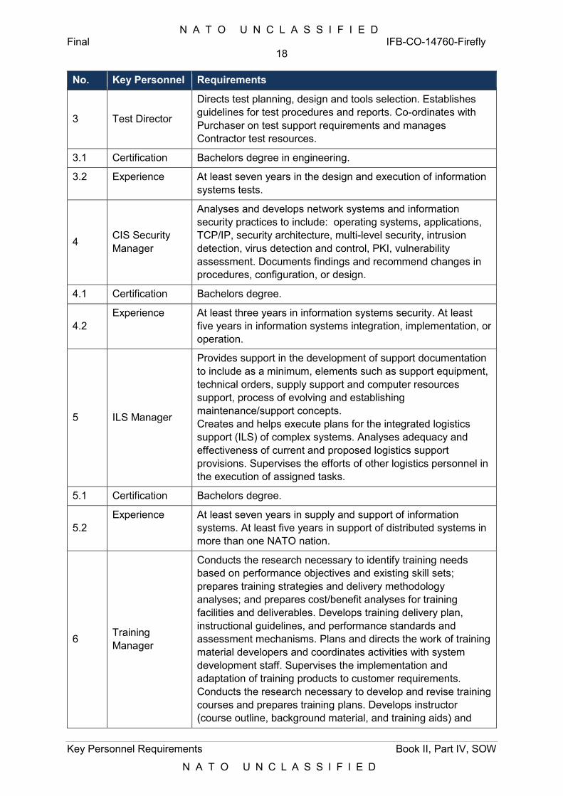
N A T O U N C L A S S I F I E D Final IFB-CO-14760-Firefly
18
Key Personnel Requirements Book II, Part IV, SOW
N A T O U N C L A S S I F I E D
No. Key Personnel Requirements
3 Test Director
Directs test planning, design and tools selection. Establishes guidelines for test procedures and reports. Co-ordinates with Purchaser on test support requirements and manages Contractor test resources.
3.1 Certification Bachelors degree in engineering.
3.2 Experience At least seven years in the design and execution of information systems tests.
4 CIS Security Manager
Analyses and develops network systems and information security practices to include: operating systems, applications, TCP/IP, security architecture, multi-level security, intrusion detection, virus detection and control, PKI, vulnerability assessment. Documents findings and recommend changes in procedures, configuration, or design.
4.1 Certification Bachelors degree.
4.2 Experience At least three years in information systems security. At least
five years in information systems integration, implementation, or operation.
5 ILS Manager
Provides support in the development of support documentation to include as a minimum, elements such as support equipment, technical orders, supply support and computer resources support, process of evolving and establishing maintenance/support concepts. Creates and helps execute plans for the integrated logistics support (ILS) of complex systems. Analyses adequacy and effectiveness of current and proposed logistics support provisions. Supervises the efforts of other logistics personnel in the execution of assigned tasks.
5.1 Certification Bachelors degree.
5.2 Experience At least seven years in supply and support of information
systems. At least five years in support of distributed systems in more than one NATO nation.
6 Training Manager
Conducts the research necessary to identify training needs based on performance objectives and existing skill sets; prepares training strategies and delivery methodology analyses; and prepares cost/benefit analyses for training facilities and deliverables. Develops training delivery plan, instructional guidelines, and performance standards and assessment mechanisms. Plans and directs the work of training material developers and coordinates activities with system development staff. Supervises the implementation and adaptation of training products to customer requirements. Conducts the research necessary to develop and revise training courses and prepares training plans. Develops instructor (course outline, background material, and training aids) and
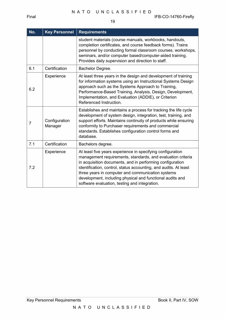
N A T O U N C L A S S I F I E D Final IFB-CO-14760-Firefly
19
Key Personnel Requirements Book II, Part IV, SOW
N A T O U N C L A S S I F I E D
No. Key Personnel Requirements
student materials (course manuals, workbooks, handouts, completion certificates, and course feedback forms). Trains personnel by conducting formal classroom courses, workshops, seminars, and/or computer based/computer-aided training. Provides daily supervision and direction to staff.
6.1 Certification Bachelor Degree.
6.2
Experience At least three years in the design and development of training for information systems using an Instructional Systems Design approach such as the Systems Approach to Training, Performance-Based Training, Analysis, Design, Development, Implementation, and Evaluation (ADDIE), or Criterion Referenced Instruction.
7 Configuration Manager
Establishes and maintains a process for tracking the life cycle development of system design, integration, test, training, and support efforts. Maintains continuity of products while ensuring conformity to Purchaser requirements and commercial standards. Establishes configuration control forms and database.
7.1 Certification Bachelors degree.
7.2
Experience At least five years experience in specifying configuration management requirements, standards, and evaluation criteria in acquisition documents, and in performing configuration identification, control, status accounting, and audits. At least three years in computer and communication systems development, including physical and functional audits and software evaluation, testing and integration.
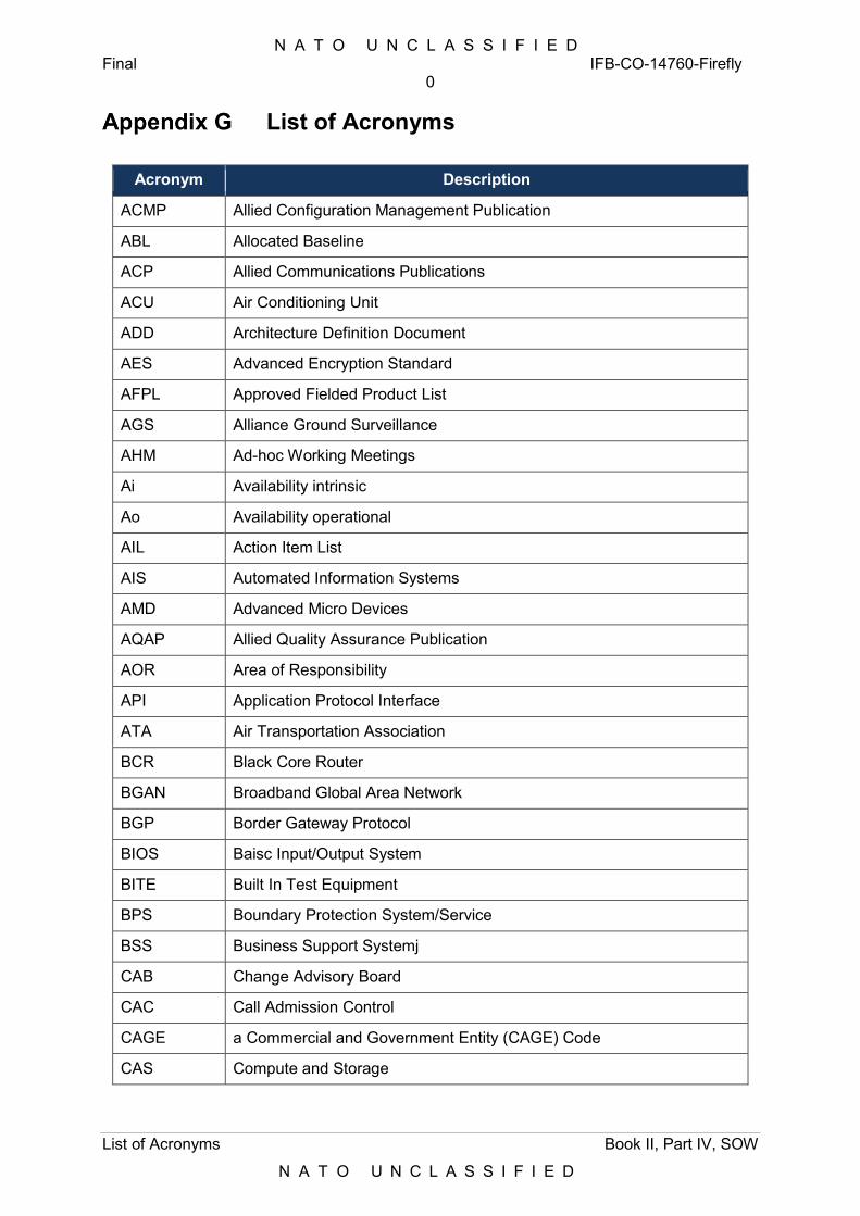
N A T O U N C L A S S I F I E D Final IFB-CO-14760-Firefly
0
List of Acronyms Book II, Part IV, SOW
N A T O U N C L A S S I F I E D
List of Acronyms
Acronym Description
ACMP Allied Configuration Management Publication
ABL Allocated Baseline
ACP Allied Communications Publications
ACU Air Conditioning Unit
ADD Architecture Definition Document
AES Advanced Encryption Standard
AFPL Approved Fielded Product List
AGS Alliance Ground Surveillance
AHM Ad-hoc Working Meetings
Ai Availability intrinsic
Ao Availability operational
AIL Action Item List
AIS Automated Information Systems
AMD Advanced Micro Devices
AQAP Allied Quality Assurance Publication
AOR Area of Responsibility
API Application Protocol Interface
ATA Air Transportation Association
BCR Black Core Router
BGAN Broadband Global Area Network
BGP Border Gateway Protocol
BIOS Baisc Input/Output System
BITE Built In Test Equipment
BPS Boundary Protection System/Service
BSS Business Support Systemj
CAB Change Advisory Board
CAC Call Admission Control
CAGE a Commercial and Government Entity (CAGE) Code
CAS Compute and Storage
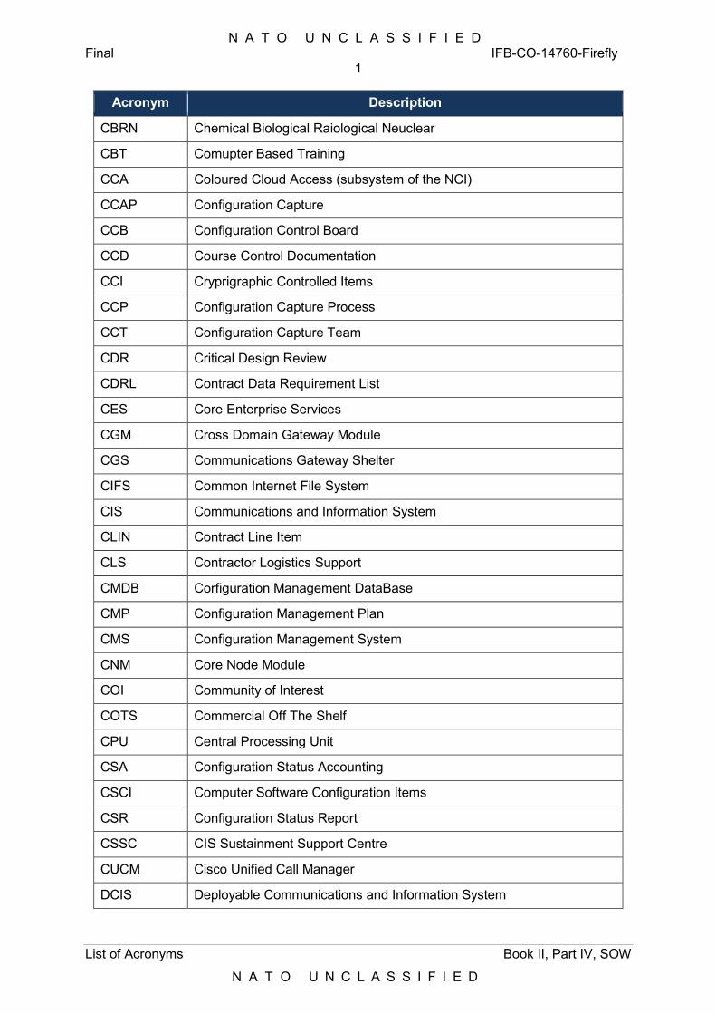
N A T O U N C L A S S I F I E D Final IFB-CO-14760-Firefly
1
List of Acronyms Book II, Part IV, SOW
N A T O U N C L A S S I F I E D
Acronym Description
CBRN Chemical Biological Raiological Neuclear
CBT Comupter Based Training
CCA Coloured Cloud Access (subsystem of the NCI)
CCAP Configuration Capture
CCB Configuration Control Board
CCD Course Control Documentation
CCI Cryprigraphic Controlled Items
CCP Configuration Capture Process
CCT Configuration Capture Team
CDR Critical Design Review
CDRL Contract Data Requirement List
CES Core Enterprise Services
CGM Cross Domain Gateway Module
CGS Communications Gateway Shelter
CIFS Common Internet File System
CIS Communications and Information System
CLIN Contract Line Item
CLS Contractor Logistics Support
CMDB Corfiguration Management DataBase
CMP Configuration Management Plan
CMS Configuration Management System
CNM Core Node Module
COI Community of Interest
COTS Commercial Off The Shelf
CPU Central Processing Unit
CSA Configuration Status Accounting
CSCI Computer Software Configuration Items
CSR Configuration Status Report
CSSC CIS Sustainment Support Centre
CUCM Cisco Unified Call Manager
DCIS Deployable Communications and Information System

N A T O U N C L A S S I F I E D Final IFB-CO-14760-Firefly
2
List of Acronyms Book II, Part IV, SOW
N A T O U N C L A S S I F I E D
Acronym Description
DCM Deployable CIS Module
DEU Deutschland
DHCP Dynamic Host Configuration Protocol
DIF Difficulty, Importance and Frequency (DIF) analysis
DMZ Demilitarized Zone
DNOC Deployable Network Operations Center
DNS Domain Name Service
DOB Deployable Operating Base
DOG Deployed Operations Gateway
DPI Dots Per Inch
DPOP Deployable Point Of Presence
DRS Deployable Removable Storage
DSGT Deployable Satellite Ground Terminal
DSMS Domain Service Management Subsystem
DSP Digital Signal Processor
DVD Digital Video Disk
DWPD Device/drive Writes Per Day
ECP Engineering Change Procedure
ECU Environmental Control Unit
EDC Effective Date of Contract
EEC European Economic Community
EGP Exterior Gateway Protocol
EMC Electro Magnetic Compatibility
EMI Electro Magementic Interference
EMSEC Emission Security
ESE Electronic Security Environment
ESECS Electronic Security Environment (ESE) Conformatnce Statement
ESP Spain
ETB External termination Board
EULA End User Licence Agreement
EUR Euro
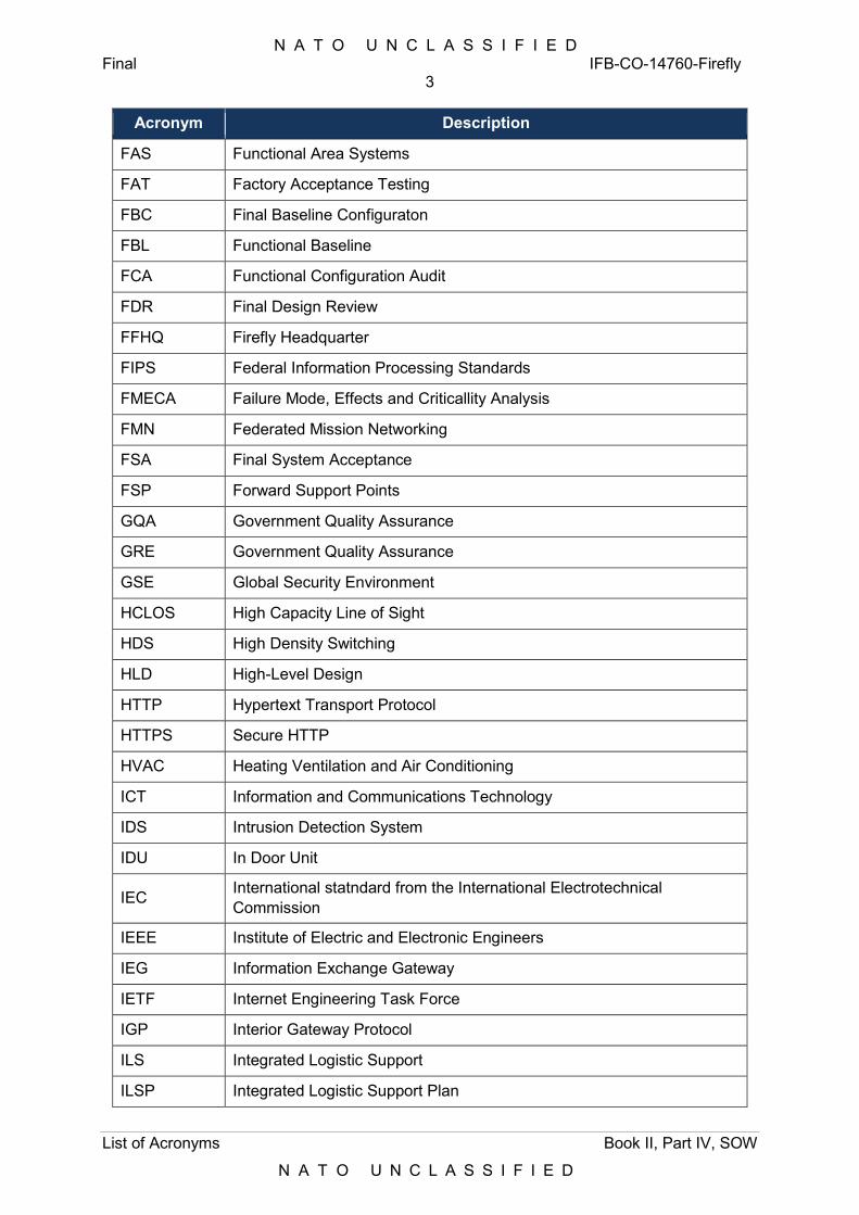
N A T O U N C L A S S I F I E D Final IFB-CO-14760-Firefly
3
List of Acronyms Book II, Part IV, SOW
N A T O U N C L A S S I F I E D
Acronym Description
FAS Functional Area Systems
FAT Factory Acceptance Testing
FBC Final Baseline Configuraton
FBL Functional Baseline
FCA Functional Configuration Audit
FDR Final Design Review
FFHQ Firefly Headquarter
FIPS Federal Information Processing Standards
FMECA Failure Mode, Effects and Criticallity Analysis
FMN Federated Mission Networking
FSA Final System Acceptance
FSP Forward Support Points
GQA Government Quality Assurance
GRE Government Quality Assurance
GSE Global Security Environment
HCLOS High Capacity Line of Sight
HDS High Density Switching
HLD High-Level Design
HTTP Hypertext Transport Protocol
HTTPS Secure HTTP
HVAC Heating Ventilation and Air Conditioning
ICT Information and Communications Technology
IDS Intrusion Detection System
IDU In Door Unit
IEC International statndard from the International Electrotechnical Commission
IEEE Institute of Electric and Electronic Engineers
IEG Information Exchange Gateway
IETF Internet Engineering Task Force
IGP Interior Gateway Protocol
ILS Integrated Logistic Support
ILSP Integrated Logistic Support Plan
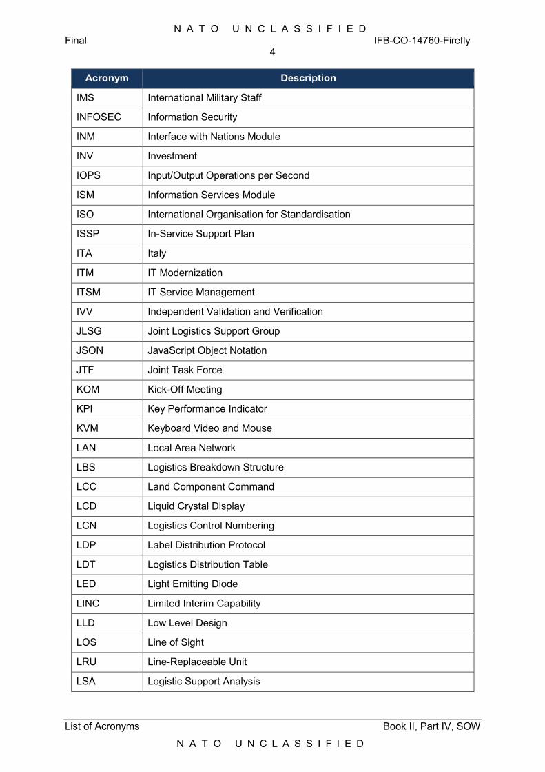
N A T O U N C L A S S I F I E D Final IFB-CO-14760-Firefly
4
List of Acronyms Book II, Part IV, SOW
N A T O U N C L A S S I F I E D
Acronym Description
IMS International Military Staff
INFOSEC Information Security
INM Interface with Nations Module
INV Investment
IOPS Input/Output Operations per Second
ISM Information Services Module
ISO International Organisation for Standardisation
ISSP In-Service Support Plan
ITA Italy
ITM IT Modernization
ITSM IT Service Management
IVV Independent Validation and Verification
JLSG Joint Logistics Support Group
JSON JavaScript Object Notation
JTF Joint Task Force
KOM Kick-Off Meeting
KPI Key Performance Indicator
KVM Keyboard Video and Mouse
LAN Local Area Network
LBS Logistics Breakdown Structure
LCC Land Component Command
LCD Liquid Crystal Display
LCN Logistics Control Numbering
LDP Label Distribution Protocol
LDT Logistics Distribution Table
LED Light Emitting Diode
LINC Limited Interim Capability
LLD Low Level Design
LOS Line of Sight
LRU Line-Replaceable Unit
LSA Logistic Support Analysis
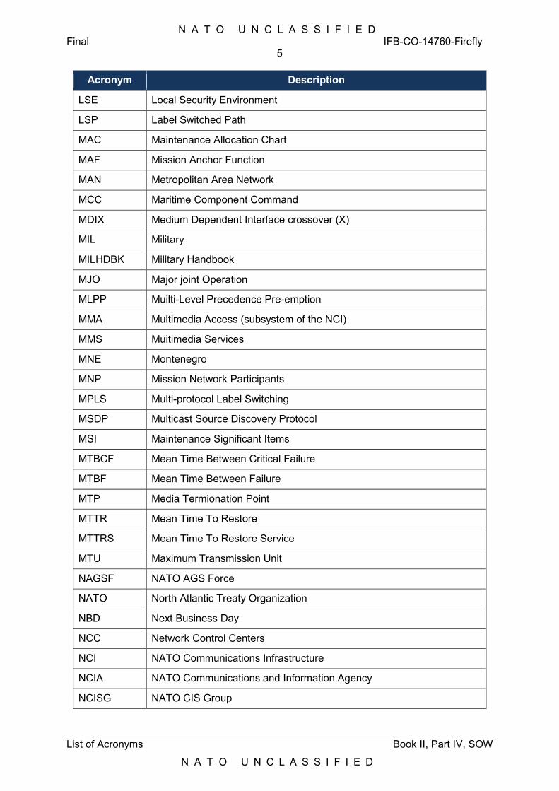
N A T O U N C L A S S I F I E D Final IFB-CO-14760-Firefly
5
List of Acronyms Book II, Part IV, SOW
N A T O U N C L A S S I F I E D
Acronym Description
LSE Local Security Environment
LSP Label Switched Path
MAC Maintenance Allocation Chart
MAF Mission Anchor Function
MAN Metropolitan Area Network
MCC Maritime Component Command
MDIX Medium Dependent Interface crossover (X)
MIL Military
MILHDBK Military Handbook
MJO Major joint Operation
MLPP Muilti-Level Precedence Pre-emption
MMA Multimedia Access (subsystem of the NCI)
MMS Muitimedia Services
MNE Montenegro
MNP Mission Network Participants
MPLS Multi-protocol Label Switching
MSDP Multicast Source Discovery Protocol
MSI Maintenance Significant Items
MTBCF Mean Time Between Critical Failure
MTBF Mean Time Between Failure
MTP Media Termionation Point
MTTR Mean Time To Restore
MTTRS Mean Time To Restore Service
MTU Maximum Transmission Unit
NAGSF NATO AGS Force
NATO North Atlantic Treaty Organization
NBD Next Business Day
NCC Network Control Centers
NCI NATO Communications Infrastructure
NCIA NATO Communications and Information Agency
NCISG NATO CIS Group
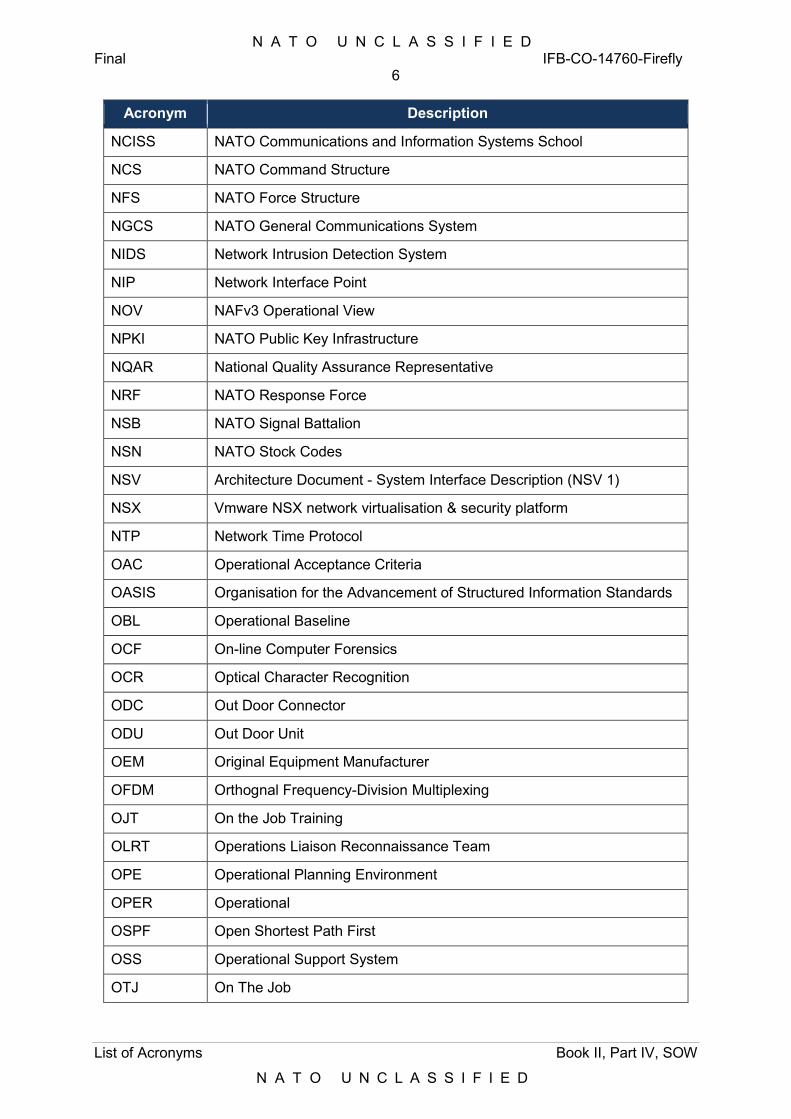
N A T O U N C L A S S I F I E D Final IFB-CO-14760-Firefly
6
List of Acronyms Book II, Part IV, SOW
N A T O U N C L A S S I F I E D
Acronym Description
NCISS NATO Communications and Information Systems School
NCS NATO Command Structure
NFS NATO Force Structure
NGCS NATO General Communications System
NIDS Network Intrusion Detection System
NIP Network Interface Point
NOV NAFv3 Operational View
NPKI NATO Public Key Infrastructure
NQAR National Quality Assurance Representative
NRF NATO Response Force
NSB NATO Signal Battalion
NSN NATO Stock Codes
NSV Architecture Document - System Interface Description (NSV 1)
NSX Vmware NSX network virtualisation & security platform
NTP Network Time Protocol
OAC Operational Acceptance Criteria
OASIS Organisation for the Advancement of Structured Information Standards
OBL Operational Baseline
OCF On-line Computer Forensics
OCR Optical Character Recognition
ODC Out Door Connector
ODU Out Door Unit
OEM Original Equipment Manufacturer
OFDM Orthognal Frequency-Division Multiplexing
OJT On the Job Training
OLRT Operations Liaison Reconnaissance Team
OPE Operational Planning Environment
OPER Operational
OSPF Open Shortest Path First
OSS Operational Support System
OTJ On The Job
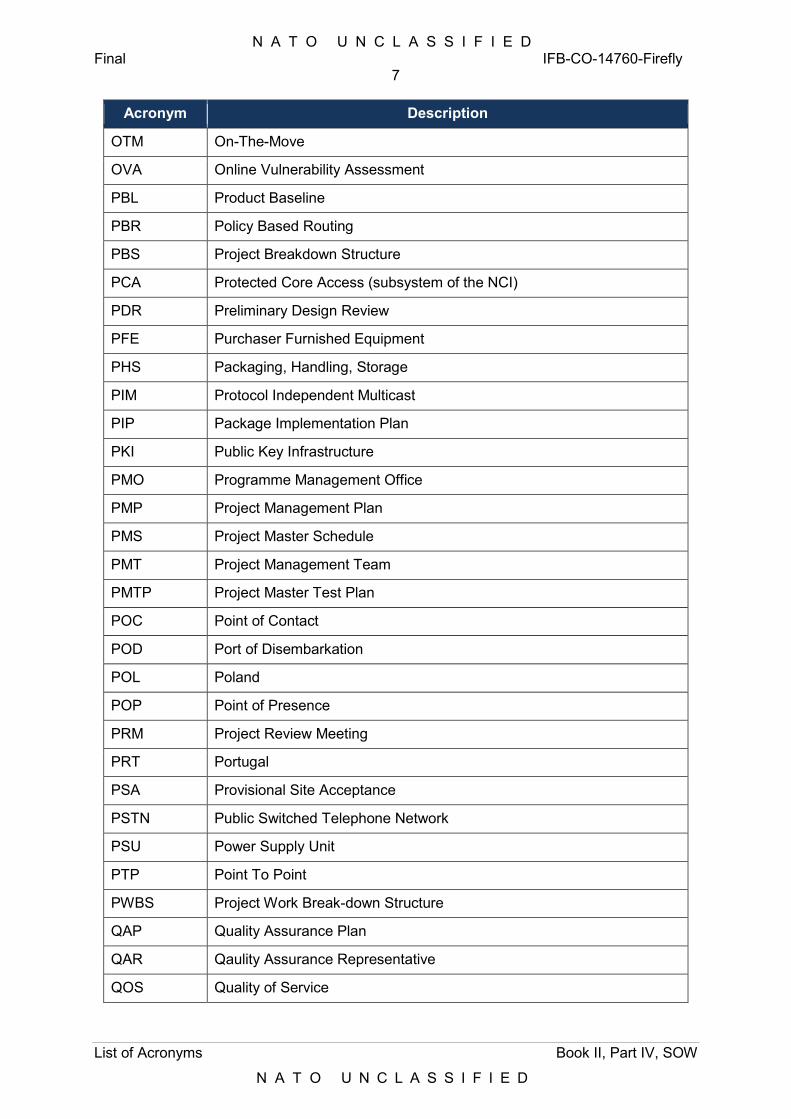
N A T O U N C L A S S I F I E D Final IFB-CO-14760-Firefly
7
List of Acronyms Book II, Part IV, SOW
N A T O U N C L A S S I F I E D
Acronym Description
OTM On-The-Move
OVA Online Vulnerability Assessment
PBL Product Baseline
PBR Policy Based Routing
PBS Project Breakdown Structure
PCA Protected Core Access (subsystem of the NCI)
PDR Preliminary Design Review
PFE Purchaser Furnished Equipment
PHS Packaging, Handling, Storage
PIM Protocol Independent Multicast
PIP Package Implementation Plan
PKI Public Key Infrastructure
PMO Programme Management Office
PMP Project Management Plan
PMS Project Master Schedule
PMT Project Management Team
PMTP Project Master Test Plan
POC Point of Contact
POD Port of Disembarkation
POL Poland
POP Point of Presence
PRM Project Review Meeting
PRT Portugal
PSA Provisional Site Acceptance
PSTN Public Switched Telephone Network
PSU Power Supply Unit
PTP Point To Point
PWBS Project Work Break-down Structure
QAP Quality Assurance Plan
QAR Qaulity Assurance Representative
QOS Quality of Service
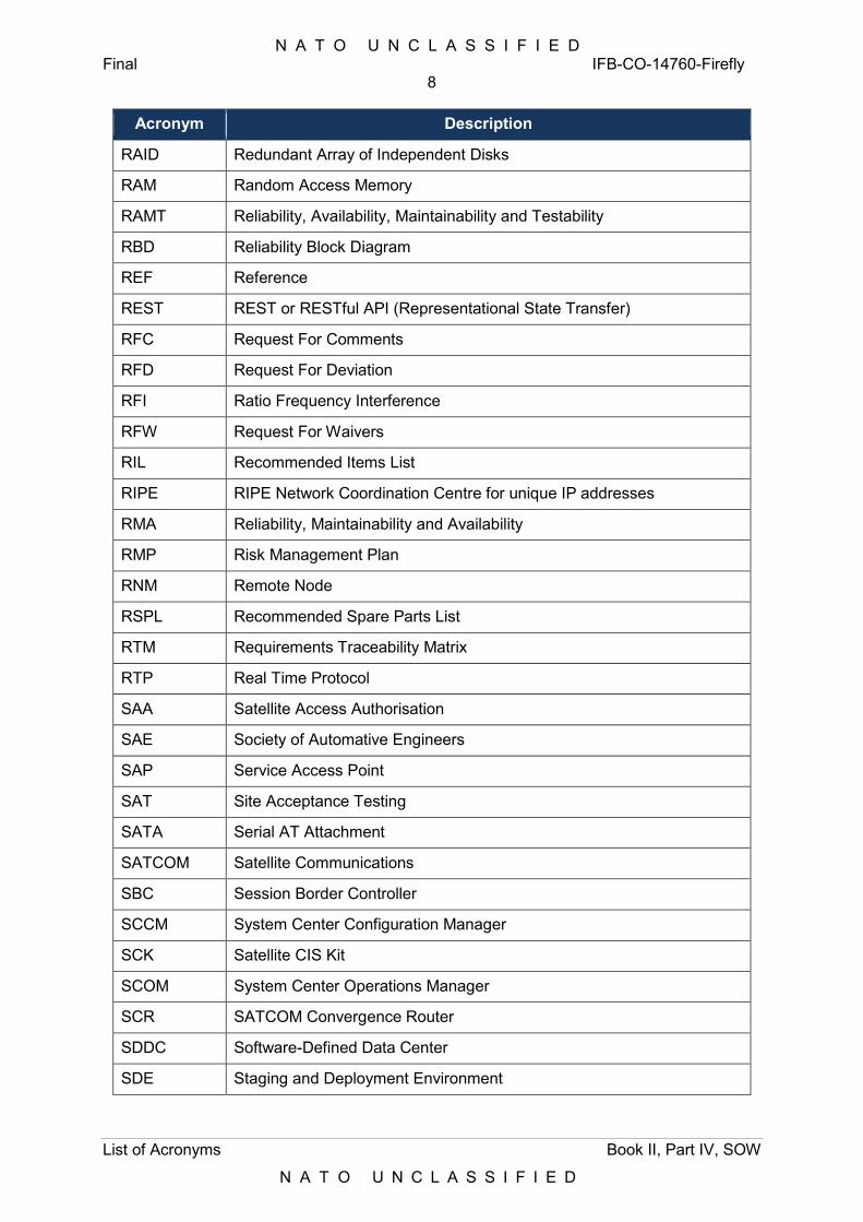
N A T O U N C L A S S I F I E D Final IFB-CO-14760-Firefly
8
List of Acronyms Book II, Part IV, SOW
N A T O U N C L A S S I F I E D
Acronym Description
RAID Redundant Array of Independent Disks
RAM Random Access Memory
RAMT Reliability, Availability, Maintainability and Testability
RBD Reliability Block Diagram
REF Reference
REST REST or RESTful API (Representational State Transfer)
RFC Request For Comments
RFD Request For Deviation
RFI Ratio Frequency Interference
RFW Request For Waivers
RIL Recommended Items List
RIPE RIPE Network Coordination Centre for unique IP addresses
RMA Reliability, Maintainability and Availability
RMP Risk Management Plan
RNM Remote Node
RSPL Recommended Spare Parts List
RTM Requirements Traceability Matrix
RTP Real Time Protocol
SAA Satellite Access Authorisation
SAE Society of Automative Engineers
SAP Service Access Point
SAT Site Acceptance Testing
SATA Serial AT Attachment
SATCOM Satellite Communications
SBC Session Border Controller
SCCM System Center Configuration Manager
SCK Satellite CIS Kit
SCOM System Center Operations Manager
SCR SATCOM Convergence Router
SDDC Software-Defined Data Center
SDE Staging and Deployment Environment
N A T O U N C L A S S I F I E D Final IFB-CO-14760-Firefly
9
List of Acronyms Book II, Part IV, SOW
N A T O U N C L A S S I F I E D
Acronym Description
SDIP SECAN Doctrine and Information Publication
SDN Software Defined Networking
SDP Standing Defence Plans
SDS Service Design Studio
SECAN (NATO) CIS Security and Evaluation Agency
SFF Safe Failure Fraction
SFP Small form-factor Pluggable
SGS Satellite Ground Station
SGT Satellite Ground Terminal
SHAPE Supreme Headquarters Allied Powers Europe
SIEM Security Information and Event Management
SIM Subscriber Identification Module
SIP Session Initiation Protocol
SIR System Installation Record
SISRS System Interconnection Security Requirement Statement
SIT System Integration Testing
SIVP Security Implementation Verification Procedures
SJO Small Joint Operations
SMB Server Message Block
SMC Service Management and Control
SME Subject Matter Expert
SMS Spectrum Monitoring System
SOCC Special Operations Component Command
SOTM SATCOM On The Move
SOW Statement of Work
SPOF Single Point of Failure
SRA Security Risk Assessement
SRD Security Related Documentation
SRR System Requirements Review
SRS System Requirements Statement
SRTS Service Request Tracking System
N A T O U N C L A S S I F I E D Final IFB-CO-14760-Firefly
10
List of Acronyms Book II, Part IV, SOW
N A T O U N C L A S S I F I E D
Acronym Description
SRU Shop Replaceable Unit
SSD Solid State Drive
SSHAR System Safety Hazard Analysis Report
SSM (PIM-SSM) Protocol Independent Multicast - Source Specific Mode
SSPP System Safety Program Plan
SSR Site Survey Report
SSRS System Specific Security Requirement Statement
SSS Schedule of Supplies and Service
STANAG Standardization Agreement
STD Standard
STK Small Team Kit
STP Spanning Tree Protocol
STVP Security Test and Verification Plan
STVR Security Test and Verification Report
SWDL Software Distribution List
TCO Total Cost of Ownership
TCP Transmission Control Protocol
TDM Time Division Multiplexing
TFS Traffic Flow Security
TLS Transport Layer Security
TNA Training Needs Analysis
TOSCA Topology and Orchestration Specification for Cloud Applications
TPM Trusted Platform Module
TRP Trusted Relay Point (MTP/TRP)
TRR Test Readiness Review
TSGT Transportable Satellite Ground Terminal
TST Test (ISM-TST)
TVV Test Validation and Verification
TWAIN Defacto standard in document scanners
TXT Trusted Execution Technology
UAM User Access Module
N A T O U N C L A S S I F I E D Final IFB-CO-14760-Firefly
11
List of Acronyms Book II, Part IV, SOW
N A T O U N C L A S S I F I E D
Acronym Description
UAT User Acceptance Testing
UNIMOG Unimog-Mercedes Benz
UPS Uninterruptable Power Supply
USA United States of America
USB Universal Serial Bus
VCRM Verification Cross Reference Matrix
VCU Virtual Crypto Units
VDC Volts Direct Current
VDI Virtual Desktop Infrastructure
VGA Vidio Graghics Array
VLAN Virtual Local Area Network
VOIP Voice over IP
VPN Virtual Private Network
VRF Virtual Routing and Forwarding
VSS Microsoft Visual SourceSafe
VTC Video Teleconference
WAN Wide Area Network
WINS Windows Internet Services
XML eXtensible Markup Language
XLS Microsoft Excel file format
YAML YAML Ain't Markup Language
ZIP File compression format

N A T O U N C L A S S I F I E D
N A T O U N C L A S S I F I E D
N A T O U N C L A S S I F I E D
N A T O U N C L A S S I F I E D
Provide DCIS Equipment for Small NRF HQ
Short Title: Project Firefly
Book II - Part IV
Statement of Work (SoW)
Annex A – System Requirements Specification (SRS)
Reference: IFB-CO-14760-Firefly
Publication Date: 14/12/2018
Classification: NATO UNCLASSIFIED
Status: Final
Version: 1.0
No. of pages 146

N A T O U N C L A S S I F I E D Final IFB-CO-14760-Firefly
ii
Book II, Part IV, SOW-Annex A (SRS)
N A T O U N C L A S S I F I E D
This page is intentionally left blank.
N A T O U N C L A S S I F I E D Final IFB-CO-14760-Firefly
iii
Book II, Part IV, SOW-Annex A (SRS)
N A T O U N C L A S S I F I E D
TABLE OF CONTENTS
TABLE OF CONTENTS ........................................................................................................ 3
Index of Figures ................................................................................................................... 6
1 Introduction .................................................................................................................. 1
1.1 CONTEXT ................................................................................................................. 2 1.2 SCOPE ..................................................................................................................... 4 1.3 CONVENTIONS .......................................................................................................... 5
2 High Level Design Specification ................................................................................. 8
2.1 CIS NODES .............................................................................................................. 9
2.1.1 Node Taxonomy ............................................................................................... 9
2.1.2 System Breakdown .........................................................................................11
2.2 NON-CIS ELEMENTS ................................................................................................16 2.3 CIS SERVICES .........................................................................................................18
2.3.1 Services Taxonomy .........................................................................................18
2.3.2 System Availability Targets .............................................................................18
2.3.2.1 Communications Services ........................................................................19
2.3.2.2 Infrastructure Services .............................................................................25
3 CIS Nodes Specification ............................................................................................ 26
3.1 GENERAL ................................................................................................................26
3.1.1 Modularity .......................................................................................................26
3.1.2 Casing .............................................................................................................27
3.1.3 Interfaces ........................................................................................................30
3.1.4 Environmental Endurance ...............................................................................31
3.1.5 Electromagnetic Compatibility .........................................................................32
3.1.6 Emission Security ............................................................................................32
3.1.7 Functional Safety ............................................................................................33
3.1.8 Power Supply ..................................................................................................33
3.1.9 Hazardous Substances ...................................................................................33
3.1.10 Security Hardening ..........................................................................................33
3.1.11 Timing .............................................................................................................33
3.2 CIS MODULES .........................................................................................................33
3.2.1 Core Network Modules ....................................................................................34
3.2.1.1 Functional Specification ...........................................................................36
3.2.1.2 Technical Requirements ...........................................................................39
3.2.1.3 Implementation Constraints ......................................................................49
3.2.2 Remote Network Modules ...............................................................................55
3.2.2.1 Functional Specification ...........................................................................56
3.2.2.2 Technical Requirements ...........................................................................57
N A T O U N C L A S S I F I E D Final IFB-CO-14760-Firefly
iv
Book II, Part IV, SOW-Annex A (SRS)
N A T O U N C L A S S I F I E D
3.2.2.3 Implementation Constraints ......................................................................60
3.2.3 User Access Modules ......................................................................................63
3.2.3.1 Functional Specification ...........................................................................65
3.2.3.2 Technical Requirements ...........................................................................65
3.2.3.3 Implementation Constraints ......................................................................67
3.2.4 Information Services Modules .........................................................................67
3.2.4.1 Functional Requirements .........................................................................69
3.2.4.2 Technical Requirements ...........................................................................73
3.2.4.3 Implementation Constraints ......................................................................81
3.2.5 Cross-domain Gateway Modules.....................................................................82
3.2.6 Small Team Kits ..............................................................................................85
3.2.6.1 Functional Requirements .........................................................................86
3.2.6.2 Technical Requirements ...........................................................................87
3.2.6.3 Implementation Constraints ......................................................................95
3.3 TRANSMISSION SYSTEMS .........................................................................................98
3.3.1 HCLOS radio ...................................................................................................98
3.3.1.1 Functional Requirements .........................................................................99
3.3.1.2 Technical Requirements ...........................................................................99
3.3.2 SATCOM On-the-move Terminal .................................................................. 101
3.3.2.1 Functional Requirements ....................................................................... 101
3.3.2.2 Technical Requirements ......................................................................... 102
3.3.3 Iridium Phone ................................................................................................ 103
3.4 USER APPLIANCES ................................................................................................. 104
3.4.1 Service Desk Laptops ................................................................................... 104
3.4.2 Printer/Scanners ........................................................................................... 105
3.4.3 Phones .......................................................................................................... 106
4 Staging and Deployment Environment ................................................................... 107
4.1 FUNCTIONAL REQUIREMENTS ................................................................................. 108
4.1.1 Orchestration Framework .............................................................................. 112
4.1.2 Service Design Studio ................................................................................... 115
4.1.3 Image Store .................................................................................................. 116
4.1.4 Version Control Tooling ................................................................................. 116
4.2 TECHNICAL REQUIREMENTS ................................................................................... 117
5 Service Management and Control ........................................................................... 120
6 Non-CIS Elements Specification ............................................................................. 122
6.1 HOUSING ELEMENTS .............................................................................................. 122
6.1.1 BC Tent ......................................................................................................... 123
N A T O U N C L A S S I F I E D Final IFB-CO-14760-Firefly
v
Book II, Part IV, SOW-Annex A (SRS)
N A T O U N C L A S S I F I E D
6.1.2 Service Desk Tent ......................................................................................... 123
6.1.3 External Termination Boards ......................................................................... 124
6.2 ENVIRONMENTAL CONTROL ELEMENTS ................................................................... 124
6.2.1 Tent Cooling .................................................................................................. 125
6.2.2 Case Cooling................................................................................................. 125
6.3 TRANSPORT ELEMENTS .......................................................................................... 126
6.3.1 Transit Cases ................................................................................................ 126
6.3.2 Transport Cases ............................................................................................ 128
6.3.3 Material Handling Equipment ........................................................................ 128
6.4 POWER SUPPLY ELEMENTS .................................................................................... 129
6.4.1 Uninterruptible Power Supply ........................................................................ 129
6.4.2 Power Distribution and Conditioning .............................................................. 130
6.4.2.1 Core Nodes ............................................................................................ 130
6.4.2.2 Remote Nodes ....................................................................................... 131
6.4.2.3 Small Team Kits ..................................................................................... 132
6.4.3 Grounding and bonding ................................................................................. 132
6.5 ANCILLARY ELEMENTS ........................................................................................... 132
6.5.1 Cabling and Wiring ........................................................................................ 132
6.5.2 Fibre Optic Reels .......................................................................................... 133
6.5.3 Antenna Masts .............................................................................................. 134
6.5.4 Vehicle Fixtures ............................................................................................. 134
Appendix A Applicable Documents ............................................................................... 1
N A T O U N C L A S S I F I E D Final IFB-CO-14760-Firefly
vi
Book II, Part IV, SOW-Annex A (SRS)
N A T O U N C L A S S I F I E D
INDEX OF FIGURES
Figure 1-1 Small NRF HQs in Context 2
Figure 1-2 Firefly in context 4
Figure 1-3 Block styling convention 7
Figure 2-1 DPOP Breakdown Structure (modelled using ArchiMate 3.0) 8
Figure 2-2 Firefly DPOP nodal breakdown 10
Figure 2-3 Firefly DPOP nodal breakdown (detail) 11
Figure 2-4 Allocation of Firefly nodes to Operational, Training and Reference roles 13
Figure 2-5 Firefly CIS Nodes breakdown 15
Figure 2-6 Non-CIS elements supporting Core Nodes 16
Figure 2-7 Non-CIS elements supporting Remote Nodes 17
Figure 2-8 Non-CIS elements supporting Small Team Nodes 17
Figure 2-9 Communication Services Availability – Core Node to Core Node 21
Figure 2-10 Communication Services Availability – Remote Node to Core Node 23
Figure 2-11 Communication Services Availability – Small Team Node to DOG (MAF) 25
Figure 3-1 CNMs in context 35
Figure 3-2 CNM building blocks 39
Figure 3-3 CNM subsystems breakdown 40
Figure 3-4 Target component distribution for CNM-PCA 49
Figure 3-5 Target component distribution for CNM-NU and CNM-xS 51
Figure 3-6 Redundant CNM-MS – Target implementation 52
Figure 3-7 CNM-NS – Target implementation 53
Figure 3-8 CNM-NU – Target implementation 54
Figure 3-9 RNMs in context (Type A and Type B) 55
Figure 3-10 RNMs in context – Connectivity to MAF and Dragonfly 56
Figure 3-11 Remote Network Module (RNM) building blocks 57
Figure 3-12 RNM subsystems breakdown – Type A (NIP and user access) 58
Figure 3-13 RNM subsystems breakdown – Type B (NIP only) 58
Figure 3-14 Target component distribution for RNM 61
Figure 3-15 RNM Type-A – Target implementation 62
Figure 3-16 RNM Type-B – Target implementation 63
Figure 3-17 UAMs in context (Core nodes) 64
Figure 3-18 UAMs in context (Core nodes) 64
Figure 3-19 User Access Module (RNM) building blocks 65
Figure 3-20 UAM subsystems breakdown 66
Figure 3-21 ISMs in context 68
Figure 3-22 Information Services Module (ISM) building blocks 74
N A T O U N C L A S S I F I E D Final IFB-CO-14760-Firefly
vii
Book II, Part IV, SOW-Annex A (SRS)
N A T O U N C L A S S I F I E D
Figure 3-23 ISM subsystems breakdown 77
Figure 3-24 ISM transit case (with associated external DRS subsystem) 82
Figure 3-25 CGM/ISM transit case (with Mail Guard Appliance) 83
Figure 3-26 CGM subsystems breakdown 84
Figure 3-27 STKs in context 86
Figure 3-28 Small Team Kit building blocks 87
Figure 3-29 STK subsystems breakdown 89
Figure 3-30 Small Team Node transit and transport cases. 96
Figure 3-31 STK – Target implementation 97
Figure 3-32 HCLOS radio in context 98
Figure 3-33 HCLOS radio building blocks 99
Figure 3-34 HCLOS radio subsystem breakdown 100
Figure 3-35 STKs in context 101
Figure 3-36 SATCOM OTM subsystem breakdown 102
Figure 3-37 User Appliances Allocation 104
Figure 4-1 Static and Deployable instances of the SDE 110
Figure 4-2 Staging and Deployment Environment (SDE) building blocks 111
N A T O U N C L A S S I F I E D Final IFB-CO-14760-Firefly
viii
Book II, Part IV, SOW-Annex A (SRS)
N A T O U N C L A S S I F I E D
INDEX OF TABLES
Table 1-1 Firefly Communications links ............................................................................... 4
Table 2-1 Communication Services Availability – Core Node to Core Node .......................20
Table 2-2 Communication Services Availability – Remote Node to Core Node ...................22
Table 2-3 Communication Services Availability – Small Team Node to DOG (MAF) ..........24
Table 2-4 Infrastructure Services Availability ......................................................................25
Table 3-1 Case Maximum Size and Weights, per Case Size type .......................................27
Table 3-2 Maximum number of cases per CIS Module (incl. all security domains) ..............28
Table 3-3 Maximum number of cases per Core Node .........................................................29
Table 3-4 Maximum number of cases per Remote Node Type-A........................................29
Table 3-5 Maximum number of cases per Remote Node Type-B........................................29
Table 3-6 Maximum number of cases per Small Team Node .............................................29
Table 3-7 Maximum volume and weight limits for a single Firefly DPOP.............................30
Table 3-8 Minimum SDIP 27 TEMPEST levels (CIS modules) ...........................................32
Table 3-9 PCA subsystem interfaces ..................................................................................42
Table 3-10 CCA subsystem interfaces ...............................................................................45
Table 3-11 MMA subsystem interfaces ...............................................................................48
Table 3-12 BPS subsystem interfaces ................................................................................49
Table 3-13 Allocation of TCE-621C to CNM modules .........................................................51
Table 3-14 PCA subsystem interfaces in RNM-NU .............................................................59
Table 3-15 Allocation of TCE-621C to RNM (Type-A and Type-B) .....................................60
Table 3-16 ISM External Interfaces ....................................................................................80
Table 3-17 PCA module Interfaces .....................................................................................90
Table 3-18 Ruggedized Laptop reference specification ......................................................94
Table 3-19 Allocation of TCE-621M to STK modules ..........................................................96
Table 3-20 Service Desk Laptop reference specification .................................................. 105
N A T O U N C L A S S I F I E D Final IFB-CO-14760-Firefly
1
Section 1 - Introduction Book II, Part IV, SOW – Annex A
N A T O U N C L A S S I F I E D
1 Introduction [1] This System Requirements Specification (SRS) document provides the functional and
Technical requirements for a Deployable Communications and Information Systems (Deployable CIS, or DCIS) infrastructure supporting:
1) The Small Headquarters (HQ) of the NATO Response Force (NRF);
2) The Operations Liaison and Reconnaissance Teams (OLRT).
[2] The OLRT are not strictly associated with or communicating to the Small HQ, but to the Large HQ that is hosting the deployed JTF HQ (e.g. an LCC HQ), as well as to the static NATO Command Structure (NCS) HQ, using commercial and military SATCOM links.
[3] In the context of this SRS, a Firefly DCIS Points of Presence (or DPOP) is defined as the following:
1) One Core Node;
2) Four Remote Nodes, two Type A and two Type B;
3) One Small Team Node for the Operations Liaison and Reconnaissance Teams (OLRT).
[4] The Core, Remote and Small Team Nodes are intended to provide communications and information systems (CIS) to NATO users of deployed NCS HQs, as well as providing Federated Mission Network (FMN) connectivity and access to DCIS to “hosted users” of the NATO Force Structure (NFS) HQ. In particular:
1) Core Nodes provide the core communications and information services capability for local users of the NCS, as well as a communications hub for the Remote Nodes;
2) Remote Nodes have a dual purpose:
a) Providing “hosted users” of the NFS with access to DCIS services via client devices, including: laptops, printer/scanners and phones;
b) Providing Network Interconnection Points (NIP) compliant with FMN Spiral 3, for elements of the NFS (Mission Network Participants, MNP) to federate with NATO DCIS (NATO Host).
[5] The Firefly is a smaller and less redundant version of the Dragonfly DPOP supporting the Large HQ. In the Dragonfly, WiCR and INM correspond to the Remote Nodes of the Firefly, whereas the µCOM, the µISM, the NS, MS and NU network and voice cores, correspond to the Core Node of the Firefly.
[6] Small Team Nodes (not present in the Dragonfly) provide the OLRT with access to DCIS services hosted in the static domain (through the Mission Anchor Function, MAF) or in the Core Nodes.
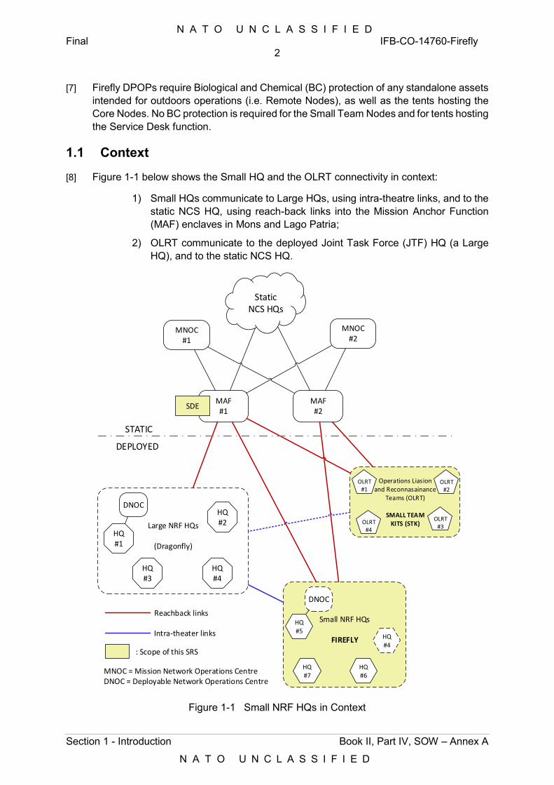
N A T O U N C L A S S I F I E D Final IFB-CO-14760-Firefly
2
Section 1 - Introduction Book II, Part IV, SOW – Annex A
N A T O U N C L A S S I F I E D
[7] Firefly DPOPs require Biological and Chemical (BC) protection of any standalone assets intended for outdoors operations (i.e. Remote Nodes), as well as the tents hosting the Core Nodes. No BC protection is required for the Small Team Nodes and for tents hosting the Service Desk function.
1.1 Context
[8] Figure 1-1 below shows the Small HQ and the OLRT connectivity in context:
1) Small HQs communicate to Large HQs, using intra-theatre links, and to the static NCS HQ, using reach-back links into the Mission Anchor Function (MAF) enclaves in Mons and Lago Patria;
2) OLRT communicate to the deployed Joint Task Force (JTF) HQ (a Large HQ), and to the static NCS HQ.
MAF#1
MNOC#2
MNOC#1
Small NRF HQs
FIREFLY HQ#4
HQ#5
HQ#6
HQ#7
Operations Liasionand Reconnasainance
Teams (OLRT)
SMALL TEAMKITS (STK)
OLRT#1
OLRT#3
OLRT#2
OLRT#4
Large NRF HQs
(Dragonfly)
HQ#1
HQ#2
HQ#3
HQ#4
MAF#2
DEPLOYED
STATIC
StaticNCS HQs
: Scope of this SRS
Reachback links
Intra-theater links
DNOC
DNOC
SDE
MNOC = Mission Network Operations CentreDNOC = Deployable Network Operations Centre
Figure 1-1 Small NRF HQs in Context
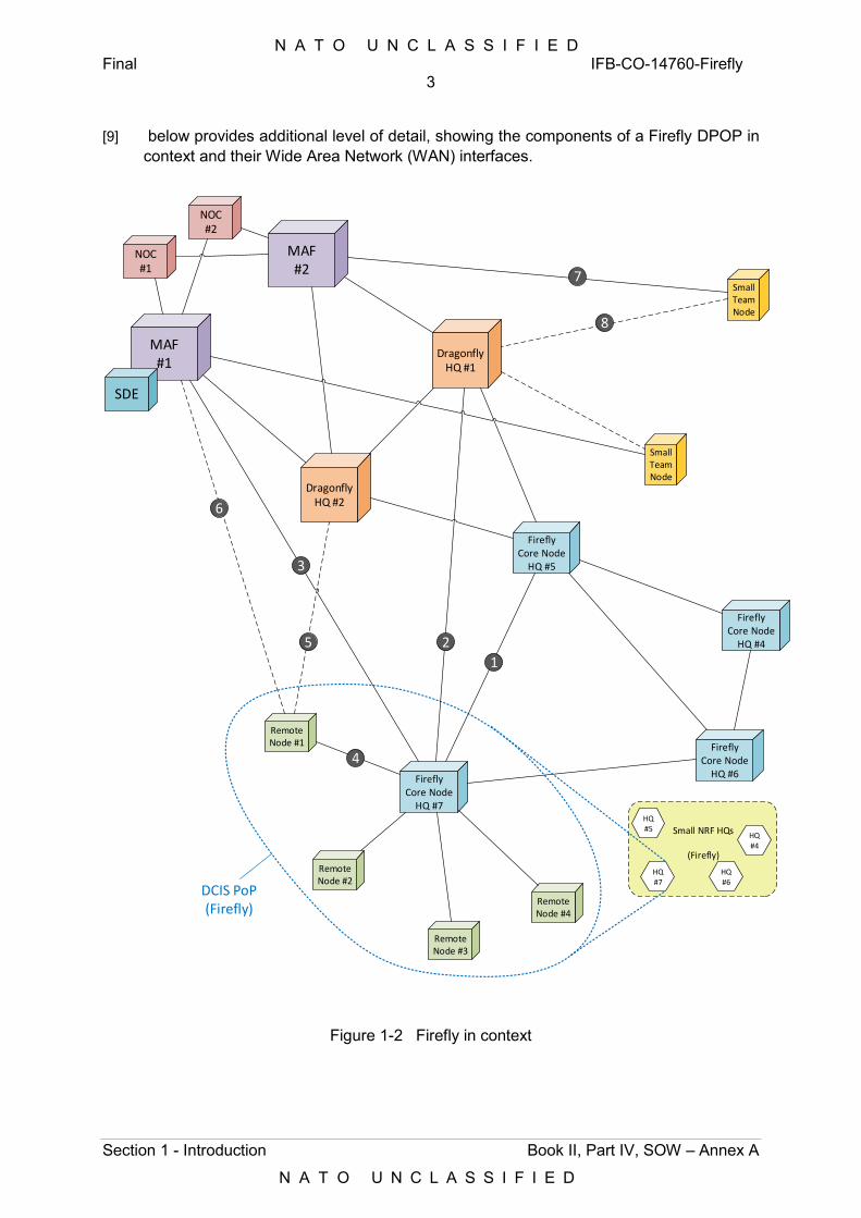
N A T O U N C L A S S I F I E D Final IFB-CO-14760-Firefly
3
Section 1 - Introduction Book II, Part IV, SOW – Annex A
N A T O U N C L A S S I F I E D
[9] below provides additional level of detail, showing the components of a Firefly DPOP in context and their Wide Area Network (WAN) interfaces.
Small NRF HQs
(Firefly)
HQ#4
HQ#5
HQ#6
HQ#7
FireflyCore Node
HQ #7
Remote Node #1
Remote Node #2
Remote Node #3
Remote Node #4
FireflyCore Node
HQ #4
FireflyCore Node
HQ #5
FireflyCore Node
HQ #6
DragonflyHQ #1
MAF#1
DragonflyHQ #2
1
4
3
6
MAF#2
Small Team Node
Small Team Node
7
8
NOC#1
NOC#2
2
DCIS PoP(Firefly)
SDE
5
Figure 1-2 Firefly in context
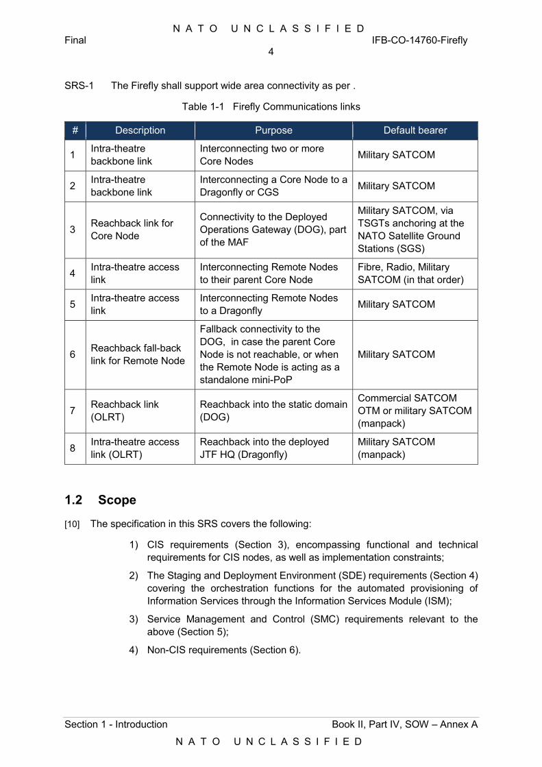
N A T O U N C L A S S I F I E D Final IFB-CO-14760-Firefly
4
Section 1 - Introduction Book II, Part IV, SOW – Annex A
N A T O U N C L A S S I F I E D
SRS-1 The Firefly shall support wide area connectivity as per .
Table 1-1 Firefly Communications links
# Description Purpose Default bearer
1 Intra-theatre backbone link
Interconnecting two or more Core Nodes Military SATCOM
2 Intra-theatre backbone link
Interconnecting a Core Node to a Dragonfly or CGS Military SATCOM
3 Reachback link for Core Node
Connectivity to the Deployed Operations Gateway (DOG), part of the MAF
Military SATCOM, via TSGTs anchoring at the NATO Satellite Ground Stations (SGS)
4 Intra-theatre access link
Interconnecting Remote Nodes to their parent Core Node
Fibre, Radio, Military SATCOM (in that order)
5 Intra-theatre access link
Interconnecting Remote Nodes to a Dragonfly Military SATCOM
6 Reachback fall-back link for Remote Node
Fallback connectivity to the DOG, in case the parent Core Node is not reachable, or when the Remote Node is acting as a standalone mini-PoP
Military SATCOM
7 Reachback link (OLRT)
Reachback into the static domain (DOG)
Commercial SATCOM OTM or military SATCOM (manpack)
8 Intra-theatre access link (OLRT)
Reachback into the deployed JTF HQ (Dragonfly)
Military SATCOM (manpack)
1.2 Scope
[10] The specification in this SRS covers the following:
1) CIS requirements (Section 3), encompassing functional and technical requirements for CIS nodes, as well as implementation constraints;
2) The Staging and Deployment Environment (SDE) requirements (Section 4) covering the orchestration functions for the automated provisioning of Information Services through the Information Services Module (ISM);
3) Service Management and Control (SMC) requirements relevant to the above (Section 5);
4) Non-CIS requirements (Section 6).
N A T O U N C L A S S I F I E D Final IFB-CO-14760-Firefly
5
Section 1 - Introduction Book II, Part IV, SOW – Annex A
N A T O U N C L A S S I F I E D
1.3 Conventions
[11] Requirements are numbered as SRS-#. Informational text is numbered as [###].
[12] Statements in numbered lists (i= 1…n) under a SRS-# requirement are to be considered individual requirements under the “shall” statement of the parent requirement. As such, they shall be traced (as SRS-#-i) and be subject to verification individually.
[13] “-xS” is the generic suffix denoting both NS and/or MS, e.g. CNM-xS.
[14] “-xx” is the generic suffix denoting either NU, NS or MS.
[15] The SRS does not discuss DPOP quantities. These are covered under the scope description in the SOW.
[16] Information and requirements contained under a “General” heading are applicable to all the elements covered by the corresponding section.
[17] Functional Requirements are provided at system-level, whereas Technical (non-functional) Requirements are provided down to subsystem-level. The latter are derived from existing architectures and systems that are proven and in operation and that the Firefly nodes need to interoperate with. Furthermore, the specification contains Implementation Constraints, which the Contractor shall adhere to when preparing the Low Level Design (LLD) specification.
[18] Requirements stating a capability to be "supported" (i.e. “shall support”) shall be understood as the ability of the Purchaser to configure the capability to be active or not active at his discretion. This means that the capability is not necessary implemented upon delivery, but shall be available in its full extent, without restrictions.
[19] Requirements stating a capability to be "implemented" (i.e. “shall implement”) shall be understood as requiring the capability to be implemented and configured for use in the delivered system.
[20] Requirements stating to be supported or implemented “fully conformant” to an architecture shall be understood as requiring full correspondence between architecture specification and implementation, where all features of this specific requirement are implemented in accordance with the architecture specification and there are no features of this specific requirement implemented that are not covered by the architecture specification.
[21] The specified router throughput performances assume the following constant packet size distribution, representative of NATO DCIS traffic over the WAN:
1) IP packets sized less than <= 64 bytes is 25%;
2) IP packets sized 64-127 bytes is 20%;
3) IP packets sized 128-255 bytes is 9%;
4) IP packets sized 256-511 bytes is 5%;
5) IP packets sized 512-1023 bytes is 18%; and
6) IP packets sized larger than1024 bytes is 23 %.
N A T O U N C L A S S I F I E D Final IFB-CO-14760-Firefly
6
Section 1 - Introduction Book II, Part IV, SOW – Annex A
N A T O U N C L A S S I F I E D
[22] The term "including" as used throughout this Annex is never meant to be limiting - the list that follows is always non-exhaustive.
[23] Any requirements using the term “target” shall be interpreted as hard constraints to be respected during the design process, with any deviation being subject of agreement by the Purchaser. Any such constraints are currently motivated by:
1) Compliance with the NRF DCIS Target Architecture (hereafter referred to as the DCIS TA1);
2) FMN compliance2 (Spiral 3);
3) Interoperability with current and legacy DCIS assets;
4) Lessons learned; or
5) Specific operational constraints.
[24] The use of the term “notional” is to be interpreted as guidance only.
[25] When calling for implementations conformant with the DCIS Cube Architecture, it shall be understood as being in accordance with and conformant to [DCIS Cube ADD Main, 2018], hereafter referred to as the DCIS CA, and its [DCIS Cube ADD Annexes, 2018], hereafter referred to as the DCIS CA Annexes. Where conformance to a specific DCIS CA Annex is required, in addition conformance to the DCIS CA [DCIS Cube ADD Main, 2018] as a whole is implicit.
[26] Those diagrams representing building blocks in Section 3 (CIS Nodes Specification) are coloured using the following conventions (refer to Figure 1-3 below):
1) Green: these are the blocks subject of the description;
2) Orange: these are blocks used to put the subject buildings blocks in context for that section;
3) Grey: not in scope (PFE), these blocks are used to put the subject building blocks in context, as required to enable operational use; and,
4) Cyan: not in scope, these blocks are used to put the subject building blocks in context (e.g. National DPOPs). They can be PFE (e.g. national DPOP simulators), or actual instances (e.g. during Operational Testing and Evaluation).
1 The DCIS TA is neither an Applicable nor a Reference document in this SRS. The interpretation of the TA and its translation into requirements in the specification is the responsibility of the Purchaser. 2 Assuring FMN compliance is the responsibility of the Purchaser, and it is fulfilled through the technical specification in this SRS, and through guidance provided to the Contractor during the design phase, and the Configuration Capturing activities in particular.
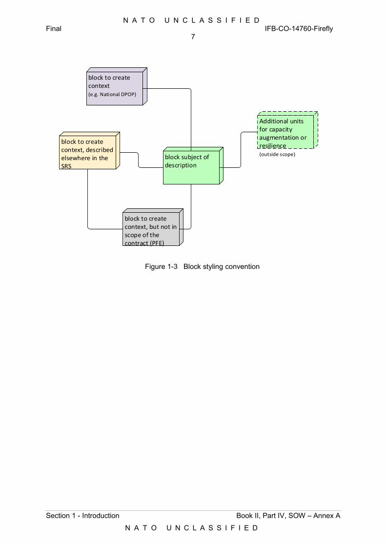
N A T O U N C L A S S I F I E D Final IFB-CO-14760-Firefly
7
Section 1 - Introduction Book II, Part IV, SOW – Annex A
N A T O U N C L A S S I F I E D
block to create context, but not in scope of the contract (PFE)
block to create context, described elsewhere in the SRS
block subject of description
block to create context (e.g. National DPOP)
Additional units for capacity augmentation or resilience(outside scope)
Figure 1-3 Block styling convention
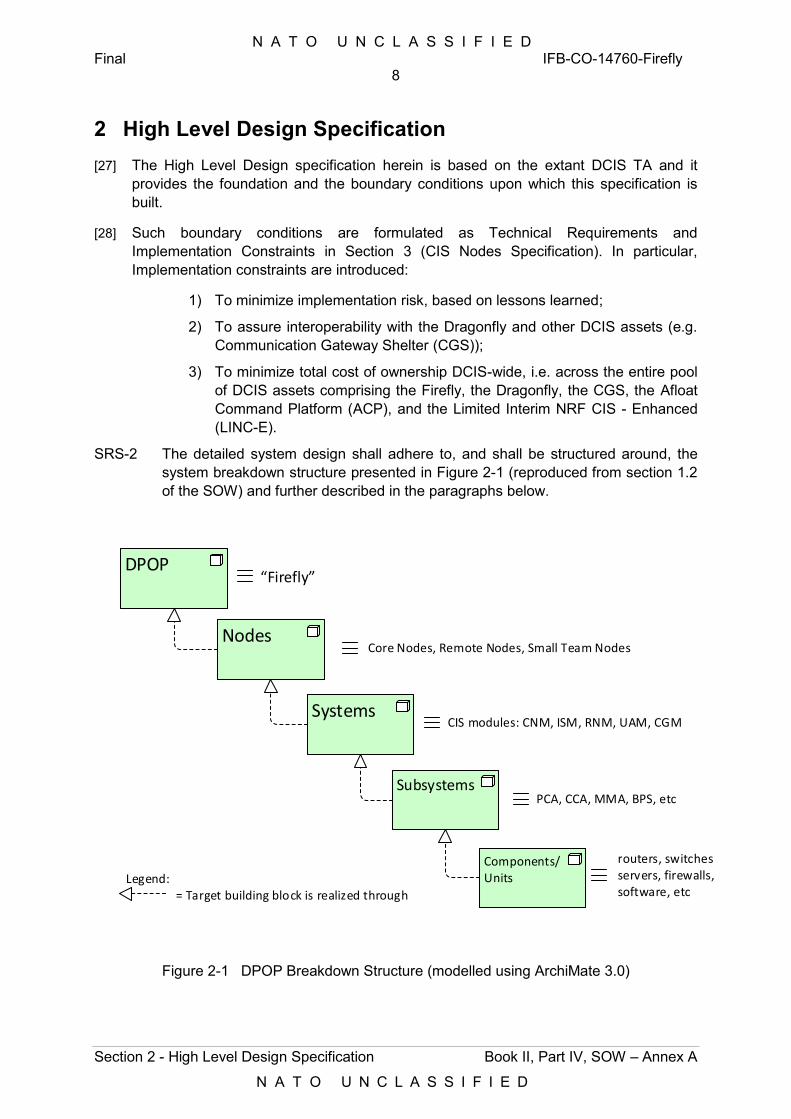
N A T O U N C L A S S I F I E D Final IFB-CO-14760-Firefly
8
Section 2 - High Level Design Specification Book II, Part IV, SOW – Annex A
N A T O U N C L A S S I F I E D
2 High Level Design Specification [27] The High Level Design specification herein is based on the extant DCIS TA and it
provides the foundation and the boundary conditions upon which this specification is built.
[28] Such boundary conditions are formulated as Technical Requirements and Implementation Constraints in Section 3 (CIS Nodes Specification). In particular, Implementation constraints are introduced:
1) To minimize implementation risk, based on lessons learned;
2) To assure interoperability with the Dragonfly and other DCIS assets (e.g. Communication Gateway Shelter (CGS));
3) To minimize total cost of ownership DCIS-wide, i.e. across the entire pool of DCIS assets comprising the Firefly, the Dragonfly, the CGS, the Afloat Command Platform (ACP), and the Limited Interim NRF CIS - Enhanced (LINC-E).
SRS-2 The detailed system design shall adhere to, and shall be structured around, the system breakdown structure presented in Figure 2-1 (reproduced from section 1.2 of the SOW) and further described in the paragraphs below.
DPOP
Nodes
Systems
Subsystems
Components/Units
Core Nodes, Remote Nodes, Small Team Nodes
“Firefly”
CIS modules: CNM, ISM, RNM, UAM, CGM
PCA, CCA, MMA, BPS, etc
routers, switchesservers, firewalls, software, etc= Target building block is realized through
Legend:
Figure 2-1 DPOP Breakdown Structure (modelled using ArchiMate 3.0)
N A T O U N C L A S S I F I E D Final IFB-CO-14760-Firefly
9
Section 2 - High Level Design Specification Book II, Part IV, SOW – Annex A
N A T O U N C L A S S I F I E D
[29] The infrastructure supporting the DCIS capability for a given deployed NCS HQ connected to one or more deployed NFS HQs, is broken down and is specified as follows:
1) DPOP, as a collection of CIS nodes (i.e. Core Nodes, Remote Nodes, Small Team Nodes);
2) CIS Nodes (e.g. a Core Node), as a collection of CIS Modules associated transmission systems and User Appliances;
3) Systems (e.g. a Core Network Module), as individual CIS Modules and transmission systems within a CIS Node;
4) Subsystems, as functional blocks within a CIS Module (e.g. a Protected Core Access subsystem, PCA); and,
5) Components/Units, as building blocks of the Subsystems above (e.g. routers, switches, servers, firewalls, software, etc).
[30] This SRS specifies the CIS Nodes in Section 3.
[31] Non-CIS Elements supporting the above CIS Nodes are specified in Section 6. Specific Non-CIS Elements, like Power Generator Systems to supply power to Core, Remote and Small Team Nodes, will be provided as PFE.
[32] The following paragraphs provide the high-level description of CIS Nodes and Non-CIS elements.
2.1 CIS Nodes
[33] A DPOP (Firefly) consists of one Core Node and four Remote Nodes (refer to Figure 2-2).
[34] Small Team Nodes are not necessarily affiliated to a given deployed HQ and DPOP, and can invariably connect to a Dragonfly and/or to the MAF/DOG.
[35] Core Nodes, Remote Nodes and Small Team Nodes, are in turn supported by a Staging and Deployment Environment (SDE). The SDE is located in the static Ops Centres, with distributed SDE components attached to the Core Nodes in garrison and at the DPOP.
2.1.1 Node Taxonomy
[36] Core Nodes host the core networking, multimedia, Information Services and local cross-domain capability of the Firefly DPOP. Core Nodes are also hosting the Service Desk capability for the DPOP. Core Nodes can host users, as Network Interconnection Points (NIP) towards any collocated MNP POP. Core Nodes act as hubs for Remote Nodes.
[37] Remote Nodes provide access to hosted users deployed away from the Core Nodes modules, as well as NIP for interconnection with MNP POPs. Remote Nodes are either connected to Core Nodes (over fibre, radio, or SATCOM), or to the MAF (typically over SATCOM).
[38] Remote Nodes connect to their parent Core Nodes using a star topology.
[39] There are two types or Remote Nodes, depending on the functions and the security domains they support:
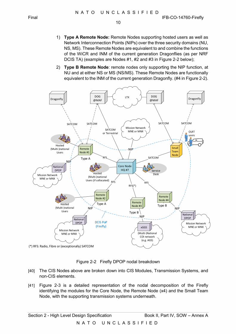
N A T O U N C L A S S I F I E D Final IFB-CO-14760-Firefly
10
Section 2 - High Level Design Specification Book II, Part IV, SOW – Annex A
N A T O U N C L A S S I F I E D
1) Type A Remote Node: Remote Nodes supporting hosted users as well as Network Interconnection Points (NIPs) over the three security domains (NU, NS, MS). These Remote Nodes are equivalent to and combine the functions of the WiCR and INM of the current generation Dragonflies (as per NRF DCIS TA) (examples are Nodes #1, #2 and #3 in Figure 2-2 below);
2) Type B Remote Node: remote nodes only supporting the NIP function, at NU and at either NS or MS (NS/MS). These Remote Nodes are functionally equivalent to the INM of the current generation Dragonfly. (#4 in Figure 2-2).
Core NodeHQ #7
Remote Node #1
Remote Node #2
Remote Node #3
Remote Node #4
RFS
RFS
RFS(*)RFS
Mission NetworkMNE or MNX
NIP
(Multi-)National COI network
(e.g. AGS)
Mission NetworkMNE or MNX
Hosted(Multi-)national
Users
Hosted(Multi-)national
Users
Service Desk
Mission NetworkMNE or MNX
Hosted(Multi-)national
Users (if collocated)
Small Team Node
OLRTusers
SATCOM
SATCOM
DCIS PoP(Firefly)
SATCOMor Terrestrial
DOG@MAF
DOG@MAF
SATCOM
LTX
(*) RFS: Radio, Fibre or (exceptionally) SATCOM
NIP
NIP
NIP
National DPOP
National DPOP
Type A
Type B
Type B
Type A
xGGSMission Network
MNE or MNX
National DPOP
NIP
Dragonfly
SATCOM
Dragonfly
SATCOM
Figure 2-2 Firefly DPOP nodal breakdown
[40] The CIS Nodes above are broken down into CIS Modules, Transmission Systems, and non-CIS elements.
[41] Figure 2-3 is a detailed representation of the nodal decomposition of the Firefly identifying the modules for the Core Node, the Remote Node (x4) and the Small Team Node, with the supporting transmission systems underneath.
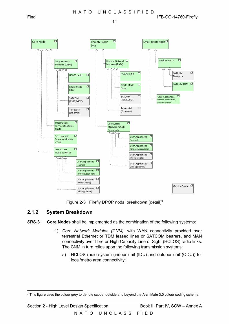
N A T O U N C L A S S I F I E D Final IFB-CO-14760-Firefly
11
Section 2 - High Level Design Specification Book II, Part IV, SOW – Annex A
N A T O U N C L A S S I F I E D
Core Node
Core Network Modules (CNM)
Cross-domain Gateway Module (CGM)
HCLOS radio
SATCOM (TSGT,DSGT)
Information Services Modules (ISM)
Remote Node(x4)
Remote Network Modules (RNM)
HCLOS radio
SATCOM (TSGT,DSGT)
Small Team Node
Small Team Kit
SATCOM Manpack
SATCOM OTM
User Appliances (phones, workstations,
printers/scanners)
User Appliances(phones)
User Appliances(printers/scanners)
User Appliances(workstations)
Outside Scope
Terrestrial (Ethernet)
Terrestrial (Ethernet)
Single ModeFibre
Single ModeFibre
User Appliances(VTC appliance)
User Access Modules (UAM)
User Appliances(phones)
User Appliances(printers/scanners)
User Appliances(workstations)
User Appliances(VTC appliance)
User Access Modules (UAM)(Type-A only)
Figure 2-3 Firefly DPOP nodal breakdown (detail)3
2.1.2 System Breakdown
SRS-3 Core Nodes shall be implemented as the combination of the following systems:
1) Core Network Modules (CNM), with WAN connectivity provided over terrestrial Ethernet or TDM leased lines or SATCOM bearers, and MAN connectivity over fibre or High Capacity Line of Sight (HCLOS) radio links. The CNM in turn relies upon the following transmission systems:
a) HCLOS radio system (indoor unit (IDU) and outdoor unit (ODU)) for local/metro area connectivity;
3 This figure uses the colour grey to denote scope, outside and beyond the ArchiMate 3.0 colour coding scheme.
N A T O U N C L A S S I F I E D Final IFB-CO-14760-Firefly
12
Section 2 - High Level Design Specification Book II, Part IV, SOW – Annex A
N A T O U N C L A S S I F I E D
b) SATCOM transportable satellite ground terminals (TSGT) or deployable satellite ground terminals (DSGT), for wide area connectivity into other Core Nodes or into the MAF. These are outside the scope of the Contract and are provided as PFE for the purpose of system integration testing (refer to SOW for details).
2) Information Services Modules (ISM); hosting core services, COI services, as well as service management and control services;
3) Cross-domain Gateway Module (CGM), enabling the information exchange between NS and MS security domains (this is also referred to as the Information Exchange Gateway Type-C, IEG-C);
4) User Access Modules (UAM), providing LAN access to the user appliances (laptops, printer/scanners, phones and VTC appliances).
SRS-4 There shall be three instances of each of the CIS Modules above, as many as security domains are to be supported (NU, NS and MS); with the exception of the CGM. The NU, NS and MS modules shall be implemented as physically separate and independent instances.
SRS-5 Each Core Node shall have the capacity, in terms of number of network ports and infrastructure services, to connect to up to eight Remote Nodes.
SRS-6 Remote Nodes shall be implemented as the combination of the following:
1) Remote Network Modules (RNM), with metro-area or WAN connectivity provided over terrestrial fibre links, HCLOS radio or SATCOM bearers, respectively, using:
a) HCLOS radio system (IDU and ODU);
b) SATCOM DSGT or fly-away (e.g. DART), for wide area connectivity into a Core Node, a Dragonfly, or the MAF. SATCOM bearers are outside the scope of the Contract to deliver, however, they will be provided as PFE and shall be interfaced to.
2) User Access Modules (UAM), see above.
SRS-7 Type A Remote Nodes (NIP and user access) shall implement RNM and UAM across all three security domains.
SRS-8 Type B Remote Nodes (NIP only) shall only feature RNM, at NU and xS levels (where x denotes either “N (NATO)” or “M (Mission)”), and no UAM, as there will be no hosted users directly connected to them.
SRS-9 Small Team Nodes in support of OLRTs shall be implemented as a combination of:
1) Small Team Kit (STK);
2) SATCOM on-the-move (OTM) terminal;
3) User Appliances, consisting of laptops, printer/scanners and phones.
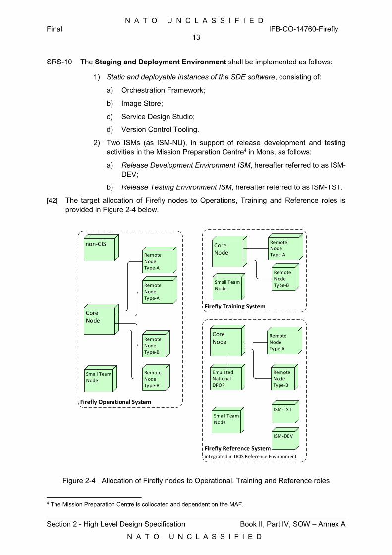
N A T O U N C L A S S I F I E D Final IFB-CO-14760-Firefly
13
Section 2 - High Level Design Specification Book II, Part IV, SOW – Annex A
N A T O U N C L A S S I F I E D
SRS-10 The Staging and Deployment Environment shall be implemented as follows:
1) Static and deployable instances of the SDE software, consisting of:
a) Orchestration Framework;
b) Image Store;
c) Service Design Studio;
d) Version Control Tooling.
2) Two ISMs (as ISM-NU), in support of release development and testing activities in the Mission Preparation Centre4 in Mons, as follows:
a) Release Development Environment ISM, hereafter referred to as ISM-DEV;
b) Release Testing Environment ISM, hereafter referred to as ISM-TST.
[42] The target allocation of Firefly nodes to Operations, Training and Reference roles is provided in Figure 2-4 below.
Core Node
Remote Node Type-A
Remote Node Type-A
Remote Node Type-B
Remote Node Type-B
Core Node
Remote Node Type-A
Remote Node Type-B
non-CIS
Firefly Reference System integrated in DCIS Reference Environment
EmulatedNational DPOP
Firefly Training System
Small Team Node
Small Team Node
Firefly Operational System
Small Team Node
ISM-TST
ISM-DEV
Core Node
Remote Node Type-A
Remote Node Type-B
Figure 2-4 Allocation of Firefly nodes to Operational, Training and Reference roles
4 The Mission Preparation Centre is collocated and dependent on the MAF.
N A T O U N C L A S S I F I E D Final IFB-CO-14760-Firefly
14
Section 2 - High Level Design Specification Book II, Part IV, SOW – Annex A
N A T O U N C L A S S I F I E D
[43] The implementation of the Core Network Module, Remote Network Module, User Access Module, and Small Team Kit, as specified in this SRS, largely adhere to the NRF DCIS Target Architecture and its current instantiation in the Dragonfly. Deviations are introduced herein in order to:
1) Reduce the deployed footprint of the Firefly, in terms of size, weight and power footprint of the Nodes and of the individual corresponding transit cases;
2) Implement the level of redundancy required specifically for the Firefly (critical CIS redundancy only, vice full redundancy in Dragonfly);
3) Adhere to the latest FMN specifications (Spiral 3).
[44] The implementation of the ISM and the Staging and Deployment Environment needs to adhere to the DCIS CUBE Architecture Definition Document and its Annexes (Version 1.0, 8 May 2018, including errata) and design principles, referred to herein as “DCIS CA”. The term “DCIS Cube” refers to a deployable instance of virtualized Infrastructure as a Service (IaaS), implemented with hardware and software integrated into one single physical transport container (per security domain).
[45] Where appropriate, this SRS directly translates the DCIS CA into functional and technical requirements.
[46] Figure 2-5 breaks the CIS nodes down into their CIS modules. The following is to be noted:
1) Remote Nodes will connect to their parent Core Node over either single mode fibre, HCLOS radio or, in absence of any of those, SATCOM;
2) Alternatively, Remote Nodes may connect to the DOG in the MAF, or to a Dragonfly, over SATCOM (TSGT or DSGT);
3) Service Desk applications, and any application supporting service management and control, will be hosted in the ISM of the Core Nodes;
4) The POPs of Mission Partner5 nations (MNE or MNX in the figure) will by default be collocated with and connected to the NIP of a Remote Node. They may also be collocated with and connected to the NIP of a Core Node.
5) Small Team Node will either or simultaneously connect to:
a) the DOG, when supporting the OLRT liaison role, over the SATCOM OTM or the SATCOM manpack (PFE); or
b) Dragonfly (µCOM), over the SATCOM manpack (both PFE).
5 Also referred to as Mission Network Participant (MNP) in other areas of this SRS.
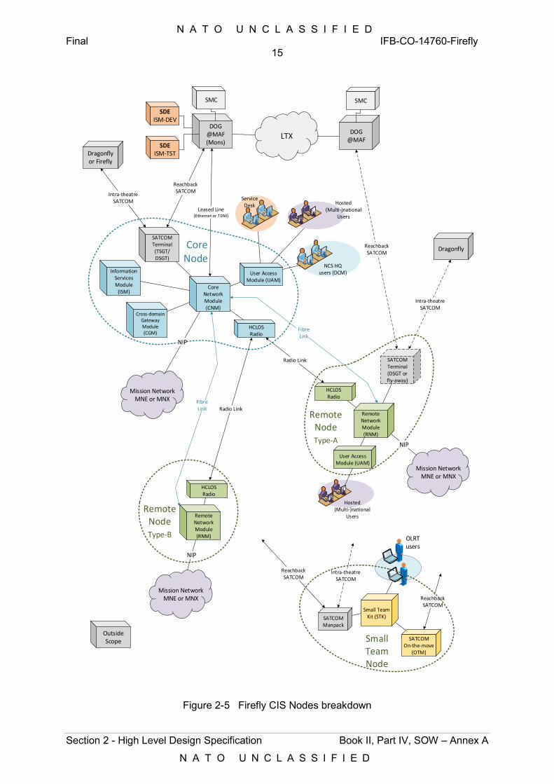
N A T O U N C L A S S I F I E D Final IFB-CO-14760-Firefly
15
Section 2 - High Level Design Specification Book II, Part IV, SOW – Annex A
N A T O U N C L A S S I F I E D
Mission NetworkMNE or MNX
NIP
Core Network Module (CNM)
Information Services Module
(ISM)
User Access Module (UAM)
SATCOMTerminal(TSGT/DSGT)
HCLOSRadio
Remote Network Module (RNM)
HCLOSRadio
Radio Link SATCOMTerminal(DSGT or fly-away)
Mission NetworkMNE or MNX
NIP
Radio Link
Intra-theatreSATCOM
ReachbackSATCOM
Intra-theatreSATCOM
ReachbackSATCOM
NCS HQusers (DCM)
NIP
Remote Network Module (RNM)
HCLOSRadio
RemoteNodeType-B
Hosted(Multi-)national
Users
User Access Module (UAM)
Leased Line(Ethernet or TDM)
FibreLink
FibreLink
Small Team Kit (STK)
SATCOM On-the-move
(OTM)
SATCOM Manpack
ReachbackSATCOM
Intra-theatreSATCOM
ReachbackSATCOM
Hosted(Multi-)national
Users
OLRTusers
Service Desk
Cross-domain Gateway Module (CGM)
OutsideScope
SDEISM-DEV
DOG@MAF (Mons)
SMC
DOG@MAF
SMC
LTXSDE
ISM-TST
Small TeamNode
RemoteNodeType-A
Mission NetworkMNE or MNX
Dragonfly Core Node
Dragonflyor Firefly
Figure 2-5 Firefly CIS Nodes breakdown
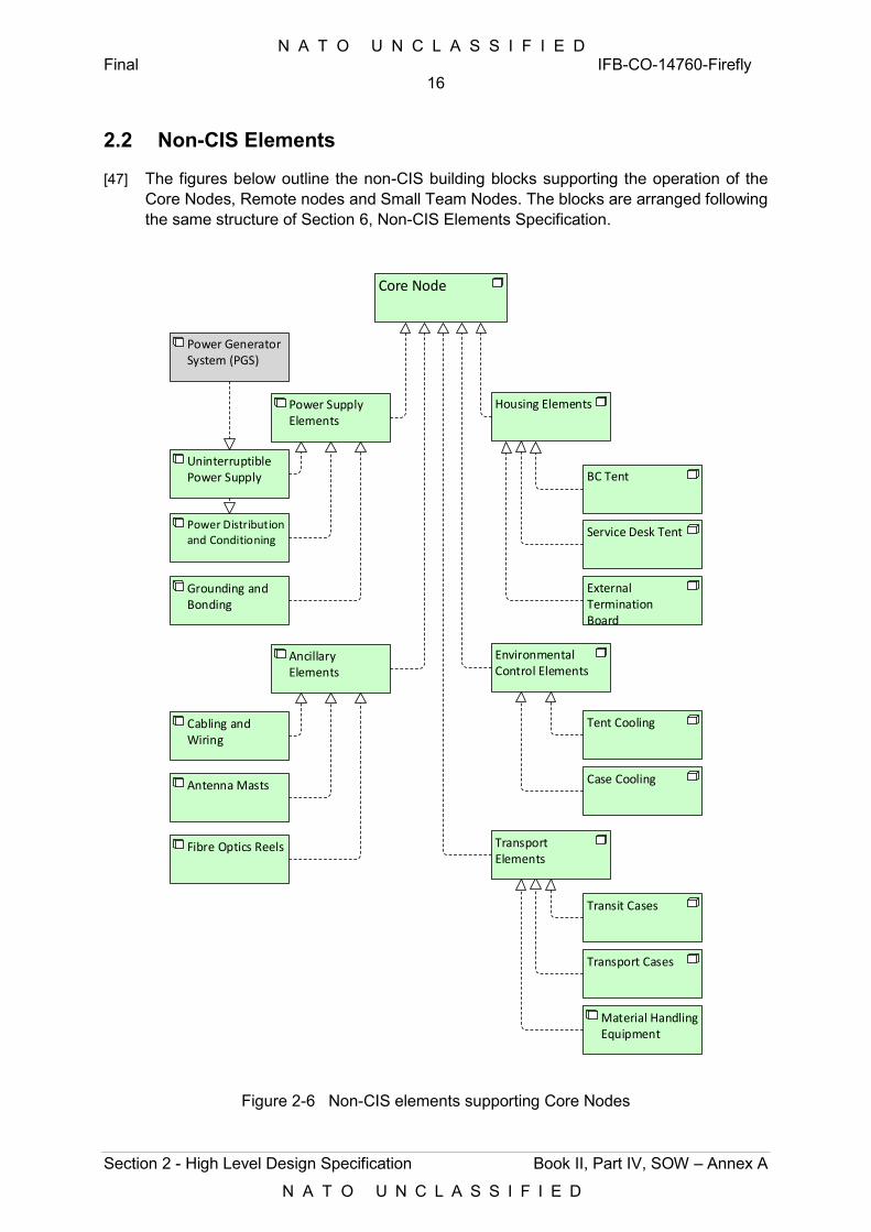
N A T O U N C L A S S I F I E D Final IFB-CO-14760-Firefly
16
Section 2 - High Level Design Specification Book II, Part IV, SOW – Annex A
N A T O U N C L A S S I F I E D
2.2 Non-CIS Elements
[47] The figures below outline the non-CIS building blocks supporting the operation of the Core Nodes, Remote nodes and Small Team Nodes. The blocks are arranged following the same structure of Section 6, Non-CIS Elements Specification.
Core Node
Housing Elements
Service Desk Tent
Environmental Control Elements
External Termination Board
BC Tent
Case Cooling
Tent Cooling
Transport Cases
Transit Cases
Transport Elements
Power Generator System (PGS)
UninterruptiblePower Supply
Power Distribution and Conditioning
Antenna Masts
Cabling and Wiring
Grounding and Bonding
Power Supply Elements
Ancillary Elements
Material Handling Equipment
Fibre Optics Reels
Figure 2-6 Non-CIS elements supporting Core Nodes
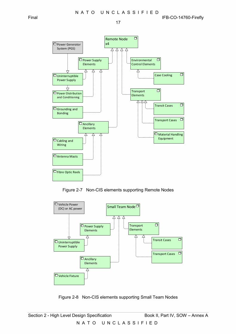
N A T O U N C L A S S I F I E D Final IFB-CO-14760-Firefly
17
Section 2 - High Level Design Specification Book II, Part IV, SOW – Annex A
N A T O U N C L A S S I F I E D
Remote Node x4
Environmental Control Elements
Case Cooling
Transport Cases
Transit Cases
Transport Elements
Power Generator System (PGS)
UninterruptiblePower Supply
Power Distribution and Conditioning
Antenna Masts
Cabling and Wiring
Grounding and Bonding
Power Supply Elements
Ancillary Elements
Material Handling Equipment
Fibre Optic Reels
Figure 2-7 Non-CIS elements supporting Remote Nodes
Small Team Node
Transport Cases
Transit Cases
Transport Elements
UninterruptiblePower Supply
Vehicle Fixture
Power Supply Elements
Ancillary Elements
Vehicle Power (DC) or AC power
Figure 2-8 Non-CIS elements supporting Small Team Nodes
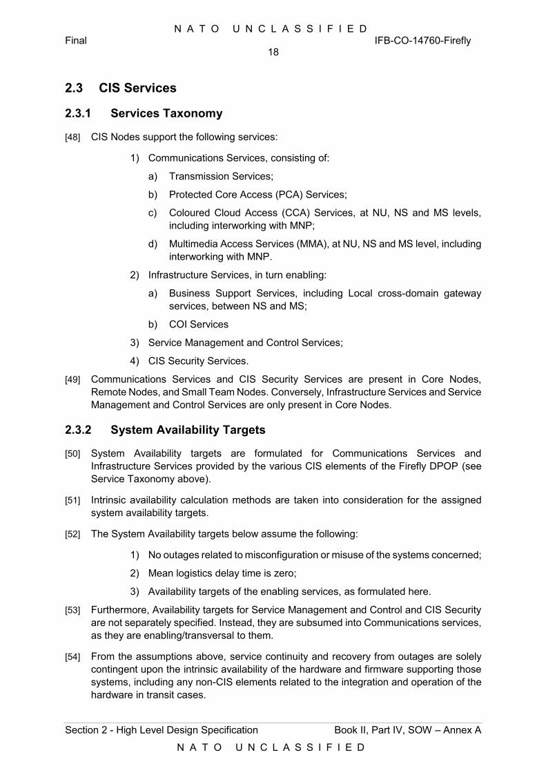
N A T O U N C L A S S I F I E D Final IFB-CO-14760-Firefly
18
Section 2 - High Level Design Specification Book II, Part IV, SOW – Annex A
N A T O U N C L A S S I F I E D
2.3 CIS Services
2.3.1 Services Taxonomy
[48] CIS Nodes support the following services:
1) Communications Services, consisting of:
a) Transmission Services;
b) Protected Core Access (PCA) Services;
c) Coloured Cloud Access (CCA) Services, at NU, NS and MS levels, including interworking with MNP;
d) Multimedia Access Services (MMA), at NU, NS and MS level, including interworking with MNP.
2) Infrastructure Services, in turn enabling:
a) Business Support Services, including Local cross-domain gateway services, between NS and MS;
b) COI Services
3) Service Management and Control Services;
4) CIS Security Services.
[49] Communications Services and CIS Security Services are present in Core Nodes, Remote Nodes, and Small Team Nodes. Conversely, Infrastructure Services and Service Management and Control Services are only present in Core Nodes.
2.3.2 System Availability Targets
[50] System Availability targets are formulated for Communications Services and Infrastructure Services provided by the various CIS elements of the Firefly DPOP (see Service Taxonomy above).
[51] Intrinsic availability calculation methods are taken into consideration for the assigned system availability targets.
[52] The System Availability targets below assume the following:
1) No outages related to misconfiguration or misuse of the systems concerned;
2) Mean logistics delay time is zero;
3) Availability targets of the enabling services, as formulated here.
[53] Furthermore, Availability targets for Service Management and Control and CIS Security are not separately specified. Instead, they are subsumed into Communications services, as they are enabling/transversal to them.
[54] From the assumptions above, service continuity and recovery from outages are solely contingent upon the intrinsic availability of the hardware and firmware supporting those systems, including any non-CIS elements related to the integration and operation of the hardware in transit cases.
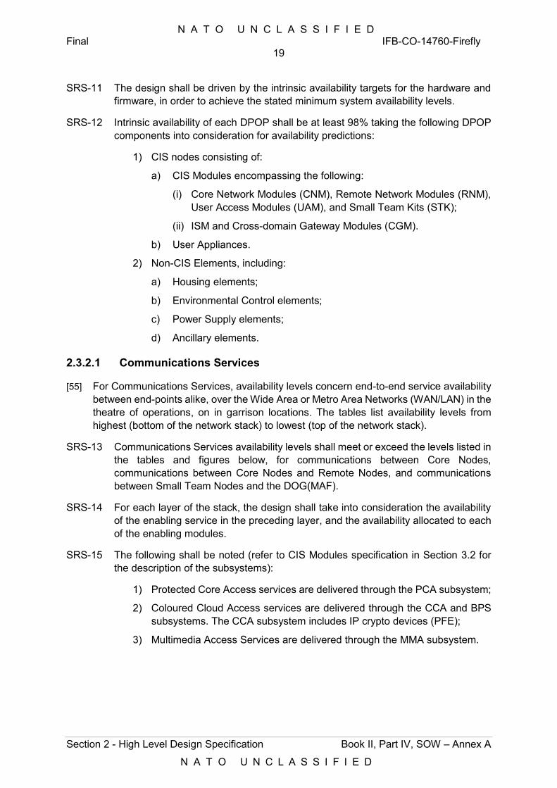
N A T O U N C L A S S I F I E D Final IFB-CO-14760-Firefly
19
Section 2 - High Level Design Specification Book II, Part IV, SOW – Annex A
N A T O U N C L A S S I F I E D
SRS-11 The design shall be driven by the intrinsic availability targets for the hardware and firmware, in order to achieve the stated minimum system availability levels.
SRS-12 Intrinsic availability of each DPOP shall be at least 98% taking the following DPOP components into consideration for availability predictions:
1) CIS nodes consisting of:
a) CIS Modules encompassing the following:
(i) Core Network Modules (CNM), Remote Network Modules (RNM), User Access Modules (UAM), and Small Team Kits (STK);
(ii) ISM and Cross-domain Gateway Modules (CGM).
b) User Appliances.
2) Non-CIS Elements, including:
a) Housing elements;
b) Environmental Control elements;
c) Power Supply elements;
d) Ancillary elements.
2.3.2.1 Communications Services
[55] For Communications Services, availability levels concern end-to-end service availability between end-points alike, over the Wide Area or Metro Area Networks (WAN/LAN) in the theatre of operations, on in garrison locations. The tables list availability levels from highest (bottom of the network stack) to lowest (top of the network stack).
SRS-13 Communications Services availability levels shall meet or exceed the levels listed in the tables and figures below, for communications between Core Nodes, communications between Core Nodes and Remote Nodes, and communications between Small Team Nodes and the DOG(MAF).
SRS-14 For each layer of the stack, the design shall take into consideration the availability of the enabling service in the preceding layer, and the availability allocated to each of the enabling modules.
SRS-15 The following shall be noted (refer to CIS Modules specification in Section 3.2 for the description of the subsystems):
1) Protected Core Access services are delivered through the PCA subsystem;
2) Coloured Cloud Access services are delivered through the CCA and BPS subsystems. The CCA subsystem includes IP crypto devices (PFE);
3) Multimedia Access Services are delivered through the MMA subsystem.
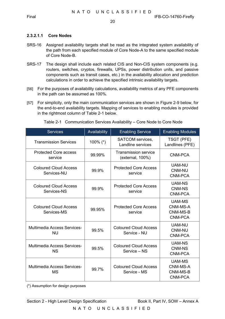
N A T O U N C L A S S I F I E D Final IFB-CO-14760-Firefly
20
Section 2 - High Level Design Specification Book II, Part IV, SOW – Annex A
N A T O U N C L A S S I F I E D
2.3.2.1.1 Core Nodes
SRS-16 Assigned availability targets shall be read as the integrated system availability of the path from each specified module of Core Node-A to the same specified module of Core Node-B.
SRS-17 The design shall include each related CIS and Non-CIS system components (e.g. routers, switches, cryptos, firewalls, UPSs, power distribution units, and passive components such as transit cases, etc.) in the availability allocation and prediction calculations in order to achieve the specified intrinsic availability targets.
[56] For the purposes of availability calculations, availability metrics of any PFE components in the path can be assumed as 100%.
[57] For simplicity, only the main communication services are shown in Figure 2-9 below, for the end-to-end availability targets. Mapping of services to enabling modules is provided in the rightmost column of Table 2-1 below.
Table 2-1 Communication Services Availability – Core Node to Core Node
Services Availability Enabling Service Enabling Modules
Transmission Services 100% (*) SATCOM services, Landline services
TSGT (PFE) Landlines (PFE)
Protected Core access service 99.99% Transmission service
(external, 100%) CNM-PCA
Coloured Cloud Access Services-NU 99.9% Protected Core Access
service
UAM-NU CNM-NU
CNM-PCA
Coloured Cloud Access Services-NS 99.9% Protected Core Access
service
UAM-NS CNM-NS
CNM-PCA
Coloured Cloud Access Services-MS 99.95% Protected Core Access
service
UAM-MS CNM-MS-A CNM-MS-B CNM-PCA
Multimedia Access Services-NU 99.5% Coloured Cloud Access
Service - NU
UAM-NU CNM-NU
CNM-PCA
Multimedia Access Services-NS 99.5% Coloured Cloud Access
Service – NS
UAM-NS CNM-NS
CNM-PCA
Multimedia Access Services-MS 99.7% Coloured Cloud Access
Service - MS
UAM-MS CNM-MS-A CNM-MS-B CNM-PCA
(*) Assumption for design purposes
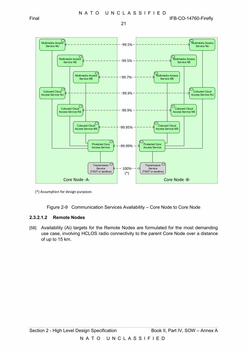
N A T O U N C L A S S I F I E D Final IFB-CO-14760-Firefly
21
Section 2 - High Level Design Specification Book II, Part IV, SOW – Annex A
N A T O U N C L A S S I F I E D
Core Node -B-Core Node -A-
Protected Core Access Service
Coloured Cloud Access Service NU
Coloured Cloud Access Service NS
Coloured Cloud Access Service MS
Protected Core Access Service
Coloured Cloud Access Service NU
Coloured Cloud Access Service NS
Coloured Cloud Access Service MS
Transmission Service
(TSGT or landline)
Multimedia Access Service NU
Multimedia Access Service NS
Multimedia Access Service MS
Multimedia Access Service NU
Multimedia Access Service NS
Multimedia Access Service MS99.7%
99.9%
99.9%
99.95%
99.99%
99.5%
99.5%
100%(*)
Transmission Service
(TSGT or landline)
(*) Assumption for design purposes
Figure 2-9 Communication Services Availability – Core Node to Core Node
2.3.2.1.2 Remote Nodes
[58] Availability (Ai) targets for the Remote Nodes are formulated for the most demanding use case, involving HCLOS radio connectivity to the parent Core Node over a distance of up to 15 km.
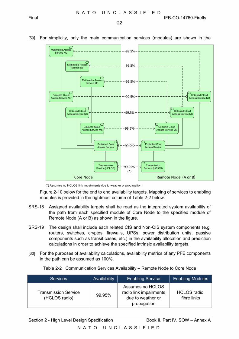
N A T O U N C L A S S I F I E D Final IFB-CO-14760-Firefly
22
Section 2 - High Level Design Specification Book II, Part IV, SOW – Annex A
N A T O U N C L A S S I F I E D
[59] For simplicity, only the main communication services (modules) are shown in the
Remote Node (A or B)Core Node
Protected Core Access Service
Coloured Cloud Access Service NU
Coloured Cloud Access Service NS
Coloured Cloud Access Service MS
Protected Core Access Service
Coloured Cloud Access Service NU
Coloured Cloud Access Service NS
Coloured Cloud Access Service MS
Multimedia Access Service NU
Multimedia Access Service NS
Multimedia Access Service MS 99.5%
99.5%
99.5%
99.5%
99.9%
99.5%
99.5%
Transmission Service (HCLOS)
Transmission Service (HCLOS)99.95%
(*)
(*) Assumes no HCLOS link impairments due to weather or propagation
Figure 2-10 below for the end to end availability targets. Mapping of services to enabling modules is provided in the rightmost column of Table 2-2 below.
SRS-18 Assigned availability targets shall be read as the integrated system availability of the path from each specified module of Core Node to the specified module of Remote Node (A or B) as shown in the figure.
SRS-19 The design shall include each related CIS and Non-CIS system components (e.g. routers, switches, cryptos, firewalls, UPSs, power distribution units, passive components such as transit cases, etc.) in the availability allocation and prediction calculations in order to achieve the specified intrinsic availability targets.
[60] For the purposes of availability calculations, availability metrics of any PFE components in the path can be assumed as 100%.
Table 2-2 Communication Services Availability – Remote Node to Core Node
Services Availability Enabling Service Enabling Modules
Transmission Service (HCLOS radio) 99.95%
Assumes no HCLOS radio link impairments
due to weather or propagation
HCLOS radio, fibre links
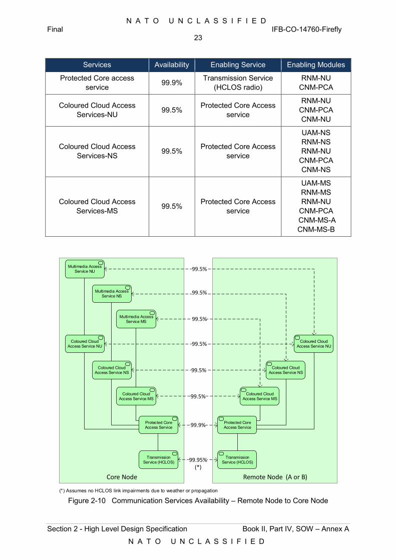
N A T O U N C L A S S I F I E D Final IFB-CO-14760-Firefly
23
Section 2 - High Level Design Specification Book II, Part IV, SOW – Annex A
N A T O U N C L A S S I F I E D
Services Availability Enabling Service Enabling Modules
Protected Core access service 99.9% Transmission Service
(HCLOS radio) RNM-NU
CNM-PCA
Coloured Cloud Access Services-NU 99.5% Protected Core Access
service
RNM-NU CNM-PCA CNM-NU
Coloured Cloud Access Services-NS 99.5% Protected Core Access
service
UAM-NS RNM-NS RNM-NU
CNM-PCA CNM-NS
Coloured Cloud Access Services-MS 99.5% Protected Core Access
service
UAM-MS RNM-MS RNM-NU
CNM-PCA CNM-MS-A CNM-MS-B
Remote Node (A or B)Core Node
Protected Core Access Service
Coloured Cloud Access Service NU
Coloured Cloud Access Service NS
Coloured Cloud Access Service MS
Protected Core Access Service
Coloured Cloud Access Service NU
Coloured Cloud Access Service NS
Coloured Cloud Access Service MS
Multimedia Access Service NU
Multimedia Access Service NS
Multimedia Access Service MS 99.5%
99.5%
99.5%
99.5%
99.9%
99.5%
99.5%
Transmission Service (HCLOS)
Transmission Service (HCLOS)99.95%
(*)
(*) Assumes no HCLOS link impairments due to weather or propagation
Figure 2-10 Communication Services Availability – Remote Node to Core Node
N A T O U N C L A S S I F I E D Final IFB-CO-14760-Firefly
24
Section 2 - High Level Design Specification Book II, Part IV, SOW – Annex A
N A T O U N C L A S S I F I E D
2.3.2.1.3 Small Team Nodes
[61] Availability targets for the Small Team Nodes are formulated for the use case involving SATCOM OTM connectivity to the DOG at the MAF. These targets assume 100% availability of the hardware and services running in the DOG/MAF.
[62] For simplicity, only the main communication services (modules) are shown in the Figure 2-11 below, for the end to end availability targets.
SRS-20 Assigned availability targets shall be read as the integrated system availability of the path from each specified module of Small Team Node to the same specified module in the DOG at the MAF. The design shall include each related CIS (e.g. routers, switches, cryptos, UPSs) and Non-CIS system components in the availability allocation and prediction calculations in order to achieve the specified intrinsic availability targets.
SRS-21 For the purposes of availability calculations, availability metrics of PFE components and DOG@MAF system can be assumed as 100%.
Table 2-3 Communication Services Availability – Small Team Node to DOG (MAF)
Services Availability Enabling Service Enabling Modules
Transmission Service (BGAN) 99.9%
BGAN network and terrestrial VPN
availability SATCOM OTM
Protected Core access service 99.5% Transmission Service
(BGAN) STK-NU
Coloured Cloud Access Services-NU 99.3% Protected Core Access
service STK-NU
Coloured Cloud Access Services-xS 99.3% Protected Core Access
service STK-xS STK-NU
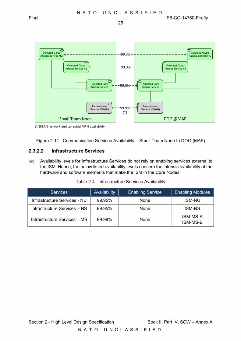
N A T O U N C L A S S I F I E D Final IFB-CO-14760-Firefly
25
Section 2 - High Level Design Specification Book II, Part IV, SOW – Annex A
N A T O U N C L A S S I F I E D
DOG @MAFSmall Team Node
Protected Core Access Service
Coloured Cloud Access Service NU
Coloured Cloud Access Service xS
Protected Core Access Service
Coloured Cloud Access Service NU
Coloured Cloud Access Service xS
99.3%
99.3%
99.5%
Transmission Service (BGAN)
Transmission Service (BGAN)99.9%
(*)
(*) BGAN network and terrestrial VPN availability
Figure 2-11 Communication Services Availability – Small Team Node to DOG (MAF)
2.3.2.2 Infrastructure Services
[63] Availability levels for Infrastructure Services do not rely on enabling services external to the ISM. Hence, the below listed availability levels concern the intrinsic availability of the hardware and software elements that make the ISM in the Core Nodes.
Table 2-4 Infrastructure Services Availability
Services Availability Enabling Service Enabling Modules
Infrastructure Services - NU 99.95% None ISM-NU
Infrastructure Services – NS 99.95% None ISM-NS
Infrastructure Services – MS 99.99% None ISM-MS-A ISM-MS-B
N A T O U N C L A S S I F I E D Final IFB-CO-14760-Firefly
26
Section 3 - CIS Nodes Specification Book II, Part IV, SOW – Annex A
N A T O U N C L A S S I F I E D
3 CIS Nodes Specification [64] This section contains requirements pertaining to CIS Nodes introduced in § 2.1.
Requirements are formulated at system and subsystem level, following the structure below:
1) General;
2) CIS Modules;
3) Transmission Systems;
4) User Appliances.
3.1 General
[65] The following are general technical requirements applicable to one or to all of the systems specified hereafter, i.e. CIS Modules, Transmission Systems and User Appliances.
3.1.1 Modularity
SRS-22 Each CIS Module shall be implemented with distinct, physically independent physical elements, one per classification. These elements are hereafter referred with the name of the module, followed by a suffix corresponding to the security domain, e.g. CNM-NU.
SRS-23 Each module shall be implemented and delivered as one or multiple transit cases.
[66] The maximum number and size of the transit cases are hereafter provided as an implementation constraint. Specifications that are common to all transit cases are provided under § 6.3, Transport Elements.
SRS-24 The hardware of the following modules shall be physically built the same, such that these modules and exchangeable:
1) CNM-NS, CNM-MS, and CNM-NU;
2) ISM-NS, ISM-NS, and ISM-NU; where the ISM-MS shall be implemented as a cluster of 2 identical transit cases, and the ISM-NS and ISM-NU shall be implemented as 1 transit case (refer to § 3.1.1);
3) ISM and CGM;
4) RNM-NS and RNM-MS;
5) UAM-NS and UAM-MS.
SRS-25 Once the active components in the transit cases are configured for a given security classification and stored, and during operation, their affiliation to the security domain shall be visually identifiable through the use of coloured tags (BLUE for MS, RED for NS, GREEN for NU). These tags shall be firmly attached to the surface of the cases, to avoid accidental removal.
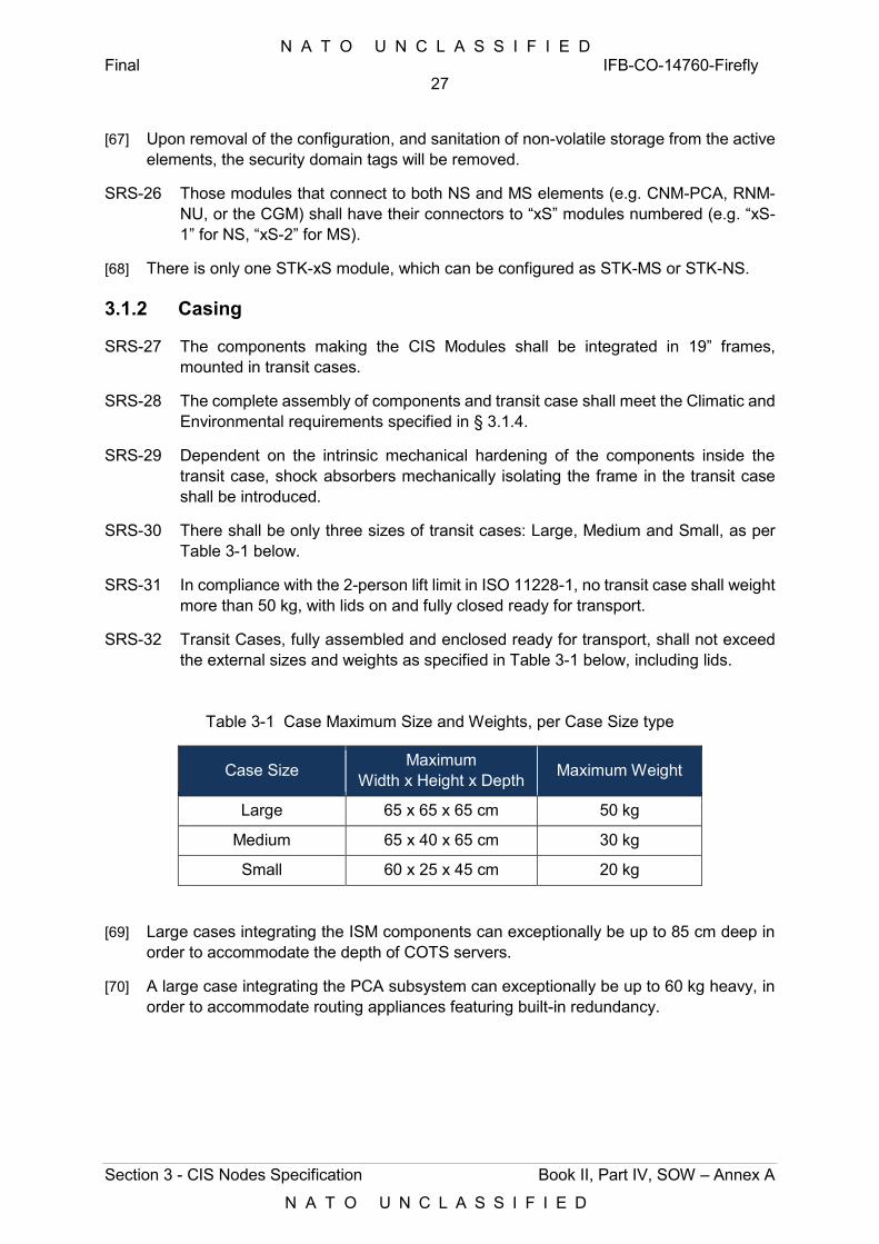
N A T O U N C L A S S I F I E D Final IFB-CO-14760-Firefly
27
Section 3 - CIS Nodes Specification Book II, Part IV, SOW – Annex A
N A T O U N C L A S S I F I E D
[67] Upon removal of the configuration, and sanitation of non-volatile storage from the active elements, the security domain tags will be removed.
SRS-26 Those modules that connect to both NS and MS elements (e.g. CNM-PCA, RNM-NU, or the CGM) shall have their connectors to “xS” modules numbered (e.g. “xS-1” for NS, “xS-2” for MS).
[68] There is only one STK-xS module, which can be configured as STK-MS or STK-NS.
3.1.2 Casing
SRS-27 The components making the CIS Modules shall be integrated in 19” frames, mounted in transit cases.
SRS-28 The complete assembly of components and transit case shall meet the Climatic and Environmental requirements specified in § 3.1.4.
SRS-29 Dependent on the intrinsic mechanical hardening of the components inside the transit case, shock absorbers mechanically isolating the frame in the transit case shall be introduced.
SRS-30 There shall be only three sizes of transit cases: Large, Medium and Small, as per Table 3-1 below.
SRS-31 In compliance with the 2-person lift limit in ISO 11228-1, no transit case shall weight more than 50 kg, with lids on and fully closed ready for transport.
SRS-32 Transit Cases, fully assembled and enclosed ready for transport, shall not exceed the external sizes and weights as specified in Table 3-1 below, including lids.
Table 3-1 Case Maximum Size and Weights, per Case Size type
Case Size Maximum Width x Height x Depth Maximum Weight
Large 65 x 65 x 65 cm 50 kg
Medium 65 x 40 x 65 cm 30 kg
Small 60 x 25 x 45 cm 20 kg
[69] Large cases integrating the ISM components can exceptionally be up to 85 cm deep in order to accommodate the depth of COTS servers.
[70] A large case integrating the PCA subsystem can exceptionally be up to 60 kg heavy, in order to accommodate routing appliances featuring built-in redundancy.
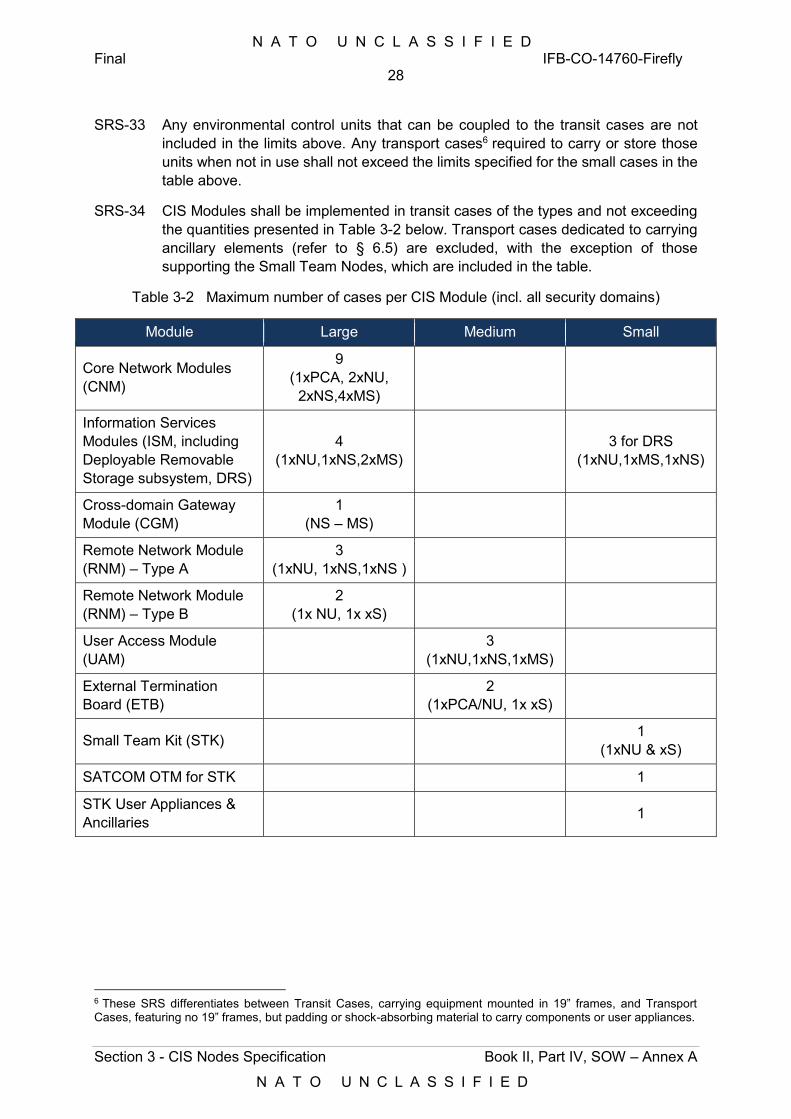
N A T O U N C L A S S I F I E D Final IFB-CO-14760-Firefly
28
Section 3 - CIS Nodes Specification Book II, Part IV, SOW – Annex A
N A T O U N C L A S S I F I E D
SRS-33 Any environmental control units that can be coupled to the transit cases are not included in the limits above. Any transport cases6 required to carry or store those units when not in use shall not exceed the limits specified for the small cases in the table above.
SRS-34 CIS Modules shall be implemented in transit cases of the types and not exceeding the quantities presented in Table 3-2 below. Transport cases dedicated to carrying ancillary elements (refer to § 6.5) are excluded, with the exception of those supporting the Small Team Nodes, which are included in the table.
Table 3-2 Maximum number of cases per CIS Module (incl. all security domains)
Module Large Medium Small
Core Network Modules (CNM)
9 (1xPCA, 2xNU,
2xNS,4xMS)
Information Services Modules (ISM, including Deployable Removable Storage subsystem, DRS)
4 (1xNU,1xNS,2xMS) 3 for DRS
(1xNU,1xMS,1xNS)
Cross-domain Gateway Module (CGM)
1 (NS – MS)
Remote Network Module (RNM) – Type A
3 (1xNU, 1xNS,1xNS )
Remote Network Module (RNM) – Type B
2 (1x NU, 1x xS)
User Access Module (UAM) 3
(1xNU,1xNS,1xMS)
External Termination Board (ETB) 2
(1xPCA/NU, 1x xS)
Small Team Kit (STK) 1 (1xNU & xS)
SATCOM OTM for STK 1
STK User Appliances & Ancillaries 1
6 These SRS differentiates between Transit Cases, carrying equipment mounted in 19” frames, and Transport Cases, featuring no 19” frames, but padding or shock-absorbing material to carry components or user appliances.
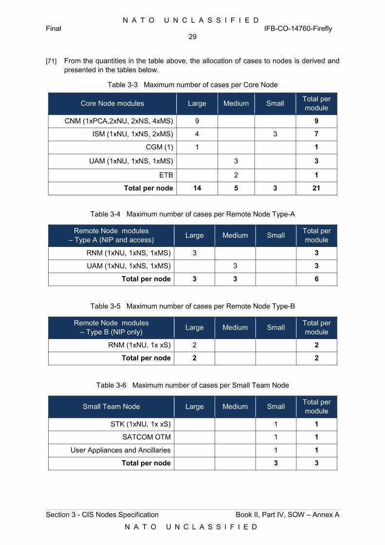
N A T O U N C L A S S I F I E D Final IFB-CO-14760-Firefly
29
Section 3 - CIS Nodes Specification Book II, Part IV, SOW – Annex A
N A T O U N C L A S S I F I E D
[71] From the quantities in the table above, the allocation of cases to nodes is derived and presented in the tables below.
Table 3-3 Maximum number of cases per Core Node
Core Node modules Large Medium Small Total per module
CNM (1xPCA,2xNU, 2xNS, 4xMS) 9 9
ISM (1xNU, 1xNS, 2xMS) 4 3 7
CGM (1) 1 1
UAM (1xNU, 1xNS, 1xMS) 3 3
ETB 2 1
Total per node 14 5 3 21
Table 3-4 Maximum number of cases per Remote Node Type-A
Remote Node modules – Type A (NIP and access) Large Medium Small Total per
module
RNM (1xNU, 1xNS, 1xMS) 3 3
UAM (1xNU, 1xNS, 1xMS) 3 3
Total per node 3 3 6
Table 3-5 Maximum number of cases per Remote Node Type-B
Remote Node modules – Type B (NIP only) Large Medium Small Total per
module
RNM (1xNU, 1x xS) 2 2
Total per node 2 2
Table 3-6 Maximum number of cases per Small Team Node
Small Team Node Large Medium Small Total per module
STK (1xNU, 1x xS) 1 1
SATCOM OTM 1 1
User Appliances and Ancillaries 1 1
Total per node 3 3
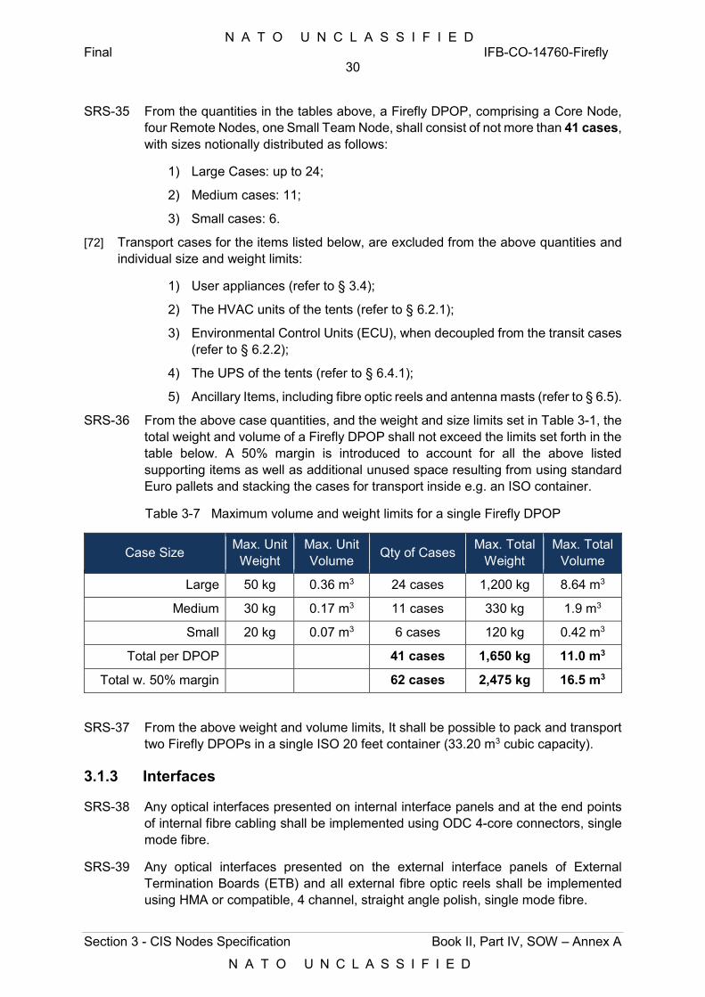
N A T O U N C L A S S I F I E D Final IFB-CO-14760-Firefly
30
Section 3 - CIS Nodes Specification Book II, Part IV, SOW – Annex A
N A T O U N C L A S S I F I E D
SRS-35 From the quantities in the tables above, a Firefly DPOP, comprising a Core Node, four Remote Nodes, one Small Team Node, shall consist of not more than 41 cases, with sizes notionally distributed as follows:
1) Large Cases: up to 24;
2) Medium cases: 11;
3) Small cases: 6.
[72] Transport cases for the items listed below, are excluded from the above quantities and individual size and weight limits:
1) User appliances (refer to § 3.4);
2) The HVAC units of the tents (refer to § 6.2.1);
3) Environmental Control Units (ECU), when decoupled from the transit cases (refer to § 6.2.2);
4) The UPS of the tents (refer to § 6.4.1);
5) Ancillary Items, including fibre optic reels and antenna masts (refer to § 6.5).
SRS-36 From the above case quantities, and the weight and size limits set in Table 3-1, the total weight and volume of a Firefly DPOP shall not exceed the limits set forth in the table below. A 50% margin is introduced to account for all the above listed supporting items as well as additional unused space resulting from using standard Euro pallets and stacking the cases for transport inside e.g. an ISO container.
Table 3-7 Maximum volume and weight limits for a single Firefly DPOP
Case Size Max. Unit Weight
Max. Unit Volume Qty of Cases Max. Total
Weight Max. Total
Volume
Large 50 kg 0.36 m3 24 cases 1,200 kg 8.64 m3
Medium 30 kg 0.17 m3 11 cases 330 kg 1.9 m3
Small 20 kg 0.07 m3 6 cases 120 kg 0.42 m3
Total per DPOP 41 cases 1,650 kg 11.0 m3
Total w. 50% margin 62 cases 2,475 kg 16.5 m3
SRS-37 From the above weight and volume limits, It shall be possible to pack and transport two Firefly DPOPs in a single ISO 20 feet container (33.20 m3 cubic capacity).
3.1.3 Interfaces
SRS-38 Any optical interfaces presented on internal interface panels and at the end points of internal fibre cabling shall be implemented using ODC 4-core connectors, single mode fibre.
SRS-39 Any optical interfaces presented on the external interface panels of External Termination Boards (ETB) and all external fibre optic reels shall be implemented using HMA or compatible, 4 channel, straight angle polish, single mode fibre.
N A T O U N C L A S S I F I E D Final IFB-CO-14760-Firefly
31
Section 3 - CIS Nodes Specification Book II, Part IV, SOW – Annex A
N A T O U N C L A S S I F I E D
SRS-40 All fibre interfaces and fibre strands shall be single-mode fibre.
SRS-41 Any copper interfaces presented on interface panels shall be implemented using MIL-DTL-38999 series III based connectors, equipped with dust caps in the receptacle as well as in the cable side.
[73] In case of Copper Ethernet interfaces, the MIL-DTL-38999 series III based connector shall have an internal RJ45 connector and a MIL-DTL-38999 series III shell.
SRS-42 When interface specifications and/or quantities are specified as “Detailed Design Driven”, it shall be understood as being subject to design decisions and thus not prescribed by this specification.
3.1.4 Environmental Endurance
SRS-43 CIS Modules of Core Nodes are intended for indoors operation (BC tent) and shall sustain and operate nominally under the climatic and environmental conditions specified in:
1) Appendix E of [NC3A TN-1078, 2008] for the conditions referred to as OPE-2C, which concern transit case mounted equipment, where the transit case is operated within an acclimatized shelter or building of opportunity;
2) [NATO STANAG 4370, 2016] for the operational condition OPE-2C as specified in [NC3A TN-1078, 2008].
[74] The climatic and environmental requirements pertaining to the BC tents hosting the CIS Modules of Core Nodes are provided in Section 6.
SRS-44 CIS Modules of Remote Nodes, as well as Transmission Systems, are intended for fully exposed outdoors operation and shall sustain and operate nominally under the climatic and environmental conditions specified in the documents above, for operational conditions OPE-1a (full exposure) or OPE-2a (full exposure in case) respectively, without external protection against the elements.
SRS-45 Furthermore, CIS Modules in Remote Nodes shall be delivered in BC-protected transit cases.
[75] [NC3A TN-1078, 2008] defines minimal requirements with respect to: High temperature, Low temperature, Change of temperature (temperature shock), Solar radiation, Humidity, Rainfall, Ice, Hail, Snow load, Wind, Dust/sand particle size and concentration, Min/max elevation, Max/min atmospheric pressure, Shock, Vibration, Acceleration, Bump, Drop and topple, Free-fall, Ingress Protection Rating, Salt mist, Acid atmosphere, Contamination by fluids, Mould growth and EMC.
[76] NATO Standardization Agreement 4370, “Environmental Testing”, Edition 6 [NATO STANAG 4370, 2016] and specifically NATO Allied Environmental Conditions and test Publication 230, “Climatic Conditions” Edition 1 [NATO AECTP-230, 2009], provide further detail and updated specifications.
SRS-46 Where the requirements specified in [NC3A TN-1078, 2008] and [NATO STANAG 4370, 2016] are in conflict, [NATO STANAG 4370, 2016] shall prevail.
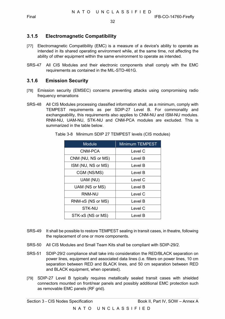
N A T O U N C L A S S I F I E D Final IFB-CO-14760-Firefly
32
Section 3 - CIS Nodes Specification Book II, Part IV, SOW – Annex A
N A T O U N C L A S S I F I E D
3.1.5 Electromagnetic Compatibility
[77] Electromagnetic Compatibility (EMC) is a measure of a device's ability to operate as intended in its shared operating environment while, at the same time, not affecting the ability of other equipment within the same environment to operate as intended.
SRS-47 All CIS Modules and their electronic components shall comply with the EMC requirements as contained in the MIL-STD-461G.
3.1.6 Emission Security
[78] Emission security (EMSEC) concerns preventing attacks using compromising radio frequency emanations
SRS-48 All CIS Modules processing classified information shall, as a minimum, comply with TEMPEST requirements as per SDIP-27 Level B. For commonality and exchangeability, this requirements also applies to CNM-NU and ISM-NU modules. RNM-NU, UAM-NU, STK-NU and CNM-PCA modules are excluded. This is summarized in the table below.
Table 3-8 Minimum SDIP 27 TEMPEST levels (CIS modules)
Module Minimum TEMPEST
CNM-PCA Level C
CNM (NU, NS or MS) Level B
ISM (NU, NS or MS) Level B
CGM (NS/MS) Level B
UAM (NU) Level C
UAM (NS or MS) Level B
RNM-NU Level C
RNM-xS (NS or MS) Level B
STK-NU Level C
STK-xS (NS or MS) Level B
SRS-49 It shall be possible to restore TEMPEST sealing in transit cases, in theatre, following the replacement of one or more components.
SRS-50 All CIS Modules and Small Team Kits shall be compliant with SDIP-29/2.
SRS-51 SDIP-29/2 compliance shall take into consideration the RED/BLACK separation on power lines, equipment and associated data lines (i.e. filters on power lines, 10 cm separation between RED and BLACK lines, and 50 cm separation between RED and BLACK equipment, when operated).
[79] SDIP-27 Level B typically requires metallically sealed transit cases with shielded connectors mounted on front/rear panels and possibly additional EMC protection such as removable EMC panels (RF grid).
N A T O U N C L A S S I F I E D Final IFB-CO-14760-Firefly
33
Section 3 - CIS Nodes Specification Book II, Part IV, SOW – Annex A
N A T O U N C L A S S I F I E D
SRS-52 Any removable EMC protection to the CIS Modules’ transit cases shall count against the maximum weight for the specified transit case and shall be carried for transport within the transit case.
SRS-53 All CIS Modules shall implement power filter within the transit case with a minimum attenuation of 60 dB over the frequency range of 100 kHz to 1 GHz.
3.1.7 Functional Safety
SRS-54 Functional safety shall be implemented as per IEC 61508.
[80] The Safe Failure Fraction (SFF) is the probability of the system failing in a safe state: the dangerous (or critical) state states are identified from Failure Mode, Effects and Criticality Analysis (FMECA) of the system.
3.1.8 Power Supply
SRS-55 All critical CIS components of the Firefly subsystems shall implement dual power supplies built-in, and connected to the separate and independent power feeds of transit cases (refer to § 6.4.2). This shall include but shall not be limited to the following elements:
1) Routers;
2) Switches;
3) Firewalls;
4) Servers.
SRS-56 Power supplies in routers and switches shall be field replaceable.
3.1.9 Hazardous Substances
SRS-57 RoHS-2 Directive [2011/65/EU] shall be applied to all Firefly systems (modules), subsystems and individual components.
3.1.10 Security Hardening
SRS-58 All the CIS equipment involving firmware and software, and integrated into or directly supporting the Firefly DPOP, shall be hardened in accordance with the Purchaser’s standard security hardening settings, as documented in the [Security Configuration Catalogue].
3.1.11 Timing
SRS-59 All the CIS equipment requiring timing shall rely on the NTP feed in the static domain, as provided by the DOG/MAF.
3.2 CIS Modules
[81] This section provides the requirements for the CIS Modules introduced under § 2.1 of the high level design description.
N A T O U N C L A S S I F I E D Final IFB-CO-14760-Firefly
34
Section 3 - CIS Nodes Specification Book II, Part IV, SOW – Annex A
N A T O U N C L A S S I F I E D
[82] For each CIS Module, functional and technical requirements are first provided at system (or module) level, followed by requirements specific to each of the subsystems identified as part of the preliminary design conveyed by this specification.
[83] CIS Modules specified in this section and the diagrams in this section represent three instances, NU, NS and MS under each module, as this will be the deployment configuration by default.
SRS-60 The specification considers full redundancy of the CNM and ISM for the MS security domain, with two independent modules of each. It shall however be possible to repurpose the redundant module to add redundancy to any of the remaining two security domains, NS or NU.
3.2.1 Core Network Modules
SRS-61 Each Core Network Module shall provide local area and metro-area network connectivity to (refer to Figure 3-1 below):
1) Information Services Module (ISM);
2) A second (redundant) Core Network Module (this is only applicable to the CNM-xS);
3) Cross-domain Gateway Module (CGM), with logical connectivity to two ISM (ISM-NS and IMS-MS);
4) User Access Module (UAM), where local users connect;
5) PoPs of collocated Mission Partner nations in the mission network environment (FMN);
6) Up to eight Remote Nodes, in the case of the CNM-PCA, in turn serving local hosted users of collocated Mission Partner nations, over HCLOS radio, fibre, or SATCOM links.
SRS-62 Each Core Node Module shall provide wide area network connectivity to (refer to Figure 3-2 below):
1) The MAF, via terrestrial lines or over SATCOM, anchoring the links at the NATO Satellite Ground Stations (SGS); and simultaneously,
2) A Dragonfly (or a CGS), via terrestrial lines or over SATCOM.
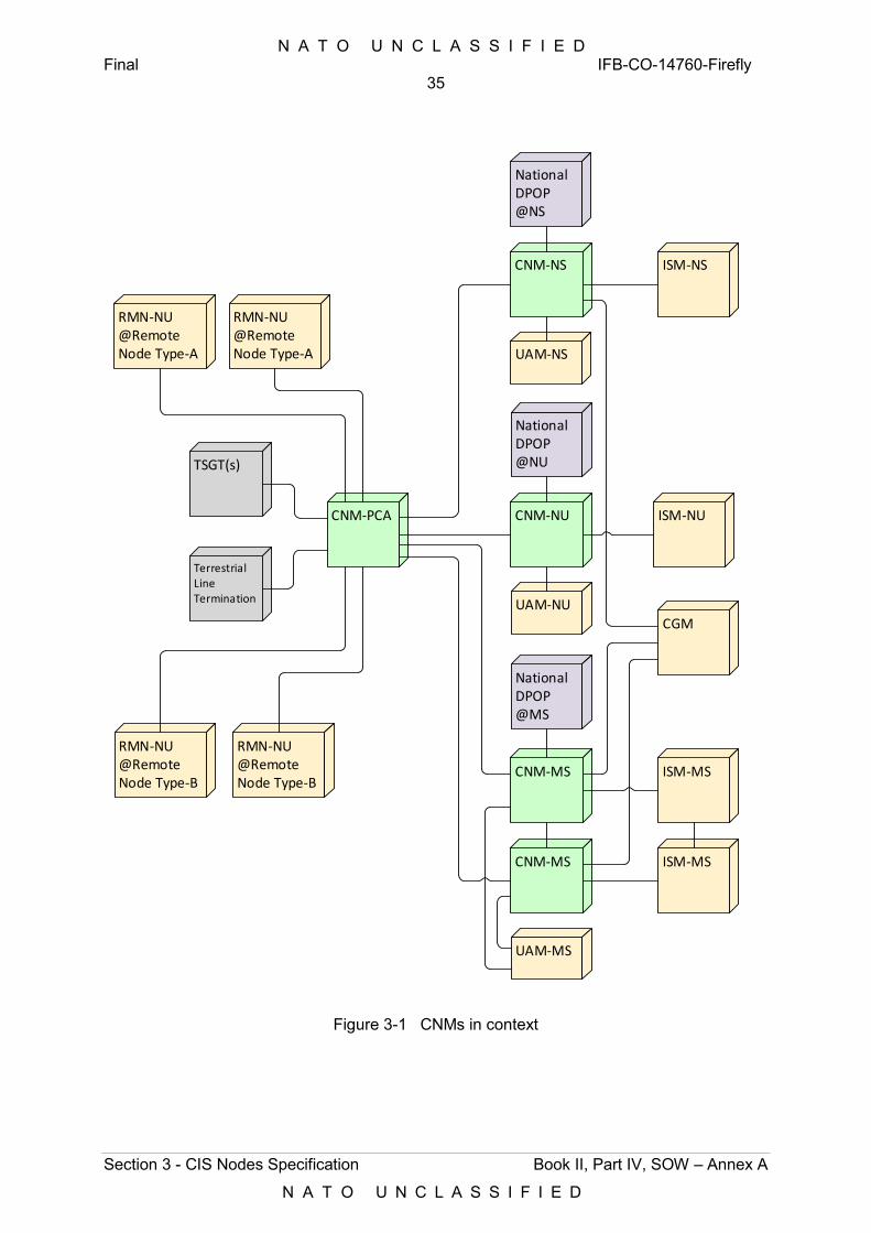
N A T O U N C L A S S I F I E D Final IFB-CO-14760-Firefly
35
Section 3 - CIS Nodes Specification Book II, Part IV, SOW – Annex A
N A T O U N C L A S S I F I E D
CNM-NS
UAM-MS
CGM
CNM-PCA
CNM-MS
CNM-MS
ISM-MS
ISM-NS
ISM-MS
UAM-NS
RMN-NU@Remote Node Type-B
NationalDPOP@MS
NationalDPOP@NS
RMN-NU@Remote Node Type-A
CNM-NU
UAM-NU
NationalDPOP@NU
ISM-NU
RMN-NU@Remote Node Type-A
RMN-NU@Remote Node Type-B
TSGT(s)
TerrestrialLine Termination
Figure 3-1 CNMs in context
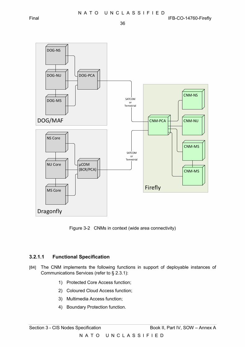
N A T O U N C L A S S I F I E D Final IFB-CO-14760-Firefly
36
Section 3 - CIS Nodes Specification Book II, Part IV, SOW – Annex A
N A T O U N C L A S S I F I E D
Figure 3-2 CNMs in context (wide area connectivity)
3.2.1.1 Functional Specification
[84] The CNM implements the following functions in support of deployable instances of Communications Services (refer to § 2.3.1):
1) Protected Core Access function;
2) Coloured Cloud Access function;
3) Multimedia Access function;
4) Boundary Protection function.
Firefly
CNM-NS
CNM-PCA
CNM-MS
CNM-MS
CNM-NUDOG/MAF
DOG-NS
DOG-NU
DOG-MS
DOG-PCA
Dragonfly
NS Core
NU Core
MS Core
µCOM(BCR/PCA)
SATCOMor
Terrestrial
SATCOMor
Terrestrial
N A T O U N C L A S S I F I E D Final IFB-CO-14760-Firefly
37
Section 3 - CIS Nodes Specification Book II, Part IV, SOW – Annex A
N A T O U N C L A S S I F I E D
SRS-63 The Protected Core Access (PCA) function of the CNM shall:
1) Aggregate and distribute traffic across the diverse transmission bearers on the DCIS Protected Core (e.g. SATCOM, HCLOS radio, fibre, and terrestrial TDM lines, where available), using IP unicast and IP multicast routing;
2) Implement the DCIS Protected Core, providing wide-area transport services in support of the Coloured Cloud Access (CCA) function, both intra-theatre towards Remote Nodes and other Core Nodes, or non-Firefly DPOPs, as well as into the static domain, i.e. reach back into the MAF;
3) Provide IP access (WAN) to the Remote Network Modules (RNM) of up to eight Remote Nodes;
4) Implement MPLS - Traffic Engineering (MPLS-TE) in order to assure end-to-end Quality and Class of Service across the WAN, for the flows of CCA functions of different classifications, and for the flows within each CCA function and security classification.
SRS-64 The Coloured Cloud Access (CCA) function of the CNM shall, for each security domain:
1) Connect to the PCA function using a commercial grade IPSec function or a NATO accredited high-grade IP Crypto function (for the CCA-NU and the CCA-xS, respectively);
2) Provide the core switching capability, acting as a hub for the MMA and BPS functions, as well as for the ISMs and CGMs;
3) Use an Interior Gateway Protocol (IGP) to converge IP information within the Coloured Cloud
4) Provide IP access (LAN) and IP transport (WAN) to the Multimedia Access function of the CNM, Information Services modules (ISM) and User Access Modules (UAM) within the Core Node;
5) Provide IP access (LAN) to the Boundary Protection function in the CNM, such that IP flows from/to the local ISM, UAM and MMA, as well as the flows from/to the WAN (other Core Nodes or Remote Nodes) can be routed through it and protected accordingly;
6) Implement traffic marking, traffic conditioning and dynamic IP routing at the edges of the network;
7) Support IP interworking with collocated Mission Network Participants (MNP), over a Network Interconnection Point (NIP), compliant with FMN Spiral 3;
8) Support IP interworking with non-collocated MNP (attached to a Remote Node), over a NIP-G compliant with FMN Spiral 3.
N A T O U N C L A S S I F I E D Final IFB-CO-14760-Firefly
38
Section 3 - CIS Nodes Specification Book II, Part IV, SOW – Annex A
N A T O U N C L A S S I F I E D
SRS-65 The Multimedia Access (MMA) function of the CNM shall, for each security domain:
1) Provide local users with multimedia access for IP Telephony, voice mail and secure voice conferencing support, at NU, NS and MS levels, using the CCA function for transport;
2) Implement an IP telephony service that enables users at the Core Node and remote Nodes to intercommunicate with other users in other Core or Remote Nodes, Dragonfly nodes, MNP nodes, or in the NATO static environment, within the same security domain;
3) Support codec conversion and voice conferencing;
4) Terminate and relay voice media streams (IP address hiding);
5) Feature a Session Border Controller (SBC) capability to enable federation with 3rd party VoIP network at NU, NS and MS levels, over the NIP of the CCA function;
6) Use Call Admission Control (CAC) to prevent oversubscription of bandwidth across the WAN trunks that would degrade voice quality;
7) Support Multi-Level Precedence Pre-emption (MLPP) across the WAN trunks to ensure best use of the available bandwidth, with four levels of priority (Flash Override, Flash, Intermediate, Priority, Routine);
8) Support user-initiated subscriber extension mobility;
9) Be able to federate with NATO DCIS and NATO Static VoIP and VoSIP Infrastructure and endpoint devices, at NU, NS and MS levels, over the DOG in the MAF;
10) Implement a Public Address (PA) capability, at NU level, that supports both live and recorded audio broadcasts across the deployed area, via internal and external loudspeakers, implemented using the same IP network as the NU MMA for transport.
SRS-66 The Boundary Protection (BPS) function of the CNM function shall, for each security domain:
1) Implement the Self-protecting Node principle and protect the following LAN, WAN and MAN traffic flows using port-based and application layer stateful inspection:
a) UAM to local ISM (LAN);
b) UAM to local MMA function (LAN);
c) ISM to remote ISM or to MAF, over the CCA and PCA functions (WAN);
d) UAM to remote ISM, over the CCA and PCA functions (WAN);
e) ISM to CGM (LAN);
f) Remote Node to MMA function (MAN);
g) Remote Node to ISM (MAN);
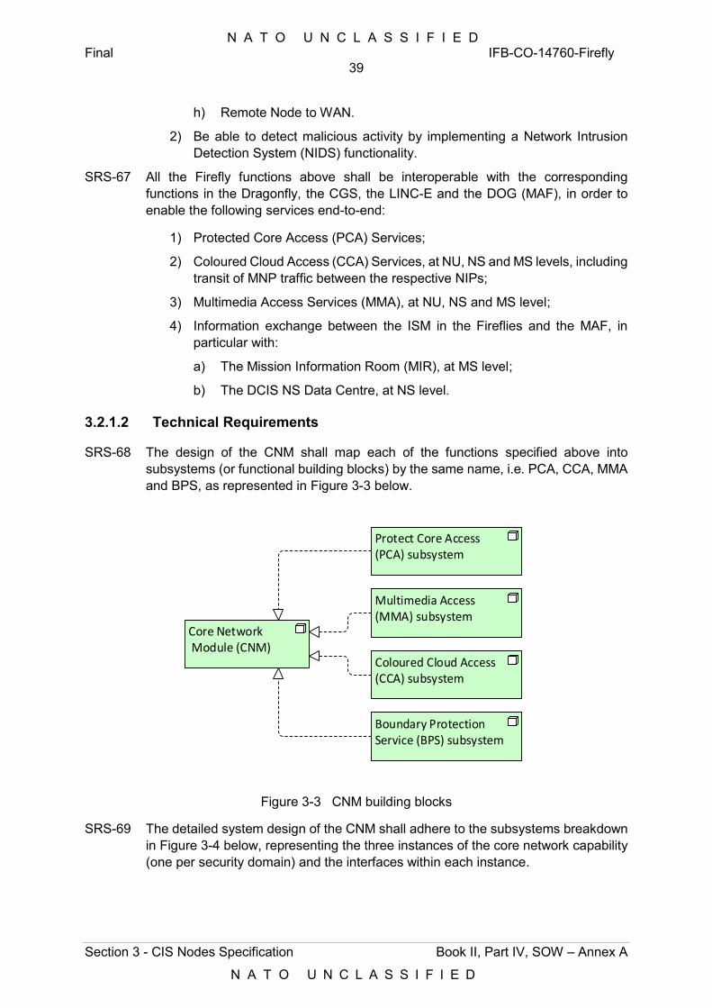
N A T O U N C L A S S I F I E D Final IFB-CO-14760-Firefly
39
Section 3 - CIS Nodes Specification Book II, Part IV, SOW – Annex A
N A T O U N C L A S S I F I E D
h) Remote Node to WAN.
2) Be able to detect malicious activity by implementing a Network Intrusion Detection System (NIDS) functionality.
SRS-67 All the Firefly functions above shall be interoperable with the corresponding functions in the Dragonfly, the CGS, the LINC-E and the DOG (MAF), in order to enable the following services end-to-end:
1) Protected Core Access (PCA) Services;
2) Coloured Cloud Access (CCA) Services, at NU, NS and MS levels, including transit of MNP traffic between the respective NIPs;
3) Multimedia Access Services (MMA), at NU, NS and MS level;
4) Information exchange between the ISM in the Fireflies and the MAF, in particular with:
a) The Mission Information Room (MIR), at MS level;
b) The DCIS NS Data Centre, at NS level.
3.2.1.2 Technical Requirements
SRS-68 The design of the CNM shall map each of the functions specified above into subsystems (or functional building blocks) by the same name, i.e. PCA, CCA, MMA and BPS, as represented in Figure 3-3 below.
Core Network Module (CNM)
Protect Core Access (PCA) subsystem
Multimedia Access (MMA) subsystem
Coloured Cloud Access (CCA) subsystem
Boundary Protection Service (BPS) subsystem
Figure 3-3 CNM building blocks
SRS-69 The detailed system design of the CNM shall adhere to the subsystems breakdown in Figure 3-4 below, representing the three instances of the core network capability (one per security domain) and the interfaces within each instance.
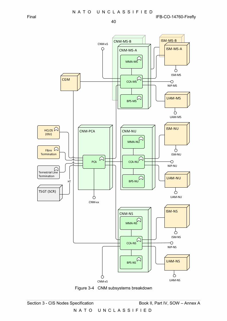
N A T O U N C L A S S I F I E D Final IFB-CO-14760-Firefly
40
Section 3 - CIS Nodes Specification Book II, Part IV, SOW – Annex A
N A T O U N C L A S S I F I E D
CNM-PCA
ISM-MS-BCNM-MS-B
CNM-NU
CCA-NUNIP-NU
HCLOS(IDU)
FibreTermination
TSGT (SCR)
UAM-NU
Terrestrial LineTermination
MMA-NU
BPS-NU
ISM-NU
CNM-NS
CCA-NSNIP-NS
UAM-NS
MMA-NS
BPS-NS
ISM-NS
x2
PCA
CNM-MS-A
CCA-MSNIP-MS
UAM-MS
MMA-MS
BPS-MS
ISM-MS-A
CGM
CNM-xS
CNM-xS
ISM-NU
ISM-MS
ISM-NS
CNM-xx
UAM-NS
UAM-NU
UAM-MS
Figure 3-4 CNM subsystems breakdown
N A T O U N C L A S S I F I E D Final IFB-CO-14760-Firefly
41
Section 3 - CIS Nodes Specification Book II, Part IV, SOW – Annex A
N A T O U N C L A S S I F I E D
3.2.1.2.1 PCA subsystem
SRS-70 The PCA subsystem shall support the functions listed under the PCA function under § 3.2.1.1 above.
SRS-71 The PCA subsystem shall deliver MPLS-based IP transport services to the MS, NS and NU IP routed domains (implemented by the respective CCA subsystems).
SRS-72 The PCA subsystem shall perform the PE function of the MPLS WAN, and support MP-BGP.
SRS-73 The PCA subsystem shall forward packets to and from each CCA subsystems based on labels.
SRS-74 The PCA subsystem shall use MPLS to implement Traffic Engineering through Label-Switched Paths (LSP). LSP are logical paths established over multiple transmission media A given logical path may involve one or more transmission bearer.
SRS-75 The PCA subsystem shall use an internal routing protocol based Intermediate System – Intermediate System (IS-IS) as the Interior Gateway protocol (IGP). IS-IS shall be configured in all WAN interfaces in support of the exchange of control-plane information. This includes:
1) IP reachability information;
2) MPLS traffic engineering metrics.
SRS-76 OSPF-TE shall be used as the Interior Gateway Protocol (IGP) within the MPLS WAN to provide BGP next-hop reach ability.
SRS-77 Label Distribution Protocol (LDP) shall be used within the MPLS core to facilitate MPLS VPN services.
SRS-78 The PCA subsystem shall use IS-IS to carry topology information for the WAN links, its loopback interfaces (which are the end-points for MPLS LSPs), its physical interfaces, used for the IPSec tunnels for the NU, NS and MS access networks (e.g. the interfaces facing the black IP port of the TCE-621C).
SRS-79 The PCA subsystem shall implement different LSPs to carry traffic internal to the NRF DCIS domain (i.e. amongst DPOPs and towards the MAF) and FMN traffic transiting the network of DPOPs, between NIPs.
SRS-80 The PCA subsystem interfaces for IPSec tunnel end-points shall be set as “passive” in IS-IS as they are Protected Core Edge connections. There shall be no IP routing interaction between the Protected Core and the NU, NS and MS networks.
SRS-81 The PCA subsystem shall implement IPv4 and IPv6 multicast routing through PIM-SM, PIM-SSM and MLDv2.
SRS-82 Rendezvous points shall be anycasted in accordance with [RFC4610]. Geographically RP redundancy shall be implemented.
SRS-83 For IPv4 multicast, the anycasted rendezvous points shall use Multicast Source Discovery Protocol (MSDP).
N A T O U N C L A S S I F I E D Final IFB-CO-14760-Firefly
42
Section 3 - CIS Nodes Specification Book II, Part IV, SOW – Annex A
N A T O U N C L A S S I F I E D
SRS-84 For IPv4 multicast, when BGP-4 is used across interoperability interfaces, MSDP shall peer using the same source and destination addresses as the external BGP peering session.
SRS-85 For IPv4 multicast, MSDP shall be configured to source from the loopback addresses on internal BGP peering sessions.
SRS-86 The PCA subsystem shall support IP throughput performances up to 5 Gbps and 20 Gbps, with and without IPSec encryption, respectively.
SRS-87 The PCA subsystem shall be able to simultaneously connect to two independent TSGTs, each equipped with two SATCOM Convergence Routers (SCR).
SRS-88 The PCA subsystem shall implement eight interfaces for terrestrial WAN/MAN connectivity purposes, including connections to the Remote Nodes and to high capacity transport bearers while in garrison (at 10 Gbps).
SRS-89 The PCA subsystem shall, as a minimum, implement interfaces to the WAN/MAN and to other subsystems within the Core Network Module, as per the table below. The need for additional interfaces, or interfaces different from those listed below, including internal interfaces within the PCA subsystem, if required, as well as their specification, shall be design-driven and shall be justified, based on component selection and functionality sought.
Table 3-9 PCA subsystem interfaces
ID Interface to Subsystem Qty. Remarks
1 SATCOM Transport, i.e. SATCOM Convergence Routers (SCR) in TSGT
External 4 1 Gbps, 1000BASE-LX/LH. Allows two TSGT connected in parallel (two ports per TSGT)
2 Optical Transport media (Terrestrial WAN/MAN) External
6 1 Gbps, 1000BASE-LX/LH
2 10 Gbps, 10GBASE-LR
3 HCLOS radio subsystem HCLOS 4 1 Gbps
4 CNM-MS-A CCA-MS 2 Interface to TCE-621C (1 Gbps)
5 CNM-MS-B CCA-MS 2 Interface to TCE-621C (1 Gbps)
6 CNM-NS CCA-NS 2 Interface to TCE-621C (1 Gbps)
7 CNM-NU CCA-NU 2 10 Gbps
8 CNM (NU, NS or MS) CCA-xS 1 Future expansion (1x 1 Gbps)
CCA-NU 1 Future expansion (1x 10 Gbps)
SRS-90 The PCA subsystem shall implement additional interfaces, as required and as driven by the design, in support of service management and control functionalities.
[85] Additional interfaces may be implemented to accommodate other connections and end-points resulting from the detailed design.
SRS-91 Any routers and switches in the PCA subsystem shall be duly sized and licensed in order to meet the functional and technical requirements above.
N A T O U N C L A S S I F I E D Final IFB-CO-14760-Firefly
43
Section 3 - CIS Nodes Specification Book II, Part IV, SOW – Annex A
N A T O U N C L A S S I F I E D
3.2.1.2.2 CCA subsystem
[86] The CCA subsystem exists in three different flavours: NU, MS and NS. The NU flavour is different from the other two in the sense that the corresponding NU module will require no crypto equipment.
SRS-92 The CCA subsystem shall implement the functions listed under the CCA function under § 3.2.1.1 above.
SRS-93 The CCA subsystem shall implement IPv4/IPv6 dual stack.
SRS-94 The CCA subsystem shall implement a 10 Gbps switching core.
SRS-95 All CCA subsystems shall be built and licensed the same, irrespective of the security domain. The CCA-NU shall be fitted for but not with IP encryption devices, and shall be pre-wired and connectorized accordingly.
SRS-96 The CCA subsystem shall use OSPFv2 as the IGP for IPv4 and OSPFv3 as the IGP for IPv6. Within each domain, OSPF shall operate in a single area structure (Area 0).
SRS-97 The CCA subsystem shall support IP multicast and fulfil all multicast-related requirements stated for the PCA subsystem above.
SRS-98 The CCA subsystem shall implement a tunnelling architecture for transporting NS/MS data between Core Nodes. Tunnels shall provide point-to-point IP transport at a given QoS level, in turn determined by the link attributes of the underlying MPLS-TE tunnels (LSP) between the PCA subsystems.
SRS-99 To allow dynamic routing updates between two connected Headquarters (two CNM or one CNM and a NS or MS Core of a Dragonfly), a main End-to-End tunnel shall be created between CCAs.
[87] This tunnel acts as a logical interface to BGP and OSPF, and as the point-to-point transport interface connecting to other networks. All dynamic routing updates shall be sent and received through this tunnel.
[88] QoS and Anti-Replay methods are performed inside the End-to-End tunnel and are transparent to the dynamic routing protocols. The per-QOS ESP between IP crypto equipment correspond to separate Virtual Crypto Units (VCU).
SRS-100 For each End-to-End GRE tunnel and for QoS purposes, five additional GRE tunnels shall be configured within the CCA subsystem, one for each QoS class. The routing design shall be implemented as follows:
1) QoS tunnels shall be established between CCA subsystem instances;
2) Traffic shall be first routed into the correct E2E tunnel by the dynamic routing protocol;
N A T O U N C L A S S I F I E D Final IFB-CO-14760-Firefly
44
Section 3 - CIS Nodes Specification Book II, Part IV, SOW – Annex A
N A T O U N C L A S S I F I E D
3) Once in the correct E2E tunnel, traffic shall be then routed into one of the associated five QoS-based GRE tunnels via static configuration. As this routing decision is based upon DSCP and destination IP (with the destination being the tunnel endpoint of the chosen E2E GRE), policy-based routing (PBR) and a separate (virtual) routing instance (VRF) are required;
4) Each QoS tunnel (mapped to a VCU) shall be associated with one or more (more in case of load balancing across cryptos) cryptographic tunnels and routed across the Protected Core (PCA network) accounting for the QoS requirements.
[89] Cryptographic tunnels are established between TCE-621 series IP encryption equipment (PFE) (this applies to the xS Coloured Cloud IP Access subsystems) or between commercial grade crypto instances (this applies to the NU Coloured Cloud IP Access subsystems).
SRS-101 The CCA subsystem shall implement a VRF to terminate user traffic from the corresponding CCA in the RNM of the Remote Nodes, or from the CCA in the STK, dedicated per RNM, such that it can be forwarded to the BPS subsystem.
SRS-102 The CCA subsystem shall implement VRFs to carry FMN transit traffic between NIPs in different DPOPs.
SRS-103 Traffic from/to this VRF shall be routed through the Boundary Protection function where required. This will grant protection to the users in the Remote Nodes, where a local Boundary Protection function is not present.
SRS-104 The CCA subsystem shall use BGP4 as the EGP to interconnect interior routing domains (iBGP) and to dynamically advertise IP information over the NIP (eBGP).
SRS-105 Over the NIP, each CCA subsystem shall transit multicast traffic on behalf of all Mission Network (MN) participants.
SRS-106 Over the NIP, the CCA subsystem shall not transit any multicast traffic and shall only forward multicast traffic that has been requested by local user or from other MN participant(s) via PIM signalling.
SRS-107 In order to fulfil end-to-end QoS for higher level services, IP performance shall be expressed as a maximum IP packet loss rate (IPRL), a maximum IP transfer delay (IPTD) and a maximum jitter (IPDV).
SRS-108 The following QoS parameters for Inter-domain Multicast Source Discovery over the CCA subsystem shall be observed or tailored to fit mission-specific requirements: Application Type: Router (multicast source discovery).
SRS-109 The following QoS parameters for Inter-domain Routing over the CCA subsystem shall be observed or tailored to fit mission-specific requirements: Application Type: Router (inter-domain routing).
SRS-110 The following QoS parameters for Inter-domain Multicast Signalling over the CCA subsystem shall be observed or tailored to fit mission-specific requirements: Application Type: Router (multicast signalling).
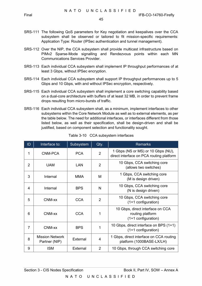
N A T O U N C L A S S I F I E D Final IFB-CO-14760-Firefly
45
Section 3 - CIS Nodes Specification Book II, Part IV, SOW – Annex A
N A T O U N C L A S S I F I E D
SRS-111 The following QoS parameters for Key negotiation and keepalives over the CCA subsystem shall be observed or tailored to fit mission-specific requirements: Application Type: Router (IPSec authentication and tunnel management).
SRS-112 Over the NIP, the CCA subsystem shall provide multicast infrastructure based on PIMv2 Sparse-Mode signalling and Rendezvous points within each MN Communications Services Provider.
SRS-113 Each individual CCA subsystem shall implement IP throughput performances of at least 3 Gbps, without IPSec encryption.
SRS-114 Each individual CCA subsystem shall support IP throughput performances up to 5 Gbps and 10 Gbps, with and without IPSec encryption, respectively.
SRS-115 Each individual CCA subsystem shall implement a core switching capability based on a dual-core architecture with buffers of at least 32 MB, in order to prevent frame drops resulting from micro-bursts of traffic.
SRS-116 Each individual CCA subsystem shall, as a minimum, implement interfaces to other subsystems within the Core Network Module as well as to external elements, as per the table below. The need for additional interfaces, or interfaces different from those listed below, as well as their specification, shall be design-driven and shall be justified, based on component selection and functionality sought.
Table 3-10 CCA subsystem interfaces
ID Interface to: Subsystem Qty. Remarks
1 CNM-PCA PCA 2 1 Gbps (NS or MS) or 10 Gbps (NU), direct interface on PCA routing platform
2 UAM LAN 2 10 Gbps, CCA switching core (allows two switches)
3 Internal MMA M 1 Gbps, CCA switching core (M is design driven)
4 Internal BPS N 10 Gbps, CCA switching core (N is design driven)
5 CNM-xx CCA 2 10 Gbps, CCA switching core (1+1 configuration)
6 CNM-xx CCA 1 10 Gbps, direct interface on CCA
routing platform (1+1 configuration)
7 CNM-xx BPS 1 10 Gbps, direct interface on BPS (1+1) (1+1 configuration)
8 Mission Network Partner (NIP) External 4 1 Gbps, direct interface on CCA routing
platform (1000BASE-LX/LH)
9 ISM External 2 10 Gbps, through CCA switching core
N A T O U N C L A S S I F I E D Final IFB-CO-14760-Firefly
46
Section 3 - CIS Nodes Specification Book II, Part IV, SOW – Annex A
N A T O U N C L A S S I F I E D
SRS-117 Each CCA subsystem shall implement additional interfaces, as required and as driven by the design, in support of service management and control functionalities.
SRS-118 Additional interfaces may be implemented to accommodate other connections and end-points resulting from the detailed design.
SRS-119 Any routers and switches in each CCA subsystem shall be duly sized and licensed in order to meet the functional and technical requirements above.
3.2.1.2.3 MMA subsystem
SRS-120 The MMA subsystem shall implement the functions listed under the MMA function under § 3.2.1.1 above.
SRS-121 There shall be as many instances of the MMA subsystems as CNMs and security domains (NU, MS and NS)
SRS-122 The MMA subsystem shall implement media stream termination and relay functions using DSP hardware acting as Media Termination Point / Trusted Relay Point (MTP/TRP).
SRS-123 The MMA subsystem shall perform codec conversion and use TLS to communicate with the call management function.
SRS-124 The MMA subsystem shall implement the call management function compatible with the specifications of a Cisco Unified Call Manager (CUCM). The corresponding application shall support running as a workload in the ISM.
SRS-125 The MMA subsystems shall support DHCP towards the user appliances connecting via the UAM of Core Nodes and Remote nodes.
SRS-126 The MMA subsystem shall support local voice conferencing.
SRS-127 The MMA subsystem shall implement a Session Border Controller (SBC) function compatible with the specifications of the Cisco Unified Border Element (CUBE).
SRS-128 The MMA subsystem shall support the implementation of the SBC function as an application running as a workload in the ISM.
SRS-129 The MMA subsystem shall support up to 1200 SIP/H.323 sessions.
SRS-130 The MMA subsystem shall support up to 350 users per DPOP.
[90] Software versions are the latest approved versions; these might however be higher during the actual implementation.
SRS-131 All MMA subsystems shall be built and licensed the same, irrespective of the security domain. This excludes the PA active elements of the MMA-NU, which shall be implemented outside the CNM transit case.
SRS-132 The MMA subsystem shall interface the CCA subsystem over 1 Gbps interface.
SRS-133 Any software component of the MMA subsystem that is able to run on commodity hardware shall be implemented as a workload on the ISM. This is applicable to all three security domain (NS, MS and NU).
N A T O U N C L A S S I F I E D Final IFB-CO-14760-Firefly
47
Section 3 - CIS Nodes Specification Book II, Part IV, SOW – Annex A
N A T O U N C L A S S I F I E D
SRS-134 The implementation of MLPP by the MMA subsystem, shall support, on top of routine calls, four levels of precedence and pre-emption, as follows (from highest to lowest)
1) Flash Override;
2) Flash;
3) Intermediate;
4) Priority;
5) Routine.
SRS-135 The MMA subsystem shall implement a dial plan compliant with STANAG 4705.
SRS-136 The MMA subsystem shall implement a local Call Management instance.
SRS-137 The MMA subsystem for each security domain shall be sized for the maximum number of VoIP phones supplied per domain + 10%.
SRS-138 The Public Address (PA) capability shall be implemented with internal and external loudspeakers.
SRS-139 External PA loudspeakers shall be of a ruggedized, weatherproof type including masts, cabling and ancillaries.
SRS-140 The PA capability shall be implemented to include as a minimum two internal loudspeakers and supporting fixtures, per CNM and per RNM, to be used within the tented areas or building of opportunity.
SRS-141 PA loudspeakers shall be driven from an audio amplifier. Input to this amplifier shall be from an IP interface to the MMA-NU
SRS-142 Any PA amplifiers shall be external to the transit case hosting the MMA-NU subsystem.
SRS-143 The external environment loudspeakers shall be weather-proofed, and shall be mounted on masts in order for the PA broadcasts to reach up to 800 metres from the Node centre.
SRS-144 The internal environment loudspeakers shall support a Power over Ethernet (PoE) interface and mains power. Mains power through an external power supply unit is acceptable.
SRS-145 The PA capability shall all support broadcast from NU telephones to all or pre-configured groups of NU telephones and through the above mentioned internal and external speakers.
SRS-146 The PA capability shall support predefined message broadcast via the NU phones.
SRS-147 The PA capability shall implement 2 switched wired microphones and 2 wireless microphones per Node.
[91] In practical realization terms, the following implementation constraints apply:
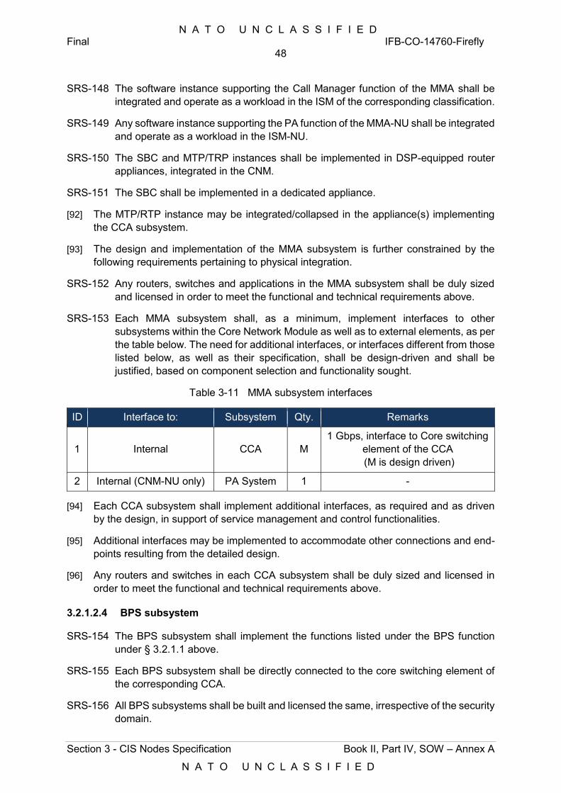
N A T O U N C L A S S I F I E D Final IFB-CO-14760-Firefly
48
Section 3 - CIS Nodes Specification Book II, Part IV, SOW – Annex A
N A T O U N C L A S S I F I E D
SRS-148 The software instance supporting the Call Manager function of the MMA shall be integrated and operate as a workload in the ISM of the corresponding classification.
SRS-149 Any software instance supporting the PA function of the MMA-NU shall be integrated and operate as a workload in the ISM-NU.
SRS-150 The SBC and MTP/TRP instances shall be implemented in DSP-equipped router appliances, integrated in the CNM.
SRS-151 The SBC shall be implemented in a dedicated appliance.
[92] The MTP/RTP instance may be integrated/collapsed in the appliance(s) implementing the CCA subsystem.
[93] The design and implementation of the MMA subsystem is further constrained by the following requirements pertaining to physical integration.
SRS-152 Any routers, switches and applications in the MMA subsystem shall be duly sized and licensed in order to meet the functional and technical requirements above.
SRS-153 Each MMA subsystem shall, as a minimum, implement interfaces to other subsystems within the Core Network Module as well as to external elements, as per the table below. The need for additional interfaces, or interfaces different from those listed below, as well as their specification, shall be design-driven and shall be justified, based on component selection and functionality sought.
Table 3-11 MMA subsystem interfaces
ID Interface to: Subsystem Qty. Remarks
1 Internal CCA M 1 Gbps, interface to Core switching
element of the CCA (M is design driven)
2 Internal (CNM-NU only) PA System 1 -
[94] Each CCA subsystem shall implement additional interfaces, as required and as driven by the design, in support of service management and control functionalities.
[95] Additional interfaces may be implemented to accommodate other connections and end-points resulting from the detailed design.
[96] Any routers and switches in each CCA subsystem shall be duly sized and licensed in order to meet the functional and technical requirements above.
3.2.1.2.4 BPS subsystem
SRS-154 The BPS subsystem shall implement the functions listed under the BPS function under § 3.2.1.1 above.
SRS-155 Each BPS subsystem shall be directly connected to the core switching element of the corresponding CCA.
SRS-156 All BPS subsystems shall be built and licensed the same, irrespective of the security domain.
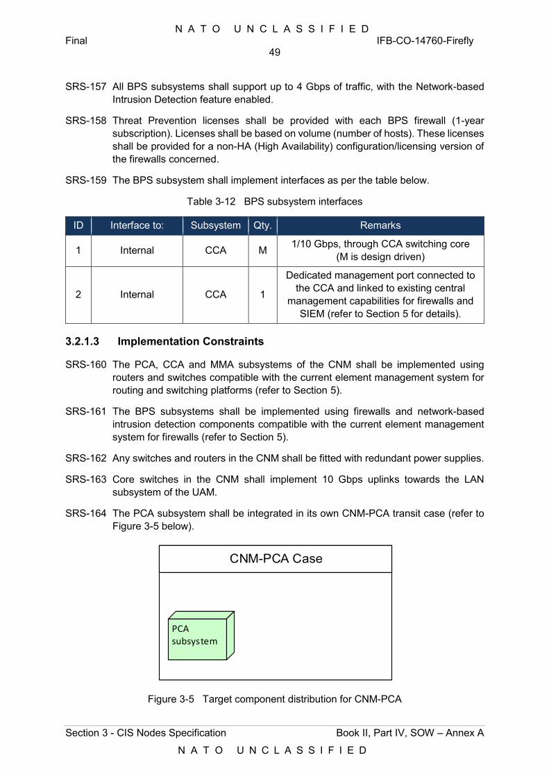
N A T O U N C L A S S I F I E D Final IFB-CO-14760-Firefly
49
Section 3 - CIS Nodes Specification Book II, Part IV, SOW – Annex A
N A T O U N C L A S S I F I E D
SRS-157 All BPS subsystems shall support up to 4 Gbps of traffic, with the Network-based Intrusion Detection feature enabled.
SRS-158 Threat Prevention licenses shall be provided with each BPS firewall (1-year subscription). Licenses shall be based on volume (number of hosts). These licenses shall be provided for a non-HA (High Availability) configuration/licensing version of the firewalls concerned.
SRS-159 The BPS subsystem shall implement interfaces as per the table below.
Table 3-12 BPS subsystem interfaces
ID Interface to: Subsystem Qty. Remarks
1 Internal CCA M 1/10 Gbps, through CCA switching core (M is design driven)
2 Internal CCA 1
Dedicated management port connected to the CCA and linked to existing central
management capabilities for firewalls and SIEM (refer to Section 5 for details).
3.2.1.3 Implementation Constraints
SRS-160 The PCA, CCA and MMA subsystems of the CNM shall be implemented using routers and switches compatible with the current element management system for routing and switching platforms (refer to Section 5).
SRS-161 The BPS subsystems shall be implemented using firewalls and network-based intrusion detection components compatible with the current element management system for firewalls (refer to Section 5).
SRS-162 Any switches and routers in the CNM shall be fitted with redundant power supplies.
SRS-163 Core switches in the CNM shall implement 10 Gbps uplinks towards the LAN subsystem of the UAM.
SRS-164 The PCA subsystem shall be integrated in its own CNM-PCA transit case (refer to Figure 3-5 below).
CNM-PCA Case
PCA subsystem
Figure 3-5 Target component distribution for CNM-PCA
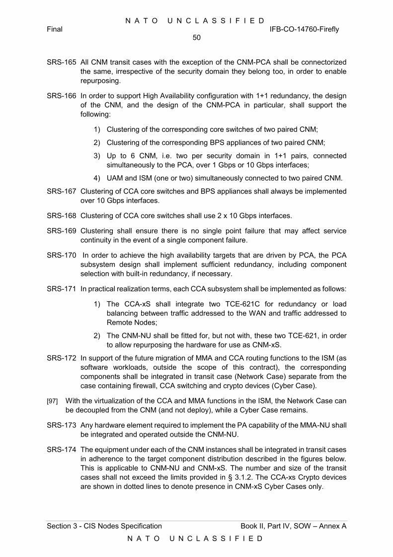
N A T O U N C L A S S I F I E D Final IFB-CO-14760-Firefly
50
Section 3 - CIS Nodes Specification Book II, Part IV, SOW – Annex A
N A T O U N C L A S S I F I E D
SRS-165 All CNM transit cases with the exception of the CNM-PCA shall be connectorized the same, irrespective of the security domain they belong too, in order to enable repurposing.
SRS-166 In order to support High Availability configuration with 1+1 redundancy, the design of the CNM, and the design of the CNM-PCA in particular, shall support the following:
1) Clustering of the corresponding core switches of two paired CNM;
2) Clustering of the corresponding BPS appliances of two paired CNM;
3) Up to 6 CNM, i.e. two per security domain in 1+1 pairs, connected simultaneously to the PCA, over 1 Gbps or 10 Gbps interfaces;
4) UAM and ISM (one or two) simultaneously connected to two paired CNM.
SRS-167 Clustering of CCA core switches and BPS appliances shall always be implemented over 10 Gbps interfaces.
SRS-168 Clustering of CCA core switches shall use 2 x 10 Gbps interfaces.
SRS-169 Clustering shall ensure there is no single point failure that may affect service continuity in the event of a single component failure.
SRS-170 In order to achieve the high availability targets that are driven by PCA, the PCA subsystem design shall implement sufficient redundancy, including component selection with built-in redundancy, if necessary.
SRS-171 In practical realization terms, each CCA subsystem shall be implemented as follows:
1) The CCA-xS shall integrate two TCE-621C for redundancy or load balancing between traffic addressed to the WAN and traffic addressed to Remote Nodes;
2) The CNM-NU shall be fitted for, but not with, these two TCE-621, in order to allow repurposing the hardware for use as CNM-xS.
SRS-172 In support of the future migration of MMA and CCA routing functions to the ISM (as software workloads, outside the scope of this contract), the corresponding components shall be integrated in transit case (Network Case) separate from the case containing firewall, CCA switching and crypto devices (Cyber Case).
[97] With the virtualization of the CCA and MMA functions in the ISM, the Network Case can be decoupled from the CNM (and not deploy), while a Cyber Case remains.
SRS-173 Any hardware element required to implement the PA capability of the MMA-NU shall be integrated and operated outside the CNM-NU.
SRS-174 The equipment under each of the CNM instances shall be integrated in transit cases in adherence to the target component distribution described in the figures below. This is applicable to CNM-NU and CNM-xS. The number and size of the transit cases shall not exceed the limits provided in § 3.1.2. The CCA-xs Crypto devices are shown in dotted lines to denote presence in CNM-xS Cyber Cases only.
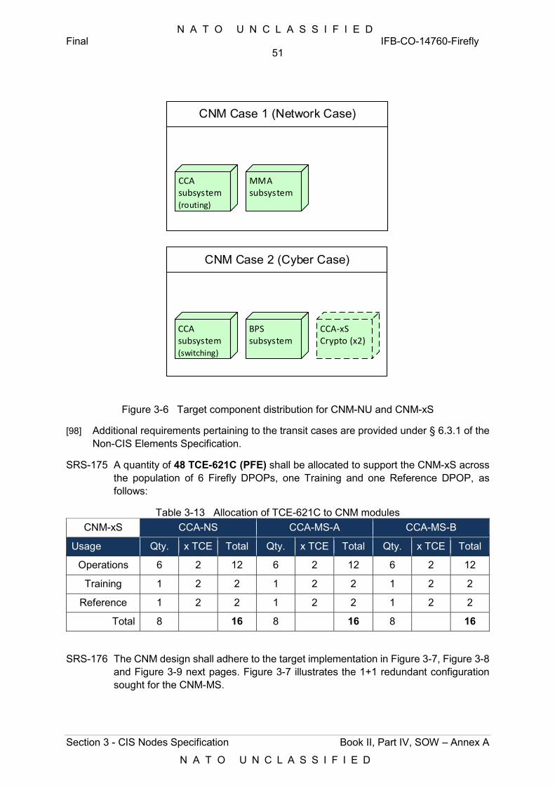
N A T O U N C L A S S I F I E D Final IFB-CO-14760-Firefly
51
Section 3 - CIS Nodes Specification Book II, Part IV, SOW – Annex A
N A T O U N C L A S S I F I E D
CNM Case 2 (Cyber Case)
CNM Case 1 (Network Case)
CCA-xS Crypto (x2)
CCA subsystem(switching)
BPS subsystem
CCA subsystem(routing)
MMA subsystem
Figure 3-6 Target component distribution for CNM-NU and CNM-xS
[98] Additional requirements pertaining to the transit cases are provided under § 6.3.1 of the Non-CIS Elements Specification.
SRS-175 A quantity of 48 TCE-621C (PFE) shall be allocated to support the CNM-xS across the population of 6 Firefly DPOPs, one Training and one Reference DPOP, as follows:
Table 3-13 Allocation of TCE-621C to CNM modules CNM-xS CCA-NS CCA-MS-A CCA-MS-B
Usage Qty. x TCE Total Qty. x TCE Total Qty. x TCE Total
Operations 6 2 12 6 2 12 6 2 12
Training 1 2 2 1 2 2 1 2 2
Reference 1 2 2 1 2 2 1 2 2
Total 8 16 8 16 8 16
SRS-176 The CNM design shall adhere to the target implementation in Figure 3-7, Figure 3-8 and Figure 3-9 next pages. Figure 3-7 illustrates the 1+1 redundant configuration sought for the CNM-MS.
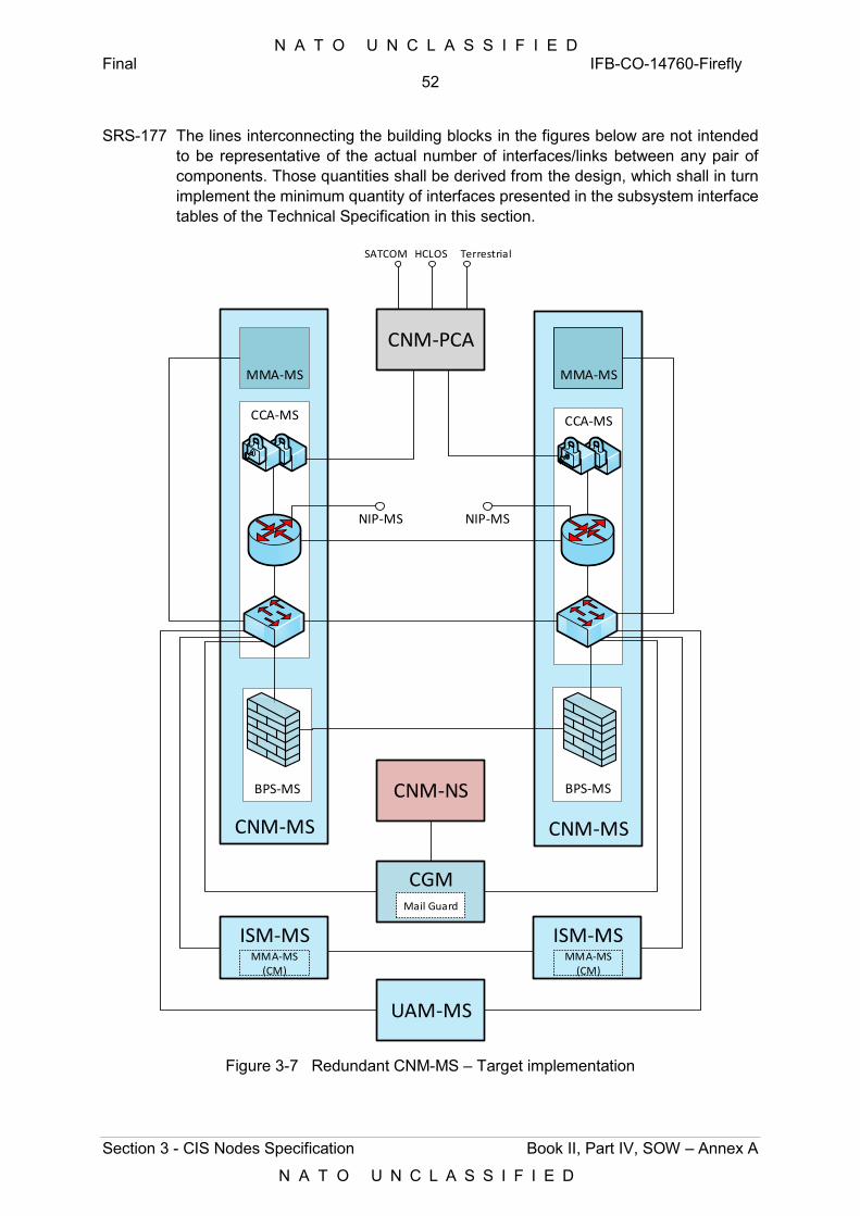
N A T O U N C L A S S I F I E D Final IFB-CO-14760-Firefly
52
Section 3 - CIS Nodes Specification Book II, Part IV, SOW – Annex A
N A T O U N C L A S S I F I E D
SRS-177 The lines interconnecting the building blocks in the figures below are not intended to be representative of the actual number of interfaces/links between any pair of components. Those quantities shall be derived from the design, which shall in turn implement the minimum quantity of interfaces presented in the subsystem interface tables of the Technical Specification in this section.
CNM-MSCNM-MS
BPS-MSBPS-MS
CCA-MSCCA-MS
MMA-MSMMA-MS
ISM-MS ISM-MS
CGM
UAM-MS
CNM-PCA
MMA-MS(CM)
MMA-MS(CM)
NIP-MSNIP-MS
Mail Guard
CNM-NS
SATCOM HCLOS Terrestrial
Figure 3-7 Redundant CNM-MS – Target implementation
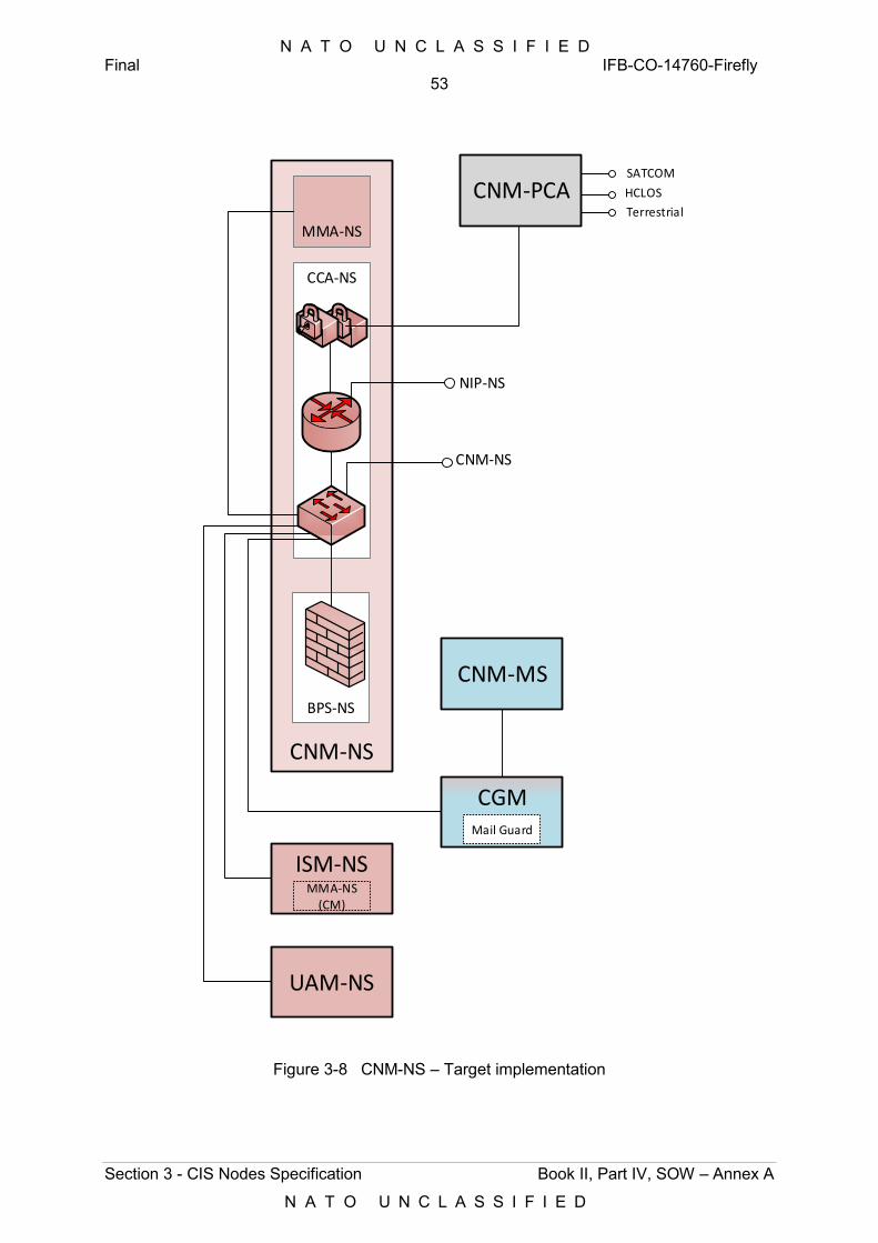
N A T O U N C L A S S I F I E D Final IFB-CO-14760-Firefly
53
Section 3 - CIS Nodes Specification Book II, Part IV, SOW – Annex A
N A T O U N C L A S S I F I E D
CNM-NS
BPS-NS
CCA-NS
MMA-NS
ISM-NS
CGM
UAM-NS
MMA-NS(CM)
NIP-NS
Mail Guard
CNM-NS
CNM-MS
CNM-PCASATCOM
HCLOS
Terrestrial
Figure 3-8 CNM-NS – Target implementation
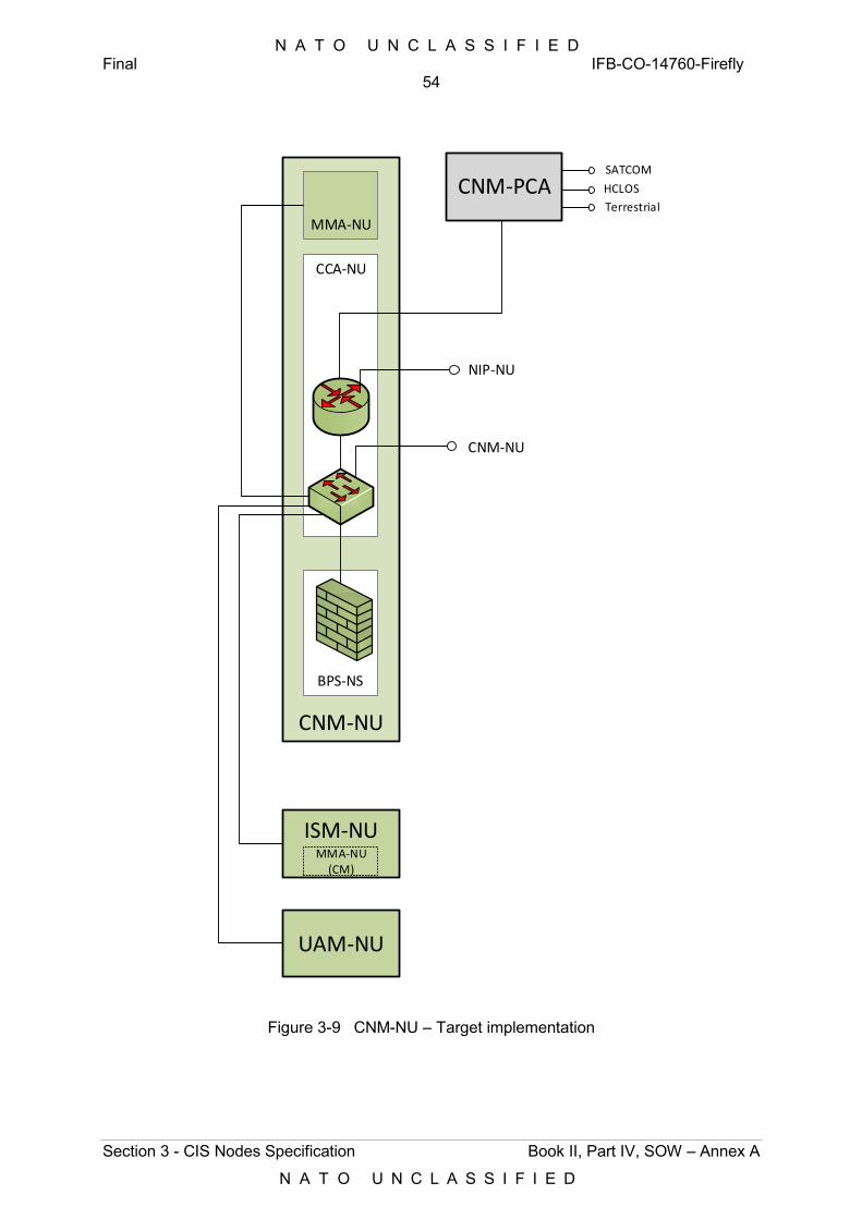
N A T O U N C L A S S I F I E D Final IFB-CO-14760-Firefly
54
Section 3 - CIS Nodes Specification Book II, Part IV, SOW – Annex A
N A T O U N C L A S S I F I E D
CNM-NU
BPS-NS
CCA-NU
MMA-NU
ISM-NU
UAM-NU
CNM-PCA
MMA-NU(CM)
NIP-NU
CNM-NU
SATCOM
HCLOS
Terrestrial
Figure 3-9 CNM-NU – Target implementation
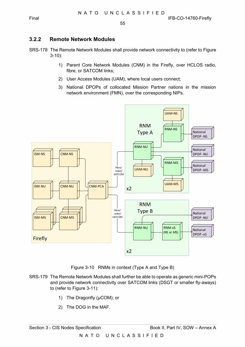
N A T O U N C L A S S I F I E D Final IFB-CO-14760-Firefly
55
Section 3 - CIS Nodes Specification Book II, Part IV, SOW – Annex A
N A T O U N C L A S S I F I E D
3.2.2 Remote Network Modules
SRS-178 The Remote Network Modules shall provide network connectivity to (refer to Figure 3-10):
1) Parent Core Network Modules (CNM) in the Firefly, over HCLOS radio, fibre, or SATCOM links;
2) User Access Modules (UAM), where local users connect;
3) National DPOPs of collocated Mission Partner nations in the mission network environment (FMN), over the corresponding NIPs.
National DPOP -NS
National DPOP -MS
National DPOP -xS
National DPOP -NU
National DPOP -NU
Firefly
x2
x2
CNM-NS
CNM-NU
CNM-MSISM-MS
ISM-NS
ISM-NU
RNM-NU
fibre/radio/
SATCOM
RNM-NU
fibre/radio/
SATCOM
RNM-NS
RNM-MS
UAM-NU
RNM-xS(NS or MS)
UAM-NS
UAM-MS
RNM Type A
RNM Type B
CNM-PCA
Figure 3-10 RNMs in context (Type A and Type B)
SRS-179 The Remote Network Modules shall further be able to operate as generic mini-POPs and provide network connectivity over SATCOM links (DSGT or smaller fly-aways) to (refer to Figure 3-11):
1) The Dragonfly (µCOM); or
2) The DOG in the MAF.
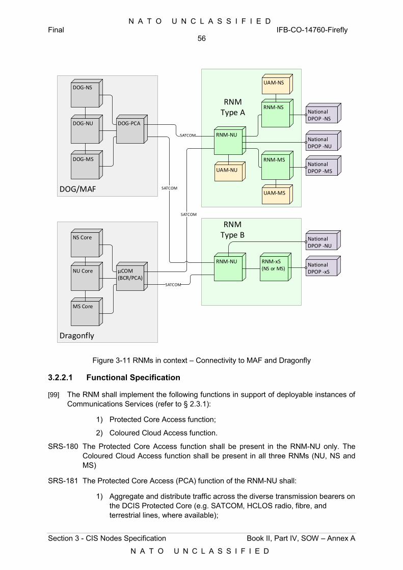
N A T O U N C L A S S I F I E D Final IFB-CO-14760-Firefly
56
Section 3 - CIS Nodes Specification Book II, Part IV, SOW – Annex A
N A T O U N C L A S S I F I E D
National DPOP -NS
National DPOP -MS
National DPOP -xS
National DPOP -NU
National DPOP -NU
DOG/MAF
DOG-NS
DOG-NU
DOG-MS
RNM-NU
RNM-NU
SATCOM
RNM-NS
RNM-MS
UAM-NU
RNM-xS(NS or MS)
UAM-NS
UAM-MS
RNM Type A
RNM Type B
DOG-PCA
Dragonfly
NS Core
NU Core
MS Core
µCOM(BCR/PCA)
SATCOM
SATCOM
SATCOM
Figure 3-11 RNMs in context – Connectivity to MAF and Dragonfly
3.2.2.1 Functional Specification
[99] The RNM shall implement the following functions in support of deployable instances of Communications Services (refer to § 2.3.1):
1) Protected Core Access function;
2) Coloured Cloud Access function.
SRS-180 The Protected Core Access function shall be present in the RNM-NU only. The Coloured Cloud Access function shall be present in all three RNMs (NU, NS and MS)
SRS-181 The Protected Core Access (PCA) function of the RNM-NU shall:
1) Aggregate and distribute traffic across the diverse transmission bearers on the DCIS Protected Core (e.g. SATCOM, HCLOS radio, fibre, and terrestrial lines, where available);
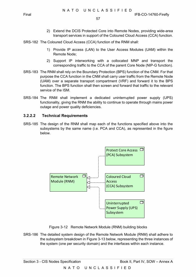
N A T O U N C L A S S I F I E D Final IFB-CO-14760-Firefly
57
Section 3 - CIS Nodes Specification Book II, Part IV, SOW – Annex A
N A T O U N C L A S S I F I E D
2) Extend the DCIS Protected Core into Remote Nodes, providing wide-area transport services in support of the Coloured Cloud Access (CCA) function.
SRS-182 The Coloured Cloud Access (CCA) function of the RNM shall:
1) Provide IP access (LAN) to the User Access Modules (UAM) within the Remote Node;
2) Support IP interworking with a collocated MNP and transport the corresponding traffic to the CCA of the parent Core Node (NIP-G function).
SRS-183 The RNM shall rely on the Boundary Protection (BPS) function of the CNM. For that purpose the CCA function in the CNM shall carry user traffic from the Remote Node (UAM) over a separate transport compartment (VRF) and forward it to the BPS function. The BPS function shall then screen and forward that traffic to the relevant service of the ISM.
SRS-184 The RNM shall implement a dedicated uninterrupted power supply (UPS) functionality, giving the RNM the ability to continue to operate through mains power outage and power quality deficiencies.
3.2.2.2 Technical Requirements
SRS-185 The design of the RNM shall map each of the functions specified above into the subsystems by the same name (i.e. PCA and CCA), as represented in the figure below.
Remote Network Module (RNM)
Protect Core Access (PCA) Subsystem
Coloured Cloud Access (CCA) Subsystem
Uninterrupted Power Supply (UPS) Subsystem
Figure 3-12 Remote Network Module (RNM) building blocks
SRS-186 The detailed system design of the Remote Network Module (RNM) shall adhere to the subsystem breakdown in Figure 3-13 below, representing the three instances of the system (one per security domain) and the interfaces within each instance.
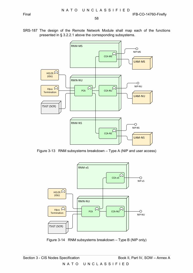
N A T O U N C L A S S I F I E D Final IFB-CO-14760-Firefly
58
Section 3 - CIS Nodes Specification Book II, Part IV, SOW – Annex A
N A T O U N C L A S S I F I E D
SRS-187 The design of the Remote Network Module shall map each of the functions presented in § 3.2.2.1 above the corresponding subsystems.
RMN-NU
PCA CCA-NU
RNM-MS
CCA-MS
RNM-NS
CCA-NS
NIP-NS
NIP-NU
NIP-MS
HCLOS(IDU)
FibreTermination
TSGT (SCR)
UAM-NU
UAM-MS
UAM-NS
Figure 3-13 RNM subsystems breakdown – Type A (NIP and user access)
RMN-NU
PCA CCA-NU
RNM-xS
CCA-xS
NIP-NU
NIP-xS
HCLOS(IDU)
FibreTermination
TSGT (SCR)
Figure 3-14 RNM subsystems breakdown – Type B (NIP only)
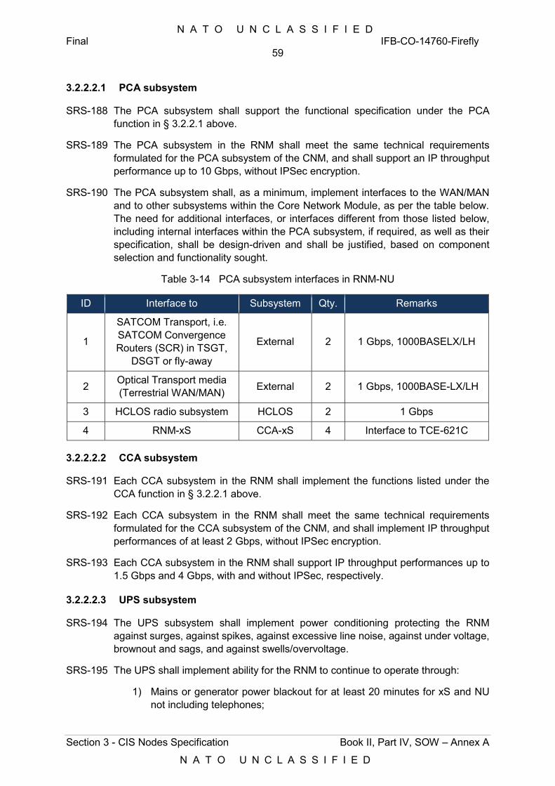
N A T O U N C L A S S I F I E D Final IFB-CO-14760-Firefly
59
Section 3 - CIS Nodes Specification Book II, Part IV, SOW – Annex A
N A T O U N C L A S S I F I E D
3.2.2.2.1 PCA subsystem
SRS-188 The PCA subsystem shall support the functional specification under the PCA function in § 3.2.2.1 above.
SRS-189 The PCA subsystem in the RNM shall meet the same technical requirements formulated for the PCA subsystem of the CNM, and shall support an IP throughput performance up to 10 Gbps, without IPSec encryption.
SRS-190 The PCA subsystem shall, as a minimum, implement interfaces to the WAN/MAN and to other subsystems within the Core Network Module, as per the table below. The need for additional interfaces, or interfaces different from those listed below, including internal interfaces within the PCA subsystem, if required, as well as their specification, shall be design-driven and shall be justified, based on component selection and functionality sought.
Table 3-14 PCA subsystem interfaces in RNM-NU
ID Interface to Subsystem Qty. Remarks
1
SATCOM Transport, i.e. SATCOM Convergence Routers (SCR) in TSGT,
DSGT or fly-away
External 2 1 Gbps, 1000BASELX/LH
2 Optical Transport media (Terrestrial WAN/MAN) External 2 1 Gbps, 1000BASE-LX/LH
3 HCLOS radio subsystem HCLOS 2 1 Gbps
4 RNM-xS CCA-xS 4 Interface to TCE-621C
3.2.2.2.2 CCA subsystem
SRS-191 Each CCA subsystem in the RNM shall implement the functions listed under the CCA function in § 3.2.2.1 above.
SRS-192 Each CCA subsystem in the RNM shall meet the same technical requirements formulated for the CCA subsystem of the CNM, and shall implement IP throughput performances of at least 2 Gbps, without IPSec encryption.
SRS-193 Each CCA subsystem in the RNM shall support IP throughput performances up to 1.5 Gbps and 4 Gbps, with and without IPSec, respectively.
3.2.2.2.3 UPS subsystem
SRS-194 The UPS subsystem shall implement power conditioning protecting the RNM against surges, against spikes, against excessive line noise, against under voltage, brownout and sags, and against swells/overvoltage.
SRS-195 The UPS shall implement ability for the RNM to continue to operate through:
1) Mains or generator power blackout for at least 20 minutes for xS and NU not including telephones;
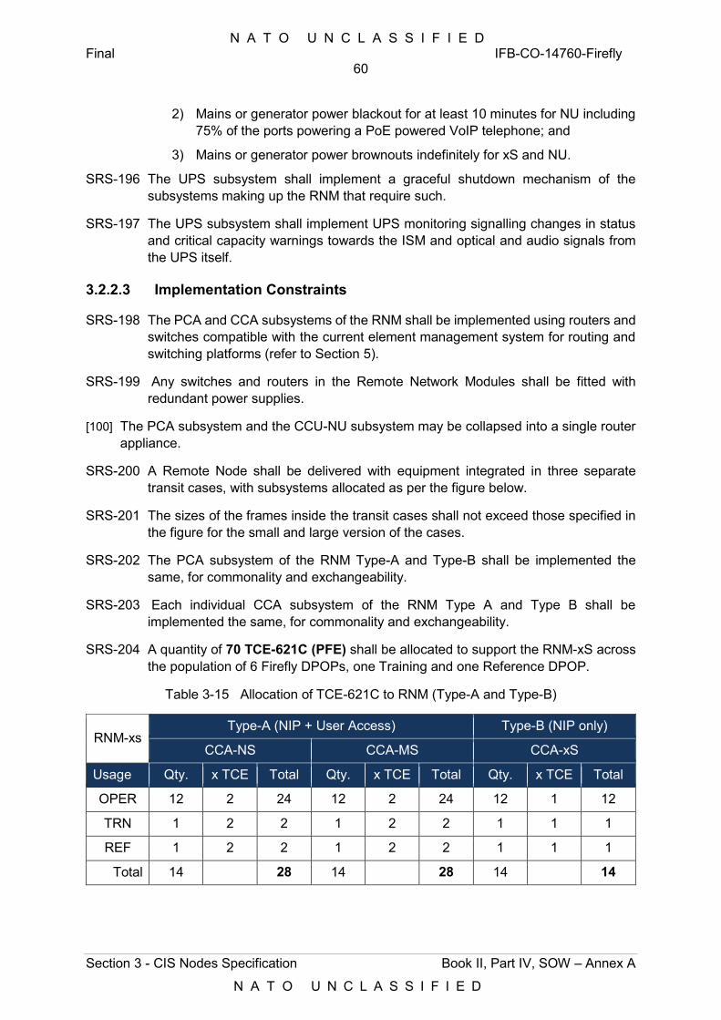
N A T O U N C L A S S I F I E D Final IFB-CO-14760-Firefly
60
Section 3 - CIS Nodes Specification Book II, Part IV, SOW – Annex A
N A T O U N C L A S S I F I E D
2) Mains or generator power blackout for at least 10 minutes for NU including 75% of the ports powering a PoE powered VoIP telephone; and
3) Mains or generator power brownouts indefinitely for xS and NU.
SRS-196 The UPS subsystem shall implement a graceful shutdown mechanism of the subsystems making up the RNM that require such.
SRS-197 The UPS subsystem shall implement UPS monitoring signalling changes in status and critical capacity warnings towards the ISM and optical and audio signals from the UPS itself.
3.2.2.3 Implementation Constraints
SRS-198 The PCA and CCA subsystems of the RNM shall be implemented using routers and switches compatible with the current element management system for routing and switching platforms (refer to Section 5).
SRS-199 Any switches and routers in the Remote Network Modules shall be fitted with redundant power supplies.
[100] The PCA subsystem and the CCU-NU subsystem may be collapsed into a single router appliance.
SRS-200 A Remote Node shall be delivered with equipment integrated in three separate transit cases, with subsystems allocated as per the figure below.
SRS-201 The sizes of the frames inside the transit cases shall not exceed those specified in the figure for the small and large version of the cases.
SRS-202 The PCA subsystem of the RNM Type-A and Type-B shall be implemented the same, for commonality and exchangeability.
SRS-203 Each individual CCA subsystem of the RNM Type A and Type B shall be implemented the same, for commonality and exchangeability.
SRS-204 A quantity of 70 TCE-621C (PFE) shall be allocated to support the RNM-xS across the population of 6 Firefly DPOPs, one Training and one Reference DPOP.
Table 3-15 Allocation of TCE-621C to RNM (Type-A and Type-B)
RNM-xs Type-A (NIP + User Access) Type-B (NIP only)
CCA-NS CCA-MS CCA-xS
Usage Qty. x TCE Total Qty. x TCE Total Qty. x TCE Total
OPER 12 2 24 12 2 24 12 1 12
TRN 1 2 2 1 2 2 1 1 1
REF 1 2 2 1 2 2 1 1 1
Total 14 28 14 28 14 14
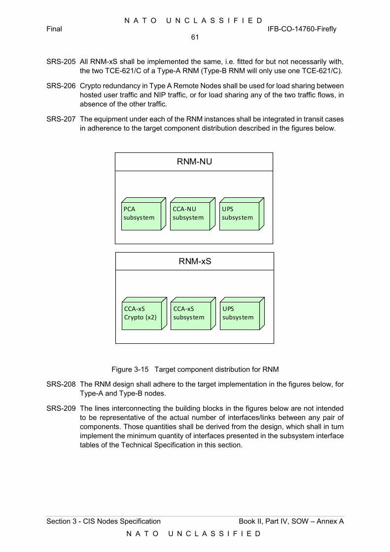
N A T O U N C L A S S I F I E D Final IFB-CO-14760-Firefly
61
Section 3 - CIS Nodes Specification Book II, Part IV, SOW – Annex A
N A T O U N C L A S S I F I E D
SRS-205 All RNM-xS shall be implemented the same, i.e. fitted for but not necessarily with, the two TCE-621/C of a Type-A RNM (Type-B RNM will only use one TCE-621/C).
SRS-206 Crypto redundancy in Type A Remote Nodes shall be used for load sharing between hosted user traffic and NIP traffic, or for load sharing any of the two traffic flows, in absence of the other traffic.
SRS-207 The equipment under each of the RNM instances shall be integrated in transit cases in adherence to the target component distribution described in the figures below.
RNM-xS
RNM-NU
CCA-xS Crypto (x2)
CCA-xS subsystem
UPS subsystem
PCAsubsystem
UPS subsystem
CCA-NUsubsystem
Figure 3-15 Target component distribution for RNM
SRS-208 The RNM design shall adhere to the target implementation in the figures below, for Type-A and Type-B nodes.
SRS-209 The lines interconnecting the building blocks in the figures below are not intended to be representative of the actual number of interfaces/links between any pair of components. Those quantities shall be derived from the design, which shall in turn implement the minimum quantity of interfaces presented in the subsystem interface tables of the Technical Specification in this section.

N A T O U N C L A S S I F I E D Final IFB-CO-14760-Firefly
62
Section 3 - CIS Nodes Specification Book II, Part IV, SOW – Annex A
N A T O U N C L A S S I F I E D
RNM-MS
CCA-MS
UAM-MS NIP-MS
RNM-NU
PCA/CCA-NU
NIP-NU
RNM-NS
CCA-NS
UAM-NS NIP-NS
UAM-NU
HCLOS, Fibre, SATCOM
Figure 3-16 RNM Type-A – Target implementation
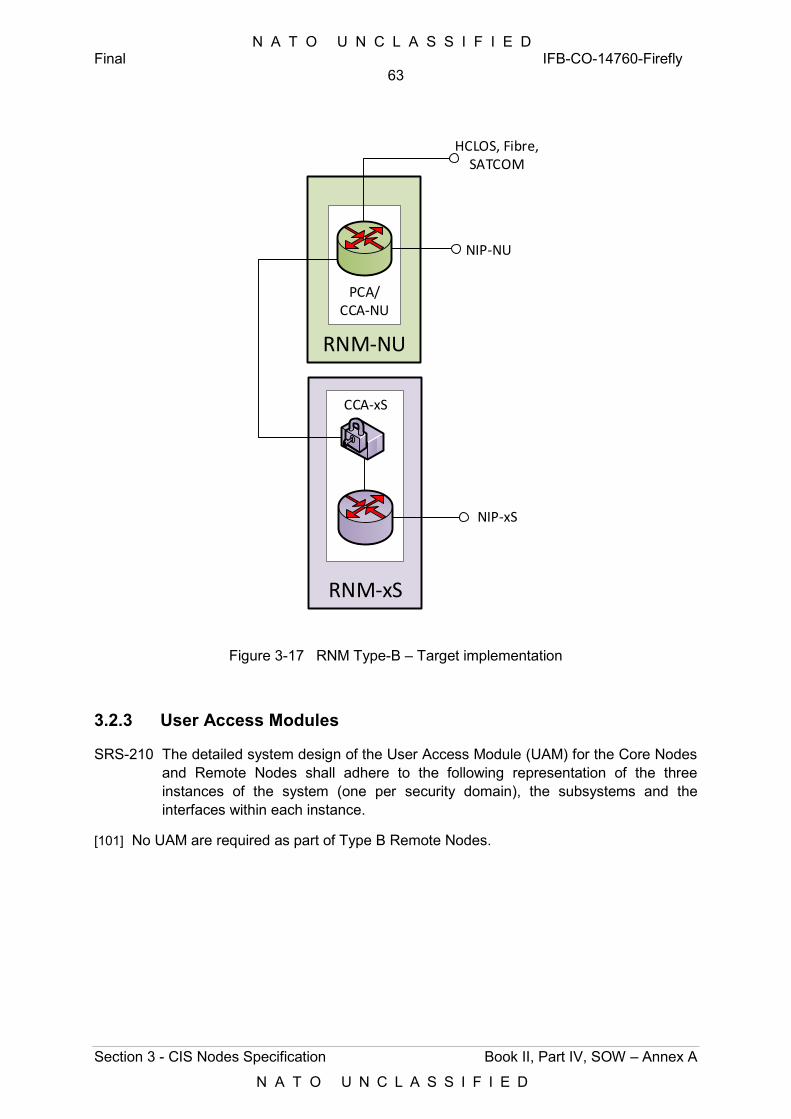
N A T O U N C L A S S I F I E D Final IFB-CO-14760-Firefly
63
Section 3 - CIS Nodes Specification Book II, Part IV, SOW – Annex A
N A T O U N C L A S S I F I E D
RNM-xS
CCA-xS
NIP-xS
RNM-NU
PCA/CCA-NU
NIP-NU
HCLOS, Fibre, SATCOM
Figure 3-17 RNM Type-B – Target implementation
3.2.3 User Access Modules
SRS-210 The detailed system design of the User Access Module (UAM) for the Core Nodes and Remote Nodes shall adhere to the following representation of the three instances of the system (one per security domain), the subsystems and the interfaces within each instance.
[101] No UAM are required as part of Type B Remote Nodes.
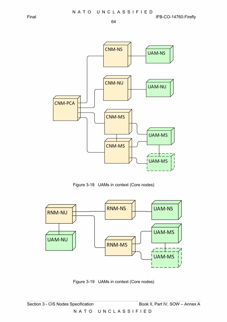
N A T O U N C L A S S I F I E D Final IFB-CO-14760-Firefly
64
Section 3 - CIS Nodes Specification Book II, Part IV, SOW – Annex A
N A T O U N C L A S S I F I E D
CNM-PCA
CNM-NS
UAM-MS
CNM-NU
CNM-MS
CNM-MS
UAM-NS
UAM-MS
UAM-NU
Figure 3-18 UAMs in context (Core nodes)
RNM-NS
UAM-MS
RNM-NU
RNM-MS
UAM-NS
UAM-MS
UAM-NU
Figure 3-19 UAMs in context (Core nodes)
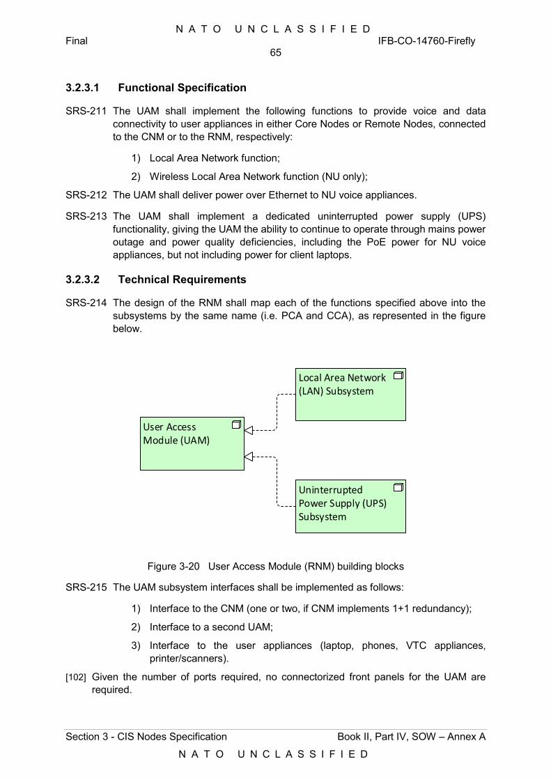
N A T O U N C L A S S I F I E D Final IFB-CO-14760-Firefly
65
Section 3 - CIS Nodes Specification Book II, Part IV, SOW – Annex A
N A T O U N C L A S S I F I E D
3.2.3.1 Functional Specification
SRS-211 The UAM shall implement the following functions to provide voice and data connectivity to user appliances in either Core Nodes or Remote Nodes, connected to the CNM or to the RNM, respectively:
1) Local Area Network function;
2) Wireless Local Area Network function (NU only);
SRS-212 The UAM shall deliver power over Ethernet to NU voice appliances.
SRS-213 The UAM shall implement a dedicated uninterrupted power supply (UPS) functionality, giving the UAM the ability to continue to operate through mains power outage and power quality deficiencies, including the PoE power for NU voice appliances, but not including power for client laptops.
3.2.3.2 Technical Requirements
SRS-214 The design of the RNM shall map each of the functions specified above into the subsystems by the same name (i.e. PCA and CCA), as represented in the figure below.
User Access Module (UAM)
Local Area Network (LAN) Subsystem
Uninterrupted Power Supply (UPS) Subsystem
Figure 3-20 User Access Module (RNM) building blocks
SRS-215 The UAM subsystem interfaces shall be implemented as follows:
1) Interface to the CNM (one or two, if CNM implements 1+1 redundancy);
2) Interface to a second UAM;
3) Interface to the user appliances (laptop, phones, VTC appliances, printer/scanners).
[102] Given the number of ports required, no connectorized front panels for the UAM are required.
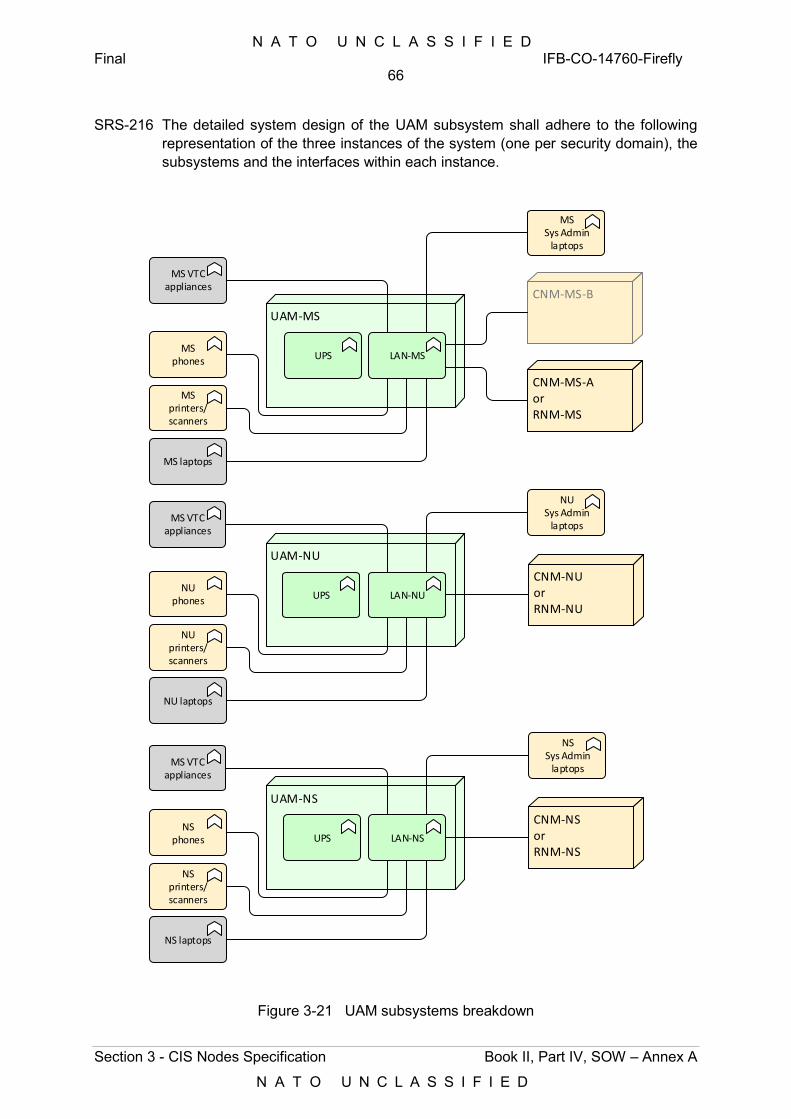
N A T O U N C L A S S I F I E D Final IFB-CO-14760-Firefly
66
Section 3 - CIS Nodes Specification Book II, Part IV, SOW – Annex A
N A T O U N C L A S S I F I E D
SRS-216 The detailed system design of the UAM subsystem shall adhere to the following representation of the three instances of the system (one per security domain), the subsystems and the interfaces within each instance.
UAM-NU
LAN-NU
CNM-NUorRNM-NU
NU phones
NU printers/scanners
NU laptops
UAM-NS
LAN-NS
CNM-NSorRNM-NS
NS phones
NS printers/scanners
NS laptops
UAM-MS
LAN-MS
CNM-MS-AorRNM-MS
MS phones
MS printers/scanners
MS laptops
CNM-MS-B
MS VTC appliances
MS VTC appliances
MS VTC appliances
MSSys Admin
laptops
NUSys Admin
laptops
NSSys Admin
laptops
UPS
UPS
UPS
Figure 3-21 UAM subsystems breakdown
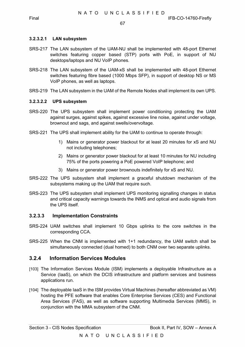
N A T O U N C L A S S I F I E D Final IFB-CO-14760-Firefly
67
Section 3 - CIS Nodes Specification Book II, Part IV, SOW – Annex A
N A T O U N C L A S S I F I E D
3.2.3.2.1 LAN subsystem
SRS-217 The LAN subsystem of the UAM-NU shall be implemented with 48-port Ethernet switches featuring copper based (STP) ports with PoE, in support of NU desktops/laptops and NU VoIP phones.
SRS-218 The LAN subsystem of the UAM-xS shall be implemented with 48-port Ethernet switches featuring fibre based (1000 Mbps SFP), in support of desktop NS or MS VoIP phones, as well as laptops.
SRS-219 The LAN subsystem in the UAM of the Remote Nodes shall implement its own UPS.
3.2.3.2.2 UPS subsystem
SRS-220 The UPS subsystem shall implement power conditioning protecting the UAM against surges, against spikes, against excessive line noise, against under voltage, brownout and sags, and against swells/overvoltage.
SRS-221 The UPS shall implement ability for the UAM to continue to operate through:
1) Mains or generator power blackout for at least 20 minutes for xS and NU not including telephones;
2) Mains or generator power blackout for at least 10 minutes for NU including 75% of the ports powering a PoE powered VoIP telephone; and
3) Mains or generator power brownouts indefinitely for xS and NU.
SRS-222 The UPS subsystem shall implement a graceful shutdown mechanism of the subsystems making up the UAM that require such.
SRS-223 The UPS subsystem shall implement UPS monitoring signalling changes in status and critical capacity warnings towards the INMS and optical and audio signals from the UPS itself.
3.2.3.3 Implementation Constraints
SRS-224 UAM switches shall implement 10 Gbps uplinks to the core switches in the corresponding CCA.
SRS-225 When the CNM is implemented with 1+1 redundancy, the UAM switch shall be simultaneously connected (dual homed) to both CNM over two separate uplinks.
3.2.4 Information Services Modules
[103] The Information Services Module (ISM) implements a deployable Infrastructure as a Service (IaaS), on which the DCIS infrastructure and platform services and business applications run.
[104] The deployable IaaS in the ISM provides Virtual Machines (hereafter abbreviated as VM) hosting the PFE software that enables Core Enterprise Services (CES) and Functional Area Services (FAS), as well as software supporting Multimedia Services (MMS), in conjunction with the MMA subsystem of the CNM.
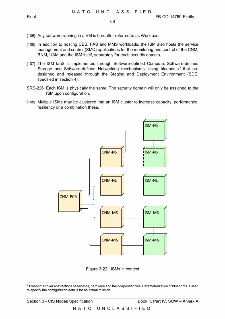
N A T O U N C L A S S I F I E D Final IFB-CO-14760-Firefly
68
Section 3 - CIS Nodes Specification Book II, Part IV, SOW – Annex A
N A T O U N C L A S S I F I E D
[105] Any software running in a VM is hereafter referred to as Workload.
[106] In addition to hosting CES, FAS and MMS workloads, the ISM also hosts the service management and control (SMC) applications for the monitoring and control of the CNM, RNM, UAM and the ISM itself, separately for each security domain.
[107] The ISM IaaS is implemented through Software-defined Compute, Software-defined Storage and Software-defined Networking mechanisms, using blueprints 7 that are designed and released through the Staging and Deployment Environment (SDE, specified in section 4).
SRS-226 Each ISM is physically the same. The security domain will only be assigned to the ISM upon configuration.
[108] Multiple ISMs may be clustered into an ISM cluster to increase capacity, performance, resiliency or a combination these.
CNM-PCA
CNM-NS
CNM-NU
CNM-MS
CNM-MS
ISM-MS
ISM-NS
ISM-MS
ISM-NU
ISM-NS
Figure 3-22 ISMs in context
7 Blueprints cover abstractions of services, hardware and their dependencies. Parameterization of blueprints is used to specify the configuration details for an actual mission.
N A T O U N C L A S S I F I E D Final IFB-CO-14760-Firefly
69
Section 3 - CIS Nodes Specification Book II, Part IV, SOW – Annex A
N A T O U N C L A S S I F I E D
3.2.4.1 Functional Requirements
SRS-227 The ISM shall be implemented in adherence to the [DCIS CA], as an instantiation of the DCIS Cube ABB, where the requirements hereafter elaborate and detail the ISM specifications.
SRS-228 The ISM shall implement the following in support of deployable instances of Infrastructure Services:
1) Software-defined Compute;
2) Software-defined Storage; and
3) Software-defined Networking.
SRS-229 Furthermore, the ISM shall implement:
1) Hardware control of the ICT hardware that makes up the ISM;
2) Image Store for use with orchestration; and
3) Backup and Recovery.
SRS-230 Through the functionality implemented by the SDE (refer to Section 4), the ISM shall further implement:
1) Automated lifecycle management, encompassing the automated infrastructure cluster provisioning and backup creation; and
2) Infrastructure and Cost Metering.
[109] Functional requirements detailing and in addition to the above are provided hereafter.
3.2.4.1.1 Software-defined Compute
[110] The software-defined compute implementation is specified in detail in DCIS CA Annex B. The requirements below elaborate and detail the software-defined networking requirements.
SRS-231 The Software-defined Compute function shall:
1) Abstract the physical hardware of the ISM into a VM cluster that shares CPU, memory and peripherals, through the use of virtualization hypervisors;
2) Establish, change, monitor, power-on, power-off, snapshot and teardown of VMs within the VM cluster established within the ISM;
3) Assure high availability for VMs, by implementing automatic failover to alternate hosts within the ISM;
4) Provide a documented and open Application Programming Interface (API) for management and control purposes.
3.2.4.1.2 Software-defined Storage
[111] The software-defined storage is specified in detail in DCIS CA Annex D. The requirements below elaborate and detail the software-defined storage requirements.
N A T O U N C L A S S I F I E D Final IFB-CO-14760-Firefly
70
Section 3 - CIS Nodes Specification Book II, Part IV, SOW – Annex A
N A T O U N C L A S S I F I E D
SRS-232 The Software-defined Storage function shall:
1) Abstract the physical storage of the ISM, and provide virtual disk access to VMs (or ISM cluster) and to collocated external machines external to the ISM;
2) Support presentation of virtual disks to the VM and networked as a Software-defined Storage area network through iSCSI. This function is also referred to as Block I/O;
3) Provide file access to VMs running on the ISM and to collocated machines external to the ISM as virtual network attached storage through NFS and CIFS/SMB. This function is also referred to as File I/O;
4) Provide object-based storage access to VMs running on the ISM and collocated machines external to the ISM through S3 or S3 compatible object storage access;
5) Enforce storage quality of service, through configurable limits (maximum) and guarantees (minimum) of storage throughput per VM, per group of VMs, per Software-defined Storage resource, and per group of Software-defined Storage resources.
[112] Depending on the available resources at a deployment, the mission profile and its associated security profile, remote storage resources may be used, including NATO or National private clouds, and/or commercial public clouds.
SRS-233 The Software-defined Storage function shall:
1) Optimize storage capacity use, though de-duplication and compression. This optimization shall be fully automatic8 and opaque to the storage consumers. As a minimum it shall be possible to configure de-duplication + compression and de-duplication only;
2) Cluster physical storage resources across all compute nodes (servers) within a single ISM and within an ISM cluster;
3) Control and monitor the execution of the above described functionalities;
4) Provide a well-documented and open API for management and control purposes.
3.2.4.1.3 Software-defined Networking
[113] The ISM’s software-defined networking implementation is specified in detail in DCIS CA Annex C. The requirements below elaborate and detail the software-defined networking requirements.
SRS-234 The Software-defined Networking function shall:
8 This may involve automatic storage tiering of less used data to slower storage resources or to external storage, which may potentially be located in the ISM of another Core Node, in the MAF or cloud service.
N A T O U N C L A S S I F I E D Final IFB-CO-14760-Firefly
71
Section 3 - CIS Nodes Specification Book II, Part IV, SOW – Annex A
N A T O U N C L A S S I F I E D
1) Establish, change, monitor and teardown virtual Ethernet LAN (VLAN) segments, within the ISM and ISM cluster;
2) Connect and remove external Ethernet interfaces and VMs to those VLAN segments;
3) Support WAN and LAN interfaces to the CCA function of the CNM, for wide-area communications purposes, as well as interfaces to other ISMs, for clustering purposes;
4) Provide a well-documented and open API for management and control purposes.
3.2.4.1.4 Hardware Control
[114] The hardware control is described in detail in DCIS CA Annex E. The requirements below elaborate and detail the hardware control requirements.
SRS-235 The Hardware Control function shall manage the hardware-based Compute, Storage and Networking components, upon which the above described Software-defined Compute, Storage and Networking functions run.
SRS-236 To that end, the Hardware Control function shall combine and abstract the hardware-specific management and control interfaces of the components that make up the ISM, into open, standardized and authenticated interfaces (standard networking API), in order to make the underlying hardware agnostic to the orchestration.
SRS-237 The Hardware Control function shall:
1) Operate both local as well as networked (i.e. over the WAN), providing both local and remote console access;
2) Subscribe to a centralized Hardware Control service in the MAF, allowing through dashboards the centralized hardware monitoring and control;
3) Implement power control: power-on, power-off, graceful shutdown, emergency shutdown;
4) Implement boot control, i.e. setting the boot source, boot and reset;
5) Implement monitoring of hardware and environmental status;
6) Support the installation, updating and configuration of BIOS and firmware;
7) Provide interfaces that are able to monitor, control and operate hosts independent of the host system CPU, firmware (BIOS) and operating system9 , in order to grant direct access the hardware-based compute, storage and network components;
9 e.g. interfaces such as, for example, an interfaces to a so-called baseboard management controller (BMC), Intelligent Platform Management Interface (IPMI), Integrated Lights-Out (iLO), terminal/console ports of servers and switches; including access to BIOS, firmware, bootloader, etc.
N A T O U N C L A S S I F I E D Final IFB-CO-14760-Firefly
72
Section 3 - CIS Nodes Specification Book II, Part IV, SOW – Annex A
N A T O U N C L A S S I F I E D
8) Interface with the Uninterruptible Power Supply control listening for a “battery low” signal, which shall result in a graceful shutdown and subsequent power-off of the individual compute, storage and networking functions and hosted VMs.
3.2.4.1.5 Backup and Recovery
[115] The backup and recovery implementation is specified in detail in DCIS CA Annex J. The requirements below elaborate and detail the backup and recovery requirements.
[116] The Firefly aims to restore the affected service exactly as it was at a point back in time before the incident occurred.
SRS-238 The Back and Recovery function shall implement the mechanisms, hardware and software in support of snapshotting, backup of, and the recovery from corruption or loss of:
1) a VM realized by the ISM;
2) a workload served by a VM realized by the ISM;
3) an ISM;
4) an ISM cluster; and
5) a complete DPOP.
SRS-239 The Backup and Recovery function shall:
1) Be implemented with a deployable backup storage component, deployed alongside the ISM, but physically separate from the ISM transit case, using deployable and networked backup storage hardware, with as many instances available as security domains;
2) Be able to create and restore (roll-back) multiple snapshots, or point-in-time copies, of any data stored in the ISM, including storage, filesystem, infrastructure data and application data.
SRS-240 Snapshots shall include the configuration of the software defined compute, networking and storage functions, both at the level of single VMs and clusters of VMs.
SRS-241 Snapshots shall be created automatically with a frequency and time that can be configured through the administration interface. It shall be possible to create snapshots on demand by the administrator.
SRS-242 The Backup and Recovery function shall create, restore, optimize and manage the storage of snapshots and backups.
SRS-243 Automatic optimization shall minimize the use of storage space on the backup media, using deduplication, compression or a combination thereof, while retaining recovery points as defined in a retention policy that can be configured through the administration interface.
SRS-244 Backup management shall allow backups to be automatically tiered to an off-site
N A T O U N C L A S S I F I E D Final IFB-CO-14760-Firefly
73
Section 3 - CIS Nodes Specification Book II, Part IV, SOW – Annex A
N A T O U N C L A S S I F I E D
storage system (PFE), typically located in the MAF.
SRS-245 The Backup and Recovery function shall maintain a continuous replica of the storage for quick disaster recovery (real-time replication).
SRS-246 The Backup and Recovery function shall implement application-consistent backups and replicas of VMs running applications supporting Microsoft VSS, and of VMs running applications that support so-called quiescing10 scripts.
SRS-247 The Backup and Recovery function of the ISM shall implement mechanisms to restore and clone an ISM from snapshots, supporting a disaster recovery scenario where an ISM cannot be recovered and is physically replaced with un-configured hardware.
SRS-248 The Backup and Recovery function of the ISM shall be implemented such that it can managed and controlled both centrally and locally, as appropriate for the specific deployment, through the static (in the Mission Preparation Centre) and deployable (local to the ISM) instances of the SDE.
SRS-249 The Backup and Recovery function of the ISM shall implement a RESTful well-documented and open API, exposing all operations.
3.2.4.2 Technical Requirements
[117] The Technical requirements provided here below concern the ISM as a system, realized by four subsystems, as depicted in Figure 3-23 below:
1) Compute and Storage (CAS) subsystem, providing CPU, RAM and solid state storage, for use by software-defined Compute and Storage functions described above;
2) High Density Switching (HDS) subsystem, providing the physical means to interconnect and manage all physical components of the CAS subsystem, including external interfaces, for use by the ISM-internal Software-defined Networking function described above;
3) Deployable Removable Storage (DRS) subsystem, comprising the storage infrastructure that is external to and not dependent on the ISM;
4) Deployable instance of the Staging and Deployment Environment (SDE), specified under Section 4.
10 Quiescing refers to pausing or altering a device or application to achieve a consistent state, usually in preparation for a backup or other maintenance activities.
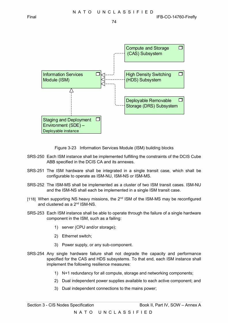
N A T O U N C L A S S I F I E D Final IFB-CO-14760-Firefly
74
Section 3 - CIS Nodes Specification Book II, Part IV, SOW – Annex A
N A T O U N C L A S S I F I E D
Information Services Module (ISM)
Compute and Storage (CAS) Subsystem
High Density Switching (HDS) Subsystem
Deployable Removable Storage (DRS) Subsystem
Staging and Deployment Environment (SDE) – Deployable instance
Figure 3-23 Information Services Module (ISM) building blocks
SRS-250 Each ISM instance shall be implemented fulfilling the constraints of the DCIS Cube ABB specified in the DCIS CA and its annexes.
SRS-251 The ISM hardware shall be integrated in a single transit case, which shall be configurable to operate as ISM-NU, ISM-NS or ISM-MS.
SRS-252 The ISM-MS shall be implemented as a cluster of two ISM transit cases. ISM-NU and the ISM-NS shall each be implemented in a single ISM transit case.
[118] When supporting NS heavy missions, the 2nd ISM of the ISM-MS may be reconfigured and clustered as a 2nd ISM-NS.
SRS-253 Each ISM instance shall be able to operate through the failure of a single hardware component in the ISM, such as a failing:
1) server (CPU and/or storage);
2) Ethernet switch;
3) Power supply, or any sub-component.
SRS-254 Any single hardware failure shall not degrade the capacity and performance specified for the CAS and HDS subsystems. To that end, each ISM instance shall implement the following resilience measures:
1) N+1 redundancy for all compute, storage and networking components;
2) Dual independent power supplies available to each active component; and
3) Dual independent connections to the mains power;
N A T O U N C L A S S I F I E D Final IFB-CO-14760-Firefly
75
Section 3 - CIS Nodes Specification Book II, Part IV, SOW – Annex A
N A T O U N C L A S S I F I E D
4) Distributing storage data blocks across:
a) Physical storage devices;
b) Physical compute nodes within the VM-cluster; and
c) Individual ISMs in a cluster (if applicable).
SRS-255 It shall be possible to upgrade and/or replace the hardware layer, the virtualization layer and the orchestration layer of the ISM, in independent cycles11. To that end, the hardware and software layers shall be chosen and be validated to support each other’s lifecycle. This shall also include the lifecycle of guest OS and workloads.
SRS-256 The ISM shall implement well-documented and open APIs compliant with the following:
1) Representational State Transfer (REST);
2) HTTPS, TLS – as a minimum version 1.1 and 1.2:
a) RFC2616:1999, Hypertext Transfer Protocol -- HTTP/1.1;
b) RFC2818:2000, HTTP Over TLS;
c) RFC2246:1999, The TLS Protocol Version 1.0;
d) RFC4346:2006, The Transport Layer Security (TLS) Protocol;
e) RFC5246:2008, the Transport Layer Security (TLS) Protocol.
3) IPv4 IETF STD5;
4) IPv6 RIPE-554;
5) PowerShell support;
6) Python support.
SRS-257 Each operation, carried across the corresponding interfaces of the ISM, shall be implemented through:
1) Use of the ISM’s hardware and software native RESTful API;
2) Use of custom made scripts developed for the ISM;
3) Use off-the-shelf scripts; or
4) A combination of the native RESTful API, custom made scrips and off-the-shelf scripts.
SRS-258 The implementation of the abovementioned API shall:
1) Build upon a well-documented and open API framework12;
2) Be compatible with the definition of OASIS TOSCA, such that operations can be referenced in the blueprints used to orchestrate ISM configuration through the SDE (refer to Section 4);
11 That implies that, for example, hardware components can be replaced while maintaining the software running on them, and vice versa. 12 Such as RESTful API Modeling Language (RAML) and OpenAPI Specification (OAS)
N A T O U N C L A S S I F I E D Final IFB-CO-14760-Firefly
76
Section 3 - CIS Nodes Specification Book II, Part IV, SOW – Annex A
N A T O U N C L A S S I F I E D
3) Include source code and full documentation of any scripts developed for the ISM.
SRS-259 In addition to an API, and in support of the Hardware Control function, the ISM shall implement:
1) The deployable instance of the SDE, as a pre-build VM, including operating system, platform, tooling, custom-design software or scripts13, to interface and expose the Hardware Control functions through the local console, the networked console and through the networked RESTful API above. The VM shall run as a workload on the ISM itself, as delivered, including all software necessary to rebuild/update/extend the VM.
2) Local console interfaces to hardware components such as servers and switches to provide low level access to the hardware systems (for use by an on-site engineer). These interfaces shall implement authentication.
4) Remote console interfaces to all hardware components, as a minimum, through SSH2 or through a web-based terminal interface over HTTPS. These interfaces shall implement both authentication and encryption.
5) Local orchestration interfaces, to bootstrap the ISM on site when no WAN connectivity is available, or for introducing changes during a communications outage, or to involve the Backup and Recovery function (see below).
SRS-260 It shall be possible to configure the ISM to operate as a Cross-domain Gateway (CGM), specified in § 3.2.5). To that end, it shall be possible to isolate and operate any physical server of the Compute and Storage hardware of the ISM segregated from the shared VM cluster and SDE, in support of applications that require dedicated hardware for information assurance reasons (e.g. Mail Guards in CGM).
[119] Figure 3-24 shows the ISM subsystems in context. Furthermore, the Figure illustrates a clustering example with the ISM-MS.
13 To serve as glue between the components above, and where no existing software products are available
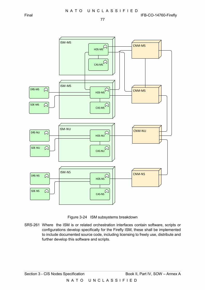
N A T O U N C L A S S I F I E D Final IFB-CO-14760-Firefly
77
Section 3 - CIS Nodes Specification Book II, Part IV, SOW – Annex A
N A T O U N C L A S S I F I E D
ISM-MS
CAS-MS
DRS-MS
CNM-NU
HDS-MS
ISM-NU
CAS-NU
DRS-NUHDS-NU
ISM-NS
CAS-NS
DRS-NSHDS-NS
CNM-MS
CNM-NS
CNM-MSISM-MS
CAS-MS
HDS-MS
SDE-MS
SDE-NU
SDE-NS
Figure 3-24 ISM subsystems breakdown
SRS-261 Where the ISM is or related orchestration interfaces contain software, scripts or configurations develop specifically for the Firefly ISM, these shall be implemented to include documented source code, including licensing to freely use, distribute and further develop this software and scripts.
N A T O U N C L A S S I F I E D Final IFB-CO-14760-Firefly
78
Section 3 - CIS Nodes Specification Book II, Part IV, SOW – Annex A
N A T O U N C L A S S I F I E D
3.2.4.2.1 CAS Subsystem
SRS-262 The Compute and Storage (CAS) subsystem shall implement the Compute and Storage hardware, within a single transit case, with each individual server (host) integrating Compute and Storage resources.
SRS-263 The servers in the CAS subsystem shall support and be agnostic to the corresponding Software-defined Compute (Virtualization Hypervisor), Software-defined Storage and Software-defined Networking.
[120] The below requirements specify the minimum performance and capacity to be implemented, with respect to CPU, RAM and permanent storage. Neither oversubscription nor any additional capacity necessary to implement the required N+1 resilience, are included in the requirements herein. Any redundancy is considered as additional capacity on top of the minimal capacity required herein.
SRS-264 A typical mission is the MS domain, the ISM-MS typically requires twice the capacity of ISM-NU and the ISM-NS. In order to allow meeting the maximum size and weight constraints of a single module (transit case), the ISM-NU and ISM-NS shall be delivered as one module each, whereas the ISM-MS shall be delivered as a cluster of two modules (two transit cases).
SRS-265 The CAS subsystem of a single module (transit case) shall implement 120 CPU cores as a minimum, where:
1) CPU cores feature as a minimum 20 Cores per processor;
2) CPU cores implement hyper-threading with as a minimum 2 threads per core, and operate at a minimum base frequency of 2.4 GHz;
3) All CPUs shall be 64-bit x86 processors implementing AMD or Intel Virtualization Technology (AMD-V or Intel VT-x).
SRS-266 All server hardware realizing the Compute function shall implement:
1) Intel Trusted Execution Technology (TXT) or equivalent AMD technology;
2) Trusted Platform Module (TPM); and
3) AES New Instructions (AES-NI).
SRS-267 The CAS subsystem shall implement a minimum available RAM capacity of 1.6 Tera byte (TB).
SRS-268 The CAS subsystem shall implement a minimum available solid-state storage capacity of 40 Terabyte (TB). Physical storage devices shall be provided as Enterprise Class. In particular, storage drives used for caching shall implement a write endurance of at least 3 drive writes per day (DWPD) or at least 4 TB written (TBW) per day.
SRS-269 The CAS subsystem shall rely on storage hardware supporting as 75,000 input/output operations per second (IOPS) at a mixed random read (70%) and write (30%).
N A T O U N C L A S S I F I E D Final IFB-CO-14760-Firefly
79
Section 3 - CIS Nodes Specification Book II, Part IV, SOW – Annex A
N A T O U N C L A S S I F I E D
SRS-270 In addition to the storage requirements above, all compute nodes (servers) shall implement dedicated hypervisor boot storage device with sufficient capacity to store the virtualization hypervisor and all necessary software to boot the computer node, to store core dumps and to store logging, following the guidelines and directions of the supported virtualization hypervisor vendors, with a minimum of 128 GB (SD Card Class 10 or above).
SRS-271 The CAS subsystem shall only implement solid state storage hardware14.
SRS-272 In support of automated storage tiering, the CAS subsystem shall automatically migrate less used data (i.e. cold data) to external S3-compatible storage resources.
SRS-273 The CAS subsystem shall implement the Hardware Control function with dedicated Controller software, hereafter referred to as the ISM Controller, running as a VM installed on the System Administrator laptop of each security domain. Once the ISM is in operation, the ISM Controller shall, in addition, be implemented as a workload in a VM running the management domain of the ISM itself. The ISM Controller software on the laptop shall reach the ISM over a network (IP) link.
3.2.4.2.2 HDS Subsystem
SRS-274 The High Density Switching (HDS) subsystem of the ISM shall be implemented physically and logically N+1 redundant, including redundant wiring with CAS components.
SRS-275 All connections within the ISM (CAS and HDS Subsystems combined) shall support at least 40 Gbps of full-duplex traffic, as follows:
1) Between the Ethernet switches within the HDS;
2) Between the Ethernet switches and the servers; and
3) Between individual servers, either direct or through the Ethernet switches.
SRS-276 The HDS subsystem shall implement as a minimum six (6) 1 Gbps interfaces, as a minimum three (3) per Ethernet switch, in accordance to the following specification:
1) Connector single mode tactical connector ODC;
2) Conform IEEE 802.3z 1000BASE-LX/LH single-mode fibre in accordance with IEEE 802.3:2012, supporting the ability to change to multi-mode fibre through replacing the SFP and fibre pig-tail;
3) Supporting an MTU of 9000 bytes;
4) Supporting VLAN tagging in accordance with 802.1Q:2011.
SRS-277 The HDS subsystem shall implement as a minimum four (4) 10 Gbps interfaces, as a minimum two (2) per Ethernet switch, in accordance to the following specification:
1) Connector single mode tactical connector ODC;
14 Non-volatile computer storage that stores and retrieves digital information using only electronic circuits, without any involvement of moving mechanical parts
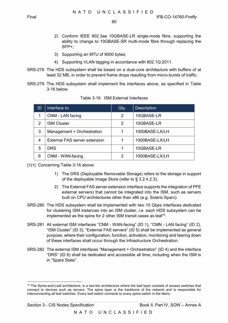
N A T O U N C L A S S I F I E D Final IFB-CO-14760-Firefly
80
Section 3 - CIS Nodes Specification Book II, Part IV, SOW – Annex A
N A T O U N C L A S S I F I E D
2) Conform IEEE 802.3ae 10GBASE-LR single-mode fibre, supporting the ability to change to 10GBASE-SR multi-mode fibre through replacing the SFP+;
3) Supporting an MTU of 9000 bytes;
4) Supporting VLAN tagging in accordance with 802.1Q:2011.
SRS-278 The HDS subsystem shall be based on a dual-core architecture with buffers of at least 32 MB, in order to prevent frame drops resulting from micro-bursts of traffic.
SRS-279 The HDS subsystem shall implement the interfaces above, as specified in Table 3-16 below.
Table 3-16 ISM External Interfaces
ID Interface to: Qty. Description
1 CNM - LAN facing 2 10GBASE-LR
2 ISM Cluster 2 10GBASE-LR
3 Management + Orchestration 1 1000BASE-LX/LH
4 External FAS server extension 1 1000BASE-LX/LH
5 DRS 1 10GBASE-LR
6 CNM - WAN-facing 2 1000BASE-LX/LH
[121] Concerning Table 3-16 above:
1) The DRS (Deployable Removable Storage) refers to the storage in support of the deployable Image Store (refer to § 3.2.4.2.3);
2) The External FAS server extension interface supports the integration of PFE external servers) that cannot be integrated into the ISM, such as servers built on CPU architectures other than x86 (e.g. Solaris Sparc).
SRS-280 The HDS subsystem shall be implemented with two 10 Gbps interfaces dedicated for clustering ISM instances into an ISM cluster, i.e. each HDS subsystem can be implemented as the spine for 2 other ISM transit cases as leaf15.
SRS-281 All external ISM interfaces “CNM - WAN-facing” (ID 1), “CMN - LAN facing” (ID 2), “ISM Cluster” (ID 3), “External FAS servers” (ID 5) shall be implemented as general purpose, where their configuration, function, activation, monitoring and tearing down of these interfaces shall occur through the Infrastructure Orchestration.
SRS-282 The external ISM interfaces “Management + Orchestration” (ID 4) and the interface “DRS” (ID 6) shall be dedicated and accessible all time, including when the ISM is in “Spare State”.
15 The Spine-and-Leaf architecture, is a two-tier architecture where the leaf layer consists of access switches that connect to devices such as servers. The spine layer is the backbone of the network and is responsible for interconnecting all leaf switches. Every leaf switch connects to every spine switch in the fabric.
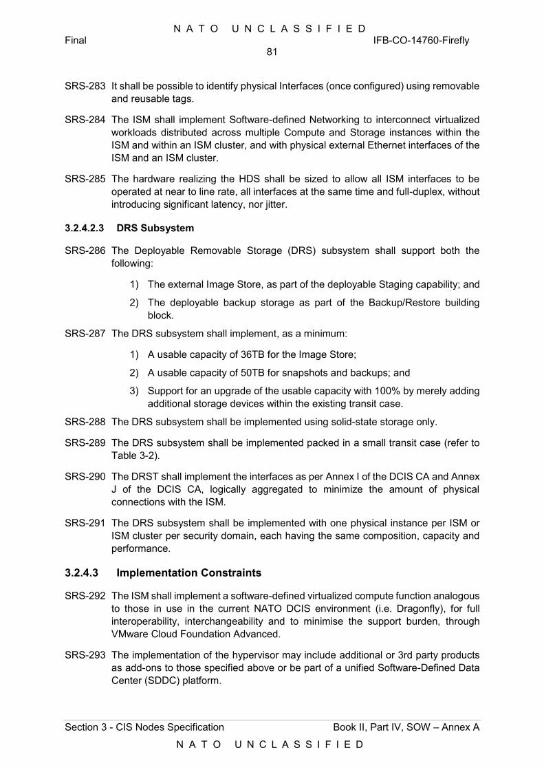
N A T O U N C L A S S I F I E D Final IFB-CO-14760-Firefly
81
Section 3 - CIS Nodes Specification Book II, Part IV, SOW – Annex A
N A T O U N C L A S S I F I E D
SRS-283 It shall be possible to identify physical Interfaces (once configured) using removable and reusable tags.
SRS-284 The ISM shall implement Software-defined Networking to interconnect virtualized workloads distributed across multiple Compute and Storage instances within the ISM and within an ISM cluster, and with physical external Ethernet interfaces of the ISM and an ISM cluster.
SRS-285 The hardware realizing the HDS shall be sized to allow all ISM interfaces to be operated at near to line rate, all interfaces at the same time and full-duplex, without introducing significant latency, nor jitter.
3.2.4.2.3 DRS Subsystem
SRS-286 The Deployable Removable Storage (DRS) subsystem shall support both the following:
1) The external Image Store, as part of the deployable Staging capability; and
2) The deployable backup storage as part of the Backup/Restore building block.
SRS-287 The DRS subsystem shall implement, as a minimum:
1) A usable capacity of 36TB for the Image Store;
2) A usable capacity of 50TB for snapshots and backups; and
3) Support for an upgrade of the usable capacity with 100% by merely adding additional storage devices within the existing transit case.
SRS-288 The DRS subsystem shall be implemented using solid-state storage only.
SRS-289 The DRS subsystem shall be implemented packed in a small transit case (refer to Table 3-2).
SRS-290 The DRST shall implement the interfaces as per Annex I of the DCIS CA and Annex J of the DCIS CA, logically aggregated to minimize the amount of physical connections with the ISM.
SRS-291 The DRS subsystem shall be implemented with one physical instance per ISM or ISM cluster per security domain, each having the same composition, capacity and performance.
3.2.4.3 Implementation Constraints
SRS-292 The ISM shall implement a software-defined virtualized compute function analogous to those in use in the current NATO DCIS environment (i.e. Dragonfly), for full interoperability, interchangeability and to minimise the support burden, through VMware Cloud Foundation Advanced.
SRS-293 The implementation of the hypervisor may include additional or 3rd party products as add-ons to those specified above or be part of a unified Software-Defined Data Center (SDDC) platform.
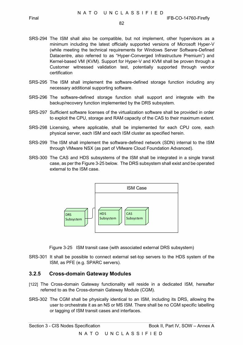
N A T O U N C L A S S I F I E D Final IFB-CO-14760-Firefly
82
Section 3 - CIS Nodes Specification Book II, Part IV, SOW – Annex A
N A T O U N C L A S S I F I E D
SRS-294 The ISM shall also be compatible, but not implement, other hypervisors as a minimum including the latest officially supported versions of Microsoft Hyper-V (while meeting the technical requirements for Windows Server Software-Defined Datacentre, also referred to as “Hyper-Converged Infrastructure Premium”) and Kernel-based VM (KVM). Support for Hyper-V and KVM shall be proven through a Customer witnessed validation test, potentially supported through vendor certification
SRS-295 The ISM shall implement the software-defined storage function including any necessary additional supporting software.
SRS-296 The software-defined storage function shall support and integrate with the backup/recovery function implemented by the DRS subsystem.
SRS-297 Sufficient software licenses of the virtualization software shall be provided in order to exploit the CPU, storage and RAM capacity of the CAS to their maximum extent.
SRS-298 Licensing, where applicable, shall be implemented for each CPU core, each physical server, each ISM and each ISM cluster as specified herein.
SRS-299 The ISM shall implement the software-defined network (SDN) internal to the ISM through VMware NSX (as part of VMware Cloud Foundation Advanced).
SRS-300 The CAS and HDS subsystems of the ISM shall be integrated in a single transit case, as per the Figure 3-25 below. The DRS subsystem shall exist and be operated external to the ISM case.
ISM Case
HDS Subsystem
CAS Subsystem
DRS Subsystem
Figure 3-25 ISM transit case (with associated external DRS subsystem)
SRS-301 It shall be possible to connect external set-top servers to the HDS system of the ISM, as PFE (e.g. SPARC servers).
3.2.5 Cross-domain Gateway Modules
[122] The Cross-domain Gateway functionality will reside in a dedicated ISM, hereafter referred to as the Cross-domain Gateway Module (CGM).
SRS-302 The CGM shall be physically identical to an ISM, including its DRS, allowing the user to orchestrate it as an NS or MS ISM. There shall be no CGM specific labelling or tagging of ISM transit cases and interfaces.
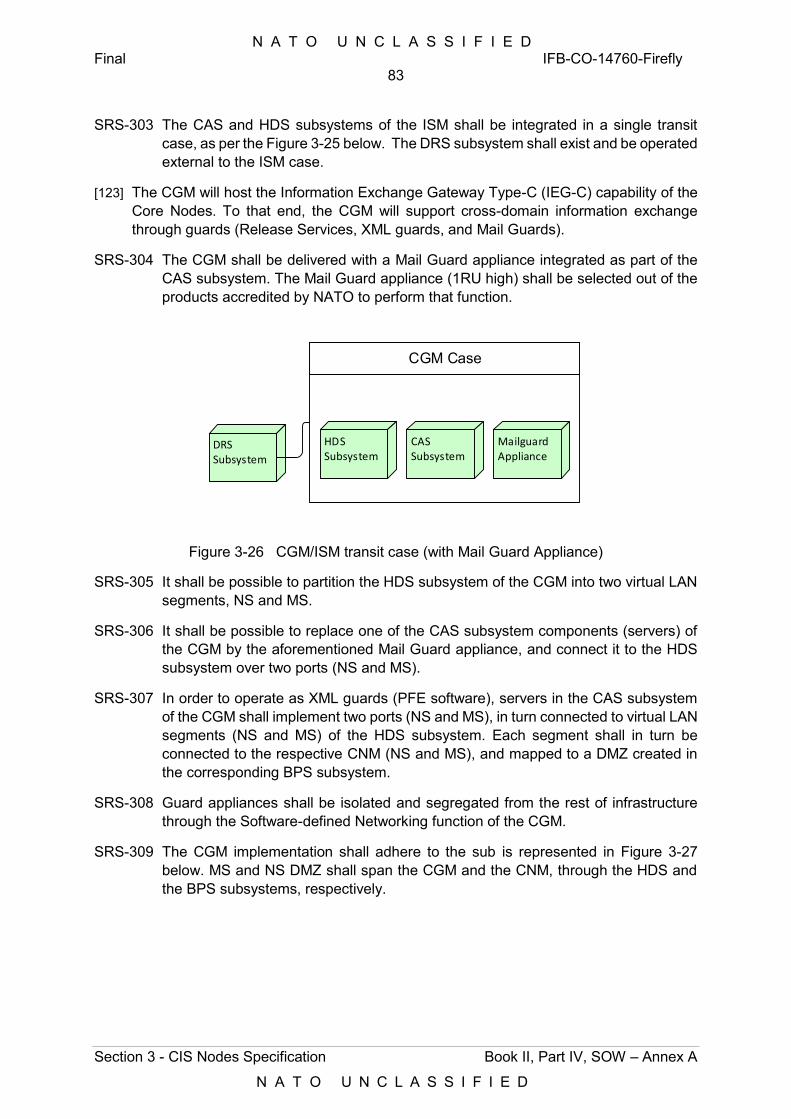
N A T O U N C L A S S I F I E D Final IFB-CO-14760-Firefly
83
Section 3 - CIS Nodes Specification Book II, Part IV, SOW – Annex A
N A T O U N C L A S S I F I E D
SRS-303 The CAS and HDS subsystems of the ISM shall be integrated in a single transit case, as per the Figure 3-25 below. The DRS subsystem shall exist and be operated external to the ISM case.
[123] The CGM will host the Information Exchange Gateway Type-C (IEG-C) capability of the Core Nodes. To that end, the CGM will support cross-domain information exchange through guards (Release Services, XML guards, and Mail Guards).
SRS-304 The CGM shall be delivered with a Mail Guard appliance integrated as part of the CAS subsystem. The Mail Guard appliance (1RU high) shall be selected out of the products accredited by NATO to perform that function.
CGM Case
HDS Subsystem
CAS Subsystem
DRS Subsystem
MailguardAppliance
Figure 3-26 CGM/ISM transit case (with Mail Guard Appliance)
SRS-305 It shall be possible to partition the HDS subsystem of the CGM into two virtual LAN segments, NS and MS.
SRS-306 It shall be possible to replace one of the CAS subsystem components (servers) of the CGM by the aforementioned Mail Guard appliance, and connect it to the HDS subsystem over two ports (NS and MS).
SRS-307 In order to operate as XML guards (PFE software), servers in the CAS subsystem of the CGM shall implement two ports (NS and MS), in turn connected to virtual LAN segments (NS and MS) of the HDS subsystem. Each segment shall in turn be connected to the respective CNM (NS and MS), and mapped to a DMZ created in the corresponding BPS subsystem.
SRS-308 Guard appliances shall be isolated and segregated from the rest of infrastructure through the Software-defined Networking function of the CGM.
SRS-309 The CGM implementation shall adhere to the sub is represented in Figure 3-27 below. MS and NS DMZ shall span the CGM and the CNM, through the HDS and the BPS subsystems, respectively.
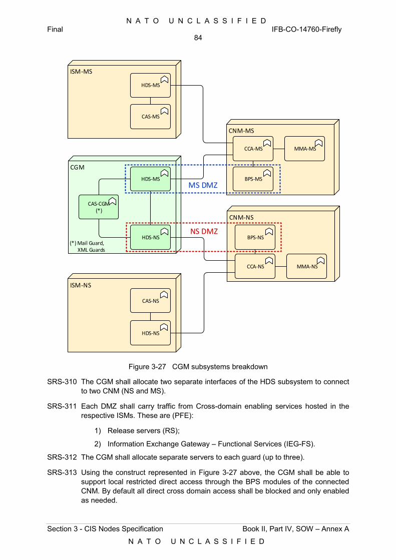
N A T O U N C L A S S I F I E D Final IFB-CO-14760-Firefly
84
Section 3 - CIS Nodes Specification Book II, Part IV, SOW – Annex A
N A T O U N C L A S S I F I E D
ISM-MS
CAS-MS
HDS-MS
CGM
CAS-CGM(*)
HDS-MS
ISM-NS
CAS-NS
HDS-NS
CNM-MS
HDS-NS
CCA-MS
BPS-MS
MMA-MS
CNM-NS
CCA-NS
BPS-NS
MMA-NS
MS DMZ
NS DMZ
(*) Mail Guard, XML Guards
Figure 3-27 CGM subsystems breakdown
SRS-310 The CGM shall allocate two separate interfaces of the HDS subsystem to connect to two CNM (NS and MS).
SRS-311 Each DMZ shall carry traffic from Cross-domain enabling services hosted in the respective ISMs. These are (PFE):
1) Release servers (RS);
2) Information Exchange Gateway – Functional Services (IEG-FS).
SRS-312 The CGM shall allocate separate servers to each guard (up to three).
SRS-313 Using the construct represented in Figure 3-27 above, the CGM shall be able to support local restricted direct access through the BPS modules of the connected CNM. By default all direct cross domain access shall be blocked and only enabled as needed.
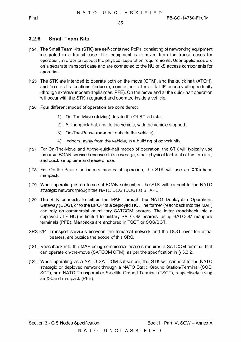
N A T O U N C L A S S I F I E D Final IFB-CO-14760-Firefly
85
Section 3 - CIS Nodes Specification Book II, Part IV, SOW – Annex A
N A T O U N C L A S S I F I E D
3.2.6 Small Team Kits
[124] The Small Team Kits (STK) are self-contained PoPs, consisting of networking equipment integrated in a transit case. The equipment is removed from the transit cases for operation, in order to respect the physical separation requirements. User appliances are on a separate transport case and are connected to the NU or xS access components for operation.
[125] The STK are intended to operate both on the move (OTM), and the quick halt (ATQH), and from static locations (indoors), connected to terrestrial IP bearers of opportunity (through external modem appliances, PFE). On the move and at the quick halt operation will occur with the STK integrated and operated inside a vehicle.
[126] Four different modes of operation are considered:
1) On-The-Move (driving), Inside the OLRT vehicle;
2) At-the-quick-halt (inside the vehicle, with the vehicle stopped);
3) On-The-Pause (near but outside the vehicle);
4) Indoors, away from the vehicle, in a building of opportunity.
[127] For On-The-Move and At-the-quick-halt modes of operation, the STK will typically use Inmarsat BGAN service because of its coverage, small physical footprint of the terminal, and quick setup time and ease of use.
[128] For On-the-Pause or indoors modes of operation, the STK will use an X/Ka-band manpack.
[129] When operating as an Inmarsat BGAN subscriber, the STK will connect to the NATO strategic network through the NATO DOG (DOG) at SHAPE.
[130] The STK connects to either the MAF, through the NATO Deployable Operations Gateway (DOG), or to the DPOP of a deployed HQ. The former (reachback into the MAF) can rely on commercial or military SATCOM bearers. The latter (reachback into a deployed JTF HQ) is limited to military SATCOM bearers, using SATCOM manpack terminals (PFE). Manpacks are anchored in TSGT or SGS/SGT.
SRS-314 Transport services between the Inmarsat network and the DOG, over terrestrial bearers, are outside the scope of this SRS.
[131] Reachback into the MAF using commercial bearers requires a SATCOM terminal that can operate on-the-move (SATCOM OTM), as per the specification in § 3.3.2.
[132] When operating as a NATO SATCOM subscriber, the STK will connect to the NATO strategic or deployed network through a NATO Static Ground Station/Terminal (SGS, SGT), or a NATO Transportable Satellite Ground Terminal (TSGT), respectively, using an X-band manpack (PFE).
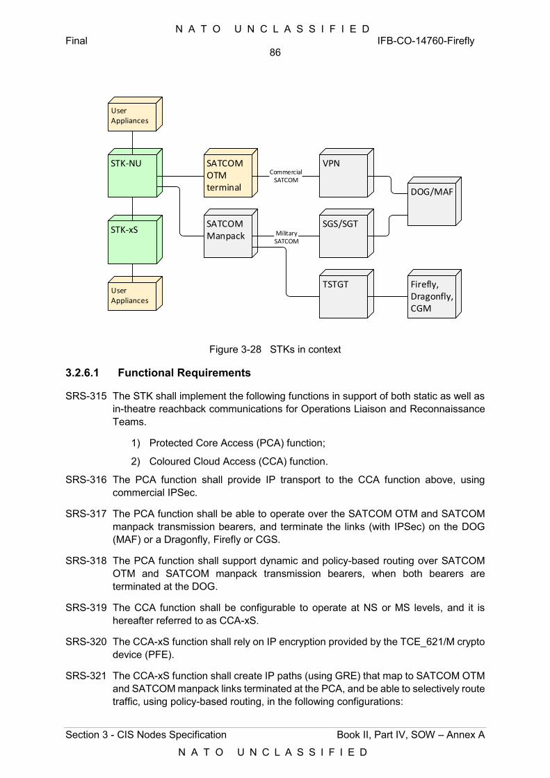
N A T O U N C L A S S I F I E D Final IFB-CO-14760-Firefly
86
Section 3 - CIS Nodes Specification Book II, Part IV, SOW – Annex A
N A T O U N C L A S S I F I E D
STK-NU
User Appliances
SATCOMOTMterminal
SATCOMManpack
STK-xS
User Appliances
SGS/SGTMilitarySATCOM
TSTGT
VPN
DOG/MAF
Firefly, Dragonfly, CGM
CommercialSATCOM
Figure 3-28 STKs in context
3.2.6.1 Functional Requirements
SRS-315 The STK shall implement the following functions in support of both static as well as in-theatre reachback communications for Operations Liaison and Reconnaissance Teams.
1) Protected Core Access (PCA) function;
2) Coloured Cloud Access (CCA) function.
SRS-316 The PCA function shall provide IP transport to the CCA function above, using commercial IPSec.
SRS-317 The PCA function shall be able to operate over the SATCOM OTM and SATCOM manpack transmission bearers, and terminate the links (with IPSec) on the DOG (MAF) or a Dragonfly, Firefly or CGS.
SRS-318 The PCA function shall support dynamic and policy-based routing over SATCOM OTM and SATCOM manpack transmission bearers, when both bearers are terminated at the DOG.
SRS-319 The CCA function shall be configurable to operate at NS or MS levels, and it is hereafter referred to as CCA-xS.
SRS-320 The CCA-xS function shall rely on IP encryption provided by the TCE_621/M crypto device (PFE).
SRS-321 The CCA-xS function shall create IP paths (using GRE) that map to SATCOM OTM and SATCOM manpack links terminated at the PCA, and be able to selectively route traffic, using policy-based routing, in the following configurations:
N A T O U N C L A S S I F I E D Final IFB-CO-14760-Firefly
87
Section 3 - CIS Nodes Specification Book II, Part IV, SOW – Annex A
N A T O U N C L A S S I F I E D
1) Both paths terminating at the DOG, for reachback redundancy purposes;
2) SATCOM OTM link terminating at the DOG, for reachback, and SATCOM manpack link terminating at a Core Network module or a µCOM of a Dragonfly or a CGS, for intra-theatre communications purposes.
SRS-322 The STK shall rely on the Boundary Protection (BPS) function of the anchor point (i.e. a CNM, the NS or MS Core nodes of the Dragonfly, or the DOG in the MAF). For that purpose, the corresponding CCA functions in those anchor points shall carry STK traffic over a separate transport compartment (VRF) and forward it to the BPS function. The BPS function will then screen and forward that traffic to the relevant service of the ISM (or the MAF, in the case of the DOG).
3.2.6.2 Technical Requirements
SRS-323 The detailed system design of the Small Team Kit (STK) shall adhere to the representation of the system breakdown (building blocks) in the figure below.
SRS-324 The design of the Small Team Kit (STK) shall map each of the functions specified above into the subsystems by the same name (i.e. PCA and CCA), as represented in the figure below.
Small Team Kit (STK)
Protect Core Access (PCA) Subsystem
Coloured Cloud Access (CCA) Subsystem
Uninterrupted Power Supply (UPS) Subsystem
User Appliances
Figure 3-29 Small Team Kit building blocks
SRS-325 The STK shall consist of (refer to Figure 3-31 under Implementation Constraints, § 3.2.6.3):
1) The STK Main Case, integrating both the STK-xS and STK-NU modules;
2) Two Transport cases, containing all user appliances and ancillaries (e.g. cabling) and the SATCOM OTM terminal.
SRS-326 None of the cases shall weight more than 20 kg or exceed the dimensions assigned to the Small Case in Table 3-1.
N A T O U N C L A S S I F I E D Final IFB-CO-14760-Firefly
88
Section 3 - CIS Nodes Specification Book II, Part IV, SOW – Annex A
N A T O U N C L A S S I F I E D
SRS-327 The STK Main Case shall contains everything required for providing four user with access to NS (or MS) and NU voice and data.
SRS-328 The STK Main Case and its components shall be ruggedized to withstand transportation, dust and high temperatures.
SRS-329 It shall be possible to integrate the components of the STK Main Case into a vehicle, for operation on the move.
SRS-330 The STK Main Case shall include a power backup and can also be powered from vehicle power or military batteries (refer to § 3.2.6.2.3 for details).
SRS-331 The STK-xS module shall be compliant to SDIP 27 Level B.
SRS-332 It shall be possible to power the components of the main case, as well as a limited number of user appliances (one laptop and IP phone per classification) from the vehicle.
SRS-333 The components of the STK Main Case shall be dismountable from the case for operation inside the vehicle, secured by appropriate vehicle fixtures (refer to § 6.5.4 for details).
SRS-334 It shall be possible to remote the RED components from the BLACK components in accordance with the above mentioned TEMPEST regulations.
SRS-335 The STK shall not participate in the DCIS MPLS domain but shall connect via a PE function at either the DOG (when performing a reconnaissance function) or on a TSGT at a DCIS HQ equipped with a Firefly or Dragonfly (when performing a Liaison function).
[133] The following figure provides the subsystem breakdown of the STK, into its three subsystems (PCA/CCA-NU, CCA-xS, and UPS).
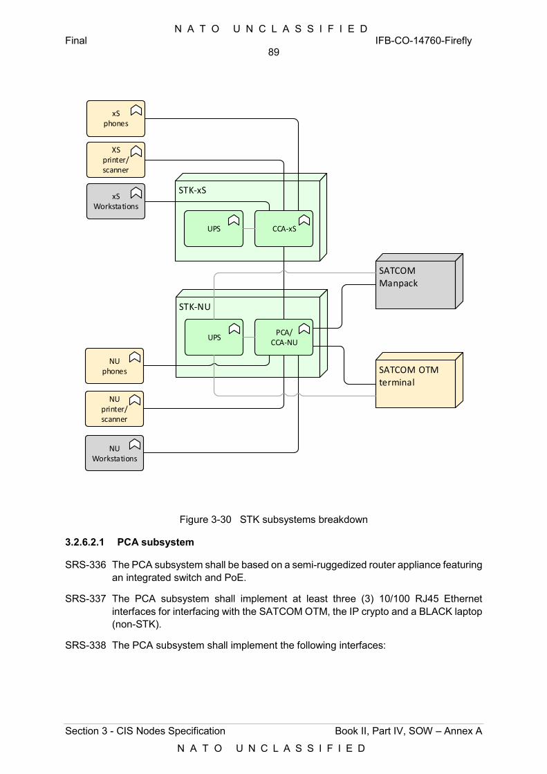
N A T O U N C L A S S I F I E D Final IFB-CO-14760-Firefly
89
Section 3 - CIS Nodes Specification Book II, Part IV, SOW – Annex A
N A T O U N C L A S S I F I E D
STK-xS
CCA-xSUPS
xS phones
XS printer/scanner
xS Workstations
STK-NU
PCA/CCA-NU
SATCOM OTM terminal
UPS
NU phones
NU printer/scanner
NU Workstations
SATCOM Manpack
Figure 3-30 STK subsystems breakdown
3.2.6.2.1 PCA subsystem
SRS-336 The PCA subsystem shall be based on a semi-ruggedized router appliance featuring an integrated switch and PoE.
SRS-337 The PCA subsystem shall implement at least three (3) 10/100 RJ45 Ethernet interfaces for interfacing with the SATCOM OTM, the IP crypto and a BLACK laptop (non-STK).
SRS-338 The PCA subsystem shall implement the following interfaces:
N A T O U N C L A S S I F I E D Final IFB-CO-14760-Firefly
90
Section 3 - CIS Nodes Specification Book II, Part IV, SOW – Annex A
N A T O U N C L A S S I F I E D
Table 3-17 PCA module Interfaces
# Interface to: Description
1 IP interface to SATCOM OTM 1 port, 100BASE-TX
2 IP interface to SATCOM ATQH (Manpack) 1 port, 100BASE-TX
3 IP interface to Ethernet transport (other than SATCOM) 1 port, 100BASE-TX
3.2.6.2.2 CCA subsystem
SRS-339 The CCA-NU subsystem shall be integrated with the PCA subsystem above, and share the resources of the corresponding router appliance, including ports of the integrated switch and PoE.
SRS-340 The CCA-NU subsystem shall provide at least eight (8) RJ45 ports at 100/1000 Mbps for connecting user appliances.
SRS-341 The CCA-NU subsystem shall implement at least two (2) 10/100 PoE enabled interfaces for the VoIP desk phones.
SRS-342 The CCA-xS subsystem shall provide at least eight (8) 100BASE-FX ports for connecting user appliances.
SRS-343 The CCA-xS subsystem shall integrate the small-sized, tactical version of the TCE-621 (TCE-621M).
SRS-344 The CCA-xS subsystem shall implement at least one (1) 100/1000 Mbps Ethernet interface for interfacing the TCE-621M.
SRS-345 The CCA- subsystem shall implement MDIX Support on the interfaces to avoid the use of cross cables if applicable.
3.2.6.2.3 UPS subsystem
[134] The STK should be usable anywhere, anytime, in an uninterrupted fashion, which is reflected in the electrical power requirements, hereafter conveyed under this “UPS subsystem” section.
[135] All power-related requirements below address situations where no power is available (i.e. autonomy), or only non-standard power sources are available (i.e. adaptation), and call for an STK that includes power feeds for user appliances and SATCOM OTM, while still keeping volume and weight low (i.e. distribution).
SRS-346 The cases shall implement power supplies for all their components, including the TCE-621/M. Although the TCE-621M is PFE, the TCE-621M power supply is not, and shall be furnished and integrated with compatible connectors.
[136] In order to save weight and volume it is allowed and recommended to power multiple components in the STK Main Case, and optionally the CCA-xS subsystem, from a single power supply, as long as the TEMPEST security requirements are met.
N A T O U N C L A S S I F I E D Final IFB-CO-14760-Firefly
91
Section 3 - CIS Nodes Specification Book II, Part IV, SOW – Annex A
N A T O U N C L A S S I F I E D
SRS-347 The STK shall implement a power autonomy function by providing:
1) Un-interruptible power, providing power to the equipment continuously, while external power input is available but also when the external power is interrupted;
2) Primary power from its rechargeable batteries for using the STK when no external power is available.
SRS-348 The STK shall implement a power conditioning function, protecting all active components against power surges, spikes, excessive line noise, under voltage, brownout and sags, and against swells/overvoltage.
SRS-349 The STK shall implement removable batteries and shall include an external charging capability to allow charging batteries elsewhere, away from the STK itself.
SRS-350 The power autonomy function shall, without external power input, provide power for a minimum duration of two (2) hours:
1) For operation of the PCA/CCA-NU subsystem and the TCE621-M (via DC-in);
2) For operation of the PCA/CCA-NU subsystem, the TCE621-M, and the CCA-xS subsystem, with two active PoE powered phones connected;
[137] The above stated minimum duration excludes powering the laptops, SATCOM OTM, printer and scanner as these can use their internal batteries or USB power.
SRS-351 Lithium-ion rechargeable batteries shall be used. For maintenance and reliability reasons the use of LiFePo4 batteries, BB2590 batteries or batteries with equivalent or better reliability and lifetime shall be implemented.
SRS-352 A charge indicator shall be included that shows:
1) The charge left (minimum four levels);
2) If the battery is charging or has finished charging.
SRS-353 Maximum charge time from empty to full shall not exceed five hours, with electrical load applied
SRS-354 The batteries shall support not less than 1000 charge/ discharge cycles.
SRS-355 The batteries shall be field removable, by-passable and replaceable, in order to:
1) Remove them for repairs;
2) Save weight;
3) Support the user to carry additional charged batteries for longer autonomy (as ancillary items, in the transport cases);
4) Charge the battery externally, while not used;
5) Transport the STK Main Case as cabin baggage on commercial airlines.
SRS-356 During battery replacements the power autonomy function is allowed to be interrupted.
N A T O U N C L A S S I F I E D Final IFB-CO-14760-Firefly
92
Section 3 - CIS Nodes Specification Book II, Part IV, SOW – Annex A
N A T O U N C L A S S I F I E D
SRS-357 It shall be possible to switch off the power autonomy function and the batteries completely, to prevent over-discharging, discharging when not in use, and for safety reasons.
SRS-358 For safety reasons the power autonomy function shall be implemented such that it is not possible to use it or to activate it when the case is closed.
SRS-359 For both reasons of safety and lifetime, the batteries shall be protected against overcharging, over discharging, overheating and shortcut.
SRS-360 Malfunctioning of batteries in the power autonomy function shall not prevent powering the components through the Power Adaptation/ Power Supply functions. The use of manual bypass switch or cable is permitted to achieve this.
SRS-361 The STK shall implement a power adaptation function, enabling the use of the following power sources:
1) AC mains power (90 – 240V, 47 – 63Hz);
2) Military batteries of the types BA and BB 2590, BA and BB 5590;
3) Vehicle power, which could be through direct DC-DC or through the use of an external (PFE) car power converter.
SRS-362 Cables and adapters shall be provided as part of the power adaptation function.
SRS-363 Power inputs that are not compatible with each other shall have STK unique sockets.
SRS-364 The power inputs and output connectors shall be clearly labelled with their function.
SRS-365 No damage to the STK components or power sources shall occur if and when multiple power sources are connected at the same time.
[138] It is permitted to use a manually operated switch or cabling to avoid conflicting power sources.
[139] It is not required to charge the batteries of the power autonomy function through the external military batteries, neither have the military batteries to be chargeable through a STK power supply.
SRS-366 The power supply shall implement overheating and shortcut protection
SRS-367 In order to connect the STK components to mains power , the STK shall include:
1) For the STK Main Case a very compact mains distribution box, minimum Power rating 1000W, featuring an ON/OFF switch, and IEC C13 and C14 based inlets/ outlets, for connecting:
a) Laptop power supplies;
b) Phone power supplies (when not powered over PoE);
c) SATCOM OTM power supply;
d) TCE621-M power supply;
e) Mains power feed.
N A T O U N C L A S S I F I E D Final IFB-CO-14760-Firefly
93
Section 3 - CIS Nodes Specification Book II, Part IV, SOW – Annex A
N A T O U N C L A S S I F I E D
2) An extension cord of 3 m;
3) Output power cables to connect the C14 outputs with the PSUs of the laptops, printer, STM main case and SATCOM OTM. The length for the laptop and SATCOM OTM power supply cables shall be minimum 100cm, for the STK Main Case power supply it shall be as short as possible to have the power supply directly next to the distribution box.
SRS-368 A resettable surge protection function shall be provided.
SRS-369 Car DC-AC power converters shall be included. To reduce the weight the STK Main Case includes a low power converter, and the Transport Case includes an ancillary high power converter with the following specifications:
1) Sufficient power for all the components belonging to that case, with discharged batteries;
2) Input: Cigarette lighter (SAE J563), NATO inter-vehicle plug;
3) Shortcut/ over current protection;
4) Overheating protection;
5) Input voltage 10-28V DC;
6) Output voltage: 230V AC 50 Hz;
7) Automatic switch-off if battery voltage drops below 9.5V;
8) Over voltage (input) protection;
9) Reversed polarity protection.
SRS-370 Any fuses inside the power functions shall be field resettable or replaceable.
SRS-371 The use of one-time fuses shall be avoided as much as possible.
SRS-372 If the use of one-time fuses cannot be avoided then spare fuses shall be included with the STK.
3.2.6.2.4 User Appliances
SRS-373 The STK user appliances shall consist of:
1) Ruggedized Laptops;
2) Printer/scanner;
3) IP phones.
SRS-374 Each STK shall be delivered with four ruggedized laptops, able to operate NS or MS.
SRS-375 Each STK shall be delivered with two A4 printers (one NU, one xS)
SRS-376 Each STK shall be delivered with four IP phones (two NU, two xS) .
SRS-377 All user appliances processing classified information in STK (xS) shall be certified to SDIP 27 Level B.
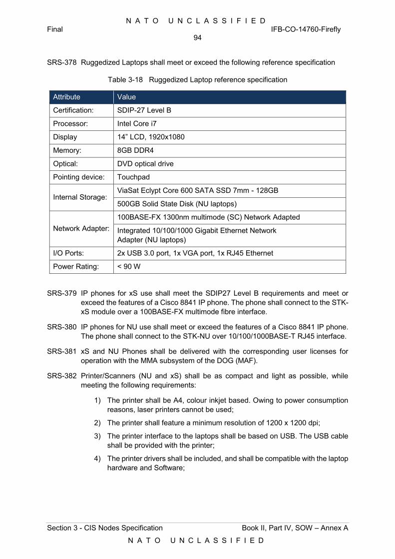
N A T O U N C L A S S I F I E D Final IFB-CO-14760-Firefly
94
Section 3 - CIS Nodes Specification Book II, Part IV, SOW – Annex A
N A T O U N C L A S S I F I E D
SRS-378 Ruggedized Laptops shall meet or exceed the following reference specification
Table 3-18 Ruggedized Laptop reference specification
Attribute Value
Certification: SDIP-27 Level B
Processor: Intel Core i7
Display 14” LCD, 1920x1080
Memory: 8GB DDR4
Optical: DVD optical drive
Pointing device: Touchpad
Internal Storage: ViaSat Eclypt Core 600 SATA SSD 7mm - 128GB
500GB Solid State Disk (NU laptops)
Network Adapter: 100BASE-FX 1300nm multimode (SC) Network Adapted
Integrated 10/100/1000 Gigabit Ethernet Network Adapter (NU laptops)
I/O Ports: 2x USB 3.0 port, 1x VGA port, 1x RJ45 Ethernet
Power Rating: < 90 W
SRS-379 IP phones for xS use shall meet the SDIP27 Level B requirements and meet or exceed the features of a Cisco 8841 IP phone. The phone shall connect to the STK-xS module over a 100BASE-FX multimode fibre interface.
SRS-380 IP phones for NU use shall meet or exceed the features of a Cisco 8841 IP phone. The phone shall connect to the STK-NU over 10/100/1000BASE-T RJ45 interface.
SRS-381 xS and NU Phones shall be delivered with the corresponding user licenses for operation with the MMA subsystem of the DOG (MAF).
SRS-382 Printer/Scanners (NU and xS) shall be as compact and light as possible, while meeting the following requirements:
1) The printer shall be A4, colour inkjet based. Owing to power consumption reasons, laser printers cannot be used;
2) The printer shall feature a minimum resolution of 1200 x 1200 dpi;
3) The printer interface to the laptops shall be based on USB. The USB cable shall be provided with the printer;
4) The printer drivers shall be included, and shall be compatible with the laptop hardware and Software;
N A T O U N C L A S S I F I E D Final IFB-CO-14760-Firefly
95
Section 3 - CIS Nodes Specification Book II, Part IV, SOW – Annex A
N A T O U N C L A S S I F I E D
5) The printer drivers or required Software shall be on the AFPL (Approved Fielded Product List). Otherwise, the Contractor may be required to initiate and manage the process of getting the driver accepted in that list, for the purpose of this project;
6) The printer shall feature no permanent data storage. Data shall not be retained after the printer is switched off and it is packed for transport, even if the battery is fully charged;
7) Two sets of spare cartridges, and one set of printer head cleaning accessories all be included with the printer;
8) The printer weight shall not exceed 2.5 kg (excluding spare cartridges and cleaning accessories).
SRS-383 The scanner function of the printer shall meet the following requirements:
1) Type: sheet fed portable;
2) Power: through USB, max 10W compatible with laptops provided;
3) Resolution: 4800 x 4800 dpi;
4) Application support: TWAIN compatible;
5) Minimum scan speed of A4 at 300 DPI: 10 seconds;
6) Minimum scan surface: A4;
7) Drivers shall be included and be compatible with the laptop hardware and Software;
8) Drivers or required Software shall be on the AFPL [Approved Fielded Product List]. Otherwise, the Contractor may request the Software to be added to the NAPL, and shall manage the request accordingly;
9) For security reasons the device shall have no permanent data storage in which user data is kept.
3.2.6.3 Implementation Constraints
SRS-384 The Small Team Node equipment shall be integrated in transport cases (vice transit cases) in adherence to the target component distribution described in the figures below. All cases are Small Cases.
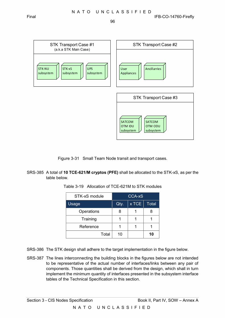
N A T O U N C L A S S I F I E D Final IFB-CO-14760-Firefly
96
Section 3 - CIS Nodes Specification Book II, Part IV, SOW – Annex A
N A T O U N C L A S S I F I E D
STK Transport Case #1 (a.k.a STK Main Case)
STK Transport Case #2
STK Transport Case #3
STK-NUsubsystem
STK-xSsubsystem
User Appliances
Ancillarries
SATCOM OTM IDUsubsystem
SATCOM OTM ODUsubsystem
UPS subsystem
Figure 3-31 Small Team Node transit and transport cases.
SRS-385 A total of 10 TCE-621/M cryptos (PFE) shall be allocated to the STK-xS, as per the table below.
Table 3-19 Allocation of TCE-621M to STK modules
STK-xS module CCA-xS
Usage Qty. x TCE Total
Operations 8 1 8
Training 1 1 1
Reference 1 1 1
Total 10 10
SRS-386 The STK design shall adhere to the target implementation in the figure below.
SRS-387 The lines interconnecting the building blocks in the figures below are not intended to be representative of the actual number of interfaces/links between any pair of components. Those quantities shall be derived from the design, which shall in turn implement the minimum quantity of interfaces presented in the subsystem interface tables of the Technical Specification in this section.
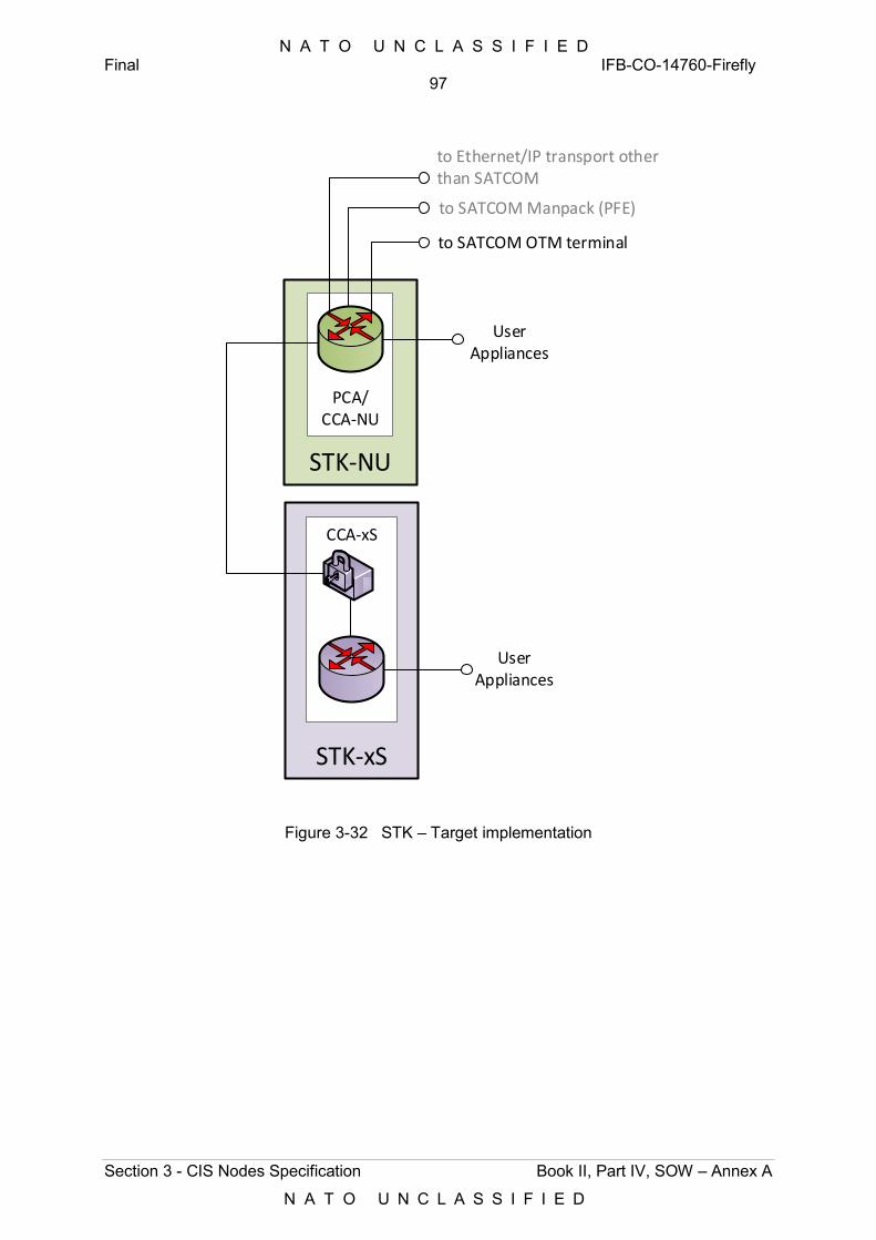
N A T O U N C L A S S I F I E D Final IFB-CO-14760-Firefly
97
Section 3 - CIS Nodes Specification Book II, Part IV, SOW – Annex A
N A T O U N C L A S S I F I E D
STK-xS
CCA-xS
User Appliances
STK-NU
PCA/CCA-NU
to SATCOM OTM terminal
User Appliances
to SATCOM Manpack (PFE)
to Ethernet/IP transport other than SATCOM
Figure 3-32 STK – Target implementation
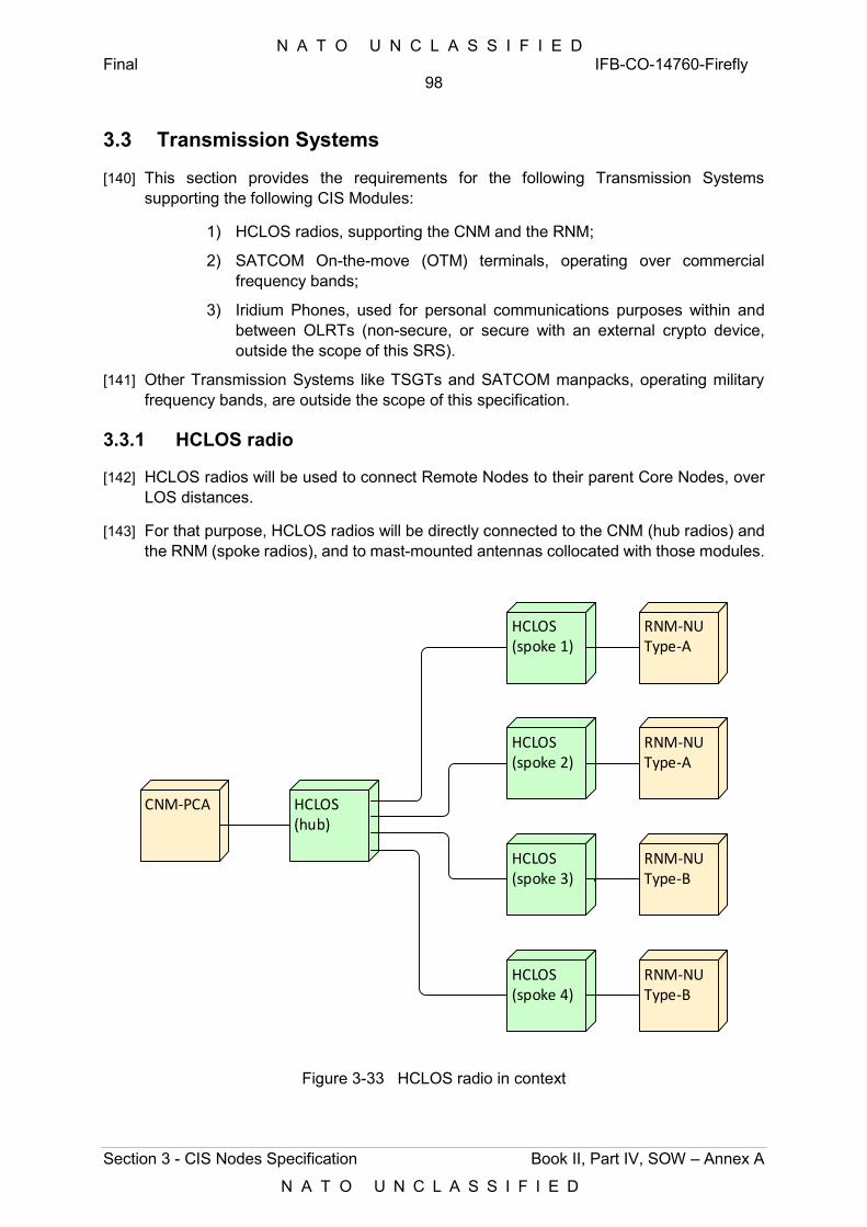
N A T O U N C L A S S I F I E D Final IFB-CO-14760-Firefly
98
Section 3 - CIS Nodes Specification Book II, Part IV, SOW – Annex A
N A T O U N C L A S S I F I E D
3.3 Transmission Systems
[140] This section provides the requirements for the following Transmission Systems supporting the following CIS Modules:
1) HCLOS radios, supporting the CNM and the RNM;
2) SATCOM On-the-move (OTM) terminals, operating over commercial frequency bands;
3) Iridium Phones, used for personal communications purposes within and between OLRTs (non-secure, or secure with an external crypto device, outside the scope of this SRS).
[141] Other Transmission Systems like TSGTs and SATCOM manpacks, operating military frequency bands, are outside the scope of this specification.
3.3.1 HCLOS radio
[142] HCLOS radios will be used to connect Remote Nodes to their parent Core Nodes, over LOS distances.
[143] For that purpose, HCLOS radios will be directly connected to the CNM (hub radios) and the RNM (spoke radios), and to mast-mounted antennas collocated with those modules.
CNM-PCA HCLOS(hub)
HCLOS(spoke 1)
HCLOS(spoke 2)
HCLOS(spoke 3)
HCLOS(spoke 4)
RNM-NUType-A
RNM-NUType-A
RNM-NUType-B
RNM-NUType-B
Figure 3-33 HCLOS radio in context
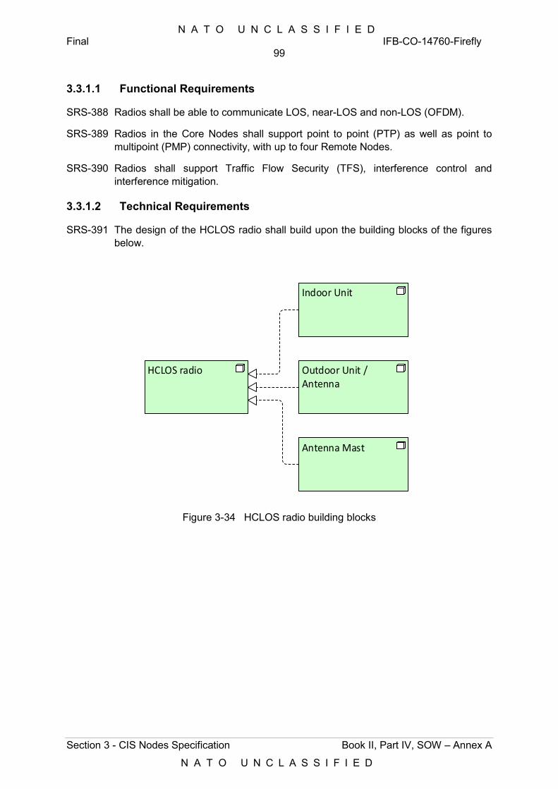
N A T O U N C L A S S I F I E D Final IFB-CO-14760-Firefly
99
Section 3 - CIS Nodes Specification Book II, Part IV, SOW – Annex A
N A T O U N C L A S S I F I E D
3.3.1.1 Functional Requirements
SRS-388 Radios shall be able to communicate LOS, near-LOS and non-LOS (OFDM).
SRS-389 Radios in the Core Nodes shall support point to point (PTP) as well as point to multipoint (PMP) connectivity, with up to four Remote Nodes.
SRS-390 Radios shall support Traffic Flow Security (TFS), interference control and interference mitigation.
3.3.1.2 Technical Requirements
SRS-391 The design of the HCLOS radio shall build upon the building blocks of the figures below.
HCLOS radio
Indoor Unit
Outdoor Unit / Antenna
Antenna Mast
Figure 3-34 HCLOS radio building blocks
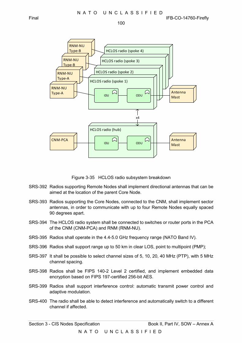
N A T O U N C L A S S I F I E D Final IFB-CO-14760-Firefly
100
Section 3 - CIS Nodes Specification Book II, Part IV, SOW – Annex A
N A T O U N C L A S S I F I E D
RNM-NUType-B
RNM-NUType-B
RNM-NUType-A
HCLOS radio (spoke 4)
HCLOS radio (spoke 3)
HCLOS radio (spoke 2)
HCLOS radio (hub)
IDU ODUCNM-PCA
HCLOS radio (spoke 1)
IDU ODU
RNM-NUType-A
x4
Antenna Mast
Antenna Mast
Figure 3-35 HCLOS radio subsystem breakdown
SRS-392 Radios supporting Remote Nodes shall implement directional antennas that can be aimed at the location of the parent Core Node.
SRS-393 Radios supporting the Core Nodes, connected to the CNM, shall implement sector antennas, in order to communicate with up to four Remote Nodes equally spaced 90 degrees apart.
SRS-394 The HCLOS radio system shall be connected to switches or router ports in the PCA of the CNM (CNM-PCA) and RNM (RNM-NU).
SRS-395 Radios shall operate in the 4.4-5.0 GHz frequency range (NATO Band IV).
SRS-396 Radios shall support range up to 50 km in clear LOS, point to multipoint (PMP);
SRS-397 It shall be possible to select channel sizes of 5, 10, 20, 40 MHz (PTP), with 5 MHz channel spacing.
SRS-398 Radios shall be FIPS 140-2 Level 2 certified, and implement embedded data encryption based on FIPS 197-certified 256-bit AES.
SRS-399 Radios shall support interference control: automatic transmit power control and adaptive modulation.
SRS-400 The radio shall be able to detect interference and automatically switch to a different channel if affected.
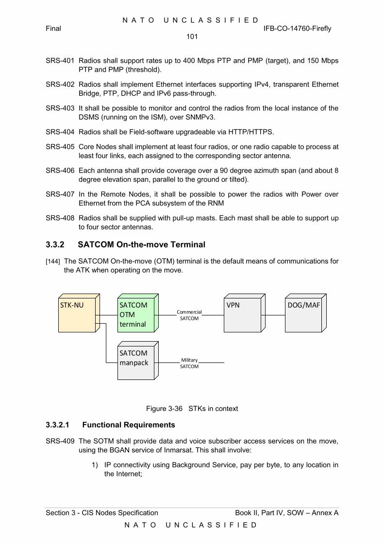
N A T O U N C L A S S I F I E D Final IFB-CO-14760-Firefly
101
Section 3 - CIS Nodes Specification Book II, Part IV, SOW – Annex A
N A T O U N C L A S S I F I E D
SRS-401 Radios shall support rates up to 400 Mbps PTP and PMP (target), and 150 Mbps PTP and PMP (threshold).
SRS-402 Radios shall implement Ethernet interfaces supporting IPv4, transparent Ethernet Bridge, PTP, DHCP and IPv6 pass-through.
SRS-403 It shall be possible to monitor and control the radios from the local instance of the DSMS (running on the ISM), over SNMPv3.
SRS-404 Radios shall be Field-software upgradeable via HTTP/HTTPS.
SRS-405 Core Nodes shall implement at least four radios, or one radio capable to process at least four links, each assigned to the corresponding sector antenna.
SRS-406 Each antenna shall provide coverage over a 90 degree azimuth span (and about 8 degree elevation span, parallel to the ground or tilted).
SRS-407 In the Remote Nodes, it shall be possible to power the radios with Power over Ethernet from the PCA subsystem of the RNM
SRS-408 Radios shall be supplied with pull-up masts. Each mast shall be able to support up to four sector antennas.
3.3.2 SATCOM On-the-move Terminal
[144] The SATCOM On-the-move (OTM) terminal is the default means of communications for the ATK when operating on the move.
STK-NU SATCOMOTMterminal
VPN DOG/MAFCommercial
SATCOM
SATCOM manpack Military
SATCOM
Figure 3-36 STKs in context
3.3.2.1 Functional Requirements
SRS-409 The SOTM shall provide data and voice subscriber access services on the move, using the BGAN service of Inmarsat. This shall involve:
1) IP connectivity using Background Service, pay per byte, to any location in the Internet;
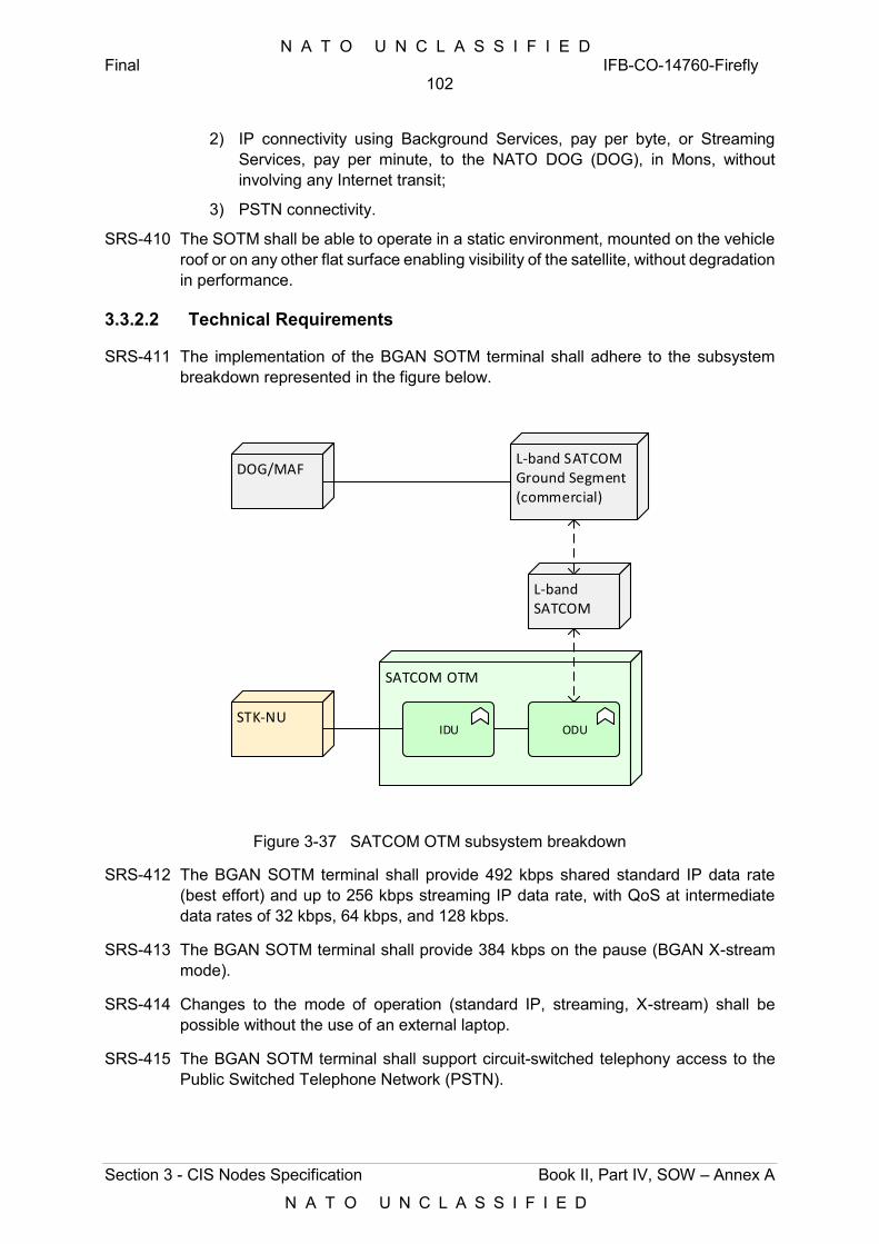
N A T O U N C L A S S I F I E D Final IFB-CO-14760-Firefly
102
Section 3 - CIS Nodes Specification Book II, Part IV, SOW – Annex A
N A T O U N C L A S S I F I E D
2) IP connectivity using Background Services, pay per byte, or Streaming Services, pay per minute, to the NATO DOG (DOG), in Mons, without involving any Internet transit;
3) PSTN connectivity.
SRS-410 The SOTM shall be able to operate in a static environment, mounted on the vehicle roof or on any other flat surface enabling visibility of the satellite, without degradation in performance.
3.3.2.2 Technical Requirements
SRS-411 The implementation of the BGAN SOTM terminal shall adhere to the subsystem breakdown represented in the figure below.
SATCOM OTM
IDU ODUSTK-NU
L-band SATCOM
DOG/MAFL-band SATCOM Ground Segment(commercial)
Figure 3-37 SATCOM OTM subsystem breakdown
SRS-412 The BGAN SOTM terminal shall provide 492 kbps shared standard IP data rate (best effort) and up to 256 kbps streaming IP data rate, with QoS at intermediate data rates of 32 kbps, 64 kbps, and 128 kbps.
SRS-413 The BGAN SOTM terminal shall provide 384 kbps on the pause (BGAN X-stream mode).
SRS-414 Changes to the mode of operation (standard IP, streaming, X-stream) shall be possible without the use of an external laptop.
SRS-415 The BGAN SOTM terminal shall support circuit-switched telephony access to the Public Switched Telephone Network (PSTN).
N A T O U N C L A S S I F I E D Final IFB-CO-14760-Firefly
103
Section 3 - CIS Nodes Specification Book II, Part IV, SOW – Annex A
N A T O U N C L A S S I F I E D
SRS-416 The BGAN SOTM terminal shall support the use of PFE SIM cards and NATO specific settings, and use NATO specific terminal settings including disabling of interfaces, administrator access, allowed services, maximum session duration.
SRS-417 The BGAN SOTM terminal shall be mountable on any vehicle, using magnetic mounts.
SRS-418 The BGAN SOTM terminal shall operate outdoors over a temperature range from -20 deg. C to +55 deg. C
SRS-419 It shall be possible to power and operate the BGAN SOTM terminal using DC levels between +12 and +23 VDC.
SRS-420 The BGAN SOTM terminal shall implement IP 56 protection against water and dust, or higher.
SRS-421 The ODU of the BGAN SOTM terminal shall not exceed 60 cm in diameter and 25 cm in height, when mounted on its magnetic mounts.
SRS-422 The BGAN terminal shall accommodate distances between IDU and ODU of up to 6 metres.
SRS-423 The IDU of the BGAN SOTM terminal shall implement at least two PoE ports.
3.3.3 Iridium Phone
[145] The Iridium phone will support a standalone voice communications capability over the PSTN, at unclassified level.
SRS-424 The Iridium phone shall be an Industrial-grade phone, data capable, and feature the following:
1) Field replaceable antenna;
2) Global SMS;
3) Headset/hands-free capability;
4) Up to 30 hours of standby time/3.6 hours of talk time.
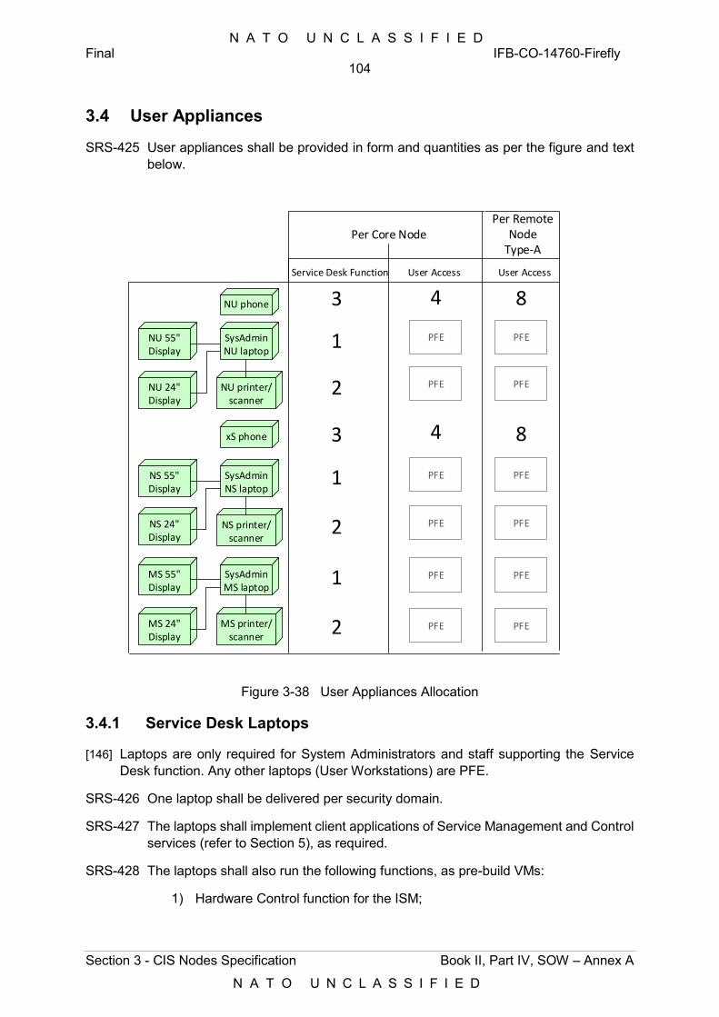
N A T O U N C L A S S I F I E D Final IFB-CO-14760-Firefly
104
Section 3 - CIS Nodes Specification Book II, Part IV, SOW – Annex A
N A T O U N C L A S S I F I E D
3.4 User Appliances
SRS-425 User appliances shall be provided in form and quantities as per the figure and text below.
SysAdminNU laptop
NU phone
xS phone
NU printer/scanner
NS printer/scanner
Service Desk Function User Access
3 4
1
2
3 4
1SysAdminNS laptop
2
MS printer/scanner
1SysAdminMS laptop
2
Per Core NodePer Remote
NodeType-A
8
User Access
8
PFE
PFE PFE
PFE
PFE
PFE
PFE
PFE
PFE
PFE
PFE
PFE
NU 55"Display
NS 55" Display
MS 55"Display
NU 24"Display
NS 24"Display
MS 24"Display
Figure 3-38 User Appliances Allocation
3.4.1 Service Desk Laptops
[146] Laptops are only required for System Administrators and staff supporting the Service Desk function. Any other laptops (User Workstations) are PFE.
SRS-426 One laptop shall be delivered per security domain.
SRS-427 The laptops shall implement client applications of Service Management and Control services (refer to Section 5), as required.
SRS-428 The laptops shall also run the following functions, as pre-build VMs:
1) Hardware Control function for the ISM;
N A T O U N C L A S S I F I E D Final IFB-CO-14760-Firefly
105
Section 3 - CIS Nodes Specification Book II, Part IV, SOW – Annex A
N A T O U N C L A S S I F I E D
2) Deployable instance of the Staging and Deployment Environment (SDE), encompassing the Orchestration Framework, Image Store, Service Design Studio and Version Control Tooling.
[147] Service Desk Laptops shall meet or exceed the following specification:
Table 3-20 Service Desk Laptop reference specification
Attribute Value
Certification: SDIP-27 Level B (for xS domains)
Processor: Intel Core i7
Display 14” LCD, 1920x1080
Memory: 8GB DDR4
Optical: DVD optical drive
Pointing device: Touchpad
Internal Storage: ViaSat Eclypt Core 600 SATA SSD 7mm - 128GB (xS laptops)
500GB Solid State Disk (NU laptops)
Network Adapter: 100BASE-FX 1300nm multimode (SC) Network Adapted (xS laptops)
Integrated 10/100/1000 Gigabit Ethernet Network Adapter (NU laptops)
I/O Ports: 2x USB 3.0 port, 1x VGA port, 1x RJ45 Ethernet
Power Rating: < 90 W
SRS-429 Each laptop shall be delivered with a docking station and an external 24” LCD.
SRS-430 Each laptop shall be delivered with an external 55” LCD, installed in ATA transportation cases, and featuring a lift mechanism.
SRS-431 Laptops and external displays supporting the xS domain shall meet SDIP-27 Level B requirements.
3.4.2 Printer/Scanners
SRS-432 Printers/scanners shall be provided as:
1) One multi-purpose colour A4 50ppm Black and Colour combined printer and scanner, with a monthly duty cycle of up to at least 80.000 pages, and a 100BASE-SX network connection;
2) One A3 Black and Colour printer.
SRS-433 Printer/scanners for the xS domain shall meet SDIP-27 Level B requirements.
SRS-434 Printing and scanning activities shall be badge-controlled. To that end, print servers running in the ISM shall be able to operate with badge-control appliances connected (or integrated in) the printer/scanners.
N A T O U N C L A S S I F I E D Final IFB-CO-14760-Firefly
106
Section 3 - CIS Nodes Specification Book II, Part IV, SOW – Annex A
N A T O U N C L A S S I F I E D
3.4.3 Phones
SRS-435 IP phones for the xS domain shall meet the SDIP27 Level B requirements and meet or exceed the features of a Cisco 8841 IP phone. The phone shall connect to the UAM switches over a suitable fibre interface.
SRS-436 IP phones for the NU domain shall meet or exceed the features of a Cisco 8841 IP phone. The phone shall connect to the UAM switches over 10/100/1000BASE-T RJ45 interface.
SRS-437 Phones shall be delivered with the corresponding user licenses for operation with the MMA subsystem of the CNM.
N A T O U N C L A S S I F I E D Final IFB-CO-14760-Firefly
107
Section 4 - Staging and Deployment Environment
Book II, Part IV, SOW – Annex A
N A T O U N C L A S S I F I E D
4 Staging and Deployment Environment [148] The Staging and Deployment Environment, or SDE, refers to:
1) Static and deployable instances of the software tools implementing the orchestration functions for the automated provisioning of the ISM, in the NU domain of the MAF, and in the NU domain of a Core Node, respectively;
2) Two ISMs (ISM-NU) for the Mission Preparation Centre in Mons, supporting Release Development and Release Testing, and referred to as the ISM-DEV and ISM-TST.
[149] Orchestration is defined as the automated arrangement, coordination and management of computer systems, middleware and services, through workflows that realize and ensure the intended end state of deployed services.
[150] Orchestration covers a broad range, including tooling and automation, people and process. When discussed herein, orchestration refers to the tools, including any the integration thereof, to enable both the design and the deployment of information services on to the ISM, in an automated manner, while supporting the management of the life-cycle of those services in full.
SRS-438 Orchestration shall span the whole service lifecycle, from design and deployment to activation and teardown of infrastructure and platform services, i.e.:
1) The staging of services, as part of the Service Design and Service Engineering activities run from the MAF, and shall consist of:
a) Template development, i.e. creating technical service templates in support of a generic deployment scenario. Templates describe the default mapping between functions and hardware, standard images, typical services, etc.;
b) Blueprint development, i.e. taking a template and developing it further into a solution (a blueprint) for a mission-specific deployment, with specific services installed, with specific configurations and pre-loaded user and system data. Blueprints enable the intent-based automation of configuration tasks;
c) Validation and verification of repositories, consisting of:
(i) The software to be loaded onto the ISM (e.g. ISO images, generic software, etc); and,
(ii) The generic service templates and the mission-specific blueprints used for orchestration.
2) The staging of the ISM, as part of Service Activation activities run from garrison or deployed locations, and consisting of the orchestration of the ISM into a mission-ready state.
N A T O U N C L A S S I F I E D Final IFB-CO-14760-Firefly
108
Section 4 - Staging and Deployment Environment
Book II, Part IV, SOW – Annex A
N A T O U N C L A S S I F I E D
[151] The ISM lifecycle16 consists of the following four states:
1) Factory State, as the ISM (or any component within) arrives from the vendor, with an unknown configuration and status, awaiting verification (e.g. BIOS, firmware, etc.) and enrolment in the inventory;
2) Spared State, with a known, controlled, self-validated condition, and featuring a management domain and associated services;
3) Node Specific State, featuring a workload domain and associated services, on top of the management domain, and ready to accept mission-specific configuration;
4) Mission Specific State, featuring one or multiple tenant or user domains, with mission-specific applications deployed and ready for user consumption. Attaining this state encompasses the loading of classified data and configurations (e.g. IP addresses, hostnames), hosted and maintained in the (PFE) Configuration Management Database (CMDB).
[152] Mission Specific States are subject of baselining, version control and build/release management.
4.1 Functional Requirements
SRS-439 The SDE shall implement tooling and mechanisms to orchestrate the ISM, encompassing:
1) The design of generic service templates (Service Design);
2) The development of mission-specific blueprints (Service Engineering);
3) The automated deployment, operation and teardown of blueprinted services (Service Activation).
SRS-440 The orchestration of the ISM shall include:
1) The automated installation and configuration of hypervisors, software defined networks, software defined storage, VMs and operating systems;
2) The automated installation of platform and application software, and any relevant configurations and user-specific data.
SRS-441 The SDE shall orchestrate:
1) The transition from Factory state to Spare State, following corrective actions involving the replacement of hardware or the installation of new firmware or system software17.;
2) The transition between Spared State, Node State and Mission Specific states, as new missions emerge (switch forward to Mission Specific State) and terminate (switch back to Node State or Spare State).
16 Refer to § 7.1.4 of the [DCIS CA] for details. 17 This transition may include manual installation activities where physical intervention is required. Examples of such are the physical installation or rearrangement of components and of cabling and the physical inspection of hardware components that make up the ISM.
N A T O U N C L A S S I F I E D Final IFB-CO-14760-Firefly
109
Section 4 - Staging and Deployment Environment
Book II, Part IV, SOW – Annex A
N A T O U N C L A S S I F I E D
[153] Transitioning from Spared State, to Node Specific State to Mission Specific State may be combined in one orchestration step when staging hardware from the Spared State directly for actual deployment.
SRS-442 The SDE shall be able to configure the ISM up to its maximum capacity, i.e. using the up to the maximum number of VMs, network and storage-resources.
SRS-443 The SDE shall be able to orchestrate the Release Development and Release Testing Environments in Mons (ISM-DEV, ISM-TST), as well as any production ISM, in garrison or deployed.
SRS-444 The SDE shall be implemented in accordance to the DCIS CA.
[154] The SDE primarily supports the user with the deployment of the ISM. Staging and deployment of the ISM is implemented central repositories accessed through the WAN, local repositories (in the ISM) alone, or through a combination thereof, depending on the mission. For deployed operations it is critical to be fully independent of wide area communication bearers. That implies being able to orchestrate the ISM when wide area communications are not available. To that end, the SDE requires centralized as well as deployable instances, the latter loaded in the SysAdmin laptops.
SRS-445 The SDE shall have centralized instances of tooling and repositories in the MAF and as well as local instances in any ISM, including the Release Development and Release Testing Environments in Mons (ISM-DEV, ISM-TST).
SRS-446 It shall be possible to orchestrate the ISM from the tooling and repositories in the MAF, with the ISMs installed at garrison locations and with the ISMs in theatre.
SRS-447 It shall be possible to orchestrate the ISM locally when deployed, using local tooling and repositories.
SRS-448 Due to NATO information assurance policy, once the ISM is loaded with operational data, or once the ISM is connected to the operational network, the ISM assumes a security classification. To that end, the SDE shall be able to interact with production ISMs using diodes18. These diodes feature proxies intended to make the diode transparent to the sending and receiving end points. Diodes are PFE, subject to integration and operation by the Purchaser, where available.
SRS-449 The static SDE shall be able to:
1) Deploy the day 0/1 implementation of the IaaS on to the ISM;
2) Deploy updated or new services, system-data, user-data or configurations (day 2). and
SRS-450 The deployable SDE support all the above, including full recovery from failed hardware on-site, without reliance on the static SDE.
SRS-451 The deployable SDE shall be implemented on the System Administrator laptop of each domain, as a pre-build VM with tooling and repositories as required.
18 A data diode is a function that realized a controlled safe one-way transfer of data between segmented networks
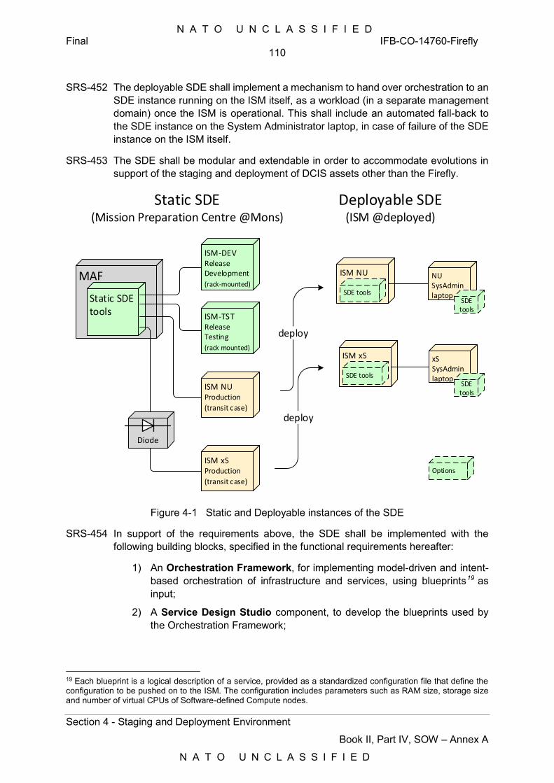
N A T O U N C L A S S I F I E D Final IFB-CO-14760-Firefly
110
Section 4 - Staging and Deployment Environment
Book II, Part IV, SOW – Annex A
N A T O U N C L A S S I F I E D
SRS-452 The deployable SDE shall implement a mechanism to hand over orchestration to an SDE instance running on the ISM itself, as a workload (in a separate management domain) once the ISM is operational. This shall include an automated fall-back to the SDE instance on the System Administrator laptop, in case of failure of the SDE instance on the ISM itself.
SRS-453 The SDE shall be modular and extendable in order to accommodate evolutions in support of the staging and deployment of DCIS assets other than the Firefly.
MAF
Static SDEtools
ISM-DEVReleaseDevelopment
(rack-mounted)
ISM-TSTReleaseTesting
(rack mounted)
ISM NUProduction
(transit case)
ISM xSProduction
(transit case)
Diode
Static SDE(Mission Preparation Centre @Mons)
Deployable SDE(ISM @deployed)
ISM NU
SDE tools
NU SysAdminlaptop
ISM xS
SDE tools
xS SysAdminlaptop
SDE tools
SDE tools
deploy
deploy
Options
Figure 4-1 Static and Deployable instances of the SDE
SRS-454 In support of the requirements above, the SDE shall be implemented with the following building blocks, specified in the functional requirements hereafter:
1) An Orchestration Framework, for implementing model-driven and intent-based orchestration of infrastructure and services, using blueprints19 as input;
2) A Service Design Studio component, to develop the blueprints used by the Orchestration Framework;
19 Each blueprint is a logical description of a service, provided as a standardized configuration file that define the configuration to be pushed on to the ISM. The configuration includes parameters such as RAM size, storage size and number of virtual CPUs of Software-defined Compute nodes.
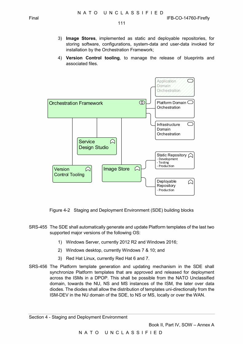
N A T O U N C L A S S I F I E D Final IFB-CO-14760-Firefly
111
Section 4 - Staging and Deployment Environment
Book II, Part IV, SOW – Annex A
N A T O U N C L A S S I F I E D
3) Image Stores, implemented as static and deployable repositories, for storing software, configurations, system-data and user-data invoked for installation by the Orchestration Framework;
4) Version Control tooling, to manage the release of blueprints and associated files.
Orchestration Framework
Infrastructure Domain Orchestration
Platform Domain Orchestration
Service Design Studio
Application Domain Orchestration
Version Control Tooling
Image Store
Deployable Repository - Production
Static Repository - Development- Testing- Production
Figure 4-2 Staging and Deployment Environment (SDE) building blocks
SRS-455 The SDE shall automatically generate and update Platform templates of the last two supported major versions of the following OS:
1) Windows Server, currently 2012 R2 and Windows 2016; 2) Windows desktop, currently Windows 7 & 10; and 3) Red Hat Linux, currently Red Hat 6 and 7.
SRS-456 The Platform template generation and updating mechanism in the SDE shall synchronize Platform templates that are approved and released for deployment across the ISMs in a DPOP. This shall be possible from the NATO Unclassified domain, towards the NU, NS and MS instances of the ISM, the later over data diodes. The diodes shall allow the distribution of templates uni-directionally from the ISM-DEV in the NU domain of the SDE, to NS or MS, locally or over the WAN.
N A T O U N C L A S S I F I E D Final IFB-CO-14760-Firefly
112
Section 4 - Staging and Deployment Environment
Book II, Part IV, SOW – Annex A
N A T O U N C L A S S I F I E D
4.1.1 Orchestration Framework
SRS-457 The SDE shall implement an open Orchestration Framework, where “open” shall be understood as enabling the basic functionality to be modified or extended through mechanisms such as API and plugins without any proprietary constraints.
SRS-458 The Orchestration Framework in the SDE shall implement the following functionality:
1) Abstraction of services to be instantiated through blueprints in order to control the orchestration process;
2) The modelling of infrastructure and platform services;
3) The generation of management domains and workload domains, by abstracting and apportioning physical resources, such as processors, storage and network segments;
4) The use of plugins and interfaces for the execution of commands and operations;
5) The installation and configuration sequencing, including the handling of dependencies; and,
6) The handling of life cycle events associated to the transition between the four states of the ISM life cycle.
SRS-459 To that end, the Orchestration Framework shall implement the technical command and control structure, automation tooling and workflow engines necessary to automate the provisioning and deployment of infrastructure services, encompassing:
1) Loading pre-developed OASIS TOSCA compliant blueprints, developed on the Service Design Studio or 3rd party OASIS TOSCA based blueprints;
2) Automatically building of service models for automated IaaS deployment on the ISM, based on the blueprint(s);
3) Using the blueprints and the Image Store to automatically deploy the software components and configurations in the proper order, while managing progress and status, and considering dependencies and interdependencies;
4) Generating workflows of discrete operations to be executed on the infrastructure;
5) Executing workflows to install, change and delete services, i.e. service provisioning.
SRS-460 Workflows shall allocate capacity to workload domains, out of the available physical infrastructure, in the amounts required to match the specified resources (CPU, memory and storage), performance, and availability.
SRS-461 The Orchestration Framework shall support Role Based Access Control, for all user (system administrator) controls, through integration with the Purchaser’s Microsoft Active Directory. Multiple roles shall be supported through integration with Active Directory, including system administrator, tester, developer, and user.
N A T O U N C L A S S I F I E D Final IFB-CO-14760-Firefly
113
Section 4 - Staging and Deployment Environment
Book II, Part IV, SOW – Annex A
N A T O U N C L A S S I F I E D
SRS-462 The Orchestration Framework shall manage and store API keys and other technical interface related keys that the SDE uses to in the machine-to-machine interface when orchestrating the infrastructure.
SRS-463 The Orchestration Framework shall automate the following:
1) The booting of a virgin ISM that has no configuration nor any software installed;
2) The establishment of an ISM cluster from multiple ISM hardware instances;
3) The establishment of virtual networks within the ISM or ISM cluster, including connections with external ISM interfaces and VMs hosted on the ISM or ISM cluster;
4) The establishment of Software-defined Storage resources within the ISM or ISM cluster;
5) The establishment of VMs within the ISM or ISM cluster and the loading the initial OS or software images;
6) The deployment of blueprinted services onto the infrastructure resulting from the above, ensuring that the intended service state is reached;
7) The updating of a running service to a new blueprint, while ensuring the intended service state is reached;
8) The deactivation of a service and the removal any associated compute, network and storage resources from the infrastructure.
SRS-464 The Orchestration Framework shall monitor and control the automation process and report on the successful achievement of the end state (or failure otherwise). This shall entail:
1) Monitoring the workflow execution, by providing a visualization of the workflow status, events and progress for the operator;
2) Rolling back to the previously working configuration in case the end state defined through the blueprint is not achieved;
3) Being able to wipe up any existing configuration and starting from scratch.
SRS-465 In support of the above, the Orchestration Framework shall provide detailed event logging of, as a minimum, all commands issued to the ISM, including detailed response messages, all events and status changes. SDE logs shall be:
1) Initially kept on the local SDE storage;
2) Accessible in human readable format, both locally and remotely, implementing view, search and filter functions; and
3) Downloadable through HTTPS in both raw and filtered human readable format.
SRS-466 The Orchestration Framework shall display the implementation progress, by showing progress, errors and warnings in:
1) A simple view, showing only progress and status; and,
N A T O U N C L A S S I F I E D Final IFB-CO-14760-Firefly
114
Section 4 - Staging and Deployment Environment
Book II, Part IV, SOW – Annex A
N A T O U N C L A S S I F I E D
2) An advanced view, showing the full detail, for expert analysis.
SRS-467 The implementation progress display shall be accessible on a local and remote console through a standard web browser, as a minimum the latest NATO supported versions of WEB Browsers at the time of FDR (i.e, Internet Explorer & Edge) without the need of special plugins. Support of HTML5 is highly recommended.
SRS-468 The Orchestration Framework shall implement:
1) Mechanisms to continuously monitor the resource usage of the workloads, both during staging and while in operation;
2) An interface to expose the IaaS status and KPI information to the SMC environment, and trigger events when predefined thresholds are exceeded;
3) Automatic IaaS scale-in and scale-out mechanisms, based on configuration policies, automatically triggered based on predefined thresholds, constraints and load;
4) Automatic mechanisms to deactivate or to limit the use of the resources to essential services only, based on policy roles, in order to increase or decrease the load to the available resources, or in response to system failure.
SRS-469 When automatically resetting the ISM to the Spared State, and in order to create the virtualization infrastructure regardless of the software configuration state, the Orchestration Framework shall implement the following:
1) Verification and installation of the current BIOS and Firmware versions;
2) Configuration of pre-defined IP addressing for the ISM Controller and for orchestration access;
3) Deletion of stored data20; and
4) Basic power-up tests such that, once completed, the ISM has a well-known, validated initial configuration ready for further orchestration.
SRS-470 The Orchestration Framework shall schedule rolling infrastructure updates, at two levels:
1) Installation and configuration of updated virtualization software or infrastructure software, such as operating system patches, software patches, new or updated applications, and new of update user data;
2) Installation and configuration of hardware BIOS and firmware.
SRS-471 The Orchestration Framework shall implement functionality and interfaces to allow further development and implementation of Southbound interfaces towards additional underlying tooling, including Continuous Configuration Automation tools21.
20 This does not involve NATO-approved secure wiping of storage. 21 Example of these tools are: Puppet, Chef, Ansible, SaltStack and Microsoft Windows' native PowerShell Desired State Configuration (DSC).
N A T O U N C L A S S I F I E D Final IFB-CO-14760-Firefly
115
Section 4 - Staging and Deployment Environment
Book II, Part IV, SOW – Annex A
N A T O U N C L A S S I F I E D
SRS-472 The Orchestration Framework shall implement a Northbound interface towards a future Operations Support System – Business Support Systems (OSS/BSS), using a well-documented and open RESTful web-services API.
4.1.2 Service Design Studio
[155] The Service Design Studio (SDS) is used to develop templates and blueprints for the configuration of the ISM, throughout the whole cycle from Service Design and Service Engineering to Service Activation22.
SRS-473 The Service Design Studio (SDS) shall implement software to develop generic service templates as well as mission-specific blueprints used for orchestration.
SRS-474 The SDS shall be implemented in accordance to the DCIS CA Annex K.
SRS-475 The SDS shall implement blueprint development through virtual canvas on which one can drag, configure and connect functional components.
SRS-476 The SDS shall implement configurable standard definitions of systems, VM types and sizes, networks and storage resources based on a number of pre-configured flavours.
SRS-477 The SDS shall implement different roles to supporting Service Design, Service Engineering and Service Activation.
SRS-478 The SDS shall implement a mechanism to promote blueprints from design, to testing, to production.
SRS-479 The SDS shall be able to take pre-developed blueprints as input for further development, or for inclusion of mission specific details and configurations.
SRS-480 The SDS shall implement mechanism to parameterize blueprints (for example parameters such as VM sizing/performance, IP addresses, user accounts, naming).
SRS-481 The SDS shall implement mechanisms to detail the parameters in blueprints at a later stage through interactive dialogues and through human readable input files, generating a mission-specific blueprints for testing, validation and actual deployment.
SRS-482 The SDS shall be agnostic to the deployment target, to as a minimum include:
1) The ISM;
2) IaaS implemented in the MAF, supporting as a minimum both VMware and Hyper-V; and
3) Commercial (public), national or NATO private Cloud Services.
SRS-483 The SDS shall be agnostic to the physical hardware layer, to the software-defined virtualization layer and to the workloads layer.
22 For details refer to Service Template development, Blueprint development, Deployment pattern, in § 7.1.6 of the [DCIS CA].
N A T O U N C L A S S I F I E D Final IFB-CO-14760-Firefly
116
Section 4 - Staging and Deployment Environment
Book II, Part IV, SOW – Annex A
N A T O U N C L A S S I F I E D
4.1.3 Image Store
[156] The Image Store holds files, such as ISO images, virtual disks, ZIP archives, software package files, configuration files, etc., that are invoked during the orchestration process of the ISM.
[157] In future, the Image Store will also be used to store the master images for physical workstation imaging and virtual desktop infrastructure (VDI).
SRS-484 The Image Store shall act as an automation file repository for use during orchestration of the ISM, and make these files available to the engines of the Orchestration Framework, as required.
SRS-485 The Image Store shall be implemented in accordance to the DCIS CA Annex I.
SRS-486 The Image Store shall allow an Administrator to manage the repository of images, executing operations such as adding, archiving, moving, versioning and deleting images.
SRS-487 To that end, the Image Store shall implement:
1) A local and a networked interface;
2) A secure and access-controlled protocol to access stored files, to upload files and for management purposes;
3) Functionality and interfaces to receive and store blueprints, configuration files, software, operating system and other image files;
4) The verification of the integrity of images.
SRS-488 The Image Store shall further implement:
1) Primary and secondary master instances, automatically replicated between the two instances of the MAF (Mons and Lago Patria);
2) Deployable instances, as local mirrors of the above, in deployable ISMs, for ease of access or faster processing as appropriate.
SRS-489 All Image Store instances shall implement automatic networked replication mechanisms to selectively distribute and update files across the network. These mechanisms shall rely on open protocols, optimizing bandwidth usage and maximizing throughput over the WAN.
4.1.4 Version Control Tooling
SRS-490 The SDE shall implement tooling realizing the technical aspects of a release pipeline for blueprints and associated files; the release pipeline shall cover the Service Design Studio and the Image Store of the SDE.
SRS-491 As a minimum, this release pipeline shall cover: build, test and release management.
N A T O U N C L A S S I F I E D Final IFB-CO-14760-Firefly
117
Section 4 - Staging and Deployment Environment
Book II, Part IV, SOW – Annex A
N A T O U N C L A S S I F I E D
SRS-492 The SDE release pipeline shall implement versioning, branching and branch merging of:
1) Generic service templates;
2) Mission specific blueprints; and
3) Raw files such as ISO images, virtual disks, software archives, configuration and data files.
SRS-493 The SDE release pipeline shall implement mechanisms and interfaces to import blueprints and associated files from an external source and to export blueprints and associated files to an external destination. This shall allow:
1) Integrating a 3rd party blueprinted service distribution package, i.e. a package from a Nation or an industry partner;
2) Providing a blueprinted NATO service distribution package for implementation by a Nation.
4.2 Technical Requirements
[158] The SDE consists of the aggregation an Orchestration Framework (service orchestration engines), the Image Store, the Service Design Studio and Version Control tooling. As such, the SDE may be realized through multiple software components and multiple technical (micro) services, integrated through well-documented and open interfaces.
SRS-494 The SDE shall support the orchestration of the Infrastructure domain and the Platform domain, and provide plugins or API to further enable the orchestration of the Application domain.
SRS-495 The SDE shall support orchestration of configuration for Palo Alto Firewalls, through Palo Alto Panorama Network Security, and the orchestration of configuration for Cisco routers and switches; as implemented in the CNM, RNM and UAM.
SRS-496 The SDE shall implement OASIS TOSCA as the common blueprint format, where blueprints are:
1) Stored on disk;
2) Used as input for (further) Service Design;
3) Used as input for (further) Service Engineering; and where
4) Used as input for Service Activation of the ISM.
[159] The SDE may use native formats (such as JSON, YAML, or XML) within and between integrated components, provided that:
1) These native formats are functionally compatible with the OASIS TOSCA blueprint definition, human readable and suitable for automatic parsing by software;
2) Automatic and transparent import and export mechanisms are implemented to bi-directionally convert between these native formats and OASIS TOSCA, without loss of fidelity.
N A T O U N C L A S S I F I E D Final IFB-CO-14760-Firefly
118
Section 4 - Staging and Deployment Environment
Book II, Part IV, SOW – Annex A
N A T O U N C L A S S I F I E D
SRS-497 Primary and alternate/secondary instances of the central/static components of the SDE shall be implemented in the MAF of Mons and Lago Patria, respectively; connected over the WAN in an Active/Passive (stand-by) mode23.
SRS-498 To ensure maximum performance and to be independent of the limited wide area networking capacity, he SDE shall make use of local storage resources to implement a local Image Store instance for the software, configurations and data to be installed on the ISM.
SRS-499 In addition to local storage, the SDE shall support centralized (private) or public cloud storage, where feasible and advantageous, to augment or replace the local Image Store.
[160] Usage of public cloud storage will be dependent on the scenario and on the associated information assurance policy constraints.
SRS-500 The Service Design Studio shall be hosted at the MAF, collocated with the master instance of the Image Store, in support of the Service Design and Service Engineering processes in Mons.
SRS-501 The static instance of the SDE shall implement sufficient capacity and performance to stage the ISMs of all Firefly operational nodes, as well as the ISM-TST, ISM-DEV, and the ISMs of the Firefly Reference System, either collocated or remotely controlled through WAN connection having a speed of 1 Gbps and using a local Image Store.
SRS-502 The SDE shall implement interfaces with the control and monitoring functions of:
1) The ISM hardware components, through the RESTful API implemented by the ISM Controller;
2) The ISM Virtualization Hypervisor, Software Defined Networking and Software Defined Storage components, through the corresponding RESTful APIs.
SRS-503 The static instance of the SDE shall implement:
1) LAN switching supporting, as a minimum, 20 ISM connected in parallel in garrison, each connected with, as a minimum, a link speed of 10 Gbps;
2) A minimum of 48 TB of physical storage local to the SDE (Image Store), and supporting extension of the physical storage to, as a minimum, 96 TB, with support for RAID levels 1, 5, 6 and 10;
3) Support for automatic bandwidth optimized and selective replication from a S3-compatible object storage, either local, in a private or public cloud.
SRS-504 The deployable instance of the SDE shall include the virtualization hypervisor software for installation on any MS Windows based laptop. The virtualisation software shall support as a minimum MS Windows 7 and MS Windows 10.
23 Active/Passive mode shall be understood as services active from one location at the time, using a technical failover procedure transparent to the user to hand over the service between MAF, with repositories continuously replicated from the active to the passive instance.
N A T O U N C L A S S I F I E D Final IFB-CO-14760-Firefly
119
Section 4 - Staging and Deployment Environment
Book II, Part IV, SOW – Annex A
N A T O U N C L A S S I F I E D
SRS-505 The Image Store instances (master/static and deployable) shall be implemented with a dedicated instance for each of the required 3 security classifications; i.e. NU, NS and MS.
SRS-506 The SDE shall further implement:
1) Automatic, but administrator initiated, bandwidth optimized and selective replication from the central master Image Store instance in the MAF;
2) Support for automatic, but administrator initiated, bandwidth optimized and selective replication from a S3-compatible object storage, either local, in a private or public cloud.
SRS-507 The static instance of the SDE shall be able to stage an ISM, starting from “Spared State” to “Mission Specific State”, in less than 8 hours, while staging 20 ISM in parallel.
SRS-508 The deployable instance of the SDE shall be able to stage an ISM from the SysAdmin laptops of the corresponding classification, starting from “Spared State” to “Mission Specific State”, in less than 8 hours, while staging 2 ISM in parallel.
SRS-509 A mechanism shall be provided to import and export blueprints and images to and from the Image Store instances at all security classifications.
SRS-510 Access to the Service Design Studio shall be implemented as a web-service, accessed through a standard web browser, as a minimum Internet Explorer & Edge, Firefox, Chrome and Safari, without the need of special browser add-ons. Any special functionality shall be provided through HTML5.
SRS-511 The Service Design Studio shall be implemented as one or more VMs on PFE VMware virtualized infrastructure. In case of containerized solutions24, the VM or group of VMs shall include the necessary container platform.
SRS-512 The Service Design Studio shall be implemented including all necessary software and licenses.
SRS-513 The SDE shall be implemented with well-documented and open plug-in mechanisms and/or APIs, including the necessary licenses to use these, which shall be proven through fully documented implementation examples of the following:
1) One interface with Ansible, demonstrating a continuous delivery pipeline;
2) One interface with Jenkins, demonstrating a continuous delivery pipeline;
3) One interface with with Hashicorp Terraform;
4) One interface using plug-in/API with PowerShell scripts;
5) One interface using plug-in/API interfacing with Python scripts; and
6) One fully interface using plug-in/API interfacing with a RESTful web-services API.
24 Such as Docker or Kubernetes.
N A T O U N C L A S S I F I E D Final IFB-CO-14760-Firefly
120
Section 5 - Service Management and Control Book II, Part IV, SOW – Annex A
N A T O U N C L A S S I F I E D
5 Service Management and Control SRS-514 All subsystems of Core, Remote and Small team nodes of the Firefly shall be
integrated into the extant Service Management and Control (SMC) environment of the Dragonfly.
SRS-515 SMC components implemented as part of the Firefly, shall support interfacing with the Purchaser’s BMC ITSM.
SRS-516 SMC components implemented as part of the Firefly, shall support Role Based Access Control via integration with Active Directory.
[161] The extant SMC environment is hosted in the DOG/MAF of Mons and Lago Patria. It support the following six functions, with tools as listed below:
1) Network Monitoring and Control:
a) Cisco Prime;
b) CA Spectrum;
c) CA Performance Centre;
d) CA Network Flow Analysis.
2) Firewall Monitoring and Control:
a) Palo Alto Panorama.
3) Security Information and Event Management (SIEM):
a) Splunk;
b) Firemon (one license per firewall, i.e. 4 licenses per DPOP);
c) On-line Vulnerability Assessment (OVA);
d) On-line Computer Forensics (OCF);
e) Host-based Intrusion Detection Service (Threat Prevention).
4) IT Service Management (ITSM);
5) Servers Configuration:
a) Systems Center Configuration Manager (SCCM);
b) Systems Center Operations Manager (SCOM).
6) Account Management and Reporting:
a) AD Manager Plus.
SRS-517 The integration of the Firefly into the extant SMC environment shall encompass the provision of the following:
1) All necessary licenses to incorporate all procured subsystems and their components thereof into the above listed tools, hosted in the DOG/MAF;
2) Deployable management Account Administration tooling, running locally on the ISM, synchronized with the extant centralized account management capability.
N A T O U N C L A S S I F I E D Final IFB-CO-14760-Firefly
121
Section 5 - Service Management and Control Book II, Part IV, SOW – Annex A
N A T O U N C L A S S I F I E D
3) The implementation of Virtual Machines as required, to run local instances of the tools above, where required (e.g. OVA and OCF scanners).
SRS-518 The solution delivered for the monitoring of the CAS subsystem of the ISMs delivered under this project shall be able to also monitor the HP server generation that supports the ISMs of the current generation of DCIS (µISM, see Annex C for details).
N A T O U N C L A S S I F I E D Final IFB-CO-14760-Firefly
122
Section 6 - Non-CIS Elements Specification Book II, Part IV, SOW – Annex A
N A T O U N C L A S S I F I E D
6 Non-CIS Elements Specification [162] This section contains requirements pertaining to the implementation of the non-CIS
elements supporting the Core Nodes and Remote Nodes specified in Section 3. Small Team Nodes are largely self-contained, with any non-CIS elements included in their CIS Modules and Transmission Systems specification above, with the exception of the Vehicle Fixtures.
[163] The scope of this Sections is as follows:
1) Housing Elements (i.e. tents, and their interfaces to external elements);
2) Environmental Control Elements (for tents and transit cases);
3) Transport Elements;
4) Power Supply Elements;
5) Ancillary Elements.
6.1 Housing Elements
SRS-519 Each Core node shall be installed in two tents, one for the CIS equipment and one for the Service desk team.
SRS-520 The CIS tent shall be a BC Tent.
[164] The Service desk tent has no BC requirement.
SRS-521 Each of both tents shall be the same tent model.
SRS-522 Additionally the BC tent shall be furnished with a BC inner lining, so that in the event of incidents affecting the integrity or the availability of the BC Tent, it is possible to reuse the Service Desk tent with the BC elements for the CNM (that requires BC protection).
SRS-523 Tents shall be packed into stackable metal frame crates to enable air/sea/land transportation.
SRS-524 Each tent shall be provided with a set of installation tools.
SRS-525 Each tent shall be equipped with three repair and maintenance kits, one for echelon/level 1 repairs, one for echelon/level 2 repairs and one for echelon/level 3 repairs.
SRS-526 Tents shall be deployable in all climatic areas and on soft or hard surfaces (i.e. concrete surface), therefore adequate sunshields and weights (i.e. water ballast) shall be delivered with the tents
SRS-527 Tents shall implement rigid exoskeletons in order to allow operation under heavy snow without collapsing inward.
SRS-528 Lights inside the tents exit shall have an automatic switch from white to red when outer door is opened
N A T O U N C L A S S I F I E D Final IFB-CO-14760-Firefly
123
Section 6 - Non-CIS Elements Specification Book II, Part IV, SOW – Annex A
N A T O U N C L A S S I F I E D
SRS-529 Tents shall implement sufficient air flow to avoid the accumulation of heat in any space.
SRS-530 Both tents shall implement hard antistatic and anti-slip floor. Alternatively, they may be provided with an antistatic and anti-slip cover. The antistatic flooring shall be firmly bondable to the ground power earth.
6.1.1 BC Tent
SRS-531 Each Core Node shall be provided with a BC Tent solution to house and protect the CIS Transit Cases during operation.
SRS-532 For dimensioning of the BC Tent the required separations for meeting the SDIP requirements between all the NU and xS CIS assets as well as the rest of non CIS assets shall be considered.
SRS-533 For dimensioning of the BC Tent a desk for up to two engineering computers shall be considered. The furniture for these two users will be PFE. Table power distribution shall be provided.
SRS-534 For dimensioning of the BC Tent the condensers of the Tent Cooling shall be considered. NU and MS transit cases cooling shall be prioritized.
SRS-535 A BC Tent floorplan shall be provided, defining location and separations of assets and cable routing plan.
SRS-536 The BC Tent solution shall include tent plus flooring, air conditioning, BC components (airlock) and tent accessories (e.g. power cables and lighting).
SRS-537 The BC Airlock provided as part of the BC Tent Solution shall include a Blackout Lighting Unit with automatic door opening detectors.
SRS-538 The BC Tent shall be opaque.
SRS-539 The BC tent shall be provided with enough in-out socks to allow proper installation of all the ETBs, cabling and connecting equipment needed for operation.
SRS-540 The BC tent solution shall include a CBRN compliant ACU solution that is appropriate for the size of tent supplied capable of operating in OPE-1a conditions.
SRS-541 Each BC Tent shall provide a mains powered lighting system, consisting of fluorescent light Units (or LED) and Emergency Light Unit.
6.1.2 Service Desk Tent
SRS-542 Each Core Node shall be provided with a non-BC Tent solution to host the System Administrators and maintainers, as well as the Service Desk function.
SRS-543 The non-BC Tent shall be suitable to host six staff members.
SRS-544 The non-BC Tent shall include floor and table power distribution for the O&M equipment and lighting consisting of fluorescent light Units (or LED) and Emergency Light Unit. Furniture for, and power supply to, the tent will be PFE.
N A T O U N C L A S S I F I E D Final IFB-CO-14760-Firefly
124
Section 6 - Non-CIS Elements Specification Book II, Part IV, SOW – Annex A
N A T O U N C L A S S I F I E D
6.1.3 External Termination Boards
[165] The External Termination Board (ETB) enables connectivity between external CIS elements and any CIS modules inside the tent.
SRS-545 The ETB shall be the boundary protection between the inside of the BC Tent and the exterior environment.
SRS-546 The ETB shall provide electrical isolation between the external electrical feed and the internal electrical circuit.
SRS-547 The ETB shall provide the internal power distribution functionality, as specified in §6.4.2 .
SRS-548 The ETB shall bundle multiple interfaces into connectors featuring multiple cores, in order to minimize the number of connectors required.
SRS-549 Two ETB shall be provided, one for PCA/NU and one for xS. TEMPEST approved power line filters shall be installed after the isolation transformer in the ETB to achieve clean power and to satisfy the RFI/EMI/EMC requirements conveyed in SDIP 29/2 § F.3.
SRS-550 The ETB shall be installed in the BC tent. The ETB shall protect both data and power lines of the inside of the BC tent from both human and natural conditions of the outside.
SRS-551 The ETB shall not be fitted into the tent wall, but housed inside the tent and use the standard sock method for cables that need to be run externally.
SRS-552 The ETB shall include an isolation transformer between outer and inner side of the power leads, as well as all surge and spike arrestors.
SRS-553 The ETB shall have a stub or equivalent fixation device to connect the internal earth to the power earth bus. The earth path impedance shall be in accordance to the level of protection provided.
SRS-554 The power plugs and power sockets shall be dimensioned and defined in accordance to IEC 60309 standard.
SRS-555 The ETB shall be delivered in its own transport case.
6.2 Environmental Control Elements
[166] Heating, Ventilation and Air Conditioning (HVAC) elements are intended to maintain the controlled elements within adequate temperature margins, independently from the external climatic and environmental conditions.
SRS-556 Sizing of any environmental control element shall be done according to the climatic and environmental conditions outside the tent or the equipment enclosure being conditioned by the element.
N A T O U N C L A S S I F I E D Final IFB-CO-14760-Firefly
125
Section 6 - Non-CIS Elements Specification Book II, Part IV, SOW – Annex A
N A T O U N C L A S S I F I E D
SRS-557 Any transmission components intended to operate outdoors, like the SATCOM OTM terminal or the HCLOS radios, shall not require environmental conditioning through external active cooling or heating elements.
[167] Environmental Control is hereafter specified for tents and transit cases.
6.2.1 Tent Cooling
SRS-558 The HVACs of the BC Tent and the non-BC Tent shall be dimensioned to adequately heat or cool the BC tents air volumes, considering that the environmental conditions will be the same as for the CIS Modules intended for full exposed outdoors operations. Therefore will fall under the operational condition OPE-1a of the [NC3A TN-1078, 2008].
SRS-559 The HVAC shall be dimensioned taking into account the external environmental factors, the internal CIS equipment and the number of people inside the respective tent.
SRS-560 Any HVAC units proposed in support of the environmental requirement above shall:
1) Operate under the conditions of OPE-1a of the Technical Note 1078;
2) Provide sufficient cooling or heating power for the interior of the tent;
3) Assure an adequate airflow in the inside of the tent, avoiding the accumulation of heat in certain areas of the tent.
[168] The non BC Tent is the working space for up to six persons with their working stations and auxiliary equipment.
[169] The BC Tent will host the Core Node Hardware and two persons for troubleshooting.
SRS-561 For each tent two HVAC units shall be provided. HVAC units shall be identical and or interchangeable for BC and non-BC tents.
6.2.2 Case Cooling
SRS-562 Any forced airflow cooled CIS components subject to integration in transit cases shall be cooled with front-to-back airflows. This shall allow stacking equipment without top or bottom clearance, therefore reducing the required rack space in transit cases.
SRS-563 All transit cases, when operated in a temperature controlled environment, shall not require any active cooling elements to be integrated in the case, other than fans or other heat exchange mechanisms.
SRS-564 All transit cases with the exception of those carrying the STK shall be fitted for, but not with, the use of external Environmental Control Units (ECU) attached to the case.
SRS-565 The use of ECU shall be compatible with and shall not alter the TEMPEST compliance specified in § 3.1.5.
N A T O U N C L A S S I F I E D Final IFB-CO-14760-Firefly
126
Section 6 - Non-CIS Elements Specification Book II, Part IV, SOW – Annex A
N A T O U N C L A S S I F I E D
SRS-566 It shall be possible to couple and de-couple the ECUs from the transit cases, based on need.
SRS-567 The installation and operation of ECUs on transit cases shall be compatible with SDIP 27 Level B requirements specified in this SRS.
SRS-568 ECU shall interchangeable between cases of the same size.
[170] CNM, ISM and CGM transit cases will by default operate in the temperature controlled environment of the BC-tent (OPE-3). These transit cases will also deploy in Buildings of Opportunity (OPE-2c), where the environmental control cannot be granted.
[171] RNM transit cases will be operated in any environment (indoors or outdoors) (OPE-2a).
SRS-569 All RNM transit cases shall be delivered with a detachable ECU.
[172] [OPTION] The provision of ECU for CNM, ISM and CGM transit cases, in support of deployments in Buildings of Opportunity or any other locations without environmental conditioning.
6.3 Transport Elements
[173] Requirements are separately provide for:
1) Transit Cases: carrying active CIS components including cryptographic devices;
2) Transport Cases: carrying user appliances and ancillary components that are not integrated in the transit cases above.
SRS-570 Items weighing more than the one-person lift limit, which is defined for this SRS to be 20 kg, shall be prominently labelled with the weight of the object and the lift limitation (i.e., two-person lift, mechanical lift, etc.).
6.3.1 Transit Cases
[174] Transit Case is the term used to denote those cases carrying electronic equipment integrated in 19” rack chassis frames. Transit Case components include the shell or housing (e.g. latches, covers, power and signal external terminal boards).
SRS-571 The transit cases shall be of a welded frame construction and stackable. Additionally, the TC shall be equipped with lifting handles, auto pressure release valves, and humidity indicators.
SRS-572 The transit cases shall be equipped with handles and casters to allow easy handling.
SRS-573 The components in a TC shall be mounted on shock absorbers and vibration dampers, or otherwise hardened, such that the TC with mounted components as a whole meets the transport conditions specified in SRS-590.
SRS-574 Transit cases shall implement 19” racks chassis frames, mounted into the outer casing of the cases in ways such that the electronic equipment is appropriately protected against shock and vibration and the TC and mounted components as a whole meets the transport conditions specified in SRS-590.
N A T O U N C L A S S I F I E D Final IFB-CO-14760-Firefly
127
Section 6 - Non-CIS Elements Specification Book II, Part IV, SOW – Annex A
N A T O U N C L A S S I F I E D
SRS-575 Transit cases shall have all signal and power interfaces presented on a front panel that is fixed to the Transit case, but can be removed for maintenance or for re-patching of connectors to equipment ports (by the Purchaser, without assistance from the Contractor).
SRS-576 Connectorized front panels shall be protected by a removable lid for transport and storage. This is however not applicable to the UAM.
SRS-577 Any EMC/EMI protection in the form of panels shall allow air to flow through.
SRS-578 The 19” rack chassis frame shall be accessible from all sides to allow maintenance on the enclosed equipment.
SRS-579 Each Transit case shall implement a pressure release valve and humidity indicator.
SRS-580 Pressure release valves shall avoid also soaking water into the case. This can occur for example (but not only) due to the negative pressure when a case is rapidly cooled down during rain after being exposed long to the sun.
SRS-581 Each Transit case shall implement heavy duty handles (minimum of four for cases heavier than 40 kg).
SRS-582 Where not in conflict with the packaging requirements stated in § 3.1.1, all Transit Cases shall fulfil MIL-STD-1472G with regards to weight lifting limits and push/pull. In case of conflicts, § 3.1.2 of this SRS prevails.
SRS-583 Each Transit case shall implement a re-settable and re-usable device to detect shocks and tilt, including the direction and angle of impact.
SRS-584 Transit Cases packed for transport shall be capable of being transported via road, rail, sea, and air transport in accordance to the requirements specified in § 3.1.4.
SRS-585 Transit Cases shall be capable of being secured to anchor points to prevent theft and movement in order to avoid damage during transportation.
SRS-586 For Road Transport, Transit Cases shall be transportable by the PFE Vehicle (Renault SHERPA or Mercedes-Benz UNIMOG) on all roads (motorway, unpaved road and country road) without sustaining any damage (for example due to shock or vibrations).
SRS-587 For Rail Transport, Transit Cases shall be capable of withstanding, without damage, the shocks and vibrations normally induced by rail transport.
SRS-588 For Sea Transport, Transit Cases shall be transportable under deck of freighters suitable for container transport and an authorised technical surveillance authority shall certify the compliance with the requirements for sea transport (ISO 1496-1).
SRS-589 For Air Transport, Transit Cases shall be capable of being loaded into and transported by military transport aircraft either loaded into the PFE vehicles or palletised on the aircraft.
SRS-590 The Transit Cases shall be capable of protecting the equipment while withstanding the loads of a crash landing without failure or breaking loose from the case. The crash landing load cases and the direction of loading are the following:
N A T O U N C L A S S I F I E D Final IFB-CO-14760-Firefly
128
Section 6 - Non-CIS Elements Specification Book II, Part IV, SOW – Annex A
N A T O U N C L A S S I F I E D
Forward: 8 g;
Backward: 1.5 g;
Sideward: 1.5 g;
Upward : 2 g;
Downward: 4.5 g.
SRS-591 Each Transit Case as a whole, including installed electronic and mechanical hardware, shall meet the requirements for environmental endurance as specified in § 3.1.4.
SRS-592 The racks shall be mounted with shock and vibration dampers and sliding bases, as required, to allow easy maintenance. Vibration damping shall be selected in accordance with the weight range to be expected.
SRS-593 Transit cases shall be stackable on Standard Euro Pallets (EUR 1, 1,200 by 800 by 144 millimetres) not exceeding these dimensions.
6.3.2 Transport Cases
[175] Transport Case is the term used to denote those cases carrying equipment not installed in 19” rack chassis frames.
SRS-594 Transport Cases shall have the following design features:
1) Be stackable. The stacks shall be secure through the use of interlocks or equivalent mechanisms;
2) Be protected against ingress of particles and liquids at IP65 or higher;
3) Feature heavy duty handles (minimum of four for cases heavier than 40 kg);
4) Carry pressure release valves and humidity indicators.
SRS-595 Transport cases shall be stackable on Standard Euro Pallets (EUR 1, 1,200 by 800 by 144 millimetres) not exceeding these dimensions.
6.3.3 Material Handling Equipment
[176] The Firefly will need to be set up in different operational scenarios. Therefore different assets for material handling and installation are required.
SRS-596 A total of 4 carrying poles shall be provided, per DPOP, for lifting and transporting transit cases or transport cases. The carrying poles shall be dimensioned to allow adequate and normative weight distribution (0 to 25 kg one man lift, 26 to 50kg 2 man lift, 51 to 100 kg 4 man lift).
SRS-597 A total of 8 carrying pole carrying slings shall be provided, per DPOP. The carrying slings shall be dimensioned individually to carry the heaviest equipment of the Firefly.
N A T O U N C L A S S I F I E D Final IFB-CO-14760-Firefly
129
Section 6 - Non-CIS Elements Specification Book II, Part IV, SOW – Annex A
N A T O U N C L A S S I F I E D
SRS-598 The carrying pole slings shall be sewed textile slings long enough to tie a “girth hitch” around the handle or frame of the equipment to lift and insert the carrying pole through the carrying loop.
SRS-599 Cases, crates or other equipment that cannot be handled manually shall include lifting slings or lifting frames. These are to be attached to a crane (PFE).
SRS-600 A total of two handle pallet trucks (jacks) for rough terrains shall be provided, per DPOP, in order to move modules loaded on Euro pallets. The trucks shall be designed to operate in rough (but flat) terrain.
6.4 Power Supply Elements
6.4.1 Uninterruptible Power Supply
[177] The Uninterruptible Power Supply (UPS) requirements cover all CIS Modules. Because of their nature and usage, the RNM, the UAM and the STK include additional UPS requirements that prevail over any overlapping requirements specified herein.
SRS-601 All CIS Nodes shall be provided with an uninterruptible power supply (UPS) subsystem.
SRS-602 Core Nodes shall have the UPS subsystem implemented separate from the CIS module transit cases.
SRS-603 Remote Nodes shall have the UPS subsystem built into the CIS modules transit cases.
SRS-604 The UPS subsystem shall implement power conditioning protecting the CIS Nodes against surges, against spikes, against excessive line noise, against under voltage, brownout and sags, and against swells/overvoltage.
SRS-605 The UPS shall implement ability for the CIS Nodes to continue to operate through:
1) Mains or generator power blackout for at least 20 minutes for xS and NU not including telephones;
2) Mains or generator power blackout for at least 10 minutes for NU including 75% of the ports powering a PoE powered VoIP telephone;
3) Mains or generator power brownouts indefinitely for xS and NU;
4) Short blackouts during transitions from (to) mains to (from) generator, typically lasting 10 to 20 milliseconds.
[178] In order to avoid data loss or data corruption, many active components that make up the individual CIS Modules require a graceful shutdown functionality, with a documented process and procedure. Examples of such are the servers that make up the ISM, and require a battery status signal to initiate the graceful shutdown process. Subject to design this may also apply to other CIS Modules.
N A T O U N C L A S S I F I E D Final IFB-CO-14760-Firefly
130
Section 6 - Non-CIS Elements Specification Book II, Part IV, SOW – Annex A
N A T O U N C L A S S I F I E D
SRS-606 Each CIS Module that requires a graceful shutdown, which includes as a minimum the ISM but dependent on the design potentially other CIS Modules, shall implement a function to initiate an automatic graceful shutdown followed by power off; the CIS Module shall expose this interface to the UPS monitoring.
SRS-607 The graceful shutdown period shall start once the keep alive period described in SRS-605 above expires.
SRS-608 For the CIS Modules that require a graceful shutdown, which includes as a minimum the ISM but dependent on the design potentially other CIS modules, the UPS shall interface with these CIS module(s) and signal a “battery low” triggering the CIS Module to initiate a graceful shutdown followed by power off of the CIS Module. The UPS shall send the battery low signal not later than reaching the point where the battery has 125% of the capacity left that is needed to complete a typical graceful shutdown of the CIS Module.
SRS-609 All the UPS systems shall include a visual and audio alarm to inform locally and remotely in the Service Desk Tent of loss of mains power and of low battery power to ensure the timely implementation of the graceful shutdown processes and procedures.
SRS-610 The UPS subsystem shall signal changes in status towards the SMC environment, as well as critical capacity warnings and visual and audio indications from the UPS itself.
6.4.2 Power Distribution and Conditioning
SRS-611 Each Core Node and each Remote Node supply shall include an Emergency Power Off (EPO) switch to isolate the external mains/generator supply and shut down UPS.
SRS-612 The total power consumption for all CIS and non-CIS system in a Firefly DPOP shall be below 60KW per generator, with a power factor better than 0.9.
SRS-613 Each CIS Module shall implement dual independent power feeds.
[179] Power generators are out of scope.
6.4.2.1 Core Nodes
SRS-614 Each Core Node shall include a power supply and distribution system supporting all the modules in the node.
SRS-615 The system shall take 3 Phase Mains/Generator TN-S Supply to the International Electro-technical Commission, (IEC) 60038, 400/230 V, 50 Hz standard, to power and operate the CIS and non-CIS elements.
SRS-616 The single phase distribution system shall be designed so that the generators phases are not subjected to an excessive unbalance, i.e. not all single phase supplies taken from phase R.
N A T O U N C L A S S I F I E D Final IFB-CO-14760-Firefly
131
Section 6 - Non-CIS Elements Specification Book II, Part IV, SOW – Annex A
N A T O U N C L A S S I F I E D
SRS-617 Each Core Node shall include a separate UPS built into the power supply and distribution system of each security domain, in order to power the equipment during transition between mains and generator power, with a minimum of autonomous battery power of 10 minutes, or to successfully complete a controlled shutdown during that period.
SRS-618 All components of the electrical system shall comply with the EMC requirements as contained in the directives 89/336/EEC, 92/31/EEC, 93/68/EEC and MIL-STD 461G. For all electrical installations and equipment a formally recognised EC Certificate of Conformity shall be provided.
SRS-619 The system shall be designed to operate using power generating sets or an external mains power supply (Power Grid) conforming to International Electro technical Commission, (IEC) 60038, 230 V, 50 Hz. The main AC power interface shall contain appropriate power distribution and protective devices (Circuit Breakers), for the entire TC. Protective devices used shall also include (but not be limited to) Earth Leakage Current Detectors/Circuit Breakers, which shall conform to IEC 60364-7-717 (Requirements for special installations or locations – mobile or transportable units).
SRS-620 A cover that protects each connector against mechanical or environmental damage (rain, dust, etc.) during transport or when not in use shall be fitted and permanently attached to all connectors. The IP rating of all sockets shall be IP67 as per IEC 60529.
SRS-621 The Contractor shall provide the external power outlet(s) required to provide UPS power to the transit cases. These power outlets shall be protected by Earth Leakage Current Detectors/Circuit Breakers which shall conform to IEC 60364-7-717. These outlets shall be clearly labelled to identify their purpose/function.
SRS-622 The Contractor shall install surge arrestors to protect the electrical system inside the transit cases from atmospheric voltage surges (lightning strikes), operating voltage surges, industrial surges and static discharges.
[180] Cabling, connectors and all other outdoor electrical equipment shall be compliant with the climatic conditions of utilisation.
SRS-623 Individual Transit Cases and Power Distribution Units shall be equipped with an emergency switch, separating the unit power from external power.
SRS-624 Each transit case shall implement power filtering meeting the electromagnetic compatibility and emission security as required in § 3.1.5 and § 3.1.6.
SRS-625 Each transit case shall implement overvoltage protection.
6.4.2.2 Remote Nodes
SRS-626 Each Remote Node shall include a power supply and distribution system, which will take 1 Phase Mains/Generator TNS Supply to the International Electro-technical Commission, (IEC) 60038, 230 V, 50 Hz standard, to power and operate the CIS and non-CIS solution.
N A T O U N C L A S S I F I E D Final IFB-CO-14760-Firefly
132
Section 6 - Non-CIS Elements Specification Book II, Part IV, SOW – Annex A
N A T O U N C L A S S I F I E D
SRS-627 Each Transit Case of the Remote Node (RNM) shall be provided with an UPS built into the transit case.
[181] Uninterrupted power supply and conditioning in Remote Nodes is considered part of each CIS module and is covered under the specification of UPS subsystems in § 3.2.2.2.3.
6.4.2.3 Small Team Kits
[182] Uninterrupted power supply and conditioning in Small Team Nodes is considered part of the CIS module and is covered under the specification of UPS subsystems in § 3.2.6.2.3.
6.4.3 Grounding and bonding
[183] In order to improve personal and equipment safety and to improve non FO communications, due to electrical noise reduction, an adequate grounding and bonding shall be assured through all the connected equipment.
SRS-628 The grounding system shall be designed to comply with TN-S grounding architecture.
SRS-629 The grounding system shall be compliant with IEC 60364-1.
SRS-630 Each Tent shall have its own Earth bonding equipment.
SRS-631 The tent earth bonding equipment shall be built up of 1 Earth Stick, dimensioned to provide a ground resistance of less than 10 Ohm in any deployable scenario, Ground bus rails with butterfly nuts to attach all ground elements inside the tent (i.e. chassis, antistatic floor,) and all the required interconnecting earth cables.
[184] For reference on grounding MIL-HDBK-419A can be consulted.
SRS-632 The tent ground system shall be connected also to the main earth ground provided from the generator.
SRS-633 All electrically supplied CIS and non CIS equipment shall have ground connection through the supply cable (3 poles or 5 poles) and through a dedicated ground stub.
SRS-634 A personal grounding device (i.e. a grounding wristband) shall be available for troubleshooting and manipulation of CIS equipment. Each CIS equipment shall be provided with a ground bonding point for the personal grounding of the operator.
6.5 Ancillary Elements
6.5.1 Cabling and Wiring
SRS-635 The cabling and wiring set shall consist of all needed cables to interconnect the complete system. The cable set shall be categorized into:
1) Ruggedized signal cables;
2) Power cables;
3) Grounding cables;
N A T O U N C L A S S I F I E D Final IFB-CO-14760-Firefly
133
Section 6 - Non-CIS Elements Specification Book II, Part IV, SOW – Annex A
N A T O U N C L A S S I F I E D
4) Transit cases for the cables.
SRS-636 Spare cables shall be provided in each cable set of each system.
SRS-637 Cabling inside the transit cases shall be implemented allowing easy exchange of each component within the transit case without the need to disconnect or remove other equipment.
SRS-638 Cables and wires shall carry an identification number at each end. These numbers shall be the same as given in the System Installation Record (SIR) which shall be provided with each TC configuration.
SRS-639 All power cabling and electrical installations shall comply with European safety rules, including (but not limited to) IEC 61008, IEC 61009, and IEC 60364.
SRS-640 All cables shall have non-toxic, non-inflammable coating. IEC 332 and IEC 754-2 applies.
SRS-641 Wires and cables shall be placed, mounted and protected as to prevent contact with rough irregular surfaces and sharp edges and to prevent wear due to vibration.
SRS-642 For the dimensioning of the bending radius of cables the regulations of VDE 0298, part 3 or equivalent shall be followed.
SRS-643 Cable harnesses shall be routed away from heat generating equipment and no wire or cable connection shall be in tension.
SRS-644 All soldered connections shall be clean and smooth in appearance and shall provide excellent electrical conductivity. The insulation of soldered wires shall not show damage from the heat of the soldering operation.
SRS-645 Dissimilar metals shall not be used in intimate contact unless suitably protected against electrolytic corrosion.
SRS-646 All conductors and appropriate hardware shall be rated for the electrical current carrying capacity in accordance with the applicable industry standards.
SRS-647 The power distribution and conditioning shall implement a grounding and potential equalization system, which shall provide effective protection for personnel. All metallic frames, transformers and electrical apparatus will be connected to the frame ground. All panels and covers shall be fastened or connected to the associated frame, in a manner that ensures that they are securely grounded. Safety grounding and potential equalization shall be implemented in accordance with safety regulations, including IEC 60364-5-54.
6.5.2 Fibre Optic Reels
SRS-648 The system shall be delivered with sufficient fibre reels to connect the four Remote Nodes to the Core Node in a star topology of up to 500 metres radius, over single mode 9-125µm fibre. The fibre reels shall be ruggedized, utilize 4-channels, be HMA compatible and utilize HMA-S (straight angle polish) ferrules. The reels shall be deployable and recoverable without the use of a separate reel stand.
N A T O U N C L A S S I F I E D Final IFB-CO-14760-Firefly
134
Section 6 - Non-CIS Elements Specification Book II, Part IV, SOW – Annex A
N A T O U N C L A S S I F I E D
6.5.3 Antenna Masts
SRS-649 Antenna Masts shall feature sufficient height to close the HCLOS radio links at the speeds specified in the Technical Requirements in § 3.3.1, over a distance of minimum 15 km, mounted over plain terrain with line of sight between the end points.
SRS-650 The HCLOS radio antenna and mast shall be installable on any surface.
SRS-651 The HCLOS radio antenna and mast shall be capable of operate in OPE-1a environment.
SRS-652 For Core Nodes, the HCLOS radio antenna shall be a multisector antenna giving a 360 degrees horizon to cover all possible locations of Remote Nodes.
SRS-653 For Remote Nodes, the HCLOS radio antenna of the Remote Node shall be directional and shall be able to point to the HCLOS radio antenna of the Core Node.
6.5.4 Vehicle Fixtures
[185] Vehicle fixtures are required in the context of the Small Team Nodes operating inside the OLRT vehicle. The fixtures are intended to enable the operation of the STK while the vehicle is in motion, while connectivity is provided by the SATCOM OTM terminal.
[186] Vehicle fixtures shall be compatible with any all-wheel-drive vehicle without any need for modifications to the inner elements of the vehicle.
SRS-654 The STK shall be delivered with fitting elements to secure the STK-NU and STK-xS modules (when operated outside their transit case) against the frame of the vehicle. This shall allow the users to operate the system and establish connectivity while driving.
SRS-655 The fitting elements shall be able to reduce the impact of vibration and shocks. To that end, they shall include shock absorbers or other elements to decouple or isolate the STK modules from the hosting surface.
SRS-656 The fitting elements shall be usable with or without the STK components integrated in their transit case, i.e. it shall be possible to fasten the actual components to the hosting surface.
N A T O U N C L A S S I F I E D Final IFB-CO-14760-Firefly
1
Applicable Documents Book II, Part IV, SOW – Annex A
N A T O U N C L A S S I F I E D
Appendix A Applicable Documents
[NATO STANAG 4370, 2016] Environmental Testing, Edition 6, 8 December 2016 (NATO Unclassified).
[NATO STANAG 4705, 2015] International Network Numbering for Communications Systems in use in NATO, Edition 1, NATO Standardization Office, 18 February 2015 (NATO Unclassified).
[NC3A TN-1078, 2008] Climatic and Environmental Specification for NATO CP 0A0149, ‘Deployable C2 Assets’, February 2008, NCI Agency, The Hague, Netherlands (NATO Unclassified).
[NATO C3 Board SDIP-27(AC/322-N(2014)0156-ADD2)] SECAN Doctrine and Information Publication (SDIP) 27/2, NATO TEMPEST Requirements and Evaluation Procedures, March 2016 (NATO CONFIDENTIAL).
[NATO C3 Board SDIP-29/2, 2015] SECAN Doctrine and Information Publication (SDIP) 29, Selection and Installation of Equipment for the Processing of Classified Information SDIP 29/2, March 2015 (NATO RESTRICTED).
[DCIS Cube ADD Main, 2018], DCIS Cube Architecture Definition Document”, Version 1.0, 8 May 2018.
[DCIS Cube ADD Annexes, 2018], “DCIS Cube Architecture – Annexes, DCIS Cube CBB and Dependencies on External ABB”, Version 1.0, 8 May 2018.
[2011/65/EU] RoHS-2 DIRECTIVE OF THE EUROPEAN PARLIAMENT AND OF THE COUNCIL on the restriction of the use of certain hazardous substances in electrical and electronic equipment, 8 June 2011.
[Security Configuration Catalogue] CS SL Catalogue of Security Settings, Installation Guides and Configuration Guidelines - NCI Agency Cyber Capability Configuration Cell, April 2018.
[IEC 61508] Functional safety of electrical/electronic/programmable electronic safety-related systems.
[IEC 60309] Plugs, socket-outlets and couplers for industrial purposes.
[IEC 60038] IEC Standard Voltages.
[IEC 60529] Degrees of protection provided by enclosures (IP Code).
[IEC 60364] Low-voltage electrical installations.
[IEC 61008] Residual current operated circuit-breakers without integral overcurrent protection for household and similar uses (RCCBs).
[IEC 61009] Residual current operated circuit breakers with integral overcurrent protection for household and similar uses (RCBOs).
[IEC 60332] Tests on electric and optical fibre cables under fire conditions.
[IEC 60754] Test on gases evolved during combustion of materials from cables.
[DIN VDE 0298] Application of cables and Cords in Power Installations.
[ISO 11228-1:2003] Ergonomics -- Manual handling -- Part 1: Lifting and carrying.
[2014/30/EU] DIRECTIVE 2014/30/EU OF THE EUROPEAN PARLIAMENT AND OF THE COUNCIL on the harmonisation of the laws of the Member States relating to electromagnetic compatibility (recast), 26 February 2014.
N A T O U N C L A S S I F I E D Final IFB-CO-14760-Firefly
2
Applicable Documents Book II, Part IV, SOW – Annex A
N A T O U N C L A S S I F I E D
[89/336/EEC] COUNCIL DIRECTIVE on the approximation of the laws of the Member States relating to electromagnetic compatibility, 3 May 1989.
[92/31/EEC] Council Directive amending Directive 89/336/EEC on the approximation of the laws of the Member States relating to electromagnetic compatibility, 28 April 1992.
[93/68/EEC] Council Directive amending Directives 87/404/EEC (simple pressure vessels), 88/378/EEC (safety of toys), 89/106/EEC (construction products), 89/336/EEC (electromagnetic compatibility), 89/392/EEC (machinery), 89/686/EEC (personal protective equipment), 90/384/EEC (non-automatic weighing instruments), 90/385/EEC (active implantable medicinal devices), 90/396/EEC (appliances burning gaseous fuels), 91/263/EEC (telecommunications terminal equipment), 92/42/EEC (new hot-water boilers fired with liquid or gaseous fuels) and 73/23/EEC (electrical equipment designed for use within certain voltage limits), 22 July 1993.
[MIL-STD-461G] REQUIREMENTS FOR THE CONTROL OF ELECTROMAGNETIC INTERFERENCE CHARACTERISTICS OF SUBSYSTEMS AND EQUIPMENT, USA Department of Defense Interface Standard, 11 December 2015.
[MIL-STD-1472G] HUMAN ENGINEERING, USA Department of Defense Design Criteria Standard, 11 January 2011.[MIL-HDBK-419A] Military Handbook, Grounding Bonding and shielding for electronic equipment and facilities, USA Department of Defense, 29 December 1987

N A T O U N C L A S S I F I E D Final IFB-CO-14760-Firefly
3
Applicable Documents Book II, Part IV, SOW – Annex A
N A T O U N C L A S S I F I E D
This page is intentionally left blank.

N A T O U N C L A S S I F I E D
N A T O U N C L A S S I F I E D

N A T O U N C L A S S I F I E D
N A T O U N C L A S S I F I E D
Provide DCIS Equipment for Small NRF HQ
Short Title: Project FIREFLY
Book II - Part IV
Statement of Work (SoW) Annex B - Security Accreditation Requirements
Reference: IFB-CO-14760-Firefly
Publication Date: 14/12/2018
Classification: NATO UNCLASSIFIED
Status: Final
Version: 1.00
No. of pages 19

N A T O U N C L A S S I F I E D Final IFB-CO-14760-Firefly
ii
Section 1 - Introduction Book II, Part IV, SOW – Annex B
N A T O U N C L A S S I F I E D
This page is intentionally left blank.

N A T O U N C L A S S I F I E D Final IFB-CO-14760-Firefly
iii
Section 1 - Introduction Book II, Part IV, SOW – Annex B
N A T O U N C L A S S I F I E D
TABLE OF CONTENTS
TABLE OF CONTENTS ........................................................................................................ 3
1 Introduction .................................................................................................................. 2
2 Applicable documents ................................................................................................. 3
2.1 SECAN DOCTRINE AND INFORMATION PUBLICATION ................................................... 3 2.2 NATO SECURITY DOCUMENTS .................................................................................. 3 2.3 NATO TEMPLATES .................................................................................................... 4
3 Security Accreditation Requirements ......................................................................... 6
4 Security-related Documentation ................................................................................. 8
4.1 SECURITY ACCREDITATION PLAN (SAP) ..................................................................... 8 4.2 CIS DESCRIPTION ..................................................................................................... 8 4.3 SECURITY RISK ASSESSMENT (SRA) ......................................................................... 9 4.4 SYSTEMS-SPECIFIC SECURITY REQUIREMENT STATEMENT (SSRS) ............................11 4.5 SYSTEM INTERCONNECTION SECURITY REQUIREMENT STATEMENT (SISRS) ...............11 4.6 SECURITY OPERATING PROCEDURES (SECOPS) .......................................................11 4.7 SECURITY TEST AND VERIFICATION PLAN (STVP) ......................................................12 4.8 SECURITY TEST AND VERIFICATION REPORT (STVR) .................................................13

N A T O U N C L A S S I F I E D Final IFB-CO-14760-Firefly
iv
Section 1 - Introduction Book II, Part IV, SOW – Annex B
N A T O U N C L A S S I F I E D
This page is intentionally blank.
N A T O U N C L A S S I F I E D Final IFB-CO-14760-Firefly
2
Section 1 - Introduction Book II, Part IV, SOW – Annex B
N A T O U N C L A S S I F I E D
1 Introduction [1] The Firefly Deployable CIS (DCIS) needs to achieve security accreditation in order to be
granted the authorisation for operational use at S*CR*T level. Therefore, the security accreditation process established by the appropriate Security Accreditation Authority (SAA) is to be followed.
[2] The primary objective of security accreditation is to ensure that an adequate level of protection is achieved and maintained throughout the life cycle of the Firefly. This includes ensuring that the Firefly conforms to NATO Security Policies and Directives identified in the chapter 2 below, and in the Firefly-specific security-related documentation (SRD) (see chapter 4).
[3] The security accreditation of the Firefly DCIS is to follow a structured process based on the high level requirements established in the Management Directive on CIS Security (ref. 9), as detailed in this document. Deviations from this structured process are to always be documented and can only be authorised by the appropriate SAA.
[4] The Security accreditation is to be granted by the SAA for the Firefly to store, process and/or transmit NATO information in its desired environment.
N A T O U N C L A S S I F I E D Final IFB-CO-14760-Firefly
3
Section 2 - Applicable documents Book II, Part IV, SOW – Annex B
N A T O U N C L A S S I F I E D
2 Applicable documents SAR-1 The following NATO Security Policies and supporting documents shall apply
throughout the project.
2.1 SECAN Doctrine and Information Publication
[5] The following document is applicable:
1) Selection and Installation of Equipment for the processing of Classified Information (SDIP-29/2), NATO R*STR*CT*D, dated March 2015
2.2 NATO Security Documents
[6] The following NATO Security documents are applicable:
1) Security within the North Atlantic Treaty Organisation (C-M(2002)49), COR 12, dated 14 September 2015;
2) Directive on Personnel Security (AC/35–D/2000–REV7), dated 07 January 2013;
3) Directive on Physical Security (AC/35–D/2001–REV2), dated 07 January 2008;
4) Directive on Security of Information (AC/35–D/2002 –REV4), dated 17 January 2012;
5) Directive on Classified Project and Industrial Security (AC/35–D/2003–REV5), dated 13 May 2015;;
6) Primary Directive on CIS Security (AC/35-D/2004-REV3), dated 15 November 2013
7) Management Directive on CIS Security (AC/35-D/2005-REV3), dated 12 October 2015;
8) INFOSEC Technical & Implementation Directive on Cryptographic Security and Cryptographic Mechanisms (AC/322-D/0047-REV2 (INV), NATO RESTRICTED, dated 11 March 2009;
9) INFOSEC Technical & Implementation Directive for Computer and Local Area network (LAN) Security (AC/322-D/0048-REV2), NATO RESTRICTED, 09 December 20111
10) INFOSEC Technical & Implementation Directive on Emission Security (AC/322-D(2007)0036), NATO RESTRICTED, dated 12 July 2007;
11) Guidelines for the Security Accreditation of CIS (AC/35-D/1021-REV3), dated 31 January 2003;
12) Guidelines for Security Risk Management (SRM) of Communication and Information Systems (CIS) (AC/35-D/1017-REV3), dated 29 June 2017;
1 New version of this directive is under final review, therefore this new version might be provided upon contract award.
N A T O U N C L A S S I F I E D Final IFB-CO-14760-Firefly
4
Section 2 - Applicable documents Book II, Part IV, SOW – Annex B
N A T O U N C L A S S I F I E D
13) Guidelines for the Development of Security Requirement Statements (SRSs) (AC/35-D1015–REV3), NATO RESTRICTED, 31 January 2012;
14) Guidelines for the Structure and Content of Security Operating Procedures (SecOPs) for CIS (AC/35-D/1014-REV3), dated 31 January 2012;
15) Guidelines for the Security Evaluation and Certification of Communication and Information Systems (CIS) (AC/35-D/1019-REV1), dated 12 December 2008;
16) INFOSEC Technical & Implementation Directive for the Interconnection of Communication and Information Systems (CIS) (AC/322-D/0030-REV5), NATO RESTRICTED, dated 23 February 2011;
17) INFOSEC Technical & Implementation Guidance for the Interconnection of Communication and Information Systems (CIS) (AC/322-D(2005)0040), dated 17 October 2005;
18) INFOSEC Technical and Implementation Directive on the requirement for, and the Selection, Approval and Implementation of Security Tools (AC/322-D(2004)0030, NATO RESTRICTED, dated 17 May 2004;
19) INFOSEC Technical and Implementation Guidance for the Protection of CIS from Malicious Software (AC/322-D(2004)0019(INV), dated 09 March 2004;
20) INFOSEC Technical and Implementation guidance on Identification and Authentication (AC/322-D(2005)0044), NATO RESTRICTED, dated 26 October 2005;
21) INFOSEC Technical & Implementation Directive for Transmission Security (AC/322-D/0049), NATO RESTRICTED, dated 29 April 2002;
22) INFOSEC Technical and Implementation Guidance for Electronic Labelling of NATO Information (AC/322-D(2004)0021), dated 16 March 2004;
23) NATO Public Key Infrastructure (NPKI) Certificate Policy (AC/322-D(2004)0024-REV2-AS1), dated 18 January 2008;
24) Security Configuration Catalogue, NCI Agency Cyber Security Service Line, v.1.10, dated April 20182;
25) NATO S*CR*T CIS Security Reference Baseline, Security Mechanisms (SMs) Requirements for Core and Site Services, version 2.0, dated 05 July 2017.
2.3 NATO Templates
[7] The following NATO Templates are applicable:
1) Security Accreditation Plan Template, version 4.0, dated 08 July 2016;
2) CIS Description Template, version 2.0, dated 02 May 2017;
3) Security Risk Assessment (SRA) Report (NATO PILAR) Template, version 1.0, dated January 2013;
2 New version might be provided upon contract award if available.

N A T O U N C L A S S I F I E D Final IFB-CO-14760-Firefly
5
Section 2 - Applicable documents Book II, Part IV, SOW – Annex B
N A T O U N C L A S S I F I E D
4) System Security Requirements Statement (SSRS) Template, version 3.0, dated 12 January 2018;
5) Abbreviated System Interconnection Security Requirements Statement (A-SISRS) Template, version 1.0, dated 19 September 2017;
6) Secure AIS Generic SecOPs, version 1.0 dated 20.05.2014;
7) Generic Security Test & Verification Plan, version 1.0, dated 17 February 2014;
8) Electronic Security Environment Conformance Statement (ESECS) Template, dated 05.02.2018;
9) Approval for Test Request Template, dated 23.01.2017.
N A T O U N C L A S S I F I E D Final IFB-CO-14760-Firefly
6
Section 3 - Security Accreditation Requirements
Book II, Part IV, SOW – Annex B
N A T O U N C L A S S I F I E D
3 Security Accreditation Requirements [8] This section defines the requirements pertaining to the execution of WP3. This section
also describes the security accreditation process for the Firefly project, in accordance with the current NATO Security Policies and Directives.
[9] Security Accreditation for NATO Communications and Information Systems (CIS) is a structured process to ensure that an adequate level of protection is achieved and maintained throughout the life cycle of the CIS.
SAR-2 Security Accreditation Process for Firefly, as described in the NATO Security Policies and Directives shall be strictly followed by the Contractor and shall encompass overall development, production and implementation of the Firefly DCIS.
SAR-3 A verification that security measures (personnel security, physical security, security of information, CIS security controls), including security baselines identified in the respective System-specific Security Requirement Statements (SSRS) and SecOPs have been properly implemented in accordance with the requirements of the Security Accreditation Authority is one of the primary bases for the security accreditation for the Firefly.
SAR-4 This verification is carried out by the SAA and typically supported by appropriate results of security testing conducted based upon agreed Security Test and Verification Plan (STVP) which is to cover all security requirements identified and approved in form of System-specific Security Requirement Statement (SSRS).
SAR-5 Due to the Firefly architecture and its operational purpose (DCIS), Electronic Security Environment (ESE) assessment process is to be decoupled from the assessment provided for the Global Security Environment (GSE) and Local Security Environment (LSE). This is because for the Firefly, being deployable CIS, both target GSE and LSE are unknown and cannot be addressed in advance. As the opposite, appropriate evaluation of ESE for the Firefly will be done before any deployment.
SAR-6 The achievement of security accreditation for Firefly is related with development and Security Accreditation Authority (SAA) approval of necessary Security-related Documentation (SRD). The Contractor should expect a number of review rounds per document before it will be approved.
SAR-7 Coordination with the SAA will be conducted by the Purchaser.
SAR-8 In support of producing the deliverables the Contractor shall closely engage directly with representatives of the Purchaser and/or Security Accreditation Authority (through the Purchaser) in order to discuss particular security-related requirements but also to clarify and/or enhance the documentation to be provided as part of the Security-related Documentation.
SAR-9 This process shall be organised in the form of one or several workshops that shall be attended by the Contractor and by representatives of the Purchaser. Location of the meetings and workshops will be defined by the Purchaser and will typically take place at a facility located in the Purchaser. The Contractor may be invited to provide briefings and/or technical expertise for meeting(s) with the SAA.
N A T O U N C L A S S I F I E D Final IFB-CO-14760-Firefly
7
Section 3 - Security Accreditation Requirements
Book II, Part IV, SOW – Annex B
N A T O U N C L A S S I F I E D
SAR-10 The SAA may provide advice and instructions to the Contractor on any security implication or any proposed change based on the findings and results of the assessments and/or security tests. The advice, instructions and guidance from the SAA shall be considered by the Contractor. The Contractor shall take action(s) to follow, carry out the necessary work and to implement the advice, instructions and guidance given by the SAA.
SAR-11 The Contractor shall recognize the NATO Security Policies and supporting Directives, in order to take into account all related requirements in the resulting Firefly system design and installation thereof.
SAR-12 The Contractor shall take into account the NATO CIS security requirements for the implementation and support of three security domains in the deployed environment, NATO S*CR*T (NS), Mission S*CR*T (MS), and NATO Unclassified (NU) respectively.
SAR-13 The Contractor shall be responsible to develop and implement the Firefly system in accordance with the NATO CIS security requirements and provide all required security-related documentation for Firefly system (in English language) in order to achieve security accreditation of the Firefly DCIS.
[10] Security accreditation for Firefly needs to be achieved before the system is to be put into the operation(s).
SAR-14 When there will be a requirement to test the specific Firefly deployable kit(s) or its element(s) before this is used in its final operational environment, the SAA may grant an Approval for Testing (AfT) by identifying specific conditions for the AfT including, for example, the scope of tests, the classification of information involved in the testing, the test plan and the timeframe for the AfT. The Contractor shall coordinate with the Purchaser all AfT requirements and provide filled AfT Request (based on the Purchaser provided template (ref. 9)) to the Purchaser as required. The Purchaser is to coordinate this request with SAA.
[11] Approval for Testing is typically required (but not limited) to conduct necessary security testing in accordance with Security Test and Verification Plan (STVP).
[12] Depending on the infrastructure involved, functional testing of Firefly may also require AfT to be issued by the SAA.
N A T O U N C L A S S I F I E D Final IFB-CO-14760-Firefly
8
Section 4 - Security-related Documentation Book II, Part IV, SOW – Annex B
N A T O U N C L A S S I F I E D
4 Security-related Documentation SAR-15 The Security-related Documentation (SRD) in support of the accreditation process,
comprised of the following deliverables in English language, shall be provided by the Contractor:
1) CIS Description;
2) Security Accreditation Plan (SAP);
3) Security Risk Assessment (SRA);
4) System Specific Security Requirement Statement (SSRS);
5) Generic System Interconnection Security Requirement Statement (SISRS);
6) Security Operating Procedures (SecOPs);
7) Security Test and Verification Plan (STVP);
8) Security Test and Verification Report (STVR); and
9) Electronic Security Environment (ESE) Conformance Statement (ESECS).
SAR-16 The Contractor shall produce key security-related documentation or inputs to documents in support of the Firefly security accreditation, as detailed below.
SAR-17 The Contractor shall produce required documentation or inputs to documents using templates (as listed in the point 2.3) provided by the Purchaser. These will be provided after contract award.
4.1 Security Accreditation Plan (SAP)
[13] The Security Accreditation Plan describes the steps to be taken to achieve security accreditation for Firefly DCIS.
[14] Initial version of the Security Accreditation Plan for the Firefly is to be developed by the Purchaser and presented for the approval to the SAA. This document will be made available to the Contractor after contract award.
SAR-18 The Contractor shall strictly adhere to the security accreditation activities described in the SAP as approved by the SAA. All activities related with the security accreditation process shall be identified in the respective Project Implementation Plan (PIP) and in the Project Management Plan (PMP).
SAR-19 Timeline specified in the SAP shall be maintained by the Contractor during the project to address changes in the PIP and PMP.
SAR-20 Any other changes required by the Customer to be incorporated into the SAP shall be provided to the Purchaser who will (if accept the changes from the overall contractual obligation) coordinate this with SAA.
4.2 CIS Description
[15] The CIS Description for Firefly is the first document in support to security accreditation to be developed after contract award.
N A T O U N C L A S S I F I E D Final IFB-CO-14760-Firefly
9
Section 4 - Security-related Documentation Book II, Part IV, SOW – Annex B
N A T O U N C L A S S I F I E D
SAR-21 The CIS Description for Firefly DCIS shall be developed by the Contractor based on Purchaser’s provided template (ref. [7]2) and shall be approved by the SAA (through the Purchaser).
SAR-22 The CIS Description shall be formulated at the earliest stage of the project (Firefly planning stage) and shall be further enhanced as the project develops.
SAR-23 The CIS Description document shall at a minimum include the following information:
1) Detailed technical description showing the main components and the high level as well as detailed information flows;
2) Description of all internal and external connections of the system;
3) List of hardware and software components used;
4) Overview of the security mechanism which are going to be implemented in the Firefly DCIS and all its components.
SAR-24 The Contractor developed CIS Description shall be submitted to the Purchaser for review before they will be provided to the SAA for approval.
SAR-25 The Contractor shall take into account any comments from the reviewers and SAA and shall update the CIS Description document as many times as necessary in order to obtain SAA approval.
SAR-26 The Contractor shall maintain and keep the CIS Description document up to date throughout the project.
4.3 Security Risk Assessment (SRA)
[16] The Security risk assessment is the process of identifying security risks, i.e. the threats and vulnerabilities to the CIS, determining their magnitude and identifying areas needing countermeasures. Security risk assessment serves to identify the risks that exist, identify the current security posture of the CIS in respect to handling information, and then assemble the information necessary for the selection of effective security countermeasures, based upon NATO Security Policy and supporting Directives and Guidance.
[17] The Security risk assessment contributes to the decision on which security measures are be required, and how the apportionment between technical and alternative security measures can be achieved, and gives an unbiased assessment of the residual risk.
SAR-27 The Security Risk Assessment (SRA) for the Firefly shall be conducted by the Contractor based on the information provided in the CIS Description document. SRA is to be approved by the SAA.
SAR-28 SRA shall be conducted in accordance with AC/35-D/1017 (ref. [6]12).
SAR-29 The Contractor shall use the SRA application “PILAR” with NATO profile for producing the Security Risk Assessment for the Firefly.
[18] Note access to the NATO Pilar application, with the NATO profile can be made available for the Contractor to produce the Firefly SRA, if required.
SAR-30 The Contractor shall use the NATO template “SRA Report (PILAR) Template” (ref. [7]3) to document the results of the SRAs.
N A T O U N C L A S S I F I E D Final IFB-CO-14760-Firefly
10
Section 4 - Security-related Documentation Book II, Part IV, SOW – Annex B
N A T O U N C L A S S I F I E D
[19] Objective of the SRA is to define the security objectives of confidentiality, availability and integrity/authenticity of the designed Firefly systems according to the particular services to be provided by the resulting Firefly system, the values of the traffic and information stored and transported over the Firefly system, and the nature and levels of the particular threats being identified.
SAR-31 The Contractor shall organise SRA workshop(s) at Purchaser facility. Respective Purchaser’s Subject Matter Experts (SMEs) shall be invited to support proper assessment. It has been anticipated that at least 2 (two) up to 5 (five) days SRA workshops will be required.
SAR-32 The Security Risk Assessment process for the Firefly shall include the following stages:
1) Identification of the scope and objective of the security risk assessment (which shall be agreed with the Purchaser and SAA);
2) Determination of the physical, personnel and information assets which contribute to the fulfilment of the mission of the Firefly;
3) Determination of the value of the physical and personnel assets;
4) Determination of the value of the information assets against the following impacts: disclosure, modification, unavailability and destruction;
5) Identification of the threats and vulnerabilities to the risk environment and their level;
6) Identification of existing countermeasures;
7) Determination of the necessary countermeasures and a comparison with existing measures; identifying those countermeasures which are already installed and identifying those countermeasures which are recommended.
SAR-33 Based on the results of the Security Risk Assessment SRA, the Contractor shall identify areas of Firefly DCIS requiring safeguards and countermeasures to comply with NATO Security Policy and supporting Directives. The decision on specific security mechanisms shall be based on evidence(s) and results produced by the Security Risk Assessment.
SAR-34 Where the implementation of security measures results in the modification of the design (without introducing additional components), other documentation requirements, and changes to configuration of components, the Contractor shall consider these changes to be within the technical and financial scope of this Contract; no Engineering Change Proposal (ECP) shall be generated.
SAR-35 Where the implementation of security measures results in a requirement for additional components to be procured for implementation that could not be reasonably foreseen beforehand, an ECP shall be raised by the Contractor.
SAR-36 The Contractor shall take into account any comments from the SAA (provided to the Contractor through the Purchaser) and shall conducts update of SRA document as many times as necessary in order to obtain SAA approval.
SAR-37 The SRA for the Firefly shall be composed as a standalone document.
N A T O U N C L A S S I F I E D Final IFB-CO-14760-Firefly
11
Section 4 - Security-related Documentation Book II, Part IV, SOW – Annex B
N A T O U N C L A S S I F I E D
4.4 Systems-specific Security Requirement Statement (SSRS)
[20] The System-specific Security Requirement Statement (SSRS) is a complete and explicit statement of the security principles to be observed ands of the detailed security requirements to be met.
[21] SSRS specifies how security is be achieved, managed and checked.
SAR-38 The SSRS for Firefly DCIS shall be developed by the Contractor based on Purchaser’s provided template (ref. [7]4) and shall be approved by the SAA (through the Purchaser).
SAR-39 The SSRS shall be formulated at the earliest stage of the project (Firefly planning stage) and shall be further developed and enhanced as the project develops.
SAR-40 The Contractor’s developed SSRS shall:
1) Describe the minimum levels of security deemed necessary to countermeasure the risk(s) identified in a risk assessment;
2) Have an unique identifier for each security requirement;
3) Indicate mandatory and recommended Security Mechanisms (SMs).
SAR-41 SSRS shall be based on NATO Security Policy and supporting Directives and the Security Risk Assessment. The SSRS for Firefly shall also take into consideration parameters covering the operational environment such as the lowest level of personnel security clearance, the highest classification of information handled, the security mode of operation and other Purchaser’s specific requirements.
SAR-42 The Contractor shall take into account any comments from the SAA (provided to the Contractor through the Purchaser) and shall conduct update of SSRS document as many times as necessary in order to obtain SAA approval.
4.5 System Interconnection Security Requirement Statement (SISRS)
SAR-43 The Contractor shall develop a generic SISRS for Firefly DICS in order to cover security requirements for the interconnection of the Firefly DCIS with other CIS (based on scenario types provided be the Purchaser).
SAR-44 The generic SISRS shall covered all identified interfaces to other system(s).
SAR-45 The generic SISRS for Firefly DCIS shall be developed by the Contractor based on Purchaser’s provided template (ref. [7]4) and shall be approved by the SAA (through the Purchaser).
SAR-46 The Contractor shall take into account any comments from the SAA (provided to the Contractor through the Purchaser) and shall conduct update of the generic SISRS document as many times as necessary in order to obtain SAA approval.
4.6 Security Operating Procedures (SecOPs)
[22] Security Operating Procedures (SecOPs) are a description of the implementation of the security measures to be adopted, the operating procedures to be followed and the responsibilities of the personnel.
N A T O U N C L A S S I F I E D Final IFB-CO-14760-Firefly
12
Section 4 - Security-related Documentation Book II, Part IV, SOW – Annex B
N A T O U N C L A S S I F I E D
SAR-47 SecOPs for Firefly DCIS shall be developed by the Contractor based on Purchaser’s provided template (ref. [7]6) and shall be approved by the SAA (through the Purchaser).
SAR-48 SecOPs for the Firefly shall contain separate chapters for personnel performing security management as well as administrative functions (e.g. Core Administrators, Local Administrators, and CIS Security Officer) and Firefly users3.
SAR-49 SecOPs for the Firefly, as a minimum, shall include following sections:
1) Administration and organisation of security, including points of contact;
2) Personnel security, physical security, security of information;
3) CIS Security;
4) Incident and emergency procedures;
5) Configuration management;
6) Acceptable use policy.
SAR-50 SecOPs shall also cover all security requirements identified in the SRA and SSRS which are not fully fulfilled by technical countermeasures. For example, following security procedures should be addressed (not exhaustive list) :
1) System configuration and maintenance;
2) System backup;
3) System recovery, etc.
SAR-51 The Contractor shall take into account any comments from the SAA (provided to the Contractor through the Purchaser) and shall conduct update of SecOPs document as many times as necessary in order to obtain SAA approval.
4.7 Security Test and Verification Plan (STVP)
[23] A Security Test and Verification Plan (STVP) is a description of the security testing and verification of the CIS Security measures to be implemented for the Firefly.
SAR-52 The STVP for Firefly DCIS shall be developed by the Contractor based on Purchaser’s provided template (ref. [7]7) and shall be approved by the SAA (through the Purchaser).
SAR-53 The STVP shall describe in details the tests which will demonstrate compliance with the security requirements for the Firefly DCIS identified in the respective SSRS, generic SISRS and SecOPs.
SAR-54 The Contractor shall ensure that the STVP defines a complete and detailed sequence of steps to be followed to prove that the security mechanisms designed into Firefly enforce the security requirements identified in the Firefly SSRS.
SAR-55 For each security test the following details shall be identified:
1) The objective of the security test;
3 If required separate SecOPs for different groups of users might be developed.
N A T O U N C L A S S I F I E D Final IFB-CO-14760-Firefly
13
Section 4 - Security-related Documentation Book II, Part IV, SOW – Annex B
N A T O U N C L A S S I F I E D
2) An outline description of the security test;
3) A description of the execution of the security test (too include technical instructions how to conduct the test);
4) The pass criteria for the security test.
SAR-56 The Contractor shall ensure that each and every security test is cross-referenced to the corresponding security requirements from the Firefly SSRS (identified by the unique identifier) as well as to the tested security mechanisms (SMs).
SAR-57 The Contractor shall ensure all security requirements and security mechanisms identified for the Firefly are planned for testing.
SAR-58 The Contractor shall execute the STVP for the Firefly DCIS and develop respective Security Test and Verification Report (STVR).
SAR-59 Execution of STVP conducted at Purchaser’s shall be witnessed by the Subject Matter Expert (SME) designated by the Purchaser. He/She is to countersign respective STVR(s).
SAR-60 The Contractor shall also develop, provide and maintain the initial and any updated Security Implementation Verification Procedures (SIVP) for the Firefly DCIS as part of Security Tests.
SAR-61 These procedures shall consist of a set of software scripts and inspection procedures that shall allow a CIS Security Officer to verify that all components of the Firefly DCIS have been installed and configured property and comply with the SSRS and SecOPs.
SAR-62 The Contractor shall take into account any comments from the SAA (provided to the Contractor through the Purchaser) and shall conduct update of STVP and/or SIVP documents as many times as necessary in order to obtain SAA approval.
4.8 Security Test and Verification Report (STVR)
[24] A Security Test and Verification Report (STVR) is a description of the results for the every instance of security testing conducted based on STVP.
SAR-63 The Contractor shall develop STVR for every instance of security testing conducted based on STVP.
SAR-64 The STVR template for the Firefly DCIS shall be developed by the Contractor.
SAR-65 For each security test the following details shall be identified in the STVR:
1) Test ID;
2) An outline description of the security test;
3) The pass criteria for the security test;
4) The results of the security tests;
5) Test status (e.g. in progress, passed, failed)
6) Test completion (in per cent);
7) Failure severity (e.g. critical, high, medium, low, none);
N A T O U N C L A S S I F I E D Final IFB-CO-14760-Firefly
14
Section 4 - Security-related Documentation Book II, Part IV, SOW – Annex B
N A T O U N C L A S S I F I E D
8) Test date;
9) An info about who conducted the test;
10) An information about who witness the test;
SAR-66 STVR shall contain overall test summary details:
1) Identification of the element under tests (Firefly deployable kit(s));
2) Tests starting date;
3) Tests finishing date;
4) Amount of all tests to be conducted;
5) Amount of tests executed;
6) Tests passed;
7) Tests failed;
8) Tests still in progress;
9) Amount of findings with clear distinguish of their severity (e.g. critical, serious, major, less important).
SAR-67 As the part of the STVR preparation, the Contractor shall also fill the Electronic Security Environment (ESE) Conformance Statement (ESECS) based on the Purchaser provided template (ref. [7]8). ESECS after the Purchaser approval (signature) will be provided together with the test results (in form of the STVR) to the SAA as required for Deployable CIS.
SAR-68 Detailed Firefly deployable kit configuration shall be depicted in the associated ESECS. If virtual infrastructure is to be used, all deployed virtual machines shall be also identified.
SAR-69 A separate ESECS shall be filled be the Contractor for each Firefly deployable kit.
SAR-70 The Contractor shall take into account any comments from the SAA (provided to the Contractor through the Purchaser) and shall conduct update of STVR (this might require some security tests to be re-conducted) and ESECS as many times as necessary in order to obtain SAA approval.


N A T O U N C L A S S I F I E D
N A T O U N C L A S S I F I E D
N A T O U N C L A S S I F I E D
N A T O U N C L A S S I F I E D
Provide DCIS Equipment for Small NRF HQ
Short Title: Project FIREFLY
Book II - Part IV
Statement of Work (SoW) Annex C - Existing DCIS Infrastructure and Services
Reference: IFB-CO-14760-Firefly
Publication Date: 03/12/2018
Classification: NATO UNCLASSIFIED
Status: Final
Version: 1.00
No. of pages 53

N A T O U N C L A S S I F I E D Final IFB-CO-14760-Firefly
i
Book II, Part IV, SOW Annex-C
N A T O U N C L A S S I F I E D
This page is intentionally left blank.
N A T O U N C L A S S I F I E D Final IFB-CO-14760-Firefly
ii
Book II, Part IV, SOW Annex-C
N A T O U N C L A S S I F I E D
TABLE OF CONTENTS
TABLE OF CONTENTS ....................................................................................................... ii
1 Introduction .................................................................................................................. 1
1.1 TERMINOLOGY .......................................................................................................... 1 1.2 DCIS CAPABILITY ..................................................................................................... 1 1.3 INTEROPERABILITY .................................................................................................... 1 1.4 MATERIAL ................................................................................................................ 1
2 Infrastructure ............................................................................................................... 4
2.1 LARGE DCIS POP’S ................................................................................................. 4 2.2 MEDIUM DCIS POP’S ............................................................................................... 8 2.3 SMALL DCIS POP’S ............................................................................................... 13 2.4 NON-CIS ............................................................................................................... 15 2.5 DEPLOYED FORCES OPERATIONAL GATEWAY (DOG) ............................................... 18
3 Services ...................................................................................................................... 19
3.1 NETWORK - WIDE AREA AND LOCAL AREA CONNECTIVITY- ........................................ 19 3.2 VOICE AND SECURE VOICE- .................................................................................... 19 3.3 VIDEO TELECONFERENCING .................................................................................... 20 3.4 FORMAL MESSAGING (INCLUDING FAX SERVICES)- ................................................... 21 3.5 INFORMAL MAIL ...................................................................................................... 22
Appendix A System Configuration Preview .................................................................. 2
A.1 INTRODUCTION ......................................................................................................... 2 A.2 INFRASTRUCTURE SERVICES ..................................................................................... 2 A.3 BUSINESS SUPPORT SERVICES ................................................................................. 5 A.4 CIS SECURITY SERVICES .......................................................................................... 6
Appendix B Operational Scenario ................................................................................. 8
B.1 GENERIC OPERATIONAL SCENARIO ............................................................................ 8 B.2 DEPLOYMENT PREPARATION AND PLANNING .............................................................. 8 B.3 INITIAL DEPLOYMENT ................................................................................................ 8 B.4 MISSION EXECUTION ................................................................................................. 9 B.5 NRF MISSION HANDOVER ......................................................................................... 9 B.6 REDEPLOYMENT ....................................................................................................... 9 B.7 DCIS SERVICES PROVIDED DURING THE DEPLOYMENT PHASES.................................. 9
Terminology .............................................................................................. 12

N A T O U N C L A S S I F I E D Final IFB-CO-14760-Firefly
iii
Book II, Part IV, SOW Annex-C
N A T O U N C L A S S I F I E D
This page is intentionally blank.
N A T O U N C L A S S I F I E D Final IFB-CO-14760-Firefly
1
Section 1 - Introduction Book II, Part IV, SOW - Annex C
N A T O U N C L A S S I F I E D
1 Introduction
1.1 Terminology
[1] There is a difference in terminology used in this SOW and that used in the existing DCIS systems. The table at Appendix C provides the translation.
1.2 DCIS Capability
[2] The Deployable Communications and Information Systems (DCIS) capability provide the NATO Response Force (NRF) and other expeditionary forces with the ability to communicate and to exchange information between deployed Command and Control (C2) elements and with NATO and national networks.
[3] The DCIS capability is based on secure, modular, scalable, sustainable and interoperable Communication Services, Core Enterprise Services and Community of Interest Services that are provided for the deployed HQs.
[4] The NATO’s DCIS capabilities are programmed in Capability Package (CP) 0A0149 (and its Addenda) and they encompass relevant equipment/assets and facilities required for flexible operational support and continued training of personnel.
1.3 Interoperability
[5] The DCIS capability needs to be interoperable with NATO static HQs as well as other Governments, Nations and Non-Government Organisations (NGOs).
[6] International interoperability between the NATO DCIS and national deployed networks will enable conduct of multinational, combined and joint operations with variations of command structure, mission type and duration of deployment. The DCIS equipment should therefore use common standards, where possible. DCIS needs also be interoperable with interdepend NATO satellite communication (SATCOM) and terrestrial communications capabilities.
[7] The C3B maintains the NATO Interoperability Standards and Profiles (NISP) that are mandatory for use in NATO common funded CIS. The FMN Framework, being a key component of the CFI, promotes the interoperability amongst Allies and Partners. The DCIS interoperability is being verified during exercises, whereby a number of national networks are being connected to the NATO DCIS and mutually tested.
1.4 Material
[8] The material component of the DCIS capability consist of deployable CIS Points of Presence (POPs) and in-garrison infrastructure. The DCIS POPs are equipped with power supply generators, vehicles and other non-CIS assets, so that these POPs can be operated outside NATO territory and in the absence of Host Nation support in all climates (-32 to +60 degrees) and all geographical zones worldwide. The POPs can either be deployed inside the biological and chemical-protected inflated tent, vehicle mounted shelters or in a building.
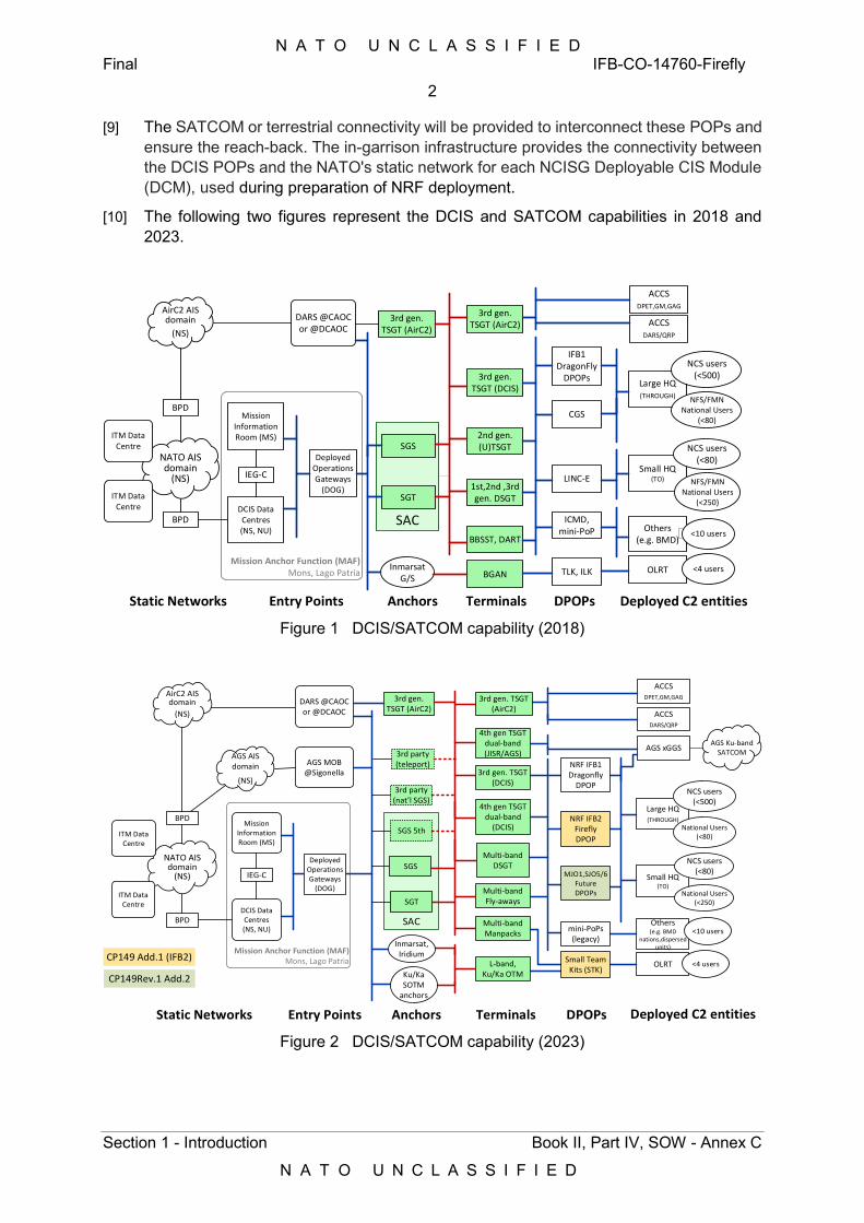
N A T O U N C L A S S I F I E D Final IFB-CO-14760-Firefly
2
Section 1 - Introduction Book II, Part IV, SOW - Annex C
N A T O U N C L A S S I F I E D
[9] The SATCOM or terrestrial connectivity will be provided to interconnect these POPs and ensure the reach-back. The in-garrison infrastructure provides the connectivity between the DCIS POPs and the NATO's static network for each NCISG Deployable CIS Module (DCM), used during preparation of NRF deployment.
[10] The following two figures represent the DCIS and SATCOM capabilities in 2018 and 2023.
SAC
Mission Anchor Function (MAF)Mons, Lago Patria OLRT
SGS
SGT
Large HQ(THROUGH)
Small HQ(TO)
3rd gen. TSGT (DCIS)
1st,2nd ,3rdgen. DSGT
LINC-E
CGS
IFB1DragonFly
DPOPs
2nd gen. (U)TSGT
Others(e.g. BMD)
ICMD, mini-PoP
BBSST, DART
3rd gen. TSGT (AirC2) ACCS
DARS/QRP
DARS @CAOC or @DCAOC
3rd gen. TSGT (AirC2)
TLK, ILKBGANInmarsat
G/S
BPD
BPD
AirC2 AIS domain
(NS)
NATO AIS domain
(NS)
ACCSDPET,GM,GAG
Deployed Operations Gateways
(DOG)
Mission Information Room (MS)
DCIS Data Centres (NS, NU)
IEG-C
NCS users(<500)
NFS/FMN National Users
(<80)
NCS users(<80)
NFS/FMNNational Users
(<250)
<10 users
<4 users
Anchors Terminals DPOPs Deployed C2 entitiesEntry PointsStatic Networks
ITM Data Centre
ITM Data Centre
Figure 1 DCIS/SATCOM capability (2018)
SAC
Mission Anchor Function (MAF)Mons, Lago Patria
Mission Information Room (MS)
DCIS Data Centres (NS, NU)
SGS 5th
IEG-C
Large HQ(THROUGH)
Small HQ(TO)
NCS users(<500)
National Users(<80)
NCS users(<80)
National Users(<250)
Others(e.g. BMD
nations,dispersed units)
<10 users
AGS xGGS
3rd gen. TSGT (AirC2)
OLRT <4 users
ACCSDARS/QRP
ACCSDPET,GM,GAG
3rd party(nat’l SGS)
AGS AISdomain
(NS)
BPD
BPD
AirC2 AIS domain
(NS)
NATO AIS domain
(NS)
Anchors Terminals DPOPs Deployed C2 entitiesEntry PointsStatic Networks
CP149 Add.1 (IFB2)
CP149Rev.1 Add.2
AGS Ku-bandSATCOM
ITM Data Centre
ITM Data Centre
3rd party(teleport)
3rd gen. TSGT(DCIS)
Multi-bandDSGT
Multi-band Fly-aways
4th gen TSGTdual-band
(DCIS)
Multi-band Manpacks
4th gen TSGTdual-band(JISR/AGS)
3rd gen. TSGT (AirC2)
L-band,Ku/Ka OTMKu/Ka
SOTM anchors
SGT
Inmarsat, Iridium
SGSDeployed
Operations Gateways
(DOG)
DARS @CAOC or @DCAOC
AGS MOB@Sigonella
NRF IFB2 Firefly DPOP
NRF IFB1 Dragonfly
DPOP
mini-PoPs(legacy)
Small Team Kits (STK)
MJO1,SJO5/6Future DPOPs
Figure 2 DCIS/SATCOM capability (2023)
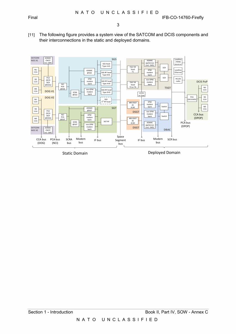
N A T O U N C L A S S I F I E D Final IFB-CO-14760-Firefly
3
Section 1 - Introduction Book II, Part IV, SOW - Annex C
N A T O U N C L A S S I F I E D
[11] The following figure provides a system view of the SATCOM and DCIS components and their interconnections in the static and deployed domains.
SATCOMNOC #1
SATCOMNOC #2
DOG #1
DOG #2
SGT
SGS
DBACDSGT
DSGT
TSGT
DCIS PoP
NU CCA
NS CCA
MS CCA
PCA(DCIS BCR)
HCLOSradio
Landline(TDM)
phased out
LandlineEthernet
SCR
SCR
SCR bus
PCA bus(DPOP)
Modem bus
CCA bus(DPOP)
Switch
IF bus
ASNMCappliances(incl. SMS)
EPMmodem
bank
non-EPM modem
bank
EPMmodem
bank
non-EPM modem
bank
ASNMCappliances(incl. SMS)
TSGT RF head
T1
TSGT RF head
T2 or T4
MB-DSGT #1
IF/RF
MB-DSGT #2
IF/RF
ASNMC@SGS
EPMmodem
bank
non-EPM modem
bank
SGS headType A #1
SGS RF headType B #1
SGT RF
SGS RF headType A #2
SGS RF headType B #2
ASNMC@SGT
EPMmodem
bank
non-EPM modem
bank
SGS5th RF head
IF bus
SCRA@SGS
NCI PCA
@SGS
SCRA@SGT
NCI PCA
@SGT
PCA(DCIS BCR
@DOG)
PCA(DCIS BCR
@DOG)
PCA bus(NCI)
Modem bus
NU CCA
NS CCA
MS CCA
CCA bus(DOG)
NU CCA
NS CCA
MS CCA
Space Segment
bus
Deployed DomainStatic Domain
ASNMCCMCP
incl. SMS
ASNMCCMCP
incl. SMS
Switch
SCRAbus
IF/FO or Coax
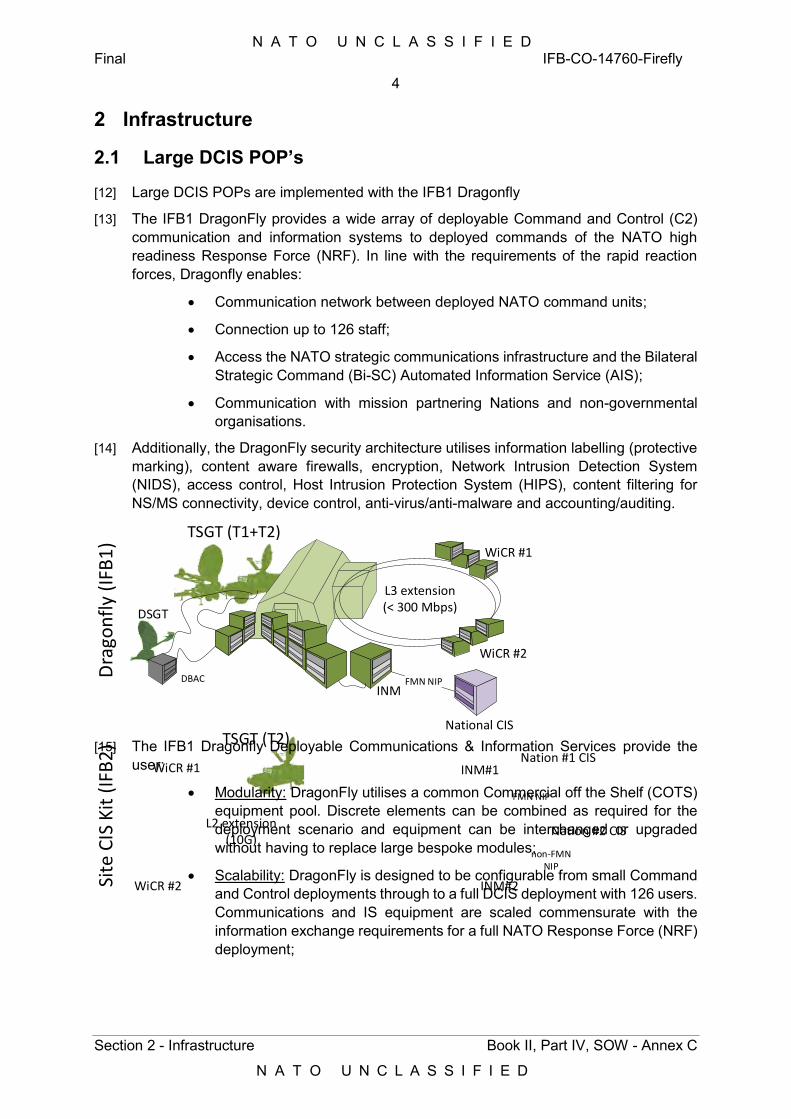
N A T O U N C L A S S I F I E D Final IFB-CO-14760-Firefly
4
Section 2 - Infrastructure Book II, Part IV, SOW - Annex C
N A T O U N C L A S S I F I E D
2 Infrastructure
2.1 Large DCIS POP’s
[12] Large DCIS POPs are implemented with the IFB1 Dragonfly
[13] The IFB1 DragonFly provides a wide array of deployable Command and Control (C2) communication and information systems to deployed commands of the NATO high readiness Response Force (NRF). In line with the requirements of the rapid reaction forces, Dragonfly enables:
Communication network between deployed NATO command units;
Connection up to 126 staff;
Access the NATO strategic communications infrastructure and the Bilateral Strategic Command (Bi-SC) Automated Information Service (AIS);
Communication with mission partnering Nations and non-governmental organisations.
[14] Additionally, the DragonFly security architecture utilises information labelling (protective marking), content aware firewalls, encryption, Network Intrusion Detection System (NIDS), access control, Host Intrusion Protection System (HIPS), content filtering for NS/MS connectivity, device control, anti-virus/anti-malware and accounting/auditing.
INM
National CIS
FMN NIP
INM#1
INM#2
Nation #1 CIS
Nation #2 CIS
FMN NIP
non-FMN NIP
L3 extension(< 300 Mbps)
WiCR #1
WiCR #2
L2 extension(10G)
WiCR #1
WiCR #2
Dra
gon
fly
(IFB
1)
Site
CIS
Kit
(IF
B2
)
TSGT (T1+T2)
DSGT
TSGT (T2)
DBAC
[15] The IFB1 Dragonfly Deployable Communications & Information Services provide the
user:
Modularity: DragonFly utilises a common Commercial off the Shelf (COTS) equipment pool. Discrete elements can be combined as required for the deployment scenario and equipment can be interchanged or upgraded without having to replace large bespoke modules;
Scalability: DragonFly is designed to be configurable from small Command and Control deployments through to a full DCIS deployment with 126 users. Communications and IS equipment are scaled commensurate with the information exchange requirements for a full NATO Response Force (NRF) deployment;
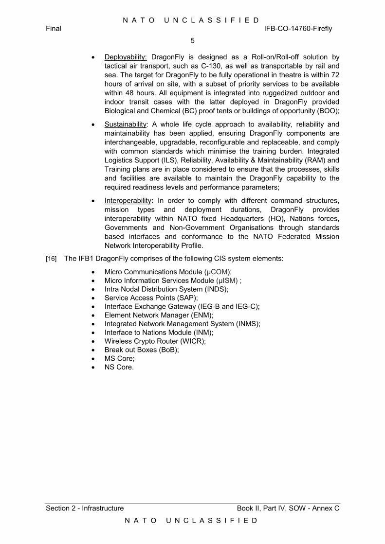
N A T O U N C L A S S I F I E D Final IFB-CO-14760-Firefly
5
Section 2 - Infrastructure Book II, Part IV, SOW - Annex C
N A T O U N C L A S S I F I E D
Deployability: DragonFly is designed as a Roll-on/Roll-off solution by tactical air transport, such as C-130, as well as transportable by rail and sea. The target for DragonFly to be fully operational in theatre is within 72 hours of arrival on site, with a subset of priority services to be available within 48 hours. All equipment is integrated into ruggedized outdoor and indoor transit cases with the latter deployed in DragonFly provided Biological and Chemical (BC) proof tents or buildings of opportunity (BOO);
Sustainability: A whole life cycle approach to availability, reliability and maintainability has been applied, ensuring DragonFly components are interchangeable, upgradable, reconfigurable and replaceable, and comply with common standards which minimise the training burden. Integrated Logistics Support (ILS), Reliability, Availability & Maintainability (RAM) and Training plans are in place considered to ensure that the processes, skills and facilities are available to maintain the DragonFly capability to the required readiness levels and performance parameters;
Interoperability: In order to comply with different command structures, mission types and deployment durations, DragonFly provides interoperability within NATO fixed Headquarters (HQ), Nations forces, Governments and Non-Government Organisations through standards based interfaces and conformance to the NATO Federated Mission Network Interoperability Profile.
[16] The IFB1 DragonFly comprises of the following CIS system elements:
Micro Communications Module (μCOM); Micro Information Services Module (μISM) ; Intra Nodal Distribution System (INDS); Service Access Points (SAP); Interface Exchange Gateway (IEG-B and IEG-C); Element Network Manager (ENM); Integrated Network Management System (INMS); Interface to Nations Module (INM); Wireless Crypto Router (WICR); Break out Boxes (BoB); MS Core; NS Core.
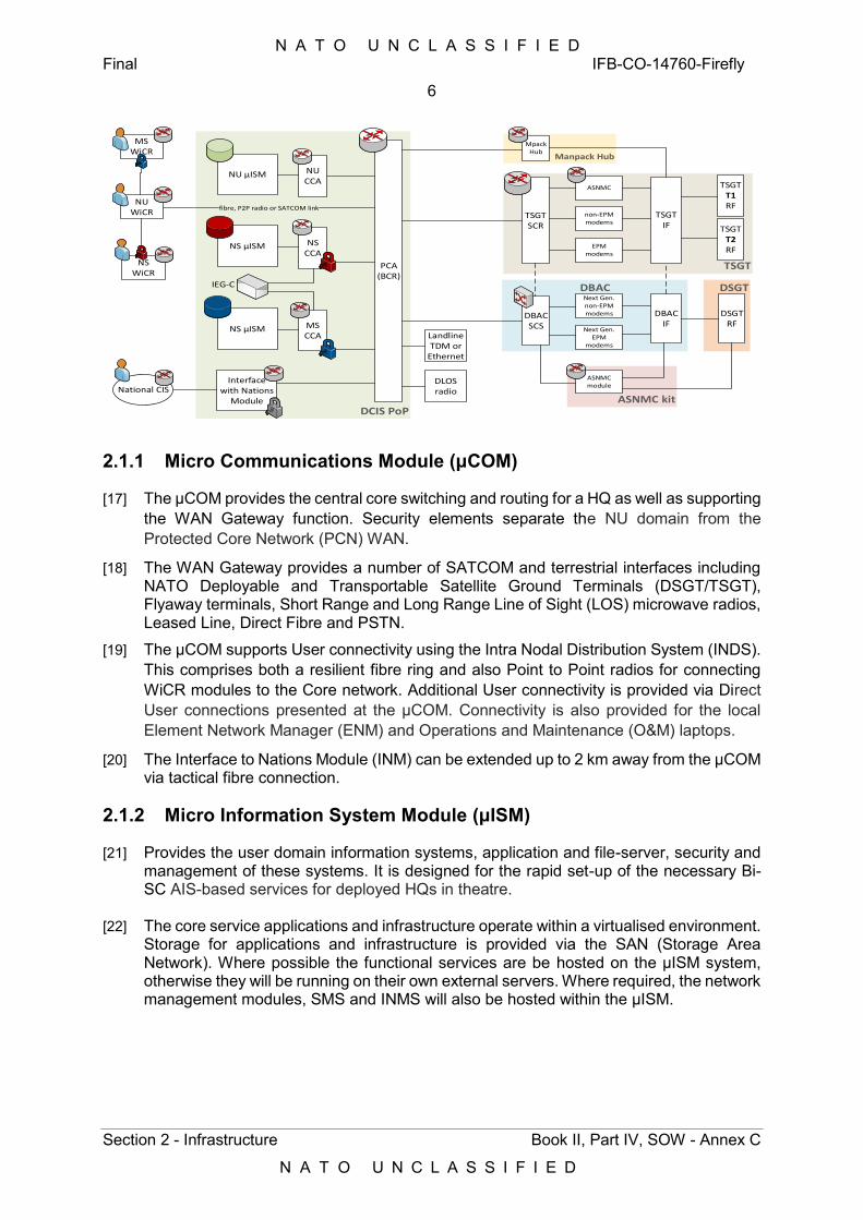
N A T O U N C L A S S I F I E D Final IFB-CO-14760-Firefly
6
Section 2 - Infrastructure Book II, Part IV, SOW - Annex C
N A T O U N C L A S S I F I E D
DCIS PoP
NS µISM
Manpack Hub
ASNMC kit
DBAC DSGT
TSGT
TSGT IF
TSGT T1RF
non-EPM modems
EPMmodems
DSGTRF
DBAC IF
Next Gen.non-EPM modems
Next Gen.EPM
modems
DBACSCS
TSGT SCR
ASNMC
ASNMCmodule
PCA(BCR)
MpackHub
DLOSradio
LandlineTDM or
Ethernet
NUCCA
NSCCA
MSCCA
NS µISM
NU µISM
IEG-C
TSGT T2RF
Interface with Nations
Module
MSWiCR
National CIS
NSWiCR
NUWiCR
fibre, P2P radio or SATCOM link
2.1.1 Micro Communications Module (μCOM)
[17] The μCOM provides the central core switching and routing for a HQ as well as supporting the WAN Gateway function. Security elements separate the NU domain from the Protected Core Network (PCN) WAN.
[18] The WAN Gateway provides a number of SATCOM and terrestrial interfaces including NATO Deployable and Transportable Satellite Ground Terminals (DSGT/TSGT), Flyaway terminals, Short Range and Long Range Line of Sight (LOS) microwave radios, Leased Line, Direct Fibre and PSTN.
[19] The μCOM supports User connectivity using the Intra Nodal Distribution System (INDS). This comprises both a resilient fibre ring and also Point to Point radios for connecting WiCR modules to the Core network. Additional User connectivity is provided via Direct User connections presented at the μCOM. Connectivity is also provided for the local Element Network Manager (ENM) and Operations and Maintenance (O&M) laptops.
[20] The Interface to Nations Module (INM) can be extended up to 2 km away from the μCOM via tactical fibre connection.
2.1.2 Micro Information System Module (μISM)
[21] Provides the user domain information systems, application and file-server, security and management of these systems. It is designed for the rapid set-up of the necessary Bi-SC AIS-based services for deployed HQs in theatre.
[22] The core service applications and infrastructure operate within a virtualised environment. Storage for applications and infrastructure is provided via the SAN (Storage Area Network). Where possible the functional services are be hosted on the μISM system, otherwise they will be running on their own external servers. Where required, the network management modules, SMS and INMS will also be hosted within the μISM.
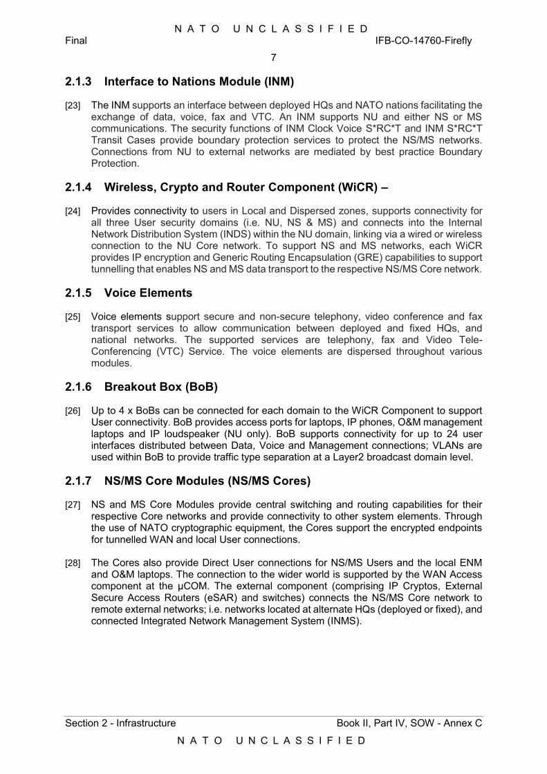
N A T O U N C L A S S I F I E D Final IFB-CO-14760-Firefly
7
Section 2 - Infrastructure Book II, Part IV, SOW - Annex C
N A T O U N C L A S S I F I E D
2.1.3 Interface to Nations Module (INM)
[23] The INM supports an interface between deployed HQs and NATO nations facilitating the exchange of data, voice, fax and VTC. An INM supports NU and either NS or MS communications. The security functions of INM Clock Voice S*RC*T and INM S*RC*T Transit Cases provide boundary protection services to protect the NS/MS networks. Connections from NU to external networks are mediated by best practice Boundary Protection.
2.1.4 Wireless, Crypto and Router Component (WiCR) –
[24] Provides connectivity to users in Local and Dispersed zones, supports connectivity for all three User security domains (i.e. NU, NS & MS) and connects into the Internal Network Distribution System (INDS) within the NU domain, linking via a wired or wireless connection to the NU Core network. To support NS and MS networks, each WiCR provides IP encryption and Generic Routing Encapsulation (GRE) capabilities to support tunnelling that enables NS and MS data transport to the respective NS/MS Core network.
2.1.5 Voice Elements
[25] Voice elements support secure and non-secure telephony, video conference and fax transport services to allow communication between deployed and fixed HQs, and national networks. The supported services are telephony, fax and Video Tele-Conferencing (VTC) Service. The voice elements are dispersed throughout various modules.
2.1.6 Breakout Box (BoB)
[26] Up to 4 x BoBs can be connected for each domain to the WiCR Component to support User connectivity. BoB provides access ports for laptops, IP phones, O&M management laptops and IP loudspeaker (NU only). BoB supports connectivity for up to 24 user interfaces distributed between Data, Voice and Management connections; VLANs are used within BoB to provide traffic type separation at a Layer2 broadcast domain level.
2.1.7 NS/MS Core Modules (NS/MS Cores)
[27] NS and MS Core Modules provide central switching and routing capabilities for their respective Core networks and provide connectivity to other system elements. Through the use of NATO cryptographic equipment, the Cores support the encrypted endpoints for tunnelled WAN and local User connections.
[28] The Cores also provide Direct User connections for NS/MS Users and the local ENM and O&M laptops. The connection to the wider world is supported by the WAN Access component at the μCOM. The external component (comprising IP Cryptos, External Secure Access Routers (eSAR) and switches) connects the NS/MS Core network to remote external networks; i.e. networks located at alternate HQs (deployed or fixed), and connected Integrated Network Management System (INMS).
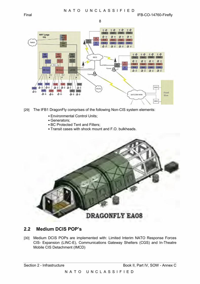
N A T O U N C L A S S I F I E D Final IFB-CO-14760-Firefly
8
Section 2 - Infrastructure Book II, Part IV, SOW - Annex C
N A T O U N C L A S S I F I E D
[29] The IFB1 DragonFly comprises of the following Non-CIS system elements:
• Environmental Control Units; • Generators; • BC Protected Tent and Filters; • Transit cases with shock mount and F.O. bulkheads.
2.2 Medium DCIS POP’s
[30] Medium DCIS POPs are implemented with: Limited Interim NATO Response Forces CIS- Expansion (LINC-E), Communications Gateway Shelters (CGS) and In-Theatre Mobile CIS Detachment (IMCD)
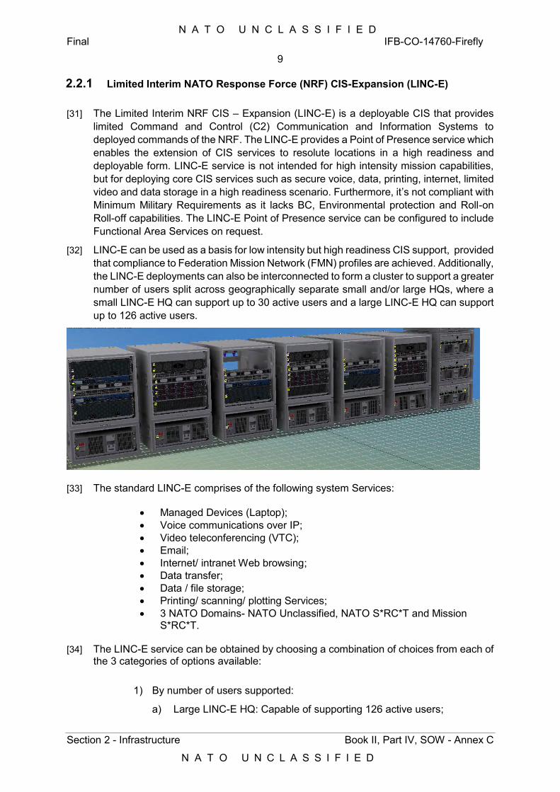
N A T O U N C L A S S I F I E D Final IFB-CO-14760-Firefly
9
Section 2 - Infrastructure Book II, Part IV, SOW - Annex C
N A T O U N C L A S S I F I E D
2.2.1 Limited Interim NATO Response Force (NRF) CIS-Expansion (LINC-E)
[31] The Limited Interim NRF CIS – Expansion (LINC-E) is a deployable CIS that provides limited Command and Control (C2) Communication and Information Systems to deployed commands of the NRF. The LINC-E provides a Point of Presence service which enables the extension of CIS services to resolute locations in a high readiness and deployable form. LINC-E service is not intended for high intensity mission capabilities, but for deploying core CIS services such as secure voice, data, printing, internet, limited video and data storage in a high readiness scenario. Furthermore, it’s not compliant with Minimum Military Requirements as it lacks BC, Environmental protection and Roll-on Roll-off capabilities. The LINC-E Point of Presence service can be configured to include Functional Area Services on request.
[32] LINC-E can be used as a basis for low intensity but high readiness CIS support, provided that compliance to Federation Mission Network (FMN) profiles are achieved. Additionally, the LINC-E deployments can also be interconnected to form a cluster to support a greater number of users split across geographically separate small and/or large HQs, where a small LINC-E HQ can support up to 30 active users and a large LINC-E HQ can support up to 126 active users.
[33] The standard LINC-E comprises of the following system Services:
Managed Devices (Laptop); Voice communications over IP; Video teleconferencing (VTC); Email; Internet/ intranet Web browsing; Data transfer; Data / file storage; Printing/ scanning/ plotting Services; 3 NATO Domains- NATO Unclassified, NATO S*RC*T and Mission
S*RC*T.
[34] The LINC-E service can be obtained by choosing a combination of choices from each of the 3 categories of options available:
1) By number of users supported:
a) Large LINC-E HQ: Capable of supporting 126 active users;
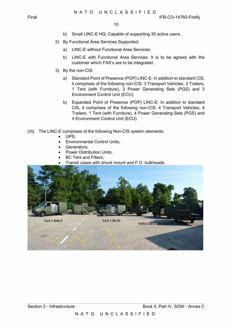
N A T O U N C L A S S I F I E D Final IFB-CO-14760-Firefly
10
Section 2 - Infrastructure Book II, Part IV, SOW - Annex C
N A T O U N C L A S S I F I E D
b) Small LINC-E HQ: Capable of supporting 30 active users.
2) By Functional Area Services Supported:
a) LINC-E without Functional Area Services;
b) LINC-E with Functional Area Services: It is to be agreed with the customer which FAS’s are to be integrated.
3) By the non-CIS:
a) Standard Point of Presence (POP) LINC-E: In addition to standard CIS, it comprises of the following non-CIS: 3 Transport Vehicles, 3 Trailers, 1 Tent (with Furniture), 3 Power Generating Sets (PGS) and 3 Environment Control Unit (ECU);
b) Expanded Point of Presence (POP) LINC-E: In addition to standard CIS, it comprises of the following non-CIS: 4 Transport Vehicles, 4 Trailers, 1 Tent (with Furniture), 4 Power Generating Sets (PGS) and 4 Environment Control Unit (ECU).
[35] The LINC-E comprises of the following Non-CIS system elements:
UPS; Environmental Control Units; Generators; Power Distribution Units; BC Tent and Filters; Transit cases with shock mount and F.O. bulkheads.
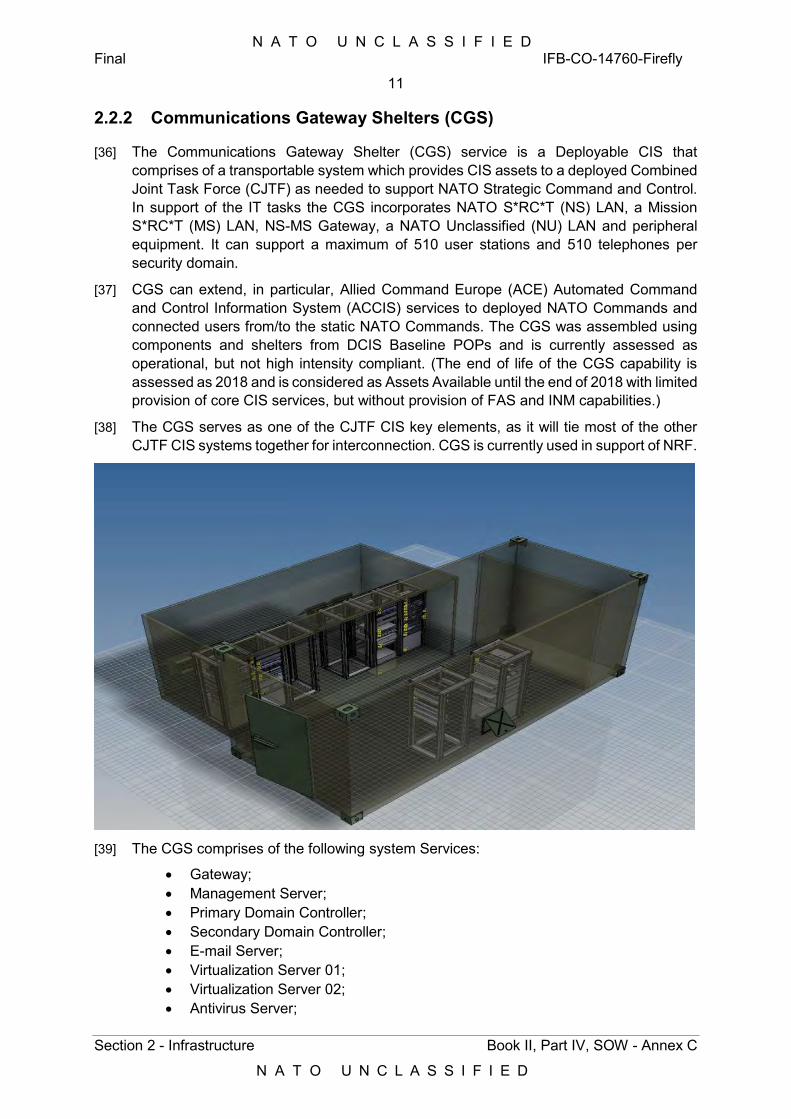
N A T O U N C L A S S I F I E D Final IFB-CO-14760-Firefly
11
Section 2 - Infrastructure Book II, Part IV, SOW - Annex C
N A T O U N C L A S S I F I E D
2.2.2 Communications Gateway Shelters (CGS)
[36] The Communications Gateway Shelter (CGS) service is a Deployable CIS that comprises of a transportable system which provides CIS assets to a deployed Combined Joint Task Force (CJTF) as needed to support NATO Strategic Command and Control. In support of the IT tasks the CGS incorporates NATO S*RC*T (NS) LAN, a Mission S*RC*T (MS) LAN, NS-MS Gateway, a NATO Unclassified (NU) LAN and peripheral equipment. It can support a maximum of 510 user stations and 510 telephones per security domain.
[37] CGS can extend, in particular, Allied Command Europe (ACE) Automated Command and Control Information System (ACCIS) services to deployed NATO Commands and connected users from/to the static NATO Commands. The CGS was assembled using components and shelters from DCIS Baseline POPs and is currently assessed as operational, but not high intensity compliant. (The end of life of the CGS capability is assessed as 2018 and is considered as Assets Available until the end of 2018 with limited provision of core CIS services, but without provision of FAS and INM capabilities.)
[38] The CGS serves as one of the CJTF CIS key elements, as it will tie most of the other CJTF CIS systems together for interconnection. CGS is currently used in support of NRF.
[39] The CGS comprises of the following system Services:
Gateway; Management Server; Primary Domain Controller; Secondary Domain Controller; E-mail Server; Virtualization Server 01; Virtualization Server 02; Antivirus Server;
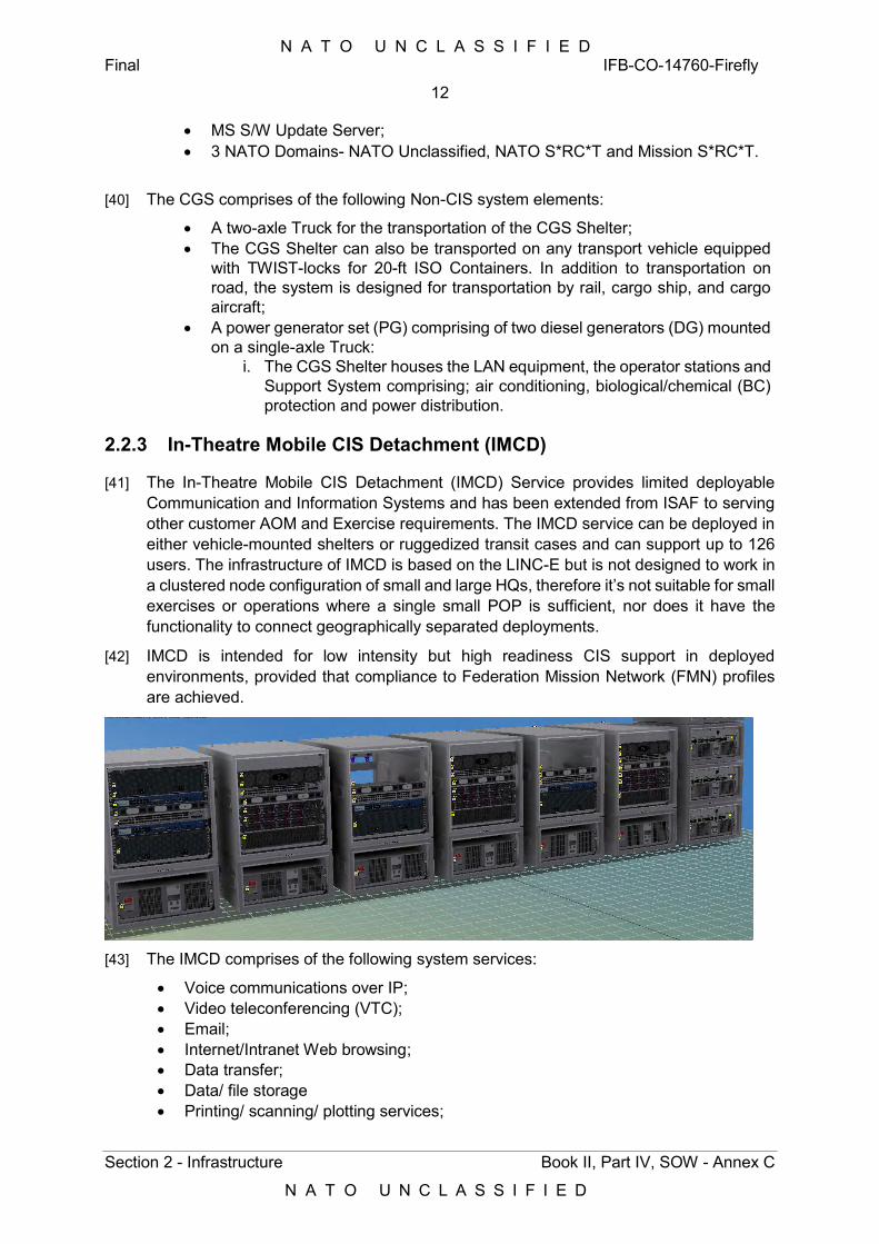
N A T O U N C L A S S I F I E D Final IFB-CO-14760-Firefly
12
Section 2 - Infrastructure Book II, Part IV, SOW - Annex C
N A T O U N C L A S S I F I E D
MS S/W Update Server; 3 NATO Domains- NATO Unclassified, NATO S*RC*T and Mission S*RC*T.
[40] The CGS comprises of the following Non-CIS system elements:
A two-axle Truck for the transportation of the CGS Shelter; The CGS Shelter can also be transported on any transport vehicle equipped
with TWIST-locks for 20-ft ISO Containers. In addition to transportation on road, the system is designed for transportation by rail, cargo ship, and cargo aircraft;
A power generator set (PG) comprising of two diesel generators (DG) mounted on a single-axle Truck:
i. The CGS Shelter houses the LAN equipment, the operator stations and Support System comprising; air conditioning, biological/chemical (BC) protection and power distribution.
2.2.3 In-Theatre Mobile CIS Detachment (IMCD)
[41] The In-Theatre Mobile CIS Detachment (IMCD) Service provides limited deployable Communication and Information Systems and has been extended from ISAF to serving other customer AOM and Exercise requirements. The IMCD service can be deployed in either vehicle-mounted shelters or ruggedized transit cases and can support up to 126 users. The infrastructure of IMCD is based on the LINC-E but is not designed to work in a clustered node configuration of small and large HQs, therefore it’s not suitable for small exercises or operations where a single small POP is sufficient, nor does it have the functionality to connect geographically separated deployments.
[42] IMCD is intended for low intensity but high readiness CIS support in deployed environments, provided that compliance to Federation Mission Network (FMN) profiles are achieved.
[43] The IMCD comprises of the following system services:
Voice communications over IP; Video teleconferencing (VTC); Email; Internet/Intranet Web browsing; Data transfer; Data/ file storage Printing/ scanning/ plotting services;
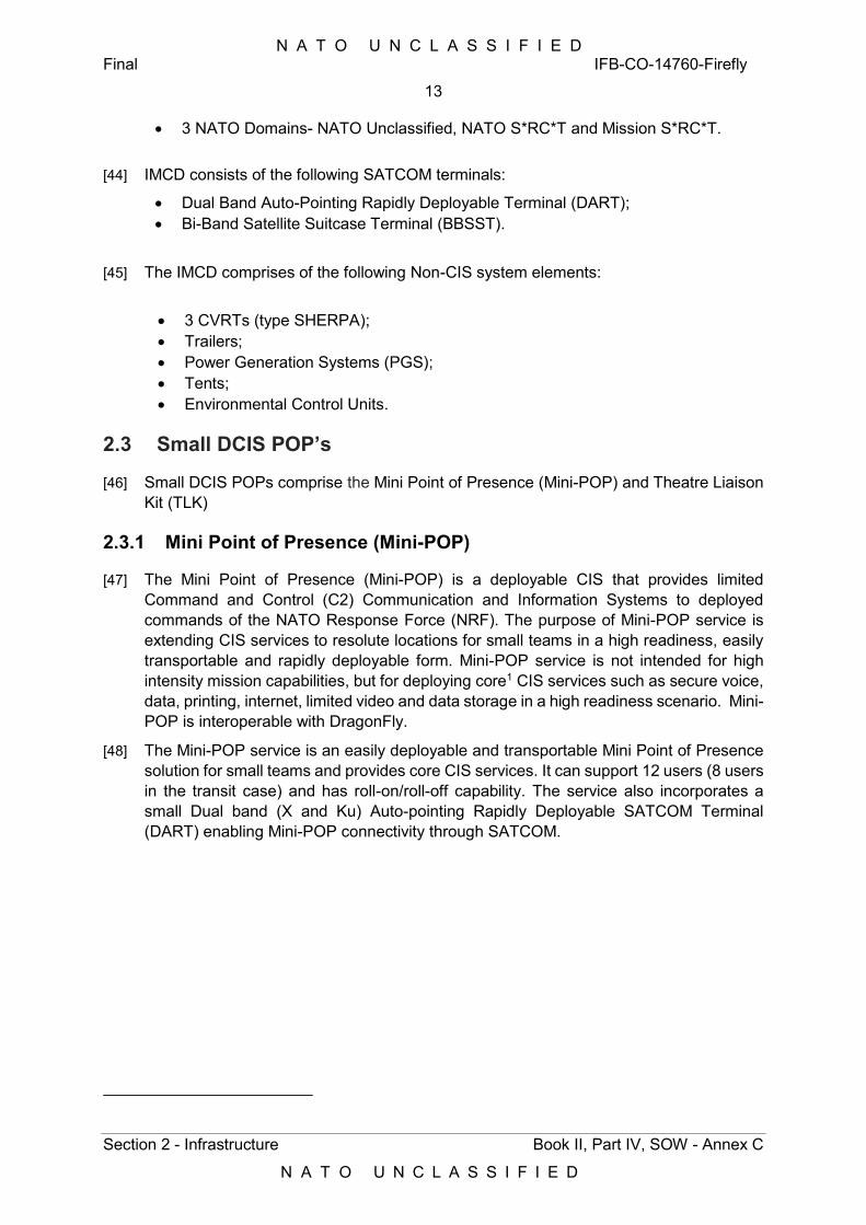
N A T O U N C L A S S I F I E D Final IFB-CO-14760-Firefly
13
Section 2 - Infrastructure Book II, Part IV, SOW - Annex C
N A T O U N C L A S S I F I E D
3 NATO Domains- NATO Unclassified, NATO S*RC*T and Mission S*RC*T.
[44] IMCD consists of the following SATCOM terminals:
Dual Band Auto-Pointing Rapidly Deployable Terminal (DART); Bi-Band Satellite Suitcase Terminal (BBSST).
[45] The IMCD comprises of the following Non-CIS system elements:
3 CVRTs (type SHERPA); Trailers; Power Generation Systems (PGS); Tents; Environmental Control Units.
2.3 Small DCIS POP’s
[46] Small DCIS POPs comprise the Mini Point of Presence (Mini-POP) and Theatre Liaison Kit (TLK)
2.3.1 Mini Point of Presence (Mini-POP)
[47] The Mini Point of Presence (Mini-POP) is a deployable CIS that provides limited Command and Control (C2) Communication and Information Systems to deployed commands of the NATO Response Force (NRF). The purpose of Mini-POP service is extending CIS services to resolute locations for small teams in a high readiness, easily transportable and rapidly deployable form. Mini-POP service is not intended for high intensity mission capabilities, but for deploying core1 CIS services such as secure voice, data, printing, internet, limited video and data storage in a high readiness scenario. Mini-POP is interoperable with DragonFly.
[48] The Mini-POP service is an easily deployable and transportable Mini Point of Presence solution for small teams and provides core CIS services. It can support 12 users (8 users in the transit case) and has roll-on/roll-off capability. The service also incorporates a small Dual band (X and Ku) Auto-pointing Rapidly Deployable SATCOM Terminal (DART) enabling Mini-POP connectivity through SATCOM.
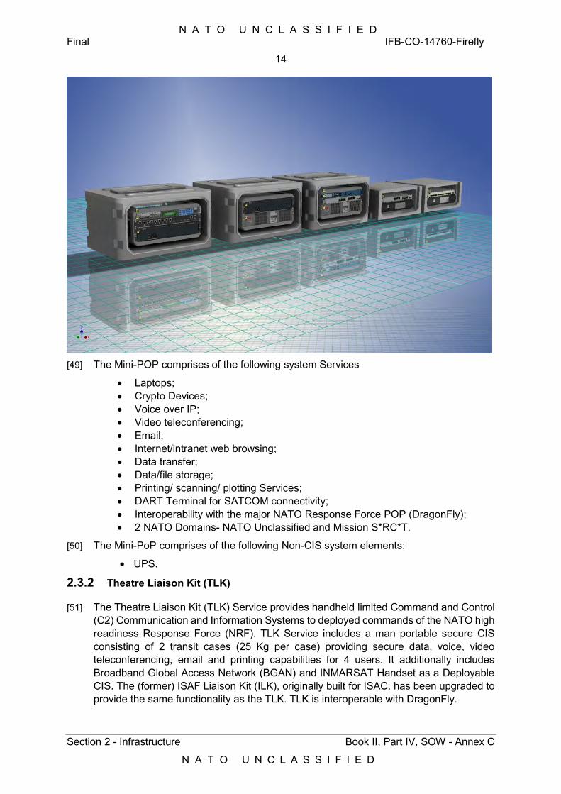
N A T O U N C L A S S I F I E D Final IFB-CO-14760-Firefly
14
Section 2 - Infrastructure Book II, Part IV, SOW - Annex C
N A T O U N C L A S S I F I E D
[49] The Mini-POP comprises of the following system Services
Laptops; Crypto Devices; Voice over IP; Video teleconferencing; Email; Internet/intranet web browsing; Data transfer; Data/file storage; Printing/ scanning/ plotting Services; DART Terminal for SATCOM connectivity; Interoperability with the major NATO Response Force POP (DragonFly); 2 NATO Domains- NATO Unclassified and Mission S*RC*T.
[50] The Mini-PoP comprises of the following Non-CIS system elements:
UPS.
2.3.2 Theatre Liaison Kit (TLK)
[51] The Theatre Liaison Kit (TLK) Service provides handheld limited Command and Control (C2) Communication and Information Systems to deployed commands of the NATO high readiness Response Force (NRF). TLK Service includes a man portable secure CIS consisting of 2 transit cases (25 Kg per case) providing secure data, voice, video teleconferencing, email and printing capabilities for 4 users. It additionally includes Broadband Global Access Network (BGAN) and INMARSAT Handset as a Deployable CIS. The (former) ISAF Liaison Kit (ILK), originally built for ISAC, has been upgraded to provide the same functionality as the TLK. TLK is interoperable with DragonFly.
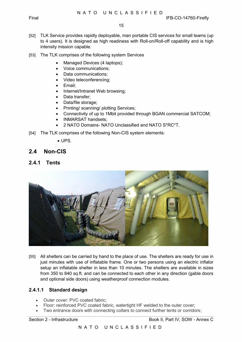
N A T O U N C L A S S I F I E D Final IFB-CO-14760-Firefly
15
Section 2 - Infrastructure Book II, Part IV, SOW - Annex C
N A T O U N C L A S S I F I E D
[52] TLK Service provides rapidly deployable, man portable CIS services for small teams (up to 4 users). It is designed as high readiness with Roll-on/Roll-off capability and is high intensity mission capable.
[53] The TLK comprises of the following system Services
Managed Devices (4 laptops); Voice communications; Data communications; Video teleconferencing; Email; Internet/Intranet Web browsing; Data transfer; Data/file storage; Printing/ scanning/ plotting Services; Connectivity of up to 1Mbit provided through BGAN commercial SATCOM; INMARSAT handsets; 2 NATO Domains- NATO Unclassified and NATO S*RC*T.
[54] The TLK comprises of the following Non-CIS system elements:
UPS.
2.4 Non-CIS
2.4.1 Tents
[55] All shelters can be carried by hand to the place of use. The shelters are ready for use in just minutes with use of inflatable frame. One or two persons using an electric inflator setup an inflatable shelter in less than 10 minutes. The shelters are available in sizes from 350 to 840 sq.ft. and can be connected to each other in any direction (gable doors and optional side doors) using weatherproof connection modules.
2.4.1.1 Standard design
Outer cover: PVC coated fabric; Floor: reinforced PVC coated fabric, watertight HF welded to the outer cover; Two entrance doors with connecting collars to connect further tents or corridors;
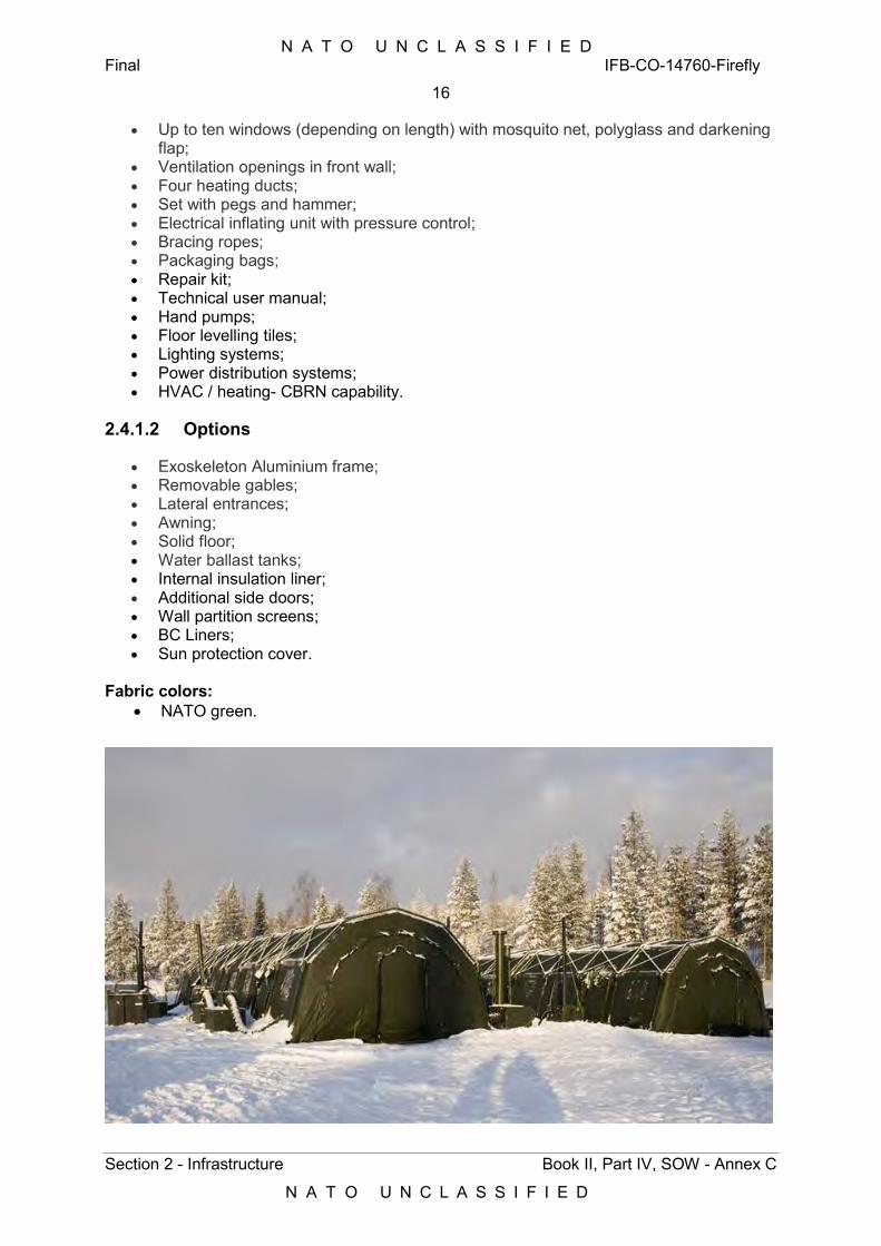
N A T O U N C L A S S I F I E D Final IFB-CO-14760-Firefly
16
Section 2 - Infrastructure Book II, Part IV, SOW - Annex C
N A T O U N C L A S S I F I E D
Up to ten windows (depending on length) with mosquito net, polyglass and darkening flap;
Ventilation openings in front wall; Four heating ducts; Set with pegs and hammer; Electrical inflating unit with pressure control; Bracing ropes; Packaging bags; Repair kit; Technical user manual; Hand pumps; Floor levelling tiles; Lighting systems; Power distribution systems; HVAC / heating- CBRN capability.
2.4.1.2 Options
Exoskeleton Aluminium frame; Removable gables; Lateral entrances; Awning; Solid floor; Water ballast tanks; Internal insulation liner; Additional side doors; Wall partition screens; BC Liners; Sun protection cover.
Fabric colors:
NATO green.
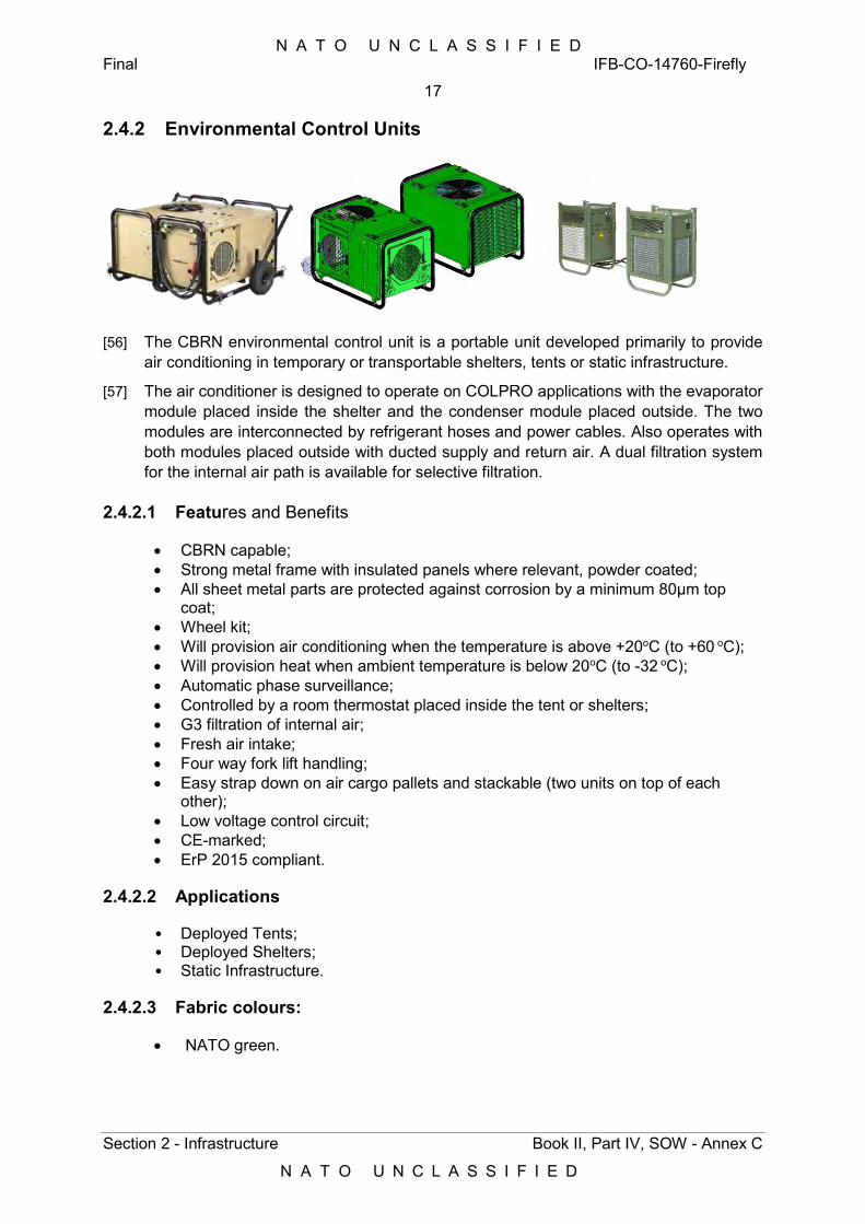
N A T O U N C L A S S I F I E D Final IFB-CO-14760-Firefly
17
Section 2 - Infrastructure Book II, Part IV, SOW - Annex C
N A T O U N C L A S S I F I E D
2.4.2 Environmental Control Units
[56] The CBRN environmental control unit is a portable unit developed primarily to provide air conditioning in temporary or transportable shelters, tents or static infrastructure.
[57] The air conditioner is designed to operate on COLPRO applications with the evaporator module placed inside the shelter and the condenser module placed outside. The two modules are interconnected by refrigerant hoses and power cables. Also operates with both modules placed outside with ducted supply and return air. A dual filtration system for the internal air path is available for selective filtration.
2.4.2.1 Features and Benefits
CBRN capable; Strong metal frame with insulated panels where relevant, powder coated; All sheet metal parts are protected against corrosion by a minimum 80μm top
coat; Wheel kit; Will provision air conditioning when the temperature is above +20oC (to +60 oC); Will provision heat when ambient temperature is below 20oC (to -32 oC); Automatic phase surveillance; Controlled by a room thermostat placed inside the tent or shelters; G3 filtration of internal air; Fresh air intake; Four way fork lift handling; Easy strap down on air cargo pallets and stackable (two units on top of each
other); Low voltage control circuit; CE-marked; ErP 2015 compliant.
2.4.2.2 Applications
• Deployed Tents; • Deployed Shelters; • Static Infrastructure.
2.4.2.3 Fabric colours:
NATO green.
N A T O U N C L A S S I F I E D Final IFB-CO-14760-Firefly
18
Section 2 - Infrastructure Book II, Part IV, SOW - Annex C
N A T O U N C L A S S I F I E D
2.5 Deployed Forces Operational Gateway (DOG)
[58] The Deployed Forces Operational Gateway (DOG) is the CIS service anchor point for all NATO Deployed Forces that interface into the NATO General-purpose Communications System (NGCS) static CIS network. The deployed forces in NATO operate primarily in the Mission S*RC*T domain (MS) whilst the NATO core network primarily operates in the NATO S*RC*T domain (NS). As NATO increased its level of ambition for deployed operations, the requirement of cross domain connectivity was identified between MS and NS, as well as between different MS domains. The Information Exchange Gateway (IEG) service facilitates this functionality, with IEG-C being the gateway that interfaces MS and NS domains. The IEG-C was deployed into SHAPE in 2004 to interface ISAF and Balkan MS domains with NS; where SHAPE is known as the NATO DOG (NDOG). With the inception of the NRF concept, a requirement for additional NRF gateways had been identified. The NATO Response Force gateways, including the IEG–C capability, were implemented at the static Satellite Ground Terminals identified to support the NRF missions, SGT F05, Norway and Castlegate in Germany. These sites are known as the NRF Mission DOGs (MDOGs).
[59] Mission DOGs enable to enhance Satellite payload, avoid terrestrial network limitations and to provide redundancy. There is an on-going review of these current locations in order to optimize the performance of the DOG. The DOG capability has been recognized as an essential component in the NATO inventory.
[60] Each DOG comprises of the following system Services:
Terrestrial network connectivity into NGCS and the respective NS, MS and NU domains;
Satellite Connectivity; NDOG has BGAN network interconnectivity with Inmarsat; MDOGs have X Band Satellite connectivity through the SGT terminal with each
MDOG able to provide connectivity for 12 deployed TSGTs; An IEG-C for cross domain service flows; Cross domain Service interfaces for Mail, Voice and VTC; 3 NATO Domains- NATO Unclassified, NATO S*RC*T and Mission S*RC*T.
NDOG:
Routers 38xx series with software support; Switches; Firewalls; VX 900; Voice Gateway and Call Managers; Crypto Equipment.
MDOG:
Crypto Equipment; Servers; Switches; VX 900; Voice Gateway and Call Managers; Firewalls; Routers 38xx series with software support;
N A T O U N C L A S S I F I E D Final IFB-CO-14760-Firefly
19
Section 3 - Services Book II, Part IV, SOW - Annex C
N A T O U N C L A S S I F I E D
3 Services [61] IFB1 Dragonfly comprises of the following system Services:
3.1 Network - Wide Area and Local Area Connectivity-
The LAN service provides users with local network connectivity. The LAN service is crucial to enable collaboration and communication. The LAN service is provided as a cabled infrastructure for all networks and as a wireless infrastructure for accessing only the unclassified and restricted networks. It is the key enabler for accessing all NATO customer facing Services such as Voice and Video, as well as Internet, and enabling services such as security and management. LAN services allow all entitled users to access shared NATO services and data across the NATO Enterprise;
Wi-Fi connections provide additional flexibility, allowing users to connect to the network from anywhere within the relevant Wi-Fi footprint, preventing users from being ‘tied’ to their desks;
LAN Services are available on the NATO Security domains in wired and, in selected locations, as Wireless (Wi-Fi) configurations. The LAN Service will be capacity sized to support the number of connected devices and Users. This is with the understanding that all equipment is located within the same building and that the cabling system is available.
The Service is available in: o Wired – This service provides a physical connection to terminate and connect devices
to one of the NATO networks. By utilising NCIA deployed LAN Services, users are able to operate on all wired NATO networks including, but not limited to: NATO Unclassified; NATO R*STR*CT*D; NATO S*RC*T; Mission S*RC*T (when invoked).
o Wireless - This service provides the ability to connect a specific client device to a network wirelessly. By utilising NCIA deployed LAN Services, users are able to operate on all wireless NATO networks including: NATO Unclassified.
3.2 Voice and Secure Voice-
The voice collaboration service provides user with the ability to collaborate and communicate through audio. Voice collaboration Services allow easy communication between more than one parties, from any location. This dramatically increases flexibility and saves cost as no travel is required (especially when using conferencing facilities);
Different Form Factors (Telephone, IP phone, mobile phones), conferencing, hunt groups, voice mail, phone billing service, call intercept and call forwarding are provided on the available NATO security domains;
The Service is available in: o Desk phone: This provides the users with a static desk phone and a number
assigned. The difference between regular phone or VoIP phone depends on the local site infrastructure. The voice subscription is not part of the service, it should be obtained separately;
o Mobile phone: This service provides users with a mobile phone device using regular carrier providers as well as Satellite providers to make voice calls. The
N A T O U N C L A S S I F I E D Final IFB-CO-14760-Firefly
20
Section 3 - Services Book II, Part IV, SOW - Annex C
N A T O U N C L A S S I F I E D
voice subscription is not part of the service, it should be obtained separately. The voice subscription is not part of the service, it should be obtained separately. The voice subscription is not part of the service, it should be obtained separately. (This service does not include mobile phones with the data plan subscription. Should a mobile phone include both voice and data plan, it is to be requested through the Managed Device service- Smart Phone.);
o Soft phone: This service provides users, via the provisioning of a soft client, the ability to place voice calls using managed devices;
o Available on: Desk phone (Static): NATO Unclassified and NATO S*RC*T; Mobile phone: NATO Unclassified; Soft phone: NATO Unclassified and NATO R*STR*CT*D.
3.3 Video Teleconferencing
o The Video (VTC) collaboration service provides users the ability to collaborate and communicate through video and audio. It allows users from different geographical location to have face-to-face like collaboration as well as it supports multi-user, multi-location collaboration;
o The Service allows individuals and groups to interact easily, which enables a more flexible and efficient exercise of the Command and Control with significant savings in travel time and cost;
o The Service features include scheduling, VIP monitoring, conferencing, recording, playback and streaming, and connectivity of third parties;
o The Service is available in: o VTC Soft Client: provides users with an application (Polycom
RealPresence Desktop) installed on the managed/qualified device. This requires a camera and a microphone (in-built or as addition);
o Dedicated Terminal: provides users with a dedicated VTC terminal (Polycom) connected to the network, which can be either:
Desktop VTC Terminal; or Huddle/small room based system.
o Conference room VTC: integrates with Conference room setups that become VTC enabled – it’s provided with a camera and microphone and can be integrated with Conference room projection and presentation devices. The provides a range of room systems depending on their size, number supported participants, and the need for mobility, as follows:
Roll About VTC system: Single Domain; Dual Domain.
15-man room VTC system (dual domain system); 25-man room VTC system (dual domain system); 50-man room VTC system (dual domain system); 175-man room VTC system (dual domain system).
o Immersive Telepresence Meeting Room VTC: This service uses enhanced conference room technologies and provides the illusion of an in person meeting through the use of multiple screens in an `across the table` setup. Available only as single domain system;
N A T O U N C L A S S I F I E D Final IFB-CO-14760-Firefly
21
Section 3 - Services Book II, Part IV, SOW - Annex C
N A T O U N C L A S S I F I E D
o VTC B2B (Business to Business): provides a possibility to communicate through audio and video between NATO users and external VTC networks such as Nations, Missions, Deployed CIS, NGO’s and GO’s;
o Available on: NATO Unclassified (including public access); NATO R*STR*CT*D; NATO S*RC*T; NATO Partner Network.
3.4 Formal Messaging (including FAX services)-
o Military Message Handling Application Service provides the user, in both static and deployed environments, with the capability of drafting, releasing and receiving military messages. The service also delivers a reliable message storing and forwarding infrastructure, which provides intercommunication between NATO organizations, Maritime Broadcast systems and National ACP127 networks;
o Military Message Handling Application Service offers the customers:
The intercommunication between NATO and National Military Organizations, the automatic distribution of incoming and outgoing formal military messages based on information within a message and rules following the operational and administrative procedure, a workflow capability to support the coordination of message preparation;
o The Military Message Handling Application Service offers the
customers the formal messaging capability with elements featuring:
Access Management; Alternate Recipients; Conversation Prohibition; Deferred Delivery; Delivery Notification; Distribution List Expansion; Latest Delivery and Message Security Labelling; Quality of Service adjustments based on different message
priorities (e.g. expediting higher priority messages).
o The Service is available in: The Military Message Handling Application service is
available based on the required functionality: Standard:
Message reception only (through e-mail services). Upon request (increased functionality).
Sending out: Desktop application need to be installed (AIMS). Addressing needs to be available; Release authority to be established; SMAs and routing need to be configured. This will be
upon request;
N A T O U N C L A S S I F I E D Final IFB-CO-14760-Firefly
22
Section 3 - Services Book II, Part IV, SOW - Annex C
N A T O U N C L A S S I F I E D
Note: multiple SMAs to be supported can be installed upon request.
o Serial ACP127 connections to National Gateways and Broadcast systems (with or without dual homing):
Serial connections to end point locations including the installation of a PCTTY ACP127 protocol);
Complete AIFS system. o Available on:
NATO S*CR*T; Mission S*CR*T;
3.5 Informal Mail
o The e-mail Service provides the user with access to the NATO e-mail system, including the provision of one or more mailboxes, on the relevant domain, allowing the user to send and receive e-mail messages and attachments;
o The e-mail Service allows users to send and receive e-mails on the relevant domain. This significantly reduces time and cost of communication, supporting all business process across the enterprise;
o Standard MS Exchange Mailbox. This mailbox is accessible through a thick mail client (outlook) or through the web-based client. Mailboxes are available to support individuals or groups; e.g. personal mailbox, functional mailbox or group mailbox.
o The Service is available in:
The standard mailbox size is 10GB.
o Available on: NATO Unclassified; NATO R*STR*CT*D; NATO S*CR*T; Mission S*CR*T; NATO Partner network.
Shared Database- o Database Platform Service provides a fully managed, scalable
database platform for use as an integral part of a production, testing and/or development environment. Service provides flexible, scalable, and demand based platform, which is oriented toward central monitoring and management where underlying complexities of Database technologies (Oracle, MS SQL, MySQL, PostgreSQL…) are encapsulated as a generic service;
o Database Platform Service offers the user the following benefits:
Lowered Total Cost of Ownership of a database through the provision of a consolidated, standardized and volume managed database environment;
Agility to meet NATO demands through provision of standardized, tested environments;
N A T O U N C L A S S I F I E D Final IFB-CO-14760-Firefly
23
Section 3 - Services Book II, Part IV, SOW - Annex C
N A T O U N C L A S S I F I E D
Size and growth of a database is monitored and provision of required capacity made to ensure continued availability and performance to meet operational needs;
For standard use the underlying technical complexities are isolated from the customers;
Increased security and availability since dedicated team of experts will monitor these services.
o Database Platform Service offers the user the following features:
Database hardware capacity to run the service; Lifecycle management of the Database Platform; Database software licensing and maintenance; Centrally managed and automated backup with point-in-time
recovery, and patching and upgrades; Full database and transaction log backups for Point-In-Time
database recovery; Fully managed database server; data Files, Transaction
Logs and Database backups; Operating System and Database Administration. (Software
Installation and Maintenance, System-level patching and support)
System and database monitoring; Fully managed operating platform infrastructure; Full platform administration services; Capacity provisioning through scalable and flexible
management of available resources.
o The Service is available in: Oracle shared high-availability database platform service; Oracle dedicated Single Instance database platform service; Oracle dedicated high-availability database platform service; SQL Server shared high-availability database platform
service; SQL Server dedicated Single Instance database platform
service; SQL Server dedicated high-availability database platform
service.
o Available on: NATO Unclassified; NATO R*STR*CT*D.
Document Publishing - on SharePoint-
o The Web Information Publishing and Portal Services provide an auditable, secure, online collaborative environment for users to create, capture, store, manage, broadcast, publish, view and search all types of digital content. Users of the service are able to publish content directly, without the intervention of a web master. This service enables organizational elements to establish an intranet or extranet rich collaboration environment by utilising and combining web information publishing and portal services feature options. This will enable collaboration and social capabilities in the context of team,
N A T O U N C L A S S I F I E D Final IFB-CO-14760-Firefly
24
Section 3 - Services Book II, Part IV, SOW - Annex C
N A T O U N C L A S S I F I E D
community, NATO enterprise and Alliance/External entities (federation);
o The Web Information Publishing and Portal Services allow users to work together much more effectively, sharing information, jointly working on documentation etc. without the requirement to send it to a group of individuals and then compile responses. The offered collaboration and social services are an enabler for an effective knowledge management. This auditable, joint approach significantly decreases the time required and improves information flow and understanding across all users;
o The Web Information Publishing and Portal Service provides the following features (subject to the available network):
Web Publication: Top Home Page; Page; Web Publishing Workflow.
Collaboration: Collaboration template supporting among others.
Team Collaboration Site: Document libraries; Lists; Task Lists; Project Sites and Sites.
Community site (Community Portal): Events Calendar; Wiki; Notifications; Surveys; Web app One Note.
Broadcast (presentation, audio, video); “MySite” (including personal online storage space):
Newsfeed (Create and view posts and updates in your Newsfeed);
Microblogging features. Search capabilities; Management, Maintenance, Development, Integration:
Maintain user profiles; Optional Web content authoring; Optional Site customization; Optional Workflows support; External data access (BI connectors); Security management and site management; Optional Integration with business applications.
o The Service is available in:
NATO Information Portal (NIP): SharePoint NATO S*RC*T Site Collection with 10 GB
(expandable) of storage. NATO Standard collaboration platform:
N A T O U N C L A S S I F I E D Final IFB-CO-14760-Firefly
25
Section 3 - Services Book II, Part IV, SOW - Annex C
N A T O U N C L A S S I F I E D
SharePoint Site Collection with 10GB (expandable) of storage.
NATO NU extranet web publishing and portal (up to and including NATO Unclassified):
Optionally, additional storage is available for each service.
o Available on: NATO Unclassified; NATO R*STR*CT*D; NATO S*RC*T.
Web Services. Web Proxy Services-
o Enterprise Internet Access Service comprises of the provision and supply of secure web browsing connectivity to the internet, mail relay and mail security sanitation. Additionally this service supports collaboration and interoperability amongst any dependent NATO resources;
o Enterprise Internet Access Service offers the user the access to the internet, enabling the user to conduct open source intelligence gathering, administration, welfare and many other activities to support their business needs. Wireless access has the additional benefit of allowing mobility in the working environment;
o Service Features: Downstream bit rates; Upstream bit rates; Monitoring from our Network Operations Centre; High-speed access; Secure access; Corporate Web Proxy; Corporate Internet DNS Service.
o The Service is available in:
Fixed Internet Access: a fixed connection to the end user, by means of a cable, through which the user can access onto the internet;
Wireless Internet Access: provision of wireless connectivity from the user’s device to the internet.
o Available on:
NATO Unclassified; NATO R*STR*CT*D; Mission S*RC*T;
o Web Hosting Services, provides a fully managed, (shared or
dedicated) scalable platform on which a user can host web applications and/or web sites. Additionally, this service provides users with the capability to host a basic MS SharePoint collaboration platform and/or portal in an internet/extranet environment. The service can be provided in a high-availability modus for customers seeking a higher level of performance, availability and reliability.
N A T O U N C L A S S I F I E D Final IFB-CO-14760-Firefly
26
Section 3 - Services Book II, Part IV, SOW - Annex C
N A T O U N C L A S S I F I E D
General features of the service include; caching, performance monitoring, platform maintenance, scalability, and security;
o Web Hosting Service offers the user multiple benefits; comprising of: Scalability; ensuring resource is available as and when the
Web Hosted Application Service needs it, ensuring no delays in the in expanding capacity or the wastage of unused capacity;
Lower Total Cost of Ownership (TCO) of a Web Hosted Application Service provided through a shared and managed Infrastructure model;
Location Independence; Web Hosted Application Service can be accessed from any location with Internet Connectivity, subject to security protocols that would allow this;
Physical Security; physical security afforded to the servers which are hosted within a secure environment;
No Single Point of Failure; if one service fails the broader service can remain unaffected, ensuring service availability and reliability.
o Service Features:
The Web Hosting Service offers the user the following features;
PaaS: Fully managed Platform. A fully managed hosting environment provides a maintained and operated platform, thus ensuring users can focus on the implementation and operation of the application;
Operational Support (including but not limited to Performance Monitoring, Technical;
Support); Optional Load balancing Service Usage of Web Application
Services ensuring availability; Secure Web Application Services through Access
Management (through the available standard options in IIS, Apache, SharePoint);
Support for standard web protocols, included but not limited to: HTTP, HTTPS (SSL), FTP;
Three tier architecture (SOA), separating presentation layer, application layer and database;
Server side frameworks and languages supported, among others:
Java; ASP.NET; PHP; Ruby.
NATO required Security features and tools; Web/application servers available: Apache, Microsoft
Internet Information Services (IIS); Provisioning of SharePoint platform to support hosting of
SharePoint based portals; Provisioning of Basic SharePoint Collaboration Platform for
Intranet/Extranet.
o The Service is available in:
N A T O U N C L A S S I F I E D Final IFB-CO-14760-Firefly
27
Section 3 - Services Book II, Part IV, SOW - Annex C
N A T O U N C L A S S I F I E D
The Service is available on the supported web hosting platforms (Microsoft Internet Information Services (IIS), Apache and SharePoint);
Shared High-availability web hosting platform (load balancing with multiple web-servers);
Dedicated Standard web hosting platform; Dedicated High-availability web hosting platform (load
balancing with multiple web-servers).
o Available on: NATO Unclassified; NATO R*STR*CT*D; NATO S*RC*T; Public Internet Access (PIA) Gateway, security classification
up to and including NATO; Unclassified.
Network Management System. Domain Name Services. Network Services Automated IP Allocation. Time Services. Authentication Services-
o The infrastructure network service provides the underlying infrastructure network services that are required to have a working IT environment. It provides essential services like Name resolution (DNS), dynamic IP address assignment (DHCP), time services (NTP), directory services (Active Directory). Additionally, the service incorporates the remote access infrastructure for the mobility of applicable Managed Devices. The service also provides optional load balancing and network acceleration for applications;
o The infrastructure network service is essential for a proper functioning IT environment. It provides customers the core network services that are required to use any other applications or collaboration tools;
o Service Features: Domain Name Resolutions (DNS); Dynamic IP Allocations (DHCP); Directory Services (Active Directory); Network Time Services (NTP); Network Access Control (NAC); Remote Access (Mobility) infrastructure; Optional Load balancing for specific applications; Optional network acceleration for specific applications.
o The Service is available in:
Load balancing for selected applications and protocols (e.g. HTTP);
Network acceleration for specific applications.
o Available on: NATO S*RC*T; NATO R*STR*CT*D; NATO Unclassified; Mission S*RC*T; Public Internet Access (PIA).
N A T O U N C L A S S I F I E D Final IFB-CO-14760-Firefly
28
Section 3 - Services Book II, Part IV, SOW - Annex C
N A T O U N C L A S S I F I E D
Microsoft Certificate Services- o The Enterprise User License service provides a Microsoft Enterprise
License based on NATO User Profile which comes in two pre-packaged profiles (NATO light and NATO Standard) of which both contain the same licensing components and the same functionality to the user, however with different number of qualified devices that the licenses are allowed to run on;
o This service allows users to access via multiple devices (desktop, laptop, thin clients…), on multiple networks (business, operational, missions & exercises), and also to leverage the mobile devices that are increasingly typifying our environment (phones, tablets, iOS, Android). This user approach achieves both of the aims of reduced cost, and simplified licensing and management;
o Service Features: o The key licensing components cover the core business needs of the
users for Windows Office and server access across the NATO Enterprise. The licensing components included are:
Windows: Windows Software Assurance per user provides access to Windows Enterprise for install or VDI across devices;
MS Office: On-premise version of MS Office Professional Plus Suite across Windows devices;
Enterprise Client Access: enterprise client access licenses to access the server functionality in Windows, Exchange, SharePoint per user across devices;
SQL Client Access: Client access to SQL Server per user across devices;
Skype for Business Plus Client Access: Client access to enterprise-grade instant messaging and phone features in Skype for Business per user;
o The Service is available in:
User-based License: NATO Light Profile authorizes use of the licensed
Products on up to 2 (two) Qualified Devices ("Qualified device" is any personal desktop computer, portable computer, workstation, or similar device (excl. Smartphones) used by or for the benefit of any Affiliate included in its Enterprise and that meets the minimum requirements for running any of the Enterprise Products) whereas at least one of those Qualified Devices is connected to the internet.
NATO Standard Profile authorizes use of the licensed Products on up to 5 (five) Qualified Devices;
Subscription-based Device License (Subscription-based device license is not a perpetual license and hence ceases to exist once the annual cost ceases to be paid. Therefore, a subscription-based license cannot be transferred back and be used for national purposes afterwards.) Is applicable where the subscription to licenses is based on devices instead on users.
N A T O U N C L A S S I F I E D Final IFB-CO-14760-Firefly
29
Section 3 - Services Book II, Part IV, SOW - Annex C
N A T O U N C L A S S I F I E D
o Available on:
NATO Unclassified; NATO R*STR*CT*D; NATO S*RC*T; Mission S*RC*T; NATO Partner network (For NNHQ).
File and Print Services-
o Print, scan and copy services enable user to create hardcopies of digital content or digitize hardcopies. Under this service, NCI Agency will provide either NATO owned or outsourced (leased) devices. These devices will be deployed in the user environment and allow users to print/scan or copy from any device. Some networks support badge controlled pull printing;
o The Print/ Scan/ Copy Service supports all business Process across the enterprise. It allows production of documentation and sending it to individuals and organizations who do not have access to the relevant security domain (including the production of multiple copies for meetings etc.). It also allows hard copy documentation (possibly externally produced) to be electronically stored and transmitted on the relevant domain.
o Service Features: Different form factors are available. Multi-Functional Printing
(MFP) devices which scan/print/copy, individual printers or scanners and plotters are available on all NATO security domains.
o The Service is available in:
Large MFP (Printer/ Scanner/Copier) Badge controlled: This device is intended for departmental or large
workgroup environments (up to 10k prints per month), it supports up to A3 printing and scanning in colour and B/W. This device prints up to 30 pages per minute in B/W and 30 pages per minute in Colour.
Printer: This device is suitable for office or small workgroup
environments (up to 5k prints per month), it supports up to A4 printing in colour and B/W. This device prints up to 20 pages per minute in B/W and 20 pages per minute in Colour.
Customer Owned Printers: Please note that this option is for customers, who
have non-NCI Agency owned printers (MFPs, Standalone or Network connected printers), and who would like NCI Agency services only for the installation support of their printers. In this case, service costs for Customer Owned Printers are limited to an initiation fee, which is needed to install the printer. The NCI Agency responsibility for these printers stops after the installation. Customers will
N A T O U N C L A S S I F I E D Final IFB-CO-14760-Firefly
30
Section 3 - Services Book II, Part IV, SOW - Annex C
N A T O U N C L A S S I F I E D
note that the NCI Agency cannot be held accountable for any hardware failure. Any support in terms of maintenance is therefore the responsibility of the customer, including printer consumables and spare-parts.
Scanner: This device is suitable for office or small workgroup
environments. It supports up to A4 scanning in colour and B/W
Large Format printer (Plotter): This device is suitable for specialised graphics
printing, it supports up to A0 printing in colour and B/W.
o Available on NATO Unclassified; NATO R*STR*CT*D; NATO S*RC*T; Mission S*RC*T; NATO Partner Network (for NNHQ).
Backup and Restore Services-
o The Infrastructure Backup/Archive Service provides the user with an automated and fully managed capability to copy business data, active and inactive, to a backup target such as a (virtual) disk or (virtual) tape. This services delivers a high-speed copy and restore functionality to minimize the risk and impact of failures, human errors or disasters that could potentially jeopardize business-critical data. Depending on the customer requirements, backups can be kept on-site or offsite;
o The backup service is delivered in conjunction with the file archiving capability which, in addition, provides the means to effectively manage data for retention and long-term access and retrieval. This capability is primarily focused on maintaining older or inactive data for extended periods of time. This service combines and applies both backup and archival in order to optimize the cost and improve the overall effectiveness of the NCI-Agency storage infrastructure. Backup is more efficient in an environment that has an effective archiving solution. Both capabilities will therefore be offered in one service.
o The Infrastructure Backup/Archive Service: Provides the ability to meet regulatory and legal
requirements; Enables the storage of large amounts of historic data; Improves the ability to recover from a disaster; Data Archival facilitates shorter backups and reduces
primary storage needs, thus diminishing total operating costs;
Reduced risk of losing critical data; Facilitates business continuity.
N A T O U N C L A S S I F I E D Final IFB-CO-14760-Firefly
31
Section 3 - Services Book II, Part IV, SOW - Annex C
N A T O U N C L A S S I F I E D
o Service Features: Fully managed and automated data protection and archive
solutions; Enterprise-class virtual tape technology; highly scalable and
performant; Automated real tape technology (high capacity tape drives
and automated tape libraries); Fully secured data access; Disaster recovery support.
o Available on:
NATO Unclassified; NATO R*STR*CT*D; NATO S*RC*T; Mission S*RC*T; Public Internet Access (PIA) Gateway.
Software Distribution and Updates-
o The Specialist Application Services provides technical support to all client facing specialist Commercial-off-the-shelf (COTS) applications approved by and available through the NCI Agency;
o The Specialist Application Services provide applications that support a number of key activities that help allow a higher standard of work to be produced, making it easier and less time consuming for key individuals and teams to produce quality output. Service Features:
o The Specialist Application Service provides ad-hoc technical support for COTS Application. This includes:
Software lifecycle management; Infrastructure preparation for software deployment
(Software Packaging); On Demand Software Deployment; Monitoring of Software licensed deployed.
The Service is available in: o The Service is based on the applications available and defined under
the NCI Agency COTS Software Portfolio. Available on:
o NATO Unclassified; o NATO R*STR*CT*D; o NATO S*RC*T.
Gateway Security Services provide a secure interconnection of different networks or network sections in order to protect an organization’s key information. Service is comprised principally of Data Diodes, Firewalls, Guard, Mailguard and VPN. Support to Cyber Security - Prevent. Expert and effective Gateway Security management is a fundamental cyber security requirement, preventing compromise and facilitating secure connectivity.
N A T O U N C L A S S I F I E D Final IFB-CO-14760-Firefly
32
Section 3 - Services Book II, Part IV, SOW - Annex C
N A T O U N C L A S S I F I E D
Service Features:
o This service is comprised of the following elements: Gateway Security VPN Services:
o Central management and configuration of VPN Gateways; o Provisioning of centrally managed VPN Gateways; o Monitoring, updating and patching of centrally managed VPN
Gateways; o Client-to-Site VPN; o Site-to-Site VPN; o Configuration Backup; o Disaster Recovery Services; o Log forwarding to archiving and/or forensic systems; o Back-reporting of system health issues.
Gateway Security – Mailguard Services:
o Central management and configuration of Mailguard; o Provisioning of centrally managed Mailguard; o Monitoring, updating and patching of centrally managed Mailguard; o Configuration Backup; o Disaster Recovery Services; o Log forwarding to archiving and/or forensic systems; o Back-reporting of system health issues; o End-user support to identify mail rejection issues.
Gateway Security – Firewall Services:
o Central management and configuration of Firewalls; o Provisioning of centrally managed firewalls; o Monitoring, updating and patching of centrally managed firewalls; o Configuration Backup; o Disaster Recovery Services; o Log forwarding to archiving and/or forensic systems; o Back-reporting of system health issues.
Gateway Security - Guard Services:
o Central management and configuration of XML-Guard Services; o Provisioning of centrally managed XML-Guards; o Monitoring, updating and patching of centrally managed XML-Guards.
Gateway Security - Data Diode Services:
o Central management and configuration of Data Diode Systems; o Provisioning of centrally managed Data Diode Systems; o Monitoring, updating and patching of centrally managed Data Diode
Systems. o Configuration Backup; o Disaster Recovery Services; o Log forwarding to archiving and/or forensic systems; o Back-reporting of system health issues.
Proxy services Service Available on:
o NATO Unclassified;
N A T O U N C L A S S I F I E D Final IFB-CO-14760-Firefly
33
Section 3 - Services Book II, Part IV, SOW - Annex C
N A T O U N C L A S S I F I E D
o NATO S*RC*T; o Mission S*RC*T.
Security Event Auditing. Anti-virus and Anti-malware. Workstation Access Controls. Host Intrusion Protection System (HIPS)-
The Cyber Security Assessment seeks to assess compliance to standards and identify vulnerabilities, through the online or onsite analysis of CIS, websites, customer sites and communication equipment, in order to allow remediation to occur. Support to Cyber Security Assessment. Principally this service enables the customer to have a better understanding of their vulnerabilities and so be able to remediate them before being exploited. Being able to understand any vulnerabilities and strengths also supports being able to build a picture of overall security, creating a baseline for measure progress to security improvements;
Service Features: Online Vulnerability Assessment and Remediation Support: Provision of Enterprise Online Vulnerability Assessment resources to carry out continuous and dynamic evaluations / audits of CIS infrastructures / systems to identify any vulnerabilities in software or configurations and to provide detailed reports. Includes the conduct of the following checks:
o Inventory of all connected devices; o Inventory of authorized and unauthorized software (limited
functionality); o Inventory of patch and update status of all installed software and
operating systems (limited functionality); o Secure configurations for hardware and software on workstations
and servers (limited functionality); o Malware defences (limited functionality); o Secure configurations for locally managed network devices (limited
functionality); o Remediation Support: Processing 30 day follow up sheet replies.
Advising on mitigation techniques, escalating issues and closing vulnerabilities at sites.
On-Site Vulnerability Assessment (Type 3-5 Security Audits) and Remediation Support: NATO Type 3 Security Audit: Provision of resources to carry out COMPUSEC checks on NATO CIS to ensure compliance with NATO CIS security policies, directives and guidance documents including NCIRC TC Security Guidance and Caveats to approved CCPs. Includes the conduct of the following checks:
o Inventory of all connected devices; o Inventory of authorized and unauthorized software; o Inventory of patch and update status of all installed software and
operating systems; o Secure configurations for hardware and software on workstations
and servers; o Malware defences; o Secure configurations for locally managed network devices; o Controlled use of administrative privileges; o Controlled access based on the need to know principle; o Data loss prevention; o Locally managed boundary defence.
N A T O U N C L A S S I F I E D Final IFB-CO-14760-Firefly
34
Section 3 - Services Book II, Part IV, SOW - Annex C
N A T O U N C L A S S I F I E D
NATO Type 4 Security Audit: Provision of resources to evaluate the security of computer systems or networks by simulating an attack from malicious outsiders or insiders and to provide detailed reports about the findings.
NATO Type 5 Security Audit: Provision of resources to evaluate the security of computer systems or networks by simulating an attack from malicious outsiders or insiders with no notification to personnel other than unit commander and security officer and to provide detailed reports. Industrial Control Systems Building Management Systems (Discretionary): Specialist VA of ICS with findings and remediation recommendations are provided with the assessment report. Remediation Co-ordination and Advice: Processing 30 days follow up sheet replies. Advising on mitigation techniques, escalating issues and ensuring the closure of vulnerabilities at sites. Provision of Enterprise Online Vulnerability Assessment resources to carry out continuous and dynamic evaluations / audits of CIS infrastructures/systems to identify any vulnerabilities in software or configurations and to provide detailed reports. This service can only be provided to customers who are covered by NCIRC FOC OVA capability.
Website Vulnerability Assessment: Provision of resources to assess internet facing web sites for security mis-configuration, vulnerabilities and coding bad practices. The findings and remediation recommendations are provided with the assessment report.
TEMPEST Facility Zoning: Provision of electronic evaluation of Facilities and Buildings where classified information is processed in order to determine their Facility Zone Rating. Including advice to local IA staff on TEMPEST issues. The zone rating is provided with a technical report.
EMSEC Vulnerability Assessment: Provision of EMSEC vulnerability assessment within a Zoned Facility. The service includes advice to local IA staff on TEMPEST issues. The findings of the assessment is provided as a report.
Equipment TEMPEST Level Testing: Provision of Equipment TEMPEST Level Testing service. The result of the testing is provided as a report.
TRANSEC Vulnerability Assessment: Provision of real time monitoring of an organisation's non secure communications (GSM, analogue, digital and VoIP), with the purpose of presenting realistic and effective countermeasures to limit the disclosure of intelligence information to unauthorised personnel/agencies. The result is provided with an assessment report.
TRANSEC Awareness: Provision of TRANSEC awareness training/briefings to include IA OPSEC/TRANSEC Awareness, including Roadshows.
Service Available On: o NATO Unclassified; o NATO R*STR*CT*D; o NATO S*RC*T; o Mission S*RC*T.
N A T O U N C L A S S I F I E D Final IFB-CO-14760-Firefly
35
Section 3 - Services Book II, Part IV, SOW - Annex C
N A T O U N C L A S S I F I E D
Cyber Security Analysis provides CIS Forensics and Malware analysis which are conducted to better understand security threats, to support the understanding, mitigation, remediation of incidents and to gather evidence. Support to Cyber Security - Defence. This provides greater insight into potential security threats that contribute to lowering business risks. Furthermore informing better future prevention strategies obtained through a deep understanding of the nature of malware and forensic analysis.
Service Features: Cyber Security Analysis Service is comprised of the two following elements:
o Forensic Analysis: Provision of resources to perform online (OCF) and stand-alone (SCF) computer forensics analysis for Incident Management and on-request.
o Malware Analysis: Provision of resources to carry out technical analysis on suspicious application code to identify any malicious content. Sharing of technical characteristics of malware within a trusted community either on an ad hoc basis or via an automated MISP platform.
Service Available on:
o NATO Unclassified; o NATO R*STR*CT*D; o NATO S*RC*T; o Mission S*RC*T.
Ability to host Functional Services-
o The Specialist Application Services provides technical support to all client facing specialist Commercial-off-the-shelf (COTS) applications approved by and available through the NCI Agency.
o The Specialist Application Services provide applications that support a number of key activities that help allow a higher standard of work to be produced, making it easier and less time consuming for key individuals and teams to produce quality output.
o Service Features: The Specialist Application Service provides ad-hoc technical
support for COTS Application. This includes: Software lifecycle management; Infrastructure preparation for software deployment
(Software Packaging); On Demand Software Deployment; Monitoring of Software licensed deployed.
o The Service is available in:
The Services are based on the applications available and defined under the NCI Agency COTS Software Portfolio.
o Available on:
NATO Unclassified; NATO R*STR*CT*D.

N A T O U N C L A S S I F I E D Final IFB-CO-14760-Firefly
36
Section 3 - Services Book II, Part IV, SOW - Annex C
N A T O U N C L A S S I F I E D
This page is intentionally blank.
N A T O U N C L A S S I F I E D Final IFB-CO-14760-Firefly
2
Appendix A - System Configuration Preview Book II, Part IV, SOW - Annex C
N A T O U N C L A S S I F I E D
Appendix A System Configuration Preview
A.1 Introduction [1] This Appendix provides information on the current configuration of the Dragonfly in
NATO, ahead of the Configuration Capturing exercise to be undertaken by the Contractor as part of the design activities in WP1.
[2] Configuration is described along the following taxonomy:
1) Infrastructure Services;
2) Business Support Services;
3) COI-Specific Services;
4) CIS Security Services.
[3] Note the SOW (Main Body) section 1.3.2 details the services and highlights which ones are to be provided by the Contractor and which ones by the Purchaser.
A.2 Infrastructure Services [4] Information will be made available after contract award on the Identity and access
management / Authentication Services.
[5] The Purchaser currently operates its DCIS using already existing software and operating system images and already existing configurations. The Purchaser refers to these as “Node Specific State Baseline”. The Node Specific State Baseline must be re-used and where necessary adjusted to meet the requirements specified herein.
[6] The Node State Baseline will be provided as part of, but not before, of the Configuration Capturing (CCAP). This Node State Baseline does not cover all requirements specified herein but must be the starting point for functionalities already in the Purchaser’s DCIS inventory. The Node State Baseline covers the following elements relevant for this procurement:
1) HyperVisors i.e. VMware ESXi;
2) Windows Server 2016;
3) IP addressing, naming and numbering;
4) Application and system software;
5) Router and switches configuration;
6) Domain Controllers;
7) Exchange Servers (Currently Exchange 2013);
8) File/Print Server;
9) MS SQL Server;
10) MS SharePoint Server;
N A T O U N C L A S S I F I E D Final IFB-CO-14760-Firefly
3
Appendix A - System Configuration Preview Book II, Part IV, SOW - Annex C
N A T O U N C L A S S I F I E D
11) Management/DHCP/Microsoft Deployment Toolkit Server for the Workstation Image Deployment;
12) The Purchasers approved version of MS SCCM (used for the service lifecycle management, mostly for delivering OS and Software updates for Servers and Workstations).
[7] The Firefly will implement the Node Specific State Baseline, which will be updated/amended by the Contractor as and where necessary to meet the requirements specified herein in tight collaboration with the Purchaser’s SMEs.
A.2.1 Hosting Services
[8] Virtual desktop hosting will be implemented including Compute and Storage in order to power zero/thin clients for as a minimum 50 users per DPOP with a single ISM, while supporting scaling up to at least 500 users per DPOP by clustering additional ISM instances into a larger ISM cluster.
[9] Virtual desktop hosting will be implemented as appropriately segregated workloads hosted at the ISM or ISM cluster, including micro segmentation of individual virtual desktop network connectivity isolating individual virtual desktops from each other only allowing the permitted connections to local hosted (on the ISM or ISM cluster) and remote hosted services.
[10] Virtual desktop hosting will be bootstrapped, configured, powered up, powered down and teared down orchestrated from the SDE.
[11] Virtual desktop hosting will be implemented using thin provisioning optimizing storage use through deduplication, optimizing vCPU use and optimizing RAM use.
[12] Virtual desktops will be orchestrated using a standard image and further configured based on an OASIS TOSCA blueprint.
A.2.2 Directory Data Synchronization Services
[13] The implementation of Directory Data Synchronization Services will adhere to the mandatory standards listed in the FMN Spiral 3 Service Instructions for Directory Data Synchronization, for what concerns:
1) Directory Data Exchange Profile;
2) Directory Data Structure Profile.
[14] The Directory Data Synchronization Services architecture for the Firefly will follow the model described by Microsoft as a branch office deployment. A branch office deployment is one in which numerous branch office locations (i.e. deployed HQs), are connected to a centralised hub location via slow or unreliable links. In this context the MAF is considered the static location representing the hub and the Core Nodes are the spokes.
[15] The Directory Data Synchronization Services will be implemented as a single forest, multiple domain model, with the static site (MAF) acting as a permanently configured core forest (e.g. nato.int). and any the deployed HQs acting as a new forest in theatre (e.g. dcis.int)
N A T O U N C L A S S I F I E D Final IFB-CO-14760-Firefly
4
Appendix A - System Configuration Preview Book II, Part IV, SOW - Annex C
N A T O U N C L A S S I F I E D
[16] There will be a trust relationship created between the existing static forest and the deployed forest. This trust will be configured two0way, allowing users in each domain to access resources in the other (trusted) domain in both directions.
[17] It will be possible to quickly deploy the deployed forest to multiple deployed sites, with unique domain names, one per Core Node (e.g. dob.dcis.int, pod.dcis.int).
[18] The deployed forest and domains will be able to operate in a standalone mode, with no linkage to the outside world.
[19] The deployed forest and domains will be able to operate within a wider trust environment to:
1) Provide access to central applications;
2) Allow management control from a central location.
[20] Each Core Node will feature a DC, in order to provide local authentication and access control services to clients and servers once deployed.
[21] The following service requirements relate to FMN Spiral 2 service instructions:
[22] The Directory Data Synchronization Services will support data exchange mechanisms required in the Hub and Spoke topology (push own information to and pull other participants information from shared, centralized repository
[23] The Directory Data Synchronization Services will support data exchange mechanisms required in the Mesh topology (pull other participants information from their repositories, allow other participants to read own information from own repository).
[24] The Directory Data Synchronization Services will be able to support replication on behalf of the Directory Service Providers not capable to perform replication (pull their information from their repository and push other participants information to that repository).
[25] The Directory Data Synchronization Services will replicate agreed set of common attributes.
[26] The Directory Data Synchronization Services will be able to filter the objects that are available for replication.
[27] The Directory Data Synchronization Services, to avoid overuse of network and service resources, will perform replication in accordance with agreed schedule.
[28] The Directory Data Synchronization Services will support multiple domains (Management/Control, Multiple Mission Tenants for NRF Standby, NRF in Preparation, JC2C)
[29] (Separate Management Domains, three “tenants” for the NRF In Prep, NRF standby and non-NRF Mission Services on the Mission S*RC*T, and one on NU and NS)
[30] ADFS Implementation for Federated Access to the Hosted WEB Portals.
A.2.3 Domain Name Services
[31] The implementation of DNS services will adhere to the mandatory standards listed in the FMN Spiral 3 Service Instructions for Domain Naming Synchronization, for what concerns Domain Naming profiles.
N A T O U N C L A S S I F I E D Final IFB-CO-14760-Firefly
5
Appendix A - System Configuration Preview Book II, Part IV, SOW - Annex C
N A T O U N C L A S S I F I E D
[32] The following key principles apply to DNS design:
[33] The DNS design will support the Active Directory logical design as well as integrate with current DNS namespace requirements
[34] The DNS architecture will provide redundancy for each namespace with no single point of failure
[35] The DNS architecture will provide appropriate response time for client queries
[36] DNS zones will correspond to the network administration infrastructure
[37] For the design of the DNS directory-integrated storage will be specified for the DNS zones for increased security, fault tolerance, simplified deployment and management.
[38] The following service requirements relate to FMN Spiral 2 service instructions:
[39] The DNS Service will support mission top level domains.
[40] The DNS Service will support country code top level domains.
[41] The DNS Service will support, at a minimum, the SOA-record, NS-record and A-record matching to the NS-records.
[42] The DNS Service will support the reverse zone containing the matching PTR-records.
[43] The DNS Service will support statically configured zones.
[44] The DNS Service will support zone updates via zone transfers.
[45] The DNS Service will support the ability to provide the root zone.
[46] A minimum of two Domain Controllers configured with AD integrated DNS will be provided to ensure availability of Naming Services at each Core Node.
A.2.4 DHCP
[47] Information will be made available after contract award.
A.2.5 Time Services
[48] Information will be made available after contract award.
A.2.6 File & Print
[49] A local File/Print Server will be provided.
A.3 Business Support Services
A.3.1 Informal Messaging
[50] The implementation of Informal Messaging services will adhere to the mandatory standards listed in the FMN Spiral 3 Service Instructions for Informal Message, for what concerns:
1) Informal Messaging Profile;
2) Character Encoding profile;
N A T O U N C L A S S I F I E D Final IFB-CO-14760-Firefly
6
Appendix A - System Configuration Preview Book II, Part IV, SOW - Annex C
N A T O U N C L A S S I F I E D
3) Content Encapsulation profile;
4) File Format profile.
[51] The naming scheme and conventions for the e-mail domain space may be independent from the naming scheme and domain space used for hostnames, (windows) domain names, or user accounts.
[52] The following service requirements relate to FMN Spiral 3 service instructions:
[53] The maximum size of an e-mail message including attachments will be configurable and initially configured to be limited to 10 MB.
[54] The E-mail service will support at least the following content-transfer-encodings: 7bit: IETF RFC 2045, base64: IETF RFC 2045, binary: BINARY/MIME SMTP extension IETF RFC 3030.
[55] The E-mail service must support the following media and content types: text/plain: IETF RFC 1521, text/enriched: IETF RFC 1896, text/html: IETF RFC 1866, multipart/mixed: IETF RFC 2046, multipart/signed: IETF RFC 1847.
[56] The E-mail service will be able to transfer attachments in all the file formats included in the corresponding profile for: still image coding, word processing documents, spreadsheets and presentations as well as document exchange, storage and long-term preservation.
A.3.2 Database
[57] This paragraph concerns the Shared Database services based on, and at service level compatible with, the Dragonfly as described in Annex C to this SOW, § 2.1.
A.3.3 Document Collaboration
[58] This paragraph concerns the Document Publishing services based on, and at service level compatible with, the Dragonfly as described in Annex C to this SOW, § 2.1.
A.3.4 Web Services
[59] Information will be made available after contract award.
A.4 CIS Security Services [60] This is concerned with Security Event Auditing, the Anti-virus and Anti-malware.
Workstation Access Controls and the Host Intrusion Protection System services based on, and at service level compatible with, the Dragonfly. Full details will be made available after contract award.
[61] The currently approved TrendMicro Scanmail will change at the end of 2018; a new product will be selected.
[62] Patch Management: Information will be made available after contract award.
N A T O U N C L A S S I F I E D Final IFB-CO-14760-Firefly
7
Appendix A - System Configuration Preview Book II, Part IV, SOW - Annex C
N A T O U N C L A S S I F I E D
This page is intentionally blank.
N A T O U N C L A S S I F I E D Final IFB-CO-14760-Firefly
8
Appendix B - Operational Scenario Book II, Part IV, SOW - Annex C
N A T O U N C L A S S I F I E D
Appendix B Operational Scenario
B.1 Generic Operational Scenario [63] The NRF DCIS equipment provided by this project will be employed to support NATO
exercises and deployed operations and will be on five days - Notice-to-Move (NTM). The equipment will normally reside with the NSBs in their garrison locations. The equipment will be available to the NSBs for training prior to deployment and will be operated and maintained on a daily basis by NSB soldiers.
[64] A generic NATO deployment would be conducted in a number of phases that would require differing levels of both static CIS and DCIS support. Those phases are: Deployment Preparation and Planning, Initial Deployment, Mission Execution, NRF Mission Handover (as required), and Redeployment.
B.2 Deployment Preparation and Planning [65] NRF deployment planning and preparation activities would require significant reliance on
NATO‟s static infrastructure. Additionally, there would be a significant amount of pre-deployment preparation of the DCIS capabilities by the NSBs in order to ensure that the needed DCIS equipment is configured properly to support the given mission requirements.
[66] It would be in this phase that the Operational Reconnaissance and Liaison Teams (OLRT) would be dispatched by the responsible NATO Operational Commander into the theatre. The responsibilities of the OLRT would be to conduct preliminary reconnaissance and to expeditiously relay that information back to the deploying HQ so that final plans and preparation for deployment can be made for the initial NRF forces.
[67] The DCIS capability to support the OLRT deployment would require a minimal amount of secure (NATO S*RC*T or Mission S*RC*T) and non-secure voice and data that could be rapidly transported on C-130 or commercial aircraft. In order to minimise the number of soldiers being deployed, the OLRT equipment will be operated by staff officers from the deploying HQ and not DCIS technical personnel.
B.3 Initial Deployment [68] Following the Deployment Preparation and Planning Phase, the Initial deployment into
the operational theatre would begin. This phase of the operation would require the initial deployment of the bulk of the DCIS equipment needed to support the deployed operation.
[69] This phase would see the deployment of the main theatre NRF forces that would require a robust in-theatre DCIS infrastructure supporting the various deployed HQs locations. The DCIS capability to support this phase would require the full DCIS capability that would provide the deployed HQs‟ secure and non-secure voice, data, and video teleconference (VTC) capabilities. All of the DCIS equipment would be able to be readily transportable on C-130 military aircraft. The NRF DCIS equipment deployed to theatre would be operated and maintained by trained NSB soldiers.
N A T O U N C L A S S I F I E D Final IFB-CO-14760-Firefly
9
Appendix B - Operational Scenario Book II, Part IV, SOW - Annex C
N A T O U N C L A S S I F I E D
B.4 Mission Execution [70] Following the Initial Deployment Phase, the Mission Execution Phase would begin. This
phase of the operation would require the deployment and integration of any additional NRF DCIS equipment needed to support the NRF operation that may not have been foreseen in the initial planning.
[71] This phase would rely very heavily on the deployed robust NATO in theatre DCIS infrastructure supporting the various deployed HQs locations. The DCIS capability to support this phase would require the continued support of the full DCIS capability at all deployed HQs and would be continued to be operated by trained NSB soldiers. DCIS capabilities would be augmented as dictated by the operational situation to ensure continued 24/7 mission support as the mission evolves.
B.5 NRF Mission Handover [72] There may be the case that a NRF operation may transition to a larger and more complex
NATO deployment. The DCIS support for the expanded mission would come from the DCIS Baseline equipment that has been procured through CP 0A0149.
[73] This phase would see the deployment of additional NATO C2 structures that will be needed to C2 the expanded NATO mission. Additional DCIS equipment will be deployed from the DCIS Baseline capability to provide support to the new mission. Successful DCIS support to the expanded NATO mission will be dependent on the seamless interoperability between the NRF DCIS and the DCIS Baseline capability.
[74] This phase would continue to rely very heavily on a deployed robust NATO in-theatre DCIS infrastructure supporting the various and possibly expanded deployed HQs locations. In-theatre DCIS capabilities will continue to mature over time to meet the new mission and ensure continued 24/7 mission support.
B.6 Redeployment [75] Following the Mission Execution Phase, the Redeployment Phase of the operation would
begin. This phase of the operation would require the initial redeployment of the NATO forces and support structure to their Peacetime (garrison) HQs.
[76] This phase would see the redeployment of the main theatre NRF forces. Redeployment would require a continuation of the robust NATO in-theatre DCIS infrastructure supporting the various deployed HQs locations.
[77] The DCIS capability to support this phase would require a flexible DCIS capability that would be able to meet the needs of redeploying HQs. Secure and non-secure voice and data capabilities will be required until the final stages of the redeployment. The NRF DCIS equipment would continue to be operated and maintained by trained NSB soldiers.
B.7 DCIS Services Provided During the Deployment Phases [78] Deployment Preparation and Planning Phase. During the Deployment Preparation and
Planning Phase of the operation, the OLRT is the only element deployed into theatre.
[79] The OLRT will use commercial SATCOM to communicate between each other and for reachback into the NGCS.
N A T O U N C L A S S I F I E D Final IFB-CO-14760-Firefly
10
Appendix B - Operational Scenario Book II, Part IV, SOW - Annex C
N A T O U N C L A S S I F I E D
[80] A reachback gateway will be provided between the COMSAT provided voice and IP services and the NGCS. Public network and Internet access are provided directly by the COMSAT provider.
B.7.1 Initial Deployment Phase
[81] The prime means of communications for the deployed NRF C2 locations will be SHF SATCOM. NATO‟s static Satellite Ground Stations (SGS) will act as the gateways between DCIS and the NGCS.
[82] COMSAT voice services will be provided at each deployed location for Engineering Order Wire (EOW), which will be capable of providing COMSAT IP services as a limited back-up capability.
[83] Local connectivity to national voice and data systems will be supported at every deployed C2 location.
[84] Internet and public network access for NRF C2 functions will be provided via reachback through the NGCS.
[85] The OLRT CIS kits may be used during this phase for in-theatre liaison team support from the NRF Commander to an in-theatre entity (i.e., warring factions and NGOs) and therefore may be deployed to locations separate from the NRF C2 locations.
B.7.2 Mission Execution Phase
[86] The NRF C2 locations will be able to take advantage of in theatre interconnections to public networks so as to provide access to commercial leased lines and voice networks using DCIS equipment.
[87] The NRF C2 locations will be able to interconnect to national defence networks in theatre. Therefore, access to military leased lines and military voice networks will be provided with DCIS equipment.
[88] NRF DCIS equipment will be configurable to use all external communication means in parallel. In case of carrier outage, traffic will need to be rerouted to the remaining connections (INFOSEC regulations permitting).
B.7.3 NRF Mission Handover Phase
[89] In this scenario, NRF C2 assets are still in theatre, but additional C2 locations are set-up to take over when the NRF redeploys. During this phase, NRF C2 and new C2 elements may collocate, but could possibly be at separate locations.
B.7.4 Redeployment Phase
[90] Support to the Redeployment Phase will be highly tailored to ensure secure and non-secure communications services remain available to support the extraction of the deployed force. The type and quantity of services provided will be highly dependent on the operational commander’s needs.

N A T O U N C L A S S I F I E D Final IFB-CO-14760-Firefly
11
Appendix B - Operational Scenario Book II, Part IV, SOW - Annex C
N A T O U N C L A S S I F I E D
This page is intentionally left blank.
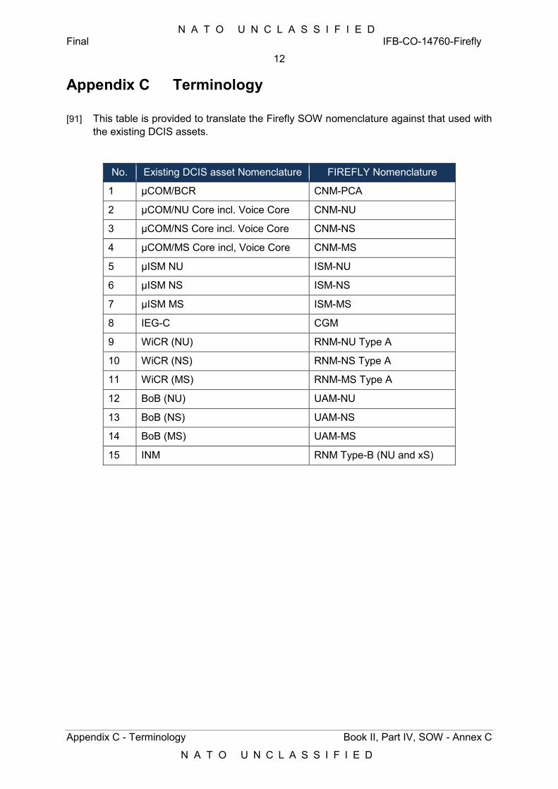
N A T O U N C L A S S I F I E D Final IFB-CO-14760-Firefly
12
Appendix C - Terminology Book II, Part IV, SOW - Annex C
N A T O U N C L A S S I F I E D
Terminology
[91] This table is provided to translate the Firefly SOW nomenclature against that used with the existing DCIS assets.
No. Existing DCIS asset Nomenclature FIREFLY Nomenclature
1 µCOM/BCR CNM-PCA
2 µCOM/NU Core incl. Voice Core CNM-NU
3 µCOM/NS Core incl. Voice Core CNM-NS
4 µCOM/MS Core incl, Voice Core CNM-MS
5 µISM NU ISM-NU
6 µISM NS ISM-NS
7 µISM MS ISM-MS
8 IEG-C CGM
9 WiCR (NU) RNM-NU Type A
10 WiCR (NS) RNM-NS Type A
11 WiCR (MS) RNM-MS Type A
12 BoB (NU) UAM-NU
13 BoB (NS) UAM-NS
14 BoB (MS) UAM-MS
15 INM RNM Type-B (NU and xS)


N A T O U N C L A S S I F I E D
N A T O U N C L A S S I F I E D

N A T O U N C L A S S I F I E D
N A T O U N C L A S S I F I E D
Provide DCIS Equipment for Small NRF HQ
Short Title: Project FIREFLY
Book II - Part IV
Statement of Work (SoW) Annex D – Testing, Verification and Validation
Requirements
Reference: IFB-CO-14760-Firefly
Publication Date: 14/12/2018
Classification: NATO UNCLASSIFIED
Status: Final
Version: 1.00
No. of pages 16

N A T O U N C L A S S I F I E D Final IFB-CO-14760-Firefly
i
Book II, Part IV, SOW – Annex D
N A T O U N C L A S S I F I E D
This page is intentionally left blank.
N A T O U N C L A S S I F I E D Final IFB-CO-14760-Firefly
ii
Book II, Part IV, SOW – Annex D
N A T O U N C L A S S I F I E D
TABLE OF CONTENTS
TABLE OF CONTENTS ....................................................................................................... ii
Index of Figures .................................................................................................................. ii
Index of Tables .................................................................................................................... ii
1 Introduction .................................................................................................................. 1
1.1 PURPOSE ................................................................................................................. 1 1.2 SCOPE OF THE DOCUMENT ........................................................................................ 1
2 Testing, Verification and Validation Requirements ................................................... 1
INDEX OF FIGURES
Figure 1 Product Quality Criteria 7
INDEX OF TABLES
Table 1 List of Test Events .................................................................................................... 5
Table 2 Test Documentation ................................................................................................. 7

N A T O U N C L A S S I F I E D Final IFB-CO-14760-Firefly
iii
Book II, Part IV, SOW – Annex D
N A T O U N C L A S S I F I E D
This page is intentionally left blank.
N A T O U N C L A S S I F I E D Final IFB-CO-14760-Firefly
1
Introduction Book II, Part IV, SOW – Annex D
N A T O U N C L A S S I F I E D
1 Introduction
1.1 Purpose [1] The Firefly consists of a set of DCIS nodes that need to be integrated into the existing
DCIS infrastructure and services. In support of a given deployed HQ, these nodes will be interconnected within the geographical footprint of the HQ, and operate as a DPOP, connecting to other DPOPs (Fireflies or Dragonflies, as well as CGS, LINC-E and ACP), or to the MAF enclaves, using Wide Area Network (WAN) bearers, e.g. SATCOM.
[2] Firefly and Dragonfly components are not to be interchangeable. DPOPs will be made of Firefly or Dragonfly nodes, but will not contain a mix of the two. The same applies to CGS, LINC-E and ACP DPOPs, vis-à-vis Dragonflies and Fireflies.
1.2 Scope of the document [3] The scope of this document includes all verification and validation principles, activities
and test processes that shall be executed by the Contractor during the various verification and validation stages of the project.
[4] All deliverables supplied by the Contractor under this contract shall be verified and validated to ensure they meet the requirements of this contract. Both fitness-for-use and fitness-for-purpose will be assessed using a quality based approach.
[5] The verification and validation approach will not only involve delivered equipment, but also interfaces and interoperability with existing NATO and/or national equipment, here considered as Purchaser Furnished Equipment (PFE).
[6] The verification and validation of PFE is out of the scope of this document and the contract.
2 Testing, Verification and Validation Requirements [7] This section defines the generic requirements to be applied by the Contractor to the
Testing, Verification and Validation (TVV) process, which is required for verification and validation of the requirements set forth under this Contract by the Purchaser.
[8] Each requirement below contains an Independent Verification and Validation (IVV) reference number (in brackets at the end of the statement), which refers to the Purchaser’s internal processes. This process will be explained in the Kick-Off meeting.
[9] The Firefly requires a set of testing activities to verify its compliance with the Contractual requirements set forth in the SOW and in the SRS (Annex A to the SOW).
All information items used during the verification and validation activities are to be classified and handled according to their security classification. Guidance is provided in this SOW, under the security section.
N A T O U N C L A S S I F I E D Final IFB-CO-14760-Firefly
2
Testing, Verification and Validation Requirements Book II, Part IV, SOW – Annex D
N A T O U N C L A S S I F I E D
All deliverables supplied by the Contractor under this contract will be verified and validated to meet the requirements of this contract. All document-based deliverables shall be produced in a manner compliant with the templates provided by the Purchaser.
The templates that shall be used are listed at Appendix A to this document.
[10] Note the provided templates are a mature drafts, the final versions will be provided at the time of Contract Award.
In particular the Contractor shall:
1) Perform the verification activities within each Build Process;
2) Perform verification to confirm that each element properly reflects the specified requirements, design, code, integration and documentation;
3) Support Purchaser led Validation Activities to confirm that the solution is fit for purpose.
The Contractor shall demonstrate to the Purchaser that there is a testing process in place for the project, with quality assurance oversight. (IVV-4)
The Contractor shall identify and communicate to the Purchaser which best practices and international standards will be applied.
The Contractor shall strictly follow the test process, document templates and guidance provided by the Purchaser unless officially agreed by the Purchaser (IVV-4).
The Contractor shall ensure that rigorous testing, including regression testing when required, is performed at every stage of the Project lifecycle in order to identify and correct defects as early as possible and minimise impact on cost and schedule (IVV-4).
The Contractor shall propose a testing process which will make use of automated testing and supporting testing tools (test management, requirement coverage, issue tracking, etc.) to the maximum applicable extent, for all system development, implementation, internal and Contractual tests. The testing process and proposed supportive tools shall be approved by the Purchaser.
[11] Requirements coverage, defect management and test management tools to be used in this project will be selected and hosted by the Purchaser. The Purchaser will grant access to an agreed number of individuals nominated by the Contractor.
All test, verification and validation material developed and used under this contract shall be delivered to the Purchaser. (IVV-4)
The Contractor shall provide an overall project Test Manager, who will work closely with the Purchaser’s assigned IVV lead. (IVV-4)
The Contractor shall provide a Test Director for each event defined in Table 1. Table 1 defines the type of test events considered. It is expected that the Firefly project will split the test event types defined in Table 1 into multiple events, as per the SOW.
N A T O U N C L A S S I F I E D Final IFB-CO-14760-Firefly
3
Testing, Verification and Validation Requirements Book II, Part IV, SOW – Annex D
N A T O U N C L A S S I F I E D
[12] The Purchaser will provide subject matter experts (SME) during each event, as well as IVV Test Engineers and, for some events and at the Purchaser’s discretion, a NATO Assurance Representative. (IVV-4)
The Contractor shall have the overall responsibility for meeting the Firefly testing requirements and conducting all related activities defined in Table 1. (IVV-4)
[13] In the context of this document the test events (Table 1) are considered as Contractual tests under Contractor responsibility. (IVV-4)
The Contractor shall support post go-live activities during the System Validation period, in order to evaluate the Firefly capability performance and establish benchmarks for future enhancements, including any changes made to fulfil the requirements.
The Contractor shall update the Purchaser periodically on verification and validation activities during the planning/design and development phases, via the use of a dashboard report within the test management tool set and/or through teleconferences.
Progress and result measurement shall be approved by the Purchaser and focused on items like number of defects (and their severity) found and fixed, labour spent for verification activities, and test activities progress.
Test results shall be recorded in the test management tool set. All results of all formal acceptance testing performed during a given day shall be recorded in the test management tool. The Contractor shall provide these test results for any given day by the starting of the next business day (0800 AM), but as a minimum no later than 24 hours following the execution of any test.
The Contractor shall define and make use of KPIs to identify opportunities for quality improvement, provide solutions and update the plans the achievement of defined objectives like coverage of risks, requirements, supported configurations, supported operational scenarios, etc.
For each event defined in Table 1, the Contractor shall perform the following activities (IVV-4):
1) Planning and management of the test event;
2) The design and development of all tests cases and associated documentation required under this Contract;
3) The conducting of all testing;
4) Reporting the results; and,
5) Closure of the of test events (including the final version of all test artefacts created during the test event).
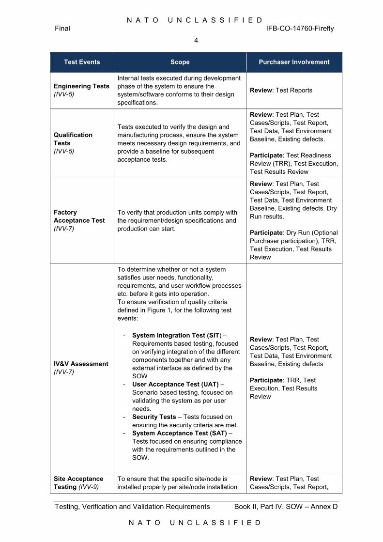
N A T O U N C L A S S I F I E D Final IFB-CO-14760-Firefly
4
Testing, Verification and Validation Requirements Book II, Part IV, SOW – Annex D
N A T O U N C L A S S I F I E D
Test Events Scope Purchaser Involvement
Engineering Tests (IVV-5)
Internal tests executed during development phase of the system to ensure the system/software conforms to their design specifications.
Review: Test Reports
Qualification Tests (IVV-5)
Tests executed to verify the design and manufacturing process, ensure the system meets necessary design requirements, and provide a baseline for subsequent acceptance tests.
Review: Test Plan, Test Cases/Scripts, Test Report, Test Data, Test Environment Baseline, Existing defects. Participate: Test Readiness Review (TRR), Test Execution, Test Results Review
Factory Acceptance Test (IVV-7)
To verify that production units comply with the requirement/design specifications and production can start.
Review: Test Plan, Test Cases/Scripts, Test Report, Test Data, Test Environment Baseline, Existing defects. Dry Run results. Participate: Dry Run (Optional Purchaser participation), TRR, Test Execution, Test Results Review
IV&V Assessment (IVV-7)
To determine whether or not a system satisfies user needs, functionality, requirements, and user workflow processes etc. before it gets into operation. To ensure verification of quality criteria defined in Figure 1, for the following test events:
- System Integration Test (SIT) – Requirements based testing, focused on verifying integration of the different components together and with any external interface as defined by the SOW
- User Acceptance Test (UAT) – Scenario based testing, focused on validating the system as per user needs.
- Security Tests – Tests focused on ensuring the security criteria are met.
- System Acceptance Test (SAT) – Tests focused on ensuring compliance with the requirements outlined in the SOW.
Review: Test Plan, Test Cases/Scripts, Test Report, Test Data, Test Environment Baseline, Existing defects Participate: TRR, Test Execution, Test Results Review
Site Acceptance Testing (IVV-9)
To ensure that the specific site/node is installed properly per site/node installation
Review: Test Plan, Test Cases/Scripts, Test Report,
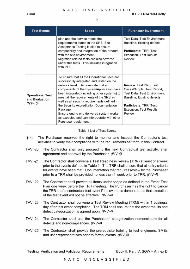
N A T O U N C L A S S I F I E D Final IFB-CO-14760-Firefly
5
Testing, Verification and Validation Requirements Book II, Part IV, SOW – Annex D
N A T O U N C L A S S I F I E D
Test Events Scope Purchaser Involvement
plan and the service meets the requirements stated in the SRS. Site Acceptance Testing is also to ensure compatibility and integration of the product with the site environment. Migration related tests are also covered under this tests. This includes integration with PFE.
Test Data, Test Environment Baseline, Existing defects Participate: TRR, Test Execution, Test Results Review
Operational Test and Evaluation (IVV-10)
To ensure that all the Operational Sites are successfully integrated and tested on the network level. Demonstrate that all components of the System/Application have been integrated (including other systems) to meet all the requirements of the SRS as well as all security requirements defined in the Security Accreditation Documentation Package. Ensure end to end delivered system works as expected and can interoperate with other Purchaser equipment
Review: Test Plan, Test Cases/Scripts, Test Report, Test Data, Test Environment Baseline, Existing defects Participate: TRR, Test Execution, Test Results Review
Table 1 List of Test Events
[14] The Purchaser reserves the right to monitor and inspect the Contractor’s test activities to verify their compliance with the requirements set forth in this Contract.
The Contractor shall only proceed to the next Contractual test activity, after agreement and approval by the Purchaser. (IVV-4)
The Contractor shall convene a Test Readiness Review (TRR) at least one week prior to the events defined in Table 1. The TRR shall ensure that all entry criteria for events have been met. Documentation that requires review by the Purchaser prior to a TRR shall be provided no less than 1 week prior to TRR. (IVV-4)
The Contractor shall provide all items under scope as defined in the Event Test Plan one week before the TRR meeting. The Purchaser has the right to cancel the TRR and/or contractual test event if the evidence demonstrates that execution of the test event will not be effective. (IVV-4)
The Contractor shall convene a Test Review Meeting (TRM) within 1 business day after test event completion. The TRM shall ensure that the event results and defect categorization is agreed upon. (IVV-4)
The Contractor shall use the Purchasers’ categorization nomenclature for all defects and non-compliances. (IVV-4)
The Contractor shall provide the prerequisite training to test engineers, SMEs and user representatives prior to formal events. (IVV-4)
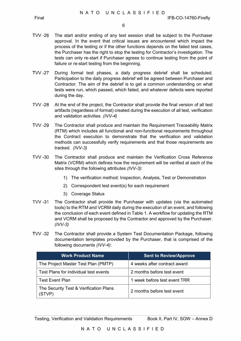
N A T O U N C L A S S I F I E D Final IFB-CO-14760-Firefly
6
Testing, Verification and Validation Requirements Book II, Part IV, SOW – Annex D
N A T O U N C L A S S I F I E D
The start and/or ending of any test session shall be subject to the Purchaser approval. In the event that critical issues are encountered which impact the process of the testing or if the other functions depends on the failed test cases, the Purchaser has the right to stop the testing for Contractor’s investigation. The tests can only re-start if Purchaser agrees to continue testing from the point of failure or re-start testing from the beginning.
During formal test phases, a daily progress debrief shall be scheduled. Participation to the daily progress debrief will be agreed between Purchaser and Contractor. The aim of the debrief is to get a common understanding on what tests were run, which passed, which failed, and whatever defects were reported during the day.
At the end of the project, the Contractor shall provide the final version of all test artifacts (regardless of format) created during the execution of all test, verification and validation activities. (IVV-4)
The Contractor shall produce and maintain the Requirement Traceability Matrix (RTM) which includes all functional and non-functional requirements throughout the Contract execution to demonstrate that the verification and validation methods can successfully verify requirements and that those requirements are tracked. (IVV-3)
The Contractor shall produce and maintain the Verification Cross Reference Matrix (VCRM) which defines how the requirement will be verified at each of the sites through the following attributes (IVV-3):
1) The verification method: Inspection, Analysis, Test or Demonstration
2) Correspondent test event(s) for each requirement
3) Coverage Status
The Contractor shall provide the Purchaser with updates (via the automated tools) to the RTM and VCRM daily during the execution of an event, and following the conclusion of each event defined in Table 1. A workflow for updating the RTM and VCRM shall be proposed by the Contractor and approved by the Purchaser. (IVV-3)
The Contractor shall provide a System Test Documentation Package, following documentation templates provided by the Purchaser, that is comprised of the following documents (IVV-4):
Work Product Name Sent to Review/Approve
The Project Master Test Plan (PMTP) 4 weeks after contract award
Test Plans for individual test events 2 months before test event
Test Event Plan 1 week before test event TRR
The Security Test & Verification Plans (STVP) 2 months before test event
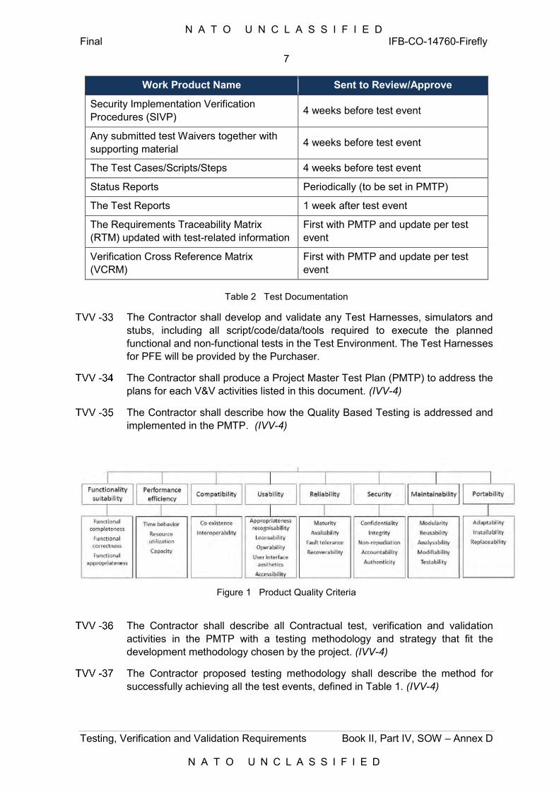
N A T O U N C L A S S I F I E D Final IFB-CO-14760-Firefly
7
Testing, Verification and Validation Requirements Book II, Part IV, SOW – Annex D
N A T O U N C L A S S I F I E D
Work Product Name Sent to Review/Approve
Security Implementation Verification Procedures (SIVP) 4 weeks before test event
Any submitted test Waivers together with supporting material 4 weeks before test event
The Test Cases/Scripts/Steps 4 weeks before test event
Status Reports Periodically (to be set in PMTP)
The Test Reports 1 week after test event
The Requirements Traceability Matrix (RTM) updated with test-related information
First with PMTP and update per test event
Verification Cross Reference Matrix (VCRM)
First with PMTP and update per test event
Table 2 Test Documentation
The Contractor shall develop and validate any Test Harnesses, simulators and stubs, including all script/code/data/tools required to execute the planned functional and non-functional tests in the Test Environment. The Test Harnesses for PFE will be provided by the Purchaser.
The Contractor shall produce a Project Master Test Plan (PMTP) to address the plans for each V&V activities listed in this document. (IVV-4)
The Contractor shall describe how the Quality Based Testing is addressed and implemented in the PMTP. (IVV-4)
Figure 1 Product Quality Criteria
The Contractor shall describe all Contractual test, verification and validation activities in the PMTP with a testing methodology and strategy that fit the development methodology chosen by the project. (IVV-4)
The Contractor proposed testing methodology shall describe the method for successfully achieving all the test events, defined in Table 1. (IVV-4)
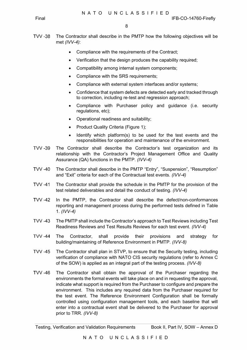
N A T O U N C L A S S I F I E D Final IFB-CO-14760-Firefly
8
Testing, Verification and Validation Requirements Book II, Part IV, SOW – Annex D
N A T O U N C L A S S I F I E D
The Contractor shall describe in the PMTP how the following objectives will be met (IVV-4):
Compliance with the requirements of the Contract;
Verification that the design produces the capability required;
Compatibility among internal system components;
Compliance with the SRS requirements;
Compliance with external system interfaces and/or systems;
Confidence that system defects are detected early and tracked through to correction, including re-test and regression approach;
Compliance with Purchaser policy and guidance (i.e. security regulations, etc);
Operational readiness and suitability;
Product Quality Criteria (Figure 1);
Identify which platform(s) to be used for the test events and the responsibilities for operation and maintenance of the environment.
The Contractor shall describe the Contractor’s test organization and its relationship with the Contractor’s Project Management Office and Quality Assurance (QA) functions in the PMTP. (IVV-4)
The Contractor shall describe in the PMTP “Entry”, “Suspension”, “Resumption” and “Exit” criteria for each of the Contractual test events. (IVV-4)
The Contractor shall provide the schedule in the PMTP for the provision of the test related deliverables and detail the conduct of testing. (IVV-4)
In the PMTP, the Contractor shall describe the defect/non-conformances reporting and management process during the performed tests defined in Table 1. (IVV-4)
The PMTP shall include the Contractor’s approach to Test Reviews including Test Readiness Reviews and Test Results Reviews for each test event. (IVV-4)
The Contractor, shall provide their provisions and strategy for building/maintaining of Reference Environment in PMTP. (IVV-8)
The Contractor shall plan in STVP, to ensure that the Security testing, including verification of compliance with NATO CIS security regulations (refer to Annex C of the SOW) is applied as an integral part of the testing process. (IVV-8)
The Contractor shall obtain the approval of the Purchaser regarding the environments the formal events will take place on and in requesting the approval, indicate what support is required from the Purchaser to configure and prepare the environment. This includes any required data from the Purchaser required for the test event. The Reference Environment Configuration shall be formally controlled using configuration management tools, and each baseline that will enter into a contractual event shall be delivered to the Purchaser for approval prior to TRR. (IVV-8)
N A T O U N C L A S S I F I E D Final IFB-CO-14760-Firefly
9
Testing, Verification and Validation Requirements Book II, Part IV, SOW – Annex D
N A T O U N C L A S S I F I E D
The Contractor shall ensure that all test/reference environments are under proper change management and configuration control. The Change Management and Configuration Control specific toolset and process shall be approved by the Purchaser. (IVV-11)
The Contractor may request a Test Waiver if the Contractor has previously successfully completed qualification testing to national, or international standards for assemblies, subassemblies components or parts. The Purchaser, after review of test waivers and analysis of their impact, reserves the right to require test and certification of the modified equipment at no cost to the Purchaser. The Purchaser has the right to reject any test Waiver:
1) If the Purchaser grants the waiver, the Contractor shall execute the Testing in accordance with the waiver;
2) In respect to a requested waiver, the Contractor shall certify that the test environment to be implemented is identical to that which was originally used for testing, or advise the Purchaser of design/construction changes which affect form, fit or function;
3) The Contractor shall record and log all waiver requests along with their resolution submitted for the Purchaser’s approval.
N A T O U N C L A S S I F I E D Final IFB-CO-14760-Firefly
10
Testing, Verification and Validation Requirements Book II, Part IV, SOW – Annex D
N A T O U N C L A S S I F I E D
This page is intentionally blank.
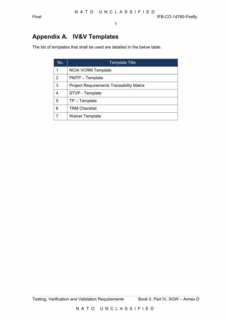
N A T O U N C L A S S I F I E D Final IFB-CO-14760-Firefly
1
Testing, Verification and Validation Requirements Book II, Part IV, SOW – Annex D
N A T O U N C L A S S I F I E D
Appendix A. IV&V Templates
The list of templates that shall be used are detailed in the below table.
No. Template Title
1 NCIA VCRM Template
2 PMTP – Template
3 Project Requirements Traceability Matrix
4 STVP - Template
5 TP – Template
6 TRM Checklist
7 Waiver Template

N A T O U N C L A S S I F I E D
N A T O U N C L A S S I F I E D