Embed Size (px)
Citation preview
AGAR D-LS-39-70 gm a:
2 (3 "I a a G a B D
ADVISORY GROUP FOR AEROSPACE RESEARCH & DEVELOPMENT
LECTURE SERIES No. 39 On
Advanced Compressors
I I
N O R T H ATLAINTIC TREATY O R G A N I Z A T I O N -
INITIAL DISTRIBUTION IS LIMITED FOR ADDITIONAL COPIES SEE BACk COVER

NORTH ATLANTIC TREATY ORGANIZATION
ADVISORY GROUP FOR AEROSPACE RESEARCH AND DEVELOPMENT
(ORGANISATION DU TRAITE DE L'ATLANTIQUE NORD)
.-
A D V A N C E D C O M P R E S S O R S
AGARD Lecture Series No.39
The material in this book has been assembled to support a Lecture Series under the sponsorship of the Propulsion and Energetics Panel and the Consultant and Exchange Programme of AGARD.
The material in t h i s publication has been composed d irec t ly from copy supplied by each author.
Published August 1970
621.438.031.3
Printed by Technical Ed i t ing and Reproduction Ltd Harford House, 7-9 Charlo t te S t , London. W d ' 1HD
ii
FORE WORD
Upon i n v i t a t i o n of Nat ional Delegates of Belgium and Norway, Lecture S e r i e s 39 on “Advanced Compressors” was presented i n Brussels , Belgium, and i n Bolkesjd, Norway, i n June 1970.
This Lecture S e r i e s was sponsored by t h e Propulsion and Energe t ics Panel and t h e Consul tant and Exchange Programme of AGARD.
During t h e past few years , s i g n i f i c a n t progress has been made i n t h e design and development of high performance a x i a l and radial compressors, i n response t o t h e increas- ing demand from j e t engine and gas t u r b i n e manufacturers and t o t h e broadening i n t e r e s t f o r such machines f o r c losed cycle gas t u r b i n e a p p l i c a t i o n f o r atomic power p l a n t s .
The development of d i g i t a l computers has enabled t h e use of more and more s o p h i s t i c a t e d design methods which are now paying o f f . S i g n i f i c a n t improvements have a l s o been obtained f o r t h e compressor opera t ion i n t h e t ransonic and supersonic range. I n t e r e s t i n t h e long f o r g o t t e n r a d i a l compressors has been revived, f o r small gas t u r b i n e a p p l i c a t i o n , and s t a r t l i n g improvement i n performance has been obtained, both i n e f f i c i e n c y and i n maximum pressure r a t i o obtainable .
It was f e l t by AGARD t h a t a review of t h e recent progress and of t h e prospec ts f o r t h e f u t u r e w a s appropr ia te .
The Lecture S e r i e s , which w a s presented by leading exper t s i n t h e f i e l d , covered advanced information on r a d i a l and a x i a l flow compressors, including a p p l i c a t i o n of through-flow methods of c a l c u l a t i o n t o a x i a l and radial t ransonic and supersonic compressors, flow i n supersonic bladings (cascade performance and mass flow l i m i t a t i o n s ) , flow i n subsonic bladings with a l o c a l supersonic region, secondary flows and losses , advanced design of r a d i a l flow compressors, supersonic vaneless and vaned d i f f u s e r s .
The Lecture S e r i e s was concluded by a round-table discussion.
S c i e n t i s t s and Engineers from 10 NATO Nations p a r t i c i p a t e d i n t h i s Lecture S e r i e s .
ROLLAND A.WILLAUME Direc tor , Plans and Programmes, AGARD
AVANT - PRQPOS
Sur l ' i n v i t a t i o n des de'16gue's nationaux de la Belgique e t de la Norvhge, la se 'r ie de confe'rences No. 39 consacre'e aux "Compresseurs d' Avant-garde" f u t prdsente'e & Bruxelles. Belgique, e t h Bolkesjd. Norvhge en j u i n 1970.
La pre'sente se'rie de confe'rences f u t placde sous 1' e'gide de la Commission "Propulsion e t Energe't ique" e t du "Programme Consultat i f e t d' Echange" de 1' AGARD.
Au cours de ces de rn ie re s anne'es. des progres importants ont &e' re'alises en m a t i h e de la conception e t de l a mise au po in t des compresseurs axiaux e t radiaux & rendement e'leve', e t ce pour re'pondre & la demande tou jou r s c ro i s san te de l a part des f a b r i c a n t s de moteurs & re 'action e t de tu rb ines & gaz, a i n s i qu '8 1' inte 'rbt de p lus en p lus large porte' & de t e l l e s machines pour app l i ca t ion aux tu rb ines k gaz & cycle fermd destine'es aux c e n t r a l e s nucle 'aires.
L' e'volution des o rd ina teu r s nume'riques a permis l ' u t i l i s a t i o n de techniques d' e'tude de p lus en p lus ra f f ine 'es q u i commencent k s ' amor t i r . fonc t ionnement du compresseur en re'gime t ranssonique e t supersonique a e'galement &e' obtenue. On por t e un nouvel inte 'rbt aux compresseurs de type r a d i a l , oublie's depuis longtemps. pour app l i ca t ion aux tu rb ines & gaz de pe t i te t a i l l e , e t dans l e domaine des performances, a u s s i b i en l e rendement que l e rappor t maximum de press ion re ' a l i sab le se sont trouve's ame'liore's de facon s a i s i s s a n t e .
Une ame'lioration sens ib l e du
I1 a semble' opportun k 1'AGARD de passer en revue l e s proprhs enregis t re ' s jusqu'k pre'sent e t les pe r spec t ives d' aveni r .
La se'rie de confe'rences, pre'sente'e par l e s grands spe'cialistes en la matiere, a fou rn i des renseignements avance's s u r l e s compresseurs & e'coulement t a n t a x i a l que r a d i a l , y compris 1' app l i ca t ion aux compresseurs t ranssoniques e t supersoniques B e'coulement axial ou r a d i a l de proce'de's de c a l c u l u t i l i s a n t un e'coulement d r o i t ; l'e'coulement dans l e s aubages supersoniques (performances des g r i l l e s e t l i m i t a t i o n s & d' e'coulement massique); 1' e'coulement dans les aubages subsoniques ayant une zone supersonique loca le ; les e'coule- ments secondai res e t les pe r t e s ; 1' dtude e'volude des compresseurs k dcoulement radial; les d i f fuseu r s supersoniques sans e t avec aubes.
La se 'r ie de conferences s'est termine'e par une "Table Ronde", e t a re'uni des sc i en - t i f i q u e s e t inge'nieurs venant de 10 pays membres de 1'OTAN.
ROLLAND A.WILW\UME Direc teur , Plans e t Programmes, AGARD
iv
C O N T E N T S
F O R E W O R D
A V A N T P R O P O S
P A R T I C I P A N T S
I N T R O D U C T O R Y R E M A R K S : R E C E N T P R O G R E S S I N A E R O D Y N A M I C D E S I G N O F C O M P R E S S O R S by J. C h a u v i n
T H E T H R O U G I I - F L O W A N A L Y S I S O F A X I A L F L O W C O M P R E S S O R S by H . M a r s h
M A S S F L O W L I M I T A T I O N I N S U P E R S O N I C C O M P R E S S O R S by J . F a b r i
T R A N S O N I C C O M P R E S S O R C A S C A D E S by H. G r i e p e n t r o g
S E C O N D A R Y F L O W L O S S E S I N A X I A L C O M P R E S S O R S by H. G r i e p e n t r o g
B A S I C E L E M E N T S F O R A D V A N C E D D E S I G N S O F R A D I A L F L O W C O M P R E S S O R S by M . H . V a v r a
S U P E R S O N I C R A D I A L D I F F U S O R S by D . P . K e n n y
S U P E R S O N I C C A S C A D E P E R F O R M A N C E by H . S t a r k e n and H . L i c h t f u s s
A P P L I C A T I O N O F T H R O U G H F L O W T O R A D I A L W H E E L D E S I G N by M . V a v r a
C O N C L U S I O N by J. C h a u v i n
P a g e
i i i
i v
v i
R e f e rence
1
2
3
4
5
6
'1
8
9
10
V
PARTICIPANTS
Lecture S e r i e s Director: Professor J. Chauvin Von K h d n I n s t i t u t e Rhode-Saint -Gen&se Be 1 g i urn
Speakers: Mr J. Fabr i Chef de Division de Recherches ONERA Chatillon-sous-Bagneux France
Dr H. Griepentrog GutehoffnungshUtte S terkrade Oberhausen Germany
Mr D.P.Kenny Supervisor, Compressor Research United Ai rc ra f t of Canada Ltd Longueuil, Quebec Canada
D r H.Marsh Engineering Department University of Cambridge UK
Mr H.Starken I n s t i t u t f u r L u f t s t r a h l m t r i e b e DFVLR Porz- Wahn Germany
Professor M.H. Vavra US Naval Postgraduate School Monterey, Ca l i fo rn ia USA
v i
1
INTRODUCTORY REMARKS
RECENT PROGRESS IN AERODYNAMIC
DESICB OF COMPRESSORS.
J..CHAUVIN
Professor, Head Turbomachinery Laboratory von Karman Institute
1
S U M M A R Y
The progress made during the last few years in compressor performance is briefly reviewed. The reasons behind this progress (systematic use of transonic or supersonic blading, improvement in understanding of the flow behaviour, development of sophisticated theories, availability of large computers) are reviewed and briefly discussed.
The course content is presented, and justified, starting from a physical description of the flow in turbomachines and of the resulting flow models and some of the critical areas for future research are presented.
S O M M A I R E
Lea progras r6alisEs d a n s l'aocroissement des performances des compresseurs a u cours de ces dernigres ann6es sont pass6s en revue. Lee bases de ces progrgs (utilisation eyst8- matigue d'aubages transsoniques et supersoniques, meilleure compr6hension des m6canismes d'6coulement, d6veloppement de th6ories plus complexes, utilisations d'ordinateurs a grande capacit8) sont pr6sent6es.
On pr6sente ensuite le contenu du cours, au d6part d'une description physique des 6cou- laments dans le8 turbomachines et'des modgles d'6coulement qui en d6coulent. On pr6sente ensuite quelques-una des domaines de recherche6 critiques pour les d6veloppement.s futurs.
1
LIST OF FIGURES
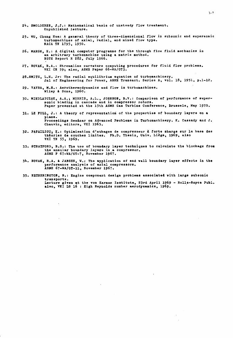
1. E v o l u t i o n of a x i a l compressor -s tages p r e s s u r e r a t i o i n f u n c t i o n of t h e mean Mach number r e l a t i v e t o t h e r o t o r M ( c o u r t e s y F. Breugelmans, V K I )
2. E v e l a t i o n of s t a g e e f f i c i e n c y i n f u n c t i o n of w ( a x i a l compresso r s ) ( c o u r t e s y F. Breugelmans, V K I )
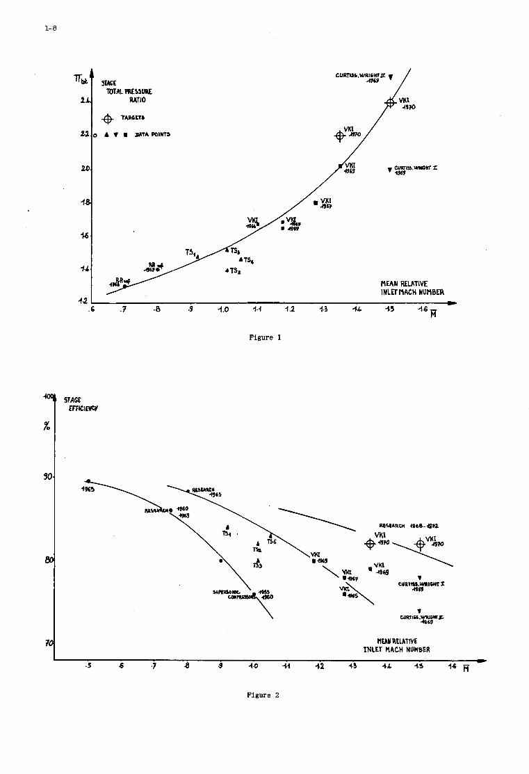
3. Number of compre r so r s t a g e s fer 1 0 / 1 p r e s s u r e r a t i o ( c o n s t a n t a d i a b a t i c efficiency (from ref. 3 )
4. E f f e c t of p r e s s u r e r a t i o and t u r b i n e i n l e t t e m p e r a t u r e cm s p e c i i i c f u e l conrumpt ion
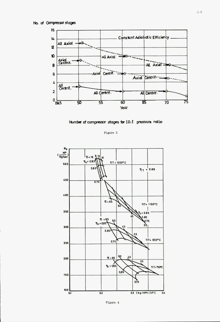
5. T y p i c a l pe r fo rmance of an advanced r a d i a l compressor (from ref. 8 )
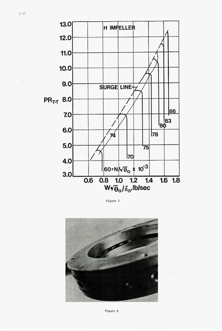
6 . A new t y p e of s u p e r s o n i c d i f f u s e r for r a d i a l compressor ( U n i t e d A i r c r a f t Canada)
and s p e c i f i c power (small g a s t u r b i n e )
(from re f . 8 )
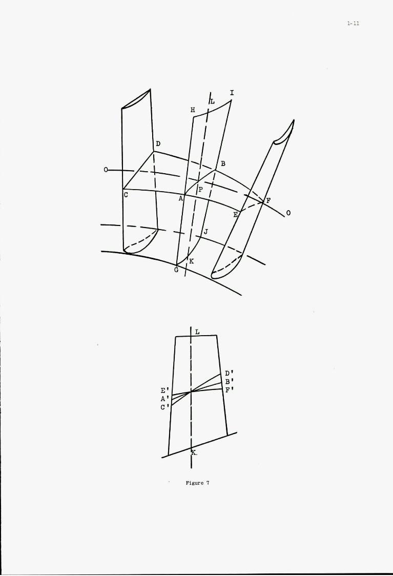
7. Stream s u r f a c e d i s t o r s i o n i n a x i a l f l ow cornpressor b l a d i n g
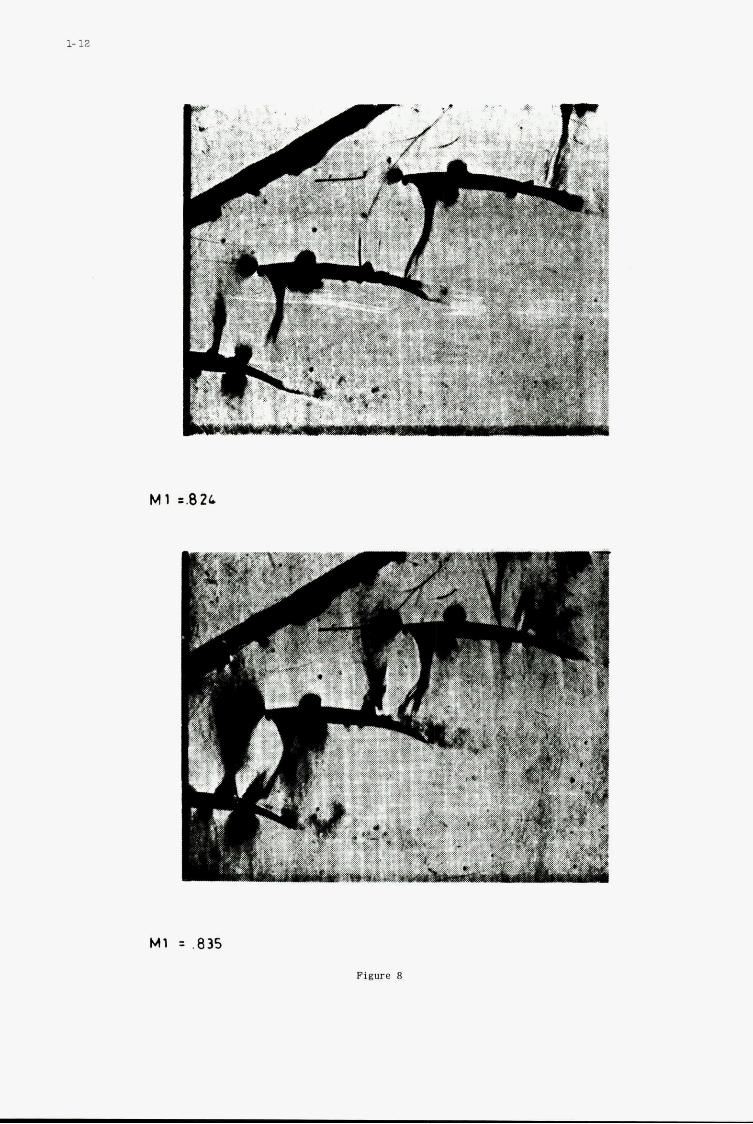
8. Flow i n b l a d i n g w i t h a l o c a l s u p e r s o n i c r e g i o n
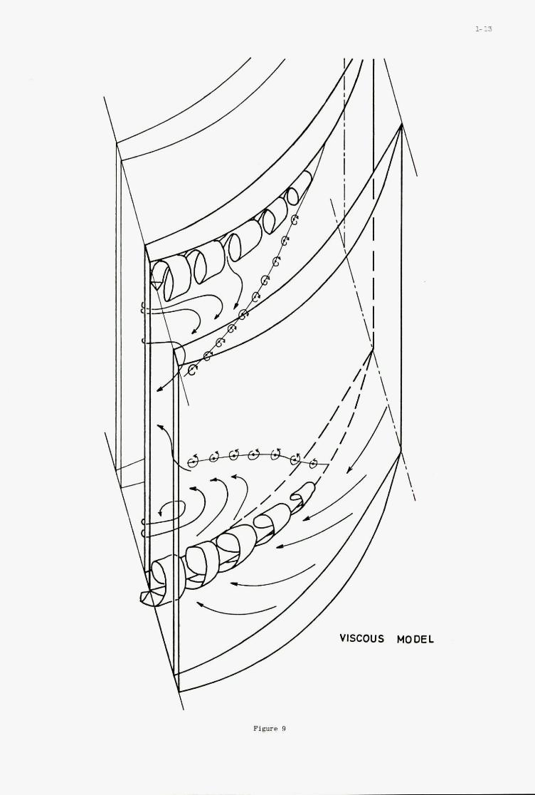
9 . Cascade secondary flow
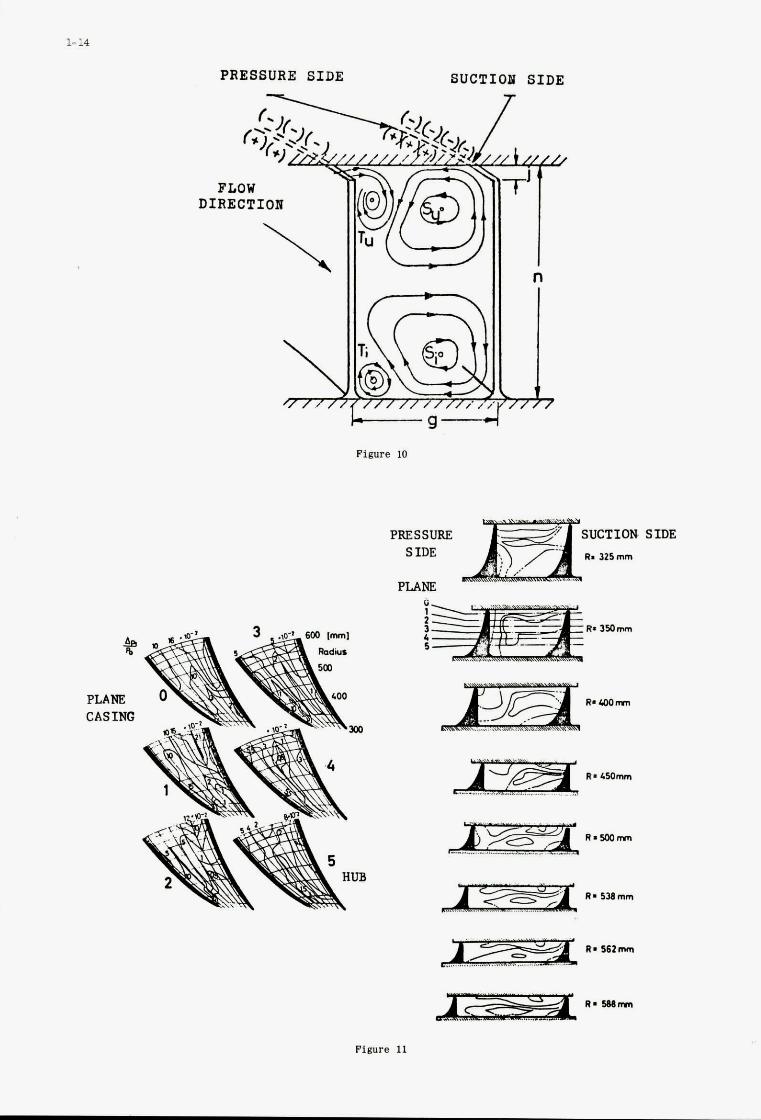
10. Downrtream view of secondary f l o w s
11. Three d i m e n s i o n a l t o t a l p r e s s u r e l o s s d i s t r i b u t i o n i n a r a d i a l wheel ( f r o m ref. 2 1 )
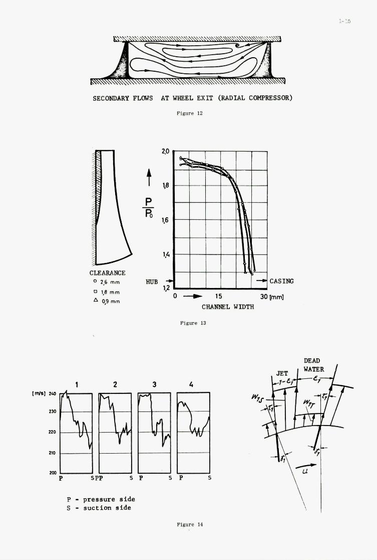
12. Secondary f l o w s a t whebl o u t l e t ( r a d i a l compresso r ) (from r e f . 21)
13. S t a t i c p r e s s u r e d i s t r i b u t i o n a t t h e wheel o u t l e t a l o n g t h e b l a d e w i d t h ( r a d i a l c o m p r e s s o r s ) ( f r o m r e f . 21 )
1 4 . I n s t a n t a n e o u s c i r c u m f e r e n t i a l v e l o c i t y d i s t r i b u t i o n a t t h e wheel o u t l e t ( r a d i a l c o m p r e s s o r s ) (from re f . 2 1 )
15. D e t a i l e d f low development i n unshrouded i m p e l l e r (from r e f . 2 2 ) ( c o u r t e s y N a t i o n a l
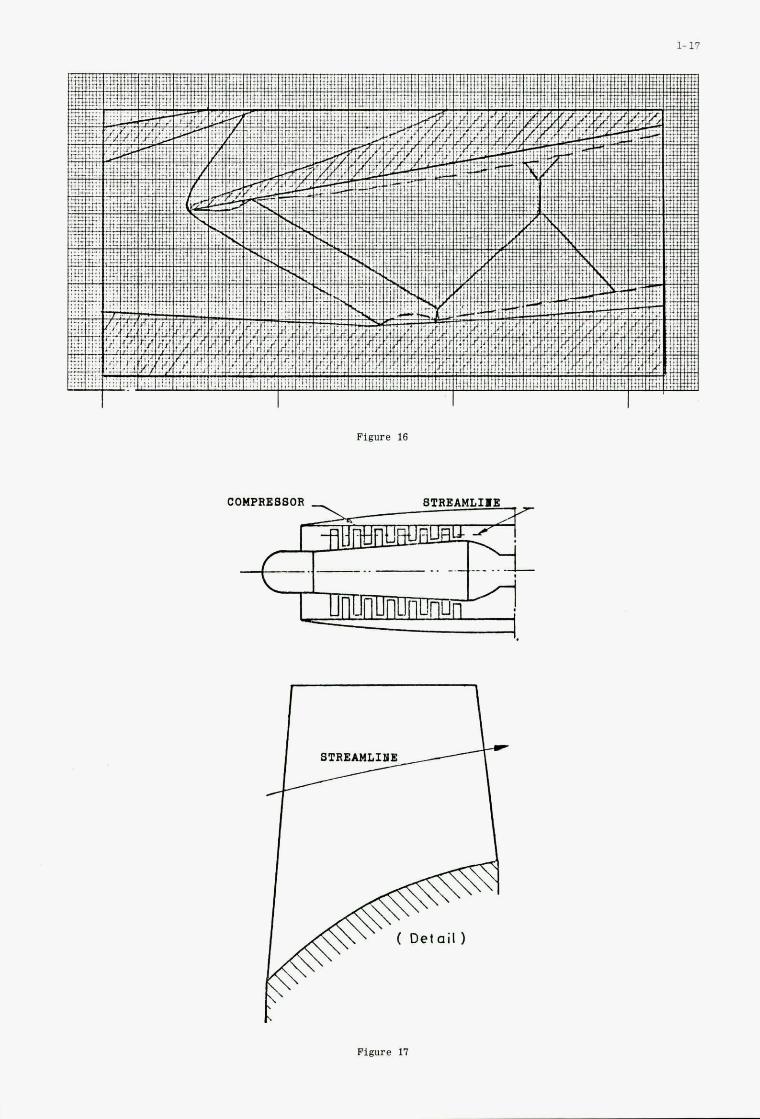
16. Schemat i c f low i n a s u p e r s o n i c vaned d i f f u s e r p a s s a g e
17. Flow i n t h e m e r i d i o n a l . p l a n e
18. Blade t o b l a d e f low
Resea rch Counc i l of Canada)

1
1- 1
I. I O T B O D U C T I O O
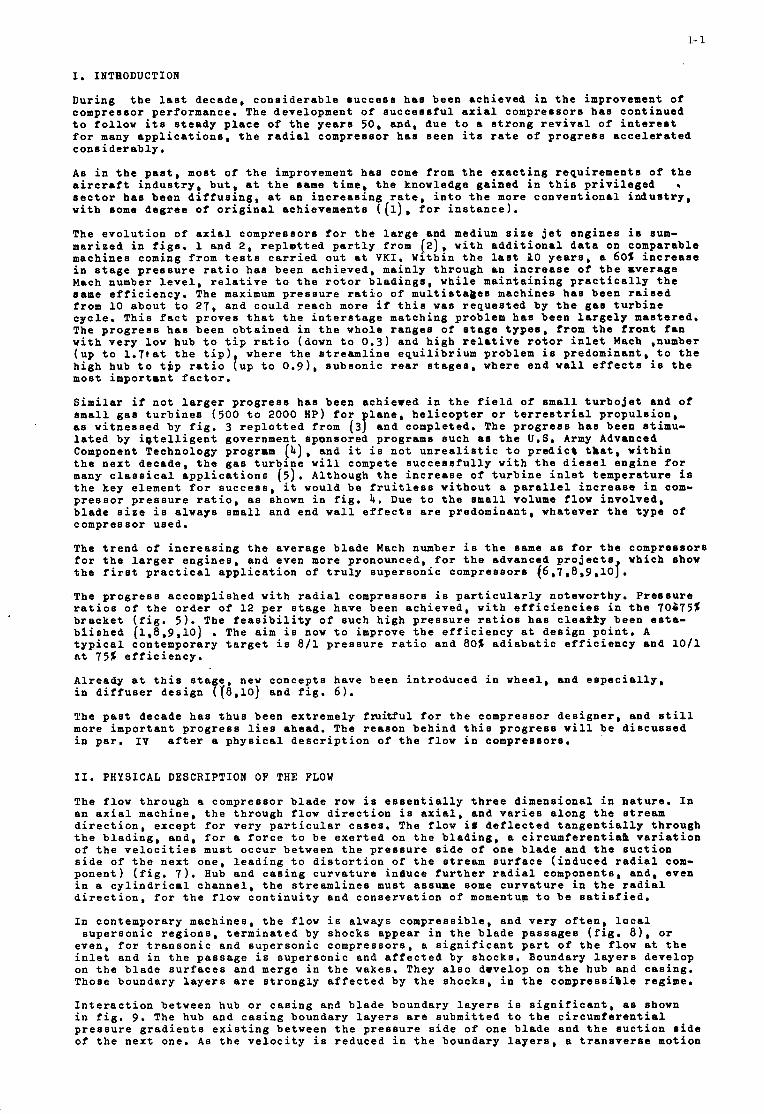
Dur ing t h e l a s t decade , c o n s i d e r a b l e s u c c e s s h a s been a c h i e v e d i n t h e improvement of compresso r pe r fo rmance . The development of s u c c e s s f u l a x i a l compresso r s h a s c o n t i n u e d t o f o l l o w i t s s t e a d y p l a c e of t h e y e a r s 50, and , due t o a s t r o n g r e v i v a l o f i n t e r e s t f o r many a p p l i c a t i o n s , t h e r a d i a l compressor h a s s e e n i t s r a t e o f p r o g r e s s a c c e l e r a t e d cons i d e r a b l y .
A s i n t h e p a s t , most o f t h e improvement h a s come from t h e e x a c t i n g r e q u i r e m e n t s o f t h e a i r c r a f t i n d u s t r y , b u t , a t t h e same t ime, t h e knowledge g a i n e d i n t h i s p r i v i l e g e d s e c t o r h a s been d i f f u s i n g , a t an i n c r e a s i n g r a t e , i n t o t h e more c o n v e n t i o n a l i n d u s t r y , w i t h some d e g r e e of o r i g i n a l ach ievemen t s ( (1) , f o r i n s t a n c e ) .
The e v o l u t i o n of a x i a l compresso r s f o r t h e l a r g e and medium s i z e j e t e n g i n e s i s sum- m a r i z e d i n f i g s . 1 and 2 , r e p l o t t e d p a r t l y from [ 2 ) , w i t h a d d i t i o n a l d a t a on comparable machines coming from t e s t s c a r r i e d o u t a t V K I . Wi th in t h e l a s t PO y e a r s , a 60% i n c r e a s e i n s t a g e p r e s s u r e r a t i o h a s been a c h i e v e d , ma in ly t h r o u g h an i n c r e a s e o f t h e r v e r a g e Mach number l e v e l , r e l a t i v e t o t h e r o t o r b l a d i n g s , w h i l e m a i n t a i n i n g p r a c t i c a l l y t h e same e f f i c i e n c y . The maximum p r e s s u r e r a t i o o f m u l t i s t a b e s machines h a s been r a i sed from 1 0 a b o u t t o 27 , and c o u l d r e a c h more i f t h i s was r e q u e s t e d by t h e g a s t u r b i n e c y c l e . T h i s f a c t p r o v e s t h a t t h e i n t e r s t a g e ma tch ing p rob lem h a s been l a r g e l y mastered. The p r o g r e s s h a s been o b t a i n e d i n t h e whole r a n g e s o f s t a g e t y p e s , f rom t h e front f a n w i t h v e r y low hub t o t i p r a t i o (down t o 0.3) and h i g h r e l a t i v e r o t o r i n l e t Mach ,number ( u p t o l . 7 t a t t h e t i p ) where t h e s t r e a m l i n e e q u i l i b r i u m problem i s p redominan t , t o t h e h i g h hub t o t $ p r a t i o [up t o 0.9), s u b s o n i c rear s tages , where e n d w a l l e f f e c t s i s t h e most i m p o r t a n t f a c t o r .
S i m i l a r i f n o t l a r g e r p r o g r e s s h a s been a c h i e v e d i n t h e f i e l d of small t u r b o j e t and o f small g a s t u r b i n e s (500 t o 2000 AP) f o r l a n e , h e l i c o p t e r o r t e r r e s t r i a l p r o p u l s i o n , as w i t n e s s e d by f i g . 3 r e p l o t t e d from ( 3 7 and comple ted . The p r o g r e s s h a s been s t imu- l a t e d by i p t e l l i g e n t government sponsored programs such as t h e U.S. Army Advanced Component Technology program ( b ) , and it i s n o t u n r e a l i s t i c t o p r e d i c 8 t h a t , w i t h i n t h e n e x t decade , t h e g a s t u r b i n e w i l l compete s u c c e s s f u l l y w i t h t h e d i e s e l e n g i n e f o r many c l a s s i c a l a p p l i c a t i o n s ( 5 ) . Al though t h e i n c r e a s e o f t u r b i n e i n l e t t e m p e r a t u r e is t h e key e l emen t f o r s u c c e s s , i t would b e f r u i t l e s s w i t h o u t a p a r a l l e l i n c r e a s e i n com- p r e s s o r p r e s s u r e r a t i o , as shown i n f i g . 4. Due t o t h e small volume f l o w i n v o l v e d , b l a d e s i z e i s a lways small and end w a l l e f f e c t s a r e p redominan t , wha teve r t h e t y p e of compresso r used .
The t r e n d o f i n c r e a s i n g t h e a v e r a g e b l a d e Mach number i s t h e same as f o r t h e compresso r s f o r t h e l a r g e r e n g i n e s , and even more pronounced , f o r t h e advanced p r o j e c t s which show t h e f i r s t p r a c t i c a l a p p l i c a t i o n of t r u l y s u p e r s o n i c compresso r s (6,7,8,9,10~.
.The p r o g r e s s accompl i shed w i t h r a d i a l compresso r s i s p a r t i c u l a r l y no tewor thy . P r e s s u r e r a t i o s of t h e o r d e r of 1 2 p e r s t a g e have been a c h i e v e d , w i t h e f f i c i e n c i e s i n t h e 70975% b r a c k e t ( f i g . 5 ) . The f e a s i b i l i t y of such h i g h p r e s s u r e r a t i o s h a s c l e a t k y been e s t a - b l i s h e d (1 ,8 ,9 ,10) t y p i c a l con tempora ry t a r g e t i s 8 1 1 p r e s s u r e r a t i o and 80% a d i a b a t i c e f f i c i e n c y and 1 0 1 1 n t 75% e f f i c i e n c y .
A l ready a t t h i s s t a g e , new c o n c e p t s have been i n t r o d u c e d i n whee l , and e s p e c i a l l y , i n d i f f u s e r d e s i g n ( ( 8 , l o ) and f i g . 6).
The p a s t decade h a s t h u s been e x t r e m e l y f x u i t f u l f o r t h e compresso r d e s i g n e r , and s t i l l more i m p o r t a n t p r o g r e s s l i e s ahead . The r e a s o n b e h i n d t h i s p r o g r e s s w i l l b e d i s c u s s e d i n p a r . IV a f t e r a p h y s i c a l d e s c r i p t i o n of t h e f l o w i n compresso r s .
. The a i m i s now t o improve t h e e f f i c i e n c y a t d e s i g n p o i n t , A
11. PHYSICAL DESCRIPTION OF THE FLOW
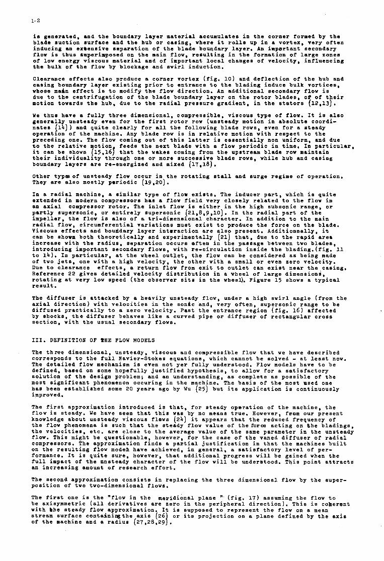
The f l o w t h r o u g h a compresso r b lade row i s e s s e n t i a l l y t h r e e d i m e n s i o n a l i n n a t u r e . I n an a x i a l machine , t h e t h r o u g h flow d i r e c t i o n i s a x i a l , and v a r i e s a l o n g t h e stream d i r e c t i o n , e x c e p t f o r v e r y p a r t i c u l a r c a s e s . The flow i S d e f l e c t e d t a n g e n t i a l l y t h r o u g h t h e b l a d i n g , and , f o r a f o r c e t o b e e x e r t e d on t h e b l a d i n g , a c i r c u m f e r e n t i a a v a r i a t i o n of t h e v e l o c i t i e s must o c c u r be tween t h e p r e s s u r e s i d e of one blade and t h e s u c t i o n s i d e of t h e n e x t one , l e a d i n g t o d i s t o r t i o n of t h e s t r e a m s u r f a c e ( i n d u c e d r a d i a l com- p o n e n t ) ( f i g . 7). Hub and c a s i n g c u r v a t u r e i n d u c e f u r t h e r r a d i a l components, and , even i n a c y l i n d r i c m l c h a n n e l , t h e s t r e a m l i n e s must assume some c u r v a t u r e i n t h e r a d i a l d i r e c t i o n , f o r t h e f l o w c o n t i n u i t y and c o n s e r v a t i o n o f momentum t o be s a t i s f i e d .
I n con tempora ry mach ines , t h e f l o w i s a lways c o m p r e s s i b l e , and v e r y o f t e n , l o c a l s u p e r s o n i c r e g i o n s , t e r m i n a t e d by sho.cks appea r i n t h e b l a d e p a s s a g e s ( f i g . 81, o r
even , f o r t r a n s o n i c and s u p e r s o n i c c o m p r e s s o r s , a s i g n i f i c a n t p a r t of t h e f low a t t h e i n l e t and i n t h e p a s s a g e i s s u p e r s o n i c and a f f e c t e d by shocks . Boundary l a y e r s d e v e l o p on t h e b l a d e s u r f a c e s and merge i n t h e wakes. They a l s o dwvelop on t h e hub and c a s i n g . Those boundary l a y e r s a r e s t r o n g l y a f f e c t e d by t h e s h o c k s , i n t h e c o m p r e s s i b l e reg ime.
I n t e r a c t i o n be tween hub o r c a s i n g and b l a d e boundary l a y e r s i s s i g n i f i c a n t , as shown i n f i g . 9. The hub and c a s i n g boundary l a y e r s a r e s u b m i t t e d t o t h e c i r c u m f e r e n t i a l p r e s s u r e g r a d i e n t s e x i s t i n g be tween t h e p r e s s u r e s i d e of one b l a d e and t h e s u c t i o n s i d e of t h e n e x t one. A s t h e v e l o c i t y i s r e d u c e d i n t h e boundary l a y e r s , a t r a n s v e r s e mot ion
1- 2
i s g e n e r a t e d , and t h e boundary l a y e r m a t e r i a l a c c u m u l a t e s i n t h e c o r n e r formed by t h e b l a d e s u c t i o n s u r f a c e and t h e hub or c a s i n g , where it r o l l s up i n a v o r t e x , v e r y o f t e n i n d u c i n g an e x a e n s i v e s e p a r a t i o n of t h e b l a d e bouqdary l a y e r . An i m p o r t a n t s e c o n d a r y f l o w i s t h u s supe r imposed on t h e main flow, r e s u l t i n g i n t h e f o r m a t i o n of l a r g e zones of low e n e r g y v i s c o u s material and of i m p o r t a n t l o c a l changes of v e l o c i t y , i n f l u e n c i n g t h e b u l k of t h e f l o w by b l o c k a g e and s w i r l i n d u c t i o n .
C l e a r a n c e e f f e c t s a l s o p roduce a c o r n e r v o r t e x ( f i g . 10) and d e f l e c t i o n of t h e hub and c a s i n g boundary l a y e r e x i s t i n g p r i o r t o e n t r a n c e t o t h e b l a d i n g i n d u c e b u l k v o r t i c e s , whose main e f f e c t i s t o mod i fy t h e f l o w d i r e c t i o n . A n a d d i t i o n a l s econdary flow i s due t o t h e c e n t r i f u g a t i o n of t h e b lade boundary l a y e r on t h e r o t o r b l a d e s , of of t h e i r mot ion towards t h e hub , due t o t h e r a d i a l p r e s s u r e g r a d i e n t , i n t h e s t a t o r s (12 ,13) .
We t h u s have a f u l l y t h r e e d i m e n s i o n a l , c o m p r e s s i b l e , v i s c o u s t y p e of flow. I t i s a l s o g e n e r a l l y u n s t e a d y even for t h e f i r s t r o t o r row ( u n s t e a d y mot ion i n a b s o l u t e c o o r d i - n a t e s (14)) and q u i t e c l e a r l y for a l l t h e f o l l o w i n g b l a d e rows, even for a s t e a d y o p e r a t i o n of t h e machine. Any b l a d e row i s i n r e l a t i v e mot ion w i t h r e s p e c t t o t h e p r e c e d i n g one. The f l o w coming o u t of t h i s l a t t e r i s e s s e n t i a l l y non un i fo rm, and due t o t h e r e l a t i v e mot ion f e e d s t h e n e x t b l a d e w i t h a f low p e r i o d i c i n t i m e . I n p a r t i c u l a r , it c a n be shown (15,16f t h a t t h e wakes coming from t h e ups t r eam b l a d e row m a i n t a i n t h e i r i n d i v i d u a l i t y t h r o u g h one or more s u c c e s s i v e b l a d e rows, w h i l e hub and c a s i n g boundary l a y e r s a r e r e - e n e r g i z e d and mixed (17 ,18 ) ,
O the r t y p c s o f u n s t e a d y flow o c c u r i n t h e r o t a t i n g s t a l l and s u r g e r eg ime of o p e r a t i o n . They are a l s o m o s t l y p e r i o d i c (19 ,20) .
I n a r a d i a l machine , a s imilar t y p e of Q l o r e x i s t s . The i n d u c e r p a r t , which i s q u i t e e x t e n d e d i n modern compresso r s h a s a f l o w f i e l d v e r y c l o s e l y r e l a t e d t o t h e f l o w i n an a x i a l compresso r r o t o r . T h e i n l e t f l o w i s e i t h e r i n t h e h i g h s u b s o n i c r a n g e , or p a r t l y s u p e r s o n i c , or e n t i r e l y s u p e r s o n i c (21 ,8 ,9 ,10 ) . I n t h e r a d i a l p a r t of t h e i m p e l l e r , t h e f l o w i s a l s o of a t r i - d i m e n s i o n a l c h a r a c t e r . I n a d d i t i o n t o t h e main r a d i a l flow, c i r c u m f e r e n t i a l v a r i a t i o n s must e x i s t t o paoduce t h e f o r c e on t h e b l a d e . V i scous e f f e c t s and bouddary l a y e r i n t e r a c t i o n a r e a l s o p r e s e n t . A d d i t i o n n a l l y , it can b e shown b o t h t h e o r e t i c a l l y and e x p e r i m e n t a l l y (21) t h a t , due t o t h e r a p i d area i n c r e a s e w i t h t h e r a d i u s , s e p a r a t i o n o c c u r s e f t e n i n t h e p a s s a g e be tween two b l a d e s , i n t r o d u c i n g impox tan t s econdary f l o w s , w i t h r e - c i r c u l a t i o n i n s i d e t h e b l a d i n g . ( f i g . 11 t o 1 4 ) . I n p a r t i c u l a r , a t t h e wheel o u t l e t , t h e f l o w can b e c o n s i d e r e d as b e i n g made of two j e t s , one w i t h a h i g h v e l o c i t y , t h e o t h e r w i t h a small or even z e r o v e l o c i t y . Due t o c l e a r a n c e e f f e c t s , a r e t u r n flow from e x i t t o o u t l e t can e x i s t n e a r t h e c a s i n g . R e f e r e n c e 22 g i v e s d e t a i l e d v e l o c i t y d i s t r i b u t i o n i n a wheel of l a r g e d i m e n s i o n s , r o t a t i n g a t v e r y low speed ( t h e o b s e r v e r s i t s i n t h e wheel). F i g u r e 1 5 shows a t y p i c a l r e s u l t .
The d i f f u s e r i s a t t a c k e d by a h e a v i l y u n s t e a d y f l o w , unde r a h i g h s w i r l a n g l e ( f rom t h e a x i a l d i r e c t i o n ) w i t h v e l o c i t i e s i n t h e s o n i c and , v e r y o f t e n , s u p e r s o n i c r a n g e t o b e d i f f u s e d p r a c t i c a l l y t o a z e r o v e l o c i t y . P a s t t h e e n t r a n c e r e g i o n ( f i g . 1 6 ) a f f e c t e d by s h o c k s , t h e d i f f u s e r behaves l i k e a c u r v e d p i p e o r d i f f u s e r of r e c t a n g u l a r c r o s s s e c t i o n , w i t h t h e u s u a l s e c o n d a r y f lows .
111. DBFIBITIOB OF SHE FLOW MODELS
The t h ree d i m e n s i o n a l , u n s t e a d y , v i s c o u s and c o m p r e s s i b l e flow t h a t w e have d e s c r i b e d c o r r e s p o n d s t o t h e f u l l Nav ie r -S tokes e q u a t i o n s , which canno t b e s o l v e d - a t l e a s t now. The d e t a i l e d f l o w mechanism i s even n o t y e r f u l l y u n d e r s t o o d . Flow models have t o be d e f i n e d , b a s e d on some h o p e f u l l y j u s t i f i e d h y p o t h e s i s , t o a l l o w f o r a s a t i s f a c t o r y s o l u t i o n of t h e d e s i g n problem; and an u n d e r s t a n d i n g , as comple t e as p o s s i b l e of t h e most s i g n i f i c a n t phenomenon o c c u r i n g i n t h e machine. The bas i s of t h e most u s e d one h a s been e s t a b l i s h e d some 20 y e a r s ago by Wu (25) b u t i t s a p p l i c a t i o n i s c o n t i n u o u s l y improve d.
T h e f i r s t a p p r o x i m a t i o n i n t r o d u c e d i s t h a t , for s t e a d y o p e r a t i o n of t h e machine , t h e flow i s s t e a d y . We have seen t h a t t h i s was by no means t r u e . However, faom o u r p r e s e n t knowledge a b o u t u n s t e a d y v i s c o u s f l o w s (24) it a p p e a r s t h a t t h e r educed f r e q u e n c y of t h e f low phenomena i s such t h a t t h e s t e a d y flow v a l u e of t h e force a c t i n g on t h e b l a d i n g s , t h e v e l o c i t i e s , e t c . a r e c l o s e t o t h e a v e r a g e v a l u e of t h e same p a r a m e t e r i n t h e u n s t e a d y flow. T h i s migh t be q u e s t i o n a b l e , however, for t h e c a s e of t h e vaned d i f f u s e r of r a d i a l compresso r s . The a p p r o x i m a t i o n f i n d s a p a t t i a l j u s t i f i c a t i o n i n t h a t t h e machines b u i l t on t h e r e s u l t i n g f l o w mode% have a c h i e v e d , i n g e n e r a l , a s a t i s f a c t o r y l e v e l of p e r - formance . I t i s q u i t e s u r e , however, t h a t a d d i t i o n a l p r o g r e s s w i l l be g a i n e d when t h e f u l l impac t of t h e u n s t e a d y c h a r a c t e r of t h e flow w i l l be u n d e r s t o o d . T h i s p o i n t a t t r a c t s an i n c r e a s i n g amount of r e s e a r c h e f f o r t .
The second a p p r o x i m a t i o n c o n s i s t s i n r e p l a c i n g t h e t h r e e d i m e n s i o n a l f l o w by t h e s u p e r - p o s i t i o n of two two-dimens iona l f l o w s .
The f i r s t one i s t h e " f low i n t h e m e r i d i o n a l p l a n e 'I ( f i g . 17) assuming t h e flow t o be ax i symmet r i c ( a l l d e r i v a t i v e s a r e z e r o i n t h e p e r i p h e r a l d i r e c t i o n ) . T h i s i s c o k e r s n t w i t h bhe s t e a d y f low approx ima t ion . I t i s supposed t o r e p r e s e n t t h e f l o w on a mean s t r e a m s u r f a c e c o n t a i n i w t h e a x i s (26 of t h e machine and a r a d i u s (27,28,29 I . o r i t s p r o j e c t i o n on a p l a n e d e f i n e d by t h e a x i s
' I
1- 3
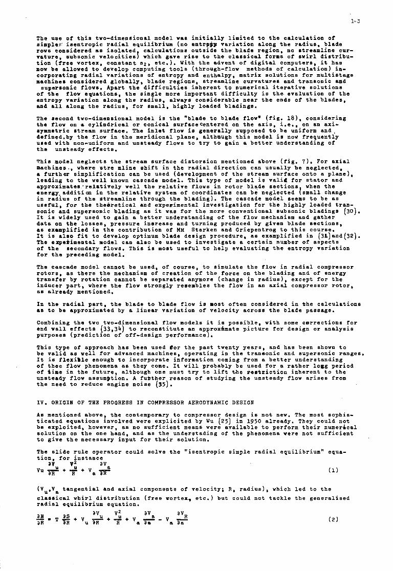
The u s e of t h i s two-dimenSional model was i n i t i a l l y l i m i t e d t o t h e c a l c u l a t i o n o f s i m p l e r ' i s e n t r o p i c r a d i a l e q u i l i b r i u m (no e n t r p p p v a r i a t i o n a l o n g t h e r a d i u s , b l a d e rows c o n s i d e r e d as i s o l a t e d c a l c u l a t i o n s o u t s i d e t h e b l a d e r e g i o n , no s t r e a m l i n e c u r - v a t u r e , s u b s o n i c v e l o c i t i e s j which gave r i s e t o t h e c l a s s i c a l forms o f s w i r l d i s t r i b u - t i o n ( f r e e v o r t e x , c o n s t a n t 0 2 , e t c . ) . W i t h t h e a d v e n t o f d i g i t a l compute r s , it h a s now be a l l o w e d t o d e v e l o p comput ing t o o l s ( th rough- f low methods o f c a l c u l a t i o n ) i n - c o r p o r a t i n g r a d i a l v a r i a t i o n s of e n t r o p y and e n t h a l p y , m a t r i x s o l u t i o n s f o r m u l t i s t a g e machines c o n s i d e r e d g l o b a l l y , b l a d e r e g i o n s , s t r e a m l i n e c u r v a t u r e s and t r a n s o n i c aad
s u p e r s o n i c f l o w s . Apar t t h e d i f f i c u l t i e s i n h e r e n t t o n u m e r i c a l i t e r a t i v e s o l u t i o n s of t h e f l o w e q u a t i o n s , t h e s i n g l e more i m p o r t a n t d i f f i c u l t y i s t h e . e v a l u a t i o n o f t h e e n t r o p y v a r i a t i o n a l o n g t h e r a d i u s , a lways c o n s i d e r a b l e n e a r t h e e n d s o f t h e b l a d e s , and a l l a l o n g t h e r a d i u s , f o r smal l , h i g h l y l o a d e d b l a d i n g e .
The second two-dimens iona l model i s t h e "blade t o b l a d e flow. ( f i g . l a ) , c o n s i d e r i n g t h e f l o w on a c y l i n d r i c a l or c o n i c a l s u r f a c e c e n t e r e d on t h e a x i s , i .e., on an a x i - symmetr ic stream s u r f a c e . The i n l e t f l o w i s g e n e r a l l y supposed t o b e un i fo rm a n d , d e f i n e d . b y t h e f l o w i n t h e m e r i d i o n a l p l a n e , a l t h o u g h t h i s model i s now f r e q u e n t l y u s e d w i t h non-uniform and u n s t e a d y f l o w s t o t r y t o g a i n a b e t t e r u n d e r s t a n d i n g o f t h e u n s t e a d y e f f e c t s .
T h i s model n e g l e c t s t h e s t r e a m s u r f a c e d i s t o r s i o n men t ioned above ( f i g . 7). For a x i a l m a c h i n e s . , where s t r e m l i n e s h i f t i n t h e r a d i a l d i r e c t i o n can u s u a l l y b e n e g l e c t e d , a f u r t h e r s i m p l i f i c a t i o n can be u s e d (deve lopmen t o f t h e s t r e a m s u r f a c e o n t o a p l a n e ) , l e a d i n g t o t h e w e l l known c a s c a d e model. T h i s t y p e o f model i s v a l i d f o r s t a t o r and a p p r o x i m a t e s 2 r e l a t i v e l y w e l l t h e r e l a t i v e f l o w s i n r o t o r b l a d e s e c t i o n s when t h e energy . a d d i t i o n i n t h e r e l a t i v e sys t em o f c o o r d i n a t e s can b e n e g l e c t e d [ smal l change i n r a d i u s of t h e s t r e a m l i n e t h r o u g h t h e b l a d i n g ) . The c a s c a d e model seems t o b e as u s e f u l , f o r t h e t h e i r e t i c a l and e x p e r i m e n t a l i n v e s t i g a t i o n f o r t h e h i g h l y l o a d e d t r a n - s o n i c a n d s u p e r s o n i c b l a d i n g as it w a s f o r t h e more c o n v e n t i o n a l s u b s o n i c b l a d i n g 8 It i s w i d e l y u s e d t o g a i n a b e t t e r u n d e r s t a n d i n g o f t h e f l o w mechanism and g a t h e r d a t a on t h e l o s s e s , p r e s s u r e i n e r e a s e and t u r n i n g p roduced by g i v e n b l a d e s e c t i o n s , as e x a m p l i f i e d i n t h e c o n t r i b u t i o n o f M M S t a r k e n and G r i e p e n t r o g t o t h i s c o u r s e . It i s a l s o f i t t o d e v e l o p optimum blade d e s i g n p r o c e d u r e , as e x a m p l i f i e d i n (3L)and(32) . The e x p e r i m e n t a l model can a l s o be u s e d t o i n v e s t i g a t e a c e r t a i n number of a s p e c t s o f t h e s e c o n d a r y f lows . T h i s i s most u s e f u l t o h e l p e v a l u a t i n g t h e e n t r o p y v a r i a t i o n f o r t h e p r e c e d i n g model.
The c a s c a d e model canno t b e used , o f c o u r s e , t o s i m u l a t e t h e f l o w i n r a d i a l compresso r r o t o r s , as t h e r e t h e mechanism of c r e a t i o n o f t h e f o r c e on t h e b l a d i n g and of e n e r g y t r a n s f e r by r o t a t i o n c a n n o t b e s e p a r a t e d anymore ( change i n r a d i u s ) , e x c e p t f o r t h e i n d u c e r p a r t , where t h e f l o w s t r o n g l y r e s e m b l e s t h e f l o w i n an a x i a l compresso r r o t o r , as a l r e a d y ment ioned .
I n t h e rad ia l p a r t , t h e b l a d e t o b l a d e f l o w i s most o f t e n c o n s i d e r e d i n t h e c a l c u l a t i o n s as t o be approx ima ted by a l i n e a r v a r i a t i o n of v e l o c i t y a c r o s s t h e b l a d e p a s s a g e .
Combining t h e two two-dimens iona l f l ow models it i s p o s s i b l e , w i t h some c o r r e c t i o n s f o r end w a l l e f f e c t s ( 3 3 , 3 4 ) t o r e c o n s t i t u t e an approx ima te p i c t u r e f o r d e s i g n or a n a l y s i s p u r p o s e s ( p r e d i c t i o n o f o f f - d e s i g n pe r fo rmance ) .
T h i s t y p e o f approach h a s been u s e d # o r t h e p a s t t w e n t y y e a r s , and h a s been shown t o b e v a l i d as w e l l f o r advanced mach ines , o p e r a t i n g i n t h e t r a n s o n i c and s u p e r s o n i c r a n g e s . I t i s f l e x i l l e enough t o i n c o r p o r a t e i n f o r m a t i o n coming from a b e t t e r u n d e r s t a n d i n g o f t h e e f l o w phenomena as t h e y come. It w i l l p r o b a b l y b e u s e d f o r a r a t h e r l o g g p e r i o d o f t i m e i n t h e f u t u r e , a l t h o u g h one must t r y t o l i f t t h e r e s f r i c t i o n i n h e r e n t t o t h e u n s t e a d y f l o w as sumpt ion . A f u O t h e r r e a s o n o f s t u d y i n g t h e u n s t e a d y f l o w a r i s e s from t h e need t o r e d u c e e n g i n e n o i s e (95) .
(30).
I V . O R I G I N OF THE PROORESS I N COMPRESSOR A E R O D Y N A M I C DESIGN
A s men t ioned above , t h e contemporary t o compresso r d e s i g n i s n o t new. The most s o p h i s - t i c a t e d e q u a t i o n s i n v o l v e d were e x p l i c i t e d by Wu (25 ) i n 1950 a l r e a d y . They c o u l d n o t be e x p l o i t e d , however, as no s u f f i c i e n t means were a v a i l a b l e t o pe r fo rm t h e i r n u m e r i c a l s o l u t i o n on t h e one hand, and as t h e u n d e r s t a d i n g o f t h e phenomena were n o t s u f f i c i e n t t o g i v e t h e n e c e s s a r y i n p u t f o r t h e i r s o l u t i o n .
The s l i d e r u l e o p e r a t o r c o u l d s o l v e t h e " i s e n t r o p i c s i m p l e r a d i a l e q u i l i b r i u m " equa- t i o n . f o r i n s t a n c e
a i , u v i ava V u - + - + V a r a R R
( V u , V c l a s s i c a l w h i r l d i s t r i b u t i o n ( f r e e P o r t e r , e t c . ) b u t c o u l d n o t t a c k l e t h e g e n e r a l i s e d r a d i a l e q u i l i b r i u m e q u a t i o n .
t a n g e n t i a l and a x i a l components o f v e l o c i t y ; R , r a d i u s ) , which l e d t o t h e a
- aa as avu V; a vR a R a R R 'a aa T - + V u 3 + - ( 2 )
1- 4
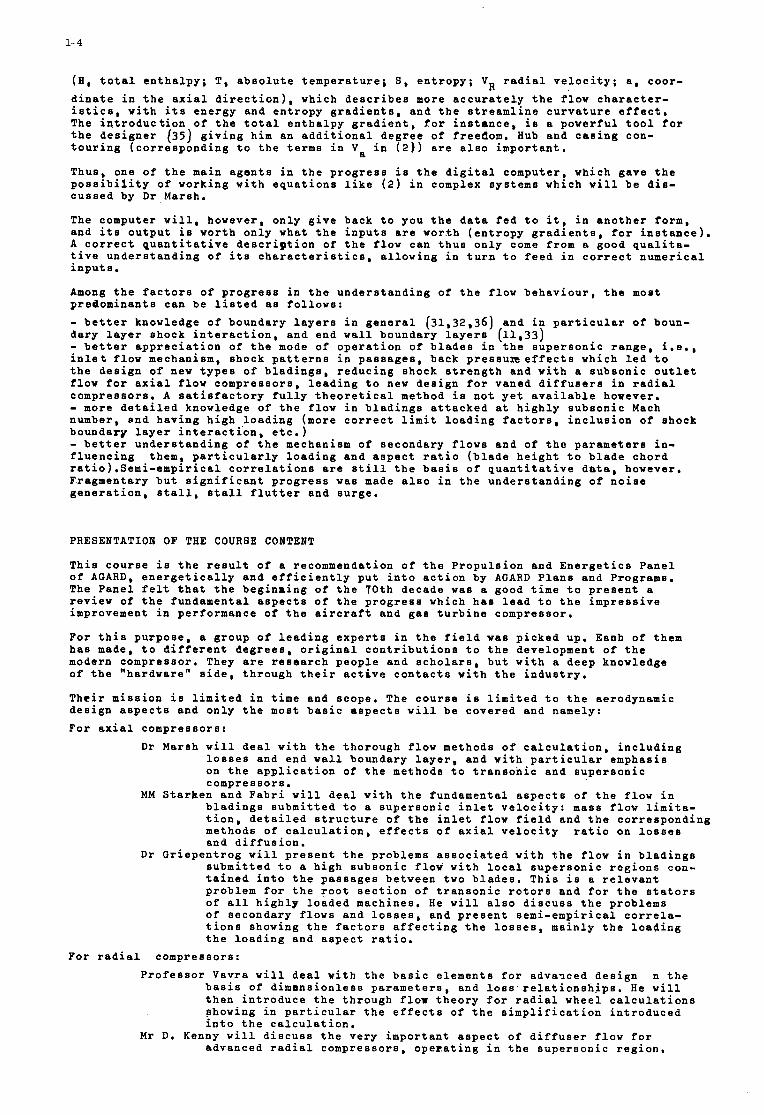
(E, t o t a l e n t h a l p y ; T , a b s o l u t e t e m p e r a t u r e ; S, e n t r o p y ; VR r a d i a l v e l o c i t y ; a , coor - d i n a t e i n t h e a x i a l d i r e c t i o n ) , which d e s c r i b e s more a c c u r a t e l y t h e f l o w c h a r a c t e r - i s t i c s , w i t h i t s e n e r g y and e n t r o p y g r a d i e n t s , and t h e s t r e a m l i n e c u r v a t u r e e f f e c t , The i n t r o d u c t i o n of t h e t o t a l e n t h a l p y g r a d i e n t , f o r i n s t m c e , i s a p o w e r f u l t o o l f o r t h e d e s i g n e r (35) g i v i n g him an a d d i t i o n a l d e g r e e of freedom. Hub and c a s i n g con- t o u r i n g ( c o r r e s p o n d i n g t o t h e t e r m s i n Va i n ( 2 ) ) a r e a l s o i m p o r t a n t .
Thus, one of t h e main a g e n t s i n t h e p r o g r e s s i s t h e d i g i t a l computer , which gave t h e p o s s i b i l i t y of working w i t h e q u a t i o n s l i k e (2) i n complex sys t ems which w i l l b e d i s - c u s s e d by D r Marsh.
The computer w i l l , however, o n l y g i v e back t o you t h e da t a f e d t o i t , i n a n o t h e r form, and i t s o u t p u t i s wor th o n l y what t h e i n p u t s are wor.th ( e n t r o p y g r a d i e n t s , f o r i n s t a n c e ) . A c o r r e c t q u a n t i t a t i v e d e s c r i p t i o n of t h e f l o w can t h u s o n l y come from a good q u a l i t a - t i v e u n d e r s t a n d i n g of i t s c h a r a c t e r i s t i c s , a l l o w i n g i n t u r n t o f e e d i n c o r r e c t n u m e r i c a l i n p u t s .
Among t h e f a c t o r s of p r o g r e s s i n t h e u n d e r s t a n d i n g of t h e f l o w b e h a v i o u r , t h e most p redominan t s can b e l i s t e d as f o l l o w s : - b e t t e r knowledge of boundary l a y e r s i n g e n e r a l (31,32,36) and i n p a r t i c u l a r o f boun- d a r y l a y e r shock i n t e r a c t i o n , and end w a l l boundary l a y e r s (11 ,33) - b e t t e r a p p r e c i a t i o n of t h e mode of o p e r a t i o n of b l a d e s i n t h e s u p e r s o n i c r a n g e , i . e . , i n l e t flow mechanism, shock p a t t e r n s i n p a s s a g e s , back p r e s s u E e f f e c t s which l e d t o t h e d e s i g n of new t y p e s of b l a d i n g a , r e d u c i n g shock s t r e n g t h and w i t h a s u b s o n i c o u t l e t f l o w for a x i a l f l o w c o m p r e s s o r s , l e a d i n g t o new d e s i g n f o r vaned d i f f u s e r s i n r a d i a l compresso r s . A s a t i s f a c t o r y f u l l y t h e o r e t i c a l method i s n o t y e t a v a i l a b l e hoveve r . - more d e t a i l e d knowledge o f t h e f l o w i n b l a d i n g s a t t a c k e d a t h i g h l y s u b s o n i c Mach number, end h a v i n g h i g h l o a d i n g (more c o r r e c t l i m i t l o a d i n g f a c t o r s , i n c l u s i o n o f shock boundary l a y e r i n t e r a c t i o n , e t c . ) - b e t t e r u n d e r s t a n d i n g of t h e mechanism of secondary flows and of t h e p a r a m e t e r s i n - f l u e n c i n g them, p a r t i c u l a r l y l o a d i n g and a s p e c t r a t i o ( b l a d e h e i g h t t o b l a d e c h o r d r a t i o ) . S e m i - e m p i r i c a l c o r r e l a t i o n s a r e s t i l l t h e bas i s of q u a n t i t a t i v e d a t a , however, F ragmen ta ry b u t s i g n i f i c a n t p r o g r e s s w a s made a l s o i n t h e u n d e r s t a n d i n g of n o i s e g e n e r a t i o n , s t a l l , e t a l l f l u t t e r and s u r g e .
PRESENTATION OF THE COURSE CONTENT
T h i s c o u r s e i s t h e r e s u l t of a recommendation of t h e P r o p u l s i o n and E n e r g e t i c s P a n e l o f A G A R D , e n e r g e t i c a l l y and e f f i c i e n t l y p u t i n t o a c t i o n by AGARD P l a n s and Programs. The P a n e l f e l t t h a t t h e b e g i n 8 i n g of t h e 7 0 t h decade w a s a good t i m e t o p r e s e n t a r e v i e w of t h e fundamen ta l a s p e c t s of t h e p r o g r e s s which h a s l e a d t o t h e i m p r e s s i v e improvement i n pe r fo rmance o f t h e a i r c r a f t and g a s t u r b i n e compresso r .
F o r t h i s p u r p o s e , a g roup of l e a d i n g e x p e r t s i n t h e f i e l d was p i c k e d up. Eaoh of them h a s made, t o d i f f e r e n t d e g r e e s , o r i g i n a l c o n t r i b u t i o n s t o t h e deve lopment of t h e modern compressor . They a r e r e s e a r c h p e o p l e and s c h o l a r s , b u t w i t h a deep knowledge o f t h e "hardware" s i d e , t h r o u g h t h e i r a c t i v e c o n t a c t s w i t h t h e i n d u s t r y .
T h e i r m i s s i o n i s l i m i t e d i n t i m e and scope . The c o u r s e i s l i m i t e d t o t h e aerodynamic d e s i g n a s p e c t s and o n l y t h e most b a s i c a s p e c t s w i l l b e c o v e r e d and namely: F o r a x i a l compresso r s :
D r Marsh w i l l d e a l w i t h t h e t h o r o u g h flow methods of c a l c u l a t i o n , i n c l u d i n g l o s s e s and end w a l l boundary l a y e r , and w i t h p a r t i c u l a r emphas is on t h e a p p l i c a t i o n of t h e methods t o t r a n s o n i c and s u p e r s o n i c compresso r s .
b l a d i n g s s u b m i t t e d t o a s u p e r s o n i c i n l e t v e l o c i t y : mass flow l i m i t a - t i o n , d e t a i l e d s t r u c t u r e of t h e i n l e t flow f i e l d and t h e c o r r e s p o n d i n g methods of c a l c u l a t i o n , e f f e c t s of a x i a l v e l o c i t y r a t i o on l o s s e s and d i f f u s i o n .
D r G r i e p e n t r o g w i l l p r e s e n t t h e p rob lems a s s o c i a t e d w i t h t h e flow i n b l a d i n g s s u b m i t t e d t o a h i g h s u b s o n i c f low w i t h l o c a l s u p e r s o n i c r e g i o n s con- t a i n e d i n t o t h e p a s s a g e s be tween two b l a d e s . T h i s i s a r e l e v a n t problem f o r t h e r o o t s e c t i o n of t r a n s o n i c r o t o r s and f o r t h e s t a t o r s of a l l h i g h l y l o a d e d machines . He w i l l a l s o d i s c u s s t h e p rob lems of secondary flows and l o s s e s , and p r e s e n t s e m i - e m p i r i c a l c o r r e l a - t i o n s showing t h e f a c t o r s a f f e c t i n g t h e l o s s e s , ma in ly t h e l o a d i n g t h e l o a d i n g and a s p e c t r a t i o .
MM S t a r h e n and F a b r i w i l l dea l w i t h t h e fundamen ta l a s p e c t s of t h e f low i n
F o r r a d i a l compresso r s : P r o f e s s o r Vavra w i l l d e a l w i t h t h e b a s i c e l e m e n t s f o r adva?ced d e s i g n n t h e
bas i s of d i m e n s i o n l e s s p a r a m e t e r s , and loss r e l a t i o n s h i p s . He w i l l t h e n i n t r o d u c e t h e t h r o u g h f l o w t h e o r y f o r r a d i a l whee l c a l c u l a t i o n s showing i n p a r t i c u l a r t h e e f f e c t s of t h e s i m p l i f i c a t i o n i n t r o d u c e d i n t o t h e c a l c u l a t i o n .
advanced r a d i a l compresso r s , o p e r a t i n g i n t h e s u p e r s o n i c r e g i o n , M r D. Kenny w i l l d i s c u s s t h e v e r y i m p o r t a n t a s p e c t of d i f f u s e r flow f o r
1- 5
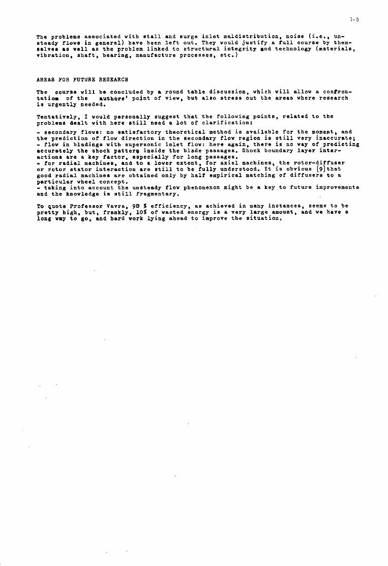
The p rob lems a s s o c i a t e d w i t h s t a l l and s u r g e i n l e t m a l d i s t r i b u t i o n , n o i s e ( i . e . , un- s t e a d y f l o w s i n g e n e r a l ) have been l e f t o u t . They would j u s t i f y a f u l l c o u r s e by them- s e l v e s as w e l l as t h e problem l i n k e d t o s t r u c t u r a l i n t e g r i t y and t e c h n o l o g y ( m a t e r i a l s , v i b r a t i o n , s h a f t , b e a r i n g , manufac tu re p r o c e s s e s , e t c . )
AREAS FOR FUTURE RESEARCH
The c o u r s e w i l l b e c o n c l u d e d by a round t a b l e d i s c u s s i o n , which w i l l a l l o w a con t ron - tatiom of t h e a u t h b r g ' p o i n t of view, b u t a l s o s t r e s s o u t t h e a r e a s where r e s e a r c h i s u r g e n t l y needed .
T e n t a t i v e l y , I would p e r s o n a l l y s u g g e s t t h a t t h e f o l l o w i n g p o i n t s , r e l a t e d t o t h e problems d e a l t w i t h h e r e s t i l l need a l o t of c l a r i f i c a t i o n ; - r e c o n d a r y flows: no s a t i s f a c t o r y t h e o r e t i c a l method i s a v a i l a b l e for t h e moment, and t h e p r e d i c t i o n of f l o w d i r e c t i o n i n t h e secondary f l o w r e g i o n i s s t i l l v e r y i n a c c u r a t e ; - flow i n b l a d i n g 0 w i t h s u p e r s o n i c i n l e t f l ow: h e r e a g a i n , t h e r e i s no way of p r e d i c t i n g a c c u r a t e l y t h e shock p a t t e r 9 i n s i d e t h e b l a d e p a s s a g e s . Shock boundary l a y e r i n t e r - a c t i o n s a r e a key f a c t o r , e s p e c i a l l y for l o n g p a s s a g e s . - for r a d i a l mach ines , and t o a lower e x t e n t , for a x i a l mach ines , t h e r o t o r - d i f f u s e r or r o t o r s t a t o r i n t e r a c t i o n a r e s t i l l t o b e f u l l y u n d e r s t o o d . It i s o b v i o u s ( 9 ) t h a t good r a d i a l machines a r e o b t a i n e d o n l y by h a l f e m p i r i c a l ma tch ing of d i f f u s e r s t o a p a r t i c u l a r wheel concep t . - t a k i n g i n t o a c c o u n t t h e u n s t e a d y flow phenomenon might b e a key t o f u t u r e improvements and t h e knowledge i s s t i l l f r a g m e n t a r y .
To q u o t e P r o f e s s o r Vavra , 90 5 e f f i c i e n c y , as a c h i e v e d i n many i n s t a n c e s , seems t o b e p r e t t y h i g h , b u t , f r a n k l y , 1 0 5 of wasted ene rgy i s a v e r y l a r g e amount, and we have a l o n g way t o go, and h a r d work l y i n g ahead t o improve t h e s i t u a t i o n .
1- 6
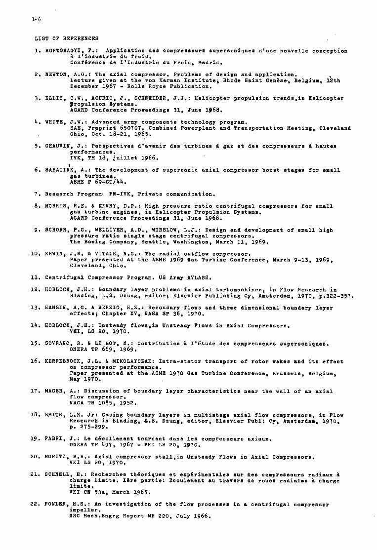
LIST OF REFERENCES
1. HORTOBACYI, F.: Application des compresseurs supersoniques d'une nouvelle conception b l'industrie du froid. Conf6rence de 1'Industrie du Froid, Madrid.
Lecture given at the von Karman Institute; Rhode Saint Geni2se, Belgium, 1;th December 1967 - Rolls Royce Publication.
2. NEWTON, A.C.: The axial compressor. Problems of design and application.
3. ELLIS, C.W., ACURIO, J., SCHNEIDER, J.J.: Helicopter propulsion trendBBin Helicopter propulsion Systems. ACARD Conference Protreedings 31, June 1968.
SAE, Prpprint 650707. Combined Powerplant and Transportation Meeting, Cleveland Ohio, Oct. 18-21, 1965.
4. WHITE, J.W.: Advanced army components technology program.
5. CHAUVIN, J.: Perspectives d'avenir des turbines b gaz et des compresseurs b hautes performances. IVK, TU 18, juillet 1966.
I
gas turbines. 6. SABATINK, A.: The development of supersonic axial compressor boost stages for small
ASME P 69-CT/44.
7. Research Program, FN-IVK, Private communication.
8. MORRIS, R.E. & KENNY, D.P.: High pressure ratio centrifugal compressors for small gas turbine engines, in Helicopter Propulsion Systems. ACARD Conference Proceedings 31, June 1968.
9. SCHORR, P.C., WELLIVER, A.D., WINSLOW, L.J.: Design and development of small high pressure ratio single stage centrifugal compressors. The Boeing Company, Seattle, Washington, March 11, 1969,
10. ERWIN, J.R. b VITALE, N.G.: The radial outflow compressor. Paper presented at the ASME 1969 Bas Turbine Conference, March 9-13, 1969, Cleveland, Ohio.
11. Centrifugaa Compressor Program. US Army AVLABS.
12. HORLOCK, J.H.: Boundary layer problems in axial turbomachinee, in Flow Research in Blading, L.S. Dzung, editor; Elsevier Publishing Cy, Amsterdam, 1970, p.322-357.
effects; Chapter XV, NASA SP 36, 1970. 13. HANSEN, A.G. & HERZIC, H . Z . : Secondary flows and three dimensional boundary layer
14. HORLOCK, J.H.: Unsteady flows,in Unsteady Flows in Axial Compressors. VKI, LS 20, 1970.
15. SOVRANO, R. d, LE BOT, 9 . : Contribution b 1'6tude des compresseurs supersoniques.
16. KERREBROCK, J.L. b MIKOLAYCZAK: Intra-stator transport of rotor wakes and its effect
ONERA TP 669, 1969.
on compressor performance. Paper presented at the ASME 1970 Gas Turbine Conference, Brussels, Belgium, May 1970.
17. MACER, A.: Discussion of boundary layer characteristics near the wall of an axial flow compressor. BACA TR 1085, 1952.
18. SMITH, L.H. Jr: Casing boundary layers in multistage axial flow compressors, in Flow Research in Blading, L.S. Dzung, editor, Elsevier Publ; Cy, Amsterdam, 1970, P* 275-299.
19. FABRI, J.: Le d6collement tournant dans le8 compresseurs axiaux.
20. MORITZ, R.R.: Axial compressor etallpin Unsteady Flows in Axial Compressors.
21. SCHNELL, E.: Recherche6 th6oriques et exp6rimentales sur Bes compresseurs radiaux b charge limite. Iare partie: Ecoulement au travers de roues radialos b charge limite. VKI CN 538, March 1965.
OIERA TP 497, 1967 - VKI LS 20, 1970. VKI LS 20, 1970.
22, FOWLER, H.S.: An investigation of the flow processes in a centrifugal cornpressor impeller. NRC Mech.Engrg Report ME 220, July 1966.
1- 7
24. SMOLDEREB, J.J.: Mathemat i ca l b a s i s of u n s t e a d y f low t r e a t m e n t . Unpubl i shed l e c t u r e .
25. WU, Chung Hua: A g e n e r a l t h e o r y of t h r e e - d i m e n s i o n a l f l o v i n s u b s o n i c and s u p e r s o n i c tu rbomach ines of a x i a l , r a d i a l , and mixed f low t y p e . NACA TIS 1795, 1950.
26. MARSH, H.: A d i g i t a l computer programme f o r t h e t h r o u g h f low f l u i d mechanics i n an a r b i t r a r y tu rbomach ine u s i n g a m a t r i x method. BGTE Repor t R 282, J u l y 1966.
V K I CIS 59; a l s o , ASME Pape r 66-WA/GT3.
J n l of E n g i n e e r i n g f o r Pover , ASME T r a n s a c t . S e r i e s A , v o l . 18, 1951, p.1-12.
w i l e y & Sons, 1960.
s o n i c b l a d i n g i n c a s c a d e and i n compressor r o t o r s . Pape r p r e s e n t e d a t t h e 1 5 t h ASME Gas Turb ine Confe rence , B r u s s e l s , May 1970.
27. BOVAK, R.A.: S t r e a m l i n e c u r v a t u r e computing p r o c e d u r e s for f l u i d f low problems.
28.SMITH, L.H. Jr: The r a d i a l e q u i l i b r i u m e q u a t i o n of t u rbomach ine ry .
29. VAVRA, M.H.: Aerothermodynamics and f low i n tu rbomach ines .
30. M I K O L A Y C Z A K , A.A.; MORRIS, A.L., JOHBSOH, B.V.: Comparison of performance of s u p e r -
31. LE FOLL, J.: A t h e o r y of r e p r e s e n t a t i o n of t h e p r o p e r t i e s of boundary l a y e r s on a p l a n e . P r o c e e d i n g s S e m h a r on Advanced Pcoblems i n Turbomachinery. K. Cassady and J. Chauvin, e d i t o r s , V K I 1965.
32. PAPAILIOU; IC.: O p t i m i s a t i o n d ' aubages de compresseur B f o r t e oha rge sur l a b a s e d e s t h k o r i e s de couches l i m i t e s . Ph.D. T h e s i s , Univ. LiBge, 1969, a l s o V K I TB 55, 1969.
33. STRATFORD, B.S.: The u s e of boundary l a y e r t e c h n i q u e s t o c a l c u l a t e t h e b lockage from t h e a n n u l a r boundary l a y e r s i n a compresso r , ASME P 67-WA/GT-T, November 1967.
34. BOVAK, R.A. & JAISSEIS, W.: The a p p l i c a t i o n of end w a l l boundary l a y e r e f f e c t s i n t h e per formance a n a l y s i s of a x i a l compressors . ASME 67-WA/GT-llB November 1967.
35. HETHERIBGTOB, R . : Engine component d e s i g n problems a s s o c i a t e d w i t h l a r g e s u b s o n i c t r a n s p o r t s , L e c t u r e g i v e n a t t h e von Karman I n s t i t u t e , 23 rd A p r i l 1969 - Rol1.s-Royce Publ. a l s o , V K I LS 16 : High Reynolds number aerodynamics , 1969.
1- 8
46
4.2
SThCE TOTAL PRESJURE
RATIO
TAROMI
A V m M A P O I N T S
HEAN RELATIVE INLET NACH NUMBER
c .6 .? .0 .9 4.0 1.4 I .2 1.3 41 1.5 4 6 jq
Figure 1
STAGE €FFIcIEwcY
\
vu1 JS69
HEAN RELATIVE INLET MACH NUMBER
c .5 6 .? 8 9 4.0 4i 42 4.3 44 i .5 la iq
Figure 2
16
I4
P a
8
6
4
2
0
Year
kink, of comppsw stages fm I0:l pressure ratio
Figure 3
150 IZ 100 &I
€- 9
lIT.'l150*C
I %- .7 5
TIT. 9SO.C g 1ll.750
I KglHPh 1 SFC
Figure 4
1- 10
Figure 5
Figure 6
1- 11
E' A'
I 1
I I I D'
B' F'
C ' F
' Figure 7
1- 12
d
M1 +.82L
M1 = ,835
\ I
1-15
\
I
\ \,
Figure 9
1- 14
PLANE CASING
PRESSURE SIDE SUCTION SIDE
I - - - - - - s 4 Figure 10
PRESSrn SUCTION SIDE
SIDE Rm 325 mm
PLANE 0 1 2 3 4 5
R. 450-
..___............_I._. ...
R. 530mm
L-Tx R * S 6 2 m m ,............ . . ............ I
R. Wnnl
Figure 11
1- 15
CLEARANCE 0 2.6 m m
0 1.8 m m * O,S mm
t P Po -
HUB
SECONDARY FLOWS AT WHEEL EXIT (RADIAL COMPRESSOR)
Figure 12
zo
18
1-6
1.4
12 m C A S I N
0 - 15 30 (mml CHANNEL WIDTH
Figure 13
DEAD .
1 2 3 4
P B I SPP S
P - pressure s ide s - suction s ide
N I P S P S
Figure 14
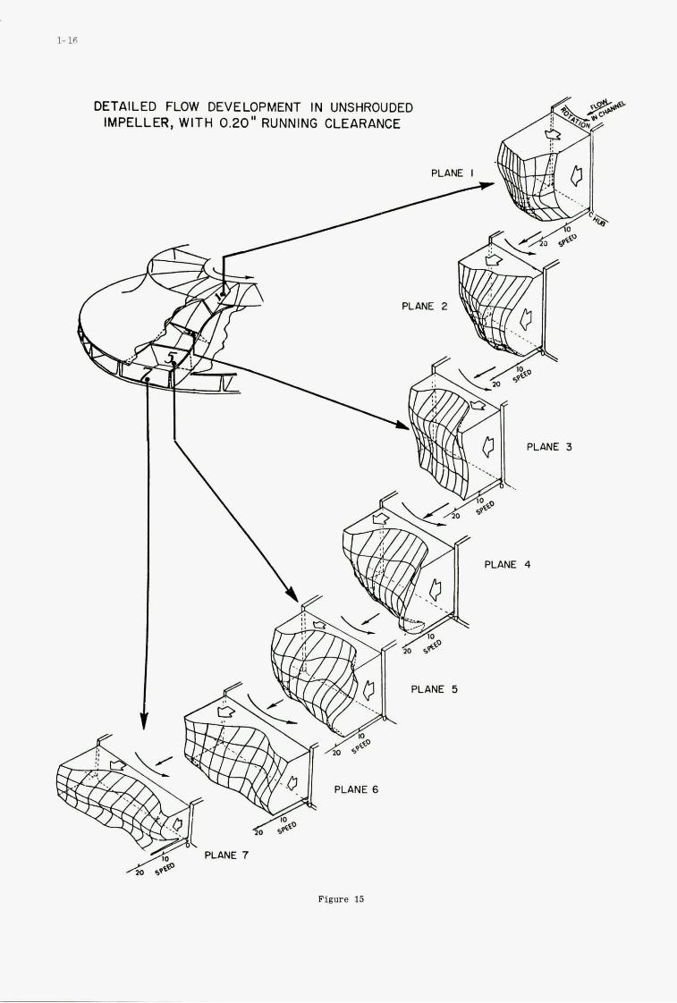
DETAILED FLOW DEVELOPMENT IN UNSHROUDED IMPELLER, WITH 0.20" RUNNING CLEARANCE
Figure 15
1- 17
Figure 16
COYPREBBOR BIREAMLIIE
Figure 17
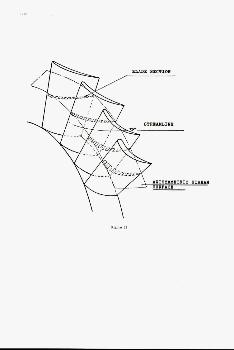
P'igllre 18
The Through-flow Analysis of Axial Flow Compreesors
bY
H. Marsh *
Q, Cambridge University Engineering Department.
2 I
2
Summary
Methods f o r predict ing the performance of a x i a l flow compressors a r e described i n d e t a i l and it is shown t h a t t he methods of streamline curvature and matrix thrcugh-flow ana lys i s a r e based on the same mathematical model f o r flow on the mean stream surface. The need f o r an accurate loss model i s emphasised and the Mach number l imi t a t ions c f these two methods of analysis a r e defined. Methods f o r predict ing the development of the wal l boundary l a y e r s a re discussed and the simple theory o f S t r a t f o r d (10) is shown t o be i n agreement w i t h experimental r e s u l t s obtained f o r f lows w i t h low angles o f s w i r l . work of Gregory-Smith (11) suggests t h a t i f an accurate estimate of t he wall boundary l a y e r can be obtained, then it is possible t o p red ic t t he flow p a t t e r n acros8 the e n t i r e annulus.
The
I
2
a
B
C
Deq F h
H
i
I
P
r
R
Rm s
9
T
6
I
w
l o c a l veloci ty of
surface thickness
chord,
equivalent d i f fus
force vector,
s t a t i c enthalpy,
sound,
parameter,
on f ac to r ,
s tagnat ion enthalpy,
incidence,
r e l a t i v e stagnation enthalpy (rothalpy) I = H - wrVe,
const ants,
meridional Mach number,
r e l a t i v e Mach number,
vector normal t o the mean stream surface,
pressure,
radius,
gas constant,
r ad ius of curvature of meridional streamlines,
entropy,
mean stream surface,
temperature , blade speed ' a t mean radius,
ve loc i ty vector,
r e l a t i v e veloct ty vector,
a i r angle,
deviation,
angles defining the l o c a l mean stream surface,
densi t y , s o l i d i t y (chord/pitch),
slope of t he meridional streamlines,
stream function,
angular veloci ty ,
t o t a l pressure loss coe f f i c i en t ,
Sub s c r i P t 8
1 i n l e t ,
2 o u t l e t ,
r r a d i a l ,
2 ax ia l ,
0 circumferential .
2
Notation (Cont.)
. Boundary Layer
&* displacement thickness,
e momentum thickness,
r shear s t r e s s ,
wall shear s t r e s s . ?L
2- 1
Introduction
The ul t imate object ive of the through-flow analysis i s t o predict the performance of a turbomachine so t h a t t he design engineer can ensure an e f f i c i e n t machine w i t h the minimum time f o r development. During the past f o r t y years, methods of flow analysie f o r turbomachines have progressed from the b a s i c mean l i n e analysis , first t o the method of simple r a d i a l equilibrium, which was necessary t o d e a l w i t h machines o f low hub t o t i p r a t i o , then t o actuator disc theory, which contributed t o our understanding of blade row in t e rac t ion , and f i n a l l y t o the numerical methods of streamline curvature and matrix through-flow ana lys i s which both use d i g i t a l computers t o solve the equations of f l u i d motion. The calculat ion of the flow pa t t e rn remains a very d i f f i cu l t mathematical problem and a complete explanation of the flow requires an understanding of several branches of' f l u i d dynamics.
than the methods of computation; f o r example, the computing f a c i l i t i e s ava i l ab le i n 1952 were not ade a t e f o r obtaining general solut ions t o the governing equations derived by Wu developed having s u f f i c i e n t speed and storage capacity t o deal economically with these problems of flow calculation. The techniques now e x i s t f o r calculat ing the flow i n turbomachines on the b a s i s of a flow model which includes the e f r e c t s of compressibil i ty, r a d i a l va r i a t ions of l i f t and lo s ses , blade row in t e rac t ion , secondary flow e f f e c t s and the development of t he wal l boundary layers. T h i s flow model is based on our understanding of the flow through cascades, i so l a t ed blade rows and s ing le s tage machines; it is a model which i s cont inual ly being revised and improved.
Un t i l 1960, the mathematical model f o r the flow i n turbomachines was more advanced
( l r It is only during the past decade t h a t computers have been
Methods of Flow Calculation
There a re two methods of flow ca lcu la t ion f o r turbomachines and they both attempt t o obtain information about the ove ra l l flow pa t t e rn without including the e f f e c t s of time dependent flows. These methods, of ten ca l l ed streamline curvature and matrix through-flow, a re based on the same mathematical model, but d i f f e r i n t h e i r numerical techniques. a r e usual ly t r e a t e d separately, they have much i n common and the following discussion is an attempt t o show t h e i r r e l a t ionsh ip t o each other.
In Wu's general theory f o r the flow i n turbomachines, reference 1, the equations of f l u i d motion a re s a t i s f i e d on two in t e r sec t ing famil ies of stream surfaces , the complete three-dimensional flow f i e l d being obtained by an i t e r a t i v e process between solut ions f o r the flow on the two s e t s of surf'aces. Throughout the ana lys i s , i t i s assumed t h a t the flow is steady. However, a t e x i t from a blade row, the flow and the gas s t a t e vary circumferent ia l ly and i f the following blade row has a motion r e l a t i v e t o the first, then it is subject t o a time dependent i n l e t flow. It follows t h a t the general theory is therefore only appl icable t o the flow through an i so l a t ed blade row. The theory is general i n the sense t h a t it i s a general method f o r estimating a steady three-dimensional flow by calculat ing the flow on two in t e r sec t ing s e t s of stream surf aces.
The through4low theory is s imi l a r t o the general theory, but the equations of f l u i d motion a re only solved f o r the steady flow on a mean stream surface. The flow and f l u i d s t a t e on t h i s surface may be regarded a s average values f o r t h e flow within the blade passage. For a multi-stage turbomachine, the time dependence of the flow is removed by t r e a t i n g the through-flow solut ion a s an ax ia l ly symmetric flow f o r the duct region between each p a i r of blade rows. In the analysis which follows, the equations governing the flow on the mean stream surface a r e derived and t h e two methods of so lu t ion are uiscussed i n d e t a i l .
Although these two methods of analysis were developed independently and
In a coordinate system ro ta t ing wi th the blade row a t an angular veloci ty U, any steady reversible , i nv i sc id flow is-governed by the equation o f motion
2 is x W - CW x [Vx 9) = - VI + T V s
where ?i i s the r e l a t i v e veloci ty vector. In the r, e , z coordinate system, the equations o f cont inui ty , motion, energy and s t a t e a re
2- 2
Enerrty (ad iaba t ic )
S t a t e (per fec t gas)
where h i s . the s t a t i c enthalpy per u n i t mass. boundary condi t ions def ine the steady flow through any blade row or duct.
flow on the mean stream surface which is defined a8
These equations together w i t h t h e i r
In the through-flow ana lys is , t he governing e w a t i o n s are only solved for t h e
(€3)
where it i s assumed t h a t the surface i s s ing le valued i n 0. %- T If 3 and ~ - a r e p a r t i a l der iva t ives taken along the stream surface, then
where A,, ne and ttz are the components of the u n i t vector X normal t o the surface. These spec ia l der iva t ives a re taken on the stream surface an2 must be dist inguished from ordinary p a r t i a l der ivat ives . of % with r on the stream surface a t a given value of z, whereas -& is the r a t e of change of %with r a t given values of z and 8.
der iva t ives f o r t he flow on the mean stream surface,
Continuity -
The spec ia l der iva t ive 3 is t he r a t e of change & a
The equations governing the flow may now be expressed in terms of the spec ia l
Energy
I n an inv i sc id flow, the force vector i s normal t o the stream surface S and i e therefore normal t o the r e l a t i v e ve loc i ty vector ,
- 2- 3
It is convenient t o def ine the l o c a l form of the stream surface by two angles 1 and y where
_-
(I 7)
The th ree ve loc i ty components a r e then r e l a t e d by
WO = - W r L X - WzT- which i s the geometrical condition t h a t the flow follows the mean stream surface.
Following Wu’s analysis , an in t eg ra t ing f a c t o r B i s introduced such t h a t t he equation of continuity becomes
the f a c t o r B being given by
The equations ind ica t e t h a t B i s proportional t o the l o c a l angular thickness of t he stream surface and a s a first approximation, the thickness o f the stream surface is assumed t o be proportional t o the width of the blade passage,
circumferential width of t he blade passage blade p i t ch B =
For the flow i n a duct region, where there a r e no blades, the parameter B is taken as unity.
surface without assuming a x i a l symmetry, so t h a t t h i s can be seen t o be the f i r s t s tage i n applying the general theory. However, i f a x i a l symmetry were assumed and a d i s t r ibu ted body force introduced t o represent the blade force, then the governing equations a r e of the same form, but w i t h t he spec ia l de r iva t ives replaced by Ordinary p a r t i a l derivatives. It follows t h a t the same flow pa t t e rn i s obtained by assuming a x i a l symmetry, o r by solving f o r the flow on the mean stream surface and then t r e a t i n g t h i s a s an a x i a l l y symmetric solution. The same solut ion f o r t he flow pa t t e rn is obtained i r r e spec t ive of whether the assumption of a x i a l symmetry is made before o r a f t e r the equations a r e solved.
streamline curvature and the matrix method. The method of streamline curvature is based on the r a d i a l equation of motion,
The through-flow analysis has been presented here f o r t h e flow on the mean stream
There are two methods f o r solving the governing equations, nainely the method of
The l a s t term on the r i g h t hand s ide can be expressed i n terms of t he meridional veloci ty Wm and the slope and curvature of t he meridional streamlines - - -
CJ, ?!!r = W, @r - d,- Nr 2 r (2 1) a r 2- where m i s measured i n the d i r ec t ion of the meridional streamline. Introducing the streamline slope $ and radius of curvature R-, t h i s term can a l so be wr i t t en a s
so t ha t t h e r a d i a l equation of motion becomes
The l a s t term on the r i g h t hand s ide can be evaluated from the equations of cont inui ty and energy, much algebra being omitted,
2- 4
Energy
If the working f l u i d i s a perfect gas then - L.* = A . I x - - - I & P 3m CP Jrn R am
and subs t i t u t ing from the equations of cont inui ty and energy
+ W,Fe - W, - we‘ a a% P a
The r a d i a l equation of motion can therefore be wr i t t en a s
o r
T h i s i s the form of the r a d i a l equilibrium equation a s derived by Smith (2), Novak ( 3 ) and S i l v e s t e r and Hetherington (4).
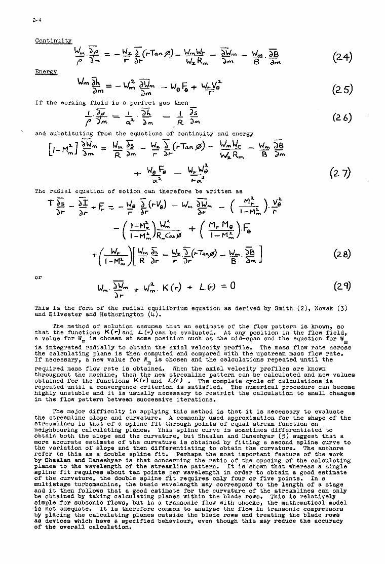
t h a t the functions KCr) and f-(r)can be evaluated. A t any posi t ion i n the flow f i e l d , a value f o r Wm is chosen a t some posi t ion such a s the mid-span and t h e equation f o r Wm is integrated r a d i a l l y t o obtain the a x i a l veloci ty prof i le . The mass flow r a t e across the calculat ing plane is then computed and compared with the upstream mass flow ra t e . If necessary, a new value f o r Wm i s chosen and the calculat ions repeated u n t i l the required mass flow r a t e i s obtained. When the a x i a l veloci ty p r o f i l e s a r e known throughout the machine, then the new streamline pa t t e rn can be calculated and new values obtained f o r t he funct ions K(r ) and L(r) . The complete cycle of ca lcu la t ions is repeated u n t i l a convergence c r i t e r i o n is s a t i s f i e d . The numerical procedure can become highly unstable and it is usual ly necessary t o r e s t r i c t t he calculat ion t o small changes i n the flow pa t t e rn between successive i t e r a t ions .
the streamline slope and curvature. A commonly used approximation f o r t he shape of t he streamlines is t h a t of a sp l ine f i t through points of equal stream function on neighbouring calculat ing planes. T h i s sp l ine curve is sometimes d i f f e r e n t i a t e d t o obtain both the slope and the curvature, but Shaalan and Daneshyar (5) suggest t h a t a more accurate estimate of t h e curvature i s obtained by f i t t i n g a second sp l ine curve t o the va r i a t ion of slope and then d i f f e r e n t i a t i n g t o obtain the curvature. The authors r e f e r t o t h i s as a double sp l ine f i t . Perhaps the most important f ea tu re of the work by Shaalan and Daneshyar is t h a t concerning the r a t i o of the spacing of the ca l cu la t ing planes t o the wavelength of t he streamline pattern. It is shown t h a t whereas a s ing le sp l ine f i t requires about t en points per wavelength i n order t o obtain a good estimate of the curvature, t he double sp l ine f i t requires only four o r f i v e points. In a multistage turbomachine, the basic wavelength may correspond t o the length of a s tage and it then follows t h a t a good estimate f o r the curvature of the streamlines can only be obtained by taking ca l cu la t ing planes within the blade rows. T h i s is r e l a t i v e l y simple f o r subsonic flows, but i n a transonic flow with shocks, the mathematical model is not adewate. I t is therefore common t o analyse the flow i n t ransonic compressors by placing the ca l cu la t ing planes outs ide the blade rows and t r e a t i n g the blade rows ae devices which have a spec i f i ed behaviour, even though t h i s may reduce t h e accuracy of t he ove ra l l calculation.
The method of solut ion assumes t h a t an estimate of the flow pa t t e rn is known, so
The major d i f f i c u l t y i n applying t h i s method is t h a t i t i s necessary t o evaluate
2- 5
The a l t e rna t ive method of solving the equations governing the flow on ‘ the mean stream surface is t o def ine a stream funct ion $J where
and
The r a d i a l equation of motion (12) can then be expressed a s
o r
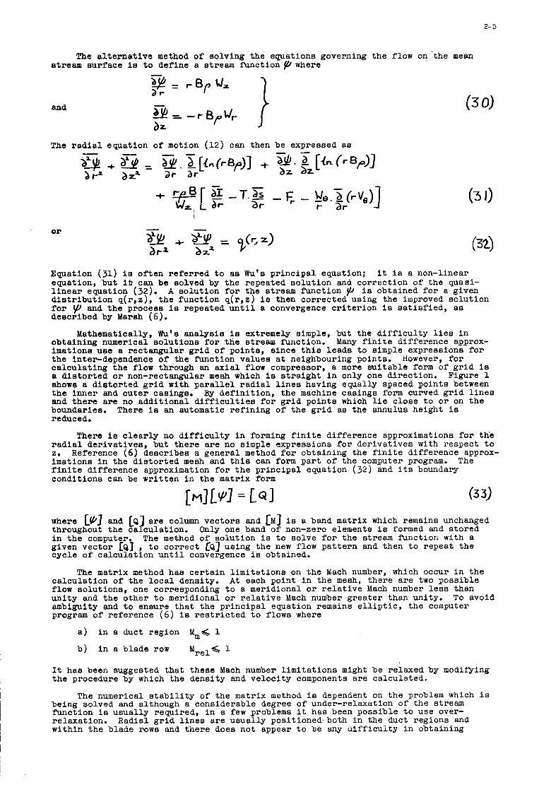
Equation (31) is of ten r e fe r r ed t o a s Wu’s pr inc ipa l equation; it is a non-linear equation, bu t i b can be solved by the repeated so lu t ion and cor rec t ion of the quasi- l i n e a r equation (32). A so lu t ion f o r the stream funct ion Y is obtained f o r a given d i s t r i b u t i o n q ( r , z ) , t he funct ion q ( r , z ) is then corrected using the improved so lu t ion f o r and the process is repeated u n t i l a convergence c r i t e r i o n is s a t i s f i e d , a s described by Marsh (6).
obtaining numerical so lu t ions f o r t he stream function. Many f i n i t e difference approx- imations use a rectangular g r id of points , s ince t h i s leads t o simple expressions f o r the interdependence of the funct ion values a t neighbouring points. However, f o r ca lcu la t ing the flow through an a x i a l flow compressor, a more su i t ab le form of g r id is a d i s t o r t e d o r non-rectangular mesh which is s t r a i g h t i n only one direct ion. Figure 1 shows a d i s to r t ed gr id w i t h p a r a l l e l r a d i a l l i n e s having equally spaced poin ts between the inner and outer casings. and there are no addi t iona l d i f f i c u l t i e s f o r g r id poin ts which l i e c lose t o o r on the boundaries. There is an automatic r e f in ing of the g r i d as the annulus height is reduced.
Mathematically, Wu’s analys is is extremely s imple, but the d i f f i c u l t y l i e s i n
By def in i t ion , t he machine casings form curved g r i d l i n e s
There is c l e a r l y no d i f f i c u l t y i n forming f i n i t e difference approximations f o r th’e r a d i a l der ivat ives , bu t t he re a r e no s imple expressions for der iva t ives with respect t o 2. Reference ( 6 ) descr ibes a general method f o r obtaining the f i n i t e difference approx- imations i n the d i s t o r t e d mesh and t h i s can form pa r t of the computer program. The f i n i t e difference approximation f o r t h e pr inc ipa l equation (32) and i ts boundary condi t ions can be wr i t t en i n the matrix form
where L(b] and LQ] are column vec tors and [MI is a band matrix which remains unchanged throughout t he calculat ion. Only one band of non-zero elements i s formed and s tored i n the computer. The method of so lu t ion is t o solve f o r the stream funct ion w i t h a given vector [Q] , t o cor rec t CQ] using the new flow pa t t e rn and then t o repeat t he cycle of ca lcu la t ion until convergence is obtained.
ca lcu la t ion of the l o c a l density. A t each point i n the mesh, there a r e two possible flow solut ions, one corresponding t o a meridional o r r e l a t i v e Mach number l e s s than un i ty and the o ther t o meridional o r r e l a t i v e Mach number g rea t e r than unity. ambiguity and t o ensure t h a t t he p r inc ipa l equation remains e l l i p t i c , the computer program of reference (6) i s r e s t r i c t e d t o flows where
The matrix method has ce r t a in l imi t a t ions on the Mach number, which occur i n the
To avoid
a ) i n a duct region Idm< 1
b) i n a blade row Idrel< 1
It has been suggested tha t these Mach number l imi t a t ions might be relaxed by modifying the procedure by which the densi ty and ve loc i ty components a re calculated.
The numerical s t a b i l i t y of the matrix method is dependent on the problem which i s being solved and although a considerable degree of under-relaxation o f the stream f’unctlon is usual ly required, i n a few problems it has been poss ib le t o use over- re laxat ion. Radial g r i d l i n e s a re usua l ly posi t ioned.both i n the duct regions and within the blade rows and the re does not appear t o be any d i f f i c u l t y i n obtaining
numerical solut ions, provided tha t t h e machine boundaries form smooth curves.
through-flow analysis a r e merely two d i f f e ren t numerical techniques f o r solving the same s e t of equations governing the flow on the mean stream surface. When applied t o the same flow problem with the same mesh, then the two methods of ca lcu la t ion must lead t o the same solution. The major difference between the two methods as they a r e now applied, is t h a t the method o f streamline curvature usual ly places the calculat ing planes only i n the duct regions, while the matrix method includes calculat ing planes within the blade rows. T h i s is, however, a difference of no g rea t s ignif icance i n t h a t e i t h e r method can be applied w i t h o r without calculat ing planes in s ide the blade rows.
It is important t o r e a l i s e t h a t t h e method of streamline curvature and t h e matrix
The Loss Model
One d i f f i c u l t y i n calculat ing the flow pa t t e rn i s t h a t it is necessary t o estimate the loss of r e l a t i v e stagnation pressure, o r t he entropy change, on passing through the blade rows. This problem is perhaps bes t phrased i n terms of entropy i n t h a t it is then c l e a r t h a t the e f f e c t of l o s s i n a multi-stage compressor is cumulative. It i s t h e radial gradient o f entropy which e n t e r s d i r e c t l y i n the governing equations f o r t he matrix method, while the method o f streamline curvature requires both the r a d i a l and meridional gradients of entropy. As the flow passes through each blade row, then f o r an adiabat ic flow, the entropy increases monotonically along the streamlines. The changes i n entropy and the entropy gradient i n an i so l a t ed blade row a re usual ly small, but when the flow has passed through a large number of blade rows, then the entropy gradient term i n the governing equations becomes more important. For a multi-stage machine, the flow ca lcu la t ions require an extremely accurate d e f i n i t i o n of t he l o s s model f o r each blade row.
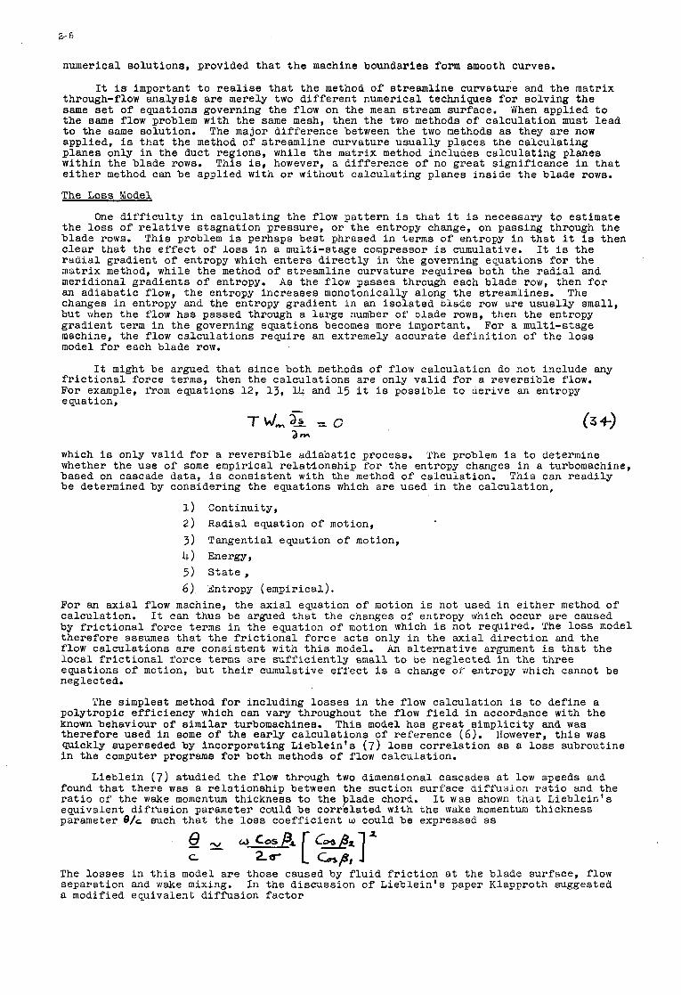
It might be argued t h a t s ince both methods of flow calculat ion do not include any f r i c t i o n a l force terms, then the ca l cu la t ions a re only v a l i d f o r a r eve r s ib l e flow. For example, from equations 1 2 , 13, 14 and 15 it is possible t o derive an entropy e quat ion,
which i s only v a l i d f o r a r eve r s ib l e adiabat ic process. The problem i s t o determine whether the use of some empirical r e l a t lonsh ip f o r the entropy changes i n a turbomachine, based on cascade data, i s consis tent w i t h the method of calculation. T h i s can r ead i ly be determined by considering the equations which a re used i n the calculat ion,
1) Continuity, 2 ) Radial equation o f motion, 3 ) Tangential equation of motion,
5) S t a t e , 6 ) Entropy (empirical) .
4) Energy,
For an a x i a l flow machine, the a x i a l equation of motion i s not used i n e i t h e r method of calculat ion. It can thus be argued t h a t the changes o f entropy which occur a re caused by f r i c t i o n a l force terms i n the equation of motion which i s not required. The l o s s model therefore assumes t h a t t he f r i c t i o n a l force a c t s only i n the a x i a l d i r ec t ion and the flow calculat ions a r e consis tent with t h i s model. An a l t e r n a t i v e argument is t h a t t he l o c a l f r i c t i o n a l force terms a re s u f f i c i e n t l y small t o oe neglected i n the th ree equations of motion, but t h e i r cumulative e f f e c t is a change of' entropy which cannot be neglected.
polytropic eff ic iency which can vary throughout the flow f i e l d i n accordance with the known behaviour o f s imi l a r turbomachines. This model has g rea t s implici ty and was therefore used i n some o f the ea r ly ca l cu la t ions o f reference ( 6 ) . However, t h i s was Wickly superseded by incorporating L ieb le in ' s ( 7 ) l o s s co r re l a t ion a s a l o s s subroutine i n the computer programs f o r both methods of flow calculat ion.
found t h a t there was a r e l a t ionsh ip between the suction surface aiff 'usion r a t i o and the r a t i o o f the wake momentum thickness t o the plade chord. equivalent difr'usion parameter could be co r re l a t ed w i t h che wake momentum thickness parameter e/, such t h a t t he l o s s coe f f i c i en t o could be expressed a s
The simplest method f o r including l o s s e s i n the flow calculat ion is t o define a
Lieblein (7) studied the flow through two dimensional cascades a t low speeds and
It was shown t h i t Lieblein 's
The lo s ses i n t h i s model a r e those caused by f l u i d f r i c t i o n a t t he blade surface, flow separation and wake mixing. In the discussion of Lieb le in ' s paper Klapproth suggested a modified equivalent d i f f i s i o n f a c t o r
I
2-7
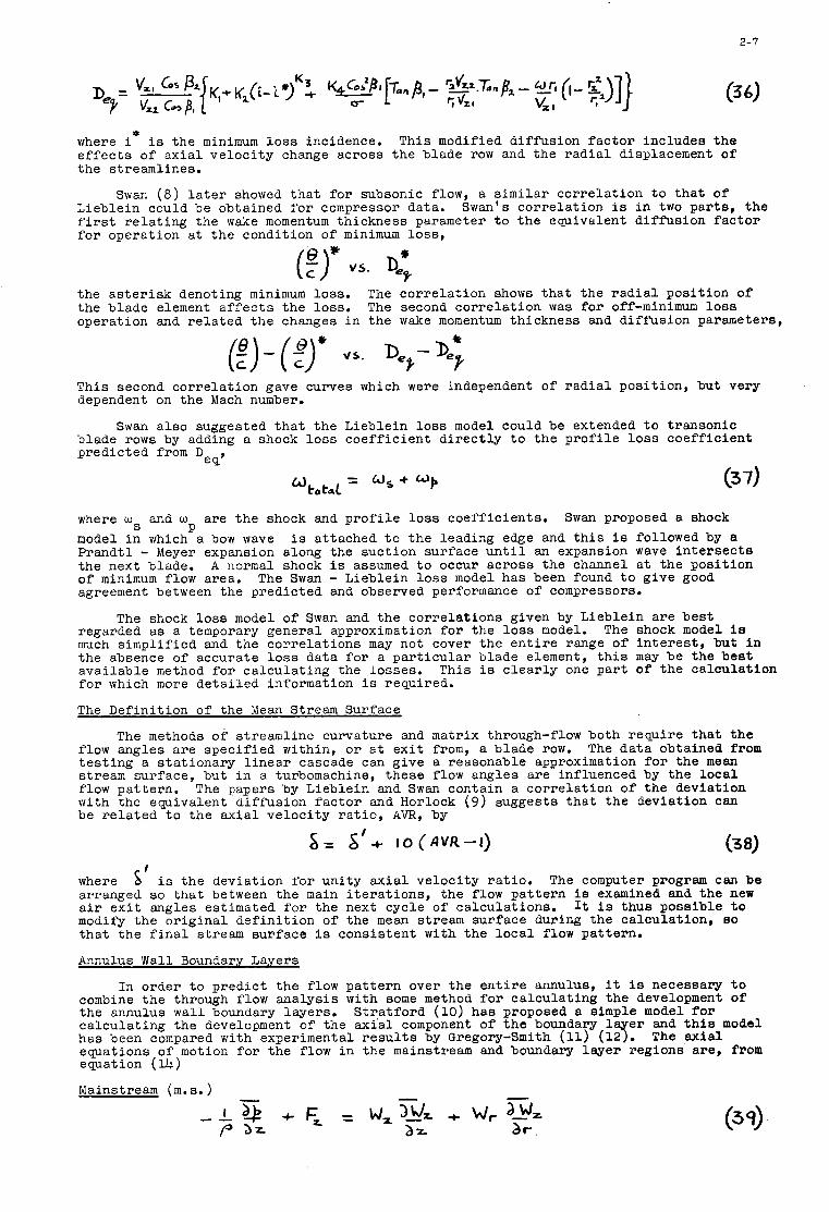
0 where i is the minimum l o s s incidence. T h i s modified diffusion f a c t o r includes the e f f e c t s of a x i a l ve loc i ty change across the blade row and the r a d i a l displacement of the streamlines.
Swan (8) l a t e r showed t h a t f o r subsonic flow, a s imi l a r co r re l a t ion t o that of Lieblein could be obtained f o r compressor data. Swan's co r re l a t ion is i n two pa r t s , t he first r e l a t i n g the wake momentum thickness parameter t o t h e equivalent d i f fus ion f a c t o r f o r operation a t t h e condition of minimum l o s s ,
the a s t e r i s k denoting minimum loss . the blade element a f f e c t s t h e loss . The second co r re l a t ion was for off-minimum l o s s operation and r e l a t e d t h e changes i n the wake momentum thickness and diffusion parameters,
The co r re l a t ion shows t h a t t he r a d i a l posi t ion of
T h i s second co r re l a t ion gave curves which were independent o f r a d i a l posi t ion, but very dependent on the Mach number.
blade rows by adding a shock l o s s coe f f i c i en t d i r e c t l y t o the p r o f i l e loss coe f f i c i en t predicted from D
Swan a l so suggested t h a t t he Lieblein l o s s model could be extended t o transonic
e 9'
where ws and w
model i n which a bow wave is attached t o t h e leading edge and t h i s is followed by a Prandt l - Meyer expansion along the suct ion surface u n t i l an expansion wave i n t e r s e c t s the next blade. A normal shock is assumed t o occur across the channel a t the posi t ion of minimum flow area. The Swan - Lieblein l o s s model has been found t o give good agreement between the predicted and observed performance of compressors.
The shock l o s s model of Swan and the co r re l a t ions given by Lieblein a r e bes t regarded a s a temporary general approximation f o r t he l o s s model. much s implif ied and the co r re l a t ions may not cover the e n t i r e range of i n t e r e s t , but in the absence of accurate l o s s data f o r a p a r t i c u l a r blade element, t h i s may be the b e s t avai lable method f o r ca l cu la t ing the losses. f o r which more de t a i l ed information i s required.
The Defini t ion of the Mean Stream Surface
are the shock and p r o f i l e loss coeff ic ients . Swan proposed a shock P
The shock model is
T h i s is c l e a r l y one pa r t of t he calculat ion
The methods o? streamline curvature and matrix through-flow both require t h a t t h e flow angles a r e spec i f i ed within, o r a t e x i t from, a blade row. The da ta obtained from t e s t i n g a s t a t iona ry l i n e a r cascade can give a reasonable approximation f o r the mean stream surface, but i n a turbomachine, these flow angles a re influenced by the l o c a l flow pat tern. w i t h the equivalent d i f fus ion f a c t o r and Horlock ( 9 ) suggests t h a t t h e deviation can be r e l a t e d t o t h e a x i a l ve loc i ty r a t i o , AVR, by
The papers by Lieblein and Swan contain a co r re l a t ion of t he deviation
s = &'+ I O ( A V R - l )
where arranged s o t h a t between the main i t e r a t i o n s , the flow pa t t e rn is examined and the new a i r e x i t angles estimated f o r the next cycle o f calculat ions. modify the o r i g i n a l de f in i t i on o f the mean stream surface during the calculat ion, so t h a t t he f i n a l stream surface i s consis tent w i t h t he l o c a l flow pattern.
Annulus Wall Boundary Layers
In order t o p red ic t the flow pa t t e rn over t he e n t i r e annulus, it is necessary t o combine the through flow analysis w i t h some method f o r ca l cu la t ing the development of the annulus wall boundary layers. ca l cu la t ing the development of the a x i a l component of t h e boundary 1 e r and t h i s model has been compared with experimental r e s u l t s by Gregory-Smith (11) (18. The a x i a l equations o f motion for the flow i n the mainstream and boundary l aye r regions are , from equation (14)
6' is the deviation f o r un i ty a x i a l veloci ty r a t i o . The computer program can be
It is thus possible t o
S t r a t f o r d (10) has proposed a simple model f o r
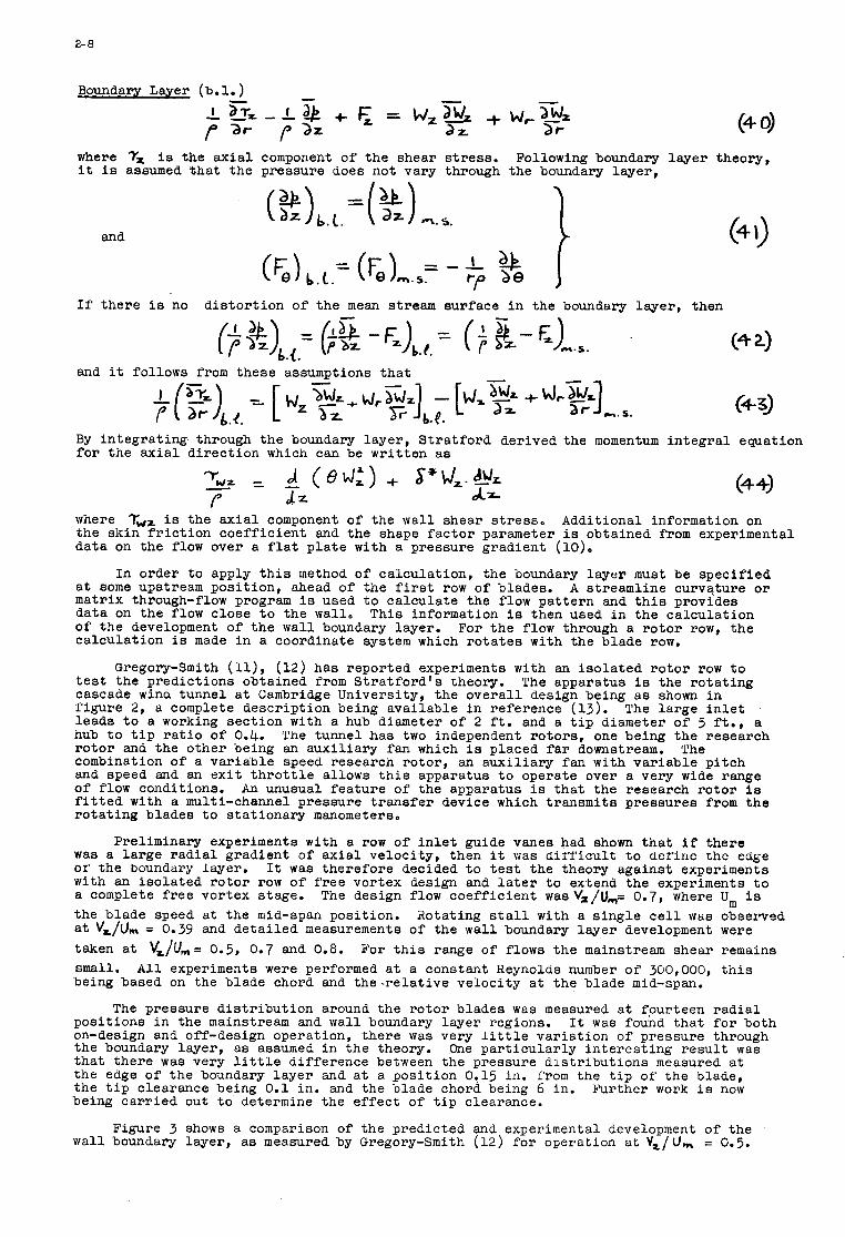
2- 8
Boundary Layer (b. 1. )
where 7, is the a x i a l component of t he shear s t r e s s . it i s assumed t h a t the pressure does not vary through
and
w, 3% 2f-
Following boundary the boundary layer ,
1 layer theory,
If t he re i s no d i s t o r t i o n o f t he mean stream surface i n the boundary layer , then
and it follows from these assumptions t h a t
(4 0)
(4 1)
(43)
By in t eg ra t ing through the boundary layer , S t r a t f o r d derived the momentum i n t e g r a l equation f o r t he a x i a l d i r ec t ion which can be wr i t t en a s
where T,, is the a x i a l component of the wall shear s t r e s s . Additional information on the skin f r i c t i o n coe f f i c i en t and the shape f a c t o r parameter i s obtained from experimental data on the flow over a f l a t p l a t e w i t h a pressure gradient
In order t o apply t h i s method of calculat ion, the boundary l aye r must be spec i f i ed a t some upstream posi t ion, ahead of the first row o f blades. A streamline curvature o r matrix through-flow program is used t o ca l cu la t e the flow pa t t e rn and t h i s provides data on the flow close t o the wall, This information i s then used i n the ca l cu la t ion of t he development of t h e wall boundary layer. For the flow through a r o t o r row, the calculat ion is made i n a coordinate system which r o t a t e s with the blade row.
Gregory-Smith (U), ( 1 2 ) has reported experiments w i t h an i so l a t ed r o t o r row t o t e s t the predict ions obtained from S t r a t f o r d ' s theory. cascade wind tunnel a t Cambridge University, the o v e r a l l design being a s shown i n f igu re 2, a complete descr ipt ion being avai lable i n reference (13). The l a rge i n l e t leads t o a working sect ion w i t h a hub diameter of 2 f t . and a t i p diameter of 5 f t . , a hub t o t i p r a t i o of 0.4. The tunnel has two independent ro to r s , one being the research r o t o r and the other being an aux i l i a ry fan which i s placed f a r downstream. The combination of a va r i ab le speed research ro to r , an aux i l i a ry fan w i t h va r i ab le p i t ch and speed and an e x i t t h r o t t l e allows t h i s apparatus t o operate over a very wide range of flow conditions. A n unusual f ea tu re of the apparatus is t h a t the research r o t o r ia f i t t e d w i t h a multi-channel pressure t r a n s f e r device which t ransmits pressures from t h e r o t a t i n g blades t o s t a t iona ry manometers.
was a l a rge r a d i a l gradient o f a x i a l veloci ty , then it vas dir 'f ' icult t o der'iiie the edge o r the boundary layer. It was therefore decided t o t e s t the theory against experiments with an i so l a t ed r o t o r row of f r e e vortex design and l a t e r t o extend the experiments t o a complete f r e e vortex stage. the blade speed a t the mid-span posit ion. a t V,/&, = 0.39 and de ta i l ed measurements of the w a l l boundary l aye r development were taken a t vz/um= 0.5, 0.7 and 0.8. small. A l l experiments were performed a t a constant Reynolds number of 300,000, t h i s being based on the blade chord and t h e - r e l a t i v e veloci ty a t t he blade mid-span.
The pressure d i s t r i b u t i o n around the r o t o r blades was measured a t fpurteen r a d i a l posi t ions i n the mainstream and wall boundary layer regions. It was found t h a t f o r both on-design and off-design operation, t he re was very l i t t l e va r i a t ion o f pressure through the boundary layer , a s assumed i n the theory. One p a r t i c u l a r l y i n t e r e s t i n g r e s u l t was t h a t t he re was very l i t t l e difference between the pressure d i s t r i b u t i o n s measured a t t he edge of t he boundary l aye r and a t a posi t ion 0.15 in. from the t i p of' t he blade, the t i p clearance being 0.1 in. and the blade chord being 6 in. Further work i s now being ca r r i ed out t o determine the e f f ec t of t i p clearance.
Figure 3 shows a comparison of the predicted and experimental development o f the wall boundary layer , a s measured by Gregory-Smith ( 1 2 ) f o r operation a t vZ/l).,, = 0.5.
The apparatus is the ro t a t ing
Preliminary experiments w i t h a row of i n l e t guide vanes had shown t h a t i f t he re
The design flow coe f f i c i en t wasv,/u,= 0.7, where U, i s Rotating s t a l l with a s i n g l e c e l l was observed
E'or t h i s range o f flows the mainstream shear remains
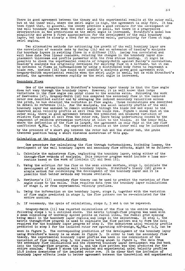
2- 9
There i s good agreement between the theory and the experimental r e s u l t s a t the outer wall , but a t the inner wall , where the s w i r l angle is high, the agreement is only f a i r . It has been found t h a t , i n general , the theory provides a good estimate f o r the development o f t he wall boundary l a y e r s when the s w i r l angle is small, but t he re is a progressive de t e r io ra t ion i n the predict ions a s t he s w i r l angle is increased. S t r a t f o r d ' s model has s impl i c i ty and gives a first approximation f o r the development of the wall boundary layer , but t he re i s c l e a r l y a need f o r an improved model, pa r t i cu la r ly f o r flows a t high s w i r l angles.
Two a l t e r n a t i v e methods f o r estimating the growth o f the wall boundary layer a re the co r re l a t ion of cascade data by Hanley (14) and an extension of Hoadley's analysis f o r boundary l aye r s i n s w i r l i n g flows i n a diff 'user (15). Hanley has co r re l a t ed end wall l o s s data from l i n e a r cascades, r e l a t i n g the changes i n the boundary layer dis- placement thickness and p r o f i l e parameter with the f r e e stream loading. It might be possible t o check the experimental r e s u l t s of Gregory-Smith against Hanley's correlat ion. Hoadley's analysis was o r i g i n a l l y developed f o r swir l ing flow i n a diz'l'user, but it can be extended to flows i n turbomachines by using a d i s t r i b u t e d body force t o represent a blade row. Gregory-Smiths experimental r e s u l t s when the s w i r l angle is small, but a s with S t r a t f o r d ' s method, the agreement worsens rapidly a s t h e s w i r l angle i s increased.
Secondary Flows
Horlock (16) has found t h a t Hoadley's ana lys i s gives good agreement with
One of the assumptions i n S t r a t f o r d ' s boundary l aye r theory i s t h a t t he flovi angle does not vary through the boundary layer. However, i t i s well known t h a t l a rge v a r i a t i o n s i n the flow angle can occur c lose t o the annulus walls. Following the work of Hawthorne (17), Gregory-Smith (12) has computed the secondary flow i n the i so l a t ed r o t o r row described e a r l i e r and by averaging the induced secondary v e l o c i t i e s across the p i t ch , he has obtained the va r i a t ion i n flow angle. These ca l cu la t ions a re described i n d e t a i l i n reference (11). boundary l aye r was assumed t o remain unchanged through the blade row and equal t o the observed a x i a l ve loc i ty p r o f i l e a t e x i t from the blade row. Figure 4 shows t h a t a t the outer wall, t he re is good agreement between the predicted and measured va r i a t ion o f r e l a t i v e flow angle a t e x i t from the r o t o r row, the re being underturning caused by the component of r e l a t i v e streamwise v o r t i c i t y a t i n l e t t o t he blades. A t t he inner wall, where the def lect ion o f t he flow is l a rge r , the agreement i s only f a i r a t the low flow coe f f i c i en t vZ/om = 0.5. by t h e presence of a shor t gap between the ro to r hub and the s t a t o r hub, the probe t r ave r se pos i t i on being a sho r t dis tance downstream of t h i s gap.
Calculation of the Complete Flow Pa t t e rn
For the analysis , t he a x i a l veloci ty p r o f i l e of the wall
The experimental r e s u l t s a t the inner wall may be influenced
One procedure f o r ca l cu la t ing the flow through turbomachines, including losses , t he development of the w a l l boundary l aye r s and secondary flow e f fec t s , might be as follows:-
1.
2.
3.
4.
5.
Calculate t he mainstream flow, neglecting the boundary layer , using e i t h e r of t he through-flow methods of analysis. This computer program would include a loss sub- rou t ine based on the work of Lieblein (7) and Swan (8) .
Using the so lu t ion f o r the flow on the mean stream surface, s tage 1, ca lcu la t e the development of t he annulus wall boundary layers. simple method f o r ca l cu la t ing the development of the boundary l aye r and it i s possible t h a t b e t t e r methods may become available.
Hawthorne's (17) secondary flow theory can be used t o predict t he va r i a t ion of flow angle c lose t o the walls. This requires data from the boundary l aye r calculat ions of stage 2, o r from experimental ve loc i ty p ro f i l e s .
Using the information on the boundary layer , s tage 2 , together with the va r i a t ion of flow angle predicted i n s tage 3 , the flow pa t t e rn can be re-calculated f o r t he e n t i r e annulus.
If necessary, the cycle o f calculat ion, s t eps 2 , 3 and 4 can be repeated.
S t r a t f o r d ' s theory (10) gives a
Grenoru-Smith (11) has PeDOrted ca l cu la t ions of' the flow i n the e n t i r e annulus, followinij s t e p s 1 t o &.out l ined above. a meah consis t ing of unevenly spaced po in t s on r a d i a l l i n e s , the r a d i a l g r i d spacing being small i n the boundary l aye r regions and l a rge i n the mainstream. In s t ep 1, the matrix through-flow program is used t o ca l cu la t e the flow pa t t e rn and t o form the data required f o r t he boundary l a y e r program of s t ep 2. The downstream a x i a l veloci ty p r o f i l e predicted i n e tep 1 f o r the isolated. r o t o r row operating off-design, vz/um= 0.5, can be seen i n f i g u r e 5. The corresponding predict ion of t he development o f the boundary layer using S t r a t f o r d ' s theory is a s shown i n f igu re 3. In order t o t e s t the secondary flow theory, the experimental boundary layer p r o f i l e was used i n the calculat ion o f the v a r i a t i o n of flow angle, s t e p 3, the r e s u l t s being shown i n f igu re 4. The data from the secondary flow ca lcu la t ions and t h e observed boundary l aye r development was fed back i n t o the through-flow program, s t ep 4, and t h e flow p a t t e r n was then predicted f o r the e n t i r e annulus. Figure 5 shows t h e predicted and experimental a x i a l ve loc i ty p r o f i l e s 15.8 inches downstream of the i so l a t ed r o t o r row. It is c l e a r t h a t t he inclusion of boundary l a y e r e f f e c t s leads t o b e t t e r agreement between the t h e o r e t i c a l and experimental
The matrix through-flow program was used with
2- 10
r eau1 t a.
For the present, development of the wa
it has been necessary t o base 1 boundary layers . However,
the ca l cu la t ions on the observed h i s , work by Gregory-Smith shows
t h a t if an accurate method of predict ion can 'be developed f o r the annulus wall boundary layers , then it should be possible t o estimate the complete flow pa t t e rn i n a turbomachine and thereby obtain a more r e l i a b l e predict ion of performance.
Mach Number Limitations
The streamline curvature and matrix through-flow methods have Mach number l i m i t a t i o n s and a t present, the flow pa t t e rn i n a transonic compressor can only be calculated by t r e a t i n g the blade rows a s devices with a spec i f i ed behaviour and by not placing cal- culat ing planes within the blade rows. The major d i f f i c u l t y can b e s t be i l l u s t r a t e d by considering the flow i n an axisymmetric convergent-divergent nozzle, a turbomachine w i t h no blades and no hub. The streamline curvature and matrix methods can both p red ic t t he flow pa t t e rn when the e n t i r e flow is subsonic, but ne i the r method can deal w i t h t h e more general problem when the re is supersonic flow following the th roa t and a shock down t o subsonic flow. It is unl ikely t h a t t he present methods of flow ca lcu la t ion w i l l b e able t o deal with t h i s problem and it may therefore be necessary t o develop a new numerical method f o r flows which include regions of subsonic and supersonic flows and shocks. It may be possible t o extend t o turbomachinery flows the methods of calculat ion based on solving the time dependent eqyations of motion t o obtain the u l t ima te steady s t a t e flow pattern. References (18) and (19) describe a numerical technique f o r calculat ing the flow i n one-dimensional and two-dimensional convergent-divergent nozzle8 w i t h regions of subsonic flow, supersonic flow and a shock. Figure 6 compares t h e numerical so lu t ion f o r the pressure d i s t r i b u t i o n i n a one-dimensional nozzle wi th t h a t obtained analyt ical ly . There is seen t o be close agreement between the two solut ions; t he shock is smeared, but the main feature6 of the flow a r e preserved. Stable numerical solut ions have a l so been obtained by Merryweather (19) f o r the flow i n two-dimensional nozzles. important t o r e a l i s e t h a t these so lu t ions a r e based only on the equations of cont inui ty , motion, energy and s t a t e , together with the boundary conditions of t he upstream stagnation s t a t e and the downstream e x i t pressure. It is hoped t h a t t h i s numerical technique might be extended t o flows i n turbomachines and thus remove the present Mach number l imitat ions.
Conclusions
During recent years, two methods have been developed f o r solving the equations governing the flow i n turbomachines, namely streamline curvature and matrix through-flow analysis. I n t h i s paper it has been shown t h a t these two approaches t o turbomachinery flow ca lcu la t ions a re based on the same mathematical model; they a r e merely two dSfferent techniques f o r obtaining numerical solut ions t o the same s e t of equations. With the computer programs based on these methods of flow calculat ion, it is now possible t o estimate the performance of a turbomachine operating on-design o r off-design. However, t he accuracy of these predict ions is dependent on the mathematical model. There remains a need f o r more accurate methods f o r predict ing l o s s e s and for predict ing the development of the wa l l boundary layers. More work i s a l so required on the e f f e c t s of turbulence on the performance of a blade row, the behaviour of a cascade i n an unsteady flow, such a s t h a t produced by an upstream blade row, and the flow i n transonic blade rows. Research i s being c a r r i e d out on seve ra l o f these problems and as our understanding of t he flow improves, then we may expect t o see fu r the r improvements i n the predict ion o f t he performance of turbomachines. In the past , methods of computation were not adequate t o dea l w i t h t he flow model f o r turbomachines, whereas a t present, t he means of calculat ion e x i s t and it is t he mathematical model of the flow which requires f u r t h e r improvement.
It is
2- 11
References
1. Wu, C-H
2.
3-
4.
5.
6.
7.
8.
9.
10.
11.
12.
13
U.
15
16.
17 0
18.
19.
Smith, L.S.
Nova, R.A.
S i lves te r , M.E. and Hetherington, R.
Shaalan, M.R.A. and Daneshyar, H.
Marsh, H.
Lieblein, S.
swan, W.C.
Horlock, J.H.
S t ra t ford , B.S.
A general theory of th ree dimensional flow i n subsonic and supersonic turbomachines of axial , r a d i a l and mixed-flow types, N.A.C.A. TN 2604, 1952
The r a d i a l equilibrium equation of turbomachinery, Trans. A.S.M.E., Ser ies A, Vol. 88, 1966.
Streamline curvature computing procedures f o r f l u i d flow problems. A.S.M.E., Paper 66 - WA/GT-3, 1966.
Three-dimensional compressible flow through a x i a l flow turbomachines , i n 'Numerical Analysis - An Introduction' Academic Press 1966.
Methods of calculat ing slope and curvature of streamlines i n f l u i d flow problems, Cambridge University Engineering Department Report, CUED/A - Turbo/TR2, 1969.
A d i g i t a l computer program f o r the through-flow f l u i d mechanics i n an a r b i t r a r y turbomachine using a matrix method. N.G.T.E. Report R282, 1966, a l so Aero. Res. Coun. Rep. Memor.
Loss and s t a l l analysis of compressor cascades, T r a n s . A.S.M.E. Ser ies D, Vol, 81, 1959.
A p r a c t i c a l method of predict ing transonic compressor performance, Trans. A.S.M.E., Ser ies A, Vol. 83, 1961.
Some recent research i n turbomachinery, Proc. Instn. Mech. Engrs. Vol. 182, 1968.
The use of boundary layer techniqges t o calculate the blockage from the annulus boundary layers i n a compressor, A.S.M.E., Paper 67 - YJA/GT - 7, 1967.
3509, 1968.
Gregory-Smith, D.G. Annulus wal l boundary layers i n turbomachines, Ph.D. d i sser ta t ion , Cambridge University, 1970.
Gregory-Smith, D. G.
Oxford, J.T.B.
Hanley, W. T.
Hoadley, D.
Horlock, J.H.
Hawthorne, W.R. and Novak, R.A.
Marsh, H. and Merryweather, H.
Merryweather, H.
An invest igat ion of annulus wall boundary layers i n a x i a l flow turbomachines, To be published by A.S.M.E.
A ro ta t ing cascade wind tunnel and a ro ta t ing aerofo i l i n ro ta t iona l flow, Ph.D. d i sser ta t ion , Cambridge University, 19650
A cor re la t ion of end wall losses i n plane compressor cascades, Trans. A.S.M.E., Ser ies A, Vol. 90, 1968.
Three dimensional turbulent boundary layers i n an annular d i f f'user, Ph.D. d i sser ta t ion , Cambridge University, 1969.
Pr ivate communication, 1969.
The aerodynamics of turbomachinery, Annual Review o f Fluid Mechanics, Annual Reviews Inc., Vol. l., 1969.
The calculat ion of subsonic and supersonic flows i n nozzles, Cambridge ,University Engineering Department Report, CUED/A - Turbo/TR3, 1969.
The calculat ion of subsonic and supersonic f lows i n ducts, Ph.D. d i sser ta t ion , Cambridge University 1969.
M a y 1970.
I 2-12 .
Acknowledgement
experimental and theore t ica l work o f reference (11). ~ The author would l i k e t o thank M r . D.G. Gregory-Smith f o r permission t o quote the
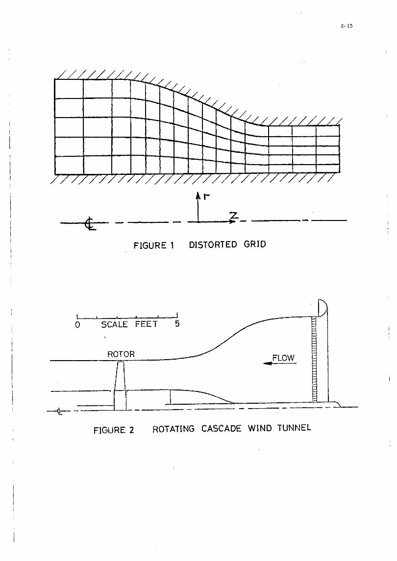
2- 13
t’ 4 - -
FIGURE 1
0 SCALE FEET 5
DISTORTED GRID
FIGURE 2 ROTATING CASCADE WIND TUNNEL
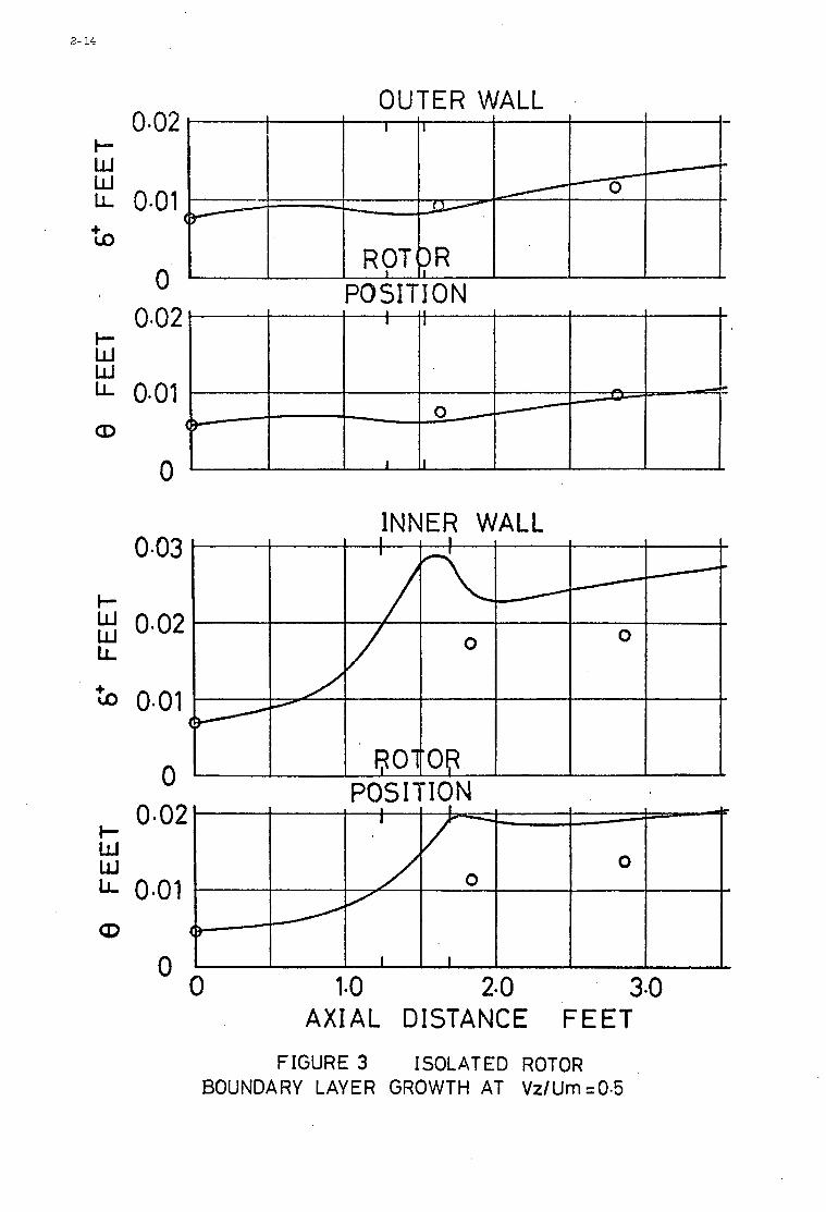
2- 14
I- w W LL
Lo +
I- W W LL
CD
I- W w LL
a +
t- W W LL
CD
OUTER WALL
PO SI T I 0 N
INNER WALL 0.03
0-02
0-01
0 I I 0.02
0.01 B
I W. S' A
0 0
($
I I
0 1.0 2-0 3.0 0
A X I A L DISTANCE FEET
FIGURE 3 ISOLATED ROTOR BOUNDARY LAYER GROWTH AT Vz/Um ~ 0 . 5
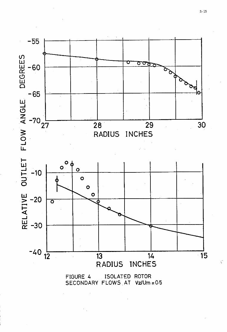
2- 15
-55
w
(3 LbJ Q
E -60
-65 w J 0 z 4 -70 27
-10
-20
-3 0
-40 a
28 29 RADIUS INCHES
30
13 14 RADIUS INCHES
15
FIGURE 4 ISOLATED ROTOR SECONDARY FLOWS AT Vz/Um =0.5
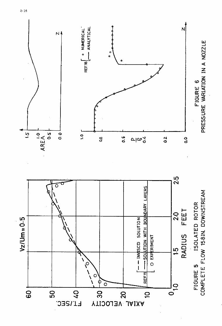
2- 16
LD
II
3 N >
' 0
E -
U O I
P ii w LL:
P 9 a
d LJ d
0 * 0 c')
0 cv 0 .L
0 F
0
W -J N N 0 z
z Z
a L(
0 d
I-
CUW LL
O W
rn 3 U
'33Sll.J AlI3013A W I X V
3
I I
MASS FLOW LIMITATION IN SUPERSONIC COMPRESSORS
by Jean FDBI
Office National d'Etudes e t de Eecherohes ABroapatiales 92 - CHATILLON - Franoe
3
SUMMARY
Aoourate pred ic t ion of supersonic oompnssor mass flows i s the main oondition of progress f o r thoso maohinos. As i n the o m e of s u p e ~ c sonlo aircraft a i r - in lo ts , d i f f e r e n t types of flow pa t t e rns may appear. The ohoked ( or uns tar ted) regime corresponds t o high sub- sonio or low supersonio r o t o r speeds. The sonic ohoking of tho blado ohamol th roa t s l i m i t a t e s the mass flow. The supersonic (or s t a r tod ) regime appoars f o r higher supersonic r o t o r Mach numbers. The perio- d i o i t y of tho shook and expansion wave pa t te rn , t h a t extends upstream of the r o t o r i n l e t , imposos the mass flow. The oorrosponding uniquo inoidonoa, funot ion of r o t o r spoed, oan be calculated. For even higher suporsonio r o t o r speods, tho shook waves are swallomd by the ro to r : t he i n l o t ve loc i ty i n absolute reference frames beoomes sonio and mass flow is independent of r o t o r speed.
The r a n m of v a l i d i t y of these regimes i s given. Valuos of l i m i t DAB8 flown a m oaloulatod. Ekperimental n a u l t s a r e compared t o t h e o n t i o a l eva lua t ions .
Lo problame d e . l a prev is ion prec ise du deb i t d3s oompnsseurs supor- soniquos oons t i tue l a p ior ro d'achoppemont du d6veloppement de 00.9
mrohinos. Commo dans l e s p r i s e s d ' a i r de turbomaohinas d 'av ia t ion on wl supersoniquo, dos r6gimes d i f f6 ren t s de fonotionnement peuvont sppara l t ro . Lo rigime rnixte ou d6samorc6 oorresponL? aux v i t e s sos da r o t a t i o n faiblement supersoniques. I1 e s t oa rac t6 r i s6 par un blooag. sonique on mouvement r e l a t i f de l a soc t ion de passage minimale des
oanaux interaubos. Le r e g i m e supersoniquo ou amorc6 prend le dessus lorsque l a v i t e s s e de r o t a t i o n e s t p lus BlevBe. I1 oorrespond A un fonotionnement avec une configuration periodique d'ondea de choo ou de f a i s o e a u de detente remontant en amont de l a g r i l l e . Llinoi- denoe, fonotion du nombre de Mach de ro t a t ion , e s t de f in i e par l a pe r iod io i t e de 1'8ooulement. Un troisihme regime appara i t pour l e s v i to s sos de r o t a t i o n Moore plus 6lev6ea e t oorrespond au blooago sonique du oanal d'amen6e.
Los conditions d 'ex is tence e t l e s d e b i t s l imi t e oorrespondant ?I
chaoun do oes r6gimes sont analys6a. Une oomparaison avec des
r6sultat.s exp6rimentau e s t effoctu6e.
3- 1
1. - INTRODUCTION -- Aoourate prediction of the mass flow of supersonic compressors i s one of the
main problems i n supersonic oompressor design. The ro l e of oompressibility i n ax ia l
oompressor mass flow l imitat ion i s visualised on Figure 1 . When , a t a given speed of
A t a t i o n , the downstream t h r o t t l e i s progressively closed, the f l o w through the com - pressor decreases and the pressure inoreases u n t i l the surge l i n e i s at ta ined (curve -a-).
As the speed of rotat ion increases, compressibility e f f ec t s appear. The slope of the
pressure vs mass flow ourve inoreases, i.e. the range of mass flow becomes narrower
( oume -b- ). For transonio operation the pressure r i s e ourve may even be reduoed
t o a ver t i ca l , constant mass flow, l ine. There would then be ju s t a small var ia t ion
of mass flow near the surge l i n e ( ourve -0- ).
Many of the aerodynamical problems encountered i n the ea r ly supersonio
oompressor research [ l ] a r e due t o t h i s oonstant mass flow operation,at a mass flow
a few peroent lowsr than the expected design mass flow, The oorresponding off-design
losses, due t o wrong angles of attack, reduoed the oompressor efficienoy. It seema
therefore very Important t o estimate oorreotly t h i s unavoidably oonstant mas8 flow
that depends only on ro t a t iona l speed of the rotor. When flow angles willbe known
correotly, it w i l l be possible to s e t the oompressor blades at a low los s angle
of st tack.
2.- BLADE SHAPES FOR SUPERSONIC COMPRESSORS
Most of the ea r ly designs of supersonio bladings f o r compressors [2] [3] [4]
were based on low drag shook wave patterns derived from the BUSE&U" biplane [5] in
which both oompression and expansion waves
a i r f o i l s ( ~ g . 2 ).
are oonfined between two symmetrioal
bn example of a low drag oasoade designed f o r a supersonio oompreasor [2] is
&ven on f igu re 3 . Internal oompression is aohieved by means of oompression waves
issued f r o m the upper supface of a blade and foouslng on the angular point of the
next blade. Unftirtunately, experimental r e s u l t s did not oonfirm the theoret ioal
prediotions. This oan be eas i ly understood, sinoe an improved theory of supersonio
oompressor oasoades[J] shows t h a t the lnoident velooity is always pa ra l l e l t o the
blade upper surfaoe and not the lowsr'surfaoe.
A shook wave pat tern suoh as the one of f igure 4 may be m o m satisfaotory.
I n l e t flow is p s r a l l e l t o the blade upper surfaoe and the leading edge shook wave
6 2
is oonfined i n the blade ohannel.At design operation, the t r a i l i n g edge shook wave def-
l e o t s the flow t o a d i r eo t ion p a r a l l e l t o the downstreaun p a r t of the blade lower eurfaoe.
This shook pa t t e rn is s t r i o t l y reduoed t o two shook waves.
Though these flow oonfigurations seemed very a t t r a o t i v e , expsrimental r e s u l t s
on oompressors mm disappointing. One i s then very n a t u r a l l y l e d t o aesume that there
oould be a d i f f e r e n t type of flow that takes plaoe i n ac tua l oompressors, a t l e a e t a t
moderate supersonio ro t a t iona l speeds.
, Casoade wind tunnel expsrimentation shows t h a t t he re e x i s t s ao tub l ly two
d i f f e r e n t f low regimes [a]. The s t a r t e d and the ohoked opera t iop of a supersonio
oasoade made of t rapezoida l blades is shown on f igu re 5 . The s t rong normal shook
waves shown in the ohoked oase gives the ind ica t ion t h a t t he re may e x i s t a sonio sectdon
in s ide the blade ohannel.
Analysis of mass flow l imi t a t ion i n supersonic oompressors in tends t o date-
mine w h a t a r e the oonditions f o r ohoked and s t a r t e d operbtions.
3. - STARTED BUDE PASSAGES OR SUPERSONIC REGIME
Star ted blade passages, i.e. supersonio throughflow of the blade ohannele
"unique inoidenoe" [3] [TI. Analysis of the supersonio operation of oaaoades impose a
mbde of more and more e labora te p r o f i l s w i l l define the laws of suoh a regime. $
3.1. - Wind tunnel t e s t i n g of oompressor blade cascades i n the supersonio reuime
Consider first the eupersonio wind tunnel t e s t i n g of a cascade of blades
with zero thiokness and zero oamber ( Fig. 6) . I n t h i s semi- i n f i n i t e obsoade
the most upatream blade induoes a shook wave that gives f o r a l l the o the r blades f iexoep
ted the one near the wind tunnel upper w a l l submitted t o shook wave w a l l re f lex ion)
a flow p a r a l l e l t o the blades. If the casosde is s e t i n suoh a way as t o induoe an
expansion fan , the blades a r e again submitted t o a flow p a r a l l e l t o them ( Fig.7).
Changing the blade s e t t i n g or the i n l e t f low inoidenoe angle r e s u l t s only i n a change
of Maoh number i n f r o n t of the cascade. Behind a shock wave Mach number is decreased,
behind an expansion f a n i t is i n c r k s e d .
It has t o be noted t h a t the shock wave or the expansion f an extends upstream
of the cascade i n l e t l i n e only i f the oomponent of the Mach number normal t o the oas-
osde i n l e t is subsonio. I n the o ther oase, i.e. when the undisturbed wind tunnel
ve looi ty has a supersonio component normal t o the oasoade i n l e t , the shook waves or
expansion f ans en te r the blade ohannels ( Fig.8 ). I n t h a t oase the casoade does not
i n t e r f e r e with the upstream flow.
I
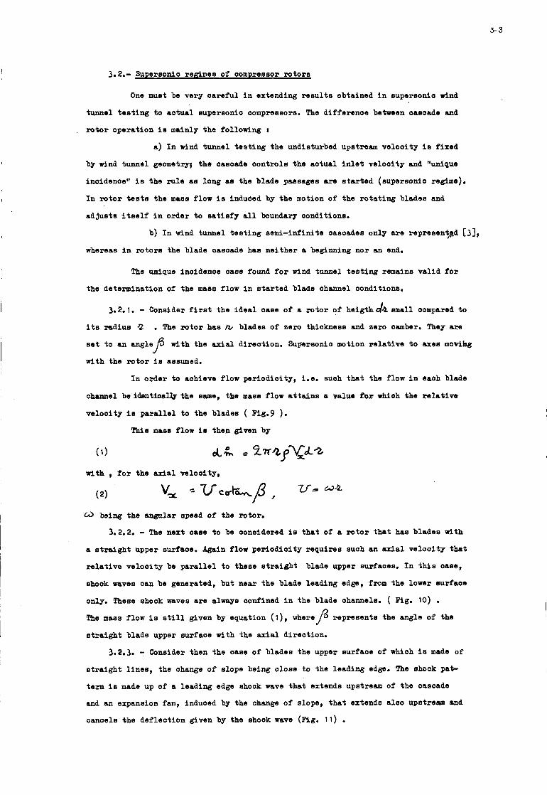
3-3
3.2.- Supereonlo regimes of oompressor rotors
t
I
One muet be very oareful i n extending r e su l t s obtained i n supersonlo r ind
tunnel t e s t i n g t o aotusl supersonio oompressors. The differenoe between oasoade and
rotor operation is mainly the following :
a ) I n wind tunnel t e s t ing the undisturbed upstream velooity is fixed
by wind tunnel geometry; the oasosde oontrols the aotual i n l e t velooity and "unipue
inoidenoe" is the rule ae long as the blade passages are s t a r t e d (supersonlo regime).
I n ro to r tests the mass flow is induoed by the motion of the ro t a t ing blades and
adjusts i t s e l f i n order t o s a t i s f y a l l boundary oonditions.
b) I n wind tunnel t e s t ing semi-infinite oasoades only a re representp$ [,I, whereas i n rotors the blade oasoade has nei ther a beginning nor an end.
The unique lnoidenoe oase found f o r wind tunnel t e s t ing remains val id f o r
the determination of the ma08 flow i n s t a r t ed blade ohannel oonditions.
3.2.1. - Consider first the idea l oase of a ro to r of h e i g t h d a small oompared t o
i t s mdius 2 . The ro to r has b blades of zero thiokness and zero oamber. "hey are
s e t t o M angle
with the ro to r is assumed.
with the ax ia l direotion. Supersonlo motion r e l a t ive t o axe6 movihg P I n order to aohieve flow periodioity, i.e. suoh that the flow in eaoh blade
ohannel be l d a n t l o a ~ the same, the mas8 flow a t t a l n s 8 value for d o h the r e l a t i v e
velooity 10 para l l e l t o the blade6 ( Fig.9 ).
This mass flow is then given by
with , f o r the axial velooity,
being the angular speed of the rotor.
3.2.2. - The next oase t o be oonsidered is that of a ro to r that has blades with
a s t r a lgh t upper surfaoe. Again flow periodioity requires suoh an &a1 w l o o i t y that
r e l a t ive velooity be pa ra l l e l to these s t r a i g h t blade upper surfaoes. I n this -se,
shook waves can be generated, but near the blade leading edge, f r o m the lower surfaoe
only. These shook waves are always oonfined i n the blade ohannels. ( Fig. 10) . The mass flow is still given by equation ( l ) , w h e r e p represents the angle of the
s t r a igh t blade upper surfaoe with the ax ia l direotion.
3.2.3. - Consider then the oase of blades the upper surfaoe of which is made of
s t r a igh t l i nes , the ohange of slope being olose to the leading edge. The shook pa+
t e rn is made up of a leading edge shook wave that extends upstream of the oasoade
and an expansion fan, induoed by the ohange of alope, t ha t extends aleo upstream and
canoels the deflection given by the shook wave (Fig. 11) .
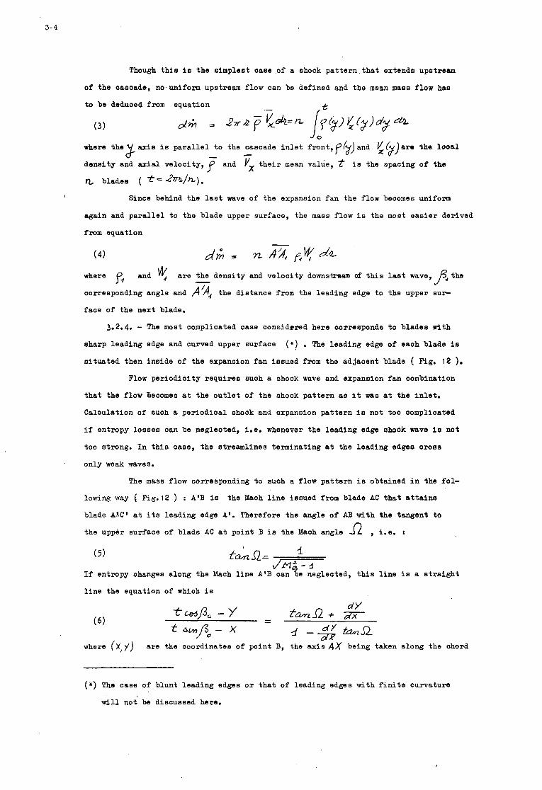
3- 4
Though t h i s i s t he simplest case .of a shock p a t t e r n . t h a t extends upstream
of the cascade, no,uniform upstream flow can be defined and the mean mass f low hae
t o be deduced f r o m equation .-
(3) J o
where t h e x axis is p a r a l l e l t o the cascade i n l e t f ront ,p$)and 1/ ( ) dens i ty and axial ve loc i ty , f and vx t h e i r mean value,
- c x 2 are the i s the spacing of t he
blades ( t- Z r a / h ) . Since behind the las t wave of the expansion f a n the flow beoomes uniform
again and p a r a l l e l t o the blade upper surface, the mass flow i s the most e a s i e r derived
from equation
where fi and
corresponding angle and p/A, the d is tance from the leading edge t o the upper SUP
face of the next blade.
a r e the dens i ty and ve loc i ty downsham af t h i s last wave, f4 the -
3.2.4. - The most complicated case considered here corresponds t o b lades wi th
sharp leading edge and curved upper sur face (*) . The leading edge of each blade is
s i t u a t e d then in s ide of t he expansion f an i ssued from the ad jacent blade ( Fig. 12 ).
Flow pe r iod ic i ty r equ i r e s such a shock wave and expansion f a n combination
t h a t t he f low becomes at the o u t l e t of the shock pa t t e rn as i t was a t the i n l e t .
Calculation of such a pe r iod ica l shock and expansion p a t t e r n i s not too complicated
i f entropy lo s ses can be neglected, i.e. whenever the lead ing edge shook wave i s not
too strong. I n t h i s case, t he s t reaml ines terminating a t t h e lead ing edges c ros s
only weak waves.
The mass flow Corresponding t o such a flow pa t t e rn i s obtained i n the f c l -
lowing way ( FSg.12 ) : A'B i s
blade A?X1 at i ts leading edge A'. Therefore the angle of AB wi th the tangent t c
the upper sur face of blade AC a t poin t B i s the Maoh angle
the Mach l i n e i ssued from blade AC t h a t a t t a i n 8
, i.e. I
( 5 ) -i fd/nR= /-
If entropy changes along the Mach l i n e A'B can be neglected, t h i s l i n e i s a s t r a i g h t
l i n e the equation of which i s
where ( X ; j ) are the coordinates of point B, the a x i s A X being taken along the ohord
(*) The case of b lunt l ead ing edges or t h a t of lead ing edges with f i n i t e curvature
w i l l n o t be discussed here.
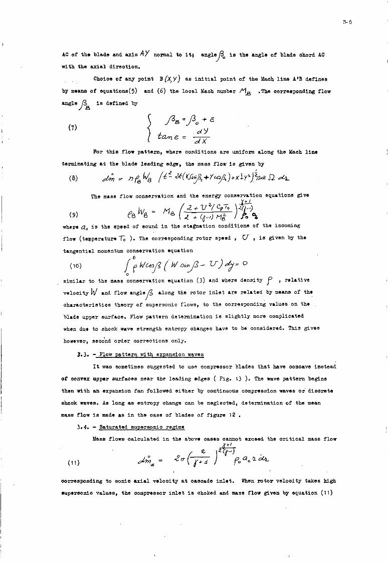
3- 5
i
I
I
AC of the blade and axis AY normal t o it; ang leyo i s the angle of blade ohord AC
with the axial d i rec t ion .
Choice of any poin t B(X,y) as i n i t i a l point of the Maoh l i n e A'B definee
by means of equations(5)
ang le /38 i s defined by
and (6) the l o o a l Maoh number MB .The oorreeponding flow
(7)
For this flow pa t te rn , where conditions a re uniform along the Maoh l i n e
terminating a t the blade leading edgs, the mass flow i s given by
(8)
The m8S8 flow conservation and the energy conservction equations give V I I
(9) where a, is the speed of sound i n the sta%nation conditions o f the incoming
flow (tepperature -fo ). The corresponding r o t o r speed , t angent ia l momentum conservation equation
U , i s given by the
similar t o the mass conservation equation (3) and where dens i ty
ve loc i ty w and flow angle/3 along the r o t o r i n l e t a re r e l a t ed by means of the
c h a r a c t e r i s t i c s theory of supersonic flows, t o the corresponding values on the
blade upper surface. Flow pa t t e rn determination i s s l i g h t l y more complicated
wh6n due t o shock WLVb s t rength entropy ohanges have t o be considered. This gives
however, second order cor rec t ions only.
, r e l a t i v e
)I
29.3. - Flow pa t t e rn with expansion waves
It w a s sometimes suggested t o use compressor blades t h a t have conoave ins tead
o f convex upper sur faces near the leading edges ( Fig. 13 ). The wave p a t t e r n begins
then with an expansion f a n followed e i t h e r by continuous compression waves or d i s c r e t e
shook waves. A s long as entropy change can be neglected, determination of the mean
mass flow i s made as i n the case of blades of f igu re 12 . 3.4. - Saturated supersonic rea;ime
Mass flows ca lcu la ted i n the above oases cannot exceed the c r i t i c a l mass flow
corresponding t o sonic axial ve loc i ty a t cascade i n l e t .
supersonic values, the compressor i n l e t i s choked and mass flow given by equation (11)
When r o t o r ve loc i ty takes high
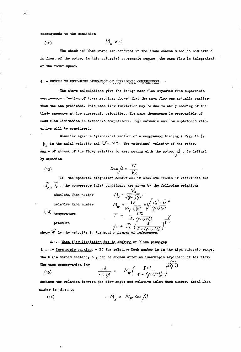
3- 6
comespond[s t o the condition
M, = 3
The shock and Mach waves a re confined i n the blade channels and do not extend
i n f r o n t of the rotor. I n t h i s sa tura ted supersonic regime, the mass flow i s independent
of the r o t o r epeed.
4. - CHOKED OR UNSTARTED OPERATION OF SUPERSONIC COMPRESSORS
The above ca lcu la t ions give the design mass flow expected f r o m supersonio
compressors. Testing of these machines showed t h a t the mass flow w a s a c t u a l l y smaller
than the one predicted. T h i s mass flow l i m i t a t i o n may be due t o e a r l y choking of the
blade passages a t low supersonic ve loc i t i e s . The same phenomenon i s responsible of
mass flow l i m i t a t i o n i n t ransonic compressors. High subsonic and low supersonic velo-
c i t i e s w i l l be oonsidered.
Consider again a cy l ind r i ca l s ec t ion of a cornpressor blading ( Fig. 14 ).
vx i s the axial ve loc i ty and u.2 the ro t a t iona l ve looi ty of the ro tor .
Angle of a t t a c k of t he flow, r e l a t i v e t o eaes moving with the ro to r ,
by equation
, i s defined f
If the upstream stagnation oonditions i n absolute frames of re ferences are
x, , the compressor i n l e t conditions a r e given by the following r e l a t ione 92-
absolu te Msch number
r e l a t i v e Mach number
(l4) temperature
pressul’e
w h e m h f i e the ve loc i ty i n the mod
4.1.- Mass flow l i m i t a t i o n duo t o choking of blade passaaes
4.1.1.- I sen t rop ic choking. - If the r e l a t i v e Mach number i s i n the high subsonio rang.,
the blsdo th roa t sec t ion , s , oan be ohoked a f t e r an i s en t rop ic expansion of tho flow.
, d ~ f i n o s tho m l a t i o n botwoen $he flow anglo and r e l a t i v e i n l o t Mach numbor. Axial Mach
I
I
C
These las t two equations w i l l held a11 along tho f u r t h e r oaloulatione.
4.1.2. - Choking with shook wave normal t o i n l o t r e l a t i v e vo loo i tg - As r e l a t i v e veh-
o i t y becomes supersonio,shook waves may appear and move with the blades. I n the low
supersonio range only normal shook waves appear. It is not fundamentally important t o
descrikie exac t ly the shook pa t t e rn , tha t qu i t ep robab ly ia similar t o the choked con-
f i g u r a t i o n shown on f igu re 5, i n order t o determine the o r i t i c a l mass flow,
As a f i r e t approximation, tho shook waves can bn considered normal t o the
i n l e t r e l a t i v e ve loc i ty ( Eyg.15 ). The Mach number downstream of the shock wave is
F m m the choking oondition,similar to equation (15) that r e l a t o s
the flow cont rac t ion the following r e l a t i o n is obtained
Mach number MLto /
4
4' ' (19) give the same r e s u l t when i n l e t r e l a t i v e ve loc i ty i s sonio (M,= d ).
4.1.3. - Shock normal t o the mean passage d i r ec t ion - It is q u i t e hard t o say whether
the flow a t the entrance of the blade ohannel i s def lec ted before or a f t e r going
through the shook wave. Therefore an o the r t heo re t i ca l f l o w pa t t e rn is analyzed, where
the shook wave is normal t o the mean passage d i r ec t ion ( F'ig. 16 ).
expans ion , re la tes i n l e t conditions ( IV w, f) t o the oonditions i n f r o n t of the shock
(M,,,,)where angle /3. gives the mean channel d i rec t ion . Mass flow conservation during
An i s en t rop io
and again between the downstream face of the shock wave and the blade channel t h roa t
3- 8
4.1.4. - Shook def leo t ion - A thorohghly d i f f e r e n t representa t ion [8] is obtained
when momentum losses due t o body foroes a r e also taken i n t o aocount [g]. The method
genera l izes t o compressible flows tho equations of hydraulic losses, more o r less
empir ica l ly used for the off-design s tud ie s of oompressors [IO] [ 111.
I n t h i s t heo re t ioa l n p r e s e n t a t i o n the flow de f l eo t ion takes plaoe with
momentum oonservation i n the eero l i f t d i r e c t i o n of tho blade r o w . If momentum
equation is projooted on t h i s d i reo t ion , for a oont ro l surfaoe that takes an i n t e g e r
number of blade paesagrs, one obta ins(subsor ip t 1 for the zero l ift d i r eo t ion ) i
Maas flow oonaervation g ives
and energy oonservation -
Sinor p n s e u r e ? i s r e l a t ed t o trmperature7 and dons i ty by means of
the gas s t a t e equation
there follows
M w (26)
where the Maoh number flw4 of the flow having gone through the shook-defleotion is
given by the oontraotion r a t i o equation <
a) i n the d i r ec t ion normal t o the zoro l i f t d i r ec t ion the ohange of momentum
gives the body fo rces a c t i n g on the f l u i d ;
b) i n the no-defleotion oaso ( =yA ), shook-defleotion i s eqUiVQhnt t o
i sen t ropio flow when f l is subsonio’and t o a normal shook wave whenM is supersonio.
4.2.- Choioe of the model descr ib ing ao tua l ohoked f low
% ’41
I n order t o oompare the above desoribed four theo re t ioa l models, app l io r t lon
of? the theory w i l l be made t o a r o t o r made of trianguaar blades ( Table I ). The i n l e t
r e l a t i v e flow anglesJ3 and axial Maoh numbers Mx oaloulated as functions o f the
ro to r Msoh number a r e presented i n f igu re 17 . The i sen t ropio evolution (4.1.1 .) i s va l id i n the subsonio r e l a t i v e Maoh
numbor range only ( M,,,‘ 1 ). The corresponding ourves a r e continued by thoso
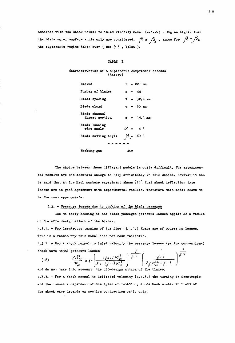
3- 9
obta ined w i t h tho shook normal t o i n l e t v o l o o i t y model (4.1.2.) . Angles h ighor t h a n
t h e b lade upper sur faoe anglo o n l y are oonsidered,
t h e suporsonio regimo t a k e s o v e r ( so0 5 5 , below ).
, s i n c e f o r ~3=/3" P
TABLE I
C h r r a o t o r i s t i o s o f a supersonio comprossor oasoado ( theory)
Brdius r E 227 mm
Number of blrdos n = 44
Blado spac ing t 3294 mm
Blado ohord 0 = 6 0 m
Blado channel throat s o o t i o n s = 14.1 mm
Blade l o a d i n g edgo anglo d = 4 O
Blado s o t t i n g anglo Po- 60 0
Working gas Air
The ohoice betweon thoso d i f f e r e n t models i s q u i t e d i f f i c u l t . The exporimon-
tal r e s u l t s a r e not a c c u r a t e enough t o h e l p e f f i o i o n t l y i n t h i s ohoice. However i t oan
be s a i d that a t low Mach numbers experiment shows [ l l ] t h a t shock d e f l e c t i o n typo
l o s s o s a r e i n good agroement w i t h experimental r e s u l t s . Theroforo th i s model seoms t o
bo t h e most appropr ia te .
4.3. - Prossure l o a s e s due t o ohokinR o f tho b l r d o p a s s a ~ o s
Duo t o e a r l y choking o f t h e b lade passages prossuro 1 0 s s O S appoar as a r o s u l t
o f t h o o f f - des ign a t t a c k o f t h e blades.
4.3.1. - For i s e n t r o p i c t u r n i n g o f t h e f low (4.1.1.) thoro aro o f oourso no losses .
This i s a roason why t h i s model does n o t seem r e a l i a t i c .
4.3.2. - For a shock normal t o i n l e t v e l o o i t y t h e prossure l o e s e s are t h e oonvont ional
ahoak wave t o t a l p r e s s u r e l o s s e s I
(28)
and do n o t t a k e i n t o account
4.3.3. - For a shock normal t o d e f l e c t o d v e l o o i t y (4.1.3.) t h e t u r n i n g i s i s e n t r o p i o
and t h e l o s s e s independent o f t h e speed o f r o t a t i o n , s i n o e Maoh number i n f r o n t o f
t h e shook wave depends on s e c t i o n c o n t r a c t i o n r a t i o only.
t h e off-design a t t a c k of t h e blados.
3-10 '
4.3.4. - I n the i s given [8] by
(29)
and the pressure lo s ses by
4.3.5. - The t o t a l pressure lo s ses oorresponding t o the f o u r modela a r e represented
on figure 18. From the l o s s viewpoint a l so , the shock-defleotion model seems the
more adequate.
Sinoe there i s an overlapping of the range of v a l i d i t y of the th ree regimes,
choked, supersonio and sa tu ra t ed regimes, a f u r t h e r condition has t o be f ixed i n . ordery-to d isor imina t r among these regimes.
\ ~
\\, It can be said, and experiment seems to v e r i f y t h i s assumption, t h a t among
the ' t h ree regimes the one w i l l a c t u a l l y take place t h a t g ives the smal les t mass flow \ '
\< , for the same speed of ro ta t ion .
\ \ A s an example of suoh a rule, f i g u r e 19 shows the va r i a t ion of a x i a l Maoh
number 8 as a func t iod of r o t o r Mach number f o r the oompressor defined by Table I. x For high subsonic or low supersonio operation the ohoked model con t ro l s
the mass flow . Trans i t ion from t h i s regime t o the supersonio i s obtained when
r e l a t i v e i n l e t angle i s the same f o r both regimes. This corresponds for the r o t o r
oonsidered t o the somewhat high Maoh number 1.38 . Then the supersonic reglme i s
maintained unt i l the i n l e t i s choked. Sonic axial velooi ty i s obtained f o r flu= 1.73.
\
6.- ABAW 818 OF BF3SerMET?!l?aL W38UL88 8% U80 F I A W L'IMITATION I N COMPBESSORS
&os4 of the experdrnental r e s u l t s published on supersonic compressors show
evidenoe of unstarted opmration . T h 8 r O e x i s t s however some r e s u l t s published by
UJdcd [12] [13] [14] for whioh t r a n s i t i o n from the ohoked t o the supersonio regime
OM b. shown.
The compressor is a s ing le stage, oonstant seotion, a x i a l flow compressor.
Freon - 12 w a s used as working gas. The main i n t e r e s t of t h i s work comes f r o m the
shadowgraphs of the flow i n the rotor.
Table I1 gives the main da ta of t h i s oompressor, the mean seot ion o f
whioh i s analyzed. The blading of this seot ion i s represented on f i g u r e 20
and f i g u r e 21 compares the axial Maoh number vs r o t o r Maoh number diagram obtained
experimantally t o the t h e o n t i c a l oa loula t ions based on Table 11.
The s a t i s f a c t o r y oorrep3ondance between theory and experiment i s oonfirmed
by the shadographs shown on the same figure.f 141 .The normal shook t h a t appeamat
blade entrance f o r r o t o r speeds lower than 9000 r.p.m. disappears a t higher speeds.
1
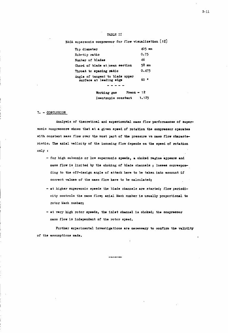
3- 11
TABLE I1
NACA aupernonio oompnsaor f o r flow visualizatbon I: 123 Tip diameter
Hub-tip r a t i o Number of blades
405 nm 0.75 46
Chord of blade rt /mesn mot ion 58 mm Throat to spacing X&biO 0.475 Angle of tangent ' to blade upper
surfaoe at leading edg. 60 O
working gss b o a - 12
Isentropio oonsturt 1.125
7. - CONCLUSION
Analysis of theoret ioal and experimental mass flow performanoes of super
sonio compressors shows t h a t at a given spmed of ro t a t ion the oompnasor operates
with constant mas8 flow owr the most pa r t of the pressure vs mass flow o h m o t e -
r i s t i o . The u i r l w l l c i t y of the inooming flow depends on the speed of rotat ion
only :
- f o r high subsonio or low aupersonio spoeds, a ohoked regime appears a d
maas flow i s limited by the ohoking of blade ohannels ; losses oorrespon-
ding to the off-design angle of a t t ack have t o be taken in to aooount if
oorrect values of the mass flow have t o be orloulated;
- rt higher supersonio speeds the blade channels a re s tar ted; flow periodi-
c i t y oontrols the mass flow; a x i a l Maoh number is usually proportional t o
ro to r Mroh number;
- rt very high r o t o r speeds, the i n l e t ohmnel is ohoked; the oompressor
mass flow i s independent of the ro to r speed.
Further experimrntal i n w a t i g r t i o n s a re neoessary t o oonfirm the validity
of the resumptions made.
-=---
3- 12
REFERENCES
Q.K. SEROW Recent progress in aerodynamic design of axial flow compressors in the United States.
Trans ASME Journal of Engineering for Power, July 1966 A.WEISE herschal laxialverdichter .
Lilienthal Gesellschaft Bericht 171, 1943 J.R. ERWIN & A. FERRI The Supersonic Compressor.
In W.R. HAWTHORNE - Aerodynamics of Turbines and Compressors - High Speed Asrodyna- mics and Jet Propulsion, vol X, Prinoeton University presp,1964
J. CALMON Le fonctionnement des grilles de compression dans le domaine transsonique.
L'ABronautique et l'Astronautique, vol. 17, no 1, 1970 A. BUSEMA" Atti del V Convegno Volta
Accad. Nag1 Lincei - Roma, 1935 J. FABRI, J. PAULON. 0. JANSSENS Use of supersonic cascades made of blades of simple geometrio shapes for cascade wind tun- nel performance evaluation.
ASME - Bruxelles meeting 1970 J. CHAUVIN, F. BWGELMANS & A. JANIGRO Supersonic Compressors. ,
Von Kbrmbn Institute for Fluid Mechanics, CR 7, 1967 J. FABRI, R. SIESTRUNCK La limitation du debit dans les compresseurs supersoniques
Entropie no 1 1 , Sept-Oct. 1966 M.H. VAVRA Aerothermodynamics and flow in turbomaohines.
John Wiley & sons, New-York, 1960 B. ECKERT Axial und Radialkomspressoren.
Springer Verlag, Berlin 1953 Y. LE BOT, J. PAULON, P. BELAYCUE ,
Theoretical and experimental determination of pressure losses in a single stage axial flow compress or.
A W Bruxelles meeting 1970 Th.J. COLDBERG, E. BOXER & P.T. BERNOT Experimental investigation of an axial flow Supersonic Compressor having rounded leading edge blades wich an 8-percent mean thiokness - chord ratio.
NACA RM L 53 G 16,1953 Th.J.GOLDBERG Experimental investigation of an axial flow supersonic compressor having sherp leading edge blades with an 8-percent thickness - chord ratio.
NACA RM L 54 K 16, 1955 Th.J. COLDBERG & J.R.STERRET Use of shadow-graph technique in the analysis of the performance of two supersonic axial flow compressor rotors operating over a mean radius relative inlet Mach number range
NACA Rbl L 56 A 0 5 , 1958 of 0.85 to t . 7
[ 41
[51
[ 61
71
[91
I
I
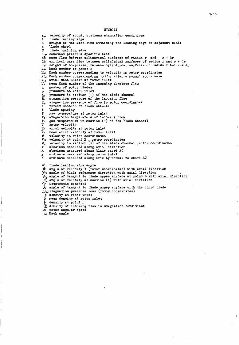
3- 13
SYMBOLS
CO ve loc i ty of sound, upstream s tagnat ion oonditions A blade leading edge B o r i g i n of the Mach l i n e a t t a i n i n g the leading edge of adjacent blade
C blade t r a i l i n g edga C3 constant pressure s p e c i f i c hea t dm mass flow between oy l ind r i ca l sur faces of rad ius r and r + d r &I c r i t i c a l mass flow between oy l ind r i ca l sur faces of rad ius r and r + d r d r height of compressor between cy l ind r i ca l sur faces of rad ius r and ra-+ dr Ya Mach number at p i n t B M M Mach number corresponding t o ve loc i ty i n r o t o r coordinates M; Mach number corresponding t o M w a f t e r a normal shock wave ,Mx axial Mach number at r o t o r i n l e t MA mean Mach number of the incoming absolute flow n number of r o t o r blades p pressure a t r o t o r i n l e t pa P, s tagnat ion pressure of the incoming flow Pw s t h roa t s ec t ion of blade ohannel t blade spacing T gas temperature a t r o t o r i n l e t To s tagnat ion temperature of incoming flow T, gas temperature i n sec t ion ( 1 ) of the blade channel U r o t o r ve loc i ty - V, a x i a l ve loc i ty at r o t o r i n l e t Vx mean axial ve loc i ty a t r o t o r i n l e t W ve loc i ty i n r o t o r coordinates We ve loc i ty a t point B , r o t o r coordinates W4 ve loc i ty i n sec t ion ( 1 ) of the blade channel , r o t o r coordinates x absc issa measured along axial d i r e c t i o n X abac issa measured along blade chord AC y ord ina te measured along r o t o r i n l e t Y o rd ina te measured along a x i s Ay normal t o ohord AC
d blade leading edge angle angle of ve loc i ty W ( r o t o r coordinates) with axial d i r e c t i o n PO angle o f blade reference d i r ec t ion with u r i a l d i r ec t ion angle of tangent t o blade upper surface a t point B with a x i a l d i r ec t ion
/38 angle of ve loc i ty a t s ec t ion ( 1 ) with a x i a l d i r ec t ion p4 i s en t rop ic constant angle of tang8nt t o bkade upper surface with the chord blade
Arw s tagnat ion pressure loss ( r o t o r coordinates) dens i ty at rotor i n l e t
blade chord
pressure i n sec t ion (1 ) of the blade ohannrl
s tagnat ion pressure of flow i n r o t o r coordinates
f mean dens i ty a t r o t o r i n l e t p~ dens i ty a t poin t B
w r o t o r angular speed dens i ty of incoming flow i n s tagnat ion conditions p.
fi M80h 8ngle
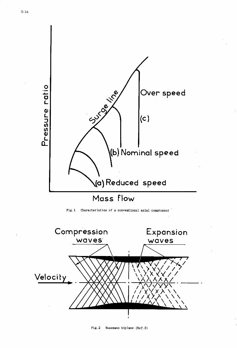
3- 14
0
0 L Q1 L 3 r/l m Q, t L
.- L
/
Over speed
speed
\(a) Reduced speed
Mass Flow F i g . l Characteristics of a conventional axial compressor
Compression waves' 7
Expansion waves
Fig . 2 Busemann biplane (Ref. 5)
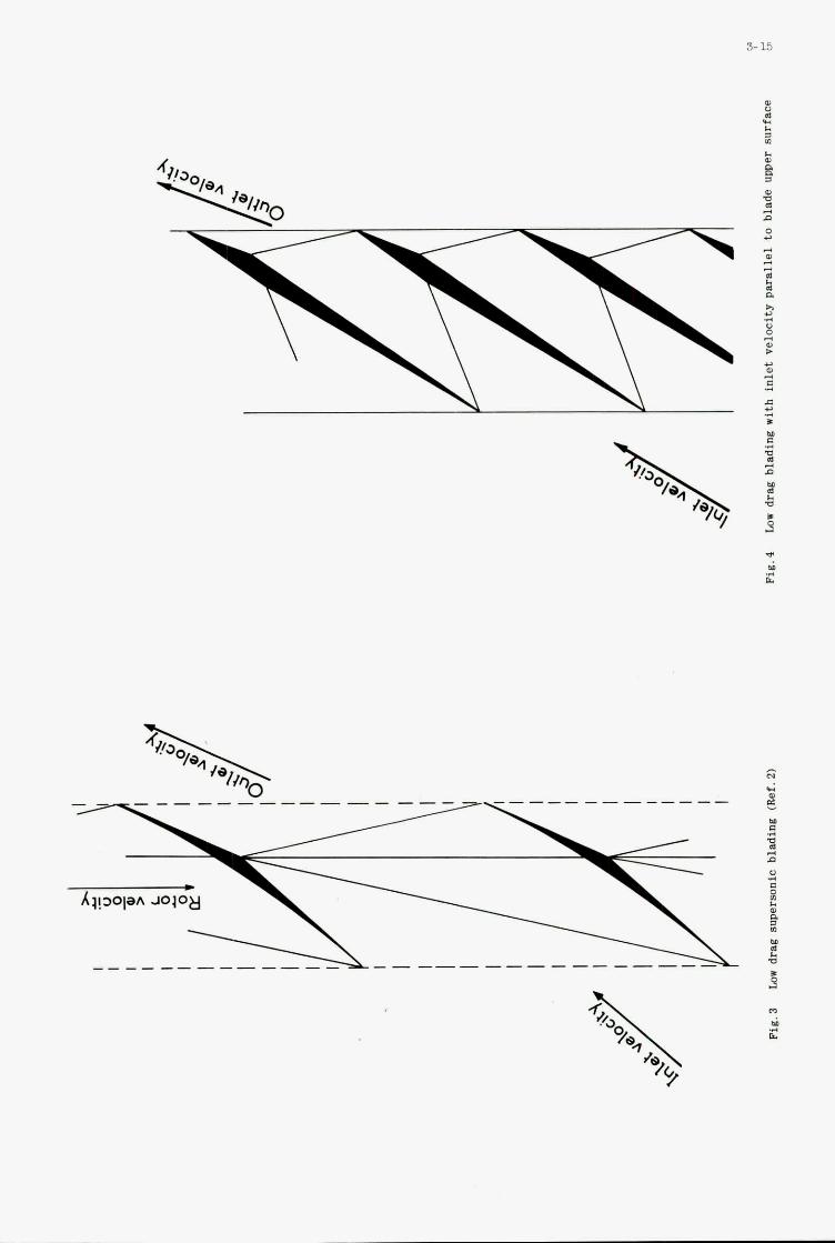
3 0 3 3
$ P
R U 3 U .. e
c U 3 B
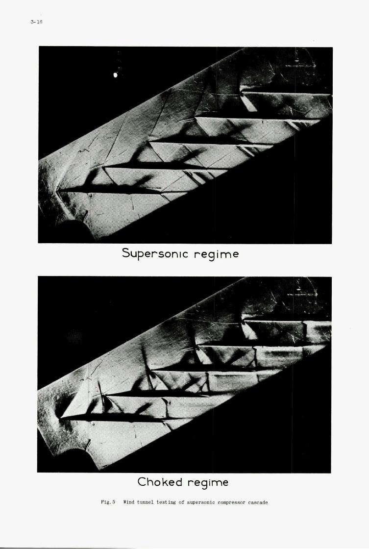
3- 16
I
t , .:
Supersonic r e g i m e
Choked regime
F i g . 5 Wind tunnel testing of suDersonic compressor cascade
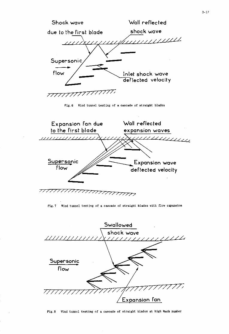
3- 17
Shock wave Wall reflected
due to the First blade shock wave
//%U//- - Su person i c/ -
F k / - -7s\ Inlet shock wave deflected velocity
Fig .6 Wind tunnel t e s t i n g o f a cascade of s tra ight blades
Expansion Fan due Wall reflected to the First blade expansion waves
\
deflected velocity
Supersonic Flow
7777777777727777727777 Fig .7 Wind tunnel t e s t i n g of a cascade of s tra ight blades with flow expansion
Swallowed shock wave
/ / / U / / / / / / / / / //// ////// / / ////A
Supersonic A.
/ / / / / / ’ / / I / ’ -
/Expansion Fan
Fig .8 Wind tunnel t e s t i n g of a cascade of s tra ight blades at high Mach number
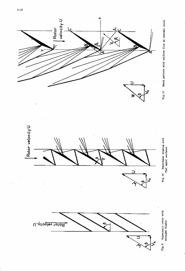
3- 18
4 d
M .r( E
Y .- U
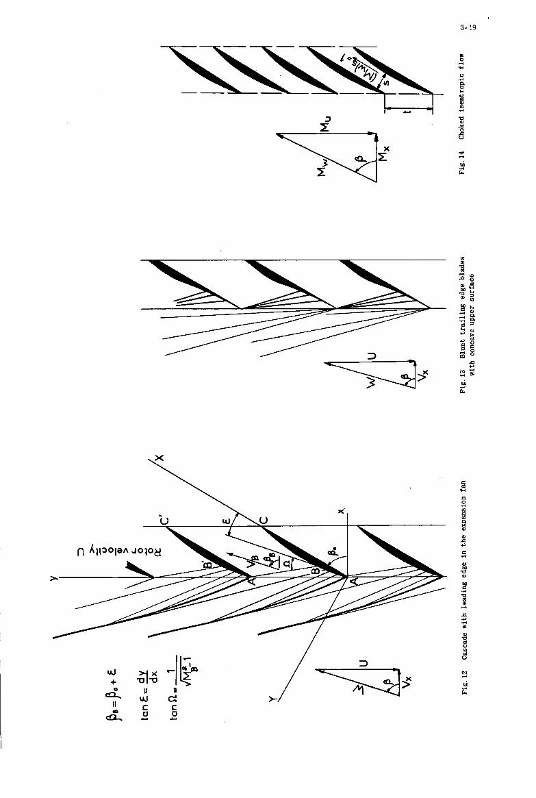
3- 19
I - n .d Y
2 M .d E
0) P

3- 22
Shock on inlet velocity
X
1
Shock on ef lecled velocity
//
,f 1,
= t 4 .
L a, n
Q
0 6
.4
02
0 I _T--l 1 2
Rotor Mach number Mu
I
Fig. 17(b) Comparison of ax ia l Mach numbers corresponding t o the vsrious flow Patterns
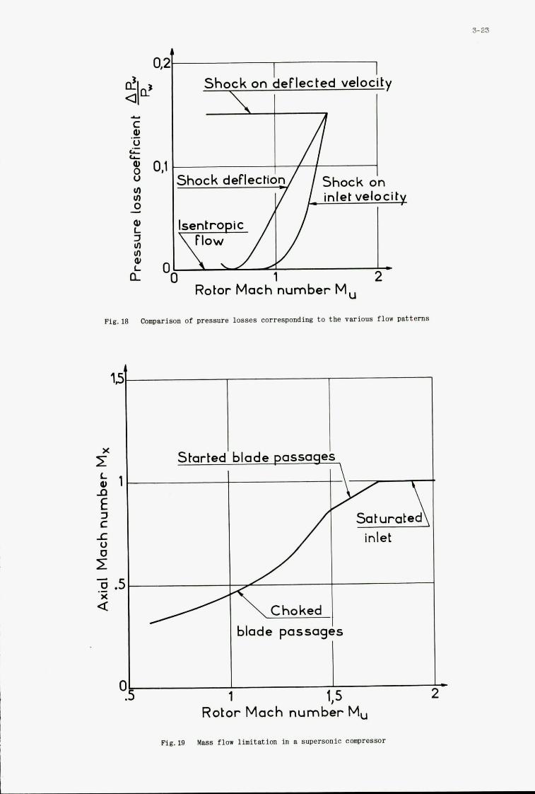
3-23
C PI U ic al 0 U ul ul 0
.- LL
d
'UL I ul ul 0, L a C
Shock on deflected velocity
Fig. 18 Comparison of pressure losses corresponding t o the various flow patterns
1
a
1 1.5 Rotor Mach number Mu
Fig. 19 Ma88 flow limitation in a supersonic ComPressor
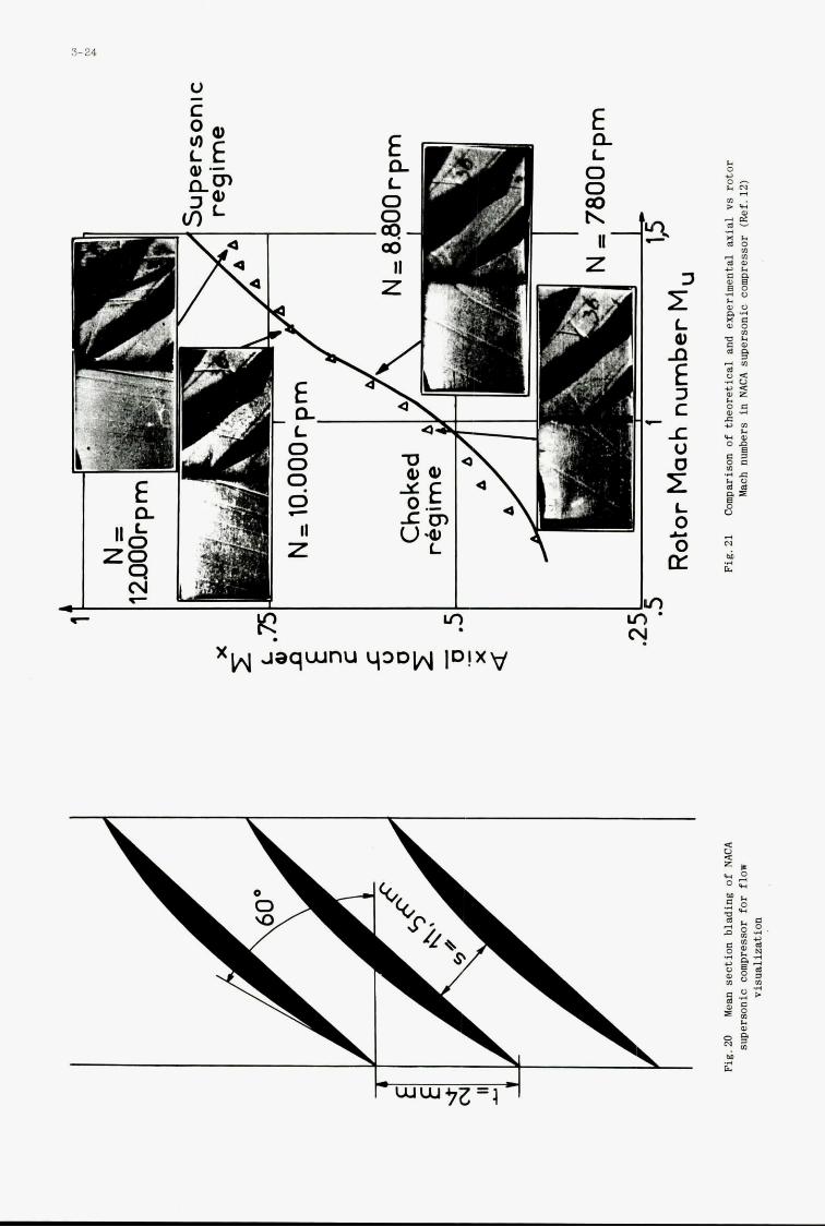
3-24
U
3 t L Q, n 3 C 5 U
E -
2 I 0 U 0 nf
3
* N
6 c
4
T R A N S O N I C C O M P R E S S O R C A S C A D E S
H . GRIEPENTROG t
G u t e h o f f n u n g s h c t t e S t e r k r a d e A.G.
t f o r m e r l y P r o j e c t E n g i n e e r , von Karman I n s t i t u t e , Rhode S a i n t Genese, Belgium
4
S U M M A R Y
Blad ings w i t h i n l e t and o u t l e t subson ic flows, b u t p r e s e n t i n g a l o c a l s u p e r s o n i c r e g i o n a r e used i n a l l of t h e advanced a x i a l compressors today. P r e d i c t i o n of t q e i r performance and performance o p t i m i s a t i o n are t h e r e f o r e a must.
The g e n e r a l f e a t u r e s of t h e compress ib l e flow e f f e c t s i n cascade a r e d i s c u s e e d , t o g e t h e r w i t h t h e i n f l u e n c e of c o m p r e s s i b i l i t y on t h e performance of compressor cascade. The n o t i o n s of c r i t i c a l and choking Mach number a r e i n t r o d u c e d , t o g e t h e r w i t h a p h y a i c a l d e s c r i P t i o n of t h e flow i n t h e b l a d e passage , where f o u r d i s t i n c t r e g i o n s can be d i g t i n - gu i shed ( subson ic i n l e t and o u t l e t flow f i e l d , s u p e r s o n i c flow f i e l d , s o n i c l i n e r e g i o n and shock-boundary l a y e r i n t e r a c t i o n r e g i o n ) .
The e v a l u a t i o n of t h e c r i t i c a l and choking Mach number i s t h e n t r e a t e d , as w e l l as t h e e f f e c t s of c o m p r e s s i b i l i t y on l o s s e s , t u r n i n g and s t a t i c p r e s s u r e r i s e . Some remarks are made on t h e des ign of t r a n s o n i c cascades .
The four r e g i o n s o f flow d e t a i l e d above a r e t h e n d e a l t w i t h independen t ly . A review i r made of t h e e x i s t i n g t h e o r i e s and e x p e r i m e n t a l c o r r e l a t i o n s , and t h e i r l i m i t of a p p l i - c a t i o n for cascade flows i s de f ined . A semi-empir ical model, v a l i d for cascade flows, i s p r e s e n t e d lor t h e shock-boundary l a y e r i n t e r a c t i o n r eg ion .
A p a r t i c u l a r method of c a l c u l a t i o n , developed by t h e a u t h o r a t VKI, add based on t h e a n a l y s i s of t h e flow r e g i o n s i s t h e n p r e s e n t e d . T h i s method s t a r t s from t h e incompres- s i b l e flow f i e l d , i n a b l a d i n g , o b t a i n e d t h e o r e t i c a l l y or e x p e r i m e n t a l l y , and e n a b l e s t o c a l c u l a t e t h e compress ib l e flow f i e l d , w i t h a l o c a l s u p e r s o n i c r e g i o n , t a k i n g f u l l y i n t o k c c o u n t t h e s h o c k - i n t e r a c t i o n r eg ion . The v a l i d i t y of t h e method i s l i m i t e d t o h igh s o l i d i t y c a s c a d e s , of any d e f l e c t i o n . Comparison w i t h e x p e r i m e n t a l r e s u l t s shows t h e method t o be s a t i s f a c t o r y .
4
/
a
A
b C
C P
g h
H 3 2
i M
P
PO r 8
s t h t
U B V
W
X , Y
a
8
Y
6 2
e e
d
P
a
0
6 c , n , c w
s p e e d o f sound
a r e a
s t r e a m t u b e w i d t h b l a d e c h o r d
P2'Pl s t a t i c p r e s s u r e r i s e c o e f f i c i e n t -
POl'P1 p i t c h
b l a d e h e i g h t
fo rm f a c t o r i n c i d e n c e a n g l e w i t h r e s p e c t t o camber l i n e Mach number s t a t i c p r e s s u r e
t o t a l p r e s s u r e
r e c o v e r y f a c t o r
d i s t an c e
t h r o a t o f b l a d i n g t h i c k n e 8 s
v e l o c i t y components i n x , y d i r e c t i o n
r e l a t i v e v e l o c i t y
C a r t e s i a n c o o r d i n a t e s
a b s o l u t e f l o w a n g l e
r e l a t i v e f l o w a n g l e
r a t i o o f s p e c i f i c h e a t o r s t a g g e r a n g l e
momentum l o s s t h i c k n e s s of boundary l a y e r
I' d e 1" ope ra t o r hodograph c o o r d i n a t e a i r t u r n i n g a n g l e 81-82
mass d e n s i t y
s o l i d i t y
camber a n g l e
p o t e n t i a l
s t ream f u n c t i o n
c o o r d i n a t e s f o r s i n k - s o u r c e d i s t r i b u t i o n POl'P02
t o t a l p r e s s u r e l o s s c o e f f i c i e n t POl'Pl
S u b s c r i p t s
0 t o t a l c o n d i t i o n s 1 u p s t r e a m o f c a s c a d e
2 downst ream o f cascade
OD f r e e stream c o n d i t i o n s
C
CH CR
i
e MAX
M I N
PS ss
c ompre 8 8 i b l e
c h o k i n g c o n d i t i o n s c r i t i c a l c o n d i t i o n s
i n c o m p r e s s i b l e
l o c a l maximum v a l u e minimum v a l u e
p r e s s u r e s i d e s u c t i o n s i d e
S u p e r s c r i p t s A c o n d i t i o n s downst ream o f shock
s o n i c c o n d i t i o n s * p e r t u r b a t i o n v a l u e
4
LIST OF FIGURES
1 S k e t c h o f c o m p r e s s i b i l i t y e f f e c t s i n a c o m p r e s s o r c a s c a d e
2 S c h l i e r e n p i c t u r e o f a t r a n s o n i c c a s c a d e
3 P r e s s u r e d i s t r i b u t i o n f o r d i f f e r e n t i n l e t Mach numbers
4 Dependence of l o c a l Mach number o n i n l e t Mach number
5 C r i t i c a l Mach number i n f u n c t i o n o f minimum s t a t i c p r e s s u r e r i s e 6 L i m i t v a l u e s o f c r i t i c a l Mach number i n f u n c t i o n o f t h e s t a t i c p r e s s u r e r i s e 7 Choking Mach number f o r r e a l f l o w c o n d i t i o n s i n c a s c a d e
8 X n f l u e n c e of Mach number on t o t a l p r e s s u r e loss 9 I n f l u e n c e o f Mach number on t u r n i n g a n g l e
10-11 S t a t i c p r e s s u r e r i s e i n f u n c t i o n o f Mach number
12
13 14
1 5 16 17 18 19
20 21 22
23 24
25 26
27 28
29 30 31
32 33 34
Data f o r BTB b l a d e
I n f l u e n c e o f b a c k p r e s s u r e on t o t a l p r e s s u r e loss T a n g e n t g a s r e l a t i o n
Karman-Tsien p r e s s u r e c o r r e l a t i o n f o r m u l a Compar ison o f Karman-Tsien r u l e a n d P r a n d t l - G l a u e r t r u l e w i t h e x p e r i m e n t s
I n f l u e n c e o f c o m p r e s s i b i l i t y on c a s c a d e p a r a m e t e r
Compar ison o f P r a n d t l - G l a u e r t t r a n s f o r m a t i o n a n d e x p e r i m e n t a l r e s u l t s
P r e s s u r e d i s t r i b u t i o n c a l c u l a t e d b y i m p r o v e d l i n e a r i z a t i o n a n d b y P r a n d t l - G l a u e r t
Compar ison o f t h e method o f Imbach w i t h m e a s u r e m e n t s
S k e t c h f o r f l u x a n a l y s i s method
R e s u l t s o f t h e method o f U c h i d a
C u r v i l i n e a r c o o r d i n a t e s y s t e m i n c a s c a d e
V e l o c i t y d i s t r i b u t i o n a l o n g a p o t e n t i a l l i n e
S u p e r s o n i c f l o w p o c k e t
E x p a n s i o n c o r r e l a t i o n
S k e t c h of s h o c k b o u n d a r y l a y e r i n t e r a c t i o n Model f o r s h o c k b o u n d a r y l a y e r i n t e r a c t i o n
Shock i n t e n s i t y c o r r e l a t i o n
T h e o r e t i c a l p r e s s u r e d i s t r i b u t i o n
C o r r e l a t i o n f o r d i s p l a c e m e n t p h a s e Nomogram f o r d i s p l a c e m e n t p h a s e
S k e t c h f o r c a l c u l a t i o n p r o c e d u r e
Compar ison of p r e d i c t e d a n d m e a s u r e d v e l o c i t y d i s t r i b u t i o n
r u l e i n c o m p a r i s o n w i t h m e a s u r e m e n t s
I
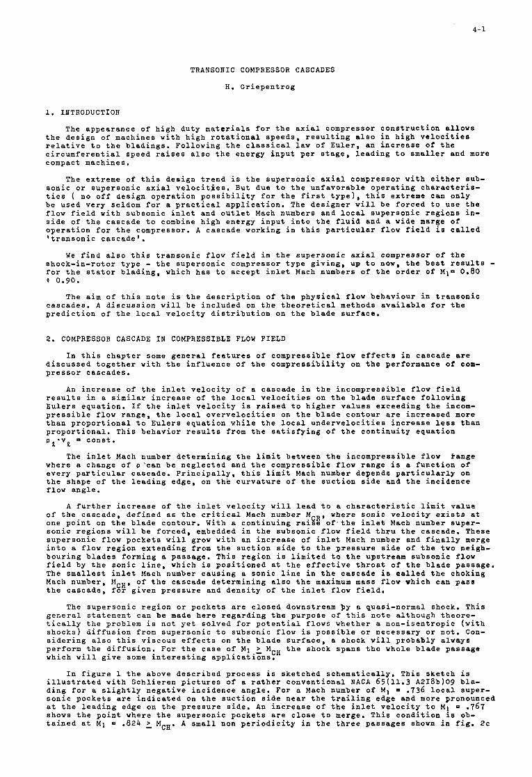
4- 1
TRANSONIC COMPRESSOR CASCADES
H . G r i e p e n t r o g
1. I N T R O D U C T I O N
The appea rance of h i g h d u t y m a t e r i a l s f o r t h e a x i a l compresso r c o n s t r u c t i o n a l l o w s t h e d e s i g n of machines w i t h h i g h r o t a t i o n a l s p e e d s , r e s u l t i n g a l s o i n h i g h v e l o c i t i e s r e l a t i v e t o t h e b l a d i n g s . Fo l lowing t h e c l a s s i c a l l a w o f E u l e r , an i n c r e a s e of t h e c i r c u m f e r e n t i a l speed r a i s e s a l s o t h e ene rgy i n p u t p e r s t a g e , l e a d i n g t o smaller and more compact machines .
The ex t r eme o f t h i s d e s i g n t r e n d i s t h e s u p e r s o n i c a x i a l compressor w i t h e i t h e r sub- s o n i c o r s u p e r s o n i c a x i a l v e l o c i t i e s . But due t o t h e u n f a v o r a b l e o p e r a t i n g c h a r a c t e r i s - t i c s ( no o f f d e s i g n o p e r a t i o n p o s s i b i l i t y f o r t h e f i r s t t y p e ) , t h i s ex t r eme can o n l y be u s e d v e r y seldom f o r a p r a c t i c a l a p p l i c a t i o n . The d e s i g n e r w i l l be f o r c e d t o u s e t h e f low f i e l d w i t h s u b s o n i c i n l e t and o u t l e t Mach numbers and l o c a l s u p e r s o n i c r e g i o n s i n - s i d e o f t h e c a s c a d e t o combine h i g h ene rgy i n p u t i n t o t h e f l u i d and a wide marge of o p e r a t i o n f o r t h e compressor . A c a s c a d e working i n t h i s p a r t i c u l a r f l o w f i e l d i s c a l l e d ' t r a n s o n i c c a s c a d e ' .
We f i n d a l s o t h i s t r a n s o n i c f l o w f i e l d i n t h e s u p e r s o n i c a x i a l compresso r o f t h e s h o c k - i n - r o t o r t y p e - t h e s u p e r s o n i c compressor t y p e g i v i n g , up t o now, t h e b e s t r e s u l t s - f o r t h e s t a t o r b l a d i n g , which h a s t o a c c e p t i n l e t Mach numbers o f t h e o r d e r o f M I = 0.80 + 0.90.
The a i m o f t h i s n o t e i s t h e d e s c r i p t i o n o f t h e p h y s i c a l f l o w b e h a v i o u r i n t r a n s o n i c c a s c a d e s . A d i s c u s s i o n w i l l b e i n c l u d e d on t h e t h e o r e t i c a l methods a v a i l a b l e f o r t h e p r e d i c t i o n o f t h e l o c a l v e l o c i t y d i s t r i b u t i o n on t h e b l a d e s u r f a c e .
2. COMPRESSOR CASCADE I N COMPRESSIBLE FLOW FIELD
I n t h i s c h a p t e r some g e n e r a l f e a t u r e s o f c o m p r e s s i b l e f low e f f e c t s i n c a s c a d e a r e d i s c u s s e d t o g e t h e r w i t h t h e i n f l u e n c e o f t h e c o m p r e s s i b i l i t y on t h e pe r fo rmance of com- p r e s s o r c a s c a d e s .
An i n c r e a s e of t h e i n l e t v e l o c i t y o f a c a s c a d e i n t h e i n c o m p r e s s i b l e f l o w f i e l d r e s u l t s i n a s imi l a r i n c r e a s e of t h e l o c a l v e l o c i t i e s on t h e b l a d e s u r f a c e f o l l o w i n g E u l e r s e q u a t i o n . I f t h e i n l e t v e l o c i t y i s r a i s e d t o h i g h e r v a l u e s e x c e e d i n g t h e incom- p r e s s i b l e f low r a n g e , t h e l o c a l o v e r v e l o c i t i e s on t h e b l a d e c o n t o u r a r e i n c r e a s e d more t h a n p r o p o r t i o n a l t o E u l e r s e q u a t i o n w h i l e t h e l o c a l u n d e r v e l o c i t i e s i n c r e a s e l e s s t h a n p r o p o r t i o n a l . T h i s b e h a v i o r r e s u l t s from t h e s a t i s f y i n g o f t h e c o n t i n u i t y e q u a t i o n p Q * v Q = c o n s t .
where a change o f p ' c a n b e n e g l e c t e d and t h e c o m p r e s s i b l e f low r a n g e i s a f u n c t i o n o f e v e r y p a r t i c u l a r c a s c a d e . P r i n c i p a l l y , t h i s l i m i t Mach number depends p a r t i c u l a r l y on t h e shape o f t h e l e a d i n g edge , on t h e c u r v a t u r e o f t h e s u c t i o n s i d e and t h e i n c i d e n c e f low a n g l e .
The i n l e t Mach number d e t e r m i n i n g t h e l i m i t be tween t h e i n c o m p r e s s i b l e f l o w Pange
A f u r t h e r i n c r e a s e o f t h e i n l e t v e l o c i t y w i l l l e a d t o a c h a r a c t e r i s t i c l i m i t v a l u e o f t h e c a s c a d e , d e f i n e d as t h e c r i t i c a l Mach number M C R , where s o n i c v e l o c i t y e x i s t s a t one p o i n t on t h e b l a d e c o n t o u r . With a c o n t i n u i n g r a i s e o f , t h e i n l e t Mach number s u p e r - s o n i c r e g i o n s w i l l b e f o r c e d , embedded i n t h e s u b s o n i c f l o w f i e l d t h r u t h e cascade . These s u p e r s o n i c f l o w p o c k e t s w i l l grow w i t h an i n c r e a s e o f i n l e t Mach number and f i n a l l y merge i n t o a f l o w r e g i o n e x t e n d i n g from t h e s u c t i o n s i d e t o t h e p r e s s u r e s i d e o f t h e two ne igh - b o u r i n g b l a d e s fo rming a passage . T h i s r e g i o n i s l i m i t e d t o t h e ups t r eam s u b s o n i c f l o w f i e l d by t h e s o n i c l i n e , which i s p o s i t i o n e d a t t h e e f f e c t i v e t h r o a t o f t h e b l a d e p a s s a g e . The s m a l l e s t i n l e t Mach number c a u s i n g a s o n i c l i n e i n t h e c a s c a d e i s o a l l e d t h e chok ing Mach number, M C H , o f t h e c a s c a d e d e t e r m i n i n g a l s o t h e maximum mass f l o w v h i c h can p a s s t h e c a s c a d e , f o r g i v e n p r e s s u r e and d e n s i t y o f t h e i n l e t f l ow f i e l d .
The s u p e r s o n i c r e g i o n o r p o c k e t s a r e c l o s e d downstream py a quas i -normal shock , T h i s g e n e r a l s t a t e m e n t can b e made h e r e r e g a r d i n g t h e p u r p o s e of t h i s n o t e a l t h o u g h t h e o r e - t i c a l l y t h e problem i s n o t y e t s o l v e d f o r p o t e n t i a l f l ows whe the r a n o n - i s e n t r o p i c ( w i t h s h o c k s ) d i f f u s i o n from s u p e r s o n i c t o s u b s o n i c f l o w i s p o s s i b l e o r n e c e s s a r y o r n o t . Con- s i d e r i n g a l s o t h i s v i s c o u s e f f e c t s on t h e b l a d e s u r f a c e , a shock w i l l p r o b a b l y a lways pe r fo rm t h e d i f f u s i o n . Fo r t h e c a s e o f M 1 2 M C H t h e shock s p a n s t h e whole b l a d e p a s s a g e which w i l l g i v e some i n t e r e s t i n g a p p l i c a t i o n s .
I n f i g u r e 1 t h e above d e s c r i b e d p r o c e s s i s s k e t c h e d s c h e m a t i c a l l y . T h i s s k e t c h i s i l l u s t r a t e d w i t h S c h l i e r e n p i c t u r e s o f a r a t h e r c o n v e n t i o n a l NACA 6 5 ( 1 1 . 3 A218b)09 b l a - d i n g f o r a s l i g h t l y n e g a t i v e i n c i d e n c e a n g l e . For a Mach number of M 1 = .736 l o c a l supe r - s o n i c p o c k e t s a r e i n d i c a t e d on t h e s u c t i o n s i d e n e a r t h e t r a i l i n g edge and more pronounced a t t h e l e a d i n g edge on t h e p r e s s u r e s i d e . An i n c r e a s e o f t h e i n l e t v e l o c i t y t o M 1 = .767 shows t h e p o i n t where t h e s u p e r s o n i c p o c k e t s a r e c l o s e t o merge. T h i s c o n d i t i o n i s ob- t a i n e d a t M 1 = .82b 1. MCH. A small non p e r i o d i c i t y i n t h e t h r e e p a s s a g e s shown i n f i g , 2 c
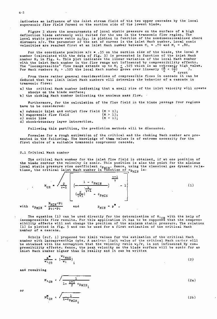
4- 2
i n d i c a t e s a n i n f l u e n c e o f t h e i n l e t stream f i e l d o f t h e two u p p e r c a s c a d e s by t h e l o c a l s u p e r s o n i c f l o w f i e l d f o r m e d on t h e s u c t i o n s i d e o f t h e l o w e s t b l a d e .
F i g u r e 3 shows t h e m e a s u r e m e n t s o f l o c a l s t a t i c p r e s s u r e on t h e s u r f a c e o f a h i g h d e f l e c t i o n b l a d e e x t r e m e l y w e l l s u i t e d f o r t h e u s e i n t h e t r a n s o n i c f l o w r e g i o n . The l o c a l s t a t i c p r e s s u r e r a t i o p 2 / p o 1 i s p l o t t e d i n f u n c t i o n o f t h e n o n d i m e n s i o n a l i z e d c h o r d d i s t a n c e x / c . The p a r a m e t e r o f t h e s e t o f c u r v e s i s t h e i n l e t Mach number. L o c a l s o n i c v e l o c i t i e s a r e r e a c h e d f i r s t a t a n i n l e t Mach number b e t w e e n M 1 = .70 a n d M 1 = .80.
F o r t h e c o o r d i n a t e p o s i t i o n x / c = .35 on t h e s u c t i o n s i d e o f t h e b l a d e , t h e l o c a l M number ( c a l c u l a t e d w i t h t h e d a t a o f f i g . 3 ) i s p r e s e n t e d i n f u n c t i o n o f t h e i n l e t Mach number M1 i n f i g . 4. T h i s p l o t i n d i c a t e s t h e l i n e a r , v a r i a t i o n o f t h e l o c a l Mach number w i t h t h e i n l e t Mach number i n t h e f l o w r a n g e n o t i n f l u e n c e d b y c o m p r e s s i b i l i t y e f f e c t s . The ‘ i n c o m p r e s s i b l e ’ f l o w r a n g e e x t e n d s up t o M 1 2 .525 w h i c h i s a n e x z r e m e l y h i g h v a l u e . F o r Mach n u m b e r s M 1 > .525 t h e l o c a l Mach number grows o v e r l i n e a r l y (c < (t) 1.
c r e s t From t h e s e r a t h e r g e n e r a l c o n s i d e r a t i o n s o f c o m p r e s s i h l e f l o w s i n c a s c a d e i t c a n b e
d e d u c e d t h a t two l i m i t i n l e t Mach numbers w i l l d e t e r m i n e t h e b e h a v i o r o f a c a s c a d e i n t r a n s o n i c f l o w s :
a ) t h e c r i t i c a l Mach number i n d i c a t i n g t h a t a smal l r i s e o f t h e i n l e t v e l o c i t y w i l l c r e a t e
b ) t h e c h o k i n g Mach number i n d i c a t i n g t h e maximum mass f l o w . s h o c k s on t h e b l a d e s u r f a c e ;
F u r t h e r m o r e , f o r t h e c a l c u l a t i o n of t h e f l o w f i e l d i n t h e b l a d e p a s s a g e f o u r r e g i o n s h a v e t o b e c o n s i d e r e d :
a ) s u b s o n i c i n l e t a n d o u t l e t f l o w f i e l d ( M < 1); b ) s u p e r s o n i c f l o w f i e l d ( M > 1); c ) s o n i c l i n e ( M = 1); d ) s h o c k - b o u n d a r y l a y e r i n t e r a c t i o n .
F o l l o w i n g t h i s p a r t i t i o n , t h e p r e d i c t i o n m e t h o d s w i l l b e d i s c u s s e d .
F o r m u l a e f o r a r o u g h e s t i m a t i o n o f t h e c r i t i c a l a n d t h e c h o k i n g Mach number a r e p r e - s e n t e d i n t h e f o l l o w i n g . The k n o w l e d g e o f these v a l u e s i s o f e x t r e m e n e c e s s i t y f o r t h e f i r s t c h o i c e o f a s u i t a b l e t r a n s o n i c c o m p r e s s o r c a s c a d e .
2 .1 C r i t i c a l Mach number
The c r i t h e b l a d e c l o c a l s t a t i t i o n s , t h e
t i c a l Mach number f o r t h e i n l e t f l o w f i e l d i o n t o u r t h e v e l o c i t y i s s o n i c . T h i s p o s i t i o n c p r e s s u r e r i s e c o e f f i c i e n t cPYIN. Hence , u s c r i t i c a l i n l e t Mach number i n u n c t i o n o f c p
/ r
s o b t a i n e d i s a l s o t h i n g t h e c l
, M I N i s :
’ * .e . a
i f P ? i
.SSlC
a t . n t ! a 1
o n e f o r g a s
p o s i t i o n o f t h e minimum dynamic r e l a -
L
a n d PMIN-P~ wi th ‘PMIN - p o l - p l
X PMIN P
The e q u a t i o n (1) c a n b e u s e d d i r e c t l y f o r t h e d e t e r m i n a t i o n o f M 1 w i t h t h e h e l p o f i n c o m p r e s s i b l e f l o w r e s u l t s . F o r t h i s a p p l i c a t i o n it h a s t o b e supposgff t h a t t h e compres- s i b i l i t y e f f e c t s w i l l n o t c h a n g e t h e p o s i t i o n o f t h e minimum s t a t i c p r e s s u r e . The r e l a t i o n ( 1 ) i s p l o t t e d i n f i g . 5 a n d c a n b e u s e d f o r a f i r s t e s t i m a t i o n o f t h e c r i t i c a l hlach number o f a c a s c a d e .
S c h o l z ( r e f , 1) p r o p o s e d two l i m i t v a l u e s f o r t h e e s t i m a t i o n o f t h e c r i t i c a l Mach number w i t h i n c o m p r e s s i b l e d a t a . A maximur, l i m i t v a l u e o f t h e c r i t i c a l Mach nu!qbcr w i l l b e o b t a i n e d w i t h t h e a s s u m p t i o n t h a t t h e v e l o c i t y r a t i o w 2 / w l i s n o t i n f l u e n c e d 6 y com- p r e s s i b i l i t y e f f e c t s . Hence , t h e p e a k v e l o c i t y on t h e b l a d e s u r f a c e w i l l b e s o n i c f o r an i n l e t Mach number h i g h e r t h a n i n r e a l i t y a n d i t c a n b e w r i t t e n
a n d r e s u l t i n g
or 1
PMINi 1 - c ( 2 b )
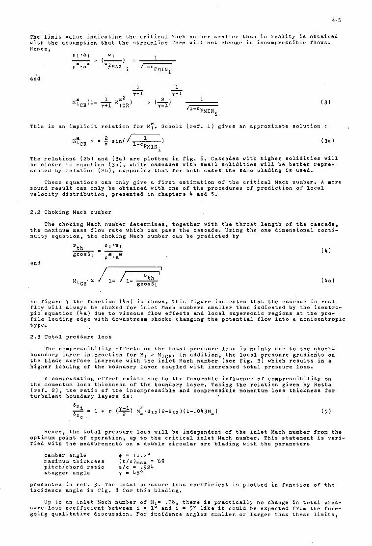
4- 3
a n d
The l i m i t v a l u e i n d i c a t i n g t h e c r i t i c a l Mach number s m a l l e r t h a n i n r e a l i t y i s o b t a i n e d w i t h t h e a s s u m p t i o n t h a t t h e s t r e a m l i n e f o r m w i l l n o t c h a n g e i n i n c o m p r e s s i b l e f l o w s . Hence ,
1 p 1 .81 W 1 - > (-1 =
T h i s i s a n i m p l i c i t r e l a t i o n f o r M Y . S c h o l z ( r e f , 1) g i v e s a n a p p r o x i m a t e s o l u t i o n :
2 M Y C R > = - s i n ( J l-c
PEIINi
The r e l a t i o n s ( 2 b ) a n d ( 3 a ) a r e p l o t t e d i n f i g . 6 . C a s c a d e s w i t h h i g h e r s o l i d i t i e s w i l l b e c l o s e r t o e q u a t i o n ( 3 a ) , w h i l e c a s c a d e s w i t h s m a l l s o l i d i t i e s w i l l b e b e t t e r r e p r e - s e n t e d by r e l a t i o n ( 2 b ) , s u p p o s i n g t h a t f o r b o t h c a s e s t h e same b l a d i n g i s u s e d .
T h e s e e q u a t i o n s c a n o n l y g i v e a f i r s t e s t i m a t i o n o f t h e c r i t i c a l Mach number. A more s o u n d r e s u l t c a n o n l y b e o b t a i n e d w i t h o n e o f t h e p r o c e d u r e s o f p r e d i c t i o n of l o c a l v e l o c i t y d i s t r i b u t i o n , p r e s e n t e d i n c h a p t e r s 4 a n d 5.
2.2 C h o k i n g Mach number
The c h o k i n g Mach number d e t e r m i n e s , t o g e t h e r w i t h t h e t h r o a t l e n g t h o f t h e c a s c a d e , t h e maximum mass f l o w r a t e w h i c h c a n p a s s t h e c a s c a d e . U s i n g t h e o n e d i m e n s i o n a l c o n t i - n u i t y e q u a t i o n , t h e c h o k i n g Mach number c a n b e p r e d i c t e d b y
and
I n f i g u r e 7 t h e f u n c t i o n ( h a ) i s shown, T h i s f i g u r e i n d i c a t e s t h a t t h e c a s c a d e i n r e a l f l o w w i l l a l w a y s b e c h o k e d f o r i n l e t Mach numbers s m a l l e r t h a n i n d i c a t e d b y t h e i s e n t r o - p i c e q u a t i o n ( 4 a ) d u e t o v i s c o u s f l o w e f f e c t s a n d l o c a l s u p e r s o n i c r e g i o n s a t t h e p r o - f i l e l e a d i n g e d g e w i t h d o w n s t r e a m s h o c k s c h a n g i n g t h e p o t e n t i a l f l o w i n t o a n o n i s e n t r o p i c t y p e .
2 . 3 T o t a l p r e s s u r e l o s s
The c o m p r e s s i b i l i t y e f f e c t s on t h e t o t a l p r e s s u r e loss i s m'ainly d u e t o t h e qhock- b o u n d a r y l a y e r i n t e r a c t i o n f o r M 1 > M I C R . I n a d d i t i o n , t h e l o c a l p r e s s u r e g r a d i e n t s on t h e b l a d e s u r f a c e i n c r e a s e w i t h t h e i n l e t Mach number ( s e e f i g . 3 ) w h i c h r e s u l t s i n a h i g h e r l o a d i n g o f t h e b o u n d a r y l a y e r c o u p l e d w i t h i n c r e a s e d t o t a l p r e s s u r e loss.
A c o m p e n s a t i n g e f f e c t e x i s t s d u e t o t h e f a v o r a b l e i n f l u e n c e o f c o m p r e s s i b i l i t y on t h e momentum loss t h i c k n e s s o f t h e b o u n d a r y l a y e r . T a k i n g t h e r e l a t i o n g i v e n b y R o t t a ( r e f . 21, t h e r a t i o o f t h e i n c o m p r e s s i b l e a n d c o m p r e s s i b l e momentum loss t h i c k n e s s f o r t u r b u l e n t b o u n d a r y l a y e r s i s :
H e n c e , t h e t o t a l p r e s s u r e loss w i l l b e i n d e p e n d e n t o f t h e i n l e t Mach number f r o m t h e opt imum p o i n t o f o p e r a t i o n , up t o t h e c r i t i c a l i n l e t Mach number , T h i s s t a t e m e n t i s v e r i - f i e d w i t h t h e m e a s u r e n e n t s on a d o u b l e c i r c u l a r a r c b l a d i n g W i t h t h e p a r a m e t e r s
camber a n g l e @ = 11.2O
s t a g g e r a n g l e y = 4 5 0
maximum t h i c k n e s s ( t / c ) m a x = '6% p i t c h / c h o r d r a t i o s / c = .92b
p r e s e n t e d i n r e f . 3 . The t o t a l p r e s s u r e l o s s c o e f f i c i e n t i s p l o t t e d i n f u n c t i o n o f t h e i n c i d e n c e a n g l e i n f i g . 8 f o r t h i s b l a d i n g .
Up t o a n i n l e t Mach number o f !Il= .78, t h e r e i s p r a c t i c a l l y n o c h a n g e i n t o t a l p r e s - s u r e l o s s c o e f f i c i e n t b e t w e e n i = lo a n d i = 5' l i k e it c o u l d b e e x p e c t e d f r o m t h e f o r e - g o i n g q u a l i t a t i v e d i s c u s s i o n . For i n c i d e n c e a n g l e s s m a l l e r o r l a r g e r t h a n t h e s e l i m i t s ,
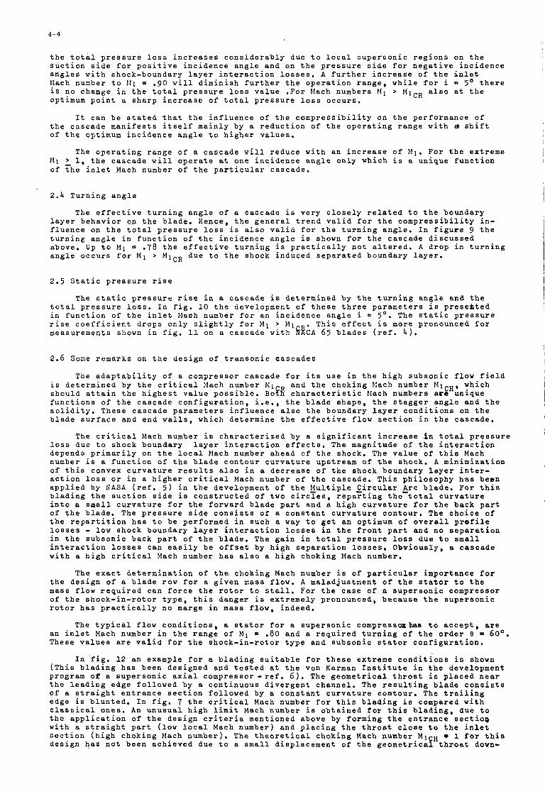
4-4
t h e t o t a l p r e s s u r e loss i n c r e a s e s c o n s i d e r a b l y due t o l o c a l s u p e r s o n i c r e g i o n s on t h e s u c t i o n s i d e f o r p o s i t i v e i n c i d e n c e a n g l e a n d on t h e p r e s s u r e s i d e f o r n e g a t i v e i n c i d e n c e a n g l e s w i t h s h o c k - b o u n d a r y l a y e r i n t e r a c t i o n l o s s e s , A f u r t h e r i n c r e a s e o f t h e i n l e t Mach number t o 1.11 = .gO w i l l d i m i n i s h f u r t h e r t h e o p e r a t i o n r a n g e , w h i l e f o r i = 5 O t h e r e i s n o c h a n g e i n t h e t o t a l p r e s s u r e loss v a l u e . F o r Mach numbers h21 > M I C R a l s o a t t h e opt imum p o i n t a s h a r p i n c r e a s e o f t o t a l p r e s s u r e loss o c c u r s .
I t c a n b e s t a t e d t h a t t h e i n f l u e n c e o f t h e c o m p r e s s i b i l i t y on t h e p e r f o r m a n c e o f t h e c a s c a d e m a n i f e s t s i t s e l f m a i n l y by a r e d u c t i o n o f t h e o p e r a t i n g r a n g e w i t h d s h i f t o f t h e opt imum i n c i d e n c e a n g l e t o h i g h e r v a l u e s .
The o p e r a t i n g r a n g e o f a c a s c a d e w i l l r e d u c e w i t h a n i n c r e a s e o f M 1 . For t h e e x t r e m e Mi 1. 1, t h e c a s c a d e w i l l o p e r a t e a t o n e i n c i d e n c e a n g l e o n l y w h i c h i s a u n i q u e f u n c t i o n o f t h e i n l e t Mach number o f t h e p a r t i c u l a r c a s c a d e .
2.4 T u r n i n g a n g l e
The e f f e c t i v e t u r n i n g a n g l e o f a c a s c a d e i s v e r y c l o s e l y r e l a t e d t o t h e b o u n d a r y l a y e r b e h a v i o r on t h e b l a d e . H e n c e , t h e g e n e r a l t r e n d v a l i d f o r t h e c o m p r e s s i b i l i t y i n - f l u e n c e on t h e t o t a l p r e s s u r e loss i s a l s o v a l i d f o r t h e t u r n i n g a n g l e . I n f i g u r e 9 t h e t u r n i n g a n g l e i n f u n c t i o n o f t h e i n c i d e n c e a n g l e i s shown f o r t h e c a s c a d e d i s c u s s e d a b o v e , Up t o M 1 .78 t h e e f f e c t i v e t u r n i n g i s p r a c t i c a l l y n o t a l t e r e d . A d r o p i n t u r n i n g a n g l e o c c u r s f o r M 1 > M I C R d u e t o t h e s h o c k i n d u c e d s e p a r a t e d b o u n d a r y l a y e r .
I
2.5 S t a t i c p r e s s u r e r i s e
The s t a t i c p r e s s u r e r i s e i n a c a s c a d e i s d e t e r m i n e d b y t h e t u r n i n g a n g l e a n d t h e t o t a l p r e s s u r e loss. I n f i g , 10 t h e d e v e l o p m e n t o f t h e s e t h r e e p a r a m e t e r s i s p r e s e h t e d i n f u n c t i o n o f t h e i n l e t Mach number f o r a n i n c i d e n c e a n g l e i = 5'. The s t a t i c p r e s s u r e r i s e c o e f f i c i e n t d r o p s o n l y s l i g h t l y f o r M 1 > MI , T h i s e f f e c t i s more p r o n o u n c e d f o r m e a s u r e m e n t s shown i n f i g . 11 on a c a s c a d e w i t h EWCA 6 5 b l a d e s ( r e f . 4 ) .
2.6 Some r e m a r k s on t h e d e s i g n o f t r a n s o n i c c a s c a d e s
The a d a p t a b i l i t y o f a c o m p r e s s o r c a s c a d e f o r i t s u s e i n t h e h i g h s u b s o n i c f l o w f i e l d i s d e t e r m i n e d by t h e c r i t i c a l Mach number M1 a n d t h e c h o k i n g Mach number MiCH, w h i c h s h o u l d a t t a i n t h e h i g h e s t v a l u e p o s s i b l e . Bog! c h a r a c t e r i s t i c Mach n u m b e r s a r c u n i q u e f u n c t i o n s of t h e c a s c a d e c o n f i g u r a t i o n , i . e . , t h e b l a d e e h a p e , t h e s t a g g e r a n g l e a n d t h e s o l i d i t y . T h e s e c a s c a d e p a r a m e t e r s i n f l u e n c e a l s o t h e b o u n d a r y l a y e r c o n d i t i o n s on t h e b l a d e s u r f a c e a n d e n d w a l l s , w h i c h d e t e r m i n e t h e e f f e c t i v e f l o w s e c t i o n i n t h e c a s c a d e .
The c r i t i c a l Mach number i s c h a r a c t e r i z e d b y a s i g n i f i c a n t i n c r e a s e i n t o t a l p r e s s u r e loss d u e t o s h o c k b o u n d a r y l a y e r i n t e r a c t i o n e f f e c t s . The m a g n i t u d e o f t h e i n t e r a c t i o n d e p e n d s p r i m a r i l y on t h e l o c a l Mach number a h e a d o f t h e s h o c k , The v a l u e o f t h i s Mach number i s a f u n c t i o n o f t h e b l a d e c o n t o u r c u r v a t u r e u p s t r e a m of t h e s h o c k . A m i n i m i z a t i o n o f t h i s c o n v e x c u r v a t u r e r e s u l t s a l s o i n a d e c r e a s e o f t h e s h o c k b o u n d a r y l a y e r i n t e r - a c t i o n loss o r i n a h i g h e r c r i t i c a l Mach number o f t h e c a s c a d e . T h i s p h i l o s o p h y h a s b e e n a p p l i e d by NASA ( r e f . 5 ) i n t h e d e v e l o p m e n t o f t h e M u l t i p l e C i r c u l a r A r c b l a d e . For t h i s b l a d i n g t h e s u c t i o n s i d e i s c o n s t r u c t e d o f t w o c i r c l e s , r e p a r t i n g t h e t o t a l c u r v a t u r e i n t o a small c u r v a t u r e f o r t h e f o r w a r d b l a d e p a r t a n d a h i g h c u r v a t u r e f o r t h e b a c k p a r t o f t h e b l a d e . The p r e s s u r e s i d e c o n s i s t s o f a c o n s t a n t c u r v a t u r e c o n t o u r . The c h o i c e o f t h e r e p a r t i t i o n h a s t o b e p e r f o r m e d i n s u c h a way t o g e t a n opt imum o f o v e r a l l p r e f i l e l o s s e s - low s h o c k b o u n d a r y l a y e r i n t e r a c t i o n l o s s e s i n t h e f r o n t p a r t a n d n o s e p a r a t i o n i n t h e s u b s o n i c b a c k p a r t o f t h e b l a d e . The g a i n i n t o t a l p r e s s u r e l o s s d u e t o small i n t e r a c t i o n l o s s e s c a n e a s i l y b e o f f s e t , b y h i g h s e p a r a t i o n l o s s e s , O b v i o u s l y , a c a s c a d e w i t h a h i g h c r i t i c a l Mach number h a s a l s o a h i g h c h o k i n g Mach number.
The e x a c t d e t e r m i n a t i o n o f t h e . c h o k i n g Mach number i s o f p a r t i c u l a r i m p o r t a n c e f o r t h e d e s i g n o f a b l a d e r o w f o r a g i v e n mass f l o w , A m a l a d j u s t m e n t o f t h e s t a t o r t o t h e mass f l o w r e q u i r e d c a n f o r c e t h e r o t o r t o s t a l l . F o r t h e c a s e o f a s u p e r s o n i c c o m p r e s s o r o f t h e s h o c k - i n - r o t o r t y p e , t h i s d a n g e r i s e x t r e m e l y p r o n o u n c e d , b e c a u s e t h e s u p e r s o n i c r o t o r h a s p r a c t i c a l l y n o marge i n mass f l o w , i n d e e d .
The t y p i c a l f l o w c o n d i t i o n s , a s t a t o r f o r a s u p e r s o n i c c o m p r e s s o n h a s t o a c c e p t , a re a n i n l e t Mach number i n t h e r a n g e o f M1 = .80 a n d a r e q u i r e d t u r n i n g o f t h e o r d e r 0 = 6 0 ° . T h e s e v a l u e s a r e v a l i d f o r t h e s h o c k - i n - r o t o r t y p e a n d s u b s o n i c s t a t o r c o n f i g u r a t i o n .
I n f i g . 1 2 a n e x a m p l e f o r a b l a d i n g s u i t a b l e f o r t h e s e e x t r e m e c o n d i t i o n s i s shown ( T h i s b l a d i n g h a s b e e n d e s i g n e d a n d t e s t e d a t t h e von Karman I n s t i t u t e i n t h e d e v e l o p m e n t p r o g r a m of a s u p e r s o n i c a x i a l c o m p r e s s o r - r e f . 6 ) . The g e o m e t r i c a l t h r o a t i s p l a c e d n e a r t h e l e a d i n g e d g e f o l l o w e d b y a c o n t i n u o u s d i v e r g e n t c h a n n e l . The r e s u l t i n g b l a d e c o n s i s t s o f a s t r a i g h t e n t r a n c e s e c t i o n f o l l o w e d by a c o n s t a n t c u r v a t u r e c o n t o u r . The t r a i l i n g e d g e i s b l u n t e d . I n f i g . 7 t h e c r i t i c a l Mach number f o r t h i s b l a d i n g i s compared w i t h c l a s s i c a l o n e s . A n u n u s u a l h i g h l i m i t Mach number i s o b t a i n e d f o r t h i s b l a d i n g , d u e t o t h e a p p l i c a t i o n o f t h e d e s i g n c r i t e r i a m e n t i o n e d a b o v e by f o r m i n g t h e e n t r a n c e s e c t i o p w i t h a s t r a i g h t p a r t ( l o w l o c a l Mach number) a n d p l a c i n g t h e t h r o a t c l o s e t o t h e i n l e t s e c t i o n ( h i g h c h o k i n g Mach n u m b e r ) . The t h e o r e t i c a l c h o k i n g Mach number M I C H I 1 f o r t h i s d e s i g n h a s n o t b e e n a c h i e v e d d u e t o a s m a l l d i s p l a c e m e n t o f t h e g e o m e t r i c a l t h r o a t down-
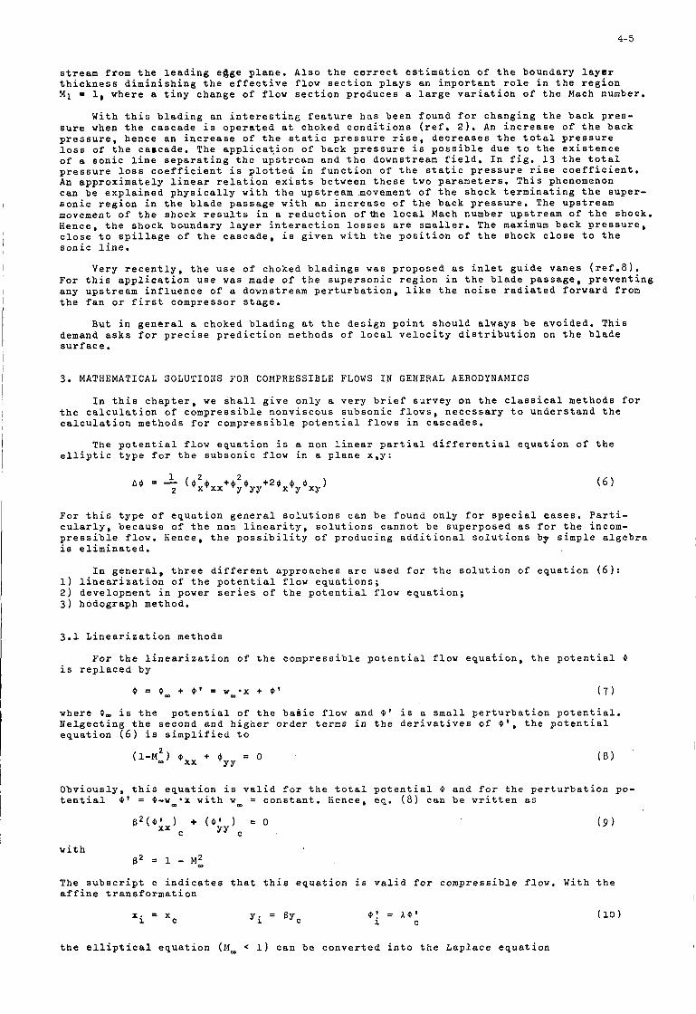
4-5
I
stream f r o m t h e l e a d i n g e d g e p l a n e . A l s o t h e c o r r e c t e s t i m a t i o n o f t h e b o u n d a r y l a y e r t h i c k n e s s d i m i n i s h i n g t h e e f f e c t i v e f l o w s e c t i o n p l a y s a n i n p o r t a n t r o l e i n t h e r e g i o n M i 1, w h e r e a t i n y c h a n g e o f f l o w s e c t i o n p r o d u c e s a l a r g e v a r i a t i o n o f t h e Mach number.
W i t h t h i s b l a d i n g a n i n t e r e s t i n g f e a t u r e h a s b e e n f o u n d f o r c h a n g i n g t h e b a c k p r e s - s u r e when t h e c a s c a d e i s o p e r a t e d a t c h o k e d c o n d i t i o n s ( r e f . 2 ) . An i n c r e a s e o f t h e b a c k p r e s s u r e , h e n c e a n i n c r e a s e o f t h e s t a t i c p r e s s u r e r i s e , d e c r e a s e s t h e t o t a l p r e s s u r e loss o f t h e c a a c a d e . The a p p l i c a t i o n o f b a c k p r e s s u r e i s p o s s i b l e d u e t o t h e e x i s t e n c e of a s o n i c l i n e s e p a r a t i n g t h e u p s t r e a m a n d t h e d o w n s t r e a m f i e l d . I n f i g . 1 3 t h e t o t a l p r e s s u r e loss c o e f f i c i e n t i s p l o t t e d i n f u n c t i o n o f t h e s t a t i c p r e s s u r e r i s e c o e f f i c i e n t . An a p p r o x i m a t e l y l i n e a r r e l a t i o n e x i s t s b e t w e e n t h e s e t w o p a r a m e t e r s . T h i s phenomenon c a n b e e x p l a i n e d p h y s i c a l l y w i t h t h e u p s t r e a m . m o v e m e n t o f t h e s h o c k t e r m i n a t i n g t h e s u p e r - s o n i c r e g i o n i n t h e b l a d e p a s s a g e w i t h a n i n c r e a s e o f t h e b a c k p r e s s u r e , The u p s t r e a m movement of t h e s h o c k r e s u l t s i n a r e d u c t i o n o f t h e l o c a l Mach number u p s t r e a m o f t h e s h o c k , Hence , t h e s h o c k b o u n d a r y l a y e r i n t e r a c t i o n l o s s e s a r e s m a l l e r . The maximum b a c k p r e s s u r e , c l o s e t o s p i l l a g e o f t h e c a s c a d e , i s g i v e n w i t h t h e p o s i t i o n o f t h e s h o c k c l o s e t o t h e s o n i c l i n e .
Very r e c e n t l y , t h e u s e o f c h o k e d b l a d i n g s w a s p r o p o s e d as i n l e t g u i d e v a n e s ( r e f . 8 ) . F o r t h i s a p p l i c a t i o n u s e was made of t h e s u p e r s o n i c r e g i o n i n t h e b l a d e p a s s a g e , p r e v e n t i n g a n y u p s t r e a m i n f l u e n c e o f a d o w n s t r e a m p e r t u r b a t i o n , l i k e t h e n o i s e r a d i a t e d f o r w a r d f r o m t h e f a n o r f i r s t c o m p r e s s o r s t a g e .
B u t i n g e n e r a l a c h o k e d b l a d i n g a t t h e d e s i g n p o i n t s h o u l d a l w a y s b e a v o i d e d , T h i s demand a s k s f o r p r e c i s e p r e d i c t i o n m e t h o d s o f l o c a l v e l o c i t y d i s t r i b u t i o n on t h e b l a d e s u r f a c e .
3 . MATHEMATICAL SOLUTIONS F O R COMPRESSIBLE FLOWS I N GENERAL AERODYNAMICS
I n t h i s c h a p t e r , w e s h a l l g i v e o n l y a v e r y b r i e f s u r v e y on t h e c l a s s i c a l m e t h o d s f o r t h e c a l c u l a t i o n o f c o m p r e s s i b l e n o n v i s c o u s s u b s o n i c f l o w s , n e c e s s a r y t o u n d e r s t a n d t h e c a l c u l a t i o n m e t h o d s f o r c o m p r e s s i b l e p o t e n t i a l f l o w s i n c a s c a d e s .
The p o t e n t i a l f l o w e q u a t i o n i s a non l i n e a r p a r t i a l d i f f e r e n t i a l e q u a t i o n o f t h e e l l i p t i c t y p e f o r t h e s u b s o n i c f l o w i n a p l a n e x , y :
F o r t h i s t y p e o f e q u a t i o n g e n e r a l s o l u t i o n s c a n b e f o u n d o n l y f o r s p e c i a l eases. P a r t i - c u l a r l y , b e c a u s e o f t h e non l i n e a r i t y , s o l u t i o n s c a n n o t b e s u p e r p o s e d as f o r t h e incom- p r e s s i b l e f l o w . H e n c e , t h e p o s s i b i l i t y o f p r o d u c i n g a d d i t i o n a l s o l u t i o n s by s i m p l e a l g e b r a i s e l i m i n a t e d .
I n g e n e r a l , t h r e e d i f f e r e n t a p p r o a c h e s a r e u s e d f o r t h e s o l u t i o n o f e q u a t i o n (6): 1) l i n e a r i z a t i o n o f t h e p o t e n t i a l f l o w e q u a t i o n s ; 2 ) d e v e l o p m e n t i n power s e r i e s o f t h e p o t e n t i a l f l o w e q u a t i o n ; 3 ) h o d o g r a p h method.
3.1 L i n e a r i z a t i o n m e t h o d s
F o r t h e l i n e a r i z a t i o n o f t h e c o m p r e s s i b l e p o t e n t i a l f l o w e q u a t i o n , t h e p o t e n t i a l 0 i s r e p l a c e d b y
0 = 0- + 0 ' = wm*x + 0 ' ( 7 )
w h e r e 0- i s t h e p o t e n t i a l o f t h e b a s i c f l o w a n d 0' i s a s m a l l p e r t u r b a t i o n p o t e n t i a l . N e l g e c t i n g t h e s e c o n d a n d h i g h e r o r d e r terms i n t h e d e r i v a t i v e s o f 0', t h e p o t e n t i a l e q u a t i o n ( 6 ) i s s i m p l i f i e d t o
O b v i o u s l y , t h i s e q u a t i o n i s v a l i d f o r t h e t o t a l p o t e n t i a l 0 a n d f o r t h e p e r t u r b a t i o n po- t e n t i a l 0 ' = 4-wm*x w i t h w m = c o n s t a n t . Hence , e q . ( 8 ) c a n b e w r i t t e n a s
w i t h B 2 =I 1 - M Z
The s u b s c r i p t c i n d i c a t e s t h a t t h i s e q u a t i o n i s v a l i d f o r c o m p r e s s i b l e f l o w . W i t h t h e a f f i n e t r a n s f o r m a t i o n
x i = x Y i = BYc 0 ' = A@' i C
t h e e l l i p t i c a l e q u a t i o n (14- 1) c a n b e c o n v e r t e d i n t o t h e L a p l a c e e q u a t i o n
(10)
4- 6
f o r a n i n c o m p r e s s i b l e p e r t u r b a t i o n p o t e n t i a l @:(yy). The f a c t o r A h a s s t i l l t o b e d e t e r - mined .
U s i n g t h i s t r a n s f o r m a t i o n , t h e p e r t u r b a t i o n v e l o c i t i e s U' a n d v ' a r e
H e n c e , w i t h e q . (11) a n d (12) r e s u l t s o f t h e i n c o m p r e s s i b l e f l o w f i e l d , w h i c h a r e r e l a t i v e l y e a s y t o o b t a i n , c a n b e t r a n s f o r m e d i n t o t h e c o m p r e s s i b l e f l o w f i e l d . The mag- n i t u d e o f M, d e t e r m i n e s t h e i n f l u e n c e o f t h e c o m p r e s s i b i l i t y . W i t h t h e c h o i c e o f t h e p a r a m e t e r A d i f f e r e n t t y p e s o f t r a n s f o r m a t i o n s c a n b e p e r f o r m e d . T h r e e o f t h o s e a r e d i s c u s s e d i n t h e f o l l o w i n g .
2 The t r a n s f o r m a t i o n w i t h A = l - F l m w i l l g i v e f o r a n i n c o m p r e s s i b l e f l o w f i e l d a r o u n d a s l e n d e r b o d y t h e c o m p r e s s i b l e f l o w by d i s t o r t i o n o f t h e body a n d t h e a n g l e o f a t t a c k w i t h :
Th s t a h i c p r e s s u r e p ' d i s t r i b u t i o n a r o u n d a p r o f i l e c a n b e d e t e r m i n e d by u s i n g t h e B e r n o u l l i e q u a t i o n ( r e f . 9 )
P ' = P - P, a n d
c P POl'P1
Hence , w i t h e q . (12)
U' S -2 -
w m
1 1 2
A 1-M, -= -
( 1 3 )
T h i s r e l a t i o n i s n o r m a l l y named t h e ' G o e t h e r t r u l e ' .
The f i r s t r u l e o f P r a n d t l - G l a u e r t a s s u m e s e q u a l b o d i e s f o r t h e t r e a t m e n t i n compres- s i b l e a n d = m p r e s s i b l e f l o w
The s e c o n d r u l e o f P r a n d t l - G l a u e r t a s s u m e s t h e same p r e s s u r e d i s t r i b u t i o n on t h e b l a d e s u r f a c e bor t h e c o m p r e s s i b l e a n d i n c o m p r e s s i b l e f l o w f i e l d :
cPc - = 1 P i C
T h i s r e l a t i o n g i v e s
( 1 6 1
t h e t r a n s f o r m a t i o n f o r % h e b l a d e c o n t o u r :
- = . - E - = - O C 1 a i e i
The f i r s t o f t h e t w o P r a n t l - G l a u e r t r u l e s i s o f i n t e r e s t t o s t u d y t h e b e h a v i o r o f a g i v e n b l a d i n g o v e r a r a n g e o f d i f f e r e n t Mach n u m b e r s , w h i l e t h e s e c o n d c a n h e l p t o f i n d a p r o f i l e w h i n h h a s t h e same l i f t c o e f f i c i e n t f o r d i f f e r e n t Mach numbers .
A d i f f i c u l t y f o r a p r a c t i c a l a p p l i c a t i o n e x i s t s a l w a y s d u e t o t h e a s s u m p t i o n s made f o r t h e l i n e a r i z a t i o n :
4- 7
The f i r s t t h r e e a s s u m p t i o n s a r e i n c l u d e d i n t.he l a s t t w o o n e s . N o r m a l l y , t h e s e assump- t i o n s c a n n o t b e f u l f i l l e d w i t h t h e t y p e o f b l a d i n g u s e d i n c o m p r e s s o r c a s c a d e s .
3.2 Power s e r i e s
We c o n s i d e r i n t h i s n o t e o n l y t h e d e v e l o p m e n t i n power s e r i e s o f t h e Ilach number. A n o t h e r p o s s i b i l i t y i s t h e e x p a n s i o n i n s e r i e s o f a p a r a m e t e r d e s c r i b i n g t h e t a n g e n t o f t h e p r o f i l e c o n t o u r a g a i n s t t h e m a i n f l o w d i r e c t i o n . The l a s t p r o c e d u r e i s o f p a r t i c u l a r i n t e r e s t f o r s l e n d e r b o d i e s . B u t we a r e l o o k i n g h e r e f o r a p r o c e d u r e t o b e u s e f u l f o r t h i c k b o d i e s i n o p p o s i t i o n t o t h e small p e r t u r b a t i o n method d i s c u s s e d i n t h e p r e c e d i n g c h a p t e r .
' L e t u s c o n s i d e r a g a i n a two d i m e n s i o n a l f l o w i n t h e p l a n e x , y f o r w h i c h t h e p o t e n - t i a l e q u a t i o n s c a n b e w r i t t e n as ,
( 1 7 ) @ X X + @yy = 2 ( Q x x 9 x + ~ ; y Q y + 2 9 x y ~ x O y ) 5 2nT
2 2
Y w h e r e a' i s a f u n c t i o n o f w 2 = Qx+O as
d e t e r m i n e d w i t h t h e c o m p r e s s i b l e g a s f l o w c o n d i t i o n s
Knowing t h a t a n i n c o m p r e s s i b l e f l o w a r o u n d a body i s q u a l i t a t i v e l y n o t t o o d i f f e r e n t f r o m t h e s u b s o n i c c o m p r e s s i b l e f l o w , t h e s o l u t i o n o f t h e l e f t h a n d s i d e o f e q . ( 1 7 ) , t h e L a p l a c e e q u a t i o n 8 +Q = 0 , c a n b e t a k e n as a f i r s t a p p p r o x i m a t i o n f o r t h e p o t e n t i a l
f l o w e q u a t i o n . The s o l u t i o n f o r Q ( x , y ) o f t h i s f i r s t a p p r o x i m a t i o n i s t a k e n a s t h e f i r s t f a c t o r o f a n e x p a n s i o n i n s e r i e s o f e q . ( 1 7 ) ( r e f . 9 ) :
x x YY
(18)
E q u a t i o n (18) i s i n t r o d u c e d i n t o e q . (17). A f t e r a n a r r a p g e m e n t w i t h t h e p o w e r s o f M_, a s y s t e m o f l i n e a r d i f f e r e n t i a l e q u a t i o n s i s o b t a i n e d f o r t h e f u n c t i o n s Ok(x ,y)
2 Q ( x , y ) = o o ( X , y ) + 0 , ( x , y ) M m + Q Z M ; + ...
2
. . . . . . . . . . . . . . ( 'k'xx + ( o k ) y y = 2 n T k ( x , Y )
The r i g h t h a n d s i d e s o f t h e s y s t e m o f P o i s s o n ' s e q u a t i o n (19) 2 r i k ( x , y ) i n c o r p o r a t e
I n s e r t i n g t h e a p p r o p r i a t e b o u n d a r y c o n d i t i o n s
o n l y t h e a p p r o x i m a t i o n s 00, 4 1 , ..., @k,l.
x = m 340
ay y = m - = o a t a Q 0
ax - =
a o an - = o a t s o l i d b o u n d a r y ( n i s
n o r m a l t o t h e b o u n d a r y
a t s o l i d b o u n d a r y a o k ao, a o 2 ... = - = 0 - = - = an an an
t h e s o l u t i o n s o f t h e s y s t e m (19) are d e t e r m i n e d .
S a u e r ( r e f . 9 ) p r o p o s e s t o c o n s i d e r n o t o n l y t h e s o l u t i o n O o ( x , y ) as a n i n c o m p r e s - s i b l e o n e , b u t a l s o t h e f o l l o w i n g a p p r o x i m a t i o n s Q k ( x , y ) . For t h e l a t t e r c a s e a d d i t i o n a l
4-8
s o u r c e s a n i s i n k s a r e d i s t r i b u t e d i n t h e f l o w f i e l d w i t h t h e s t r e n g t h T ( x , y ) . T h i s means t h a t a l s o t h e i n t e r i o r o f t h e p r o f i l e h a s t o i n c l u d e s o u r c e s a n d s i n k s io f u l f i l l t h e b o u n d a r y c o n d i t i o n a t t h e b l a d e c o n t o u r . Hence , t h e a p p r o x i m a t i o n s a r e
4 k ( x , ~ ) = 11 T ~ ( F , ~ ) an ~ X - C ) ~ + ( Y - ~ ) ~ dEdn ( 2 0 )
Now t h e f u n c t i o n s O k ( x , y ) a r e n o t a n y l o n g e r c o n s i d e r e d a s f a c t o r s o f t h e s e r i e s e x p a n - s i o n (18), b u t a s s u c c e s s i v e a p p r o x i m a t i o n s f o r e q . (17). The a p p r o x i m a t i o n Ok,l(x,y) i s i n t r o d u c e d i n t o t h e r i g h t h a n d s i d e o f eq . O k ( x , y ) . A p r a c t i c a l a p p l i c a t i o n o f t h i s p r o c e d u r e h a s b e e n f o u n d f o r t h e c a l c u l a t i o n o f c o m p r e s s i b l e f l o w s i n c a s c a d e s .
(17) t o o b t a i n O k ( x , y ) a n d f o l l o w i n g f r o m (20.)
The p r o c e d u r e t o d e v e l o p t h e c o m p r e s s i b l e p o t e n t i a l f l o w e q u a t i o n i n a s e r i e s o f Mach number h a s t h e a d v a n t a g e o f n o t t o b e r e s t r i c t e d t o s l e n d e r b o d i e s . But u n f o r t u n a t e l y , t h e r e i s n o e v i d e n c e t h a t t h e method c o n v e r g e s .
, 3 . 3 Hodograph method
I n c h a p t e r E . l t h e c o m p r e s s i b l e f l o w e q u a t i o n s h a v e b e e n l i n e a r i z e d by n e g l e c t i n g some h i g h e r o r d e r t e r m s , H e n c e , t h e r e s u l t i n g l i n e a r d i f f e r e n t i a l e q u a t i o n s a r e v a l i d o n l y a p p r o x i m a t e l y f o r s t r e a m f i e l d s c l o s e t o t h e main p a r a l l e l s tream f i e l d .
A n o t h e r t y p e o f l i n e a r i z a t i o n i s t h e u s e o f a h o d o g r a p h m e t h o d , t h e t r a n s f o r m a t i o n o f t h e 4 o r Y f u n c t i o n s f r o m t h e x , y p l a n e i n t o t h e v e l o c i t y p l a n e u , v o r w , 0 . The l i n e a r d i f f e r e n t i a l e q u a t i o n s o b t a i n e d i n t h i s way a r e e x a c t . They a r e a l s o v a l i d f o r h i g h p e r t u r b a t i o n s t r e a m f i e l d s a n d i n t h e r a n g e M = 1.
Two t y p e s of t r a n s f o r m a t i o n a re p o s s i b l e f o r a p l a n e a n d i r r o t a t i o n a l f l o w t h e M o l e n b r o e k t r a n s f o r m a t i o n , w h i c h c o n v e r t s on$y t h e i n d e p e n d e n t v a r i a b l e s a n d n o t t h e f u n c t i o n s 4 a n d Y , g i v i n g t h e s t r e a m f u n c t i o n i n t h e w , 9 p l a n e w i t h 9 = a r c c o s ( u / w ) ;
t h e L e g e n d r e t r a n s f o r m a t i o n w h i c h c o n v e r t s n o t o n l y t h e v e l o c i t y c o m p o n e n t s b u t a l s o t h e 0 a n d Y f u n c t i o n s :
u v U 2 + 2 - 4uv + (1- ,.I OVV = 0 V 2 (1- - a 2 4uu a2
( 2 2 )
w i t h 4 = x$x + Y$y - $.
The d i f f i c u l t y f o r t h e p r a c t i c a l p r o b l e m of f l o w p a s t g i v e n b o u n d a r i e s
A s i g n i f i c a n t s i m p l i f i c a t i o n f o r o b t a i n e d w i t h a n a p p r o x i m a t i o n o f t h e t i c a l r e l a t i o n f o r a l i m i t e d r a n a e o f
a p p l i c a t i o n o f t h e h o d o g r a p h method i s t h a t t h e i s s u s c e p t i b l e t o a d i r e c t t r e a t m e n t ,
t h e a p p l i c a t i o n o f t h e h o d o g r a p h method h a s b e e n p r e s s u r e - d e n s i t y r e l a t i o n p = p ( p ) b y a h y p o t h e - - ~ v e l o c i t y , l i k e t h e w e l l known t a n g e n t - g a s r e l a t i o n
l e a d i n g t o t h e Karman-Ts ien c o r r e c t i o n f o r m u l a .
F o r t h e t a n g e n t g a s r e l a t i o n t h e i s e n t r o p i c r e l a t i o n p * p l / ’ = c o n s t . i s a p p r o a c h e d by a s t r a i g h t l i n e i n t h e p l a n e p = p ( l / p ) ( f i g . 13) :
2 2 1 1 P ( 2 3 ) P - P, = a, P, (< - -1
I n t r o d u c i n g (23) i n t o t h e B e r n o u l l i e q u a t i o n , w e g e t
2 (-.- 1 w 2 - w, = am P, -+) P P m
2 2 W i t h p 2 - a 2 = p;a2 = p i - a g w h i c h i s v a l i d bec .ause o f
w e o b t a i n f r o m e q . ( 2 4 )
2 2 w 2 - a2 = wm - am 2 2 w 2 = a - a.
U s i n g t h e s e r e l a t i o n s , t h e e q . (21) c a n b e w r i t t e n as ( r e f . 10) :
4-9
T h i s e q u a t i o n c a n b e r e d u c e d i n t o t h a t o f a n i n c o m p r e s s i b l e f l o w b y d e f i n i n g a new v a r - i a b l e wi w i t h t h e r e l a t i o n
I n t r o d u c i n g t h i s u n i q u e r e l a t i o n b e t w e e n wi a n d w 1 t h e e q u a t i o n ( 2 6 ) i s t ransf0rme.d i n t o . a
Compar ing e q s ( 2 6 ) a n d ( 2 8 ) it i s e v i d e n t t h a t f o r M = 0 i n e q . ( 2 6 ) b o t h t h e r e l a - t i o n s a r e i d e n t i c a l . H e n c e , e q . ( 2 8 ) i s t h e d i f f e r e n t i a l e q u a t i o n f o r a n i n c o m p r e s s i b l e f l u i d i n t h e h o d o g r a p h p l a n e w i , t l .
i n t h e p h y s i c a l p l a n e f o r g i v e n b o u n d a r i e s . Knowing t h e i n c o m p r e s s i b l e r e s u l t s f o r a g i v e n p r o f i l e Jl i = J l i ( x i , y i ) , t h e v e l o c i t y c o m p o n e n t s u i a n d v i c a n b e d e t e r m i n e d t o
g i v e Jli = J l i (wi ,O) . T h i s f u n c t i o n h a s t h e same f o r n l i k e JI = J l (w,O) , d u e t o t h e t r a n s -
f o r m a t i o n ( 2 7 ) u s e d . The c o m p r e s s i b l e s o l u t i o n , f o u n d by r e p l a c i n g W i a n d w , w i l l g i v e t h e body s h a p e i n t h e p h y s i c a l p l a n e , by i n t e g r a t i n g :
The i m p o r t a n c e o f t h i s r e s u l t i s t h a t i t i s p o s s i b l e now t o o b t a i n more e a s i l y r e s u l t s
The body f o r m w i l l b e s l i g h t l y d i f f e r e n t f r o m t h e i n c o m p r e s s i b l e o n e .
T o p e r f o r m t h i s p r o c e d u r e , w e h a v e t o s o l v e t w o s t e p s . F i r s t , a r e l a t i o n b e t w e e n t h e c o r r e s p o n d i n g v e l o c i t i e s i n t h e c o m p r e s s i b l e a n d i n c o m p r e s s i b l e f l o w f i e l d h a s t o b e e s t a b l i s h e d . S e c o n d , a r e l a t i o n b e t w e e n t h e c o r r e s p o n d i n g p r o f i l e s h a p e s h a s t o b e f o r m u l a t e d.
3.3.1 C o r r e s p o n d i n g v e l o c i t i e s
A r e l a t i o n b e t w e e n t h e c o r r e s p o n d i n g v e l o c i t i e s i s o b t a i n e d u s i n g t h e e q s ( 2 5 ) a n d ( 2 7 ) :
W .
2 w i t h 1.l m A=czT m
2 w i t h 1.l m A=czT m
( 3 0 )
The d e t a i l e d d e r i v a t i o n w h i c h i s p u r e l y m a t h e m a t i c a l c a n b e f o u n d i n r e f . 10.
S i m i l a r t o t h e P r a n d t l - G l a u e r t r u l e , w e c a n a l s o c o n s t r u c t a s t a t i c p r e s s u r e r i s e c o e f f i c i e n t c o r r e c t i o n f o r m u l a w i t h e q . ( 2 9 ) :
C n : ( 3 1 )
m
T h i s f o r m u l a i s t h s o - c a l l e d Karman-Tsien p r e s s u r e c o r r e c t i o n f o r m u l a . I n f i g . 1 5 t h e e q . ( 3 1 ) i s p l o t t e d i n f o r m o f a g r a p h .
The eq . ( 3 1 ) o f c o u r s e d o e s n o t r e p r e s e n t e x a c t l y t h e i n f l u e n c e o f t h e c o m p r e s s i b i - l i t y on t h e p r e s s u r e d i s t r i b u t i o n o f a n , a i r f o i l , b e c a u s e t h e p r o f i l e s f o r w h i c h t h e c p v a l u e s a r e compared a r e s l i g h t l y d i f f e r e n t .
F o r t h e p r a c t i c a l a p p l i c a t i o n o f e q . ( 3 1 ) it i s u s e f u l t o know t h a t c o u n t e r a c t i n g e r r o r s e x i s t , w h i c h seem t o n e a r l y c a n c e l e a c h o t h e r . The l i n e a r p r e s s u r e d e n s i t y r e l a - t i o n o v e r e s t i m a t e s t h e c o m p r e s s i b i l i t y e f f e c t s . On t h e o t h e r h a n d , t h e c o m p r e s s i b i l i t y c o r r e c t i o n o f t h e p r o f i l e c o o r d i n a t e s w i l l p r o d u c e a t h i c k e r p r o f i l e . Hence , u s i n g t h e t h i n n e r i n c o m p r e s s i b l e p r o f i l e , w e s h a l l b e c l o s e r t o r e a l i t y .
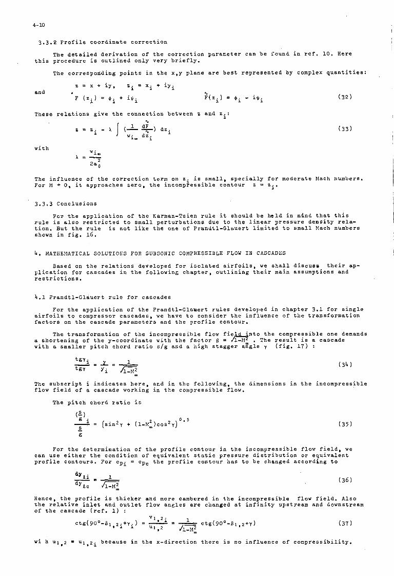
4- 10
3.3 .2 P r o f i l e c o o r d i n a t e c o r r e c t i o n
The d e t a i l e d d e r i v a t i o n o f t h e c o r r e c t i o n p a r a m e t e r c a n b e f o u n d i n r e f , 10. Here t h i s p r o c e d u r e i s o u t l i n e d o n l y v e r y b r i e f l y .
The c o r r e s p o n d i n g p o i n t s i n t h e x , y p l a n e a r e b e s t r e p r e s e n t e d by complex q u a n t i t i e s :
z = x + i y , z i = x i + i y i and b %
F ( z i ) = $ i + iJli F ( z i ) = O i - i 6 i
T h e s e r e l a t i o n s g i v e t h e c o n n e c t i o n b e t w e e n z a n d z i :
w i t h
(32)
The i n f l u e n c e o f t h e c o r r e c t i o n t e r m on z i i s s m a l l , s p e c i a l l y f o r m o d e r a t e Mach numbers . F o r M -+ 0 , i t a p p r o a c h e s z e r o , t h e i n c o m p r e s s i b l e c o n t o u r z 3 z i '
3 . 3 . 3 C o n c l u s i o n s
F o r t h e a p p l i c a t i o n o f t h e Karman-Ts ien r u l e i t s h o u l d b e h e l d i n mind t h a t t h i s r u l e i s a l s o r e s t r i c t e d t o small p e r t u r b a t i o n s due t o t h e l i n e a r p r e s s u r e d e n s i t y r e l a - t i o n . B u t t h e r u l e i s n o t l i k e t h e o n e o f P r a n d t l - G l a u e r t l i m i t e d t o small Mach n u m b e r s shown i n f i g . 16 .
4. M A T H E f l A T I C A L SOLUTIOHS FOR SUBSONIC COMPRESSIBLE FLOW I N CASCADES
B a s e d on t h e r e l a t i o n s d e v e l o p e d f o r i s o l a t e d a i r f o i l s , we s h a l l d i s c u e a t h e i r ap- p l i c a t i o n f o r c a s c a d e s i n t h e f o l l o w i n g c h a p t e r , o u t l i n i n g t h e i r main a s s u m p t i o n s a n d r e s t r i c t i o n s .
4 . 1 P r a n d t l - G l a u e r t r u l e f o r c a s c a d e s
F o r t h e a p p l i c a t i o n o f t h e P r a n d t l - G l a u e r t r u l e s d e v e l o p e d i n c h a p t e r 3.1 f o r s i n g l e a i r f o i l s t o c o m p r e s s o r c a s c a d e s , w e h a v e t o c o n s i d e r t h e i n f l u e n c e o f t h e t r a n s f o r m a t i o n f a c t o r s on t h e c a s c a d e p a r a m e t e r s a n d t h e p r o f i l e c o n t o u r .
The t r a n s f o r m a t i o n o f t h e i n c o m p r e s s i b l e f l o w f i e l d i n t o t h e c o m p r e s s i b l e o n e demands a s h o r t e n i n g o f t h e y - c o o r d i n a t e w i t h t h e f a c t o r 6 = , The r e s u l t i s a c a s c a d e w i t h a s m a l l e r p i t c h c h o r d r a t i o s / g a n d a h i g h s t a g g e r a g g l e y ( f i g . 17) :
! m
The s u b s c r i p t i i n d i c a t e s h e r e , f l o w f i e l d o f a c a s c a d e w o r k i n g
The p i t c h c h o r d r a t i o i s
( 3 4 1
a n d i n t h e f o l l o w i n g , t h e d i m e n s i o n s i n t h e i n c o m p r e s s i b l e i n t h e c o m p r e s s i b l e f l o w .
F o r t h e d e t e r m i n a t i o n o f t h e p r o f i l e c o n t o u r i n t h e i n c o m p r e s s i b l e f l o w f i e l d , w e c a n u s e e i t h e r t h e c o n d i t i o n o f e q u i v a l e n t s t a t i c p r e s s u r e d i s t r i b u t i o n o r e q u i v a l e n t p r o f i l e c o n t o u r s . F o r cpi = cpc t h e p r o f i l e c o n t o u r h a s t o b e c h a n g e d a c c o r d i n g t o
Hence , t h e p r o f i l e i s t h i c k e r a n d more cambered i n t h e i n c o m p r e s s i b l e f l o w f i e l d . A l s o t h e r e l a t i v e i n l e t a n d o u t l e t f l o w a n g l e s a r e c h a n g e d a t i n f i n i t y u p s t r e a m a n d d o w n s t r e a m o f t h e c a s c a d e ( r e f . 1) :
w i h u l 2 = ~ 1 . 2 ~ b e c a u s e i n t h e x - d i r e c t i o n t h e r e i s n o i n f l u e n c e o f c o m p r e s s i b i l i t y .
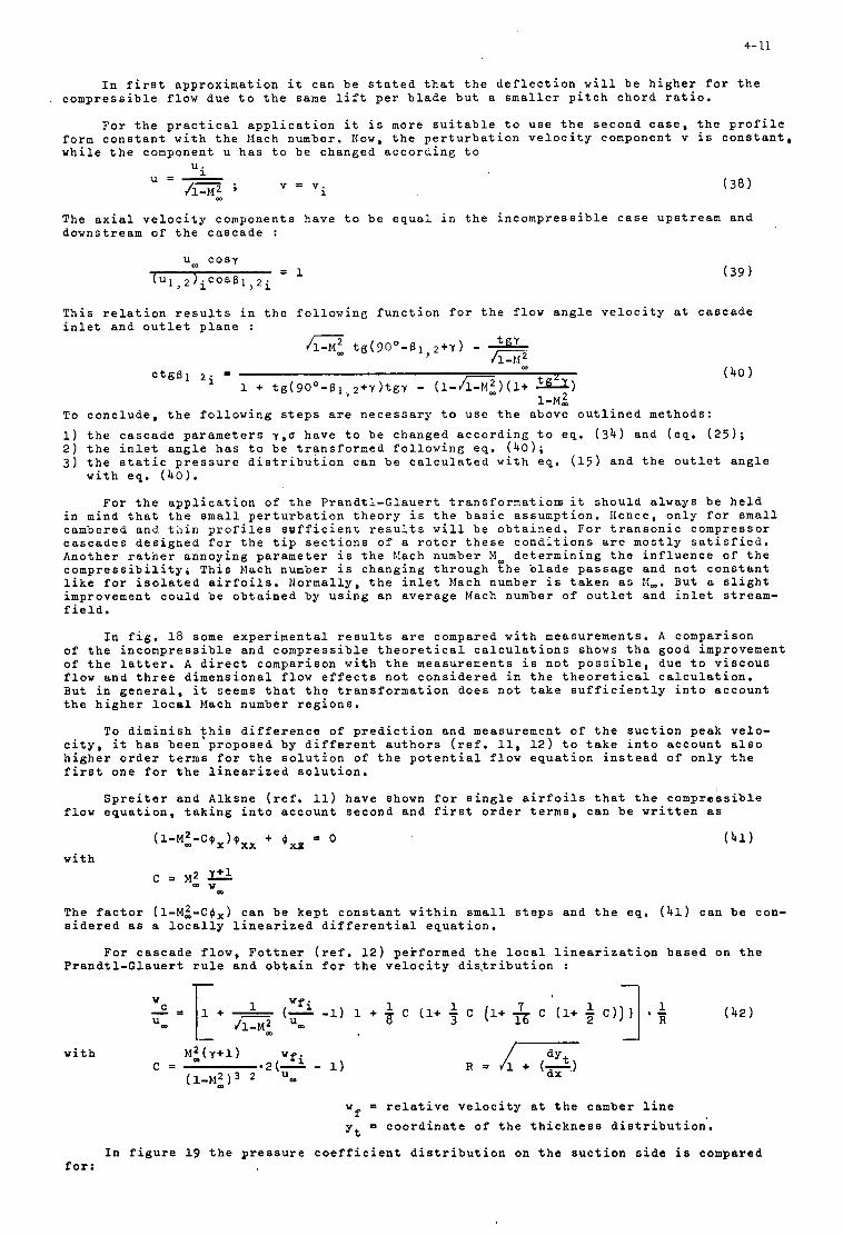
4- 11
I n f i r s t a p p r o x i m a t i o n i t c a n b e s t a t e d t h a t t h e d e f l e c t i o n w i l l b e h i g h e r f o r t h e c o m p r e s s i b l e f l o w d u e t o t h e sane l i f t p e r b l a d e b u t a smal le r p i t c h c h o r d r a t i o .
F o r t h e p r a c t i c a l a p p l i c a t i o n i t i s more s u i t a b l e t o u s e t h e s e c o n d c a s e , t h e p r o f i l e f o r m c o n s t a n t w i t h t h e Mach number. Now, t h e p e r t u r b a t i o n v e l o c i t y component v i s c o n s t a n t , w h i l e t h e component U h a s t o b e c h a n g e d a c c o r d i n g t o
U .
( 3 8 )
The a x i a l v e l o c i t y c o m p o n e n t s h a v e t o b e e q u a l i n t h e i n c o m p r e s s i b l e c a s e u p s t r e a m a n d d o w n s t r e a m o f t h e c a s c a d e :
T h i s r e l a t i o n r e s u l t s i n t h e f o l l o w i n g f u n c t i o n f o r t h e f l o w a n g l e v e l o c i t y a t c a s c a d e i n l e t a n d o u t l e t p l a n e :
To c o n c l u d e , t h e f o l l o w i n g s t e p s a r e n e c e s s a r y t o u s e t h e a b o v e o u t l i n e d m e t h o d s :
1) t h e c a s c a d e p a r a m e t e r s y , o h a v e t o b e c h a n g e d a c c o r d i n g t o e q . ( 3 4 ) and ( e q . ( 2 5 ) ; 2) t h e i n l e t a n g l e h a s t o b e t r a n s f o r m e d f o l l o w i n g eq . ( 4 0 ) ; 3 ) t h e s t a t i c p r e s s u r e d i s t r i b u t i o n c a n b e c a l c u l a t e d w i t h e q . (15) a n d t h e o u t l e t a n g l e
w i t h e q . ( 4 0 ) .
F o r t h e a p p l i c a t i o n o f t h e P r a n d t l - G l a u e r t t r a n s f o r n a t i o r s i t s h o u l d a l w a y s b e h e l d i n mind t h a t t h e s m a l l p e r t u r b a t i o n t h e o r y i s t h e b a s i c a s s u m p t i o n . Hence , o n l y f o r small c a m b e r e d and t h i n p r o f i l e s s u f f i c i e n t r e s u l t s w i l l b e o b t a i n e d . F o r t r a n s o n i c c o m p r e s s o r c a s c a d e s d e s i g n e d f o r t h e t i p s e c t i o n s o f a r o t o r t h e s e c o n d i t i o n s a r e m o s t l y s a t i s f i e d . A n o t h e r r a t h e r a n n o y i n g p a r a m e t e r i s t h e Mach number M m d e t e r m i n i n g t h e i n f l u e n c e o f t h e c o m p r e s s i b i l i t y ; T h i s Mach number i s c h a n g i n g t h r o u g h t h e b l a d e p a s s a g e a n d n o t c o n s t a n t l i k e f o r i s o l a t e d a i r f o i l s . N o r m a l l y , t h e i n l e t Mach number i s t a k e n as M-. B u t a s l i g h t improvement c o u l d b e o b t a i n e d by u s i n g a n a v e r a g e Mach number o f o u t l e t a n d i n l e t stream- f i e l d .
I n f i g . 1 8 some e x p e r i m e n t a l r e s u l t s a r e compared w i t h m e a s u r e m e n t s , A c o m p a r i s o n o f t h e i n c o m p r e s s i b l e a n d c o m p r e s s i b l e t h e o r e t i c a l c a l c u l a t i o n s shows t h a g o o d improvement o f t h e l a t t e r , A d i r e c t c o m p a r i s o n w i t h t h e m e a s u r e m e n t s is n o t p o s s i b l e , due t o v i s c o u s f l o w a n d t h r e e d i m e n s i o n a l f l o w e f f e c t s n o t c o n s i d e r e d i n t h e t h e o r e t i c a l c a l c u l a t i o n . B u t i n g e n e r a l , it seems t h a t t h e t r a n s f o r m a t i o n d o e s n o t t a k e s u f f i c i e n t l y i n t o a c c o u n t t h e h i g h e r l o c a l Mach number r e g i o n s .
To d i m i n i s h $ h i s d i f f e r e n c e o f p r e d i c t i o n a n d m e a s u r e m e n t o f t h e s u c t i o n p e a k v e l o - c i t y , it h a s b e e n p r o p o s e d b y d i f f e r e n t a u t h o r s ( r e f , 11, 1 2 ) t o t a k e i n t o a c c o u n t a l s o h i g h e r o r d e r terms f o r t h e s o l u t i o n o f t h e p o t e n t i a l f l o w e q u a t i o n i n s t e a d o f o n l y t h e f i r s t o n e f o r t h e l i n e a r i z e d s o l u t i o n .
S p r e i t e r a n d A l k s n e ( r e f . 11) h a v e shown f o r s i n g l e a i r f o i l s t h a t t h e c o m p r e s s i b l e f l o w e q u a t i o n , t a k i n g i n t o a c c o u n t s e c o n d a n d f i r s t o r d e r t e rms , c a n b e w r i t t e n as
The f a c t o r ( l -Mi-C$x) c a n b e k e p t c o n s t a n t w i t h i n s m a l l s t e p s a n d t h e eq . ( 4 1 ) c a n b e con- s i d e r e d as a l o c a l l y l i n e a r i z e d d i f f e r e n t i a l e q u a t i o n .
F o r c a s c a d e f l o w , F o t t n e r ( r e f , 1 2 ) p e r f o r m e d t h e l o c a l l i n e a r i z a t i o n b a s e d o n t h e P r a n d t l - G l a u e r t r u l e a n d o b t a i n f o r t h e v e l o c i t y d i s ~ t r i b u t i o n :
I
w i t h
wf = r e l a t i v e v e l o c i t y a t t h e camber l i n e
y t = c o o r d i n a t e o f t h e t h i c k n e s s d i s t r i b u t i o n .
I n f i g u r e 19 t h e p r e s s u r e c o e f f i c i e n t d i s t r i b u t i o n on t h e s u c t i o n s i d e i s compared fo r :
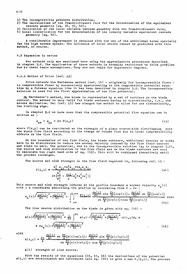
4- 12
1 ) The i n c o m p r e s s i b l e p r e s s u r . e d i s t r i b u t i o n ; 2) The c a l c u l a t i o n s o f t h e P r a n d t l - C l a u e r t r u l e f o r t h e d e t e r m i n a t i o n o f t h e e q u i v a l e n t
c a s c a d e g e o m e t r y ( e q . 3 4 , 35 , 4 0 ) ; 3 ) C a l c u l a t i o n of t h e l o c a l v a r i a b l e c a s c a d e g e o m e t r y w i t h t h e P r a n d t l - G l a u e r t r u l e ; 4) L o c a l l i n e a r i z a t i o n f o r t h e d e t e r m i n a t i o n o f t h e l o c a l l y v a r i a b l e e q u i v a l e n t c a s c a d e
g e o m e t r y ( e q . 42).
A c o n s i d e r a b l e improvement i s o b t a i n e d w i t h t h e u s e o f t h e a d d i t i o n a l t e r m s s p e c i a l l y f o r t h e h i g h e x c e s s s p e e d s . The i n f l u e n c e o f l o c a l s h o c k s c a n n o t b e p r e d i c t e d w i t h t h i s m e t h o d , of c o u r s e ,
4.2 E x p a n s i o n i n s e r i e s
Two m e t h o d s o n l y a r e m e n t i o n e d h e r e u s i n g t h e a p p r o x i m a t i v e p r o c e d u r e s d e s c r i b e d i n c h a p t e r 3.2. The a p p l i c a t i o n o f t h e s e m e t h o d s i s n o r m a l l y r e s t r i c t e d t o t h i c k p r o f i l e s d u e t o t h e i r b a s i c a s s u m p t i o n s . They a r e n o t v a l i d f o r s u p e r s o n i c r e g i o n s .
4 .2 .1 Method of P r i c e ( r e f . 13)
P r i c e e x t e n d s t h e M a r t e n s e n method ( r e f . 1 4 ) - o r i g i n a l l y f o r i n c o m p r e s s i b l e f l o w s - t o c o m p r e s s i b l e f l o w s by s u c c e s s i v e l y a p p r o x i m a t i n g t o t h e c o m p r e s s i b l e p o t e n t i a l e q u a - t i o n b y a P o i s s o n e q u a t i o n l i k e it h a s b e e n d e s c r i b e d i n c h a p t e r 3 .2 . The i n c o m p r e s s i b l e s o l u t i o n i s u s e d f o r t h e f i r s t a p p r o x i m a t i o n o f t h e f l o w p o t e n t i a l .
a M a r t e n s e n ' s m e t h o d , t h e b l a d e i s r e p r e s e n t e d by a s e t o f v o r t i c e s on t h e b l a d e c o n t o u r . The method i s o n l y v a l i d f o r b l a d e c o n t o u r s h a v i n E n o d i s c o n t i n u i t y , i . e . , t h e s e c o n d d e r i v a t i v e . P a l ( r e f . 1 5 ) h a s c h a n g e d t h e method t o a l l o w f o r one d i s c o n t i n u i t y , t h e t r a i l i n g e d g e .
I n c h a p t e r 3.2 w e h a v e s e e n t h a t t h e c o m p r e s s i b l e p o t e n t i a l f l o w e q u a t i o n c a n b e w r i t t e n as :
( 4 3 )
where F ( x , y ) c a n b e c o n s i d e r e d as t h e s t r e n g t h of a p l a n e s o u r c e - s i n k d i s t r i b u t i o n o v e r t h e w h o l e f l o w f i e l d a c c o r d i n g t o t h e c h a n g e o f volume f l o w due t o l o c a l c o m p r e s s i b i l i t y e f f e c t s i n t h e f l o w f i e l d .
On t h e b o u n d a r i e s of t h e f l o w f i e l d , t h e b l a d e c o n t o u r s , a d d i t i o n a l s o u r c e s o r s i n k s h a v e t o b e d i s t r i b u t e d t o r e d u c e t h e n o r m a l v e l o c i t y i n d u c e d by t h e f l o w f i e l d s o u r c e s and s i n k s t o z e r o . The p o t e n t i a l , d u e t o t h e i n c o m p r e s s i b l e s o l u t i o n ( $ 0 i n c h a p t e r 3 . 2 1 , t h e s o u r c e a n d s i n k d i s t r i b u t i o n i n t h e f l o w f i e l d a n d on t h e b l a d e c o n t o u r s a r e u s e d t o c a l c u l a t e t h e r i g h t hand s i d e o f e q . ( 4 3 ) . T h i s w i l l b e c o n t i n u e d i t e r a t i v e l y u n t i l t h e p r o c e s s c o n v e r g e s .
The s o u r c e a n d s i n k s t r e n g t h i n t h e f l o w f i e l d r e q u i r e d i s , f o l l o w i n g r e f . 1 3 :
T h i s s o u r c e a n d s i n k s t r e n g t h i n d u c e s a t t h e p r o f i l e b o u n d a r y a n o r m a l v e l o c i t y w n ( X ) w i t h X a c o o r d i n a t e d e s c r i b i n g t h e p r o f i l e by i n c r e a s i n g f r o m 0 - 2n :
The l i n e s o u r c e d i s t r i b u t i o n on t h e b l a d e i s g i v e n w i t h eq . ( 4 5
m(A) s t r e n g t h of l i n e s o u r c e .
W i t h t h e r e s u l t s of t h e e q u a t i o n s ( 4 4 , 4 5 , 4 6 ) t h e d e r i v a t i o n s o f t h e p o t e n t i a l @(E,n) a re r e c a l c u l a t e d a n d i n t r o d u c e d i n t o e q . ( 4 4 ) t o g i v e a new Fl(6.n). The p r o c e s s
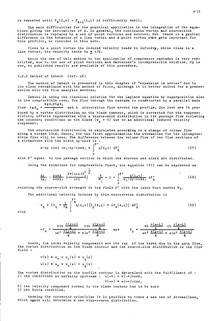
4- 13
The main d i f f i c u l t i e s f o r t h e p r a c t i c a l a p p l i c a t i o n i s t h e i n t e g r a t i o n o f t h e equa- t i o n s g i v i n g t h e d e r i v a t i v e s o f @ , I n g e n e r a l , t h e c o n t i n u o u s v o r t e x a n d s o u r c e - s i n k d i s t r i b u t i o n i s r e p l a c e d b y a s e t o f p o i n t v o r t i c e s a n d s o u r c e s . But t h e r e i s a g e n e r a l d i f f e r e n c e i n t h e b e h a v i o r o f a l i n e v o r t e x a n d a p o i n t v o r t e x which g e t s i m p o r t a n t f o r t h i n p r o f i l e s ; we c o n s i d e r i n t h i s n o t e .
C l o s e t o a p o i n t v o r t e x t h e i n d u c e d v e l o c i t y t e n d s t o i n f i n i t y , w h i l e c l o s e t o a l i n e v o r t e x , t h e v e l o c i t y t e n d s t o 2 y f 2 .
Hence t h e u s e o f t h i s m e t h o d t o t h e a p p l i c a t i o n o f c o m p r e s s o r c a s c a d e s i s v e r y res - t r i c t e d , d u e t o t h e u s e o f p o i n t v o r t i c e s a n d M a r t e n s e n ' s i n c o m p r e s s i b l e s o l u t i o n . Up t o now, n o p u b l i s h e d r e s u l t s a r e a v a i l a b l e o f t h i s p r o c e d u r e ,
4.2.2 N e t h o d o f Imbach ( r e f . 16)
The method o f Imbach i s p r e s e n t e d i n t h i s c h a p t e r o f " e x p a n s i o n i n s e r i e s " d u e t o i t s c l o s e r e s e m b l a n c e w i t h t h e method o f P r i c e , a l t h o u g h i t i s b e t t e r s u i t e d f o r a p r e s e n - t a t i o n w i t h t h e f l u x a n a l y s i s m e t h o d s ,
Imbach i s u s i n g t h e c l a s s i c a l s o l u t i o n f o r t h e L a p l a c e e q u a t i o n b y s u p e r p o s i t i o n a l s o i n t h e c o m p r e s s i b l e c a s e . The f l o w t h r o u g h t h e c a s c a d e i s c o n s t r u c t e d b y a p a r a l l e l main
a n d a c i r c u l a t i o n f l o w a r o u n d t h e p r o f i l e . The l a s t o n e i s p r o - f l o w t g B m = d u c e d b y a v o r t e x d i s t r i b u t i o n on t h e b l a d e c o n t o u r , w h i c h i s c o r r e c t e d f o r t h e compres- s i b i l i t y e f f e c t s r e p r e s e n t e d w i t h a s o u r c e - s i n k d i s t r i b u t i o n i n t h e p a s s a g e f l o w v i o l a t i n g t h e b o u n d a r y c o n d i t i o n s on t h e b l a d e (w = 0 ) d u e t o a n a d d i t i o n a l i n d u c e d v e l o c i t y component .
t g B l + t g 6 2 2
n
The s o u r c e - s i n k d i s t r i b u t i o n i s c a l c u l a t e d a c c o r d i n g t o a c h a n g e o f vo lume f l o w a l o n g a s t ream l i n e . Hence , f o r t h e f i r s t a p p r o x i m a t i o n t h e s t r e a m l i n e f o r t h e i n c o m p r e s - s i b l e f l o w w i l l b e u s e d . The d i f f e r e n c e b e t w e e n t h e volume f l o w o f two f l o w s e c t i o n s o f a s t r e a m t u b e w i t h t h e w i d t h A y - c o s 6 i s :
F ' w*Ay COS6 - w ~ ~ A y * c o s B 1 = I q ( C . 0 ) dF' ( 4 7 )
9 0
w i t h F ' e q u a l t o t h e p a s s a g e s e c t i o n i n w h i c h t h e s o u r c e s a n d s i n k s a r e d i s t r i b u t e d .
U s i n g t h e r e l a t i o n s f o r c o m p r e s s i b l e f l o w s , t h e e q u a t i o n ( 4 7 ) c a n b e e x p r e s s e d as
I 0
r e l a t i n g t h e s o u r c e - s i n k s t r e n g t h i n t h e f i e l d F ' w i t h t h e i n l e t Elach number Kl. +
The a d d i t i o n a l v e l o c i t y i n d u c e d b y t h i s s o u r c e - s i n k d i s t r i b u t i o n i s F'
w i t h 0
Hence , t h e l o c a l v e l o c i t y c o m p o n e n t s a r e t h e sum o f t h e t h e v o r t e x d i s t r i b u t i o n on t h e b l a d e c o n t o u r a n d t h e s o u r c e - s f i e l d :
v ( z ) = vm + v ( z ) + v ( z )
u ( z ) = U- + U ( z ) + U ( 2 )
Y 9
Y 9
t e r m s d u e t o t h e nk d i s t r i b u t i o n
main f l o w , n t h e f l o w
The v o r t e x d i s t r i b u t i o n on t h e p r o f i l e c o n t o u r i s d e t e r m i n e d w i t h t h e f u l f i l l m e n t o f : 1) t h e c o n d i t i o n s a t i n f i n i t y u p s t r e a m : U ( - - ) = w(-- )cosB1
v ( - - ) = w ( - - ) s i n g ,
2 ) t h e v e l o c i t y component n o r m a l t o t h e b l a d e c o n t o u r h a s t o b e z e r o 3 ) t h e K u t t a c o n d i t i o n .
Knowing t h e c o r r e c t e d v e l o c i t i e s i t i s p o s s i b l e t o t r a c e a new s e t o f s t r e a m l i n e s , w h i c h a g a i n w i l l d e t e r m i n e a new s i n k - s o u r c e d i s t r i b u t i o n .
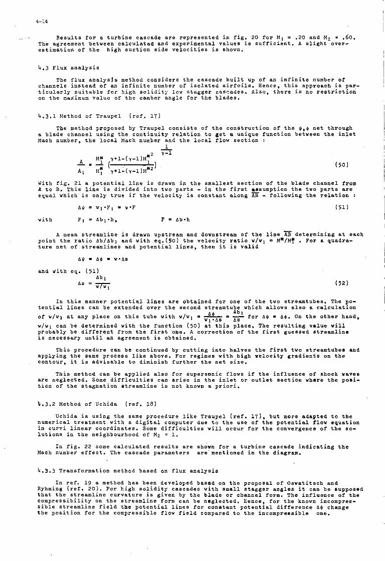
I 4- 14
_- R e s u l t s f o r a t u r b i n e c a s c a d e a r e r e p r e s e n t e d i n f i g . 20 f o r M 1 = .20 and M 2 = .60. The ag reemen t be tween c a l c u l a t e d and e x p e r i m e n t a l v a l u e s i s s u f f i c i e n t . A s l i g h t o v e r - e s t i m a t i o n o f t h e h i g h s u c t i o n s i d e v e l o c i t i e s i s shown.
I
4.3 F l u x a n a l y s i s
The f l u x a n a l y s i s method c o n s i d e r s t h e c a s c a d e b u i l t up o f an i n f i n i t e number o f c h a n n e l s i n s t e a d o f an i n f i n i t e number o f i s o l a t e d a i r f o i l s . Hence, t h i s a p p r o a c h i s pay- t i c u l a r l y s u i t a b l e f o r h i g h s o l i d i t ; . low s t a g g e r c a s c a d e s . A l s o , t h e r e i s no r e s t r i c t i o n on t h e maximum v a l u e of t h e camber a n g l e f o r t h e b l a d e s .
4.3.1 Method of T r a u p e l ( r e f . 17)
The method p roposed by T r a u p e l c o n s i s t s of t h e c o n s t r u c t i o n o f t h e $,$ n e t t h r o u g h a b l a d e c h a n n e l u s i n g t h e c o n t i n u i t y r e l a t i o n t o g e t a u n i q u e f u n c t i o n be tween t h e i n l e t Mach number, t h e l o c a l Mach number and t h e l o c a l f l o w s e c t i o n :
1 -
W i t h f i g . 2 1 a p o t e n t i a l l i n e i s drawn i n t h e smallest s e c t i o n of t h e b l a d e c h a n n e l from A t o B. T h i s l i n e i s d i v i d e d i n t o two p a r t s - i n t h e f i rs t =sumption t h e two p a r t s are e q u a l which i s o n l y t r u e i f t h e v e l o c i t y i s c o n s t a n t a l o n g AB - f o l l o w i n g t h e r e l a t i o n :
A$ = w l * F l = w * F (51)
w i t h F1 3 Abl*h , F = Ab-h
A mean s t r e a m l i n e i s drawn u p s t r e a m and downstream o f t h e l i n e AB d e t e r m i n i n g a t e a c h p o i n t t h e r a t i o Ab/Abl and w i t h eq . (5O) t h e v e l o c i t y r a t i o w / w l - M"/My . For a quadra - t u r e n e t o f s t r e a m l i n e s and p o t e n t i a l l i n e s , t h e n it i s v a l i d
A$ = A$ = w * A s
and w i t h eq . (51)
I n t h i s manner p o t e n t i a l l i n e s a r e o b t a i n e d f o r one o f t h e two s t r e a m t u b e s . The po- t e n t i a l l i n e s can be e x t e n d e d o v e r t h e second s t r e a m t u b e which a l l o w s a l s o a c a l c u l a t i o n o f w / w l a t any p l a c e on t h i s t u b e w i t h w / w l = A = - f o r A$ = A$. On t h e o t h e r hand ,
w / w l c an b e d e t e r m i n e d w i t h t h e f u n c t i o n (50) a t t h i s p l a c e . The r e s u l t i n g v a l u e w i l l p r o b a b l y b e d i f f e r e n t from t h e f i r s t one . A c o r r e c t i o n o f t h e f i r s t g u e s s e d s t r e a m l i n e i s n e c e s s a r y u n t i l an ag reemen t i s o b t a i n e d .
Ab 1 W l * A S AS
T h i s p r o c e d u r e can be c o n t i n u e d by c u t t i n g i n t o h a l v e s t h e f i r s t two s t r e a m t u b e s and a p p l y i n g t h e same p r o c e s s l i k e above . Fo r r e g i m e s w i t h h i g h v e l o c i t y g r a d i e n t s on t h e c o n t o u r , it i s a d v i s a b l e t o d i m i n i s h f u r t h e r t h e n e t s i z e .
T h i s method can be a p p l i e d a l s o f o r s u p e r s o n i c f l o w s i f t h e i n f l u e n c e o f shock waves a r e n e g l e c t e d . Some d i f f i c u l t i e s can a r i s e i n t h e i n l e t o r o u t l e t s e c t i o n where t h e p o s i - t i o n o f t h e s t a g n a t i o n s t r e a m l i n e is, n o t known a p r i o r i .
4.3.2 Method o f Uchida ( r e f , 18)
Uchida i s u s i n g t h e same p r o c e d u r e l i k e T r a u p e l ( r e f . 171, b u t more a d a p t e d t o t h e n u m e r i c a l t r e a t m e n t w i t h a d i g i t a l computer due t o t h e u s e o f t h e p o t e n t i a l flow e q u a t i o n i n c u r v i l i n e a r c o o r d i n a t e s . Some d i f f i c u l t i e s w i l l o c c u r f o r t h e c o n v e r g e n c e of t h e so- l u t i o n s i n t h e ne ighbourhood o f M2 = 1.
I n f i g . 22 some c a l c u l a t e d r e s u l t s a r e shown f o r a t u r b i n e c a s c a d e i n d i c a t i n g t h e Mach number e f f e c t . The c a s c a d e p a r a m e t e r s a r e men t ioned i n t h e d iagram.
4.3.3 T r a n s f o r m a t i o n method b a s e d on f l u x a n a l y s i s
I n r e f . 19 a method h a s been d e v e l o p e d b a s e d on t h e p r o p o s a l o f O s w a t i t s c h a n d Ryhming ( r e f . 2 0 ) . Fo r h i g h s o l i d i t y c a s c a d e s w i t h s m a l l s t a g g e r a n g l e s i t can b e s u p p o s e d t h a t t h e s t r e a m l i n e c u r v a t u r e i s g i v e n by t h e b l a d e o r c h a n n e l form. The i n f l u e n c e o f t h e c o m p r e s s i b i l i t y on t h e s t r e a m l i n e form can b e n e g l e c t e d , Hence, f o r t h e known incompres- s i b l e s t r e a m l i n e f i e l d t h e p o t e n t i a l l i n e s f o r c o n s t a n t p o t e n t i a l d i f f e r e n c e A$ change t h e p o s i t i o n f o r t h e c o m p r e s s i b l e f l o w f i e l d compared t o t h e i n c o m p r e s s i b l e one.
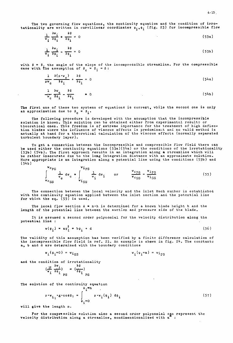
4- 15
The t w o g o v e r n i n g f l o w e q u a t i o n s , t h e c o n t i n u i t y e q u a t i o n a n d t h e c o n d i t i o n o f i r r o - t a t i o n a l i t y a r e w r i t t e n i n c u r v i l i n e a r c o o r d i n a t e s ( f i g . 2 3 ) f o r i n c o m p r e s s i b l e f l o w
w i t h 6 = 8 . t h e a n g l e o f t h e s l o p e o f t h e i n c o m p r e s s i b l e s t r e a m l i n e . F o r t h e c o m p r e s s i b l e c a s e w i t h t h e a s s u m p t i o n o f B C = B i = B :
The f i r s t o n e o f t h e s e t w o s y s t e m s o f e q u a t i o n s i s c o r r e c t , w h i l e t h e s e c o n d one i s o n l y a n a p p r o x i m a t i o n d u e t o 6 = si.
The f o l l o w i n g p r o c e d u r e i s d e v e l o p e d w i t h t h e a s s u m p t i o n t h a t t h e i n c o m p r e s s i b l e s o l u t i o n i s known, T h i s s o l u t i o n c a n b e o b t a i n e d e i t h e r f r o m e x p e r i m e n t c l r e s u l t s o r t h e o r e t i c a l o n e s . T h i s f r e e d o m i s o f e x t r e m e i m p o r t a n c e f o r t h e t r e a t n e n t o f h i g h d e f l e c - t i o n b l a d e s w h e r e t h e i n f l u e n c e of v i s c o u s e f f e c t s i s p r e d o m i n a x t a n d n o v a l i d method i s a c t u a l l y a t h a n d f o r a t h e o r e t i c a l c a l c u l a t i o n o f t h e v i s c o u s e f f e c t s ( n o r m a l l y s e p a r a t e d t u r b u l e n t b o u n d a r y l a y e r ) .
To g e t a c o n n e c t i o n b e t w e e n t h e i n c o m p r e s s i b l e a n d c o m p r e s s i b l e f l o w f i e l d t h e r e c a n b e u s e d e i t h e r t h e c o n t i n u i t y e q u a t i o n s ( 5 3 a ) ( 5 4 a ) o r t h e c o n d i t i o n s o f t h e i r r o t a t i o n a l i t y ( 5 3 b ) ( 5 4 b ) . The f i r s t a p p r o a c h r e s u l t s i n a n i n t e g r a t i o n a l o n g a s t r e a m l i n e w h i c h w i l l b e r a t h e r i n a c c u r a t e d u e t o t h e long i n t e g r a t i o n d i s t a n c e w i t h a n a p p r o x i m a t e s o l u t i o n . More a p p r o p r i a t e i s a n i n t e g r a t i o n a l o n g a p o t e n t i a l l i n e u s i n g t h e c o n d i t i o n s ( 5 3 b ) a n d ( 54b
The c o n n e c t i o n b e t w e e n t h e l o c a l v e l o c i t y a n d t h e i n l e t Mach number i s e s t a b l i s h e d w i t h t h e c o n t i n u i t y e q u a t i o n a p p l i e d b e t w e e n t h e i n l e t s e c t i o n a n d t h e p o t e n t i a l l i n e f o r w h i c h t h e eq. ( 5 5 ) i s u s e d .
The l o c a l f l o w s e c t i o n A = n * h i s d e t e r m i n e d f o r a known b l a d e h e i g h t h a n d t h e l e n g t h o f t h e p o t e n t i a l l i n e b e t w e e n t h e s u c t i o n a n d p r e s s u r e s i d e o f t h e b l a d e ,
It i s a s s u m e d a s e c o n d o r d e r p o l y n o m i a l f o r t h e v e l o c i t y d i s t r i b u t i o n a l o n g t h e p o t e n t i a l l i n e :
( 5 6 ) 2
w ( e i ) = a $ i + b $ i + d
The v a l i d i t y o f t h i s a s s u m p t i o n h a s b e e n v e r i f i e d by a f i n i t e d i f f e r e n c e c a l c u l a t i o n o f t h e i n c o m p r e s s i b l e f l o w f i e l d i n r e f . 21 . An e x a m p l e i s shown i n f i g . 24. The c o n s t a n t s a , b a n d d a r e d e t e r m i n e d w i t h t h e b o u n d a r y c o n d i t i o n s
a n d t h e c o n d i t i o n o f i r r o t a t i o n a l i t y
The s o l u t i o n o f t h e c o n t i n u i t y e q u a t i o n Qi=n
p * w i ( Q i ) dJli I p a w * ~ * c o s B ~ = i l
Q j = O
w i l l g i v e t h e l e n g t h n .
( 5 7 )
F o r t h e c o m p r e s s i b l e s o l u t i o n a l s o a s e c o n d o r d e r p o l y n o m i a l c p r e p r e s e n t t h e v e l o c i t y d i s t r i b u t i o n a l o n g a s t r e a m l i n e , n o n d i m e n s i o n a l i z e d w i t h a :
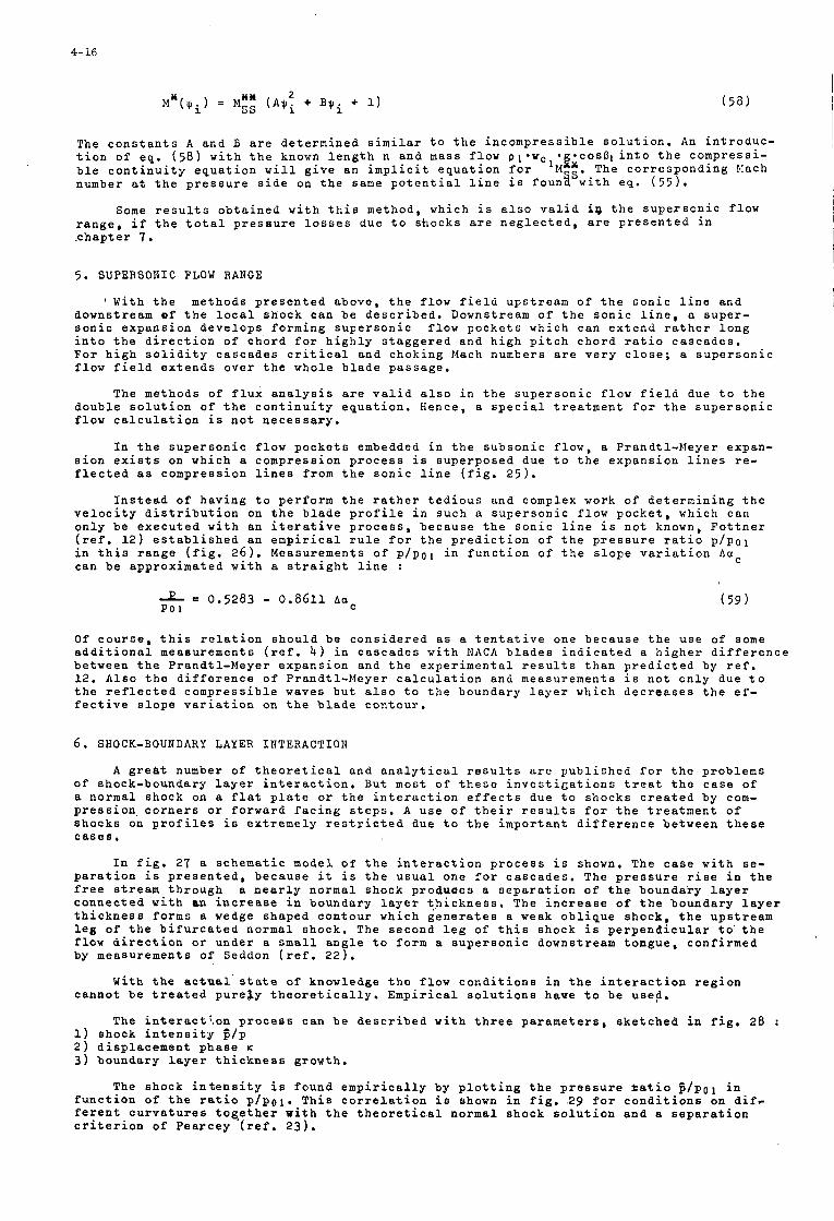
4- 16
( 5 8 )
The c o n s t a n t s A a n d B a r e d e t e r m i n e d s imi l a r t o t h e i n c o m p r e s s i b l e s o l u t i o n , An i n t r o d u c - t i o n o f e q . b l e c o n t i n u i t y e q u a t i o n w i l l g i v e a n i m p l i c i t e q u a t i o n f o r number a t t h e p r e s s u r e s i d e on t h e same p o t e n t i a l l i n e i s foun8.Swith e q . ( 5 5 ) .
( 5 8 ) w i t h t h e known l e n g t h n a n d mass f l o w p l * w c * g * c o s 6 l i n t o t h e c o m p r e s s i - 'MXx . The c o r r e s p o n d i n g Mach
Some r e s u l t s o b t a i n e d w i t h t h i s m e t h o d , w h i c h i s a l s o v a l i d i p t h e s u p e r s o n i c f l o w r a n g e , i f t h e t o t a l p r e s s u r e l o s s e s d u e t o s k o c k s a r e n e g l e c t e d , a r e p r e s e n t e d i n . c h a p t e r 7 .
5 . SUPERSONIC FLOW RANGE
' With t h e m e t h o d s p r e s e n t e d a b o v e , t h e f l o w f i e l d u p s t r e a m o f t h e s o n i c l i n e a n d d o w n s t r e a m o f t h e l o c a l s h o c k c a n b e d e s c r i b e d . Downstream o f t h e s o n i c l i n e , a s u p e r - s o n i c e x p a n s i o n d e v e l o p s f o r m i n g s u p e r s o n i c f l o w p o c k e t s w h i c h c a n e x t e n d r a t h e r l o n g i n t o t h e d i r e c t i o n o f c h o r d f o r h i g h l y s t a g g e r e d a n d h i g h p i t c h c h o r d r a t i o c a s c a d e s . F o r h i g h s o l i d i t y c a s c a d e s c r i t i c a l a n d c h o k i n g Mach numbers a r e v e r y c l o s e ; a s u p e r s o n i c f l o w f i e l d e x t e n d s o v e r t h e w h o l e b l a d e p a s s a g e .
The m e t h o d s o f f l u x a n a l y s i s a r e v a l i d a l s o i n t h e s u p e r s o n i c f l o w f i e l d due t o t h e d o u b l e s o l u t i o n o f t h e c o n t i n u i t y e q u a t i o n . Hence , a s p e c i a l t r e a t m e n t f o r t h e s u p e r s o n i c f l o w c a l c u l a t i o n i s n o t n e c e s s a r y ,
I n t h e s u p e r s o n i c f l o w p o c k e t s embedded i n t h e s u b s o n i c f l o w , a P r a n d t l - M e y e r e x p a n - s i o n e x i s t s on w h i c h a c o m p r e s s i o n p r o c e s s i s s u p e r p o s e d d u e t o t h e e x p a n s i o n l i n e s re- f l e c t e d as c o m p r e s s i o n l i n e s f r o m t h e s o n i c l i n e ( f i g . 2 5 ) .
I n s t e a d o f h a v i n g t o p e r f o r m t h e r a t h e r t e d i o u s a n d complex work o f d e t e r m i n i n g t h e v e l o c i t y d i s t r i b u t i o n on t h e b l a d e p r o f i l e i n s u c h a s u p e r s o n i c f l o w p o c k e t , w h i c h c a n o n l y b e e x e c u t e d w i t h a n i t e r a t i v e p r o c e s s , b e c a u s e t h e s o n i c l i n e i s n o t known, F o t t n e r ( r e f . 1 2 ) e s t a b l i s h e d a n e m p i r i c a l r u l e f o r t h e p r e d i c t i o n of t h e p r e s s u r e r a t i o p / p o l i n t h i s r a n g e ( f i g . 2 6 ) . M e a s u r e m e n t s o f p / p o l i n f u n c t i o n o f t h e s l o p e v a r i a t i o n Aac c a n b e a p p r o x i m a t e d w i t h a s t r a i g h t l i n e :
2 =' 0 . 5 2 8 3 - 0 , 8 6 1 1 Aac ( 5 9 ) PO 1
O f c o u r s e , t h i s r e l a t i o n s h o u l d b e c o n s i d e r e d as a t e n t a t i v e o n e b e c a u s e t h e u s e o f some a d d i t i o n a l m e a s u r e m e n t s ( r e f . 4 ) i n c a s c a d e s w i t h N A C A b l a d e s i n d i c a t e d a h i g h e r d i f f e r e n c e b e t w e e n t h e P r a n d t l - M e y e r e x p a n s i o n a n d t h e e x p e r i m e n t a l r e s u l t s t h a n p r e d i c t e d by r e f . 1 2 . A l s o t h e d i f f e r e n c e o f P r a n d t l - M e y e r c a l c u l a t i o n a n d m e a s u r e m e n t s i s n o t o n l y d u e t o t h e r e f l e c t e d c o m p r e s s i b l e waves b u t a l s o t o t h e b o u n d a r y l a y e r w h i c h d e c r e a s e s t h e e f - f e c t i v e s l o p e v a r i a t i o n on t h e b l a d e c o n t o u r .
6. SHOCK-BOUNDARY LAYER I N T E R A C T I O N
A g r e a t number o f t h e o r e t i c a l a n d a n a l y t i c a l r e s u l t s a r e p u b l i s h e d f o r t h e p r o b l e m s o f s h o c k - b o u n d a r y l a y e r i n t e r a c t i o n . B u t m o s t o f t h e s e i n v e s t i g a t i o n s t r e a t t h e c a s e o f a n o r m a l s h o c k on a f l a t p l a t e or t h e i n t e r a c t i o n e f f e c t s d u e t o s h o c k s c r e a t e d b y com- p r e s s i o n c o r n e r s o r f o r w a r d f a c i n g s t e p s . A u s e o f t h e i r r e s u l t s f o r t h e t r e a t m e n t o f s h o c k s on p r o f i l e s i s e x t r e m e l y r e s t r i c t e d d u e t o t h e i m p o r t a n t d i f f e r e n c e b e t w e e n t h e s e c a s e s .
I n f i g . 27 a s c h e m a t i c m o d e l o f t h e i n t e r a c t i o n p r o c e s s i s shown, The c a s e w i t h se- p a r a t i o n i s p r e s e n t e d , b e c a u s e i t i s t h e u s u a l o n e f o r c a s c a d e s . The p r e s s u r e r i s e i n t h e f r e e stream t h r o u g h a n e a r l y n o r m a l s h o c k p r o d u a e s a s e p a r a t i o n o f t h e b o u n d a r y l a y e r c o n n e c t e d w i t h an i n c r e a s e i n b o u n d a r y l a y e r t h i c k n e s s . The i n c r e a s e o f t h e b o u n d a r y l a y e r t h i c k n e s s f o r m s a wedge s h a p e d c o n t o u r w h i c h g e n e r a t e s a weak o b l i q u e s h o c k , t h e u p s t r e a m l e g o f t h e b i f u r c a t e d n o r m a l s h o c k . The s e c o n d l e g o f t h i s s h o c k i s p e r p e n d i c u l a r t o ' t h e f l o w d i r e c t i o n or u n d e r a s m a l l a n g l e t o f o r m a s u p e r s o n i c d o w n s t r e a m t o n g u e , c o n f i r m e d by m e a s u r e m e n t s o f Seddon ( r e f . 2 2 ) .
Wi th t h e a c t u a l ' s t a t e o f k n o w l e d g e t h e f l o w c o n d i t i o n s i n t h e i n t e r a c t i o n r e g i o n c a n n o t b e t r e a t e d p u r e l y t h e o r e t i c a l l y . E m p i r i c a l s o l u t i o n s h a v e t o b e u s e a .
1) s h o c k i n t e n s i t y c / p 2 ) d i s p l a c e m e n t p h a s e K
3 ) b o u n d a r y l a y e r t h i c k n e s s g r o w t h .
The i n t e r a c t t o n p r o c e s s c a n b e d e s c r i b e d w i t h t h r e e p a r a m e t e r s , s k e t c h e d i n f i g , 28 :
The s h o c k i n t e n s i t y i s f o u n d e m p i r i c a l l y by p l o t t i n g t h e p r e s s u r e b a t i o z / p 0 1 i n f u n c t i o n o f t h e r a t i o p / p 0 1 . T h i s c o r r e l a t i o n i s shown i n f i g . 29 f o r c o n d i t i o n s on d i f - f e r e n t c u r v a t u r e s t o g , e t h e r w i t h t h e t h e o r e t i c a l n o r m a l s h o c k s o l u t i o n a n d a s e p a r a t i o n c r i t e r i o n o f P e a r c e y ( r e f . 2 3 ) .
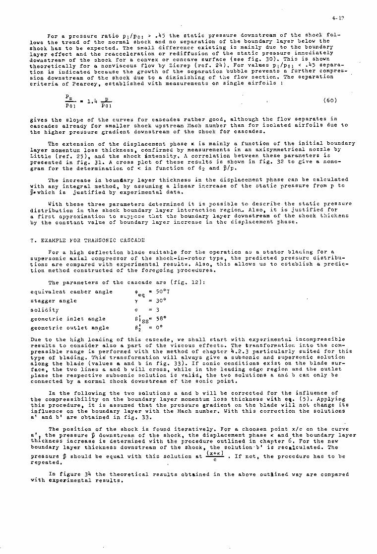
4- 17
F o r a p r e s s u r e r a t i o p l / p o l > . 4 5 t h e s t a t i c p r e s s u r e d o w n s t r e a m o f t h e s h o c k f o l - l o w s t h e t r e n d o f t h e n o r m a l s h o c k a n d n o s e p a r a t i o n o f t h e b o u n d a r y l a y e r b e l o w t h e s h o c k h a s t o b e e x p e c t e d . The s m a l l d i f f e r e n c e e x i s t i n g i s m a i n l y d u e t o t h e b o u n d a r y l a y e r e f f e c t a n d t h e r e a c c e l e r a t i o n o r r e d i f f u s i o n o f t h e s t a t i c p r e s s u r e i m m e d i a t e l y d o w n s t r e a m o f t h e s h o c k f o r a c o n v e x o r c o n c a v e s u r f a c e ( s e e f i g . 3 0 ) . T h i s i s shown t h e o r e t i c a l l y f o r a n o n v i s c o u s f l o w b y Z i e r e p ( r e f . 2 4 ) . F o r v a l u e s p 1 / p 0 1 < .45 s e p a r a - t i o n i s i n d i c a t e d b e c a u s e t h e g r o w t h o f t h e s e p a r a t i o n b u b b l e p r e v e n t s a f u r t h e r compres- s i o n d o w n s t r e a m o f t h e s h o c k d u e t o a d i m i n i s h i n g o f t h e f l o w s e c t i o n . The s e p a r a t i o n c r i t e r i a of P e a r c e y , e s t a b l i s h e d w i t h m e a s u r e m e n t s on s i n g l e a i r f o i l s :
g i v e s t h e s l o p e of t h e c u r v e s f o r c a s c a d e s r a t h e r g o o d , a l t h o u g h t h e f l o w s e p a r a t e s i n c a s c a d e s a l r e a d y f o r smal le r s h o c k u p s t r e a m E!ach number t h a n f o r i s o l a t e d a i r f o i l s d u e t o t h e h i g h e r p r e s s u r e g r a d i e n t d o w n s t r e a m o f t h e s h o c k f o r c a s c a d e s .
The e x t e n s i o n o f t h e d i s p l a c e m e n t p h a s e K i s m a i n l y a f u n c t i o n o f t h e i n i t i a l b o u n d a r y l a y e r momentum loss t h i c k n e s s , c o n f i r m e d b y m e a s u r e m e n t s i n a n a x i s y m m e t r i c a l n o z z l e b y L i t t l e ( r e f . 2 5 ) . a n d t h e s h o c k i n t e n s i t y . A c o r r e l a t i o n b e t w e e n t h e s e p a r a m e t e r s i s p r e s e n t e d i n f i g . 31. A c r o s s p l o t o f t h e s e r e s u l t s i s shown i n f i g . 32 t o G i v e a nomo- gram f o r t h e d e t e r m i n a t i o n o f K i n f u n c t i o n o f 6 2 a n d c / p .
The i n c r e a s e i n b o u n d a r y l a y e r t h i c k n e s s i n t h e d i s p l a c e m e n t p h a s e c a n b e c a l c u l a t e d r i t h a n y i n t e g r a l m e t h o d , b y a s s u m i n g a l i n e a r i n c r e a s e o f t h e s t a t i c p r e s s u r e f r o m p t o p e w h i c h i s j u s t i f i e d b y e x p e r i m e n t a l d a t a .
W i t h t h e s e t h r e e p a r a m e t e r s d e t e r m i n e d i t i s p o s s i b l e t o d e s c r i b e t h e s t a t i c p r e s s u r e d i s t r i b u t i o n i n t h e s h o c k b o u n d a r y l a y e r i n t e r a c t i o n r e g i o n , A l s o , i t i s j u s t i f i e d f o r a f i r s t a p p r o x i m a t i o n t o s u p ~ i o s e t h a t t h e b o u n d a r y l a y e r d o w n s t r e a m o f t h e s h o c k t h i c k e n s by t h e c o n s t a n t v a l u e o f b o u n d a r y l a y e r i n c r e a s e i n t h e d i s p l a c e m e n t p h a s e .
7 . EXAMPLE F O R TRAIlSONIC CASCADE
F o r a h i g h d e f l e c t i o n b l a d e s u i t a b l e f o r t h e o p e r a t i o n as a s t a t o r b l a d i n g f o r a s u p e r s o n i c a x i a l c o m p r e s s o r of t h e s h o c k - i n - r o t o r t y p e , t h e p r e d i c t e d p r e s s u r e d i s t r i b u - t i o n s a r e c o m p a r e d w i t h e x p e r i m e n t a l r e s u l t s . A l s o , t h i s a l l o w s u s t o e s t a b l i s h a p r e d i c - t i o n method c o n s t r u c t e d o f t h e f o r e g o i n g p r o c e d u r e s .
The p a r a m e t e r s o f t h e c a s c a d e a r e ( f i g . 12):
= 50'7 ' e s
e q u i v a l e n t camber a n g l e
s t a g g e r a n g l e y = 30'
s o l i d i t y U = 3
g e o m e t r i c i n l e t a n g l e 4:ss' 5 8 O g e o m e t r i c o u t l e t a n g l e B; = o o
Due t o t h e h i g h l o a d i n g o f t h i s c a s c a d e , we s h a l l s t a r t w i t h e x p e r i m e n t a l i n c o m p r e s s i b l e r e s u l t s t o c o n s i d e r a l s o a p a r t o f t h e v i s c o u s e f f e c t s . The t r a n s f o r m a t i o n i n t o t h e com- p r e s s i b l e r a n g e i s p e r f o r m e d w i t h t h e method o f c h a p t e r 4 .2 .3 p a r t i c u l a r l y s u i t e d f o r t h i s t y p e of b l a d i n g . This ' t r a n s f o r m a t i o n w i l l a l w a y s g i v e a s u b s o n i c a n d s u p e r s o n i c s o l u t i o n a l o n g t h e b l a d e ( v a l u e s a a n d b i n f i g . 33 ) . I f s o n i c c o n d i t i o n s e x i s t on t h e b l a d e s u r - f a c e , t h e t w o l i n e s a a n d b w i l l c r o s s , w h i l e i n t h e l e a d i n g e d g e r e g i o n a n d t h e o u t l e t p l a n e t h e r e s p e c t i v e s u b s o n i c s o l u t i o n i s v a l i d , t h e two s o l u t i o n s a a n a b c a n o n l y b e c o n n e c t e d by a n o r m a l s h o c k d o w n s t r e a m o f t h e s o n i c p o i n t .
I n t h e f o l l o w i n g t h e t w o s o l u t i o n s a a n d b w i l l b e c o r r e c t e d f o r t h e i n f l u e n c e o f t h e c o m p r e s s i b i l i t y on t h e b o u n d a r y l a y e r momentum loss t h i c k n e s s w i t h e a . ( 5 ) . A p p l y i n g t h i s p r o c e d u r e , it i s assumed t h a t t h e p r e s s u r e g r a d i e n t on t h e b l a d e w i l l n o t c h a n g e i t s i n f l u e n c e on t h e b o u n d a r y l a y e r w i t h t h e Mach number. Wi th t h i s c o r r e c t i o n t h e s o l u t i o n s a ' a n d b ' a re o b t a i n e d i n f i g . 33 .
The p o s i t i o n o f t h e s h o c k i s f o u n d i t e r a t i v e l y . F o r a c h o o s e n p o i n t x / c on t h e c u r v e a ' ) t h e p r e s s u r e $ d o w n s t r e a m o f t h e s h o c k , t h e d i s p l a c e m e n t p h a s e K a n d t h e b o u n d a r y l a y e r t h i c k n e s s i n c r e a s e i s d e t e r m i n e d w i t h t h e p r o c e d u r e o u t l i n e d i n c h a p t e r 6. F o r t h e new b o u n d a r y l a y e r t h i c k n e s s d o w n s t r e a m o f t h e s h o c k , t h e s o 1 u t i o n . b ' i s r e c a l c u l a t e d . The
p r e s s u r e $ s h o u l d b e e q u a l w i t h t h i s s o l u t i o n a t 7 . If n o t , t h e p r o c e d u r e h a s t o b e r e p e a t e d ,
(X+K)
I n f i g u r e 34 t h e t h e o r e t i c a l r e s u l t s o b t a i n e d i n t h e a b o v e o u t l i n e d way a r e c o n p a r e d w i t h e x p e r i m e n t a l r e s u l t s .
4- 18
I
I
8. COBCLUSIONS
T h i s n o t e h a s p r e s e n t e d , i n a n i n t r o d u c t o r y way, some a s p e c t s o f c o m p r e s s o r c a s c a d e s w o r k i n g i n t h e t r a n s o n i c f l o w r a n g e .
The d i s c u s s i o n o f t h e p e r f o r m a n c e b e h a v i o r o f a c a s c a d e w i t h i n c r e a s i n g i n l e t I,:rrch number h a s shown t h e d e c r e a s e o f o p e r a t i o n r a n e e . Hence , a n e x a c t i n v e r s e o r d i r e c t m e t h a a is n e c e s s a r y f o r a s a t i s f a c t o r y d e s i g n .
D i r e c t m e t h o d s a r e , w i t h t h e a c t u a l k n o w l e d g e , n o t a v a i l a b l e f o r c o m p r e s s i b l e f l o w s i n c o m p r e s s o r c a s c a d e s . F o r t h e i n d i r e c t p r o c e d u r e s , i . e . , t h e p r e d i c t i o n o f t h e p r e s s u r e d i s t r i b u t i o n f o r a g i v e n b l a d i n g , t h e r e a r e two p r i n c i p a l Groups o f m e t h o d s a v a i l a b l e f o r t h e p o t e n t i a l f l o w c a l c u l a t i o n , s u p e r s o n i c as w c l l as s u b s o n i c . The f i r s t o n e c a n b e ap- p l i e d t o h i g h p i t c h - c h o r d r a t i o , h i g h s t a e g e r c a s c a d e s w i t h t h i n s m a l l c a m b e r e d b l a d e s , t y p i c a l f o r t h e t i p s e c t i o n o f a r o t o r . The m e t h o d s o f t h e s e c o n d g r o u p a r e v a l i d f o r h i g h s o l i d i t y , low s t a g g e r a n g l e c a s c a d e s . The t y p e o f b l a d i n C i s n o r m a l l y n o t r e s t r i c t e d . A method f o r a n i n t e r m e d i a t e t y p e o f c a s c a d e i s s t i l l m i s s i n g .
F o r s h o c k b o u n d a r y l a y e r i n t e r a c t i o n r e g i o n s a n a p p r o a c h f o r a n e m p i r i c a l s o l u t i o n h a s b e e n p r e s e n t e d , a l t h o u g h t h i s o n e h a s t o b e c o n s i d e r c d as a t e n t a t i v e o n e . Some f u r t h e r i n v e s t i g a t i o n i s n e c e s s a r y t o c o m p l e t e l y u n d e r s t a n d t h e i n t e r a c t i o n o f a n e a r l y n o r m a l s h o c k w i t h a t u r b u l e n t b o u n d a r y l a y e r .
9 . LIST OF REFERENCES
1. SCHOLZ, t i , : Aerodynamik d e r S c h a u f e l g i t t e r , Band I. V e r l a g G . B r a u n , K a r l s r u h e , 1 9 6 5 .
2 . ROTTA, J . C . : I n t r o d u c t i o n t o t u r b u l e n t b o u n d a r y l a y e r c a l c u l a t i o n s . VKI L e c t u r e S e r i e s 5 , 1969.
3. K O N D O , l i . , MIEJOTA, M . , Y A M A Z A K I , N . , PURUKAWA, N . : High s p e e d t e s t s c f c o m p r e s s o r c a s c a d e s w i t h d o u b l e c i r c u l a r arc b lude s e c t i o n s . N a t i o n a l A e r o s p a c e Lab . , TR 1 5 2 , 1968.
4 . VAN DEB BRAEMBUSSCUE, €7.: T h e o r e t i c a l a n d e x p e r i m e n t a l s t u d y o f c h o k i n g i n c a s c a d c s i n t h e Mach number r a n 6 e .6 t o 1 . 2 . V K I PR 69-250, 1969.
5 . HONSARRAT, N.T. & KEEBAN, 14.J.: E x p e r i m e n t a l e v a l u a t i o n o f t r a n s o n i c s t a t o r s ; p r e - l i m i n a r y a n a l y s i s a n d d e s i g n r e p o r t . NASA CR 54620, 1 9 6 7 .
6 . C H A U V I H , J . & BREUGELMANS, F . : R e s e a r c h on t h e u s e o f b l u n t t r a i l i n c c d g e b l a d e s i n s u p e r s o n i c c o m p r e s s o r s t a g e s . S c i e n t i f i c R e p o r t N o 1, G r a n t AF E O A R 65-65, V K I , 1 9 6 5 .
7 . BHEUCELMANS, F. & SIEVERDING, C. : C a s c a d e d a t a f o r h i g h c a n b e r b l u n t t r a i l i n g e d g e b l a d e s . V K I IN 17, 1966.
8. CIIESTIITT, D. : I l o i s e r e d u c t i o n b y means o f i n l e t g u i d e v a n e s c h o k i n g i n a x i a l f l o w c o m p r e s s o r s . UASA TN D 4682, J u l y 1968.
9 . SAUER, R . : X i n f c h r u n g i n d i e t h e o r e t i s c h e Gasdynamik , 3. A u f l . a e r l i n , 1960.
10. SHAPIRO, A . B . : The d y n a m i c s a n d t h e r m o d y n a m i c s o f c o m p r e s s i b l e f l u i d f l o w . The R o n a l d P r e s s Company, 1 9 5 4 .
11. SPREITER, J.R. & ALKSNE, A.Y.: T h i n a i r f o i l t h e o r y b a s e d on a p p r o x i m a t e s o l u t i o n o f t h e t r a n s o n i c f l o w e q u a t i o n . NACA R 1 3 5 9 , 1 9 5 8 .
1 2 . FOTTBER, L . : A s e m i - e m p i r i c a l a p p r o a c h o f t h e t r a n s o n i c f l o w p a s t c a s c a d e s i n c l u d i n g s h o c k a n d v i s c o u s e f f e c t s . AGARD CP 34, 1968.
13. PRICE, D . : Two d i m e n s i o n a l c o m p r e s s i b l e f l o w a r o u n d p r o f i l e s i n c a s c a d e , P r o c . S e m i n a r on Adv.Problems i n T u r b o m a c h i n e r y , V K I , !.larch 29-30, 1 9 6 5 , P a r t I.
1 4 . MARTEIJSEN, E. : B e r e c h n u n g d e r D r u c k v e r t e i l u n g a n G i t t e r p r o f i l e n i n e b e n e r P o t e n t i a l - s t r i imung n i t e i n e r F r e d h o l m s c h e n I n t e g r a l g l e i c h u n g . Arc. Rat .Mech.Anal . , 3, 1959, p p 235-270.
1 5 . PAL, P. U n t e r s u c h u n g e n Gber d e n I n t e r f e r e n z i n f l u s s b e i S t r h u n g e n d u r c h Tandem-Schau- f e l g i t t e r . I n g e n i e u r - A r c h i v , Bd 3 4 , 1965.
16 . I M B A C H , H.E.: D i e B e r e c h n u n g d e r k o m p r e s s i b l e n , r e i b u n g s f r c i e n U n t e r s c h a l l s t r 6 m u n g d u r c h r z u m l i c h e G i t t e r a u s S c h a u f e l n s u c h g r o s s e r D i c k e und s t a r k e r W6lbung. M i t t . I n s t . f : r t h e o r e t i s c h e T u r b o m a s h c i n e n a n d e r E .T .H . , Z G r i c h , n r 8, 1 9 6 (.
4- 19
17. TRAUPEL, W . : T h e r m i s c h e T u r b o m a s c h i n e n , Bd I. S p r i n g e r V e r l a g 1 9 6 2 .
18. U C H I D A , S.: C a l c u l a t i o n of c o m p r e s s i b l e c a s c a d e f l o w by t h e m e t h o d o f f l u x a n a l y s i s . J . A e r o n . S c . , 1954.
19. GRIEPENTROG, H . : P r E d i c t i o n s d e s p e r f o r m a n c e s d e s g r i l l e s d ’ a u b e s t r a n s s o n i q u e s & h a u t e d e f l e x i o n e t f a i b l e a l l o n g e m e n t . Ph.D. T h e s i s , Univ . L i $ g e - V K I , 1969 ; V K I TN 5 9 , 1969.
20. OSWATITSCH, K. & R Y H M I N G , I . : f iber d e n Kompressibilitgteinfluss b e i e b e n e n S c h a u f e l - g i t t e r n s t a r k e r Umlenkung. D V L B e r i c h t 2 8 , 1 9 5 7 .
21. ROTTIERS, H . : O p t i m i z a t i o n o f b l u n t t r a i l i n g e d g e b l a d e s a t low s p e e d ( p o t e n t i a l f l o w c a l c u l a t i o n ) . V K I PR 69-237, 1969.
22. SEDDON, J . : The f l o w p r o d u c e d by i n t e r a c t i o n o f a t u r b u l e n t b o u n d a r y l a y e r w i t h a n o r m a l s h o c k wave o f s t r e n g t h s u f f i c i e n t t o c a u s e s e p a r a t i o n . A R C R & 1.1 3 5 0 2 , 1 9 6 0 .
23 . PEARCEY, Ii.11.: Sone e f f e c t s ’ o f s h o c k i n d u c e d s e p a r a t i o n o f t u r b u l e n t b o u n d a r y l a y e r s i n t r a n s o n i c f l o w p a s t a e r o f o i l s . A R C R & M 3 1 0 8 , 1 3 5 9 .
24 . ZIEREP, J . : Der s e n k r e c h t e V e r d i c h t u n g s s t o s s a m gekrzmmten P r o f i l . D V L B e r i c h t 51, 1963.
25. LITTLE, B.H., J r : L f f e c t s o f i n i t i a l t u r b u l e n t b o u n d a r y l a y e r on s h o c k i n d u c e d s e p a r a t i o n i n t r a n s o n i c f l o w . V K I TN 39, 1967.
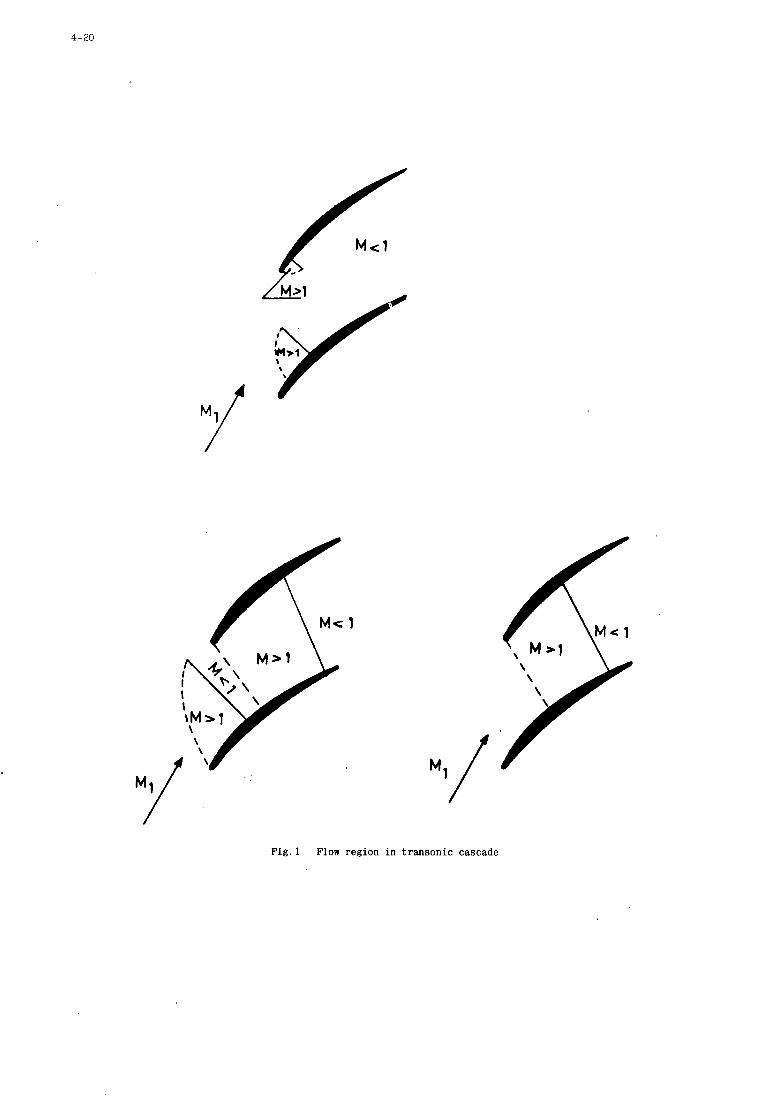
4- 20
f Y
F i g . 1 Flow region in t ransonic cascade
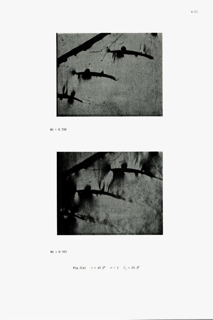
M I = 0.161
Fig.a(a) y = 4 7 . 4 U = 1 6, = 5 7 . 9
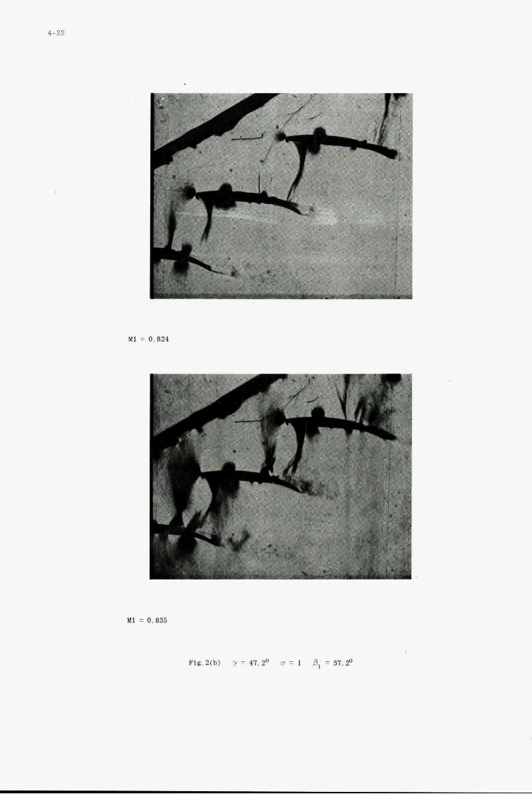
4-22
7 -
M1 = 0.824
MI = 0.835
Fig. 2(b) y = 47. Z0 cr = 1 ,8, = 5 1 . 9
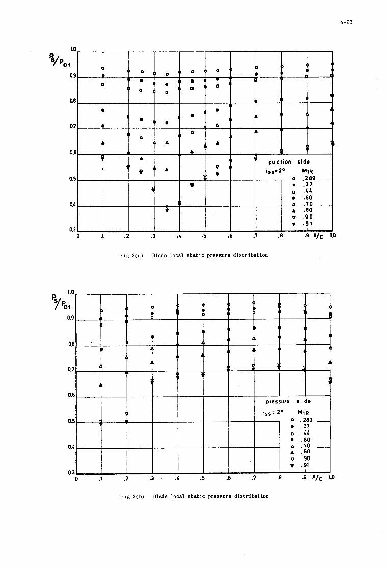
1.0
a5
0.3
Fig. 3(a) Blade local s t a t i c pressure d is tr ibut ion
0.9
0.7
0.t
4-23
Fig .3(b) Blade loca l s t a t i c pressure d is tr ibut ion
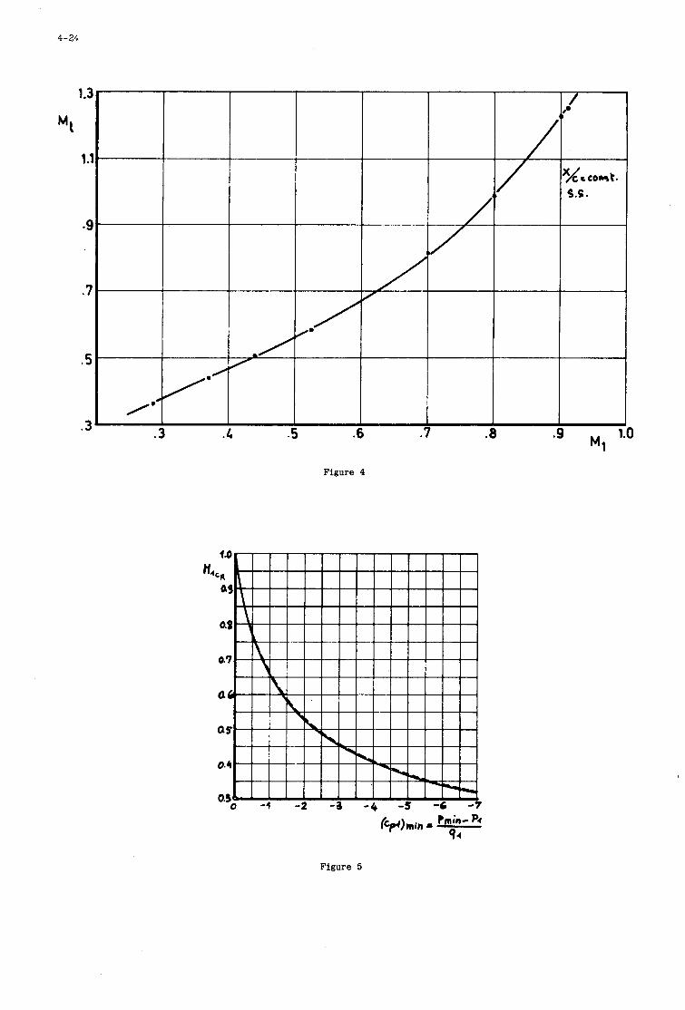
4-24
Figure 4
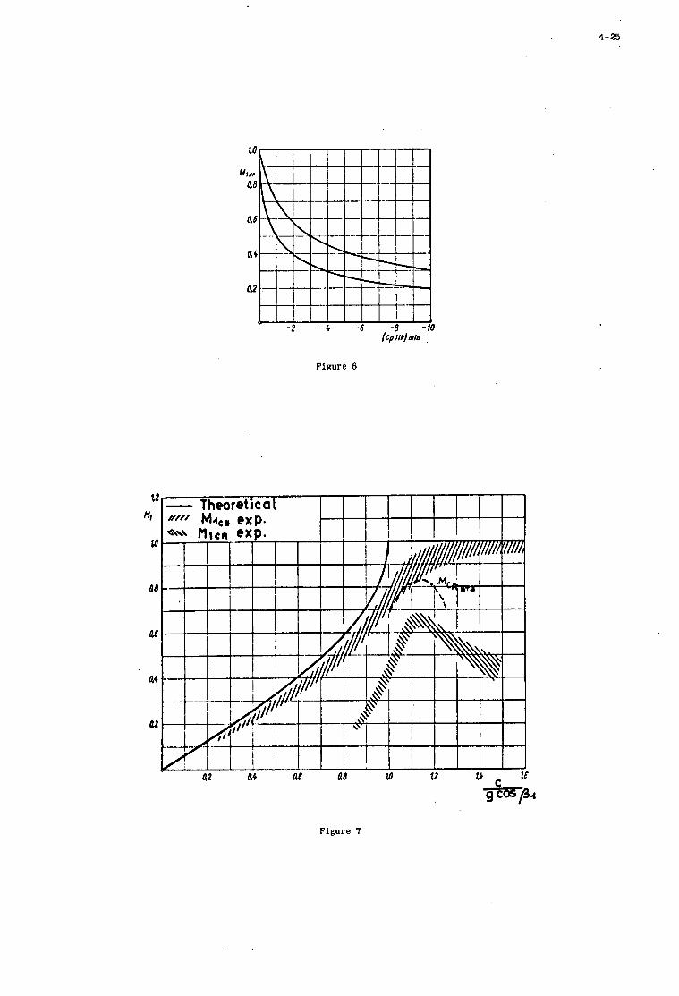
4-25 ,
-2 -4 -6 -E -10 fCp 1ih)min
Figure 6
Figure I
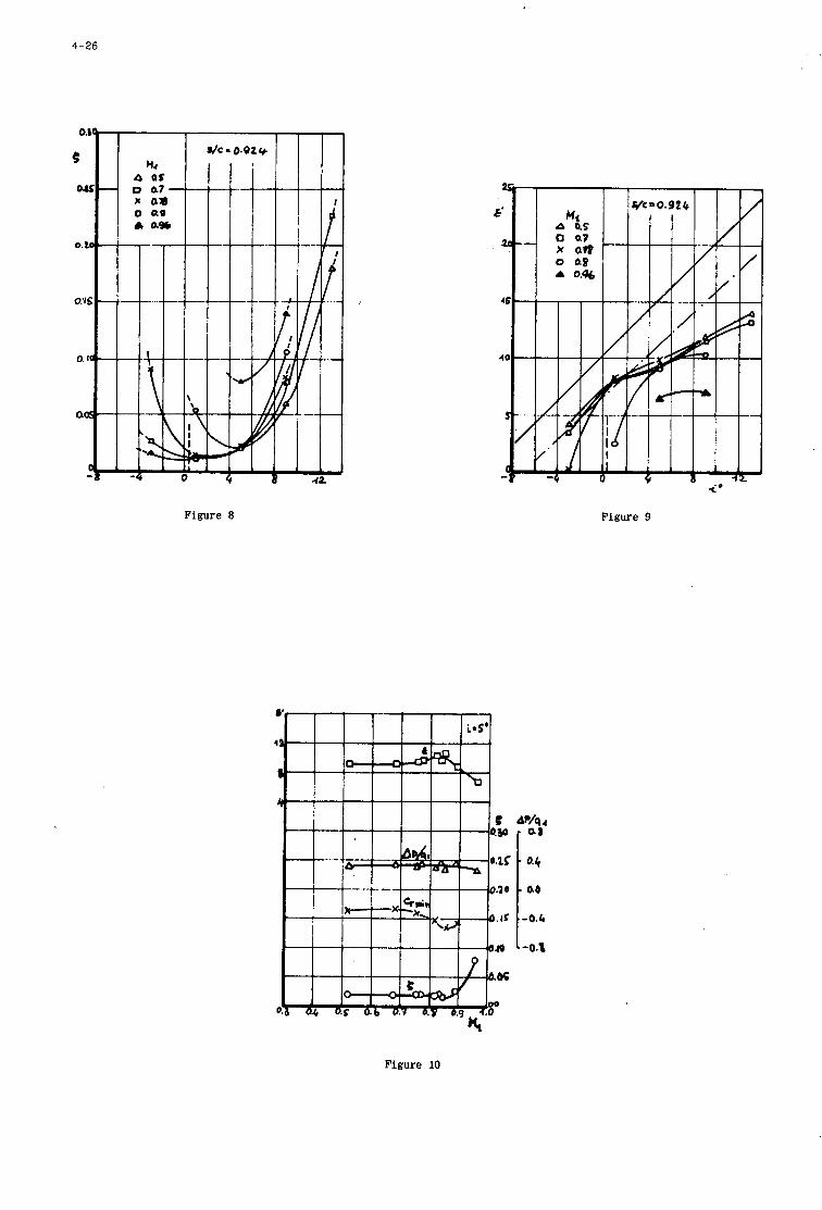
4-26
0.BL
e Or2 -
0. to -
O.'lS -
0.10 -
OQ -
42
Figure 8 Figure 9
0.4
ao
-0.4
-0.3
- 4
Figure 10
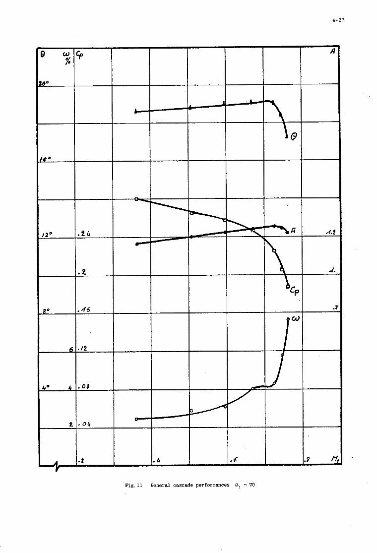
4- 27
Fig.ll General cascade performances CI, = 70
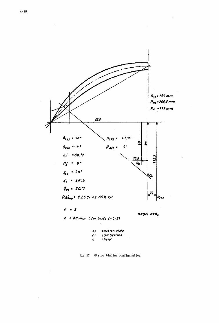
\
Y Y 9b l-
3c
74 4
d = 3
C = 60 mrn ( tor te& i n C-2) ffODEL 8TS.
ss suction side C L comberline t chord
Fig. 12 Stator blading configuration
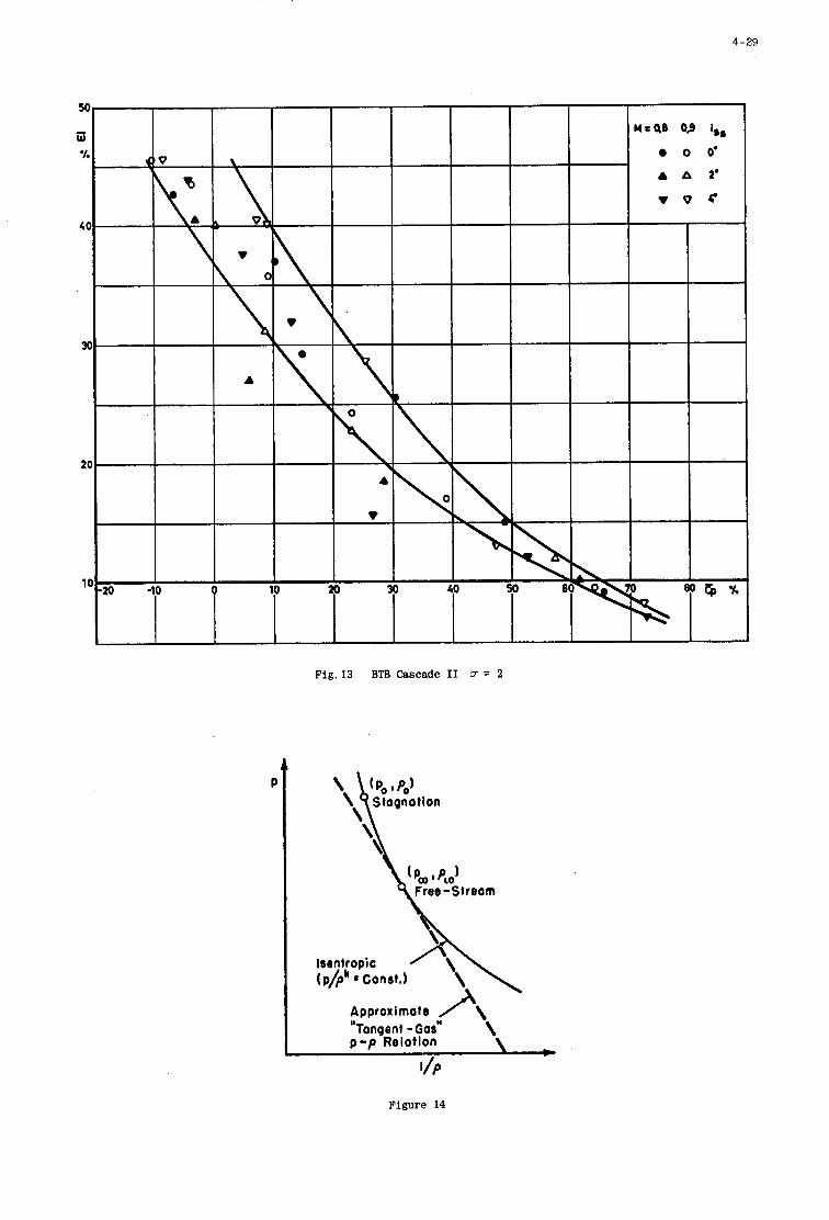
4-29
.VP
Figure 14
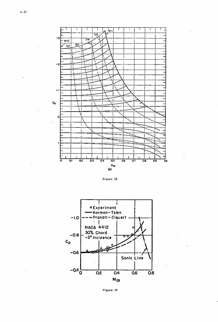
4-30
-1.0
-0.8
CP
4 6
I 4 4
Figure 15
I i OExperiment
-Korrnon-Tsien ---Prondt I - Glauert
Sonic Line
o.e 0.4 0.6 0 Moo
Figure 16
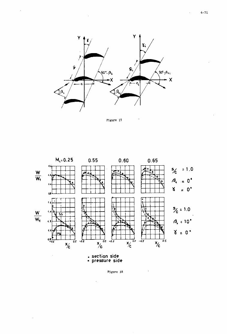
4-31
I
Figure 17
M,= 0.2 5 0.55 0.60 0.65
W wt _. 4 . 1
4 .O
1.6
q.4
4 . a
1.0
QS at -0.5 CIS
X -0.5
I C x/c o.s
-0. s -Q 5 0.5
section side Q pressure side
= 1.0
, = o b = 0'
yc : 1.0
: 10'
\I t o b
Figure 18
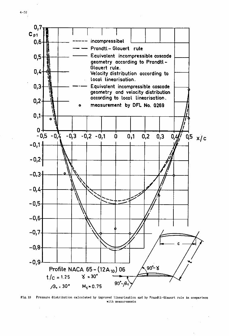
4-32
I ----- incompressibel ~
-- Prandtl- Glauert ru le E cui va lent in com p re s si ble ca scade geometry according t o Prandt l - Glauert rule. Ve loci t y d is t r i b u t i on o cc o r d in g t o local l inearisation.
-.- Equivalent incompressible cascade geometry and velocity distribution according t o local l inearisation. measurement by DFL No. 0269
f
o
- 4 3 -0,2 -0,l 0 0,1 0,2 0,3
Profile NACA 65- (12Alo) 06
Fig.19 Pressure d i s t r i b u t i o n ca l cu la t ed by improved l i n e a r i s a t i o n and by Prandtl-Glauert r u l e i n comparison with measurements
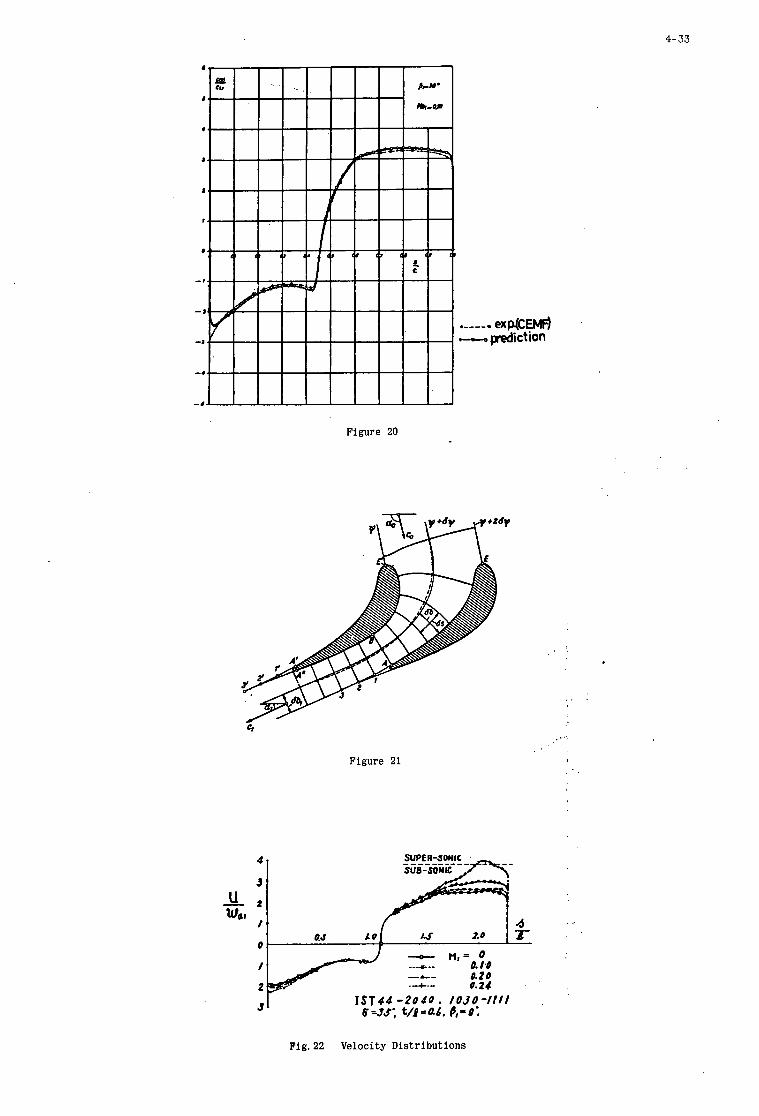
4-33
Figure 20
Figure 21
. 4.
Fig. 22 Velocity Distributions
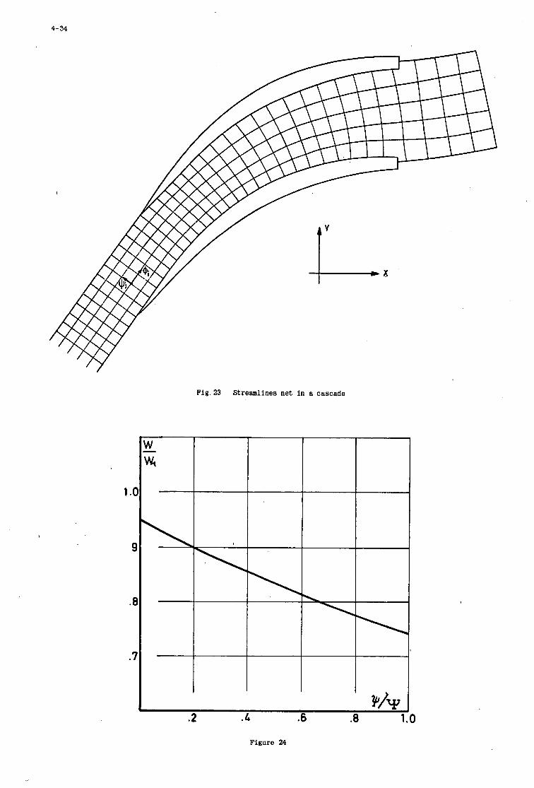
4-34
1 .a
, 9
.a
.7
Fig. 23 Streamlines net in a cascade
Figure 24
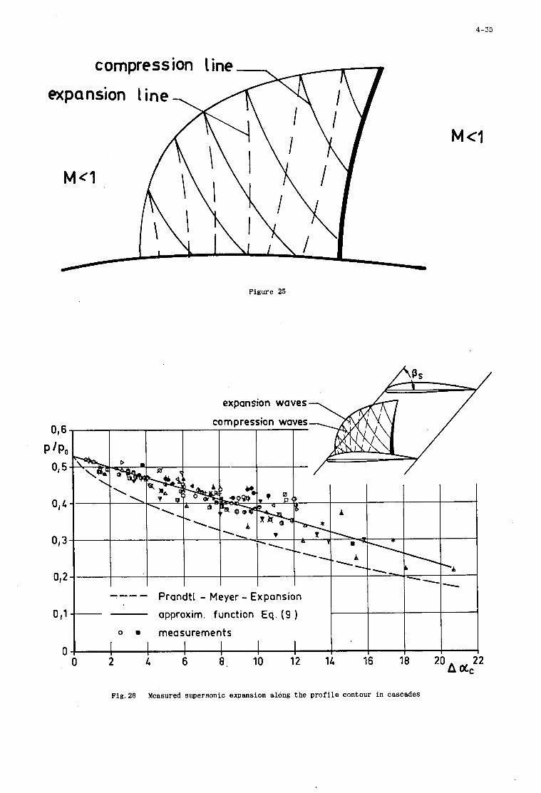
4-35
Figure 25
expansion waves
016
015
P /Po
approxim. function Eq. (9 )
0 A 0 2 6 10 12 14 16 18 20
Fig.26 Measured supersonic expansion along the p r o f i l e contour in cascades
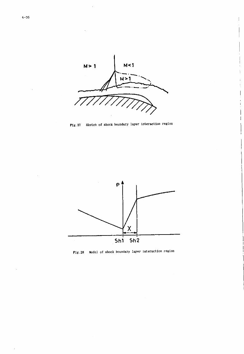
4-36
Fig.27 Sketch of shock boundary layer interaction region
Shl Sh2
Fig.28 Model of shock boundary layer interaction region
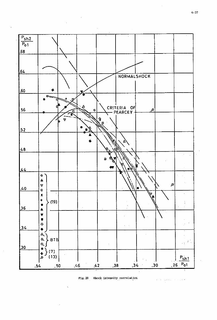
P 37
Fig. 29 Shock intensity correlation
4- 3a
Figure 30(a)
Figure 30(b)
.76
.7 2
10 20 30 40 50 60 70 _ -
62 shl
Fig. 31 Shock in tens i ty versus displacement phase
4 39
18 16 1L 12 10 8 6 4 2 .1 .2 .3 .4 .5 .6 .7 x(mm) 62shl
Fig .32 Displacement phase c o r r e l a t i o n
P -
o we
(I
Fig. 33 Sketch for: t h e a p p l i c a t i o n of t h e p r e d i c t i o n method
4- 40
1.( P -
PO
( ..
.i
.6
.5
.4
.3 .9 s 1.0
C - .1 .2 .3 .4 .5 -6 .7 .8
Fig.34(a) Comparison between calculated and measured velocity distribution
1.( P -
PO
C ..
.I
.i
.€
.5
.4
.3 .9 s
C - .1 .2 .3 .4 .s .6 .7 .8
Fig.34(b) Comparison between calculated and measured velocity distribution
5
S E C O N D A R Y F L O W L O S S E S
I N A X I A L C O M P R E S S O R S
H . GRIEPENTROG t
Gutehoffnungshctte Sterkrade A . G .
I
formerly P r o j e c t Engineer , von Karman I n s t i t u t e , Rhode S a i n t Gensse, Belgium
5
S U M M A R Y
The i m p o r t a n c e o f s e c o n d a r y f l o w s and l o s s e s i n h i g h l y l o a d e d compresso r i s s t r e s s e d . Tde v a r i o u s t y p e s o f p o s s i b l e s e c o n d a r y f l o w s a r e d e s c r i b e d , and t h e t h r e e most u s u a l mode l s , r e p r e s e n t i n g t h o s e f l o w s a r e p r e s e n t e d , t o g e t h e r w i t h t h e i r l i m i t a t i o n s . The s o u r c e s o f t h e l o s s e s i n d u c e d by t h e s e c o n d a r y f l o w s a r e t h e n i d e n t i f i e d , w i t h t h e r e l e v a n t c a s c a d e p a r a m e t e r s , and t h e c l a s s i c a l s e m i - e m p i r i c a l f o r m u l a o f l o s s e v a l u a t i o n (Howel l , Vavra , E h r i c h and Detra , e t c . ) a r e p r e s e n t e d . Comparing t h e p r e d i c t i o n s made w i t h t h o s e f o r m u l a s w i t h a c t u a l da t a on h i g h l y l o a d e d compresso r b l a d i n g , i t can b e con- c l u d e d t h a t t h e y f a i l i n p r e d i c t i n g c o r r e c t l y t h e l o s s e s f o r h i g h camber a n d / o r low a s p e c t r a t i o b l a d i n g s . A new model f o r s e c o n d a r y f l o w i s i n t r o d u c e d , b a s e d on boundary l a y e r g rowth on t h e hub o r c a s i n g and a ho r se - shoe v o r t e x m o d e l ( a s s u g g e s t e d by C a r t e r and Cohen) and a f o r m u l a i s d e r i v e d , which a p p e a r s t o be v a l i d f o r a l a r g e r r a n g e of b l a d i n g c o n f i g u r a t i o n . E f f e c t s o f s e c o n d a r y f l o w on o u t l e t f l o w d i r e c t i o n a r e t h e n t r e a t e d , F i n a l l y , t h e methods a v a i l a b l e t o r e d u c e s e c o n d a r y f l o w l o s s e s a r e d i s c u s s e d and t h e n t h e r a n g e o f a p p l i c a t i o n i s d e f i n e d .
LIST OF SYMBOLS
5
aspect ratio chord lift coefficient drag coefficient blade height blade height of replacement blade pressure dynamic pressure pitch Cartesian co,ordinate system velocity components relative flow angle boundary layer thickness total pressure loes coefficient density solidity camber angle vorticity components
Subscripts stagnation point conditions induced meridional secondary flow effect up 8 t ream downstream
5
LIST OF FIGURES
1 2
3 4 5 6 7 0 9 10
11 12
13 14
15
Radial total pressure loss distribution Secondary flow elements
Inviscid model Viscous model Titanium dioxyde traces in compressor cascades
Corner vortex Horse-shoe vortex Spanwise total pressure loss Cascade model system
Ws/Wt = f ( e - f ) Comparison of empirical formulae for secondary flow drag coefficient in a cascade Comparison of measured and predicted secondary flow Comparison of measured and predicted spanwise outlet flow angle distribution
Measured spanwise outlet flow angle distribution for a highly loaded compressor cascade Influence of meridional contraction
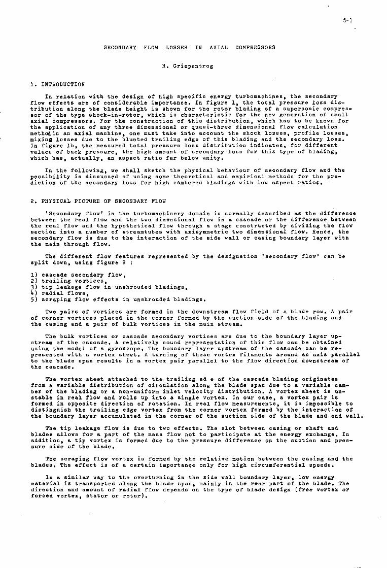
5- 1
SECONDARY FLOW LOSSES I N A X I A L COMPRESSORS
H . G r i e p e n t r o g
1. I N T R O D U C T I O N
I n r e l a t i o n w i t h t h e d e s i g n o f h i g h s p e c i f i c e n e r g y t u r b o m a c h i n e s , t h e s e c o n d a r y f l o w e f f e c t s are o f c o n s i d e r a b l e i m p o r t a n c e . I n f i g u r e 1, t h e t o t a l p r e s s u r e loss d i s - t r i b u t i o n a l o n g t h e b l a d e h e i g h t i s shown f o r t h e r o t o r b l a d i n g o f a s u p e r s o n i c compres- s o r o f t h e t y p e s h o c k - i n - r o t o r , which i s c h a r a c t e r i s t i c f o r t h e new g e n e r a t i o n o f s m a l l a x i a l compresso r s . For t h e c o n s t r u c t i o n o f t h i s d i s t r i b u t i o n , which h a s t o b e known f o r t h e a p p l i c a t i o n o f any t h r e e d i m e n s i o n a l o r q u a s i - t h r e e d i m e n s i o n a l f l o w c a l c u l a t i o n methodin an a x i a l machine , one must t a k e i n t o accoun t t h e shock l o s s e s , p r o f i l e l o s s e s , mix ing l o s s e s due t o t h e b l u n t e d t r a i l i n g edge o f t h i s b l a d i n g and t h e secondary loss. In f i g u r e l b , t h e measured t o t a l p r e s s u r e loss d i s t r i b u t i o n i n d i c a t e s , f o r d i f f e r e n t v a l u e s o f back p r e s s u r e , t h e h i g h amount o f s e c o n d a r y loss f o r t h i s t y p e o f b l a d i n g , which h a s , a c t u a l l y , an a s p e c t r a t i o f a r below u n i t y .
I n t h e f o l l o w i n g , w e s h a l l s k e t c h t h e p h y s i c a l b e h a v i o u r of s e c o n d a r y f l o w and t h e p o s s i b i l i t y i s d i s c u s s e d o f u s i n g some t h e o r e t i c a l and e m p i r i c a l methods f o r t h e p r e - d i c t i o n o f t h e s e c o n d a r y loss f o r h i g h cambered b l a d i n g s w i t h low a s p e c t r a t i o s .
2. PHYSICAL PICTURE OF SECONDARY FLOW
'Secondary f low ' i n t h e tu rbomach ine ry domain i s n o r m a l l y d e s c r i b e d as t h e d i f f e r e n c e be tween t h e r e a l f l o w and t h e two d i m e n s i o n a l f l o w i n a c a s c a d e o r t h e d i f f e r e n c e be tween t h e r e a l f l o w and t h e h y p o t h e t i c a l f l o w t h r o u g h a s t a g e c o n s t r u c t e d by d i v i d i n g t h e f l o w s e c t i o n i n t o a number o f s t r e a m t u b e s w i t h ax isymrnet r ic two d i m e n s i o n a l flow. Hence, t h e s e c o n d a r y f l o w i s due t o t h e i n t e r a c t i o n o f t h e s i d e w a l l o r c a s i n g boundary l a y e r w i t h t h e main t h r o u g h f low.
The d i f f e r e n t f l o w f e a t u r e s r e p r e s e n t e d by t h e d e s i g n a t i o n ' s e c o n d a r y f l o w ' can b e s p l i t down, u s i n g f i g u r e 2 :
1) c a s c a d e s e c o n d a r y f l o w , 2 ) t r a i l i n g v o r t i c e s , 3 ) t i p l e a k a g e flow i n unshrouded b l a d i n g s , 4 ) r a d i a l f l o w s , 5 ) s c r a p i n g flow e f f e c t s i n unsh rouded b l a d i n g s .
Two p a i r s o f v o r t i c e s are formed i n t h e downstream f l o w f i e l d o f a b l a d e row. A p a i r o f c o r n e r v o r t i c e s p l a c e d i n t h e c o r n e r formed by t h e s u c t i o n s i d e o f t h e b l a d i n g and t h e c a s i n g and a p a i r o f b u l k v o r t i c e s i n t h e main s t r e a m .
The b u l k v o r t i c e s o r c a s c a d e secondary v o r t i c e s a r e due t o t h e boundary l a y e r up- stream o f t h e c a s c a d e . A r e l a t i v e l y sound r e p r e s e n t a t i o n o f t h i s f l o w can b e o b t a i n e d u s i n g t h e model o f a gyroscope . The boundary l a y e r ups t r eam o f t h e c a s c a d e can b e r e - p r e s e n t e d w i t h a v o r t e x s h e e t . A t u r n i n g of t h e s e v o r t e x f i l a m e n t s a round an a x i s p a r a l l e l t o t h e b l a d e span r e s u l t s i n a v o r t e x p a i r p a r a l l e l t o t h e f l o w d i r e c t i o n downstream o f t h e c a s c a d e .
The v o r t e x s h e e t a t t a c h e d t o t h e t r a i l i n g e d e o f t h e c a s c a d e b l a d i n g o r i g i n a t e s from a v a r i a b l e d i s t r i b u t i o n o f c i r c u l a t i o n a l o n g t h e b l a d e span due t o a v a r i a b l e cam- b e r of t h e b l a d i n g o r a non-uniform i n l e t v e l o c i t y d i s t r i b u t i o n . A v o r t e x s h e e t i s un- s t a b l e i n r e a l f l o w and r o l l s up i n t o a s i n g l e v o r t e x . I n o u r c a s e , a v o r t e x p a i r i s formed i n o p p o s i t e d i r e c t i o n of r o t a t i o n . I n r e a l f l o w measurements , i t i s i m p o s s i b l e t o d i s t i n g u i s h t h e t r a i l i n g edge v o r t e x from t h e c o r n e r v o r t e x formed by t h e i n t e r a c t i o n of. t h e boundary l a y e r accumula t ed i n t h e c o r n e r o f t h e s u c t i o n s i d e of t h e b l a d e and end w a l l ,
The t i p l e a k a g e f l o w i s due t o two e f f e c t s . The s l o t be tween c a s i n g o r s h a f t and b l a d e s a l l o w s f o r a p a r t o f t h e mass f l o w n o t t o p a r t i c i p a t e a t t h e e n e r g y exchange . In a d d i t i o n , a t i p v o r t e x i s formed due t o t h e p r e s s u r e d i f f e r e n c e on t h e s u c t i o n and p r e s - s u r e s i d e o f t h e b l a d e .
The s c r a p i n g f l o w v o r t e x i s formed by t h e r e l a t i v e mot ion be tween t h e c a s i n g and t h e blades. Ths e f f e c t i s o f a c e r t a i n impor t ance o n l y f o r h i g h c i r c u m f e r e n t i a l s p e e d s .
In a s imilar way t o t h e o v e r t u r n i n g i n t h e s i d e w a l l boundary l a y e r , low e n e r g y m a t e r i a l i s t r a n s p o r t e d a l o n g t h e b l a d e span , ma in ly i n t h e rear p a r t o f t h e b l a d e . The d i r e c t i o n and ,amount o f r a d i a l f l o w depends on t h e t y p e o f b l a d e d e s i g n ( f r ee v o r t e x o r f o r c e d v o r t e x , s t a t o r o r r o t o r ) .
5- 2
Secondary f l o w models
The complex mechanism o f s e c o n d a r y f l o w s i s n o t c o m p l e t e l y u n d e r s t o o d up t o now, b e c a u s e it i s p r i n c i p a l l y a t h r e e d i m e n s i o n a l boundary l a y e r problem. T h i s boundary l a y e r s e p a r a t e s and r c l l s up i n t o a v o r t e x , a problem which canno t b e s o l v e d w i t h t h e a c t u a l knowledge.
The r e s e a r c h i n s e c o n d a r y f l o w h a s made c o n s i d e r a b l e p r o g r e s s t h a n k s t o t h e u s e o f two d i f f e r e n t models : t h e i n v i s c i d model and t h e v i s c o u s model, s k e t c h e d i n f i g s . 3 and 4. R e c e n t l y , it h a s been found o u t t h a t t h e s e two models f a i l t o d e s c r i b e t h e s e c o n d a r y f low f o r h i g h l y l o a d e d b l a d i n g s w i t h a low a s p e c t r a t i o . A t h i r d model s h o u l d b e u s e d b a s e d on t h e a n a l o g y w i t h a r e c t a n g u l a r bend ( r e f . 2).
The i n v i s c i d model n e g l e c t s t h e v i s c o u s e f f e c t s i n t h e b l a d e p a s s a g e . Only t h e i n - f l u e n c e o f t h e n o n u n i f o r m i t y o f t h e f l o w ups t r eam o f t h e c a s c a d e i s c o n s i d e r e d on t h e downstream f low. The two c a s c a d e s e c o n d a r y v o r t i c e s , p a r a l l e l t o t h e downstream f l o w d i - r e c t i o n , are formed. An a n a l y t i c a l t r e a t m e n t i s p o s s i b l e as shown by t h e c l a s s i c a l p a p e r s of S q u i r e and Win te r and Hawthorne ( r e f s 1 and 3 ) . S q u i r e and Win te r found a r e l a t i o n be tween t h e v o r t i c i t y downstream o f t h e c a s c a d e , t h e camber a n g l e o f t h e b l a d e and t h e v e l o c i t y g r a d i e n t i n d i r e c t i o n z :
au E, = - 2 6
w i t h t h e a s sumpt ion t h a t t h e v o r t i c i t y i s z e r o i n d i r e c t i o n o f t h e u p s t r e a m f l o w ,
Due t o t h e v e r y r e s t r i c t i v e a s s u m p t i o n s n e c e s s a r y t o a r r i v e a t eq . ( 1 1 , t h e i n v i s c i d model can o n l y b e u s e d f o r t h e d e s c r i p t i o n o f t h e f l o w i n h i g h a s p e c t r a t i o and s m a l l cambered b l a d i n g s . The model c a n n o t be u s e d f o r t h e b l a d i n g n e c e s s a r y f o r small h i g h s p e c i f i c e n e r g y tu rbomach ines .
The v i s c o u s model t a k e s i n t o accoun t t h e v i s c o u s e f f e c t s i n s i d e o f t h e c a s c a d e . The development o f t h e c o r n e r v o r t i c e s ( f i g . 4) which a r e d e t e r m i n e d w i t h t h i s model, can be d e s c r i b e d p h y s i c a l l y u s i n g t h e c o n d i t i o n o f e q u i l i b r i u m be tween t h e c e n t r i f u g a l f o r c e s c r e a t e d by t h e c u r v a t u r e o f t h e s t r e a m l i n e s and t h e s t a t i c p r e s s u r e g r a d i e n t be tween two n e i g h b o u r i n g b l a d e s . The boundary l a y e r f l u i d on t h e end w a l l s h a s t o s u p p o r t t h e same p r e s s u r e g r a d i e n t as t h e main f l o w , b u t t h e k i n e t i c e n e r g y i s s m a l l e r . Hence, t h e boun- d a r y l a y e r m a t e r i a l i s d e f l e c t e d from t h e p r e s s u r e s i d e t o t h e s u c t i o n o f a b l a d e c h a n n e l . I n t h e c o r n e r formed by t h e s u c t i o n s i d e and t h e end w a l l , t h e boundary l a y e r m a t e r i a l accumula t e s and t h e c o r n e r v o r t e x i s formed by t h e i n t e r a c t i o n w i t h t h e main f low. The c r e a t i o n o f t h e c o r n e r v o r t e x c a n be d e s c r i b e d by r e p r e s e n t i n g t h e boundary l a y e r on t h e end w a l l by a v o r t e x s h e e t . The d e f l e c t i o n o f t h i s v o r t e x s h e e t i n t h e c o r n e r be tween end w a l l and b l a d e r e s u l t s i n a s e l f - i n d u c e d r o l l up o f t h e v o r t e x s h e e t ,
T h i s d e s c r i p t i o n i s conf i rmed by t h e f l o w v i s u a l i z a t i o n w i t h t i t a n i u m d i o x y d e p r e -
An a n a l y t i c a l t r e a t m e n t o f t h e f l o w d e s c r i b e d by t h e v i s c o u s model i s n o t p o s s i b l e
s e n t e d i n f i g u r e 5.
i n t h e a c t u a l s t a t e o f knowledge.
3. SECONDARY FLOW LOSS
The c a s c a d e s e c o n d a r y models t r e a t e d i n t h e p r e c e d i n g c h a p t e r can a g i v e a p h y s i c a l d e s c r i p t i o n o f t h e s e c o n d a r y flow, b u t n o t o f t h e s e c o n d a r y l o s s e s i n which t h e t u r b o - machine d e s g i n e r i s i n t e r e s t e d i n . Most p r o b a b l y , t h e f o l l o w i n g f a c t o r s w i l l h ave a c e r t a i n i n f l u e n c e on t h e magni tude o f t h e secondary l o s s :
1) t h e c a s c a d e s e c o n d a r y v o r t i c e s and c o r n e r v o r t i c e s , 2) t h e i n t e r a c t i o n o f t h e c o r n e r v o r t i c e s w i t h t h e main f l o w , 3 ) t h e s e p a r a t i o n on t h e s i d e w a l l .
D e t r a ( r e f . 4 ) h a s shown t h a t t h e ene rgy bounded i n t h e v o r t i c e s can b e n e g l e c t e d i n compar ison t o t h e o t h e r t o t a l p r e s s u r e l o s s e s o c c u r i n g i n t h e b l a d e passage .
L o u i s ( r e f . 5 ) c o u l d show e x p e r i m e n t a l l y t h a t o n l y t h e i n t e r a c t i o n o f t h e c o r n e r v o r t i c e s w i t h t h e main f l o w h a s t o b e c o n s i d e r e d o r t h e d e t e r m i n a t i o n o f t h e t o t a l p r e s - s u r e l o s s . The i n f l u e n c e o f t h e c a s c a d e v o r t e x p a i r can b e n e g l e c t e d .
Hence, it can be assumed t h a t most o f t h e secondary l o s s e s a r e o r i g i n a t i n g o f two f a c t o r s , whose f l u i d mechanics canno t b e d e s c r i b e d t h e o r e t i c a l l y w i t h a c t u a l knowledge. W e a r e f o r c e d t o u s e e m p i r i c a l o r , a t t h e b e s t , s e m i - e m p i r i c a l r e l a t i o n s .
A comprehens ive r6sum6 o f t h e c l a s s i c a l e m p i r i c a l r e l a t i o n s can be found i n re f . 1.
With t h e i n v i s c i d model o f S q u i r e and W i n t e r , we know t h a t t h e v o r t i c i t y downstream o f t h e c a s c a d e i s p r o p o r t i o n a l t o t h e d e f l e c t i o n a n g l e o f t h e c a s c a d e . Hence, t h e t o t a l p r e s s u r e l o s s e s a r e p r o p o r t i o n a l t o e 2 .
A l s o , t h e camber a n g l e o f a b l a d e can b e c o n s i d e r e d as an i n d i c a t i o n o f t h e l o a d i n g o f t h e b l a d i n g and t h e end w a l l s .
5- 3
Using t h i s c o n d i t i o n , Howell ( r e f . 6 ) h a s e s t a b l i s h e d t h e r e l a t i o n f o r t h e induced drag due t o secondary flow :
w i t h measurements of c l a s s i c a l compressor cascades .
Fol lowing Scho lz ( r e f , 7), it can be supposed i n f i r s t approximation t h a t t h e secon- dary l o s s e s a r e a unique f u n c t i o n of t h e b l a d e t u r n i n g . T h a t means, t h e r a t i o of secon- da ry l o s s e s t o t o t a l l o s s e s i n c r e a s e s w i t h a d e c r e a s e of t h e b l a d e h e i g h t . G e n e r a l l y , t h e b l a d e h e i g h t i s n o t used a s c h a r a c t e r i s t i c pa rame te r , bu t t h e r a t i o h / c , t h e a s p e c t r a t i o . T h i s r a t i o a l s o t a k e s i n t o account t h e l e n g t h of t h e flow p a t h on which t h e par- t i c l e s of t h e end w a l l boundary l a y e r a r e t r a v e l l i n g t o form t h e c o r n e r v o r t e x .
Vavra ( r e f . 8 ) g i v e s t h e f o l l o w i n g r e l a t i o n u s i n g t h e i n f l u e n c e of t h e a s p e c t r a t i o and t h e camber a n g l e on t h e secondary d r a g c o e f f i c i e n t :
2 = .04 CL 2 'Di s h ( 3 )
A t h i r d p a r a m e t e r , t h e s o l i d i t y U of t h e cascade , can i n f l u e n c e t h e secondary l o s s e s , a l t h o u g h t h e e x p e r i m e n t a l ev dence of i t s i n f l u e n c e i s c o n t r a d i c t o r y . Ehr i ch and Detra ( r e f . 9 ) a r e u s i n g t h i s pa rame te r i n t h e form : A.R. = Ago * h / s . The f o l l o w i n g r e l a t i o n i s proposed :
R e l a t i o n s ( 3 ) and (4) a r e a l s o e s t a b l i s h e d w i t h e x p e r i m e n t a l r e s u l t s of c l a s s i c a l com- p r e s s o r b l a d e s , i .e . , w i t h a s p e c t r a t i o s h / c > 1 and camber a n g l e s 0 30°.
A t t h e von Karman I n s t i t u t e a method t o p r e d i c t t h e secondary flow loss i n f u n c t i o n o f t h e t u r n i n g a n g l e and a s p e c t r a t i o was developed ( r e f . 10) u s i n g a model t h a t can be p l a c e d between t h e v i s c o u s and t h e i n v i s c i d model. T h i s i n t e r m e d i a t e p o s i t i o n o c c u r s due t o t h e c o n s i d e r a t i o n o f t h e boundary l a y e r t h i c k n e s s b u i l d up i n t h e cascade passage , b u t n o t of t h e i n t e r a c t i o n between t h e end w a l l and t h e s u c t i o n s i d e boundary l a y e r .
The c a l c u l a t i o n of t h e end w a l l boundary l a y e r i s based on t h e assumption t h a t a mean l o a d i n g of t h e p r e s s u r e and s u c t i o n s i d e l o a d i n g a t midspan e x i s t s on t h e end w a l l s , due t o t h e assumption of a c o n s t a n t s t a t i c p r e s s u r e g r a d i e n t ove r t h e span. The boundary l a y e r t h i c k n e s s i s de te rmined a t t h e t r a i l i n g edge, u s i n g t h e d i f f u s i o n f a c t o r r e l a t i o n w i t h B u r i ' s s e p a r a t i o n c r i t e r i o n a s d e t e r m i n a t i o n o f t h e b l a d e l o a d i n g .
t h e c o r n e r v o r t e x h a s been proved amongst o t h e r by measurements o f Senoo ( r e f . 11). He cou ld show t h a t t h e s i z e of t h e v o r t e x and t h e d i s t a n c e between t h e c e n t e r of t h e v o r t e x and t h e endwa l l s r i s e s w i t h t h e boundary l a y e r t h i c k n e s s ( f i g . 6).
The impor t an t i n f l u e n c e of t h e boundary l a y e r t h i c k n e s s on t h e s i z e a n d ' p o s i t i o n o f
Assuming a l i m e a r v a r i a t i o n of t h e v e l o c i t y d i s t r i b u t i o n i n t h e boundary l a y e r a t t h e b l a d e o u t l e t p l a n e , t h e c i r c u l a t i o n a long t h e b l a d e span can be approximated by t h e model of a horse-shoe v o r t e x ( f i g . 7 ) . The d i s t a n c e between t h e two t r a i l i n g v o r t i c e s i s f i x e d i n f u n c t i o n of t h e boundary l a y e r t h i c k n e s s P i t h t h e c o n d i t i o n t h a t t h e l i f t of t h e o r i g i n a l b l a d e and t h e r e p l a c i n g b l a d e u s i n g t h e horse-shoe model, i s t h e . s a m e . The f o l l o w i n g r e l a t i o n i s o b t a i n e d f o r t h e r a t i o of replacement b l a d e h e i g h t m d r e a l b l a d e h e i g h t
I n f i g u r e 8 t h e c a l c u l a t e d v a l u e s o f t h e v o r t e x c e n t e r s a r e compared w i t h t h e measure- ments. A s a t i s f a c t o r y correspondence i s o b t a i n e d .
Using a p r o p o s a l of Carter and Cohen ( r e f . 1 2 ) t h e whole cascade system i s r e p l a c e d by t h e model b lades a s shown i n f i g . 9. The induced d r a g due t o t h e t r a i l i n g edge vor- t i c e s and t h e i r images i s c a l c u l a t e d i n re f . 1 0 w i t h l e s s r e s t r i c t i o n s t h a n i n r e f . 12 .
c = & U 2 1-h ' / h
D i s GEz7 The secondary flow loss c o e f f i c i e n t , . o can be c a l c u l a t e d u s i n g t h e formula
8 ,
With t h e above b r i e f l y o u t l i n e d method, t h e secondary loss h a s been c a l c u l a t e d f o r d i f - f e r e n t ca scades . A s u f f i c i e n t agreement has been o b t a i n e d between c a l c u l a t e d v a l u e s and measured ones.
5-4
I n f i g u r e 1 0 , t h e r a t i o o f s e c o n d a r y l o s s t o t h e t o t a l c g s c a d e loss i s shown i n f u n c t i o n o f t h e main p a r a m e t e r s i n f l u e n c i n g t h e s e c o n d a r y f l o w : 8 and c / h . The s e c o n d a r y l o s s i s c a l c u l a t e d w i t h t h e a b o v e d e s c r i b e d method u s i n g t h e measurements o b t a i n e d a t midspan , o r t a k e n d i r e c t l y f rom measurements i f a s u r e d i s t i n c t i o n be tween p r o f i l e l o s s and s e c o n d a r y l o s s c o u l d b e made. The c u r v e shows f o r small v a l u e s o f 9 ( c / h ) an i n c r e a s e o f t h e s e c o n d a r y l o s s o f p a r a b o l i c t y p e . Fo r h i g h e r v a l u e s o f 8 ( c / h ) , t h i s r a t i o t e n d s t o a p p r o a c h a c o n s t a n t v a l u e . The b l a d e fo rms u s e d i n t h e i n v e s t i g a t i o n s up t o now f o r compresso r b l a d e s were a l l i n t h e r a n g e o f 8 = 30°, c / h 2 . 5 , t h a t means, 8 ( c / h ) 2 .25 rud. Hence, t h e approach t o a c o n s t a n t v a l u e c o u l d n o t b e p r e d i c t e d .
The f o r m u l a e (21, ( 3 ) and ( 4 ) r o u g h l y g i v e t h e same r e s u l t s f o r c l a s s i c a l b l a d e s . I n f i g u r e 11, t h e e q u a t i o n s o f Vavra and D e t r a and E h r i c h a r e compared. Almost i d e n t i c a l r e s u l t s a r e o b t a i n e d f o r t h e two r e l a t i o n s f o r small t o modera t e l o a d i n g s o f t h e b l a d e . A l s o , a t h i g h CL v a l u e s t h e d i f f e r e n c e i s o n l y small be tween t h e r e s u l t s o f t h e two e q u a t i o n s .
, F o r v e r y h i g h l y l o a d e d b l a d e s , t h e s e c l a s s i c a l r e l a t i o n s and t h e V K I method are com- p a r e d w i t h measurements i n f i g . 1 2 , where t h e s e c o n d a r y loss c o e f f i c i e n t i s p l o t t e d i n f u n c t i o n of t h e a s p e c t r a t i o . None o f t h e c l a s s i c a l methods i s a b l e t o p r e d i c t t h e secon- d a r y loss f o r t h i s t y p e o f b l a d i n g s u f f i c i e n t l y e x a c t .
4. OUTLET FLOW ANGLE
The change o f d e f l e c t i o n due t o s e c o n d a r y f l o w s can be approached i n two d i f f e r e n t ways : 1) t h e t r a i l i n g edge v o r t i c e s a r e t a k e n as p r i n c i p a l o r i g i n o f s e c o n d a r y l o s s by i n d u c i n g
2) t h e change o f o u t l e t a n g l e o v e r t h e span i s d e t e r m i n e d due t o t h e i n f l u e n c e o f t h e a d e f l e c t i o n a t t h e l i f t i n g l i n e ;
c a s c a d e s e c o n d a r y f l o w u s i n g t h e s t r e a m f u n c t i o n f o r t h e s e c o n d a r y f l o w i n t h e c a s - cade o u t l e t p l a n e . Normal ly , an u n d e r t u r n i n g a t t h e c e n t e r o f t h e v o r t e x and an ove-- t u r n i n g a t t h e s i d e w a l l i s i n d i c a t e d .
A t t h e s i d e w a l l , t h e i n f l u e n c e o f t h e c a s c a d e s e c o n d a r y v o r t e x i s p redominan t and c a u s e s a n o v e r t u r n i n g o f t h e f low. Moving t o t h e c e n t e r of t h e b l a d e t h e i n f l u e n c e o f t h e c o r n e r v o r t e x d i m i n i s h e s t h i s o v e r t u r n i n g u n t i l t h e c o r e o f t h i s v o r t e x i s p a s s e d where t h e h i g h e s t d e v i a t i o n a n g l e e x i s t s . Now t h e c o r n e r v o r t e x and t h e s e c o n d a r y v o r t e x c a u s e s an i n c r e a s e of t h e t u r n i n g which weaks o f f t o t h e midspan o f t h e b l a d e .
Some a n a l y t i c a l r e s u l t s a r e p u b l i s h e d by Hor lock ( r e f . 1 3 ) and Hawthorne b a s e d on t h e t h e o r y of t h e l a t t e r . But due t o t h e r e s t r i c t i o n o f t h e v a l i d i t y o f t h i s method, t h e r a n g e o f a p p l i c a t i o n s i s a l s o v e r y l i m i t e d f o r t h e o u t l e t a n g l e d i s t r i b u t i o n .
A compar i son be tween c a l c u l a t e d and measured v a l u e s i s shown i n f i g , 13 f o r a com- p r e s s o r c a s c a d e w i t h b l a d e s o f 30' camber a n g l e and an a s p e c t r a t i o of' u n i t y . A spanwise v a r i a t i o n of 7' i s shown.
I n f i g u r e 1 4 t h e o u t l e t f l o w a n g l e d i s t r i b u t i o n f o r a 50' camber compresso r b l a d e i s p r e s e n t e d , i n d i c a t i n g even a v a r i a t i o n o f h i g h e r t h a n lo', which makes t h e d e s i g n t a s k f o r t h e f o l l o w i n g b l a d e row e x t r e m e l y d i f f i c u l t .
5. M I N I M Z Z A T I O N OF SECONDARY FLOW LOSS
Many a t t e m p t s have been made t o r e d u c e t h e s e c o n d a r y f l o w loss. T h i s can be a c h i e v e d u s i n g t h e f o l l o w i n g p o s s i b i l i t i e s : 1) t o r e d u c e t h e end w a l l boundary l a y e r t h i c k n e s s ; 2) t o r e d u c e t h e r a d i a l p r e s s u r e g r a d i e n t ; 3 ) t o r e d u c e t h e p r e s s u r e d i f f e r e n c e be tween s u c t i o n and p r e s s u r e s i d e o f t h e b l a d e ; 4 ) t o u s e a n optimum t i p c l e a r a n c e .
The end w a l l boundary l a y e r can be r e d u c e d u s i n g s m a l l c h o r d b l a d e s , what i s o f t e n i m p o s s i b l e t o o b t a i n due t o m e c h a n i c a l r e a s o n s , Ano the r p o s s i b i l i t y i s t h e s u c t i o n o f t h e end wa l l boundary l a y e r m a t e r i a l u p s t r e a m o f t h e b l a d e row and i n s i d e of t h e b l a d e p a s s age.
A f u r t h e r means t o r e d u c e t h e end w a l l boundary l a y e r was s u g g e s t e d by Burrows ( r e f . 1 4 ) . I n t h e n o z z l e d e s i g n f o r s m a l l g a s t u r b i n e s w i t h h i g h i n l e t t e m p e r a t u r e t h e n e c e s - s i t y a r i s e s o f s i d e w a l l c o o l i n g . The c o o l i n g a i r can be i n j e c t e d i n such a way t h a t s i d e w a l l f l o w s e p a r a t i o n i s p r e v e n t e d due t o r e e n e r g i z i n g t h e boundary l a y e r w i t h t h e i n j e c t e d a i r .
The d i f f e r e n c e i n p r e s s u r e be tween t h e concave and t h e convex s i d e of t h e f l o w c h a n n e l , one of t h e main f a c t o r s t o c r e a t e s e c o n d a r y f l o w s , can be d i m i n i s h e d u s i n g a m e r i d i o n a l c o n s t r i c t i o n ( f i g . 15).
A d i f f e r e n t t w i s t i n g ( r e f . 15) o f t h e b l a d e o r a l o n g c h o r d i n t h e a n n u l u s boundary l a y e r s e c t i o n can r e d u c e t h e c o r n e r v o r t i c e s , due t o c r e a t i n g a un i fo rm d i s t r i b u t i o n of c i r c u l a t i o n a l o n g t h e b l a d e . T o g e t h e r w i t h t h e p r o l o n g a t i o n o f t h e b l a d e c h o r d , a h i g h e r camber a n g l e i n t h e l e a d i n g edge p a r t s h o u l d be u s e d , t o t a k e t h e h i g h e r (measu red a g a i n s t a x i a l d i r e c t i o n ) f l o w a n g l e i n t h e boundary l a y e r i n t o a c c o u n t .
5-5
Some investigator8,propose a twisting of the blade in such a way to produce a uni- form outlet angle, which is advantageous for the adaptation of the following blade row.
Todd (ref. 16) used some flow fences on the blade to reduce the cross flow on the suction side of the blade. The total pressure loss could be decreased by this means, but for the whole blade passage the total pressure loss was increased due to : 1) additional viscous losses on the fence, and 2) additional losses produced by a maladaptation of the streamlines on the blade surface
and the fence.
At the von Karman Institute, partial slotting of the blades has been applied rather successfully (ref, 10). A decrease of 20% of the total pressure l o s s coefficient of the whole blade passage has been obtained, which corresponds to an increase of 15% of the efficiency of a compressor stage.
6. CONCLUSIONS
The influence of sccondary flow effects has to be takeii into account to be able to establish a sound design of high specific power turbomachines.
Only the viscous and the channel model give a sufficient prediction of the secondary loss. The use of the inviscid model has to be restricted to the design of inlet guide vanes.
With the actual knowledge the viscous and the channel model cannot be treated mathematically. Hence, it is necessary to develop semi-empirical rules based on measure- ments of the type of blades necessary for the new generation of turbomachines.
LIST OF REFERENCES
1. LAKSHMINARAYANA, B. & HORLOCK, J.H.: Secopdary flows and losses in cascades and axial flow turbomachines. Int. Jnl Mech. SC., vol. 5, 1963.
2. GRIEPEBTROG, H.: Ecoulements secondaires dans les grilles d'aubes de compresseurs 2 forte ddflexion et faible allongement. Conference donnde au 9e Congrss Int. A6ron. Paris, juin 1969; also VKI IN 30, 1969.
3. SQUIRE, H.B. & WINTER, K.G.: The secondary flow in a cascade of airfoils in a non- uniform stream. J.A.S., April 1951.
4. DETRA, R.W.: The secondary flow in curved pipes. Ph.D. Thesis, ETH Zcrich, 1953.
5. LOUIS, J.F.: Secondary flow and losses in a compressor cascade. ARC R&M 3136, 1960.
6. CARTER, A.D.S.: The axial compressor. Section 5 'Gas Turbine Principles and Practice', edited by Sir H.A. Lex, 1955,
Princeton University Press, 1964. 7. High speed and jet propulsion, vol. X - Aerodynamics of turbines and compressors. 8. VAVRA, M.H.: Aero-thermodynamics and flow in turbomachines. Wiley, 1960.
9. EHRICH, F.W. & DETRA, R.W.: Transport of the boundary layer in secondary flow. J.A.S., 1954.
10. GRIEPENTROG, H.: Prediction des performances des grilles d'aubes transsoniques & haute ddflexion et faihle allongement. Ph.D. Thesis, Universite de Lisge, 1969. also VKI TN 59, 1969.
Transact. 1958. 11. SENOO, J.: The boundary layer on the end wall of a turbine nozzle cascade. ASME
12. CARTER, A.D.S. & COHEN, E.M.: Preliminary investigation into the three dimensional flow through a cascade of aerofoils. ARC R&M 2339, 1949.
Engrg, 1966.
bines. VKI PR 68-211, 1968.
13. HORLOCK, J.H., et al.: Wall stall in compressor cascades. ASME Transact., Jnl Basic
14. BURROWS, L.: Investigation of the design and performance of small axial flow tur-
15. DEICH, M.E.: A new method of profiling the guide cascades of stages with small ratios ' of diameter to length. AIE Ltd, Transl. No 3277, 18 July, 1963.
16. TODD,K.W.: Flow characteristics in steamturbines. Reprint of Paper given at the Conf. on Reheat Steam Turbines of great output, Inst. of FLuid-Flow Machinery of the Polish Academy of Sciences, Gdansk, 1962.
17. CBAUVIN, J., BREUGELMANS, F.A.E., JANIGRO, A.: Supersonic compressors. VKI CN 67, 1967.
5- 6
18, SHALAAN, M . R . A . : A wind tunnel investigation of the stalling performance of two compressor cascades of different aspect ratio at low speed. U L M E l B 2 6
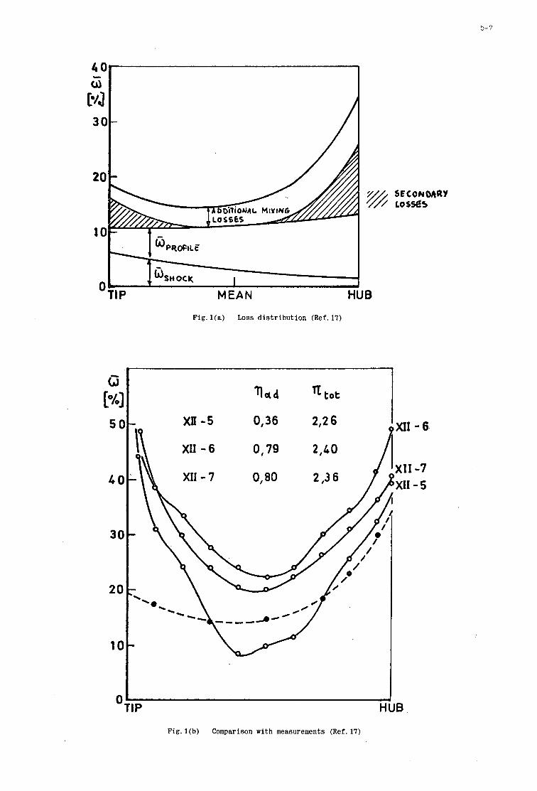
5- 7
'TIP HUB
4 Og I
G P4 5c
40
30
20
10
SECONOARY lOSSe5
Fig. l ( a ) Loss d i s t r i b u t i o n (Ref. 17)
xn - 5
XI1 - 6
0,36
0,79
2,2 6
2 , t O
Tl t o t
- 6
-7 - 5
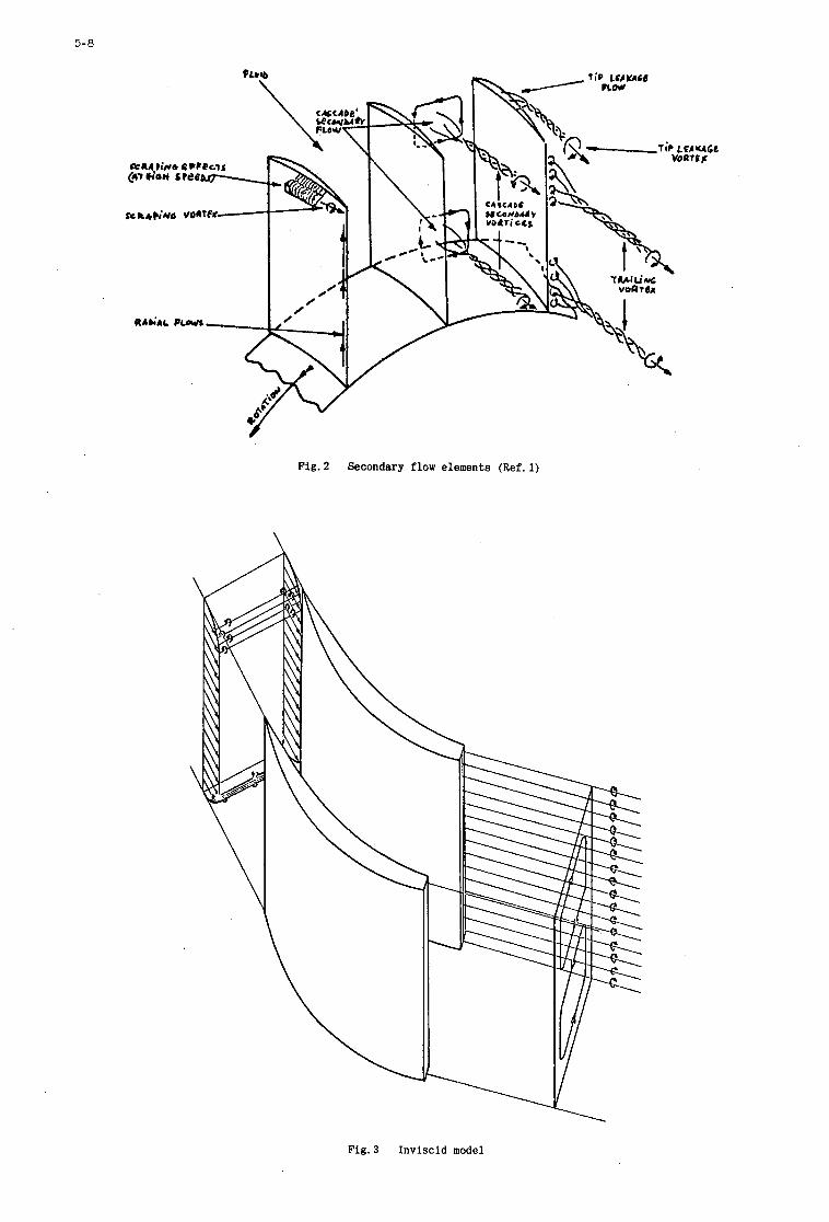
5-0
Fig. 2 Secondary flow elements (Ref. 1)
Fig. 3 Inviscid model
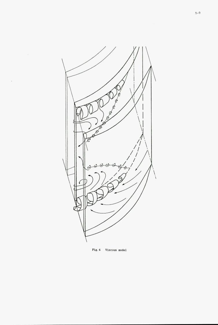
5-9
\
\ \
Fig. 4 Viscoua model
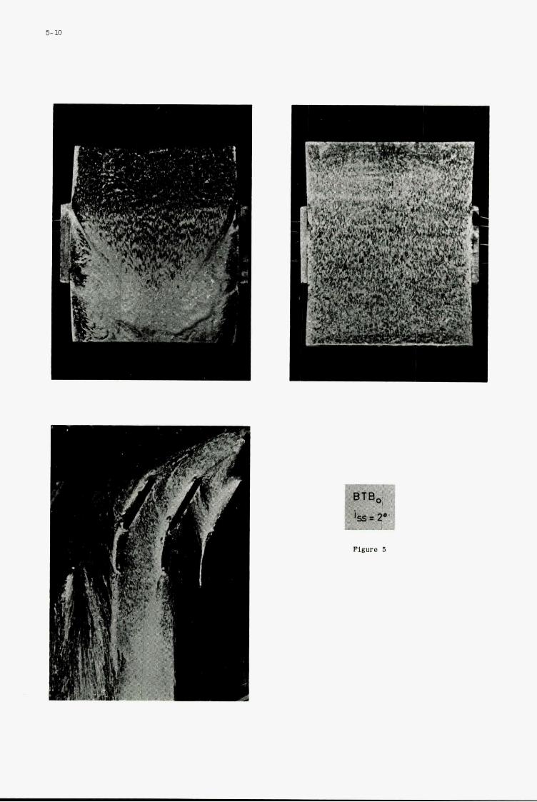
~
5- 10
Figme 5
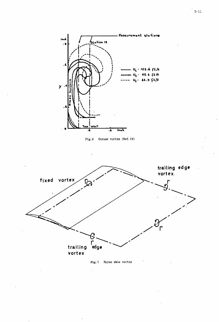
5- 11 I
.a .4 tnrb
Fig. 6 Corner vortex (Ref. 11)
trailing edge vortex.
-\
H , -2 / .' / /
vortex
Fig .7 Horse shoe vortex
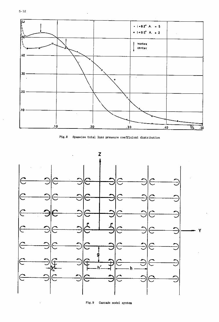
5- 12
I I i -8.2' A. P 5
Q i=8.So A. I 2
i \
\ I
vortex center I
C 3 L J
C 3
C 3 c 3
3 F L -
3i A L
Fig. 8 Spanwise total loss pressure coefficient distribution
Fig.9 Cascade model system
9 C J
C 3 C 3 C 3
C 3 C 3
C 3
- Y
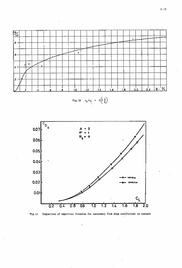
5- 13
A . 2 p - 1
S D c
0.07 - 006 *
0.05 -
0.04-
0.03 -
0.02 -
0.01 -
*
-b- VAVRA
-e- rwnica
1
0.2 0.4 0.6 0.8 1.0 1.2 1.4 1.6 1.8 2.0
Fig.11 Comparison of empirical formulae f o r secondary flow drag c o e f f i c i e n t i n cascade
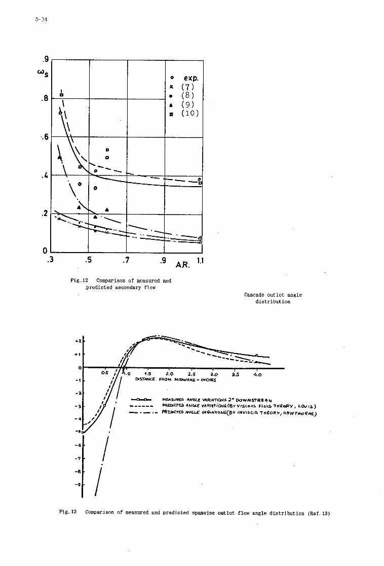
5- 14
-6
-7
-0
.9
O S
.8
4.6
.c
.2
0
I - *
I
.3 .5 .7 1 .I AR.
Fig..l2 Comparison of measured and .pred ic ted secondary flow
Cascade o u t l e t angle d i s t r i b u t i o n
Fig.13 Comparison of measured and predic ted spanwise o u t l e t flow angle d i s t r i b u t i o n (Ref.13)
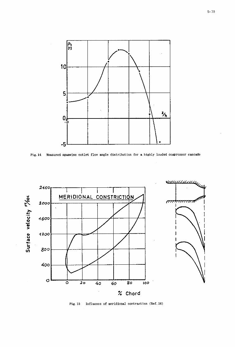
5- 15
Fig .14 Measured spanwise out l e t flow angle d is tr ibut ion for a highly louded compressor cascade
240C
200c
4 600
4 2 0 0
800
400
0
I I I I I I
0 20 40 60 80 100
% Chord
Fig .15 Influence o f meridional contraction (Ref.14)

6
BASIC ELEMENTS FOR ADVANCED DESIGNS OF RADIAGFLOW CcpllPRESSORS
bY
M. H. Vavra
Naval Postgraduate School Monterey, California 93940
6
SUMMARY
, Dimensionless parameters are presented for the design of compressors with axial i n l e t velocit ies and r ad ia l blades at the rotor discharge. and hold for arbitrary fluids. the conditions of s t a t e of the f luid a t different locations, and on the geometry of the design. relationships are discussed and the i r effects on performance are shown. campared with the so-called specific speed c r i t e r i a t o show tha t the l a t t e r do not s a t i s fy the laws of
.Eimilarity i f compressibility effects m e taken into account.
These parameters take account of the compressibility of the flow They permit t o evaluate the effect of changes of the design variables on
Loss The design parameters are
6-1
BASIC ELEMENTS FOR ADVANCED DESIGN OF RADIAL-FLOW COMFWSSORS
M. H. Vavra
1. INTRODUCTION
Under consideration are high-speed centrifugal compressors with rotors of the type shownin Fig. 1 that have radial blades at the discharge and where the absolute in l e t velocit ies are i n axial direction. With a straight annular i n l e t duct these in l e t velocities w i l l be uniform between the radi i R u and R i o of the impeller eye. a t Rlo,there is then known the peripheral speed Ulo , which, for chosen radius ra t ios R 2 / R l o , establishes the peripheral rotor speed U2 a t R2. not radial , but has an average angle B2.
For a particular relative flow angle @lo and the relative velocity Wlo
With the s l i p factor P t he re . i s The average relative velocity W2 a t the dischaxge of a rotor with radial blades i s
where V& i s the average meridional velocity a t the rotor discharge. definit ion of the s l ip factor
Equation 1 is a consequence of the
For a simplified analysis of the compressor performance that assumes uniform conditions a t the rotor discharge not only i n peripheral but also i n axial direction, across the blade width b2, and for axial absolute velocit ies V 1 a t the rotor i n l e t , the specific work AHw necessary t o drive the compressor i s fron moment of momentum consideration, for an assumed adiabatic process,
2 a y v = w u 2 ft- l b ( 3 )
For a perfect gas with y = q / c v = constant, the actual r i s e i n t o t a l temperature AT, i n the rotor i s n
With the gas constant Rg there i s ,
(4) Y $ = %
L e t
ql= /x = /T& be the velocity of sound a t the t o t a l i n l e t temperature Tt- = To. Then
(5)
For an isentropic compression process frm the t o t a l i n l e t pressure Po = Pto = Pt. t o the discharge pressure Pt4, the necessary work required would be 5 A Tis, where
v- 1
The compressor efficiency 9, i s defined by
6- 2
For a particular design the following data are naually prescribed:
A - mass flow ra t e (slug/s)
p0 - t o t a l i d e t pressure (psia)
To - t o t a l i n l e t temperature (OR)
Pt4 - discharge pressure (psia) I
y - r a t i o of specific heats c1, and cv f't- l b
. R G - gm constant ( s l M , ~ ~
With the indicated units, which are frequently used for engineering purposes, a quantity of mass is i n slugs,which i s derived from the chosen units of force, length, and time. going t o be established hold for any consistent system of units, hence also for one where the primary units are mass, length and time, and where forces are in derived units.
However, the relations which are
For the given conditions there are t o be found the following data for an optimum design:
U2 - peripheral rotor speed a t %
'21% - outer radius of impeller r a t i o of axial impeller width a t discharge
outer radius at rotor i n l e t outer radius of impeller , R ~ J % - inner radius a t rotor inlet
Rli/R1o - w - angular velocity of impeller (radiansls)
$1, - relative f low angle a t Rlo
"2 - absolute flow angle a t % Rd/R2 - radius at in l e t l i p of diffusor blades
outer radius of impeller
radius a t discharge of diffusor RJRZ - outer radius of impeller
Important design cri;teria are also:
'lo % = - - al impeller i n l e t
v2
2 - & 2
Mach number of relative velocity Wlo a t outer radius Rlo a t
Mach number of absolute velocity V2 a t impeller discharge - - -
Mechanical and f luid dynamics considerations impose design limits of:
a ) U2, because of permissible rotor stresses b) R i a / % , which cannot exceed about 0.70 t o 0.75 t o obtain an outer rotor contour with acceptably
s m a l l curvatures i n the meridinal plane c) RU/R%, which, if too small, does not permit the arrangement of a sufficiently large number of
rotor
:2;2, which cannot be smaller than certain limits t o obtain good efficiencies cl2, which cannot exceed TO0 t o 800 because of manufacturing reasons and because of poor diffusor performance, especially i f ME i s larger than unity.
lades ZR with reasonable thickness which cannot be larger than about, TO0 for manufacturing reasons
f )
2. CaMPRESSION PROCESS , F i P e 2 is a temperature-entropy diagram showing the thermodynamic process i n the compressor of Fig. 1.
The temperature differences i n Fig. 2 correspond roughly t o the velocities of the trianglss of Fig. 1 t o obtain a r e a l i s t i c representation. ture r i s e T2 - T 1 i n the.rotor is roughly one-half of AT,. Later-on the so-called degree of reaction r+ w i l l be introduced t o determine t h i s r a t io more precisely.
Since by Eq. 6 the work input ATw is a l s o ATw = p (U2 I C p ) , the tempera-
Station (1) i n Fig. 2 corresponds t o the s t a t i c condition a t the rotor i n l e t , given by the s t a t i c pressure p1 and the s t a t i c temperature T1. Ptl = Po and Ttl = To.
The t o t a l pressure and t o t a l temperature a t t h i s station are For the isentropic process between (0) and (1).
6-3
and
where V- V.
is the Mach number of the absolute velocity Vi a t the rotor i n l e t .
The conditions of s t a t e a t all locations can be expressed with the parameters U~/EQ, Rid%, h, P l o y cy2, b, and loss coefficients that establish the entropy increments between the different stations, i f it is assumed that the flow process along the outer contour of the rotor between the r ad i i representative of the rotor flow i n general. The l a t e r assumption i s made because the r z g t i v e velocity W l and the relat ive f l o w angle 8 1 are higher a t R i o than a t other r d i i R1. Hence along the outer rotor contour from R i o t o R2 there occur the highest deceleration r a t io WlO/W2 and the largest flow deflection L$ = f310 + &. shorter than that travelled by a par t ic le entering at other r ad i i RI, the conditions along the outer rotor contour w i l l establish design l imitations and have a c r i t i c a l influence on the rotor losses.
With the chosen parameters, Eq. 9 can be rewritten
and % i s
Moreover since the path travelled by a f luid par t ic le along the outer rotor contour i s
T, I I - = y l 2 2 To 1 + * MlJl cos Bl0
This formula i s also given by Eq. I ( 5 ) of Table I . This table has been arranged t o l i s t the pertinent relations for the determination of the flow properties i n the compressor for ready reference. following only the main steps w i l l be indicated that led t o these formulas without going into the detai ls of t he i r derivations. Some of the equations, for instance Eq. 1(6), can be obtained direct ly from Fig. 2. It can be noted that a l l temperatures are given as multiples of the t o t a l i n l e t temperature Tg = Ttl, and
The s t a t i c temperature T2 of the 50 or discharge fEq. I(")] i s equal t o the difference of the t o t a l temperature Tt2 a t the rotor ex i t and V2 /2%, where V2 i s given by Eq. I (3 ) . The temperature T2' i s necessary t o calculate the pressure r a t io pdP0 by Eq. I(20). Evidently T2'depends on the entropy increase s2 - si i n the rotor.
In the
ressures are l i s t e d as rat ios with respect t o Po = Ptl.
The process between stations (1) and (2) f r o m the rotor i n l e t t o i t s discharge can be formulated by
which is a fundamental relation obtained fran the energy equation for steady, adiabatic flows along stream- l ines i n rotors, as shown i n Art. 7.5 of Ref. 1.
The following discussion uses a relation which i s obtained f r o m Eq. 10 for incompressible flows (See Eq. 7( 4.4) of Ref. 1). relat ive velocit ies are U and W, respectively, the s t a t i c pressure p i s
A t a particular radius R along the outer rotor contour where the peripheral and
P 2 2 P = P I + p (3 - UJ + 4 (Wl0 - w) - Apf (11)
where p i s the constant mass density of the fluid, and Apf the pressure loss due t o f r ic t ional effects i n the rotor. the s t a t i c pressure i n the absolute f low j u s t ahead of the rotor a t Rio. ently of the values of W and Apf, there w i l l alweys occur a pressure increase p/2(U2-Ulo ) i f a f luid par t ic le moves from R l 0 t o R. from Wlo t o W. t o separations than an accelerated flow, but the fr ic t ional pressure loss between neighboring stations i s proportional t o the dynamic head (p/2) W2 i n both flows. In view of Eq. 11 however there exis t differences between flows tha t pass through stationary channels and those i n rotating impellers. i s decelerated i n a rotating channel, whose distance f rom the axis of rotation increases i n flow direction, it w i l l not necessarily separate even though it moves against r a idly increasing s t a t i c pressures, provided these pressure gradients are produced by the centrifugal force g e l d and not. by large reductions i n re la t ive velocity. length as the rotating one, the deceleration of the flow per unit length would very l ikely become excessive and could be associated with considerably increased losses because of flw separations. On the other hand, i f it were possible t o ignore the effects due t o Coriolis accelerations, it could be stated that the pressure losses i n a stationary and i n a rotating channel of equal length and shape would have t o be equal for the same velocity heads and equal f low decelerations, except for influences due t o Reynolds number differences. Moreover, for different velocity heads the pressure losses would be direct ly proportional t o the velocity heads at corresponding locations i n the two channels. However i f the respective performance of the two channels were evaluated by a loss coefficient CR that re la tes the f r i c t iona l pressure drop Apf t o the actual s t a t i c pressure r i s e i n the channel, i ts value would be l o one because of the additional pressure r i s e (P/2)(U2 - U l o 1. compared only by means of a loss coefficient Cw that i s defined as the r a t io of the pressure drop Apf and
A t the rotor i n l e t , where U = U 1 0 and W = W l o , the s t a t i c pressure i s evidently equal t o p l y Equation 11 sh w s that , independ- B
An additional pressure r i s e i s produced by decelerating the relat ive velocity ,
A flow t h a t moves i n a direction where the s t a t i c pressure increases i s more susceptible
I f a re la t ive flow
If the same s t a t i c pressure r i s e would have t o be produced i n a stationary channel of the same
r for the rotating channel than for the stationary F The performance of the channels can be
2 the pressure r i s e (p/2)(Wl,2 - W l ) due t o the f low deceleration, irrespective of whether additional pressure r i s e i s produced by the centrifugal force f i e l d or not.
These elementary considerations have not been presented here t o imply tha t the loss coefficients Cw i n a rotating and i n a stationary channel of the same geometry are equal. sham tha t flows i n stationary and rotating channels have fundamental differences as far as the i r ro ta t iona l charac te r i s t ics are concermd, and consequences of these conditions are described i n Arts. 10.5 and 12.2 of Ref, 1. The in ten t of the above discussion is to d r a w a t ten t ion t o the fac t t ha t frequently used formu- la t ions fo r the efficiency of impellers for centrifugal turbines and compressors cannot serve as a measure for the performance of these rotors, and t h a t same of the separation c r i t e r i a applied t o flows i n centrifugal ro tors have no physical meaning.
I n Ref. 1, Art. 8.5, it i s
A c m o n l y used def in i t ion for the efficiency of a centrifugal campressor ro tor i s
T2' - T1 rlR =
T2 - T1
The significance of the temperatures is evident f r o m Fig. 2. Equation 12 holds for the compressible flow of f lu ids with a constant value of y = cp/cv. incompressible flows, pa r t of the temperature r i s e i n the ro tor i s due t o the increase i n peripheral speed from s t a t ion (1) t o s t a t ion (2 ) .
S i m i l a r t o the preceding discussion tha t d e l t with
Equation 10, rewrit ten as
shows tha t the s t a t i c temperature r i s e Tu - T1 due t o the centrifugal force f i e l d i s equal t o the f i r s t term on the right-hand side of Eq. 13. It occurs in ro tors with and without flow losses hence it i s independent of the entropy increase s2 - SI. Thus the compression Correspondin@; t o (U$ - U10)2/2 cp occurs along the isentropic l ine 81 = constant f r o m T1 t o Tu, from s ta t ion (1) t o s ta t ion (U) i n Fig. 2, producing the s t a t i c pressure r i s e pu - p1, where
The deceleration of the re la t ive velocity from W l o t o W2 produces the temperature r i s e
with an entropy increase from s1 t o 62, due t o the flow losses, which i n turn a f fec t the pressure r i s e p2 - pu. The efficiency of the process f r o m (U) t o (2) can be defined by the so-called wheel efficiency Tw
T,' - T..
and
% - = T2' $ - + 1 - T2
TU Tu
From a f lu id dynamics view point only the efficiency % i s a measure for the quali ty of the rotac performance. I n par t icu lar , low measured values of are indications for the existence of flow separations, although b will be affected a l so by the t i p clearance losses, the so-called scrubbing losses produced by the ro ta t ing blades i n the w a l l baiundary leyer a t the fixed shroud, and the mixing losses a f t e r the rotor. However, l o w e f f ic ienc ies 'Ttw are only par t ly re f lec ted i n the ro tor efficiency VR of Eq 12 because of the temperature r i s e Tu - T1 which i s produced without entropy increases. t o represent the actual conditions i n the compressor of Fig. 1, there would be, by measuring the temper& tw differences i n Fig. 2,
I f the entropy diagram of Fig. 2 were
rlR = 0.84
and
% = 0.57
Although the value of 7 ) ~ = 0.84 seems t o indicate tha t the f l o w i n the ro tor i s reasonably good, the l o w value of Q = 0.52 shows c lear ly tha t it should be possible t o improve the ro tor considerably with a redesign. by reducing the entropy r i s e 82 - si i n the ro tor , but a l so t o produce more uniform flow conditions a t the
Such improvement should be undertaken not only t o increase the overall e f f ic ien ty of the campressor
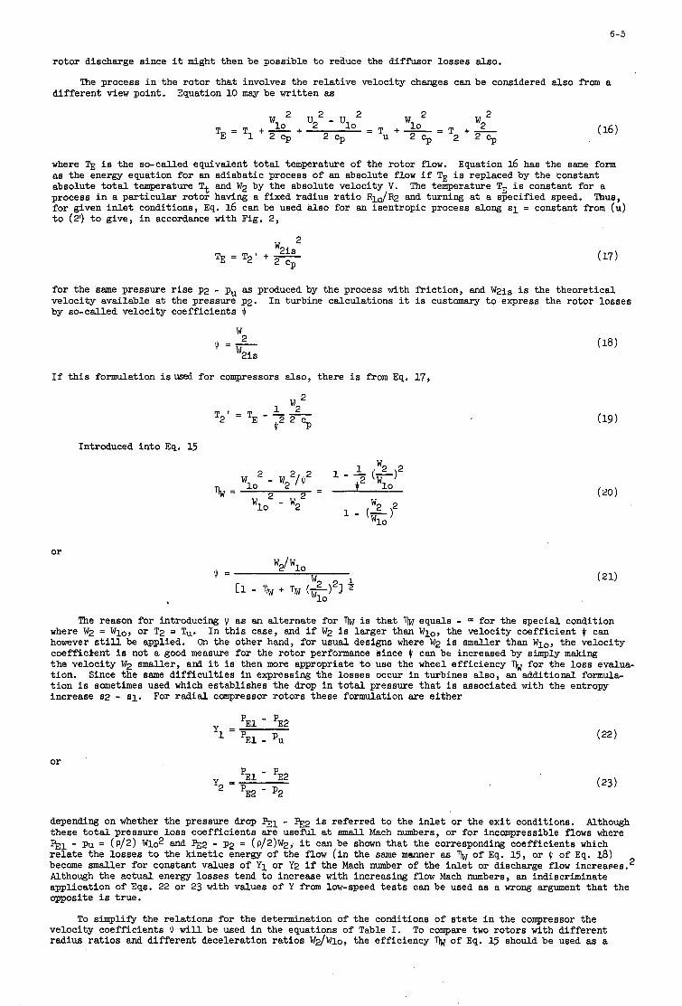
6-5
rotor discharge since it might then be possible t o reauce the diffusor losses
The process i n the rotor t ha t involves the relat ive velocity changes can different view point. Equation 10 may be writ ten as
2 2 = T u + L = T +
CP 2 c p 2
also.
be considered
where TE i s the so-called equivalent t o t a l temperature of the rotor flow. as the energy equation for an adiabatic process of an absolute flow i f TE i s replaced by the constant absolute t o t a l temperature Tt and W2 by the absolute velocity V. process i n a particular rotor having a fixed radius r a t i o RlO/R2 and turning at a specified speed. for given i n l e t conditions, Eq. 16 can be used also for an isentropic process along si = constant from (U) t o (2') t o give, i n accordance with Fig. 2,
Equation 16 has the same form
The temperature TE i s constant for a Thus,
for the same pressure velocity available a t by so-called velocity
r i s e p2 - pu as produced by the process with fr ic t ion, and W2is i s the theoretical the pressure p2. coefficients J I
In turbine calculations it is customary t o express the rotor losses
W 2 J I = -
w2is
If t h i s formulation isused for compressors also, there i s from Eq. 17,
Introduced into Eq. 15
or
Wl0Z - w2z
w2 2 1 - - (-1 J12 wlo
The reason for introducing $ as an alternate for 7 ) ~ i s that equals - O3 for the special condition where W2 = W l o , or T2 = Tu. however s t i l l be applied. coefficient i s not a good measure for the rotor performance since $ can be increased by simply making the velocity W2 smaller, ard it i s then more appropriate t o use the wheel efficiency b for the loss evalua- t ion. t ion is sometimes used which establishes the drop i n t o t a l pressure that i s associated with the entropy increase 82 - si.
In t h i s case, and i f W2 i s larger than yo, the velocity coefficient J I can On the other hand, for usual designs where W2 i s smaller than W l o , the velocity
Since the same d i f f i cu l t i e s i n expressing the losses occur i n turbines also, an additional formula-
For radial compressor rotors these formulation are e i ther
or
'E1 - 'E2
'E1 - 'U Y =
'E1 - 'E2 y2 PE2 - P2
depending on whether the pressure drop pE1 - pE2 i s referred t o the i n l e t or the ex i t conditions. these t o t a l pressure loss coefficients are usefW. a t smal l Mach numbers, or for incompressible flows where pE1 - pu = (P/2) W1o2 and pE2 - p2 = (P/2)W2,, it can be sham that the corresponding coefficients which r e l a t e the losses t o the kinetic energy of the f l o w ( i n the same manner as become smaller for constant values of Y1 or Y2 i f the Mach number of the in l e t or discharge flow increapes.' Although the actual energy losses tend t o increase with increasing flow Mach numbers, an indiscriminate application of Eqs. 22 or 23 with values of Y f r o m low-speed t e s t s can be used as a wrong argument that the opposite i s true.
Although
of Eq. 15, or $ of Eq. 18)
To s i m p l i e the relations for the determination of the conditions of s t a t e i n the compressor the velocity coefficients J I w i l l be used i n the equations of Table I. To compare two rotors with different radiua r a t io s and different deceleration rat ios W2/Wlo, the efficiency 'I)w of Eq. 15 should be used as a
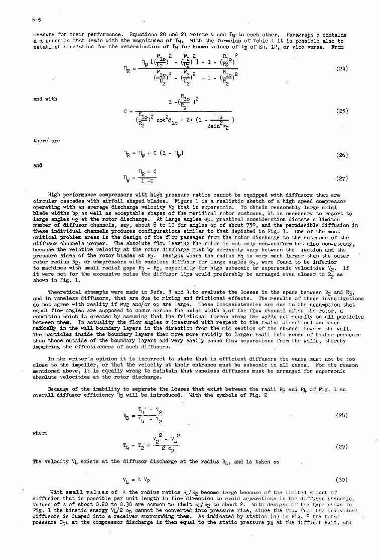
6- 6
measure for t h e i r performance. a discussion tha t deals with the magnitudes of 'lw. establish a r e l a t ion for the determination of % for known values of T ~ R of Eq. 12, or vice versa.
Equations 20 and 21 r e l a t e Jr and % t o each other. Paragraph 5 contains With the formulas of Table I it i s possible also t o
Frm
and with
there' are
and
R1o )2 1 -(r
c = - c
% = \ + c (1 -
High performance compressors with high pressure r a t io s cannot be equipped with diffusors t ha t are c i rcu lar cascades with a i r f o i l shaped blades. operating with an average discharge velocity V2 tha t i s supersonic. blade widths b2 as well as acceptable shapes o f the meridinal ro tor contDus, it is necessary t o resor t t o large angles cy2 a t the rotor discharge. number of diffusor channels, say, about 8 t o 10 for angles (UP of about 750, and the permissible diffusion i n these individual channels produces configurations similar t o tha t depicted i n Fig. 1. c r i t i c a l problem areas i s the design of the flow passages from the rotor discharge t o the entrance of the diffusor channels proper. because the re la t ive velocity a t the ro tor discharge must by necessity vary between the pressure sides of the ro tor blades a t R2. ro tor radius R2, o r compressors with vaneless diffusor for large angles a2, were found t o be infer ior t o machines with s m a l l r ad i a l gaps R3 - R2, especially for high subsonic or supersonic ve loc i t ies V2. it were not for the excessive noise the diffusor l i p s would preferably be arranged even closer t o F$ as shown i n Fig. 1.
Figure 1 is a r e a l i s t i c sketch of a high speed compressor To obtain reasonably large ax ia l
A t large angles 9, prac t ica l consideration d ic ta te a l imited
One of the most
The absolute flow leaving the ro tor i s not only non-uniform but also non-steady, suction and the
Designs where the radius R 3 i s very much la rger than the outer
I f
Theoretical attempts were made i n Refs. 3 and 4 t o evaluate the losses i n the space between R2 and R3,
These inconsistencies are due t o the assumption tha t and i n vaneless diffusors, t ha t are due t o mixing and f r i c t iona l e f fec ts . do not agree with r e a l i t y i f Mv2 and/or o(2 are large. equal flow angles are supposed t o occur across the ax ia l width b20f the flow channel a f t e r the rotor, a condition which i s created by assuming tha t the f r i c t iona l forces along the w a l l s act equally on a l l pa r t i c l e s between them. radicaJJy i n the w a l l boundary layers i n the direction from the mid-section of the channel toward the w a l l . The par t ic les inside the boundary layers then move more rapidly t o larger radii in to zones of higher pressure than those outside of the boundary layers and very eas i ly cause flow separations from the w a l l s , thereby impairing the effectiveness of such diffusors.
The r e s u l t s of these investigations
In ac tua l i ty the flow angles cy (measured with respect t o the rad ia l direction) decrease
I n the wr i t e r ' s opinion it i s incorrect t o s t a t e t ha t i n e f f i c i en t diffusors the vanes must not be too close t o the impeller, o r t ha t the velocity a t t he i r entrance must be subsonic i n a l l cases. For the reason mentioned above, it i s equally wrong t o maintain tha t vaneless diffusors must be arranged for supersonic absolute ve loc i t ies at the rotor discharge.
Because of the inab i l i t y t o separate the l t ~ s s e s tha t ex i s t between the r ad i i R2 and RJ, of Fig. 1 an overall diffusor efficiency w i l l be introduced. With the symbols of Fig. 2
where
T 4 ' - T2
% = T4 - T2
2 v2 - v t T4 - T2 =
2 c p The velocity V 4 ex i s t s a t the diffusor discharge a t the radius R4, and is taken as
v4 = A v,
With s m a l l v a l u e s of A the radius r a t io s RJR2 become large because of the limited amount of diffusion tha t i s possible per un i t length i n flow direction t o avoid separations i n the diffusor channels. Values of A of about 0.20 t o 0.30 are comon t o l i m i t RJR2 t o about 2. With designs of the type shown i n Fig. 1 the k ine t ic energy VJ2 9 cannot be converted in to pressure r i s e , since the flow f r o m the individual diffusors is dumped in to a receiver surrounding them. As indicated by s ta t ion (c l ) i n Fig. 2 the t o t a l pressure P t 4 a t the compressor discharge i s then equal t o the s t a t i c pressure p4 at the diffusor e x i t , and
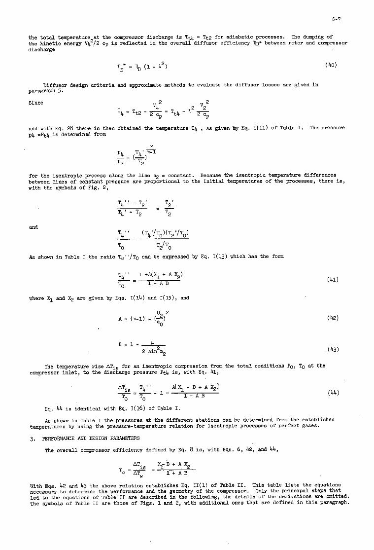
6-7
the t o t a l temperature a t the compressor discharge is T t 4 = Tt2 for adiabatic processes. the kinetic energy V 4 /2 cp i s reflected i n the overall diffusor efficiency b* between rotor and compressor discharge
The dumping of 2
ID" = % (1 - A2)
Diffusor design c r i t e r i a and approximate methods t o evaluate the diffusor losses are given i n paragraph 5 .
Since
and with Eq. 28 there i s then obtained the temperature T4 , as given hy Eq. I(11) of Table I. p4 =Pt4 i s determined from
The pressure
for the isentropic process along the l ine s2 = constant. between l ines of constant pressure are proportional t o the i n i t i a l temperatures of the processes, there is, with the symbols of Fig. 2,
Because the isentropic temperature differences
T2' - T21 T4' - T2 T2
T4" - - -
As shown i n Table I the r a t io T4"/To can be expressed by Eq. I(13) which has the form
T4" 1 +A(X1 + A X2) - - - 1 + A B TO
where X1 and X2 are given by Eqs. I ( l 4 ) and I ( l 5 ) , and
The temperature r i s e ATis for an isentropic compression from the t o t a l conditions PO, TO a t the compressor i n l e t , t o the discharge pressure Pt4 is , with Eq. 41,
ATis T4" A[% - B + A $1 ' = 1 + A B
- = - - To To
, (43)
Eq. 4.4 is identical with Eq. 1(16) of Table I.
A s shown i n Table' I the pressures at the different stations can be determined f rom the established temperatures by using the pressure-temperature re la t ion for isentropic processes of perfect gases.
3. PEXFORMAIKE AND DESIGN PARAMETERS
The overall compressor efficiency defined by Eq. 8 is , with Eqs. 6, 42, and 44,
- V B + A x2 1 + A B TC = -
ATW
With Eqs. 42 and 43 the above relat ion establishes Eq. I I (1 ) of Table 11. necessary t o determine the performance and the geometry of the compressor. led t o the equations of Table I1 are described i n the following, the detai ls of the derivations are omitted. The symbols of Table I1 are those of Figs. 1 and 2, with additional ones that are defined i n t h i s paragraph.
This table l is ts the equations Only the principal steps that
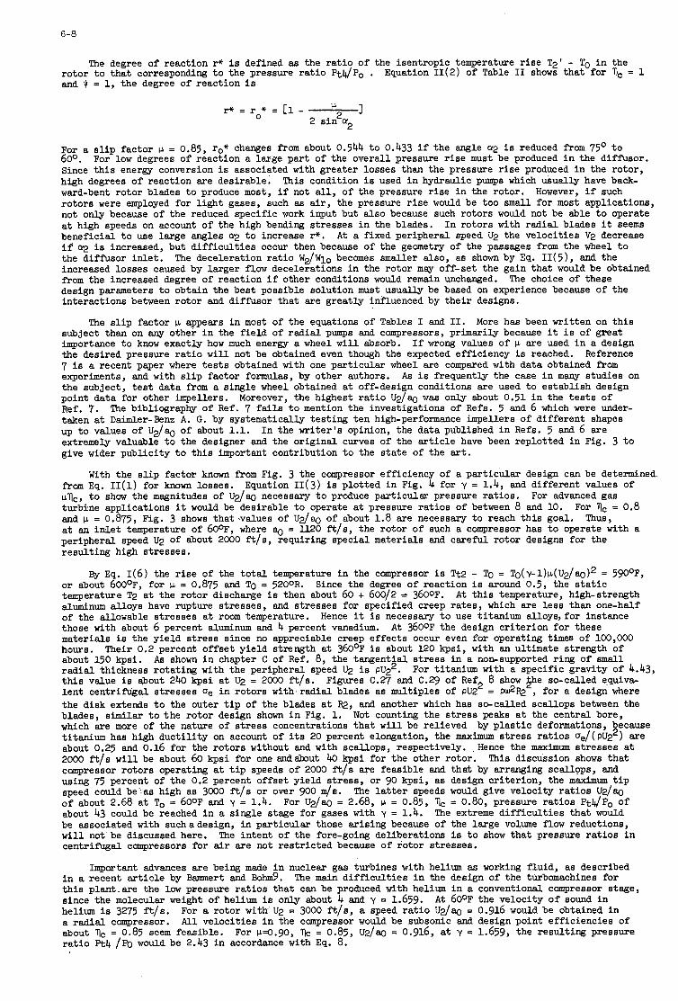
6-8
The degree of reaction I+ is defined as the r a t io of the isentropic temperature r i s e T2' - TO i n the rotor t o that corresponding t o the pressure r a t io Pt4/Po . and Jr = 1, the degree of reaction i s
Equation I I ( 2 ) of Table I1 shows that for 11, = 1
2 ~ + = r * = [ l - 2 s in a2
For a s l i p factor p = 0.85, ro* changes f r o m about 0.544 t o 0.433 i f the angle cy2 i s reduced from 75' t o 600. Since t h i s energy conversion i s associated with greater losses than the pressure r i s e produced i n the rotor, high degrees of reaction are desirable. ward-bent rotor blades t o produce most, i f not all, of the pressure r i s e i n the rotor. However, i f such rotors were employed for l i gh t gases, such as a i r , the pressure r i s e would be too small for most applications, not only because of the reduced specific work input but also because such rotors would not be able t o operate a t high speeds on account of the high bending stresses in the blades. beneficial t o use large angles cl;! t o increase I+. if cq i s increased, but d i f f i cu l t i e s occur then because of the geometry of the passages f r o m the wheel t o the diffusor i n l e t . increased losses caused by larger flow decelerations i n the rotor may off-set the gain that would be obtained from the increased degree of reaction i f other conditions would remain unchanged. design parameters t o obtain the best possible solution must usually be based on experience because of the interactions between rotor and diffusor that are greatly influenced by the i r designs.
For low degrees of reaction a large part of the overall pressure r i s e must be produced i n the diffusor.
This condition i s used i n hydraulic pumps which usually have back-
In rotors with radial blades it seems A t a fixed peripheral speed U2 the velocit ies V2 decrease
The deceleration r a t io W2/Wlo becomes smaller also, as shown by Eq. I I ( 5 ) , and the
The choice of these
The s l i p factor p appears i n most of the equations of Tables I and 11. More has been written on t h i s
I f wrong values of '.L are used i n a design Reference
subject than on any other i n the f ie ld of radial pumps and compressors, primarily because it i s of great importance t o know exactly how much energy a wheel w i l l absorb. the desired pressure r a t i o w i l l not be obtained even though the expected efficiency is reached. 7 i s a recent paper where t e s t s obtained with one particular wheel are compared with data obtained from experiments, and with s l i p factor formulas, by other authors. the subject, t e s t data f r o m a single wheel obtained a t off-design conditions are used t o establish design point data for other impellers. Ref. 7. taken a t Daimler-Benz A. G. by systematically testing ten high-performance impellers of different shapes up t o values of U2/% of about 1.1. In the wri ter ' s opinion, the data published i n Refs. 5 and 6 are extremely valuable t o the designer and the original curves of the a r t i c l e have been replotted i n Fig. 3 t o give wider publicity t o th i s important contribution t o the s ta te of the art.
A s i s frequently the case i n many studies on
Moreover, the highest r a t i o U 2 / q was only about 0.51 i n the t e s t s of The bibliography of Ref. 7 fails t o mention the investigations of Refs. 5 and 6 which were under-
With the s l i p factor known from Fig. 3 the compressor efficiency of a particular design can be determined from Eq. I I (1 ) for known losses. pVc, t o show the magnitudes of U2/w necessary t o produce particular pressure rat ios . turbine applications it would be desirable t o operate a t pressure rat ios of between 8 and 10. For llc = 0.8 and CL = 0.875, Fig. 3 shows that values of U 2 / q of about 1.8 are necessary t o reach t h i s goal. a t an in l e t temperature of 600F, where 80 = U20 fils, the rotor of such a compressor has t o operate with a peripheral speed U2 of about 2000 f i ls , requiring special materials and caref'ul rotor designs for the result ing high stresses.
Equation I I (3 ) is plotted i n Fig. 4 for y = 1.4, and different values of For advanced gas
Thus,
By Eq. 1(6) the r i s e of the t o t a l temperature i n the compressor i s Tt2 - To = To(y-1)p(U2/ao)2 = 59OoF, or about 6 0 0 0 ~ ~ for I.L = 0.875 and To = 5200R. temperature T2 a t the rotor discharge i s then about 60 + 60012 = 3600~. A t t h i s temperature, high-strength aluminum alloys have rupture stresses, and stresses for specified creep rates, which are l e s s than one-half of the allowable stresses a t room temperature. those with about 6 percent aluminum and 4 percent vanadium. materials is the yield s t ress since no appreciable creep effects occur even for operating time6 of 100,000 hours. about 150 kpsi. radial thickness rotating with the peripheral speed U2 is pQ2. t h i s value i s about 240 kpsi a t U2 = 2000 f i ls . Figures C.27 and C.29 of Ref2 8 show she so-called equiva, lent centrifugal stresses De i n rotors withmradial blades as multiples of pU2 = p$FQ , for a design where the disk extends t o the outer t i p of the blades a t FQ, and another which has so-called scallops between the blades, similar t o the rotor design sham i n Fig. 1. which are more of the nature of s t ress concentrations that w i l l be relieved by p l a s t i c deformations, because t i t a n i u m has high duct i l i ty on account of i t s 20 percent elongation, the meximum stress ra t ios De/(PU22) are about 0.25 and 0.16 for the rotors without and with scallops, respectively. Hence the maximum stresses a t 2000 fils w i l l be about 60 kpsi for one a n d h u t 40 kpsi for the other rotor. This discussion shows that compressor rotors operating at t i p speeds of 2000 ftls are feasible and that by arranging scallops, and using 75 percent of the 0.2 percent offset yield s t ress , or 90 kpsi, as design criterion, the maximum t i p speed could be' as high as 3000 ft/s or over 900 4 s . of about 2.68 a t To = 6 0 0 ~ and y = 1.4. For U2/w = 2.68, p = 0.85, 11, = 0.80, pressure rat ios Ptll/Po of about 43 could be reached i n a single stage for gases with y = 1.4. be associated with suchadesign, i n particular those arising because of the large volume flow reductions, w i l l not be discussed here. centrifugal canpressors for air are not restricted because of rotor stresses.
Since the degree of reaction i s around 0.5, the s t a t i c
Hence it i s necessary t o use titanium alloy8,for instance A t 3600F the design criterion for these
Their 0.2 percent offset yield strength a t 360°F i s about 120 kpsi, with an ultimate strength of As shown i n chapter C of Ref. 8, the tangential s t ress i n a non-supported ring of small
For titanium with a specific gravity of 4.43,
Not counting the s t ress peaks a t the central bore,
The l a t t e r speeds would give velocity ra t ios U ~ / Q
The extreme d i f f i cu l t i e s that would
The intent of the fore-going deliberations is t o show that pressure rat ios i n
Important advances are being made i n nuclear gas turbines with helium a6 working fluid, as described i n a recent a r t i c l e by Bammert and Bo&. t h i s plant,are the low pressure rat ios that can be produced with helium in a conventional compressor stage, since the molecular weight of helium is only about 4 and y = 1.659. helium is 3275 ftls. a radial compressor. about flc = 0.85 seem feasible. r a t io Pt4 /Po would be 2.43 in accordance with Eq. 8.
The main d i f f i cu l t i e s i n the design of the turbomachines for
A t 6 0 0 ~ the velocity of sound i n For a rotor with U2 = 3000 ft/s, a speed r a t i o U2/ag = 0.916 would be obtained i n A l l velocities i n the compressor would be subsonic and design point efficiencies of
For ~ e . 9 0 , f l ~ = 0.85, U2/ag = 0.916, a t y = 1.659, the resulting pressure
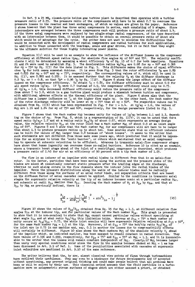
6-9
I n Ref. 9 a 25 We closed-cycle helium gas turbine plant i s described tha t operates with a turbine Dressure r a t i o of 2.55. pressure losses i n the reactor and heat exchangers, of which no values are given i n the paper. 9 shows however tha t the plant has three ax ia l compressors i n ser ies , each consisting of 9 stages. intercoolers are arranged between the three compressors each w i l l produce a pressure r a t i o of about 1.4. I f the three ax ia l compressors were replaced by two single-stage r ad ia l compressors, of the type described with an intercooler between them, it would be possible t o obtain an overall pressure r a t i o of about s i x which would be of advantage for the cycle. would be connected with the development of radial compressors and radial turbines for such applications, i n addition t o those connected with the bearings, sea ls and gear drives, but it i s f e l t t ha t they might be the ultimate solution for these highly in te res t ing power plants.
The pressure r a t i o of the compressors w i l l have t o be about 2.7 t o overcome the Reference
Since
The writer does not want t o minimize the d i f f i c u l t i e s t ha t
Equation S ( 1 ) w i l l be used i n an example t o show the influence of the diffusor losses on the compressor The velocity coeffi- efficiency a t d i f fe ren t speed r a t io s U ~ W , fo r absolute flow angles cy;! of 600 and 750.
cients JI w i l l be determined by assuming a wheel efficiency % of Eq. 15 of 0.7 for both impellers. 21 and 24 were used t o es tab l i sh Fig. 5. The deceleration r a t io s W 2 / W l o are 0.68 for cq = 600 and 0.366 for a;! = 750 by Eq. I ( 5 ) for the data l i s t e d i n Fig. 5. This difference makes the choice of equal e f f ic ie r r c i e s b for both cases somewhat dubious. It i s seen fram Fig. 5 t ha t the ro tor e f f ic ienc ies I]R are 0.89 and 0. 55 for a2 = 60° and a2 = 75O, respectively. The corresponding values of 9 , which w i l l be used i n Eq. I(l1, are 0.865 and 0.585. It i s assumed f h t h e r t h a t the velocity V 4 at the diffusor discharge i s 0.2 V2, o r A = 0.2, s o tha t ID* = 0.96 1~ by Eq. I (12) . Figure 6 shows the large e f fec t of the diffusor losses on the compressor efficiency. To obtain I]c = 0.85, the diffusor efficiency must be about 0.9 for all speed r a t io s U 2 / a g . If were 0.7 instead of 0.9, the compressor efficiency would only be 0.75. A t U 2 / % = 1.6, t h i s decreased diffusor efficiency would reduce the pressure r a t i o of the compressor from about 7 t o 5.8, which i n a gas turbine plant would produce a mismatch between turbine and compressor, with additional adverse e f fec ts on the thermal efficiency of the p lan t . diffusor has a larger influence on I]c a t the higher flow angle a2. On the other hand, the Mach number Mm of the ro tor discharge velocity w i l l be lower a t cy2 = 7 5 O than a t a;! = 600. obtained from Eq. 11(6) which has been represented i n Fig. 7 for y = 1.4. Mm are 1.16 and 1.24 for a;! of 750 and 600, respectively, for the design parameters l i s t e d i n Fig. 5.
Equations
Figure 6 shows also t ha t the
The respective values can be A t U2/w = 1.6, the values of
Figure 7 shows tha t the Mach number Mm becomes unity for values of U 2 / a g between 1.1 and 1.3, depend- ing on the choice of 9. speed r a t i o U ~ / C Q = 1.2 and at a radius r a t i o Rla/R2 of about 0.67, which represents an average design value, the r e l a t ive velocity yo a t the ro tor i n l e t has a Mach number B l o of 650. than about 1.3 t o produce pressure r a t io s up t o about ten. can be b u i l t for values of Mm larger than 0.8 because of "shock losses". I t seems t o the writer t ha t such statements are not d i f fe ren t f r o m those made some years ago, which predicted tha t it would be imposs- i b l e for an airplane t o break the "sonic bar r ie r" , or others which maintained tha t an axia l compressor has t o operate at subsonic ve loc i t ies t o be e f f ic ien t . Advances i n transonic axial-flow compressor steges have sham tha t human ingenuity can overcome these so-called bar r ie rs . where a transonic boost stage ahead of the i n l e t of a centrifugal compressor is described, which produces a pressure r a t i o of 1.43 for a i r at an efficiency of 90 percent w i t h a t i p Mach number of 1.05.
From Fig. 8, which i s a representation of Eq. 11( 4 ) , it can be noted tha t for a
of about 0.9 a t an i n l e t angle Figures 8 and 4 show tha t the Mach number Mm for air compressors w i l l not have t o be la rger
Some sources s t a t e t ha t no e f f i c i en t inducers
Reference 10 i s c i ted as an example,
The f l o w i n an inducer of an impeller with r ad ia l blades i s d i f fe ren t fram t ha t i n an .&ial-flow rotor. blades are mixed at essent ia l ly constant s t a t i c pressure a f t e r the t r a i l i ng edges a t the discharge, whereas no such mixing OCCUTS i n the flow channels where the inducer joins the r ad ia l blades of the impeller. Hence the pressure d is t r ibu t ions along the walls of the inducer blades must be rad ica l ly d i f fe ren t from those along the surfaces of an ax ia l ro tor blade, and separation c r i t e r i a t ha t are based on t t e diffuston fac tor of ax ia l cascades cannot be applied. Similar t o the conditions i n transonic ax ia l stages the supersonic re la t ive velocity a t the t i p of an inducer becomes sonic a t a par t icu lar radius Rlc, and subsonic at r a d i i R h smaller than R I c . R l 0 by Mm as previously defined, there i s
I n the l a t t e r , pa r t i c l e s t ha t have been moving along the suction and the pressure sides of the
Denoting the Mach number of Wl at Rlx by M h , and tha t a t
Figure 10 shows the values of R l x / R l o obtained from Eq. 45 for Mm = 1.3, a t d i f fe ren t re la t ive flow This graph i s presented angles p i 0 at the inducer t i p , and for par t icu lar values of the Mach number M h .
t o show tha t it i s non-sensical t o s t a t e t ha t Mm cannot exceed par t icu lar values without speciwing a t what angle p i o and a t what r a t i o RljfRlo t h i s l imi ta t ion holds. Whereas a t @lo = 750 a Mach number of unity occurs at R l x / R l o = 0.75, the whole i n l e t annulus w i l l have supersonic r e l a t ive velocitLes a t p l o = 50°, fo r the same Mach number Mm = 1.3 a t the t i p . Moreover, i f a t B l o = 7 5 O the hub/tip r a t i o R l i / R l o of the i n l e t eye i s 0.75 i n one machine and, say, 0.3 i n another the losses due t o compressibility e f fec ts w i l l ce r ta in ly be d i f fe ren t . of the impeller which, as indicated ea r l i e r , has been assumed t o remain constant i n rad ia l direction. have values of 0.336 and 0.919, respectively, for p i o = 7 5 O and B l o = 5 5 O a t Mm = 1.3, and it i s inconceiv- able t o the writer t ha t the losses w i l l rem4n constant independent of Mm. than unity very spec ia l conditions occur since the flow i n the annulus becomes choked a t Mm = 1 as has been discussed i n Art. 9.9 of Ref. 1. Some of the pecul ia r i t i es associated with cascades a t supersonic i n l e t ve loc i t ies a re mentioned i n Art. 9.10 of the same reference.
The writer believes tha t the, by now, almost c l a s s i ca l view points of flows through turbomachines
Figure 10 also shows the Mach numbers Mm of the absolute velocity V1 ahead They
Clear ly , i fMm becomes la rger
have outlived t h e i r useflilness. without questioning, m e y prevent or ig ina l thinking and could make people believe tha t all problems have been or w i l l be solved by t h e i r use. machine move on axisynrmetric stream surfaces of shwes which are e i the r assumed a p r io r i , o r obtained
They may even be a hindrance for future developments and i f accepted
This c l a s s i ca l method assumes tha t the f lu id pa r t i c l e s i n a turbo-
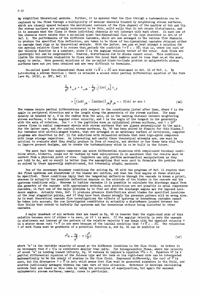
6- 10
)JY simplified theore t ica l methods. replaced by the flows through a mul t ip l ic i ty of annular channels bounded by neighboring stream surfaces, which are closely spaced between the meridional contours of the flow channel of the machine a t hub and t i p . The stream surfaces are actually considered t o be th in , so l id walls t ha t do not create disturbances, and it is assumed tha t the flows In these individual channels do not in te rac t with each other. I n each one of the channels there ex i s t s then. a so-called quasi two-dimensional flow of the type described i n Art.12 of Ref. 1. The performances of the d i f fe ren t cascades, which are now arranged i n the various flow channels t o produce the specified flow deflection, are taken t o be those of two-dimensional cascades obtained e i ther i n cascade t e s t r i g s or by theore t ica l methods. With the l a t t e r , one-can at-best attempt a solution for the spec ia l r e l a t ive flows W i n ro tors that-satisfy the condition V x W = - 2w; that i s , where the cur l of the velocity function i s a constant, since w i s the angular velocity vector of the rotor. Such flows are isentropic but can be compressible. However, disturbances due t o shocks cannot occur. This condition limits the theore t ica l evaluation t o flows where the loca l Mach numbers must be l e s s than o r , a t the most, equal t o unity. More general solutions of the so-called blade-to-blade problem on axisymmetric stream surfaces have not ye t been obtained and are very d i f f i c u l t t o formulate.
Further, it i s assumed tha t the flow through a turbomachine can be
--L
,So-called quasi two-dimensional flows with V % W = - 2f are discussed i n Art. 12 of Ref. 1. BY introducing a stream function Q there i s obtained a second order (see Eq. 12(9), P. 307, Ref. 1)
p a r t i a l d i f f e ren t i a l equation of the form
- 2(&) pw s i n A ( 4 6 )
The commas denote p a r t i a l differentions with respect t o the coordinates l i s t e d a f t e r them, where 8 i s the angle i n peripheral d i rec t ion and m the length along the generatrix of the stream surface. density i s denoted by P, R i s the radius from the axis, Ah i s the varying distance between neighboring stream surfaces, w i s the angular ro tor velocity, and A i s the angle of the tangent t o the generatrix with the axis of rotation. For A = 0 the pa r t i c l e s move on cylindrical stream surfaces, and A = 90' covers flows i n radial compressor wheels with stream surfaces tha t are planes perpendicular t o the axis. For the l a t t e r case, and for conical stream surfaces, Eq. 46 has been solved by Stanitz for t h in blades.3 For cascades with airfoil-shaped blades, t h a t are arranged on an a rb i t ra ry surface of revolution, computer programs are described i n Ref. 11 for solutions with relaxation methods tha t need high-speed computers with large storage capacit ies. c r i t i c a l t o evaluate what they rea l ly produce i n form of resu l t s , and whether or how these data w i l l help t o improve present designs, and t o create the turbomachinery which i s t o be b u i l t i n the future.
The m a s s
As in te res t ing and u s e m these theore t ica l attempts a re , one must be
The mere fac t t ha t modern computers can solve d i f f e ren t i a l equations with complicated boundary condi- t ions which, hitherto, could not be tackled by hand calculations i s no assurance tha t the r e su l t s must be correct from a physical point of view. are to ld t o do, and no r e su l t i s be t t e r than the assumptions tha t were used t o formulate the problem tha t i s solved by these apparently sophisticated, but inherently stupid, machines.
Computers can only perform mathematical manipulations as they
Two of the necessary boundary conditions for solving Eq. 46 with the programs of Ref. 11 require tha t the flows upstream and downstream of the blades are uniform, and tha t the flow angles a t these s ta t ions be specified. whereas i n ac tua l i ty the possible deflection depends on the a t t i tude of the blades i n the cascade and the upstream conditions only. the geometry of the cascade cascades, i n f ac t one of the major problems is t o find out what the discharge angles are for imposed inci- dence angles. Actually then, Ref. ll produces pressure distributions abdut blades for specified locations of the rear stagnation points, and i f they have been chosen wrongly the pressure pattern w i l l be wrong also. As i n most theore t ica l cascade flow investigations %he ef fec ts of upstream or downstream cascades cannot be taken in to account; the row investigated consti tutes i n ac tua l i ty a disturbance located between two flow f i e lds tha t extend t o i n f i n i t y f a r upstream and f a r downstream without being disturbed by other cascades.
These conditions i m p l y t ha t the tangential deflection through the cascade is known a p r io r i ,
Whereas i n turbine cascades it i s possible t o calculate the discharge mgle'from with approximate methods, such predictions are not possible i n ax ia l compressor
A major drawback of all methods tha t are based on Eq. 46 i s however tha t the right-hand side of t h i s re la t ion becomes zero if ei ther i s stationary and instead zf the pa t te rn of the re la t ive velocity W one deals with- the ab_solutb velocity V i n a s t a to r whose cu r l Vx V i s now zero because of the in i t ia l condition that V x W = - 2w. The ve loc i t ies V of such flows must be gradients of a poten t ia l function 'p, and Eq. 46 can be mdi f i ed t o
i s zero, or i f A i s zero. I f the angular velocity i s zero the cascade
"
where " a " i s the variable velocity of sound a t the d i f fe ren t locations i n the flow f ie ld . i s necessary tha t M = V/a i s everywhere smaller than unity. of sound "a" i s tending toward in f in i ty , Eq. 47 reduces t o Laplace's equation V2v = 0. Equation 47 i s a p a r t i a l d i f f e ren t i a l equation of the Poisson type and the term on i t s right-hand side can be interEreted mathematically t o be the resu14t of sources i n the flow f ie ld . Expressed d i f fe ren t ly , the cur l of V i s zero, but i t s divergence V V is not; which means tha t flow must be generated somewhere i n t h e f i e ld , and sources judiciously arranged therein can take care of t h i s si tuation. methods tha t are based on t h i s idea by using the principles of superposition, but again for assumed axisymmetric stream surfaces, nmely, cones i n particular.
As before it For incompressible flows, where the velocity
- Reference 12 develops calculating
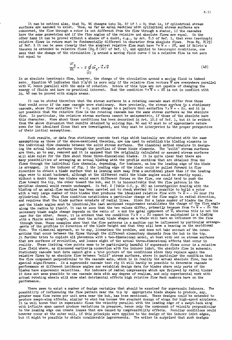
I
6-11
It can be noticed also, t ha t Eq. 46 changes in to Eq. 47 i f h = 0; tha t is, i f cylindrical stream surfaces are assumed t o ex is t . Thus, as f a r as ax ia l machines with cy l indr ica l stream surfaces are concerned, the flow through a ro tor i s not d i f fe ren t f r o m the flow through a s t a to r , i f the cascades have the same geometries and i f the flow angles of the re la t ive and absolute flows are equal. other hand it can be proved without a shadow of a doubt, e.g., by Art. 8.5 of Ref. 1, t ha t even isentropic r e l a t ive flows i n ro tors must be f'undementslly d i f fe ren t i n character from absglute flows. From Eq. 8(23) of Ref. 1 it can be seen c lear ly tha t the simplest re la t ive flow must have V x W = - 2w', and i f Kelvin's theorem i s extended t o r e l a t ive flows (Eq. 8 (22) of Ref. 1) , and applied t o isentropic conditions, one sees tha t the change of the c i rcu la t ion r R around a moving f lu id curve C i n a r e l a t ive flow i s not zero but equal t o
On the
(C)
I n an absolute isentropic flow, however, the change of the c i rcu la t ion around a movAng f lu id i s indeed zero. with G, hence p a r a l l e l with the axis of rotation. Rotors of t h i s type s e not zapable of changing the energy of f lu ids and have no p rac t i ca l i n t e re s t . That the condition 0% W = - 2w i s not i n conflict with Eq. 48 can be proved with simple means.
Equation 48 indicates t ha t Dr$fdt i s zero only i f the re la t ive flow vectors W are everywhere pa ra l l e l
It can be s ta ted therefore that the stream surfaces i n a rotating cascade must d i f f e r from those tha t would occur if the same casc$e were stationary. cascade, whose flow s a t i s f i e s V X V = 0, must change t o a pa t te rn tha t s a t i s f i e s V x W = - 2w, and it is not possible tha t the re la t ive flow i n the ro ta t ing cascade has the same stream surfaces as the absolute flow. In par t icu lar , the r e l a t ive stream surfaces cannot be axisymmetric, i f those of the absolute have t h i s character. from the above discussion tha t r e su l t s obtained by solving Eqs. 46 and 47 must be of approximate nature even for the idealized flows tha t are investigated, and they must be interpreted i n the proper perspective of t h e i r i n i t i a l assumptions.
More precisely, the stream s y f a c e &n a stationary
More about these conditions has been described i n A r t . 10.5 of Ref. 1, but it i s evident
Such r e su l t s , or data f r o m stationary cascade t e s t r i g s which bas ica l ly are obtained w i t h the same assumptions as those of the above-mentioned theories, are now used t o e s t a b l i s h t h e blading elements i n the individual f l o w channels between the so l id stream surfaces. ing the actual blade surfaces through the p ro f i l e s of these blade elements. The "solid" stream surfaces are then, so t o say, removed and it i s assumed tha t the or ig ina l ly calculated or assumed stream surfaces w i l l a l so ex i s t for the f l o w about these three-dimensional blades. It i s quite c lear t ha t there are many poss ib i l i t i e s of arranging an actual blading with the prof i le sections tha t are obtained f r o m the flows through the individual flow channels, depending, for instance, on how the leading edge of t he blade is arranged. I n the inducer of Fig. 1 the leading edge of the blade could be pulled forward i n flow direction t o obtain a blade surface tha t i s leaning more away f r o m a meridional plane than i f the leading edge were t o s lan t backward, although a t the d i f fe ren t r a d i i the blade angles would be exactly equal. Without a doubt these two blades would exert d i f fe ren t forces on the flow, one could tend t o push the f low toward t h e t i p , the other toward the hub, and it i s inconceivable tha t the flow pattern i n the meridian channel would remain unchanged. blading of an axial-flow machine has been carried out t o check whether it i s possible t o build a cotor with a very large number of t h in blades tha t produces the idealized r e l a t ive flow with Vx W = - 2 w near i t s cy l indr ica l hub. and requires tha t the blade surface consists of radial l ines . and the blade angles must be identical , the last mentioned requirement establishes the change of tke f loxang le don@; the radius by i t s e l f . It can be seen tha t the two values d i f f e r , primarily because from Vx W = - 2 w the necessary blade angle change depends on the r a t i o of U) and the yial smponent of W, whereas t h i s i s not the case for the other. Hence, it i s evident t ha t the condition V x W = - 2d cannot be maintained i n a blading with a f in i t e ax ia l length, and tha t the ac tua l blade shapes as a whole will have an influence on the flow through them. These examples show tha t the f l o w patterns i n a machine can be influenced by par t icu lar a r r q e - ments of the prof i les i n d i rec t ion of the blade height and tha t they w i l l have a bearing on the meridional flow. The c l a s s i ca l approach, so t o say, l inear izes the problem, and does not take account of the inter- actions tha t occur between the flows through the d i f fe ren t elementary channels from the hub t o the t i p . It fur ther t r i e s t o explain all phenomena with a two-dimensional model, a t best w i t h one on stream surfaces t h a t are surfaces of revolution, and looses sight of the actual three-dimensional e f f ec t s t ha t occur i n r ea l i t y . flow f i e l d where, as discussed e a r l i e r i n connection with the inducer i n l e t , the absolute f low is subsonic. Stationary cascade t e s t data cannot give a t rue picture of the conditions since they replace again the r e l a t ive flows by an absolute flow between "solid" stream surfaces, where i n par t icu lar the condition tha t the f low component perpendicular t o the cascade a x i s , which i s i n r e a l i t y the actual absolute flow, has no spec ia l significance. performance at d i f fe ren t incidence angles nor establish design data for blades where only par t s of the blades have supersonic velocit ies. For inducers of r ad ia l ccanpressors which are followed by r ad ia l blades it does not seem possible t o use cascade data with any degree of realism, and only experimental work with actual ro ta t ing wheels w i l l show what detrimental e f f ec t s high r e l a t ive flow Mach numbers have on the performance.
The c l a s s i ca l method consists i n design-
I n Ref. 2 (Table C-2, p. 26) an investigation dealing with the
This f l o w condition establishes a par t icu lar change of the f low angle i n r ad ia l direction, Since for a large number of blades the flow
These l imiting view points seem t o be par t icu lar ly harmful i f supersonic flows occur i n a r e l a t ive
I n a supersonic cascade test r i g it w i l l hardly be possible t o determine cascade
There seem t o ex i s t a number of design variables tha t should be examined for supersonic inducers. The
These designs could be extended t o poss ib i l i t y of influencing the flow pa t te rn near the t i p by appropriate blade shapes t o produce, say, greater mass flow ra t e s per unit area near the hub, has been mentioned. produce swept-wing ef fec ts , similar t o what has become the standard design of w i n g s for high-speed airplanes. It is well known tha t i n supersonic flows the velocity pa ra l l e l with the leading edge of a swept-back wing with i n f i n i t e span cannot produce variations i n pressure, hence only the component of velocity perpendicular t o the leading edge can create losses tha t are caused by compressibility effects. Peculiar conditions could however occur at the outer w a l l , i f t h i s principle were applied t o the design of the inducer i n l e t edges, bu t it might be possible t o obtain considerable improvements. The writer i s surprised tha t such designs
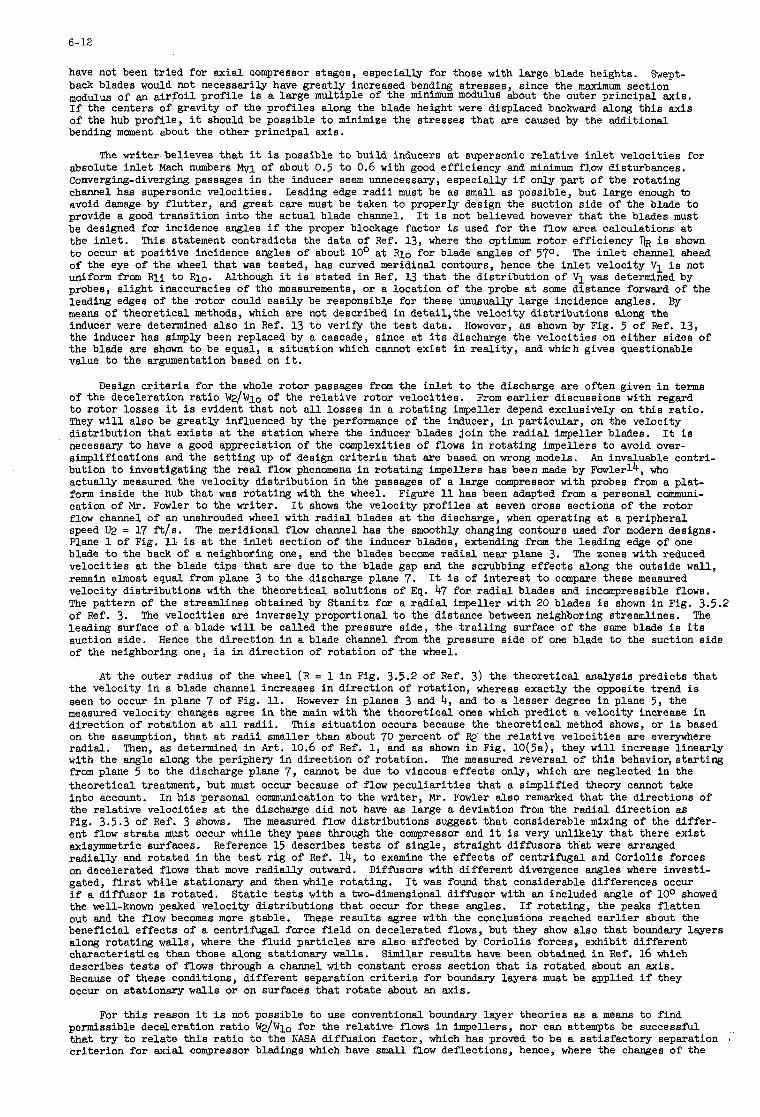
6-12
have not been t r i e d for ax ia l compressor stages, especially for those with large blade heights. back blades would not necessarily have greatly increased bending stresses, since the maximum section
of an a i r f o i l p rof i le i s a large multiple of the minimum modulus about the outer principal axis. I f the centers of gravity of the prof i les along the blade height were displaced backward along t h i s axis of the hub prof i le , it should be possible t o minimize the s t resses tha t are caused by the additional bending moment about the other principal axis.
Swept-
The wri te r believes t h a t it is possible t o build inducers a t supersonic r e l a t ive i n l e t ve loc i t ies for absolute i n l e t Mach numbers Mv1 of about 0.5 t o 0.6 with good efficiency and minimum flow disturbances. Converging-diverging passages i n the inducer seem unnecessary, especially i f only par t of the rotating channel has supersonic velocit ies. avoid damage by f l u t t e r , and great care must be taken t o properly design the suction side of the blade t o provide a good t rans i t ion in to the actual blade channel. It i s not believed however tha t the blades must be designed for incidence angles i f the proper blockage factor is used for the flow area calculations a t the i n l e t . This statement contradicts the data of Ref. 13, where the optimum ro tor efficiency TJR i s shown t o occur a t posit ive incidence angles of about 10' at Rio for blade angles of 570. of the eye of the wheel t ha t was tested, has curved meridinal contours, hence the i n l e t velocity Vl i s not d f o r m f r o m R l i t o Rio. probes, s l i gh t inaccuracies of the measurements, or a location of the probe a t some distance forward of the leading edges of the ro tor could eas i ly be responsible for these unusually large incidence angles. means of theore t ica l methods, which are not described i n detai1,the velocity d is t r ibu t ions along the inducer were determined also i n Ref. 13 t o verify the t e s t data. However, as shown by Fig. 5 of Ref. 13, the inducer has simply been replaced by a cascade, since a t i t s discharge the ve loc i t ies on e i ther sides of the blade are shown t o be equal, a s i tua t ion which cannot ex i s t i n r ea l i t y , and whhh gives questionable value t o the argumentation based on it.
Leading edge radii must be as s m a l l as possible, but large enough tD
The i n l e t channel ahead
Although it i s s ta ted i n Ref. 13 tha t the d is t r ibu t ion of VI was determined by
By
Design c r i t e r i a for the whole ro tor passages f r o m the i n l e t t o the discharge are often given i n terms of the deceleration r a t i o W2/Wlo of the re la t ive ro tor velocit ies. t o ro tor losses it i s evident t ha t not a l l losses in a rotating impeller depend exclusively on this r a t io . They w i l l also be grea t ly influenced by the performance of the inducer, i n par t icu lar , on the velocity d is t r ibu t ion tha t ex i s t s a t the s ta t ion where the inducer blades jo in the r ad ia l impeller blades. necessary t o have a good appreciation of the complexities of flows i n ro ta t ing impellers t o avoid over- simplifications and the se t t ing up of design c r i t e r i a t ha t are based on wrong models. bution t o investigating the r e a l flow phenomena i n ro ta t ing impellers has been made by Fowlerl4, who actually measured the velocity d is t r ibu t ion i n the passages of a large compressor with probes f r o m a p la t - form inside the hub tha t was ro ta t ing with the wheel. Figure 11 has been adapted from a personal communi- cation of Mr. Fowler t o the writer. f low channel of an unshrouded wheel with r ad ia l blades a t the discharge, when operating at a peripheral speed U2 = 17 f'tls. Plane 1 of Fig. 11 i s a t the i n l e t section of the inducer blades, extending f r o m the leading edge of one blade t o the back of a neighboring one, and the blades become rad ia l near plane 3. ve loc i t ies at the blade t i p s t ha t are due t o the blade gap and the scrubbing ef fec ts along the outside w a l l , remain almost equal from plane 3 t o the discharge plane 7. velocity d is t r ibu t ions with the theore t ica l solutions of Eq. 47 for r ad ia l blades and incompressible flows. The pa t te rn of the streamlines obtained by Stanitz for a r ad ia l impeller with 20 blades i s shown i n Fig. 3.5.2 of Ref. 3. The ve loc i t ies are inversely proportional t o the distance between neighboring streamlines. The leading surface o f a blade w i l l be called the pressure side, the t r a i l i n g surface of the same blade i s i t s suction side. Hence the direction i n a blade channel from the pressure side of one blade t o the suction side of the neighboring one, i s i n direction of ro ta t ion of the wheel.
From e a r l i e r discussions with regard
It i s
A n invaluable contri-
It shows the velocity prof i les at seven cross sections of the ro tor
The meridional f low channel has the smoothly changing contours used fo r modern designs.
The zones with reduced
It i s of i n t e re s t t o compare these measured
A t the outer radius of the wheel ( R = 1 i n Fig. 3.5.2 of Ref. 3) the theore t ica l analysis predicts t h a t the velocity i n a blade channel increases i n direction of rotation, whereas exactly the opposite trend i s seen t o occur i n plane 7 of Fig. ll. However i n planes 3 and 4, and t o a lesser degree i n plane 5, the measured velocity changes agree i n the main with the theore t ica l ones which predict a velocity increase i n d i rec t ion of ro ta t ion a t all radii. on the assumption, t ha t a t r a d i i smaller than about 70 percent of rad ia l . with the angle along the periphery i n direction of rotation. from plane 5 t o the discharge plane 7, cannot be due t o viscous e f fec ts only, which are neglected i n the theore t ica l treatment, but must occur because of flow pecu l i a r i t i e s t ha t a simplified theory cannot take i n t o account. the re la t ive ve loc i t ies at the discharge did not have as large a deviation from the radial direction as Fig. 3.5.3 of Ref. 3 shows. ent flow s t r a t a must occur while they pass through the compressor and it i s very unlikely tha t there ex i s t axisymmetric surfaces. rad ia l ly and rotated i n the t e s t r i g of Ref. 14, t o examine the e f f ec t s of centrifugal ani Coriolis forces on decelerated flows tha t move rad ia l ly outward. gated, f i r s t while stationary and then while rotating. if a diffusor i s rotated. the well-known peaked velocity d is t r ibu t ions tha t occur for these angles. out and the flow becomes more stable. beneficial e f fec ts of a centrifugal force f i e l d on decelerated flows, but they show also tha t boundary layers along ro ta t ing w a l l s , where the f lu id par t ic les a re a l so affected by Coriolis forces, exhibit d i f fe ren t charac te r i s t ics than those along stationary walls. Similar r e su l t s have been obtained i n Ref. 16 which describes t e s t s of flows through a channel with constant cross section tha t i s rotated about an axis. Because of these conditions, d i f fe ren t separation c r i t e r i a for boundary layers must be applied i f they occur on stationary w a l l s or on surfaces tha t ro ta te about an axis.
This s i tua t ion occurs because the theore t ica l method shows, or i s based the re la t ive ve loc i t ies are everywhere
Then, as determined in A r t . 10.6 of Ref. 1, and as shown i n Fig. 10(5a), they w i l l increase l i nea r ly The measured reversal of t h i s behavior, s t a r t i ng
I n h i s personal communication t o the writer, Mr. Fowler also remarked tha t the directions of
The measured flow d is t r ibu t ions suggest t h a t considerable mixing of the d i f fe r -
Reference 15 describes t e s t s of single, s t ra ight diffusors th'at were arranged
Diffusors with d i f fe ren t divergence angles where investi- It was found tha t considerable differences occur
S ta t i c t e s t s with a two-dimensional diffusor with an included angle of loo showed I f rotating, the peaks f l a t t e n
These r e su l t s agree wi th the conclusions reached e a r l i e r about the
For t h i s reason it i s not possible t o use conventional boundary layer theories as a means t o find permissible deceleration r a t i o W 2 / W l o fo r the r e l a t ive flows i n impellers, nor can attempts be successfU tha t t r y t o r e l a t e t h i s r a t i o t o the NASA diffusion factor, which has proved t o be a sa t i s fac tory separation j
c r i t e r ion fo r ax ia l compressor bladings which have small f l o w deflections, hence, where the changes of the
6-13
Coriolis forces are small i f the blading rotates. Much more hdamen ta l work dealing with boundary layers on rotating w a l l s and investigations with modern flow visualization methods must be carried out before it i s possible t o establish satisfactory design limits for flows i n r ad ia l impellers. Recent endeavors that use holography with Pulse-Lasers for investigations of flows i n rotating wheels might open ent i re ly new ways t o study actual flows i n high-speed machines where the effects of centrifugal and Coriolos forces are large.
If the above-mentioned pecul iar i t ies of rotor flows are not taken into account one might come t o the cmclusion, as some sources do, that flow separations w i l l occur i n an impeller i f W2/wlo equals 0.6, and tha t a r a t i o of 0.62 should be used for design purposes t o avoid excessive losses. f r o m analogies with stationary diffusors or oversimplified boundary layer considerations for, s a y , l inearly changing velocit ies along a surface, as i s the case on the suction side of a blade i n an axial compressor cascade. Figure 9 i s a diagram for the determination of the deceleration r a t i o W2/Wlo i n accordance with Eq. I I ( 5 ) of Table 11. 012 could not be larger than about 600 for a radius r a t i o Rlo/w of 0.7 and $10 = 600. angle cl;! the radius r a t i o Rlo/w would have t o be decreased. Figure 12 i s presented t o show these condi- t ions more precisely i f the lower l i m i t of W2/Wlo is assumed t o equal 0.6 and i f the s l i p factor For these conditions and at 0'2 = 75O, the maximum radius r a t i o RlO/R2 could not exceed 0.42 a t a re la t ive f l o w angle p i o = TO0. radius r a t io i n accordance with the dashed curve have operated successfully. and a t a radius r a t i o Rlo/R2 of 0.68 the deceleration r a t i o i s of the order of 0.35 t o 0.3,depending on @lo, as shown i n Fig. 9 by following path "b" i n the diagram. used as a preliminary design cr i ter ion it i s permissible t o apply minimum values of about 0.3 or even somewhat lower, s a y , about 0.26. be established because of lack of t e s t data but i n Paragraph 5 some t e s t resul ts are plotted t o show the order of magnitude of Ttw. A correlation between W d W l o and can probably never be obtained because of the additional rotor losses that depend on a number of additional factors.
Such values are obtained
I f , for instance, the l imit for t h i s r a t io were se t a t 0.65, the discharge angle For larger discharge
i s 0.85.
Experience with high performance campressors shows however tha t impellers w i t h A t 012 = 7 5 O , for instance,
Therefore, i f the deceleration r a t io W d W l o i s
A unique relationship between W ~ / W ~ O and the wheel efficiency Tlw cannot
For known values of by @lo, and U2/ag it i s possible t o calculate the wheel radius with Eq. II(9) of Table 11, if the r a t io R l i / R l o were known. The quantity kgl i s a blockage factor which i s primarily depending on the number of inducer blades and the i r thickness a t the i n l e t throat, although excessively thick boundary layers on the w a l l s of the in l e t annulus can affect kgl also. the angular velocity w i s known also, i f R2 has been determined. Eq. I I (10) of Table 11, for known or chosen quantities Mm and $lo. Eq. II(10) i s u s e m t o establish the necessary rotative speed t o handle particular flow rates . I f w i s given, because of the prime mover tha t drives the compressor, Eq. II(10) makes it possible t o verify whether a particular f low r a t e can be handled at t h i s speed. The r a t i o of axial blade width b2 and % i s obtained by Eq. II(11). The blockage factor kg2 is the r a t i o of the actual flow area at the wheel discharge and the area 277 R2 b2, multiplied by an experience factor that depends on the boundary layer thickness on the side w a l l s .
A = v4/V2 and known efficiencies ?IC. of the boundary layers which reduce the actual f l a r area at the discharge of the diffusor. Fig. 1 is taken t o be ei ther the throat of the diffusor where the f l o w i s choked i f the absolute velocity V2 a f t e r the rotor i s supersonic, or the entrance section of the actual diffusor i f V2 i s subsonic. necessary t o t a l flow area of all diffusor channels i s denoted by Ax,and kgx i s again an area blockage factor. and Pt2 at the rotor discharge is known. Although Pt2/Po could be expressed by Eq. I(19) of Table I and then introduced into Eqs. II(13) and II(14) , it is bet ter t o u e these relations as l i s t ed , since it i s possible t o judge approximately what Values the r a t io Ptx/Pt2 w i l l have for particular diffusor designs. I f V2 i s supersonic the throat area i s obtained with the dimensionless c r i t i c a l flow f'unction m c of Eq. II(14) which has a value @c = 0.6847 for y = 1.4. determined only i f the velocity Vx a t s ta t ion x i s specified, by assuming a value 5 = V r a t i o i s taken t o be about 1.02 t o 1.05 because a s l igh t acceleration between stations f 2) and (x) w i l l produce more uniform flow conditions at the diffusor inlet. usually arranged between paral le l w a l l s , the d i f f i so r widths a t i n l e t and discharge can be determined f r o m 4 and AI+, and the methods described i n Paragraph 5 establish the necessary length of the diffusor channels. With t h i s length and the chosen diffusor arrangement it is possible t o establish the outer radius R 4 of the diffusor.
Evidently i f U2/ag is known However w can be determined direct ly by
The necessary diffusor ex i t area A 4 a t the radius Q is obtained from Eq. II(14) for specified values
Section x-x of A blockage factor kB4 takes account of the displacement thickness
The
The area Ax can be determined for both cases i f the r a t i o of the t o t a l pressures Ptx at s ta t ion x
For subsonic velocit ies V2 the diffusor i n l e t area can be V2. Usually t h i s
For a chosen number of diffusor flow channels,
4. SIMILARITY CONSIDERATCONS
I f effects due t o gravity, surface tension, and heat conductivity can be ignored, which i s permissible for most flows i n turbomachines, the l a w s of dynamic similari ty establish tha t f low processes of perfect gases i n geometrically similar channels are equal i n performance if the Reynolds numbers ra t ios V / e a r e respectively equal at corresponding stations i n the channels. Ackeret e t . al., i n Ref. 17, the l a t t e r condition can be expressed i n terms of equal Mach numbers M y with the additional requirement that the f luids passingsthrough the geometrically similar channels have equal specific heat r a t io s y. Reference 17 shows also tha t the effects of different values of y are s m a l l only if the Mach numbers are l e s s than about 0.6. different re la t ive changes i n density i f passing thr0ugh.a channel with particular area rat ios . the values V / m c a n n o t remain equal i n geometrically sMlar channels.
and the velocity As derived for instance by
The reason i s tha t gases with different heat ra t ios y produce Hence
A s s d n g then tha t gases with equal values of y are considered only, and that the Reynolds numbers of the flars i n the c q e s s o r s t o be ccmrpared are i n a range where they can vary considerably without largely changing the f r i c t iona l coefficients; that is, i f they are moderately large and i f the f l o w surfaces are rough, dynamic similari ty i s achieved i n geometrically similar machines at equal Mach numbers.
In hydraulic machines, similari ty considerations that are based on the so-called specific speed have been used with success and it will now be examined whether it is possible t o apply t h i s method also t o the compressors considered here that operate a t high speed rat ios U d q . A t t e m p t s t o obtain design limits end t o establish the optimum operating range of radial ccnnpressors with t h i s means are described i n Refs.
6- 14
18 and 19. I n both reference there i s used the spec i f ic speed NE (see Eq; I I I ( 1 ) of Table 111)
similar t o the practice i n hydraulic pump design. flow r a t e through the machine, i s everywhere constant. volume Cow r a t e w i l l change considerably fiom i n l e t t o discharge, a choice must be made whether Q a t s ta t ion (l), or at, say, s ta t ion (2) i s t o be used i n Eq. 50. taken t o be the i n l e t f low r a t e Q1 without giving reasons fo r t h i s choice. as shown i n Table I11 by Eq. III(l), the value of NS the two c i ted references Ns has the dimension rpm fdt ~ e c - ~ ? ~ , which i s awkward for purposes of compari- son with similar coefficients i n other systems of units, and such formulations are not i n keeping with the general and very desirable tendency t o use dimensionless quantit ies throughout. more appropriate t o use the dimensionless speed ns, with uni t s aa defined by Eq. III(3) of Table 111, which for par t icu lar conditions has the same value i n all consistent systems of units. i s obtained by dividing the value of NS i n the given English uni t s by 129.
I n the l a t t e r application, Q, which is the volume I n a compressor for gases however, where the
In both references the quantity Q i s As i n Refs. 18 and 19, and
pends n the system of units which is used. I n
For t h i s reason it i s
The quantity ns
Whereas Ref. 18 (Fig. 2.8) simply presents a graph showing a d i rec t correlaticn of the efficiency of d i f fe ren t compressor types w i t h Ns, Ref. 19 uses the so-called specific diameter DS as an additional parameter, which is defined by (see Eq. I I I ( 2 ) of Table 111)
This quantit ds t ha t i s ogtained f r o m DS i n English units by division with 0.42.
i n l e t and the area TT Rio2, where R l 0 i s the outer radius of the ro tor i n l e t eye. As shown i n Table I11 the quantit ies ns and ds can be expressed also’with the chosen parameters of Tables I and 11, t o obtain Eqs. 111(6) and I I I (7) . as shown by Eqs. 111(8) and III(9).
i s a l so not dimensionless. However Eq. III(4) defines a dimensionless spec i f ic diameter
The coefficient 51 of Eq. I I I (5) represents the r a t i o of the area of the flow annulus a t the compressor
Both contain 51, so tha t t h i s r a t i o can be obtained f r o m e i ther of these re la t ions By equating these expressions there i s obtained Eq. I I I ( l O ) , o r
h
where p i s the s l i p factor and IC the compressor efficiency. compressor design, and because IC can be determined with Eq. 11( l), the spec i f ic diameter ds i s d i r ec t ly re la ted t o ns and there i s no reason why both n,c, and ds should be specified for a design with radial blades. Equation I I I ( U ) shows tha t by specifying ns there can be obtained the radius r a t i o Rli/Rlo for par t icu lar values of f31 and Rlo/R2 which are usually chosen on the basis of other considerations, as explained ea r l i e r , Equations 1199) and I I (10) of Table 11, w i t h the known ra t io s Rli/Rlo, would then give d i r ec t ly the necessary radius R2 or the angular velocity w for given operating conditions. were a unique function of ns, and if Rli/Rlo and/or the other parameters could be adjusted t o meet the opti- mum value, the designer would have a simple c r i t e r ion for the optimization of compressors.
values of NS between 75 and 85, or for ns between 0.58 and 0.66. parameters t ha t have been used successfd ly . r a t i o Rio/% = 0.7 was chosen. since the hub/tip r a t i o at the i n l e t becomes zero a t NS = 71. I n an actual design of a compressor that had ef f ic ienc ies him than 80 percent, the hub/tip r a t i o a t the i n l e t was about 0.46 for RI /@ = 0.56, hence it operated at Ns = 60 and did not have the much lower efficiency predicted by Ref. 18. example i n Table I11 with the higher r a t i o R i O / b = 0.7 the r a t i o R L i / R l o becomes zero at NS = 99.4, and an actual high-performance machine i s known t o the writer t ha t has an i n l e t hub/tip r a t i o of 0.34, hence it operates at ns = 0.725 or N r e a l i t y and Ns = 80 o r ns = O . b = i s not a design c r i te r ion .
Since p i s a known quantity for a par t icu lar
I f the optimum efficiency of a compressor
From Ref. 18 (Fig. 2.8, p. 38) it appears t ha t radial compressors should have the bes t efficiency for Table Et gives an example for design
I n one case, a radius r a t i o Rlo/R2 of 0.56, i n another a For the smaller value of Rio/@ it i s not% possible t o design for NS = 80,
For the
93.5. Thus, the sharp optimum for Ns i n Ref. 18 does not occur i n
It i s obvious f rom Eq. 111(6) tha t all radial compressors have values of NS between, say, 60 and l l 0 . The only merit
I f NS i s outside the range of 60 t o 110, and i f the above-mentioned design conditions can-
Lawer and higher values would lead t o impossible designs which would never be b u i l t anyway. of the spec i f ic speed i s t o find out whether a r ad ia l compressor can be b u i l t a t all for given values of N, Ql, and H i s . not be changed, another type of compessor has t o be chosen. However, i f the re la t ions of Table I1 were applied, the same conclusions would a l so be reached immediately even i f the specific speed concept had never been invented. Table I11 with R /R2 = 0.56, the designer would t r y t o reach the highest possible NS by making the radius r a t i o R&Q excessively small or choosing too high a value of R d Q t o reduce N s for Rlo/R2 = 0.7. The example also shows tha t large changes of R 1 F / R l o have a s m a l l influence of NS except, near the m a x i - mum possible value of NS where R l F / % tends toward zero. a large number of high-performance radial compressors would E v e r have been b u i l t , much t o the detriment of the development of these promising machims, where a be t t e r physical understanding of the complicated flow phenomena can s t i l l lead t o considerably improved performance.
I n f ac t i t s use can a l so be dangerous i f , as might be the case for the example of
Further, i f NS = 80 would be considered necessary,
Unfortunately there a l w a y s ex i s t s the tendency i n engineering t o t r y t o se t up simple ru les or c r i t e r i a which make it possible t o judge whether or not a design i s feasible, without having t o go through the strenuous mental processes t o t r y t o understand the phenomena tha t actually occur and t o r e l a t e them t o the fundamental l a w s of nature. If our only task were t o build the same machines over and over again, sometimes
6- 15
a l i t t l e smaller, all would be w e l l w i t h this.kind of handbook engineering. However i f an engineer believes tha t Mprovements are possible,aand i f he r e f l ec t s on what has happened during the past years he cannot doubt t ha t t h i s will be the case, he must not accept the bar r ie rs t ha t have been s e t up by pas t experience, and be impressed by the achievements t ha t have been made. t o evaluate what i s t rue and what i s false with accepted methods, and h i s aim must be t o t r y t o under- stand, t o search, and t o improve. Too often engineers are handlers of formulas or recipes, and there is the tendency t o accept t h e i r r e su l t s as correct without much questioning, especially i f they are ground out by a computer, without finding out what so r t of basic principles and assumptions led t o the numbers. I n the near future our modern computers m a y well be the biggest obstacle t o imaginative or ig ina l thinking and the use of new concepts, since for every problem there will very soon ex is t some so r t of a program tha t can show tha t everything i s known, and tha t nothing new needs t o be added. All one has t o know is the necessary format for the input t o obtain the desired r e su l t , i n p r in t , i n graphs, even i n drawings. The inventive and c r i t i c a l engineer harever must take the trouble t o find out how the program was established and what basic principles and assumption were made, and must then evaluate the obtained numbers i n the l i g h t of these conditions.
With a c r i t i c a l mind he has
The biggest objection t o the spec i f ic speed c r i t e r i a i s however tha t they do not s a t i s fy the laws of dynamic s imi la r i ty , even not for the l imiting conditions tha t were assumed ea r l i e r . t ha t ns i s independent of the pressure r a t i o tha t i s produced by a compressor. are equal for two compressors, they can have d i f fe ren t values of U2/% and therefore widely d i f fe ren t blade width b2 a t the rotor dischwge. ve loc i t ies at the diffusor i n l e t . The curves of constant efficiency Ref. 19 and redrawn i n a bigger scale. curves for Nm = constant are for constant r a t io s of re la t ive i n l e t and c r i t i c a l velocity for the t o t a l i n l e t temperature. Equation I I I (14) of Table I11 shows how these r a t io s are related t o the actual Mach numbers m. Although the differences between Nm and Mm are s m a l l a t low Mach numbers, the values of
According t o the author of Ref. 19 the curves for Nm = 1.0 and 1.2 represent design limits for higher pressure ra t ios . t h a t maximum ef f ic ienc ies w i l l occur for impellers with backward bent blades operating a t specific speeds Ns between 90 and 130, and specific diameters DS between 1.3 and 1.7. constant which the present writer drew in to the or ig ina l diagram of Ref. 19 represent Eq. I I I ( l O ) , and r e l a t e DS t o NS for wheels with radial blades at the discharge. are 0.7, hence all rad ia l campressor of t h i s type must l i e i n the v i c in i ty of t h i s curve for b$ i n Fig. 13. The points labeled (1) t o (7) i n Fig. 13 represent design points for some actual compressors known t o the writer, operating with U2/% of about unity, and i n l e t Mach numbers of 0.9 and higher. It i s of i n t e re s t t o note tha t all these points l i e on the curve 1, = 0.70 of Ref. 19 whereas all compressors, even those having NS-values between 60 and 70, have e f f ic ienc ies of 80 percent and higher. again tha t the spec i f ic speed concept is a highly unsatisfactory design c r i te r ion , especially for radially- bladed compressor wheels, since it i s impossible t o design such machines with operating points t ha t f a l l inside the closed curve, labeled I) = 0.8 i n Fig. 13. i n i t s Fig. 4 were calculated on the basis of loss considerations. t h i s loss evaluation i s i n e r ror o r unsuitable for compressors with ro tors t ha t have radial blades a t the discharge.
What seems more c ruc ia l t o the writer i s the f ac t t ha t on the basis of Fig. 4 of Ref. 19 (o r Fig. 13
Equation 111(6) shows I f all factors i n Eq. 111(6)
One compressor could operate w i t h subsonic, the other with supersonic 'Figure 13 is an adaptation of Fig. 4 of Ref. 19.
= 1.2 for PtJPo were taken from = 0.7 and IC = 0.8 and the curves labeled = 1.0 and Although labeled as l i nes of constant Mach number i n Ref. 19 the
vary f r o m 0.94 t o 1.01 for = 1.0 i f B l 0 changes from 50° t o 7 5 O . It i s s ta ted
The s t ra ight l i n e s labeled bVc =
Average values for pTc for such impellers
This s i tua t ion shows
It i s pointed out i n Ref. 19 t ha t the data presented It can be concluded therefore tha t
of the present a r t i c l e ) one might come t o the conclusion tha t it i s not possible t o build high-speed compressors of the type discussed here with high efficiencies, for instance, as required for gas turbines, and tha t fur ther developments of these machines might not be undertaken because of "proof" tha t improvements are not possible. This i s again a case which shows tha t an analysis i s no be t te r than i t s assumption. Since the spec i f ic spekd has no r e a l physical meaning, unlike the actual s imi la r i ty parameters such as Reynolds number, Mach number and others, the wr i te r deplores the tendency t o express everything i n flow machines with Ns, a l so phenomena on which NS ha8 r ea l ly no primary influence. Because of the def in i t ion of NS it i s always possible t o do so because e i the r ro ta t ive speeds and flow velocit ies, o r lengths? can be related t o it, and since i n all these expressions there then appears NS i n one form or another, depending on what s b p l i f y i n g assumptions were made, the reader is given t o believe that NS has a governing influence on the performance, and that manipulating N s i s all tha t needs t o be done t o create an optimum design. Everyone who has observed actual flows i n turbomachines complexities of these processes w i l l agree tha t nature j u s t i s not so simple t h a t it can be explained by a s e t of convenient numbers.
5. LOSSES I N RADIAL CCMPRFSSORS
i n t e s t r i g s , and has t r i e d t o understand the
It has been s ta ted e a r l i e r t ha t the wheel efficiency $ of 15 i s the bes t measure for the quali ty of a ro tor wheel. deceleration r a t i o W 2 / W l o has an overriding e f f ec t on T(w, as has been suggested by some sources which s t a t e t h a t W2/Wlo should not be smaller than about 0.6 t o avoid flow separations. Fig. 12 t ha t such a limit cannot be used for compressors t ha t operate a t high speed r a t io s U2/9 because the radius r a t io s Rl0/R2 become too small, and it i s then not possible t o handle the large changes i n volume flow r a t e from ro tor i n l e t t o ro tor discharge, that occur at high pressure<ra t ios , with acceptable r a t io s of a x i a l blade width b2 and R2. w ~ / W ~ O 2 0.6 were a r e a l i s t i c c r i te r ion , the losses i n ro tors with high speed ratio's would be large and it would be d i f f i c u l t t o obtain high efficiencies. have deceleration r a t io s tha t are smaller than 0.6 without a d ra s t i c decrease i n $. 14 represent design point data of some of the compressors of Ref. 6, and others t ha t are known t o the writer. The points indicated by x and + were calculated from the data given i n Ref. 13, and the curves &awn through them represent the change of Q,I w i t h operating conditions of a par t icu lar wheel a t values of u 2 / ~ of 0.83 and 1.02, respectively. ro tor discharge, and a l l compressors operate at high speed r a t io s , having overall e f f ic ienc ies i n excess of 80 percent.
As indicated, a number of factors influence w, but it will be examined now whether the
It has already been shown i n
The example of paragraph 6 demonstrates t h i s condition clearly. I f
Figure 14 is presented t o show t h a t m a n y compressors The c i r c l e s i n Fig.
All data points are for impellers with radial blades a t the
I n contrast t o the expected trend tha t Tiw decreases w i t h decreasing values of W2/Wlo, the opposite
6-16
could be deduced *om Fig. 14, since wheel No. 1 with W 2 / W l o = 0.265 has the highest efficiency % = 0.77. For each data point i n Fig. 14 are also given the r a t io s R l O / Q , R 1 d R l o , bdR2 and Ax/AR of the rotor. The l a t t e r r a t i o establishes the general shape of the meridional channel and the values show tha t the contours of the meridional flow paths of all compressors must have s m a l l curvatures with the exception, meybe, of wheel No. 11. Definite reasons for the higher values of Tiw i n some designs cannot be given, probably because of the e f fec t of the design of the inducers on the wheel performance. However, it i s recognizable f r o m Fig. 14 tha t high e f f ic ienc ies are reached e i the r for high r a t io s R I I / R l o o r high values of bpf-. The influence of Rlo/R2 seems small, although most good wheels have values of R l o / Q between 0.6 and 0.7. through the eye of the impeller, and high r a t io s b2/R2 are obtained i f the absolute f l o w angles cy2 are large. For high values of the inducer becomes crit ica1,and with large angles a the design of the diffusorlespecially the t r ans i t i on between wheel and diffusor throat, becomes a d i f s i cu l t task. It i s f e l t t ha t high performance compressors can be developed i f more a t ten t ion i s given t o these two problem areas.
Large r a t i o s R 1 i / R l o require high r e l a t ive Mach numbers t o pass the flow r a t e
From th? curves i n Fig. 14 it i s quite evident t ha t the range i n which T$,, remains constant for off- design operation becomes smaller the higher the speed r a t i o Udag i s , a condition which is, at l e a s t i n p a t , responsible for the steeper charac te r i s t ics of compressors operating at high speed ra t ios .
The r a t i o of b2/& also has an e f fec t on the disk f r i c t ion lo s s of an impeller. Assuming tha t the disk extends t o the outer radius R2; t h a t i s , i f no sca l lo 8 are arranged, a f r i c t iona l moment MDF ac t s on the back side of the impeller which can be determined by 2g
%F = "M '2
where cM depends on the Reynolds number
u2 D2 Re = - V
and the ax ia l gap ga between the rotating disk and the stationary w a l l . and the e f fec t of disk roughness, which have been investigated by Refs. 21, 22, 23, and 24 are discussed i n Ref. 8. Figure 15 has been established f r o m the r e su l t s of the quoted references, but experience has s h m tha t the values of CM can be a multiple of those of Fig. 15 i f the f low i n the region between the disk and the wall has r ad ia l velocity components pointing away from or toward the axis of the impeller. compressors pumpiq ambient air the Reynolds number of Eq. 50 varies between about (lo6) and 3(107) for peripheral speeds between 1000 and 1600 ft/s, and ro tor diameters between 3 and 20 inches. average value of c~ from Fig. 15 i s then about 1.5 is more r a l i s t i c for actual compressor wheels. i s riI p U2
The influence of the r a t i o 6$R2,
For
Although the it has been shown by experience tha t CM = 2.5(10-4)
For a mass flow r a t e xh the power absorbed by an impeller h i n accordance with Eq. 3, which i s also equal t o Mu, where M i s the driving moment, and
However .
and, with the re la t ions of Table I,
"he t o t a l moment which has t o be,overcome by the driving source is then M + MDF and i f the efficiency of the compressor i s llc,without taking the disk f r i c t i s n moment in to account, the actual compressor efficiency ll of the machine i s IDF llc, and
M 1 I,, = - M + k+)F = -7
Then by Eqs. 49 and 5 1
It can be noted tha t 5DF i s independent of the mass density p2 and R2 since both M and MDF are proportional t o these quantit ies. Hence Eq. 51 holds for a l l impellers with radial blades the outer radius R2. Equation
1
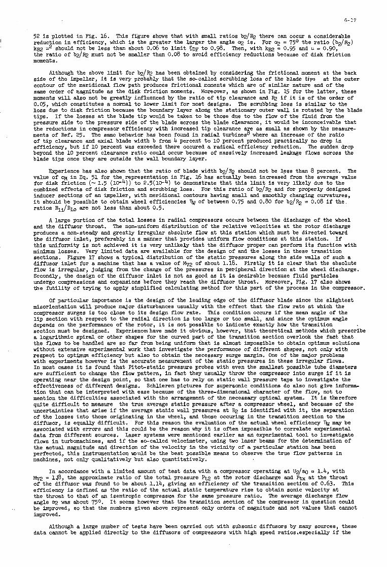
6- 17
52 i s plotted i n Fig. 16. This figure shows that with small ra t ios b2/R2 there :an occur a considerable reduction i n efficiency, which is the greater the larger the angle a2 is. kg2 w2 should not be l e s s than about 0.06 t o l imit ~ D F t o 0.98. the r a t i o of b d m must not be smaller than 0.08 t o avoid efficiency reductions because of disk f r i c t ion moments.
For a2 = 7 5 O the r a t i o (b2/R2) Then, with kg2 = 0.95 and IL = 0.90,
Although the above l imit for bdR2 has been obtained by considering the f r i c t iona l moment a t the back side of the impeller, it is very probably that the s+called scrubbing loss of the blade tips contour of the meridional f l o w path produces fr ic t ional moments which are of similar nature and of the same order of magnitude as the disk fr ic t ion moments. Moreover, as shown i n Fig. 15 for the l a t t e r , these moments w i l l also not be greatly influenced by the r a t i o of t i p clearance and FQ i f it i s of the order of 0.05, which constitutes a normal t o lower l imit for most designs. The scrubbing loss i s similar t o the loss due t o disk fr ic t ion because the boundary layer along the stationary outer w a l l i s rotated by the blade t i p s . pressure side t o the pressure side of the blade across the blade clearance, it would be inconceivable that the reductions i n compressor efficiency with increased t i p clearance e as s m a l l as shown by the measure-
of t i p clearance and axial blade width b f r o m 4 percent t o 10 percent produced practically no drop i n efficiency, but i f 10 percent was exceeded there occured a radical efficiency reduction. The sudden drop beyond the 10 percent clearance r a t i o could occur because of massively increased leakage flows across the blade t i p s once they are outside the w a l l boundary laJrer.
Experience has a lso shown tha t the r a t i o of blade width bdR2 should not be l e s s than 8 percent. The value of CM i n Eq. 51 for the representation i n Fig. 16 has actually been increased from the average value for disk f r i c t ion (- 1.5 combined effects of disk f r i c t ion and scrubbing loss. For t h i s r a t i o of b d m and for properly designed inducer sections of an impeller, with meridional contours having small and smoothly changing curvatures, it should be possible t o obtain wheel efficiencies ra t ios Rli/Rlo are not l e s s than about 0.5.
and the diffusor throat. produces a non-steady and greatly irregular absolute f low a t t h i s s ta t ion which must be directed toward the diffusor i n l e t , preferably i n a manner that provides uniform f l o w conditions a t t h i s station. t h i s uniformity i s not achieved it i s very unlikely that the diffusor proper can perform i t s function with minimum losses. sections. Figure 17 shows a typical distribution of the s t a t i c pressures along the side walls of such a diffusor i n l e t for a machine that has a value of Mv2 of about 1.18. flow is irregular, judging from the change of the pressures i n peripheral direction a t the wheel discharge. Secondly, the design of the diffusor i n l e t i s not as good as it is desirable because f luid par t ic les undergo compressions and expansions before they reach the diffusor throat. the f u t i l i t y of trying t o apply simplified calculating method for t h i s par t of the process i n the compressor.
Of particular importance is the design of the leading edge of the diffusor blade since the s l ightest
at the outer
I f the losses a t the blade t i p would be taken t o be those due t o the f l o w o f t h e f luid f r o m the
ments of Ref. 25. The same behavior has been found i n r ad ia l turbines % where an increase of the r a t io
t o 2.5(10-4) t o demonstrate that t h i s l i m i t is very l ikely due t o the
of between 0.75 and 0.80 for bdR2 = 0.08 i f the
A large portion of the t o t a l losses i n radial compressors occurs between the discharge of the wheel The non-uniform distribution of the relat ive velocit ies at the rotor discharge
I f
Very limited data are available for the design of and the losses i n these t ransi t ion
Firs t ly it i s clear that the absolute
Moreover, Fig. 17 also shows
misorientation w i l l produce major disturbances usually with the effect that the flow ra t e at which the compressor surges i s too close t o i t s design flow rate. This condition occurs i f the mean angle of the l i p section with respect t o the r ad ia l direction i s too large or too smal l , and since the optimum angle depends on the performance of the rotor, it i s not possible t o indicate exactly how the t ransi t ion section must be designed. Experienceshave made it obvious, however, that theoretical methods which prescribe a logarithmic spiral .or other shapes for the curved pa? of the t ransi t ion section overlook the fact t ha t the flows t o be handled are so f a r f r o m being Uniform that i s almost impossible t o obtain optimum solutions without extensive experimental work that investigate the performance of different shapes, not only with respect t o optimum efficiency but also t o obtain the necessary surge margin. One of the major problems with experiments however i s the accurate measurement of the s t a t i c pressures i n these irregular flows. In most cases it is found that Pi tot-s ta t ic pressure probes with even the smallest possible tube diameters are sufficient t o change the f low pattern, i n fact they usually throw the compressor into surge i f it i s operating near the design point, so that one has t o re ly on s t a t i c w a l l pressure taps t o investigate the effectiveness of different designs. t ion tha t can be interpreted with ease because of the three-dimensional character of the f low, not t o mention the d i f f i cu l t i e s associated with the arrangement of the necessary opt ical system. It is therefore quite d i f f i c u l t t o measure the true average s t a t i c pressure a f t e r a compressor wheel, and because of the uncertainties that ar ise i f the average s t a t i c w a l l pressures at R2 i s identified with it, the separation of the losses into those originating i n the wheel, and those occuring i n the t ransi t ion section t o the diffusor, i s equally d i f f i cu l t . m a y be associated with errors and th i s could be the reason why it i s often impossible t o correlate experimental data from different sources. Laser systems were mentioned ea r l i e r as an experimental t oo l t o investigate flows i n turbomachines, and i f the so-called velocimeter, using two laser beams for the determination of the actual magnitude and direction of the velocity i n the vicini ty of a particular s ta t ion has been perfected, t h i s instrumentation m i l d be the best possible means t o observe the true flow patterns i n machines, not only qualitatively but also quantitatively.
Mv2 = 118, the approximate r a t io of the t o t a l pressure Pt2 at the rotor discharge and Ptx a t the throat of the diffusor was found t o be about 1.14, giving an efficiency of the t ransi t ion section of 0.63. efficiency is defined as the r a t i o of the actual s t a t i c temperature r i s e t o obtain sonic velocity a t the throat t o that of an isentropic compression for the same pressure rat io . angle a2 was about 750. be improved, so t h a t the numbers given above represent only orders of magnitude and not values that cannot improved.
Schlieren pictures for supersonic conditions do also not give informa-
For t h i s reason the evaluation of the actual wheel efficiency
I n accordance with a limited amount of t e s t data with a compressor operating at U 2 / q = 1.4, with
This
The average discharge flow It seems harever that the t ransi t ion section of the compressor i n question could
Although a large number of t e s t s have been carried out with subsonic diffusors by many sources, these data cannot be applied direct ly t o the diffusors of compressors with high speed ratios,especially i f the
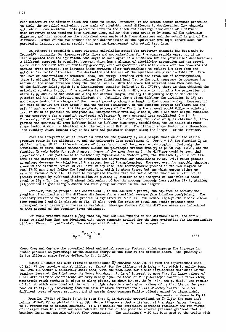
6- 18
Mach numbers a t the diffusor i n l e t are close t o unity. t o apply the so-called equivalent cone angle of straight, round diffusors t o decelerating flow channels with other cross sections. with arbitrary cross sections into circular ones, e i ther with equal areas or by means of the hydraulic diameter, and then determines the equivalent cone angle with these diameters and the actual length of the diffusor. Either of the two methods for the determination of the equivalent cone angle breaks down for particular designs, or gives resul ts that are i n disagreement with actual t e s t data.
Moreover, it has almost become standard procedure
This procedure converts the in l e t and discharge f low areas of a diffusor
An ttempt t o establish a more rigorous calculating method for arbitrary channels has beenmade by Traupe12 8 , primarily for incompressible flows and approximations for the compressible case, but it i s then suggested that the equivalent cone angle be used again as a cri terion for the permissible deceleration. A different approach i s possible, however, which has a minimum of simplifying assumption and has proved t o be valid for diffusors of arbitrary geometry, even axisymmetric ones with curved meridian channels and annular cross sections, for instance those arranged a f t e r turbomachines t o deflect the flow f r o m the axial t o the radial direction. The derivation and the use of the equations are given i n Table I V . From the l a w s of conservation of momentum, mass, and energy, combined with the f i r s t law of thermodynamics, there i s obtained Eq. IV(10) which relates the fr ic t ional heat T d s t o the work necessary t o overcome the action of the shear stresses along the channel W s . at the diffusor i n l e t , which i s a dimensionless quantity defined by Eq. IV(14), there i s then obtained the principal equation I V ( 1 5 ) . s ta te p, p, and 8, a t the stations along the channel length, and w i s depending only on the channel geometry and the skin fr ic t ion coefficient cf. not independent of the changes of the channel geometry along i t s length L that occur i n q. one were t o adjust the flow areas A and the wetted perimeter C of the sections between the i n l e t and the exi t i n such a manner that the thermodynamic process of the f luid i n the channel would follow a polytropic law, it would be possible t o integrate dX1 independently f r o m dX2 since 8, and p are then unique functions of the pressure p for a constant polytropic efficiency '$, or a constant loss coefficient 5 = 1 - $. Conversely, i f dn average skin fr ic t ion coefficient ?f is introduced, the value of X 2 i s obtained by inte- grating the quantity d62 f r o m diffusor i n l e t t o diffusor discharge, establishing the so-called diffusor shape factor fi which i s identical with the value CP of Ref. 26. less quantity which depends only on the area and perimeter changes along the length L of the diffusor.
With the so-called referred mass flow ra t e hr3
This equation is of the form dX1 = w, where dX1 contains the properties of
Actually, for a given diffusor the variables i n dX1 are However, i f
The diffusor shape factor i s a dimension-
From the integration of dX1 there i s obtained the quantity X l as a unique f i c t i o n of the s t a t i c pressure r a t i o i n the diffusor, y , and the polytropic loss coefficient 5 . plotted i n Fig. 18 for different values of 5 , as function of the pressure r a t i o p d p . Obviously the conditions of s t a t e change monotonously during the polytropic process f rom p3 t o p4 ?n Fig. IV(2) , and the function X i only holds for such changes. compressions i n one part would be followed by expansions i n another part , the function X i could not take care of the situation, since for an expansion the polytropic law established by Eq. IV(7) would produce an entropy decrease i n violation of the second law of thermodynamics. However, even for smoothly changing areas i n the diffusor, which it w i l l have i n any case, the thermodynamic process i n the T-s diagram of Fig. IV(2) might not follow the isentropic l ine which i s shown there, but one which curves either up- ward or downward from it. It must be recognized however that the value of the f'unction Xl w i l l not be greatly changed by different distribution of p dong L, similar t o the integral of Tds which i s about equal t o (T (4),providea it goes along a smooth and f a i r ly regular curve i n the T-s diagram.
For y = 1.4 the function Xl i s
Hence i f the area changes i n the diffusor would be such that
+ T4) (84 - s 3 ) / 2 almost independent of how the process proceeds f r o m station (3) t o station
Moreover, the polytropic loss coefficient 5 i s not assumed a pr ior i , but adjusted t o sat isfy the equation of continuity a t the diffusor discharge for a specified average skin fr ic t lon coefficient. necessary i terat ion t o solve t h i s problem is explained i n Table I V . flaw m c t i o n CP which i s plotted i n Fig. 18 also, with the r a t i o of t o t a l and s t a t i c pressure that correspond t o an isentropic process a8 variable. to take account of the boundary layer thickness.
The The method employs the dimensionless
Blockage factors for the diffusor areas are introduced
For small. pressure rat ios p4/p3; that is , for l o w Mach numbers at the diffusor i n l e t , the metfiod leads t o relations that are identical with those c m o n l y applied for the loss evaluation for inccanpressible diffusor flows. In particular, the average skin f r i c t ion coefficient i s equal t o
- 'PRi - 'PR n Cf = (53)
where Cpm and CPR are the so-called ideal and actual recovery factors, which express the increase i n s t a t i c pressure as percentage of the kinetic e n e r a of the flow a t the diffusor inlet . i s the diffusor shape factor defined by Eq. I V ( 1 9 ) .
Figure 19 shows the skin fr ic t ion coefficients
The quantity R
obtained with Eq. 53 f r o m the experimental data of Ref. 27 for two-dimensional diffusors. 48, which i s unduly long, the data l i e within a relat ively s m a l l band, with the t e s t data for a thin disilacement thickness of the boundary l w e r a t the in l e t near i t s lower boundary. It i s of interest t o note that for large values of R the skin fr ic t ion coefficients are very nearly equal t o those of fuUy developed turbulent flows along moderately rough surfaces i n pipes or along plates, as shown by Ref. 20 (p. 587, pui p. 611). of Ref. 28 which were obtained, i n par t , a t high subsonic speeds give values of cf that l i e i n the same band as i n Fig. 19, indicating that the skin fr ic t ion coefficients 'E. are directly related t o R for different types of cross sections, and a t speeds where compressibility effects cannot be disregarded.
Except for the diffusor with b / a
The resul ts
This product is shown, in Fig. 20 From Eq. 1v(18) of Table I V it is seen that $ is directly proportional t o Ff R;for the same data
points of Ref. 27 as plotted in Fig. 19. Hence it appears that a diffusor with a shape factor n equal t o 10 represents an opthum solution. If R i s smaller the efficiency decreases radically and for values of R larger than 10 a diffusor does not make full use of the possible adverse pressure gradient that a '
boundary layer can sustain without f low separations. The criterion R = 10 has been used by the writer with
I
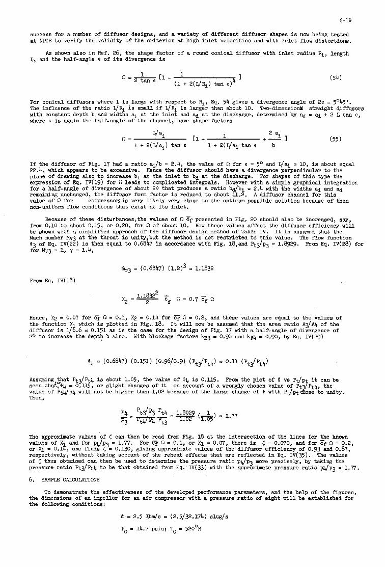
6-19
success for a number of diff'usor designs, and a variety of different diffusor shapes i s now being tested a t NPGS t o verify the validity of the cr i ter ion a t high in l e t velocit ies and with in l e t flow distortions.
As shown also i n Ref. 26, the shape factor of a round conical diffusor with in l e t radius R i , length L, and the half-angle E of i t s divergence is
For conical diffusors where L i s large with respect t o q, Eq. 54 gives a divergence angle of 26 = 5O45'. The influence of the r a t i o q& i s small i f L/& i s larger than about 10. Two-dimensional straight diffusors with constant depth b,and wid th ai a t the inlez and where E is again the half-angle of the channel, have
L/ a i n =
1 + 2 ( ~ / a ~ ) tan 6
a t the discharge, determined by &a = a i + 2 L tan E,
shape factors
2 ai
b + - I 1 c 1 +
1 + 2(L/ai tan E (55)
If the diff'usor of Fig. 17 had a r a t i o aF/b = 2.4, the v a u e of 61 for E = 5 O and L/ai = 10, i s about equal 22.4, which appears t o be excessive. Hence the diffusor should have a divergence perpendicular t o the plane of drawing also t o increase b i a t the in l e t to bd a t the discharge. For shapes of t h i s type the expression of Eq. IV(19) for 61 leads t o complicated integrals. for a half-angle of divergence of about 20 that produces a r a t i o b d b i = 2.4 with the widths a i and &d remaining unchanged, the diffusor form factor i s reduced t o about l l .2. value of 61 for non-uniform flow conditions that exis t a t i t s inlet .
However with a simple graphical integratior.
A diffusor channel for t h i s compressorJ is very l ikely very close t o the optimum possible solution because of then
Because of these disturbances,the values of 61 Ff presented i n Fig. 20 should also be increased, say, from 0.10 t o about 0.15, or 0.20, for n of about 10. be shown with a simplified approach of the diff'usor design method of Table I V . Mach number Mv3 a t the throat i s unity but the method is not res t r ic ted t o t h i s value. $3 of Eq. IV(22) i s then equal t o 0.68b i n accordance with Fig. 18,and Pt.p3 = 1.8929. Frau Eq. IV(28) for for Mv3 = 1, y = 1.4,
How these values affect the diffusor efficiency w i l l It i s assumed that the
The flow f'unction
1i+3 = (0.6847) (l .2)3 = 1.1832
From Eq. 1v(18)
Hence, X2 = 0.07 for Cf n = 0.1, @ = 0.14 for e 61 = 0.2, and these values are equal t o the values of the f'unction X which is plotted i n Fig.. 18. It will now be assumed that the area r a t i o A3/AI+ of the diffusor i s $.6 = 0.151 as i s the case for the design of Fig. 17 with a half-angle of divergence of 2O t o increase the depth b a l s o . With blockage factors kg3 = 0.96 and kg4 = 0.90, by Eq. IV(29)
Assuming that P t g P t 4 i s about 1.05, the value of $4 is 0.115. seen that",'m4 = O . l l 5 , or s l ight changes of it on acoount of a wrongly chosen value of PtJPt4, the value of Pt4/p4 w i l l not be higher than 1.02 because of the large change of I with Pt/ptdLose t o unity. Then,
From the plot of I vs Pt/p it can be
The approximate values of 5 can then be read from Fig. 18 a t the intersection of the l ines for the known values of X and for pJp3 = 1.77. or X i = 0.16, one finds 5 = 0.130, giving approximate values of the diffusor efficiency of 0.93 and 0.87, respectively, without taking account of the reheat effects that are ref1ecte.d i n Eq. IV(35). of 5 thus obtained can then be used t o determine the pressure r a t i o pJp3 more precisely, by taking the pressure r a t i o Pt3/Pt4 t o be that obtained from Eq: IV(33) with the approximate pressure r a t i o p u p 3 = 1.7.
6. SAMPIE CALCULATIONS
For Cj 61 = 0.1, or X i = 0.07, there i s 5 = 0.070, and far cf 61 = 0.2,
The values
To demonstrate the effectiveness of the developed performance parameters, and the help of the figures, the dimensions of an impeller for an a i r campressor with a pressure r a t i o of eight w i l l be established for the following conditions:
Ifi = 2.5 l b q s = (2.5/32.174) slUg/s
P = 14.7 psia; To = 520°R 0
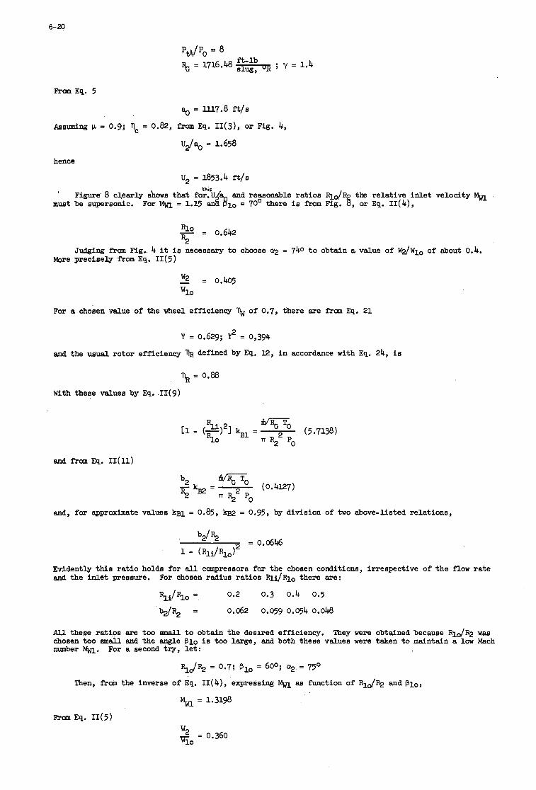
6-20
From Eq. 5
= I.I.I.7.8 ft/S
Assuming p = 0.9; 1, = 0.82, fram Eq. I I ( 3 ) , or Fig. 4,
"J.0 = 1.658
hence
U2 = 1853.4 fils this
' Figure 8 clearly shows tha t for,U/a and reasonable ra t ios R l J R the relative in l e t velocity m u s t be supersonic. For = 1.15 a& pl0 = 70' there i s f r o m Fig. 6, or Eq. I I (4) ,
Rlo - = 0.642 R2
Judging f r o m Fig.. 4 it i s necessary t o choose a2 = 740 t o obtain a value of W 2 / W l o of about 0.4. More precisely from Eq. I I ( 5 )
- w2 = 0.405 Wlo
For a chosen value of the wheel efficiency of 0.7, there are from Eq. 21
2 'i' = 0.629; 1 = 0,394
and the usual rotor efficiency % defined by Eq. 12, i n accordance with Eq. 24, i s
1 =0.88 R
With these values by Eq. I I (9)
and fram Eq. II(ll)
To R22 Po
(0.4127) b2 5 % -
and, far approximate values kgl = 0.85, kg2 = 0.95, by division of two above-fisted relations,
= 0.0646 ' b 2 h
1 - (Rl i /Rlo i2
Evidently this r a t i o holds for all compressors for the chosen conditions, irrespective of the flow ra te and the inlet pressure. For chosen radius ra t ios R l i / R l o there are:
R l i / R l O = 0.2 0.3 0.4 0.5
b d % = 0.062 0.059 0.054 0.048
W these rat ios are too emall t o obtain the deslred efficiency. chosen too mall and the angle B l o is too large, and both these values were taken t o maintain a low Mach number w. For a second try, l e t :
They were obtained because RlJR2 was
R.J% = 0.7; B l o = 60'; a2 = 75'
Then, from the inverse of Eq. I I (4 ) , expressing as Function of Rlo/R2 and Blo,
From Eq. I I (5 )
w2 = 0.360 T O
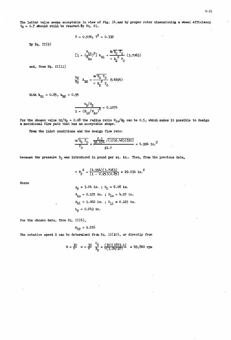
6-21
The l a t t e r value seems acceptable i n view of Fig. l4,and by proper rotor dimensioning a wheel efficiency % = 0.7 should s t i l l . b e reached.& Eq. 21.
(3.7063) Rli 2 S O
11 - (-) 1 kBl =
and, from Eq. II(11)
For the chosen value b2/R2 = 0.08 the radius r a t i o R l & can be 0.5, which makes it possible t o design a meridional flow path that has an acceptable shape.
From the i n l e t conditions and the design flow rate:
because the pressure Po was introduced in pound per sq. in.. Then, from the previous data,
R = -- = 29.034 in. 2 2
Hence % = 3.04 in. ; D2 = 6.08 in.
So = 2.125 in. ; Dlo = 4.25 in.
Rli = 1.062 in. ; Dli = 2.125 in.
b2 = 0.243 in.
For the chosen data, f r o m Eq. 11(6),
% = 1.256
The rotative speed N can be determined fran Eq. I I ( l O ) , or directly f r o m
6-22
REFERENCES
Vawa, M. H. Aerothermodynamics and Flow i n Turbomachines, Wiley Bros, New York, 1960.
1.
2.
3.
4.
5.
6.
7.
8.
9.
10.
ll.
12.
U.
14.
16.
17.
18.
19
20.
21.
22.
23.
24.
Vavra, M. H.
Traupel, W.
Johnston, J. P. Dean, R. C. , Jr.
Stiefel , W.
S t iefel , W.
S&ai, T. Watanabe, I., e t al.
Vavra, M. H.
Bemmert, K. Bohm, E.
Groh, F. W. Robb, W. L.
Katsanis, T. McNally, W. D.
Jmbach, H. E .
Linsi, U.
Fowler, H. S.
Fowler, H. S.
Helleen, R. M. Johnson, J. P.
Ackeret, J. Keller, C. Salzmsnn, F.
Shepherd, D. G.
B a l j d , 0. E.
Schlichting, H.
D a i l y , J. W., Nece, R. E.
Nece, R. E. D a i l y , J. R.
Pantel, K.
Maroti, L. A. De&, G. mei th , F.
Schmidt- Theuner , P. Mattern, J.
Axial Flow Turbines Von Karman Inst i tute for Fluid Dynamics, Lecture Series 15, pp. 99/lbo, April 1969.
D i e Theorie der Stroemung durch Radialmaschinen, EIraun, Karlsruhe,
J. Engg. for Power, Trans. ASME, pp. 49-62, January 1966.
1962.
'%Experimental Investigations on Radial Compressors . . . ' I , Course Note 53b, Von Karman Inst i tute , March 1965.
''Undersuchung an Radialen Verdichterlauefern," AVA Forschungsbericht 63-01, Triebwerksaercdymuik der Turbanaschinen, Teil I1 , Goettingen, 1963.
"On the Slip Factor of Centri-al and Mixed-Flow lmpellers", ASME Paper 67-WA/GT-10.
" R a d i a l Turbines", P a r t 4 of AGARD-VKt Lecture Series 6 on*Flm i n Turbines", Von K a r m a n Inst i tute , March 1968.
"Nuclear Plants with High-Temperature Reactor and Helium Turbine, 'I
ASME Paper 69-GT-43, March 1969.
"High Efficiency Can Be Achieved in Small Size Transonic Compressor Rotors," SAE Paper 820c, January 1964.
"Frograms for Computation of Velocities and Streamlines on a Blade- to-Blade Surface of a Turbomachine" ASME Paper 69 -~~-48 , March 1969.
"Die Berechnung der kcrmpressiblen, reibungsfreien Unterschallstroemung durch rauemliche Gitter &us Schaufeln auch grosser Dicke und starker Woelbung" Mit- No 8, Inst . Thermische Turbomaschinen, ETH, Ju r i s Verlag, Zurich, 1964.
Brown Boveri Review, Vol. 53, No. 3, p. 161, March 1965.
"Sane Measurements of the Flow Patterns i n a Centriflgal Comp-essor Impeller," ASME Paper 65-WA/FTP-7, April 1965.
"The Distribution and Stabi l i ty of Flow i n a Rotating Channel," ASME Paper 6 8 - ~ ~ - 1 , March 1968,
"The Influence of Rotation on Flow i n a Long Rectangular Channel" Stanford University, Report MD-18, May 1967.
Schweizer Bauzeitung, No. 23, December 1934.
"Principles of Turbamachinery", Macmillan; New York, 1956.
J. Engg for Power, Trans. ASME Series A, Vol. 84, No. 1, pp. 83-114, Jan 1962.
Boundary-Layer Theory, 6th ed., p. 606, McGraw-Hill, N. Y., 1968.
J. of Basic Engg., Trans. ASME, p. 217, March 1960.
Forschung, Vol. 16, p. 97, 1950.
J. of Baskc Engg., ! ham. ASME, p. 539, Sept. 1960.
25. Brown Boveri Review, Vol. 55, No. 8, p. 453, 1968.
6-23
26. Traupel, W.
27. waitman, B. A. Reneau, L. R. Kline, S. J.
Klomp, E. D. 28. Sovran, G.
Thermische Turbcrmaschinen, Ed. I., p. 308, Springer, Berlin, 1962.
J. of Basic Em., Trans. BME, Vol. 83, Series D., No. 3, p. 349, Sept. 1961.
'%xperFmentally Determined Optimum Geometries for Rectinlinear DiffUsors with Rectangular, Conical or Annular Cross Sections," symposium on Fluid Mechanics of Internal Flow,General Motors Research Laboratories, Sept. 1965.
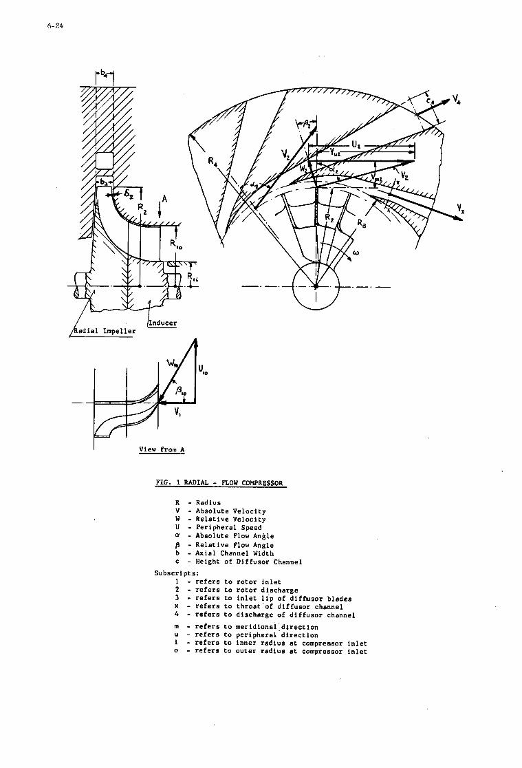
6- 24
/Inducer k adial Impeller
I View from A
FIG. 1 RADIAL - FLOW COMPRESSOR
R - Radius V - Absolute Velocity W - Relative Velocity U - Peripheral Speed - Absolhte Flow Angle ~3 - Relative Flow Angle b - Axial Channel Width c - Height of Diffusor Channel
Subscripts: 1 - refers to rotor inlet 2 3 - refers to inlet lip of diffusor blades x - refers to throat-of diffusor channel 4 m - refers to meridiona1:direction U - refers to peripheral direction i - refers to inner radius at compressor inlet o - refers t o outer radius at compressor inlet
- refers to rotor discharge - refers to discharge of diffusor channel
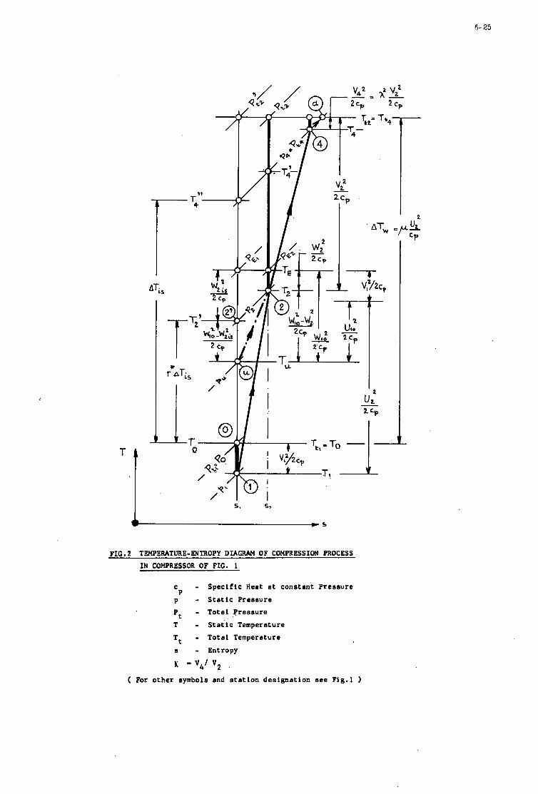
6- 25
0 /
4G - ' /
QO
FIG. 2 TEMPERATURE-ENTROPY DIAGRAM OF COMPRESSION PROCESS IN COMPRESSOR OF FIG. 1
c - S p e c i f i c Heat a t constant Pressure
p - S t a t i c Pressure P
Pt - Total Pressure
T - S t a t i c Temperature Tt - Total Temperature
I - Entropy
E - v,/ vp .
( For other symbols and s t a t i o n des ignat ion see Fig.1 )
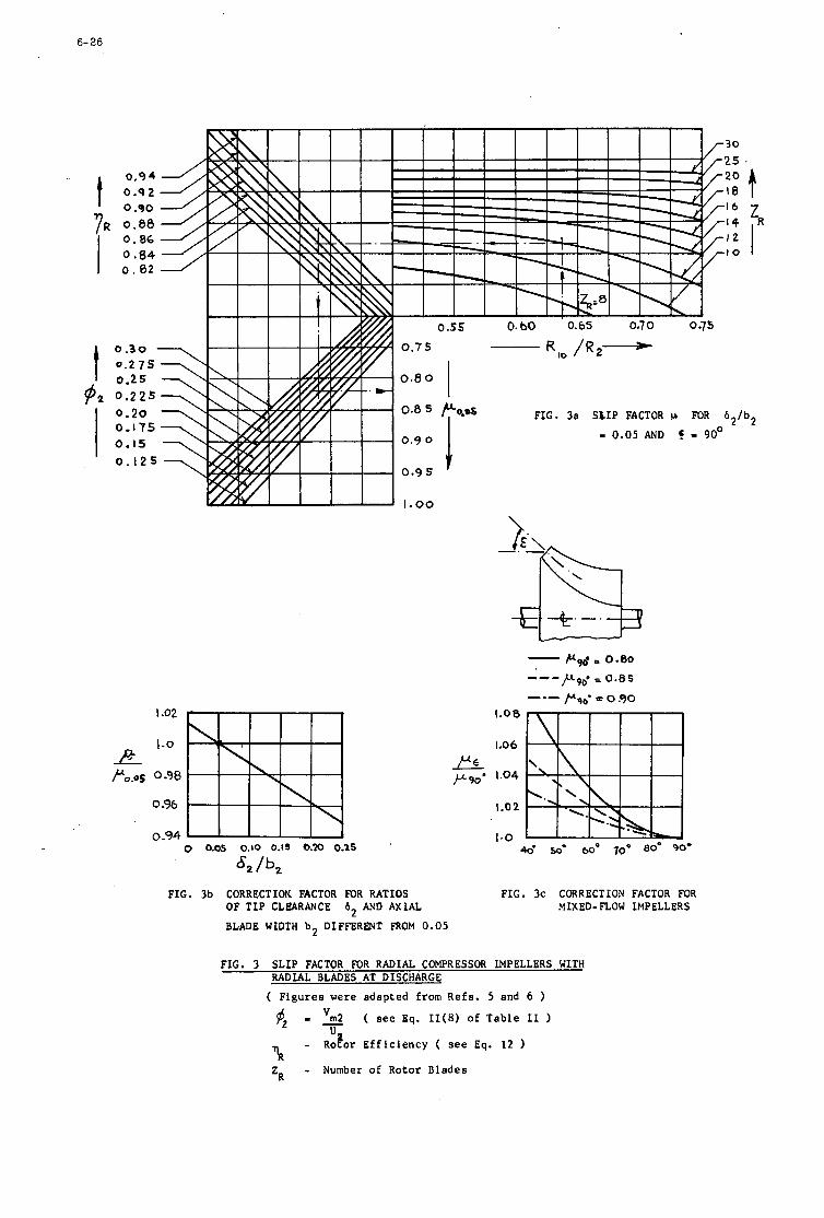
6- 26
t
1-02
1.0
0 -98
0.96
0 -94 0 0.05 0.10 0.1s 0.m 0.15 '
8, /b, FIG. 3b CORRECTION FACTOR FOR RATIOS FIG. 3c CORRECTION FACTOR FOR
OF T I P CLKARANCE b2 AMP AXIAL MIXED- FLOW IMPELLERS
BLADE WIDTH b 2 DIFFERENT FXOM 0.05
FIG. 3 SLIP FACTOR FOR RADIAL COMPRESSOR IMPELLERS WITH RADIAL BLADES AT DISCHARGE
( F i g u r e s were a d a p t e d from R e f s . 5 and 6 - ( see Eq. II(8) of T a b l e 11
- R o t o r E f f i c i e n c y ( see Eq. 12 U
?R ZR - Number of R o t o r B l a d e s
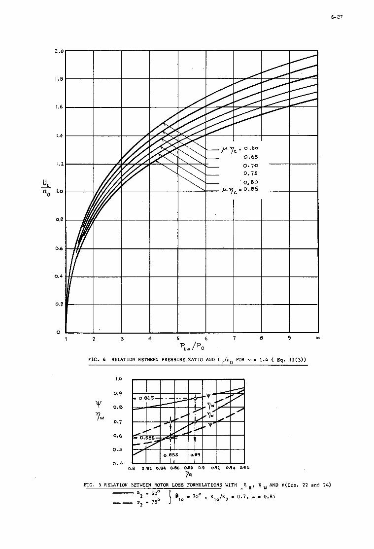
6-27
2 .o
I .8
1.6
I .4
1.2
- "2 a, 1.0
0.8
0.6
0.4
0 . 2
0 I 2 3 4 5 6 7 8 9 IO
Pk, /Po F I G . 4 RELATION BETWEEN P R E S S U R E R A T I O AND ti,/a, MR v - 1.h ( Eq. I I ( 3 ) )
t .O
0.9
0 .8
0.1
0.6
0 .s
0.4 0.8 0 .82 0.84 0.86 t 0 8 0.9 0.92 0.94 0.9C
1 R
F I G . 5 RELATION BETWEEN ROTOR LOSS FORMULATIONS WITH R, AND Y ( E a s . 22 and 24)
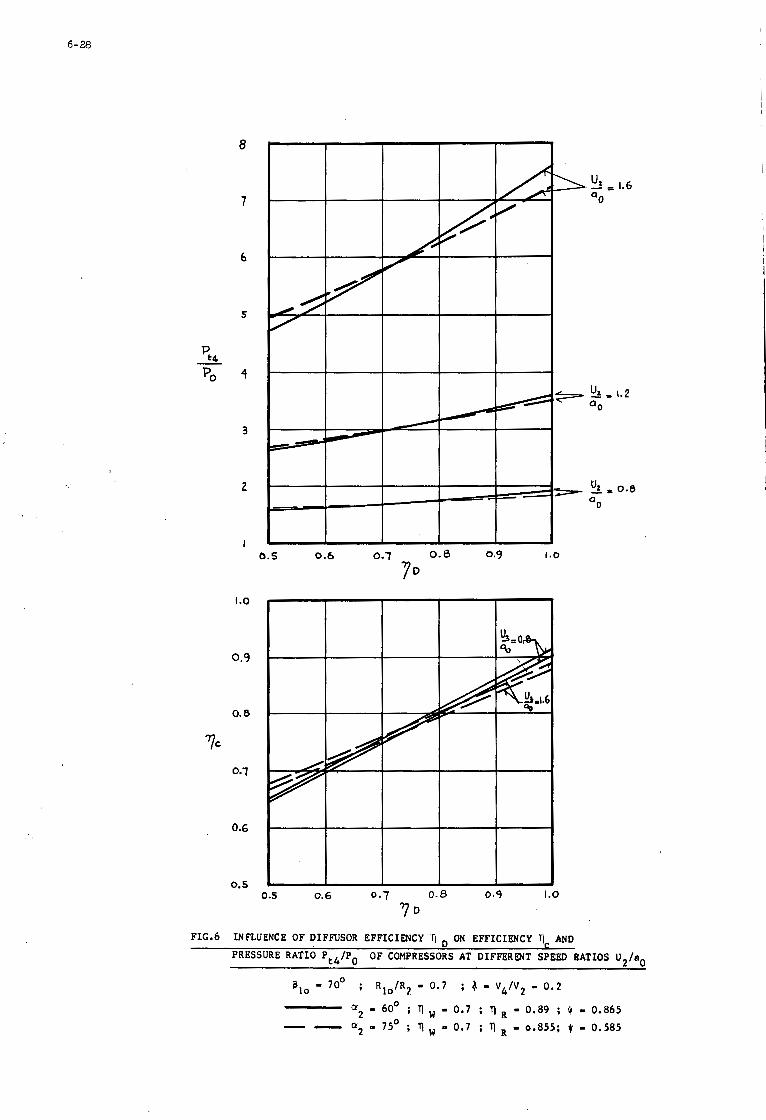
6-28
8
7
6
5
4
3
2
I
I .o
0.9
0.8
'7c
0.7
0.6
0.5
0 .5 0.6 0.7 0.8 0.9 1.0
5 !!? = 1.6 OO
1.0
' I o
FIG-6 INFLUENCE OF DIFFUSOR EFFICIENCY U ON EFFICIENCY AND
PRESSURE RATIO Pt4/Po OF COMPRESSORS AT DIFFERWT SPEED RATIOS U2/ao
8,' 70' ; R l o / R 2 - 0.7 ; 4 - V,,/V2 - 0 . 2
O2 - 60' ; 9 ,,, - 0.7 ; 7) - 0.89 ; $ - 0.865 - - - 75' ; 9 - 0.7 ; - 0.855; JI - 0.585
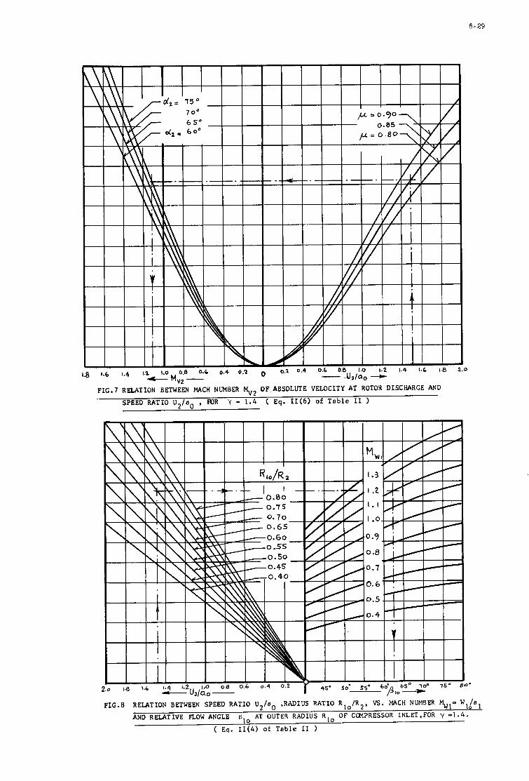
6- 29
.- F I C . 7 RELATION BETWEEN MACH NUMBER MV2 0F.ABSOLUTE VELOCITY AT ROTOR DISCHARGE AND
SPEED RATIO U 2 / a o , FOR Y - 1 . 4 ( Eq. II(6) of T a b l e 11 )
F I C . 8 RELATION BETWEEN SPEED RATIO U 2 / a o ,RADIUS RATIO R l o / R 2 , E. MACH NUMBER
AND RELATIVE FLOW ANGLE WILal
AT OUTER RADIUS R i o OF CCNPRESSOR INLET,FOR y -1 .4.
( Eq. II(4) of T a b l e I1 )
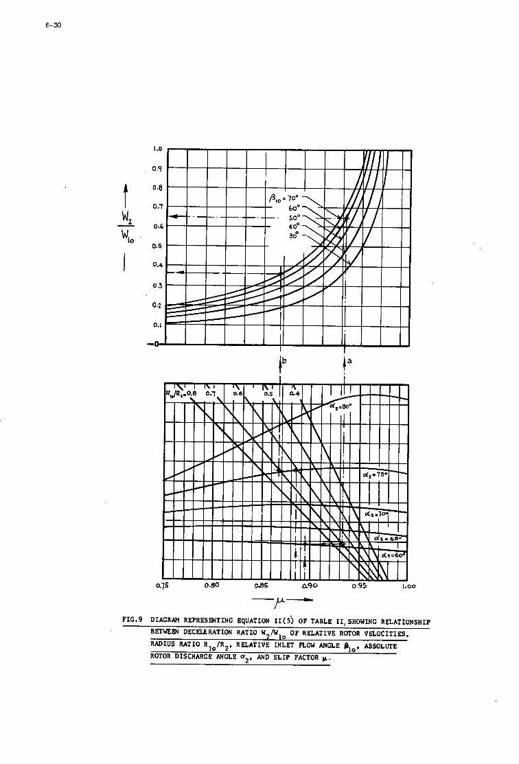
6- 30
-P- F I G . 9 DIAGRAM R E P R E S m T I N G EQUATION I I ( i ) OF TABLE 11, SHOWING RELATIONSHIP
BETWEEN DECELERATION RATIO W I N , , O F RELATIVE ROTOR VELOCITIES, I Y
RADIUS RATIO R l o / R 2 , RELATIVE INLET FLOW ANGLE B,,, ABSOLVTE
ROTOR DISCHARGE ANGLE Q2, AND S L I P FACTOR p .
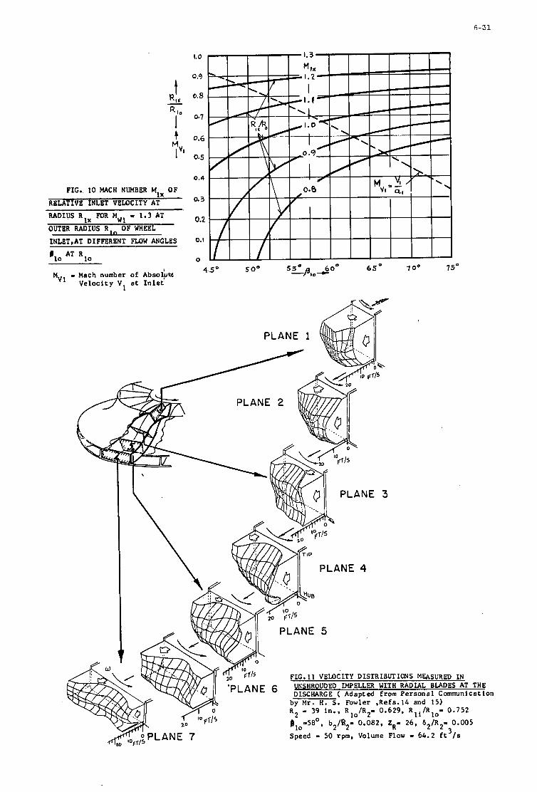
6-31
FIG. 10 MACH NUMBER M1, OF
RELATIVE INLET VELOCITY AT RADIUS R l x FOR MW1 I 1.3 AT
OUTER RADIUS R, OF WHEEL 1NLET.AT DIFFERENT FLOW ANGLES
810 AT 5 0 ,
MV1 - Mach number of A b s o l p Ve loc i ty V a t I n l e t 1
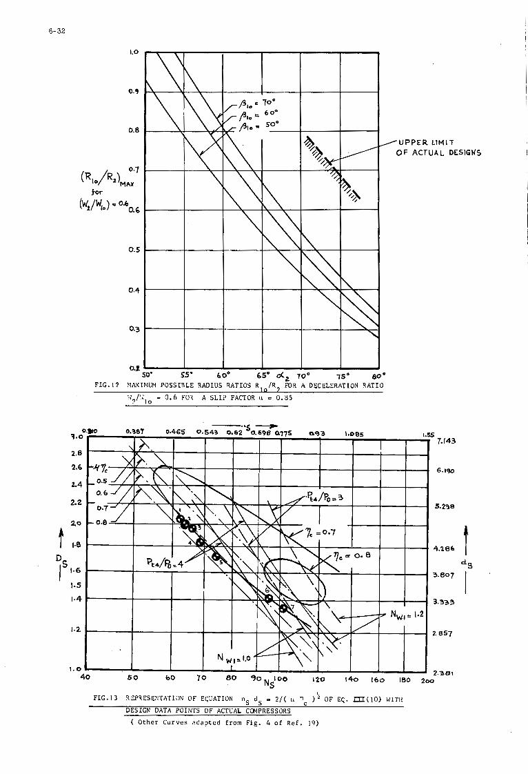
6-32
1.0
0.9
0.8
0.5
0.3
Y I I I
80 O
55' 6 Oo 65" d , TOo 750
/UPPER LIMIT OF ACTUAL DESIGNS
FIG. 1 2 MAXI(IMU?1 POSSIBLE XADIUS RATIOS R, / R 2 bR A DECELERATION RATIO
Id,/':,* - 3 . 6 FOX A SLI2 FACTO? II 0 0.35
5 7.143
6.190
4.206 t 3.333
L 857
FIG.13 lEPTESENTATION OF ECUATION nS dS - 2 / ( LL Tc ) ' OF EC. m(10) WITH DESIGN DATA POINTS OF ACTUAL COElPRESSORS
( Other C u r v e s z d a p t e d from Fig. 4 of R e f . 19)
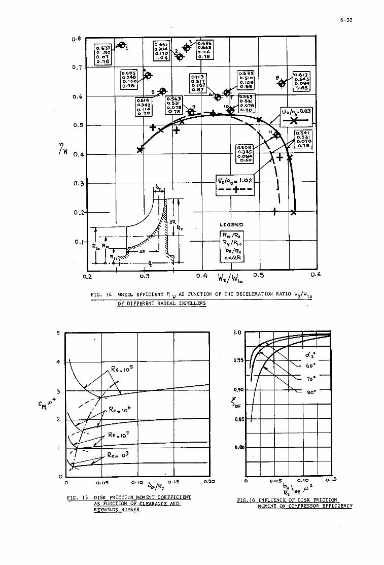
6- 33
0.8
0.7
0.6
0.5
7l ’‘ 0.4 0.3
0.2
0.1
5
4
3
2
I
0
0.631 0 . 7 3 0 ’ 0 . 0 1 0 . 1 8
I I I -/I \
1 1 1 1 1 4
0.5 W2/WI0
0.2 0.3 0.4
0.54 I 0.531 0 . 0 7 8
r
0.6
F I G . 14 WHEEL E F F I C I E N Y 7 A S FUKCTION O F THE DECELERATION R A T I O W 2 / W l o
O F D I F F E R E N T R A D I A L I M P E L L E R S
0 0.05 0.10 0.15 0.20
F I G . 15 DISK F R I C T I O N MOMENT COEFFI,C.UD A S FUNCTION O F CLEARANCE AND REYNOLDS NUMBER
F I G . 16 I N F L U E N C E O F DISK F R I C T I O N MOMENT ON COMPRESSOR E F F I C I E N C Y
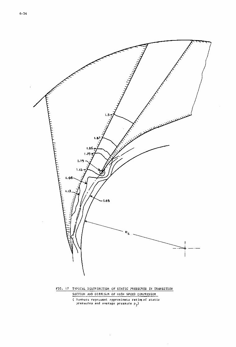
6-34
FIG. 1 7 TYPICAL DISTSIBUTION OF STATIC PRESSURES Ih’ TRANSITION
SECTION AND DIFFCSO3 OF H I G H SPEED COMPRESSOR
( Surnbers r e p r e s e n t approximate r a t i o s of s t a t i c p r e s s u r e s and average p r e s s u r e p )
2
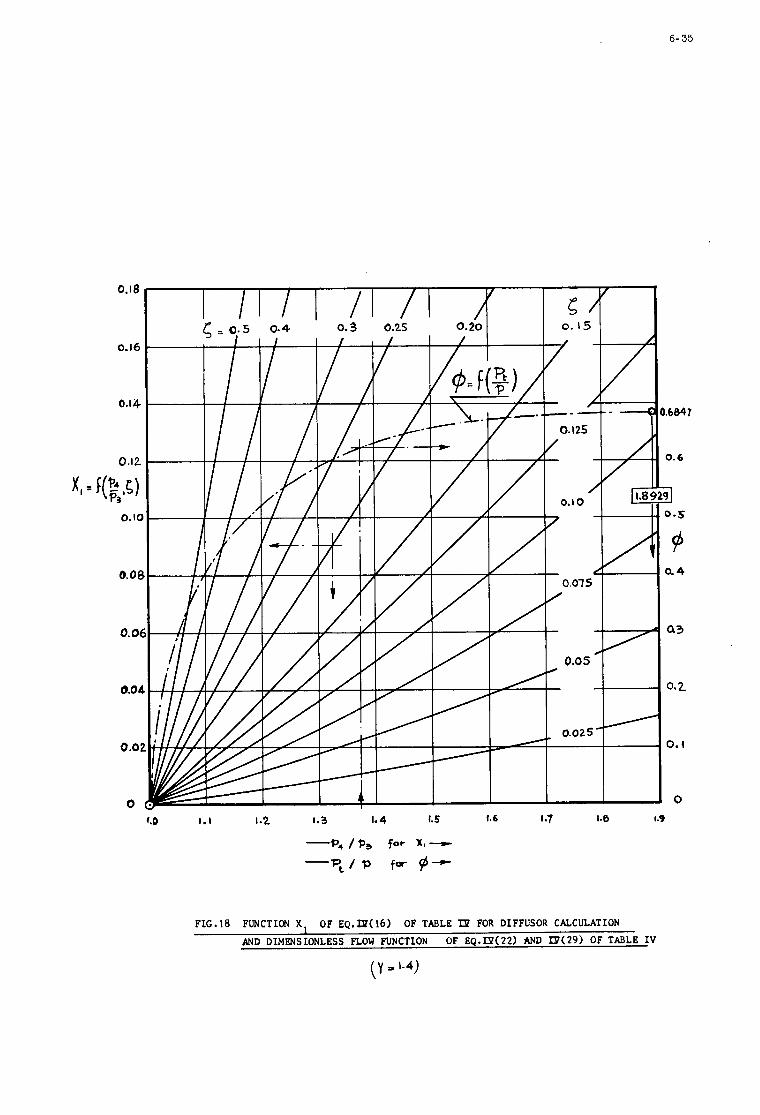
6- 35
0.18
0.16
0.14
0.12
XI = (8,~) o. la
A
0.oe
0. O(
0.04
0.0:
0 f.0 1.1 1.2 1.3 1.4 I. 5 1.6 1 ~7 1.8 1.9
FLC.18 FUNCTION X OF EQ.fP(16) OF TABLE Tp FOR DIFFUSOR CALCULATION
AND DIMENSIONLESS FLOW FUNCTION OF EQ.IP(22) AND KY(29) OF TABLE IV
( Y = ‘ - 4 )
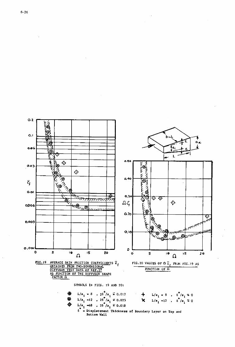
6-36
0.003 c 0.001 LITm
0 s 10 I5 20 a
0.50
a4o
0.3~
o. za
0. IC
0 0 5 i5 2 0
lo hz FIG.^^ VALUES O F n C~ RUM FIG.^^ AS
FUNCTION OF Q
SYMBOLS IN FIGS. 19 AND 20:
o @ Q
L/ai - a , 26*/ai z 0.017 L f a i -12 , 2b*/ai = 0.025 L I ~ , d a , 2b*/ai = 0.018 b* 9 Dieplacement Thickness of Boundary Layer on Top end
-I- L/ai - a , &*/ai = o b*/ai 2 0 L/ai -12 ,
Bottom Wall
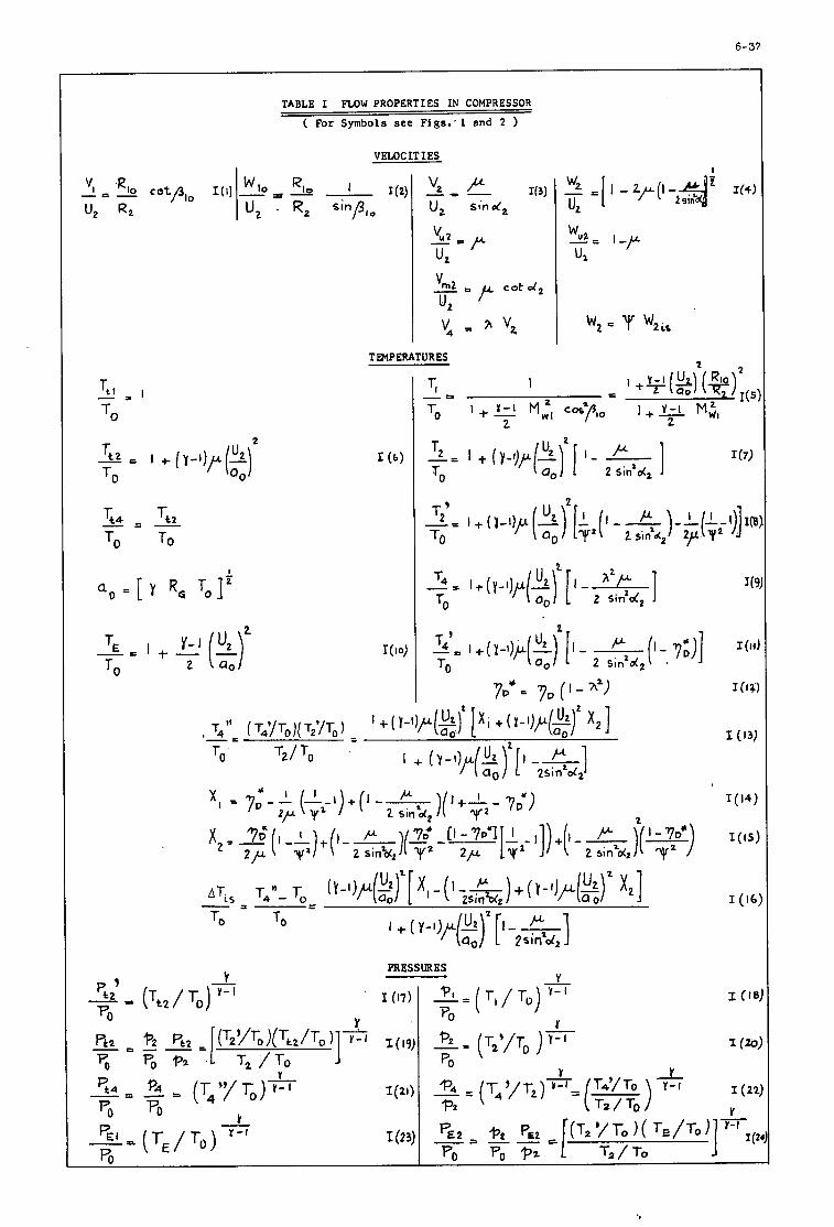
6-37
TABLE I FLOW PROPERTIES IN COMPRESSOR
( For Symbols see Figs: 1 and 2
I VELOCITIES
7 I TPlPERATURES
I
d o = [ Y R,
2 - = I + - ( - - ) TE Y - J U2
T O 2
J (9)
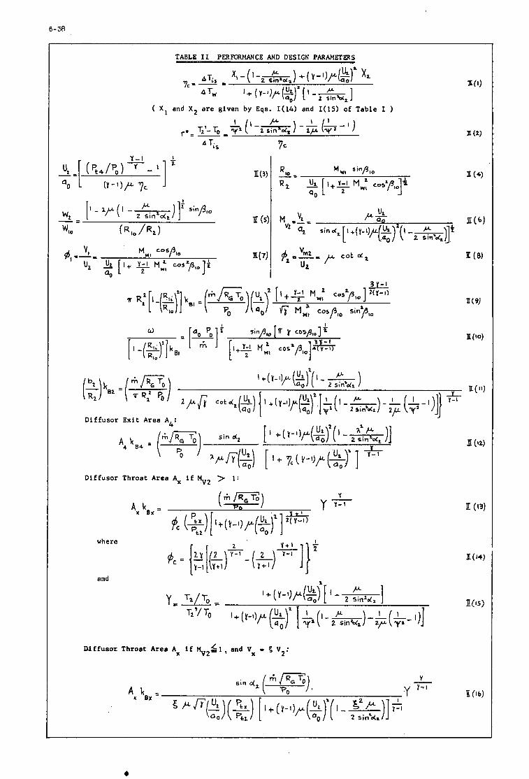
D i f f u s o r Throat Area Ax i f MV2 7 1 :
A x k*#. =
where
and
("TI U Y Y r - (
D i f f u s o r Throat Area Ax i f M V 2 6 1 , and V, - 5 V2:
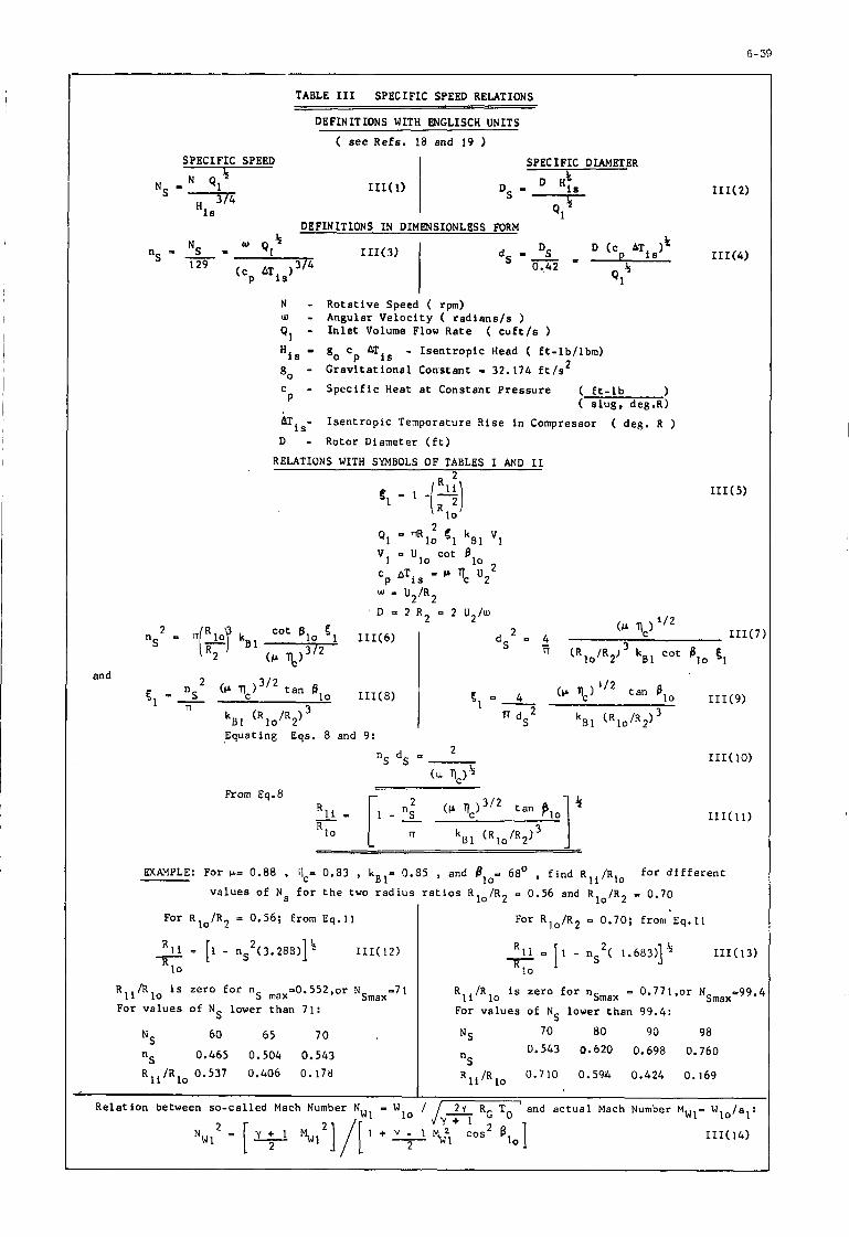
6- 39
SPECIFIC SPEED - 4
I Q, NS 3/4
is
TABLE 111 SPECIFIC SPEED RELATIONS
DEFINITIONS WITH WCLISCH UNITS
( see Refs. 18 and 19 1 SPECIFIC DIAMETER
DEFINITIONS I N DIMENSIONLESS FORM
N - Rota t ive Speed ( rpm) U) - Angular V e l o c i t y ( r a d i a n s l s ) Q, - I n l e t Volume Flow Rate ( c u f t / s )
go - G r a v i t a t i o n a l Constant - 32.174 f t / s
c - S p e c i f i c Heat a t Constant P r e s s u r e ( f t - l b P ( s l u g , de8.R)
ATis- I s e n t r o p i c Temperature R i se in Compressor ( deg. R )
D - Rotor Diameter ( E t )
go c p ATis - I s e n t r o p i c Head ( f t - l b / lbm) 2
His - )
RELATIONS WITH SWBOLS OF TABLES I AND I1
R 2 9. = 1 -/*\
n
Equating Eqs. 8 and 9:
From Eq. 8
EXAMPLE: For t.b= 0.88 , 11,- 0.83 , k B l = 0.85 , and plO- 68' , f i n d R I i / R l o f o r d i f f e r e n t
v a l u e s o f N s for t h e two r a d i u s r a t i o s R l o / R 2 - 0.56 and R l o / R 2 - 0.70
For R l o / R 2 n 0.70; from Eq.11 I For R l o / R 2 = 0.56; from Eq.11
R l i = [I - nS2(3 .288) l4 III( 12) Alo
R I i / R l o is ze ro f o r n
For v a l u e s of NS lower than 71:
max=0.552,0r N R I i / R l o is ze ro for nSmax - 0 . 7 7 1 . 0 ~ NSmax=99.r
For v a l u e s of NS lower than 99.4:
60 65 70 NS "S 0.465 0.504 0.543 R I i / R l o 0.537 0.406 0.178
NS 70 80 90 98 0.543 0.620 0.698 0.760
R I i / R l o 0.710 0.594 0.424 0.169 nS
., I Rela t ion between so -ca l l ed Mach Number NW1 - Wlo / /- and a c t u a l Mach Number MWl= Wlo/al:
Y + 1 III( 14)
2
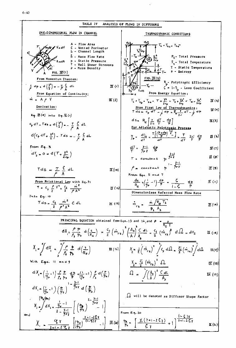
6-40
TABLE I V ANALYSIS OF Fu)WS I N DIFFUSORS
ONE-DIMENSIONAL F L O W IN CHANNEL
A - Flow Area v+dv C - Wetted Perimeter
L - Channel Length
- Mass Flow Rate +dA p - S t a t i c P res su re
7 - Wall Shear S t r e s s e s P - Mass Densi ty -
From Momentum Theorem:
-Om Equation of Cont inui ty:
A f V
Der iva t ion :
From €9. 3
T d s 1 dL P A
From R ' i c t i o n a l Law with Eq.2:
E ( 1 , m p
Jnto E?. 10
T d s , A -, t i l 2 C d L , 2 P'A'
Ip (I:
THERMODYNAMIC CONDITIONS
Pt- Tota l P r e s r u r e
Tt- T o t a l Temperature
T - S t a t i c Temperature 8 - Entropy
P o l y t r o p i c Ef f i c i ency
1-\ - Loss Coef f i c i en t
Equation :
Dimensionless Referred Mass Flow Rate
with E*&. I t a n d 9
0 w i l l be denoted a s Dif fuso r Shape Factor
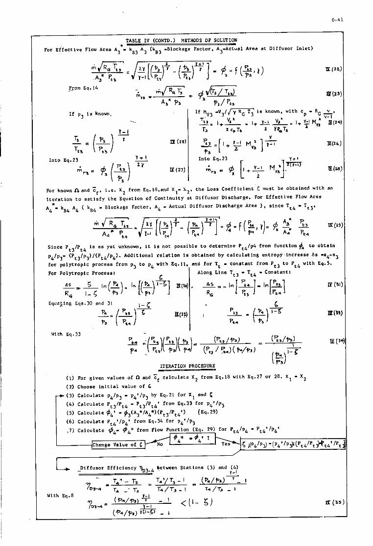
6-41
I f p3 is known, --.
Y-I
Ip (25)
I n t o Eq.23 - Y t l 2Y
E (27)
TABLE I V (CONTD. ) METHODS OF SOLIRION
For E f f e c t i v e Flow Area A *- kB3 A 3 (kB3 -Blockage Factor , A Actual Area a t D i f fuso r I n l e t ) 3 3-
- V 3 / J T i is known, wi th c - RG y, p y-1 If 3 3
Tt 3 "a -= I+- . I + EL= I + 2 MY: E(24 r3 * CpTa 2 Y%T3
'E(2 6 ;
I n t o Eq.23
E (ze
--- From Eq.14
Since Pt3/Pt4 is a s ye t unknown, i t is no t poss ib l e t o determine Pt4/p4 from func t ion #4 t o o b t a i n
p4/p3- (P t 3 3 f o r p o l y t r o p i c p rocess from p3 t o p4 wi th Eq.11, and f o r Tt - cons tan t from Pt3 t o Pt4 wi th Eq.5.
For P o l y t r o p i c Process:
/p )/(Pt4/p4). Addit ional r e l a t i o n is obtained by c a l c u l a t i n g e n t r o p y . i n c r e a s e As -a4-s3
Along Line T t 3 - Tt4 - Constant:
E (31
R, 1-5
ITERATION PROCEDURE - (1) For given va lues of and cf c a l c u l a t e X 2 from Eq.18 wi th Eq.27 o r 28. - x 2 (2) Choose i n i t i a l value of 6
.) (3) C a l c u l a t e p4/p3 - p4'/p3 by Eq.21 f o r XI and 6 (4) C a l c u l a t e Pt3/Pt4 - Pt3/Pt4* from Eq.33 f o r p4'/p3
(5) C a l c u l a t e #4* - ~3(A3*/A4*)(Pt3/Pt4')
( 6 ) C a l c u l a t e Pt4*/p4' from Eq.34 f o r p4*/p3
.7) C a l c u l a t e g4- #411 from Flow Function (Eq. 29
(Eq.29)
$2 d4* 1 -/Change Value of 6 5 j(P41P3) -(P4'/P?)i[pt4/ptJ+t4* /p,
L -Diffusor E f f i c i e n c y between S t a t i o n s (3) and (4) v - '
T4' - l-3
T, _- l-3 T4/T, - I T4 /t - I
- - - T4 '/ T', - I P ( P 4 / W " - I - =
With En.8 Y- I

7
SUPERSONIC RADIAL
DIFFUSERS
D.P. KENNY
Supervisor, Compressor Research, United Aircraft of Canada, Limited, Ville Jacques Cartier, P.Q., Canada.
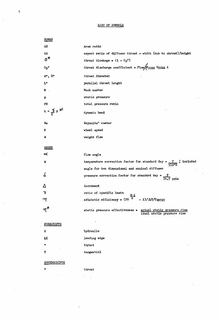
7
LIST OF SYMBOLS
ROMAN
AR
- AS
i3*
CD*
d*, D*
L*
M
P
PR
Q',P d M2 2
R e
U
w
e
d
SUBSCRIPTS
H
LE
*
T
area r a t i o
aspect r a t i o of diffuser throat = width (hub t o shroud)/height
throat blockage =I (1 - CD')
t h o a t discharge coefficient = nOv/pcom vcom A
throat diameter
paral le l throat length
Mach number
s t a t i c pressure
t o t a l pressure r a t i o
dynamic head
Reynolds' number
wheel speed
weight flow
flow angle
temperature correction ictor for standard day = T 519OR <-.
angle fo r two dimensional and conical diffuser
pressure correction factor for standard day = P 14.7 psia
included
increment
r a t i o of specific heats
adiabatic efficiency = (PR ' Li - l)/aTflmaJTRy
s t a t i c pressure effectiveness I actual s t a t i c uressure r i s e ideal static.pressure r i s e
hydraulic
leading edge
throat
tangential
SUPERSCRIPTS
throat
7-1
A DISCUSSION OF SUPERSONIC DIFFUSERS f o r cent r i fuga l compressors implies a general discussion of d i f fuse r s f o r cent r i fuga l compressors, since f o r pressure r a t i o s grea te r than 3.8 the d i f fuser en t ry Mach number exceeds 1.0. stage pressure r a t i o f o r zero prewhirl ro to r s with r a d i a l ex i t blading. of exceeding 1.25 shocl&oundary layer in te rac t ion e f f ec t s lead t o separation. t o PR = 12 which suggests an upper l imi t ing ta rge t f o r contemporary s t a t e of the art without spec ia l devices f o r reducing the adverse e f f ec t of shock/boundary layer interaction. normalized t i p speed VS. s tage pressure r a t io . about 2800 f p s corresponding t o a stage PR = 28:i and entry Mach number = 1.405.
To da te the m a x i m u m pressure r a t i o of cent r i fuga l compressors i n an operating engine is 7:l in the UACL JTl5D corresponding t o an entry Mach number o f f = 1.20. cen t r i fuga l compressors a re i n the 4 - 6:1 pressure r a t i o range with entry Mach numbers down t o 1.0. Recently, research s tages have demonstrated an operating pressure r a t i o up t o l 2 : l w i t h an overspeed maximum of 14:l.
Since the pressure r a t i o requirement of cent r i fuga l compressors has increased with time, t he entry Mach number capabi l i ty has evolved i n a natural chronological order.
Therefore the various d i f fuser concepts f o r cent r i fuga l compressors are discussed i n i t i a l l y with regard t o overa l l performance i n the chronological order; vaneless, vaned, passage, multiple cascade and pipe. Then each type i s discussed individually with regard t o its basic mechanism, design technique, performance evaluation and possible improvements. Finally, general conclusions a r e drawn with regard t o the capabi l i ty of the various types and possible ult imate performance.
OVERALL PERFORMANCE OF VARIOUS DIFFUSER CONCEPTS
This is indicated i n Fig. 1 where d i f fuser entry Mach number is plotted vs. The l imiting asymptotic value
2.3 f o r i n f i n i t e pressure r a t i o is indicated. It is commonly accepted that fo r Mach number I n Fig. 1 t h i s corresponds
In Fig. 1 is a l so plotted A t present, maximum safe operating t i p speeds a r e
Many other operating engines with
I n t h e i r e a r l i e r applications, cen t r i fuga l compressors f o r a i r were designed f o r the 2 : l pressure r a t i o l eve l with vaneless d i f fusers which had an exceptionally wide operating range from ro to r choke to vaneless space s ta l l with acceptable efficiency = 7596, while re ta in ing the utmost mechanical and aerodynamic simplicity. a t t a i n a useful diffusion, typ ica l ly four times the ro to r f ron ta l area.
A s pressure r a t i o requirements increased up t o 3 and 4:l vaned d i f fusers (cambered and f la t p la te ) were introduced t o reduce f r o n t a l a rea and improve range at higher pressure r a t io . entry Mach numbers were now becoming supersonic and a la rge vaneless space w a s retained t o obtain diffusion t o subsonic Mach number at cascade entry. d i f fuser f o r supersonic flow. When pressure r a t i o s of 5 - 6:1 were attempted, t he vaneless space required f o r subsonic leading edge Mach number was prohibit ive and improved d i f fuser types were introduced namely, passages with a low loading uncovered suction surface and multiple cascade. Typical performance is shown in Fig. 2 f o r t he passage type. I n Ref. 1 a 4.2 pressure r a t i o cambered vane stage at 74% w a s improved t o 4.6 pressure r a t i o at 84% efficiency f o r a 20 lb/sec. cgmpressor by converting t o a multiple cascade diffuser.
A t t h i s t i m e t he swept leading edge, unloaded vaned d i f fuser concept, was introduced by Dallenbach and V a n Le a t 4 - 6:l pressure ra t io . still in the 75% efficiency range.
The major drawback of such d i f fuse r s is the la rge f r o n t a l area required t o
However, d i f fuser
Thus the vaneless d i f fuser was still the only
This proved ef fec t ive as shown i n Fig. 3 but performance was
Recently, both UACL and Boeing/AVLABS demonstrated the high pressure r a t i o capabi l i ty of s ing le cent r i fuga l stages. Refs. 2 and 3. Ns = 70 (Fig. 4).
Boeing used the rectangular channel concept with sp i ra l . l ead ing edge and a low spec i f ia speed ro to r of N s = 50 (Fig. 5). ear ly 5 - 6:l capabi l i ty of Fig. 2.
This recent Boeing and UACL work demonstrates that cent r i fuga l compressor d i f fusers can be operated up t o entry Mach numbers of 1.4.
VANELESS DIFFUSERS
The vaneless d i f fuse r s accomplish diffusion primarily by the inverse reduction of mirl with radius f o r conservation of angular momentum. tangential , so that the tangential velocity is 94% of the t o t a l , w h i l e the r a d i a l velocity is 2: 34%. Thus a 2:l rad ius r a t i o w i l l reduce the tangential velocity by 5d and the t o t a l by 42% f o r constant r a d i a l velocity, while a l so halving the r a d i a l velocity only reduces the t o t a l velocity another 8%. Even reducing the r a d i a l velocity t o zero only decreases the t o t a l velocity another 3%. diffusion capabi l i ty of a vaneless d i f fuser is primarily dependent on the rad ius ra t io .
The vaneless d i f fuser would seem t o be the most e f fec t ive f o r supersonic flow, having no obstructions. However, as i t turns out, 'it is the worst. Primarily both the range and effectiveness of the vaneless d i f fuser a r e severely l imited by the invariable i n s t a b i l i t y of the radial velocity p ro f i l e at ex i t from the impeller par t icu lar ly f o r PR > 2.
(UACL - 1O:l pressure r a t i o at 74% and Boeing - 1 O : l pressure r a t i o at 72%) in UACL used the pipe d i f fuser concept of Ref. 4 with a medium specifiq speed ro to r of
By ref in ing the downstream channels they were ab le t o improve on the basic
Typically cent r i fuga l impeller ex i t flow angles a r e = 20° from
Thus the
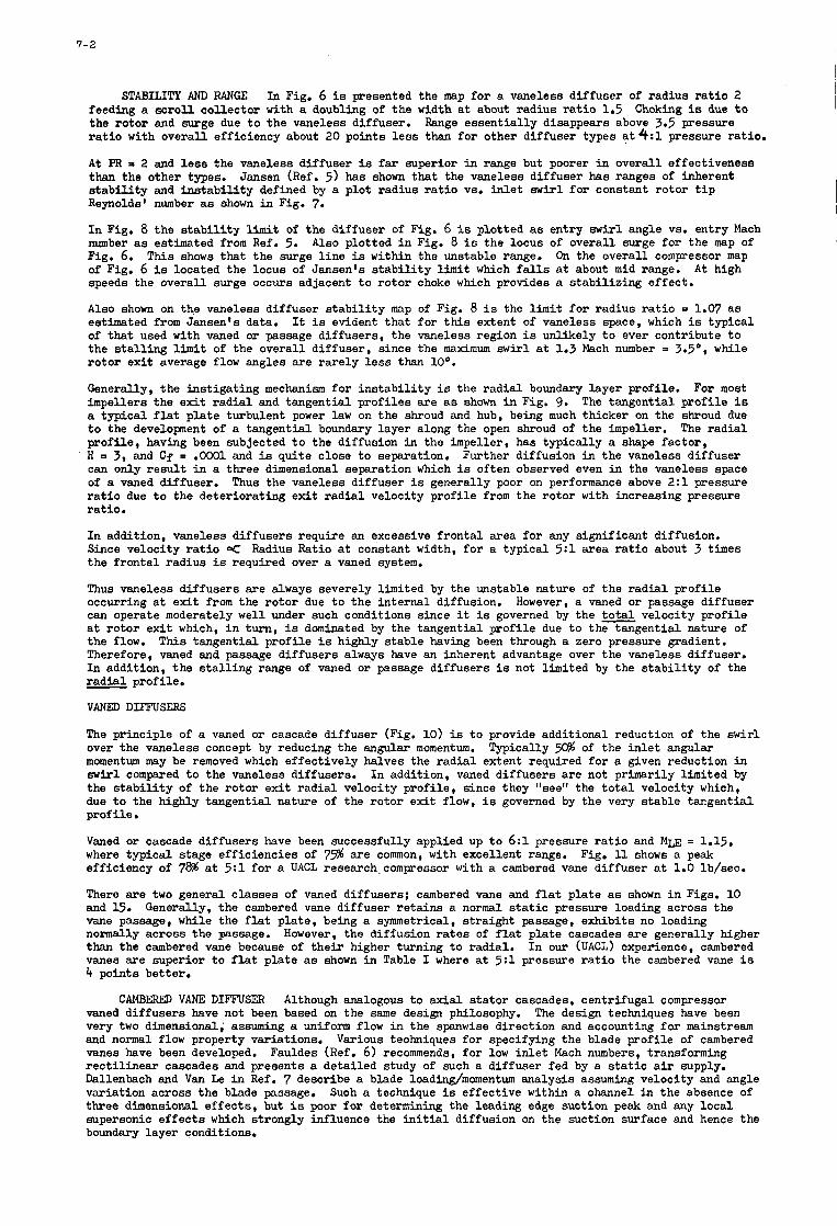
7-2
STABILITY AND RANGE In Fig. 6 is presented the map f o r a vaneless d i f fuser of radius r a t i o 2 feeding a s c r o l l co l lec tor with a doubling of t he width at about rad ius r a t i o 1.5 the ro to r and surge due t o the vaneless diffuser. r a t i o with overa l l efficiency about 20 poin ts l e s s than f o r other d i f fuser types a t4 :1 pressure ra t io .
A t PR than the other types. s t a b i l i t y and i n s t a b i l i t y defined by a plot radius r a t i o VS. i n l e t swirl for constant ro tor t i p Reynolds' number as shown i n Fig. 7.
I n Fig. 8 the s t a b i l i t y l imi t of the d i f fuser of Fig, 6 is plotted as entry swirl angle VS. entry Mach number as estimated from Ref. 5. Fig. 6. of Fig. 6 is located the locus of Jansen's s t a b i l i t y limit which falls at about mid range. speeds the overa l l surge occurs adjacent t o ro to r choke which provides a s t ab i l i z ing e f fec t .
Also shown on the vaneless d i f fuser s t a b i l i t y map of Fig. 8 is the l imi t f o r radius r a t i o = 1.07 a s estimated from Jansen's data. of that used with vaned or passage d i f fusers , the vaneless region is unlikely t o ever contribute t o the stalling l i m i t of the overa l l d i f fuser , since the maximum swirl at 1.3 Mach number a 3.5'. while ro to r ex i t average flow angles a re r a re ly l e s s than loo. Generally, the ins t iga t ing mechanism f o r i n s t a b i l i t y is the r a d i a l boundary layer profile. For most impellers the e x i t r a d i a l and tangent ia l p ro f i l e s a re as shown i n Fig. 9. The tangent ia l p ro f i l e i s a typica l f l a t p l a t e turbulent power l a w on the shroud and hub, being much thicker on the shroud due t o the development of a tangential boundary layer along the open shroud of the impeller. The r a d i a l p rof i le , having been subjected t o the diffusion i n the impeller, has typ ica l ly a shape fac tor , H a 3, and Cf = .OW1 and is qui te close t o separation. can only r e s u l t in a three dimensional separation which is often observed even in the vaneless space of a vaned diffuser. Thus the vaneless d i f fuser is generally poor on performance above 2 : l pressure r a t i o due t o the de te r iora t ing e x i t r a d i a l velocity p ro f i l e from the ro to r with increasing pressure ra t io .
I n addition, vaneless d i f fusers require an excessive f ron ta l area f o r any s igni f icant diffusion. Since velocity r a t i o 9 Radius Ratio at constant width, f o r a typ ica l 5:1 area r a t i o about 3 times the f ron ta l rad ius is required over a vaned system.
Thus vaneless d i f fusers a re always severely l imited by the unstable nature of the r a d i a l p ro f i l e occurring at e x i t from the ro to r due t o the in te rna l diffusion. can operate moderately well under such conditions since it is governed by the total velocity p ro f i l e at ro to r e x i t which, i n turn, is dominated by the tangential p ro f i l e due t o the tangent ia l nature of t he flow. This tangential p ro f i l e is highly s t ab le having been through a zero pressure gradient. Therefore, vaned and passage d i f fusers always have an inherent advantage over the vaneless diffuser. I n addition, t he s t a l l i n g range of vaned or passage d i f fusers is not limited by the s t a b i l i t y of the - r a d i a l profile.
VANED DIFFUSERS
The principle of a vaned or cascade d i f fuser (Fig. 10) is t o provide additional reduction of the swir l over the vaneless concept by reducing the angular momentum. momentum may be removed which e f fec t ive ly halves the r a d i a l extent required f o r a given reduction i n s w i r l compared t o the vaneless diffusers. I n addition, vaned d i f fusers a re not primarily l imited by the s t a b i l i t y of t he ro to r ex i t r a d i a l velocity prof i le , since they rrseerr the t o t a l velocity which, due t o the highly tangent ia l nature of the ro to r ex i t flow, is governed by the very s tab le tangent ia l p ro f i l e .
Choking is due t o Range essent ia l ly disappears above 3.5 pressure
2 and l e s s the vaneless d i f fuser is far superior in range but poorer i n overa l l effectiveness Jansen (Ref. 5 ) has shown that the vaneless d i f fuser has ranges o f inherent
Also plotted in Fig. 8 is the locus of overall surge fo r the map of T h i s shows that the surge l i n e is within the unstable range. On the overa l l compressor map
A t high
It is evident that f o r this extent of vaneless space, which is typica l
Further diffusion in the vaneless d i f fuser
However, a vaned or passage d i f fuser
Typically .!A% of the i n l e t angular
Vaned or cascade d i f fusers have been successfully applied up t o 6:1 pressure r a t i o and Mm = 1.15, where typ ica l stage e f f ic ienc ies of 75% a r e common, with excellent range. efficiency o f 78% at 5:l f o r a UACL research.compressor with a cambered vane d i f fuser at 1.0 lb/sec.
There a r e two general c lasses of vaned d i f fusers ; cambered vane and f l a t p l a t e as shown i n Figs. 10 and 15. vane passage, while the f la t p la te , being a symmetrical, s t r a igh t passage, exhib i t s no loading nonnally across the passage. than the cambered vane because of t h e i r higher turning t o rad ia l . I n our (UACL) experience, cambered vanes a r e superior t o f la t p l a t e as shown i n Table I where a t 5:l pressure r a t i o the cambered vane i s 4 points better.
Fig. 11 shows a peak
Generally, the cambered vane d i f fuser r e t a ins a normal s t a t i c pressure loading across the
However, the diffusion r a t e s of f la t p l a t e cascades a re generally higher
CAMBERED VANE DIFFUSER Although analogous t o a x i a l s t a to r cascades, cen t r i fuga l compressor vaned d i f fusers have not been based on the same design philosophy. very two dimensional; assuming a *miform flow i n the spanwise d i rec t ion and accounting f o r mainstream and normal flow property variations. Various teohniques f o r specifying the blade p ro f i l e of cambered vanes have been developed. Fauldes (Ref. 6) recommends, f o r low i n l e t Mach numbers, transforming r e c t i l i n e a r cascades and presents a de ta i led study of such a d i f fuser fed by a s t a t i c a i r supply. Dallenbach and Van Le i n Ref. 7 describe a blade loading/momentum analysis assuming velocity and angle variation across the blade passage. th ree dimensional e f f ec t s , but is poor f o r determining the leading edge suction peak and any local. supersonic e f f ec t s which strongly influence the initial diffusion on the suction surface and hence the boundary layer conditions.
The design techniques have been
Such a technique is ef fec t ive within a channel in the absence of
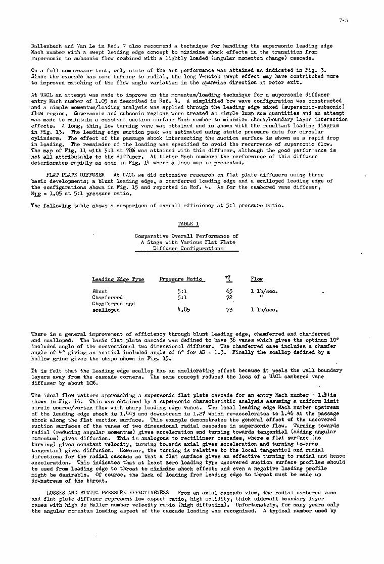
7 - 3
Dallenbach and V a n Le in Ref. 7 a l so recommend a technique f o r handling the supersonic leading edge Mach number with a swept leading edge concept t o minimize shock e f f ec t s i n the t r ans i t i on from supersonic t o subsonic flow combined with a l i g h t l y loaded (angular momentum change) cascade.
On a f u l l compressor t e s t , only s t a t e of the art performance w a s a t ta ined as indicated i n Fig. 3. Since the cascade has some turning t o r ad ia l , the long V-notch swept e f f ec t may have contributed more t o improved matching of the flow angle var ia t ion in the spanwise d i rec t ion at ro to r ex i t .
A t UACL an attempt w a s made t o improve on the momentum/loading technique f o r a supersonic d i f fuser en t ry Mach number of 1.05 as described i n Ref. 4. and a simple momentum/loading ana lys i s w a s applied through the leading edge mixed (supersonic-subsonic) flow region. Supersonic and subsonic regions were t rea ted as simple lump sum quant i t ies and an attempt was made t o maintain a constant suction surface Mach number t o minimize shock/boundary layer interaction e f fec ts . in Fig. 13. cylinders. i n loading. The map of Fig. 11 with 5:1 at 78% w a s a t ta ined with this d i f fuser , although the good performance is not all a t t r ibu tab le t o the diffuser. de te r iora tes rap id ly as seen i n Fig. 14 where a loss map is presented.
A simplified bow wave configuration w a s constructed
A long, th in , low turning vane was obtained and is shown with the resu l tan t loading diagram The leading edge suction peak was estimated using s t a t i c pressure data f o r c i r cu la r
The e f f ec t of the passage shock in te rsec t ing the suction surface is shown as a rapid drop The remainder of the loading was specified t o avoid the recurrence of supersonic flow.
A t higher Mach numbers the performnce of this d i f fuser
FLAT F U T E DIFFUSER A t UACL w e did extensive research on f l a t p l a t e d i f fusers using three basic developments; a blunt leading edge, a chamferred leading edge and a scalloped leading edge of the configurations shown i n Fig. 15 and reported i n Ref. 4. Mm = 1.05 a t 5:1 pressure ratio.
The following t ab le shows a comparison of overa l l efficiency a t 5:1 pressure ra t io .
A s f o r the cambered vane d i f fuser ,
TABLE 1
Comparative Overall Performance of A Stage with Various F la t P la te
Diffuser C o n f i w a t i o n s
Leading Edge T . m Pressure Ratio '/T Flow
Blunt 5:l 65 1 lb/sec. Chamferred 5:l 72 Chamferred and scalloped 4.85 73 1 lb/sec.
11
There is a general improvement of efficiency through blunt leading edge, chamferred and chamferred and scalloped. included angle of the conventional two dimensional diffuser. angle of bo giving an in i t i a l included angle of 6" f o r AR = 1.3. hollow grind g ives the shape shown in Fig. 15.
It is f e l t t ha t the leading edge sca l lop has an ameliorating e f f ec t because it pee ls the w a l l boundary layers away from the cascade corners. d i f fuser by about Id.
The idea l flow pa t te rn approaching a supersonic f la t p l a t e cascade f o r an en t ry Mach number = 13fis shown i n Fig. 16. This w a s obtained by a supersonic charac te r i s t ic ana lys i s assuming a uniform l i m i t c i r c l e source/vortex flow with sharp leading edge vanes. The loca l leading edge Mach number upstream of the leading edge shock is 1.443 and downstream i s 1.27 which re-accelerates t o 1.46 at the passage shock along the f l a t suction surface. This example demonstrates the general e f f ec t of the uncovered suction surfaces of the vanes of two dimensional r a d i a l cascades in supersonic flow. Turning towards r a d i a l (reducing angular momentum) gives acceleration and turning towards tangential (adding anguhr momentum) gives diffusion. This i s analogous t o r e c t i l i n e a r cascades, where a f l a t surface (no turning) gives constant velocity, turning towards a x i a l gives acceleration and turming towards ,
t angent ia l gives diffusion. However, the turning is re l a t ive t o the loca l tangential and r ad ia l d i rec t ions f o r the r a d i a l cascade s o that a f l a t surface gives an e f fec t ive turning t o r a d i a l and hence acceleration. This ind ica tes that at l e a s t zero loading type uncovered suction surface p ro f i l e s should be used from leading edge t o throa t t o minimize shock e f f ec t s and even a negative loading p ro f i l e might be desirable. downstream of the throat.
The basic f l a t p l a t e cascade w a s defined t o have 36 vanes which gives the optimum 10" The chamferred case includes a chamfer
F ina l ly the sca l lop defined by a
The same concept reduced the l o s s of a UACL cambered vane
Of course, the lack of loading from leading edge t o throa t must be made up
LOSSES AND STATIC PRESSURE EFFECTIVENESS From an axial cascade view, the r a d i a l cambered vane and f la t p l a t e d i f fuser represent low aspect r a t i o , high so l id i ty , th ick sidewall boundary layer cases with high de Haller number ve loc i ty r a t i o (high diffusion). the angular momentum loading aspect of the Cascade loading w a s recognized.
Unfortunately, f o r many years only A typ ica l number used by
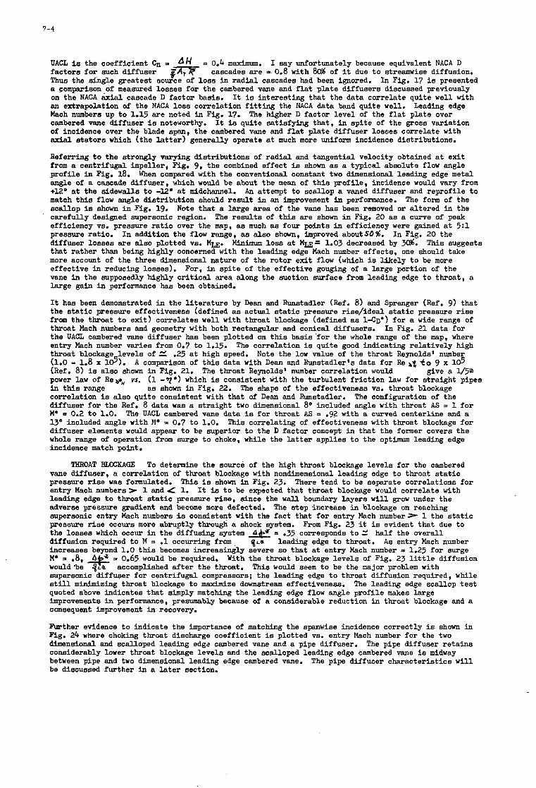
7-4
UACL is the coefficient Cn a factors fo r such diffuser Thus the single greatest source of loss i n radial cascades had been ignored. a comparison,of measured losses for the cambered vane and f l a t plate diffusers discussed previously on the NACA axial cascade D factor basis. an extrapolation of the NACA loss correlation f i t t i n g the NACA data band quite well. Mach numbers up t o 1.15 are noted in Fig. 17. cambered vane diffuser is noteworthy. of incidence over the blade span, the cambered vane and f l a t plate diffuser losses correlate with axial s t a to r s which (the l a t t e r ) generally operate at much more uniform incidence distributions.
Referring t o the strongly varying distributions of r ad ia l and tangential velocity obtained at exi t from a centrifugal impeller, Fig. 9, the combined effect is shown a s a typical absolute flow angle profile in Fig. 18. angle of a cascade diffuser, which would be about the mean of t h i s profile, incidence would vary from +Uo at the sidewalls t o -12O at midchannel. An attempt t o scallop a vaned diffuser and reprofile t o match t h i s flow angle distribution should result i n an improvement h performance. The form of the scallop is shown i n Fig. 19. Note that a large area of the vane has been removed o r altered in the carefully d e s i s e d supersonic region. efficiency VS. pressure r a t i o over the map, as much as four points in efficiency were gained at .5:1 pressure ratio. diffuser losses are also plotted VS. Mm. that rather than being highly concerned with the leading edge Mach number effects, one should take more account of the three dimensional nature of the rotor exit flow (which is l ikely t o be more effective i n reducing losses). vane in the supposedly highly c r i t i c a l area along the suction surface from leading edge t o throat, a large gain i n performance has been obtained.
It has been demonstrated in the l i t e r a tu re by Dean and Runstadler (Ref. 8) and Sprenger (Ref. 9) that the s t a t i c pressure effectiveness (defined as actual s t a t i c pressure rise/ideal s t a t i c pressure r i s e from the throat t o exi t ) correlates well with throat blockage (defined as ~ - C D * ) for a wide range of throat Mach numbers and geometry with both rectangular and conical diffusers. the UACL cambered vane diffuser has been plotted on t h i s basis 'for the whole range of the map, where entry Mach number varies from 0.7 t o 1.15. The correlation is quite good indicating relat ively high throat blockage levels o f e .25 a t high speed. (1.0 - 1.8 x 16). (Ref. 8) is also shown i n Fig. 21. power l a w of R e d , vs. (1 -?*I which is consistent with the turbulent f r i c t ion l a w for straight pipes in this range a s shown i n Fig. 22. correlation is also quite consistent with that of Dean and Runstadler. diffuser fo r the Ref. 8 data was a straight two dimensional 8 O included angle with throat AS = 1 for M* = 0.2 t o 1.0. The UACL cambered vane data is for throat AS = .92 with a curved centerline and a 1 3 O included angle with M* = 0.7 t o 1.0. This correlating of effectiveness with throat blockage for diffuser elements would appear t o be superior t o the D factor concept i n that the former covers the whole range of operation from surge t o choke, while the l a t t e r applies t o the optimum leading edge incidence match point.
AH 8-
P 0.4 m a x i m u m . I say unfortunately because equivalent NACA D cascades are 5 0.8 with 80% of it due t o streamwise diffusion.
In Fig. 17 is presented
It is interesting that the data correlate quite well with
The higher D factor level of the f l a t plate over Leading edge
It is quite satisfying that, in spi te of the gross variation
When compared with the conventional constant two dimensional leading edge metal
The resul ts of this are shown i n Fig. 20 a s a curve of peak
In addition the flow range, a s also shown, improved aboutso%. In Fig. 20 the M i n i m u m loss at M u = 1.03 decreased by 3&. T h i s suggests
For, in spi te of the effective gouging of a large portion of the
In Fig. 21 data for
Note the low value of the throat Reynolds' number A comparison of this data with Dean and Runstadler's data for Re &$ fo 9 x 1 6
The throat Reynolds' number correlation would give a 1/5@
The shape of the effectiveness VS. throat blockage The configuration of the
THROAT W K A G E To determine the source of the high throat blockage levels for the cambered vane diffuser, a correlation of throat blockage with nondimensional leading edge t o throat s t a t i c pressure r i s e was formulated. entry Mach numbers) 1 and 4 1. It is t o be expected that throat blockage would correlate with leading edge t o throat static pressure rise, since the w a l l boundary layers w i l l grow under the adverse pressure gradient and become more defected. supersonic entry Mach numbers is consistent with the f ac t that fo r entry Mach n u m b e r r 1 the s t a t i c pressure r i s e occurs more abruptly through a shock system. the losses which occur in the diffusing system = .35 corresponds t o Z half the overall diffusion required t o M = .1 occurring from %LE leading edge t o throat. A s entry Mach number increases beyond 1.0 this becomes increasingly severe so that a t entry Mach number = 1.25 for surge M* = .8, With the throat blockage levels of Fig. 23 l i t t l e diffusion would-be q ~ l t accomplished a f t e r the throat. This would seem t o be the major problem with supersonic diffuser for centrifugal compressors; the leading edge t o throat diffusion required, while still minimizing throat blockage t o maximize downstream effectiveness. The leading edge scallop t e s t quoted above indicates that simply matching the leading edge flow angle profile makes large improvements i n performance, presumably because of a considerable reduction i n throat blockage and a consequent improvement in recovery.
This i s shown in Fig. 23. There tend t o be separate correlations fo r
The step increase i n blockage on reaching
From Fig. 23 it is evident that due to
3 0.65 would be required.
Further evidence t o indicate the importance of matching the spanwise incidence correctly is shown in Fig. 24 where choking throat discharge coefficient is plotted VS. entry Mach number for the two dimensional and scalloped leading edgz cambered vane and a pipe diffuser. The pipe diffuser re ta ins considerably lower throat blockage levels and the scalloped leading edge cambered vane is midway between pipe and two dimensional leading edge cambered vane. The pipe diffuser characterist ics w i l l be discussed further in a l a t e r section.
'1
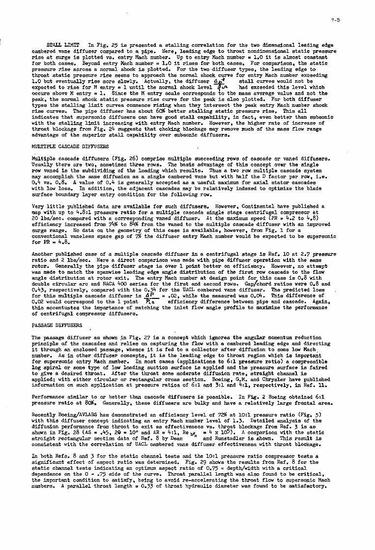
7-5
STAIL L I M I T I n Fig. 25 is presented a s t a l l i ng correlation fo r the two dimensional leading edge cambered vane diffuser compared t o a pipe. r i s e at surge is plotted VS. entry Mach number. Up t o entry Mach number = 1.0 it is almost constant f o r both cases. For comparison, the s t a t i c pressure rise across a normal shock is plotted. For the two-diffuser types, the leading edge to throat s t a t i c pressure r i s e seems t o approach the normal shock curve for entry Mach number exceeding 1.0 but eventually rise more slowly. Actually, the diffuser d stell curves would not be expected t o r i s e fo r M entry = 1 u n t i l the normal shock level-& occurs above M entry = 1. Since the M entry scale corresponds t o the mass average value and not the peak, the normal shock s t a t i c pressure r i s e curve fo r the peak is also plotted. types the s t a l l i ng l imit curves commence rising when they intersect the peak entry Mach number shock r i s e curves. indicates that supersonic diffusers can have good s ta l l capability, in fact , even bet ter than subsonic with the s t a l l i ng limit increasing with entry Mach number. throat blockage from Fig. 24 suggests that choking blockage may remove much of the mass flow range advantage of the superior stall capabili ty over subsonic diffusers.
MULTIPLE CASCADE DIFFUSERS
Here, leading edge t o throat nondimensional s t a t i c pressure
Beyond entry Mach number = 1.0 it r i s e s fo r both cases.
had exceeded t h i s l eve l which
For both diffuser
This all The pipe diffuser has about 6d bet ter s t a l l i ng s t a t i c pressure r ise .
However, the higher r a t e of increase of
Multiple cascade diffusers (Fig. 26) comprise multiple succeeding rows of cascade or vaned diffusers. Usually there are two, sometimes three rows. row vaned is the subdividing of the loading which results. may accomplish the same diffusion as a single cambered vane but with half the D factor per row, i.e. 0.4 VS. 0.8. with low loss. surface boundary layer entry condition for the following row.
Very l i t t l e published data are available fo r such diffusers. map with up t o 4.8:1 pressure r a t i o fo r a multiple cascade single stage centrifu compressor at 20 lbs/sec. compared with a corresponding vaned diffuser. A t the maximum speed % = 4.2 t o 4.8) efficiency increased from 74% t o 84% from the vaned t o the multiple cascade diffuser with an improved surge range. conventional vaneless space gap of % the diffuser entry Mach number would be expected t o be supersonic fo r PR = 4.8.
The basic advantage of this concept over the single Thus a two row multiple cascade system
A value of 0.4 i s generally accepted as a useful maximum for axial s t a to r cascades In addition, the adjacent cascades may be relat ively indexed t o optimize the blade
However, Continental have published a
No data on the geometry of t h i s case is available, however, from Fig. 1 for a
Another published case of a multiple cascade diffuser In a centrifugal stage is Ref. 10 at 2.7 pressure r a t i o and 2 lbs/sec. rotor. w a s made t o match the spanwise leading edge angle distribution of the f i r s t row cascade t o the flow angle distribution at rotor exit . double circular arc and NACA 400 se r i e s for the f i r s t and second rows. 0.43, respectively, compared with the 0.9 for the UACL cambered vane diffuser. fo r this multiple cascade diffuser is d p P .02, while the measured was 0.d. 0.02 would correspond t o the 1 point PLO efficiency difference between pipe and cascade. Again, this accentuates the importance of matching the i n l e t flow angle prof i le t o maximize the performance of centrifugal compressor diffusers.
PASSAGE DIFFUSERS
The passage diffuser as shown .in Fig. 27 is a concept which ignores the angular momentum reduction principle of the cascades and r e l i e s on capturing the flow with a cambered leading edge and directing it through an enclosed passage, whence it is fed t o a collector a f t e r diffusion t o some low Mach, number. fo r supersonic entry Mach number. In most cases (applications to 6:l pressure r a t io ) a compressible log sp i r a l or some type of low loading suction surface is applied and the pressure surface is faired t o give a desired throat. applied; with ei ther circular or rectangular cross section. information on such application at pressure r a t io s of 6:l and 3:l and 4:1, respectively, in Ref. 11.
Performance similar t o or bet ter than cascade diffusers is possible. pressure r a t i o a t 8d.
Recently BoeindAVLABS has demonstrated an efficiency level of 72% at 1O:l pressure r a t i o (Fig. 5) w i t h this diffuser concept indicating an entry Mach number level of 1.3. Detailed analysis of the diffusion performance from throat t o ex i t as effectiveness VS. throat blockage from Ref. 3 is as shown i n Fig. 28 (AS = .45, 20 = loo and AR = 4:1, RegH = 4 x 16). st raight rectangular section data of Ref. 8 by Dean and Runstadler is shown. This r e su l t is consistent with the correlation of UACL cambered vane diffuser effectiveness with throat blockage.
In both Refs. 8 and 3 f o r the s t a t i c channel t e s t s and the 1O:l pressure r a t i o compressor t e s t s a significant effect of aspect r a t i o was determined. Fig. 29 shows the r e su l t s from Ref. 8 fo r the s t a t i c channel t e s t s indicating an optimum aspect r a t i o of 0.75 = deptwwidth with a c r i t i c a l dependence on the 0 - .75 side of the curve. the important condition t o sat isfy, being t o avoid re-accelerating the throat flow t o supersonic Mach numbers.
Here a direct comparison w a s made with pipe diffuser operation with the same Generally the pipe diffuser stage is over 1 point bet ter on efficiency. However, no attempt
The entry Mach number at design point fo r this case is 0.8 with Gap/chord r a t i o s were 0.8 and
The predicted loss This difference of
A s in other diffuser concepts, it is the leading edge t o throat region which is important
After the throat some moderate diffusion r a t e , straight channel is Boeing, G.M. and Chrysler have published
In Fig. 2 Boeing obtained 6:1 Generally, these diffusers are bulky and have a relat ively large frontal area.
A comparison with the s t a t i c
Throat paral le l length was also found t o be c r i t i c a l ,
A paral le l throat length = 0.33 of throat hydraulic diameter w a s found t o be satisfactory.
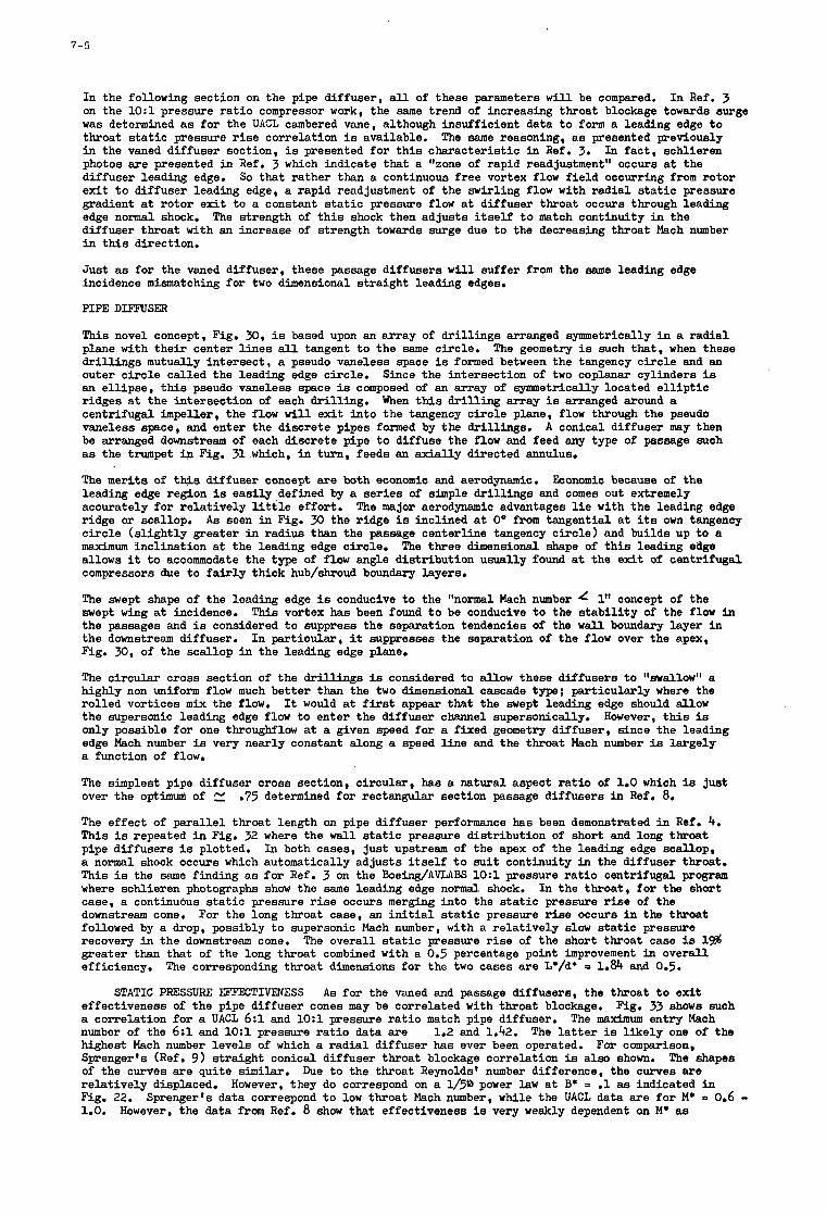
7-6
In the following section on the pipe diffuser, a l l of these parameters w i l l be compared. on the 1O:l pressure r a t i o compressor work, the same trend of increasing throat blockage towards surge w a s determined as for the UACL cambered vane, although insufficient data t o form a leading edge t o throat s t a t i c pressure r i s e correlation is available. The same reasoning, a s presented previously i n the vaned diffuser section, is presented for t h i s characterist ic i n Ref. 3. In fact , schlieren photos are presented i n Ref. 3 which indicate that a %one of rapid readjustment" occurs a t the diffuser leading edge. So that rather than a continuous free vortex flow f i e ld occurring from rotor exi t t o diffuser leading edge, a rapid readjustment of the swirling flow with radial s t a t i c pressure gradient a t rotor exi t t o a constant s t a t i c pressure flow at diffuser throat occurs through leading edge normal shock. diffuser throat with an increase of strength towards surge due t o the decreasing throat Mach number i n this direction.
Just a s for the vaned diffuser, these passage diffusers w i l l suffer from the same leading edge incidence mismatching for two dimensional straight leading edges.
PIPE DIFFUSER
In Ref. 3
The strength of t h i s shock then adjusts i t s e l f t o match continuity i n the
This novel concept, Fig. 30, is based upon an array of dr i l l ings arranged symmetrically i n a radial plane with the i r center l i nes all tangent t o the seme circle. drillings mutually intersect , a pseudo vaneless space is formed between the tangency circle and an outer c i rc le called the leading edge circle. an el l ipse, this pseudo vaneless space is composed of an array of symmetrically located e l l i p t i c ridges at the interseotion of each dril l ing. centrifugal impeller, the flow w i l l exit into the tangency circle plane, flow through the pseudo vaneless space, and enter the discrete pipes formed by the drillings. A conical diffuser may then be arranged downstream of each discrete pipe t o diffuse the flow and feed any type of passage such a s the trwnpet in Fig. 31 which, i n turn, feeds an axial ly directed annulus.
The merits of this diffuser concept are both economic and aerodynamic. leading edge region is easily defined by a ser ies of simple drillings and comes out extremely accurately for re la t ively l i t t l e effort. ridge or scallop. c i rc le (s l ight ly greater in radius than the passage centerline tangency circle) and builds up t o a maximum inclination a t the leading edge circle. allows it t o accommodate the type of flow angle distribution usually found at the exi t of centrifugal compressors due to f a i r l y thick hub/shroud boundary layers.
The swept shape of the leading edge is conducive t o the %orma1 Mach number 4 1" concept of the swept wing at incidence. the passages and is considered t o suppress the separation tendencies of the w a l l boundary layer i n the downstream diffuser. Fig. 30, of the scallop i n the leading edge plane.
The circular cross section of the drillings is considered to allow these diffusers t o 'lswallowll a highly non uniform flow much bet ter than the two dimensional cascade type; particularly where the rolled vortices m i x the flow. the supersonic leading edge flow t o enter the diffuser channel supersonically. only possible for one throughflow at a given speed for a fixed geometry diffuser, since the leading edge Mach number is very nearly constant along a speed line and the throat Mach number is largely a function of flow.
The geometry is such that, when these
Since the intersection of two coplanar cylinders is
When this drilling array is arranged around a
Eoonomic because of the
The major aerodynamic advantages l i e with the leading edge A s seen in Fig. 30 the ridge is inclined at 0' from tangential a t its own tangency
The three dimensional shape of t h i s leading edge
This vortex has been found t o be conducive t o the s t ab i l i t y of the flow in
In particular, it suppresses the separation of the flow over the apex,
It would a t f i r s t appear that the swept leading edge should allow However, t h i s is
The simplest pipe diffuser cross section, circular, has a natural aspect r a t i o of 1.0 which is just over the optimum of
The effect of paral le l throat length on pipe diffuser performance has been demonstrated in Ref. 4. T h i s is repeated i n Fig. 32 where the w a l l s t a t i c pressure distribution of short and long throat pipe diffusers is plotted. a normal shock occurs which automatically adjusts i t s e l f t o s u i t continuity i n the diffuser throat. This is the same finding as fo r Ref. 3 on the Boeing/AVLABS 1O:l pressure r a t i o centrifugal program where schlieren photographs show the same leading edge normal shock. case, a continuous s t a t i c pressure r i s e occurs merging into the s t a t i c pressure r i s e of the downstream cone. followed by a drop, possibly t o supersonic Mach number, with a re la t ively slow s t a t i c pressure recovery in the downstream cone. greater than that of the long throat combined with a 0.5 percentage point improvement in overall efficiency.
.75 determined for rectangular section passage diffusers i n Ref. 8.
In both cases, just upstream of the apex of the leading edge scallop,
In the throat, for the short
For the long throat case, an i n i t i a l s t a t i c pressure rise occurs i n the throat
The overall s t a t i c pressure r i s e of the short throat case is 1 9
The corresponding throat dimensions for the two cases are L*/d* = 1.84 and 0.5.
STATIC PRESSURE EFFECTIVENESS A s for the vaned and passage diffusers, the throat t o exit effectiveness of the pipe diffuser cones may be correlated with throat blockage. a correlation for a UACL 6:1 and 1O:l pressure r a t i o match pipe diffuser. number of the 6:l and 1O:l pressure r a t i o data are highest Mach number levels of which a radial diffuser has ever been operated. Sprenger's (Ref. 9 ) straight conical diffuser throat blockage correlation is also shown. of the curves are quite similar. relat ively displaced. Fig. 22. 1.0.
Fig. 33 shows such
The l a t t e r is l ikely one of the
The shapes
The maximum entry Mach
For comparison, 1.2 and 1.42.
Due t o the throat Reynolds' number difference, the curves are However, they do correepond on a 1/5& power l a w a t B* = .1 as indicated i n
Sprenger's data correspond t o low throat Mach number, while the UACL data are fo r M* n 0.6 - However, the data from Ref. 8 show that effectiveness is very weakly dependent on M* as
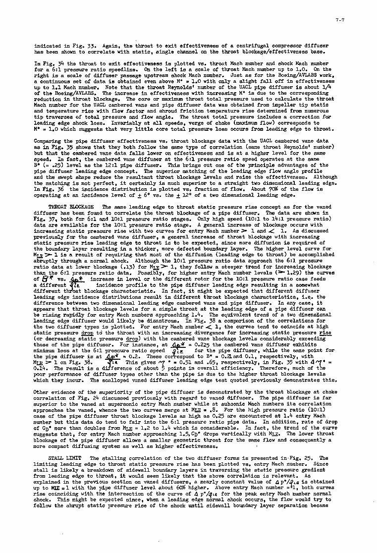
7-7
indicated i n Figo 33. has been shown t o correlate with s t a t i c , single channel on the throat blockage/effectiveness base.
I n Fig. 34 the throat t o exi t effectiveness is plotted vs. throat Mach number and shock Mach number fo r a 6:l pressure r a t i o speedline. r ight is a scale of diffuser passage upstream shock Mach number, Just as fo r the Boeing/AVLABS work, a continuous s e t of data is obtained even above M* = 1.0 with only a s l ight f a l l off i n effectiveness up t o 1.1 Mach number. of the BoeingfAVLABS. The increase in effectiveness with increasing M* is due to the corresponding reduction in throat blockage. Mach number for the UACL cambered vane and pipe diffuser data was obtained from impeller t i p s ta t ic and temperature r i s e with flow factor and shroud f r i c t ion temperature r i s e determined from numerous t i p traverses of t o t a l pressure and flow angle. leading edge shock loss. M* a 1.0 which suggests that very l i t t l e core t o t a l pressure loss occurs from leading edge t o throat.
Comparing the pipe diffuser effectiveness VS. throat blockage data with the UACL cambered vane data as i n Fig. 35 shows that they both follow the same type of correlation (same throat Reynolds' number) but t h a t the cambered vane data f a l l s lower on effectiveness and is at a higher level f o r the same speed. B* (= .25) level as the 12:l pipe diffuser. pipe diffuser leading edge concept. and the swept shape reduce the resultant throat blockage levels and r a i se the effectiveness. Although the matching is not perfect, it certainly is much superior t o a s t ra ight two dimensional leading edge. I n Fig. 36 operating at an incidence level of 2 6 O vs. the 2 l 2 O of a two dimensional leading edge.
Again, the throat t o ex i t effectiveness of a centrifugal compressor diffuser
On the l e f t is a scale of throat Mach number up t o 1.0. On the
Note that the throat Reynolds' number of the UACL pipe diffuser is about 1/4 The core or maximum throat t o t a l pressure used t o calculate the throat
The throat t o t a l pressure includes a correction far Invariably at all speeds, verge of choke (maximum flow) corresponds t o
In f ac t , the cambered vane diffuser at the 6: l pressure r a t i o speed operates at the same T h i s brings out one of the principle advantages of the
The superior matching of the leading edge flow angle prof i le
the incidence distribution is plotted VS. fraction of flow. About 7% of the flow i s
THROAT FEGCKAGE The same leading edge t o throat s t a t i c pressure r i s e concept as for the vaned diffuser has been found t o correlate the throat blockage of a pipe diffuser. Fig. 37, both fo r 6:l and 1 O : l pressine r a t i o stages. only high speed (10:l t o 14: l pressure r a t io ) data are available fo r the 1O:l pressure r a t i o stage. A general increase of blockage occurs with increasing s t a t i c pressure r i s e with two curves for entry Mach numberr 1 and 4 previously fo r the cambered vane diffuser, a general increase of throat blockage with increasing static pressure r i s e leading edge t o throat is t o be expected, since more diffusion is required of the boundary layer result ing in a thicker, more defected boundary layer. M u > 1 is a resul t of requiring that most of the diffusion (leading edge t o throat) be accomplished abruptly through a normal shock. r a t i o data at lower blockage (.l3) fo r Mu> 1, they follow a steeper trend f o r increasing blockage than the 6:l pressure r a t i o data. Possibly, f o r higher entry Mach number levels (sl.2g) the curves of e" VS. +$- increase in level o r the different rotor f o r the 1O:l pressure r a t i o case feeds a different J L L incidence prof i le t o the pipe diffuser leading edge result ing i n a somewhat different t oat blockage characterist ic. In f ac t , it might be expected that different diffuser leading edge incidence distributions resul t in different throat blockage characterist ics, i.e. the difference between two dimensional leading edge cambered vane and pipe diffuser. appears that throat blockage levels fo r a simple throat at the leading edge of a pipe diffuser can be r i s ing rapidly fo r entry Mach numbers approaching 1.4. leading edge diffuser would l i ke ly be disastrous. In Fig. 38 a comparison of the correlations for the two diffuser types is plotted. s t a t i c pressure drop to' the throat with an increasing divergence fo r increasing s t a t i c pressure (or decreasing s t a t i c pressure drop) with the cambered vane blockage levels considerably exceeding those of the pipe diffuser. = 0.225 the cambered vane diffuser exhibits minimum loss at the 6: l pressure r a t i o speed * the pipe diffuser is a t Mm > 1 on Fig. 38. 0.14. The r e su l t is a poor performance of diffuser types other than the pipe is due t o the higher throat blockage levels which they incur. The scalloped vaned diffuser leading edge t e s t quoted previously demonstrates this.
Other evidence of the superiority of the pipe diffuser is demonstrated by the throat blockage at choke correlation of Fig. 24 discussed previously with regard t o vaned diffuser. The pipe diffuser is f a r superior t o the vaned at supersonic entry Mach number while a t subsonic Mach numbers its correlation approaches the vaned, whence the two curves merge a t Mm = .8. For the high pressure r a t i o (10:l) case of the pipe diffuser throat blockage levels as high as 0.25 are encountered at 1.4 entry Mach number but this data do tend t o f a i r into the 6:l pressure r a t io pipe data. of CD* more than doubles from Mm = 1.2 t o 1.4 which is considerable. suggests that, fo r entry Mach number approaching 1.5,C~* drops ver t ical ly with Mu. blockage of the pipe diffuser allows a smaller geometric throat fo r the same flow and consequently a more compact diffusing system as w e l l as higher effectiveness.
The data are shown in
1. A s discussed
The higher level curve for
Although the 1O:l pressure r a t i o data approach the 6:1 pressure
In any case, it
The equivalent trend of a two dimensional
For entry Mach number .( 1, the curves tend t o coincide at high
For instance, at for the pipe diffuser, while the same point for
P 0.2. These co&Epond t o B* = O.2land 0.1, respectively, with * a 0.51 and .65, respectively, i n Fig. 35 with 4 T h i s gives
of about? points in overall efficiency. Therefore, much of
In addition, r a t e of drop In f ac t , the trend of the curve
The lower throat
S T U LIMIT The s t a l l i ng correlation of the two diffuser forms is presented in.Fig. 25. The Since l imiting leading edge t o throat s t a t i c pressure r i s e has been plotted VS. entry Mach number.
s tall is l ike ly a breakdown of sidewall boundary layers i n traversing the s t a t i c pressure gradient from leading edge t o throat, it would seem l ike ly that the above correlation is relevant. explained in the previous section on vaned diffusers, a nearly constant value of Ap*/ L E is obtained
r i s e coinciding with the intereection of the curve of A p*/g~e for the peak entry Mach number normal shock. T h i s might be expected since, when a leading edge normal shock occurs, the flow would t r y t o follow the abrupt s t a t i c pressure r i s e of the shock u n t i l sidewall boundary layer separation became
A s
up t o MIE = 1 with the pipe diffuser level about 60% higher. Above entry Mach number = =% 1, both curves
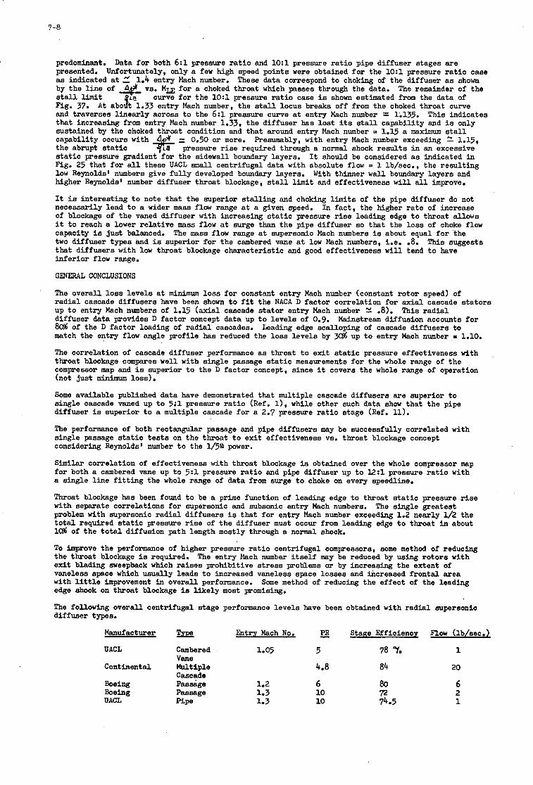
predominant. presented. as indicated at 5 1.4 entry Mach number. by the l i ne of A& VS. Mu fo r a choked throat which passes through the data. s tall limit Fig. 37. and traverses l inear ly across t o the 6:z pressure curve at entry Mach number = 1.135. that increasing from entry Mach number 1.33, the diffuser has l o s t its stall capabili ty and is only sustained by the choked throat condition and that around entry Mach number = 1.15 a maximum stall * pressure r i s e required through a normal shock r e su l t s i n an excessive capability occurs with the abrupt s t a t i c s t a t i c pressure gradient fo r the sidewall boundary layers. It should be considered as indicated i n Fig. 25 that f o r all these UACL s m a l l centrifugal data with absolute flow = 1 lb/sec., the result ing low Reynolds' numbers give f u l l y developed boundary layers. With thinner w a l l boundary layers and higher Reynolds' number diffuser throat blockage, s ta l l l imit and effectiveness w i l l a l l improve.
It is interesting t o note that the superior s t a l l i ng and choking limits of the pipe diffuser do not necessarily lead t o a wider mass f l o w range at a given speed. In fact , the higher r a t e of increase of blockage of the vaned diffuser with increasing s t a t i c pressure r i s e leading edge t o throat allows it t o reach a lower relat ive mass flow at surge than the pipe diffuser so that the loss of choke flow capacity is just balanced. two diffuser types and is superior for the cambered vane at low Mach numbers, i.e. -8. This suggests that diffusers with low throat blockage characterist ic and good effectiveness w i l l tend t o have infer ior flow range.
GENERAL CONCLUSIONS
The overall loss levels at minimum loss fo r constant entry Mach number (constant rotor speed) of r ad ia l cascade diffusers have been shown t o f i t the NACA D factor correlation for axial cascade s t a to r s up t o entry Mach numbers of 1.15 (axial cascade s t a to r entry Mach number V, .SI. diffuser data provides D factor concept data up t o levels of 0.9. 8 d of the D factor loading of radial cascades. match the entry flow angle prof i le has reduced the loss levels by
The correlation of cascade diffuser performance as throat t o exi t s t a t i c pressure effectiveness with throat blockage compares well with single passage s t a t i c measurements f o r the whole range of the compressor map and is superior t o the D factor concept, since it covers the whole range of operation (not just minimum loss).
Some available published data have demonstrated that multiple cascade diffusers are superior t o single cascade vaned up t o 5;1 pressure r a t i o (Ref. 11, while other such data show that the pipe diffuser is superior t o a multiple cascade f o r a 2.7 pressure r a t i o stage (Ref. 11).
The performance of both rectangular passage and pipe diffusers may be successfully correlated with single passage s t a t i c t e s t s on the throat t o exi t effectiveness VS. throat blockage concept considering Reynolds' number t o the l/5a power.
Similar correlation of effectiveness with throat blockage is obtained over the whole compressor map fo r both a cambered vane up t o 5:1 pressure r a t i o and pipe diffuser up t o 12:l pressure r a t i o with a single l i n e f i t t i n g the whole range of data from surge t o choke on every speedline*
Throat blockage has been found t o be a prime function of leading edge t o throat s t a t i c pressure r i s e with separate correlations fo r supersonic and subsonic entry Mach numbers. problem with supersonic radial diffusers is that for entry Mach number exceeding 1.2 nearly l/2 the t o t a l required s t a t i c pressure r i s e of the diffuser must occur from leading edge t o throat i n about 10% of the t o t a l diffusion path length mostly through a normal shock.
Data f o r both 6:l pressure r a t i o and 1O:l pressure r a t i o pipe diffuser stages are Unfortunately, only a few high speed points were obtained f o r the 1O:l pressure r a t i o case
These data correspond to choking of the diffuser as shown The remainder of the
curve fo r the 1O:l pressure r a t i o case is shown estimated from the data of iLe A t abo t 1.33 entry Mach number, the s ta l l locus breaks off from the choked throat curve This indicates
=. 0.50 or more. Presumably, with entry Mach number exceedhg 2 1.15'
The mass flow range at supersonic Mach numbers is about equal f o r the
This r ad ia l Mainstream diffusion accounts f o r
Leading edge scalloping of cascade diffusers t o up t o entry Mach number E 1.10.
The single greatest
To improve the performance of higher pressure r a t i o centrifugal compressors, some method of reducing the throat blockage is required. exi t blading sweepback which raises prohibitive s t r e s s problems or by increasing the extent of vaneless space which usually leads t o increased vaneless space losses and increased frontal area with l i t t l e improvement in overall performance. edge shock on throat blockage is l ike ly most promising.
The following overall centrifugal stage performance levels have been obtained with radial supersonic diffuser types.
The entry Mach number i t s e l f may be reduced by using rotors with
Some method of reducing the effect of the leading
Manufacturer &try Mach No. - PR Stage Efficiency Flow (lb/sec.)
UACL Cambered Vane
Continental Multiple Cascade
Boeing Passage Boeing Passage UACL =Pe
1.05 5
4.8 84
1.2 6 80 1.3 10 72 1.3 10 74.5
1
20
6 2 1
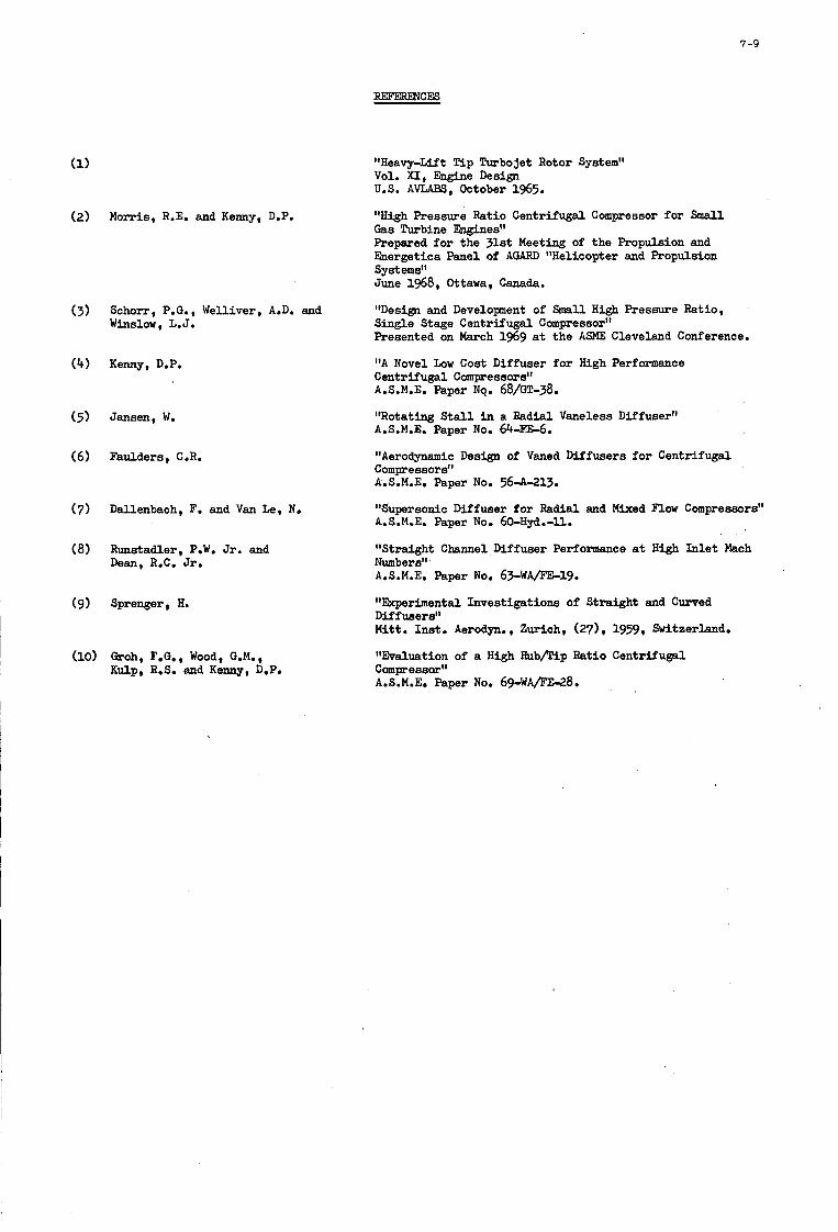
7-9
( 2 ) Morris, R.E. and Kenny, D.P.
(3) Schorr, P.G., Welliver, A.D. and Winslow, L.J.
(4) Kenny, D.P.
(5) Jansen, W.
(6) Faulders, C.R.
(7) Dallenbach, F. and V a n Le, N.
(8) Runstadler, P.W. Jr. and Dean, R.C. Jr.
(9) Sprenger, H.
(10) &oh, F.G. , Wood, G.M., Kulp, R.S. and Kenny, D,P.
"Heavy-Lift !Pip Turbojet Rotor System" Vol. XI, Engine Design U.S. AVLABS, October 1965.
"High Pressure Ratio Centrifugal Compressor for Small Gas TuFbine Engines" Prepared fo r the 3lst Meeting of the Propulsion and Energetics Panel of AGARD "Helicopter and Propulsion Syst emsft June 1968, Ottawa, Canada.
"Desim and Development of Small High Pressure Ratio, Single Stage Centrifugal Compressor" Presented on March 1969 at the ASME Cleveland Conference.
"A Novel Low Cost Diffuser fo r High Performaace Centrifugal Comp-essors" A.S.M.E. Paper No. 68/GT-38.
"Rotating S t a l l i n a Radial Vaneless Diffuser" A.S.M.E. Paper No. 64-F'E-6.
"Aerodynamic Design of Vaned Diffusers f o r Centrifugal Compressors" A.S.M.E. Paper No. 564-213.
"Supersonic Diffuser for Radial and Mixed Flow Compressors" A.S.M.E. Paper No. 6&Hyd.-ll.
"Straight Channel Diffuser Performance at High In l e t Mach Numbers" A.S.M.E. Paper No. 63-WA/FE-19.
"Ekperimental Investigations of Straight and Curved Mff users" Mitt. Inat. Aerodyn. , Zurich, (271, 1959, Switzerland.
"Evaluation of a High HubDip Ratio Centrifugal Compessar" A.S.M.E. Paper No. 69-WAFE-28.
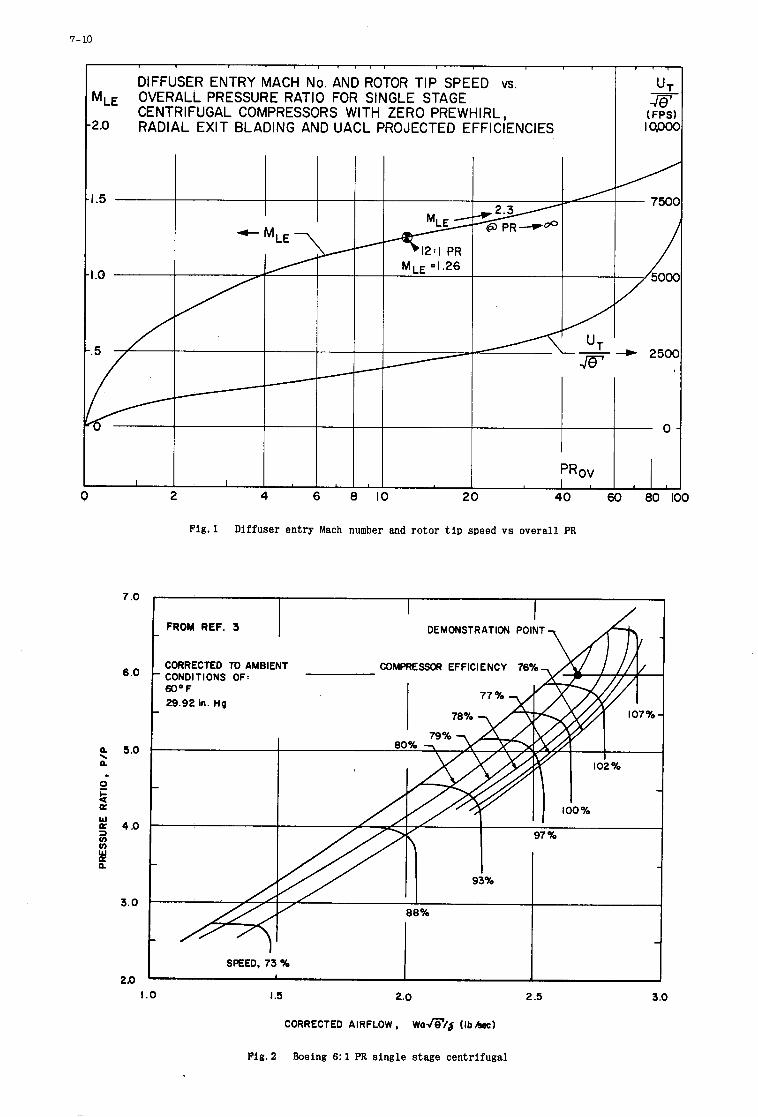
7-10
I
DIFFUSER ENTRY MACH No. AND ROTOR TIP SPEED vs.
CENTRIFUGAL COMPRESSORS WITH ZERO PREWHIRL, RADIAL EXIT BLADING AND UACL PROJECTED EFFICIENCIES
M,, OVERALL PRESSURE RATIO FOR SINGLE STAGE
2.0
PRov I
7 .O
6 .O
a 5.0 a
0 t? a P 4.0
\
w 3 v)
H a 3 . 0
240 1.0
Fig.1 Diffuser entry Mach number and rotor t i p speed vs overall PR
FROM REF. 3 DEMONSTRATION POINT
CORRECTED TO AMBIENT COMPRESSOR EFFlCl E NCY 76 CONDITIONS OF: 600 F 29.92 in. Hg
-
97 Yo
- 93%
88%
-
SPEED, 73 %
3 .O I .5 2.0 2 .S
CORRECTED AIRFLOW, w o r n / $ ( I ~ A O C )
Fig. 2 b e i n g 6: 1 PR single stage centrifugal
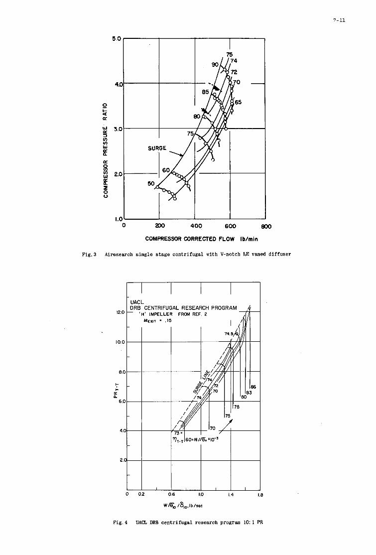
7-11
I
0 Po 400 600 800
COMPRESSOR CORRECTED FLOW Ib/min
I I I
Fig.3 Airesearch single stage centrifugal with V-notch LE vaned diffuser
12.0
10.0
8.C
I-
I- , a 0
6.C
4.(
2.1
UAC L DRB CENTRIFUGAL RESEARCH PROGRAM - 'H' IMPELLER FROM REF. 2
MEXIT = . I5
02 0.6 I .o 1.4 1.8
WmD /6,,,Ib/sec
Fig.4 UACL DRB centrifugal research program 10: 1 PR
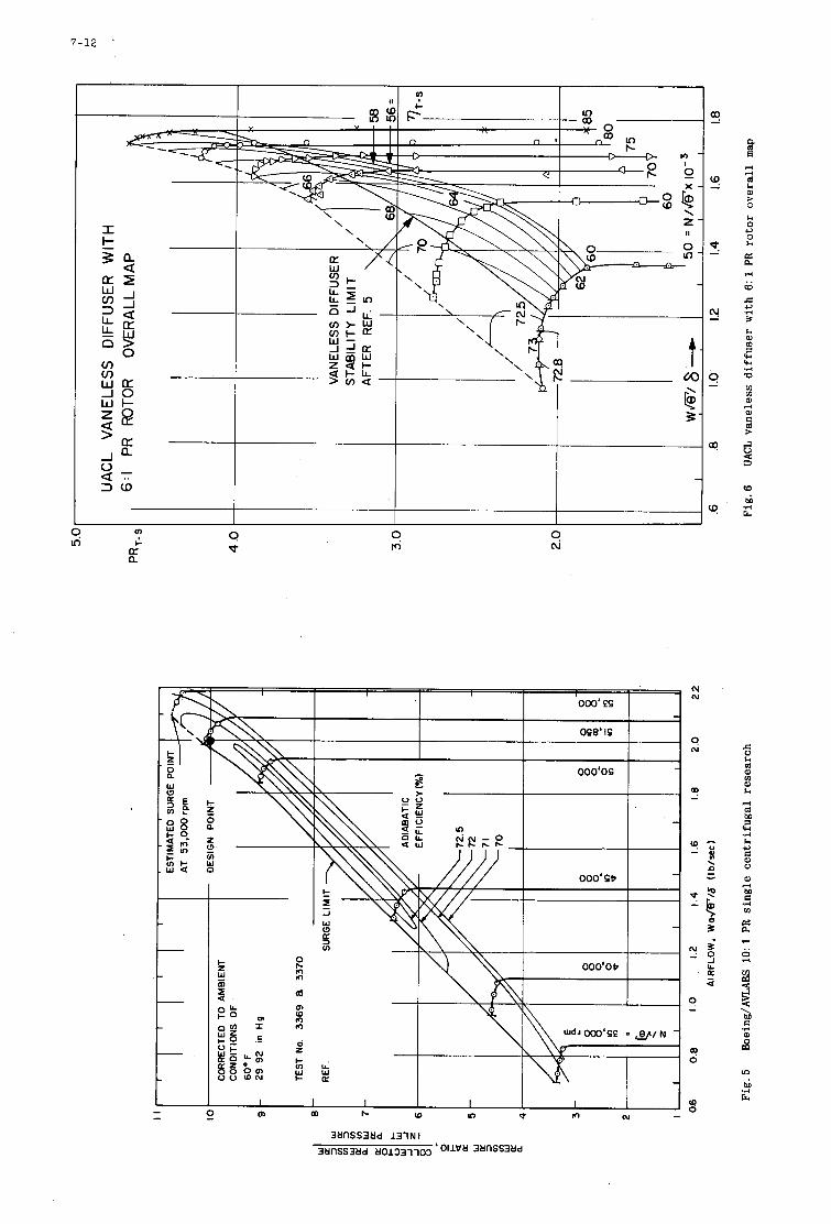
7-12
9 d-
w a o
c z m w m m 3 .. Q
I I I 6c
000‘0s I
3MIlSS3Md 131N I
3t1flSS3Ud t101331103 ‘‘UvU 3t1nSS3t1d
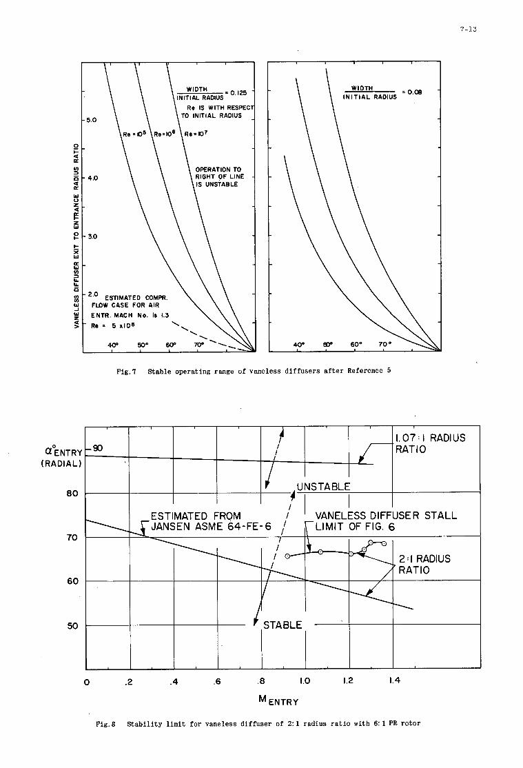
7-13
f I I
I .90
E 4 I Y - C < I I4
2 <
I?
8 I4
c 5 I
!!
z E U
II
II 2 5
1
, I. 07 : I RADIUS RATIO (TOENTRY
( R A D I A L )
80
INITIAL RADIUS Re IS WITH RESPEC
TO INITIAL RADIUS
OPERATION TO
IS UNSTABLE
*” ESTIMATED COMPR. FLDW CASE FOR AIR
ENTR. MACH No. ir 1.3 Re 0 5 a106
I N I T I A L RADIUS
40° 9DD 60° 70°
Fig.7 Stable operating range of vaneless diffusers after Reference 5
70
60
50
0 .2 4 .6 .8
ENTRY
Fig.8 Stabil i ty limit for vaneless diffuser of 2:1
.o 1.2 1.4
radius ratio w i t h 6: 1 PR rotor
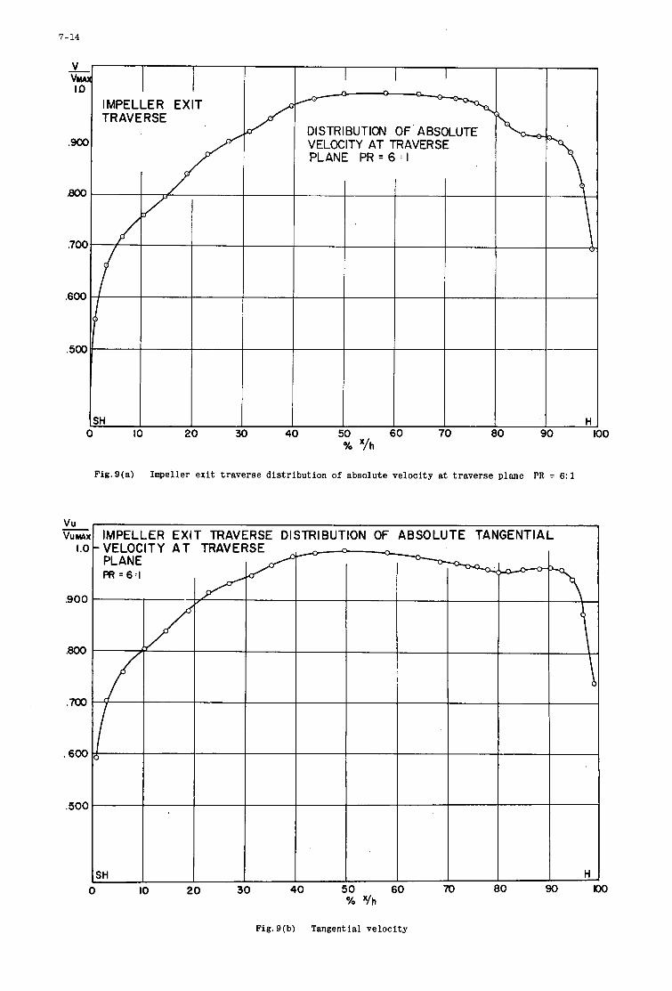
7-14
V V W IO
-
.go0
.700
.600
,500
I / IMPELLER EXIT TRAVERSE
1
I I I P
DISTRIBUTION OF ABSOLUTE VELOCITY AT TRAVERSE PLANE P R = 6 : I
I 60 70 H
I
v u vu MA)
I .o -
.goo
.800
600
.500
% '/h
Fig.S(a) Impeller exit traverse distribution of absolute velocity at traverse plane PR = 6 : l
IMPELLER EXIT TRAVERSE DISTRIBUTION OF ABSOLUTE TANGENTIAL -VELOCITY A T TRAVERSE
0 IO 20 30 40 50 60 70 I ?4 '/h
Fig. 9(b) Tangential velocity
H ) 90
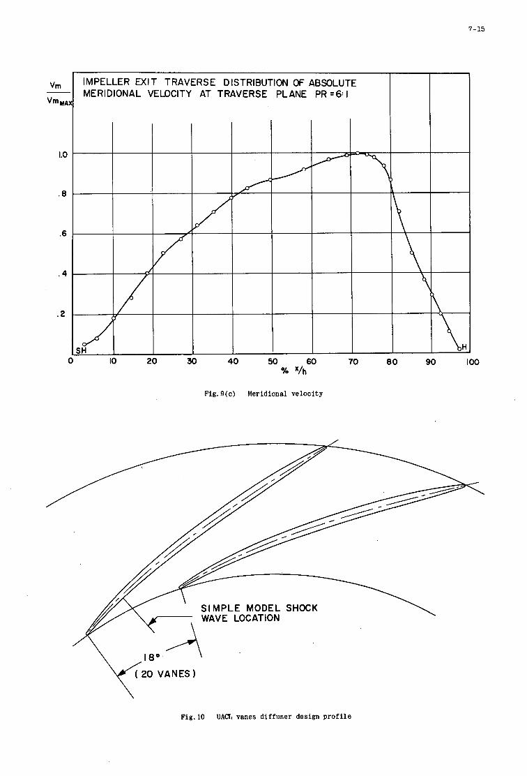
7-15
Vm
Vm MA:
1.0
. 8
.6
. 4
. 2
IMPELLER EXIT TRAVERSE DISTRIBUTION OF ABSOLUTE MERIDIONAL VEDCITY AT TRAVERSE PLANE PR =6: I
IO 20 30 40 50 60 70 80 90 IO0 % x/h
Fig. 9(c) Meridional ve loc i ty
Fig.10 UACL vanes d i f fuser design p r o f i l e
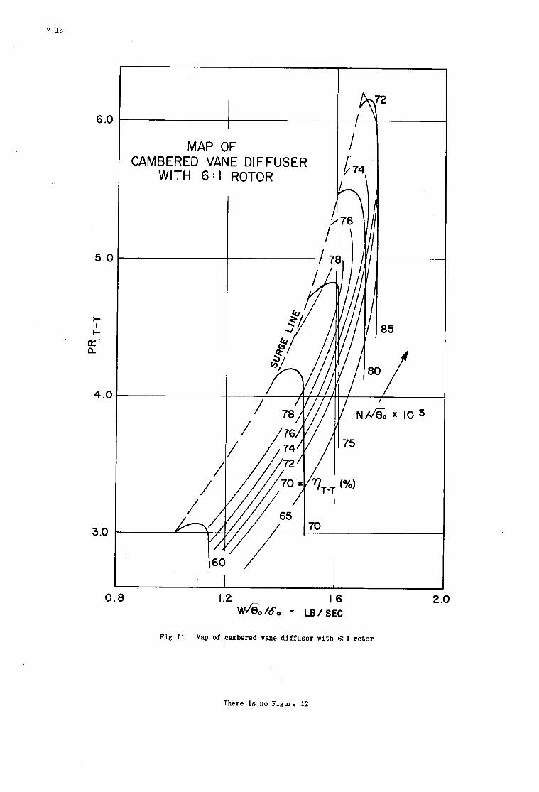
7-16
6 .C
5 . c
I- I b a a
4 .c
3 .O
CAMB WITH 6 : l
/ /
0.8 1.2 1.6 2 .o w 6 0 / 6 0 - LB/SEC
Fig . 11 Map of cambered vane d i f f u s e r with 6: 1 ro tor
There is no Figure 12
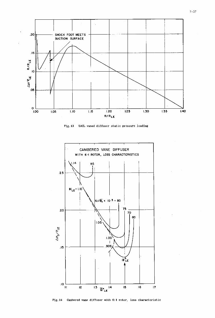
I .oo 1.05 1. IO 1.15 1.20 1.25 1.30
R / R L E
Fig. 13 UACL vaned d i f f u s e r s t a t i c pressure loading
CAMBERED VANE DIFFUSER WITH 6:l ROTOR, LOSS CHARACTERISTICS
.2 5
.20
w a'
a! \
a .I5
.IO I I 12 13 - 14 15 16 17
Q'LE
7-17
1.35 I. 40
Fig. 14 Cambered vane d i f f u s e r with 6: 1 ro to r , loss c h a r a c t e r i s t i c
7-18
SECTION A - A \ VIEW 8 0
Fig.15 UACL flat plate diffuser LE types
3 s LL
X w I-
\
7-19
a
a 0
7-20
Fig. 17
a0
24
2 0
‘ 6 ,
12
8
4
I
- LOSS PER SPEED WITH NACA STATOR ‘D’ c COMPARISON OF UACL VANED DIFFUSER MINIMUM
FACTOR LOSS CORRELATION Reo* = 10-1 8 X IO5
+ CAMBERED VANE WITH 6 I ROTOR CAMBERED VANE WITH 5 I ROTOR
0 CAMBERED VANE WITH 6 I ROTOR WITH SCALLOPED LEADING EDGE
-
-
o 5 I ROTOR WITH FLAT PLATE - DIFFUSER HAVING LEADING EDGE
PRESSURE SURFACE CHAMFER AND HOLLOW GRIND
NACA STATOR
0 . I .2 .3 .4 .5 .6 .7 .e . 9
’ D ’ FACTOR
Comparison of UACL vaned d i f f u s e r minimum l o s s pe r speed with NACA s t a t o r “D” f a c t o r l o s s co r re l a t ion
IMPELLER EXIT TRAVERSE DISTRIBUTION OF CORRECTED FLOW ANGLE REFERRED TO TANGENTIAL FROM SHROUD TO HUB PR = 6: I
0 IO 20 30 40 50 60 70 80 90 100 O h X/h
Fig.18 Impeller e x i t t r a v e r s e d i s t r i b u t i o n o f cor rec ted flow angle
7-21
/ \ WITHOUT SCALLOP
UACL CAMBERED VANE DIFFUSER WITH
~
- % IMPROVEMENT IN FLOW RANGE
1
.7 .8 .9 1.0 1.1 MLE 1.2
LEADING EDGE SCALLOP
Fig.19 UACL cambered vane diffuser with LE scallop
.76
rl .74
.72
- .06
Y%) -.05
-.04
- .03 50
40
30
20
IO
0
REDUCTION IN LOSS DUE TO LE SCALLOP
\,
\ /’
Fig.20 Comparison of overall efficiency vs PR for cambered vane diffuser for LE scallop
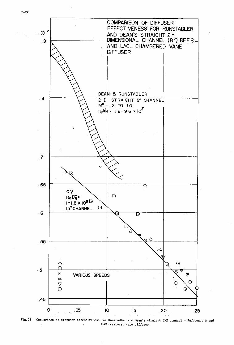
7-22
. 9
.8
. 7
. 6 5
.55
- 5
COMPARISON OF DIFFUSER EFFECTIVENESS FOR RUNSTADLER AND DEAN'S STRAIGHT 2 - DIMENSIONAL CHANNEL (8") REF8 AND UACL CHAMBERED VANE DIFFUSE R
I DEAN 81 RUNSTADLER 2 - 0 STRAIGHT 8' CHANNEL
0 , .05 .IO .I5 .20 .25
Fig.21 Comparison of d i f fuser e f f ec t iveness for Runstadler and Dean's s tra ight 2-D channel - Reference 8 and UACL cambered vane d i f fuser
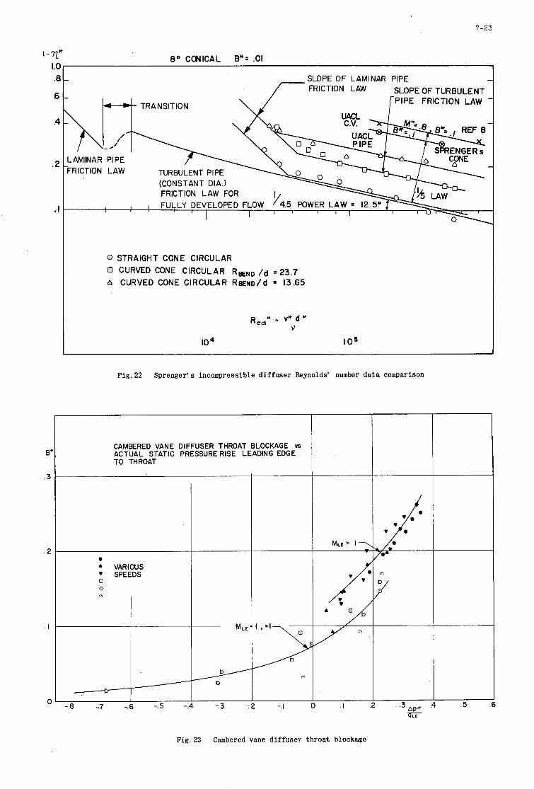
7-23
1 - 7 2 “ 1.c .E
6
.4
.2
‘I
E
..
. I
. I
(
8 O CCIJICAL By= .01
SLOPE O F LAMINAR PIPE FRICTION LAW SLOPE OF TURBULENT
PIPE FRICTION LAW
-RlCTlON LAW
FRICTION LAW FOR
0 STRAIGHT CONE CIRCULAR EI CURVED CONE CIRCULAR REND /d = 2 3 . 7
CURVED CONE CIRCULAR ReENo/d = 13.65
R ~ ~ * = v* d * 3
IO I 0 5
Fig .22 Sprenger’s incompressible d i f fuser Reynolds’ number data comparison
CAMBERED VANE DIFFUSER THROAT BLOCKAGE VS ACTUAL STATIC PRESSURE RISE LEADING EDGE TO THROAT
0
A VARIOUS SPEEDS
0 0 A
- -. 8 77 -.
/
-.5 -
MLE /
n
P
.3 DP* 73 72 -. I 0 . I .z qLE
.5
Fig. 23 Cambered vane d i f fuser throat blockage
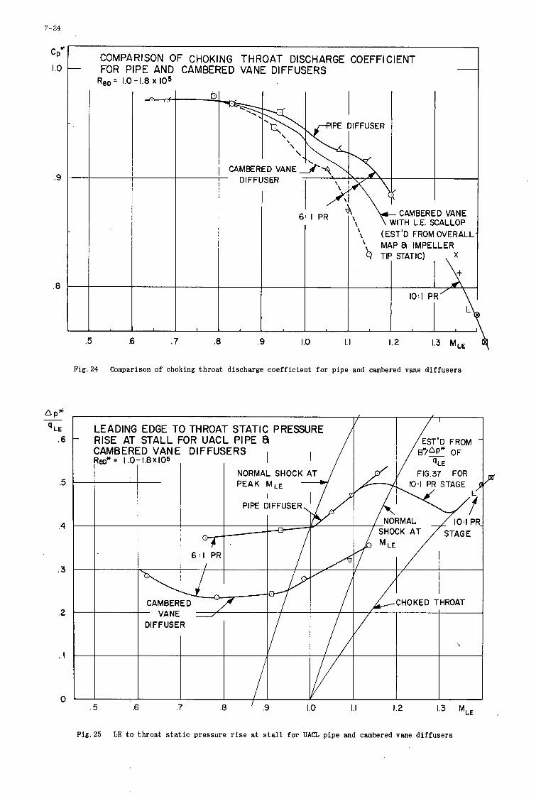
7-24
c D*
I .o
.9
.8
\
P*
LE -
.6
.5
.4
.3
.2
. I
0
\ I
~
- COMPARISON OF CHOKING THROAT DISCHARGE COEFFICIENT
- FOR PIPE AND CAMBERED VANE DIFFUSERS Re, = 1.0 - 1.8 x IO5
l'h\\ . d P E DIFFUSER I I
CAMBERED ' "\N VANE 2 3 I
(EST'D FROM OVERALL 1 1 I I :? M A P 8 IMPELLER
.5 .7 .8 .9 I .o 1. I 1.2
Fig. 24 Comparison of choking t h r o a t discharge coe f f i c i en t f o r p ipe and cambered vane d i f f u s e r s
LEADING EDGE TO THROAT STATIC PRESSURE - RISE AT STALL FOR UACL PIPE &
CAMBERED VANE DIFFUSERS I I Reo* 2 I .0-1.8X10⁵ ,
I' FIG.37 FOR
STAG;, L'
I I I I rirtz uirruacm. I I
. 5 .6 .7 .8 ' .9 1.0 I. I 1.2 1.3 M,,
Fig .25 LE t o t h r o a t s ta t ic pressure rise at s t a l l for UACL pipe and cambered vane d i f f u s e r s
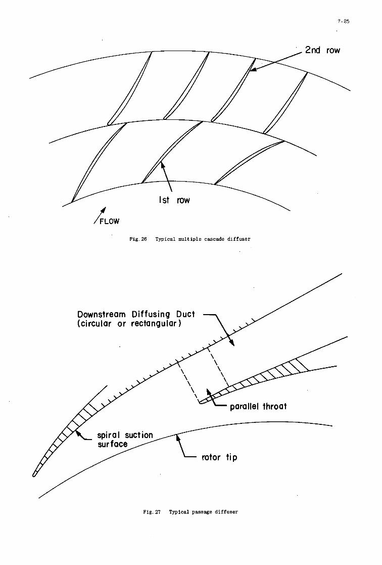
7-25
I i
t I
I
i
I
1 , ~
1
I
I 1
/FLOW
F i g . 2 6 Typical multiple cascade diffuser
Downstream Diffusing Duct (circular or rectangular 1
Fig. 27 Typical passage diffuser
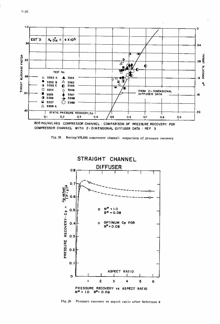
7-26
.80 A 3358 A
I .20 I STATIC PRESSURE RECOVERY,Cp
0.1 0.2 0.3 0.4 0.6 O.? 0.8 0.9
BOEING/AVLABS COMPRESSOR CHANNEL : COMPARISON OF PRESSURE RECOVERY FOR COMPRESSOR CHANNEL WITH 2-DIMENSIONAL DIFFUSER DATA : REF 3
Fig. 28 Boeing/AVLABS compressor channel: comparison of pressure recovery
STRAIGHT CHANNEL DIFFUSER
OB r-----l
0 :: 0 . 5 1 Q M” = 1.0 E* = 0.08
>r. II 0 OPTIMUM Cp FOR
E*= 0.08 0 W
E 0.2 W [L n
0. Ib -I ASPECT RATIO
I 2 3 4 5 6 0 I I I I I
PRESSURE RECOVERY vs ASPECT RATIO M * = 1.0 E*= 0.08
Fig.29 Pressure recovery vs aspect rat io after Reference 8
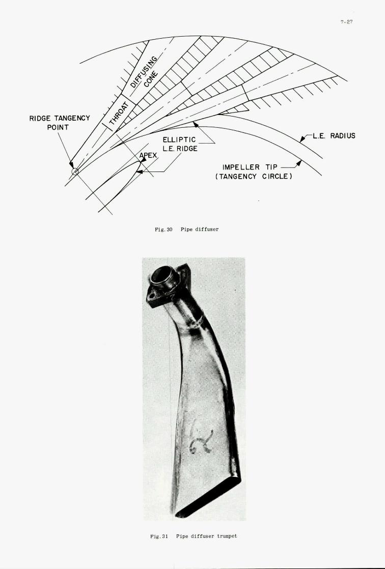
T- (TANGENCY IMPELLER CIRCLE TIP A' 1
Fig.30 Pine diffuser
Fig. 31 Pipe diffuser trumpet
7-27
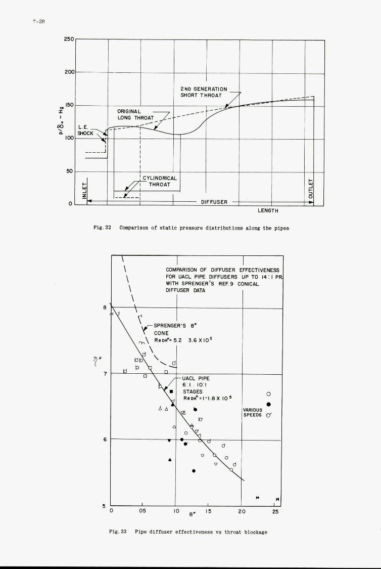
I
7-28
I
Fig.32 compsrison of static Dresswe distributions along the pipes
* * I I
E
7
6
I I \
COMPARISON OF DIFFUSER mR UACL PIPE DIFFUSERS UP TO 14: I P WITH SPRENGER'S REFS CONICAL
\ \
I \ DIFFUSER MTA
\ I
Fig.33 Pipe diffuser effect iveness vs throat blockage
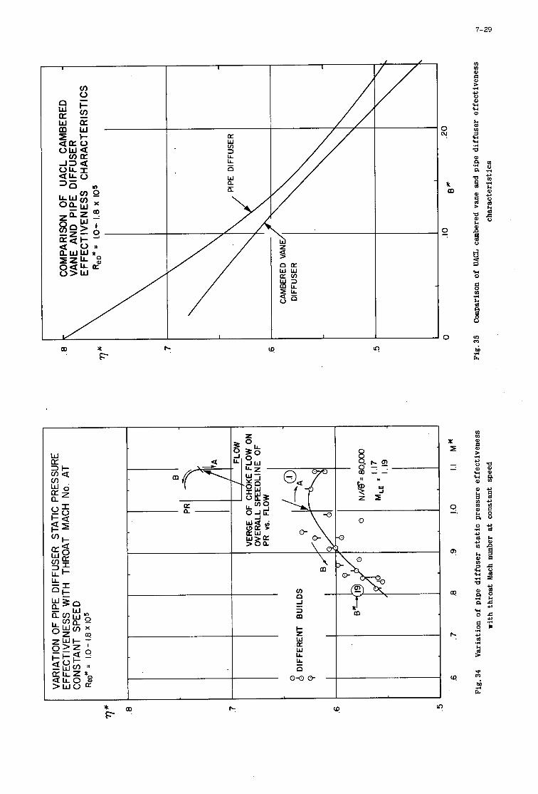
7-29
a0 x F
I I
\ m
7
p:
cr!
* o o rc c4 ? F '
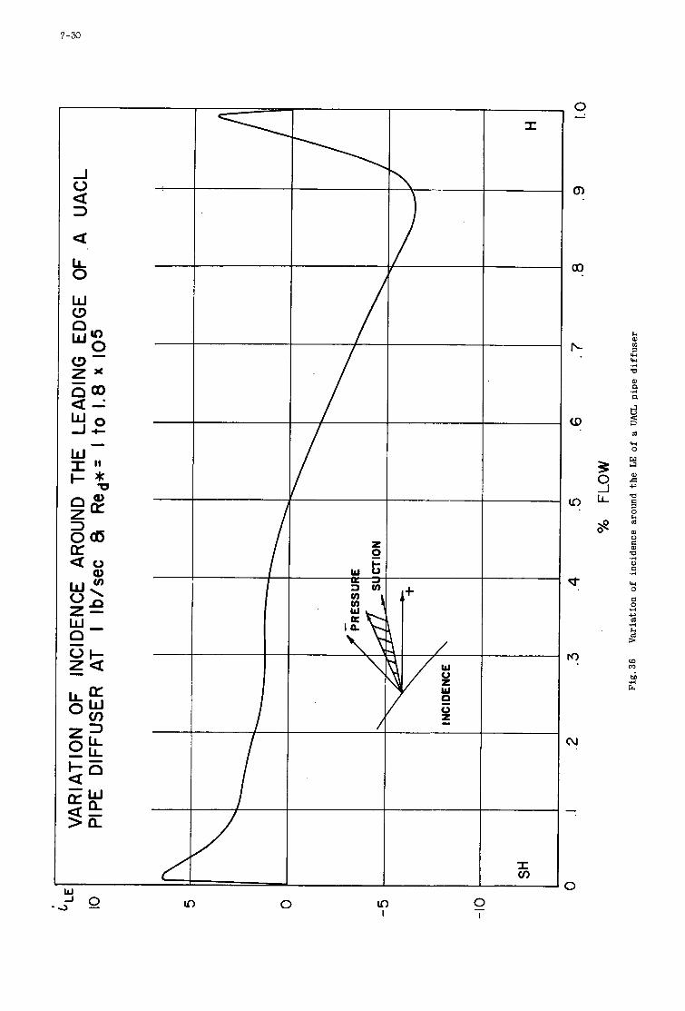
7-30
i
-I 0
3 a
a i5 W (3 n
E m a -* W O - I t W I "
In 0 In I
I
I v,
h 0) rn w w .r(
P
0) a .d a
3 d w 0
Y 0) E c, P
0 d m 0 0)
3
2 E: .r(
'U 0 C 0 .d
c, d .r(
2 >
W m i .r(
E
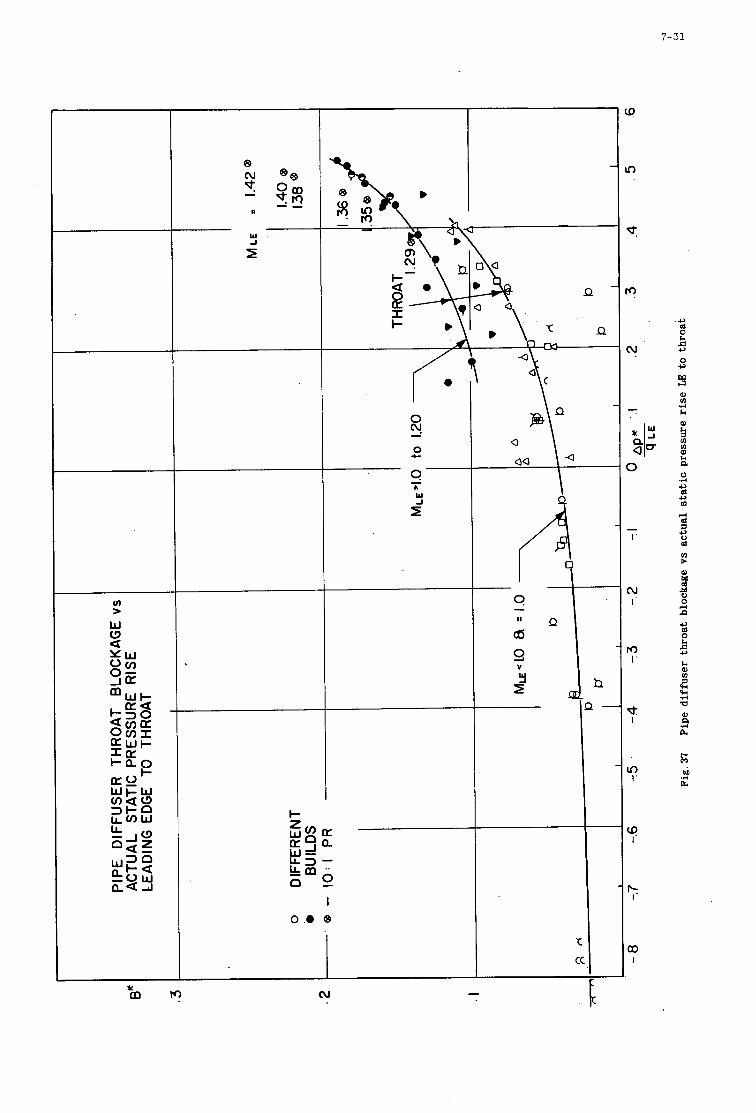
7-31
v) >
W W a
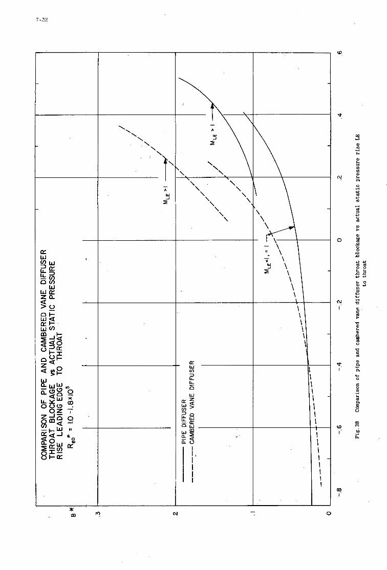
7-32
I * - m r! cr! 0
W.
d
"!
0
"! I
t
P
cq
3 W ln .,-I
h
0)
a ln W
a 0 .r( c,
c, ln 4 d c,
d (I) c W
24 0 4 c)
c,c, d d 0 0
c,+ h 0 0)-
w w .d a 0) t: > a h
8
2 2
3
4 0
P
d a, a .,-I
a w 0
c 0 .d h
a 0 U a
00 0
.,-I M
G.
8
I
S U P E R S O N I C C A S C A D E P E R F O R M A N C E
BY
H. STARKEN H. J . LICHTFUA
DEUTSCHE FORSCHUNGS- UND VERSUCHSANSTALT FUR LUFT- UND RAUMFAHRT E . V .
INSTITUT FUR LUFTSTRAHLANTRIEBE GERMANY
8
SUMMARY
An introduction to the fundamentals of supersonic f low through cascades is presented. The effect of back pressure and the starting conditions are described using simplified f l o w models.
Different design methods proposed in the literature are discussed. In detail, the inflow conditions at design and off-design operations of a supersonic cascade are presented. Finally, approximate methods are described for calculating shock losses and the depen- dency of total pressure losses from static pressure rise and axial-velocity-density ratio.
8
NOMENCLATURE
A
A T e
h
M
M "
A''abs
P
T
t
W
6
V
flow a r e a
c r o s s s e c t i o n a rea of t h r o t t l e behind t h e cascade
l eng th of t h e l e f t running c h a r a c t e r i s t i c through E
energy p e r u n i t mass flow
chord l eng th
Mach number
c r i t i c a l Mach number
d i f f e r e n c e of t a n g e n t i a l components of abso lu t e c r i t i c a l Mach numbers.
p re s su re
temperature
spacing
veloc 1 t y
flow angle ( w i t r e spec t t o cascade f r o n t )
s t agge r angle
t u r n i n g
r a t i o o f s p e c i f i c hea t s
Mach angle
Prandtl-Meyer angle
dens i ty
a x i a l v e l o c i t y dens i ty r a t i o
- :'tot 2-'t?t 1 w = t o t a l p ressure l o s s c o e f f i c i e n t
P to t m-pm -
' shock l o s s c o e f f i c i e n t - p r o f i l e l o s s c o e f f i c i e n t
abs
ax
C
E
I
L
max
N
P
S
SP
t
abso lu te va lues ( i n a r o t o r )
a x i a l component (normal t o cascade f r o n t )
va lue a t po in t C ( f ig .4 .15)
, value a t po in t E ( f ig .4 .10 and 4.15)
n e u t r a l c h a r a c t e r i s t i c of a cascade ( f lg .4 .9)
value a t po in t L ( f ig .4 .9)
maximum value
n e u t r a l c h a r a c t e r i s t i c of a s i n g l e p r o f i l e ( f ig .4 .14) .
va lue a t po in t P on t h e p r o f i l e su r face (fig.4.17)
sonic poin t on t h e bow wave (f ig .4 .15)
sonic poin t on t h e su r face (f lg .4 .15)
component i n t a n g e n t i a l d i r e c t i o n ( p a r a l l e l t o cascade f r o n t )
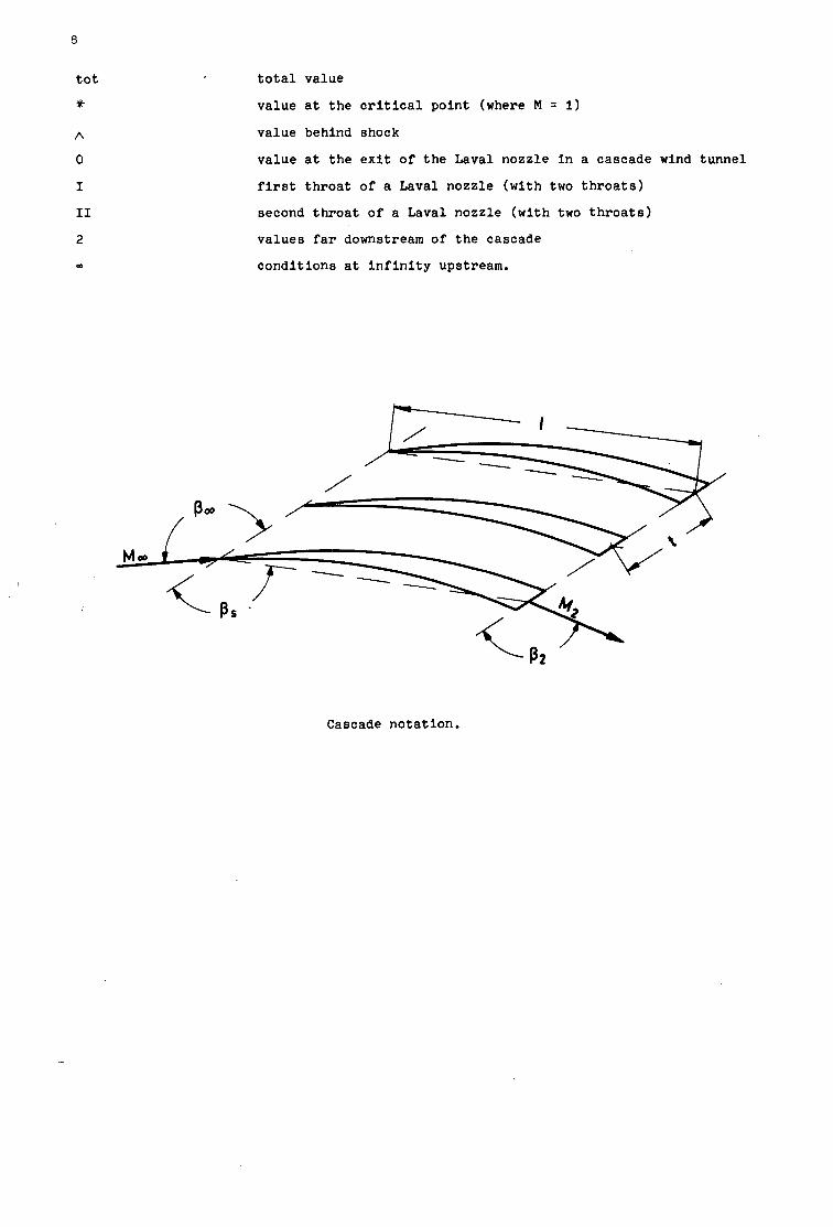
8
t o t
?k
A
0
I
I1
2
m
t o t a l va lue
va lue a t t h e c r i t i c a l po in t (where M = 1)
value behind shock
va lue a t t h e e x i t o f t h e Laval nozz le i n a cascade wind tunne l
f irst t h r o a t of a Laval nozzle ( w i t h two t h r o a t s )
second t h r o a t of a Laval nozzle ( w i t h two t h r o a t s )
va lues far downstream of t h e cascade
cond i t ions a t i n f i n i t y upstream.
Cascade no ta t ion .
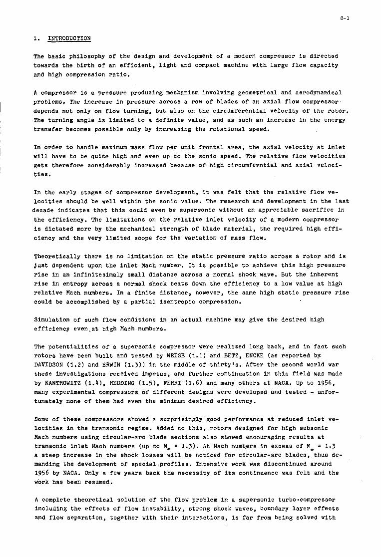
8- 1
1. INTRODUCTION
The bas i c philosophy of t h e design and development of a modern compressor i s d i r e c t e d towards the b i r t h of an e f f i c i e n t , l i g h t and compact machine w i t h l a r g e flow capac i ty and high compression r a t i o .
A compressor is a p re s su re producing mechanism involv ing geometr ical and aerodynamical problems. The inc rease i n p re s su re ac ross a row of b lades of an a x i a l f low compressor depends not only on flow tu rn ing , but a l s o on the c i r cumfe ren t i a l Veloci ty of t h e r o t o r . The tu rn ing angle i s l i m i t e d t o a d e f i n i t e value, and a s such an inc rease i n t h e energy t r a n s f e r becomes p o s s i b l e only by inc reas ing t h e r o t a t i o n a l speed.
I n o rde r t o handle maximum mass flow per u n i t f r o n t a l a r ea , t h e a x i a l ve loc i ty a t i n l e t w i l l have t o be q u i t e high and even up t o t h e sonic speed. The r e l a t i v e flow v e l o c i t i e s g e t s t h e r e f o r e considerably increased because of high c i r cumfe rn t i a l and a x i a l Veloci- t i es .
I n t h e e a r l y stages of compressor development, it was f e l t t h a t t h e r e l a t i v e flow ve- l o c i t i e s should be w e l l wi th in t h e sonic value. The r e sea rch and development i n the l a s t
decade i n d i c a t e s t h a t t h i s could even be supersonic without an apprec i ab le s a c r i f i c e i n t h e e f f i c i ency . The l i m i t a t i o n s on t h e r e l a t i v e i n l e t ve loc i ty of a modern compressor i s d i c t a t e d more by the mechanical s t r e n g t h of blade ma te r i a l , t h e r equ i r ed high e f f i - c iency and t h e very l imi t ed scope f o r t h e v a r i a t i o n o f mass flow.
Theore t i ca l ly there i s no l i m i t a t i o n on t h e s t a t i c pressure r a t i o ac ross a r o t o r and i s J u s t dependent upon t h e i n l e t Mach number. It i s poss ib l e t o achieve t h i s high pressure r ise i n an i n f i n i t e s i m a l y small d i s t ance ac ross a normal shock wave. But t h e inherent r i s e i n entropy ac ross a normal shock bea t s down t h e e f f i c i e n c y t o a low va lue a t high r e l a t i v e Mach numbers, I n a f i n i t e d i s t ance , however, t h e same high s t a t i c p re s su re r i s e could be accomplished by a p a r t i a l i s e n t r o p i c compression.
Simulation of such flow condi t ions i n an a c t u a l machine may g ive t h e des i r ed h i g h e f f i c i e n c y even ,a t high Mach numbers.
The p o t e n t i a l i t i e s of a supersonic compressor were r e a l i z e d long back, and i n f a c t such r o t o r s have been b u i l t and t e s t e d by WEISE (1.1) and BETZ, ENCKE ( a s r epor t ed by DAVIDSON ( 1 . 2 ) and ERWIN (1.3)) i n t h e middle of t h i r t y ' s . Af te r t h e second world war these i n v e s t i g a t i o n s received impetus, and f u r t h e r cont inua t ion i n t h i s f i e l d was made by KANTROWITZ (1 .41 , R E D D I N G (1.51, FERRI (1 .6) and many o t h e r s a t NACA. Up t o 1956, many experimental compressors of d i f f e r e n t des igns were developed and t e s t e d - unfor- t u n a t e l y none of them had even t h e minimum des i r ed e f f i c i ency .
Some of these compressors showed a s u r p r i s i n g l y good performance a t reduced i n l e t ve- l o c i t i e s i n t h e t r anson ic regime. Added t o t h i s , r o t o r s designed f o r high subsonic Mach numbers us ing c i r c u l a r - a r c blade s e c t i o n s a l s o showed encouraging r e s u l t s a t t r anson ic i n l e t Mach numbers (up t o Ma, = 1.3). A t Mach numb,ers i n excess of M- = 1.3 a s t e e p inc rease i n t h e shock l o s s e s w i l l be not iced f o r c i r cu la r - a rc b lades , t hus de- manding t h e development of s p e c i a l . p r o f i l e s . In t ens ive work was d iscont inued around 1956 by NACA. Only a few yea r s back t h e necess i ty of i t s continuence was f e l t and t h e work has been resumed.
A complete t h e o r e t i c a l so lu t ion of t h e flow problem i n a supersonic turbo-compressor inc luding t h e e f f e c t s of f low i n s t a b i l i t y , s t rong shock waves, boundary l a y e r e f f e c t s and flow separa t ion , t oge the r w i t h t h e i r i n t e r a c t i o n s , i s f a r from being solved w i t h
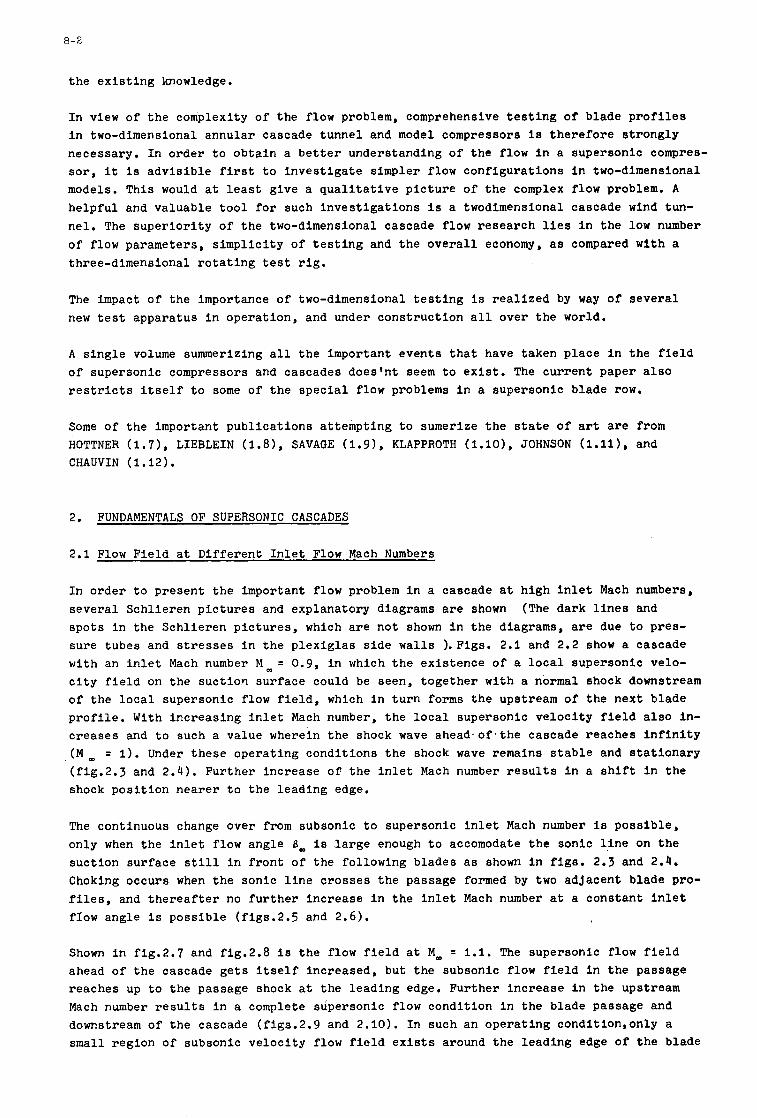
8- 2
the existing knowledge.
In view of the complexity of the flow problem, comprehensive testing of blade profiles in two-dimensional annular cascade tunnel and model compressors i s therefore strongly necessary. In order to obtain a better understanding of the flow in a supersonic compres- sor, it is advisible first to investigate simpler flow configurations in two-dimensional models. This would at least give a qualitative picture of the complex flow problem. A
helpful and valuable tool for such investigations is a twodimensional cascade wind tun- nel, The superiority of the two-dimensional cascade flow research lies In the low number of flow parameters, simplicity of testing and the overall economy, as compared with a three-dimensional rotating test rig.
The impact of the importance of two-dimensional testing is realized by way of several new test apparatus in operation, and under construction all over the world.
A single volume summerizing all the important events that have taken place in the field of supersonic compressors and cascades does'nt seem to exist. The current paper also restricts itself to some of the special flow problems in a supersonic blade row.
Some of the important publications attempting to sumerize the state of art are from HOTTNER ( 1.7 ) , LIEBLEIN (1.8 ) , SAVAffE ( 1.9) , KLAPPROTH (1.10) , JOHNSON (1.11 1, and CHAUVIN (1.12).
2. FUNDAMENTALS OF SUPERSONIC CASCADES
2.1 Flow Field at Different Inlet Flow Mach Numbers
In order to present the important flow problem in a cascade at high inlet Mach numbers, several Schlieren pictures and explanatory diagrams are shown spots in the Schlieren pictures, which are not shown in the diagrams, are due to pres- sure tubes and stresses in the Plexiglas side walls ).Figs. 2.1 and 2.2 show a cascade with an inlet Mach number M m = 0.9, in which the existence of a local supersonic velo- city field on the suctiorl surface could be seen, together with a normal shock downstream of the local supersonic flow field, which in turn forms the upstream of the next blade profile. With increasing inlet Mach number, the local supersonic velocity field also in- creases and to such a value wherein the shock wave ahead,of,the cascade reaches infinity (M, = 1). Under these operating conditions the shock wave remains stable and stationary (fig.2.j and 2.4). Further increase of the inlet Mach number results in a shift in the shock position nearer to the leading edge.
(The dark lines and
The continuous change over from subsonic to supersonic inlet Mach number is possible, only when the inlet flow angle Bm is large enough to accomodate the sonic line on the suction surface still in front of the following blades as shown in figs. 2.3 and 2.4. Choking occurs when the sonic line crosses the passage formed by two adjacent blade pro- files, and thereafter no further increase in the inlet Mach number at a constant inlet flow angle is possible (figs.2.5 and 2.6).
Shown in fig.2.7 and fig.2.8 is the flow field at MOD = 1.1. The supersonic flow field ahead of the cascade gets itself increased, but the subsonic flow field in the passage reaches up to the passage shock at the leading edge. Further increase in the upstream Mach number results in a complete supersonic flow condition in the blade passage and downstream of the cascade (figs.2.9 and 2.10). In such an operating condition,only a small region of subsonic velocity flow field exists around the leading edge of the blade
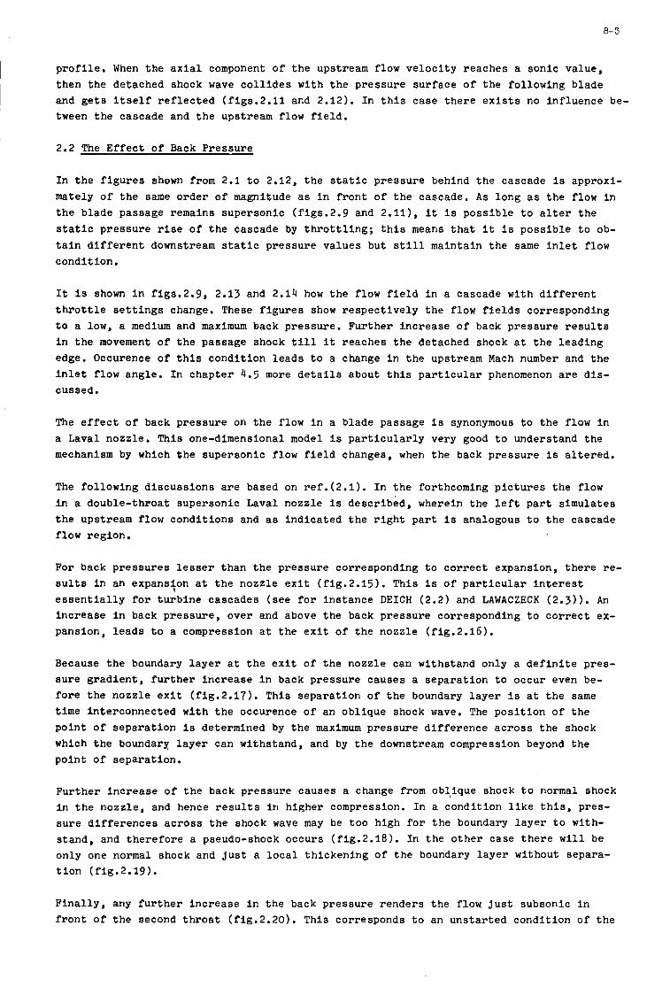
a- 3
p r o f i l e . When t h e axial component of t h e upstream flow v e l o c i t y reaches a sonic value, then t h e detached shock wave c o l l i d e s with t h e pressure su r face of t h e fol lowing blade and g e t s I t s e l f r e f l e c t e d (f igs .2 .11 and 2.12). I n t h i s case t h e r e e x i s t s no in f luence be- tween t h e cascade and t h e upstream flow f i e l d .
2.2 The E f f e c t of Back Pressure
I n t h e f i g u r e s shown from 2.1 t o 2.12, t h e s t a t i c pressure behind t h e cascade i s approxi- mately of t h e same o rde r of magnitude a s i n f r o n t of t h e cascade. A s long a s t h e flow i n t h e blade passage remains supersonic (figs.2.9 and 2.111, i t i s poss ib l e t o a l t e r t h e s t a t i c pressure r i s e o f t h e cascade by t h r o t t l i n g ; t h i s means t h a t it i s poss ib l e t o ob- t a i n d i f f e r e n t downstream s t a t i c pressure va lues but s t i l l maintain t h e same i n l e t flow condi t ion .
It i s shown i n f igs .2 .9 , 2.13 and 2 .14 how t h e flow f i e l d i n a cascade wi th d i f f e r e n t t h r o t t l e s e t t i n g s change. These f i g u r e s show re spec t ive ly t h e flow f i e l d s corresponding t o a low, a medium and maximum back pressure . Fur ther i nc rease of back pressure r e s u l t s I n t h e movement of t h e passage shock till it reaches t h e detached shock a t t h e l ead ing edge. Occurence of t h i s condi t ion l e a d s t o a change i n t h e upstream Mach number and t h e i n l e t f low angle . I n chapter 4.5 more d e t a i l s about t h i s p a r t i c u l a r phenomenon a r e d i s - cussed.
The e f f e c t o f back p res su re on t h e flow i n a blade passage i s synonymous t o t h e flow i n a Laval nozzle . Thio one-dimensional model is p a r t i c u l a r l y very good t o understand t h e mechanism by which t h e supersonic flow f i e l d changes, when t h e back p res su re i s a l t e r e d .
The fol lowing d i scuss ions are based on re f . (2 .1) . In t h e forthcoming p i c t u r e s t h e flow i n a double- throat supersonic Laval nozzle i s descr ibed , wherein t h e l e f t p a r t s imula tes t h e upstream flow cond i t ions and as ind ica t ed t h e r i g h t p a r t i s analogous t o t h e cascade flow region.
For back p res su res lesser than t h e p re s su re corresponding t o c o r r e c t expansion, t h e r e re- s u l t s i n an expans4on a t t h e nozzle e x i t ( f ig .2 .15) . This I s of p a r t i c u l a r i n t e r e s t e s s e n t i a l l y f o r t u r b i n e cascades ( see f o r i n s t ance DEICH (2.2) and LAWACZECK (2 .3) ) . An i nc rease i n back pressure , over and above t h e back pressure corresponding t o c o r r e c t ex- pansion, l e a d s t o a compression a t t h e e x i t o f t h e nozzle ( f ig .2 .16) . ,
Because t h e boundary l a y e r a t t h e e x i t of t h e nozzle can withstand only a d e f i n i t e pres - su re g rad ien t , f u r t h e r i nc rease i n back pressure causes a s epa ra t ion t o occur even be- f o r e t h e nozz le e x i t ( f ig .2 .17) . This s epa ra t ion of t h e boundary l a y e r l s a t t h e same time Interconnected wi th t h e occurence o f an obl ique shock wave. The p o s i t i o n of t h e poin t o f Separat ion is determined by t h e maximum pres su re d i f f e r e n c e a c r o s s t h e shock which t h e boundary l a y e r can withstand, and by t h e downstream compression beyond t h e poin t of separa t ion .
Fur ther i nc rease o f t h e back pressure causes a change from obl ique shock t o normal shock i n t h e nozz le , and hence r e s u l t s i n h igher compression. I n a condi t ion l i k e t h i s , pres- s u r e d i f f e r e n c e s ac ross t h e shock wave may be too high f o r t h e boundary l a y e r t o with- s tand , and t h e r e f o r e a pseudo-shock occurs ( f ig .2 .18) . In t h e o t h e r case t h e r e w i l l be only one normal shock and j u s t a l o c a l th ickening of t h e boundary l a y e r without separa- t i o n (f ig .2 .19) .
F i n a l l y , any f u r t h e r i nc rease i n t h e back pressure renders t h e flow j u s t subsonic i n f r o n t of t h e second t h r o a t ( f ig .2 .20) . This corresponds t o an uns t a r t ed condi t ion of t h e
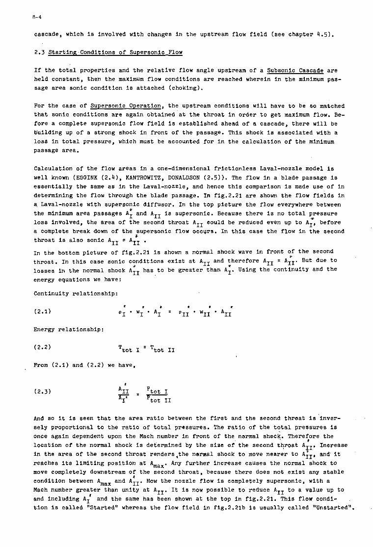
0-4
Y l o s s involved, t h e a r e a of t h e second t h r o a t AII eould be reduced even up t o AI, be fore a complete break down of t h e supersonic flow occurs . I n t h i s case t h e flow i n t h e second t h r o a t i s a l s o sonic AII =
In t h e bottom p i c t u r e of f ig .2 .21 i s shown a normal shock wave i n f r o n t of t h e second t h r o a t . In t h i s case sonic condi t ions e x i s t a t AII and t h e r e f o r e AII = AIIO But1 due t o l o s s e s i n t h e normal shock AII has t o be g r e a t e r t han AI. Using t h e con t inu i ty and t h e energy equat ions we have:
Cont inui ty r e l a t i o n s h i p :
* AII
* Y *
cascade, which i s involved with changes i n t h e upstream flow f i e l d ( see chap te r 4.5).
2.3 S tar t inK.Condi t ions of Supersonic Flow
I f t h e t o t a l p r o p e r t i e s and t h e r e l a t i v e flow angle upsfream of a Subsonic Cascade a r e he ld cons t an t , then t h e maximum flow condi t ions a r e reached wherein i n t h e minimum pas- sage a r e a sonic condi t ion i s a t t ached (choking) .
(2.1) * t t t t t
PI WI A I = P I 1 wII AII
Energy r e l a t i o n s h i p :
(2.2) T t o t I = T t o t I1
From (2.1) and (2.2) w e have,
(2.3) *
AII - P t o t I AIn P t o t I1 - - -
And so it i s seen t h a t t h e a r e a r a t i o between the f i r s t and t h e second t h r o a t i s ' i n v e r - s e l y p ropor t iona l t o t h e r a t i o of t o t a l p ressures . The r a t i o of t h e t o t a l p re s su res 1s once aga in dependent upon t h e Mach number i n f r o n t of t h e normal shock. Therefore t h e l o c a t i o n of t h e normal shock i s determined by t h e s i z e of t h e second t h r o a t AzI , Inorease i n t h e a r e a of t h e second t h r o a t r ende r s , t he normal shock t o move nea re r t o AII , and it reaches i t s l i m i t i n g pos i t i on a t Amax. Any f u r t h e r i nc rease causes t h e normal shock t o move completely downstream of t h e second t h r o a t , because t h e r e does not e x i s t any s t a b l e condi t ion between Amax and AII . Now t h e nozzle flow i s completely supersonic , wi th a Mach number g r e a t e r than un i ty a t AII. It i s now poss ib l e t o reduce AII t o a value up t o and inc luding AI t i o n i s c a l l e d "Star ted" whereas t h e flow f i e l d i n fig.2.21b i s usual ly c a l l e d "Unstarted".
XL
*
I and t h e same has been shown a t t h e top i n fig.2.21. This flow condi-

8- 5 - -
The t h e o r e t i c a l r e l a t i o n s h i p between t h e Mach number and t h e corresponding a r e a r a t i o 8 f o r t h e s t a r t e d and t h e s t a r t i n g condi t ions a r e shown i n fig.2.22.
App l i cab i l i t y of t h e above onedimensional model t o a cascade flow problem demands accoun- t i n g f o r a two-dimensional f low t h a t e x i s t s i n i t . Unfortunately, till now t h e r e appea.rs t o e x i s t no exac t t h e o r e t i c a l method by which a gene ra l two-dimensional flow f i e l d w i t h s t r o n g shocks could be predic ted . An acceptab le and emperical estimate of t h e probable p o s i t i o n and shape of t he sonic l i n e i s t h e r e f o r e necessary t o ge t an idea about t h e s t a r t i n g of a supersonic cascade.
The flow f i e l d s i n a s t a r t e d and uns t a r t ed supersonic cascade a r e shown i n figs.2.23 and 2.24, w i t h Mach numbers M- = 1.1 and M- = 1.24 r e spec t ive ly .
3. DESIGN METHODS OF SUPERSONIC BLADING
The geometry of t h e supersonic b lad ing depends e s s e n t i a l l y on t h e flow condi t ions re- qu i r ed a t t h e e x i t o f t h e r o t o r . That means, t h e mode of energy t r a n s f e r p lays an impor- t a n t r o l e . Typical supersonic cascades toge the r w i t h v e l o c i t y t r i a n g l e s a r e shown i n fig.3.1. Fig.3.la shows a cascade o f t h e impulse type , wherein t h e r e l a t i v e c r i t i c a l Machnumber M remains nea r ly unchanged and only high t u r n i n g e x i s t s symmetrical t o t he a x i a l f low d i r e c t i o n . However, such a r o t o r cascade i s inherent w i t h s t rong a c c e l e r a t i o n i n t h e abso lu t e flow Mabs followed by l a r g e d e f l e c t i o n . I n o t h e r words, it means t h a t t h e change i n the abso lu te c i r cumfe ren t i a l c r i t i c a l Machnumber AMt abs i s high. A s t h e poss ib l e va lue of AMt abs is high f o r a b lad ing of t h i s c l a s s , it i s seen from t h e Euler-Turbine equat ion t h e energy t r a n s f e r h i s a l s o q u i t e high:
U
* *
t
(3 .1) w *
= Mt A't abs
I n a symmetrical b lad ing a s shown i n f ig .3 . l a , it i s seen t h a t t h e e n t i r e change i n t h e s t a t i c p re s su re has t o take p lace completely i n t h e fol lowing s t a t o r a t a high supersonic v e l o c i t y s ince t h e s t a t i c pressure remains cons tan t a c r o s s the r o t o r .
The o t h e r type o f b lad ing a s shown i n f ig .3 . lb has a very small camber and hence t h e de- f l e c t i o n of t h e r e l a t i v e flow i s a l s o small . The l a r g e t u r n i n g i n t h e abso lu te flow i s due t o t h e severe d e c e l e r a t i o n of t h e r e l a t i v e flow (p res su re r i s e ) and t h i s is respon- s i b l e f o r t h e energy t r a n s f e r .
The design of t h e b lad ing as such governs t h e abso lu te o u t l e t v e l o c i t y ( i d e n t i c a l t o t h e i n l e t v e l o c i t y of t h e s t a t o r ) , which may be subsonic o r supersonic . Apart from the above s a i d two l i m i t i n g cases , a v a r i e t y of conf igu ra t ions having d i f f e r e n t t u rn ings and s t a - t i c p re s su re r i s e s a r e poss ib l e and many of them have a l s o been t e s t e d . Three d i f f e r e n t t ypes of supersonic cascade can be thought o f f , t ak ing i n t o cons ide ra t ion t h e r e l a t i v e components of t h e flow.
a ) Impulse type cascade. A cascade of t h i s type i s shown i n f ig .3 . la . To e s t a b l i s h t h e flow of an impulse type r o t o r , a cascade w i t h high tu rn lng and low p res su re r ise i s requi red . The same geo- metry holds good f o r an a c c e l e r a t i n g and d e c e l e r a t i n g machine. Hence t h e knowledge a v a i l a b l e i n t h e f i e l d of t u r b i n e blading becomes a l s o u s e f u l f o r t h e design o f supersonic compressors. For the same i n l e t and o u t l e t condi t ions c a l l e d f o r , t h e r e are d i f f e r e n t ways of g e t t i n g t h e p r o f i l e shape. SHAPIRO (3.1) has given a method and such a p r o f i l e is shown i n fig.3.2. The method c o n s i s t s i n i s e n t r o p i c a l l y (s imple wave) d e c e l e r a t i n g t h e flow i n t h e i n l e t po r t ion of t h e b lades up t o a p a r a l l e l f low a t the t h r o a t , and f u r t h e r a c c e l e r a t i n g it wi th in t h e passage t o t h e flow Mach number
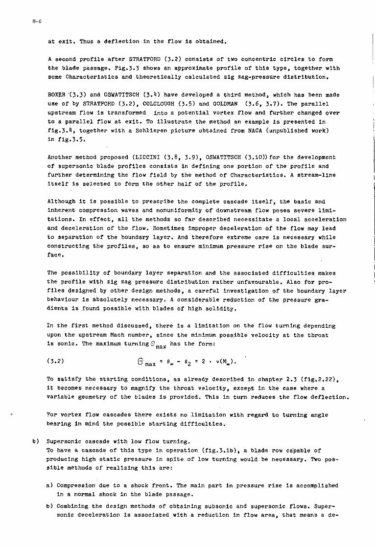
8- 6
a t e x i t . Thus a d e f l e c t i o n . i n t h e flow i s obtained.
A second p r o f i l e a f t e r STRATFORD (3.2) c o n s i s t s o f two concent r ic c i r c l e s t o form t h e blade passage. Fig.3.3 shows an approximate p r o f i l e of t h i s type , t oge the r w i t h some C h a r a c t e r i s t i c s and t h e o r e t i c a l l y ca l cu la t ed z i g zag-pressure d i s t r i b u t i o n .
BOXER'(3.3) and OSWATITSCH (3.4) have developed a t h i r d method, which has been made use o f by STRATFORD (3.21, COLCLOUGH (3.5) and GOLDMAN (3.6, 3.7). The p a r a l l e l upstream flow i s transformed i n t o a p o t e n t i a l vor tex flow and f u r t h e r changed over t o a p a r a l l e l f low a t e x i t . To i l l u s t r a t e t h e method an example i s presented i n
, f ig .3 .4 , t oge the r w i t h a Schl ie ren p i c t u r e obtained from NACA (unpublished work) i n fig.3.5.
Another method proposed ( L I C C I N I (3.8, 3.91, OSWATITSCH (3.10)) f o r t h e development of supersonic b lade p r o f i l e s c o n s i s t s i n de f in ing one po r t ion of t h e p r o f i l e and f u r t h e r determining t h e flow f i e l d by t h e method of C h a r a c t e r i s t i c s . A st ream-l ine i t s e l f i s se l ec t ed t o form t h e o t h e r ha l f of t h e p r o f i l e .
Although i t i s poss ib l e t o p re sc r ibe t h e complete cascade i t s e l f , t h e bas i c and inherent compression waves and nonuniformlty of downstream flow poses severe l i m i - t a t i o n s . I n e f f e c t , a l l t h e methods so f a r descr ibed n e c e s s i t a t e a l o c a l a c c e l e r a t i o n and dece le ra t ion of t h e flow. Sometimes improper dece le ra t ion of t h e flow may lead t o sepa ra t ion of t h e boundary l a y e r . And t h e r e f o r e extreme c a r e i s necessary whi le cons t ruc t ing t h e p r o f i l e s , so a s t o ensure minimum pressure r i s e on t h e blade sur - face.
The p o s s i b i l i t y of boundary l a y e r s epa ra t ion and t h e a s soc ia t ed d i f f i c u l t i e s makes t h e p r o f i l e w i t h z i g zag p res su re d i s t r i b u t i o n rather unfavourable. Also f o r pro- f i l e s designed by o t h e r design methods, a c a r e f u l i n v e s t i g a t i o n of t h e boundary l a y e r behaviour i s abso lu te ly necessary. A cons iderable reduct ion of t h e p re s su re gra- d i e n t s i s found poss ib l e w i t h b lades of h igh s o l i d i t y .
In t h e f i rs t method d iscussed , t h e r e i s a l i m i t a t i o n on t h e flow tu rn ing depending upon t h e upstream Mach number, s ince t h e minimum poss ib l e v e l o c i t y a t t h e t h r o a t i s sonic . The maximum t u r n i n g g m a x has t h e form:
To s a t i s f y the s t a r t i n g condi t ions , a s a l ready descr ibed i n chap te r 2.3 (fig.2.22), i t becomes necessary t o magnify t h e t h r o a t v e l o c i t y , except i n t h e case where a v a r i a b l e geometry of t h e blades i s provided. T h i s i n t u r n reduces t h e flow de f l ec t ion .
For vor tex flow cascades t h e r e ex is t s no l i m i t a t i o n w i t h regard t o t u r n i n g angle bear ing i n mind t h e poss ib l e s t a r t i n g d i f f i c u l t i e s .
b ) Supersonic cascade w i t h low flow turn ing . To have a cascade o f t h i s t ype i n ope ra t ion ( f ig .3 . lb ) , a blade row capable of producing h i g h s t a t i c pressure i n s p i t e of low tu rn ing would be necessary. Two pos- s i b l e methods of r e a l i z i n g t h i s are:
a ) Compression due t o a shock f r o n t . The main p a r t i n pressure r ise i s accomplished i n a normal shock i n t h e blade passage.
b ) Combining t h e des ign methods of ob ta in ing subsonic and supersonic flows. Super- sonic d e c e l e r a t i o n i s a s soc ia t ed w i t h a reduct ion i n flow a rea , t h a t means a de-
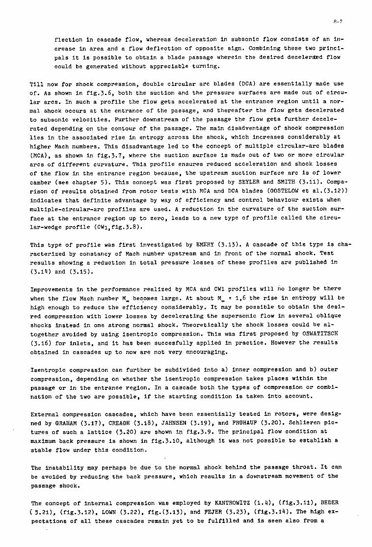
8- 7
f l e c t i o n i n cascade flow, whereas dece le ra t ion i n subsonic flow c o n s i s t s of an in- c r ease i n area and a flow d e f l e c t i o n of oppos i te s ign , Combining these two p r i n c i - p a l s it i s p o s s i b l e t o ob ta in a blade passage wherein t h e des i r ed d e c e l e r e d flow could be genera ted without apprec iab le turn ing .
T i l l now f o r shock compression, double c i r c u l a r a r c blades ( D C A ) a r e e s s e n t i a l l y made use o f . A s shown i n f ig .3 .6 , both the suc t ion and t h e pressure su r faces a r e made out of c i r cu - l a r a r c s . I n such a p r o f i l e t h e flow g e t s acce le ra t ed a t t h e en t rance reg ion u n t i l a nor- mal shock occurs a t t h e en t rance of t he passage, and t h e r e a f t e r t h e flow g e t s dece le ra t ed t o subsonic v e l o c i t i e s . Fur ther downstream of the passage t h e flow g e t s f u r t h e r decele- rated depending on t h e contour of t h e passage. The main disadventage of shock compression l i e s i n t h e a s soc ia t ed r i s e i n entropy ac ross t h e shock, which inc reases considerably a t h igher Mach numbers. T h i s disadvantage l e d t o t h e concept of mu l t ip l e c i r c u l a r - a r c blades (MCA) , as shown i n f ig .3 .7 , where t h e suc t ion sur face i s made ou t of two o r more c i r c u l a r a r c s of d i f f e r e n t curva ture . T h i s p r o f i l e ensures reduced a c c e l e r a t i o n and shock l o s s e s of t h e flow i n t h e en t rance reg ion because, t h e upstream suc t ion su r face a r c is of lower camber ( s e e chap te r 5 ) . T h i s concept was f i rs t proposed by SEYLER and SMITH (3.11). Compa- r i s o n of r e s u l t s ob ta ined from r o t o r t e s t s w i t h MCA and DCA b lades (GOSTELOW e t a1.(3.12)) i n d i c a t e s t h a t d e f i n i t e advantage by way of e f f i c i e n c y and c o n t r o l behaviour e x i s t s when mul t ip l e -c i r cu la r - a rc p r o f i l e s a r e used. A reduct ion i n t h e curva ture of t h e suc t ion sur- f ace a t t h e en t rance reg ion up t o zero, l eads t o a new type of p r o f i l e c a l l e d t h e c i r cu - lar-wedge p r o f i l e (CWl,fig.3.8).
T h i s type o f p r o f i l e was f i rs t inves t iga t ed by EMERY (3.13). A cascade o f t h i s type i s cha- r a c t e r i z e d by constancy of Mach number upstream and i n f r o n t of t h e normal shock. Tes t r e s u l t s showing a reduct ion i n t o t a l p ressure l o s s e s of t hese p r o f i l e s a r e publ ished i n (3.14) and (3.15).
Improvements i n t h e performance r e a l i z e d by MCA and C W 1 p r o f i l e s w i l l no longer be t h e r e when t h e flow Mach number M- becpmes l a rge . A t about M- = 1,6 t h e r i se i n entropy w i l l be high enough t o reduce t h e e f f i c i e n c y considerably. It may be poss ib l e t o ob ta in t h e des i - r ed compression w i t h lower l o s s e s by d e c e l e r a t i n g t h e supersonic flow i n s e v e r a l ob l ique shocks in s t ead i n one s t rong normal shock. Theore t i ca l ly t h e shock l o s s e s could be al- toge the r avoided by us ing i s e n t r o p i c compression. T h i s was f i rs t proposed by OSWATITSCH (3.16) f o r i n l e t s , and it has been succes fu l ly appl ied i n p rac t i ce . However t h e r e s u l t s ob ta ined i n cascades up t o now are not very encouraging.
I s e n t r o p i c compression can f u r t h e r be subdivided i n t o a ) inne r compression and b ) o u t e r compression, depending on whether t h e i s e n t r o p i c compression takes p l aces wi th in t h e passage o r i n t h e en t rance region. I n a cascade both t h e types of compression o r combi- na t ion of t he two are poss ib l e , i f t h e s t a r t i n g condi t ion i s t aken i n t o account.
Externa l compression cascades, which have been e s s e n t i a l l y t e s t e d i n r o t o r s , were desig- ned by GRAHAM (3.17), CREAOH (3.181, JAHNSEN (3.19), and FRUHAUF (3.20). Sch l i e ren pic- t u r e s of such a l a t t i c e (3.20) a r e shown i n fig.3.9. The p r i n c i p a l f low condi t ion a t maximum back p res su re i s shown i n fig.3.10, a l though it was not poss ib l e t o es tabl ish a stable flow under t h i s condi t ion .
The i n s t a b i l i t y may perhaps be due t o t h e normal shock behind t h e passage t h r o a t . It can be avoided by reducing t h e back pressure , which r e s u l t s i n a downstream movement o f t h e passage shock.
The concept of i n t e r n a l compression was employed by KANTROWITZ ( 1 . 4 1 , ( f ig .3 .11) , BEDER ( 9.211, (fig.3.121, LOW (3.221, f ig . (3 .13) , and FEJER (3.231, (fig.3.14). The h igh ex- p e c t a t i o n s of a l l t hese cascades remain y e t t o be f u l f i l l e d and i s seen a l s o from a
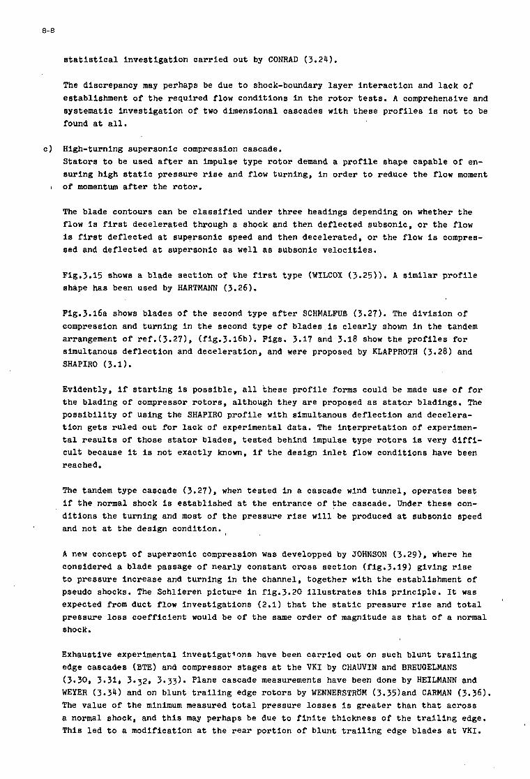
8-8
s t a t i s t i c a l i n v e s t i g a t i o n c a r r i e d out by CONRAD (3.24).
The discrepancy may perhaps be due t o shock-boundary l a y e r i n t e r a c t i o n and l a c k of es tabl ishment o f t he requi red flow condi t ions i n t h e r o t o r tests. A comprehensive and sys temat ic i n v e s t i g a t i o n of two dimensional cascades w i t h t hese p r o f i l e s is not t o be found a t a l l .
c ) High-turning supersonic compression cascade. S t a t o r s t o be used a f te r an impulse type r o t o r demand a p r o f i l e shape capable of en- su r ing h igh s t a t i c pressure r i s e and flow tu rn lng , i n o rde r t o reduce t h e flow moment
I o f momentum a f t e r t h e r o t o r .
The blade contours can be c l a s s i f i e d under three headings depending on whether t h e flow is first dece le ra t ed through a shock and then de f l ec t ed subsonic , o r t h e flow is first d e f l e c t e d a t supersonic speed and then dece lera ted , or t h e flow i s compres- sed and de f l ec t ed a t supersonic as well a s subsonic v e l o c i t i e s .
Fig.3.15 shows a blade s e c t i o h of t h e f i r s t type (WILCOX (3.25)). A similar p r o f i l e shape has been used by HARTMANN (3.26).
Fig.3.16a shows blades o f t h e second type a f t e r SCHMALFUA (3.27). The d i v i s i o n of compression and tu rn ing i n t h e second type of blades is c l e a r l y shown I n the tandem arrangement of ref . (3 .27) , (f ig.3.16b). Figs. 3.17 and 3.18 show t h e p r o f i l e s f o r simultanous d e f l e c t i o n and dece le ra t ion , and were proposed by KLAPPROTH (3.28) and SHAPIRO (3.1).
Evident ly , i f s t a r t i n g is poss ib l e , a l l t hese p r o f i l e forms could be made use o f f o r t h e b lad ing of compressor r o t o r s , a l though they a r e proposed a s s t a t o r bladings. The p o s s i b i l i t y o f us ing the SHAPIRO p r o f i l e w i t h simultanous d e f l e c t i o n and dece lera- t i o n g e t s r u l e d ou t f o r l a c k of experimental data. The i n t e r p r e t a t i o n of experimen- t a l r e s u l t s of t hose s t a t o r blades, t e s t e d behind impulse type r o t o r s I s very d i f f i - c u l t because it is not exac t ly known, i f t h e design i n l e t flow condi t ions have been reached.
The tandem type cascade (3.271, when t e s t e d i n a cascade wind tunnel , ope ra t e s best i f t h e normal shock is es t ab l i shed a t t h e en t rance of t h e cascade. Under these con- d i t i o n s t h e tu rn ing and most of t h e pressure r i s e w i l l be produced a t subsonic speed and not a t the design c o n d i t i o n . f
A new concept of supersonic cornpression was developped by JOHNSON (3.29), where he considered a blade passage of nea r ly cons tan t c r o s s sec t ion (fig.3.19) g iv ing r i s e t o pressure inc rease and tu rn ing i n t h e channel, t oge the r w i t h t h e establ ishment of pseudo shocks. The Schl ie ren p i c t u r e i n fig.3.20 I l l u s t r a t e s t h i s p r i n c i p l e . It was expected from duct flow Inves t iga t ions (2.1) t h a t the s t a t i c pressure r i s e and t o t a l p ressure loss c o e f f i c i e n t would be of t h e same order of magnitude a s t h a t o f a normal shock.
Exhaustive experimental i n v e s t i g a t i o n s have been c a r r i e d out on such b lunt t r a i l i n g edge cascades (BTE) and compressor s t ages a t t h e V K I by C H A W I N and BREUGELMANS (3.30, 3.31, 3.32, 3.33). Plane cascade measurements have been done by HEILMANN and WEYER (3.34) and on b lunt t r a i l i n g edge r o t o r s by WENNERSTRUM (3.35)and CARMAN (3.36). The value of t h e minimum measured t o t a l p ressure l o s s e s is g r e a t e r than t h a t ac ross a normal shock, and t h i s may perhaps be due t o f i n i t e t h i ckness of t h e t r a i l i n g edge. T h i s l e d t o a modif icat ion a t t h e r e a r po r t ion of b lunt t r a i l i n g edge blades a t V K I .
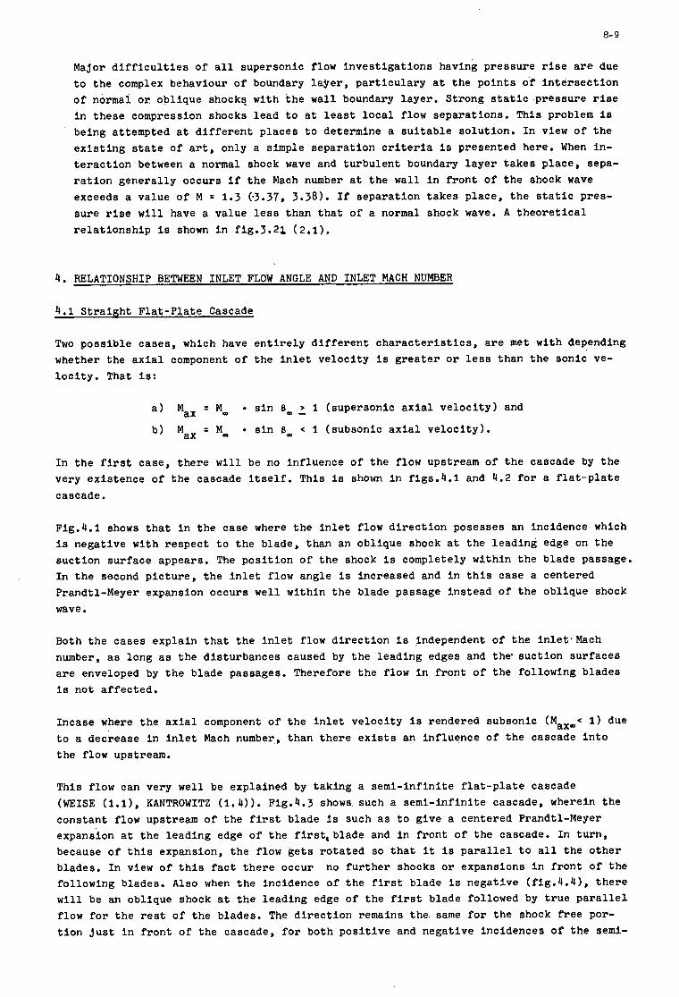
8- 9
Major d i f f i c u l t i e s of a l l supersonic flow i n v e s t i g a t i o n s having p res su re r i s e are due t o t he complex behaviour of boundary l a y e r , p a r t i c u l a r y a t t h e p o i n t s of i n t e r s e e t i o n of normal o r ob l ique shock? w i t h t h e w a l l boundary l aye r . Strong s t a t i c p re s su re r i se i n these compression shocks l ead t o a t l e a s t l o c a l flow separa t ions . This problem i s being at tempted a t d i f f e r e n t p l aces t o determine a s u i t a b l e so lu t ion . In view o f t h e e x i s t i n g s t a t e of a r t , only a simple sepa ra t ion c r i t e r t a i s presented here. When in- t e r a c t i o n between a normal shock wave and tu rbu len t boundary l a y e r takes p lace , sepa- r a t i o n gene ra l ly occurs i f the Mach number a t the wal l i n f r o n t of t h e shock wave exceeds a value of M = 1.3 (a3.37, 3.38). If sepa ra t ion t akes p lace , t h e s t a t i c pres - su re r i se w i l l have a value less than t h a t of a normal shock wave. A t h e o r e t i c a l r e l a t i o n s h i p i s shown i n f ig .3 .21 (2 .1 ) .
4 . RELATIONSHIP BETWEEN INLET FLOW ANGLE AND INLET MACH NUMBER
4 . 1 S t r a i g h t F l a t - P l a t e Cascade
Two poss ib l e cases , which have e n t i r e l y d i f f e r e n t c h a r a c t e r i s t i c s , are met w i t h depending whether t he a x i a l component of t h e i n l e t v e l o c i t y i s g r e a t e r o r l e s s than the son ic ve- l o c i t y . That is:
a ) Max = M,
b ) Max = Mm
s i n 8, 2 1 (supersonic a x i a l v e l o c i t y ) and
s i n 8, < 1 (subsonic a x i a l v e l o c i t y ) .
I n t h e first case , there w i l l be no in f luence of t h e flow upstream of t he cascade by the very ex i s t ence of t h e cascade i t s e l f . This i s shown i n f igs .4 .1 and 4.2 f o r a f l a t - p l a t e cascade.
Fig.4.1 shows t h a t i n t h e case where t h e i n l e t f low d i r e c t i o n posesses an incidence which is negat ive w i t h r e spec t t o t h e blade, than an obl ique shock a t t h e l ead ing edge on the suc t ion sur face appears . The p o s i t i o n of t h e shock is completely wi th in t h e blade passage. I n t h e second p i c t u r e , t h e i n l e t f low angle i s increased and i n t h i s case a centered Prandtl-Meyer expansion occurs wel l wi th in t h e blade passage in s t ead of t h e obl ique shock wave.
Both t h e cases expla in t h a t t h e i n l e t f low d i r e c t i o n i s Independent of t h e Inlet 'Mach number, as long as t h e d i s tu rbances caused by t h e l ead ing edges and t h e suc t ion su r faces a r e enveloped by t h e blade passages. Therefore t h e flow i n f r o n t of the fo l lowing blades i s not a f f ec t ed .
Incase where t h e a x i a l component of t h e i n l e t v e l o c i t y i s rendered subsonic (Max,< 1) due t o a decrease i n i n l e t Mach number, than there e x i s t s an in f luence o f t h e cascade i n t o t h e flow upstream.
T h i s f low can very well be explained by t ak ing a semi - in f in i t e f l a t - p l a t e cascade (WEISE (l.l), KANTROWITZ ( 1 . 4 ) ) . Fig.4.3 shows such a semi - in f in i t e cascade, wherein t h e cons tan t flow upstream of t h e f i r s t blade i s such a s t o g ive a centered Prandtl-Meyer expansion a t t h e l ead ing edge of t h e first, blade and i n f r o n t o f t h e cascade. In t u r n , because of t h i s expansion, t h e flow g e t s r o t a t e d so t h a t it i s p a r a l l e l t o a l l t h e o t h e r blades. In view of t h i s f a c t t h e r e occur no f u r t h e r shocks o r expansions i n f r o n t of t h e fol lowing blades. Also when t h e incidence of t h e first blade i s negat ive (f ig .4 .41, t h e r e w i l l be an obl ique shock a t t h e l ead ing edge of the f i r s t blade followed by t r u e p a r a l l e l f low f o r t h e rest of t h e blades. The d i r e c t i o n remains t h e same f o r t h e shock f r e e por- t i o n j u s t i n f r o n t of t h e cascade, f o r both p o s i t i v e and negat ive inc idences of t h e semi-
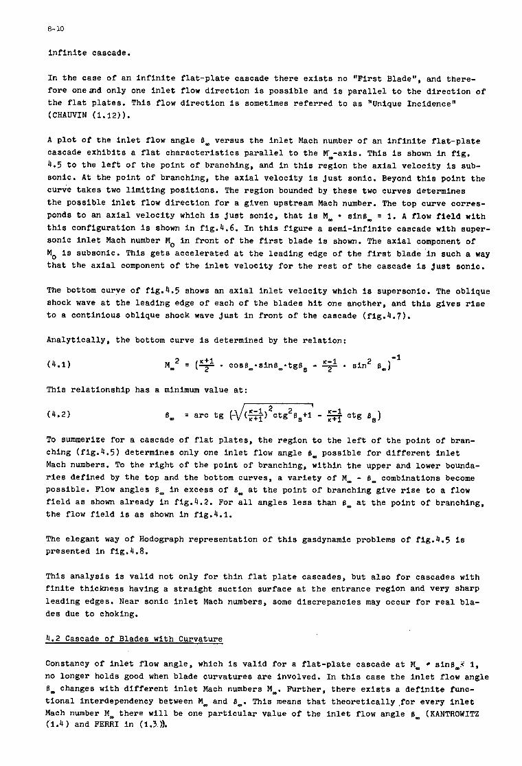
8- 10
i n f i n i t e cascade.
I n t h e case of an i n f i n i t e f l a t - p l a t e cascade t h e r e e x i s t s no " F i r s t Blade", and there- f o r e oneznd only one i n l e t flow d i r e c t i o n i s poss ib l e and i s p a r a l l e l t o t h e d i r e c t i o n o f t h e f l a t p l a t e s . T h i s f low d i r e c t i o n i s sometimes r e f e r r e d t o a s "Unique Incidence" (CHAUVIN ( 1 . 1 2 ) ) .
A p l o t o f t h e i n l e t f low angle 6, versus t h e i n l e t Mach number o f an i n f i n i t e f l a t - p l a t e cascade e x h i b i t s a f l a t c h a r a c t e r i s t i c s p a r a l l e l t o t h e M,-axis. This i s shown i n f i g . 4.5 t o t h e l e f t o f t he po in t of branching, and i n t h i s region t h e a x i a l v e l o c i t y i s sub- sonic . A t t h e po in t of branching, the a x i a l v e l o c i t y is j u s t sonic . Beyond t h i s po in t the curve t akes two l i m i t i n g pos i t i ons . The region bounded by these two curves determines t h e poss ib l e i n l e t f low d i r e c t i o n f o r a given upstream Mach number. The t o p curve cor res - ponds t o an axial v e l o c i t y which is j u s t sonic , t h a t i s M, sin6, = 1. A flow f i e l d w i t h t h i s conf igura t ion i s shown i n fig.4.6. I n t h i s f i g u r e a s emi - in f in i t e cascade w i t h super- sonic i n l e t Mach number MO i n f r o n t of t h e f i r s t blade i s shown. The a x i a l component of MO i s subsonic. T h i s g e t s acce le ra t ed a t t h e l ead ing edge of the first blade i n such a way t h a t t h e a x i a l component o f t h e i n l e t v e l o c i t y f o r t h e rest of t h e cascade i s j u s t sonic .
The bottom curve of f ig .4 .5 shows an a x i a l i n l e t v e l o c i t y which is supersonic . The obl ique shock wave a t t h e l ead ing edge of each o f t h e b lades h i t one another , and t h i s g ives r i s e t o a cont in ious obl ique shock wave j u s t i n f r o n t of t h e cascade (f ig .4 .7) .
Ana ly t i ca l ly , t h e bottom curve is determined by t h e r e l a t i o n :
T h i s r e l a t i o n s h i p has a minimum value a t :
(4.2) t 1
To summerize f o r a cascade of f l a t p l a t e s , t h e reg ion t o t h e l e f t of t he po in t of bran- ching (f ig .4 .5) determines only one i n l e t flow angle 6, poss ib l e f o r d i f f e r e n t i n l e t Mach numbers. To t h e r i g h t of t h e poin t of branching, wi th in t h e upper and lower bounda- r ies def ined by t h e top and the bottom curves, a v a r i e t y o f M, - 6, combinations become poss ib l e . Flow angles 6, i n excess o f 6, a t t h e po in t o f branching g ive r ise t o a flow f i e l d a s shown a l ready i n fig.4.2. For a l l angles less than B, a t t h e po in t o f branching, t h e flow f i e l d i s a s shown i n fig.4.1.
The e legant way of Hodograph r ep resen ta t ion of t h i s gasdynamic problems of f ig .4 .5 i s presented i n fig.4.8.
T h i s a n a l y s i s i s v a l i d not only f o r t h i n f l a t p l a t e cascades, but a l s o f o r cascades w i t h f i n i t e t h i ckness having a s t r a i g h t suc t ion su r face a t t h e en t rance reg ion and very sharp l ead ing edges. Near sonic i n l e t Mach numbers, some d i sc repanc ie s may occur f o r r e a l bla- des due t o choking.
4.2 Cascade of Blades w i t h Curvature
Constancy o f i n l e t f low angle , which is v a l i d f o r a f l a t - p l a t e cascade a t M, sin6,.< 1, no longer holds good when blade curva tures a r e involved. I n t h i s case t he i n l e t f low angle 6, changes w i t h d i f f e r e n t i n l e t Mach numbers M,. Fur ther , t h e r e e x i s t s a d e f i n i t e func- t i o n a l interdependency between M, and 8,. This means t h a t t h e o r e t i c a l l y , f o r every i n l e t Mach number M, t h e r e w i l l be one p a r t i c u l a r value o f t h e i n l e t f low angle 6, (KANTROWITZ (1.4 1 and FERRI i n (1.3 1).
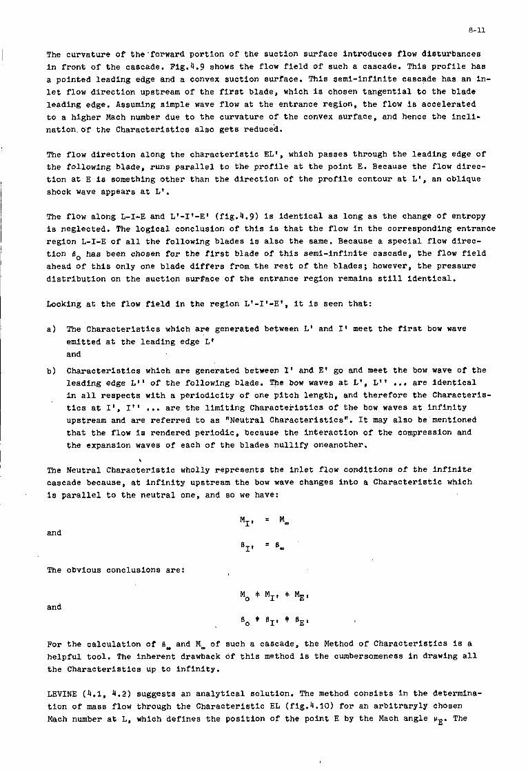
8-11
The curvature of the'forward portion of the suction surface introduces flow disturbances in front of the cascade. Fig.4.9 shows the flow field of such a cascade. This profile has a pointed leading edge and a convex suction surface. This semi-infinite cascade has an in- let flow direction upstream of the first blade, which is chosen tangential to the blade leading edge. Assuming simple wave flow at the entrance region, the flow is accelerated to a higher Mach number due to the curvature of the convex surface, and hence the incli- nation. of the Characteristics also gets reduced.
The flow direction along the characteristic EL', which passes through the leading edge of the following blade, runs parallel to the profile at the point E. Because the flow direc- tion at E is something other than the direction of the profile contour at L', an oblique shock wave appears at L'.
The flow along L-I-E and L1-I1-E1 (fig.4.9) is identical as long as the change of entropy is neglected. The logical conclusion of this is that the flow in the corresponding entrance region L-I-E of all the following blades is also the same. Because a special flow direc- tion Bo has been chosen for the first blade of this semi-infinite cascade, the flow field ahead of this only one blade differs from the rest of the blades; however, the pressure distribution on the suction surface of the entrance region remains still identical.
Looking at the flow field in the region L1-I1-E1, it is seen that:
a) The Characteristics which are generated between L1 and I' meet the first bow wave emitted at the leading edge L' and
Characteristics which are generated between 1' and El go and meet the bow wave of the leading edge L1' of the following blade. The bow waves at L', L" ... are Identical in all respects with a periodicity of one pitch length, and therefore the Characteris- tics at I', 1" ... are the limiting Characteristics of the bow waves at infinity upstream and are referred to as "Neutral Characteristics". It may also be'mentioned that the flow is rendered periodic, because the interaction of the compression and the expansion waves of each of the blades nullify oneanother.
b)
$
The Neutral Characteristic wholly represents the inlet flow conditions of the infinite cascade because, at infinity upstream the bow wave changes into a Characteristic which is parallel to the neutral one, and so we have:
and
The obvious conclusions are:
For the calculation of 6, and M- of such a cascade, the Method of Characteristics is a helpful tool. The inherent drawback of this method is the cumbersomeness in drawing all the Characteristics up to infinity.
LEVINE (4.1, 4.2) suggests an analytical solution. The method consists in the determina- tion of mass flow through the Characteristic EL (fig.4.10) for an arbitraryly chosen Mach number at L, which defines the position of the point E by the Mach angle uE. The
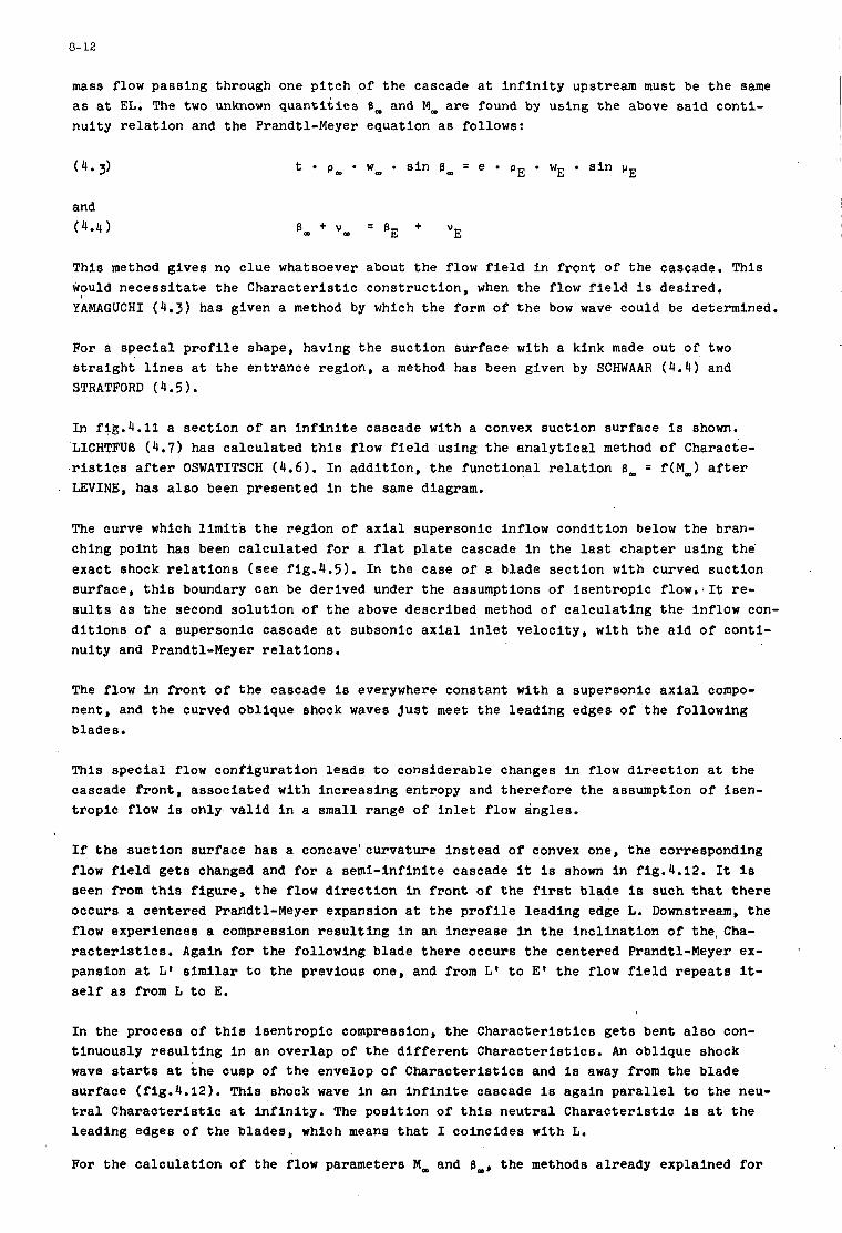
8- 12
mass flow pass ing through one p i t c h of t h e cascade a t i n f i n i t y upstream must be t h e same a s a t EL. The two unknown q u a n t i t i e s 8, and MOo are found by us ing the above s a i d con t i - n u i t y r e l a t i o n and t h e Prandtl-Meyer equat ion a s fol lows:
(4.3)
and (4.4 1
E t p, w, s i n 8, = e p E wE s i n Y
T h i s method g ives no c lue whatsoever about t h e flow f i e l d i n f r o n t of t h e cascade. T h i s would n e c e s s i t a t e t h e C h a r a c t e r i s t i c cons t ruc t ion , when t h e flow f i e l d i s des i red . YAMAGUCHI (4 .3) has given a method by which t h e form of t h e bow wave could be determined.
For a s p e c i a l p r o f i l e shape, having the suc t ion su r face w i t h a kink made out of two s t r a i g h t l i n e s a t t he en t rance reg ion , a method has been given by SCHWAAR ( 4 . 4 ) ' and STRATFORD ( 4.5 1,
In flg.4.11 a sec t ion of an i n f i n i t e cascade w i t h a convex suc t ion su r face i s shown. LICHTFUB (4.7) has ca l cu la t ed t h i s flow f i e l d using t h e a n a l y t i c a l method o f Characte-
. r i s t i c s a f te r OSWATITSCH (4.6). I n add i t ion , t h e func t iona l r e l a t i o n 8, = f ( M , ) a f t e r LEVINE, has a l s o been presented i n t h e same diagram.
The curve which l imi t ' s t h e reg ion of a x i a l supersonic inf low condi t ion below t h e bran- ching poin t has been ca l cu la t ed f o r a f l a t p l a t e cascade i n t h e l a s t chapter us ing the' exac t shock r e l a t i o n s (see f ig .4 .5) . I n t h e case of a blade s e c t i o n w i t h curved suc t ion su r face , t h i s boundary can be der ived under t h e assumptions of i s e n t r o p i c flow. 1 It re - s u l t s as t h e second s o l u t i o n of t h e above descr ibed method o f c a l c u l a t i n g t h e inf low con- d i t i o n s of a supersonic cascade a t subsonic a x i a l i n l e t ve loc i ty , w i t h t h e a i d o f con t i - nu i ty and Prandtl-Meyer r e l a t i o n s .
The flow i n f r o n t of t he cascade is everywhere cons tan t w i t h a supersonic a x i a l compo- nent , and the curved obl ique shock waves j u s t meet t h e l ead ing edges of t h e fo l lowing blades.
This s p e c i a l f low conf igura t ion l e a d s t o cons iderable changes i n flow d i r e c t i o n a t t h e cascade f r o n t , a s soc ia t ed w i t h i nc reas ing entropy and t h e r e f o r e t h e assumption o f i sen- t r o p i c flow i s only v a l i d i n a small range of i n l e t flow angles .
If the suc t ion su r face has a concavelcurvature in s t ead o f convex one, t h e corresponding flow f i e l d g e t s changed and f o r a semi - in f in i t e cascade it is shown i n fig.4.12. It i s seen from t h i s f i g u r e , t h e flow d i r e c t i o n i n f r o n t of the f i r s t blade is such tha t there occurs a centered Prandtl-Meyer expansion a t t h e p r o f i l e l ead ing edge L. Downstream, t h e flow experiences a compression r e s u l t i n g i n an inc rease i n t h e i n c l i n a t i o n of the , Cha- r a c t e r i s t i c s . Again f o r t h e fol lowing blade t h e r e occurs t he centered Prandtl-Meyer ex- pansion a t L' s i m i l a r t o t h e previous one, and from L' t o E ' t he flow f i e l d r e p e a t s it- self as from L t o E.
In t h e process o f t h i s i s e n t r o p i c compression, t h e C h a r a c t e r i s t i c s g e t s bent a l s o con- t inuous ly r e s u l t i n g i n an over lap of t h e d i f f e r e n t Charac t e r i s t i c s . An obl ique shock wave starts a t t h e cusp of t h e envelop o f C h a r a c t e r i s t i c s and is away from t h e b lade su r face (fig.4.12). This shock wave i n an i n f i n i t e cascade i s aga in p a r a l l e l t o the neu- t r a l C h a r a c t e r i s t i c a t i n f i n i t y . The p o s i t i o n o f t h i s n e u t r a l C h a r a c t e r i s t i c i s a t the l ead ing edges of t h e b lades , which means that I coinc ides w i t h L.
For the c a l c u l a t i o n o f t h e flow parameters M- and B,, t h e methods a l ready explained f o r ' I
1
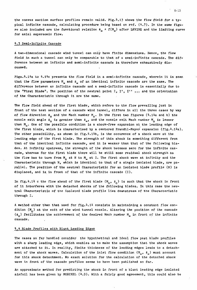
8- 13
t h e convex suc t ion su r face p r o f i l e s remain va l id . Fig.4.13 shows the flow f i e l d f o r a ty - p i ca1 i n f i n i t e cascade, c a l c u l a t i n g procedure being based on r e f . (4.7). In t h e same f igu- r e a l s o included a r e t h e func t iona l r e l a t i o n 6- = f ( M - 1 a f t e r LEVINE and t h e l i m i t i n g curve f o r a x i a l supersonic flow.
I
4.3 Semi- Inf in i te Cascade
A two-dimensional cascade wind tunnel can only have f i n i t e dimensions. Hence, t h e flow f i e l d i n such a tunnel can only be comparable t o t h a t o f a s emi - in f in i t e cascade. The d i f - fe rence between an i n f i n i t e and semi - in f in i t e cascade i s t h e r e f o r e exhaus t ive ly d i s - cussed.
Figs.4.14a t o 4 . 1 4 ~ p re sen t s t h e flow f i e l d i n a s emi - in f in i t e cascade, wherein it i s seen t h a t t h e flow parameters Mm and 6- of an i d e n t i c a l i n f i n i t e cascade a r e t h e same. The d i f f e r e n c e between an i n f i n i t e cascade and a semi - in f in i t e cascade is e s s e n t i a l l y due t o t h e " F i r s t Blade". The pos i t i on of t h e n e u t r a l po in t I, I * , I * * ... and t h e o r i e n t a t i o n o f the C h a r a c t e r i s t i c through it a r e t h e same.
The flow f i e l d ahead of t h e f i rs t blade, which r e f e r s t o t h e flow p r e v a i l i n g j u s t i n f r o n t of t h e t e s t s ec t ion of a cascade wind tunnel , d i f f e r s i n a l l t h e t h r e e cases by way of flow d i r e c t i o n 6, and t h e Mach number MO. I n t h e first two f i g u r e s (4.14a and b ) t h e nozzle e x i t angle 6, i s g r e a t e r than B,, and t h e nozzle e x i t Mach number MO is l e s s e r than Mm. One of t h e poss ib l e condi t ion i s a shock-free expansion a t t he l ead ing edge of t h e f i r s t blade , which i s cha rac t e r i s ed by a centered Prandtl-Meyer expansion (f ig .4 .14a) . The o t h e r p o s s i b i l i t y , as shown i n fig. ' l . lbb, is t h e occurence of a shock wave a t t h e l ead ing edge of t he f i rs t blade. The s t r e n g t h of t h i s shock is something d i f f e r e n t from t h a t of t he i d e n t i c a l i n f i n i t e cascade, and it i s weaker than t h a t of t h e fol lowing b la - des. A t i n f i n i t y upstream, t h e s t r e n g t h of t h e shock becomes zero f o r t h e i n f i n i t e cas- cade, whereas f o r t h e first blade there w i l l be s t i l l some r e s i d u a l shock s t r e n g t h a s t h e flow has t o t u r n from MO a t N t o Mw a t I. The first shock wave a t i n f i n i t y and t h e C h a r a c t e r i s t i c through N, which is i d e n t i c a l t o t h a t of a s i n g l e i s o l a t e d blade, a r e pa- r a l l e l . The pos i t i on of t h e n e u t r a l C h a r a c t e r i s t i c f o r an i s o l a t e d b lade p r o f i l e (N) i s d i sp laced , and 1s. i n f r o n t of t h a t o f t h e i n f i n i t e cascade ( I ) .
I n fig.4.14 c t h e flow ahead of t h e f i rs t blade (MO, Bo) is such t h a t t h e shock i n f r o n t o f i t i n t e r f e r e s w i t h t h e detached shocks of t h e fol lowing blades. I n t h i s case t h e neu- t r a l C h a r a c t e r i s t i c of t h e i s o l a t e d blade p r o f i l e l i e s downstream o f t h e C h a r a c t e r i s t i c through I.
A method o t h e r than t h a t used f o r fig.4.14 c o n s i s t s i n maintaining a cons tan t flow con- d i t i o n ( M O ) a t t h e e x i t o f t h e wind tunnel nozzle . A l t e r ing t h e pos i t i on of t h e cascade (6,) f a c i l i t a t e s the achievement of t h e des i r ed Mach number Mm i n f r o n t of t h e i n f i n i t e cascade.
4.4 Blade P r o f i l e s w i t h Blunt Leading Edaes
The cases so f a r handled cons ider t h e hypothe t ica l and i d e a l flow p a s t blade p r o f i l e s w i t h a sharp l ead ing edge, which enables us t o make t h e assumption t h a t t h e shock waves are a t tached t o it. I n r e a l i t y , f i n i t e t h i ckness of t h e l ead ing edges l eads t o a detach- ment of the shock waves. Calcu la t ion of t h e i n l e t flow condi t ion (M-, 6-1 must account f o r t h i s shock detachment. No exac t so lu t ion f o r t h e c a l c u l a t i o n of t h e detached shock wave i n f r o n t of t h e cascade p r o f i l e s seems t o have been published so far.
An approximate method f o r p red ic t ing t h e shock i n f r o n t of a b lunt l ead ing edge i s o l a t e d a i r f o i l has been given by MOECKEL (4.9) . With a f a i r l y good agreement, t h i s could a l s o be
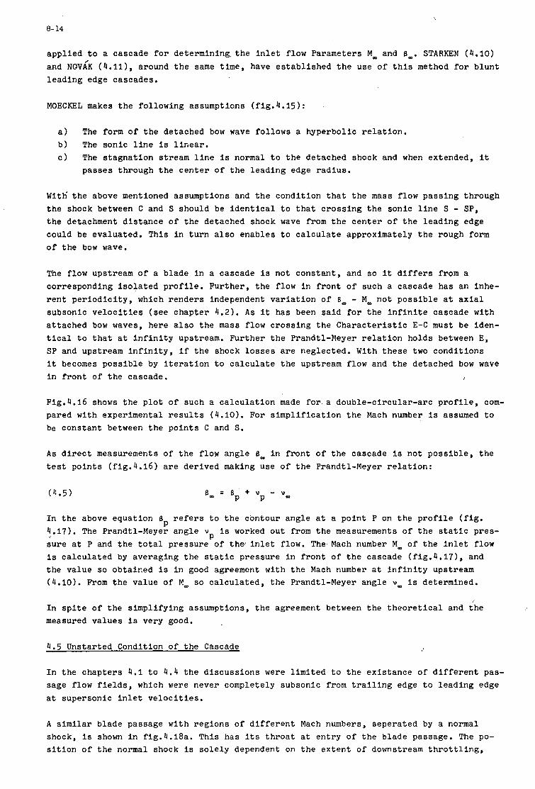
\
8- 14
appl ied t o a cascade f o r de te rmining . the i n l e t f low Parameters M, and 6,. STARKEN (4.10) and NQVLK ( 4 . 1 1 1 , around t h e same time, have e s t ab l i shed t h e use of t h i s method f o r b lun t l ead ing edge cascades.
MOECKEL makes t h e fol lowing assumptions (f ig .4 .15):
a ) The form of t h e detached bow wave fol lows a hyperbol lc r e l a t i o n . b ) The sonic l i n e i s l i n e a r . c ) The s t agna t ion s t ream l i n e is normal t o t h e detached shock and when extended, i t
passes through t h e c e n t e r of t h e l ead ing edge r ad ius .
W i t h ' t h e above mentioned assumptions and t h e condi t ion t h a t t h e mass flow pass ing through t h e shock between C and S should be i d e n t i c a l t o t h a t c ros s ing t h e sonic l i n e S - SP, the detachment d i s t ance of t h e detached shock wave from t h e c e n t e r of t h e l ead ing edge could be eva lua ted , T h i s i n t u r n a l s o enables t o c a l c u l a t e approximately t h e rough form o f t h e bow wave.
The flow upstream of a blade i n a cascade i s not cons tan t , and so it d i f f e r s from a corresponding i s o l a t e d p r o f i l e . Fur ther , t h e flow i n f r o n t of such a cascade has an inhe- r e n t p e r i o d i c i t y , which renders independent v a r i a t i o n of 13, - M, no t poss ib l e a t a x i a l subsonic v e l o c i t i e s ( see chapter 4 . 2 ) . A s it has been s a i d f o r t h e i n f i n i t e cascade w i t h a t tached bow waves, here a l s o t h e mass flow c ross ing t h e C h a r a c t e r i s t i c E-C must be iden- t i c a l t o t h a t a t i n f i n i t y upstream. Fur ther t h e Prandtl-Meyer r e l a t i o n holds between E, SP and upstream i n f i n i t y , i f t h e shock l o s s e s a r e neglected. With t hese two cond i t ions it becomes poss ib l e by i t e r a t i o n t o c a l c u l a t e t h e upstream flow and t h e detached bow wave i n f r o n t of t h e cascade.
Fig.4.16 shows t h e p l o t of such a c a l c u l a t i o n made f o r a double-c i rcu lar -a rc p r o f i l e , com- pared w i t h experimental r e s u l t s ( 4 . 1 0 ) . For s i m p l i f i c a t i o n t h e Mach number i s assumed t o be cons tan t between t h e p o i n t s C and S.
A s d i r e c t measurements of t h e flow angle 6- i n f r o n t of t h e cascade i s not poss ib l e , t h e t e s t p o i n t s ( f ig .4 .16) a r e der ived making use of t h e Prandtl-Meyer r e l a t i o n :
(4.5)
In t h e above equat ion 6 r e f e r s t o t h e contour angle a t a po in t P on t h e p r o f i l e ( f i g . 4.17). The Prandtl-Meyer angle v i s worked out from t h e measurements of t h e s t a t i c pres- su re a t P and t h e t o t a l p ressure of t h e , i n l e t flow. The Mach number M, of t h e i n l e t flow i s ca l cu la t ed by averaging t h e s t a t i c pressure i n f r o n t of t h e cascade (fig.4.171, and t h e value so obtained i s i n good agreement w i t h t h e Mach number a t i n f i n i t y upstream (4.10). From t h e value of M, so ca lcu la t ed , t h e Prandtl-Meyer angle U, i s determined.
P P
I n s p i t e of t h e s impl i fy ing assumptions, t h e agreement between t h e t h e o r e t i c a l and the measured va lues i s very good.
4.5 Unstar ted Condition of t h e Cascade
I n t h e chap te r s 4 . 1 t o 4 . 4 t h e d i scuss ions were l i m i t e d t o t h e ex i s t ance of d i f f e r e n t pas- sage flow f ie lds , which were never completely subsonic from t r a i l i n g edge t o l ead ing edge a t supersonic i n l e t v e l o c i t i e s .
A s i m i l a r blade passage w i t h reg ions of d i f f e r e n t Mach numbers, sepera ted by a normal shock, i s shown i n fig.4.18a. T h i s has i t s t h r o a t a t en t ry of t h e blade passage. The po- s i t i o n of t h e normal shock l s s o l e l y dependent on t h e ex ten t of downstream t h r o t t l i n g ,
8- 15
because t h e flow cuss ion only t h e l e d a r e a AT a l s o
A decrease i n AT
i n t h e t h r o t t l e d a r e a AT i s assumed t o be sonic . I n t h e fol lowing d is - loss ac ross t h e normal passage shock i s accounted f o r . Hence, t h e t h r o t t - r e p r e s e n t s t h e c r i t i c a l a r e a behind t h e normal shock.
causes t h e normal shock t o move nea re r t o the l ead ing edge. The i n l e t f low f i e l d remains una l t e red till t h e normal shock i s J u s t a t t h e t h r o a t o f the passage, and i n t h i s p a r t i c u l a r case it a l s o happens t o be a t t h e l ead ing edge of t h e blade pro- f i l e (fig.4.18b). Any f u r t h e r t h r o t t l i n g causes t h e flow wi th in t h e blade passage t o be- come completely subsonic.
F i g . 4 . 1 8 ~ shows such a completely subsonic flow passage and the fol lowing observa t ions could be made:
a) The bow wave de taches i t s e l f from t h e l ead ing edge.
b ) There i s a s h i f t i n t h e p o s i t i o n of t h e s t agna t ion s t ream-l ine, causing a reduct ion i n t h e i n l e t mass flow i n t o t h e blade passage
A decrease i n t h e i n l e t Mach number M- i s followed by an inc rease i n t h e i n l e t flow angle B,,
and c )
Theore t i ca l c a l c u l a t i o n of t h e i n l e t flow condi t ion (M, - 6,) f o r t h i s case must account f o r the t o t a l p ressure l o s s e s i n t h e normal po r t ion of t h e detached shock i n f r o n t of t h e blade passage, and t h e mass flow as d i c t a t e d by t h e choking a t t h e t h r o t t l e d a rea . D i P f e - r e n t i n l e t flow ang les 6, f o r a cons tan t t h r o t t l e p o s i t i o n become poss ib l e f o r t h i s un- s t a r t e d case by an independent v a r i a t i o n of t h e t h r o t t l e pos i t i on . I n fig.4.19 the func- t i o n a l r e l a t i o n s h i p 6, = f(M,) f o r a double-circular-arc p r o f i l e i s shown. A t a x i a l sub- sonic i n l e t v e l o c i t y t h e bottom l i m i t i n g curve corresponds t o t h e s t a r t e d condi t ion , which has been c a l c u l a t e d w i t h t h e method descr ibed i n chap te r 4 .4 . Some l i n e s of cons tan t c r i - t i c a l a r e a x * / t , which i n f r i c t i o n l e s s flow a r e equal t o t h e c r o s s sec t ion ATLt o f t h e downstream t h r o t t l e , a r e added i n t h i s f i gu re . They correspond t o the uns t a r t ed opera t ion of t h e cascade. An inc rease i n t h e ex ten t of t h r o t t l i n g , t h a t a l s o means a decrease i n t h e r a t i o A T / t , accomodates h igher i n l e t f low angles 6,.
Experimental i n v e s t i g a t i o n s i n a two-dimensional cascade tunne l , (f ig.4.20) a s well a s i n three-dimensional compressor r o t o r t e s t r i g s (fig.4.21), c l e a r l y r e f l e c t upon t h e ex is - tence of a maximum i n l e t f low angle a t t h e uns t a r t ed condi t ion , which has not been so f a r t h e o r e t i c a l l y w e l l explained,
z
Even when t h e t h r o a t l i e s wi th in t h e blade passage, t h e above arguments hold va l id . A s an example of t h i s case t he cascade shown i n fig.4.19 has been modified. T h i s modifica- t i o n c r e a t e s a t h r o a t wi th in t h e blade passage. Although e s s e n t i a l l y the t h e o r e t i c a l cha- r a c t e r i s t i c o f B, = f ( M , ) w i t h ( A T / t ) a s parameter remains the same, t h e r e i s a maximum (AT/ t ) - l ine below which t h e t h r o t t l e has no e f f e c t t o change t h e i n l e t ang le (fig.4.22). The shaded a r e a below t h i s maximum ( A T / t ) c h a r a c t e r i s t i c shows t h e reg ion where no opera- t i o n i s poss ib l e .
S imi l a r t h e o r e t i c a l i n v e s t i g a t i o n s have been made by GRAHAM (3.17) and MILLER (4.13). I n both t h e papers t h e emphasis i s placed'on shock l o s s e s . I n ref . (3 .17) a simple case w i t h s t r a i g h t suc t ion su r face a t t h e i n l e t has been analysed, whereas i n re f . (4 .13) t h e i n t e r - dependency of i n l e t Mach number and flow d i r e c t i o n has not a t a l l been taken ca re of.
5. SHOCK LOSSES I N SUPERSONIC CASCADES
What has been descr ibed i n chap te r 4 enables t h e c a l c u l a t i o n of supersonic flow f i e l d and
8- 16
p o s i t i o n of t h e normal and obl ique shocks i n f r o n t of a cascade, under t h e assumption t h a t t h e i n l e t f low i s i s e n t r o p i c . Using t h e w e l l known shock r e l a t i o n s , t h e t o t a l p r e s - su re l o s s e s due t o shock waves can t h e r e f o r e be ca l cu la t ed f o r supersonic cascades having d i f f e r e n t geometries.
The i n l e t region of an i n f i n i t e cascade, w i t h t h e a x i a l component of t h e i n l e t v e l o c i t y subsonic , i s a s soc ia t ed w i t h i n f i n i t e number of shock waves. Evaluat ion of t h e t o t a l shock l o s s e s i n f r o n t of a blade passage, t h a t i s a l s o between two adjacent s t agna t ion s t ream l i n e s , c o n s i s t s i n t h e summing up of a l l t h e shock l o s s e s a long one shock wave up t o in- f i n i t y (5.1). Looking a t f i g u r e 5.1 i t i s seen t h a t t h e mesh of shock waves and s tagna- t i o n s t ream l i n e s resembles a matr ix w i t h i d e n t i c a l diagonal b i t s , and each s t agna t ion stream l i n e i n t e r s e c t s w i t h an i n f i n i t e number of shock waves o f progress ive ly decreas ing shock s t r eng th .
The p o s i t i o n of t h e passage shock, a s a l ready descr ibed e a r l i e r , i s dependent on the ex- t e n t of downstream t h r o t t l i n g . Calcu la t ion of t h e supersonic flow wi th in t h e blade pas- sage f o r d i f f e r e n t passage shock p o s i t i o n i s poss ib le a s long a s boundary l a y e r sepera- t i o n e f f e c t s a r e not t oo l a rge . It has not been poss ib l e up t o now t o c a l c u l a t e t h e exac t p o s i t i o n of t h e passage shock i t s e l f , a l though it i s known t o be dependent upon t h e back pressure .
A p l o t o f ca l cu la t ed shock l o s s c o e f f i c i e n t s ws as a func t ion of Mm f o r double-circular- a r c ( DCA) and wedge type p r o f i l e s ( C W I ) i s presented i n f ig .5 .2 , w i t h pitch-chord r a t i o t / l a s parameter, based upon the assumption t h a t t h e passage shock i s j u s t a t t h e l ead ing edge o f t h e blade. In case t h e t h r o a t of t h e blade passage a l s o happens t o l i e a t t h e l ead ing edge, t h i s r e p r e s e n t s t h e optimum ope ra t ing condi t ion s i g n i f i e d by minimum t o t a l p ressure 1osses.KLAPPROTH (5.1) and YAMAGUCHI ( 4 . 3 ) have shown t h a t t h e l o s s e s due t o t h e bow waves a r e small and hence, they have been neglected f o r t h e purposes o f c a l c u l a t i o n .
The wedge type p r o f i l e CW1 w i t h s t r a i g h t suc t ion sur face a t en t ry i s cha rac t e r i zed by a f l a t 6 , r e l a t i o n ( s e e chapter 4.11, which i s independent of t h e p i t c h chord r a t i o t / l ( f ig .5 .3) . Therefore , t h e shock l o s s c o e f f i c i e n t is i s a l s o independent of t / l ( f ig .5 .2) . A cons iderable inc rease i n t h e shock l o s s c o e f f i c i e n t i s not iced t o be a func t ion of t h e suc t ion sur face curva ture a t i n l e t , because t h e flow experiences a l a r g e a c c e l e r a t i o n i n f r o n t of t h e shock i n case of t h e DCA-cascade.
A s a r e s u l t of t he above explained phenomenon, developmentsof ,mul t ip le -c i rcu lar -a rc ( M C A ) p r o f i l e s ( f ig .3 .7) w i t h a r e l a t i v e l y small suc t ion su r face curva ture a t t h e en t rance r e - gion has rece ived g r e a t emphasis (3.1'1).
A p l o t o f p r o f i l e l o s s e s obtained by sub t r ac t ing t h e ca l cu la t ed shock l o s s e s ( f i g . 5.2) from t h e measured t o t a l p ressure l o s s e s , a s a func t ion of i n l e t Mach number MOD i s shown In. f i g u r e 5.4. The l i m i t e d i n v e s t i g a t i o n s i n d i c a t e t h a t t h e i n l e t Mach number, t h e p r o f i l e shape and t h e cascade conf igura t ion .
P'
i s almost Independent of P
6. RELATION BETWEEN STATIC PRESSURE RISE AND TOTAL PRESSURE LOSSES I N A CASCADE
A cascade a l ready s t a r t e d and ope ra t ing under supersonic condi t ions , i n cont ra ry t o t h e subsonic case , enable a change i n t h e s t a t i c pressure r i s e without a f f e c t i n g t h e i n l e t f low by varying t h e downstream pressure .
The v a r i a t i o n i n the flow f i e l d wi th in t h e blade passage a s a r e s u l t o f a change i n t h e t h r o t t l e p o s i t i o n does 'n t seem t o have been t h e o r e t i c a l l y ca l cu la t ed , because of t h e
complicated and mixed subsonic-supersonic flow f i e l d e x i s t i n g toge the r w i t h a severe boundary l a y e r sepera t ion .
8-17
To ge t a b e t t e r understanding of t he flow mechanism of a supersonic cascade, i n s p i t e of t h e complexity of t h e flow, a s impl i f i ed flow model has been Ind ica t ed by DETTMERING ( 6 . 1 ) , extended by STARKEN ( 3 . 1 5 ) f o r d i f f e r e n t a x i a l ve loc i ty dens i ty r a t i o s . T h i s me- thod p l aces i t s complete emphasis on t h e flow condi t ions upstream and downstream of t h e cascade, without account ing f o r t h e probable and poss ib l e flow v a r i a t i o n s wi th in t h e cas- cade.
I I
The con t inu i ty equat ion between t h e i n l e t and o u t l e t p lanes of t h e cascade can be w r i t t e n a s :
( 6 . 1 ) p, w, s i n 6, = p 2 w2 s i n 62.
To account f o r t h e con t r ac t ion of t he channel wid th due t o t h e growth and poss ib l e sepa- r a t i o n o f boundary l a y e r on t h e s ide wal l s of t h e wind tunnel , t h e "Axial Veloci ty Den- s i t y Rat io" n is int roduced as a parameter i n t o t h e con t inu i ty r e l a t i o n :
Rewriting i n terms of t o t a l p re s su res , s t a t i c p re s su res and t o t a l temperatures , t h e above equat ion can be transformed t o ge t an expression f o r t h e t o t a l p ressure l o s s c o e f f i c i e n t w as fol lows: -
c c s i n 6- P m T t o t 2 .(-) . - '(sin) p2 T t o t m
Under t h e assumption t h a t t h e t o t a l temperature remains cons tan t , t h a t i s
( 6 . 4 ) = T~~~ (energy equa t ion ) , T t o t
t h e t o t a l p ressure l o s s c o e f f i c i e n t O can be expressed as a func t iona l r e l a t i o n i n terms of t h e p re s su re r a t i o p2/p,, t h e con t r ac t ion c o e f f i c i e n t n, t h e flow ang les 6, and 62 and t h e f r e e s t ream Mach number M, as fol lows:
l
( 6 . 5 )
Fur ther s i m p l i f i c a t i o n is poss ib l e f o r t h e case wherein t h e a x i a l component of t h e i n l e t Veloci ty i s subsonic and M, no t t oo low (M, > 1,2). For t h i s case , a s d i scussed i n de- t a i l i n chapter 4, t h e ex i s t ence of a unique incidence holds v a l i d and t h e r e f o r e ; takes t h e form:
( 6 . 6 )
The a x i a l v e l o c i t y dens i ty r a t i o is t h e r e f o r e an independent parameter and can have any value.
F i r s t l y when n i s cons tan t , t h e l o s s c o e f f i c i e n t ; is dependent only on t h e p re s su re r a t i o p2/p,, t he e x i t flow angle B2 and t h e i n l e t Mach number M,.
8- 18
To a first approximation, t h e e x i t flow angle B 2 is a l s o assumed t o be cons tan t . If t h e va lue of B2 i s determined experimental ly , from t h e func t iona l r e l a t i o n (eqn.(6.6) der i - ved from t h e con t inu i ty and energy r e l a t1ons ) the l o s s c o e f f i c i e n t can be worked out i n terms o f p2/p,.
I
Flg.6.1 shows a p l o t of t h e numerical r e s u l t s ca l cu la t ed on t h e above s a i d b a s i s f o r a wedge type p r o f i l e . A family of curves f o r d i f f e r e n t i n l e t and e x i t Mach numbers, as shown i n f u l l and do t t ed l i n e s r e spec t ive ly , a r e presented. The t o t a l p re s su re loss c o e f f i c i e n t poss ib l e range of p2/p, opera t ion cont inous ly becomes l a r g e r and l a r g e r w i t h i nc reas ing
reaches a maximum value when t h e e x i t flow Mach number M2 is uni ty . The
'me
The v a l i d i t y of t h i s diagram depends on t h e ex is tence of exac t two-dimensional flow w i t h no con t r ac t ion of the; stream. I n a cascade wind tunnel i n e v i t a b l e con t r ac t ion of t h e flow stream due t o boundary l a y e r e f f e c t s makes t h e value of R d i f f e r e n t from uni ty . T h i s is t h e reason f o r showing t h e curves of d i f f e r e n t R i n f ig .6 .2 . Increas ing s ide con t r ac t ion must r e s u l t i n decreas ing pressure loss c o e f f i c i e n t , i f a l l t h e o t h e r flow parameters r e - main una l te red .
Both t h e diagrams 6 .1 and 6.2 only g ive t h e common r e l a t i o n s h i p e x i s t i n g between t h e i n l e t and t h e e x i t p lanes of a cascade, which have been e s s e n t i a l l y der ived from the energy and con t inu i ty equat ions. Therefore it is impossible t o g e t any i n s i g h t i n t o t h e r e a l l y e x i s t i n g flow phenomena i n a cascade.
Although a q u a l i t a t i v e d iscuss ion of t h e t r end i n which t h e t o t a l p ressure l o s s e s vary is poss ib l e , exac t eva lua t ion of it without an a c t u a l experiment s t i l l remains imposs,ible. But an i n s i g h t i n t o t h e e f f e c t o f a x i a l ve loc i ty dens i ty r a t i o n on t h e o v e r a l l per for - mance o f t h e cascade has become poss ib l e through t h i s aproach.
To r e f l e c t t h e emphasis of t h i s important parameter, t e s t p o i n t s of a high tu rn ing cas- cade have been superimposed on t h e t h e o r e t i c a l l y determined ;-curves in f ig .6 .3 ( ref . (3.15)). A s t rongdevia t ion from the expected t r end , t h a t is v a r i a t i o n of n w i t h back pressure from 1.0 t o 1.7, s t r e s s e s t h e g r e a t importance of t h i s parameter. A sudden jump i n t h e value of n from 1.0 t o 1.5 occuring when t h e cascade changes from a c c e l e r a t i n g
(p2/p- < 1) t o dece le ra t ing (p2/p, > 1) flow, can be explained by a side wal l boundary l a y e r s epa ra t ion occuring i n the case where p2 is l a r g e r than p,. Fur ther a s t h r o t t l i n g beyond a c e r t a i n p o s i t i o n causes no inf luence on (p2/pm.), i t ' c o u l d be argued ou t t h a t t h e r e must be n a t u r a l l y a con t r ac t ion o f t h e stream tube exh ib i t ed by an inc rease i n n from 1.5 t o 1.7.
From these t e s t r e s u l t s it i s s t rong ly f e l t necessary t h a t the ax ia l -ve loc i ty-dens i ty r a t i o n has t o be taken ca re o f f i n a l l supersonic cascade measurements.
ACKNOWLEDGEMENTS
The au tho r s wish t o express her g r a t i t u d e f o r t h e help given by M.R.Narasimha Swamy (Nat ional Aeronaut ical Laboratory, Bangalore) i n t h e t r a n s l a t i o n of t h i s paper.
8- 19
REFERENCES
Chapter 1
WEISE, A.
DAVIDSON, B.
HAWTHORNE, W.R. (Editor
KANTROWITZ, A.
REDDING, A.H.
FERRI, A.
HOTTNER, l'h.
LIEBLEIN, S ., JOHNSEN, I.A.
SAVAGE, M., BOXER, E., ERWIN, J.R.
KLAPPROTH, J.F.
JOHNSON, E.G.
CHAUVIN, J., BREUGELMANS, F., JANIGRO, A.
Chapter 2
(2.1) EMMONS, H.W. (Editor) ,
(2.2) DEICH, M.E.
(2.3) LAWACZECK, 0.
(2.4) EGGINK
(2.5) KANTROWITZ, A., DONALDSON, C.
Chapter 3
(3.1) SHAPIRO, A.H.
(3.2) STRATFORD, B.s., SANSOME, G.E.
(3.3) BOXER, E., STERRET, J.R., WLODARSKI, J.
(3.4) OSWATITSCH, K.
Uberschallaxialverdichter. Bericht 171 der Lilienthal-Gesellschaft, S.92 (1943).
Some Data Pertaining to the Supersonic Axial-Flow Compressor. ARC R&M N0.2554 (1947).
High Speed Aerodynamics and Jet Propulsion, Volume X, Aerodynamics of Turbines and Compressors (1964).
The Supersonic Axial-Flow compressor. NACA Report 974 (1950).
Superacoustic Compressor. US Patent 2, 435, 236 (1948).
Prelfminary Analysis of Axial-Flow Compressors Having Super- sonic Velocity at the Entrance of the Stator. NACA RM L 9G06 (1949).
Amerikanische Versuche mit Uberschallverdichtern. AVA-Bericht Nr. 59/A/25, (1959).
R6sum6 of Transonic Compressor Research at NACA Lewis-Labora- tory . Trans.ASME "Journal of Engineering for Power", 83 (1961) , Series A, No.3.
Rt?sum6 of Compressor Research at the NACA Langley Laboratory. Trans .ASME "Journal of Engineering for Power", 83, (1961), Series A.
A Review of Supersonic Compressor Development. Trans.ASME "Journal of Engineering for Power", Series A, 83 (19611, s.258.
Introduction to Lectures on Supersonic Turbomachinery. AGARD Lecture Series, Varenna, May (1967). Supersonic Compressors. AGARD Lecture Series, Varenna, May (19671, also: VKI CN 67.
Fundamentals of Gas Dynamics, High Speed Aerodynamics and Jet Propulsion V01.111, (1958).
Flow of Gas through Turbine Lattices. NACA TM 1393 (1956). Transl.of ch.7 from Tekhnickes Kaia Gazodinamika (1953). Verfahren zur Ermittlung der AbstrbmgrbAen transsonischer Turbinengitter. Diss.TU Braunschweig (1969).
StrBmungsaufbau und Druckrilckgewinnung in UberschallkanUen. Deutsche Luftfahrtforschung. Forschungsbericht Nr.1756, (1943).
Preliminary Investigation of Supersonic Diffusers. NACA ACR No.L5D20, (1945).
The Dynamics and Thermodynamics of Compressible Fluid Flow. Vol.1, The RonaldPress Corp., 1953, N.Y.
Theory and Tyne1 Tests of Rotor Blades for Supersonic Turbines. ARC R&M No.3275, 1962.
Application of Supersonic Vortex-Flow Theory to the Design of Supersonic Impulse Compressor or Turbine-Blade Sections. NACA RM L 52 B 06. April 1952.
Potentialwirbel-Gitter fur Uberschallgeschwindigkelten. ZfW 4, (1956), Heft 112, Selte 53.
8- 20
(3.5)
(3.7)
(3.8)
(3.9)
(3.10)
COLCLOUGH, C.D.
GOLDMAN, L.J . , SCULLIN, V.J.
GOLDMAN, L.J.
L I C C I N I , L.L.
L I C C I N I , L.L.
OSWATITSCH, K.
SEYLER, D.R. , SMITH, L.H.
GOSTELOW, J.P. , KRABACHER , K. W. SMITH, L.H.(Jr.!
EMERY, J . C . , DUNAVANT, J . C . , WESTPHAL, W.R.
HEILMANN, W., STARKEN, H. , WEYER, H.
STARKEN, H., LICHTFUA, H. J.
OSWATITSCH, K.
GRAHAM, C. , KLAPPROTH, J.F., BARINA, F.J.
CREAGH, J.W.R., KLAPPROTH, J.F.
JAHNSEN, L.J., HARTMANN , M. J . FRUHAUF , H. H.
BEDER, E.D., BUHLER, R.
LOWN, H., HARTMANN, M . J .
FEJER, A.A. , WENZLAU, W.N.
Design of Turbine Blades S u i t a b l e - f o r Supersonic Relative In- l e t Ve loc i t i e s and t h e Inves t iga t ion of t h e i r Performance i n Cascades: Pa r t I - Theory and Design. Journa l Mechanical Engineering Science V01.8, N0.1~1966. P a r t I1 - Experiments, Resul t s and Discussion. Journa l Mechanical Engineering Science Vo1.8, No.2, (1966) .
Analy t ica l Inves t iga t ion of Supersonic Turbomachinery Bla- ding. I - Computer Program f o r Blading Design. NASA TN D-4421, March 1968.
Analy t ica l Inves t iga t ion of Supersonic Turbomachinery Blading. 11- Analysis of Impulse Turbine-Blade Sec t ions .
Analy t ica l and Experimental Inves t iga t ion of 90' Supersonic Turning Passages S u i t a b l e f o r Supersonic Compressors o r Turbines. NACA RM L 9GO7, 1949.
Experimental Inves t iga t ion of t h e Mixing Loss Behind t h e T r a i l i n g Edge of a Cascade of Three 900 Supersonic Turning Passages. NACA RM L 50F21a3 1950.
Ober d i e StrSmung i n einem Uberscha l lg i t t e r . Allgemeine WBrmetechnik, Jahrgang 6, 1955.
S ing le Stage Experimental Evaluat ion of High Mach Number Com- p res so r Rotor Blading, Pa r t 1, Design of Rotor Blading. NASA C R - 5 4 5 8 1 , Apr i l 1967.
Performance Comparisons of High Mach Number Compressor Rotor
NASA TN D - 4422, Apr i l 1968.
- Blading. NASA CR-1256, 1968.
Experimental Inves t iga t ion of a Transonic Compressor Cascade and Test Resul t s f o r Four Blade Sect ions. NASA TM X 197, Jan.1960.
Cascade Wind Tunnel Tes t s on Blades Designed f o r Transonic and Supersonic Compressors. i n "Advanced Components f o r Turbojet Engines", Part 1 , AGARD CP No.34, 1968.
Some Experimental Resul t s of Two-Dimensional Compressor Cas- cades a t Supersonic I n l e t Ve loc i t i e s . To be publ ished i n "Trans.of ASME", Journa l of Engineer ing f o r Power.
Pressure Recovery f o r M i s s I l e s < w i t h Reaction Propuls ion a t High Supersonic Speeds. NACA TM 1140, 1947.
Inves t igd t ion of Off-Design Performance of Shock-In-Rotor Type Supersonic Blading. NACA RM E51C22 (1951).
U t i l i z a t i o n o f External-Compression Diffusion P r i n c i p l e i n Design of Shock-In-Rotor Supersonic Compressor Blading. NACA RM E 53F18, 1953.
Inves t iga t ion of Supersonic Compressor Rotors Designed wi th Externa l Compression. NACA RM E 54 G 27a, 1954.
DFVLR, unpublished.
A s tudy of a Cascade System f o r Supersonic Flow Diffusion.
Inves t iga t ion of a 24-Inch-Shock i n Rotor Type Supersonic Compressor. Designed f o r Simple Radial Equi l ibr ium Behind Normal Shock. NACA RM E51H08, 1951. SuDersonic Cascades S tud ie s
WADC TR-54-261, (1954).
TR- NO. AEI Research Foundation, Univ.of Toledo (1951).
6-21
(3.24) CONRAD, 0.
(3.25) WILCOX, W.W.
(3.26) HARTMANN, M.J., TYSL, E.R.
(3.27) SCHMALFUA, H.G.
(3.28) KLAPPROTH, J.F., ULLMAN, G.N., TYSL, E.R.
(3.29) JOHNSON, E.G., von OHAIN, H. , LAWSON, M.O., CRAMER, K.R.
(3.30) CHAWIN, J.
(3.31) CHAUVIN, J.
(3.32) CHAUVIN, J.
(3.33) CHAWIN, J., BREUGELMANS , F.
(3.34) HEILMANN, W., WEYER, H.
(3.35) WENNERSTRUM, A.J., JOHNSON, E.G., CARMAN, C.T.
(3.36) CARMAN, C.T.. MYERS, -J .R., WENNERSTRUM, A.J., STEURER, J.W.
MYERS, -J .R., WENNERSTRUM, A.J., STEURER, J.W.
(3.37) NUSSDORFER, T.J.
(3.38) PEARCEY, H.H.
Chapter 4
(4.1) LEVINE, P.
(4.2) LEVINE, P.
(4.3) YAMAGUCHI, S.
(4.4) SCHWAAR, P.
Statistische Untersuchung von uberschallverdichtern. WGLR-Jahrbuch 1965, Seite 374.
Investigation of Impulse-Type Supersonic Compressor with Hub- Tip Ratio of 0.6 and Turning to Axial Direction. 11-Stage Performance with Three Different Sets of Stators. NACA RM E 55 F 28, 1955.
Investigation of a Supersonic-Compressor Rotor with Turning to Axial Direction. 11-Rotor Component Off-Design and Stage Performance. NACA RM E 53L24, 1953.
Experimentelle Untersuchungen an stark umlenkenden Uberschall- verztigerungsgittern. Forschungsberichte des Landes Nordrhein-Westfalen Nr.1677 (1966).+
Performance of an Impulse-Type Supersonic Compressor with Stators. NACA RM E 52 B 22 (1952).
A Blunt Trailing Edge Supersonic Compressor Blading. WADC TN 59-269, (1959).
The Concept of Blunt Trailing Edge Blading for Use in Super- sonic Compressors. Jahrbuch der WGLR, (1962), S.179.
Research on the Concept of Blunt Trailing Edge Blades. Part I - High Speed Range. AF EOAR GRANT 63-84, SRl(1964). Research on the Concept of Blunt Trailing Edge Blades
Research on the Use of Blunt Trailing Edge Blades in Super- sonic Compressor Stages.
Untersuchungen am Uberschall-Gitterwindkanal. Aufbau der NACA-6-inch-~berschall-MeAstrecke in der DVL, Entwicklung des MeAsystems und erste Versuchsergebnisse.
Experimentally Determined Shock Configurations in a High-So- lidity Supersonic Rotor. Advanced Components for Turbojet-Engines Part l., AGARD Conference Proceedings No. 34 , (1968). Experimental Investigation of Two-Blunt Trailing Edge Super- sonic Compressor Rotors of Different Blade Thicknisses and with Circular Arc Camber Line.
GRANT AF EOAR 64-4 (1965).
GRANT AF EOAR 65-65, SR 1 (1966).
DLR FB 68-28, (1968).
AEDC-TR-68-197 (1968).
Some Observations of Shock-induced Turbulent Separation on Supersonic Diffusers. NACA RM E 51L26, 1951.
Some Effects of Shock-induced Separation of Turbulent Boun- dary Layers in Transonic Flow past Aerofoils. ARC R&M No.3108, 1959.
The Two Dimensional Inflow Conditions for a Supersonic Com- pressor with Curved Blades.
Two Dimensional Inflow Conditions for a Supersonic Compres- sor with Curved Blades. Journ.of Appl.Mech.Vol24, No.2, (1957).
On the Inlet-Flow Field for a Two-Dimensional Supersonic Cas- cade with Curved Entrance Regions. Bulletin of JSME Vo1.7, No.25, (1964).
Determination of the Stationary Flow Field in Front of a Su- personic Cascade. Jorn.of Aeron.Sci., Vo1.23, No.10 (1956).
WADC TR 55-38" (1956).
8- 22
(4.5)
(4.6)
(4.7)
(4.8)
(4.9)
(4.10)
(4.11)
(4.12)
(4.13)
STRATFORD, B.S., SANSOME, G.E.
OSWATITSCH, K.
LICHTFUA, H.J.
COURANT, R., FRIEDRICHS, K.O.
MOECKEL, W.E.
STARKEN, H.
NOVAK, 0.
GOSTELOW, J.P., KRABACHER, K.W.
MILLER, G.R. , HARTMANN, M.J.
Chapter 5
(5.1) KLAPPROTH, J.F.
Chapter 6
(6.1) DETTMERING, W., BECKER, B.
The Performance of Supersonic Turbine Nozzles, R&M No.3273 (1962).
Das Ausbreiten von Wellen endllcher Amplitude, ZfW - 10, Heft 4/5, (19621, S.130.
Die Berechnung der ebenen uberschallstrbmung, einschlieAlich schwacher VerdichtungsstaBe, mit Hilfe des Analytischen Cha- rakteristikenverfahrens. Erscheint als DLR-FB.
Supersonic Flow and Shock Waves. Pure and Applied Mathematics Vol.1, N.Y.(1948),
Approximate Method for Predicting Form and Location of De- tached Shock Waves ahead of Plane or Axially Symmetric Bodies. NACA TN 1921, (1949).
Untersuchung der StrBmung in geraden Uberschallverz6gerungs- &it t ern . Erscheint als DLR-Forschungsbericht.
Flow in the Entrance Region of a Supersonic Cascade. Strojnfcky Easopis XIX, E.2-3, Selte 138 (196'0, Vydavatel' stvo, Slovenskej Akade'mie vied Bratislava.
Single Stage Experimental Evaluation of High Mach Number Compressor Rotor Blading part 5 - Performance of Rotor 2 B, NASA CR-54585 , October 1967. Experimental Shock Configurations and Shock Losses in a Transonic-Compressor Rotor at Design Speed. NACA RM E58Al'ob (1958).
Approximate Relative-Total-Pressure Losses of an Infinite Cascade of Supersonic Blades with Finite Leading-Edge Thick- ness. NACA RM E 9L21 (1950).
Steps in the Development of a Supersonic Compressor Stage. Advanced Components for Turbojet Engines Part 1 AGARD CP No.34 (1968).
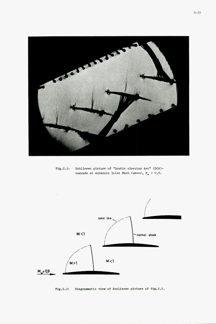
Fig.2.1: Schlieren picture of "Dauble circular Arc" (DCAI- cascade at subaonie in le t Maoh number, M_ = 0.9.
/ I
sonic line
/
Fig.2.2: Diagmmatic vier or Schlieren picture or rlg.2.1.
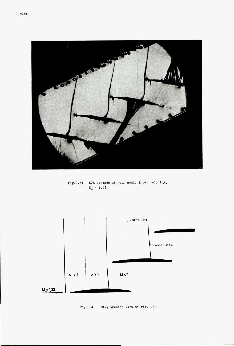
8- 24
I I
I
' M>1 I
M C1
Flg.2.3: DCA-cascade at near sonic inlet Velocity, M_ = 1.03.
M <1
Fig.2.4 Dlagramatlc view of fig.2.3.
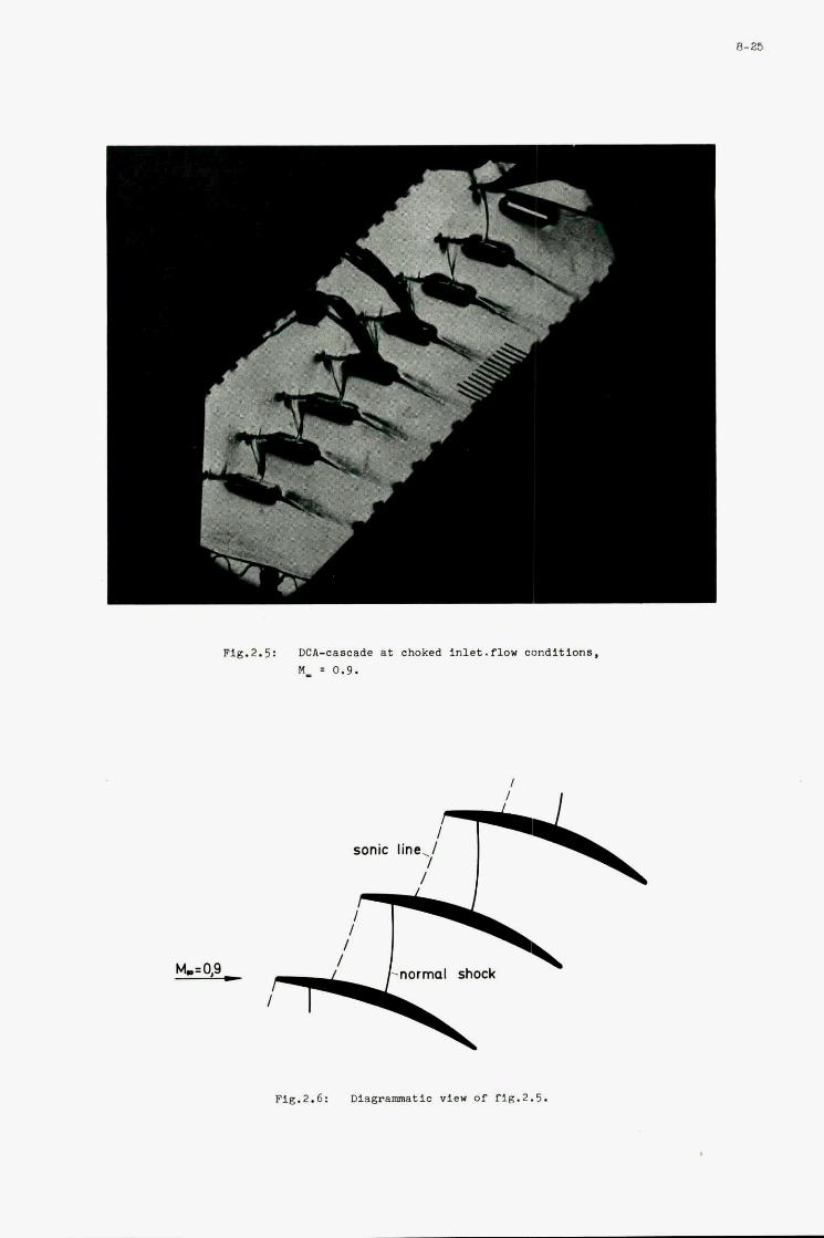
8-25
Fig.2.5: DCA-cascade at choked inlet.flow conditions, M_ = 0.9.
sonic line,/ I /
Fig.2.6: Diagramatic view Of fig.2.5.
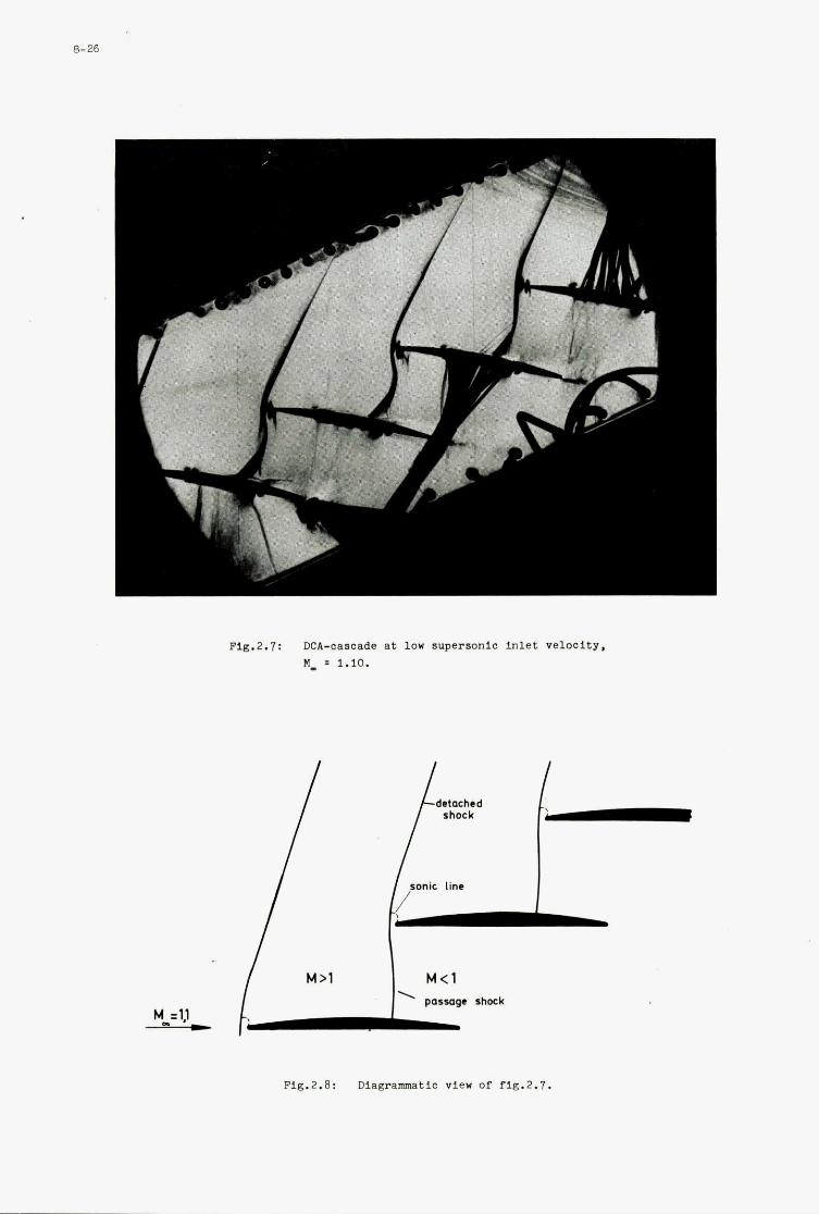
8-26
I
shock
' passage shock M_=l,l -
Fig.2.8: Diagrammatic view of fig.2.1.
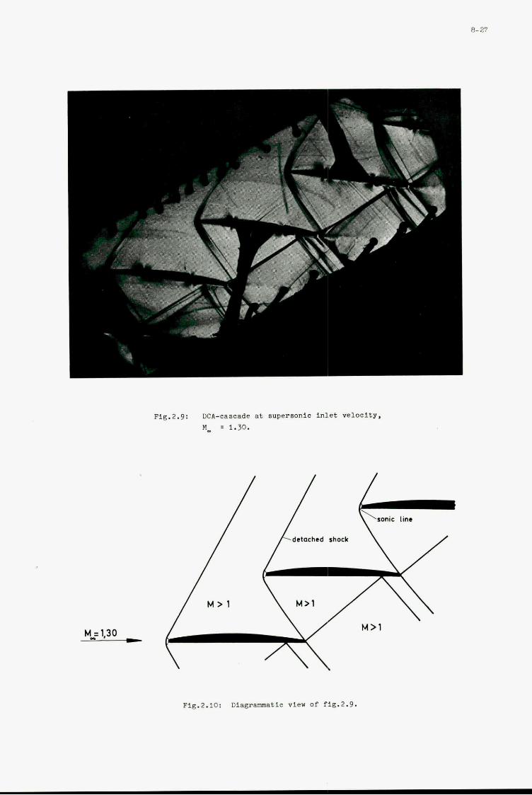
8- 27
Pig.2.9: DCII-caBcade at supersonlo inlet velocity, E", = 1.30.
dctnchcd shock M Fig.2.10: Diagrammatic view of fig.2.9.
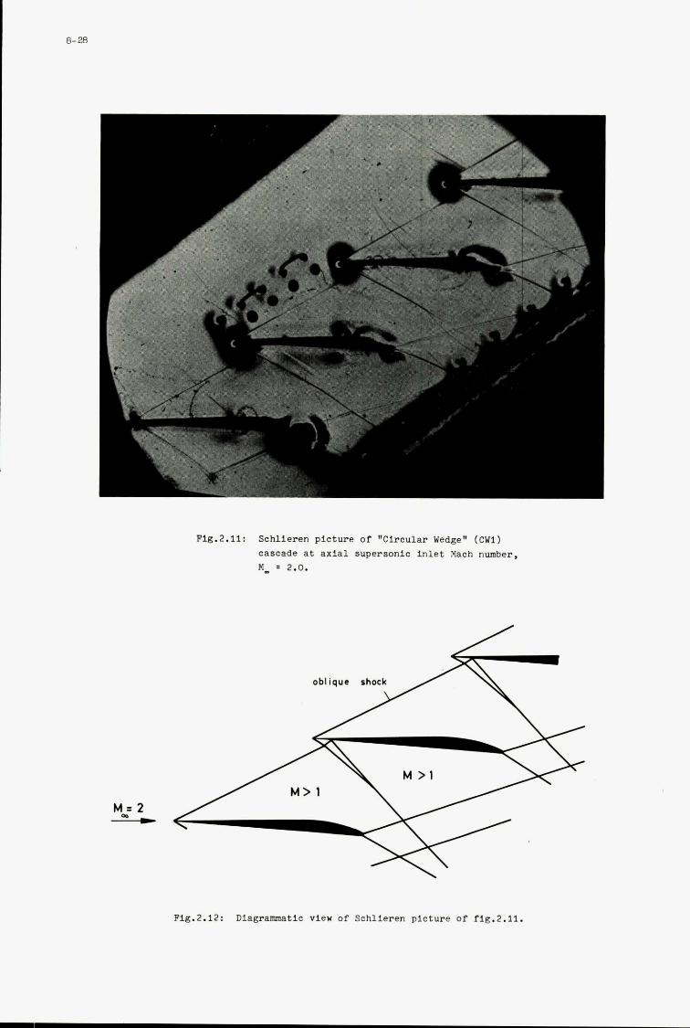
Fig.2.11: Schlieren Plcture of "Cincular Wedge" ( C W l )
CaBcade at axial supersonlo inlet Mach number, M, : 2.0.
Pig.2.12: Dlagramatic view of Schlieren picture Of fig.2.11.
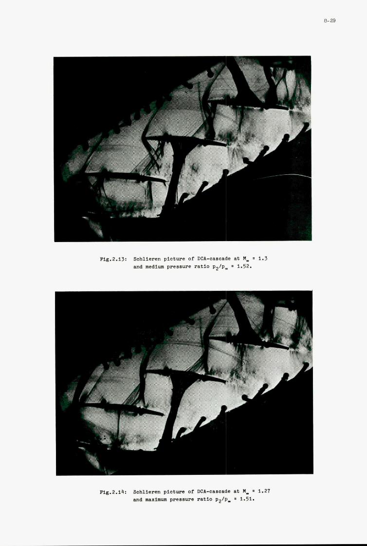
‘ 1
-. ., T
Fig.2.13: Schlieren picture of DCA-cascade at M, = 1.3 and medium presswe ratio p2/p, = 1.52.
I .
&
8-29
Pig.2.14: Schlieren pictun of OCA-cascade at M_ = 1.21 and maximum prensure ratio p2/p. = 1.51.
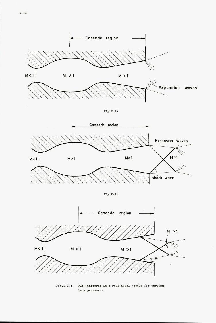
Cascade region t I
M < 1 M > 1 M > 1
ansion waves
F i g . 2.15
Cascade reaion 1
Fig.2.16
-i Cascade region
I
M > 1 M<1 I
' / / / / / / / / / / / / / / / / / / / / / / / / I Fig.2.17: Flow pat terns in a real Lava1 nozzle for varying
back pressures.
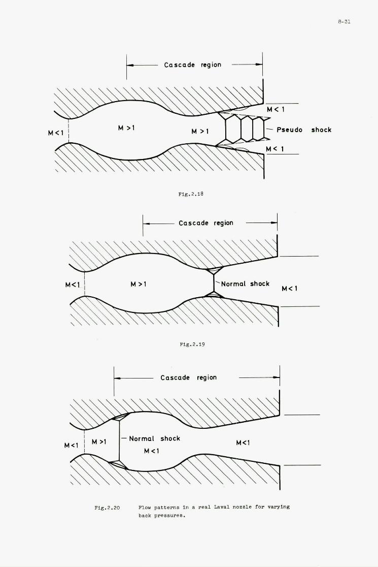
Cascade region t- Pseudo shock
Fig. 2.18
Cascade region
M > 1
I
M< 1 Normal shock
Flg.2.19
Cascade region
M<1 -Normal shock
Fig.2.20 n o w patterns in a real Lava1 nozzle for varying back pressures.
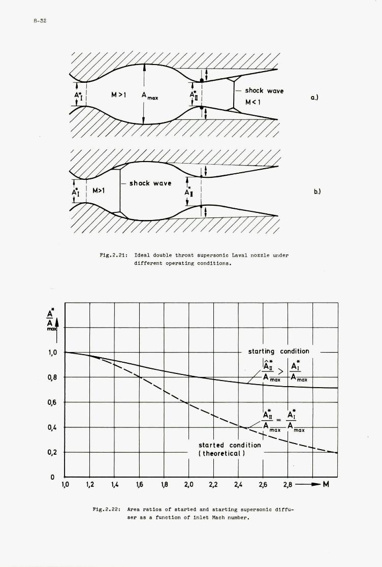
8-32
- shock wave
Fig.2.21: I d e a l double throat supersonlc Lava1 n o z z l e under d i f f e r e n t operating condi t ions .
b.1
Fig.2.22: Area r a t i o s OC s t a r t e d and s t a r t i n g supersonic d i f f u - ser as a funct ion of i n l e t Maoh number.
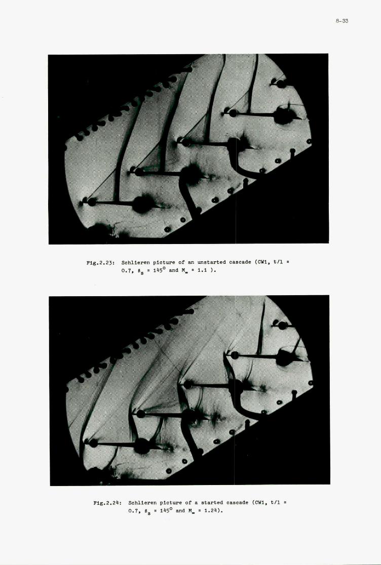
7
Pig.2.23: Schlieren picture of LUI vnatarted cascade (mi, tll = 0.7. 0. = 145' and M, = 1.1 ).
8-33
Fig.2.24: Schlieren picture of a atartcd cascade (CWI , tll 0.1. = 145' and M, = 1.24).
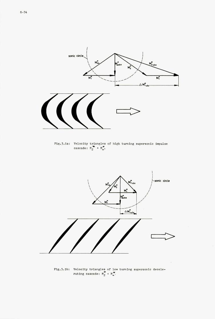
Fig.3.la: Veloc i ty t r i a n g l e s of high turning supersonic impulse % *
cascade: M2 = M**
circle
P i g . J . l b : Velocity t r i a n g l e s of low turning supersonic dece le - * * r a t i n g cascade: M2 < M _ .
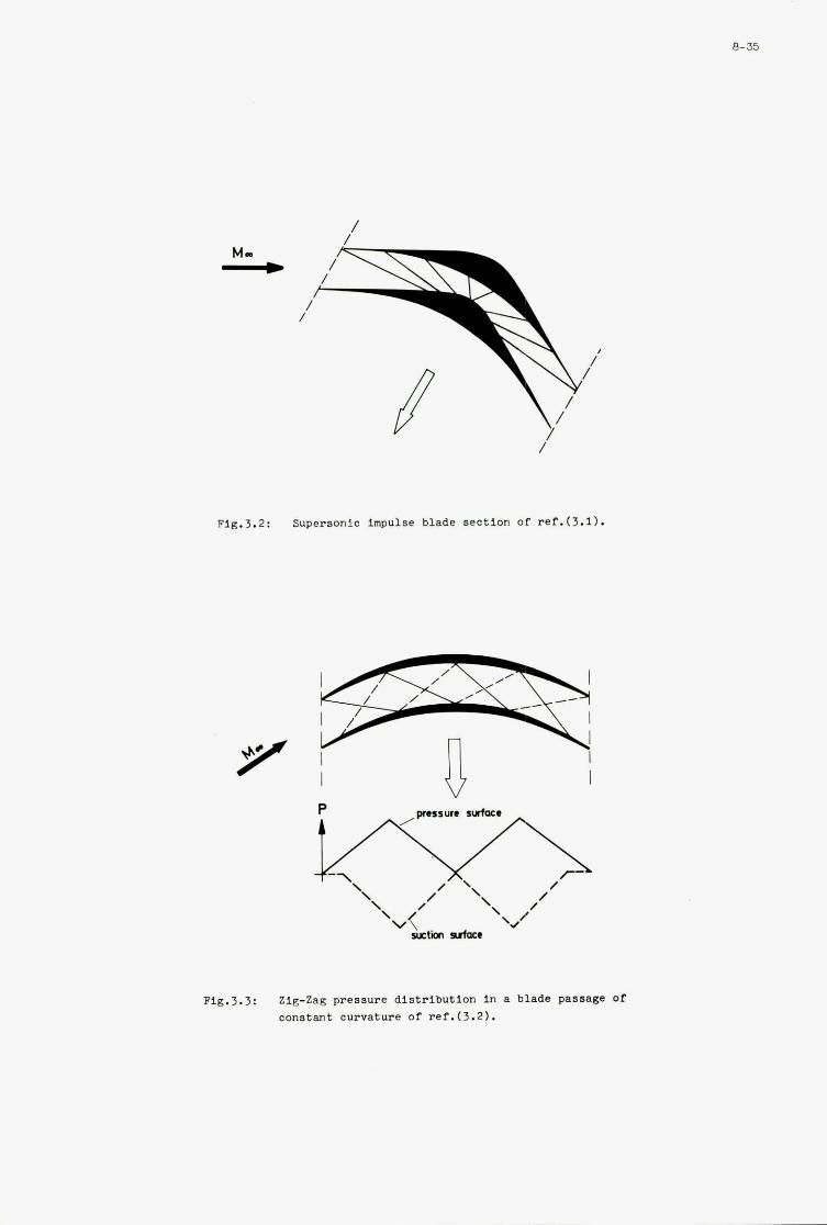
8-35
Fig.3.2: Supersonic impulse blade section Of ref.(3.1).
Fig.3.3: Zlg-Zag pressure distribution in a blade pasaage Of constant curvature of ref.(3.2).
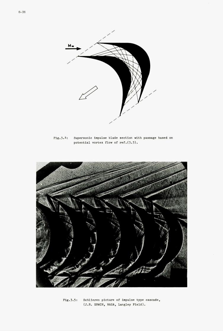
8-36
/
Fi8.3.4: Superaonic impulse blade s e c t i o n with passage baaed on p o t e n t i a l vortex flow of ref.(3.3).
Fig.3.5: Sch l i eren p ic ture of impulae type cascade, (J.R. ERWIN, NASA, Langley F i e l d ) .
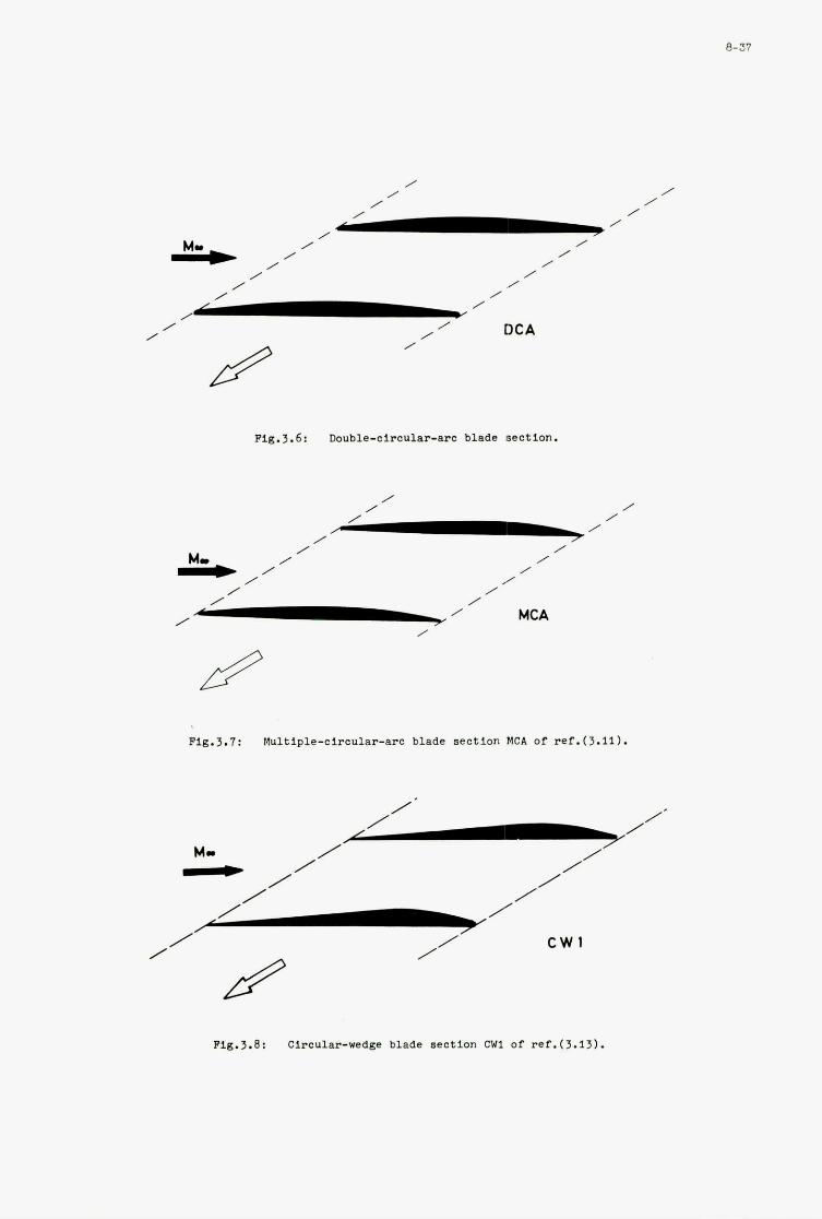
/ M r , / / /
I
/ /
/ /
/ , /
/ /
/
Pig.3.6: DQuble-circU1ar-arc blade section.
/ /
/ /
/ /
/ / / /
/ /
/ / /
MCA /
Pig.3.7: Multiple-circular-arc blade section fCA of ref.(3.11).
c w 1
8-37
Pig.3.B: Circular-wedge blade section CW1 of ref.(3.13).
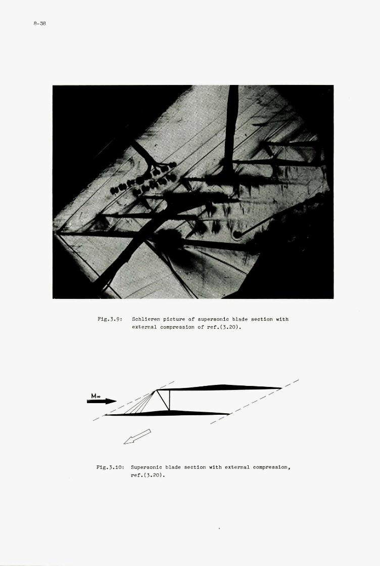
J
I- * **
Fig.3.9: Schlieren picture of supersonic blade aaotion with external compression of ref.(3.20).
Fig.3.10: Supersonie blade 8ection with external compression. ref.(3.20).
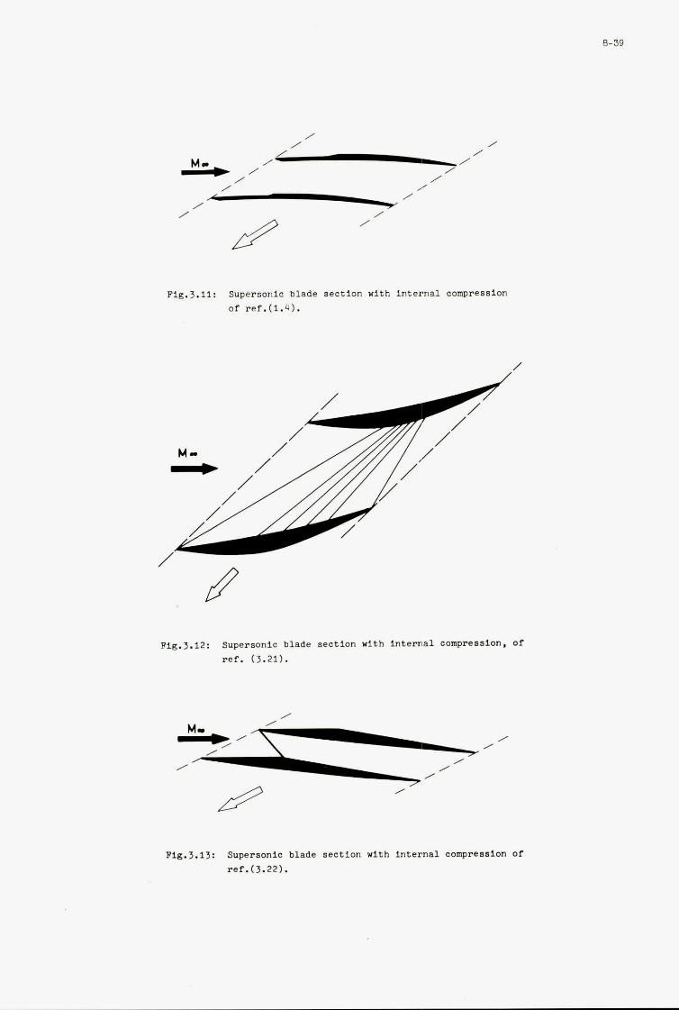
I
a-39
, /
Flg.3.11: Supersonlc blade s e c t i o n with i n t e r n a l compression of ref.(1.4).
Fig.3.12: Supersonic blade s e c t i o n with i n t e r n a l compression, of ref. (3.21).
/
MI, , *--, ~
, /
/ / /
Flg.3.13: Supersonic blade s e c t i o n with i n t e r n a l compression of ref.(3.22).
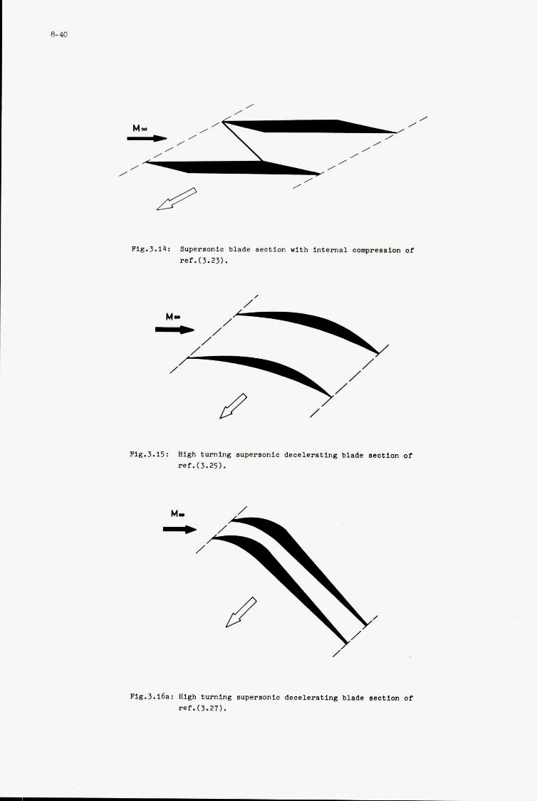
R-40
Fig.3.14: Supersonic blade s e c t i o n with i n t e r n a l compreasion of r e f . ( 3 . 2 3 ) .
,
Fig.3.15: High turning aupersonic d e c e l e r a t i n g blade section oi r e f . ( 3 . 2 5 ) .
Flg.3.16a: High turning supersonic d e c e l e r a t i n g blade s e c t i o n of r e f . 0 . 2 7 ) .
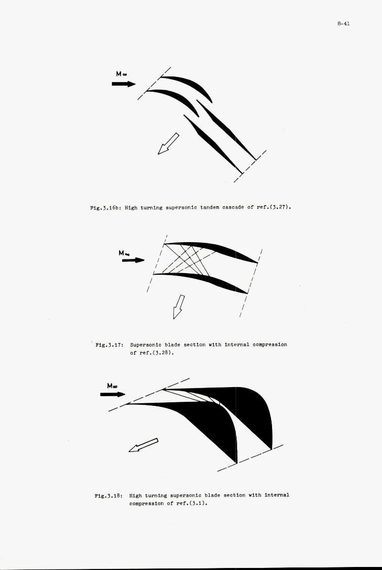
Fig.3.16b: High turning supersonic tandem cascade of ref.(3.27).
Fig.3.17: Supersonic blade section with internal compreaaion of ref.(3.28).
Mc
8-41
Fig.3.18: High turning supersonic blade section with internal compression of rer.(3.1).
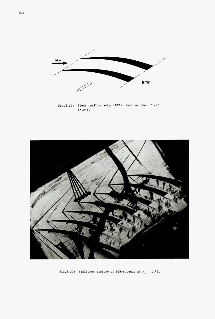
/ /
Fig.3.19: Blunt trailing edge (BTE) blade section of ref. (3.29).
7 i
Fig.3.20: Schlieren picture of BTE-cascade at MI = 1.48.
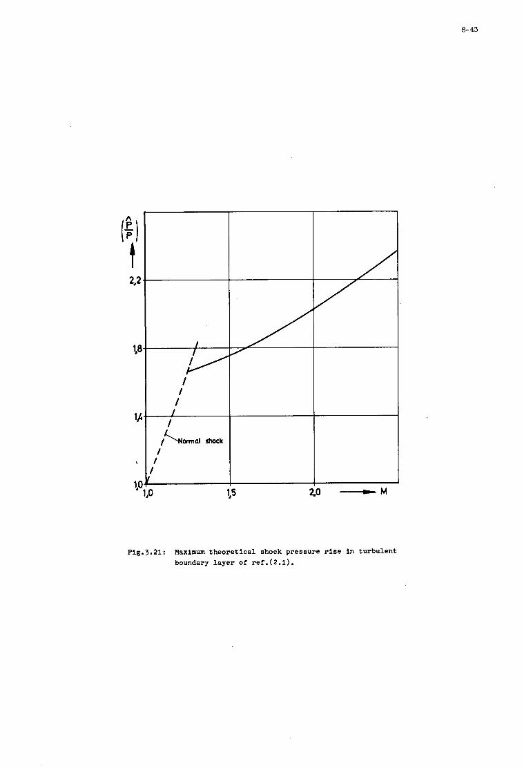
8-43
I I
Fig.3.21: Maximum theoretical shock pressure rise in turbulent boundary layer of ref.(2.1).
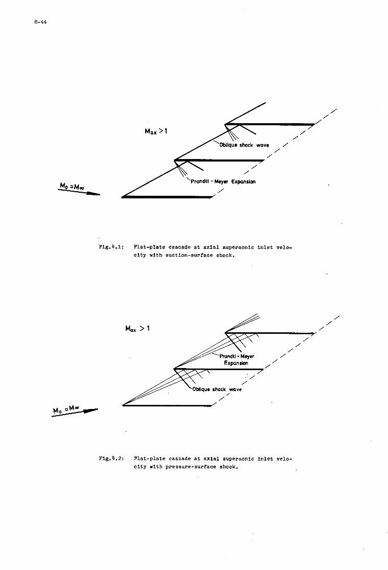
0- 44
/ /
/
/
Fig.4.1: Flat-plate cascade at axial supersonic inlet velo- city with suction-surface shock.
’-OMiquo shock wave /
/
Fig.4.2: Flat-plate cascade at axial supersonic inlet velo- city with pressure-surface shock.
/ /
/
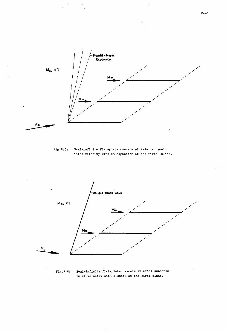
Max (1
-Randtl -Meyrr I l l Expansion
i I / / /
/ Mm / , - ' I/ I / / / /
/ / / /
/ /
Fig.4.3: Semi-infinite flat-plate cascade at axial subsonic inlet velocity with an expansion at the first blade.
Max
-0bliqur shock wave I /
/
Fig.4.4: Semi-infinite flat-plate cascade at axial subsonic inlet velocity with a shock at the first blade.
/ /
/ /
/ /
/
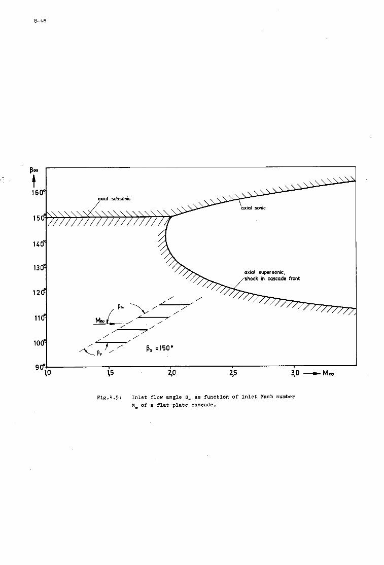
8-46
Flg.4.5: I n l e t flow angle E, a s func t ion of I n l e t Mach number M, o f a f l a t - p l a t e cascade.
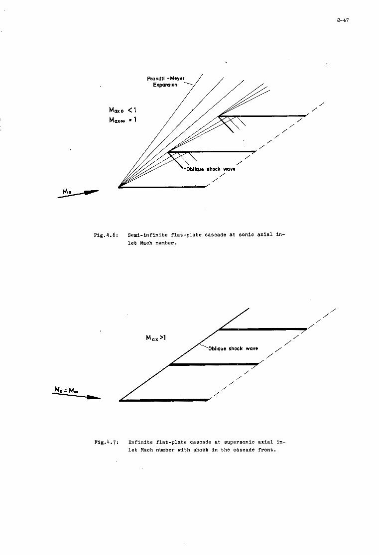
8-47
Prandt//// Expansion 1 , ,
bliqur shock wave
/ /
Fig.4.6: Semi-infinite f l a t - p l a t e cascade a t sonic a x i a l in- l e t Mach number.
/ /
/ /
/ /
/ /
/ /
Fig.4.7: I n f i n i t e f l a t - p l a t e cascade a t supersonic a x i a l in- l e t Mach number with shock i n the cascade front.
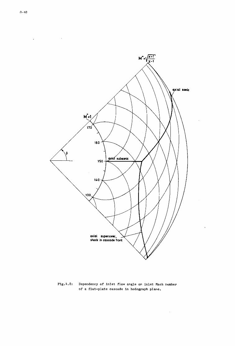
a- 48
Fig.4.8: Dependency of I n l e t flow angle on I n l e t Mach number of a f l a t - p l a t e cascade In hodograph plane.
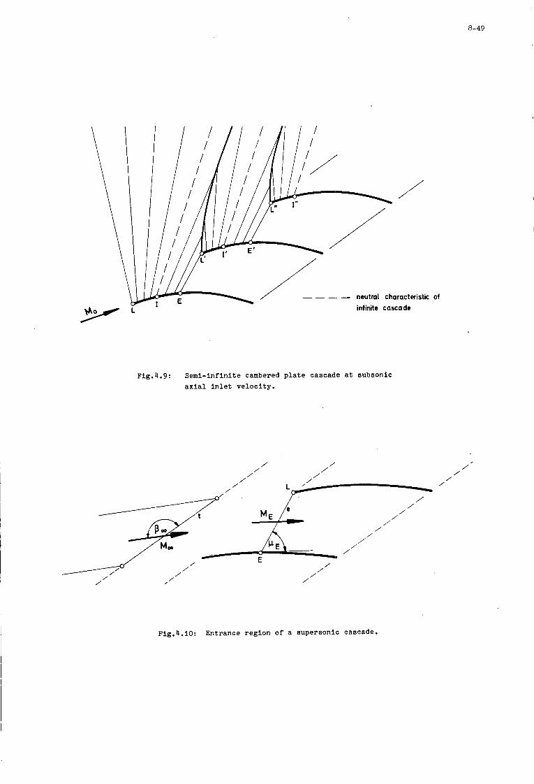
8-49
neutral characteristic infinite cascade
of
Fig.4.9: Semi-infinite cambered plate cascade a t subsonic a x i a l i n l e t v e l o c i t y .
/ / / /
/ / / /
/ /
/ /
/ /
/
/ /
/ / / /
/
/ / /' / / /
/ / /
/ / /
/ /
/ /
/ /
/
/ /
/ / / /
/
Fig.4.10: Entrance region of a supersonic cascade.
/' /
/ /
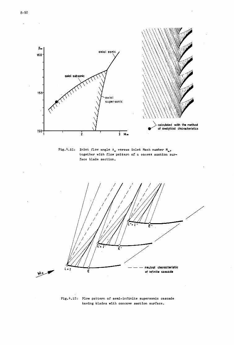
8-50
axial sonic Y
1 no' supersonic
i
calculated with the method of analytical characteristics
Fig.4.11: I n l e t flow angle E, versus i n l e t Mach number M,, t o g e t h e r w i t h flow p a t t e r n of a convex suc t ion sur - face blade sec t ion .
--- neutral charactrrirtic of infinitr c a x a d r
--- neutral charactrrirtic E of infinitr c a x a d r
Flg.4.12: Flow p a t t e r n of semi- lnf in l te supersonic cascade having blades w i t h concave s u c t i o n sur face .
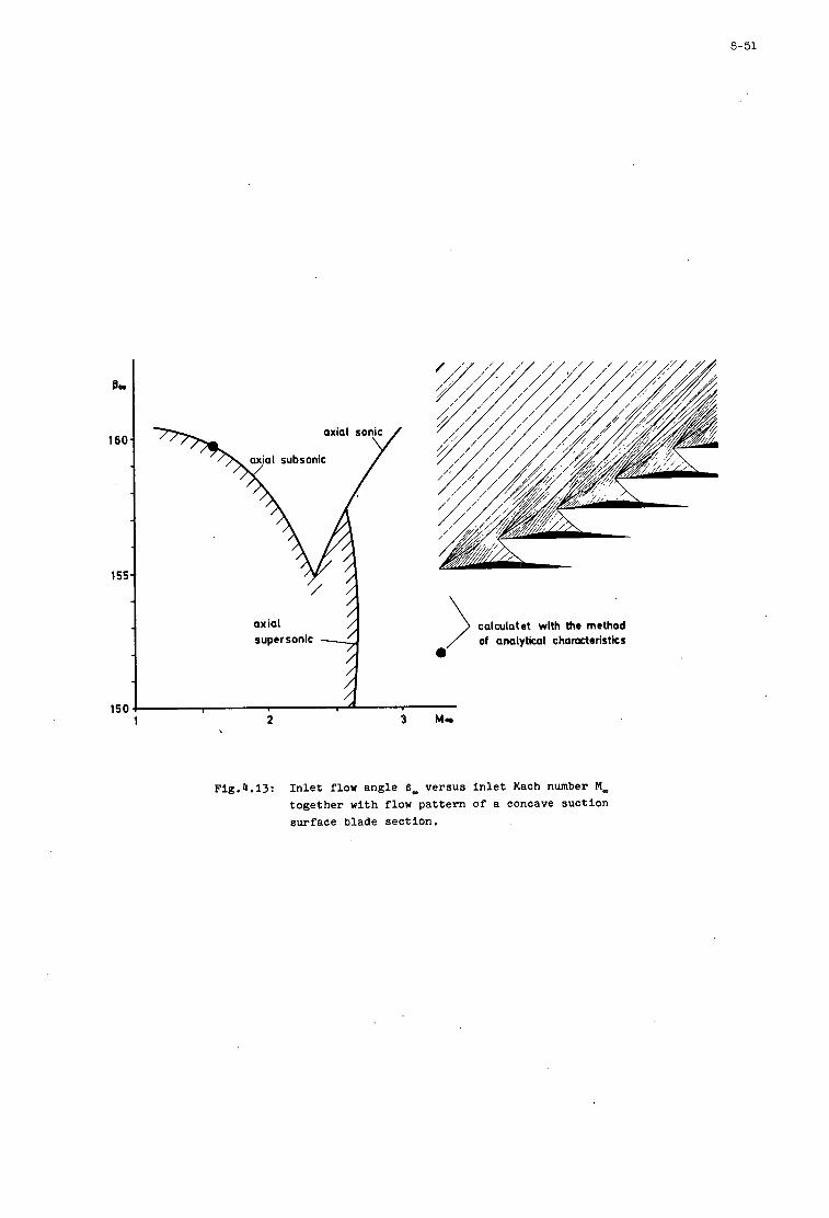
8-51
Bo
160
1 S I
IS(
calculatet with the method of analytical characteristics
0
1 2
Flg.4.13: I n l e t flow angle 6, versus I n l e t Mach number M- together with flow pattern o f a concave suction surface blade sect ion.
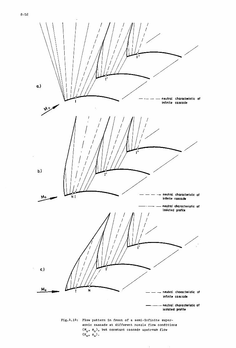
8-52
neutral characteristic of infinite cascade
a.)
/I I I
-. neutral characteristic of isolated profile
- - - neutral chamcteristic of infinite cascade
neutral characteristic of isolated profile
Fig.4.14: Flow pattern in front of a semi-infinite super- sonic cascade at different nozzle flow conditions (MO* 0 0 ) 9 but constant cascade upstream flow (M,,,* 8-1.
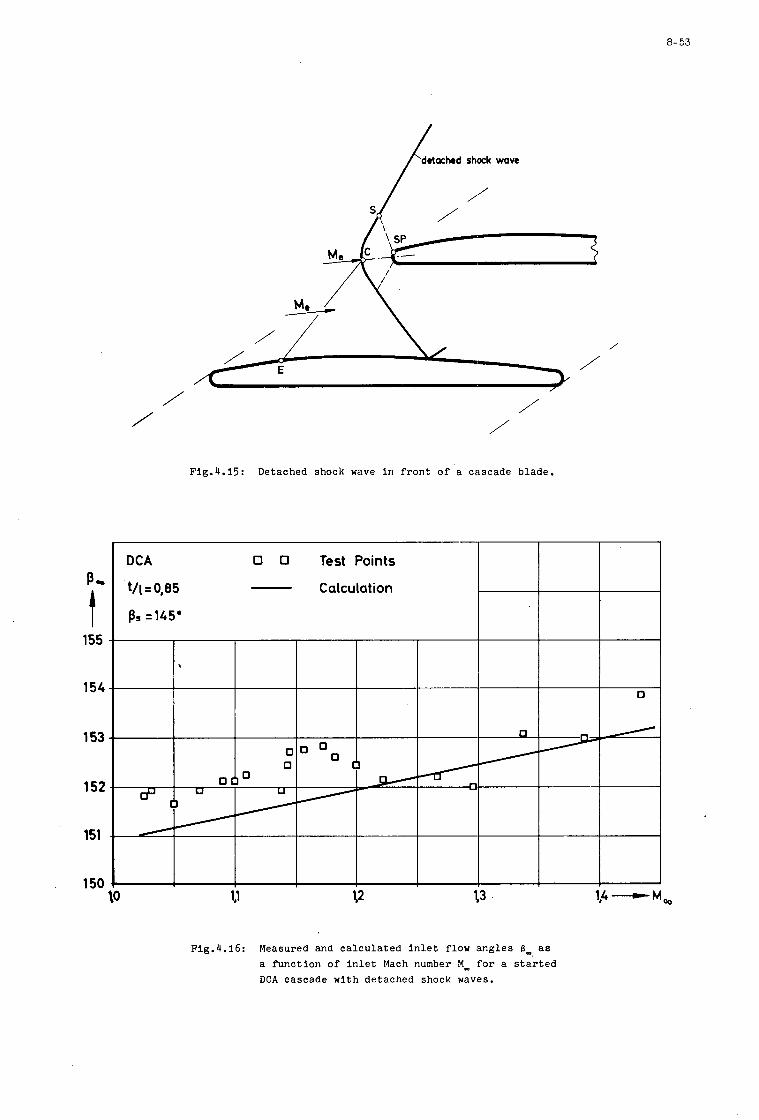
8-53
detcrhed shock wave
/
/ \ /
/ + E
/
/ ,
/ / / /
Flg.4.15: Detached shock wave In f r o n t o f a cascade blade.
P,
t 155
154
153
152
151
150
Flg.4.16: Measured and c a l c u l a t e d I n l e t flow angles 6 , a s a func t ion of I n l e t Mach number Mm f o r a s t a r t e d DCA cascade w i t h detached shock waves.
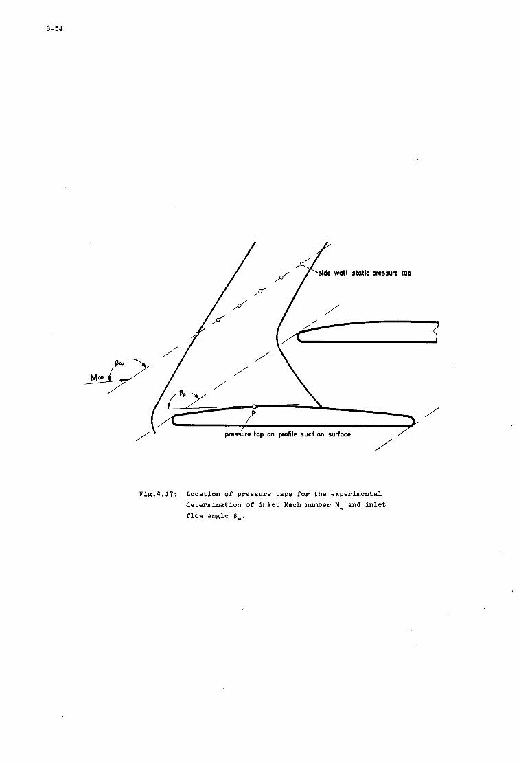
8- 54
p'
/
p'
/
'side wall f / static pressure
pressure tap on profile suction surface /
/
Fig.4.17: Location of pressure t a p s f o r t h e experimental determinat ion of i n l e t Mach number M,'and i n l e t f low angle 6,.
' 1
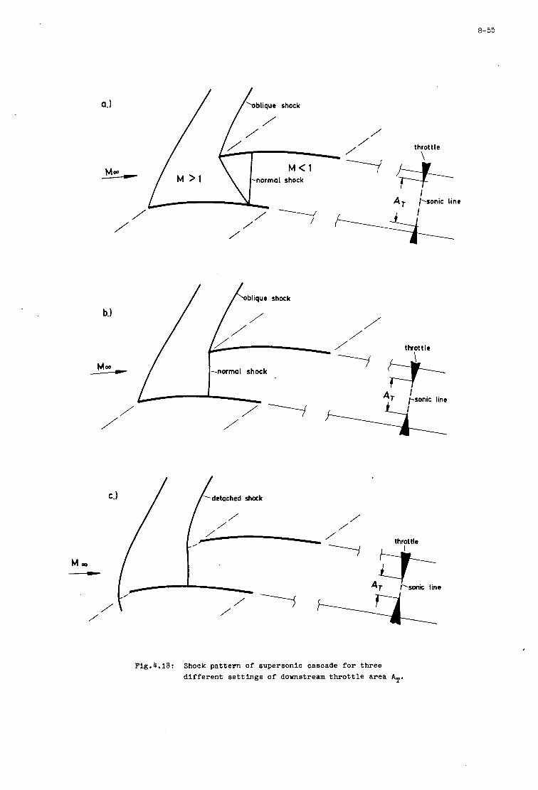
a.)
8- 55
I I
/ / ‘oblique shock
/ / /
/ /
C.) / / ‘detached shock
throttle
Flg.4.18: Shock pattern of supersonic cascade f o r three d i f f e r e n t s e t t i n g s of downstream t h r o t t l e area AT.
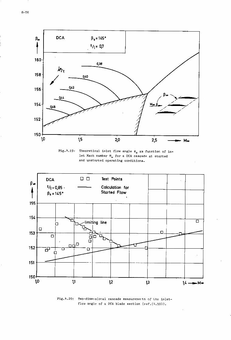
8-56
POD
t 160
158 I
156
154
152
150
Pa
t 155
154
153
152
151
150
DCA p,= 145"
t/l= OJ7
Fig.4.19: Theore t ica l i n l e t flow angle 6, a s func t ion o f In- l e t Mach number M_ f o r a DCA cascade a t s t a r t e d and uns ta r ted opera t ing condi t ions .
DCA U 0 Test Points
p s = 145" Started Flow Calculation for - t/ l= OJ85
0
0 0
Fig.4.20: Two-dimensional cascade measurements of t h e i n l e t - flow angle of a DCA blade s e c t i o n ( r e f . ( 4 . 1 0 ) ) .
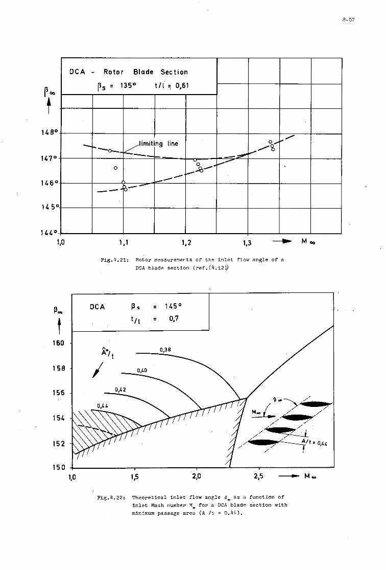
8- 57
P,
t 160
158
156
154
152
150
Fig.4.21: Rotor measurements Of the Inlet flow angle of a DCA blade section (ref.(4.12))
I /
I f '
Fig.4.22: Theoretical inlet flow angle 8- as a function of Inlet Mach number M_ for a DCA blade section with minimum passage area ( A /t = 0.44).
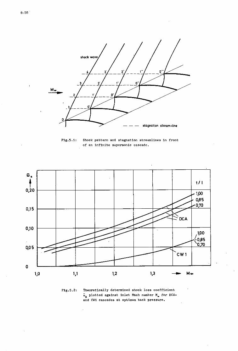
8- 58
Q s
OJ2O t
OJ15
0) 0
0,o 5
0
Fig.5.1: Shock pattern and stagnation streamlines in front of an infinite supersonic cascade.
Fig.5.2: Theoretically determined shock loss coefficient is plotted against inlet Mach number M- for DCA-
and CWl cascades at optimum back pressure.
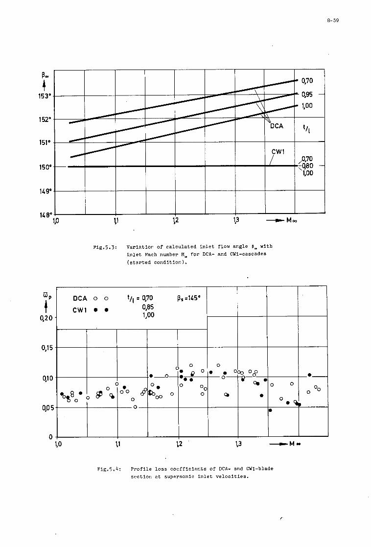
8-59
Q P
OJ2 0 t
O,l5
91 0
OJ0 5
0
Fig.5.3: Varia t ion of c a l c u l a t e d i n l e t flow angle 8- with i n l e t Mach number M _ f o r DCA- and CWI-cascades ( s t a r t e d condi t ion) .
Fig.5.4: P r o f i l e loss c o e f f i c i e n t s of DCA- and CW1-blade s e c t i o n a t supersonic i n l e t v e l o c i t i e s .
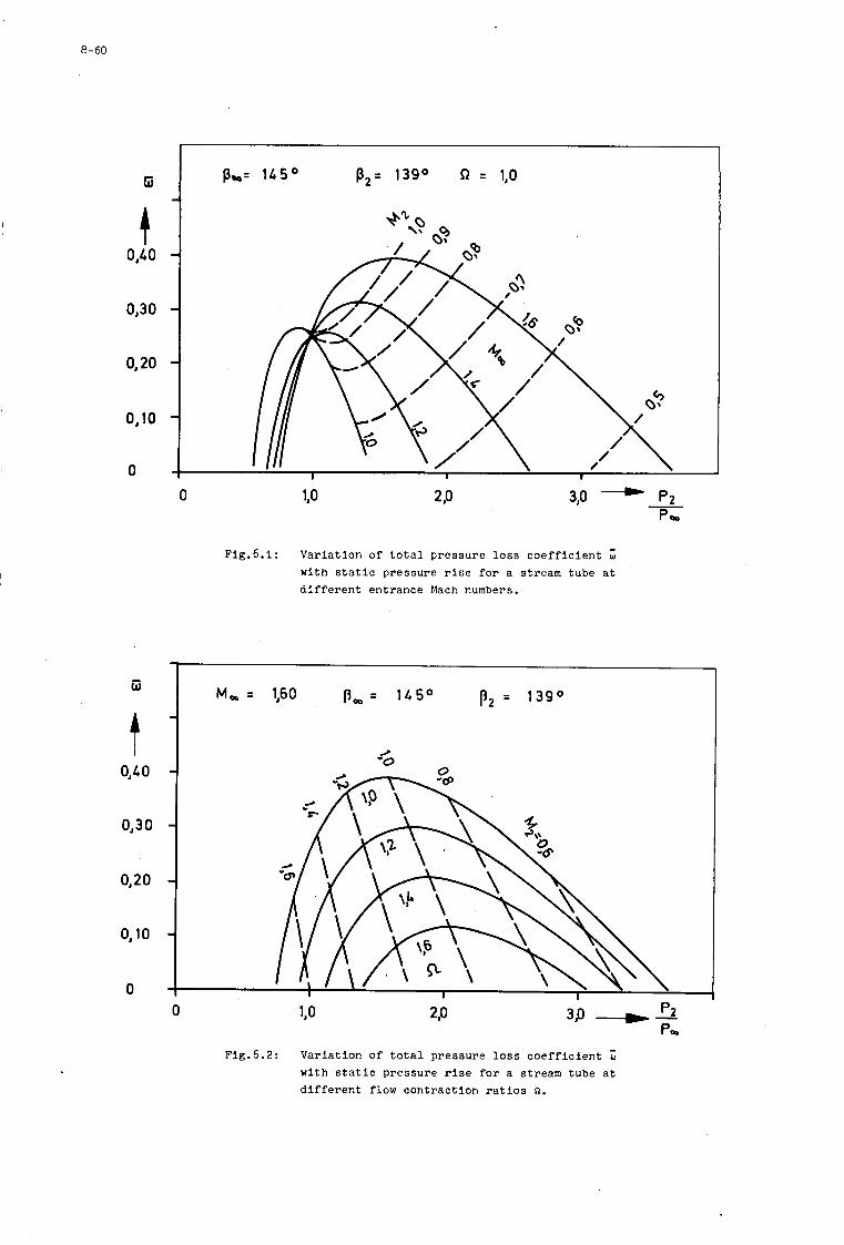
8- 60
Ei
t 0,40
0,30
0,20
0,lO
0
iii
0,40
0,30
0,20
0,lO
p s = 145' p2= 139' R = 1,O
0 1j0
~ig.6.1: Varia t ion of t o t a l p ressure l o s s c o e f f i c i e n t W w i t h s t a t i c pressure r i s e f o r a stream tube a t d i f f e r e n t entrance Mach numbers.
M, = 1,60 P, - - 145' pz = 139O
/ '0
0
Fig.6.2: Varia t ion of t o t a l pressure l o s s c o e f f i c i e n t w i t h s t a t i c pressure r i s e f o r a stream tube a t d i f f e r e n t flow cont rac t ion r a t i o s n.
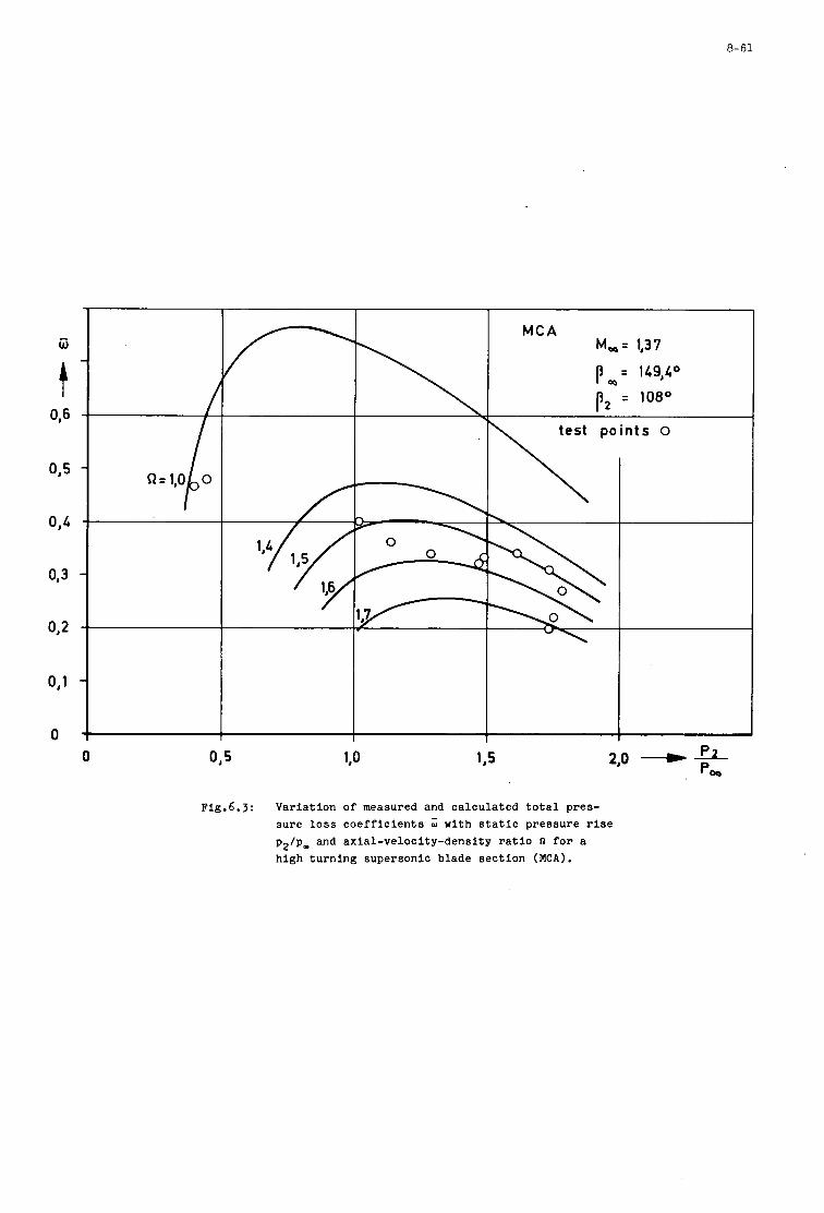
8-61
M C A M,= lJ37
p,= 149JA0
p2 = 108O
0 O J 5
Fig.6.3: Variation of measured and calculated t o t a l pres- sure l o s s c o e f f i c i e n t s 'w with s t a t i c pressure r i s e p2/p, and axial-velocity-density r a t i o $2 f o r a high turning supersonic blade sect ion MCA).

9
APPLICATION OF THROUGH-FLOW THEORIES
TO RADIAL WHEEL DESIGN
M. H. Vavra
Naval Postgraduate School Monterey, Cal i fornia 93940
9
SUMMARY
A review i s presented of the basic flow equations for the analysis of flows i n ro tors , together ,with a discussion of the e f fec ts of simplifying assumptions tha t are necessary t o obtain solutions. Particular flows i n r ad ia l compressor rotors are treated, and the approach necessary to calculate a rb i t ra ry flow patterns for given blade shapes is described. description of the blade surface is demonstrated, and the applicabili ty of the r e su l t s t o the design of compressor rotors is discussed.
The necessity of using a correct
9- 1
APPUCATI ON OF THROUGH- FLOW THEORIES
TO RADIAL WHEEL DESIGN
1. INTRODUCTION
The present lec ture is not concerned with the procedures t o calculate the flow patterns i n r ad ia l compressor wheels but endeavors t o discuss the effect8 of simplifications tha t have t o be made i n most theore t ica l treatments t o obtain solutions.
All rigorous calculating methods must be based on the fundamental laws of f lu id dynamics which are formulated in Ref. l*. solutions are diecussed i n Ref. 2.*
2. FUNDAMENTAL FLOW ELATIONS
Some of the pecul ia r i t i es of flows i n ro tors and the nature of blade-to-blade
Irrespective of i t s par t icu lar nature or f i e l d of application,a flow w i l l adapt i t s e l f t o conditions where the laws of conservation of momentum, mass, and energy are sa t i s f ied . meet specified boundary conditions of the f i e l d and it i s a l so affected by the thermodynamic processes which it undergoes. I f the f lu id is a gas, it must s a t i s fy the so-called condition of s t a t e , which r e l a t e s i t s mass density t o pressure and temperature.
I n addition, a flow has t o
The formulations of the three aboved-mentioned conservation laws for rotating flow channels d i f f e r from those for flows i n stationary passages because of the e f fec ts of the cent r ipe ta l and and Coriolis forces. for the r e l a t ive velocity f i e ld W of a compressible f lu id i n the Eulerian description are:
If the angular velocityA@ of a ro tor with fixed axis i s constant, the three basic re la t ions
Equation of Motion, Eq. [7(35)11: & - A a
A
d,' + v H R = W X ( V ~ W , + Z U ) + T V S + ~ a t
Equation of Continuity, Eq. [7(29)1l: A - v*(p W L 0
a t Energy Equation, Eq. [7( 43)Jl:
The derivatives a,( ) / a t express the non-steady, or time-depending character of the flow i n the rotating frame of reference, and the d i f f e ren t i a l s d i ( ) i n Eq. 3 represent changes of the flow properties along the r e l a t ive flow paths travelled by the f lu id par t ic les .
The so-called re la t ive t o t a l enthalpy HR per un i t mass is defined by
where;
h - w - u - go - z -
Also , s - T - 3 - P - Q -
s t a t i c enthalpy a t the s t a t i c p re s su re2 and the s t a t i c temperature T magnitude of re la t ive Yelocity vector W peripheral rotor speed gravitational constant elevation from a specified leve l surface
entropy of f lu id per un i t mass absolute s t a t i c temperature f r i c t iona l force acting on f lu id pa r t i c l e per un i t mass '
mass density heat added t o uni t mass partic;le along its path from sources outside the flow f i e l d
For so-called absolute flows i n stationary passages whereo and U are zero, the absolute t o t a l - enthalpy H is obtained f r o m Eq. 4 i f W i s replaced by the magnitude V of the absolute velocity vector V.
~~~
*For simplicity, chapter, page, flgure, and equation numbers, f r o m these sources are put i n square brackets with postfixes 1 or 2 pertaining t o Ref. 1 or Ref. 2 , respectively. equation 47 of reference 2.
E.@., Eq.[47]2 is
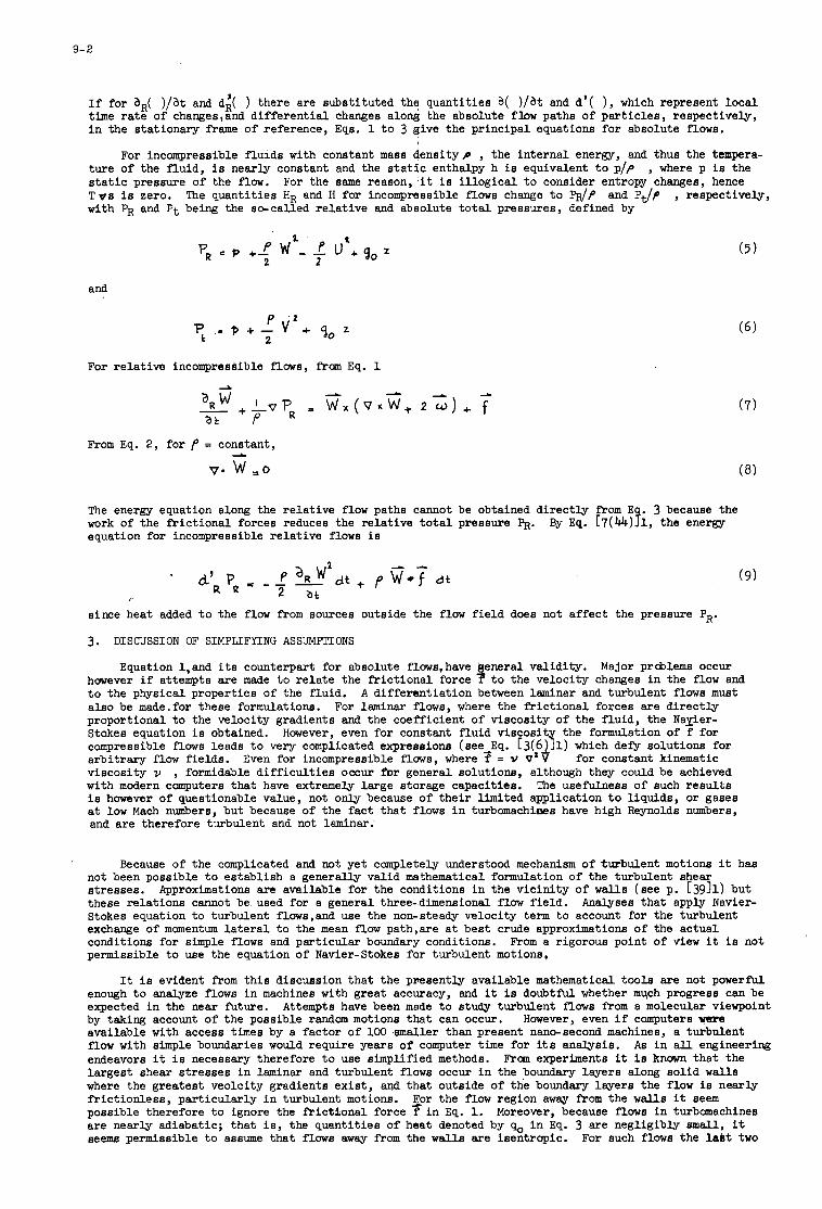
9- 2
If for a,( ) / a t and d;( ) there are substi tuted the quantit ies a( ) / a t and d'( ), which represent l oca l time r a t e of changes,and d i f f e ren t i a l changes along the absolute flow paths of pa r t i c l e s , respectively, i n the stationary frame of reference, Eqs. 1 t o 3 give the principal equations for absolute flows.
I
For incompressible f lu ids with constant mass dens i typ , the in te rna l energy, and thus the tunpera- tu re of the fluid, i s nearly constant and the s t a t i c enthalpy h is equivalent t o p/p s t a t i c pressure of the f low. T o e i s zero. with p R and P t being the so-called r e l a t ive and absolute t o t a l pressures, defined by
, where p is the For the same reason, it i s i l l og ica l t o consider entropy changes, hence
The quantit ies HR and H for incompressible flows change t o WP and Pdp , respectively,
2 ' I PR = P f- f w - P u + ~ o z
2 2
and
For re la t ive incompressible flows, from Eq. 1
(5)
From Eq. 2, for f = constant, I
m e energy equation along the r e l a t ive flow paths cannot be obtained d i r ec t ly from E . 3 because the work of the f r i c t iona l forces reduces the re la t ive t o t a l pressure PR. By Eq. C7(44)?1, the energy equation for incompressible r e l a t ive flows is
since heat added t o the f l o w from sources outside the flow f i e l d does not a f fec t the pressure PR.
3. DISCUSSION OF SIMPLIFYING ASSUMPTIONS
Equation 1,and i t s counterpart for absolute flows, have however i f attempts a re made t o r e l a t e the f r i c t iona l force
va l id i ty . Major prcblems occur velocity changes in the flow and
t o the physical properties of the fluid. also be made.for these formulations. For laminar flows, where the f r i c t iona l forces are d i r ec t ly proportional t o the velocity gradients and the coefficient of viscosity of the f lu id , the Nayier- Stokes equation i s obtained. However, even for constant f l u id v iscos i t the formulation of f for compressible flows leads t o very complicated expressions (see_Eq. [3(64!1) which de@ solutions for a rb i t ra ry f low f ie lds . for constant kinematic viscosity v , formidable d i f f i c u l t i e s occur for general solutions, although they could be achieved with modern computers t ha t have extremely large storage capacities. The usefulness of such r e su l t s i s however of questionable value, not only because of t he i r limited application t o l iqu ids , or gases a t low Mach numbers, but because of the f ac t t ha t flows i n turbomachines have high Reynolds numbers, and are therefore turbulent and not laminar.
A d i f fe ren t ia t ion between laminar and turbulent flows must
Even for incompressible flows, where f = V 0'
Because of the complicated and not yet completely understood mechanism of turbulent motions it has not been possible t o es tab l i sh a generally valid mathematical formulation of the turbulent shear stresses. these re la t ions cannot be used for a general three-dimensional flow f ie ld . Stokes equation t o turbulent floWs,and use the non-steady velocity term t o account for the turbulent exchange of momentum l a t e r a l t o the mean f l o w path,are a t bes t crude approximations of the actual conditions for simple flows and par t icu lar boundary conditions. From a rigorous point of view it is not permissible t o use the equation of Navier-Stokes for turbulent motions,
Approximations are available for the conditions i n the v i c in i ty of walls (see p. [3911) but Analyses tha t apply Navier-
It i s evident from t h i s discussion tha t the presently available mathematical too ls are not powerful I enough t o analyze flows i n machines with great accuracy, and it is doubtful whether much progress can be expected i n the near future. by taking account of the possible random motions tha t can occur. available with access times by a fac tor of 100 smaller than present nano-second machines, a turbulent flow with simple boundaries would require years of computer time for its analysis. endeavors it is necessary therefore t o use simplified methods. From experiments it is known tha t the la rges t shear s t resses i n laminar and turbulent flows occur i n the boundary layers along so l id w a l l s where the greatest veolcity gradients ex i s t , and tha t outside of the boundary layers the flow is nearly f r i c t ion le s s , par t icu lar ly i n turbulent motions. possible therefore t o ignore the f r i c t iona l force i n Eq. 1. Moreover, because flows i n turbomachines are nearly adiabatic; t ha t i s , the quantit ies of heat denoted by s, i n Eq. 3 are negligibly small, it seema permissible t o assume tha t flows away from the w a l l s are isentropic. For such flows the l a b t two
Attempts have been made t o study turbulent flows from a molecular viewpoint However, even i f computers vere
As i n a l l engineering
I
I For the f low region away from the w a l l s it seem
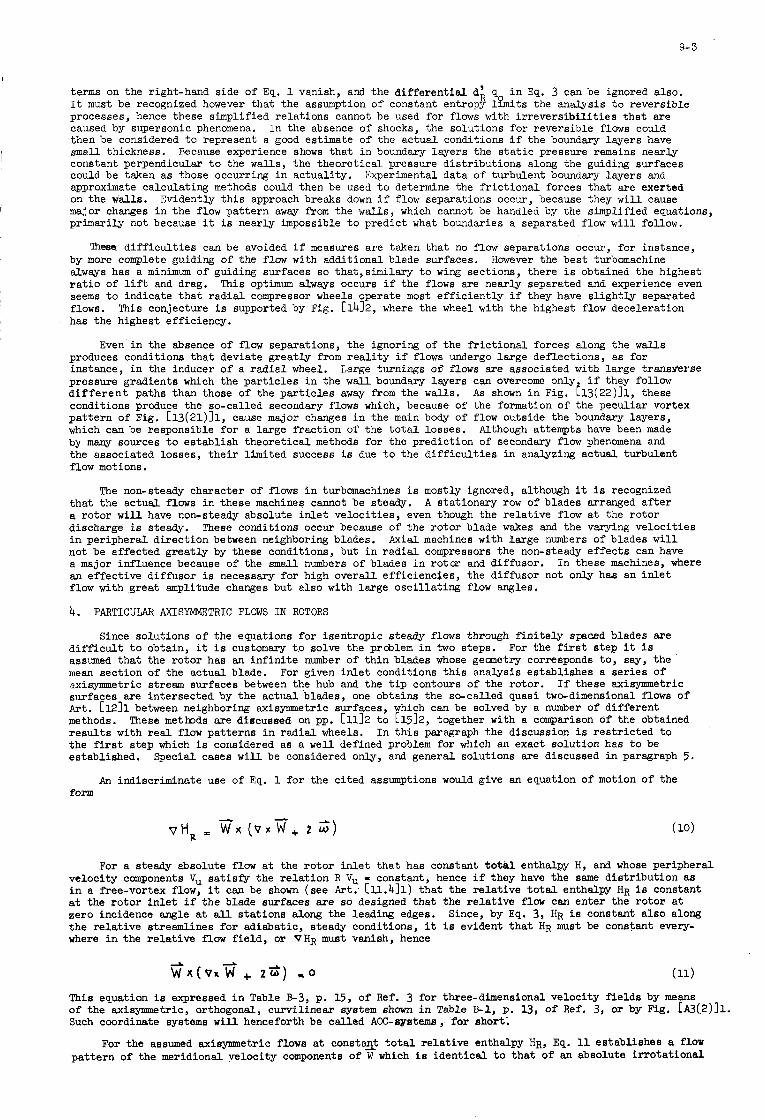
9- 3
terms on the right-hand side of Eq. 1 vanish, and the a i f f e ren t i a l d i q, i n Eq. 3 can be ignored a l so , It must be recognized however tha t the assumption of constant entropy limits the analysis t o reversible processes, hence these simplified re la t ions cannot be used for flows with i r r eve r s ib i l i t i e s t ha t are caused by supersonic phenomena. In the absence of shocks, the solutions for reversible flows could then be considered t o represent a good estimate of the ac tua l conditions i f the boundary layers have small thickness. Because experience shows tha t i n 5oundaxy layers the s t a t i c pressure remains nearly constant perpendicular t o the walls, the theore t ica l pressure d is t r ibu t ions along the guiding surfaces could be taken as those occurring i n actuali ty. Experimental data of turbulent boundary layers and approximate calculating methods could then be used t o determine the f r i c t iona l forces tha t are exerted on the w a l l s . major changes i n the flow pattern awq? f r o m the walls, which cannot be handled by the simplified equations, primarily not because it i s nearly impossible t o predict what boundaries a separated flow w i l l follow.
Evidently t h i s approach breaks down i f flow separations occur, because they w i l l cause
These. d i f f i c u l t i e s can be avoided i f measures are taken tha t no flow separations occur, for instance, by more complete guiding of the flow w i t h additional blade surfaces. alwws has a minimum of guiding surfaces so that,similary t o wing sections, there i s obtained the highest r a t i o of lift and drag. This optimum always occurs i f the flows are nearly separated and experience even seems t o indicate t h a t r ad ia l compressor wheels operate most e f f i c i en t ly i f they have s l igh t ly separated flows. has the highest efficiency.
However the bes t turbomachine
This conjecture is supported by Fig. [1412, where the wheel with the highest flow deceleration
Even i n the absence of flow separations, the ignoring of the f r i c t iona l forces along the walls produces conditions tha t deviate greatly from r e a l i t y i f flows undergo la rge deflections, as for instance, i n the inducer of a r a d i a l wheel. pressure gradients which the pa r t i c l e s i n the w a l l boundary layers can overcome only i f they follow d i f f e r e n t paths than those of the pa r t i c l e s a w q from the w a l l s . As sham i n Fig. t13(22)11, these conditions produce the so-called secondary flows which, because of the formation of the peculiar vortex pa t te rn of Fig. [l3(21)]1, cause major changes i n the main body of flow outside the boundary layers, which can be responsible for a large f rac t ion of the t o t a l losses. Although attempts have been made by many sources t o es tab l i sh theore t ica l methods for the prediction of secondary flow phenomena and the associated losses, t h e i r l imited success is due t o the d i f f i c u l t i e s i n analyzing actual turbulent flow motions.
Large turnings of flows are associated with la rge transyeterse
The non-steady character of flows i n turbomachines i s mostly ignored, although it i s recognized A stationary row of blades arranged a f t e r t ha t the actual flows i n these machines cannot be steady,
a ro tor w i l l have non-steady absolute i n l e t ve loc i t ies , even though the re la t ive flow a t the ro tor discharge is steady. These conditions occur because of the ro to r blade wakes and the varying ve loc i t ies i n peripheral d i rec t ion between neighboring blades. A x i a l machines with la rge numbers of blades w i l l not be affected grea t ly by these conditions, but i n r ad ia l compressors the non-steady e f f ec t s can have a major influence because of the s m a l l numbers of blades i n ro tor and diffbsor. an ef fec t ive diffusor is necessary fo r high overall e f f ic ienc ies , the diffusor not only has an i n l e t f l o w with great amplitude changes but also with large osc i l la t ing flow angles.
4.
In these machines, where
PARTICULAR AXSYMMETRIC FLOWS I N ROTORS
Since solutions of the equations fo r isentropic steady flows through f i n i t e l y spaced blades are d i f f i c u l t t o obtain, it i s customary tg solve the problem i n two steps. assumed tha t the ro tor has an i n f i n i t e number of t h in blades whose geometry corresponds to , say, the mean section of the actual blade. axisymmetric stream surfaces between the hub and the t i p contours of the rotor. surfaces are intersected by the actual blades, one obtains the so-called quasi two-dimensional flows of A r t . El211 between neighboring axisymmetric surfaces, which can be solved by a number of d i f fe ren t methods. These methods are discussed on pp. [1112 t o [15]2, together with a comparison of the obtained r e su l t s with r e a l flow patterns i n radial wheels. the f i r s t s tep which i s considered as a well defined problem for which an exact solution has t o be established.
For the f i r s t s tep it i s
For given i n l e t conditions t h i s analysis establishes a ser ies of If these axisymmetric
I n t h i s paragraph the discussion i s r e s t r i c t ed t o
Special cases w i l l be considered only , and general solutions are discussed i n paragraph 5.
An indiscriminate use of Eq. 1 for the c i ted assumptions would give an equation of motion of the form
d
vHR ic W x ( 0 x 2 , 2 w ' )
For a steady absolute f low at the ro tor i n l e t t ha t has constant t o t k l enthalpy H, and whose peripheral velocity components Vu s a t i s fy the r e l a t ion R Vu - constant, hence i f they have the same d is t r ibu t ion as i n a free-vortex flow, it can be shown (see Art: cll.411) tha t the r e l a t ive t o t a l enthalpy HR i s constant a t the ro to r i n l e t i f the blade surfaces are so designed tha t the r e l a t ive f l o w can enter the ro tor a t zero incidence angle a t all s ta t ions along the leading edges. Since, by Eq. 3, HR i s constant a l so along the re la t ive streamlines fo r adiabatic, steady conditions, it i s evident t h a t HR must be constant every- where i n the r e l a t ive flow f i e ld , or VHR must vanish, hence
This equation is expressed i n Table E3, p. 15, of Ref. 3 for three-dimensional velocity f i e lds by means of the axisymmetric, orthogonal, curvil inear system shown i n Table U-1, p. 13, of Ref. 3, or by Fig. [A3(2)11. Such coordinate systems w i l l henceforth be celled Am-systems, fo r short;
For the assumed axisynunetric flows a t consta$ t o t a l re la t ive enthalpy HR, Eq. 11 establishes a flow pa t te rn of the meridional velocity components of W which i s ident ica l t o t h a t of an absolute i r ro t a t iona l
944
flow a t constant t o t a l enthalpy H i n the sane flow channel but without blades. Therefore, it i s neither affected by the blade shapes nor i s it influenced by d i f fe ren t angular ro tor ve loc i t ies . shown i n Art. C~t.411, it i s solely depending on the shape and the curvatures of the meridional channel contours and the generatrices of the axisymmetric stream surfaces.
As
A t an e a r l i e r stage o f t h e development even th i s approximation had a considerable impact on the design of r ad ia l wheels. and rad ica l Chan@;e6 i n curvature could produce considerable changes i n the meridional velocity components between the inner and outer wheel contours, and could be responsible for large flow decelerations, especially along the outer wheel contour. These conditions could create the non-uniformities of ro tor discharge flows t h a t were often observed. giving hub and t i p contours with small and gradually changing curvatures, produced the first significant increase i n efficiency a f t e r many years of stagnant development.
Inspite of i t a shortcomings it showed tha t meridional generatrices with large
Indeed, the introduction of wheels with larger ax ia l extensions,
A closer examination of the problem indicates, however, t h a t the in f in i t e ly small pressure changes i,n peripheral direction between adjacent blades have a f i n i t e efxect because of the in f in i t e number of blades,which must be accounted fo r by introducing a blade force Fg i n the equation of motion, representing the force tha t an element of blade surface exerts on a uni t mass of f lu id .
For a steady ro tor f l o w having a free-vortex type absolute i n l e t flow at constant t o t a l enthalpy H, there is from Eq. 1 for isentropic conditions,
For the assumed f r i c t ion le s s flows the vector of the blade force must be perpendicular t o the blade
Hence the blade surface must be known t o es tab l i sh FB,and it must be surface a t a l l s ta t ions , and must point i n such directions as t o require tha t a compresgor ro tor needs t o be driven by an outside source. so arranged tha t the desired i n l e t and discharge flow conditions can be achieved without sudden changes i n f l o w angle.
Equation 12 w i l l now be applied t o a compressor wheel of the type shown i n Fig. h12, i n par t icu lar , t o the impeller w i t h s t ra ight meridional blades a r r q e d a f t e r the inducer. f l o w sclution the ac tua l impeller blades are replaced by an i n f i n i t e iiumber of mxridional half-planes. Thus, Fg points everywhere i n peri&eral s r e @ o n , and the re la t ive ve loc i t ies W cannot have peripheral velocity components. Expressing w x ( V ~ W + ~ ~ ) for t h i s condition,by using the re la t ions of Table E!-3, p. 15, of Ref. 3, it can be seen tha t
For the axisynrmetric through-
A 2 -
FB 2 w x w
and
Equation U shows tha t the blade force ?B per uni t m & s d f l u i . equals the Coriolis acceleration. Hence, the flow exerts a force - FB on the blade surface. away from the axis, the necessary ro tor driving moment i s i n opposite d i rec t ion t o w , as i s the case for a canpressor.
Then, i f W has r ad ia l components t ha t point
EquQion 14 indicates t ha t the vectors $ and V x ? have t o be p a r a l l e l without necessarily requiring that V x W must be zero. flow pa t te rn specified by Eq. 14 is ident ica l with tha t obtained from Eq. ll. the velocity d is t r ibu t ions are also not affected byw , but depend odly on the shape of the axisynrmetric stream surfaces, i n par t icu lar , on the curvatures of t h e i r generatrices.
It can be shown that, for the impeller with straight meridional blades, the Hence for meridional blades
5 . AXTSYMMETRIC FLOWS I N ROTORS WITH ARBITRARY BLAEE SHAPES
Although several methods of solution are available t o obtain flow patterns i n ro tors with a rb i t ra ry blade shapes, the present discussion i s r e s t r i c t ed t o the approach of Ref. 1. Further, a l imi ta t ion i s made by considering only the equation of motion of Eq. 12 which is va l id for steady ro tor flows with constant r e l a t ive to t a l enthalpy HR. necessary that the shape of the in f in i t e ly m a n y and i n f in i t e ly t h i n blade surfaces be specified a t a l l s ta t ions i n the f i e ld .
To solve Eq. 12 correctly for the above-mentioned assumptions it i s
Since the meridional flow channel of an arb i t ra ry ro tor is bounded by surfaces of revolution a t hub and t i p , and because the flows under consideration have axisymmetric stream surfaces, it i s of advantage t o use the earlier-mentioned AOC-coordinate systems for the evaluation of the flow patterns. Cylindrical and spherical coordinate systems are special cases of a general ACC-system. involve methods of successive approximations i n the manner tha t axisynrmetric stream surfaces are assumed, and tha t they are modified i n the course of the calculations u n t i l the equations of motions and continuity, and the energy equation, are sa t i s f ied . These stream surfaces between hub and t i p are taken as coordinate surfaces having the so-called m-generatrices, or meridians, along which the coordinates m are measured i n actual lengths. Evidently, the generatrices of the inner and outer w a l l s are m-generatrices also. They are, i n fac t , the only ones tha t are fixed. For this discussion it w i l l be assumed tha t the whole f ami ly of m-generatrices i s known. t h a t are werywhere orthogonal t o the m-generatrices, and along which the coordinates n are measured. Obviously i f the m-generatrices are modified during the successive approximations, the n-generatrices w i l l have t o be adjusted a l so t o maintain theorthogonalitybetween the two nets of curves. All AOC-systems contain further a fan of M f - p l a n e s through the axis of symmetry, the so-called meridional planes, o r planes wit! e = constant.
Most calculating schemes
It i s possible then t o es tab l i sh a net of so-called n-generatrices, o r normals,
Each one of these planes is specified by i t s angle 8 with respect t o a fixed
9-5
reference meridional plane. Thus, stations i n the flow f ie ld are completely specified by the i r coordinates m y n, and 8 . parameters V, V- , V x , etc., for general AOC-systems. They are functions of the distance R f r o m the axis of symmetry, the angle a between the tangents Bo the n-curves and the axis, the curvatures
and kn of the m- and n-curves, and the coordinates m y n, and 8 . t o be the generatrices of the stream surfaces of the flow, no velocity canponents can exis t i n direction of the normals n. dire$Son, respectively.
coordinates m y n, and 8 .
A s shown on page [51411, it is possible t o establish the different ia l
Because the m-curves are supposed
However, there do occur components Wm and Wu along the m-curves and i n peripheral
of Eq. 12, which represents a vector f i e ld with components i n directions of the For these components it i s then possible t o express the quantity
wX(vx W + zz)
A given blade surface,that meets the in l e t and discharge flow conditions of the rotor, is described completely by its intersections with a number of successive meridional planes which i n turn are specified by the i r angles B . is called the 8 -curve of the blade surface. plane and form a family of curves which, together with the pertaining angles 8 of the planes where the blade intersection occurs in actuali ty, specify the blade surface i n i t s entirety. the @-curves of a given blade surface remain fixed even though the nets of m-curves and n-curves have t o be modified during the calculations.
The intersection of the blade surface with a particular plane 8 = constant All these 8-curves can be shown i n a particular meridional
B = constant, Evidently,
Article c l l .211 shows how the 8 -curves can be used t o determine the deviations of the blade surface from the radial directions t o estimate, for instance, the bending stresses i f t t h e blades due t o centrifugal forces, and gives relations t o establish the directions of the blade forces %which are everywhere perpen- dicular t o the blade surface. closely spwed blade surfaces. with the meridional planes. also be tangent t o the stream surfaces which have the m-curves as generatrices. of these curves the angles p are known. Then
A t all stations, the relative velocity vectors W muet be tangent t o t h 5 "he relat ive flow angles /3 are defined as the angles of the veciors W
They a r e not given by the blade surface alone, because the vectors W must However for a given s e t
w = w t a n p u m A
where Wu anda% are the peripheral and meridional velocity components of W. blade force Fg can be formulated also, and from Eq. 12 there is then obtained a different ia l equation of the form
For known angles p the
where XI, 4, X3 are known functions of m and n that depend on the nets of the m-curves and 11-curves, and on the shape of the blade surface.
Equation 15 can be used t o determine the distribution ef the meridional velocity component Wm i n the f ie ld . The term with aWm / a m occurs because of the blade force.
It c+ be noted, however, t ha t Eq. 15 contains derivates of W,,, i n the directions of n and m. In particular the function X1 equals
where b is the angle between the 0 -curve of the blade surface and the normal n a t particular stations.
The p a r t i a l d i f f e ren t i a l equation of Eq. 15 can be transformed into an ordinary different ia l equation i f the method of solving along pwt icu la r characterist ics i s applied. are curves i n the meridionalplane tha t have the angle y with the normals, where
These characterist ics
I f the lengths measured along these characteristicsaredenoted by x, Eq. 15 can be written as
where the functions Y1 and Y2 are related t o the functions X1, $, and 5, l inear different ia l equation which has the solution
Equation 18 represents a
C is a constant that can be determined by applying the equation of continuity.
Some methods t r y t o avoid the complications associated with the establishing of the characterist tcs, by limiting the analysis t o particular blade shapes, namely, frequently t o those which are ealled "normal" blade surfaces i n Ref. 1, and whose angles d of Eqs. 16 ani 17 are everywhere zero. Thus, a normal blade surface h a s 8 -curves tha t coincide everywhere w i t h the normals, or n-generatrices. Then the function Xl of Eq. 16 i s zero and the velocity components % can be obtained direct ly from Eq. 19 by integration along the normals. Hence, these methods do not deal with a fixed blade surface, but with one
9- 6
t ha t changes its shape i f the n-generatrices must bg modified i n the course of performing the successive approximations.
chosen flow angles, have shapes which e i the r cannot be b u i l t for manufacturing reason, o r deviate so much f r o m the r ad ia l direction tha t the bending s t resses during ro ta t ion become excessive.
Such methods usually specify the flow angles p along the normals. I n some cases it then occur tha t the blade surfaces tha t r e su l t , namely, those with the f i n a l n-generatrices for the
If the method of solution with charac te r i s t ics i s applied, it &an be shown tha t the charac te r i s t ics terminate at the leading and t r a i l i n g edges of the blade surfaces, and then continue as "normals" in to the non-bladed regions of the flow channel. Hence i f it i s assumed a p r i o r i t ha t the blade surfaces a re normal blade surfaces, the analysis cannot investigate the condilions tha t occur with obliquely cut-off leading edges o r t r a i l i n g edges of the blades, i n f ac t , the method has d i f f i c u l t i e s i n producing compatible flow conditions a t the ro tor i n l e t and discharge unless the blade terminates at locations where the correct normals can be established a p r i o r i also.
6. APPLICABILLTY OF AXISYMMETRIC THROUGH-FLOW METHODS
For the analyses discussed above it i s necessary t o assume tha t the flow follows the hub and t i p
The velocity prof i les of and the cushionin@; ef fec ts due t o the boundary layers a t contours of the flow channel, hence these surfaces must be the stream surfaces tha t form the boundaries of the f low f ie ld . these surfaces, and the velocity changes and disturbances that are created by the t i p clearance flows and scrubbing ef fec ts i n unshrouded wheels, cannot be taken in to account. occur with f l o w incidence angles a t the blade leading edges can be treated i n an approximate manner, primarily as f a r as the associated changes i n r e l a t ive t o t a l enthalpy are concerned, the assumption of ax ia l flow symmetry precludes investigations t o establish optimum conditions a t the ro tor i n l e t . same assumption makes it .impossible a l so t o take account of losses. equation of continuity as a uniformly distributed e f fec t t h a t changes the mass density of the f lu id .
Reference 2 discusses the lack of knowledge in predicting the permissible flow decelerations i n
Although the conditions tha t
The They can be considered only i n the
compressor rotors. changes along the inner and outer wheel contours.
Equally lacking i s information tha t gives c r i t e r i a for the permissible velocity
I n ac tua l i ty the described methods cannot take account of disturbances tha t are created by the flows downstream of the ro tor , i n fac t , t h i s s i tua t ion very frequently creates incompatfbilities between the calculated pressure d is t r ibu t ions a t the t r a i l i n g edges of the blading and those which are imposed by elements arranged a f t e r the ro tor .
It was shown e a r l i e r t ha t the methods give only limited information about the flow i n the impeller pa r t s t ha t have r ad ia l blades, inasmuch as the flow patterns are only influenced by the streamline curvatures and tha t the e f f ec t s of the Coriolis accelerations have no bearing on the velocity changes. Hence small changes in the assumed net of streamlines,which can s t i l l be associated with large changes i n t h e i r curvatures,may produce considerable deviations i n the f l o w d is t r ibu t ions which are d i f f i c u l t t o evaluate for lack of a firm basis.
It seems t o the writer t ha t the maximum benefits of the method ar i se with determination of the flow conditions i n the inducer par t of a radial wheels, not so much as far absolute acouracy is concerned but with regard t o comparison of re la t ive e f f ec t s of design changes. of the inab i l i t y of the method t o deal with supersonic flow phenomena. advantages of par t icu lar leading edge configurations, and calculations i n t h i s direction have produced in te res t ing r e su l t s by applying the method of solution with the afore-mentioned charac te r i s t ic curves, i n contrast t o the approach with "normal" blade surfaces which cannot deal with such blade shapes. A s pointed out i n Ref. 2 also, the discussed method represents the only approach, a t l e a s t t o t h i s date, t ha t can provide data with regards t o the e f f ec t s of blade shapes of the inducer par t s , since these bladings cannot be analyzed with the usual cascade theories because the flow a t the inducer discharge enters the individual blade channel of the r ad ia l wheel.
Limitations are however imposed because Reference 2 mentions the possible
Although the so-called blade-to-blade solutions are discussed i n Ref. 2, it should be pointed out here tha t the usual approach of applying the r e su l t s of the axisymmetric calculations t o f i n i t e blade spacings, t ha t i s based on the moment of momentum considerations of Art. [ll.l.211, gives erroneous r e su l t s near the rotor discharge because it cannot take account of the equalizing of the pressures on the suction and pressure sides of the blades. meet the impeller blades, t h i s approach w i l l provide interesting information which can be used for the design of improved inducer bladings.
However, at the discharge of the inducer, where i t s blades
1. Vavra, M. H.
2. Vavra, M. H.
FEFERENCES
Aerothermodynamics and Flow i n Turbomachines, Wiley Bros., New York 1960.
Basic Elements for Advanced Designs of Radial-Flow Compressors, AGARD Lecture Series No. 39, 1970.
"Axial Flow Turbines," Von Karman Ins t i t u t e , Brussels, Lecture Series 15, April 1969.
I
3. Vavra, M. H.
10
CONCLUSIONS
bY
J. C H A W I N - Leoture Seriee Direotor
10
The i n t e r e s t i n advanced compressors has been shown by the number and qua l i ty of people a t tending the course (84 i n t o t a l ) , represent ing most of the companies, research or teaching establishments coping with turbomachinery i n Europe, with a small delegat ion from the U.S.A. and Canada.
%om i t s i n i t i a t i o n , the Leoture S e r i e s has been l imi ted i n time t o two days i n each of the host ocunt r ies , Belgium and Norway. t o oover only some of the main foref ront problems of the f l u i d mechanio design ofadvanoed (i.e. high pressure r a t i o ) axial and r a d i a l compressors. d i r e c t o r ' s f e e l i n g that it i s representa t ive of the main a r e a of pas t progress and f u t u r e research.
This has, i n tu rn , l imi ted its scope, which was a r b i t r a r i l y chosen,
It is therefore fragmentary, b u t it is the course
Due t o the l imi ted time, the verbal presentat ions had t o be r a t h e r succ in t , but t h e message was obviously c a r r i e d across t o the audi tors . the authors have t o be thanked f o r providing an exce l len t s e t of notes , which cover, i n most cases , h i t h e r t o unpublished or o r i g i n a l d a t a or approaches. Some of the verbal presentat ion even included addi t iona l o r i g i n a l information gained between t e x t publ icat ion and presentat ion.
The wr i t ten contr ibut ions a r e c l e a r l y more comprehensive, and
Although turbomachinists can be proud of the achievement made i n high performance axial and radial compressors, the Lecture Ser ies has c l e a r l y shown the urgent need f o r m o r e information and therefore more d e t a i l e d research on the d e t a i l e d flow behaviour between blade passages. a x i a l compressors as for inducers, impel lers and d i f fusors of high pressure r a t i o , small mass flow r a d i a l compressors. boundary layer i n t e r a c t i o n , unsteady flow, Cor io l i s and cent r i fuga l forces i s not y e t f u l l y understood. Even the apparent ly simple quest ion of the v a l i d i t y of high speed cascade data when appl ied t o real machine or of t h e way t o apply them, i s not s a t i s f a c t o r i l y solved, although the work c a r r i e d out by the groups of Professor Vavra, Mr. Fabri and Mr. Starken i s expeoted t o throw much more l i g h t on this p a r t i c u l a r problem i n t h e near future.
This i s v a l i d as w e l l f o r
The r e a l behaviour of the flow, a f fec ted by boundary layer separat ion, shook
It i s evident that i f we want t o progress f u r t h e r , and in p a r t i c u l a r t o achieve within the next decade, the same order of increase of pressure r a t i o per stage, at almost constant e f f i c i e n c y that has been achieved i n the last t e n years , we need t o develop more theore t ioa l work, bu t p a r t i o u l a r l y , b e t t e r experimental techniques t o explore the complicated three-dimensional, unsteady viscous compressible flow i n s i d e t h e turbomachines, without d i s t u r b i n g too much the flow by the instrumentat ion (laser-beam holo- grams, probe minia tur i sa t ion , measurements i n ro ta t ion) . We a r e confident that success can be achieved within a reasonable period of time and that the corresponding investment i s worthwhile. development of advanced material has removed the l i m i t a t i o n s on peripheral speed.
Already, t h e
As mentioned e a r l i e r , only some p a r t i c u l a r aspec ts of the problems assoc ia ted with advanoed compressors have been examined i n t h i s Lecture Series.
It would be worthwhile, as a follow-iup, t o envisage addi t iona l courses on subjec ts such as off- design performanoe, stall and surge evaluat ion, mechanical problems, such as bearings, shaft, s t r e s s i n g and v ibra t ions of d i sks and bladings, manufacturing problems and mater ia l c h a r a c t e r i s t i c s within a reasonable per iod of time.
fiom the experienoe of t h i s course, we a r e confident that the i n i t i a t i v e would be w e l l r00eIved.
0
' I
i
I-.
0 a cl 0 a
m N I-
* W
0 W
W
Po
r
m N
* W
0 W r
W
r
m
m N c
A W
Po 8 r
W
Y Y.
a N I-
* W
0 W I-
W
Po
r i. 0 0 E ? 52 <
I-. m
a
a" cl 0
m N c
w
0 m 2 w
sr w
0 W c
w
m

NATIONAL DISTRIBUTIOh CENTRES,' FOR UNCLA8SIFIED AOARD PUBLICATIONS Onclusified MMD plbllcationa w distributed ki NMQ k b r Nat im
tbrourtl ths UIICIMlifi'ed National DiStr ibnth h t n s fietad blow
mwNx Zratralstelle fur Liiftfnbrtdohantation und Infonution uuia-mweaia str. 21 I) wiinchen n A t t n : Dr Ins H.J .RAuIUim
Hellenic h d mrcss W a n d DBrmch. A t I S M
Q-E
UJ ba pumhved
Microfiche
ira:

I


