Embed Size (px)
Citation preview
FORM 150.72-EG8 (115)
MODEL YLAA AIR-COOLED SCROLL CHILLERS WITH BRAZED PLATE HEAT EXCHANGERS
STYLE B50 – 150 TON180 – 530 kW
50 HzR-410A
JOHNSON CONTROLS
FORM 150.72-EG8 (115)
2
Approvals
• ASME Boiler and Pressure Vessel Code – Section Vlll Division 1.
• AHRI Standard 550/590.
• UL 1995 – Heating and Cooling Equipment
• ASHRAE 15 – Safety Code for Mechanical Refrigeration
• ASHRAE Guideline 3 – Reducing Emission of Halogenated Refrigerants in Refrigeration and Air-Condition-ing Equipment and Systems
• N.E.C. – National Electrical Code
• OSHA – Occupational Safety and Health Act
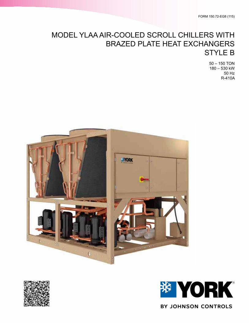
Nomenclature
Products are produced at af ac i l i t y whose qua l i t y -management systems areISO9001 certified.
Y L A A 0320 S E 50 X A B
Y = YORK CHILLER
A = AIR COOLED
S = STANDARD EFFICIENCYH = HIGH EFFICIENCY
REFRIGERANT = R-134a
DESIGN SERIES A (MCHX)
A = AMERICAS
FOUR DIGIT UNIT NUMBER
VOLTAGE CODE:50 = 380/415-3-50
DEVELOPMENT LEVEL = B (BPHX)
X = ACROSS THE LINE
L = SCROLL COMPRESSOR
FORM 150.72-EG8 (115)
JOHNSON CONTROLS 3
Table Of ContentsNOMENCLATURE ................................................................................................................................................... 2
APPROVALS ........................................................................................................................................................... 2
TABLE OF CONTENTS ........................................................................................................................................... 3
INTRODUCTION ...................................................................................................................................................... 5
EQUIPMENT OVERVIEW ........................................................................................................................................ 8
UNIT COMPONENTS ............................................................................................................................................ 15
ACCESSORIES AND OPTIONS ........................................................................................................................... 16
DESIGN PARAMETERS ........................................................................................................................................ 20
WATER PRESSURE DROP ................................................................................................................................... 21
PHYSICAL DATA AND RATINGS ......................................................................................................................... 22
UNIT DIMENSIONS .............................................................................................................................................. 24
ISOLATOR LOCATIONS ....................................................................................................................................... 30
ELECTRICAL NOTES ........................................................................................................................................... 32
WIRING LUGS ....................................................................................................................................................... 34
ELECTRICAL DATA W/O PUMPS ........................................................................................................................ 36
WIRING DIAGRAM ................................................................................................................................................ 38
USER CONTROL WIRING .................................................................................................................................... 40
NOTES ................................................................................................................................................................... 42
APPLICATION DATA ............................................................................................................................................. 44
GUIDE SPECIFICATIONS ..................................................................................................................................... 46

JOHNSON CONTROLS
FORM 150.72-EG8 (115)
4
THIS PAGE INTENTIONALLY LEFT BLANK.
FORM 150.72-EG8 (115)
JOHNSON CONTROLS 5
Johnson Controls, the building efficiency leader, is proud to present the YORK Model YLAA Air-Cooled Scroll Chiller.
FEATURES AND BENEFITS
Installation
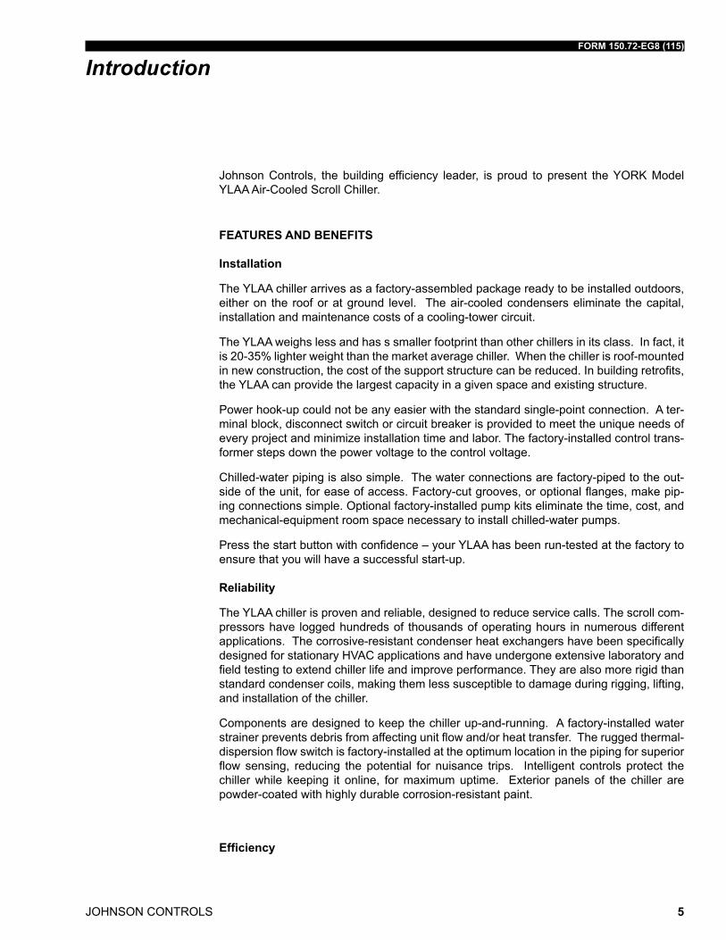
The YLAA chiller arrives as a factory-assembled package ready to be installed outdoors, either on the roof or at ground level. The air-cooled condensers eliminate the capital, installation and maintenance costs of a cooling-tower circuit.
The YLAA weighs less and has s smaller footprint than other chillers in its class. In fact, it is 20-35% lighter weight than the market average chiller. When the chiller is roof-mounted in new construction, the cost of the support structure can be reduced. In building retrofits, the YLAA can provide the largest capacity in a given space and existing structure.
Power hook-up could not be any easier with the standard single-point connection. A ter-minal block, disconnect switch or circuit breaker is provided to meet the unique needs of every project and minimize installation time and labor. The factory-installed control trans-former steps down the power voltage to the control voltage.
Chilled-water piping is also simple. The water connections are factory-piped to the out-side of the unit, for ease of access. Factory-cut grooves, or optional flanges, make pip-ing connections simple. Optional factory-installed pump kits eliminate the time, cost, and mechanical-equipment room space necessary to install chilled-water pumps.
Press the start button with confidence – your YLAA has been run-tested at the factory to ensure that you will have a successful start-up.
Reliability
The YLAA chiller is proven and reliable, designed to reduce service calls. The scroll com-pressors have logged hundreds of thousands of operating hours in numerous different applications. The corrosive-resistant condenser heat exchangers have been specifically designed for stationary HVAC applications and have undergone extensive laboratory and field testing to extend chiller life and improve performance. They are also more rigid than standard condenser coils, making them less susceptible to damage during rigging, lifting, and installation of the chiller.
Components are designed to keep the chiller up-and-running. A factory-installed water strainer prevents debris from affecting unit flow and/or heat transfer. The rugged thermal-dispersion flow switch is factory-installed at the optimum location in the piping for superior flow sensing, reducing the potential for nuisance trips. Intelligent controls protect the chiller while keeping it online, for maximum uptime. Exterior panels of the chiller are powder-coated with highly durable corrosion-resistant paint.
Efficiency
Introduction
JOHNSON CONTROLS
FORM 150.72-EG8 (115)
6
YLAA high-efficiency chillers, with their innovative control algorithms, offer industry-lead-ing energy efficiency. Real-world energy efficiency is measured by IPLV (off-design) per-formance, and YLAA chillers provide some of the best IPLVs in their class.
YLAA also offers an efficiency choice. In addition to the high-efficiency units, YLAA chill-ers are available in standard efficiency models with smaller footprints and lower capital costs.
Only pay for the chiller you need – the multi-efficiency levels of the YLAA allow you to decide the best investment for the job.
Flexibility
The YLAA chiller offers a number of options designed to operate reliably across a wide range of customer needs. It can cool glycol down to 10°F (-12°C). It can provide heat recovery up to 140°F (60°C), with up to 85% of total heat rejection captured.
When factory-mounted pump kits are considered, there are now more pump sizes to choose from. The optional kits come standard with valves, pressure ports, flow switch, and strainer for quick hook-up, and frost protection to prevent freeze-up. There are also more pump options available: variable-speed drives, dual pumps, service shut-off valves, expansion tanks, and additional test ports for temperature and pressure sensing.
Standard low sound and multiple sound attenuation options allow flexibility in locating the chiller, and reduce the cost for field-constructed barriers.
Sustainability
The YLAA makes you a leader in sustainability through innovation, not added cost. With the combination of R-410A refrigerant, which has no ozone-depletion potential, and state-of-the-art heat exchanger technology that allows refrigerant charge to be reduced by as much as 30%, the YLAA chiller provides the most ecologically friendly equipment. Part-nered with its low-sound properties for noise pollution prevention, this chiller is a true earth-friendly offering.
Communications
The YLAA chiller comes standard with native communication capability for BACnet (MS/TP), Modbus, and N2, with optional capabilities available for LON. The standard unit ca-pabilities include built-in-scheduling, remote start-stop, remote water temperature reset and up to two steps of demand (load) limiting depending on model. The standard control panel can be directly connected to a Johnson Controls Building Automated System via the standard factory-installed RS232 communication port.
Introduction (Cont'd)
FORM 150.72-EG8 (115)
JOHNSON CONTROLS 7
Serviceability
Minimal maintenance is required to keep the unit operating at maximum performance. If service should ever be required, the YLAA chiller has been designed to simplify the work, keeping costs down. The layout of the chiller locates all the major components that can be serviced near the outside edge. The condenser heat exchangers are light enough that no crane is required for replacement. And when it’s time to clean them, city tap water, with water pressure typical of a spray from a common garden hose, is all that’s needed.
Introduction (Cont'd)
JOHNSON CONTROLS
FORM 150.72-EG8 (115)
8
Equipment Overview
The 50 - 150 Ton (180 - 530 kW) YLAA models are shipped complete from the factory ready for installa tion and use.The unit is pressure-tested, evacuated, and fully charged with a zero Ozone Depletion Potential Refrigerant R-410A and includes an initial oil charge. After assembly, a complete operational test is performed with water flowing through the evaporator to as sure that the refrigeration circuit operates correctly.
The unit structure is heavy-gauge, galvanized steel. This galvanized steel is coated with baked-on powder paint, which, when subjected to ASTM B117 1000 hour, salt spray test-ing, yields a minimum ASTM 1654 rating of “6”. Units are designed in accordance with NFPA 70 (National Electric Code), ASHRAE/ANSI 15 Safety code for mechanical refrig-eration, ASME and rated in accordance with AHRI Standard 550/590.
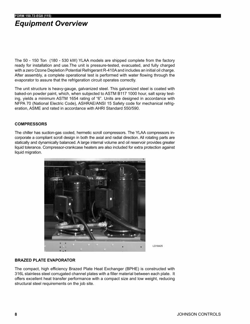
COMPRESSORS
The chiller has suction-gas cooled, hermetic scroll com pressors. The YLAA compressors in-corporate a compli ant scroll design in both the axial and radial direction. All rotating parts are statically and dynamically balanced. A large internal volume and oil reservoir provides greater liquid tolerance. Compressor-crankcase heaters are also included for extra protection against liquid migration.
BRAZED PLATE EVAPORATOR
The compact, high efficiency Brazed Plate Heat Exchanger (BPHE) is constructed with 316L stainless steel corrugated channel plates with a filler material between each plate. It offers excellent heat transfer performance with a compact size and low weight, reducing structural steel requirements on the job site.
LD18425
FORM 150.72-EG8 (115)
JOHNSON CONTROLS 9
Equipment Overview (Cont'd)
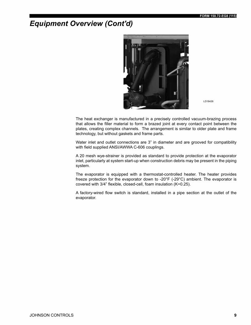
The heat exchanger is manufactured in a precisely controlled vacuum-brazing process that allows the filler material to form a brazed joint at every contact point between the plates, creating complex channels. The arrangement is similar to older plate and frame technology, but without gaskets and frame parts.
Water inlet and outlet connections are 3” in diameter and are grooved for compatibility with field supplied ANSI/AWWA C-606 couplings.
A 20 mesh wye-strainer is provided as standard to provide protection at the evaporator inlet, particularly at system start-up when construction debris may be present in the piping system.
The evaporator is equipped with a thermostat-controlled heater. The heater provides freeze protection for the evaporator down to -20°F (-29°C) ambient. The evaporator is covered with 3/4” flexible, closed-cell, foam insulation (K=0.25).
A factory-wired flow switch is standard, installed in a pipe section at the outlet of the evaporator.
LD18426
JOHNSON CONTROLS
FORM 150.72-EG8 (115)
10
Equipment Overview (Cont'd)CANADIAN REGISTRATION NUMBER (CRN) APPLICATION & PROOF OF CONFORMANCE
Reference Table 1 for YLAA brazed plate evaporator Canadian Registration Numbers (CRN) for all Canadian Provinces. Since all YLAA brazed plate evaporators are catego-rized as pressure “H” fittings per CSA-B51, a CRN label or marking is not provided on the evaporator. According to the Canadian Standards Association’s Boiler, pressure vessel, and pressure piping code B-51 (2009 version), a product registered as a category “H” fit-ting does not require a label or marking displaying the CRN.
TABLE 1 - CANADIAN REGISTRATION NUMBERSCANADIAN PROVINCE CRN#
BC OH13953.51AB OH13953.52ON OH13953.5
PQ/MB/SK OH13953.56NB OH13953.57NS OH13953.58PEI OH13953.59NF OH13953.50NU OH13953.5N
NWT OH13953.5TYU OH13953.5Y
CONDENSER
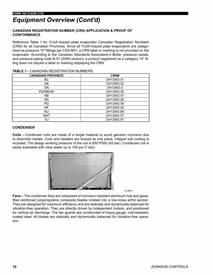
Coils - Condenser coils are made of a single material to avoid galvanic corrosion due to dissimilar metals. Coils and headers are brazed as one piece. Integral sub cooling is included. The design working pressure of the coil is 650 PSIG (45 bar). Condenser coil is easily washable with clear water up to 100 psi (7 bar).
Fans – The condenser fans are composed of corrosion resistant aluminum hub and glass-fiber-reinforced poly propylene composite blades molded into a low-noise airfoil section. They are designed for maximum efficiency and are statically and dynamically balanced for vibration-free operation. They are directly driven by independent motors, and positioned for vertical air discharge. The fan guards are constructed of heavy-gauge, rust-resistant, coated steel. All blades are statically and dynamically balanced for vibration-free opera-tion.
LD18427
FORM 150.72-EG8 (115)
JOHNSON CONTROLS 11
Equipment Overview (Cont'd)
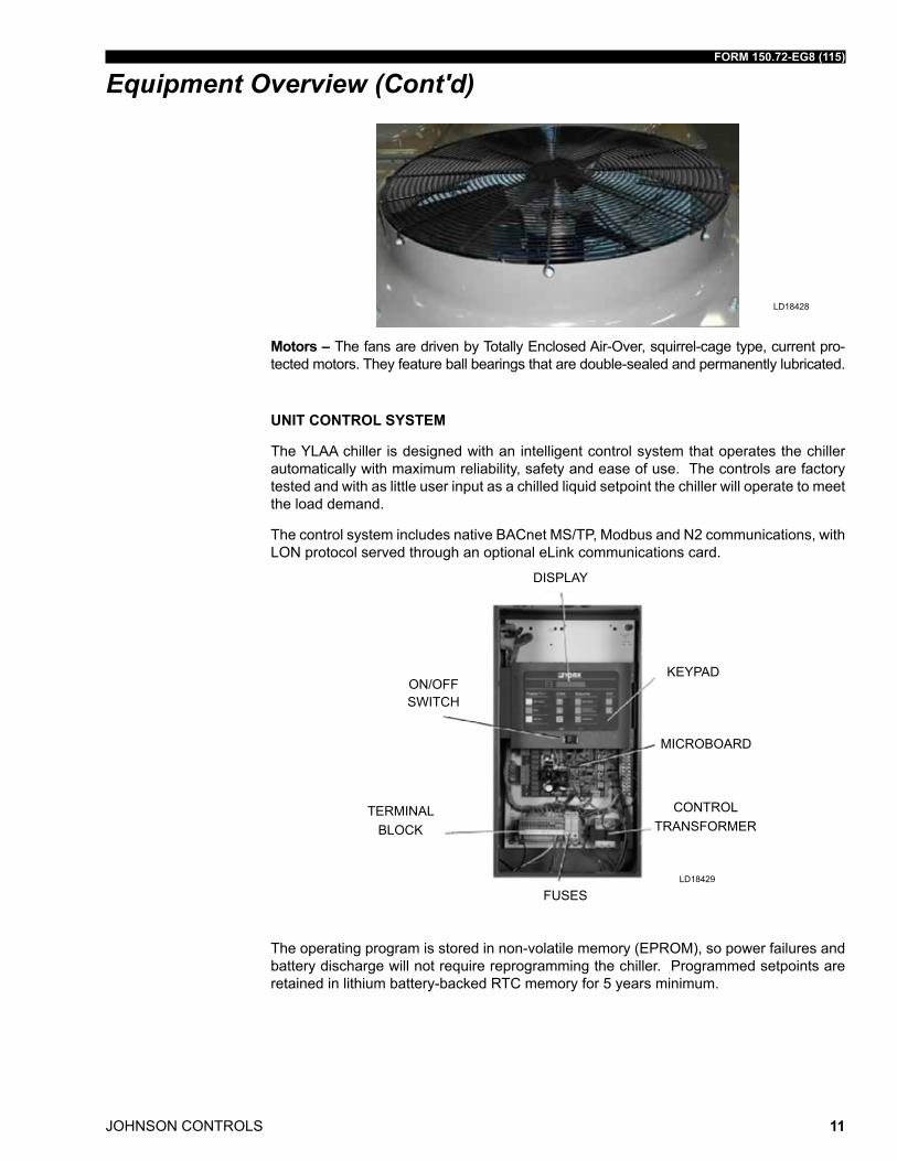
Motors – The fans are driven by Totally Enclosed Air-Over, squirrel-cage type, current pro-tected motors. They feature ball bearings that are double-sealed and permanently lu bricated.
UNIT CONTROL SYSTEM
The YLAA chiller is designed with an intelligent control system that operates the chiller automatically with maximum reliability, safety and ease of use. The controls are factory tested and with as little user input as a chilled liquid setpoint the chiller will operate to meet the load demand.
The control system includes native BACnet MS/TP, Modbus and N2 communications, with LON protocol served through an optional eLink communications card.
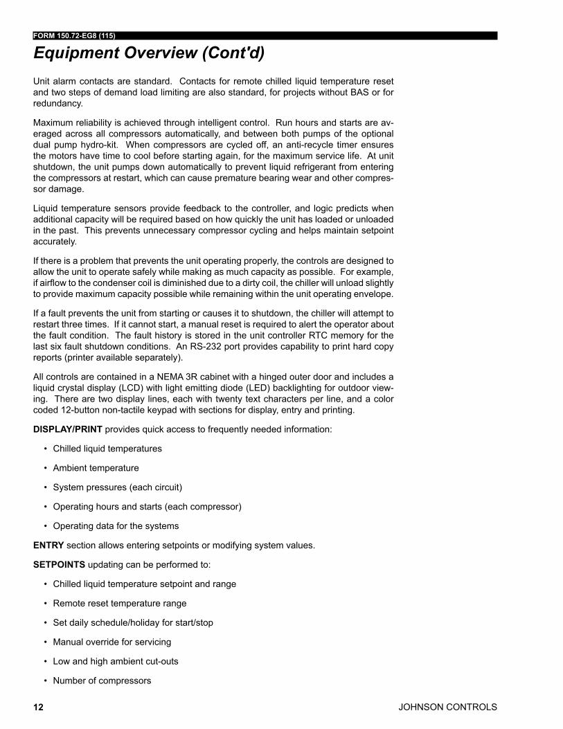
The operating program is stored in non-volatile memory (EPROM), so power failures and battery discharge will not require reprogramming the chiller. Programmed setpoints are retained in lithium battery-backed RTC memory for 5 years minimum.
FUSES
DISPLAY
ON/OFF SWITCH
TERMINALBLOCK
CONTROLTRANSFORMER
MICROBOARD
KEYPAD
LD18428
LD18429
JOHNSON CONTROLS
FORM 150.72-EG8 (115)
12
Unit alarm contacts are standard. Contacts for remote chilled liquid temperature reset and two steps of demand load limiting are also standard, for projects without BAS or for redundancy.
Maximum reliability is achieved through intelligent control. Run hours and starts are av-eraged across all compressors automatically, and between both pumps of the optional dual pump hydro-kit. When compressors are cycled off, an anti-recycle timer ensures the motors have time to cool before starting again, for the maximum service life. At unit shutdown, the unit pumps down automatically to prevent liquid refrigerant from entering the compressors at restart, which can cause premature bearing wear and other compres-sor damage.
Liquid temperature sensors provide feedback to the controller, and logic predicts when additional capacity will be required based on how quickly the unit has loaded or unloaded in the past. This prevents unnecessary compressor cycling and helps maintain setpoint accurately.
If there is a problem that prevents the unit operating properly, the controls are designed to allow the unit to operate safely while making as much capacity as possible. For example, if airflow to the condenser coil is diminished due to a dirty coil, the chiller will unload slightly to provide maximum capacity possible while remaining within the unit operating envelope.
If a fault prevents the unit from starting or causes it to shutdown, the chiller will attempt to restart three times. If it cannot start, a manual reset is required to alert the operator about the fault condition. The fault history is stored in the unit controller RTC memory for the last six fault shutdown conditions. An RS-232 port provides capability to print hard copy reports (printer available separately).
All controls are contained in a NEMA 3R cabinet with a hinged outer door and includes a liquid crystal display (LCD) with light emitting diode (LED) backlighting for outdoor view-ing. There are two display lines, each with twenty text characters per line, and a color coded 12-button non-tactile keypad with sections for display, entry and printing.
DISPLAY/PRINT provides quick access to frequently needed information:
• Chilled liquid temperatures
• Ambient temperature
• System pressures (each circuit)
• Operating hours and starts (each compressor)
• Operating data for the systems
ENTRY section allows entering setpoints or modifying system values.
SETPOINTS updating can be performed to:
• Chilled liquid temperature setpoint and range
• Remote reset temperature range
• Set daily schedule/holiday for start/stop
• Manual override for servicing
• Low and high ambient cut-outs
• Number of compressors
Equipment Overview (Cont'd)
FORM 150.72-EG8 (115)
JOHNSON CONTROLS 13
• Low liquid temperature cut-out
• Low suction pressure cut-out
• High discharge pressure cut-out
• Anti-recycle timer (compressor start cycle time)
• Anti-coincident timer (delay compressor starts)
UNIT section to:
• Set time
• Set unit options
In addition, the microprocessor control center is capable of displaying the following data points:
• Return and leaving liquid temperature
• Low leaving liquid temperature cut-out setting
• Low ambient temperature cut-out setting
• Outdoor air temperature
• English or Metric data
• Suction pressure cut-out setting
• Each system suction pressure
• Discharge pressure (optional)
• Anti-recycle timer status for each system
• Anti-coincident system start timer condition
• Compressor run status
• Day, date and time
• Daily start/stop times
• Holiday status
• Automatic or manual system lead/lag control
• Lead system definition
• Compressor starts & operating hours (each compressor)
• Status of hot gas valves, evaporator heater and fan operation
• Run permissive status
• Number of compressors running
• Liquid solenoid valve status
Equipment Overview (Cont'd)
JOHNSON CONTROLS
FORM 150.72-EG8 (115)
14
• Load & unload timer status
• Water pump status
COMMUNICATIONS
• Native communication capability for BACnet (MS/TP), Modbus and N2
• Optional communciation available for LON via eLink option
BUILDING AUTOMATION SYSTEM INTERFACE
In addition to native BACnet, Modbus and N2, the YLAA chiller accepts a 4-20 milliamp or 0-10VDC input to reset of the leaving chilled liquid temperature. The standard unit ca-pabilities include remote start-stop, remote water temperature reset via up to two steps of demand (load) limiting depending on model. The standard control panel can be directly connected to a Johnson Controls Building Automated System via the standard on-board RS232 communication port. (Factory- installed)
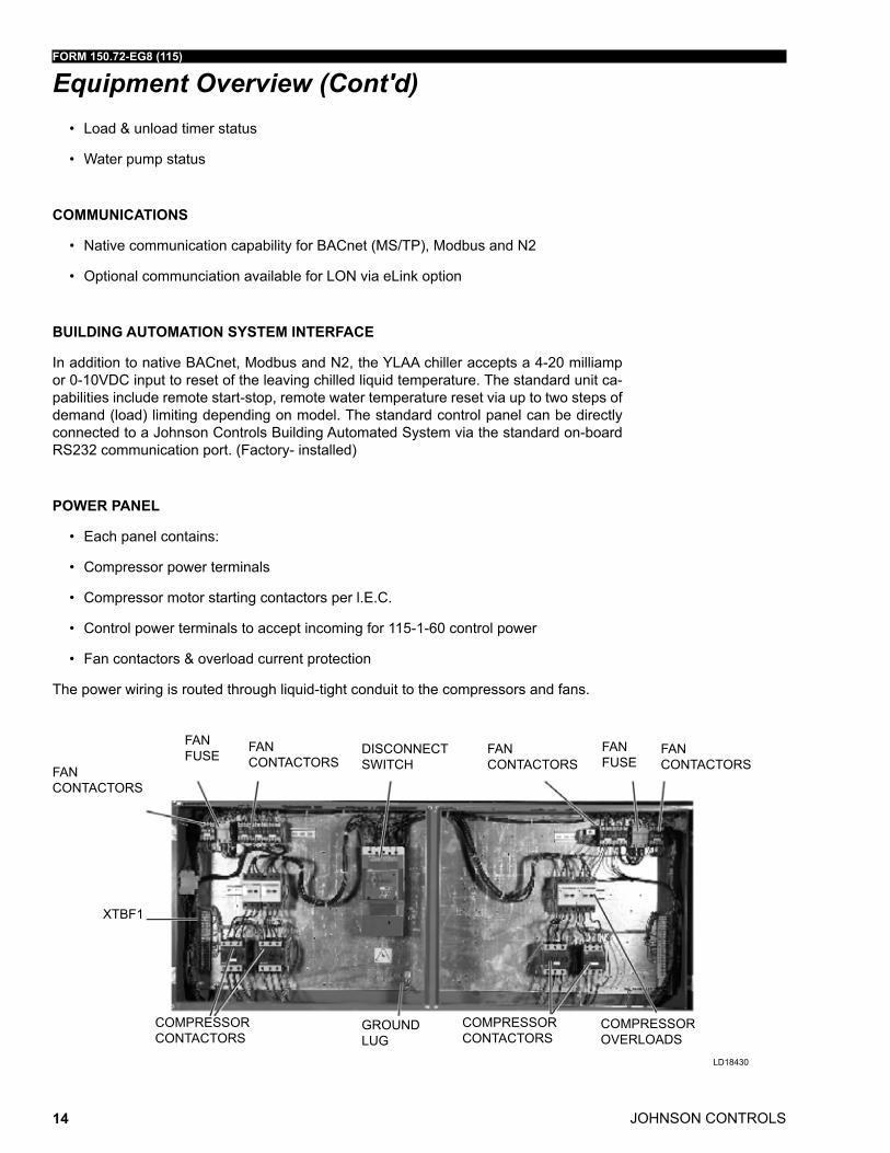
POWER PANEL
• Each panel contains:
• Compressor power terminals
• Compressor motor starting contactors per l.E.C.
• Control power terminals to accept incoming for 115-1-60 control power
• Fan contactors & overload current protection
The power wiring is routed through liquid-tight conduit to the compressors and fans.
FANFUSE
FANCONTACTORS
DISCONNECTSWITCH
FANFUSE
FANCONTACTORS
FANCONTACTORS
XTBF1
COMPRESSORCONTACTORS
GROUND LUG
COMPRESSORCONTACTORS
COMPRESSOROVERLOADS
LD18430
FANCONTACTORS
Equipment Overview (Cont'd)
FORM 150.72-EG8 (115)
JOHNSON CONTROLS 15
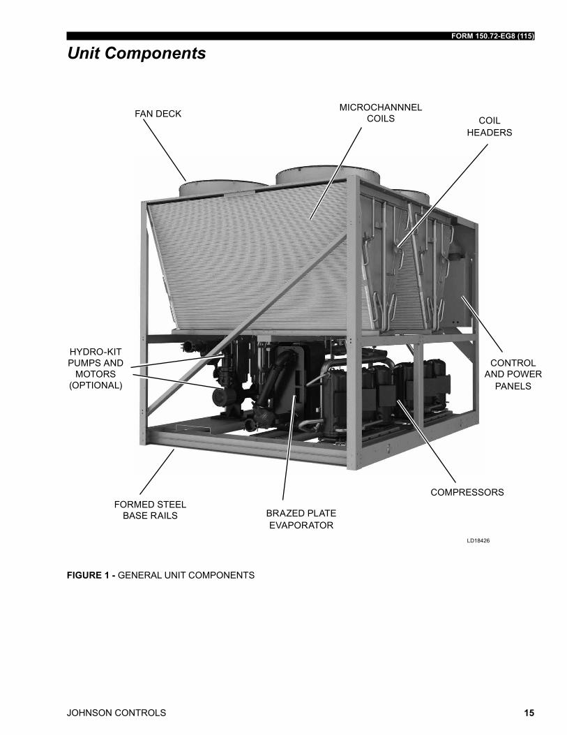
FIGURE 1 - GENERAL UNIT COMPONENTS
Unit Components
FAN DECKMICROCHANNNEL
COILS COIL HEADERS
CONTROL AND POWER
PANELS
COMPRESSORS
BRAZED PLATE EVAPORATOR
FORMED STEEL BASE RAILS
HYDRO-KIT PUMPS AND
MOTORS (OPTIONAL)
LD18426
JOHNSON CONTROLS
FORM 150.72-EG8 (115)
16
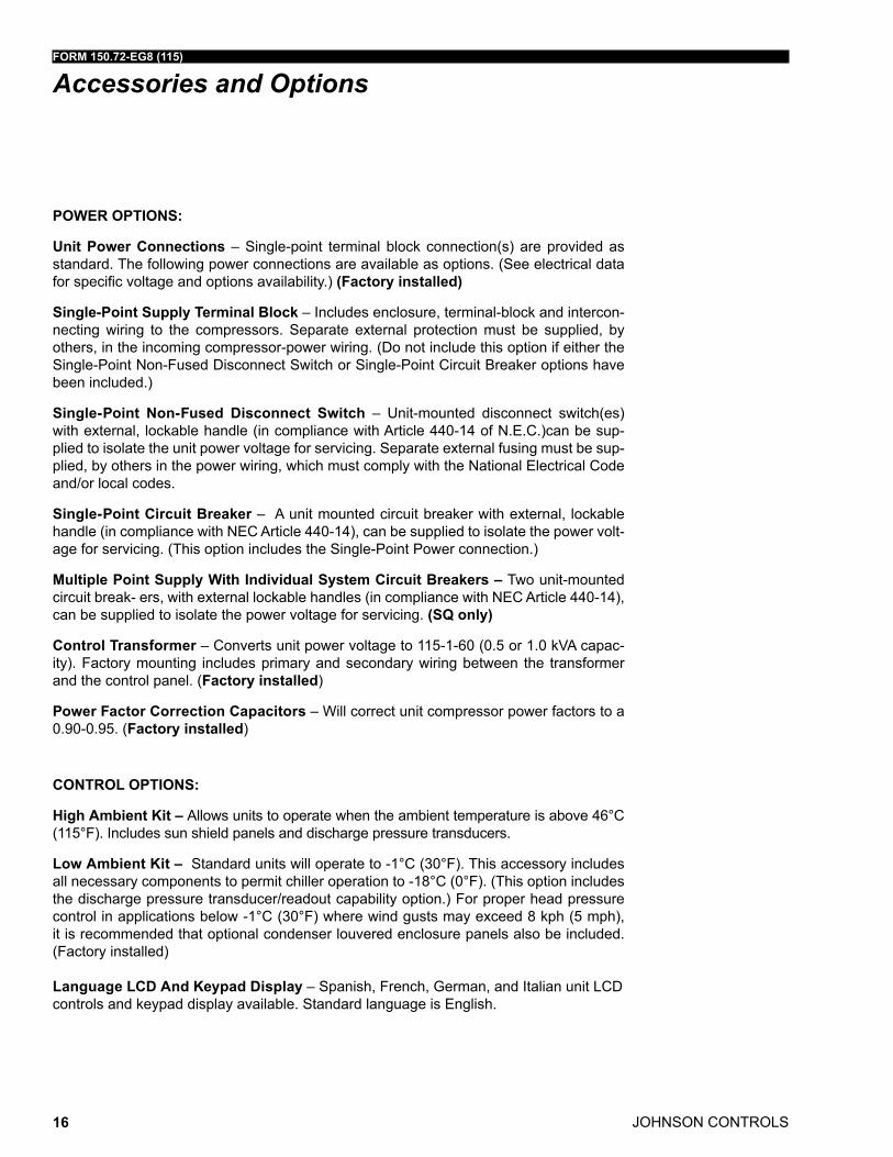
POWER OPTIONS:
Unit Power Connections – Single-point terminal block connection(s) are provided as standard. The following power connections are available as options. (See electrical data for specific voltage and options availability.) (Factory installed)
Single-Point Supply Terminal Block – Includes enclosure, terminal-block and intercon-necting wiring to the compressors. Separate external protection must be supplied, by others, in the incoming compressor-power wiring. (Do not include this option if either the Single-Point Non-Fused Disconnect Switch or Single-Point Circuit Breaker options have been included.)
Single-Point Non-Fused Disconnect Switch – Unit-mounted disconnect switch(es) with external, lockable handle (in compliance with Article 440-14 of N.E.C.)can be sup-plied to isolate the unit power voltage for servicing. Separate external fusing must be sup-plied, by others in the power wiring, which must comply with the National Electrical Code and/or local codes.
Single-Point Circuit Breaker – A unit mounted circuit breaker with external, lockable handle (in compliance with NEC Article 440-14), can be supplied to isolate the power volt-age for servicing. (This option includes the Single-Point Power connection.)
Multiple Point Supply With Individual System Circuit Breakers – Two unit-mounted circuit break- ers, with external lockable handles (in compliance with NEC Article 440-14), can be supplied to isolate the power voltage for servicing. (SQ only)
Control Transformer – Converts unit power voltage to 115-1-60 (0.5 or 1.0 kVA capac-ity). Factory mounting includes primary and secondary wiring between the transformer and the control panel. (Factory installed)
Power Factor Correction Capacitors – Will correct unit compressor power factors to a 0.90-0.95. (Factory installed)
CONTROL OPTIONS:
High Ambient Kit – Allows units to operate when the ambient temperature is above 46°C (115°F). Includes sun shield panels and discharge pressure transducers.
Low Ambient Kit – Standard units will operate to -1°C (30°F). This accessory includes all necessary components to permit chiller operation to -18°C (0°F). (This option includes the discharge pressure transducer/readout capability option.) For proper head pressure control in applications below -1°C (30°F) where wind gusts may exceed 8 kph (5 mph), it is recommended that optional condenser louvered enclosure panels also be included. (Factory installed)
Language LCD And Keypad Display – Spanish, French, German, and Italian unit LCD controls and keypad display available. Standard language is English.
Accessories and Options
FORM 150.72-EG8 (115)
JOHNSON CONTROLS 17
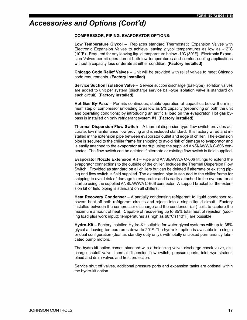
COMPRESSOR, PIPING, EVAPORATOR OPTIONS:
Low Temperature Glycol – Replaces standard Thermostatic Expansion Valves with Electronic Expansion Valves to achieve leaving glycol temperatures as low as -12°C (10°F). Required for any leaving liquid temperature below -1°C (30°F). Electronic Expan-sion Valves permit operation at both low temperatures and comfort cooling applications without a capacity loss or derate at either condition. (Factory installed)
Chicago Code Relief Valves – Unit will be provided with relief valves to meet Chicago code requirements. (Factory installed)
Service Suction Isolation Valve – Service suction discharge (ball-type) isolation valves are added to unit per system (discharge service ball-type isolation valve is standard on each circuit). (Factory installed)
Hot Gas By-Pass – Permits continuous, stable operation at capacities below the mini-mum step of compressor unloading to as low as 5% capacity (depending on both the unit and operating conditions) by introducing an artificial load on the evaporator. Hot gas by-pass is installed on only refrigerant system #1. (Factory installed)
Thermal Dispersion Flow Switch – A thermal dispersion type flow switch provides ac-curate, low maintenance flow proving and is included standard. It is factory wired and in-stalled in the extension pipe between evaporator outlet and edge of chiller. The extension pipe is secured to the chiller frame for shipping to avoid risk of damage to evaporator and is easily attached to the evaporator at startup using the supplied ANSI/AWWA C-606 con-nector. The flow switch can be deleted if alternate or existing flow switch is field supplied.
Evaporator Nozzle Extension Kit – Pipe and ANSI/AWWA C-606 fittings to extend the evaporator connections to the outside of the chiller. Includes the Thermal Dispersion Flow Switch. Provided as standard on all chillers but can be deleted if alternate or existing pip-ing and flow switch is field supplied. The extension pipe is secured to the chiller frame for shipping to avoid risk of damage to evaporator and is easily attached to the evaporator at startup using the supplied ANSI/AWWA C-606 connector. A support bracket for the exten-sion kit or field piping is standard on all chillers.
Heat Recovery Condenser – A partially condensing refrigerant to liquid condenser re-covers heat off both refrigerant circuits and rejects into a single liquid circuit. Factory installed between the compressor discharge and the condenser (air) coils to capture the maximum amount of heat. Capable of recovering up to 85% total heat of rejection (cool-ing load plus work input); temperatures as high as 60°C (140°F) are possible.
Hydro-Kit – Factory installed Hydro-Kit suitable for water glycol systems with up to 35% glycol at leaving temperatures down to 20°F. The hydro-kit option is available in a single or dual configuration (dual as standby duty only), with totally enclosed permanently lubri-cated pump motors.
The hydro-kit option comes standard with a balancing valve, discharge check valve, dis-charge shutoff valve, thermal dispersion flow switch, pressure ports, inlet wye-strainer, bleed and drain valves and frost protection.
Service shut off valves, additional pressure ports and expansion tanks are optional within the hydro-kit option.
Accessories and Options (Cont'd)
JOHNSON CONTROLS
FORM 150.72-EG8 (115)
18
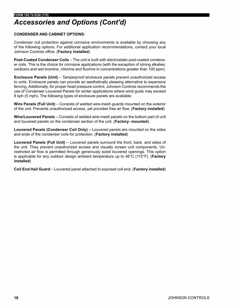
CONDENSER AND CABINET OPTIONS:
Condenser coil protection against corrosive environments is available by choosing any of the following options. For additional application recommendations, contact your local Johnson Controls office. (Factory installed)
Post-Coated Condenser Coils – The unit is built with electrostatic post-coated condens-er coils. This is the choice for corrosive applications (with the exception of strong alkalies, oxidizers and wet bromine, chlorine and fluorine in concentrations greater than 100 ppm).
Enclosure Panels (Unit) – Tamperproof enclosure panels prevent unauthorized access to units. Enclosure panels can provide an aesthetically pleasing alternative to expensive fencing. Additionally, for proper head pressure control, Johnson Controls recommends the use of Condenser Louvered Panels for winter applications where wind gusts may exceed 8 kph (5 mph). The following types of enclosure panels are available:
Wire Panels (Full Unit) – Consists of welded wire-mesh guards mounted on the exterior of the unit. Prevents unauthorized access, yet provides free air flow. (Factory installed)
Wire/Louvered Panels – Consists of welded wire-mesh panels on the bottom part of unit and louvered panels on the condenser section of the unit. (Factory- mounted).
Louvered Panels (Condenser Coil Only) – Louvered panels are mounted on the sides and ends of the condenser coils for protection. (Factory installed)
Louvered Panels (Full Unit) – Louvered panels surround the front, back, and sides of the unit. They prevent unauthorized access and visually screen unit components. Un-restricted air flow is permitted through generously sized louvered openings. This option is applicable for any outdoor design ambient temperature up to 46°C (115°F). (Factory installed)
Coil End Hail Guard – Louvered panel attached to exposed coil end. (Factory installed)
Accessories and Options (Cont'd)
FORM 150.72-EG8 (115)
JOHNSON CONTROLS 19
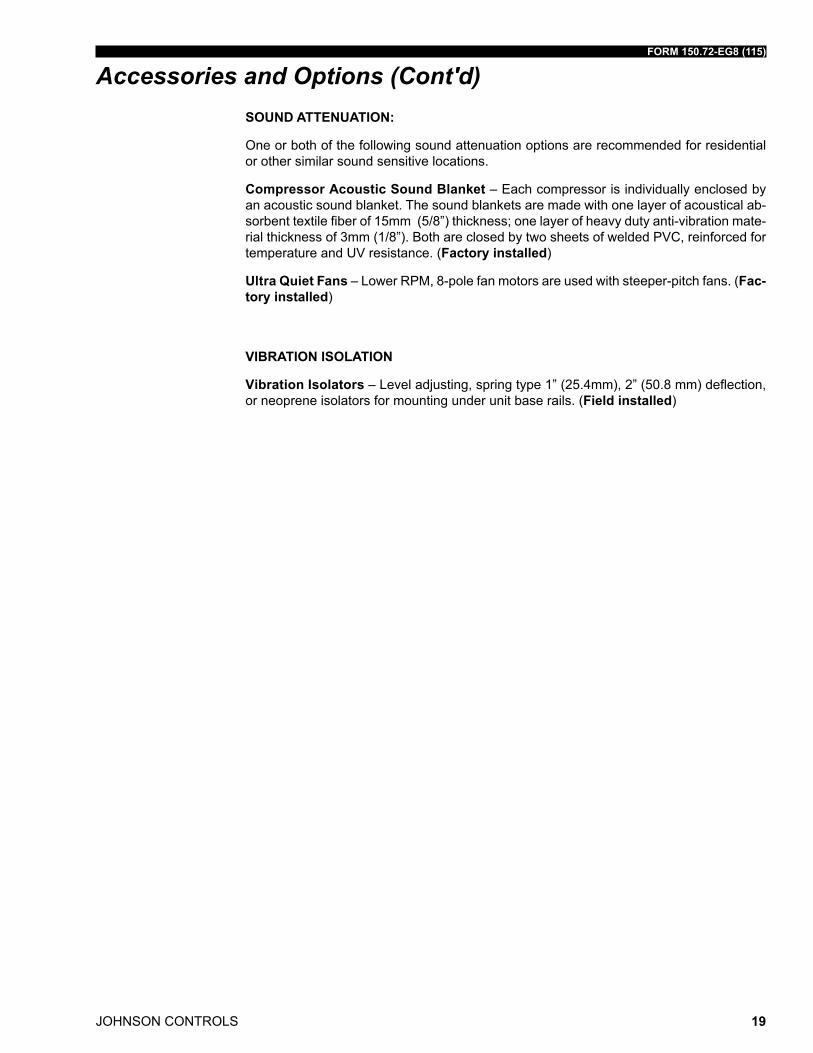
SOUND ATTENUATION:
One or both of the following sound attenuation options are recommended for residential or other similar sound sensitive locations.
Compressor Acoustic Sound Blanket – Each compressor is individually enclosed by an acoustic sound blanket. The sound blankets are made with one layer of acoustical ab-sorbent textile fiber of 15mm (5/8”) thickness; one layer of heavy duty anti-vibration mate-rial thickness of 3mm (1/8”). Both are closed by two sheets of welded PVC, reinforced for temperature and UV resistance. (Factory installed)
Ultra Quiet Fans – Lower RPM, 8-pole fan motors are used with steeper-pitch fans. (Fac-tory installed)
VIBRATION ISOLATION
Vibration Isolators – Level adjusting, spring type 1” (25.4mm), 2” (50.8 mm) deflection, or neoprene isolators for mounting under unit base rails. (Field installed)
Accessories and Options (Cont'd)
JOHNSON CONTROLS
FORM 150.72-EG8 (115)
20
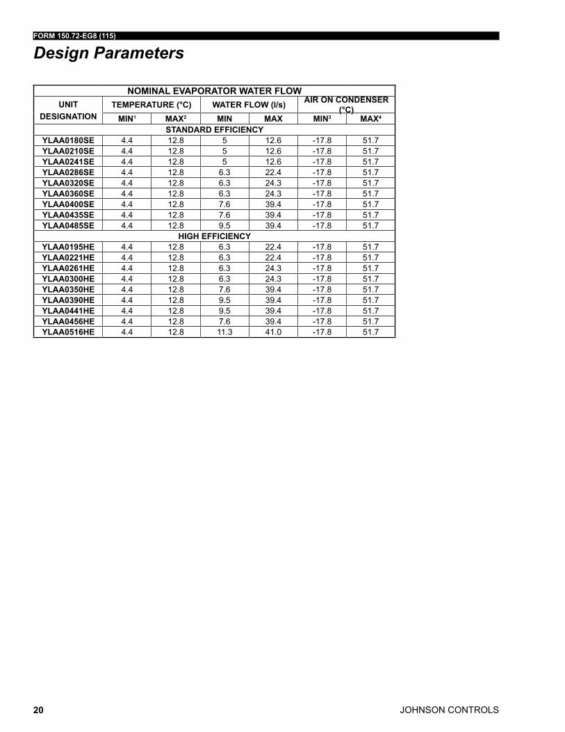
NOMINAL EVAPORATOR WATER FLOWUNIT
DESIGNATIONTEMPERATURE (°C) WATER FLOW (l/s) AIR ON CONDENSER
(°C)MIN1 MAX2 MIN MAX MIN3 MAX4
STANDARD EFFICIENCYYLAA0180SE 4.4 12.8 5 12.6 -17.8 51.7YLAA0210SE 4.4 12.8 5 12.6 -17.8 51.7YLAA0241SE 4.4 12.8 5 12.6 -17.8 51.7YLAA0286SE 4.4 12.8 6.3 22.4 -17.8 51.7YLAA0320SE 4.4 12.8 6.3 24.3 -17.8 51.7YLAA0360SE 4.4 12.8 6.3 24.3 -17.8 51.7YLAA0400SE 4.4 12.8 7.6 39.4 -17.8 51.7YLAA0435SE 4.4 12.8 7.6 39.4 -17.8 51.7YLAA0485SE 4.4 12.8 9.5 39.4 -17.8 51.7
HIGH EFFICIENCYYLAA0195HE 4.4 12.8 6.3 22.4 -17.8 51.7YLAA0221HE 4.4 12.8 6.3 22.4 -17.8 51.7YLAA0261HE 4.4 12.8 6.3 24.3 -17.8 51.7YLAA0300HE 4.4 12.8 6.3 24.3 -17.8 51.7YLAA0350HE 4.4 12.8 7.6 39.4 -17.8 51.7YLAA0390HE 4.4 12.8 9.5 39.4 -17.8 51.7YLAA0441HE 4.4 12.8 9.5 39.4 -17.8 51.7YLAA0456HE 4.4 12.8 7.6 39.4 -17.8 51.7YLAA0516HE 4.4 12.8 11.3 41.0 -17.8 51.7
Design Parameters
FORM 150.72-EG8 (115)
JOHNSON CONTROLS 21
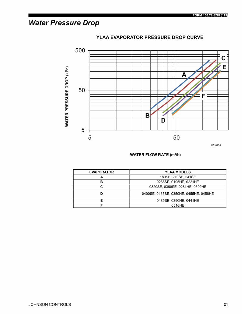
Water Pressure Drop
EVAPORATOR YLAA MODELSA 180SE, 210SE, 241SEB 0286SE, 0195HE, 0221HEC 0320SE, 0360SE, 0261HE, 0300HE
D 0400SE, 0435SE, 0350HE, 0455HE, 0456HE
E 0485SE, 0390HE, 0441HEF 0516HE
5
50
500
5 50
A
B
C
D
E
F
YLAA EVAPORATOR PRESSURE DROP CURVE
WATER FLOW RATE (m3/h)
WAT
ER P
RES
SUR
E D
RO
P (k
Pa)
LD18455
JOHNSON CONTROLS
FORM 150.72-EG8 (115)
22
Physical Data and Ratings
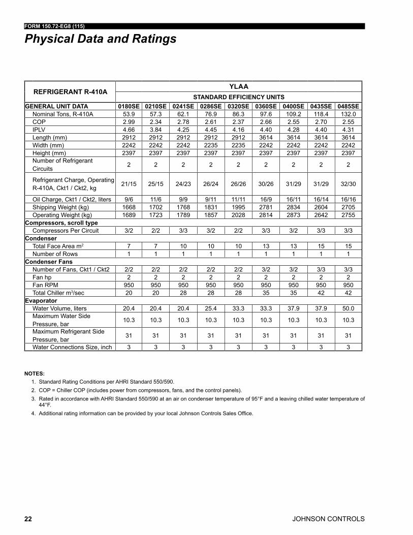
NOTES:1. Standard Rating Conditions per AHRI Standard 550/590. 2. COP = Chiller COP (includes power from compressors, fans, and the control panels). 3. Rated in accordance with AHRI Standard 550/590 at an air on condenser temperature of 95°F and a leaving chilled water temperature of
44°F.4. Additional rating information can be provided by your local Johnson Controls Sales Office.
REFRIGERANT R-410AYLAA
STANDARD EFFICIENCY UNITSGENERAL UNIT DATA 0180SE 0210SE 0241SE 0286SE 0320SE 0360SE 0400SE 0435SE 0485SE
Nominal Tons, R-410A 53.9 57.3 62.1 76.9 86.3 97.6 109.2 118.4 132.0COP 2.99 2.34 2.78 2.61 2.37 2.66 2.55 2.70 2.55IPLV 4.66 3.84 4.25 4.45 4.16 4.40 4.28 4.40 4.31Length (mm) 2912 2912 2912 2912 2912 3614 3614 3614 3614Width (mm) 2242 2242 2242 2235 2235 2242 2242 2242 2242Height (mm) 2397 2397 2397 2397 2397 2397 2397 2397 2397Number of Refrigerant Circuits
2 2 2 2 2 2 2 2 2
Refrigerant Charge, Operating R-410A, Ckt1 / Ckt2, kg
21/15 25/15 24/23 26/24 26/26 30/26 31/29 31/29 32/30
Oil Charge, Ckt1 / Ckt2, liters 9/6 11/6 9/9 9/11 11/11 16/9 16/11 16/14 16/16 Shipping Weight (kg) 1668 1702 1768 1831 1995 2781 2834 2604 2705Operating Weight (kg) 1689 1723 1789 1857 2028 2814 2873 2642 2755
Compressors, scroll typeCompressors Per Circuit 3/2 2/2 3/3 3/2 2/2 3/3 3/2 3/3 3/3
CondenserTotal Face Area m2 7 7 10 10 10 13 13 15 15Number of Rows 1 1 1 1 1 1 1 1 1
Condenser FansNumber of Fans, Ckt1 / Ckt2 2/2 2/2 2/2 2/2 2/2 3/2 3/2 3/3 3/3Fan hp 2 2 2 2 2 2 2 2 2Fan RPM 950 950 950 950 950 950 950 950 950Total Chiller m3/sec 20 20 28 28 28 35 35 42 42
EvaporatorWater Volume, liters 20.4 20.4 20.4 25.4 33.3 33.3 37.9 37.9 50.0Maximum Water Side Pressure, bar
10.3 10.3 10.3 10.3 10.3 10.3 10.3 10.3 10.3
Maximum Refrigerant Side Pressure, bar
31 31 31 31 31 31 31 31 31
Water Connections Size, inch 3 3 3 3 3 3 3 3 3
FORM 150.72-EG8 (115)
JOHNSON CONTROLS 23
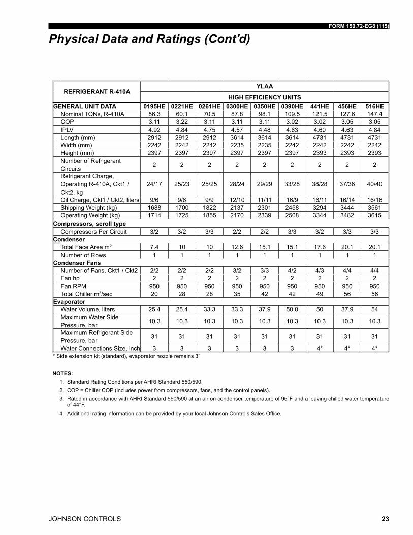
REFRIGERANT R-410AYLAA
HIGH EFFICIENCY UNITSGENERAL UNIT DATA 0195HE 0221HE 0261HE 0300HE 0350HE 0390HE 441HE 456HE 516HE
Nominal TONs, R-410A 56.3 60.1 70.5 87.8 98.1 109.5 121.5 127.6 147.4COP 3.11 3.22 3.11 3.11 3.11 3.02 3.02 3.05 3.05IPLV 4.92 4.84 4.75 4.57 4.48 4.63 4.60 4.63 4.84Length (mm) 2912 2912 2912 3614 3614 3614 4731 4731 4731Width (mm) 2242 2242 2242 2235 2235 2242 2242 2242 2242Height (mm) 2397 2397 2397 2397 2397 2397 2393 2393 2393Number of Refrigerant Circuits
2 2 2 2 2 2 2 2 2
Refrigerant Charge, Operating R-410A, Ckt1 / Ckt2, kg
24/17 25/23 25/25 28/24 29/29 33/28 38/28 37/36 40/40
Oil Charge, Ckt1 / Ckt2, liters 9/6 9/6 9/9 12/10 11/11 16/9 16/11 16/14 16/16 Shipping Weight (kg) 1688 1700 1822 2137 2301 2458 3294 3444 3561Operating Weight (kg) 1714 1725 1855 2170 2339 2508 3344 3482 3615
Compressors, scroll typeCompressors Per Circuit 3/2 3/2 3/3 2/2 2/2 3/3 3/2 3/3 3/3
CondenserTotal Face Area m2 7.4 10 10 12.6 15.1 15.1 17.6 20.1 20.1Number of Rows 1 1 1 1 1 1 1 1 1
Condenser FansNumber of Fans, Ckt1 / Ckt2 2/2 2/2 2/2 3/2 3/3 4/2 4/3 4/4 4/4Fan hp 2 2 2 2 2 2 2 2 2Fan RPM 950 950 950 950 950 950 950 950 950Total Chiller m3/sec 20 28 28 35 42 42 49 56 56
EvaporatorWater Volume, liters 25.4 25.4 33.3 33.3 37.9 50.0 50 37.9 54Maximum Water Side Pressure, bar
10.3 10.3 10.3 10.3 10.3 10.3 10.3 10.3 10.3
Maximum Refrigerant Side Pressure, bar
31 31 31 31 31 31 31 31 31
Water Connections Size, inch 3 3 3 3 3 3 4* 4* 4** Side extension kit (standard), evaporator nozzle remains 3”
Physical Data and Ratings (Cont'd)
NOTES:1. Standard Rating Conditions per AHRI Standard 550/590. 2. COP = Chiller COP (includes power from compressors, fans, and the control panels). 3. Rated in accordance with AHRI Standard 550/590 at an air on condenser temperature of 95°F and a leaving chilled water temperature
of 44°F.4. Additional rating information can be provided by your local Johnson Controls Sales Office.
JOHNSON CONTROLS
FORM 150.72-EG8 (115)
24
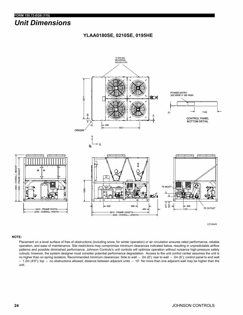
Unit Dimensions
NOTE: Placement on a level surface of free of obstructions (including snow, for winter operation) or air circulation ensures rated performance, reliable
operation, and ease of maintenance. Site restrictions may compromise minimum clearances indicated below, resulting in unpredictable airflow patterns and possible diminished performance. Johnson Controls’s unit controls will optimize operation without nuisance high-pressure safety cutouts; however, the system designer must consider potential performance degradation. Access to the unit control center assumes the unit is no higher than on spring isolators. Recommended minimum clearances: Side to wall – 2m (6'); rear to wall – 2m (6’); control panel to end wall – 1.2m (4'0''); top – no obstructions allowed; distance between adjacent units – 10'. No more than one adjacent wall may be higher than the unit.
YLAA0180SE, 0210SE, 0195HE
LD18445
FORM 150.72-EG8 (115)
JOHNSON CONTROLS 25
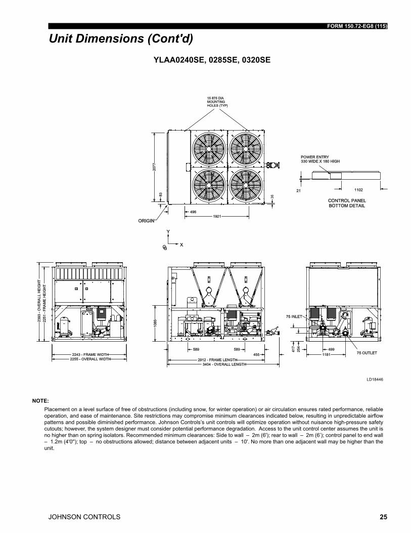
Unit Dimensions (Cont'd)YLAA0240SE, 0285SE, 0320SE
NOTE: Placement on a level surface of free of obstructions (including snow, for winter operation) or air circulation ensures rated performance, reliable
operation, and ease of maintenance. Site restrictions may compromise minimum clearances indicated below, resulting in unpredictable airflow patterns and possible diminished performance. Johnson Controls’s unit controls will optimize operation without nuisance high-pressure safety cutouts; however, the system designer must consider potential performance degradation. Access to the unit control center assumes the unit is no higher than on spring isolators. Recommended minimum clearances: Side to wall – 2m (6'); rear to wall – 2m (6’); control panel to end wall – 1.2m (4'0''); top – no obstructions allowed; distance between adjacent units – 10'. No more than one adjacent wall may be higher than the unit.
LD18446
JOHNSON CONTROLS
FORM 150.72-EG8 (115)
26
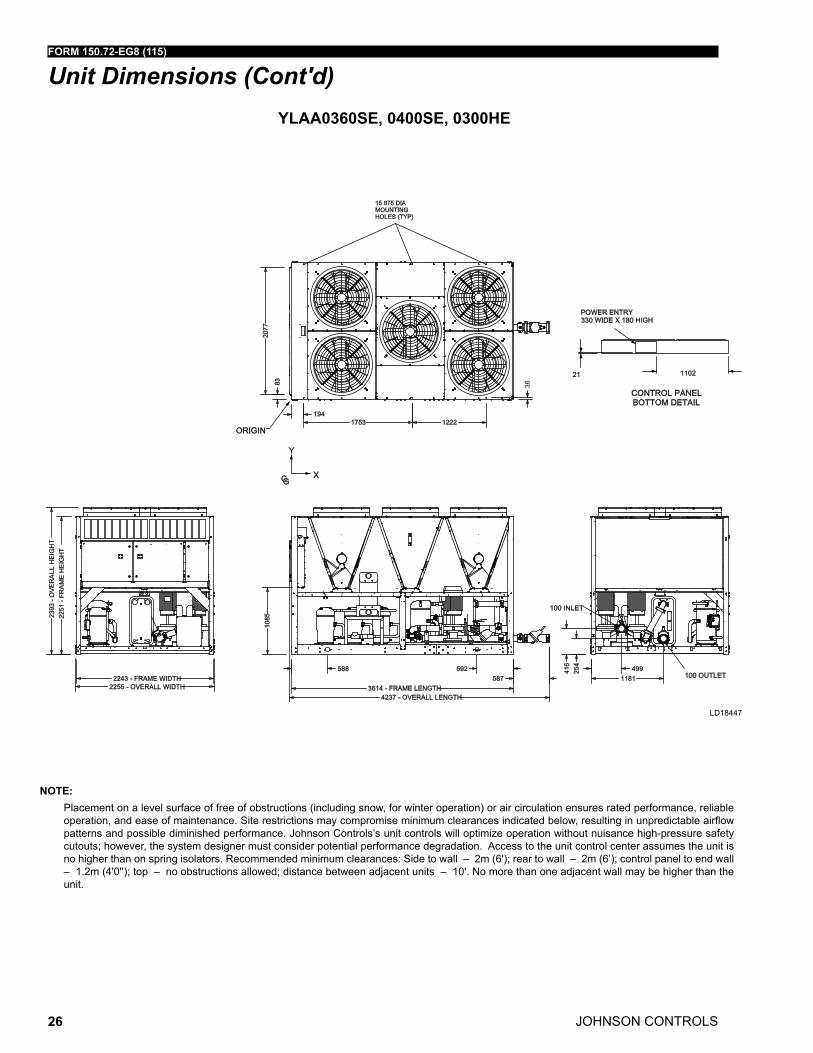
YLAA0360SE, 0400SE, 0300HE
Unit Dimensions (Cont'd)
LD18447
NOTE: Placement on a level surface of free of obstructions (including snow, for winter operation) or air circulation ensures rated performance, reliable
operation, and ease of maintenance. Site restrictions may compromise minimum clearances indicated below, resulting in unpredictable airflow patterns and possible diminished performance. Johnson Controls’s unit controls will optimize operation without nuisance high-pressure safety cutouts; however, the system designer must consider potential performance degradation. Access to the unit control center assumes the unit is no higher than on spring isolators. Recommended minimum clearances: Side to wall – 2m (6'); rear to wall – 2m (6’); control panel to end wall – 1.2m (4'0''); top – no obstructions allowed; distance between adjacent units – 10'. No more than one adjacent wall may be higher than the unit.
FORM 150.72-EG8 (115)
JOHNSON CONTROLS 27
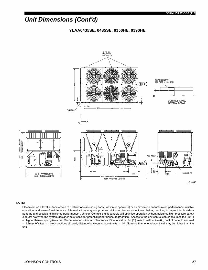
YLAA0435SE, 0485SE, 0350HE, 0390HE
Unit Dimensions (Cont'd)
LD18448
NOTE: Placement on a level surface of free of obstructions (including snow, for winter operation) or air circulation ensures rated performance, reliable
operation, and ease of maintenance. Site restrictions may compromise minimum clearances indicated below, resulting in unpredictable airflow patterns and possible diminished performance. Johnson Controls’s unit controls will optimize operation without nuisance high-pressure safety cutouts; however, the system designer must consider potential performance degradation. Access to the unit control center assumes the unit is no higher than on spring isolators. Recommended minimum clearances: Side to wall – 2m (6'); rear to wall – 2m (6’); control panel to end wall – 1.2m (4'0''); top – no obstructions allowed; distance between adjacent units – 10'. No more than one adjacent wall may be higher than the unit.
JOHNSON CONTROLS
FORM 150.72-EG8 (115)
28
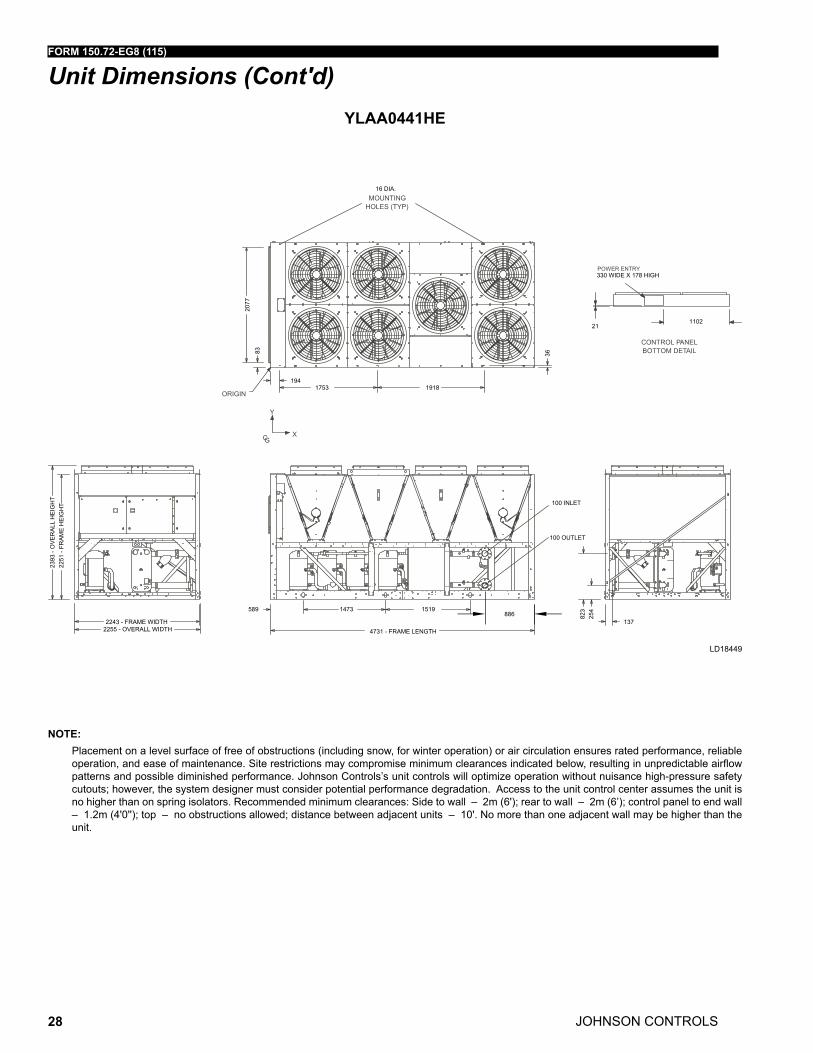
YLAA0441HE
Unit Dimensions (Cont'd)
LD18449
NOTE: Placement on a level surface of free of obstructions (including snow, for winter operation) or air circulation ensures rated performance, reliable
operation, and ease of maintenance. Site restrictions may compromise minimum clearances indicated below, resulting in unpredictable airflow patterns and possible diminished performance. Johnson Controls’s unit controls will optimize operation without nuisance high-pressure safety cutouts; however, the system designer must consider potential performance degradation. Access to the unit control center assumes the unit is no higher than on spring isolators. Recommended minimum clearances: Side to wall – 2m (6'); rear to wall – 2m (6’); control panel to end wall – 1.2m (4'0''); top – no obstructions allowed; distance between adjacent units – 10'. No more than one adjacent wall may be higher than the unit.
FORM 150.72-EG8 (115)
JOHNSON CONTROLS 29
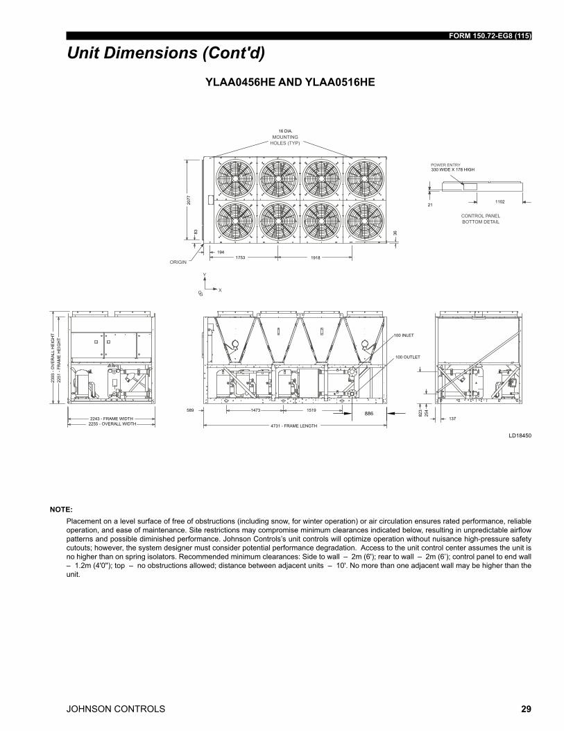
YLAA0456HE AND YLAA0516HE
Unit Dimensions (Cont'd)
LD18450
NOTE: Placement on a level surface of free of obstructions (including snow, for winter operation) or air circulation ensures rated performance, reliable
operation, and ease of maintenance. Site restrictions may compromise minimum clearances indicated below, resulting in unpredictable airflow patterns and possible diminished performance. Johnson Controls’s unit controls will optimize operation without nuisance high-pressure safety cutouts; however, the system designer must consider potential performance degradation. Access to the unit control center assumes the unit is no higher than on spring isolators. Recommended minimum clearances: Side to wall – 2m (6'); rear to wall – 2m (6’); control panel to end wall – 1.2m (4'0''); top – no obstructions allowed; distance between adjacent units – 10'. No more than one adjacent wall may be higher than the unit.
JOHNSON CONTROLS
FORM 150.72-EG8 (115)
30
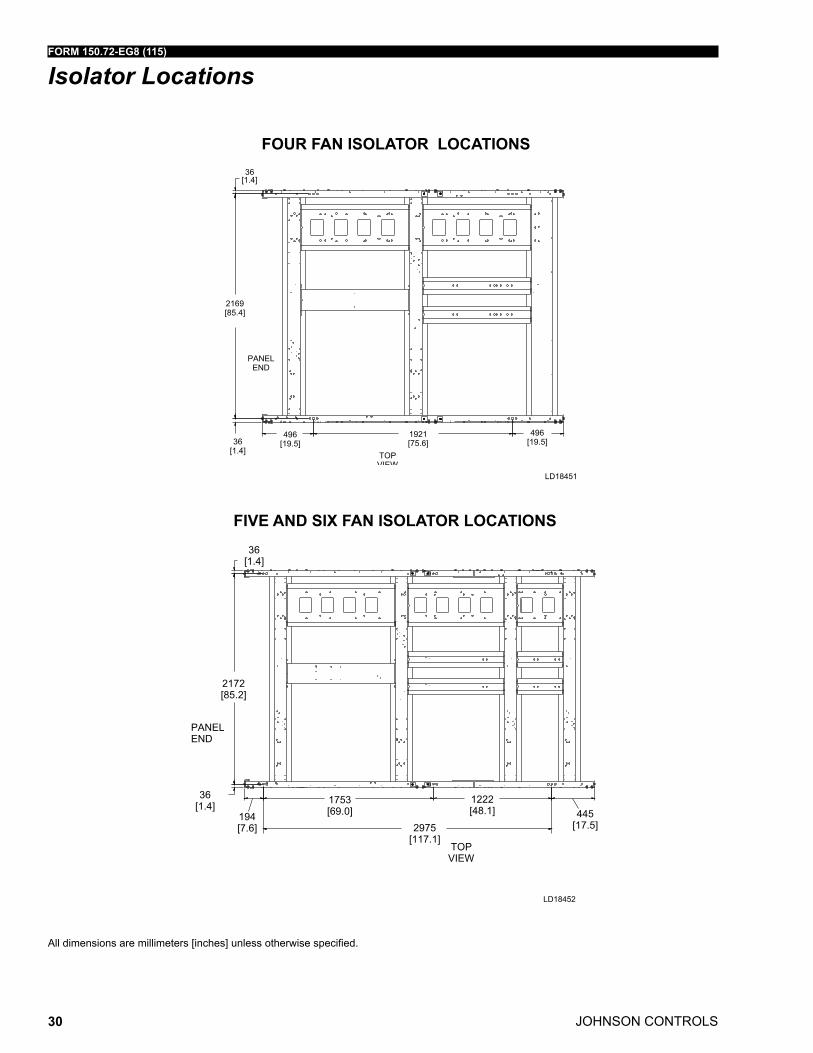
Isolator Locations
FOUR FAN ISOLATOR LOCATIONS
FIVE AND SIX FAN ISOLATOR LOCATIONS
All dimensions are millimeters [inches] unless otherwise specified.
LD18451
LD18452
FORM 150.72-EG8 (115)
JOHNSON CONTROLS 31
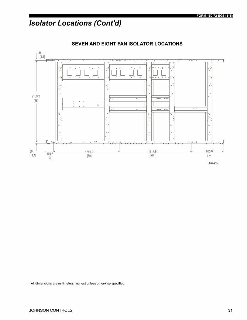
SEVEN AND EIGHT FAN ISOLATOR LOCATIONS
All dimensions are millimeters [inches] unless otherwise specified.
Isolator Locations (Cont'd)
LD18453
JOHNSON CONTROLS
FORM 150.72-EG8 (115)
32
1. Minimum Circuit Ampacity (MCA) is based on 125% of the rated load amps for the largest motor plus 100% of the rated load amps for all other loads included in the cir-cuit, per N.E.C. Article 430-24. If the optional Factory Mounted Control Transformer is provided, add the following MCA values to the electrical tables for the system providing power to the transformer: -50 = 380/415-3-50, add 1 amps.
2. The minimum recommended disconnect switch is based on 115% of the rated load amps for all loads included in the circuit, per N.E.C. Article 440.
3. Minimum fuse size is based upon 150% of the rated load amps for the largest motor plus 100% of the rated load amps for all other loads included in the circuit to avoid nuisance trips at start-up due to lock rotor amps. It is not recommended in applica-tions where brown outs, frequent starting and stopping of the unit, and/or operation at ambient temperatures in excess of 35ºC (95ºF) is anticipated.
4. Maximum fuse size is based upon 225% of the rated load amps for the largest mo-tor plus 100% of the rated load amps for all other loads included in the circuit, per N.E.C. Article 440-22.
5. Circuit breakers must be UL listed and CSA certified and maximum size is based on 225% of the rated load amps for the largest motor plus 100% of the rated load amps for all other loads included in the circuit. Otherwise, HACR-type circuit break-ers must be used. Maximum HACR circuit breaker rating is based on 225% of the rated load amps for the largest motor plus 100% of the rated load amps for all other loads included in the circuit.
6. The “INCOMING WIRE RANGE” is the minimum and maximum wire size that can be accommodated by the unit wiring lugs. The (2) preceding the wire range indi-cates the number of termination points available per phase of the wire range speci-fied. Actual wire size and number of wires per phase must be determined based on the National Electrical Code, using copper connectors only. Field wiring must also comply with local codes.
7. A ground lug is provided for each compressor system to accommodate a field grounding conductor per N.E.C. Table 250-95. A control circuit grounding lug is also supplied.
8. The supplied disconnect is a “Disconnecting Means” as defined in the N.E.C. 100, and is intended for isolating the unit for the available power supply to perform main-tenance and troubleshooting. This disconnect is not intended to be a Load Break Device.
9. Field Wiring by others which complies to the National Electrical Code & Local Codes.
NOTES:
Electrical Notes
FORM 150.72-EG8 (115)
JOHNSON CONTROLS 33
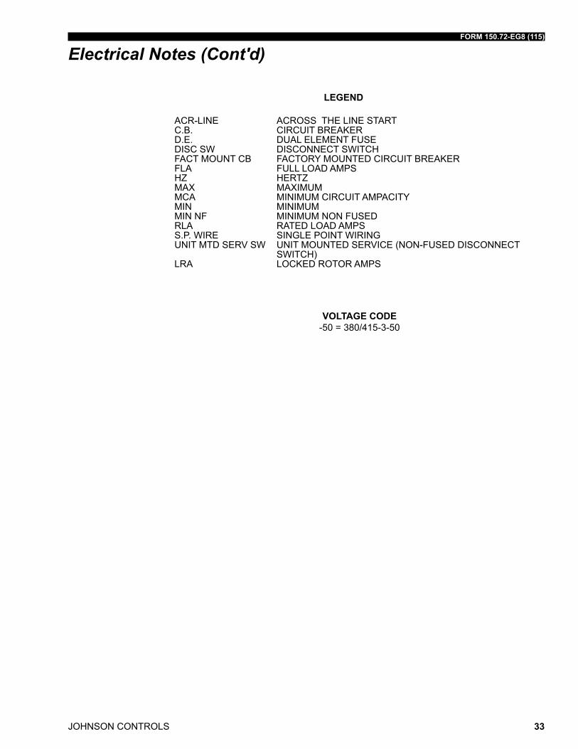
LEGEND
ACR-LINE ACROSS THE LINE START C.B. CIRCUIT BREAKER D.E. DUAL ELEMENT FUSE DISC SW DISCONNECT SWITCH FACT MOUNT CB FACTORY MOUNTED CIRCUIT BREAKER FLA FULL LOAD AMPS HZ HERTZ MAX MAXIMUM MCA MINIMUM CIRCUIT AMPACITY MIN MINIMUM MIN NF MINIMUM NON FUSED RLA RATED LOAD AMPS S.P. WIRE SINGLE POINT WIRING UNIT MTD SERV SW UNIT MOUNTED SERVICE (NON-FUSED DISCONNECT SWITCH) LRA LOCKED ROTOR AMPS
VOLTAGE CODE-50 = 380/415-3-50
Electrical Notes (Cont'd)
JOHNSON CONTROLS
FORM 150.72-EG8 (115)
34
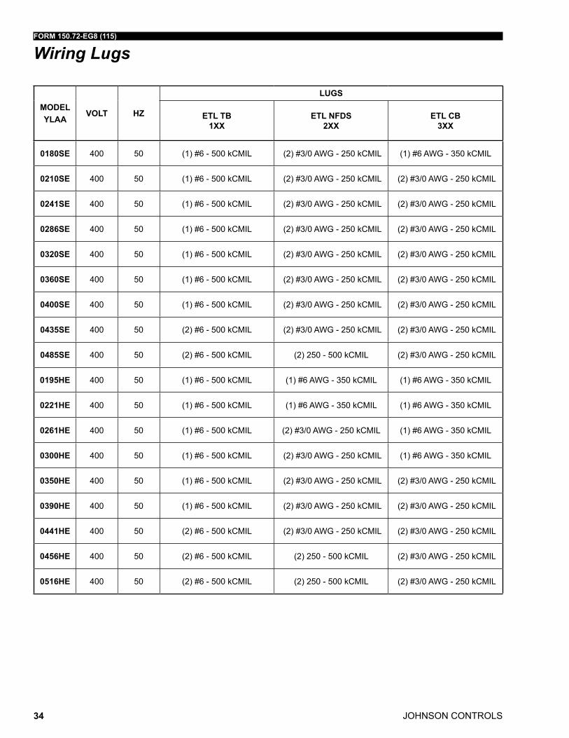
Wiring Lugs
MODELYLAA
VOLT HZ
LUGSMODELYLAA
VOLT HZ
LUGS
ETL TB 1XX
ETL NFDS 2XX
ETL CB 3XX
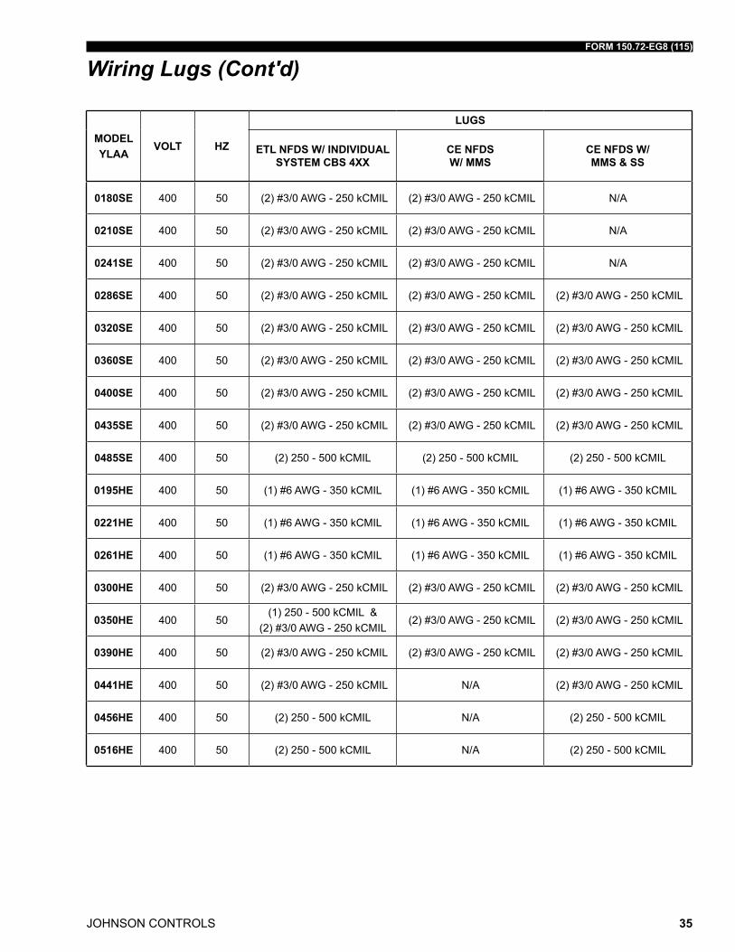
ETL NFDS W/ INDIVIDUAL SYSTEM CBS 4XX
CE NFDS W/ MMS
CE NFDS W/ MMS & SS
0180SE 400 50 (1) #6 - 500 kCMIL (2) #3/0 AWG - 250 kCMIL (1) #6 AWG - 350 kCMIL 0180SE 400 50 (2) #3/0 AWG - 250 kCMIL (2) #3/0 AWG - 250 kCMIL N/A
0210SE 400 50 (1) #6 - 500 kCMIL (2) #3/0 AWG - 250 kCMIL (2) #3/0 AWG - 250 kCMIL 0210SE 400 50 (2) #3/0 AWG - 250 kCMIL (2) #3/0 AWG - 250 kCMIL N/A
0241SE 400 50 (1) #6 - 500 kCMIL (2) #3/0 AWG - 250 kCMIL (2) #3/0 AWG - 250 kCMIL 0241SE 400 50 (2) #3/0 AWG - 250 kCMIL (2) #3/0 AWG - 250 kCMIL N/A
0286SE 400 50 (1) #6 - 500 kCMIL (2) #3/0 AWG - 250 kCMIL (2) #3/0 AWG - 250 kCMIL 0286SE 400 50 (2) #3/0 AWG - 250 kCMIL (2) #3/0 AWG - 250 kCMIL (2) #3/0 AWG - 250 kCMIL
0320SE 400 50 (1) #6 - 500 kCMIL (2) #3/0 AWG - 250 kCMIL (2) #3/0 AWG - 250 kCMIL 0320SE 400 50 (2) #3/0 AWG - 250 kCMIL (2) #3/0 AWG - 250 kCMIL (2) #3/0 AWG - 250 kCMIL
0360SE 400 50 (1) #6 - 500 kCMIL (2) #3/0 AWG - 250 kCMIL (2) #3/0 AWG - 250 kCMIL 0360SE 400 50 (2) #3/0 AWG - 250 kCMIL (2) #3/0 AWG - 250 kCMIL (2) #3/0 AWG - 250 kCMIL
0400SE 400 50 (1) #6 - 500 kCMIL (2) #3/0 AWG - 250 kCMIL (2) #3/0 AWG - 250 kCMIL 0400SE 400 50 (2) #3/0 AWG - 250 kCMIL (2) #3/0 AWG - 250 kCMIL (2) #3/0 AWG - 250 kCMIL
0435SE 400 50 (2) #6 - 500 kCMIL (2) #3/0 AWG - 250 kCMIL (2) #3/0 AWG - 250 kCMIL 0435SE 400 50 (2) #3/0 AWG - 250 kCMIL (2) #3/0 AWG - 250 kCMIL (2) #3/0 AWG - 250 kCMIL
0485SE 400 50 (2) #6 - 500 kCMIL (2) 250 - 500 kCMIL (2) #3/0 AWG - 250 kCMIL 0485SE 400 50 (2) 250 - 500 kCMIL (2) 250 - 500 kCMIL (2) 250 - 500 kCMIL
0195HE 400 50 (1) #6 - 500 kCMIL (1) #6 AWG - 350 kCMIL (1) #6 AWG - 350 kCMIL 0195HE 400 50 (1) #6 AWG - 350 kCMIL (1) #6 AWG - 350 kCMIL (1) #6 AWG - 350 kCMIL
0221HE 400 50 (1) #6 - 500 kCMIL (1) #6 AWG - 350 kCMIL (1) #6 AWG - 350 kCMIL 0221HE 400 50 (1) #6 AWG - 350 kCMIL (1) #6 AWG - 350 kCMIL (1) #6 AWG - 350 kCMIL
0261HE 400 50 (1) #6 - 500 kCMIL (2) #3/0 AWG - 250 kCMIL (1) #6 AWG - 350 kCMIL 0261HE 400 50 (1) #6 AWG - 350 kCMIL (1) #6 AWG - 350 kCMIL (1) #6 AWG - 350 kCMIL
0300HE 400 50 (1) #6 - 500 kCMIL (2) #3/0 AWG - 250 kCMIL (1) #6 AWG - 350 kCMIL 0300HE 400 50 (2) #3/0 AWG - 250 kCMIL (2) #3/0 AWG - 250 kCMIL (2) #3/0 AWG - 250 kCMIL
0350HE 400 50 (1) #6 - 500 kCMIL (2) #3/0 AWG - 250 kCMIL (2) #3/0 AWG - 250 kCMIL 0350HE 400 50(1) 250 - 500 kCMIL &
(2) #3/0 AWG - 250 kCMIL (2) #3/0 AWG - 250 kCMIL (2) #3/0 AWG - 250 kCMIL
0390HE 400 50 (1) #6 - 500 kCMIL (2) #3/0 AWG - 250 kCMIL (2) #3/0 AWG - 250 kCMIL 0390HE 400 50 (2) #3/0 AWG - 250 kCMIL (2) #3/0 AWG - 250 kCMIL (2) #3/0 AWG - 250 kCMIL
0441HE 400 50 (2) #6 - 500 kCMIL (2) #3/0 AWG - 250 kCMIL (2) #3/0 AWG - 250 kCMIL 0441HE 400 50 (2) #3/0 AWG - 250 kCMIL N/A (2) #3/0 AWG - 250 kCMIL
0456HE 400 50 (2) #6 - 500 kCMIL (2) 250 - 500 kCMIL (2) #3/0 AWG - 250 kCMIL 0456HE 400 50 (2) 250 - 500 kCMIL N/A (2) 250 - 500 kCMIL
0516HE 400 50 (2) #6 - 500 kCMIL (2) 250 - 500 kCMIL (2) #3/0 AWG - 250 kCMIL 0516HE 400 50 (2) 250 - 500 kCMIL N/A (2) 250 - 500 kCMIL
FORM 150.72-EG8 (115)
JOHNSON CONTROLS 35
MODELYLAA
VOLT HZ
LUGSMODELYLAA
VOLT HZ
LUGS
ETL TB 1XX
ETL NFDS 2XX
ETL CB 3XX
ETL NFDS W/ INDIVIDUAL SYSTEM CBS 4XX
CE NFDS W/ MMS
CE NFDS W/ MMS & SS
0180SE 400 50 (1) #6 - 500 kCMIL (2) #3/0 AWG - 250 kCMIL (1) #6 AWG - 350 kCMIL 0180SE 400 50 (2) #3/0 AWG - 250 kCMIL (2) #3/0 AWG - 250 kCMIL N/A
0210SE 400 50 (1) #6 - 500 kCMIL (2) #3/0 AWG - 250 kCMIL (2) #3/0 AWG - 250 kCMIL 0210SE 400 50 (2) #3/0 AWG - 250 kCMIL (2) #3/0 AWG - 250 kCMIL N/A
0241SE 400 50 (1) #6 - 500 kCMIL (2) #3/0 AWG - 250 kCMIL (2) #3/0 AWG - 250 kCMIL 0241SE 400 50 (2) #3/0 AWG - 250 kCMIL (2) #3/0 AWG - 250 kCMIL N/A
0286SE 400 50 (1) #6 - 500 kCMIL (2) #3/0 AWG - 250 kCMIL (2) #3/0 AWG - 250 kCMIL 0286SE 400 50 (2) #3/0 AWG - 250 kCMIL (2) #3/0 AWG - 250 kCMIL (2) #3/0 AWG - 250 kCMIL
0320SE 400 50 (1) #6 - 500 kCMIL (2) #3/0 AWG - 250 kCMIL (2) #3/0 AWG - 250 kCMIL 0320SE 400 50 (2) #3/0 AWG - 250 kCMIL (2) #3/0 AWG - 250 kCMIL (2) #3/0 AWG - 250 kCMIL
0360SE 400 50 (1) #6 - 500 kCMIL (2) #3/0 AWG - 250 kCMIL (2) #3/0 AWG - 250 kCMIL 0360SE 400 50 (2) #3/0 AWG - 250 kCMIL (2) #3/0 AWG - 250 kCMIL (2) #3/0 AWG - 250 kCMIL
0400SE 400 50 (1) #6 - 500 kCMIL (2) #3/0 AWG - 250 kCMIL (2) #3/0 AWG - 250 kCMIL 0400SE 400 50 (2) #3/0 AWG - 250 kCMIL (2) #3/0 AWG - 250 kCMIL (2) #3/0 AWG - 250 kCMIL
0435SE 400 50 (2) #6 - 500 kCMIL (2) #3/0 AWG - 250 kCMIL (2) #3/0 AWG - 250 kCMIL 0435SE 400 50 (2) #3/0 AWG - 250 kCMIL (2) #3/0 AWG - 250 kCMIL (2) #3/0 AWG - 250 kCMIL
0485SE 400 50 (2) #6 - 500 kCMIL (2) 250 - 500 kCMIL (2) #3/0 AWG - 250 kCMIL 0485SE 400 50 (2) 250 - 500 kCMIL (2) 250 - 500 kCMIL (2) 250 - 500 kCMIL
0195HE 400 50 (1) #6 - 500 kCMIL (1) #6 AWG - 350 kCMIL (1) #6 AWG - 350 kCMIL 0195HE 400 50 (1) #6 AWG - 350 kCMIL (1) #6 AWG - 350 kCMIL (1) #6 AWG - 350 kCMIL
0221HE 400 50 (1) #6 - 500 kCMIL (1) #6 AWG - 350 kCMIL (1) #6 AWG - 350 kCMIL 0221HE 400 50 (1) #6 AWG - 350 kCMIL (1) #6 AWG - 350 kCMIL (1) #6 AWG - 350 kCMIL
0261HE 400 50 (1) #6 - 500 kCMIL (2) #3/0 AWG - 250 kCMIL (1) #6 AWG - 350 kCMIL 0261HE 400 50 (1) #6 AWG - 350 kCMIL (1) #6 AWG - 350 kCMIL (1) #6 AWG - 350 kCMIL
0300HE 400 50 (1) #6 - 500 kCMIL (2) #3/0 AWG - 250 kCMIL (1) #6 AWG - 350 kCMIL 0300HE 400 50 (2) #3/0 AWG - 250 kCMIL (2) #3/0 AWG - 250 kCMIL (2) #3/0 AWG - 250 kCMIL
0350HE 400 50 (1) #6 - 500 kCMIL (2) #3/0 AWG - 250 kCMIL (2) #3/0 AWG - 250 kCMIL 0350HE 400 50(1) 250 - 500 kCMIL &
(2) #3/0 AWG - 250 kCMIL (2) #3/0 AWG - 250 kCMIL (2) #3/0 AWG - 250 kCMIL
0390HE 400 50 (1) #6 - 500 kCMIL (2) #3/0 AWG - 250 kCMIL (2) #3/0 AWG - 250 kCMIL 0390HE 400 50 (2) #3/0 AWG - 250 kCMIL (2) #3/0 AWG - 250 kCMIL (2) #3/0 AWG - 250 kCMIL
0441HE 400 50 (2) #6 - 500 kCMIL (2) #3/0 AWG - 250 kCMIL (2) #3/0 AWG - 250 kCMIL 0441HE 400 50 (2) #3/0 AWG - 250 kCMIL N/A (2) #3/0 AWG - 250 kCMIL
0456HE 400 50 (2) #6 - 500 kCMIL (2) 250 - 500 kCMIL (2) #3/0 AWG - 250 kCMIL 0456HE 400 50 (2) 250 - 500 kCMIL N/A (2) 250 - 500 kCMIL
0516HE 400 50 (2) #6 - 500 kCMIL (2) 250 - 500 kCMIL (2) #3/0 AWG - 250 kCMIL 0516HE 400 50 (2) 250 - 500 kCMIL N/A (2) 250 - 500 kCMIL
Wiring Lugs (Cont'd)
JOHNSON CONTROLS
FORM 150.72-EG8 (115)
36
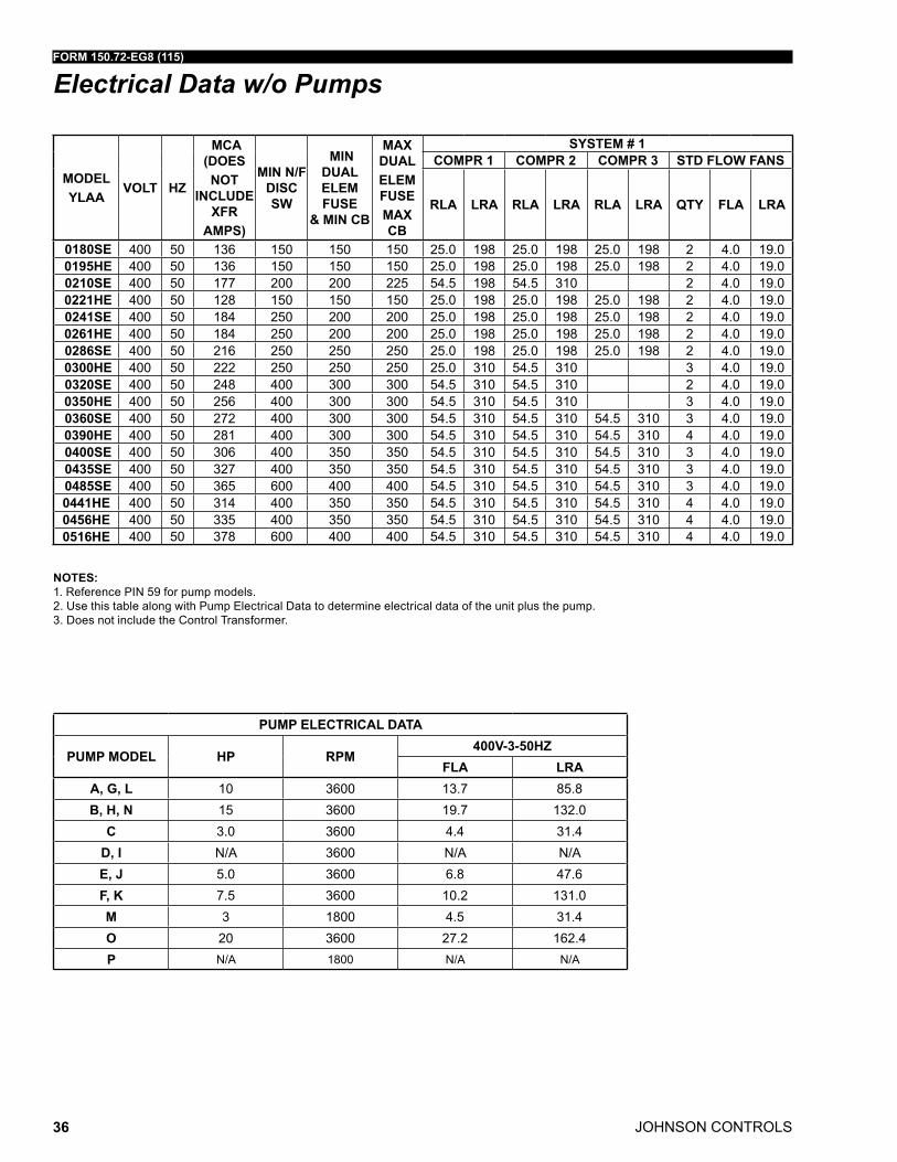
Electrical Data w/o Pumps
MODELYLAA
VOLT HZ
MCA (DOES NOT
INCLUDE XFR
AMPS)
MIN N/F DISC SW
MIN DUAL ELEM FUSE
& MIN CB
MAX DUALELEM FUSEMAX CB
SYSTEM # 1
MODELYLAA
VOLT HZ
SYSTEM # 2COMPR 1 COMPR 2 COMPR 3 STD FLOW FANS COMPR 1 COMPR 2 COMPR 3 STD FLOW FANS
RLA LRA RLA LRA RLA LRA QTY FLA LRA RLA LRA RLA LRA RLA LRA QTY FLA LRA
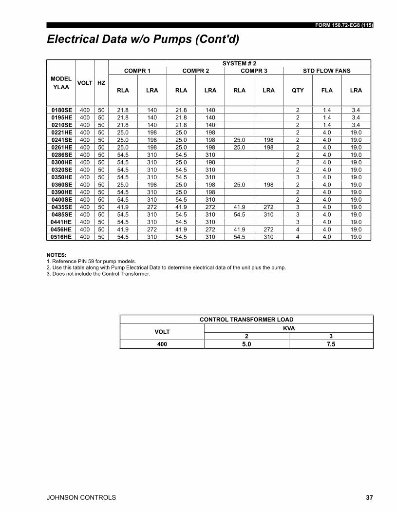
0180SE 400 50 136 150 150 150 25.0 198 25.0 198 25.0 198 2 4.0 19.0 0180SE 400 50 21.8 140 21.8 140 2 1.4 3.4 0195HE 400 50 136 150 150 150 25.0 198 25.0 198 25.0 198 2 4.0 19.0 0195HE 400 50 21.8 140 21.8 140 2 1.4 3.4 0210SE 400 50 177 200 200 225 54.5 198 54.5 310 2 4.0 19.0 0210SE 400 50 21.8 140 21.8 140 2 1.4 3.4 0221HE 400 50 128 150 150 150 25.0 198 25.0 198 25.0 198 2 4.0 19.0 0221HE 400 50 25.0 198 25.0 198 2 4.0 19.0 0241SE 400 50 184 250 200 200 25.0 198 25.0 198 25.0 198 2 4.0 19.0 0241SE 400 50 25.0 198 25.0 198 25.0 198 2 4.0 19.0 0261HE 400 50 184 250 200 200 25.0 198 25.0 198 25.0 198 2 4.0 19.0 0261HE 400 50 25.0 198 25.0 198 25.0 198 2 4.0 19.0 0286SE 400 50 216 250 250 250 25.0 198 25.0 198 25.0 198 2 4.0 19.0 0286SE 400 50 54.5 310 54.5 310 2 4.0 19.0 0300HE 400 50 222 250 250 250 25.0 310 54.5 310 3 4.0 19.0 0300HE 400 50 54.5 310 25.0 198 2 4.0 19.0 0320SE 400 50 248 400 300 300 54.5 310 54.5 310 2 4.0 19.0 0320SE 400 50 54.5 310 54.5 310 2 4.0 19.0 0350HE 400 50 256 400 300 300 54.5 310 54.5 310 3 4.0 19.0 0350HE 400 50 54.5 310 54.5 310 3 4.0 19.0 0360SE 400 50 272 400 300 300 54.5 310 54.5 310 54.5 310 3 4.0 19.0 0360SE 400 50 25.0 198 25.0 198 25.0 198 2 4.0 19.0 0390HE 400 50 281 400 300 300 54.5 310 54.5 310 54.5 310 4 4.0 19.0 0390HE 400 50 54.5 310 25.0 198 2 4.0 19.0 0400SE 400 50 306 400 350 350 54.5 310 54.5 310 54.5 310 3 4.0 19.0 0400SE 400 50 54.5 310 54.5 310 2 4.0 19.0 0435SE 400 50 327 400 350 350 54.5 310 54.5 310 54.5 310 3 4.0 19.0 0435SE 400 50 41.9 272 41.9 272 41.9 272 3 4.0 19.0 0485SE 400 50 365 600 400 400 54.5 310 54.5 310 54.5 310 3 4.0 19.0 0485SE 400 50 54.5 310 54.5 310 54.5 310 3 4.0 19.00441HE 400 50 314 400 350 350 54.5 310 54.5 310 54.5 310 4 4.0 19.0 0441HE 400 50 54.5 310 54.5 310 3 4.0 19.00456HE 400 50 335 400 350 350 54.5 310 54.5 310 54.5 310 4 4.0 19.0 0456HE 400 50 41.9 272 41.9 272 41.9 272 4 4.0 19.00516HE 400 50 378 600 400 400 54.5 310 54.5 310 54.5 310 4 4.0 19.0 0516HE 400 50 54.5 310 54.5 310 54.5 310 4 4.0 19.0
NOTES:1. Reference PIN 59 for pump models.2. Use this table along with Pump Electrical Data to determine electrical data of the unit plus the pump.3. Does not include the Control Transformer.
PUMP ELECTRICAL DATA
PUMP MODEL HP RPM400V-3-50HZ
FLA LRAA, G, L 10 3600 13.7 85.8B, H, N 15 3600 19.7 132.0
C 3.0 3600 4.4 31.4D, I N/A 3600 N/A N/AE, J 5.0 3600 6.8 47.6F, K 7.5 3600 10.2 131.0M 3 1800 4.5 31.4O 20 3600 27.2 162.4P N/A 1800 N/A N/A
FORM 150.72-EG8 (115)
JOHNSON CONTROLS 37
MODELYLAA
VOLT HZ
MCA (DOES NOT
INCLUDE XFR
AMPS)
MIN N/F DISC SW
MIN DUAL ELEM FUSE
& MIN CB
MAX DUALELEM FUSEMAX CB
SYSTEM # 1
MODELYLAA
VOLT HZ
SYSTEM # 2COMPR 1 COMPR 2 COMPR 3 STD FLOW FANS COMPR 1 COMPR 2 COMPR 3 STD FLOW FANS
RLA LRA RLA LRA RLA LRA QTY FLA LRA RLA LRA RLA LRA RLA LRA QTY FLA LRA
0180SE 400 50 136 150 150 150 25.0 198 25.0 198 25.0 198 2 4.0 19.0 0180SE 400 50 21.8 140 21.8 140 2 1.4 3.4 0195HE 400 50 136 150 150 150 25.0 198 25.0 198 25.0 198 2 4.0 19.0 0195HE 400 50 21.8 140 21.8 140 2 1.4 3.4 0210SE 400 50 177 200 200 225 54.5 198 54.5 310 2 4.0 19.0 0210SE 400 50 21.8 140 21.8 140 2 1.4 3.4 0221HE 400 50 128 150 150 150 25.0 198 25.0 198 25.0 198 2 4.0 19.0 0221HE 400 50 25.0 198 25.0 198 2 4.0 19.0 0241SE 400 50 184 250 200 200 25.0 198 25.0 198 25.0 198 2 4.0 19.0 0241SE 400 50 25.0 198 25.0 198 25.0 198 2 4.0 19.0 0261HE 400 50 184 250 200 200 25.0 198 25.0 198 25.0 198 2 4.0 19.0 0261HE 400 50 25.0 198 25.0 198 25.0 198 2 4.0 19.0 0286SE 400 50 216 250 250 250 25.0 198 25.0 198 25.0 198 2 4.0 19.0 0286SE 400 50 54.5 310 54.5 310 2 4.0 19.0 0300HE 400 50 222 250 250 250 25.0 310 54.5 310 3 4.0 19.0 0300HE 400 50 54.5 310 25.0 198 2 4.0 19.0 0320SE 400 50 248 400 300 300 54.5 310 54.5 310 2 4.0 19.0 0320SE 400 50 54.5 310 54.5 310 2 4.0 19.0 0350HE 400 50 256 400 300 300 54.5 310 54.5 310 3 4.0 19.0 0350HE 400 50 54.5 310 54.5 310 3 4.0 19.0 0360SE 400 50 272 400 300 300 54.5 310 54.5 310 54.5 310 3 4.0 19.0 0360SE 400 50 25.0 198 25.0 198 25.0 198 2 4.0 19.0 0390HE 400 50 281 400 300 300 54.5 310 54.5 310 54.5 310 4 4.0 19.0 0390HE 400 50 54.5 310 25.0 198 2 4.0 19.0 0400SE 400 50 306 400 350 350 54.5 310 54.5 310 54.5 310 3 4.0 19.0 0400SE 400 50 54.5 310 54.5 310 2 4.0 19.0 0435SE 400 50 327 400 350 350 54.5 310 54.5 310 54.5 310 3 4.0 19.0 0435SE 400 50 41.9 272 41.9 272 41.9 272 3 4.0 19.0 0485SE 400 50 365 600 400 400 54.5 310 54.5 310 54.5 310 3 4.0 19.0 0485SE 400 50 54.5 310 54.5 310 54.5 310 3 4.0 19.00441HE 400 50 314 400 350 350 54.5 310 54.5 310 54.5 310 4 4.0 19.0 0441HE 400 50 54.5 310 54.5 310 3 4.0 19.00456HE 400 50 335 400 350 350 54.5 310 54.5 310 54.5 310 4 4.0 19.0 0456HE 400 50 41.9 272 41.9 272 41.9 272 4 4.0 19.00516HE 400 50 378 600 400 400 54.5 310 54.5 310 54.5 310 4 4.0 19.0 0516HE 400 50 54.5 310 54.5 310 54.5 310 4 4.0 19.0
NOTES:1. Reference PIN 59 for pump models.2. Use this table along with Pump Electrical Data to determine electrical data of the unit plus the pump.3. Does not include the Control Transformer.
CONTROL TRANSFORMER LOAD
VOLT KVA2 3
400 5.0 7.5
Electrical Data w/o Pumps (Cont'd)
JOHNSON CONTROLS
FORM 150.72-EG8 (115)
38
�������
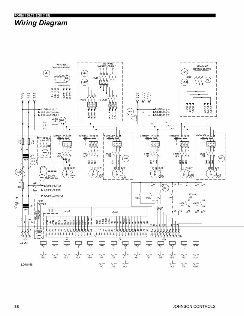
Wiring Diagram
FORM 150.72-EG8 (115)
JOHNSON CONTROLS 39
�������
�������
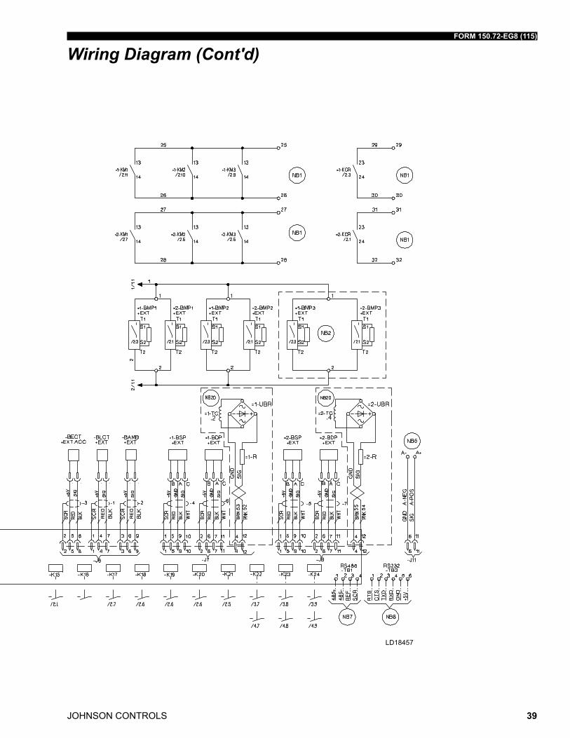
Wiring Diagram (Cont'd)
JOHNSON CONTROLS
FORM 150.72-EG8 (115)
40
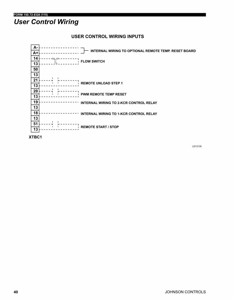
User Control Wiring
USER CONTROL WIRING INPUTS
LD13130
XTBC1
A-A+1413501321132013191318135113
INTERNAL WIRING TO OPTIONAL REMOTE TEMP. RESET BOARD
FLOW SWITCH
REMOTE UNLOAD STEP 1
PWM REMOTE TEMP RESET
INTERNAL WIRING TO 2-KCR CONTROL RELAY
INTERNAL WIRING TO 1-KCR CONTROL RELAY
REMOTE START / STOP
LD13130
FORM 150.72-EG8 (115)
JOHNSON CONTROLS 41
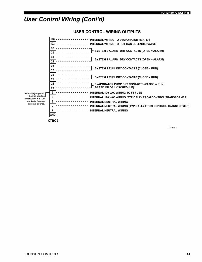
LD13242
XTBC2
140123323130292827262524235L222
GND
INTERNAL WIRING TO EVAPORATOR HEATER
INTERNAL 120 VAC WIRING TO F1 FUSEINTERNAL 120 VAC WIRING (TYPICALLY FROM CONTROL TRANSFORMER)INTERNAL NEUTRAL WIRING
INTERNAL NEUTRAL WIRINGINTERNAL NEUTRAL WIRING (TYPICALLY FROM CONTROL TRANSFORMER)
INTERNAL WIRING TO HOT GAS SOLENOID VALVE
SYSTEM 2 ALARM DRY CONTACTS (OPEN = ALARM)
SYSTEM 2 RUN DRY CONTACTS (CLOSE = RUN)
SYSTEM 1 RUN DRY CONTACTS (CLOSE = RUN)
EVAPORATOR PUMP DRY CONTACTS (CLOSE = RUN BASED ON DAILY SCHEDULE)
SYSTEM 1 ALARM DRY CONTACTS (OPEN = ALARM)
Normally jumpered. Can be used as
EMERGENCY STOP contacts from an external source.
USER CONTROL WIRING OUTPUTS
User Control Wiring (Cont'd)
JOHNSON CONTROLS
FORM 150.72-EG8 (115)
42
���������������������������������������������� �������������������������
������ ������������� ����� ���������������������������������������������������������������������
��� ����������������������� ������������ ����������������� � �������������� ��������������������������� ����� ��������� �������������������������� �� �������������
������������������������������ � ���������������������
���� �������������������������� ��� ������������������������������������
��� � ��������� ����������������������� ����� ��������������
����������������������� ������������������������������������������������
���� �������������� ������������������������� ��� ����������������
������������������ ��������������������� ��������������������������� ������ ������������� ��������
������� ������������������������������
��� ����� ������ ��������������������������� �������������� �������������������������
������� �������������������������������������������������
�������������������� ������������������������������������������
� ������������������ ����� ����������� � ������������������� �� ������������������������
�������������������������� �� ����������������������� ��������������������
�������������������������� ��� ������������ �� ��������������� ��������������������������
����������� ���������������������������������� ��������������������������
������������������������������������ � ����������������������������������� �
��������������������������������������������������
��� ����������������� ����������������������������������� ������������ ����������
�� ��������
��� �������������������� ��������������������������
������������������������������
��
Notes
FORM 150.72-EG8 (115)
JOHNSON CONTROLS 43
�� ���������������������������������� ���� ��� ���������������������������������������� ������� ������� ����������� ����� �������
� ���� ��������������������������� � ������������ ����������������������������������������������������� ����������
���������� ������������������������ ��������������������������� ����� �������� ���������� ����� ����������������������������������� ��� ���������������� ��� ������������������������������������������������ ������������������ ���������� ��������� �������������� �������
�� �������������������������������������������������������������� ������������ ���� ������������������ ���������������� ���������������������������������������������������������������������������� ����������������� ����������� ������������������������������ ���������������������������������� ����������� ��������������������� ��������� �������������������������� �������������� ����������������� ������������������������������������� ������������������������������������������������������������������������� ����������� ���������������� �������������������������������������������� ��������������������������������������������������� �������������� ������������������������� ���������������������������������������� ��������������������� �������������������������� ������������������������������������� ������������������������������������
�� ���������� ��������������������������������������� ������������������������ ���������� ����� ������������� ���������������������������������������� ���� ������������ ��������� ���������������������������������������� ���� ���� �������������������������� ������������������������������ ������� ������� ��������� ��������� � ������������������������������������������� ��
��������������� ������������������������������������������������ �������������������������������������������������������������� ����������������������������� ����� �������������������
���������������������������������������� ������������������������������������������������������������� ���������� ������������������ ���������� ������������� ���������� ������������������ ���������� �
����������� ���������������� ��������������������������������������������� ���������� ������������������ ������������������������ ���������� ������������������ �����������
� ���������������������������������������� ���������������������������� ���������������������������� ����� ���������������� ������������������������ ����������� ������������������������������������������������� � ����� ���������������� ���
�� ���������������������������������������������������������������������������������������������
��������������������������������������� ������������������������������������� ����������������������������������� ����� ��������������������������� ����������������������������������� ����� ������
�� �� �������������������������������������� �� ��������������������������������� �� ������������������������� ������ �� �������������������������������
�� ���������������������������������������������������������������������� ��������������� �� ����
�� ��������������������������������� �������� ������������� ���������������� �� ���
�� �� �������� �������������������� ��� ��� ���������� ��������������������������������������������������������������
������������ ����������������������������������������������������������� ���������������������������������������������������������������������������������������������� �����������������������������
�� ��������������������������������������� �� ����������������������������� ������������� �� ���������������������������������������� ������ ��������������� ����������������������������������������� ������������������������������������������������������ � ������������������������������������������������������������� �� �������������������������������������������
������
��
��
��
�����
Notes (Cont'd)
JOHNSON CONTROLS
FORM 150.72-EG8 (115)
44
Application Data
UNIT LOCATION
The YLAA chillers are designed for outdoor installation. When selecting a site for installa-tion, be guided by the following conditions:
1. For outdoor locations of the unit, select a place having an adequate supply of fresh air for the condenser.
2. Avoid locations beneath windows or between structures where normal operating sounds may be objectionable.
3. Installation sites may be either on a roof, or at ground level. (See FOUNDATION.)
4. The condenser fans are the propeller-type, and are not recommended for use with duct work in the condenser air stream.
5. When it is desirable to surround the unit(s), it is recommended that the screening be able to pass the required chiller CFM without exceeding 0.1" of water external static pressure.
6. Protection against corrosive environments is available by supplying the units with either copper fin, cured phenolic, or epoxy coating on the condenser coils. The ep-oxy coils should be offered with any units being installed at the seashore or where salt spray may hit the unit.
In installations where winter operation is intended and snow accumulations are expected, additional height must be provided to ensure normal condenser air flow.
Recommended clearances for units are given in Dimensions. When the available space is less, the unit(s) must be equipped with the discharge pressure transducer option to permit high pressure unloading in the event that air recirculation were to occur.
FOUNDATION
The unit should be mounted on a flat and level foundation, ground or roof, capable of sup-porting the entire operating weight of the equipment. Operating weights are given in the PHYSICAL DATA tables.
Roof Locations – Choose a spot with adequate structural strength to safely support the entire weight of the unit and service personnel. Care must be taken not to damage the roof during installation. If the roof is “bonded”, consult the building contractor or architect for special installation requirements. Roof installations should incorporate the use of spring-type isolators to minimize the transmission of vibration into the building structure.
Ground Level Installations – It is important that the units be installed on a substantial base that will not settle, causing strain on the liquid lines and resulting in possible leaks. A one-piece concrete slab with footers extending below the frost line is highly recom-mended. Additionally, the slab should not be tied to the main building foundation as noises will telegraph.
FORM 150.72-EG8 (115)
JOHNSON CONTROLS 45
Application Data (Cont'd)Mounting holes (5/8" diameter) are provided in the steel channel for bolting the unit to its foundation. See DIMENSIONS.
For ground level installations, precautions should be taken to protect the unit from tam-pering by or injury to unauthorized persons. Screws on access panels will prevent casual tampering; however, further safety precautions, such as unit enclosure options, a fenced-in enclosure, or locking devices on the panels may be advisable. Check local authorities for safety regulations.
CHILLED LIQUID PIPING
The chilled liquid piping system should be laid out so that the circulating pump discharges into the evaporator. The inlet and outlet evaporator liquid connections are given in DI-MENSIONS.
Hand stop valves are recommended for use in all lines to facilitate servicing. Drain con-nections should be provided at all low points to permit complete drainage of the evapora-tor and system piping. Additionally, a strainer (20 mesh) is recommended for use on the INLET line to the evaporator.
Pressure gauge connections are recommended for installation in the inlet and outlet wa-ter lines. Gauges are not furnished with the unit and are to be furnished by other suppliers.
The chilled liquid lines that are exposed to outdoor ambients should be wrapped with a supplemental heater cable and covered with insulation. As an alternative, ethylene glycol should be added to protect against freeze-up during low ambient periods.
A flow switch is available as an accessory on all units. The flow switch (or its equivalent) must be installed in the leaving water piping of the evaporator and must not be used to start and stop the unit.
JOHNSON CONTROLS
FORM 150.72-EG8 (115)
46
PART 1 – GENERAL
1.01 SCOPE
A. The requirements of this Section shall conform to the general provisions of the Con-tract, including General and Supplementary Conditions, Conditions of the Contract, and Contract Drawings.
B. Provide Microprocessor controlled, multiple-scroll compressor, air-cooled, liquid chill-ers of the scheduled capacities as shown and indicated on the Drawings, including but not limited to:
1. Chiller package with zero Ozone Depletion Potential Refrigerant R-410A
2. Electrical power and control connections
3. Chilled water connections
4. Manufacturer Start-Up
5. Charge of refrigerant and oil.
1.02 QUALITY ASSURANCE
A. Products shall be Designed, Tested, Rated and Certified in accordance with, and In-stalled in compliance with applicable sections of the following Standards and Codes:
1. AHRI 550/590 – Water Chilling Packages Using the Vapor Compression Cycle
2. AHRI 370 – Sound Rating of Large Outdoor Refrigerating and Air-Conditioning Equipment
3. ANSI/ASHRAE 15 – Safety Code for Mechanical Refrigeration
4. ANSI/ASHRAE 34 – Number Designation and Safety Classification of Refrigerants
5. ASHRAE 90.1 – Energy Standard for Buildings Except Low-Rise Residential Build-ings
6. ANSI/NFPA 70 – National Electrical Code (N.E.C.)
7. ASME Boiler and Pressure Vessel Code, Section VIII, Division 1
8. OSHA – Occupational Safety and Health Act
9. Manufactured in facility registered to ISO 9001
10. Conform to Intertek Testing Services for construction of chillers and provide ETL/cETL Listed Mark
B. Factory Run Test: Chiller shall be pressure-tested, evacuated and fully charged with re-frigerant and oil, and shall be factory operational run tested with water flowing through the vessel.
Guide Specifications
FORM 150.72-EG8 (115)
JOHNSON CONTROLS 47
Guide Specifications (Cont'd)C. Chiller manufacturer shall have a factory trained and supported service organization.
D. Warranty: Manufacturer shall Warrant all equipment and material of its manufacture against defects in workmanship and material for a period of eighteen (18) months from date of shipment or twelve (12) months from date of start-up, whichever occurs first.
1.03 DELIVERY AND HANDLING
A. Unit shall be delivered to job site fully assembled with all interconnecting refrigerant piping and internal wiring ready for field installation and charged with refrigerant and oil by the Manufacturer.
B. Provide protective covering over vulnerable components for unit protection during shipment. Fit nozzles and open ends with plastic enclosures.
C. Unit shall be stored and handled per Manufacturer’s instructions.
PART 2 - PRODUCTS
2.01 CHILLER MATERIALS AND COMPONENTS
A. General: Install and commission, as shown on the schedules and plans, factory as-sembled, charged, and tested air cooled scroll compressor chiller(s) as specified herein. Chiller shall be designed, selected, and constructed using a refrigerant with Flammability rating of “1”, as defined by ANSI/ASHRAE STANDARD 34 Number Des-ignation and Safety Classification of Refrigerants. Chiller shall include not less than two refrigerant circuits above 50 tons (200kW), scroll compressors, direct-expansion type evaporator, air-cooled condenser, refrigerant, lubrication system, interconnecting wiring, safety and operating controls including capacity controller, control center, mo-tor starting components, and special features as specified herein or required for safe, automatic operation.
B. Cabinet: External structural members shall be constructed of heavy gauge, galvanized steel coated with baked on powder paint which, when subject to ASTM B117, 1000 hour, 5% salt spray test, yields minimum ASTM 1654 rating of “6”.
C. Operating Characteristics: Provide low and high ambient temperature control options as required to ensure unit is capable of operation from -1°C to 46°C (30°F to 115°F) ambient temperature. [Optional: -18°C to 52°C (0°F to 125°F) ambient.]
D. Service Isolation valves: Discharge (ball type) isolation valves factory installed per refrigerant circuit. Includes a system high-pressure relief valve in compliance with ASHRAE15.
E. Pressure Transducers and Readout Capability
1. Discharge Pressure Transducers: Permits unit to sense and display discharge pres-sure.
2. Suction Pressure Transducers: Permits unit to sense and display suction pressure.
3. High Ambient Control: Allows units to operate when the ambient temperature is above 46°C (115°F). Includes discharge pressure transducers.
JOHNSON CONTROLS
FORM 150.72-EG8 (115)
48
2.02 COMPRESSORS
A. Compressors: Shall be hermetic, scroll-type, including:
1. Compliant design for axial and radial sealing
2. Refrigerant flow through the compressor with 100% suction cooled motor.
3. Large suction side free volume and oil sump to provide liquid handling capability.
4. Compressor crankcase heaters to provide extra liquid migration protection.
5. Annular discharge check valve and reverse vent assembly to provide low-pressure drop, silent shutdown and reverse rotation protection.
6. Initial oil charge.
7. Oil level sight glass.
8. Vibration isolator mounts for compressors.
9. Brazed-type connections for fully hermetic refrigerant circuits.
10. Compressor Motor overloads capable of monitoring compressor motor current. Pro-vides extra protection against compressor reverse rotation, phase-loss and phase-imbalance
2.03 REFRIGERANT CIRCUIT COMPONENTS
Each refrigerant circuit shall include: a discharge service ball type isolation valve, high side pressure relief, liquid line shutoff valve with charging port, low side pressure relief device, filter-drier, solenoid valve, sight glass with moisture indicator, thermostatic expan-sion valves [Option: electronic expansion valves], and flexible, closed-cell foam insulated suction line and suction pressure transducer.
2.04 HEAT EXCHANGERS
A. Evaporator :
1. Evaporator shall be brazed-plate stainless steel construction capable of refrigerant working pressure of 3103 kPa (450 PSIG) and liquid side pressure of 1034 kPa (150 PSIG) (Option for 2068 kPa [300 PSIG] available).
2. Brazed plate heat exchangers shall be UL listed.
3. Exterior surfaces shall be covered with 19mm (3/4”), flexible, closed cell insulation, thermal conductivity of 0.26k ([BTU/ HR-Ft2 -°F]/in.) maximum.
4. Water nozzles shall be provided with grooves for field provided ANSI/AWWA C-606 mechanical couplings.
5. Evaporator shall include vent and drain fittings and thermostatically controlled heat-ers to protect to -29°C (-20°F) ambient in off-cycle.
6. A 20-mesh, serviceable wye-strainer and mechanical couplings shall be provided for field installation on evaporator inlet prior to startup.
Guide Specifications (Cont'd)
FORM 150.72-EG8 (115)
JOHNSON CONTROLS 49
[Option] Evaporator shall be provided with piping extension kit and mechanical couplings to extend liquid connection from evaporator to edge of unit. Thermal dispersion type flow switch shall be factory installed in the evaporator outlet pipe extension and wired to the unit control panel. Extension kit nozzle connections shall be ANSI/AWWA C-606 (grooved) .
B. Air Cooled Condenser:
1. Coils: Condenser coils shall be constructed of a single material to avoid galvanic corrosion due to dissimilar metals. Coils and headers are brazed as one piece. Inte-gral sub cooling is included. Coils shall be designed for a design working pressure of 45 bar (650 psig). Condenser coil shall be washable with potable water under 7 bar (100 psig) pressure.
2. Low Sound Fans: Shall be dynamically and statically balanced, direct drive, corro-sion resistant glass fiber reinforced composite blades molded into a low noise, full-airfoil cross section, providing vertical air discharge and low sound. Each fan shall be provided in an individual compartment to prevent crossflow during fan cycling. Guards of heavy gauge, PVC (polyvinyl chloride) coated or galvanized steel shall be factory installed.
3. Fan Motors: High efficiency, direct drive, 6 pole, 3 phase, insulation class “F”, current protected, Totally Enclosed Air-Over (TEAO), rigid mounted, with double sealed, permanently lubricated, ball bearings.
2.05 CONTROLS
A. General: Automatic start, stop, operating, and protection sequences across the range of scheduled conditions and transients.
B. Power/Control Enclosure: Rain and dust tight NEMA 3R powder painted steel cabi-net with hinged, latched, and gasket sealed door.
C. Microprocessor Control Center:
1. Automatic control of compressor start/stop, anti-coincidence and anti-recycle tim-ers, automatic pumpdown at system shutdown, condenser fans, evaporator pump, evaporator heater, unit alarm contacts, and chiller operation from -18°C to 52°C(0°F to 125°F) ambient. Automatic reset to normal chiller operation after power failure.
2. Remote water temperature reset via 0-10 VDC or 4-20 mA input signal or up to two steps of demand (load) limiting.
3. Software stored in non-volatile memory, with programmed setpoints retained in lith-ium battery backed real-time-clock (RTC) memory for minimum 5 years.
4. Forty character liquid crystal display, descriptions in English (or Spanish, French, Italian, or German), numeric data in English (or Metric) units. Sealed keypad with sections for Setpoints, Display/Print, Entry, Unit Options & clock, and On/Off Switch.
5. Programmable Setpoints (within Manufacturer limits): display language; chilled liq-uid temperature setpoint and range, remote reset temperature range, daily schedule/holiday for start/stop, manual override for servicing, low and high ambient cutouts,
Guide Specifications (Cont'd)
JOHNSON CONTROLS
FORM 150.72-EG8 (115)
50
low liquid temperature cutout, low suction pressure cutout, high discharge pressure cutout, anti-recycle timer (compressor start cycle time), and anti-coincident timer (delay compressor starts).
6. Display Data: Return and leaving liquid temperatures, low leaving liquid tempera-ture cutout setting, low ambient temperature cutout setting, outdoor air tempera-ture, English or metric data, suction pressure cutout setting, each system suction pressure, discharge pressure (optional), liquid temperature reset via a 4-20milliamp or 0-10 VDC input, anti-recycle timer status for each compressor, anti-coincident system start timer condition, compressor run status, no cooling load condition, day, date and time, daily start/stop times, holiday status, automatic or manual system lead/lag control, lead system definition, compressor starts/operating hours (each), status of hot gas valves, evaporator heater and fan operation, run permissive sta-tus, number of compressors running, liquid solenoid valve status, load & unload timer status, water pump status.
7. System Safeties: Shall cause individual compressor systems to perform auto shut down; manual reset required after the third trip in 90 minutes. System Safeties in-clude: high discharge pressure, low suction pressure, high pressure switch, and motor protector. Compressor motor protector shall protect against damage due to high input current or thermal overload of windings.
8. Unit Safeties: Shall be automatic reset and cause compressors to shut down if low ambient, low leaving chilled liquid temperature, under voltage, and flow switch operation.
9. Alarm Contacts: Low ambient, low leaving chilled liquid temperature, low voltage, low battery, and (per compressor circuit): high discharge pressure, and low suction pressure.
10. BAS Communications: YORKTalk 2, BACnet MS/TP, Modbus and N2 commu-nication capabilities are standard. (Option: LON communication via ELink Micro-gateway)
D. Manufacturer shall provide any controls not listed above, necessary for automatic chiller operation. Mechanical Contractor shall provide field control wiring necessary to interface sensors to the chiller control system.
2.06 POWER CONNECTION AND DISTRIBUTION
A. Power Panels:
1. NEMA 3R raintight, powder painted steel cabinets with hinged, latched, and gasket sealed outer doors. Provide main power connection(s), control power connections, compressor and fan motor start contactors, current overloads, and factory wiring.
2. Power supply shall enter unit at a single location, be 3 phase of scheduled voltage, and connect to individual terminal blocks per compressor. Separate disconnecting means and/or external branch circuit protection (by Contractor) required per appli-cable local or national codes.
B. Compressor, control and fan motor power wiring shall be located in an enclosed panel or routed through liquid tight conduit.
Guide Specifications (Cont'd)

FORM 150.72-EG8 (115)
JOHNSON CONTROLS 51
2.07 ACCESSORIES AND OPTIONS
Some accessories and options supercede standard product features. Your Johnson Con-trols representative will be pleased to provide assistance.
A. Microprocessor controlled, Factory installed Across-the-Line type compressor motor starters as standard.
B. Outdoor Ambient Temperature Control
1. Low Ambient Control: Permits unit operation to -17.8°C (0°F) ambient. Standard unit controls to -1.1°C (30°F) ambient.
2. High Ambient Control: Permits unit operation above 46°C (115°F) ambient.
C. Power Supply Connections:
1. Single Point Power Supply: Single point Terminal Block for field connection and interconnecting wiring to the compressors. Separate external protection must be supplied, by others, in the incoming power wiring, which must comply with the Na-tional Electric Code and/or local codes.
2. Single Point or Multiple Point Disconnect: Single or Dual point Non-Fused Disconnect(s) and lockable external handle (in compliance with Article 440-14 of N.E.C.) can be supplied to isolate the unit power voltage for servicing. Separate ex-ternal fusing must be supplied, by others, in the incoming power wiring, which must comply with the National Electric Code (CE) and/or local codes.
3. Single Point Circuit Breaker: Single point Terminal Block with Circuit Breaker and lockable external handle (in compliance with Article 440-14 of N.E.C.) can be sup-plied to isolate power voltage for servicing. Incoming power wiring must comply with the National Electric Code and/or local codes.
D. Control Power Transformer: Converts unit power voltage to 120-1-60 (500 VA ca-pacity). Factory-mounting includes primary and secondary wiring between the trans-former and the control panel.
E. Power Factor Correction Capacitors: Provided to correct unit compressor factors to a 0.90-0.95.
F. Condenser Coil Environmental Protection:
1. Post-Coated Dipped: Dipped-cured coating on condenser coils for seashore and other corrosive applications (with the exception of strong alkalis, oxidizers, and wet bromine, chlorine and fluorine in concentrations greater than 100 ppm).
G. Protective Chiller Panels (Factory or Field Mounted)
1. Louvered Panels (condenser coils only):Painted steel as per remainder of unit cabinet, over external condenser coil faces.
2. Wire Panels (full unit): Heavy gauge, welded wire- mesh, coated to resist corro-sion, to protect con- denser coils from incidental damage and restrict unauthorized access to internal components.
3. Louvered Panels (full unit): Painted steel as per re- mainder of unit cabinet, to pro-tect condenser coils from incidental damage, visually screen internal components, and prevent unauthorized access to internal components.
Guide Specifications (Cont'd)
JOHNSON CONTROLS
FORM 150.72-EG8 (115)
52
4. Louvered/Wire Panels: Louvered steel panels on external condenser coils painted as per remainder of unit cabinet. Heavy gauge, welded wire-mesh, coated to resist corrosion, around base of machine to restrict unauthorized access.
5. End Louver (hail guard): Louvered steel panels on external condenser coil faces located at the ends of the chiller.
H. Thermal Dispersion Flow Switch (Factory installed and wired in piping extension kit): Normally open, 30bar pressure rating, stainless steel 316L construction, IP67,-20°C to 70°C (-4°F to 158°F) ambient rating.
I. Evaporator options:
1. Provide 1-1/2”” evaporator insulation in lieu of standard 3/4”.
J. Hot Gas By-Pass: Permits continuous, stable operation at capacities below the mini-mum step of unloading to as low as 5% capacity (depending on both the unit & operat-ing conditions) by introducing an artificial load on the evaporator. Hot gas by-pass is installed on only one refrigerant circuit.
K. Thermal Storage: Leaving chilled liquid setpoint range for charge cycle from -3.9°C to -6.7°C (25°F to 20°F) minimum, with automatic reset of the leaving brine temperature up to 4.4°C (40°F) above the setpoint.
L. Low Temperature Process Glycol: Leaving chilled liquid setpoint range -12°C to 10°C (10°F to 50°F)
M. Sound Reduction (Factory installed):
1. Ultra Quiet - Low speed, reduced noise fans
2. Compressor Acoustic Sound Blankets
N. Vibration Isolation (Field installed):
1. Elastomeric Isolators.
2. 1” Deflection Spring Isolators: Level adjustable, spring and cage type isolators for mounting under the unit base rails.
3. 2” Deflection Restrained Spring Isolators: Level adjustable, restrained mounts in rugged welded steel housing with vertical and horizontal limit stops. Housings shall be designed to withstand a minimum 1.0g accelerated force in all directions to 50.8 mm (2”)
Guide Specifications (Cont'd)
FORM 150.72-EG8 (115)
JOHNSON CONTROLS 53
PART 3 – EXECUTION
3.01 INSTALLATION
A. General: Rig and Install in full accordance with Manufacturers requirements, Project drawings, and Contract documents.
B. Location: Locate chiller as indicated on drawings, including cleaning and service maintenance clearance per Manufacturer instructions. Adjust and level chiller on sup-port structure.
C. Components: Installing Contractor shall provide and install all auxiliary devices and accessories for fully operational chiller.
D. Electrical: Co-ordinate electrical requirements and connections for all power feeds with Electrical Contractor (Division 16).
E. Controls: Co-ordinate all control requirements and connections with Controls Contrac-tor.
F. Finish: Installing Contractor shall paint damaged and abraded factory finish with touch-up paint matching factory finish.
Guide Specifications (Cont'd)

Printed on recycled paperForm 150.72-EG8 (115) Supersedes: 150.72-EG8 (914) © 2015 Johnson Controls, Inc. P.O. Box 423, Milwaukee, WI 53201 Printed in USAwww.johnsoncontrols.comIssued on 1/12/2015
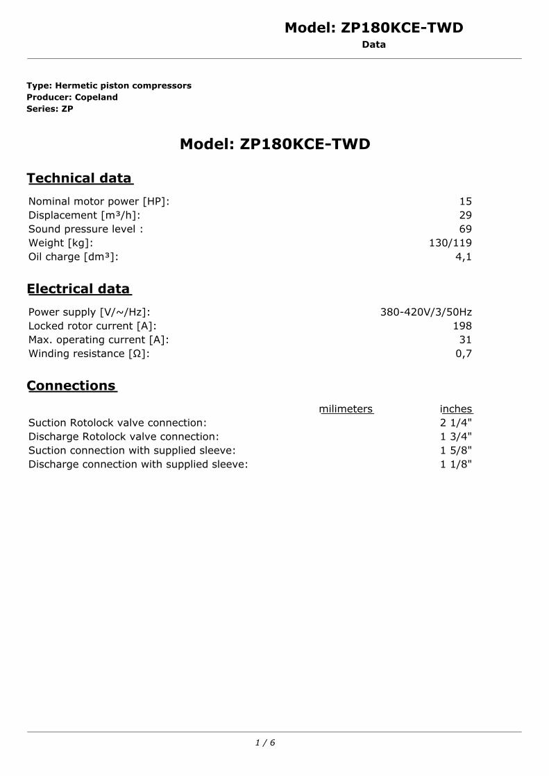
Model: ZP180KCE-TWDData
Type: Hermetic piston compressorsProducer: CopelandSeries: ZP
Model: ZP180KCE-TWD
Technical data
Nominal motor power [HP]: 15Displacement [m³/h]: 29Sound pressure level : 69Weight [kg]: 130/119Oil charge [dm³]: 4,1
Electrical data
Power supply [V/~/Hz]: 380-420V/3/50HzLocked rotor current [A]: 198Max. operating current [A]: 31Winding resistance [Ω]: 0,7
Connections
milimeters inchesSuction Rotolock valve connection: 2 1/4"Discharge Rotolock valve connection: 1 3/4"Suction connection with supplied sleeve: 1 5/8"Discharge connection with supplied sleeve: 1 1/8"
1 / 6
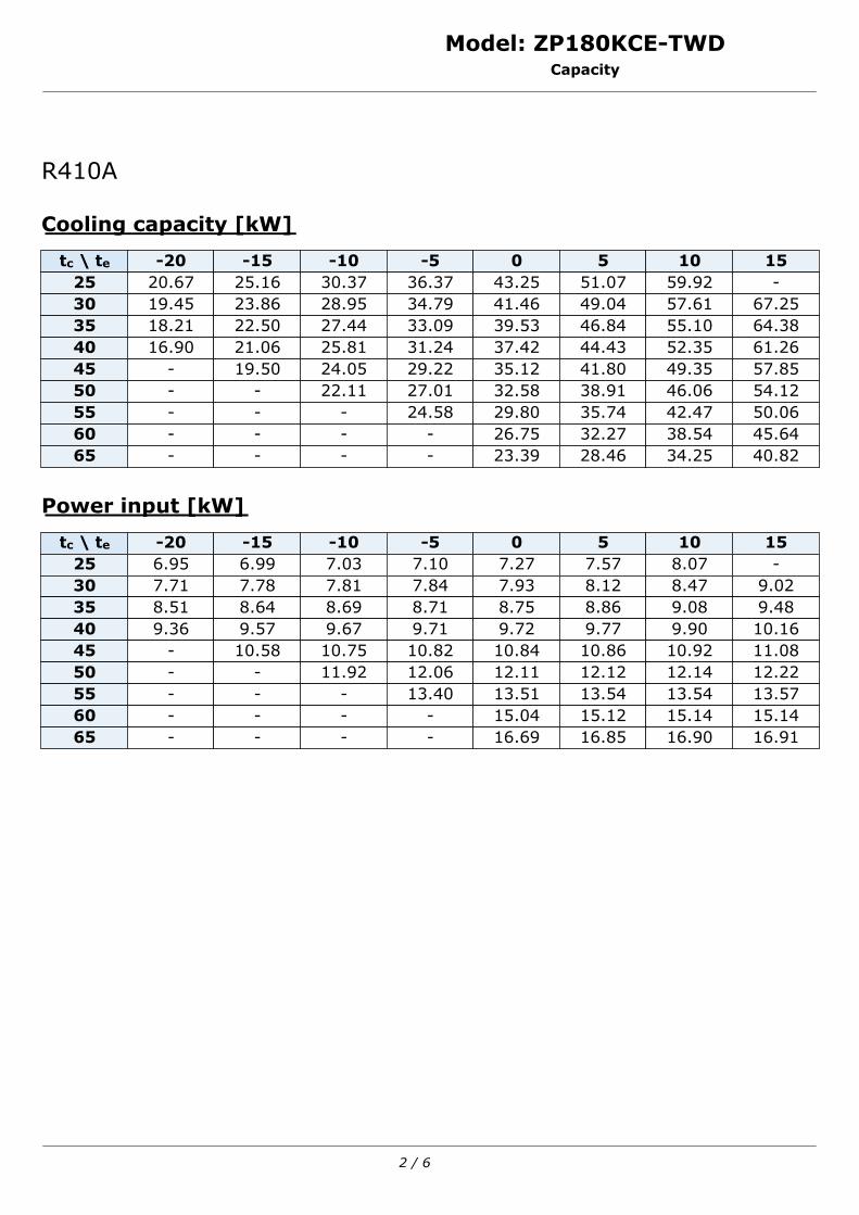
Model: ZP180KCE-TWDCapacity
R410A
Cooling capacity [kW]
tc \ te -20 -15 -10 -5 0 5 10 1525 20.67 25.16 30.37 36.37 43.25 51.07 59.92 -30 19.45 23.86 28.95 34.79 41.46 49.04 57.61 67.2535 18.21 22.50 27.44 33.09 39.53 46.84 55.10 64.3840 16.90 21.06 25.81 31.24 37.42 44.43 52.35 61.2645 - 19.50 24.05 29.22 35.12 41.80 49.35 57.8550 - - 22.11 27.01 32.58 38.91 46.06 54.1255 - - - 24.58 29.80 35.74 42.47 50.0660 - - - - 26.75 32.27 38.54 45.6465 - - - - 23.39 28.46 34.25 40.82
Power input [kW]
tc \ te -20 -15 -10 -5 0 5 10 1525 6.95 6.99 7.03 7.10 7.27 7.57 8.07 -30 7.71 7.78 7.81 7.84 7.93 8.12 8.47 9.0235 8.51 8.64 8.69 8.71 8.75 8.86 9.08 9.4840 9.36 9.57 9.67 9.71 9.72 9.77 9.90 10.1645 - 10.58 10.75 10.82 10.84 10.86 10.92 11.0850 - - 11.92 12.06 12.11 12.12 12.14 12.2255 - - - 13.40 13.51 13.54 13.54 13.5760 - - - - 15.04 15.12 15.14 15.1465 - - - - 16.69 16.85 16.90 16.91
2 / 6
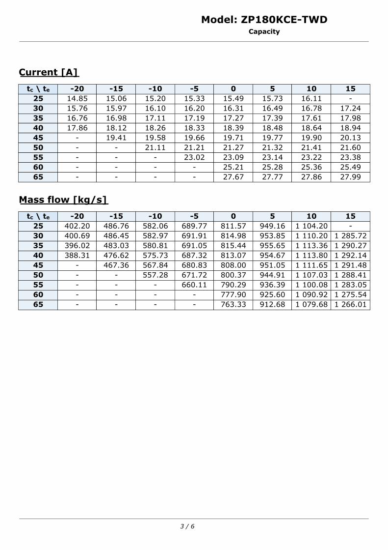
Model: ZP180KCE-TWDCapacity
Current [A]
tc \ te -20 -15 -10 -5 0 5 10 1525 14.85 15.06 15.20 15.33 15.49 15.73 16.11 -30 15.76 15.97 16.10 16.20 16.31 16.49 16.78 17.2435 16.76 16.98 17.11 17.19 17.27 17.39 17.61 17.9840 17.86 18.12 18.26 18.33 18.39 18.48 18.64 18.9445 - 19.41 19.58 19.66 19.71 19.77 19.90 20.1350 - - 21.11 21.21 21.27 21.32 21.41 21.6055 - - - 23.02 23.09 23.14 23.22 23.3860 - - - - 25.21 25.28 25.36 25.4965 - - - - 27.67 27.77 27.86 27.99
Mass flow [kg/s]
tc \ te -20 -15 -10 -5 0 5 10 1525 402.20 486.76 582.06 689.77 811.57 949.16 1 104.20 -30 400.69 486.45 582.97 691.91 814.98 953.85 1 110.20 1 285.7235 396.02 483.03 580.81 691.05 815.44 955.65 1 113.36 1 290.2740 388.31 476.62 575.73 687.32 813.07 954.67 1 113.80 1 292.1445 - 467.36 567.84 680.83 808.00 951.05 1 111.65 1 291.4850 - - 557.28 671.72 800.37 944.91 1 107.03 1 288.4155 - - - 660.11 790.29 936.39 1 100.08 1 283.0560 - - - - 777.90 925.60 1 090.92 1 275.5465 - - - - 763.33 912.68 1 079.68 1 266.01
3 / 6

Model: ZP180KCE-TWDCapacity
C.O.P. [W/W]
tc \ te -20 -15 -10 -5 0 5 10 1525 2.97 3.60 4.32 5.12 5.95 6.74 7.43 -30 2.52 3.07 3.71 4.44 5.23 6.04 6.80 7.4535 2.14 2.60 3.16 3.80 4.52 5.29 6.07 6.7940 1.81 2.20 2.67 3.22 3.85 4.55 5.29 6.0345 - 1.84 2.24 2.70 3.24 3.85 4.52 5.2250 - - 1.86 2.24 2.69 3.21 3.79 4.4355 - - - 1.83 2.21 2.64 3.14 3.6960 - - - - 1.78 2.13 2.55 3.0165 - - - - 1.40 1.69 2.03 2.41
Application range
Maximum evaporating temperature25ºC suction gas temperature10K gas overheat
Operating conditions: 10K suction superheat, 0K subcoolingtc - Condensing temperature [ºC]te - Evaporating temperature [ºC]
4 / 6
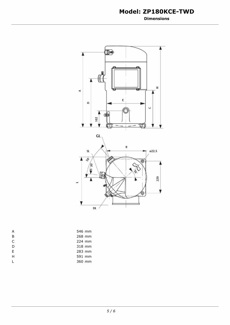
Model: ZP180KCE-TWDDimensions
A 546 mmB 268 mmC 224 mmD 318 mmE 283 mmH 591 mmL 360 mm
5 / 6
Model: ZP180KCE-TWDImage
6 / 6
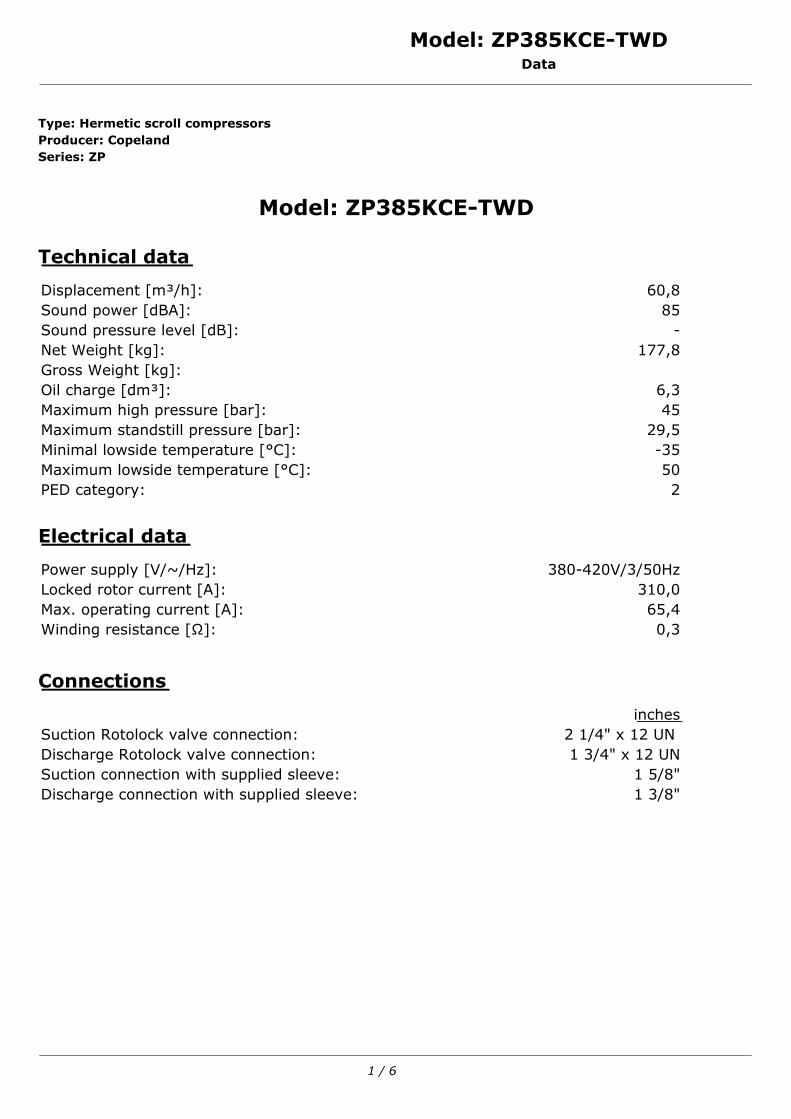
Model: ZP385KCE-TWDData
Type: Hermetic scroll compressorsProducer: CopelandSeries: ZP
Model: ZP385KCE-TWD
Technical data
Displacement [m³/h]: 60,8Sound power [dBA]: 85Sound pressure level [dB]: -Net Weight [kg]: 177,8Gross Weight [kg]:Oil charge [dm³]: 6,3Maximum high pressure [bar]: 45Maximum standstill pressure [bar]: 29,5Minimal lowside temperature [°C]: -35Maximum lowside temperature [°C]: 50PED category: 2
Electrical data
Power supply [V/~/Hz]: 380-420V/3/50HzLocked rotor current [A]: 310,0Max. operating current [A]: 65,4Winding resistance [Ω]: 0,3
Connections
inchesSuction Rotolock valve connection: 2 1/4" x 12 UN Discharge Rotolock valve connection: 1 3/4" x 12 UNSuction connection with supplied sleeve: 1 5/8"Discharge connection with supplied sleeve: 1 3/8"
1 / 6
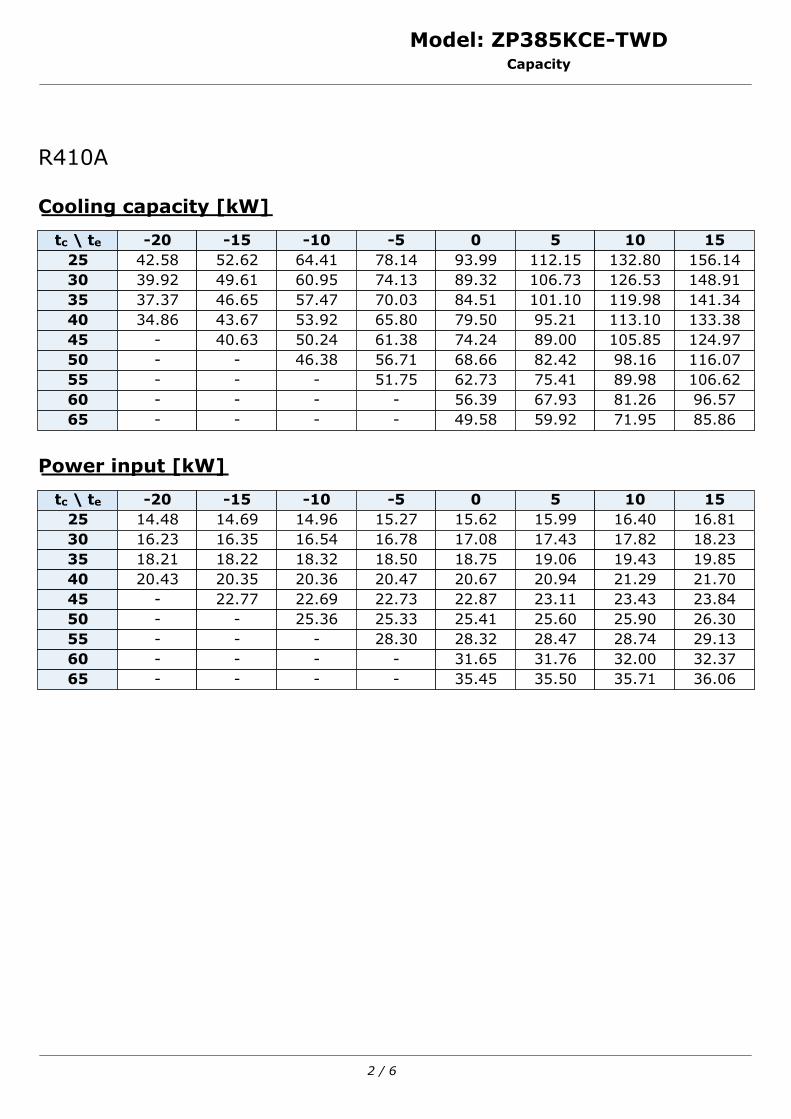
Model: ZP385KCE-TWDCapacity
R410A
Cooling capacity [kW]
tc \ te -20 -15 -10 -5 0 5 10 1525 42.58 52.62 64.41 78.14 93.99 112.15 132.80 156.1430 39.92 49.61 60.95 74.13 89.32 106.73 126.53 148.9135 37.37 46.65 57.47 70.03 84.51 101.10 119.98 141.3440 34.86 43.67 53.92 65.80 79.50 95.21 113.10 133.3845 - 40.63 50.24 61.38 74.24 89.00 105.85 124.9750 - - 46.38 56.71 68.66 82.42 98.16 116.0755 - - - 51.75 62.73 75.41 89.98 106.6260 - - - - 56.39 67.93 81.26 96.5765 - - - - 49.58 59.92 71.95 85.86
Power input [kW]
tc \ te -20 -15 -10 -5 0 5 10 1525 14.48 14.69 14.96 15.27 15.62 15.99 16.40 16.8130 16.23 16.35 16.54 16.78 17.08 17.43 17.82 18.2335 18.21 18.22 18.32 18.50 18.75 19.06 19.43 19.8540 20.43 20.35 20.36 20.47 20.67 20.94 21.29 21.7045 - 22.77 22.69 22.73 22.87 23.11 23.43 23.8450 - - 25.36 25.33 25.41 25.60 25.90 26.3055 - - - 28.30 28.32 28.47 28.74 29.1360 - - - - 31.65 31.76 32.00 32.3765 - - - - 35.45 35.50 35.71 36.06
2 / 6
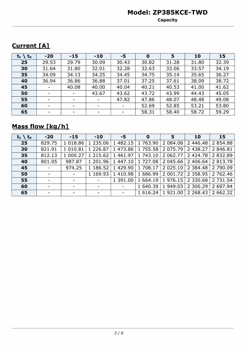
Model: ZP385KCE-TWDCapacity
Current [A]
tc \ te -20 -15 -10 -5 0 5 10 1525 29.53 29.79 30.09 30.43 30.82 31.28 31.80 32.3930 31.64 31.80 32.01 32.28 32.63 33.06 33.57 34.1935 34.09 34.13 34.25 34.45 34.75 35.14 35.65 36.2740 36.94 36.86 36.88 37.01 37.25 37.61 38.09 38.7245 - 40.08 40.00 40.04 40.21 40.53 41.00 41.6250 - - 43.67 43.62 43.72 43.99 44.43 45.0555 - - - 47.82 47.86 48.07 48.48 49.0860 - - - - 52.69 52.85 53.21 53.8065 - - - - 58.31 58.40 58.72 59.29
Mass flow [kg/h]
tc \ te -20 -15 -10 -5 0 5 10 1525 829.75 1 018.86 1 235.06 1 482.15 1 763.90 2 084.08 2 446.48 2 854.8830 821.91 1 010.81 1 226.87 1 473.86 1 755.58 2 075.79 2 438.27 2 846.8135 812.13 1 000.27 1 215.62 1 461.97 1 743.10 2 062.77 2 424.78 2 832.8940 801.05 987.87 1 201.96 1 447.10 1 727.08 2 045.66 2 406.64 2 813.7845 - 974.25 1 186.52 1 429.90 1 708.17 2 025.10 2 384.48 2 790.0950 - - 1 169.93 1 410.98 1 686.99 2 001.72 2 358.95 2 762.4655 - - - 1 391.00 1 664.19 1 976.15 2 330.68 2 731.5460 - - - - 1 640.39 1 949.03 2 300.29 2 697.9465 - - - - 1 616.24 1 921.00 2 268.43 2 662.32
3 / 6
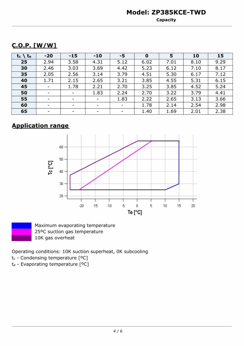
Model: ZP385KCE-TWDCapacity
C.O.P. [W/W]
tc \ te -20 -15 -10 -5 0 5 10 1525 2.94 3.58 4.31 5.12 6.02 7.01 8.10 9.2930 2.46 3.03 3.69 4.42 5.23 6.12 7.10 8.1735 2.05 2.56 3.14 3.79 4.51 5.30 6.17 7.1240 1.71 2.15 2.65 3.21 3.85 4.55 5.31 6.1545 - 1.78 2.21 2.70 3.25 3.85 4.52 5.2450 - - 1.83 2.24 2.70 3.22 3.79 4.4155 - - - 1.83 2.22 2.65 3.13 3.6660 - - - - 1.78 2.14 2.54 2.9865 - - - - 1.40 1.69 2.01 2.38
Application range
Maximum evaporating temperature25ºC suction gas temperature10K gas overheat
Operating conditions: 10K suction superheat, 0K subcoolingtc - Condensing temperature [ºC]te - Evaporating temperature [ºC]
4 / 6
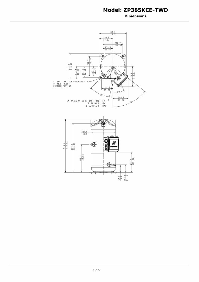
Model: ZP385KCE-TWDDimensions
5 / 6
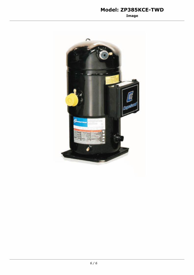
Model: ZP385KCE-TWDImage
6 / 6