Embed Size (px)
Citation preview
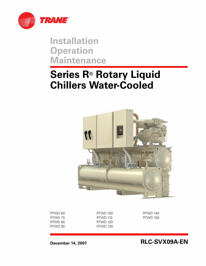
Installation OperationMaintenance
Series R® Rotary Liquid Chillers Water-Cooled
RTWD 60 RTWD 100 RTWD 140RTWD 70 RTWD 110 RTWD 150RTWD 80 RTWD 120RTWD 90 RTWD 130
December 14, 2007
RLC-SVX09A-EN
Important
Environmental Concerns!
Scientific research has shown that certain man-made chemicals can affect the earth’s naturally occurring
stratospheric ozone layer when released to the atmosphere. In particular, several of the identified
chemicals that may affect the ozone layer are refrigerants that contain Chlorine, Fluorine and Carbon
(CFCs) and those containing Hydrogen, Chlorine, Fluorine and Carbon (HCFCs). Not all refrigerants
containing these compounds have the same potential impact to the environment. Trane advocates the
responsible handling of all refrigerants—including industry replacements for CFCs such as and HCFCs and
HFCs.
Responsible Refrigerant Practices!
Trane believes that responsible refrigerant practices are important to the environment, our customers, and
the air conditioning industry. All technicians who handle refrigerants must be certified. The Federal Clean
Air Act (Section 608) sets forth the requirements for handling, reclaiming, recovering and recycling of
certain refrigerants and the equipment that is used in these service procedures. In addition, some states or
municipalities may have additional requirements that must also be adhered to for responsible
management of refrigerants. Know the applicable laws and follow them.
� WARNING
Contains Refrigerant!
System contains oil and refrigerant under high pressure. Recover refrigerant to relieve pressure before
opening the system. See unit nameplate for refrigerant type. Do not use non-approved refrigerants,
refrigerant substitutes, or refrigerant additives.
Failure to follow proper procedures or the use of non-approved refrigerants, refrigerant substitutes, or
refrigerant additives could result in death or serious injury or equipment damage.
NOTICE: Warnings and Cautions appear at appropriate sections through-out this literature. Read these carefully.
� WARNING: Indicates a potentially hazardous situation which, if not avoided, could result in death or serious injury.
� CAUTION: Indicates a potentially hazardous situation which, if not avoided, may result in minor or moderate injury. It may also be used to alert against unsafe practices.
CAUTION: Indicates a situation that may result in equipment or property-damage only accidents.
2 RTWD • RLC-SVX09A-EN

RLC-SVX09A-EN • RTWD 3
Contents
Model Number Description . . . . . . . . . . . . . . . . . . . . . . . . . . . . . . . . . . . . . . . . . . 6
Overview . . . . . . . . . . . . . . . . . . . . . . . . . . . . . . . . . . . . . . . . . . . . . . . . . . . . . . 6
Nameplates . . . . . . . . . . . . . . . . . . . . . . . . . . . . . . . . . . . . . . . . . . . . . . . . . . . . 6
General Information . . . . . . . . . . . . . . . . . . . . . . . . . . . . . . . . . . . . . . . . . . . . . . 11
Unit Description . . . . . . . . . . . . . . . . . . . . . . . . . . . . . . . . . . . . . . . . . . . . . . . . 11
Accessory/Options Information . . . . . . . . . . . . . . . . . . . . . . . . . . . . . . . . . . . 11
Pre-Installation . . . . . . . . . . . . . . . . . . . . . . . . . . . . . . . . . . . . . . . . . . . . . . . . . . . 13
Inspection Checklist . . . . . . . . . . . . . . . . . . . . . . . . . . . . . . . . . . . . . . . . . . . . 13
Unit Storage . . . . . . . . . . . . . . . . . . . . . . . . . . . . . . . . . . . . . . . . . . . . . . . . . . . 13
Installation requirements and Contractor responsibilities . . . . . . . . . . . . . 13
Unit Dimensions/Weights . . . . . . . . . . . . . . . . . . . . . . . . . . . . . . . . . . . . . . . . . . 15
General Data . . . . . . . . . . . . . . . . . . . . . . . . . . . . . . . . . . . . . . . . . . . . . . . . 15
Service Clearances and Dimensions . . . . . . . . . . . . . . . . . . . . . . . . . 19
Weights . . . . . . . . . . . . . . . . . . . . . . . . . . . . . . . . . . . . . . . . . . . . . . . . . . . . 24
Installation - Mechanical . . . . . . . . . . . . . . . . . . . . . . . . . . . . . . . . . . . . . . . . . . . 27
Location Requirements . . . . . . . . . . . . . . . . . . . . . . . . . . . . . . . . . . . . . . . . . . 27
Rigging . . . . . . . . . . . . . . . . . . . . . . . . . . . . . . . . . . . . . . . . . . . . . . . . . . . . . . . 27
Unit Isolation and Leveling . . . . . . . . . . . . . . . . . . . . . . . . . . . . . . . . . . . . . . . 31
Evaporator Piping . . . . . . . . . . . . . . . . . . . . . . . . . . . . . . . . . . . . . . . . . . . . . . 35
Condenser Water Piping (for RTWD Units Only) . . . . . . . . . . . . . . . . . . . . . 46
Water Regulations Valve (for RTWD Units Only) . . . . . . . . . . . . . . . . . . . . . 47
Refrigerant Relief Valve Venting . . . . . . . . . . . . . . . . . . . . . . . . . . . . . . . . . . 48
Installation - Electrical . . . . . . . . . . . . . . . . . . . . . . . . . . . . . . . . . . . . . . . . . . . . . 51
General Recommendations . . . . . . . . . . . . . . . . . . . . . . . . . . . . . . . . . . . . . . 51
Installer-Supplied Components . . . . . . . . . . . . . . . . . . . . . . . . . . . . . . . . . . . 64
Interconnecting Wiring . . . . . . . . . . . . . . . . . . . . . . . . . . . . . . . . . . . . . . . . . . 66
Communications Interface options . . . . . . . . . . . . . . . . . . . . . . . . . . . . . . . . 75
RTWD Operating Principles . . . . . . . . . . . . . . . . . . . . . . . . . . . . . . . . . . . . . . . . 77
General . . . . . . . . . . . . . . . . . . . . . . . . . . . . . . . . . . . . . . . . . . . . . . . . . . . . . . . 77
Refrigeration (Cooling) Cycle . . . . . . . . . . . . . . . . . . . . . . . . . . . . . . . . . . . . . 79
Oil System Operation (RTWD) . . . . . . . . . . . . . . . . . . . . . . . . . . . . . . . . . . . . 83
Controls Interface . . . . . . . . . . . . . . . . . . . . . . . . . . . . . . . . . . . . . . . . . . . . . . . . . 87
CH530 Communications Overview . . . . . . . . . . . . . . . . . . . . . . . . . . . . . . . . 87
Controls Interface . . . . . . . . . . . . . . . . . . . . . . . . . . . . . . . . . . . . . . . . . . . . . . 87
4 RLC-SVX09A-EN
Contents
Pre-Start Checkout . . . . . . . . . . . . . . . . . . . . . . . . . . . . . . . . . . . . . . . . . . . . . . . 123
Unit Start-Up Procedures . . . . . . . . . . . . . . . . . . . . . . . . . . . . . . . . . . . . . . . . . 129
Sequence of Operation . . . . . . . . . . . . . . . . . . . . . . . . . . . . . . . . . . . . . . . . . 129
Start-up . . . . . . . . . . . . . . . . . . . . . . . . . . . . . . . . . . . . . . . . . . . . . . . . . . . . . 133
Seasonal Unit Start-Up Procedure . . . . . . . . . . . . . . . . . . . . . . . . . . . . . . . . 134
Limit Conditions . . . . . . . . . . . . . . . . . . . . . . . . . . . . . . . . . . . . . . . . . . . . . . 135
Unit Shutdown . . . . . . . . . . . . . . . . . . . . . . . . . . . . . . . . . . . . . . . . . . . . . . . . . . 137
Service and Maintenance . . . . . . . . . . . . . . . . . . . . . . . . . . . . . . . . . . . . . . . . . 140
Overview . . . . . . . . . . . . . . . . . . . . . . . . . . . . . . . . . . . . . . . . . . . . . . . . . . . . 140
Maintenance . . . . . . . . . . . . . . . . . . . . . . . . . . . . . . . . . . . . . . . . . . . . . . . . . 140
Operating Log . . . . . . . . . . . . . . . . . . . . . . . . . . . . . . . . . . . . . . . . . . . . . . . . 142
Service Procedures . . . . . . . . . . . . . . . . . . . . . . . . . . . . . . . . . . . . . . . . . . . . 145
Freeze Protection . . . . . . . . . . . . . . . . . . . . . . . . . . . . . . . . . . . . . . . . . . . . . . 154
Diagnostics . . . . . . . . . . . . . . . . . . . . . . . . . . . . . . . . . . . . . . . . . . . . . . . . . . . . . 155
Starter Diagnostics . . . . . . . . . . . . . . . . . . . . . . . . . . . . . . . . . . . . . . . . . . . . 156
Main Processor Diagnostics . . . . . . . . . . . . . . . . . . . . . . . . . . . . . . . . . . . . . 161
Communication Diagnostics . . . . . . . . . . . . . . . . . . . . . . . . . . . . . . . . . . . . 173
RLC-SVX09A-EN 5
Model Number Description
Overview
This manual covers the installation, operation and maintenance of the RTWD units.
Nameplates
The RTWD unit nameplates are applied to the exterior surface of the control panel door.
A compressor nameplate is located on each compressor.
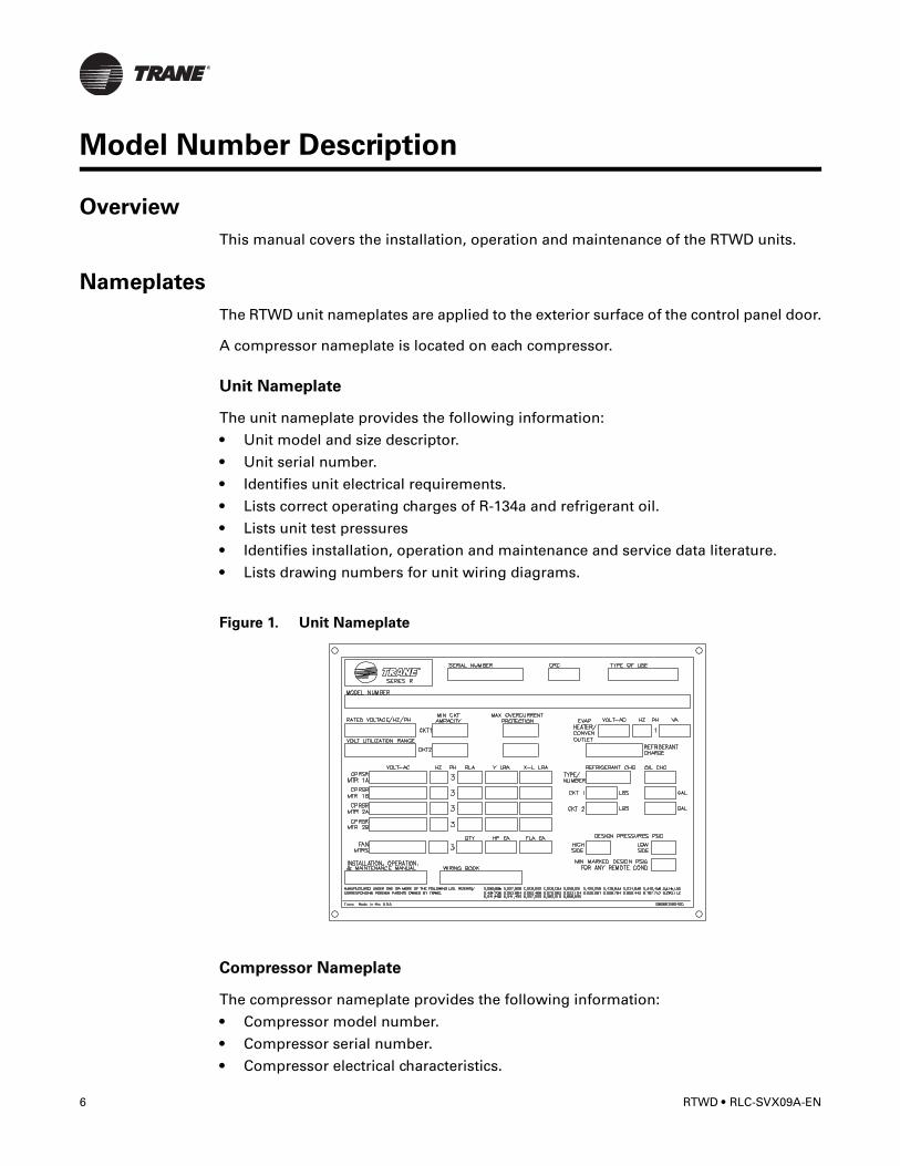
Unit Nameplate
The unit nameplate provides the following information:
• Unit model and size descriptor.
• Unit serial number.
• Identifies unit electrical requirements.
• Lists correct operating charges of R-134a and refrigerant oil.
• Lists unit test pressures
• Identifies installation, operation and maintenance and service data literature.
• Lists drawing numbers for unit wiring diagrams.
Figure 1. Unit Nameplate
Compressor Nameplate
The compressor nameplate provides the following information:
• Compressor model number.
• Compressor serial number.
• Compressor electrical characteristics.
6 RTWD • RLC-SVX09A-EN
Model Number Description
• Utilization Range.
• Recommended refrigerant.
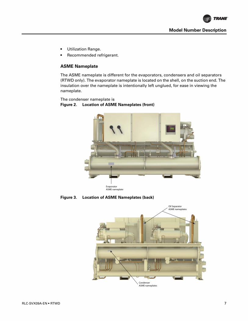
ASME Nameplate
The ASME nameplate is different for the evaporators, condensers and oil separators (RTWD only). The evaporator nameplate is located on the shell, on the suction end. The insulation over the nameplate is intentionally left unglued, for ease in viewing the nameplate.
The condenser nameplate is Figure 2. Location of ASME Nameplates (front)
Figure 3. Location of ASME Nameplates (back)
RLC-SVX09A-EN • RTWD 7
Model Number Description
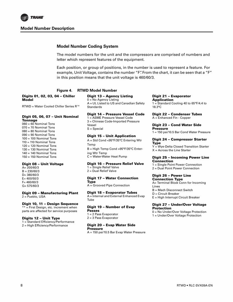
Model Number Coding System
The model numbers for the unit and the compressors are comprised of numbers and letter which represent features of the equipment.
Each position, or group of positions, in the number is used to represent a feature. For example, Unit Voltage, contains the number “F”. From the chart, it can be seen that a “F” in this position means that the unit voltage is 460/60/3.
Figure 4. RTWD Model Number
Digits 01, 02, 03, 04 – Chiller Model
RTWD = Water Cooled Chiller Series R™
Digit 05, 06, 07 – Unit Nominal Tonnage060 = 60 Nominal Tons070 = 70 Nominal Tons080 = 80 Nominal Tons090 = 90 Nominal Tons100 = 100 Nominal Tons110 = 110 Nominal Tons120 = 120 Nominal Tons130 = 130 Nominal Tons140 = 140 Nominal Tons150 = 150 Nominal Tons
Digit 08 – Unit VoltageA= 200/60/3B = 230/60/3D= 380/60/3E= 400/50/3F= 460/60/3G= 575/60/3
Digit 09 – Manufacturing Plant2 = Pueblo, USA
Digit 10, 11 – Design Sequence** = First Design, etc. increment when parts are affected for service purposes
Digits 12 – Unit Type1 = Standard Efficiency/Performance2 = High Efficiency/Performance
Digit 13 – Agency Listing0 = No Agency ListingA = UL Listed to US and Canadian Safety Standards
Digit 14 – Pressure Vessel Code1 = ASME Pressure Vessel Code3 = Chinese Code-Imported Pressure Vessel S = Special
Digit 15 – Unit ApplicationA = Std Cond <95°F/35°C Entering Wtr TempB = High Temp Cond >95°F/35°C Enter-ing Wtr TempC = Water-Water Heat Pump
Digit 16 – Pressure Relief Valve1 = Single Relief Valve2 = Dual Relief Valve
Digit 17 – Water Connection TypeA = Grooved Pipe Connection
Digit 18 – Evaporator TubesA = Internal and External Enhanced Evap Tube
Digit 19 – Number of Evap Passes1 = 2 Pass Evaporator2 = 3 Pass Evaporator
Digit 20 – Evap Water Side PressureA = 150 psi/10.5 Bar Evap Water Pressure
Digit 21 – Evaporator Application1 = Standard Cooling 40 to 65°F/4.4 to 18.3°C
Digit 22 – Condenser TubesA = Enhanced Fin - Copper
Digit 23 – Cond Water Side Pressure1 = 150 psi/10.5 Bar Cond Water Pressure
Digit 24 – Compressor Starter TypeY = Wye-Delta Closed Transition StarterX = Across the Line Starter
Digit 25 – Incoming Power Line Connection1 = Single Point Power Connection2 = Dual Point Power Connection
Digit 26 – Power Line Connection TypeA= Terminal Block Conn for Incoming LinesB = Mech Disconnect SwitchD = Circuit BreakerE = High Interrupt Circuit Breaker
Digit 27 – Under/Over Voltage Protection0 = No Under/Over Voltage Protection1 = Under/Over Voltage Protection
8 RTWD • RLC-SVX09A-EN
Model Number Description
RTWD Model Number (cont.)
Digit 28 – Unit Operator InterfaceA = Dyna-View/EnglishB = Dyna-View/SpanishC = Dyna-View/Spanish-MexicoD = Dyna-View/FrenchE = Dyna-View/GermanF = Dyna-View/DutchG = Dyna-View/ItalianH = Dyna-View/JapaneseJ = Dyna-View/Portuguese-PortugalK = Dyna-View/Portuguese-BrazilL = Dyna-View/KoreanM = Dyna-View/ThaiN = Dyna-View/Simplified ChineseP = Dyna-View/Traditional ChineseR = Dyna-View/RussianT = Dyna-View/PolishU = Dyna-View/CzechV = Dyna-View/HungarianW = Dyna-View/GreekX = Dyna-View/RomanianY = Dyna-View/Swedish
Digit 29 – Remote Interface (Digital Comm)0 = No Remote Digital Communication1 = LonTalk/Tracer Summit Interface2 = Time of Day Scheduling
Digit 30 – Ext Water & Curr Limit Setpoint0 = No Ext Water & Curr Limit SetpointA = Ext Water & Curr Limit Setpoint - 4–20 mAB = Ext Water & Curr Limit Setpoint - 2–10 Vdc
Digit 32 – Programmable Relays0 = No Programmable RelaysA = Programmable Relays
Digit 33 – Cond Refrigerant Pressure Output Option0 = No Condenser Refrigerant Output1 = Condenser Water Control Output
Digits 34 – Outdoor Air Temp Sensor0 = No Outdoor Air Temp SensorA = Outdoor Air Temp Sensor-CWR/Low Ambient
Digit 35 – Cond Leaving Hot Water Temp Control
0 = No Cond Leaving Hot Water Temp Control1 = Cond Leaving Hot Water Temp Control
Digit 36 – Power Meter0 = No Power MeterP = Power Meter
Digit 37 – Motor Current Analog Output (%RLA)0 = No Motor Current Analog Output1 = Motor Current Analog Output
Digit 40 – Installation Accessories0 = No Installation AccessoriesA = Elastomeric IsolatorsB = Flanged Water Connection KitC = Isolators & Flanged Water Connection Kit
Digit 41 – Flow Switch0 = 150 psi NEMA 1 Flow Switch; Qty 11 = 150 psi NEMA 1 Flow Switch; Qty 22 = 150 psi NEMA 4 Flow Switch; Qty 13 = 150 psi NEMA 4 Flow Switch; Qty 2
Digit 42 – 2-Way Water Regulating Valve0 = No 2-Way Water Regulating ValveA = 3” 150 psi 115-220 V 2-Way Water Reg ValveB = 4” 150 psi 115-220 V 2-Way Water Reg Valve
Digit 44 – Insulation0 = No Insulation1 = Factory Insulation2 = Insulation for High Humidity
Digit 45 – Factory Charge0 = Full Factory Refrigerant Charge (134a)1 = Nitrogen Charge
Digit 46 – Base Rail Forklifting0 = No Base Rail ForkliftingB = Base Rail Forklifting
Digit 47 – Label and Literature LanguageA = BulgarianB = Spanish and EnglishC = GermanD = EnglishE = French and English
F = Chinese - SimpleG = Chinese - TraditionalH = Dutch SI (Hollandais)J = ItalianK = FinishL = DanishM = SwedishN = NorwegianP = PolishR = RussianT = CzechU = GreekV = PortugueseW = SloveneX = RomanianY = SerbianZ = Slovak1 = Croatian2 = Hungarian
Digit 48 – Specials0 = NoneA = Special Denoted ElsewhereS = Specials not Denoted Elsewhere
RLC-SVX09A-EN • RTWD 9
Model Number Description
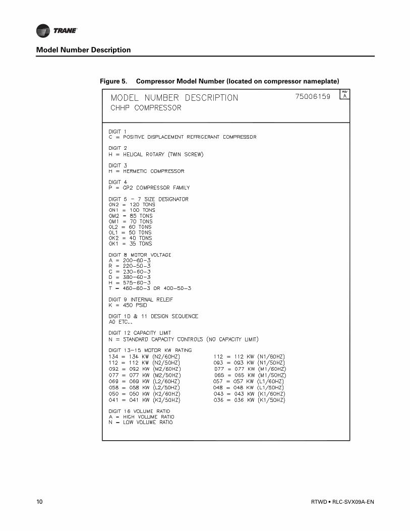
Figure 5. Compressor Model Number (located on compressor nameplate)
10 RTWD • RLC-SVX09A-EN
General Information
Unit Description
The RTWD units are helical-rotary type, water-cooled, liquid chillers, designed for installation indoors. The units have 2 independent refrigerant circuits, with one compressor per circuit. The RTWD units are packaged with an evaporator and condenser.
Note: Each RTWD unit is a completely assembled, hermetic package that is factory-piped, wired, leak-tested, dehydrated, charged and tested for proper control operations prior to shipment. The chilled water inlet and outlet openings are covered for shipment.
The RTWD series features Trane's exclusive Adaptive Control logic with CH530 controls. It monitors the control variables that govern the operation of the chiller unit. Adaptive Control logic can correct these variables, when necessary, to optimize operational efficiencies, avoid chiller shutdown, and keep producing chilled water.
Compressor unloaders are solenoid actuated. Each refrigerant circuit is provided with filter drier, sight glass, electronic expansion valve, and charging valves on the RTWD.
The evaporator is manufactured in accordance with ASME standards. Each evaporator is fully insulated and is equipped with water drain and vent connections.
Accessory/Options Information
Check all the accessories and loose parts which are shipped with the unit against shipping list. Included in these items will be water vessel drain plugs, rigging, electrical diagrams, and service literature, which are placed inside the control panel and/or starter panel for shipment. Also check for optional components, such as flow switches and isalotors.
RLC-SVX09A-EN • RTWD 11
General Information
12 RTWD • RLC-SVX09A-EN
Pre-Installation
Inspection Checklist
When the unit is delivered, verify that it is the correct unit and that it is properly equipped. Compare the information which appears on the unit nameplate with the ordering and submittal information. Refer to “Nameplates”.
Inspect all exterior components for visible damage. Report any apparent damage or material shortage to the carrier and make a “unit damage” notation on the carrier's delivery receipt. Specify the extent and type of damage found and notify the appropriate Trane Sales Office.
Do not proceed with installation of a damaged unit without sales office approval.
To protect against loss due to damage incurred in transit, complete the following checklist upon receipt of the unit.
• Inspect the individual pieces of the shipment before accepting the unit. Check for obvious damage to the unit or packing material.
• Inspect the unit for concealed damage as soon as possible after delivery and before it is stored. Concealed damage must be reported within 15 days.
• If concealed damage is discovered, stop unpacking the shipment. Do not remove damaged material from the receiving location. Take photos of the damage, if possible. The owner must provide reasonable evidence that the damage did not occur after delivery.
• Notify the carrier's terminal of the damage immediately, by phone and by mail. Request an immediate, joint inspection of the damage with the carrier and the consignee.
• Notify the Trane sales representative and arrange for repair. Do not repair the unit, however, until damage is inspected by the carrier's representative.
Unit Storage
If the chiller is to be stored for more than one month prior to installation, observe the following precautions:
• Do not remove the protective coverings from the electrical panel.
• Store the chiller in a dry, vibration-free, secure area.
• At least every three months, attach a gauge and manually check the pressure in the refrigerant circuit. If the refrigerant pressure is below 71 psig at 70 F (or 46 psig at 50 F), call a qualified service organization and the appropriate Trane sales office.
Note: Pressure will be approximately 20 psig if shipped with the optional nitrogen charge.
Installation requirements and Contractor responsibilitiesA list of the contractor responsibilities typically associated with the unit installation process is provided.
Unit Start-up must be completed by a qualified Trane service technician.
RLC-SVX09A-EN • RTWD 13
Pre-Installation
Type of Requirement
Trane SuppliedTrane Installed
Trane SuppliedField Installed
Field SuppliedField Installed
Foundation • Meet foundation requirements
Rigging • Safety chainsClevis connectorsLifting beam
Isolation • Isolation pads or spring isolators
• Isolation pads or spring isolators
Electrical • Circuit breakers or fusible disconnects (optional)
• Unit mounted starter
• Flow switches (may be field supplies)
• Circuit breakers or fusible disconnects (optional)• Electrical connections to unit mounted starter (optional)• Electrical connections to remote mounted starter (optional)• Wiring sizes per submittal and NEC• PFCCs (remote mounted starter optional only)• Terminal lugs• Ground connection(s)• BAS wiring (optional)• Control voltage wiringChilled water pump contactor and wiring
including interlock• Condenser water pump contactor and wiring including interlock• Option relays and wiring
Water piping • Flow switches (may be field supplied)
• Taps for thermometers and gauges• Thermometers• Strainers (as required)• Water flow pressure gauges• Isolation and balancing valves in water piping• Vents and drain on waterbox valves (1 each per pass)• Pressure relief valves (for waterboxes as required)
Relief • Rupture disc assembly • Vent line and flexible connector and vent line from rupture disc to atmosphere
Insulation • Insulation • Insulation
Water Piping Connection Components
Flanged• Victaulic to flange
adapter for 150 psig waterboxes
Other Materials • R-134A refrigerant (1 lb. maximum per machine as needed)• Dry nitrogen (8 psig maximum per machine as needed)
14 RTWD • RLC-SVX09A-EN
Unit Dimensions/Weights
General Data
Table 1. General Data - RTWD 70-150 60 Hz - standard efficiency
Size 80 90 100 110 120 130 140
Compressor
Quantity 2 2 2 2 2 2 2
Evaporator
Water Storage (gal) 11.2 11.2 12.6 14 15.2 16.2 17.7
(L) 42.2 42.2 47.6 53.0 57.4 61.5 66.8
2 Pass Arrangement
Water Conn. Size NPS 4 4 4 4 5 5 5
mm 100 100 100 100 125 125 125
Minimum Flow (gpm) 77 77 89 101 101 110 122
(L/s) 4.9 4.9 5.6 6.4 6.4 6.9 7.7
Maximum Flow (gpm) 281 281 325 368 368 400 444
(L/s) 17.7 17.7 20.5 23.2 23.2 25.2 28
3 Pass Arrangement
Water Conn. Size NPS 3 3 3 3 4 4 4
mm 80 80 80 80 100 100 100
Minimum Flow (gpm) 52 52 59 67 67 73 81
(L/s) 3.3 3.3 3.8 4.3 4.3 4.6 5.1
Maximum Flow (gpm) 187 187 216 244 244 266 295
(L/s) 11.8 11.8 13.6 15.4 15.4 16.8 18.6
Condenser
Water Storage (gal) 12.4 14.2 16.0 16.9 18.5 18.5 20.9
(L) 46.8 53.6 60.4 63.8 70.1 70.1 79.2
Water Conn. Size NPS 5 5 5 5 5 5 5
mm 125 125 125 125 125 125 125
Minimum Flow (gpm) 83 99 115 124 135 135 156
(L/s) 5.2 6.3 7.3 7.8 8.5 8.5 9.9
Maximum Flow (gpm) 301 361 421 451 491 491 572
(L/s) 18.9 22.7 26.5 28.4 31.0 31.0 36.0
General Unit
Refrigerant Type R134a R134a R134a R134a R134a R134a R134a
# Refrig Circuits 2 2 2 2 2 2 2
Refrigerant Charge (lb) 114.6/114.6 114.6/114.6 112.4/114.6 112.4/112.4 132.3/132.3 130.1/130.1 127.9/132.3
(kg) 52/52 52/52 51/52 51/51 60/60 59/59 58/60
Oil Charge (quarts) 7.2/7.2 7.2/7.2 7.2/10.5 10.5/10.5 10.5/10.5 10.5/10.5 10.5/10.5
(L) 6.8/6.8 6.8/6.8 6.8/9.9 9.9/9.9 9.9/9.9 9.9/9.9 9.9/9.9
1. Data containing information on two circuits is shown as circuit 1/circuit 2.
2. Flow limits are for water only.
RLC-SVX09A-EN • RTWD 15
Unit Dimensions/Weights
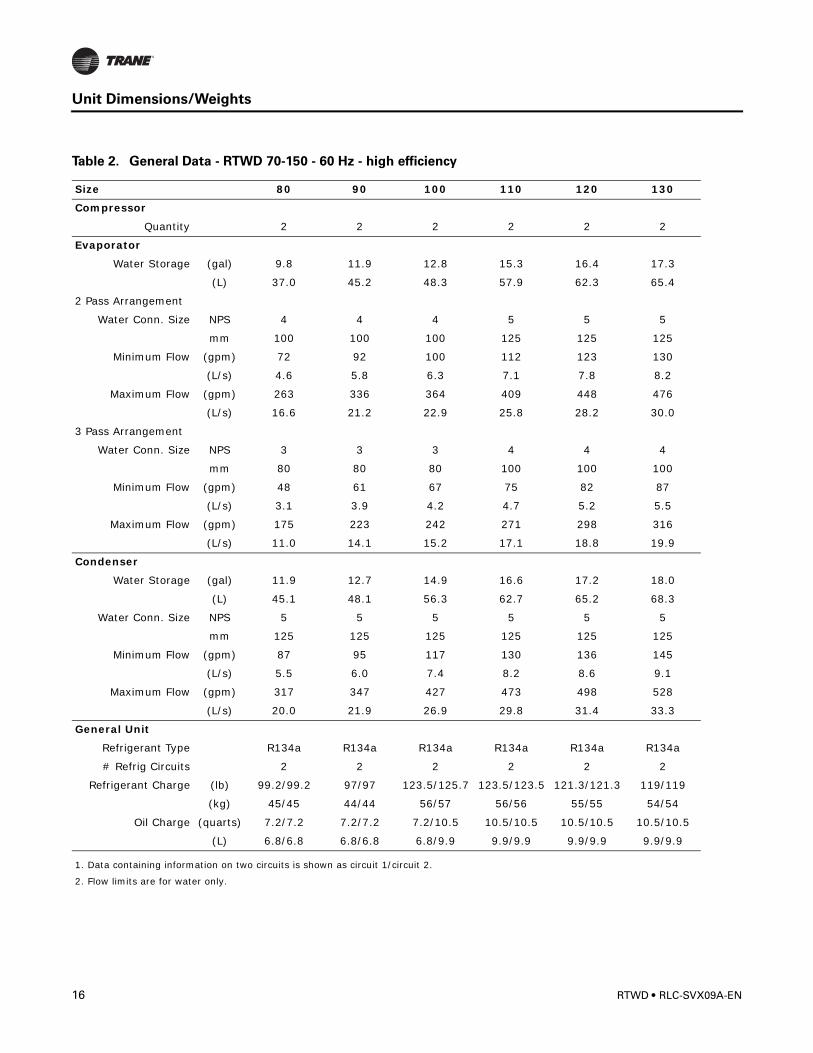
Table 2. General Data - RTWD 70-150 - 60 Hz - high efficiency
Size 80 90 100 110 120 130
Compressor
Quantity 2 2 2 2 2 2
Evaporator
Water Storage (gal) 9.8 11.9 12.8 15.3 16.4 17.3
(L) 37.0 45.2 48.3 57.9 62.3 65.4
2 Pass Arrangement
Water Conn. Size NPS 4 4 4 5 5 5
mm 100 100 100 125 125 125
Minimum Flow (gpm) 72 92 100 112 123 130
(L/s) 4.6 5.8 6.3 7.1 7.8 8.2
Maximum Flow (gpm) 263 336 364 409 448 476
(L/s) 16.6 21.2 22.9 25.8 28.2 30.0
3 Pass Arrangement
Water Conn. Size NPS 3 3 3 4 4 4
mm 80 80 80 100 100 100
Minimum Flow (gpm) 48 61 67 75 82 87
(L/s) 3.1 3.9 4.2 4.7 5.2 5.5
Maximum Flow (gpm) 175 223 242 271 298 316
(L/s) 11.0 14.1 15.2 17.1 18.8 19.9
Condenser
Water Storage (gal) 11.9 12.7 14.9 16.6 17.2 18.0
(L) 45.1 48.1 56.3 62.7 65.2 68.3
Water Conn. Size NPS 5 5 5 5 5 5
mm 125 125 125 125 125 125
Minimum Flow (gpm) 87 95 117 130 136 145
(L/s) 5.5 6.0 7.4 8.2 8.6 9.1
Maximum Flow (gpm) 317 347 427 473 498 528
(L/s) 20.0 21.9 26.9 29.8 31.4 33.3
General Unit
Refrigerant Type R134a R134a R134a R134a R134a R134a
# Refrig Circuits 2 2 2 2 2 2
Refrigerant Charge (lb) 99.2/99.2 97/97 123.5/125.7 123.5/123.5 121.3/121.3 119/119
(kg) 45/45 44/44 56/57 56/56 55/55 54/54
Oil Charge (quarts) 7.2/7.2 7.2/7.2 7.2/10.5 10.5/10.5 10.5/10.5 10.5/10.5
(L) 6.8/6.8 6.8/6.8 6.8/9.9 9.9/9.9 9.9/9.9 9.9/9.9
1. Data containing information on two circuits is shown as circuit 1/circuit 2.
2. Flow limits are for water only.
16 RTWD • RLC-SVX09A-EN
Unit Dimensions/Weights
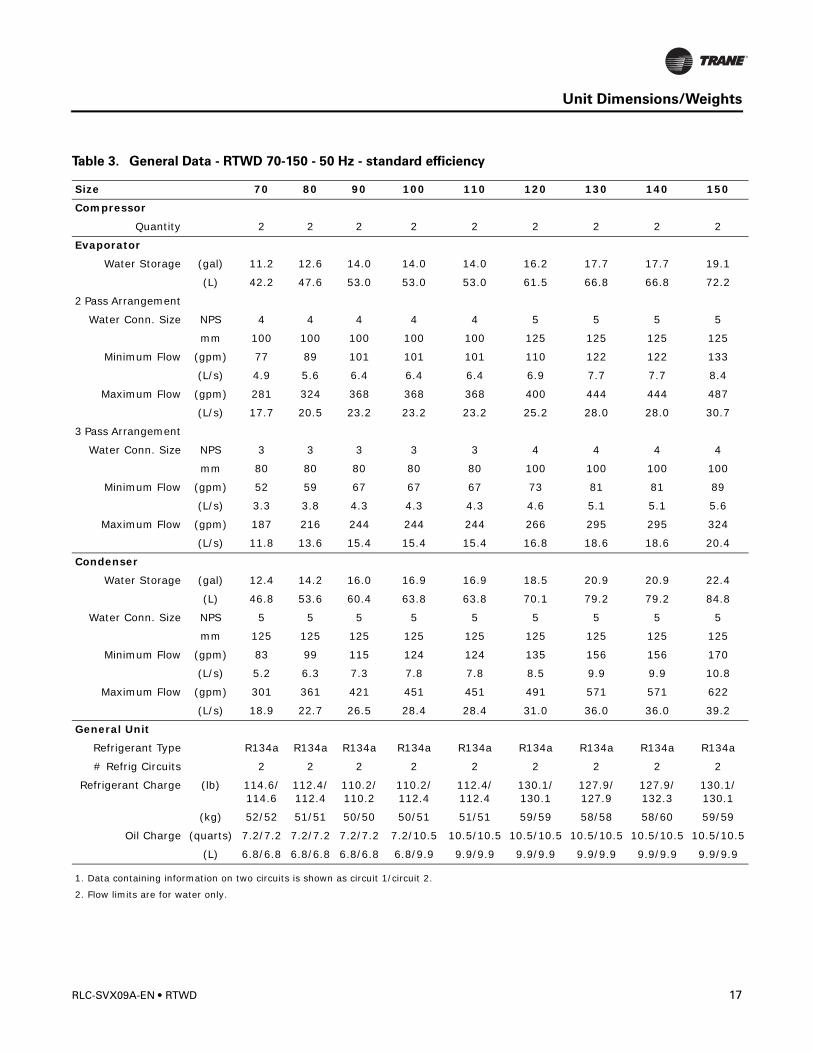
Table 3. General Data - RTWD 70-150 - 50 Hz - standard efficiency
Size 70 80 90 100 110 120 130 140 150
Compressor
Quantity 2 2 2 2 2 2 2 2 2
Evaporator
Water Storage (gal) 11.2 12.6 14.0 14.0 14.0 16.2 17.7 17.7 19.1
(L) 42.2 47.6 53.0 53.0 53.0 61.5 66.8 66.8 72.2
2 Pass Arrangement
Water Conn. Size NPS 4 4 4 4 4 5 5 5 5
mm 100 100 100 100 100 125 125 125 125
Minimum Flow (gpm) 77 89 101 101 101 110 122 122 133
(L/s) 4.9 5.6 6.4 6.4 6.4 6.9 7.7 7.7 8.4
Maximum Flow (gpm) 281 324 368 368 368 400 444 444 487
(L/s) 17.7 20.5 23.2 23.2 23.2 25.2 28.0 28.0 30.7
3 Pass Arrangement
Water Conn. Size NPS 3 3 3 3 3 4 4 4 4
mm 80 80 80 80 80 100 100 100 100
Minimum Flow (gpm) 52 59 67 67 67 73 81 81 89
(L/s) 3.3 3.8 4.3 4.3 4.3 4.6 5.1 5.1 5.6
Maximum Flow (gpm) 187 216 244 244 244 266 295 295 324
(L/s) 11.8 13.6 15.4 15.4 15.4 16.8 18.6 18.6 20.4
Condenser
Water Storage (gal) 12.4 14.2 16.0 16.9 16.9 18.5 20.9 20.9 22.4
(L) 46.8 53.6 60.4 63.8 63.8 70.1 79.2 79.2 84.8
Water Conn. Size NPS 5 5 5 5 5 5 5 5 5
mm 125 125 125 125 125 125 125 125 125
Minimum Flow (gpm) 83 99 115 124 124 135 156 156 170
(L/s) 5.2 6.3 7.3 7.8 7.8 8.5 9.9 9.9 10.8
Maximum Flow (gpm) 301 361 421 451 451 491 571 571 622
(L/s) 18.9 22.7 26.5 28.4 28.4 31.0 36.0 36.0 39.2
General Unit
Refrigerant Type R134a R134a R134a R134a R134a R134a R134a R134a R134a
# Refrig Circuits 2 2 2 2 2 2 2 2 2
Refrigerant Charge (lb) 114.6/114.6
112.4/112.4
110.2/110.2
110.2/112.4
112.4/112.4
130.1/130.1
127.9/127.9
127.9/132.3
130.1/130.1
(kg) 52/52 51/51 50/50 50/51 51/51 59/59 58/58 58/60 59/59
Oil Charge (quarts) 7.2/7.2 7.2/7.2 7.2/7.2 7.2/10.5 10.5/10.5 10.5/10.5 10.5/10.5 10.5/10.5 10.5/10.5
(L) 6.8/6.8 6.8/6.8 6.8/6.8 6.8/9.9 9.9/9.9 9.9/9.9 9.9/9.9 9.9/9.9 9.9/9.9
1. Data containing information on two circuits is shown as circuit 1/circuit 2.
2. Flow limits are for water only.
RLC-SVX09A-EN • RTWD 17
Unit Dimensions/Weights
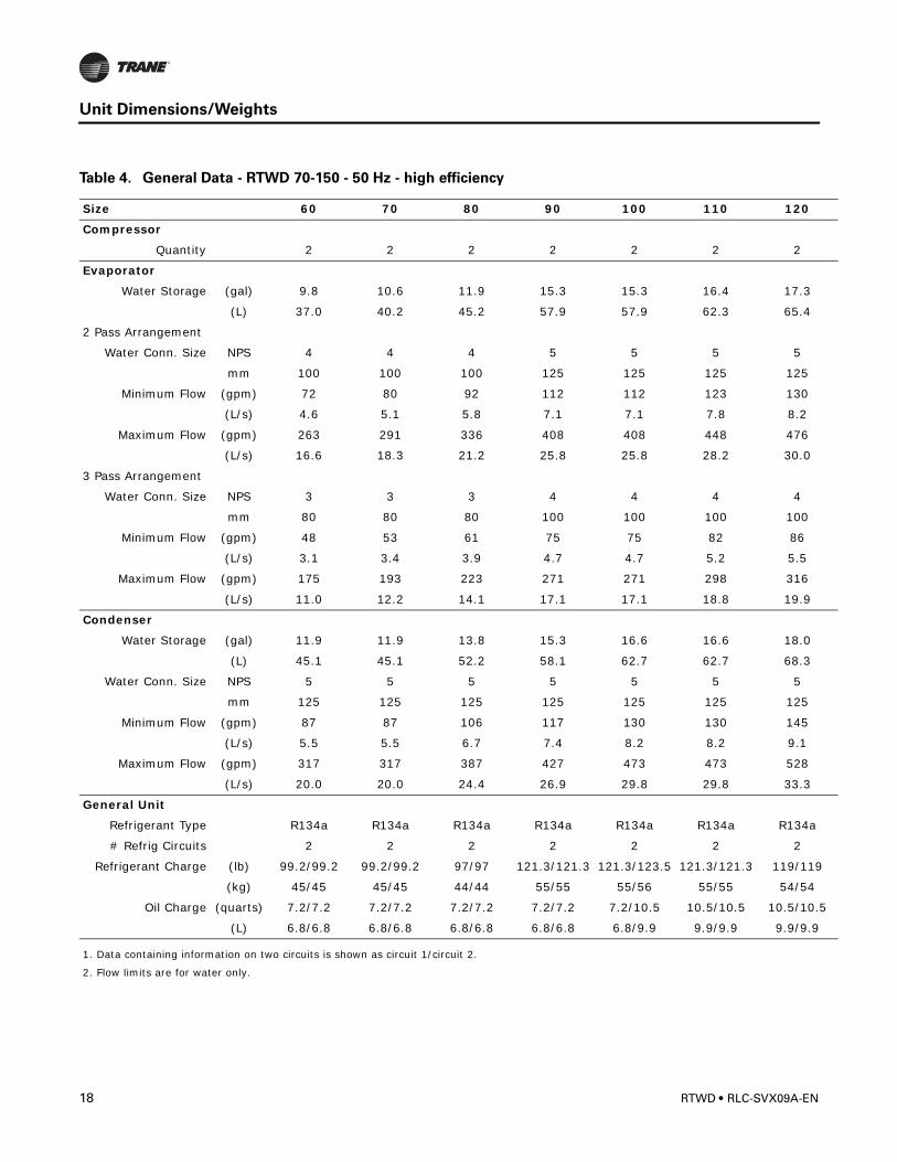
Table 4. General Data - RTWD 70-150 - 50 Hz - high efficiency
Size 60 70 80 90 100 110 120
Compressor
Quantity 2 2 2 2 2 2 2
Evaporator
Water Storage (gal) 9.8 10.6 11.9 15.3 15.3 16.4 17.3
(L) 37.0 40.2 45.2 57.9 57.9 62.3 65.4
2 Pass Arrangement
Water Conn. Size NPS 4 4 4 5 5 5 5
mm 100 100 100 125 125 125 125
Minimum Flow (gpm) 72 80 92 112 112 123 130
(L/s) 4.6 5.1 5.8 7.1 7.1 7.8 8.2
Maximum Flow (gpm) 263 291 336 408 408 448 476
(L/s) 16.6 18.3 21.2 25.8 25.8 28.2 30.0
3 Pass Arrangement
Water Conn. Size NPS 3 3 3 4 4 4 4
mm 80 80 80 100 100 100 100
Minimum Flow (gpm) 48 53 61 75 75 82 86
(L/s) 3.1 3.4 3.9 4.7 4.7 5.2 5.5
Maximum Flow (gpm) 175 193 223 271 271 298 316
(L/s) 11.0 12.2 14.1 17.1 17.1 18.8 19.9
Condenser
Water Storage (gal) 11.9 11.9 13.8 15.3 16.6 16.6 18.0
(L) 45.1 45.1 52.2 58.1 62.7 62.7 68.3
Water Conn. Size NPS 5 5 5 5 5 5 5
mm 125 125 125 125 125 125 125
Minimum Flow (gpm) 87 87 106 117 130 130 145
(L/s) 5.5 5.5 6.7 7.4 8.2 8.2 9.1
Maximum Flow (gpm) 317 317 387 427 473 473 528
(L/s) 20.0 20.0 24.4 26.9 29.8 29.8 33.3
General Unit
Refrigerant Type R134a R134a R134a R134a R134a R134a R134a
# Refrig Circuits 2 2 2 2 2 2 2
Refrigerant Charge (lb) 99.2/99.2 99.2/99.2 97/97 121.3/121.3 121.3/123.5 121.3/121.3 119/119
(kg) 45/45 45/45 44/44 55/55 55/56 55/55 54/54
Oil Charge (quarts) 7.2/7.2 7.2/7.2 7.2/7.2 7.2/7.2 7.2/10.5 10.5/10.5 10.5/10.5
(L) 6.8/6.8 6.8/6.8 6.8/6.8 6.8/6.8 6.8/9.9 9.9/9.9 9.9/9.9
1. Data containing information on two circuits is shown as circuit 1/circuit 2.
2. Flow limits are for water only.
18 RTWD • RLC-SVX09A-EN
Unit Dimensions/Weights
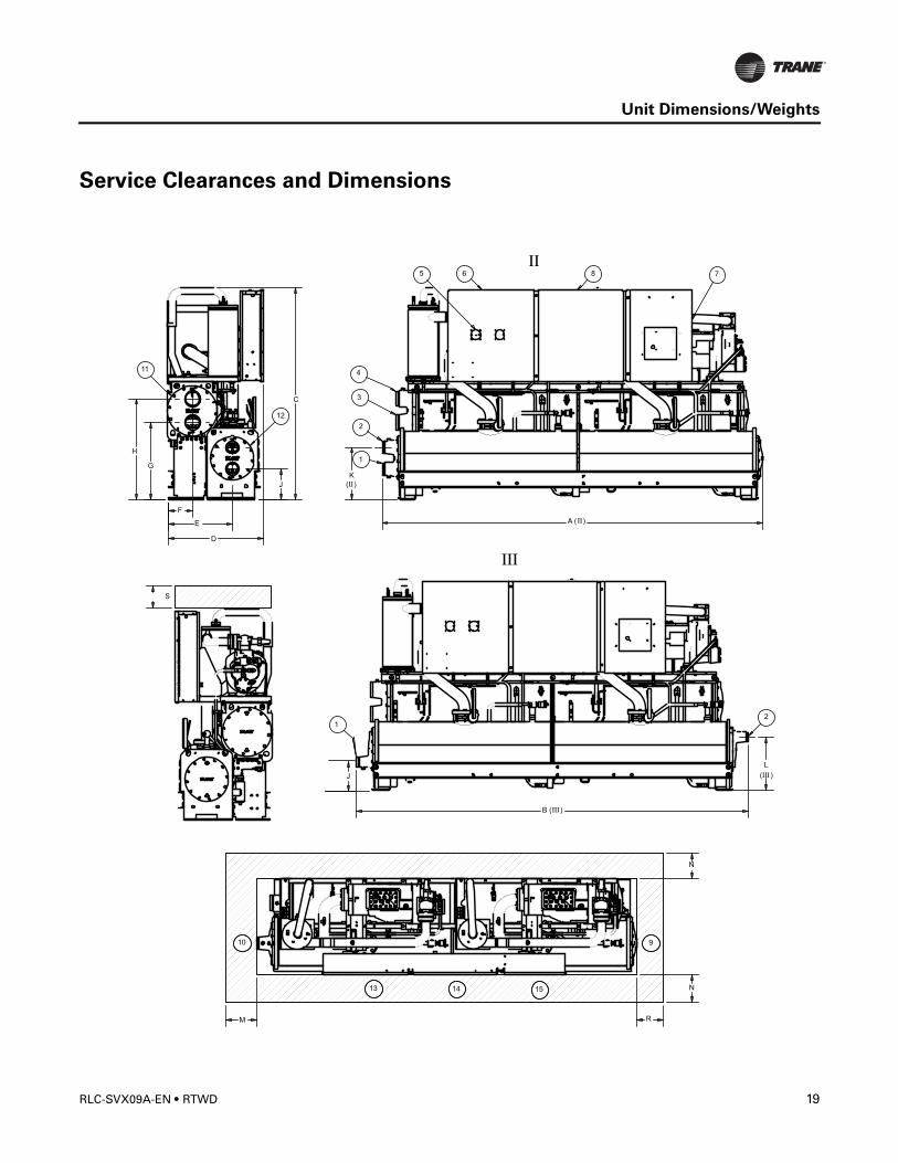
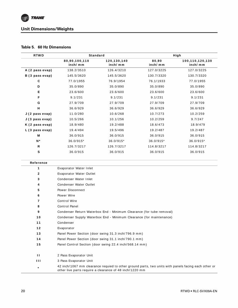
Service Clearances and Dimensions
10 9
13 14 15
2
1
3
411
5 6 8 7
12
12
A ( )
G
H
C
D
E
F
N
RM
B ( )
J
L
( )
K
( )
N
J
S
RLC-SVX09A-EN • RTWD 19
Unit Dimensions/Weights
Table 5. 60 Hz Dimensions
RTWD Standard High
80,90,100,110inch/mm
120,130,140inch/mm
80,90inch/mm
100,110,120,130inch/mm
A (2 pass evap) 138.2/3510 126.4/3210 127.0/3225 127.0/3225
B (3 pass evap) 145.5/3620 145.5/3620 130.7/3320 130.7/3320
C 77.0/1955 76.9/1954 76.1/1933 77.0/1955
D 35.0/890 35.0/890 35.0/890 35.0/890
E 23.6/600 23.6/600 23.6/600 23.6/600
F 9.1/231 9.1/231 9.1/231 9.1/231
G 27.9/709 27.9/709 27.9/709 27.9/709
H 36.6/929 36.6/929 36.6/929 36.6/929
J (2 pass evap) 11.0/280 10.6/268 10.7/273 10.2/259
J (3 pass evap) 10.5/266 10.1/256 10.2/259 9.7/247
K (2 pass evap) 18.9/480 19.2/488 18.6/473 18.9/479
L (3 pass evap) 19.4/494 19.5/496 19.2/487 19.2/487
M 36.0/915 36.0/915 36.0/915 36.0/915
N* 36.0/915* 36.0/915* 36.0/915* 36.0/915*
R 126.7/3217 126.7/3217 114.8/3217 114.8/3217
S 36.0/915 36.0/915 36.0/915 36.0/915
Reference
1 Evaporator Water Inlet
2 Evaporator Water Outlet
3 Condenser Water Inlet
4 Condenser Water Outlet
5 Power Disconnect
6 Power Wire
7 Control Wire
8 Control Panel
9 Condenser Return Waterbox End - Minimum Clearance (for tube removal)
10 Condenser Supply Waterbox End - Minimum Clearance (for maintenance)
11 Condenser
12 Evaporator
13 Panel Power Section (door swing 31.3 inch/796.9 mm)
14 Panel Power Section (door swing 31.1 inch/790.1 mm)
15 Panel Control Section (door swing 22.4 inch/568.14 mm)
II 2 Pass Evaporator Unit
III 3 Pass Evaporator Unit
*42 inch/1067 mm clearance requied to other ground parts, two units with panels facing each other or other live parts require a clearance of 48 inch/1220 mm
20 RTWD • RLC-SVX09A-EN
Unit Dimensions/Weights
10 9
13 14 15
2
1
3
411
5 6 8 7
12
12
A ( )
G
H
C
D
E
F
N
RM
B ( )
J
L
( )
K
( )
N
J
S
RLC-SVX09A-EN • RTWD 21

Unit Dimensions/Weights
Table 6. 50 Hz Dimensions
RTWD Standard High
70,80,90,100,110inch/mm
120,130,140,150inch/mm
60,70,80inch/mm
90,100,110,120inch/mm
A (2 pass evap) 138.2/3510 126.4/3210 127.0/3225 127.0/3225
B (3 pass evap) 145.5/3620 145.5/3620 130.7/3320 130.7/3320
C 77.0/1955 76.9/1954 76.1/1933 77.0/1955
D 35.0/890 35.0/890 35.0/890 35.0/890
E 23.6/600 23.6/600 23.6/600 23.6/600
F 9.1/231 9.1/231 9.1/231 9.1/231
G 27.9/709 27.9/709 27.9/709 27.9/709
H 36.6/929 36.6/929 36.6/929 36.6/929
J (2 pass evap) 11.0/280 10.6/268 10.7/273 10.2/259
J (3 pass evap) 10.5/266 10.1/256 10.2/259 9.7/247
K (2 pass evap) 18.9/480 19.2/488 18.6/473 18.9/479
L (3 pass evap) 19.4/494 19.5/496 19.2/487 19.2/487
M 36.0/915 36.0/915 36.0/915 36.0/915
N* 36.0/915* 36.0/915* 36.0/915* 36.0/915*
R 126.7/3217 126.7/3217 114.8/3217 114.8/3217
S 36.0/915 36.0/915 36.0/915 36.0/915
Reference
1 Evaporator Water Inlet
2 Evaporator Water Outlet
3 Condenser Water Inlet
4 Condenser Water Outlet
5 Power Disconnect
6 Power Wire
7 Control Wire
8 Control Panel
9 Condenser Return Waterbox End - Minimum Clearance (for tube removal)
10 Condenser Supply Waterbox End - Minimum Clearance (for maintenance)
11 Condenser
12 Evaporator
13 Panel Power Section (door swing 31.3 inch/796.9 mm)
14 Panel Power Section (door swing 31.1 inch/790.1 mm)
15 Panel Control Section (door swing 22.4 inch/568.14 mm)
II 2 Pass Evaporator Unit
III 3 Pass Evaporator Unit
*42 inch/1067 mm clearance requied to other ground parts, two units with panels facing each other or other live parts require a clearance of 48 inch/1220 mm
22 RTWD • RLC-SVX09A-EN
Unit Dimensions/Weights
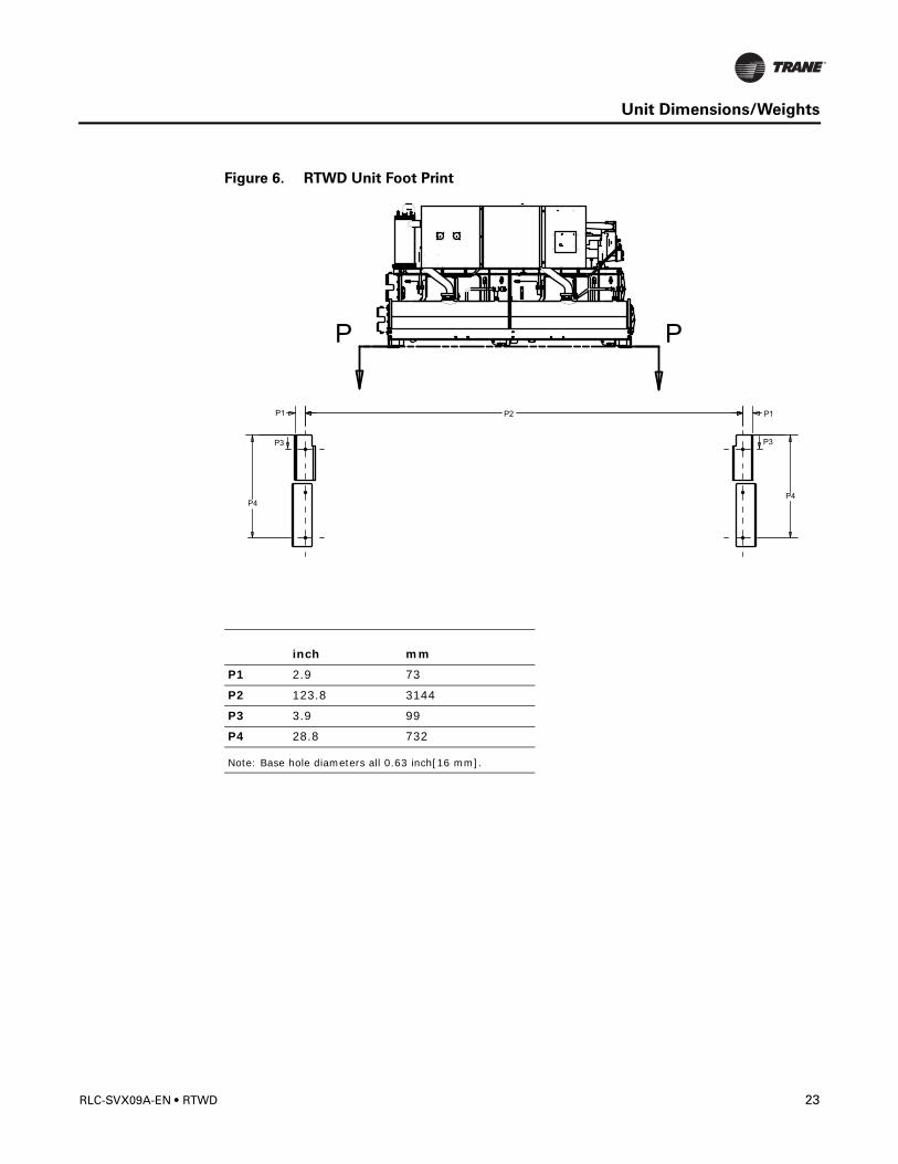
Figure 6. RTWD Unit Foot Print
inch mm
P1 2.9 73
P2 123.8 3144
P3 3.9 99
P4 28.8 732
Note: Base hole diameters all 0.63 inch[16 mm].
PP
P3
P1 P2
P3
P4
P1
P4
RLC-SVX09A-EN • RTWD 23
Unit Dimensions/Weights
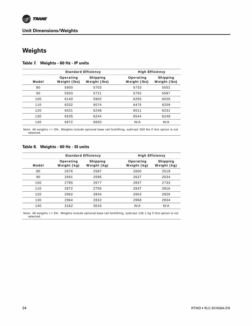
Weights
Table 7. Weights - 60 Hz - IP units
Standard Efficiency High Efficiency
ModelOperating
Weight (lbs)Shipping
Weight (lbs)Operating
Weight (lbs)Shipping
Weight (lbs)
80 5900 5703 5733 5552
90 5933 5721 5792 5587
100 6140 5902 6255 6026
110 6332 6074 6475 6209
120 6531 6248 6511 6231
130 6535 6244 6544 6248
140 6972 6650 N/A N/A
Note: All weights +/-3%. Weights include optional base rail forklifting, subtract 300 lbs if this option is not selected.
Table 8. Weights - 60 Hz - SI units
Standard Efficiency High Efficiency
ModelOperating
Weight (kg)Shipping
Weight (kg)Operating
Weight (kg)Shipping
Weight (kg)
80 2676 2587 2600 2518
90 2691 2595 2627 2534
100 2785 2677 2837 2733
110 2872 2755 2937 2816
120 2962 2834 2953 2826
130 2964 2832 2968 2834
140 3162 3016 N/A N/A
Note: All weights +/-3%. Weights include optional base rail forklifting, subtract 136.1 kg if this option is not selected.
24 RTWD • RLC-SVX09A-EN
Unit Dimensions/Weights
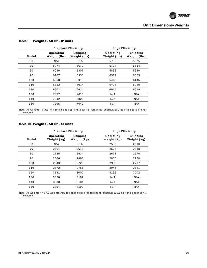
Table 9. Weights - 50 Hz - IP units
Standard Efficiency High Efficiency
ModelOperating
Weight (lbs)Shipping
Weight (lbs)Operating
Weight (lbs)Shipping
Weight (lbs)
60 N/A N/A 5706 5525
70 5874 5677 5724 5534
80 6030 5807 5893 5680
90 6187 5938 6319 6063
100 6268 6010 6412 6145
110 6332 6014 6495 6220
120 6903 6614 6914 6619
130 7337 7016 N/A N/A
140 7342 7020 N/A N/A
150 7395 7049 N/A N/A
Note: All weights +/-3%. Weights include optional base rail forklifting, subtract 300 lbs if this option is not selected.
Table 10. Weights - 50 Hz - SI units
Standard Efficiency High Efficiency
ModelOperating
Weight (kg)Shipping
Weight (kg)Operating
Weight (kg)Shipping
Weight (kg)
60 N/A N/A 2588 2506
70 2664 2575 2596 2510
80 2735 2634 2673 2576
90 2806 2693 2866 2750
100 2843 2726 2908 2787
110 2872 2755 2946 2821
120 3131 3000 3136 3002
130 3328 3182 N/A N/A
140 3330 3184 N/A N/A
150 3354 3197 N/A N/A
Note: All weights +/-3%. Weights include optional base rail forklifting, subtract 136.1 kg if this option is not selected.
RLC-SVX09A-EN • RTWD 25
Unit Dimensions/Weights
26 RTWD • RLC-SVX09A-EN
Installation - Mechanical
Location Requirements
Noise Considerations• Refer to Trane Engineering Bulletin -Series R® Chiller Sound Ratings and Installation
Guide for sound consideration applications.
• Locate the unit away from sound-sensitive areas.
• Install the isolation pads under the unit. Refer to “Unit Isolation.”
• Install rubber vibration isolators in all water piping.
• Use flexible electrical conduit for final connection to the CH530.
• Seal all wall penetrations.
Note: Consult an acoustical engineer for critical applications.
Foundation
Provide rigid, non-warping mounting pads or a concrete foundation of sufficient strength and mass to support the applicable operating weight (i.e., including completed piping, and full operating charges of refrigerant, oil and water). Refer to Tables 1, 3 and 4 for unit operating weights. Once in place, the unit must be level within 1/4” (6.4 mm) over its length and width. The Trane Company is not responsible for equipment problems resulting from an improperly designed or constructed foundation.
Clearances
Provide enough space around the unit to allow the installation and maintenance personnel unrestricted access to all service points. Refer to submittal drawings for the unit dimensions, to provide sufficient clearance for the opening of control panel doors and unit service. Refer to Figures 5 to 6, 8, 9 and 11 for minimum clearances. In all cases, local codes which require additional clearances will take precedence over these recommendations.
Note: Required vertical clearance above the unit is 36” (914.4 mm). There should be no piping or conduit located over the compressor motor. If the unit configuration requires a variance to the clearance dimensions, contact your Trane Sales Office Representative. Also refer to Trane Engineering Bulletins for application information on RTWD chillers.
Rigging
The Model RTWD chiller should be moved by lifting, unless the unit is ordered with the “Base Rail Forklifting” option. Refer to the unite model number, digit 46, for more details.
Refer to Figures 5, 7 and 10 for typical unit lifting and operating weights. Refer to the rigging diagram that ships with each unit for specific “per unit” weight data.
RLC-SVX09A-EN • RTWD 27
Installation - Mechanical
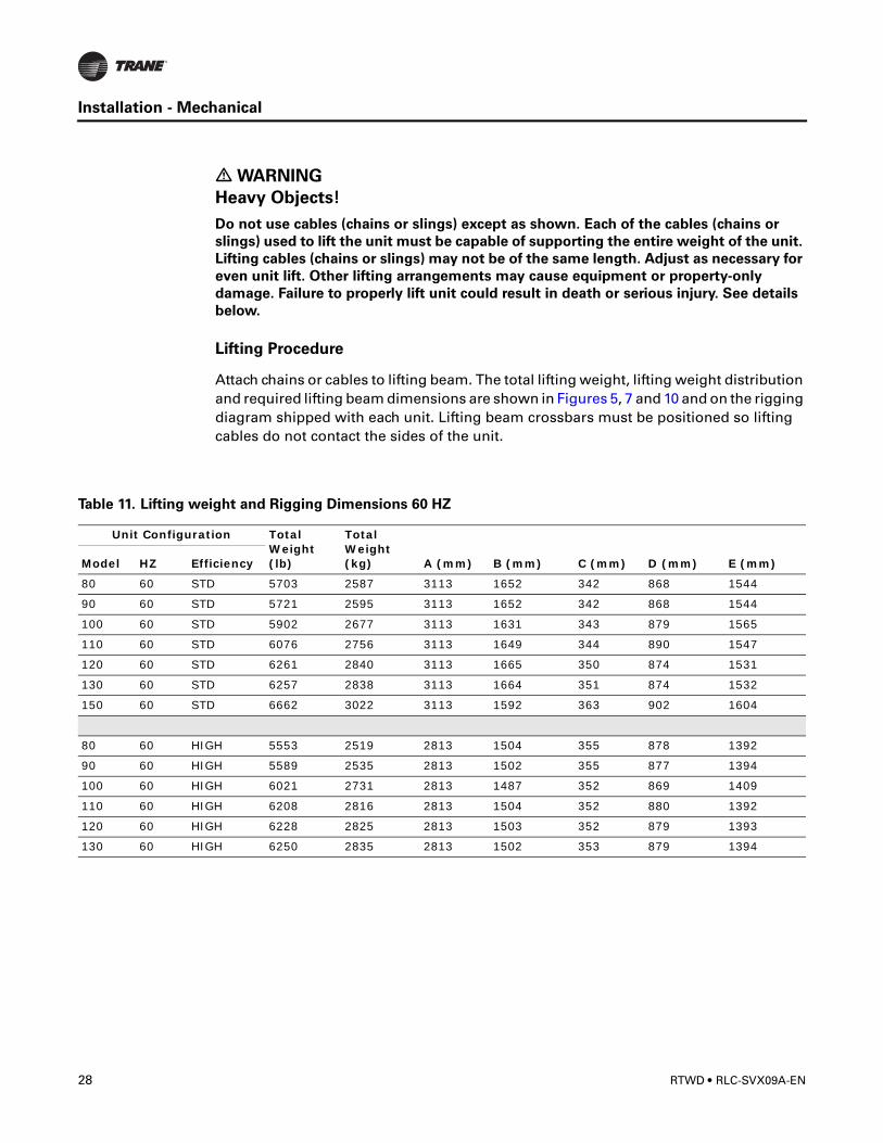
� WARNING
Heavy Objects!
Do not use cables (chains or slings) except as shown. Each of the cables (chains or
slings) used to lift the unit must be capable of supporting the entire weight of the unit.
Lifting cables (chains or slings) may not be of the same length. Adjust as necessary for
even unit lift. Other lifting arrangements may cause equipment or property-only
damage. Failure to properly lift unit could result in death or serious injury. See details
below.
Lifting Procedure
Attach chains or cables to lifting beam. The total lifting weight, lifting weight distribution and required lifting beam dimensions are shown in Figures 5, 7 and 10 and on the rigging diagram shipped with each unit. Lifting beam crossbars must be positioned so lifting cables do not contact the sides of the unit.
Table 11. Lifting weight and Rigging Dimensions 60 HZ
Unit Configuration Total Weight (lb)
Total Weight (kg) A (mm) B (mm) C (mm) D (mm) E (mm)Model HZ Efficiency
80 60 STD 5703 2587 3113 1652 342 868 1544
90 60 STD 5721 2595 3113 1652 342 868 1544
100 60 STD 5902 2677 3113 1631 343 879 1565
110 60 STD 6076 2756 3113 1649 344 890 1547
120 60 STD 6261 2840 3113 1665 350 874 1531
130 60 STD 6257 2838 3113 1664 351 874 1532
150 60 STD 6662 3022 3113 1592 363 902 1604
80 60 HIGH 5553 2519 2813 1504 355 878 1392
90 60 HIGH 5589 2535 2813 1502 355 877 1394
100 60 HIGH 6021 2731 2813 1487 352 869 1409
110 60 HIGH 6208 2816 2813 1504 352 880 1392
120 60 HIGH 6228 2825 2813 1503 352 879 1393
130 60 HIGH 6250 2835 2813 1502 353 879 1394
28 RTWD • RLC-SVX09A-EN
Installation - Mechanical
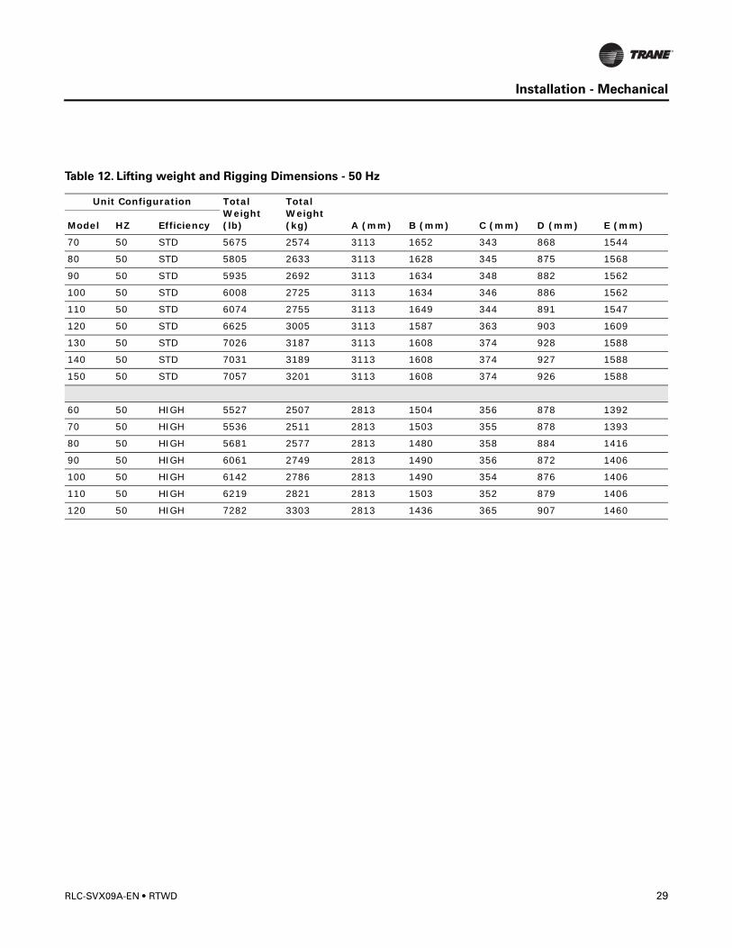
Table 12. Lifting weight and Rigging Dimensions - 50 Hz
Unit Configuration Total Weight (lb)
Total Weight (kg) A (mm) B (mm) C (mm) D (mm) E (mm)Model HZ Efficiency
70 50 STD 5675 2574 3113 1652 343 868 1544
80 50 STD 5805 2633 3113 1628 345 875 1568
90 50 STD 5935 2692 3113 1634 348 882 1562
100 50 STD 6008 2725 3113 1634 346 886 1562
110 50 STD 6074 2755 3113 1649 344 891 1547
120 50 STD 6625 3005 3113 1587 363 903 1609
130 50 STD 7026 3187 3113 1608 374 928 1588
140 50 STD 7031 3189 3113 1608 374 927 1588
150 50 STD 7057 3201 3113 1608 374 926 1588
60 50 HIGH 5527 2507 2813 1504 356 878 1392
70 50 HIGH 5536 2511 2813 1503 355 878 1393
80 50 HIGH 5681 2577 2813 1480 358 884 1416
90 50 HIGH 6061 2749 2813 1490 356 872 1406
100 50 HIGH 6142 2786 2813 1490 354 876 1406
110 50 HIGH 6219 2821 2813 1503 352 879 1406
120 50 HIGH 7282 3303 2813 1436 365 907 1460
RLC-SVX09A-EN • RTWD 29
Installation - Mechanical
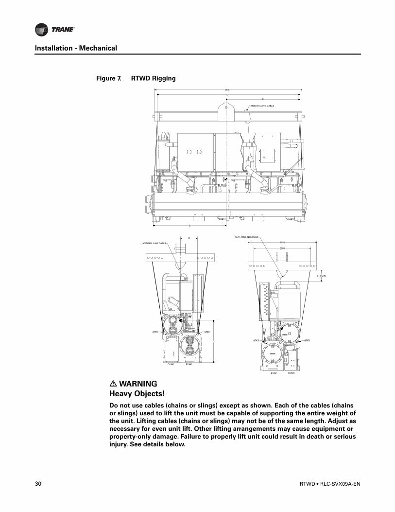
Figure 7. RTWD Rigging
� WARNING
Heavy Objects!
Do not use cables (chains or slings) except as shown. Each of the cables (chains
or slings) used to lift the unit must be capable of supporting the entire weight of
the unit. Lifting cables (chains or slings) may not be of the same length. Adjust as
necessary for even unit lift. Other lifting arrangements may cause equipment or
property-only damage. Failure to properly lift unit could result in death or serious
injury. See details below.
30 RTWD • RLC-SVX09A-EN
Installation - Mechanical
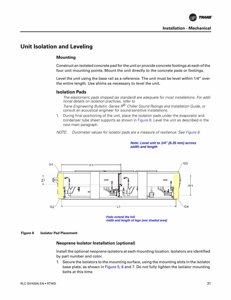
Unit Isolation and Leveling
Mounting
Construct an isolated concrete pad for the unit or provide concrete footings at each of the four unit mounting points. Mount the unit directly to the concrete pads or footings.
Level the unit using the base rail as a reference. The unit must be level within 1/4” over the entire length. Use shims as necessary to level the unit.
Isolation PadsThe elastomeric pads shipped (as standard) are adequate for most installations. For addi-tional details on isolation practices, refer to Trane Engineering Bulletin -Series R® Chiller Sound Ratings and Installation Guide, or consult an acoustical engineer for sound-sensitive installations.
1. During final positioning of the unit, place the isolation pads under the evaporator and condenser tube sheet supports as shown in Figure 8. Level the unit as described in the next main paragraph.
NOTE: Durometer values for isolator pads are a measure of resilience. See Figure 8.
Neoprene Isolator Installation (optional)
Install the optional neoprene isolators at each mounting location. Isolators are identified by part number and color.
1. Secure the isolators to the mounting surface, using the mounting slots in the isolator base plate, as shown in Figure 5, 6 and 7. Do not fully tighten the isolator mounting bolts at this time.
Figure 8 Isolator Pad Placement
Note: Level unit to 1/4” (6.35 mm) across
Pads extend the fullwidth and length of legs (see shaded area)
width and length
RLC-SVX09A-EN • RTWD 31
Installation - Mechanical
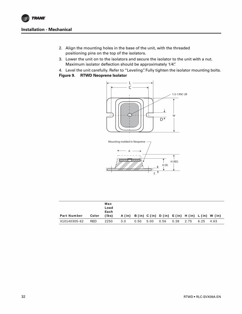
2. Align the mounting holes in the base of the unit, with the threaded positioning pins on the top of the isolators.
3. Lower the unit on to the isolators and secure the isolator to the unit with a nut. Maximum isolator deflection should be approximately 1/4”.
4. Level the unit carefully. Refer to “Leveling”. Fully tighten the isolator mounting bolts.Figure 9. RTWD Neoprene Isolator
Part Number Color
Max Load Each (lbs) A (in) B (in) C (in) D (in) E (in) H (in) L (in) W (in)
X10140305-62 RED 2250 3.0 0.50 5.00 0.56 0.38 2.75 6.25 4.63
32 RTWD • RLC-SVX09A-EN
Installation - Mechanical
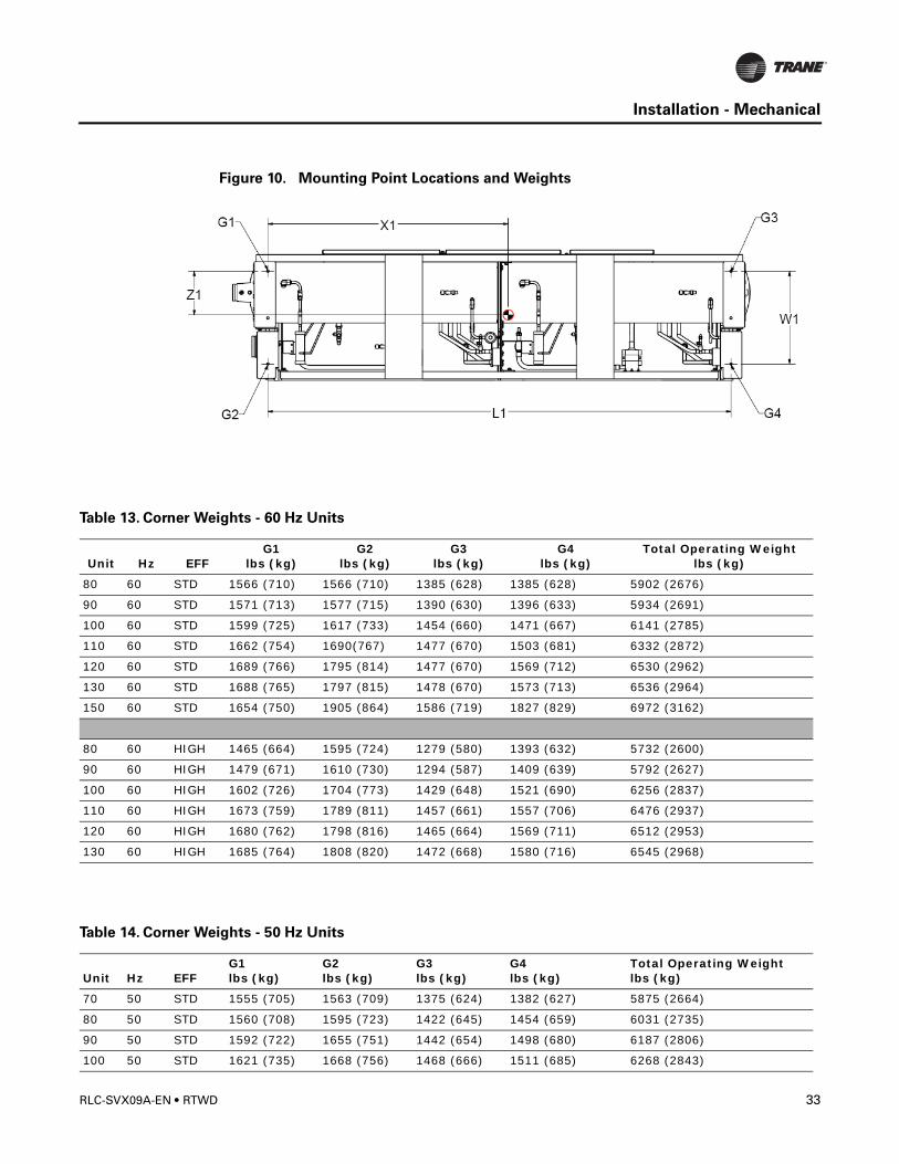
Figure 10. Mounting Point Locations and Weights
Table 13. Corner Weights - 60 Hz Units
Unit Hz EFFG1
lbs (kg)G2
lbs (kg)G3
lbs (kg)G4
lbs (kg)Total Operating Weight
lbs (kg)
80 60 STD 1566 (710) 1566 (710) 1385 (628) 1385 (628) 5902 (2676)
90 60 STD 1571 (713) 1577 (715) 1390 (630) 1396 (633) 5934 (2691)
100 60 STD 1599 (725) 1617 (733) 1454 (660) 1471 (667) 6141 (2785)
110 60 STD 1662 (754) 1690(767) 1477 (670) 1503 (681) 6332 (2872)
120 60 STD 1689 (766) 1795 (814) 1477 (670) 1569 (712) 6530 (2962)
130 60 STD 1688 (765) 1797 (815) 1478 (670) 1573 (713) 6536 (2964)
150 60 STD 1654 (750) 1905 (864) 1586 (719) 1827 (829) 6972 (3162)
80 60 HIGH 1465 (664) 1595 (724) 1279 (580) 1393 (632) 5732 (2600)
90 60 HIGH 1479 (671) 1610 (730) 1294 (587) 1409 (639) 5792 (2627)
100 60 HIGH 1602 (726) 1704 (773) 1429 (648) 1521 (690) 6256 (2837)
110 60 HIGH 1673 (759) 1789 (811) 1457 (661) 1557 (706) 6476 (2937)
120 60 HIGH 1680 (762) 1798 (816) 1465 (664) 1569 (711) 6512 (2953)
130 60 HIGH 1685 (764) 1808 (820) 1472 (668) 1580 (716) 6545 (2968)
Table 14. Corner Weights - 50 Hz Units
Unit Hz EFFG1lbs (kg)
G2 lbs (kg)
G3 lbs (kg)
G4 lbs (kg)
Total Operating Weight lbs (kg)
70 50 STD 1555 (705) 1563 (709) 1375 (624) 1382 (627) 5875 (2664)
80 50 STD 1560 (708) 1595 (723) 1422 (645) 1454 (659) 6031 (2735)
90 50 STD 1592 (722) 1655 (751) 1442 (654) 1498 (680) 6187 (2806)
100 50 STD 1621 (735) 1668 (756) 1468 (666) 1511 (685) 6268 (2843)
RLC-SVX09A-EN • RTWD 33
Installation - Mechanical
Note: Isolators need to be placed under G1, G2, G3 and G4.
Figure 11. Center of Gravity
110 50 STD 1662 (754) 1690 (766) 1477 (670) 1503 (681) 6332 (2872)
120 50 STD 1634 (741) 1872 (852) 1578 (716) 1814 (823) 6905 (3131)
130 50 STD 1692 (767) 2091 (948) 1590 (721) 1965 (891) 7338 (3328)
140 50 STD 1696 (769) 2092 (949) 1591 (722) 1964 (891) 7343 (3330)
150 50 STD 1707 (774) 2107 (956) 1603 (727) 1978 (897) 7395 (3354)
60 50 HIGH 1455 (660) 1592 (722) 1270 (576) 1389 (630) 5706 (2588)
70 50 HIGH 1461 (663) 1595 (723) 1275 (578) 1392 (631) 5723 (2596)
80 50 HIGH 1468 (666) 1632 (740) 1324 (600) 1471 (667) 5894 (2673)
90 50 HIGH 1600 (726) 1747 (792) 1421 (645) 1551 (704) 6320 (2866)
100 50 HIGH 1631 (740) 1765 (800) 1448 (657) 1567 (711) 6412 (2908)
110 50 HIGH 1678 (761) 1793 (813) 1463 (663) 1563 (709) 6497 (2946)
120 50 HIGH 1635 (741) 1894 (859) 1569 (711) 1817 (824) 6914 (3136)
Table 14. Corner Weights - 50 Hz Units
Unit Hz EFFG1lbs (kg)
G2 lbs (kg)
G3 lbs (kg)
G4 lbs (kg)
Total Operating Weight lbs (kg)
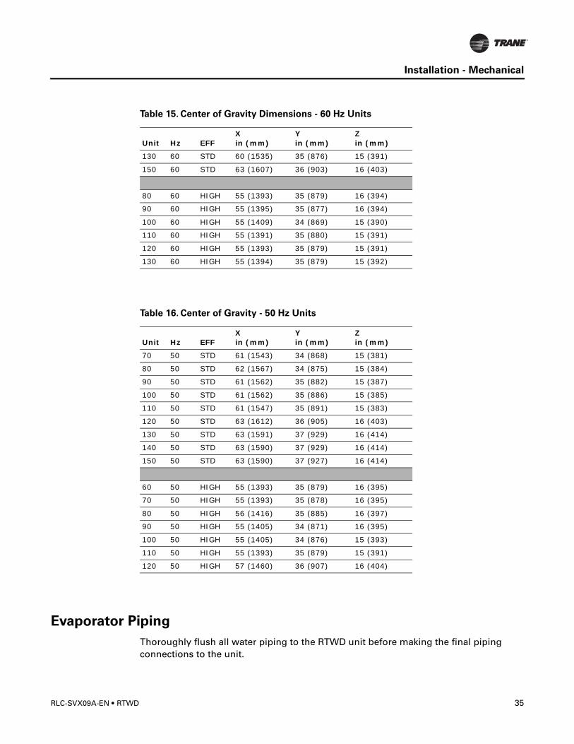
Table 15. Center of Gravity Dimensions - 60 Hz Units
Unit Hz EFFXin (mm)
Y in (mm)
Z in (mm)
80 60 STD 61 (1543) 34 (868) 15 (381)
90 60 STD 61 (1544) 34 (868) 15 (381)
100 60 STD 62 (1566) 35 (879) 15 (382)
110 60 STD 61 (1547) 35 (891) 15 (383)
120 60 STD 60 (1534) 34 (876) 15 (390)
34 RTWD • RLC-SVX09A-EN
Installation - Mechanical
Evaporator Piping
Thoroughly flush all water piping to the RTWD unit before making the final piping connections to the unit.
130 60 STD 60 (1535) 35 (876) 15 (391)
150 60 STD 63 (1607) 36 (903) 16 (403)
80 60 HIGH 55 (1393) 35 (879) 16 (394)
90 60 HIGH 55 (1395) 35 (877) 16 (394)
100 60 HIGH 55 (1409) 34 (869) 15 (390)
110 60 HIGH 55 (1391) 35 (880) 15 (391)
120 60 HIGH 55 (1393) 35 (879) 15 (391)
130 60 HIGH 55 (1394) 35 (879) 15 (392)
Table 16. Center of Gravity - 50 Hz Units
Unit Hz EFFXin (mm)
Y in (mm)
Zin (mm)
70 50 STD 61 (1543) 34 (868) 15 (381)
80 50 STD 62 (1567) 34 (875) 15 (384)
90 50 STD 61 (1562) 35 (882) 15 (387)
100 50 STD 61 (1562) 35 (886) 15 (385)
110 50 STD 61 (1547) 35 (891) 15 (383)
120 50 STD 63 (1612) 36 (905) 16 (403)
130 50 STD 63 (1591) 37 (929) 16 (414)
140 50 STD 63 (1590) 37 (929) 16 (414)
150 50 STD 63 (1590) 37 (927) 16 (414)
60 50 HIGH 55 (1393) 35 (879) 16 (395)
70 50 HIGH 55 (1393) 35 (878) 16 (395)
80 50 HIGH 56 (1416) 35 (885) 16 (397)
90 50 HIGH 55 (1405) 34 (871) 16 (395)
100 50 HIGH 55 (1405) 34 (876) 15 (393)
110 50 HIGH 55 (1393) 35 (879) 15 (391)
120 50 HIGH 57 (1460) 36 (907) 16 (404)
Table 15. Center of Gravity Dimensions - 60 Hz Units
Unit Hz EFFXin (mm)
Y in (mm)
Z in (mm)
RLC-SVX09A-EN • RTWD 35
Installation - Mechanical
Components and layout will vary slightly, depending on the location of connections and the water source.
CAUTION
Evaporator Damage!
The chilled water connections to the evaporator are to be “victaulic” type connections.
Do not attempt to weld these connections, as the heat generated from welding can
cause microscopic and macroscopic fractures on the cast iron waterboxes that can
lead to premature failure of the waterbox. To prevent damage to chilled water
components, do not allow evaporator pressure (maximum working pressure) to
exceed 150 psig (10.5 bar).
CAUTION
Equipment Damage!
If using an acidic commercial flushing solution, construct a temporary bypass around
the unit to prevent damage to internal components of the evaporator.
CAUTION
Proper Water Treatment!
The use of untreated or improperly treated water in a Chiller may result in scaling,
erosion, corrosion, algae or slime. It is recommended that the services of a qualified
water treatment specialist be engaged to determine what water treatment, if any, is
required. Trane assumes no responsibility for equipment failures which result from
untreated or improperly treated water, or saline or brackish water.
CAUTION
Use Piping Strainers!
To prevent evaporator or condenser damage, pipe strainers must be installed in the
water supplies to protect components from water born debris. Trane is not responsible
for equipment-only-damage caused by water born debris.
Drainage
Locate the unit near a large capacity drain for water vessel drain-down during shutdown or repair. Condensers and evaporators are provided with drain connections. Refer to “Water Piping.” All local and national codes apply.
A vent is provided on the top of the evaporator at the return end. Be sure to provide additional vents at high points in the piping to bleed air from the chilled water system. Install necessary pressure gauges to monitor the entering and leaving chilled water pressures.
Provide shutoff valves in lines to the gauges to isolate them from the system when they are not in use. Use rubber vibration eliminators to prevent vibration transmission through the water lines.
36 RTWD • RLC-SVX09A-EN
Installation - Mechanical
If desired, install thermometers in the lines to monitor entering and leaving water temperatures. Install a balancing valve in the leaving water line to control water flow balance. Install shutoff valves on both the entering and leaving water lines so that the evaporator can be isolated for service.
A pipe strainer must be installed in the entering water line to prevent water-borne debris from entering the evaporator.
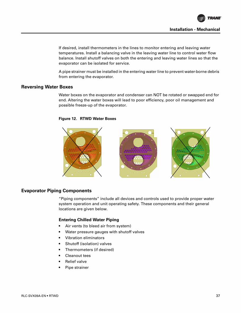
Reversing Water Boxes
Water boxes on the evaporator and condenser can NOT be rotated or swapped end for end. Altering the water boxes will lead to poor efficiency, poor oil management and possible freeze-up of the evaporator.
Figure 12. RTWD Water Boxes
Evaporator Piping Components
“Piping components” include all devices and controls used to provide proper water system operation and unit operating safety. These components and their general locations are given below.
Entering Chilled Water Piping
• Air vents (to bleed air from system)
• Water pressure gauges with shutoff valves
• Vibration eliminators
• Shutoff (isolation) valves
• Thermometers (if desired)
• Cleanout tees
• Relief valve
• Pipe strainer
RLC-SVX09A-EN • RTWD 37
Installation - Mechanical
CAUTION
Use Piping Strainers!
To prevent evaporator or condenser damage, pipe strainers must be installed in the
water supplies to protect components from water born debris. Trane is not responsible
for equipment-only-damage caused by water born debris.
Leaving Chilled Water Piping
• Air vents (to bleed air from system)
• Water pressure gauges with shutoff valves
• Vibration eliminators
• Shutoff (isolation) valves
• Thermometers
• Cleanout tees
• Balancing valve
• Flow Switch
CAUTION
Evaporator Damage!
The chilled water connections to the evaporator are to be “victaulic” type
connections. Do not attempt to weld these connections, as the heat generated
from welding can cause microscopic and macroscopic fractures on the cast
iron waterboxes that can lead to premature failure of the waterbox. To prevent
damage to chilled water components, do not allow evaporator pressure
(maximum working pressure) to exceed 150 psig (10.5 bar).Evaporator Drain
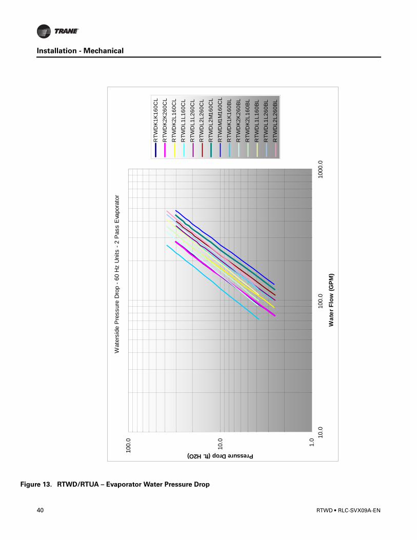
Flow Sensing Devices
The installer must provide flow switches or differential pressure switches with pump inter-locks to sense system water flow. Flow switch locations are schematically shown in Figure 15.To provide chiller protection, install and wire flow switches in series with the water pump interlocks, for both chilled water and condenser water circuits (refer to the Installation Electri-cal section). Specific connections and schematic wiring diagrams are shipped with the unit.Flow switches must stop or prevent compressor operation if either system water flow drops off below the required minimum shown on the pressure drop curves. Follow the manufac-turer’s recommendations for selection and installation procedures. General guidelines for flow switch installation are outlined below.• Mount the switch upright, with a minimum of 5 pipe diameters straight, horizontal run on
each side.
• Do not install close to elbows, orifices or valves.
NOTE: The arrow on the switch must point in the direction of the water flow.
• To prevent switch fluttering, remove all air from the water system
38 RTWD • RLC-SVX09A-EN
Installation - Mechanical
NOTE: The CH530 provides a 6-second time delay on the flow switch input before shutting down the unit on a loss-of-flow diagnostic. Contact a qualified service organization if nuisance machine shutdowns persist.
• Adjust the switch to open when water flow falls below nominal. Refer to the General Data table in Section 1 for minimum flow recommendations for specific water pass arrangements. Flow switch contacts are closed on proof of water flow.
RLC-SVX09A-EN • RTWD 39
Installation - Mechanical
Figu
re 13. RTWD/RTUA – Evaporator Water Pressure DropWat
ersi
de P
ress
ure
Dro
p - 6
0 H
z U
nits
- 2
Pas
s E
vapo
rato
r
1.0
10.0
100.
0 10.0
100.
010
00.0
Wat
er F
low
(GPM
)
Pressure Drop (ft. H2O)
RTW
DK
1K16
0CL
RTW
DK
2K26
0CL
RTW
DK
2L16
0CL
RTW
DL1
L160
CL
RTW
DL1
L260
CL
RTW
DL2
L260
CL
RTW
DL2
M16
0CL
RTW
DM
1M16
0CL
RTW
DK
1K16
0BL
RTW
DK
2K26
0BL
RTW
DK
2L16
0BL
RTW
DL1
L160
BL
RTW
DL1
L260
BL
RTW
DL2
L260
BL
40 RTWD • RLC-SVX09A-EN
Installation - Mechanical
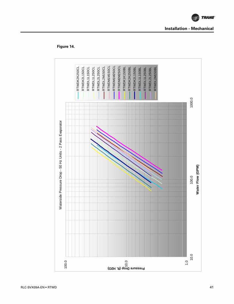
Figure 14.
Wat
ersi
de P
ress
ure
Dro
p - 5
0 H
z U
nits
- 2
Pas
s E
vapo
rato
r
1.0
10.0
100.
0 10.0
100.
010
00.0
Wat
er F
low
(GPM
)
Pressure Drop (ft. H2O)
RTW
DK2
K25
0CL
RTW
DK2
L150
CL
RTW
DL1
L150
CL
RTW
DL1
L250
CL
RTW
DL2
L250
CL
RTW
DL2
M15
0CL
RTW
DM
1M15
0CL
RTW
DM
1M25
0CL
RTW
DM
2M25
0CL
RTW
DK1
K15
0BL
RTW
DK2
K25
0BL
RTW
DK2
L150
BL
RTW
DL1
L150
BL
RTW
DL1
L250
BL
RTW
DL2
L250
BL
RTW
DL2
M15
0BL
RLC-SVX09A-EN • RTWD 41
Installation - Mechanical
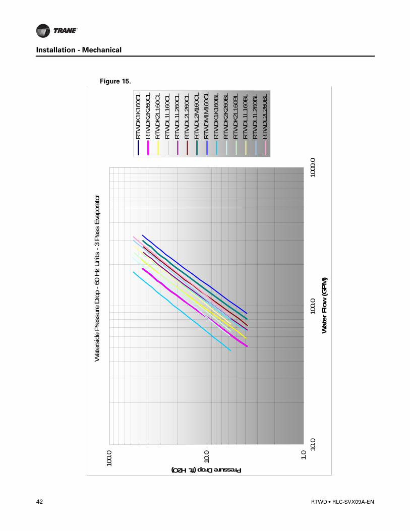
Figure 15.
Wat
ersi
de P
ress
ure
Dro
p - 6
0 Hz
Uni
ts -
3 Pas
s Eva
pora
tor
1.0
10.0
100.
0 10.0
100.
010
00.0
Wat
er F
low
(GPM
)
Pressure Drop (ft. H2O)
RTW
DK1
K160
CL
RTW
DK2
K260
CL
RTW
DK2
L160
CL
RTW
DL1
L160
CL
RTW
DL1
L260
CL
RTW
DL2
L260
CL
RTW
DL2
M16
0CL
RTW
DM
1M16
0CL
RTW
DK1
K160
BL
RTW
DK2
K260
BL
RTW
DK2
L160
BL
RTW
DL1
L160
BL
RTW
DL1
L260
BL
RTW
DL2
L260
BL
42 RTWD • RLC-SVX09A-EN
Installation - Mechanical
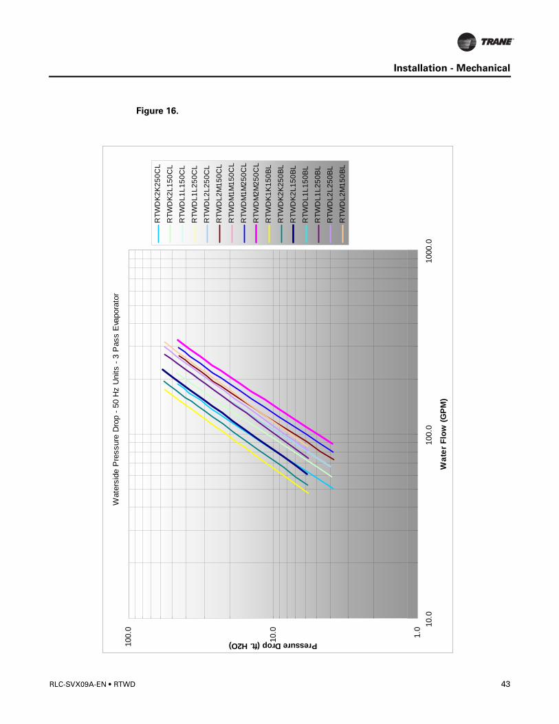
Figure 16.W
ater
side
Pre
ssur
e D
rop
- 50
Hz
Uni
ts -
3 P
ass
Eva
pora
tor
1.0
10.0
100.
0 10.0
100.
010
00.0
Wat
er F
low
(GPM
)
Pressure Drop (ft. H2O)
RTW
DK2
K25
0CL
RTW
DK2
L150
CL
RTW
DL1
L150
CL
RTW
DL1
L250
CL
RTW
DL2
L250
CL
RTW
DL2
M15
0CL
RTW
DM
1M15
0CL
RTW
DM
1M25
0CL
RTW
DM
2M25
0CL
RTW
DK1
K15
0BL
RTW
DK2
K25
0BL
RTW
DK2
L150
BL
RTW
DL1
L150
BL
RTW
DL1
L250
BL
RTW
DL2
L250
BL
RTW
DL2
M15
0BL
RLC-SVX09A-EN • RTWD 43

Installation - Mechanical
Figure 17.
Wat
ersi
de P
ress
ure
Dro
p - 6
0 H
z U
nits
- C
onde
nser
1.0
10.0
100.
0 10.0
100.
010
00.0
Wat
er F
low
(GPM
)
Pressure Drop (ft. H2O)
RTW
DK
1K16
0CL
RTW
DK
2K26
0CL
RTW
DK
2L16
0CL
RTW
DL1
L160
CL
RTW
DL1
L260
CL
RTW
DL2
L260
CL
RTW
DL2
M16
0CL
RTW
DM
1M16
0CL
RTW
DK
1K16
0BL
RTW
DK
2K26
0BL
RTW
DK
2L16
0BL
RTW
DL1
L160
BL
RTW
DL1
L260
BL
RTW
DL2
L260
BL
44 RTWD • RLC-SVX09A-EN
Installation - Mechanical
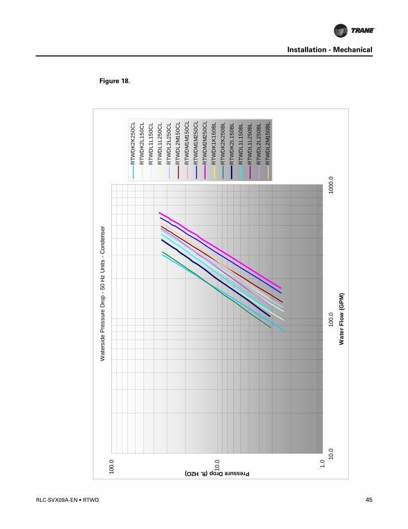
Figure 18.
Wat
ersi
de P
ress
ure
Dro
p - 5
0 H
z U
nits
- C
onde
nser
1.0
10.0
100.
0 10.0
100.
010
00.0
Wat
er F
low
(GPM
)
Pressure Drop (ft. H2O)
RTW
DK2
K25
0CL
RTW
DK2
L150
CL
RTW
DL1
L150
CL
RTW
DL1
L250
CL
RTW
DL2
L250
CL
RTW
DL2
M15
0CL
RTW
DM
1M15
0CL
RTW
DM
1M25
0CL
RTW
DM
2M25
0CL
RTW
DK1
K15
0BL
RTW
DK2
K25
0BL
RTW
DK2
L150
BL
RTW
DL1
L150
BL
RTW
DL1
L250
BL
RTW
DL2
L250
BL
RTW
DL2
M15
0BL
RLC-SVX09A-EN • RTWD 45
Installation - Mechanical
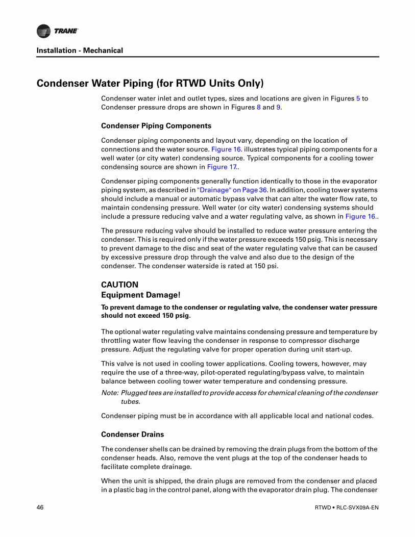
Condenser Water Piping (for RTWD Units Only)
Condenser water inlet and outlet types, sizes and locations are given in Figures 5 to Condenser pressure drops are shown in Figures 8 and 9.
Condenser Piping Components
Condenser piping components and layout vary, depending on the location of connections and the water source. Figure 16. illustrates typical piping components for a well water (or city water) condensing source. Typical components for a cooling tower condensing source are shown in Figure 17..
Condenser piping components generally function identically to those in the evaporator piping system, as described in "Drainage" on Page 36. In addition, cooling tower systems should include a manual or automatic bypass valve that can alter the water flow rate, to maintain condensing pressure. Well water (or city water) condensing systems should include a pressure reducing valve and a water regulating valve, as shown in Figure 16..
The pressure reducing valve should be installed to reduce water pressure entering the condenser. This is required only if the water pressure exceeds 150 psig. This is necessary to prevent damage to the disc and seat of the water regulating valve that can be caused by excessive pressure drop through the valve and also due to the design of the condenser. The condenser waterside is rated at 150 psi.
CAUTION
Equipment Damage!
To prevent damage to the condenser or regulating valve, the condenser water pressure
should not exceed 150 psig.
The optional water regulating valve maintains condensing pressure and temperature by throttling water flow leaving the condenser in response to compressor discharge pressure. Adjust the regulating valve for proper operation during unit start-up.
This valve is not used in cooling tower applications. Cooling towers, however, may require the use of a three-way, pilot-operated regulating/bypass valve, to maintain balance between cooling tower water temperature and condensing pressure.
Note: Plugged tees are installed to provide access for chemical cleaning of the condenser tubes.
Condenser piping must be in accordance with all applicable local and national codes.
Condenser Drains
The condenser shells can be drained by removing the drain plugs from the bottom of the condenser heads. Also, remove the vent plugs at the top of the condenser heads to facilitate complete drainage.
When the unit is shipped, the drain plugs are removed from the condenser and placed in a plastic bag in the control panel, along with the evaporator drain plug. The condenser
46 RTWD • RLC-SVX09A-EN
Installation - Mechanical
drains may be connected to suitable drains to permit drainage during unit servicing. If they are not, the drain plugs must be installed.
Water Regulations Valve (for RTWD Units Only)
Water Treatment
Using untreated or improperly treated water in these units may result in inefficient operation and possible tube damage. Consult a qualified water treatment specialist to determine whether treatment is needed. The following disclamatory label is provided on each RTWD unit:
CAUTION
Proper Water Treatment!
The use of untreated or improperly treated water in a Chiller may result in scaling,
erosion, corrosion, algae or slime. It is recommended that the services of a qualified
water treatment specialist be engaged to determine what water treatment, if any, is
required. Trane assumes no responsibility for equipment failures which result from
untreated or improperly treated water, or saline or brackish water.
Water Pressure Gauges
Install field-supplied pressure gauges (with manifolds, whenever practical) on the RTWD units, as shown in Figures 7, 16 and 17. Locate pressure gauges or taps in a straight run of pipe; avoid placement near elbows, etc. Be sure to install the gauges at the same elevation.
To read manifolded pressure gauges, open one valve and close the other (depending upon the reading desired). This eliminates errors resulting from differently calibrated gauges installed at unmatched elevations.
Water Pressure Relief Valves
Install a water pressure relief valve in the condenser and evaporator leaving chilled water piping. See Figures 7, 16 and 17. Water vessels with close coupled shutoff valves have a high potential for hydrostatic pressure buildup on a water temperature increase. Refer to applicable codes for relief valve installation guidelines.
CAUTION
Prevent Shell Damage!
To prevent shell damage, install pressure relief valves in both the evaporator and
condenser water systems.
RLC-SVX09A-EN • RTWD 47
Installation - Mechanical
Refrigerant Relief Valve Venting
Condenser Pressure Relief Valve Venting (for RTWD units only)
All RTWD units utilize a refrigerant-pressure relief valve for each circuit which must be vented to the outdoor atmosphere. The valves are located at the top of the condenser. Relief valve connections are 7/8” - 14 UNF-2B. See Figure 16 and Table 17. Refer to local codes for relief valve vent line sizing requirements.
Note: Vent line length must not exceed code recommendations. If the line length will exceed code recommendations for the outlet size of the valve, install a vent line of the next larger pipe size.
CAUTION
Equipment Damage!
To prevent capacity reduction and relief valve damage, do not exceed vent piping code
specifications.
Relief valve discharge setpoints are 300 psig. Once the relief valve has opened, it will reclose when pressure is reduced to a safe level.
Pipe each relief valve on the unit into a common vent line. Provide access valve located at the low point of the vent piping, to enable draining of any condensate that may accumulate in the piping.
� WARNING
Contains Refrigerant!
System contains oil and refrigerant under high pressure. Recover refrigerant to relieve
pressure before opening the system. See unit nameplate for refrigerant type. Do not
use non-approved refrigerants, refrigerant substitutes, or refrigerant additives.
Failure to follow proper procedures or the use of non-approved refrigerants, refrigerant
substitutes, or refrigerant additives could result in death or serious injury or
equipment damage.
If multiple chillers are installed, each unit must have a separate venting for its relief valves. Consult local regulations for any special relief line requirements.
Note: Units can be ordered with “Dual Relief Valve” options. Model number digit 16 is a “2”. Units with this option will have 8 total relief valves.
48 RTWD • RLC-SVX09A-EN
Installation - Mechanical
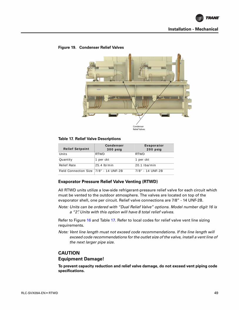
Figure 19. Condenser Relief Valves
Evaporator Pressure Relief Valve Venting (RTWD)
All RTWD units utilize a low-side refrigerant-pressure relief valve for each circuit which must be vented to the outdoor atmosphere. The valves are located on top of the evaporator shell, one per circuit. Relief valve connections are 7/8” - 14 UNF-2B.
Note: Units can be ordered with “Dual Relief Valve” options. Model number digit 16 is a “2”. Units with this option will have 8 total relief valves.
Refer to Figure 16 and Table 17. Refer to local codes for relief valve vent line sizing requirements.
Note: Vent line length must not exceed code recommendations. If the line length will exceed code recommendations for the outlet size of the valve, install a vent line of the next larger pipe size.
CAUTION
Equipment Damage!
To prevent capacity reduction and relief valve damage, do not exceed vent piping code
specifications.
Table 17. Relief Valve Descriptions
Relief SetpointCondenser300 psig
Evaporator200 psig
Units RTWD RTWD
Quantity 1 per ckt 1 per ckt
Relief Rate 25.4 lb/min 20.1 Iba/min
Field Connection Size 7/8” - 14 UNF-2B 7/8” - 14 UNF-2B
RLC-SVX09A-EN • RTWD 49
Installation - Mechanical
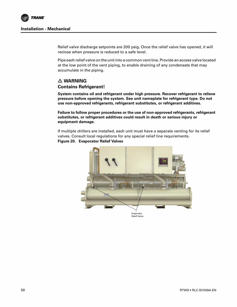
Relief valve discharge setpoints are 200 psig. Once the relief valve has opened, it will reclose when pressure is reduced to a safe level.
Pipe each relief valve on the unit into a common vent line. Provide an access valve located at the low point of the vent piping, to enable draining of any condensate that may accumulate in the piping.
� WARNING
Contains Refrigerant!
System contains oil and refrigerant under high pressure. Recover refrigerant to relieve
pressure before opening the system. See unit nameplate for refrigerant type. Do not
use non-approved refrigerants, refrigerant substitutes, or refrigerant additives.
Failure to follow proper procedures or the use of non-approved refrigerants, refrigerant
substitutes, or refrigerant additives could result in death or serious injury or
equipment damage.
If multiple chillers are installed, each unit must have a separate venting for its relief valves. Consult local regulations for any special relief line requirements.Figure 20. Evaporator Relief Valves
50 RTWD • RLC-SVX09A-EN
Installation - Electrical
General Recommendations
All wiring must comply with local codes and the National Electric Code. Typical field wiring diagrams are included at the end of the manual. Minimum circuit ampacities and other unit electrical data are on the unit nameplate and in Table 17 though Table 17. See the unit order specifications for actual electrical data. Specific electrical schematics and connection diagrams are shipped with the unit.
� WARNING
Hazardous Voltage!
Disconnect all electric power, including remote disconnects before servicing. Follow
proper lockout/tagout procedures to ensure the power can not be inadvertently
energized. Failure to disconnect power before servicing could result in death or serious
injury.
CAUTION
Use Copper Conductors Only!
Unit terminals are not designed to accept other types of conductors. Failure to use
copper conductors may result in equipment damage.
Important!
Do not allow conduit to interfere with other components, structural members or
equipment. Control voltage (115V) wiring in conduit must be separate from conduit
carrying low voltage (<30V) wiring. To prevent control malfunctions, do not run low
voltage wiring (<30V) in conduit with conductors carrying more than 30 volts.
RLC-SVX09A-EN • RTWD 51
Installation - Electrical
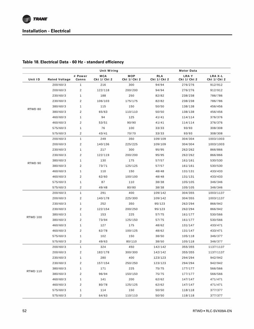
Table 18. Electrical Data - 60 Hz - standard efficiency
Unit Wiring Motor Data
Unit ID Rated Voltage# Power Conns
MCACkt 1/Ckt 2
MOPCkt 1/Ckt 2
RLACkt 1/Ckt 2
LRA Y Ckt 1/Ckt 2
LRA X-L Ckt 1/Ckt 2
RTWD 80
200/60/3 1 216 300 94/94 276/276 912/912
200/60/3 2 122/118 200/200 94/94 276/276 912/912
230/60/3 1 188 250 82/82 238/238 786/786
230/60/3 2 106/103 175/175 82/82 238/238 786/786
380/60/3 1 115 150 50/50 138/138 456/456
380/60/3 2 65/63 110/110 50/50 138/138 456/456
460/60/3 1 94 125 41/41 114/114 376/376
460/60/3 2 53/51 90/90 41/41 114/114 376/376
575/60/3 1 76 100 33/33 93/93 308/308
575/60/3 2 43/41 70/70 33/33 93/93 308/308
RTWD 90
200/60/3 1 249 350 109/109 304/304 1003/1003
200/60/3 2 140/136 225/225 109/109 304/304 1003/1003
230/60/3 1 217 300 95/95 262/262 866/866
230/60/3 2 122/119 200/200 95/95 262/262 866/866
380/60/3 1 130 175 57/57 161/161 530/530
380/60/3 2 73/71 125/125 57/57 161/161 530/530
460/60/3 1 110 150 48/48 131/131 433/433
460/60/3 2 62/60 100/100 48/48 131/131 433/433
575/60/3 1 87 110 38/38 105/105 346/346
575/60/3 2 49/48 80/80 38/38 105/105 346/346
RTWD 100
200/60/3 1 291 400 109/142 304/355 1003/1137
200/60/3 2 140/178 225/300 109/142 304/355 1003/1137
230/60/3 1 252 350 95/123 262/294 866/942
230/60/3 2 122/154 200/250 95/123 262/294 866/942
380/60/3 1 153 225 57/75 161/177 530/566
380/60/3 2 73/94 125/150 57/75 161/177 530/566
460/60/3 1 127 175 48/62 131/147 433/471
460/60/3 2 62/78 100/125 48/62 131/147 433/471
575/60/3 1 102 150 38/50 105/118 346/377
575/60/3 2 49/63 80/110 38/50 105/118 346/377
RTWD 110
200/60/3 1 324 450 142/142 355/355 1137/1137
200/60/3 2 182/178 300/300 142/142 355/355 1137/1137
230/60/3 1 280 400 123/123 294/294 942/942
230/60/3 2 157/154 250/250 123/123 294/294 942/942
380/60/3 1 171 225 75/75 177/177 566/566
380/60/3 2 96/94 150/150 75/75 177/177 566/566
460/60/3 1 141 200 62/62 147/147 471/471
460/60/3 2 80/78 125/125 62/62 147/147 471/471
575/60/3 1 114 150 50/50 118/118 377/377
575/60/3 2 64/63 110/110 50/50 118/118 377/377
52 RTWD • RLC-SVX09A-EN
Installation - Electrical
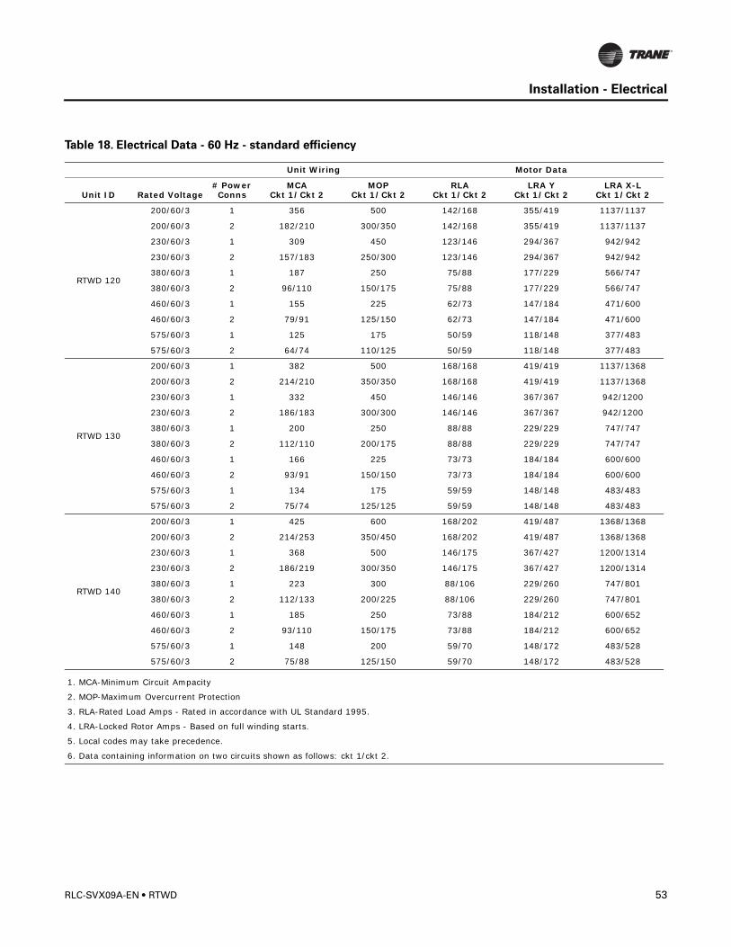
RTWD 120
200/60/3 1 356 500 142/168 355/419 1137/1137
200/60/3 2 182/210 300/350 142/168 355/419 1137/1137
230/60/3 1 309 450 123/146 294/367 942/942
230/60/3 2 157/183 250/300 123/146 294/367 942/942
380/60/3 1 187 250 75/88 177/229 566/747
380/60/3 2 96/110 150/175 75/88 177/229 566/747
460/60/3 1 155 225 62/73 147/184 471/600
460/60/3 2 79/91 125/150 62/73 147/184 471/600
575/60/3 1 125 175 50/59 118/148 377/483
575/60/3 2 64/74 110/125 50/59 118/148 377/483
RTWD 130
200/60/3 1 382 500 168/168 419/419 1137/1368
200/60/3 2 214/210 350/350 168/168 419/419 1137/1368
230/60/3 1 332 450 146/146 367/367 942/1200
230/60/3 2 186/183 300/300 146/146 367/367 942/1200
380/60/3 1 200 250 88/88 229/229 747/747
380/60/3 2 112/110 200/175 88/88 229/229 747/747
460/60/3 1 166 225 73/73 184/184 600/600
460/60/3 2 93/91 150/150 73/73 184/184 600/600
575/60/3 1 134 175 59/59 148/148 483/483
575/60/3 2 75/74 125/125 59/59 148/148 483/483
RTWD 140
200/60/3 1 425 600 168/202 419/487 1368/1368
200/60/3 2 214/253 350/450 168/202 419/487 1368/1368
230/60/3 1 368 500 146/175 367/427 1200/1314
230/60/3 2 186/219 300/350 146/175 367/427 1200/1314
380/60/3 1 223 300 88/106 229/260 747/801
380/60/3 2 112/133 200/225 88/106 229/260 747/801
460/60/3 1 185 250 73/88 184/212 600/652
460/60/3 2 93/110 150/175 73/88 184/212 600/652
575/60/3 1 148 200 59/70 148/172 483/528
575/60/3 2 75/88 125/150 59/70 148/172 483/528
1. MCA-Minimum Circuit Ampacity
2. MOP-Maximum Overcurrent Protection
3. RLA-Rated Load Amps - Rated in accordance with UL Standard 1995.
4. LRA-Locked Rotor Amps - Based on full winding starts.
5. Local codes may take precedence.
6. Data containing information on two circuits shown as follows: ckt 1/ckt 2.
Table 18. Electrical Data - 60 Hz - standard efficiency
Unit Wiring Motor Data
Unit ID Rated Voltage# Power Conns
MCACkt 1/Ckt 2
MOPCkt 1/Ckt 2
RLACkt 1/Ckt 2
LRA Y Ckt 1/Ckt 2
LRA X-L Ckt 1/Ckt 2
RLC-SVX09A-EN • RTWD 53
Installation - Electrical
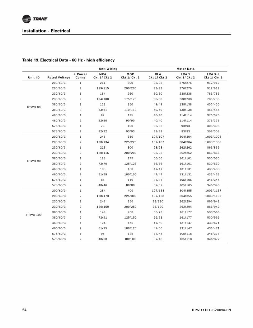
Table 19. Electrical Data - 60 Hz - high efficiency
Unit Wiring Motor Data
Unit ID Rated Voltage# Power Conns
MCACkt 1/Ckt 2
MOPCkt 1/Ckt 2
RLACkt 1/Ckt 2
LRA Y Ckt 1/Ckt 2
LRA X-L Ckt 1/Ckt 2
RTWD 80
200/60/3 1 211 300 92/92 276/276 912/912
200/60/3 2 119/115 200/200 92/92 276/276 912/912
230/60/3 1 184 250 80/80 238/238 786/786
230/60/3 2 104/100 175/175 80/80 238/238 786/786
380/60/3 1 112 150 49/49 138/138 456/456
380/60/3 2 63/61 110/110 49/49 138/138 456/456
460/60/3 1 92 125 40/40 114/114 376/376
460/60/3 2 52/50 90/90 40/40 114/114 376/376
575/60/3 1 73 100 32/32 93/93 308/308
575/60/3 2 32/32 93/93 32/32 93/93 308/308
RTWD 90
200/60/3 1 245 350 107/107 304/304 1003/1003
200/60/3 2 138/134 225/225 107/107 304/304 1003/1003
230/60/3 1 213 300 93/93 262/262 866/866
230/60/3 2 120/116 200/200 93/93 262/262 866/866
380/60/3 1 128 175 56/56 161/161 530/530
380/60/3 2 72/70 125/125 56/56 161/161 530/530
460/60/3 1 108 150 47/47 131/131 433/433
460/60/3 2 61/59 100/100 47/47 131/131 433/433
575/60/3 1 85 110 37/37 105/105 346/346
575/60/3 2 48/46 80/80 37/37 105/105 346/346
RTWD 100
200/60/3 1 284 400 107/138 304/355 1003/1137
200/60/3 2 138/173 225/300 107/138 304/355 1003/1137
230/60/3 1 247 350 93/120 262/294 866/942
230/60/3 2 120/150 200/250 93/120 262/294 866/942
380/60/3 1 149 200 56/73 161/177 530/566
380/60/3 2 72/91 125/150 56/73 161/177 530/566
460/60/3 1 124 175 47/60 131/147 433/471
460/60/3 2 61/75 100/125 47/60 131/147 433/471
575/60/3 1 98 125 37/48 105/118 346/377
575/60/3 2 48/60 80/100 37/48 105/118 346/377
54 RTWD • RLC-SVX09A-EN
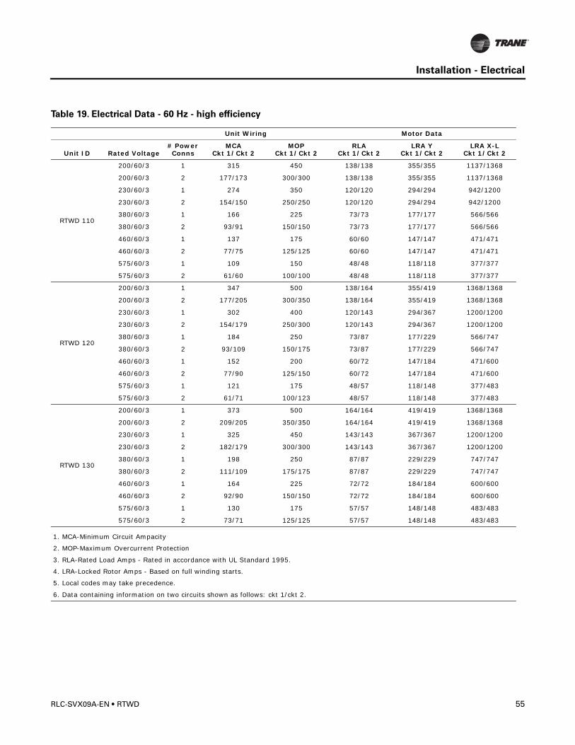
Installation - Electrical
RTWD 110
200/60/3 1 315 450 138/138 355/355 1137/1368
200/60/3 2 177/173 300/300 138/138 355/355 1137/1368
230/60/3 1 274 350 120/120 294/294 942/1200
230/60/3 2 154/150 250/250 120/120 294/294 942/1200
380/60/3 1 166 225 73/73 177/177 566/566
380/60/3 2 93/91 150/150 73/73 177/177 566/566
460/60/3 1 137 175 60/60 147/147 471/471
460/60/3 2 77/75 125/125 60/60 147/147 471/471
575/60/3 1 109 150 48/48 118/118 377/377
575/60/3 2 61/60 100/100 48/48 118/118 377/377
RTWD 120
200/60/3 1 347 500 138/164 355/419 1368/1368
200/60/3 2 177/205 300/350 138/164 355/419 1368/1368
230/60/3 1 302 400 120/143 294/367 1200/1200
230/60/3 2 154/179 250/300 120/143 294/367 1200/1200
380/60/3 1 184 250 73/87 177/229 566/747
380/60/3 2 93/109 150/175 73/87 177/229 566/747
460/60/3 1 152 200 60/72 147/184 471/600
460/60/3 2 77/90 125/150 60/72 147/184 471/600
575/60/3 1 121 175 48/57 118/148 377/483
575/60/3 2 61/71 100/123 48/57 118/148 377/483
RTWD 130
200/60/3 1 373 500 164/164 419/419 1368/1368
200/60/3 2 209/205 350/350 164/164 419/419 1368/1368
230/60/3 1 325 450 143/143 367/367 1200/1200
230/60/3 2 182/179 300/300 143/143 367/367 1200/1200
380/60/3 1 198 250 87/87 229/229 747/747
380/60/3 2 111/109 175/175 87/87 229/229 747/747
460/60/3 1 164 225 72/72 184/184 600/600
460/60/3 2 92/90 150/150 72/72 184/184 600/600
575/60/3 1 130 175 57/57 148/148 483/483
575/60/3 2 73/71 125/125 57/57 148/148 483/483
1. MCA-Minimum Circuit Ampacity
2. MOP-Maximum Overcurrent Protection
3. RLA-Rated Load Amps - Rated in accordance with UL Standard 1995.
4. LRA-Locked Rotor Amps - Based on full winding starts.
5. Local codes may take precedence.
6. Data containing information on two circuits shown as follows: ckt 1/ckt 2.
Table 19. Electrical Data - 60 Hz - high efficiency
Unit Wiring Motor Data
Unit ID Rated Voltage# Power Conns
MCACkt 1/Ckt 2
MOPCkt 1/Ckt 2
RLACkt 1/Ckt 2
LRA Y Ckt 1/Ckt 2
LRA X-L Ckt 1/Ckt 2
RLC-SVX09A-EN • RTWD 55
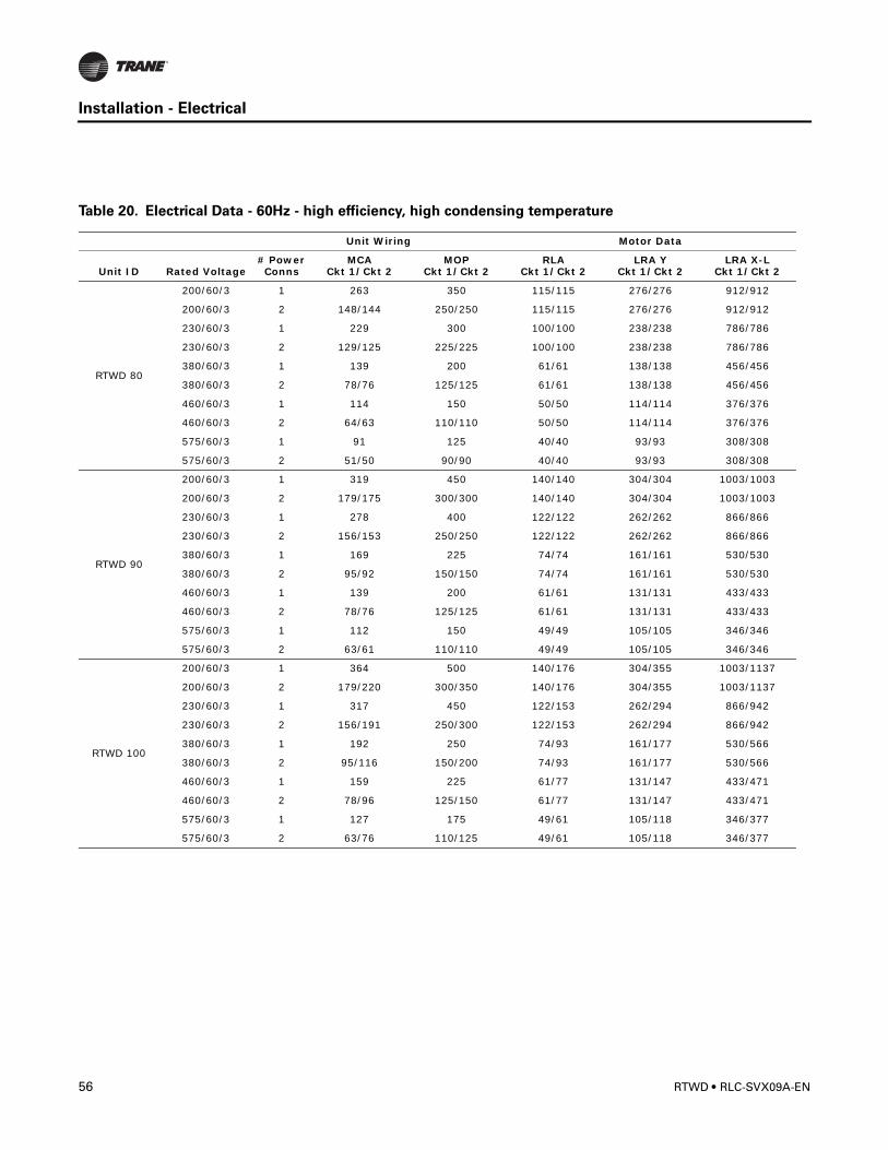
Installation - Electrical
Table 20. Electrical Data - 60Hz - high efficiency, high condensing temperature
Unit Wiring Motor Data
Unit ID Rated Voltage# Power Conns
MCACkt 1/Ckt 2
MOPCkt 1/Ckt 2
RLACkt 1/Ckt 2
LRA Y Ckt 1/Ckt 2
LRA X-L Ckt 1/Ckt 2
RTWD 80
200/60/3 1 263 350 115/115 276/276 912/912
200/60/3 2 148/144 250/250 115/115 276/276 912/912
230/60/3 1 229 300 100/100 238/238 786/786
230/60/3 2 129/125 225/225 100/100 238/238 786/786
380/60/3 1 139 200 61/61 138/138 456/456
380/60/3 2 78/76 125/125 61/61 138/138 456/456
460/60/3 1 114 150 50/50 114/114 376/376
460/60/3 2 64/63 110/110 50/50 114/114 376/376
575/60/3 1 91 125 40/40 93/93 308/308
575/60/3 2 51/50 90/90 40/40 93/93 308/308
RTWD 90
200/60/3 1 319 450 140/140 304/304 1003/1003
200/60/3 2 179/175 300/300 140/140 304/304 1003/1003
230/60/3 1 278 400 122/122 262/262 866/866
230/60/3 2 156/153 250/250 122/122 262/262 866/866
380/60/3 1 169 225 74/74 161/161 530/530
380/60/3 2 95/92 150/150 74/74 161/161 530/530
460/60/3 1 139 200 61/61 131/131 433/433
460/60/3 2 78/76 125/125 61/61 131/131 433/433
575/60/3 1 112 150 49/49 105/105 346/346
575/60/3 2 63/61 110/110 49/49 105/105 346/346
RTWD 100
200/60/3 1 364 500 140/176 304/355 1003/1137
200/60/3 2 179/220 300/350 140/176 304/355 1003/1137
230/60/3 1 317 450 122/153 262/294 866/942
230/60/3 2 156/191 250/300 122/153 262/294 866/942
380/60/3 1 192 250 74/93 161/177 530/566
380/60/3 2 95/116 150/200 74/93 161/177 530/566
460/60/3 1 159 225 61/77 131/147 433/471
460/60/3 2 78/96 125/150 61/77 131/147 433/471
575/60/3 1 127 175 49/61 105/118 346/377
575/60/3 2 63/76 110/125 49/61 105/118 346/377
56 RTWD • RLC-SVX09A-EN
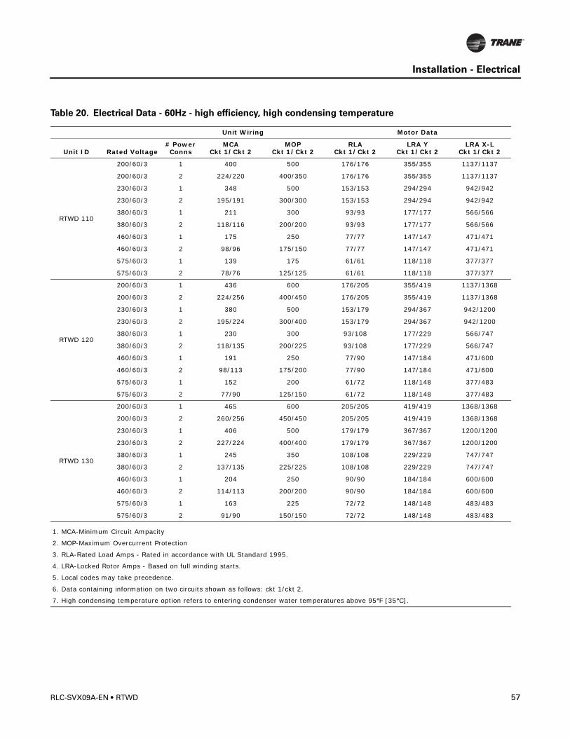
Installation - Electrical
RTWD 110
200/60/3 1 400 500 176/176 355/355 1137/1137
200/60/3 2 224/220 400/350 176/176 355/355 1137/1137
230/60/3 1 348 500 153/153 294/294 942/942
230/60/3 2 195/191 300/300 153/153 294/294 942/942
380/60/3 1 211 300 93/93 177/177 566/566
380/60/3 2 118/116 200/200 93/93 177/177 566/566
460/60/3 1 175 250 77/77 147/147 471/471
460/60/3 2 98/96 175/150 77/77 147/147 471/471
575/60/3 1 139 175 61/61 118/118 377/377
575/60/3 2 78/76 125/125 61/61 118/118 377/377
RTWD 120
200/60/3 1 436 600 176/205 355/419 1137/1368
200/60/3 2 224/256 400/450 176/205 355/419 1137/1368
230/60/3 1 380 500 153/179 294/367 942/1200
230/60/3 2 195/224 300/400 153/179 294/367 942/1200
380/60/3 1 230 300 93/108 177/229 566/747
380/60/3 2 118/135 200/225 93/108 177/229 566/747
460/60/3 1 191 250 77/90 147/184 471/600
460/60/3 2 98/113 175/200 77/90 147/184 471/600
575/60/3 1 152 200 61/72 118/148 377/483
575/60/3 2 77/90 125/150 61/72 118/148 377/483
RTWD 130
200/60/3 1 465 600 205/205 419/419 1368/1368
200/60/3 2 260/256 450/450 205/205 419/419 1368/1368
230/60/3 1 406 500 179/179 367/367 1200/1200
230/60/3 2 227/224 400/400 179/179 367/367 1200/1200
380/60/3 1 245 350 108/108 229/229 747/747
380/60/3 2 137/135 225/225 108/108 229/229 747/747
460/60/3 1 204 250 90/90 184/184 600/600
460/60/3 2 114/113 200/200 90/90 184/184 600/600
575/60/3 1 163 225 72/72 148/148 483/483
575/60/3 2 91/90 150/150 72/72 148/148 483/483
1. MCA-Minimum Circuit Ampacity
2. MOP-Maximum Overcurrent Protection
3. RLA-Rated Load Amps - Rated in accordance with UL Standard 1995.
4. LRA-Locked Rotor Amps - Based on full winding starts.
5. Local codes may take precedence.
6. Data containing information on two circuits shown as follows: ckt 1/ckt 2.
7. High condensing temperature option refers to entering condenser water temperatures above 95°F [35°C].
Table 20. Electrical Data - 60Hz - high efficiency, high condensing temperature
Unit Wiring Motor Data
Unit ID Rated Voltage# Power Conns
MCACkt 1/Ckt 2
MOPCkt 1/Ckt 2
RLACkt 1/Ckt 2
LRA Y Ckt 1/Ckt 2
LRA X-L Ckt 1/Ckt 2
RLC-SVX09A-EN • RTWD 57
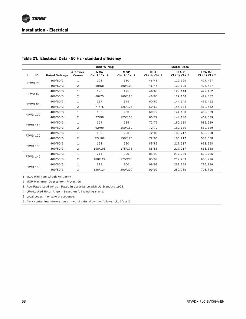
Installation - Electrical
Table 21. Electrical Data - 50 Hz - standard efficiency
Unit Wiring Motor Data
Unit ID Rated Voltage# Power Conns
MCACkt 1/Ckt 2
MOPCkt 1/Ckt 2
RLACkt 1/Ckt 2
LRA Y Ckt 1/Ckt 2
LRA X-L Ckt 1/Ckt 2
RTWD 70400/50/3 1 106 150 46/46 129/129 427/427
400/50/3 2 60/58 100/100 46/46 129/129 427/427
RTWD 80400/50/3 1 123 175 46/60 129/144 427/462
400/50/3 2 60/75 100/125 46/60 129/144 427/462
RTWD 90400/50/3 1 137 175 60/60 144/144 462/462
400/50/3 2 77/75 125/125 60/60 144/144 462/462
RTWD 100400/50/3 1 152 200 60/72 144/180 462/589
400/50/3 2 77/90 125/150 60/72 144/180 462/589
RTWD 110400/50/3 1 164 225 72/72 180/180 589/589
400/50/3 2 92/90 150/150 72/72 180/180 589/589
RTWD 120400/50/3 1 180 250 72/85 180/217 589/668
400/50/3 2 92/106 150/175 72/85 180/217 589/668
RTWD 130400/50/3 1 193 250 85/85 217/217 668/668
400/50/3 2 108/106 175/175 85/85 217/217 668/668
RTWD 140400/50/3 1 211 300 85/99 217/259 668/796
400/50/3 2 108/124 175/200 85/99 217/259 668/796
RTWD 150400/50/3 1 225 300 99/99 259/259 796/796
400/50/3 2 126/124 200/200 99/99 259/259 796/796
1. MCA-Minimum Circuit Ampacity
2. MOP-Maximum Overcurrent Protection
3. RLA-Rated Load Amps - Rated in accordance with UL Standard 1995.
4. LRA-Locked Rotor Amps - Based on full winding starts.
5. Local codes may take precedence.
6. Data containing information on two circuits shown as follows: ckt 1/ckt 2.
58 RTWD • RLC-SVX09A-EN
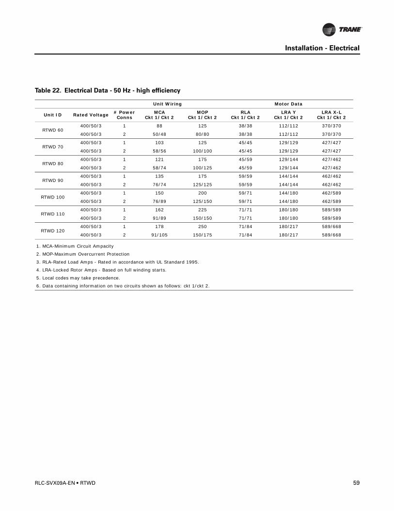
Installation - Electrical
Table 22. Electrical Data - 50 Hz - high efficiency
Unit Wiring Motor Data
Unit ID Rated Voltage # Power Conns
MCACkt 1/Ckt 2
MOPCkt 1/Ckt 2
RLACkt 1/Ckt 2
LRA Y Ckt 1/Ckt 2
LRA X-L Ckt 1/Ckt 2
RTWD 60400/50/3 1 88 125 38/38 112/112 370/370
400/50/3 2 50/48 80/80 38/38 112/112 370/370
RTWD 70400/50/3 1 103 125 45/45 129/129 427/427
400/50/3 2 58/56 100/100 45/45 129/129 427/427
RTWD 80400/50/3 1 121 175 45/59 129/144 427/462
400/50/3 2 58/74 100/125 45/59 129/144 427/462
RTWD 90400/50/3 1 135 175 59/59 144/144 462/462
400/50/3 2 76/74 125/125 59/59 144/144 462/462
RTWD 100400/50/3 1 150 200 59/71 144/180 462/589
400/50/3 2 76/89 125/150 59/71 144/180 462/589
RTWD 110400/50/3 1 162 225 71/71 180/180 589/589
400/50/3 2 91/89 150/150 71/71 180/180 589/589
RTWD 120400/50/3 1 178 250 71/84 180/217 589/668
400/50/3 2 91/105 150/175 71/84 180/217 589/668
1. MCA-Minimum Circuit Ampacity
2. MOP-Maximum Overcurrent Protection
3. RLA-Rated Load Amps - Rated in accordance with UL Standard 1995.
4. LRA-Locked Rotor Amps - Based on full winding starts.
5. Local codes may take precedence.
6. Data containing information on two circuits shown as follows: ckt 1/ckt 2.
RLC-SVX09A-EN • RTWD 59
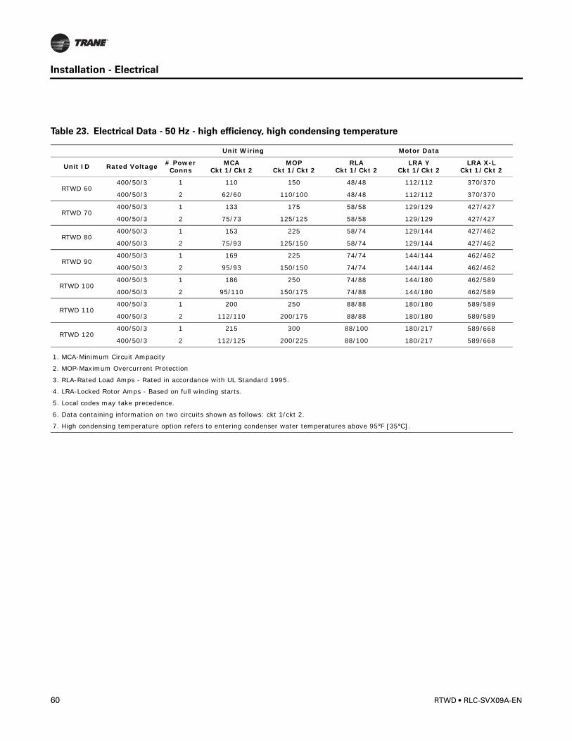
Installation - Electrical
Table 23. Electrical Data - 50 Hz - high efficiency, high condensing temperature
Unit Wiring Motor Data
Unit ID Rated Voltage # Power Conns
MCACkt 1/Ckt 2
MOPCkt 1/Ckt 2
RLACkt 1/Ckt 2
LRA Y Ckt 1/Ckt 2
LRA X-L Ckt 1/Ckt 2
RTWD 60400/50/3 1 110 150 48/48 112/112 370/370
400/50/3 2 62/60 110/100 48/48 112/112 370/370
RTWD 70400/50/3 1 133 175 58/58 129/129 427/427
400/50/3 2 75/73 125/125 58/58 129/129 427/427
RTWD 80400/50/3 1 153 225 58/74 129/144 427/462
400/50/3 2 75/93 125/150 58/74 129/144 427/462
RTWD 90400/50/3 1 169 225 74/74 144/144 462/462
400/50/3 2 95/93 150/150 74/74 144/144 462/462
RTWD 100400/50/3 1 186 250 74/88 144/180 462/589
400/50/3 2 95/110 150/175 74/88 144/180 462/589
RTWD 110400/50/3 1 200 250 88/88 180/180 589/589
400/50/3 2 112/110 200/175 88/88 180/180 589/589
RTWD 120400/50/3 1 215 300 88/100 180/217 589/668
400/50/3 2 112/125 200/225 88/100 180/217 589/668
1. MCA-Minimum Circuit Ampacity
2. MOP-Maximum Overcurrent Protection
3. RLA-Rated Load Amps - Rated in accordance with UL Standard 1995.
4. LRA-Locked Rotor Amps - Based on full winding starts.
5. Local codes may take precedence.
6. Data containing information on two circuits shown as follows: ckt 1/ckt 2.
7. High condensing temperature option refers to entering condenser water temperatures above 95°F [35°C].
60 RTWD • RLC-SVX09A-EN
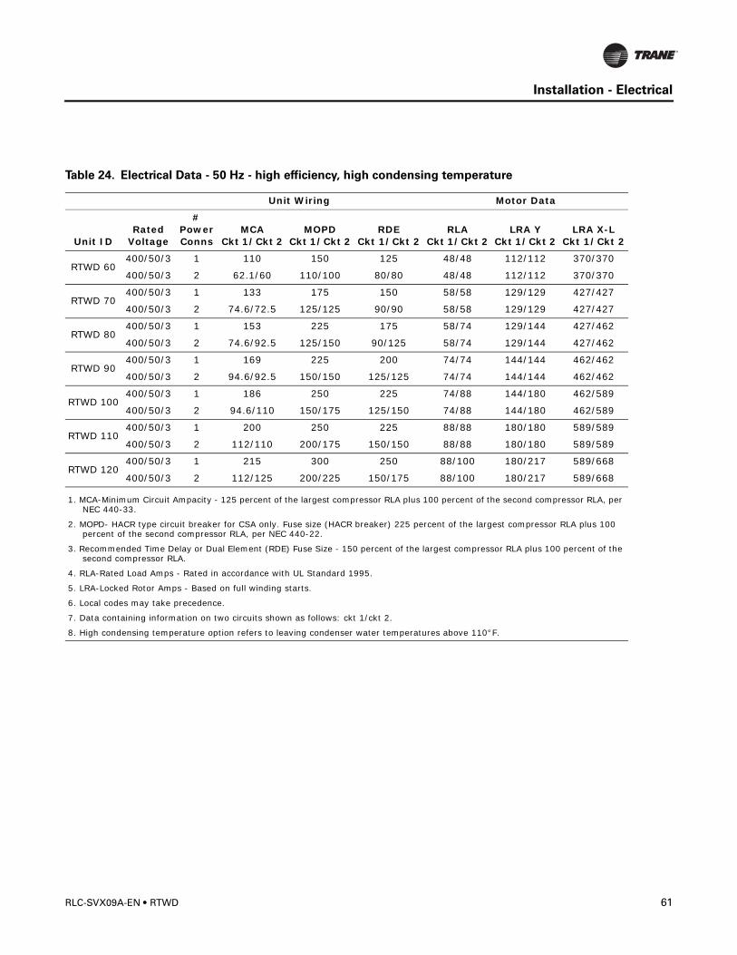
Installation - Electrical
Table 24. Electrical Data - 50 Hz - high efficiency, high condensing temperature
Unit Wiring Motor Data
Unit IDRated
Voltage
# Power Conns
MCACkt 1/Ckt 2
MOPDCkt 1/Ckt 2
RDECkt 1/Ckt 2
RLACkt 1/Ckt 2
LRA Y Ckt 1/Ckt 2
LRA X-L Ckt 1/Ckt 2
RTWD 60400/50/3 1 110 150 125 48/48 112/112 370/370
400/50/3 2 62.1/60 110/100 80/80 48/48 112/112 370/370
RTWD 70400/50/3 1 133 175 150 58/58 129/129 427/427
400/50/3 2 74.6/72.5 125/125 90/90 58/58 129/129 427/427
RTWD 80400/50/3 1 153 225 175 58/74 129/144 427/462
400/50/3 2 74.6/92.5 125/150 90/125 58/74 129/144 427/462
RTWD 90400/50/3 1 169 225 200 74/74 144/144 462/462
400/50/3 2 94.6/92.5 150/150 125/125 74/74 144/144 462/462
RTWD 100400/50/3 1 186 250 225 74/88 144/180 462/589
400/50/3 2 94.6/110 150/175 125/150 74/88 144/180 462/589
RTWD 110400/50/3 1 200 250 225 88/88 180/180 589/589
400/50/3 2 112/110 200/175 150/150 88/88 180/180 589/589
RTWD 120400/50/3 1 215 300 250 88/100 180/217 589/668
400/50/3 2 112/125 200/225 150/175 88/100 180/217 589/668
1. MCA-Minimum Circuit Ampacity - 125 percent of the largest compressor RLA plus 100 percent of the second compressor RLA, per NEC 440-33.
2. MOPD- HACR type circuit breaker for CSA only. Fuse size (HACR breaker) 225 percent of the largest compressor RLA plus 100 percent of the second compressor RLA, per NEC 440-22.
3. Recommended Time Delay or Dual Element (RDE) Fuse Size - 150 percent of the largest compressor RLA plus 100 percent of the second compressor RLA.
4. RLA-Rated Load Amps - Rated in accordance with UL Standard 1995.
5. LRA-Locked Rotor Amps - Based on full winding starts.
6. Local codes may take precedence.
7. Data containing information on two circuits shown as follows: ckt 1/ckt 2.
8. High condensing temperature option refers to leaving condenser water temperatures above 110°F.
RLC-SVX09A-EN • RTWD 61
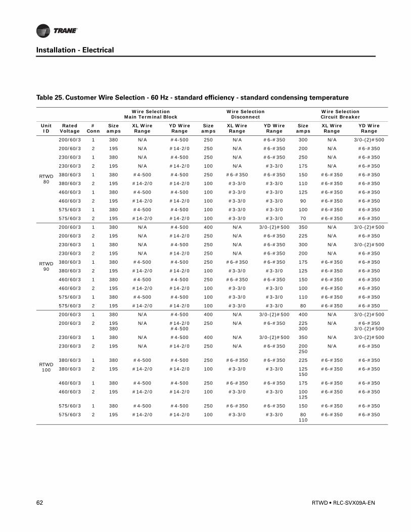
Installation - Electrical
0
0
0
0
0
0
Table 25. Customer Wire Selection - 60 Hz - standard efficiency - standard condensing temperature
Wire SelectionMain Terminal Block
Wire SelectionDisconnect
Wire SelectionCircuit Breaker
Unit ID
Rated Voltage
# Conn
Size amps
XL Wire Range
YD Wire Range
Size amps
XL Wire Range
YD WireRange
Size amps
XL Wire Range
YD Wire Range
RTWD 80
200/60/3 1 380 N/A #4-500 250 N/A #6-#350 300 N/A 3/0-(2)#50
200/60/3 2 195 N/A #14-2/0 250 N/A #6-#350 200 N/A #6-#350
230/60/3 1 380 N/A #4-500 250 N/A #6-#350 250 N/A #6-#350
230/60/3 2 195 N/A #14-2/0 100 N/A #3-3/0 175 N/A #6-#350
380/60/3 1 380 #4-500 #4-500 250 #6-#350 #6-#350 150 #6-#350 #6-#350
380/60/3 2 195 #14-2/0 #14-2/0 100 #3-3/0 #3-3/0 110 #6-#350 #6-#350
460/60/3 1 380 #4-500 #4-500 100 #3-3/0 #3-3/0 125 #6-#350 #6-#350
460/60/3 2 195 #14-2/0 #14-2/0 100 #3-3/0 #3-3/0 90 #6-#350 #6-#350
575/60/3 1 380 #4-500 #4-500 100 #3-3/0 #3-3/0 100 #6-#350 #6-#350
575/60/3 2 195 #14-2/0 #14-2/0 100 #3-3/0 #3-3/0 70 #6-#350 #6-#350
RTWD 90
200/60/3 1 380 N/A #4-500 400 N/A 3/0-(2)#500 350 N/A 3/0-(2)#50
200/60/3 2 195 N/A #14-2/0 250 N/A #6-#350 225 N/A #6-#350
230/60/3 1 380 N/A #4-500 250 N/A #6-#350 300 N/A 3/0-(2)#50
230/60/3 2 195 N/A #14-2/0 250 N/A #6-#350 200 N/A #6-#350
380/60/3 1 380 #4-500 #4-500 250 #6-#350 #6-#350 175 #6-#350 #6-#350
380/60/3 2 195 #14-2/0 #14-2/0 100 #3-3/0 #3-3/0 125 #6-#350 #6-#350
460/60/3 1 380 #4-500 #4-500 250 #6-#350 #6-#350 150 #6-#350 #6-#350
460/60/3 2 195 #14-2/0 #14-2/0 100 #3-3/0 #3-3/0 100 #6-#350 #6-#350
575/60/3 1 380 #4-500 #4-500 100 #3-3/0 #3-3/0 110 #6-#350 #6-#350
575/60/3 2 195 #14-2/0 #14-2/0 100 #3-3/0 #3-3/0 80 #6-#350 #6-#350
RTWD 100
200/60/3 1 380 N/A #4-500 400 N/A 3/0-(2)#500 400 N/A 3/0-(2)#50
200/60/3 2 195380
N/A #14-2/0#4-500
250 N/A #6-#350 225300
N/A #6-#3503/0-(2)#50
230/60/3 1 380 N/A #4-500 400 N/A 3/0-(2)#500 350 N/A 3/0-(2)#50
230/60/3 2 195 N/A #14-2/0 250 N/A #6-#350 200250
N/A #6-#350
380/60/3 1 380 #4-500 #4-500 250 #6-#350 #6-#350 225 #6-#350 #6-#350
380/60/3 2 195 #14-2/0 #14-2/0 100 #3-3/0 #3-3/0 125150
#6-#350 #6-#350
460/60/3 1 380 #4-500 #4-500 250 #6-#350 #6-#350 175 #6-#350 #6-#350
460/60/3 2 195 #14-2/0 #14-2/0 100 #3-3/0 #3-3/0 100125
#6-#350 #6-#350
575/60/3 1 380 #4-500 #4-500 250 #6-#350 #6-#350 150 #6-#350 #6-#350
575/60/3 2 195 #14-2/0 #14-2/0 100 #3-3/0 #3-3/0 80110
#6-#350 #6-#350
62 RTWD • RLC-SVX09A-EN
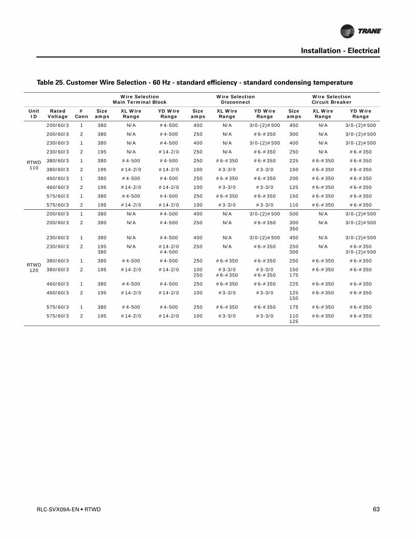
Installation - Electrical
RT1
RT1
U
WD 10
200/60/3 1 380 N/A #4-500 400 N/A 3/0-(2)#500 450 N/A 3/0-(2)#500
200/60/3 2 380 N/A #4-500 250 N/A #6-#350 300 N/A 3/0-(2)#500
230/60/3 1 380 N/A #4-500 400 N/A 3/0-(2)#500 400 N/A 3/0-(2)#500
230/60/3 2 195 N/A #14-2/0 250 N/A #6-#350 250 N/A #6-#350
380/60/3 1 380 #4-500 #4-500 250 #6-#350 #6-#350 225 #6-#350 #6-#350
380/60/3 2 195 #14-2/0 #14-2/0 100 #3-3/0 #3-3/0 150 #6-#350 #6-#350
460/60/3 1 380 #4-500 #4-500 250 #6-#350 #6-#350 200 #6-#350 #6-#350
460/60/3 2 195 #14-2/0 #14-2/0 100 #3-3/0 #3-3/0 125 #6-#350 #6-#350
575/60/3 1 380 #4-500 #4-500 250 #6-#350 #6-#350 150 #6-#350 #6-#350
575/60/3 2 195 #14-2/0 #14-2/0 100 #3-3/0 #3-3/0 110 #6-#350 #6-#350
WD 20
200/60/3 1 380 N/A #4-500 400 N/A 3/0-(2)#500 500 N/A 3/0-(2)#500
200/60/3 2 380 N/A #4-500 250 N/A #6-#350 300350
N/A 3/0-(2)#500
230/60/3 1 380 N/A #4-500 400 N/A 3/0-(2)#500 450 N/A 3/0-(2)#500
230/60/3 2 195380
N/A #14-2/0#4-500
250 N/A #6-#350 250300
N/A #6-#3503/0-(2)#500
380/60/3 1 380 #4-500 #4-500 250 #6-#350 #6-#350 250 #6-#350 #6-#350
380/60/3 2 195 #14-2/0 #14-2/0 100250
#3-3/0#6-#350
#3-3/0#6-#350
150175
#6-#350 #6-#350
460/60/3 1 380 #4-500 #4-500 250 #6-#350 #6-#350 225 #6-#350 #6-#350
460/60/3 2 195 #14-2/0 #14-2/0 100 #3-3/0 #3-3/0 125150
#6-#350 #6-#350
575/60/3 1 380 #4-500 #4-500 250 #6-#350 #6-#350 175 #6-#350 #6-#350
575/60/3 2 195 #14-2/0 #14-2/0 100 #3-3/0 #3-3/0 110125
#6-#350 #6-#350
Table 25. Customer Wire Selection - 60 Hz - standard efficiency - standard condensing temperature
Wire SelectionMain Terminal Block
Wire SelectionDisconnect
Wire SelectionCircuit Breaker
nit ID
Rated Voltage
# Conn
Size amps
XL Wire Range
YD Wire Range
Size amps
XL Wire Range
YD WireRange
Size amps
XL Wire Range
YD Wire Range
RLC-SVX09A-EN • RTWD 63
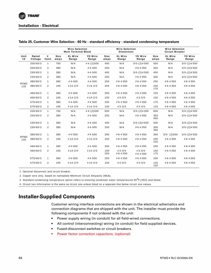
Installation - Electrical
0
0
0
0
0
0
0
0
0
Installer-Supplied Components
Customer wiring interface connections are shown in the electrical schematics and connection diagrams that are shipped with the unit. The installer must provide the following components if not ordered with the unit:
• Power supply wiring (in conduit) for all field-wired connections.
• All control (interconnecting) wiring (in conduit) for field supplied devices.
• Fused-disconnect switches or circuit breakers.
• Power factor correction capacitors. (optional)
RTWD 130
200/60/3 1 760 N/A #4-(2)500 400 N/A 3/0-(2)#500 500 N/A 3/0-(2)#50
200/60/3 2 380 N/A #4-500 250 N/A #6-#350 350 N/A 3/0-(2)#50
230/60/3 1 380 N/A #4-500 400 N/A 3/0-(2)#500 450 N/A 3/0-(2)#50
230/60/3 2 380 N/A #4-500 250 N/A #6-#350 300 N/A 3/0-(2)#50
380/60/3 1 380 #4-500 #4-500 250 #6-#350 #6-#350 250 #6-#350 #6-#350
380/60/3 2 195 #14-2/0 #14-2/0 250 #6-#350 #6-#350 200175
#6-#350 #6-#350
460/60/3 1 380 #4-500 #4-500 250 #6-#350 #6-#350 225 #6-#350 #6-#350
460/60/3 2 195 #14-2/0 #14-2/0 100 #3-3/0 #3-3/0 150 #6-#350 #6-#350
575/60/3 1 380 #4-500 #4-500 250 #6-#350 #6-#350 175 #6-#350 #6-#350
575/60/3 2 195 #14-2/0 #14-2/0 100 #3-3/0 #3-3/0 125 #6-#350 #6-#350
RTWD 140
200/60/3 1 760 N/A #4-(2)500 600 N/A 3/0-(2)#500 600 N/A 3/0-(2)#50
200/60/3 2 380 N/A #4-500 250 N/A #6-#350 350450
N/A 3/0-(2)#50
230/60/3 1 380 N/A #4-500 400 N/A 3/0-(2)#500 500 N/A 3/0-(2)#50
230/60/3 2 380 N/A #4-500 250 N/A #6-#350 300350
N/A 3/0-(2)#50
380/60/3 1 380 #4-500 #4-500 250 #6-#350 #6-#350 300 3/0- (2)500 3/0-(2)#50
380/60/3 2 195 #14-2/0 #14-2/0 250 #6-#350 #6-#350 200225
#6-#350 #6-#350
460/60/3 1 380 #4-500 #4-500 250 #6-#350 #6-#350 250 #6-#350 #6-#350
460/60/3 2 195 #14-2/0 #14-2/0 100250
#3-3/0#6-#350
#3-3/0#6-#350
150175
#6-#350 #6-#350
575/60/3 1 380 #4-500 #4-500 250 #6-#350 #6-#350 200 #6-#350 #6-#350
575/60/3 2 195 #14-2/0 #14-2/0 100 #3-3/0 #3-3/0 125150
#6-#350 #6-#350
1. Optional disconnect and circuit breaker.
2. Copper wire only, based on nameplate Minimum Circuit Ampacity (MCA).
3. Standard condensing temperature option refers to entering condenser water temperatures 95°F [35C] and below.
4. Circuit two information is the same as circuit one unless listed on a separate line below circuit one values.
Table 25. Customer Wire Selection - 60 Hz - standard efficiency - standard condensing temperature
Wire SelectionMain Terminal Block
Wire SelectionDisconnect
Wire SelectionCircuit Breaker
Unit ID
Rated Voltage
# Conn
Size amps
XL Wire Range
YD Wire Range
Size amps
XL Wire Range
YD WireRange
Size amps
XL Wire Range
YD Wire Range
64 RTWD • RLC-SVX09A-EN
Installation - Electrical
Power Supply Wiring
� WARNING
Ground Wire!
All field-installed wiring must be completed by qualified personnel. All field-installed
wiring must comply with NEC and applicable local codes. Failure to follow this
instruction could result in death or serious injuries.
All power supply wiring must be sized and selected accordingly by the project engineer in accordance with NEC Table 310-16.
� WARNING
Hazardous Voltage!
Disconnect all electric power, including remote disconnects before servicing. Follow
proper lockout/tagout procedures to ensure the power can not be inadvertently
energized. Failure to disconnect power before servicing could result in death or serious
injury.
All wiring must comply with local codes and the National Electrical Code. The installing (or electrical) contractor must provide and install the system interconnecting wiring, as well as the power supply wiring. It must be properly sized and equipped with the appropriate fused disconnect switches.
The type and installation location(s) of the fused disconnects must comply with all applicable codes.
CAUTION
Use Copper Conductors Only!
Unit terminals are not designed to accept other types of conductors. Failure to use
copper conductors may result in equipment damage.
Knock-outs for wiring are located on the upper left side of the control panel.The wiring is passed through these conduits and connected to the terminal blocks, optional unit-mounted disconnects, or HACR type breakers. Refer to Figure 21.
To provide proper phasing of 3-phase input, make connections as shown in field wiring diagrams and as stated on the WARNING label in the starter panel. For additional information on proper phasing, refer to “Unit Voltage Phasing.” Proper equipment ground must be provided to each ground connection in the panel (one for each customer-supplied conductor per phase).
115 volt field-provided connections (either control or power) are made through knockouts on the right side of the panel (Figure 21). Additional grounds may be required for each 115 volt power supply to the unit. Green lugs are provided for 115V customer wiring.
RLC-SVX09A-EN • RTWD 65
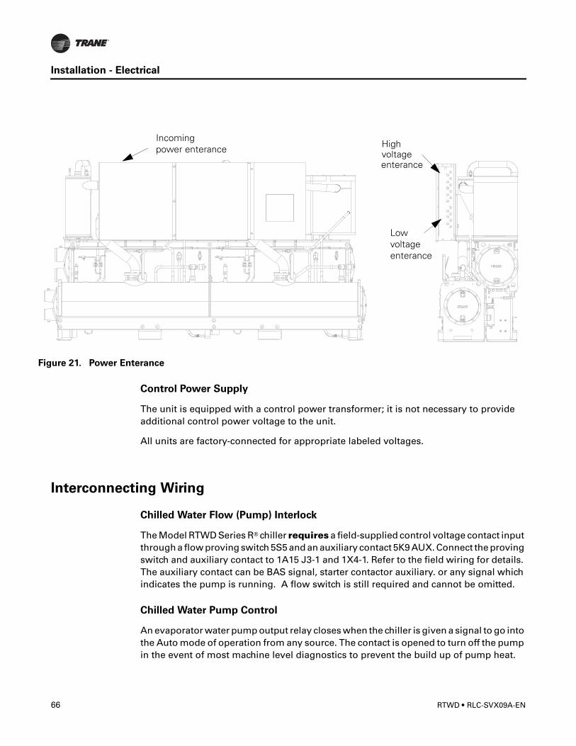
Installation - Electrical
F
Control Power Supply
The unit is equipped with a control power transformer; it is not necessary to provide additional control power voltage to the unit.
All units are factory-connected for appropriate labeled voltages.
Interconnecting Wiring
Chilled Water Flow (Pump) Interlock
The Model RTWD Series R® chiller requires a field-supplied control voltage contact input through a flow proving switch 5S5 and an auxiliary contact 5K9 AUX. Connect the proving switch and auxiliary contact to 1A15 J3-1 and 1X4-1. Refer to the field wiring for details. The auxiliary contact can be BAS signal, starter contactor auxiliary. or any signal which indicates the pump is running. A flow switch is still required and cannot be omitted.
Chilled Water Pump Control
An evaporator water pump output relay closes when the chiller is given a signal to go into the Auto mode of operation from any source. The contact is opened to turn off the pump in the event of most machine level diagnostics to prevent the build up of pump heat.
igure 21. Power Enterance
Incomingpower enterance High
voltageenterance
Lowvoltageenterance
66 RTWD • RLC-SVX09A-EN
Installation - Electrical
CAUTION
Evaporator Damage!
All unit chilled water pumps must be controlled by the Trane CH530 to avoid
catastrophic damage to the evaporator due to freezing.
The relay output from 1A14 is required to operate the Evaporator Water Pump (EWP) contactor. Contacts should be compatible with 115/240 VAC control circuit. The EWP relay operates in different modes depending on CH530 or Tracer commands, if available, or service pumpdown (See maintenance section). Normally, the EWP relay follows the AUTO mode of the chiller. Whenever the chiller has no diagnostics and is in the AUTO mode, regardless of where the auto command is coming from, the normally open relay is energized. When the chiller exits the AUTO mode, the relay is timed open for an adjustable (using TechView) 0 to 30 minutes. The non-AUTO modes in which the pump is stopped, include Reset (88), Stop (00), External Stop (100), Remote Display Stop (600), Stopped by Tracer (300), Low Ambient Run Inhibit (200), and Ice Building complete (101).
Regardless of whether the chiller is allowed to control the pump on a full-time basis, if the MP calls for a pump to start and water does not flow, the evaporator may be damaged catastrophically. It is the responsibility of the installing contractor and/or the customer to ensure that a pump will start when called upon by the chiller controls.
Note: Exceptions are listed below.
When going from Stop to Auto, the EWP relay is energized immediately. If evaporator water flow is not established in 4 minutes and 15 sec., the CH530 de-energizes the EWP relay and generates a non-latching diagnostic. If flow returns (e.g. someone else is controlling the pump), the diagnostic is cleared, the EWP is re-energized, and normal control resumed.
If evaporator water flow is lost once it had been established, the EWP relay remains energized and a non-latching diagnostic is generated. If flow returns, the diagnostic is cleared and the chiller returns to normal operation.
In general, when there is either a non-latching or latching diagnostic, the EWP relay is turned off as though there was a zero time delay. Exceptions (see above table) whereby the relay continues to be energized occur with:
A Low Chilled Water Temp. diagnostic (non-latching) (unless also accompanied by an Evap Leaving Water Temperature Sensor Diagnostic)
Table 26. Pump Relay Operation
Chiller Mode Relay OperationAuto Instant closeIce Building Instant closeTracer Override CloseStop TImed OpenIce Complete Instant OpenDiagnostics Instant Open
RLC-SVX09A-EN • RTWD 67
Installation - Electrical
or
A starter contactor interrupt failure diagnostic, in which a compressor continues to draw current even after commanded to have shutdown
or
A Loss of Evaporator Water Flow diagnostic (non-latching) and the unit is in the AUTO mode, after initially having proven evaporator water flow.
Alarm and Status Relay Outputs (Programmable Relays)
A programmable relay concept provides for enunciation of certain events or states of the chiller, selected from a list of likely needs, while only using four physical output relays, as shown in the field wiring diagram. The four relays are provided (generally with a Quad Relay Output LLID) as part of the Alarm Relay Output Option. The relay’s contacts are isolated Form C (SPDT), suitable for use with 120 VAC circuits drawing up to 2.8 amps inductive, 7.2 amps resistive, or 1/3 HP and for 240 VAC circuits drawing up to 0.5 amp resistive.
The list of events/states that can be assigned to the programmable relays can be found in Table 27.. The relay will be energized when the event/state occurs.
Table 27. Alarm and Status Relay Output Configuration Table
DescriptionAlarm - Latching This output is true whenever there is any active diagnostic that requires a manual reset to clear, that
affects either the Chiller, the Circuit, or any of the Compressors on a circuit. This classification does not include informational diagnostics.
Alarm - Auto Reset This output is true whenever there is any active diagnostic that could automatically clear, that affects either the Chiller, the Circuit, or any of the Compressors on a circuit. This classification does not include informational diagnostics.
Alarm This output is true whenever there is any diagnostic affecting any component, whether latching or automatically clearing. This classification does not include informational diagnostics
Alarm Ckt 1 This output is true whenever there is any diagnostic effecting Refrigerant Circuit 1, whether latching or automatically clearing, including diagnostics affecting the entire chiller. This classification does not include informational diagnostics.
Alarm Ckt 2 This output is true whenever there is any diagnostic affecting Refrigerant Circuit 2 whether latching or automatically clearing, including diagnostics effecting the entire chiller. This classification does not include informational diagnostics.
Chiller Limit Mode (with a 20 minute filter)
This output is true whenever the chiller has been running in one of the Unloading types of limit modes (Condenser, Evaporator, Current Limit or Phase Imbalance Limit) continuously for the last 20 minutes.
Circuit 1 Running This output is true whenever any compressors are running (or commanded to be running) on Refrigerant Circuit 1, and false when no compressors are commanded to be running on that circuit.
Circuit 2 Running This output is true whenever any compressors are running (or commanded to be running) on Refrigerant Circuit 2, and false when no compressors are commanded to be running on that circuit.
Chiller Running This output is true whenever any compressors are running (or commanded to be running) on the chiller and false when no compressors are commanded to be running on the chiller.
Maximum Capacity(software 18.0 or later)
This output is true whenever the chiller has reached maximum capacity or had reached its maximum capacity and since that time has not fallen below 70% average current relative to the rated ARI current for the chiller. The output is false when the chiller falls below 70% average current and, since that time, had not reestablished maximum capacity.
68 RTWD • RLC-SVX09A-EN
Installation - Electrical
Relay Assignments Using TechView
CH530 Service Tool (TechView) is used to install the Alarm and Status Relay Option package and assign any of the above list of events or status to each of the four relays provided with the option. The relays to be programmed are referred to by the relay’s terminal numbers on the LLID board 1A13.
The default assignments for the four available relays of the RTWD Alarm and Status Package Option are:
If any of the Alarm/Status relays are used, provide electrical power, 115 VAC with fused-disconnect to the panel and wire through the appropriate relays (terminals on 1A13. Provide wiring (switched hot, neutral, and ground connections) to the remote annunciation devices. Do not use power from the chiller’s control panel transformer to power these remote devices. Refer to the field diagrams which are shipped with the unit.
Low Voltage Wiring
� WARNING
Ground Wire!
All field-installed wiring must be completed by qualified personnel. All field-installed
wiring must comply with NEC and applicable local codes. Failure to follow this
instruction could result in death or serious injuries.
The remote devices described below require low voltage wiring. All wiring to and from these remote input devices to the Control Panel must be made with shielded, twisted pair conductors. Be sure to ground the shielding only at the panel.
Note: To prevent control malfunctions, do not run low voltage wiring (<30 V) in conduit with conductors carrying more than 30 volts.
Emergency Stop
CH530 provides auxiliary control for a customer specified/installed latching trip out. When this customer-furnished remote contact 5K24 is provided, the chiller will run normally when the contact is closed. When the contact opens, the unit will trip on a manually resettable diagnostic. This condition requires manual reset at the chiller switch on the front of the control panel.
Connect low voltage leads to terminal strip locations on 1A5, J2-3 and 4. Refer to the field diagrams that are shipped with the unit.
Table 28. Default Assignments
Relay Relay 1 Terminals J2 -12,11,10: AlarmRelay 2 Terminals J2 - 9,8,7: Chiller RunningRelay 3 Terminals J2-6,5,4: Maximum Capacity (software 18.0 or later)Relay 4 Terminals J2-3,2,1: Chiller Limit
RLC-SVX09A-EN • RTWD 69
Installation - Electrical
Silver or gold-plated contacts are recommended. These customer-furnished contacts must be compatible with 24 VDC, 12 mA resistive load.
External Auto/Stop
If the unit requires the external Auto/Stop function, the installer must provide leads from the remote contacts 5K23 to the proper terminals onb 1A5 J2-1 and 2.
The chiller will run normally when the contacts are closed. When either contact opens, the compressor(s), if operating, will go to the RUN:UNLOAD operating mode and cycle off. Unit operation will be inhibited. Closure of the contacts will permit the unit to return to normal operation.
Field-supplied contacts for all low voltage connections must be compatible with dry circuit 24 VDC for a 12 mA resistive load. Refer to the field diagrams that are shipped with the unit.
External Circuit Lockout – Circuit #1 and Circuit #2
CH530 provides auxiliary control of a customer specified or installed contact closure, for individual operation of either Circuit #1 or #2. If the contact is closed, the refrigerant circuit will not operate 5K21 and 5K22.
Upon contact opening, the refrigerant circuit will run normally. This feature is used to restrict total chiller operation, e.g. during emergency generator operations.
Connections to 1A10 are shown in the field diagrams that are shipped with the unit.
These customer-supplied contact closures must be compatible with 24 VDC, 12 mA resistive load. Silver or gold plated contacts are recommended.
Ice Building Option
CH530 provides auxiliary control for a customer specified/installed contact closure for ice building if so configured and enabled. This output is known as the Ice Building Status Relay. The normally open contact will be closed when ice building is in progress and open when ice building has been normally terminated either through Ice Termination setpoint being reached or removal of the Ice Building command. This output is for use with the ice storage system equipment or controls (provided by others) to signal the system changes required as the chiller mode changes from “ice building” to “ice complete”. When contact 5K20 is provided, the chiller will run normally when the contact is open.
CH530 will accept either an isolated contact closure (External Ice Building command) or a Remote Communicated input (Tracer) to initiate and command the Ice Building mode.
CH530 also provides a “Front Panel Ice Termination Setpoint”, settable through TechView, and adjustable from 20 to 31°F (-6.7 to -0.5°C) in at least 1°F (1°C) increments.
When in the Ice Building mode, and the evaporator entering water temperature drops below the ice termination setpoint, the chiller terminates the Ice Building mode and changes to the Ice Building Complete Mode.
70 RTWD • RLC-SVX09A-EN
Installation - Electrical
CAUTION
Evaporator Damage!
Freeze inhibitor must be adequate for the leaving water temperature. Failure to do so
may result in damage to system components.
Techview must also be used to enable or disable Ice Machine Control. This setting does not prevent the Tracer from commanding Ice Building mode.
Upon contact closure, the CH530 will initiate an ice building mode, in which the unit runs fully loaded at all times. Ice building shall be terminated either by opening the contact or based on the entering evaporator water temperature. CH530 will not permit the ice building mode to be reentered until the unit has been switched out of ice building mode (open 5K20 contacts) and then switched back into ice building mode (close 5K20 contacts.)
In ice building, all limits (freeze avoidance, evaporator, condenser, current) will be ignored. All safeties will be enforced.
If, while in ice building mode, the unit gets down to the freeze stat setting (water or refrigerant), the unit will shut down on a manually resettable diagnostic, just as in normal operation.
Connect leads from 5K20 to the proper terminals of 1A10. Refer to the field diagrams which are shipped with the unit.
Silver or gold-plated contacts are recommended. These customer furnished contacts must be compatible with 24 VDC, 12 mA resistive load.
External Chilled Water Setpoint (ECWS) Option
The CH530 provides inputs that accept either 4-20 mA or 2-10 VDC signals to set the external chilled water setpoint (ECWS). This is not a reset function. The input defines the set point. This input is primarily used with generic BAS (building automation systems). The chilled water setpoint set via the DynaView or through digital communication with Tracer (Comm3). The arbitration of the various chilled water setpoint sources is described in the flow charts at the end of the section.
The chilled water setpoint may be changed from a remote location by sending either a 2-10 VDC or 4-20 mA signal to the 1A7, J2-1 and 2. The 2-10 VDC and 4-20 mA each correspond to a 10 to 65°F (-12 to 18°C) external chilled water setpoint.
The following equations apply:Voltage Signal Current Signal
As generated from external source
VDC=0.1455*(ECWS)+0.5454 mA=0.2909(ECWS)+1.0909
As processed by CH530 ECWS=6.875*(VDC)-3.75 ECWS=3.4375(mA)-3.75
RLC-SVX09A-EN • RTWD 71
Installation - Electrical
If the ECWS input develops an open or short, the LLID will report either a very high or very low value back to the main processor. This will generate an informational diagnostic and the unit will default to using the Front Panel (DynaView) Chilled Water Setpoint.
TechView Service Tool is used to set the input signal type from the factory default of 2-10 VDC to that of 4-20 mA. TechView is also used to install or remove the External Chilled Water Setpoint option as well as a means to enable and disable ECWS.
External Current Limit Setpoint (ECLS) Option
Similar to the above, the CH530 also provides for an optional External Current Limit Setpoint that will accept either a 2-10 VDC (default) or a 4-20 mA signal. The Current Limit Setting can also be set via the DynaView or through digital communication with Tracer (Comm 3). The arbitration of the various sources of current limit is described in the flow charts at the end of this section. The External Current Limit Setpoint may be changed from a remote location by hooking up the analog input signal to the 1A7, J2-4 and 5. Refer to the following paragraph on Analog Input Signal Wiring Details. The following equations apply for ECLS:
If the ECLS input develops an open or short, the LLID will report either a very high or very low value back to the man processor. This will generate an informational diagnostic and the unit will default to using the Front Panel (DynaView) Current Limit Setpoint.
The TechView Service Tool must be used to set the input signal type from the factory default of 2-10 VDC to that of 4-20 mA current. TechView must be also be used to install or remove the External Current Limit Setpoint Option for field installation, or can be used to enable or disable the feature (if installed).
ECLS and ECWS Analog Input Signal Wiring Details:
Both the ECWS and ECLS can be connected and setup as either a 2-10 VDC (factory default), 4-20 mA, or resistance input (also a form of 4-2OmA) as indicated below. Depending on the type to be used, the TechView Service Tool must be used to configure the LLID and the MP for the proper input type that is being used. This is accomplished by a setting change on the Custom Tab of the Configuration View within TechView.
Voltage Signal Current Signal
As generated from external source
VDC+0.133*(%)-6.0 mA=0.266*(%)-12.0
As processed by UCM %=7.5*(VDC)+45.0 %=3.75*(mA)+45.0
72 RTWD • RLC-SVX09A-EN
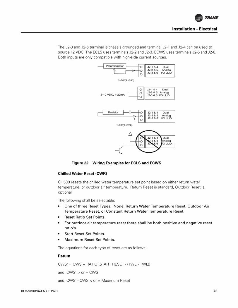
Installation - Electrical
The J2-3 and J2-6 terminal is chassis grounded and terminal J2-1 and J2-4 can be used to source 12 VDC. The ECLS uses terminals J2-2 and J2-3. ECWS uses terminals J2-5 and J2-6. Both inputs are only compatible with high-side current sources.
Chilled Water Reset (CWR)
CH530 resets the chilled water temperature set point based on either return water temperature, or outdoor air temperature. Return Reset is standard, Outdoor Reset is optional.
The following shall be selectable:• One of three Reset Types: None, Return Water Temperature Reset, Outdoor Air
Temperature Reset, or Constant Return Water Temperature Reset.
• Reset Ratio Set Points.
• For outdoor air temperature reset there shall be both positive and negative reset ratio's.
• Start Reset Set Points.
• Maximum Reset Set Points.
The equations for each type of reset are as follows:
Return
CWS' = CWS + RATIO (START RESET - (TWE - TWL))
and CWS' > or = CWS
and CWS' - CWS < or = Maximum Reset
Figure 22. Wiring Examples for ECLS and ECWS
RLC-SVX09A-EN • RTWD 73
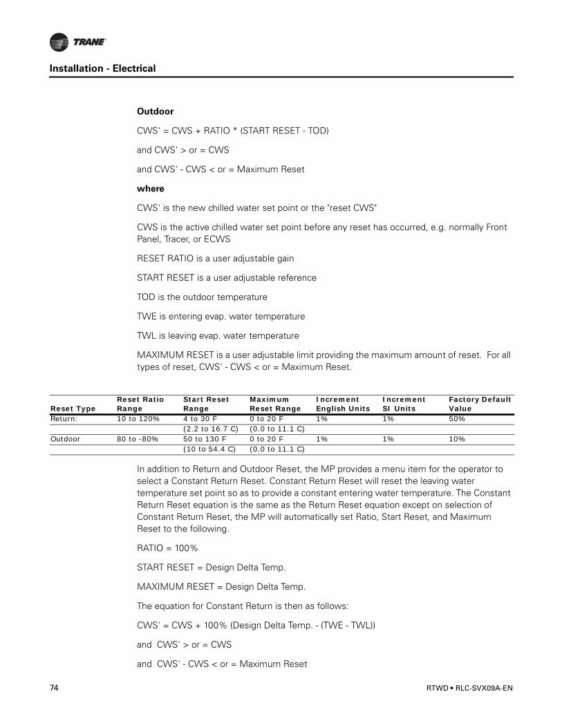
Installation - Electrical
Outdoor
CWS' = CWS + RATIO * (START RESET - TOD)
and CWS' > or = CWS
and CWS' - CWS < or = Maximum Reset
where
CWS' is the new chilled water set point or the "reset CWS"
CWS is the active chilled water set point before any reset has occurred, e.g. normally Front Panel, Tracer, or ECWS
RESET RATIO is a user adjustable gain
START RESET is a user adjustable reference
TOD is the outdoor temperature
TWE is entering evap. water temperature
TWL is leaving evap. water temperature
MAXIMUM RESET is a user adjustable limit providing the maximum amount of reset. For all types of reset, CWS' - CWS < or = Maximum Reset.
In addition to Return and Outdoor Reset, the MP provides a menu item for the operator to select a Constant Return Reset. Constant Return Reset will reset the leaving water temperature set point so as to provide a constant entering water temperature. The Constant Return Reset equation is the same as the Return Reset equation except on selection of Constant Return Reset, the MP will automatically set Ratio, Start Reset, and Maximum Reset to the following.
RATIO = 100%
START RESET = Design Delta Temp.
MAXIMUM RESET = Design Delta Temp.
The equation for Constant Return is then as follows:
CWS' = CWS + 100% (Design Delta Temp. - (TWE - TWL))
and CWS' > or = CWS
and CWS' - CWS < or = Maximum Reset
Reset TypeReset Ratio Range
Start ResetRange
Maximum Reset Range
IncrementEnglish Units
IncrementSI Units
Factory Default Value
Return: 10 to 120% 4 to 30 F 0 to 20 F 1% 1% 50%(2.2 to 16.7 C) (0.0 to 11.1 C)
Outdoor 80 to -80% 50 to 130 F 0 to 20 F 1% 1% 10%(10 to 54.4 C) (0.0 to 11.1 C)
74 RTWD • RLC-SVX09A-EN
Installation - Electrical
When any type of CWR is enabled, the MP will step the Active CWS toward the desired CWS' (based on the above equations and setup parameters) at a rate of 1 degree F every 5 minutes until the Active CWS equals the desired CWS'. This applies when the chiller is running.
When the chiller is not running the CWS is reset immediately (within one minute) for Return Reset and at a rate of 1 degree F every 5 minutes for Outdoor Reset. The chiller will start at the Differential to Start value above a fully reset CWS or CWS' for both Return and Outdoor Reset.
Communications Interface options
Optional Tracer Communications Interface
This option allows the Tracer CH530 controller to exchange information (e.g. operating setpoints and Auto/Standby commands) with a higher-level control device, such as a Tracer Summit or a multiple-machine controller. A shielded, twisted pair connection establishes the bi-directional communications link between the Tracer CH530 and the building automation system.
Note: To prevent control malfunctions, do not run low voltage wiring (<30 V) in conduit with conductors carrying more than 30 volts.
� WARNING
Ground Wire!
All field-installed wiring must be completed by qualified personnel. All field-installed
wiring must comply with NEC and applicable local codes. Failure to follow this
instruction could result in death or serious injuries.
Field wiring for the communication link must meet the following requirements:• All wiring must be in accordance with the NEC and local codes.
• Communication link wiring must be shielded, twisted pair wiring (Belden 8760 or equivalent). See the table below for wire size selection:
• The communication link cannot pass between buildings.
• All units on the communication link can be connected in a “daisy chain” configuration.
Table 29. Wire Size
Wire Size Maximum Length of Communication Wire14 AWG (2.5 mm2) 5,000 FT (1525 m)16 AWG (1.5 mm2) 2,000 FT (610 m)18 AWG (1.0 mm2) 1,000 FT (305 m)
RLC-SVX09A-EN • RTWD 75
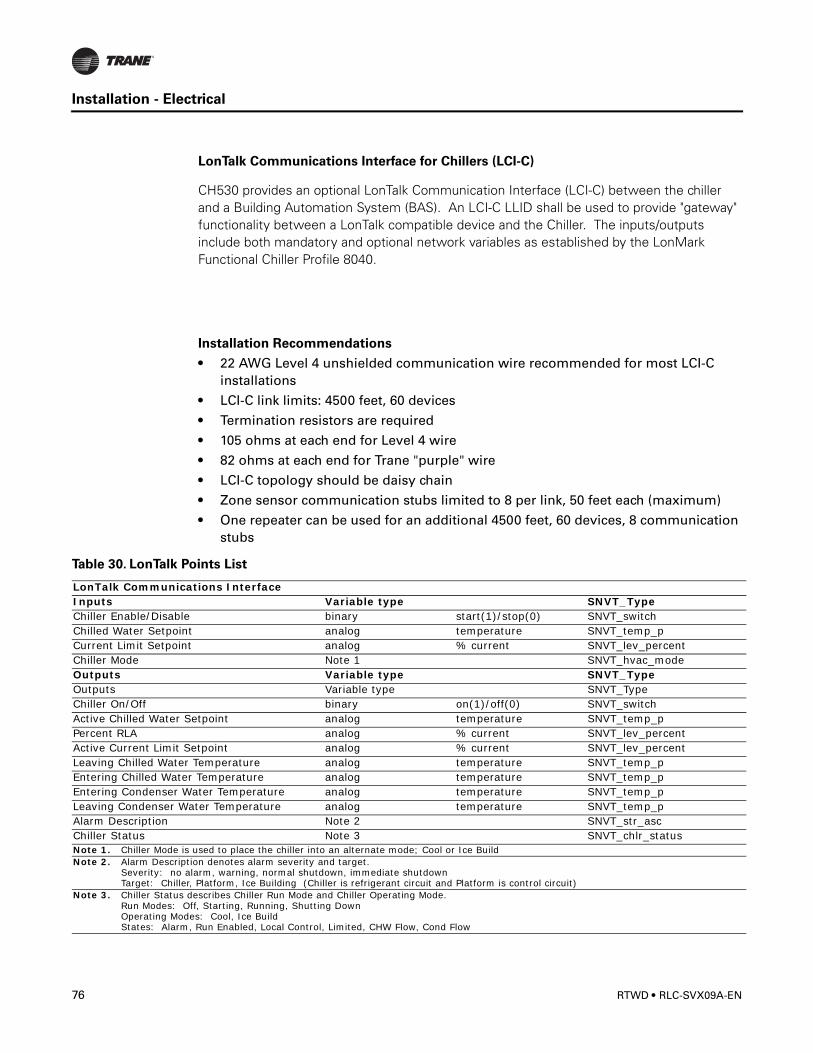
Installation - Electrical
LonTalk Communications Interface for Chillers (LCI-C)
CH530 provides an optional LonTalk Communication Interface (LCI-C) between the chiller and a Building Automation System (BAS). An LCI-C LLID shall be used to provide "gateway" functionality between a LonTalk compatible device and the Chiller. The inputs/outputs include both mandatory and optional network variables as established by the LonMark Functional Chiller Profile 8040.
Installation Recommendations
• 22 AWG Level 4 unshielded communication wire recommended for most LCI-C installations
• LCI-C link limits: 4500 feet, 60 devices
• Termination resistors are required
• 105 ohms at each end for Level 4 wire
• 82 ohms at each end for Trane "purple" wire
• LCI-C topology should be daisy chain
• Zone sensor communication stubs limited to 8 per link, 50 feet each (maximum)
• One repeater can be used for an additional 4500 feet, 60 devices, 8 communication stubs
Table 30. LonTalk Points List
LonTalk Communications InterfaceInputs Variable type SNVT_TypeChiller Enable/Disable binary start(1)/stop(0) SNVT_switchChilled Water Setpoint analog temperature SNVT_temp_pCurrent Limit Setpoint analog % current SNVT_lev_percentChiller Mode Note 1 SNVT_hvac_modeOutputs Variable type SNVT_TypeOutputs Variable type SNVT_TypeChiller On/Off binary on(1)/off(0) SNVT_switchActive Chilled Water Setpoint analog temperature SNVT_temp_pPercent RLA analog % current SNVT_lev_percentActive Current Limit Setpoint analog % current SNVT_lev_percentLeaving Chilled Water Temperature analog temperature SNVT_temp_pEntering Chilled Water Temperature analog temperature SNVT_temp_pEntering Condenser Water Temperature analog temperature SNVT_temp_pLeaving Condenser Water Temperature analog temperature SNVT_temp_pAlarm Description Note 2 SNVT_str_ascChiller Status Note 3 SNVT_chlr_statusNote 1. Chiller Mode is used to place the chiller into an alternate mode; Cool or Ice BuildNote 2. Alarm Description denotes alarm severity and target.
Severity: no alarm, warning, normal shutdown, immediate shutdown Target: Chiller, Platform, Ice Building (Chiller is refrigerant circuit and Platform is control circuit)
Note 3. Chiller Status describes Chiller Run Mode and Chiller Operating Mode. Run Modes: Off, Starting, Running, Shutting Down Operating Modes: Cool, Ice Build States: Alarm, Run Enabled, Local Control, Limited, CHW Flow, Cond Flow
76 RTWD • RLC-SVX09A-EN
RTWD Operating Principles
This section contains an overview of the operation of RTWD Series R chillers equipped with microcomputer-based control systems. It describes the overall operating principles of the RTWD water chiller.
Note: To ensure proper diagnosis and repair, contact a qualified service organization if a problem should occur.
General
The Model RTWD units are dual-compressor, dual circuit, water-cooled liquid chillers. These units are equipped with unit-mounted starter/control panels.
The basic components of an RTWD unit are:
• Unit-mounted panel containing starter and Tracer CH530 controller and Input/Output LLIDS
• Helical-rotary compressor
• Evaporator
• Electronic expansion valve
• Water-cooled condenser with integral subcooler
• Oil supply system
• Oil cooler (application dependent)
• Related interconnecting piping.
Components of a typical RTWD unit are identified in the following diagram.
� WARNING
Contains Refrigerant!
System contains oil and refrigerant under high pressure. Recover refrigerant to relieve
pressure before opening the system. See unit nameplate for refrigerant type. Do not
use non-approved refrigerants, refrigerant substitutes, or refrigerant additives.
Failure to follow proper procedures or the use of non-approved refrigerants, refrigerant
substitutes, or refrigerant additives could result in death or serious injury or
equipment damage.
� WARNING
Hazardous Voltage!
Disconnect all electric power, including remote disconnects before servicing. Follow
proper lockout/tagout procedures to ensure the power can not be inadvertently
energized. Failure to disconnect power before servicing could result in death or serious
injury.
RLC-SVX09A-EN • RTWD 77
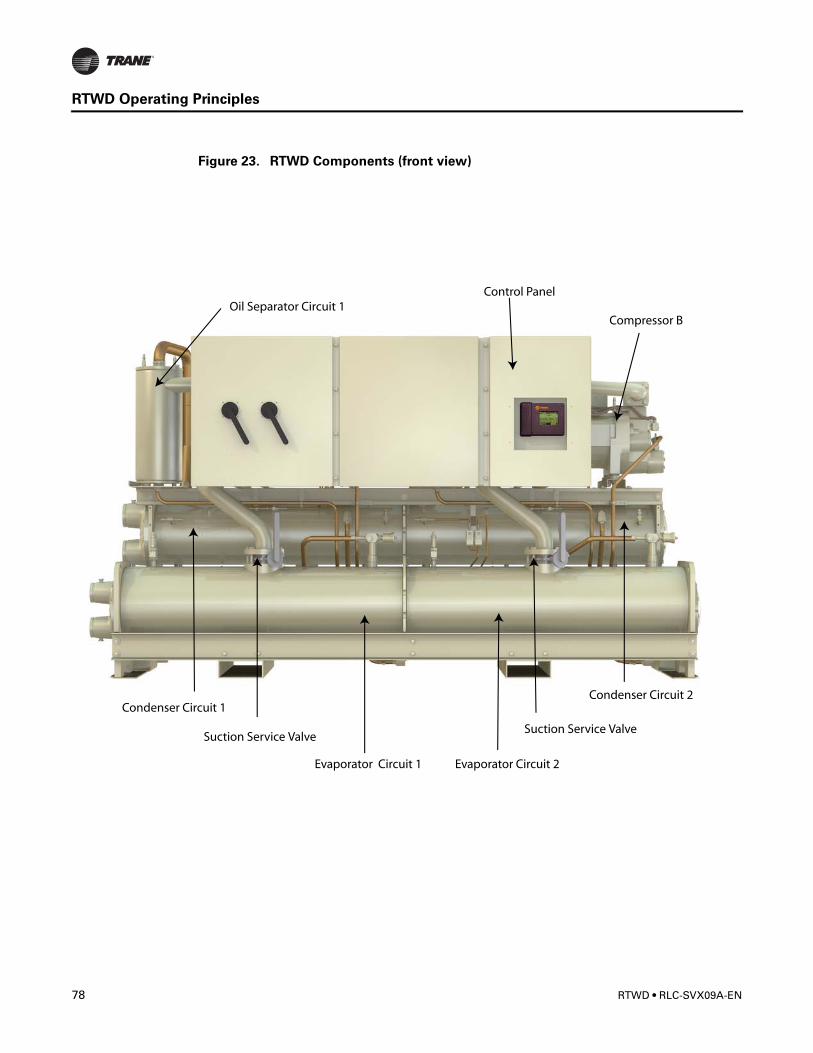
RTWD Operating Principles
Figure 23. RTWD Components (front view)
78 RTWD • RLC-SVX09A-EN

RTWD Operating Principles
Figure 24. RTWD Components (back view)
Refrigeration (Cooling) Cycle
Overview
The refrigeration cycle of the Series R chiller is conceptually similar to that of other Trane chiller products. It makes use of a shell-and-tube evaporator design with refrigerant evaporating on the shell side and water flowing inside tubes having enhanced surfaces.
The compressor is a twin-rotor helical rotary type. It uses a suction gas-cooled motor that operates at lower motor temperatures under continuous full and part load operating conditions. An oil management system provides an almost oil-free refrigerant to the
RLC-SVX09A-EN • RTWD 79
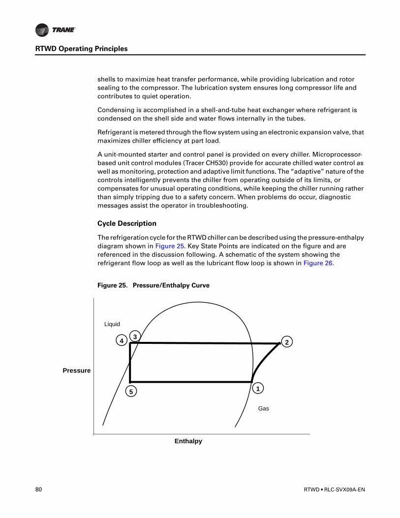
RTWD Operating Principles
shells to maximize heat transfer performance, while providing lubrication and rotor sealing to the compressor. The lubrication system ensures long compressor life and contributes to quiet operation.
Condensing is accomplished in a shell-and-tube heat exchanger where refrigerant is condensed on the shell side and water flows internally in the tubes.
Refrigerant is metered through the flow system using an electronic expansion valve, that maximizes chiller efficiency at part load.
A unit-mounted starter and control panel is provided on every chiller. Microprocessor-based unit control modules (Tracer CH530) provide for accurate chilled water control as well as monitoring, protection and adaptive limit functions. The “adaptive” nature of the controls intelligently prevents the chiller from operating outside of its limits, or compensates for unusual operating conditions, while keeping the chiller running rather than simply tripping due to a safety concern. When problems do occur, diagnostic messages assist the operator in troubleshooting.
Cycle Description
The refrigeration cycle for the RTWD chiller can be described using the pressure-enthalpy diagram shown in Figure 25. Key State Points are indicated on the figure and are referenced in the discussion following. A schematic of the system showing the refrigerant flow loop as well as the lubricant flow loop is shown in Figure 26.
Figure 25. Pressure/Enthalpy Curve
Pressure
Enthalpy
Liquid
Gas
1
234
5
80 RTWD • RLC-SVX09A-EN
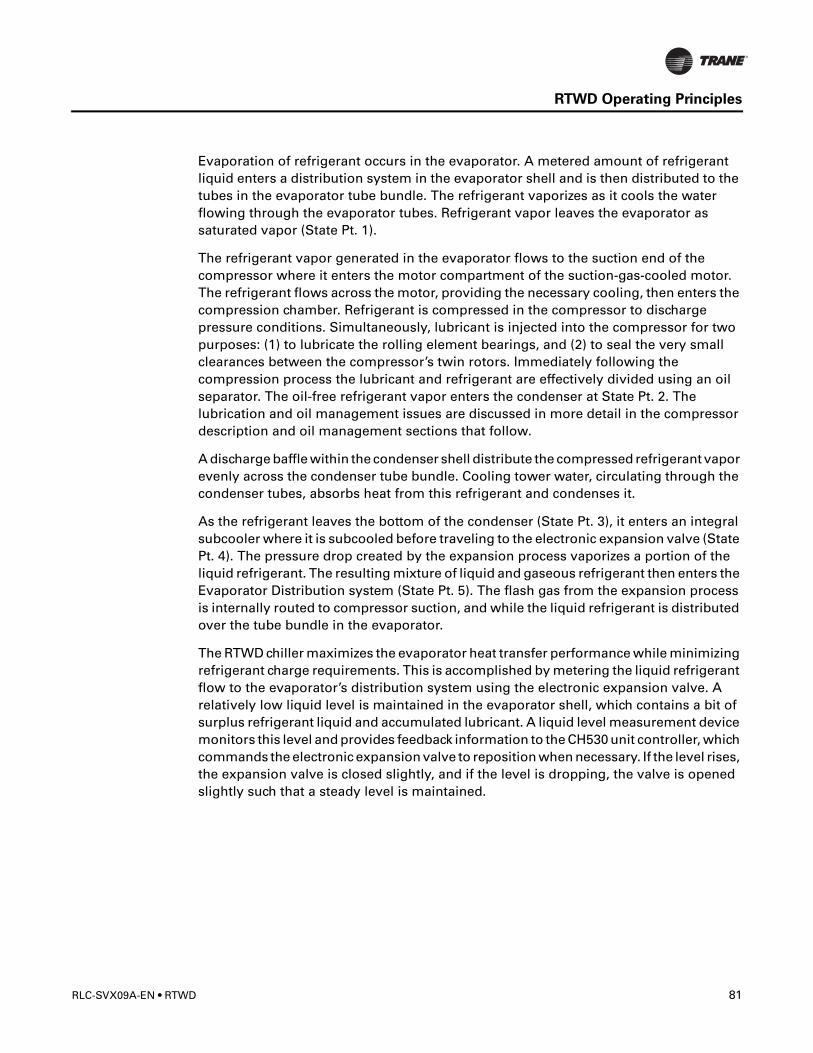
RTWD Operating Principles
Evaporation of refrigerant occurs in the evaporator. A metered amount of refrigerant liquid enters a distribution system in the evaporator shell and is then distributed to the tubes in the evaporator tube bundle. The refrigerant vaporizes as it cools the water flowing through the evaporator tubes. Refrigerant vapor leaves the evaporator as saturated vapor (State Pt. 1).
The refrigerant vapor generated in the evaporator flows to the suction end of the compressor where it enters the motor compartment of the suction-gas-cooled motor. The refrigerant flows across the motor, providing the necessary cooling, then enters the compression chamber. Refrigerant is compressed in the compressor to discharge pressure conditions. Simultaneously, lubricant is injected into the compressor for two purposes: (1) to lubricate the rolling element bearings, and (2) to seal the very small clearances between the compressor’s twin rotors. Immediately following the compression process the lubricant and refrigerant are effectively divided using an oil separator. The oil-free refrigerant vapor enters the condenser at State Pt. 2. The lubrication and oil management issues are discussed in more detail in the compressor description and oil management sections that follow.
A discharge baffle within the condenser shell distribute the compressed refrigerant vapor evenly across the condenser tube bundle. Cooling tower water, circulating through the condenser tubes, absorbs heat from this refrigerant and condenses it.
As the refrigerant leaves the bottom of the condenser (State Pt. 3), it enters an integral subcooler where it is subcooled before traveling to the electronic expansion valve (State Pt. 4). The pressure drop created by the expansion process vaporizes a portion of the liquid refrigerant. The resulting mixture of liquid and gaseous refrigerant then enters the Evaporator Distribution system (State Pt. 5). The flash gas from the expansion process is internally routed to compressor suction, and while the liquid refrigerant is distributed over the tube bundle in the evaporator.
The RTWD chiller maximizes the evaporator heat transfer performance while minimizing refrigerant charge requirements. This is accomplished by metering the liquid refrigerant flow to the evaporator’s distribution system using the electronic expansion valve. A relatively low liquid level is maintained in the evaporator shell, which contains a bit of surplus refrigerant liquid and accumulated lubricant. A liquid level measurement device monitors this level and provides feedback information to the CH530 unit controller, which commands the electronic expansion valve to reposition when necessary. If the level rises, the expansion valve is closed slightly, and if the level is dropping, the valve is opened slightly such that a steady level is maintained.
RLC-SVX09A-EN • RTWD 81
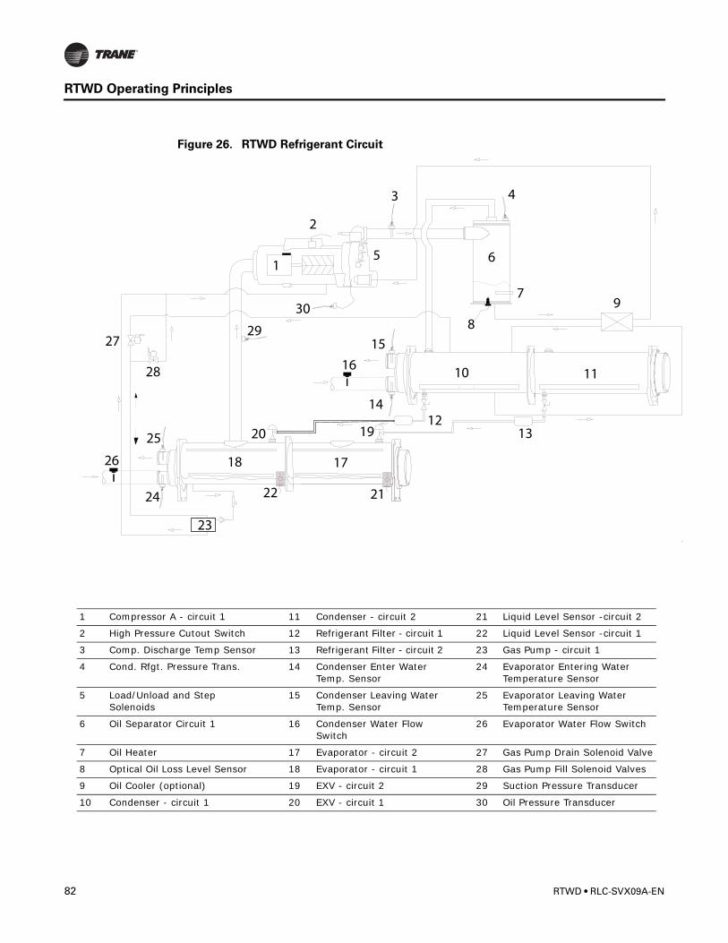
RTWD Operating Principles
Figure 26. RTWD Refrigerant Circuit
1 Compressor A - circuit 1 11 Condenser - circuit 2 21 Liquid Level Sensor -circuit 2
2 High Pressure Cutout Switch 12 Refrigerant Filter - circuit 1 22 Liquid Level Sensor -circuit 1
3 Comp. Discharge Temp Sensor 13 Refrigerant Filter - circuit 2 23 Gas Pump - circuit 1
4 Cond. Rfgt. Pressure Trans. 14 Condenser Enter Water Temp. Sensor
24 Evaporator Entering Water Temperature Sensor
5 Load/Unload and Step Solenoids
15 Condenser Leaving Water Temp. Sensor
25 Evaporator Leaving Water Temperature Sensor
6 Oil Separator Circuit 1 16 Condenser Water Flow Switch
26 Evaporator Water Flow Switch
7 Oil Heater 17 Evaporator - circuit 2 27 Gas Pump Drain Solenoid Valve
8 Optical Oil Loss Level Sensor 18 Evaporator - circuit 1 28 Gas Pump Fill Solenoid Valves
9 Oil Cooler (optional) 19 EXV - circuit 2 29 Suction Pressure Transducer
10 Condenser - circuit 1 20 EXV - circuit 1 30 Oil Pressure Transducer
82 RTWD • RLC-SVX09A-EN
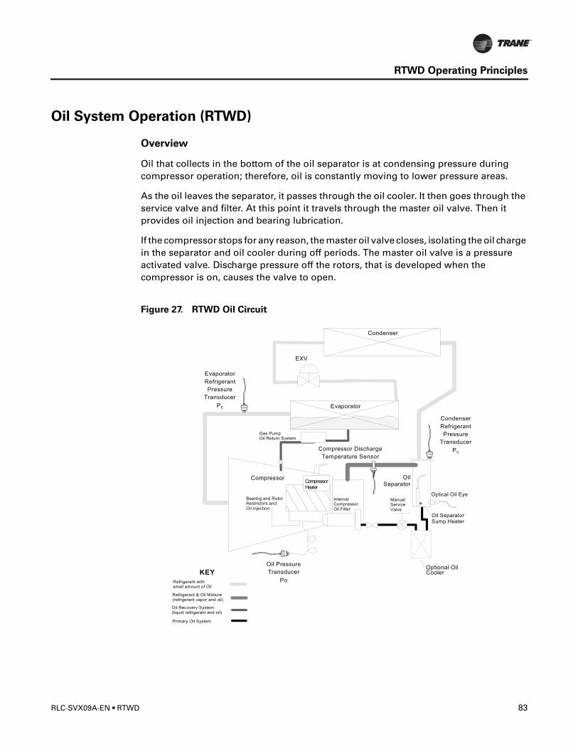
RTWD Operating Principles
Oil System Operation (RTWD)
Overview
Oil that collects in the bottom of the oil separator is at condensing pressure during compressor operation; therefore, oil is constantly moving to lower pressure areas.
As the oil leaves the separator, it passes through the oil cooler. It then goes through the service valve and filter. At this point it travels through the master oil valve. Then it provides oil injection and bearing lubrication.
If the compressor stops for any reason, the master oil valve closes, isolating the oil charge in the separator and oil cooler during off periods. The master oil valve is a pressure activated valve. Discharge pressure off the rotors, that is developed when the compressor is on, causes the valve to open.
Figure 27. RTWD Oil Circuit
RLC-SVX09A-EN • RTWD 83
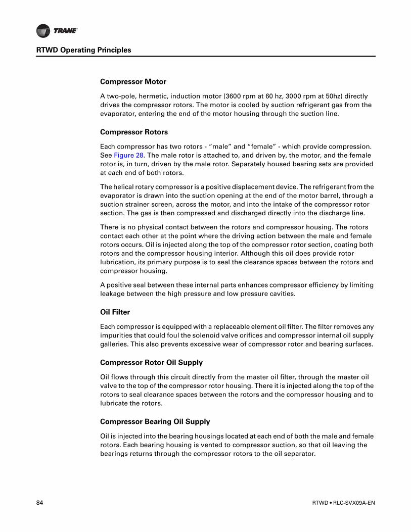
RTWD Operating Principles
Compressor Motor
A two-pole, hermetic, induction motor (3600 rpm at 60 hz, 3000 rpm at 50hz) directly drives the compressor rotors. The motor is cooled by suction refrigerant gas from the evaporator, entering the end of the motor housing through the suction line.
Compressor Rotors
Each compressor has two rotors - “male” and “female” - which provide compression. See Figure 28. The male rotor is attached to, and driven by, the motor, and the female rotor is, in turn, driven by the male rotor. Separately housed bearing sets are provided at each end of both rotors.
The helical rotary compressor is a positive displacement device. The refrigerant from the evaporator is drawn into the suction opening at the end of the motor barrel, through a suction strainer screen, across the motor, and into the intake of the compressor rotor section. The gas is then compressed and discharged directly into the discharge line.
There is no physical contact between the rotors and compressor housing. The rotors contact each other at the point where the driving action between the male and female rotors occurs. Oil is injected along the top of the compressor rotor section, coating both rotors and the compressor housing interior. Although this oil does provide rotor lubrication, its primary purpose is to seal the clearance spaces between the rotors and compressor housing.
A positive seal between these internal parts enhances compressor efficiency by limiting leakage between the high pressure and low pressure cavities.
Oil Filter
Each compressor is equipped with a replaceable element oil filter. The filter removes any impurities that could foul the solenoid valve orifices and compressor internal oil supply galleries. This also prevents excessive wear of compressor rotor and bearing surfaces.
Compressor Rotor Oil Supply
Oil flows through this circuit directly from the master oil filter, through the master oil valve to the top of the compressor rotor housing. There it is injected along the top of the rotors to seal clearance spaces between the rotors and the compressor housing and to lubricate the rotors.
Compressor Bearing Oil Supply
Oil is injected into the bearing housings located at each end of both the male and female rotors. Each bearing housing is vented to compressor suction, so that oil leaving the bearings returns through the compressor rotors to the oil separator.
84 RTWD • RLC-SVX09A-EN
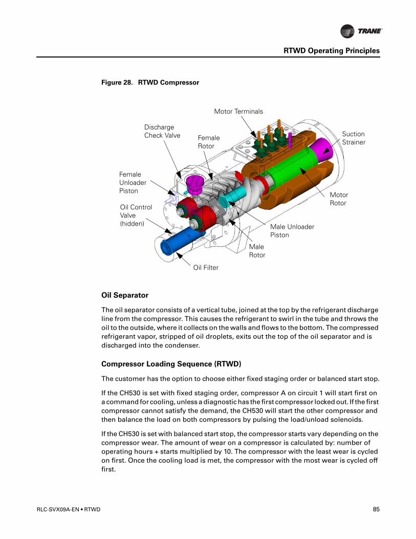
RTWD Operating Principles
Figure 28. RTWD Compressor
Oil Separator
The oil separator consists of a vertical tube, joined at the top by the refrigerant discharge line from the compressor. This causes the refrigerant to swirl in the tube and throws the oil to the outside, where it collects on the walls and flows to the bottom. The compressed refrigerant vapor, stripped of oil droplets, exits out the top of the oil separator and is discharged into the condenser.
Compressor Loading Sequence (RTWD)
The customer has the option to choose either fixed staging order or balanced start stop.
If the CH530 is set with fixed staging order, compressor A on circuit 1 will start first on a command for cooling, unless a diagnostic has the first compressor locked out. If the first compressor cannot satisfy the demand, the CH530 will start the other compressor and then balance the load on both compressors by pulsing the load/unload solenoids.
If the CH530 is set with balanced start stop, the compressor starts vary depending on the compressor wear. The amount of wear on a compressor is calculated by: number of operating hours + starts multiplied by 10. The compressor with the least wear is cycled on first. Once the cooling load is met, the compressor with the most wear is cycled off first.
SuctionStrainer
MotorRotor
Motor Terminals
DischargeCheck Valve
Male Unloader
Oil Filter
Female
Oil ControlValve(hidden)
MaleRotor
FemaleRotor
Piston Unloader
Piston
RLC-SVX09A-EN • RTWD 85

RTWD Operating Principles
86 RTWD • RLC-SVX09A-EN

Controls Interface
CH530 Communications Overview
The Trane CH530 control system that runs the chiller consists of several elements:• The main processor collects data, status, and diagnostic information and communicates
commands to the starter module and the LLID (for Low Level Intelligent Device) bus. The main processor has an integral display (DynaView).
• Higher level modules (e.g. starter) exist only as necessary to support system level control and communications. The starter module provides control of the starter when starting, running, and stopping the chiller motor. It also processes its own diagnostics and provides motor and compressor protection.
• Low level intelligent device (LLID) bus. The main processor communicates to each input and output device (e.g. temperature and pressure sensors, low voltage binary inputs, analog input/output) all connected to a four-wire bus, rather than the conventional control architecture of signal wires for each device.
• The communication interface to a building automation system (BAS).• A service tool to provide all service/maintenance capabilities.
Main processor and service tool (TechView) software is downloadable from www.Trane.com. The process is discussed later in this section under TechView Interface.
DynaView provides bus management. It has the task of restarting the link, or filling in for what it sees as “missing” devices when normal communications has been degraded. Use of TechView may be required.
The CH530 uses the IPC3 protocol based on RS485 signal technology and communicating at 19.2 Kbaud to allow 3 rounds of data per second on a 64-device network. A typical four-compressor RTWD will have around 50 devices.
Most diagnostics are handled by the DynaView. If a temperature or pressure is reported out of range by a LLID, the DynaView processes this information and calls out the diagnostic. The individual LLIDs are not responsible for any diagnostic functions. The only exception to this is the Starter module.
NOTE:It is imperative that the CH530 Service Tool (TechView) be used to facilitate the replacement of any LLID or reconfigure any chiller component. TechView is discussed later in this section.
Controls Interface
Each chiller is equipped with a DynaView interface. The DynaView has the capability to display information to the operator including the ability to adjust settings. Multiple screens are available and text is presented in multiple languages as factory-ordered or can be easily downloaded from www.trane.com.
TechView can be connected to either the DynaView module and provides further data, adjustment capabilities, diagnostics information using downloadable software.
RLC-SVX09A-EN • RTWD 87
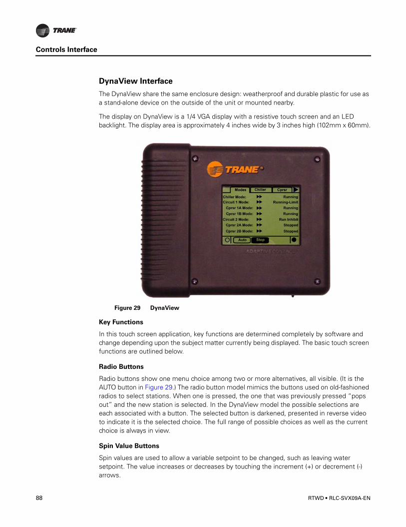
Controls Interface
DynaView Interface
The DynaView share the same enclosure design: weatherproof and durable plastic for use as a stand-alone device on the outside of the unit or mounted nearby.
The display on DynaView is a 1/4 VGA display with a resistive touch screen and an LED backlight. The display area is approximately 4 inches wide by 3 inches high (102mm x 60mm).
Key Functions
In this touch screen application, key functions are determined completely by software and change depending upon the subject matter currently being displayed. The basic touch screen functions are outlined below.
Radio Buttons
Radio buttons show one menu choice among two or more alternatives, all visible. (It is the AUTO button in Figure 29.) The radio button model mimics the buttons used on old-fashioned radios to select stations. When one is pressed, the one that was previously pressed “pops out” and the new station is selected. In the DynaView model the possible selections are each associated with a button. The selected button is darkened, presented in reverse video to indicate it is the selected choice. The full range of possible choices as well as the current choice is always in view.
Spin Value Buttons
Spin values are used to allow a variable setpoint to be changed, such as leaving water setpoint. The value increases or decreases by touching the increment (+) or decrement (-) arrows.
Figure 29 DynaView
88 RTWD • RLC-SVX09A-EN
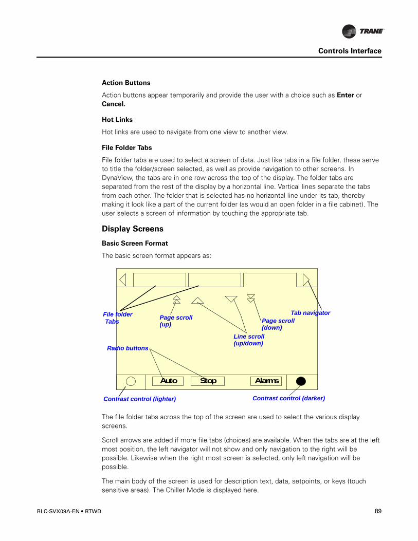
Controls Interface
Action Buttons
Action buttons appear temporarily and provide the user with a choice such as Enter or Cancel.
Hot Links
Hot links are used to navigate from one view to another view.
File Folder Tabs
File folder tabs are used to select a screen of data. Just like tabs in a file folder, these serve to title the folder/screen selected, as well as provide navigation to other screens. In DynaView, the tabs are in one row across the top of the display. The folder tabs are separated from the rest of the display by a horizontal line. Vertical lines separate the tabs from each other. The folder that is selected has no horizontal line under its tab, thereby making it look like a part of the current folder (as would an open folder in a file cabinet). The user selects a screen of information by touching the appropriate tab.
Display Screens
Basic Screen Format
The basic screen format appears as:
The file folder tabs across the top of the screen are used to select the various display screens.
Scroll arrows are added if more file tabs (choices) are available. When the tabs are at the left most position, the left navigator will not show and only navigation to the right will be possible. Likewise when the right most screen is selected, only left navigation will be possible.
The main body of the screen is used for description text, data, setpoints, or keys (touch sensitive areas). The Chiller Mode is displayed here.
Auto Stop Alarms
Contrast control (lighter)
Tab navigatorTabs
File folder
Radio buttons
Line scroll
Page scroll
(up/down)
Contrast control (darker)
Page scroll(down)(up)
RLC-SVX09A-EN • RTWD 89
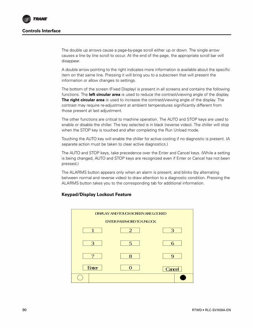
Controls Interface
The double up arrows cause a page-by-page scroll either up or down. The single arrow causes a line by line scroll to occur. At the end of the page, the appropriate scroll bar will disappear.
A double arrow pointing to the right indicates more information is available about the specific item on that same line. Pressing it will bring you to a subscreen that will present the information or allow changes to settings.
The bottom of the screen (Fixed Display) is present in all screens and contains the following functions. The left circular area is used to reduce the contrast/viewing angle of the display. The right circular area is used to increase the contrast/viewing angle of the display. The contrast may require re-adjustment at ambient temperatures significantly different from those present at last adjustment.
The other functions are critical to machine operation. The AUTO and STOP keys are used to enable or disable the chiller. The key selected is in black (reverse video). The chiller will stop when the STOP key is touched and after completing the Run Unload mode.
Touching the AUTO key will enable the chiller for active cooling if no diagnostic is present. (A separate action must be taken to clear active diagnostics.)
The AUTO and STOP keys, take precedence over the Enter and Cancel keys. (While a setting is being changed, AUTO and STOP keys are recognized even if Enter or Cancel has not been pressed.)
The ALARMS button appears only when an alarm is present, and blinks (by alternating between normal and reverse video) to draw attention to a diagnostic condition. Pressing the ALARMS button takes you to the corresponding tab for additional information.
Keypad/Display Lockout Feature
DISPLAY AND TOUCH SCREEN ARE LOCKED
ENTER PASSWORD TO UNLOCK
Enter
987
653
321
Cancel0
90 RTWD • RLC-SVX09A-EN

Controls Interface
Note: The DynaView display and Touch Screen Lock screen is shown below. This screen is used if the Display and touch screen and lock feature is enabled. Thirty minutes after the last keystroke, this screen is displayed and the Display and Touch Screen is locked out until the sequence “159 <ENTER>” is pressed.
Until the proper password is entered, there will be no access to the DynaView screens including all reports, setpoints, and Auto/Stop/Alarms/Interlocks.
The password “159” can not be changed from either DynaView or TechView
Modes Screen
The Mode Screen is only found on software revisions 18 and later. This screen provides a display for the top level operating mode for each of the components and sub-components of the chiller (i.e. Chiller, Circuits, and Compressors) that exist on the Chiller as it is configured. The modes are displayed as text only without the hex codes.
In software revisions 17.0 and earlier, the top level mode and the sub mode for each component was displayed on the respective component tab on the first two lines. The mode display of the first three lines of the Compressor and Chiller Screen tabs is eliminated with the addition of the Mode Screen
Auto Stop
Modes Chiller Compressor
Chiller Mode:Circuit 1 Mode:Cprsr 1A Mode:Cprsr 1B Mode:Circuit 2 Mode:Cprsr 2A Mode:Cprsr 2B Mode:
Running
StoppedStoppedRun InhibitRunningRunningRunning - Limit
RLC-SVX09A-EN • RTWD 91
Controls Interface
Table 31 Chiller Modes
Chiller Modes Description
Top Level Mode
Sub-modes
Stopped The chiller is not running and cannot run without inter-vention. Further information is provided by the sub-mode:
Local Stop Chiller is stopped by DynaView Stop button command- cannot be remotely overridden.
Immediate Stop Chiller is stopped by the DynaView Immediate Stop (by pressing Stop button then Immediate Stop buttons in succession) - previous shutdown was manually commanded to shutdown immediately without a run-unload or pumpdown cycle - cannot be remotely overridden.
No Circuits Available The entire chiller is stopped by circuit diagnostics or lockouts that may automatically clear.
Diagnostic Shutdown - Manual Reset The chiller is stopped by a diagnostic that requires manual intervention to reset.
Other sub-modes are possible in conjunction with at least one of the above modes - See items below for their descriptions:Diagnostic Shutdown - Auto ResetStart Inhibited by Low Cond TempStart Inhibited by Low Ambient TempStart Inhibited by External SourceStart Inhibited by BASWaiting for BAS CommunicationsIce Building to Normal TransitionIce Building is Complete Design Note: Maximum Capacity was eliminated as a annunciated mode prior to any release
Run Inhibit The chiller is currently being inhibited from starting (running), but may be allowed to start if the inhibiting or diagnostic condition is cleared. Further information is provided by the sub-mode:
No Circuits Available The entire chiller is stopped by circuit diagnostics or lockouts that may automatically clear.
Ice Building Is Complete The chiller is inhibited from running as the Ice Building process has been normally terminated on the evaporator entering temperature. The chiller will not start unless the ice building command (hardwired input or Building Automation System command) is removed or cycled.
92 RTWD • RLC-SVX09A-EN
Controls Interface
Ice to Normal Transition The chiller is inhibited from running for a brief period of time if it is commanded from active ice building mode into normal cooling mode via the ice building hardwired input or Tracer. This allows time for the external system load to "switchover" from an ice bank to the chilled water loop, and provides for a controlled pull down of the loop's warmer temperature. This mode is not seen if the ice making is automatically terminated on return brine temperature per the mode below.
Starting is Inhibited by BAS (Building Automation System)
Chiller is stopped by Tracer or other BAS system.
Starting is Inhibited by External Source The chiller is inhibited from starting (and running) by the "external stop" hardwired input.
Diagnostic Shutdown - Auto Reset. The entire chiller is stopped by a diagnostic that may automatically clear.
Waiting for BAS Communications to Establish Operating Status
The chiller is inhibited because of lack of communication with the BAS. This is only valid 15 minutes after power up.
Starting is Inhibited by Low Ambient Temp The chiller is inhibited from starting (and running) by an outdoor air ambient temperature lower than a specified temperature - per user adjustable settings and can be disabled.
Starting is Inhibited by Local Schedule The chiller is inhibited from starting based on the local time of day scheduling (option).
Auto The chiller is not currently running but can be expected to start at any moment given that the proper conditions and interlocks are satisfied. Further information is provided by the sub-mode:
Waiting For Evaporator Water Flow The unit will wait up to 20 minutes in this mode for water flow to be established per the flow switch hardwired input
Waiting for Need to Cool The chiller will wait indefinitely in this mode, for a leaving water temperature higher than the Chilled Water Setpoint plus some control dead-band.
Waiting for Need to Heat The chiller will wait indefinitely in this mode, for a leaving water temperature lower than the Hot Water Setpoint plus some control dead-band.
Power Up Delay Inhibit: min:sec
On Power Up, the chiller will wait for the Power Up Delay Timer to expire.
Table 31 Chiller Modes
Chiller Modes Description
Top Level Mode
Sub-modes
RLC-SVX09A-EN • RTWD 93
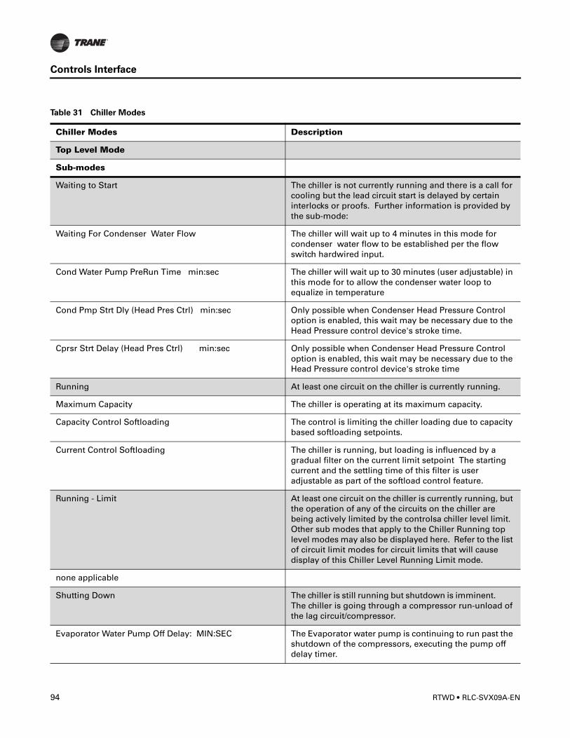
Controls Interface
Waiting to Start The chiller is not currently running and there is a call for cooling but the lead circuit start is delayed by certain interlocks or proofs. Further information is provided by the sub-mode:
Waiting For Condenser Water Flow The chiller will wait up to 4 minutes in this mode for condenser water flow to be established per the flow switch hardwired input.
Cond Water Pump PreRun Time min:sec The chiller will wait up to 30 minutes (user adjustable) in this mode for to allow the condenser water loop to equalize in temperature
Cond Pmp Strt Dly (Head Pres Ctrl) min:sec Only possible when Condenser Head Pressure Control option is enabled, this wait may be necessary due to the Head Pressure control device's stroke time.
Cprsr Strt Delay (Head Pres Ctrl) min:sec Only possible when Condenser Head Pressure Control option is enabled, this wait may be necessary due to the Head Pressure control device's stroke time
Running At least one circuit on the chiller is currently running.
Maximum Capacity The chiller is operating at its maximum capacity.
Capacity Control Softloading The control is limiting the chiller loading due to capacity based softloading setpoints.
Current Control Softloading The chiller is running, but loading is influenced by a gradual filter on the current limit setpoint The starting current and the settling time of this filter is user adjustable as part of the softload control feature.
Running - Limit At least one circuit on the chiller is currently running, but the operation of any of the circuits on the chiller are being actively limited by the controlsa chiller level limit. Other sub modes that apply to the Chiller Running top level modes may also be displayed here. Refer to the list of circuit limit modes for circuit limits that will cause display of this Chiller Level Running Limit mode.
none applicable
Shutting Down The chiller is still running but shutdown is imminent. The chiller is going through a compressor run-unload of the lag circuit/compressor.
Evaporator Water Pump Off Delay: MIN:SEC The Evaporator water pump is continuing to run past the shutdown of the compressors, executing the pump off delay timer.
Table 31 Chiller Modes
Chiller Modes Description
Top Level Mode
Sub-modes
94 RTWD • RLC-SVX09A-EN
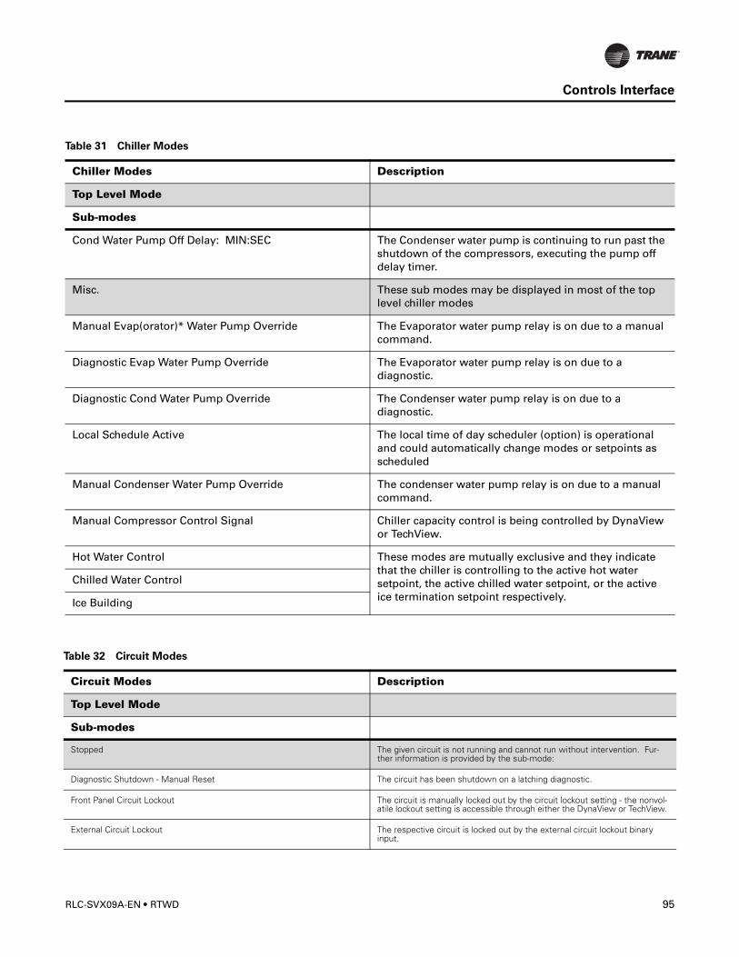
Controls Interface
Cond Water Pump Off Delay: MIN:SEC The Condenser water pump is continuing to run past the shutdown of the compressors, executing the pump off delay timer.
Misc. These sub modes may be displayed in most of the top level chiller modes
Manual Evap(orator)* Water Pump Override The Evaporator water pump relay is on due to a manual command.
Diagnostic Evap Water Pump Override The Evaporator water pump relay is on due to a diagnostic.
Diagnostic Cond Water Pump Override The Condenser water pump relay is on due to a diagnostic.
Local Schedule Active The local time of day scheduler (option) is operational and could automatically change modes or setpoints as scheduled
Manual Condenser Water Pump Override The condenser water pump relay is on due to a manual command.
Manual Compressor Control Signal Chiller capacity control is being controlled by DynaView or TechView.
Hot Water Control These modes are mutually exclusive and they indicate that the chiller is controlling to the active hot water setpoint, the active chilled water setpoint, or the active ice termination setpoint respectively.
Chilled Water Control
Ice Building
Table 31 Chiller Modes
Chiller Modes Description
Top Level Mode
Sub-modes
Table 32 Circuit Modes
Circuit Modes Description
Top Level Mode
Sub-modes
Stopped The given circuit is not running and cannot run without intervention. Fur-ther information is provided by the sub-mode:
Diagnostic Shutdown - Manual Reset The circuit has been shutdown on a latching diagnostic.
Front Panel Circuit Lockout The circuit is manually locked out by the circuit lockout setting - the nonvol-atile lockout setting is accessible through either the DynaView or TechView.
External Circuit Lockout The respective circuit is locked out by the external circuit lockout binary input.
RLC-SVX09A-EN • RTWD 95
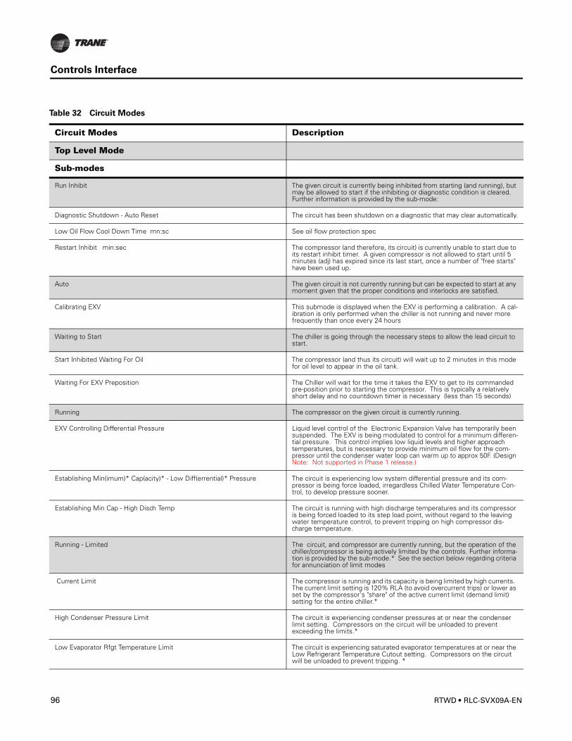
Controls Interface
Run Inhibit The given circuit is currently being inhibited from starting (and running), but may be allowed to start if the inhibiting or diagnostic condition is cleared. Further information is provided by the sub-mode:
Diagnostic Shutdown - Auto Reset The circuit has been shutdown on a diagnostic that may clear automatically.
Low Oil Flow Cool Down Time mn:sc See oil flow protection spec
Restart Inhibit min:sec The compressor (and therefore, its circuit) is currently unable to start due to its restart inhibit timer. A given compressor is not allowed to start until 5 minutes (adj) has expired since its last start, once a number of "free starts" have been used up.
Auto The given circuit is not currently running but can be expected to start at any moment given that the proper conditions and interlocks are satisfied.
Calibrating EXV This submode is displayed when the EXV is performing a calibration. A cal-ibration is only performed when the chiller is not running and never more frequently than once every 24 hours
Waiting to Start The chiller is going through the necessary steps to allow the lead circuit to start.
Start Inhibited Waiting For Oil The compressor (and thus its circuit) will wait up to 2 minutes in this mode for oil level to appear in the oil tank.
Waiting For EXV Preposition The Chiller will wait for the time it takes the EXV to get to its commanded pre-position prior to starting the compressor. This is typically a relatively short delay and no countdown timer is necessary (less than 15 seconds)
Running The compressor on the given circuit is currently running.
EXV Controlling Differential Pressure Liquid level control of the Electronic Expansion Valve has temporarily been suspended. The EXV is being modulated to control for a minimum differen-tial pressure. This control implies low liquid levels and higher approach temperatures, but is necessary to provide minimum oil flow for the com-pressor until the condenser water loop can warm up to approx 50F. (Design Note: Not supported in Phase 1 release.)
Establishing Min(imum)* Cap(acity)* - Low Diff(errential)* Pressure The circuit is experiencing low system differential pressure and its com-pressor is being force loaded, irregardless Chilled Water Temperature Con-trol, to develop pressure sooner.
Establishing Min Cap - High Disch Temp The circuit is running with high discharge temperatures and its compressor is being forced loaded to its step load point, without regard to the leaving water temperature control, to prevent tripping on high compressor dis-charge temperature.
Running - Limited The circuit, and compressor are currently running, but the operation of the chiller/compressor is being actively limited by the controls. Further informa-tion is provided by the sub-mode.* See the section below regarding criteria for annunciation of limit modes
Current Limit The compressor is running and its capacity is being limited by high currents. The current limit setting is 120% RLA (to avoid overcurrent trips) or lower as set by the compressor's "share" of the active current limit (demand limit) setting for the entire chiller.*
High Condenser Pressure Limit The circuit is experiencing condenser pressures at or near the condenser limit setting. Compressors on the circuit will be unloaded to prevent exceeding the limits.*
Low Evaporator Rfgt Temperature Limit The circuit is experiencing saturated evaporator temperatures at or near the Low Refrigerant Temperature Cutout setting. Compressors on the circuit will be unloaded to prevent tripping. *
Table 32 Circuit Modes
Circuit Modes Description
Top Level Mode
Sub-modes
96 RTWD • RLC-SVX09A-EN
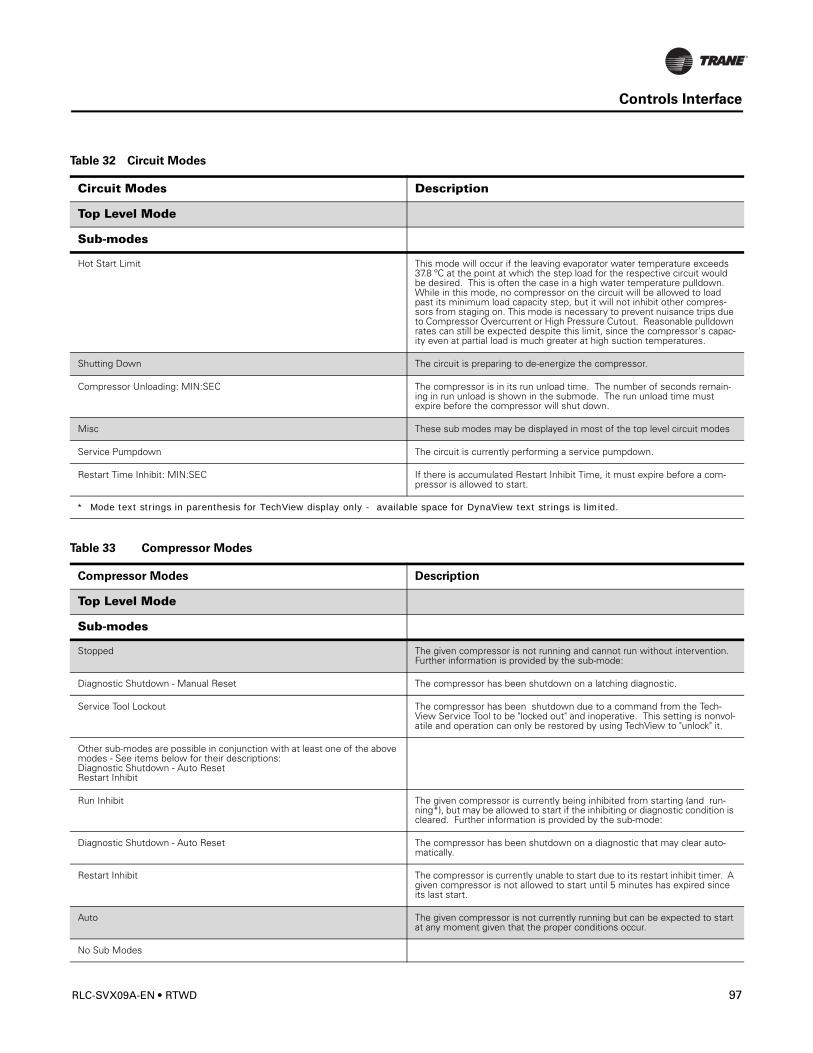
Controls Interface
Hot Start Limit This mode will occur if the leaving evaporator water temperature exceeds 37.8 ºC at the point at which the step load for the respective circuit would be desired. This is often the case in a high water temperature pulldown. While in this mode, no compressor on the circuit will be allowed to load past its minimum load capacity step, but it will not inhibit other compres-sors from staging on. This mode is necessary to prevent nuisance trips due to Compressor Overcurrent or High Pressure Cutout. Reasonable pulldown rates can still be expected despite this limit, since the compressor's capac-ity even at partial load is much greater at high suction temperatures.
Shutting Down The circuit is preparing to de-energize the compressor.
Compressor Unloading: MIN:SEC The compressor is in its run unload time. The number of seconds remain-ing in run unload is shown in the submode. The run unload time must expire before the compressor will shut down.
Misc These sub modes may be displayed in most of the top level circuit modes
Service Pumpdown The circuit is currently performing a service pumpdown.
Restart Time Inhibit: MIN:SEC If there is accumulated Restart Inhibit Time, it must expire before a com-pressor is allowed to start.
* Mode text strings in parenthesis for TechView display only - available space for DynaView text strings is limited.
Table 32 Circuit Modes
Circuit Modes Description
Top Level Mode
Sub-modes
Table 33 Compressor Modes
Compressor Modes Description
Top Level Mode
Sub-modes
Stopped The given compressor is not running and cannot run without intervention. Further information is provided by the sub-mode:
Diagnostic Shutdown - Manual Reset The compressor has been shutdown on a latching diagnostic.
Service Tool Lockout The compressor has been shutdown due to a command from the Tech-View Service Tool to be "locked out" and inoperative. This setting is nonvol-atile and operation can only be restored by using TechView to "unlock" it.
Other sub-modes are possible in conjunction with at least one of the above modes - See items below for their descriptions:Diagnostic Shutdown - Auto ResetRestart Inhibit
Run Inhibit The given compressor is currently being inhibited from starting (and run-ning*), but may be allowed to start if the inhibiting or diagnostic condition is cleared. Further information is provided by the sub-mode:
Diagnostic Shutdown - Auto Reset The compressor has been shutdown on a diagnostic that may clear auto-matically.
Restart Inhibit The compressor is currently unable to start due to its restart inhibit timer. A given compressor is not allowed to start until 5 minutes has expired since its last start.
Auto The given compressor is not currently running but can be expected to start at any moment given that the proper conditions occur.
No Sub Modes
RLC-SVX09A-EN • RTWD 97
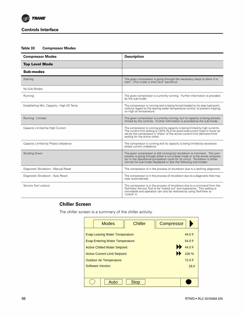
Controls Interface
Chiller Screen
The chiller screen is a summary of the chiller activity.
Starting The given compressor is going through the necessary steps to allow it to start. (This mode is short and transitory)
No Sub Modes
Running The given compressor is currently running. Further information is provided by the sub-mode:
Establishing Min. Capacity - High Oil Temp The compressor is running and is being forced loaded to its step load point, without regard to the leaving water temperature control, to prevent tripping on high oil temperature.
Running - Limited The given compressor is currently running, but its capacity is being actively limited by the controls. Further information is provided by the sub-mode:
Capacity Limited by High Current The compressor is running and its capacity is being limited by high currents. The current limit setting is 120% RLA (to avoid overcurrent trips) or lower as set by the compressor's "share" of the active current limit (demand limit) setting for the entire chiller.
Capacity Limited by Phase Unbalance The compressor is running and its capacity is being limited by excessive phase current unbalance.
Shutting Down The given compressor is still running but shutdown is imminent. The com-pressor is going through either a run-unload mode or is the active compres-sor in the operational pumpdown cycle for its circuit. Shutdown is either normal (no sub-mode displayed) or due the following sub-modes:
Diagnostic Shutdown - Manual Reset The compressor is in the process of shutdown due to a latching diagnostic.
Diagnostic Shutdown - Auto Reset The compressor is in the process of shutdown due to a diagnostic that may clear automatically.
Service Tool Lockout The compressor is in the process of shutdown due to a command from the TechView Service Tool to be "locked out" and inoperative. This setting is nonvolatile and operation can only be restored by using TechView to "unlock" it.
Table 33 Compressor Modes
Compressor Modes Description
Top Level Mode
Sub-modes
Auto Stop
Chiller Compressor
Evap Leaving Water Temperature:
Evap Entering Water Temperature:
Active Chilled Water Setpoint:
44.0 F
54.0 F
44.0 F
Active Current Limit Setpoint: 100 %
Outdoor Air Temperature: 72.0 F
Modes
Software Version: 18.0
98 RTWD • RLC-SVX09A-EN
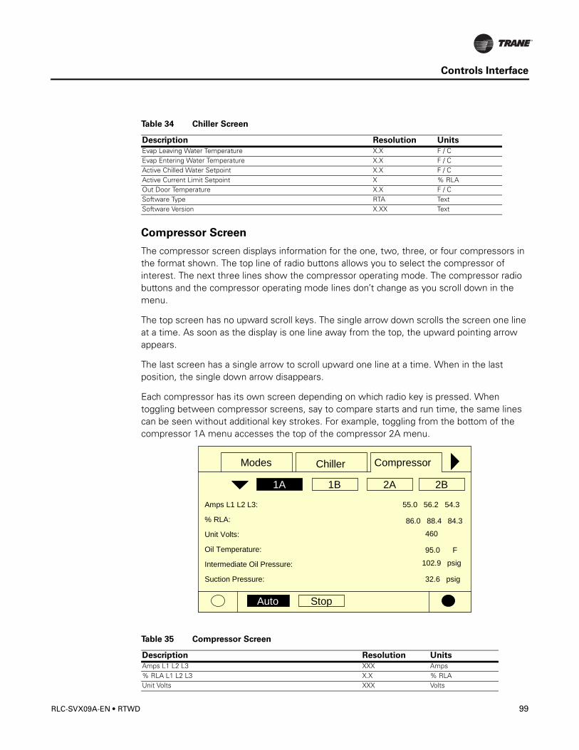
Controls Interface
Compressor Screen
The compressor screen displays information for the one, two, three, or four compressors in the format shown. The top line of radio buttons allows you to select the compressor of interest. The next three lines show the compressor operating mode. The compressor radio buttons and the compressor operating mode lines don’t change as you scroll down in the menu.
The top screen has no upward scroll keys. The single arrow down scrolls the screen one line at a time. As soon as the display is one line away from the top, the upward pointing arrow appears.
The last screen has a single arrow to scroll upward one line at a time. When in the last position, the single down arrow disappears.
Each compressor has its own screen depending on which radio key is pressed. When toggling between compressor screens, say to compare starts and run time, the same lines can be seen without additional key strokes. For example, toggling from the bottom of the compressor 1A menu accesses the top of the compressor 2A menu.
Table 34 Chiller Screen
Description Resolution Units
Evap Leaving Water Temperature X.X F / CEvap Entering Water Temperature X.X F / CActive Chilled Water Setpoint X.X F / CActive Current Limit Setpoint X % RLAOut Door Temperature X.X F / CSoftware Type RTA TextSoftware Version X.XX Text
Table 35 Compressor Screen
Description Resolution Units
Amps L1 L2 L3 XXX Amps% RLA L1 L2 L3 X.X % RLAUnit Volts XXX Volts
Auto Stop
Chiller Compressor
2B2A1B1A
Amps L1 L2 L3:
% RLA:
Unit Volts:
55.0 56.2 54.3
460
86.0 88.4 84.3
Oil Temperature:
Intermediate Oil Pressure:
95.0 F
Suction Pressure:
102.9 psig
32.6 psig
Modes
RLC-SVX09A-EN • RTWD 99
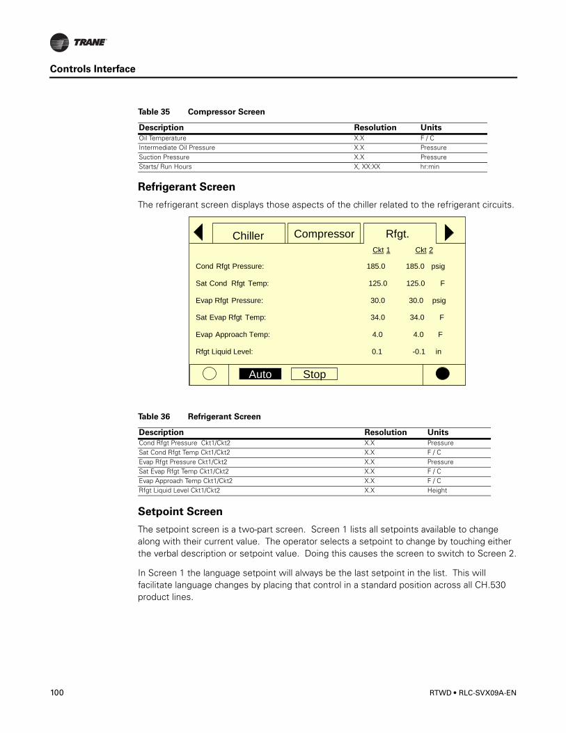
Controls Interface
Refrigerant Screen
The refrigerant screen displays those aspects of the chiller related to the refrigerant circuits.
Setpoint Screen
The setpoint screen is a two-part screen. Screen 1 lists all setpoints available to change along with their current value. The operator selects a setpoint to change by touching either the verbal description or setpoint value. Doing this causes the screen to switch to Screen 2.
In Screen 1 the language setpoint will always be the last setpoint in the list. This will facilitate language changes by placing that control in a standard position across all CH.530 product lines.
Oil Temperature X.X F / CIntermediate Oil Pressure X.X PressureSuction Pressure X.X PressureStarts/ Run Hours X, XX:XX hr:min
Table 36 Refrigerant Screen
Description Resolution Units
Cond Rfgt Pressure Ckt1/Ckt2 X.X PressureSat Cond Rfgt Temp Ckt1/Ckt2 X.X F / CEvap Rfgt Pressure Ckt1/Ckt2 X.X PressureSat Evap Rfgt Temp Ckt1/Ckt2 X.X F / CEvap Approach Temp Ckt1/Ckt2 X.X F / CRfgt Liquid Level Ckt1/Ckt2 X.X Height
Table 35 Compressor Screen
Description Resolution Units
Auto Stop
Chiller Compressor Rfgt.
Cond Rfgt Pressure:
Sat Cond Rfgt Temp:
Evap Rfgt Pressure:
185.0 psig
125.0 F
30.0 psig
Ckt 1 Ckt 2
185.0
125.0
30.0
Sat Evap Rfgt Temp: 34.0 F34.0
Evap Approach Temp: 4.0 F4.0
Rfgt Liquid Level: 0.1 -0.1 in
100 RTWD • RLC-SVX09A-EN
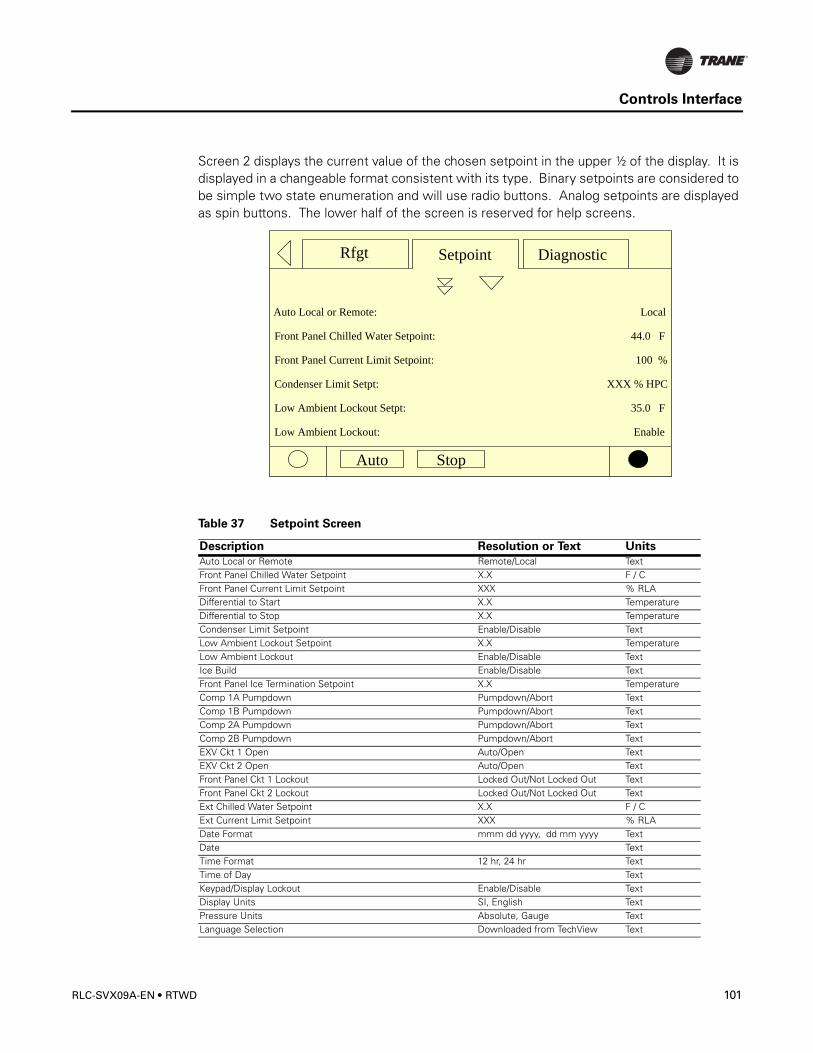
Controls Interface
Screen 2 displays the current value of the chosen setpoint in the upper ½ of the display. It is displayed in a changeable format consistent with its type. Binary setpoints are considered to be simple two state enumeration and will use radio buttons. Analog setpoints are displayed as spin buttons. The lower half of the screen is reserved for help screens.
Table 37 Setpoint Screen
Description Resolution or Text Units
Auto Local or Remote Remote/Local TextFront Panel Chilled Water Setpoint X.X F / CFront Panel Current Limit Setpoint XXX % RLADifferential to Start X.X TemperatureDifferential to Stop X.X TemperatureCondenser Limit Setpoint Enable/Disable TextLow Ambient Lockout Setpoint X.X TemperatureLow Ambient Lockout Enable/Disable TextIce Build Enable/Disable TextFront Panel Ice Termination Setpoint X.X TemperatureComp 1A Pumpdown Pumpdown/Abort TextComp 1B Pumpdown Pumpdown/Abort TextComp 2A Pumpdown Pumpdown/Abort TextComp 2B Pumpdown Pumpdown/Abort TextEXV Ckt 1 Open Auto/Open TextEXV Ckt 2 Open Auto/Open TextFront Panel Ckt 1 Lockout Locked Out/Not Locked Out TextFront Panel Ckt 2 Lockout Locked Out/Not Locked Out TextExt Chilled Water Setpoint X.X F / CExt Current Limit Setpoint XXX % RLADate Format mmm dd yyyy, dd mm yyyy TextDate TextTime Format 12 hr, 24 hr TextTime of Day TextKeypad/Display Lockout Enable/Disable TextDisplay Units SI, English TextPressure Units Absolute, Gauge TextLanguage Selection Downloaded from TechView Text
Auto Stop
Rfgt Setpoint Diagnostic
Auto Local or Remote:
Front Panel Chilled Water Setpoint:
Local
Condenser Limit Setpt: XXX % HPC
Front Panel Current Limit Setpoint:
Low Ambient Lockout Setpt: 35.0 F
Low Ambient Lockout: Enable
44.0 F
100 %
RLC-SVX09A-EN • RTWD 101
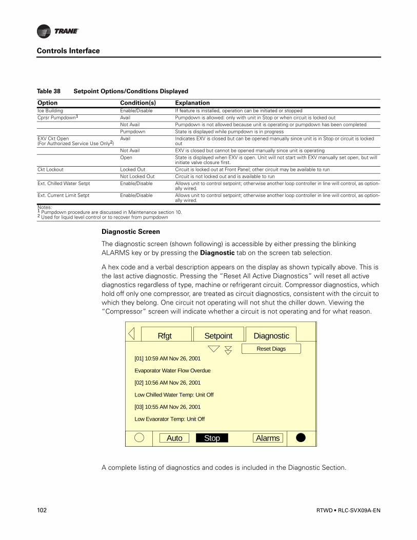
Controls Interface
Diagnostic Screen
The diagnostic screen (shown following) is accessible by either pressing the blinking ALARMS key or by pressing the Diagnostic tab on the screen tab selection.
A hex code and a verbal description appears on the display as shown typically above. This is the last active diagnostic. Pressing the “Reset All Active Diagnostics” will reset all active diagnostics regardless of type, machine or refrigerant circuit. Compressor diagnostics, which hold off only one compressor, are treated as circuit diagnostics, consistent with the circuit to which they belong. One circuit not operating will not shut the chiller down. Viewing the “Compressor” screen will indicate whether a circuit is not operating and for what reason.
A complete listing of diagnostics and codes is included in the Diagnostic Section.
Table 38 Setpoint Options/Conditions Displayed
Option Condition(s) Explanation
Ice Building Enable/Disable If feature is installed, operation can be initiated or stoppedCprsr Pumpdown1 Avail Pumpdown is allowed: only with unit in Stop or when circuit is locked out
Not Avail Pumpdown is not allowed because unit is operating or pumpdown has been completedPumpdown State is displayed while pumpdown is in progress
EXV Ckt Open(For Authorized Service Use Only2)
Avail Indicates EXV is closed but can be opened manually since unit is in Stop or circuit is locked out
Not Avail EXV is closed but cannot be opened manually since unit is operatingOpen State is displayed when EXV is open. Unit will not start with EXV manually set open, but will
initiate valve closure first.Ckt Lockout Locked Out Circuit is locked out at Front Panel; other circuit may be available to run
Not Locked Out Circuit is not locked out and is available to runExt. Chilled Water Setpt Enable/Disable Allows unit to control setpoint; otherwise another loop controller in line will control, as option-
ally wired.Ext. Current Limit Setpt Enable/Disable Allows unit to control setpoint; otherwise another loop controller in line will control, as option-
ally wired.Notes:1 Pumpdown procedure are discussed in Maintenance section 10.2 Used for liquid level control or to recover from pumpdown
Auto Stop Alarms
DiagnosticSetpointRfgt
[01] 10:59 AM Nov 26, 2001
Evaporator Water Flow Overdue
[02] 10:56 AM Nov 26, 2001
Low Chilled Water Temp: Unit Off
[03] 10:55 AM Nov 26, 2001
Low Evaorator Temp: Unit Off
Reset Diags
102 RTWD • RLC-SVX09A-EN

Controls Interface
Power-Up
On Power-Up, DynaView will progress through three screens:
First Screen, Version # of the Boot, full version # displayed.
This screen will display for 5 seconds and move on to the second screen. The contrast will also be adjustable from this screen.
Second Screen, Application or No Application.
This screen will display for 5 seconds “A Valid Application Is Present” or “A Valid Application Is Not Present” and move on to the third screen.
Third Screen, First screen of the Application, the Chiller Tab.
Display Formats
Units
Temperature settings are in °F or °C, depending on Display Units settings. Settings can be entered in tenths or whole degrees depending on a menu setting at the TechView.
Dashes (“-----”) appearing in a temperature or pressure report, indicates that the value is invalid or not applicable.
Languages
English plus two alternate languages may be installed with DynaView and will reside in the main processor. English will always be available. Alternate languages must be installed using TechView, Software Download View.
RLC-SVX09A-EN • RTWD 103
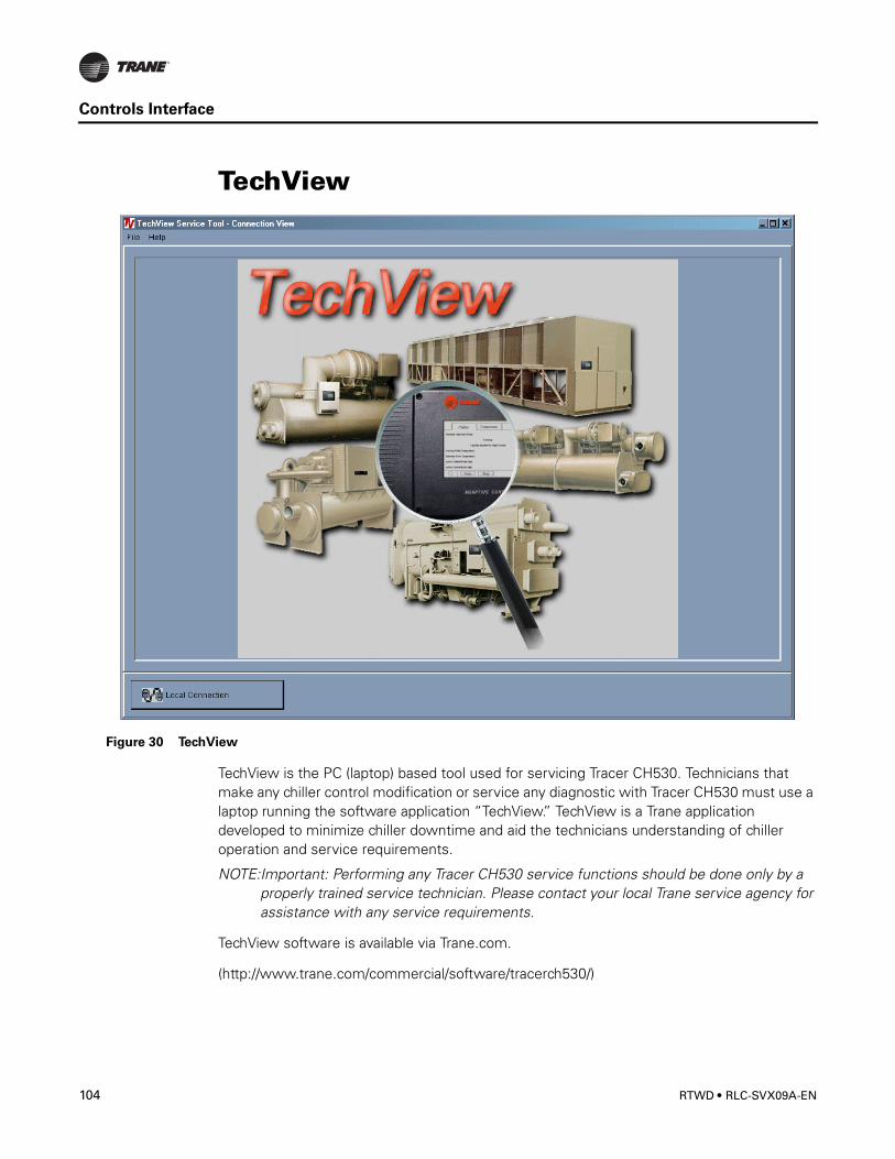
Controls Interface
TechView
TechView is the PC (laptop) based tool used for servicing Tracer CH530. Technicians that make any chiller control modification or service any diagnostic with Tracer CH530 must use a laptop running the software application “TechView.” TechView is a Trane application developed to minimize chiller downtime and aid the technicians understanding of chiller operation and service requirements.
NOTE:Important: Performing any Tracer CH530 service functions should be done only by a properly trained service technician. Please contact your local Trane service agency for assistance with any service requirements.
TechView software is available via Trane.com.
(http://www.trane.com/commercial/software/tracerch530/)
Figure 30 TechView
104 RTWD • RLC-SVX09A-EN
Controls Interface
This download site provides a user the TechView installation software and CH530 main processor software that must be loaded onto your PC in order to service a CH530 main processor. The TechView service tool is used to load software into the Tracer CH530 main processor.
Minimum PC requirements to install and operate TechView
• Pentium II or higher processor• 128Mb RAM• 1024 x 768 resolution of display• 56K modem• 9-pin RS-232 serial connection• Operating system - Windows 2000• Microsoft Office (MS Word, MS Access, MS Excel)• Parallel Port (25-pin) or USB Port
NOTE:TechView was designed for the preceding listed laptop configuration. Any variation will have unknown results. Therefore, support for TechView is limited to only those operating systems that meet the specific configuration listed here. Only computers with a Pentium II class processor or better are supported; Intel Celeron, AMD, or Cyrix processors have not been tested.
TechView is also used to perform any CH530 service or maintenance function. Servicing a CH530 main processor includes: • Updating main processor software• Monitoring chiller operation• Viewing and resetting chiller diagnostics• Low Level Intelligent Device (LLID) replacement and binding• Main processor replacement and configuration modifications• Setpoint modifications• Service overrides
Unit View
Unit view is a summary for the system organized by chiller subsystem. This provides an overall view of chiller operating parameters and gives you an "at-a-glance" assessment of chiller operation.
The Control Panel tab displays important operating information for the unit and allows you to change several key operating parameters. The panel is divided into four or more sub-panels (depending on the number of circuits in the unit).
The Operating Mode tab displays the unit, circuit and compressor top level operating modes.
The Hours and Starts tab displays the number a hours (total) a compressor has run and the number of times the compressor has started. This window plays a key role in evaluating maintenance requirements.
RLC-SVX09A-EN • RTWD 105
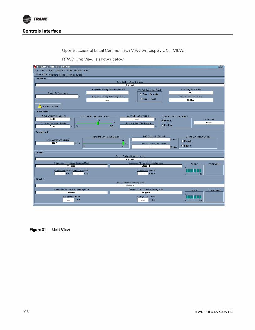
Controls Interface
Upon successful Local Connect Tech View will display UNIT VIEW.
RTWD Unit View is shown below
Figure 31 Unit View
106 RTWD • RLC-SVX09A-EN
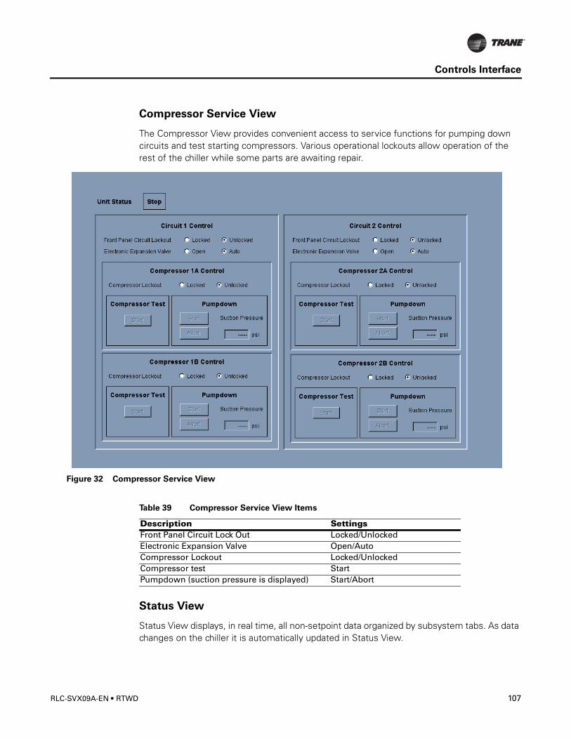
Controls Interface
Compressor Service View
The Compressor View provides convenient access to service functions for pumping down circuits and test starting compressors. Various operational lockouts allow operation of the rest of the chiller while some parts are awaiting repair.
Status View
Status View displays, in real time, all non-setpoint data organized by subsystem tabs. As data changes on the chiller it is automatically updated in Status View.
Figure 32 Compressor Service View
Table 39 Compressor Service View Items
Description SettingsFront Panel Circuit Lock Out Locked/UnlockedElectronic Expansion Valve Open/AutoCompressor Lockout Locked/UnlockedCompressor test StartPumpdown (suction pressure is displayed) Start/Abort
RLC-SVX09A-EN • RTWD 107
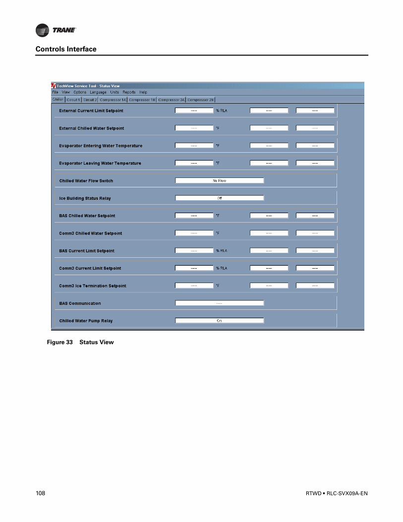
Controls Interface
Figure 33 Status View
108 RTWD • RLC-SVX09A-EN
Controls Interface
Table 40 Status View Items
Tab Text UnitsChiller Chiller Top Level Operating Mode Text
Chiller Sub Operating Mode TextOperating Mode TextChiller Sub Operating Mode TextFront Panel Auto/Stop TextOutdoor Air Temperature TemperatureExternal Auto/Stop Auto/StopExternal Emergency Stop Auto/StopActive Chilled Water Setpoint TemperatureActive Current Limit Setpoint TemperatureActive Ice Termination Setpoint TemperatureExternal Current Limit Setpoint % RLAExternal Chilled Water Setpoint TemperatureEvaporator Entering Water Temperature TemperatureEvaporator Leaving Water Temperature TemperatureChilled Water Flow Switch Flow/NoFlowIce Building Status Relay Ice Build/NormalComm3 Chilled Water Setpoint TemperatureBAS Chilled Water Setpoint TemperatureBAS Current Limit Setpoint % RLAComm3 Current Limit Setpoint % RLAComm3 Ice Termination Setpoint TemperatureBAS Communication TextChilled Water Pump Relay on/off
Compressor Compressor 1 Operating Mode TextCompressor 1 Sub Mode TextCompressor 1 Top Level Operating Mode TextRun Hours IntegerStarts IntegerPhase A-B Voltage VoltsAverage Line Current AmpsLine 1 Current AmpsLine 2 Current AmpsLine 3 Current AmpsLine 1 Current % RLALine 2 Current % RLA
Compressor Line 3 Current % RLAMaximum Line Current AmpsSupply Oil Temperature TemperatureIntermediate Oil Pressure PressureFemale Step Loader Loaded/UnloadedHigh Pressure Cutout Switch Tripped/Not Tripped
Circuit Circuit Sub Mode TextCircuit Top Level Operating Mode TextExternal Hardwired Lockout Locked/Not lockedFront Panel Lockout Locked/Not lockedAir Flow %Inverter Speed % Full Speed
RLC-SVX09A-EN • RTWD 109
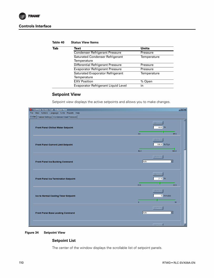
Controls Interface
Setpoint View
Setpoint view displays the active setpoints and allows you to make changes.
Setpoint List
The center of the window displays the scrollable list of setpoint panels.
Condenser Refrigerant Pressure PressureSaturated Condenser Refrigerant Temperature
Temperature
Differential Refrigerant Pressure PressureEvaporator Refrigerant Pressure PressureSaturated Evaporator Refrigerant Temperature
Temperature
EXV Position % OpenEvaporator Refrigerant Liquid Level in
Table 40 Status View Items
Tab Text Units
Figure 34 Setpoint View
110 RTWD • RLC-SVX09A-EN
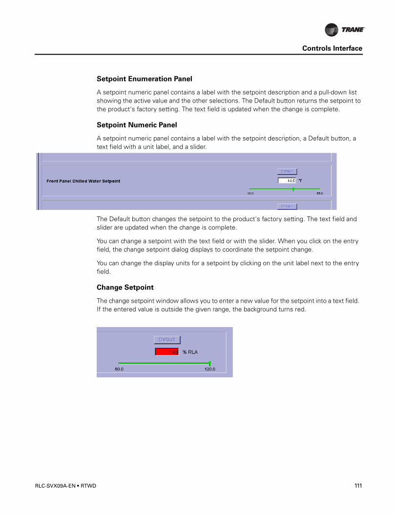
Controls Interface
Setpoint Enumeration Panel
A setpoint numeric panel contains a label with the setpoint description and a pull-down list showing the active value and the other selections. The Default button returns the setpoint to the product's factory setting. The text field is updated when the change is complete.
Setpoint Numeric Panel
A setpoint numeric panel contains a label with the setpoint description, a Default button, a text field with a unit label, and a slider.
The Default button changes the setpoint to the product's factory setting. The text field and slider are updated when the change is complete.
You can change a setpoint with the text field or with the slider. When you click on the entry field, the change setpoint dialog displays to coordinate the setpoint change.
You can change the display units for a setpoint by clicking on the unit label next to the entry field.
Change Setpoint
The change setpoint window allows you to enter a new value for the setpoint into a text field. If the entered value is outside the given range, the background turns red.
RLC-SVX09A-EN • RTWD 111
Controls Interface
Table 41 Setpoints View Items
Tab TextMinValue Max Value Default Value Unit Type
Chiller Front Panel Display Units English, SI English Display UnitsChiller Front Panel Chilled Water Setpoint 10
(-12.22)65(18.33)
44(6.67)
Temp Deg F(C)
Chiller Front Panel Current Limit Setpoint 60 120 120 PercentChiller Differential to Stop 0.5
(0.2777)2.5(1.388)
2.0(1.111)
Differential Temp Deg F(C)
Chiller Differential to Start 1.0(0.555)
30(16.666)
2(1.111)
Differential Temp Deg F(C)
Chiller Leaving Water Temp Cutout 0.0(-17.78)
36.0(2.22)
36.0(2.22)
Temp Deg F(C)
Chiller Low Refrigerant Temp Cutout -5.0(-20.56)
36.0(2.22)
28.0(-2.22)
Temp Deg F(C)
Chiller Front Panel Condenser Limit Setpoint
80 120 90 Percent
Chiller Low Ambient Lockout Setpoint -10(-23.333)
70(21.111)
25(-3.89)
Temp Deg F(C)
Chiller Low Ambient Lockout Enable, Disable Enable Enabled / Disabled
Chiller Front Panel Ice Termination Setpoint
20(-6.67)
31(-0.56)
31(-0.56)
Temp Deg F(C)
Chiller External Ice Building Input Enable, Disable Disable Enabled / Disabled
Chiller Under/Over Voltage Protection Enable, Disable Disable Enabled / Disabled
Chiller Local Atmospheric Pressure 9.93(68.5)
16.0(110.3)
14.7(101.3)
Absolute Pressure psia(Kpa)
Chiller Design Delta Temperature 4(2.22)
30(16.666)
10(5.6)
Differential Temp Deg F(C)
Chiller Reset Type None, Return, Outdoor, Constant Return
None RstTyp
Chiller Return Reset Ratio 10 120 50 PercentChiller Return Start Reset 4.0
(2.22)30.0(16.666)
10.0(5.56)
Differential Temp Deg F(C)
Chiller Return Maximum Reset 0 20(11.11)
5.0(2.78)
Differential Temp Deg F(C)
Chiller Outdoor Reset Ratio -80 80 10 PercentChiller Outdoor Start Reset 50
(10)130(54.44)
90(32.22)
Temp Deg F(C)
Chiller Outdoor Maximum Reset 0 20(11.11)
5(2.78)
Differential Temp Deg F(C)
Chiller External Chilled Water Setpoint Enable, Disable Disable Enabled / Disabled
Chiller External Current Limit Setpoint Enable, Disable Disable Enabled / Disabled
112 RTWD • RLC-SVX09A-EN
Controls Interface
Chiller Evaporator Water Pump Off Delay 0 30 1 MinutesChiller Chilled Water Setpoint Filter
Settling Time30 1800 200 Seconds
Chiller Compressor Staging Deadband 0.4(0.222)
4.0(2.222)
0.05(0.2778)
Differential Temp Deg F(C)
Table 41 Setpoints View Items
Tab TextMinValue Max Value Default Value Unit Type
RLC-SVX09A-EN • RTWD 113
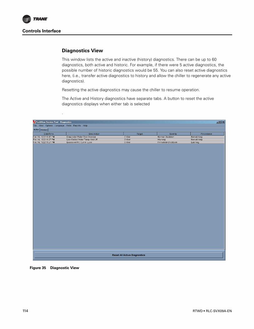
Controls Interface
Diagnostics View
This window lists the active and inactive (history) diagnostics. There can be up to 60 diagnostics, both active and historic. For example, if there were 5 active diagnostics, the possible number of historic diagnostics would be 55. You can also reset active diagnostics here, (i.e., transfer active diagnostics to history and allow the chiller to regenerate any active diagnostics).
Resetting the active diagnostics may cause the chiller to resume operation.
The Active and History diagnostics have separate tabs. A button to reset the active diagnostics displays when either tab is selected
.
Figure 35 Diagnostic View
114 RTWD • RLC-SVX09A-EN
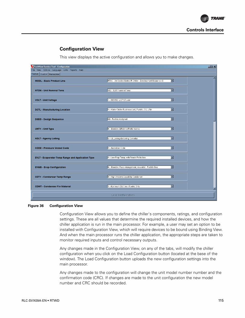
Controls Interface
Configuration View
This view displays the active configuration and allows you to make changes.
Configuration View allows you to define the chiller's components, ratings, and configuration settings. These are all values that determine the required installed devices, and how the chiller application is run in the main processor. For example, a user may set an option to be installed with Configuration View, which will require devices to be bound using Binding View. And when the main processor runs the chiller application, the appropriate steps are taken to monitor required inputs and control necessary outputs.
Any changes made in the Configuration View, on any of the tabs, will modify the chiller configuration when you click on the Load Configuration button (located at the base of the window). The Load Configuration button uploads the new configuration settings into the main processor.
Any changes made to the configuration will change the unit model number number and the confirmation code (CRC). If changes are made to the unit configuration the new model number and CRC should be recorded.
Figure 36 Configuration View
RLC-SVX09A-EN • RTWD 115
Controls Interface
Selecting the Undo All button will undo any configuration setting changes made during the present TechView connection and since the last time the Load Configuration button was selected. .
Table 42 Configuration View Items
Tab Item Default DescriptionFeature Basic Product Line RTWD - Air Cooled Series R Chiller
Unit Nominal Capacity 140 Nominal Tons155 Nominal Tons170 Nominal Tons185 Nominal Tons200 Nominal Tons225 Nominal Tons 250 Nominal Tons275 Nominal Tons300 Nominal Tons350 Nominal Tons375 Nominal Tons400 Nominal Tons450 Nominal Tons500 Nominal Tons
Unit Voltage A - 200V/60Hz/3Ph power K - 220V/50Hz/3 Ph power C - 230V/60Hz/3Ph powerJ - 380V/60Hz/3Ph power D - 400V/50Hz/3Ph power4 - 460V/60Hz/3Ph power5 - 575V/60Hz/3Ph power
Manufacturing Location U - Water Chiller Business Unit - PuebloE - Epinal Business Unit -Charmes
Design Sequence XX - Factory/ABU AssignedUnit Type N - Standard Efficiency/Performance
H - High Efficiency/Performance Agency Listing N - No agency listing
U - C/UL listingPressure Vessel Code A - ASME pressure vessel code
C - Canadian codeD - Australian codeL - Chinese codeR - Vietanamese codeS - Special
Evaporator Temperature Range & Application Type
F - Standard Temp. with Frz ProtR - Rem Evap, Std Temp, No Frz ProtG - Low Temp, with Frz Prot
Evaporator Configuration N - Standard 2 pass arrangement, insulated P -3 pass arrangement, insulated
Condenser Temperature Range N - Standard ambient range 25-115 deg FH - High ambient capability 25-125 deg FL - Low ambient capability 0-115 deg FW - Wide ambient capability 0-125 deg F
Condenser Fin Material 1 - Standard aluminum slit fins2 - Copper fins, non-slit fins4 - Complete Coat aluminum fins
116 RTWD • RLC-SVX09A-EN

Controls Interface
Feature Condenser Fan/Motor Configuration N - Condenser fans with ODP motorsW - Low Noise fansT - Condenser fans with TEAO motors
Compressor Motor Starter Type X - Across-the-line startersY - Wye-delta closed transition starters
Incoming Power Line Connection 1 - Single point power connection2 - Dual point power connection (1/ckt)
Power Line Connection Type T - Terminals only D - Non-fused disconnect switch(es) C - Circuit Breaker(s), HACR-rated
Unit Operator Interface E - Easy-View operator interfaceD -Dyna-View operator interface
Remote Interface N - No remote interface C - Tracer Comm 3 interfaceL -Lon Talk Communication interface (LCI)
Control Input Accessories/Options N -No remote input R -Remote leaving water temp stptC -Remote current limit setpointB -Remote lvg. temp.setpoint and remote current limit setpoint
Control Output Accessories/Options N -No output options A -Alarm relayC -IcemakingD -Icemaking and alarm relay
Short Circuit Rating 0 - No short circuit withstand rating 5 -10000A SCR4 -35000A SCR6 -65000A SCR
Electrical Accessories and Export Packing N - No flow switches F - NEMA-1 flow switch - 150 psi E - Vapor Proof FS - 150 psi
Control Panel Accessories N - No convenience outletA - 15A 115V convenience outlet (60HZ)
Refrigerant Service Valves 0 - No suction services valves1 - Suction service valves
Compressor Sound Attenuator Option 0 - No sound attenuator 1 - Factory installed sound attenuator
Appearance Options N - No appearance optionsA - Architectural louvered panelsC - Half LouversG - Access guardsB - Access guards and half louversP - Painted unitL - Painted unit with full louvered panelsH - Painted unit with half louvered panelsK - Painted unit with access guards W - Painted w/access guards and half louvers
Features Installation Accessories N - No installation accessoriesR - Neoprene IsolatorsF - Flanged water connection kitG - Neoprene isolators and flange wtr conn kit
Table 42 Configuration View Items
Tab Item Default Description
RLC-SVX09A-EN • RTWD 117
Controls Interface
Software View
Software view allows you to verify the version of chiller software currently running on the EasyView or DynaView and download a new version of chiller software to the EasyView or DynaView.
Factory Test 0 - No factory run testControl, Label, and Literature Language
E - EnglishG - Chinese
Special Order X - Standard catalog configurationS - Unit has special order feature
Custom Comm 3 ICD address 55 1-64REM = C
Status Relay #1 J2-10,11,12 Alarm - Latching None, Alarm - Latching (Active diagnostic persistence latching), Alarm - Auto reset (Active diagnostic persistence non-latching), Alarm (Active diagnostic persistence latching or non-latching), Alarm Ckt1 (Active diagnostic persistence latching or non-latching), Alarm Ckt2 (Active diagnostic persistence latching or non-latching), Chiller Limit Mode (With 20 minute filter), Circuit 1 Running, Circuit 2 Running, Maximum CapacityCOOP = A, D or X
Status Relay #2 J2-7,8,9 Chiller RunningStatus Relay #3 J2-4,5,6 Maximum CapacityStatus Relay #4 J2-1,2,3 Chiller Limit Mode
Phase Unbalance Trip 30 10-50% Phase Unbalance Grace Period
90 30-255 Sec
Maximum Acceleration Time
3 1-255 Sec
Starter Feature All Enabled Contactor Integrity Test, Phase Reversal Detect, Phase Unbalance Detect
External Chilled Water Setpoint Detection
2-10 VDC 2-10 VDC, 4-20 mACIOP = C or B
External Current Limit Water Setpoint Detection
2-10 VDC 2-10 VDC, 4-20 mACIOP = C or B
Custom Unit Voltage 400 380,400,415VOLT = D
Nameplate The Model Number field contains the model number stored in the EasyView or DynaView.
The Confirm Code field contains the confirm code stored in the EasyView or DynaView. The confirm code is a four-digit hex value that is a mathematical calculation of the model number. This number has one to one correlation to a specific model number and is used to verify that the model number was entered properly.
The Serial Number field contains the serial number stored in the EasyView or DynaView.
This model number and confirmation code must be know when the main processor requires replacement.
Table 42 Configuration View Items
Tab Item Default Description
118 RTWD • RLC-SVX09A-EN
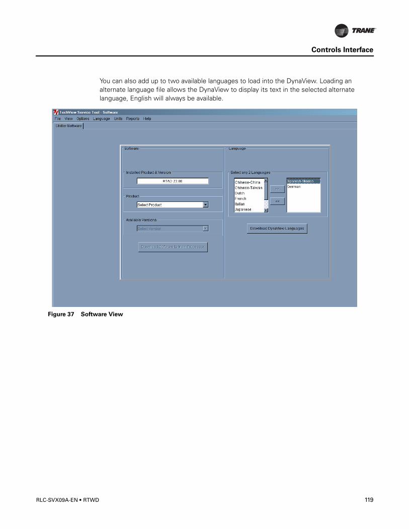
Controls Interface
You can also add up to two available languages to load into the DynaView. Loading an alternate language file allows the DynaView to display its text in the selected alternate language, English will always be available.
Figure 37 Software View
RLC-SVX09A-EN • RTWD 119
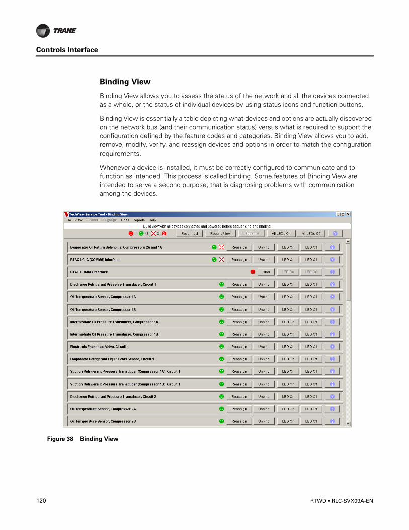
Controls Interface
Binding View
Binding View allows you to assess the status of the network and all the devices connected as a whole, or the status of individual devices by using status icons and function buttons.
Binding View is essentially a table depicting what devices and options are actually discovered on the network bus (and their communication status) versus what is required to support the configuration defined by the feature codes and categories. Binding View allows you to add, remove, modify, verify, and reassign devices and options in order to match the configuration requirements.
Whenever a device is installed, it must be correctly configured to communicate and to function as intended. This process is called binding. Some features of Binding View are intended to serve a second purpose; that is diagnosing problems with communication among the devices.
Figure 38 Binding View
120 RTWD • RLC-SVX09A-EN

Controls Interface
Replacing or Adding Devices
If a device is communicating but incorrectly configured, it might not be necessary to replace it. If the problem with the device is related to communication, attempt to rebind it, and if the device becomes correctly configured, it will then communicate properly.
If a device that needs to be replaced is still communicating, it should be unbound. Otherwise, it will be necessary to rebuild the CH530 network image for Binding View to discover that it has been removed. An unbound device stops communicating and allows a new device to be bound in its place.
It is good practice to turn the power off while detaching and attaching devices to the CH530 network. Be sure to keep power on the service tool computer. After power is restored to the CH530 network, the reconnect function in Binding View restores communication with the network. If the service tool computer is turned off, you must restart TechView and Binding View.
If a device is not communicating, the binding function displays a window to request manual selection of the device to be bound. Previously-selected devices are deselected when the function starts. When manual selection is confirmed, exactly one device must be selected; if it is the correct type, it is bound. If the desired device cannot be selected or if multiple devices are accidentally selected, you can close the manual selection window by clicking on No and repeat the bind function.
Software Download
Instructions for First Time TechView Users
This information can also be found at http://www.trane.com/commercial/software/tracerch530/.
1. Create a folder called “CH530” on your C:\ drive. You will select and use this folder in subsequent steps so that downloaded files are easy to locate.
2. Download the Java Runtime installation utility file onto your PC in the CH530 folder (please note that this does not install Java Runtime, it only downloads the installation utility).
– Click on the latest version of Java Runtime shown in the TechView Download table. – Select “Save this program to disk” while downloading the files (do not select “Run this
program from its current location”). 3. Download the TechView installation utility file onto your PC in the CH530 folder (please
note that this does not install TechView, it only downloads the installation utility).
– Click on the latest version of TechView shown in the TechView Download table. – Select “Save this program to disk” while downloading the files (do not select “Run this
program from its current location”). 4. Remember where you downloaded the files (the “CH530” folder). You will need to
locate them to finish the installation process.
5. Proceed to “Main Processor Software Download” page and read the instructions to download the latest version of main processor installation files.
Note: you will first select the chiller type to obtain the available file versions.
RLC-SVX09A-EN • RTWD 121

Controls Interface
122 RTWD • RLC-SVX09A-EN

Pre-Start Checkout
When installation is complete, but prior to putting the unit into service, the following pre-start procedures must be reviewed and verified correct:
� WARNING
Hazardous Voltage!
Disconnect all electric power, including remote disconnects before servicing. Follow
proper lockout/tagout procedures to ensure the power can not be inadvertently
energized. Failure to disconnect power before servicing could result in death or serious
injury
• Inspect all wiring connections to be sure they are clean and tight.• Verify that all refrigerant valves are “OPEN”
CAUTION
Compressor Damage!
Do not operate the unit with the compressor, oil discharge, liquid line service valves
and the manual shutoff on the refrigerant supply to the auxiliary coolers “CLOSED”.
Failure to “OPEN” all valves may cause serious compressor damage.
• Check the power supply voltage to the unit at the main power fused-disconnect switch. Voltage must be within the voltage utilization range stamped on the unit nameplate. Voltage imbalance must not exceed 2 percent. Refer to Paragraph "Unit Voltage Imbalance" on Page 125.
• Check the unit power phasing to be sure that it has been installed in an “ABC” sequence. Refer to Paragraph "Unit Voltage Phasing" on Page 125.
� WARNINGLive Electrical Components!During installation, testing, servicing and troubleshooting of this product, it may be
necessary to work with live electrical components. Have a qualified licensed electrician
or other individual who has been properly trained in handling live electrical
components perform these tasks. Failure to follow all electrical safety precautions
when exposed to live electrical components could result in death or serious injury.
• Fill the evaporator and condenser chilled water circuits. Vent the system while it is being filled. Open the vents on the top of the evaporator and condenser during filling and close when filling is completed.
RLC-SVX09A-EN • RTWD 123
Pre-Start Checkout
CAUTION
Proper Water Treatment!
The use of untreated or improperly treated water in the RTWD may result in scaling,
erosion, corrosion, algae or slime. It is recommended that the services of a qualified
water treatment specialist be engaged to determine what water treatment, if any, is
required. Trane assumes no responsibility for equipment failures which result from
untreated or improperly treated water, or saline or brackish water.
• Close the fused-disconnect switch(es) that supplies power to the chilled water pump starter and the condenser water pump starter.
� WARNING
Hazardous Voltage!
Disconnect all electric power, including remote disconnects before servicing. Follow
proper lockout/tagout procedures to ensure the power can not be inadvertently
energized. Failure to disconnect power before servicing could result in death or serious
injury.
• Start the chilled water pump and condenser water pump to begin circulation of the water. Inspect all piping for leakage and make any necessary repairs.
• With water circulating through the system, adjust water flow and check water pressure drop through the evaporator and condenser.
• Adjust the chilled water flow switch and condenser water flow switch (if installed) for proper operation.
• Prove all Interlock and Interconnecting Wiring Interlock and External as described in Section “Installation - Electrical”.
• Check and set, as required, all CH530 Menu Items.
• Stop the chilled water pump and condenser water pump.
Unit Voltage Power Supply
� WARNING
Live Electrical Components!
During installation, testing, servicing and troubleshooting of this product, it may be
necessary to work with live electrical components. Have a qualified licensed electrician
or other individual who has been properly trained in handling live electrical
components perform these tasks. Failure to follow all electrical safety precautions
when exposed to live electrical components could result in death or serious injury.
Voltage to the unit must meet the criteria given in Table 16. Measure each leg of the supply voltage at the unit's main power fused-disconnect. If the measured voltage on any
124 RTWD • RLC-SVX09A-EN
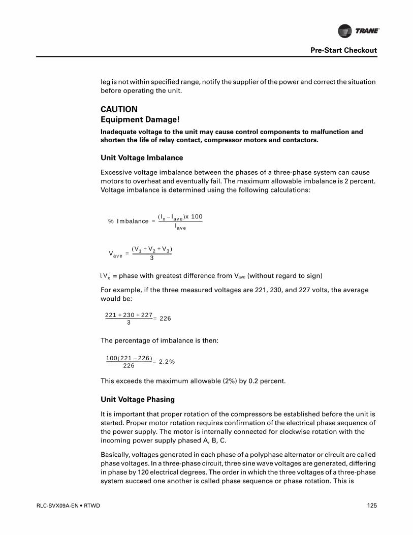
Pre-Start Checkout
leg is not within specified range, notify the supplier of the power and correct the situation before operating the unit.
CAUTION
Equipment Damage!
Inadequate voltage to the unit may cause control components to malfunction and
shorten the life of relay contact, compressor motors and contactors.
Unit Voltage Imbalance
Excessive voltage imbalance between the phases of a three-phase system can cause motors to overheat and eventually fail. The maximum allowable imbalance is 2 percent. Voltage imbalance is determined using the following calculations:
= phase with greatest difference from Vave (without regard to sign)
For example, if the three measured voltages are 221, 230, and 227 volts, the average would be:
The percentage of imbalance is then:
This exceeds the maximum allowable (2%) by 0.2 percent.
Unit Voltage Phasing
It is important that proper rotation of the compressors be established before the unit is started. Proper motor rotation requires confirmation of the electrical phase sequence of the power supply. The motor is internally connected for clockwise rotation with the incoming power supply phased A, B, C.
Basically, voltages generated in each phase of a polyphase alternator or circuit are called phase voltages. In a three-phase circuit, three sine wave voltages are generated, differing in phase by 120 electrical degrees. The order in which the three voltages of a three-phase system succeed one another is called phase sequence or phase rotation. This is
% Imbalancelx lave–( )x 100
lave-------------------------------------------=
VaveV1 V2 V3+ +( )
3---------------------------------------=
1Vx
221 230 227+ +3
----------------------------------------------- 226=
100 221 226–( )226
--------------------------------------------- 2.2%=
RLC-SVX09A-EN • RTWD 125
Pre-Start Checkout
determined by the direction of rotation of the alternator. When rotation is clockwise, phase sequence is usually called “ABC”, when counterclockwise, “CBA”.
This direction may be reversed outside the alternator by interchanging any two of the line wires. It is this possible interchange of wiring that makes a phase sequence indicator necessary if the operator is to quickly determine the phase rotation of the motor.
Proper compressor motor electrical phasing can be quickly determined and corrected before starting the unit. Use a quality instrument, such as the Associated Research Model 45 Phase Sequence Indicator.
1. Press the Stop key on the Clear Language Display.
2. Open the electrical disconnect or circuit protection switch that provides line power to the line power terminal block(s) in the starter panel (or to the unitmounted disconnect).
3. Connect the phase sequence indicator leads to the line power terminal block, as follows:Phase Sea. Lead Terminal
Black (Phase A) ......................L1Red (Phase B) ........................L2Yellow (Phase C) .....................L3
4. Turn power on by closing the unit supply power fused-disconnect switch.
5. Read the phase sequence on the indicator. The “ABC” LED on the face of the phase indicator will glow if phase is “ABC”.
6. If the “CBA” indicator glows instead, open the unit main power disconnect and switch two line leads on the line power terminal block(s) (or the unit mounted disconnect). Reclose the main power disconnect and recheck the phasing.
CAUTION
Equipment Damage!
Do not interchange any load leads that are from the unit contactors or the motor
terminals.
7. Reopen the unit disconnect and disconnect the phase indicator.
� WARNING
Hazardous Voltage!
Disconnect all electric power, including remote disconnects before servicing. Follow
proper lockout/tagout procedures to ensure the power can not be inadvertently
energized. Failure to disconnect power before servicing could result in death or serious
injury.
Water System Flow Rates
Establish a balanced chilled water flow through the evaporator. The flow rates should fall between the minimum and maximum values given in Table 1. Chilled water flow rates below the minimum values will result in laminar flow, which reduces heat transfer and
126 RTWD • RLC-SVX09A-EN
Pre-Start Checkout
causes either loss of EXV control or repeated nuisance, low temperature cutouts. Flow rates that are too high can cause tube erosion and damage to the tube supports and baffles in the evaporator.
The flow rates through the condenser must also be balanced, according to the flow rates in Table 1.
Water System Pressure Drop
Measure water pressure drop through the evaporator and condenser at the field-installed pressure taps on the system water piping. Use the same gauge for each measurement. Do not include valves, strainers fittings in the pressure drop readings.
Pressure drop readings should be approximately those shown in the Pressure Drop Charts, Figures 16, 17 and 18.
RLC-SVX09A-EN • RTWD 127

Pre-Start Checkout
128 RTWD • RLC-SVX09A-EN
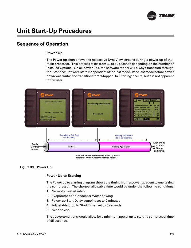
Unit Start-Up Procedures
Sequence of Operation
Power Up
The Power up chart shows the respective DynaView screens during a power up of the main processor. This process takes from 30 to 50 seconds depending on the number of installed Options. On all power ups, the software model will always transition through the 'Stopped' Software state independent of the last mode. If the last mode before power down was 'Auto', the transition from 'Stopped' to 'Starting' occurs, but it is not apparent to the user.
Power Up to Starting
The Power up to starting diagram shows the timing from a power up event to energizing the compressor. The shortest allowable time would be under the following conditions:
1. No motor restart inhibit
2. Evaporator and Condenser Water flowing
3. Power up Start Delay setpoint set to 0 minutes
4. Adjustable Stop to Start Timer set to 5 seconds
5. Need to cool
The above conditions would allow for a minimum power up to starting compressor time of 95 seconds.
Figure 39. Power Up
Completing Self Test
(15 Seconds)
Apply
Control
Power
Starting Application
(15 to 25 Seconds)
Last Mode
i.e. Auto
or Stopped
as Shown
Self Test Starting Application
Note: The variation in DynaView Power up time is
dependent on the number of installed options.
RLC-SVX09A-EN • RTWD 129
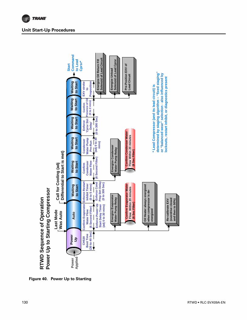
Unit Start-Up Procedures
Figure 40. Power Up to Starting
En
forc
e R
esta
rt
Inh
ibit
Tim
er
(0 t
o 5
min
s)
Co
nfi
rm
Co
nd
en
se
r
Wate
r F
low
RT
WD
Seq
uen
ce o
f O
pera
tio
n
Po
wer
Up
to
Sta
rtin
g C
om
pre
sso
r
Po
wer
Ap
plied
La
st
Mo
de
Wa
s A
uto
Au
to
Ca
ll f
or
Co
oli
ng
(a
dj
Dif
fere
nti
al to
Sta
rt is
me
t)
Wa
itin
g
to S
tart
En
erg
ize
Eva
po
rato
r
Wate
r P
um
p R
ela
yE
nerg
ize C
on
den
ser
Wate
r P
um
p R
ela
y
Co
nfi
rm E
vap
ora
tor
Wate
r
Flo
w
Wit
hin
20 m
inu
tes
(6 S
ec F
ilte
r)
Co
nfi
rm C
on
den
ser
Wate
r
Flo
w W
ith
in 2
0 m
inu
tes
(6 S
ec F
ilte
r)
Wa
itin
g
to S
tart
Oil H
eate
r alw
ays e
nerg
ized
wh
en
co
mp
resso
r is
de-
en
erg
ized
Co
nfi
rm E
vap
ora
tor
Wate
r F
low
(6 S
eco
nd
Filte
r)
Wa
itin
g
to S
tart
Co
nd
en
ser
Wa
ter
Pu
mp
Pre
-Ru
n
Wa
itin
g
to S
tart
En
forc
e C
on
d
Pm
p S
trt
Dela
y
(0 t
o 3
00
Se
c)
(ad
j 0 t
o 3
0
min
s)
En
forc
e
'Cp
rsr
Str
t
Dela
y'
Wa
itin
g
to S
tart
(0 t
o 3
00 S
ec)
(6 S
eco
nd
Filte
r)
Po
wer
Up
CH
530
Bo
ot
Tim
e
(30
to
40 S
ec)
En
forc
e P
ow
er
Up
Sta
rt D
ela
y T
imer
(ad
j 0
to
30
min
s)
Re-c
alib
rate
EX
V
(overd
rive c
losed
an
d t
hen
to
50%
)
* L
ead
Co
mp
resso
r (a
nd
its
lead
cir
cu
it)
is
dete
rmin
ed
by s
tag
ing
alg
ori
thm
– “
fixed
sta
gin
g”
or
“b
ala
nced
wear”
sele
cti
on
-als
o in
flu
en
ced
by
locko
uts
, re
sta
rt in
hib
it,
or
dia
gn
osti
cs p
resen
t
Co
nfi
rm
Pre
se
nc
e o
f O
il
(0 t
o 2
min
s)
En
erg
ize U
nlo
ad
So
len
oid
Pre
-Po
sit
ion
EX
V o
f
Lead
Cir
cu
it
En
erg
ize U
nlo
ad
So
len
oid
of
Lead
Cp
rsr
En
erg
ize O
il R
etu
rn F
ill
So
len
oid
of
Lead
Cir
cu
it
EX
V s
tro
ke
to
Pre
po
sit
ion
Wa
itin
g
to S
tart
Sta
rt
Co
mm
an
d
to L
ead
Cp
rsr*
130 RTWD • RLC-SVX09A-EN
Unit Start-Up Procedures
Stopped to Starting:
The stopped to starting diagram shows the timing from a stopped mode to energizing the compressor. The shortest allowable time would be under the following conditions:
1. No motor restart inhibit
2. Evaporator and Condenser Water flowing
3. Power up Start Delay Timer has expired
4. Adjustable Stop to Start Timer has expired
5. Need to cool
The above conditions would allow the compressor to start in 60 seconds.
CAUTION
Refrigerant!
If both suction and discharge pressures are low but sub-cooling is normal, a problem
other than refrigerant shortage exists. Do not add refrigerant, as this may result in
overcharging the circuit.
Use only refrigerants specified on the unit nameplate (HFC 134a) and Trane OIL00048.
Failure to do so may cause compressor damage and improper unit operation.
CAUTION
Equipment Damage!
Ensure that the oil sump heaters have been operating for a minimum of 24 hours
before starting. Failure to do so may result in equipment damage.
RLC-SVX09A-EN • RTWD 131
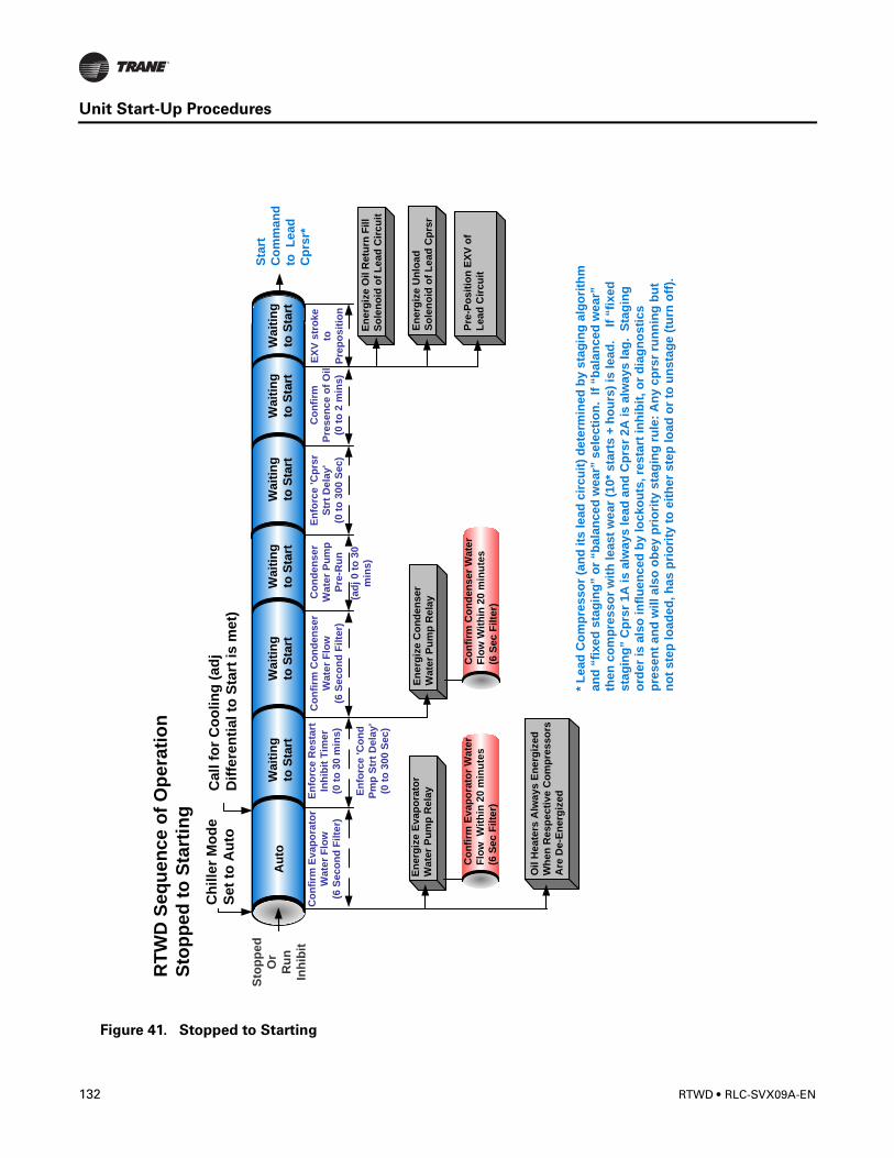
Unit Start-Up Procedures
Figure 41. Stopped to Starting
En
forc
e R
esta
rt
Inh
ibit
Tim
er
(0 t
o 3
0 m
ins
)
Co
nfi
rm C
on
den
ser
Wate
r F
low
(6 S
ec
on
d F
ilte
r)
RT
WD
Seq
uen
ce o
f O
pera
tio
n
Sto
pp
ed
to
Sta
rtin
g
Sto
pp
ed
Or
Ru
n
Inh
ibit
Ch
ille
r M
od
e
Se
t to
Au
to
Au
toW
ait
ing
to S
tart
En
erg
ize E
vap
ora
tor
Wate
r P
um
p R
ela
yE
nerg
ize C
on
den
se
r
Wate
r P
um
p R
ela
y
Co
nfi
rm E
vap
ora
tor
Wate
r
Flo
w
Wit
hin
20 m
inu
tes
(6 S
ec F
ilte
r)
Co
nfi
rm C
on
den
ser
Wate
r
Flo
w W
ith
in 2
0 m
inu
tes
(6 S
ec F
ilte
r)
Wa
itin
g
to S
tart
Oil
Hea
ters
Alw
ay
s E
nerg
ized
Wh
en
Resp
ecti
ve C
om
pre
sso
rs
Are
De-E
nerg
ized
Co
nfi
rm E
vap
ora
tor
Wate
r F
low
(6 S
eco
nd
Filte
r)
En
erg
ize
Un
loa
d
So
len
oid
Co
nfi
rm
Pre
sen
ce o
f O
il
(0 t
o 2
min
s)
Wa
itin
g
to S
tart
Co
nd
en
ser
Wa
ter
Pu
mp
Pre
-Ru
n
Wa
itin
g
to S
tart
En
forc
e 'C
on
d
Pm
p S
trt
Dela
y'
(0 t
o 3
00
Sec
)
(ad
j 0 t
o 3
0
min
s)
En
forc
e 'C
prs
r
Str
t D
ela
y'
(0 t
o 3
00 S
ec)
Wa
itin
g
to S
tart
Ca
ll f
or
Co
oli
ng
(a
dj
Dif
fere
nti
al to
Sta
rt is
me
t)
Pre
-Po
sit
ion
EX
V o
f
Le
ad
Cir
cu
it
Sta
rt
Co
mm
an
d
to
Lead
Cp
rsr*
* L
ead
Co
mp
resso
r (a
nd
its
lead
cir
cu
it)
dete
rmin
ed
by s
tag
ing
alg
ori
thm
an
d “
fixed
sta
gin
g” o
r “b
ala
nced
wear”
sele
cti
on
. If
“b
ala
nced
wear”
then
co
mp
resso
r w
ith
least
we
ar
(10*
sta
rts +
ho
urs
) is
lead
. If
“fi
xed
sta
gin
g” C
prs
r 1A
is a
lways lead
an
d C
prs
r 2A
is a
lways l
ag
. S
tag
ing
ord
er
is a
lso
in
flu
en
ced
by lo
cko
uts
, re
sta
rt in
hib
it, o
r d
iag
no
sti
cs
pre
sen
t an
d w
ill
als
o o
bey p
rio
rity
sta
gin
g r
ule
: A
ny c
prs
r ru
nn
ing
bu
t
no
t ste
p l
oad
ed
, h
as p
rio
rity
to
eit
her
ste
p l
oad
or
to u
nsta
ge (
turn
off
).
En
erg
ize
Un
loa
d
So
len
oid
of
Lead
Cp
rsr
En
erg
ize O
il R
etu
rn F
ill
So
len
oid
of
Lead
Cir
cu
it
EX
V s
tro
ke
to
Pre
po
sit
ion
Wa
itin
g
to S
tart
132 RTWD • RLC-SVX09A-EN
Unit Start-Up Procedures
Start-up
CAUTION
Equipment Damage!
Ensure that the oil sump heaters have been operating for a minimum of 24 hours
before starting. Failure to do so may result in equipment damage.
If the pre-start checkout, has been completed, the unit is ready to start.
1. Press the STOP key on the CH530.
2. As necessary, adjust the setpoint values in the CH530 menus using TechView.
3. Close the fused-disconnect switch for the chilled water pump. Energize the pump(s) to start water circulation.
4. Check the service valves on the discharge line, suction line, oil line and liquid line for each circuit. These valves must be open (backseated) before starting the compressors.
CAUTION
Compressor Damage!
Catastrophic damage to the compressor will occur if the oil line shut off valve or the
isolation valves are left closed on unit start-up.
5. Press the AUTO key. If the chiller control calls for cooling and all safety interlocks are closed, the unit will start. The compressor(s) will load and unload in response to the leaving chilled water temperature.
6. Verify that the chilled water pump runs for at least one minute after the chiller is commanded to stop (for normal chilled water systems).
Note: Once the system has been operating for approximately 30 minutes and has become stabilized, complete the remaining start-up procedures, as follows:
7. Check the evaporator refrigerant pressure and the condenser refrigerant pressure under Refrigerant Report on the CH530 TechView. The pressures are referenced to sea level (14.6960 psia).
8. Check the EXV sight glasses after sufficient time has elapsed to stabilize the chiller. The refrigerant flow past the sight glasses should be clear. Bubbles in the refrigerant indicate either low refrigerant charge or excessive pressure drop in the liquid line or a stuck open expansion valve. A restriction in the line can sometimes be identified by a noticeable temperature differential between the two sides of the restriction. Frost will often form on the line at this point. Proper refrigerant charges are shown in the General Data tables.
Note: Important! A clear sight glass alone does not mean that the system is properly charged. Also check system subcooling, liquid level control and unit operating pressures.
9. Measure the system subcooling.
10. A shortage of refrigerant is indicated if operating pressures are low and subcooling is also low. If the operating pressures, sight glass, superheat and subcooling readings
RLC-SVX09A-EN • RTWD 133
Unit Start-Up Procedures
indicate a refrigerant shortage, gas-charge refrigerant into each circuit, as required. With the unit running, add refrigerant vapor by connecting the charging line to the suction service valve and charging through the backseat port until operating conditions become normal.
Seasonal Unit Start-Up Procedure1. Close all valves and re-install the drain plugs in the evaporator and condenser heads.
2. Service the auxiliary equipment according to the start-up/maintenance instructions provided by the respective equipment manufacturers.
3. Vent and fill the cooling tower, if used, as well as the condenser and piping. At this point, all air must be removed from the system (including each pass). Close the vents in the evaporator chilled water circuits.
4. Open all the valves in the evaporator chilled water circuits.
5. If the evaporator was previously drained, vent and fill the evaporator and chilled water circuit. When all air is removed from the system (including each pass), install the vent plugs in the evaporator water boxes.
CAUTION
Equipment Damage!
Ensure that the oil sump heaters have been operating for a minimum of 24 hours
before starting. Failure to do so may result in equipment damage.
CAUTION
Compressor Damage!
Catastrophic damage to the compressor will occur if the oil line shut off valve or the
isolation valves are left closed on unit start-up.
134 RTWD • RLC-SVX09A-EN
Unit Start-Up Procedures
Limit Conditions
CH530 will automatically limit certain operating parameters during startup and run modes to maintain optimum chiller performance and prevent nuisance diagnostic trips. These limit conditions are noted in Figure 43, p. 135.
Table 43. Limit Conditions
Running - Limited
The chiller, circuit, and compressor are currently running, but the operation of the
chiller/compressor is being actively limited by the controls. Further information is
provided by the sub-mode.
Capacity Limited by High Cond Press
The circuit is experiencing condenser pressures at or near the condenser limit setting. The compressor will be unloaded to prevent exceeding the limits.
Capacity Limited by Low Evap Rfgt Temp
The circuit is experiencing saturated evaporator temperatures at or near the Low Refrigerant Temperature Cutout setting. The compressors will be unloaded to prevent tripping.
Capacity Limited by Low Liquid Level
The circuit is experiencing low refrigerant liquid levels and the EXV is at or near full open. The compressor will be unloaded to prevent tripping.
Capacity Limited by High Current
The compressor is running and its capacity is being limited by high currents. The current limit setting is 120% RLA (to avoid overcurrent trips).
Capacity Limited by Phase Unbalance
The compressor is running and its capacity is being limited by excessive phase current unbalance.
RLC-SVX09A-EN • RTWD 135
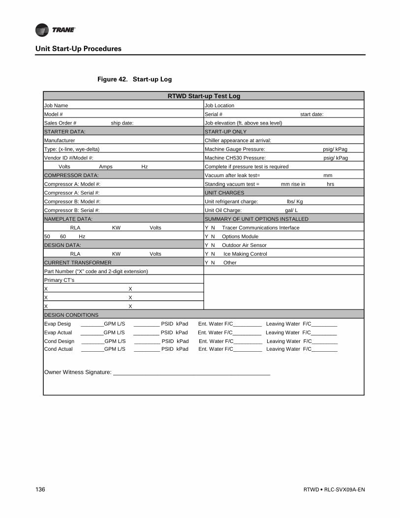
Unit Start-Up Procedures
Figure 42. Start-up Log
Job Name Job Location
Model # Serial # start date:
Sales Order # ship date: Job elevation (ft. above sea level)
STARTER DATA: START-UP ONLY
Manufacturer Chiller appearance at arrival:
Type: (x-line, wye-delta) Machine Gauge Pressure: psig/ kPag
Vendor ID #/Model #: Machine CH530 Pressure: psig/ kPag
Volts Amps Hz Complete if pressure test is required
COMPRESSOR DATA: Vacuum after leak test= mm
Compressor A: Model #: Standing vacuum test = mm rise in hrs
Compressor A: Serial #: UNIT CHARGES
Compressor B: Model #: Unit refrigerant charge: lbs/ Kg
Compressor B: Serial #: Unit Oil Charge: gal/ L
NAMEPLATE DATA: SUMMARY OF UNIT OPTIONS INSTALLED
RLA KW Volts Y N Tracer Communications Interface
50 60 Hz Y N Options Module
DESIGN DATA: Y N Outdoor Air Sensor
RLA KW Volts Y N Ice Making Control
CURRENT TRANSFORMER Y N Other
Part Number (“X” code and 2-digit extension)
Primary CT’s
X X
X X
X X
DESIGN CONDITIONS
Evap Desig ________GPM L/S _________ PSID kPad Ent. Water F/C__________ Leaving Water F/C_________
Evap Actual ________GPM L/S _________ PSID kPad Ent. Water F/C__________ Leaving Water F/C_________
Cond Design ________GPM L/S _________ PSID kPad Ent. Water F/C__________ Leaving Water F/C_________Cond Actual ________GPM L/S _________ PSID kPad Ent. Water F/C__________ Leaving Water F/C_________
Owner Witness Signature: _________________________________________________
RTWD Start-up Test Log
136 RTWD • RLC-SVX09A-EN
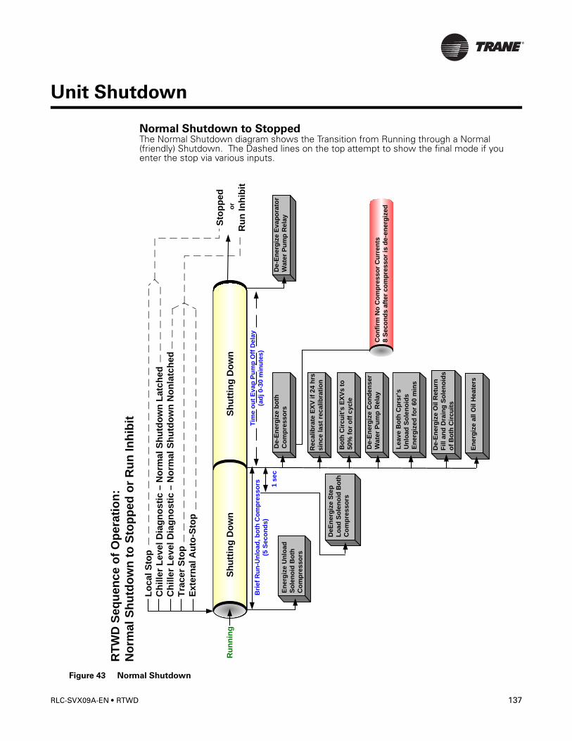
Unit Shutdown
Normal Shutdown to StoppedThe Normal Shutdown diagram shows the Transition from Running through a Normal (friendly) Shutdown. The Dashed lines on the top attempt to show the final mode if you enter the stop via various inputs.
Figure 43 Normal Shutdown
RT
WD
Seq
uen
ce o
f O
pera
tio
n:
No
rmal S
hu
tdo
wn
to
Sto
pp
ed
or
Ru
n In
hib
it
Ru
nn
ing
Lo
ca
l S
top
Ch
ille
r L
ev
el
Dia
gn
os
tic
– N
orm
al
Sh
utd
ow
n L
atc
he
d
Ch
ille
r L
ev
el
Dia
gn
os
tic
– N
orm
al
Sh
utd
ow
n N
on
latc
he
d
Tra
ce
r S
top
Ex
tern
al
Au
to-S
top
Sto
pp
ed
or
Ru
n In
hib
it
Sh
utt
ing
Do
wn
En
erg
ize U
nlo
ad
So
len
oid
Bo
th
Co
mp
resso
rs
Sh
utt
ing
Do
wn
De-E
nerg
ize b
oth
Co
mp
resso
rs
Bri
ef
Ru
n-U
nlo
ad
, b
oth
Co
mp
res
so
rs
(5 S
eco
nd
s)
De-E
nerg
ize C
on
de
ns
er
Wate
r P
um
p R
ela
y
Bo
th C
ircu
it’s
EX
Vs t
o
50
% f
or
off
cycle
Leave B
oth
Cp
rsr’
s
Un
loa
d S
ole
no
ids
En
erg
ized
fo
r 60 m
ins
En
erg
ize a
ll O
il H
eate
rs
Tim
e o
ut
Ev
ap
Pu
mp
Off
De
lay
(ad
j 0-3
0 m
inu
tes)
De-E
nerg
ize E
vap
ora
tor
Wate
r P
um
p R
ela
y
DeE
nerg
ize S
tep
Lo
ad
So
len
oid
Bo
th
Co
mp
resso
rs
1 s
ec
Recali
bra
te E
XV
if
24 h
rs
sin
ce last
recalib
rati
on
De-E
nerg
ize O
il R
etu
rn
Fill
an
d D
rain
g S
ole
no
ids
of
Bo
th C
ircu
its
Co
nfi
rm N
o C
om
pre
sso
r C
urr
en
ts
8 S
eco
nd
s a
fter
co
mp
resso
r is
de-e
nerg
ized
RLC-SVX09A-EN • RTWD 137

Unit Shutdown
Seasonal Unit Shutdown
1. Perform the normal unit stop sequence using the <Stop> key.
NOTE: Do not open the starter disconnect switch. This must remain closed to provide control power from the control power transformer to the oil heaters.
2. Verify that the chilled water and condenser water pumps are cycled off. If desired, open the disconnect switches to the pumps.
3. Drain the condenser piping and cooling tower, if desired.
4. Remove the drain and vent plugs from the condenser headers to drain the condenser.
5. Verify that the oil heaters are working.
6. Once the unit is secured, perform the maintenance identified in the following sections.
138 RTWD • RLC-SVX09A-EN
Unit Shutdown
RLC-SVX09A-EN • RTWD 139
Service and Maintenance
Overview
This section describes preventative maintenance procedures and intervals for the RTWD unit. Use a periodic maintenance program to ensure optimal performance and efficiency of the Series R units.
An important aspect of the chiller maintenance program is the regular completion of the “Series R Operating Log”; an example of this log is provided in this manual. When filled out properly the completed logs can be reviewed to identify any developing trends in the chiller's operating conditions.
For example, if the machine operator notices a gradual increase in condensing pressure during a month's time, he can systematically check for and then correct, the possible cause(s) of this condition (e.g., fouled condenser tubes, non-condensables in the system).
Maintenance
� WARNING
Hazardous Voltage!
Disconnect all electric power, including remote disconnects and discharge all motor
start/run capacitors before servicing. Follow proper lockout/tagout procedures to
ensure the power cannot be inadvertently energized. Verify with an appropriate
voltmeter that all capacitors have discharged. Failure to disconnect power and
discharge capacitors before servicing could result in death or serious injury.
WARNING
Live Electrical Components!
During installation, testing, servicing and troubleshooting of this product, it may be
necessary to work with live electrical components. Have a qualified licensed electrician
or other individual who has been properly trained in handling live electrical
components perform these tasks. Failure to follow all electrical safety precautions
when exposed to live electrical components could result in death or serious injury.
Weekly Maintenance and Checks
After the unit has operated for approximately 30 minutes and the system has stabilized, check the operating conditions and complete the procedures below:
• Log the chiller.
• Check evaporator and condenser pressures with gauges and compare to the reading on the CH530. Pressure readings should fall within the specified ranges listed under Operating Conditions.
Note: Optimum condenser pressure is dependent on condenser water temperature, and should equal the saturation pressure of the refrigerant at a temperature 2 to 5°F above that of leaving condenser water at full load.
140 RTWD • RLC-SVX09A-EN
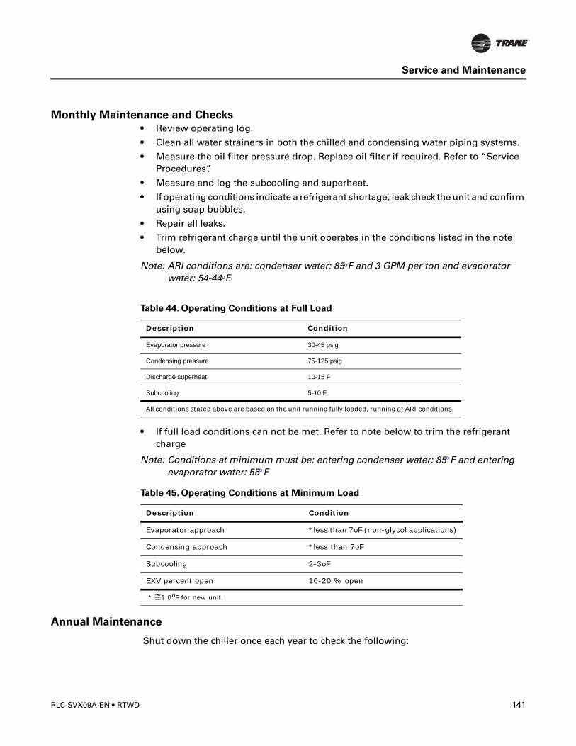
Service and Maintenance
Monthly Maintenance and Checks• Review operating log.
• Clean all water strainers in both the chilled and condensing water piping systems.
• Measure the oil filter pressure drop. Replace oil filter if required. Refer to “Service Procedures”.
• Measure and log the subcooling and superheat.
• If operating conditions indicate a refrigerant shortage, leak check the unit and confirm using soap bubbles.
• Repair all leaks.
• Trim refrigerant charge until the unit operates in the conditions listed in the note below.
Note: ARI conditions are: condenser water: 85oF and 3 GPM per ton and evaporator water: 54-44oF.
• If full load conditions can not be met. Refer to note below to trim the refrigerant charge
Note: Conditions at minimum must be: entering condenser water: 85°F and entering evaporator water: 55°F
Annual Maintenance
Shut down the chiller once each year to check the following:
Table 44. Operating Conditions at Full Load
Description Condition
Evaporator pressure 30-45 psig
Condensing pressure 75-125 psig
Discharge superheat 10-15 F
Subcooling 5-10 F
All conditions stated above are based on the unit running fully loaded, running at ARI conditions.
Table 45. Operating Conditions at Minimum Load
Description Condition
Evaporator approach *less than 7oF (non-glycol applications)
Condensing approach *less than 7oF
Subcooling 2-3oF
EXV percent open 10-20 % open
* ≅1.0oF for new unit.
RLC-SVX09A-EN • RTWD 141
Service and Maintenance
� WARNING
Hazardous Voltage!
Disconnect all electric power, including remote disconnects and discharge all motor
start/run capacitors before servicing. Follow proper lockout/tagout procedures to
ensure the power cannot be inadvertently energized. Verify with an appropriate
voltmeter that all capacitors have discharged. Failure to disconnect power and
discharge capacitors before servicing could result in death or serious injury.
• Perform all weekly and monthly maintenance procedures.
• Check the refrigerant charge and oil level. Refer to “Maintenance Procedures”. Routine oil changing is not necessary on a hermetic system.
• Have a qualified laboratory perform an oil analysis to determine system moisture content and acid level.
Note: Due to the hygroscopic properties of the POE oil, all oil must be stored in metal containers. The oil will absorb water if stored in a plastic container.
• Check the pressure drop across the oil filter. Refer to “Maintenance Procedures”.
• Contact a qualified service organization to leak check the chiller, to inspect safety controls, and inspect electrical components for deficiencies.
• Inspect all piping components for leakage and/or damage. Clean out any inline strainers.
• Clean and repaint any areas that show signs of corrosion.
• Test vent piping of all relief valves for presence of refrigerant to detect improperly sealed relief valves. Replace any leaking relief valve.
• Inspect the condenser tubes for fouling; clean if necessary. Refer to “Maintenance Procedures”.
• Check to make sure that the crank case heater is working.
Scheduling Other Maintenance• Use a nondestructive tube test to inspect the condenser and evaporator tubes at 3-
year intervals.
Note: It may be desirable to perform tube tests on these components at more frequent intervals, depending upon chiller application. This is especially true of critical process equipment.
• Depending on chiller duty, contact a qualified service organization to determine when to conduct a complete examination of the unit to determine the condition of the compressor and internal components.
Operating Log
A sample of several operating logs and checklists have been included.
142 RTWD • RLC-SVX09A-EN
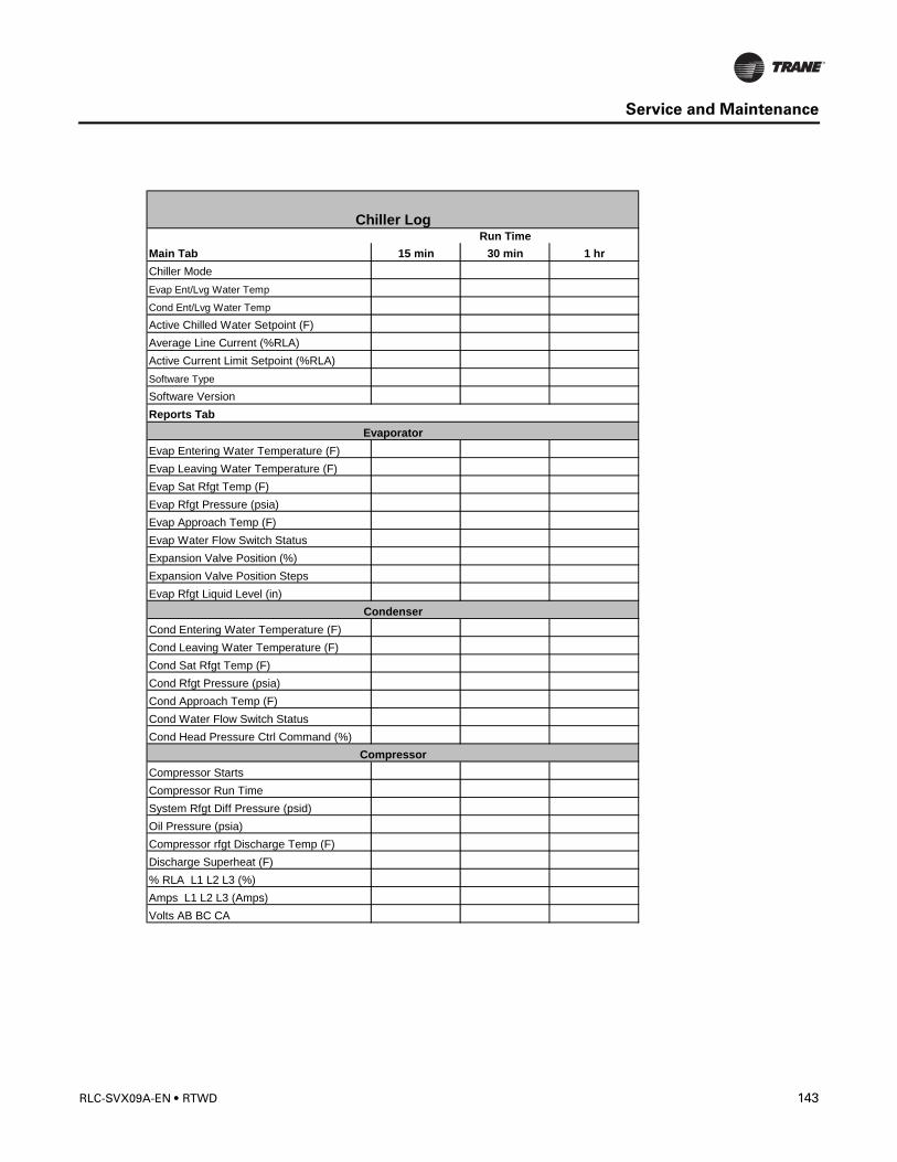
Service and Maintenance
Main Tab 15 min 30 min 1 hrChiller ModeEvap Ent/Lvg Water Temp
Cond Ent/Lvg Water Temp
Active Chilled Water Setpoint (F)Average Line Current (%RLA)Active Current Limit Setpoint (%RLA)Software Type
Software VersionReports Tab
Evap Entering Water Temperature (F)Evap Leaving Water Temperature (F)Evap Sat Rfgt Temp (F)Evap Rfgt Pressure (psia)Evap Approach Temp (F)Evap Water Flow Switch StatusExpansion Valve Position (%)Expansion Valve Position StepsEvap Rfgt Liquid Level (in)
Cond Entering Water Temperature (F)Cond Leaving Water Temperature (F)Cond Sat Rfgt Temp (F)Cond Rfgt Pressure (psia)Cond Approach Temp (F)Cond Water Flow Switch StatusCond Head Pressure Ctrl Command (%)
Compressor StartsCompressor Run TimeSystem Rfgt Diff Pressure (psid)Oil Pressure (psia)Compressor rfgt Discharge Temp (F)Discharge Superheat (F)% RLA L1 L2 L3 (%)Amps L1 L2 L3 (Amps)Volts AB BC CA
Compressor
Run TimeChiller Log
Evaporator
Condenser
RLC-SVX09A-EN • RTWD 143
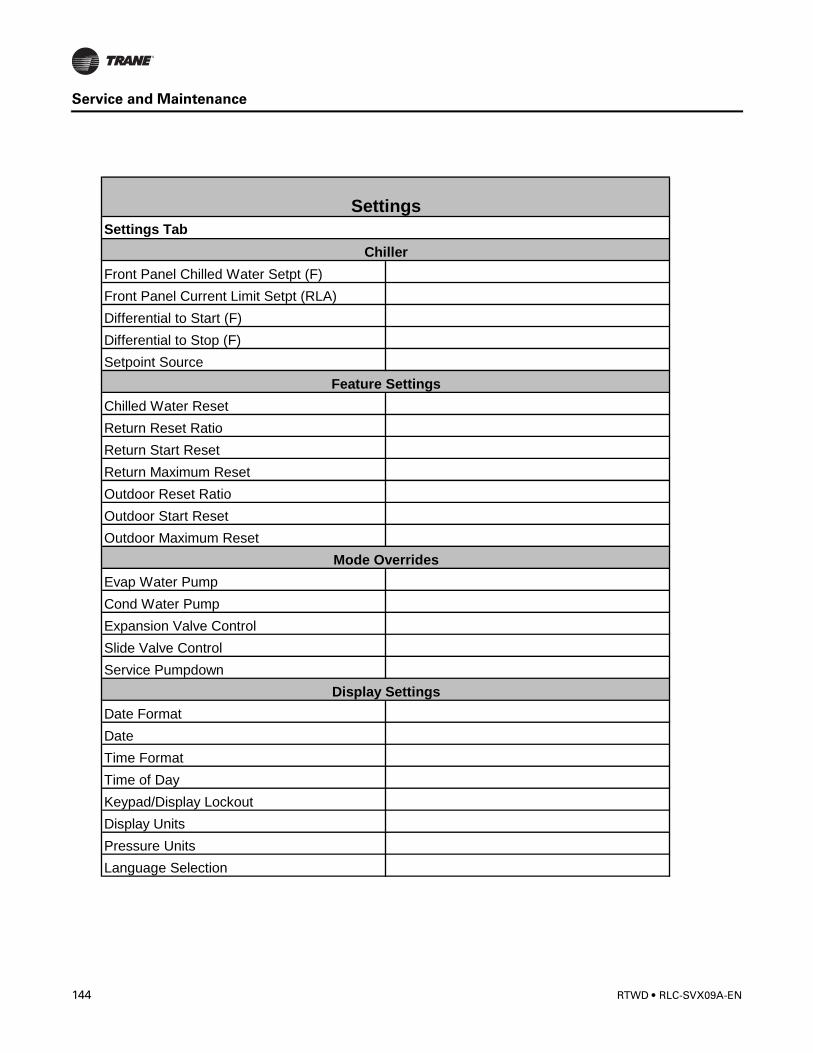
Service and Maintenance
Settings Tab
Front Panel Chilled Water Setpt (F)Front Panel Current Limit Setpt (RLA)Differential to Start (F)Differential to Stop (F)Setpoint Source
Chilled Water ResetReturn Reset RatioReturn Start ResetReturn Maximum ResetOutdoor Reset RatioOutdoor Start ResetOutdoor Maximum Reset
Evap Water PumpCond Water PumpExpansion Valve ControlSlide Valve ControlService Pumpdown
Date FormatDateTime FormatTime of DayKeypad/Display LockoutDisplay UnitsPressure UnitsLanguage Selection
Display Settings
Settings
Chiller
Feature Settings
Mode Overrides
144 RTWD • RLC-SVX09A-EN
Service and Maintenance
Service Procedures
Cleaning the Condenser
CAUTION
Proper Water Treatment!
The use of untreated or improperly treated water in a RTWD may result in scaling,
erosion, corrosion, algae or slime. It is recommended that the services of a qualified
water treatment specialist be engaged to determine what water treatment, if any, is
required. The Trane Company assumes no responsibility for equipment failures which
result from untreated or improperly treated water, saline or brackish water.
Condenser tube fouling is suspect when the “approach” temperature (i.e., the difference between the refrigerant condensing temperature and the leaving condenser water temperature) is higher than predicted.
Standard water applications will operate with less than a 10oF approach. If the approach exceeds 10oF cleaning the condenser tubes is recommended.
Note: Glycol in the water system typically doubles the standard approach.
If the annual condenser tube inspection indicates that the tubes are fouled, 2 cleaning methods can be used to rid the tubes of contaminants.The methods are:
Mechanical Cleaning Procedure
Mechanical tube cleaning method is used to remove sludge and loose material from smooth-bore condenser tubes.
� WARNING
Heavy Objects!
Each of the individual cables (chains or slings) used to lift the waterbox must be
capable of supporting the entire weight of the waterbox. The cables (chains or slings)
must be rated for overhead lifting applications with an acceptable working load limit.
Failure to properly lift waterbox could result in death or serious injury.
� WARNING
Eyebolts!
The proper use and ratings for eyebolts can be found in ANSI/ASME standard B18.15.
Maximum load rating for eyebolts are based on a straight vertical lift in a gradually
increasing manner. Angular lifts will significantly lower maximum loads and should be
avoided whenever possible. Loads should always be applied to eyebolts in the plane
of the eye, not at some angle to this plane. Failure to properly lift waterbox could
result in death or serious injury.
Review mechanical room limitations and determine the safest method or methods of rigging and lifting the waterboxes.
RLC-SVX09A-EN • RTWD 145
Service and Maintenance
1. Determine the size of chiller being serviced. Refer to Trane Nameplate located on chiller control panel.
2. Select the proper lift connection device from Table 48. The rated lifting capacity of the selected lift connection device must meet or exceed the published weight of the waterbox.
3. Insure the lift connection device has the correct connection for the waterbox. Example: thread type (course/fine, English/metric). Bolt diameter (English/metric).
4. Properly connect the lift connection device to the waterbox. Refer to Figure 44. Insure lift connection device is securely fastened.
5. Install hoist ring on to the lifting connection on the waterbox. Torque to 28 ft-lbs (37 Nm).
6. Disconnect water pipes, if connected.
7. Remove waterbox bolts
8. Lift the waterbox away from the shell.
Figure 44 Water Box Lifting
146 RTWD • RLC-SVX09A-EN
Service and Maintenance
� WARNING
OVERHEAD HAZARD!
Never stand below or in close proximately to heavy objects while they are suspended
from, or being lifted by, a lifting device. Failure to follow these instructions could result
in death or serious injuries.
9. Store waterbox in a safe and secure location and position.
Note: Do not leave waterbox suspended from lifting device.10. Work a round nylon or brass bristled brush (attached to a rod) in and out of each of
the condenser water tubes to loosen the sludge.
11. Thoroughly flush the condenser water tubes with clean water.
Note: (To clean internally enhanced tubes, use a bi-directional brush or consult a qualified service organization for recommendations.)
Reassembly
Once service is complete, the waterbox should be reinstalled on the shell following all previous procedures in reverse. Use new o-rings or gaskets on all joints after thoroughly cleaning each joint.
1. Torque waterbox bolts.
Note: Torque bolts in a star pattern. Refer to Table 46 for torque values.
Waterbox Weights
Parts Ordering Information
Use the Table 48, “Connection Devices,” on page 147 for part ordering information.
Table 46. RTWD Torque
Evaporator Condenser
65 ft-lbs (88 Nm) 65 ft-lbs (88 Nm)
Table 47. RTWD Waterbox Weights
Standard Grooved Pipe Waterbox
WaterboxWeightKg (lbs)
LiftingConnection
Evaporator 20.4 (45) M12x1.75
Condenser 20.4 (45) M12x1.75
Table 48. Connection Devices
Unit Product Part Number
RTWD Safety Hoist RingM12x1.75
RNG01886
RLC-SVX09A-EN • RTWD 147
Service and Maintenance
Obtain the required parts from your local Trane Parts Center.
Chemical Cleaning Procedure
• Scale deposits are best removed by chemical means. Consult a qualified water treatment specialist (i.e., one that knows the local water supply chemical/mineral content) for a recommended cleaning solution suitable for the job. (A standard condenser water circuit is composed solely of copper, cast iron and steel.) Improper chemical cleaning can damage tube walls.
All of the materials used in the external circulation system, the quantity of the solution, the duration of the cleaning period, and any required safety precautions should be approved by the company furnishing the materials or performing the cleaning.
Note: Chemical tube cleaning should always be followed by mechanical tube cleaning.
Cleaning the Evaporator
Since the evaporator is typically part of a closed circuit, it does not accumulate appreciable amounts of scale or sludge. However, if cleaning is deemed necessary, use the same cleaning methods described for the condenser tubes.
Compressor Oil
CAUTION
Equipment Damage!
To prevent oil sump heater burnout, open the unit main power disconnect switch
before removing oil from the compressor.
Trane Polyolester Oil is the approved oil for the RTWD units. Polyolester oil is extremely hygroscopic meaning it readily attracts moisture. The oil can not be stored in plastic containers due to the hygroscopic properties. As with mineral oil, if water is in the system it will react with the oil to form acids. Use Table 49. to determine the acceptability of the oil.
Note: Use an oil transfer pump to change the oil regardless of chiller pressure.
Oil Sump Level Check
Running the chiller at minimum load is the best for the quickest return of oil to the separator and sump. The machine still needs to sit for approximately 30 minutes before
Table 49. POE Oil Properties
Description Acceptable Levels
Moisture content less than 300 ppm
Acid Level less than 0.5 TAN (mg KOH/g)
Mineral oil used in the RTHA and RTHB units had different acceptable levels (< 50 ppm of moisture and < 0.05 mg KOH/g)
148 RTWD • RLC-SVX09A-EN

Service and Maintenance
the level is taken. At minimum load, the discharge superheat should be highest. The more heat in the oil as it lays in the sump, the more refrigerant will boil off in the sump and leave more concentrated oil.
The oil level in the oil sump can be measured to give an indication of the system oil charge. Follow the procedures below to measure the level.
1. Run the unit fully unloaded for approximately 20 minutes.
2. Cycle the compressor off line.
CAUTION
Oil Loss!
Never operate the compressor with the sightglass service valves opened. Severe oil
loss will occur. Close the valves after checking the oil level. The sump is above the
condenser and it is possible to drain the oil.
Figure 45. Determining Oil Level in Sump
Oil separatorservice valve
Oil sumpservice valve
4 “- 9.5”
RLC-SVX09A-EN • RTWD 149

Service and Maintenance
3. Attach a 3/8” or 1/2” hose with a sightglass in the middle to the oil sump service valve (1/4” flare) and the oil separator service valve (1/4” flare).
Note: Using high pressure rated clear hose with appropriate fittings can help speed up the process.
4. After the unit is off line for 30 minutes, move the sightglass along the side of the oil sump.
5. The level should be between 4” and 9.5” from the bottom of the oil sump. If the level appears to be above 9.5”, the oil sump is completely full. Most likely more oil resides in the rest of the system and some oil needs to be removed until the level falls between 4” and 9.5” in the oil sump.
Note: Nominal height of oil is 8 inches.
6. If the level is below 4”, there is not enough oil in the sump. This can occur from not enough oil in the system or more likely, oil migration to the evaporator. Oil migration can occur from a low refrigerant charge, gas pump malfunction, etc.
Note: If the oil is logged in the evaporator confirm the operation of the gas pump. If the gas pump is not functioning properly all oil will be logged in the evaporator.
7. After the level is determined, close the service valves and remove the hose/sightglass assembly.
Removing Compressor Oil
The oil in the compressor oil sump is under a constant positive pressure at ambient temperature. To remove oil, open the service valve located on the bottom of the oil sump and drain the oil into a suitable container using the procedure outlined below:
CAUTION
POE Oil!
Due to the hygroscopic properties of the POE oil, all oil must be stored in metal
containers. The oil will absorb water if stored in a plastic container.
Oil should not be removed until the refrigerant is isolated or removed.
1. Connect a line to the oil sump drain valve.
2. Open the valve and allow the desired amount of oil to flow into the container and close the charging valve.
3. Measure the exact amount of oil removed from the unit.
Oil Charging Procedure
It is critical to fill the oil lines feeding the compressor when charging a system with oil. The diagnostic “Loss of oil at the compressor stopped” will be generated if the oil lines are not full on start-up.
150 RTWD • RLC-SVX09A-EN
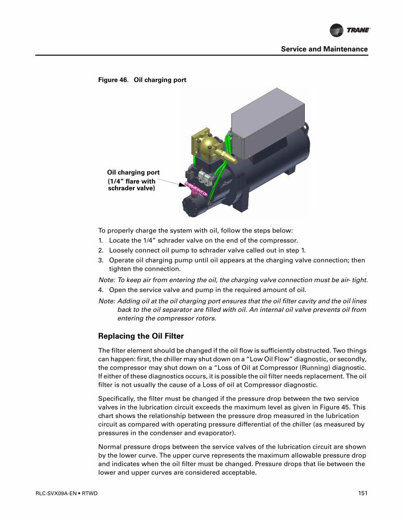
Service and Maintenance
Figure 46. Oil charging port
To properly charge the system with oil, follow the steps below:
1. Locate the 1/4” schrader valve on the end of the compressor.
2. Loosely connect oil pump to schrader valve called out in step 1.
3. Operate oil charging pump until oil appears at the charging valve connection; then tighten the connection.
Note: To keep air from entering the oil, the charging valve connection must be air- tight.
4. Open the service valve and pump in the required amount of oil.
Note: Adding oil at the oil charging port ensures that the oil filter cavity and the oil lines back to the oil separator are filled with oil. An internal oil valve prevents oil from entering the compressor rotors.
Replacing the Oil Filter
The filter element should be changed if the oil flow is sufficiently obstructed. Two things can happen: first, the chiller may shut down on a “Low Oil Flow” diagnostic, or secondly, the compressor may shut down on a “Loss of Oil at Compressor (Running) diagnostic. If either of these diagnostics occurs, it is possible the oil filter needs replacement. The oil filter is not usually the cause of a Loss of oil at Compressor diagnostic.
Specifically, the filter must be changed if the pressure drop between the two service valves in the lubrication circuit exceeds the maximum level as given in Figure 45. This chart shows the relationship between the pressure drop measured in the lubrication circuit as compared with operating pressure differential of the chiller (as measured by pressures in the condenser and evaporator).
Normal pressure drops between the service valves of the lubrication circuit are shown by the lower curve. The upper curve represents the maximum allowable pressure drop and indicates when the oil filter must be changed. Pressure drops that lie between the lower and upper curves are considered acceptable.
Oil charging port
(1/4” flare withschrader valve)
RLC-SVX09A-EN • RTWD 151

Service and Maintenance
For a chiller equipped with an oil cooler, add 5 psid to the values shown in Figure 47. For example, if the system pressure differential was 80 psid, then the clean filter pressure drop would be approximately 15 psid (up from 10 psid). For a chiller with an oil cooler and operating with a dirty oil filter, the maximum allowable pressure drop would be 28 psid (up from 23 psid).
Under normal operating conditions the element should be replaced after the first year of operation and then as needed thereafter.
Refer to Table 3 - Table 6 and Unit nameplate for Oil charge information.Figure 47. Recommended Oil Filter Replacement
Refrigerant Charge
If a low refrigerant charge is suspected, first determine the cause of lost refrigerant. Once the problem is repaired follow the procedures below for evacuating and charging the unit.
Evacuation and Dehydration
1. Disconnect ALL power before/during evacuation.
2. Connect the vacuum pump to the 5/8” flare connection on the bottom of the evaporator and/or condenser.
3. To remove all of the moisture from the system and to insure a leak free unit, pull the system down below 500 microns.
4. After the unit is evacuated, perform a standing rise test for at least an hour. The pressure should not rise more than 150 microns. If the pressures rises more than 150 microns, either a leak is present or moisture is still in the system.
Un
it s
hu
t d
ow
n
Min
imu
m s
yste
m p
ressu
re d
iffe
ren
tial
= 2
5 p
sid
Clean Filter below this line
Recommend replacing filter
Start protection line for 1st 2.5 minutes of operation
Run protection line after 2.5 minutes of operation
GP2 / RTWD Clean Filter Versus Recommended Filter Replacement Line CH530 RTWD Oil Pressure Protection Scheme
152 RTWD • RLC-SVX09A-EN
Service and Maintenance
Notes: If oil is in the system, this test is more difficult. The oil is aromatic and will give off vapors that will raise the pressure of the system.
Refrigerant Charging
Once the system is deemed leak and moisture free, use the 5/8” flare connections at the bottom of the evaporator and condenser to add refrigerant charge.
Refer to General Data Tables and Unit nameplate for refrigerant charge information.
Refrigerant and Oil Charge Management
Proper oil and refrigerant charge is essential for proper unit operation, unit performance, and environmental protection. Only trained and licensed service personnel should service the chiller.
Some symptoms of a refrigerant under-charged unit:
• Low subcooling
• Higher than normal discharge superheat
• Bubbles in EXV sight glass
• Low liquid level diagnostic
• Larger than normal evaporator approach temperatures (leaving water temperature - saturated evaporator temperature)
• Low evaporator refrigerant temperature limit
• Low refrigerant temperature cutout diagnostic
• Fully open expansion valve
• Possible whistling sound coming from liquid line (due to high vapor velocity)
• High condenser + subcooler pressure drop
Some symptoms of a refrigerant over-charged unit:
• High subcooling
• Evaporator liquid level higher than centerline after shut down
• Larger than normal condenser approach temperatures (entering condenser saturated temperature – leaving condenser water temperature)
• Condenser pressure limit
• High pressure cutout diagnostic
• Higher than normal compressor power
• Very low discharge superheat at startup
• Compressor rattle or grinding sound at startup
Some symptoms of an oil over-charged unit:
• Larger than normal evaporator approach temperatures (leaving water temperature - saturated evaporator temperature)
• Low evaporator refrigerant temperature limit
• Erratic liquid level control
RLC-SVX09A-EN • RTWD 153
Service and Maintenance
• Low unit capacity
• Low discharge superheat (especially at high loads)
• Low liquid level diagnostics
• High oil sump level after normal shut down
Some symptoms of an oil under-charged unit:
• Compressor rattle or grinding sound
• Lower than normal pressure drop through oil system
• Seized or welded compressors
• Low oil sump level after normal shut down
• Lower than normal oil concentrations in evaporator
Refrigerant Filter Replacement Procedure
A dirty filter is indicated by a temperature gradient across the filter, corresponding to a pressure drop. If the temperature downstream of the filter is 4°F (4.4°C) lower than the upstream temperature, the filter should be replaced. A temperature drop can also indicate that the unit is undercharged. Ensure proper subcooling before taking temperature readings.
1. With the unit off, verify that the EXV is closed. Close liquid line isolation valve.
2. Attach hose to service port on liquid line filter flange.
3. Evacuate refrigerant from liquid line and store.
4. Remove hose.
5. Depress schrader valve to equalize pressure in liquid line with atmospheric pressure.
6. Remove bolts that retain filter flange.
7. Remove old filter element.
8. Inspect replacement filter element and lubricate o-ring with Trane OIL00048.
NOTE: Do not use mineral oil. It will contaminate the system.
9. Install new filter element in filter housing.
10. Inspect flange gasket and replace if damaged.
11. Install flange and torque bolts to 14-16 lb-ft (19-22 n-m).
12. Attach vacuum hose and evacuate liquid line.
13. Remove vacuum hose from liquid line and attach charging hose.
14. Replace stored charge in liquid line.
15. Remove charging hose.
16. Open liquid line isolation valve.
Freeze Protection
For unit operation in a low temperature environment, adequate protection measures must be taken against freezing.
154 RTWD • RLC-SVX09A-EN
Diagnostics
Diagnostic Name and Source: Name of Diagnostic and its source. Note that this is the exact text used in the User Interface and/or Service Tool displays.
Affects Target: Defines the “target” or what is affected by the diagnostic. Usually either the entire Chiller, or a particular Circuit or Compressor is affected by the diagnostic (the same one as the source), but in special cases functions are modified or disabled by the diagnostic. None implies that there is no direct affect to the chiller, sub components or functional operation.
Severity: Defines the severity of the above effect. Immediate means immediate shutdown of the affected portion, Normal means normal or friendly shutdown of the affected portion, Special Action means a special action or mode of operation (limp along) is invoked, but without shutdown, and Info means an Informational Note or Warning is generated.
Persistence: Defines whether or not the diagnostic and its effects are to be manually reset (Latched), or can be either manually or automatically reset when and if the condition returns to normal (Nonlatched).
Active Modes [Inactive Modes]: States the modes or periods of operation that the diagnostic is active in and, as necessary, those modes or periods that it is specifically “not active” in as an exception to the active modes. The inactive modes are enclosed in brackets, []. Note that the modes used in this column are internal and not generally annunciated to any of the formal mode displays.
Criteria: Quantitatively defines the criteria used in generating the diagnostic and, if nonlatching, the criteria for auto reset. If more explanation is necessary a hot link to the Functional Specification is used.
Reset Level: Defines the lowest level of manual diagnostic reset command which can clear the diagnostic. The manual diagnostic reset levels in order of priority are: Local or Remote. For example, a diagnostic that has a reset level of Remote, can be reset by either a remote diagnostic reset command or by a local diagnostic reset command.
Help Text: Provides for a brief description of what kind of problems might cause this diagnostic to occur. Both control system component related problems as well as chiller application related problems are addressed (as can possibly be anticipated). These help messages will be updated with accumulated field experience with the chillers.
RLC-SVX09A-EN • RTWD 155
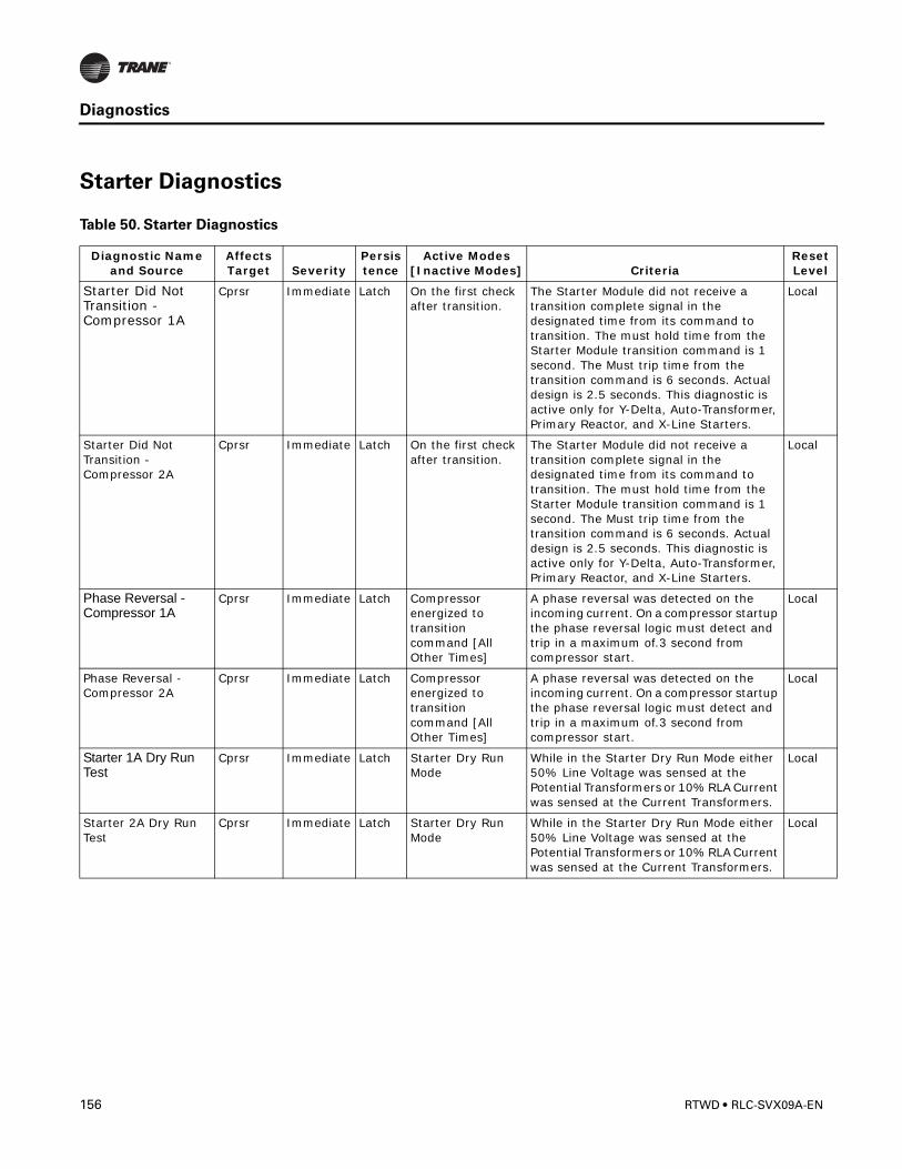
Diagnostics
Starter Diagnostics
Table 50. Starter Diagnostics
Diagnostic Name and Source
Affects Target Severity
Persistence
Active Modes [Inactive Modes] Criteria
Reset Level
Starter Did Not Transition - Compressor 1A
Cprsr Immediate Latch On the first check after transition.
The Starter Module did not receive a transition complete signal in the designated time from its command to transition. The must hold time from the Starter Module transition command is 1 second. The Must trip time from the transition command is 6 seconds. Actual design is 2.5 seconds. This diagnostic is active only for Y-Delta, Auto-Transformer, Primary Reactor, and X-Line Starters.
Local
Starter Did Not Transition - Compressor 2A
Cprsr Immediate Latch On the first check after transition.
The Starter Module did not receive a transition complete signal in the designated time from its command to transition. The must hold time from the Starter Module transition command is 1 second. The Must trip time from the transition command is 6 seconds. Actual design is 2.5 seconds. This diagnostic is active only for Y-Delta, Auto-Transformer, Primary Reactor, and X-Line Starters.
Local
Phase Reversal - Compressor 1A
Cprsr Immediate Latch Compressor energized to transition command [All Other Times]
A phase reversal was detected on the incoming current. On a compressor startup the phase reversal logic must detect and trip in a maximum of.3 second from compressor start.
Local
Phase Reversal - Compressor 2A
Cprsr Immediate Latch Compressor energized to transition command [All Other Times]
A phase reversal was detected on the incoming current. On a compressor startup the phase reversal logic must detect and trip in a maximum of.3 second from compressor start.
Local
Starter 1A Dry Run Test
Cprsr Immediate Latch Starter Dry Run Mode
While in the Starter Dry Run Mode either 50% Line Voltage was sensed at the Potential Transformers or 10% RLA Current was sensed at the Current Transformers.
Local
Starter 2A Dry Run Test
Cprsr Immediate Latch Starter Dry Run Mode
While in the Starter Dry Run Mode either 50% Line Voltage was sensed at the Potential Transformers or 10% RLA Current was sensed at the Current Transformers.
Local
156 RTWD • RLC-SVX09A-EN
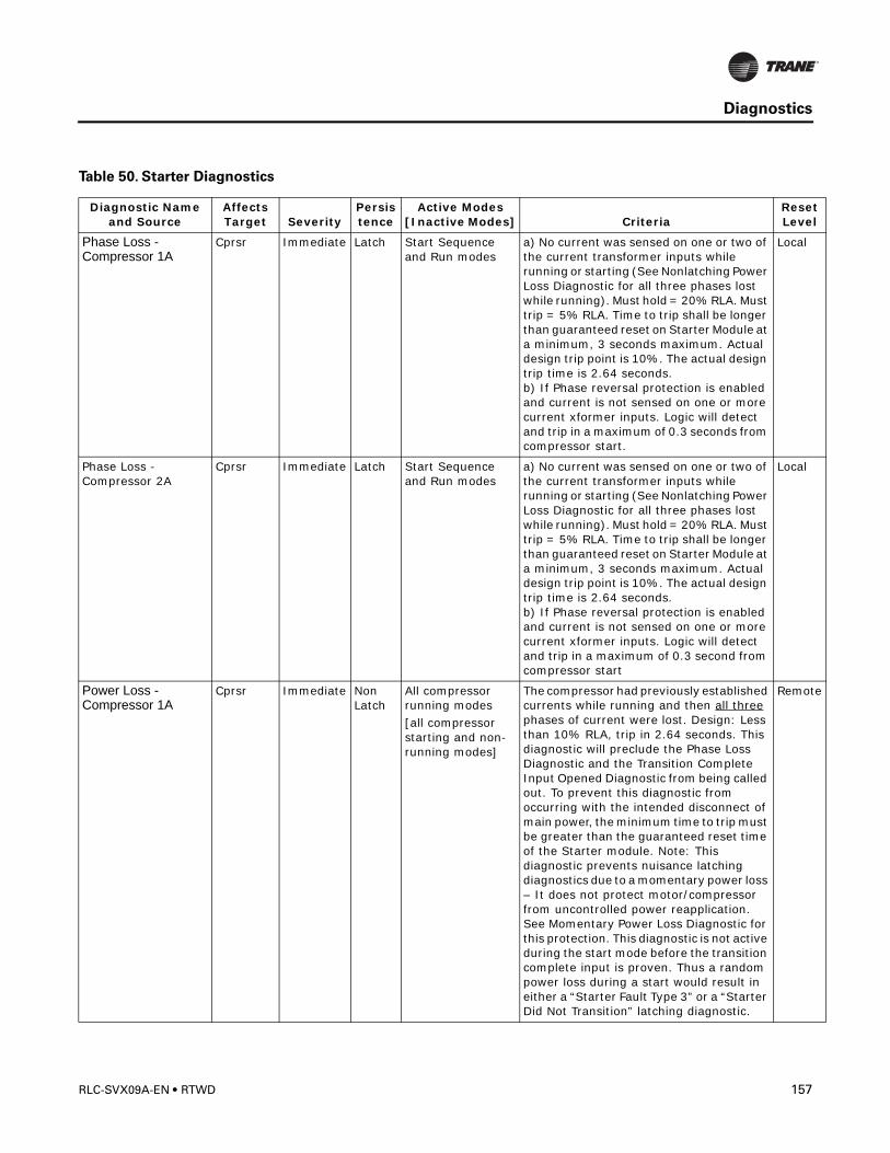
Diagnostics
Phase Loss - Compressor 1A
Cprsr Immediate Latch Start Sequence and Run modes
a) No current was sensed on one or two of the current transformer inputs while running or starting (See Nonlatching Power Loss Diagnostic for all three phases lost while running). Must hold = 20% RLA. Must trip = 5% RLA. Time to trip shall be longer than guaranteed reset on Starter Module at a minimum, 3 seconds maximum. Actual design trip point is 10%. The actual design trip time is 2.64 seconds.b) If Phase reversal protection is enabled and current is not sensed on one or more current xformer inputs. Logic will detect and trip in a maximum of 0.3 seconds from compressor start.
Local
Phase Loss - Compressor 2A
Cprsr Immediate Latch Start Sequence and Run modes
a) No current was sensed on one or two of the current transformer inputs while running or starting (See Nonlatching Power Loss Diagnostic for all three phases lost while running). Must hold = 20% RLA. Must trip = 5% RLA. Time to trip shall be longer than guaranteed reset on Starter Module at a minimum, 3 seconds maximum. Actual design trip point is 10%. The actual design trip time is 2.64 seconds. b) If Phase reversal protection is enabled and current is not sensed on one or more current xformer inputs. Logic will detect and trip in a maximum of 0.3 second from compressor start
Local
Power Loss - Compressor 1A
Cprsr Immediate Non Latch
All compressor running modes[all compressor starting and non-running modes]
The compressor had previously established currents while running and then all three phases of current were lost. Design: Less than 10% RLA, trip in 2.64 seconds. This diagnostic will preclude the Phase Loss Diagnostic and the Transition Complete Input Opened Diagnostic from being called out. To prevent this diagnostic from occurring with the intended disconnect of main power, the minimum time to trip must be greater than the guaranteed reset time of the Starter module. Note: This diagnostic prevents nuisance latching diagnostics due to a momentary power loss – It does not protect motor/compressor from uncontrolled power reapplication. See Momentary Power Loss Diagnostic for this protection. This diagnostic is not active during the start mode before the transition complete input is proven. Thus a random power loss during a start would result in either a “Starter Fault Type 3” or a “Starter Did Not Transition” latching diagnostic.
Remote
Table 50. Starter Diagnostics
Diagnostic Name and Source
Affects Target Severity
Persistence
Active Modes [Inactive Modes] Criteria
Reset Level
RLC-SVX09A-EN • RTWD 157
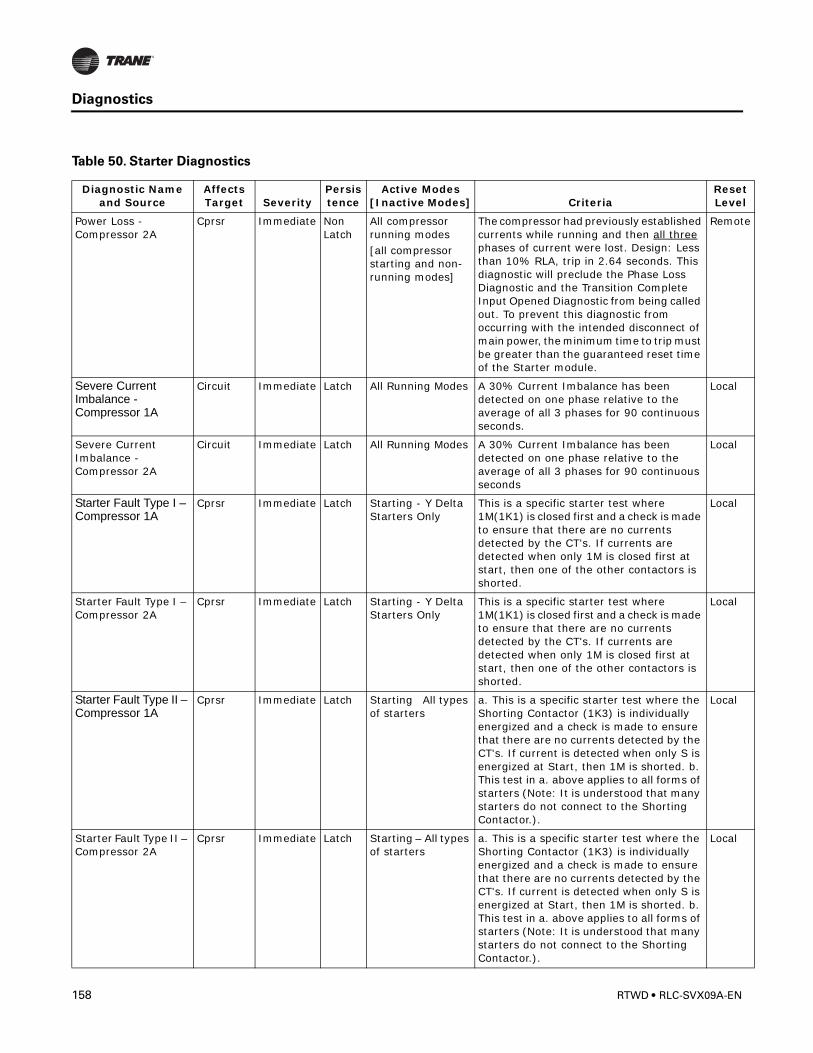
Diagnostics
Power Loss - Compressor 2A
Cprsr Immediate Non Latch
All compressor running modes[all compressor starting and non-running modes]
The compressor had previously established currents while running and then all three phases of current were lost. Design: Less than 10% RLA, trip in 2.64 seconds. This diagnostic will preclude the Phase Loss Diagnostic and the Transition Complete Input Opened Diagnostic from being called out. To prevent this diagnostic from occurring with the intended disconnect of main power, the minimum time to trip must be greater than the guaranteed reset time of the Starter module.
Remote
Severe Current Imbalance - Compressor 1A
Circuit Immediate Latch All Running Modes A 30% Current Imbalance has been detected on one phase relative to the average of all 3 phases for 90 continuous seconds.
Local
Severe Current Imbalance - Compressor 2A
Circuit Immediate Latch All Running Modes A 30% Current Imbalance has been detected on one phase relative to the average of all 3 phases for 90 continuous seconds
Local
Starter Fault Type I – Compressor 1A
Cprsr Immediate Latch Starting - Y Delta Starters Only
This is a specific starter test where 1M(1K1) is closed first and a check is made to ensure that there are no currents detected by the CT's. If currents are detected when only 1M is closed first at start, then one of the other contactors is shorted.
Local
Starter Fault Type I – Compressor 2A
Cprsr Immediate Latch Starting - Y Delta Starters Only
This is a specific starter test where 1M(1K1) is closed first and a check is made to ensure that there are no currents detected by the CT's. If currents are detected when only 1M is closed first at start, then one of the other contactors is shorted.
Local
Starter Fault Type II – Compressor 1A
Cprsr Immediate Latch Starting All types of starters
a. This is a specific starter test where the Shorting Contactor (1K3) is individually energized and a check is made to ensure that there are no currents detected by the CT's. If current is detected when only S is energized at Start, then 1M is shorted. b. This test in a. above applies to all forms of starters (Note: It is understood that many starters do not connect to the Shorting Contactor.).
Local
Starter Fault Type II – Compressor 2A
Cprsr Immediate Latch Starting – All types of starters
a. This is a specific starter test where the Shorting Contactor (1K3) is individually energized and a check is made to ensure that there are no currents detected by the CT's. If current is detected when only S is energized at Start, then 1M is shorted. b. This test in a. above applies to all forms of starters (Note: It is understood that many starters do not connect to the Shorting Contactor.).
Local
Table 50. Starter Diagnostics
Diagnostic Name and Source
Affects Target Severity
Persistence
Active Modes [Inactive Modes] Criteria
Reset Level
158 RTWD • RLC-SVX09A-EN
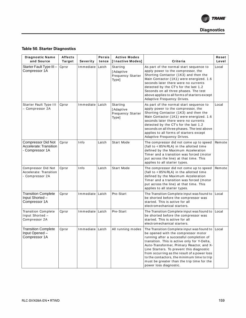
Diagnostics
Starter Fault Type III – Compressor 1A
Cprsr Immediate Latch Starting [Adaptive Frequency Starter Type]
As part of the normal start sequence to apply power to the compressor, the Shorting Contactor (1K3) and then the Main Contactor (1K1) were energized. 1.6 seconds later there were no currents detected by the CT's for the last 1.2 Seconds on all three phases. The test above applies to all forms of starters except Adaptive Frequency Drives.
Local
Starter Fault Type III – Compressor 2A
Cprsr Immediate Latch Starting [Adaptive Frequency Starter Type]
As part of the normal start sequence to apply power to the compressor, the Shorting Contactor (1K3) and then the Main Contactor (1K1) were energized. 1.6 seconds later there were no currents detected by the CT's for the last 1.2 seconds on all three phases. The test above applies to all forms of starters except Adaptive Frequency Drives.
Local
Compressor Did Not Accelerate: Transition - Compressor 1A
Cprsr Info Latch Start Mode The compressor did not come up to speed (fall to <85%RLA) in the allotted time defined by the Maximum Acceleration Timer and a transition was forced (motor put across the line) at that time. This applies to all starter types.
Remote
Compressor Did Not Accelerate: Transition - Compressor 2A
Cprsr Info Latch Start Mode The compressor did not come up to speed (fall to <85%RLA) in the allotted time defined by the Maximum Acceleration Timer and a transition was forced (motor put across the line) at that time. This applies to all starter types.
Remote
Transition Complete Input Shorted – Compressor 1A
Cprsr Immediate Latch Pre-Start The Transition Complete input was found to be shorted before the compressor was started. This is active for all electromechanical starters.
Local
Transition Complete Input Shorted – Compressor 2A
Cprsr Immediate Latch Pre-Start The Transition Complete input was found to be shorted before the compressor was started. This is active for all electromechanical starters.
Local
Transition Complete Input Opened – Compressor 1A
Cprsr Immediate Latch All running modes The Transition Complete input was found to be opened with the compressor motor running after a successful completion of transition. This is active only for Y-Delta, Auto-Transformer, Primary Reactor, and X-Line Starters. To prevent this diagnostic from occurring as the result of a power loss to the contactors, the minimum time to trip must be greater than the trip time for the power loss diagnostic.
Local
Table 50. Starter Diagnostics
Diagnostic Name and Source
Affects Target Severity
Persistence
Active Modes [Inactive Modes] Criteria
Reset Level
RLC-SVX09A-EN • RTWD 159
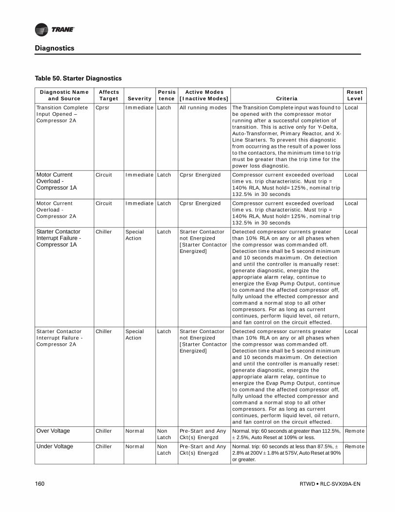
Diagnostics
Transition Complete Input Opened – Compressor 2A
Cprsr Immediate Latch All running modes The Transition Complete input was found to be opened with the compressor motor running after a successful completion of transition. This is active only for Y-Delta, Auto-Transformer, Primary Reactor, and X-Line Starters. To prevent this diagnostic from occurring as the result of a power loss to the contactors, the minimum time to trip must be greater than the trip time for the power loss diagnostic.
Local
Motor Current Overload - Compressor 1A
Circuit Immediate Latch Cprsr Energized Compressor current exceeded overload time vs. trip characteristic. Must trip = 140% RLA, Must hold=125%, nominal trip 132.5% in 30 seconds
Local
Motor Current Overload - Compressor 2A
Circuit Immediate Latch Cprsr Energized Compressor current exceeded overload time vs. trip characteristic. Must trip = 140% RLA, Must hold=125%, nominal trip 132.5% in 30 seconds
Local
Starter Contactor Interrupt Failure - Compressor 1A
Chiller Special Action
Latch Starter Contactor not Energized [Starter Contactor Energized]
Detected compressor currents greater than 10% RLA on any or all phases when the compressor was commanded off. Detection time shall be 5 second minimum and 10 seconds maximum. On detection and until the controller is manually reset: generate diagnostic, energize the appropriate alarm relay, continue to energize the Evap Pump Output, continue to command the affected compressor off, fully unload the effected compressor and command a normal stop to all other compressors. For as long as current continues, perform liquid level, oil return, and fan control on the circuit effected.
Local
Starter Contactor Interrupt Failure - Compressor 2A
Chiller Special Action
Latch Starter Contactor not Energized [Starter Contactor Energized]
Detected compressor currents greater than 10% RLA on any or all phases when the compressor was commanded off. Detection time shall be 5 second minimum and 10 seconds maximum. On detection and until the controller is manually reset: generate diagnostic, energize the appropriate alarm relay, continue to energize the Evap Pump Output, continue to command the affected compressor off, fully unload the effected compressor and command a normal stop to all other compressors. For as long as current continues, perform liquid level, oil return, and fan control on the circuit effected.
Local
Over Voltage Chiller Normal Non Latch
Pre-Start and Any Ckt(s) Energzd
Normal. trip: 60 seconds at greater than 112.5%, ± 2.5%, Auto Reset at 109% or less.
Remote
Under Voltage Chiller Normal Non Latch
Pre-Start and Any Ckt(s) Energzd
Normal. trip: 60 seconds at less than 87.5%, ± 2.8% at 200V ± 1.8% at 575V, Auto Reset at 90% or greater.
Remote
Table 50. Starter Diagnostics
Diagnostic Name and Source
Affects Target Severity
Persistence
Active Modes [Inactive Modes] Criteria
Reset Level
160 RTWD • RLC-SVX09A-EN
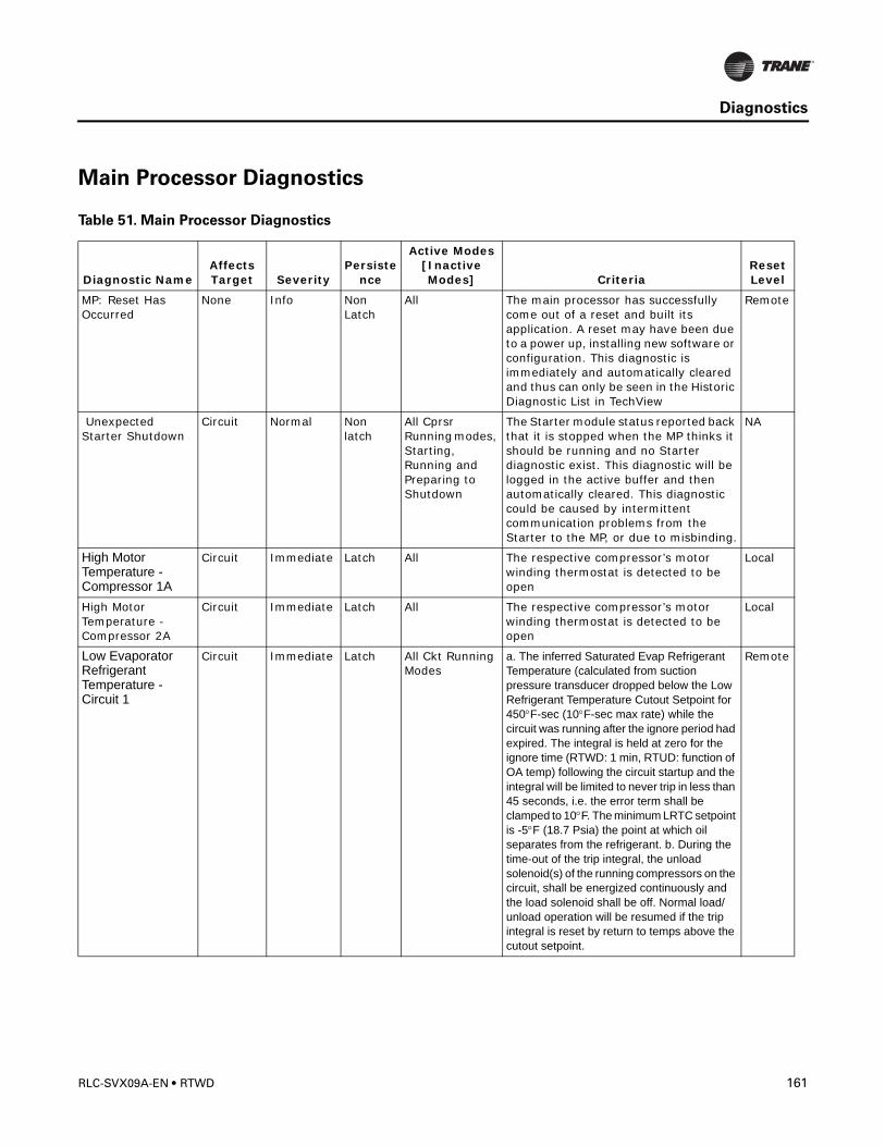
Diagnostics
Main Processor Diagnostics
Table 51. Main Processor Diagnostics
Diagnostic NameAffects Target Severity
Persistence
Active Modes [Inactive Modes] Criteria
Reset Level
MP: Reset Has Occurred
None Info Non Latch
All The main processor has successfully come out of a reset and built its application. A reset may have been due to a power up, installing new software or configuration. This diagnostic is immediately and automatically cleared and thus can only be seen in the Historic Diagnostic List in TechView
Remote
Unexpected Starter Shutdown
Circuit Normal Non latch
All Cprsr Running modes, Starting, Running and Preparing to Shutdown
The Starter module status reported back that it is stopped when the MP thinks it should be running and no Starter diagnostic exist. This diagnostic will be logged in the active buffer and then automatically cleared. This diagnostic could be caused by intermittent communication problems from the Starter to the MP, or due to misbinding.
NA
High Motor Temperature - Compressor 1A
Circuit Immediate Latch All The respective compressor’s motor winding thermostat is detected to be open
Local
High Motor Temperature - Compressor 2A
Circuit Immediate Latch All The respective compressor’s motor winding thermostat is detected to be open
Local
Low Evaporator Refrigerant Temperature - Circuit 1
Circuit Immediate Latch All Ckt Running Modes
a. The inferred Saturated Evap Refrigerant Temperature (calculated from suction pressure transducer dropped below the Low Refrigerant Temperature Cutout Setpoint for 450°F-sec (10°F-sec max rate) while the circuit was running after the ignore period had expired. The integral is held at zero for the ignore time (RTWD: 1 min, RTUD: function of OA temp) following the circuit startup and the integral will be limited to never trip in less than 45 seconds, i.e. the error term shall be clamped to 10°F. The minimum LRTC setpoint is -5°F (18.7 Psia) the point at which oil separates from the refrigerant. b. During the time-out of the trip integral, the unload solenoid(s) of the running compressors on the circuit, shall be energized continuously and the load solenoid shall be off. Normal load/unload operation will be resumed if the trip integral is reset by return to temps above the cutout setpoint.
Remote
RLC-SVX09A-EN • RTWD 161
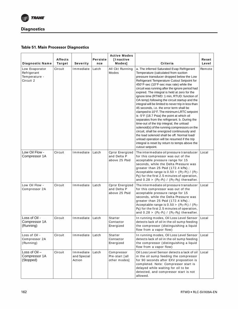
Diagnostics
Low Evaporator Refrigerant Temperature - Circuit 2
Circuit Immediate Latch All Ckt Running Modes
a. The inferred Saturated Evap Refrigerant Temperature (calculated from suction pressure transducer dropped below the Low Refrigerant Temperature Cutout Setpoint for 450°F-sec (10°F-sec max rate) while the circuit was running after the ignore period had expired. The integral is held at zero for the ignore time (RTWD: 1 min, RTUD: function of OA temp) following the circuit startup and the integral will be limited to never trip in less than 45 seconds, i.e. the error term shall be clamped to 10°F. The minimum LRTC setpoint is -5°F (18.7 Psia) the point at which oil separates from the refrigerant. b. During the time-out of the trip integral, the unload solenoid(s) of the running compressors on the circuit, shall be energized continuously and the load solenoid shall be off. Normal load/unload operation will be resumed if the trip integral is reset by return to temps above the cutout setpoint.
Remote
Low Oil Flow - Compressor 1A
Circuit Immediate Latch Cprsr Energized and Delta P above 25 Psid
The intermediate oil pressure transducer for this compressor was out of the acceptable pressure range for 15 seconds, while the Delta Pressure was greater than 25 Psid (172.4 kPa).: Acceptable range is 0.50 > (PC-PI) / (PC-PE) for the first 2.5 minutes of operation, and 0.28 > (PC-PI) / (PC-PE) thereafter.
Local
Low Oil Flow - Compressor 2A
Circuit Immediate Latch Cprsr Energized and Delta P above 25 Psid
The intermediate oil pressure transducer for this compressor was out of the acceptable pressure range for 15 seconds, while the Delta Pressure was greater than 25 Psid (172.4 kPa).: Acceptable range is 0.50 > (PC-PI) / (PC-PE) for the first 2.5 minutes of operation, and 0.28 > (PC-PI) / (PC-PE) thereafter.
Local
Loss of Oil - Compressor 1A (Running)
Circuit Immediate Latch Starter Contactor Energized
In running modes, Oil Loss Level Sensor detects lack of oil in the oil sump feeding the compressor (distinguishing a liquid flow from a vapor flow)
Local
Loss of Oil - Compressor 2A (Running)
Circuit Immediate Latch Starter Contactor Energized
In running modes, Oil Loss Level Sensor detects lack of oil in the oil sump feeding the compressor (distinguishing a liquid flow from a vapor flow)
Local
Loss of Oil – Compressor 1A (Stopped)
Circuit Immediate and Special Action
Latch Compressor Pre-start [all other modes]
Oil Loss Level Sensor detects a lack of oil in the oil sump feeding the compressor for 90 seconds after EXV preposition is completed. Note: Compressor start is delayed while waiting for oil to be detected, and compressor start is not allowed.
Local
Table 51. Main Processor Diagnostics
Diagnostic NameAffects Target Severity
Persistence
Active Modes [Inactive Modes] Criteria
Reset Level
162 RTWD • RLC-SVX09A-EN
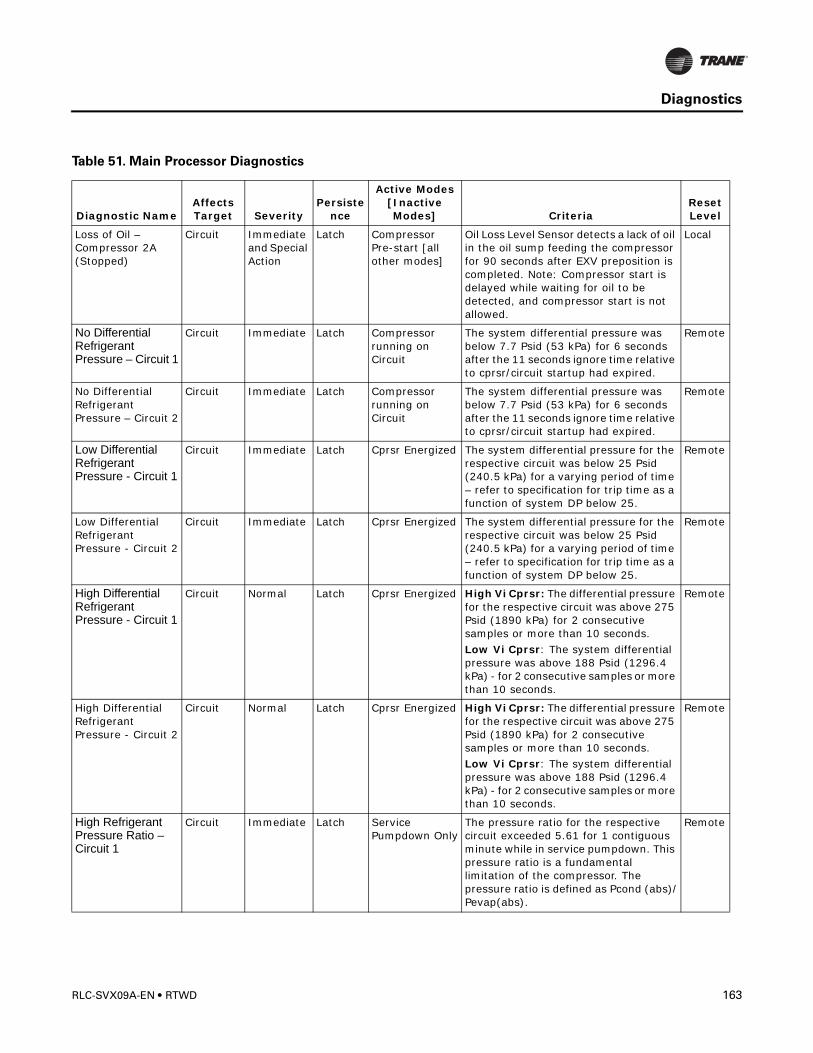
Diagnostics
Loss of Oil – Compressor 2A (Stopped)
Circuit Immediate and Special Action
Latch Compressor Pre-start [all other modes]
Oil Loss Level Sensor detects a lack of oil in the oil sump feeding the compressor for 90 seconds after EXV preposition is completed. Note: Compressor start is delayed while waiting for oil to be detected, and compressor start is not allowed.
Local
No Differential Refrigerant Pressure – Circuit 1
Circuit Immediate Latch Compressor running on Circuit
The system differential pressure was below 7.7 Psid (53 kPa) for 6 seconds after the 11 seconds ignore time relative to cprsr/circuit startup had expired.
Remote
No Differential Refrigerant Pressure – Circuit 2
Circuit Immediate Latch Compressor running on Circuit
The system differential pressure was below 7.7 Psid (53 kPa) for 6 seconds after the 11 seconds ignore time relative to cprsr/circuit startup had expired.
Remote
Low Differential Refrigerant Pressure - Circuit 1
Circuit Immediate Latch Cprsr Energized The system differential pressure for the respective circuit was below 25 Psid (240.5 kPa) for a varying period of time – refer to specification for trip time as a function of system DP below 25.
Remote
Low Differential Refrigerant Pressure - Circuit 2
Circuit Immediate Latch Cprsr Energized The system differential pressure for the respective circuit was below 25 Psid (240.5 kPa) for a varying period of time – refer to specification for trip time as a function of system DP below 25.
Remote
High Differential Refrigerant Pressure - Circuit 1
Circuit Normal Latch Cprsr Energized High Vi Cprsr: The differential pressure for the respective circuit was above 275 Psid (1890 kPa) for 2 consecutive samples or more than 10 seconds.Low Vi Cprsr: The system differential pressure was above 188 Psid (1296.4 kPa) - for 2 consecutive samples or more than 10 seconds.
Remote
High Differential Refrigerant Pressure - Circuit 2
Circuit Normal Latch Cprsr Energized High Vi Cprsr: The differential pressure for the respective circuit was above 275 Psid (1890 kPa) for 2 consecutive samples or more than 10 seconds.Low Vi Cprsr: The system differential pressure was above 188 Psid (1296.4 kPa) - for 2 consecutive samples or more than 10 seconds.
Remote
High Refrigerant Pressure Ratio – Circuit 1
Circuit Immediate Latch Service Pumpdown Only
The pressure ratio for the respective circuit exceeded 5.61 for 1 contiguous minute while in service pumpdown. This pressure ratio is a fundamental limitation of the compressor. The pressure ratio is defined as Pcond (abs)/Pevap(abs).
Remote
Table 51. Main Processor Diagnostics
Diagnostic NameAffects Target Severity
Persistence
Active Modes [Inactive Modes] Criteria
Reset Level
RLC-SVX09A-EN • RTWD 163

Diagnostics
High Refrigerant Pressure Ratio – Circuit 2
Circuit Immediate Latch Service Pumpdown Only
The pressure ratio for the respective circuit exceeded 5.61 for 1 contiguous minute while in service pumpdown. This pressure ratio is a fundamental limitation of the compressor. The pressure ratio is defined as Pcond (abs)/Pevap(abs).
Remote
High Discharge Temperature – Compressor 1A
Circuit Immediate Latch All[compressor run unload or compressor not running]
The compressor discharge temperature exceeded 200°F (without oil cooler) or 230ºF (with oil cooler). This diagnostic will be suppressed during Run-Unload or after the compressor has stopped. Note: As part of the Compressor High Temperature Limit Mode (aka Minimum Capacity Limit), the compressor shall be forced loaded as the filtered discharge temperature reaches 190ºF(without oil coolers), or 220ºF (with oil coolers).
Remote
High Discharge Temperature – Compressor 2A
Circuit Immediate Latch All[compressor run unload or compressor not running]
The compressor discharge temperature exceeded 200°F (without oil cooler) or 230ºF (with oil cooler). This diagnostic will be suppressed during Run-Unload or after the compressor has stopped. Note: As part of the Compressor High Temperature Limit Mode (aka Minimum Capacity Limit), the compressor shall be forced loaded as the filtered discharge temperature reaches 190ºF(without oil coolers), or 220ºF (with oil coolers).
Remote
Low Discharge Superheat – Circuit 1
Circuit Normal Latch Any Running Mode
While Running Normally, the Discharge Superheat was less than 12 degrees F +- 1F for more than 6500 degree F seconds. At circuit startup the Discharge Superheat will be ignored for 5 minutes.
Remote
Low Discharge Superheat – Circuit 2
Circuit Normal Latch Any Running Mode
While Running Normally, the Discharge Superheat was less than 12 degrees F +- 1F for more than 6500 degree F seconds. At circuit startup the Discharge Superheat will be ignored for 5 minutes.
Remote
Discharge Temperature Sensor – Compressor 1A
Circuit Immediate Latch All Bad Sensor or LLID Remote
Discharge Temperature Sensor – Compressor 2A
Circuit Immediate Latch All Bad Sensor or LLID Remote
Evaporator Liquid Level Sensor – Circuit 1
Circuit Normal Latch All Bad Sensor or LLID Remote
Table 51. Main Processor Diagnostics
Diagnostic NameAffects Target Severity
Persistence
Active Modes [Inactive Modes] Criteria
Reset Level
164 RTWD • RLC-SVX09A-EN
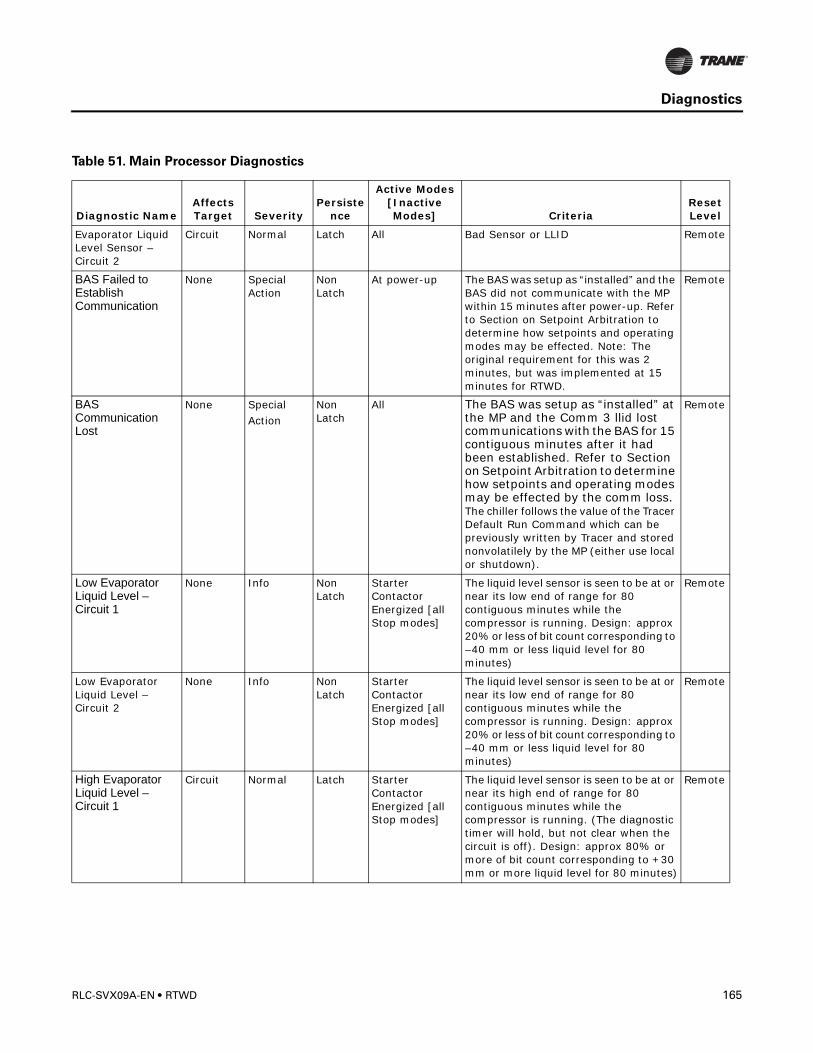
Diagnostics
Evaporator Liquid Level Sensor – Circuit 2
Circuit Normal Latch All Bad Sensor or LLID Remote
BAS Failed to Establish Communication
None Special Action
Non Latch
At power-up The BAS was setup as “installed” and the BAS did not communicate with the MP within 15 minutes after power-up. Refer to Section on Setpoint Arbitration to determine how setpoints and operating modes may be effected. Note: The original requirement for this was 2 minutes, but was implemented at 15 minutes for RTWD.
Remote
BAS Communication Lost
None SpecialAction
Non Latch
All The BAS was setup as “installed” at the MP and the Comm 3 llid lost communications with the BAS for 15 contiguous minutes after it had been established. Refer to Section on Setpoint Arbitration to determine how setpoints and operating modes may be effected by the comm loss. The chiller follows the value of the Tracer Default Run Command which can be previously written by Tracer and stored nonvolatilely by the MP (either use local or shutdown).
Remote
Low Evaporator Liquid Level – Circuit 1
None Info Non Latch
Starter Contactor Energized [all Stop modes]
The liquid level sensor is seen to be at or near its low end of range for 80 contiguous minutes while the compressor is running. Design: approx 20% or less of bit count corresponding to –40 mm or less liquid level for 80 minutes)
Remote
Low Evaporator Liquid Level – Circuit 2
None Info Non Latch
Starter Contactor Energized [all Stop modes]
The liquid level sensor is seen to be at or near its low end of range for 80 contiguous minutes while the compressor is running. Design: approx 20% or less of bit count corresponding to –40 mm or less liquid level for 80 minutes)
Remote
High Evaporator Liquid Level – Circuit 1
Circuit Normal Latch Starter Contactor Energized [all Stop modes]
The liquid level sensor is seen to be at or near its high end of range for 80 contiguous minutes while the compressor is running. (The diagnostic timer will hold, but not clear when the circuit is off). Design: approx 80% or more of bit count corresponding to +30 mm or more liquid level for 80 minutes)
Remote
Table 51. Main Processor Diagnostics
Diagnostic NameAffects Target Severity
Persistence
Active Modes [Inactive Modes] Criteria
Reset Level
RLC-SVX09A-EN • RTWD 165
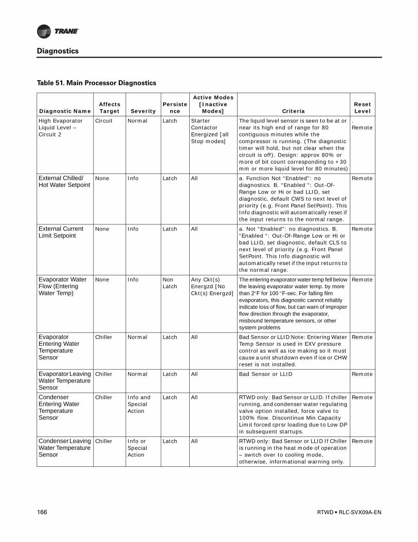
Diagnostics
High Evaporator Liquid Level – Circuit 2
Circuit Normal Latch Starter Contactor Energized [all Stop modes]
The liquid level sensor is seen to be at or near its high end of range for 80 contiguous minutes while the compressor is running. (The diagnostic timer will hold, but not clear when the circuit is off). Design: approx 80% or more of bit count corresponding to +30 mm or more liquid level for 80 minutes)
. Remote
External Chilled/Hot Water Setpoint
None Info Latch All a. Function Not “Enabled”: no diagnostics. B. “Enabled “: Out-Of-Range Low or Hi or bad LLID, set diagnostic, default CWS to next level of priority (e.g. Front Panel SetPoint). This Info diagnostic will automatically reset if the input returns to the normal range.
Remote
External Current Limit Setpoint
None Info Latch All a. Not “Enabled”: no diagnostics. B. “Enabled “: Out-Of-Range Low or Hi or bad LLID, set diagnostic, default CLS to next level of priority (e.g. Front Panel SetPoint. This Info diagnostic will automatically reset if the input returns to the normal range.
Remote
Evaporator Water Flow (Entering Water Temp)
None Info Non Latch
Any Ckt(s) Energzd [No Ckt(s) Energzd]
The entering evaporator water temp fell below the leaving evaporator water temp. by more than 2°F for 100 °F-sec. For falling film evaporators, this diagnostic cannot reliably indicate loss of flow, but can warn of improper flow direction through the evaporator, misbound temperature sensors, or other system problems
Remote
Evaporator Entering Water Temperature Sensor
Chiller Normal Latch All Bad Sensor or LLID Note: Entering Water Temp Sensor is used in EXV pressure control as well as ice making so it must cause a unit shutdown even if ice or CHW reset is not installed.
Remote
Evaporator Leaving Water Temperature Sensor
Chiller Normal Latch All Bad Sensor or LLID Remote
Condenser Entering Water Temperature Sensor
Chiller Info and Special Action
Latch All RTWD only: Bad Sensor or LLID. If chiller running, and condenser water regulating valve option installed, force valve to 100% flow. Discontinue Min Capacity Limit forced cprsr loading due to Low DP in subsequent startups.
Remote
Condenser Leaving Water Temperature Sensor
Chiller Info or Special Action
Latch All RTWD only: Bad Sensor or LLID If Chiller is running in the heat mode of operation – switch over to cooling mode, otherwise, informational warning only.
Remote
Table 51. Main Processor Diagnostics
Diagnostic NameAffects Target Severity
Persistence
Active Modes [Inactive Modes] Criteria
Reset Level
166 RTWD • RLC-SVX09A-EN
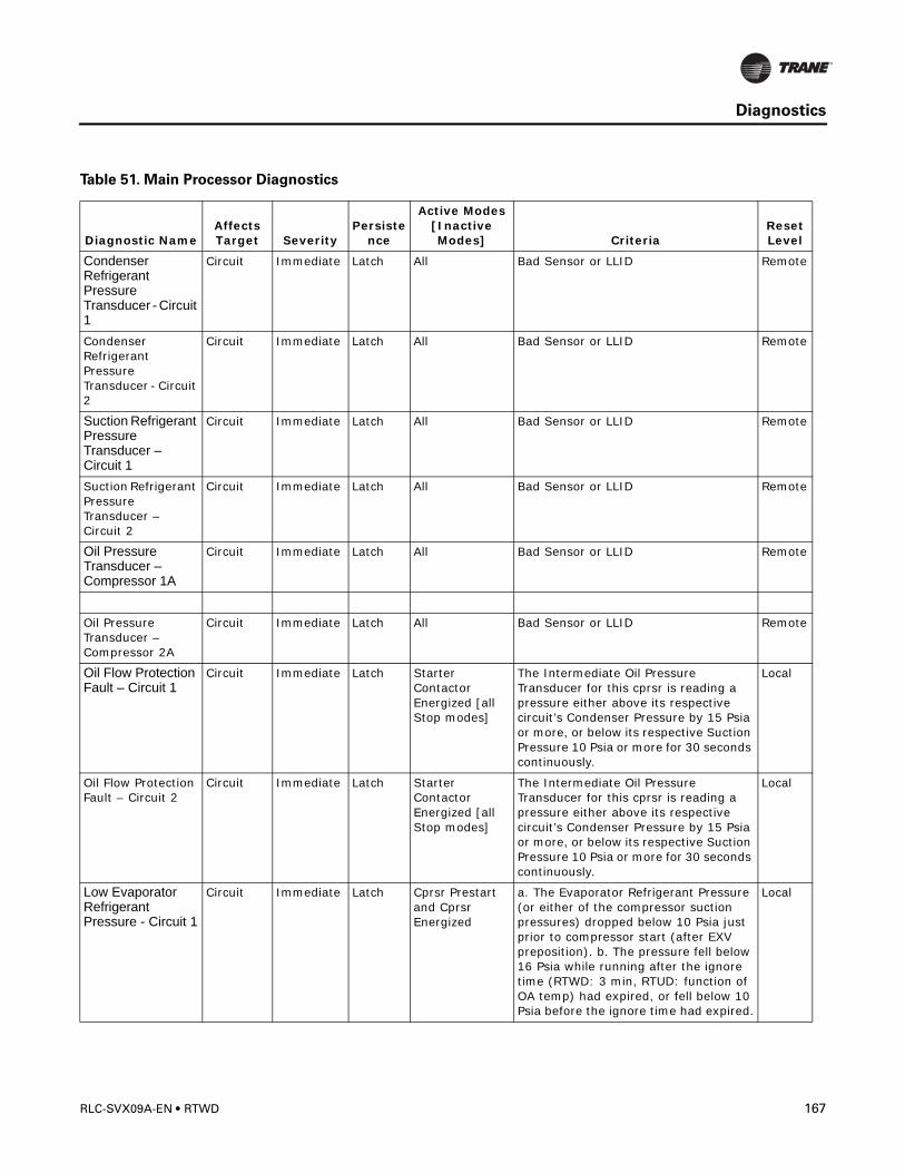
Diagnostics
Condenser Refrigerant Pressure Transducer - Circuit 1
Circuit Immediate Latch All Bad Sensor or LLID Remote
Condenser Refrigerant Pressure Transducer - Circuit 2
Circuit Immediate Latch All Bad Sensor or LLID Remote
Suction Refrigerant Pressure Transducer – Circuit 1
Circuit Immediate Latch All Bad Sensor or LLID Remote
Suction Refrigerant Pressure Transducer – Circuit 2
Circuit Immediate Latch All Bad Sensor or LLID Remote
Oil Pressure Transducer – Compressor 1A
Circuit Immediate Latch All Bad Sensor or LLID Remote
Oil Pressure Transducer – Compressor 2A
Circuit Immediate Latch All Bad Sensor or LLID Remote
Oil Flow Protection Fault – Circuit 1
Circuit Immediate Latch Starter Contactor Energized [all Stop modes]
The Intermediate Oil Pressure Transducer for this cprsr is reading a pressure either above its respective circuit’s Condenser Pressure by 15 Psia or more, or below its respective Suction Pressure 10 Psia or more for 30 seconds continuously.
Local
Oil Flow Protection Fault – Circuit 2
Circuit Immediate Latch Starter Contactor Energized [all Stop modes]
The Intermediate Oil Pressure Transducer for this cprsr is reading a pressure either above its respective circuit’s Condenser Pressure by 15 Psia or more, or below its respective Suction Pressure 10 Psia or more for 30 seconds continuously.
Local
Low Evaporator Refrigerant Pressure - Circuit 1
Circuit Immediate Latch Cprsr Prestart and Cprsr Energized
a. The Evaporator Refrigerant Pressure (or either of the compressor suction pressures) dropped below 10 Psia just prior to compressor start (after EXV preposition). b. The pressure fell below 16 Psia while running after the ignore time (RTWD: 3 min, RTUD: function of OA temp) had expired, or fell below 10 Psia before the ignore time had expired.
Local
Table 51. Main Processor Diagnostics
Diagnostic NameAffects Target Severity
Persistence
Active Modes [Inactive Modes] Criteria
Reset Level
RLC-SVX09A-EN • RTWD 167
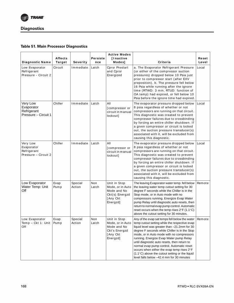
Diagnostics
Low Evaporator Refrigerant Pressure - Circuit 2
Circuit Immediate Latch Cprsr Prestart and Cprsr Energized
a. The Evaporator Refrigerant Pressure (or either of the compressor suction pressures) dropped below 10 Psia just prior to compressor start (after EXV preposition). b. The pressure fell below 16 Psia while running after the ignore time (RTWD: 3 min, RTUD: function of OA temp) had expired, or fell below 10 Psia before the ignore time had expired.
Local
Very Low Evaporator Refrigerant Pressure – Circuit 1
Chiller Immediate Latch All[compressor or circuit in manual lockout]
The evaporator pressure dropped below 8 psia regardless of whether or not compressors are running on that circuit. This diagnostic was created to prevent compressor failures due to crossbinding by forcing an entire chiller shutdown. If a given compressor or circuit is locked out, the suction pressure transducer(s) associated with it, will be excluded from causing this diagnostic.
Local
Very Low Evaporator Refrigerant Pressure – Circuit 2
Chiller Immediate Latch All[compressor or circuit in manual lockout]
The evaporator pressure dropped below 8 psia regardless of whether or not compressors are running on that circuit. This diagnostic was created to prevent compressor failures due to crossbinding by forcing an entire chiller shutdown. If a given compressor or circuit is locked out, the suction pressure transducer(s) associated with it, will be excluded from causing this diagnostic.
Local
Low Evaporator Water Temp: Unit Off
Evap Pump
Special Action
Non Latch
Unit in Stop Mode, or in Auto Mode and No Ckt(s) Energzd [Any Ckt Energzd]
The leaving Evaporator water temp. fell below the leaving water temp cutout setting for 30 degree F seconds while the Chiller is in the Stop mode, or in Auto mode with no compressors running. Energize Evap Water pump Relay until diagnostic auto resets, then return to normal evap pump control. Automatic reset occurs when the temp rises 2°F (1.1°C) above the cutout setting for 30 minutes.
Remote
Low Evaporator Temp – Ckt 1: Unit Off
Evap Pump
Special Action
Non Latch
Unit in Stop Mode, or in Auto Mode and No Ckt's Energzd [Any Ckt Energzd]
Any of the evap sat temps fell below the water temp cutout setting while the respective evap liquid level was greater than –21.2mm for 30 degree F seconds while Chiller is in the Stop mode, or in Auto mode with no compressors running. Energize Evap Water pump Relay until diagnostic auto resets, then return to normal evap pump control. Automatic reset occurs when either the evap temp rises 2°F (1.1°C) above the cutout setting or the liquid level falls below –42.4 mm for 30 minutes
Remote
Table 51. Main Processor Diagnostics
Diagnostic NameAffects Target Severity
Persistence
Active Modes [Inactive Modes] Criteria
Reset Level
168 RTWD • RLC-SVX09A-EN
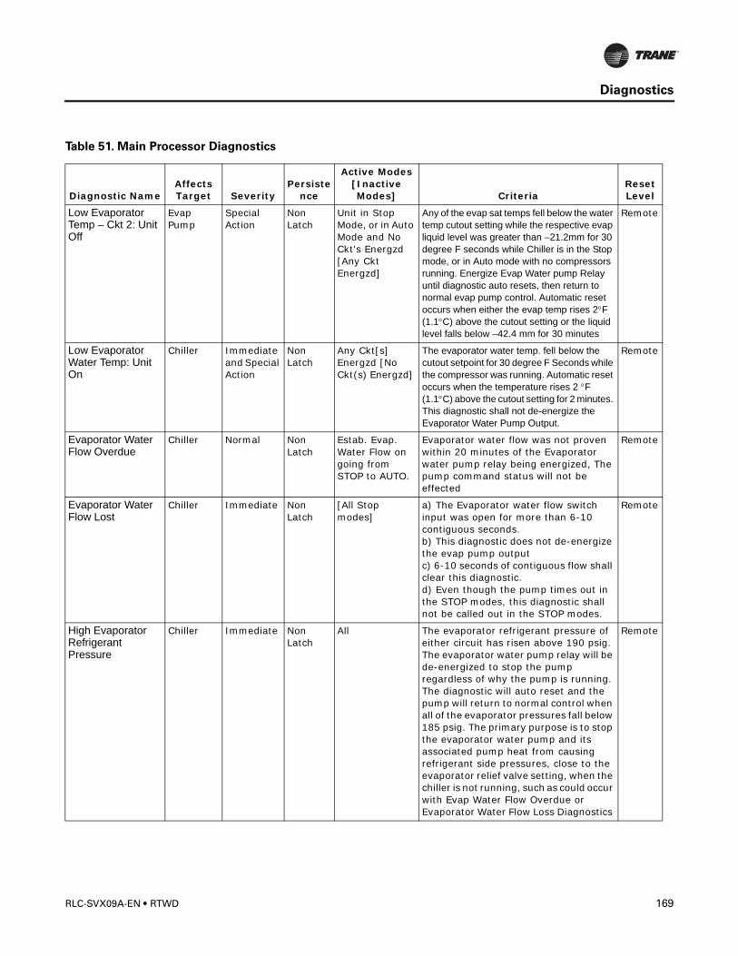
Diagnostics
Low Evaporator Temp – Ckt 2: Unit Off
Evap Pump
Special Action
Non Latch
Unit in Stop Mode, or in Auto Mode and No Ckt's Energzd [Any Ckt Energzd]
Any of the evap sat temps fell below the water temp cutout setting while the respective evap liquid level was greater than –21.2mm for 30 degree F seconds while Chiller is in the Stop mode, or in Auto mode with no compressors running. Energize Evap Water pump Relay until diagnostic auto resets, then return to normal evap pump control. Automatic reset occurs when either the evap temp rises 2°F (1.1°C) above the cutout setting or the liquid level falls below –42.4 mm for 30 minutes
Remote
Low Evaporator Water Temp: Unit On
Chiller Immediate and Special Action
Non Latch
Any Ckt[s] Energzd [No Ckt(s) Energzd]
The evaporator water temp. fell below the cutout setpoint for 30 degree F Seconds while the compressor was running. Automatic reset occurs when the temperature rises 2 °F (1.1°C) above the cutout setting for 2 minutes. This diagnostic shall not de-energize the Evaporator Water Pump Output.
Remote
Evaporator Water Flow Overdue
Chiller Normal Non Latch
Estab. Evap. Water Flow on going from STOP to AUTO.
Evaporator water flow was not proven within 20 minutes of the Evaporator water pump relay being energized, The pump command status will not be effected
Remote
Evaporator Water Flow Lost
Chiller Immediate Non Latch
[All Stop modes]
a) The Evaporator water flow switch input was open for more than 6-10 contiguous seconds. b) This diagnostic does not de-energize the evap pump output c) 6-10 seconds of contiguous flow shall clear this diagnostic. d) Even though the pump times out in the STOP modes, this diagnostic shall not be called out in the STOP modes.
Remote
High Evaporator Refrigerant Pressure
Chiller Immediate Non Latch
All The evaporator refrigerant pressure of either circuit has risen above 190 psig. The evaporator water pump relay will be de-energized to stop the pump regardless of why the pump is running. The diagnostic will auto reset and the pump will return to normal control when all of the evaporator pressures fall below 185 psig. The primary purpose is to stop the evaporator water pump and its associated pump heat from causing refrigerant side pressures, close to the evaporator relief valve setting, when the chiller is not running, such as could occur with Evap Water Flow Overdue or Evaporator Water Flow Loss Diagnostics
Remote
Table 51. Main Processor Diagnostics
Diagnostic NameAffects Target Severity
Persistence
Active Modes [Inactive Modes] Criteria
Reset Level
RLC-SVX09A-EN • RTWD 169
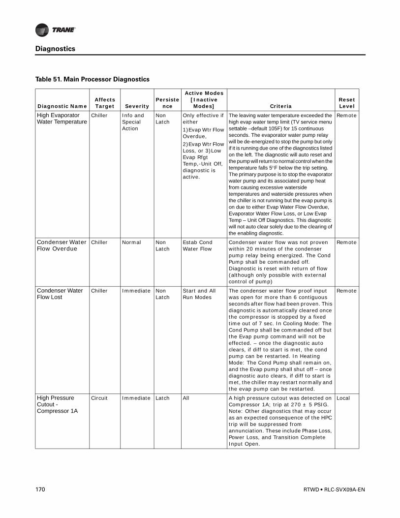
Diagnostics
High Evaporator Water Temperature
Chiller Info and Special Action
Non Latch
Only effective if either 1)Evap Wtr Flow Overdue,2)Evap Wtr Flow Loss, or 3)Low Evap Rfgt Temp,-Unit Off, diagnostic is active.
The leaving water temperature exceeded the high evap water temp limit (TV service menu settable –default 105F) for 15 continuous seconds. The evaporator water pump relay will be de-energized to stop the pump but only if it is running due one of the diagnostics listed on the left. The diagnostic will auto reset and the pump will return to normal control when the temperature falls 5°F below the trip setting. The primary purpose is to stop the evaporator water pump and its associated pump heat from causing excessive waterside temperatures and waterside pressures when the chiller is not running but the evap pump is on due to either Evap Water Flow Overdue, Evaporator Water Flow Loss, or Low Evap Temp – Unit Off Diagnostics. This diagnostic will not auto clear solely due to the clearing of the enabling diagnostic.
Remote
Condenser Water Flow Overdue
Chiller Normal Non Latch
Estab Cond Water Flow
Condenser water flow was not proven within 20 minutes of the condenser pump relay being energized. The Cond Pump shall be commanded off. Diagnostic is reset with return of flow (although only possible with external control of pump)
Remote
Condenser Water Flow Lost
Chiller Immediate Non Latch
Start and All Run Modes
The condenser water flow proof input was open for more than 6 contiguous seconds after flow had been proven. This diagnostic is automatically cleared once the compressor is stopped by a fixed time out of 7 sec. In Cooling Mode: The Cond Pump shall be commanded off but the Evap pump command will not be effected. – once the diagnostic auto clears, if diff to start is met, the cond pump can be restarted. In Heating Mode: The Cond Pump shall remain on, and the Evap pump shall shut off – once diagnostic auto clears, if diff to start is met, the chiller may restart normally and the evap pump can be restarted.
Remote
High Pressure Cutout - Compressor 1A
Circuit Immediate Latch All A high pressure cutout was detected on Compressor 1A; trip at 270 ± 5 PSIG. Note: Other diagnostics that may occur as an expected consequence of the HPC trip will be suppressed from annunciation. These include Phase Loss, Power Loss, and Transition Complete Input Open.
Local
Table 51. Main Processor Diagnostics
Diagnostic NameAffects Target Severity
Persistence
Active Modes [Inactive Modes] Criteria
Reset Level
170 RTWD • RLC-SVX09A-EN
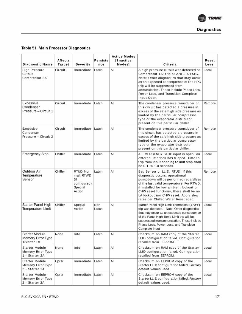
Diagnostics
High Pressure Cutout - Compressor 2A
Circuit Immediate Latch All A high pressure cutout was detected on Compressor 1A; trip at 270 ± 5 PSIG. Note: Other diagnostics that may occur as an expected consequence of the HPC trip will be suppressed from annunciation. These include Phase Loss, Power Loss, and Transition Complete Input Open.
Local
Excessive Condenser Pressure – Circuit 1
Circuit Immediate Latch All The condenser pressure transducer of this circuit has detected a pressure in excess of the safe high side pressure as limited by the particular compressor type or the evaporator distributor present on this particular chiller
Remote
Excessive Condenser Pressure – Circuit 2
Circuit Immediate Latch All The condenser pressure transducer of this circuit has detected a pressure in excess of the safe high side pressure as limited by the particular compressor type or the evaporator distributor present on this particular chiller
Remote
Emergency Stop Chiller Immediate Latch All a. EMERGENCY STOP input is open. An external interlock has tripped. Time to trip from input opening to unit stop shall be 0.1 to 1.0 seconds.
Local
Outdoor Air Temperature Sensor
Chiller RTUD:Normal, RTWD (if configured) Special Action
Latch All Bad Sensor or LLID. RTUD: if this diagnostic occurs, operational pumpdown will be performed regardless of the last valid temperature. For RTWD, if installed for low ambient lockout or CHW reset functions, there shall be no LA lockout nor CHW reset. Apply slew rates per Chilled Water Reset spec.
Remote
Starter Panel High Temperature Limit
Chiller Special Action
Non Latch
All Starter Panel High Limit Thermostat (170°F) trip was detected. Note: Other diagnostics that may occur as an expected consequence of the Panel High Temp Limit trip will be suppressed from annunciation. These include Phase Loss, Power Loss, and Transition Complete Input
Local
Starter Module Memory Error Type 1Starter 1A
None Info Latch All Checksum on RAM copy of the Starter LLID configuration failed. Configuration recalled from EEPROM.
Local
Starter Module Memory Error Type 1 - Starter 2A
None Info Latch All Checksum on RAM copy of the Starter LLID configuration failed. Configuration recalled from EEPROM.
Local
Starter Module Memory Error Type 2 - Starter 1A
Cprsr Immediate Latch All Checksum on EEPROM copy of the Starter LLID configuration failed. Factory default values used.
Local
Starter Module Memory Error Type 2 - Starter 2A
Cprsr Immediate Latch All Checksum on EEPROM copy of the Starter LLID configuration failed. Factory default values used.
Local
Table 51. Main Processor Diagnostics
Diagnostic NameAffects Target Severity
Persistence
Active Modes [Inactive Modes] Criteria
Reset Level
RLC-SVX09A-EN • RTWD 171
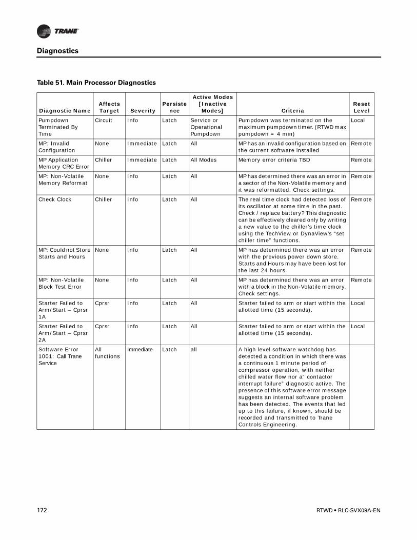
Diagnostics
Pumpdown Terminated By Time
Circuit Info Latch Service or Operational Pumpdown
Pumpdown was terminated on the maximum pumpdown timer. (RTWD max pumpdown = 4 min)
Local
MP: Invalid Configuration
None Immediate Latch All MP has an invalid configuration based on the current software installed
Remote
MP Application Memory CRC Error
Chiller Immediate Latch All Modes Memory error criteria TBD Remote
MP: Non-Volatile Memory Reformat
None Info Latch All MP has determined there was an error in a sector of the Non-Volatile memory and it was reformatted. Check settings.
Remote
Check Clock Chiller Info Latch All The real time clock had detected loss of its oscillator at some time in the past. Check / replace battery? This diagnostic can be effectively cleared only by writing a new value to the chiller’s time clock using the TechView or DynaView’s “set chiller time” functions.
Remote
MP: Could not Store Starts and Hours
None Info Latch All MP has determined there was an error with the previous power down store. Starts and Hours may have been lost for the last 24 hours.
Remote
MP: Non-Volatile Block Test Error
None Info Latch All MP has determined there was an error with a block in the Non-Volatile memory. Check settings.
Remote
Starter Failed to Arm/Start – Cprsr 1A
Cprsr Info Latch All Starter failed to arm or start within the allotted time (15 seconds).
Local
Starter Failed to Arm/Start – Cprsr 2A
Cprsr Info Latch All Starter failed to arm or start within the allotted time (15 seconds).
Local
Software Error 1001: Call Trane Service
All functions
Immediate Latch all A high level software watchdog has detected a condition in which there was a continuous 1 minute period of compressor operation, with neither chilled water flow nor a” contactor interrupt failure” diagnostic active. The presence of this software error message suggests an internal software problem has been detected. The events that led up to this failure, if known, should be recorded and transmitted to Trane Controls Engineering.
Table 51. Main Processor Diagnostics
Diagnostic NameAffects Target Severity
Persistence
Active Modes [Inactive Modes] Criteria
Reset Level
172 RTWD • RLC-SVX09A-EN
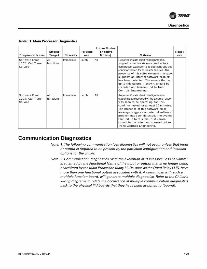
Diagnostics
Communication DiagnosticsNote: 1. The following communication loss diagnostics will not occur unless that input
or output is required to be present by the particular configuration and installed options for the chiller.
Note: 2. Communication diagnostics (with the exception of “Excessive Loss of Comm” are named by the Functional Name of the input or output that is no longer being heard from by the Main Processor. Many LLIDs, such as the Quad Relay LLID, have more than one functional output associated with it. A comm loss with such a multiple function board, will generate multiple diagnostics. Refer to the Chiller's wiring diagrams to relate the occurrence of multiple communication diagnostics back to the physical llid boards that they have been assigned to (bound).
Software Error 1002: Call Trane Service
All functions
Immediate Latch All Reported if state chart misalignment in stopped or inactive state occurred while a compressor was seen to be operating and this condition lasted for at least 5 minutes. The presence of this software error message suggests an internal software problem has been detected. The events that led up to this failure, if known, should be recorded and transmitted to Trane Controls Engineering.
Software Error 1003: Call Trane Service
All functions
Immediate Latch All Reported if state chart misalignment in stopping state occurred while a compressor was seen to be operating and this condition lasted for at least 10 minutes. The presence of this software error message suggests an internal software problem has been detected. The events that led up to this failure, if known, should be recorded and transmitted to Trane Controls Engineering.
Table 51. Main Processor Diagnostics
Diagnostic NameAffects Target Severity
Persistence
Active Modes [Inactive Modes] Criteria
Reset Level
RLC-SVX09A-EN • RTWD 173
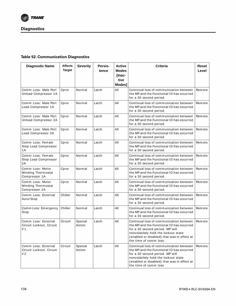
Diagnostics
Table 52. Communication Diagnostics
Diagnostic Name Affects Target
Severity Persis-tence
Active Modes [Inac-tive
Modes]
Criteria Reset Level
Comm Loss: Male Port Unload Compressor 1A
Cprsr Normal Latch All Continual loss of communication between the MP and the Functional ID has occurred for a 30 second period.
Remote
Comm Loss: Male Port Load Compressor 1A
Cprsr Normal Latch All Continual loss of communication between the MP and the Functional ID has occurred for a 30 second period.
Remote
Comm Loss: Male Port Unload Compressor 2A
Cprsr Normal Latch All Continual loss of communication between the MP and the Functional ID has occurred for a 30 second period.
Remote
Comm Loss: Male Port Load Compressor 2A
Cprsr Normal Latch All Continual loss of communication between the MP and the Functional ID has occurred for a 30 second period.
Remote
Comm Loss: Female Step Load Compressor 1A
Cprsr Normal Latch All Continual loss of communication between the MP and the Functional ID has occurred for a 30 second period.
Remote
Comm Loss: Female Step Load Compressor 2A
Cprsr Normal Latch All Continual loss of communication between the MP and the Functional ID has occurred for a 30 second period.
Remote
Comm Loss: Motor Winding Thermostat Compressor 1A
Cprsr Normal Latch All Continual loss of communication between the MP and the Functional ID has occurred for a 30 second period.
Remote
Comm Loss: Motor Winding Thermostat Compressor 2A
Cprsr Normal Latch All Continual loss of communication between the MP and the Functional ID has occurred for a 30 second period.
Remote
Comm Loss: External Auto/Stop
Chiller Normal Latch All Continual loss of communication between the MP and the Functional ID has occurred for a 30 second period.
Remote
Comm Loss: Emergency Stop
Chiller Normal Latch All Continual loss of communication between the MP and the Functional ID has occurred for a 30 second period.
Remote
Comm Loss: External Circuit Lockout, Circuit #1
Circuit Special Action
Latch All Continual loss of communication between the MP and the Functional ID has occurred for a 30 second period. MP will nonvolatilely hold the lockout state (enabled or disabled) that was in effect at the time of comm loss.
Remote
Comm Loss: External Circuit Lockout, Circuit #2
Circuit Special Action
Latch All Continual loss of communication between the MP and the Functional ID has occurred for a 30 second period. MP will nonvolatilely hold the lockout state (enabled or disabled) that was in effect at the time of comm loss
Remote
174 RTWD • RLC-SVX09A-EN
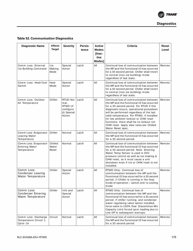
Diagnostics
Comm Loss: External Ice Building Command
Ice Making Mode
Special Action
Latch All Continual loss of communication between the MP and the Functional ID has occurred for a 30 second period. Chiller shall revert to normal (non-ice building) mode regardless of last state.
Remote
Comm Loss: Heat/Cool Switch
Heat Mode
Special Action
Latch All Continual loss of communication between the MP and the Functional ID has occurred for a 30 second period. Chiller shall revert to normal (non-ice building) mode regardless of last state.
Remote
Comm Loss: Outdoor Air Temperature
Chiller RTUD:Normal, RTWD (if configured) Special Action
Latch All Continual loss of communication between the MP and the Functional ID has occurred for a 30 second period. For RTUD if this diagnostic occurs, operational pumpdown will be performed regardless of the last valid temperature. For RTWD, if installed for low ambient lockout or CHW reset functions, there shall be no lockout nor CHW reset. Apply slew rates per Chilled Water Reset spec.
Remote
Comm Loss: Evaporator Leaving Water Temperature
Chiller Normal Latch All Continual loss of communication between the MP and the Functional ID has occurred for a 30 second period.
Remote
Comm Loss: Evaporator Entering Water Temperature
Chilled Water Reset
Normal Latch All Continual loss of communication between the MP and the Functional ID has occurred for a 30 second period. Note: Entering Water Temp Sensor is used in EXV pressure control as well as ice making & CHW reset, so it must cause a unit shutdown even if Ice or CHW reset is not installed.
Remote
Comm Loss: Condenser Leaving Water Temperature
Chiller Special Action
Latch All RTWD Only: Continual loss of communication between the MP and the Functional ID has occurred for a 30 second period. If Chiller is running in the heat mode of operation – switch over to cooling mode
Remote
Comm Loss: Condenser Entering Water Temperature
Chiller Info and Special Action
Latch All RTWD Only: Continual loss of communication between the MP and the Functional ID has occurred for a 30 second period. If chiller running, and condenser water regulating valve option installed, force valve to 100% flow. Discontinue Min Capacity Limit forced cprsr loading due to Low DP in subsequent startups.
Remote
Comm Loss: Discharge Temperature Circuit 1, Cprsr 1A
Circuit Normal Latch All Continual loss of communication between the MP and the Functional ID has occurred for a 30 second period.
Remote
Table 52. Communication Diagnostics
Diagnostic Name Affects Target
Severity Persis-tence
Active Modes [Inac-tive
Modes]
Criteria Reset Level
RLC-SVX09A-EN • RTWD 175
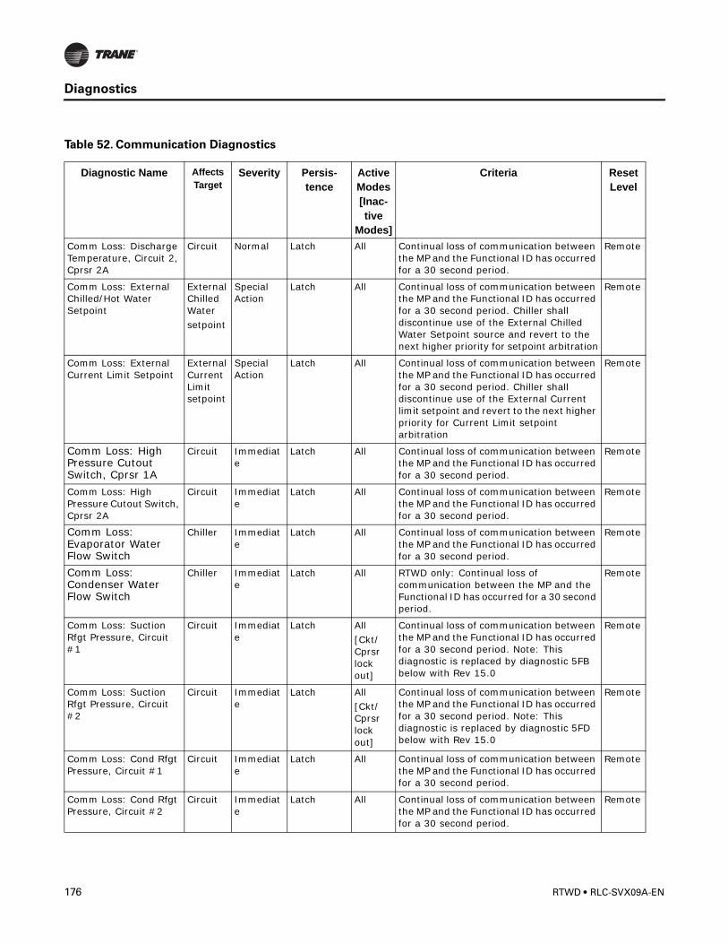
Diagnostics
Comm Loss: Discharge Temperature, Circuit 2, Cprsr 2A
Circuit Normal Latch All Continual loss of communication between the MP and the Functional ID has occurred for a 30 second period.
Remote
Comm Loss: External Chilled/Hot Water Setpoint
External Chilled Watersetpoint
Special Action
Latch All Continual loss of communication between the MP and the Functional ID has occurred for a 30 second period. Chiller shall discontinue use of the External Chilled Water Setpoint source and revert to the next higher priority for setpoint arbitration
Remote
Comm Loss: External Current Limit Setpoint
External Current Limit setpoint
Special Action
Latch All Continual loss of communication between the MP and the Functional ID has occurred for a 30 second period. Chiller shall discontinue use of the External Current limit setpoint and revert to the next higher priority for Current Limit setpoint arbitration
Remote
Comm Loss: High Pressure Cutout Switch, Cprsr 1A
Circuit Immediate
Latch All Continual loss of communication between the MP and the Functional ID has occurred for a 30 second period.
Remote
Comm Loss: High Pressure Cutout Switch, Cprsr 2A
Circuit Immediate
Latch All Continual loss of communication between the MP and the Functional ID has occurred for a 30 second period.
Remote
Comm Loss: Evaporator Water Flow Switch
Chiller Immediate
Latch All Continual loss of communication between the MP and the Functional ID has occurred for a 30 second period.
Remote
Comm Loss: Condenser Water Flow Switch
Chiller Immediate
Latch All RTWD only: Continual loss of communication between the MP and the Functional ID has occurred for a 30 second period.
Remote
Comm Loss: Suction Rfgt Pressure, Circuit #1
Circuit Immediate
Latch All[Ckt/Cprsr lock out]
Continual loss of communication between the MP and the Functional ID has occurred for a 30 second period. Note: This diagnostic is replaced by diagnostic 5FB below with Rev 15.0
Remote
Comm Loss: Suction Rfgt Pressure, Circuit #2
Circuit Immediate
Latch All[Ckt/Cprsr lock out]
Continual loss of communication between the MP and the Functional ID has occurred for a 30 second period. Note: This diagnostic is replaced by diagnostic 5FD below with Rev 15.0
Remote
Comm Loss: Cond Rfgt Pressure, Circuit #1
Circuit Immediate
Latch All Continual loss of communication between the MP and the Functional ID has occurred for a 30 second period.
Remote
Comm Loss: Cond Rfgt Pressure, Circuit #2
Circuit Immediate
Latch All Continual loss of communication between the MP and the Functional ID has occurred for a 30 second period.
Remote
Table 52. Communication Diagnostics
Diagnostic Name Affects Target
Severity Persis-tence
Active Modes [Inac-tive
Modes]
Criteria Reset Level
176 RTWD • RLC-SVX09A-EN
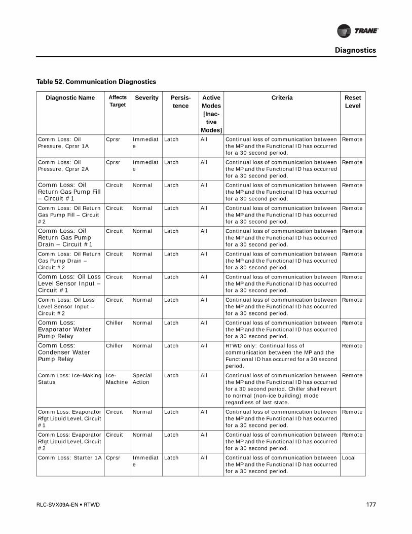
Diagnostics
Comm Loss: Oil Pressure, Cprsr 1A
Cprsr Immediate
Latch All Continual loss of communication between the MP and the Functional ID has occurred for a 30 second period.
Remote
Comm Loss: Oil Pressure, Cprsr 2A
Cprsr Immediate
Latch All Continual loss of communication between the MP and the Functional ID has occurred for a 30 second period.
Remote
Comm Loss: Oil Return Gas Pump Fill – Circuit #1
Circuit Normal Latch All Continual loss of communication between the MP and the Functional ID has occurred for a 30 second period.
Remote
Comm Loss: Oil Return Gas Pump Fill – Circuit #2
Circuit Normal Latch All Continual loss of communication between the MP and the Functional ID has occurred for a 30 second period.
Remote
Comm Loss: Oil Return Gas Pump Drain – Circuit #1
Circuit Normal Latch All Continual loss of communication between the MP and the Functional ID has occurred for a 30 second period.
Remote
Comm Loss: Oil Return Gas Pump Drain – Circuit #2
Circuit Normal Latch All Continual loss of communication between the MP and the Functional ID has occurred for a 30 second period.
Remote
Comm Loss: Oil Loss Level Sensor Input – Circuit #1
Circuit Normal Latch All Continual loss of communication between the MP and the Functional ID has occurred for a 30 second period.
Remote
Comm Loss: Oil Loss Level Sensor Input – Circuit #2
Circuit Normal Latch All Continual loss of communication between the MP and the Functional ID has occurred for a 30 second period.
Remote
Comm Loss: Evaporator Water Pump Relay
Chiller Normal Latch All Continual loss of communication between the MP and the Functional ID has occurred for a 30 second period.
Remote
Comm Loss: Condenser Water Pump Relay
Chiller Normal Latch All RTWD only: Continual loss of communication between the MP and the Functional ID has occurred for a 30 second period.
Remote
Comm Loss: Ice-Making Status
Ice-Machine
Special Action
Latch All Continual loss of communication between the MP and the Functional ID has occurred for a 30 second period. Chiller shall revert to normal (non-ice building) mode regardless of last state.
Remote
Comm Loss: Evaporator Rfgt Liquid Level, Circuit #1
Circuit Normal Latch All Continual loss of communication between the MP and the Functional ID has occurred for a 30 second period.
Remote
Comm Loss: Evaporator Rfgt Liquid Level, Circuit #2
Circuit Normal Latch All Continual loss of communication between the MP and the Functional ID has occurred for a 30 second period.
Remote
Comm Loss: Starter 1A Cprsr Immediate
Latch All Continual loss of communication between the MP and the Functional ID has occurred for a 30 second period.
Local
Table 52. Communication Diagnostics
Diagnostic Name Affects Target
Severity Persis-tence
Active Modes [Inac-tive
Modes]
Criteria Reset Level
RLC-SVX09A-EN • RTWD 177
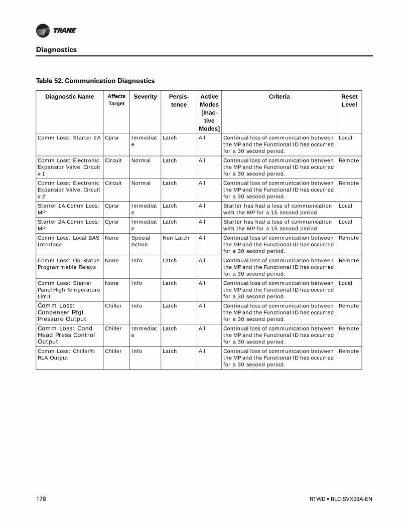
Diagnostics
Comm Loss: Starter 2A Cprsr Immediate
Latch All Continual loss of communication between the MP and the Functional ID has occurred for a 30 second period.
Local
Comm Loss: Electronic Expansion Valve, Circuit #1
Circuit Normal Latch All Continual loss of communication between the MP and the Functional ID has occurred for a 30 second period.
Remote
Comm Loss: Electronic Expansion Valve, Circuit #2
Circuit Normal Latch All Continual loss of communication between the MP and the Functional ID has occurred for a 30 second period.
Remote
Starter 1A Comm Loss: MP
Cprsr Immediate
Latch All Starter has had a loss of communication with the MP for a 15 second period.
Local
Starter 2A Comm Loss: MP
Cprsr Immediate
Latch All Starter has had a loss of communication with the MP for a 15 second period.
Local
Comm Loss: Local BAS Interface
None Special Action
Non Latch All Continual loss of communication between the MP and the Functional ID has occurred for a 30 second period.
Remote
Comm Loss: Op Status Programmable Relays
None Info Latch All Continual loss of communication between the MP and the Functional ID has occurred for a 30 second period.
Remote
Comm Loss: Starter Panel High Temperature Limit
None Info Latch All Continual loss of communication between the MP and the Functional ID has occurred for a 30 second period.
Local
Comm Loss: Condenser Rfgt Pressure Output
Chiller Info Latch All Continual loss of communication between the MP and the Functional ID has occurred for a 30 second period.
Remote
Comm Loss: Cond Head Press Control Output
Chiller Immediate
Latch All Continual loss of communication between the MP and the Functional ID has occurred for a 30 second period.
Remote
Comm Loss: Chiller% RLA Output
Chiller Info Latch All Continual loss of communication between the MP and the Functional ID has occurred for a 30 second period.
Remote
Table 52. Communication Diagnostics
Diagnostic Name Affects Target
Severity Persis-tence
Active Modes [Inac-tive
Modes]
Criteria Reset Level
178 RTWD • RLC-SVX09A-EN

Diagnostics
Table 53. Main Processor (Boot Messages and Diagnostics)
DynaView Display MessageDescription
Troubleshooting
Boot Software Part Numbers:LS Flash --> 6200-0318-04MS Flash --> 6200-0319-04
The “boot code” is the portion of the code that is resident in all MPs regardless of what application code (if any) is loaded. Its main function is to run power up tests and provide a means for downloading application code via the MP’s serial connection. The Part numbers for the code are displayed in the lower left hand corner of the DynaView during the early portion of the power up sequence and during special programming and converter modes. See below. For the EasyView, the extension of the boot code part number is displayed for approximately 3 immediately following power up.// This is normal, but you should provide this information when contacting Technical Service about power up problems.
Err2: RAM Pattern 1 Failure There were RAM errors detected in RAM Test Pattern #1.// Recycle power, if the error persists, replace MP.
Err2: RAM Pattern 2 Failure There were RAM errors detected in RAM Test Pattern #2.//Recycle power, if the error persists, replace MP.
Err2: RAM Addr Test #1 Failure There were RAM errors detected in RAM Address Test #1.// Recycle power, if error persists, replace MP.
Err2: RAM Addr Test #2 Failure There were RAM errors detected in RAM Address Test #2.//Recycle power, if the error persists, replace MP.
No Application PresentPlease Load Application...
No Main Processor Application is present – There are no RAM Test Errors.// Connect a TechView Service Tool to the MP’s serial port, provide chiller model number (configuration information) and download the configuration if prompted by TechView. Then proceed to download the most recent RTWD application or specific version as recommended by Technical Service.
App Present. Running Selftest.…Selftest Passed
An application has been detected in the Main Processor’s nonvolatile memory and the boot code is proceeding to run a check on its entirety. 8 seconds later, the boot code had completed and passed the (CRC) test.// Temporary display of this screen is part of the normal power up sequence.
App Present. Running Selftest…Err3: CRC Failure
An application has been detected in Main Processor’s nonvolatile memory and the boot code is proceeding to run a check on its entirety. A few seconds later, the boot code had completed but failed the (CRC) test.//Connect a TechView Service Tool to the MP’s serial port, provide chiller model number (configuration information) and download the configuration if prompted by TechView. Then proceed to download the most recent RTWD application or specific version as recommended by Technical Service. Note that this error display may also occur during the programming process, if the MP never had a valid application any time prior to the download. If the problem persists, replace the MP.
A Valid Configuration is Present A valid configuration is present in the MP’s nonvolatile memory. The configuration is a set of variables and settings that define the physical makeup of this particular chiller. These include: number/airflow,/and type of fans, number/and size of compressors, special features, characteristics, and control options.// Temporary display of this screen is part of the normal power up sequence.
RLC-SVX09A-EN • RTWD 179
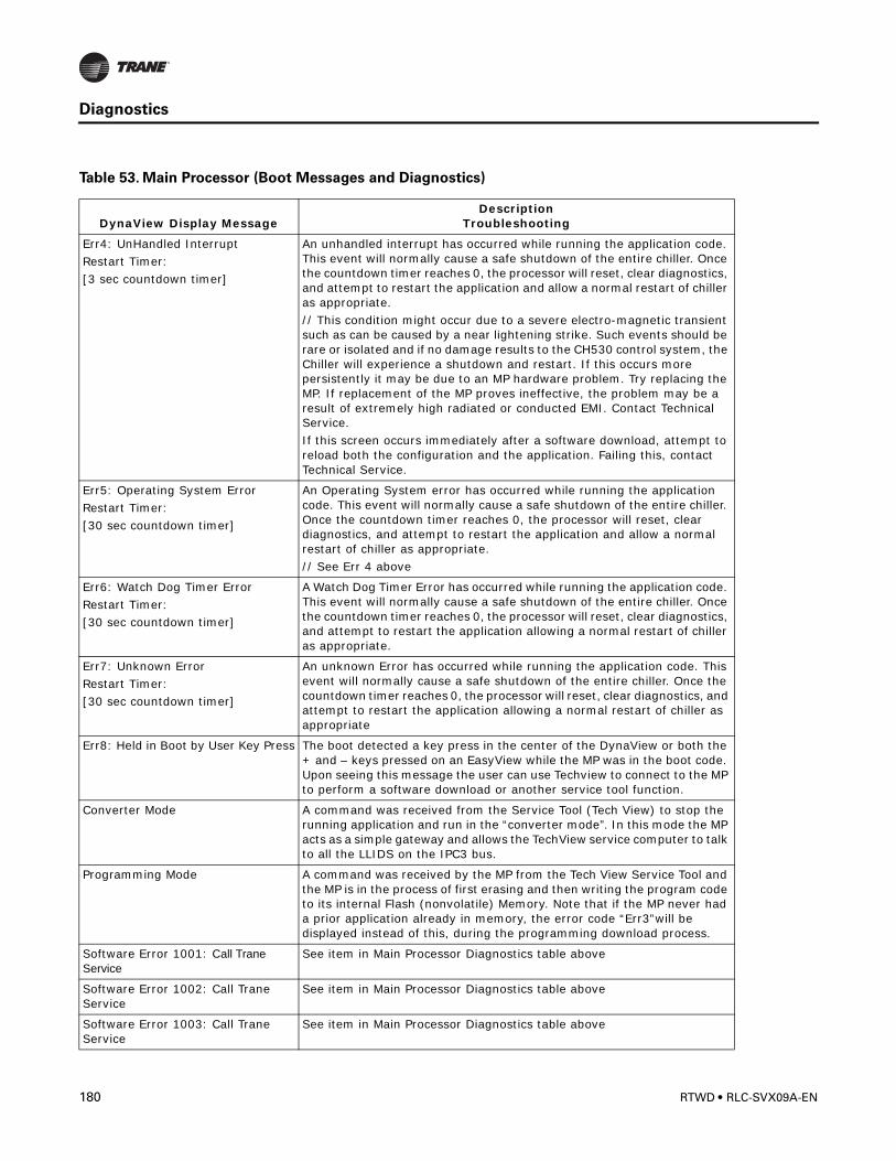
Diagnostics
Err4: UnHandled InterruptRestart Timer:[3 sec countdown timer]
An unhandled interrupt has occurred while running the application code. This event will normally cause a safe shutdown of the entire chiller. Once the countdown timer reaches 0, the processor will reset, clear diagnostics, and attempt to restart the application and allow a normal restart of chiller as appropriate.// This condition might occur due to a severe electro-magnetic transient such as can be caused by a near lightening strike. Such events should be rare or isolated and if no damage results to the CH530 control system, the Chiller will experience a shutdown and restart. If this occurs more persistently it may be due to an MP hardware problem. Try replacing the MP. If replacement of the MP proves ineffective, the problem may be a result of extremely high radiated or conducted EMI. Contact Technical Service.If this screen occurs immediately after a software download, attempt to reload both the configuration and the application. Failing this, contact Technical Service.
Err5: Operating System ErrorRestart Timer:[30 sec countdown timer]
An Operating System error has occurred while running the application code. This event will normally cause a safe shutdown of the entire chiller. Once the countdown timer reaches 0, the processor will reset, clear diagnostics, and attempt to restart the application and allow a normal restart of chiller as appropriate.// See Err 4 above
Err6: Watch Dog Timer ErrorRestart Timer:[30 sec countdown timer]
A Watch Dog Timer Error has occurred while running the application code. This event will normally cause a safe shutdown of the entire chiller. Once the countdown timer reaches 0, the processor will reset, clear diagnostics, and attempt to restart the application allowing a normal restart of chiller as appropriate.
Err7: Unknown ErrorRestart Timer:[30 sec countdown timer]
An unknown Error has occurred while running the application code. This event will normally cause a safe shutdown of the entire chiller. Once the countdown timer reaches 0, the processor will reset, clear diagnostics, and attempt to restart the application allowing a normal restart of chiller as appropriate
Err8: Held in Boot by User Key Press The boot detected a key press in the center of the DynaView or both the + and – keys pressed on an EasyView while the MP was in the boot code. Upon seeing this message the user can use Techview to connect to the MP to perform a software download or another service tool function.
Converter Mode A command was received from the Service Tool (Tech View) to stop the running application and run in the “converter mode”. In this mode the MP acts as a simple gateway and allows the TechView service computer to talk to all the LLIDS on the IPC3 bus.
Programming Mode A command was received by the MP from the Tech View Service Tool and the MP is in the process of first erasing and then writing the program code to its internal Flash (nonvolatile) Memory. Note that if the MP never had a prior application already in memory, the error code “Err3”will be displayed instead of this, during the programming download process.
Software Error 1001: Call Trane Service
See item in Main Processor Diagnostics table above
Software Error 1002: Call Trane Service
See item in Main Processor Diagnostics table above
Software Error 1003: Call Trane Service
See item in Main Processor Diagnostics table above
Table 53. Main Processor (Boot Messages and Diagnostics)
DynaView Display MessageDescription
Troubleshooting
180 RTWD • RLC-SVX09A-EN
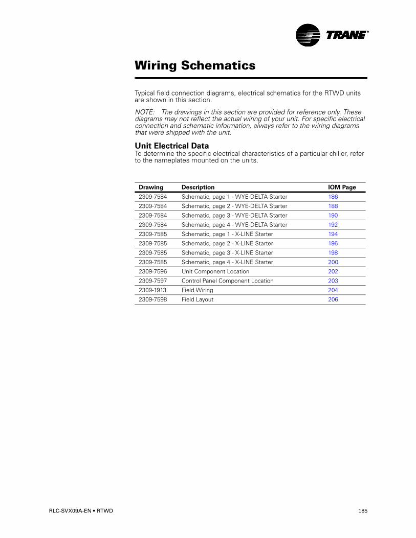
Wiring Schematics
Typical field connection diagrams, electrical schematics for the RTWD units are shown in this section.
NOTE: The drawings in this section are provided for reference only. These diagrams may not reflect the actual wiring of your unit. For specific electrical connection and schematic information, always refer to the wiring diagrams that were shipped with the unit.
Unit Electrical DataTo determine the specific electrical characteristics of a particular chiller, refer to the nameplates mounted on the units.
Drawing Description IOM Page
2309-7584 Schematic, page 1 - WYE-DELTA Starter 186
2309-7584 Schematic, page 2 - WYE-DELTA Starter 188
2309-7584 Schematic, page 3 - WYE-DELTA Starter 190
2309-7584 Schematic, page 4 - WYE-DELTA Starter 192
2309-7585 Schematic, page 1 - X-LINE Starter 194
2309-7585 Schematic, page 2 - X-LINE Starter 196
2309-7585 Schematic, page 3 - X-LINE Starter 198
2309-7585 Schematic, page 4 - X-LINE Starter 200
2309-7596 Unit Component Location 202
2309-7597 Control Panel Component Location 203
2309-1913 Field Wiring 204
2309-7598 Field Layout 206
RLC-SVX09A-EN • RTWD 185
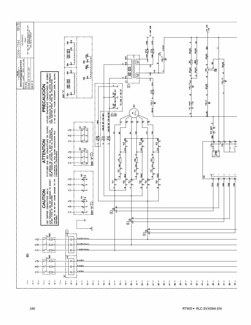
7552
186 RTWD • RLC-SVX09A-EN
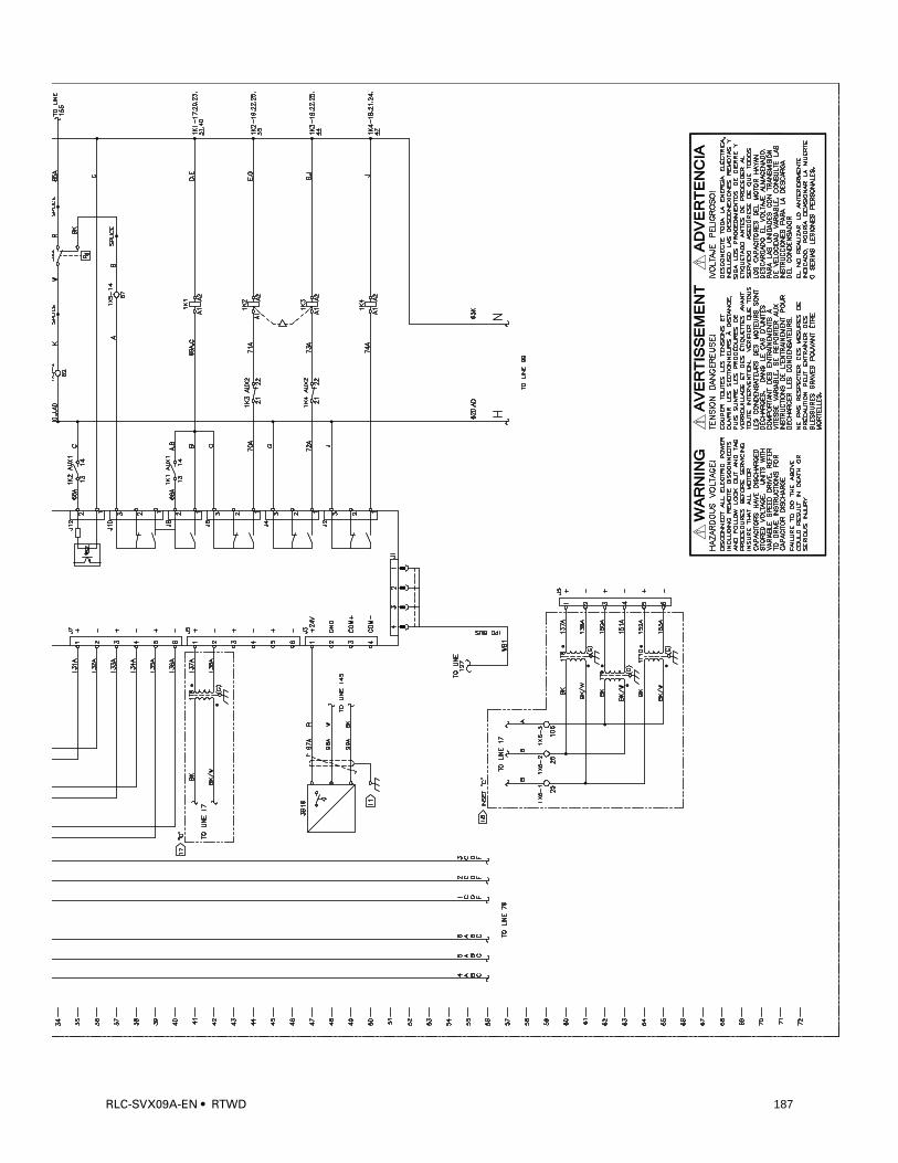
RLC-SVX09A-EN • RTWD 187
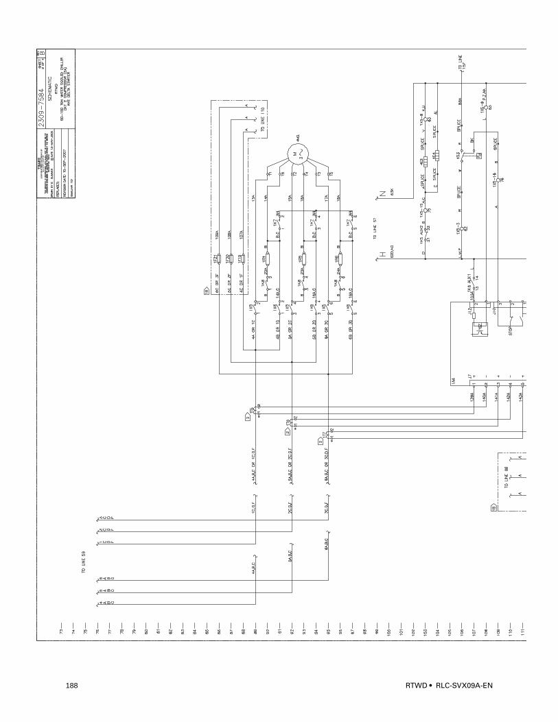
7553
188 RTWD • RLC-SVX09A-EN
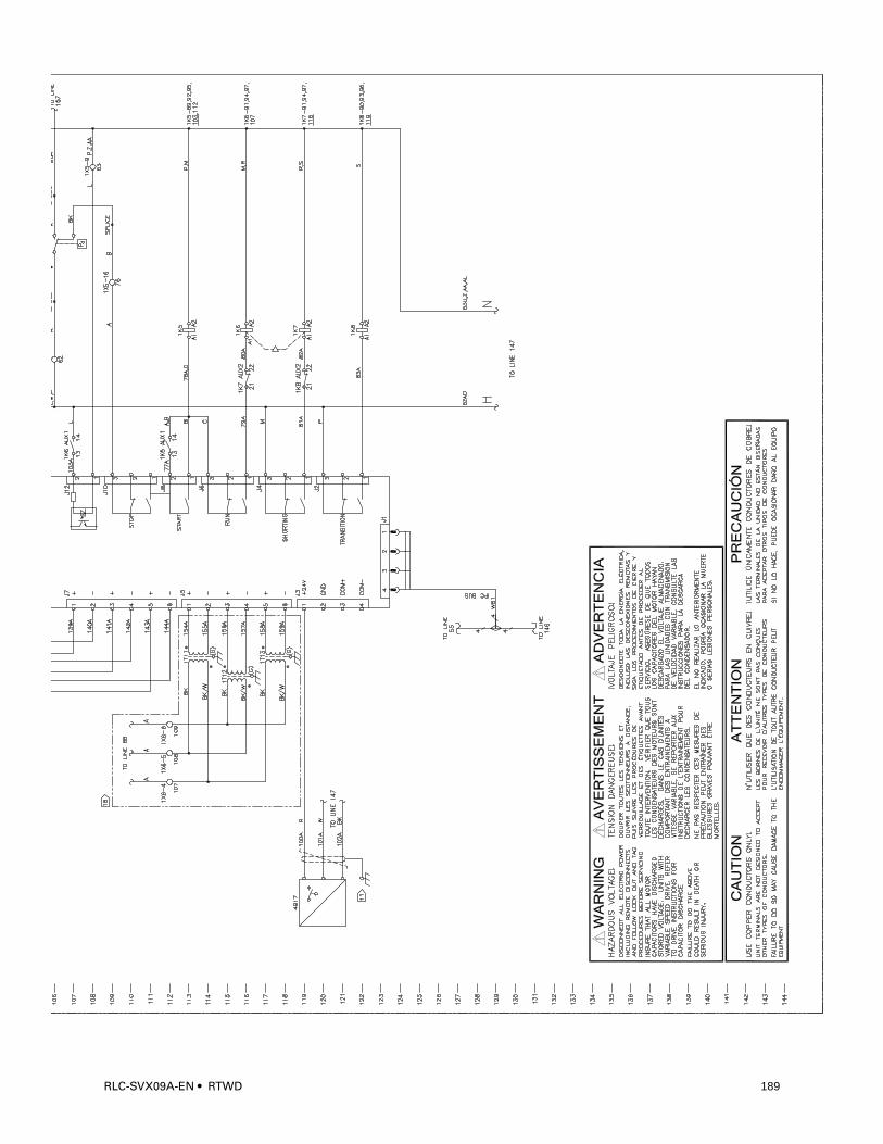
RLC-SVX09A-EN • RTWD 189
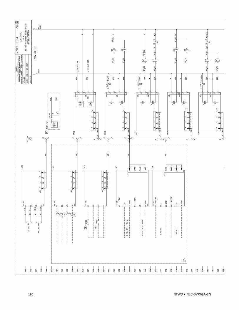
7554
190 RTWD • RLC-SVX09A-EN
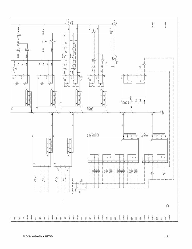
RLC-SVX09A-EN • RTWD 191
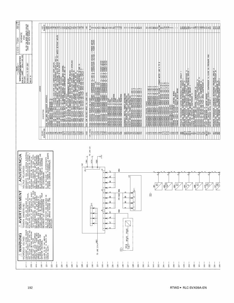
7555
192 RTWD • RLC-SVX09A-EN
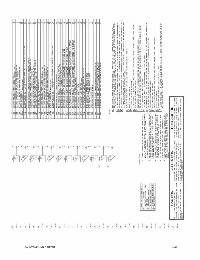
RLC-SVX09A-EN • RTWD 193
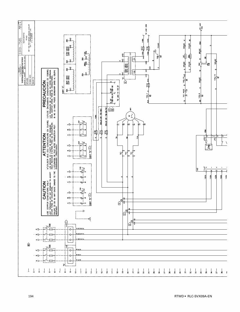
1360
194 RTWD • RLC-SVX09A-EN
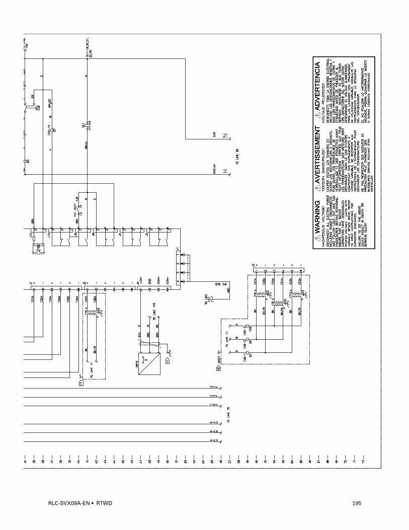
RLC-SVX09A-EN • RTWD 195
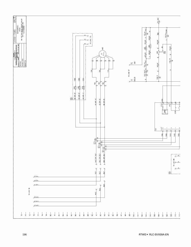
1361
196 RTWD • RLC-SVX09A-EN
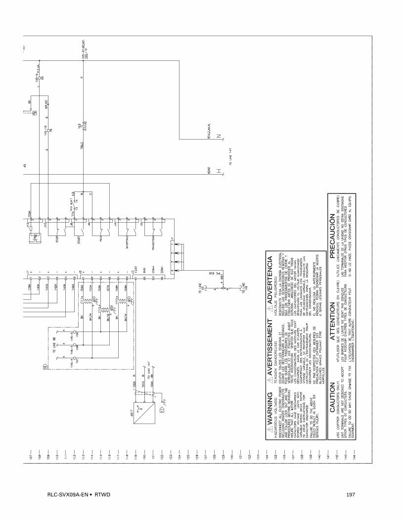
RLC-SVX09A-EN • RTWD 197
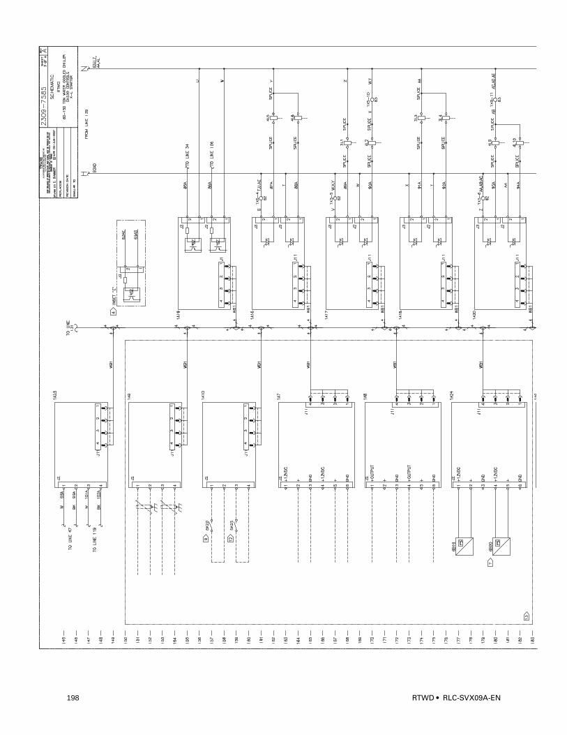
1362
198 RTWD • RLC-SVX09A-EN

RLC-SVX09A-EN • RTWD 199
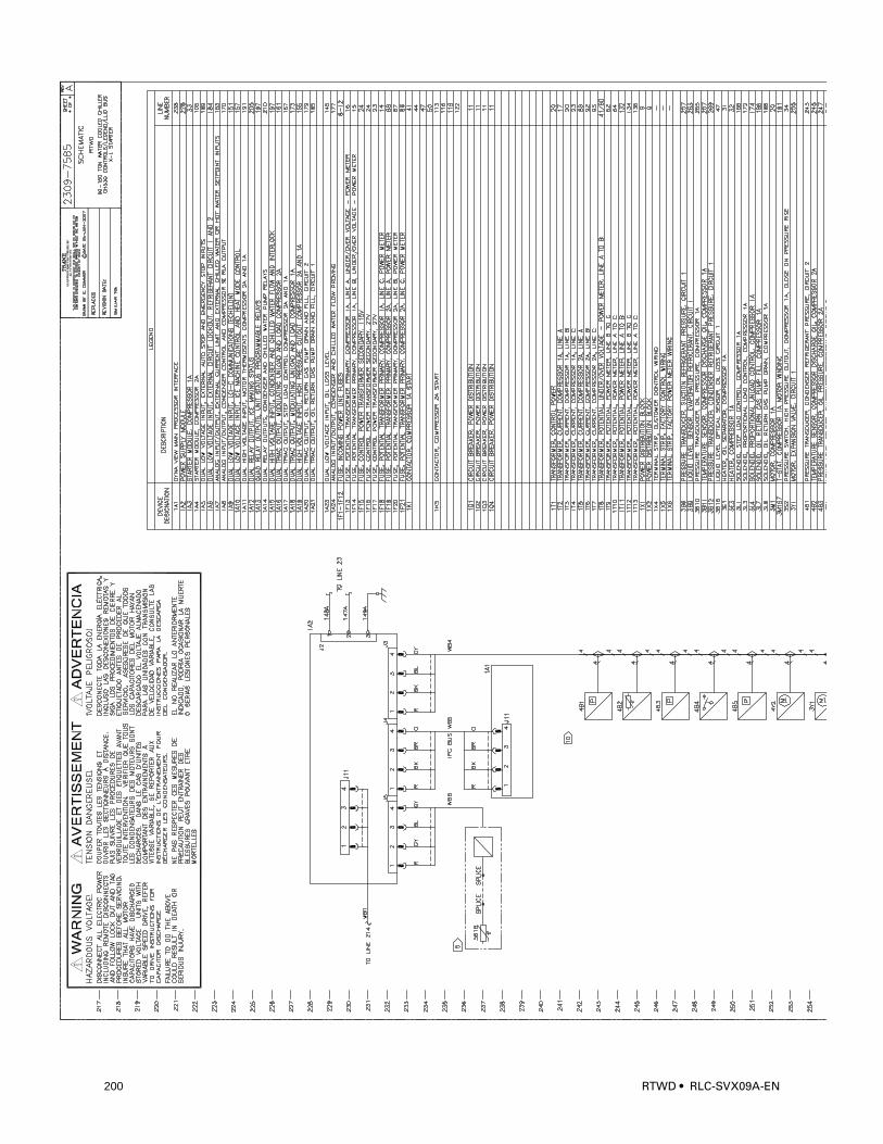
1363
200 RTWD • RLC-SVX09A-EN
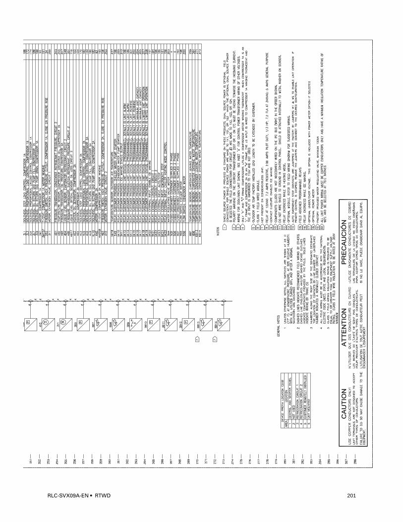
RLC-SVX09A-EN • RTWD 201
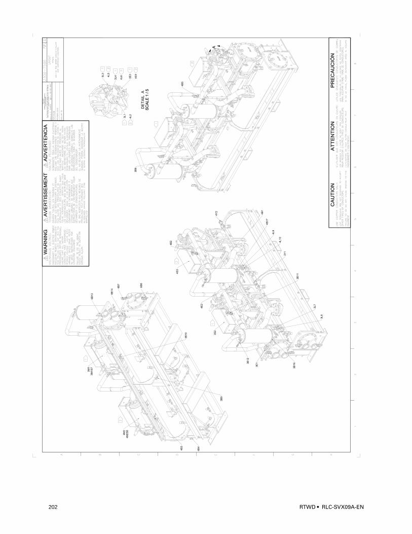
7564
6B
13 6
B1
4
6B
7
3B
10
4B
3
4S
3
3S
2
3B
6
4B
5
3B
12
3B
16
3B
11
3Y
1
4B
17
4B
1
4Y
2
DE
TA
IL A
6B
8
3B
9
4B
4
4B
2
3E
1
4E
2
3L
1
4L
2
3L
4
4L
63L
3
4L
5
3L
8
3L
7
4L10
4L
9
3E
3
4E
4
4M
2
4M
2S
8
3M
1
3M
1S
7
C
A D
IVIS
ION
OF
AM
ER
ICA
N S
TA
ND
AR
D IN
C.
ALL R
IGH
TS
RE
SE
RV
ED
202 RTWD • RLC-SVX09A-EN
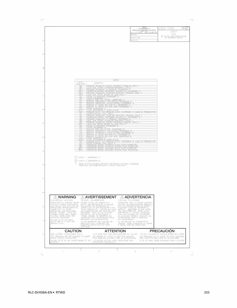
7565
C
A DIVISION OF AMERICAN STANDARD INC.
ALL RIGHTS RESERVED
RLC-SVX09A-EN • RTWD 203
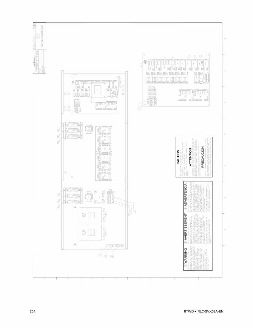
4870
C
A D
IVIS
ION
OF
AM
ER
ICA
N S
TA
ND
AR
D IN
C.
ALL R
IGH
TS
RE
SE
RV
ED
204 RTWD • RLC-SVX09A-EN
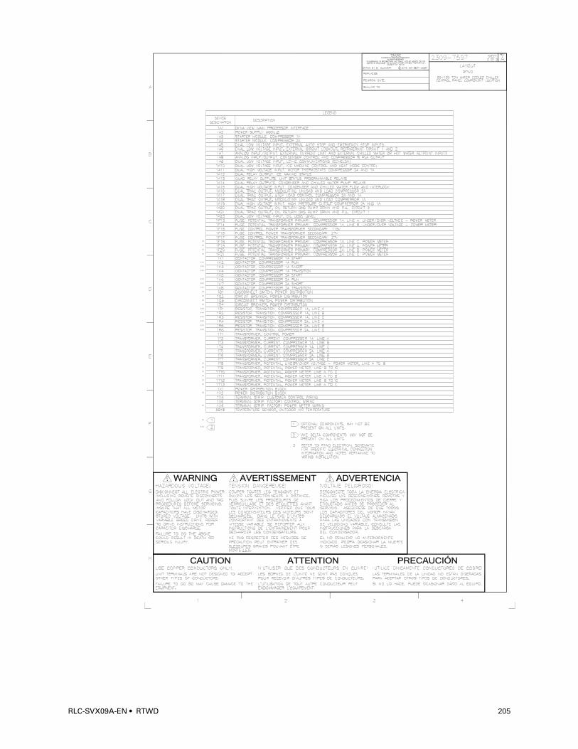
C
A DIVISION OF AMERICAN STANDARD INC.
ALL RIGHTS RESERVED
RLC-SVX09A-EN • RTWD 205
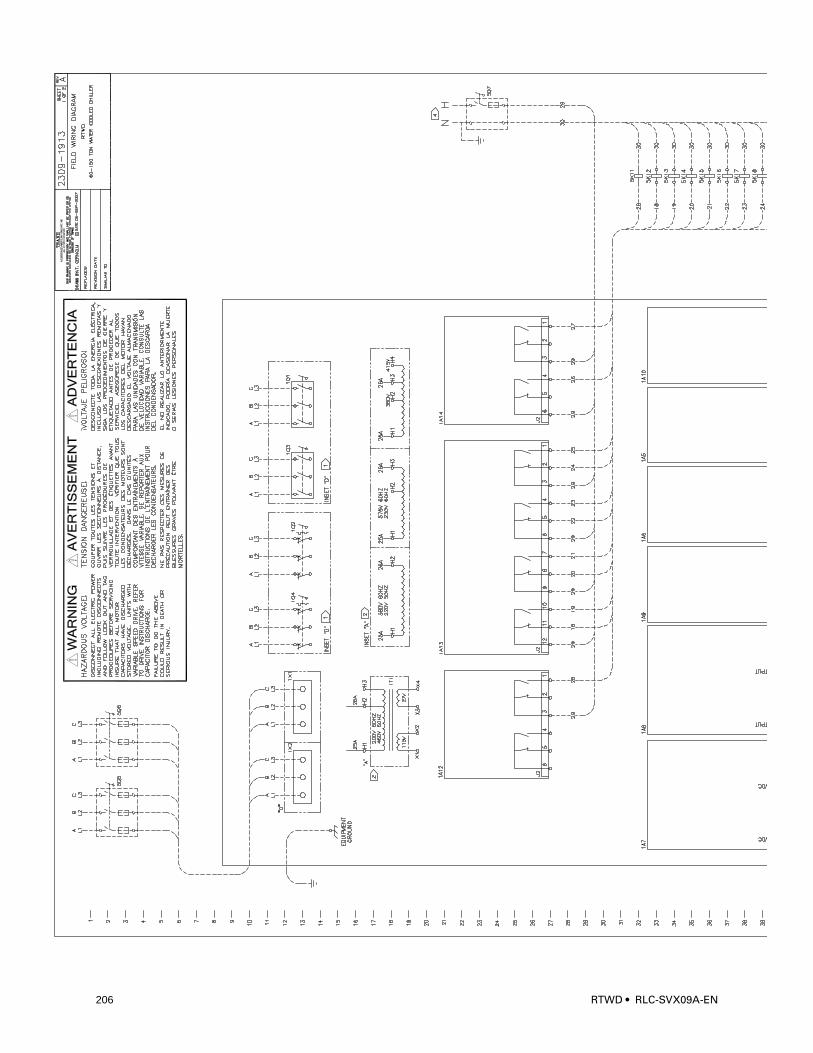
4869
206 RTWD • RLC-SVX09A-EN
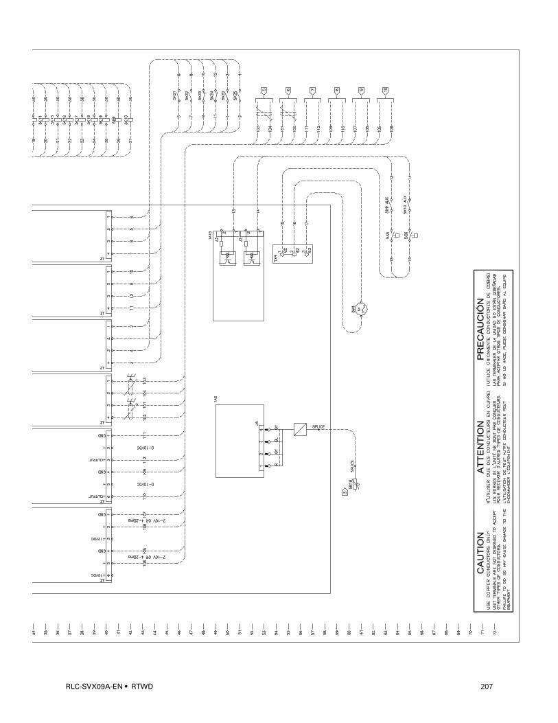
RLC-SVX09A-EN • RTWD 207
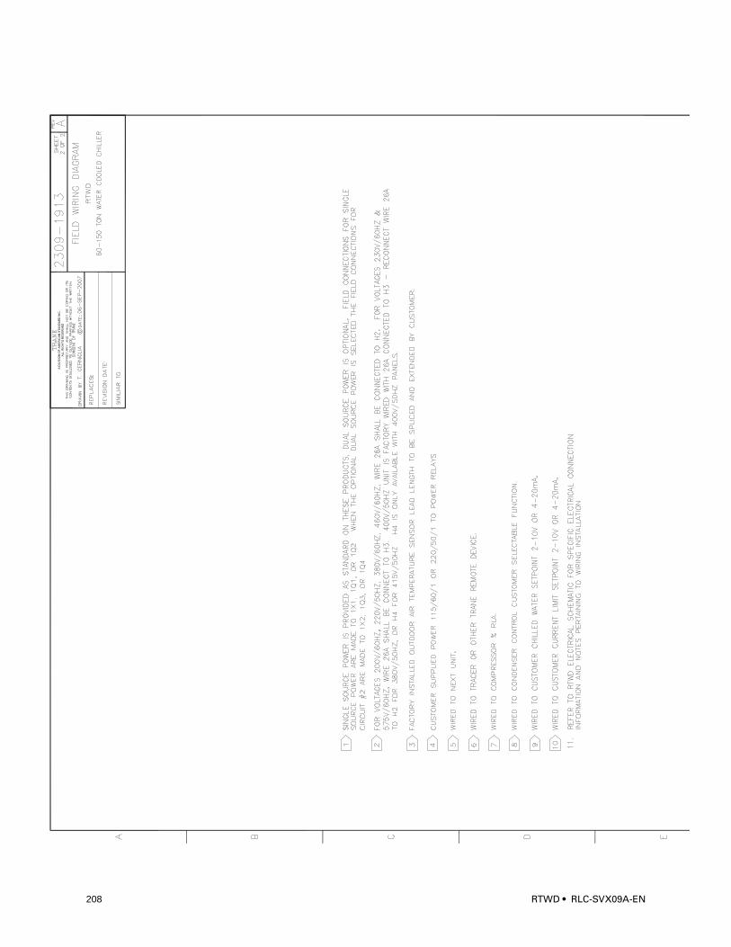
C
A D
IVIS
ION
OF
AM
ER
ICA
N S
TA
ND
AR
D IN
C.
ALL R
IGH
TS
RE
SE
RV
ED
208 RTWD • RLC-SVX09A-EN
RLC-SVX09A-EN • RTWD 209

C
A DIVISION OF AMERICAN STANDARD INC.
ALL RIGHTS RESERVED
210 RTWD • RLC-SVX09A-EN
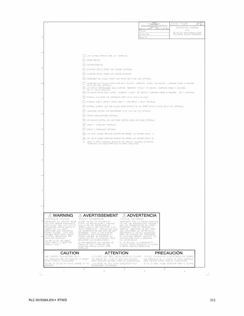
C
A DIVISION OF AMERICAN STANDARD INC.
ALL RIGHTS RESERVED
RLC-SVX09A-EN • RTWD 211
Trane
A business of American Standard Companies
www.trane.com
For more information, contact your local Trane office or e-mail us at [email protected]
Literature Order Number RLC-SVX09A-EN
Date December 2006
Supersedes New